FX1000 Paperless Recorder BU04L21B01 01EN 030
User Manual: FX1000
Open the PDF directly: View PDF ![]() .
.
Page Count: 8
Subject to change without notice
All Rights Reserved. Copyright © 2005, by Yo kogawa Electric Corporation
www.FxRecorder.com
Bulletin 04L21B01-01EN
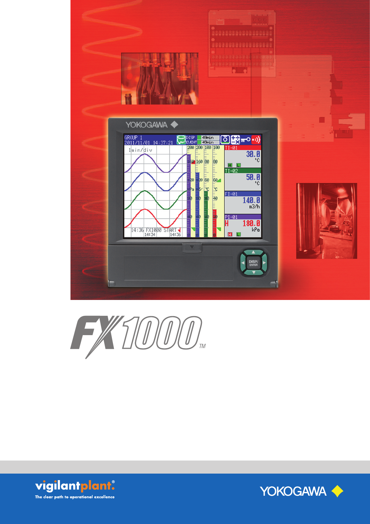
Paperless Recorder
PAPERLESS RECORDER
FX1000
2
At YOKOGAWA, we are committed to the “quality first, customer first” principle in all areas of our
business, including product design, research and development, and sales and services. The new
FX1000 paperless recorder exceeds customer expectations for quality, high performance and
capability- at a price that meets the needs of a cost-sensitive market.
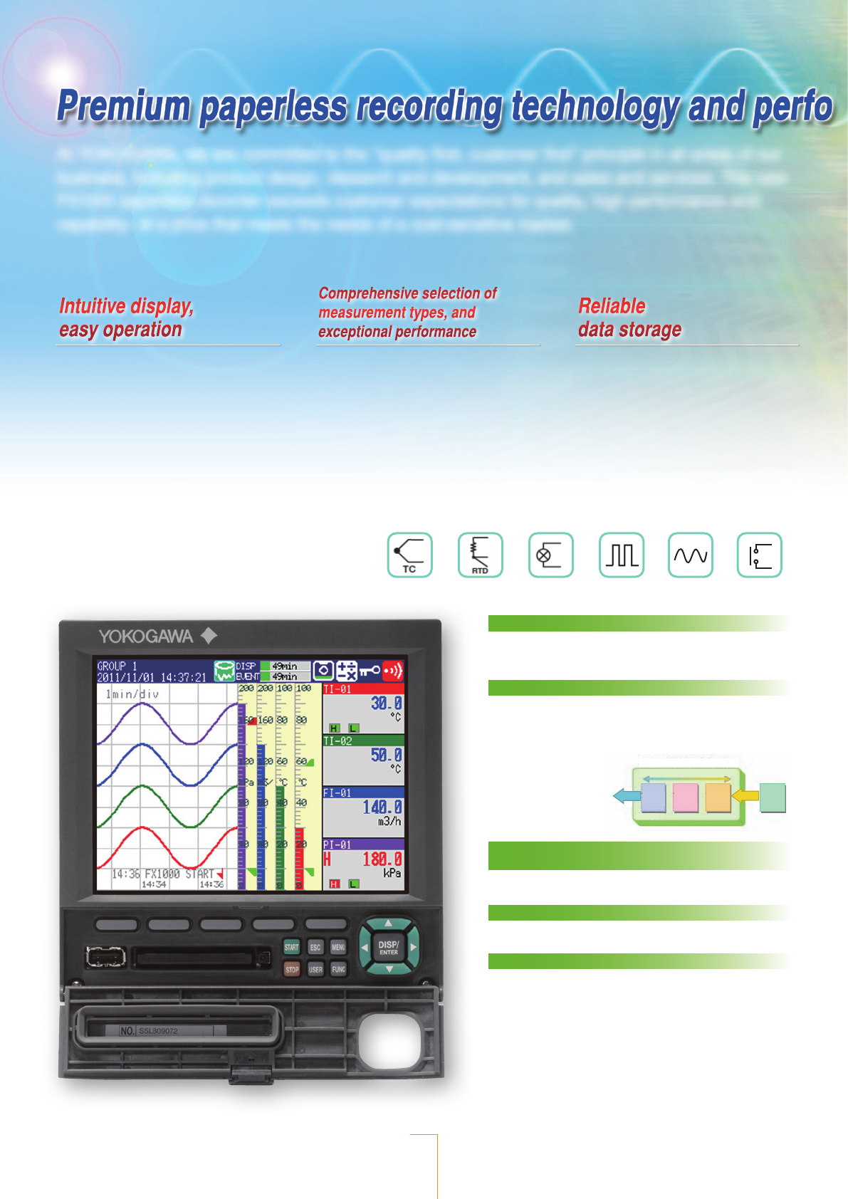
Intuitive display,
easy operation
Comprehensive selection of
measurement types, and
exceptional performance
Reliable
data storage
Multi-Channel Measurement and
Recording
Universal input signal measurement
High capacity internal memory
Standard 400MB non-volatile flash memory for secure, long
term recording
Media FIFO function
This function ensures that the CF card always retains the
latest data when files are saved to it automatically. When the
CF card is full, the oldest files are deleted to make room for
the newest files. The media FIFO function allows you to use
the FX continuously
for long periods of
time without having to
change the CF card.
Compact dimensions for easy panel &
enclosure installation
Shallow case depth behind the panel of 162 mm (6.4”)
Water- and dustproof
Complies with IEC529-IP65, except side-by-side mounting
Pulse (option)RTDThermocouple DC voltage/current Power (option) DI input
Overview of the Media FIFO function
Old
Medium
Deleted File 1 File 2 File 3 File 4Saved
Update date New
l 5.7-inch, high-precision, wide-
viewing-angle color TFT LCD
l Many types of displays such as
trend, digital, bar graph, overview,
alarm, and historical trend
l Remote viewing of the FX1000
screen through the Internet
l Multi-functional panel keys
l Input types:
DCV, TC, RTD, DI
l Scan interval:
1 s, 125 ms (fast sampling)
l Channels:
2, 4, 6, 8, 10, 12
l Measurement accuracy:
±0.05% of reading (DCV),
±0.15% of reading (TC, RTD)
l Large (400 MB) internal memory
l CF cards up to 2 GB (option)
l USB interface (option)
l Binary data storage
l Network enables data redundancy
Intuitive operator controls
The DISP/ENTER and arrow keys provide display mode and
setting menu navigation. Clearly labeled menu, function,
and record start/stop keys handle all setting and control
operations.
3
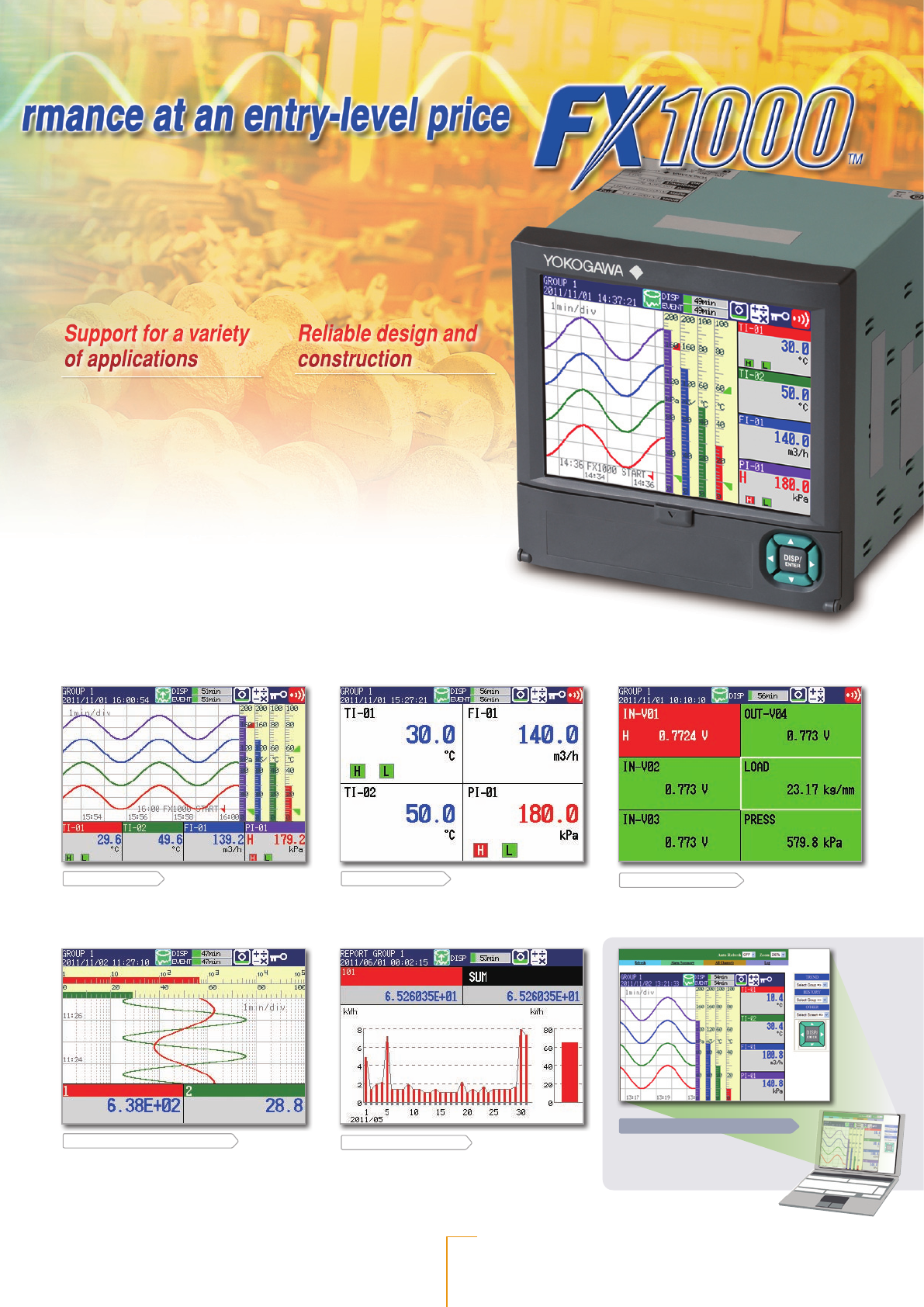
Support for a variety
of applications
Trend display (Log scale)
You can display log scales for degree of
vacuum (pressure input), and record the data
(option).
Stacked bar graph
You can display and record
power consumption of each piece of electronic equipment;
useful for energy saving and equipment maintenance as part of
environmental protection programs (option).
IE browser monitor screen
FX screen monitoring and
operation is made easy via
Ethernet.
Trend display Displays measured data
as waveforms. Displays each channel's scale
value, industrial units, user messages, and
other information.
Digital display In addition to displaying
measurements digitally, it displays channel/
tag, industrial units, and alarm statuses.
Overview display Displays
measurements and alarm statuses on all
channels.
Monitor display
You can use the keys to switch to any of the operation screens.
The operating states of memory sampling, alarms, key lock, computation, and other conditions are graphically displayed.
Supports Chinese, English, German, French, Italian, Spanish, Portuguese, Russian, Korean, and Japanese.
Reliable design and
construction
Bar graph, historical trend, and information displays (alarm summaries, message summaries, and reports) are also included.
l Power measurement
recording (option)
l Vacuum pressure recording
(Log scale, option)
l Flow rate summation (option)
l F value calculation (option)
See “Applications” on the next
page.
l Space-saving design
l Waterproof and dustproof
(IP65 compliant)
Steam
L
L
1
L
2
L
3
L
4
L
5
S
1
S
2
S
3
S
4Sn-4
Sn-1
Ln-2
Ln-1
Ln
Δt Δt t
F0 summation area
Dry bulb
temperature
Wet bulb
temperature
Outer
diameter
Temperature
Supply
Extruder
Water tank
Measurement
Haul-OFF
Take-up or
auto coiler
machine
Accumulator
Temperature controller
PLC
Electromagnetic
control
Batch
recording
Start/Stop
Serial
communications
Linear rise
Vacuum gauge
Vacuum
furnace
Log display
Furnace data record
Molten metal temperature
Cooling water temperature
Melting furnace
Metal mold
Tire press,
batch operation
Pressure
Temperature
Temperature
Solenoid valve
Adjustment valve
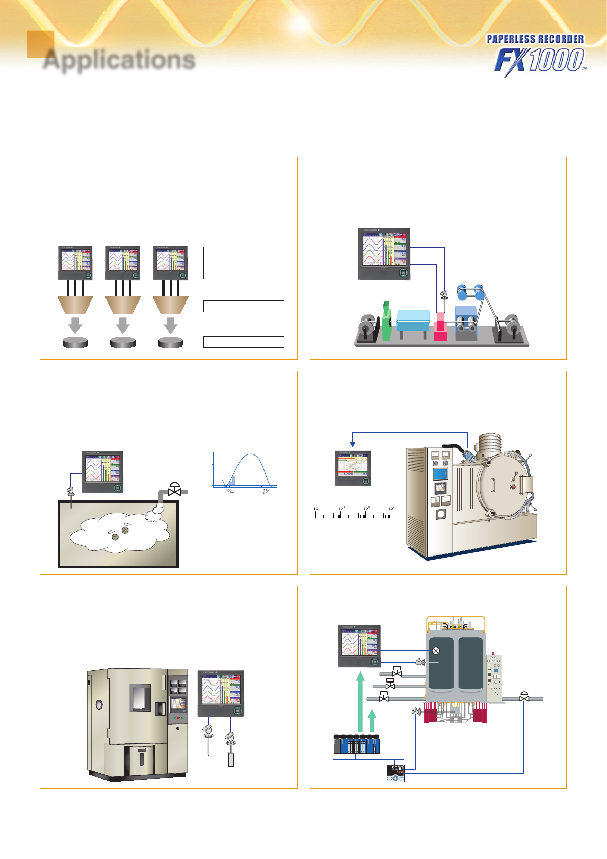
Temperature Recording/Monitoring for Aluminum Casting
Simplifies casting temperature quality management.
– Displays and records aluminum casting data
Molten metal temperature
Cooling water temperature
– Archives data upon alarm occurrence
Analysis alarm data
Managing Sterilization of Food Industry
(Acquisition of Sterilization/Pasteurization Data)
MATH function (/M1, /PM1, /PWR1 options) enables recording (and F
value calculation) of sterilization and pasteurization processes.
– Automatically computes F0 value according to temperature
– Computed results are recorded together with temperature and other parameters (Foodstuff
temperature, pressure, etc.)
– Measurement ON/OFF through external contact input (/R1, /PM1 options)
Vacuum Gauge Recording
Physical quantities of voltage converted to logs are input to the FX,
and those physical quantities are displayed and recorded on the FX
log scale.
Controlling Temperature and Pressure in Tire Manufacturing
(Vulcanization)
Measures and records mold temperature and pressure
Display and Recording of Data from Environmental Testing
Equipment (Acquisition of Test Data from a Thermostatic Chamber)
Measures environmental testing data, and displays and records a
variety of data in an easy-to-understand format
– Select from a variety of inputs (universal input)
– Automatically computes relative humidity from dry bulb temperature and web bulb
temperature (/M1, /PM1, /PWR1 options)
– Computed results are recorded together with temperature and humidity (pressure and
current)
Management of an Electrical Wire Coating Process
(Acquisition of Data on Wire Temperature and Outer Diameter)
Displays outer diameter and temperature in a electrical wire coating
process for monitoring insulation quality.
– Select from a variety of inputs (universal input)
– Displays temperature and wire diameter simultaneously for monitoring of correlations
– On-site monitoring and recording of diameter, temperature, and alarms upon occurrence of
abnormalities
4
Applications
Secure Monitoring and Recording for a Wide Range of Applications
FX1000 combines a clear view of process data with highly reliable recording and efficient data access. Network file transfer
and web browser viewing improves efficiency and saves time. Use the Power Monitor option to monitor and record energy
consumption on equipment to learn true energy usage costs and for diagnostic and preventive maintenance purposes.
5
STANDARD SPECIFICATIONS
GENERAL SPECIFICATIONS
lConstruction
Mounting: Flush panel mounting (on a vertical plane)
Mounting may be inclined downward up to 30 degrees from a
horizontal plane.
Allowable panel thickness:
2 to 26 mm
Front panel: Water- and dustproof: Complies with IEC529-IP65 (excluding
side-by-side mounting)
lInput
Number of inputs: FX1002: 2 channels, FX1004: 4 channels, FX1006: 6 channels,
FX1008: 8 channels, FX1010: 10 channels, FX1012: 12 channels
Measurement intervals:
FX1002, FX1004: 125 ms, 250 ms
FX1006, FX1008, FX1010, FX1012: 1 s, 2 s, 5 s
Inputs: DCV (20, 60, 200 mV, 1, 2, 6, 20, 50 V, 1-5 V)
TC (R, S, B, K, E, J, T, N, W, L, U, WRe)
RTD (Pt100, JPt100)
DI (Contact input, TTL level)
DCA (with external shunt resistor attached)
Measurement/display accuracy:
Standard operating conditions: Temperature: 23 ± 2°C; Humidity: 55% ± 10%RH;
Power supply voltage: 90 to 132 or 180 to 250 VAC; Power supply frequency: 50/60
Hz ± 1%; Warm-up time: At least 30 minutes. Other ambient conditions such as
vibration should not adversely affect the operation.
Input Range Measurement Accuracy
Digital Display
Max. Resolution
DCV 1-5 V ±(0.05% of rdg+3 digits) 1 mV
Thermocouple* K±(0.15% of rdg + 0.7°C)
–200 to –100°C: ±(0.15% of rdg + 1°C) 0.1°C
RTD Pt100 ±(0.15% of rdg+0.3°C) 0.1°C 0.1°C
* Does not include the accuracy of reference junction compensation
lDisplay
Display: 5.7-inch TFT color LCD (240 × 320 dots)
* A section of the LCD monitor may contain pixels that are always on
or off. The brightness of the LCD may also not be uniform due to the
characteristics of the LCD. This is not a malfunction.
Display groups:
Number of groups: 10
Number of channels that can be assigned to each group: Up to six
Display color:
Channel: Select from 24 colors
Background: White or black (selectable)
Trend display: Layout: Vertical, horizontal, or wide
Bar graph display: Direction: Vertical or horizontal (selectable)
Digital display: Update rate: 1 s
Overview display: Measuring values and alarm status of all channels
Information display: Alarm summary, message summary, memory summary, report,
stacked bar graph, status, Modbus status
Modbus log display: Displays the login log, error log, communication log (/C2, /C3,
and /C7), FTP log (/C7), Web log (/C7), e-mail log (/C7), SNTP
log (/C7), and DHCP log (/C7)
Tag display:
Number of displayable characters: Up to 16
Displayable characters: English, Japanese, and Chinese
Messages:
Number of displayable characters: Up to 32 alphanumeric
Displayable characters: English, Japanese, and Chinese
Historical display function:
Plays back data from internal memory or external memory
media.
Back light saver function:
LCD back light dims or turns OFF (user selectable) if no keys
have been pressed for a specified period (1, 2, 5, 10, 30, or 60
min).
lData Saving Function
External storage medium:
Medium: CompactFlash memory card (CF card) (on FXs with a CF card slot)
Internal memory:
Medium: Flash memory
Format: FAT32 or FAT16
Capacity: 400 MB
Maximum number of files that can be saved: 400 (total number of display data
and event data files)
Operation: FIFO (First In, First Out)
lAlarm Function
Number of alarm levels: Up to four for each channel
Alarm types: High limit, low limit, differential high limit, difference low limit,
high rate-of-change limit, low rate-of-change limit, alarm delay
high limit, and alarm delay low limit
lEvent Action Function
General: A particular action can be executed by particular event.
Number of event actions: 40 actions can be set
lSecurity Functions
General: Login function or key lock function can be set for each key
operation or communication operation.
Key lock function: On/off and password can be set for each operation key and
FUNC operation.
Login function: User name and password to login can be set.
System administrators: 5 (with access to all operations)
Users: 30 (with access to operations based on their user access rights)
lClock
Clock: With calendar function (Western calendar)
Accuracy: ±50 ppm (0 to 50°C); does not include the delay (1 second or
less) that occurs when the power is turned on.
lBatch Function
General: Data display and data management with batch name, text field
function and batch comment function are available.
lPower Supply
Rated power supply: 100 to 240 VAC (automatic switching)
Allowable power supply voltage range:
90 to 132 or 180 to 264 VAC
Rated power supply frequency:
50/60 Hz (automatic switching)
Power consumption: Max. 45 VA (for 240 VAC power supply)
NORMAL OPERATING CONDITIONS
Supply voltage: 90 to 132, 180 to 250 VAC
Rated power supply frequency:
50 Hz ±2%, 60 Hz ±2%
Ambient temperature: 0 to 50°C
Ambient humidity: 20 to 80% RH (at 5 to 40°C), 10 to 50% (at 40 to 50°C)
OPTIONS
lAlarm Output Relay (/A1, /A2, /A3, and /A4A)
Action: Outputs relay contact signals from the terminals on the rear
panel when alarms occur.
Number of outputs: 2 (/A1), 4 (/A2), 6 (/A3), and 12 (/A4A)
Relay contact rating: 250 VAC (50/60 Hz)/3 A, 250 VDC/0.1 A (for resistance load)
Output format: NO-C-NC: Except /A4 option,
NO-C: /A4A option
Relay operation: Energized/de-energized, AND/OR, hold/non-hold, and reflash
settings are selectable.
lRS-232 Interface (/C2) and RS-422A/485 Interface (/C3)
Connection: EIA RS-232(/C2) or EIA RS-422/485(/C3)
Protocol: Dedicated protocol or Modbus protocol
Setting/measurement server function:
Operation, setting or output of measurement data are available
by FX private protocol.
Modbus communication:
Reading or writing of measurement data on other instruments
are available by Modbus protocol.*
* The /M1, /PM1 or /PWR1 option is required to read data from another
instrument.
lEthernet Communication Interface (/C7)
Electrical and mechanical specifications:
Conforms to IEEE 802.3 (Ethernet frames conform to the DIX
specification).
Medium: Ethernet (10BASE-T)
Protocol: Dedicated protocol as well as the TCP, IP, UDP, ICMP, ARP,
DHCP, HTTP, FTP, SMTP, SNTP, and Modbus protocols
E-mail client: Automatically send e-mail at specified times.
FTP client, FTP Server, Web server, SNTP client, SNTP server, DHCP client,
Modbus client, Modbus server
lFAIL/Status Output Relay (/F1)
The relay contact output on the rear panel indicates the occurrence of CPU failure or
selected status.
Specification·Performance
6
lComputation Function (Including the Report Function) (/M1)
Used for calculating data, displaying trends and digital values, and recording
calculated data assigned to channels.
Number of computation channels:
FX1002 and FX1004: 12 channels
FX1006, FX1008, FX1010, and FX1012: 24 channels
Max. characters in formulas: 120
Operation: General arithmetic operations, relational operations, logic
operations, statistical operations, special operations,
conditional operations
Constants: Up to 60 (K01 to K60)
Report functions:
Report type: Hourly, daily, hourly + daily, daily + weekly and daily + monthly
Operation: Average, maximum, minimum, instantaneous and summation
l3-Wire Isolated RTD Input (/N2)
All the RTD input terminals (A, B, and b) are isolated on each channel.
Applies to the FX1006, FX1008, FX1010, and FX1012
Note: On the FX1002 and FX1004 standard models, the A, B, and b terminals are already
isolated on each channel.
lExtended Input (/N3F)
This option allows the extra input types below to be added to the standard input types.
TC: Kp vs Au7Fe, PLATINEL, PR40-20, NiNiMo, W/Wre26, TypeN (AWG14), XK GOST
RTD: Ni100 (SAMA), Ni100 (DIN), Ni120, Pt100 GOST, Cu100 GOST, Cu50
GOST, Pt200(WEED)
lDC/AC 24 V Power Supply (/P1)
Rated supply voltage: 24 VDC and 24 VAC (50/60Hz)
Allowable power supply voltage range:
21.6V to 26.4 VDC/AC
Max. power consumption:
18 VA (24 VDC), 30 VA (24 VAC (50/60 Hz))
lRemote Control (/R1)
This option allows eight functions to be controlled remotely by a contact input.
l24 VDC Transmitter Power Supply (/TPS2 and /TPS4)
Output voltage: 22.8 to 25.2 VDC (under rated load current)
Rated output current: 4 to 20 mADC
Max. output current:
25 mADC (overcurrent protection operation current: approx. 68 mADC)
lUSB Interface (/USB1)
USB port: Complies with rev. 1.1 and host function
Number of ports: 1 (front panel)
Connectable devices: Keyboard complies with HID Class Ver. 1.1
104 keyboard/89 keyboard (US) and 109 keyboard/89 keyboard
(Japanese)
External medium: USB flash memory
Does not guarantee the operation of all USB flash memories.
lPulse Input (/PM1)
Accepts pulses via contact input or open collector signals to dedicated input
terminals (remote input).
Pulse input option includes mathematical functions option (/M1) and remote control
option (/R1).
Number of inputs: 3 (8 are available if using remote inputs)
Input format: Photocoupler isolation (shared common)
Isolated power supply for input terminal (approx. 5 V)
Input type: Voltage-free contact, open collector
lCalibration Correction (/CC1)
Corrects the measured values of each channel using segment linearizer approximation.
Number of segment points: 2 to 16
lPower Monitor (/PWR1)
By including power measurement elements in an expression, you can measure a
variety of power values.
Active power, regenerative electric power, reactive power, apparent power, voltage, current,
frequency, power factor (LEAD:–, LAG: +), and electric energy (active energy, regenerative
energy, reactive energy –LAG: +, reactive energy –LEAD: –, and apparent energy)
The MATH option (/M1) is included with the power monitoring option.
Phase and wiring system:
Single-phase two-wire system, single-phase three-wire system,
and three-phase three-wire system
Frequency: 45 to 65 Hz
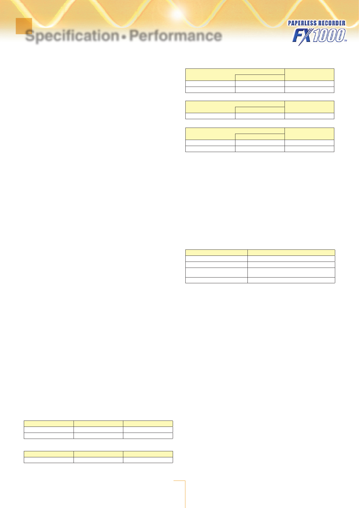
Rated input voltage:
Rated Voltage Voltage Range (Variable) Allowable Input Voltage
120 V 120 V 150 V
240 V 240 V 300 V
Rated input current
Rated Current Current Range (Fixed) Allowable Input Current
1 A 1 A 1.2 A
Rated input power and measuring range: The VT and CT’s secondary side when
using VT and CT.
Single-phase two-wire system
Input (AC) Input Measuring Range1
Rated Power
120 V / 1 A 100 W -120 to 120 W
240 V / 1 A 200 W -240 to 240 W
Single-phase three-wire system
Input (AC) Input Measuring Range
Rated Power
200 V / 1 A 200 W -240 to 240 W
Three-phase three-wire system
Input (AC) Input Measuring Range
Rated Power
120 V / 1 A 200 W -240 to 240 W
240 V / 1 A 400 W -480 to 480 W
The input measuring range when you are using a VT and CT is calculated using the following equation.
The measuring range must be within the input measuring ranges listed above, and the primary
side input power2 must be less than 10 GW.
1: Input measuring range (W) = Primary side input power in W*2/(VT ratio × CT ratio).
2: Primary side input power = Secondary side rated power in W × 1.2 × VT ratio × CT ratio.
VT ratio/CT ratio: By setting the VT and CT ratios, input to the FX is converted to
the primary side input value before the VT/CT and displayed.
Low cut power function:
A power measurement element is included in which power
below a specified value is treated as 0.
This is used when calculating power as watt hours.
Setting range: 0.05 to 20.00% of the rated power
Update interval: 1 sec.
Power computation:
With TLOG, SUM, or the report function, you can measure watt hours (active
watt hours, regenerated energy, var-hours (LAG: +), var-hours (LEAD: −), volt-
ampere-hours).
Measurement accuracy
Item Measurement Accuracy (Instantaneous Values)
Active power (W) ±1.0% of Range
Voltage (V), current (A) ±1.0% of Range
Apparent power, reactive power,
power factor Value calculated from the measured value ±1 digit
Frequency ±1.0 Hz
lLog Scale (/LG1)
Function: A logarithmic voltage that has been converted from a physical value is
applied to the FX, and then the FX’s Log scale (logarithmic scale) is used to display
and record the physical value.
Input type: Log input: Logarithmic input (LogType1)
Log linear input: Input that is linear on a logarithmic scale
(LogType2)
Range: 20 mV, 60 mV, 200 mV, 2 V, 6 V, 20 V, 50 V, and 1 V
Unit symbol: Any character string up to 6 characters in length
Scalable range:
Log input (LogType1)
1.00E–15 to 1.00E+15 (15 decades maximum)
Lower limit mantissa range: 1.00 to 9.99.
Upper limit mantissa range: 1.00 to 9.99.
Scale_L < Scale_U
If the lower limit mantissa is 1.00, the difference between the exponents must be
1 or more.
If the lower limit mantissa is a value other than 1.00, the difference between the
exponents must be 2 or more.
Log linear input (LogType2)
Lower limit mantissa range: 1.00 to 9.99. Upper limit mantissa range: N/A (the
value is the same as the lower limit mantissa).
If the lower limit mantissa is 1.00, the value must be between 1.00E–15 and
1.00E+15, the difference between the exponents must be 1 or more, and the
maximum decades is 15.
If the lower limit mantissa is a value other than 1.00, the value must be between
1.01E–15 and 9.99E+14, the difference between the exponents must be 1 or
more and the maximum decades is 14.
Alarm:
Kind: High limit, low limit, delay high limit, and delay low limit
Range 1.00E–16 to 1.00E+16, mantissa: 1.00 to 9.99
Hysteresis: 0% (fixed)
Color scale band range: 1.00E–16 to 1.00E+16, mantissa: 1.00 to 9.99
The display position lower limit must be less than the display
position upper limit.
Number of mantissa display digits: 2 or 3
Specification·Performance
7
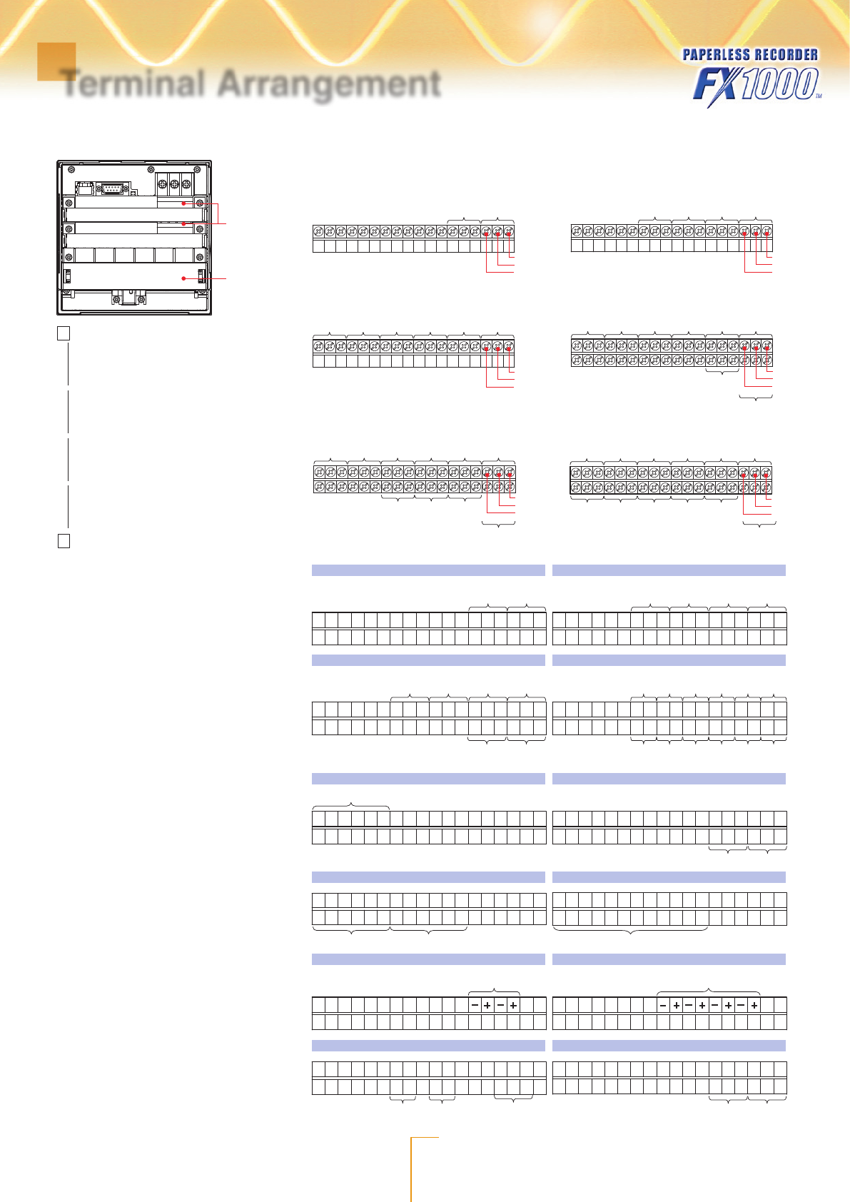
Optional
terminal
block
Input
terminal
block
1 to 8 : Remote control terminal number
C :Common
NC : Normally closed
C : Common
NO : Normally opened
NC
Remote control input
Alarm output, FAIL, Status
H and L
Pulse input
+ and –
Transmitter power supply
output
Symbols such as “NC” indicate the terminal functions.
A terminal that is not used.
+/A
/b
CH1
-/B
Input terminal block
of the FX1002
Input terminal block
of the FX1004
Input terminal block
of the FX1006
Input terminal block
of the FX1008
Input terminal block
of the FX1010
Input terminal block
of the FX1012
CH2
+/A
/b
CH1
-/B
CH2CH3CH4
+/A
/b
CH1
-/B
CH2CH3CH4CH5CH6
+/A
/b
CH1
CH7
-/B
CH2
CH8
CH3CH4CH5CH6
+/A
/b
CH1
CH7
-/B
CH2
CH8
CH9CH10
CH3CH4CH5CH6
+/A
/b
CH1
CH7
-/B
CH2
CH8
CH9CH10CH11CH12
CH3CH4CH5CH6
NC
C
NO
/A1 /A2
01
NC
C
NO
02
NC
C
NO
Alarm outputAlarm output
01
NC
C
NO
NC
C
NO
0102
NC
C
NO
NC
C
NO
NC
C
NO
02
NC
C
NO
03
NC
C
NO
04
NC
C
NO
/A3 /A4A
01
NC
C
NO
NC
C
NO
NC
C
NO
02
0506
C
NO
C
NO
C
NO
C
NO
C
NO
C
NO
C
NO
C
NO
C
NO
C
NO
C
NO
C
NO
Alarm outputAlarm output
Alarm output Alarm output
Alarm output
RS-422A/485
NC
C
NO
03
NC
C
NO
04 010203040506
07
0809101112
Memory endFAIL
/C3
/F1
FG SG
SDB SDA RDB RDA
Remote control input Remote control inputPulse input
/PM1
/R1
L H L H L H 4 23 1 C5 8 7 6 4 23 1 C5
Voltage inputCurrent inputCurrent input
/PWR1
/A1 when installed in the FX with a /TPS2
3S 1L 1S P2P3 P13L
Transmitter power supply output
/TPS2
/TPS4
+−+−
Transmitter power supply output
+−+−+− +−
Terminal Arrangement
Arrangement of the Input Terminals
Arrangement of the Optional Terminals
This is the arrangement of the terminals for models and options. For combinations of models and options, see the chart of
models and option codes.

Subject to change without notice
All Rights Reserved. Copyright © 2011, by Yo kogawa Electric Corporation
www.yokogawa.co.jp
Bulletin 04L00X00-00JA
Paperless Recorder
Model and Suffix Codes
Model code Suffix code Optional
code Description
FX1002 2ch, Shortest measurement interval: 125ms
FX1004 4ch, Shortest measurement interval: 125ms
FX1006 6ch, Shortest measurement interval: 1s
FX1008 8ch, Shortest measurement interval: 1s
FX1010 10ch, Shortest measurement interval: 1s
FX1012 12ch, Shortest measurement interval: 1s
External
storage
medium slot
-0 Without CF card slot and medium (Note)
-4 With CF card slot and medium
Language -2 English/German/French, deg F and DST
Withstanding voltage
between measuring
input terminals
-H 1000 VAC(50/60 Hz), 1 min
Options
/A1 Alarm output 2 points (C-contact)*10
/A2 Alarm output 4 points (C-contact)*1
/A3 Alarm output 6 points (C-contact)*1*3
/A4A Alarm output 12 points (A-contact)*1*3
/C2 RS-232 interface*2
/C3 RS-422A/485 interface*2
/C7 Ethernet interface
/F1 FAIL/Status output*3
/M1
Mathematical functions (including Report functions)
/N2 3 leg isolated RTD*4
/N3F Extended input type (without Pt1000)
/P1 24 VDC/AC power supply
/R1 Remote control 8 points*5
/TPS2 24VDC transmitter power supply (2 loops)*10
/TPS4 24VDC transmitter power suply (4 loops)*7
/USB1 USB interface (1 port)
/PM1 Pulse input 3 points, Remote control 5 points
(including Mathematical functions)*8
/CC1 Calibration correction function
/LG1 Log scale
/PWR1
Power monitor (including Mathmatical functions)
*10
*1 Any combination of /A1, /A2, /A3, and /A4A cannot be specified together.
*2 /C2 and /C3 cannot be specified together.
*3 If /A3 or /A4A is specified, /F1 cannot be specified.
*4 /N2 cannot be specified for FX1002 and FX1004.
*5 If /R1 is specified, /A4A, /TPS2, /TPS4, /PM1, or /PWR1 cannot be specified.
*6 If /TPS2 is specified, /TPS4, /A2, /A3, /A4A, /F1, /R1, or /PM1 cannot be specified.
*7 If /TPS4 is specified, /TPS2, /A1, /A2, /A3, /A4A, /F1, /R1, or /PM1 cannot be specified.
*8 If /PM1 is specified, /A4A, /M1, /R1, /TPS2, /TPS4, or /PWR1 cannot be specified.
*9 If /PWR1 is specified, /A3, /A4A, /F1, /R1, /PM1, or /M1 cannot be specified.
*10 The three options /TPS2, /PWR1, and /A1 cannot be specified together.
Note: To load data, the FX must be equipped with a communication interface (/C2, /C3, or /C7
option) or the USB interface (/USB1 option).
Standard Accessories
Mounting brackets (2), FX1000 DAQSTANDARD/Manuals CD (1), FX1000 Safety Precautions
and Installation Guide (1), How to Use the CD Installing FXA120 DAQSTANDARD and
Opening FX1000 Manuals (1), CF card (512MB; On FXs that have a CF card slot (suffix code
-4.) CF card capacity is subject to change.
Precaution on purchasing the Log scale (Optional code, /LG1)
To support the nonlinear output of vacuum gauges, the FX must be required with the Log
scale (/LG1) and the calibration correction function (/CC1).
Accessories (Sold Separately)
Name Model Notes
Shunt resistor
X010-250-3 250 W ± 0.1%
X010-100-3 100 W ± 0.1%
X010-010-3 10 W ± 0.1%
CF card adapter 772090 −
CF card
772093 512 MB
772094 1 GB
772095 2 GB
Mounting brackets B8730BU −
Terminal screws
B8730CZ M3 (spares for I/O terminals)
B8730CY M4 (spares for power terminals)
Application Software
Model code Description Operating System
FX A120 DAQSTANDARD for FX1000 Windows XP, Vista, 7
External Dimensions/Panel Cut Dimensions
Unit: mm (approx. inches)
Unless otherwise specified, tolerance is ±3%.
However, tolerance is ±0.3 mm (0.01 inches)
for dimensions smaller than 10 mm (0.39 inches).
Panel thickness
(Dimensions after attaching
the mounting bracket)
(Dimensions after attaching
the mounting bracket)
136.5
(5.37)
156.5 (6.16)
144.0 (5.67)
72.0 (2.83)
72.0 (2.83)
12.6
(0.50) 12.6 (0.50)
+ 0.4 (0.02)
0
(2.74)
74.5 (2.93)
156.5 (6.16)
22.2 (0.87) 161.7 (6.37)
108.0 (4.25)
144.0 (5.67)
2 to 26
(0.08 to 1.02)
Mounting bracket
69.5
External dimensions
Panel cut dimensions
MIN 175
(6.89)
L
+ 2 (0.08)
0
137 (5.39)+ 2 (0.08)
0
Side-by side mounting
(vertically; max. 3 units)
137
(5.39)
MIN 175
(6.89)
0
L+ 2 (0.08)
0
Side-by-side mounting
(horizontally)
137 (5.39)+ 2 (0.08)
0
137
(5.39)
+ 2 (0.08)
0
Single-unit mounting
L
+ 2 (0.08)
0
2
3
4
5
6
7
8
9
10
n
282 (11.10)
426 (16.77)
in mm
570 (22.44)
714 (28.11)
858 (33.78)
1434 (56.46)
1290 (50.79)
1146 (45.12)
1002 (39.45)
(144 × n) – 6 [(5.67 × n) – 0.24]
Units
(approx. inches)
+2 (0.08)
●vigilantplant is registered trademarks of Yokogawa Electric Corporation.
●Microsoft and Windows are registered trademarks or trademarks of Microsoft Corporation
in the United States and/or other countries.
●Adobe and Acrobat are registered trademarks or trademarks of Adobe Systems
Incorporated.
●Company and product names that appear in this manual are registered trademarks or
trademarks of their respective holders.
●Thecompanyandproductnamesusedinthismanualarenotaccompaniedbythe
registeredtrademarkortrademarksymbols(®and™).
●Before operating the product, read the instruction manual thoroughly for
proper and safe operation.
NOTICE
