Bamocar CAN Manual
User Manual:
Open the PDF directly: View PDF ![]() .
.
Page Count: 28
O:\Documents\unitek-tms\briefe\can tx 16-32 .docx Seite: 1 / 3
Stand: 17.12.2009
Valid from
Gültig ab FW 378
Indust r i e E l e k t ronik
G m b H
A short description of the CAN-Bus interface
Ein kurze Erklärung des CAN-Bus Interfaces
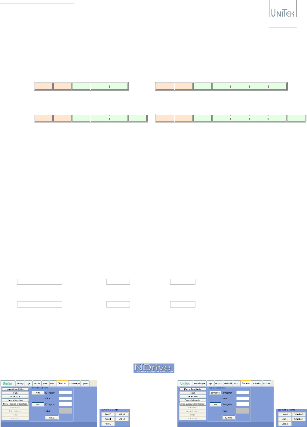
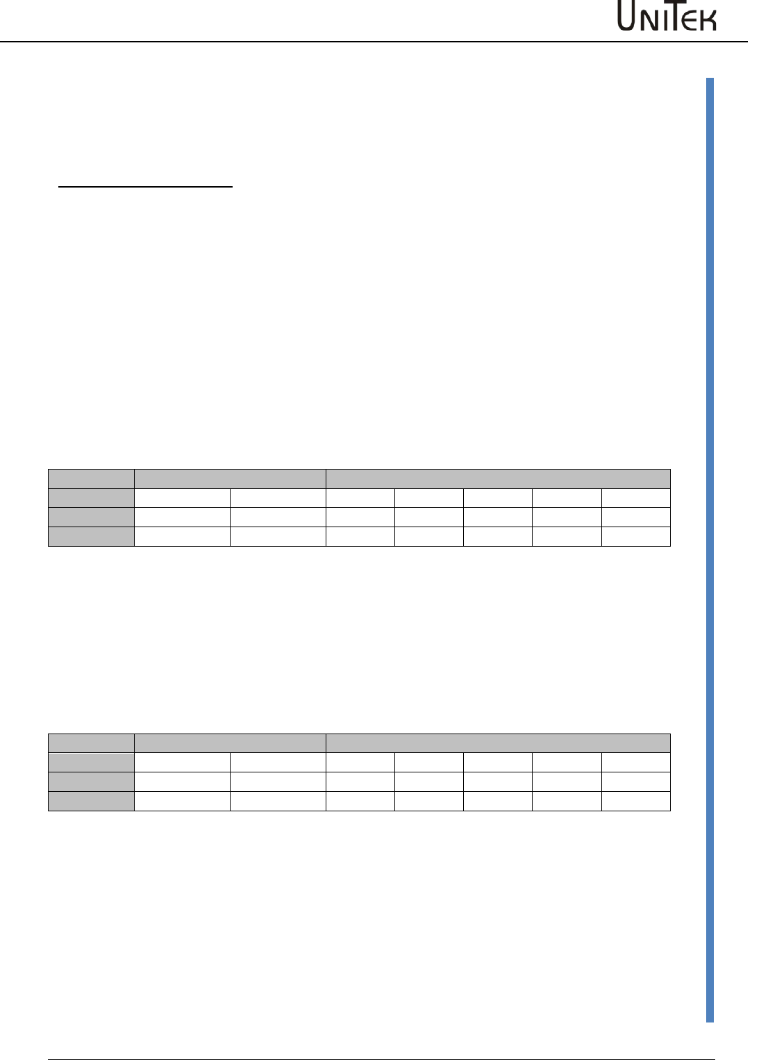
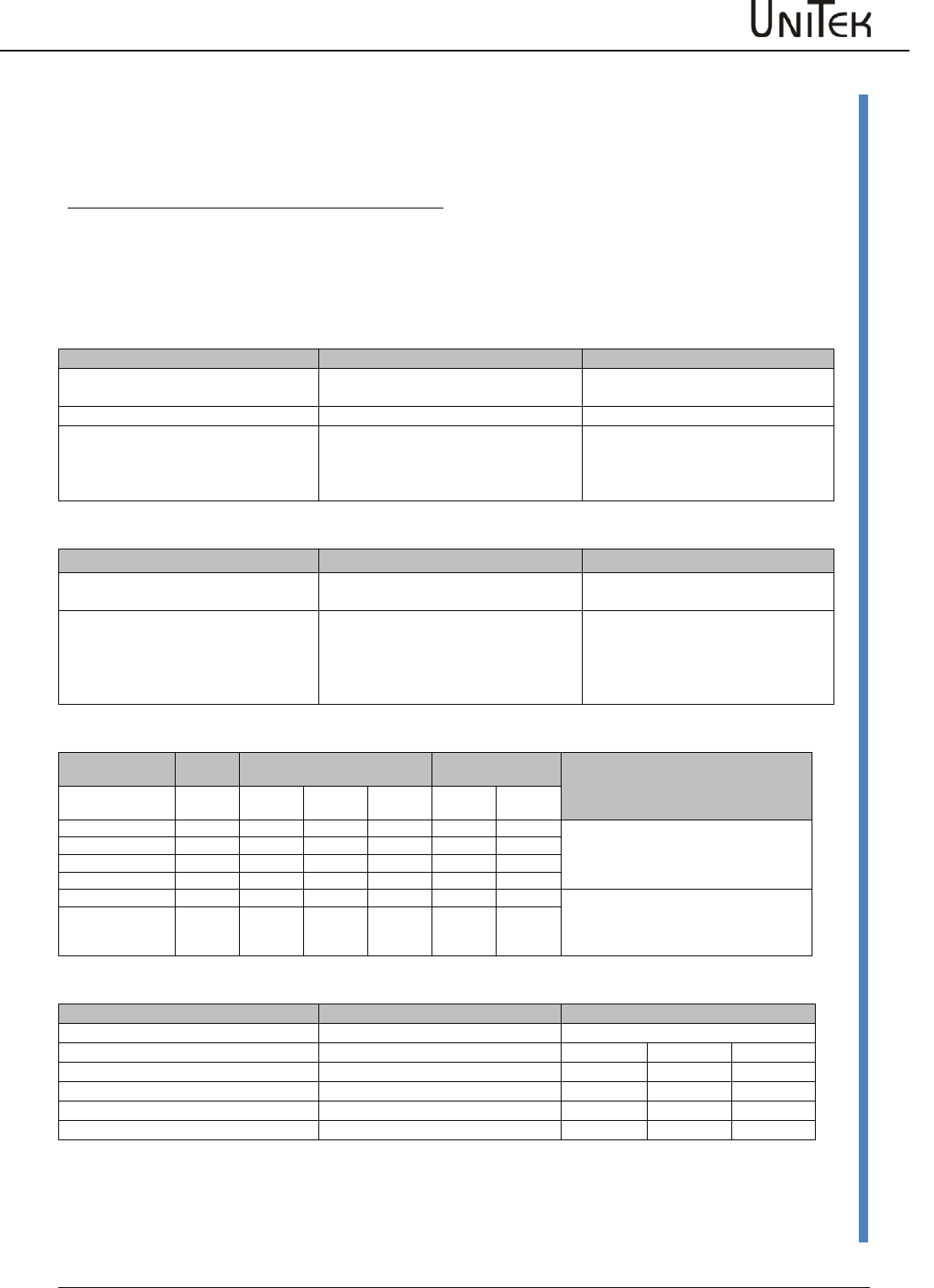
Receive
Empfangen
COB
-
ID
DLC
Byte1
Byte2
Byte3
RxID 3 RegID DATA07..00 DATA15..08
COB
-
ID
DLC
Byte1
Byte2
Byte3
Byte4
Byte5
RxID 5 RegID DATA07..00 DATA15..08 DATA23..16 DATA31..24
Transmit
Senden
COB
-
ID
DLC
Byte1
Byte2
Byte3
Byte4
TxID 4 RegID DATA07..00 DATA15..08
Stuff
COB
-
ID
DLC
Byte1
Byte2
Byte3
Byte4
Byte5
Byte6
TxID 6 RegID DATA07..00 DATA15..08 DATA23..16 DATA31..24
Stuff
1. As standard drive CAN-Bus command messages are 3 bytes long (16-bit data) or 5 bytes long (32-bit data).
Standartmässig sind die Regler CAN-Bus Befehl-Telegramme 3 Byte lang (16-Bit Daten) oder 5 Byte lang (32-Bit Daten).
○ “Remote Transmit Requests” (RTR) will be ignored.
“Remote Transfer Requests” (RTR) werden ignoriert.
○ If a 3 byte message (16-bit data) is received and 32-bit data expected, the value will be zero / sign extended as required.
Wenn ein 3 Byte Telegramm(16-Bit Daten) ankommt und 32-Bit Daten erwartet wird, wirt der Wert nach Bedarf null- /
vorzeichen-erweitert.
○ If a 5 byte message (32-bit data) is received and 16 bit data expected, the upper data will be thrown away.
Wenn ein 5 Byte Telegramm(32-Bit Daten) ankommt und 32-Bit Daten erwartet wird, werden die oberen Daten wegwerfen
2. As standard drive CAN-Bus reply messages are 4 bytes long (16-bit data) or 6 bytes long (32-bit data).
Standartmäsig sind die Regler CAN-Bus Antwort-Telegramme 4 Byte lang (16-bit Daten) oder 6 Byte lang (32-bit Daten).
3. To get the drive to send all replies as 6 byte messages (32-bit data) a bit in RegID 0xDC has to be manually modified.
Daß der Regler alle Antworten als 6-Byte Telegramme schicken, muß ein Bit in RegID 0xDC manuell modifiziert werden.
○ In NDrive open “Manual Read/Write” in the Diagnostic window
In NDrive “Manual Read/Write” in der Diagnose-Fenster aufmachen.
○ Read / Lesen ID register 0xDC value 0x00nn
○ change upper byte to 01 (00 = standard configuration)
ändere obere Byte zum 01 (00 = Standartkonfiruration)
○ Write / Schreiben ID register 0xDC value 0x01nn
4. Don’t forget to save using “Write 0” in the Settings window.
Vergesse nicht mit “Schreibe 0” in den Einstellungen-Fenster zum sichern.
O:\Documents\unitek-tms\briefe\can tx 16-32 .docx Seite: 2 / 3
Stand: 17.12.2009
Valid from
Gültig ab FW 378
Indust r i e E l e k t ronik
G m b H
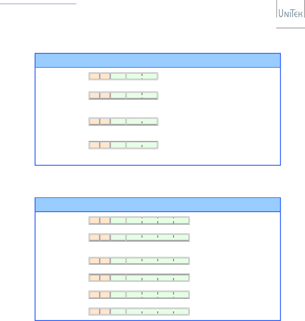
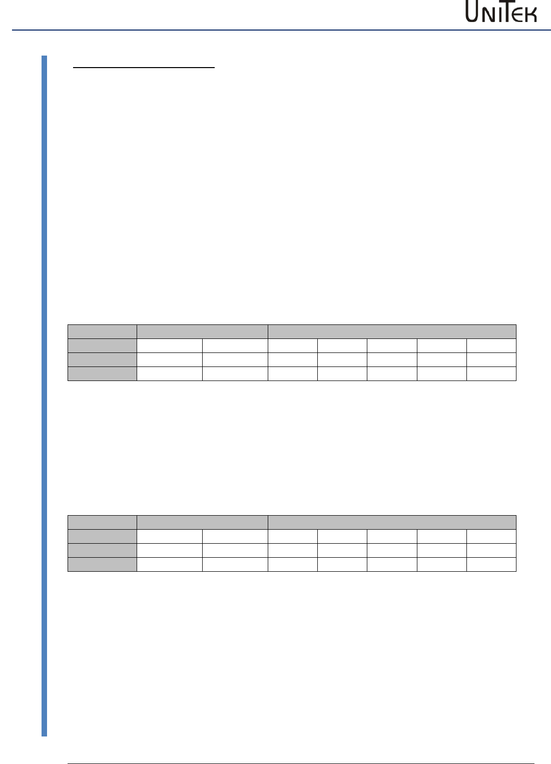
5. Commands with 16-bit formats (as examples)
Befehle mit 16-Bit Formate (als Beispiele)
Command (PC
Drive)
Befehl (PC
Regler) Range (16-Bit)
Bereich Units
Einheiten
SPEED_COMMAND
(send on requirement
noch Bedarf schicken)
COB
-
ID
DLC
Byte1
Byte2
Byte3
RxID
3 31 0xNN 0xNN
RegID
Data
07..00
Data
15..08
+100%
+32767
0x7FFF
0x7FFF0x7FFF
0x7FFF
+50%
+16384
0x4000
0x40000x4000
0x4000
0 %
0
0x0000
0x00000x0000
0x0000
−50%
−16384
0xC000
0xC0000xC000
0xC000
−100%
−32767
0x8001
0x80010x8001
0x8001
±32767
±100%
STOP
≡
SPEED_COMMAND = 0
(send on requirement
noch Bedarf schicken)
COB
-
ID
DLC
Byte1
Byte2
Byte3
RxID
3 31 0x00 0x00
RegID
Data
07..00
Data
15..08
FUNC_REF_START
(send on requirement
noch Bedarf schicken)
COB
-
ID
DLC
Byte1
Byte2
Byte3
RxID
3 78 0xNN 0xNN
RegID
Data
07..00
Data
15..08
TORQUE_COMMAND
(send on requirement
noch Bedarf schicken)
COB
-
ID
DLC
Byte1
Byte2
Byte3
RxID
3 90 0xNN 0xNN
RegID
Data
07..00
Data
15..08
+150%
+32767
0x7FFF
0x7FFF0x7FFF
0x7FFF
+100%
+21845
0x5555
0x55550x5555
0x5555
0 %
0
0x0000
0x00000x0000
0x0000
−100%
−21845
0xAAAA
0xAAAA0xAAAA
0xAAAA
−150%
−32767
0x8001
0x80010x8001
0x8001
±32767
±150%
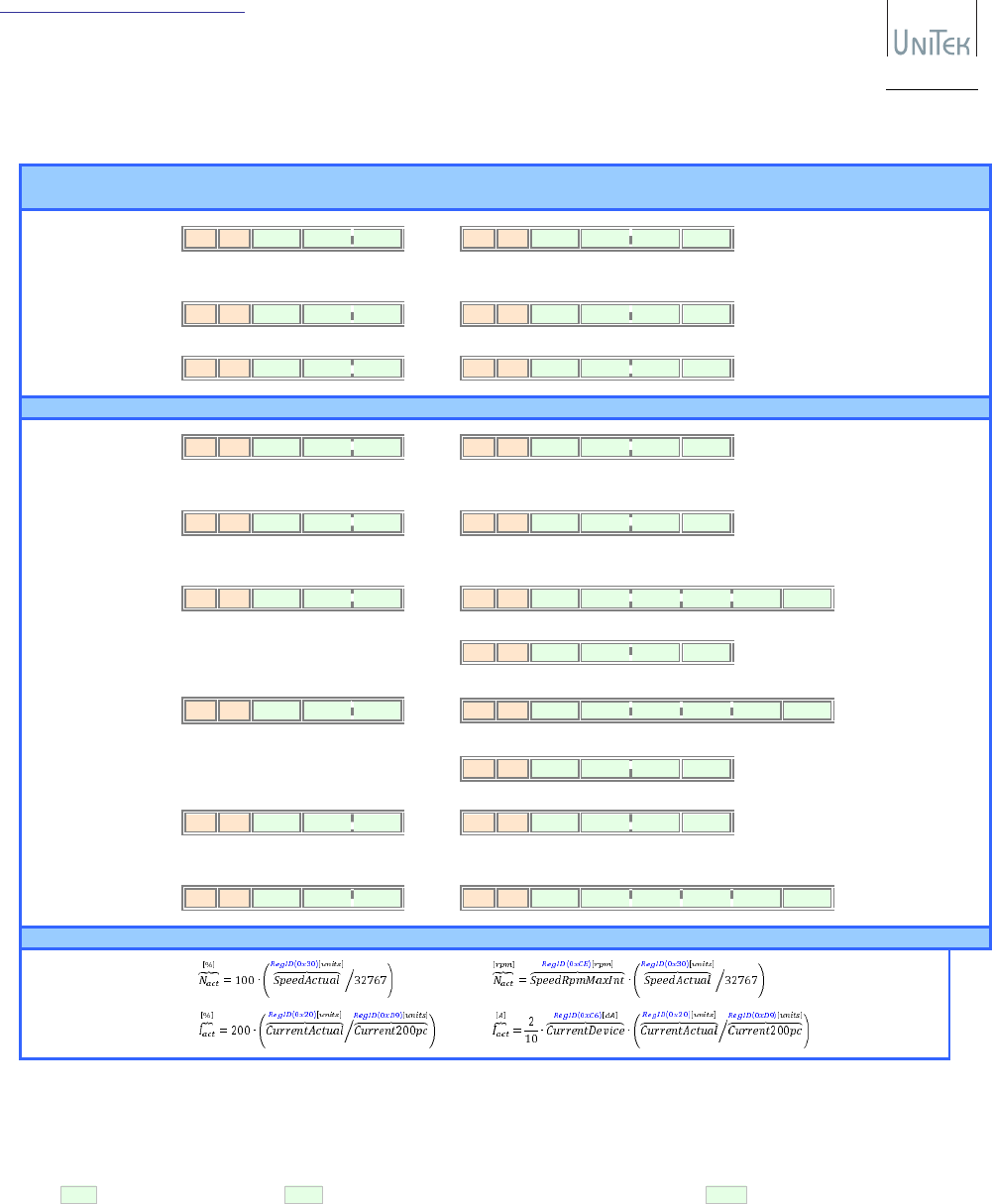
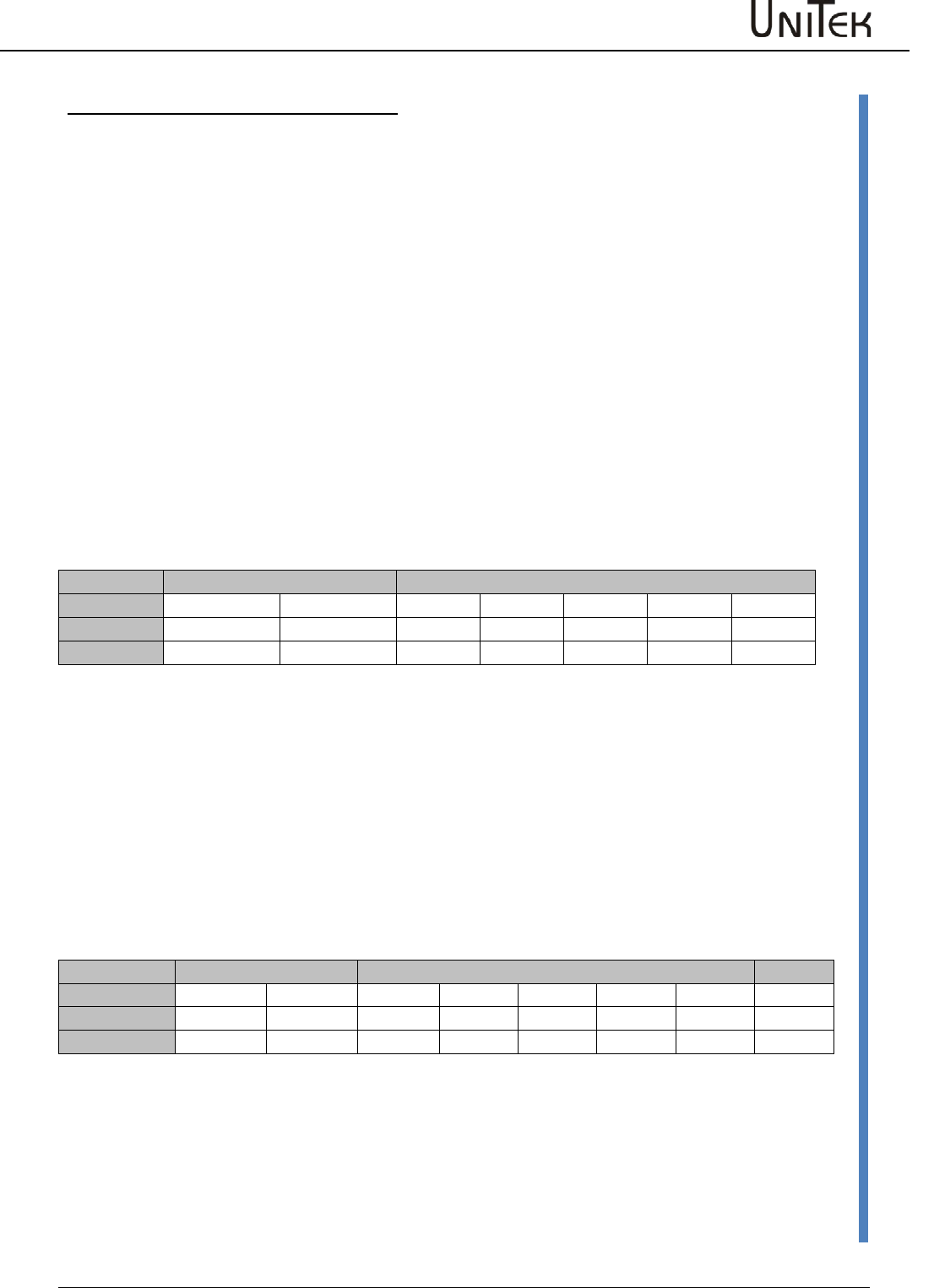
6. Commands with 32-bit formats (as examples)
Befehle mit 32-Bit Formate (als Beispiele)
Command (PC
Drive)
Befehl (PC
Regler) Range (32-Bit)
Bereich Units
Einheiten
POS_DEST
(send on requirement
noch Bedarf schicken)
COB
-
ID
DLC
Byte1
Byte2
Byte3
Byte4
Byte5
RxID
5 6E 0xNN 0xNN 0xNN 0xNN
RegID
Data
07..00
Data
15..08
Data
23..16
Data
31..24
+2147483647
0x7FFF’FFFF
0x7FFF’FFFF0x7FFF’FFFF
0x7FFF’FFFF
+1073741824
0x4000’0000
0x4000’00000x4000’0000
0x4000’0000
+1048576
0x0010’000ß
0x0010’000ß0x0010’000ß
0x0010’000ß
+65536
0x0001’0000
0x0001’00000x0001’0000
0x0001’0000
+32767
0x0000’7FFF
0x0000’7FFF0x0000’7FFF
0x0000’7FFF
+16384
0x0000’4000
0x0000’40000x0000’4000
0x0000’4000
0
0x0000’0000
0x0000’00000x0000’0000
0x0000’0000
−16384
0xFFFF’C000
0xFFFF’C0000xFFFF’C000
0xFFFF’C000
−32767
0xFFFF’8001
0xFFFF’80010xFFFF’8001
0xFFFF’8001
-
65536
0xFFFF’0000
0xFFFF’00000xFFFF’0000
0xFFFF’0000
-
1048576
0xFFF0’0000
0xFFF0’00000xFFF0’0000
0xFFF0’0000
-
1073741824
0xC000’0000
0xC000’00000xC000’0000
0xC000’0000
-
2147483647
0x8000’0001
0x8000’00010x8000’0001
0x8000’0001
±65536
≡ ±rev
POS_PRESET
(send on requirement
noch Bedarf schicken)
COB
-
ID
DLC
Byte1
Byte2
Byte3
Byte4
Byte5
RxID
5 7E 0xNN 0xNN 0xNN 0xNN
RegID
Data
07..00
Data
15..08
Data
23..16
Data
31..24
VAR1
(send on requirement
noch Bedarf schicken)
COB
-
ID
DLC
Byte1
Byte2
Byte3
Byte4
Byte5
RxID
5 D1 0xNN 0xNN 0xNN 0xNN
RegID
Data
07..00
Data
15..08
Data
23..16
Data
31..24
VAR2
(send on requirement
noch Bedarf schicken)
COB
-
ID
DLC
Byte1
Byte2
Byte3
Byte4
Byte5
RxID
5 D2 0xNN 0xNN 0xNN 0xNN
RegID
Data
07..00
Data
15..08
Data
23..16
Data
31..24
VAR3
(send on requirement
noch Bedarf schicken)
COB
-
ID
DLC
Byte1
Byte2
Byte3
Byte4
Byte5
RxID
5 D3 0xNN 0xNN 0xNN 0xNN
RegID
Data
07..00
Data
15..08
Data
23..16
Data
31..24
VAR4
(send on requirement
noch Bedarf schicken)
COB
-
ID
DLC
Byte1
Byte2
Byte3
Byte4
Byte5
RxID
5 D4 0xNN 0xNN 0xNN 0xNN
RegID
Data
07..00
Data
15..08
Data
23..16
Data
31..24
O:\Documents\unitek-tms\briefe\can tx 16-32 .docx Seite: 3 / 3
Stand: 17.12.2009
Valid from
Gültig ab FW 378
Indust r i e E l e k t ronik
G m b H
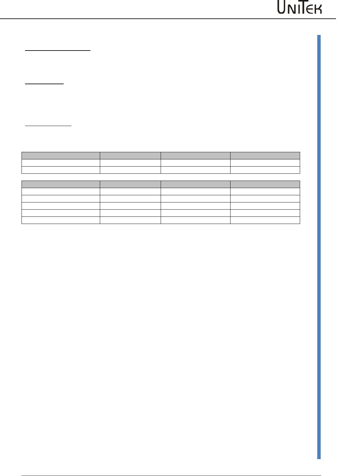
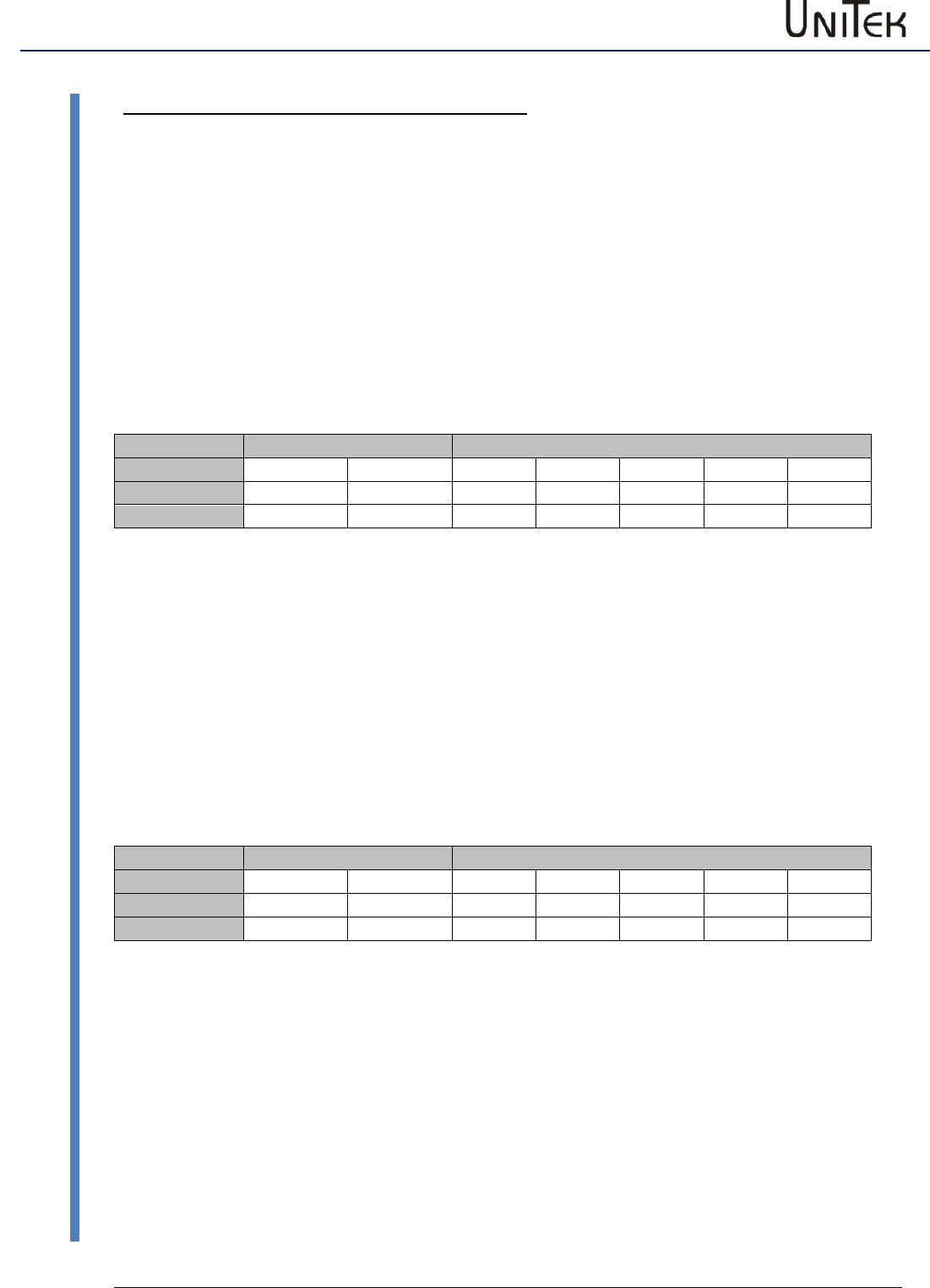
7. Commands for an immediate reply request (as examples)
Sofortiger Antwortanforderungsbefehl (als Beispiele)
Request (PC
Drive)
Anforderung (PC
Regler)
Reply (Drive
PC)
Antwort (Regler
PC) Range
Bereich
Units
Einheiten
SPEED_RPMMAX_INT
(request once
einmal anfordern)
COB
-
ID
DLC
Byte1
Byte2
Byte3
RxID
3 0x3D 0xCE 0x00
Read
RegID
Time
COB
-
ID
DLC
Byte1
Byte2
Byte3
Byte4
TxID
4 0xCE 0xNN 0xNN Stuff
RegID
Data
07..00
Data
15..08
16-bit rpm
U/min
CURRENT_DEVICE
(request once
einmal anfordern)
COB
-
ID
DLC
Byte1
Byte2
Byte3
RxID
3 0x3D 0xC6 0x00
Read
RegID
Time
COB
-
ID
DLC
Byte1
Byte2
Byte3
Byte4
TxID
4 0xC6 0xNN 0xNN Stuff
RegID
Data
07..00
Data
15..08
16-bit dA
CURRENT_200PC
(request once
einmal anfordern)
COB
-
ID
DLC
Byte1
Byte2
Byte3
RxID
3 0x3D 0xD9 0x00
Read
RegID
Time
COB
-
ID
DLC
Byte1
Byte2
Byte3
Byte4
TxID
4 0xD9 0xNN 0xNN Stuff
RegID
Data
07..00
Data
15..08
16-bit ADC units
SPEED_ACTUAL
(request on requirement
noch Bedarf anfordern)
COB
-
ID
DLC
Byte1
Byte2
Byte3
RxID
3 0x3D 0x30 0x00
Read
RegID
Time
COB
-
ID
DLC
Byte1
Byte2
Byte3
Byte4
TxID
4 0x30 0xNN 0xNN Stuff
RegID
Data
07..00
Data
15..08
16-bit ±32767
≡ ±100%
CURRENT_ACTUAL
(request on requirement
noch Bedarf anfordern)
COB
-
ID
DLC
Byte1
Byte2
Byte3
RxID
3 0x3D 0x20 0x00
Read
RegID
Time
COB
-
ID
DLC
Byte1
Byte2
Byte3
Byte4
TxID
4 0x20 0xNN 0xNN Stuff
RegID
Data
07..00
Data
15..08
16-bit ADC units
STATUS
(request on requirement
noch Bedarf anfordern)
COB
-
ID
DLC
Byte1
Byte2
Byte3
RxID
3 0x3D 0x40 0x00
Read
RegID
Time
COB
-
ID
DLC
Byte1
Byte2
Byte3
Byte4
Byte5
Byte6
TxID
6 0x40 0xNN 0xNN 0xNN 0xNN Stuff
RegID
Data
07..00
Data
15..08
Data
23..16
Data
31..24
32-bit Bit-Map
COB
-
ID
DLC
Byte1
Byte2
Byte3
Byte4
TxID
4 0x40 0xNN 0xNN Stuff
RegID
Data
07..00
Data
15..08
16-bit Bit-Map
LOGICMAP_ERRORS
(request on requirement
noch Bedarf anfordern)
COB
-
ID
DLC
Byte1
Byte2
Byte3
RxID
3 0x3D 0x8F 0x00
Read
RegID
Time
COB
-
ID
DLC
Byte1
Byte2
Byte3
Byte4
Byte5
Byte6
TxID
6 0x8F 0xNN 0xNN 0xNN 0xNN Stuff
RegID
Data
07..00
Data
15..08
Data
23..16
Data
31..24
32-bit Bit-Map
COB
-
ID
DLC
Byte1
Byte2
Byte3
Byte4
TxID
4 0x8F 0xNN 0xNN Stuff
RegID
Data
07..00
Data
15..08
16-bit Bit-Map
LOGICMAP_IO
(request on requirement
noch Bedarf anfordern)
COB
-
ID
DLC
Byte1
Byte2
Byte3
RxID
3 0x3D 0xD8 0x00
Read
RegID
Time
COB
-
ID
DLC
Byte1
Byte2
Byte3
Byte4
TxID
4 0xD8 0xNN 0xNN Stuff
RegID
Data
07..00
Data
15..08
16-bit Bit-Map
POS_ACTUAL
(request on requirement
noch Bedarf anfordern)
COB
-
ID
DLC
Byte1
Byte2
Byte3
RxID
3 0x3D 0x6E 0x00
Read
RegID
Time
COB
-
ID
DLC
Byte1
Byte2
Byte3
Byte4
Byte5
Byte6
TxID
6 0x6E 0xNN 0xNN 0xNN 0xNN Stuff
RegID
Data
07..00
Data
15..08
Data
23..16
Data
31..24
32-bit
±65536
≡ ±rev
(units conversions
Einheiten-Umstellung)
8. Up to 8 time-triggered reply requests can be activated
Bis 8 zeitgesteuerte Antwortanforderungen können aktiviert werden
○ The format is as above , with the “Time” entry setup as follows:
Der Format ist wie oben, mit dem „Time“ Feld folgendes definiert:
○ 0x00 immediate 0xFF suspend transmission otherwise 0xNN timer setup (1 – 254 ms)
Time sofort Time Senden suspendiert sonst Time Zeit einstellen (1 – 254 ms)
○ Entries with suspended transmissions can be overwritten by newer requests.
Eingaben mit suspendierten Senden können bei neueren Anforderungen überschrieben werden.

M A N U A L
CAN - BUS
for Servo Amplifiers
DS 2xx / DS 4xx / DPCxx
BAMOCAR
BAMOBIL / BAMOBIL Dxx
Industrie Elektronik
G m b H
Hans-Paul-Kaysser-Straße 1
71397 Leutenbach – Nellmersbach
Edition /
Version
Tel.: 07195 / 92 83 – 0
Fax: 07195 / 92 83 – 129
info@unitek-online.de
www.unitek-online.de
06/2017 V 04

Safety
1
06 / 2017 – V03
CAN-BUS
1 Contents
2 Safety .............................................................................................................................. 2
2.1 Safety advices ..................................................................................................................... 2
2.2 Regulations and guidelines ................................................................................................ 2
3 General information ......................................................................................................... 4
3.1 Logic functions ................................................................................................................... 4
4 CAN BUS connections ....................................................................................................... 5
4.1 Connections ........................................................................................................................ 5
5 Software .......................................................................................................................... 7
5.1 Format description ............................................................................................................. 7
5.2 Head field ........................................................................................................................... 8
5.3 COB ID bits (CAN OBJECT ID) .............................................................................................. 8
5.4 RTR bit (REMOTE TRANSMISSION REQUEST) ..................................................................... 8
5.5 DLC bits (DATA LENGTH CODE) .......................................................................................... 8
5.6 Data field ............................................................................................................................ 9
5.7 REGID .................................................................................................................................. 9
5.8 Data .................................................................................................................................... 9
6 Examples ....................................................................................................................... 10
6.1 Receiving CAN BUS data ................................................................................................... 10
6.2 Transmission of CAN data from the DSxx and BAxx servo to the CAN BUS ..................... 10
6.3 Sending from the master to the CAN bus to the DS servo ............................................... 11
6.4 Transmission from the DS servo to the CAN BUS ............................................................ 14
7 Units .............................................................................................................................. 20
7.1 Conversion of the measuring units .................................................................................. 20
Safety
CAN-BUS
06/2017 – V03
2
Safety advices
2 Safety
2.1 Safety advices
Note:
This manual description is only to be used in
connection with the hardware manual DS and the
software manual NDrive!!
Before installation or commissioning begins, this manual must be thoroughly read and
understood by the skilled technical staff involved. If any uncertainty arises, the manufacturer or
dealer should be contacted
2.2 Regulations and guidelines
The devices and their associated components can only be installed and switched on where the
local regulations and technical standards have been strictly adhered to.
EU Guidelines
2004/108/EG, 2006/95/EG, 2006/42/EG
EN 60204-1, EN292, EN50178, EN60439-1,
EN61800-3, ECE-R100
ISO 6469, ISO 26262, ISO 16750, ISO 20653, ISO12100
IEC/UL:
IEC 61508, IEC364, IEC664, UL508C, UL840
VDE Regulations/TÜV Regulations:
VDE100, VDE110, VDE160
Regulations of the statutory
accident insurance and prevention
institution:
VGB4
The user must ensure that in the event of:
- device failure
- incorrect operation
- loss of regulation or control
the axis will be safely de-activated.
It must also be ensured that the vehicles, machines, equipment,
or vehicles are fitted with device independent monitoring and
safety features.
Unearthed systems (e.g. vehicles) must be protected by means
of independent insulation monitors.
Man as well as property must not be exposed to danger at any
time!!!

Safety
3
06 / 2017 – V03
CAN-BUS
Regulations and guidelines
Assembly
- should only be carried out when all voltages have been removed and the units are secured
- should only be carried out by suitably trained personnel
Installation
- should only be carried out when all voltages have been removed and the units are secured
- should only be carried out by suitably trained personnel for electrics
- should only be carried out in accordance with health and safety guidelines
Adjustments and programming
- should only be carried out by suitably trained personnel with knowledge in electronic drives and
their software
- should only be carried out in accordance with the programming advice
- should only be carried out in accordance with safety guidelines
- should only be carried out if the path monitoring systems are active for limited travel distances.
CE
When mounting the units into vehicles, machines, and installations the proper operation of the
units may not be started until it is ensured that the machine, the installation, or the vehicle
comply with the regulations of the EC machinery directive 2006/42/EG, the EMC guideline
2004/108/EG, and the guideline ECE-R100.
On the described installation and test conditions (see chapter ‘CE notes’) it is adhered to the EC
guideline 2004/108/EG including the EMC standards EN61000-2 and EN61000-4.
A manufacturer's declaration can be requested.
The manufacturer of the machine or installation is responsible for observing the threshold values
demanded by the EMC laws.
QS
Test results are archived with the device serial number by the manufacturer for a period of 5
years.
The test protocols can be asked for.
General information
CAN-BUS
06/2017 – V03
4
Logic functions
3 General information
3.1 Logic functions
Originally the serial data bus system CAN (Controller Area Network) was developed for the
automobile industry. Since then, the CAN-BUS is used for a wide range of applications in the plant
and mechanical engineering. CAN is internationally standardized as ISO11898. CAN meets the
particularly high safety requirements of highly available machines and medical equipment. High
transmission rates and favourable connection costs are the advantages of the CAN-BUS.
During the CAN data transmission no stations are addressed but the content of a message is
marked by a network-wide clear identifier. The identifier also determines the priority of the
message.
A high system and configuration flexibility is achieved due to the content-related addressing.
Thus, it is very easy to add further equipment to the network.
In all digital UNITEK devices the CAN-BUS interface is installed as Slave.
It is intended for being connected to a CAN-BUS master.
The interface is opto-decoupled.
The primary supply is effected internally via DC/DC converters.
The UNITEK CAN-BUS can transmit the following functions:
Examples from master (CNC/SPS/ to slave (DRIVE-DS) (receiving)
Logic functions
Command values
Parameters
Enable
Torque command value
Control parameters
Reference run
Speed command value
Settings
Start, Stop
Position command value
Current limits
Examples from slave (DRIVE-DS) to master (CNC/SPS) (sending, transmitting)
Logic functions
Actual values
Parameters
Signals
RUN
Actual torque value
Control parameter
State signal
ENABLE
Actual speed value
Settings
Error signal
POS
Actual position value
Limit switch
The addresses (REGID) are indicated in the parameter survey (see NDrive Manual),
e.g. speed command value (SPEED_CMD) = REGID 0x31 <value in hex>.
CAN BUS connections
5
06 / 2017 – V03
CAN-BUS
Connections
4 CAN BUS connections
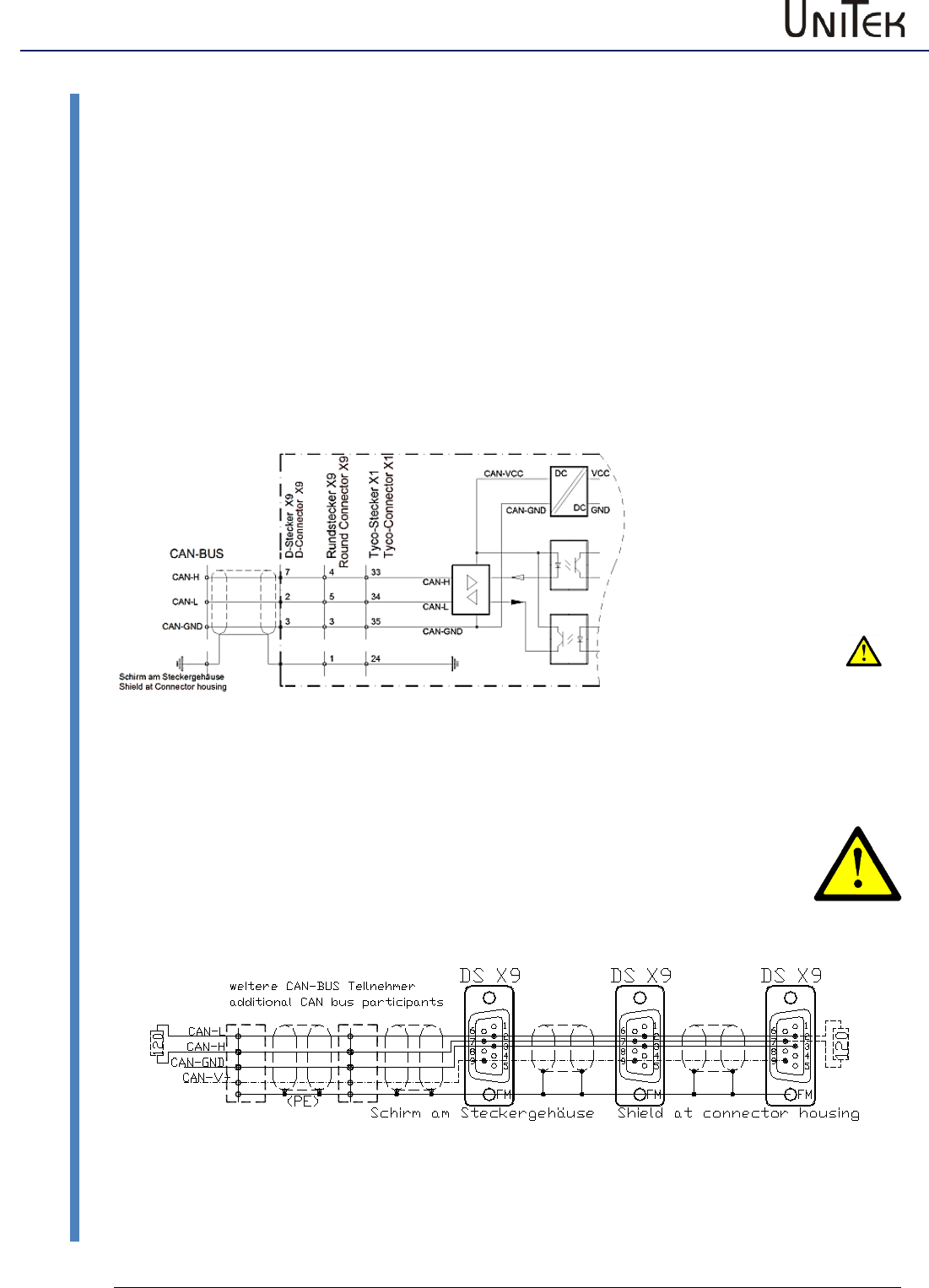
4.1 Connections
The CAN-BUS is the digital connection to the CNC control (CAN master).
The programming and operation is effected via the CAN-BUS by means of the control panel.
Interface acc. to ISO 11898-2.
Connection hardware:
Characteristic impedance 120 Ω
Conductor resistance (loop) 160 Ω/km
Operating capacity (800 Hz) <60 nF/km
nput circuit
Connector pin assignment:
see device manual
Cable colours (recommended)
LiYCY 4x0.25 + shield
CAN-GND white
CAN-H green
CAN-L yellow
(Note: colors may different)
Fig. 4-1
CAN BUS isolated / CAN Gnd to common potential
CAN-BUS connection with several servo amplifiers DS- (slave) (example):
For other device types please observe the connector pin assignment (device manual)
Address xx Address xx Address xx
Fig. 4-2
CAN BUS connections
CAN-BUS
06/2017 – V03
6
Connections
Termination resistance
The line connection resistance (R = 120Ω) must be installed across the first and the last BUS
participants between CAN-H and CAN-L.
Power supply
The power supply of the CAN-BUS is internally provided via a DC/DC converter.
CAN BUS setting
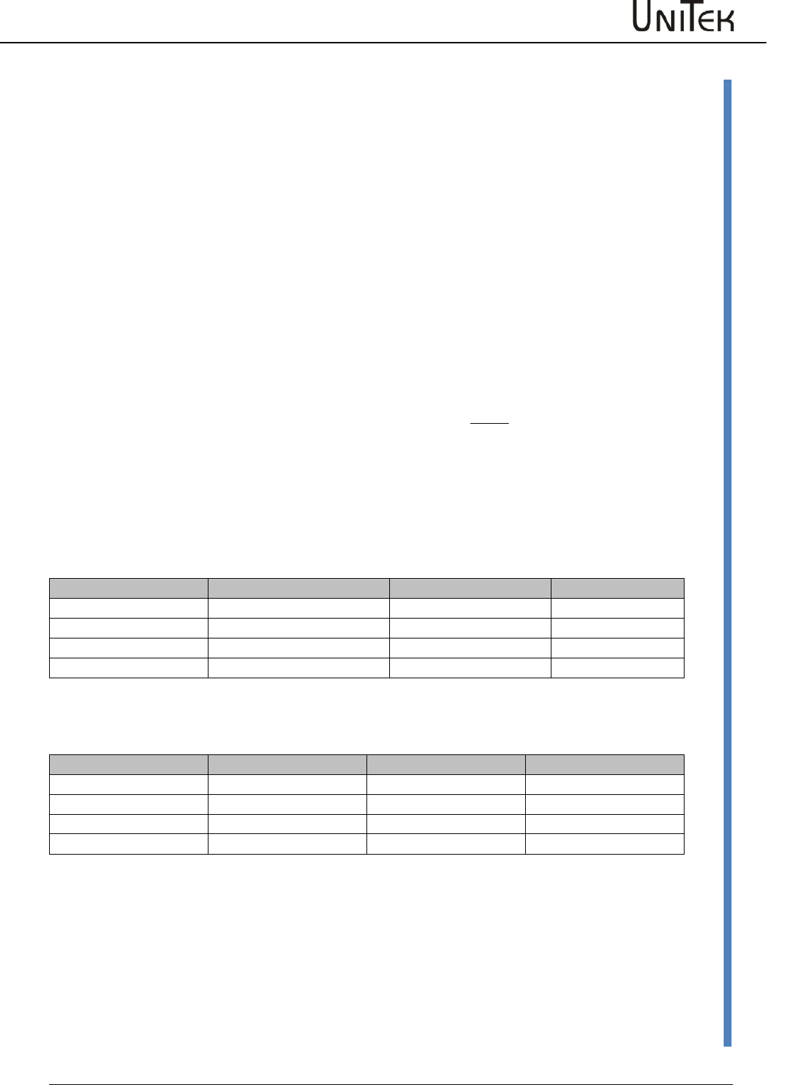
The transmission addresses for receiving and sending and the transmission rate are entered via
the parameter field ‘CAN-Setup’ of the pc program NDrive.
Address
Short symbol
Basic value (default)
Range
Receiving address (slave)
RPD01
0x201
0x201 to 0x27F
Transmission address (slave)
TPD01
0x181
0x181 to 0x1FF
Transmission rate NBT
Setting value BTR
Line length max.
1000 kBaud
0x4002
20 m
500 kBaud
0x4025
70 m
625 kBaud
0x4014
70 m
250 kBaud
0x405c
100 m
100 kBaud
0x4425
500 m
Software
7
06 / 2017 – V03
CAN-BUS
Format description
5 Software
5.1 Format description
The software format is designed for an optimal communication with the CNC machine controls
and CAN modules of the Labod electronic company.
This format does not correspond to CANopen.
The transmission rate (Baud rate) is programmable.
The UNITEK standard is 500 kB/s (Labod 615 kB/s).
The devices UNITEK DSxx and BAxx can be added to a CANopen network (TPDO1, RPDO1) as slave.
Numerical format
Parameter value and parameter no. as Little-Endian format (Intel format)
Bit7 to 0 / Bit15 to 8 / Bit23 to 16 / Bit31 to 24
CAN format
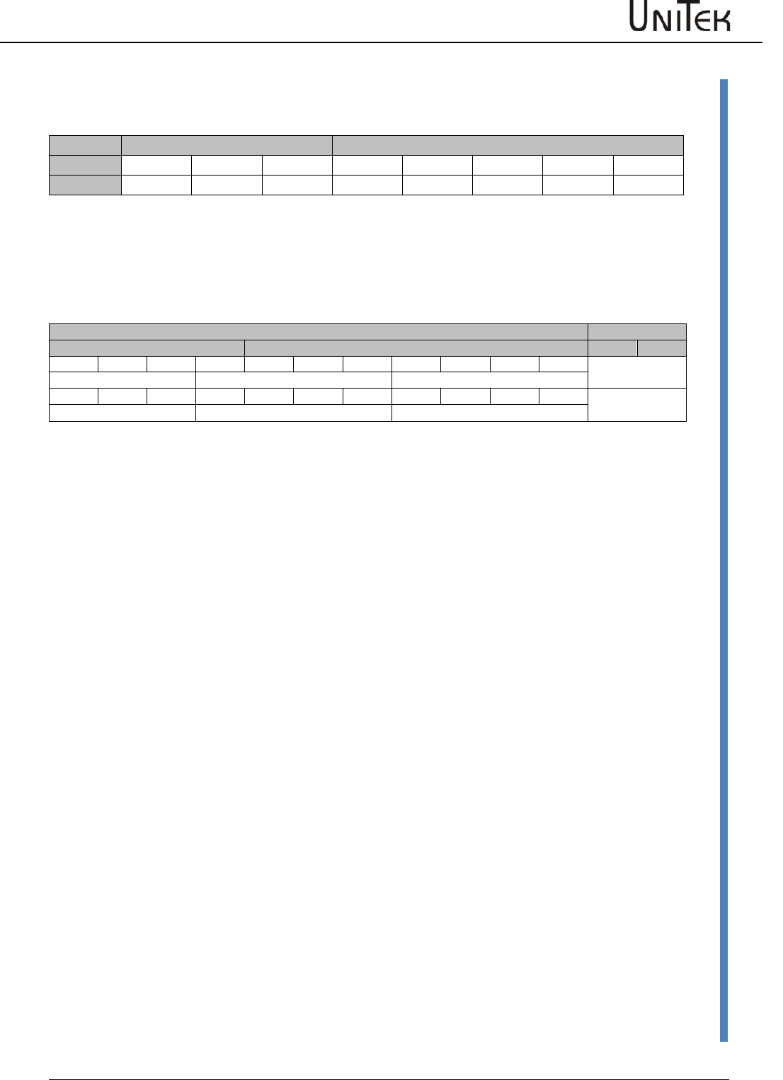
The CAN protocol is a 3 or 5 byte data package when received and 4 or 6 when send.
It is also possible to receive data packages of up to 8 byte. In this case, however, it is evaluated as
5 Byte data package. The identifier is 11Bit wide. It comprises the COB identifier, the RTR function
(Remote Transmission Request) and the DLC information (Data Length Code).
The byte 0 of the data field is for the REGID index (parameter no.).
The second to the fifth byte (byte 1 to byte 4) contains the data of the REGID index (parameter
value).
Range
Head
Data field
COB-ID
RTR
DLC
byte 0
byte 1
byte 2
byte 3
byte 4
Function
11 Bit
0
Length
REGID
b7 to 0
b15 to 8
b23 to 16
b31 to 24
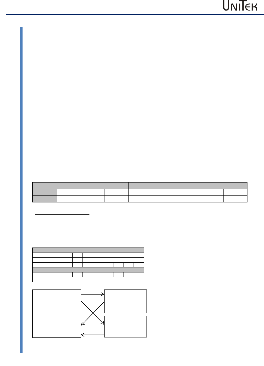
Master-Slave connection
In order to simplify the configuration a predefined Master/Slave connection set was specified in
CANopen. For networks with one master and up to 127 slaves this assignment of COB identifiers
offers each participant a simple solution for a CANopen network. Any information is solely
distributed from the master. Direct communication among the slaves is not possible.
COB identifier
Service
Node ID
10
7
6
0
Example 0 x 181
0
0
1
1
0
0
0
0
0
0
1
1
8
1
The preferred objects (slave) are
TPDO1 (0x201 to 0x27F) and
RPDO1 (0x181 to 0x1FF).
The objects TPDO2..4 and RPDO2..4 can
also be used.
Connection from master to slave
Master (CNC/SPS)
Sending (transmit PDO)
TPDO1 0x201
TPDO1 0x202
Receiving (receive PDO)
RPDO1 0x181
RPDO! 0x182
Slave 1 (DRIVE DS)
RPDO1 0x201
TPDO1 0x181
Slave 2 (DRIVE DS)
RPDO1 0x202
TRPO1 0x182
Software
CAN-BUS
06/2017 – V03
8
Head field
5.2 Head field
Range
Head
Data field
COB-ID
RTR
DLC
byte 0
byte 1
byte 2
byte 3
byte 4
Function
11 Bit
0
Length
REGID
B7 to 0
B15 to 8
B23 to 16
B31 to 24
5.3 COB ID bits (CAN OBJECT ID)
With CANopen the standard value (default) for TPDO1=0x181 and for RPDO1=0x201.
COB identifier
Object
Service
Node ID
0
0
1
1
0
0
0
0
0
0
1
TPDO1
0x181-0x1FF
1
8
1
1
0
0
0
0
0
0
0
0
1
RPD01
0x201-0x27F
2
0
1
The address can be changed by entering a direct transmission address in the servo amplifier
(DSxx, BAxx) for receiving (CAN-ID-Rx 0x68) and for transmission field CAN-Setup in the NDrive.
The addresses of Tx-ID and Rx-ID can also be changed directly via the CAN (see example 1).
5.4 RTR bit (REMOTE TRANSMISSION REQUEST)
The value for RTR is always set to 0 / RTR is not used.
5.5 DLC bits (DATA LENGTH CODE)
The size of the data field is determined by the DLC bits.
Receiving: value 0x03 corresponds to REGID plus 2 byte (16 bit)
value 0x05 corresponds to REGID plus 4 byte (32 bit)
Transmission: value 0x04 corresponds to REGID plus 2 byte plus Dummy (16 bit)
value 0x06 corresponds to REGID plus 4 byte plus Dummy (32 bit)

Software
9
06 / 2017 – V03
CAN-BUS
Data field
5.6 Data field
The length of the data field for messages received in the servo is 3 or 5 byte.
The upper data bytes are registered when received, however, not taken into account.
The message for transmitting from the servo to the CAN-BUS is 4 or 6 byte wide.
5.7 REGID
The first byte is provided for the REGID index (parameter no.).
It is possible to determine up to 254 registers.
The most important parameter indexes are listed in the REGID list (see manual NDrive).
5.8 Data
The data length is preset in the field ‘DLC bits’ (16 or 32 bits).
Byte 2 to byte 5 are for the 32 bit register data (4 byte).
Byte 2 to byte 3 are for the 16 bit register data (2 byte).
Example for the data field
Position command value for num 300010000
Function
Hex value
Transmission address for receiving
0x201
Data length 4 byte
DLC=5
REGID for the position command value (POS_SOLL)
0x6E
Data length 4 byte
DLC=5
Data for the position command value
Num 300010000
0x11E1CA10
Data input
Byte 0 Byte 1 Byte 2 Byte 3 Byte 4
REGID Data bits 7 to 0 Data bits 15 to 8 Data bits 23 to 16 Data bits 31 to 24
6
E
1
0
C
A
E
1
1
1
Data = 0x11E1CA10 (corresponds to the num. position 300010000)
The input format is Little-Endian (Intel format)
Range
Head
Data field
COB ID
DLC
Byte 0
Byte 1
Byte 2
Byte 3
Byte 4
Function
REGID
b7 to 0
b15 to 8
b23 to 16
b31 to 24
Example 2
0x201
5
0x6E
0x10
0xCA
0xE1
0x11

Examples
CAN-BUS
06/2017 – V03
10
Receiving CAN BUS data
6 Examples
6.1 Receiving CAN BUS data
Transmission address at the DS servo
COB ID
(default = 0x201)
Data format
DLC
(3, 4, 5)
Parameter
Byte 0
(REGID – see
parameter list)
Parameter content
Byte 1 to byte 4
Examples:
Changing the transmission address via CAN
see example 1
Disable the controller (no enable)
see example 2
Speed command value
see example 3
Position command value
see example 4
Torque command value
see example 5
Parameter value
see example 6
Write EEPROM
see example 7
6.2 Transmission of CAN data from the DSxx and BAxx servo to the CAN BUS
In general the following is valid for the request to transmit from the DS servo:
Data field:
(DLC = 3)
Byte 0 =
0x3D
Parameter transmission request
Byte 1 =
REGID Value
Content of this REGID
Byte 2 =
0x??
Time interval
1. Transmitting once: (see example 8)
Data field:
(DLC = 3)
Byte 0 =
0x3D
Parameter transmission request
Byte 1 =
0xA8
Content of this REGID
Byte 2 =
0x00
Transmitting once
2. Cyclic transmission: (see example 9)
Data field:
(DLC = 3)
Byte 0 =
0x3D
Parameter transmission request
Byte 1 =
0xA8
Content of this REGID
Byte 2 =
0x0A
Transmitting every 10ms (0 to 254ms)
Note:
Byte 2 =
0xFF
Stop cyclic transmission
3. Request for a status message after action: (see example 10)
Data field:
(DLC = 3)
Byte 0 =
0x51
REGID for data after action
Byte 1 =
0x10
Activation via bit 4
Byte 2 =
0x00
Don’t care
Examples
11
06 / 2017 – V03
CAN-BUS
Sending from the master to the CAN bus to the DS
6.3 Sending from the master to the CAN bus to the DS servo
Example 1: Changing the transmission address via CAN
The address for receiving (slave) on a new DSxx, BAxx servo is 0x201 (default).
This address is to be changed in 0x210.
The REGID index for the receiving ID for the configuration of this address is 0x68
(FORE_CANIDREAD).
Function
Hex value
Transmission address to the Servo
0x201
Data length 2 byte
DLC=3
REGID for CAN-Rx address
0x68
Value for a new CAN-Rx address
0x0210
Range
Head
Data field
COB ID
DLC
Byte 0
Byte 1
Byte 2
Byte 3
Byte 4
Function
REGID
b7 to 0
b15 to 8
b23 to 16
b31 to 24
Example 1
0x201
3
0x68
0x10
0x02
---
---
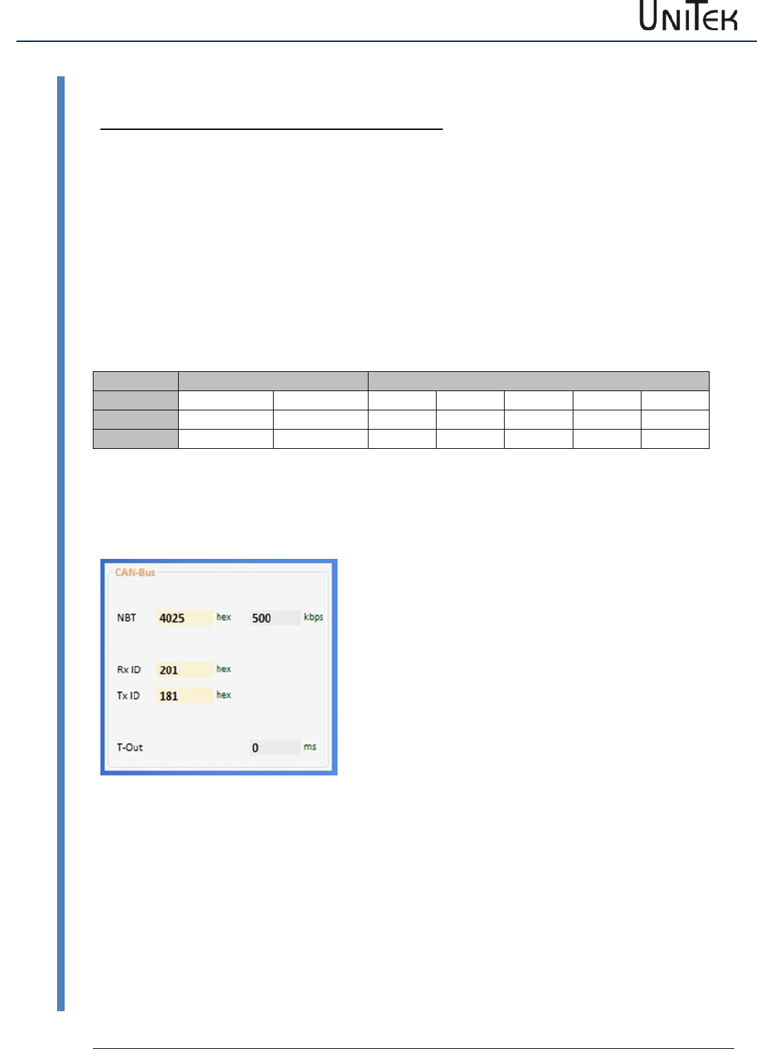
Changing the transmission address in the pc program NDrive
Inputs:
NBT Transmission rate (kBaud)
Rx ID
Receiving address in the DS (default 0x201)
Tx ID
Transmission address from the DS
(default 0x181)
T-Out
Time error monitoring
Fig. 6-1
Examples
CAN-BUS
06/2017 – V03
12
Sending from the master to the CAN bus to the DS servo
Example 2: Disable the controller (no enable) Message to the servo
Function
Hex value
Transmission address to the servo
0x201
Data length 2 byte
DLC=3
REGID for disable (MODE)
0x51
Value for the disable MODE BIT2
0x0004
Range
Head
Data field
COB ID
DLC
Byte 0
Byte 1
Byte 2
Byte 3
Byte 4
Function
REGID
b7 to 0
b15 to 8
b23 to 16
b31 to 24
Example 2
0x201
3
0x51
0x04
0x00
---
---
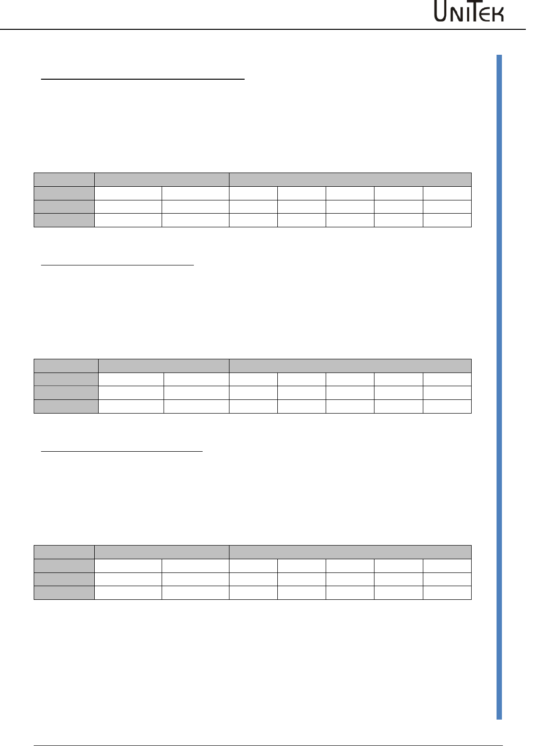
Example 3: Speed command value Message to the servo
Function
Hex value
Transmission address to the servo
0x201
Data length 2 byte
DLC=3
REGID for the speed command value (SPEED_SOLL)
0x31
Value for 10% speed num. 3277
0x0CCD (100 % ≙ 32767)
Range
Head
Data field
COB ID
DLC
Byte 0
Byte 1
Byte 2
Byte 3
Byte 4
Function
REGID
b7 to 0
b15 to 8
b23 to 16
b31 to 24
Example 3
0x201
3
0x31
0xCD
0x0C
---
---
Example 4: Position command value Message to the servo
Function
Hex value
Transmission address to the servo
0x201
Data length 4 byte
DLC=6
REGID for the speed command value (POS_DEST)
0x6E
Value for position 3000000
0x2DC6C0
Range
Head
Data field
COB ID
DLC
Byte 0
Byte 1
Byte 2
Byte 3
Byte 4
Function
REGID
b7 to 0
b15 to 8
b23 to 16
b31 to 24
Example 4
0x201
5
0x6E
0xC0
0xC6
0x2D
0x00
Examples
13
06 / 2017 – V03
CAN-BUS
Sending from the master to the CAN bus to the DS
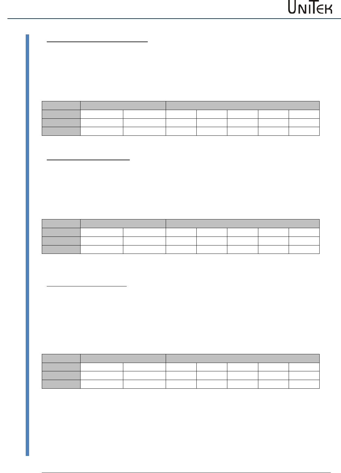
Example 5: Torque command value Message to the servo
Function
Hex value
Transmission address to the servo
0x201
Data length 2 byte
DLC=3
REGID for speed command value (TORQUE-CMD)
0x90
Value for 50% torque num 16380
0x3FFC
Range
Head
Data field
COB ID
DLC
Byte 0
Byte 1
Byte 2
Byte 3
Byte 4
Function
REGID
b7 to 0
b15 to 8
b23 to 16
b31 to 24
Example 5
0x201
3
0x90
0xFC
0x3F
---
---
Beispiel 6: Einstell-Parameter Message to the servo
Function
Hex value
Transmission address to the servo
0x201
Data length 2 byte
DLC=3
REGID for parameter acceleration (ACC ramp)
0x35
Data for 1000ms acceleration
0x03E8
Range
Head
Data field
COB ID
DLC
Byte 0
Byte 1
Byte 2
Byte 3
Byte 4
Function
REGID
b7 to 0
b15 to 8
b23 to 16
b31 to 24
Example 6
0x201
3
0x35
0xCD
0x0C
---
---
Example 7: Writing EEPROM Message to the servo
Function
Hex value
Transmission address to the servo
0x201
Data length 2 byte
DLC=3
REGID to write EEPROM
0x84
EEPROM level 0
0x0000
(EEPROM level1 = 0X0001)
Range
Head
Data field
COB ID
DLC
Byte 0
Byte 1
Byte 2
Byte 3
Byte 4
Function
REGID
b7 to 0
b15 to 8
b23 to 16
b31 to 24
Example 7
0x201
3
0x84
0x00
0x00
---
---
Examples
CAN-BUS
06/2017 – V03
14
Transmission from the DS servo to the CAN BUS
6.4 Transmission from the DS servo to the CAN BUS
All examples have the default transmission addresses (Rx ID=0x201 receiving, Tx ID=0x181
transmitting)
Example 8: Status message One-time transmission from the servo
In order to receive the information of a specified REGID a transmission request must be send to
the servo. In the following example a one-time transmission of the REGID information is
requested.
Message to the servo for a transmission request:
Function
Hex value
Transmission address to the servo
0x201
Data length 2 byte
DLC=3
REGID for reading data from the servo and
transmission to the CAN (READ)
0x3D
REGID for status (KERN_STATUS)
0x40
Time interval (transmitting once)
0x00
Range
Head
Data field
COB ID
DLC
Byte 0
Byte 1
Byte 2
Byte 3
Byte 4
Function
REGID
b7 to 0
b15 to 8
b23 to 16
b31 to 24
Example 8
0x201
3
0x3D
0x40
0x00
---
---
Retransmitted information from the servo:
Function
Hex value
Transmission address to the servo
0x181
Data length 2 byte
DLC=4
REGID for status (KERN_STATUS)
0x40
Value of KERN_STATUS (0x40) are
0x0181
Range
Head
Data field
COB ID
DLC
Byte 0
Byte 1
Byte 2
Byte 3
Byte 4
Function
REGID
b7 to 0
b15 to 8
b23 to 16
b31 to 24
Example 8
0x181
4
0x40
0x81
0x01
0x**
(Data range byte 1 to byte 4 in Little Endian format)
Current state of the status = 0x0181:
Bit0
Enable drive
(Ena)
Bit7
Position control
(P-N)
Bit8
Speed control
(N-I)
Examples
15
06 / 2017 – V03
CAN-BUS
Transmission from the DS servo to the CAN BUS
Example 9: Actual speed value Cyclic transmission from the servo
For the cyclic retransmission the register REGID_READ is programmed with a repeating time.
For the transmission repetition a cycle time (in ms) is entered in the byte 2 in hex format
(1-254ms).
Message to the servo for a transmission request:
Function
Hex value
Transmission address to the servo
0x201
Data length 2 byte
DLC=3
REGID for reading data from the servo and
transmission to the CAN (READ)
0x3D
REGID for actual speed value (SPEED_IST)
0x30
For the repeating time 100ms the input in byte 2 is
0x64
Note:
The permanent transmission in byte 2 can be stopped by
0xFF
Range
Head
Data field
COB ID
DLC
Byte 0
Byte 1
Byte 2
Byte 3
Byte 4
Function
REGID
b7 to 0
b15 to 8
b23 to 16
b31 to 24
Example 9
0x210
3
0x3D
0x30
0x64
---
---
Information retransmitted from the servo within the interval of 100ms
Function
Hex value
Transmission address to the servo
0x201
Data length 2 byte
DLC=4
REGID for actual speed value (SPEED_IST)
0x30
Value of the speed command value 100% (num 32767)
0x7FFF
Range
Head
Data field
COB ID
DLC
Byte 0
Byte 1
Byte 2
Byte 3
Byte 4
Function
REGID
b7 to 0
b15 to 8
b23 to 16
b31 to 24
Example 9
0x190
4
0x30
0xFF
0x7F
0x**
---
Note:
It is possible to configure max. 8 state values which send their status cyclically.
Examples
CAN-BUS
06/2017 – V03
16
Transmission from the DS servo to the CAN BUS
Example 10: Status message after an event Transmission from the servo (0x51 – BIT4)
Activation:
The automatic transmission is activated according to a specified configuration by setting of bit 4 in
the REGID address 0x51. The device status signal (REGID 0x40) is automatically sent. In case of a
modification of the device status the transmission takes place according to a configuration mask
(bit mask (REGID 0x52)).
Configuration:
The configuration is effected via the bit mask (REGID 0x52). The bit mask has a preset value of
0x0030. That is, in case the status bit 12 (Cal) or status bit 13 (Tol) is modified the complete status
message (KERN_STATUS bit 0 to bit 15) is send to the CAN BUS.
Transmission request to the servo:
Function
Hex value
Transmission address to the servo
0x201
Data length 2 byte
DLC=3
REGID for data after an event (event trigger)
0x51
REGID for MODE BIT 4
0x10
Range
Head
Data field
COB ID
DLC
Byte 0
Byte 1
Byte 2
Byte 3
Byte 4
Function
REGID
b7 to 0
b15 to 8
b23 to 16
b31 to 24
Beispiel 10
0x201
3
0x51
0x10
0x00
---
---
Information retransmitted from the servo:
In the example the target position of a positioning run is reached and bit 13 is set in the device
status (Tol). Thus, the automatic transmission of the device status (REGID 0x40) is triggered.
Function
Hex value
Transmission address to the servo
0x181
Data length 4 byte
DLC=6
REGID for status (KERN_STATUS)
0x40
Value of KERN_STATUS (0x40)
0x0181
Range
Head
Data field
COB ID
DLC
Byte 0
Byte 1
Byte 2
Byte 3
Byte 4
Byte 5
Function
REGID
b7 to 0
b15 to 8
b23 to 16
b31 to 24
b32 to 39
Example 10
0x181
6
0x40
0x81
0x31
0x00
0x00
0x**
Current state of the status (KERN_STATUS) = 0x3181:
Bit0
Enable drive
(Ena)
Bit7
Position control
(P-S)
Bit8
Speed control
(S-I)
Bit12
Calibrated
(Cal)
Examples
17
06 / 2017 – V03
CAN-BUS
Transmission from the DS servo to the CAN BUS
Example 10-1: Status message after a selected event Transmission from the servo
The event trigger is changed to the assigned status bit via the configuration mask (REGID 0x52).
For example: Configuration mask (0x52) = 0x20 corresponds to continuous current (Icns)
Configuration mask (0x52) = 0x12 corresponds to limit switch + and – (Lim+, Lim-)
Determine the trigger event with the configuration mask (0x52).
Function
Hex value
Transmission address to the servo
0x201
Data length 2 byte
DLC=3
REGID for configuration mask
0x52
REGID for status trigger selection (e.g. limit switch)
0x12
Range
Head
Data field
COB ID
DLC
Byte 0
Byte 1
Byte 2
Byte 3
Byte 4
Function
REGID
b7 to 0
b15 to 8
b23 to 16
b31 to 24
Example 10-1
0x201
3
0x52
0x12
0x00
---
---
Transmission of the status after a selected status event:
The set value for the configuration mask (0x52) is 0x0012.
When a limit switch is assigned (+ or -) the complete status message (4 byte) is send.
Function
Hex value
Transmission address to the servo
0x201
Data length 2 byte
DLC=3
REGID for data after an event (event trigger)
0x51
REGID for MODE BIT 4
0x10
Range
Head
Data field
COB ID
DLC
Byte 0
Byte 1
Byte 2
Byte 3
Byte 4
Function
REGID
b7 to 0
b15 to 8
b23 to 16
b31 to 24
Example 10-1
0x201
3
0x51
0x10
0x00
---
---

Examples
CAN-BUS
06/2017 – V03
18
Transmission from the DS servo to the CAN BUS
Information retransmitted from the servo:
Function
Hex value
Transmission address to the servo
0x181
Data length 4 byte
DLC=6
REGID for status (KERN_STATUS)
0x40
Data for KERN_STATUS (0x40)
0x0181
Range
Head
Data field
COB ID
DLC
Byte 0
Byte 1
Byte 2
Byte 3
Byte 4
Byte 5
Function
REGID
b7 to 0
b15 to 8
b23 to 16
b31 to 24
b32 to 39
Example 10-1
0x181
6
0x40
0x85
0x31
0x00
0x00
0x**
Current state of the status (KERN_STATUS) = 0x3185
Bit 0
Enable drive
(Ena)
Bit 2 oder Bit 3
Limit switch assigned
(Lim+ oder Lim-)
Bit 7
Position control
(P-N)
Bit 8
Speed control
(N-I)
Bit 12
Calibrated
(Cal)

Examples
19
06 / 2017 – V03
CAN-BUS
Transmission from the DS servo to the CAN BUS
Example 11: Routine for simple speed control
Driving with different speeds and stops (Rx-ID = 0x201; Tx-ID=0x181).
Example 12: Routine for simple position control
Reference run and driving to a target position and back to zero position
COB ID
DLC
Byte 0
Byte 1
Byte 2
Byte 3
Byte 4
Byte 5
Note (master view)
201
3
3D
E2
00
Transmitting transmission request BTB
181
4
E2
01
00
00
Receiving BTB 0xE2
201
3
51
04
00
Transmitting disable
201
3
3D
E8
00
Transmitting transmission request enable (hardware)
181
4
E8
01
00
00
Receiving enable 0xE8
201
3
51
00
00
Transmitting no disable (enable)
201
3
35
F4
01
Transmitting ACC ramp (500ms = 0x01FE4)
201
3
ED
E8
03
Transmitting DEC ramp (1000ms =0x03E8)
201
3
31
D4
03
Transmitting speed command value 0x31 (30%=0x03D4)
201
3
3D
30
64
Transmitting transmission request actual speed value
(every 100ms)
181
4
30
xx
xx
xx
Receiving actual speed value 0x30 (value xxx every 100ms)
201
3
31
A4
7F
Transmitting speed command value 0x31
(100% = 0x7FA4)
201
3
31
00
00
Transmitting speed zero
201
3
51
04
00
Transmitting disable
COB ID
DLC
Byte 0
Byte 1
Byte 2
Byte 3
Byte 4
Byte 5
Note (master view)
201
3
3D
E2
00
Transmitting transmission request BTB
181
4
E2
01
00
00
Receiving BTB 0xE2
201
3
51
04
00
Transmitting disable
201
3
31
00
00
Transmitting transmission request enable (hardware)
201
3
3D
E8
00
Receiving enable 0xE8
181
4
E8
01
00
00
Transmitting no disable (enable)
201
3
51
00
00
Transmitting start reference run
201
3
78
01
00
Transmitting value for the configuration mask
201
3
52
30
00
Transmitting speed command value 0x31 (30%=0x03D4)
201
3
51
10
00
Transmitting transmission request status message after an
event
181
4
40
xx
xx
xx
Receiving status message (value xxxx)
201
5
6E
C0
C6
2D
00
Transmitting target position 3000000 num
201
3
3D
F4
00
Transmitting transmission request within tolerance
181
4
F4
01
00
00
Receiving in tolerance
201
5
6E
00
00
00
00
Transmitting target position zero
181
3
F4
01
00
00
Receiving within tolerance
201
3
51
04
00
Transmitting disable
Units
CAN-BUS
06/2017 – V03
20
Conversion of the measuring units
7 Units
7.1 Conversion of the measuring units
For position, speed, current, and command value:
The measured values are not converted in the device.
The numerical values (num) are displayed and processed.
These values are to be observed during the data transmission (CAN-BUS, RS232) as well as for the
track and oscilloscope display.
Position
Actual position value range
Resolver
Incremental encoder
Pulses/rpm
Max. value +/-2147483647 (31bit-1)
65536 65536
Resolution (smallest value)
16 (65536/4096 (12Bit)
65536/Inc x4
Example
Spindle drive
Slope 5mm/rpm
Travel 1000 mm = 200 rpm
200 rpm = 13107200
Resolution 65536/4096 = 16
Incremental encoder 2048 puls/rpm
Travel 1000 mm = 200 rpm
200 rpm = 1638400
Resolution 65536/8192 = 8
Speed
Actual speed value range
Calibration speed (Nmax)
Limitation
Max. value +/- 32767 (15Bit-1)
N max value in the parameter field
Motor and speed = 32767
Limitation in the parameter field
Speed within the limit
Example
N max = 2000
The speed of 2000 rpm
corresponds to 32767
Limit the speed to 1500 rpm
Limit = 32767/2000*1500 =
24575 num
The max. speed is limited
to 1500 rpm
Current
Actual current
value range
l 100%
Rated current calibration
l-device
Peak current
DC disabled
Limitation
Max. value
+/- 9Bit
mV Num Aeff A= Num A=
DS 205/405
550
110
5
7
160
10
Limitation in the parameter field..
Motor and current.
The smaller value is effective..
DS 412
800
160
12
17
230
24
DS 420
700
140
20
28
200
40
Limit lcont.eff. to 2 A.
lcont. = 110 / 5 * 2 = 44 num.
The max. continuous current
is limited to 2 A.
Example
(DS205/4059)
Command values
Position command value range
Speed command value range
Current command value range
Max. value +/- 31Bit
Max. value +/- 15Bit
Max. value +/- 9Bit
+/- 2147483647 num
+/- 32767 num
DS205/405
rated:110
max:160
DS 412
rated:160
max:230
DS 420
rated: 140
max:200
Note: The analog command value (AIN1, AIN2) 10 V corresponds to 29490 (90% of the
max. speed).
NDrive: all registers (2017-07-04 09:55:16, page 1 of 4)
RegNr Typ Hex value Decimal Label (intern name) Description
--------------------------------------------------------------------------------------------------
0x00 (UK): 0x0000 0 (rsv) (rsv ) (reserved)
0x01 (UK): 0x0000 0 Usr-Opt (USER_SPEC_OPT) (Deif) Options
0x02 (RO): 0x0000 0 SC-info (USER_SPEC_STA) (Deif) Safety-State
0x03 (SP): 0x0000 0 Cmd-Spec (USER_SPEC_DEM) (Deif) Cmd-Specials
0x04 (SP): 0x0000 0 (Key) (USER_KEY ) ?? (User Key)
0x05 (RW): 0x05dc 1500 F nom (MOTOR_NOM_F ) Nominal motor frequency (FU)
0x06 (RW): 0x0000 0 V nom (MOTOR_NOM_V ) Motor nominal voltage (FU)
0x07 (RW): 0x00000000 0 T dc (UF_TDC ) Time DC-pre-mag. (FU)
0x08 (RW): 0x00000000 0 V dc (UF_UDC ) DC voltages (FU)
0x09 (RW): 0x00000064 100 F dc (UF_SPEZIAL ) ??
0x0a (RW): 0x00000000 0 U min (UF_UMIN ) Minimum voltage (FU)
0x0b (RW): 0x00000000 0 F min (UF_FMIN ) Minimum frequency (FU)
0x0c (RW): 0x00000000 0 V corner (UF_UECK ) Voltage für max. frequency (FU)
0x0d (RW): 0x00000000 0 F corner (UF_FECK ) Frequency for max. voltage (FU)
0x0e (RW): 0x0000 0 Cos Phi (UF_POWF ) Power factor (FU)
0x0f (RW): 0x0064 100 (...) (UF_EXTRA ) (...)
0x10 (SP): 0x0000 0 Chan (CAPTURE_CHAN ) Oscilloscope trigger channel
0x11 (RO): 0xcb5e37b4 3411949492 Ctrl (CONTROL_STATU) Control-Status
0x12 (SP): 0x7ae8 31464 Trig. Level (CAPTURE_TRIGL) Oscilloscope trigger level
0x13 (SP): 0x0001 1 Trig. Edge (CAPTURE_TRIGE) Oscilloscope trigger function
0x14 (SP): 0x9134 37172 Trig. Sce (CAPTURE_TRIGS) Oscilloscope trigger source
0x15 (SP): 0x0001 1 Source (CAPTURE_SOURC) Oscilloscope source
0x16 (SP): 0x0001 1 Skip (CAPTURE_SKIP ) Oscilloscope skip
0x17 (FN): 0x0000 0 Read Cmd (CAPTURE_READ ) Oscilloscope read
0x18 (FN): 0xface 64206 Run Cmd (CAPTURE_RUN ) Oscilloscope Run
0x19 (RW): 0x0000 0 PWM freq. (PWM-FREQ ) Frequency PWM-stage
0x1a (SP): 0x0000 0 Look-up (LOOKUP_TEMP ) lookup field (temperary)
0x1b (RO): 0x01d8 472 FW (FW-VERSION ) Firmware
0x1c (RW): 0x000a 10 Kp (I_KP ) Proportional amplification current controller
0x1d (RW): 0x03e8 1000 Ti (I_KI ) Integral action time current controller
0x1e (RW): 0x0000 0 Cutoff (dig.) (DIG_CUTOFF ) Cutoff-digital-cmd
0x1f (RO): 0x07f0 2032 ?? (I3_ISTOFFSET ) Offset actual current 3
0x20 (RO): 0x0002 2 I actual (I_IST ) current actual value
0x21 (SP): 0x0000 0 Id set (dig.) (I_SOLLOFFSET ) D-current setpoint
0x22 (RO): 0x0000 0 I cmd (ramp) (I_REF ) current set point numeric
0x23 (RO): 0x0000 0 Id ref (ID_REF ) D-Current reference
0x24 (RO): 0x013f 319 I max inuse (I_MAXPLUS ) I max inuse
0x25 (RW): 0x03e9 1001 Ramp (I_DELTAMAXPLU) Icmd ramp
0x26 (RO): 0x0000 0 I cmd (I_SOLL ) command current
0x27 (RO): 0xffff -1 Iq actual (IQ_ACTUAL ) Q-current actual
0x28 (RO): 0xfffd -3 Id actual (ID_ACTUAL ) D-current actual
0x29 (RO): 0x0000 0 Vq (VQ ) Q-Outputvoltage
0x2a (RO): 0x0000 0 Vd (VD ) D-Outputvoltage
0x2b (RW): 0x0050 80 TiM (I_ERRSUMMAX ) Max. integration sample count
0x2c (RW): 0x000a 10 Kp (SPEED_KP ) Proportional gain speed
0x2d (RW): 0x0064 100 Ti (SPEED_KI ) Integration time speed
0x2e (RW): 0x0000 0 Td (SPEED_KD ) D_ speed
0x2f (RW): 0x10000000 268435456 Ain1 offset/scale (ANALOG_OFFSET) Offset/scale Ain1
0x30 (RO): 0x0000 0 N actual (SPEED_ACTUAL ) Speed actual value
0x31 (RW): 0x0000 0 N set (dig.) (SPEED_CMD ) Digital Speed Set Point
0x32 (RO): 0x0000 0 N cmd (ramp) (SPEED_REF ) Command speed after ramp
0x33 (RW): 0x0000 0 N error (SPEED_ERR ) Speed error
0x34 (RW): 0x7fff 32767 N-Lim (SPEED_LIMIT ) Speed limit
0x35 (RW): 0x00010064 65636 Accel. (SPEED_DELTAMA) Speed/torque acceleration ramp times
0x36 (RW): 0x0000 0 Command (COMMAND_SOURC) Selection command speed
0x37 (RO): 0x0002 2 Loop (SPEED_COUNTMA) current to speed loop factor
0x38 (RO): 0x0000 0 Iq error (IQ_ERR ) Current Iq error
0x39 (RO): 0x0000 0 Id error (ID_ERR ) Current Id error
0x3a (RW): 0xface 64206 ?? (...) (0x3a (...) ) ?? (...)
0x3b (RW): 0x0050 80 TiM (SPEED_ERRSUMM) Max. integration sample count
0x3c (RW): 0x7fff 32767 I-red-N (I_RD_N ) Current derating speed
0x3d (FN): 0x0618 1560 Read (READ ) Function
0x3e (RW): 0x8000 -32768 N-Lim- (SPEED_CLIP_NE) Speed limit negative
0x3f (RW): 0x7fff 32767 N-Lim+ (SPEED_CLIP_PO) Speed limit positive
NDrive: all registers (2017-07-04 09:55:16, page 2 of 4)
RegNr Typ Hex value Decimal Label (intern name) Description
--------------------------------------------------------------------------------------------------
0x40 (RO): 0x00000380 896 Status map (STATUS ) Status
0x41 (RO): 0x0000 0 incr_delta (INCR_DELTA ) ??
0x42 (RO): 0x86b9 -31047 MotorPos mech (MPOS_ACTUAL_M) Motor actual angular position mechanical
0x43 (RO): 0x6a13 27155 MotorPos elec (MPOS_ACTUAL_E) Motor actual angular position electrical
0x44 (RW): 0xfdb0 -592 FB-Offset (MPOS_ISTOFFSE) phase angle offset Feedback
0x45 (RO): 0x00000000 0 I2t & Regen. Energy (IT_RG_MONITOR) monitor i2t & regen circuit
0x46 (RW): 0x7fff 32767 I lim dig (I_LIMIT ) Current limit with a digital switch
0x47 (RW): 0xface 64206 ... (... ) ...
0x48 (RO): 0x013f 319 I lim inuse (I_LIM_INUSE ) actual current limit
0x49 (RO): 0x0000 0 T-motor (T_MOTOR ) motor temperature
0x4a (RO): 0x0000 0 T-igbt (T_IGBT ) power stage temperature
0x4b (RO): 0x0000 0 T-air (T_AIR ) air temperature
0x4c (RW): 0x0000 0 I-red-TE (I_RD_TE ) Current derate Temp.
0x4d (RW): 0x0035 53 I max (MOTOR_I_MAX ) max. motor current
0x4e (RW): 0x0035 53 I nom (MOTOR_I_DAUER) Motor continuous current
0x4f (RW): 0x0006 6 M-Pole (MOTOR_POLE ) Motor pole count
0x50 (RW): 0x0000 0 Cutoff (AIN1_CUTOFF ) cutoff window Ain1
0x51 (SP): 0x0000 0 Mode (MODE ) Mode State
0x52 (SP): 0x0000f811 63505 Status mask (STATUS_MASK ) Status mask
0x53 (RW): 0x0000 0 Cutoff (AIN2_CUTOFF ) cutoff window Ain2
0x54 (RO): 0xffff -1 I1 actual (I1_IST ) Current actual value I1
0x55 (RO): 0x0004 4 I2 actual (I2_IST ) Current actual value I2
0x56 (RO): 0x0002 2 I3 actual (I3_IST ) Current actual value I3
0x57 (RO): 0x0000 0 I lim inuse rmp (I_LIM_INUSE_R) ??
0x58 (RW): 0x0000 0 I-red-TD (I_RD-TD ) ??
0x59 (RW): 0x0bb8 3000 N nom (MOTOR_RPMMAX ) Rated motor speed
0x5a (RW): 0x00000808 2056 Device Options (KERN_OPTIONS ) Device settings (options)
0x5b (RW): 0x0000 0 Kacc (SPEED_KS ) Acceleration amplification
0x5c (RO): 0x86b9 34489 Rotor (ROTOR ) Rotor signals
0x5d (RO): 0x0000 0 N cmd (int) (SPEED_CMD_INT) Command speed internal
0x5e (RW): 0x0002 2 Filter (SPEED_FILTER_) Filter speed actual value
0x5f (RO): 0x0000 0 I act (filt) (I_IST_FILT ) Filtered actual current
0x60 (RW): 0x0000 0 Filter (AINx_FILT )
0x61 (RO): 0x0000 0 I t (IT_MONITOR ) I t monitor
0x62 (RW): 0x075bcd15 123456789 S-Nr. (DEVICE_SERIAL) Device Serial number Servo
0x63 (RO): 0x0000 0 fpga Status (POWER_BOARD_S) FPGA Status
0x64 (RW): 0x00e6 230 Mains (DEVICE_MAINS ) Mains supply voltage
0x65 (RW): 0x00500019 5242905 Regen-P, Regen-R (DEVICE_EXT_RE) Regenerative Resistor power rating
0x66 (RO): 0xface 64206 Vdc-Bat (DC_BUS ) Battery voltage
0x67 (RW): 0x00011313 70419 Type (DEVICE_AUTO_I) Device type
0x68 (RW): 0x0201 513 Rx ID (CAN_ID_RX ) CAN-Bus drive rx address
0x69 (RW): 0x0181 385 Tx ID (CAN_ID_TX ) CAN-Bus drive tx address
0x6a (RW): 0x000f 15 Kp (POS_KP ) position controller proportional amplification P-N
0x6b (RW): 0x01f5 501 Ti (POS_KI ) integral action time (Integral part) position controller P-N
0x6c (RW): 0x0000 0 Td (POS_KD ) advancing-time (Differezial-part) position controller P-N
0x6d (RO): 0x000086b9 34489 Pos actual (POS_ACTUAL ) actuael position numeric
0x6e (SP): 0x00000000 0 Pos dest (POS_DEST ) position-destination
0x6f (RO): 0x00000000 0 Pos actual 2 (RegName_0x6f ) Pos actual 2
0x70 (RO): 0x00000000 0 Pos error (POS_ERR ) position error
0x71 (RW): 0x0033 51 TiM (POS_ERRSUMMAX) Max.integration sample count, position
0x72 (RW): 0x00000000 0 Off. Ref. (POS_REF_OFFSE) reference zero offset
0x73 (RW): 0x4025 16421 NBT (CAN_BTR ) CAN-BUS transmission rate
0x74 (RO): 0x91be -28226 Zero-Capture (POS_ZEROCAPTU) Pos Zero Capture
0x75 (RW): 0x0000 0 Reso edge (POS_REFRESOED) Reso pos. at Rsw
0x76 (RW): 0x0078 120 Speed 1 (SPEED_CALIB_F) Reference speed (fast)
0x77 (RW): 0x0078 120 Speed 2 (SPEED_CALIB_S) Reference speed (slow)
0x78 (FN): 0x444d 17485 Start park cycle (FUN_REF_START) Start park cycle
0x79 (RW): 0x0064 100 Tol-wind (POS_WINDOW ) Tolerance window for position
0x7a (SP): 0xfd944f98 4254355352 Preset (POS_PRESET ) Preset value
0x7b (RO): 0x00000000 0 Off. Var (POS_VAR_OFFSE) user zero offset
0x7c (RW): 0x00000000 0 ND-Scale (NDRIVE_SCALE ) Display-conversion factor-position
0x7d (RW): 0x00000000 0 ND-Offset (NDRIVE_OFFSET) Verschiebefaktor Pos-Anzeige
0x7e (RW): 0x00000000 0 Factor-ext (ENCODER_2_SCA) Scale 2nd encoder
0x7f (RW): 0x00000000 0 ?? (OFFSET_SLACK ) ??
NDrive: all registers (2017-07-04 09:55:16, page 3 of 4)
RegNr Typ Hex value Decimal Label (intern name) Description
--------------------------------------------------------------------------------------------------
0x80 (RW): 0x86b9 34489 ?? (POS_DIFF_SLAC) ??
0x81 (UK): 0xface 64206 ... (... ) ...
0x82 (RO): 0xface 64206 (DEVICE_SERIAL) Device serial number ext.
0x83 (FN): 0x444d 17485 ?? (FUN_PARAREAD ) ??
0x84 (FN): 0x444d 17485 ?? (FUN_PARAWRITE) ??
0x85 (FN): 0x0000 0 Auto-Fn (FUN_SPEZIAL ) Auto-Functions
0x86 (UK): 0xface -1330 ?? (READ_INFO ) ??
0x87 (RW): 0xface 64206 ... (... ) ...
0x88 (RW): 0x00000000 0 Rx ID 2 (CAN_ID_RX_2 ) CAN-Bus drive rx 2 address
0x89 (RW): 0x00000000 0 Tx ID 2 (CAN_ID_TX_2 ) CAN-Bus drive tx 2 address
0x8a (RO): 0x0000 0 V out (VOUT ) Output-voltage usage
0x8b (RW): 0x0000 0 V red (VRED ) Start point field reduction
0x8c (RW): 0x0000 0 V kp (VKP ) Proportional amplification field reduction
0x8d (RW): 0x0000 0 V-Ti (VTI ) Time constant integral part field reduction
0x8e (FN): 0x444d 17485 ?? (FUN_ERRCANCEL) Clear error list
0x8f (RO): 0x00000020 32 Warning-Error map (ERR_BITMAP1 ) Description of 0x8f
0x90 (SP): 0x0000 0 M set (dig.) (TORQUE_SETPOI) Digital Torque Set Point
0x91 (RO): 0x000086b9 34489 Pos cmd (POS_COMMAND ) Command position
0x92 (RO): 0x0000 0 ?? (CAN_ERROR_BUS) CAN-BUS Bus-Off count
0x93 (RO): 0x0000 0 ?? (CAN_ERRWRITET) CAN-BUS ??
0x94 (RO): 0x0000 0 fpga 1st error (POWER_BOARD_E) FPGA 1st Error
0x95 (RO): 0x0000 0 ?? (CAN_COUNTREAD) CAN-BUS ??
0x96 (RO): 0x0000 0 ?? (CAN_COUNTWRIT) CAN-BUS ??
0x97 (RO): 0x0000 0 ?? (CAN_COUNTREJ ) CAN-BUS
0x98 (RO): 0xface -1330 O-Block (LOG_O_BLOCK ) O-Block
0x99 (RO): 0x02b5 693 Info Intr (INFO_INTERRUP) Info - Interrupt time
0x9a (RO): 0x0000 0 (dbg) temp (TEMP ) (dbg) Temp
0x9b (RO): 0xface 64206 in Block (LOG_I_BLOCK ) I-Block
0x9c (UK): 0xface -1330 Pt100-1 (T-PT-1 ) Temp. Sensor Pt100-1
0x9d (UK): 0xface -1330 Pt100-2 (T-PT-2 ) Temp. Sensor Pt100-2
0x9e (UK): 0xface -1330 Pt100-3 (T-PT-3 ) Temp. Sensor Pt100-3
0x9f (UK): 0xface -1330 Pt100-4 (T-PT-4 ) Temp. Sensor Pt100-4
0xa0 (RO): 0x0000 0 M out (TORQUE_OUT ) Digital Torque Intern
0xa1 (RO): 0x0000 0 Ballast counter (BALLAST_COUNT) Ballast counter
0xa2 (RW): 0x15e0 5600 I-red-TM (I_RD_TM ) ??
0xa3 (RW): 0x1b58 7000 M-Temp (MOTOR_TEMP_ER) Motor-Temperatur Abschaltpunkt
0xa4 (RW): 0x3001 12289 Label 0xa4 (MOTOR_OPTION ) Description of 0xa4
0xa5 (RW): 0x00000064 100 DC-Bus min, DC-Bus max (DEVICE_DCBUS_) Description of 0xa5
0xa6 (RW): 0x0400 1024 FB-Incr (Mot) (MOTOR_GEBER_I) Increments per Rpm
0xa7 (RW): 0x0002 2 FB-Pole (MOTOR_GEBER_P) Resolver pole
0xa8 (RO): 0x0000 0 N act (filt) (SPEED_ACTUAL_) Actual speed value (filtered)
0xa9 (RO): 0x07ef 2031 I3 adc (I1_ADC ) Current sensor M1
0xaa (RO): 0x07ee 2030 I2 adc (I2_ADC ) Current sensor M3
0xab (RO): 0xfde8 65000 Logic freq. (LOGIC_HZ ) Forerground frequency
0xac (RO): 0x0618 1560 pwm1 (5/6) (PWM1 ) pulse widths modulation Ph1
0xad (RO): 0x0618 1560 pwm2 (3/4) (PWM2 ) pulse widths modulation Ph2
0xae (RO): 0x0618 1560 pwm3 (1/2) (PWM3 ) pulse widths modulation Ph3
0xaf (RO): 0x007d 125 T-intr (TIMER_DELTA ) Intr. time
0xb0 (RW): 0x444d 17485 ?? (FUN_SERIALBOO) ??
0xb1 (RW): 0x0000 0 L sigma-q (MOTOR_INDUCTA) Stator Leakage inductance
0xb2 (RW): 0x0000 0 Id nom (ID_NOM ) nominal magnetising current
0xb3 (RW): 0x007b 123 L magnet. (MOTOR_MAGN_L ) Motor magnetising inductance
0xb4 (RW): 0x0000 0 R rotor (MOTOR_ROTOR_R) rotor resistance
0xb5 (RW): 0x0000 0 Id min (ID_MIN ) minimum magnetising current
0xb6 (RW): 0x07d0 2000 TC rotor (MOTOR_TR ) time constant rotor
0xb7 (SP): 0x9133 37171 (dbg) ptr1 (TEMP1_PTR ) (dbg) ptr1
0xb8 (UK): 0x0000 0 (dbg) *ptr1 (TEMP1_PTR_IND) (dbg) *ptr1
0xb9 (SP): 0x902b 36907 (dbg) ptr2 (TEMP2_PTR ) (dbg) ptr2
0xba (UK): 0x0002 2 (dbg) *ptr2 (TEMP2_PTR_IND) (dbg) *ptr2
0xbb (RW): 0x0000 0 L sigma-d (MOTOR_INDUCTA) leakage inductance ph-ph
0xbc (RW): 0x007b 123 R stator (MOTOR_STATOR_) stator resistance ph-ph
0xbd (RW): 0x0000 0 TC stator (MOTOR_SPECS_I) time constant stator
0xbe (RW): 0x8005 32773 Label 0xbe (LOGIC_DEFINE_) Description of 0xbe
0xbf (RW): 0x8004 32772 Label 0xbf (LOGIC_DEFINE_) Description of 0xbf
NDrive: all registers (2017-07-04 09:55:16, page 4 of 4)
RegNr Typ Hex value Decimal Label (intern name) Description
--------------------------------------------------------------------------------------------------
0xc0 (RW): 0x800c 32780 Label 0xc0 (LOGIC_DEFINE_) Description of 0xc0
0xc1 (RW): 0x800c 32780 Label 0xc1 (LOGIC_DEFINE_) Description of 0xc1
0xc2 (RW): 0x0000 0 Label 0xc2 (LOGIC_DEFINE_) Description of 0xc2
0xc3 (RW): 0x0000 0 Label 0xc3 (LOGIC_DEFINE_) Description of 0xc3
0xc4 (RW): 0x20a3 8355 I max pk (DEVICE_I_MAX_) Limit for peak current (Servo)
0xc5 (RW): 0x3a3d 14909 I con eff (DEVICE_I_CNT_) Limit for continius current (Servo)
0xc6 (RW): 0x0032 50 I device (DEVICE_I ) Type current, protected
0xc7 (RW): 0x000a 10 R-Lim (SPEED_DELTAMA) Emergency stops time ramp, limit switch for 100 % speed command
0xc8 (RW): 0x0e10 3600 Nmax-100% (SPEED_RPMMAX ) Maximum rotation speed in turns per minute (Servo)
0xc9 (RW): 0x0000 0 xKp2 (I_KP2 ) proportional amplification position controller P-I
0xca (RW): 0x0000 0 Ti (POSI_KI ) integral action time (Integral part) position controller P-I
0xcb (RW): 0x0000 0 Kf (I_KF ) ...
0xcc (RO): 0xc953 -13997 0xcc (POSI_ERR ) 0xcc
0xcd (RW): 0x0000 0 TiM (POSI_ERRSUMMA) Limit integral storeroom peak value P-I
0xce (RO): 0x0e10 3600 Label 0xce (SPEED_RPMMAX_) Description of 0xce
0xcf (RW): 0x0000 0 Label 0xcf (POSI_KY ) Description of 0xcf
0xd0 (SP): 0x0000 0 T-Out (CAN_TIMEOUT ) CAN timeout
0xd1 (RW): 0x0000003e 62 Var1 (VAR1 ) Comparison variable-1
0xd2 (RW): 0x00002710 10000 Var2 (VAR2 ) Comparison variable-2
0xd3 (RW): 0x00000000 0 Var3 (VAR3 ) Comparison variable-3
0xd4 (RW): 0x00000000 0 Var4 (VAR4 ) Comparison variable-4
0xd5 (RO): 0xffe0ffe0 -2031648 Ain1 (AIN1 ) Analog Ain1 in/scaled
0xd6 (RO): 0x00580058 5767256 Ain2 (AIN_2 ) Analog Ain2 in/scaled
0xd7 (RW): 0x10000000 268435456 Offset 2 (AIN2_OFFSET ) analog input 2 offset compensation
0xd8 (RO): 0x0020 32 Label 0xd8 (LOGIC_READ_BI) Description of 0xd8
0xd9 (RO): 0x0349 841 Label 0xd9 (KERN_I_200PC ) Description of 0xd9
0xda (RW): 0x0000 0 (LOGIC_DEFINE_)
0xdb (RW): 0x0000 0 (LOGIC_DEFINE_)
0xdc (RW): 0x0030 48 ?? (DEFINE_DAC ) ??
0xdd (UK): 0xface 64206 ... (... ) ...
0xde (RO): 0x0000 0 out Dout3 (O_DOUT3 ) Digital output 3
0xdf (RO): 0x0000 0 out Dout4 (O_DOUT4 ) Digital output 4
0xe0 (RO): 0x0000 0 out Dout1 (O_DOU1 ) Digital output 1
0xe1 (RO): 0x0000 0 out Dout2 (O_DOU2 ) Digital output 2
0xe2 (RO): 0x0000 0 out Rdy (BTB) (O_BTB ) Device ready
0xe3 (RO): 0x0000 0 O Go (O_GO ) Internal run
0xe4 (RO): 0x0000 0 (in) Limit1 (I_END1 ) Digital input END1
0xe5 (RO): 0x0000 0 (in) Limit2 (I_END2 ) Digital input END2
0xe6 (RO): 0x0000 0 (in) Din1 (I_DIN1 ) Digital input DIN1
0xe7 (RO): 0x0000 0 (in) Din2 (I_DIN2 ) Digital input DIN2
0xe8 (RO): 0x0000 0 (in) Run (Frg) (I_FRG ) Digital input RUN
0xe9 (RO): 0x0000 0 I Fault (I_FAULT ) internal error message of the power part
0xea (RO): 0x0000 0 I Regen (I_BALLAST ) message regen circuit
0xeb (RO): 0x0001 1 Vdc-Bus (DC_BUS ) DC-Bus voltage
0xec (RO): 0x0000 0 I LossOfSignal (I_LOS ) Resolver fault. Incorrect or missing cable
0xed (RW): 0x00010064 65636 Decel. (SPEED_DELTAMA) Speed/torque deceleration ramp times
0xee (RW): 0x0226 550 I 100% (Stromsensor) (IIST_100PC ) Current sensor justage (protected)
0xef (RO): 0x0001 1 Label 0xef (O_NOFAULT ) Description of 0xef
0xf0 (RW): 0x0005 5 T-peak (TIME_IPEAK ) Timing for peak current
0xf1 (RW): 0x00fa 250 Brake delay (USER_T_BRAKE ) Brake delay time
0xf2 (RO): 0x0001 1 O Brake (VO_BRAKE ) Brake on
0xf3 (RO): 0x0000 0 O Icns (VO_ICNS ) message continuous current
0xf4 (RO): 0x0000 0 O Toler (VO_TOLER ) message position in tolerance
0xf5 (RO): 0x0001 1 O Less N0 (VO_Less_ N0 ) message speed <1%
0xf6 (RO): 0x0000 0 Power (POWER ) Power
0xf7 (RO): 0x0000 0 Work (WORK ) Work
0xf8 (RW): 0x0000444d 17485 Axis (ASCII_USER ) Axis label
0xf9 (FN): 0x444d 17485 ?? (ASCII_WR_EEP ) ??
0xfa (FN): 0x444d 17485 ?? (ASCII_RD_EEP ) ??
0xfb (RO): 0xffd4 -44 Ain1 calc (AIN1_CALC ) Ain1 calc
0xfc (RO): 0x0054 84 Ain2 calc (AIN2_CALC ) Ain2 calc
0xfd (UK): 0xface 64206 ... (... ) ...
0xfe (UK): 0xface 64206 ... (... ) ...
0xff (UK): 0xface -1330 rsv (rsv ) reserved
