Bang Olufsen Beolab 3500 Service Manual
User Manual:
Open the PDF directly: View PDF ![]() .
.
Page Count: 24
BeoLab 3500 MKII
Type 1601, 1602, 1603, 1604, 1605, 1607, 1608
from serial no. 19343452
Service Manual
English
German and French, versions are available in the Retail System
CONTENTS
Survey of modules ........................................................................................ 1.1
Adjustments ................................................................................................. 2.1
Repair tips ..................................................................................................... 3.1
Disassembly .................................................................................................. 4.1
Insulation test ............................................................................................... 5.1
Specification guidelines for service use .......................................................... 6.1
Wiring diagram ............................................................................................. 7.1
Block diagrams .................................................................................... 7.3 – 7.5
Available parts .............................................................................................. 8.1
Survey of modules 1.1
2 Switch Mode Power Supply
19 DC/DC Converter
20 Transformer left
21 Transformer right
22 Power Amplifier left
22 Power Amplifier right
25 NTC
31 LF Supply and Control
32 Cross Field
34 Plug PCB
35 Display, Keyboard and IR Receiver
36 Microcomputer
Seen from the front
36
34
20
2
22
25
32 35
21
19
31 22
25
Seen from the back

1.2
Adjustments 2.1
ADJUSTMENTS
5V
When replacing IC1, LM3578, on PCB2, Switch-Mode Power Supply, the supply
voltage may have to be adjusted to 5V ±0.25V by means of R2 and R10:
- If 5V is above level, install R2 (R1//R2).
- If 5V is below level, install R10 (R3//R10).
SPEAKER
Adjustment of bass/treble sound level.
To be carried out only when replacing a speaker unit or PCB36, Microcomputer.
TEST MODE 01
This test mode permits manual adjustment of speaker bass and treble levels and
can only be executed from stand-by with a Beo4.
- Press MENU 0 1 GO.
The display reads SPK.CAL. to indicate that the product is ready for speaker
calibration.
- Press GO.
The display shows the present adjustment:
‘X X X X’ = left bass (LB).
‘X X X X’ = left treble (LT).
‘X X X X’ = right treble (RT).
‘X X X X’ = right bass (RB).
The value that can be changed is flashing. Press >> or << to change unit of
adjustment, and change the value by pressing the digit keys. When all four
speakers have the desired encoding, press STORE, and abandon test mode by
pressing STOP.
C3
L1
IC1
L2
C7 R11
C1C2
R3
R10
R1
R2
R5
R4
2

2.2 Adjustments
Replacement of PCB36, Microcomputer
The bass and treble levels of the speakers are stored electronically in the
Microcomputer (PCB36). When replacing PCB36, the original bass and treble level
values must be restored:
- Install the new Microcomputer (see section 4, Disassembly, if necessary).
- In TEST MODE 01, enter the values printed on the label in the socket well:
LT (left treble) : X LB (left bass) : X
RT (right treble) : X RB (right bass) : X
- Press STORE STORE when all four speakers have been encoded as desired.
Replacement of a speaker unit
A rated value in dB is printed on the back of the new speaker unit. This value is
used for adjusting the sound level, which is done in TEST MODE 01:
- Note the value on the back of the new speaker unit
- Replace the old speaker unit.
- Execute the point TEST MODE 01.
- The rated value printed on the back of the speaker may be either positive or
negative:
Positive:
If the rated value printed on the back of the speaker is positive, the unit in
question must be damped by X number of steps. Press >> to select speaker, if
necessary (the active speaker is flashing), and enter a new digit (see table).
Negative:
If the rated value printed on the back of the speaker is negative, the other three
units must be damped by X number of steps. Press >> to select the three speakers
in question, and enter new digits (see table).
Rated value in dB X steps down
0.00
+/-0.25 0 steps down
+/-0.50
+/-0.75
+/-1.00
+/-1.25 1 step down
+/-1.50
+/-1.75
+/-2.00 2 steps down
- Press STORE when all four speakers have the desired encoding.
- Abandon test mode by pressing STOP.

Repair tips 3.1
REPAIR TIPS
BeoLab 3500 can be brought into TEST MODE from stand-by with a Beo4, giving
access to the following functions:
TEST MODE 00
Display of: Software version number and time of operation in Audio mode, Video
mode and stand-by.
- Press MENU 0 0 GO.
The display reads: SW X.Y, which is the software version number.
- Press m
The display reads: A: XXXXX, which is the Audio mode operating time in hours x 10.
- Press m
The display reads: B: XXXXX, which is the Video mode operating time in hours x 10.
- Press m
The display reads: C: XXXXX, which is the stand-by operating time in hours x 10.
Press m or p to scroll in the scroll menu, and abandon test mode by pressing STOP.
TEST MODE 01
Electronic adjustment of the bass and treble levels of the speakers. See section 2,
Adjustments.
SERVICE SET-UP
BeoLab 3500 is connected to a Beomaster as an ordinary Master link installation.
As regards option programming, see User’s Guide.
TEST MODE 02
Display of Master Link error types. Gives an identification of the error types that
may occur in the Beolink installation.
- Press MENU 0 2 GO
The display reads:
ML OK = The Master Link connection is OK.
Or
NO ML = Master Link is not connected.
Or
ERROR 1 = Address configuration impossible.
Or
ERROR 2 = Master Link data pulled low.
Or
ERROR 3 = Master Link data pulled high.
Or
ERROR 4 = Data collision on Master Link.
- Press STOP to abandon display of Master Link error types and to delete registered
errors.
The Master Link error system is a part of the software in the product. It registers
communication errors between the microcomputer, the data transceiver circuits
(PCB35) and the products connected to BeoLink. The error types will be described
below, and tips will be given regarding how the cause of the error can be found:

3.2 Repair tips
ERROR 1:
Error during address configuration. No address has been allocated because too
many units are connected to the BeoLink.
- Remove all products from BeoLink, and connect them again one at a time until the
error code occurs. Disconnect that product from BeoLink.
ERROR 2:
It is not possible to transmit on BeoLink, because it has been pulled low. The error
may occur if there is no Master Link driver circuit, or as a result of a physical short-
circuit on BeoLink or in the data transceiver circuits.
- Disconnect one product from BeoLink at a time, and see if it starts up.
- Reset the faulty product, and check the connection (cable/plug) and signal path
(the data transceiver circuits).
ERROR 3:
It is not possible to transmit on BeoLink, because it has been pulled high. This
error is caused either by the pull-up resistance in the system having become too
small or by an error in the data transceiver circuit.
- Disconnect one product from BeoLink at a time, and see if it starts up.
- Reset the faulty product, check whether the Master Link cable is too long, and
check the signal path (the data transceiver circuit).
ERROR 4:
The data traffic on BeoLink has been excessive, or a product has jammed and will
not receive telegrams.
- Press the operating sequence again.
- Disconnect one product from BeoLink at a time to determine which product has
jammed. Reset the faulty product, and check the Master Link connection (cable/
plug) and signal path (amplifiers in the data transceiver circuit).
TEST MODE 0 3
Direct selection of Master Link input. Permits the Master Link signal path to be
tested without having a BeoLink master connected.
- Press MENU 0 3 GO
The display reads:
ML SEL. = Opens the Master Link signal path.
- Press STOP to close the Master Link signal path.
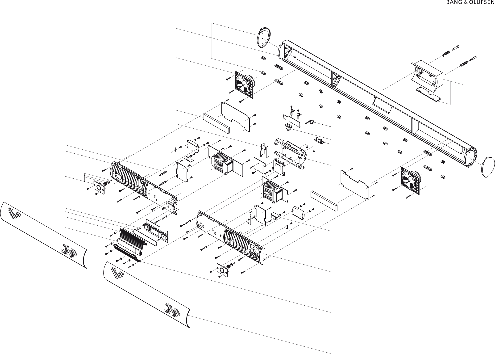
Disassembly 4.1
DISASSEMBLY
Front fabric frame
- Push the front fabric frame to the side and lift it off.
When both front fabric frames have been removed, PCB35, Display, Keyboard & IR
receiver, PCB36, Microcomputer, and PCB32, Cross field, are accessible:
- Remove the display glass (two screws) and the two plastic covers (four screws).
PCB35 can now be tilted out into service position, thereby also providing access to
PCB36 and PCB32.
35
32
36
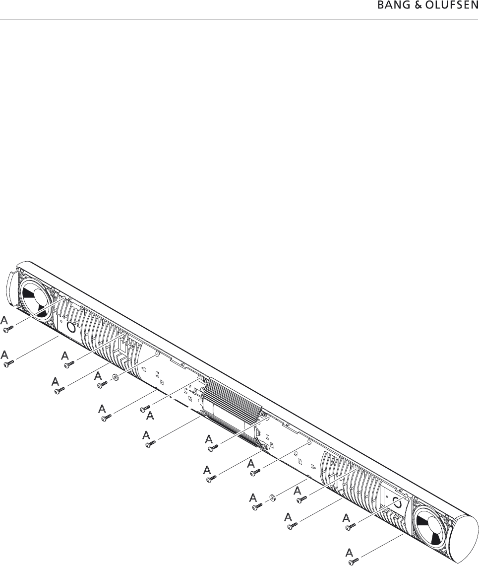
4.2 Disassembly
Service position
Important!
The display glass and cabinet must be protected against scratches by placing them
on a soft base.
- Remove the sixteen screws, A, behind the front fabric frames.
- Place the front face down.
- Remove the socket well by first removing the two Allen screws.
- Lift the cabinet up and off carefully. Place the cabinet parallel to the electronics
block, and remove the two woofer plugs (22P4) if necessary.
- When assembling the product, lower the electronics block carefully down into the
cabinet. Place the woofer leads at the centre of the cabinet so that they will not
rattle against the cabinet sides.
A
A
A
A
A
A
A
A
A
A
A
A
A
A
A
A

Insulation test 5.1
INSULATION TEST
Each set must be insulation tested after dismantling. The test is to be performed
when the set has been re-assembled and is ready for delivery to the customer.
Make the insulation test as follows: Short-circuit the two plug pins of the mains
plug and connect one of the terminals of the insulation tester. Connect the other
terminal of the insulation tester to the chassis of the 8-pin DIN socket.
N.B.!
To avoid ruining the set, it is esential that both insulator test terminals are in really
good mechanical contact.
Now turn slowly the voltage control of the insulation tester until a voltage of 1.3kV
is obtained. Hold it there for 1 second, then turn slowly the voltage down again.
At no point during the testing procedure any flash-overs are permissible.

5.2

Specification guidelines for service use 6.1
SPECIFICATION GUIDELINES FOR SERVICE USE
BeoLab 3500 MKII Type 1601 (EU), 1602 (GB), 1603 (USA-CDN), 1604 (JAP), 1605 (AUS)
1607 (KOR), 1608 (CHK)
Concept
X-tra room product Active stereo loudspeaker with control circuitry, stand-by relay
and IR receiver
Operation
Local operation Two sensi-touch fields with restriced operation (Mute/on/off/listen-in,
timer on/off)
Remote operation Beolink 1000 or Beo4, one-way (optional extra)
Status feedback Red 8 char. LED dot matrix display, (program source, program or
track number, record, clock)
Red LED 1.8mm (Timer indication)
Independent sound control Volume, balance, bass, treble, loudness
Compatability Master Link
Wireless 1 via 8-pin DIN plug
Cabinet
Rear finish Polished aluminium, high gloss
Front cloth Black
Center front Black aluminium/plastic
Wall bracket Grey plastic
Placement
Wall Wall bracket included
Stand Polished aluminium (optional extra)
Acoustics
Cabinet net volume per channel 0.8 litres
Woofer in each channel 9 cm - 3½”
Tweeter in each channel 1.8 cm - 3/4”
Crossover frequency 3000 Hz
Bass reflex principle Port
Electronics
Overload protection Yes
Volumecontrol +12 dB in relation to central room
Bass/treble equalization ±12 dB, 100Hz/20kHz
System data
Principle Active, Bass reflex, 2-way, bi-amp,stereo
Frequency response 70 - 22.000 Hz +4 -8 dB, half field
Sound Pressure Level 95 dB weighted noise (IEC 268-5),stereo, half room, 3m
Harmonic distortion 250 -1,000Hz <10% 94 dB SPL, 1m
Harmonic distortion 1,000 - 5,000Hz <3% 94 dB SPL, 1m
Minimum distance to TV 25cm

6.2 Specification guidelines for service use
Power amplifiers
Rated power woofer 35W, 8W
Rated power tweeter 35W, 8W
Amplifier signal-to-noise ratio > 80 dBA, 1W/8W
Signal-to-noise ratio > 74 dBA, full volume
Frequency range 20 - 20,000 Hz +0 -1 dB
Harmonic distortion < 0.1%
Total harmonic distortion < 0.3% IHF
Cross talk 50 dB
Active crossover network 24 dB/octave Linkwitz/Riley
Low frequency equalization +12 dB/60 - 250 Hz, ABL
High pass filter 30 dB/octave, 60 Hz
Connections
Mains Cable included, 3 meters
230V AC, 1601 EU, 1607 KOR, 1608 CHK
240V AC, 1602 GB and 1605 AUS
120V AC, 1603 USA - CDN
100V AC, 1604 JAP
BeoLink Wireless 1 (W1) 8-pin DIN 45326 socket
Dimensions
Total dimensions W x H x D (on wall) 111 x 9.5 x 11 cm
Power consumption, operation 95 watts (230V)
Power consumption, stand-by 1.1 watt, ‘Dot’ in display
3 watt, ‘Watch’ in display
Weight 10 kg, without stand
Optional accessories
Beo4 Type 1627
Wall bracket Type 1607 - 3031302
Wall bracket 3031235
Wall plate 3031333
Table stand Type 1606 - 1160611
Cable cover 2560276 (10 pieces x 2.5m)
Subject to change without notice
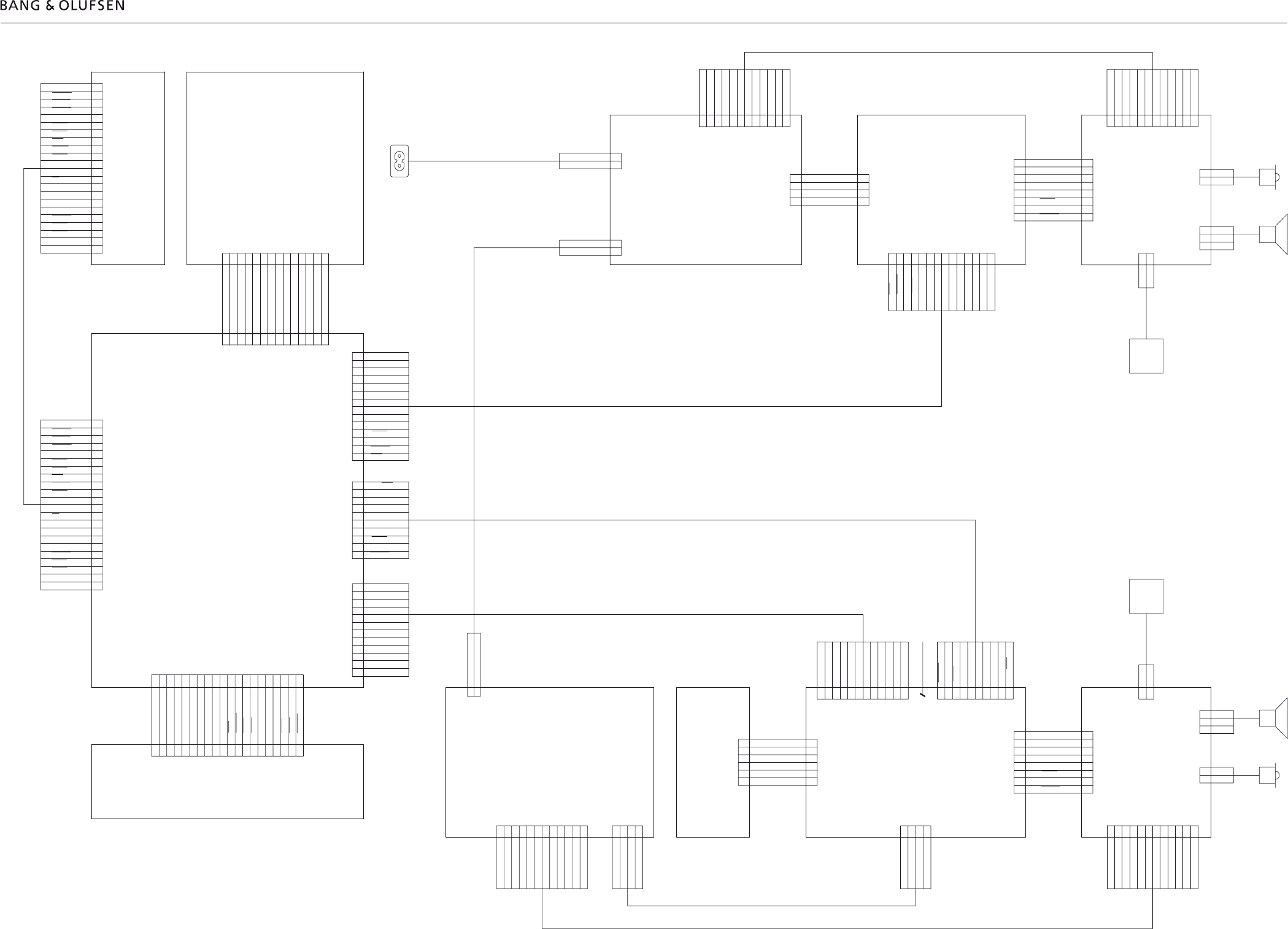
7.1
Wiring diagram
Wiring diagram 7.1 7.1 Wiring diagram
SWITCH MODE
POWER SUPPLY
TRANSFORMER LEFT
PLUG PCB
MICRO
COM-
PUTER
NTC
+9V
-9V
GND
BASS R
TREB R
PLIM
PMUTE
PFAIL
AC2 1
AC2-1
AC2-1
AC2-1
AC2 G
AC2 G
AC2 G
AC2 G
AC2 2
AC2-2
AC2-2
AC2-2
AC2-1
AC2-1
AC2-1
AC2-1
AC2 G
AC2 G
AC2 G
AC2 G
AC2-2
AC2-2
AC2-2
AC2-2
18V
GND
+9V
-18V
GND
-9V
13V AC AC3 2
AC3 G
AC3 G
13V AC AC3 1
13V AC AC3 1
AC3 G
AC3 G
13V AC AC3 2
ML?
MCL
SDA
SCL
GND
BAS L
GND
TREB L
PLIM
PMUTE
PFAIL
N.C.
N.C.
+9V
-9V
MLL-
MLL+
MLR-
MLR+
MCLL-
MCLL+
MCLR-
MCLR+
ML?
MCL
SDA
SCL
GND
BAS L
GND
TREB L
PLIM
PMUTE
PFAIL
N.C.
N.C.
+9V
-9V
MLL-
MLL+
MLR-
MLR+
PL in R
GND REF
PL in L
GND
+5V ST.BY
GND
-5V ST.BY
GND
BAS L
GND
TREB L
GND
+9V
-9V
PLIM
PMUTE
PFAIL
PON
+5V ST.BY
GND
-5V ST.BY
GND
BAS L
GND
TREB L
GND
+9V
-9V
PLIM
PMUTE
PFAIL
PON
MLRX
MLTX
MLD+
MLD-
STROBE
IRRX
MUTE
TIMER
PON
-5V ST.BY
OE
DATA
CLOCK
GND
GND
+5VA ST.BY
+5V ST.BY
L_LEV
PMUTE
L LEV
PFAIL
MLCON
MCLRX
MCLTX
MLRX
MLTX
PLIM
DATA
CLOCK
OE
GND
GND
+5V
TIMER
MUTE
IRRX
STROBE
L LEV
PFAIL
MLCON
MCLRX
MCLTX
MLRX
MLTX
SDA
PLIM
DATA
CLOCK
OE
GND
GND
+5V
TIMER
MUTE
IRRX
STROBE
MLD-
MLD+
SP ON
VML
8V5 u?15V
VML
-8V5 u?-15V
MLL-
MLL+
MLR-
MLR+
PL in R
GND REF
PL in L
GNDD
PL data
+9V
-9V
GND
BAS L
TREB L
PLIM
PMUTE
PFAIL
REL1
REL2
GND
10V
AC1 1
AC1 1
AC1 1
AC1 1
AC1 G
AC1 G
AC1 G
AC1 G
AC1 2
AC1 2
AC1 2
AC1 2
AC1 1
AC1 1
AC1-1
AC1 1
AC1 G
AC1 G
AC1 G
AC1 G
AC1 2
AC1 2
AC1 2
AC1-2
NTC
POWER AMPLIFIER
22
2
20
34
36
POWER AMPLIFIER
22
LF SUPPLY AND CONTROL
31
19
TRANSFORMER RIGHT
21
CROSS FIELD PCB
32
DISPLAY AND IR RECEIVER
35
STKEY
25
25
P1
P2
P25
P8
P3
P4
P23
P24
P21
P22
P20
230VAC
230VAC
230VAC
230VAC
P19
P7
P3
P8
STKEY
NC
STKEY
SDA
NC
P1
P4
P5
P6
P9
P2
P10
230VAC
230VAC
P11 P12
P14
P13
P17
P18
P15
P16 P2
P1
P3
P4
P8
NC
NC
CP1
20
19
18
17
16
15
14
13
12
11
10
9
8
7
6
5
4
3
2
1
1
2
3
4
1
2
3
4
1
2
12
11
10
9
8
7
6
5
4
3
20
19
18
17
16
15
14
13
12
11
10
9
8
7
6
5
4
3
2
1
1
2
1
2
+
-
-
+
1
2
1
2
3
4
5
6
7
8
8
7
6
5
4
3
2
1
12
11
10
9
8
7
6
5
4
3
2
1
4
3
2
1
4
3
2
1
12
11
10
9
8
7
6
5
4
3
2
1
6
1
61
2
3
4
5
5
4
3
2
DC/DC
CONVERTER
1
2
3
4
5
6
7
8
9
10
11
12
1
10
9
8
7
6
5
4
3
2
GND
12
11
10
9
8
7
6
5
4
3
2
1
1
10
9
8
7
6
5
4
3
2
14
13
12
11
10
9
8
7
6
5
4
3
2
1
1
2
3
4
5
6
7
8
9
10
11
12
13
14 1
2
3
11
12
13
14
10
9
8
7
6
5
4
1
2
3
4
5
6
7
8
9
10
11
12
13
14
15
16
17
18
19
20
21
22
22
21
20
19
18
17
16
15
14
13
12
11
10
9
8
7
6
5
4
3
2
1
12
11
10
9
8
7
6
5
4
3
2
1
1
2
3
4
5
6
7
8
8
7
6
5
4
3
2
1
1
14
13
12
11
10
9
8
7
5
6
4
3
2
1
2
1
2-
+
+
-
LEFT
RIGHT
3
3N.C.
N.C.
MAINS
1
2

7.2 7.27.2
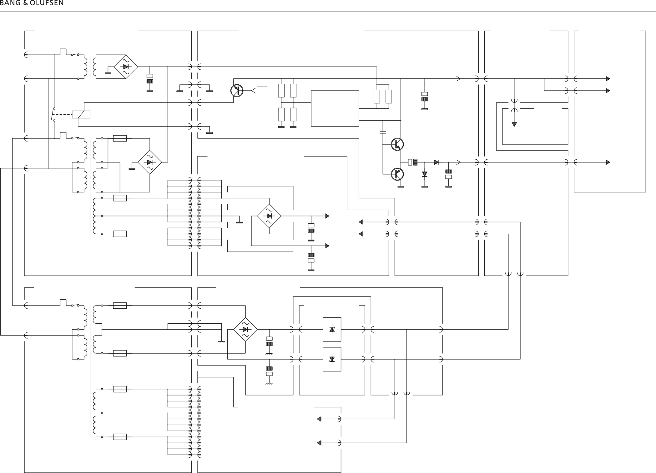
7.3 Block diagramBlock diagram 7.3 7.3
MAINS IN
MAINS
OUT
P19-2
P19-1
TF1
T1
D2
C5
RL1
P20-1
P20-2
TF5
T2 F2
F4
F3
D3
P22-1
P22-12 P1-12
P1-1
10V
P21-4
P21-3 P23-3
P23-4
REL1
P21-1
REL2
P21-2
P23-2
P23-1
5V
PON
1V 1IC1
LM3578 7/6
5
R1
R2
R3
R10
R4
R5
C5
C6
TR2
C8
D4
TR3
C9
D3 -5V ST.BY
P24-3
P24-1
5V ST.BY
P4-1
5V ST.BY 5V ST.BY
5VA ST.BY
P1-6
P8-17
P2-3
P2-4
P9-18
P9-17
P9-11 -5V ST.BY
P2-10
P4-3
-5V ST.BY
5V
P4-10
P4-9
9V
P6-10
-9V
P6-9
P24-10
9V
P24-9
-9V
P25-2
P25-1
-9V
9V
P2-2
P2-1
C2
C1
-35V
35V
D200
MAINS IN
P10-1
P10-2
TF1 F3
T1
F2
F4
F5
P12-4
P12-3
P12-2
P15-1
P15-2
P15-3
P15-4
P12-1
D1
C29
C30
P14-6
P14-3
-18V
18V
P13-1
P13-4 P13-6
P13-3
9V
-9V
IC1
LM317
IC2
LM337
9V
-9V
P14-1
P14-4 P18-10
P18-9
-9V
9V
P2-2
P2-1
P11-1 P1-1
P11-12 P1-12
SEE PCB 22 POWER
AMPLIFIER LEFT
20 TRANSFORMER LEFT SWITCH MODE POWER SUPPLY
2 32 CROSS
FIELD
µC
36
35 DISPLAY,
KEYB.&IR
DC/DC
19
22 POWER AMPLIFIER
(LEFT)
LF POWER SUPPLY
3121 TRANSFORMER RIGHT
POWER AMP.
(RIGHT)
22
-+10V
-+
26V AC
26V AC 26V AC
26V AC
- +
-+
13V AC
13V AC
26V AC
26V AC
-9V
P16-2
9V
P16-1
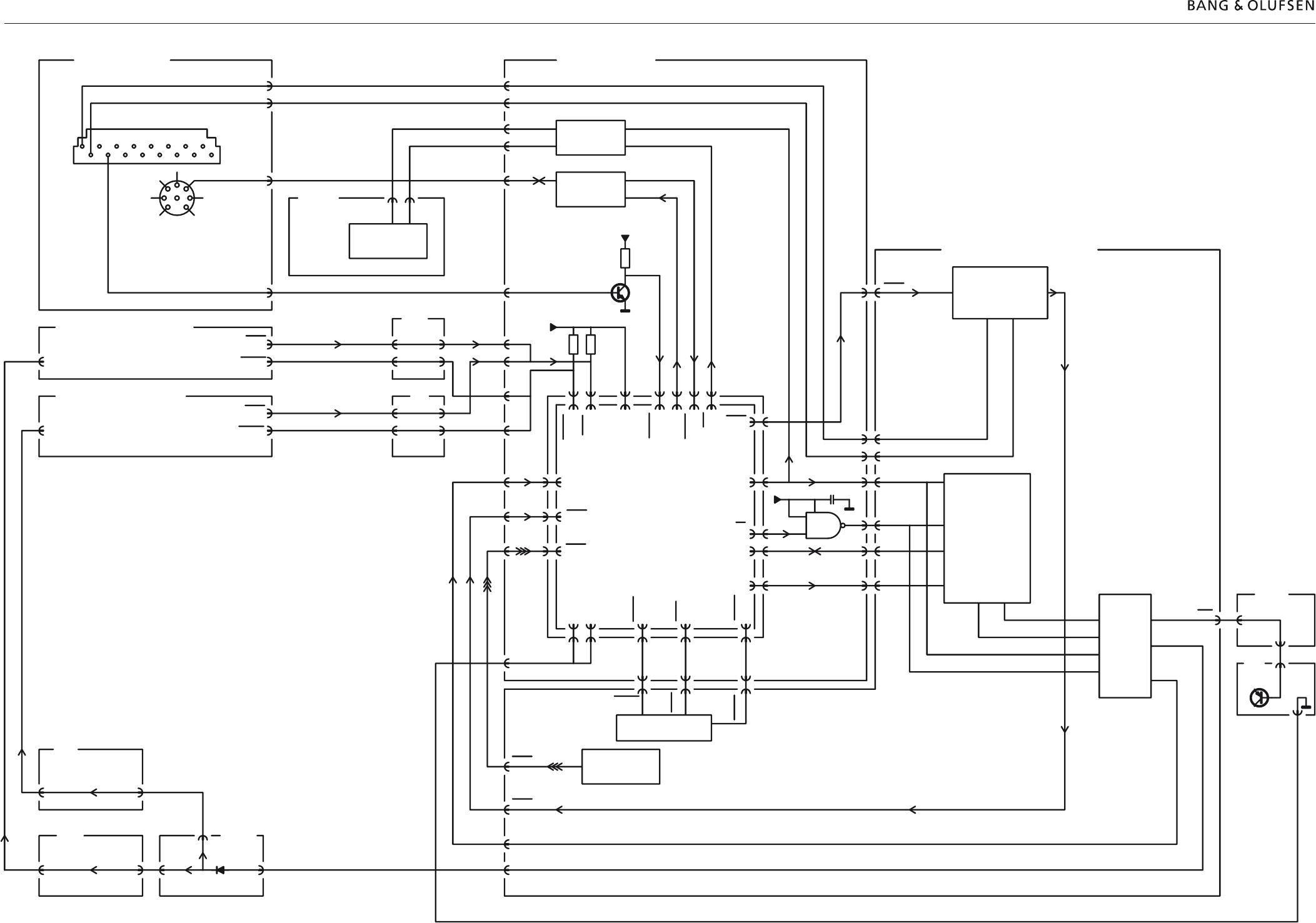
7.4 Block diagramBlock diagram 7.47.4
34 PLUG PCB
POWER AMP. RIGHT
POWER AMP. LEFT
22
22 31
2
31LF
CROSS FIELD
32
35 DISPLAY, KEYBOARD & IR
MICROCOMPUTER
36
32
2
SMPS
P2-11
P4-14
P24-14
P24-2
RELAY
TR1
PON
P9-10
PMUTE
L-LEV
LCD
CONTRAST
POWER
ON/MUTE
IC4
TR7,8,15
DATA
STROBE
CLOCK
OE
DISPLAY
IC1,2,7
2/4IC6,DP1
ML DATA
TRANSCEIVER
TR9-14,IC8
P9-3
MLTX
MLD-
P9-5
MLD+
P9-4
CLOCK
P9-14
OE
P9-12
DATA
P9-13
P9-6
P2-15
P2-8
P2-9
3
P2-7
P2-17
P2-16
C4 22n
14
1
21/4IC1
5V
P1-10
P1-12
P1-1
P1-11
OE
P8-13
CLOCK
P8-12
MLTX
P8-7
DATA
P8-11
STROBE
P8-22
PFAIL
P8-2
PLIM
P8-10
5V
P8-17
PL ON
P8-3
PL RX
P8-4
SDA
P8-8
PL TX
P8-5
IRRX
P8-20
MLRX
P8-6
L-LEV
P8-1
GND
P8-15
GND
P8-16
TIMER
P8-18
MUTE
P8-19
STKEY
P8-9
P2-12
P1-5
P2-13
P1-4
P2-20
P1-14
P1-8
7
P9-9
TIMER
P9-8
P9-1
STKEY
MUTE
SOFT TOUCH KEYB.
TR3,TR4,2/4IC6
IR RECEIVER
IC3,TR1,2,5,6
IRRX
P9-7
MLRX
P9-2
P9-19
L-LEV
P-MUTE
P9-20
GND
P4-2
P1-22
P2-2
P1-17
P2-19
P1-3
P2-14
P1-18
P5
P4-13
P4-11
P5-8
5V
R6
10K
10K
R7
R21
10K
TR6
P1-
21
P1-13
P1-6
P1-20
P1-19
P1-15
5V
P3-11
VML
8V5 =>15V
PL DATA
TR3,4,5
P3-1
PL D
P5-2
SDA
SCL
P5-3
P3-13
MLD+
MLD-
P3-14
SDA, SCL
3/4IC1
P25-8
P24-13
P25-6
P24-11
P16-6
P16-8
P17-10
P17-8
SOUND CONTROL
IC1
P17-3 P17-2
MLD-
MLD+
PL DATA
VML
PLIM
P2-6
PFAIL
P2-8
PLIM
P2-6
PFAIL
P2-8
R78,TR8-10 AND
IC2, TR7
R78,TR8-10 AND
IC2, TR7
PL
5
3
72
1
4
6
P7-4
VML
8V5 =>15V
P7-14
P7-2
P7-1
116
MASTER LINK
1A
1A
1A
1A 1A
SCL SDA
10
P1
16
P2-18
STR.
2
31 32
P25-7 P24-12
P16-7 P17-9 P5-9 P2-1
D5
PMUTE
12
PMUTE
P2-7
PMUTE
P2-7
P4
P1
7.5 Block diagramBlock diagram 7.5 7.5
22 POWER AMPLIFIER
- +
P1-1,2,3,4
-35V
P1-9,10,11,12
P1-5,6,7,8
POWER SUPPLY
35V
D200
C2 C1
3
2
1
1/2
IC100
4558 1/2
IC100
4558
5
6
7
TREBLE FILTER, 4. ORDER HP
P2-5
TREBLE IN
D12 D4
C14
R32
TO IC1 PIN 6
PA MUTE
P2-4
BASS IN
FROM
PCB 5
P9-20
PMUTE
P2-7
3
2
1
1/2
IC101
4558
BASS EXTENSION
2. ORDER HP
3
2
1
1/2
IC103
4558
1/2
IC103
4558
6
5
7
BASS EXTENSION 4. ORDER LP
5
6
7
1/2
IC101
4558
R109
LDR
BAND PASS FILTER
WITH ADJUSTMENT
3
2
1
1/2
IC102
4558
1/2
IC102
4558
R113
2. ORDER HP
DIFFERENTIAL FILTER
9V
5
6
7
R114
R129
5
6
1/2
IC104
4558
7 3
2
1
1/2
IC104
4558
R128
R127
R130
R109
LED
AMPLITUDE DETECTOR
BASS FILTER WITH ABL
R58
R66
12
13
14
1/4
IC2 1/4
IC2
1/4
IC2
1/4
IC2
10
9
8
C26 R67
5
6
7
3
2
1TR7
D8 D9
POWER LIMITER BASS (LONG AND SHORT TERM)
PLIM
P2-6
TO PCB3 ?P
25
NTC
R78
9V
TR5
TR6
TREBLE PROTECT
TR3
MUTE
TRANSISTOR
1
2
10
TREBLE
R26
1/2
IC1
STK4171V
R27
POWER AMPLIFIER TREBLE
R69
PFAIL
P2-8
TO PCB3 ?P
R71
9V
P8-1
P8-2
TR10
TR9
TR8
MUTE
TRANSISTOR
TR4
1/2
IC1
STK4171V
R70
18
17
13
R52
R49
POWER AMPLIFIER BASS
BASS
9V
TR1
TR2
35V 9V
R4
R2
R5
SIGNAL MUTE
P2
1
P4
1
-9V
+
-
+
-
+
-
+
-
+
-
+
-
+
-
+
-
+
-
+
-
+
-
+
-
+
-
+
-
+
-
+
-
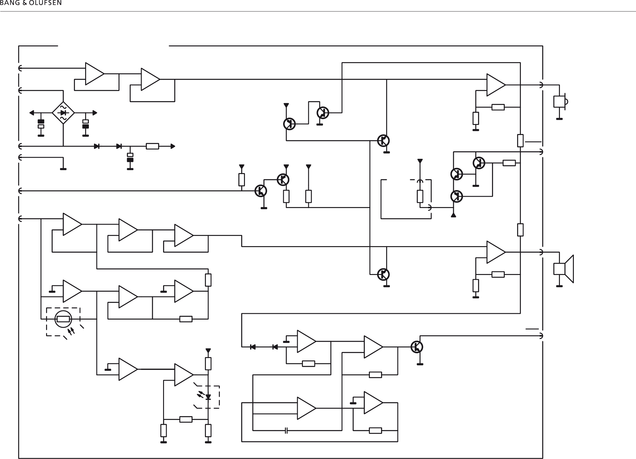
Block diagram for Power amplifier
8.1 Available partsAvailable parts 8.18.1
9001
9002
9003
9008
9009
9010
9011
9012
9013
9014
9015
9016
9017
9004
9005
9006
9007
9019
9020
9021
9022
9023
4
4
1
2
3
32
1
5
55
5
6
6
6
7
8
9
7
8
9
7
7
6
6
6
5
5
5
5
10
10
6
66
10
10
10
6
6
6
6
15
14
14 10
10
14
6
5
5
16
17
18
21
21
5
5
20
5
5
5
19
19 20
5
6
6
6
6
13
13
13 13
13
13
21
21
519
20
19
5
5
520
5
5
5
16
17
18
66
6
6
10
10
14
14
11
11 10
15
14
13
9018
21
21
35
20
22
25
236
32
34
22
22
22
21
19 31
25
Available parts
BeoLab 3500
Available parts 8.1
Available parts 9001 2576302 Distance bolt
9002 3114422 Chassis
9003 8480340 Tweeter
9004 3907064 Rubber
9005 3950053 Rubber belt
9006 3451207 Front piece
9007 3169016 Operating panel
9008 3459454 Cap, dark grey
3459108 Cap, black
3459106 Cap, grey
9009 3430055 Cabinet, dark grey
3430056 Cabinet, black
3430614 Cabinet, grey
9010 2816214 Clips
9011 8480259 Woofer
9012 3332055 Damper
9013 3170300 Insulating piece
9014 3152214 Wire holder
9015 6276907 Mains socket
9016 3164935 Cover
9017 3114406 Chassis f. sockets
9018 8006108 Rectifier PCB
9019 3114422 Chassis
9020 3451207 Front piece
9021 3451470 Cloth front, dark grey
3451472 Cloth front, silver
3451244 Cloth front, black
9022 3031382 Wall fittings
9023 3164920 Cover f. wall fittings
02Module 8006073 Switch Mode Power Supply
19Module 8006107 DC/DC Converter
2622423 Insulating piece
2364066 Rivet
2816195 Spring clips
20Module 8006091 Transformer left, type 1601, 1607, 1608
8006092 Transformer left, type 1602, 1605
8006093 Transformer left, type 1603
8006094 Transformer left, type 1604
21Module 8006061 Transformer right, type 1601, 1607, 1608
8006062 Transformer right, type 1602, 1605
8006063 Transformer right, type 1603
8006064 Transformer right, type 1604
22Module 8006087 Power Amplifier
6200044 Band cable
25Module 8006109 NTC PCB
31Module 8002938 LF Supply and Control
32Module 8002935 Cross Field
34Module 8002932 Plug PCB
35Module 8002937 Display, Keyboard and IR Receiver
36Module 8002944 Microcomputer
Survey of screws and washers 1 2046032 Allen screw, 6 x 32.7mm
2 2816267 Spring
3 2622487 Washer
4 2013176 Screw, 3 x 6mm
5 2015154 Screw, 3.5 x 25mm
6 2013188 Screw, 3 x 8mm
7 2036082 Screw, 2.5 x 8mm
8 7530119 Solder tag
9 2640054 Washer
10 2011056 Screw, 3 x 16mm
11 2038111 Screw, 3 x 8mm
13 2622041 Washer
14 2624013 Washer
15 2013177 Screw, 3 x 13mm
16 2038103 Screw, 3 x 12mm
17 2622247 Washer, 3.2 x 10.2 x1mm
18 3358305 Heat sink
19 2015167 Screw, 3.5 x 14mm
20 2625039 Lock washer
21 2011055 Screw, 3 x 10mm

8.2 Available parts
Accessories 3031302 Wall bracket, type 1607
3031235 Wall bracket
3390481 Bag with parts f/Wall bracket
3031333 Wall plate
3390468 Bag with parts f/Wall plate
1160611 Table stand
3390480 Bag with parts f/table stand
2560276 Cable cover, 10 pieces
Parts not shown 3947547 Foam, 3x19mm x 10m
3947350 Foam, 3x7mm x 10m
3947548 Foam, 6x7mm x 10m
3984215 Heat sink compound
3040016 Allen key, 4mm
6100273 Mainscable EU, type 1601
6100329 Mainscable GB, type 1602
6100307 Mainscable US, type 1603
6100247 Mainscable JAP, type 1604
6100086 Mainscable AUS, type 1605
6100386 Mainscable KOR, type 1607
6100047 Mainscable CHK, type 1608
Survey of wire bundles 6276906 Wire bundle, left:
2P23 - 20P21
2P24 - 32P4
2P25 - 22P2
20P22 - 22P1
22P3 - Tweeter
22P4 - Woofer
6276908 Wire bundle, right:
31GND - Chassis
31P14 - 19P13
31P15 - 21P5
31P16 - 22P2
31P17 - 32P5
31P18 - 32P6
22P3 - Tweeter
22P4 - Woofer
6200239 Varnished tubing PCB set
6276907 Mains socket wire bundle
Packing 3392368 Outer carton
3397921 Foam packing
3946038 Foam foil
Available documentation See Retail Ordering System

Bang & Olufsen
DK-7600 Struer
Denmark
Phone +45 96 84 11 22*
Fax +45 97 85 39 11
06-06 A
