Batt IR Meter Assembly Instructions
User Manual:
Open the PDF directly: View PDF ![]() .
.
Page Count: 6

The BattIR Project
Since the author has no control over the
quality or skill level of the persons building
up this project, there needs to be the follow-
ing disclaimer.
The software is provided “As Is” with the au-
thor not being responsible for any claim,
damages or similar issues on the use of this
project.
HOW IT WORKS
The BattIR project uses 14 electronic relays to
connect each battery cell in succession to the
same PicChip A/D input. This way there is no var-
iation in the PicChip between different A/D inputs
since only one PicChip channel is used.
So far, 31 BattIR meters have been built, all work
very well. (I did miss a solder joint on one meter)
A precision 0.2% Voltage reference, part U2 has
been added to the original design in order to im-
prove basic DC voltage accuracy, as compared to
the original BattIR meters.
In addition, each cell voltage is read 10 times, and
an average is taken of those voltage readings. .
The multiple cell voltage readings eliminates volt-
age "jitter" on the last digit of the four digit display
of the battery voltage. Tests on the three proto-
types shows that the voltage read out is accurate
to around 0.3% on voltages between 2.5 VDC and
4.5 VDC as compared to my Fluke 87V meter
while using its Hi Res feature. These units should
hold plus/minus 1% on the measured cell voltag-
es.
The BattIR meter first connects a 5 Ohm 1% re-
sistor across the battery pack, then reads and
saves the individual cell voltage readings to the
first table. Next, it connects a 2.00 Ohm 1% re-
sistor to the battery pack, and reads and saves
the individual voltage readings to a second table.
Last, the BattIR meter applies both the 5.00 and
2.00 Ohm resistors in parallel to the battery pack,
and again reads and saves the voltage readings
to a third table.
The individual cell IR calculation is:
IR = (Volts Low Amps- Volts Hi Amps)
Divided by (High Amps - Low Amps)
The first and third voltage readings are used to
calculate the individual cell IR values and displays
them to the LCD display.
Example, a cell measuring 3.71 Volts at 4.45
Amps and measuring 3.58 Volts at 15.1 Amps
would have a cell resistance of 12.2 MilliOhms.
This meter has a maximum of 999 MilliOhms
range.
The software also has commands to preset the
batteries Mah rating and uses the Mah rating to
calculate the maximum safe current for the bat-
tery.
Credit must be given to Forsyth, Julian, and Giles
for their work in testing countless LiPo batteries,
and coming up with the formula that is used to cal-
culate the maximum safe current for the given
LiPo or LiFe/A123 battery pack. These names are
included on the BattIR LCD display.
Last but not least, the test currents that are ap-
plied to the battery pack are derived by the batter-
ies voltage divided by the resistance of the power
resistors.
If the 1% 5 ohm and 2 ohm power resistors are
not available, 5% units can be substituted with a
slight loss of IR accuracy.
One feature of this setup is that the 5, 6 or 7 cell
packs will pull higher test currents through the
power resistors, compared to much lower test cur-
rents that occur with the 1, 2 or 3 cell LiPo packs.
As a result, those usually smaller 2 cell 200 Mah
battery packs are tested at current levels of
around 5 Amps, compared to the test current of
around 15 Amps for the higher voltage big battery
packs.
This meter also has the capability of displaying
the individual cell voltage of the battery pack on
each of the load currents applied to the pack. It
can also display all cell voltages while connected
to an ESC and motor under full power as an ex-
ample.
Time to start the project!
(Equipment Needed)
This project uses a number of surface mounted
resistors in its design. Surface mounted resis-
tors might be a bit scary for someone that has
not worked with them. But, with a bit of prac-
tice, assembly of a project like this goes much
faster than through hole resistors.
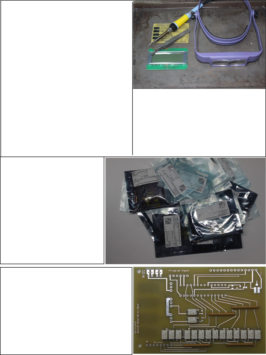
Note the required equipment in the photo at
right that will be used to build up the circuit
board. An old cookie sheet will aid in finding
any surface mounted parts accidentally
dropped. For older folks, a magnifying visor
helps a lot. Then a needle pointed soldering
iron is used along with tweezers to place and
solder the components. I use 0.040 sized rosin
cored solder for these type projects.
What I’ve learned over the years, is to place a
tiny bit of solder on ONE of the pads of the re-
sistor as an example.
Then, place the iron on that bit of solder, and,
using the tweezers, “slide” the surface mounted
resistor into that tiny bit of solder. Wait for the
solder to cool off, then solder the other end of
the resistor. This takes longer to describe than
actually doing it.
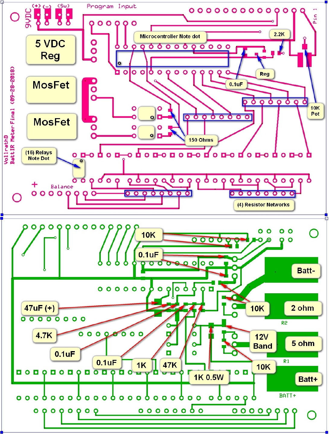
Install the electronic relays
Next, insert each of the 16 electronic relays into
the circuit board. Be careful to not have any of
the relay pins bent under the relay, rather than
going into their respective holes. Also, pay at-
tention to the small dot on these relays showing
which is pin #1. Next, install and solder up the
resistor networks that are used with the elec-
tronic relays.
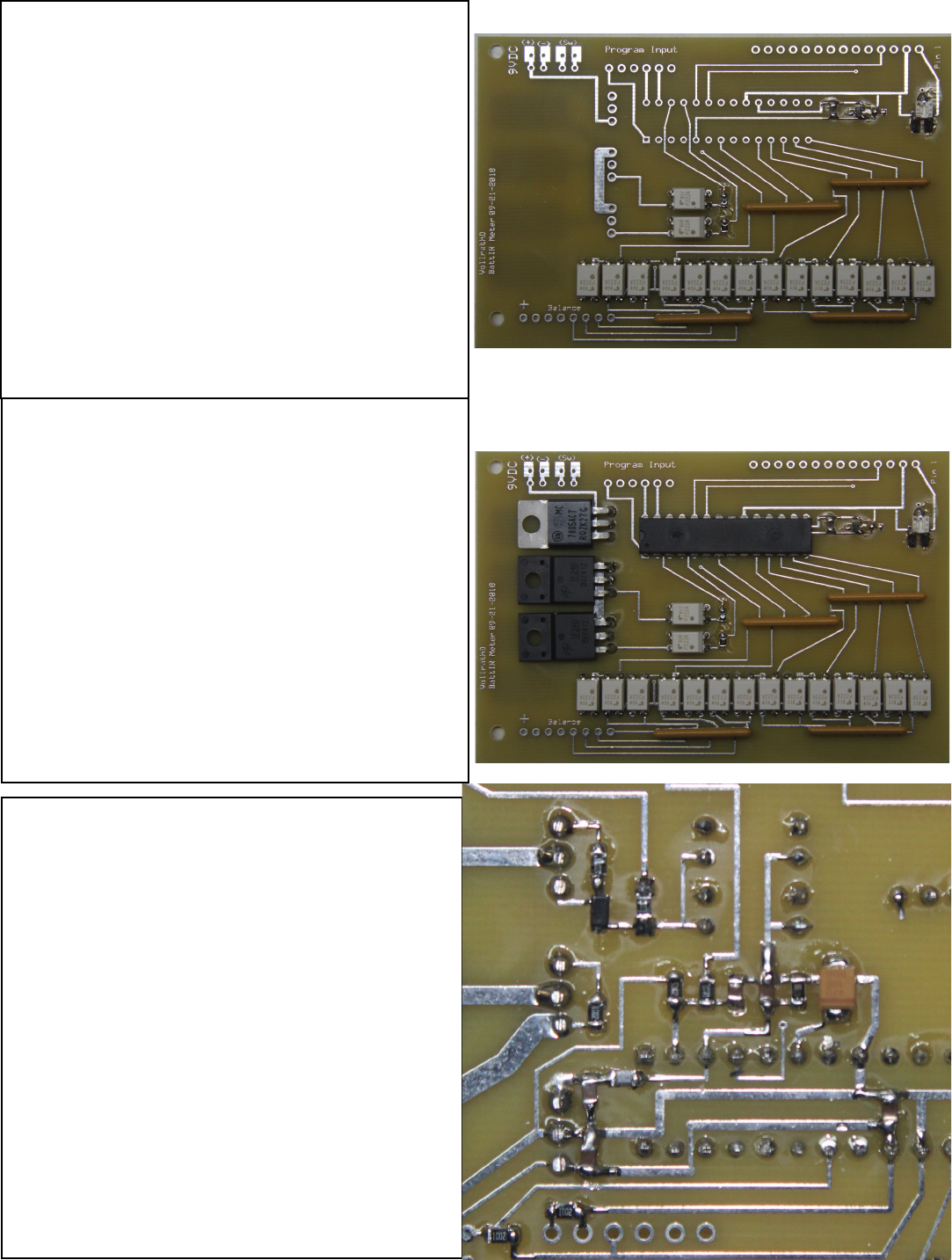
At the right is the components as re-
ceived from www.digikey.com. All
components are placed in individual
bags, properly marked with compo-
nent type and value.
Order extra resistors and capacitors.
Most 10 parts for under 50 cents.
These correspond with the parts list
that is part of the
www.expresspcb.com schematic that
is included along with the PCB layout
that can be downloaded from github.
Install The Microcontroller
Here we install the microcontroller, along with
the 5 Volt regulator that powers the project,
along with the two MosFets that are used to
connect the battery under test to the load resis-
tors.
Be very careful not to fold any of the microcon-
troller pins under the chip. If this happens it will
be difficult to fix after the chip is soldered.
Again, be aware of the location of the dot on
the microcontroller, it should be located to the
bottom left on the photo. (The PCB Pin#1 hole
Install the surface mounted parts on the
back of the PCB
Time to install the parts on the back of the
PCB, paying particular attention to the part
number, part value, and location on the PCB.
For those interested in this project, the au-
thor will make available a limited supply of
the circuit board plus the programmed mi-
crocontroller for 20% over cost of the two
items, plus shipping cost, USA only.
Install the 0.2% voltage reference
with its associated resistor and capacitor. Next,
install the potentiometer that is used to set the
LCD display Contrast.
Note the PCB layout on the voltage reference
has been changed. The author placed the cir-
cuit board order through www.expresspcb.com.
This web site repeatedly warns to verify that the
proper PCB layout is attached.
And, of course, I didn’t include the proper lay-
out! The PCB layout plans in this project has
the corrected circuit board layout.
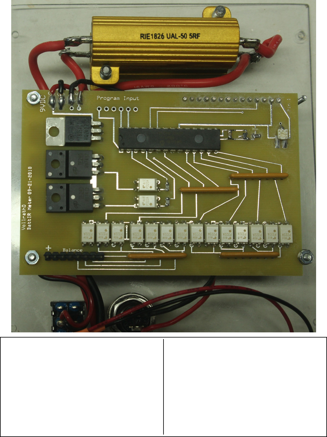
The final project as installed on a piece of Luan
sheet found at the local lumberyard.
The PCB is mounted along with the LCD dis-
play by four one inch long 2-56 screws, along
with nuts and washers. Note that the PCB is
slightly smaller than the LCD display, requiring
the bottom right screw holding the PCB with a
couple of washers.
The power resistor mounting brackets were
tapped and installed with 6-32 screws. The flat
pads on the PCB are used to connect the #16
wire for the power test lead to the battery under
test, along with connections to the two power
resistors.
When first powered up, the LCD display will be
blank. The top right potentiometer must be
turned counter clockwise until the LCD display
properly displays the information.
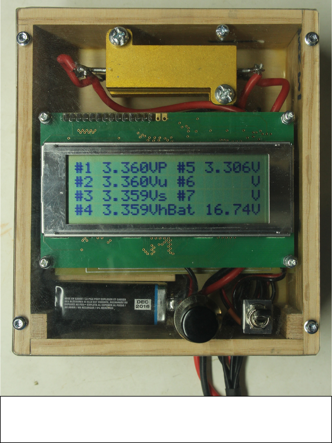
The final project. The case was built up from some 1/4 by 2 inch Oak
trim pieces from the local lumber yard. This project will also fit into a
commercial 6X4X2 plastic project box available from many sources.
