Beginners Guide To DCS World Aircraft Mods V0.5.1
User Manual:
Open the PDF directly: View PDF ![]() .
.
Page Count: 72
- Change Summary
- 1 Introduction
- 2 Building the 3D external model
- 3 Creating a Mods directory structure
- 4 Aircraft Reference Data
- 5 Standard Flight Model Tuning
- 6 Animate the External Model (WIP)
- 7 Damage Model (WIP)
- 8 LODS (WIP)
- 9 Textures and Liveries (WIP)
- 10 Human Cockpit (WIP)
- 11 External Flight Model (WIP)
- 12 Documentation (WIP)
- 13 References

Beginners Guide to DCS World Aircraft Mods
Version 0.5.1
By Jim “Red Beard” Knutson
Copyright 2015 Jim Knutson
August 19, 2015 1 Ver. 0.5.1

Change Summary
Version 0.3 – 17 Aug 2013
•Initial public release
Version 0.4 – 06 Nov 2013
•Many additions and corrections to the SFM section, including:
◦Engine modeling
◦Flight testing and tuning
•External animations described, including:
◦Visibility control
◦Connectors
◦Lights
◦Engine nozzle
•Stage 5 animated model draft work
•Stage 9 minor updates on HUD programming
•Reordered some of the later stages
Version 0.5 – 18 Aug 2015
•Corrections to the SFM flight model, including:
◦Updates to kjx, and kjz params
◦Updates to Mzalfa and Mzalfadt
•Stage 5
◦New model of F-104
◦All pertinent external animations put in place
◦Initial start at F-104 cockpit
◦HUD programming removed for now
◦Made flyable using Su-25T cockpit
Version 0.5.1 – 19 Aug 2015
•Simplified handling of unused bones
•Added tips regarding using hidden layers for objects that should not be exported
August 19, 2015 2 Ver. 0.5.1

Table of Contents
Change Summary.......................................................................................................................................2
1 Introduction............................................................................................................................................6
1.1 Skill Requirements.........................................................................................................................6
1.2 Acknowledgments..........................................................................................................................7
2 Building the 3D external model.............................................................................................................7
2.1 Modeling in General.......................................................................................................................7
2.2 Textures in General.......................................................................................................................11
2.2.1 Creating a simple texture bitmap..........................................................................................12
2.2.2 Create 3ds Max material.......................................................................................................12
2.2.3 Apply material to the aircraft................................................................................................12
2.2.4 Make the material usable in DCS World..............................................................................13
2.2.5 UV Unwrap (WIP)................................................................................................................13
2.2.6 Converting bitmaps to DDS (WIP)......................................................................................13
2.2.7 Skinning (WIP).....................................................................................................................13
2.2.8 Export the model...................................................................................................................14
2.3 The Wunderluft model – Stage 1..................................................................................................14
3 Creating a Mods directory structure.....................................................................................................14
3.1 The Wunderluft example..............................................................................................................14
3.1.1 Installing the Mod.................................................................................................................15
3.1.2 Required modifications.........................................................................................................15
3.1.3 Validating the new Mod........................................................................................................15
3.1.4 Wunderluft Mod cleanup......................................................................................................15
3.2 Restructuring the Mod..................................................................................................................17
3.3 Renaming the Mod.......................................................................................................................18
3.4 DCS World User Interface............................................................................................................19
3.5 F-104T Sample – Stage 2.............................................................................................................19
4 Aircraft Reference Data........................................................................................................................20
4.1 Weights and Measures..................................................................................................................20
4.2 Performance..................................................................................................................................22
4.3 Countermeasures..........................................................................................................................23
4.4 Sensors..........................................................................................................................................24
4.5 Weapons Loadouts........................................................................................................................25
4.6 Mission.........................................................................................................................................27
4.7 The F-104T Sample – Stage 3......................................................................................................27
5 Simple Flight Model Tuning................................................................................................................27
5.1 Research.......................................................................................................................................27
5.2 Introduction to Aerodynamics......................................................................................................28
5.2.1 Aerodynamic coefficients and factors needed by DCS World..............................................30
5.3 Reverse Engineering From Flight Manuals..................................................................................31
5.4 DCS World Simple Flight Model Mapping..................................................................................31
5.4.1 Aerodynamics spreadsheet....................................................................................................33
5.4.1.1 Validating SFM params and flap correction.................................................................37
5.5 Engine Dynamics.........................................................................................................................38
5.5.1 Research................................................................................................................................38
August 19, 2015 3 Ver. 0.5.1

5.5.2 Introduction to jet engine dyamics.......................................................................................41
5.5.3 DCS World Mapping............................................................................................................41
5.6 Validating the Performance Envelope..........................................................................................44
5.6.1 Troubleshooting the Performance Envelope.........................................................................46
5.7 The F-104T Sample – Stage 4......................................................................................................49
6 Animate the External Model (WIP).....................................................................................................49
6.1 References....................................................................................................................................49
6.2 Introduction..................................................................................................................................50
6.3 Reference material........................................................................................................................50
6.4 Special cases.................................................................................................................................51
6.4.1 Ejection seat and pilot...........................................................................................................51
6.4.2 Visibility...............................................................................................................................52
6.5 Connector based animations.........................................................................................................53
6.5.1 Lights....................................................................................................................................54
6.5.1.1 Example navigation light texture..................................................................................55
6.5.1.2 Aircraft LUA file light declaration................................................................................56
6.5.1.3 Lights in 3ds Max.........................................................................................................57
6.6 Other Animation Issues................................................................................................................58
6.6.1 Engine nozzle........................................................................................................................58
6.6.2 Engine afterburner glow.......................................................................................................59
6.6.3 Landing gear.........................................................................................................................59
6.6.4 Baking the Animation Keys..................................................................................................64
6.6.5 Aircraft numbering................................................................................................................65
6.7 The F-104T Sample – Stage 5......................................................................................................65
7 Damage Model (WIP)..........................................................................................................................65
7.1 The F-104T Sample – Stage 6......................................................................................................65
8 LODS (WIP)........................................................................................................................................65
8.1 The F-104T Sample – Stage 7......................................................................................................66
9 Textures and Liveries (WIP)................................................................................................................66
9.1 The F-104T Sample – Stage 8......................................................................................................68
10 Human Cockpit (WIP).......................................................................................................................68
10.1 Reference....................................................................................................................................68
10.2 Introduction................................................................................................................................68
10.3 Concepts and terminology..........................................................................................................69
10.4 Devices.......................................................................................................................................70
10.5 Connectors..................................................................................................................................70
10.6 Relevant forum posts..................................................................................................................70
10.7 HUD...........................................................................................................................................71
10.8 The F-104T Sample – Stage 9....................................................................................................72
11 External Flight Model (WIP).............................................................................................................72
11.1 The F-104T Sample – Stage 10..................................................................................................72
12 Documentation (WIP)........................................................................................................................72
12.1 In-game manual..........................................................................................................................72
12.2 The F-104T Sample – Stage 11..................................................................................................73
August 19, 2015 4 Ver. 0.5.1

August 19, 2015 5 Ver. 0.5.1

1 Introduction
This guide is intended to describe what is necessary to get from nothing to a new Mod that provides a
human flyable aircraft in DCS World. It is a collection of wisdom from the forum brought together into
a single place to illustrate the skills and process and my thanks goes out to the many forum participants
that answer questions from new developers such as myself. This document will not go over every
exact detail required, but will cover scenarios sufficiently so that each area of creation is covered
enough to describe basics and common questions are answered. A full sample is included with the
guide of an extremely simplified F-104 Starfighter.
The general flow for adding an aircraft is the following:
1. Build a 3D external model using 3ds Max
2. Build a Mods directory structure for the aircraft
3. Make the aircraft flyable for AI
4. Animate the external features
5. Define the collision model
6. Define the LODs
7. Define skins / liveries
8. Build a 3D cockpit model and integrate it with the 3D external model
9. Animate and integrate the cockpit controls with aircraft systems
10. Add an External Flight Model (EFM)
11. Documentation
12. Refine, refine, refine
While it is not absolutely required that these steps be followed in sequential order, there are
dependencies that will tend to push this kind of ordering.
TIP: It may be more reasonable to push the EFM higher up in priority since it appears that integration
with the cockpit model may depend somewhat on whether or not an EFM is in use. This may be a
chicken and egg problem where the EFM needs some basic cockpit integration as well.
1.1 Skill Requirements
The skills required to add an aircraft Mod to DCS World will depend on the accuracy and completeness
that is desired. Adding a graphical aircraft model is not terribly difficult, but making it look realistic
requires an eye for detail and a lot of skill with texturing. Creating a Standard Flight Model
repreresentation of the aircraft is not difficult, but making it behave close to the actual aircraft's
performance may require math skills in geometry and calculus as well as a basic understanding of
aircraft aerodynamics. It may help to have spreadsheet programming skills as well. Creating a
clickable cockpit will require scripting programming skills at a minimum and adding an External Flight
Model (EFM) will require C++ programming skills.
August 19, 2015 6 Ver. 0.5.1

1.2 Acknowledgments
I'd like to start out by saying thanks to the DCS World community for helping to fill in the blanks for
this guide. I would specifically like to thank torrecillas for providing helpful hints to understanding
aerodynamic coefficient behavior and for reviewing the SFM tuning section.
2 Building the 3D external model
There are two models required to make a human flyable aircraft. One is the aircraft model itself and
the other is the cockpit. Even if you have an existing aircraft model in 3ds Max format, you will still
need 3ds Max in order to convert the model into a proprietary format used by DCS World.
Modeling generally covers creating a mesh or set of meshes that describes the shape of the aircraft and
then providing textures that give the shape color. Animation of the meshes and textures for things such
as control surface movement and aircraft damage will be covered in later sections.
2.1 Modeling in General
The following prerequisites are required for modeling in DCS World:
•3ds Max (check plugin for supported versions)
•EDM plugin for Max (http://forums.eagle.ru/showthread.php?t=86205). See also
http://en.wiki.eagle.ru/wiki/EDM_plugin
•Standalone Model Viewer (http://forums.eagle.ru/showthread.php?t=86205)
The standalone model viewer isn't necessarily an absolute requirement, but it is so handy that working
without it hardly makes sense.
Setting up the environment starts with following the instructions in the basic_model_guide.pdf file
available from the EDM plugin and standalone model viewer forum post.
Once both the plugin and standalone model viewer are installed, you will want to set some options for
the exporter in 3ds Max as shown in the following figure.
August 19, 2015 7 Ver. 0.5.1
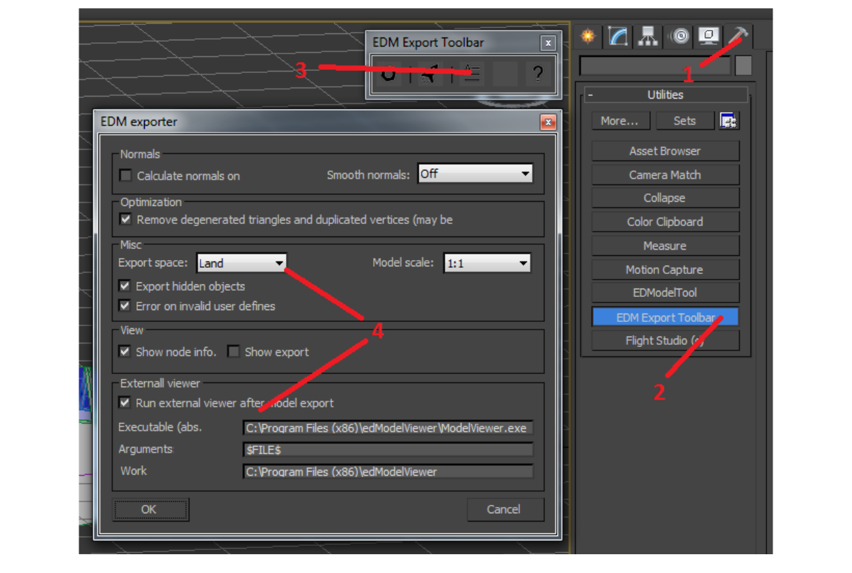
The install path for the standalone model viewer allows the model viewer to display an exported model
quickly without having to start DCS World to check the model in game. The argument $FILE$ will
substitute the exported model file name, and the Set the Model Exporter option to use Export Space:
Land as this will reorient the model so that the nose is pointing along the positive X axis. Be sure to
validate this in the standalone model viewer when you export your models. If you do not do this, the
AI will fly your aircraft sideways.
Getting textures to show up in the model viewer is a bit of a challenge and will likely push you to
setting up a build / install environment. The model viewer has the ability to mount a zip file or
directory location which contains textures, but this only seems to work when you start the model
viewer manually, mount the textures first, then load your model. Since 3ds Max will be starting and
loading the model before you can mount, the only thing you can do is place textures into a “default”
location. The easiest way to do this is to set the Work location of the EDM Exporter options to the
DCS World install directory. Then when you need to view a model with textures, copy those textures
to the DCS World install/Bazar/TempTextures directory. This will make the textures visible in
both the model viewer and in game.
August 19, 2015 8 Ver. 0.5.1
Illustration 1: EDM tool export options
Getting started with modeling is something that takes more than this guide can provide. There are
many tutorials available on YouTube and other places. However, there are some basics you must be
aware of:
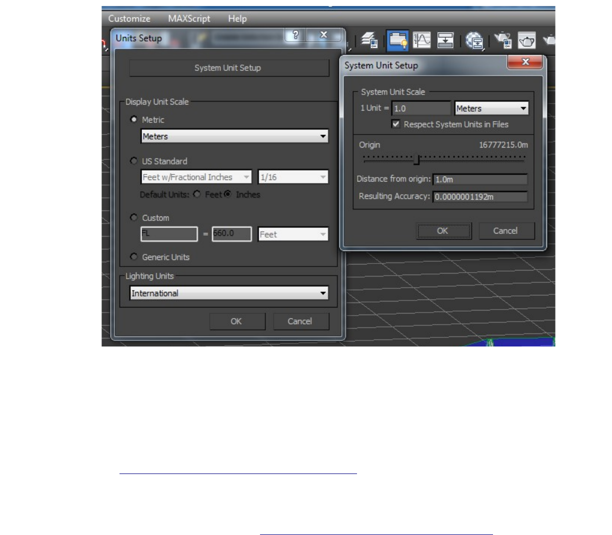
•Make sure you start with a 1 unit = 1 meter system and object unit. Use Customize >
Units Setup. Verify that Display Unit Scale is Metric Meters. Click System
Unit Setup and verify 1 Unit = 1.0 Meters as shown below.
•Orient the aircraft with the nose pointing along the positive Y axis. Note, the model exporter
has an option to reorient the model with the nose pointing along the positive X axis.
Everything else is pretty much optional. There are additional tips you may want to utilize.
TIP: Building a model using nesting of smaller components is a good idea, but be aware that while
model references work in 3ds Max, they do not work well in DCS. You will eventually need to merge
models. See http://forums.eagle.ru/showthread.php?t=110289.
TIP: Find blueprints and pictures of the aircraft you want to model. You can put these on the X. Y, and
Z planes to help you draw your model. If you go this route, you will probably need to resize the
aircraft to actual dimensions after modeling with blueprints. Search YouTube for 3ds Max blueprints if
you want a tutorial of how to do this. See http://forums.eagle.ru/showthread.php?t=23968 for
references to blueprints that may be used. Place these background blueprints in a separate 3ds Max
August 19, 2015 9 Ver. 0.5.1
Illustration 2: Units setup

layer that can be hidden during export as these should not be exported with the rest of the model.
TIP: The simplicity of the sample aircraft at this stage makes it easy to fully define the shape.
However, a more detailed model may be easier to create by only working on half the aircraft and using
object cloning or symmetry modifiers to model the other side of the aircraft once animations are
complete.
TIP: The number of polygons used will affect performance. A good detailed model will have tens of
thousands of polygons up to and over 100,000 polygons. The more polygons, the more need there will
be for optimizing performance using Levels of Detail (LODs). The less detail, the less realistic your
aircraft will be. See later sections for information on optimizing performance.
TIP: Modeling tips can be found at http://www.military-meshes.com/web/forum/military-
academy/obstacle-course/115-3d-aircraft-tips-best-of and http://www.military-
meshes.com/web/forum/military-academy/obstacle-course/129-subdivisional-modelling-solutions
2.2 Textures in General
Describing the shape of a model does not make it visible. In order to make it visible, a mesh needs to
have textures applied to it. The proper application of textures is an extremely complicated subject so
this guide will only touch on some very basic cases and requirements.
DCS World supports BMP, TGA, and DDS files for textures, though it appears that it is also possible to
use CDDS files as well. You have the option of:
•texturing the model with .BMP or .TGA bitmaps and converting the textures to .DDS files later,
or
•saving the textures in .DDS format and using the .DDS files during modeling
It appears that most (all?) current Mods use the former pattern. In this case, when you convert your
texture to DDS, you name your DDS file after the full name of the original file, so green.tga is
converted to file green.tga.dds.
Even the most basic case requires several steps to be able to render the model appropriately in either
the standalone model viewer or in game. For example, suppose the entire aircraft should be colored
green, we must do the following:
1. Create a bitmap of the desired green color. The size should be a power of 2 square to get the
best hardware support. Sizes from 512x512 to 2048x2048 seem to be the most common.
2. Create a material in 3ds Max that uses the BMP or TGA bitmap just created.
3. Apply the material to the aircraft object
4. Make the material usable by DCS by setting properties in 3ds Max
5. Install the bitmap to the TempTextures directory
6. Export the model as a .EDM file
TIP: Each model you create should have its own directory of textures and all textures should be placed
in that directory.
TIP: Name your textures uniquely to so that you don't conflict with other bitmaps. E.g. use F-
104_pilot_green.bmp and not just green.bmp. There's no telling who else uses a green.bmp and
August 19, 2015 10 Ver. 0.5.1

whether or not it's the correct color of green.
TIP: Photoshop can manipulate the alpha channel, but Photoshop Elements does not directly support
this.
A slightly more complicated example includes the use of glass, which is not opaque, and to complicate
things even further, there are bump maps (bitmaps which use subtle shadows to provide a 3D effect,
such as rivets and grooves, to a flat surface), diffuse maps to provide color, and specular values to
change the reflectivity of material to differentiate between rough cloth and polished metal.
http://forums.eagle.ru/showpost.php?p=2314497&postcount=798
http://forums.eagle.ru/showthread.php?p=1805326&highlight=glass#post1805326
http://translate.google.com/translate?hl=en&sl=auto&tl=en&u=http%3A%2F%2Fwww.news3d.eu
%2Findex.php%2Ftopic%2C66114.msg892280.html
There are also complications in trying to provide different colors to a single object. It would be pretty
boring if the aircraft was only solid green. At a minimum, we would like to see a transparent canopy
and maybe a black exhaust cone.
There are a couple of ways to approach this. One is to use the 3ds Max Multi/Sub-object material and
assign different materials to specific polygon faces in the object by specifying a material index.
Another is by taking the object an doing a UV unwrap on it to translate the 3D object into a 2D skin
(bitmap). More on these later.
Once the aircraft is nearing completion, the textures can be converted to DDS files.
2.2.1 Creating a simple texture bitmap
There are a number of ways to create a texture bitmap, but you will need to be able to manipulate alpha
channels in .TGA files and you will want to be able to edit bitmaps in layers. Applications such as
Photoshop or Gimp can be used for this.
Creating a bitmap for a glass texture is a bit more difficult. It takes a special bitmap and a special setup
in 3ds Max materials. In general, you create a glass texture by creating a blue (RGB 0 0 255) bitmap
with an alpha channel opacity to 20% and saving it as a 32 bit TGA file, then setting up the material
appropriately in 3ds Max as described below.
Note that mirror textures require special config in DCS. See http://forums.eagle.ru/showpost.php?
p=1520102&postcount=162
TIP: Be sure to place a copy of the texture in the <DCS World install>/Bazar/TempTextures directory
so that the modelviewer can find it.
2.2.2 Create 3ds Max material
Creating materials in 3ds Max is not too hard. Just use the M key to bring up the materials editor and
drag the Standard material +Materials+Standard+Standard to the view panel and name it what you
want (e.g. F-104_pilot_green), then drag from the Diffuse Color circle of that material to anywhere on
the view panel and select Bitmap. Fill in the Bitmap field for the bitmap file you want to use.
Canopy material is handled by using a bitmap as described above, but with special configuration of the
material. Under Material Attributes, choose glass (see http://forums.eagle.ru/showthread.php?
August 19, 2015 11 Ver. 0.5.1

t=109564&highlight=glass and http://forums.eagle.ru/showpost.php?p=1503247&postcount=131).
TIP: Don't use any material other than Standard with Bitmaps or Multi/Sub-object as they won't be
rendered appropriately in game.
One sided vs. two sided
2.2.3 Apply material to the aircraft
This is also fairly easy for applying a single color to an object. Just drag the circle on the right side of
the Standard material from the view panel to the object you want to apply it to.
If you want to apply more than one color to an object (e.g. a black face shield to a white helmet object),
then you need to create a Multi/Sub-Object material in more or less the same way as the Standard
material. Attach materials to the left side index circles to define what colors / materials are assigned to
what number. When you apply this material to an object, you can paint by numbers. After applying the
Multi/Sub-object material to the object, select the object, choose the Modify tab, choose polygons
selection type and then select the polygons you want paint a particular color. There should be a
Polygon: Material Ids drop down. You set the material index number in the Set ID: field. If you set it
to 1, then the material associated with index 1 of the Multi/Sub-object material will be used to paint
those polygons.
While texturing in this fashion is not the end goal, it at least provides a simple texturing option for use
while the model is still evolving.
2.2.4 Make the material usable in DCS World
Whenever you create a new material, you have to add some special properties and scripting to it in
order to make the material properly export and be usable in DCS World. To do this, you click the
Utilities tab, then click the EDModelTool button, select the material slot in the Material viewer and
finally click on the Make Cool button. This should add several Material Attributes to each of your
materials, which now makes them exportable.
TIP: Be sure to check special material already defined after clicking the Make Cool button. I've had
glass and light material revert back to default materials after using this button.
2.2.5 UV Unwrap (WIP)
UV unwrap is used to flatten a 3D object into a 2D bitmap so that the bitmap may be painted and then
applied (wrapped) around the 3D model. This is VERY sensitive to model changes, so you want to do
this last. If you are going to refine your model, it is probably best to use simple bitmaps in the
meantime and return to UV unwrap when the model is stable.
http://waylon-art.com/uvw_tutorial/uvwtut_02.html
http://www.military-meshes.com/web/forum/military-academy/obstacle-course/104-advanced-aircraft-
texturing-tutorial
Skinning: http://forums.eagle.ru/showthread.php?t=73093
Move most of this and the Skinning sub section to the Skinning and Liveries section below.
August 19, 2015 12 Ver. 0.5.1

2.2.6 Converting bitmaps to DDS (WIP)
Done last
http://www.catalinzima.com/2012/11/converting-textures-to-dds/
2.2.7 Skinning (WIP)
Really needs to be a part of the Mods setup.
Tutorial on skinning: http://forums.eagle.ru/attachment.php?attachmentid=47290&d=1296754578
http://forums.eagle.ru/showpost.php?p=1401006&postcount=5
2.2.8 Export the model
DCS uses .EDM files for models, so you must export your model once you have it created and
textured. Save the export to a temporary location.
2.3 The Wunderluft model – Stage 1
What should a model include? Everything that is required is the obvious answer. To start off, you will
want to have the basic aircraft shape, including fuselage, wings, rudder and tail surfaces, a canopy, and
landing gear in the down position. Eventually, you will want to add some detail such as ejection seats,
control panels, and a pilot inside the cockpit as well as detail inside other cavities such as engine
exhaust and intakes. The more detail you add, the more realistic the model will be as many of these
kinds of details can be visually animated.
Once the mesh is in place to describe the shape, the model needs to have materials or textures applied
in order to give the shape a visible form.
The sample included in this guide is provided in various stages of development and does not represent
a typical level of detail for aircraft models. It is only intended to shows the basic skills and process to
produce your own aircraft. Stage 1 includes the basic model mesh and color textures. If you want to
create your own F-104, there's a tutorial located at http://www.indiedb.com/tutorials/tutorial-008-f-104-
creation.
TIP: Place the origin of the model close to the Center of Gravity, otherwise changes in pitch, roll, and
yaw may have very odd visual affects. For example, placing the origin at the nose would make a
helicopter pitch up action feel and look like you are falling.
3 Creating a Mods directory structure
The easiest way to start out is to work with an existing sample and refine it. There's a How To thread in
the forums that provides a basis to work from, called Wunderluft. It would be a good idea to read
through the thread located here, http://forums.eagle.ru/showthread.php?t=89164, but be aware that the
Wunderluft.zip file is not complete and links in the thread to complete contents have expired and
are no longer useful. Hence this guide. Creating your own Wunderluft Mod starts with extracting the
Wunderluft zip file and copying the .EDM file for the aircraft model to the
August 19, 2015 13 Ver. 0.5.1

Mods/aircraft/Wunderluft/Shapes directory. Then you start tweaking the script files.
TIP: It is very important to note that DCS is very sensitive to the file contents and although they look
like normal text files, you must use notepad++ for editing LUA files or you risk having the file contents
silently ignored.
3.1 The Wunderluft example
While the ultimate goal is to have an F-104 Mod, creating from scratch is a risky business as there may
be multiple problems introduced that become difficult to solve, therefore, we'll start with Wunderluft
and refine.
3.1.1 Installing the Mod
Start by downloading the Wunderluft.zip file and set it aside (you may need it multiple times).
Extract the zip file into the DCS World install/Mods/aircraft directory. The Mods/aircraft
directory should now contain an additional directory called Wunderluft.
Copy the .EDM file of your external aircraft model to Wunderluft/Shapes/Wunderluft.EDM
to make your external aircraft model used. The textures should already be available based on earlier
work copying them to TempTextures.
3.1.2 Required modifications
There are a few things to tweak before using in game. The first is correcting the landing gear contact
positions so that the aircraft won't sink into the ground at the start of a mission. Use 3ds Max to find
the point where the wheels of the model will touch the ground, then modify the properties of
Wunderluft/Wunderluft.lua using Y, Z, X as the location order of specification. Units are
meters. For our example, we will be using the following:
•nose_gear_pos = { 3.3, -2, 0},
•main_gear_pos = { -1.5, -2, 2},
Note that you only need to specify one side for the main gear position and the other is assumed to be
symmetrical to that in the opposite X direction.
Make sure you only use notepad++ to edit LUA files or you may have to re-extract the Mod and
start over!
3.1.3 Validating the new Mod
Create a fast mission with the Wunderluft aircraft and start from ramp. Use F2 to check the external
model placement on the ramp.
If you have done everything correctly, you should start out sitting more or less on top of the airplane,
with an orange grid in front of you and a green rectangle behind it with a missing texture. The aircraft
should be sitting on the ramp with the wheels touching the ground.
The orange grid is from a simplified radar used in the Wunderluft example and the green rectangle
behind it is from a HUD.
August 19, 2015 14 Ver. 0.5.1

Exit the flight to start fixing the problems.
3.1.4 Wunderluft Mod cleanup
Before moving on, we are going to clean up the sample. We'll start with taking care of the missing
texture for the HUD and we'll cleanup the cockpit avionics to get rid of the radar in our face. There are
some error messages in the log we'll clean up and finally, we'll restructure and rename the Wunderluft
configuration to our goal of F-104.
We can start by trying to find out what texture is missing from the HUD and provide a suitable
replacement. Look in the log file (C:\Users\<yourusername>\Saved
Games\DCS\Logs\dcs.log and look for “failed to open file” messages. There should
be one that looks like:
00058.085 ERROR DXRENDERER: DXDefTexture: failed to open file
bazar/textures/avionicscommon.tga
We can provide a suitable replacement by using a “glass” texture from our model and copying it to the
expected name. Rather than placing the texture in TempTextures for all aircraft, place it instead in the
<DCS World
install>/Mods/aircraft/Wunderluft/Textures/Avionics/Bazar/Textures/Av
ionicsCommon.tga file. How did we know this?
Each Mod starts with an entry.lua, which sets up initial properties and then calls another .lua file to
configure the aircraft. In this case, entry.lua uses
dofile(current_mod_path..'/Wunderluft.lua') to setup the Wunderluft example
aircraft. Looking at the Wunderluft.lua file, we can see three statements used to setup paths:
mount_vfs_model_path (current_mod_path..”/Shapes”)
mount_vfs_liveries_path (current_mod_path..”/Liveries”)
mount_vfs_texture_path (current_mod_path..”/Textures/Avionics”)
From this, we can see that the Mod expects the external model to be placed in the Mod's Shapes
directory and textures should be placed in the Textures/Avionics directory. DCS will start
looking for the missing Bazar/Textures/AvionicsCommon.tga file in the
Textures/Avionics directory. Try another test flight to validate that the HUD missing texture has
been corrected.
The radar grid is going to be of interest when we get to cockpits, but for now it's just in the way, so lets
turn it off. I'm going to defer the details for making Cockpits until later, so for now, comment out the
following lines in Cockpit/device_init.lua by adding a --RADAROFF to the beginning of the
lines (remember to use notepad++!):
creators[devices.RADAR] = {"avSimpleRadar",
LockOn_Options.script_path.."RADAR/Device/init.lua"}
and:
indicators[#indicators + 1] =
{"ccIndicator",LockOn_Options.script_path.."RADAR/Indicator/init.lua",--init script
nil,--id of parent device
{
August 19, 2015 15 Ver. 0.5.1

{}, -- initial geometry anchor , triple of connector names
{sx_l = 0, -- center position correction in meters (forward , backward)
sy_l = 0, -- center position correction in meters (up , down)
sz_l = 0, -- center position correction in meters (left , right)
sh = 0, -- half height correction
sw = 0, -- half width correction
rz_l = 0, -- rotation corrections
rx_l = 0,
ry_l = 0}
}
} --RADAR
Try another flight to see if the radar grid has disappeared. You should be left with an orange 0.10
floating in front of you. This is HUD data projected on the HUD glass.
The log also contains some error messages such as “can't open MO-file ...”. These are message
files used for translated messages. The easiest way to get rid of them is to copy an empty file from
another Mod. Copy the Mods\Su-25T\en\LC_MESSAGES\messages.mo to
Mods\aircraft\Wunderluft\l10n\en\LC_MESSAGES\messages.mo. Try another
flight and then check to log to make sure the error message has disappeared.
There's another error in the log referencing a problem with line 265 in Cockpit/clickabledata.lua:
00016.797 ERROR COCKPITBASE: ccLuaLoader::LuaDofile(L,
"./mods/aircraft/Wunderluft/Cockpit/clickabledata.lua"): Can't execute Lua file
./mods/aircraft/Wunderluft/Cockpit/clickabledata.lua - [string
"./mods/aircraft/Wunderluft/Cockpit/clickab..."]:265: attempt to call global
'LOCALIZE' (a nil value)
This is partly due to configuring a clickable switch in the cockpit, which we don't have yet, so let's also
comment out this line in Cockpit\clickabledata.lua, by adding a --SWITCHOFF prefix to the
line:
elements["POINTER"] = default_2_position_tumb(LOCALIZE("Test
Command"),devices.TEST, device_commands.Button_1,444) -- 44 arg
number
Once again, try a flight to validate the change is correct. Are you starting to see a pattern here? There
aren't very many things you can use to debug problems, so you need to limit your scope of changes
before validating them. This will save you trouble in the long run.
The next set of errors in the log include:
00016.896 ERROR GRAPHICSXP: ModelManager: can't find Wunderluft-part-wing-R
00016.897 ERROR GRAPHICSXP: ModelManager: can't find Wunderluft-part-wing-L
00016.899 ERROR GRAPHICSXP: ModelManager: can't find Wunderluft-part-nose
00016.900 ERROR GRAPHICSXP: ModelManager: can't find Wunderluft-part-tail
00016.912 ERROR GRAPHICSXP: ModelManager: can't find Cockpit-Wunderluft
The first four lines are due to missing damage model information. Comment out the following lines
from Mods\Wunderluft\Wunderluft.lua using --DAMAGEOFF as a prefix to the lines:
[1] = "Wunderluft-part-wing-R", -- wing R
[2] = "Wunderluft-part-wing-L", -- wing L
[3] = "Wunderluft-part-nose", -- nose
August 19, 2015 16 Ver. 0.5.1

[4] = "Wunderluft-part-tail", -- tail
The last error message is due to the cockpit model missing from Cockpit/Shapes. You can ignore this
for now, or copy the Cockpit-Wunderluft.edm file from a later stage.
3.2 Restructuring the Mod
Before we get very far into customizing the Mod, we are going to move some of the content around to
match current directory structures, then we'll go through the changes necessary to make this Mod
unique by renaming it from Wunderluft to F-104.
There's no external flight model yet, so we will skip creating the “bin” directory and “FM” directory
for now.
The “Skins” and “Liveries” directories will be handled in a later stage, so we can leave them
alone as well.
Rename the Docs directory to Doc and create a manual_en directory in the Doc directory. The
manual_en directory will be used to contain a localized (English) in-game manual written in .lua
script files. The details of creating an In-game manual will be covered in a later section.
Current Mods, such as A-10C, Ka-50, and P-51D, use a more structured directory layout for the
Cockpit. We'll make those changes now even though we aren't going to work on the cockpit until a
later stage. Create a Scripts directory under the Cockpit directory and move all the .lua files and
the 3 directories already in Cockpit to the Scripts directory. Modify the Wunderluft.lua file
HumanCockpitPath to refer to the new scripts location:
HumanCockpitPath = current_mod_path..'/Cockpit/Scripts/',
Create a Cockpit\Resources\Model\Shape and a
Cockpit\Resources\Model\Textures directory. Add the following as the first line of
Cockpit\Scripts\device_init.lua so that the new locations will be used:
mount_vfs_model_path(LockOn_Options.script_path.."../Resources/Model/Shape")
3.3 Renaming the Mod
Now it's time to make the Mod unique to what we are creating. We want to change Wunderluft to F-
104, but there are some things we need to be careful with. In some cases, Wunderluft is used as a LUA
variable name and in other cases, it is used as a string. Care must be taken to use legal variable names,
so “-” cannot be used in those cases. In some string cases, the string is used as a file name and we must
take care to use a legal file name, so we can't use “/” characters in those cases either. Lastly, rather than
potentially conflicting with other F-104 Mods, we're going to call this the F-104T (for Tutorial).
Start by renaming the Mod directory from Mods/aircraft/Wunderluft to
Mods/aircraft/F-104T.
Next rename F-104T/Wunderluft.lua to F-104T/F-104T.lua. Change the F-
104T/entry.lua dofile reference from Wunderluft.lua to F-104T.lua. While editing
entry.lua, go ahead and change the declare_plugin function call (line 1) and info variable.
Change the Skins name, Missions name, Logbook name and type, and
August 19, 2015 17 Ver. 0.5.1

InputProfiles array index from Wunderluft to F-104T.
In F-104T.lua, make the following changes:
•line 8 Wunderluft > F_104T. Note the use of underscore here instead of dash. It's a
variable name and needs to follow those rules. Change the last line reference in the
add_aircraft function call from Wunderluft to F_104T as well.
•Change lines 10, 11, 18, 23*, 28 from Wunderluft to F-104T. *Note that line 23 is a file
reference, so you cannot use “/” in the name. Also note that the reference to the EDM file name
has changed, so rename Mods/aircraft/F-104T/Shapes/Wunderluft.EDM to
Mods/aircraft/F-104T/Shapes/F-104T.EDM.
Change F-104T/Input/name.lua Wunderluft reference to F-104T.
There are a few references in F-104T.lua to Wunderluft left for files or model parts we have not
created yet. You can change these now or address them later when they are created:
•Change the Picture variable from Wunderluft.png to
../../../../../Mods/aircraft/F-104T/F-104T.png. Note, this is a file name,
so no “/” may be used in the file name here, but it does accept a path to a picture file in our mod
directory. The Picture variable is used to identify an iconic image of the aircraft used by the
mission editor. If unspecified, it uses a default of the <Name property>.dds. The 1024x512
image should include a gray background with a frontal blueprint style view of the aircraft with
store points numbered/labeled. See MissionEditor/data/images/Loadout/Units
for examples.
•Change all “Wunderluft_destr” and “Wunderluft-destr” references to “F-
104T_destr” and “F-104T-destr” respectively.
•Eventually, you will want to change “Wunderluft_canopy” to “F-104T_canopy”, but
we'll save that for when we do canopy animation. For now reuse an existing canopy model by
replacing the quoted string “Wunderluft_canopy” with the number 12.
•Change “Wunderluft-part to “F-104T-part. There are 4 instances with different
strings, so be careful with substitution.
Do not proceed from here without checking your work. Note, starting DCS without actually flying a
mission will not create a new log, so when you test and check the logs, keep that in mind.
TIP: DCS World can get unstable if scripts reference missing files and those files are used. Missing
canopy models, ejection models, and destruction files may cause DCS to crash.
3.4 DCS World User Interface
There are icons and background images that may be updated when the aircraft is in use.
The .png files in the Theme folder are icons that are displayed at the bottom of the main panel. The
particular icon used varies based on whether or not a theme the current aircraft's theme is active,
whether it has been selected, and whether or not it has been purchased.
There are three backgrounds that may be used for various screens. These images are located in the
Theme/ME folder. It is recommended that replacement images match the size of the existing images.
August 19, 2015 18 Ver. 0.5.1

I don't know what would happen if they didn't match.
All of these files have well known names and cannot be renamed.
3.5 F-104T Sample – Stage 2
The F-104T stage 2 zip file contains all the work done so far and provides the first usable sample Mod.
It may be unzipped to the DCS World installation/Mods/aircraft directory to install the Mod.
4 Aircraft Reference Data
The Standard Flight Model needs some basic data to work with, so let's start by doing some research:
•http://en.wikipedia.org/wiki/Lockheed_F-104_Starfighter
•http://www.aerospaceweb.org/aircraft/fighter/f104/
•http://www.airplanedriver.net/study/f104.htm
•http://www.916-starfighter.de/F104_Chaff%20Flare%202011.htm
•http://www.grupoaerea.es/F104/Avion/ElAvionUsa.htm
•http://forum.keypublishing.com/showthread.php?39447-F-104-
Question&s=3ccabf2a94f36c4146f2b68686ff13f9&p=1107379#post1107379
•http://www.flightglobal.com/pdfarchive/view/1963/1963%20-%200386.html
•http://digital.library.unt.edu/ark:/67531/metadc61439/m1/1/
•http://www.rolfferch.de/F104G/Zipper_ES.pdf
•http://www.airspacemag.com/history-of-flight/starfighter.html
•http://www.i-f-s.nl/
•http://www.avialogs.com/index.php/en/aircraft/usa/lockheed/f-104starfighter/1-14404-1-f-104g-
flight-manual.html
•http://www.avialogs.com/list/item/4379-3497qf-1041f-104a-1-3
We can now fill in some of the details for the Flight Model. For examples of other aircraft, see the
following:
•Scripts/Database/PlaneConst.lua
•Scripts/Database/SFM_Data.lua
•Scripts/Database/planes/*.lua
4.1 Weights and Measures
The following weights and measurements come direct from Wikipedia and aerospaceweb.org (note,
this is not exactly correct since you should be obtaining data on a specific model or block, but it will
serve the purpose of this guide):
M_empty = 6350, -- kg
...
August 19, 2015 19 Ver. 0.5.1

M_max = 13170, -- kg
M_fuel_max = 2641, -- kg ~ 5822 lbs – 6516 lbs varies by
type
H_max = 15000, -- m
...
has_afteburner = true, -- AFB yes/no
has_speedbrake = true, -- Speedbrake yes/no
...
wing_area = 18.22, -- wing area in m2
wing_span = 6.36, -- wing span in m
wing_type = 0, –- FIXED_WING
thrust_sum_max = 5394, -- thrust in kg (52.9 kN)
thrust_sum_ab = 8086, -- thrust in kg (79.3 kN)
length = 16.66, -- full length in m
height = 4.09, -- height in m
...
range = 2623, -- Max range in km (for AI)
...
brakeshute_name = 3, -- Landing - brake chute visual shape
after separation
TIP: You can use Google to do many conversions, such as kN to kgf for thrust.
Note that the values for thrust above are questionable. The original file used thrust_sum_max as
8000 with a 44kN comment, but 44 kN should be 4487 kgf.
Range value is unclear if it is ferry range (e.g. 2920 km) or combat load (480 km).
The brakeshute_name is the name of an object used to display the drag chute once it has been
released from the aircraft (i.e. left on the runway). You may use 0 for none, one of the pre-existing
values (1=B-52 style chute, 3=single cross chute, and 4=double cross chute) or a simple model name of
a model that you provide, but without the .edm extension (the latter is an assumption that has not been
verified). The drag chute, while attached to the plane, is handled by animation argument.
Air refueling data comes in two forms. Is this a tanker aircraft capable of refueling others and how
does this aircraft take on addition fuel from a tanker?
–- PlaneConst.lua values appear to match 0=none, 1=boom, 2=probe and drogue
tanker_type = 0, -- Tanker type if the plane is air refuel
capable
...
is_tanker = false, -- Tanker yes/no
–- This F-104T has no air refuel probe attached to the fuselage
air_refuel_receptacle_pos = {0, 0, 0}, -- refuel coords
The following information comes from model measurements.
nose_gear_pos = { 3.3, -2, 0}, -- nosegear coord
main_gear_pos = { -1.5, -2, 2}, -- main gear coords
–- tangent of degrees of rotation max of nose wheel steering
–- http://forums.eagle.ru/showpost.php?p=1594393&postcount=25
–- F-104 value unknown, based on F-4 steering
tand_gear_max = 0.466, –- +/- 25 degrees
...
wing_tip_pos = {-1.268, -0.69, 4.014}, -- wingtip coords
for visual effects
nose_gear_wheel_diameter = 0.400, -- in m
August 19, 2015 20 Ver. 0.5.1

main_gear_wheel_diameter = 0.400, -- in m
RCS = 3.38, -- Radar Cross Section m2
IR_emission_coeff = 0.5, -- Normal engine -- IR_emission_coeff =
1 is Su-27 without afterburner. It is reference.
IR_emission_coeff_ab = 2, -- With afterburner
...
–- The following is used for graphical AB effects
engines_count = 1, -- Engines count
engines_nozzles = {
[1] =
{
pos = {-6.806, 0, 0}, -- nozzle coords
–- for engines mounted at an angle to fuselage, change elevation
–- e.g. F-4 is 3.7
elevation = 0, -- AFB cone elevation
diameter = 1, -- AFB cone diameter
exhaust_length_ab = 7, -- length in m
exhaust_length_ab_K = 0.76, -- AB animation
}, -- end of [1]
}, -- end of engines_nozzles
For RCS, you can measure it by switching the 3ds Max view to Front, then create a line that outlines
the frontal view (close it at the end). Convert the line to an editable poly, then go to utilities and click
measure. It should provide the surface area of the poly line as meters squared.
For IR_emission* values, try relative comparison against other aircraft based on engine type and
number. In this case, both the F-4 and the F-104 share the J79 engine. The F-4's IR values are 1 and 4,
but it has two engines, so we'll make the F-104 .5 and 2. The F-16 has a single engine, but it is a more
powerful engine and it has IR values of .6 and 3, so it looks pretty good from a relative perspective.
4.2 Performance
The following values were computed based on information at airplanedriver.net. It is not clear if
M_nominal is full fuel and pilot only or half fuel and combat load, but I assumed the latter. Most
of these required some kind of conversion to the required scale. I placed the original data and units in
the comment. One other interesting aspect is that initially, these values are set to the aircraft's potential,
but may eventually be detuned for typical AI usage.
Some speed values are unclear (e.g. V_max_h is CAS or TAS).
M_nominal = 7393, -- kg ~ %50 fuel, combat load
...
average_fuel_consumption = 0.41, -- this is highly relative, but good
estimates are 36-40l/min = 28-31kg/min = 0.47-0.52kg/s -- 45l/min = 35kg/min =
0.583kg/s
...
–- Assume Mach 0.80 at 20000 ft as optimal. See
-- http://www.nasa.gov/centers/dryden/pdf/87789main_H-636.pdf and
–- http://www.hochwarth.com/misc/AviationCalculator.html
–- Mach 0.8 at 20000 = 491 kts TAS = 252 m / s
V_opt = 252, –- cruise m/s (for AI)
–- ~ 190 kts = 97.7 m/s
V_take_off = 97.7, -- Take off speed in m/s (for AI)
–- ~ 220 kts = 113 m/s
August 19, 2015 21 Ver. 0.5.1

V_land = 113, -- Land speed in m/s (for AI)
–- ~ 1.2 Mach @ SL = 793 kts = 408 m/s
V_max_sea_level = 408, -- Max speed at sea level in m/s (for
AI)
–- Mach 2.2 @ 36000 ft = 925 kts CAS, 1262 kts TAS = 649 m/s TAS
V_max_h = 649, -- Max speed at max altitude in m/s (for
AI)
–- 400 kts TAS @ 10000 ft = 206 m / s
Vy_max = 206, -- Max climb speed in m/s (for AI)
Mach_max = 2.2, -- Max speed in Mach (for AI)
Ny_min = -2.8, -- Min G (for AI)
Ny_max = 7.33, -- Max G (for AI)
Ny_max_e = 7.33, -- Max G (for AI)
–- no known data for F-104, but assume 10 degrees = 0.17 radians
AOA_take_off = 0.17, -- AoA in take off (for AI)
–- The following appears to be an AI limitation as most existing fighter data
–- uses a max of 60 degrees.
bank_angle_max = 60, -- Max bank angle (for AI)
flaps_maneuver = 0.5, -- Max flaps in take-off and maneuver
(0.5 = 1st stage; 1.0 = 2nd stage) (for AI)
The best way to estimate average_fuel_consumption is to do a mission plan. In this plane, you
can expect to burn about 5000 pounds of fuel in a 1.5 hour mission. Converting to kg/s will give you
0.41. An alternative is to base it on engine data and convert from kg/(h-kN) and figuring for each
power change for each phase and altitude of the flight. This is definitely more labor intensive, so
working a mission plan based on the dash-1 manual data should be used if possible.
4.3 Countermeasures
The data for chaff and flares is used to allow the mission editor to customize loadouts of chaff and flare
and assumes that dispensers may be loaded with varying amounts of chaff and flares. Each dispenser
holds a fixed volume of countermeasures and chaff and flare sizes can vary. The total volume is
defined by SingleChargeTotal. The size of each chaff and flare is defined by ChaffChargeSize and
FlareChargeSize. The default amount of chaff and flares contained by each dispenser is defined by
ChaffDefault and FlareDefault. For things to make sense, ( ChaffDefault * ChaffChargeSize
) + ( FlareDefault * FlareChargeSize ) = SingleChargeTotal. When customizing the
loadout in the mission editor, the CMDS_Incrementation value controls the amount of countermeasure
change when the increment or decrement buttons are clicked. Be aware that this setting can cause odd
things to happen in the mission editor.
For example, if I used CMDS_Edit = true with the below settings, I could add 15 flares and it would
replace 30 chaff. However, if I add 15 chaff by using the incrementor controls in the load out panel,
then I would have 7.5 chaff. Setting the CMDS_Incrementation to 30 does not help either. It would
have been better if the incrementation value were a volume size (e.g. 2 would mean 2 chaff or 1 flare),
but that's not how it is implemented.
The following is partially speculative. It is based on the AN/ALE-40 CMDS, which has a 3x5 flare
dispenser (left) and a 3x10 chaff dispenser (right) located on the lower rear part of the fuselage. It is
not clear whether or not all chaff or all flares may be substituted in the F-104, so I have fixed the
amount.
-- Countermeasures
August 19, 2015 22 Ver. 0.5.1

SingleChargeTotal = 60,
CMDS_Incrementation = 15,
ChaffDefault = 30,
ChaffChargeSize = 1,
FlareDefault = 15,
FlareChargeSize = 2,
CMDS_Edit = false,
chaff_flare_dispenser = {
[1] =
{
dir = {-1, 0, 0}, –- dispenses to rear
pos = {-6, 0, -0.8}, –- left rear of fuselage
}, -- end of [1]
}, -- end of chaff_flare_dispenser
Although there are two dispensers, I opted to treat them together as a single dispenser. If I treated them
as two dispensers, I'd have to figure out how to get 15 chaff and 7.5 flares in each dispenser and that
just didn't make sense. The only difference that a virtual combined single dispenser has is that chaff
bundles will be seen coming from the left side of the plane instead of the right and even then, that
would be hard to see anyway.
4.4 Sensors
Sensors are used for the detection of targets and include the Mk-1 eyeball, radar, optical, IRST, RWR.
While not necessarily used for detecting targets, we also include the radio as a sensor. See
Scripts/Database/db_sensors.lua for a list of supported devices and their type.
It appears that detection_range_max is the max range in kilometers that the radar can see something
large (e.g. a bomber, tanker, AWACS, etc.). It also appears that radar_can_see_ground is a ground
target identification capability, but this has not been verified. Comparisons against other aircraft can be
made by looking at Scripts/Database/PlaneConst.lua.
detection_range_max = 60,
radar_can_see_ground = false, -- this should be examined (what is
this exactly?)
The Mk-1 eyeball is sensor data is defined by the CanopyGeometry. The azimuth covers visibility to
the left and right in degrees while the elevation covers the visibility out the side of the aircraft from the
down direction to the up direction in degrees.
CanopyGeometry = {
azimuth = {-160.0, 160.0}, -- pilot view horizontal (AI)
elevation = {-40.0, 90.0} -- pilot view vertical (AI)
},
Onboard electronic sensors are covered by the Sensors array. Just list the types of sensors aboard the
aircraft.
-- Want either early use of AN/ASG-14T-2 fire control radar or later use of
NASARR F15A-41B including
-- A-A search, range, track, A-G CCRP/CCIP equiv., Ground map/terrain
avoidance.
-- Best guess equivalent based on Scripts/Database/db_sensors.lua
Sensors = {
August 19, 2015 23 Ver. 0.5.1

RWR = "Abstract RWR", -- RWR type
RADAR = "AN/APQ-120", -- Radar type
},
Presumably, this provides feedback to the AI, but it does nothing for human players that I can tell.
Lastly, we include the ability to communicate over a radio.
–- Early models used AN/ARC-34 8 watt UHF AM radio operating from
–- 225.0-399.9 MHz and also monitoring guard on 243 MHz.
–- The following is the default (Scripts/Database/db_units_planes.lua) if
–- HumanRadio data is not specified.
HumanRadio = {
frequency = 251.0, -- Radio Freq
editable = true,
minFrequency = 225.000,
maxFrequency = 399.975,
modulation = MODULATION_AM
},
4.5 Weapons Loadouts
Weapons are the business end of the typical aircraft we fly in DCS. Weapons can include a wide
variety of stores:
•guns
•bombs
•unguided rockets
•A-A missiles
•A-G missiles
•Countermeasure pods
•Fuel tanks
•Racks to fit stores to the aircraft
Guns are declared using the following gun_mount declaration:
-- See Config/Weapons/aircraft_gun_mounts.lua for a list of declared gun
mount templates
Guns = {gun_mount("M_61", { count = 725 },
{ muzzle_pos_connector = "GUN_POINT",
muzzle_pos = {6.103, -0.496, -0.406},
elevation_initial = 2.000})
},
TIP: The format of the gun_mount function call has changed since the Wunderluft sample was posted.
Be sure to update your use accordingly.
The first parameter to gun_mount is a name found in the aircraft_gun_mounts.lua file.
This provides a template for the weapon. Ammo load is specified by count and the position of the
muzzle on the aircraft is identified by the muzzles_pos value. There are animated visual effects
August 19, 2015 24 Ver. 0.5.1

associated with a named connector called “GUN_POINT” that is placed in front of the barrel and there
is a gun flash effect_arg_number that gets invoked as well. The Animate the External Model
(WIP) later in this guide containers further info on connectors and their usage. Guns is an array, so
include a separate gun_mount declaration for each gun as needed. See also the forum discussion at
http://forums.eagle.ru/showpost.php? p=1588516&postcount=1 for handling multiple guns.
The rest of the weapons loadout is based on pylons located around the aircraft. Each pylon is declared
by pylon number, type, position, connector position info, and an array of possible loadouts that may be
carried at that location. The type value is discussed in http://forums.eagle.ru/showpost.php?
p=1581709&postcount=146. Note that you probably need to make sure the external model is created
with pylons and launch rails already attached. The only racks in the weapons database are multiple
ejector racks which would attach to the aircraft pylon anyway. Also note that there are draw arguments
that allow visibility control of the individual pylons.
Start with the object model updates to add the pylons, then use model measurements to create/update
the pylon definitions. Since there are only 5 hard points on the F-104, that is all the pylon information
we need. Create a pylon definition for each hard point. Start at the left most wing hard point as
position one and work across to the right most hard point. Each hard point will include a possible
loadout array of CLSIDs for weapons that may be loaded there. The following shows an example of
the first 2 pylons.
-- 5 pylons (2 wingtip, 2 mid wing, 1 centerline)
-- possible loads:
-- pos 1 & 5: AIM-9B
-- pos 2 & 4: AIM-7?, MK-83, AGM-12B, LAU-3
-- pos 3: MK-83, MK-84
-- station numbers are always 1-N starting with leftmost position
-- pylon(position, ext wing/pylion=0|ext fuselage=1|internal bay=2, posy,
posz, posx, connector_pos, possible load array)
-- See http://forums.eagle.ru/showpost.php?p=1833726&postcount=5
-- See Scripts/Database/db_weapons_data.lua
Pylons = {
pylon(1, 0, -0.555, -0.69, -3.995,
{
use_full_connector_position=true,
},
{
{ CLSID = "{9BFD8C90-F7AE-4e90-833B-BFD0CED0E536}" }, --
AIM-9P
}
),
-- left wing pylon
pylon(2, 0, -0.555, -0.659, -2.94,
{
use_full_connector_position=true,
},
{
{ CLSID = "{BCE4E030-38E9-423E-98ED-24BE3DA87C32}" }, --
"Mk-82"
{ CLSID = "{7A44FF09-527C-4B7E-B42B-3F111CFE50FB}" }, --
"Mk-83"
{ CLSID = "{FD90A1DC-9147-49FA-BF56-CB83EF0BD32B}"}, --
LAU-61 2.75x19 (closest LAU-3 equiv)
{ CLSID = "{C40A1E3A-DD05-40D9-85A4-217729E37FAE}"}, --
August 19, 2015 25 Ver. 0.5.1

AGM-62 (closest AGM-12B equiv)
}
),
Note that initially, the mission editor will not provide any default weapon payloads. You can create
your own. I have not figured out whether or not it is possible to supply default payloads yet.
4.6 Mission
The aircraft can perform different mission roles in the Mission Editor based on the tasks assigned to it.
The possible tasks are located in Scripts/Database/db_targets.lua:
Tasks = {
aircraft_task(GroundAttack),
--aircraft_task(RunwayAttack),
--aircraft_task(PinpointStrike),
--aircraft_task(CAS),
--aircraft_task(AFAC),
--aircraft_task(CAP),
--aircraft_task(Escort),
aircraft_task(FighterSweep),
aircraft_task(Intercept),
},
DefaultTask = aircraft_task(Intercept),
4.7 The F-104T Sample – Stage 3
The stage 3 mod zip file provides an aircraft with basic parameters matching the F-104 and some AI
behavior information that allows inclusion in missions using AI to fly it, but lift, drag, and thrust
performance has not been tweaked yet, nor is there a damage model for the aircraft yet, so use in actual
combat scenarios may not be reasonable.
5 Standard Flight Model Tuning
Tuning the flight model for the aircraft is not a simple task. It generally requires knowledge of
calculus, aerodynamics equations, and aircraft design. It also requires a substantial amount of data for
the aircraft, based on speed and altitude.
5.1 Research
The simple weights and measures we can find on Wikipedia and other sources are a start for the flight
model, but it is not sufficient. More than likely, you will need to find very specific performance data
providing the coefficients for flight and these will typically be found either in manufacturer or NASA
reports. I'm not sure where the sources are for non-USA aircraft. The following are some reports that
include data on the F-104:
•http://www.robertheffley.com/docs/Data/NASA%20CR-2144--Heffley--Aircraft%20Handling
%20Qualities%20Data.pdf
•http://www.nasa.gov/centers/dryden/pdf/87804main_H-666.pdf
August 19, 2015 26 Ver. 0.5.1

5.2 Introduction to Aerodynamics
I'm going to assume that you understand there are four forces (lift, gravity, thrust, and drag) that act on
the aircraft. Gravity is a constant, so we can ignore that. Thrust is based on engine data, which is
covered later, so that will be ignored for now as well. That leaves lift and drag. By the way, if you
need more education on aerodynamics, try the following:
•https://sites.google.com/site/aerodynamics4students/
•http://dynlab.mpe.nus.edu.sg/mpelsb/me4241/index.html
The Standard Flight Model is based on basic coefficients of lift, drag, and roll. Lift and drag can vary
with speed, altitude, and angle of attack, so you must collect a substantial amount of information to
reasonably model the aircraft. Just finding data on the aircraft's performance is not good enough. You
need to know how to interpret it as well, which means you will need to understand some amount of
aerodynamics.
Wings provide lift in two ways. The airfoil shape can create a vacuum above the wing which sucks the
wing up. In addition, as angle of attack increases, so does lift. Be aware that wings may not be
mounted in line with the centerline of the aircraft, so angle of attack for the wing may be different than
the angle of the aircraft. The total lift coefficient is the sum of these two and is generally represented
by the equation:
CL = (CLα)(α – α0L) + C1α2
This basically states that the coefficient of lift is equal to the sum of the coefficient of lift for angle of
attack times the difference of the current angle of attack and the angle of attack where zero lift is
produced and the non-linear coefficient of lift times the angle of attack squared. Most fighter aircraft
use a symmetric airfoil, so α0L is 0, and the equation can be simplified further. The non-linear
coefficient of lift, C1, tends to have a large influence in low aspect ratio wing aircraft, but is generally
ignored for high Mach numbers (physically impossible to pull high alpha at high Mach). See
http://www.robertheffley.com/docs/Data/NASA%20CR-2144--Heffley--Aircraft%20Handling
%20Qualities%20Data.pdf page 40 for example data.
The amount of drag that an aircraft has is a composition of parasitic drag and drag due to lift. Parasitic
drag is drag which is there regardless of lift (or at zero lift). This covers not only the amount of frontal
area (see RCS) the aircraft must push through the air (note that a spinning propeller arc is considered
frontal area), but also how efficient the layout is. A sleek, but somewhat fat aircraft may be more
efficient than a thinner design with lots of things (rivets, antennas, pylons) sticking out that disturb the
air flow. This skin friction is affected by all exposed area of the aircraft, not just the frontal area.
Drag due to lift comes in two forms (viscous and inviscid). Viscous drag is drag caused by air flow
separation from the wing and skin friction. Inviscid drag or induced drag is caused by wing vortices.
As the angle of attack increases, so does both lift and drag. While increases in lift are fairly linear (the
lift doesn't drop off until the angle of attack starts to exceed the stall angle where air flow starts to
separate from the wing), increases in drag are parabolic. The sum of these types of drag provides the
total drag at any given point in time and is represented by the equation:
CD = CD0 + CDLi + CDLV
More specifically, we have the following:
August 19, 2015 27 Ver. 0.5.1

CDLi = K'CL2
CDLV
= K''(CL – CLmin
)2
As we can see, drag increases in a squared relationship compared to lift. In many cases, CD0 and CDmin
(which corresponds with CLmin) are sufficiently close that the terms are sometimes used
interchangeably. K'', or the viscous flow drag factor, is based on the leading edge radius and taper ratio
of the wing. K', or the induced drag factor, is based on wing efficiency factor (e) and aspect ratio (A)
such that K' = 1 / ( πAe ). The wing efficiency factor requires Weissinger Wing Planform Efficiency
tables/charts to determine the correct value based on wing aspect ratio, taper ratio, and sweep. See
http://naca.central.cranfield.ac.uk/reports/1957/naca-report-1339.pdf. There are similar charts for K''.
For symmetric airfoil aircraft, the equation is simplified to the following:
CD = CD0 + (K' +K'')CL2
The above calculations work for sub-sonic speeds, but a different calculation of K is needed for
supersonic.
As an aircraft accelerates towards Mach 1.0, pressure waves build up from the nose and the wing root
leading edge and flow backwards. The faster the aircraft moves, the further back the waves progress in
angle, potentially causing problems if the pressure wave reaches control surfaces on the wing. This is
one reason for wing sweep. In addition to pressure waves from the nose, there are interesting changes
in wing lift and drag due to pressure waves and supersonic air flow from the wing itself.
In many cases, a wing's airfoil is thicker on top than on bottom, so the air on top must move faster than
the air on the bottom. This creates the vacuum lift as described above. Consider as the aircraft
accelerates closer to Mach 1.0. Some portions of the air above the wing may start to exceed Mach 1.0
even if the aircraft itself is only going Mach 0.8. This is the start of the transonic region where air flow
starts to separate from the wing and coefficients of lift and drag change substantially.
There are other effects in this region such as changes in the center of pressure, trim, airflow over
control surfaces, buffet, asymmetric flows, etc. that can occur here, but are not modeled in the Standard
Flight Model, so we don't need to worry about it now.
Also, it's important to note that changes in configuration of the aircraft can affect lift and drag. This
includes wing sweep, flaps, landing gear, and external stores. See
http://www.robertheffley.com/docs/Data/NASA%20CR-2144--Heffley--Aircraft%20Handling
%20Qualities%20Data.pdf page # 40 for example data.
That covers basic lift and drag, but what if you want to pull up (increase the angle of attack)? There are
generally three forces that play here which rotate the aircraft around its center of gravity. One is the lift
from the wings, which is factored in as lift at the center of pressure applied a certain distance from the
center of gravity. Another is down force from the elevators or horizontal tail applied a particular
distance both to the rear and vertically from the center of gravity. Last, there is thrust from the engines
which may not be in line with the center of gravity and the airstream striking the air intakes at a
particular angle of attack. The combination of these are represented by the CMα coefficient. Note that
thrust is usually separated as it is not affected by the angle of attack. See
http://www.robertheffley.com/docs/Data/NASA%20CR-2144--Heffley--Aircraft%20Handling
%20Qualities%20Data.pdf page # 41 for example data.
August 19, 2015 28 Ver. 0.5.1

The previous discussion covered longitudinal stability. Lateral stability governs roll rate and roll-yaw
coupling. Roll rate itself is defined as:
P = - ((2V) / b ) * (Cl
δa
/Cl
p) * δa
This states that the roll rate is two times the velocity divided by the wing span multiplied by the aileron
control power derivative divided by the roll damping coefficient multiplied by the aileron deflection.
In some cases, you may be given the above coefficients in the aircraft data rather than the actual roll
rate, so you may need to calculate the roll rate yourself. Be aware of the use of radians rather than
degrees and pay attention to the scale used in graphs. See
http://www.robertheffley.com/docs/Data/NASA%20CR-2144--Heffley--Aircraft%20Handling
%20Qualities%20Data.pdf page #s 45-47 for example data.
Note that in the F-104, roll rate is limited by approximately 10 degrees aileron deflection with landing
gear up, but 20 degrees aileron deflection with gear down. See http://www.warbirdsnews.com/warbird-
articles/f-104-starfighter-veterans-ongena-touch-roll-touch-maneuver.html.
Directional stability or yaw is handled by the rudder or vertical tail fin. The tail fin itself provides
positive stability to weathercock the aircraft back to a stable flight condition. The rudder power is used
to overcome that stability and force a yaw of the aircraft. Rudder power is covered by the coefficient
Cnδr
. See http://www.robertheffley.com/docs/Data/NASA%20CR-2144--Heffley--Aircraft
%20Handling%20Qualities%20Data.pdf page #48 for example data. Side slip force is governed by the
Cnβ coefficient.
5.2.1 Aerodynamic coefficients and factors needed by DCS World
The following are coefficients and factors that are needed for the SFM:
•CLαCoefficient of lift, usually per radian
•CLmax Maximum lift (after multiplying by AoA). Simulates stall by capping lift.
•CDminMinimum coefficient of drag
•Cl
δa
Aileron control power coefficient, usually per radian
•Cl
pRoll damping coefficient, usually per radian
•CmαWing pitch coefficient
•Cmδ Horizontal tail pitch coefficient
•Cnβ Directional stability coefficient
•K Drag induced from lift factor. Usually is broken down into K' and K''.
August 19, 2015 29 Ver. 0.5.1
5.3 Reverse Engineering From Flight Manuals
Reverse engineering a flight model from a flight manual is extremely difficult. However, if you are
going to limit yourself to the SFM, the results may be close enough since the SFM is a series of
compromises to begin with.
Perhaps the easiest approach is to start with a copy of a similar aircraft and tweak its performance to
match the desired results. In fact, to some extent, the F-104T flight model was created this way by
using the Wunderluft model as a starting point and modifying it.
When looking for a starting point, you should probably focus on planes with similar aspect ratio, wing
loading, and wing sweep and adjust from there. Work the stall side of the performance envelope first,
trying to find adjustments that provide a lift and drag combination that emulates the appropriate “stall”
characteristics. Note that the SFM will not really stall, it will just max out lift.
After you have the left side of the flight envelope reasonably defined, try working the right side. In
some cases, aircraft are limited on the right side of the performance envelope by engine inlet
termperature and other material issues, even though the engine is capable of powering beyond that. Try
limiting engine power above certain Mach ranges to emulate the limits.
Working the area in between the left and ride side of the performance envelope will require
interpolation and an understanding on the specific power available to the aircraft at various altitudes
and mach numbers. You will need to adjust your flight model to emulate that within the limits of the
SFM.
5.4 DCS World Standard Flight Model Mapping
See thread http://forums.eagle.ru/showthread.php?t=96357 for a discussion of SFM tuning parameters.
If you are lucky in your research, you may have found aircraft performance data from NASA or the
aircraft's manufacturer. However, this may lead to some issues as you try to match what is provided in
the aircraft performance data with DCS' data requirements. I have tried to provide a table of
equivalence to help with that interpretation here, but you need to be able to understand the data that is
provided by the source in order to make sure it is correct in how you apply it.
Description Guide Terms NASA Report Terms DCS Terms
Angle of attack α ϵ or α
Stall angle of attack,
angle of maximum lift
αstall See Note 1
Horizontal stabilizer or
elevator deflection angle
δs
Rudder deflection angle causes yaw angle of β
Will β and δr be the
same in the SFM?
δr or δv
Coefficient of drag for
zero lift
CD0 and CDmin CDmin Cx0
August 19, 2015 30 Ver. 0.5.1

Description Guide Terms NASA Report Terms DCS Terms
Coefficient of lift at zero
angle of attack
CLmin Always 0 for
symmetrical airfoil
Cy0
Coefficient of lift for
angle of attack
CLαCLαCya
Maximum coefficient of
lift, corresponding to
αstall
CLmax CLmax Cymax
Induced drag factor K' B
Viscous drag factor K'' B4 (may not be same as
viscous drag as the term
is used with CLα^4)
Roll rate P p Omxmax
Visual effects settings
for stability /
controlability
Aldop
Horizontal tail pitch
coefficient
CmδCmδMzalfa
Wing pitch coefficient CmαCmαMzalfadt
Roll rate acceleration
constant in radians /
second
related to Cl
δa
/ Cl
pkjx
Unknown pitch
constant. All planes use
0.00125.
kjz
Directional stability
coefficient
CnβCnβCzbe
Additional coefficient of
drag for gear extended
cx_gear
Additional coefficient of
drag for flap extended
cx_flap
Additional coefficient of
lift for flap extended
cy_flap
Additional coefficient of
drag for air brakes
cx_brk
August 19, 2015 31 Ver. 0.5.1

Note 1: See http://www.robertheffley.com/docs/Data/NASA%20CR-2144--Heffley--Aircraft
%20Handling%20Qualities%20Data.pdf page # 38 for peak angle of attack at various speeds and
altitudes.
See http://forums.eagle.ru/showpost.php?p=1220035&postcount=13,
http://forums.eagle.ru/showpost.php?p=919468&postcount=19, and
http://lockon.co.uk/en/dev_journal/technology/?PAGEN_2=3#559 for a discussion of some of these
values.
I have included a spreadsheet to help collect and manipulate the data for the flight model.
5.4.1 Aerodynamics spreadsheet
The first place to start is the first sheet of the spreadsheet (uses OpenOffice), which collects basic
reference data for the aircraft. This information is typically found on Wikipedia or by measuring on
blueprints. As you fill in the values, pay special attention to the expected units. If you enter a value as
meters, but the units expects feet, your flight model will not work correctly.
TIP: The body diameter value is not the width of the fuselage including the inlets. You must think of
this diameter as you would the area rule. The inlet area needs to be distributed evenly around the
aircraft fuselage so that you conceptually end up with a coke bottle shape. Probably the easiest way to
handle this is to measure the fuselage diameter vertically and horizontally and average the two.
Note, this spreadsheet has been setup for NASA reports made years ago. It assumes a particular
transformation of signs from the axis system used by NASA to the one used by DCS World. If
someone wants to supply other reports and provide an additional mappings for metric, I will be happy
to include the information.
After filling out the information on the Reference Data sheet, proceed to the Aerodynamic Coefficients
sheet. This sheet collects real life flight test data. Flight test data is typically reported for each
coefficient at various Mach numbers and altitudes. Use rulers or other straight edges to determine
coefficient values from provided graphs. Be very careful measuring log scale data as it is easy to get
values wrong. Graphs are included in the spreadsheet to help visualize the data entry and match it
against the NASA flight test data. If the graphs don't look very similar, investigate your data capture.
Note that the CDmin
table includes an extra column beyond the altitude columns. This must be created
as follows: Start by finding the absolute minimum drag coefficient value, which in this case is .015 at
Mach .8 at sea level. Carry this value across to the last column and all values above it. This is the
minimum subsonic drag value. All rows of minimum drag values after that (i.e. at higher Mach values)
are the minimum for all altitudes at that Mach.
In some cases the data is not provided for what you need. For example, the aileron control power
coefficient only included data for sea level and 35,000 ft. In some cases, you may need to fill in
missing data by interpolation or other means. Use the graphs to visualize the impact of your changes
though.
One example of this is adding a roll damping coefficient value for Mach .2 at sea level. The F-104
takes off and lands at about Mach .26. This is half way between Mach .2 and .3, so data for Mach .2 is
not included in the NASA report as it is outside the flight envelope. However, DCS World will need
Mach .2 data to interpolate lift and drag for takeoff and landing airspeeds. I found a video of an F-104
August 19, 2015 32 Ver. 0.5.1

performing a 360 degree roll at takeoff, counted the seconds, mapped that to roll rate, interpolated what
Mach .2 should be based on the video's Mach .26 roll rate and added the value.
Be aware that it does not make sense to fill in the entire table for all coefficients. The aircraft will stall
below a certain speed at various altitudes and it will not have enough thrust to get to max Mach at all
altitudes.
Once all known data has been captured, it is time to consolidate it into a usable form for the SFM. The
SFM will vary some data by Mach, but it does not vary by altitude, so compromises must be made.
The Computed Data sheet of the spreadsheet is designed to help consolidate the data.
For each coefficient, you will need to determine what data you want to use. The sheet uses min, max,
and average values for some coefficients. Another alternative is to pick only the most commonly used
altitude and fill in data from surrounding altitudes as necessary. Do this for the first four coefficients
on the Computed Data sheet.
The coefficients governing pitch are consolidated into a pitch effectiveness diagram in order to help
select a meaningful set of values. The SFM only supports a single value for each of the wing and
horizontal tail pitch coefficients, so we must consolidate the by Mach and by altitude values into single
values. In addition, the horizontal tail pitch coefficient needs to be sufficiently strong enough to rotate
the nose at critical airspeeds such as takeoff and landing.
The NASA reports generally provide a Cmδ for the critical airspeeds (see page 37 Cmδs of the NASA
report), so the choice should at least meet this value at a minimum. Collect this value and provide it as
the Required minimum Cmδ on the Pitch Effectiveness chart. This will filter the pitch coefficient
values to those that meet takeoff and landing requirements. Next, analyse and select the speed and
altitude you want to use. The more negative the value, the more pitch authority there will be. Keep in
mind that this pitch will apply to all flight regimes so picking the greatest pitch effectiveness is
probably not the correct answer if that is only obtainable at Mach 2 and 50,000 feet. In other words,
you want it to represent the 80% case. Then copy the Cmα and Cmδ values that correspond with that
Mach and altitude from the Aerodynamic Coefficients sheet to the wing and horizontal tail pitch
coefficients entries in the Computed Data sheet.
FYI: The F-104 is not known for being a turn fighter. In fact, the turn radius at Mach 2.0 is more like
the size of a small European country. However, it has been known to work the vertical reasonably well
by making high speed slashing attacks and using its excellent climb and small size in the vertical to its
advantage.
You will also need to select values for the aileron control power coefficient and aileron damping
coefficient, but these values should be chosen after roll rate selection is done below.
The Directional Stability Coefficient is consolidated in a similar manner and its value is entered into
the Directional Stability Coefficient data entry on the Computed Data sheet. In this case, just select a
Mach and alititude from the Aerodynamic Coefficients sheet and choose the value associated with that
point and enter it.
FYI: the F-104 has a very large vertical tail, whose area and lift is nearly equivalent to the left or right
wing. This, coupled with the anhedral wings, rocket-like shape, and excellent climb rate, provided the
nickname “Missle with a man in it”.
August 19, 2015 33 Ver. 0.5.1

The various ratios, sweep angles, and leading edge radius should be computed automatically based on
existing reference data. However, the efficiency and drag factors may be problematic. You will need
to read aerodynamic papers to understand how to determine the proper value to use. See the
spreadsheet for more details.
The Drag due to lift table is fairly complex and difficult to completely automate with formulas, so here
is the process I used to create it. Start with filling in the K' and K'' columns based on the previously
determined values. Fill in the K column from Mach 0 to Mach 1.0 using a simple sum of K' and K''. In
the supersonic region, the drag factor K is 1 / CLα when the wing leading edge is supersonic, but less
than that when it is subsonic. To determine whether the leading edge is in the supersonic or subsonic
flow, we use the Beta*cot(ΔLE) column. For all rows where the Beta*cot(ΔLE) column is < 1, fill in the
next three columns. The ΔN / ΔNMach1.0 column is again filled in by looking at aerodynamic papers
and determining the value to use. See the paper used to determine the viscous drag due to lift factor
(K''). The last two columns already have the formula defined.
The last aerodynamic table (engine modelling will be covered next) is roll rate. For this, I used the
actual roll coefficients and then consolidated rates to min, max, and average. I didn't like what I was
seeing in the graph, so I chose to add a 15K consolidated rate column, where all the 15,000 ft. values
are used and sea level is used for slower values and 35,000 ft. values are used for faster values. This
seemed like the best compromise for keeping performance as close to real as possible.
Once the roll rate selection has been accomplished, the aileron control power and aileron damping
coefficient values can be selected on the Computed Data sheet. These should probably correlate
reasonably well with the roll rate selection above. In this case, I choose to use a 15,000 ft consolidation
for roll rate and a Mach 0.9 combat speed to select the coefficient values.
Computing the lift and drag coefficient deltas for flaps, landing gear, and air brakes is done by a
combination of methods depending on the data available. For lift devices (flaps, slats, and boundary
layer control), the values are estimated based on differences between NASA reports of the Power on
approach configuration (full flaps, gear down) coefficients and normal flight coefficients of lift and
drag. For landing gear and air brakes, the estimation is based on computing form drag from exposed
surface area.
Start by entering the NASA report power on approach speed and coefficient values for CLα and CDα.
If the approach speed is not between Mach 0.2 and 0.3, then the interpolation formulas will need to be
adjusted. The delta drag and lift will be computed.
To compute the landing gear drag, enter the number of wheels and struts and their frontal area for each
type (main gear and nose gear). The frontal area can be determined by drawing poly lines around each
item in the Front View, converting to editable poly, and using the Tools > Measure button to determine
the area. You can either convert the units to feet squared or enter in the meters squared fields and the
conversion will be done for you as a convenience. The drag coefficients assume a typical fighter
aircraft configuration of a cylindrical strut and fully exposed wheels. If this is not the case, see the drag
constants on the Constants sheet for adjustment.
A similar exercise is used for the air brake. Enter the number of air brake panels and the front area of
an individual panel. The drag constant for the air brake may need to be adjusted based on whether or
not it's a rounded fuselage panel or a flat plate as well as how angled the panel is at full extension to the
air flow.
August 19, 2015 34 Ver. 0.5.1
The next sheet is the mapping to DCS World SFM data values. This sheet provides transformations
from coordinate systems and various units used by the NASA reports to the coordinate systems and
units used by DCS World. Empty weight and max fuel are the M_empty and M_fuel_max reference
parameters used to fill in the F-104T.lua file. The validation params in the spreadsheet will be
covered shortly. We will start with the most simplified parameters.
Cy0 will almost always be 0. It is the angle of attack where the wing produces zero lift. For symetric
airfoils, this is always 0. Larger aircraft are likely to use a wing with camber and this value will be
non-zero in radians.
Mzalfa and Mazlfadt are the pitch coefficients. There are a few things to note here. These values
come from the Cmα and Cmδ coefficients we consolidated earlier, but DCS World has swapped the two
so that Mzalfa correlates to Cmδ and Mzalfadt correlates to Cmα. In addition, DCS World uses a
different coordinate system, so we have to invert the signs. It may be that the swap is a bug and it may
reverse in the future, but for now, be aware that the DCS World SFM sheet will need to swap the values
to account for this.
Observed behaviors:
Decreasing the size of Mzalfadt makes pitch more responsive, conversely, increasing Mzalfadt makes
pitch less responsive. The following table was flight tested using Mzalfa = 2, Mach=0.8, alt=5000 ft
and measured time from horizontal flight applying full pitch up to reach stall angle of attack.
Mzalfadt Time to reach stall AoA
0.5 1.5
1 2
2 4
Decreasing the size of Mzalfa reduces pitch effectiveness and conversely increasing the size of Mzalfa
increases pitch effectiveness.
If Mzalfadt was a pitch rate acceleration, it would have a positive effect as the value increased, but this
is not the case. If these were actual moments for the wing and horizontal tail, they would be opposite
signs (though this could be corrected in the code if these are treated as absolute values). However, at
no time has the plane become completely uncontrollable by increasing Mzalfadt and reducing Mzalfa.
For example, with Mzalfadt=4 and Mzalfa=1, there was a very slow pitch rate, but it still was doing the
correct thing. If these were actual moments, you would think a large wing moment would overpower a
small tail moment.
One possibility is that Mzalfa is a maximum rotational force or velocity and that Mzalfadt is a damping
value. The aircraft pitch is noticably more bouncy with small values of Mzalfadt. If this is the case,
then it begs the question of what are the units? Values of Mzalfa run from 4.355 to 6.66 with Mzalfadt
being pegged at either 0.8 or 1.
Yo-Yo claims the kj parameters are coefficient time constants for short-period oscillations
(http://forums.eagle.ru/showpost.php?p=1539280&postcount=106). Short period oscillations are
characterized by changes in angle of attack and are usually heavily damped out within a few seconds.
My observations for both kxj and kjz are described below.
August 19, 2015 35 Ver. 0.5.1

The kjx parameter is a roll acceleration constant in radians / second. Larger values will accelerate roll
more quickly to the maximum roll rate defined by Omxmax. To determine a value for kjx, use the
spreadsheet to compute maximum roll rate based on the roll coefficients Cl
δa
and Cl
p. Select a typical
combat altitude and speed and determine the maximum roll rate in degrees and then convert this to
radians. Make sure this is a positive value to match the DCS World coordinate system requirements.
Note: existing SFM aircraft use values as low as 1.4 (B-52) to as high as 2.9 (F-15).
Calculating a value for roll rate acceleration normally requires calculating intertia using moments, but
rarely do we have the data to perform this calculation. In the Standard Flight Model, we must
approximate a value to be used across all airspeeds, altitudes, and angles of attack. Here are some
simple rules to consider:
•Don't make kjx any larger than the largest Omxmax value. The acceleration rate cannot exceed
the maximum roll rate of the aircraft.
•Maximum roll rates will vary with airspeed, so choose a typical combat airspeed roll rate from
Omxmax and make kjx at least as small as that.
•Aircraft with a short wingspan and large ailerons will accelerate more quickly than aircraft with
a long wingspan and small ailerons. Use research to help find actual values. MIL standard
8785c specifies aircraft performance requirements for various classes of modern military
aircraft. The FAA has similar standards as well.
•General Aviation and transport aircraft can take up to 10 seconds to achieve steady state
maximum roll rate. Modern fighter aircraft can achieve this within a second or two. If you
have to guess, you might choose Omxmax / 10 for transports and Omxmax / 2 to 1.2 for modern
fighters.
The kjz parameter is nearly useless at the moment. It currently must be a positive non-zero number,
but beyond that, it appears that any value may be used without changing the behavior of the aircraft
(see http://forums.eagle.ru/showpost.php?p=1923473&postcount=24). Changing the value does not
affect short-period longitudinal oscillations. The intent can only be guessed at this point. All AI
aircraft use the same value of 0.00125. Until more details are known, it is recommended to keep the
same value used by all other aircraft.
Czbe is the consolidated directional stability coefficient. It governs the amount of sideways movement
that occurs when the aircraft yaws left or right. The DCS World coordinate system expects a negative
value. Yaw appears to be hard coded in the SFM such that a specific amount of rudder pedal input will
cause a specific amount of degrees of yaw.
The table_data section provides slightly more complex data input that varies by Mach number. It
appears that any number of rows and Mach values may be used, but you should always have at least
one row below minimum Mach and one row above maximum Mach to allow for proper interpolation of
data.
The Cx0 column is pulled directly from the coefficients data. Cya is pulled from consolidated CLα
data, but it is converted from radians to degrees. B is pulled from the drag factor K data. I left B4 as
zero as it appears to be used with a CLα^4 term, which is not a typical drag formula that I'm aware of
and we have already factored K'' into the K value used for B. Note, this is only valid for symmetrical
August 19, 2015 36 Ver. 0.5.1

airfoils. Omxmax is the roll rate data converted to radians / second. Cymax comes from captured
coefficient data for CLmax. Be aware that CLmax reference data is typically for the wing only and will
need to be modified when mapped to Cymax to allow for additional lift of flaps and slats. Note that I
added a Mach 1.05 row which is interpolated between the Mach 1 and Mach 1.1 values.
If there are any values that are missing at this point, such as division by zero values, and the Mach
ranges are reasonable (i.e. not beyond max Mach), then go back and figure out why and correct the
problems.
The Aldop column is the degrees of AoA used for buffet onset. This column may be used for both AoA
limits and for G limits (i.e. aircraft G limits may be exceeded before maximum AoA at higher Mach
numbers). For the F-104, we have a 15 degree AoA limit due to downwash from the wing interferring
with the T tail and we have the following G limits:
•Acceleration Limits Below 1.9 Mach + 7.33 / - 3.0 W < 5000 Int Fuel
•Mach 1.9 or above + 4.50 / - 2.8 W > 5000 Int Fuel
•Abv 1.9 M & FL 400 + 2.20 / - 2.8
5.4.1.1 Validating SFM params and flap correction
There is one additional column and three tables to the right of the table_data table that have not been
discussed yet. I added the three tables to validate expectations. There is a Maximum AoA table that
will provide expected AoA in degrees for takeoff and landing speeds. The first column is the basic
wing stall angle without flaps or slats deployed. The second column is the take off and landing AoA,
also without flaps or slats deployed, which is governed by MILSTD requirements. It provides a first
pass estimate of your take off and landing AoA. The take off or landing speed AoA should not need to
exceed this value. The last column provides insight to what combat flap corrections will do to the stall
angle of the wing. Flap corrections will be discussed shortly.
To the right of the Maximum AoA table is the Critical Speed Validation table. It requires the Validation
params to be filled in and it provides a finer grained look at airspeeds for take off and landing
configurations. For take off, it uses an aircraft with full fuel, no external stores, and take off flap
settings. For landing, it uses an aircraft with 1500 lbs of fuel remaining and landing flap settings. Take
off and landing speeds are approximated by the points where lift lines cross weight lines. Landing
speeds will be slightly slower than the crossing point since the aircraft is not maintaining a steady state
altitude.
Again, we run into compromises with the SFM. The Cymax column we just filled in is for the wing
only. It does not include flaps. The Cymax table values in DCS World will approximate stall conditions
during flight by preventing any more lift than the Cymax value. This means that ( Cya + cy_flap) *
alpha must be less than or equal to Cymax. If we do not correct the Cymax setting, we lose the lift
generated by flaps. We can add the cy_flap coefficient to the Cymax value in the Flap Corrected
Cymax column for all take off and landing Mach values. We can do a similar correction for cases
where flaps may be deployed in combat configuration, though the combat flap lift correction will be
governed by the combat flap setting.
One problem with correcting Cymax to support combat flap deployment is that it is irrespective of
whether flaps are deployed or not. If you add a combat flap correction, then additional AoA may be
August 19, 2015 37 Ver. 0.5.1

used without flaps as well. Take a look at the Flap Corrected Stall alpha column in the Maximum AoA
table to make sure you want to make the corrections.
TIP: The aerodynamics and engine table_data will need entries for at least one Mach number less
than the slowest speed and one Mach number greater than the fastest speed of the aircraft in order to
properly interpolate values.
In the actual F-104, there is a very bad pitch up behavior when AoA starts to exceed 15 degrees and the
wing airflow starts to interfere with the horizontal tail airflow. In this case, I allowed combat flap
corrections up to the point where the corrected stall alpha exceeds 15 degrees. At that point, I corrected
to keep it close to 15 degrees.
To the right of the Critical Speed Validation table is the Lift to Drag Ratio table. This table may be
used to compare the DCS World Lift to Drag vs. the actual aircraft's Lift / Drag ratio. If the curves are
not similar, then you should investigate why. Common problems here are filling in low speed
coefficient values where the ratio of lift vs. drag is not properly maintained and would be visible as a
large L/D spike on the graph. You can validate this by deleting the low speed (Mach 0 – Mach 0.3)
values of the graph (or values where the spike occurred) and look at the curve again. Recompute the
necessary coefficients to achieve the proper L/D ratio for the simulated aircraft.
At this point, we can start doing flight testing of the model, but the only thing that we can validate at
this point would be the stall characteristics. If you want to do this now, set the engine table_data
Pmax column to something reasonably large such as 100000 for all Mach values and the dpdh_m param
to 0. This should provide enouch thrust to get to max altitudes to validate stall characteristics. Check
the stall at various altitudes. Don't worry about matching max altitudes yet as that will be governed by
the engine thrust, which has not been defined yet.
5.5 Engine Dynamics
Engine modelling requires similar kinds of care and compromise that was performed for the flight
model. We start with researching as much information as we can find on the engine to be modeled.
Then we use that data and engineering knowledge to map out missing data. Finally, we consolidate
down to a form that DCS can use. Last, we flight test and adjust the values to meet realistic
performance goals.
5.5.1 Research
I found the following on the J79 engine. Note there are different blocks with different characteristics,
so be careful in choosing your data. Important data to collect about your engine includes inlet
diameter, thrust, Thust Specific Fuel Consumption (TSFC), pressure ratios, and mass airflow.
•http://en.wikipedia.org/wiki/General_Electric_J79 - Wikipedia – F-104G used J79-GE-11A with
15,600 lbs (69 kN) thrust in AB. Note, F-4E used J79-GE-17 with 17,900 lbf (79.379 kN) of
AB.
•http://www.alternatewars.com/SAC/J79-GE-8,_-8A,_-8B,_-8C_Turbojet_AECS_-
_August_1968.pdf
•http://www.rolfferch.de/F104G/Brochure_J79_Engine1.pdf
•http://starfighter.no/web/hi-alt.html
August 19, 2015 38 Ver. 0.5.1
Let's start by looking at what we are trying to achieve:
What does this tell us? There are a number of performance goals:
•We need enough MIL power thrust at sea level to achieve approximately Mach 0.96.
•We need enough MIL power thrust to achieve Mach 0.9 at 45,000 feet.
•Maximum altitude at MIL power is relatively flat (40,000-45,000 feet), but best at Mach 0.9.
•The maximum speeds at all altitudes in MIL power is approximately constant, though if starts to
fall off above 36,000 feet.
August 19, 2015 39 Ver. 0.5.1
Illustration 3: Performance envelope

•There is enough power in afterburner to exceed structural limits (750 kts EAS with a Mach 2.0
upper limit) from sea level to maximum altitude.
•We need enough afterburner thrust at sea level to achieve approximately Mach 1.15 or 750
knots Equivalent Air Speed (EAS).
•We need enough afterburner thrust at Mach 0.8 to climb to 50,000 feet.
•We need enough afterburner thrust to achieve Mach 2.0 and beyond at 60,000 feet.
5.5.2 Introduction to jet engine dyamics
Modern jet turbine engines produce thrust by taking incoming air and compressing it, mixing it with
fuel and then burning it. This causes the air to heat and expand and rush out the back of the engine
nozzle.
Compression is handled by several stages of compressor turbine blades that incrementally compress the
incoming air to the engine's pressure ratio. That air volume flows through the engine and has mass
associated with it, called the mass air flow. The compressed air is mixed with fuel in the burner section
and burned. This causes lots of heat and expansion of the gas. The air starts to exit out the back of the
engine, but passes through the turbine blades first. The expanded gas passing through causes the
turbine blades to turn and since the turbine blades are connected by a shaft to the compressor blades,
this drives the compressor blades to push more compressed air through. As the air exits the turbine, it
may or may not be mixed with additional raw fuel and burned in the afterburner.
Note that altitude, airspeed, and temperature have an effect on engine performance. As the altitude
increases, the air gets thinner and there is less oxygen to burn and therefore engine performance drops.
Also, as the altitude increases, there is a temperature drop (at least until 36,000 feet), which increases
engine performance (compared to the same pressure at a warmer temperature). In addition, as the
airspeed increases, there is a ram effect, which increases the engine performance. Lastly, there is also
the issue that the velocity of the airflow exiting the engine is fairly constant at a given setting, so as the
airspeed increases, the difference between the airspeed and the velocity of the exiting airflow grows
smaller, so net thrust decreases.
Ram air effects are small for subsonic aircraft and very significant for supersonic aircraft. For
example, the SR-71 gets enough ram pressure at Mach 3, that it can shut down it's turbine and convert
to operating solely as a ramjet. It should also be noted that with the increased ram pressure comes an
increase in temperature. If the temperatures start to exceed the limits of the engine, bad things can
happen.
To make it easier to compare engine performance, fuel consumption is normalized into TSFC. This is a
measure of fuel consumed over time per thrust unit. You will need to be aware of the units for TSFC
and convert accordingly. Note that while TSFC is common for engine modeling, DCS World uses a
more generalized fuel burning model based on average fuel burned per flight hour.
For a more detailed discussion, see the NASA jet engine simulation covered in the next section.
5.5.3 DCS World Mapping
There are three options for modeling an engine in DCS World. First, if enough real performance data is
available for the engine in question, use it. Second, model the engine using the NASA jet engine
August 19, 2015 40 Ver. 0.5.1

simulator and use the data from the simulator. Third, copy data from an aircraft with a similar engine
that is already modeled in SFM_data.lua.
If you cannot find specific static thrust testing data for the Mach ranges you need, then one option I can
see for modeling the engine is to use the NASA engine simulator to design an engine as close as
possible to the engine you want, then use the tunnel test mode to vary the speed and altitude for your
engine and record the results.
I'm not sure if the actual number of stages in the compressor and turbine matter in the engine simulator.
Also, you may need to model the engine twice. Once without afterburner and a separate engine
configuration with afterburner. I could not find a simulation configuration that sufficed for both, but
that may be my particular choices of parameters.
Note, I do not trust the engine sim all that much as I cannot rationalize the Mach, Speed, and Altitude
settings in their test mode, but it may be good enough for SFM data work.
See thread http://translate.googleusercontent.com/translate_c?
depth=1&hl=en&ie=UTF8&prev=_t&rurl=translate.google.com&sl=ru&tl=en&u=http://forums.eagle.r
u/showpost.php%3Fs%3D8ee3f02997abd8395a07a060187ab485%26p%3D880162%26postcount
%3D1&usg=ALkJrhi35wQ98VXFh0b83ax6FkPdCqd9fQ for a discussion of the SFM data for flight
and engine.
The NASA engine sim can be found at http://www.grc.nasa.gov/WWW/k-12/airplane/ngnsim.html. I
used the following for some test runs I made with the engine sim. This was for an early model J79 that
I was trying to match data against.
Station Data Test 1 Test 2 Test 3 Test 4 (J79-
11 dry)
Test 5 (J79-
11 AB)
Test 6 (J79-
11 AB)
Size (ft. diameter) 3.2 ft 2.7 2.23 2.43 2.43 2.378_
Inlet pressure
recovery
5.79E-001 7.66E-001 Mil Spec Mil Spec Mil Spec Mil Spec
Compressor
•Stages
•Pressure
ratio
•Efficiency
•T lim-R
17
13.0
0.826
Stainless
Steel
17
13.005
0.8205
Stainless
Stell
computed
12.809
0.9205
Stainless
Steel
computed
18.493
0.688
Stainless
Steel
computed
18.493
0.7695
Stainless
Steel
computed
11.143
0.995
Stainless
Steel
Burner
•Tmax
(Rankine)
•Pressure
ratio
•Efficiency
2276
0.995
0.995
2276
0.922
0.995
2460
0.995
0.978
2460
0.921
0.926
2460
0.921
0.926
2458
0.9605
0.926
Turbine
•Stages
•Efficiency
3
0.995
3
0.9365
computed
0.947
computed
0.909
computed
0.909
computed
0.883
Nozzle 0.92 0.92 0.92 0.92
August 19, 2015 41 Ver. 0.5.1

If you are going to experiment with modeling the engine in the jet engine simulator, I recommend the
following:
1. Check the construction materials of each of the engine sections as this will have a significant
impact on the performance that is possible in the jet engine simulator. Without this, the engine
will still perform, but will flash temperature limits exceeded warnings.
2. Adjust all the efficiency sliders in the various engine stages to a bit less than max efficiency.
You may want to experiment with the sliders some using the F100 engine design just to
familiarize yourself with the impacts of moving the sliders.
3. Don't worry about matching the number of compressor stages, compressor pressure ratio, or
turbine stages exactly. Let the jet engine sim calculate the stages for you and use the sliders to
get the simulated output you want.
4. Start with the engine diameter first and try to get dry thrust and mass airflow close to the
engine's rated values for static test at sea level.
5. Next, adjust the compressor pressure ratio and efficiency to get a close approximation of TSFC
for dry thrust. Adjust Turbine and Nozzle efficiency to tune the thrust and TSFC. The burner
efficiency can be used last to fine tune TSFC alone.
6. Switch to Tunnel Test Mode and try various Mach settings at sea level. For dry thrust, you
really only need values to just beyond the maximum dry thrust Mach of the aircraft, but it
doesn't hurt to run through the full range. You might want to investigate temperature violations,
but don't worry about it too much. If the temparature graphs show the violation as a borderline
condition and not a gross violation, then it might possibly be ignored for this level of detail (you
could switch to a higher temperature material to get around the temperature limit, but this may
be introducing a flaw in your engine design).
7. Enter the data for Net Thrust vs mach at sea level on the aerodynamics.ods spreadsheet Engine
Simulation Data sheet. It is not necessary to consolidate multiple altitudes as altitude effect will
be handled in the flight model tuning at a later point. Note that aircraft with fixed inlets are
optimized for a particular Mach number and performance below and particularly above that
number may fall off. This may show up as a significant drop in thrust when the flight model is
tuned.
8. You can try to turn on the afterburner and then play with the sliders, but I could not get dry and
afterburner thrust and TSFC to match closely when I did this. I recommend modeling
afterburner separately using the above process. Note that TSFC is not specifically modeled in
the SFM, so don't worry too much about it.
If you are unsure of your ability to model the engine sufficiently, you can also check to see if any
aircraft in the database use the same engine as yours and copy the data. However, be aware that the
engine thrust table_data in the database has been tuned to the flight model of the aircraft it is used in so
that it properly represents that aircraft's flight envelope. Treat the data as a starting point and tune to
meet the flight envelope of your own aircraft.
The SFM will need the following values:
Nmg = % RPM at idle.
August 19, 2015 42 Ver. 0.5.1

MinRUD = always 0 in current modeled aircraft
MaxRUD = always 1 in current modeled aircraft
MaksRUD = .85 for afterburning, 1 for non-afterburning engine.
ForsRUD = .91 for afterburning, 1 for non-afterburning
typeng = See comments. However, note that even though some aircraft use turbofans, no model uses
that engine type. I suggest using only values 0 and 1 for now.
The hMax_eng parameter defines the maximum operating altitude for the engine in km. Do not set this
to the service ceiling of the aircraft as aircraft can typically zoom climb much higher than their service
ceiling. For example, the F-104 service ceiling is 60,000 feet, but the J79 can operate up to 75,000 feet
as long as there is enough ram pressure to force air through the engine.
dcx_eng = drag coefficient for the engine. I looked at the list of values configured for various aircraft
in SFM_Data.lua and cannot find any correlation of this value to number of engines, engine type,
diameter, pressure ratio, bypass ratio, inlet size or inlet type (fixed or variable). The most common
values are 0.0085 and 0.0144. I suggest defaulting to either of those until more is known about those
values.
The cemax and cefor parameters appear to be the fuel consumption for a single engine in dry vs.
afterburner configuration. Units are in kg / sec. When mapping you would take Wikipedia figures for
kN thrust and kg/(h-kN) TSFC (or SFC) and multiply them together, then divide by 3600 to convert
from per hour to per second. Note that values seem to be in the ball park for dry thrust, but the
SFM_Data always seems to use a value less than I compute for afterburner. This may be a compromise
for altitude variation from sea level data. Use your best judgement here. Note, there is very little
variation of these values in SFM_data.lua. At this time, it is probably best to reuse a value from a
similar aircraft (generally, there are only two values used). Note, these values are not used for actual
fuel consumption, just flight planning. Fuel consumption appears to be handled by the
average_fuel_consumption parameter. [ Not yet verified ]
The dpdh_m and dpdh_f values add altitude effects to thrust and fuel rate (see
http://forums.eagle.ru/showpost.php? p=923482&postcount=3 and
http://forums.eagle.ru/showpost.php?p=1902920&postcount=6), but there's no good description of
what these params mean and how they are used. The best recommendation at this point is to start with
these values between 2000 and 3000 and adjust as needed after initial flight testing.
Pmax and Pfor are total thrust in Newtons (kN * 1000) for all engines.
5.6 Validating the Performance Envelope
Once the flight data has been entered, it is time to start validating the performance envelope and tune
the parameters until the flight model provides the correct feel for the aircraft. In order to do this, you
will need a cockpit with instruments. The easiest way to do this at this point is to rename the Mod's
Cockpit directory to Cockpit.save and create an empty Cockpit directory to replace it. This
will use one of the other existing cockpits by default.
For aircraft performance reference, see:
August 19, 2015 43 Ver. 0.5.1

•http://starfighter.no/web/hi-alt.html
•http://forum.keypublishing.com/showthread.php?20750-Flying-the-F-104
Here are some things you can try:
•Maximum speed at various altitudes
•Stall speeds at various altitudes
•Maximum altitudes
•Roll rates at various speeds
•Climb rates
•Sustained turn rates
•Takeoff and landing speeds
For example, there is a climb potential chart for the F-104 that shows what the instantaneous climb rate
should be if you are traveling at a specific velocity and altitude. A speed of 900 feet / second or 300
m / sec (top scale) at sea level equates to 533 kts or 987 kph. If I pull up with afterburner on, the
aircraft should be able to climb at 48,000 feet / minute, but only at the instant when the aircraf pulls up.
After that, you have to reconsider current speed and altitude to refigure the climb performance, but
your best bet for climb performance appears to be to keep the 900 feet / second true velocity throughout
the climb. A flight envelope chart can be used to validate minimum and maximum speeds for various
altitudes in MIL and afterburner power settings.
Once initial data for the engine is obtained, there are some steps that can be taken to fit the data to the
required performance envelope. Start with a dpdh_m and dpdh_f value of 2000 to 3000 and adjust
upward or downward as necessary. These parameters will increase the effect of altitude reducing thrust
as the value increases. For the F-104, the MIL power maximum speeds are fairly constant at all
altitudes, so that indicates a small value should be used. The Constants sheet in the spreadsheet shows
the effect on maximum speed at various obtainable altitudes (i.e. the effect on thrust) for various values
of dpdh_m. Note that the maximum sea level speed and maximum altitude at that speed are likely to
govern the dpdh_m value.
Validate MIL power stall characteristics at all altitudes first as this will help setup the lift and drag for
higher speed testing. Work on sea level maximum speed in MIL power next as this altitude is generally
uneffected by loss of thrust at altitude. Check maximum air speeds at various altitudes going up from
sea level. Lastly, check the maximum altitudes at various Mach numbers and start adjusting dpdh_m to
get the high altitude high speed MIL power performance correct. Follow that up with similar testing in
afterburner.
Working the afterburner performance is similar, but with some caveats. The engine will be able to push
the aircraft to speeds beyond the maximum speed limits (aircraft structural limits) shown in the
performance envelope figure, so after working the stall side and adjusting the sea level maximum speed
(note, the speed is not an engine thrust limit, it is an engine temperature limit) and maximum speeds
from sea level up to maximum Mach, work the maximum altitudes at various constant Mach climb
speeds. It is probably best to increase dpdh_f until the maximum alitutudes fall below what is required
and then increase thrust at each Mach until it fits the required value.
TIP: The drag equation becomes very important beyond Mach 1.0, so make sure you get the lift
August 19, 2015 44 Ver. 0.5.1

coefficient and drag factor values correct first before adding lots of afterburner thrust to compensate.
Flight test data can be recorded on the Flight Test Data sheet of the aerodynamics spreadsheet.
5.6.1 Troubleshooting the Performance Envelope
Trying to get performance to match the real thing is a difficult task involving a lot of trial and error and
an understanding of the relationships between the forces that act on the aircraft. There is no easy
answer here, just some tips for things to look for. You may want to perform all sea level tests first.
Maximum speed not achieved
Start with sea level maximum speed and work your way higher as you achieve proper performance. If
you cannot reach the expected speed, you either do not have enough thrust (engine table at each Mach
value) or there is too much drag in the aerodynamics table Cx0 or Cya or B/B4 values. Changing Cya
will change lift as well as drag (affecting maximum altitudes and stall speeds). Compare the DCS
World Lift to Drag ratios to the aerodynamic coefficients Lift to Drag ratio to see if they are sufficiently
similar.
One example of this is that originally, the F-104T model was having problems reaching 750 kts EAS at
10,000 feet. The brute force way to solve this is to increase the dpdh_f value and then increase thrust
across all Mach numbers to compensate for the high altitude loss and to provide additional thrust
needed at 10,000 and, in particular, roughly Mach 1.2-1.3. However, this was the only range that was
having a problem. Looking at the minimum drag coefficients, it was clear there was a spike in drag as
the coefficients transitioned from one altitude to another at Mach 1.2. This is one case where I
smoothed the value by hand and the performance for the Mach 1.2-1.3 range feels much better now and
there is no longer a substantial problem in obtaining maximum airspeed at 10,000 feet.
Note that an aircraft that is supposed to have a Mach 2.0 maximum speed will not achieve this speed at
sea level. That's why the coefficients do not go that high for sea level. Use the coefficient diagrams as
indications of the lower and upper bounds of speeds at various altitudes.
Maximum altitude
An aircrfat reaches its service ceiling when the maximum climb rate it can achieve falls below 500 feet
per minute. Lift, thrust, and drag all have an influence here. Drag increases as a square of the
coefficient of lift, so higher lift values mean much larger drag values.
If the maximum altitude on the left side of the performance envelope is stall limited rather than thrust
limited, then variations in the flight testing altitudes will need adjustment by changing lift rather than
thrust.
Climb rates
Low altitude climb rates are going to be governed more by thrust than lift or drag. As the altitude
increases, the trend will be drag and lift limited.
Takeoff and landing speeds
These are critical speeds for an aircraft and are likely to be criticized if they are not close to correct.
Note that speeds will vary with the weight of the aircraft (stores, fuel load, etc.), but they will need to
be close to the proper value. Since these critical speeds will likely take place between the
aerodynamics and engine table values, care must be used to set the Mach values on either side of the
August 19, 2015 45 Ver. 0.5.1

critical speed. For example, an F-104 landing at 170 kts at sea level will be flying at Mach 0.257 and
the Mach .2 and .3 values will need to interpolate correctly to reach the proper Mach 0.257
requirements. However, keep in mind that the lift and drag of the flaps and gear will be added to this,
so the Mach .2 values of the tables will need to be adjusted so that the sum of all the parts is correct for
interpolating the Mach 0.257 value.
Example flight testing
Testing is time consuming, but not too difficult, as each data point can easily take 5 or more minutes to
obtain and a full test of altitudes and Mach ranges can run to several hours. To test the maximum
airspeed, climb to the desired altitude and set altitude hold autopilot. Set to MIL power or afterburner
as desired, then wait until the airspeed has stabilized for 30 seconds. Take that as a data point and
proceed to testing the next data point. When testing the stall speed, the aircraft should climb (or
descend) to a particular altitude and set altitude hold autopilot. Slowly back off on the airspeed until
the aircraft stalls (cannot hold altitude) and record the airspeed as a data point. Testing maximum
altitude is a bit more difficult. The idea here is that you fly a constant Mach number and climb until the
climb rate falls below 500 fpm. Once you fall below that climb rate, record the altitude as a data point.
TIP: Use F2 view to watch for airspeed changes as it is finer grained than some HUD airspeed
indications (e.g. Su-25). In addition, some HUD indicators are not calibrated for errors. The F2 view
displays TAS, which can easily be converted to Mach or CAS as needed.
TIP: It may be easier to do flight testing with a custom HUD that displays altitude, vertical velocity,
Mach, engine RPM, pitch angle, and angle of attack. However, custom HUDs require programming
skills. See the Human Cockpit (WIP) Chapter later in this document if you want to attempt this now.
TIP: Testing maximum altitude at high Mach speeds is very difficult to do by hand as small pitch
changes can have drastic effects on the constant Mach climb speed and vertical velocity. It is highly
recommended that attitude hold or pitch hold autopilot be used to keep the trajectory fairly steady with
an airspeed that is slightly greater than the required constant Mach. As airspeed bleeds off, release the
autopilot and allow the aircraft to naturally nose down and build up speed slightly before setting
attitude hold again at the new pitch angle. Try not to let the airspeed fall below the required constant
Mach number as there can be sharp performance breaks when this happens.
August 19, 2015 46 Ver. 0.5.1
Here is an example figure of an early test of the F-104T flight model:
There are four potential problems that would need to be investigated in the above illustration. The sea
level maximum airspeed is slightly slower than the actual aircraft (an indication of insufficent thrust or
insufficient lift at that Mach number). On the right side of the solid blue line, we see the slope of the
MIL power maximum air speed is different. Most likely, this is due to too high a dpdh_m value. On the
left side, we see the lines crossing at Mach 0.4 and 0.6, which indicates that the lift and power is correct
for those values, but the Mach 0.5 values (and those around it) are too high, so the lift may need to be
decreased for that Mach number (if that region is stall limited instead of thrust limited). Lastly, we see
a dip between Mach 0.6 and 0.7 for maximum alititude at that air speed. In order to replicate that dip,
either the lift coefficient or thrust data we are using will need a corresponding dip or drag increase at
those Mach values as well. As the F-104T is more of an educational model, the addition of a Mach
0.65 table entry is left as an exercise.
TIP: Before attempting to fix all of these problems, it is highly recommended that you attempt to fix
one problem at a time and remeasure the result.
Work the low speed side of the performance envelope first as this will be governed mainly by the lift
coefficients.
TIP: Collect the low speed data point if either the climb rate drops below 500 feet per minute or if the
stall angle of attack is reached.
August 19, 2015 47 Ver. 0.5.1
Illustration 4: Flight envelope flight test 1

To fix the maximum airspeeds, adjust the slope of the maximum speed side of the performance
envelope so the curves are similar in shape, but don't necessarily use the same speeds or altitudes. This
will make it easier to adjust the thrust table amounts.
Adjust the low altitude maximum airspeed next. You will need to determine the upper and lower bound
Mach number of the interpolated high speed Mach number. In the case above, the engine table_data
has a Mach 0.9 and Mach 1.0 value and will need to interpolate the Mach 0.96 thrust. Adjust either the
high or low bounds to increase or decrease the thrust as necessary. Keep in mind that this will have a
greater impact on the high alititude speeds as well.
Pay close attention to dips in performance around Mach 1.0. This is typically caused by high drag of
pushing through the sound barrier and the lift coefficients may need to be adjusted to reflect this. You
can see this reflected in the drag coefficients on the spreadsheet (Minimum Coefficient of Drag table)
and the Lift to Drag ratio tables. However, since DCS World computes drag as a function of lift, we are
not going to see a corresponding change in drag from the lift coefficient. One way around this is to
adjust the induced and viscous drag factors K, K', and K'' (mapped as B and B4 in DCS World).
Another possibility is to reduce thrust in those air speed ranges. For supersonic dips, look at the high
alitutude lift and drag aerodynamic coefficients first and compare to the DCS World mapped lift and
determine if you want to adjust those first. For subsonic dips, look at low altitude lift and drag
coefficients and how they were mapped.
5.7 The F-104T Sample – Stage 4
The stage 4 mod zip file includes an aircraft that has been tuned for proper flight characteristics within
the limitations of the Standard Flight Model, however, it does not include a damage model yet, so use
in combat scenarios should be limited.
6 Animate the External Model (WIP)
Some animations of the external model are eye candy and some are necessary to make the aircraft
flyable with a human cockpit. This section covers how animations work and it is your choice as to how
much you want to actually animate.
6.1 References
As always, collect your references for animated features before you start to animate.
•http://www.youtube.com/watch?v=mhdAX8WHzBk – landing gear retract
•http://www.youtube.com/watch?v=sHCHpIcRn6s – canopy hinging, flaps and slats, landing and
taxi lights
•http://www.youtube.com/watch?v=8xK9EwWr690 – canopy hinging, landing gear retract, air
brakes, rudder, spent cannon shells, drag chute, radar scope, gun sight
•http://www.youtube.com/watch?v=j3qA0O_2-kE F-104S instrument panel in action
•http://www.youtube.com/watch?v=AlPnGp22c34 – Engine sound, anti-collision lights, control
surface movement
•http://www.youtube.com/watch?v=eyiDzKu29Mg – air brakes, control surfaces
August 19, 2015 48 Ver. 0.5.1

•http://www.youtube.com/watch?v=VO1_hjlPzuw – radar scope
•http://www.youtube.com/watch?v=PffjUdL6vJM – Engine nozzle
•http://www.youtube.com/watch?v=55EphJwK928 – Afterburner flames, radar scope, navigation
lights, formation lights, drag chute
•http://www.youtube.com/watch?v=IU0MydPznhs – gunsight pictures
•http://www.youtube.com/watch?v=OUzxgsh_jgk – radar scope
•http://www.youtube.com/watch?v=l9IP5pokdPs – gunsight during ground attack
•http://www.youtube.com/watch?v=pOz_V3_bcGA – radar scope
•http://www.youtube.com/watch?v=UafM1hMKqs4 – afterburner, nav lights, drag chute
•http://www.youtube.com/watch?v=h6bnRyK7SOI – asymmetric flaps / BLC
•http://www.grubby-fingers-aircraft-illustration.com/f-104_walkaround.html – wing pylons
6.2 Introduction
To get started with animating the external model, you need to understand how it works. Animation in
DCS World is handled in part by the animation support in 3ds Max and in part by the DCS graphics
engine. You record, in 3ds Max, a sequence of key frames over time and associate that with an
animation argument number. The key frames note the positions of parts of the model at those points in
time. Then, when the animation argument number's value changes over a range of values, the
animation will proceed to a corresponding range of values in the animation timeline. For example,
flaps may be up at time 0 and down at time 100. The flaps animation argument will have a value that
ranges from 0 to 1. When the value is .5, you will get half flaps (the animation position at time 50, or
half of the time 0 to time 100 animation sequence) visually. A tutorial PDF can be found at:
http://forums.eagle.ru/showpost.php?p=1522334&postcount=185.
TIP: Argument values generally range from -1 to +1, so use a -100 to +100 time scale with 100 frames
per second frame rate to make it easier to match up argument values and animation associated with
that. Think of the scale in terms of percent complete. The actual length of the animation will be
governed by the argument value as it changes from 0 to 1 or some other value.
TIP: Before animating the model, test exporting to .EDM files first. Fix any issues with undeleted
xform nodes by using reset Xform on the object prior to linking bones to the object.
6.3 Reference material
The draw arguments have to be well known so that the DCS engine may play the appropriate animation
regardless of aircraft type. For example, canopy open/close always uses draw argument 38 for the
external model. You can exercise draw argument animations in the model viewer by changing the
argument number and then sliding the value slider left or right. See
http://forums.eagle.ru/showthread.php?t=111545 for information about draw arguments.
Be careful in choosing which arguments to animate as some have become obsolete. For example,
argument 49 used to animate the navigation lights, but this has been replaced by arguments 190-199 so
August 19, 2015 49 Ver. 0.5.1

that each light can be animated appropriately.
The list of current arguments changes, so do a bit of research with existing models and arguments
before committing to work on them. For example, argument 21 is listed as Drag parachute and
argument 35 is listed as parachute. You can load the AI aircraft into the standalone model viewer app
to exercise arguments and see what they do. If you load the Mig-21, you will see argument 21
animates speed brakes while argument 35 animates the drag parachute. Always check the behavior
with existing models before animating your external model.
Animations of the human cockpit model are custom and separate from animations for the external
model.
TIP: For animations that start and end in the same place (e.g. wheel rotation), use key frames every ¼
of the time scale used.
6.4 Special cases
The following special cases are considered mandatory for a variety of reasons:
•Ejection – This does not have to be animated in the 3DS model, but there does need to exist a
canopy model definition and a valid ejection seat model definition in the LUA files or the
ejection sequence will crash DCS.
•Cockpit visibility – You need to hide the external model cockpit if you are using a human
cockpit or the two will interfere with each other.
6.4.1 Ejection seat and pilot
When placing the ejection seat and pilot in the external model, the origin of both models should be
approximately mid torso of the pilot. You can see examples of this by using the modelviewer on the
following Bazar/World/Shapes objects:
•aces.edm – ACES II ejection seat
•f14-seat.edm – Martin Baker ejection seat
•k36.edm – K36 ejection seat
•pilot.edm – Pilot sitting
•pilot+f14-seat.edm
•pilot+aces.edm
•pilot+k36.edm
Define a location for the ejection seat and pilot by modifying the F-104T/Scripts/F104T.lua
crew member data and setting the pos property to a reasonable {Y, Z, X} coordinate:
crew_size = 1,
crew_members =
{
[1] =
{
-- Shape objs used for ejection sequence
August 19, 2015 50 Ver. 0.5.1

ejection_seat_name = 18, –- Martin Baker
drop_canopy_name = 12,
pos = {5.45, 0.15, 0},
canopy_pos = {4, 1, 0},
}, -- end of [1]
}, -- end of crew_members
Note, without a valid 3D model of the cockpit existing in the Cockpit/Resources/Model/Shape
directory, the eye position will be controlled by this value. When a valid 3D cockpit is in place, this
value may need to be readjusted to where the ejection models and animation require them to be.
The ejection_seat_name and drop_canopy_name are names of object models used for
visualizing ejections. They can be a simple string name of a shape file (without .EDM extension) for
custom visualizations or you can reuse one of the existing registered shapes by number. See
Scripts/Database/wsTypes.lua and look for the section:
–- **************** 4 level *************
–- Free-fall air objects; parts
Currently, modeled seats appear to include:
•Zvezda K-36 (MiG-29)
•Martin Baker (F-14)
•ACES II (F-16)
However, be aware that the ejection seat part declarations in PlaneConst.lua do not always
coincide with expected values in wsTypes.lua. For example, even though the F-14 uses a Martin
Baker seat, it is registered in PlaneConst.lua to use the K-36.
Since the canopy is unique to the aircraft, isolate the canopy from the existing model, export it as F-
104T_canopy.EDM, and place it in the F-104T/Shapes directory. There does not appear to be
any required origin, so it may be easiest to just reuse the existing aircraft's origin. You should be able
to isolate the canopy to its own 3ds Max layer, hide all the other layers and export with options set to
not export hidden items. Once this is done, update the F-104T.lua file to use:
drop_canopy_name = “F-104T_canopy”,
canopy_pos = {0, 0, 0},
TIP: When animating parachutes and drag chutes, you have two choices. One alternative is to draw a
cone and apply a mostly transparent texture to it with shroud lines drawn onto the texture. However,
you may need a fairly large texture to prevent lines from being stretched and blurred. Another
possibility is to create a 3DS Max line, but if you do this, you will need to apply a 3DS Max material
with the Material Attributes Material set to lines_material. Lines pick up their color from the 3DS
Max object properties color, not from the Diffuse map, so don't bother texturing them.
TIP: You may want to use temporary textures for animations that require them and defer more detailed
texturing until the final texturing phase.
6.4.2 Visibility
Animating visibility can be a bit complicated. This may not be the easiest way to do it, but it seems to
August 19, 2015 51 Ver. 0.5.1

work. See also http://www.youtube.com/watch?v=fY3pR0bZlUI.
In 3ds Max, select the object you want to control visibility for. Click the Motion tab. Select the Graph
Editors > Track View – Curve Editor menu item at the top of the screen. This will create a pop
up window and the navigation panel on the left will include your selected object in the hierarchy.
Select your object in the navigational panel hierarchy so that it is highlighted. Now select the Tracks
> Visibility Track > Add menu item. Select the Visibility track you just added in the
navigation panel on the left. If you want to see the values better, you can click the zoom values button
and drag the mouse along the scale until the scale reads 0 to 1.
Objects with a visibility of 1.0 are fully visible. Objects with a visibility of 0.0 are invisible. You can
check the visibility value by editing the object properties. We will now record an animation to handle
the object visibility.
With the Visibility track highlighted in the navigation panel, select the Controller > Assign … >
ArgBased Visibility menu item. You will then add and select the argument like the animations in
the tutorial above. Slide the time slider to the position where you want the object fully visibible.
Check the visibility property in the Object Properties. Now slide the time slider to the point where you
want the object invisible. Edit the object properties and set visibility to 0.0. You can now stop
recording. An alternative is to edit the animation curve in the Curve Editor.
TIP: In some cases, it may be easier to move an item inside the body of the aircraft to make it invisible
instead of manipulating its visibility property.
TIP: There are some conflicting draw arguments regarding cockpit visibility. Argument 38 controls
canopy angle and visibility, argument 50 controls ejection seat and pilot visibility, and argument 114
controls external cockpit visibility. Since all three want to control visibility of the same parts of the
model, you will need to use the normal proceedure for the first argument, then to add additional
argument controls, double click the visibility track in the navigation pane of the Track View – Curve
Editor. You will then be able to add an additional argument.
6.5 Connector based animations
Some animations are handled solely by the DCS graphics engine and only need a well defined location
to be described in order for the graphics engine to perform the visualization. This is done by creating a
connector. A list of known connectors can be found in the following forum threads:
•http://forums.eagle.ru/showpost.php?p=1599297&postcount=1
•http://forums.eagle.ru/showpost.php?p=1588732&postcount=6
Connectors are created in the 3ds Max model by clicking on Create > Helpers > Dummy. Place the
dummy object where you want the connector to be placed. The following are a list of connectors that
will provide animation support just by placing the connector in the model:
•Pylonn – where n is the weapon station number. The connector indicates where weapons
should attach to the pylon. This can be useful for things such as folding wings with weapon
stations. Just link the connector to the station and it will rotate with the wing and any mounted
weapons will follow. There appears to be a way to dynamically determine appropriate
rack models based on loaded weapon type, but I have not figured this out yet (it may be
related to the pylon type parameter). TIP: For wing tip mounted stores, you will not only
need to face the connector forward, you will also need to rotate the up direction towards the
August 19, 2015 52 Ver. 0.5.1

fuselage since the default mounting location assumes stores are slung beneath the connector
and a wing tip mounted missile wants a side mount.
•AIR_REFUELING_RECEPTACLE – controls refueling probe contact point
•DUST_WHEEL_001 – 003 – adds dust effects when wheels touch down during landing
•FLOW_001 – 002 – adds wingtip vortices.
•AFTERBURN_001 – 002 – handles afterburner effects. Overrides the enging_nozzle definition
in the aircraft LUA file. Be sure to use the appropriate orientation here.
•FUEL_JETTISON_001 – 002 – provides fuel dump effects
•INVERS_001 – 002 – handles high altitude contrail effects, however, other forum posts indicate
that fire_pos[8] through [11] should be used for each engine.
•FLARE_DISPENSER_1 – 2 – handles location and direction of flare ejection visualization.
TIP: Do not try to adjust the forward direction by adjusting the pivot point. You must rotate the
connector itself.
Other connectors use a combination of model placement and aircraft LUA file declaration to provide
the visual effect. Also note that while it is difficult to see in 3ds Max, each dummy has a forward
direction, so be sure to face the dummy object's forward direction appropriately.
For example, there is a GUN_POINT connector for muzzle flash and smoke, so it would be placed just in
front of the gun barrel and the forward direction of the dummy object would face the same direction as
the aircraft. Once the dummy object is created, change the dummy object's name to the connctor name
(e.g. GUN_POINT). Then select the object properties of the dummy object and add a user defined
property of:
TYPE = “connector”;
TIP: Be sure to add a new line after the semi-colon or there may be some confusion with exports.
While some connectors are well known, others are by convention and configuration. In the case of the
GUN_POINT connector, the aircraft's LUA file has a configuration value that maps to the name used in
the model. For example:
Guns = {gun_mount("M_61", {
count = 725,
muzzle_pos_connector = "GUN_POINT",
muzzle_pos = {5.5, -0.5, -0.5},
elevation_initial = 2.000,
supply_position = {4, 0, 0},
effect_arg_number = 350,
}
)
},
As long as the dummy object name and LUA file string value are the same, you can use whatever name
you want. Once example is you may want to use GUN_POINT1 and GUN_POINT2 if you have two
guns. Note, there is at least one claim on the forum that you must use specific names such as
GUN_POINTx, but this has not been verified.
The aircraft lights use a similar convention for defining and configuring connectors.
August 19, 2015 53 Ver. 0.5.1

6.5.1 Lights
Once we get to texturing, lights will be part of the aircraft texture as a dark shape when they are turned
off. When lights are on, we want something bright with a light bloom associated with it. There will
also be light shining on other objects from this light source. The DCS World graphics engine will
handle light shining on other objects, but the 3D model must handle the light bloom.
DCS configuration of the light source is handled in the aircraft LUA file. See the F-104T.lua file
section starting with lights_data = {. Each light is defined by the type of light source, a connector
associated with it, a 3ds Max model argument for animating the light bloom, and information about
color, and periodicity (for flashing lights). The types and example use cases of light sources may be
found in the DCSinstall/Scripts/Aircrafts/_Common/Lights.lua file and generally
include the following:
•strobe lights – includes all rotating and flashing lights.
•spot lights – used for landing lights and other forms of high intensity lights with a focused beam
•navigation lights – lower intensity usually colored lights, can be steady, flashing (in SFM?) or
off.
•formation lights – steady low intensity lights of variable brightness, usually yellow/green glow
•tip lights – other lights such as air refueling lights. The origin of these lights may have been for
helicopter blade tip lights, but can be used for other cases as needed.
See the following forums threads on lights for additional discussion and reference material:
•http://forums.eagle.ru/showpost.php?p=1594354&postcount=1
•http://forums.eagle.ru/showpost.php?p=1490496&postcount=47 (ignore missing video and
click the Spoiler Show buttons)
•http://forums.eagle.ru/showpost.php?p=1109348&postcount=111
•http://wiki.flightgear.org/Aircraft_lighting
•http://www.youtube.com/watch?v=gn6nGyNYcis
•http://zarco-macross.wdfiles.com/local--files/wiki:f-104-starfighter/F104_cutaway_AI.jpg
TIP: Be aware that some draw arguments and animations are only available with the External Flight
Model. There is no clear definitive answer as to which ones though.
There are two styles of creating navigation lights. The old style is to create 3 planes (x, y, and z) and
apply a double sided texture for the light bloom to each of those planes. A more recent style is to use a
billboard or sprite style so that only one plane is created and it always faces the camera. In either case,
you will need a texture for each color and kind of light.
6.5.1.1 Example navigation light texture
I'm not an artist by any means, so if anyone has a better suggestion for this, please let me know. I used
Gimp to create a small 128x128 texture for the left (red) navigation light. Start by creating a new file
and fill the background layer with the appropriate color red. The colors in the texture and the colors
described in the aircraft's LUA file should match. Since the left navigation light color in the LUA file
will be {0.99, 0.11, 0.3}, we will use the RGB color 253, 28, 77 (256 * the LUA file color value
August 19, 2015 54 Ver. 0.5.1

rounded to integer) to fill the background. Add an alpha channel and a layer mask with the layer mask
based on the alpha channel. Make the alpha channel opaque (black) to start with. Select the alpha
channel/layer mask. Now add a 10-20% opacity filled white circle that extends nearly to each edge of
the image. This is your light bloom. Add a 10 pixel 100% opacity filled white circle to the center.
This is your light. Feather the edges of the circles so the edges are not so distinct. You can add
additional bloom or star patterns if you want with a 10-20% opacity white airbrush. Save the image as
a TGA file to preserve the alpha channel. You will need to place the texture in TempTextures and save
it for your Mod.
For spot lights, you may want less light bloom and more star pattern. Use YouTube searches for night
flights as a way to see what lights ought to look like.
6.5.1.2 Aircraft LUA file light declaration
Each light of the aircraft will have a corresponding declaration in the aircraft's LUA file. Light data is
grouped by control (i.e. turn on/off all navigation lights) and follows a specific order of declaration.
Keep groupings and orders of lights as described in the Wunderluft file, which is the same order listed
above and is defined at the top of Lights.lua.
It is a bit confusing that the indexing of light_data is by light type, but the contents of each index may
include a mixture of light types. The best way to think about this is the index is mapped to a light
control switch and usually contains only that kind of light type, but may contain other light types as
well.
Note that strobe lights will need a period and phase_shift definition and spot lights will need
information about the direction and focus of the light.
The F-104G has the following lights and lights switches:
•Air refueling probe light switch - on / off (left console, but no probe installed on this model)
•Storm lights switch – on / off (right forward panel)
◦top anti-collision light – red, dorsal spine just forward of rudder
◦lower anti-collision light – red, just behind main gear, but windows on both sides of
fuselage
•Landing lights switch - landing / off / taxi (left forward panel)
◦landing light – one per main gear door
◦taxi light – nose wheel strut
•Exterior lights switch – flash / off / steady & bright / dim switch (right console)
◦upper rear nav light (red) - red on top both sides of rear fuselage
◦lower rear nav light (white) – white both sides of rear fuselage
◦nav lights on rear of tip tanks (not used in this model)
◦position lights just forward of wing root leading edge
◦upper formation light (white) just aft of cockpit canopy
If the model included a refueling probe, we could add the refueling probe light by defining it as part of
August 19, 2015 55 Ver. 0.5.1

the tip lights group, but we will ignore that case. The anti-collision lights will be defined as part of the
strobe group ([1]), the landing lights will be covered under the spot group ([2]) and the exterior
navigation, position, and formation lights will be defined under the navigation lights group ([3]). In
order to keep the F-104T more of an instructional model, we will pretend that the bright/dim switch
really covers the formation lights on / off which are defined as a different group ([4]).
TIP: If you define less groups than all 5 available, that is ok, but if an “empty” group exists before the
last non-empty group, you will need to define it as an empty collection, e.g. {}. See the
default_lights_plane function in Lights.lua as an example.
TIP: There appears to be a limit to the number of lights defined in a collection. If you have trouble
having all your lights in your collection appear (i.e. not all the defined navigation lights), then try
nesting them in additional lights collections. For example, see the sample's six navigation lights
definition.
How can we test anti-collision strobe lights? May not be possible in SFM. See
http://forums.eagle.ru/showpost.php?p=1608030&postcount=57.
Note that some light definitions (e.g. formation lights) do not have a connector associated with them
since they will not be reflecting off of or lighting other objects.
The following LUA light types are known to be available:
•strobelight – uses a single color and default speed for rotation/blinking. Texture animations
should ramp up/down visibility rather than just switching on/off. Angle of the beacon can be
set if necessary. See the CH-47 example in Lights.lua.
•natostrobelight – can create either a single or two color light strobing effect (e.g. red and
white strobes). Each color gets its own argument for animation. Texture animation should
ramp up/down, not just switch on/off. Period and phase of the flashing may be adjusted.
•spotlight – light that is focused in a specific direction for illumination of other objects. You
need to supply a direction at a minimum. Focus and intensity can be specified. The beam will
follow the forward direction of the connector.
•omnilight – shines in all directions (non-directional). Color can be varied for reflections and
illuminations of other close objects.
•argumentlight – low power light that doesn't illuminate other objects and is simply controlled
by the 3D model animation argument.
6.5.1.3 Lights in 3ds Max
Once the texture is in place, create a standard material in 3ds Max that uses the texture that was just
created. Apply the texture to both the Diffuse and Opacity maps. Use the Make Cool tool and set the
material type to bano for navigation lights and set the Misc: Opacity setting to Blend.
Create a plane of the light bloom size you want that is close to, but in front of the navigation light.
Apply the navigation light material to the plane. Animate the visibility of the plane to correspond to
the navigation light's argument number (see the aircrafts's LUA file declaration). In the object
properties of the light bloom plane, set the following User defined object properties:
TYPE = ”billboard”;
billboard_type = “direction”;
August 19, 2015 56 Ver. 0.5.1

billboard_axis = “all”;
For spot lights (with a focus direction), you may want to create a cone instead of a plane to apply the
spot light bloom texture to. Set the material type to bano and Misc: Opacity to Sum, blending.
When you export the model, you will need to check the results using the standalone model viewer, by
setting the argument number and value and adjusting the sun slider to make it dark enough to see the
bloom.
TIP: When creating planes and cones for landing lights and other retractable forms of lights, you will
want to make sure the plane or cone fully retracts, otherwise, parts of the light bloom will be visible
after retraction.
6.6 Other Animation Issues
There are some animation scenarios that you may find problematic because they don't follow typical
animation patterns. This section provides some hints on how to solve those animation issues.
6.6.1 Canopy and control surfaces
The animation of a canopy or control surface can be complicated by a number of factors. In some
cases, there are combined sliding and rotation motions. For these, it may be necessary to use
mechanical bone rigging as described below for landing gear. In many cases, hinging will be on the
under surface or side of the object. In these cases, you not only need to move the pivot point to a
particular location (usually a vertex of the object), but you will also want to align the pivot point with
an edge. You can get close by eyeballing the alignment, but for things like full length wing slats, you
will probably need to get the alignment exact.
TIP: There is no good way that I have found to align the pivot manually and 3ds Max does not provide
a function to do this that I know of. I recommend looking at third party scripts such as FunkyBunnies
FB_sub-objPivot, but most times I just reposition the pivot by hand.
6.6.2 Engine nozzle
Animating the engine nozzle would seem easy at first, but it's not as easy as you would think. The
typical approach would be to scale the outer vertices of the vanes. However, this is a sub-object
animation, which doesn't work well for argument based control.
The brute force method is to detach and animate each individual vane of the nozzle as an argument
based rotation where the vane attaches to the engine. While this is certainly possible, it's not a very
elegant solution and requires a lot of precision to get all the moving parts working well together.
A cheap solution would be to use multiple nozzle objects in varying open / closed positions and
animate the visibility of each. This could work reasonably well for aircraft that will not be viewed
particularly close, but it will not be a smooth transition to each of the various positions.
A more elegant solution appears to be to use bones for animation and is described by SkateZilla in the
forums. The idea is to setup two bones. The inner bone controls the inner part of the vanes (stationary)
and the outer bone controls the outer part of the vanes (moving). You can then animate the outer bone
scale to get the nozzle to open or close. For more information on the basics of using bones for
animation, try the following:
August 19, 2015 57 Ver. 0.5.1

•http://www.youtube.com/watch?v=PlCMkYzkfrk
•http://forums.eagle.ru/showpost.php?p=1877993&postcount=4
The key to getting this animation to work correctly is to position the bones and edit the bone envelopes
so that the outer vertices are influenced by the outer bone and the inner vertices are influenced by the
inner bone.
To do this, place the first bone inside the nozzle and extending a bit beyond the end of the nozzle and
the second bone beyond that. Center and align the bones with the engine (remember your engine may
not be aligned with the world axis). Add a skin modifier to the nozzle object and then add the two
bones to that skin modifier. Click the Edit Envelopes button and adjust the inner and outer envelope
of the inner bone to influence all vertices you don't want to move. Adjust the inner and outer envelope
of the outer bone to influence the vertices you do want to move. Verify the behavior by scaling the
outer bone. Once this is working as expected, you can animate the scale for the outer bone.
TIP: Scaling across two axes alone will not achieve a true realistic effect as reducing the scale
(closing the nozzle) will actually lengthen the vanes. To counteract this, you will need to move the
vertices closer to the engine a small amount as well. However, be careful with this. Scaling along the
Y axis in 3ds Max works differently from scaling in the model viewer and in game.
Once the 3ds Max animation is working, create a bounding box around the aircraft using a dummy
object and use scaling to size it to fit the aircraft. Make sure the landing gear extend outside the
bounding box and set a user defined property of:
TYPE = “bounding_box”;
You will not be able to export the aircraft with bones until this is done.
TIP: There has been a fair amount of discussion about animating realistic nozzle position in the
forums. In particular, most aircraft use the following nozzle positions:
•Engine off – fully open
•Idle engine – fully open or nearly fully open
•100% MIL power – fully closed or nearly fully closed
•Afterburner – fully open
It would be desirable to animate the position across the time range to achieve this, but this is not the
case. The nozzle position is controled by the DCS engine and the animation argument value will not
change at appropriate times to allow for this kind of animation, so don't bother trying to animate based
on throttle position. The best you can do at this time is to tie nozzle position to afterburner argument
28 and use only MIL power position and full afterburner position.
6.6.3 Engine afterburner glow
I would like to fade in the afterburner glow, but I'm not sure how to animate that with argument control.
In addition, at this point in time, the SFM model really only supports the two settings of MIL power
and full afterburner animation, so it really doesn't make a whole lot of sense to do anything other than
control visibility on and off.
August 19, 2015 58 Ver. 0.5.1
6.6.4 Landing gear retraction
The landing gear of the aircraft may be simple to animate or extremely difficult. Fixed landing gear are
the easiest and typically only require a slight bit of flexing for weight on and off the wheels or skids.
Retractable landing gear can sometimes be handled with simple rotations for the gear and gear well
doors and scaling for weight on and off the wheels. However, once you start modeling shock absorbers
and multi-hinge, multi-angle linkages to the gear, the animation can be quite complex. For these cases,
you will likely want to use bones and movement constraints.
An interesting tutorial on ball joints, including animated pistons and movement constraints, can be
found at http://www.youtube.com/watch?v=LKG5aX0KYl8.
The F-104 has a fairly simple front landing gear strut which should be easy to animate. However, the
main landing gear struts use multiple doors with some doors opening independently of the gear
movement and some doors tied directly to the landing gear struts using hinged rods. This makes the
main landing gear candidates for more complex animation using bones.
The F-104 main landing gear consists of joints to handle weight on and off the wheel, rotation of struts
into the aircraft, and a series of push rods and cranks that increase the toe-in of the wheel during
retraction so that the wheels will fit in the cramped wheel well space. Additional push rods will link
the strut to one of the gear doors, a shock absorber, and a hydraulically activated gear retractor on a
floating assembly. All of these parts need to move in coordination with each other. Some of the parts
are shown in the following figure:
The vertical movement is handled by the main landing gear joint (shown in gray with pink edges). The
retraction of the main landing gear occurs when the hydraulic actuator (black and orange) rotates the
strut (gray and light blue) forward (towards the eye point). As this happens, the upper push rod will
push on the bell crank (shown in black and green) causing it rotate and this in turn will pull on the
lower push rod, which will pull the wheel mount arm inwards, causing the tire to lie flat against the
strut.
In order to optimally animate the model, you need to first understand your options, then plan your rig,
August 19, 2015 59 Ver. 0.5.1

and finally animate and test. There are four options available that I know of:
1. Manual manipulation
2. Foward Kinetics (FK) using bones
3. History Independent Inverse Kinetics (HI IK)
4. History Dependent Inverse Kinetics (HD IK)
Manually positioning everything is conceptually easy and very time consuming. Each object must be
precisely manipulated into its proper position, rotation, and scale. For simple animations (e.g. aileron
deflection), this is probably the best choice.
FK animation is used when you need bones to maintain proper orientation, but the animation itself is
simple. An example of this might be using bones for exhaust vanes opening and closing. In general,
you will want to manipulate root bones first and work towards the terminator bone.
IK animation is used when you want 3ds Max to figure out the joint positions for you. This can be a
huge time saver if you have complex animations. In the F-104, the left main gear retraction requires
manipulating 15 parts and 16 joints (not all are shown above). It would be very tiresome to manually
manipulate all the parts connected to those joints on an animation timeline. Instead, we create bone
chains and constrain the bone joint movement and orientation so that when we rotate the strut, all the
other parts and joints move in coordination with the strut rotation. IK works by computing all the joint
positions and orientations between the root bone joint and the terminator bone joint.
The HI IK solver is the easiest to setup, but has the most constraints. All joints must remain coplanar
and once the plane of movement is defined, it generally doesn't change. Most movement is done
closest to the terminator bone.
The HD IK solver is used mainly for mechanical rigs. It is more difficult to setup and is a bit quirky,
but supports sliding joints and multiple planes of joint movement.
It's important to plan your rig before you start implementing it. In fact, you may want to plan even
before you make your first object. Look at the planes of movement and rotation for joints. What is the
geometric relationship of the joints and hinges? Lengths between joints and whether joint axes are
parallel or not can be important. What parts are moving the most or least? Are some joints causing
movement or are reacting to movement? Joints causing movement are usually placed at or near the
terminator bone. Multiple bone chains can be used as well, so don't think everything has be connected
to a single skeleton. In some cases, it may be best to prototype the movement using bones and simple
boxes before committing the model shape as this may help with understanding part movement across
its full range (e.g. retracted vs. extended landing gear).
It's also important to setup properly ahead of time. Create dummys and points to help align objects and
bone joints. Reset the transforms and collapse transformations on your objects so that animations don't
do funny things to the model. When creating bone structures, it can sometimes help to work in a single
plane until the last moment.
There is an art to determining the appropriate bone system to use in these cases. Generally, you want to
place a bone at each hinge point, however, it may require multiple bone chains to achieve the proper
effect. Important points to consider is the root or anchor point of the bone chain, the goal point or end
affector of where the gear should end up, and hinge points in between the root and goal. Generally, the
root should start off being the hinge point where the landing gear attaches to the aircraft and the goal
August 19, 2015 60 Ver. 0.5.1

should be out by the wheels, but this can vary depending on the scenario.
Lastly, create the bone chain, attach an IK rig to it if necessary, attach model parts to the bone chain and
animate. When using IK bone chains, you will need to create two skeletons, one for IK, and one for
arg based control. The arg based control bones will be aligned to the IK bones and the keys baked in
during animation. The details of this are a bit long, so take a look at the following YouTube videos for
a walk through:
•3ds Max Mechanical Rigging - Part 1: HI IK Solver
•3ds Max Mechanical Rigging - Part 2: HD IK Solver
•3ds Max Mechanical Rigging - Part 3a: Arg based control of IK animation
•3ds Max Mechanical Rigging - Part 3b: Arg based controllers for multiple IK
TIP: Create dummy points for the center of the ball joints and sockets to make it easier to align bones
and objects using the align tool.
TIP: You Must have something linked to a bone structure or it will be flagged at export time as an
undeleted TransformNode error or unused bone error. Place IK bones in a separate layer that can be
hidden during export so this error will not appear for them. If other bones (e.g. terminator bones) are
flagged with unused bone errors, add them to the hidden IK bone layer as well.
TIP: Set IK chain thresholds to zero to keep bone and object pivot points locked to the goal point,
otherwise, they will drift away within the threshold distance as the goal is moved.
TIP: Start the bone root at the rotation point you want to control and use the first bone to define the
plane of rotation.
TIP: When creating end effectors, do your bind first, then create the end effector. Otherwise the end
effector will jump away from the object it is bound to. I don't know why.
TIP: Link the root bone to a dummy to rotate the bone to something other than the view X/Y/Z plane.
In some cases, the HD IK Solver may do unexpected movement calculations such as jumping across
the possible sphere of motion. For an example of this, see Rotational Joint Limits Problem. There are
several possible workarounds for this including manual positioning. In this particular case, I chose to
use the HD IK solver without limits when it does the right thing and with limits turned on when it does
not. This works ok because we are matching bone rotations and baking the keys so switching settings
in mid animation is not an issue.
6.6.5 Shock Absorbers
Shock absorbers and hydraulic actuators are a bit of a pain as well. Normally, we could use the typical
3ds Max style for pistons with two aligned cylinders and LookAt constraints so they stay aligned.
However, DCS World doesn't appear to use LookAt constraints, so you may need to use dummy objects
with LookAt constraints and align the cylinders to the dummy and bake the keys for the arg based
control during animation.
TIP: Do not use the flip checkbox for LookAt constraints. If the dummy and aligned part are pointing
in the wrong direction, change the pivot points until they do point in the right direction, otherwise, all
the corrections you make while baking keys will add unwanted effects to your animation.
TIP: You don't need to lower the nose of the aircraft or roll it for strut compression. Just raise the
August 19, 2015 61 Ver. 0.5.1
wheel instead for your animation.
6.6.6 Baking the Animation Keys
The length of time it takes for the animation to play is up to the internals of the simulator. You will
have control of this when you implement the cockpit, but not before then. However, you do have
control of the ratio of when things happen and that is one reason why it is good to choose a -100 to
+100 animation range.
To bake the animation keys with the proper timing, we first have to take real world data for animation
timing and convert that into percentages of the entire animation. For the F-104 main landing gear
extension, the actual timing is (in seconds, though I've simplified the actual data a bit to make it easier
to understand):
Seconds Action
0 Front doors start to open
0.5 Rear doors start to open as landing gear starts to rotate down
1 Front doors are fully open
3.5 Landing gear struts down and locked
4 Front doors start to close
5 Front doors fully closed to cracked position (leaving clearance for hydraulic actuator)
If we take the 5 second range of actual time on the full sequence of animation and divide it up into
percentages, we get 20% for each second of animation. That means that each second of the sequence
should be 20 frames when we bake our keys. Now, we convert the table into key frames:
Frame Action
0 Front doors start to open
10 Rear doors start to open as landing gear starts to rotate down
20 Front doors are fully open
30 30 degrees of strut rotation
50 60 degrees of strut rotation
70 Landing gear struts down and locked
80 Front doors start to close
100 Front doors fully closed to cracked position (leaving clearance for hydraulic actuator)
TIP: When baking the keys for your bones, make sure you bake keys for each animated objected and
that the object is active and the rotation keys are being baked. Position keys should be handled by the
bones. Always check your animation in the viewer afterwards.
August 19, 2015 62 Ver. 0.5.1

6.6.7 Aircraft numbering
http://forums.eagle.ru/showpost.php?p=356097&postcount=11
6.6.8 Nose art
6.7 The F-104T Sample – Stage 5
The stage 5 zip file contains a completely redone aircraft model with animations enabled. The model
was recreated from scratch in order to add enough detail to show working animations of sufficient
complexity. It also ensured that animations for the left landing gear were the same animations for the
right landing gear as both would be symmetrical.
The symmetry of the remodeled aircraft was maintained by modeling the left half of the aircraft,
including detaching and animating control surfaces and parts. Once the left half was in reasonable
shape, the right half was created using the mirror control and symmetry modifier.
The mirror control is a bit easier to use for simple parts, but it has some drawbacks. Primarily, it wants
to mirror about the object origin. This is usually not where you want the mirrored object to be placed.
To counteract this, select the part and change to Move mode. Note the X position. Sometimes, 3ds
Max gets confused and won't show the X position for the selected part, but some other part. Select
multiple parts first to ensure the X position changes and you are using the correct value. Once you
have the X position, use a calculator to double it. Now you can use the mirror control on the selected
object. Slide the offset value in the direction you want it to be, then enter the numeric value from the
calculator, preserving the sign from the sliding. This should place the object in the proper position.
However, mirrored objects retain object links and animations, so you will need to undo this for the
newly mirrored object and reparent the object and recreate the animations for this part using a different
argument. One other drawback to mirror is that it can change the polygons of your object. It seems to
prefer triangles to rectangles and may convert both the original and mirrored objects into a different set
of polygons it prefers.
The symmetry modifier seems to be more well behaved for duplicating an object, but also comes with
drawbacks. The general pattern is to add the symmetry modifier, then select the mirror control under
the symmetry modifier and change its X position to be zero. You may then need to realign the mirror
with the YZ plane by using the rotator control. Once this is done and the mirror is in the proper
position, collapse the modifiers, place the object into plane selection mode, select the mirrored planes
and detach them from the original. You will now need to reset the origin for this new object.
Duplicating the animations is probably best done by creating new helpers, bones, and step through
recreating the animations.
The Cockpit folder is empty and defaults to the Su-25T cockpit. The Su-25T cockpit defines the
controls and sensors available to use. Seeing the animations work is dependent on that cockpit. At this
point in time, some animations will work without further effort and some will require an integrated
custom cockpit. For example, wheel rotation during taxi, canopy open/close, control surface
movement, dispensing chaff and flares, and navigation lights should all animate with no further work,
though flares seem to use the Su-25T style of dispensing. However, other animations, such as
afterburner glow (in the engine burner section), leading edge slats, and F-104 style aircraft lights, won't
August 19, 2015 63 Ver. 0.5.1

animate because the Su-25T doesn't have those features. They require cockpit integration (at least for
human flown aircraft). Weapons use is dependent on what the Su-25T supports and will require an air
start since the cockpit is not completely initialized when using a ramp start. This will be fixed when a
custom F-104 cockpit is available.
7 Damage Model (WIP)
There are a number of queries regarding the collision model. You need collision lines around the
model. There are specifics declarations of name and type required. Also, it appears that the wheels and
struts need some kind of collision info.
For wheels, draw box around wheels. Name box WHEEL_[F|R|L]. Bring up Object Properties and
add TYPE = “collision_shell”; Not sure if strut lines are required.
Beczl posted a short description on visual updates for damage models at
http://forums.eagle.ru/showpost.php?p=676568&postcount=2.
7.1 The F-104T Sample – Stage 6
8 LODS (WIP)
It is not possible nor is it necessary to display every object a full resolution all the time. When an
object is far away, you can't see the detail, so it is useful to use a lower poly count model for longer
viewing distances.
SkateZilla: The Shapes folder, contains the Main EDMs, the Lower LOD EDMs, the Damage EDMs,
the Destroyed EDMs and the Shape.LODS File.
The Shape.LODs file should be named "AircraftName.LODS", This is the File that the Data LUA will
open, so your "ShapeName" and the LODS FileName must match.
And it should look like this:
Code:
model={
lods={
{"AircraftName.edm",50.0};
{"AircraftNameL01.edm",100.0};
{"AircraftNameL02.edm",500.0};
{"AircraftNameL03.edm",1500.0};
{"AircraftNameL04.edm",100000.0};
};
collision_shell="AircraftNameCOLLISION.edm";
}
•Damage and collision models
•DCSW LUA files
Log files can be found in C:\Users\<username>\Saved Games\DCS\Logs
Connectors – Use Dummy object, name it, TYPE = “connector”;
August 19, 2015 64 Ver. 0.5.1

For visibility, use Track Curve Editor, select the part and add a visibility track, then select the visibility
track and add an arg based visibility controller.
See http://www.youtube.com/watch?v=LKG5aX0KYl8 for tutorial on joints
8.1 The F-104T Sample – Stage 7
9 Textures and Liveries (WIP)
http://www.476vfightergroup.com/downloads.php?do=file&id=249
http://forums.eagle.ru/showpost.php?p=1872403&postcount=1
http://forums.eagle.ru/showpost.php?p=1463243&postcount=25
http://forums.eagle.ru/showpost.php?p=1306612&postcount=4
http://www.primeportal.net/hangar/bill_spidle2/f-104a_56-0733/index.php?Page=1
Reflective textures: http://forums.eagle.ru/showpost.php?p=1686091&postcount=1
http://forums.eagle.ru/showpost.php?p=1260600&postcount=789
See also http://lockon.co.uk/en/dev_journal/technology/ for texture information.
SkateZilla (http://simhq.com/forum/ubbthreads.php/topics/3779808/Re_Tutorial_for_getting_an_air)
The Textures Folder will contain Textures in sub folders so:
/Textures/CockpitPanels/
/Textures/LiveryName1/ (note all texture folders must be vfs mounted in the Entry LUA to be loaded.
/Textures/LiveryName2/
Each Textureset can have it's own unique filename (ie. fuselage-VF110.dds. fuselage-VF103.dds etc.)
/Options/ and /Missions/ are optional folders they aren't important right now.
They contain custom Options for some things and custom missions for that module.
/Loadout/ is Also Optional.
/Liveries/ contains the Skins/Liveries.
/Liveries/ should have a Sub folder /AircraftName/ (<- that must match the "AircraftName", you put
everywhere else)
inside the /Liveries/AircraftName/ Folder you should have a Folder for Each Skin, so:
/Liveries/AircraftName/LiveryName1/
/Liveries/AircraftName/LiveryName2/
etc
August 19, 2015 65 Ver. 0.5.1

inside each /LiveryNameX/ folder you need a description.lua file
the description.lua file contains texture mapping and country data.
Here's an example:
(note Syntax is: Material name, Channel Number, Filename, True/False)
Material Name = 3ds Max Material name
Channel Number = 0=Diffuse, 1=Bump, 2=Specular
Filename = Texture Filename
True/False = Scan outside folder/zip, TRUE=Texture is outside this folder, False Means it is in this
Folder.
Name = "the name of your livery"
Countries = ("USA") you can change this to the country code that your plane is.
So make the 3 entries for each material, if a material dont have a bump or spec, just delete the entire
line cleanly.
Code:
livery = {
{"3ds Max Material Name", 0,"Livery Texture Filename with extension", true},
{"3ds Max Material Name", 1,"Livery Texture Filename with extension", true},
{"3ds Max Material Name", 2,"Livery Texture Filename with extension", true},
{"3ds Max Material Name2", 2,"Livery Texture Filename with extension", true},
{"3ds Max Material Name2", 2,"Livery Texture Filename with extension", true},
{"3ds Max Material Name2", 2,"Livery Texture Filename with extension", true},
}
name = "USAF Silver"
countries = {
"USA",
}
9.1 The F-104T Sample – Stage 8
10 Human Cockpit (WIP)
http://forums.eagle.ru/showpost.php?p=1605828&postcount=1
http://forums.eagle.ru/showpost.php?p=1470816&postcount=9
Having a clickable human cockpit unique to the aircraft is one of the main goals we are trying to
achieve. This section covers how they work and provides some examples for setting up guages,
switches, and aircraft systems necessary to have a working human cockpit. However, be aware that
creating a clickable human cockpit requires programming skills and attempting to create a cockpit
without these skills is likely to be a frustrating experience.
August 19, 2015 66 Ver. 0.5.1

10.1 Reference
http://www.rolfferch.de/F104G/index.html
http://www.avialogs.com/en/aircraft/usa/lockheed/f-104starfighter/aer1f-104tgm-1-tf-104g-m-flight-
manual.html
10.2 Introduction
While it is sometimes possible to use an existing airplane cockpit by copying it and configuring to use
it with the new aircraft, this guide will assume a cockpit is being built from scratch.
10.2.1 Using existing cockpits
You can use an existing cockpit, such as the Su-25T cockpit, by renaming the existing F-104T Cockpit
directory to Cockpit.save and copying the Su-25T Cockpit directory to the F-104T directory. This
allows for testing inflight animations.
Using an existing cockpit can work for temporary testing, but beware of using this method of cockpit
generation for long term use. Updates to Mods can cause incompatibilities between what you have
previously copied and what is required by the current update.
[ May need to copy the Input directory as well ]
10.2.2 Create a custom cockpit
Cockpit models appear to be origin located at the eyepoint.
It appears that when flying, the two are superimposed on top of one another and are positioned relative
to each other using the Cockpit/mainpanel_init.lua cockpit_local_point value. This requires animating
the visibility of the external cockpit model.
Important files include:
Mods/aircraft/<AC>/entry.lua
TIP: early stages of the sample were created when DCS World used the path Mods/aircrafts/... but
stage 05 and later were created with a version of DCS World that used the path Mods/aircraft/... If you
use Mods from stages 01-04, then be sure to update the path.
Debugging window methodology noted: http://forums.eagle.ru/showpost.php?
p=1643723&postcount=166
We'll start with cleaning up the directory structure to understand some of the directories and files that
are used for the Mod.
TIP: Rearrange Cockpit directory to be:
Cockpit/
Resources/
Model/
Shape/
August 19, 2015 67 Ver. 0.5.1

Textures/
Scripts/
Add the following to device_init.lua:
mount_vfs_model_path(LockOn_Options.script_path.."../Resources/Model/Shape")
Update Scripts/mainpanel_init.lua so that shape_name reflects the cockpit model.
10.2.2.1
10.3 Concepts and terminology
Device Devices are holders of state information and potentially include logic. They can
represent large scale things such as electrical or hydraulic systems, medium scale things
such as a COMMS panel, or a specific item such as a HUD. Declared in devices.lua.
Defined in device_init.lua, which may also delegate to specific device .lua files.
Connector A dummy object in the 3ds Max cockpit model that identifies an interaction point. They
are generally associated with an animation argument as well. For example, a gear level
will have a connector drawn around the handle and the handle will have an animation
allowing the gear lever to be raised and lowered.
Elements Interaction controllers for items in the cockpit. Generally, these are specific switches,
buttons, and levers. Elements have specific well known interaction styles such as a push
button, multi-position switches, knobs, and analog sliders. Elements associate specific
UI gestures with commands that are sent to a device. Defined in clickabledata.lua.
Commands Commands are input that a device needs to react to. They are generated when some
physical UI interaction occurs that needs to be translated into a logical action. Defined
in command_defs.lua.
Indicators These are the gauge controllers for cockpit gauges. Indicators translate device state into
animations in the cockpit model. Defined in mainpanel_init.lua.
The general flow is the mouse will move around and will at some point come inside the bounds of a
connector from the 3D model. DCS will find the element associated with that connector and activate it.
This generally displays a “tip” such as “Gear lever” and a visual indication of the interaction style such
as a green dot with arrows extending above and below to indicate the switch may be moved up/down.
The actual interaction style will affect the element's actions, but in essence, when the mouse button is
pressed, it interacts with the animation argument of the cockpit model and eventually sends a command
to a device with the model's current argument value when the interaction is complete. The device
receives the command through the SetCommand function and performs any logic necessary.
Let's continue the scenario a bit. Let's assume the switch is controlling flap position for a flaps device.
When the mouse was pressed, the element will interact with the connector and animation to change the
cockpit position of the switch. This in turn notifies the flaps device that the switch position has
changed via a command. The device can now start moving the flaps to a new position, which affects
the lift, drag and also has an impact on the external model visualization, but how does an avLuaDevice
do that?
There are some well known commands that can be sent to let the rest of the sim and the external model
August 19, 2015 68 Ver. 0.5.1

known what is happening. This is done by using the dispatch_action() function and providing the
command to describe the external impact. The known external commands can be found at the end of
<DCSinstall>/Scripts/Export.lua.
TIP: Don't bother using dispatch_action() yet since it has been disabled/stopped working since Dec
2012. See http://forums.eagle.ru/showthread.php?t=96901. Dispatch_action has been replaced by
get|set_aircraft_draw_argument function. See thread http://forums.eagle.ru/showthread.php?
p=1605828#post1605828
10.4 Devices
Devices are controlled by a device class type. Unless you are a 3rd party developer building a product
with access to the API, you are mostly likely to add devices using the “avLuaDevice” type. There are
other device types used in the Wunderluft example, but there is no information on these device types,
so using them is going to be guess work.
The avLuaDevice type is completely controlled by .lua scripts and will include a script file to initialize
and update the device.
What does the linked devices table do?
What does input commands script file do?
What does the indicator class and script file tuple table do?
Respnding to key clicks: http://forums.eagle.ru/showpost.php?p=1982586&postcount=348
http://forums.eagle.ru/showpost.php?p=1983454&postcount=357
http://forums.eagle.ru/showpost.php?p=1984229&postcount=370
10.5 Connectors
Relevant forum posts include:
•http://forums.eagle.ru/showthread.php?p=1599297
•http://forums.eagle.ru/showpost.php?p=1606628&postcount=33
10.6 Relevant forum posts
•http://forums.eagle.ru/showpost.php?p=1558185&postcount=124
•http://forums.eagle.ru/showpost.php?p=1558197&postcount=125
•http://forums.eagle.ru/showpost.php?p=1570653&postcount=136
•http://forums.eagle.ru/showpost.php?p=1488817&postcount=57
•http://forums.eagle.ru/showpost.php?p=1943163&postcount=313
Next is /Input/ Folder
This folder usually has 1 main /AircraftName/ subfolder then 5 sub folders inside it (/headtracker,
/joystick, /keyboard, /mouse, /trackir.
August 19, 2015 69 Ver. 0.5.1

and one file (name.lua),
Until your module is in game and working it's best to make your/AircraftName/ folder and just copy
the 5 subfolders from one of the FC3 sets, the SU-25T's set, or the Template from ED's set.
10.7 HUD
Early on, there was some cleanup done to make the HUD minimally functional. This section describes
some basics for displaying information on the HUD. A device will be needed to provide data to be
used by the HUD indicator. The device will typically gather information from the simulation engine
and store it in a well known location after manipulating the data (such as unit conversion). The HUD
indicator will create visual text representations of the data and locate it in a specific location on the
HUD.
Wunderluft has a test_device that shows how to create a shared parameter and update it. It consists of
three parts. Allocating and accessing the shared parameter by name, initialization of the parameter, and
updating the parameter value. See Cockpit/Scripts/test_device.lua for example code. See
http://forums.eagle.ru/showpost.php?p=1482517&postcount=51 for a list of sensor data that can be
used. Allocation of the shared parameter is handled by the following:
local current_mach = get_param_handle("CURRENT_MACH")
This allocates a parameter called CURRENT_MACH, which may be used by the HUD indicator. All
allocated parameters should be initialized with a value. This is done by:
current_mach:set(0.0)
This is done outside of the initialize and update functions and each parameter will need similar
code to this. Lastly, this particular device is designed to be called every tenth of a second (based on
update_time_step), so the update function will be called quite frequently. The update function is
where the actual values we are interested in are obtained from and converted into a form we want. For
example, here are values that are useful in flight testing:
current_mach:set(sensor_data.getMachNumber())
current_alt:set(sensor_data.getBarometricAltitude()*feet_per_meter)
current_hdg:set(360-(sensor_data.getHeading()*degrees_per_radian))
current_ias:set(sensor_data.getIndicatedAirSpeed()*ias_conversion_to_knots)
current_pitch:set(sensor_data.getPitch()*degrees_per_radian)
current_AOA:set(sensor_data.getAngleOfAttack()*degrees_per_radian)
current_vv:set(sensor_data.getVerticalVelocity()*feet_per_meter_per_minute)
current_G:set(sensor_data.getVerticalAcceleration())
current_RPM:set(sensor_data.getEngineLeftRPM())
The code that handles placing these values on the HUD resides in the
Cockpit/Scripts/HUD/Indicator/indication_page.lua file. In particular, the Wunderluft
example uses test_output as a variable to hold the visual element to add to the HUD.
TIP: It may be that a unique variable is needed for each visual element, so be careful in reusing
variable names if more than one item is added.
The pattern consists of creating a visual string, defining its position on the HUD, formating the shared
parameter into a string value, and naming the parameter to be used for the value. Position is controlled
by the init_pos data member. The string format seems to be similar to, though not exactly the same
August 19, 2015 70 Ver. 0.5.1

as, a C/C++ printf format and is controlled by the formats data member. An example of the code
block for each visual element looks like the following:
local ias_output = CreateElement "ceStringPoly"
ias_output.name = create_guid_string()
ias_output.material = FONT_
ias_output.init_pos = {-grid_radius,0}
ias_output.alignment = "CenterCenter"
ias_output.stringdefs = {0.01,0.75 * 0.01, 0, 0}
ias_output.formats = {"%.0f IAS","%s"}
ias_output.element_params = {"CURRENT_IAS"}
ias_output.controllers = {{"text_using_parameter",0,0}}
ias_output.additive_alpha = true
ias_output.collimated = true
AddElement(ias_output)
Building a full function HUD basically requires two things:
1. Create a HUD device that collects sensor data and makes it available to the HUD indicator.
2. Update the HUD indicator code to display the sensor data depending on what master modes and sub-
modes the aircraft is in (i.e. NAV, A-A, A-G, CCIP, CCRP, etc.) and other switches that affect HUD
display.
This means that you will need mode, sub-mode, and HUD switch parameters for the HUD indicator to
react to, and sensor data for each of the modes and sub-modes.
Some of the modes will require an understanding of physics in order to properly visualize the display.
For example, CCIP will require computation of bomb trajectories and computing fall angles from the
aircraft (including the aircraft's orientation to the ground) to the impact point in order to project the
proper visuals on the HUD. This, in turn, means that you need to understand the drag characteristics of
each ordinance type as well since high drag bombs and low drag bombs all have different trajectories.
Some modes are likely not possible yet with the current public info. As far as I know, we don't have
information yet on how to get radar target data or IR track data for A-A missiles. Other modes may
have similar issues as I've yet to dig into what kind of data is and is not available.
10.8 The F-104T Sample – Stage 9
11 External Flight Model (WIP)
See the following post for some help with descriptions: http://forums.eagle.ru/showpost.php?
p=1647596&postcount=177
http://forums.eagle.ru/showpost.php?p=1468603&postcount=1
http://forums.eagle.ru/showthread.php?p=1873805
http://translate.googleusercontent.com/translate_c?
depth=1&hl=en&ie=UTF8&prev=_t&rurl=translate.google.com&sl=ru&tl=en&u=http://forums.eagle.r
August 19, 2015 71 Ver. 0.5.1

u/showpost.php%3Fs%3Da4dd9703fb06ab842ed5cef80fa6e662%26p%3D1586782%26postcount
%3D57&usg=ALkJrhjO4PgYu4bVFUaCoG3Si5HsxBfaaw
Creating debug windows: http://translate.google.com/translate?
sl=ru&tl=en&js=n&prev=_t&hl=en&ie=UTF-8&u=http%3A%2F%2Fforums.eagle.ru
%2Fshowthread.php%3Fp%3D1644116%26highlight%3DED_FM_Template%23post1644116
DCS World provides a template project and API files in the installation directory API sub-directory.
11.1 The F-104T Sample – Stage 10
12 Documentation (WIP)
12.1 In-game manual
The in-game manual is created by in lua script. The manual.txt.lua file is located in the Doc/manual_en
directory (different manual_<LANG> per lanugage). It returns an array of pages where each page
consists of an array of tuples, where each tuple is { '<type string>', [[content]]}. Type strings can be:
•header1
•header2
•header3
•text
•picture
12.2 The F-104T Sample – Stage 11
13 References
Aircraft Design: A Systems Engineering Approach, Mohammad Sadraey, September 2012, Wiley
Publications, http://www.wiley.com/WileyCDA/WileyTitle/productCd-1119953405.html,
http://faculty.dwc.edu/sadraey/
MIL standard 8785c, 5 November 1980, http://www.mechanics.iei.liu.se/edu_ug/tmme50/8785c.pdf
August 19, 2015 72 Ver. 0.5.1
