Benparts Multi Control Field NET Operation Manual Rev A ECN 32745 19 Jan 18
User Manual: Benparts Multi-Control FieldNET Operation Manual Rev A ECN 32745 19 Jan 18
Open the PDF directly: View PDF ![]() .
.
Page Count: 94

Multi-Control for FieldNET
Operation Manual
P/N 1608739 Rev A (ECN 32745)


P/N 1608739 Rev A (ECN 32745) Multi-Control for FieldNET Operation Manual
Table of Contents
Table of Contents
Safety & Service ................................................. S-1
Requirements for Electrical Service ............................................ S-1
Service ............................................................................................ S-1
Section 1 – Setup.................................................1-1
Initial Setup ................................................................1-1
General Properties ....................................................1-1
Properties – System .................................................1-2
Water Source Setup ........................................................................1-3
Injector Setup ..................................................................................1-4
Options Setup .................................................................................1-5
System Setup ..................................................................................1-6
Filtration Properties ........................................................................ 1-7
Valve Controller Properties ............................................................1-8
Zone Properties ..............................................................................1-9
Alert Properties .............................................................................1-10
Account Contact Access Setup...................................................1-11
Alert Notication Setup ................................................................1-12
Section 2– FieldNET Portal .................................2-1
General Integration ...................................................2-1
Icons ................................................................................................2-2
Action Feedback .............................................................................2-3
Map ...................................................................................................2-4
Where to Locate Multi-Control Systems .................2-7
Multi-Control on FieldNET ........................................2-8
Title Bar ......................................................................2-9
Dashboard ...............................................................2-10
PLANS ......................................................................2-14
Sidebar .....................................................................2-16
Related Equipment .......................................................................2-16
Plans ..............................................................................................2-16
Schedule ........................................................................................2-24
Properties – General ..................................................................... 2-26
Properties – System .....................................................................2-26
Properties – Filtration ................................................................... 2-40

P/N 1608739 Rev A (ECN 32745) Multi-Control for FieldNET Operation Manual
Table of Contents
Properties – Wireless Switches ...................................................2-45
Properties – Zones .......................................................................2-47
Properties – Alerts ........................................................................2-49
Event History ................................................................................. 2-51
Tools – Firmware Manager ........................................................... 2-52
Tools – Service Mode ...................................................................2-53
Water Usage Report......................................................................2-54
General Reports ............................................................................2-55
Section 3– FieldNET Mobile App. .......................3-1
Introduction ...............................................................3-1
Equipment List ................................................................................3-2
Map View .........................................................................................3-3
Dashboard .......................................................................................3-4
Equipment Groups .......................................................................3-12
Section 4– Alerts & Support ...............................4-1
Alerts ................................................................................................4-1
P/N 1608739 Rev A (ECN 32745) S-1 Multi-Control for FieldNET Operation Manual
Safety & Service
Safety & Service
WARNING
Training; All individuals involved in the installation, operation or maintenance of this equipment
must receive and understand training in the safe and proper methods of performing all duties assigned
to them at the time of the initial assignment and at least annually thereafter. Safety messages and appropriate
response procedures to emergencies or other situations which may arise should be fully understood.
WARNING
Follow Safety Instructions; Carefully read all safety
messages in this manual and safety signs on the machinery. Keep
safety signs in legible condition. Replace any missing or damaged safety
signs.
Learn how to operate the machine and controls properly. Do not allow any-
one to operate the machinery without proper instructions.
Keep the machine in proper working condition. Only have the machine
serviced by a trained service technician on a routine basis. Unauthorized
modications to the machine may impair the function and/or safety and
reduce the life of the machine.
WARNING
Proper Communication; It is important that Web portal operators and personnel in the eld
communicate with each other when initializing FieldNET systems to ensure a safe work environment.
Requirements for Electrical Service
All Electrical equipment shall be installed by a qualied electrician. As a result, a correct installation will allow the
irrigation system to protect itself from overloads and ground faults with minimal downtime, damage and hazard.
Refer to ANSI, ASAE Standard S397.2 (latest revision) Electrical Service and Equipment for Irrigation for exact
requirements.
Service
For location of the nearest Lindsay Dealer visit:
www.zimmatic.com
Or write:
Service Department
Lindsay Manufacturing LLC
214 East Second Street
Lindsay, NE 68644
Or call:
(800) 829-5300

P/N 1608739 Rev A (ECN 32745) S-2 Multi-Control for FieldNET Operation Manual
Safety & Service
P/N 1608739 Rev A (ECN 32745) 1-1 Multi-Control for FieldNET Operation Manual
Section 1 – Setup
Section 1 – Setup
Initial Setup
This section contains information about the Multi-Control panel and Wireless Switch Set-Up and Start-Up instruc-
tions.
Prior to setting up the Micro-Irrigation System the following tasks are required:
• Dealer has installed the Multi-Control and Wireless Switches.
• Dealer has congured the Multi-Control and Wireless Switches.
• Dealer has installed the RTU.
• Dealer has added the Multi-Control and RTU to FieldNET.
After the above tasks are complete, the Dealer should have the equipment properly set up for use within Field-
NET and the Multi-Control will be shown in the Equipment List. Before initial operation, the Multi-Control must set
Grower specic settings, notications and reporting through the FieldNET portal [https://app.myeldnet.com/]. The
instructions assume being a Super User of the Account. Contact the local Lindsay Dealer for adding a Super User
to the Account if one has not be created.
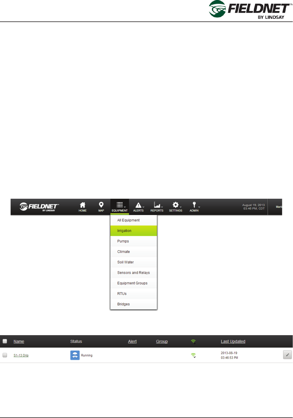
General Properties
After logging into the FieldNET portal select on the Irrigation link in the Equipment Menu at the top of the page to
display the Equipment List limited to Irrigation equipment.
Select on the Edit button of the new Multi-Control to view the General Settings page.
Alternatively, select the Properties – General link in the sidebar if viewing the Dashboard.

P/N 1608739 Rev A (ECN 32745) 1-2 Multi-Control for FieldNET Operation Manual
Section 1 – Setup
Review the current settings for any changes.
Setting the Time Zone is important and must be set local to the Multi-Control.
If the precise latitude and longitude of the Multi-Control are available, enter the appropriate decimal degrees. This
will add the Multi-Control to the FieledNET Map. The Add to Map feature on the FieldNET Map can be used to
enter the latitude and longitude if the exact location is unknown.
Press the Save button to save the settings.
Properties – System
Select the Properties – System link in the sidebar to view the System Settings. Most of the settings will have been
programmed by the Lindsay Dealer and should not be adjusted.
Guard Times are used by the system to prevent water hammer, accidental chemigation, and smooth transitions
between starting or stopping Zone irrigation.
The Water Source Guard Time is applied at the beginning of startup. The Injector and Zone Guard Times are ap-
plied at the end of the Injector and Zone runtimes. The specic component will shut off during Guard Times.
8:00 AM 9:00 AM 10:00 AM 11:00 AM
Pump / Master
Injector
Zone 1
Zone 2
Zone 3
Zone 4
Start of Plan End of Plan
Guard Time
for Zone 2
Guard Time
for Zone 1
Guard Time
for Injector
Guard Time
for Zone 3
Guard Time
for Water Source
Guard Time
for Zone 4
P/N 1608739 Rev A (ECN 32745) 1-3 Multi-Control for FieldNET Operation Manual
Section 1 – Setup
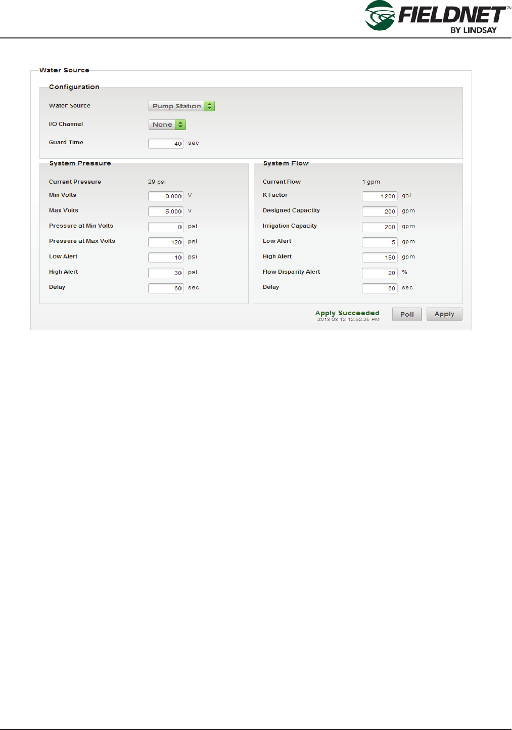
Water Source Setup
The Designed Flow Rate is the designed Water Source capacity that is available for Irrigation, Filtration, and Tem-
perature Protection. The Reserved Flow Rate for Irrigation is meant to reserve allowable capacity for Irrigation in
order to run Filtration and Temperature Protection simultaneously. When making Plan Steps, this setting is used to
calculate remaining capacity.
Flow Disparity is dened as the ± percent difference between the total actively irrigating Zone Application Rates
over the System Flow. The Zone Application Rates are dened on the Properties – Zones page.
For example, if a Plan Step had 3 Zones set to 100 gpm for a total of 300 gpm running at the same time and the
System Flow reads 200 gpm, the Flow Disparity would be equal to -33% (200 gpm / 300 gpm). This could indicate
a drip tape is plugged or a stuck valve.
Using the same example, if the System Flow reads 500 gpm, the Flow Disparity would be equal to +67% (500
gpm / 300 gpm). This could indicate a leak or a broken pipe.
Select the Poll button to request the current Water Source settings from the Controller. Select the Apply button to
save the settings and push the changes to the Multi-Control.
P/N 1608739 Rev A (ECN 32745) 1-4 Multi-Control for FieldNET Operation Manual
Section 1 – Setup
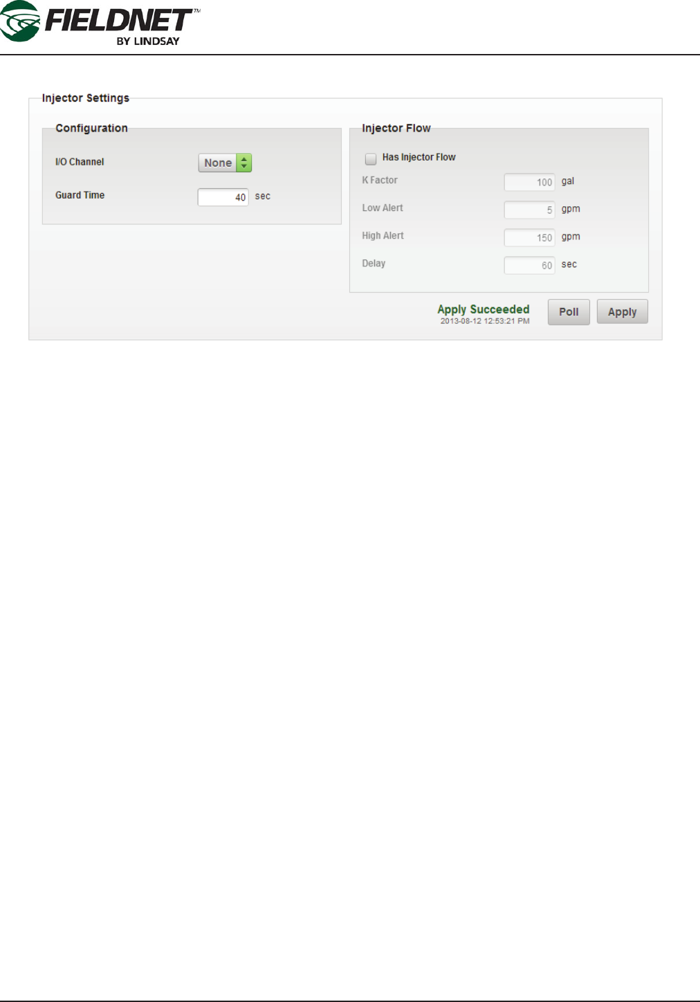
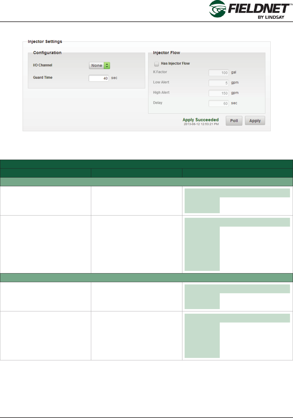
Injector Setup
Select the Poll button to request the current Injector settings from the Controller. Review the current settings for
any changes.
If an Injector is installed the I/O Channel should be set to the correct I/O Board and Channel. This is typically on
Output 2 of the System I/O Board.
If an Injector Flow Meter is installed the Has Injector Flow checkbox should be checked.
Select the Apply button to save the settings and push the changes to the Multi-Control.
P/N 1608739 Rev A (ECN 32745) 1-5 Multi-Control for FieldNET Operation Manual
Section 1 – Setup
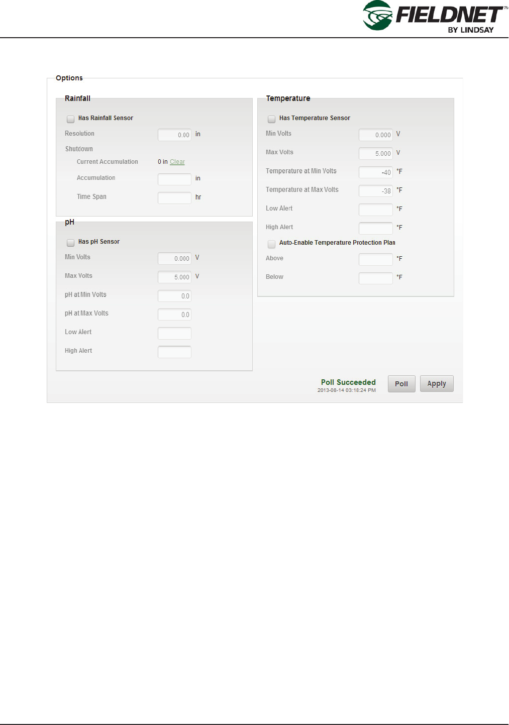
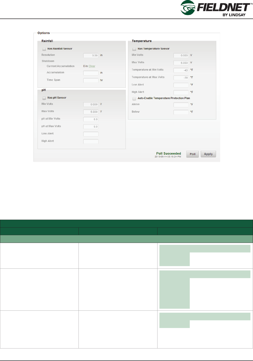
Options Setup
Select the Poll button to request the current Options settings from the Controller. Review the current settings for
any changes.
If a Rainfall Sensor is installed the Has Rainfall Sensor checkbox should be checked.
If a pH Sensor is installed the Has pH Sensor checkbox should be checked.
If a Temperature Sensor is installed the Has Temperature Sensor should be checked. The Auto-Enable Tempera-
ture Protection Plan option is available if a Temperature Sensor is installed. This will continuously run the Tem-
perature Protection Plan as long as the Above or Below criteria are met.
Select the Apply button to save the settings and push the changes to the Multi-Control.
P/N 1608739 Rev A (ECN 32745) 1-6 Multi-Control for FieldNET Operation Manual
Section 1 – Setup
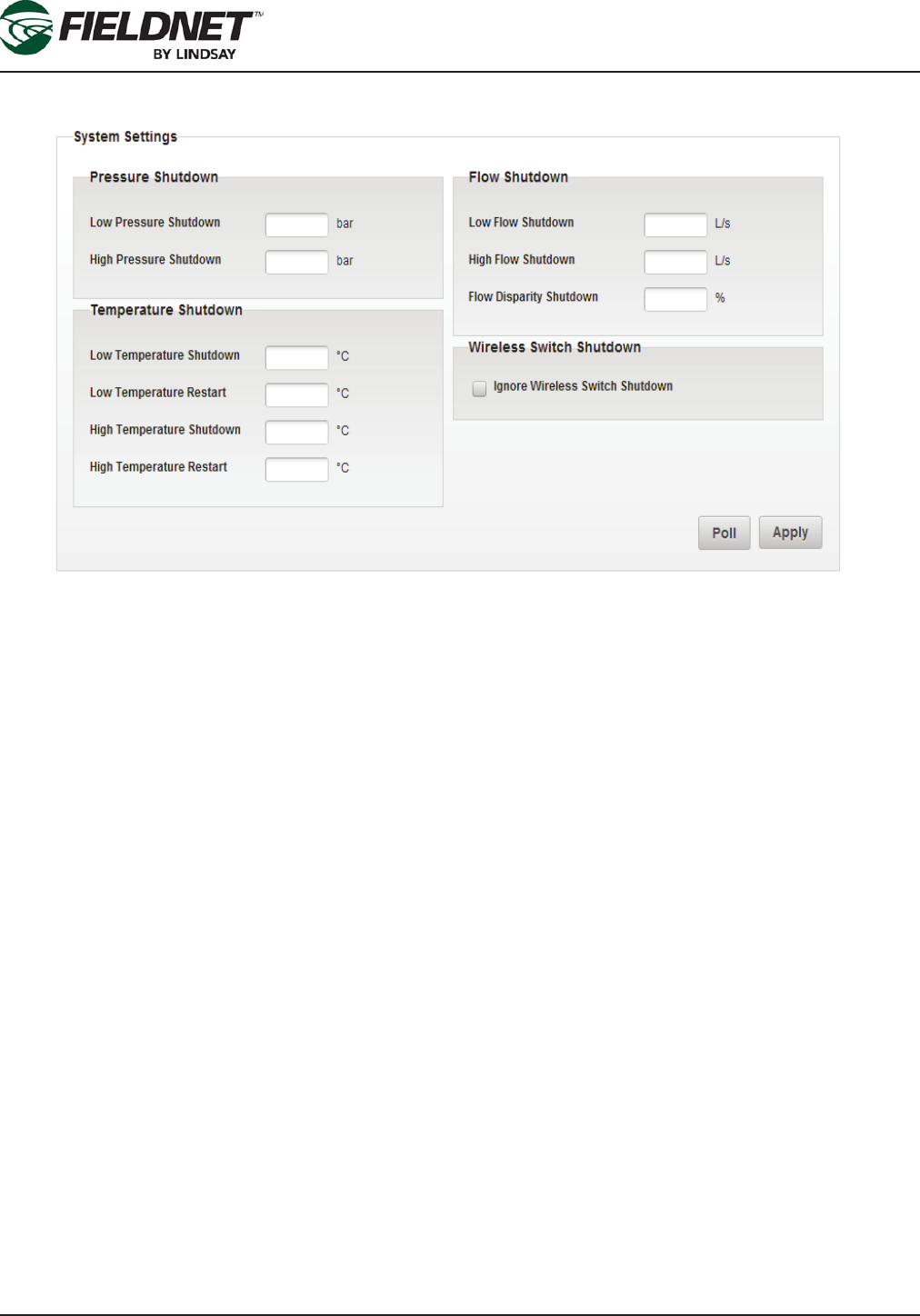
System Setup
Select the Poll button to request the current System settings from the Controller. Review the current settings for
any changes. All of the settings above are used for dening fault shutdown criteria. if implementing Temperature
Shutdown capability, a temperature sensor must be installed.
If a Wireless Switch has a Shutdowns condition, it will shutdown the entire system. In order to ignore a Wireless
Switch Shutdown and continue running the scheduled plans, check the Ignore Wireless Switch Shutdown check-
box.
NOTE: Ignoring Wireless Switch Shutdown conditions may affect chemigation applications, cause Flow Disparity
alerts, and other related side effects.
Select the Apply button to save the settings and push the changes to the Multi-Control.
P/N 1608739 Rev A (ECN 32745) 1-7 Multi-Control for FieldNET Operation Manual
Section 1 – Setup
Filtration Properties
Select the Properties – Filtration link in the sidebar to view the Filtration Settings. Most of the settings will be pro-
grammed by the Lindsay Dealer and should not be adjusted.
The number of Filter Flush Valves and the settings generate the Filter Flush Plan, which cycles through each Filter
Flush Valve chronologically and executes a back ush for the set Flush Time.
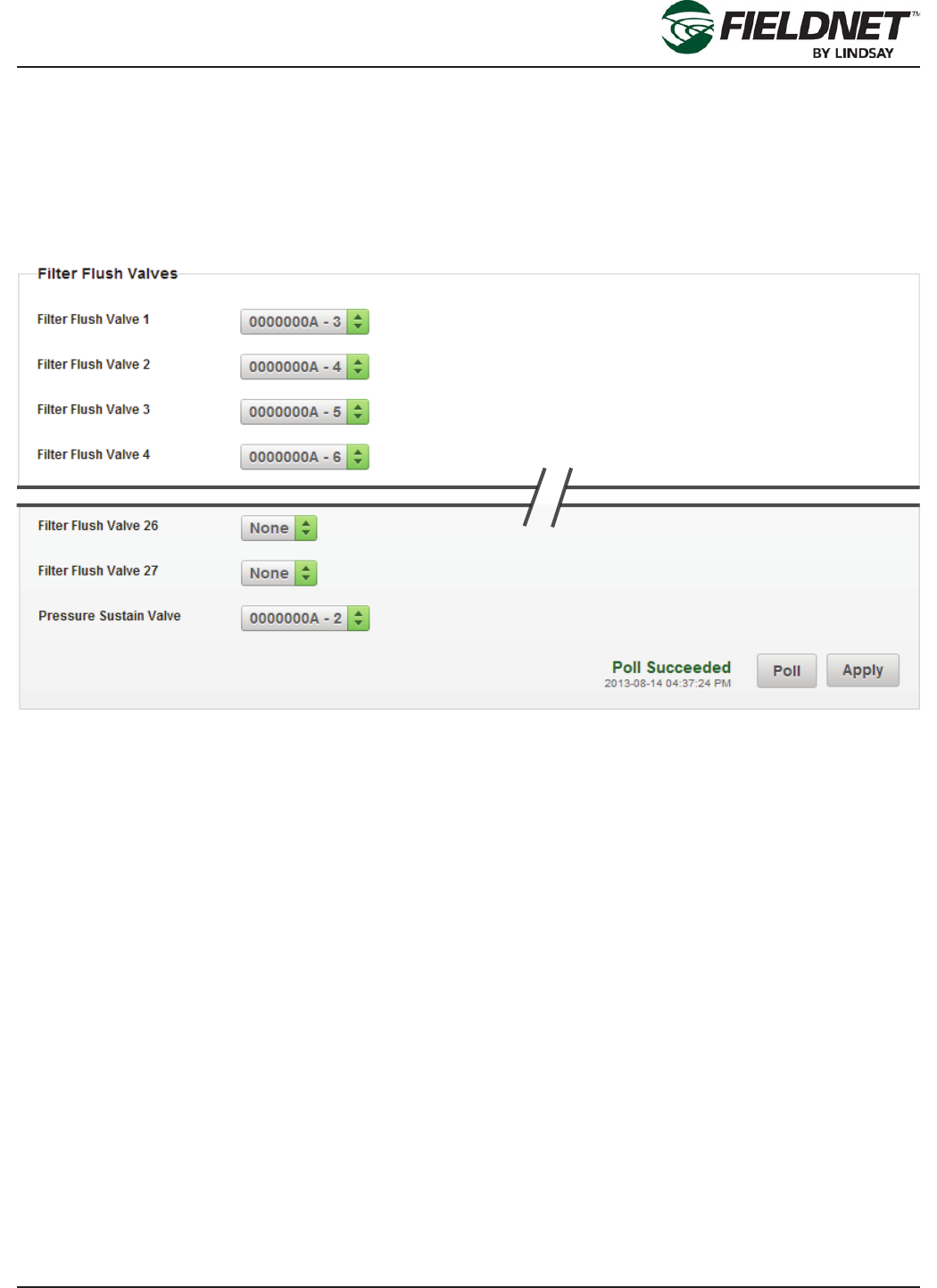
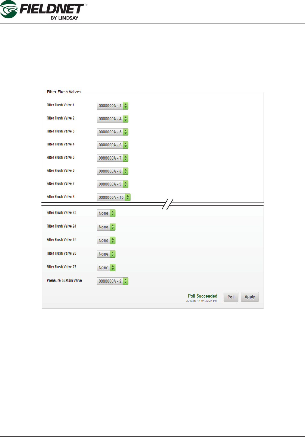
Filter Flush Valves
Select the Poll button to request the current Filter Flush Valves installed on the Controller. Review the current set-
tings for any changes.
The order of the Filter Flush Plan is determined by assigning the I/O channel to the corresponding Filter Flush
Valve. If you have 3 lters, select the I/O channel for Filter Flush Valve 1-3 and set the others to None.
Similarly, set the I/O channel for the Pressure Sustain Valve. The Pressure Sustain Valve creates back pressure
during each ush.
Press the Apply button to save the settings and push the changes to the Multi-Control.
P/N 1608739 Rev A (ECN 32745) 1-8 Multi-Control for FieldNET Operation Manual
Section 1 – Setup
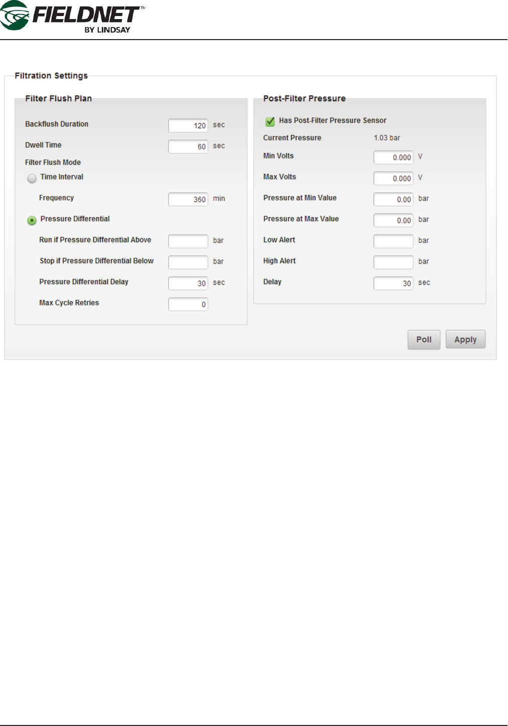
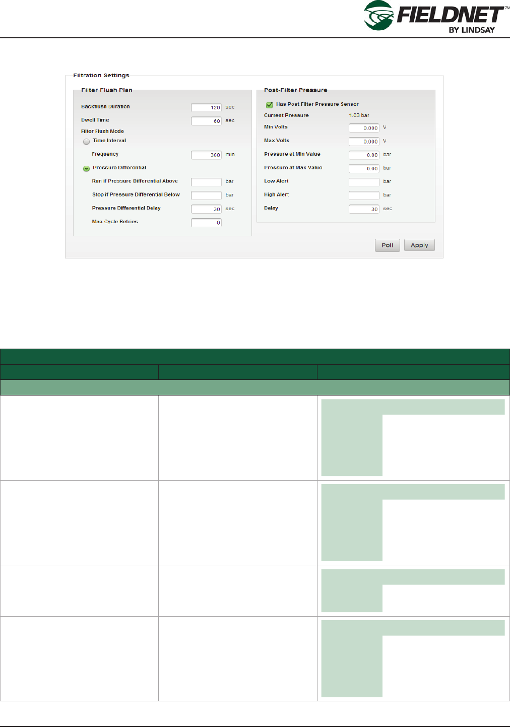
Filtration Settings
Select the Poll button to request the current Filtration Settings on the Controller. Review the current settings for
any changes.
Choose the method of determining when to execute a Filter Flush Cycle by selecting either a Time Interval or
Pressure Differential. The Pressure Differential method requires installing a Post-Filter Pressure Sensor.
Press the Apply button to save the settings and push the changes to the Multi-Control.
Valve Controller Properties
Select the Properties – Valve Controllers link in the sidebar to view the Wireless Switch Settings. This step is for
verifying the installed Wireless Switches. There are no settings to change on this screen.
P/N 1608739 Rev A (ECN 32745) 1-9 Multi-Control for FieldNET Operation Manual
Section 1 – Setup
Zone Properties
Select the Properties – Zones link in the sidebar to view the Zone Settings. Most of the settings will be pro-
grammed by the Lindsay Dealer and should not be adjusted.
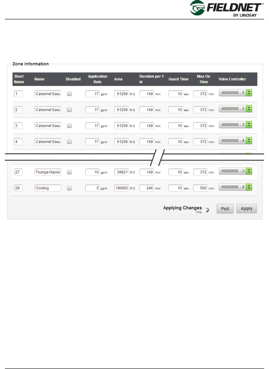
Zone Information
Select the Poll button to request the current Zone settings on the Controller. Review the current settings for any
changes.
Each Zone has a name and a short name. The short name is used for displaying a list of Zones on the FieldNET
portal and mobile application. A Zone number or an abbreviation or acronym of 3 characters or less is the best
practice for short names.
If a Zone is under maintenance and should be temporarily removed from running during a Plan, checking the Dis-
abled checkbox will disable the Zone.
The Application Rate is a requirement for calculating resource availability. The Application Rate is not the emitter
or sprinkler rate, but rather the overall ow rate expected for the entire Zone at pressure.
The Area is the area of irrigated land included in the Zone.
The Duration per 1 inch or Duration per 25 mm is the amount of time in minutes that a Zone must irrigate to apply
1 inch or 25 millimeters across the Zone area.
The Guard Time is the amount of time in seconds that a Zone valve remains open after a Plan Step to mitigate
water hammer and provide smooth transitions to the next step.
The Max On Time is the amount of time in minutes that a Zone can irrigate to mitigate washout or runoff.
P/N 1608739 Rev A (ECN 32745) 1-10 Multi-Control for FieldNET Operation Manual
Section 1 – Setup
The Valve Controller is a dropdown listing the Valves of available Wireless Switches. Select which Valve Controller
and Valve Number is assigned to the Zone.
Select the Add Zone button to add a new Zone to the end of the list. Select the Apply button to save the settings
and push the changes to the Multi-Control for distribution to the Wireless Switches.
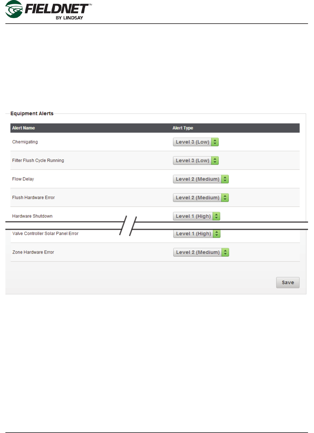
Alert Properties
Select the Properties – Alerts link in the sidebar to view the Alert Settings.
Equipment Alerts
Outside of site-specic needs, it is a best practice to use the default Alert Types.
Press the Save button to save the settings.
P/N 1608739 Rev A (ECN 32745) 1-11 Multi-Control for FieldNET Operation Manual
Section 1 – Setup
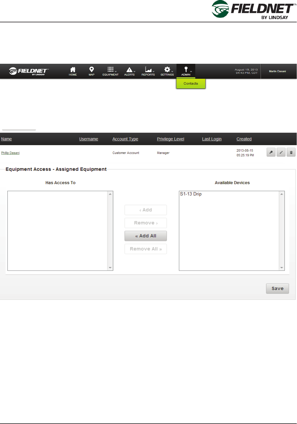
Account Contact Access Setup
Select the Contacts link in the Admin Menu at the top of the page to display the Account Contacts.
Super Users have access to all Equipment in the Account. However, Managers and Viewers must be granted ac-
cess to Equipment.
Select the name or Edit icon of the Contact needing Equipment access.
Select the Properties – Equipment Access link in the sidebar to manage Equipment Access for this Contact.
Add Equipment access by moving the desired Equipment from the Available Equipment list to the Has Access To
list. This can be done with the following methods:
• Double Right-Click on specic Equipment in the Available Equipment list.
• Select the specic Equipment in the Available Equipment list and press the Add button.
• For selecting multiple Equipment Ctrl- Right-Click on the desired Equipment.
• Select the Add All button to grant access to all Equipment.
Remove Equipment access by moving the desired Equipment from the Has Access To list to the Available Equip-
ment list. This can be done with the following methods:
• Double Right-Click on specic Equipment in the Has Access To list.
• Select the specic Equipment in the Has Access To list and press on the Remove button.
• For selecting multiple Equipment Ctrl- Right-Click on the desired Equipment.
• Press the Remove All button to revoke access to all Equipment.
Press the Save button to save the changes.
P/N 1608739 Rev A (ECN 32745) 1-12 Multi-Control for FieldNET Operation Manual
Section 1 – Setup
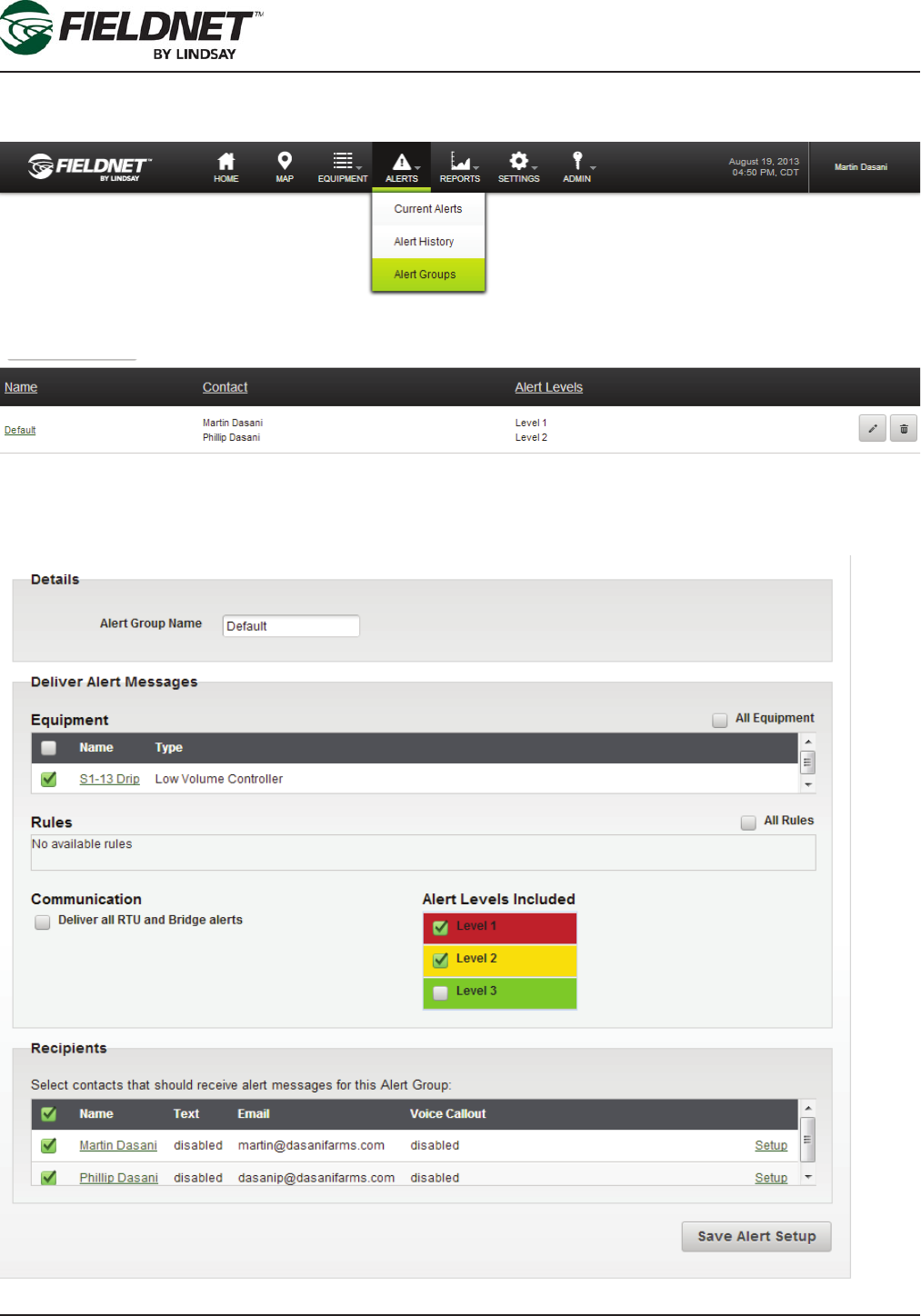
Alert Notication Setup
Select the Alert Groups link in the Alerts Menu at the top of the page to display the Alert Groups.
Setting up Alert Groups are required in order to send Alert notications.
Select the name or Edit icon of an existing Alert Group or select the Add Alert Group button and follow the step-by-
step wizard to add a new Alert Group.

P/N 1608739 Rev A (ECN 32745) 1-13 Multi-Control for FieldNET Operation Manual
Section 1 – Setup
Check each Equipment and Recipient checkbox for setting up Alert notications. Recipients must have Email or
SMS Text Messaging enabled in their prole to receive notications.
Press the Save button to save the changes.

P/N 1608739 Rev A (ECN 32745) 1-14 Multi-Control for FieldNET Operation Manual
Section 1 – Setup

P/N 1608739 Rev A (ECN 32745) 2-1 Multi-Control for FieldNET Operation Manual
Section 2– FieldNET Portal
Section 2– FieldNET Portal
General Integration
FieldNET is an integrated irrigation management platform available on the web or on Apple iOS and Google An-
droid mobile devices.
The FieldNET Portal can be accessed with any browser by visiting https://app.myeldnet.com.
This section will provide an overview of all Multi-Control related pages. Please refer to the FieldNET Operation
Manual for an overview of all other sections of the portal.
The Multi-Control is integrated into the following sections of the portal:
• Equipment List
• Equipment Groups
• Map View
• Dashboard and related pages
• Plans
• Schedule
• Logs
• Tools
• Reports
• Rules
P/N 1608739 Rev A (ECN 32745) 2-2 Multi-Control for FieldNET Operation Manual
Section 2– FieldNET Portal
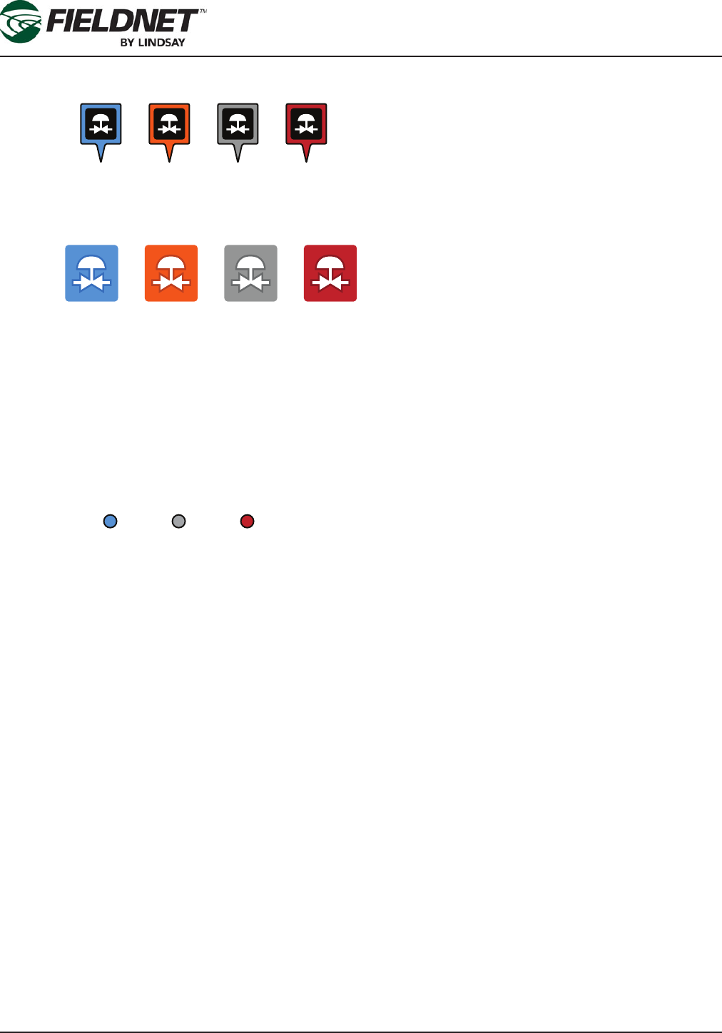
Icons
The Multi-Control map icons represent the complete Multi-Control system location.
The Multi-Control status icons represent the MC system current operation condition and can be found on dash-
boards and status columns in equipment lists.
The color codes represent the four conditions signifying proper operation or some system fault. The following
describes the color codes.
Blue: The system is in proper irrigation operation.
Orange: The sytem is in proper chemigation operations (water with chemicals).
Gray: The system has stopped or paused (typical of going into Auto-reverse cycle or Auto-Stop has activated).
Red: Alert. There is a system fault that has caused the machine to stop out of normal operation conditions. A more
detailed alert description will be displayed on the equipment list for the particular MC system.
Icons used for the Wireless Switch Valves:
Wireless Switch Valve icons represent specic valves and will display the following three states:
Blue: Proper irrigation operation.
Red: Alert. There is a fault with the valve or its wireless communication and it has stopped. A more detailed de-
scription of this alert will be displayed in the Zone tab of the equipment Quick Tray (later in this section).
Gray: Valve is fully operational but has momentarily paused or stopped as commanded in the settings.
P/N 1608739 Rev A (ECN 32745) 2-3 Multi-Control for FieldNET Operation Manual
Section 2– FieldNET Portal
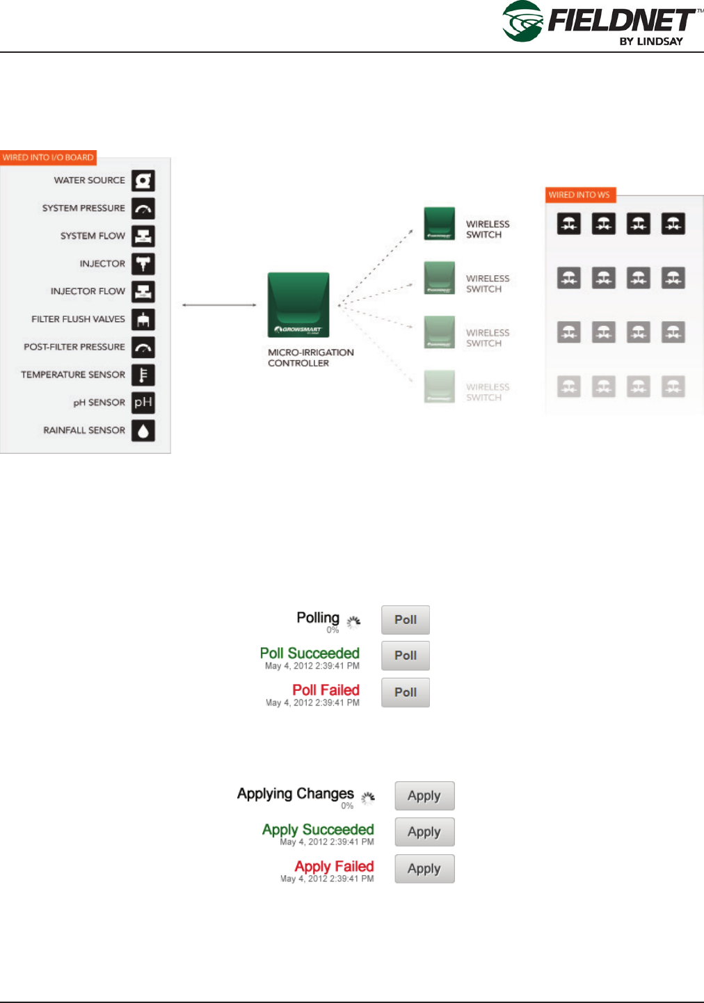
Action Feedback
Actions taken throughout FieldNET, such as a Poll or Apply commands, will provide feedback for acknowledging
a request and displaying this progress. In most cases the acknowledgement and action is completed within 30
seconds. However, the Multi-Control uses a “sleeping network” where communication to the Wireless Switches
are not real-time, but communicated upon a set interval.
Due to this method of communication, FieldNET provides feedback for the Multi-Control receiving the request as
well as feedback for distribution to Wireless Switches.
NOTE: Actions for a Multi-Control are not necessarily applied immediately in eld and may take longer than 5
minutes depending upon the number of hops and intervals.
Polling
Polling the Multi-Control provides the following standard Polling feedback next to the Poll button:
Applying
Applying settings to the Multi-Control provides the following standard Applying feedback next to the Apply button:
P/N 1608739 Rev A (ECN 32745) 2-4 Multi-Control for FieldNET Operation Manual
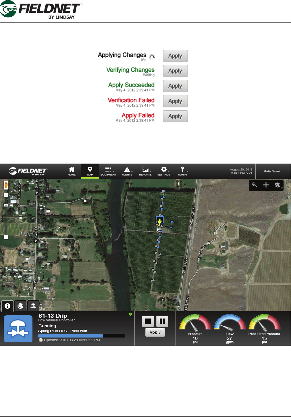
Section 2– FieldNET Portal
Updating Apply settings to the Wireless Switches will display additional feedback. “Verifying Changes” will display
before an “Application Succeeded” feedback and “Verication Failed” will display will display on a verication fail-
ure without attempting application.
Map
The Map is a satellite image with an Equipment Overlay displaying icon markers. Zoom, pan and search function-
ality make for easier navigation.
If a Multi-Control has been added to the Map, a marker is displayed using the latitude and longitude provided in
the Map Tab of the system’s Quick Tray. Generic location markers are displayed until zoomed in when Equipment
markers will be displayed.
Zone markers will be displayed upon selecting the Multi-Control marker.
P/N 1608739 Rev A (ECN 32745) 2-5 Multi-Control for FieldNET Operation Manual
Section 2– FieldNET Portal
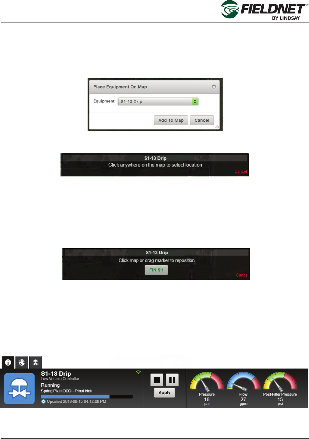
Add To Map
Use the Add To Map Wizard to add equipment to the Map View.
Select the “+” icon in the Map Toolbar to add Equipment to the Map.
In to following dialog box, select the equipment to place on the Map from the Equipment dropdown menu. The
dropdown will only list equipment not already placed on the Map.
Press the Add To Map button to begin the Add To Map Wizard and follow the instructions provided at the top of the
screen.
Select a location on the map. A marker will display, showing the placed equipment. This can be repositioned by
selecting on the map or selecting and dragging the marker across the map.
Selecting Cancel will exit the Add To Map Wizard and will not place the equipment on the map or save any chang-
es.
Upon pressing the Finish button, the Add To Map Wizard will close and the position marker is replaced with the
Multi-Control marker. Additionally, the Multi-Control is made active and opens the Quick Tray.
The Add Zone To Map process is explained in the following Quick Tray section.
Quick Tray
The Quick Tray is displayed when selecting an equipment marker on the map. A yellow arrow will appear on top of
the marker selected.
Information Tab:
The Quick Tray Information Tab displays operational information relating to the selected equipment.
The Information Tab for the Multi-Control displays the current status of the Multi-Control, a link to the Dashboard,
controls, and primary sensor information.
P/N 1608739 Rev A (ECN 32745) 2-6 Multi-Control for FieldNET Operation Manual
Section 2– FieldNET Portal
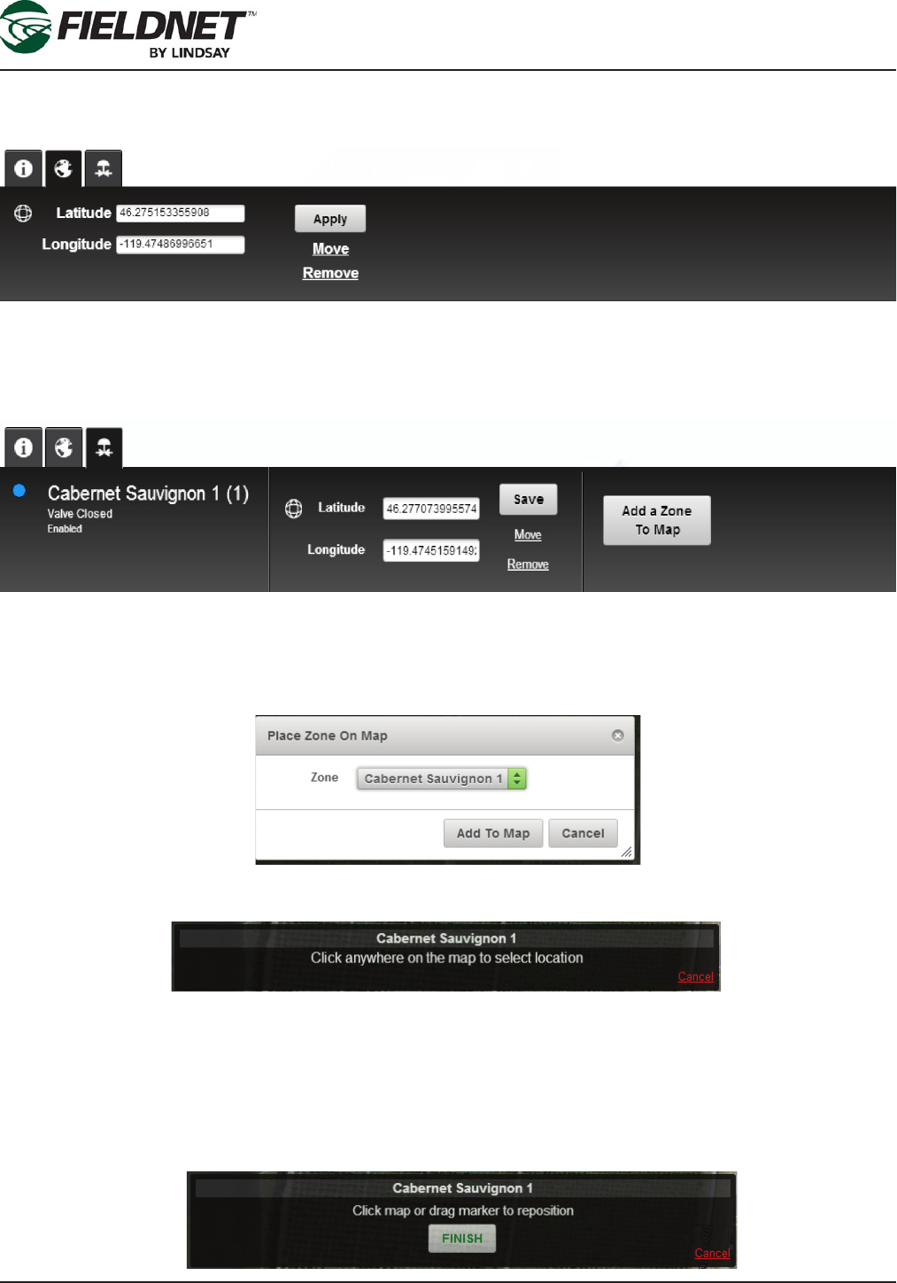
Map Tab:
The Map Tab for the Multi-Control displays the geographic location information with the ability to save changes,
remove the Multi-Control from the map, or move the location using the Add To Map Wizard.
Zone Tab:
The Zone Tab is specic to the Multi-Control and displays the current status and basic information of an irriga-
tion zone with the ability to save changes to the geographic location, remove the Zone from the map, or move the
Zone using the Add Zone to Map Wizard.
Zone To Map Wizard
Select the Add a Zone To Map button to add a Zone to the Map.
Select the Zone to place on the Map from the Zone dropdown menu list. The dropdown only displays Zones avail-
able to the Multi-Control and not currently placed on the map.
Press the Add to Map button to begin the Add Zone To Map Wizard and follow the instructions provided at the top
of the screen.
Select a location on the map. A marker will be displayed, showing the Zone, which can be repositioned by select-
ing on the map or selecting and dragging the marker.
Pressing Cancel will exit the Add Zone To Map Wizard and not place the Zone on the Map or save changes.
Select the Finish button to close the Add Zone To Map Wizard and replace the position marker with the a Zone
marker. Additionally, the Zone is made active and refreshes the Quick Tray Zone Tab.

P/N 1608739 Rev A (ECN 32745) 2-7 Multi-Control for FieldNET Operation Manual
Section 2– FieldNET Portal
Where to Locate Multi-Control Systems
Refer to the FieldNET User’s Manual (P/N 1600502) for details on navigating and editing within the following
categories discussed here.
Multi-Control information can be located within several categories in the Equipment Pulldown menu.
• They can be listed individually under the Irrigation category.
• They can be part of an Equipment Group.
• Communication status and information for the Multi-Control can be found under the RTU and Bridge catego-
ries.
P/N 1608739 Rev A (ECN 32745) 2-8 Multi-Control for FieldNET Operation Manual
Section 2– FieldNET Portal
Multi-Control on FieldNET
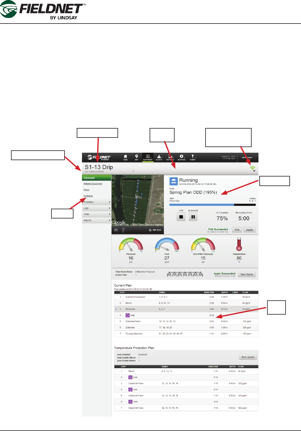
The initial interface for the Multi-Control on FieldNET is the Equipment page. This page is broken down into differ-
ent sections of information and each is explained in further detail following this overview.
The Equipment Page Consists of the following:
• Title Bar: The name of the system is listed here along with the system RTU status at the right-end of the bar
and all individual pieces of equipment within this system build (pivots, pumps, VRI, Multi-Control, etc.) are listed
within the pulldown menu found under the system name.
• Sidebar: The sidebar provides additional information and edit functions for the equipment currently displayed.
• Dashboard: The main interface for the equipment. A thumbnail of the equipment on the map, settings, condi-
tions and any customized data is displayed on the dashboard for quick reference of the equipment.
• Plans: Displays the current plan uploaded to FieldNET or in operation.
Title Bar
System Name
Specic Equipment
Dashboard
Communication
Status
Sidebar
Plans
P/N 1608739 Rev A (ECN 32745) 2-9 Multi-Control for FieldNET Operation Manual
Section 2– FieldNET Portal
Title Bar
The Title bar displays the system name. Systems typically consist of one or more pieces of equipment installed in
the eld (e.g. Pivots, Laterals, VRI, Pumps, Chemical Injection and Multi-Control to name a few).
If there are multiple pieces of equipment on a system, the system name here will be nothing more than a refer-
ence. The actual equipment dashboards will display when the equipment name is selected from the pulldown
menu located under the system name.
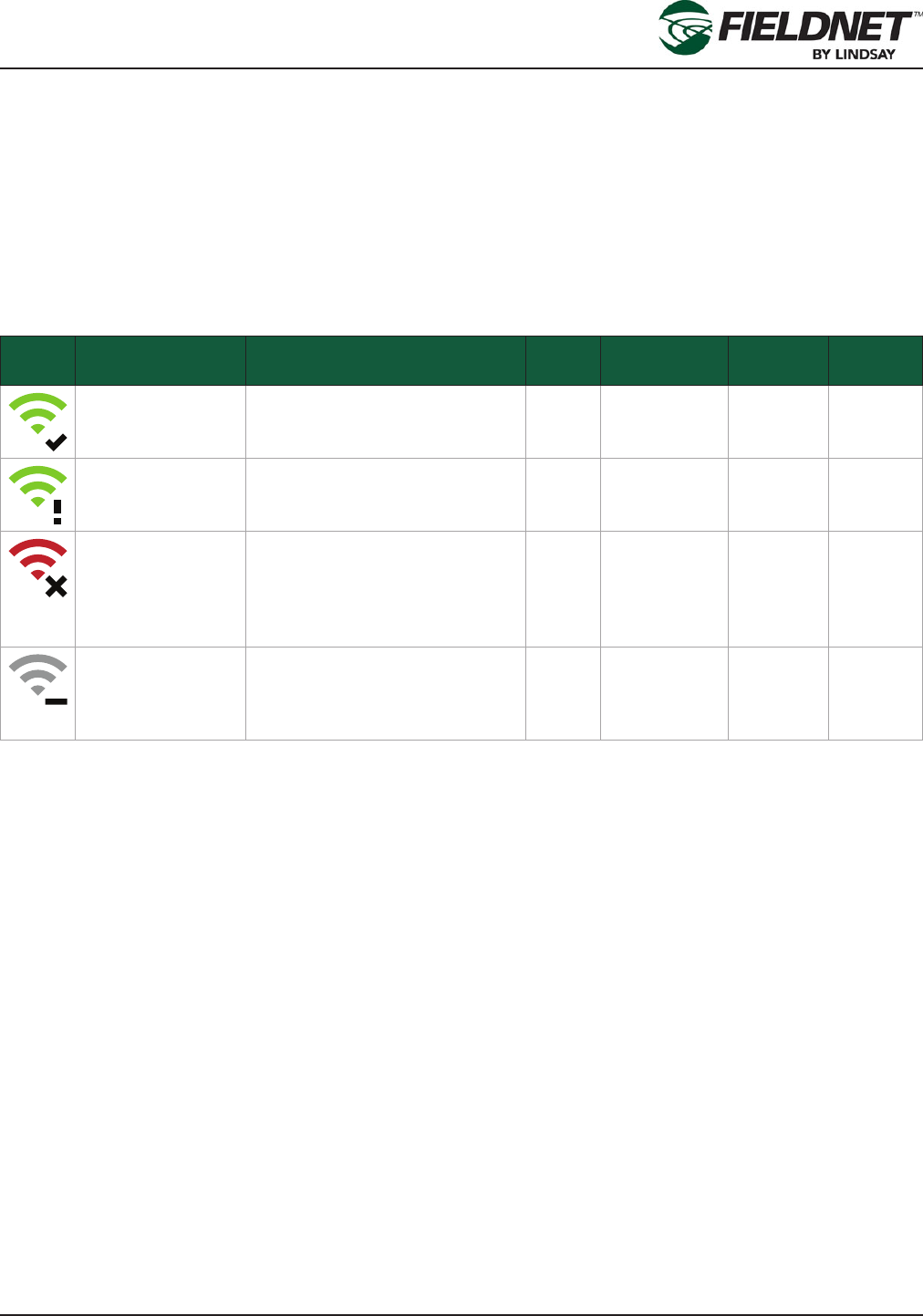
At the right-end of the Title bar is a small Communication Status Icon.
Selecting the communication status icon will display the assigned RTU dashboard. The communication status icon
has the following states:
Icon Tooltip Description Online Subscription
Status
Last Re-
quest
Powered
Off
RTU is Online The RTU is online without any
recent issues.
Yes Active successful N/A
RTU is Online with
recent issues
The RTU is online, but the last
request failed.
Yes Active failed N/A
RTU is Unexpect-
edly Ofine
The RTU is unexpectedly ofine
as it has an active subscription
but is not connected. This is not
applicable for Spectrum Station
RTU setups.
No Active N/A No
RTU is Ofine or
does not have an
active subscription
The RTU is ofine due to not
having an active subscription or
the RTU has sent a powered off
packet
No Expired or Off
Season
N/A Yes
NOTE: A failed request is dened as FieldNET attempting 10 consecutive times to communicate a request (Poll,
Apply, etc.) without an acknowledgement from the RTU assuming the RTU is online and has a subscription.
P/N 1608739 Rev A (ECN 32745) 2-10 Multi-Control for FieldNET Operation Manual
Section 2– FieldNET Portal
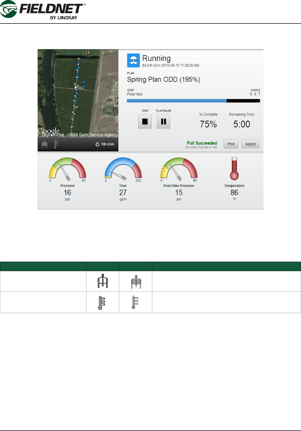
Dashboard
The Dashboard is the main interface for monitoring and controlling the Multi-Control settings.
Map
The map is automatically zoomed into the MC location and shows the status of zones. Located to the bottom left
corner of the Map View are notication icons for active Filter Flush and Temperature Protection. When inactive, the
icons will be transparent and when active, the icons will highlight.
Notication Active Inactive Criteria
Filter Flush Status Active whenever Filter Flush is running (Automatic or
Manual)
Temperature Protection Status Active whenever Temperature Protection Plan is run-
ning (Automatic or Manual)
The run time of the current irrigation plan is displayed below the map to the right.
Status
The status icon and description for Multi-Control are displayed next to the map. The duration and timestamp indi-
cate how long the Multi-Control has been in the current state and when it started.
The current irrigation plan, plan step, and active zones are displayed above the plan progress bar. Percent Com-
plete and Remaining Time are estimated based on the time elapsed since starting the current plan step and the
remaining steps.

P/N 1608739 Rev A (ECN 32745) 2-11 Multi-Control for FieldNET Operation Manual
Section 2– FieldNET Portal
Plan actions include Stop, Pause, and Run:
Action Running Stopped
/ Paused
Upon Selecting
Run/Pause Button This button will be highlighted and will require Apply in order to Start
or Pause the Plan
Stop Button This button will be highlighted and will require Apply in order to Stop
the Plan
Stopping the plan puts the Multi-Control into “Off” mode, which does the following:
• Stop Pump Station / Main Valve
• Stop Chemical Injector
• Stops current Plan
• Stops Filter Flush
• Stops Temperature Protection Plan
• Closes all Zone valves
Upon stopping the plan, the Pause button will change to a Run button.
The Multi-Control is in “Auto” mode when the plan is running or paused. Pausing the plan will suspend plan prog-
ress. Upon restarting the plan will continue where it left off.
Whenever running a plan after a plan has been stopped, the Multi-Control will go into “Auto” mode and the irriga-
tion plan will skip to the scheduled plan step based on the time of day.
Pressing the Poll button will request Multi-Control status information. Pressing the Apply button will send changes
to the Multi-Control. Feedback for these actions is provided next to the buttons. The status information refreshes
upon success.
P/N 1608739 Rev A (ECN 32745) 2-12 Multi-Control for FieldNET Operation Manual
Section 2– FieldNET Portal
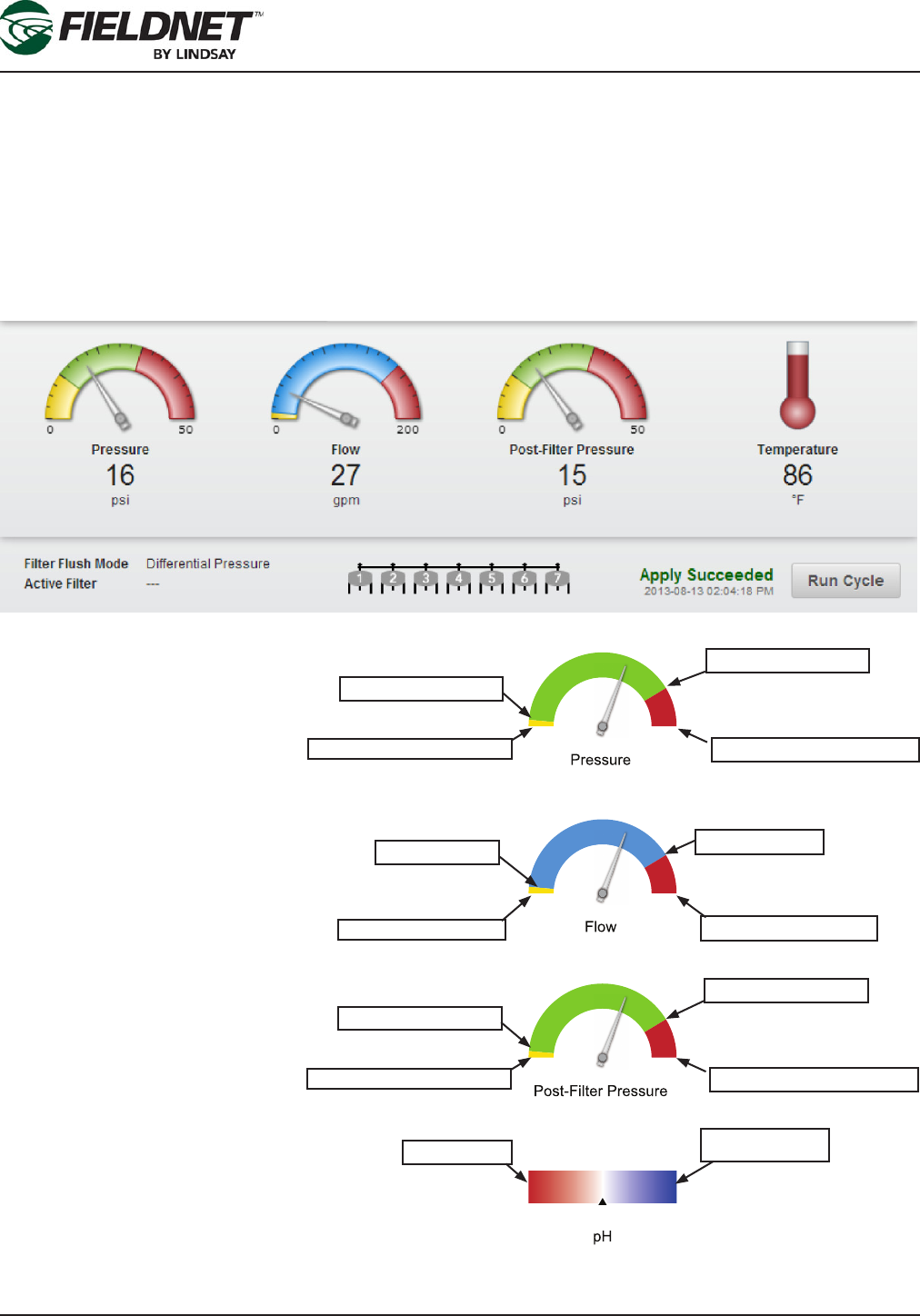
Sensors and Filtration
Sensors provide a clear user interface for monitoring system ow, pressure, temperature, rainfall amounts and pH
balance.
The Multi-Control has the following sensors available:
• System Flow
• System Pressure
• Post-Filter Pressure (optional)
• Temperature (optional)
• pH (optional)
• Rainfall (optional)
The diagram to the right shows a ref-
erence shutdown and alert locations
on the sensor dial indicators in order
to understand the purpose of alerts
and shutdowns.
The System Pressure, Flow Rate,
Post-Filter Pressure and pH Balance
sensors provide warning zones on
their UI dial indicators when displayed
on the dashboard.
The low and high shutdown settings
are typically zero and the sensor’s
maximum range respectively. When
the system reaches shutdown, the
system will go into either a low or high
pressure/ow fault and shutdown.
The alerts “points” are established to
submit warnings to the operator that
the system is nearing a shutdown
condition and should inspect the sys-
tem for problems.
The alerts are set up in the Water
Source page of the System Proper-
ties menu. When established, the dial
indicators on the dashboard will show
these alert ranges in yellow or red elds.
0
100
0
100
0
100
Low Pressure Alert
Low Pressure Shutdown
High Pressure Alert
High Pressure Shutdown
Low Flow Shutdown
Low Flow Alert High Flow Alert
High Flow Shutdown
Low Pressure Alert
Low Pressure Shutdown
High Pressure Alert
High Pressure Shutdown
Zero (Acidic) 14 (High Base)

P/N 1608739 Rev A (ECN 32745) 2-13 Multi-Control for FieldNET Operation Manual
Section 2– FieldNET Portal
If the Multi-Control has a ltration system installed and set up (through Properties – Filtration) the Dashboard will
display information about Filter Flush cycles.
The Filter Flush Mode can be either a Time Interval or Pressure Differential. A Multi-Control can have up to 27
Filters with 1 Sustaining Pressure Valve.
Basic ltration settings are displayed on the left of the ltration section of the dashboard (see diagram on previous
page). If ltration is set up to use a Time Interval, the information includes the Mode and Active Filter. If ltration is
set up to use Pressure Differential, the information includes the Mode, Active Filter, and Active Filter Retries.
A graphical representation of the ltration system displays completed and active lters in blue for the current ush
cycle. All lters turn gray upon completed cycle.
Select the Run Cycle button to manually initiate a Filter Flush Cycle. Feedback is provided in the space next to the
button.
P/N 1608739 Rev A (ECN 32745) 2-14 Multi-Control for FieldNET Operation Manual
Section 2– FieldNET Portal
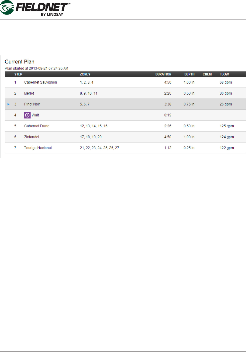
PLANS
Current Plan
If the Multi-Control is in “Auto” mode and a Plan is scheduled the Dashboard will display the current plan start time
and a table of Plan Steps and the respective Zones, duration, depth, chemigation (if applicable), and ow.
The running Plan Step will be highlighted and will display an icon indicating point-in-time progress of the plan. If
the plan is paused the pause icon is displayed.

P/N 1608739 Rev A (ECN 32745) 2-15 Multi-Control for FieldNET Operation Manual
Section 2– FieldNET Portal
Temperature Protection Plan
If the Temperature Protection Plan has been set up, the Dashboard will display the Temperature Protection Plan
(similar to the Current Plan table).
The Temperature Protection Plan (TPP) is a special overlay Plan that runs at the same time as an Irrigation Plan.
The plan can be automatically enabled when a Temperature Sensor is installed and will show set point tempera-
tures for activation of the TPP.
The Multi-Control will run the TPP an entire cycle when the trigger is met and keep running until TPP completes its
cycle, which will then stop the TPP. If the temperature reading is still above the TPP reset level, the Multi-Control
will repeat another cycle. The TPP cycle is not constrained to the day it started and can continue into the next day
if a cycle is not complete.
The Temperature Protection Plan can be manually executed for one cycle by clicking on the Run Cycle button.
P/N 1608739 Rev A (ECN 32745) 2-16 Multi-Control for FieldNET Operation Manual
Section 2– FieldNET Portal
Sidebar
The Sidebar menu offers additional information and editing of equipment settings. The Dashboard was explained
previously and is included as a selection on the sidebar, the other options are explained further.
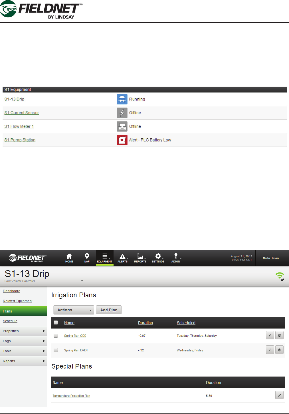
Related Equipment
The Related Equipment page displays the Equipment Groups which include the Multi-Control. The list includes a
equipment name linked to each piece of equipment’s respective dashboard, equipment icon, and operating status.
To add related equipment for the Multi-Control, add or edit an Equipment Group by selecting on Equipment –
Equipment Group and include the Multi-Control to the group.
Plans
Plans are a series of irrigation steps, which allow for simultaneously opening (and closing) of multiple Valve Zones
for a set duration of time. This provides more precise irrigation control and balance between excessive run-off or
insufcient watering amounts.
Plans are sent to the Multi-Control using the Schedule page.
Plan List
The Plan List displays all saved Irrigation Plans as well as Special Plans for a given irrigation system
.
P/N 1608739 Rev A (ECN 32745) 2-17 Multi-Control for FieldNET Operation Manual
Section 2– FieldNET Portal
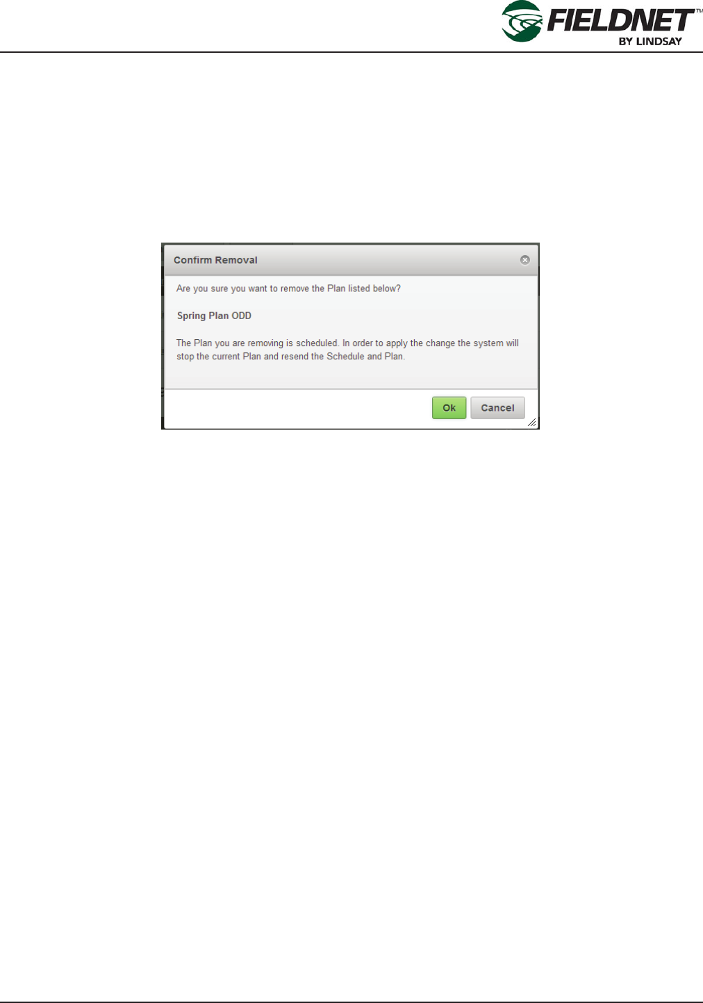
All Plans can be edited by selecting on their name or respective edit button to the right end of the row. Selecting
the remove button (next to the edit button) will remove the respective Irrigation Plan. Multiple Irrigation Plans can
be selected for mass removal by selecting the check-box, next to the name, and selecting Remove Plans from the
Actions drop-down menu.
Special Plans are unable to be removed.
Saving or removing scheduled Irrigation Plans or saving Special Plans requires updating the schedule and send-
ing the plans and schedule to the Multi-Control. Removed Irrigation Plans with schedules will have their schedules
cleared as well. The following dialog will show upon removing an Irrigation Plan:
Saving or removing Irrigation Plans that are not scheduled provides feedback that the Plan was saved or removed.
P/N 1608739 Rev A (ECN 32745) 2-18 Multi-Control for FieldNET Operation Manual
Section 2– FieldNET Portal
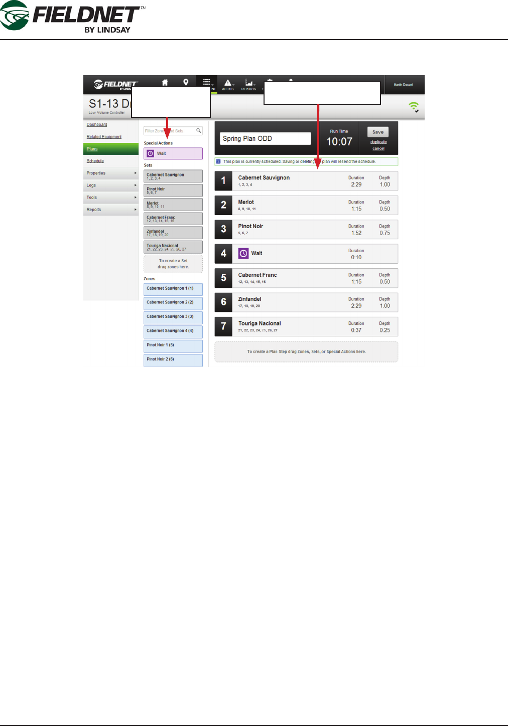
Edit Plan
The Edit Plan page is used for creating new or managing saved Irrigation and Special Plans.
The Edit Plan page is split into two major sections: 1) Zones, Sets, and Special Actions and 2) Plan Overview and
Steps.
Zones are the named drip elds assigned to a Wireless Switch valve, which are managed through the Properties –
Zones page. Zones which have been disabled will be grayed out be can be added to Sets and Plan Step for future
use. Disabled Zones in the Plan will not run but they are used for calculating Duration Depth, Capacity Remaining
and Validation of the duration.
Sets allow for grouping Zones commonly irrigated at the same time, but do not include any Plan Step information
such as irrigation duration. Sets are shared among all Plans and can be a Plan Step. However, making changes to
a Set will not update Plans with a Plan Step based on the Set with the changes.
Wait is the only Special Action and allows for temporarily stopping the water and injector for a period of time. It is
primarily intended for providing time in the eld for manual operations such as changing the chemical tank.
The Zones, Sets, and Special Actions are searchable by case-insensitive name. Phrases separated by spaces will
provide results which match all phrases.
The search results will show the Special Actions, Sets, and Zones sections with matching results for each. “No
Results” is displayed if no results are found.
Similar to the Map View, an “x” on the far right side of the search eld is used to clear the search and reset the
search eld.
Zones, Sets and
Special Actions
Steps and Plan Overview
P/N 1608739 Rev A (ECN 32745) 2-19 Multi-Control for FieldNET Operation Manual
Section 2– FieldNET Portal
Zones, Sets, and Special Actions are all drag-and-drop items on the FieldNET interface. They can be dragged to
any of the following locations on the page:
• Create New Set Area: Located below existing Sets.
• Existing Set
• Create New Plan Step Area: Located below existing Plan Steps.
• Existing Plan Step
Selecting and dragging a Zone, Set, or Special Action and dropping it onto a target will take the appropriate action.
Allowed actions are:
Create Set Add To Set Create
Plan Step
Add To Existing
Plan Step
Special Actions
Sets
Zones
For example, adding a Special Action, such as Wait, to a Plan Step is not allowed. It is a Plan Step by itself and
cannot be part of an existing Plan Step.
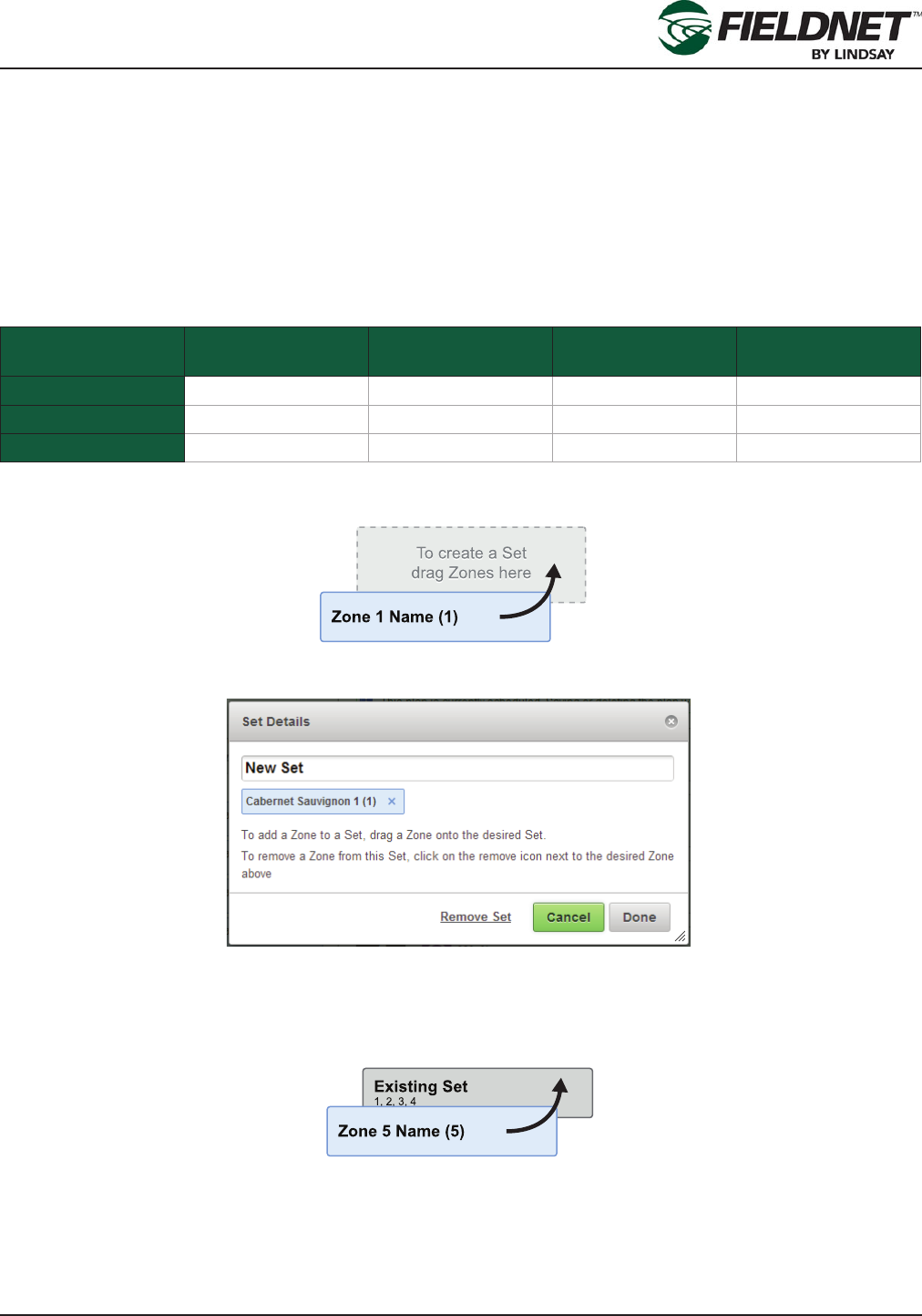
Select and drag a Zone onto the “To create a Set drag Zone here” target to create a new Set starting with the
selected Zone.
Upon adding a Zone to a Set or double-clicking a Set, the Set Details dialog will display, allowing changes to the
name of the Set and remove Zones. Select the Remove Set link to permanently remove the Set. Press the Can-
cel button to ignore any changes and close the dialog. Press the Done button to save changes to the Set.
Add more Zones by dragging other Zones onto an existing Set.
P/N 1608739 Rev A (ECN 32745) 2-20 Multi-Control for FieldNET Operation Manual
Section 2– FieldNET Portal
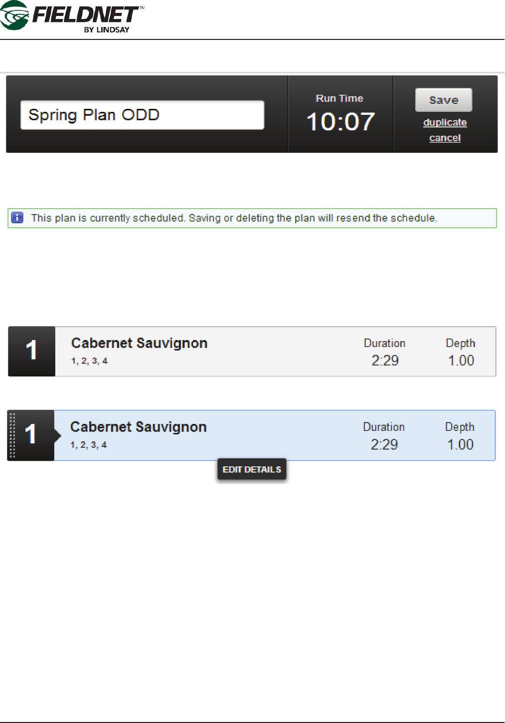
The Plan Overview displays the Plan name, Run Time, and actions. Select the Plan name to change the name of
the Plan.
The Run Time is calculated upon making changes to Plan Steps. Select the duplicate link to clone this Plan as a
new Plan. Press the Cancel link to ignore any changes and return to the Plan List. Press the Save button to save
changes to the Plan and Plan Steps.
If the Plan is currently schedule, a notice will be displayed below the Plan Overview to inform the need to resend
the Plan and Schedule upon saving changes.
Plan Steps are displayed below the Plan Overview and have a collapsed and expanded view. The collapsed view
is for reviewing and sorting Plan Steps. The expanded view is for editing a Plan Step.
Collapsed Plan Step:
P/N 1608739 Rev A (ECN 32745) 2-21 Multi-Control for FieldNET Operation Manual
Section 2– FieldNET Portal
Selected Collapsed Plan Step:
Expanded Plan Step:
Expand a Plan Step by selecting a collapsed Plan Step and select the Edit Details button. To reorder the Plan
Steps, select the collapsed Plan Step and drag it to the new position and release it. Affected Plan Step numbers
will update to reect the new order.
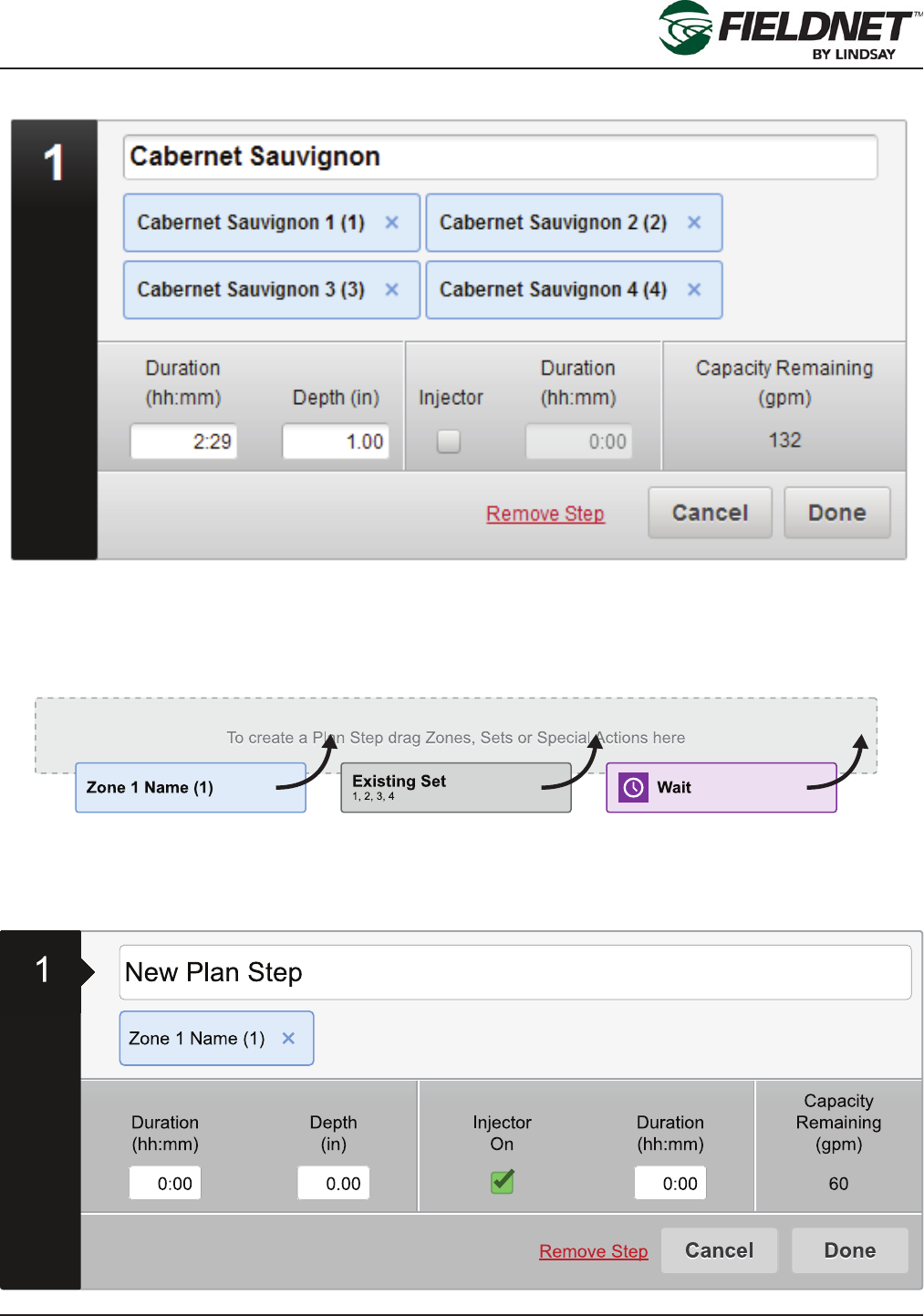
Select and drag a Zone, Set, or Special Action onto the “To create a Plan Step drag Zones, Sets or Special Ac-
tions here” target to create a new Plan Step with the selected item.
P/N 1608739 Rev A (ECN 32745) 2-22 Multi-Control for FieldNET Operation Manual
Section 2– FieldNET Portal
Upon adding a Zone, Set or Special Action to a Plan Step or expanding a Plan Step, the step details are dis-
played. Select the Plan Step name to change the name of the Plan Step.
Add more Zones by dragging other Zones onto the Plan Set. Press the “x” icon of a Zone to remove it from the
Plan Step.
Zone settings are used for calculating Duration Depth, Capacity Remaining and validation of the duration. It is
important to have these settings as accurate as possible for plan building and reporting purposes.
Application Duration and Depth affect each other. Entering the Duration will calculate the Depth. Entering the
Depth will calculate the Duration. This calculation is based on the “Duration to Apply 1 in” or “Duration to Apply 25
mm” settings of the Zones included in the Plan Step. This setting is also known as Duration Conversion Factor.
If the setting is not available for the included Zones the Depth will not be calculated nor will Depth be able to be
entered.
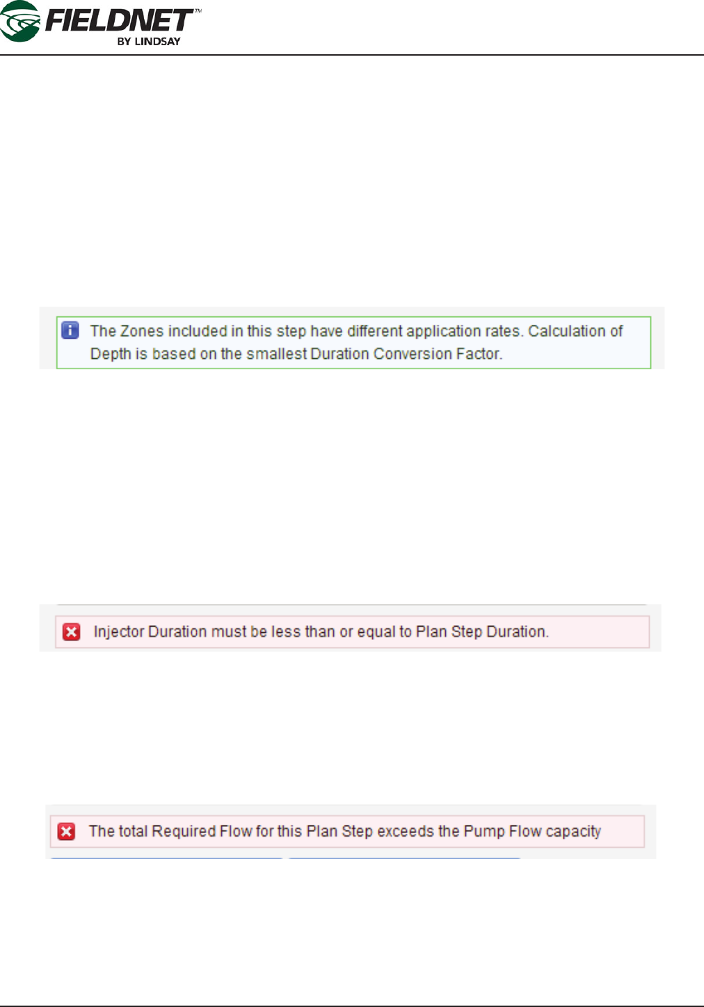
While it is allowable to have Zones in the Plan Step with different Duration Conversion Factors, it is advised to only
irrigate Zones with the same setting at the same time. A notice display, explaining that Depth will be calculated
based on the Zone with the smallest Duration Conversion Factor. This means when entering the Duration value,
some of the Zones will apply less than the Depth displayed. Regardless of the setting, all Zones in the Plan Step
will irrigate for the same Duration.
If the Plan Step requires chemigation, select the Injector On checkbox to enable entering the Injector Duration.
The Injector Duration must be greater than zero, if enabled, and can be shorter; but not greater than the Plan Step
Duration.
If the Injector Duration is greater than the Plan Step Duration, pressing Done will display an error requiring chang-
ing the Injector Duration.
The Capacity Remaining is calculated based on the included Zone “Application Rate” settings and the “Reserved
Flow Rate for Irrigation” System Water Source setting.
If the sum of the Zone Application Rates is greater than the Reserved Flow Rate for Irrigation, the Capacity Re-
maining will be negative and turn to the color red. If not addressed, selecting Done will display an error requiring
removing Zones until the Capacity Remaining is greater than or equal to zero.
Select the Remove Step link to permanently remove the Plan Step. Press the Cancel button to ignore any chang-
es and collapse the Plan Step. Press the Done button to collapse the Plan Step.

P/N 1608739 Rev A (ECN 32745) 2-23 Multi-Control for FieldNET Operation Manual
Section 2– FieldNET Portal
Add more Zones to a Plan Step by selecting and dragging other Zones onto an existing Plan Set. Zones can be
added to a collapsed or expanded Plan Step.
Upon pressing the Done button the Plan Run Time will be updated in the Plan Overview.
Changes to Plan Steps are not saved until pressing the Save button in the Plan Overview.
P/N 1608739 Rev A (ECN 32745) 2-24 Multi-Control for FieldNET Operation Manual
Section 2– FieldNET Portal
Schedule
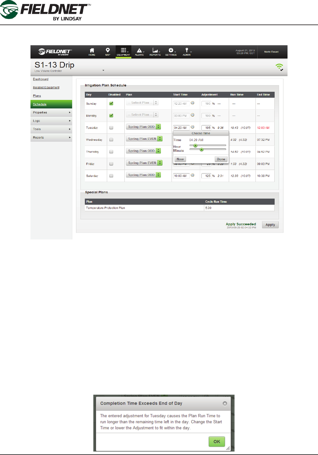
The Schedule displays a table of scheduled Plans for the Multi-Control.
The Irrigation Plans interface is based on days of the week for scheduling different plans each day. The disable
checkbox, when checked, prevents any plan use or editing for the selected day.
Schedule a Plan for a day of the week by selecting the desired Plan from the Plan dropdown menu,
Enter the start time: Type in the hours an minutes into the Start Time eld on the Plan Schedule screen or select
the clock icon and the “Choose Time” dialog box will appear. Use the sliders on the “Choose Time” menu to set
the hours and minutes for the start time on a given day or select Now to default to the current time on the system
clock. Select Done when nished setting the start time.
Changes in weather patterns, crop maturity, or other factors can require the need of adjusting the scheduled Run
Time. By default, a Plan will run at 100% of the Run Time and can be adjusted from 0% to 250%. Upon chang-
ing the Adjustment Percentage, the time difference will display next to the Adjustment Percentage as a positive or
negative variable. The Run Time displays the new Run Time compared to the original Plan Run Time (displayed in
parentheses). The End Time is based on the Start Time plus the adjusted Run Time.
If the Adjustment Percentage causes the Plan Run Time run beyond midnight, a dialog will display requiring
changing the Start Time or the Adjustment Percentage before sending the schedule to the Multi-Control.
P/N 1608739 Rev A (ECN 32745) 2-25 Multi-Control for FieldNET Operation Manual
Section 2– FieldNET Portal
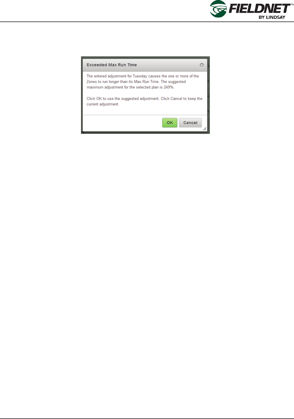
While it is allowable to have Zones run longer than its set Max Run Time, if the Adjustment Percentage causes
any of the Zones to run longer than the Max Run Time, a dialog will display, suggesting the maximum Adjustment
Percentage to avoid overwatering.
Upon pressing the Apply button, the scheduled Irrigation Plans and the Temperature Protection Plan are sent to
the Multi-Control for distribution to the Wireless Switches. Feedback is provided next to the button.
P/N 1608739 Rev A (ECN 32745) 2-26 Multi-Control for FieldNET Operation Manual
Section 2– FieldNET Portal
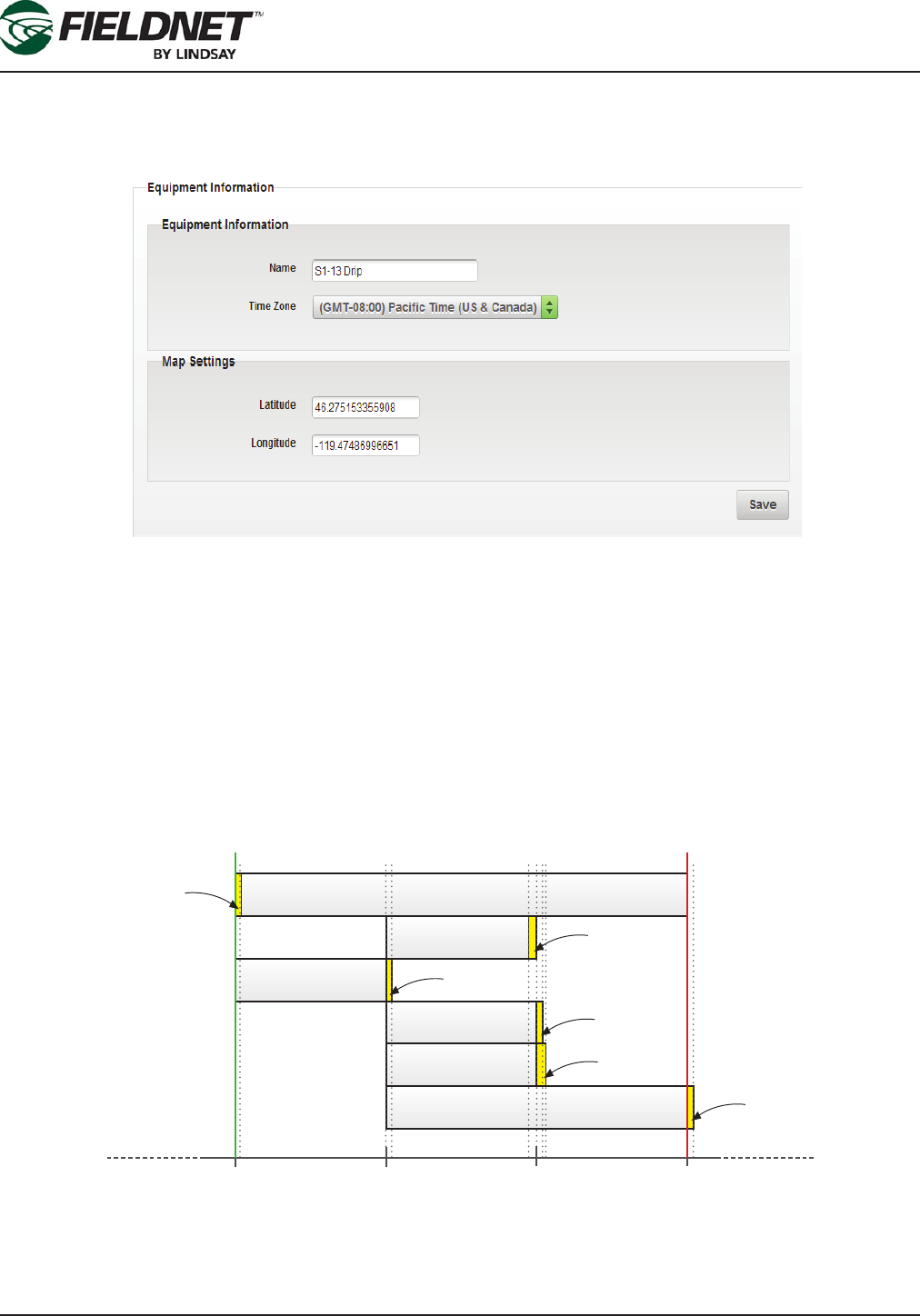
Properties – General
Select Properties then General from the sidebar to view the General Properties page. Here the Time Zone and
Map location (latitude and longitude from a GPS) can be adjusted.
The Time Zone must be set local to the Multi-Control. The Time Zone is set to UTC by default.
Although the Add to Map feature on the Map is a simpler method, if the precise Latitude and Longitude of the
Multi-Control are available, enter the appropriate decimal degrees. This will add or adjust the Multi-Control location
on the Map.
Press the Save button to save the settings.
Properties – System
Select Properties then System from the sidebar to view the System Settings and establish “Guard Times”.
Guard Times are used by the system to prevent water hammer, accidental chemigation, and smooth transitions
between starting or stopping Zone irrigation.
The Water Source Guard Time is applied at the beginning of startup. The Injector and Zone Guard Times are ap-
plied at the end of the Injector and Zone runtimes. The specic component will shut off during Guard Times.
8:00 AM 9:00 AM 10:00 AM 11:00 AM
Pump / Master
Injector
Zone 1
Zone 2
Zone 3
Zone 4
Start of Plan End of Plan
Guard Time
for Zone 2
Guard Time
for Zone 1
Guard Time
for Injector
Guard Time
for Zone 3
Guard Time
for Water Source
Guard Time
for Zone 4
P/N 1608739 Rev A (ECN 32745) 2-27 Multi-Control for FieldNET Operation Manual
Section 2– FieldNET Portal
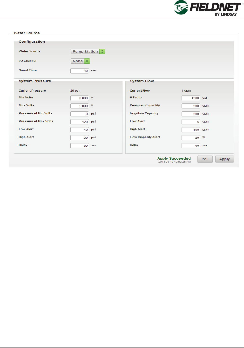
Water Source Setup
I/O Boards are labeled with a unique 8 character ID (WRID) and each I/O Channel has a number. The Water
Source is assigned to a specic I/O Board and Channel.
The Designed Flow Rate is the designed Water Source capacity that is available for Irrigation, Filtration, and Tem-
perature Protection. The Irrigation Capacity for Irrigation is an allowable reserve capacity for Irrigation in order to
run Filtration and Temperature Protection simultaneously. When making Plan Steps, this setting is used to calcu-
late Remaining Capacity.
Flow Disparity is dened as the ± percent difference between the current System Flow over the total actively ir-
rigating Zone Application Rate(s). The Zone Application Rates are dened on the Properties – Zones page.
For example: The Alert is set at 20% disparity; if a Plan Step had 3 Zones set to 100 gpm for a total of 300 gpm
running at the same time and the System Flow reads 200 gpm, the Flow Disparity would be equal to -33% (200
gpm / 300 gpm). This would set off the alert.
Press the Poll button to request the current Water Source settings from the Controller. Press the Apply button to
save the settings to the Multi-Control.
P/N 1608739 Rev A (ECN 32745) 2-28 Multi-Control for FieldNET Operation Manual
Section 2– FieldNET Portal
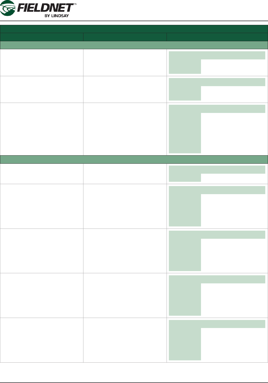
Water Source Setup Settings
Field Description Values
Conguration
Water Source Dropdown: Select the water
source that is installed. Options Pump Station
Main Valve
I/O Channel Dropdown: Select an available
I/O Channel on System or Auxil-
iary I/O Board. Options I/O Channels available
with current assignments
Guard Time Time in seconds. Amount of time
to allow for Zone valves to open
before the water source is run-
ning.
Unit sec
Default 10
Min 0
Max 600
Disable 0
System Pressure
Current Pressure Last reading of the System Pres-
sure based on settings. English Metric
Unit psi bar
Min Volts Minimum Volts the Pressure
Transducer will report
Typically 0 for a 0-5 V, 1 for
4-20mA.
Unit V
Default 0.000
Min 0.000
Max 12.000
Max Volts Maximum Volts the Pressure
Transducer will report. Typically 5
for a 0-5 V, 5 for 4-20mA. Unit V
Default 0.000
Min 0.000
Max 12.000
Pressure at Min Volts Pressure reading at Min Volts.
Typically the bottom of the sen-
sor’s range.
English Metric
Unit psi bar
Default 0.0 0.00
Min 0.0 0.00
Max 145.0 10.00
Pressure at Max Volts Pressure reading at Max Volts.
Typically the top of the sensor’s
range.
English Metric
Unit psi bar
Default 0.0 0.00
Min 0.0 0.00
Max 145.0 10.00
P/N 1608739 Rev A (ECN 32745) 2-29 Multi-Control for FieldNET Operation Manual
Section 2– FieldNET Portal
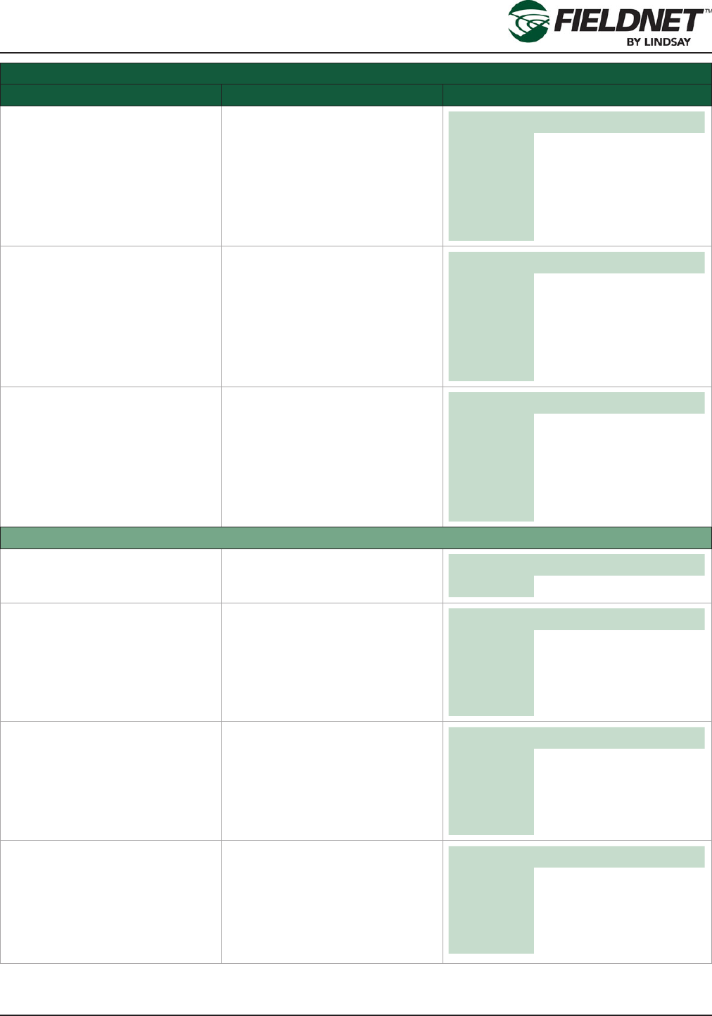
Water Source Setup Settings
Field Description Values
Low Alert Low Pressure Alert Threshold.
Send an alert when the System
Pressure is at or below this set-
ting.
English Metric
Unit psi bar
Default blank blank
Min 0.0 0.00
Max 145.0 10.00
Disable blank blank
High Alert High Pressure Alert Threshold.
Send an alert when the System
Pressure is at or above this set-
ting.
English Metric
Unit psi bar
Default blank blank
Min 0.0 0.00
Max 145.0 10.00
Disable blank blank
Delay Time in seconds. Amount of time
to allow for System Pressure to
stabilize upon water source run-
ning before checking for alert or
shutdown conditions.
Unit sec
Default 10
Min 0
Max 600
Disable 0
System Flow
Current Flow Last reading of the System Flow
Based on settings. English Metric
Unit gpm L/s
K Factor Unit volume per Pulse. Number
of gallons or liters per pulse. English Metric
Unit gal L
Default 0 0
Min 0 0
Max 17312 65534
Designed Capacity Flow rate.
Flow Rate capacity of the Water
Source for Irrigation, Filtration,
and Temperature Protection.
English Metric
Unit gpm L/s
Default 0 0
Min 0 0
Max 17312 65534
Irrigation Capacity Flow Rate capacity reserved
specically for Irrigation only.
Remaining capacity is made
available for Filtration and Tem-
perature Protection. Must be less
than or equal to Designated Flow
Rate.
English Metric
Unit gpm L/s
Default 0 0
Min 0 0
Max 17312 65534
P/N 1608739 Rev A (ECN 32745) 2-30 Multi-Control for FieldNET Operation Manual
Section 2– FieldNET Portal
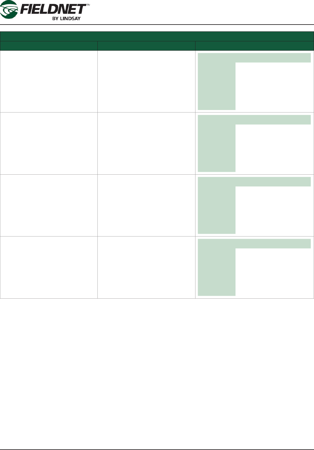
Water Source Setup Settings
Field Description Values
Low Alert Low Pressure Alert Threshold
Send an alert when the System
Flow is at or below this setting.
English Metric
Unit gpm L/s
Default blank blank
Min 0 0
Max 17312 65534
Disable blank blank
High Alert High Pressure Alert Threshold
Send an alert when the System
Flow is at or above this setting.
English Metric
Unit gpm L/s
Default blank blank
Min 0 0
Max 17312 65534
Disable blank blank
Flow Disparity Alert Flow Disparity Alert Threshold
Send an alert when the difference
between System Flow and the
total of the active Zone applica-
tion rates is greater than or equal
to this percentage.
Unit %
Default blank
Min 0
Max 100
Disable blank
Delay Time in seconds. Amount of time
to allow for System Flow to stabi-
lize upon system changes before
checking for alert or shutdown
conditions.
Unit sec
Default 60
Min 0
Max 600
Disable 0
P/N 1608739 Rev A (ECN 32745) 2-31 Multi-Control for FieldNET Operation Manual
Section 2– FieldNET Portal
Injector Setup
Press the Poll button to request the current Injector settings from the Controller. Press the Apply button to save the
settings to the Multi-Control.
Injector Setup Settings
Field Description Values
Conguration
I/O Channel Dropdown: Select an available
I/O Channel on System or Auxil-
iary I/O Board. Options I/O Channels available
with current assignments
Guard Time Time in seconds. Amount of
time to subtract from the Injector
runtime to allow the chemical to
ush out.
Unit sec
Default 254
Min 0
Max 254
Disable 0
Injector Flow
Has Injector Flow Checkbox: Select the check-
box if an Injector Flow Meter is
installed. Options Checked
Unchecked
K Factor Unit volume per Pulse.
Number of gallons or liters per
pulse
English Metric
Unit gal L
Default 0 0
Min 0 0
Max 17312 65534
P/N 1608739 Rev A (ECN 32745) 2-32 Multi-Control for FieldNET Operation Manual
Section 2– FieldNET Portal
Injector Setup Settings
Field Description Values
Low Alert Low Pressure Alert Threshold
Send an alert when the Injector
Flow is at or below this setting.
English Metric
Unit gpm L/s
Default blank blank
Min 0 0
Max 17312 65534
Disable blank blank
High Alert High Pressure Alert Threshold
Send an alert when the Injector
Flow is at or above this setting.
English Metric
Unit gpm L/s
Default blank blank
Min 0 0
Max 17312 65534
Disable blank blank
Delay Time in seconds. Amount of time
to allow for System Flow to stabi-
lize upon system changes before
checking for alert or shutdown
conditions.
Unit sec
Default 60
Min 0
Max 600
Disable 0
P/N 1608739 Rev A (ECN 32745) 2-33 Multi-Control for FieldNET Operation Manual
Section 2– FieldNET Portal
Options Setup
The Auto-Enable Temperature Protection Plan option is available if a Temperature Sensor is installed. This will
continuously run the Temperature Protection Plan as long as the Above or Below temperature criteria are met.
A Multi-Control can have either a Temperature Sensor or a pH Sensor installed, but not both.
Select the Poll button to request the current Options settings from the Controller. Select the Apply button to save
the settings to the Multi-Control.
Options Setup Settings
Field Description Values
Rainfall
Has Rainfall Sensor Checkbox: Select the checkbox
if a Rainfall Sensor is installed.
If not installed the remaining
related elds are disabled.
Options Checked
Unchecked
Resolution Sensor Resolution.
Amount of rainfall accumulated
per pulse.
English Metric
Unit in mm
Default 0.00 0.0
Min 0.00 0.0
Max 2.58 65.5
Current Accumulation Rainfall Accumulation.
Amount of rainfall accumulated
over the time specied above.
Select the Clear link to reset the
accumulated rainfall on the Multi-
Control.
English Metric
Unit in mm
P/N 1608739 Rev A (ECN 32745) 2-34 Multi-Control for FieldNET Operation Manual
Section 2– FieldNET Portal
Options Setup Settings
Field Description Values
Accumulation Rainfall Accumulation.
Amount of rainfall accumulated
used in combination with Over
Time to create a shutdown condi-
tion.
English Metric
Unit in mm
Default blank blank
Min 0 0
Max 393.70 10000.0
Disable blank blank
Time Span Time in hours.
Amount of time to accumulate
rainfall over to create a shutdown
condition.
Unit hr
Default 24
Min 0
Max 672
Disable 0
Temperature
Has Temperature Sensor Checkbox: Select the checkbox if
a Temperature Sensor is in-
stalled. If not installed the remain-
ing related elds are disabled.
Options Checked
Unchecked
Min Volts Minimum Volts the Temperature
Sensor will report. Typically 0 for
a 0-5 V, 1 for 4-20mA. Unit V
Default 0.000
Min 0.000
Max 12.000
Max Volts Maximum Volts the Temperature
Sensor will report. Typically 5 for
a 0-5 V, 5 for 4-20mA. Unit V
Default 0.000
Min 0.000
Max 12.000
Temperature at Min Volts Temperature reading at Volts
Minimum. Typically the bottom of
the sensor’s range.
English Metric
Unit °F °C
Default -40 -40
Min -40 -40
Max 185 85
Temperature at Max Volts Temperature reading at Volts
Maximum. Typically the top of the
sensor’s range.
English Metric
Unit °F °C
Default 185 85
Min -40 -40
Max 185 85

P/N 1608739 Rev A (ECN 32745) 2-35 Multi-Control for FieldNET Operation Manual
Section 2– FieldNET Portal
Options Setup Settings
Field Description Values
Low Alert Low Temperature Alert Threshold
Send an alert when the Tempera-
ture is at or below this setting.
English Metric
Unit °F °C
Default blank blank
Min -40 -40
Max 185 85
Disable blank blank
High Alert High Temperature Alert Threshold
Send an alert when the Tempera-
ture is at or above this setting.
English Metric
Unit °F °C
Default blank blank
Min -40 -40
Max 185 85
Disable blank blank
Auto-Enable Temperature Protec-
tion Plan
Checkbox: Select the checkbox
if the Multi-Control should run
the Temperature Protection Plan
automatically runs based on the
Above and Below temperature
settings. If not auto-enabling
the remaining related elds are
disabled.
Options Checked
Unchecked
Above High Temperature Threshold.
The Temperature Protection Plan
will cycle if the Temperature is
greater than or equal to this set-
ting.
English Metric
Unit °F °C
Default blank blank
Min -40 -40
Max 185 85
Disable blank blank
Below Low Temperature Threshold.
The Temperature Protection Plan
will cycle if the Temperature is
less than or equal to this setting.
English Metric
Unit °F °C
Default blank blank
Min -40 -40
Max 185 85
Disable blank blank
pH
Has pH Sensor Checkbox: Select the checkbox
if a pH Sensor is installed. If not
installed the remaining related
elds are disabled.
Options Checked
Unchecked
P/N 1608739 Rev A (ECN 32745) 2-36 Multi-Control for FieldNET Operation Manual
Section 2– FieldNET Portal
Options Setup Settings
Field Description Values
Min Volts Minimum Volts the pH Sensor will
report. Typically 0 for a 0-5 V, 1
for 4-20mA. Unit V
Default 0.000
Min 0.000
Max 12.000
Max Volts Maximum Volts the pH Sensor
will report. Typically 5 for a 0-5 V,
5 for 4-20mA. Unit V
Default 0.000
Min 0.000
Max 12.000
pH at Min Volts pH reading at Volts Minimum.
Typically the bottom of the sen-
sor’s range. Unit pH
Default 0.0
Min 0.0
Max 14.0
pH at Max Volts pH reading at Volts Maximum.
Typically the top of the sensor’s
range. Unit pH
Default 14.0
Min 0.0
Max 14.0
Low Alert Low pH Alert Threshold.
Send an alert when the pH is at
or below this setting. Unit pH
Default blank
Min 0.0
Max 14.0
Disable blank
High Alert High pH Alert Threshold.
Send an alert when the pH is at
or above this setting. Unit pH
Default blank
Min 0.0
Max 14.0
Disable blank

P/N 1608739 Rev A (ECN 32745) 2-37 Multi-Control for FieldNET Operation Manual
Section 2– FieldNET Portal
System Settings
A Temperature Sensor must be installed for a Temperature Shutdown.
If a Wireless Switch has a Shutdowns condition, it will shutdown the entire system. To ignore a Wireless Switch
Shutdown and continue running the scheduled plans, select the Ignore Wireless Switch Shutdown checkbox.
NOTE: Ignoring Wireless Switch Shutdown conditions may affect chemigation applications, cause Flow Disparity
alerts, and other related side effects.
Press the Poll button to request the current System settings from the Controller. Press the Apply button to save the
settings to the Multi-Control.
P/N 1608739 Rev A (ECN 32745) 2-38 Multi-Control for FieldNET Operation Manual
Section 2– FieldNET Portal
System Settings
Field Description Values
Pressure Shutdown
Low Pressure Shutdown Low Pressure Shutdown Thresh-
old. Shutdown the Multi-Control
when the System Pressure is
less than or equal to this setting.
English Metric
Unit psi bar
Default blank blank
Min 0.0 0.00
Max 145.0 10.00
Disable blank blank
High Pressure Shutdown High Pressure Shutdown Thresh-
old. Shutdown the Multi-Control
when the System Pressure is
greater than or equal to this set-
ting.
English Metric
Unit psi bar
Default blank blank
Min 0.0 0.00
Max 145.0 10.00
Disable blank blank
Flow Shutdown
Low Flow Shutdown Low Flow Shutdown Threshold.
Shutdown the Multi-Control when
the System Flow is less than or
equal to this setting
English Metric
Unit gpm L/s
Default blank blank
Min 0 0
Max 17312 65534
Disable blank blank
High Flow Shutdown High Flow Shutdown Threshold.
Shutdown the Multi-Control when
the System Flow is greater than
or equal to this setting.
English Metric
Unit gpm L/s
Default blank blank
Min 0 0
Max 17312 65534
Disable blank blank
Flow Disparity Shutdown Flow Disparity Shutdown Thresh-
old. Shutdown the Multi-Control
when the difference between
System Flow and the total of the
active Zone application rates
is greater than or equal to this
percentage.
Unit %
Default blank
Min 0
Max 100
Disable blank
P/N 1608739 Rev A (ECN 32745) 2-39 Multi-Control for FieldNET Operation Manual
Section 2– FieldNET Portal
System Settings
Field Description Values
Temperature Shutdown
Low Temperature Shutdown Low Temperature Shutdown
Threshold. Shutdown the Multi-
Control when the Temperature is
less than or equal to this setting.
English Metric
Unit °F °C
Default blank blank
Min -40 -40
Max 212 212
Disable blank blank
Low Temperature Restart Low Temperature Restart Thresh-
old. Restart the Multi-Control
after a shutdown when the Tem-
perature is greater than or equal
to this setting.
English Metric
Unit °F °C
Default blank blank
Min -40 -40
Max 212 212
Disable blank blank
High Temperature Shutdown High Temperature Shutdown
Threshold. Shutdown the Multi-
Control when the Temperature
is greater than or equal to this
setting.
English Metric
Unit °F °C
Default blank blank
Min -40 -40
Max 212 212
Disable blank blank
High Temperature Restart High Temperature Restart
Threshold. Restart the Multi-
Control after a shutdown when
the Temperature is less than or
equal to this setting.
English Metric
Unit °F °C
Default blank blank
Min -40 -40
Max 212 212
Disable blank blank
Wireless Switch Shutdown
Ignore Wireless Switch Shutdown Checkbox: Select the checkbox if
the Multi-Control should continue
irrigating if there is a Wireless
Switch Shutdown.
Options Checked
Unchecked
P/N 1608739 Rev A (ECN 32745) 2-40 Multi-Control for FieldNET Operation Manual
Section 2– FieldNET Portal
Properties – Filtration
Select Properties then Filtration, in the sidebar, to view the Filtration Settings. Most of the settings will have been
entered by the Lindsay Dealer and do not require any adjustment.
The number of Filter Flush Valves and the settings generate the Filter Flush Plan, which cycles through each Filter
Flush Valve chronologically and executes a back ush for the set Flush Time.
Filter Flush Valves
I/O Boards are labeled with a unique 8 character ID (WRID) and each I/O Channel has a number. Filter Flush
Valves and the Pressure Sustain Valve are assigned to a specic I/O Board and Channel.
The order of the Filter Flush Plan is determined by assigning the I/O channel to the corresponding Filter Flush
Valve. If, for instance, there are three lters, select the I/O channel for Filter Flush Valve 1, 2 and 3 and set the
others to None.
Then set the I/O channel for the Pressure Sustain Valve. The Pressure Sustain Valve creates back pressure dur-
ing each ush.
Press the Poll button to request the current Filter Flush Valves installed on the Controller. Press the Apply button
to save the settings to the Multi-Control.
P/N 1608739 Rev A (ECN 32745) 2-41 Multi-Control for FieldNET Operation Manual
Section 2– FieldNET Portal
Filtration Settings
Choose the method of determining when to execute a Filter Flush Cycle by selecting either a Time Interval or
Pressure Differential. The Pressure Differential method requires installing a Post-Filter Pressure Sensor.
Press the Poll button to request the current Filtration Settings on the Controller. Press the Apply button to save the
settings to the Multi-Control.
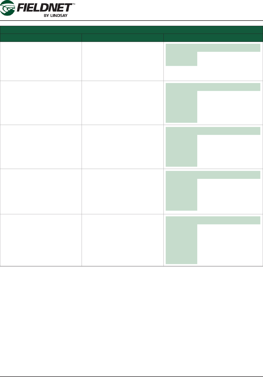
Filtration Settings
Field Description Values
Filter Flush Valves
Backush Duration Time in seconds. Amount of time
to backush a lter tank. Unit sec
Default 120
Min 0
Max 600
Dwell Time Time in seconds. Amount of time
between backushing of lter
tanks. Unit sec
Default 60
Min 0
Max 600
Time Interval Radio Button: Select if the Filter
Flush Plan is based on a time
interval. Options Selected
Unselected
Frequency Time in minutes. Amount of time
between Filter Flush Plan cycles
based on the Water Source run
time.
Unit min
Default 360
Min 0
Max 2880
P/N 1608739 Rev A (ECN 32745) 2-42 Multi-Control for FieldNET Operation Manual
Section 2– FieldNET Portal
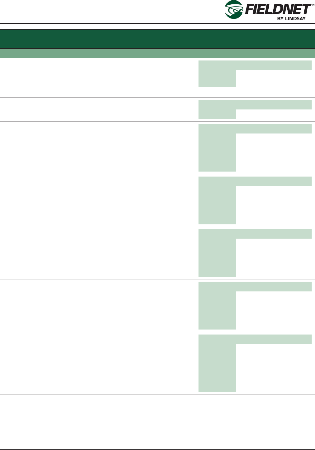
Filtration Settings
Field Description Values
Pressure Differential Radio Button: Select if the Filter
Flush Plan is based on a Pres-
sure Differential (System Pres-
sure – Post-Filter Pressure). This
option requires having a Post-
Filter Pressure Sensor installed.
Options Selected
Unselected
Run if Pressure Differential
Above
Run Filter Flush Plan Pressure
Differential Threshold. Initiate
Filter Flush Plan cycle if Pres-
sure Differential is greater than or
equal to this setting.
English Metric
Unit psi bar
Default blank blank
Min 0.0 0.00
Max 145.0 10.00
Stop if Pressure Below Stop Filter Flush Plan Pressure
Differential Threshold. Do not
initiate Filter Flush Plan cycle if
Pressure Differential is less than
or equal to this setting.
English Metric
Unit psi bar
Default blank blank
Min 0.0 0.00
Max 145.0 10.00
Attempts Before Alerting Number of tries. Number of con-
tiguous Filter Flush Plan cycles
allowed in order to reduce the
Pressure Differential to meet the
Stop threshold before sending
an alert condition and stopping
future Filter Flush Plan cycles.
Default 0
Min 0
Max 254
Disable 0
Delay Time in seconds. Amount of time
the Pressure Differential is above
the Run threshold before initiating
Filter Flush Plan cycle.
Unit sec
Default 30
Min 0
Max 600
Disable 0
P/N 1608739 Rev A (ECN 32745) 2-43 Multi-Control for FieldNET Operation Manual
Section 2– FieldNET Portal
Filtration Settings
Field Description Values
Post-Filter Pressure
Has Post-Filter Pressure Sensor Checkbox: Select the checkbox
if a Post-Filter Pressure Sen-
sor is installed. If not installed
the remaining related elds are
disabled.
Options Checked
Unchecked
Current Pressure Last reading of the Post-Filter
Pressure based on settings. English Metric
Unit psi bar
Min Volts Minimum Volts the Pressure
Transducer will report typically 0
for a 0-5 V, 1 for 4-20mA. Unit V
Default 0.000
Min 0.000
Max 12.000
Max Volts Maximum Volts the Pressure
Transducer will report typically 5
for a 0-5 V, 5 for 4-20mA. Unit V
Default 0.000
Min 0.000
Max 12.000
Pressure at Min Volts Pressure reading at Volts Mini-
mum, typically the bottom of the
sensor’s range.
English Metric
Unit psi bar
Default 0.0 0.00
Min 0.0 0.00
Max 145.0 10.00
Pressure at Max Volts Pressure reading at Volts Maxi-
mum, typically the top of the sen-
sor’s range.
English Metric
Unit psi bar
Default 0.0 0.00
Min 0.0 0.00
Max 145.0 10.00
Low Alert Low Pressure Alert Threshold.
Send an alert when the Post-
Filter Pressure is at or below this
setting.
English Metric
Unit psi bar
Default blank blank
Min 0.0 0.00
Max 145.0 10.00
Disable blank blank

P/N 1608739 Rev A (ECN 32745) 2-44 Multi-Control for FieldNET Operation Manual
Section 2– FieldNET Portal
Filtration Settings
Field Description Values
High Alert High Pressure Alert Threshold.
Send an alert when the Post-
Filter Pressure is at or above this
setting.
English Metric
Unit psi bar
Default blank blank
Min 0.0 0.00
Max 145.0 10.00
Disable blank blank
Delay Time in seconds. Amount of time
to allow for Post-Filter Pressure
to stabilize upon water source
running or Filter Flush Plan cycle
completing before checking for
alert conditions.
Unit sec
Default 30
Min 0
Max 600
Disable blank
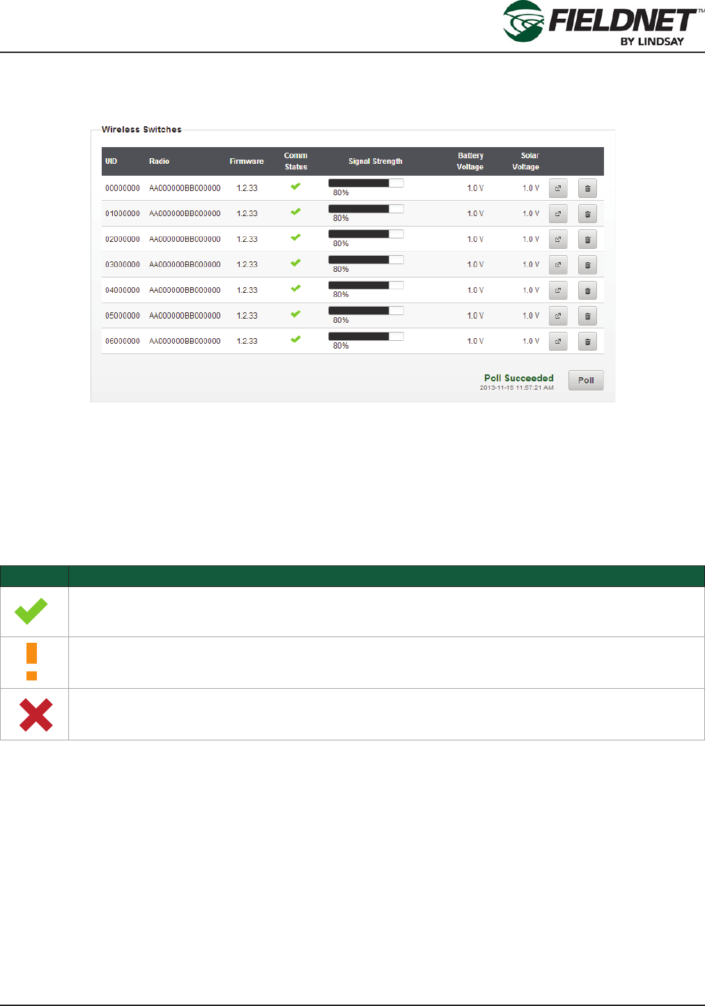
P/N 1608739 Rev A (ECN 32745) 2-45 Multi-Control for FieldNET Operation Manual
Section 2– FieldNET Portal
Properties – Wireless Switches
Select Properties then Wireless Switches in the sidebar to view the Wireless Switches congured for use with the
Multi-Control.
Press the Poll button to request the available Wireless Switches on the Controller.
Each Wireless Switch will have a unique 8 character UID (WRID) for identifying Zones. The Radio column displays
the radio address for support purposes. Firmware displays the current version of rmware for the specic Wireless
Switch.
The Comm Status and Signal Strength are used to show current communication status. The Comm Status has the
following states:
Icon Description
Good (> 75% success rate)
Warning (> 25% to < 75% success rate)
Fault (< 25% success rate)
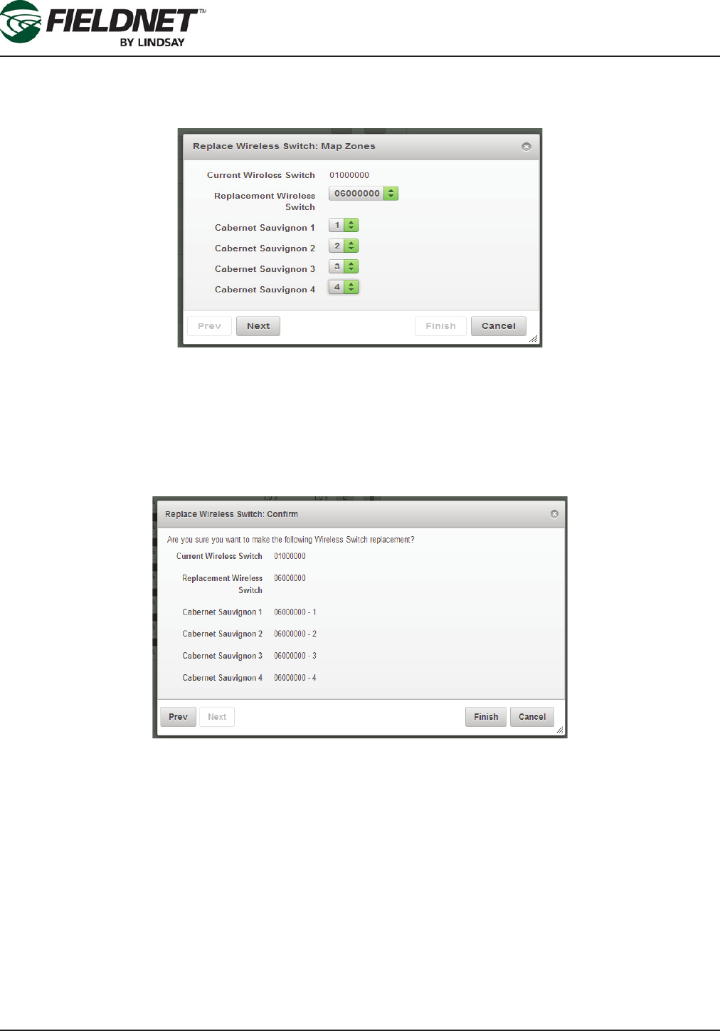
P/N 1608739 Rev A (ECN 32745) 2-46 Multi-Control for FieldNET Operation Manual
Section 2– FieldNET Portal
In the event a Wireless Switch needs to be replaced, selecting the Replace button will display the Replace Valve
Controller wizard. Any unused or new Wireless Switch must be installed prior to replacing a Wireless Switch. Upon
completing the wizard, the old Wireless Switch will be unassigned and removed from the Multi-Control.
Select the Replacement Valve Controller to the new Wireless Switch.
If the Switch has Zones assigned to it, a list of these Zones and valves will display. Select the correct Zone and
valve number from the dropdown menu to establish each Zone and valve. The dropdown will be populated with
the available valves from the Replacement Valve Controller. Map the current Zones to the appropriate Wireless
Switch and Valves.
Select the Next button to conrm the replacement. Select the Prev (Previous) button to go to the previous step.
Select the Cancel button to exit the wizard and ignore any changes. Select the Finish button to proceed with re-
placing the Wireless Switch.
In the event a Wireless Switch needs to be removed, selecting the Remove button will display the Conrm Remov-
al dialog. Upon proceeding, the old Wireless Switch will be unassigned and removed from the Multi-Control.
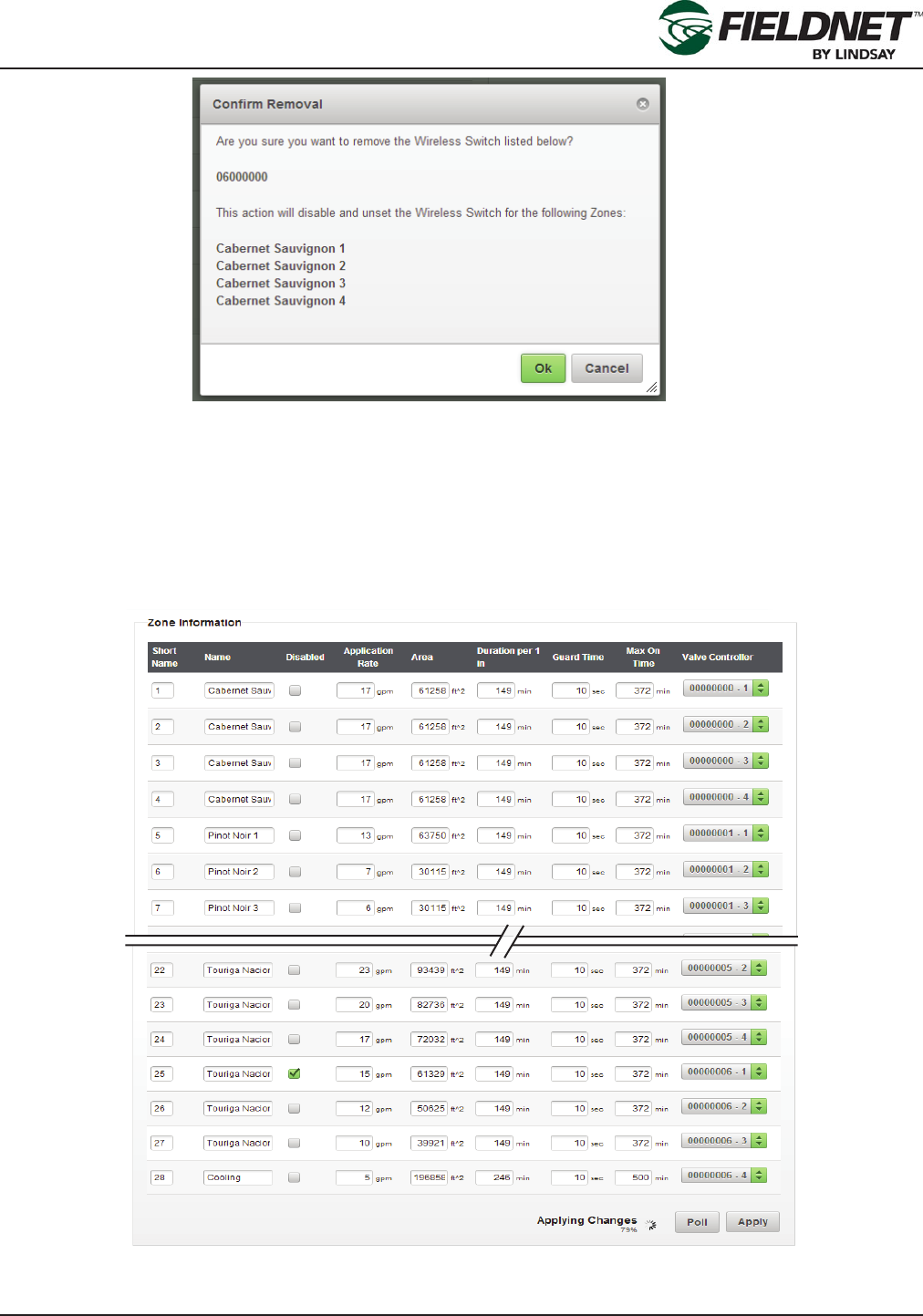
P/N 1608739 Rev A (ECN 32745) 2-47 Multi-Control for FieldNET Operation Manual
Section 2– FieldNET Portal
A list of the Zones is displayed, if Zones are assigned to the Wireless Switch. Press the Ok button to proceed with
removing the Wireless Switch. Select the Cancel button to exit the wizard and ignore any changes.
Feedback is provided next to the Poll button for Replace or Remove actions.
Properties – Zones
Select Properties then Zones in the sidebar to view the Zone Settings. Most of the settings will have been entered
by the Lindsay Dealer and will not require any editing.
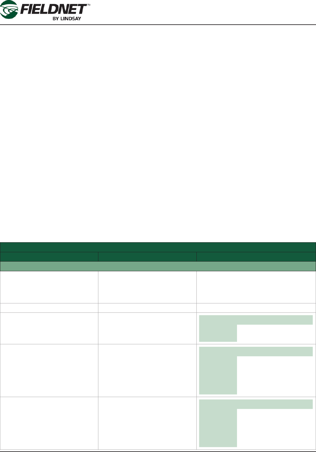
P/N 1608739 Rev A (ECN 32745) 2-48 Multi-Control for FieldNET Operation Manual
Section 2– FieldNET Portal
Each Zone has a full name and a short name. The short name is used for displaying a list of Zones on the Field-
NET portal and mobile application. A Zone number or an abbreviation or acronym of three characters or less is the
best practice for short names.
If a Zone is under maintenance and should be temporarily removed from running during a Plan, select the Dis-
abled checkbox to disable the Zone.
The Application Rate is a requirement for calculating resource availability. The Application Rate is not the emitter
or sprinkler rate, but rather the overall ow rate expected for the entire Zone at pressure.
The Area is the area of irrigated land included in the Zone.
The Duration per 1 inch (25 mm) is the amount of time in minutes that a Zone must irrigate to apply 1 inch or 25
millimeters across the Zone area. This is also known as the Duration Conversion Factor.
The Guard Time is the amount of time in seconds that a Zone valve will remain opened after the ending of a Plan
Step if the Zone valve is not included in the next Plan Step.
The Max On Time is the amount of time (in minutes) that a Zone can irrigate without overwatering.
The Valve Controller is a dropdown list of Valves available for the Wireless Switches. Select which Valve Control-
ler and Valve Number is assigned to the Zone. Multiple Zones cannot share the same Valve Controller and Valve
Number.
Press the Add Zone button to add a new Zone to the end of the list. Press the Poll button to request the current
Zone settings on the Controller. Press the Apply button to save the settings to the Multi-Control for distribution to
the remote Wireless Switches.
Zone Information Settings
Field Description Values
Zone Information
Short Name Text Field. Short Name of the Zone. A Zone number
or an abbreviation or acronym of three
characters or less is the best practice for
short names.
Name Text Field. Name of the Zone
Disabled Checkbox: Select the checkbox if
a Zone is temporarily disabled. Options Checked
Unchecked
Application Rate Designed Flow Rate. Overall ow
rate expected for the entire Zone
at pressure.
English Metric
Unit gpm L/s
Default 0 0
Min 0 0
Max 158503 10000
Area Area of irrigated land. Area of ir-
rigated land included in the Zone. English Metric
Unit ft^2 m^2
Default 0 0
Min 1076390 100000
Max 0 0
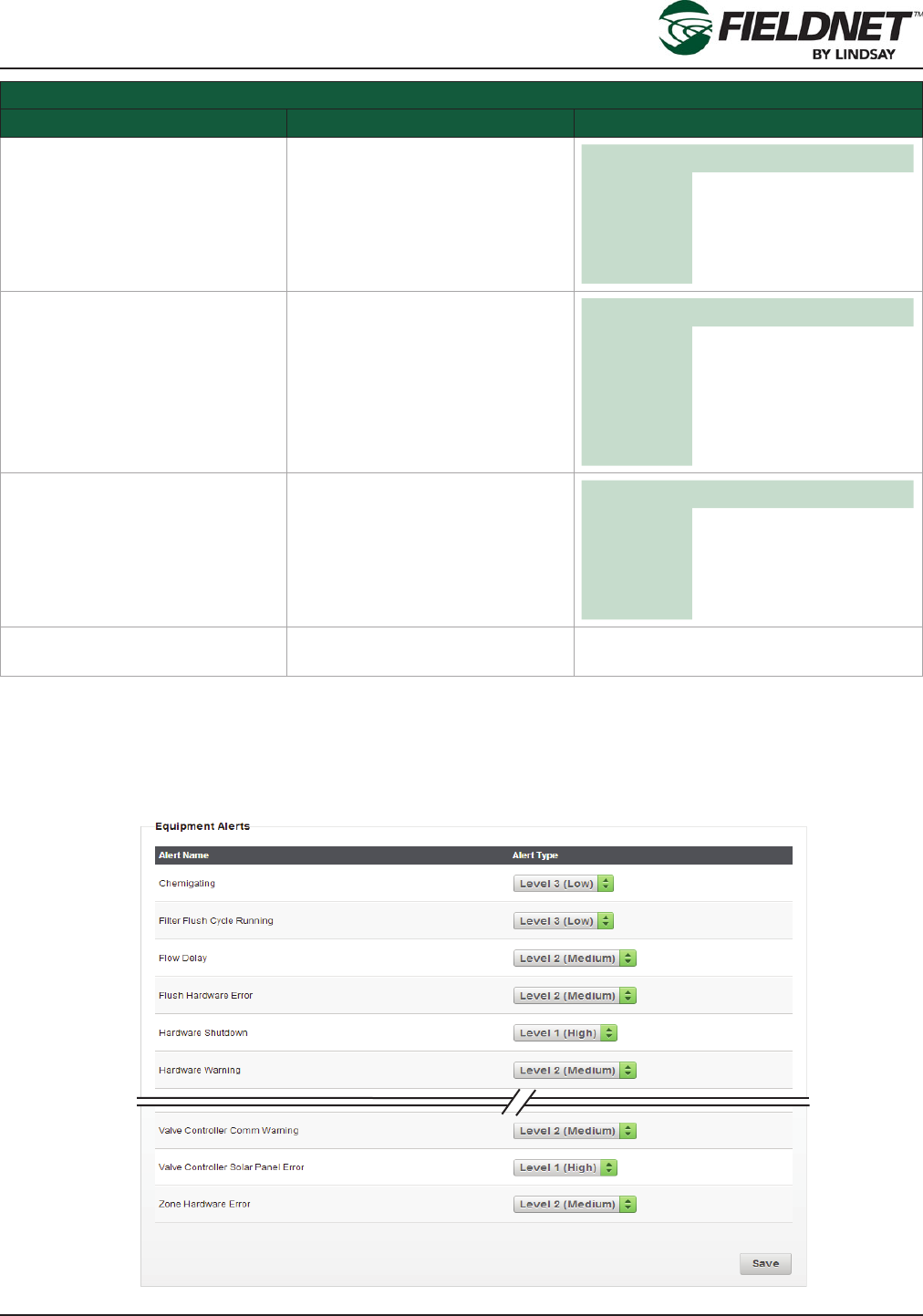
P/N 1608739 Rev A (ECN 32745) 2-49 Multi-Control for FieldNET Operation Manual
Section 2– FieldNET Portal
Zone Information Settings
Field Description Values
Duration per 1 inch or
Duration per 25 mm
Time in minutes.
Duration Conversion Factor
Amount of time that a Zone must
irrigate to apply 1 inch or 25 mil-
limeters across the Zone area.
Unit min
Default 0
Min 0
Max 600
Guard Time Time in seconds.
Amount of time to subtract from
the Zone runtime to allow for
smooth transitions between Plan
Steps or Zone changes.
Unit sec
Default 60
Min 0
Max 254
Disable 0
Max On Time Time in minutes.
Amount of time Zone can irrigate
in a Plan Step to prevent overwa-
tering.
Unit min
Default 0
Min 0
Max 65534
I/O Channel Dropdown. Dropdown of available Wired or Wireless
Switches and Channels
Properties – Alerts
Select Properties then Alerts in the sidebar to view the Alert Settings.
Equipment Alerts

P/N 1608739 Rev A (ECN 32745) 2-50 Multi-Control for FieldNET Operation Manual
Section 2– FieldNET Portal
Equipment Alerts have three different Alert Types.
• Level 1 alerts are faults or shutdown conditions and require immediate action to continue operation.
• Level 2 alerts are warnings and should be acted on to prevent a fault or shutdown condition.
• Level 3 alerts are informational notications and do not require action.
Outside of site-specic needs, it is a best practice to use the default Alert Type settings.
Select the Save button to save the settings.
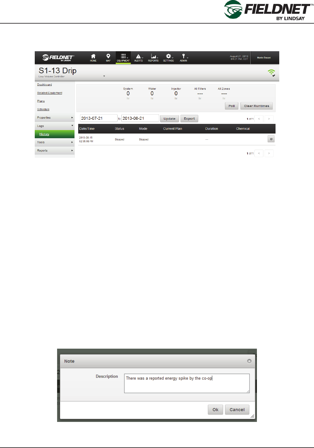
P/N 1608739 Rev A (ECN 32745) 2-51 Multi-Control for FieldNET Operation Manual
Section 2– FieldNET Portal
Event History
Select Logs then History in the sidebar to view the Multi-Control History.
Runtimes are displayed based on the amount of active time. When hours are greater than 1,000 hours the number
will be displayed in thousands. For example, if the Multi-Control has been active for 2,340 hours the runtime would
display 2.34k hours.
Press the Poll button to request the runtimes on the Controller. Press the Clear Runtimes button to reset all run-
times except for the System.
Multi-Control event history is displayed below the runtimes interface. History can be limited to a specic date range
by entering a start and end date then selecting the Update button. Download the history for use in other programs
by selecting the Export button, which generates history in a Comma Separated Values (CSV) le format.
Navigate the event history using the pagination buttons above and below the event history table.
The Date/Time is when the operational change occurred. Status is the operational change that occurred. Mode is
shown as either Auto, Service, or Off.
The name of the running Plan is displayed if it was running during the event.
The Duration is the amount of time between operational changes. The most recent event will not have a Duration
as it currently does not have a completed status.
If the Injector was on any point during the status the Chemical column will indicate that it was On.
A journal of notes can be kept for an individual event. Select the note button of the respective event to add a note.
Enter the note and press the Ok button to save the note and close the dialog. Select the Cancel button to ignore
changes and close the dialog.

P/N 1608739 Rev A (ECN 32745) 2-52 Multi-Control for FieldNET Operation Manual
Section 2– FieldNET Portal
Tools – Firmware Manager
Select Tools then Firmware Manager in the sidebar to check for rmware updates.
Press the Poll button to request the rmware versions for on the Controller. If there are multiple rmware versions
for a given controller the oldest version is displayed.
The Firmware Manager provides the ability to update rmware for the following hardware:
• Multi-Control
• Wireless Switch
• I/O Board
Firmware can be updated from a downloaded le. Contact the Lindsay Dealer for the latest rmware version.
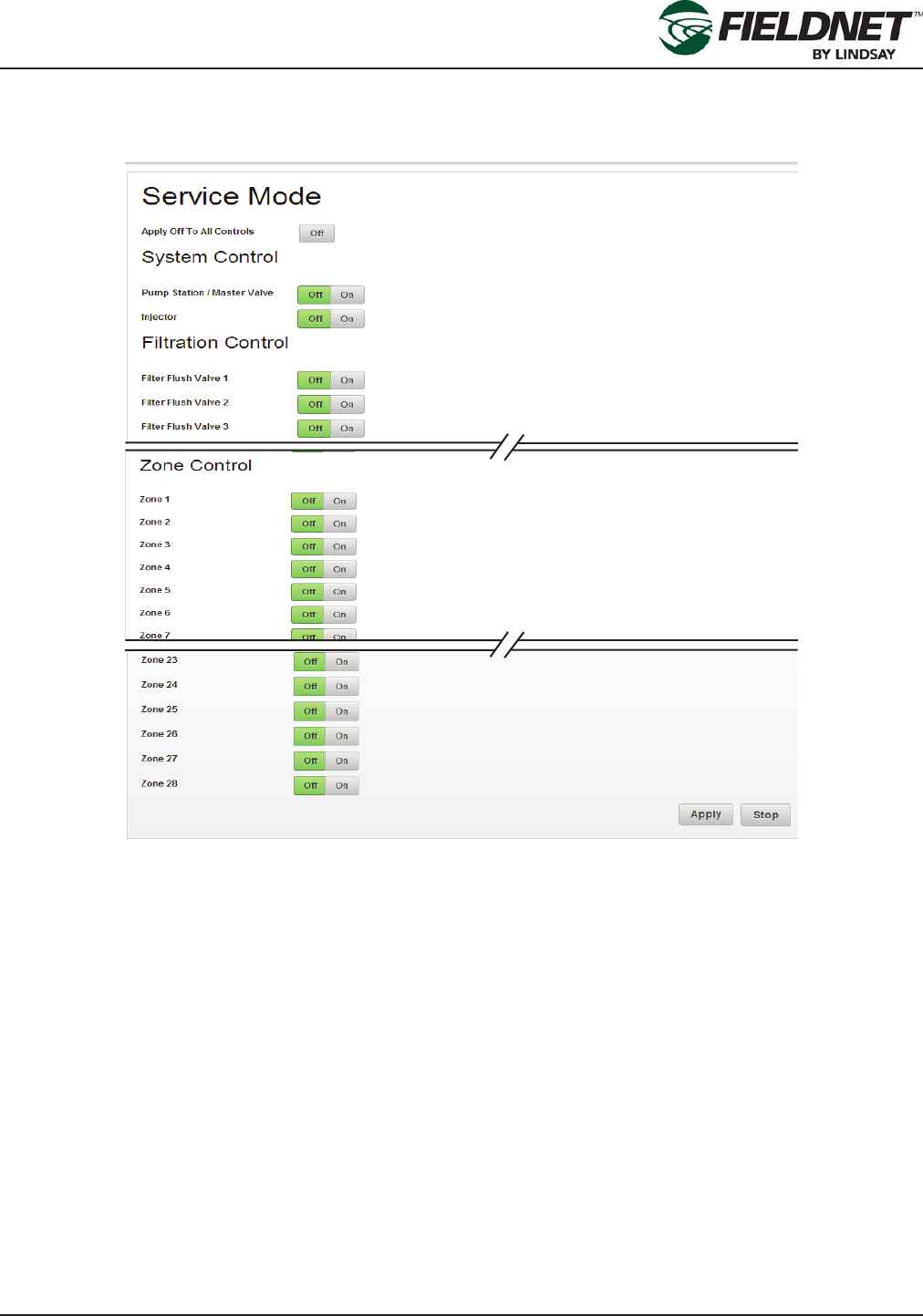
P/N 1608739 Rev A (ECN 32745) 2-53 Multi-Control for FieldNET Operation Manual
Section 2– FieldNET Portal
Tools – Service Mode
Select Tools then Service Mode in the sidebar to operate the Multi-Control in manual mode.
Service Mode provides manual control of these Multi-Control features:
• Pump Station / Main Valve
• Injector
• Specic Filter Flush Valves
• Specic Zone Valves
Each section will display the control and a Button Bar with the options of Off and On. By default, all controls will be
set to Off.
After selecting the items to control select the Apply button to put the system into Service Mode and apply changes.
Press the Stop button to put the system into Stop Mode, which will set all controls to Off.
Once the system is in Service Mode the wireless network will remain active until the user presses the Stop button.
Service Mode should not be used for extended lengths of time as Wireless Switches will drain the battery after
continued radio communication.
Any scheduled plans will need to be restarted after Service Mode.
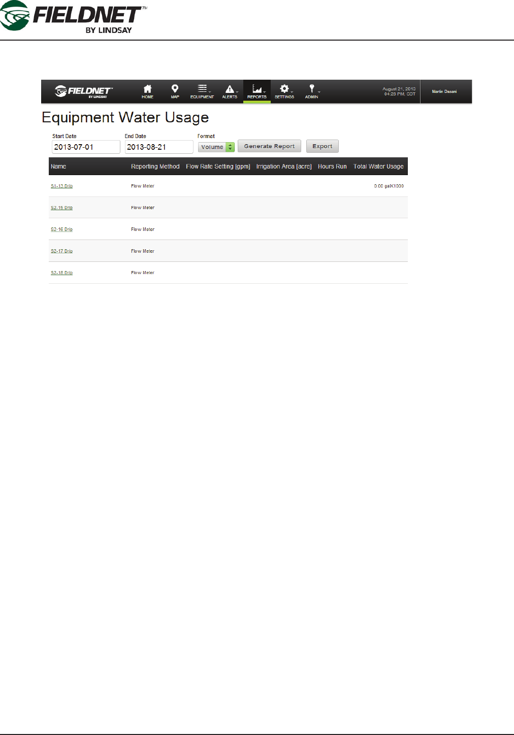
P/N 1608739 Rev A (ECN 32745) 2-54 Multi-Control for FieldNET Operation Manual
Section 2– FieldNET Portal
Water Usage Report
Select Reports then Water Usage in the sidebar to view the Water Usage Report.
The Water Usage Report calculates totals from Equipment which report water usage for a specied date range.
Enter a start and end date to limit the reporting period. Select the format of the report and press the Generate
Report button to update the report. Download the report for use in other programs by pressing the Export button,
which generates the report in a Comma Separated Values (CSV) le format.
There are three formats:
• Volume
• Area Depth
• Depth Applied
Only Volume and Area Depth apply to Multi-Controls.
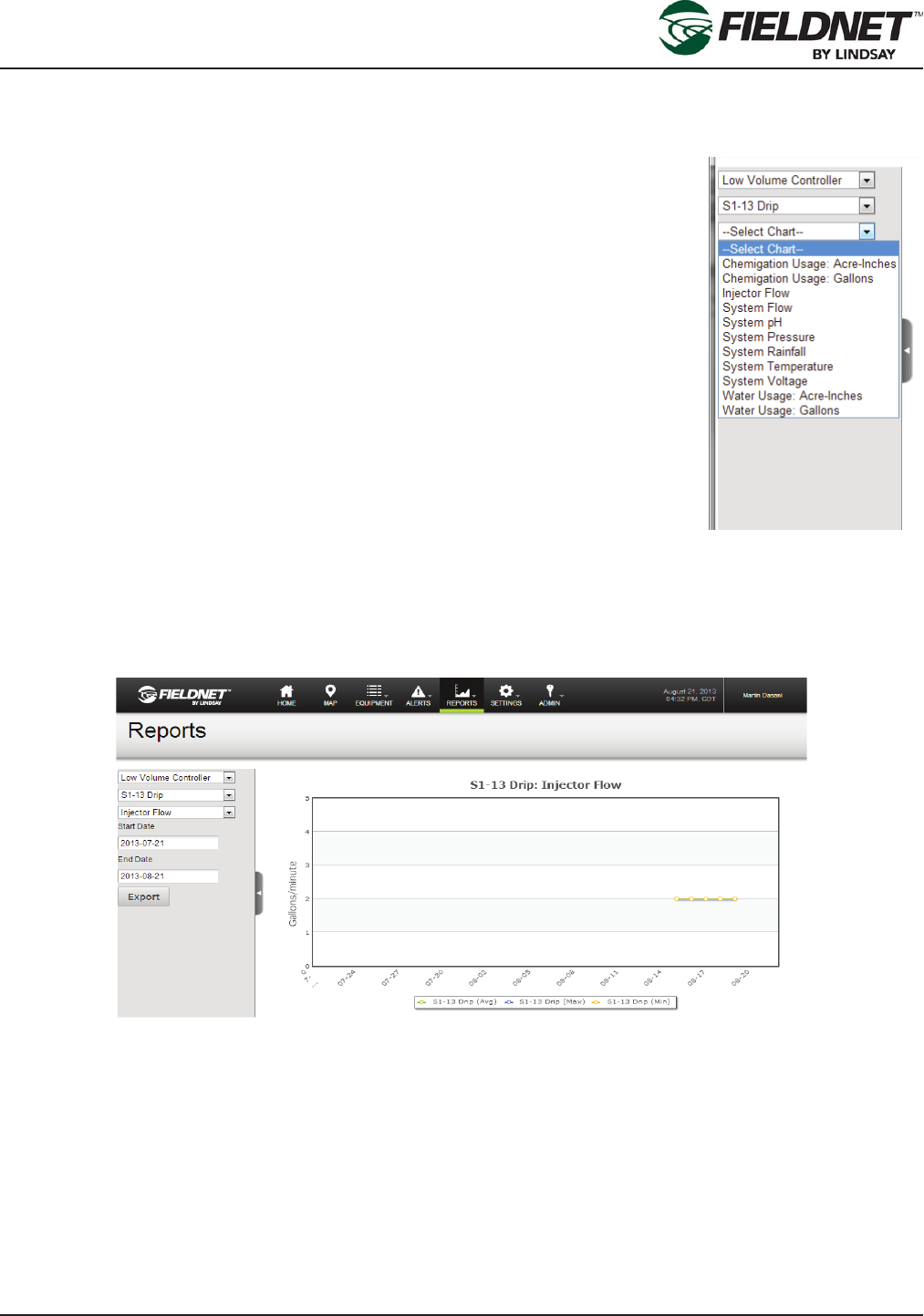
P/N 1608739 Rev A (ECN 32745) 2-55 Multi-Control for FieldNET Operation Manual
Section 2– FieldNET Portal
General Reports
Select Reports then All in the sidebar to view the Equipment Sensors reporting page with the Multi-Control already
selected.
The following charts are available for Multi-Control:
• Chemigation Usage: Acre-Inches / Cubic Meters
• Chemigation Usage: Gallons / Liters
• Injector 1 Flow Meter Rate
• System Flow Meter Rate
• System pH
• System Pressure
• System Rainfall Diff
• System Temperature
• System Voltage
• Water Usage: Acre-Inches / Cubic Meters
• Water Usage: Gallons / Liters
The chart will use a month’s worth of data ending on the current date, by default. Entering a start and end date
will limit the reporting period, any change to the summary criteria will refresh the chart immediately. Download the
report for use in other programs by selecting the Export button, which generates the report in a Comma Separated
Values (CSV) le format.

P/N 1608739 Rev A (ECN 32745) 2-56 Multi-Control for FieldNET Operation Manual
Section 2– FieldNET Portal
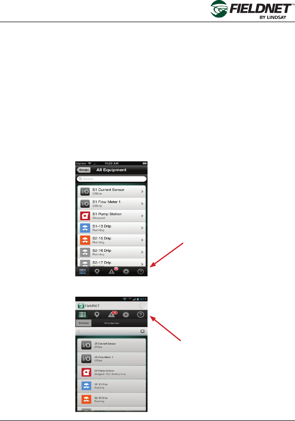
P/N 1608739 Rev A (ECN 32745) 3-1 Multi-Control for FieldNET Operation Manual
Section 3– FieldNET Mobile App.
Section 3– FieldNET Mobile App.
Introduction
The FieldNET Mobile Application can be found on the Apple App Store for iOS devices and on the Google Play
Store for Android.
This section will provide an overview of all Multi-Control for Mobile App related pages.
As with other Equipment, the Multi-Control is integrated into the following sections of the portal:
• Equipment List
• Equipment Groups
• Map View
• Dashboard and related pages
• Schedule
• History
• Help
Navigation for Apple iOS devices is located at the bottom of the screen.
Navigation for Google Android devices can be found at the top of the screen.
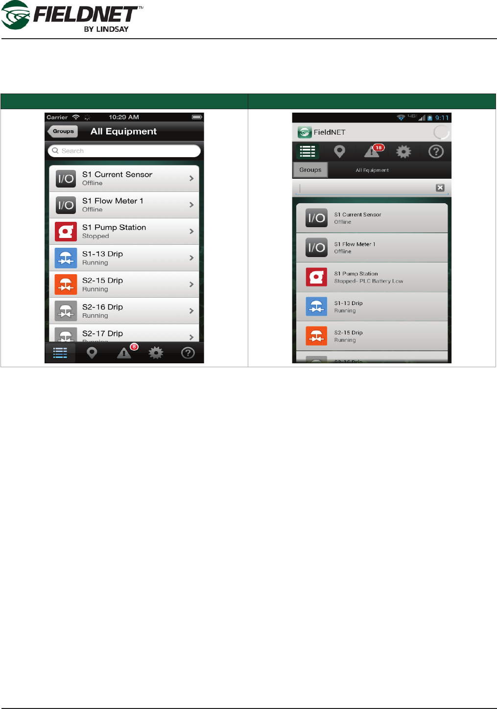
P/N 1608739 Rev A (ECN 32745) 3-2 Multi-Control for FieldNET Operation Manual
Section 3– FieldNET Mobile App.
Equipment List
Select the Equipment List icon in the main navigation to display a list of Equipment with current statuses.
Apple iOS Google Android
Multi-Controls will show the status icon, the name of the controller, and the current status. Select on a Multi-Con-
trol to view the Dashboard.
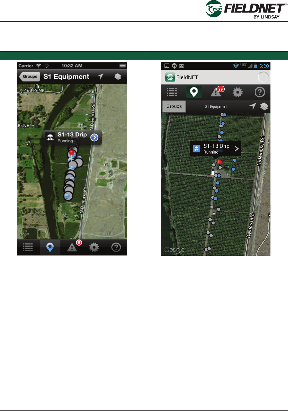
P/N 1608739 Rev A (ECN 32745) 3-3 Multi-Control for FieldNET Operation Manual
Section 3– FieldNET Mobile App.
Map View
Select the Map View icon in the main navigation to display a map with Equipment.
Apple iOS Google Android
The map will display markers—colored pins (iOS) or colored ags (Android)—at the geolocation of Equipment.
Selecting a pin will display the name of the Equipment in a balloon. Selecting the balloon will display the respec-
tive Dashboard.
Selecting a Multi-Control marker will display Zone markers on the map.
Geolocation of the Multi-Control and Zones is managed on the Portal.
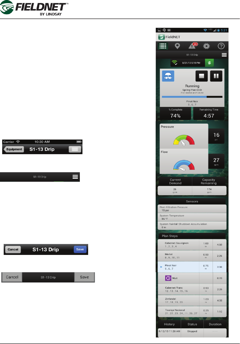
P/N 1608739 Rev A (ECN 32745) 3-4 Multi-Control for FieldNET Operation Manual
Section 3– FieldNET Mobile App.
Dashboard
Select Equipment from the Equipment List or Map View to display
the respective Dashboard.
The Multi-Control Dashboard has the following sections:
• Action Bar
• Menu
• Communication Bar
• Current Status
• Sensors
• Plan Steps
• History
The detail to the right shows the entire scroll-through screen.
Action Bar
The Action Bar is used for navigating and displaying the Dashboard
menu. The Action Bar changes depending on the Dashboard mode.
When in View mode the Action Bar will display the following:
Apple iOS
Google Android
Selecting the Equipment button (iOS only) or the Back button (An-
droid only) displays the Equipment List. Selecting the Menu button
slides the Dashboard to the left and displays the menu. Pressing the
Menu Icon again will close the Menu and display the Dashboard.
Alternatively, swiping from the right edge to the left will display the
menu.
When in Edit mode the Action Bar will display the following:
Apple iOS
Google Android
Pressing the Cancel button ignores changes and returns to View
mode. Press Save to apply the changes to the Multi-Control and
return to View mode.
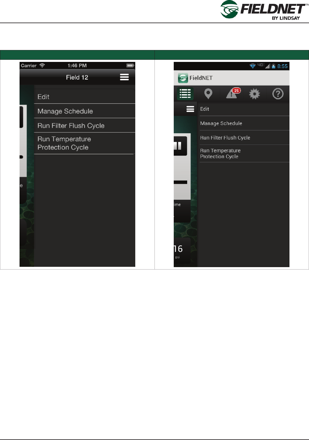
P/N 1608739 Rev A (ECN 32745) 3-5 Multi-Control for FieldNET Operation Manual
Section 3– FieldNET Mobile App.
Menu
The Dashboard Menu provides actions available to the Multi-Control. Selecting the Menu button slides the Dash-
board to the left and displays the menu. Select the Menu Icon again to close the Menu and display the Dashboard.
Apple iOS Google Android
Edit
Selecting Edit will close the Menu and display the Dashboard in Edit mode for making operational changes.
Manage Schedule
Select Manage Schedule to display the Irrigation Schedule.
Run Filter Flush Cycle
If a ltration system is installed, Selecting Run Filter Flush Cycle will invoke the Filter Flush Plan for one cycle. If a
ltration system is not installed, the option will not be displayed in the menu.
Run Temperature Protection Cycle
If the Temperature Protection Plan is set up, Select Run Temperature Protection Cycle to run the Temperature
Protection Plan for one cycle. If the Temperature Protection Plan does not have any steps, the option will not be
displayed in the menu.
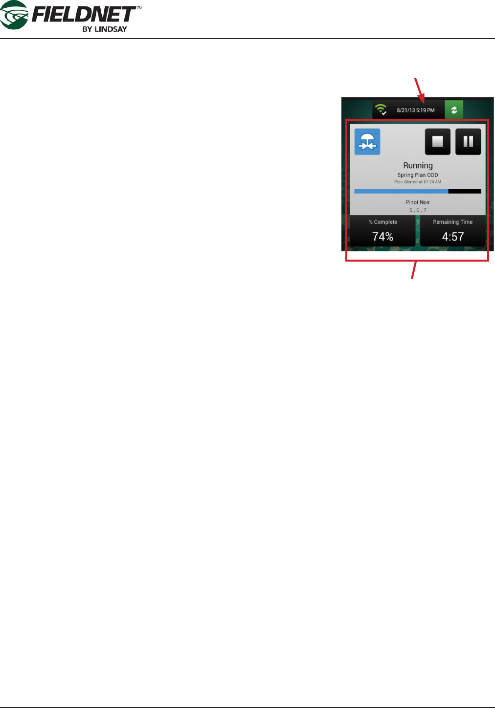
P/N 1608739 Rev A (ECN 32745) 3-6 Multi-Control for FieldNET Operation Manual
Section 3– FieldNET Mobile App.
Communication Bar
The Communication Bar is used to inform the user about communication
health and when the information displayed was last updated.
The Communication Status icon reects the communication health of the RTU
assigned to the Multi-Control. For details regarding the Communication Status
icon, refer to Communication Status table found in Section 3 under Multi-Con-
trol.
The timestamp is when the last information was received from the Multi-Con-
trol.
Press the Poll button to request the current status of the Multi-Control. The
icon will spin until complete and information on the Dashboard will be re-
freshed. The Poll button is disabled in Edit mode.
Current Status
The Current Status is used to inform the user of the progress of the Plan and
for control of the Plan.
The status icon is displayed at the top left of the screen. Please refer to Section 3 for an explanation of status
icons.
To the right of the screen are action buttons for stopping and running or pausing the Irrigation Plan. These are en-
abled when selecting the Edit option in the menu. To make an operational change, press the Stop or Run/Resume/
Pause button, which will become highlighted, and press the Save button.
The status is displayed below the status icon and action buttons. The Irrigation Plan, start time, plan progress
bar, and current Plan Step are displayed when a Plan is currently running, pending, or complete. Additionally, the
percent complete and estimated remaining time are displayed below the status.
Communication Bar
Status
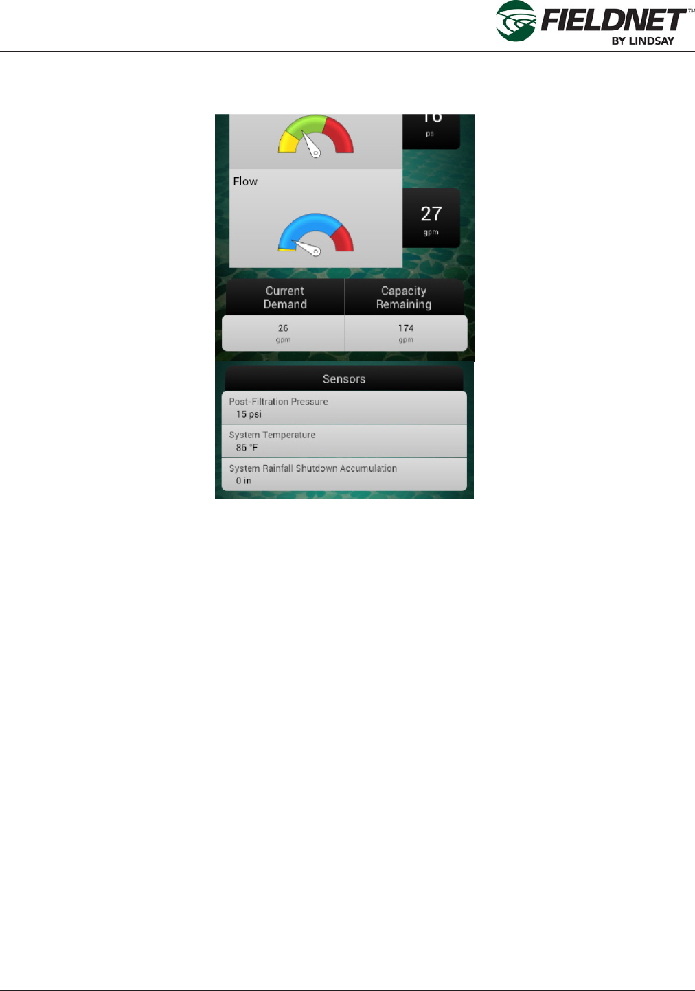
P/N 1608739 Rev A (ECN 32745) 3-7 Multi-Control for FieldNET Operation Manual
Section 3– FieldNET Mobile App.
Sensors
System Flow and System Pressure readings and gauges are displayed below the Current Status.
The colored sections of the gauge are the same as described in Section 3-FieldNET Portal under Sensors.
Current Demand is the expected volume of water for the Zones currently running. Capacity Remaining is the vol-
ume the Water Source is capable of providing minus the Current Demand.
Optional sensors display water demand and sensor readings in a table. Optional sensors include Post-Filter Pres-
sure, Temperature, pH, and Rainfall.
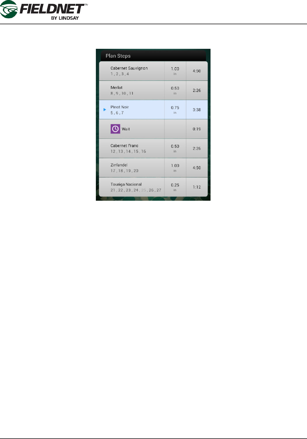
P/N 1608739 Rev A (ECN 32745) 3-8 Multi-Control for FieldNET Operation Manual
Section 3– FieldNET Mobile App.
Plan Steps
Plan Steps display the current progress of the Irrigation Plan including what has completed and what is pending
within the Irrigation Plan.
The current Plan Step is highlighted with an icon indicating if the plan is paused or running on that step. Each row
displays the Plan Step name and Zones, depth applied, and duration of the Plan Step.
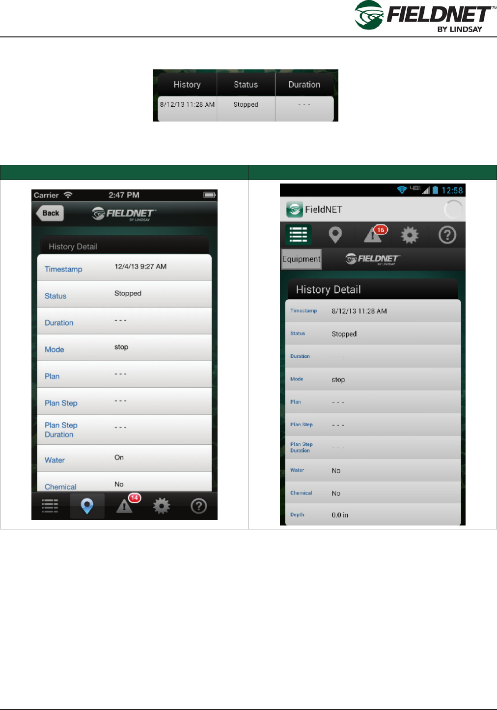
P/N 1608739 Rev A (ECN 32745) 3-9 Multi-Control for FieldNET Operation Manual
Section 3– FieldNET Mobile App.
History
The History displays recent Multi-Control Events in a table.
Each row displays the time of the event, the status, and the duration of the event in hours. Select an event to dis-
play History Detail.
Apple iOS Google Android
Press the Equipment button to close History Detail and display the Dashboard.

P/N 1608739 Rev A (ECN 32745) 3-10 Multi-Control for FieldNET Operation Manual
Section 3– FieldNET Mobile App.
Manage Schedule
Selecting the Manage Schedule option will display the Schedule screen, which shows the scheduled irrigation
plan, start time, and plan adjustment for each day of the week.
Apple iOS Google Android
When in View mode the Action Bar will display.
If changes are required on the Schedule, press the Edit button and select the desired day to edit. This will display
the schedule wizard.
The schedule wizard is a series of dialog screens that step through parameter editing to the Irrigation Plan, the
start time, and rate adjustment screens, by pressing the Next button on each dialog display. Pressing the Done
button at any time will close the wizard and return to the Schedule screen (still in Edit mode).
Schedule Wizard screen sequence for Apple iOS
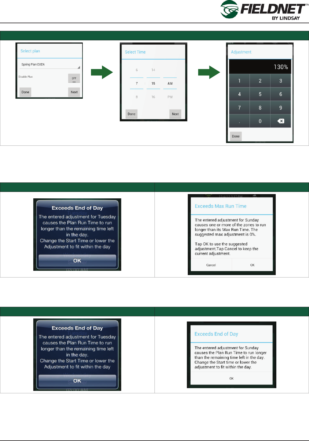
P/N 1608739 Rev A (ECN 32745) 3-11 Multi-Control for FieldNET Operation Manual
Section 3– FieldNET Mobile App.
Schedule Wizard screen sequence for Google Android
Upon making changes, press Done to return to the Schedule (still in Edit mode).
If the adjusted Plan exceeds a Zone’s Max Run Time the following alert will be displayed:
Apple iOS Schedule Error Google Android Schedule Error
Select the OK button to use the suggested adjustment or select Cancel to keep the current adjustment.
If the Plan Run Time exceeds the end of day the following alert will be displayed:
Apple iOS Run Time Error Google Android Run Time Error
Change the start time or decrease the adjustment to t the scheduled plan within the day.
Select the Back button to ignore unsaved changes and display the Multi-Control Dashboard. Select the Save but-
ton to Apply the changes to the Schedule displays the Dashboard.
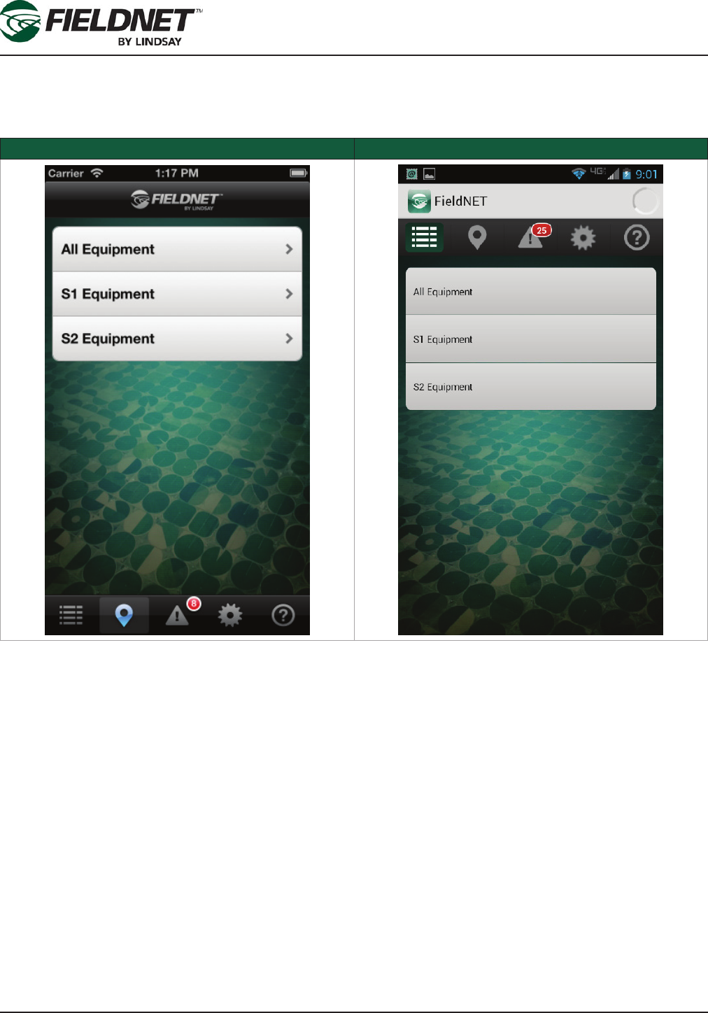
P/N 1608739 Rev A (ECN 32745) 3-12 Multi-Control for FieldNET Operation Manual
Section 3– FieldNET Mobile App.
Equipment Groups
Select the Groups button on the Map View, Equipment List, or Alerts to limit the Equipment displayed. Equipment
Groups are managed on the Portal.
Apple iOS Equipment Groups Google Android Equipment Groups
Select an Equipment Group to limit the Equipment on the respective view.

P/N 1608739 Rev A (ECN 32745) 3-13 Multi-Control for FieldNET Operation Manual
Section 3– FieldNET Mobile App.
Help
Help displays a table of icons for various Equipment and application features and a brief description of each.
Apple iOS Help Google Android Help
Selecting the globe button at the top right will open the Portal website on the mobile device browser.

P/N 1608739 Rev A (ECN 32745) 3-14 Multi-Control for FieldNET Operation Manual
Section 3– FieldNET Mobile App.

P/N 1608739 Rev A (ECN 32745) 4-1 Multi-Control for FieldNET Operation Manual
Section 4– Alerts & Support
Section 4– Alerts & Support
For issues regarding Equipment or the FieldNET Portal or Mobile Application, please contact the FieldNET Sup-
port Team at 866.MY.FIELD (866-693-4353) or send an email to eldnet@lindsay.com.
All service should be done by a Lindsay Dealer.
Alerts
ALERT DEFAULT LEVEL DESCRIPTION
Filter Hardware Error 2 One of the Filter Flush Valves is reporting a problem
which may impact lter ush cycles
Zone Hardware Error 2 One of the Wireless Switch Zone Valves is report-
ing a problem which may impact irrigation plans or
temperature protection
Irrigating 3 The Multi-Control is irrigating
Chemigating 3 The Multi-Control is chemigating
Plan Paused 3 The current plan is paused
High System Flow Shutdown 1 Shut down due to high System Flow
High System Flow Warning 2 System Flow is high
Low System Flow Shutdown 1 Shut down due to low System Flow
Low System Flow Warning 2 System Flow is low
High Flow Disparity Warning 2 System Flow is higher than the total of expected run-
ning Zone application rates, which could indicate a
leak or a broken pipe
High Flow Disparity Shutdown 1 Shut down due the high Flow Disparity
Low Flow Disparity Warning 2 System Flow is lower than the total of expected run-
ning Zone application rates, which could indicate a
drip tape is plugged or a stuck valve
Low Flow Disparity Shutdown 1 Shut down due the low Flow Disparity
High System Pressure Shutdown 1 Shut down due the high System Pressure
High System Pressure Warning 2 System Pressure is high
Low System Pressure Shutdown 1 Shut down due the low System Pressure
Low System Pressure Warning 2 System Pressure is low
High Post-Filter Pressure Warning 2 Post-Filter Pressure is high
Low Post-Filter Pressure Warning 2 Post-Filter Pressure is low
High Temperature Shutdown 1 Shut down due the high Temperature
High Temperature Warning 2 Temperature is high
Low Temperature Shutdown 1 Shut down due the low Temperature
Low Temperature Warning 2 Temperature is low
High Injector Flow Shutdown 1 Shut down due to high Injector Flow
High Injector Flow Warning 2 Injector Flow is high
Low Injector Flow Shutdown 1 Shut down due to low Injector Flow
Low Injector Flow Warning 2 Injector Flow is low
High Voltage Shutdown 1 Shut down due to high System Voltage
High Voltage Warning 2 System Voltage is high
Low Voltage Shutdown 1 Shut down due to low System Voltage

P/N 1608739 Rev A (ECN 32745) 4-2 Multi-Control for FieldNET Operation Manual
Section 4– Alerts & Support
ALERT DEFAULT LEVEL DESCRIPTION
Low Voltage Warning 2 System Voltage is low
Wireless Switch Battery Shutdown 1 One of the Wireless Switches shut down due to an
issue with the battery
Wireless Switch Battery Warning 2 One of the Wireless Switches is reporting an issue
with the battery
Wireless Switch Solar Panel Error 1 One of the Wireless Switches shut down due to an
issue with the solar panel
Filter Flush Cycle Running 3 A lter ush cycle is running
Max Filter Flush Cycles Warning 2 The Multi-Control has attempted the maximum num-
ber of contiguous lter ush cycles to reduce Pres-
sure Differential
Wireless Switch Communication
Error
1 One of the Wireless Switches has not communicated
after multiple attempts
Stopped 2 The Multi-Control stopped running
Powered Off Normal 3 The Multi-Control powered off
Powered Off While Running Wet 1 The Multi-Control powered off while running
Temperature Protection Plan Run-
ning
3 A temperature protection cycle is running
Pressure Startup Delay 2 Temporarily disregarding System Pressure alert and
shutdown conditions due to system pressurizing
Flow Delay 2 Temporarily disregarding System Flow alert and shut-
down conditions due to changes affecting ow
Injector Flow Delay 2 Temporarily disregarding Injector Flow alert and shut-
down conditions due to changes affecting ow
Plan Running 3 The current plan is running
Wireless Switch Communication
Warning
2 One of the Wireless Switches has low signal strength
or data loss
High Rainfall Shutdown 1 Shut down due to heavy Rainfall
High Rainfall Warning 2 Rainfall accumulation is high
Communication Warning 2 FieldNET can communicate with RTU but not the
Multi-Control, which could indicate a loose or cut se-
rial connection
Post-Filter Pressure Delay 3 Temporarily disregarding Post-Filter Pressure alert
condition due to system pressurizing
Injector Off for Filter Flush Delay 3 Temporarily stopping chemigation during lter ush
cycle
Low pH Shutdown 1 Shut down due to low pH
High pH Shutdown 1 Shut down due to high pH
Low pH Warning 2 pH is low
High pH Warning 2 pH is high
Hardware Shutdown 1 Shut down due to a hardware failure

P/N 1608739 Multi-Control for FieldNET Operation Manual
Revisions
Date ECN Published ECN Description
8/22/14 32745 32745 Reformatted Manual

P/N 1608739 Multi-Control for FieldNET Operation Manual
Revisions
