Bio Tac SP Product Manual
BioTac_SP_Product_Manual
User Manual:
Open the PDF directly: View PDF ![]() .
.
Page Count: 32
BioTac® SP Product Manual
Updated: October 26, 2015, V2
Authors: Blaine Matulevich, Jeremy Fishel, Gary Lin and Gerald Loeb
Page%|%2%%
%
!"#$%&'(&)'*+%*+,&
1%Introduction+to+Technology+..........................................................................................+3%
2%Engineering+Support+........................................................................................................+5%
3%Available+Software+...........................................................................................................+6%
4%Care+and+Handling+............................................................................................................+7%
4.1%Skin+Replacement+and+Fluid+Filling+Proceedure+.........................................................+7%
5%Sensor+Electronics+............................................................................................................+8%
5.1%Sensor+Output+..........................................................................................................................+8%
6%Sensor+Performance+Considerations+......................................................................+11%
6.1%Maximum+Loading+and+Saturation+................................................................................+11%
6.2%Skin+Wear+Rate+.....................................................................................................................+11%
6.3%Calibration+and+Converting+to+Engineering+Units+....................................................+11%
6.4%Accounting+for+Signal+Drift+...............................................................................................+12%
7%Electrical+Connections+..................................................................................................+13%
7.1%Flexible+Circuit+Model+........................................................................................................+13%
7.1.1%Flexible%Circuit%Model%Power%Requirements%....................................................................%13%
7.2%6+Pin+Connector+Model+.......................................................................................................+14%
7.2.1%6@Pin%Connector%Power%Requirements%................................................................................%15%
8%SPI+Communication+Protocol+2.3+and+later+...........................................................+16%
8.1%Overview+................................................................................................................................+16%
8.2%SPI+Configuration+.................................................................................................................+16%
8.3%Command+Types+..................................................................................................................+17%
8.3.1%Sampling%command%.....................................................................................................................%18%
8.3.2%Data%Resend%command%...............................................................................................................%21%
8.3.3%Set/Write%and%read%command%.................................................................................................%21%
9%Sampling+sequences+......................................................................................................+23%
9.1%Default+Sampling+Sequence+..............................................................................................+23%
9.2%Alternate+Sampling+Sequences+.......................................................................................+24%
9.2.1%All%Channels%(31%Samples/frame):%........................................................................................%24%
9.2.2%Electrodes%Only%..............................................................................................................................%25%
9.2.3%AC/DC%Pressure%.............................................................................................................................%25%
9.2.4%Single%Channel%and%Other%Sampling%Sequences%...............................................................%25%
Appendix+A.%Materials+......................................................................................................+26%
Appendix+B.%Legal+..............................................................................................................+27%
9.2.5%PURPOSE%..........................................................................................................................................%28%
9.2.6%CUSTOMER%SUPPORT%AND%SERVICE%...................................................................................%28%
9.2.7%CUSTOMER%FEEDBACK%..............................................................................................................%28%
9.2.8%TAXES%AND%TARIFFS%...................................................................................................................%28%
9.2.9%SAFETY%AND%HEALTH%ACKNOWLEDGEMENTS%.............................................................%28%
Page%|%3%%
%
- .*+/'012+3'*&+'&!%24*'$'56&
This manual describes the performance and function of SynTouch’s BioTac® SP
tactile sensor. The biomimetic design consists of a rigid core surrounded by an
elastic skin filled with a liquid to give compliance similar to the human fingertip
and the original BioTac design (Figure 1). The curved, deformable nature of both
the BioTac SP and biological fingertips provides mechanical features that are
desirable for the manipulation of objects. The skin of the BioTac SP possesses
texture and tackiness similar to the properties of human skin.
Figure+1+–+Left:+The+Original+BioTac+Schematic,+Right:+BioTac+SP+Picture.+
The BioTac SP is the smallest tactile sensor capable of detecting the full range of
cutaneous sensory information that human fingers can detect: forces,
microvibrations, and temperature. Note that all of these sensory functions have
been incorporated into the bone-like core of the device; there are no sensors in
the skin itself. If the skin of the BioTac SP is damaged, SynTouch can replace it.
The BioTac SP takes the functionality of the BioTac and incorporates it into a
single phalanx design whereby the pressure sensor and electronics are inside
the bone-like single-phalanx core.
The three sensory modalities of the BioTac SP are made possible by three
separate sets of transducers:
• As forces are applied to the skin, the skin and fluid deform. Changes in
impedance as the fluid deforms are detected by an array of electrodes on the
surface of the BioTac SP core.
• As objects slide across the surface of the BioTac SP, they generate vibrations
that are detected by a hydro-acoustic pressure transducer inside the core.
• As objects of different thermal conductivity come into contact with the core, the
heat that flows from the BioTac SP into the object produces thermal gradients
that are detected as a change in temperature of the thermistor in the BioTac
SP.
08
Fall
Page%|%4%%
%
Raw data collected from the BioTac SP include:
• Voltages on impedance sensing electrodes
• Absolute fluid pressure (DC Pressure)
• Dynamic fluid pressure = vibration (AC Pressure)
• Temperature (DC Temperature)
• Heat flow (AC Temperature)
Signal processing of these data enables the BioTac SP to do many things that
humans can do by touch, such as:
• Determine point of contact
• Estimate tri-axial forces
• Estimate the radius of curvature of a contacted object
• Discriminate edges, corners, and flat surfaces
• Sense initial contact, with a remarkably high sensitivity
• Detect slip
• Discriminate objects based on their texture
• Discriminate object based on their compliance
• Discriminate objects based on their thermal properties
For tasks such as identifying objects or maintaining stable grasp, these sensory
modalities tend to be synergistic. For example, information about texture and slip
can be derived from vibrations of skin ridges sliding over a surface, but only if the
forces on the skin are known and well-controlled. Similarly, information about the
material composition of an object can be inferred from the rate of heat transfer
from a heated finger to the object, but only if the location and force of contact are
known and controlled.

Page%|%5%%
%
7 8*53*%%/3*5&91::'/+&
SynTouch provides engineering support for troubleshooting and installation
assistance with various platforms. Additional technical support can be purchased
to aid with implementing new communication protocols, design and production of
mechanical or electrical adapters, or generation of novel signal processing tools.
Contact SynTouch at support@syntouchllc.com for additional details.

Page%|%6%%
%
; <="3$"#$%&9'(+>"/%&
SynTouch provides various software and programming libraries to help with the
development of custom applications using the BioTac. These software are
provided free of charge to all customers as a development tool. The latest
versions of these software and their documentation are provided on our website
at www.syntouchllc.com under the products tab. SynTouch intends to update
these software libraries to fully support the BioTac SP in the future.
Software provided by SynTouch includes various graphical user interfaces to
visualize and record data (Windows) as well as software libraries for LabVIEW,
and C-Libraries to support various hardware interfaces. As of the writing of this
document, supported hardware includes the Cheetah SPI USB Host Adapter
(LabVIEW: Windows, C-Libraries: Linux, Windows, OS X) and PEAK-System
Technik’s PCAN-PCI Card (C-Libraries: Real Time Linux). Software libraries for
Willow Garage’s Robotic Operating System (ROS) as well as other platforms and
hardware are currently under development.

Page%|%7%%
%
? )"/%&"*0&@"*0$3*5&
Special care should be taken when using the BioTac SP to ensure its long life
and stable performance.
• Skin Changes and Bracket Removal: Return the BioTac SP to SynTouch for
skin changes or bracket removal.
! The screws connecting the BioTac SP bracket to the sensor should NOT be
removed by the customer. Doing so may cause BioTac fluid to leak into the
core of the sensor, causing corrosion and potentially shorting electronics.
Because of this the BioTac SP skin may NOT be changed by the customer.
• Maximum Force: The BioTac SP is rated at forces up to 250N and should not
be used in a robotic gripper using more force.
• Skin Leaks: Under normal usage the skin should not leak, if leaks are noticed
disconnect the sensor, clean up any BioTac fluid and notify SynTouch. Do
NOT attempt to run the sensor.
• Shock: The BioTac SP is not designed to be resistant to severe shock. Do not
drop the BioTac SP on hard surfaces or swing a robotic hand with BioTac SPs
installed into hard objects as fracture from this impact could occur.
• Storage: Store the BioTac SP in dry conditions and keep the electrical
connectors coated with dielectric grease.
! The BioTac SP is NOT water resistant and should not be rinsed in water.
4.1 Skin Replacement and Fluid Filling Proceedure
! The BioTac SP skin may NOT be replaced or reinflated by the customer. If
the skin becomes damaged, please contact SynTouch at
support@syntouchllc.com. Skins may only be replaced or refilled by
SynTouch. Attempting to remove the BioTac SP bracket, replace the skin, or
refill the BioTac SP will void all warranties on the device and cause the
sensor to fail.
Page%|%8%%
%
A 9%*,'/&8$%2+/'*32,&
The integrated electronics of the BioTac SP contains all sensory transducers,
signal conditioning, and analog-to-digital conversion electronics to enable digital
transmission of the sensor data (Figure 2).
Figure+9+X+Electrical+schematic+of+the+BioTac+
5.1 Sensor Output
The BioTac SP contains three classes of sensors: impedance sensing
electrodes, static and dynamic fluid pressure, and temperature and thermal flux.
Details of the acquisition and summary of performance of the three main sensor
types are provided below:

Page%|%9%%
%
Sensory
Modality
Symbol
Range
Resolution
Frequency
Response
Impedance
En
0 - 3.3V
3.2 mV
0 - 100 Hz
Fluid Pressure
PDC
0 - 100 kPa
36.5 Pa
0 - 1040 Hz
Microvibration
PAC
+/-0.76 kPa
0.37 Pa
10 - 1040 Hz
Temperature
TDC
0 - 75 C
0.1 C
0 – 22.6 Hz
Thermal Flux
TAC
0 - 1 C/s
0.001 C/s
0.45 – 22.6 Hz
Table+1+–+BioTac+Sensory+Transducer+Sampling+Details+
• Impedance between each electrode and 4 common excitation electrodes
is measured in a voltage divider with reference to a 10kΩ load resistor
(Rload). For each sampling, the electrode of interest is connected by the
multiplexer and a short 3.3V pulse is sent from the excitation electrodes
through the fluid to the sensing electrode. As the impedance over the
sensing electrode increases, the measured voltage decreases. This
voltage (Vn) is digitized with 12-bit resolution (En: 0-4095). The exact
impedance (Zn) can be determined from the voltage divider equation as:
impedancen=3.3 V
Vn
−1
"
#
$%
&
'10 kΩ=4095 bits
En
−1
"
#
$%
&
'10 kΩ
• Fluid pressure is measured with a piezo-resistive pressure transducer with
a range of 0-100kPa (15psi with reference to atmospheric pressure). The
transducer output is biased in the positive direction to prevent negative
saturation and amplified with a gain of 10 and a low-pass anti-aliasing filter
at 1040Hz to produce the DC pressure signal (PDC). A second stage
includes a band-pass filter of 10-1040Hz and an additional gain of 99.1 to
produce the high-resolution AC pressure vibration signal (PAC). Both are
sampled with 12-bit resolution for the range of 0-3.3V. Both AC and DC
pressure can be estimated with the following equations (see Application
Notes below):
fluid pressure =P
DC −offset
( )
0.0365 kPa bit
dynamic pressure =P
AC −offset
( )
0.37 Pa bit
! The pressure transducer used in the BioTac is not thermally
compensated and can drift slightly in response to changes in
temperature. Due to the fabrication of the BioTac, mechanical strains
applied to the core are coupled to the pressure transducer and can
cause small fluctuations in sensor output.

Page%|%10%%
%
• Temperature is measured with a thermistor voltage divider with reference
to a 30kΩ resistor and a 10V supply. The resistance of the thermistor is
given as: 0.6444 exp(4025°K/T) in units of ohms. The absolute
temperature (TDC) has a low-pass anti-aliasing filter at 22.6Hz and unity
gain buffer. Dynamic temperature (TAC) is measured with a band-pass
filter of 0.25-22.6Hz and an additional gain of 98. Both are sampled with
12-bit resolution for the range 0-3.3V. Both absolute temperature and
dynamic temperature can be estimated with the following equations:
temperature =4025
ln
155183 −46555 TDC 4095bits
TDC 4095bits
"
#
$
$
$
%
&
'
'
'
°C−273.15°C
dynamic temperature =−41.07
ln
155183 −46555 TAC 4095bits
TAC 4095bits
"
#
$
$
$
%
&
'
'
'
°C

Page%|%11%%
%
B 9%*,'/&C%/('/D"*2%&)'*,30%/"+3'*,&
6.1 Maximum Loading and Saturation
The saturation force is the point at which the device output no longer varies with
applied force. The saturation force for each electrode voltage is based on the
skin properties, electrode configuration, fluid pressure and measurement
circuitry. The saturation of the electrode impedance occurs above 250N, at
which point the electrode voltage goes approximately to zero. Due to the non-
linearity of the impedance circuit, higher-resolution is afforded at lower forces,
while higher forces have a reduced resolution. The DC pressure also responds
linearly to low forces before the skin comes into contact with the core; this
measurement saturates at about 2N.
! The maximum recommended force applied to the BioTac SP should not
exceed 250N.
This assumes a 250N force applied to the tip while loading against a relatively
large flat surface. Lower forces with sharper objects will result in higher local
pressures that could result in skin puncture and should also be avoided.
As a general rule of thumb, the BioTac SP has a similar resistance to damage as
the human finger. Large forces, heavy impacts, and sharp objects that would
cause harm to the biological finger may also damage the skin or core of the
BioTac SP. Common sense should be used to avoid these situations.
6.2 Skin Wear Rate
The skin’s wear rate will depend upon usage and environmental conditions. In
an effort to retain human-like compliance for grip, the hardness of the elastomer
skin was kept low and near human skin (Shore A 26). However other properties
of the elastomer have been maximized (tensile strength, elongation % at break)
to minimize wear. In most applications the skin and fingerprints should last for
more than 100 hours of use. Care should be taken to avoid intentionally sliding
the BioTac SP over abrasive materials that could increase the wear rate of the
skin and fingerprints. Wearing of fingerprints has a substantial impact on the loss
of sensitivity to texture-related vibrations.
! If a BioTac SP skin needs replacement, do not try to replace the skin. Instead
contact SynTouch to arrange for the skin to be replaced.
6.3 Calibration and Converting to Engineering Units
Calibration is the method by which the sensor’s electrical output is related to an
engineering unit, such Newtons or Pascals. The BioTac SP is a highly non-linear
device susceptible to drift (like the human fingertip) so it is generally not
Page%|%12%%
%
recommended to be used in this fashion, although these equations are provided
for convenience and to give a sense of magnitude. The recommended use of the
sensor output is to use the raw data output for various signal-processing
algorithms. If it is still desired to convert to engineering units, direct values can
be obtained through the equations in the previous section or through other
analytical or machine learning methods. Frequent calibration is recommended if
this approach is used.
6.4 Accounting for Signal Drift
Similar to human fingertips, the BioTac SP is better at providing information
about changes than absolute values. The recommended use of the sensor
output, is to use the raw data for various signal-processing algorithms. Further,
absolute signal levels will drift slightly with changes in temperature, inflation
volumes, and skin wear. The BioTac SP’s fluid blend has been optimized to
reduce the effects of fluid diffusion through the skin that might affect impedance
sensed by the electrodes. In developing algorithms utilizing BioTac SP data, we
suggest that users incorporate a function to account for signal drift that will occur
in their particular application and/or conditions of use. In general, these effects
are not dramatic, but it is important that users are aware of the potential for these
changes to occur. When the BioTac SP is not in contact with external objects, it
is recommended the sensor be tared to account for any offset.

Page%|%13%%
%
E 8$%2+/32"$&)'**%2+3'*,&
The BioTac SP comes in two different versions for electrical connections and can
be reconfigured by SynTouch if needed.
7.1 Flexible Circuit Model
The following pinout is used in the BioTac SP Flexible Circuit Model:
Pin number
Function
Description
1
N.C.
Not Used
2
SCLK
SPI, clock
3
SS
SPI, Chip select
4
MOSI
SPI, Master out slave in
5
GND
Power (input)
6
MISO
SPI, Master in slave out
7
3.3-5V
Power (do not exceed 5.5V)
8
N.C.
Not Used
Table+2+–+BioTac+Flex+Circuit+Pinout+
! BioTac fluid is electrically conductive by design and can damage electrical
components and corrode electrical leads. Care should be taken to ensure the
BioTac fluid does not come into contact with electrical connections!!!
EF-F- G$%H3#$%&)3/213+&I'0%$&C'>%/&J%K13/%D%*+,&
For optimal sensitivity, the noise of these power supplies should be less than
20mV.
! Do not supply the BioTac SP with greater than 5.5V of voltage. This can
cause damage to the electrical components, which could make the BioTac
unusable.
Page%|%14%%
%
7.2 6 Pin Connector Model
The 6 pin connector model of the BioTac SP is designed to use the same cabling
and electronics as the original BioTac and can be connected to with a 6-pin
connector to supply 5V power and SPI communication.
Figure+11+–+BioTac+6XPin+Connections+(Versions+2.4+and+later)+
! Do not supply the BioTac SP with greater than 5.5V of voltage. This can
cause damage to the electrical components, which could make the BioTac
unusable.
The 6-pin connector is designed to mate with the following connector:

Page%|%15%%
%
Manufacturer
JST Sales America Inc
Manufacturer Part Number
SHR-06V-S
Digi-Key Part Number
455-1396-ND
Datasheet
http://www.jst-mfg.com/product/pdf/eng/eSR.pdf
Family
Rectangular Connectors - Housings
Connectors
Interconnects
Series
SH
Connector Type
Receptacle
Number of Positions
6
Pitch
0.039" (1.00mm)
Mounting Type
Free Hanging (In-Line)
Termination
Crimp
Table+5+–+6XPin+Connector+Information+
%
! BioTac fluid is electrically conductive by design and can damage electrical
components and corrode electrical leads. Care should be taken to ensure the
BioTac fluid does not come into contact with electrical connections!!!
EF7F- BLC3*&)'**%2+'/&C'>%/&J%K13/%D%*+,&
For optimal sensitivity, the noise of these power supplies should be less than
20mV.
! Do not supply the BioTac 5V power-supply with greater than 5.5V of voltage.
This can cause damage to the electrical components, which could make the
BioTac unusable.
Page%|%16%%
%
M 9C.&)'DD1*32"+3'*&C/'+'2'$&7F;&"*0&$"+%/&
8.1 Overview
The BioTac SP uses identical communication protocol as the BioTac and
NumaTac products.
During regular data acquisition the master sends a 2-byte request for a particular
sensor channel measurement and then pauses the clock while each BioTac SP
on the bus simultaneously acquires a 2-byte (12 bit) datum. The master then
selects each BioTac SP in sequence and drives the SPI clock so that each slave
transmits its datum to the master when its chip select is activated.
See Appendix A for SPI protocol V1.1 in which a single BioTac SP collects a
preset sequence of data from its sensors for transmission as a buffer when
queried by the host.
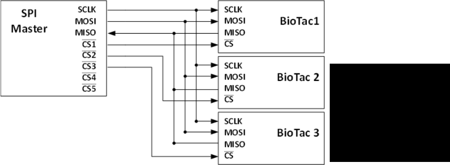
8.2 SPI Configuration
Figure+12+X+SPI+Connection+Overview+
SPI Communication Details
• Word Structure: 2-byte words (16 bits)
• Clock rate: 500kHz-10MHz
• Clock priority: idle low
• Clock phase: first edge
• MISO is changing at negative edge of SCLK; master should sample the signal
from MISO line during positive edge and NOT sample the MISO line during
negative edge of SCLK.
***
The locations of the
wires do not reflect
the arrangement on
the connectors
***

Page%|%17%%
%
• BioTac SP samples MOSI line around positive edge; master should change
the signal at negative edge and NOT change the signal at positive edge.
MISO
MOSI
Signal update
-ve clock edge
-ve clock edge
Signal sample
+ve clock edge
+ve clock edge
Table+6+X+Timing+of+SPI+signal+update+and+sample+
8.3 Command Types
There are four types of basic commands between the host controller and
individual BioTac SPs:
• Sampling command
• Resend command
• Parameter Set/Write command
• Parameter Read command
Page%|%18%%
%
Figure+13+–+SPI+Communication+Protocol+Command+Types+and+Structure+
While SPI supports full duplex transmission, the current version of SPI protocol is
designed to communicate in half duplex with two-byte commands being sent
from the host and 2xn bytes of response from the BioTac SPs.
! While listening to the responses from the BioTac SP the host should
write 0x0001 to the MOSI lines to avoid errors.
MF;F- 9"D:$3*5&2'DD"*0&
8.3.1.1 Description/
The sampling command is a 2-byte command from the host. Only the first byte is
processed and the second byte is ignored. Upon receiving the 2-byte command
from the host, all BioTac SPs with an active slave select during the command
simultaneously and independently sample the requested channel specified by the
6-bit command SSSSSS (63 possible channels) and load the value into a 2-byte
buffer.
First Byte
Second Byte
bit#
7
6
5
4
3
2
1
0
7
6
5
4
3
2
1
0
Sampling
0b
1
S
S
S
S
S
S
P
X
X
X
X
X
X
X
X
Resend
0b
0
1
0
1
0
0
0
0
X
X
X
X
X
X
X
X
Set/Write
0b
0
1
0
0
0
0
0
0
N
N
N
N
V
V
V
P
Read
0b
0
1
1
0
0
0
0
1
N
N
N
N
V
V
V
P
Subset
Variables
0b: indicating the command is sent as binary code
0/1
: command type
SSSSSS: sampling channels number (0~63)
NNNN: subset number (0~15)
VVV: variable number (0~7)
P: parity check (odd parity)
X: ignored
Page%|%19%%
%
! NOTE: A minimum of 50µs delay is required between the sampling
command and response from the BioTac SPs. During this time the CS
lines should be disabled.
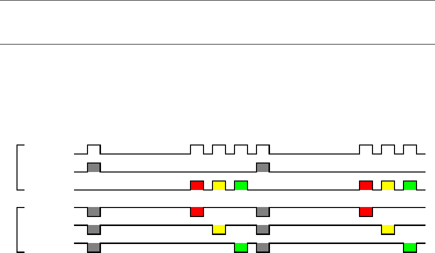
After the minimum delay of 50µs individual BioTac SPs can be queried for this 2-
byte buffer by enabling the CS and CLK line to each BioTac SP for two bytes.
This buffer must be read before sending a new sampling request. A sample of
the recommended communication structure is outlined below:
Figure+14+X+Recommended+Sampling+Sequence+for+3+BioTac+SPs+
Bytes 2B 2B 2B 2B 2B 2B 2B 2B
Timming,Delay 50µs 5µs 5µs 5µs 50µs 5µs 5µs 5µs
SPI,clock
MOSI
MISO
BioTac,1,/CS
BioTac,2,/CS
BioTac,3,/CS
Sample
Sample,Delay
BT1,Transmit
Delay
BT2,Transmit
Delay
BT3,Transmit
Delay
Sample
Sample,Delay
BT1,Transmit
Delay
BT2,Transmit
Delay
BT3,Transmit
Delay
SPI,Master
BioTacs

Page%|%20%%
%
8.3.1.2 Detailed/Sampling/Commands/
Description
Index
1st Byte
Command
Return
(bytes)
Note
Pac
0
0b10000000
2
/
Pdc
1
0b10000011
2
/
Tac
2
0b10000101
2
/
Tdc
3
0b10000110
2
/
Hall Sensor
15
0b10011110
2
Only on specific models
Version 1.1 Streaming
Protocol
16
0b10100001
92 x
#Frames
See Appendix for details
of SPI V1.1 Protocol
Get Electrode #1 data
17
0b10100010
2
/
Get Electrode #2 data
18
0b10100100
2
/
Get Electrode #3 data
19
0b10100111
2
/
Get Electrode #4 data
20
0b10101000
2
/
Get Electrode #5 data
21
0b10101011
2
/
Get Electrode #6 data
22
0b10101101
2
/
Get Electrode #7 data
23
0b10101110
2
/
Get Electrode #8 data
24
0b10110000
2
/
Get Electrode #9 data
25
0b10110011
2
/
Get Electrode #10 data
26
0b10110101
2
/
Get Electrode #11 data
27
0b10110110
2
/
Get Electrode #12 data
28
0b10111001
2
/
Get Electrode #13 data
29
0b10111010
2
/
Get Electrode #14 data
30
0b10111100
2
/
Get Electrode #15 data
31
0b10111111
2
/
Get Electrode #16 data
32
0b11000001
2
/
Get Electrode #17 data
33
0b11000010
2
/
Get Electrode #18 data
34
0b11000100
2
/
Get Electrode #19 data
35
0b11000111
2
/
Get Electrode #20 data
36
0b11001000
2
/
Get Electrode #21 data
37
0b11001011
2
/
Get Electrode #22 data
38
0b11001101
2
/
Get Electrode #23 data
39
0b11001110
2
/
Get Electrode #24 data
40
0b11010000
2
/
Table+7+–+Sampling+Commands+
8.3.1.3 Response/Format:/
Signals from sensors are digitized as 12-14 bits of data; and split into two bytes
(low byte and high byte) in the following format.

Page%|%21%%
%
Figure+15+–+Sampling+Command+Response+Format+
8.3.1.4 SPI/Version/1/Communication/Note/
Sending a 0b10100001 command enters SPI Version 1.1 program loop,
described in appendix A. To exit this loop, CLK must remain idle for 5 seconds.
8.3.1.5 Error/Handling/
Sampling Errors
BioTac Response
Description
Insufficient Sampling Delay (-)
0b10100101 00101101
There has been insufficient delay between
the sampling command and response time
(minimum delay is 50µs)
Channel Not Recognized (X)
0b10100101 01011000
The channel is not recognized by the
BioTac firmware or unavailable
Table+8+–+Sampling+Error+Responses+
MF;F7 N"+"&J%,%*0&2'DD"*0&
The data resend command is a 2-byte command from the host. Only the first byte
is processed and the second byte is ignored. Upon receipt of the data resend
command, the BioTac SP responds with the previous 2 bytes of sampled data
(this should be used in case of a parity error).
Chip select can be used to request a data resend from an individual BioTac SP.
If the data resend command is sent before the BioTac SP has been sent a
sampling command the BioTac SP will ignore the resend request.
MF;F; 9%+OP/3+%&"*0&/%"0&2'DD"*0&
The set/write and read commands are a 2-byte commands from the host (with
additional bytes in the case of set/write. Upon receiving the command the BioTac
SP responds with 2x bytes.
Group index
Subset name
Function
1
NNNN=0001
Information
BioTac SP general parameters
6
NNNN=0110
CPU
BioTac SP CPU parameters
7
NNNN=0111
Internal
sampling
Internal sampling mode parameters
Table+9+–+Read/Write+Function+Subset+Groups+
MSB LSB
Parity 0 0 Parity
bit-15 bit-14 bit-13 bit-12 bit-11 bit-10 bit-9 bit-8 bit-7 bit-6 bit-5 bit-4 bit-3 bit-2 bit-1 bit-0
Data<11:5>
Data<4:0>

Page%|%22%%
%
Description
2nd byte
Command
Return
Bytes
rw
Details
NNNN = 0001
/
/
/
/
General information
subset
0b0001VVVP
/
/
/
Flex version
0b00010000
2
r-
Format: M.N - ASCII (no parity)
Software version
0b00010011
4
r-
Format MMNN - ASCII (no
parity)
Serial number
0b00010101
16
r-
Format ASCII (no parity)
NNNN = 0110
/
/
/
/
CPU information
subset
0b0110VVVP
/
/
/
CPU speed
0b01100001
2
r-
0-65535 kHz (no parity)
NNNN = 0111
/
/
/
/
Internal sampling
information subset
0b0111VVVP
/
/
/
Sampling frequency
0b01110000
2
r-
0-65535 Hz (no parity)
Sampling pattern
0b01110011
2 x n
r-
2 byte channel array:
0b 1SSSSSSP 00000001 x n
Last Sample Ends in:
0b 1SSSSSSP 11111110
Table+10++X+Read/Write+Function+Details+
8.3.3.1 Error/Handling/
Set/Write Errors
BioTac Response
Description
Parameter is read-only (R)
0b10100101 01010010
Trying to write to a read-only parameter
Table+11+–+Read/Write+Error+Codes+
Page%|%23%%
%
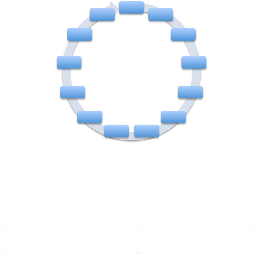
Q 9"D:$3*5&,%K1%*2%,&
While the sampling sequence is configurable and controllable by the host by
sending various sequences of sampling commands the following sequences are
recommended by SynTouch to optimize the available bandwidth of sensory
modalities and reduce the communication bandwidth.
9.1 Default Sampling Sequence
Vibrations signals are measured (PAC) and interleaved with the electrode
impedances (Electrodes #n) and other sensor signals (PDC, TAC, and TDC). It is
recommended that this sampling sequence is run at a minimum 4.4kHz to take
advantage of the full bandwidth of PAC and electrodes.
Sequence (54 Samples/frame):
PAC, E1, PAC, E2, PAC, E3, PAC, E4, PAC, E5, PAC, E6, PAC, E7, PAC, E8, PAC, E9, PAC,
E10, PAC, E11, PAC, E12, PAC, E13, PAC, E14, PAC, E15, PAC, E16, PAC, E17, PAC, E18,
PAC, E19, PAC, E20, PAC, E21, PAC, E22, PAC, E23, PAC, E24, PAC, PDC, PAC, TAC, PAC,
TDC
Bandwidth:
Data: 16 bits/ch/BioTac SP, 864 bits/frame/BioTac SP
Communication Overhead: 864 bits/frame
3 BioTac SPs sampled at 4.4kHz: 281.6 kB/s
Page%|%24%%
%
Figure+16+–+Recommended+Default+Sampling+Sequence+
Using the recommended sampling rate of 4.4kHz, this permits for the following
bandwidth:
Sensor type
Numbers of sensor
Sampling rate
Signal bandwidth
Electrode
24
73Hz per electrode
36.5Hz
AC Pressure (PAC)
1
2200Hz
1100Hz
DC Pressure (PDC)
1
73Hz
36.5Hz
AC Temperature (TAC)
1
73Hz
36.5Hz
DC Temperature (TDC)
1
73Hz
36.5Hz
Table+12+–+Bandwidth+and+Sampling+rate+for+Default+Sampling+Sequence+at+4.4kHz+
9.2 Alternate Sampling Sequences
QF7F- <$$&)4"**%$,&R7M&9"D:$%,O(/"D%ST&
This sampling sequence is advised when high bandwidth vibration is not
necessary. It reduces the sampling rate of PAC to conserve bandwidth.
Recommended sampling rate is 3.1kHz, however lower sampling rates can be
used if desired. This is a preferred sampling pattern for a low-bandwidth standby
mode when not interacting with objects. NOTE: when using this sampling
sequence PAC is subject to aliasing.
Sequence:
E1%
Pac%
E2%
Pac%
...%...%
E24%
Pac%Pdc%
Pac%
Tac%
Pac%
Tdc%
Pac%
Page%|%25%%
%
PAC, PDC, TAC, TDC, E1, E2, E3, E4, E5, E6, E7, E8, E9, E10, E11, E12, E13, E14, E15,
E16, E17, E18, E19, E20, E21, E22, E23, E24
Bandwidth:
Data: 16 bits/ch/BioTac, 448 bits/frame/BioTac
Communication Overhead: 448 bits/frame
3 BioTacs sampled at 3.1kHz: 198.4 kB/s
3 BioTacs sampled at 310Hz: 19.8 kB/s
QF7F7 8$%2+/'0%,&U*$6&
This sampling sequence is preferred for force extraction algorithms that make
use of the BioTac electrodes, preferably for lighter forces. The recommended
sampling rate is 1.9kHz.
Sequence (24 Samples/frame):
E1, E2, E3, E4, E5, E6, E7, E8, E9, E10, E11, E12, E13, E14, E15, E16, E17, E18, E19, E20,
E21, E22, E23, E24
Bandwidth:
Data: 16 bits/ch/BioTac, 384 bits/frame/BioTac
Communication Overhead: 384 bits/frame
3 BioTacs sampled at 2.4kHz: 153.6 kB/s
Sequence:
QF7F; <)ON)&C/%,,1/%&
This sampling sequence is preferred for high-resolution sampling of vibration
signals and alternates between the PAC and PDC channels. The recommended
sampling rate is 4.4kHz.
Sequence (2 Samples/frame):
PAC, PDC
Bandwidth:
Data: 16 bits/ch/BioTac, 32 bits/frame/BioTac
Communication Overhead: 32 bits/frame
3 BioTacs sampled at 4.4kHz: 281.6 kb/s
QF7F? 93*5$%&)4"**%$&"*0&U+4%/&9"D:$3*5&9%K1%*2%,&
The provided sampling sequences above are merely guidelines and users are
able to customize their own sampling sequences or configure software to sample
a single channel at any rate they prefer.

Page%|%26%%
%
<::%*03H&<F I"+%/3"$,&
Part
Material
Weight
Remarks
Core
Vectra® Thermoplastic
7 g
Durable
Skin
Silicone Elastomer
2 g
Good Wear
Properties
Bracket
Aluminum
0.5 g
Anodized
Electrodes
Stainless Steel
-
Screws
Stainless Steel
-
Cover Plate
Stainless Steel
-
Fluid
1M Sodium Bromide
dissolved in PEG-
200/Water mixture
0.3 - 0.5 g
Nontoxic
Page%|%27%%
%
<::%*03H&VF W%5"$&
BioTac® SP Warranty
1. The customer should check goods immediately after receipt for possible
problems. Defective, damaged, or missing goods (hereafter: Defective
Goods) are to be reported to SynTouch in writing within 5 working days. If
a customer elects to not notify SynTouch about Defective Goods, or if a
customer uses Defective Goods they waive all rights under this warranty.
2. Repairs or replacements of Defective Goods occur at the discretion of
SynTouch. Discretion is not waived under any circumstances, including
prior attempts to repair or replace Defective Goods.
3. Upon SynTouch acknowledging notice from a customer about Defective
Goods, SynTouch has 90 days in which they may elect to resolve the
issue by either: A) repairing or replacing the Defective Goods, or B)
crediting the customer for the value of the Defective Goods.
4. The customer must provide access by shipping Defective Goods and all
documentation about them to SynTouch. SynTouch may elect to send a
representative to the customer, in which case the customer must provide
access by enabling the representative to perform testing, repairs and
replacements to Defective Goods. If a customer refuses to provide
access they waive all rights under this warranty.
5. After receiving an acknowledgement about Defective Goods from
SynTouch, if 90 days elapse without resolution of the issue, a customer
has the right to a credit for the Defective Goods. To receive their credit a
customer must return the Defective Goods along with a written description
of the issues encountered, and a written description of efforts to resolve
the issue.
6. No warranty claims will be accepted if it is determined that the cause was
due to normal wear and tear, or damage caused by faulty or negligent
maintenance, shipping with packaging other than the original packaging,
modification, or use outside the specifications listed. Nor will warranty
claims be accepted if it is determined that Damaged Goods have
insignificantly reduced value or utility.
7. No warranty claims will be accepted if the customer removes the screws
holding the skin in place.
8. SynTouch is not liable for consequential or incidental damages during
customer attempted repairs or any cost or expense of providing substitute
equipment during periods of malfunction or pending repairs.
9. If any part of this warranty is deemed unenforceable, all remaining parts
remain in full effect.
Page%|%28%%
%
Customer Service and Health and Safety Acknowledgements
QF7FA CXJCU98&
This document is intended as a written confirmation of the terms and conditions
under which SynTouch LLC will provide Customer Service for our products to our
customers. This agreement defines the services SynTouch LLC will provide to
customer in conjunction with license of or purchase of SynTouch LLC products
as well as Customer’s notice and acknowledgement of any potential hazards,
restrictions or limitations with regards to SynTouch LLC’s products.
QF7FB )X9!UI8J&9XCCUJ!&<YN&98JZ.)8&
Under this agreement, Customer seeks to receive, and SynTouch LLC agrees to
provide customer service, in some cases for a fee, for Customer’s purchased
SynTouch LLC products.
Customer agrees and understands that some service options may be limited to
normal business hours and days of the week. Customer agrees and
understands that this agreement only covers their SynTouch LLC products and
not any third-party product or modification. Customer understands that if it is
determined that support and service are being used to support a third-party
product or any modification or alteration to a SynTouch LLC product not
authorized or approved in SynTouch LLC documentation, Customer may be
charged and Customer agrees to pay for such service, at SynTouch LLC’s sole
discretion .
QF7FE )X9!UI8J&G88NV<)[&
Under this agreement, SynTouch LLC seeks to receive, and Customer agrees to
provide, certain levels of customer feedback regarding Customer’s purchased
SynTouch LLC products.
QF7FM !<\89&<YN&!<J.GG9&
Customer shall be responsible for payment and satisfaction of all taxes
applicable and/or tariffs, costs of import or costs of export related to purchasing,
shipping or transporting materials for providing services under this agreement.
QF7FQ 9<G8!]&<YN&@8<W!@&<)[YUPW8N^8I8Y!9&
SynTouch LLC is concerned for your safety has communicated to Customer, and
Customer understands, the following potential safety and health issues
associated with SynTouch LLC Products:
1. SHARPS WARNING Many SynTouch LLC products use a standard
insulin syringe with a 25 gauge needle in the operation of said products.
Customer acknowledges
Page%|%29%%
%
a. that he or she has consulted with a SynTouch sales, marketing or
development professional regarding whether his or her purchase
uses such needles and therefore whether proper operation of that
product involves a sharps hazard;
b. that Customer is wholly responsible for communicating such a
hazard to any parties using his or her SynTouch LLC product,
whether or not such use is under his or her supervision; and
c. that Customer is wholly responsible for proper storage and disposal
of sharps and biomedical waste in conjunction with operation of his
or her SynTouch LLC product and in compliance with applicable
law.
2. CHEMICAL WARNING Many SynTouch LLC products use certain
chemicals in their operations. Customer acknowledges:
a. that Customer has been provided with the Material Safety Data
Sheets (MSDS) for all SynTouch LLC products he or she has
purchased, either with said purchase or through a request to a
SynTouch LLC sales, marketing or development professional;
b. that Customer has read all MSDS for chemicals used in the
appropriate SynTouch LLC products and understands the potential
safety and health risks associated with such chemicals;
c. that Customer is wholly responsible for communicating such a
safety and health risks to any parties using his or her SynTouch
LLC product, whether or not such use is under his or her
supervision;
d. that Customer will provide copies of the MSDS for chemicals used
in the appropriate SynTouch LLC products to any parties who
request them in conjunction with the Customer’s SynTouch LLC
products; and
e. that Customer is wholly responsible for proper storage and disposal
of chemicals in conjunction with operation of his or her SynTouch
LLC product and in compliance with applicable law.

Page%|%30%%
%
Indemnification
Customer shall indemnify and hold harmless SynTouch LLC for all legal claims
resulting from Customer’s failure to reasonably communicate information in this
agreement to parties using Customer’s SynTouch LLC products, reasonably
communicate information listed under above section Health & Safety
Acknowledgements to parties using Customer’s SynTouch LLC products or
failure to take steps to account for responsibilities listed under above section
Health & Safety Acknowledgements. SynTouch LLC shall indemnify and hold
harmless Customer for all legal claims resulting from failure to respond in a
reasonable time to requests made by Customer under above section Health &
Safety Acknowledgements or for failure to provide full information requested in
response to requests made by Customer under above section Health & Safety
Acknowledgements. Procedure. In case any Claim is at any time brought against
Syntouch LLC or Customer, the party obligated to provide such indemnification
(the "Indemnifying Party") will defend such Claim, at the sole expense of the
Indemnifying Party, using counsel selected by the Indemnifying Party but subject
to the Indemnified Party's reasonable approval. If the Indemnifying Party fails to
take timely action to defend such a Claim after having received written notice
from the Indemnified Party of such failure, the Indemnified Party may defend
such a Claim at the Indemnifying Party's expense. The Indemnifying Party will
keep the Indemnified Party fully advised with respect to such Claims and the
progress of any suits, and the Indemnified Party shall have the right to
participate, at the Indemnified Party's expense, in any suit instituted against it
and to select attorneys to defend it, which attorneys will be independent of any
attorneys chosen by the Indemnifying Party relating to such Claim or related
claim. The Indemnifying Party will not settle, compromise or otherwise enter into
any agreement regarding the disposition of any Claim against the Indemnified
Party without the prior written consent and approval of the Indemnified Party
which shall not be unreasonable withheld.
GOVERNING LAW
This Agreement and the performance hereunder shall be governed by the laws of
the State of California without regard to conflicts of law rules. The Parties agree
on behalf of themselves and any person claiming by or through them that the
sole and exclusive jurisdiction and venue for any litigation which may arise
hereunder shall be an appropriate federal or state court located in the County of
Los Angeles and the Parties hereby consent to the personal jurisdiction of such
courts.
DISCLAIMERS AND LIMITATIONS
DISCLAIMER OF WARRANTIES. EXCEPT AS OTHERWISE PROVIDED IN
THIS AGREEMENT, NEITHER PARTY MAKES, AND EACH PARTY HEREBY
WAIVES AND DISCLAIMS, ANY REPRESENTATIONS OR WARRANTIES

Page%|%31%%
%
REGARDING THIS AGREEMENT OR THE TRANSACTIONS CONTEMPLATED
HEREBY, INCLUDING ANY IMPLIED WARRANTIES OF MERCHANTABILITY,
FITNESS FOR A PARTICULAR PURPOSE OR NON-INFRINGEMENT OR
IMPLIED WARRANTIES ARISING OUT OF COURSE OF DEALING, COURSE
OF PERFORMANCE OR USAGE OF TRADE.
LIMITATION OF DAMAGES. NEITHER PARTY SHALL HAVE ANY LIABILITY
TO THE OTHER PARTY FOR ANY LOST PROFITS OR SPECIAL,
INCIDENTAL, PUNITIVE, EXEMPLARY, INDIRECT OR CONSEQUENTIAL
DAMAGES, EVEN IF SUCH PARTY HAS BEEN ADVISED OF THE
POSSIBILITY OF SUCH DAMAGES, NOR SHALL ANY OF THE TERMS OF
THIS AGREEMENT BENEFIT OR CREATE ANY RIGHT OR CAUSE OF
ACTION IN OR ON BEHALF OF ANY PERSON OR ENTITY OTHER THAN THE
PARTIES HERETO REGARDLESS OF THE FORM OF THE ACTION,
DAMAGE, CLAIM, LIABILITY, COST, EXPENSE, OR LOSS, WHETHER IN
CONTRACT, STATUTE, TORT (INCLUDING WITHOUT LIMITATION,
NEGLIGENCE), OR OTHERWISE, PROVIDED THAT THIS LIMITATION SHALL
NOT APPLY TO ANY AMOUNTS PAYABLE TO THIRD PARTIES UNDER THE
INDEMNIFICATION PROVISIONS OF THIS AGREEMENT OR TO BREACH BY
A PARTY OF THE CONFIDENTIALITY OBLIGATIONS APPLICABLE
HEREUNDER.
Severability and Conflict of Prevailing Law: The provisions of this Agreement
are severable and if any provision shall be rendered invalid, void or otherwise
unenforceable by statute, court order or any other legal action, it shall not affect
the validity or enforceability of any other provision and all remaining provisions
shall remain in full force and effect. Should any applicable federal law of the
United States or applicable international treaty of which the United States is a
signatory conflict with any part of this agreement, that part of the agreement shall
be read and construed as broadly as possible within the limits of that law or
treaty, and all other provisions of this agreement shall be unchanged and retain
full force and meaning.

Page%|%32%%
%
CONTACT
SynTouch LLC
2222 S.Figueroa St, PH2
Los Angeles, CA 90007
213.493.4400
info@syntouchllc.com
www.syntouchllc.com
