Unknown Boat Building Manual
User Manual: manual pdf -FilePursuit
Open the PDF directly: View PDF ![]() .
.
Page Count: 246 [warning: Documents this large are best viewed by clicking the View PDF Link!]
A project of Voluntsers in Ash
Boatbuilding Manual
._I
by Robert M. Steward
Published by:
International Marine Publishing Company
21 Elm Street
Camden, Maine 04843
USA
Available from:
same as above
Reproduced by permission.
Reprodlrction of this microfiche document in any
form is subject to the same restrictions as those
of the original document.
2n.d Edibbn
6v
International Marine Publishing Company
~.11111,1,‘11. .\ln,u,, 04s Ii

1
2
3
4
5
6
7
8
9
10
11
12
13
14
15
16
17
FOREWORD “’
Vlll
PREFACE ix
PREFACE TO THE FIRST EDITION xi
GENERAL 1
PLANS 10
TOOLS 15
WOOD 19
FIBERGLASS AND OTHER HULL MATERIALS
FASTENINGS 46
LINES AND LAYING DOWN 66
MOLDS, TEMPLATES, AND THE BACKBONE
SETTING IJP 108
FRAMING 117
PLANKING 130
DECK FRAMING 153
DECKING 161
DECK JOINERWORK 170
INTERIOR JOINERWORK 182
MISCEELftNEOUS DETAILS 192
SAF!?Y STANDARDS 227
RECOMMENDED READING 231
EQUIVALENTS 233
INDEX 236
35
88

l’h ligtlls otrt.11 showt*tl bright lalt* in lht* t~vt*ning 21 rht. ?i!i/zNItlJt) in IIiin1irlglc~l.
Nt-w York, anal r2b1il inrlc- 10 (tfj 50 aI :\r~c~t~ortIowri J1c.w in D;hricw. I havv tvijovtd ;L
tit’c~linic* intluc-ncxscl tjv I IIt. t;\tk of srnatt 1Jo;iIs 1 tit-ir tlc3ign. I tIcA I)uittting. ;~rdl I ticbir
us(*. Most rcwarclill,~ of all ;Ispc’( lb. tx.1 tiat~s. arc ItIc* tc*:l(*:s lhdl ccbmc’ ;Itong It.1 I (.I’!?
c*ulcJilin,g Itic- <grand c~st)c-ric~ncx-
c*n(.oulll~‘lt’(l in ItIt* tJuil(liyg ot ;1 l)Oill!
‘t’hc~rc~ has always Ilt-c-n gr~a’ saridac[ion 3 just itid fcc-tinSg 01 accomplish-
IlIl’Ill rrbla!td to making things with one’s own hands. in this age of specialization I
t)c~tit-v~ hoal huitding can offer t’v~n morr satisfarrion as wctt as rrlaxalion and a
c.ti:illc*ngc- (0 individual ahilitv and irigrnuitv. FPw things involvr Itit, manv skills rt*-
cluirot in \)uil(ting a bcJ;rt c;1( h rxscntial fat- it4 succxsful c~nnplcrion. PlJssibly nothing
c*tsc* i5 as rc-wdrttin~g.
I;urrht*r. nict-ly tastiiontd. d-t)uilt tJo;tts art* growing mort~ and mor(* t3pt-nsivt-.
‘1‘0 huittt your own rn;iy wt*tl t)c* ;I practic,,lt sotulion ;1s wcdt as rc*wirding. Surctv ttw
,jovs of bring krtloar ;ir(b manifoltl, and t host- t3ptGnc-rd ;Il~o;ird ;1 t>bJal you ti;lvt- Luitl
with your 0wI1 hdntls ;iI(’ inimt~dsurabtt-.
Hot, Stcwartt. tGng t~sc~t~ptionalt~ welt quatiiicd t)v his tong c~sp~-rit*nix~ in r!ic “world
of small stiit~s.” ha5 l)roductd ;I cl~~ai-iy writttbn It’s1 of nici-it and grrat worth. At’tt-r
vt*ilrs as an ;~ppr~-ntic~~- ht. work4 in scvc-rat small boat vards btaforc joining rhr highly
rcspecrerl office of naval architect Philip 1.. Rho&s. where he spent manv yrars cn-
I ,
gagecl in dcsi<gning and planning numc’rous power and sailing vachts. as welt as com-
mt~rciat boats. I’ttt* prriod of World War II found him in an tyginrering c-apacitp
working bt-twrlrn vari:jalq vards and &sign off&s. Far morr plcasanl work was . . >tirn-
rd at the war‘s t%ntI involving vat t.i ax: Bob ac‘\elrtit (! :I lx)sition wirh a Wrs. Coast
firm as superint,.-dent of vachr repair anti construction. Somerime ti;Icr tx returnd
IO I hc East Coast where a number of vac.hr designs werr proctucxd. ranging from 22 LO
73 ft’et . which required his cxperirn&i supervision of loft in= anti cnnslruction. l‘hc
vii

viii f~Ol<I-~ II’OHI)
warmer- cllrne tjt~ckontd. wi! h its slowt~r l)acx- anti t*.isitar iivin,g. ant! 13oh ~onrinut~tl his
work In~(jlv!rl,q the d~s~gn~n~ anti supervlslon of Ilumt’rous var.lli\ PIt.st.~lr iv i~r* is !vi!i!
a Floritla tJuiltlcr. whtarl* iIt> is co11t t-rncd wit Ir I ht. cIt*sign rlntl prc),qrt*~~ 01 clulstantling
p”W”’ ;a< hIS.
Bol) S~vwartl‘s classic- work has bcbtbn ht*ar-iily I-cc t*ivc-d from rlicb rimt- iI w;ls first
l,uhlishd. In this larrsl tdition. Hoh has Inatlt~ riumt~rous revisions daring IO nt-w
marrrials and presenr rrgularit~ris antl sIandaids in atltliIion 10 provicling more* of his
wonth-fully char drawings. Surt-Iv I his comprt~ht~nsive anti practical marvrial. SO ~~11
prcxn1td. will provitlr~ ! ht- .rnialt~r- boatt~uilrlt~~ arid Itit+ f)roft3sional with ;I worltl 01
v;Ilutd ant1 valid information. Intlccd. scardv a wt.t-k passe-s wht*n. in wriring It-IIt-1-s
I(J hoa huiltlvrs ail ovt’t I IIt* world. I (1~: no1 sii#gt-51 Hofr(hrr/ltl/~rg ,tlfltrrrfr/ as ;d sourt‘(- 01
knowlt~tigc,
,~011l1 .Alhill ?I .s.r\ & XI.E
t\nc tl~lr-tl~nvIl
Dalit~l. C:c~nnc~ ricur

II is indt*tvl ditficull IO rt-;ili/cs rli;tl IO yc*;11-s li,1\,tb passtbd since Inic~rnaiional Marim,
f’uhli5hing (:~m1l1;11iv wt.111 i11ro Ou4int*bs nritl ;1c.tluirc*cl ltw cxqyighr IO flotr//~rrr;tlttr~
.ll,ctrrrtr/ II 11:*c lM’~~ll :I Ir.rr, I\' !Il:lI !-I.:;;:. !!E!
."I I ! !::*:x h;1LT !XX~I! :ic‘i; 'Ul! iKl ii1 Tc‘iir c .> rlihi
i1ig llii~ tlt~ iidt.: Boris l.au(-1. L.tv~n;irtli. ihca sniall I1r~;1ll1uildt~1’~ slaurit~li Ir-itv1tl. ;irIll
f’hil Rhoclt5. OII(- of Ilit~ ,qwaItw ;i~Iti mosi vt*rs,iIili* 1i:i\~l art hi1cv 14. li;rvc- l~oili +;tilrvl
ovt*r lilt- hoi izcjtr ~11tl dt(’ 111i55t*il l1v mdnv irit-ncls.
I v~*nl IO llavt* I1t7-Ii t,xl105tvI I0 Inilnv 111ort’ p(*iq)It~ 5im.t. Ilit- I;151 tvlili~,ti o! flflttr
hrr//tlt’t/,q .IltrtIrrfl/ ;illii il Il;is l~i*i~Il gri11ifVilIg I0 mt 3 so m;inv who h;ivt* rt-;icl ~1111
It~;ll~Ilt~tl 1’1~0111 11 1t
’ \ 1c)c)k. In .icltiilicm. rhv Iwo vac~hr dt~sign sc~lioo~~ in IIitb I’ S. ~onlinuc~
10 us fhlfl I I/ lr;lr!il,,~ Alfl t11111: a _ IVSC material. l’acht Dvsign Insrirurcb. in Brooklin.
Mainc~. uws rhtk coml)l~tt~ l)ook. while thtb Wtbstlawn School of 1’ac-h1 DrsiRn. Sram-
ford. Connc~~it~ut , rtyrinrb portions of rhe hook.
~I‘hroqqhout I his hook. vou will find [ht. names ant1 aildrt~~sc~s of firms Illill c‘arr1
IOOIS a11t1 111att.arials or firms that providtb svrvicrhs of valur lo boatbuildrrs. 9~11 h men-
Zion is noI IO IW vonstrucd ijs advvrtising for the products or sty-vice offtvxvl. Rarhc-r. I
iwlit~w lha~ Iht* rthacit-r will Iwrwfit fro1n my rt-srilrch of tht* s(1urcx.s. Conli~ct lhtb firms
ctirc-crly iIlltl lt*ll tht’r11 wlI;ll you Ilt-tvt.
In adtlitic1ri 10 thia fI!lolo and illusrration crvdiis given in the caarlit-r tditioll. I wish 10
thank the following sour(‘vs: Srcmann Plastics. Inc.. Hurkins \1’il<hr CI~rpIIralion. ,rlItl
Gtlugcwl HIothcrs. Inc , for the ust‘ of photos .
311 lhis revis rdition: tliv Xirrbs ciisision
of h11za. Illl~.. for ho~h phoros ancl skrrc-ht-s; and SW nirigazinta for permission IO us{’
drawings that I did years ago for how-to-build articles that appeared in 7‘/1r Rudrf~~r
I cannot close wiihout thanking Dorothv C. Marks fo1 doing some of thth rt*vision
copy ior me with her 5 percmr rypIng meanin,g that she can ‘I;pc a pa,gP 31 times
fasrw rhan 1 ran.
KotitW M. .Sltward
,jat~lamt ilk. FItAla
l);lriIlg ;I Ilic~i~liIl# ii num!,ci I,f‘)c..ii.> .i,gtt \lillI IL,r-ih l..lu~-I -Ix-t~tldrrli dntl ilit- Irtlr* :4\111lL
Pillll’rsOIl. Etlilor ilIlt BusiIit-ss M;tIl;tgc~I~ rty)t7Iivt~ly Of IlIt* fintb (,I(1 it/ltttlt*r Illil#il/iIl~‘,
ii was clct~iclt4 IIlitl I Shoultl wriits sonll~ ,irIit.lt-s ill)OUt hoirl (~011slruc lion ;tinlcVl ill IlIt-
amalt-uI’ ;tIl~l. Ilol!t~l‘uII,‘. of soIlIt’ VillUt’ I0 lhca l~r0ft~SSiC~IIitl. -1‘lris (It7 ision It~sulltvl ii: ;I
sturic5 of ‘LO c.oIIst~ciIlivt* Inorlllllv l)itxx3 I Il;tl Mx*rt* So \\~t~ll rtxx~ivt~tl Ill;11 I hty wt’rt- Illiltlt*
inlo il i:ook. J‘ht- rtw~f>litrIl ol Ihis, IOO. was c~IiIhusi,isIic. ~llill ~)on .itlt*l iI w;h in
~r~tl~(~*tl. I Ilt- l)o(bk $viIS l)uhlislIt~tl itl)Ioatl iII L’I~t~I~t II. l.t*1It51S 01 itl)l)IovitI wt*r(’ rtG\c~cl
from afar. On<* IhaI lingt.rs in IIIV mint1 was frton a l‘urkislt naval oflicc,r who IIOI onI)
bouplIr Iht- I)ook. ~LII also l)uilI a I)oaI lrom III\’ plans. ‘l‘il~ll ii#i3ill Olin Sl~pht~IlS.
faIntd yacht ticsi,gncr. lolcl nit’ how I tic E‘rcnr.11 tbtiirion was of \alut* lo him on an ins
slx‘t.Iion writ) in I;:urol)t- ~vht*n Ihtb I)ook illusrrarions scrvtyl IO brrak a language- harrit*I
lxYwc*t*n hiiI anti a l)uiltlt*r. .l‘hirigs like Ihis al-t- lit~drIt;-II. htx~au~- in SO sm;tll a ficltl
lllr* Ill~:11t’lilr~ rtwartl niubl, UIlfOrtLlllillt~l~. hc stxxmtlilrv.
As Iimt* wt*nI orl. I he numl~t*r of rqutxIs for Ihtb hook showtd I haI a rt*\,i&m wab in
ortlt-I . Sll IlOW \VI’ Il.lVC~
fjo///1lf11’/f1it~
,g .Mtrurrrl/. qain tiont- wirh Ilit- t~nIhu~i3sm of Boris
ilb il l)I.iIIIt’ movi~r. I l a I ioirgh llit7~~ IlilVt’ hcbt-Ii Iimt*s, wlit-Ii Iht* midIiighI oil was burniIi~y
IOW. I IIiII I WiIS IIOI SO lIi\l’l)v wirh his l~rodtling .l‘ht> ‘II’W l)ook has t)(bcIl rcwriI~cn. I)UI
inc~lutlt~S it IIrIl(’ Ot lht’ Oltl. iIS Wt.11 a5 It~c~tiniilIIt5 I 1lilVt’ 1)icbt.d lip in ltltb inrcrim. illltl
nt’w m;tIt~rialS I haI Ilao* I)t~t*n accrptcd.
DO noI think IhaI Ihis or any orhrr book can Itsac-h all Ihc-rt- is IO know about boaI.
building. The br*st I can hope for is I!) givt- somy guidancr IO 1h0:;c with rhr urgt- IO
build a boat an urge IhaI usually is \erv rewarding. I Irust Ihal I hi, book. plus a good
MY of plans from an unt!ersIanding and experienced desi<gncr. will lead IO rhc realiza-
tion of a drram for many who orherwisc could non enjov boaring and Ihc St-a.
Assuming 11~ has Ihr ability lvith woodworking rools. hnd is arm4 with pians and
thr &mrnts of boatbuilding set forth in this book. the1.e is no reason whv an amateur
X:
BOATi3UILDlNGi'WANUAL
Chapte: 1
During the past two decades, mort b and m’)rc people have learned how IC) use skillfully
both hand and power tools for household chores and improvements, making fur-
niture, outbuildings, and the like, and they often turn out very creditable jobs. Such
people are good candidates for boatbuilding. Y~I, many are turned off by the thought
of making something th,lt is 1101 all squat-c corners; bending wood or other flat
nlaterial to form curved shapes discourages them. And when thev look into boat-
building and see that it usually starts with a lines plan and the attrz’riant table of off-
sets that dimensions the GUI VP+ well, that’s that. These people are unnecessarily
depriving themselves of a very fascinating and satisfying pastime.
Constructing the first boat, however small, is an experience not to be soon forgot-
ten. Watching a hull grow from flat paper drawings and flat material into a shapely
form provides hours of fun and is super theraI,y after a stressful day. When the job is
carefully done, the finished vessel is a source of great pride to the builder. And unlike
a piece of furniture, which is often put in a corner and soon forgotten, a boat is used
over and dver for plrasurca through the years.
A number of lucky people with the desire to learn boatbuilding have been able to
take courses in various parts of the United States, principally in ttre Northeast and
Northwest. Unfortunately. all too few of such courses are located so that the great
number of would-be boatbuilders can take advantage of this splendid opportunity to
learn the craft, so there is still ample reason for books on bnatbuilding.
The purpose of this book is to introduce boat construction by explaining the
elementary problems involved from starting the hull until water first laps at the kee;. I
don’t purport to teach all the skills of an expert boatbuilder.
It is impossible to coker briefly all the information needed to build e\prv tyr:: of
boat. If you are fortuna:.e enough to live in a boatbuilding area, you can :>Farn a great
deal from observation. When it comes down to building the kind of boat you want,
1
--L
J
\i
‘1,
‘.
\
;
\
-
$
-.
s
-
!I
\,
:
9
.-----L
-F
.I/ ’
* iI 1.
!t
‘v
1.1
;/ ;
I
L;
,/I
i’J
,I 2
i d
5
J
i k
2
ti
-, -
i
i
‘/I
3
2
‘L
z
3
. .
g,
r=
s
3
z
:
2
2
-T
c
<
=
L
E
.z
2
z
;
-g
:
3
2
-- 2
z
52
- <
z;
2.s
-2.
z E
I c
.-
2 ;
- .z
t- .
f\ 2
,Q N
E
&tz
2-c
uk
b >,
2;
L4-2
GE.VER.4 1. 3
FLAT BOTTOMS
5COW QE’ t ALGE DORY OP 5r(1 i=F AFL i3OiTQt.l
VEE. f3Tl-TOMS
L~c.,u~HIN~ j
+.-&AE5
DEEP’ \/EE OOMLE ‘cw hrJE
?
ROUND BOTTOMS
i,\ 1) J&J/l
~A1Llt.I~ DIt.IGUf
-ucJl-OLT ROAT
I&TEL +IL~oAT
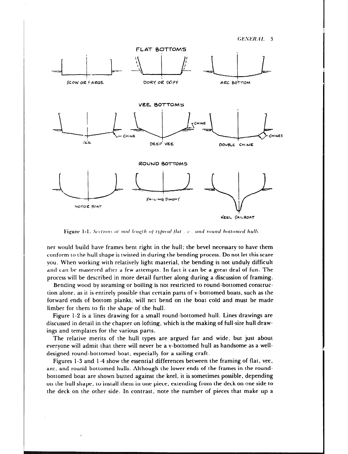
Icigurtb I-1. .St,t,t/fJ//s ftl ttf/tl /t.//q/Il fB/ /YlJlt’fl/ /lrl/ I’ rllrd rr~rrlrtt- tlrtltr~ftrtvi trrlll.\
ner would build have frames bent right in the hull: the bevel necessary to have them
conform to the hull shape is twisted in during the bending process. Do not let this scare
you. When working with relatively light material. the bending is not unduly difficult
and can be mastered after a few attempts. In fact it can be a great deal of fun. The
process will be described in more detail further along during a discussion of framing.
Bending wood by steaming or boiling is not restricted to round-bottomed construc-
tion alone, as it is entirely possible that certain parts of v-bottomed boats, such as the
forward ends of bottom planks, will net bend on the boat cold and must be made
limber for them to fit the shape of the hull.
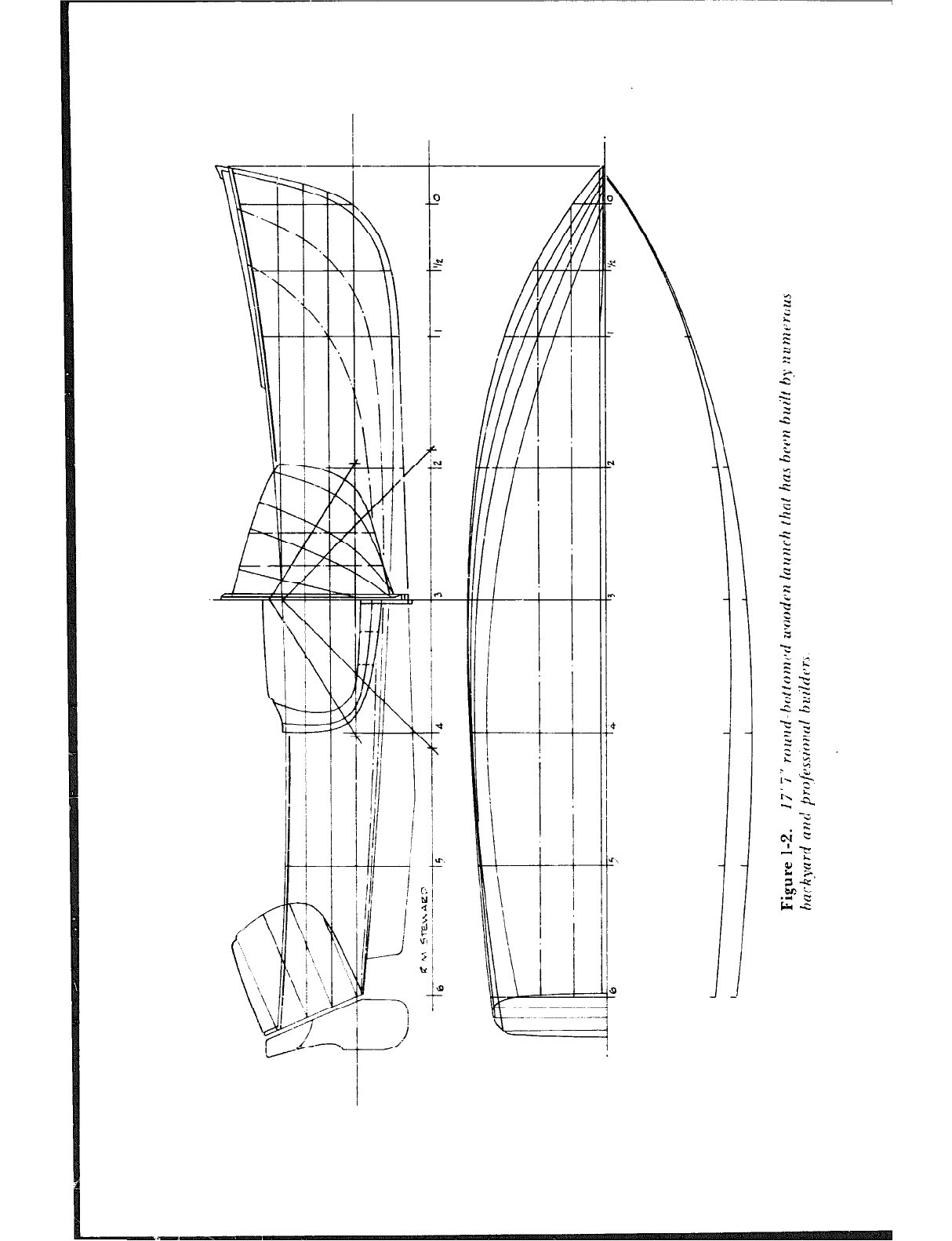
Figure l-2 is a lines drawing for a small round.bottomed hull. Lines drawings are
discussed in detail in the chapter on lofting, which is the making of full-size hull draw-
ings and templates for the various parts.
The relative merits of the hull types are argued far and wide, but just about
everyone will admit that there will never be a v-bottomed hull as handsome as a well-
designed round-bottomed boat, especially for a sailing craft.
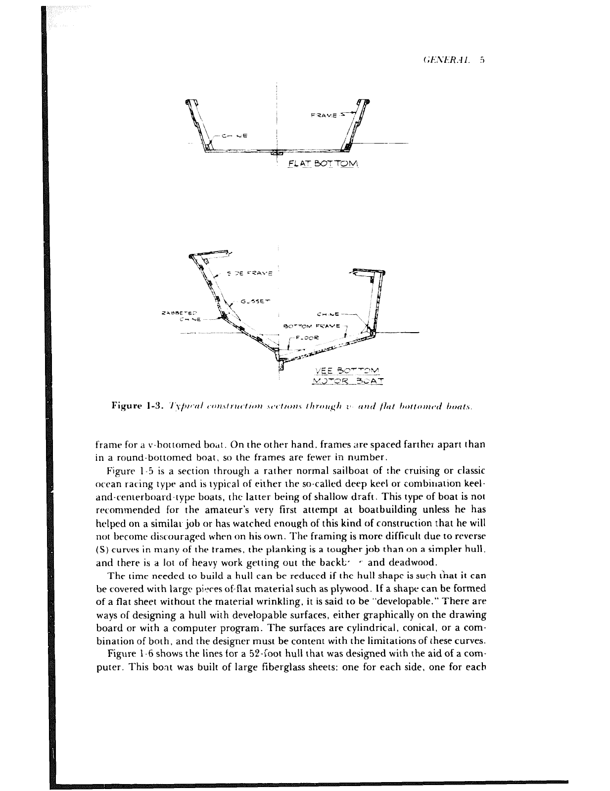
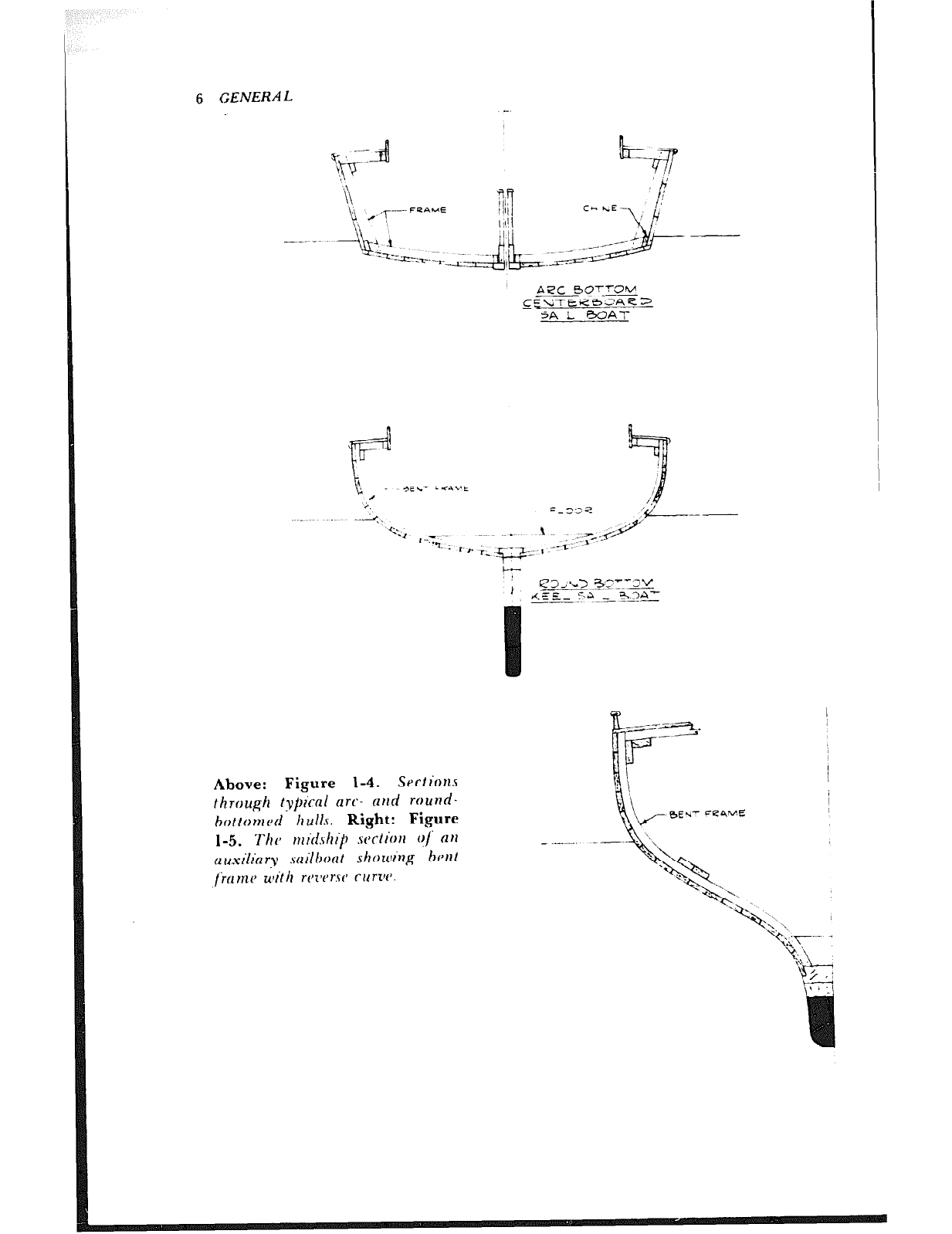
Figures l-3 and l-4 show the essential differences between the framing of flat, vee,
ZliC , and round-bottomed hulls. Although the lower ends of the frames in the round-
bottomed boat are shown butted against the keel, it is sometimes possible, depending
on the hull shape, to install them in one piece, extending from the deck on one side to
the deck on the other side. In contrast, note the number of pieces that make up a
~;lC.2'l~:R.4 I. :i
FLAT Bo-?Tm
-
ygE 4e--q-y.
Y.2’V’Y SaA-‘-
__ .-
Figure I-3. ‘I‘\,/H~YI~ (~ttr.\/r’r~~‘/tott \(v‘ttotr\ ~Irror~glr 1’ trr~tl /ht Itottotttd ht~tt.\
frame for a v-bottomed bodt. On the other hand, frames ;dre spaced farther apart than
in a round-bottomed boat, so the frames are fewer in number.
Figure l-5 is a section through a rather normal sailboat of the cruising or classic
ocean racing type and is :ypical of either the so-called deep keel or combination keel-
and-centerboard-type boats, the latter being of shallow draft. This type of boat is not
recommended for the amateur’s very first attempt at boatbuilding unless he has
helped on a similat job or has watched enough of this kind of construction that he will
not become discouraged when on his own. The framing is more difficult due to reverse
(S) curves in many of the trames, the planking is a tougher job than on a simpler hull.
and there is a lot of heavy work getting out the backb, *. and deadwood.
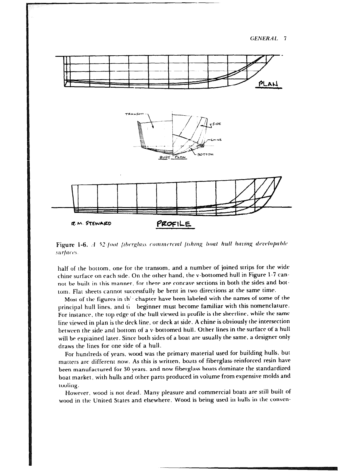
The time needed to build a hull can be reduced if the hull shape is such &at it can
be covered with large pieces of.flat material such as plywood. If a shape can be formed
of a flat sheet without the rnaterial wrinkling, it is said to be “developable.” There are
ways of designing a hull with developable surfaces, either graphically on the drawing
board or with a computer program. The surfaces are cylindrical, conical, or a com-
bination of both, and the designer must be content with the limitations of these curves.
Figure l-6 shows the lines for a 52-foot hull that was designed with the aid of a com-
puter. This boat was built of large fiberglass sheets: one for each side. one for each
6 GENERAL
A.pC 6Orz
CgEkiTER63AE~
SAL BOA-l-
ty-
1 4331’“> .3;7pz
&E’ %+-A
--. -- I s??L’
Above: Figure 1-4. Sectiot~s
through ty~G-d nrc- nnd round-
hotton~d II ~11s. Right: Figure
l-5. -f-hip t1lilfStli~) WCtI'OII O/' (111
~~u.rr’li~r~~ sclilhortt showing hisnt
ticrrnc ulith rt’zvrsC curzv.
l1illJ.j ~ I
/ ! I1 2
p ; 1
/I11 (
iji
4-f
11
I 1
-t
tc-
Ii/ / I
/ I 1’
-p-
I! /
P--
I
‘!
11 I +
t- --
11: /
3
/ L
4
I(~ ,--I-
‘/ j
Ii----
i
1-q -
t-t
----I- --c-
4
‘I
ii
4 ;j
‘I
-3
i!
‘I
4
iI
!I
-3 iI
-1
1
-
k
1 ----’ _
t ’
$ ~ i 11
I
- La
2 -I
ft
‘I’!: ;
j ‘i
/ ;
c
2
t-
I
3
$
2
z
h
2
z
s
4
.’
wz
= .2
i t
73+
2”
5 ‘2
=: *.
- .‘;:
,< 2
I
2 .g
2
TS
. ^
9 e
P-4”
E $4
S-G
-2 2
GENER.4L 7
R. M. %b’-‘A(LD PPQfLE
Fiqurc l-6. :I 52./oat ,Jih~r,~lu.~~ conttnt~rctu~ Ir\hrrrg bout h 1111 hm~r’l~ fiwP1i~p1 Oh
.\U)./flCl’.\.
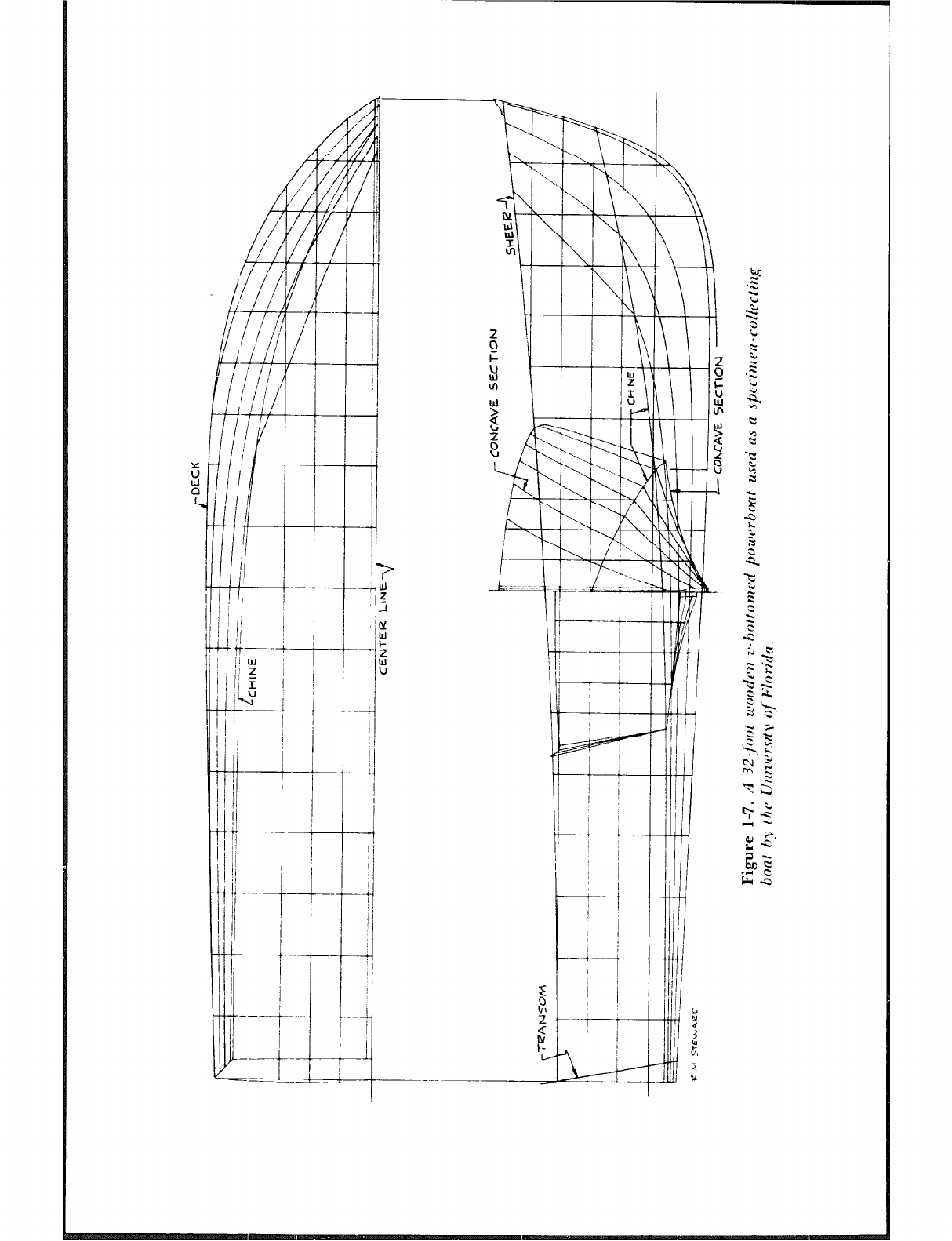
half of the bottom, one for the transom, and a number of joined strips for the wide
chine surface on each stde. On the other hand. the v-bottomed hull in Figure 1-7 can-
not be built in this manner, for there are concave sections in both the sides and bot-
tom. Flat sheets cannot successfully be bent in two directions at the same time.
Most of the figures in th’- chapter have been labeled with the names of some of the
principal hull lines, and ti beginner must become familiar with this nomenclature.
For instance, the top edge of the hull viewed in profile is the sheet-line. while the same
line viewed in plan is the deck line. or deck at side. A chine is obviously the intersection
between the side and bottom of a v.bottomed hull. Other lines in the surface of a hull
will be exp‘rained later. Since both sides of a boat are usually the same, a designer only
draws the lines for one side of a hull.
For hundreds of years, wood was the primary material used for building hulls, but
matters are, different now. As this is written, boats of fiberglass-reinforced resin have
been manufactured for 30 years, and now fiberglass boats dominate the standardized
boat market, with hulls and other parts produced in volume from expensive molds and
tooling.
However, wood is not dead. Many pleasure and commercial boats are still built of
wood in tht: United States and elsewhere. Wood is being used in hulls in the conven-
f~l~..~I:‘R.~~l. 9
tional manner, covered on the outside with resin and reinforced with synthetic fabrics.
and cold-molded and saturated with resin, a relatively new scheme for building hulls
that will be discussed farther on.
The techniques of wooden boatbuilding are extensively employed in the construc-
tion of tooling for fiberglass boats and parts. Wood is used for the interior joinerwork
in ihe better quality fiberglass boats to avoid the cold, antiseptic apj?cyrance of the
molded plastic and “mica” finishes that have become a logical extension of molded
fiberglass hulls and cabins.
When demand is small, such as for yachts 65 feet and longer, welded aluminum
alloy construction or a welded steel hull with superstructure built of the light alloy is
the choice of some of the larger builders. But here again. wood is usually chosen for
the finish in the quarters because it provides a feeling of warmth tha: can never be
achieved by thr sy I ittlctics.
it is possible to gain an introduction to boatbuilding by purchasing and assembling
a .‘kit” boat. There are a number of kits for vbottomed motorboats and sailboats,
usually with plywood planking. Most of these are furnished with beveled parts that re-
quire but reasonable care to set up the frames accurately to form the hull. Also
available are full-size paper patterns and templates for parts, with all the wood provid-
cd by the builder from local stock. Then there are kits that supply fiberglass hulls.
“Hare” fiberglass hulls, mostly for powerboats, are also available. Here is where an
amateur must be careful to be >:tre that guidance is provided or available to locate
c’omptrnents such as engincss and fuel and watc’r tanks. ‘l‘hr weights of such items must
be positioned so the boat will trim and run properly and safely. Some of thrsc hulls can
IIC cluite largca. and the atnateur should not bite off more than he can chew.
Making ;I kit boat does not give the same sense of accomplishment as building a boat.
from scratch, 1~111 the scheme dons make sense for those with limitrd spare time ot for
those who want a particular model of boar that is available in kit form. Listings of kit
boat manufacturers are found in boating magazine ads and in the RrW Owner;) Buym
CZuirfc. In addition, a good number of fiberglass hull builders advertise in Nationcll
Fi.thc~rmcln. See thr Recommended Reading at the end of this book.
Chapter 2
,
A Set of plans is needed for a boarbuilding project unless you have decided to build a
kit boat. Seldom does one want to build just any boat rather there is an urge to own a
certain tvpe, either power or sail, and usually there is an idea about the size suitable
for the intended use. There are several sources for plans, and ample time should be
spent on the search for a design to make sure the boat will meet your requirements.
Knowledge of arrangements feasible for various lengths of boats can be obtained by
scanning the design sections of the monthly boating magazines. These small drawings
are ample for study of what is offered by the design, and the naval architect can be
contacted for furttlrx information. Some of the boating magazines, particularly Molar
Boutz’ng & Snifing, and some of the monthly do-it-yourself magazines for the home
mechanic offer for sale a choice of power and sailboat plans that have been run as
“how-to-buiid” articies over the years. The pians they make avaiiable arc to a iarger.
more practical scale than those in the original articles. The same magazines carry ads
of several firms that spxialize in plans for the backyard buildt=r, and in some cases
they also offer full-size patterns for hulls.
l&at Owners Ruyws Guide, listed elsewhere in this book under Recommended
Reading, lists the names nnd addresses of many naval architects who have plans for all
sizes of boats, Another source is the various class associations for small one-design
sailboats.
Regardless of their source, try to determine whether the plans that interest you are
sufficiently detailed for you to completely understand the vessel’s construction. It can-
not be emphasized too strongly that good plans are well worth their price, because
, 7
‘.. :r cost is but a fraction of the total cost of the boat. The cost of the plans might be
considered as insurance that the finished boat wilt be a success. When designers do not
draw the profusion of details that the novice builder would like to have, this book
should be very helpful in filling in snme of the missing information.
19%’ SLOOP ‘TRITON”
SAIL PLAN
5CfiE ?h.:cc
DCSlQhED FOR
THE a%
RUDDER
~~_~~~~~~LE.~J.E e3.n
Gf\tzA- z VEr.5 OL.5
.EP.c,T.3 o.ee a-- a *
==A
4
/;/
B “: i
/ ‘I
‘\
\,x
/ \
1,
\\
/ I 1
,;i \A ‘\,$
.r.-.:-- 7.. . W-Y
BE’.’ w.
-PI-- I___ 7 _
ii ,.!
lb=-=-+
c%.‘,NO h”MbER 2’ C~Ocl
(1
;/ .
‘/ ._I a
0
J
;;’ ‘ii ?i$,
P
.,,’
>i s, w \
,;I( \)i
,;I 9 I 1
y,‘:\ I*‘\,;
‘/ 6” a,.’
;i c ;,I\ ( :
3, p
;,:I; ___, t’i: (’
ti; ;
d /
a
d
/ 8: II
:, !
‘: ,
.I
r! ;, ,: ”
IS I’Gn
;j 1
,
*
’
*,.5 l’1
3..
i’ *j’ I;\
\’
,/ ;, I!\!
. 1, I_
/- --~- -~~- ~~... ;
1’
/
:-vi i
/ I
,‘\
.:
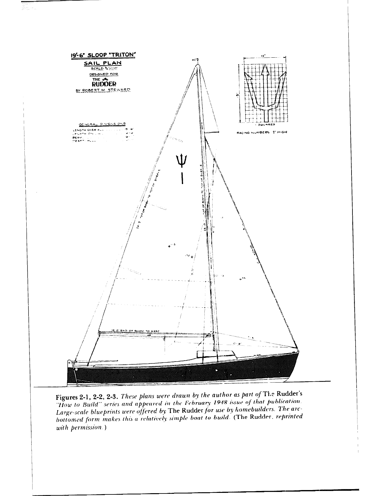
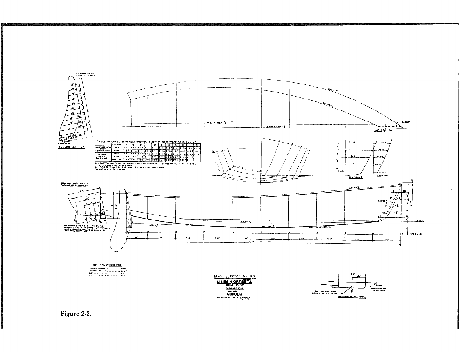
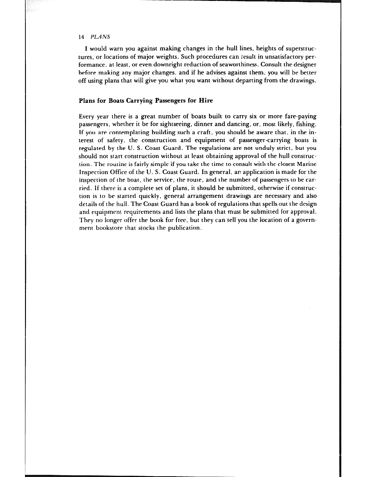
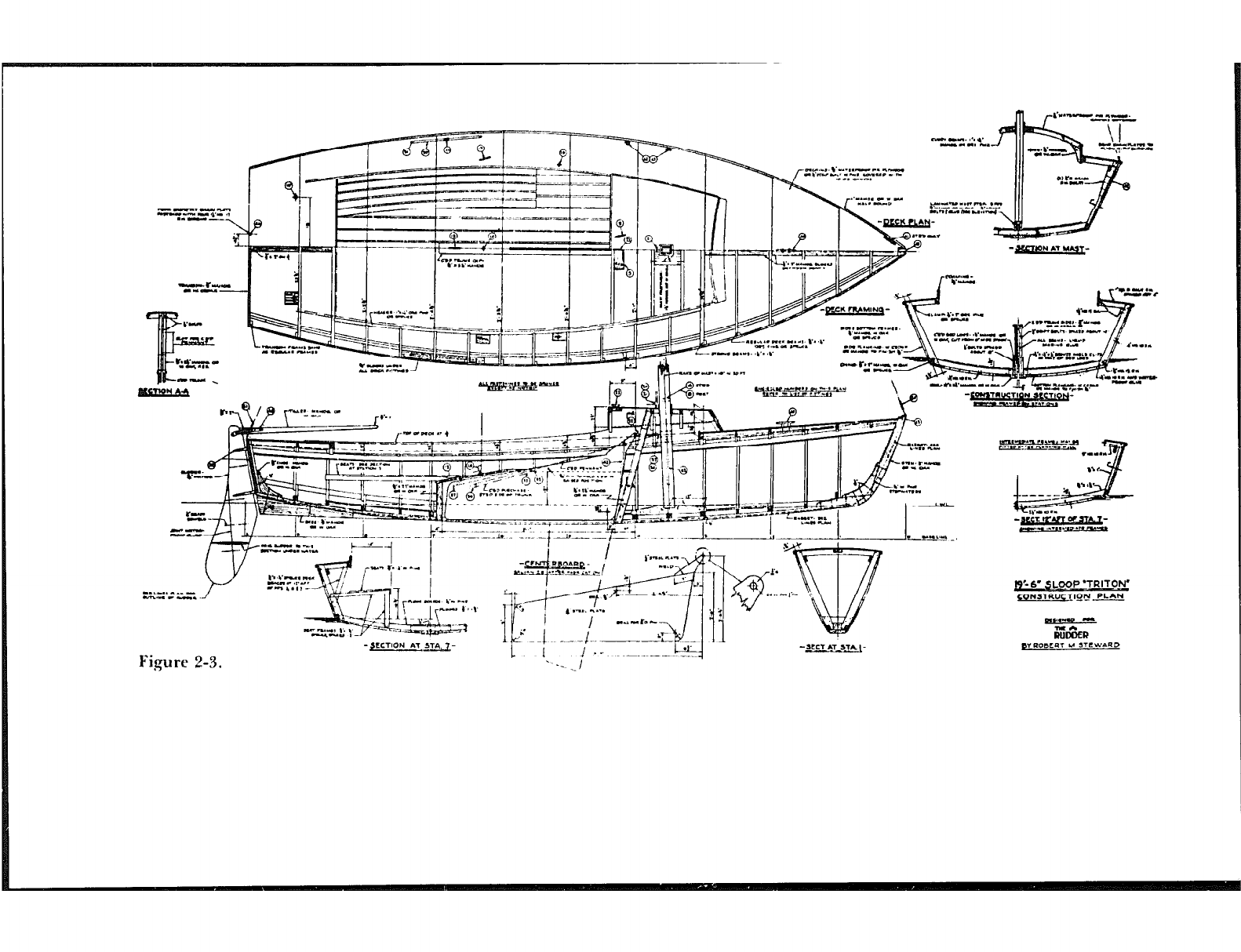
Figures 2-1, 2-2, 2-3. ThtJw p/am uvrt’ drnuw by lhr author as part ofTt.e Rudder’s
“llou~ fo Build” writes nrrd appeartd in rhc Fvhruary 1948 ikut~ t$ lhl publicalirm.
Lnrgr-scale blwprit~h uvw off&-ed by The Rudderjor ust
) by h o nl t> b uild t’ rs. Th e a rc
hot ~on;.cd fornl nlnl;cs I i1i.q n rt4atirvly simplr boat lo build. (The Rudder, rt$rinled
ztvi h pt~mi.~sion, )
:r,‘,;:7-2:;:
n-1 _ ---.-r -.-- _
*; -1
.‘ .,
A -. rri /
_ /+---:
,a
/JY ;,’
.- .~--~~-p---~~~.I:\,
- --___
\ L-J’
yrrrrui Dihw.ll,r.q
L.“rn”lY.iL __.... I ,.a.
L0”rn-l P L-L . . ..___I. *.
ET -L .-: ..I,’
0.I’ p’-6- SLOOP’TRllON~
L~0ldEq
+(.L,.~,-. .o.
-*ID vu-
rJii&m
s. e-7 L( SRV.RD
Nz*wz
n.v Rq
Figure 2-2.
14 PLANS
I would warn you against making changes in the hull lines, heights of superstruc-
tures, or locations of major weights. Such procedures can result in unsatisfactory per-
formance, at least, or even downright reduction of seaworthiness. Consult the designer
before making any major changes, and if he advises against them, you will be better
off using plans that will give you what you want without departing from the drawings.
Plans for Boats Carrying Passengers for Hire
Every year there is a great number of boats built to carry six or more fare-paying
passengers, whether it be for sightseeing, dinner and dancing, or, most likely, fishing.
If you are contemplating building such a craft, you should be aware that, in the in-
terest of safety, the construction and equipment of passenger-carrying boats is
regulated by the U. S. Coast Guard. The regulations are not unduly strict, but you
should not start construction without at least obtaining approval of the hull construc-
tion. The routine is fairly simple if you take the time to consult with the closest Marine
Inspection Office of the U. S. Coast Guard. In general, an application is made for the
inspection of the boat, the service, the route, and the number of passengers to be car-
ried. If there is a complete set of plans, it should be submitted. otherwise if construc-
tion is to be started quickly, general arrangement drawings are necessary and also
details of the hull. The Coast Guard has a book of regulations that spells out the design
and equipment requirements and lists the plans that must be submitted for approval.
They no longer offer the book for free, but they can tell you the location of a govern-
ment bookstore that stocks the publication.
-r-L”zle-- lf yi;b i 3;d+
-se -/
‘“c .I..- . . .
) L.... -1 Vn-lm-U-*
m-.-1 n . . . . . e
f, ..* *-le.
.“..1-
m-m.. 3? .-. <-
i L...... . .- - ZL-
Figure 2-3. --‘-iq ’ A 4LCTAT~
L 1 j .- 7
--_ /
--
t9’-6’OOP ‘TRITOW
~ONSTRU~ION PLAN
a,,..,su -
Gii&R
pf mol5L4T 6.4 ,TCWbRD
Chamer 3
The selection of tools needed to build a boat depends upon the type of project that is
being undertaken, It is best to start with a small craft to get the feel of the work-- the
difference between bqatbuilding and common carpentry. The construction of a simple
plywood-planked boat, either as a kit or one started from scratch, calls for a minimum
of tools. For such a boat, the usual assortment of home workshop tools such as a ham-
mer, hand saws, planes, chisels, screwdrivers, a brace and bits, a hand drill, etc., is
sufficient. One item the amateur may not have when starting a boat is a number of
clamps, either the “C” or bar type. It seems as though one never has enough of these;
they really :,re indispensable. The one power tool that is well worth the money in labor
saving, even for the simplest of boats, is a % R electric drill.
Other hand tools, such as a drawknife, spokeshave. bullnose plane, rabbet plane,
and round-bottom plane are out of the ordinary but very handy in the building of
some boats. If not on hand, these can be added as the need develops.
Essential tools for layout work, and useful from start to finish, are a 24” carpenter’s
framing square, a level. dividers, and a carpenter’s pencil compass. Also essential is a
rule or measuring tape, but it should not be a cloth tape that stretches. For making
your own long bolts from rod stock, a few thread-cutting dies and a die holder will be
needed. Another handy tool, one that a boatbuilder cannot do without, is an ad-
justable sliding bevel such as Stanley Tools No. 25 or No. 18. Thi: is used for transfer-
ring bevels from drawings to the lumber and picking up bevels in many ways, as you
will learn. Needless to say, both carpenter’s and machinist’s vises will be used.
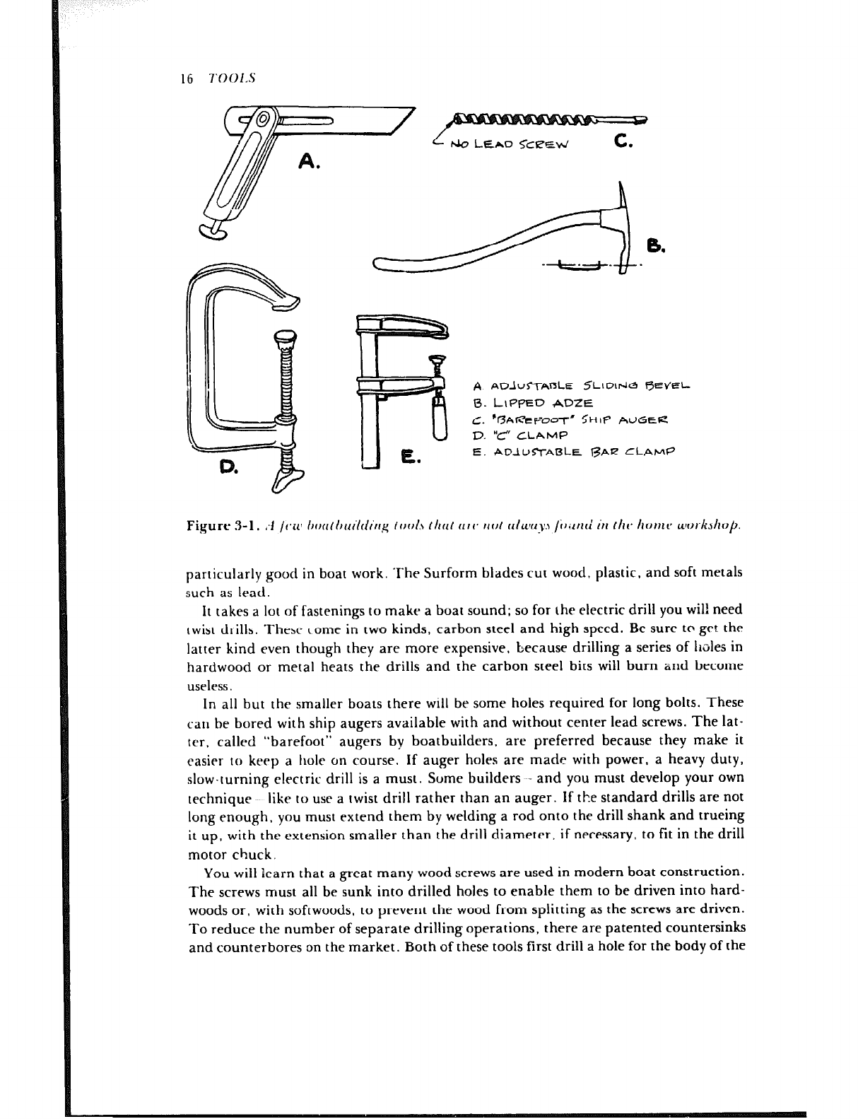
A relatively new kind of tool that is often useful for some of the little jobs that come
up in boatbuilding is the Stanley “Surform,” featuring a unique throwaway rasp-like
blade. There are two blade holders that can be used like regular wood planes, one of
which holds the blade in a curve, two file-like holders, one of which is round, and also
a scraper-like holder with a short, curved blade. The holders for curved blades are
15
16 7‘001.S
A
0.
C.
D.
E.
ADlUmABLE .k?Llobk5 fiEVEL
L\PPED ADZE
%AI=‘EFDoT” CHIP AUGER
‘c-f CLAMP
ADIU~-AI~LE BAL? CLAMP
Figure 3-l. ;I tc,rcl bout t~ctilriirrg tool.5 ltlrlt (lrv lrol cllzc~crqs /iJiltld iI1 ttrc tlomiJ wortzstlo~.
particularly good in boat work. The Surform blades cut wood, plastic, and soft metals
such as lead.
It takes a lot of fastenings to make a boat sound; so for the electric drill you will need
twist drills. Thehc come in two kinds, carbon steel and high speed. Be sure to get the
latter kind even though they are more expensive, because drilling a series of holes in
hardwood or metal heats the drills and the carbon steel bits will burn and become
useless.
In all but the smaller boats there will be some holes required for long bolts. These
car1 be bored with ship augers available with and without center lead screws. The lat-
ter, called “barefoot” augers by boatbuilders. are preferred because they make it
easier to keep a hole on course. If auger holes are made with power, a heavy duty,
slow-turning electric drill is a must. Some builders and you must develop your own
technique like to use a twist drill rather than an auger. If the standard drills are not
long enough, you must extend them by welding a rod onto the drill shank and trueing
it up, with the extension smaller than the drill diameter, if necessary, to fit in the drill
motor chuck.
You will learn that a great many wood screws are used in modern boat construction.
The screws must all be sunk into drilled holes to enable them to be driven into hard-
woods or. with softwoods, to prevent the wood from splitting as the screws are driven.
To reduce the number of separate drilling operations, there are patented countersinks
and counterbores on the market. Both of these tools first drill a hole for the body of the
TOOLS 17
screw; the countersink then follows up by shaping the hole to take the head of the
screw, while the counterbore drills a straight-sided hole for a wooden plug. These
gadgets both have an adjustment for depth of hole and are valuable time-savers:
eliminating much baclr-and-forth changing of drills and the necessity of working twice
on every hole. These are shown in the chapter on fastenings. Unfortunately, the range
of available sizes is not as extensive as might be desired.
There are also some similar drilling tools of more expensive construction that do
more or less the same job. These drills look as though they were stamped out of a steel
sheet to the profile of a screw and have two diameters, one for clearance of the screw
shank, and one about equal to the diameter of the screw at the root of the threads, and
some makes have a stop on the shank of the drill to control depth of the hole. One
name for these drills is wood screw pilot bits, and they are sold in sizes for various
diameters and lengths of screws. They can be burned when drilling hardwoods, but
they are cheap and thus expendable. These bits are also shown in the rhapter on
fastenings.
Old-hand boatbuilders often grind twist drills to a tapered point similar to a gimlet,
especially when a hole is to be made completely through the wood for a rivet or clout
nail fastening. The tapered point does not tear the wood as the drill goes through.
One of the traditional tools of the boatbuildpr is the adze. I‘his tool is shaped like a
hoe and is still in use in yards that build vessels with heavy timbers. Boatbuilders usu-
ally use the lipped adze, which is a smooth-cutting type with curled edges at the ends
of the blade. The adze is used diagonally across the grain and, when in the hands of a
skilled workman, is a wonderful tool for working heavy pieces of wood. The adze can
also be dangerous to the limbs when in the hands of the inexperienced, so it is best to
learn how to use one under the guidance of someone who has plenty of adze time
under his belt.
As we progress. it will be apparerlt that some hand tools have been omitted from the
foregoing, but mention has been made of most that you will ever need, and the
chances are good that your home workshop is already equipped with many of them. If
not, go ahead and start your boat anyway, because these hand tools aren’t really ex-
pensive and can be bought as you go along.
Power tools in the home workshop are more common now than ever before. By far
one of the most useful for boatbuilding is the bandsaw, which should be 12 or 14” in
size. For straight cuts an 8-inch rircular table saw with tilting arbor will do most jobs
in a small shop. A 4.inch jointer, while not essential, can be a labor-saver. A portable
circular saw is a poor substitute for a table saw but does have some use, particularly for
cutting up plywood panels. It can also be used for cutting curved planking out of
lumber if the planking is not too thick and the saw is set to cut out little more depth
than the plank thickness. A saber saw is invaluable for cutouts such as for pqrtlights in
the hull and hatch openings in plywood decks. As in the case of the %-inch electric
drill, do not buy the cheapest saber saw you can find. Stick to a good grade in a good
brand, because even repuLable makers have competitive lines and better lines. the dif-
ference being in bearings and power, and thus in life expectancy. Somewhat of a lux-
ury for small boats is an electric screwdriver. but it is a tremendous labor-saver when
quantities of anything but small screws are to be driven.
One of the mozt labor-saving power tools is the sander, and it helps prevent
L
boredom, too. The disc sander is good for such jobs as cutting down the seams of
planking and for sanding fiberglass. For finishing, the orbital sander is about the best,
whether for wood or fiberglass, and the belt sander is used by the pros for smoothing
up joinerwork. Again, quality is important in sanders, so don’t skimp.
Another power tool that might be considered a luxury, but which is an enormous
labor-saver during the construction of boats longer than 25 feet long, is an electric
plane, All you need is a lightweight one such as the S-inch plane made by Skil. This
tool has even been used for smoothing up lead ballast keels.
This is all that will be said about tools because, as mentioned in the introduction,
familiarity and a certain ability with woodworking tools has been assumed.
Sources for Tools
.4 few places are mentioned below that are known for stocking a good selection of
tools, both for woodworking and metaiworking. One of the largest and best known is,
of course, Sears, but not everyone knows that they put out a fine tool catalog that is
revised annually. Here are some others know]! to me, listed in alphabetical order:
Brookstone Company, I27 Vose Farm Road, Peterborough, New Hampshire 03458.
Craftsman Wood Service Co., 2727 South Mary Strcc:, Chicago, Illinois 60608.
Garrett Wade Co., Inc., 302 Fifth Avenue, New York, New York 10001. (This
ca:alog is so beautifully illustrated it should bc a collertor’s item.)
W.1,. Fuller Inc., P.0. Bax 8767, Warwick, R.I. 02888. (They sell the “barefoot”
wood auger hits shown in Figure :I- 1 .)
Wetzler Clamp Co., Inc.. 43-15 11th Street. Long island City, New York 11101. (A
manufacturer of clamps only and will sell direct IO boatbuildcrs.)
Woodcraft Supply Corp., 313 Montvalc Avenue, Woburn, Massachusetts 01801.
(Another house with a nicely illustrated catalog that lowers one’s resistance to purchas-
ing.)
Woodworkrr’s Supply, Inc., P.O. Box 14117. 11200 Menaul NE, Albuquerque,
New Mexico X71 12.
Chapter 4
Wood is ow of the c,asit>st materials out of which the amateur can build a boat. and ir
rtlmain:; a favoritt* of many proft5sionais. tIrspirt* tht* grc-at growth in synthctit
marerials. Not ail woods nrr sui~nblr for bonthuiiding. howcvcr. so as we go along.
1 tit-rt- will I)t% commt’n~s OII IIKW kill& tl~a~ have provt’n rlutahit* onr of I he most
(ltXir;ll)lt’ qualities sought anal have I he necessary st rengr h
It is beyond the scope of this hook 10 morth rhan scrarch the surface on rhts subjrcr of
wc~ocl, even when iimite(1 I0 rhe trees found in rhe llnited States dlone, so I will limit
our discussions 10 the small numher 01 commonly accepted boatbuilding woods and
how the lumber is manufactusrri lrom logs. A few reasons for the elimination of cer-
rain woods from boatbuilding are brittleness. softness. weakness. susceptibility to
dccavq and shortness of growth. On the orher hand there are rime-tested woods
availablt- that have lhe net.essary qualities. but rhese rypes can seldom be found in an
ordinary iurnber~ard. Fortunately aimosi every area where boats are built has a yard
that fully untlers:ands the nec~ls of the hoathuiider. and the amateur is advisrd to seek
rile aid of such a supplier to obtain the high grade lumber needed for long hull life.
‘l‘herc should ht. no compromise in the matter of lumber quatiry. for when the labor of
Ihe builder is consideI~ecl. the t-xtra ~0sI and trouble of good material is of little conse-
TV”““““.
Sawing of Lumber
Grain is formed by the angle of the annual rings with the face of a hoard and its orien-
tation has much to do with the suitability of the lumber for use in boats. The grain’s
orirntation in boards depends upon how rhe lumber is GUI from logs. After a tree has
been felled and trimmed. it is easy for the lumberman to run the log through a saw
19
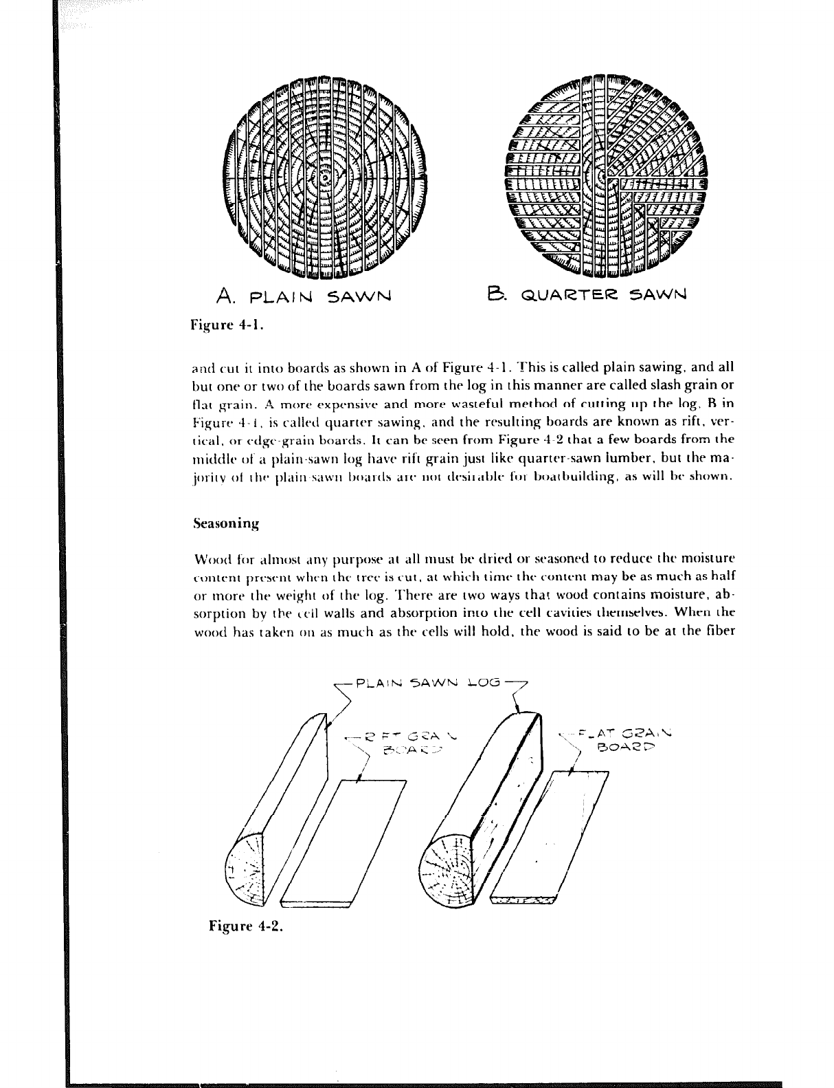
A. PLAIN SAWN
Figure 4- 1.
e. QUARTER SA’NM
and cut it into boards as shown in A of Figure 4- 1. -!-his is called plain sawing, and all
but one or two of the boards sawn from the log in this manner are called slash grain or
tlat grain. A more expensive and more wasteful method of cutting up the log. B in
Figure 4- I 1 is ralicd quarter sawing. and the rrsultinp; boards are known as rift, ver-
tical. or edge-grain boards. It can be seen from Figure 4-2 that a few boards from the
nlidtilc clt’ it plain-sawn iog have rift grain just like quarter-sawn lumber, but the ma-
,joritv 01 tllr~ I)l;tin sawn boartls arta not tlf3ir;tblr for I~OilI~~llildil~g, as will h showl~.
Seasoning
Wood for ,tlmost ,~ny purpose at a11 must be tlricd or scbasoned to reduce thr moisture
content prewnt when thr tree is cut , at which time the content may be as much as half
or more the weight of the log. I‘here are two ways that wood contains moisture, ab-
sorption by the ceil walls and absorption into the cell cavities themselves. When the
wood has taken on as much as the cells will hold, the wood is said to be at the fiber
F’LAlh; SAWN LOG7
Figure 4-2.
il’OOU 21
saturation point. In this condition the moisture content of the wood averages about 25
percent, and no shrinkage takes placc un:il this percentage is reduced. Seasoning is the
process ot reducing the moisture content to about 15 percent, an acceptable level for
hoatbuilding material, and this is when the wood shrinks. After it seasons to whatever
level is wanted, wood shrinks further if more moisture is removed and swells if more
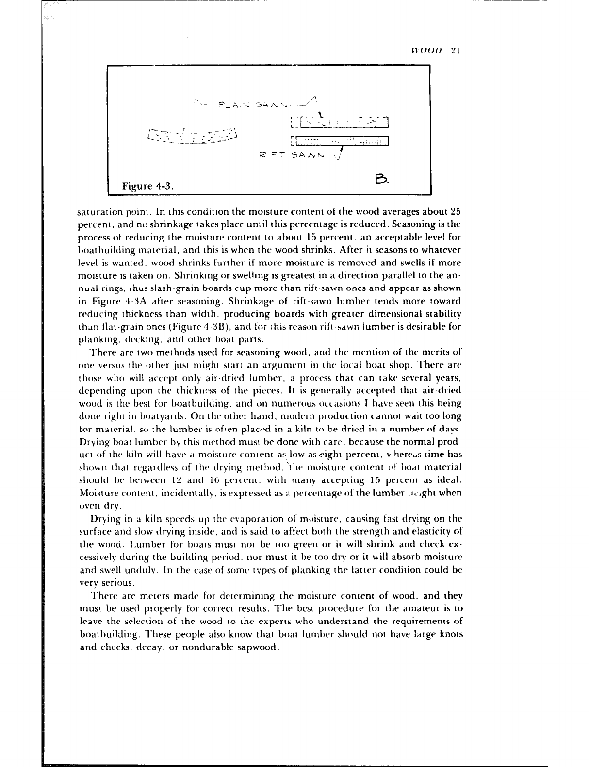
moisture is taken on. Shrinking or swelling is greatest in a direction parallel to the an-
nual rings, thus slash-grain boards cup more than rift-sawn ones and appear as shown
in Figure 4-YA dfter seasoning. Shrinkage of rift-sawn lumber tends more t.oward
reducing thickness than width, producing boards with grrater dimensional stability
tlian flat-grain ones (Figure 4 :!H), and t<br 1 hia rcasrjn rift -bdwn lumber is desirable for
planking. tlccking. and other boar parts.
Thrrt* are two methods used for seasoning wood. and the mention of the merits of
one versus the other just might start an argument in the local t)oat shop. There are
those who will accept only air-dried lumber, a process that can take several years,
depending upon I hr thickrl:*ss of the pieces. It is gt*~lt*rilll~ accepted that air-dried
wood is tht- best for boatbuilding. and on nutnerous occasionh 1 hate seen this being
done right in boatyards. On the other hand. modern production cannot wait too long
for material, so ;he lumber is often place-d in a kiln to be dried in a number of days.
Drying boat lumber by this nlethod mus: be done with care. because the normal prod-
uct of thr kiln wilt have a moisture content a:;,low as eight percent, v herc,s time has
shown llldl I’t’gitl-dlt?iS Of 111th drying mctl~od. the moisture content (if boat material
sliould he between 12 and 16 ptarccnt, with many accepting 15 percent as ideal.
Moisture c~ontent, incidentally, is expressed as ;: pt-rcentage of the lumber .v,,ight when
cwen dry.
Drying in a kiln spcbc-ds up thr t-vaporation of m,)isture, causing fast drying on the
surface illld slow drving inside, and is said to affect both the strength and elasticity of
the wood. Lumber for boats must not be too green or it will shrink and check PX-
cessively during the building period. nyr must it be too dry or it will absorb moisture
and swell unduly. In the case of some types of planking the latter condition could be
very serious.
There are meters made for determining the moisture content of wood. and they
must. be used properly for correct results. The best procedure for the amateur is to
leave the selection of the wood to the experts who understand the requirements of
boatbuilding. These people also know that boat lumber should not have large knots
and checks, decay. or nondurable sapwood.
Kinds of Wood
In the northeastern part of the United States, where many tike to think boatbuilding in
this country was born, the practice of using certain available native woods was
established long ago. and time has proven its worth. Through the years, lumber from
other parts of the country, as well as material from foreign lands, has been added to
the list of suitable woods, with substitutions of local products being made in certain
areas as a result of satisfactory experience with these woods for boatbuilding. As a
typical example, frames would be of oak in most localities. but keel, deadwood, and
other backbone members might be yellow pine in the South, white oak in the North-
east, or Alaska cedar or Douglas fir on the West Coast. As tong as it is proven. the
choice of wood makes little difference, but a boat involves too much work to gamble
with untried materials that mav rot in a short time .rr be brittle or not hold fasten-
ings.
As a guide, 1 give here a list of good woods, together with principal properties and
approxitnate weights per board foot (one foot square by one inch thick) at 12 percent
moisture content.
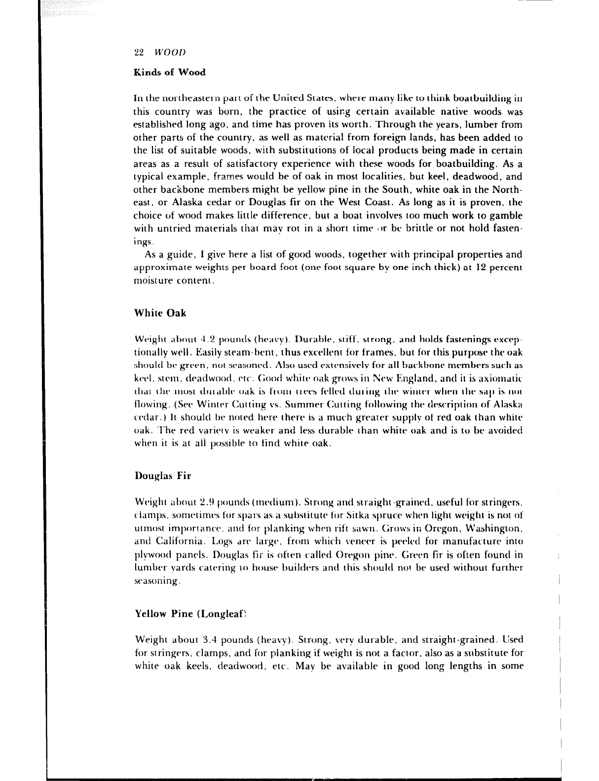
White Oak
Weight iItlO~ll al.2 l~Oll~~llS (ht’ilt’y). I)Uleat)lt~, stiff, strong, and holds fastenings excrp.
tionally well. Easily steam-bent, thus excellent for frames, but for this purpose the oak
should be green. not seasoned. Also used extensivrlv for all !rackbonr members such as
ktbcl, stem, dradwood, (‘11‘. ~hd white* oak grows iI1 ?kw Enghnd. and it is dxilJln~tic’
that the most dtrrablc oak ib from trees felled during the winter when the sit11 is not
flowing. (Set- Winter Cutting vs. Summer Cutting following the description of Alaska
cedar.) 11 should be noted here there is a much greater supply 01 red oak than white
oak. ‘l‘he red varietv is weaker and less durable than white oak and is to br avoided
when it is at aii possible to tind white oak.
Douglas Fir
Weight about ‘) ,.!I t)ounds (metlium). Strong and straighl-graincd. useful for stringers,
c~fitmfrs. scrmctimes for spars as it substitute for Sitka sfrruce when light weight is not of
utmost importance. and ~‘oI- planking whtn rift sitwtr. Grows it; Oregon, W’ashington.
and California. Logs dre IiligC. from which veneer is peeled for manufacture into
plywood panels. Douglas fir is often called Oregon pine. Green fir is often found in
lumber vards catering IO house builders and this should not be used without further
scasoiling.
Yellow Pine (Longleaf!
Weight about 3.4 pounds (heavy). Strong, very durable, and straight-grained. Used
for stringers, clamps, and for planking if weight is not a factor, also as a substitute for
white oak keels, deadwood, etc. May be available in good long lengths in some
localities. Has been reported as not durable in fresh water. but I cannot substantiate
this. Grows in Southern United States in Atlantic and Gulf states.
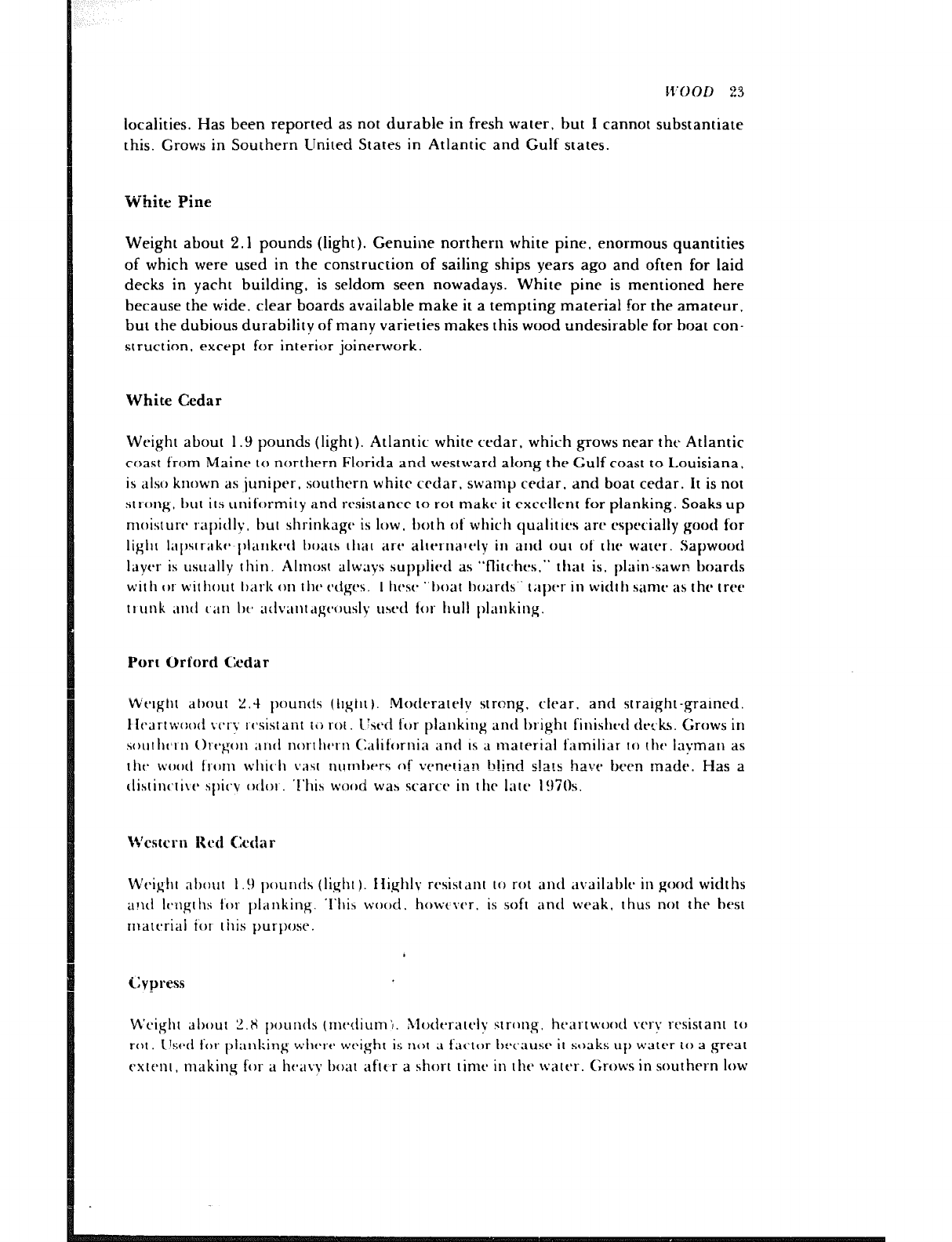
-White Pine
Weight about 2.1 pounds (tight). Genuine northern white pine. enormous quantities
of which were used in the construceion of sailing ships years ago and often for laid
decks in yacht building. is seldom seen nowadays. White pine is mentioned here
because the wide, clear boards available make it a tempting material for the amateur,
but the dubious durability of many varieties makes this wood undesirable for boat con-
struction. except for inlerior joinerwork.
White Cedar
Weight about 1.9 pounds (tight). Atlantic white cedar, which grows near the Atlantic
roast from Maine IO northern Florida and westward along the Gulf coast to L,ouisiana.
is also known as juniper. southern white crdar, swamp cedar, and boat cedar. It is not
strong. 1,111 its uniformity and resistance 10 rot make it excellenr for planking. Soaks up
moisture- r;nt)idty. bum shrinkage is tow. ho[h of which qualities are especially good for
tight I;lt)str;lk(* t~lank4 I)oals [11;1[ art* atrt~rnal4y in and OUI of the water. Sapwood
taycsr is usually thin. Atmosr always suppliett as “flirches.” lhal is. plain-sawn boards
wit II or wilhout I)arti on I ht. r~tgc*s. ‘I Iic*sc* “boat hoards” tat)c*r in width sanx- as the tree
trunk ;~ntl I.;II~ IN* art~~al~t,I~:c~clusly usect for Ilull t)Iankinj=.
Port Orford Cedar
Weight ah0ul Z.-l puntis (iigilr ). Moderarely strong, clear. and srraight-grained.
1 Irartwcxxi VVI-;C ~c*sis[ant iti rot I!4 for planking and bright finisht*tt decks. Grows in
sout I)(,1 11 Orc*gon ;11i(t nor-rllc~ri CI,llifornia anti IS d material familiar to thcb tavman as
tht* woo(1 lrtrm wl1ic.h \‘;ISI rlurnlwr~ 4’ vene!ian b!ind s!a!s have been made. Has a
ttisrinc~li~~t~ st1ic.v o(t01 ‘t’hih wood wah scarcch in the tare 1!)7Os.
Wcstcrn Red Cedar
Wt.ight ahout 1 .!I f)ounAs (lighl). Ilighly rvsisldnl 10 rol and availahlt- in good widths
and twgr hs for planking. ‘1‘lli.s wood. howt ver. is soft and weak. thus not the ht’st
rnal~riai ior (his purpose.
Cypress
M’cighl at)out 2.X founds (rncdiuni’~. Modvralcly slrcmg. heartwood very rtxistanr to
rot. Llscd for f)ianking wlww wc,ight is not ;I f‘;l<.tor hrcausc it steaks up water IO a great
cxtt’nl. making for a h<nil\v boar aflt,r a short rime in [ht. ivatt’r. Grows in southern low
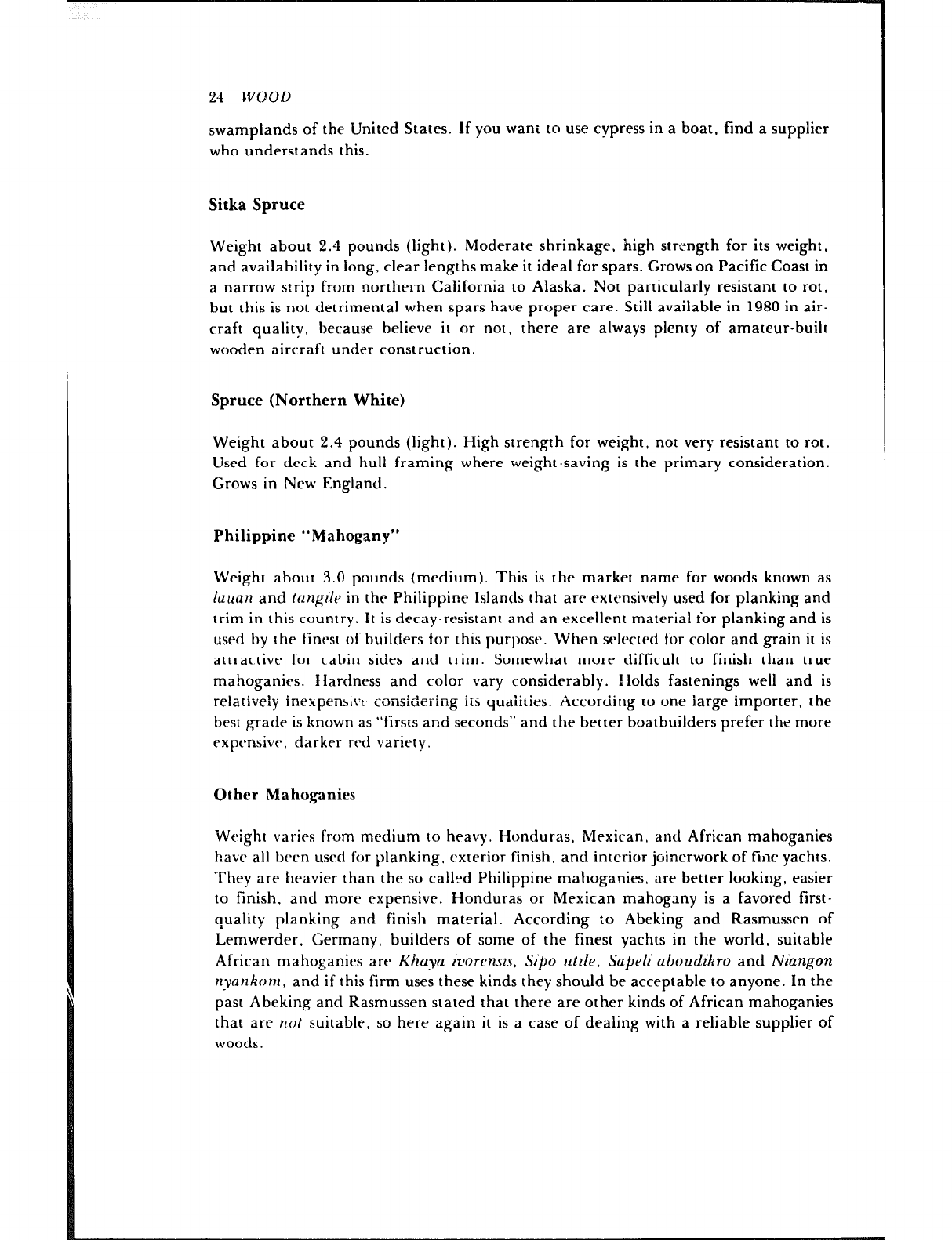
swamplands of the United States. If you wani to use cypress in a boat. fmd a supplier
who understands this.
Sitka Spruce
Weight about 2.4 pounds (tight). Moderate shrinkage, high strength for its weight,
and availability in long, clear lengths make it ideal for spars. Grows on Pacific Coast in
a narrow strip from northern California to Alaska. Not particularly resistant 10 rot,
but this is not detrimental when spars have proper care. Stilt available in 1980 in air-
craft quality. because believe it or not, there are always plenty of amateur-built
wooden aircraft under construction.
Spruce (Northern White)
Weight about 2.4 pounds (tight). High strength for weight. not very resistant to rot.
Used for deck and hull framing where weight-saving is the primary consideration.
Grows in New England.
Philippine “Mahogany”
Weight about 3.0 pounds (medium). This is the market name for woods known as
laucl~l and tnn~l’lr in the Philippine Islands that are exlcnsively used for planking and
trim in this country. It is decay.resistant and an excellent material ior planking and is
used by the finest of builders for this purpose. When srtrc~ed for color and grain it is
attractive for cabin sides and trim. Somewhat more difficult 10 finish than true
mahoganies. Hardness and color vary considerably. Holds fastenings well and is
relatively inexpens,vt considering iis qualiiies. According io one iarge importer. the
besr grade is known as “firsts and seconds” and the better boatbuilders prefer the more
expensive, darker red variety.
Other Mahoganies
Weight varies from medium to heavy. Honduras, Mexican, and African mahoganies
have all been used for planking. exterior finish, and interior joinerwork of flile yachts.
They are heavier than the so-catl?d Philippine mahoganies, are better looking, easier
10 finish, and more expensive. Honduras or Mexican mahogany is a favored first-
quality planking and finish material. According to Abeking and Rasmussen nf
Lemwerder, Germany, builders of some of the finest yachts in the world, suitable
African mahoganies are Khava iz~orcnsis. Sipo utile, Sapeli aboudikro and Niangon
nyankom, and if this firm uses these kinds they should be acceptable to anyone. In the
past Abeking and Rasmussen stated that there are other kinds of African mahoganies
that arc riot suitable, so here again it is a case of dealing with a reliable supplier of
woods.
W’OOD 25
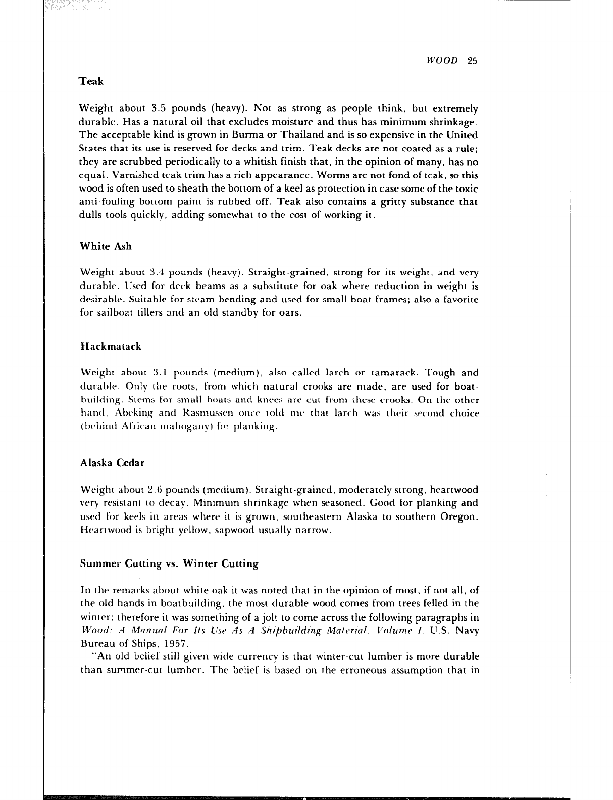
Teak
Weight about 3.5 pounds (heavy). Not as strong as people think. but extremely
durable. Has a natural oil that excludes moisture and thus has minimum shrinkage.
The acceptable kind is grown in Burma or Thailand and is so expensive in the United
States that its use is reserved for decks and trim. Teak decks are noe coated as a rule;
they are scrubbed periodically to a whitish finish that, in the opinion of many, has no
equal. Varnished teak trim has a rich appearance. Worms are not fond of teak, so this
wood is often used to sheath the bottom of a keel as protection in case some of the toxic
anti-fouling bottom paint is rubbed off. Teak also contains a gritty substance that
dulls tools quickly, adding somewhat lo the cost of working it.
White Ash
Weight about 3.4 pounds (heavy). Straight-grained. strong for its weight. and very
durable. Used for deck beatns as a substitute for oak where reduction in weight is
desirabtp. Suitable for s:tAam-bending and used for small boat frames; also a favorite
for sailboat tillers and an old standby for oars.
Hackmarack
Weight about 3.1 pounds (medium), also called larch or tamarack. Tough and
durable. Only the roots, from which natural crooks arc made, are used for boat-
huitding. Slems for small boats and knees are cut from rhc-se crooks. On rhe other
hancl. Ahrking and R;~sI~~ss~~~ once told nit’ that larch was tht-ir sc:ctmtt choice
(twtlind African mahogany) fclr planking.
Alaska Cedar
Weight ahout 2.6 pounds (medium). Straight-grainrd. moderately strong. heartwood
very resistant to decay. Minimum shrinkage when seasoned. Good for planking and
used for keels in areas where it is grown, southeastern Alaska to southern Oregon.
fkartwood is bright yrttow, sapwood usually narrow.
Summer Cutting vs. Winter Cutting
In the remarks about white oak it was noted that in the opinion of most. if not all, of
the old hands in boatbuilding, the most durable wood comes from trees felled in the
winter: therefore it was something of a jolt to come across the following paragraphs in
Wood: .-I Manual For Its I/w As .4 Shipbuilding Material, C’olurn~ I, U.S. Navy
Bureau of Ships, 1957.
“An old belief still given wide currency is that winier-cut lumber is more durable
than summer-cut lumber. The belief is based on the erroneous assumption that in
26 L1’001)
winter, ‘the sap is down, ’ while in the summer. ‘the sap is up,’ in the living tree. Ac-
tually, tests have demonstratt-d conclusively that standtng trees contain about as much
sap in winter as in summer.
“The only sound objection to summer-cut lumber is that logs are more likely to
deteriorate if left exposed to high summer temperatures t;lat may accelerate checking
and attack by insects and decay fungi. Reasonable precautions, particularly prompt
sawing after felling, and good piling and seasoning methods, remove the danger of
such damage to summer-cut material.”
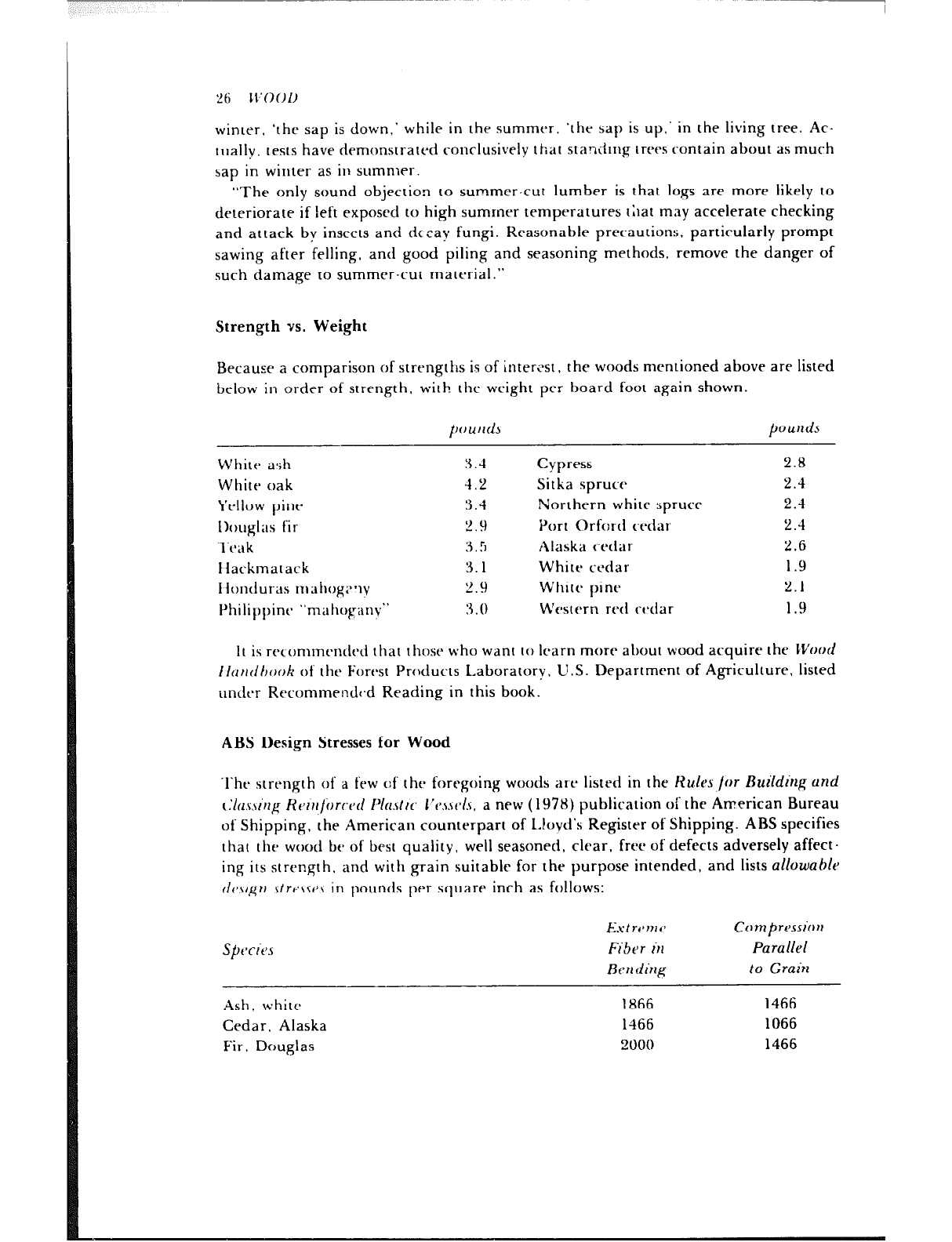
Strength vs. Weight
Because a comparison of strengtlis is of interLast, the woods mentioned above are listed
below in order of strength, with the weight per board foot again shown.
pound3 pOU&S
White ash
White oak
Yellow pint
Ih~~glas fir
‘l‘tbak
liackmatack
llondur-as mahog;~*ly
Philippint "nlilhOp~~IlV"
3 .-I
4.2
3.4
2 9
3 .!I
3.1
2.9
:3 . 0
Cypress
Sitka spruce
Northern white spruce
Port Orford cedar
Alaska c-<hda~
White cedar
White pine
Western red ct*dar
2.8
2.4
2.4
2.4
2.6
1.9
2.1
1.9
it is recommrndcd that those who want IO learn more about wood acquire the CVood
Iltrrrtlhook of the Forcast Products Laboratory, U.S. Department of Agriculture. listed
under Recommendc,d Reading in this book.
ASS Design Stresses for Wood
‘l‘he strength of a few c:f the foregoing woods are listed in the Huks /or LSuilding and
t.‘lns.\l’~g Kt~lrrfi)rwtl I’icls~tr~ ~‘P.uv/.\, a new ( 1978) publication of the American Bureau
of Shipping, the American counterpart of L!oyd’s Register of Shipping. ABS specifies
that the wood be of best quality, well seasoned, clear, free of defects adversely affect-
ing its strength. and with grain suitable for the purpose intended, and lists allowable
tlt-.~grr .\[rc\.st~J in pounds per square inch as follows:
SptTitJs
-
Ash, whit<
Cedar, Alaska
Fir ~ Douglas
Est ronl(J Comprt~ssion
FiSer in Parallel
Rrn ding to Grain
1866 1466
1466 1066
2000 1466
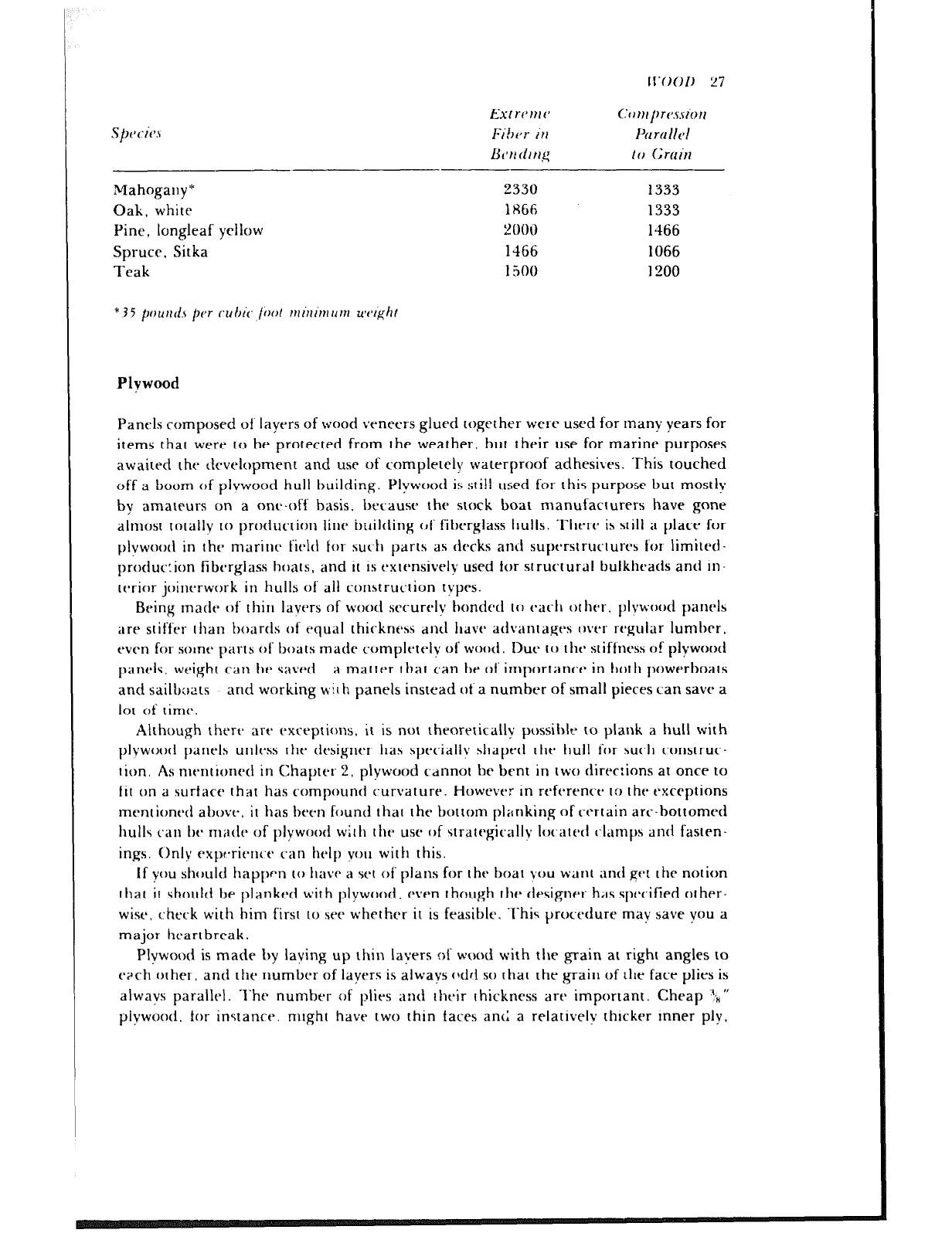
lI’OO1) 27
Extwvrv
Fiht,r 111
&~I! tir t1.g
I.‘cll,lf,rr~.ssiorl
Ihrtlllt~l
If) Gruin
Mahogany’ 2330 1333
Oak, white 1866 1333
Pine, longleaf yellow 2000 1466
Spruce, Sitka 1466 1066
Teak l!JOO 1200
* 35 punf1.t per ~01’~ /ool mini~num uvrght
Plvwood
Panels composed of layers of wood veneers glued together wet-e used for man): years for
items that werr to be protected from the weather, but their use for marine purposes
awaited the ctcvelopment and use of completely waterproof adhesives. This touched
off a boom of plvwood hull building. Plywood is sti!l ttsed for this purpose but mostlv
by amateurs on a one-off basis. because the stock boat manufacturers have gone
almost tc)tally to production line building c~f fibrrglass hulls. There is still a place for
plywootl in the marinr fit-ld for suc.h parts as decks and supc~rstructure5 for limited-
produc:ion fibtsrglass boats, and it is extensively used for structural bulkheads and in-
tcsrior joinrrwork in hulls of all construc.tion types.
Being made of thirl layers of wood srrurcly bonded t(r tBa(.l1 other. plywood panel5
are stiffer than boartls of equal thickness dntl have advantages over regular lumber,
even for solne parts of boats made rompletelv of wood. Due to t hc* st iftness of plywood
panels, weight can br savc~i a matter that can be of importance* in both powerboats
and sailb;,;?ts and working with panels instead of a number of small pieces can save a
lot of time.
Although thrrc* art’ exceptions. it is not theoretically possible to plank a hull with
plvwood panel5 unless t ht. designtar llas speciallv shaped the hull for such construc-
tion. As nit-ntioned in Chapter 2, plywood CdnnOt be bent in two direc:ions at once to
fit on a surface that has compound curvature. However in reft~renct- I:) the exceptions
mentioned above. it has been found that the bottom pl;rnking of certain arc-bottomed
hulls can br niatlt~ of plywood wilh thca use of stratt$cally IOt’i1lt’tl (~l,tmp5 and fastrn-
ings. Only expr.rieric.t% can help vou with this.
If you should happen to have a set of plans for the boat you want and get the notion
that it should be planked with plywood. c’ven though the designer has specified other-
wise, check with him first to see whether it is feasible. This procedure may save you a
major heartbreak.
Plywood is made by laying up thin layers of wood with tile grain at right angles to
each other, and the number of layers is always cldri so that the <grain of the face plies is
alwavs parallel. The number of plies and their thickness are important. Cheap “k”
plywood, for instanct-. might have two thin faces ant I a relatively thicker inner ply.
“8 M’OOD
whereas a better grade will have five plies of wood, e,ch of about equal thickness. It
can readily be seen that with right angle construction, the three-ply panel will be
relatively weak when bent parallel to the grain of the inner ply.
The most common and inexpensive kind of plywood is made of Douglas fir.To ob-
tain the fir veneer for making plywood paneis. the fogs are placed in a lathe and
turned against a knife edge that peels the veneer at its desired thickness; thus most of
the grain is flat g-ain, called wild grain, and in fir it is indeed difficult to tame suffi-
ciently for a smooth paini finish. Fir also checks badly sn that a paint finish develops
hairline cracks that become greater in number as time goes on. This situation is at its
worst whe;l tht plywood is exposed to the elements. but even when the plywood is used
in interior joinerwork, checking can make it difficult to achieve a first-class paint job.
Such checking can be alleviated somewhat by coating the fir with a sealer before paint-
ing, using ;I f,lywood sealer matfe by one of the marine paint or plywood manufac-
turers. Fir f,lywootl is acceptable for interior work that is to be covered with either one
of the modern vinvl wall coverings or with one of the durable plastic laminates such as
Formica. It can also be used for planking and decking that is to be covered with a syn-
thetic cloth. such as fiberglass and resin.
Plvwood for any purpose in a f)oar, whether for planking or for interior joinerwork,
should f)e of nlarine grade. This guarantees that the veneers are bonded with water-
fjroof adhesive, that a minitnum number of patches are used in thr, face plies, and that
voids in thrs inner f,lir3 are minitnal.
Plywood Grading
Previous ctlitions of this book carried data furnished by a large marine plywood
tnanufa(.turt~r. I1.S. Plvwood Corp., now called Champion Building Products. Asking
for an updatcb on what is availaf)lc for boatbuilders rrsuftcd in the receipt of eben more
complete gr-ading ilkformation than wds available before. This has got to be a sign of
the times. becausx there is a for of plywood around of horrible quality.
Mat-inc.-gratis plvwood panels art’ laminated with waterproof phenol-formaldehyde
or rc*sorc.incll glut>. anrf th:, fac(* f)lics are all grade A veneers. while there is a choice of
grade A or gracfr H backs. ~l‘hertb is also a choice of either Douglas fir or fauan for
i‘or(*s. tlot h gratltb B.
Cfertb is ;I I)it morr detail, although there is little you can do ;tf,out what is produced
todav. Kf*f);tir5 in ;I gratlc* A ~;I(x, art’ limitt~cl IO ninc* in ;I -I x K-foot panel. including a
masinlum 01’ six vtbnecr f)atl.ht*s. I’ntchrs it: a ~gratle I3 back are limited to eighteen in a
4 x 8 pantbl. ‘1‘1~ panel cores art‘ of grade B I~ougfas fir or fauan. with no more than
four (‘ori* gaf)s in any ply. with (‘ore gaps not to exceed ‘$ “, and with none of t hesr gaps
suf~erimf)ost~d.
Marine plywood panels art’ offered in the following types: marine fir. grades A-A
and A-B: rnaritle rotary lauan. grades A-A and A-2; and marinr ribbon fauan. grades
A-A and A-2. (An A-A panel means both sides are of the same grade of the same
species; A-R ot- A-2 indicates the back plv is of B or ;I? grade of the same species.)
Champion has a “marine Durapfy” panel with a paper like resin-impregnated
CrrZon overlay on the face and back. This panel is good for bulkheads and partitions
ll’OI)l) 29
[flat arp to br painlcd. ‘l‘hr fat-? VCnt’c’rs untft-r- the trvt-rlay arc* pdich-frcc rotar\l fauan.
Duraply is also made as Lgratfr GIS. wiLlI a C:rvZon fact, (II? qratft* B fir and C1 rofarv or
ribbon fauan f)ac k. Optionally. thv ventbcr ulltivr I~W C:rc%c,n <‘an I)c f)ouFlas fir, f,ur
as mrntionvcf hefortb. rhr wild grain of the fir tan usuaffy fly dtzrcclrtf rflrough a paint
fini5fl.
.f‘hr m:lrlrlcs ttbak f>an(*fs matfv f)\. C~hnmf~ion al-v f;l<cyf witfl 1 ,,,‘I (rflib is [flick for a
teak vrnrer) fjfain-slicvcl lcbak X cxmiparcd I0 lotarv cut niatchcd for color and
grain variarions wilh snlalf f)urf and knot indications afic,:>rctf. <;r;l(fy A-.,j is used when
horh sidvs of tflc- pancf will f)c visif)lr. othrrwist. grade ,A-
2 is availahfv witi) a choice of
grad? B backs.
Cflampion is a c’ompany witfl a hi:;t!jry of making fflcir f,ro(lucts wtaif known as float.
f)uiftiing rnatc~rials. :lIlti t~lt’v sUp])lV rt’rail tunittu vard ourftqs br.atttqxyi rflroughout
IIIt’ II.S ChilIll~S~t~Il. 1IOWt’Vl’I i,, rlol the onfv SOI::~~ for \va~c~rf,roof marinr-gratfc
f~fvwooti. All0ltlt~l' concx’r11 tflal IIdS carcvcyf I0 f)o;iIf)uif~f~*rs ov(*r tfjcs yy;irh is -f‘fltb kfar-
her SillC~~ comparlv. l-101 Kuswff Strt-t-r, Baf~inlc)l-t~ , Marvlanti 2 1230. ‘l‘rv Harbor for-
~11 spc’cim of fmnt~fs fir, lvak. an(f ot!lcrwisr. .f‘f~cv usually c‘arrv il Dutch-made
mafrcjgany-like: ~la11c.l ~all~i Bruvn;rwl th.~l is superbfv nla(fr, aff)eit ;1 flit t)rl the heavy
4th..
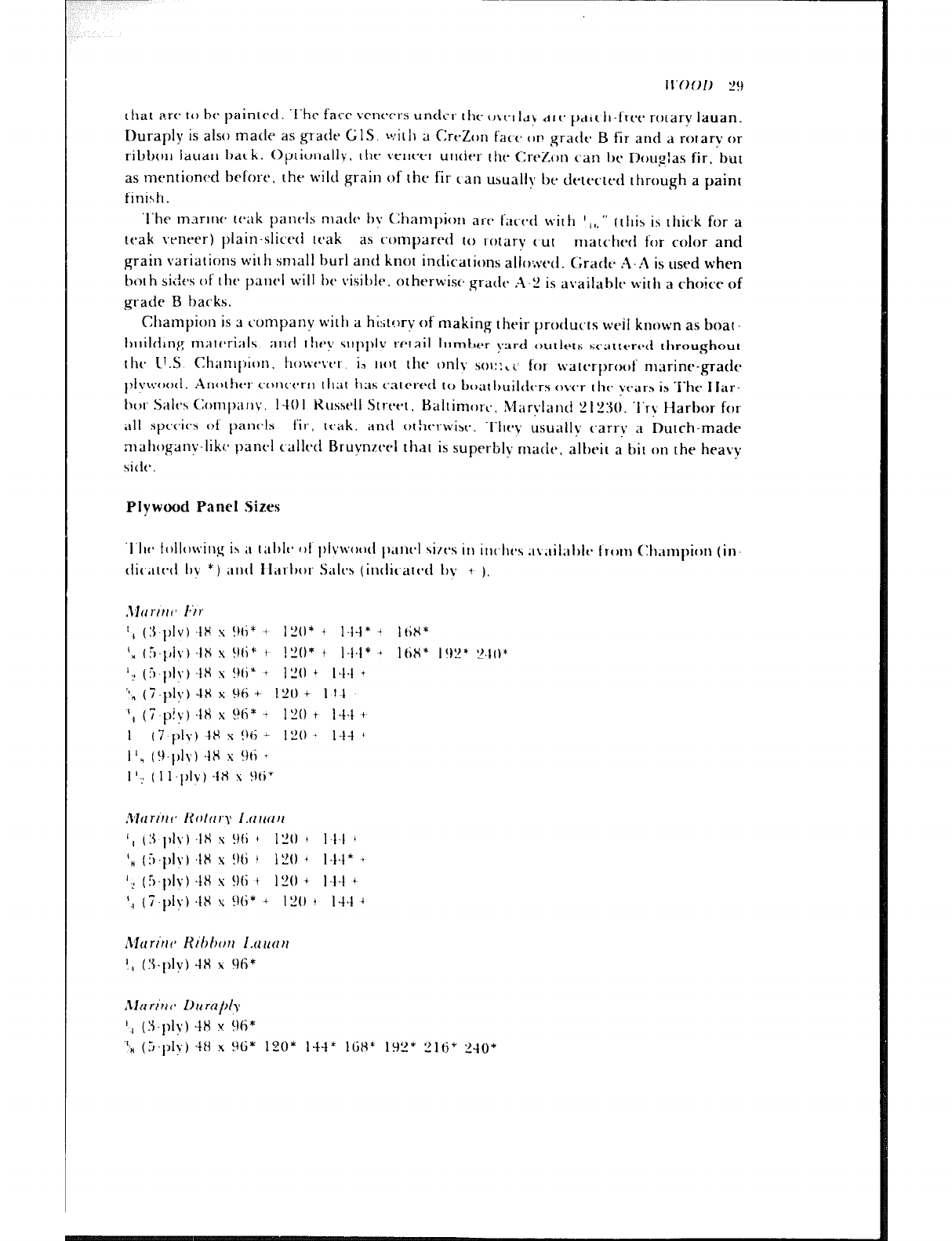
Plywood Panel Sizes
‘f’flf- lolfowinq ih il rill)lC’ 01 f)fvM.()o~f f)CInt’f sin-s in illt.ht3 ;Iv.lil;if)ft- Iron1 (:h;imf)itrn (iri-
tiic,;llc-ti II? *) ;Intf Ifarf)or Salt3 (intfic~arcd fq i ).
.\I(Irlrrf’ I*‘/1
‘, (3.f,lV) 4x s !hi’ 4 1”0* + 14-f* ’ IciH*
Iy (.r,-pi”) 48 s !)li+ f !“o* t 144* l ItiX* I!)P* “.I()*
‘? (:PpIy) 48 s !W ’ I”0 4 I.14 +
“” (i-f+) 4H s 96 4~ 121) + 11 I
‘, (7 p!y) 48 s !?(i* - I”0 + 144 +
I (i-ply) 4H s 96 + I”0 * l-1-f +
I Iq (!I-f,lY) 4x s 9ri ’
1 I.> ( 11 .f’fV) -fH s 9ti*
Murl’rrf~ I~fll~lrp l.tll/illl
‘( (?I plv) .lH s !)(i ’ I”0 ’ I.14 ’
I”0 +
‘” (.:,.plv) ,lH s !Mi I - 1.14* 4
IL’ (5.plv) 4x s 96 t I”0 4 l,fd +
‘,( (7.f,fY) 48 s wi* ’ I”0 i f-14 ’
,Varirrc Kihtwll l.nucltr
I,, (3.[‘IV) 4x x Lx*
,Zln rl’ti f* 1)~ rajdy
‘, (5.]‘I?) -18 Y 96’
“,” (5.fjly) 48 x 96 * 120* i-f-f* 16x* 192* !216* ‘L-10’
‘SO II 001)
Special Sizes of Plywood
Both (Ihampjon anti iiar bar Salts\ 0ftc.r 10 malit. p,snrl:; in sites other than stock.
Champion. for instance. mentions panels fr-on! ‘b ’ !o I IL’
” thick in increments of $,,“.
sviclttls 10 Ml”, and ll*ngths ot Sti (A friend of mine built several hundred hard-chine
,~ss;iulf h),irs whmt* topsiti~* l,lanking t on4stc C1 .a’ ti! ;i single pant.1 on each side of about
s(i feet.) l+;trt)or 5alt.h. on tilt- ot ht.1 h,lnJ. otfcrs panels in any length. with a max-
imum width r,l H’, or i)allc-l5 ill an! width, with a maximum length of H1/2’. Panel
I hI( kwss start5 at ‘% “.
Exterior Grade Plvwood
1\23Ilv 1)uiltlt-1.5. ills lucling me. have SIIC c~ssfully usrd exterior grade plywood instead of
rllar-int- grath~. hut L
I huffi< icllt nurnhc*l c~f failures. sue_h as delamination, have been
rt-c~orclt~d. Bwaus~ of this. the use ot c,xrt-r.ior grade is not recommended unless one is
~lh\ol~/(,l~ c,t,rfo/n that the panels ar, - made with truly waterproof glue, that all voids
arc pluggc~l hv the- bui!dcr IO prevent the entrance of water, and that the weaker con-
SIIEC tion iniltbrc.llt III I hc lesser number of plies is suitable for the job. All in all, con-
>,idc-ring rho tr~~mt~ndous amount ot troub!e that could be caused by failure of this
~I~~JVO()(~ lnatc~rial. thta hc,.~thuiltlt~r is ativisc:l against gambling his labor against the
\,l\‘in,g iI1 lllq\t(-l-i.il ~051 ,gainerl i)v 1 tI(. us(’ ot f.xtcricn gra(lt-
Cutting Plywood
IhIt. IO [Iit* rtiili \t-nt’t-t\ th,l: Ilidkt’ utl .I I).41~c~i ~~lvwo~~tl rt-ntl5 to 5)llinter 011 its undcr-
hitIt* w ht.11 4;lwtYl , ,~nct t‘i1 i\ 0111’ 01 ~IIc* WI~I~I itI ttii\ it3l)t*(‘t. :I 1)iec.e of solid lumber
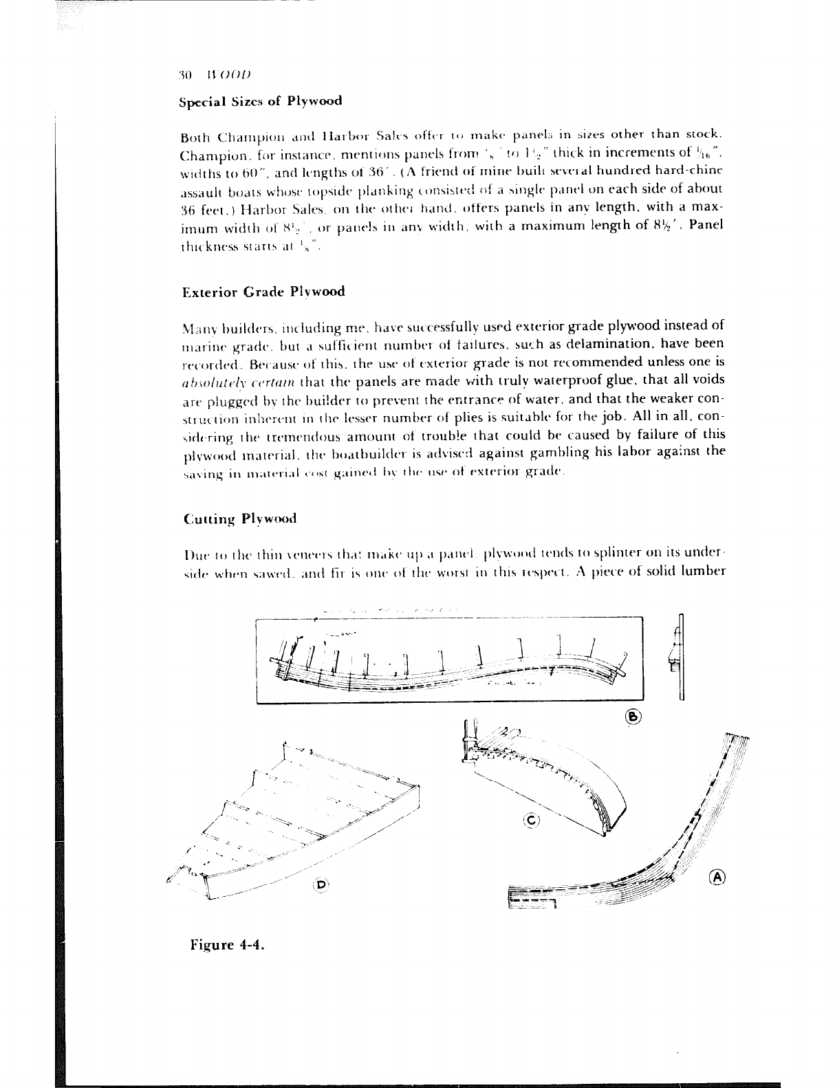
Figure 4-4.
1l’f~Ol~ 3 1
c!amped on the underside of the panel will eliminate this splintering. Cuts should
always be made by a fine-toothed crosscut saw with the face-side of the plywood up.
Lightweight portable circular saws are handy when much plywood is to be cut. and
there are blades with fine teeth made for just this purpose. The edges of plywood
panels are best smoothed with a low angle, sharp block plane set for a fine cut and
held at an angle to the edge rather than parallel to it.
Bending Plywood
Plywood can be bent to curvature either dry or after it has been steamed. If the latter
method is used, the panel must be dried before another part can be laminated IO it.
Sometimes it is advantageous to dry-bend two panels eat-h of half the desired finished
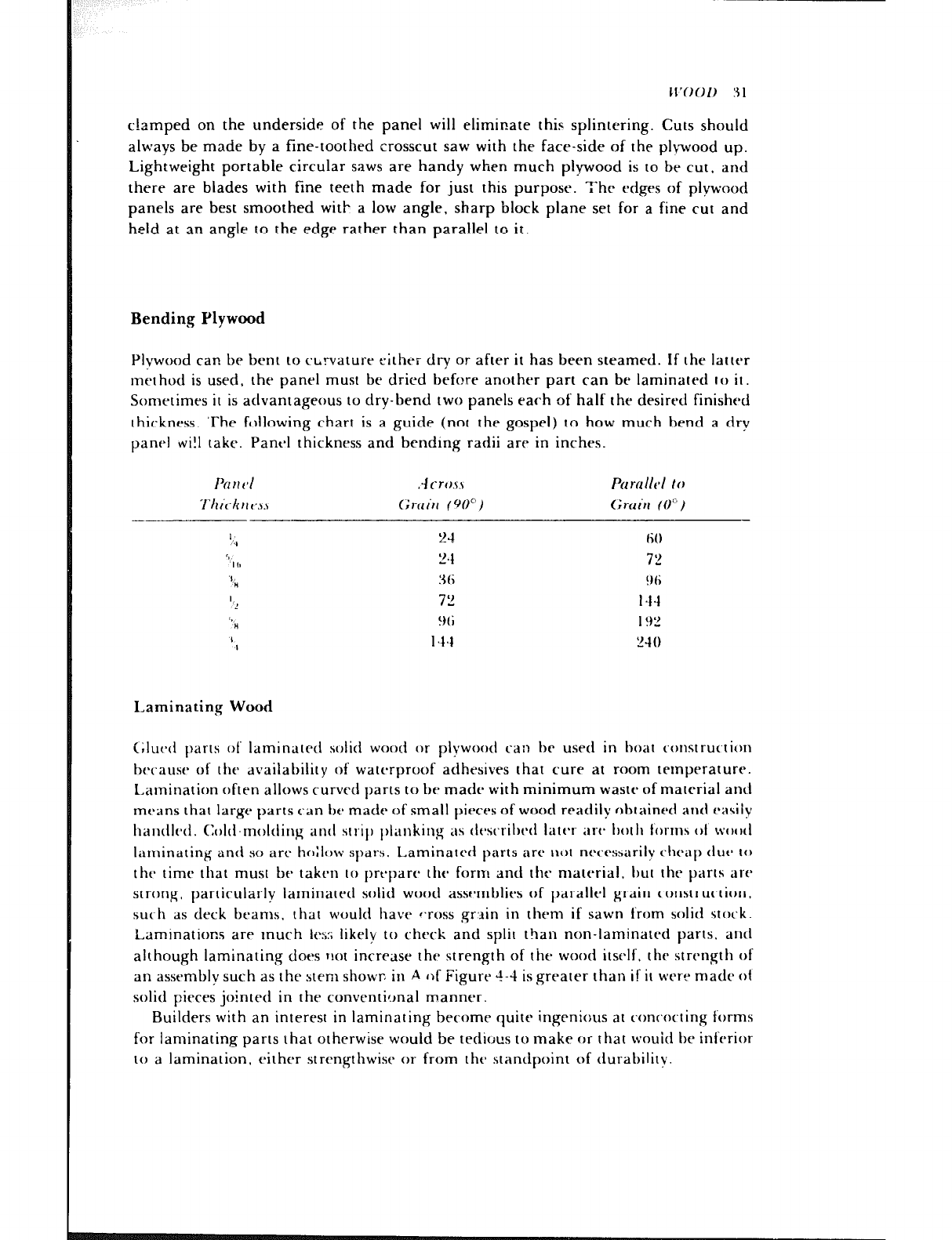
thickness. ‘The following chart is a guide (not the gospel) to how much bend a dry
panel wi!l take. Pant-l thickness and bending radii are in inches.
,J cr0.n
Cirnitr (W)
P~~mllt~l to
(;rclill (0”)
I
,‘,I 24 60
‘2
I I, ‘4 72
‘I!
” 3fi !Jfi
1’: 7” 144
‘,
” Wi I92
I
I 144 “40
Laminating Wood
<;lut~cl parts of laminated solid wood or plywood l.kIil he used in hoat construction
hc-cause of the availability of watt-t-proof adhesives that cure at room temperature.
Lamination often allows curved parts to be made with minimum waste of material and
means that large parts can be made of small pieces of wood readily obtained and easiiv
ha~ltlI(*d. Ct)llI-rnol~lin~ antI str,il) l)lanking as tit*sc~riI)t~(l latc*r art- t)ottl form5 01 \v(N,;I
laminating and so arc ho;low spars. Laminated parts ilrt' trot necfxsarily cheap tluc to
thtb time that must be taken to prt*pare the form and thr material, hut the parts are
strong, particularly laminated solid wood asst~mblies of parallel grain construi~tion.
sue-h as deck beams. that would have “ross grain in them if sawn from solid stock.
Laminations are tnuch ICS:; likely to check and split than non-laminated parts. a1111
although laminating does not increase the strength of the wood itself. the strength of
an assembly such as the stem showr, in A of Figure 4-4 is greater than if it were made ot
solid pieces jointed in the conventic,nal manner.
Builders with an interest in laminating become quite ingenious at conr,oc.ting forms
for laminating parts that otherwise would be tedious to make or that wouid be inferior
to a lamination, either strengthwise or from the standpoint of durability.
‘3 9
. L 11’001)
Fi,gure 4-4B shows the lamination of a tiller. A part like this would have cross grain
if sawn from one piece of wood. The shape is laid out on a hoard or on the floor, and a
series of cleats is fastened in place to secure the form to which the lamination will be
clamped.
Another type of form is shown in C. and it can he used for laminating either solid
stock or plywood. Fir plywood $,” thick, which is available ftom Champion and prob-
ably from Harbor if you ask for it, can he bent quite sharply to laminate such parts as
deckhouse roof corners. rockpit coaming corners. and the like. D is a sketch of a form
used to ,gluc up right- and left-hand parts with twist, such as the bulwark rails at the
bow of a boat
No matter how the form is constructed. there is one thing that must be remembered
in all forms: the form must be covered with waxed paper to prevent it from becoming
glued 10 tlte part being laminated.
I’hrrt~ is no rule for the thickness of the lamination strips except that they must be
thirt encrugh to take the required shape easily. If they are not sufficiently thin, you will
have a hard time holding them in place prior to clamping.
Scarphing I,umber and Plywood
Wttt-tt luml~c~ is nc)t ol~tainal~lt~ in long enough lengths for the jot; at hand, shorter
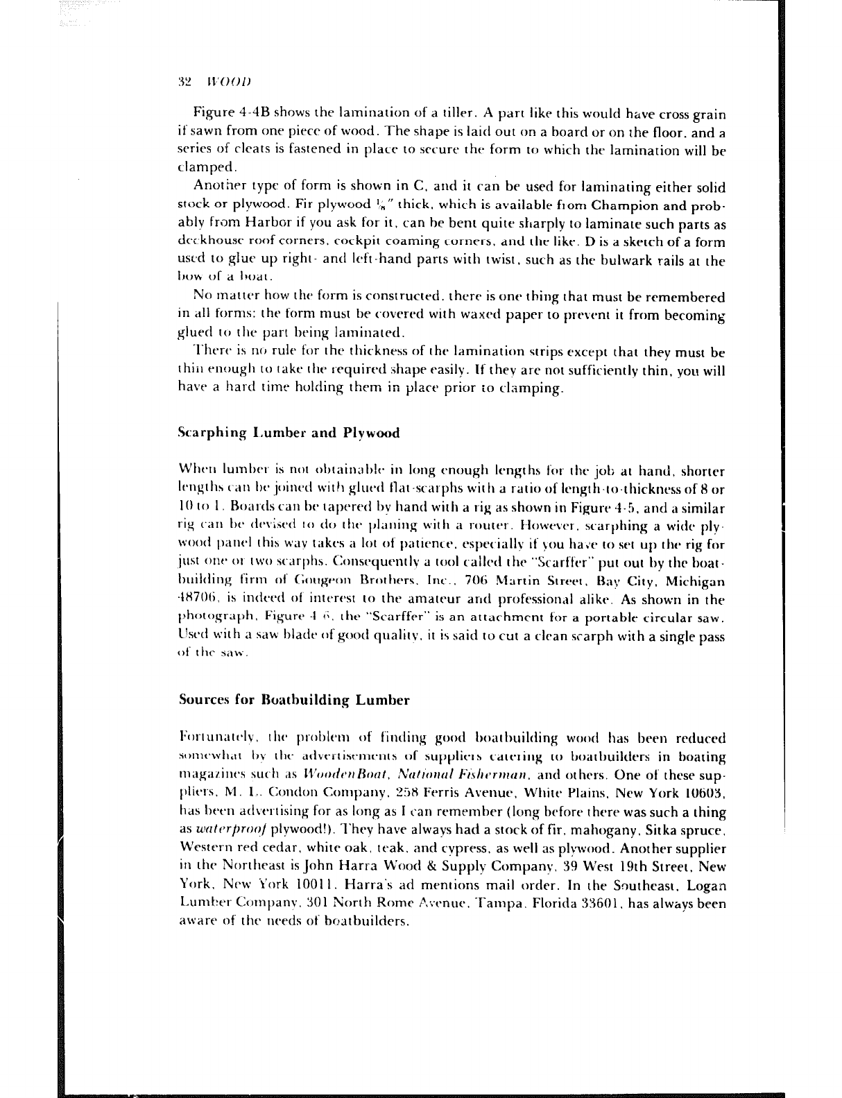
Icngtl1s (‘a11 IN* jcbinc*tl with gluecl llat -scarphs with a ratio of Ic~t1gth-t(~~thickt~c~ss of 8 or
IO to I Bciat-cls can be tapered Iry hand with a rig as shown in Figure 4-h. and a similar
rig (‘a11 tbc* cfc~\,&t~ct to cl0 t tits plaiting with a routet-. Ilowevet . scarl)t1ing a wide ply-
wood f~ant~l this way taktx a lot of f)atience. espec-ially if you tta.le to set up the rig for
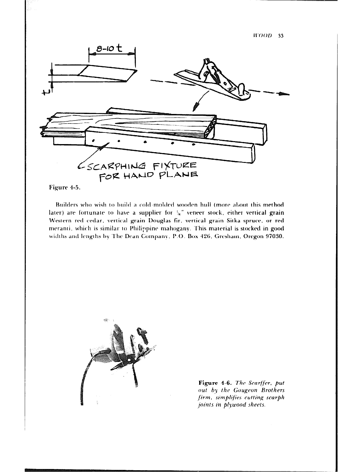
just 01w 01 two sc,trf)tis. Consc~quentlv a toot caiteci the “Scarffer” put out by the boat -
buitcling firm of Gclugecul Brothers. Inc., 706 slartin Street, L&1!; City. Michigan
4X706, is incleed 01 interest to the amateur and profession,tl alike. As shown in the
photograph. Figure -4 1;. the “Scarffer” is an attachment for a portable circular saw.
Llsc-ci with a saw blade of good quality. it is said to cut a clean sc-arph with a single pass
of ltlt~ saw.
Sources for Roatbuilding Lumber
I~ortun;1tc~lv. the prcrblem of finding good I~oatlmilding wood has been reduced
son1cwI1;tt I)y IlIt* ~Cl~~t~itist~lll~~IltS of supplirrs catering to b0irtlruilderS in boating
magarines such ‘1s i2’c~JtlcQrt Rf>cit, ,~fl~r’(J~I(L/ f’-/:\/lf~~~tWIl. and others. One of these sup-
ltlic*rs. M. 1.. COIK~CJI~ Co111panv. 258 Ferris Avenue, White Plains. New York 10603,
has been advertising for as long as I c-an remember (long before there was such a thing
as uutvrproof plywood!). l-hey have always had a stock of fir. mahogany. Sitka spruce,
U’estcrn red cedar. white oak. teak. and cypress, as well as plywood. Another supplier
in the Northeast is John Hart-a \Vctod & Supply Company. 39 West 19th Street, New
York. New York 1001 I. Harra‘s ad mentions mail cnder. In the Snutheast, Logan
Lumt:rr Companv. 301 North Rome C.;cnuc. Tampa. Florida 33601. has alwhys been
aware of the needs of hr?at builders.
II’OOD 33
Figure 4-5.
Huilhs WINI wish to l)uil(t iI colti-molded woodcn hull (mart* ;tt,out this method
1att.r) art’ fortunatt~ to havt~ a supplier for ‘In” vt’nrer stc)rk, eirhtbr vertical grain
Wettbrn rt4 c.rclar. vtBrric;il grain Douglas fir. vt=rtical grain Silka spruct~. or red
nit-ranti. whit~h is similar to I’hili;~pine mahoganv. .I’his marcrial is scockrd in good
witlrh~ and Irnghs t)y I’ht~ Dr;In Lompnv. P.O. .Box -126. Grt*shatn. Ort-gon 97030.
Figure 4-6. The Scarljfer, put
out by the Gougc~or~ Brothers
jiirm, vs~mplifie.~ cu/ting scarph
joints in plywood sheets.
34 lI:OOL)
Prevention of Wood Decay
The first step in the prevention of decay is to select woods that have proven durable in
boats, and it should be remembered that the heartwood of a log is the most resistant to
rot, Decay is caused by fungi that feed on the cellulose between the cell walls of wood.
For the fungi to grow, certain conditions of moisture, temperature, and air must be
present . The moisture content must be on the order of 25-30 percent, the temperature
75-90 degrees F., and the air stagnant. Wood that is always dry does not rot because of
the lack of moisture, a,-td wood that is continuously wet does not rot because there is no
air present.
There will be more later on the importance of building to avoid leaks in deck and
cabin. where watet can enter and he trapped, just waiting for the right temperature
for the fungi to grow.
In addition to the natural decay resistance of some woods and the precautions
against leaks that can he taken bv the builder, chemicals can be used that are toxic to
fungi and marine borers. These preparations are cheap, easy IO apply, and they
reduce the chances of drcav.
I;or many vears dn old standby in preventing decay was copper naphthanate; then
l~~~t~tit~~t~loro~~ht~t~~~l c ame along,anci mot-t recently ‘I‘B’I‘O (trihutyl tin oxide) ap-
ftt~,rted, All 01 I hesc art* ~tld under various names bv marine paint manufacturers and
art* rc~aclilv dvailaltlc- It-oni sulrlrliers. Although I am ~rluCl;inl to recommend any one
of these as the best, the experience of boatbuildt~rs I have talked with and photos of
Ic’ht }),IIK-~!. 1 hdrc c losr.lv ehdtirittt-d portit up TBI‘C) as the most effeclivr preservative
for fnotection against miirilw borers dnd wood-tit~stroyitig fungi.
‘l‘hesc~ preset-vatives are easy to apply bv brushing or dipping. the larger parts being
brusheci anal smaller- pieces. such as planking butt blocks, short deck beams, and the
like, being dipped in a container of the preparation.
Scantling
‘The ciimensions of the hull timbers in wooden boatbuilding are called scantlings. For
itibtanct’. a list of scantlings includes the sire and spacing of frames, planking
thickness, keel depth and width, stem width. and sizes of clamps, stringers, deck
beams etc. ‘l’he actual dimensions may be given as the “siding,” generally the smaller
dimension, and the “molding.” usually a vertical dimension. As an example of this,
referring to Figure 12-l A, a deckbeam would be sided I t, ” and molded 2 th “, while a
clamp would he sided 1 t*j ” and molded 4 “. The dimensions of frames are an excep-
tion to the above. because the fore-and-aft dimension is the siding, and the athwart-
ship dimension is the molded size. The terminology is peculiar to boatbuilding. and
the builder quickly becomes adjusted to its usage.
It has been noted that quite a few designers, apparently tiring over the years of hand
lettering the words “sided” and “molded’* on their drawings. simply abbreviate these
words to S and M. This could be very confusing to the first-tirr,er. but now you know.
Chapter 5
Wood has bt-cn tht- traditional material for boatbuilding and it remains so because of
the- relative ease with which it can be worked by the beginmar. However, depending
upon the skill and ingenuity of the builtlrr. tht-rt* are other materials to be considered,
somel imt-s in combination with wood,
Wood and Fiberglass
When the type of wood hull construction is suitable, there is much to rt=commend
covering the wood with resin and fiberglass or other such cloth. The hull planking
should preferably be of a stable type, such as strip planking, doub!e or triple diagonal
planking, or plywood. Normal carve1 planking swells and shrinks with moisture
changes, and this might cause the covering to crack. However, there are those who do
not hesitate to cover old carvel-planked hulls with fiberglass, but the covering is made
quite thick and is mt*chanically fastened to the hull.
When the hull is suitable. t hp use of covering adds strength, prevents rot, minimizes
leaks and weight gain from absorption of water, and protects against the attack of
worms and borers. The latter by itself is a great advantage, for it reduces the worries
that can be brought on by delays in hauling out for bottom cleaning. ‘l-he weight of the
covering does not add much to the overall weight of the boat, and when it is planned for
in the design, the wooden structures can be reduced in size to compensate for the weight
of the covering. In anything but very fast boats the added weight does not count for much
anyway.
The fabric is usually fiberglass cloth. but polypropylene and Dyne1 are also used.
The resin can be either polyester or epoxy. The latter is more expensive and more
35
3G E-IHER~~l.ASS A ND O’l‘Ilk:R lI1 ‘I.I. .21.4 7‘k.RI:I I..5
time-consuming to use, due to slower cure at room temperatures, but its adhesion to
wood is superior.
Covering is also recommended for plywood decks. cabin tops, and the like, and the
covering of joints in cabin sides. etc., to prevent leaks is a genuine boon to the builder
when the joined work is to be painted rather than varnished. Taped joints can be
sanded to feather edges and made invisible under d paint finish.
Huils are oitcn covered wtth %O-ounce fiberglass cloth. doubled Lil areas of strain
such as at the chines of v-bottomed boats. Ten-ounce cloth is often used to cover ver-
tit-al cabin sides of plywood. To give you an idea of the weight added by one layer of
such covering, figurr a minimum of 2.25 ounces per square foot for IO-ounce cloth
and doul~k t tlis for 20.ounce cioth. both including polyester resin.
Anyone who clabbles with boats will sooner or later want to cover old wood, and
there are certain prt-cautions that must be taken for I dood job. All old finish must be
cltxaned off the wood. and the wood must be dry. In the case of a plywood hull, for in-
stance, the boat must be hauled out of the water and put under cover, the old finish
stripped, and the wood allowed to dry for several weeks before covering. Epoxy resin is
stronglv 1-t-commrnded for old wood.
New wood OI old, oil IJZW fillers must 11o1 be used ovet the heads of fastenings,
because they will he sot’tent~d by the resin. For filling cracks and smoothing gouges use
(41 her il polyester ,turomot~ile body putlv. which is very fast drying and can be sanded
ho011 attc*r USC’. or makts ;I mixture of t*l)oxy resin and .L material like Cabosil propor.
tionetl to produce lhe consistency of putty.
For many years I~rlentler lntiusrries. Inc. has catered IO the 11twIs of the home boat’
huildt~r and they c’arry a large selt*c.tion ot p0)vestc.t .~nd c-poxy resins, fiberglass and
olht-r bvnt ht*tic. fahric,s. s11c.h as ~J(~lv~)ro~)vl~~rit~
;lIlII Kt*Vlilr. ilIlt glassing IOOIS. ‘l‘llr
(~iltalo~ alho Itas instruc~tions for (.ovt-ring WJO~. ‘l’he address ot lIefender is 255 Main
St I-WI , New Kochelle. New \I’ork I OH01
Molded Fiberglass Hulls
.l‘htb shiny, commerciallv prcduwtl fiberglass hulls are usualiy made from a female
1110Itl. ‘l‘his rc-quit-es that a wooden male plug 1)~ made, just as though you were
IJuiltIing iI wooctI~11 hull, using stripplanking or l~lywood. whichever is suitable for tht-
hull shape. ‘l’ht- plug is tlwn covered with glass cloth and resin and is worked to a very
snloot II I‘iIlish. for every blemish will IJC reproducx~tl when the female mold is made.
When t IIt- plug is finished as desired. a release is applied so that the female will not
stick to it. I’hen glass cloth and mat and polyesret- resin at-y laid up successively until a
s1r011g. rigid molt1 has been made. Rather than relv entirelv upon shell thickness to
hold the mold’s shape, the shell is rt-inforr-ed 011 the outside with a nerwork of rough
wood anti sometimes steel. If a particular hull shape is such that it cannot be
withdrawn vertically, the mold is made to split on the centerline.
Some builders decrease the time needed to build stiffness into the mold by using
sandwic h construct ion. After 1 .I ” or so of fibrIglab% hd> brrn laid up against the plug,
they use a core materiai such as end-grain balsa, followed by more fiberglass. The
mold stiffness is thus increased e-reatlv bv soreadine the rrlass skins aoart. the core
FIBERG1..-1SS .-I IV-II OTHER Hl’1.1. M.-I TERIA LS 37
material acting in much the same manner as the web of an I-beam that separates the
flanges.
When the female mold for the production of a hull has been removed from the
plug, it is polished and waxed and any blemishes are repaired. IL is then ready for Iay-
ing up a hull. Sometimes a partial disc of wood or steel, larger in diameter than the
beam of the boat, is added to the mold near each end so the mold can be rolled from
side to side while laying up the fiberglass and resin. When the hull is anything larger
than dinghy size, this minimizes the amount of time the builders must spend actually
working in the hull while laying up and makes the work mostly downhand. The more
you can stay out of the sticky resin the less disiasieful the job will he. This presumes
that the hull will be made by laying up the laminates by hand and applying the resin
with roller and brush. When hulls are produced in large quantity. resin and chopped
glass fibers can br applied with specialized spray equipment, but these hulls are not as
strong as those laminated of fiberglass cloth.
The high g!oss finish on the outside of molded hulls or other simiiariy cortttructed
parts of the boat results from first spraying a gel coat of resin on the surface of the
mold. The gel coat can be of any color desired. and contrasting stripes at the waterline
and other accent stripes can be sprayed as well when you know what it is all about.
After the gel coat has been applied, the hull is laid up with fiberglass fabrics known as
wovtw roving and choppt*d strand mat until the nectassary thickness hrl+ been reached.
llow does one make a mold and lay up a fiberglass hull if detailed instructions are
not available? Watching others do these things is the best way, but if this is not possi-
ble, thrrc ale htroks that spell out the techniques. One book, iLfnr/rrc* Dc~.\/~I~ Mnuul,
has been the bible of the tiberglass boat industry for many years. and now there are
I
other hooks on tIrt* market writrcbn with the bt*ginnt’t. in mind. l‘h~ laminate
sc~hcvllll~* int;)rmation (It*t;tilitlg the* c.omposit ion of rho tiberglass hull laminate. such
as thcb wc$$ir anal tvpe of glass reinforcement, nunlbcr of lavers, etc. should be out
lined in rhr Plans of the boar. .Is experience is Rained. the builder mav develop his
own ith*as about laminatc~s. l)ut guiclancth is nt~eded for rht, first artcmpt at [his type of
bc~athuiltling.
“One-Off” Fiberglass Hulls
It was inevitable that huildt-rs would come along and figure out a way to build a
tiberglass hull without having tn spend the time and money to construct a female
mold. Setkmann Plastics, Inc., P. 0. Box 13704, NVW Orleans. L,ouisiana 70185, not
only devised a method but also invented and patented C-Flex “planking.” which con-
sists of parallel rods made of fiberglass-reinforced polyester alternating with bundles of
continuous roving, with each “plank” being held together by a webbing of two layers
of Itghtweight, open-weave fiberglass cloth.
The construction method is fairly simple. A hull form is framed with sectional
molds and sometimes stiffener! with longitudinal strips let into the molds. Obviously
the hull must be built upside down. The molds must be spaced so that the C-Flex
“planking” will not sag between thetn. the spacing varying with the weight of the
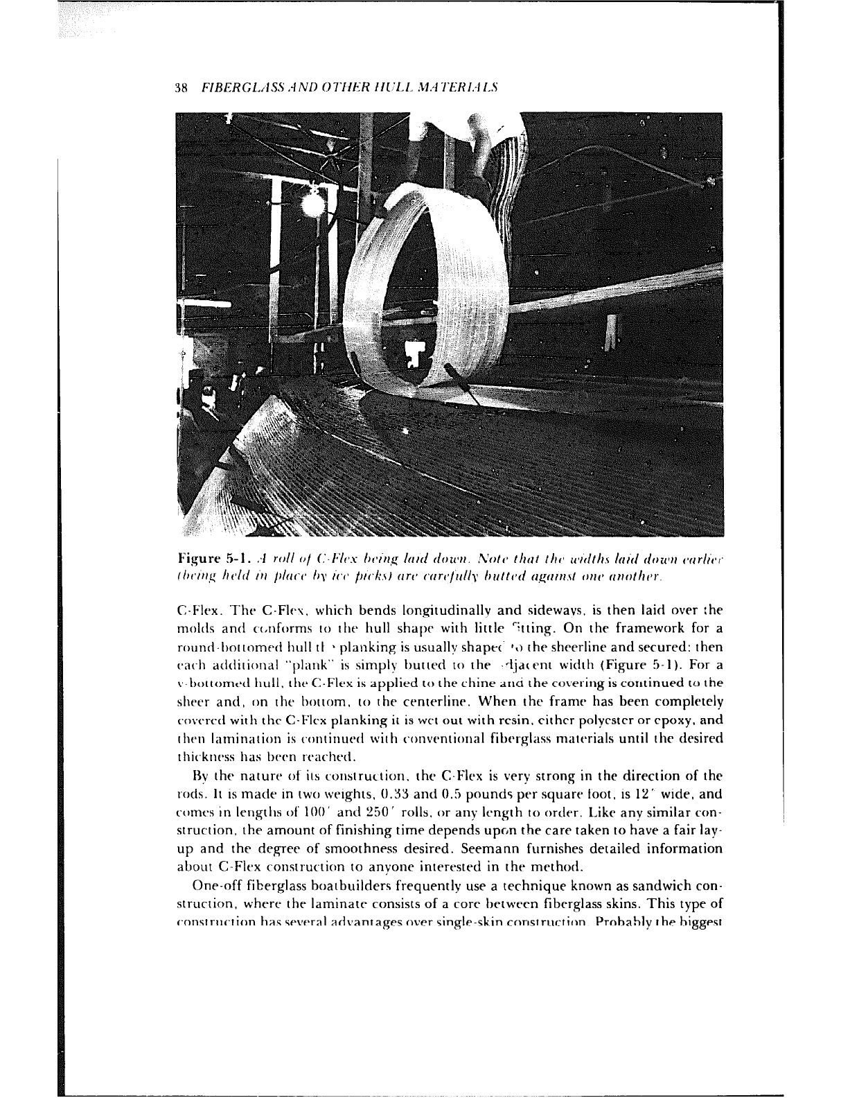
38 FIRERGL.I~SS .-INU OTIIER III’LL M.47’1:RI:Il.S
Figure 5-l. :I roll cl/ (:-It1 1’1 : / )r~itrg lurrl dower. .Volr* tlttrt tlrc icvtltI~s hiti rior4fu wrlr’vi~
(lwrrrg hdti ill plw hy I’(.(’ ptlk\I (iT(’ cYrrc~/rlIIy /rrltt(~d rrgr1rrr,\t OII(’ ri,rr,tll,‘,.
C-Flex. The C-FIvu. which bends lon<gitudinally and sideways, is then laid over :he
molrts and c,c,nforms IO the hull shape with little ‘itting. On the framework for a
rountl-l)nttomett hull tI 1 planking is usually; shape<- *<) the sheerline and secured: then
c-ach aclditional “plank” is simply butted to the .djac ent width (Figure 5-1). For a
v-bottom~~tl hu11, the C-Flex is applied to the chine and the covering is continued to the
sheer and, on the hottom. to the centerline. When the frame has been completely
covered with the C-Flex planking it is wet out with resin, either polyester or epoxy, and
t htsti l~ttIlill;ltiOt~ is contiriut4 with c~onventional fitWrgliIss miltc~rials until the desired
t hic.kness has been reach~-d.
13~ the nature of its cwttstruction, the C-Flex is very strong in the direction of the
rods. It is made in two wc+ghts. 0.33 and 0.5 pounds per square foot, is 12’ wide, and
conit’s in lerigtlis of 100’ and 250’ rolls. or any length to order. Like any similar con-
struction, the amount of finishing time depends upon the care taken to have a fair lay-
up and the degree of smoothness desired. Seemann furnishes detailed information
about C-Flex construction to anyone interested in the method.
One-nff fiberglass hoarbuilders frequently use a technique known as sandwich con-
struction, where thr laminate consists of a core between fiberglass skins. This type of
construction has several advantages over single-skin construction. Probably the biggest

l.‘III~;KI;I..JS.‘;S!i :l.t’l) O’I‘ttER ill ‘1.1 .lI.-fTERI.-lI.S 39
advantage is its favorable stiffness/weight ratio. A sandwich laminate is significantly
stifter than a single skin of the same number of laminations, and with a lightweight
core such as balsa or foam, the weight of the sandwich is not much greater than the
single skin. I’his fact offers the designer who uses sandwich construction with options:
he calI krzp thy same thickness and weight lanlinate as for a similar single-skin hull
and VI;;I up wtth a thicket-, muc-h stiffer hull; he can reduce the thickness and weight of
the glass skins and have a cored laminate with strength equal to the single skin; or he
can use a sandwic.h latninate designed to both save weight and increase stiffness.
Other than stiftncxs and ligllt weight, sandwich construction offers additional
benefits. ‘I’hc interior sweating for which single-skin fiberglass hulls are notorious is
minimized or non-rxistcmt in a sandwich hull. Noise and vibration are also reduced,
arid thtb .tI)st.nc~e of thtb transvetsc- framing sometimes used in single-skin fiberglass hulls
givt-5 11101 t’ u.,;Ibit- slmcx. insitiv the hull.
:2n11r trrar ~-OIII~,~I ison that should bc- made between single-skin and sandwich con.
strut-tiotl is wltat ttappcns in thr e:~nt that the hull is punctured, particularly under
tht. w,lt~:rlinc~ Iti s1tc.h (.ir~utnst;Itl(.t’l;. the single-skin hull will admit water, but this is
not so of a sandwic.h hull unless both skins and the core are punctured-- something
that ad~oc.;itrs of san(lwic.h construction feel is unlikely during the normal life of a
boat. It totlrn\s. ot t.ourbc. that if a c~)rrd laminate should be completely punctured
the rt*sult of strc-tl XII .tccitlt~nt is no worse than for a single-skin hull. As a safeguard
,ig;tiilzt irnp;l( I, I hts otttcr skin of it sanctwich is often made thicker than the inner skin,
1111 11) ;I t.ttio 01 lx.1 .I%(- tcpit 01 $3 sanclwicll laminate is no more difficult than for a
singIt* \kitl. 1111lt~ t ht. core material has been damaged, in which case a piccc of the
(‘on’ will ric~~l to 1)~. irisc~rtc*~l it the hull is to be repaired in the same way it was con.
~ttu~:tc~~l. OIlit-IMGW-. rhc- (l;ltn;tg~~i section of thr outer skin is ground away with
~i1)1-St4i\,t. 11~~1~. It..it tic-rcbrl ilit0 t IIt* acliacc-tit unilatn;igc~l skin, and I he void is filled with
I’il)c%rgl,las .ln(l tt4tl thts S,I~H~ as for single-skin tibrt-glass repair.
.I‘I~ I)uil(l ;I 5atldivic.h hull, a framework of transverse section molds and longitudinal
strips (usunllv ( allc :! r-ibbands (jr Ijattens) is needed to define the shape of the hull. and
it tn;lkt*s st& to build upside down. Figure 5-2 shows the forward end of a male mold
for an X6-foot powtarboai hull.
I Ising loam (or-t- as a:~ c~x;tnipIr. foam sheets are fitted against the mold (using a
heat lamp to makt the foam pliable where necessary or using “contoured” core
matc~rial instt-atI) atltl held in place with nails driven through plywood scrap “washers”
until tht. foan~ (‘at1 t)t- held in place wit11 screws through the ribbands from r’nsl’dr> the
tnold into thta foam (l;igurcb 5 3). ‘I’hcs foam is then cc~vrred wit)1 the specified thickness
of the fibt*rglass outsi& skin (Figurts 5-a).
Careful workmanshi~~ is t-equired to ensure a complete bond between the core
material and the glass skins. Interruptions in the bond will hasten delamination of the
sandwich whm the lamination is loaded to deflect between supports and this will
weaken the affected part of the hull. When there is a good bond between the skins and
the core. some of thcb burden of the laminate strength fails upon the core itself. For this
reason that laminate clesi,gner must carefully investigate the available core materials for
use in boat Ilulls. Obviously. a material that resists crumbling upon impact and that
does not absorb water is desirable.
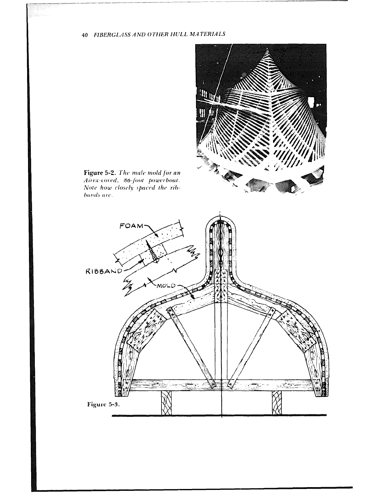
40 FIBERGLASS A Nil OTIIER IiULL M.-l TERIALS
Figure 5-2. ‘X‘ht, tnult’ ~101rf for on
Airex-corrd, X6jiwt pouw~‘rhoclt.
Note> how clo.st*lv .spncd thrb rib-
h(l trtl.5 (1 r(‘.
FOAM\ // I
(
i
i
t
I
i
:
?
/
h
i
Figure 5-3.
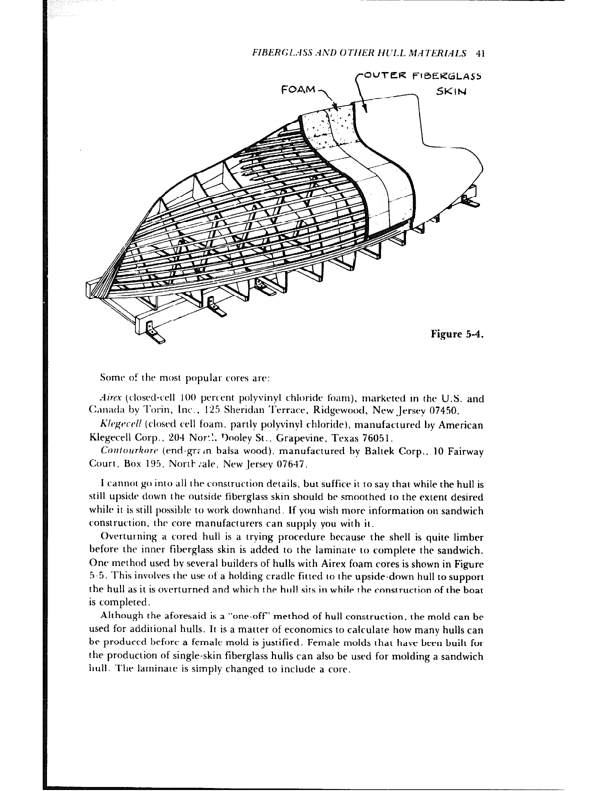
FIRERCL:lSS .1h’D OTIIER HC’1.L MATERIAIS 41
/-OUTER FIBERGLASS
Some o!‘ the most popular cores are:
iiircu (closed-cell 100 perrcnt polyvinyl chloride l’oam), marketed in the U.S. and
C,~n;td;r by l’clrin, Inc., 12.5 Sht2ridan ‘I’crracr, Ridgewood, New .Jrrsey 07450.
h’lrgt~c~~ll (closed cell foam, partly polyvinyl chloride), manufactured by American
Klegrcell Corp. I 204 NoJ:~. %oley St.. Grapevine. Texas 7605 1.
Cotttourkorr (end-gr; in balsa wood), manufactured by Baltek Corp., 10 Fairway
Court, Box 195. North :ale. New Jersey 07647.
I cannot go into all the construction details, but suffice it to say that while the hull is
still upside down the nutside fiberglass skin should be smoothed to the extent desired
while it is still possible to work downhand, If you wish more information on sandwich
construction, the, core manufacturers can supply you with it.
C)verturning a cored hull is a trying procedure because the shell is quite limber
before the inner fiberglass skin is added to the laminate to complete the sandwich.
One method used by several builders of hulls with Airex foam cores is shown in Figure
5-5. This involves the use of a holding cradle fitted to the upside-down hull to support
the hull as it is overturned and which the hull sits in while the construction of the boat
is completed.
Although the aforesaid is a “one-off” method of hull construction, the mold can be
used for additional hulls. It is a matter of economics to calculate how many hulls can
be produced before a female mold is justified. Female molds that have been built for
the production of single-skin fiberglass hulls can also be used for molding a sandwich
hull. Thr laminate is simply changed to include a core.
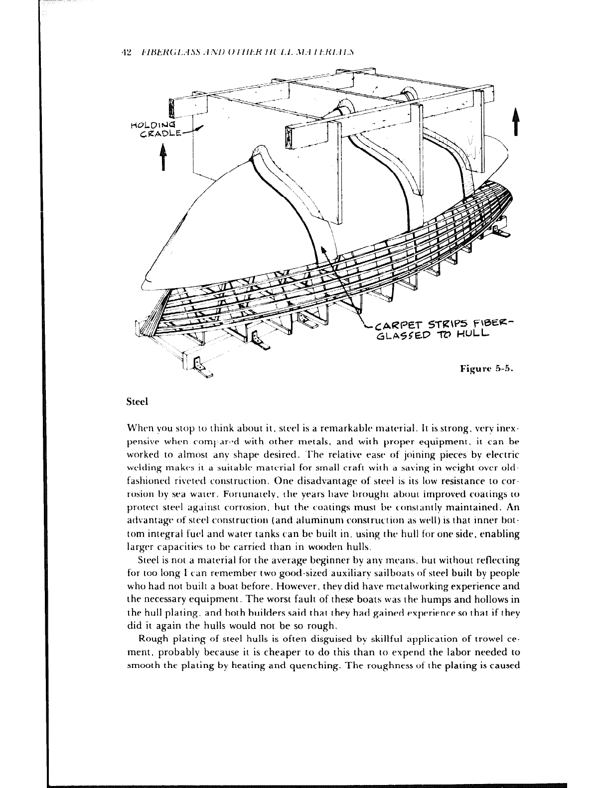
42 I~‘IHER(~I.:I!iS .dh’l) 07’111:R 111 ‘1.1. .11.-l 7‘1.111:1 1.S
CARPET STR\fS f=\=e-
GLA4$Ep -R’ HULL
Figure 5-5.
Steel
When you stop to think about it, steel is a remarkable material. it is strong, very inrx-
pensive when rornl~ar~*d with other metals, and with proper equipment, it can be
worked to almost any shape desired. ‘I’he relative ease of joining pieces by electric
welding makes it a suitabltx material for small craft with a saving in weight over old-
fashioned riveted construction. One disadvantage of steel is its low resistanre to cor-
rosion by sea water. Fortunately. the years have brought about improved coatings to
protect steel against corrosion, hut the coatings must be tcrnstantly maintained. An
advantage of steel construction (and aluminum construction as well) is that inner bot-
tom integral fuc*l and water tanks ran be built in, using the hull for one side, enabling
larger capacities to be carried than in wooden hulls.
Steel is not a material for the average beginner by any means. but without reflecting
for too long 1 can remember two good-sized auxiliary sailboats of steel built by people
who had not built a boat before. However, they did have metalworking experience and
the necessary equipment. The worst fault of these boats was the humps and hollows in
the hull plating, and both builders said that they had gained experience so that if they
did it again the hulls would not be so rough.
Rough plating of steel hulls is often disguised by skillful application of trowel ce-
ment, probably because it is cheaper to do this than to expend the labor needed to
smooth the plating by heating and quenching. The roughness of the plating is caused
l~~lHt:K~~I..-l.sS .l.VI) 1)771t~;K II1 ‘1.1. .ll:I 7‘l~:HI:~l.S -IS
by stresses ser up when welding the plating to the frames and one plate 10 another. The
sequence of welding is of importance in this respect.
Even though steel is an old material, research technicians have invented new alloys
of higtler strength so that steel hulls can be built lighter today rhan ever before.
Aluminum Alloys
A few of the many aluminum alloys, notably alloy 5086 in rhe United States. are
satisfacror-y for- boalhuilding. These alloys are relatively high in strcngl h and corrosion
resistance and can be satisfactorilv welded. A fair amount of rhis meral is consumed by
yacht huildrrs. but bv far rhe most of it is used IO build the increasingly large fleet of
oftshore oil field crew transports and platform supply vessels.
In general terms. alloys of aluminum reduce construt.tion weight over rhar of steel.
.i‘his permits the carrying of more deadweight or an increase in speed. or the possi-
bililv of achieving speed with less horsepower. Besides ils light weight. aluminum lasts
long; Iht* fitt’r (haI commercial operators are using aluminum cannot but speak well
for irs anlicif)a’t-d Iongeviry.
Several huitttt7h of pleasure boats either Ijuilti only in dluminum or have a line of
;rluniinuni t~1a~5 in atltlition IO Ihost- 01 otht-1 nlart-ria1.s. Small craft 5ut.h as dinghies
and runabouts of aluminum are made bv stretch-ft.rming sheets over malts molds I0
I)rotluct- 2 large part or ;1n enrirt- hdlf 0~1 of 01it- p&t* of ~TWial. Orht-rwise. regular
1~-;111svi‘rst~ or tongil utlinal Lramiiig is used ant1 c.ovt*red wirh plaling i1S in sleel COII-
~rrircrio~i. Atulliinulil t~c~nstrut~tion is nio~t- t,sl)t*nsivt- than steel t~~ns~~ut~~ion. for no1
onlv tlot~s IlIt* atunlinunl ilst4t CXN more pt.r INNI~~I than ~~t.t~l, rl~e ,tt.(u;tl welding also
I’O~I~ IIIOII-. ‘i‘his mortb than m,lkt-s up for the fact rhar rhe wt+.$lt of aluminum in-
volved in a particular project will always be less than the weight of the steel required.
Manv builders of steel boars have converted 10 aluminum construction with little
need to change cquipmenr rsce11~ for welding, but like steel. it is not a nlaterial for the
bt*ginnt~r. 011~ very imptlfi~~rtn~ problem area encc,un~rrtd with aluminum construction
is galvanit t,c)rl.osion. ‘I‘his oct’urs hetwern the aluminum hull and dissimilar metals
found in sut.11 fitrings as sea cocks, prt)pt-llers, shafts, rutitlcrs, etc.. anti also occurs
when the aluminum hull is exposed to stray electrical currcrfts in anchorages. This can
be ~~JtY’tWltVi. and the methods for doing so are preferably all spt~lleti OUI in the plans
and specitit.ations for the boat. If you lack this information, the marine departments
of the aluminum manufacturers can be consulred for help.
Welding ant1 the preparation of the finished surface are also areas that require care.
Welding aluminum is quite different than welding steel. It is imperative that weld
areas be absolutely clean if good welds are to be made. If you are in need of informa-
tion about welding. the aluminum manufacturers can provide assistance. When it
comes IO painting the surface, rhe marine paint makers have special systems for
coating aluminum and instructions for cleaning it before coating. The highest quality
hull rakes a lot of labor: a really smooth yacht finish on the topsiJes of a welded
aluminum yacht hull requires fairing of the surface with fairing compounds. which
should stay in place for quite a while.
J-1 t~‘Il~t*~t~(~I.‘-Iss .-I ,YI) C)7/lt-X III .1.1. N.-t 7‘1:K1.41..~
Ferrocement
Every now and then there is a wave of enthusiasm abdL-t cl=nstructing hulls of ferroce-
ment. Essentially. the system consists of a framework of concrete reinforcing rod in-
terlaced with wirr, with cement applied to it so that the steelwork is completely
embedded and not exposed to the atmosphere. It is understood that great care must be
taken to eliminate voids in the cement, and that the basically heavy weight of the con-
struction makes it impractical for hulls under 30 feet in length.
In the years 1967-68 hardly an issue of a boating magazine did not carry some men-
tion of ferrocement hulls under construction, and there were a number of designers
actively rngaged turning out plans for the then current rage. A decade later there does
not ,.lppear to be any mention at all, an indication that the method is not as easy as the
earlier enthusiasts had broadcast.
Exotic Hull Materials
‘Tht-re have been a number of matt+als developed recently that have higher strengths
and lower weights than wood and fiberglass-reinforced plastic, and development in
this art’s is bound to continup. Graphite, in fiber form, has been used in super-
liglttw4ght fishing rods and in highly strtmssc4 areas of racing sailboat hulls. It is three
timc*s stronger and five times stiffer than stt-cl. I.ike~visr. S glass, which is twice as
strong as the common E: glass from wltirh the standard boatbuilding glass fabrics are
matlt-. is muctl stronger and i.. stiffer for its weight tllan is steel. Kevlar fabric, made
tram I)upont aramid tihers. is another lightwri<ght high.strrngth material.
F2sotic, materials havca also found their way into bulkheads. Years ago, the in:roduc-
tion of rc~lat~vc*ly stiff marine plywood bulkheads was a giant step forward in strength
as compared to the bulkheads made of vertical wood staving or decorative panels.
Now, plywood as a bulkhead material has been surpassed by at least two other
tnatt-rials that art’ stiffer and much lighter. Panels of both these materials come with
fil~t~rglass skins, and thry are used in large transport aircraft. One type of core is end-
grain balsa and the other is a honeycomb made of a DuPont material called Nomex,
which is used in helicopter bladrs.
Although such exotic matet ials can work out well, esperially where light weight is a
c.onsidrration. there are other factors to consider. If they arr to be used properly, these
I~latt~riiIlS rquirc- spccializrd techniques and knowledge. Another consideration is
t ht4r high cost. For example, S glass is twice as expensive as E glass. As for Kevlar, a
builder of high-speed powerboats who uses this material once told me that, pound for
pound, a Kevlar.,resin combination was as much as seven times more expensive than
the standard mat ‘woven roving’resin combination. Since these exotic materials are
not used throughout a hull, but only as a substitute for strength-contributing laminate
material, it is hard to make a general comment about the cost of building hulls using
exotic fibers. for laminate designs differ from boat to boat. About all that can i,i! said,
then, is that the use of such exotic materials will certainly lead to an increase in cost.
When one considers that the powerboat manufacturer referred to earlier was able to

I;IRk.XG L.:1.S.S ‘4 ND 0 7-t Il~.ii 1 I1 !l.!. ,21.-I 7’EKI.J 1.s 45
effect a weight saving of only 5 to 7 percent, the extra cost is, in most cases, not
warranted.
The state of the art is constantly changing, however, so new materials will always be
developed, and there are always those who will try to apply them to boatbuilding.
Chapter 6
___-
&mpared with the heavily constructed wooden boats of the old days, almost all
modern craft can be considered to be lightly built. Thus the innumerable fastenings
holding the parts together assume extra importance as a primary contribution to a
tight, seaworthy boat. All fastenings should bc sized according to their task and
located with thought by the designer and builder. I‘hcy should always be driven in
carefully drilled holes of proper size to ensure maximum holding power.
Galvanized Iron
The builder of a wooden boat can save a considerable amount of money by using gal-
vanized iron hull fastenings. Old timers have passed down the word that galvanized-
fastened boats will last a lifetime, and indeed there are hulls here and there that seem
to prove this point. On the other hand, I examined a wrecked shrimp boat, beached
about 10 years after it was built. that proved just the opposite.
Although the above would appear to offer contradictory evidence regarding the
clurability of galvanized fastenings, it doesn’t. The galvanized fastenings of today
simply are not the galvanized fastenings of yesterday. In the first place, the old timers
used galvanized iron. whereas the fastenings available today are most likely of mild
steel. When bared of their protective coatings, fastenings of mild steel do not have
nearly as much resistance to corrosion as do iron ones. Second, the old-time iron nails
and rods were always coated by hot dipping in molten zinc. Many “galvanized” fas-
trners today are zinc coated by electroplating, which results in a relatively thin coating
that cannot be compared to coating by hot dipping. In fact these “zinc-plated” fas-
teners have no place in a boat.
Here is what Independent Nail, Inc., a manufacturer of special-purpose nails, has
to say about the zinc coating of fasteners:
I.‘.-I s 7‘E.l’Ih’ .;.s 17
‘* ‘Galvanized’ has turned out to bc generally a poorly understood adjective. The
best type is a hot-dip, whose surface is, for practical purposes, pure zinc. Tumbler,
hot-tumbler, hot-galvanized each refer to a tumbler process from which the coating
may be contaminated with iron right on the surface. Electra and mechanical galvaniz-
ing e,tch generally produce very thin zinc coatings serving for appearance more than
for performance.”
Galvanized boat nails and galvanized wood screws have often been used to fasten
planking to frames. A frame should be at least 1 t/2 ” thick if a nail is to be buried in it
without going through the frame. With lighter frames, the nail goes through the
frames and is clinched over on the inside. When poor nails are used, the zinc will
separate from the nail where it is bent, exposing the bare metal. Many boats have had
to be refastened because corrosion started at the end of such nails and progressed
throughout the length of the fastening. Renailing is an expensive job, and the necessity
to do so is a good sign that the fastenings were inferior or inadequate to start with.
In the case of the smaller-sized hot-dipped galvanized wood screws, the threads are
frequently clogged with zinc when they are dipped, and when driven, they tear the
wood around the hole. reducing holding power.
Even if he has had sotne good experiences in the past with galvanized fastenings, the
builder is advised to be sure of his fastenings by using a better metal for fastenings
that are to be constantly in water. Although more expensive initially, the best fasten-
ings are cheap in the end.
Brass
If a decision is made against using galvanized fastenings it might seem that a good
alternative would be brass fastenings. but the use of brass for fastenings exposed to salt
water cannot be advised against too strongly. Brass as furnished for the manufacture
of screws and bolts is very high in zinc content, perhaps as much as 30 percent, and in
an electrolyte sucl~ as sea water, the zinc ieaves the alloy. What remains is a spongy
copper so reduced in strength that the fastening is practically useless. This is called de-
zincifiration and can he expected when a copper alloy is used that contains zinc in ex-
cess 01 16 percent. There are mechanical disadvantages, too. The high zinc brass
alloys are not particularly strong: it is easy to break off screws being driven into hard
woods. Brass is all right for the fastening of interior parts such as joinerwork, but care
should be taken not to use it in thr hull.
Silicon Bronze
For every structural fastening in a boat it is hard to beat a copper silicon alloy
sometimes called Everdur. It is about 96 percent copper and is so strong that fasten-
ings are seldom wrung off when being driven, and of major importance, it is highly
resistant to corrosion from sea water. The use of this metal removes the risks involved
with the brasses and galvanized steel fastenings and is well worth the difference in cost.
A point to be remembered is the higher resale value of a bronze-fastened boat.
48 F.4 s TENINGS
Monel ‘L
This nickel copper alloy ranks above silicon bronze in strength and corrosion
resistance, but the cost of screws and bolts made from it is much too high for most
people to afford. It can be used in conjunction with silicon bronze without fear of
much galvanic action between the metals. For instance, Monel IS often used for fasten-
ing bronze propeller shaft struts and Monel shafts have bronze propellers in direct con-
tact. The strength and stiffness of Monel make it very satisfactory for Anchorfast boat
nails, a popular fastening for some purposes because of the labor saving it offers over
driving screws. (See Threaded Nails.) Monel as a metal has many uses in boat con-
struction and will be mentioned further.
Copper
Copper has excellent corrosion resistance, but because of its scftness it is suitable
mostly for fastenings in the form of flat-head nails that are used as rivets or for clout
nails sometimes, used in hulls with light lapstrake planking.
Stainless Steel
‘I‘here arc many alloys under 1 his common heading. It IS recommended that these
merals not he considered for hull fastenings unless you are guided by someone who has
vast cxpt-rirnce and satisfactory proof of corrosion resistance and freedom from
galvanic action with other materials being used in the same boat. Without such
assutanct~, thtn USC’ of stainless steel should be limit,4 to applications above water. It is
the bt-st metal for f’asrening aluminum alloy deck hardware. stanchions, and
aluminum alloy window frames. for it avoids corrosion of the alloy parts. Of the many
stainless ste&. the OIW known as Typo 316 seems to be the most corrosion-resistant in a
salt atmosphere, but finding fastenings of this alloy may take some doing. One or two
of thr high-qualitv yacht builders have, in the past,
, special ordered Type 316 wood
S~I‘VLYS to st’curC% stainless sterl half-oval rub strips to minimize “bleeding” of the screw
Il~ads. If you can find one of these builders, he might be happy to reduce his stock of
such fasrt-tiings.
Othc*r than as a fastener material. stainless steel is being used more and more for
hll p“‘s, tlotahly drrk hardware. sailhoat specialty hardware, stanchions and
Ijulpits, engine cxhausr systtm parts. and propeller shafting. Stainless is also used for
wire ropts rigging and rigging fittings on spars. As with many materials that might be
used in a boat. it is brst to Iravtb experimentation to others. using it yourself only when
vou know thr application has been proven.
Mixture of Metals
The loosely used term “electrolysis” is applied by the average boatman to the corrosion
and erosion of metals by electrolysis, cavitation, or galvanic action; usually the
destruction of metals is blamed on electrolysis, due to lack of knowledge of the other
.F.4.Sl‘EIL’INC;S 49
causes. Except for discussing galvanic action between fastenings, the subject is beyond
the scope of :his work.
Sea water is an electrolyte that will cause an electric current to flow between
dissimilar metals when in contact or close proximity to each other. When this occurs,
currtznt will flow from :he anode to the cathode, that is. the anndic fitting or fastening
will be attacked and gradually destroyed by what is properly termed galvanic corro-
sion. The intensity of the attack will vary according to the relative positions of the
metals in the galvanic series and also upon the relative areas or masses of the metals.
The posi:ions in the galvanic series in sea water of some metals follow:
Anodic or Least Noble
Zinc
Galvanized steel or galvanized wrought iron
Aluminum alloy 5456
Aluminum alloy 5086
Aluminum alloy 5052
Aluminum alloy 356, 6061
Mild steel
Wrought iron
Cast iron
1% H Stainless steel ‘I’ypc 304 (active)
18-H Stainltsss sttst-I ‘I’ypt* 316. 3’!{, molybdenum (active
Lead
‘I‘in
Mangantbsc- hronzt~
Naval brass (60’+{, coppt*r, 39”:, rinc)
I ncm1~4 (act ivr )
Yrllow brass (65% copper, 35% Lint)
Aluminum bronze
Red brass (H5S;, copper, IS?:, zinc)
Copper
Silicon hronrr
Cupro-nickttl (904h copper, 10% nickel)
Cupro-nickel (704’, copper. 30% nickel)
Coml)osition G bronzts (#?A copper, 2’,‘/0 zinc, 10% tin)
Composition M bronze (885; copper, SU’, zinc, 61~2 “4, silicon. I I/? ?A Icad)
Incclnel (passive)
Mont.1
IX-R Stainless steel Type 304 (passive)
18-H Stainless steel Type 316, SS’, molybdenum (passive)
Titanium
Cathodic or Most Nobte
It might he possible to use only one metal, notably silicon bronze for all of the
fastenings in a wooden hull, but where a mixture is the most practical, the metals used
50 FASTENINGS
should be ones that are reasonably close together in the galvanic scale. such as copper,
silicon bronze, and Monet. Ail of these metals are used to manufacture fasteners of one
sort or another.
Note that stainless steels are shown in the series above in two different positions. As I
understand it, the surface of the steel is passivated by chemical treatmen: to hasten the
formation of oxide. This can be donr after ail machining and working has been fin-
ished, and after the steel has been thoroughly cleaned and degreased. The passivated
surface is more resistant to corrosion. Without passivation, the corrosion resistance is
severely reduced, and it is best to avoid the use of these metals for underwater fasten-
ings. If the surface has been treated, but the treatment has been destroyed or altered,
the metal’s corrosion resistance will be uncertain; it is best tc treat such metals as if
they were not passivated.
l know of a case wh: re a bronze stern bearing casting was fastened with galvanized
iron tag screws a perfect example of setting up o
maivanic corrosion. The dissimilar
metals were in contact in sea water; first the zinc disap;,eared, and then the iron was
attacked until the bearing finally came loose.
Many boats with’bronze hull fastenings have been built with cast iron ballast keels. but
in this case I he comparatively huge mass of anodic material. the iron keel, would show
signs of attack slowly due to its bulk. The bolts securing the keel cdn be of hot-dipped
galvanized wrought iron or Monrl. The outside of the iron should have several coats of a
vinyl-lvpc anti-corrosivtb paint to act as a nonmetailic barricsr to galvanic action.
N~~t-;ih~ss to say, only the Icast cxpc*nsive ritrt~i fastcsners should be used in the con-
struction of molds, jigs, plugs for fiberglass parts, bracing, etc., that will never be part
of a boat, It may sc-em ridi?ulous to even mention something like this, but I have seen
hoatyarti enipioyec3 use bronze and Monet fasteners in throw-away work rathrr than
visit tht* stockroom for stcsrI nails and screws.
Erlww Belts
____..
These are ordinary machine bolts with square or hexagonal heads and nuts, and they
al-r made in silicon bronze, Monet. and galvanized iron. Longer bolts can be home-
madr by t breading a pirre of rod on both ends. screwing a nut as a head on one end,
and pruning over the end of the rod to prevent the head nut from turning. Washers of
the same material are used under the head and nut. Drilled holes should be the same
tliamt~ter as the bolt, Screw hoits are used tor fastening many backbone parts and have
the advantage over drift bolts of being able to be tightener, . .
s.4 -**hen the wood shrinks.
Welt-equipped professional huiiders sometimes head their own tong bolts. They
have a die. usually for a flat head. and the end of the rod is heated and forged to
shape.
Drift Bolts
When bolts must be very long and a through-bolt is not practical or necessary, a drift
bolt can be used. They are made from a piece of rod and driven like a large nail. The
one end is pointed slightly by hammering, the other has a washer or clinch ring under
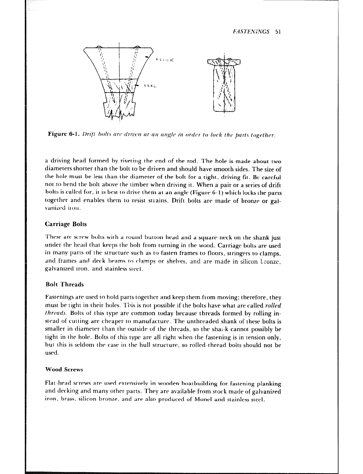
F.4 S TENiNGS 5 1
Figure 6-1. lIrij/ hoit.\ (II’V tlrl’z~rl (11 (III (III~IP /‘II orrlvr- 10 lock /ilc, /)nrt.c ~o,q,rc~t/t~~r.
a driving head formed by riveting the end of the rod. The hole is made about two
diameters shorter than the bolt to be driven and should have smooth sides. The size of
the hole must be less than the diameter of the bolt for a tight. driving fit. Be careful
not to henci the bolt above the timber when driving it. When a pair or a series of drift
bolts is caiiecl for, it is best to drive them at an angle (Figure 6- 1) which locks the parts
together and enables thrtn to resist strains. Drift bolts are made of bronze or gai-
vanizeii it on,
Carriage Bolts
Thesr are screw bolts with a round button head and a square neck on the shank just
under the head that keeps the bolt from turning in the wood. Carriage bolts are used
in tnany jrarts of the structure such as to fasten frames to floors, stringers to clamps,
dnd frames and deck beams to (‘lamps or she!ves. and are made in si!teon b:onze.
galvanized iron, and stainless steel.
Bolt Threads
Fastenings are used to hold parts together and keep them from moving: therefore, they
tnust be tight in their i~oirs. .I’l\is is not possible if the bolts have what are catted rolled
thrtwds. Bolts of this type are common today because threads formed by roiling in-
stead of cutting are cheaper to manufacture. The unthreaded shank of these bolts is
smatter in diameter than the outside of the threads, so the shargk cannot possibly be
tight in the hole. Bolts of this type are ail right when the fastening is in tension only,
but this is sridc~m the case in the hull structure, so roiled-thread bolts should not be
used.
Wood Screws
Fiat-head screws are used extensively in wooden boatbuilding for fastening planking
and decking and many other parts. They are available from stock made of galvanized
iron, brass, silicon bronze, and are also produced of Monel and stainless steel.
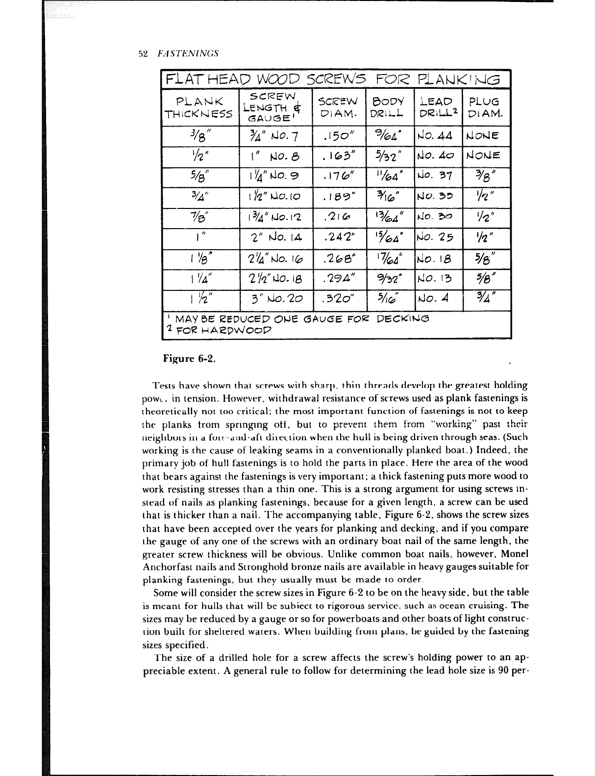
52 F/l S TENI NC3
FOR
I” W-8 . IG3”
$fc.lo. 9 * 176” “hd p. 37 %s”
743” 13/4” hlo. I2 .2lG7 do. 30 ‘/2 ”
I I, 2” do. I4 ,242” ‘%A’ do. 25 l/z’(
2 &” do. I & .2613” ’ 7/6A” do. I8 70 I’
I Y4” 2 $f do. 10 .29d” 9/s” /-lo. 13 s/a”
1 g 3” tJo.zo .320” %L ‘Jo. 4 3/d It
’ MAYBE REDUCED OrJE GAUGE FOR DECti1t&3
-12 FOR HAeDv\/ooP
Figure 6-2.
Tests have shown that screws with sharp, thin threads develop the greatest holding
powc. in tension. However, withdrawal resistance of screws used as plank fastenings is
theoretically not too critical; the most important function of fastenings is not to keep
the planks from sprtngtng otf. but to pre~en: *h-m ~nm “l*rnrL;n-” past :hei:
,.&\a.. L.X,.l, ““‘““‘h
neighbors in a for!.-and-aft direction when the hull is being driven through seas. (Such
working is the cause of leaking seams in a conventionally planked boat.) Indeed, the
primary job of hu!i fastenings is to hold the parts in place. Here the area of the wood
that bears against the fastenings is very important; a thick fastening puts more wood to
work resisting stresses than a thin one. This is a strong argument for using screws in-
stead of nails as planking fastenings, because for a given length, a screw can be used
that is thicker than a nail. The accompanying table. Figure 6-2, shows the screw sizes
that have been accepted over the years for planking and decking, and if you compare
the gauge of any one of the screws with an ordinary boat nail of the same length, the
greater screw thickness wilt be obvious. Unlike common boat nails, however, Monet
Anchorfast nails and Stronghoid bronze nails are available in heavy gauges suitable for
planking fastenings, but they usually must bc made to order.
Some wilt consider the screw sizes in Figure 6-2 to be on the heavy side, but the table
is meant for hulls that wilt be subiect to rigorous service, such as ocean crttising. The
sizes may be reduced by a gauge or so for powerboats and other boats of tight construc-
tion built for sheltered waters. When building from plans. be guided by the fastening
sizes specified.
The size of a drilled hole for a screw affects the screw’s holding power to an ap-
preciable extent. A general rule to follow for determining the lead hole size is 90 per-
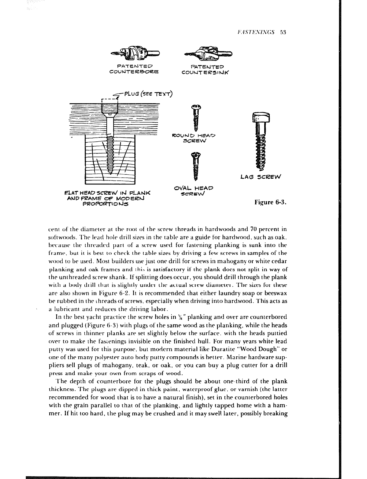
<PLUG (SEE TEwl-)
F 1
FLAT HEAD SClBti Id PLAWX
AUP FVAME at= MOC’ERhJ
PROFbR-rIO~S
FZOUbJD HEAr>
SCREW
LAG SCIZEW
OVAL HEAP
SCREd
Figure 6-3.
cent of the diameter at the root of the screw threads in hardwoods and 70 percent in
softwoods. The lead hole drill sizes in the table are a guide for hardwood, such as oak,
because the threaded part of a screw used for fastening planking is sunk into the
frame, but it is best to check the table sizes by driving a few screws in samples of the
wood to be used. Most builders use just one drill for screws in mahogany or white cedar
planking and oak frames and rhib is satisfactory if the plank does not split in way of
the unthreaded screw shank. If splitting does occur, you should drill through the plank
with a body drill that is slightly under the actual screw diameter. The sizes for these
are also shown in Figure 6-2. It is recommended that either laundry soap or beeswax
be rubbed in the threads of screws, especially when driving into hardwood. This acts as
a lubricant and rt-duces the driving labor.
In thr best yacht practice the screw holes in 5/H” planking and over are counterbored
and plugged (Figure 6-3) with plugs of the same wood as the planking, while the heads
of screws in thinner planks are set slightly below the surface. with the heads puttied
over to make the fasicnings invisible on the finished hull. For many years white lead
putty was used for this purpose, but modern material like Duratite “Wood Dough” or
one of the many polyester auto body putty compounds is better. Marine hardware sup-
pliers sell plugs of mahogany, teak, or oak, or you can buy a plug cutter for a drill
press and make your own from scraps of wood.
The depth of counter-bore for the plugs should be about one-third of the plank
thickness. The plugs are dipped in thick paint, waterproof glue. or varnish (the latter
recommended for wood that is to have a natural finish), set in the counterbored holes
with the grain parallel to that of the planking, and lightly tapped home with a ham-
mer. If hit too hard, the plug may be crushed and it may swell later, possibly breaking
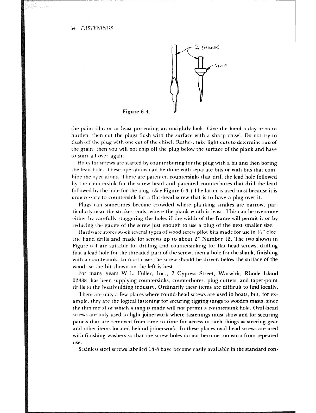
51 F:l S7‘I*:l~VIN(;.s
Figure 6-4
the paint film or at least presenting an unsightly look. Give the bond a day or so to
harden. then cut the plugs flush with the surface with a sharp chisel. Do not try to
flush off the plug with one cut of the chisel. Rather, take light cuts to determine run of
the grain: then you will not chip off the plug below the surface of the plank and have
to start all ovt’r again.
Holes tot- screws are started by counterboring for the plug with a bit and then boring
the lend hole. l‘hesr operations can be done with separate bits or with bits that com-
hint- lht~ opt7ations. l‘htw arc patented countersinks that drill the lead hole followed
lrv the c~outttcrsink for the screw head and patented ccmnterbores that drill the lead
followed by the hole for the plug. (See Figure 6-3.) ‘I’he latter is used most tm-ause it is
unnt’twwry to c.ountcrsink for a flat-head screw that is to have a plug over it.
Plugs can sorncrimcs become crowded where planking strakes are narrow, par-
ticularlv near the strakrs’ ends. where the plank wid:h is least. This can be overcome
either hy carefully staggering the holes if the width of the frame will permit it or by
reducing the gauge of the screw just enough to use a plug of the next smaller size.
Hardware stores stock several types of wood screw pilot bits made for use in $!t 0 elec-
tric hand drills and made for screws up to about 2” Number 12. The two shown in
Figure 6-4 are suitable for drilling and countersinking for flat-head screws, drilling
first a lead hole for the threaded part of the screw, then a hole for the shank, finishing
with a countersink. In most cases the screw should be driven below the surface of the
wootl~ so the lrit shown on the left is best.
For IIMII~ years W.L. Fuller, Inc., 7 Cypress Street, Warwick, Rhode Island
02HHH. has been supplying countersinks, counterbores. plug cutters, and taper-point
drills to the hoarbuilding industry. Ordinarily these items are difficult to find locally.
l‘hcre arc only a few places where round-head screws are used in boats, but, for ex-
ample, they are the logical fastening for securing rigging tangs to wooden masts, since
the thin metal of which a tang is made will not permit a countersunk hole. Oval-head
screws are only used in light joinerwork where fastenings must show and for securing
panels that are removed from time to time for access to such things as steering gear
and other items located behind joinerwork. In these places oval-head screws are used
with finishing washers so that the screw holes do not become too worn from repeated
use.
Stainless steel screws labelled 18-8 have become easily available in the standard con-
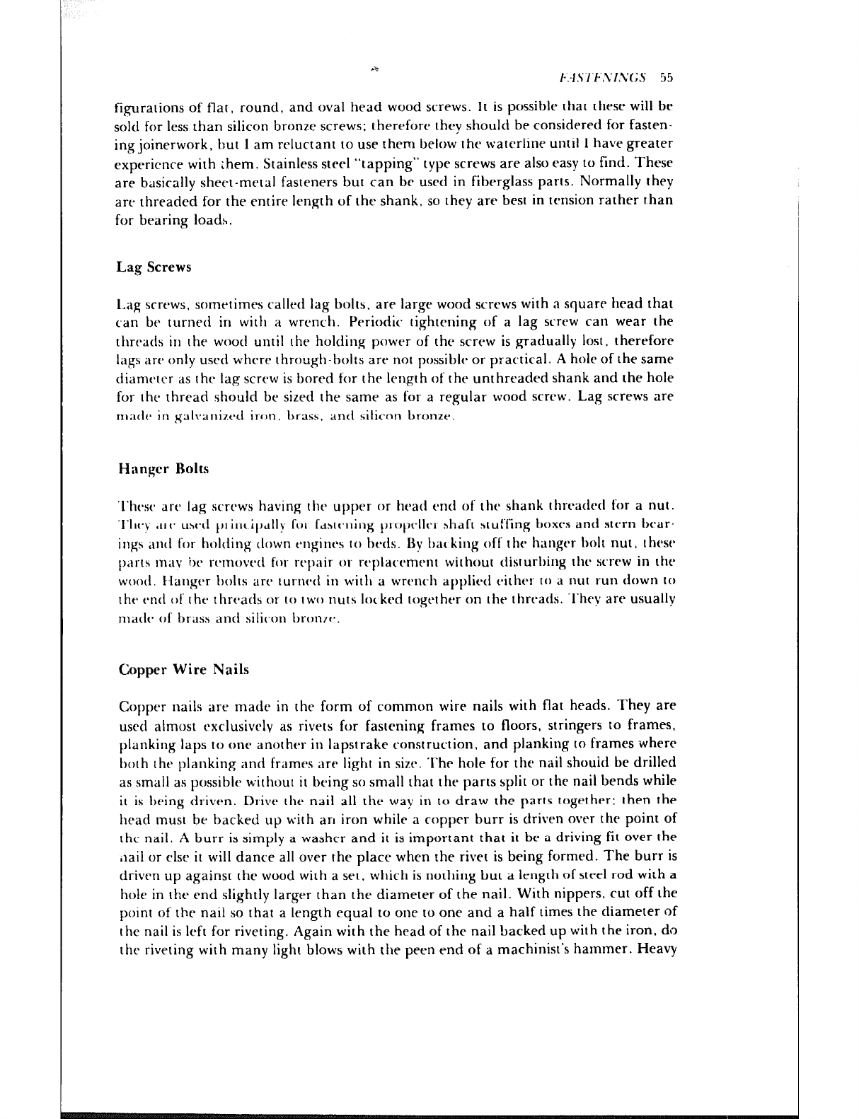
ia t~‘.-lS7‘F.~I.v~;S 5.5
figurations of flat, round, and oval head wood screws. It is possible that these will be
sold for less than silicon bronze screws; therefore they should be considered for fasten-
ing joinerwork, but I am reluctant to use them below the waterline until 1 have greater
experience with them. Stainless steel “tapping” type screws are also easy to find. These
are basically sheet-metal fasteners but can be used in fiberglass parts. Normally they
are threaded for the entire length of the shank, so they are best in tension rather than
for bearing loads.
Lag Screws
I.ag screws, sometimes callecl lag bolts. are large wood screws with a square head that
can be turned in with a wrench. Periodic tightening of a lag screw can wear the
threads in the wood until the holding power of the screw is gradually lost, therefore
lags are only used where through-bolts are not possible or practical. A hole of the same
diarnt~tcr as the lag screw is bored for the length of the unthreaded shank and the hole
for the thread should be sized the same as for a regular wood screw. Lag screws are
nlatlt* in ~galvariiztd it-on, brass. and silicon bronze.
Hanger Rolts
‘I’hese are ldg screws having the upper or head end of the shank threatled for a nut.
‘I‘hev art‘ used principally for fastening propeller shaft stuffing boxes and stern bear.
ings and for holding tlown engines to beds. Bv bat king off the hanger holt nut, these
parts mav ire rtmoved fat- repair or rt~plactmenr without disturbing the screw in the
wood. IIanger lrolts are turned in witlt a wrench applied either to a nut run down to
the end of the threads or to two nuts lot krd together on the threads. They are usually
ma& of brass anti silicon bronrc*.
Copper Wire Nails
Copper nails are made in the form of common wire nails with flat heads. They are
used almost exclusively as rivets for fastening frames to floors, stringers to frames,
planking laps to one another in lapstrake construction, and planking to frames where
both the planking and frames are light in size. The hole for the nail shouid be drilled
as small as possible without it being so small that the parts split or the nail bends while
it is being dt-iven. Drive the nail all the way in to draw the parts together; then the
head must be backed up with an iron while a copper burr is driven over the point of
the nail. A burr is simply a washer and it is important that it be a driving fit over the
,iail or else it will dance all over the place when the rivet is being formed. The burr is
driven up against the wood with a set. which is nothing but a length of steel rod with a
hole in the end slightly larger than the diameter of the nail. With nippers, cut off the
point of the nail so that a length equal to one to one and a half times the diameter of
the nail is left for riveting. Again with the head of the nail backed up with the iron, do
the riveting with many light blows with the peen end of a machinist’s hammer. Heavy

‘I,
56 E;4S7XNINC5
1 r\lO@-FERFZous bi ,4 IL ~IZTE~
. roq” 200
. 134”
Figure 6-5.
blows will bend the nail inside the wood. A bent rivet tends to straighten under stress,
resulting in a weak, loose fastening. Light blows form the head and draw the wood
together.
Copper rivets are excellent for light work but are rather soft. Screws should be used
for fastening planking when the size of the frame will permit them to be completely
sunk. Nails are also thinner than screws for the same job, a point discussed under
Wood Screws. See Figure 6-5 for sizes of copper wire nails.
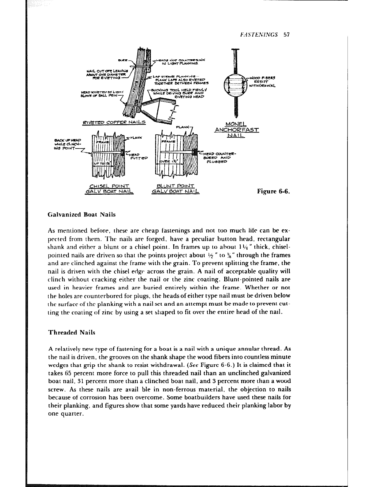
tztf2zY
‘?.I0 Poltrr
-2
u
Al
MOhlEL
ANCHORFAST
NAIL
&HIsEL POINT
GAL’s! BOAT NAIL BLUNT PItiT
GAL\/ BOA-I- hIAlL Fi.gure 6-6.
Galvanized Boat Nails
As mentioned before, rhesc are cheap fastenings and not too much life can be ex-
prcred from rhcm. Thr nails are forged, have a peculiar button head, rectangular
shank and cithrr a blunt or a chisel point. In frames up to about 1 t/i R thick, chisel-
pointed nails are driven so that the points project about ‘/j H to :!i” through the frames
and are clinched against the frame with the grain. To prevent splitting the frame, the
nail is driven with the chisel edge across the grain. A nail of acceptable quality will
clinch without cracking either the nail or the zinc coating. Blunt-pointed nails are
used in heavier frames and are buried entirely within the frame. Whether or not
the holes are countcrbored for plugs, the heads of either type nail must be driven below
the surface of the planking with a nail set and an attempt must be made to prevent cut-
ting the coating of zinc by using a set shaped to fit over the entire head of the natl.
Threaded Nails
A relatively new type of fastening for a boat is a nail with a unique annular thread. AS
the nail is driven, the grooves on the shank shape the wood fibers into countless minute
wedges that grip the shank to resist withdrawal. (See Figure 6-6.) It is claimed that it
takes 65 percent more force to pull this threaded nail than an unclinched galvanized
boat nail, 31 percent more than a clinched boat nail, and 3 percent more than a wood
screw. As these nails are avail ble in non-ferrous material, the objection to nails
because of corrosion has been overcome. Some boatbuilders have used these nails for
their planking, and figures show that some yards have reduced their planking labor by
one quarter.
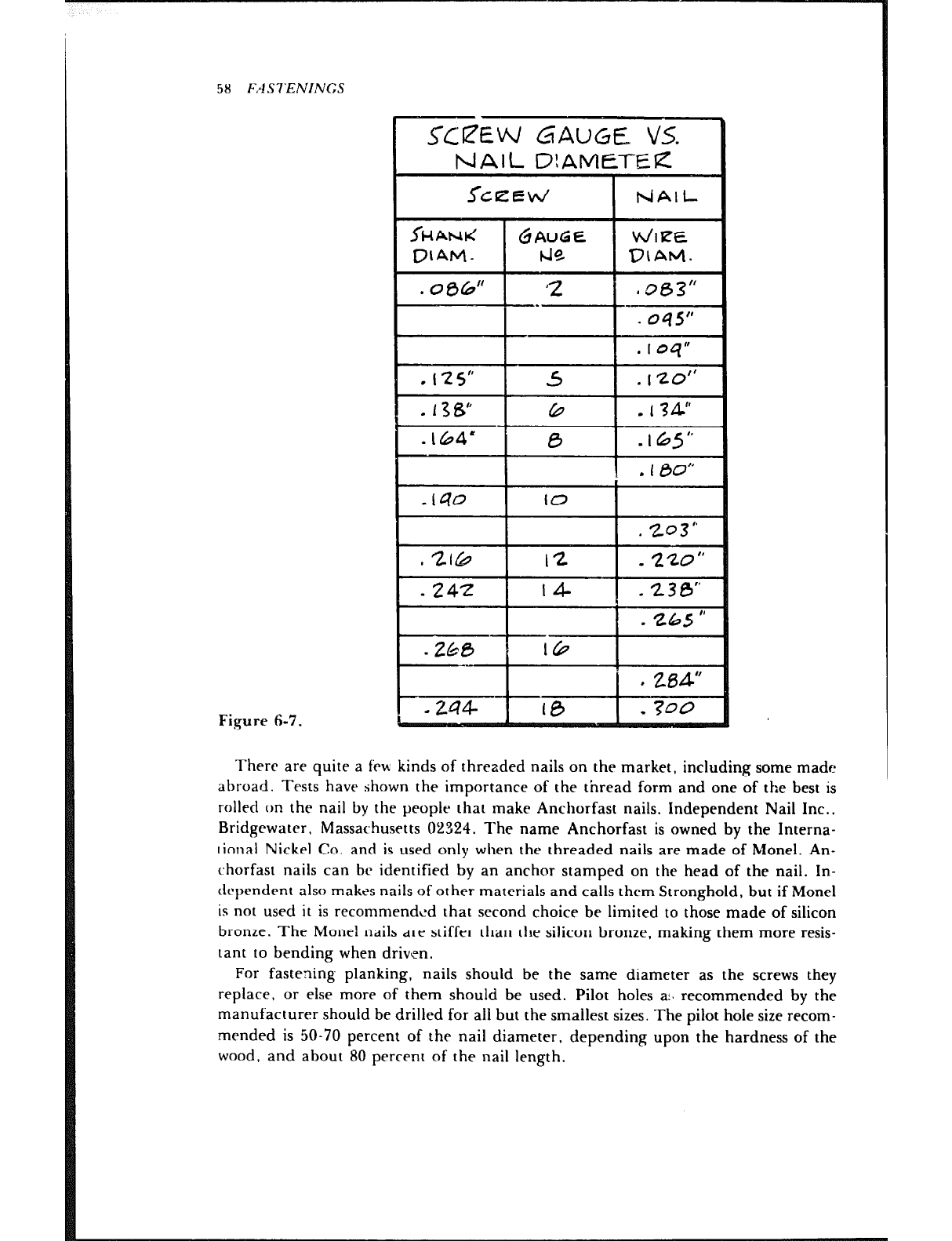
58 I;,4 SI‘ENINGS
Figure 6-i’.
There are quite a few kinds of threzded nails on the market, including some made
abroad. Tests have shown the importance of the thread form and one of the best is
rolled on the nail by the people that make Anchorfast nails, Independent Nail Inc.,
Bridgewater. Massachusetts 02324. The name Anchorfast is owned by the Interna-
tional Nickel Co. and is used only when the threaded nails are made of Monel. An-
chorfast nails can be identified by an anchor stamped on the head of the nail. In-
drpendent also makes nails of other materials and calls them Stronghold, but if Monel
is not used it is recommended that second choice be limited to those made of silicon
bronze. The Monel nails are stiffer than the silicon bronze, making them more resis-
tant to bending when driven.
For fastening planking, nails should be the same diameter as the screws they
replace, or else more of them should be used. Pilot holes a!. recommended by the
manufacturer should be drilled for all but the smallest sizes. The pilot hole size recom-
mended is 50-70 percent of the nail diameter, depending upon the hardness of the
wood, and about 80 percent of the nail length.

FASTENINGS 59
F&we 6-8.
In Figure 6-5 are shown the sizes of Monel Anchorfast and Stronghold silicon bronze
nails usually found in the stocks of distributors. Figure S-7 is a comparison of standard
nail and screw gauges as a guide for those wishing to substitute nails for screws, and in
Figure 6-8 nail sizes for various types of planking and decking are tabulated. These
sizes, of course. must be used with discretion, as they do not necessarily apply to every
case.
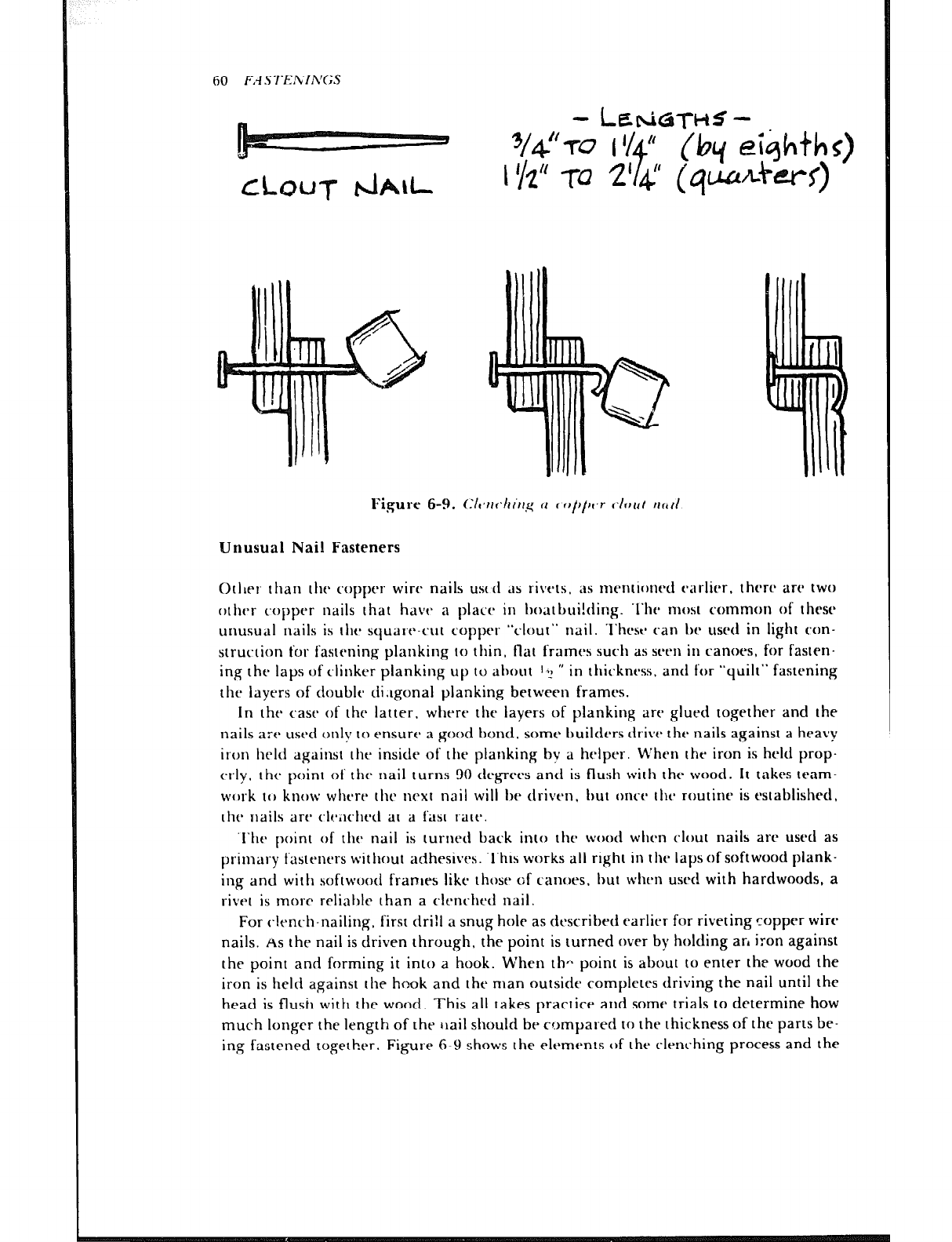
60 FA .STEKIh'(;S
Figure 6-9. CIt~rr~~Irirrg 11 c t~f)/o~r clr~trt IIC,II
Unusual Nail Fasteners
Otller than the copper wire nails ust (1 ds rivers. as mentioned t-arlier. there are two
othtxr copper nails that have a pIact in boatbui!cting. ‘l‘he most common of thcsc
unusual nails is rlie squart-cuI coppt.1 “clour” nail. ‘l‘hcst* can Iw used in light con-
struction for fastening planking lo thin, flat frames such as seen in canoes, for fasten-
ing the laps of clinker planking up to about 1, ” in thit.kness. and for “quilt” fastening
the layers of double di.tgonal planking between frames.
In the case of the latter. where the layers of planking are glued rogether and the
nails are used only ICI ensure a good bond. some builders ttr-ive the nails against a heavy
iron held against [he inside of the planking by a helper. When the iron is held prop-
erly, the point of the nail turns 90 degrees and is flush wirh the wood. It takes team-
work to know where the next nail will be driven. but once the routine is established,
ltw liails art’ c~lf:;ichetl at a fast rate.
‘l‘he point of rhe nail is turned back into rhe wood when clout nails are used as
primary fasreners without adhesives. ‘l‘his works all right in the laps of softwood plank-
ing and with softwoocl franles like those of canoes. but whrn used with hardwoods, a
rivet is more rcliahlr than a clcnc-hrd nail.
For clench-nailing, first drill a snug hole as described earlier for riveting copper wire
nails. AS rhe nail is driven through, the point is turned over by holding arl iron against
the point and forming it into a hook. When th- point is about to enter the wood the
iron is held against the hook and the man outside completes driving the nail until the
head is flush with the wood. This all takes practice and some trials to determine how
much longer the length of the trail should be compared to rhe thickness of the parts be-
ing fastened together. Figure 6-Y shows the elements of the clenching process and the
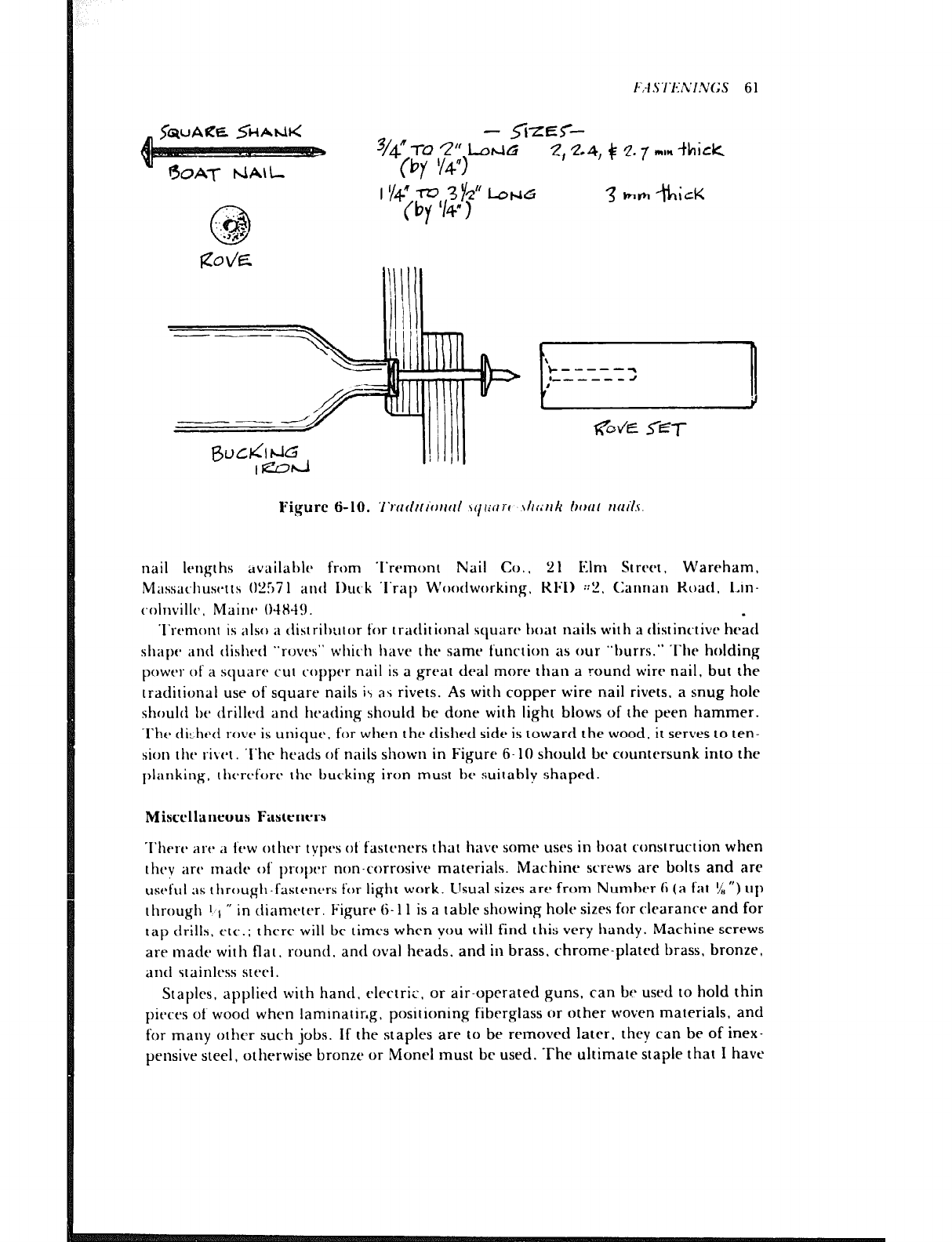
F,4 .S7‘f-;/YlNGS 6 1
- s-k?xr-
3/4% 2” LorcrG
(by llq”) 2,2-4, + 2.7 ml* thick
I ‘/4” -KJ 3v Lot-lb
(by ‘I49
3 hh +icK
Figure C-10. 7‘rtrfilt~orrfrl \i/tiilrt \hi;trk Ooml rrtlr%S
nail lengths available from ‘I‘remonl Nail Co.. 21 Elm Street. Wareham,
Massat~husc~~~s 0257 1 antI 1)uck ~l‘rap Woodworking. Kl;I) ::P, Cannan Road. Lin-
colnvillt~. Maim- 04X49. I
‘I’rtmonr is also a tiistril)utor for ~rirditi0Ilal square boat nails with a distinctive head
sllaf>t* and tlishetl “roves” which have the same funcrion as our “burrs.” The holding
power of a square C‘UI copper nail is a great deal more than a round wirr nail, but the
traditional use of square nails i\ as rivets. As with copper wire nail rivets. a snug hole
should be drilled and ht~ading should he done with light blows of the peen hammer.
‘I’he di:hetl rove is unique. for when the dished side is toward the wood, ir serves 10 ten-
sion 111~ rivt.1. ‘l’hc heads of nails shown in Figure 6- 10 should hc countt~rsunk into the
planking. ~hrrefore 111~ hutking iron must be suitably shaped.
Miscellaneous Fasteners
Thert~ are ‘1 few other tyl)es ot fasrencrs that have some uses in hoat construction when
I hey i1IY made of prol)t-r non-corrosive materials. Machine screws are bolts and are
useful as through-fastt,ners for light work. Usual sizes arr from Numbt-r 6 (a fat 5/n”) up
through 1 1 ” in diametrr. Figure 6- 11 is a rahle showing hole sizes for clearance and for
tap drills. t-tc.; then, will he times when vou will find this very handy. Machine screws
are made with flat. round, and oval heads. and in brass. chrome-plated brass, bronze,
and stainless sterl.
Staples, applied with hand, elecrri,. or air-operated guns, can he used IO hold thin
pieces of wood when 1aminatir.g. positioning fiberglass or other woven materials, and
for many other such jobs. If the staples are to be removed later. they can he of inex-
pensive steel, otherwise bronze or Monel musl be used. The ultimate staple that I have
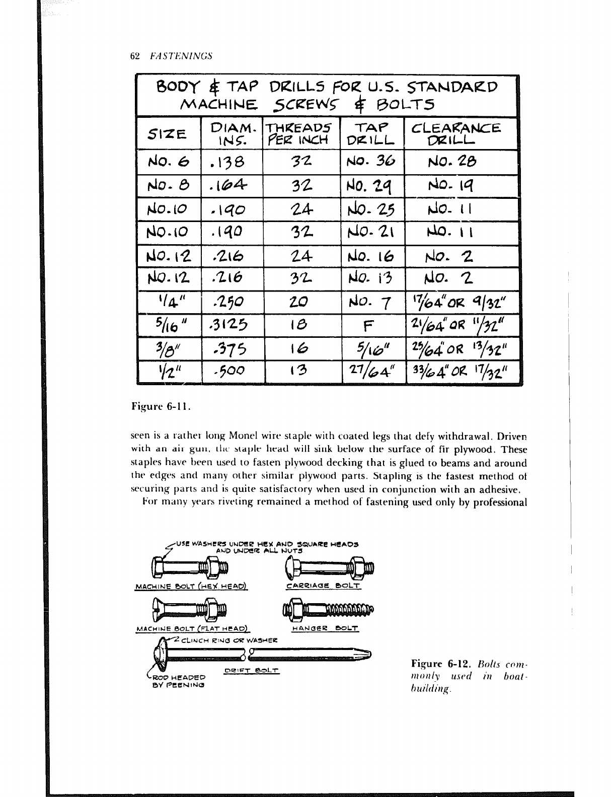
62 F/l S-I’ENINGS
BODY $ -I-A9 DRILL-5 @R USa ~TYWDARP
MACHINE sCfEb&T 4 @oLTS
SIZE DIAM. -M?EAD~ TAf
r&i pf3z INCH DlzlLL “‘ZEt-
tb. 6 .ry3 72 b40. 30 do- 20
32
t&u2 1 .a6 1 32 I &I. i3 I do- 2
‘14” 250 20 Jo. 7
5hkl if .3125 10 F 2(/64” 0 u ’ yzff
%3” -375 16 5/1df 23/64’ QR ‘3/g,”
I 11
I2 .500 13
Figure G-1 1.
seen is a rather long Monel wire staple with coated legs that defy withdrawal. Driven
with an air gun. ttlc’ staple head will sink below the surface of fir plywood. These
staples have been used to fasten plywood decking that is glued to beams and around
the edges and many otht1-r similar plywood parts. Stapling is the fastest method of
securing parts and is quite satisfactory when used in conjunction with an adhesive.
For many years rivc.ting remained a method of fastening used only by professional
UNLX!L? HEY PtJD 5)QUARE IdeAD
D UNDiS AU
MACHINE BOLT (HEY! HEAd
MACHIClE l3OL-r (FLAT HtAC’) HANr3EE -LT
CLINCH 04? WAE.Uf3-E
Figure 6-12. Bolts corn--
111 011 Iv usd in 6ouI -
huilrting.
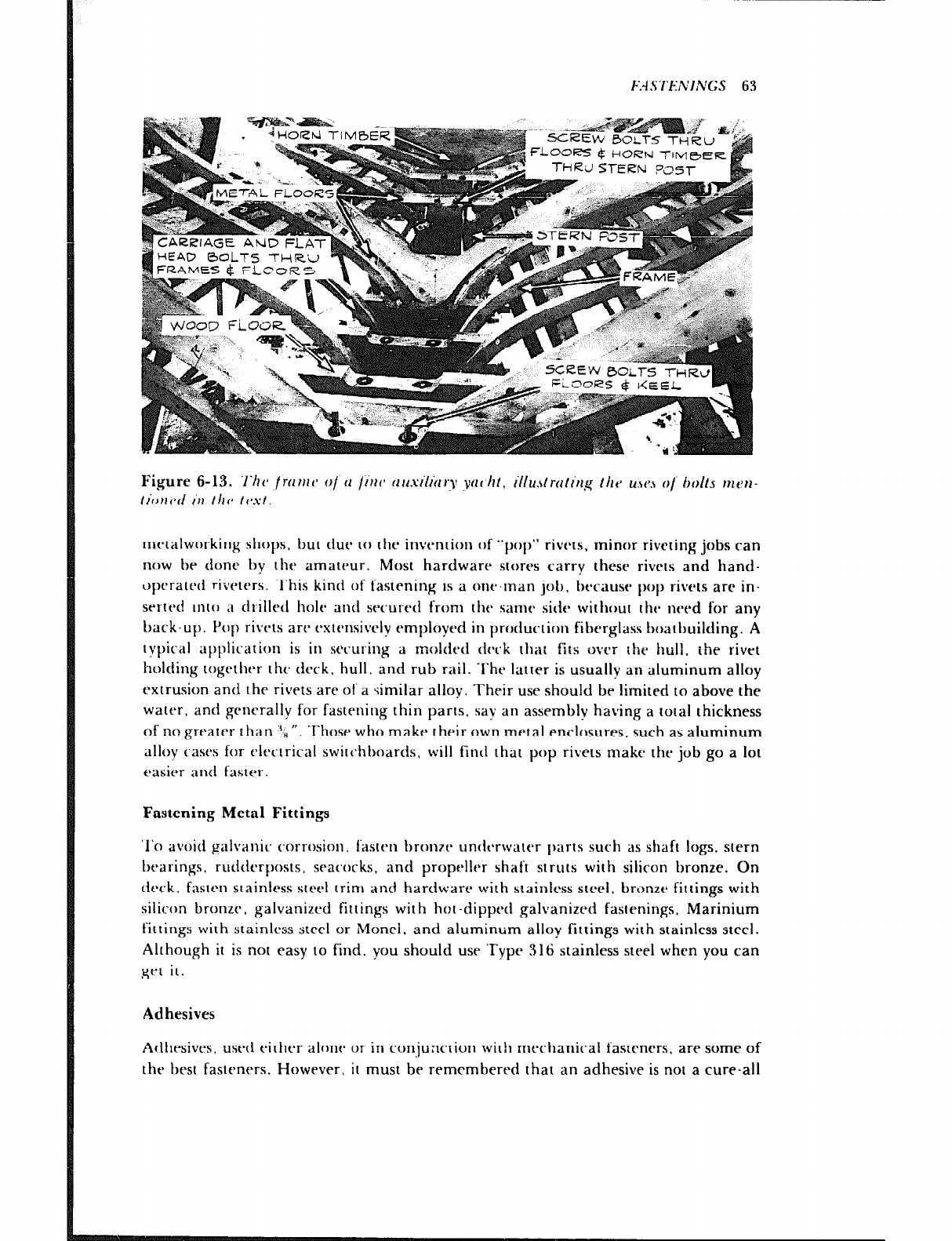
F.4SI‘E:NINGS 63
Figure 6-13. ‘l‘ht~ fmrut~ o/ II /into nusiliu,y yclt~ht, illu.,trctlirg /At* u.w.~ o/ bolts mt’n-
Iiorltd iI1 Ilrts tvxt.
metalworking shops. but due to the invention of “pop” rivets. minor riveting jobs can
now be done by thfh amatfaur. Most hardware stores carry these rivets and hand-
opc.rated riveters. .I’his kind of fastening is a one-man job, because pop rivets are in-
serted unto ;I drilletl hole and srcur-cd from the samt side without tht- need for any
back-up. f’op rivets arc- estensivcly employed in production fiberglass boatbuilding. A
typical application is in securing a molded d~~ck tha: fi:s <ii’er the hull. the rivet
holding together the deck, hull. and rub rail. The latter is usually an aluminum alloy
extrusion and the rivets are of a 4milar allov. Their use should be limited to above the
water, and generally for fastening thin parts, say an assemblv having a total thickness
of no greater than “h “. Those who make their own metal enclosures, such as aluminum
alloy C;ISYS for clcctrical switc.hhoards, will find that pop rivets make the job go a lot
easier and faster.
Fastening Metal Fittings
‘1’0 avoid galvanic corrosion. fasten bron7r untlc7water f)arts such as shaft logs, stern
bearings, rudderposts. seacocks, and propeller shaft struts with silicon bronze. On
deck. fasten stainless steel trim and hardware with stainless steel, bronztb fittings with
silicon bronze. galvanized fittings with hot -dipped galvanized fastenings, Marinium
fittings with stainless steel or Monel. and aluminum alloy fittings with stainless steel.
Although it is not easy to find. you should use ‘Type 316 stainless steel when you can
grt it.
Adhesives
Adhesives. used either alonr or in conjunction with mechanic-al fasteners. are some of
the best fasteners. However, it must be remembered that an adhesive is not a cure-all
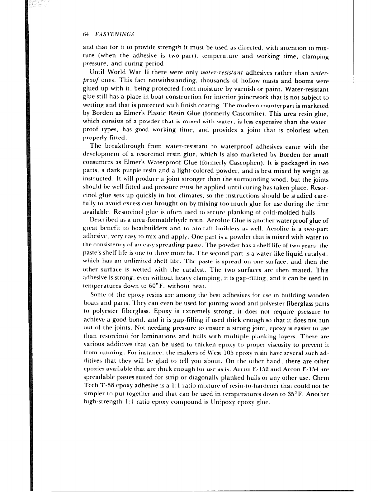
64 l.~:~.S’l‘E:NIN(;.S
and that for it to provide strength it must be used as directed, with attention to mix-
ture (when the adhesive is two-part), temperature and working time, clamping
pressure, and curing period.
Until World War II there were only water-rclsistant adhesives rather than &later-
l-)ro~/ ones. This fact notwithstanding, thousands of hollow masts and booms were
glued up with it, being protected from moisture by varnish or paint. Water-resistant
glue still has a place in boat construction for interior joinerwork that is not subject to
wetting and that is prote-*-:-’ - ‘-’
CLCU wit11 finish coating. The modern counterpart is marketed
by Borden as Elmer’s Plastic Resin Glue (formerly Cascomite). This urea resin glue,
which consists of a powder that is mixed with water, is less expensive than the water-
proof types, has good wnrking time, and provides a joint that is colorless when
properly fitted.
The breakthrough from water-resistant to waterproof adhesives canoe with the
development of a resorcinol resin glue, which is also marketed by Borden for small
consumers as Elmer’s Waterproof Glue (formerly Cascophen). It is packaged in two
parts, a dark purple resin and a light-colored powder, and is best mixed by weight as
instructed. It will produce a joint strnnger than the surrounding wood, but the joints
should he well fitted and pressure must be applied until curing has taken place. Resor-
cinol glue sets up quickly in hot climates , so the instructions should be studied care-
fully to avoid excess rest hrought on by mixing too much glut* for use during the time
available. Rcsorcinol glue is often used IO secure planking of cold-molded hulls.
Described as a ltrea-formaltirhytic resin, Aerolite Glue is another waterproof glue of
great benefit to boatbuilders and to aircraft builders as well. Aerolite is a two-part
adhesive, very easy to mix and apply. One part is a powder that is mixed with water to
the consistency of an easy spreading paste. The powder has a shelf life of two years; the
paste’s shelf life is one to three months. The second part is a water-like liquid catalyst,
which has an unlimited shelf life. ‘I‘he paste is spread on one surface, and then the
other surface is wetted with the catalvst. The two surfaces are then mated. This
adhesive is strong, e\‘cll without heavy clamping, it is gap-filling. and it can be used in
temperatures down to 60°F. without heat.
Some of tl~r epoxy resins are among the best adhesives for use in building wooden
boats and parts. .I‘hcy can even be used for joining wood and polyester fiberglass parts
to polyester fiberglass. Epoxy is extremely strong, it does not require pressure to
achieve a good bond, and it is gap-filling if used thick enough SC) that it does not run
out of the joints. Not needing pressure to ensure a strong joint ( epoxy is easier to use
than resorcinol for laminations and hulls with multiple planking layers. There are
various additivrs that can be used to thicken epoxy to proper viscosity to prevent it
from running. For instance. the makers of West 105 epoxy r&n have several such ad-
ditives that thev will he glad to tell you about. On the other hand, there are other
epoxies available that are thick enough for use as is. Arcon E- 152 and Arcon E-154 are
spreadable pastes suited for strip or diagonally planked hulls or any other use. Chem
Tech T-88 epoxy adhesive is a 1: 1 ratio mixtuie of resin-to-hardener that could not be
simpler to put together and that can be used in temp:>ratures down to 35°F. Another
high-strength 1: 1 ratio epoxy compound is IJnipoxy epoxy glue.
~‘:I.ST~:.‘L’I.L;(;S 65
Caution to Epoxy Users
So much is written about epoxy resins and the material is so valuable to boatbuilders,
principaily as an adhesive, that it would be remiss not to warn that epoxy resins,
especically hardeners, must be used with caution. Avoid contact with unprotected skin
and breathing the fumes released by epoxies as they cure. These words are to reinforce
manufacturers’ directions that are often taken lightly. I have never had a problem, but
I have seen others who were unhappy, so beware!
Sources for Adhesives
Most general and marine hardware stores carry Elmer’s Plastic Resin Glue and Elmer’s
Waterproof Glue as well as the various brands of contact cement for sticking Formica-
type plastic laminatts to wood and metal. The Elmer’s glues in quantities larger than
quarts are handled by Harbor Sales Co., 1401 Russell Street, Baltimore. Maryland
21230.
Acrolire is a (:iba-Geigy product distributrci in the> lJ.S. by Aircraft Spruce and
Specialty CI,., P.0. Box 424. Fullerton, California 92632. and is available in the
(‘astern L1.S. from Woodcraft Supply Corp.. 313 Montvalr Ave., Woburn,
Massac~huscc IS 0 I HO I
Following arc* the* names anti addrf~ssrs of thy firms produ(.ing the epoxies
mm1 iont~tl:
Arcon I+ I52 and Arcon E-15-1. Allied Resin Corp., Wcymouth Industrial Park.
East W~~ymouth. M;tssachust*tts 02 189.
(:he~rn-Tech ‘1’-H8, Chem-Tech Inc., Nj9 I~ancl~r Road, Chagrin Falls, Ohio
44U22.
Wrsr I05 atlhcsivc, Chugwn Brothers. Inc.. 706 Martin Strecr. Bay City,
Michigan -18706.
Ilnipoxv fyxy glue. Kristal Kraft, Inc.. 900 Fourth Street, Palmetto, Florida
33561, ’
Chapter 7
‘1‘0 properly build a boat from l)lans, the hull lines and part of the construction plan
must be (11 awn full sire. ‘l’his fact has been repeated to thr point of monotony in
countless “how IO build” articles. but the job is so important IO the successful com-
pit-tic)11 of a boat that instructions in boatbuilding would br incomplete without a
drscription of thr work involved. Thp job is distasteful to some, even among profes.
sional boatbuilders. but otIlcrs find it IO be fascinating work. Either way, it is true that
once the plans are on hand one becomes impatient, but be assured that the com-
paratively few hours used to properly prepare for the actual building is time well spent
and will never be rqretted. The full-size drawings from which molds and templates
are made are especially valuable when more than one boat is to be built from the same
plans, or for the construction of a one-design class boat where the hull must conform
to reasonably close dimensional tolerances.
OIW must trace thr history of shipbuilding to discover why tht- full-size hull lines are
“laitl ctown” on the ” trrold loft” floor-. ‘I’ht- full-si?t- drawing board. so to speak, in a
shipyard almost always consisted of a floor above a workshop of some sort, thus it was a
loft, Molds or templates wt‘rc taken off the full-size drawings, hence the terms “mold-
lofting. ” “laying down,” and “taking off.” ‘I‘hr roof above thr mold loft was preferably
trussed. so t herr were no columnss to obstruct the work, and there were windows on all
sides and o\~tAratl to provide maximum light. The wooden floor was level and
smooth. sufficiently sacred so somt~ vards prohibited the wraring of hard-soled shoes.
The floor was painted flat white or light gray, sometimes dull black, and on one edge
of the floor there was a permanently fixed batten having an absolute straight edge that
served as a baseline.
Hull Lines
The work of enlarging the plans from the scale of the blueprints to full size is termed
I.lh’ES :IND L-I k.I.VIi 110 Wh’ 67
mold lofting, for it is from these drawings that molds are made for the shape of the
hull and various other parts. Of course, to make the job more interesting, the different
lines that constitute the architect’s lines plan should be understood, and to aid the
beginner Figure 7-1 has been prepared. Some of the lines are obvious, because from
reading the desibm sections of yachting magazines and from prowling around hulls
under construction or stored in boatyards most of you are familiar with the first three
lines drawn by the designer that really characterize a hull. These are the sheerline or
edge of deck as seen from the side, the profile (the outline of the bottom and ends
above the waterline as seen from the side at the same time the sheerline is viewed), and
the deck line, a gull’s eye view of the outline of the hull as seen from above. Altholtgh
these lines are important, they are not sufficient for the builder to construct a hull
from. He also needs the shape of the boat between the three lines. To provide points to
define the hull shape between these lines, the architect simply cuts the hull into pieces
on planes that conveniently establish points for dimensions. These planes are called
waterlines, buttocks. and diagonals.
If a hull could be lifted straight up out of the water without the resulting hole filling
in with water, the shape of the edge of the hole would be the same as the shape of the
boat at the surface of the water. On the boat, this line is called the load waterline and
it is one of the most important lines drawn by the designer. For further subdivision the
architect then divides the depth of the huil above dnd beiow the load waterline into
convenient spaces, and draws the edges of additional horizontal planes which, for the
want of something better, are also called waterlines because they are parallel to the
load waterline. Then there are vertical planes called buttocks, located parallel to the
centerline of the boat and conveniently spaced evenly outboard to each side of thr
centerline. Finally, the edges of inclined planes are drawn and these are called
diagonals, because they are drawn diagonal to the horizontal and vertical planes.
‘l‘hese planes, like the others, are located to provide as many signifirant dimensioned
points for the boatbuilder as is possible.
All of the aforesaid lines are fore-and-aft lines running the length of the hull, and
although it has been mentioned above that these lines are drawn for the purpose of
having points on the surface of the hull, actually no usable points are established until
vertical planes CI(‘~OSS the hull have been drawn to intersect the fore-and-aft lines. The
outlines or shapes formed by vertical transverse planes intersecting the horizontal, ver-
tical, and diagonal fore-and-aft planes are called sections. A point on the hull is
established wherever a section intersects one of the fore-and-aft lines, and by means of
the many points of intersection it is possible for the builder to make molds for the exact
shape of the hull as the architect has it designed.
Sections may be compared to slices of bread. Just as is the case with the sections on a
shapely boat, the slices through an old-fashioned rye loaf are all different, for the
shape is ever-changing from end to end. A vessel’s shapr. :hen, c-- . .
LQIl be transm:tted :nto
three-dimensional form by making full-size templates of the sections. When these are
set up at each section’s respective station the same as called for in the lines drawing, a
vessel’s shape in skeletal form has been established. The vessel’s shape is represented in
this manner just as a loaf of bread would be if every other slice was removed, while
keeping the spacing of the remaining slices the same.
Figure 7-1 has been included to pictorially show waterline. buttock, diagonal, and
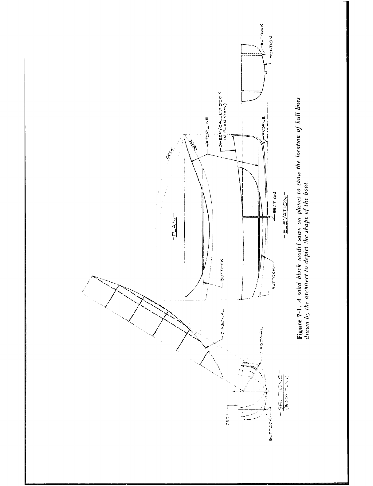
Iy
/ I
3
k,
F
9
I ?,J
1 )I:
/I t
;i
\
\
‘1
!!
i k
:
3
6’
A i
---
1
.;:-q>
,T ’
i
l
.x.
7
\-,.
; i ;i
\ 1 \ - iJ-
\
7.
i/l I/
\;\ I
4
\--- I
\ (J
J \
>
z
. . . n
\ ,A i
v
A,
-J ‘,
x.. ‘\
-- . \
\
X!
Y
x
: 2
2 P
cl 4, i
1 n
i
I 7’
I
I/
7r
; !
I :
I
j ~
1 i+;
1 ‘1:
b :
i’,, 3
J_L
.+=-y
_ 7 ‘!
\
.
_ ‘Lo.- L :a
7
r
--y’ ,I /),.
‘i
:: -5 ‘i
C’ Ll
0
F
i
LINES AND L.-I YING DOWN 69
sectional planes as though a solid block half model of a hull were sawn into pieces on
the various planes. The shapes of the planes are shown by the shaded areas, and on the
body plan it may be seen how a point on the hull is created wherever a buttock,
diagonal, or waterline is intersected by an athwartship sectional plane.
Figure 7-2 is the architect’s lines drawing for the same hull shown in Figure 7-1, and
on this plan are shown all the lines mentioned in the foregoing together with the
necessary dimensions to reproduce them. (Incidentally, do not attempt to build a boat
from these lines, as they are purely for illustration and have not been worked out for
any specific purpose.) Note that spacing of waterlines, buttocks, and stations are in-
dicated, as well as offsets for the profile of the stem, dimensions for the profile angle of
the stern board, and a table of dimensions For laying out all the fore-and-aft curved
lines. Because of the nature of diagonals, their location can only be indicated in sec-
tion, that is, on the body plan.
Sometimes it is possible to define the shape of a hull without the use of diagonals,
such as in Figure l-7. In the case of a really simple hull with straight-line sections (see
Figure 7-3), the sheer, deck line, chine, and/or profile provide a sufficient number of
points from which to make the frames or molds. This eliminates the need ior water-
lines, buttocks. and diagonals, as will be explained a little further on.
Abbreviations
Before we go any furtlirr, it should bc pointed out that many sets of lines plans for
hulls have abbreviations for words used thus far in this chapter, and it is a help for the
reader to be familiar with them.
Centerline
Waterline
Buttock
Diagonal
Baseline
Station
Frame
Deck
Length over all
Length of load waterline
Section
Displacement
Pounds
Longitudinal center of buoyancy
Center of gravity
Offsets
C.L.
W.L.
Butt. or butt’k
Diag.
B.L.
Sta.
Fr.
Dk.
L.O.A.
L.W.L.
Sect.
Displ.
fl
C.B. or L.C.B.
C.G.
An offset is simply another name for a dimension, and they are always taken from a
straight line of reference such as a baseline for the elevation drawing or the centerline
in the case of the plan view of the lines. Dimensions are tabulated because it is obvi-
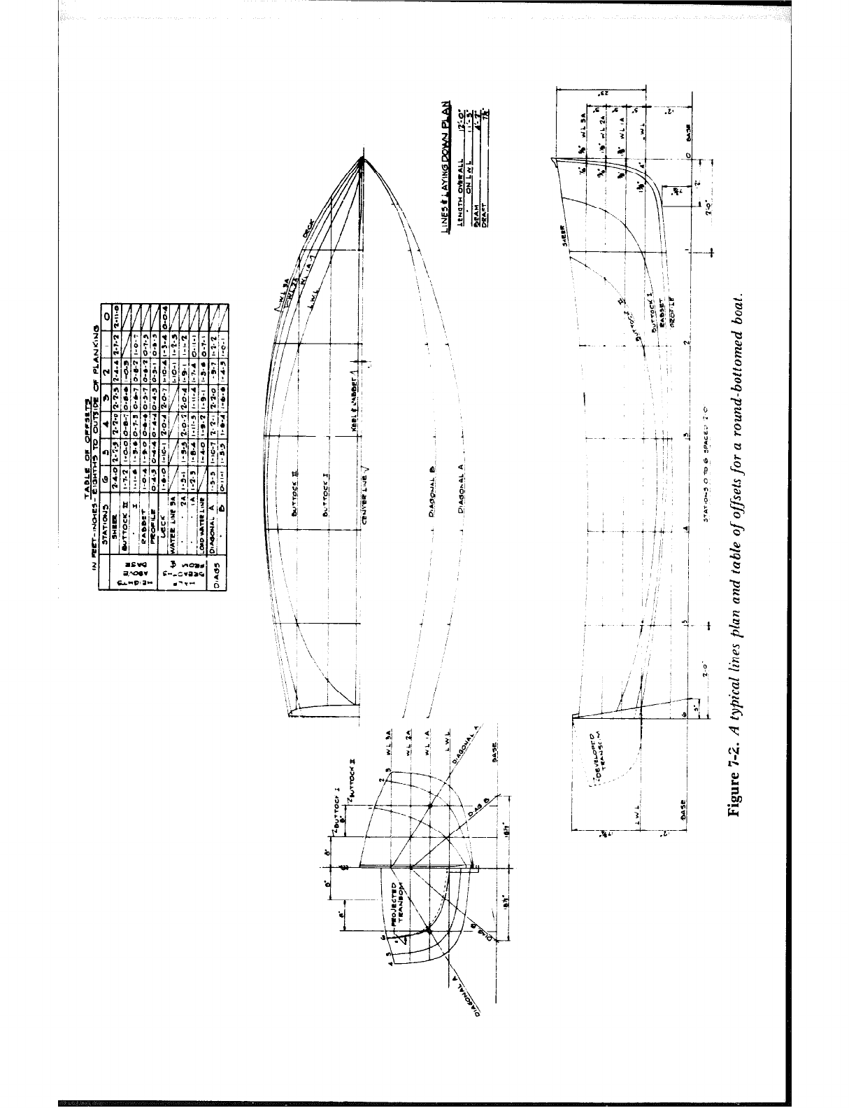
;i
“I
f’
/
?1
/:
j>
/ ‘4
I :A
i@
:i
/ I$
t
I
. . .*
.?I.; . .
17
:-I
1 ju
z <.I
5 Hi
; E
\,, 3 gi,
- 1
a 4
2
l :
i:
‘a 2i
? 81
5’
61 01
: -
b i
;/I “I’
-1
j I,” I
I !. I I \h ,
\I\ * 1
0 n‘s / ‘1 i
I I’ !J
‘3
,’ ii 7
-
J . ?+a
n
. ’ ‘I
I\
L
4.
*4,
b
,L .5
.
i-j- j- 3--
j &’ G, f s
.* !Y-.. -0 r7
2 .# *.I
!
66
1 */ 3‘ “,;
-\_ / ’ &
\ 1 !I
\< ! ;i ;\ ---t
* I\ :I
_ : :i
\
I.4
4 iYl k’ ’
-2
U’ “.! t!
;\ 2: 0 ’
F
5 ‘C ~
dlY i
-. . . .A _ PA
7 ,’ 1
is /
~ 0
- + ?i ‘j,
,;,, / a’
/ i 3
(,: 1;
5
t &. 4
i 0:
,I:/
’
i ,; ,’
‘8
1 i . fj-
1 ! ‘Q
I, / j
i’
i
ii
w
‘, ----- J ~
.a
o’r
PC
9: / ~
:u
“0’ ‘I
L:t- I
i j $i
L-----j-~-. --I
.%A’ .L’
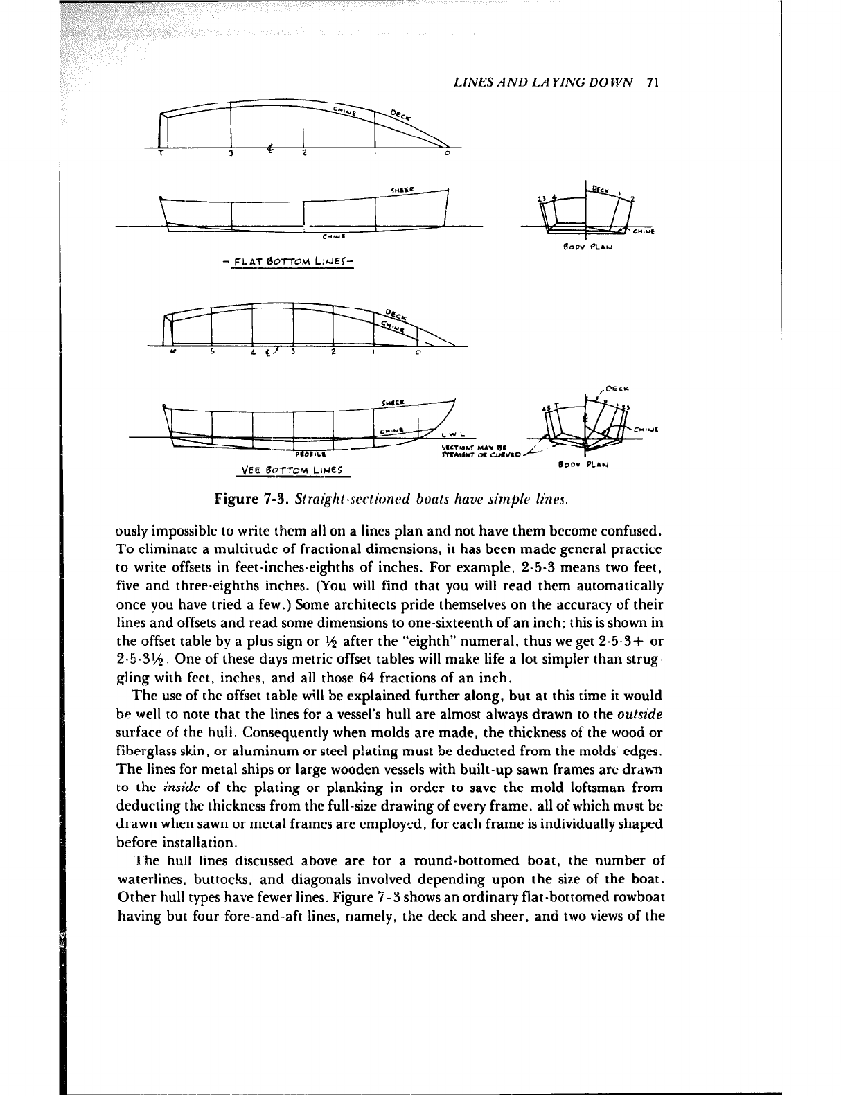
LINES AND LAYING DOWN 71
- FLAT tkTTOM L.JEc-
VEE 6OTTOM LINES
--- loor PLIH
Figure 7-3. Slrai~tll-sectrhncd boats ham> simple lines.
ously impossible to write them all on a lines plan and not have them become confused.
To eliminate a multitude of fractional dimensions, it has been made general practice
to write offsets in feet-inches-eighths of inches. For example, 2-5-3 means two feet,
five and three-eighths inches. (You will find that you will read them automatically
once you have tried a few.) Some architects pride themselves on the accuracy of their
lines and offsets and read some dimensions to one-sixteenth of an inch; this is shown in
the offset table by a plus sign or lV$ after the “eighth” numeral. thus we get 2-5-3+ or
2-5-31/j. One of these days metric offset tables will make life a lot simpler than strug-
gling with feet, inches, and all those 64 fractions of an inch.
The use of the offset table will be explained further along, but at this time it would
be well to note that the lines for a vessel’s hull are almost always drawn to the outside
surface of the ht.&. Consequently when molds are made, the thickness of the wood or
fiberglass skin, or aluminum or steel p!ating must be deducted from the molds edges.
The lines for metal ships or large wooden vessels with built-up sawn frames are drawn
to the inside of the plating or planking in order to save the mold loftsman from
deducting the thickness from the full-size drawing of every frame, all of which must be
drawn when sawn or metal frames are employed, for each frame is individually shaped
before installation.
The hull lines discussed above are for a round-bottomed boat, the number of
waterlines, buttocks, and diagonals involved depending upon the size of the boat.
Other hull types have fewer lines. Figure 7-Y shows an ordinary flat-bottomed rowboat
having but four fore-and-aft lines, namely, the deck and sheer, and two views of the
72 LJNES A ND LA YING DOWN
chine, which is the corner at the intersection of the side and bottom. Also shown are
the lines for a v-bottomed boat having lines similar to a flattie except for the addition
of a bottom profile. The sections of this particular boat consist of straight lines. If they
were curved. other points would be needed to draw the sections, and these would be
established by waterlines, buttocks, and diagonals.
The Mold Loft
Although we have said that the builder’s first step is lofting the hull, in reality the first
thing is to find a place to do the job. At a minimum, the space should be at least four
or more feet longer than the boat in one direction, while in the other it must be equal
to the dist-rnce from the baseline to the highest point of the sheer, or top of cabin if
there is one, plus some space on all sides for working around the drawing. Well-
equipped boatyards use a level wooden floor maintained for just this purpose that is
sanded smooth and coated with flat light gray or white paint. It is too much to ask that
an amateur have such facilities at his disposal, so the next best alternative would be a
level space, such as a floor or platform, where paper or plywood may be used to lay
down the lines.
A few years PRO while visiting boatyards I noticed lofting being done on a very
heavy, light bplge paper that was also being used for patterns for one-off parts. This
material was 200.pound “Alexandritr” template paper, 12 square feet per pound. In
each case it was purchased from a paper goods supply house in a nearby city. The in.
formation about the paper is given here, but the amateur builder will probably not be
able to cope with the cost of this 72” wide material. Each roll is said to weigh between
500 and 6Otl pounds -- a lifetime supply indeed.
The drawing supply people make a buff detail paper of acceptable quality,
available up to 48 ” and 54” in width, in rolls of 10. 20. and 50 yards and priced
reasonably. Some of the paper-faced building panels are also all right, and SO is
plywood, as mentioned above, in standard-size panels that may be arranged edge to
edge to make any size desired. Whatever the material, if several pieces are used to
make up the required size, the pieces must be secured against movement.
Lofting Tools
The tools for lofting are few and simple. To draw sharp lines, flat carpenter’s pencils
are used, sharpened to a chisel point so a thin line may be drawn for a long distance.
Colored pencils may also be used to advantage to make it easier to distinguish between
different types of lines. For measuring, a steel tape is ideal for long lengths, but an or-
dinary folding six-foot rule will do, and the rule can also be used to lay off many short
dimensions. A large carpenter’s square, either as manufactured or homemade out of
:‘/H ” or % ” wood, is needed for drawing lines perpendicular to other lines, such as for
station lines in relation to the base and waterlines. You may also erect perpendiculars
with a regular or improvised beam compass, as will be shown later. The adjustable
bevel shown in Figure 3-1 will be found handy, as will a straightedge six or eight feet
long, which you can make yourself from a piece of thin wood. For marking the really
LINES AND LA YING DOWN 73
long, straight base and waterlines, you should use either a mason’s chalk line, pencil-
ing the line on the floor before the chalk rubs off, or a length of light, strong fishing
line stretched tightly between two nails, marking in points directly under the cord at
intervals of about three feet, to be connected later with a straightedge.
Battens
Fair curves have no bumps and are pleasing to the eye. To draw them, you must have a
set of battens, which are nothing more than straight, square-edged pieces of clear
white pine or other such wood. These should be at least two feet longer at each end
than the line to be drawn. When the available stock isn’t long enough for the job, bat-
tens can be made up of two pieces connected in the middle, where the curve is least, by
making a tapered glue splice of about 18” to 2’ in length. Or the line itself may be
pieced if you make sure there is a fair overlap over the length of a couple of stations.
For best results, you should use as stiff a batten as will go through all the points on the
curve, for a stiff batten will tend to fair itself unless unduly forced, whereas a supple
batten can be passed through all the points and not lie fair. It is difficult to say just
what size battens should be used, as the correct size depends so much on the length of
the lint and the character of the curve.
A batten 14 ” to $1 ” thick by 1 th ” to 2” wide used on the flat is suggested for
relatively easy curves like the sheerline. For certain curves it may be necessary to taper
the battens at the ends somewhat, with ail the taper cut on one edge. For curves in the
plan view, also known as the half-breadth plan, something like I$$ ” x 1 M or th ” x 1 t,4 ”
used on the flat, possibly tapered at the ends, or :?t ” square and untapered might be
tried. Like a lot of boatbuilding operations, accumulated experience will aid in the
selection of batten sizes. If you have a table saw, start by making the battens on the
heavy side until you get the hang of it, ripping the strips narrower as needed. Curves
such as sections. the stem profile. and similar shapes will be drawn with shorter bat-
tens, probably ‘j/H” and 14 ” square, and inasmuch as these curves sometimes have
harder bends in the middle than at the ends, such as around the turn of the bilge, they
may have to be tapered in the middle in order to make a fair curve that touches all the
points.
A batten is held in place wiih finishing nails driven on both sides of it, not through
it. Not necessary by any means, but very desirable from the standpoint of readily
sighting the shape of a batten when sprung to a curve, is a coat of flat black paint. The
contrast of the dark batten against the light-colored floor or paper will help detect a
line that is not fair.
The Grid
By examining the table of offsets, Figure 7-2. it will be seen that dimensions for the
waterlines, buttocks, diagonals, sheer, and profile curves are laid out on the station
lines and are measured above the baseline and out from the centerline. Therefore, it is
the straight lines that must be laid down in the beginning. This group of lines, called
the grid, is shown in Figure 7-4. You will note in Figure 7-5 that the grid is set up in a
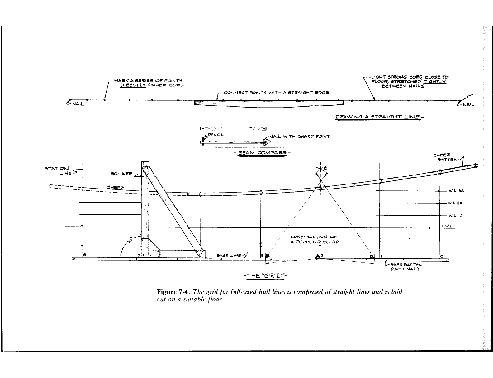
MAUI.! A SCRtES OF Pear J-r5
lfJ?tCTLY b4VER CURL7
11ol-n srR.ocl5 cdcq “;LO,‘“L”
FLOOR, JfRCTCntV T 4 T y
bCTwee~ t-JAILS
-DRAV/ltdG A STPAIGHT LINE-
D a, m .-,
AIL VJlTb-4 5HARP POdT
-- --
-BEAM COMF’ASS -
- SHCCR
I K-f-l *Al-&~
I t .
e a
1
i ;i L,F jZIXj ‘;I \ - ,, ,,,,,, /,,“‘I[;; ,j
I \
1,
‘\
6 \
al I 0
. ( ._ . .
+ t BA5E BA7-t-d
(OPTlOtiAL)
-THE “GRID”-
Figure 7-4. The grid for full-sized hull lines is comprised of straight lines and is laid
out on a suita ble.floor.
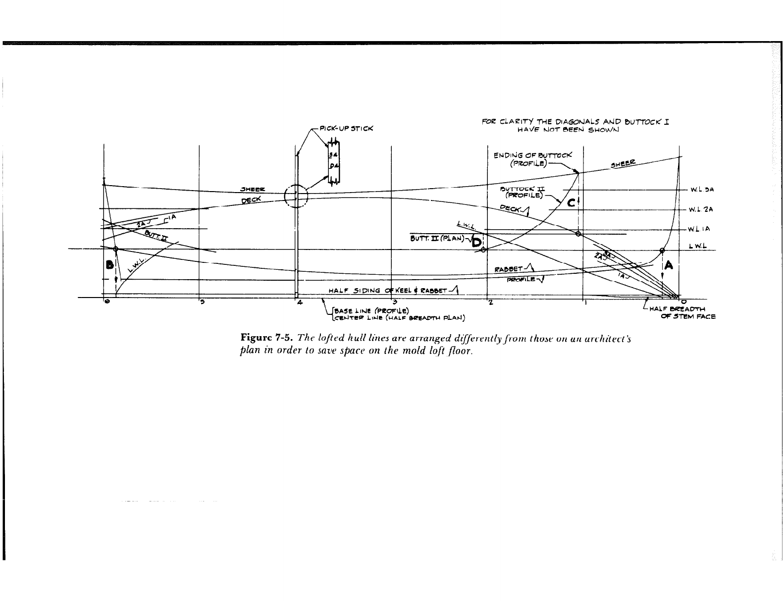
/T met6.w mctt FOE CLAEWy THE DIAGo~IALS AtiD BUlTOC< I
HAL/E hJOl- BEt?!d 5HOWd
L HALF BUEAOTH
OF 5l-EM FACE
Figure 7-5. The lofied hull lines are arranged d$ferently,from those on an architect Ys
plan in order to save space on the mold lqft floor.

76 LINES AND LA YING DOWN
compressed form relative to the paper plans: the half-breadth plan is superimposed
over the profile drawing to save space and to minimize the distances one must crawl on
hands and knees when laying the lines down. (Some professionals save themselves from
crawling around the loft floor by building a dolly of padded plywood mounted on low
swivel casters.) Thus the grid is started by drawing a straight line that doubles both as
the baseline for the profile view and the centerline for the half-breadth plan. The
spacing of the stations is laid off along this line and the stations are drawn in perpen-
dicular to it.
The perpendiculars may be drawn either with a set of trammel points, a regular
beam compass, or an improvised one, and is done as follows. Mark a point A (Station 2
has been used as a practical example in Figure 7-4); then using the compass with A as
a center., strike an arc B equidistant to each side of point A. Lengthen the arm of the
compass and, using each of the points B as a center, strike two intersecting arcs above
the baseline. From the intersection C draw a straight line through A on the base. The
line CA is perpendicular to the base. This method can be used at each station, or it
can be used at only one, with the resulting right angle used to build a large square for
drawing in the remainder of the stations perpendicular to the base.
The spacing of the straight waterlines in profile is taken from the architect’s lines
plan and they are drawn in parallel to the baseline. With the exception of the load
waterline for reference, it is not usually necessary to draw the profile view of the
waterline, except at the ends of the boat. Therefore, mark off the waterline spacing on
the two end stations and again one or two stations from the ends and draw them in
with a straightedge.
As mentioned above, the offsets for the curves are dimensioned as heights above the
baseline or distances out from the centerline as the case may be. Some of the dimen-
sions will be long enough that you will not be able to tell readily whether the end of
your rule is exactly on the line or not. To be sure of this and to save time, some
builders nail a batten against the under side of the baseline as shown in Figure 7-4.
The end of the rule can then be butted against it when making measurements. lnstead
of a batten, a nail may be driven at each intersection of a station with the base. You
will find either way to be very helpful and, to say the least, easier on the knees.
Sheerline and Deck line
Either the sheerline or the deck line will be the first curved line to be drawn and faired.
For the sake of argument we will select the sheerline, which the table of offsets, Figure
7-2, shows is dimensioned above the baseline. Starting at the bow, Station 0, the table
reads 2-11-O for the height of the sheer: so with the rule against the nail or batten
measure up two feet, eleven inches above the base on Station 0 and make a mark.
Move the rule over to Station 1. read 2-7-2 from the table and make a mark 2’7%”
above the base. The process is repeated similarly at all of the stations.
With all the points marked, it is time to select a batten with which to draw the
sheerline, placing it so that it extends beyond the length of the boat at each end. With
one edge of the batten against the sheer point on a station amidships, Station 3 of the
boat we are using as an example, drive nails to hold the batten in place. Now fasten
the batten at Station 2, then at Station 4, alternating towards the ends of the boat un-
LINES AND LA YING DOWN 77
til the batten is sprung to and fastened at all the points. The batten’s ends, which pro-
ject beyond the boat, should be sprung to extend the curve fairly and then nailed.
After the batten is secured for the entire length, sight along it to see whether there
are any unfair or lumpy spots in the curve. If so, pull the nails at the stations adjacent
to the unfairness and note the result. If the batten moves very far from one of the
points and still does not appear to be fair. pull other nails and make adjustments, giv-
ing here and taking there until the resulting line is pleasing to the eye. You may expect
points to be out of line occasionally because the architect has drawn the lines to a small
scale compared to the full-size job; thus errors are bound to creep into the work.
However, it must be remembered that the batten should be shifted as little as possible
to obtain a sweet and true curve without hard spots.
The deck line is faired in the same manner after it has been laid down from offsets
measured out from the centerline.
Profile and Rabbet
After the deck line has been drawn in and faired, you can continue working on the
profile plan, drawing and fairing the profile (bottom of keel), the stem, and the rab-
bet. The rabbet line is normally found in traditional wooden construction, although it
may or may not exist in other types of wooden hull construction, or in fiberglass or
metal hulls. For these latter hulls, a similar line may be referred to by some other
name. In any rasc, the lines plan will make all this clear.
The profile and rabbet must be faired in so that they will meet the relatively quick
curves of the stem and stem rabbet. INith these bow curves not yet drawn in, the best
way 1.0 ensure that the two sets of curves will meet fairly is to extend the rabbet and
profile forward beyond the point of tangency with the stem and its rabbet. You will
note that this has been done in Figure 7-5.
The stem profile and the stem rabbet are drawn with a thin batten, as mentioned
previously. When points for the stem curves have been marked in from the dimensions
on the lines plans, a nail is driven at each spot, the batten is bent against the nails, and
other nails are driven on the opposite side of the batten to hold it in place.
If your particular plans give a half-siding for the rabbet, this should be drawn in
next before going on to the body plan.
Body Plan Sections
It is strongly recommended that the body plan be drawn on a separate portable board.
Such a board is easy to move around to suit making molds, and it avoids confusion of
lines on the floor. Referring to the body plan for the lines in Figure 7.2, you can see
that the board or paper used for the sections must be somewhat wider than the boat
and at least as high as the distance from the baseline to the sheer at Station 0, the bow.
Begin by drawing the baseline; then draw the centerline perpendicular to the base.
The waterlines are drawn in parallel to the base, the buttocks parallel to the centerline
and the diagonals exactly as dimensioned on the lines plan. Needless to say, trouble
78 LINES AND LA YING DOWN
will result if the waterlines and the buttocks of the body plan are not spaced exactly the
same as they were laid out on the half-breadth and profile plans.
Cut some narrow strips of straight wood anywhere from ‘/,b” to ‘/B” thick for use in
transferring to the body plan the deck half-breadths and the sheer and rabbet heights
from the already faired lines on the floor. Butt the end of a strip against the baseline
and mark the half-breadths and heights on the stick, carefully identifying each one
with a symbol and the station number. These measuring sticks are called pick-up sticks
or battens and one is shown in the picking up position at Station 4 in Figure 7-5.
With the end of the pick-up stick at the baseline of your body plan, mark the heights
of the sheer and rabbet on the centerline. Draw short horizontal lines at each rabbet
point and draw in the width of the rabbet. Draw horizontal lines at each sheer height
and with the pick-up stick against the centerline of the body plan, mark the deck
width corresponding to each station. At each intersection of sheer and deck draw a
small cross and label it with the station number. Each section now has two definite
points; the sheer height/deck width intersection, and the intersection of the rabbet
height and width.
Now to fill in some of the points in between. Nail a batten against one side of the
centerline on the body plan and with the rule laid on a waterline with its end against
the centerline batten, mark points for all the waterline half-breadths from the offset
table and label each one. For instance, lay the rule on waterline 2A to the right of the
centerline and from the offset table under Station 1 mark off l-l-2, put a little circle
around it with a 1 next to it to show it is a point on the section at Station 1; then mark
1.9- 1 for Statinn 2, and so on. Do the same with the offsets for the other waterlines.
With the waterlines done, go on to the buttocks. Place the rule on Buttock I with the
end of the rule at the base and mark all the heights for Buttock I from the offset table.
Follow with Buttock II. Then lay the rule along the diagonal with the end of the rule
again at the centerline and lay off all the diagonal offsets along the diagonal lines.
Move the batten to the left side of the centerline and lay out all the waterline, buttock,
and diagonal offsets for the sections in the stern half of the boat. Needless to say, all
the layout and transfer of measurements should be done with utmost care and ac-
curacy. In the end, the time spent to this end will speed the job to completion faster
than if the work is done in a slipshod manner.
Rdy Plan Battens
Nails are driven at all the reference marks on each section. Then a batten is bent
around the nails of each section, using a batten long enough to extend 6” or so above
the sheer point and beyond the rabbet at the centerline, as shown in Figure 7-6.
Holding the sheer and rabbet points as definitely fixed by the previous fairing of these
lines, examine the batten carefully and shift it, if necessary, to get a smooth, true
curve. Before doing any shifting, remember that points established by lines crossing
other lines at right angles, or nearly so, are more accurate than those established by
crossings at acute angles. When two lines intersect at an acute angle it is difficult to tell
precisely at which spot on a line the crossing occurs; consequently it is possible for the
architect, working from his small-scale drawing, to misread offsets taken from such in-
tersections. (See Figure 7-7.) With this fact in mind, it is readily seen that for the flat
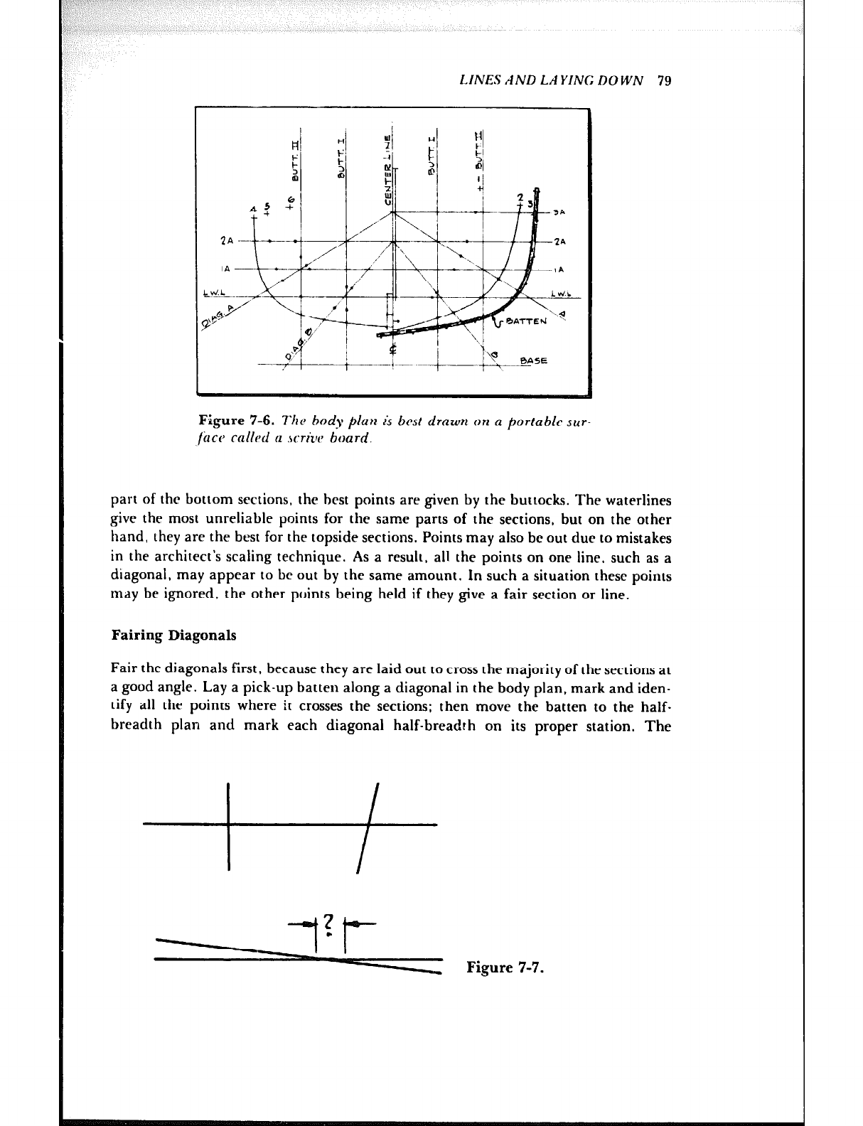
LINES AND LA YING DOWN 79
3A
-
Figure 7-6. Tfz~ body P/UH is best drawn on a portable sur-
lCrct> called a .\criuc board.
part of the bottom sections, the best points are given by the buttocks. The waterlines
give the most unreliable points for the same parts of the sections, but on the other
hand, they are the best for the topside sections. Points may also be out due to mistakes
in the architect’s scaling technique. As a result, all the points on one line, such as a
diagonal, may appear to be out by the same amount. In such a situation these points
may be ignored, the other points being held if they give a fair section or line.
Faking Diagonals
Fair the diagonals first, because they are laid out to cross the majority of the sections at
a good angle. Lay a pick-up batten along a diagonal in the body plan, mark and iden-
tify all the points where it crosses the sections; then move the batten to the half-
breadth plan and mark each diagonal half-breadth on its proper station. The
Figure 7-7.
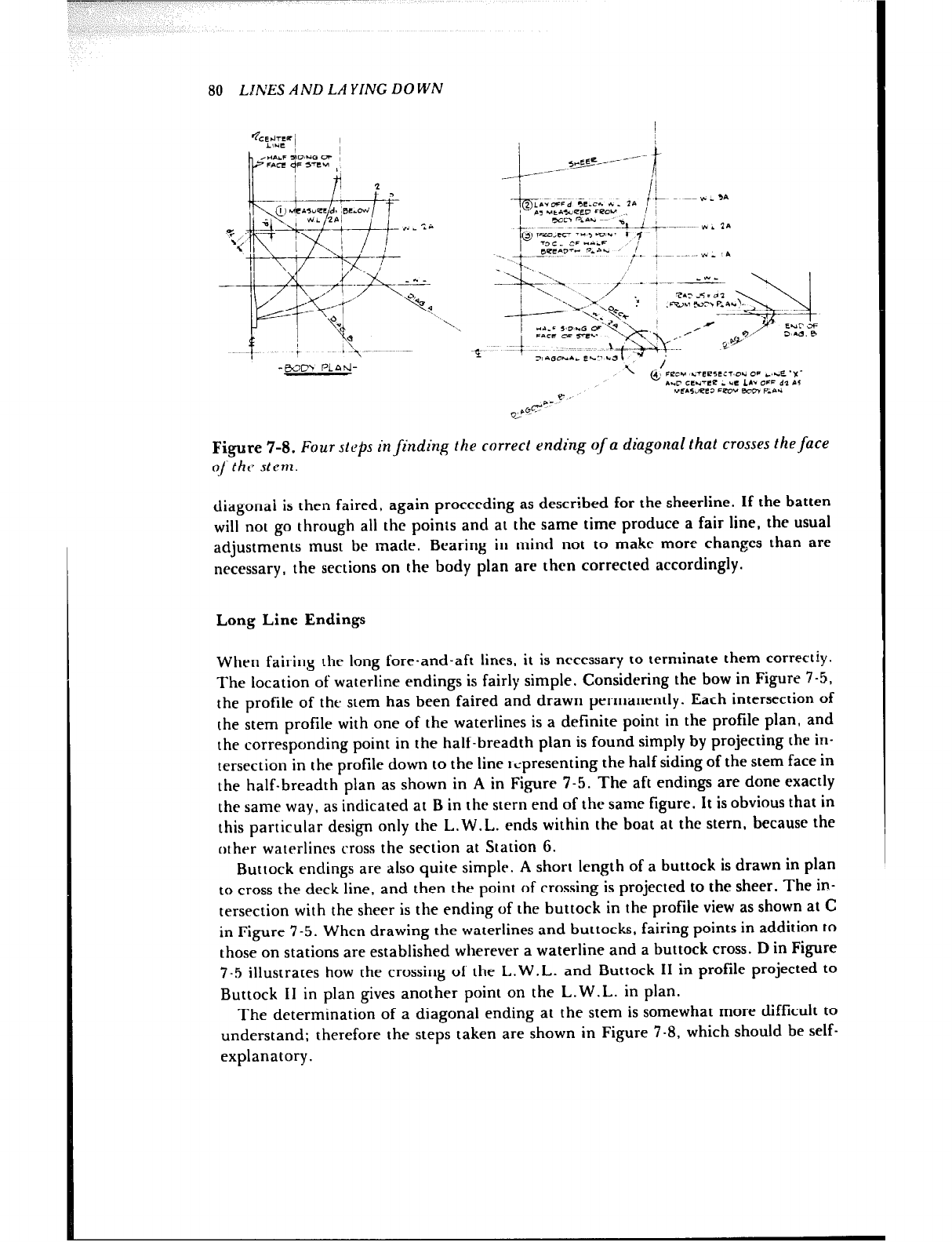
80 LINES AND LA YING DOWN
2 ?I
p1 +.
3, b.4 *,uec -3, lBE.& /
,~ 7 +J! PJL 2*’ I. _ ‘; i
\= ’
z +-if+
\ pq&f
-- I ,xkh~~
_ /’
b--% x 4
%
5: Ka
t + i 1.. ~_
--$-Q+ - 4. - _u_
/ ,,// .Azy‘LL&+ -“-<;2w: ;
0 1 :;;z”Y y$&,:-’ ‘i 9+x:“.z
3, .aciO~... CL” *a :
-WI3 PLAtJ- --. ,I,,,, ILTeeSC:l~O*i OF c,se ‘X’
A..C cl!.Jv3? * UC 10 Lx- dl er
&.G &.- e U~.5d?C3 =erJv em7 P-.-.I
Figure 7-8. Four steps in finding the correct ending of a diagonal that crosses the face
! t
S,.=g5-/----
_--- f
-/ ii
-p&cd kc* ..; 11 f \ ~~ yl - ‘A
Pa UCc.x1PCD FrzDV 1 1
bL;i> oinr, ~~
I- ~~
- --..__?Li+--~-~ vrl ?,I
@PpDoJcc”5rp~- I ,
73 c _ CF ..rc-
____ ?- .b’“D” 3”” ’ ;. ; ~. ..* _ ,*
/
o/the? stern.
diagonai is then faired, again proceeding as described for the sheerline. If the batten
will not go through all the points and at the same time produce a fair line, the usual
adjustments must be made. Bearing in mind not to make more changes than are
necessary, the sections on the body plan are then corrected accordingly.
Long Line Endings
When fairing the long fore-and-aft lines, it is necessary to terminate them correctly.
The location of waterline endings is fairly simple. Considering the bow in Figure 7-5,
the profile of the stem has been faired and drawn permanently. Each intersection of
the stem profile with one of the waterlines is a definite point in the profile plan, and
the corresponding point in the half-breadth plan is found simply by projecting the in-
tersection in the profile down to the line ~spresenting the half siding of the stem face in
the half-breadth plan as shown in A in Figure 7-5. The aft endings are done exactly
the same way, as indicated at B in the stern end of the same figure. It is obvious that in
this particular design only the L.W.L. ends within the boat at the stern, because the
other waterlines cross the section at Station 6.
Buttock endings are also quite simple. A short length of a buttock is drawn in plan
to cross the deck line, and then the point of crossing is projected to the sheer. The in-
tersection with the sheer is the ending of the buttock in the profile view as shown at C
in Figure 7-5. When drawing the waterlines and buttocks, fairing points in addition to
those on stations are established wherever a waterline and a buttock cross. D in Figure
7-5 illustrates how the crossing of the L.W.L. and Buttock II in profile projected to
Buttock II in plan gives another point on the L.W.L. in plan.
The determination of a diagonal ending at the stem is somewhat more difficult to
understand; therefore the steps taken are shown in Figure 7-8, which should be self-
explanatory.
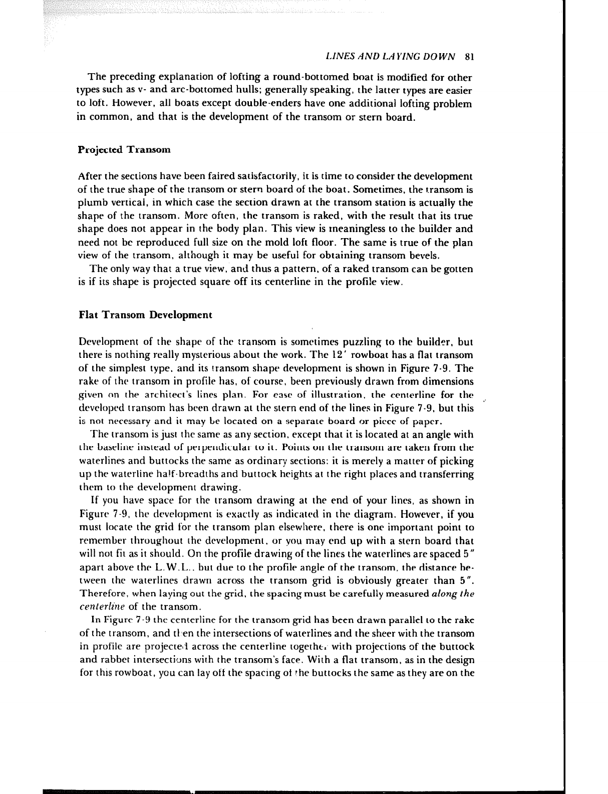
LINES AND LAYING DOWN 81
The preceding explanation of lofting a round-bottomed boat is modified for other
types such as v- and arc-bottomed hulls; generally speaking, the latter types are easier
to loft. However, all boats except double-enders have one additional lofting problem
in common, and that is the development of the transom or stern board.
Projected Transom
After the sections have been faired satisfactorily, it is time to consider the development
of the true shape of the transom or stern board of the boat. Sometimes, the transom is
plumb verticai, in which case the section drawn at the transom station is actually the
shape of the transom. More often, the transom is raked, with the result that its true
shape does not appear in the body plan. This view is meaningless to the builder and
need not be reproduced full size on the mold loft floor. The same is true of the plan
view of the transom, although it may be useful for obtaining transom bevels.
The only way that a true view, and thus a pattern, of a raked transom can be gotten
is if its shape is projected square off its centerline in the profi!e view.
Flat Transom Development
Development of the shape of thr transom is sometimes puzzling to the builder, but
there is nothing really mysterious about the work. The 12’ rowboat has a flat transom
of the simplest type, and its transom shapts development is shown in Figure 7-9. The
rake of the transom in profile has, of course, been previously drawn from dimensions
given on the architect’s lines plan. For c35c of illustration, the centerline for the .,
developed transom has bren drawn at the stern end of the lines in Figure 7-9, but this
is not necessary and it may be located on a separate board or piece of paper.
The transom is just thr same as any section, except that it is located at an angle with
the baseline instead of perperldicular to it. Points on the transom are taken from the
waterlines and buttocks the same as ordinary sections: it is merely a matter of picking
up the waterline half-breadths and buttock heights at the right places and transferring
thcqm to the development drawing.
If you have space for the transom drawing at the end of your lines, as shown in
Figurr 7-9, thr dcvelopmrnt is exactly as indicated in the diagram. However, if you
must locate the grid for the transom plan elsewhere. there is one important point to
remember throughout the development, or you may end up with a stern board that
will not fit as it should. On the profile drawing of the lines the waterlines are spaced 5 ”
apart above the L. W.L.. but due to the profile angle of the transom, the distance be-
tween the waterlines drawn across the transom grid is obviously greater than 5”.
Therefore, when laying out the grid, the spacing must be carefully measured along the
centerline of the transom.
In Figure 7-9 the centerline for the transom grid has been drawn parallel to the rake
of the transom, and tt,en the intersections of waterlines and the sheer with the transom
in profile are projected across the centerline togetht. with projections of the buttock
and rabbet intersecti(Jns with the transom’s face. With a flat transom, as in the design
for this rowboat, you can lay off the spacing of rhe buttocks the same as they are on the
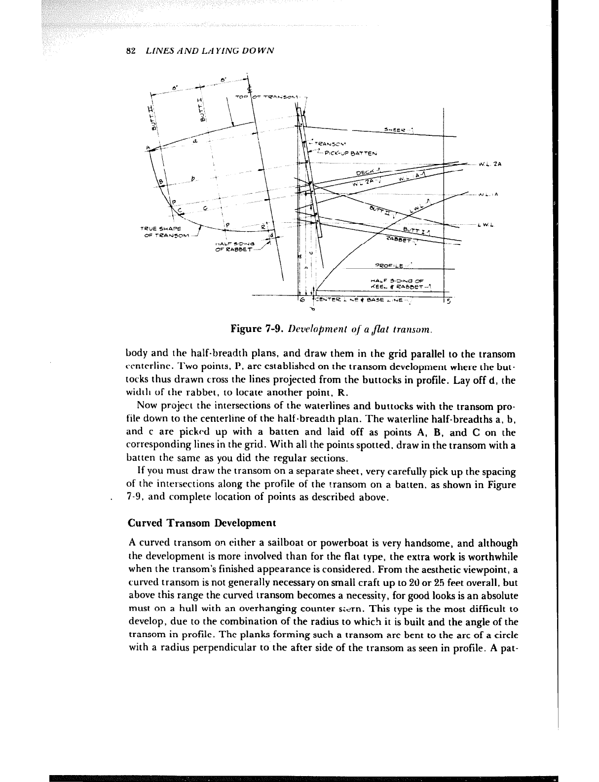
82 LINES AND LAYING DOWN
Figure 7-9. Ikwloprnent o/ a Jlat transom.
body and the half-breadth plans, and draw them in the grid parallel to the transom
rcnterline. Two points, P, are established on the transom development where the but-
tocks thus drawn cross the lines projected from the buttocks in profile. Lay off d, the
width of the rabbet, to locate another point, R.
Now project the intersections of the waterlines and buttocks with the transom pro-
file down to the centerline of the half-breadth plan. The waterline half-breadths a, b,
and c are picked up with a batten and laid off as points A, B. and C on the
corresponding lines in the grid. With all the points spotted, draw in the transom with a
batten the same as you did the regular sections.
If you must draw the transom on a separate sheet, very carefully pick up the spacing
of the intersections along the profile of the transom on a batten, as shown in Figure
. 7-9, and complete location of points as described above.
Curved Transom Development
A curved transom on either a sailboat or powerboat is very handsome, and although
the development is more involved than for the flat type, the extra work is worthwhile
when the transom’s finished appearance is considered. From the aesthetic viewpoint, a
curved transom is not generally necessary on small craft up to 20 or 25 feet overall, but
above this range the curved transom becomes a necessity, for good looks is an absolute
must on a hut1 with an overhanging counter sltirn. This type is the most difficult to
develop, due to the combination of the radius to which it is built and the angle of the
transom in profile. The planks forming such a transom are bent to the arc of a circle
with a radius perpendicular to the after side of the transom as seen in profile. A pat-

--
-
--
--
-----
--.-.
-.-
I Li 2% AND L.-l YING DO Wh’ 83
tern for the shape must be made, and this is accomplished as thougtl G rvlinder :~~~-~:Y
cut and rolled out flat.
A transom proportioned as shown in Figure 7-10 is developed principally with but-
tocks, because they cross the edges of the transom more nearly at right angles than do
the waterlines, and thus are the most accurate. By this time you are familiar with but-
tocks and must realize that those on the architect’s lines plan are not the only ones it is
possible to have on a hull. There are an infinite number, and they may be spaced as
clo-Fly as needed to hc!c, you make proper templates for parts The stern in Figure
7-10 has been purposely drawn with enough buttocks to develrp the transom ac-
curately, but ordinarily, extra buttocks for development of the tramt.m must be added
between those shown on the lines plan.
Before the transom is attempted, the hull lines have been completely faired full size,
usually to a staticn beyord the transom. To be sure of the shape of his hull, the ar-
chitect designs to a vertical station at the extreme stern and then cuts it off at the
desired angle in profile and in a radius in the plan view as mentioned above.
There are undoubtedly many methods of transom development in use and sworn to
by their advocates. However, the system illustrated here will at least help the reader
understand the principle. To avoid confusion, the profile and half-breadth plans of
the stern in Figure 7-1C have been drawn separated and the transom radius made
smalier than usual to clarify the drawing. Dashed lines show the projection of one view
to another. After following the development of the flat transom in Figure 7-9. the use
of the buttocks in Figure 7-10 is obvious, with the exception of their spacing in the grid
for the expansion.
Extend the after side of the transom in profile up clear of other drawings, Figure
7-lOA, and draw a centerline perpendicular to it. Tangent to the intersection, swing
an arc of radius as shown on the plans. This is the curve to which the transom planking
will be bent when it is built. Draw the buttocks parallel to the centerline, spaced the
same as in the half-breadth plan. Project the intersections of the burtocks with the arc
down to cross the corresponding buttocks in the profile view. Now prepare the grid for
the expanded transom, Figure 7-lOB, spacing the buttocks out from the centerline as
measured around the arc instead of as laid out in the half-breadth plan. These
measurements give the true distances between the buttocks when the cylindrical tran-
som is rolled out flat. Project the buttocks in profile to the grid to obtain points on the
edge of the transom as was done in the flat transom, Figure 7-9. For clarity only one
buttock, Buttock II, has been used as an example in Figure 7-10.
In order to find the point where the transom terminates at the sheerline. the deck
line is drawn in the auxiliary projection shown in Figure 7-10A. To draw the deck line
in this view, select convenient points (P) along the projection’s centerline; square them
above the centerline and also down to cross the sheer on the profile: and then square
the points of intersectior? with the sheer parallel to the stations to cross the deck line in
the half-breadth plan. The widths of the deck at these points are lifted, transf+=rr?d tn
the auxiliary projection, and a batten is run rhrough them. The corner of the transom
at the deck is located where the deck line intersects the arc of the transom. The half-
breadth of the point is measured from the centerline around the arc and duly trans-
ferred to the grid.
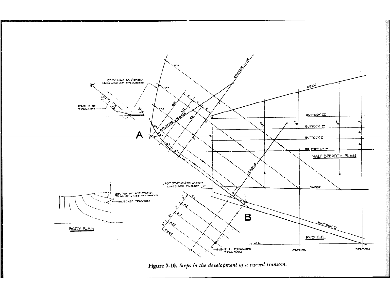
RADl U5 OF
TRA?450M -
CE~NTWZ AINC .
’
,L E!%PANoeo
\ yy~~,gNSO~
--
-
Figure 7-10. Steps in the development of a curved transom.
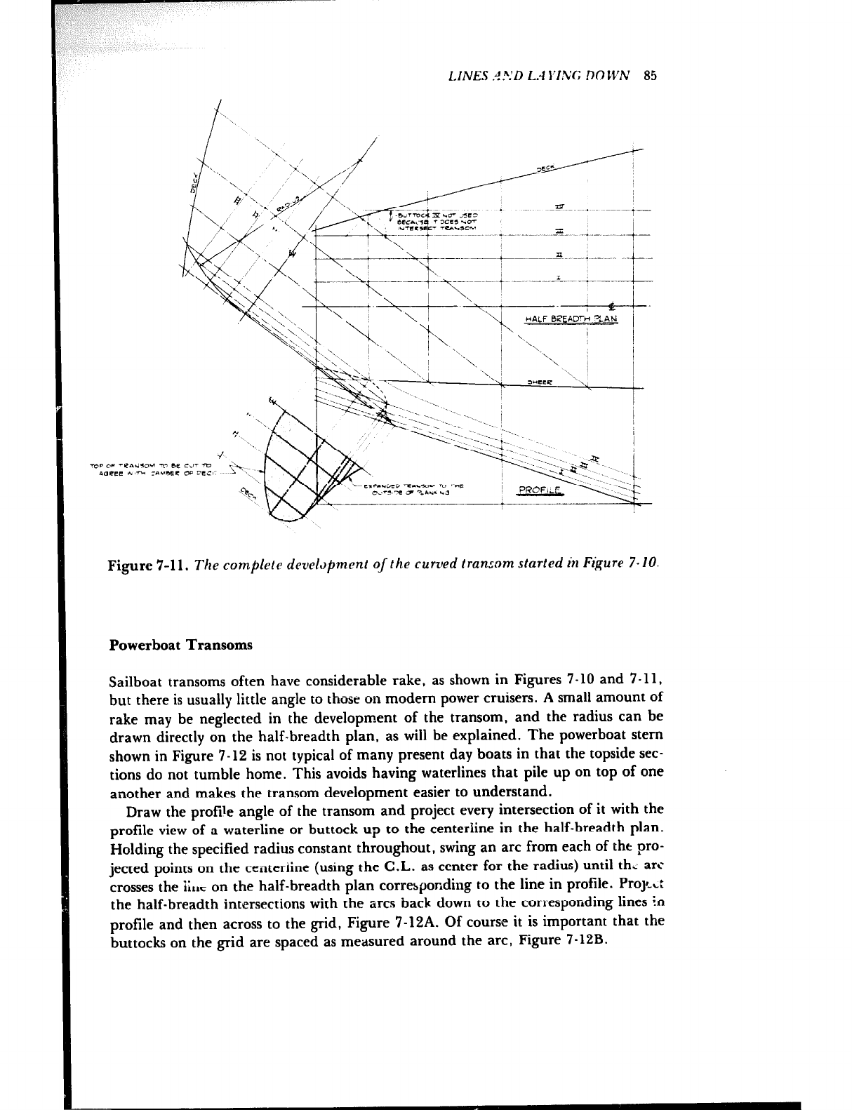
LINES .J?.‘D L.4 S1.1;G Ml IZ’N 85
Figure 7-l 1. The complete devehpment of the curved transom started in Figure 7- 10.
Powerboat Transoms
Sailboat transoms often have considerable rake, as shown in Figures 7-10 and 7-11,
but there is usually little angle to those on modem power cruisers. A small amount of
rake may be neglected in the development of the transom, and the radius can be
drawn directly on the half-breadth plan, as will be explained. The powerboat stem
shown in Figure 7-12 is not typical of many present day boats in that the topside sec-
tions do not tumble home. This avoids having waterlines that pile up on top of one
another and makes the transom development easier to understand.
Draw the profile angle of the transom and project every intersection of it with the
profile view of a waterline or buttock up to the centeriine in the half-breadth plan.
Holding the specified radius constant throughout, swing an arc from each of tht pro-
jected points on the centeriine (using the C.L. as center for the radius) until th: arc
crosses the 1;~~ on the half-breadth plan corresponding to the line in profile. ProyWc:
the half-breadth intersections with the arcs back down to the corresponding lines in
profile and then across to the grid, Figure 7-12A. Of course it is important that the
buttocks on the grid are spaced as measured around the arc, Figure 7-12B.
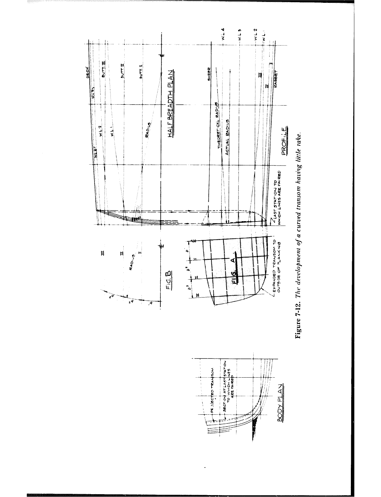
/ IHj
: i$j’ ;
01 ;
1; 1
: i
3 ; i
li /,
i j 1
l-J1 *-
Ii,
/ ‘/ ;
:.
vt : -1
I / Al / A
3i 3,
‘, :
I 1 ‘1 ;
H #I nH
3
0‘
ii
I
2 !
i
CL
F
I ---
- 4 -~~
3
CL
2
z-y -- -z-_
+
SE -&&
i j
3 3 !/
A-4 -
/I !
+I
I ‘,
‘“I
‘IL
! B
ys
(I
/j
+t-
:j
i
j/ y
i p
%
P%
@
k;;I
hz
-I
k1
3,‘1’
9
/’ SOa
>z
t
0:
: 4
WB
t- IL
00
2111
20
St
., 26
-2
F
-2
.2
e
b3
.=
P
G
C
E
z
F:
E
P
i2
t
c
5
$.
-7
,’
c
‘3
2
b
sl
d
A
2
EL
.r(
Fr
LINES AND 1 1 YING DOWN 87
The development is the shape of the outside edge of the transom planking, but
allowance must be made for the bevel on the edges, which causes the transom to be
larger on the inside than on the outside face. When making the transom frame, :he
planking thickness must be deducted before the allowance for beveling can be made.
Computer-Aided Lines Fairing
The purpose of much of the work described in this chapter is to correct errors in the
architect’s lines drawing. Errors creep in due to the necessity of making a small-scale
drawing, due to mistakes made in reading the offsets, and because of sloppy drafts-
manship. It may not pay an amateur to depart from the time-tested methods of lofting
ani, mold-making, but the professional should certainly investigate services that fair
hull lines by computer. Such computers fair the lines from the table of offsets.
resulting in corrected offsets reading to one-sixteenth of an inch or one hundredth of a
foot. (It is easy to lay out offsets in feet and decimals with an ordinary surveyor’s six-
foot folding rule.) A logica! extension of computer-aided lines fairing is the full size
drawing of the body plan, and this is discussed in the next chapter.
I have used firms supplying computer-guided lofting for hulls up to 78 feet in length.
Such lofting is available from Justin E. Ketwin, 25 Hallett Hill Road, Weston,
Massachusetts 02193; Bristolcomp, c/o Halsey C. Herreshoff, Inc., 18 Burnside
Street, Bristol, Rhode Island 02809; and Hullforms, Inc., 3667 Woodland Drive, RD
#3, Baldwinsville, New York 13027.
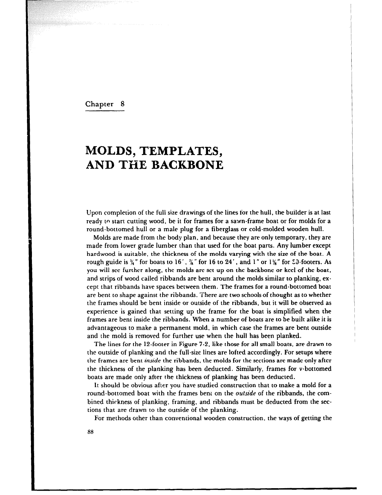
Chapter 8
S, TEMPLATES,
AND THE BACKBONE
Upon completion of the full size drawings of the lines for the hull. the builder is at last
ready to start cutting wood, be it for frames for a sawn-frame boat or for molds for a
round-bottomed hull or a male plug for a fiberglass or cold-molded wooden hull.
Molds are made from the body plan, and because they are only temporary, they are
made from lower grade lumber than that used for the boat parts. Any lumber except
hardwood is suitable, the thickness of the molds varying with the size of the boat. A
rough guide is XV for boats to 16’ , % ” for 16 to 24 ’ , and 1 rr or 1 ‘ig N for Z&footers. As
you will see further along, the molds are set up on the backbone or keel of the boat,
and strips of wood called ribbands are bent around the molds similar to planking, ex-
cept that ribbands have spaces between them. The frames for a round-bottomed boat
are bent to shape against the ribbands. There are two schools of thought as to whether
the frames should be bent inside or outside of the ribbands, but it will be observed as
experience is gained that setting up the frame for the boat is simplified when the
frames are bent inside the ribbands. When a number of boats are to be built alike it is
advantageous to make a permanent mold, in which case the frames are bent outside
and the mold is removed for further use when the hull has been planked.
The lines for the 12-footer in Figure 7.2, like those for all small boats, are drawn to
the outside of planking and the full-size lines are lofted accordingly. For setups where
the frames are bent inside the ribbands, the molds for the sections are made only after
the thickness of the planking has been deducted. Similarly, frames for v-bottomed
boats are made only after the thickness of planking has been deducted.
It should be obvious after you have studied construction that to make a mold for a
round-bottomed boat with the frames bent on the outside of the ribbands, the com-
bined thickness of planking, framing, and ribbands must be deducted from the sec-
tions that are drawn to the outside of the planking.
For methods other than conventional wooden construction, the ways of getting the
88
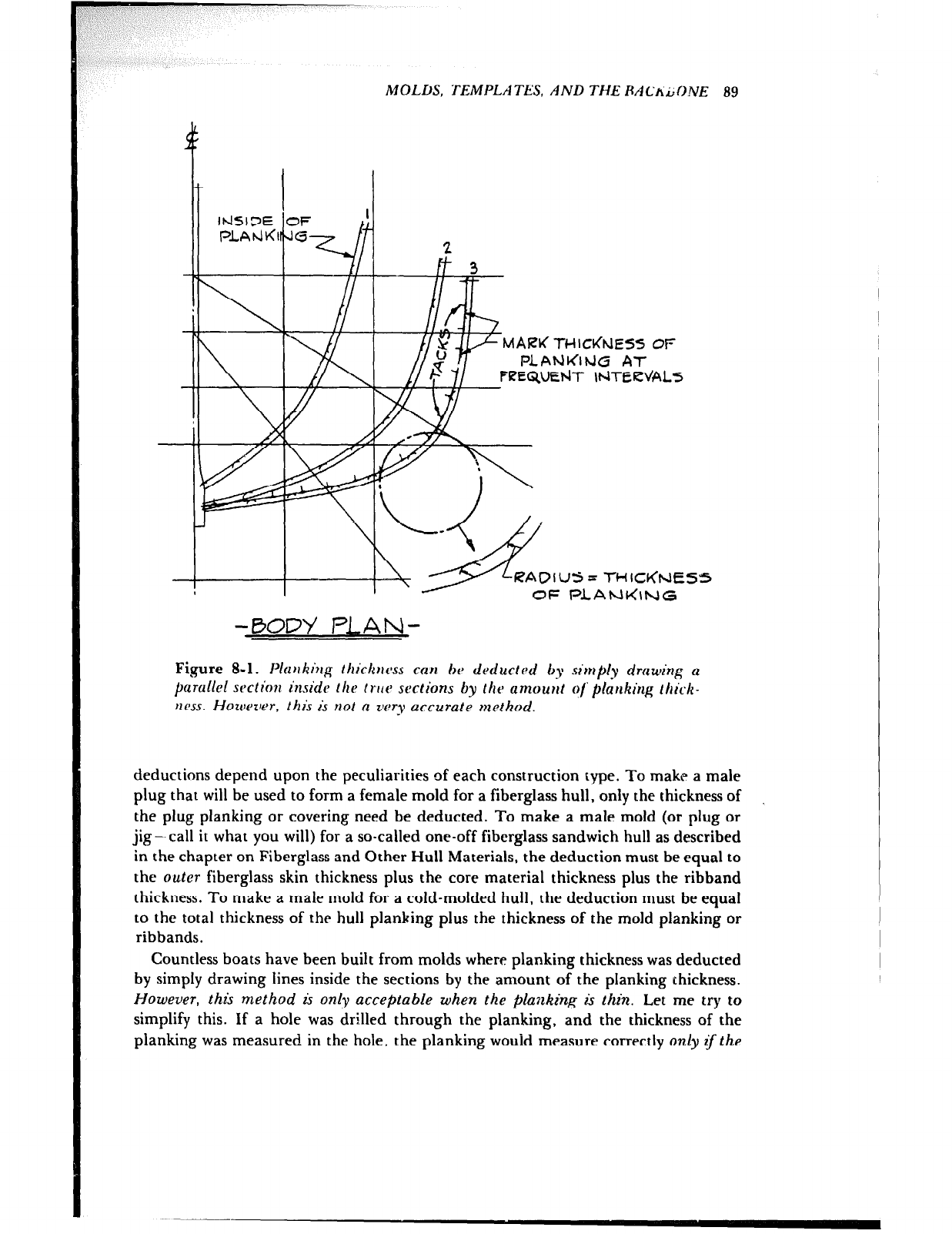
MOLDS, TEMPLATES, AND THE RACfiLDNE 89
MAW THICdNES5 OF
PlAhi~lbJB AT
C?EQUEtdT ItdTERL’ALS
RAOlYS= THIC~(NE
OF l=LANC(\NG
-BOD)/ PLAN-
Figure 8-l. Plajrking thickucss can 6~ deducted by sin~ply drawing a
parullel wction insido the IWP sections by thr amou,tt o/‘ planking thick-
ncss. Howtqler, this is not a zltq accurate method.
deductions depend upon the peculiarities of each construction type. To make a male
plug that will be used to form a female mold for a fiberglass hull, only the thickness of
the plug planking or covering need be deducted. To make a male mold (or plug or
jig- call it what you will) for a so-called one-off fiberglass sandwich hull as described
in the chapter on Fiberglass and Other Hull Materials, the deduction must be equal to
the outer fiberglass skin thickness plus the core material thickness plus the ribband
thickness. To make a male mold for a cold-molded hull, the deduction must be equal
to the total thickness of the hull planking plus the thickness of the mold planking or
ribbands.
Countless boats have been built from molds where planking thickness was deducted
by simply drawing lines inside the sections by the amount of the planking thickness.
However, this method is only acceptable when the planking is thin. Let me try to
simplify this. If a hole was drilled through the planking, and the thickness of the
planking was measured in the hole, the planking wouid measure correctly only q the
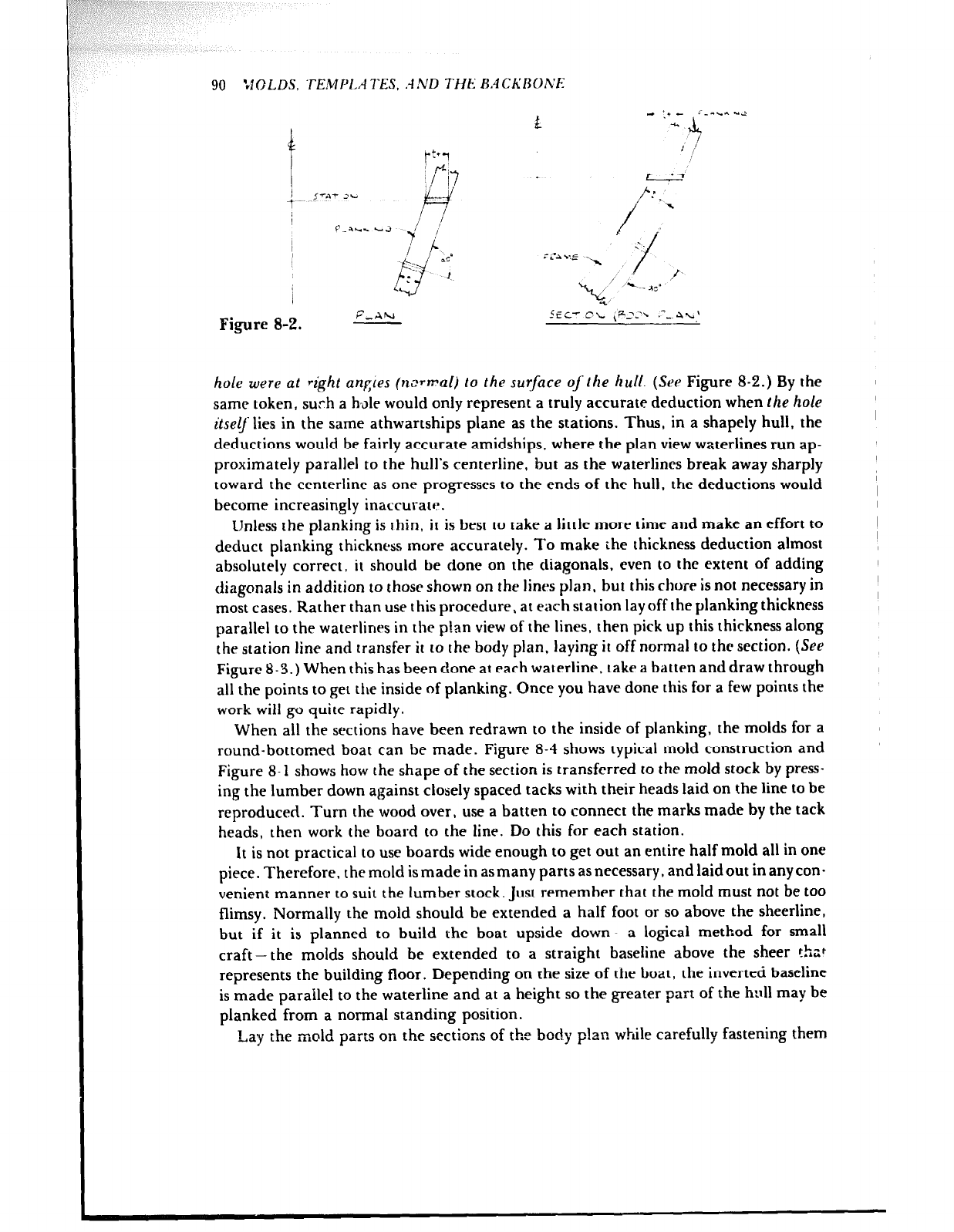
90 ‘JO LDS. TEMF’LA TES, .4 ND THE l-3.4 CKROh’E
Figure 8-2. AEC’ CL ,P:-h .-_ 4-n’
L
hole were at right angles (n,.
-TmaI) to the surface o/‘ the it&i. (See Figure 8-2.) By the
same token, such a h,ole would only represent a truly accurate deduction when the hole
itselj lies in the same athwartships plane as the stations. Thus, in a shapely hull, the
deductions would be fairly accurate amidships, where the pian view waterlines run ap-
proximately parallel to the hull’s centerline, but as the waterlines break away sharply
toward the centerline as one progresses to the ends of the hull, the deductions would
become increasingly inaccurate.
IJnless the planking is thin, it is best to take a little more time and make an effort to
deduct planking thickness snore accurately. To make the thickness deduction almost
absolutely correct, it should be done on the diagonals, even to the extent of adding
diagonals in addition to those shown on the lines plan, but this chore is not necessary in
most cases. Rather than use this procedure, at each station layoff the planking thickness
parallel to the waterlines in the p!an view of the lines, then pick up this thickness along
the station line and transfer it to the body plan, laying it off normal to the section. (See
Figure 8-3.) When this has been done at each waterline, take a batten and draw through
all the points to get tire inside of planking. Once you have done this for a few points the
work will go quite rapidly.
When all the sections have been redrawn to the inside of planking, the molds for a
round-bottomed boat can be made. Figure 8-4 shows typical mold construction and
Figure 8-l shows how the shape of the section is transferred to the mold stock by press-
ing the lumber down against closely spaced tacks with their heads laid on the line to be
reproduced. Turn the wood over, use a batten to connect the marks made by the tack
heads, then work the board to the line. Do this for each station.
It is not practical to use boards wide enough to get out an entire half mold all in one
piece. Therefore, the mold is made in asmany parts asnecessary, and laidout in anycon-
venient manner to suit the lumber stock. Just remember that the mold must not be too
flimsy. Normally the mold should be extended a half foot or so above the sheerline,
but if it is planned to build the boat upside down-a logical method for small
craft-the molds should be extended to a straight baseline above the sheer that
represents the building floor. Depending on the size of the boat, the inverted baseline
is made parailel to the waterline and at a height so the greater part of the hull may be
planked from a normal standing position.
Lay the mold parts on the sections of the body plan while carefully fastening them
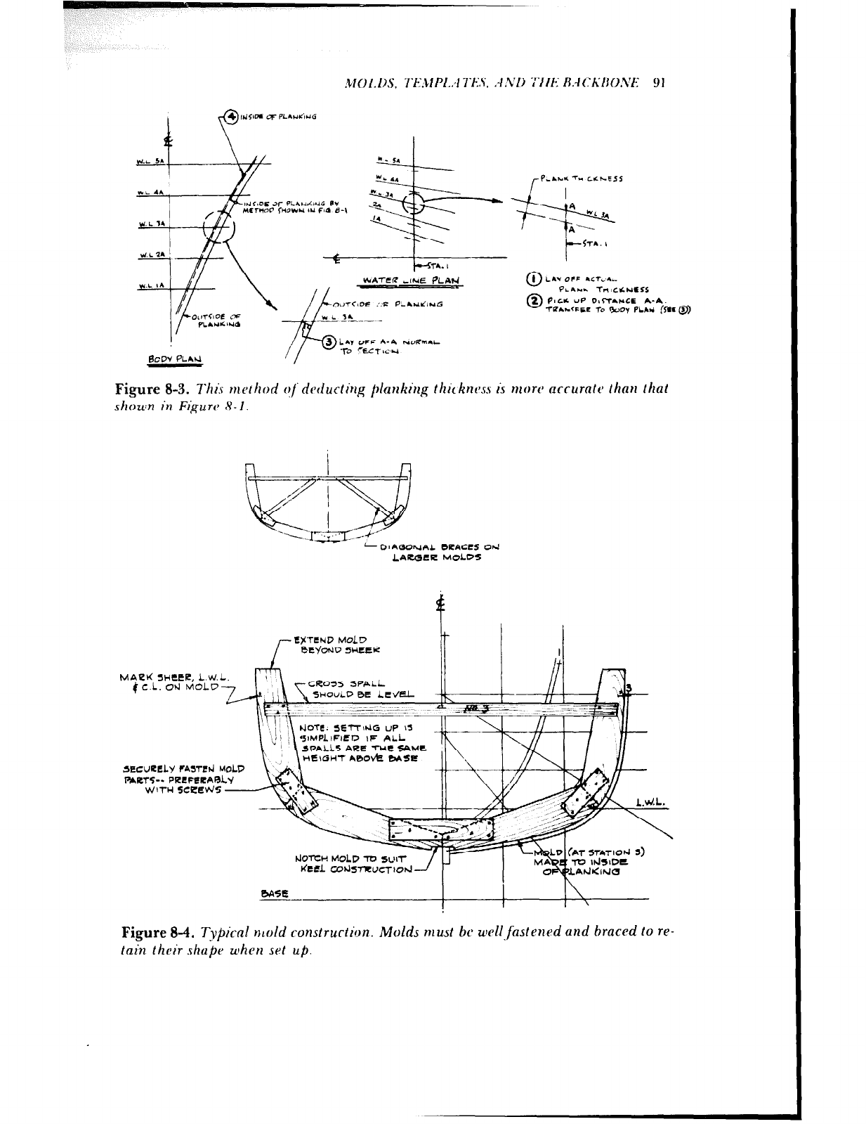
!vlOl. DS, 7‘~.~:clPI..~l7‘i-.~~:‘.‘i. .-l .VI) -i‘llif R.-lCKi~O.l’E 9 I
=-r--i@
CM-SIDE c;F P-IUICIHG
yP,Aw.r -7” CLhESS
A
*
-I *
A-‘
t-
<TI. h
0
1 L&WcTFF I‘T,.I
PLaNa. TntCuiNtSs
0
2 Pmc* UP o,CT.*.s n-n.
-rPa.+.(~5L l-0 9cJoy fLAti (WC@)
LAY OFF A-4 NORM&L
‘l-0 %a- LC *I
Figure 8-3. 7’his rtto~ hod ojdPducting planking thic knvss is ntow ncrurn~c~ than that
shown in Figure 8- 1.
- 01 AOOhlnL ORACRS Od
LAccclRFZ MOLOS
I- l?$‘T.RND MOLD
bI3’o+lD 5ucCR It I li
MALI< SWttR, L.W.L.
4 c.L. Od MoLD 7
SECURELY FATTEd MOLD
T+*RTcTs-- PRRFRRAR~s’
vJIl-bl5ceRNs -
‘rl’ \ &Ails ARR”&<~Mt
HEIGHT A0Ovk
\I I \\ 9lMPLlFl~D IF ALL
bhXCI+ MOLD -TO
KCfL CohlSRU
Figure 8-4. Tvt)icnl mold ronstrurtion. Molds must bc wll~fastened und braced to re-
lain their shape when set up.
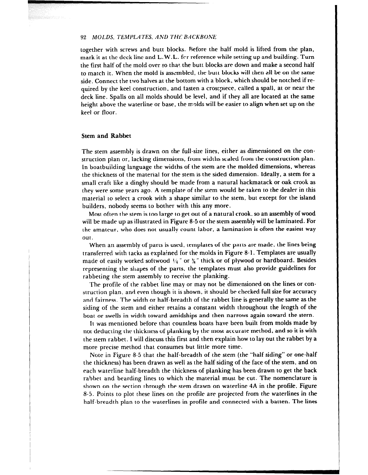
92 MOLDS, TEMPLATES. AND THf BACKBONE
together with screws and butt blocks. rsefore the half mold is lifted from the plan,
mark it at the deck line and L.W.L. fcr reference while setting up and building. Turn
the first half of the mold over so thar. the butt blocks are down and make a second half
to match it. When the mold is aswmbled, the butt blocks will then all be on the same
side. Connect the two halves at the bottom with a block, which should be notched if re-
quired by the keel construction, and fasten a crosepiece, called a spall, at or near the
deck line. Spalls on all molds should be level, and if they all are located at the same
height above the waterline or base, the molds will be easier to align when set up on the
keel or floor.
Stem and Rabbet
The stem assembly is drawn on the full-size lines, either as dimensioned on the con-
struction plan or, lacking dimensions, from widths scaled from the construction plan.
In boatbuilding language the widths of the stem are the molded dimensions, whereas
the thickness of the material for the stem is the sided dimension. Ideally, a stem for a
small craft like a dinghy should be made from a natural hackmatack or oak crook as
they were some years ago. A template of the stem would be taken to the dealer in this
material to select a crook with a shape similar to the stem, but except for the island
builders, nobody seems to bother with this any more.
Most often the stem is too large to get out of a natural crook, so an assembly of wood
will be made up as illustrated in Figure 8-5 or the stem assembly will be laminated. For
the amateur, who does not usually count labor. a lamination is often the easiest way
out.
When an assembly of parts is used, templates of the parts are made, the lines being
transferred with tacks as explained for the molds in Figure 8.1. Templates are usually
made of easily worked softwood !/i r, or y8 ” thick or of plywood or hardboard. Besides
representing the shapes of the parts, the templates must also provide guidelines for
rabbeting the stem assembly to receive the planking.
The profile of the rabbet line may or may not be dimensioned on the lines or con-
struction plan, and even though it is shown, it should be checked full size for accuracy
and fairness. The width or half-breadth of the rabbet line is generally the same as the
siding of the stem and either retains a constant width throughout the length of the
boat or swells in width toward amidships and then narrows again toward the stern.
It was mentioned before that countless boats have been built from molds made by
not deducting the thickness of planking by the most accurate method, and so it is with
the stem rabbet. I will discuss this first and then explain how to lay out the rabbet by a
more precise method that consumes but little more time.
Note in Figure S-5 that the half-breadth of the stem (the “half siding” or one-half
the thickness) has been drawn as well as the half siding of the face of the stem, and on
each waterline half-breadth the thickness of planking has been drawn to get the back
rabbet and bearding lines to which the material must be cut. The nomenclature is
shown on the section through the stem drawn on waterline 4A in the profile, Figure
8-5. Points to plot these lines on the profile are projected from the waterlines in the
half-breadth plan to the waterlines in profile and connected with a batten. The lines
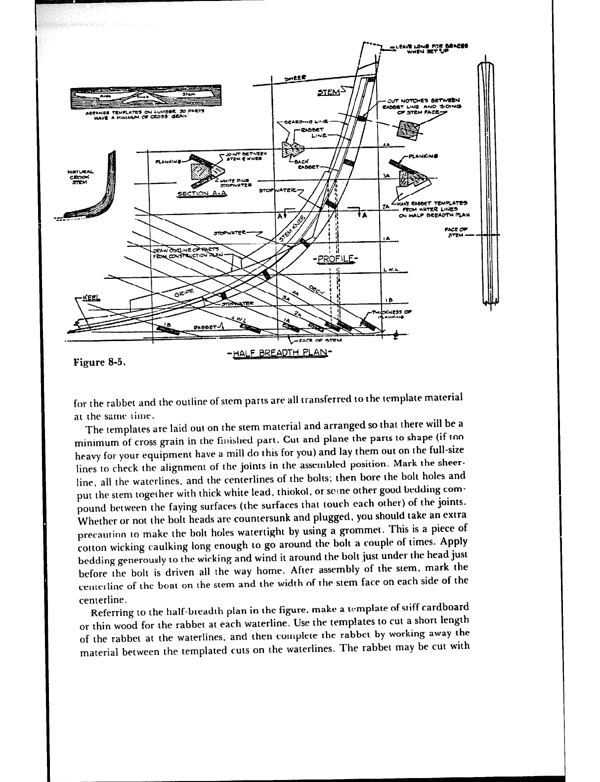
Figure 8-5.
for the rabbet and the outline of stem parts are all transferred to the template material
at the same time.
The templates are laid out on the stem material and arranged so that there will be a
minimum of cross grain in the finished part. Cut and plane the parts to shape (if too
heavy for your equipment have a mill do this for you) and lay them out on the full-size
lines to check the alignment of the joints in the assembled position. Mark the sheer-
line, all the waterlines, and the centerlines of the bolts; then bore the bolt holes and
put the stem together with thick white lead, t hiokol, or sc rne other good bedding com-
pound between the faying surfaces (the surfaces that touch each other) of the joints.
Whether or not the bolt heads are countersunk and plugged, you should take an extra
precaution to make the bolt holes watertight by using a grommet. This is a ptece of
cotton wicking caulking long enough to go around the bolt a couple of times. Apply
bedding generously to the wicking and wind it around the bolt just under the head just
before the bolt is driven all the way home. After assembly of the stem, mark the
centerline of the boat on the stem and the width of the stem face on each side of the
centerline.
Referring to the half-breadth plan in the figure, make a tc.mplate of stiff cardboard
or thin wood for the rabbet at each waterline. Use the temp!ates to cut a short length
of the rabbet at the waterlines, and then complete the rabbet by working away the
material between the templated cuts on the waterlines. The rabbet may be cut wrth
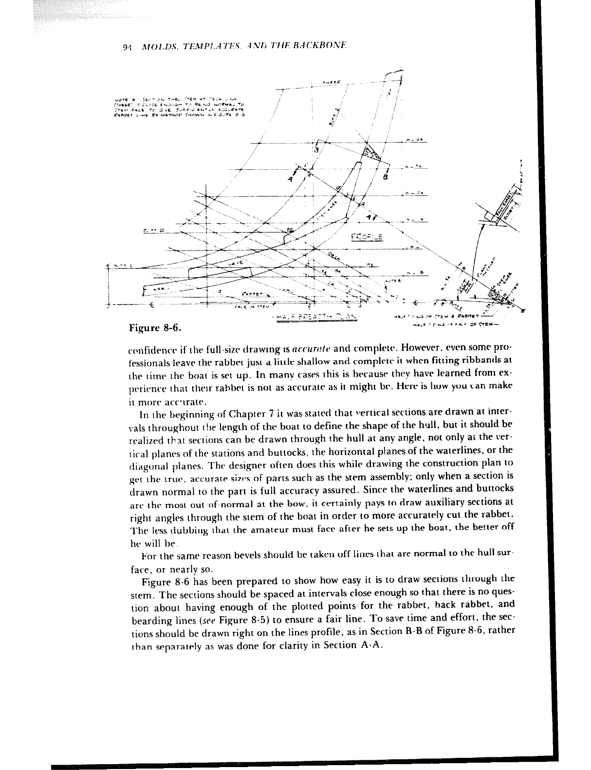
94 M0I.D.S. TEMPI.,-I 7'E.S. :I.VIj TIIE RrlCKR0.V~
Figure 8-6. r;.: i=C>-T
rc~nficienc~ if the full-six drawing IS accrlrc!ta and complete. However, even some pro-
fessionals leave the rabbet ,just a little shallow and complete it when fitting ribbands at
the time the boat is set up. In many cases this is because they have learned from ex-
perience that their rabhet is not as accurate as it might be. Here is how you can make
it more acc’trate.
In the beginning of Chapter 7 it was stated that vertical sections are drawn at intcr-
vals throughout r!re length of the boat to define the shape of the hull, but it should be
realized that sections can be drawn through the hull at any angle, not only at the ver-
tical planes of the stations and buttocks, the horizontal planes of the waterlines, or the
diagonal planes. The designer often does this while drawing the construction plan to
get the true, accurate sizes of parts such as the stem assembly: only when a section is
drawn normal to the part is full accuracy assured. Since the waterlines and buttocks
are the most out-of-normal at the bow, it certainly pays to draw auxiliary sections at
right angles through the strm of the boat in order to more accurately cut the rabbet.
The less dubbing that the amateur must face after he sets up the boat, the better off
he will be.
For the same reason bevels should be taken off lines that are normal to the hull sur-
face, or nearly so.
Figure 8-6 has been prepared to show how easy it is to draw sections through the
stem. The sections should be spaced at intervals close enough so that there is no ques-
tion about having enough of the plotted points for the rabbet, back rabbet, and
bearding fines (see Figure 8-5) to ensure a fair line. To save time and effort, the sec-
tions should be drawn right on the lines profile, as in Section B-B of Figure 8-6, rather
than separately as was done for clarity in Section A-A.
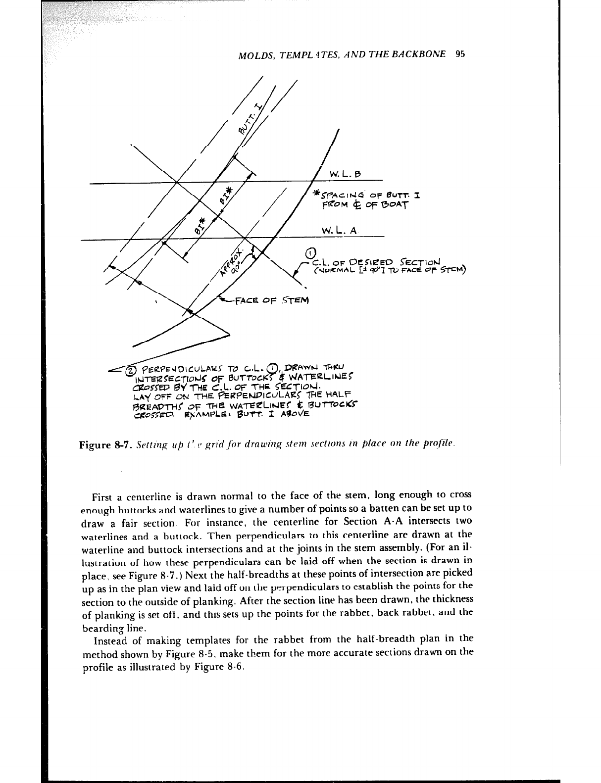
MOLDS, TEMPL 4TES, AND THE BACKBONE 95
W.L. n
L@&WE*IDICULA(ZS To C.!m. 9, DUAWJ -IiWJ
INTW~ECTIO~~ OF BuTrocK 4‘ PJAT’=LINEC
C&‘SnP @lr’ -j-HE C.L. OF THE. 5=3-lO~.
LAY OFF ON -rwz QERPEwIcuLALJ -WE HALF
~%EAD*!: 3~ me ku~-rERLlrJEr t: WnocrCC
cZ$O5<-. EFAMPLE: BUTT. 1 AVOVE-
Figure 8-7. !G~lt~~~ 111 1 ‘. 1~ grid for dmwing stern sections in p/arc on /he prqfi[~
First a centerline is drawn normal to the face of the stem, long enough to cross
enough buttocks and waterlines to give a number of points so a batten can be set up to
draw a fair section. For instance, the centerline for Section A-A intersects two
waterlines and a huttork. Then perpendiculars TO this centerline are drawn at the
waterline and buttock intersections and at the joints in the stem assembly. (For an il-
lustration of how these perpendiculars can be laid off when the section is drawn in
place, see Figure 8-7.) Next the half-breadths at these points of intersection are picked
up as in the plan view and laid off on the perpendiculars 10 establish the points for the
section to the outside of planking. After the section line has been drawn, the thickness
of planking is set off, and this sets up the points for the rabbet, back rabbet, and the
bearding line.
Instead of making templates for the rabbet from the half-breadth plan in the
method shown by Figure 8-5, make them for the more accurate sections drawn on the
profile as illustrated by Figure 8-6.
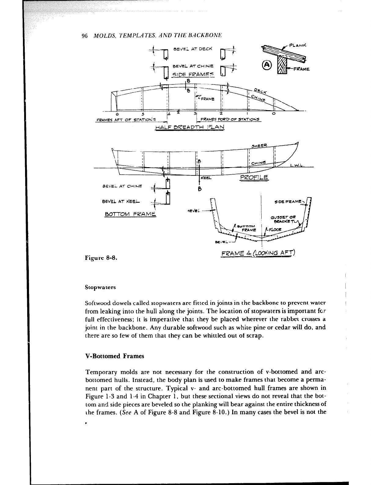
96 MOLDS, Y‘EMPLATES, AND THE BACh’RONE
4=-n
REVEL AT DE&
rT===+
ITAMES AFT OF STAT-Id5 I
- CFRAME?: FC+?‘D OF STATIO~JS
i-lAiF 0READTH I’LAbJ
BE\;Ei AT CHINE
=F h
0Ei’EL AT KEEL -_
.i-u
BOTTOM FRAME
Figure 8-8.
I
FPAME 4 (~~%ING AFT)
Stopwaters
Softwood dowels called stopwaters are fitted in joints in the backbone to prevent water
from leaking into the hull along the joints. The location of stopwaters is important fcr
full effectiveness: it is imperative that they be placed wherever the rabbet crosses a
joint in the backbone. Any durable softwood such as white pine or cedar will do, and
there are so few of them that they can be whittled out of scrap.
V-Bottomed Frames
Temporary molds are not necessary for the construction of v-bottomed and arc-
bottomed hulls. Instead, the body plan is used to make frames that become a perma-
nent part of the structure. Typical v- and arc-bottomed hull frames are shown in
Figure l-3 and l-4 in Chapter 1, but these sectional views do not reveal that the bot-
tom and side pieces are beveled so the planking will bear against the entire thickness of
the frames. (See A of Figure 8-8 and Figure 8-10.) In many cases the bevel is not the
.
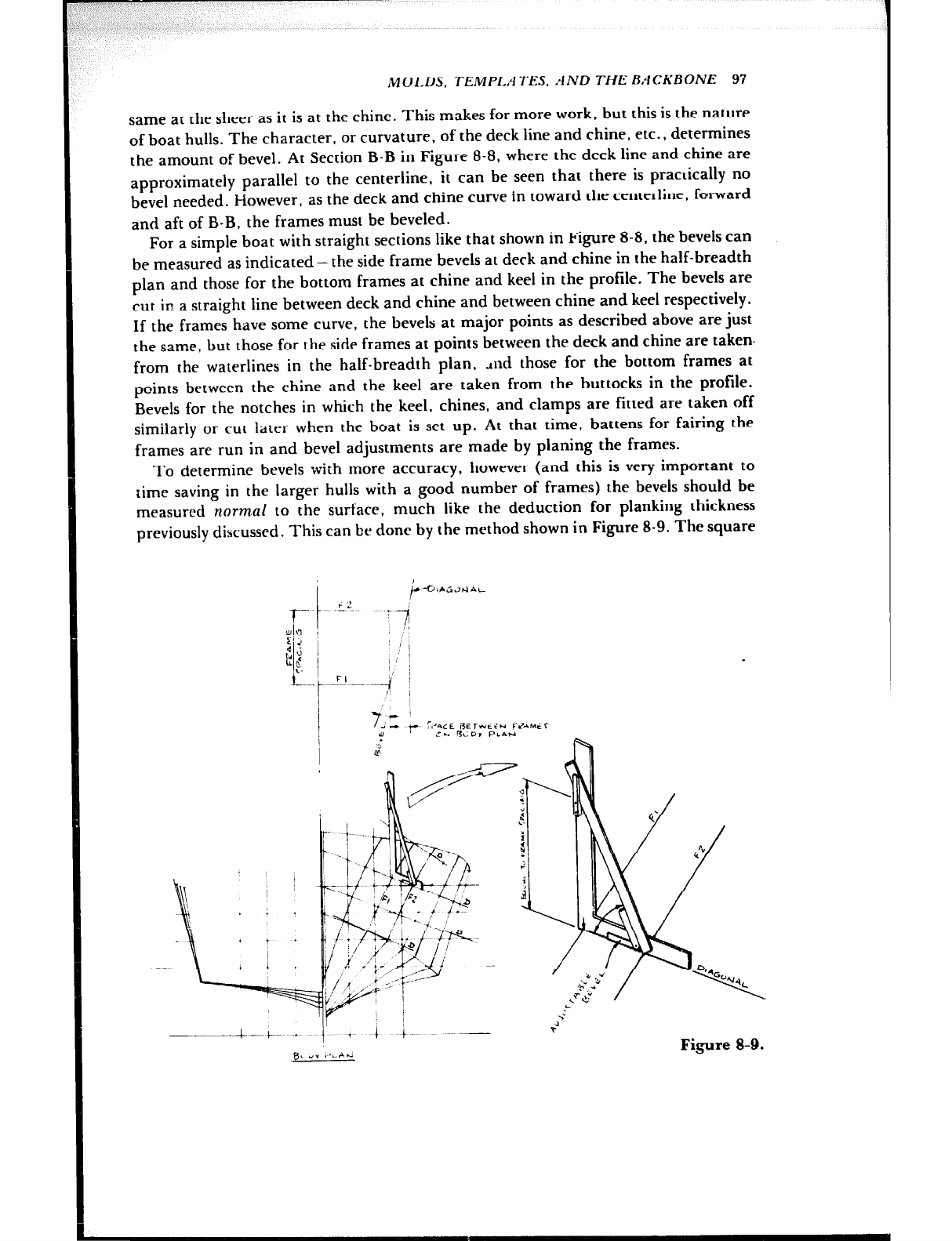
MOl.DS, TEMPLATES. AND THE BACKBONE 97
same at the sheer as it is at the chine. This makes for more work, but this is the nature
of boat hulls. The character, or curvature, of the deck line and chine, etc., determines
the amount of bevel. At Section B-B in Figure 8-8, where the deck line and chine are
approximately parallel to the centerline, it can be seen that there is practically no
bevel needed. f-fowever, as the deck and chine curve in toward the centerline, forward
and aft of B-B, the frames must be beveled.
For a simple boat with straight sections like that shown in Figure 8-8. the bevels can
be measured as indicated- the side frame bevels at deck and chine in the half-breadth
plan and those for the bottom frames at chine and keel in the profile. The bevels are
cut in a straight line between deck and chine and between chine and keel respectively.
If the frames have some curve, the bevels at major points as described above are just
the same, but those for the side frames at points between the deck and chine are taken.
from the waterlines in the half-breadth plan, dnd those for the bottom frames at
points between the chine and the keel are taken from the buttocks in the profile.
Bevels for the notches in which the keel, chines, and clamps are fitted are taken off
similarly or cut later when the boat is set up. At that time, battens for fairing the
frames are run in and bevel adjustments are made by planing the frames.
To determine bevels with more accuracy, however (and this is very important to
time saving in the larger hulls with a good number of frames) the bevels should be
measured normal to the surface, much like the deduction for planking thickness
previously discussed. This can be done by the method shown in Figure 8-9. The square
~- --... 4 -.. &- .~
Id” ,,irrd Figure 8-9.
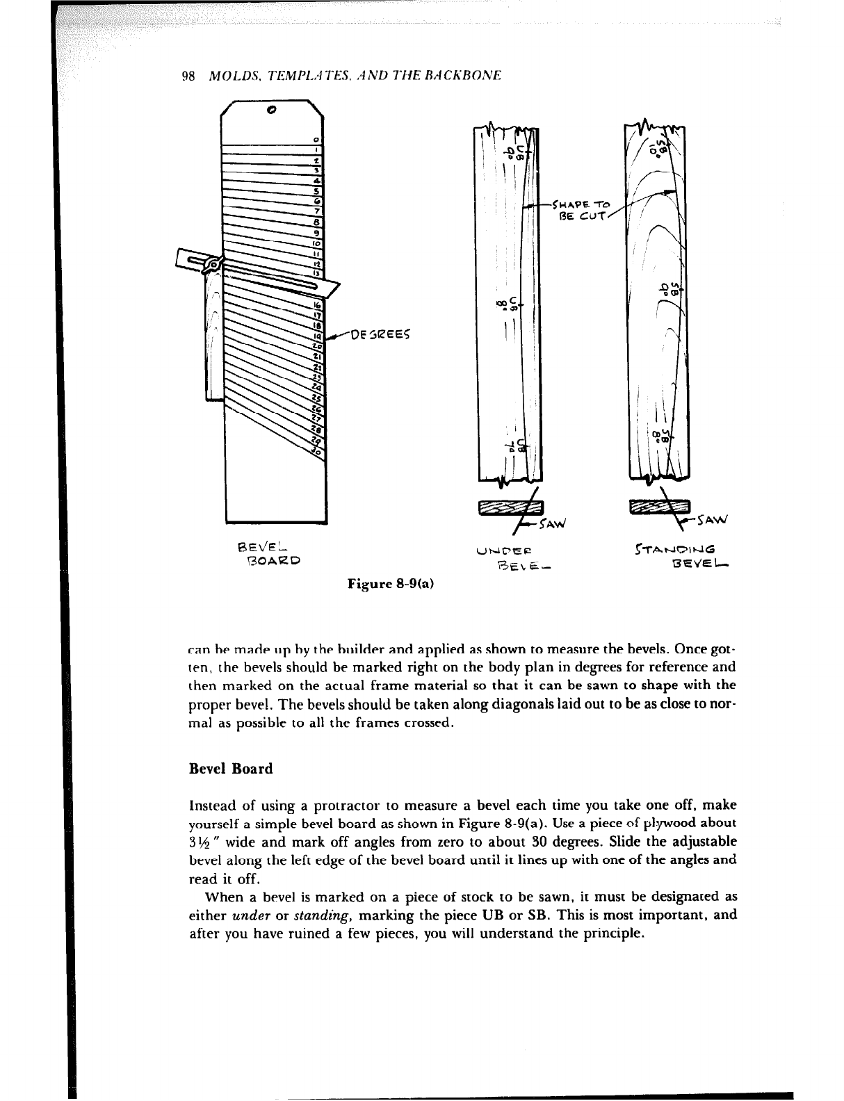
98 MOLDS. TEMP1.A TES. .4 ND T1i 'E BACKBOh'E
RE\JEL
BOAED
-DE
L
‘\I j
I
ef-
11
/
-2%
Figure 8-9(a)
can be made up by the builder and applied as shown to measure the bevels. Once got-
ten, the bevels should be marked right on the body plan in degrees for reference and
then marked on the actual frame material so that it can be sawn to shape with the
proper bevel. The bevels should be taken along diagonals laid out to be as close to nor-
mal as possible to all the frames crossed.
Bevel Board
Instead of using a protractor to measure a bevel each time you take one off, make
yourself a simple bevel board as shown in Figure 8-9(a). Use a piece of plyood about
3 I,$ rr wide and mark off angles from zero to about 30 degrees. Slide the adjustable
bevel along the left edge of the bevel board until it lines up with one of the angles and
read it off.
When a bevel is marked on a piece of stock t o be sawn, it must be designated as
either under or standing, marking the piece UB or SB. This is most important, and
after you have ruined a few pieces, you will understand the principle.
MOLDS, TEMP1.A TES. .4MD THE BACKBONE 99
Lofting by Computer
Fairing hull lines with the aid of a computer was mentioned in the previous chapter,
which dealt with enlarging to full size the designer’s scale drawing of the set of lines
defining the shape of the outside of the hull, whether it be wood, metal, fiberglass, or
otherwise. Earlier in this chapter it was explained that for round-bottomed hulls molds
are needed to make a male framework on which to shape the frames and that for
v-bottomed hulls frames are needed on which to build the boat. Here is where fairing
by computer pays off if your project justifies the expense. A computer-guided plotter
can draw full-size sections through the hull (spaced either equally or unequally) at any
1oc::tion desired, complete with deductions from the outside of the hull.
If lofting by computer is used, most of the lofting in the yard is avoided, but the
bevels for the edges of the molds or frames will not be available to you. Therefore, you
must order bevels from the computer people. Be certain that you understand how the
bevels given by the computer should be applied to the section drawings. An explana-
tion will be furnished, along with probably two or three times as many bevels as you
really need. There’s just no stopping that compurer. but better too many bevels than
too few!
The mold spacing for round-bottomed hulls and the frame spacing for v-bottomed
hulls is usually at uniform intervals. Sometimes the location of joiner bulkheads, those
partitions dividing the cabin accommodations, etc., arc not located in the same place
as molds or frames. If full-size bulkhead drawings are desired, these, too, can be sup-
plied by the computer service, and once again you should ask for the edge bevels.
Many of the larger boats are built of welded steel or aluminum alloy framing, with a
skin or shell plating of the same marerial. For this type of construction the computer
service can supply full-size drawings from which to cut the frames to shape from flat
material, so the drawings should be ordered with the deduction for the thickness of the
shell plating.
Transom and Transom Bevels
As will bc seen later, the station molds, the stem, and the transom are needed before
the boat can be set up. The molds and the stem have been explained and the develop-
ment of the transom shape has been illustrated. You also need the bevels on the tran-
som edges. Remember that the developed shape of the transom is to the outside of the
planking, and depending upon the type of construction, it may or may not represent
the actual size of the finished transom. The simplest method is to let the side planking
overlap the transom and to then cut it flush with the after side. In this case the plank
thickness is subtracted from the edges of the transom. The best practice, however, is to
make the transom to the outside of planking and rabbet the edge f-rr the planking.
Both methods are shown in Figure 8-10.
Figure 8-10A shows that the inside of the transom is larger thaii the outside, except
at the top edge where the shape depends upon the construction detnirr; because the
boat narrows from amidships to the transom. Consequently, like the frames of a
v-bottomed boat, the edges of the transom must be beveled to allow the planks to lie
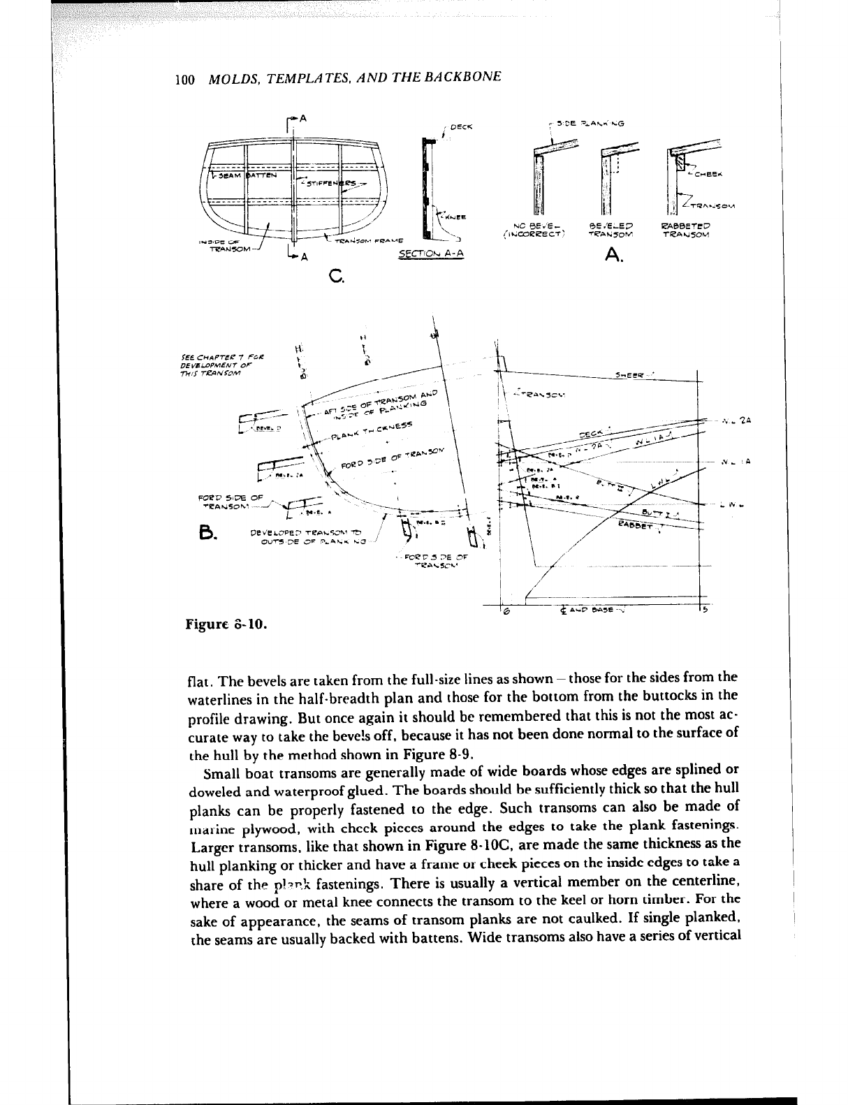
100 MOLDS, TEMPLATES, AND THE BACKBONE
/X-T-
NC BE .‘E - RE .‘ELE3 ETABBE?FD
(ILcoeeECT: -i%.ri70K fLAh.JSOM
A.
Figure i3- 10.
flat. The bevels are taken from the full-size lines as shown - those for the sides from the
waterlines in the half-breadth plan and those for the bottom from the buttocks in the
profile drawing. But once again it should be remembered that this is not the most ac-
curate way to take the beve!s off, because it has not been done normal to the surface of
the hull by the method shown in Figure 8-9.
Small boat transoms are generally made of wide boards whose edges are splined or
doweled and waterproof glued. The boards should be sufficiently thick so that the hull
planks can be properly fastened to the edge. Such transoms can also be made of
marine plywood, with cheek pieces around the edges to take the plank fastenings.
Larger transoms, like that shown in Figure 8-lOC, are made the same thickness as the
hull planking or thicker and have a frame or cheek pieces on the inside edges to take a
share of the p!‘~k fastenings. There is usually a vertical member on the centerline,
where a wood or metal knee connects the transom to the keel or horn timber. For the
sake of appearance, the seams of transom planks are not caulked. If single planked,
the seams are usually backed with battens. Wide transoms also have a series of vertical
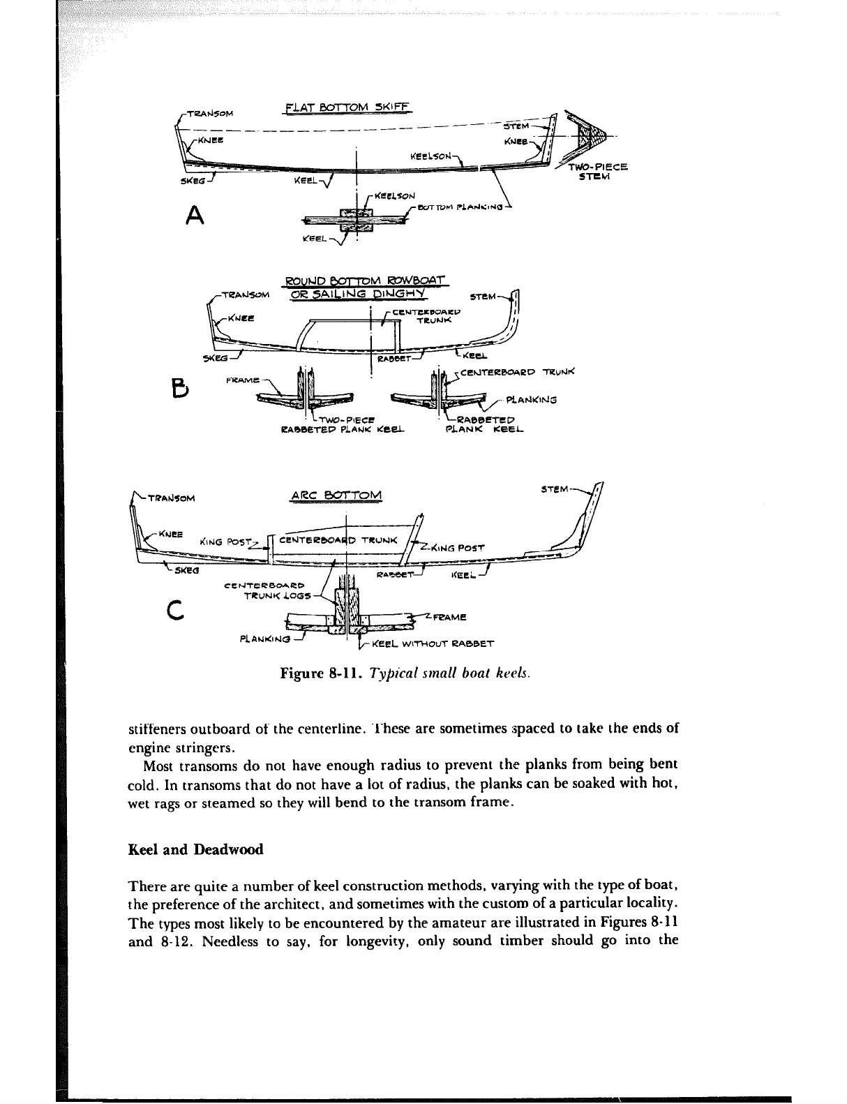
TeAd5OM FLAT B0l-K PM 5KlFF
L- I___ ________ ~_--
i rtiee~s~~ \
A EWTTOM PLAN<:lNG 1
FXluhJD &TTTOtvl !ZUK’BOA~
TeA&.OM
./- OR SAlLlhlC DlUGHb’ 5-rTtM
-4
TWO-PIECE
PARBETEP PLAIJlC tit& PLANK lCEEL
ARC BOTTOM SCM 8’
,
CErJTER0OAKb
Ti?UNK LOGS
N
UT RA00ET
Figure 8-l 1. Tyjical small boat keels.
stiffeners outboard of the centerline. These are sometimes spaced to take the ends of
engine stringers.
Most transoms do not have enough radius to prevent the planks from being bent
cold. In transoms that do not have a lot of radius, the planks can be soaked with hot,
wet rags or steamed so they will bend to the transom frame.
Keel and Deadwood
There are quite a number of keel construction methods, varying with the type of boat,
the preference of the architect, and sometimes with the custom of a particular locality.
The types most likely to be encountered by the amateur are illustrated in Figures 8-l 1
and 8-12. Needless to say. for longevity, only sound timber should go into the
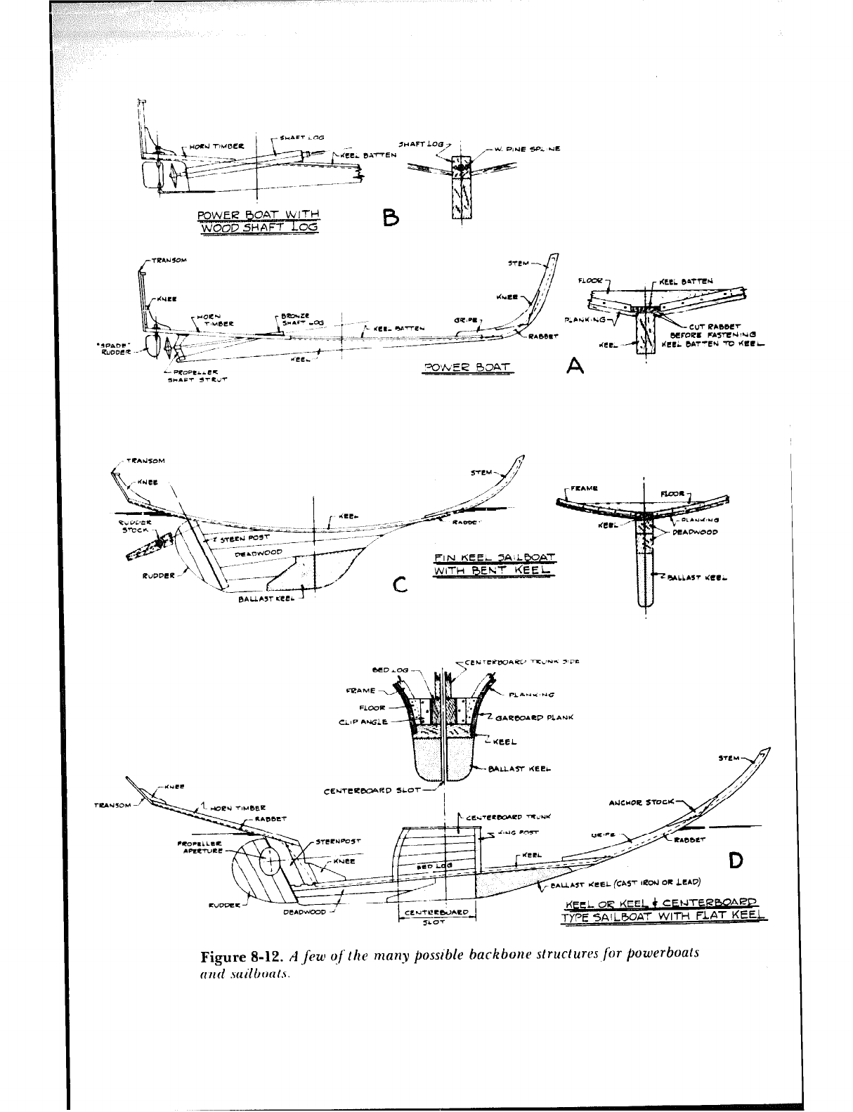
POWER BOAT WITH
LOG WOOD SHAFT
I
% dMCI
lk ~cI%cP r Bea”LL
L Fe*=- -ctf 4 . .-~ -.-_
*g;::; ..qj pig=,. -;-
?’
- 4OPC~~CLL
,)*AFT ,TCV
y*;-+ r- ~. - ~.&z~&LL,,
._-- $ .~~“~~.~~~~~_~~=lb~=f
_ +. -4 -_-_ --.-- -
- --------&, , wve.4 BOAT
l-
t
I(*lec
PL
“c.c- LAP
Lo --- \
~~~~~~~~~~~~~~~~~.~
‘\ t
-... ._... ~- -- ~
\-- ---A _. #-
.--k-’ __-L-.-y+-’ L
Eau.C,T <ccl.
Figure 8-12. A.few qflhc many possible backbone structures.for powerboats
ccnti .~ailboats.
MOLDS, TEMPLATES. AND THE BACKBONE 103
backbone members. White oak is the usual material for keel and other backbone
members, but other wood can be used as dictated by local practice.
The flat-bottomed skiff construction shown in Figure 8-11A is very common. When
building the boat upside down, the forms are notched for the keelson; then the bottom
is cross planked and the keel fitted on top of the planking. Sometimes twin keelsons are
used, one on each side instead of a single one on the centerline. Before fastening the
keel, cut a slot for the skeg on the centerline aft. Straight stems are frequently made up
of two pieces, as shown, to avoid rabbeting. The side planks are cut off flush with the
inner stem, and then the outer stem is fastened to the inner, with sealant between the
two.
The rabbeted keel in Figure 8- 11 B is typical construction for a great many boats. As
was done for the stem in Figure 8-5. the rabbet should be cut at each station from
templates and then cut away between the stations to make a continuous fair rabbet for
the planking. The amateur will find it easier to make the two-piece keel if he fastens
the pieces together over the molds after first beveling them to form the rabbet. There
should be thick white lead or other such composition between the pieces to exclude
water. All backbone joints are so treated.
A few of the one-design sailboats use a keel without a rabbet, like that shown in
Figure B-11C. This is all right, but because the garboard plank (the one next to the
keel on each side) is not fastened to the keel, care should be taken to attach the frames
strongly to the keel. If the frames butt at the centerline, the floor timbers connecting
thr frame halves must be well fastened to the frames and keel. In way of the ccnter-
board slot in the kzcl. thr bed logs should be thick to make for good fastening through
rhe keel.
Powerboat Keels
The keel structure shown in Figure 8-12A is typical of many modern powerboats. The
keel is usually the same thickness throughout and is cut to shape from a template made
from the full-size profile. A batten bent into place on top forms a back rabbet for the
planking. The rabbet is cut the same as for the little boat in Figure B-11B. The horn
timber aft is rabbctcd. A bronze shaft log with packing gland is installed for water-
tightness where the shaft leaves the hull. The bottom of the keel may be cut away or
continued aft and fittrd with a skeg to support the bottom of the rudder.
Although not scen as much as formerly, the wooden shaft log in Figure 8-12B is
worthy of mention. A two-piece log is shown in the section: this is easier for the
amateur to make than a log in a single piece, because the shaft hole in each half can be
worked out and grooves for splines can be cut on a small table saw or with a plow
plane. ‘l’he purpose of the splines is to swell and prevent leaks in the same manner that
stopwaters do, and they are made of softwood such as white pine. It is all right to cut
through the splines with bolts so long as the bolt holes are l.ight. The splines swell
against the bolts and function just as well as when not cut. The shaft hole in a one-
piece log is bored with an auger and may be troublesome for the inexperienced,
because a jig must be devised to align the hole. The chances are against finding a com-
mercially made auger of sufficient length. Therefore, have someone cut the shank and
add the needed length by welding in a piece of rod. It is very important that the shaft
104 MOLDS, TEMPLJTES, AND THE BACKBONE
hole be lined with a light copper tube or lead pipe to exclude water from the wood
around the hole. The ends of the tube are flanged under the bases of the stern bearing
and stuffing box.
Fin-Keel Sailboats
Fin-keel sailboats up to about 30 feet may have bent keels like that shown in Figure
8-12C. Indeed even larger boats have had this type of construction, with keels thick
enough to need steaming to bend the keel to shape. Probably the easiest way to build a
boat of this type is upside down, the keel being bent down over the molds and the fin
keel added after the hull is turned over.
Attention must be given to the sequence of the bolting in order to properly fasten
the fin. The ballast keel bolts usually extend from the casting through the deadwood,
keel, and floors, although sometimes they terminate between frames. The deadwood is
carefully shaped as called for by the lines, and although it requires hard work by hand,
a lot of effort should be put into the deadwood to make it smooth and fair, not only for
the sake of appearance but also to offer a minimum of resistance as the boat moves
through the water. The aft edge of the sternpost is gouged out to take the rudder stock
and the rounded forward edge of the rudder. While the forward edge of the rudder
can be painted by alternately swinging it hard over to each side, it is impossible to
paint the concave edge of the sternpost. To prevent accumulation of marine growth,
the after side of the sternpost is sheathed with light copper sheet brought around on
the sides just enough for it to be fastened with tacks.
Large Sailboat Keels
The backbone in Figure 8-12D is typical of most keel sailboats or combination keel
and centerboard sailboats upwards of 20 feet on the waterline. The keel in such boats
is a thick plank of the same thickness from end to end, but varying in width
throughout the length. It is rabbeted for the planking as shown in the section. The ver-
tical position of the keel in the hull structure is drawn in on the full-size profile; then
the heights of the keel at the stations it crosses are transferred to the corresponding sec-
tions in the body plan to obtain the half-widths of the keel at the stations. A centerline
is drawn on the piece of lumber to be used for the keel, the station spacing is picked up
and laid off from the full-size profile (the station spacing along the keel is greater than
the spacing along the baseline because the keel is at an angle with the base), and the
half-breadths of the top of the keel are picked up from the sections and laid off on the
keel stock. Draw the outline of the keel with a batten. After the keel is sawn to the
shape of the top edge, draw a centerline on the underside of the keel, making sure it
aligns with the one on top, and similarly lay off the half-breadths of the keel bottom.
The outline of the bottom will give the constantly changing bevel to which to cut the
sides of the keel. The rabbet at each section is then ternplated as a guide for cutting, as
mentioned before.
MOLDS, TEMPLATES, AND THE BACKBONE 105
Gripe and Horn Timber
The gripe is the piece that connects the keel to the stem, a;rd the horn timber connects
the keel or sternpost to the transom in some types of power and sailboats. Both the
gripe and horn timber are very similar to a stem. The rabbet for the comparatively
horizontal horn timber is taken from the sections in the body plan. Knees are used to
fasten the various backbone members to each other. Much of the backbone construc-
tion work is made clear by construction sections on the architect’s plans.
Backbone Bolting
After all the backbone members are shaped, but prior to fastening them together, it is
recommended that they be given two coats of a wood preservative. These preparations
are inexpensive and well worth the investment for their rot preventive qualities. The li-
quid should also be poured down the bolt holes before the fastenings are driven.
Through-bolts and drift bolts, described at length in Chapter 6, are made and fitted
as shown on the construction plan for the boat, and the fastenings must be studied for
sequence so the assembly will go together properly. It will be seen as you go along that
some of the bolts cannot be driven at this time because they pass through floor timbers
(Figures 8-12A, C) that are not made and fitted in the structure until later. All parts
being bolted together must have thick white lead or other composition in the joints so
that no crevices are left for water to seep through or to collect in and possibly start to
rot the timbers. Under the washers of through and drift bolts it is advisable to wind a
few turns of cotton wicking soaked in paint before the bolts are finally driven home.
Very often this treatment will prevent leaks that otherwise would be troublesome or at
least annoying. Wicking is stringy cotton available in balls at marine suppliers and
does not resemble the familiar woven lamp wicking. The stopwaters mentioned earlier
are fitted after the parts have been bolted.
Scarphs
It is not always possible to obtain pieces of wood long enough for the keel, deadwood,
bilge stringers, clamps, and shelves. Fortunately, sufficient lengths may be found for
keels more often than for the’other parts, even though an extensive search is required.
The backbone requires enough work of the builder without his having to splice the
keel, particularly the type shown in Figure 8-12D. When it cannot be avoided, the
long members are pieced out by means of through-bolted joints called scarphs.
Nowaday:< these joints in wood are often waterproof-glued for good measure. If not
glued, the joint should be made up with the usual thick white lead or heavy paint.
Bolts are staggered when thickness of lumber permits.
Figure 8-13 illustrates three types of scarphs commonly in use, and it should be
noted that all have nibs to prevent one part from slipping by the other when under
strain. The joint shown in A is the very common plain scarph that is extensively used
for stringers and clamps. The hooked scarph. B, is sometimes employed in backbone
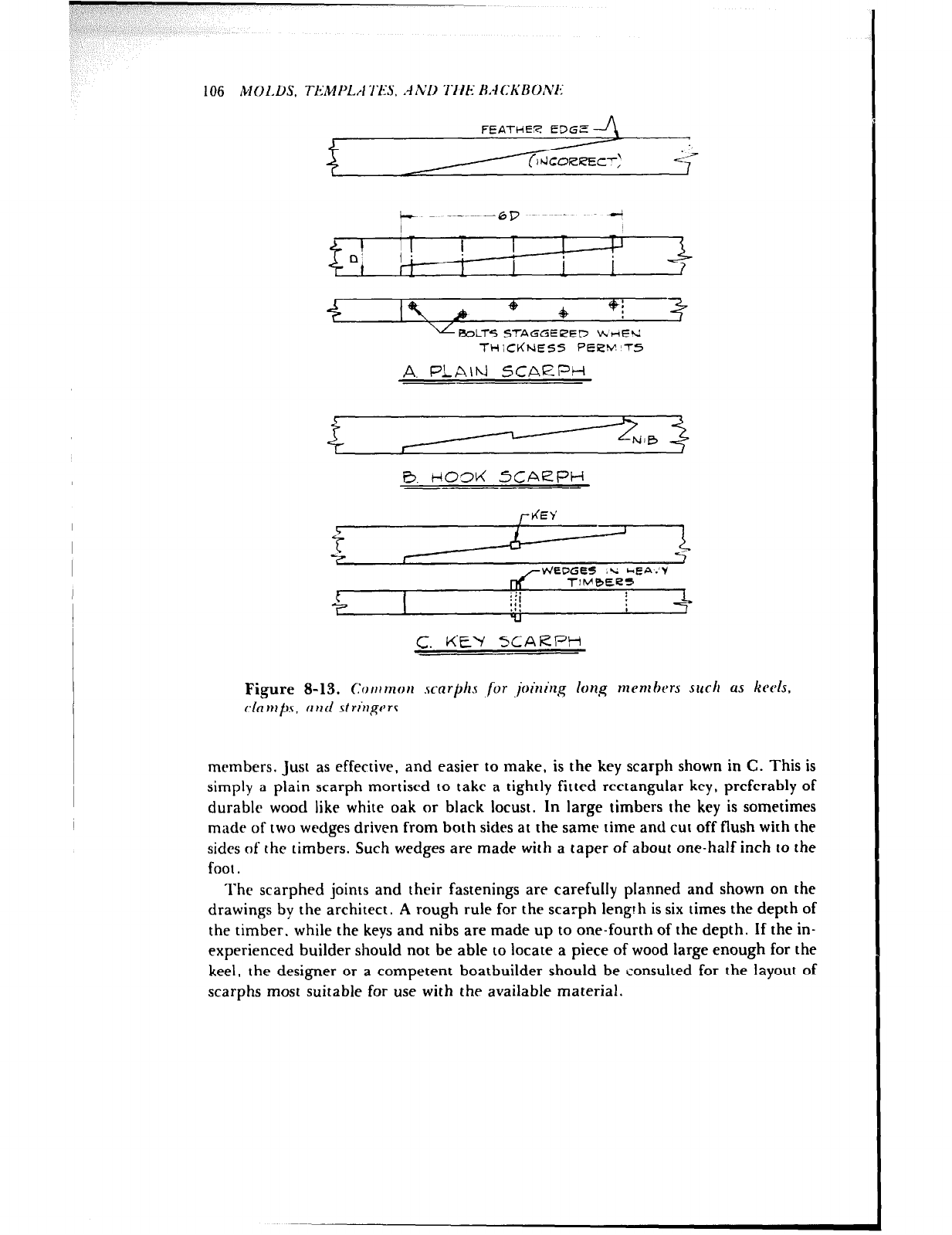
106 /iI (ILDS, TEM PLrl TES. ‘4 ND ‘I-II/i HACKLWNl:
FEATHER EDGE
v ROLTS STAGGEPED KnE’d
TH ICtiNE5S PEiZM’T5
A. PLA\h) SCARPH
B. H03ti SCARPH -
c. KEY SCARPH
Figure 8-13. ~~OUIUIOII scarphs JOT ,jtu’Gu,y lorlg rnCnl hers suck us ktds,
r.lnnlj!~s, clrld striuprs.
members. Just as effective, and easier to make, is the key scarph shown in C. This is
simply a plain scarph mortised to take a tightly fitted rectangular key, preferably of
durable wood like white oak or black locust. In large timbers the key is sometimes
made of two wedges driven from both sides at the same time and cut off flush with the
sides of the timbers. Such wedges are made with a taper of about one-half inch to the
foot.
The scarphed joints and their fastenings are carefully planned and shown on the
drawings by the architect. A rough rule for the scarph length is six times the depth of
the timber, while the keys and nibs are made up to one-fourth of the depth. If the in-
experienced builder should not be able to locate a piece of wood large enough for the
keel, the designer or a competent boatbuilder should be consulted for the layout of
scarphs most suitable for use with the available material.

M 01.13.s. TE.21 PI..*1 TES, A ND 1.1 IE
Tenons
The mortise-and-tenon joint is sometimes called upon to lock adjoining members hav-
ing grain perpendicular to each other. The joints between the vertical sternposts and
the keel in Figure S-12D are typical. When the wood is not too thin, the tenon is made
blind, that is, only part way across the pieces, and therefore it is not visible when the
parts are fitted together. Whatever the case. the joint must be made as snug as possible
and put together with white lead on the mating parts.
R.~lI:KHo:v’E 107
Chapter 9
SETTING UP
With the backbone and molds made, the builder is ready to set up the boat
preparatory to framing the hull. Just as much care and accuracy should go into the
work of setting up as went into the mold loft work and construction of the backbone.
Continued attrntion to detail at this stage of the game will pay dividends in time saved
later. The method of setting up depends upon the size, type. and construction of the
hull, but in general, most small craft are best built upside down, a method that has
much merit.
Upside Down or Right Side Up?
Although the majority of boats, excluding small stock boats produced on a mass basis,
are constructrd right side up, it would be impractical to copy this routine in building a
boat like a flat.bottomcd skiff when it is so easy to fasten the bottom planks with the
hull inverted. By the same reasoning, flat-sectioned boats like v- and arc-bottomed
hulls are also set up and built upside down. The same is true of small lapstrake boats
that are planked over molds. In this case, the fitting of the lapped plank scams is very
much simplified with the hull upside down. Smail. strip-planked hulls, on which the
planking is started at the keel and worked toward the sheer, are best built right side
up, because it is much easier to nail downhand. and if it has been decided to bend the
frames of a round-bottomed boat on the inside of the ribbands as mentioned under
Molds in Chapter 8, the boat should be built right side up in order to readily bend the
frames. Any other method would be impractical. In other instances the finished hull
will be too heavy or bulky for the amateur to turn over and should therefore be built
upright.
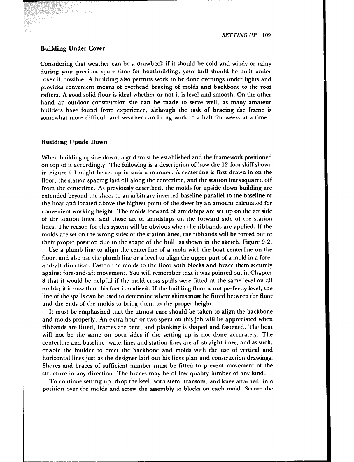
SETTING LIP 109
Building Under Cover
Considering that weather can be a drawback if it should be cold and windy or rainy
during your precious spare time for boatbuilding, your hull should be built under
cover if possible. A building also permits work to be done evenings under lights and
provides convenient means of overhead bracing of molds and backbone to the roof
rafters. A good solid floor is ideal whether or not it is level and smooth. On the other
hand an. outdoor construction site can be made to serve well, as many amateur
builders have found from experience, although the task of bracing the frame is
somewhat more difficult and weather can bring work to a halt for weeks at a time.
Building Upside Down
When building upside down, a grid must be established and the framework positioned
on top of it accordingly. The following is a description of how the 12.foot skiff shown
in Figure 9-1 might be set up in such a manner. A centerline is first drawn in on the
floor, the station spacing laid off along the centerline. and the station lines squared off
from the centerline. As previously described, the molds for upside down building are
extended beyond the sheer to ~II a~ bitrary inverted baseline parailel to the baseline of
the boat and located above the highest point of the sheer by an amount calculated for
convenient working height. The molds forward of amidships are set up on the aft side
of the station lines, and those aft of amidships on the forward side of the station
lines. The reason for this system will be obvious when the ribbands are applied. If the
molds are set on the wrong sides of the station lines, the ribbands will be forced out of
their proper position due to the shape of the hull, as shown in the sketch, Figure 9-2.
Use a plumb line to align the centerline of a mold with the boat centerline on the
floor, and also ‘rse the plumb line or a level to align the upper part of a mold in a fore-
and-aft direction. Fasten the molds to the floor with blocks and brace them securely
against fore-and-aft movement. You will remember that it was pointed out in Chapter
8 that it would be helpful if the mold cross spalls were fitted at the same level on all
molds: it is now that this fact is realized. If the building floor is not perfectly level, the
line of the spalls can be used to determine where shims must be fitted between the floor
and the ends of the molds to bring them to the proper height.
It must be emphasized that the utmost care should be taken to align the backbone
and molds properly. An extra hour or two spent on this job will be appreciated when
ribbands are fitted, frames are bent, and planking is shaped and fastened. The boat
will not be the same on both sides if the setting up is not done accurately. The
centerline and baseline, waterlines and station lines are all straight lines, and as such,
enable the builder to erect the backbone and molds with the use of vertical and
horizontal lines just as the designer laid out his lines plan and construction drawings.
Shores and braces of sufficient number must be fitted to prevent movement of the
structure in any direction. The braces may be of low-quality lumber of any kind.
To continue setting up, drop the keel, with stem, transom, and knee attached, into
position over the molds and screw the assembly to blocks on each mold. Secure the
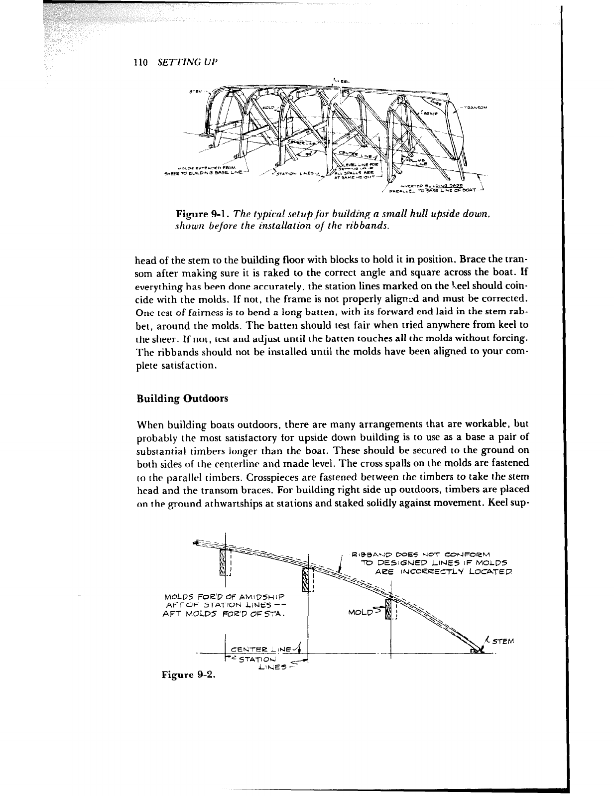
-7 .III
I
110 SETTING UP
Figure 9-1. The typical setup,for building a small hull upside down,
shown before the installation q/the ribbands.
head of the stem to the building floor with blocks to hold it in position. Brace the tran-
som after making sure it is raked to the correct angle and square across the boat. If
everything has been done accurately, the station lines marked on the ‘n.eel should coin-
cide with the molds. If not, the frame is not properly alignzd and must be corrected.
One test of fairness is to bend a long batten, with its forward end laid in the stem rab-
bet, around the molds. The batten should test fair when tried anywhere from keel to
the sheer. If not, test and adjust until the batten touches all the molds without forcing.
The ribbands should not be installed until the molds have been aligned to your com-
plete satisfaction.
Building Outdoors
When building boats outdoors, there are many arrangements that are workable, but
probably the most satisfactory for upside down building is to use as a base a pair of
substantial timbers longer than the boat. These should be secured to the ground on
both sides of the centerline and made level. The cross spalls on the molds are fastened
to the parallr1 timbers. Crosspieces are fastened between the timbers to take the stem
head and the transom braces. For building right side up outdoors, timbers are placed
on the ground athwartships at stations and staked solidly against movement. Keel sup-
::F!?Ei- M~LW~ej LyM
7
LINE5 -
Figure 9-2.
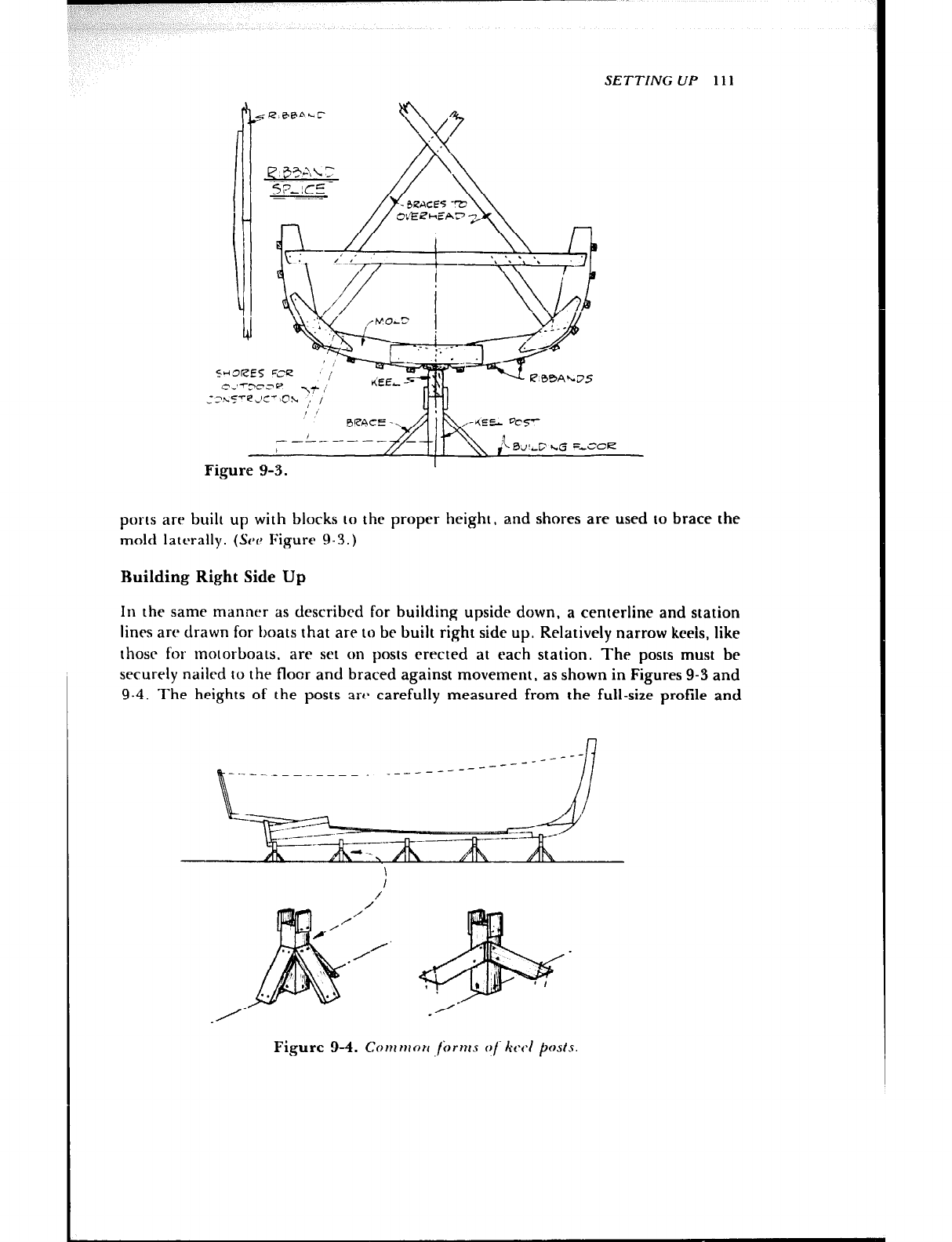
SETTING UP 111
<.;“, F
2
em
c,‘-Trce \yb / &EL 5
:‘h5’4JC’~Oh ;, ,
1
Figure 9-3.
ports are built up with blocks to the proper height, and shores are used to brace the
mold laterally. (SW Figure 9-3.)
Building Right Side Up
In the same manner as described for building upside down, a centerline and station
lines are drawn for boats that are to be built right side up. Relatively narrow keels, like
those for motorboats, are set on posts erected at each station. The posts must bc
securely nailed IO the floor and braced against movement, as shown in Figures 9-3 and
9-4. The heights of the posts arc- carefully measured from the full-size profile and
Figure 9-4. Cow WO?I jbrms of ktd posls
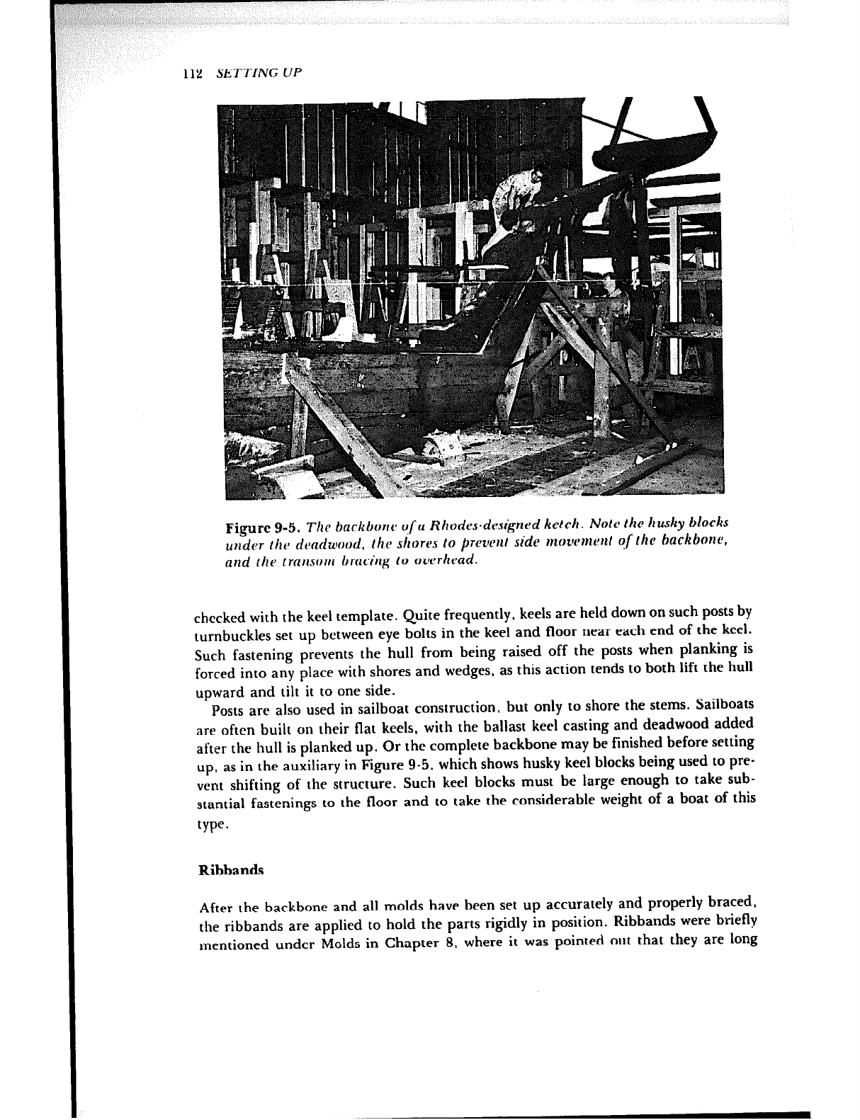
112 SETTING UP
Figure g-5. The backbone q/a Rhodcs.designed ketch. Note the husky blocks
under the deadwood, the shores to prevent side movement of the backbone,
and the transonl bracing to overhead.
checked with the keel template. Quite frequently, keels are held down on such posts by
turnbuckles set up between eye bolts in the keel and floor near each end of the keel.
Such fastening prevents the hull from being raised off the posts when planking is
forced into any place with shores and wedges, as this action tends to both lift the hull
upward and tilt it to one side.
Posts are also used in sailboat construction, but only to shore the stems. Sailboats
are often built on their flat keels, with the ballast keel casting and deadwood added
after the hull is planked up. Or the complete backbone may be finished before setting
up, as in the auxiliary in Figure 9-5, which shows husky keel blocks being used to pre-
vent shifting of the structure. Such keel blocks must be large enough to take sub-
stantial fastenings to the floor and to take the considerable weight of a boat of this
type.
Ribbands
After the backbone and all molds have been set up accurately and properly braced,
the ribbands are applied to hold the parts rigidly in position. Ribbands were briefly
mentioned under Molds in Chapter 8, where it was pointed out that they are long
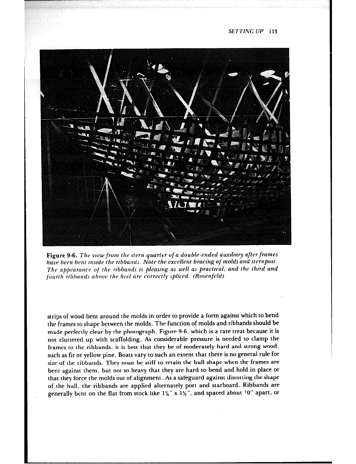
3, ,?,
/ ,~
iP
SE?‘I‘ING UP 113
Figure 9-6. The tv’cur,from the stern qu.arter qf a double-ended auxiliary after.frantes
have been bent inside the ribbarldb. Note the excellent bracing qf molds and sternpost.
The a~~~emnre of the ribbauds i.r pleasing as well as practical. aud the third and
fourth ri0tmnd.v nbozw the keel are correctly spliced. (Rosenfeld)
strips of wood bent around the molds in order to provide a form against which to bend
the frames to shape between the molds. The function of molds and ribbands should be
made perfectly clear by the photograph, Figure 9-6. which is a rare treat because it is
not cluttered up with scaffolding. As considerable pressure is needed to clamp the
frames to the ribbands, it is best that they be of moderately hard and strong wood,
such as fir or yellow pine. Boats vary to such an extent that there is no general rule for
size of the ribbands. They must be stiff to retain the hull shape when the frames are
bent against them, but not so heavy that they are hard to bend and hold in place or
that they force the molds out of alignment. As a safeguard against distorting the shape
of the hull, the ribbands are applied alternately port and starboard. Ribbands are
generally bent on the flat from stock like 1% n x 1% “, and spaced about 10 rr apart, or
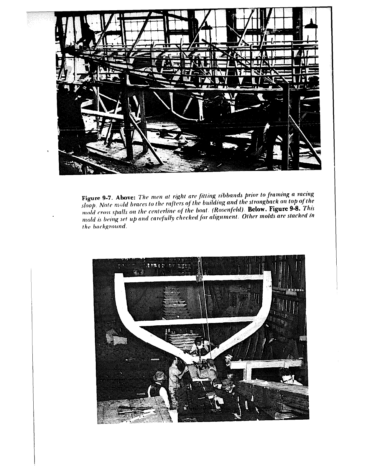
Figure 9-7. Above: ?‘irv mm ut right arc’ fitting riblmndJ prior tojiwmirl.g (1 raciq
.sloop, Note n;i>ld brarcjs to thcJ mftcsrs ofthc buildi?zg nlld the strongbd O?I IO/I of Ihc
nlold cross s/~uIls on t bra cent c~rliw q
f‘ the hr. (Roscw/dd). Below. Figure 9-8. Thh
nlold i.s /wing sat up cind rclwfilllv chrckcd ,fk itlig” nl(‘rlt. 0th molds aw stackrd h
thr backgrou~ld.
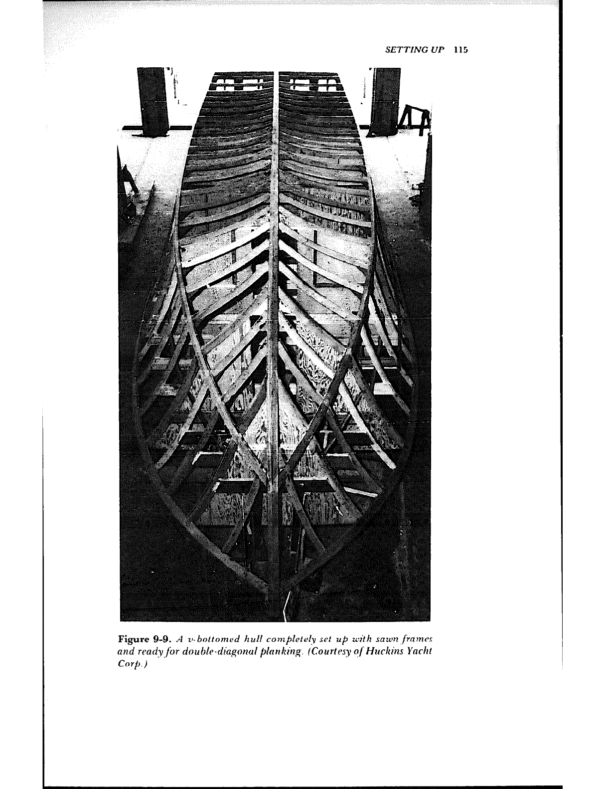
SETTING lj
,,Jw”,~“< ‘/, II II I
Figure 9-9. A v-bottomed hull completeiy set up with snwn~fram~
and ready for double-dia~gonul planking. (Courtesy of Hz&ins Yacht
Corp.) -
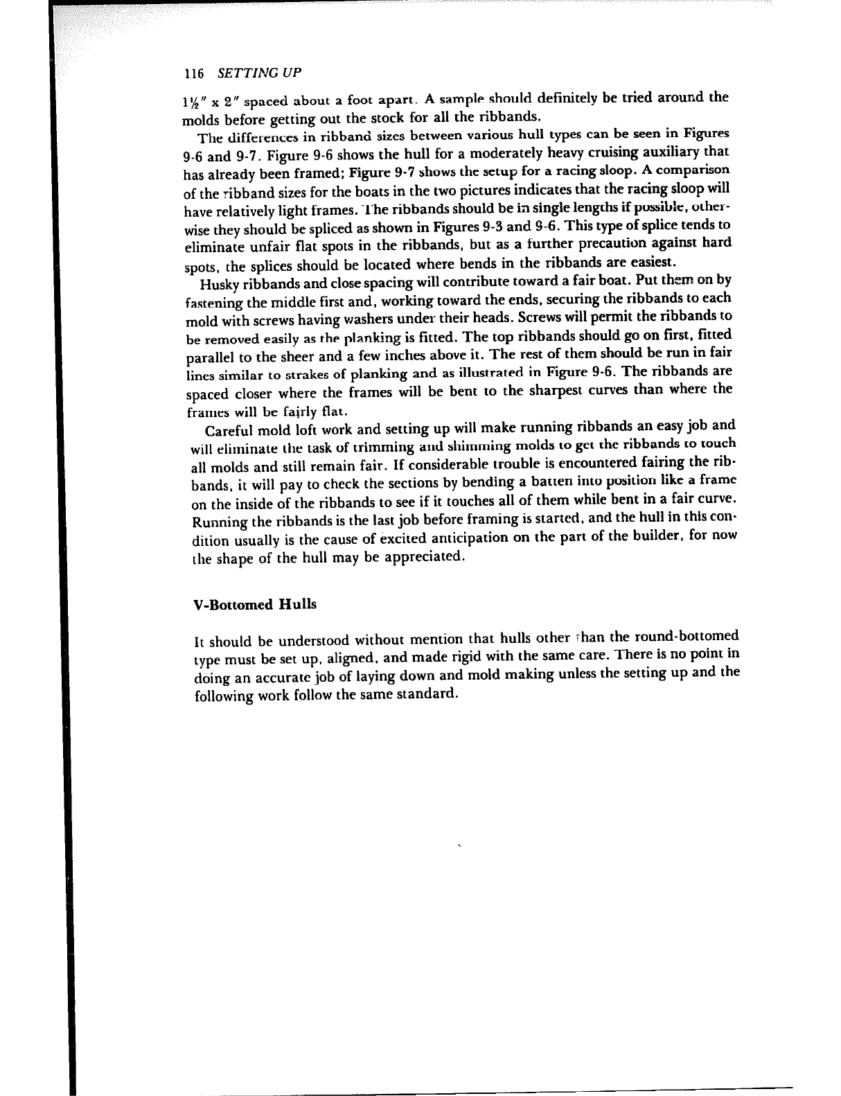
116 SETTING UP
1%” x 2” spaced about a foot apart. A sample should definitely be tried around the
molds before getting out the stock for all the ribbands.
The differences in ribband sizes between various hull types can be seen in Figures
9-6 and 9-7. Figure 9-6 shows the hull for a moderately heavy cruising auxiliary that
has already been framed; Figure 9-7 shows the setup for a racing sloop. A comparison
of the ribband sizes for the boats in the two pictures indicates that the racing sloop will
have relatively light frames. The ribbands should be in single lengths if possible, other-
wise they should be spliced as shown in Figures 9-3 and 9-6. This type of splice tends to
eliminate unfair flat spots in the ribbands, but as a further precaution against hard
spots, the splices should be located where bends in the ribbands are easiest.
Husky ribbands and close spacing will contribute toward a fair boat. Put them on by
fastening the middle first and, working toward the ends, securing the ribbands to each
mold with screws having washers under their heads. Screws will permit the ribbands to
be removed easily as the planking is fitted. The top ribbands should go on first. fitted
parallel to the sheer and a few inches above it. The rest of them should be run in fair
lines similar to strakes of planking and as illustrated in Figure 9-6. The ribbands are
spaced closer where the frames will be bent to the sharpest curves than where the
frames will be fairly flat.
Careful mold loft work and setting up will make running ribbands an easy job and
will eliminate the task of trimming and shimming molds to get the ribbands co touch
all molds and still remain fair. If considerable trouble is encountered fairing the rib-
bands, it will pay to check the sections by bending a batten into position like a frame
on the inside of the ribbands to see if it touches all of them while bent in a fair curve.
Running the ribbands is the last job before framing is started, and the hull in this con-
dition usually is the cause of excited anticipation on the part of the builder, for now
the shape of the hull may be appreciated.
V-Bottomed Hulls
It should be understood without mention that hulls other Than the round-bottomed
type must be set up, aligned, and made rigid with the same care. There is no point in
doing an accurate job of laying down and mold making unless the setting up and the
following work follow the same standard.
Chapter 10
FRAMING
There are two basic systems for framing a hull, transverse and longitudinal.
Transverse framing is the most common and being oriented athwartships. such frames
have become known as “ribs.” Transverse frames for round-bottomed wooden hulls
are either bent from one piece, as in Figures l-4 and l-5, laminated from two or more
pieces bent on top of each other, sawn from natural crooks of wood, or “double sawn”
from boards and made up of two layers with staggered joints. Small to moderate hulls
usually have the bent frames, although in places where material for bent frames is
non-existent, such as islands in the Bahamas, the frames are sawn from crooks or dou-
ble sawn according to both the size of the boat and the supply of crooks. (See Figure
10-l.) Sawn frames for v-bottomed and arc-bottomed hulls are shown in Figures l-3
and l-4. Some designers and builders use a combination of sawn and bent frames for
their v-bottomed hulls.
For the longitudinal framing system in general, transverse frames are used to shape
the hull, but are spaced farther apart than in the transverse system. Fore-and-aft
longitudinals are used to build up the necessary framing strength. This system can get
quite complicated for construction in wood, but is well suited for metal boats of welded
construction.
In this book discussion is limited to the two types of framing suitable for the size of
craft likely to be built by the amateur- bent frames and sawn v-bottom frames. Before
undertaking a craft with other kinds of more complex framing, the builder should be
certain before starting that he is aware of what is involved.
V-Bottom Frames
The lofting and construction of frames for a v-bottomed boat should be understood if
you refer to Figures l-3 and l-4 and the explanation in Chapter 8. The frames are
117
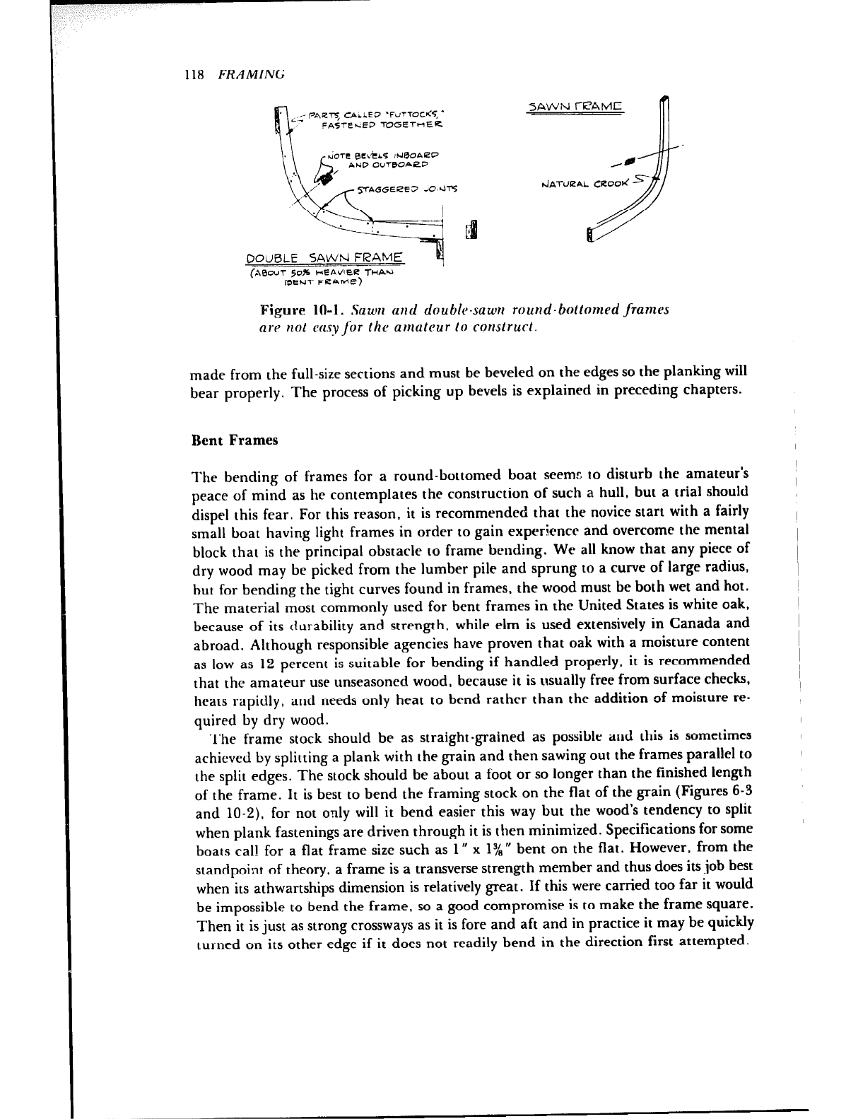
118 FRAMING
SAWN FPAME
--
(A&XT 50% CEAdlEbZ THAti
REtiT Fb?AME)
Figure 10-l. Sawn and double-sawer round-bottomed frames
are not easy fir the amateur lo construct.
.
made from the full-size sections and must be beveled on the edges so the planking will
bear properly. The process of picking up bevels is explained in preceding chapters.
Bent Frames
The bending of frames for a round-bottomed boat seems to disturb the amateur’s
peace of mind as he contemplates the construction of such a hull, but a trial should
dispel this fear. For this reason, it is recommended that the novice start with a fairly
small boat having light frames in order to gain experience and overcome the mental
block that is the principal obstacle to frame bending. We all know that any piece of
dry wood may be picked from the lumber pile and sprung to a curve of large radius,
but for bending the tight curves found in frames, the wood must be both wet and hot.
The material most commonly used for bent frames in the United States is white oak,
because of its durability and strength, while elm is used extensively in Canada and
abroad. Although responsible agencies have proven that oak with a moisture content
as low as 12 percent is suitable for bending if handled properly, it is recommended
that the amateur use unseasoned wood, because it is usually free from surface checks,
heats rapidly, and needs only heat to bend rather than the addition of moisture re-
quired by dry wood.
The frame stock should be as straight-grained as possible and this is sometimes
achieved by splitting a plank with the grain and then sawing out the frames parallel to
the split edges. The stock should be about a foot or so longer than the finished length
of the frame. It is best to bend the framing stock on the flat of the grain (Figures 6-3
and lo-2), for not only will it bend easier this way but the wood’s tendency to split
when plank fastenings are driven through it is then minimized. Speciftcations for some
boats call for a flat frame size such as 1 R x 1% rr bent on the flat. However, from the
standpoint of theory, a frame is a transverse strength member and thus does its job best
when its athwartships dimension is relatively great. If this were carried too far it would
be impossible to bend the frame, so a good compromise is to make the frame square.
Then it is just as strong crossways as it is fore and aft and in practice it may be quickly
turned on its other edge if it does not readily bend in the direction first attempted.
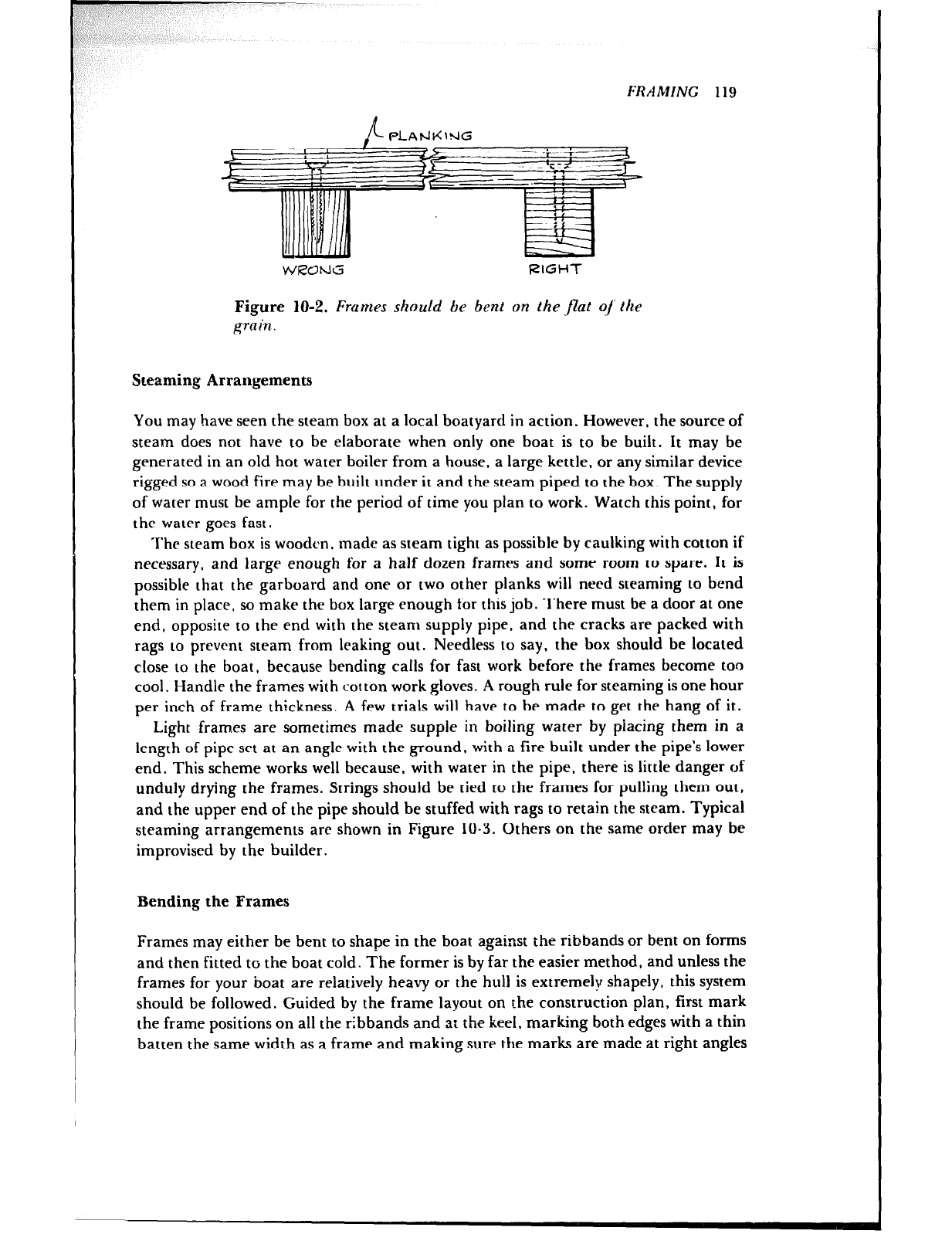
/ , 4) _
I‘
I
FRAMING 119
WRONG RIGHT
Figure 10-2. Frames should be bent on the J2at o/ the
grain.
Steaming Arrangements
You may have seen the steam box at a local boatyard in action. However, the source of
steam does not have to be elaborate when only one boat is to be built. It may be
generated in an old hot water boiler from a house, a large kettle, or any similar device
rigged so a wood fire may be built under it and the steam piped to the box. The supply
of water must be ample for the period of time you plan to work. Watch this point, for
the water goes fast.
The steam box is wooden. made as steam tight as possible by caulking with cotton if
necessary, and large enough for a half dozen frames and some room to spare. It is
possible that the garboard and one or two other planks will need steaming to bend
them in place, so make the box large enough for this job. There must be a door at one
end, opposite to the end with the steam supply pipe, and the cracks are packed with
rags to prevent steam from leaking out. Needless to say, the box should be located
close to the boat, because bending calls for fast work before the frames become too
cool. Handle the frames with cot ton work gloves. A rough rule for steaming is one hour
per inch of frame thickness. A few trials will have to be made to get the hang of it.
Light frames are sometimes made supple in boiling water by placing them in a
length of pipe set at an angle with the ground, with a fire built under the pipe’s lower
end. This scheme works well because, with water in the pipe, there is little danger of
unduly drying the frames. Strings should be tied to the frames for pulling them out,
and the upper end of the pipe should be stuffed with rags to retain the steam. Typical
steaming arrangements are shown in Figure 10-3. Others on the same order may be
improvised by the builder.
Bending the Frames
Frames may either be bent to shape in the boat agains: the ribbands or bent on forms
and then fitted to the boat cold. The former is by far the easier method, and unless the
frames for your boat are relatively heavy or the hull is extremely shapely, this system
should be followed. Guided by the frame layout on the construction plan, first mark
the frame positions on all the ribbands and at the keel, marking both edges with a thin
batten the same width as a frame and making sure the marks are made at right angles
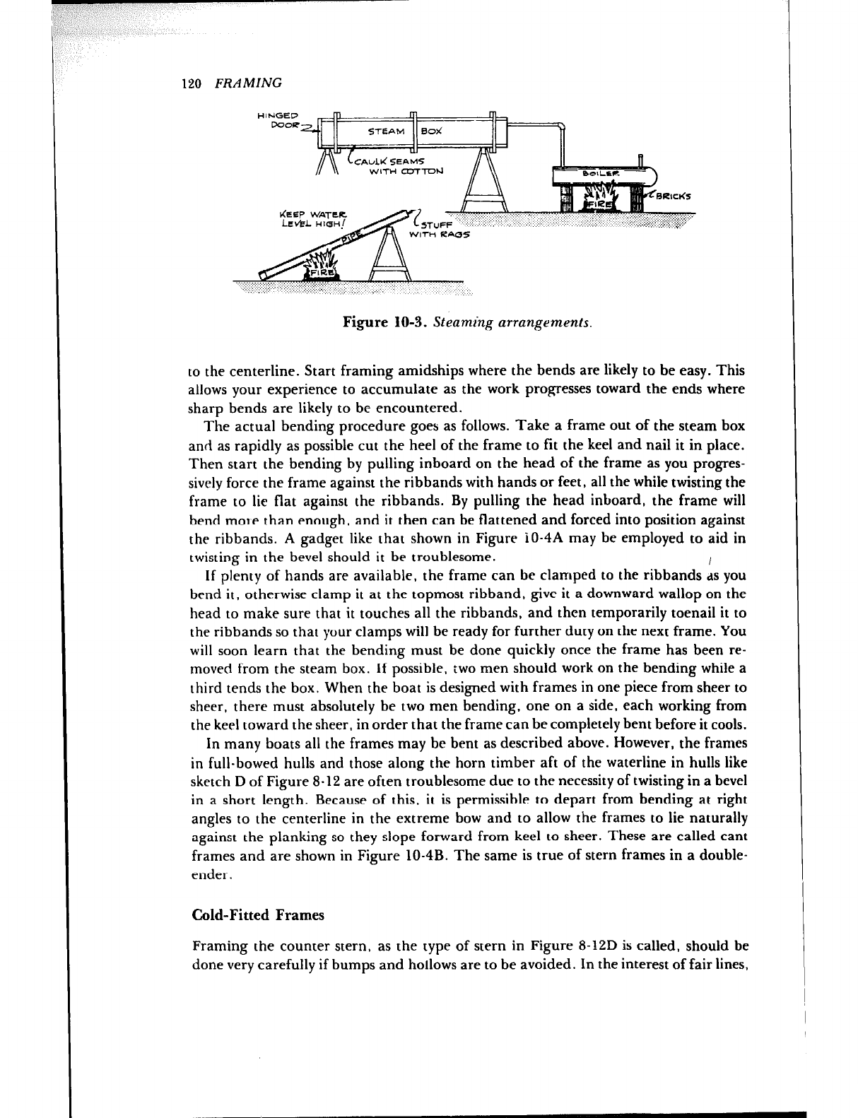
120 FRAMING
KEEP WATER .j ,: ‘,., : . . . .. . ,: -. .,..
Figure 10-3. Steaming arrangements.
to the centerline. Start framing amidships where the bends are likely to be easy. This
allows your experience to accumulate as the work progresses toward the ends where
sharp bends are likely to be encountered.
The actual bending procedure goes as follows. Take a frame out of the steam box
and as rapidly as possible cut the heel of the frame to fit the keel and nail it in place.
Then start the bending by pulling inboard on the head of the frame as you progres-
sively force the frame against the ribbands with hands or feet, all the while twisting the
frame to lie flat against the ribbands. By pulling the head inboard, the frame will
bend more than enough, and it then can be flattened and forced into position against
the ribbands. A gadget like that shown in Figure iO-4A may be employed to aid in
twisting in the bevel should it be troublesome.
If plenty of hands are available, the frame can be clamped to the ribbands 1s you
bend it, otherwise clamp it at the topmost ribband, give it a downward wallop on the
head to make sure that it touches all the ribbands, and then temporarily toenail it to
the ribbands so that your clamps will be ready for further duty on the next frame. You
will soon learn that the bending must be done quickly once the frame has been re-
moved from the steam box. If possible, two men should work on the bending while a
third tends the box. When the boat is designed with frames in one piece from sheer to
sheer, there must absolutely be two men bending, one on a side, each working from
the keel toward the sheer, in order that the frame can be completely bent before it cools.
In many boats all the frames may be bent as described above. However, the frames
in full-bowed hulls and those along the horn timber aft of the waterline in hulls like
sketch D of Figure S-12 are often troublesome due to the necessity of twisting in a bevel
in a short length. Because of this, it is permissible to depart from bending at right
angles to the centerline in the extreme bow and to allow the frames to lie naturally
against the planking so they slope forward from keel to sheer. These are called cant
frames and are shown in Figure lo-4B. The same is true of stern frames in a double-
ender .
Cold-Fitted Frames
Framing the counter stern, as the type of stern in Figure 8-12D is called, should be
done very carefully if bumps and hollows are to be avoided. In the interest of fair lines,
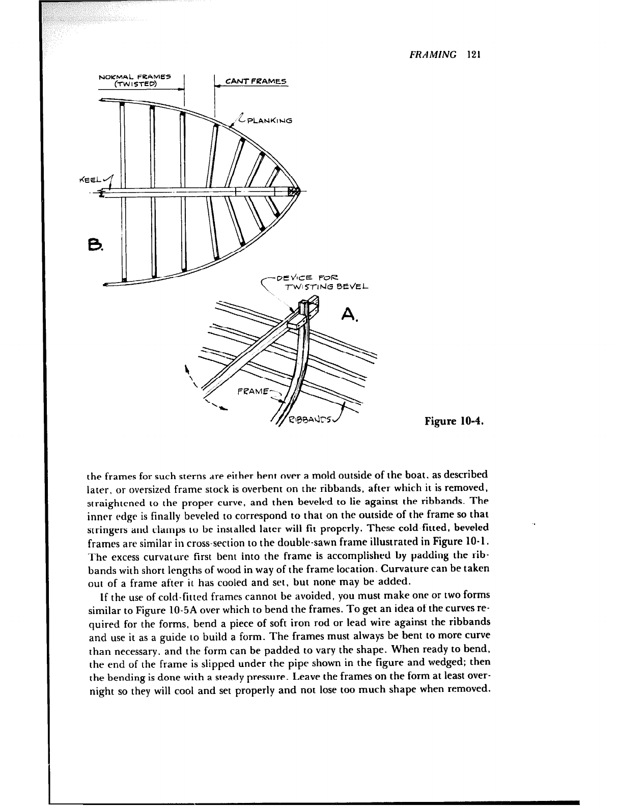
v /- CANT FfZAMES
FRAMING 121
c TWhSTlhki BE\/EL
Figure 10-4.
the frames for such sterns dre either bent over a mold outside of the boat, as described
later, or oversized frame stock is overbent on the ribbands. after which it is removed,
straightened to the proper curve, and then beveled to lie against the ribbands. The
inner edge is finally beveled to correspond to that on the outside of the frame so that
stringers and clamps to be installed later will fit properly. These cold-fitted, beveled
frames are similar in cross-section to the double-sawn frame illustrated in Figure 10-l.
The excess curvature first bent into the frame is accomplished by padding the rib-
bands with short lengths of wood in way of the frame location. Curvature can be taken
out of a frame after it has cooled and set, but none may be added.
If the use of cold-fitted frames cannot be avoided, you must make one or two forms
similar to Figure lo-5A over which to bend the frames. To get an idea of the curves re-
quired for the forms, bend a piece of soft iron rod or lead wire against the ribbands
and use it as a guide to build a form. The frames must always be bent to more curve
than necessary, and the form can be padded to vary the shape. When ready to bend,
the end of the frame is slipped under the pipe shown in the figure and wedged; then
the bending is done with a steady pressure. Leave the frames on the form at least over-
night so they will cool and set properly and not lose too much shape when removed.
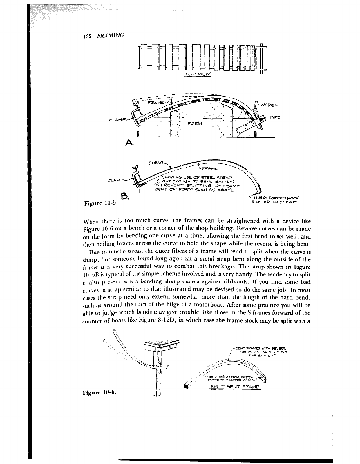
122 FRAMING
OWNG USE OF 5TEEL S-t-HAP
IGHT EIJOUGH To bEUD EA’. ILY)
l=‘b?ELk.l-f SPLlTTlhlG OF FVA,ME
Ul- Cd FORM SUCH AS ABOVE
0.
Figure 10-5. I& FORQ CO wO&
Rlb’ETED TO STICAFI
When thrre is too much CUI’W, thr frames can be straightened with a device like
Figure lo-6 on a bench or a corner of the shop building. Reverse curves can be made
on thr form by bending one curve at a time, allowing the first bend to set weil, and
then nailing braces across the curve to hold the shape while the reverse is being bent.
Due to tensile stress, the outer fibers of a frame will tend to split when the curve is
sharp, but someone found long ago that a metal strap bent along the outside of the
frame is a very successful way to combat this breakage. The strap shown in Figure
10 5~ is typical of the simple scheme involved and is very handy. The tendency to split
is also present when bending sharp curves against ribbands. If you find some bad
curves, a strap similar to that illustrated may be devised to do the same job. In most
CaSes the strap need only extend somewhat more than the length of the hard bend,
such as around the turn of the bilge of a motorboat. After some practice you will be
able to judge which bends may Rive trouble, like those in the S frames forward of the
counter of boats like Figure 8-12D, in which case the frame stock may be split with a
Figure
SPLIT BEf.J-7 FRAME
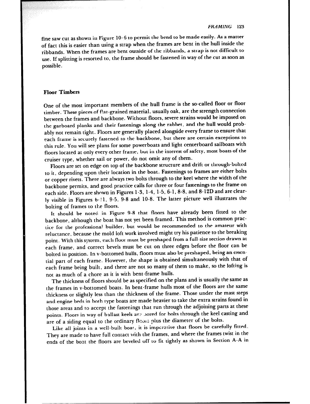
FRAMING 123
fine saw cut as shown in Figure 10-6 to permit the bend to be made easily. As a matter
of fact this is easier than using a strap when the frames are bent in the hull inside the
ribbands. When the frames are bent outside of the ribbands, a strap is not difficult to
use. If splitting is resorted to, the frame should be fastened in way of the cut as soon as
possible.
Floor Timbers
One of the most important members of the hull frame is the so-called floor or floor
timber. These pieces of f!at-grained material, usually oak, are the strength connection
between the frames and backbone. Without floors, severe strains would be imposed on
the garboard planks and their fastenings along the rabbet. and the hull would prob-
ably not remain tight. Floors are generally placed alongside every frame to ensure that
each frame is securely fastened to the backbone, but there are certain exceptions to
this rule. You will see plans for some powerboats and light centerboard sailboats with
floors located at only every other frame, but in the interest of safety, most boats of the
cruiser type, whether sail or power, do not omit any of them.
Floors are set on edge on top of the backbone structure and drift or through-bolted
to it, depending upon their location in the boat. Fastenings to frames are either bolts
or copper rivets. There are always two bolts through to the keel where the width of the
backbone permits, and good practice calls for three or four fastenings to the frame on
each side. Floors are shnwn in Figures l-3. 1-4, 1-5, 6-1, 8-8, and 8-12D and areclear-
ly visible in Figures b- ! 1, 9-5, 9-8 and 10-8. The latter picture well illustrates the
bolting of frames to tl-,e floors.
It should be noted in Figure 9-8 that floors have already been fitted to the
backbone, although the boat has not yet been framed. This method is common prac-
tice for the professional builder, but would be recommended to the amateur with
reluctance, because the mold loft work involved might try his patience to the breaking
point. With this system, each floor must be preshaped from a full-size section drawn at
each frame, and correct bevels must be cut on three edges before the floor can be
bolted in position. In v-bottomed hulls, floors must also be preshaped, being an essen-
tial part of each frame. However, the shape is obtained simultaneously with that of
each frame being built, and there are not so many of them to make, so the lofting is
not as much of a chore as it is with bent-frame hulls.
The thickness of floors should be as specified on the plans and is usually the same as
the frames in v-bottomed boats. In bent-frame hulls most of the floors are the same
thickness or shghtly less than the thickness of the frame. Those under the mast steps
and engine beds in both type boats are made heavier to take the extra strains found in
those areas and to accept the fastenings that run through the adjoining parts at these
points. Floors in way of ballast keels arc Jored for bolts through the keel casting and
are of a siding equal to the ordinary flour: ,
nlus the diameter of the bolts.
Like all joints in a well-built boat., it is impt.,
--ltive that floors be carefully fitted.
They are made to have full contact with the frames, and where the frames twist in the
ends of the boat the floors are beveled off to fit tightly as shown in Section A-A in
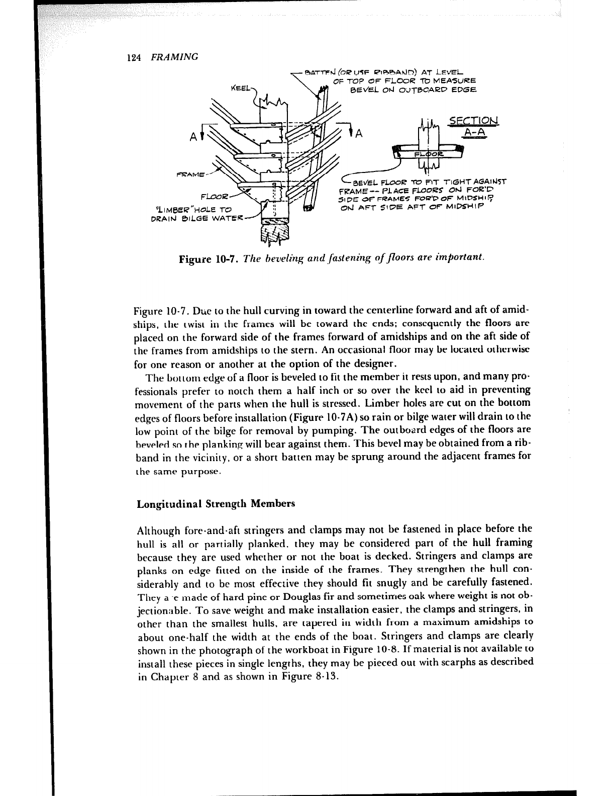
FRAMING
KEEL,
- BAT7-d (OR USE RlBbV%?) AT LE‘-‘EL
OF TOP OF FLOOR TY MEASURE
0Ek’EL Od OLIT0CARD EQGE
cBEtEL FLOOR ‘ro FIT TIGHTAGAI~~YT
FRAME -- PLACE FLOORS CM I=
‘OR72 -
51 DE OF FRAMES FCR’D 01
5 MbSHll:
Od AFT SIDE AFT OF I
i4lMHIP
Figure 10-7. The beveling and .fastening of floors are important.
Figure 10-7. Due to the hull curving in toward the centerline forward and aft of amid-
ships, the twist in the frames will bc toward the ends; consequently the floors are
placed on the forward side of the frames forward of amidships and on the aft side of
the frames from amidships to the stern. An occasional floor may be located otherwise
for one reason or another at the option of the designer.
The bottom edge of a floor is beveled to fit the member it rests upon, and many pro-
fessionals prefer to notch them a half inch or so over the keel to aid in preventing
movement of the parts when the hull is stressed. Limber holes are cut on the bottom
edges of floors before installation (Figure 10~7A) so rain or bilge water will drain to the
low point of the bilge for removal by pumping. The outboard edges of the floors are
beveled so the planking will bear against them. This bevel may be obtained from a rib-
band in the vicinity, or a short batten may be sprung around the adjacent frames for
the same purpose.
Longitudinal Strength Members
Although fore-and-aft stringers and clamps may not be fastened in place before the
hull is all or partially planked, they may be considered part of the hull framing
because they arc used whether or not the boat is decked. Stringers and clatnps are
planks on edge fitted on the inside of the frames. They strengthen the hull con-
siderahly and to be most effective they should fit snugly and be carefully fastened.
They a .e made of hard pine or Douglas fir and sometimes oak where weight is not ob-
jectionable. To save weight and make installation easier, the clamps and stringers, in
other than the smallest hulls, are tapered in width from a maximum amidships to
about one-half the width at the ends of the boat. Stringers and clamps are clearly
shown in the photograph of the workboat in Figure 10-8. If material is not available to
install these pieces in single lengths, they may be pieced out with scarphs as described
in Chapter 8 and as shown in Figure 8-13.
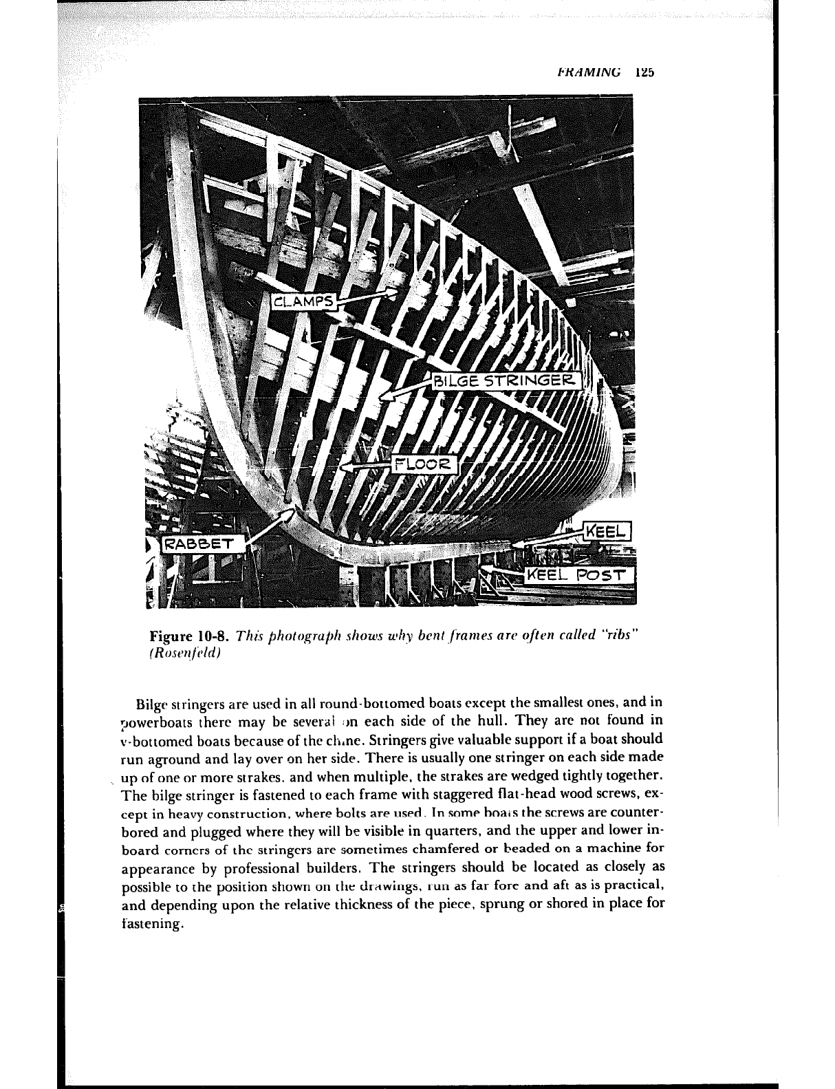
FRAMING 125
Figure 10-8. T1zi.r photo~gru# shoua why bent jLarnes nw often cnllpd “ribs”
(Roscwfihi)
Bilgr stringers are used in all round-bottomed boats except the smallest ones, and in
powerboats there may be severai :rn each side of the hull. They are not found in
v-bottomed boats because of the clrne. Stringers give valuable support if a boat should
run aground and lay over on her side. There is usually one stringer on each side made
_ up of one or more strakes, and when multiple, the strakes are wedged tightly together.
The bilge stringer is fastened to each frame with staggered flat-head wood screws, ex-
cept in heavy construction, where bolts are used. In some boais the screws are counter-
bored and plugged where they will be visible in quarters, and the upper and lower in-
board corners of the stringers are sometimes chamfered or beaded on a machine for
appearance by professional builders. The stringers should be located as closely as
possible to the position shown on the drawings, run as far fore and aft as is practical,
and depending upon the relative thickness of the piece, sprung or shored in place for
fastening.
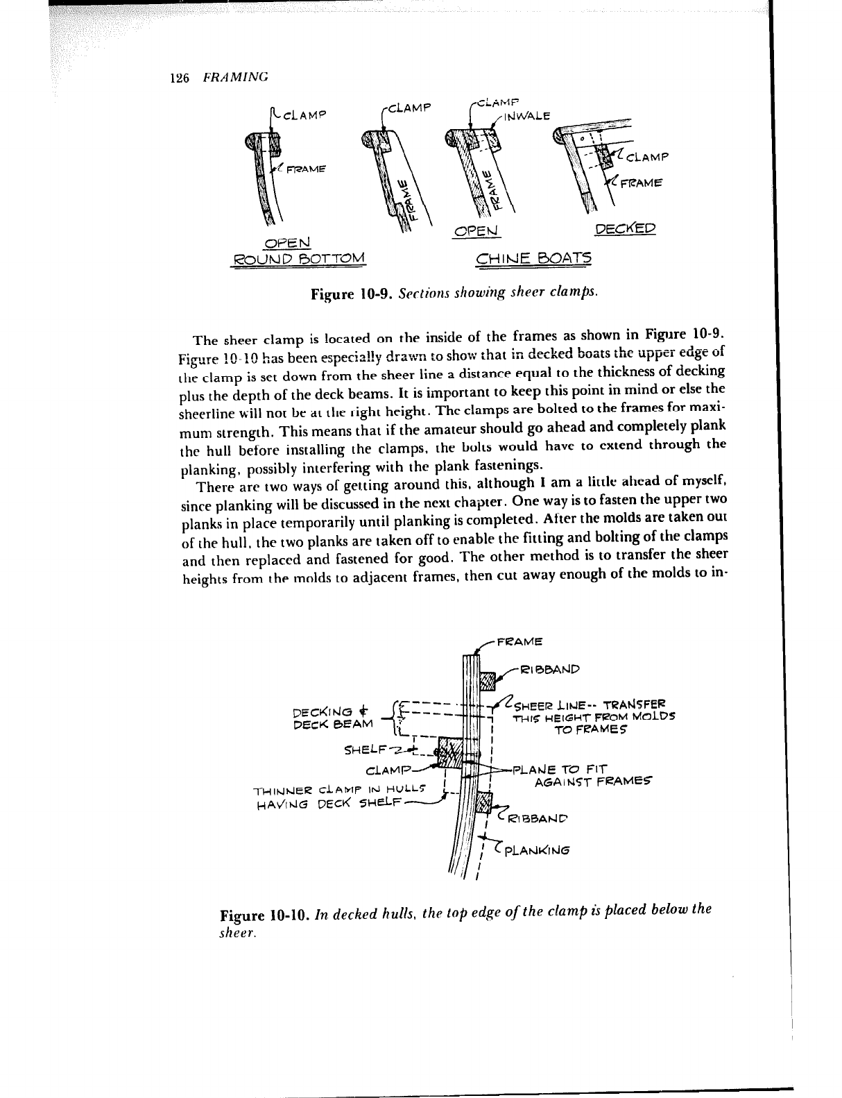
126 FRAMING
DECdED
oPEh1
ROUND BOTTOM CHIME BOATS
Figure 10-g. Scr&ions showing sht~?r dam/E
The sheer clamp is located on the inside of the frames as shown in Figure 10-9.
r;atl 4
Figure !O- !(! has been espe-.-..y ,r a:~n to show :hat in decked boats the upper edge of
the clamp is set down from the sheer line a distance equal to the thickness of decking
plus the depth of the deck beams. It is important to keep this point in mind or else the
sheerline will not be at the right height. The clamps are bolted to the frames for maxi-
mum strength. This means that if the amateur should go ahead and completely plank
the hull before installing the clamps, the bolts would have to extend through the
planking, possibly interfering with the plank fastenings.
There are two ways of gerting around this, although I am a little ahead of myself,
since planking will be discussed in the next chapter. One way is to fasten the upper two
planks in place temporarily until planking is completed. After the molds are taken out
of the hull, the two planks are taken off to enable the fitting and bolting of the clamps
and then replaced and fastened for good. The other method is to transfer the sheer
heights from the molds to adjacent frames, then cut away enough of the molds to in-
SHEER LitJE-- TRAt-&FEP
OEck 0EAM THlS HEIGHT FROM MOLDS
TO FEAMES
-i-H~tJrclER CLAMP lhl HU
HAdtdG DECK SHELF
PLAdE l-C’ FIT
AGA I hITi- FIZAMEF
Figure IO-IO. In. decked hulls, the top edge of the clamp is placed below the
sheer.
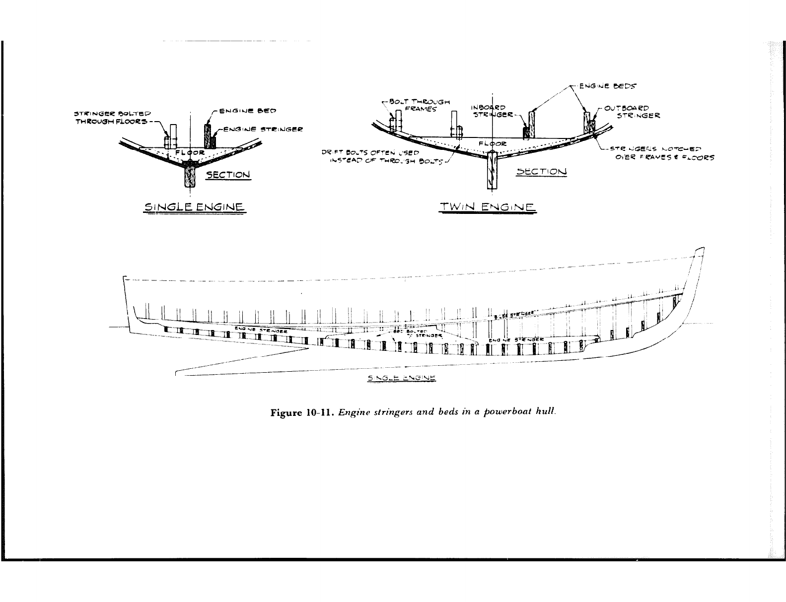
STRlhlGte 00l.TdD
TWItOUQH FLOOCS -
ENGIJE STLlhlGtP
SINGLE EtiGlNE TW,rJ ENGINE
‘--5TQ t..iGEk5 hOTbtE_7
Ob’EQ F PA’.‘ES 8 =L~OZZ%
\
-4% _ _--
Jj j\m!-J_ ii. J I( 1) 11 ,i..~il~_ii~~,l.-~i~~ ‘! 1 ~~ml~e_IT;~m ~1; ~~~s~.~~~~~~r~~-
._ ll-~$g!===-~- z iI:::-T~~3?.. . se: e0.r•r
~~.~2z:~~~~71~_ -7,
--- --- -. - -~~:~~~-l~~~_a_-al -YY ‘J .~ Lmm-,--m
_-------
~~~~~~~I:~~~~~~ai’“~~~~.
_----- _._-------
_--
5 <G&E E\G’UE
Figure 10-11. Engine stringers and beds in a powerboat hull.
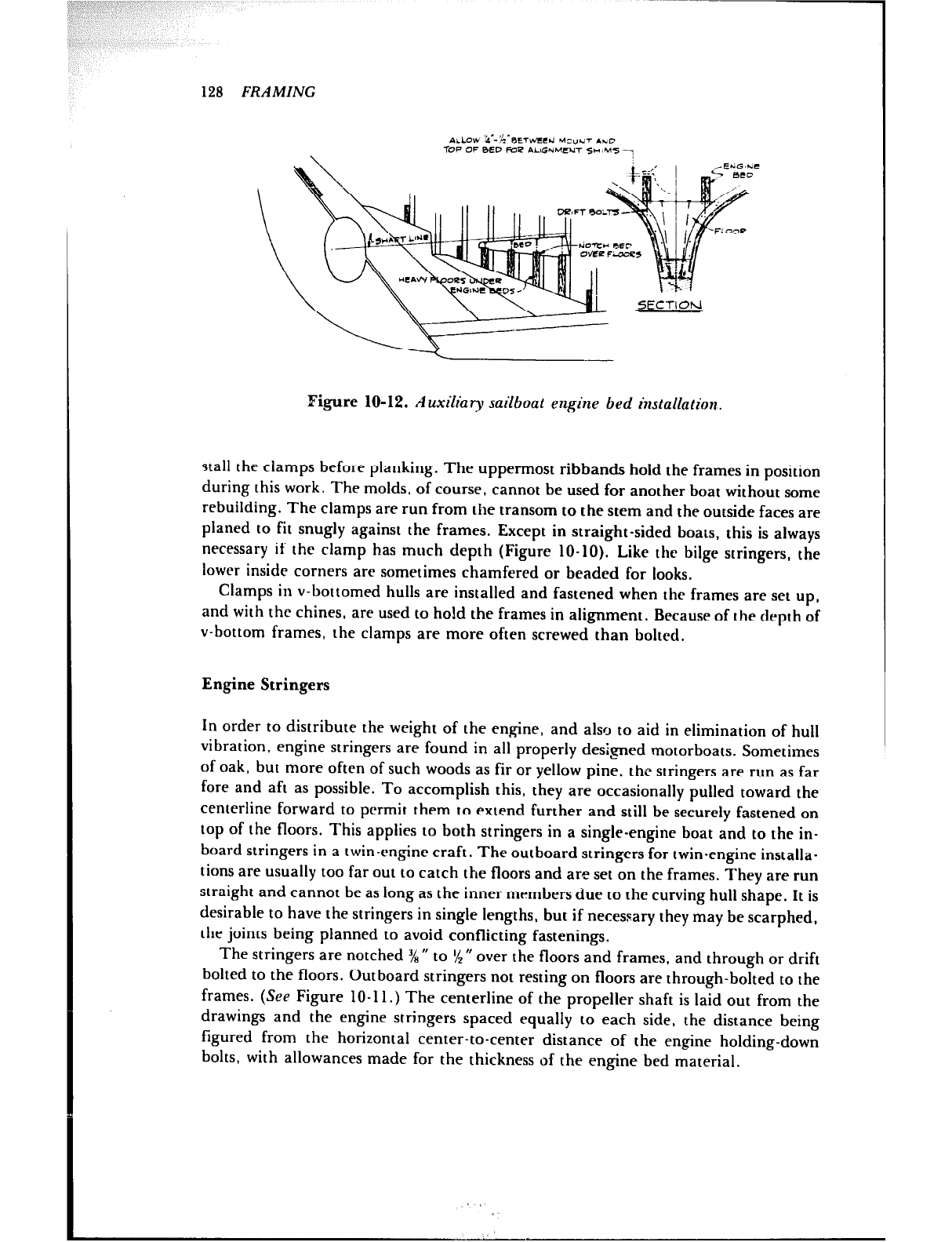
128 FRAMING
Figure 10-12. Auxiliary sailboat engine bed installation.
stall the clamps before planking. The uppermost ribbands hold the frames in position
during this work. The molds, of course, cannot be used for another boat without some
rebuilding. The clamps are run from the transom to the stem and the outside faces are
planed to fit snugly against the frames. Except in straight-sided boats, this is always
necessary if the clamp has much depth (Figure 10-10). Like the bilge stringers, the
lower inside corners are sometimes chamfered or beaded for looks.
Clamps in v-bottomed hulls are installed and fastened when the frames are set up,
and with the chines, are used to hold the frames in alignment. Because of the depth of
v-bottom frames, the clamps are more often screwed than bolted.
Engine Stringers
In order to distribute the weight of the engine, and also to aid in elimination of hull
vibration, engine stringers are found in all properly de+ed motorboats. Sometimes
of oak, but more often of such woods as fir or yellow pine, the stringers are run as far
fore and aft as possible. To accomplish this, they are occasionally pulled toward the
centerline forward to permit them to extend further and still be securely fastened on
top of the floors. This applies to both stringers in a single-engine boat and to the in-
board stringers in a twin-rngine craft. The outboard stringers for twin-engine installa-
tions are usually too far out to catch the floors and are set on the frames. They are run
straight and cannot be as long as the inner members due to the curving hull shape. It is
desirable to have the stringers in single lengths, but if necessary they may be scarphed,
the joints being planned to avoid conflicting fastenings.
The stringers are notched ‘/R U to % n over the floors and frames, and through or drift
bolted to the floors. Outboard stringers not resting on floors are through-bolted to the
frames. (Sep Figure 10-l 1.) The centerline of the propeller shaft is laid out from the
drawings and the engine stringers spaced equally to each side, the distance being
figured from the horizontal center-to-center distance of the engine holding-down
bolts, with allowances made for the thickness of the engine bed material.

34
FRAMING 129
Engine Beds
In motorboats the engine beds are bolted to the engine stringers, Figure 10-11, and
may or may not be notched over the floors. If enough bolts are used to transfer the
engine thrust to the stringers, notches are not necessary. The present custom of having
the engine in an auxiliary as far aft as possible does not lend itself to the installation of
stringers, and in this case the beds are notched over the floors and drift boited to them.
(See Figure 10-12.) In all boats the installation diagram for the engine must be con-
sulted to determine the vertical position of the bottom of the bolt lugs in relation to the
centerline of the propeller shaft in order to determine the top edge of the beds.
Anywhere from V4 “to 14 ” is allowed between the lugs and the beds for the insertion of
hardwood shims when the engine is aligned with the propeller shaft, unless the engine
is fitted with mounts that have a vertical adjustment.
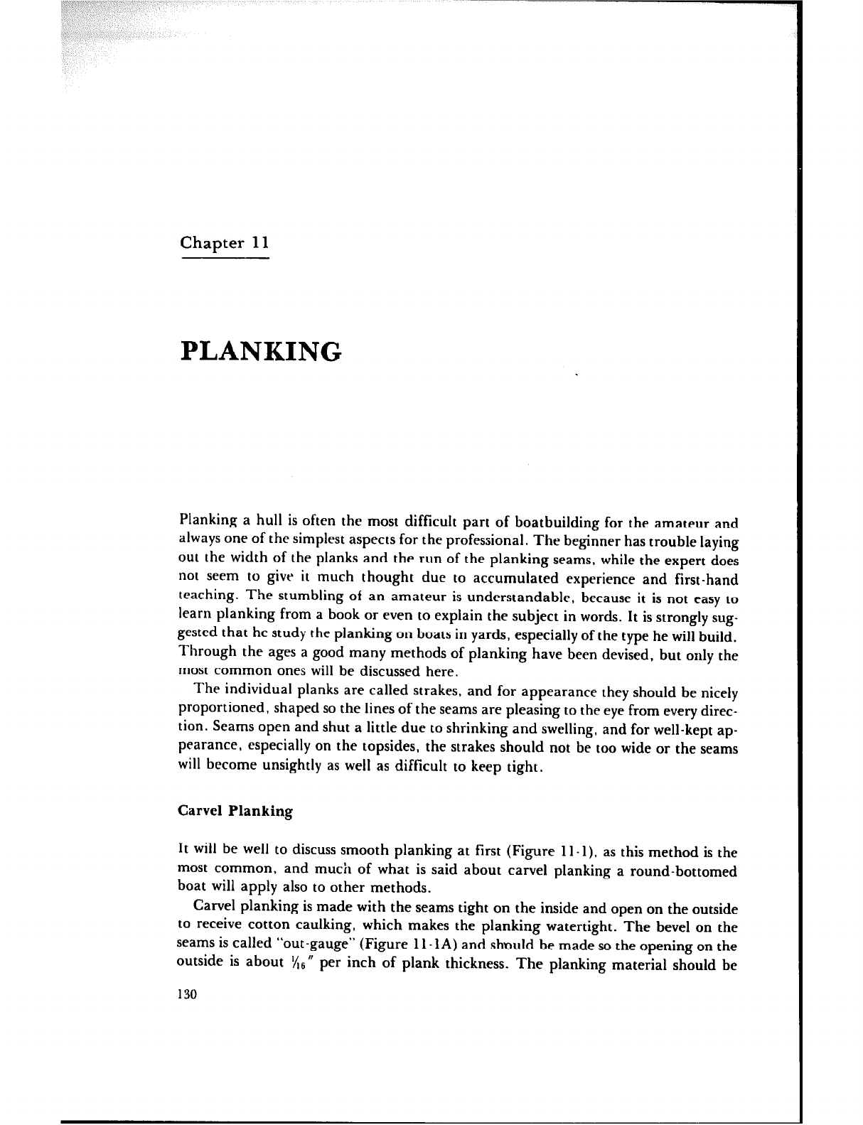
Chapter 11
PLANKING
Planking a hull is often the most difficult part of boatbuilding for the amateur and
always one of the simplest aspects for the professional. The beginner has trouble laying
out the width of the planks and the run of the planking seams, while the expert does
not seem to give it much thought due to accumulated experience and first-hand
teaching. The stumbling of an amateur is understandable, because it is not easy to
learn planking from a book or even to explain the subject in words. It is strongly sug-
gested that he study the planking on boats in yards, especially of the type he will build.
Through the ages a good many methods of planking have been devised, but only the
most common ones will be discussed here.
The individual planks are called strakes, and for appearance they should be nicely
proportioned, shaped so the lines of the seams are pleasing to the eye from every direc-
tion. Seams open and shut a little due to shrinking and swelling, and for well-kept ap-
pearance, especially on the topsides, the strakes should not be too wide or the seams
will become unsightly as well as difficult to keep tight.
Carve1 Planking
It will be well to discuss smooth planking at first (Figure 11-l). as this method is the
most common, and much of what is said about carve1 planking a round-bottomed
boat will apply also to other methods.
Carve1 planking is made with the seams tight on the inside and open on the outside
to receive cotton caulking, which makes the planking watertight. The bevel on the
seams is called “out-gauge” (Figure 11 -lA) and should be made so the opening on the
outside is about x6” per inch of plank thickness. The planking material should be
130
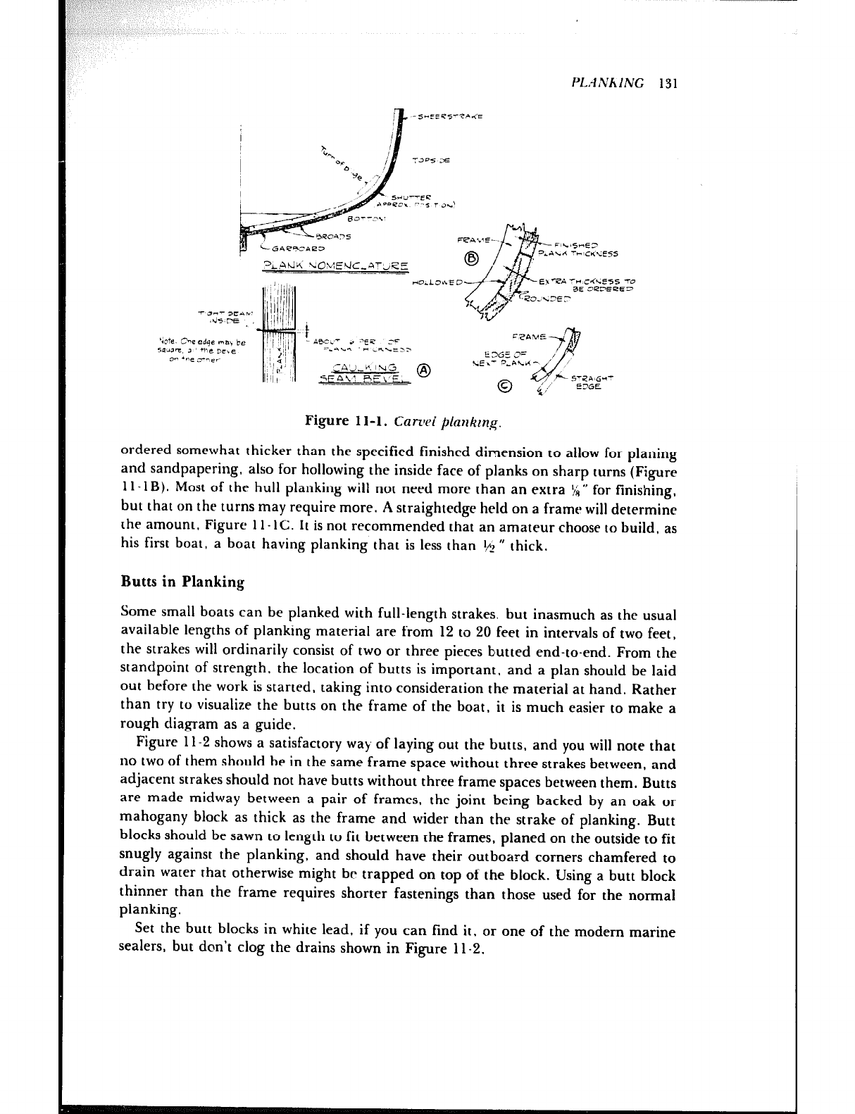
PLANhING 131
‘de. Ihe edge ma, be
5w3=, 3 the nc,e
3- *ne 3--er
Figure 1 l-l. Cam4 planking.
ordered somewhat thicker than the specified finished dimension to allow for planing
and sandpapering, also for hollowing the inside face of planks on sharp turns (Figure
1 I -1B). Most of the hull planking will not need more than an extra !/A” for finishing,
but that on the turns may require more. A straightedge held on a frame will determine
the amount, Figure 1 l- 1C. It is not recommended that an amateur choose to build, as
his first boat, a boat having planking that is less than r& ” thick.
Butts in Planking
Some small boats can be planked with full-length strakes. but inasmuch as the usual
available lengths of planking material are from 12 to 20 feet in intervals of two feet,
the strakes will ordinarily consist of two or three pieces hutted end-to-end. From the
standpoint of strength, the location of butts is important, and a plan should be laid
out before the work is started, taking into consideration the material at hand. Rather
than try to visualize the butts on the frame of the boat, it is much easier to make a
rough diagram as a guide.
Figure 11-2 shows a satisfactory way of laying out the butts, and you will note that
no two of them should be in the same frame space without three strakes between, and
adjacent strakes should not have butts without three frame spaces between them. Butts
are made midway between a pair of frames, the joint being backed by an oak or
mahogany block as thick as the frame and wider than the strake of planking. Butt
blocks should be sawn to length to fit between the frames, planed on the outside to fit
snugly against the planking, and should have their outboard corners chamfered to
drain water that otherwise might be trapped on top of the block. Using a butt block
thinner than the frame requires shorter fastenings than those used for the normal
planking.
Set the butt blocks in white lead, if you can find it, or one of the modern marine
sealers, but don’t clog the drains shown in Figure 11-2.
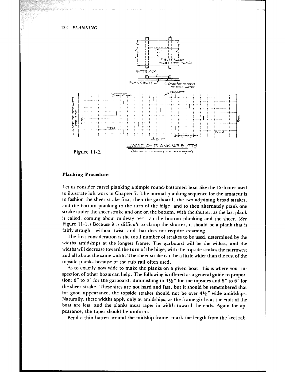
pi-Ah-e, ComerS
,- TIT dn’r wa-2r
- FF?A WE-5
--~----- ~~
t P-F-T= I * + , i ? * I + + , I i I : L iI
Figure 1 l-2.
LACCT 2= PLAti!vi.hiG 3’dT-r5
(hi0 sco e ne~esor\l for thm5 diagram)
132 PLA NRING
Planking Procedure
Let us consider carve1 planking a simple round-bottomed boat like the 12.footer used
to illustrate loft work in Chapter 7. The normal planking sequence for the amateur is
to fashion the sheer strake first, then the garboard. the two adjoining broad strakes,
and the bottom planking to the turn of the bilge, and to then alternately plank one
strake under the sheer strake and one on the bottom, with the shutter, as the last plank
is called. coming about midway b-+- -12 n the bottom planking and the sheer. (See
Figure 1 l-l.) Because it is difficult to clamp the shutter, it should be a plank that is
fairly straight, without twist, and . hat does not require steaming.
The first consideration is the tot:J number of strakes to be used, determined by the
widths amidships at the longest frame. The garboard will be the widest, and the
widths will decrease toward the turn of the bilge, with the topside strakes the narrowest
and all about the s&me width. The sheer strake can be a little wider than the rest of the
topside planks because of the rub rail often used.
As to exactly how wide to make the planks on a given boat, this is where you: in-
spection of other boats can help. The following is offered as a general guide to propor-
tion: 6” to 8” for the garboard, diminishing to 4th * for the topsides and 5” to 6” for
the sheer strake. These sizes are not hard and fast, but it should be remembered that
for good appearance, the topside strakes should not be over 4 th m wide amidships.
Naturally, these widths apply only at amidships, as the frame girths at the snds of the
boat are less, and the planks must taper in width toward the ends. Again for ap-
pearance, the taper should be uniform.
Bend a thin batten around the midship frame, mark the length from the keel rab-
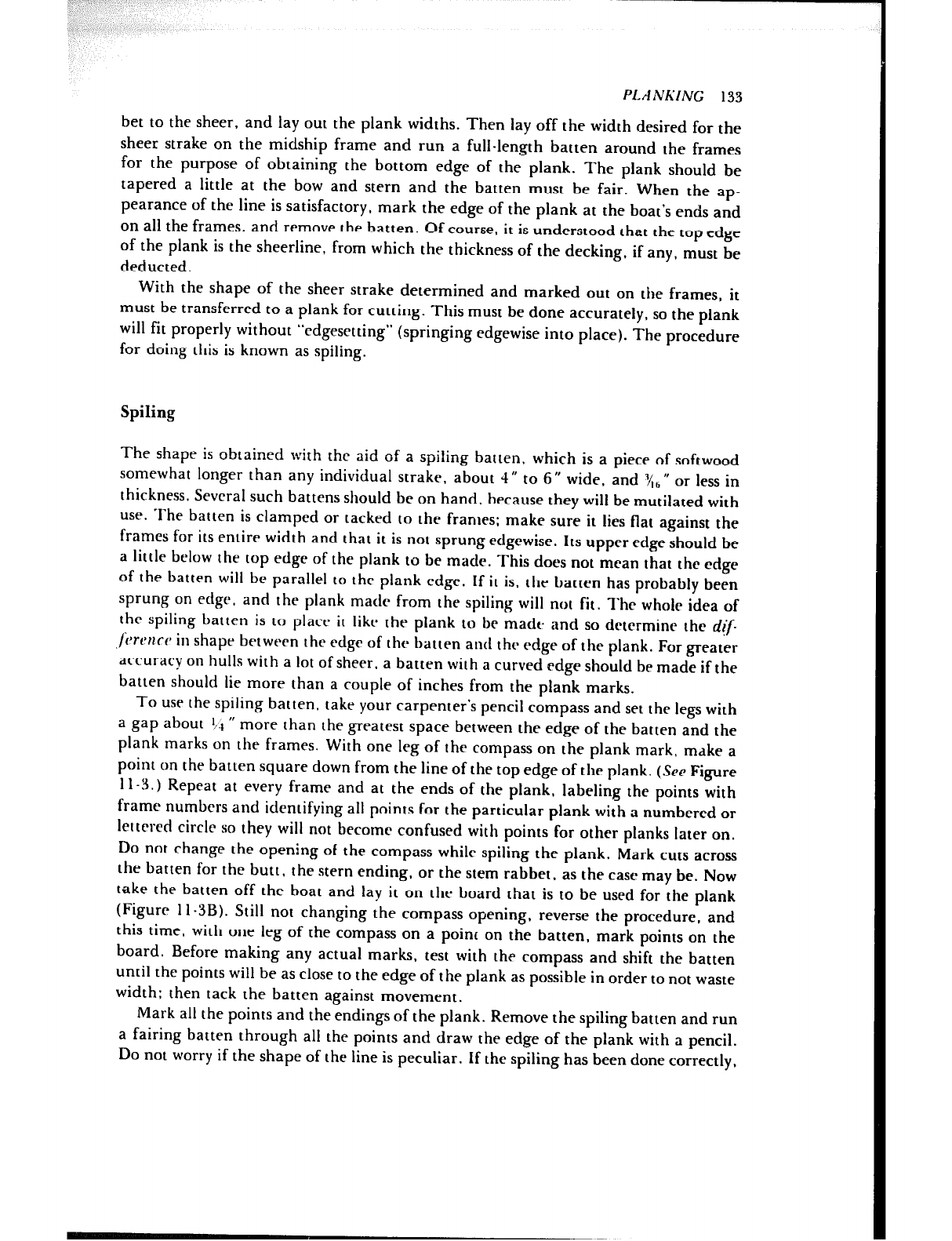
PLANKING 133
bet to the sheer, and lay out the plank widths. Then lay off the width desired for the
sheer strake on the midship frame and run a full-length batten around the frames
for the purpose of obtaining the bottom edge of the plank. The plank should be
tapered a little at the bow and stern and the batten must be fair. When the ap-
pearance of the line is satisfactory, mark the edge of the plank at the boat’s ends and
on all the frames, and remove the batten. Of course, it is understood that the top edge
of the plank is the sheerline, from which the thickness of the decking, if any, must be
deducted.
With the shape of the sheer strake determined and marked out on the frames, it
must be transferred to a plank for cutting. This must be done accurately, so the plank
will fit properly without “cdgesetting” (springing edgewise into place). The procedure
for doing this is known as spiling.
Spiling
The shape is obtained with the aid of a spiting batten, which is a piece of softwood
somewhat longer than any individual strakc, about 4” to 6” wide, and Y/1,,”
or less in
thickness. Several such battens should be on hand, because they will be mutilated with
use. The batten is clamped or tacked to the franles; make sure it lies flat against the
frames for its entire width and that it is not sprung edgewise. Its upper edge should be
a little below the top edge of the plank to be made. This does not mean that the edge
of the batten will be parallel to the plank edge. If it is. the batten has probably been
sprung on edge. and the plank made from the spiling will not fit. The whole idea of
the spiling batten is to place it like the plank to he made and so determine the d[p
,~;VIJI~CP in shape between the edge of the batten and thr edge of the plank. For greater
accuracy on hulls with a lot of sheer, a batten with a curved edge should be made if the
batten should lie more than a couple of inches from the plank marks.
To USC the spiling batten, take your carpenter’s pencil compass and set the legs with
a gap about 4.1 ” more than the greatest space between the edge of the batten and the
plank marks on the frames. With one leg of the compass on the plank mark, make a
point on the batten square down from the line of the top edge of the plank. (See Figure
11-S.) Repeat at every frame and at the ends of the plank, labeling the points with
frame numbers and identifying all points for the particular plank with a numbered or
lettrrcd circle so they will not become confused with points for other planks later on.
Do not change the opening of the compass while spiling the plank. Mark cuts across
the batten for the butt, the stern ending, or the stem rabbet, as the case may be. Now
take the batten off the boat and lay it on the board that is to be used for the plank
(Figure l l-3B). Still not changing the compass opening, reverse the procedure, and
this time, with one leg of the compass on a point on the batten, mark points on the
board. Before making any actual marks, test with the compass and shift the batten
until the points will be as close to the edge of the plank as possible in order to not waste
width: then tack the batten against movement.
Mark all the points and the endings of the plank. Remove the spiling batten and run
a fairing batten through all the points and draw the edge of the plank with a pencil.
Do not worry if the shape of the line is peculiar. If the spiling has been done correctly,
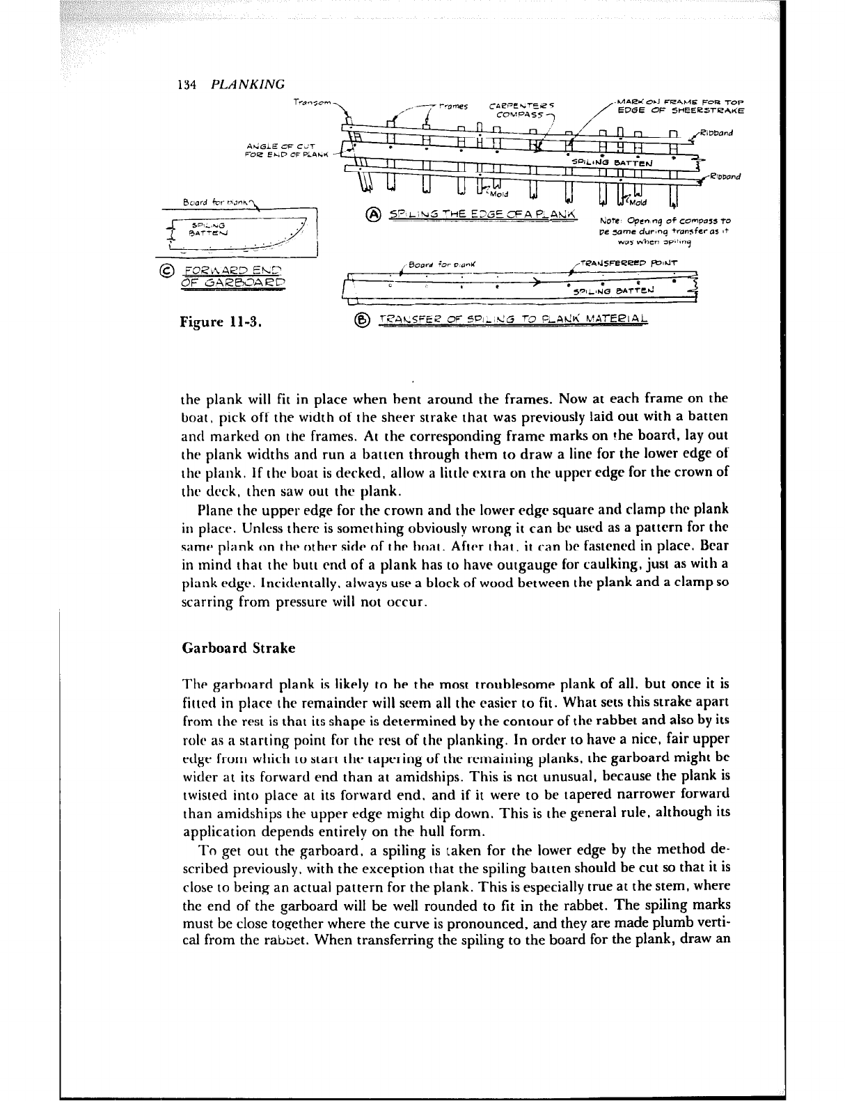
134 PLANKING
-1
i ./i
.L . I- I
tiotc opcnsnq of compllss to
me same durvnq +ransfcras 17
wm dhen sP~h?q
t3oord in D enbf wmemzeecw mm
I:;,
.-- I
\ .
c * l S”,& e&cd
Figure 1 l-3.
the plank will fit in place when bent around the frames. Now at each frame on the
boat, pick off the width of the sheer strake that was previously laid out with a batten
and marked on the frames. At the corresponding frame marks on the board, lay out
the plank widths and run a batten through them to draw a line for the lower edge of
the plank. If the boat is decked, allow a little extra on the upper edge for the crown of
the deck, then saw out the plank.
Plane the upper edge for the crown and the lower edge square and clamp the plank
in place. Unless there is something obviously wrong it can be used as a pattern for the
same plank on the othrr side of thr boat. After that, it can be fastened in place. Bear
in tnind that the butt end of a plank has to have outgauge for caulking, just as with a
plank rdge. Incidentally. always use a block of wood between the plank and a clamp so
scarring from pressure will not occur.
Garboard Strake
The garboard plank is likely to be the most troublesome plank of all, but once it is
fitted in place the remainder will scrm all the easier to fit. What sets this strake apart
from the rest is that its shape is determined by the contour of the rabbet and also by its
rolr as a starting point for the rest of the planking. In order to have a nice, fair upper
edge from which to start the tapering of the remaining planks, the garboard might be
wider at its forward end than at amidships. This is net unusual, because the plank is
twisted into place at its forward end, and if it were to be tapered narrower forward
than amidships the upper edge might dip down. This is the general rule, although its
application depends entirely on the hull form.
To get out the garboard. a spiting is taken for the lower edge by the method de-
scribed previously, with the exception that the spiting batten should be cut so that it is
close to being an actual pattern for the plank. This is especially true at the stem, where
the end of the garboard will be well rounded to fit in the rabbet. The spiling marks
must be close together where the curve is pronounced, and they are made plumb verti-
cal from the rabaet. When transferring the spiting to the board for the plank, draw an
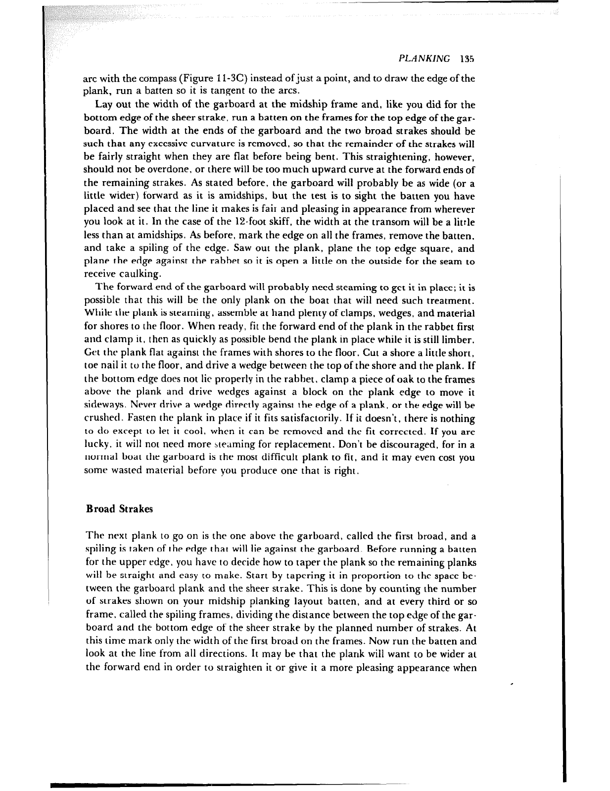
PLANKING 135
arc with the compass (Figure 1 l-3C) instead ofjust a point, and to draw the edge of the
plank, run a batten so it is tangent to the arcs.
Lay out the width of the garboard at the midship frame and, like you did for the
bottom edge of the sheer strake, run a batten on the frames for the top edge of the gar-
board. The width at the ends of the garboard and the two broad strakes should be
such that any excessive curvature is removed. so that the remainder of the strakes will
be fairly straight when they are flat before being bent. This straightening, however,
should not be overdone. or there will be too much upward curve at the forward ends of
the remaining strakes. As stated before, the garboard will probably be as wide (or a
little wider) forward as it is amidships, but the test is to sight the batten you have
placed and see that the line it makes is fair and pleasing in appearance from wherever
you look at it. In the case of the 12.foot skiff, the width at the transom will be a little
less than at amidships. As before, mark the edge on all the frames, remove the batten,
and take a spiting of the edge. Saw out the plank, plane the top edge square, and
plane the edge against the rabbet so it is open a little on the outside for the seam to
receive caulking.
The forward end of the garboard will probably need steaming to get it in place; it is
possible that this will be the only plank on the boat that will need such treatment.
While the plank is steaming, assemble at hand plenty of clamps, wedges, and material
for shores to the floor. When ready, fit the forward end of the plank in the rabbet first
and clamp it, then as quickly as possible bend the plank in place while it is still limber.
Gttt the plank flat against the frames with shores to the floor. Cut a shore a little short,
toe nail it to the floor, and drive a wedge between the top of the shore and the plank. If
the bottom edge does not tic properly in the rabhet. clamp a piece of oak to the frames
above the plank and drive wedges against a block on the plank edge to move it
sideways. Never drive a wedge directly against the edge of a plank, or the edge will be
crushed. Fasten the plank in place if it fits satisfactorily. If it doesn’t, there is nothing
to do except to let it cool, when it can be removed and the fit corrected. If you are
lucky, it will not need more ateaming for replacement. Don’t be discouraged, for in a
normal boat the garboard is the most difficult plank to fit, and it may even cost you
some wasted material before you produce one that is right.
Broad Strakes
The next plank to go on is the one above the garboard, called the first broad, and a
spiting is taken of the edge that will lie against the garboard. Before running a batten
for the upper edge, you have to decide how to taper the plank so the remaining planks
wit1 be straight and easy to make. Start by tapering it in proportion to the space be-
tween the garboard plank and the sheer strake. This is done by counting the number
of strakes shown on your midship planking layout batten, and at every third or so
frame, called the spiting frames, dividing the distance between the top edge of the gar-
board and the bottom edge of the sheer strake by the planned number of strakes. At
this time mark only the width of the first broad on the frames. Now run the batten and
look at the line from all directions. It may be that the plank will want to be wider at
the forward end in order to straighten it or give it a more pleasing appearance when
Figure 1 I-4.
136 PLANKING
PLANKING SCALE
a" E%cample: A~ume 6straKe5 remaining.
Greakst girth divided b\/ &3= 4k”
Least 15 04 'I @w 3"
4!q’-3”= lr/?“= 12 eighths
Divide space between girth nvlrKs on
scale batten into IZqual part5
Scak applied to any frame will give
plank width at that frame.
viewed from forward. If so, make it a little wider, but don’t overdo it. When the line
satisfies. mark the frames, remove the batten, take a spiting for the top edge, and saw
and plane the plank to shape. The next two or three planks are lined out with the same
system so that when the turn of the bilge is reached, the remainder of the planks be-
tween there and the sheer strake may ail be of uniform width and taper.
Width Scale for Remaining Planks
The planks between the last of the bottom planks and the sheer strake may be lined
out by dividing the unpianked girth at each spiting frame into equal spaces. However,
the work can be made easier if you use a planking scale made with a batten about ‘/R U x
I “. Mark on the batten the greatest space still to be planked, which will be near the
I,!!ddie of the boat, and also the shortest space, wherever it may be. Then
aritilmeticaiiy divide the greatest girth distance by the number of strakes still to go on.
Let us say the answer is 4 I,$ “; therefore call the corresponding mark on the scale 4!$ “.
Do the same with the shortest girth and, assuming the answer is 3”, call the cor-
responding mark on the scale 3 “. Now find the number of eighths of an inch there are
between the two girth marks on the scale, 12 in this case. Divide the space on the scale
between 3” and 41$$ ” into 12 equal spaces and label them so each one represents S”.
(See Figure 11-4.) You will see that the scale, when applied to the unpianked girth of
any frame, will give the width of the strake at that frame.
It only takes a few minutes’ time to make a planking scale, and with it you can go
along and note the plank widths on as many of the frames as you like for reference
PLANKING 137
when making the remainder of the strakes. From now on, it is unnecessary to run bat-
tens, although each plank must be spiled. However, if you find that the seams are not
coming out as they should, it is best to run a batten to straighten things out and then
redivide the remaining space once again.
The ribbands are only removed as they become an interference to making a plank.
To keep the hull from becoming distorted, do not put more planks on one side of the
boat than on the other. As you fit a plank, make a mate for the opposite side,
remembering that the pl.anks are not truly opposite. In other words, due to hollowing,
for instance, the planks on opposite sides are not exact duplicates and may be com-
pared to a pair of shoes.
Hollowing and Rounding
Hollowing of planks, Figure 1 l- 1 B, is best done with a wooden plane having a rounded
bottom. After a plank is hollowed to fit the curve of the frames, mark the finished
thickness nn the edges with a marking gauge and roughly round the face of the plank
before fastening it into position. This will save work later.
Stealer Planks
The typical auxiliary sailboat hull, with the greatest girth to be planked located at a
frame well aft of amidships, requires short planks known as stealers. These generally
start at the rabbct in the sternpost and end at varying positions forward of the stern-
post, depending upon the number of stealers and the shape of the hull. A study of such
a hull will show that these short planks are necessary to straighten the remaining
planks as the turn of the bilge is reached. The photograph, Figlut I t-5, of a hull built
over a permanent mold, in the process of being turned over, clearly shows the shape of
the stealers along the keel. (Referring to remarks in preceding chap: ers, the deadwood
and ballast keel will be fitted to the hull in Figure 1 l-5 after it is right side up.) Often,
to avoid plank ends that are too pointed to take a fastening, stealers are nibbed into
their neighbors. (SW Figure l l -6A.) In this particular type of planking there is no gar-
board running for the length of the keel rabbet , but it still is possible to have one as il-
lustrated in Figure I I-6B. There are numerous possible variations, and it is strongly
urged that before beginning the job, a study be made of the planking on a boat similar
to the one being built for whatever pointers can be picked up.
Plank Fastenings
The type of fastening will be as specified on the plans or according to your own choice.
Normal planking is secured with three fastenings per plaL~k at each frame where the
width of the plank will permit, such as throughout the bottom. and wo at each frame
in the narrow topside strakes. The fastenings are staggered to the extent allowed by the
width of the frames, and planks that cross floors have an additional fastening or two
driven into the floor. The butts are fastened with five in each plank end as shown in
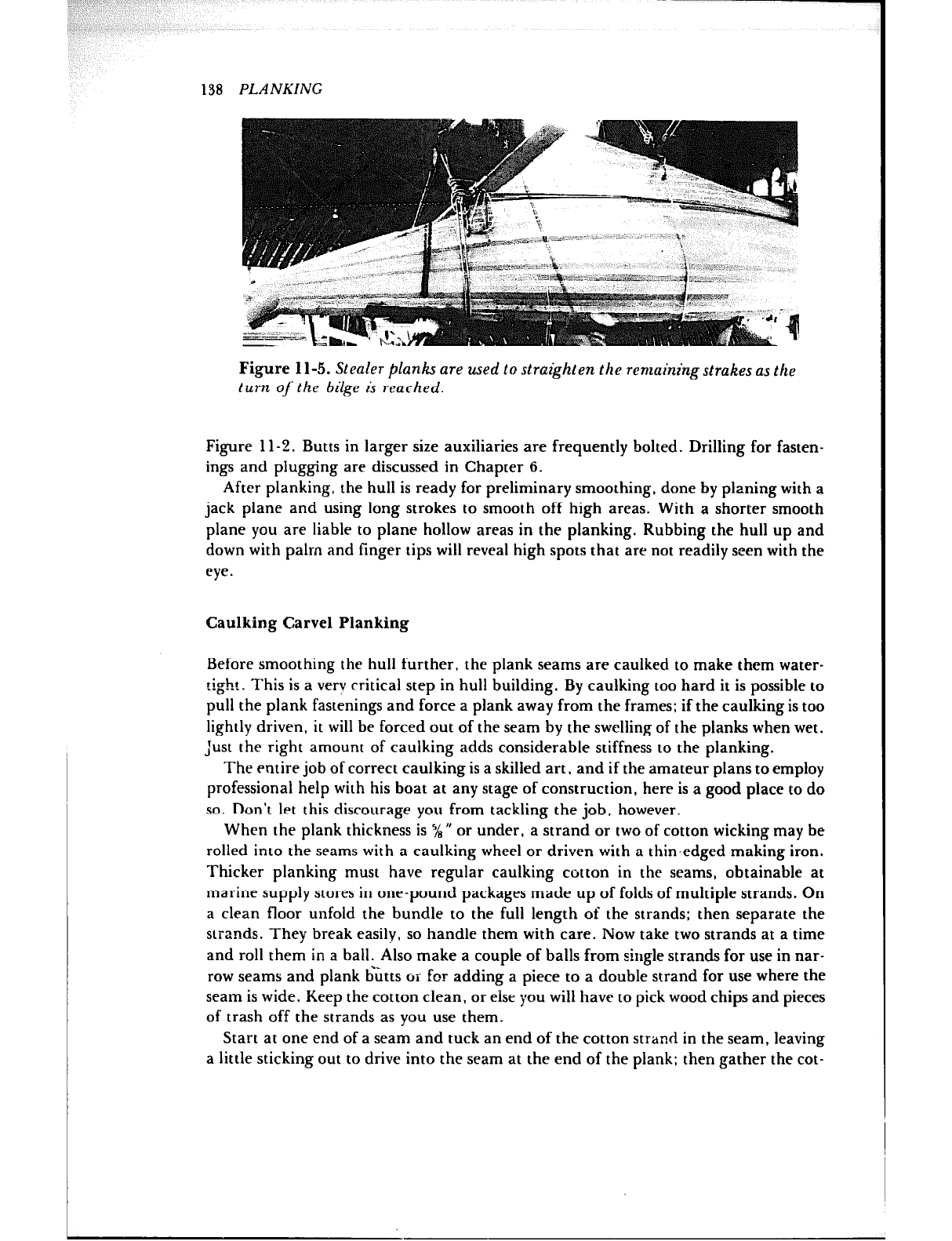
138 PLANKING
L
Figure 1 l-5. Stealer planks are used to straighten the remainingstmkes as the
turn of‘ the bilge is reached.
Figure 11-Z. Butts in larger size auxiliaries are frequently bolted. Drilling for fasten-
ings and plugging are discussed in Chapter 6.
After planking, the hull is ready for preliminary smoothing, done by planing with a
jack plane and using long strokes to smooth off high areas. With a shorter smooth
plane you are liable to plane hollow areas in the planking. Rubbing the hull up and
down with palm and finger tips will reveal high spots that are not readily seen with the
eye.
Caulking Carve1 Planking
Before smoothing the hull further, the plank seams are caulked to make them water-
tight. This is a verv critical step in hull building. By caulking too hard it is possible to
pull the plank fastenings and force a plank away from the frames; if the caulking is too
lightly driven, it will he forced out of the seam by the swelling of the planks when wet.
Just the right amount of caulking adds considerable stiffness to the planking.
The entire job of correct caulking is a skilled art, and if the amateur plans to employ
professional help with his boat at any stage of construction, here is a good place to do
so. Don’t let this discourage you from tackling the job, however.
When the plank thickness is ‘/8 H or under, a strand or two of cotton wicking may be
rolled into the seams with a caulking wheel or driven with a thin-edged making iron.
Thicker planking must have regular caulking cotton in the seams, obtainable at
marine supply stores in one-pound packages made up of folds of multiple strands. On
a clean floor unfold the bundle to the full length of the strands; then separate the
strands. They break easily, so handle them with care. Now take two strands at a time
and roll them in a hall. Also make a couple of balls from single strands for use in nar-
row seams and plank butts or for adding a piece to a double strand for use where the
seam is wide. Keep the cotton clean, or else you will have to pick wood chips and pieces
of trash off the strands as you use them.
Start at one end of a seam and tuck an end of the cotton strand in the seam, leaving
a little sticking out to drive into the seam at the end of the plank: then gather the cot-
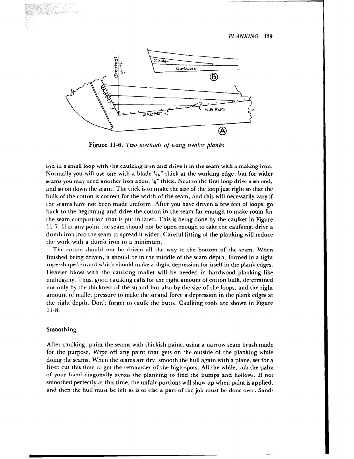
PLANKING 139
0
A
Figure 11-6. Two methods of using stealer planks.
ton in a small loop with the caulking iron and drive it in the seam with a making iron.
Normally you will use one with a blade ‘/,6” thick at the working edge, but for wider
seams you may need another iron about 7, rr
thick. Next to the first loop drive a second,
and so on down the seam. The trick is to make the size of the loop just right so that the
hulk of the cotton is correct for the width of the seam, and this will necessarily vary if
the seams have not been madr uniform. After you have driven a few feet of loops, go
hack to the beginning and drive the cotton in the seam far enough to make room for
the seam composition that is put in later. This is being done by the caulker in Figure
11-7, If at any point the seam should not he open enough to take the caulking, drive a
dumb iron into the seam to spread it wider. Careful fitting of the planking will reduce
the work with a dumb iron to a minimum.
The cotton should not be driven all the way to the bottom of the seam. When
finished being driven, it shoulrl be in the middle of the seam depth, formed in a tight
rope-shaped strand which should make a slight depression for itself in the plank edges.
Heavier blows with the caulking mallet will he needed in hardwood planking like
mahogany. Thus, good caulking calls for the right amount of cotton hulk, determined
not only by the thickness of the strand hut also by the size of the loops, and the right
amount of mallet pressure to make the strand force a depression in the plank edges at
the right depth. Don’t forget to caulk the butts. Caulking tools are shown in Figure
1 l-8.
Smoothing
After caulking, paint the seams with thickish paint, using a narrow seam brush made
for the purpose. Wipe off any paint that gets on the outside of the planking while
doing the seams. When the seams are dry, smooth the hull again with a plane, set for a
firer cut this time to get the remainder of the high spots. All the while, rub the palm
of your hand diagonally across the planking to find the bumps and hollows. If not
smoothed perfectly at this time, the unfair portions will show up when paint is applied,
and then the hull must be left as is or else a part of the job must be done over. Sand-
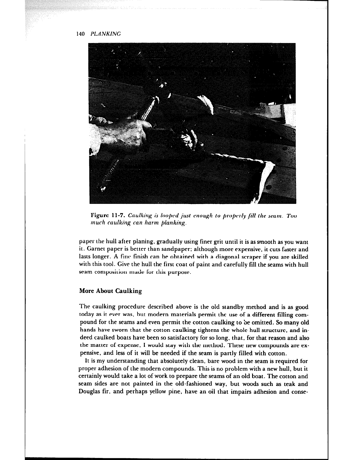
140 PLANKING
Figure 1 l-7. Caulking is looped just enough to property /ill tile seam. Too
muck caulking can harm planking.
paper the hull after planing, gradually using finer grit until it is as smooth as you want
it. Garnet paper is better than sandpaper; although more expensive, it cuts faster and
lasts longer. A tinr~ finish can be obtained with a diagonal scraper if you are skilled
with this tool. Give the hull the first coat of paint and carefully fill the seams with hull
seam composition made for this purpose.
More About Caulking
The caulking procedure described above is the old standby method and is as good
today as it ever was, but modern materials permit the use of a different filling com-
pound for the seams and even permit the cotton caulking to be omitted. So many old
hands have sworn that the cotton caulking tightens the whole hull structure, and in-
deed caulked boats have been so satisfactory for so long, that, for that reason and also
the matter of expense, I would stay with the method. These new compounds are ex-
pensive, and less of it will be needed if the seam is partly filled with cotton.
It is my understanding that absolutely clean, bare wood in the seam is required for
proper adhesion of the modern compound- 3. This is no problem with a new hull, but it
certainly would take a lot of work to prepare the seams of an old boat. The cotton and
seam sides are not painted in the old-fashioned way, but woods such as teak and
Douglas fir, and perhaps yellow pine, have an oil that impairs adhesion and conse-
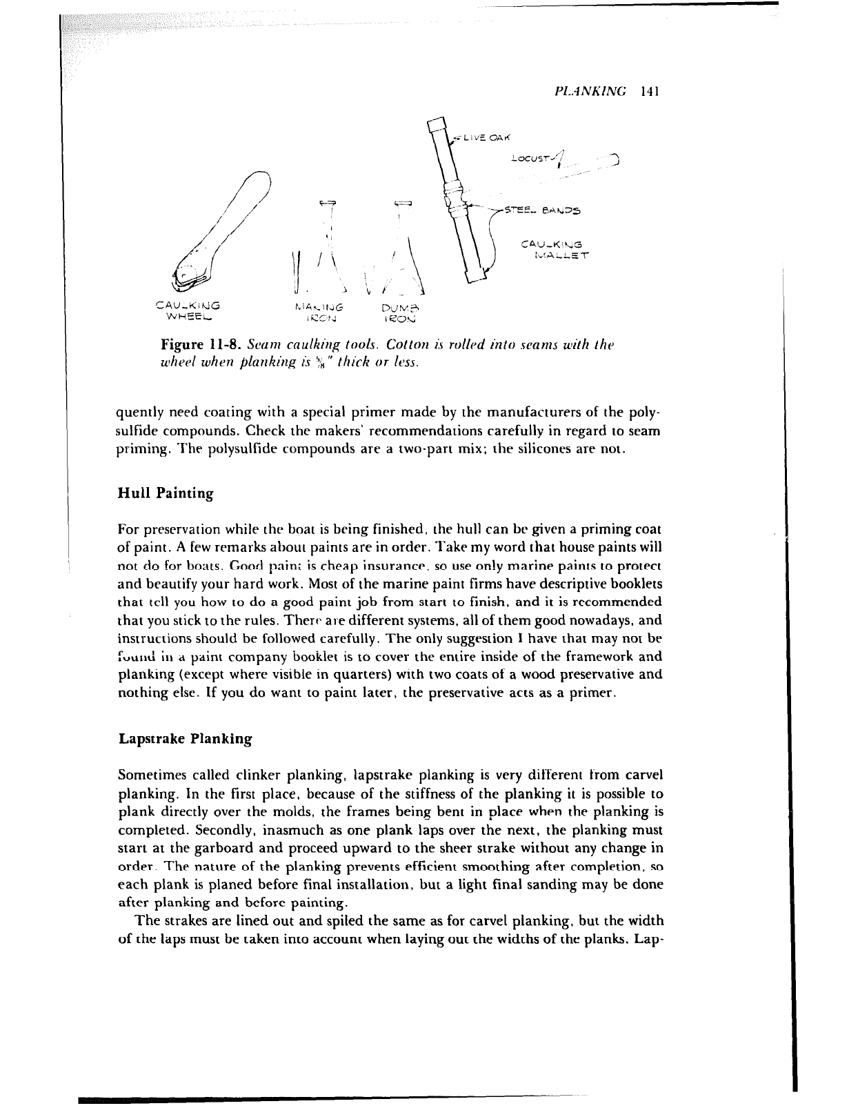
PI..1 Nh’ING 14 1
P
7
/
//
.-
d
c
CAU,KI~J!G
WHEEL
‘i
:/.
H
I i
?
J
Figure 11-8. Sca~n caulking pools. Cot&m is rollcgd into seams with the
whrel when planking is Y8” thick or ltm.
quently need coating with a special primer made by the manufacturers of the poly-
sulfide compounds. Check the makers’ recommendations carefully in regard to seam
priming. The polysulfide compounds are a two-part mix; the silicones are not.
Hull Painting
For preservation while the boat is bring finished. the hull can br given a priming coat
of paint. A few remarks about paints are in order. Take my word that house paints will
not do for boats. Good pin; is cheap insurance, so use only marine paints to protect
and beautify your hard work. Most of the marine paint firms have descriptive booklets
that tell you how to do a good paint job from start to finish, and it is recommended
that you stick to the rules. There are different systems, all of them good nowadays, and
instructions should be followed carefully. The only suggestion I have that may not be
f~urd iI1 d paint company bookiet is to cover the entire inside of the framework and
planking (except where visible in quarters) with two coats of a wood preservative and
nothing else. If you do want to paint later, the preservative acts as a primer.
Lapstrake Planking
Sometimes called clinker planking, lapstrake planking is very different from carve1
planking. In the first place, because of the stiffness of the planking it is possible to
plank directly over the molds, the frames being bent in place when the p!anking is
completed. Secondly, inasmuch as one plank laps over the next, the planking must
start at the garboard and proceed upward to the sheer strake without any change in
order. The nature of the planking prevents efficient smoothing after completion, so
each plank is planed before final installation, but a light final sanding may be done
after planking and before painting.
The strakes are lined out and spiled the same as for carve1 planking. but the width
of the laps must be taken into account when laying out the widths of the planks. Lap-
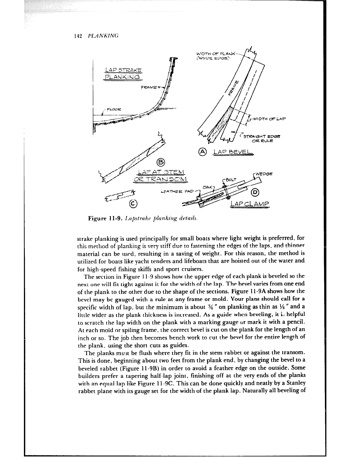
142 PIA NKINC;
Vd/inTH OF PLA)rll(-
:IdJsOE EDGE’
0
A LAP BEVEL
rV&DGE
Figure 11-9. I.npmlrc /hnkirrg cic*trcils.
strake planking is used principally for small boats where light weight is preferred, for
l I,:- -othnJ nf nl-nL;nm ic -~PPI~ rtiff riarn tn f-actpninm the edam of the laps, aned th_innpr
L.L.0 .I.L,..“U “I y.” . . . . ..‘b ..I .L., ., . . . . u..- .” &..” .c--.ae a .-*- --b-v
material can be turd, resulting in a saving of weight. For this reason, the method is
utilized for boats like yacht tenders and lifeboats that are hoisted out of the water and
for high-speed fishing skiffs and sport cruisers.
The section in Figure 11-9 shows how the upper edge of each plank is beveled so the
next one will fit tight against it for the width of the lap. The bevel varies from one end
of the plank to the other due to the shape of the sections. Figure l l-9A shows how the
bevel may be gauged with a rule at any frame or mold. Your plans should call for a
specific width of lap, but the minimum is about W ” on planking as thin as t/t 0 and a
little wider as the plank thickness is increased. As a guide when beveling, it i., helpful
to scratch the lap width on the plank with a marking gauge or mark it with a pencil.
At each mold or spiling frame. the correct bevel is cut on the plank for the length of an
inch or so. The job then becomes bench work to cut the bevel for the entire length of
the plank, using the short cuts as guides.
The planks must be flush where they fit in the stem rabbet or against the transom.
This is done, beginning about two feet from the plank end, by changing the bevel to a
beveled rabbet (Figure l l-9B) in order to avoid a feather edge on the outside. Some
builders prefer a tapering half-lap joint, finishing off at the very ends of the planks
with an equal lap like Figure l l-9C. This can be done quickly and neatly by a Stanley
rabbet plane with its gauge set for the width of the plank lap. Naturally all beveling of
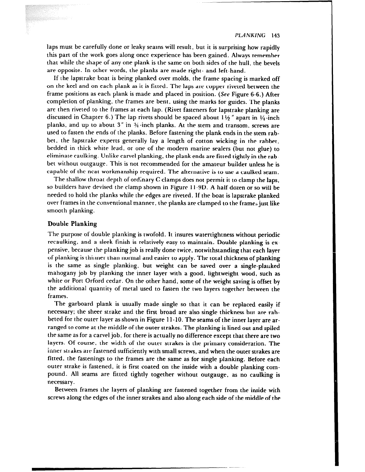
PLANKING 143
laps must be carefully done or leaky seams will result, but it is surprising how rapidly
this part of the work goes along once experience has been gained. Always remember
that while the shape of any one plank is the same on both sides of the hull, the bevels
are opposite. In other words, the planks are made right- and left-hand.
If the lapstrake boat is being planked over molds. the frame spacing is marked off
on the keel and on each plank as it is fitted. The laps are copper riveted between the
frame positions as each plank is made and placed in position. (See Figure 6-6.) After
completion of planking. the frames are bent, using the marks for guides. The planks
are then riveted to the frames at each lap. (Rivet fasteners for lapstrake planking are
discussed in Chapter 6.) The lap rivets should be spaced about 1 Id rr apart in Yl -inch
planks, and up to about 3” in %-inch planks. At the stem and transom, screws are
used to fasten the ends of the planks. Before fastening the plank ends in the stem rab-
bet, the lapstrake experts generally lay a length of cotton wicking in the rabbet.
bedded in thick white lead. or one of the modern marine sealers (but not glue) to
eliminate caulking. Unlike carve1 planking. the plank ends are fitted tightly in the rab-
bet without outgauge. This is not recommended for the amateur builder unless he is
capable of the neat workmanship required. The alternative is to use a caulked seam.
The shallow throat depth of ordinary C clamps does not permit it to clamp the laps,
so builders have devised the clamp shown in Figure 11.9D. A half dozen or so will be
needed to hold the planks while the edges are riveted. If the boat is lapstrake planked
over frames in the conventional manner, the planks are clamped to the frame* just like
smooth planking.
Double Planking
The purpose of double planking is twofold. It insures watertightness without periodic
recaulking, and a sleek finish is relatively easy to maintain. Double planking is ex-
pensive, because the planking job is really done twice, notwithstanding that each layer
of pianking is thilmer than normal and easier to apply. The total thicknessof planking
is the same as single planking. but weight can be saved over a single-plarlked
mahogany job by planking the inner layer with a good, lightweight wood, such as
white or Port Orford cedar. On the other hand, some of the weight saving is offset by
the additional quantity of metal used to fasten the two layers together between the
frames.
The garboard plank is usually made single so that it can be replaced easily if
necessary; the sheer strake and the first broad are also single thickness but are rab-
beted for the outer layer as shown in Figure 11-10. The seams of the inner layer are ar-
ranged to come at the middle of the outer strakes. The planking is lined out and spiled
the same as for a carve] job, for there is actually no difference except that there are two
layers. Of course, the width of the outer strakes is the primary consideration. The
inner sit akes ate fastened sufficiently with small screws, and when the outer strakes are
fitted, the fastenings to the frames are the same as for single planking. Before each
outer strake is fastened, it is first coated on the inside with a double planking com-
pound. All seams are fitted tightly together without outgauge. as no caulking is
necessary.
Between frames the layers of planking are fastened together from the inside with
screws along the edges of the inner strakes and also along each side of the middle of the
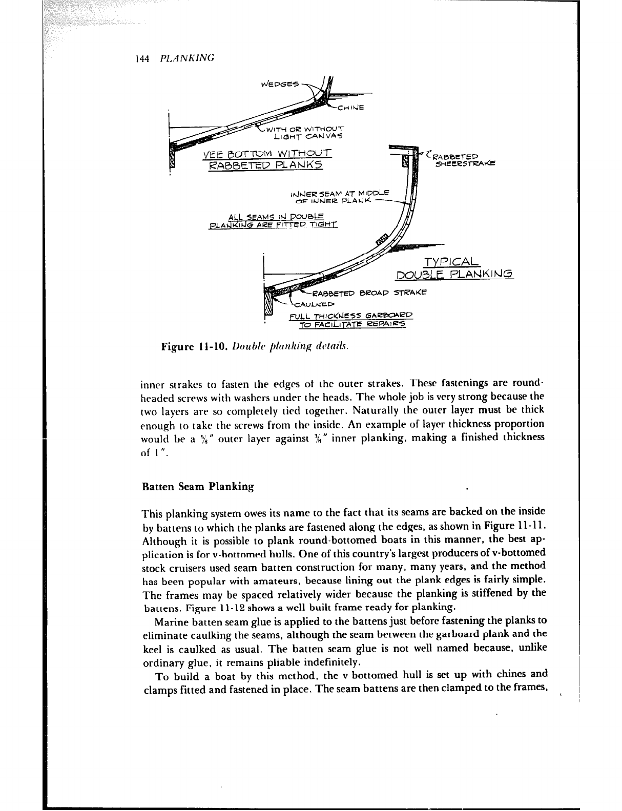
1dhh5R SEAM AT MIDDie
OF IhiPslER PLAJK -
144 P1.A NKING
Figure 1 l-10. IhuI~l~ pltr~~kiu~ rklnils.
inner strakcs to fasten the edgrs of the outer strakes. These fastenings are round-
headed screws with washers under the hrads. The whole job is very strong because the
two layers are so complctrly tied together. Naturally the outer layer must be thick
enough to takr the screws from the inside. An example of layer thickness proportion
would be a ‘7;” outer layer against l!n” inner planking, making a finished thickness
of I ‘I.
Batten Seam Planking
This planking system owes its name to the fact that its seams are backed on the inside
by battens to which the planks are fastened along the edges, as shown in Figure 11-11.
Although it is possible to plank round-bottomed boats in this manner, the best ap-
plication is for v-bottomed hulls. One of this country’s largest producers of v-bottomed
stock cruisers used seam batten construction for many, many years, and the method
has been popular with amateurs, because lining out the plank edges is fairly simple.
The frames may be spaced relatively wider because the planking is stiffened by the
battens. Figure 11-12 shows a well-built frame ready for planking.
Marine batten seam glue is applied to the battens just before fastening the planks to
eliminate caulking the seams, although the seam between the garboard plank and the
keel is caulked as usual. The batten seam glue is not well named because, unlike
ordinary glue, it remains pliable indefinitely.
To build a boat by this method, the v-bottomed hull is set up with chines and
clamps fitted and fastened in place. The seam battens are then clamped to the frames,
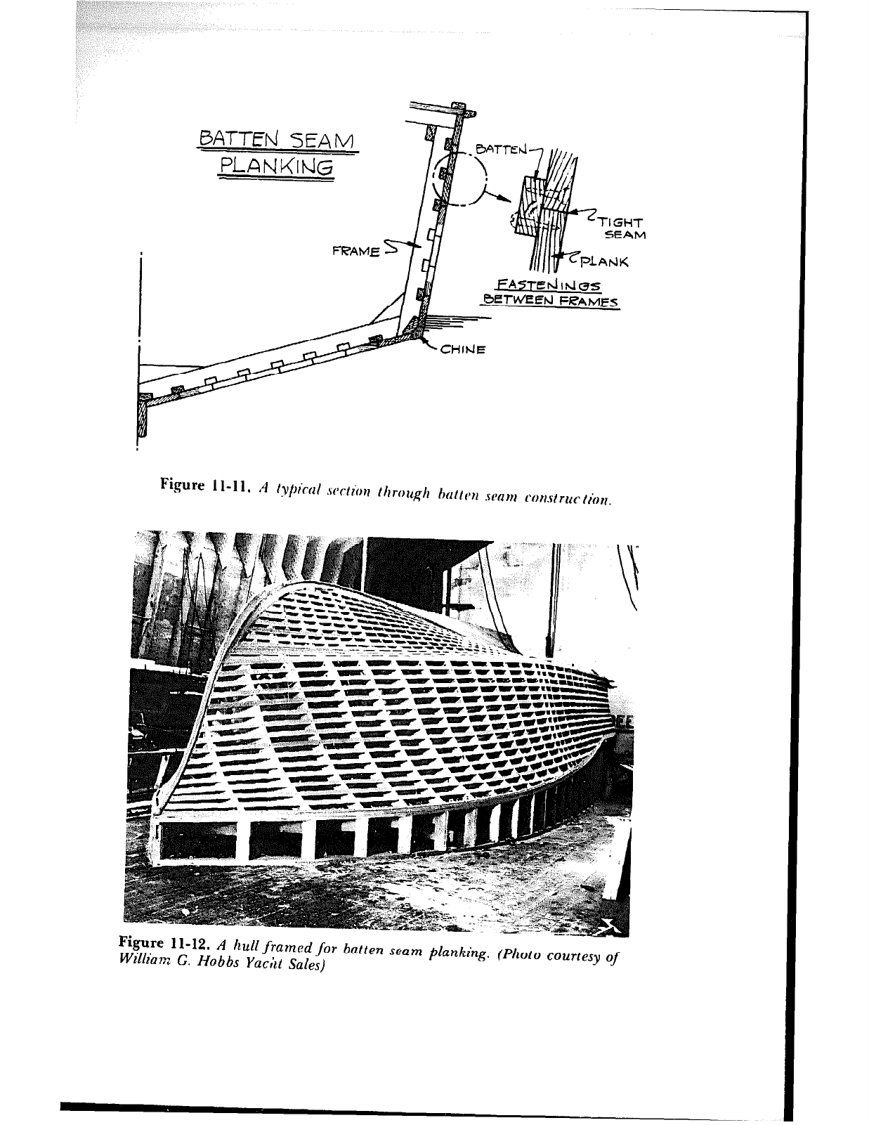
BATJE~ SEAM
l=iANG(rhl~
---
----
11-R A Ilull framed for batten seam planking. (Photo courtesy of
William G. Hobbs Yacht Sales)
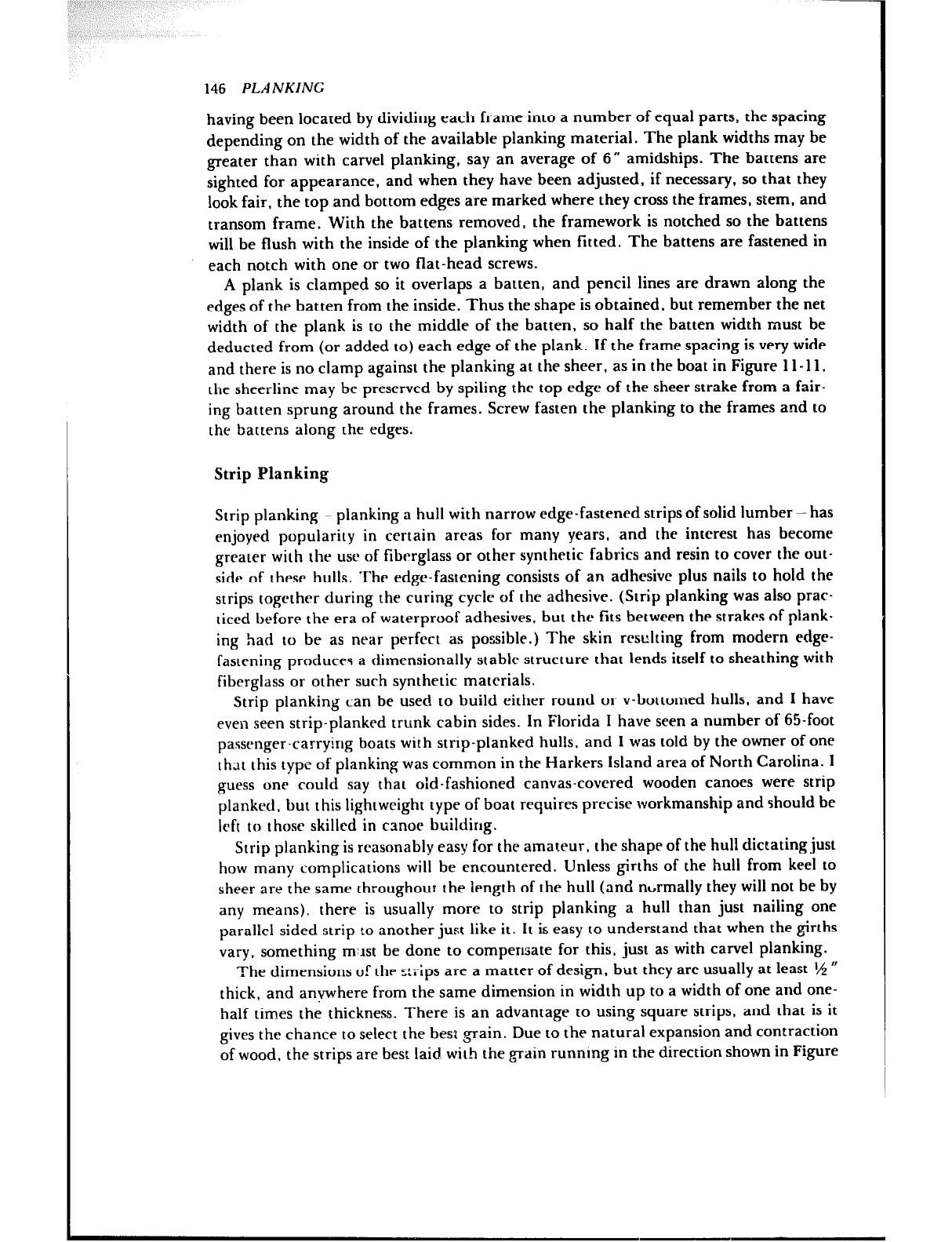
146 PLANKING
having been located by dividing each frame into a number of equal parts, the spacing
depending on the width of the available planking material. The plank widths may be
greater than with carve1 planking, say an average of 6” amidships. The battens are
sighted for appearance, and when they have been adjusted, if necessary, so that they
look fair, the top and bottom edges are marked where they cross the frames, stem, and
transom frame. With the battens removed, the framework is notched so the battens
will be flush with the inside of the planking when fitted. The battens are fastened in
each notch with one or two flat-head screws.
A plank is clamped so it overlaps a batten, and pencil lines are drawn along the
edges of the batten from the inside. Thus the shape is obtained, but remember the net
width of the plank is to the middle of the batten, so half the batten width must be
deducted from (or added to) each edge of the plank. If the frame spacing is very wide
and there is no clamp against the planking at the sheer, as in the boat in Figure 11-l 1.
the sheerline may be preserved by spiling the top edge of the sheer strake from a fair-
ing batten sprung around the frames. Screw fasten the planking to the frames and to
the battens along the edges.
Strip Blanking
Strip planking planking a hull with narrow edge-fastened strips of solid lumber-has
enjoyed popularity in certain areas for many years, and the interest has become
greater with the use of fiberglass or other synthetic fabrics and resin to cover the out-
side of these hulls. The edge-fastening consists of an adhesive plus nails to hold the
strips together during the curing cycle of the adhesive. (Strip planking was also prac-
ticed before the era of waterproof adhesives, but the fits between the strakes of plank-
ing had to be as near perfect as possible.) The skin resulting from modern edge-
fastening produce4 a dimensionally stable structure that lends itself to sheathing with
fiberglass or other such synthetic materials.
Strip planking can be used to build either round or v-bottomed hulls, and I have
even seen strip-planked trunk cabin sides. In Florida I have seen a number of 65-foot
passenger-carrying boats with strip-planked hulls, and 1 was told by the owner of one
that this type of planking was common in the Harkers lsland area of North Carolina. 1
guess one rould say that old-fashioned canvas-covered wooden canoes were strip
planked. but this lightweight type of boat requires precise workmanship and should be
left to those skilled in canoe building.
Strip planking is reasonably easy for the amateur, the shape of the hull dictating just
how many complications will be encountered. Unless girths of the hull from keel to
sheer are the same throughout. the length of the hull (and nbrmally they will not be by
any means), there is usually more to strip planking a hull than just nailing one
parallel-sided strip LO another just like it. It is easy to understand that when the girths
vary, something m;lst be done to compensate for this, just as with carve1 planking.
The dimensions of the ztrips are a matter of design. but they are usually at least l/z M
thick, and anvwhere from the same dimension in width up to a width of one and one-
half times the thickness. There is an advantage to using square strips, and that is it
gives the chance to select the best grain. Due LO the natural expansion and contraction
of wood, the strips are best laid with the grain running in the direction shown in Figure
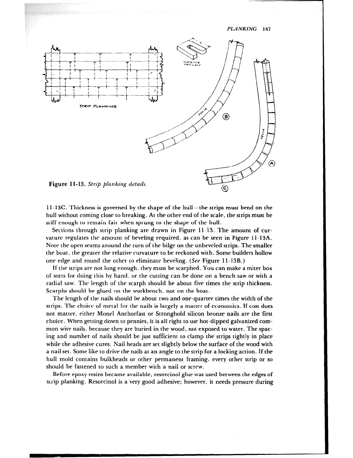
PLANKING 147
Fi.gure 11-13. Strik plcmkin~ ridails
1 l- 13C. ‘l’hickness is governed by the shape of the hull---the strips must bend on the
hull without coming close to breaking. At the other end of the scale, the strips must be
stiff enough to remain fair when sprung to the shapr of the hull.
Sections through strip planking are drawn in Figure I 1.13. The amount of cur-
vature regulates the amount of beveling required, as can be seen in Figure 1 l-13A.
Note the open seams around the turn of the bilge on the unbeveled strips. The smaller
the boat. the greater the relative curvature to be reckoned with. Some builders hollow
one edge and round the other to eliminate beveling. (See Figure ll-13B.)
If the strips are not long enough, they must be scarphed. You can make a miter box
of sorts for doing this by hand, or the cutting can be done on a bench saw or with a
radial saw. Thr length of the scarph should be about five times the strip thickness.
Scarphs should be glued on the workbench. not on the boat.
The length of thi nails sltould be about two and one-quarter times the width of the
strips. l’hc choicr of metal for the nails is largely a matter of economics. If cost does
not matter. either Moncl Anchorfast or Stronghold silicon bronze nails are the first
choice. When getting down to pennies, it is all right to use hot-dipped galvanized com-
mon wire nails, because they are buried in the wood, not exposed to water. The spac-
ing and number of nails should be just sufficient to clamp the strips tightly in place
while the adhesive cures. Nail heads are set slightly below the surface of the wood with
a nail set. Some like to drive the nails at an angle to the strip for a locking action. If the
hull mold contains bulkheads or other permanent framing, every other strip or so
should be fastened to such a member with a nail or screw.
Before epoxy resins became available, resorcinol glue was used between the edges of
strip planking. Resorcinol is a very good adhesive; however, it needs pressure during
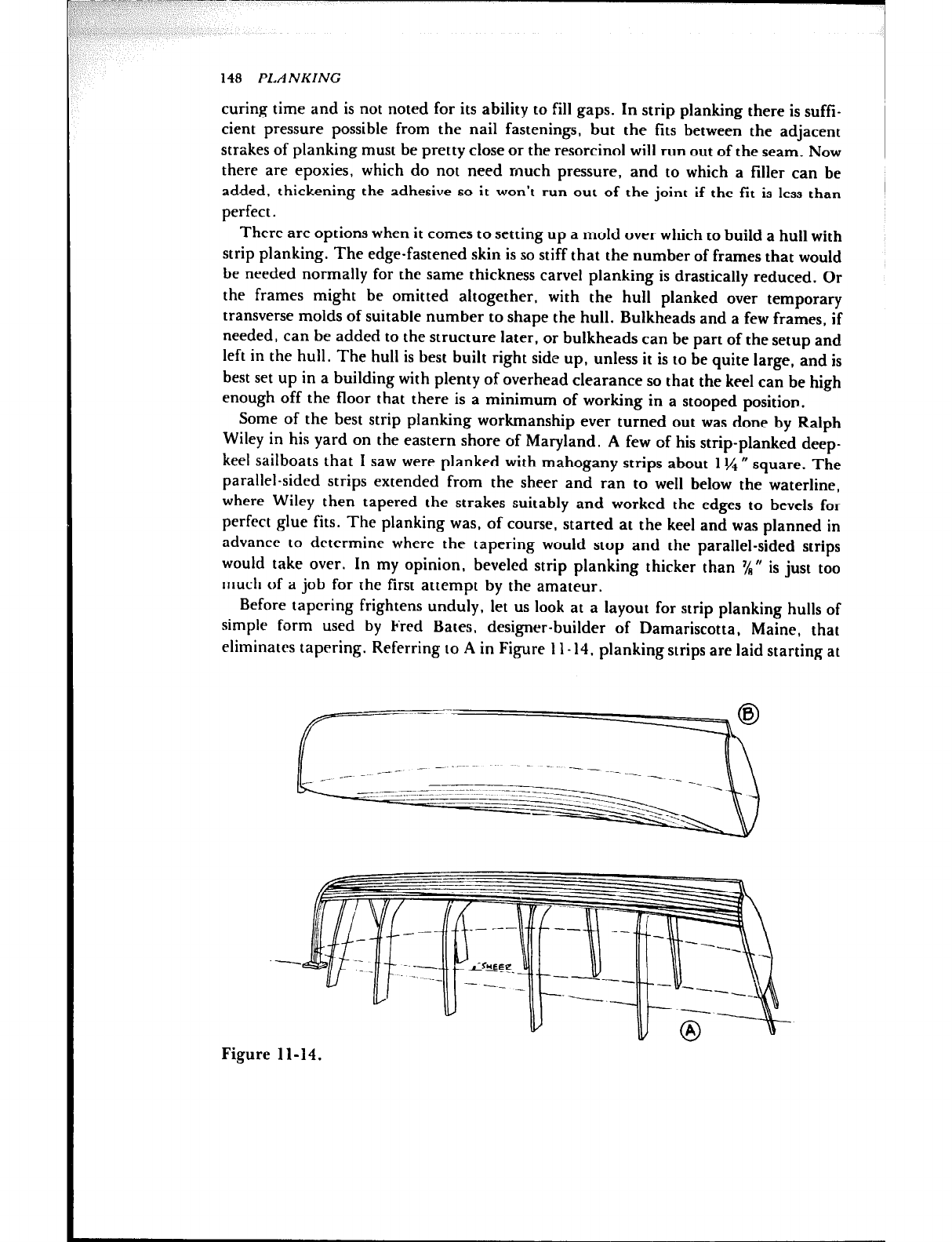
9 ~‘~~~;~~ \ ’
:
148 PLANKING
curing time and is not noted for its ability to fill gaps. In strip planking there is suffi-
cient pressure possible from the nail fastenings, but the fits between the adjacent
strakes of planking must be pretty close or the resorcinol will run out of the seam. Now
there are epoxies, which do not need much pressure, and to which a filler can be
added, thickening the adhesive so it won’t run out of the joint if the fit is less than
perfect.
There are options when it comes to setting up a mold over which to build a hull with
strip planking. The edge-fastened skin is so stiff that the number of frames that would
be needed normally for the same thickness carve1 planking is drastically reduced. Or
the frames might be omitted altogether, with the hull planked over temporary
transverse molds of suitable number to shape the hull. Bulkheads and a few frames, if
needed, can be added to the structure later, or bulkheads can be part of the setup and
left in the hull. The hull is best built right side up, unless it is to be quite large, and is
best set up in a building with plenty of overhead clearance so that the keel can be high
enough off the floor that there is a minimum of working in a stooped position.
Some of the best strip planking workmanship ever turned out was done by Ralph
Wiley in his yard on the eastern shore of Maryland. A few of his strip-planked deep-
keel sailboats that I saw were planked with mahogany strips about 1% 0 square. The
parallel-sided strips extended from the sheer and ran to well below the waterline,
where Wiley then tapered the strakes suitably and worked the edges to bevels for
perfect glue fits. The planking was, of course, started at the keel and was planned in
advance to determine where the tapering would stop and the parallel-sided strips
would take over. In my opinion, beveled strip planking thicker than ‘/R” is just too
much of a job for the first attempt by the amateur.
Before tapering frightens unduly. let us look at a layout for strip planking hulls of
simple form used by Fred Bates, designer-builder of Damariscotta, Maine, that
eliminates tapering. Referring 10 A in Figure II- 14. planking strips are laid starting at
Figure 11-14.
PLANKING 149
the keel and are temporarily held in place, not permanently fastened. Then a distance
equal to a number of strip widths is laid off from the sheer at each frame or mold, and
a tine is drawn on the strips by springing a batten through the points. The strips are
carefully marked for exact location, then removed and cut to the tine, and are per-
manently replaced with glue and fastenings. The remainder of the hull is planked with
parallel-sided strips to the sheer.
Fred has a good scheme for keeping the strips of planking aligned while nailing. He
makes a dozen or so of the horseshoe clamps sketched in Figure 11-13. These are cut
from scrap :‘d N plywood, varying the depth L, with a slot width of slightly more than
the strip thickness.
A good number of Rhodes-designed sailboats were built by a Great Lakes yard using
parallel strips with rounded and hollowed edges. There was no tapering of the strips;
they started at the keel and ran out at the sheer, as indicated in Figure II-14B.
Still another version of strip planking that I have seen was a method where hull
strips were laid on diagonally. This strake arrangement resulted in a herringbone ap-
pearance as one looked down into the hull.
Plywood Planking
The fact that a hull is v-bottomed does not automatically mean that it can be planked
with plywood: plywood can be bent without distortion in only one axis at a time and
thus should only be used to plank hulls designed with its limitations in mind. The sec-
tions of vessels design.!d for plywood construction generally consist of developable
curves curves that consist of portions of cylinders and cones. It should not go un-
noted that experienced builders have succeeded where theory dictates the impossible.
However. the methods used just about defy written description. Suffice it to say then,
that you should review the plans of your boat carefully before deciding to plank it with
plywood panels.
Plywood is a stiff material: therefore, planking thickness can be less than it would be
with conventional wooden planking. Also an advantage is its ability to cover large
areas quickly. Often, standard plywood panels wit! be too short for you to plank in one
panel from bow to stern. If so, either special panels must be ordered or else the regular
panels must be butted end to end. These joints, which should be detailed on the plans.
are generally made with good-size butt blocks. The joints should be waterproof glued
and well fastened wiih screws or rivets.
White being fitied, the plywood should be fastened with just enough screws to hold
it in place. When the tit is satisfactory, remove the panel and then, depending on the
specifications for the boat, apply either marine or waterproof glue to chines, rabbet,
frames, etc., and bend the plywood on again, again with just a few screws to hold it.
Working as fast as possible because of the glue, drive the remaining screws, of which
there are a great many. Work from the middle of the panel toward the ends, drilling
for screws and countersinking the heads slightly below the surface of the panel so they
can be made invisible with marine surfacing putty.
Some builders use plywood instead of solid lumber for the inner layer of a doubte-
planked hull, even when there is considerable curvature. They apply the plywood in
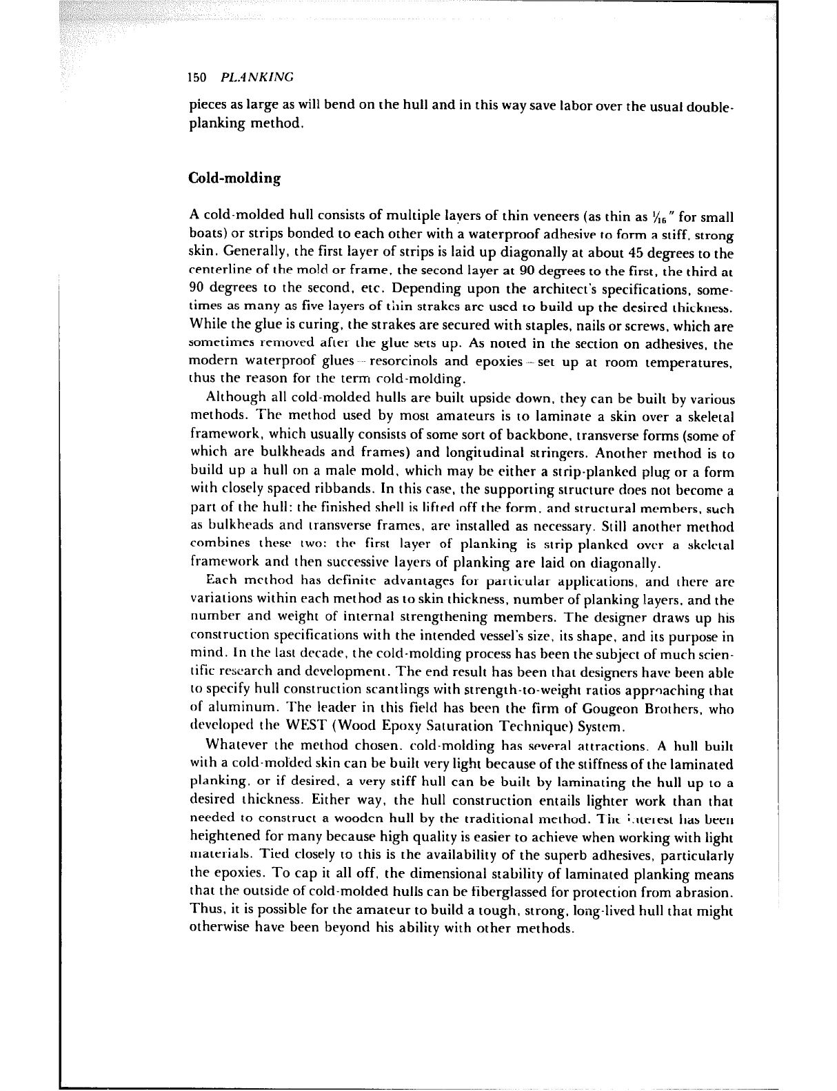
150 PL.4NKING
pieces as large as will bend on the hull and in this way save labor over the usual doubte-
planking method.
Cold-molding
A cold-molded hull consists of multiple layers of thin veneers (as thin as x6” for small
boats) or strips bonded to each other with a waterproof adhesive to form a stiff, strong
skin. Generally, the first layer of strips is laid up diagonally at about 45 degrees to the
centerline of the mo!d or frame, the second layer at 90 degrees to the first. the third at
90 degrees to the second, etc. Depending upon the architect’s specifications, some-
times as many as five layers of thin strakes are used to build up the desired thickness.
White the glue is curing, the strakes are secured with staples, nails or screws, which are
sometimes removed after the glue sets up. As noted in the section on adhesives, the
modern waterproof glues resorcinots and epoxies --set up at room temperatures,
thus the reason for the term cold-molding.
Although all cold-molded hulls are built upside down, they can be built by various
methods. The method used by most amateurs is to laminate a skin over a skeletal
framework, which usually consists of some sort of backbone, transverse forms (some of
which are bulkheads and frames) and longitudinal stringers. Another method is to
build up a hull on a male mold. which may be either a strip-planked plug or a form
with closely spaced ribbands. In this case, the supporting structure does not become a
part of the hull: the finished shell is lifted off the form, and structural membc~rs, such
as bulkheads and transverse frames, are installed as necessary. Stilt another method
combines thcsc two: the first layer of planking is strip-planked over a skeletal
framework and then successive layers of planking are laid on diagonally.
Each method has definite advantages for particular applications, and there arc
variations within each method as to skin thickness, number of planking layers. and the
number and weight of internal strengthening members. The designer draws up his
construction specifications with the intended vessel’s size, its shape, and its purpose in
mind. In the last decade, the cold-molding process has been the subject of much scien-
tific research and developmem. The end result has been that desi,gners have been able
to specify hull construction srantlings with strength-to-wright ratios approaching that
of aluminum. The leader in this field has been the firm of Gougcon Brothers. who
devclopc~tt the WEST (Wood Epoxy Saturation Technique) System.
Whatever the method chosen. cold-molding has several attractions. A hull built
with a cold-motded skin can be built very tight because of the stiffness of the laminated
planking, or if desired. a very stiff hull can be built by laminating the hull up to a
desired rhickness. Either way, the hull construction entails lighter work than that
needed to construct a wooden hull by the traditional method. Tht interest has been
heightened for many because high quality is easier to achieve when working with light
materials. Tied closely to this is the availability of the superb adhesives, particularly
the epoxies. To cap it all off, the dimensional stability of laminated planking means
that the outside of cold-molded hulls can be fiberglassed for protection from abrasion.
Thus, it is possible for the amateur to build a tough. strong, tong-lived hull that might
otherwise have been beyond his ability with other methods.
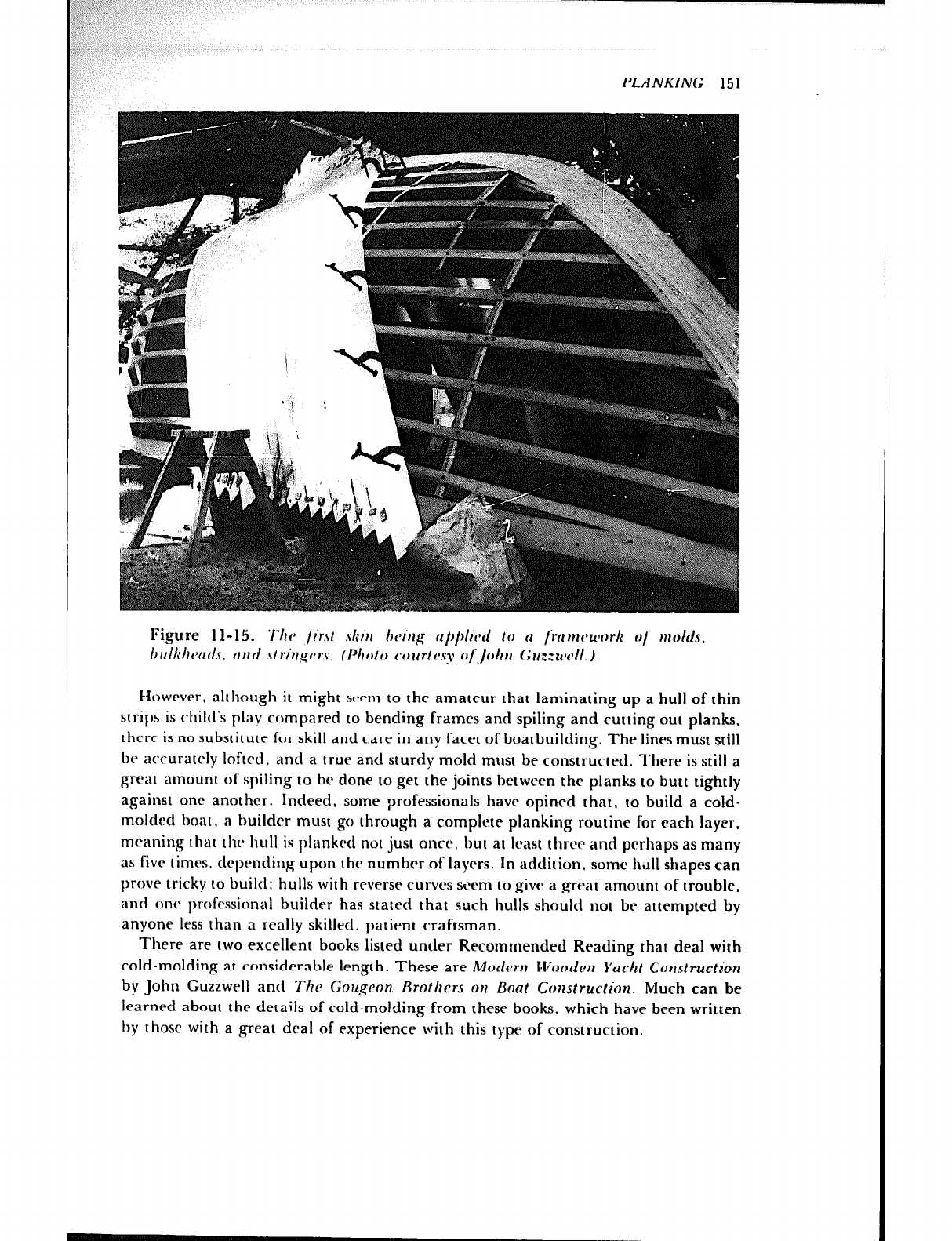
PLANKING 15 1
>,*,
4
@”
* .
Figure t l-15. ‘i’hv /i’rst .$kor hvl’trfi rlpp/ivd If, 11 /irlnrcwork o/ mfdds,
l~rrllrhfwtls, ccrrrl .strr’ugf*r.s. (I~~lf~lf~ f~orcrtf~sy o/‘,/ohli t~rrz:u~fdl.)
tiowever, although it might SWIII to the amateur that laminating up a hull of thin
strips is child’s play compared to bending frames and spiting and cutting out planks,
tht:rr is no substitute for skill and care in any facet of boatbuilding. The tines must stilt
be accurately lofted, and a [rue and sturdy mold must be constructed. There is stilt a
great amount of spiling to bc done to get the joints between the planks to butt tightly
against one another. Indeed, some professionals have opined that, to build a cotd-
molded boar, a huitdcr must go through a complete planking routine for each layer,
meaning that thy hull is ptankrd not just once. but at least three and perhaps as many
as five times. depending upon the number of layers. In addition, some hI1tt shaprs can
prove tricky to build: hulls with reverse curves seem to give a great amount of trouble,
and onr professional builder has stated that such hulls should not be attempted by
anyone less than a realty skilled, patient craftsman.
There are two excellent books listed under Recommended Reading that deal with
cold-molding at considerable length. These are Moduw Wocldrn Yacht Construction
by John Guzzwrtt and Thr Gougcon Brothers on Boat Construclion. Much can be
learned about the details of cold-molding from these books. which have been written
by those with a great deal of experience wirh this type of construction.
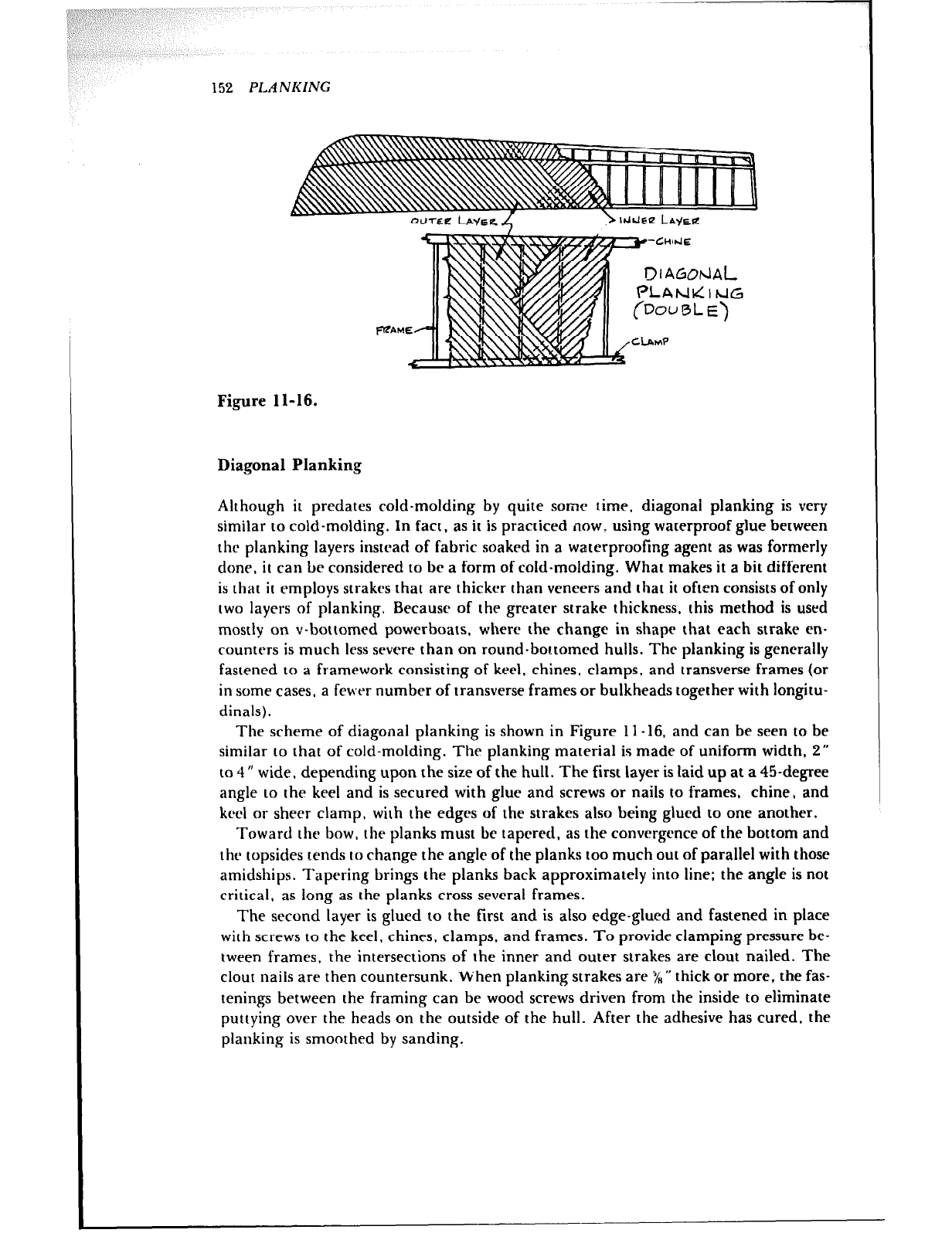
152 PLANKING
Figure 11-16.
Diagonal Planking
Although it predates cold-molding by quite some time, diagonal planking is very
similar to cold-molding. In fact, as it is practiced now. using waterproof glue between
the planking layers instrad of fabric soaked in a waterproofing agent as was formerly
done, it can bc considered to br a form of cold-molding. What makes it a bit different
is that it employs strakes that are thicker than veneers and that it often consists of only
two layers of planking. Because of the greater strake thickness, this method is used
mostly on v-bottomed powerboats, where the change in shape that each strake en-
counters is much less severe than on round-bottomed hulls. The planking is generally
fastened to a framework consisting of keel, chines, clamps, and transverse frames (or
in some cases, a fever number of transverse frames or bulkheads together with longitu-
dinals).
The scheme of diagonal planking is shown in Figure 11-16, and can be seen to be
similar to that of cold-molding. The planking material is made of uniform width, 2”
to 4” wide, depending upon the size of the hull. The first layer is laid up at a 45-degree
angle to the keel and is secured with glue and screws or nails to frames, chine, and
keel or sheer clamp, with the edges of the strakes also being glued to one another.
Toward the bow, the planks must be tapered. as the convergence of the bottom and
thr topsides tends IO change the angle of the planks too much out of parallel with those
amidships. Tapering brings the planks back approximately into line; the angle is not
critical, as long as the planks cross several frames.
The second layer is glued to the first and is also edge-glued and fastened in place
with screws to the keel, chines, clamps. and frames. To provide clamping pressure be-
tween frames, the intersections of the inner and outer strakes are clout nailed. The
clout nails are then countersunk. When planking strakes are 5/H * thick or more, the fas-
tenings between the framing can be wood screws driven from the inside to eliminate
puttying over the heads on the outside of the hull. After the adhesive has cured, the
planking is smoothed by sanding.
Chapter 12
DECK FRAMING
The decking of a boat is laid on transverse beams, which not only provide support for
the deck but also help to hold the sides of the hull together. The latter aspect is impor.
tant in all boats designed to be decked, especially in sailboats. The many types of small
powerboats and sailboats that are not decked must be designed to have enough
strength to do without the stiffening that the deck structure provides. In many such
hulls the thwarts do double duty as hull stiffening.
Clamps and Shelves
The deck beams must be of good size and strongly connected to the hull if they are to
contribute the strength required of them. In small boats they are fastened to the clamp
and the frame heads (Figure 12-1A and B). As hulls increase in size, an additional stif-
fening member callrd a shelf. or deck shelf, is fitted on each side of the boat. The shelf
is generally of the same material as the clamp, and its position on the flat against the
clamp provides a greater landing area for the beam ends, which are fastened through
it instead of the clamp.
In small craft, screws are used as fastenings, but in larger vessels through-bolts are
always used. Bolts have the extra advantage of being able to be tightened if necessary,
whereas screws through beams are not accessible once the boat is decked. To lessen the
concentration of fastenings in the vicinity of the deck beams, shelves are fastened to
the clamps between frames. (See Figure 12- 1.) They are sprung in place on edge in
single lengths, when necessary, or, in several pieces joined by scarphs, with the joints
located toward the ends of the boat. The inner edges may be left square, but the outer
edges should be planed to fit snugly against the clamps. The shelves must be fitted
with a pitch corresponding to the camber of the deck beams so that the beams will
153
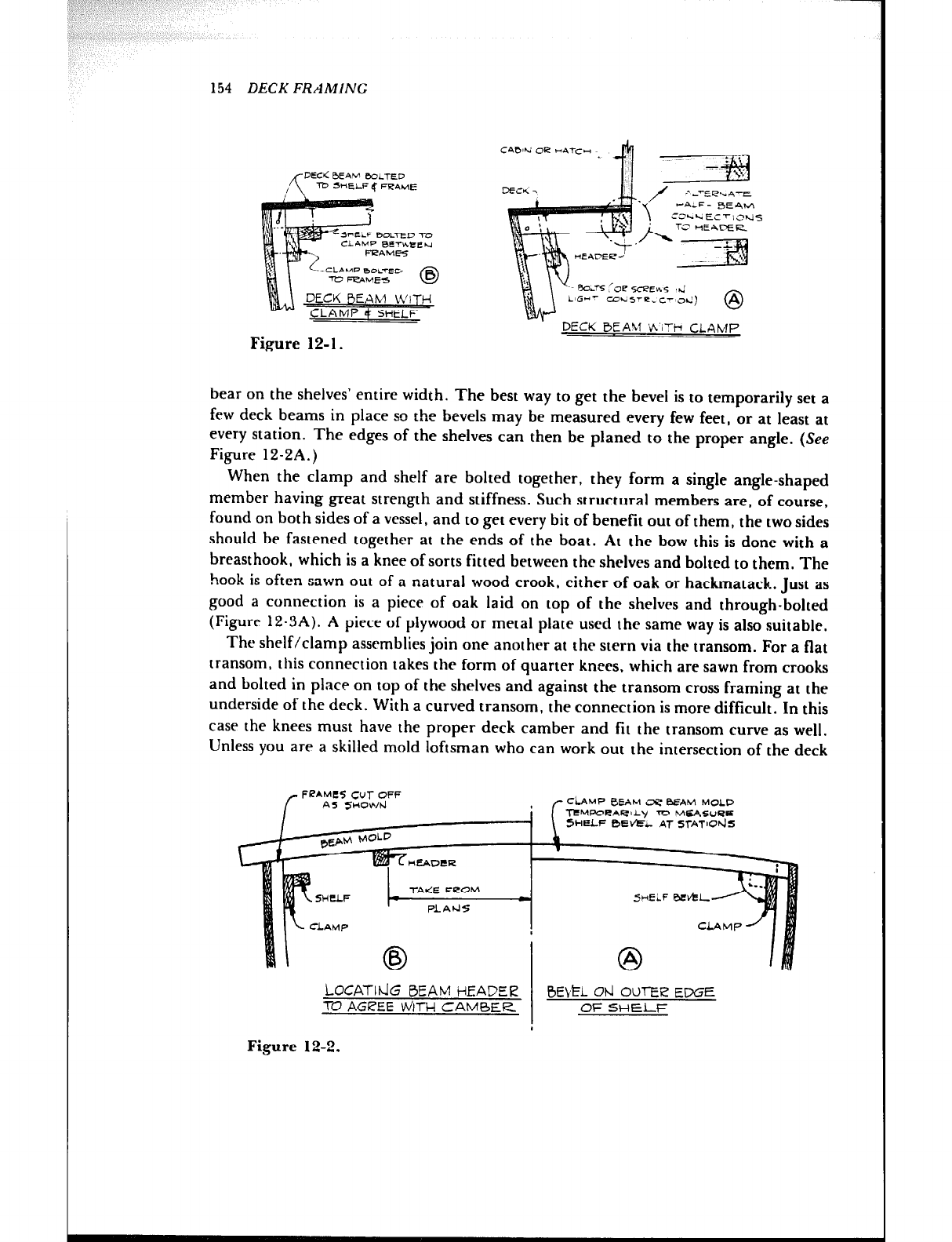
154 DECKFRAMlh'G
DECK
CLAMP 4 SHELF
Figure 12-l.
-M
/ / 2 ---EebA-r 2 ---EebA-r
‘1 ‘1
V-A-F- BEAL4 V-A-F- BEAL4
ca.4EcTlahj~ ca.4EcTlahj~
/yq /yq
ROLTS lee sceEv.5 ,+.J
CDL*5-e. C’~Od)
CDL*5-e. C’~cd) @ @
DECK BEAll K’IT+ CLAMP DECK BEAll K’iTi CLAMP
bear on the shelves’ entire width. The best way to get the bevel is to temporarily set a
few deck beams in place so the bevels may be measured every few feet, or at least at
every station. The edges of the shelves can then be planed to the proper angle. (See
Figure 12-2A.)
When the clamp and shelf are bolted together, they form a single angle-shaped
member having great strength and stiffness. Such structural members are, of course,
found on both sides of a vessel, and to get every bit of benefit out of them, the twosides
should be fastened together at the ends of the boat. At the bow this is done with a
breasthook, which is a knee of sorts fitted between the shelves and bolted to them. The
hook is often sawn out of a natural wood crook, either of oak or hackmatack. Just as
good a connection is a piece of oak laid on top of the shelves and through-bolted
(Figure 12-3A). A piece of plywood or metal plate used the same way is also suitable.
The shelf/clamp assemblies join one another at the stern via the transom. For a flat
transom, this connection takes the form of quarter knees, which are sawn from crooks
and bolted in place on top of the shelves and against the transom cross framing at the
underside of the deck. With a curved transom, the connection is more difficult. In this
case the knees must have the proper deck camber and fit the transom curve as well.
Unless you are a skilled mold loftsman who can work out the intersection of the deck
FPAMCS CUT OFF
rs
AS SHOWIJ CiAMP &EAM cc BEAM MOLD
TtMlWLAClLy ‘TU MEASVeE
5~IELF BEVEL- AT 5TATlOd5
‘AICE FeOM T 5tEi.F BE&L
PLAt45
CLAMP CLAMP
4
0
A
LOCATI& 0E,w H~YQER l3Eb~L Old OUrEi2 EDGE
m AGREE WITH CAMBER OF SHELF
Figure 12-2.
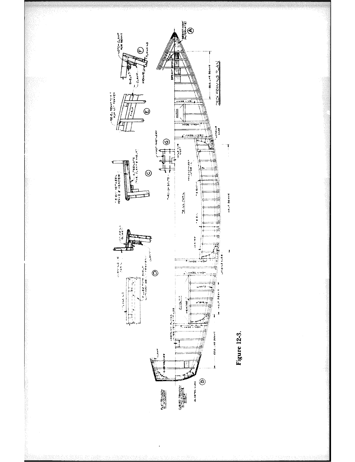
-v;-- -y
-: 1..
c- -5
‘* 1;
; I
:v- :j$
d+J” *
,a :
--- 7~.-*+& .;*:=-*-q :
:
=-----~-~:- .-m--3 z
_~ r.-:.zsm?‘-‘-- -__I 9
..~ - .,p- ~~ - - <
: i++:,
*..w-: -1:
/F- -7,’ ‘;
: 1 +-x~: 4
!: ::I Sws~ ,J, ”
::,
#===qr j
;: “,,
.T:: :,j;;
1.
Lb,
:. at
?$yp$ I ’
‘-.r-.~~~ci~’
?y . ..= p . ..z-
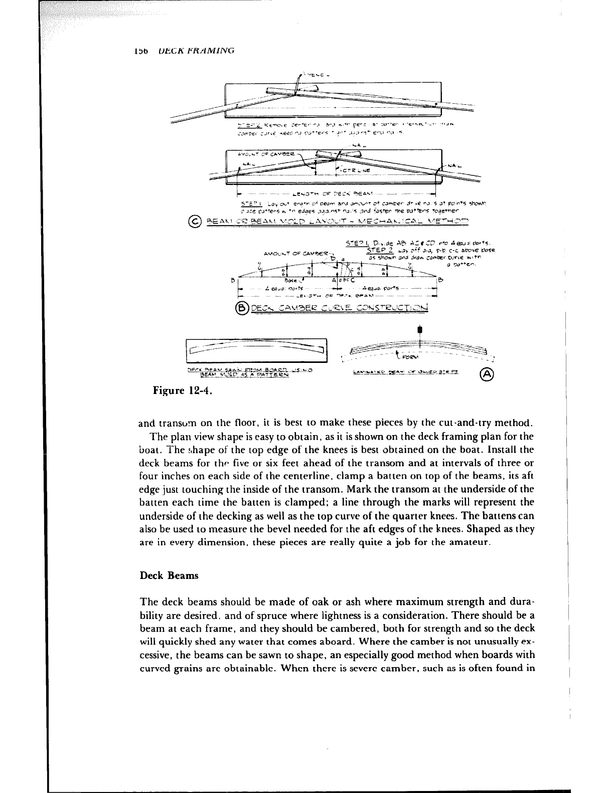
156 DECK FRAMING
5’ET I. D,,,de AB A:( ‘17 r-o A~J*Ico~~s.
c
II410C’L~ OF c&.K~~Z-, cl, ,‘i Al, C-D c-c mo*e *se
STEP Z
35 sbwr and dmr. ~ornkr wr,e yr (+r
0 m*+en.
Figure 12-4.
and transom on the floor, it is best to make these pieces by the cut-and-try method.
The plan view shape is easy to obtain, as it is shown on the deck framing plan for the
boat. The shape of the top edge of the knees is best obtained on the boat. Install the
deck beams for thr* five or six feet ahead of the transom and at intervals of three or
four inches on each side of the centerline, clamp a batten on top of the beams, its aft
edge just touching the inside of the transom. Mark the transom at the underside of the
batten each time the batten is clamped; a line through the marks will represent the
underside of the decking as well as the top curve of the quarter knees. The battens can
also be used to measure the bevel needed for the aft edges of the knees. Shaped as they
are in every dimension, these pieces are really quite a job for the amateur.
Deck Beams
The deck beams should be made of oak or ash where maximum strength and dura-
bility are desired, and of spruce where lightness is a consideration. There should be a
beam at each frame, and they should be cambered, both for strength and so the deck
will quickly shed any water that comes aboard. Where the camber is not unusually ex-
cessive, the beams can be sawn to shape, an especially good method when boards with
curved grains are obtainable. When there is severe camber, such as is often found in
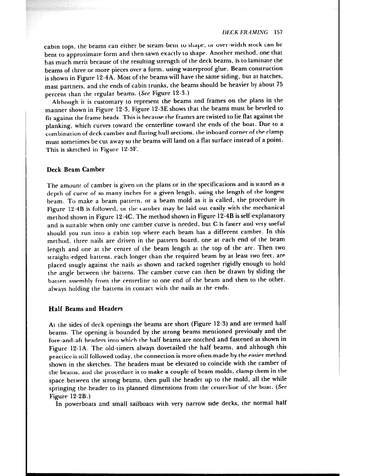
DECK FRAMING; 157
cabin tops, the beams can either be steam-bent to shape, or over-width stock can be
bent to approximate form and then sawn exactly to shape. Another method, one that
has much merit because of the resulting strength of the deck beams, is to laminate the
beams of three or more pieces over a form, using waterproof glue. Beam construction
is shown in Figure 12-4A. Most of the beams will have the same siding, but at hatches,
mast partners, and the ends of cabin trunks, the beams should be heavier by about 75
percent than the t,egular beams. (See Figure 12-3.)
Although it is customary to represent the beams and frames on the plans in the
manner shown in Figure 12-3, Figure 12-3E shows that the beams must be beveled to
fit against the frame heads. This is because the frames are twisted to lie flat against the
planking, which curves toward the centerline toward the ends of the boat. Due to a
combination of deck camber and flaring hull sections, the inboard corner of the clamp
must sometimes be cut away so the beams will land on a flat surface instead of a point.
This is sketched in Figure 12-3F.
Deck Beam Camber
The amount of camber is given on the plans or in the specifications and is stated as a
depth of curve of so many inches for a given length, using the length of the longest
beam. To make a beam pattern, or a beam mold as it is called, the procrdure in
Figure 12-4B is followed, or the camber may bc laid out easily with thr mechanical
method shown in Figure 12.4C. The method shown in Figure 12-48 is self-explanatory
and is suitable when only one camber curve is needed, but C is faster and very useful
should you run into a cabin top where each beam has a different camber. In this
method, three nails are driven in the pattern board, one at each end of thr beam
length and one at the center of the beam length at the top of the arc. Then two
straight-edged battens, each longer than the required beam by at least two feet, are
placed snugly against the nails as shown and tacked together rigidly enough to hold
the angle between the battens. The camber curve can then be drawn by sliding the
batten assembly from the centerline to one end of the beam and then to the other,
always holding the battens in contact with the nails at the ends.
Half Beams and Headers
At the sides of deck openings the beams are short (Figure 12-3) and are termed half
beams. The opening is bounded by the strong beams mentioned previously and the
fore-and-aft headers into which the half beams are notched and fastened as shown in
Figure 12-1A. The old-timers always dovetailed the half beams, and although this
practice is still followed today, the connection is more often made by the easier method
shown in the sketches. The headers must be elevated to coincide with the camber of
the beams, and the procedure is to make a couple of beam molds, clamp them in the
space between the strong beams, then pull the header up to the mold. all the while
springing the header to its planned dimensions from the centerline of the boat. (See
Figure 12-2B.)
In powerboats and small sailboats with very narrow side decks, the normal half
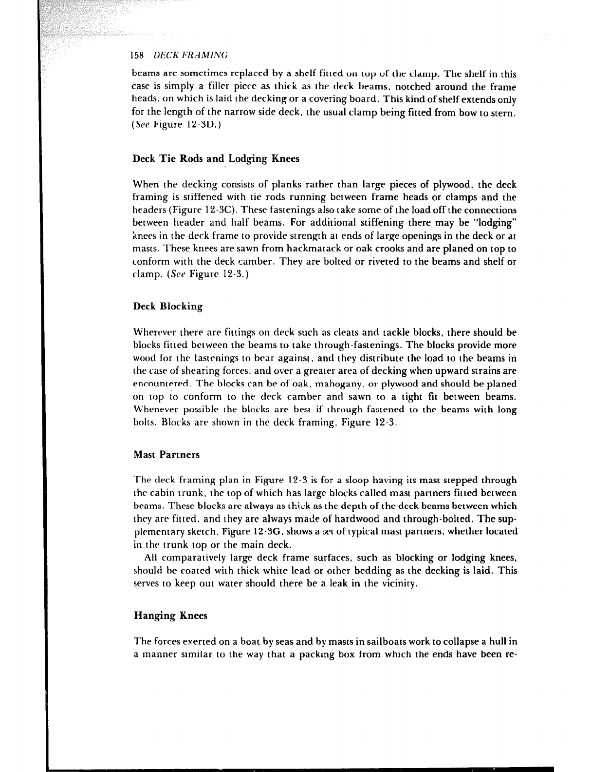
158 Db:CK E;RAMI,YG
beams are sometimes replaced by a shelf fitted on top of the clamp. The shelf in this
case is simply a filler piece as thick as the deck beams, notched around the frame
heads. on which is laid the decking or a covering board. This kind of shelf extends only
for the length of the narrow side deck, the usual clamp being fitted from bow to stern.
(See Figure 12-3D.)
Deck Tie Rods and Lodging Knees
When the decking consists of planks rather than large pieces of plywood, the deck
framing is stiffened with tie rods running between frame heads or clamps and the
headers (Figure 12-3C). These fastenings also take some of the load off the connections
between header and half beams. For additional stiffening there may be “lodging”
knees in the derk frame to provide strength at ends of large openings in the deck or at
masts. These knees are sawn from hackmatack or oak crooks and are planed on top to
conform with the deck camber. They are bolted or riveted to the beams and shelf or
clamp. (SPP Figure 12-3.)
Deck Blocking
Wherever there are fittings on deck such as cleats and tackle blocks, there should be
blocks fitted between the beams to take through-fastenings. The blocks provide more
wood for the fastenings to bear against, and they distribute the load to the beams in
I he case of shearing forces, and over a greater area of decking when upward strains are
encountered. The blocks can be of oak. mahogany, or plywood and should be planed
on top to conform to the deck camber and sawn to a tight fit between beams.
Whenever possible the blocks are best if through-fastened to the beams with long
bolts. Blocks arp shown in the deck framing. Figure 12-3.
Mast Partners
‘The deck framing plan in Figure 12-3 is for a sloop having its mast stepped through
the cabin trunk, the top of which has large blocks called mast partners fitted between
beams. These blocks are always as thick as the depth of the deck beams between which
they are fitted, and they are always made of hardwood and through-bolted. The sup.
plcmentary sketrh, Figure 1
2-3G, shows a set of typical mast partners, whether located
in thr trunk top or the main deck.
All comparatively large deck frame surfaces. such as blocking or lodging knees,
should be coated with thick white lead or other bedding as the decking is laid. This
serves to keep out water should there be a leak in the vicinity.
Haqging Knees
The forces exerted on a boat by seas and by masts in sailboats work to collapse a hull in
a manner similar to the way that a packing box from which the ends have been re-
DECti FRAMING 159
+iAC<MATACk.
P OArC KdEE5
HANCLING tNEE.5
Figure 12-5.
movt-d collapses when a man stands on it. These forces try to hinge the hull structure
at thr deck corner and are only one of the reasons why properly sized and located
fastenings are important if long hull life is to be expected. Brackets called hanging
knees are fitted for resisting such sideways strains. Like lodging knees, they are made
of natural crook oak or hackmatack and are through-fastened insofar as possible.
Metal, in the form of flanged plates, plates and angles, or castings, is often used for
kners and has the advantage of not splitting with age as wood is liable to do. Hanging
knees are grnrrally used in pairs at the masts and singly at the ends and midlength of
long deck openings. Figure 12 5 shows typical wooden hanging knees at the mast part-
ners of a sloop having its mast stepped through the cabin trunk.
Modern Construction
The quarter knees, lodging knees, and hanging knees described earlier are used in
traditional construction. The problem with such knees is to find them and then to pay
a reasonable price for them. (According to Woodr~z~onf magazine, a longtime sup-
plier of hackmatack knees was still in business in late 1979. He is Frank Morse, Cherry-
field, Maine 04622.) It should be realized that there are modern materials and tech-
niques available for small craft that can eliminate the need for traditional crook knees
of oak and hackmatack. Knees can be laminated of wood or plywood or be made of
flanged metal plates. Or. knees need not be used at all due to the enormous stiffening
provided by modern materials: a well-fitted and secure plywood deck can do the work
of lodging knees, and properly secured plywood interior joiner bulkheads often take
the place of hanging knees.

160 DECKFRAMING
In any case, be guided by the plans for your boat. The- designer should provide
details of the structure in way of masts when panel material is used for weight and
labor savings.
If there are a number of bulkheads and full-height joiner partitions in a hull, as is
common in many power cruisers packed full of cabins, head enclosures, etc., a deck
consisting of two layers of plywood glued together can be supported by these bulk-
heads and partitions with a minimum of other deck framing- just a few transverse
beams or longitudinals where it is necessary to reduce the span of unsupported
areas.
-DECKING
In general, there are really only two basic kinds of decking for a wooden boat. The
first, whirh can be the lightest, consists of a wooden deck covered with fabric to make
it watertight and minimize rot. Where the materials are available. it is logical to make
such a deck of waterproof plywood and cover it with fiberglass cloth. A cheaper dcck-
ing, one still used in areas like the Caribbean islands, is made of tongur-and-groovr-
type boards, sometimes covered with canvas, sometimes not: the latter is a short-lived
deck. The other type of deck is the so-called laid deck made of narrow strakes thick
enough to be caulked for watcartightness. And then there are variations of both types.
(The builder of a boat with a fiberglass hull might opt for a lightweight sandwich deck
having fiberglass skins over an end-grain balsa or foam core.)
Depending upon your viewpoint, each type of deck has an advantage. either
economic or aesthetic. Regardless of the decking chosen, remember that in all but the
smallest boats the deck serves the double purpose of providing strength and water-
tightness. Both these aspects contribute to safety, the latter to comfort and rot preven-
tion as well.
Tongue-and-Groove Deck
Tongue-and-groove boards make an inexpensive deck because the width of the
material, anywhere from 4”to 6”, permits the deck to be quickly built, with the boards
parallel to the centerline of the boat as in Figure IS-IA. Very often these decks are
made of non-durable material, unseasoned in the first place, and quick to rot if the
deck covering leaks. The straight-run deck is not as strong as other types and the
tongue-and-groove construction has the disadvantage that the thin upper edge of the
groove tends to warp between the fastenings (Figure 13- 1 B). The only covering for a
161
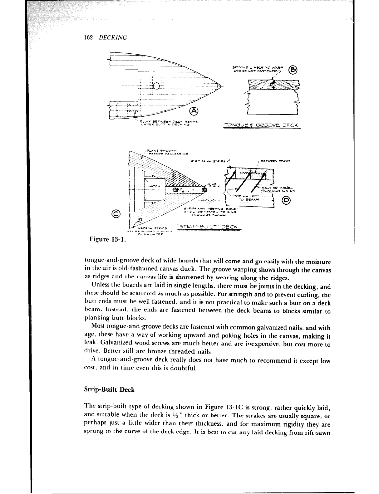
162 DECKING
“-%.ac~ BeT*CCr rEC& 9EA.4,
UkDEP BUT-- *i 3CCu. kc% TO”riGj’E 4‘ GPOOVE DE&K
~__
Figure
*.PltJL ,‘P 5-3
SrEieP-p,f~L’” C>ECh
\+.. ml! h, .VCP . -~ . ..-
--11\ 7
BLOC* \,-neo
* 3-, .
tongut~-and-grnovc~ deck of wide boards that will come and go easily with the moisture
in the air is old-fashioned canvas duck. The groove warping shows through the canvas
as ridges and the canvas life is shortened by wearing along the ridges.
Unless the boards are laid in single lengths, there must be joints in the decking, and
these should be scattered as much as possible. For strength and to prevent curling, the
butt ends must be well fastened, and it is not practical to make such a butt on a deck
beam. Instead, the ends are fastened between the deck beams to blocks similar to
planking butt blocks.
Most tongue-and-groove decks are fastened with common galvanized nails, and with
age, these have a way of working upward and poking holes in the canvas, making it
leak. Calvanizcd wood screws are much better and are inexpcnaivr, but cost more to
drive. Better still are bronze threaded nails.
A tongue-and-groove deck really cloes not have much to recommend it except low
cost. and in time even this is doubtful.
Strip-Built Deck
The strip-built type of decking shown in Figure 13.IC is strong, rather quickly laid,
and suitable when the deck is *c, ” thick or better. The strakes are usually square, or
perhaps just a little wider than their thickness, and for maximum rigidity they are
sprung to the curve of the deck edge. It is best to cut any laid decking from rift-sawn
DECKING 163
boards and lay it with the edge-grain up, for this way there will be a minimum of
shrinking and swelling across the width of the deck. (See Figure 4-3.) Galvanized
finishing nails are used for fastening and are satisfactory because they are hidden and
not exposed to sea water. The fastidious, of course, can substitute nonferrous Monel or
bronze nails at many times the cost and eliminate all misgivings.
The strakes are fastened to each other between the beams and toenailed to the
beams as shown in Figure 13-1D. It is good practice to set the nails slightly below the
surface of the wood. Around the edge of the deck, the outermost strip is fastened to the
edge of the sheer strake of planking. The deck is planed off smooth when finished.
If a strip-built deck is built with waterproof-glued seams like a strip-planked hull
(Chapter ll), it will be enormously strong if the seams are fitted reasonably tight.
After being planed smooth and sanded, such a deck can either be painted or covered
with light fiberglass cloth and then painted.
Plywood Deck
A main deck or cabin top of marine plywood is strong, light, and quickly laid. The ar-
rangement of the pieces of plywood must be planned with care to provide maximum
strength for the deck and for minimum waste of material, taking into consideration
openings in the deck for hatches, cockpit, and cabin, together with the size of the
panels available. In the previous chapter, the function in construction of lodging knees
under the deck at openings and at masts to minimize horizontal racking was mcn-
tioned. Following the same reasoning. the plywood should be cut so scams do not come
at the ends of large openings in the drck as shown in Figure 13-2. The butts should
overlap as shown in thP skctrh. and joints should be located bctwern the beams whrrr
the panel ends can br sccurety scirw fastened to a butt block underneath. Joint loca-
tions are not as important if thr plywood is waterproof glued to the deck beams,
because this adds considerably to the horizontal strength.
The deck panels should be fastened around the edges and along the deck beams
with rlosrly spaced flat-head screws or annularly threaded nails. Countersink the
fastening heads slightly below the surface and cover them over with a surfacing putty,
non-oil base if the deck is to be covered with fiberglass cloth and resin.
A well-fitted plywood deck properly glued to the deck framing can be fastened with
non-ferrous staples. Plywood up to I,$ ” thick can be fastened with coated Monet
staples driven by compressed-air-powered staplers. The coating increases the staples’
holding power so it is just about impossible to withdraw these staples from whitr oak.
When a plywood deck is specified to be :?$ R in thickness or more, the curvature due
to camber and sheer might make laying the deck in a single thickness either very dif-
ficult or even impossible. As soon as it is obvious that the flat panels will not conform
to the surface, the job must be done by using a double thickness, such as two layers of
%” or x” plywood, which should be waterproof glued together to provide the most
st rengt 4.
Canvas Covering Decks
Plywood is best covered with fiberglass, but inasmuch as I recently saw both plywood
and laid decks being covered with canvas in the Caribbean-~ ;)robabiy because of
economics-- canvas covering of decks is still worthy of mention.
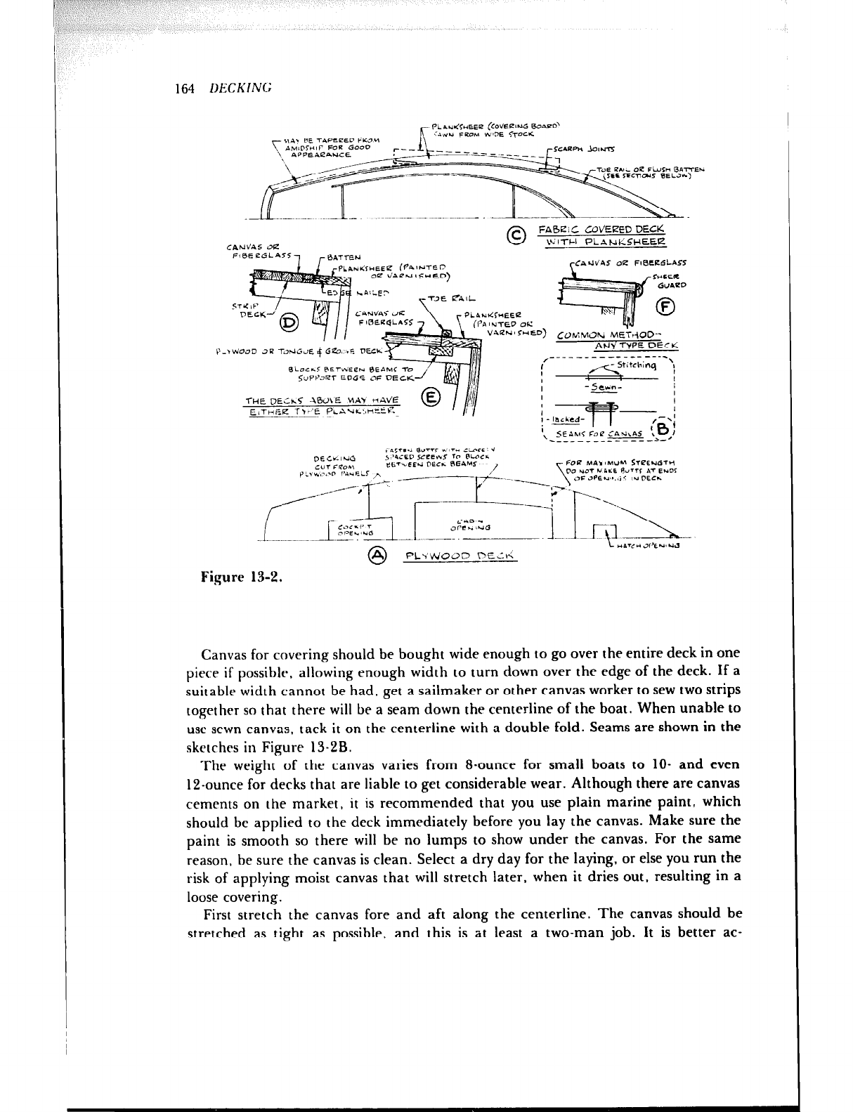
_I\I
in- -I-
164 DECKING
FAGi C COVEk3ZD DECK
CANV’AS oa WlTCI PLANICSHEEEZ
Fi0EeGLA55, eATTeN
r -,_ /_ __- 1”. ,.,-Ccl cCn.,VAS ob? FtBCKGLAS5
C4NdA5 JR PLnuwLFuEER * .\ ; 0
FlBEtZqLA55 -, ifn lUTED 062
- i ~ ~.-~
V4PN’GED) COPAMOk, M&,OD-
l’-rvjoJD JR TOtiirLJE 4 GE% -5. At& TYPE DEC<
~~
_- ____ ---___----_
0LOCF.l RETIGEEN t3EaMr -l-o
SurrJar eDG5 OF DECICZ -I’ ml4 lldil •t I
I
I
, .AWtchinq ‘;
THE ,,ECk< -r\6U\E bltaY WAti’E
E,TnBa T,.‘E pL.--“. .--cm
-
- Seun- I
kc,ITlri OVTrr KIT* iLnrE:Y
DECV.IUG , ‘4iED 5rEtr.S TO RLOCL
C”T Fl?Oh\ IbT’r.2E.d “ECr. RE4W FOP M&h OMULI STCEIIGTcl
pL,bQ,-..o i’AriELS ,h
Figure 13-2.
Canvas for covering should be bought wide enough to go over the entire deck in one
piece if possible, allowing enough width to turn down over the edge of the deck. If a
suitable width cannot be had, get a sailmaker or other canvas worker to sew two strips
together so that there will be a seam down the centerline of the boat. When unable to
use sewn canvas, tack it on the centerline with a double fold. Seams are shown in the
skctrhcs in Figure 13.2B.
The weight of the canvas varies from 8-ounce for small boats to lo- and even
12-ounce for decks that are liable to get considerable wear. Although there are canvas
cements on the market, it is recommended that you use plain marine paint, which
should bc applied to the deck immediately before you lay the canvas. Make sure the
paint is smooth so there will be no lumps to show under the canvas. For the same
reason, be sure the canvas is clean. Select a dry day for the laying, or else you run the
risk of applying moist canvas that will stretch later, when it dries out, resulting in a
loose covering.
First stretch the canvas fore and aft along the centerline. The canvas should be
stretched as tight as possible, and this is at least a two-man job. It is better ac-
DECKING 165
complished by rolling the ends of the canvas around sticks so that more area can be
worked on than can be handled by just your two hands. Pull the canvas down over the
edges of the boat and secure it with tacks, which will be hidden by moldings. Tacks
should be copper or Mone!, never steel or even galvanized, and should be very closely
spaced in order for them to hold the pressure.
After the ends are fastened, start working amidships, pulling from opposite sides of
the boat and tacking as you go along until the canvas is completely fastened around
the edges. Where the canvas covers openings for cabin and hatches, cut it about 4” in-
side of the openings, stretch it tightly, and temporarily tack it to headers and beams; it
will be turned up inside deck structures later as they are added to the boat.
When the canvas has been completely fastened, it is a good idea to apply the first
coat of flat paint. Believe it or not, one of the best methods is to wet the canvas to
further shrink and stretch it just before painting. Do this with a scrubbing brush and
paint the surface before the canvas is dry. At any time later, one or two more coats of
flat paint can be added, then a final coat of deck paint. If too much paint is applied in
an effort to get a slick, glossy surface, it will start to crack early and will also cause the
canvas to crack.
Covering Surfaces with Fiberglass Cloth
1 am going to touch only on covering the most dimensionally stable wooden structures.
such as plywood panels or diagonally planked hulls (Chapter 11). ‘There is often
disagreement about covering t hcsr surfaces: should the cloth be laid on bare wood and
then saturated with resin, or should the bare wood be coated with resin. and the glass
cloth laid in the tacky resin, smoothed. and immediately saturated with another coat
of resin? Ask an experienced supplier of these materials or someone you know who has
applied covering that has not delaminated from the wood.
There seems to be no disagreement over the fact that epoxy resin has the best
adherence to wood nr over the fact that the wood surface must be clenrr. Any oil-based
putty over the heads of fastenings or in cracks must be removed to bare wood and
replaced with another material. A materials supplier can sell you powders to mix with
the resin to thicken it for use as a putty. For instance, for an epoxy putty, a white
powder called Cabosil can be mixed with the resin.
Stable surfaces like plywood can be coveted with a single layer of cloth, with cor-
ners, such as thr chines of a v-bottomed boat, reinforced with doubling strips. The
adhesion of the wood surface is improved if rough sanded.
Fiberglass decks are painted after being sanded smooth, a fiberglass primer being
used first.
If the cabin sides and such items as hatch coamings are to be finished bright, the
decks should be covered before the installation of the deck joinerwork. When
everything is to be painted, the watertight method is to build the cabin, etc., and turn
the fabric up against it for an inch or two and “feather” the edge of the covering by
tapering it with the sander so it is not visible in the finished job.
The fabrics are also available in tape form. These narrow strips are great for
strengthening and making watertight exterior woodwork joints that v~ill be painted.
166 DECKING
Decks with Planksheer
A very attractive, old-fashioned variation of the completely canvas-covered deck is a
fabric-covered deck bounded by a varnished or contrasting colored covering board
around the edge of the deck, as illustrated by Figure 13-2C. This piece, called a
planksheer, is sawn to shape from -wide boards and the segments are joined with
scarphs. Its shape is obtained by laying a board on the deck as shown by the dotted
lines in the figure and marking the edge of the planking on the underside. Then a
parallel line is drawn for the width, unless it is a tapered planksheer, in which case it is
best to cut the outer edge on all the pieces needed, assemble them on the deck, and
draw in the tapered width with a batten.
When the deck is sufficiently heavy, the joints are edge-bolted; otherwise they are
screw fastened from the top to a butt block underneath the deck. In some cases where
the planksheer is fairly narrow, it is steamed and bent to shape on edge. The fabric is
stopped at the edge of the planksheer in either of two ways. The inner edge of the
planksheer can be rabbeted (Figure 13-2D), the fabric run down into the groove and
tacked, and the groove filled with a tightly fittt=d batten of wood to match the
planksheer. Another way is to employ a toe rail set al the inner edge of the planksheer
as shown in Figure 13-2E. The fabric is tacked along the edge and the toe rail is fas-
tened over the fabric with plugged screws. Figure 13-2F shows the most common
mc~thod of finishing the edgr of a fabric-covered deck with a half-round mahogany or
oak molding.
The outermost strakc of a stx-ip-built deck is edge fastened to the planksheer for sup-
port, but the outer cdgcx of a tongue-and-groove deck would bc sprung downward if
stepped on brt ween beams where unsupported, perhaps to the extent of tearing the
canvas fiberglass covering a tongue-and-groove deck is not recommended-- and
splitting the edge of the decking. To prevent this, and also to support the ends of the
deck planks when, rhey run out at the edges, there must be blocks fitted between the
deck beams.
Caulked Decks
There are IWO types of caulked decks. In larger yachts, where weight does not make
too much difference, deck planking 1” thick and upward is laid. In smaller boats,
wherr weight is important, thinner decking is laid over a sub-deck of marine plywood.
A tyllical laid and caulked deck is drawn in Figure 13-3 for a sailboat and the con-
struction also applies to powerboats. The planksheer is fitted first as described before;
thtsn thy narrow strakes are sprung parallel to the edge of the planksheer. The reasons
for the narrow strakes are twofold: they may bc sprung without too much trouble, and
the narrow material will not shrink and swell much or check. The wood for a laid deck
must be clear and should be in long lengths. Any joints are located so they are quite far
apart in adjacent strakes. The wood must be rift sawn so the grain can be laid on edge,
because flat grain will eventually lift and splinter- a condition that is both unsightly
and hard on bare feet. Suitable woods are good white pine, Douglas fir, Port Orford
cedar, and Burma teak. The last named is the best and, like most good things, by far
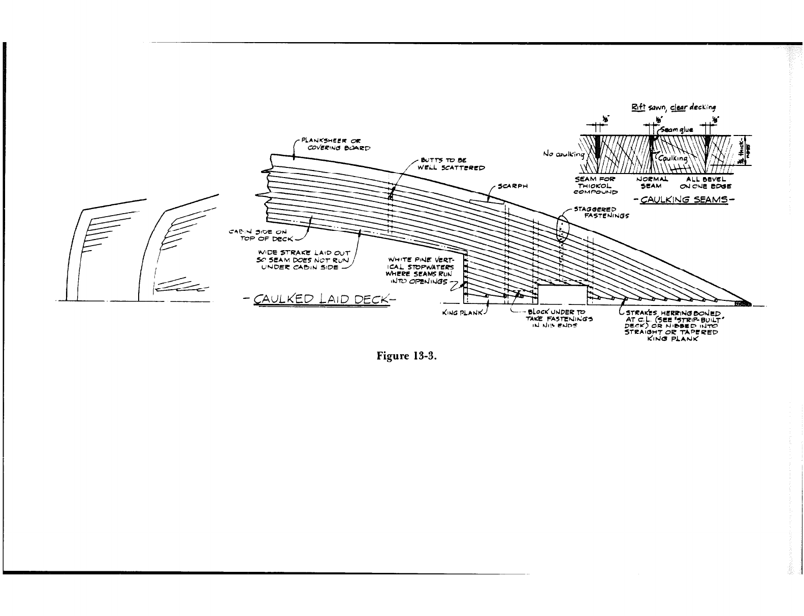
Raft awn, ckr drcwiog
-
I-?
PLbtiB3HCLR ac
SEAM FOR hJ0CMA.L ALL bWEL
rHlOISOL SCAM od cue CWE
COMPOUhlD
-GAULIcIdG SEAMS-
•~AG~CRED
FASTCdWG5
---_ .--, ._- -
Uh 6Erc CA0lhi SIDE J I CAL
b’AiCpE SCAMS Ruti
d-IV
-CAUU&D LAID DECK’-- -- -.
L-- ObCdcldDER l’D
-YAK?? FA5TEhlldG5
Iti hhS ErlDS
L STCA&S HERRNG 00dtD
AT CL. (sac %-rz~P-BUILT
DECK) BR tJIbbE!D IIJ-IU
STCAIGW OR TAPCREO
IdlhJO PLAhJ<
Figure 13-3.
168 DECKING
the most expensive. It has a natural oil that seems to make the deck everlasting, and it
does not have to be varnished or painted. Scrubbing with salt water in the sun will
bleach it out to a whitish color so that, together with its long life, there is no deck quite
equal to teak.
Teak decks do get dirty and do not look well if neglected, but since so much teak
trim is being used on fiberglass boats to offset their otherwise antiseptic appearance,
there has been a flood of teak cleaners and treatment systems put on the market. Most
of them do a good job and are easy to use.
Until the chemists got busy making up new seam compounds, standard practice was
to bevel the edges of the deck strakes for caulking to make them watertight, as shown
by the enlarged sections in Figure 13-3. The seams were caulked with cotton, and
space was left for what was called “seam glue, ” a preparation heated to make it run for
“paying” the seams. The seams were over-filled and the excess was scraped away after
the glue hardened. Now there are available thiokol-based sealers that can be run in
simple, square seams like the one shown in the figure. After the decking is laid and
secured, the open seams are masked with tape. The seam filler is then applied with a
regular household-type caulking gun. Care must be taken to avoid air bubbles by
keeping the tip of the cartridge at the root of the seam so it is filled from the bottom
up. The seams are over-filled and the excess filler is cut off with a very sharp chisel
after the thiokol has completely cured a few days after paying.
A 1 ‘/R * or 114 0 thick deck will have strakes about 1 W II wide, and this proportion is
about right as the thickness of the decking becomes greater in larger boats. Your plans
will specify what your architect wants. It is suggested that you use flat-head screws as
listed in the table, Figure 6-2. The screws will be countersunk and plugged with bungs
of the same wood as the decking, and due to the size of the plug, there will be room for
just one fastening at each deck beam. Note in Figure 6-2 that the screw gauge may be
reduced for decking, resulting in a smaller bung at times.
It is noted in Figure 1.3-3 that the strakes may be herringboned at the centerline like
the strip-built deck or nibbed into a king plank as drawn. Either way there must be
blocks under the deck at the centerline to take fastenings. It is not desirable to let deck
seams run under cabin sides, and to avoid this, the strake next to the cabin opening is
made wider, as drawn in Figure 13-3. Sometimes the decking strakes are run parallel
to the cabin sides, requiring the ends to be nibbed into the planksheer as well as the
king plank. Quite a lot of fitting is needed, as the taper on some of the nib ends will be
very long. Still another way of decking is to run the planks straight fore and aft, nib-
bing both into the planksheer and a margin plank around the cabin (unless the cabin
sides, too, are straight) and fastening the plank ends to blocks under the deck where
the lengths run out at the sides. You will find that the method used in Figure 13-3 is
not only common but is pleasing to the eye. When planking is complete4, the seams
are caulked and payed; then the entire surface of the deck is planed and sanded
smooth.
Planking a laid deck over a sub-deck of marine plywood is similar to constructing a
conventional laid deck, with the exception that the strakes are not being fastened
directly to deck beams. The decking should be thicker than the plywood sub-deck; as
an example of proportions, a 3/gti fir plywood sub-deck would be covered with a 5/gn

,pc~’ I I
!
DECKING 169
thick teak overlay. Plugging fastening holes can be avoided if desired by back-screwing
the teak to the plywood from underneath. Pains must be taken to prevent rotting of
the sub-decking should there be a leak in the seams of the teak strakes. In fact, some
builders cover the plywood with lo-ounce fiberglass cloth before laying the teak deck.
As an alternate, ttle teak can be laid on plywood covered with thiokol compound
(without allowing it to cure, of course)-a messy but effective job.
If the teak strakes are not back-screwed, the “/e W thickness mentioned above is suffi-
cient for counterboring and plugging screw holes in the conventional manner.
Chapter 14
The amount and character of deck joinerwork will vary with the type of boat. Open
boats likr daysailers will havcb simple cockpit coamings. while larger yachts might
have a deckhouse. cabin trunk, hatches, watertight cockpit, and bulwark rail. This
work should be done carefully and neatly because. regardless of how well you have
built your hull. the occasional visitor will make a snap appraisal of your boat based
on thr appearancr* of the deck structures. Pr0pf.r maintenant-c*. too, is necessary, for
nothing looks wet-se than bare and stained woodwork. peeling varnish, or scarred and
dirty paint. Even though it is said that a book cannot btb judged by its cover. my ad-
\ice is to take a great deal of care when finishing parts that meet the eye and to keep
them shipshape. A discussion about finishing follows, because the builder must keep
thinking about the ultimate appearance while doing ever); hit of the exposed deck
joinerwork.
Finishing with Varnish
Traditionally, the finest yachts had vast areas of varnished deck joinerwork of teak or
mahogany. Today, for various reasons, any large areas of varnished fine woods are
most likely to he faces of plywood rather than solid lumber, and hopefully the faces are
of veneers thick enough to survive a few refinishings to bare wood. Nowadays, var-
nished wood (“brightwork”) is limited to trim moldings used to accent fore-and-aft
lines such as the sheer of the hull.
Teak and mahogany are moderately hard and resistant to scarring, but either of
them can be dented by abuse. Their natural appearance, though, has appeal to many,
and such a finish takes work to produce initially and to maintain. These woods have an
open grain that must he ftlled for a smooth finish. Clear, natural filler is used for teak,
170
~“” I I
DECK JOINERWORK 171
while paste filler stains of desired color are applied to the mahoganies. The wood must
be sanded to a perfectly smooth finish before filling: then ‘i 2 filler, thinned to
brushing consistency, is spread on and allowed to dry to a dull appearance, at which
time the excess is wiped off across the grain with clean cotton waste or rags. This is easy
after a little practice. After a day of drying, the first coat of varnish can be applied.
When this is dry, it should be sanded with a fine-grade abrasive. Repeat for six coats
or more and you will have a finish that you will be proud to show off. The work and
work area must be clean and free of dust while varnishing.
The waterfront and boatyards are full of highly opinionated people who freely hand
out an enormous amount of advice about what kind of varnish to use. As you become
more and more experienced, you, too, may also swear by a particular brand, or a mix-
ture of brands. But regardless of the kind of varnish used, the essentials of varnishing
remain the same: cleanliness, absence of moisture, and sanding in between coats to kill
the gloss.
Finishing with Paint
There is a section abr..*
Jy. painting in Chapter 16. but 1 merely want to point out here
th-:. instead of varn:-’ ’
...aurni you may he painting wood deck joinerwork, such as Philip-
pine mahogany (solid fJr plywood), fir or Duraply plywood, or fiberglass-covered
wood. For the finest appearance, and indeed an all-paint finish can be very attractive
as well as easy to maintain, the wood must be just as smooth as if it were to be var-
nished. With a paint finish, the heads of screw fastenings need not be plugged,
because countersinking below the surface and covering with a polyester putty will do as
well. This is an advantage when working with material that is thin.
Use only a good grade of marine paint. Start with an undercoater, apply glazing
compound to smooth out irregularities, sand smooth, apply a second undercoater,
glaze again if necessary, and sand lightly and carefully before painting the first finish
coat. Sand lightly again to kill the gloss, then apply a second coat of finish.
Starting in mid-1979, the highly touted two-part polyurethane coatings used on air-
craft and yachts were marketed in brushable form by several firms catering to the
marine trade. For the previous 10 years or so, this high-gloss, durable coating had
hren available only in a sprayahle form not at all adaptable for amateur application.
If you are brave and reasonably affluent, use of the polyurethanes can result in a
superior finish that will leave the applicator (“painter” is really not proper) truly
button-bursting proud.
Cabin Trunk and Cockpit Coaming
The plans of your boat will show you the kind of cabin and coamings (along with
heights and half-breadths), type of toe or bulwark rail, size and location of hatches,
and other related information: the best 1 can do is discuss joinerwork details in
general. The largest structure you will tackle is the cabin trunk, or deckhouse,
depending upon the design. If the curve of the cockpit coaming on deck is a continua-
tion of the cabin side, it will he best and easiest to make both coaming and cabin side
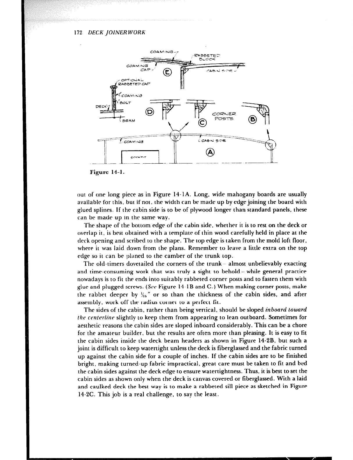
172 DECK .JOINER WORK
COAM !hiG
Figure 14-1.
out of one long piece as in Figure 14-1A. Long, wide mahogany boards are usually
available for this, but if not, the width can be made up by edge joining the board with
glued splines. If the cabin side is to be of plywood longer than standard panels, these
can be made up in the same way.
The shape of the bottom edge of the cabin side, whether it is to rest on the deck or
overlap it, is best obtained with a template of thin wood carefully held in place at the
drrk opening and scribed to the shape. The top edge is taken from the mold loft floor,
where it was laid down from the plans. Remember to leave a little extra on the top
edge so it can be planed to the camber of the trunk top.
The old-timers dovetailed the corners of the trunk -~ almost unbelievably exacting
and time-consuming work that was truly a sight to behold-- whtle general practice
nowadays is to fit the ends into suitably rabheted corner posts and to fasten them with
glue and plugged screws. (See Figure 14-1B and C.) When making corner posts, make
the rahhet deeper by ‘/,,,‘I or so than the thickness of the cabin sides, and after
assembly, work off the radius corner to a perfect fit.
The sides of the cabin, rather than being vertical, should be sloped inboard toward
fhc ccn(erlr’~c~ slightly to keep them from appearing to lean outboard. Sometimes for
aesthetic reasons the cabin sides are sloped inboard considerably. This can be a chore
for the amateur builder. but the results are often more than pleasing. It is easy to fit
the cabin sides inside the deck beam headers as shown in Figure 14.2B, but such a
joint is difficult to keep watertight unless the deck is fiberglassed and the fabric turned
up against the cabin side for a couple of inches. If the cabin sides are to be finished
bright, making turned-up fabric impractical, great care must be taken to fit and bed
the cabin sides against the deck edge to ensure watertightness. Thus, it is best to set the
cabin sides as shown only when the deck is canvas covered or fiberglassed. With a laid
and caulked deck the best way is to make a rabbeted sill piece as sketched in Figure
14-2C. This job is a real challenge, to say the least.
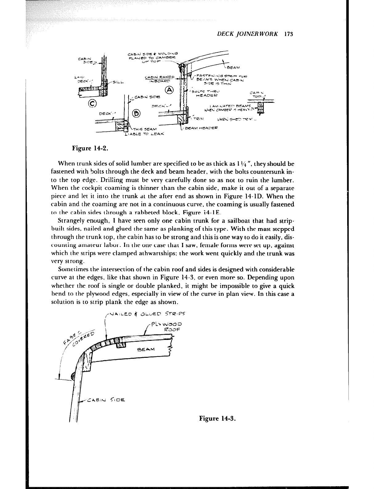
DECKJOINERWORK 173
.Sli
-FA~~E~~~~GsTKz,P Fe
/ N eoaer BE2..NS K’!-Ed cafqr:
SlmE 15 l-rritd
LIA0LE m ICAti
Figure 14-2.
When trunk sides of solid lumber are specified to be as thick as 1 ‘/I “, they should be
fastened with bolts through the deck and beam header, with the bolts countersunk in-
to the top edge. Drilling must be very carefully done so as not to ruin the lumber.
When the cockpit coaming is thinner than the cabin side, make it out of a separate
piece and let it into the trunk dt the after end as shown in Figure 14-1D. When the
cabin and the coaming are not in a continuous curve, the coaming is usually fastened
to the cabin sides through a rabbcted block. Figure i4-1E.
Strangely enough, 1 have seen only one cabin trunk for a sailboat that had strip-
built sides, nailed and glued the samr as planking of this type. With thr mast stepped
through the trunk top, the cabin has to be strong and this is one way to do it easily, dis-
counting amateur labor. In the one case that I saw, female forms were set up, against
which the strips were clamped athwartships: the work went quickly and the trunk was
very strong.
Sometimes the intersection of the cabin roof and sides is desi,gned with considerable
curve at the edges. like that shown in Figure 14-3. or even more so. Depending upon
whether the roof is single or double planked. it might be impossible to give a quick
bend to the plywood edges, especially in view of the curve in plan view. In this case a
solution is to strip plank the edge as shown.
,+JAiiED 4 &LuED ;l-RIPS
Figure 14-3.
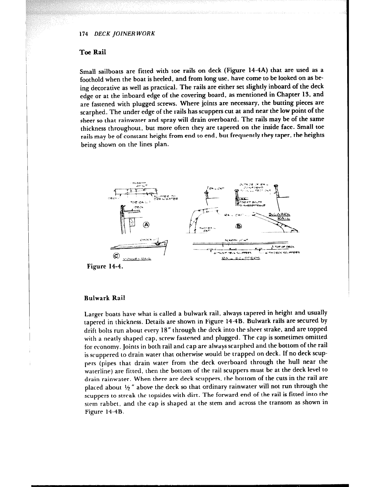
:<: ( ” :I by I
\, I-
,
I
174 DECK JOINER WORK
Toe Rail
Small sailboats are fitted with toe rails on deck (Figure 14-4A) that are used as a
foothold when the boat is heeled, and from long use, have come to be looked on as be-
ing decorative as well as practical. The rails are either set slightly inboard of the deck
edge or at the inboard edge of the covering board, as mentioned in Chapter 13, and
are fastened with plugged screws. Where jcints are necessary, the butting pieces are
scarphed. The under edge of the rails has scuppers cut at and near the low point of the
sheer so that rainwater and spray will drain overboard. The rails may be of the same
thickness throughout, but more often they are tapered on the inside face. Small toe
rails may be of constant height from end to end, but frequently they taper, the heights
being shown on the lines plan.
!.J”- .-
.-. - n-s c‘s
Figure 14-4.
Bulwark Rail
Larger boats have what is called a bulwark rail. always tapered in height and usually
tapered in thickness. Details are shown in Figure 14-4B. Bulwark rails are secured by
drift bolts run about every IS” through the deck into the sheer strake. and are topped
with a neatly shaped cap, screw fastened and plugged. The cap is sometimes omitted
for economy. Joints in both rail and cap are always scarphrd and the bottom of the rail
is scuppered to drain water that otherwise would be trapped on deck. If no deck scup-
pers (pipes that drain water from the deck overboard through the hull near the
waterline) are fitted, then the bottom of the rail scuppers must be at the deck level to
drain rainwater. When there are deck scuppers, the bottom of the cuts in the rail are
placed about tm ” above the deck so that ordinary rainwater will not run through the
scuppers to streak the topsides with dirt. The forward end of the rail is fitted into the
stem rabbet, and the cap is shaped at the stem and across the transom as shown in
Figure 14-4B.
DECK JOiNERWORK 175
Installation of the bulwark rail will call for some ingenuity on the part of the
builder. Templates should be of thin wood, sprung in place, and shaped on the bot-
tom edge to fit the edge of the deck. Then the rail heights at the stations are laid out
and a batten is run to fair the top of the rail. It will be a problem to hold the template
in place and the magnitude of the problem will vary with the type of boat. Bear in
mind that the outside face of the rail conforms to the hull sections, that is. the rail is
not installed vertically on a normal boat; thus the bottom edge bevel constantly
changes. Jigs from the cabin sides and coamings and across the fore and after decks
must be devised to hold the template in place, and then the rail while fastening. It is
very likely that at least the forward section of the rail will need steaming to get it in
place, and much care must be taken to fair the rail sections into each other at the
joints so they will be smooth.
Bulwarks for the larger boats can indeed try the patience of the inexperienced
builder. In certain cases, laminating can eliminate some of the heavy work. However,
laminating requires a jig. which takes some planning and time to construct: it is best to
laminate bulwarks when more than one boat is to be built. (See Figure 4-4D.)
Monkey Rail
Powerboats are dressed up with a short monkey rail forward, Figure 14-4C. This is
handy as a foothold when handling an anchor in a heavy sea and can be fitted with
chocks for anchor and dock lines.
Sliding Hatch
A sliding hatch is necessary to give headroom over companion ladders and elsewhere.
The hatch must be rugged enough to take the weight of a man sitting or standing on
it. The cover may be flat across, but looks much better when cambered like the deck.
It can be of plywood, either one or two layers, but is usually made of solid lumber, as
shown in Figure 14-5. The cover is made on a pair of beams sawn to the camber, using
material ‘/; ” thick and about 3” wide, with the butting edges grooved for soft white
pine splines, which stiffen the hatch as well as prevent leaks. The joints are waterproof
glued and the top piecrs are fastened to the beams with plugged screws.
The logs may be constructed in a variety of styles as shown in Figure 14-5, some of
which are easier to make than others. A common slide is shown in sketch A with brass
tongues on the beam ends to slide in grooves in the logs. The edge of the cover is pro-
tected with a piece of split brass tubing, while the tops of the logs are sheathed with
brass strips that interlock with the split tubing to keep spray out of the hatch opening.
The arrangement in sketch B is similar in operation, having a rabbeted beam header
that slides in the log groove. The top of the log may be sheathed if desired, and the
molding on the edge of the cover makes it adaptable to canvas covering. The logs
shown in sketches C and D do not have grooves, for the covers slide directly on the logs,
making it necessary to sheathe them to prevent wear of the surface. In C the sliding
friction is minimized by having an angle between the brass strips, SO contact is at one
edge only. In D there is a piece of brass let into the cover at the ends only, and it should
project slightly, so the wooden cover will not touch the log. The arrangements shown
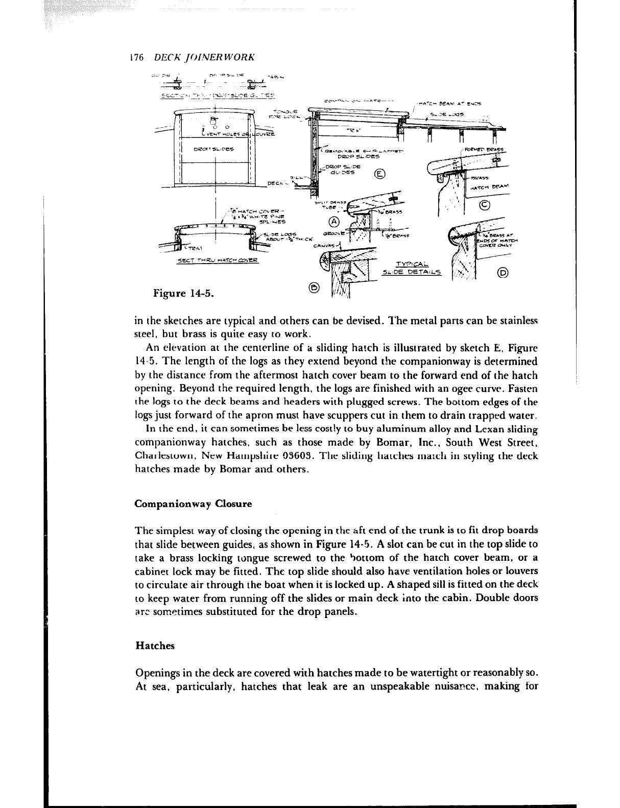
176 DECh’ ~J~~i!VER WORK
Figure 14-5.
in the sketches are typical and others can be devised. The metal parts can be stainless
steel, but brass is quite easy to work.
An elevation at the centerline of a sliding hatch is illustrated by sketch E, Figure
14.5. The length of the logs as they extend beyond the companionway is determined
by the distance from the aftermost hatch cover beam to the forward end of the hatch
opening. Beyond the required length, the logs are finished with an ogee curve. Fasten
the logs to the deck beams and headers with plugged screws. The bottom edges of the
logs just forward of the apron must have scuppers cut in them to drain trapped water.
In the end, it can sometimes be less costly to buy aluminum alloy and Lexan sliding
companionway hatches, such as those made by Bomar, Inc., South West Street,
Charlestown. New Hampshire 03603. The sliding hatches match in styling the deck
hatches made by Bomar and others.
Companicmway Closure
The simplest way of closing the opening in the aft end of the trunk is to fit drop boards
that slide between guides, as shown in Figure 14-5. A slot can be cut in the top slide to
take a brass locking tongue screwed to the bottom of the hatch cover beam, or a
cabinet lock may be fitted. The top slide should also have ventilation holes or louvers
to circu’late air through the boat when it is locked up. A shaped sill is fitted on the deck
to keep water from running off the slides or main deck into the cabin. Double doors
are sometimes substituted for the drop panels.
Hatches
Openings in the deck are covered with hatches made to be watertight or reasonably so.
At sea, particularly, hatches that leak are an unspeakable nuisance, making for
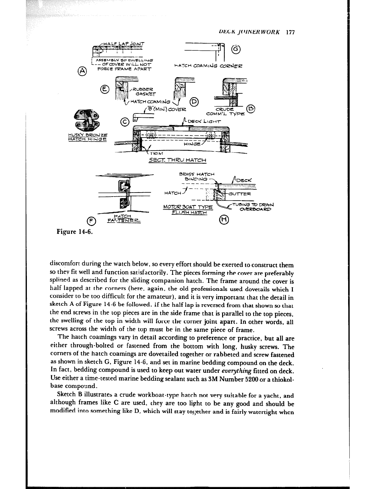
DECK JOINERWORK 177
’ A5SEM0W 54 SWELLING
‘L-- OFUWEP wiLL td0r
6-l FOfZCE FRAME HPAR-I- hATCH CDAMI~G CDPdElZ
HUSlc’\/ BROhlzE
HAl-Ctl HlblGE
HATCH COAM Ihb 0
D
-I I CRUDE
COU b-l ‘L ryPf!z
LIGHT
SECT: -l-HRU HATCH
bWl72? WA-I- TYPE
l%uSH HAl-lW 0
II
Figure 14-6.
discomfort during the watch below, so every effort should be exerted to construct them
so they fit well and function satisfactorily. The pieces forming the cover are preferably
splined as described for the sliding companion hatch. The frame around the cover is
half lapped at the corners (here, again, the old professionals used dovetails which I
consider to be too difficult for the amateur), and it is very important that the detail in
sketch A of Figure 14-6 be followed. if the half lap is reversed from that shown so that
the end screws in the top pieces are in the side frame that is parallel to the top pieces,
the swelling of the top in width will force the corner joint apart. In other words, all
screws across the width of the top must be in the same piece of frame.
The hatch coamings vary in detail according to preference or practice, but all are
either through-bolted or fastened from the bottom with long, husky screws. The
corners of the hatch coamings are dovetai!ed together or rabbeted and screw fastened
as shown in sketch G, Figure 14-6, and set in marine bedding compound on the deck.
In fact, bedding compound is used to keep out water under eveything fitted on deck.
Use either a time-tested marine bedding sealant such as 3M Number 5200 or a thiokol-
base compound.
Sketch B illustrates a crude workboat-type hatch not very suitable for a yacht, and
although frames like C are used, they are too light to be any good and should be
modified into something like D, which will stay together and is fairly watertight when
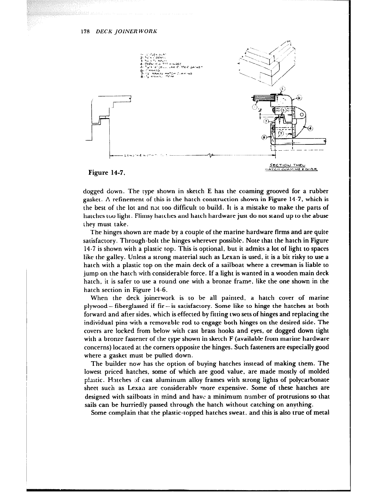
178 DECK -JOINER WORK
I_ : #LE. 1-A’
2. *(a’. I’ AL41
, $,: , ‘; RF?..-r
4. PEec f> 777 . bSE.’
J- **‘l I’CC.. -re r ?Y z j*. -E-
6. 1. UA435
7. I2 .,A”.,> C.rT’” c AC. 4
8. Ig ..‘A..-- -k’>W
Figure 14-7.
-----I
SECTlOPJ T-KU
*AT‘=* CC‘AW’hs * CdEq
dogged down. The type shown in sketch E has the coaming grooved for a rubber
gasket. A refinement of this is the hatch construction shown in Figure 14-7, which is
the best of the lot and n3t too difficult to build. It is a mistake to make the parts of
hatches too light. Flimsy hatches and hatch hardware just do not stand up to the abuse
they must take.
The hinges shown are made by a couple of the marine hardware firms and are quite
satisfactory. Through-bolt the hinges wherever possible. Note that the hatch in Figure
14-7 is shown with a plastic top. This is optional, but it admits a lot of light to spaces
like the galley. Unless a strong material such as Lexan is used, it is a bit risky to use a
hatch with a plastic top on the main deck of a sailboat where a crewman is liable to
jump on the hatch with considerable force. If a light is wanted in a wooden main deck
hatch, it is safer to use a round one with a bronze frame. like the one shown in the
hatch section in Figure 14-6.
When the deck joinerwork is to be all painted, a hatch cover of marine
plywood- fiberglassed if fir-is satisfactory. Some like to hinge the hatches at both
forward and after sides, which is effected by fitting two sets of hinges and replacing the
individual pins with a removable rod to engage both hinges on the desired side. The
covers are locked from below with cast brass hooks and eyes, or dogged down tight
with a bronze fastener of the type shown in sketch F (available from marine hardware
concerns) located at the corners opposite the hinges. Such fasteners are especially good
where a gasket must be pulled down.
The builder no-w has the option of buying hatches instead of making them. The
lowest priced hatches, some of which are good value, are made mostly of molded
p!Lstic. Hatches :,f cast aluminum alloy frames with strong lights of polycarbonate
sheet such as Lexa;l are considerablv more expensive. Some of these hatches are
designed with sailboats in mind and have a minimum number of protrusions so that
sails can be hurriedly passed through the hatch without catching on anything.
Some complain that the plastic-topped hatches sweat, and this is also true of metal
DECK ,JOlNER WORK 179
hatches. Sweating of the metal hatches can he considerably reduced or stopped en-
tirely by applying granulated cork to the underside. Of course, it is possible tc make a
minimum-sweating hatch out of one of the older materials - wood.
Flush Hatches
Cockpits usually have flush hatches over engines. tanks, and storage spaces and often
are constructed as shown in sketch H, Figure 14-6, in an effort to keep rain. spray, and
washdown water from running into the bilges and dripping on equipment on the way.
This usual method is pretty poor because it does not take much water to overflow the
sha!low gutters or much dirt to clog the drain. A better method is to use a system of
channel-shaped sheet metal gutters attached to the hatch opening framing, wide
enough to project under the opening, and having a good-sized overboard line, say 1% U
at least.
Watertight Self-Bailing Cockpit
A watertight cockpit as fitted in sailboats is simply a well sunk below main <eck level
with scuppers to drain water, whether it bf: from rain or heavy spray and seas. The sole
of the cockpit can be fiberglass-covered plywood, preferably made non-skid, or bare
teak.
The boat plans should provide details ifor the cockpit scuppers and whether or not
they should be crossed, that is, whether the port scupper discharges through the hull
on the starboarrt side and vice versa. There arc various ways to fit scuppers flush with
the cockpit sole; probably the easiest is to buy ta.:sh-fitting scuppers from one of the
marine hardware outfits. Above all, the scuppers should be generously sized so that the
cockpit well would drain rapidly shoul1.l a sea break aboitrd.
l’he cockpit sole is laid on beams that may extend to the hull sides, or it may be sup-
ported by beam headers, which in turn are suspended from the main deck headers by
long rods with threaded ends for nuts. (See Figure 14-&I.) Two types of water tables
around the edges of the sole are shown, either of which may be used with a caulked
sole. The cockpit ceiling may be permanently instaiied or fitted with hinged doors for
access to storage spaces not occupied by fuel and water tanks, exhaust piping, etc.
Many prefer cockpit seats lowered below the main deck level (Figure 14-8B) for Ihe
feeling of security it gives. If the boat has a raised doghouse, the architect must plan
the lowered seats wilh care in order not to restrict the visibility of the helmsman. The
seats are most comfortable if sloped and fitted with a slanted lazyback. They require
beams and headers for support, the latter of which are secured to blocks under the
main deck beams at the ends of the cockpit. (See dotted lines, Figure 1478B.) Sloped
seats must be scuppered with copper tubing to drain water, and may be arranged with
hinged sections over storage spaces.
Seats and Locker Lids
Hinged seats and locker lids on deck are prone to warp due to changes in moisture.
This occurs in both solid lumber and plywood. One way to minimize this is to make a
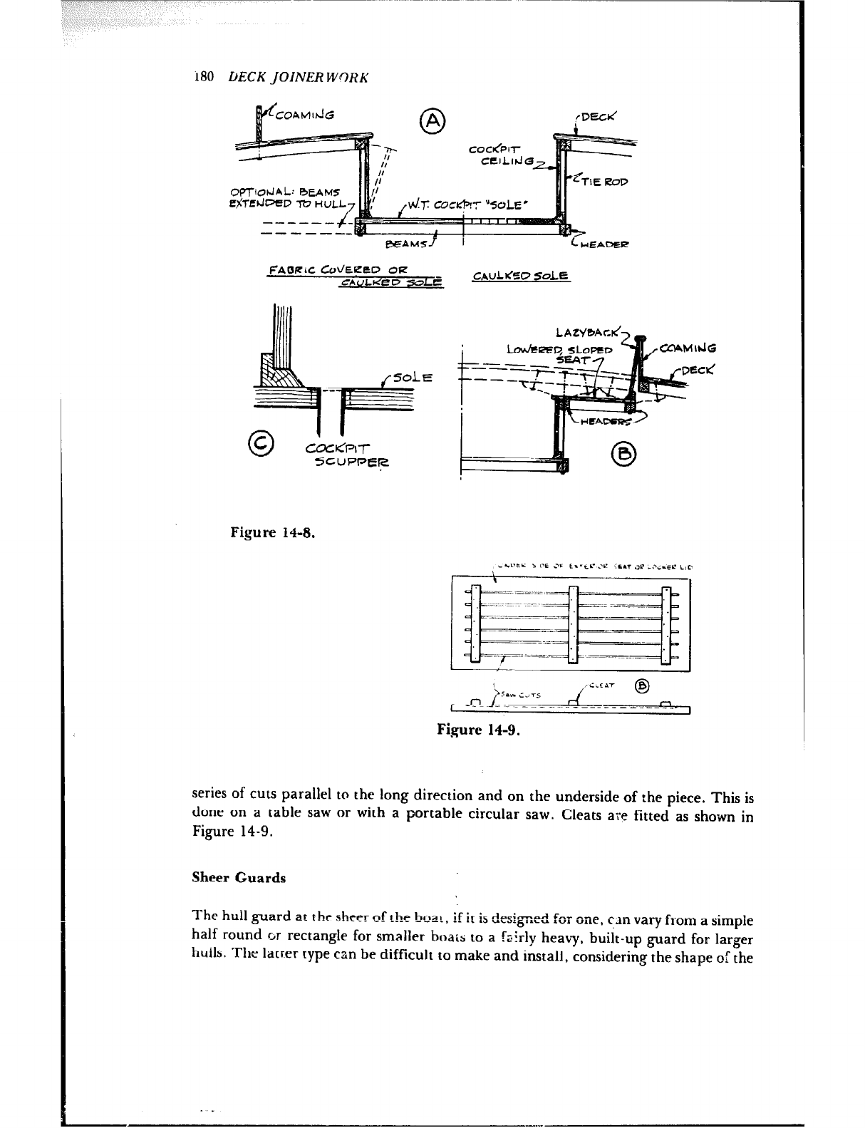
180 DECK JOINERWORK
r7f’l-lobJAL: RCA
f$T.Ed=?D -I?2 H
FAORiC CdEKEO OF?
CAULIdPC’ Sod
5-CUPPER
Figure 14-8.
CAULVfSP SdE
0
0
&GPCE i i-E 3’ t..,c .w crrr ilr -..-i.EC LIP
\
I -CLL.YT
sau ;.ir5 63
rl
-_ -- _ _ ll
Figure 14-9.
series of cuts parallel to the long direction and on the underside of :he piece. This is
done on a table saw or with a portable circular saw. Cleats are fitted as shown in
Figure 14-9.
Sheer Guards
The hull guard at the sheer of the boa?, if it is deslgneA L- -
U zvl une, cxn vary from a simple
half round GY rectangle for smaller boats to a izirly heavy, built-up guard for larger
hulls. The latter type can be difficult to make and install, considering the shape of the

DECK JOINERWORK 181
deck in plan and the changing bevel of the sections of the boat from bow to stern. The
most difficult job is to install a guard at the bow of a powerboat having a full deck line
forward and a lot of flare: a guard must be laminated to the shape of the dec : line and
sawn to the bevel of the sections. The fastenl’ng of guards is very important, for they
are there for the purpose of protecting the hull and must not come loose when called
upon to do some work.
Lower guards to protect hulls at the stern where there is tumble home (hull wider
below the sheer than at the sheer) take some hard knocks at times and also must be
securely fastened. Depending upon the construction of the hull and deck at the sheer,
the sheer guard sometimes needs blocking between the frames to take the fastenings,
which, for heavy-duty guards, are preferably through-bolts.

Chapter 15
INTERIOR JOINERWORK
From the beginning of this manual it has been assumed that the builder is familiar and
reasonably skilled with woodworking tools, having undertaken basic household proj-
ects. With this experience, the cabin joinerwork should prove to be the easiest task in
the construction of the boat. The joints and finish can be as plain or as fancy as
desired, commensurate with the ability of the builder.
The boat designer’s drawings of sections rhrough the interior should show details of
joinerwork construction methods, but in case these are lacking or sparse, I will show
some typical structural methods. In a small craft there are not too many different
details to be planned, although there might seem to be a multitude of them the first
time around. Even in a hull large enough to sleep four or more persons there are only a
few bulkheads and doors, the rest of the interior joinerwork consisting of berth tops
and fronts, lockers, drawers, the galley work top, and the all-important ice box. Any
finished carpentry in the nature of cabinet work is enhanced by neat-fitting joints and
a smooth finish, so the time spent in fitting parts and pushing sandpaper really pays
off iiith the satisfaction of a job well done.
Waterproof plywood makes interior work much easier than in years past because
this material saves labor by permitting parts to be quick!y cut from large sheets rather
than fabricated from narrow boards. Bulkheads an-d-large p+tions are a good exam-’
-.-. . ---
ple, as these cati’be made of plyivobd in a fraction of the time formerly needed to make
them either of paneling or of tongue-and-groove material, and plywood is by all means
more attractive than the latter.
Assuming that plywood will be used, the finish Can be of any of several basic types.
The most, attractive of these is a real wood finish. This can be achieved by using a
plywood faced with mahogany, teak, or other such veneers available in waterproof
panels, stained or natural, and finished with multiple coats of varnish, each rubbed
down with fine sandpaper or bronze wool between coats. Natural wood can also be
182
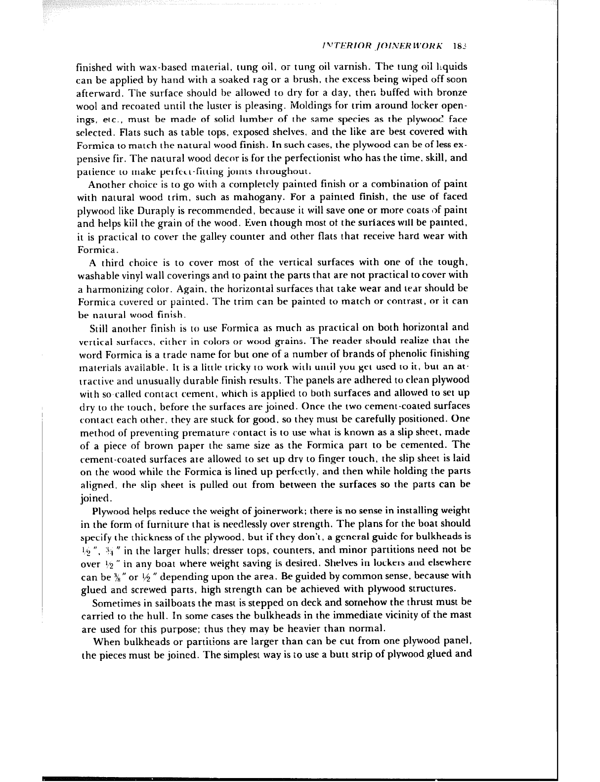
f’!TERIOR JCIA’ER WORh’ 181
finished with wax-based material, tung oil, or tung oil varnish. The tung oil liquids
can be applied by hand with a soaked rag or a brush, the excess being wiped off soon
afterward. The surface should be allowed to dry for a day, then buffed with bronze
wool and recoated until the luster is pleasing. Moldings for trim around locker open-
ings, etc., must be made of solid lumber of the same species as the plywood face
selected. Flats such as table tops, exposed shelves, and the like are best covered with
Formica to match the natural wood finish. In such cases, the plywood can be of less ex-
pensive fir. The natural wood decor is for the perfectionist who has the time. skill, and
patience to make perfect-fitting jomts throughout.
Another choice is to go with a completely painted finish or a combination of paint
with natural wood trim, such as mahogany. For a painted finish, the use of faced
plywood like Duraply is recommended, because it will save one or more coats t,f paint
and helps kiil the grain of the wood. Even though most of the surfaces will be painted,
it is practical to cover the galley counter and other flats that receive hard wear with
Formica.
A third choice is to cover most of the vertical surfaces with one of the tough,
washable vinyl wall coverings and to paint the parts that are not practical to cover with
a harmonizing color. Again, the horizontal surfaces that take wear and tear should be
Formir,a covered or painted. The trim can be painted to match or contrast, or it can
be natural wood finish.
Still another finish is to use Formica as much as practical on both horizontal and
vertical surfaces, either in colors or wood grains. The reader should realize that the
word Formica is a trade name for but one of a number of brands of phenolic finishing
materials available. It is a little tricky IO work with until you get used to it, but an at-
tractive and unusually durable finish results. The panels are adhered to clean plywood
with so-called contact cement, which is applied to both surfaces and allowed to set up
dry to the touch, before the surfaces are joined. Once the two cement-coated surfaces
contact each other. they are stuck for good. so they must be carefully positioned. One
method of preventing premature contact is to use what is known as a slip sheet, made
of a piece of brown paper the same size as the Formica part to be cemented. The
cement-coated surfaces ate allowed to set up dry to finger touch, the slip sheet is laid
on the wood while the Formica is lined up perfectly, and then while holding the parts
aligned, the slip sheet is pulled out from between the surfaces so the parts can be
joined.
Plywood helps reduce the weight of joinerwork; there is no sense in installing weight
in the fortn of furniture that is needlessly over strength. The plans for the boat should
specify the thickness of the plywood, but if they don’t, a general guide for bulkheads is
l,,, ” ( :t:,
& U in the larger hulls; dresser tops, counters, and minor partitions need not be
over t/s ” in any boat where weight saving is desired. Shelves in lockers and elsewhere
can be k ” or t,$ ” depending upon the area. Be guided by common sense, because with
glued and screwed parts, high strength can be achieved with plywood structures.
Sometimes in sailboats the mast is stepped on deck and somehow the thrust must be
carried to the hull. In some cases the bulkheads in the immediate vicinity of the mast
are used for this purpose: thus they may be heavier than normal.
When bulkheads or partitions are larger than can be cut from one plywood panel,
the pieces must be joined. The simplest way is to use a butt strip of plywood glued and
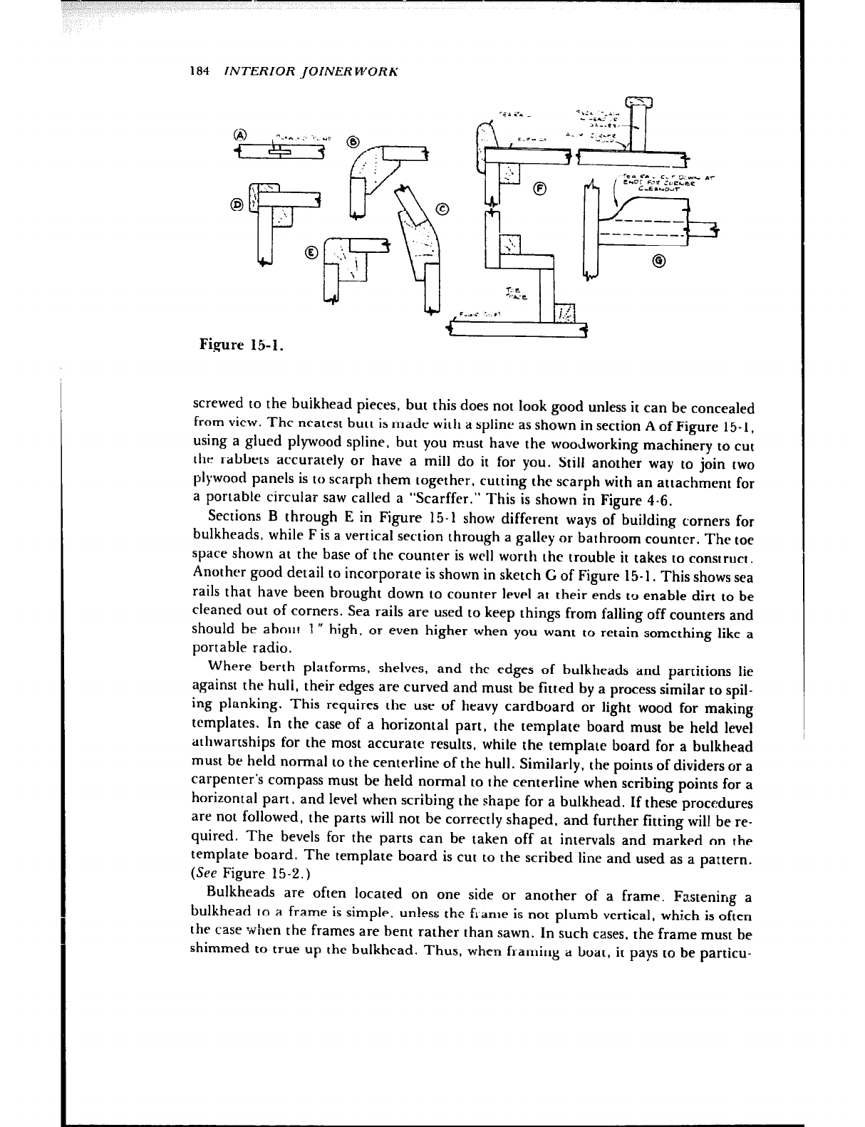
184 INTERIOR JOINER WORK
‘I
I \\
r
lJ
0 .li
F \
Figure 15-l.
screwed to the buikhead pieces, but this does not look good unless it can be concealed
from view. The neatest butt is made with a splint as shown in section A of Figure 15-l.
using a glued plywood spline, but you must have the woodworking machinery to cut
the rabbets accurately or have a mill do it for you. Still another way to join two
plywood panels is to scarph them together, cutting the scarph with an attachment for
a portable circular saw called a “Scarffer.” This is shown in Figure 4-6.
Sections B through E in Figure 15-l show different ways of building corners for
bulkheads, while F is a vertical section through a galley or bathroom counter. The toe
space shown at the base of the counter is well worth the trouble it takes to construct.
Another good detail to incorporate is shown in sketch G of Figure 15-l. This shows sea
rails that have been brought down to counter level at their ends tg enable dirt to be
cleaned out of corners. Sea rails are used to keep things from falling off counters and
should be about 1” high, or even higher when you want to retain something like a
portable radio.
Where berth platforms, shelves, and the edges of bulkheads and partitions lie
against the hull, their edges are curved and must be fitted by a process similar to spil-
ing planking. This requires the use of heavy cardboard or light wood for making
templates. In the case of a horizontal part, the template board must be held level
athwartships for the most accurate results, while the template board for a bulkhead
must be held normal to the centerline of the hull. Similarly, the points of dividers or a
carpenter’s compass must be held normal to the centerline when scribing points for a
horizontal part + and level when scribing the shape for a bulkhead. If these procedures
are not followed, the parts will not be correctly shaped, and further fitting will. be re-
quired. The bevels for the parts can be taken off at intervals and marked on the
template board. The template board is cut to the scribed line and used as a pattern.
(See Figure 15-2.)
Bulkheads are often located on one side or another of a frame. Fastening a
bulkhead to a frame is simple . lun!ess the flame is not plumb vertical, whi.ch is often
the case -when the frames are bent rather than sawn. In such cases, the frame must be
shimmed to true up the bulkhead. Thus, when framing a boat, it pays to be particu-
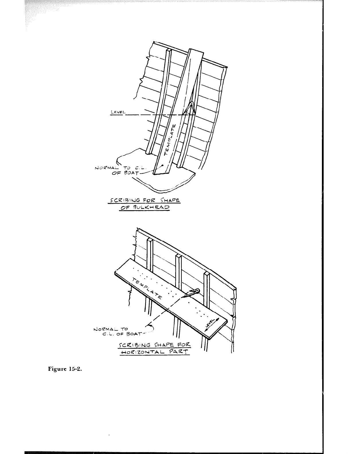
~?CRlRlkl~ FQR ~HAPC
OF !?ULIdHHF,rlD
Figure 15-2.
t4017MAL To
C.L. OF BOA-l--
TCRI~ING Q-~APE FotZ
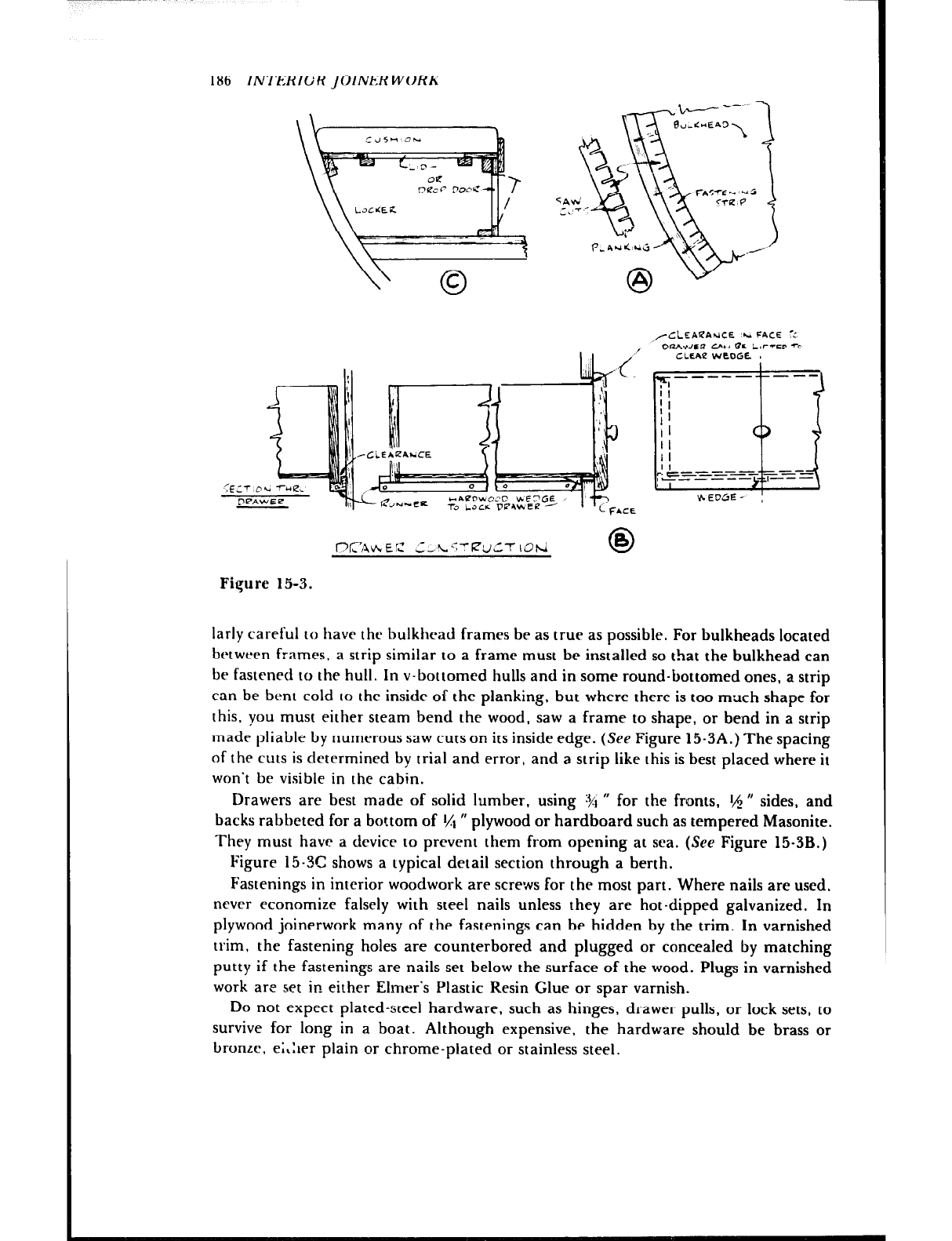
186 INl-ERIGR JOINER WoRK
l7~~hEC CcL.‘;T~UCT IOtd 0
B
Figure 15-3.
,/CLEAI?AUCE ‘.A FACE -:
OIUIWCP CAM flC LIFTED -0
CLLAe WEOGE I
larly careful to have the bulkhead frames be as true as possible. For bulkheads located
between frames, a strip similar to a frame must be installed so that the bulkhead can
be fastened to the hull. In v-bottomed hulls and in some round-bottomed ones, a strip
can be bent cold IO the inside of the planking, but where there is too much shape for
this, you must either steam bend the wood, saw a frame to shape, or bend in a strip
made pliable by numerous saw cuts on its inside edge. (See Figure 15-3A.) The spacing
of the cuts is determined by trial and error, and a strip like this is best placed where it
won’t be visible in the cabin.
Drawers are best made of solid lumber, using 191
” for the fronts, t,$ ” sides, and
backs rabbeted for a bottom of t/t ” plywood or hardboard such as tempered Masonite.
They must have a device to prevent them from opening at sea. (See Figure 15-3B.)
Figure 15-X shows a typical detail section through a berth.
Fastenings in interior woodwork are screws for the most part. Where nails are used,
never economize falsely with steel nails unless they are hot-dipped galvanized. In
plywood joinerwork many of the fastenings can be hidden by the trim. In varnished
trim, the fastening holes are counterbored and plugged 6r concealed by matching
putty if the fastenings are nails set below the surface of the wood. Plugs in varnished
work are set in either Elmer’s Plastic Resin Glue or spar varnish.
Do not expect plated-steel hardware, such as hinges, drawer pulls, or lock sets, to
survive for long in a boat. Although expensive, the hardware should be brass or
bronze. e;Ler plain or chrome-plated or stainless steel.
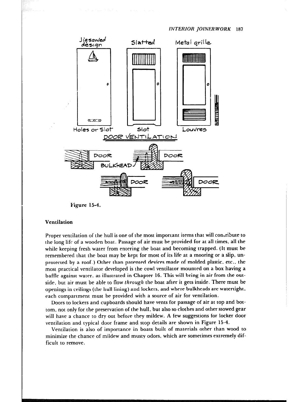
INTERIOR JOINFB WORK 187
Meta I qril Ia
Loud-e5
JXXX &tXlfsAT~Oti
Figure
Ventilation
1 5-4 I
Proper ventilation of the hull is one of the most important items that will con‘ribute to
the long lift of a wooden boat. Passage of air must be provided for at all times, all the
while keeping fresh water from entering the boat and becoming trapped. (It must be
remembered that the boat may be kept for most of its life at a mooring or a slip, un-
protected by a roof.) Other than patented devices made of molded plastic, etc., the
most practical ventilator developed is the cowl ventilator mounted on a box having a
baffle against water, as illustrated in Chapter IG. This will bring in air from the out-
side, but air must be able to flow through the boat after it gets inside. There must be
openings in ceilings (the hull lining) and lockers, and where bulkheads are watertight,
each compartment must be provided with a source of air for ventilation.
Doors to lockers and cupboards should have vents for passage of air at top and bot-
tom, not only for the preservation of the hull, but also so clothes and other stowed gear
will have a chance to dry out before they mildew. A few suggestions for locker door
ventilation and typical door frame and stop details are shown in Figure 15-4.
Ventilation is also of importance in boats built of materials other than wood to
minimize the chance of mildew and musty odors, which are sometimes extremely dif-
ficult to remove.
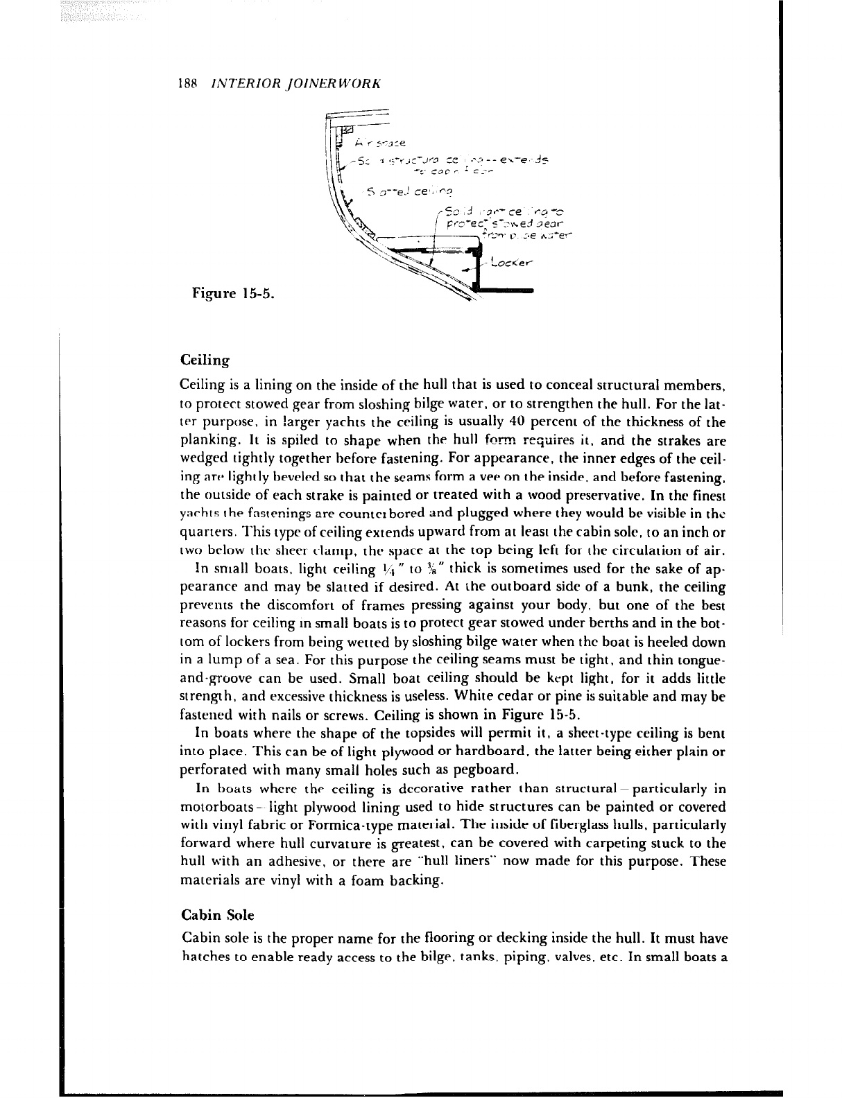
188 INTERIOR .JOINER WORK
1 .~-s,c-Jr-cl =e .---*-- e,--,~+
‘c‘ cgp r- r c--r
S z--e.! ce’, 03
Figure 15-5.
Ceiling
Ceiling is a lining on the inside of the hull that is used to conceal structural members,
to protect stowed gear from sloshing bilge water. or to strengthen the hull. For the lat-
ter purpose, in larger yachts the ceiling is usually 40 percent of the thickness of the
planking. It is spiled to shape when the hull f...
~VZ? requires it. and the strakes are
wedged tightly together before fastening. For appearance, the inner edges of the ceil-
ing are lightly bevelrd so that the seams form a vee on the inside. and before fastening,
the outside of each strake is painted or treated with a wood preservative. In the finest
yachts I he fastenings are counter bored and plugged where they would be visible in the
quarters. This type of ceiling extends upward from at least the cabin sole, to an inch or
two brlow the sheer clamp, the space at the top being left for the circulation of air.
In snlall boats, light ceiling ‘/:1 ” to ‘4” thick is sometimes used for the sake of ap-
pearance and may be slatted if desired. At the outboard side of a bunk, the ceiling
prevents the discomfort of frames pressing against your body, but one of the best
reasons for ceiling m small boats is to protect gear stowed under berths and in the bot-
tom of lockers from being wetted by sloshing bilge water when the boat is heeled down
in a lump of a sea. For this purpose the ceiling seams must be tight, and thin tongue-
and-groove can be used. Small boat ceiling should be kept light, for it adds little
strength, and excessive thickness is useless. White cedar or pine is suitable and may be
fastened with nails or screws. Ceiling is shown in Figure 15-5.
In boats where the shape of the topsides will permit it, a sheet-type ceiling is bent
into place, This can be of light plywood or hardboard. the latter being either plain or
perforated with many small holes such as pegboard.
In boats where the ceiling is decorative rather than structural- particularly in
motorboats-- light plywood lining used to hide structures can be painted or covered
with vinyl fabric or Formica-type material. The inside of fiberglass hulls, particularly
forward where hull curvature is greatest, can be covered with carpeting stuck to the
hull with an adhesive, or there are “hull liners” now made for this purpose. These
materials are vinyl with a foam backing.
Cabin Sole
Cabin sole is the proper name for the flooring or decking inside the hull. It must have
hatches to enable ready access to the bilge, tanks, piping, valves, etc. In small boats a
,qy%yg~*p ~>*“;a -719 <-,- ; I
g&~~&;~ 4, <‘,“~>~,f~,L :/. -
:x, ii ,~, I: r-‘% I
INTERIOR JOiNER WORK 189
removable panel on the centerline is usually sufficient to serve all purposes, but make
sure of this, for there is nothing more frustrating than not being able to get at, say, a
leaking sea cock: lack of access can be downright dangerous in an emergency. Plywood
is an excellent material for the sole because It savrrc much labor and can be fitted in
large pieces. The plywood can be painted for the simplest finish, or covered with vinyl
flooring either in one piece or laid in squares. There are aluminum and stainless steel
hatch bindings for use with the vinyl coverings. Do not make the hatches too tight, for
the plywood will swell just enough to make a hatch bind.
In a sailboat it is practical to make a sole nonskid ty adding a compound to the final
coat of paint. It is not pretty, but it is practical. A bare teak sole is nonskid: however, it
is very expensive and it will hold grease stains.
In cabins where a carpet will be used, the sole needs only one coat of paint. A carpet
is warm on the feet on a chilly morning, but it requires cleaning with a vacuum to be
properly shipshape, and should not be used near open hatchways. Indoor-outdoor
carpet, made of synthetic fibers that will not absorb moisture, has become very
popular with boatmen. It is light enough to be taken up and cleaned on the dock.
The sole is the first of the interior joinerwork to go in the hull. and it must be
carefully planned ahead to establish the hatch locations. In addition, it must be ade-
quately supported by beams and headers.
Headliners
Headlining - unheard of until people starred making the insides of boats look more
like homes than boats -- is a covering for the underside of deck beams and cabin tops.
The most popular headlini *.g material is a vinyl fabric material made just for that pur-
pose, and the best ones have an anti-mildew treatment. Other headliner materials are
hardboards having decorative finishes, acoustical tileboard, and light plywood with
vinyl or Formica-type covering.
Thermal Insulation
Inexpensive, lightweight fiberglass insulation on the underside of decks and cabin tops
adds to comfort both summer and winter and whether or not air conditioning is in-
stalled in the boat. The easiest kind to use is a type having a thin face of white plastic
material on what is meant to be the down side, away from the deck above. It can be
cut to fit between deck beams and stapled in place. The only way to make it look de-
cent, though, is to cover it over with headlining.
Icebox
The icebox, which looks so simple when used, is very time consuming and difficult to
construct. For this reason, if any of the ready-made boxes suit your boat, you will be
much better off buying one. There are several makes on the market with a capacity of
about 4.5 cubic feet, which amounts to abont 50 pounds of ice. They are all plastic
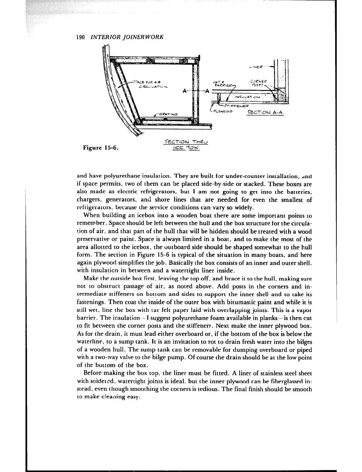
190 INTERIOR JOINER WORK
Figure 1
~t5310td A-A
<ECTION -rkieu
5-6. ICE %7X
--
and have polyurethane insulation. They are built for under-counter installation, dnd
if space permits, two of them can be placed side-by-side or stacked. These boxes are
also made as electric refrigerators, but I am not going to get into the batteries,
chargers, generators, and shore lines that are needed for even the smallest of
refrigerators, because the service conditions can vary so widely.
When building an icebox into a wooden boat there are some important points to
remember. Space should be left between the hull and the box structure for the circula-
tion of air, and that part of the hull that will be hidden should be treated with a wood
preservative or paint. Space is always limited in a boat, and to make the most of the
area allotted to the icebox, the outboard side should be shaped somewhat to the hull
form. The section in Figure 15-G is typical of the situation in many boats, and here
again plywood simplifies the job. Basically the box consists of an inner and outer shell,
with insulation in between and a watertight liner inside.
Make the outside box first, leaving the top off, and brace it to the hull, making sure
not to obstruct passage of air, as noted above. Add posts in the corners and in-
termediate stiffeners on bottom and sides to support the inner shell and to take its
fastenings. Then coat the inside of the outer box with bitumastic paint and while it is
still wet, line the box with tar felt paper laid with overlapping joints. This is a vapor
barrier. The insulation ~- I suggest polyurethane foam available in planks-is then cut
to fit between the corner posts and the stiffeners. Next make the inner plywood box.
As for the drain, it must lead either overboard or, if the bottom of the box is below the
waterline, to a sump tank. It is an invitation to rot to drain fresh water into the bilges
of a wooden hull. The sump tank can be removable for dumping overboard or piped
with a two-way valve to the bilge pump. Of course the drain should be at the low point
of the bottom of the box.
Before making the box top, the liner must be fitted. A liner of stainless steel sheet
with soidercd, watertight joints is ideal, but the inner plywood can be fiberglassed in-
stead, even though smoothing the corners is tedious. The final finish should be smooth
to make cleaning easy.
INTERIOR JOINER WORK 191
Whenever possible, a top opening is best for the icebox, because less cold air is lost
when the box is opened. Sometimes a front door is unavoidable, but the cold air will
pour out quickly, and so will the contents when rolling at sea.
The finished weight of a built-in box is significant. Limit the outside of the box to
I,$ U thickness, the inside to 3/g”. In fact, you might omit the inside wooden box and
fiberglass right on the insulation.
Finish the box with light wooden gratings in the bottom, and fit adjustable parti-
tions to separate food from ice.
Ready-made Woodwork
If you want to save time as your boatbuilding project nears completion, you can use
ready-made parts made up by a mail order supply house. There is an outfit in Cali-
fornia that makes, among other things, a complete line of dish, magazine, and book
racks; grab rails and binocular boxes; paneled and louvered doors; and gratings and
tillers. I have seen a set of doors made for a Florida boat manufacturer and they were
first class. The name of the firm is H & L Marine Woodwork, Inc., 2965 East Harcourt
Street, Compton, California 90221.
Chapter 16
MISCELLANEOUS DETAILS
There seem to be optional ways, some of them good and some bad, for doing every-
thing. Just remember that there is no compromise in quality if one is to produce a
seaworthy boat. The reader is again urged to take advantage of every opportunity to
inspect boats of all types and to study the details of construction. Such observation,
coupled with opinions of the cxpcrienced. will soon reveal the best way to handle any
job.
Patterns for Castiqs
While a great many fittings for boats may be purchased from the stocks of marine
hardware manufacturers, there are always a few items that are special. Here the
amateur can save money by making patterns and having a foundry pour the castings.
To came a few of the fittings that are usually special for the sailboat, there is the
jibstay fitting, permanent backstay fitting, propeller aprrturr casting, rudder
gudgeons and pintles, and sometimes light cast bronze floors when tanks are located
under the cabin floor. Parts usually made of cast material for powerboats include pro-
peller shaft bearing struts it is seldom that off-the-shelf struts fit properly- rudders,
and transom platform brackets. Some of the standard fittings can be homemade, too,
but this does not always pay unless you have time to burn.
Cast parts, especially for use underwater, are usually made nf manganese bronze,
and there are several different alloys. ranging in tensile strength from about 40,000
pounds per square inch to upwards of 100,000 pounds per square inch. Above water,
aluminum alloy castings are sometimes used where saving weight is important. Some
of these alloys are not very resistant to salt water, and protective finishes for aluminum
put out by some of the marine paint makers should be used. Anodizing also offers good
192
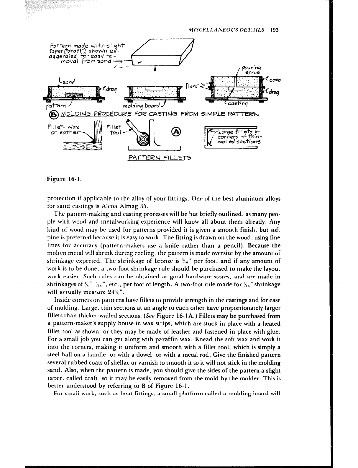
MI.SC~~l.I.,-l.~~O~~S IET.-IILS 193
/ w’;“4
sprrre
PATTEW FILLET-5
Figure 16-1.
protection if applicable to the alloy of your fittings. One of the best aluminum alloys
for sand castings is Alcoa Almag 35.
The pattern-making and casting processes will be but briefly outlined, as many peo-
ple with wood and metalworking experience wilt know all about them already. Any
kind of wood may hc used for patterns provided it is given a smooth finish, but soft
pine is prcfrrred hrcausr it is easy to work. The fitting is drawn on the wood, using fine
lines for accuracy (pattern-makers use a knife rather than a pencil). Because the
molten metal will shrink during cooling, the pattern is made ovcrsizr by the amount of
shrinkage expected. The shrinkage of bronze is Y{h n per foot, and if any amount of
work is to be done, a two-foot shrinkage rule should be purchased to make the layout
work easier. Such rules can he obtained at good hardware stores, and are made in
shrinkages of $“, ‘J,,“, etc., per foot of length. A two-foot rule made for Y,,, fl shrinkage
will actually meaTtire 249,, “.
Inside corners on patterns have fillets to provide strength in the castings and for ease
of molding. Large, thin sections at an angle to each other have proportionately larger
fillets than thicker-walled sections. (See Figure 16-1A.) Fillets may be purchased from
a pattern-maker’s supply house in wax strips, which are stuck in place with a heated
fillet tool as shown, or they may be made of leather and fastened in place with glue.
For a small job you can get along with paraffin wax. Knead the soft wax and work it
into the corners, making it uniform and smooth with a fillet tool, which is simply a
steel ball on a handle, or with a dowel, or with a metal rod. Give the finished pattern
several rubbed coats of shellac or varnish to smooth it so it will not stick in the molding
sand. Also, when the pattern is made, you should give the sides of the pattern a slight
taper, called draft, so it may be easily removed from the mold by the molder. This is
better understood by referring to B of Figure 16- 1.
For smali work, such as boat fittings, a small p!atform called a molding board will
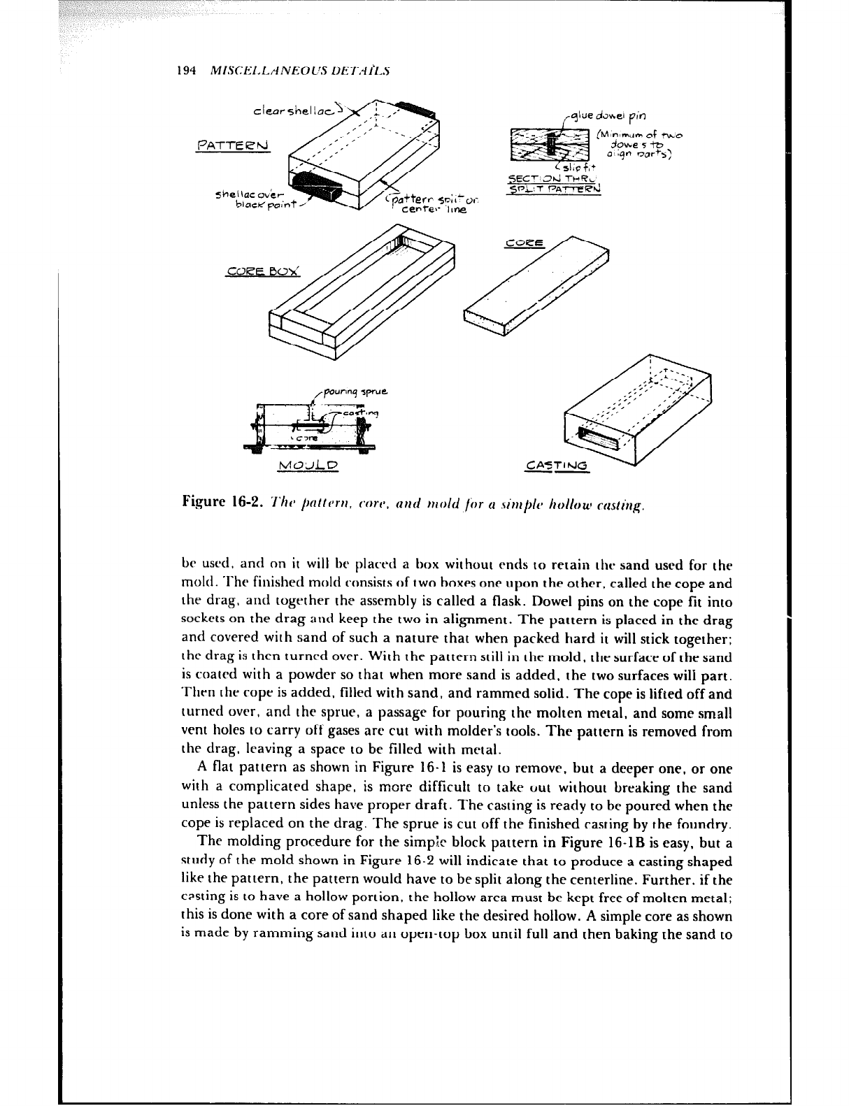
194 MISCEl,l~,~NEOL'S LXI~AI%.S
Figure 16-2. ‘l’hv /)cl/lrr,r, con’, nnd mold Ibr u .5inl~~l~~ hollouf rrtsling.
be usrd. and on it will be placed a box without ends to retain the sand used for the
mold. The finished mold consists of two boxes one upon the other, called the cope and
the drag, and togrther the assembly is called a flask. Dowel pins on the cope fit into
sockets on the drag and keep the two in alignment. The pattern is placed in the drag
and covered with sand of such a nature that when packed hard it will stick together:
the drag is then turnrd over. With the pattern still in the mold, the surface of the sand
is coated with a powder so that when more sand is added, the two surfaces will part.
Then the rope is added, tilled with sand, and rammed solid. The cope is lifted off and
turned over, and the sprite, a passage for pouring the molten metal, and some small
vent holes to carry off gases arc cut with molder’s tools. The pattern is removed from
the drag, leaving a space to be filled with metal.
A flat pattern as shown in Figure 16-1 is easy to remove, but a deeper one, or one
with a complicated shape, is more difficult to take uut without breaking the sand
unless the pattern sides have proper draft. The casting is ready to be poured when the
cope is replaced on the drag. The sprue is cut off the finished casting by the foundry.
The molding procedure for the simple block pattern in Figure 16-1B is easy, but a
study of the mold shown in Figure 16-2 will indicate that to produce a casting shaped
like the pattern, the pattern would have to be split along the centerline. Further. if the
cpsting is to have a hollow portion, the hollow area must be kept free of molten metal;
this is done with a core of sand shaped like the desired hollow. A simple core as shown
is made by ramming sand into an open-top box until full and then baking the sand to
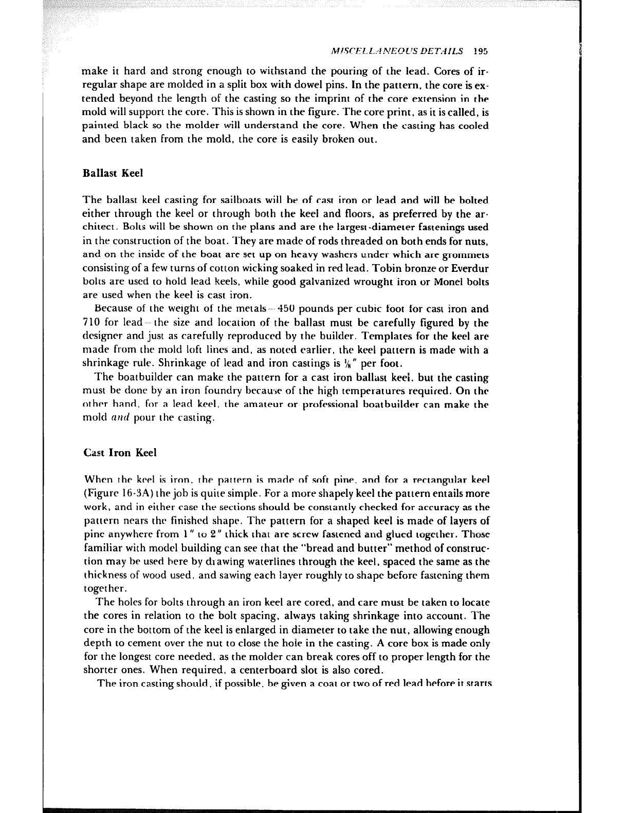
MISC’EI-L.A.VEC’L’S !?ET.d!LS !95
make it hard and strong enough to withstand the pouring of the lead. Cores of ir-
regular shape are molded in a split box with dowel pins. In the pattern, the core is ex-
tended beyond the length of the casting so the imprint of the core extension in the
mold will support the core. This is shown in the figure. The core print, as it is called, is
painted black so the molder will understand the core. When the casting has cooled
and been taken from the mold, the core is easily broken out.
Ballast Keel
The ballast keel casting for sailboats will be of cast iron or lead and will be bolted
either through the keel or through both the keel and floors, as preferred by the ar-
chitect. Bolts will be shown on the plans and are the largest -diameter fastenings used
in the construction of the boat. They are made of rods threaded on both ends for nuts,
and on the inside of the boat are set up on heavy washers under which are grommets
consisting of a few turns of cotton wicking soaked in red lead. Tobin bronze or Everdur
bolts are used to hold lead keels, while good galvanized wrought iron or Monei bolts
are used when the keel is cast iron.
Because of the weight of the metals --~ 450 pounds per cubic foot for cast iron and
710 for lead -~ the size and location of the ballast must be carefully figured by the
designer and just as carefully reproduced by the builder. Templates for the keel are
made from the mold loft lines and, as noted earlier, the keel pattern is made with a
shrinkage rule. Shrinkage of lead and iron castings is VH” per foot.
The boatbuilder can make the pattern for a cast iron ballast keel. but the casting
must be done by an iron foundry becauve of the high temperatures required. On the
other hand, for a lead keel, the amateur or professional boatbuilder can make the
mold clrttl pour the casting.
Cast Iron Keel
When the keel is iron, the pattern is made of soft pine, and for a rectangular keel
(Figure 16-t3A) the job is quite simple. For a more shapely keel the pattern entails more
work, and in either case the sections should be constantly checked for accuracy as the
pattern nears the finished shape. The pattern for a shaped keel is made of layers of
pine anywhere from 1” to 2” thick that are screw fastened and glued together. Those
familiar with model building can see that the “bread and butter” method of construc-
tion may be used here by drawing waterlines through the keel, spaced the same as the
thickness of wood used, and sawing each layer roughly to shape bcforc fastening them
together.
The holes for bolts through an iron keel are cored, and care must be taken to locate
the cores in relation to the bolt spacing, always taking shrinkage into account. l’he
core in the bottom of the keel is enlarged in diameter to take the nut, allowing enough
depth to cement over the nut to close the hole in the casting. A core box is made only
for the longest core needed, as the molder can break cores off to proper length for the
shorter ones. When required, a centerboard slot is also cored.
The iron casting should, if possible, be given a coat or two of red lead before it starts
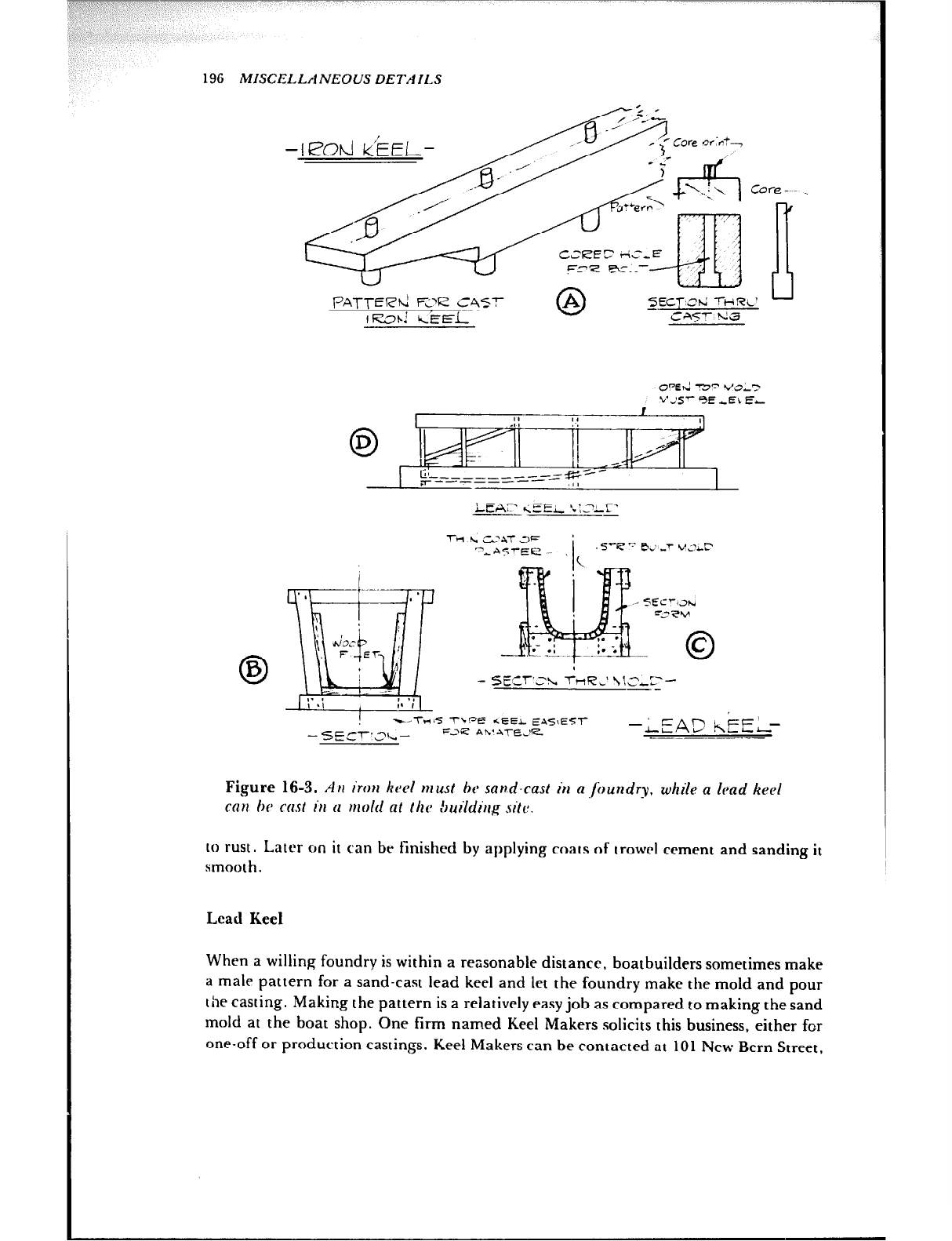
(,“A “~1 I I
196 MISCELLANEOUS DETAILS
_5ECT:Sh; -I-HRL’
OWhi w5” VOLT
~A-- 3E -EL EL
LEAF &EL ‘..:,?lf -
l-H 4 c2A-r 3-
mbn5rEE ._ _ i, .5--e” ker v13c~
---TU6 ‘T--!=‘Ft? *EEL E+,-fj\ES-,-
-SE',-:?I,- FJP Ah’ ATEJrZ -LEADkiEiz
b b ----.-__-
Figure 16-3. AH irm kvcl must h sand-cast in aloundry, while a had keel
cnn hc ccrst I’)) N mold nt /kc Suilding site.
to rust. L.atrr on it can be finished by applying coats of trowel cement and sanding it
smooth.
Lead Keel
When a willing foundry is within a reasonable distance. boatbuilders sometimes make
a male pattern for a sand-cast lead keel and let the foundry make the mold and pour
the casting. Making the pattern is a relatively easy job as compared to making the sand
mold at the boat shop. One firm named Keel Makers solicits this business, either for
one-off or production castings. Keel Makers can be contacted at 101 New Bern Street,
MISCELLANEOUS DETAILS 197
Charlotte, North Carolina 28203, or at 43 Old Brook Road, Dix Hills, New York
11746. Of course, if you have a local foundry that will do the job you are in luck.
Accuracy is particularly important when making patterns for lead castings. Each
cubic inch of lead weighs about 0.41 pound. As a comparison, cast iron weighs about
0.26 pound per cubic inch.
A rectangular lead keel mold is quite simple to make (Figure 16-3B), as it can be
made with planks, with either wood or plaster fillets used to shape the corners when
necessary. It must be remembered that the keel will be heavy, and this requires that
the mold be strong so that it will not break apart when the lead is poured and that the
mold be supported by husky braces and shores. The inside of the mold is given a thin
coat of plaster to prevent it from burning. The plaster and the mold must be perfectly
dry before starting, as the lead will spatter if poured into a wet mold and workmen
may be burned.
Making the mold for a shaped lead keel (Figure 16-3C) is quite a task and is a good
reason to have the keel sand-cast in a foundry. As shown in the section, forms are
made to the outside of the keel, plus the thickness of the mold, at stations and half sta-
tions. They are then set up rigidly (Figure 16-3D) and the mold is strip-built inside of
the forms. As the strips are fitted they are edge nailed to each other and to the forms.
The inside is finished to a set of templates representing the finished keel plus an
allowance for shrinkage. Gouges and round-bottomed planes are used for this work.
The casting will reflect the degree of smoothness of your mold.
Lead, fortunately, has a low melting point, but at the least, you will need a large
iron melting pot, supported by bricks so a roaring wood or charcoal fire can be built
under it, and several ;ron ladles. Better still is a melting pot with a pouring spigot or
pipe leading over the mold and a metal trough to distribute the molten metal over the
length of the keel. The top of the open mold must be level. A centerboard slot can be
taken care of by a plank of proper thickness to act as a core. More than enough lead
must be on hand to allow for discrepancies, and some of the pigs may be placed in the
mold before pouring. Several hands will be needed, because the pouring must be car-
ried on to completion before the top of the lead already in the mold starts to solidify.
Start to pour when the lead in the pot is hot, distribute it in the mold, skim the slag
from the top, and puddle the molten lead to prevent the formation of air pockets. Add
pigs to the pot as you pour, and they will quickly melt in the hot lead if the fire is kept
blazing. Allow at least a day for the casting to cool before removing the mold. The top
surface of the lead casting can be smoothed with a woodworking hand plane. The
holes for the keel bolts are drilled with a barefoot wood auger or with a twist drill
lengthened by welding a rod to the end, preferably used in an electric drill of ample
capacity. Eirhk r drill must be frequently withdrawn to clear the lead shavings, and
kerosene is used as a lubricant. Where necessary, the outside of the keel is smoothed
with coats of trowel cement, and the cement is then sanded. The keel casting is liber-
ally coated with thick white or red lead where it fits against keel and deadwood.
Standing Rigging Chainplates
Unless masts are designed to be free-standing, they are kept straight and prevented
from breaking by wire rope standing rigging. The mast loads are transmitted to the
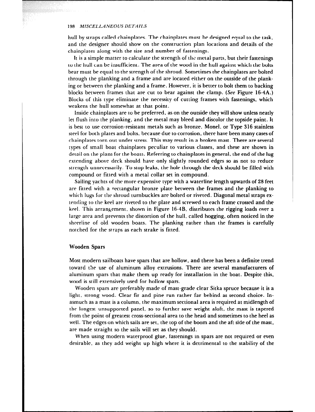
198 MISCEI.I.ANEOlJS DETAILS
hull by straps called chainplates. The chainplates must be designed equal to the task,
and the designer should show on the construction plan locations and details of the
chainplates along with the size and number of fastenings.
It is a simple matter to calculate the strength of the metal parts, but their fastenings
to the hull can be insufficient. The area of the wood in the hull against which the bolts
bear must be equal to the strength of the shroud. Sometimes the chainplates are bolted
through the planking and a frame and are located either on the outside of the plank-
ing or between the planking and a frame. However, it is better to bolt them to backing
blocks between frames that are cut to bear against the clamp. (See Figure 16-4A.)
Blocks of this type eliminate the necessity of cutting frames with fastenings, which
weakens the hull somewhat at that point.
Inside chainplates are to be preferred, as on the outside they will show unless neatly
let flush into the planking, and the metal may bleed and discolor the topside paint. It
is best to use corrosion-resistant metals such 2s bronze, Monel. or Type 316 stainless
steel for both plates and bolts, because due to corrosion, there have been many cases of
chainplates torn out under stress. This may result in a broken mast. There are several
types of small boat chainplates peculiar to various classes, and these are shown in
detail on the plans for the boats. Referring to chainplates in general, the end of the lug
extending above deck should have only slightly rounded edges so as not to reduce
strength unnecessarily. To stop leaks, the hole through the deck should be filled with
compound or fitted with a metal collar set in compound.
Sailing yachts of the more expensive type with a waterline length upwards of 28 fret
are fitted with a rectangular bronze plate between the frames and the planking to
which lugs for the shroud turnbuckles are bolted or riveted. Diagonal metal straps ex-
trnding to the keel are riveted to the plate and screwed to each frame crossed and the
keel. This arrangement. shown in Figure 16-4B, distributes the rigging loads over a
large area and prevents the distortion of the hull. called hogging, often noticed in the
sheerline of old wooden boats. The planking rather than the frames is carefully
notched for the straps as each strake is fitted.
Wooden Spars
Most modern sailboats have spars that are hollow, and there has been a definite trend
toward the use of aluminum alloy extrusions. There are several manufacturers of
aluminum spars that make them up ready for installation in the boat. Despite this,
wood is still extensively used for hollow spars.
Wooden spars are preferably made of mast-grade clear Sitka spruce because it is a
light, strong wood. Clear fir and pine run rather far behind as second choice. In-
asmuch as a mast is a column, the maximum sectional area is required at midlength of
the longest unsupported panel, so to further save weight aloft, the mast is tapered
from the point of greatest cross-sectional area to the head and sometimes to the heel as
well. The edges on which sails are set, the top of the boom and the aft side of the mast,
are made straight so the sails will set as they should.
When using modern waterproof glue, fastenings in spars are not required or even
desirable, as they add weight up high where it is detrimental to the stability of the
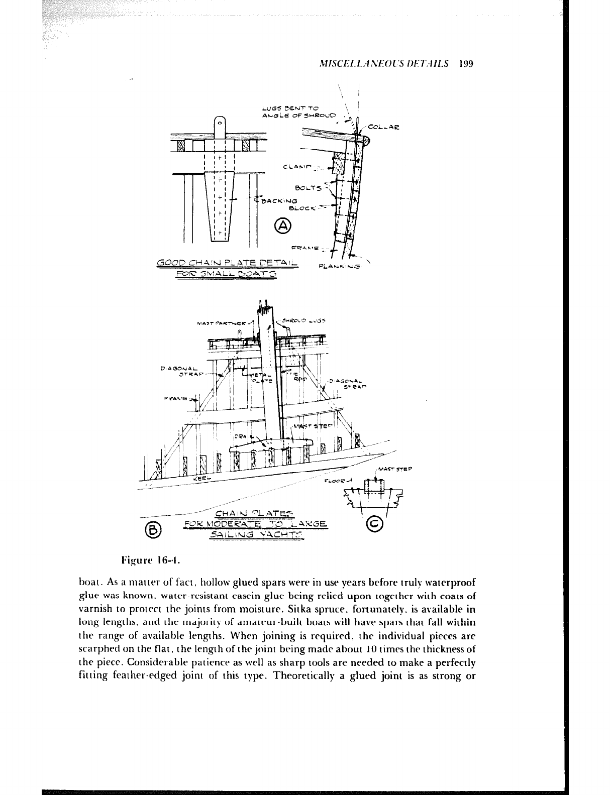
LUG5 eeur 7-C
AbdiLE OF 5i+F2ouD \ 1
’
PLATE ?ET41- \
RAtiGc;Lcs
FOR5hl,ALi3\3AT5
__. --
I
~- ------=i=i=
‘,,’ 1,
f-i--- --=Y ‘1 i I
hl&T j+J $ ~
“6
\ LN
ji& ‘w .8_1
,,lPA .+
‘7. ‘: , ‘1,+ __
A&z
- _ , __-
/- *-
,_“,
_r
._---
_._
-_,_-_-_I-- CHAlhi FL ATE5
0
B 5’3R h;?lCf=%??$;,;-;‘i$.IC5E
T
I;igu rc 164.
hoat. As a matter of fact, hollow glued spars were in use years before truly watrrproof
glue was known. water-resistant casein glue being relied upon together with coats of
varnish to protect the joints from moisture. Sitka spruce, fortunately. is available in
long lengths, and the majority of amateur-built boats will have spars that fall within
the range of available lengths. When joining is required. the individual pieces are
scarphed on the flat, the length of the joint being made about 10 times the thickness of
the piece. Considerable patience as well as sharp tools are needed to make a perfectly
fitting feather-edged joint of this type. Theoretically a glued joint is as strong or
200 MISCELLANEOUS DETAILS & -
+-/so fj~@!!!Jz?$kQ
GLUEC S-‘A~PH L.&x’
MA-X- OR 0CWt-4 SECT!,?klS O’.‘A.-
‘d AST
I soL~ca=2
@ n T;: @J Horn Qe,cdTgw,GH;pEm
5%7A-i B2A-r -Qd’- 9ECE ROUT-R
~~O!vlS Q-l=- mEct&
5!+R-3 Ci-EP ?i%? BOLT EP!=?Z SF 5,+ii
Figure 16-S.
stronger than the wood, so that splices could be adjacent to each other, but inasmuch
as a glued joint will be locally stiffer than the adjoining unjointed pieces, it is best to
stagger the scarphs as much as possible. Figure 16-5 shows a scarph and typical hollow
spar sections in use today.
The simplest mast IO make is a hollow, rectangular box spar. This section, with the
forta.antl-aft pircrs rabhetrd. is prcfcrrcd by some builders because it is easier to con-
1101 skidding of the glued surtaces. The section next in simplicity is the round spar
made of hollowed-out halves. The larger spars, both the oval section and ,he round
srction made of staves, are the most difficult to make and would be quite a job for the
amateur. Of the two, the oval is the easier in the smaller sizes, as it consists of two
round halves and two tapered side pieces. The wall thickness of oval and round spars is
always tapered in the interest of weight saving.
Some of the sailboat classes use a solid mast with a groove routed out for the
boltrope on the luft ot the mainsail. This groove can be made by first making a saw cut
with a circular saw and then routing out the groove in the saw cut, using a very high-
spetbd cutter with a shank narrower than the saw cut. (Sue Figure 16-5.) To make a
boltrope groove in a hollow spar made up of two rounded halves, the groove is hand
gouged or machine routed on each half before the sections are glued together.
l’hc T-boom is used on smaller sailboats. which also sometimes have solid rec-
tangular booms.
Hollow Rectangular Spars
Probably the easiest way for an amateur to make a box spar. unless he has extensive
machine tools, is to order the spar material dressed four sides to the dimensions at the
maximum section of the spar. It is desirable to add a slight thickness, say &“, for
dressing up and finishing after the spar has been glued. With such material at hand
there is nothing to do but taper the pieces in accordance with the architect’s detail
plans. This is done by laying off the width at the spacing shown on the plan for the
spar, fairing the shape with a long batten, and then sawing and planing the edges to
the lines. The width layout for the forward and aft pieces is done from a centerline
MISCELLANEOUS DETAILS 201
because both edges are shaped. Duplicate sides may be temporarily nailed together
and made at the same time. Be sure to keep the edges square, or else a perfect glued
joint with 100 percent surface contact cannot be made.
When only one or two spars are to be made, a makeshift spar bench may be devised
by nailing a series of short boards horizontally to a wall or fence, with legs down to the
ground to support the outer ends. (See Figure 16-6A.) All supports should be level and
at the same height, or the top edges shimmed to be so, as upon them will be placed the
side of the spar that is to be straight, that is, the aft side of the mast or the top side of
the boom.
Shellac the inside of spars, taking care not to coat the surfaces that will be glued.
Use a marking gauge to scribe the width of the side pieces on the forward and aft
pieces and shellac between the lines. The filler pieces at the ends of the spar and
elsewhere as called for by the plans are fitted and shellac is also omitted in way of
these. Because solid filler blocks have been known to swell and either split the spar or
cause poorly glued joints to open up, some prefer the pad-type fillers glued to the in-
side before assembly as shown in sketch B, Figure 16-6. A long solid filler fitted at the
heel of the mast is bound to locally stiffen the mast due to the sudden increase in sec-
tional area. The late Phil Rhodes, one of the great yacht designers, insisted upon a
block cut as shown in Figure 16-6C to avoid this situation and also advised running saw
cuts longitudinally on the block to allow for expansion. Provide drain holes in all solid
fillers cxcrpt the one at the masthead, so moisture will not collect and start rot.
When everything is ready. mix the glue strictly in accordance with the instructions,
paying partirular attention to those regarding temperature and working life after mix-
ing. Once the glue is mixed, spread it quickly and thoroughly. Before gluing make
sure there are enough clamps at hand: it is surprising how many are needed, as there
should bc one every few inches or so to apply the pressure required for the glue, par-
ticularly resorcinol. Although Figure 16-6a shows a boom that is larger than any that
the average amateur would attempt. it is a good illustratiorr of the number of clamps
used bv a builder to ensure a perfect job. Ail kinds of clamps may be utilized if their
openings are sufficiently wide to clamp the spar plus pieces of scrap used under the
clamp pads to distribute pressure and prevent scars. If the number of your clamps is
insufficient, you can make satisfactory spar clamps of two husky pieces of oak or ash
joined together at the ends with bolts of at least 92 n diameter. (Set sketch, Figure
16-6D.)
The clamps should not be removed for at least 24 hours to allow the glue to develop
full strength. Finish the spar by scraping the excess glue from the seams, round the
corners, and then sand all sides smooth, gradually working down to fine abrasive
paper. If a varnish finish is wanted Sitka spruce has a beautiful appearance when
finished clear - apply at least four or five coats, carefully sanding off the gloss between
coats.
Round Hollow Spars
Even though a boat may have a rectangular mast and boom, the spinnaker pole
(Figure 16-6G) will be round, made in symmetrical halves around a centerline. First,
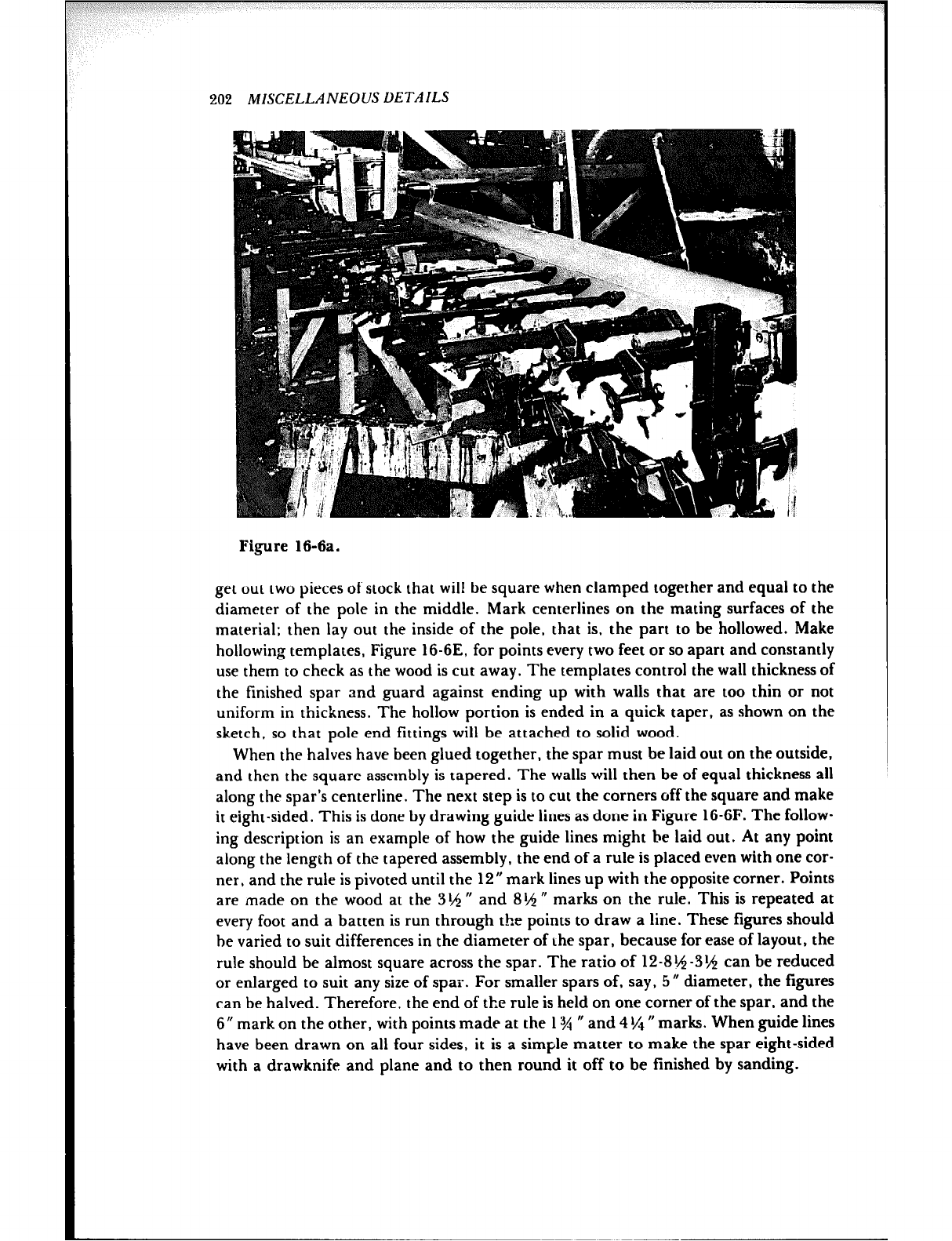
202 MISCELLANEOUS DETAILS
Figure 16-6a.
get out two pieces of stock that will be square when clamped together and equal to the
diameter of the pole in the middle. Mark centerlines on the mating surfaces of the
material; then lay out the inside of the pole, that is. the part to be hollowed. Make
hollowing templates, Figure 16-6E, for points every two feet or so apart and constantly
use them to check as the wood is cut away. The templates control the wall thickness of
the finished spar and guard against ending up with walls that are too thin or not
uniform in thickness. The hollow portion is ended in a quick taper, as shown on the
sketch, so that pole end fittings will be attached to solid wood.
When the halves have been glued together, the spar must be laid out on the outside,
and then the square assembly is tapered. The walls will then be of equal thickness all
along the spar’s centerline. The next step is to cut the corners off the square and make
it eight-sided. This is done by drawing guide lines as done in Figure 16-6F. The follow-
ing description is an example of how the guide lines might be laid out. At any point
along the length of the tapered assembly, the end of a rule is placed even with one cor-
ner, and the rule is pivoted until the 12” mark lines up with the opposite corner. Points
are made on the wood at the 3t$$ 0 and 8rh H marks on the rule. This is repeated at
every foot and a batten is run through the points to draw a line. These figures should
he varied to suit differences in the diameter of the spar, because for ease of layout, the
rule should be almost square across the spar. The ratio of 12-814-3% can be reduced
or enlarged to suit any size of spar. For smaller spars of, say, 5 d diameter, the figures
can be halved. Therefore, the end of the rule is held on one corner of the spar, and the
6” mark on the other, with points made at the 1% N and 4 !La II marks. When guide lines
have been drawn on all four sides, it is a simple matter to make the spar eight-sided
with a drawknife and plane and to then round it off to be finished by sanding.
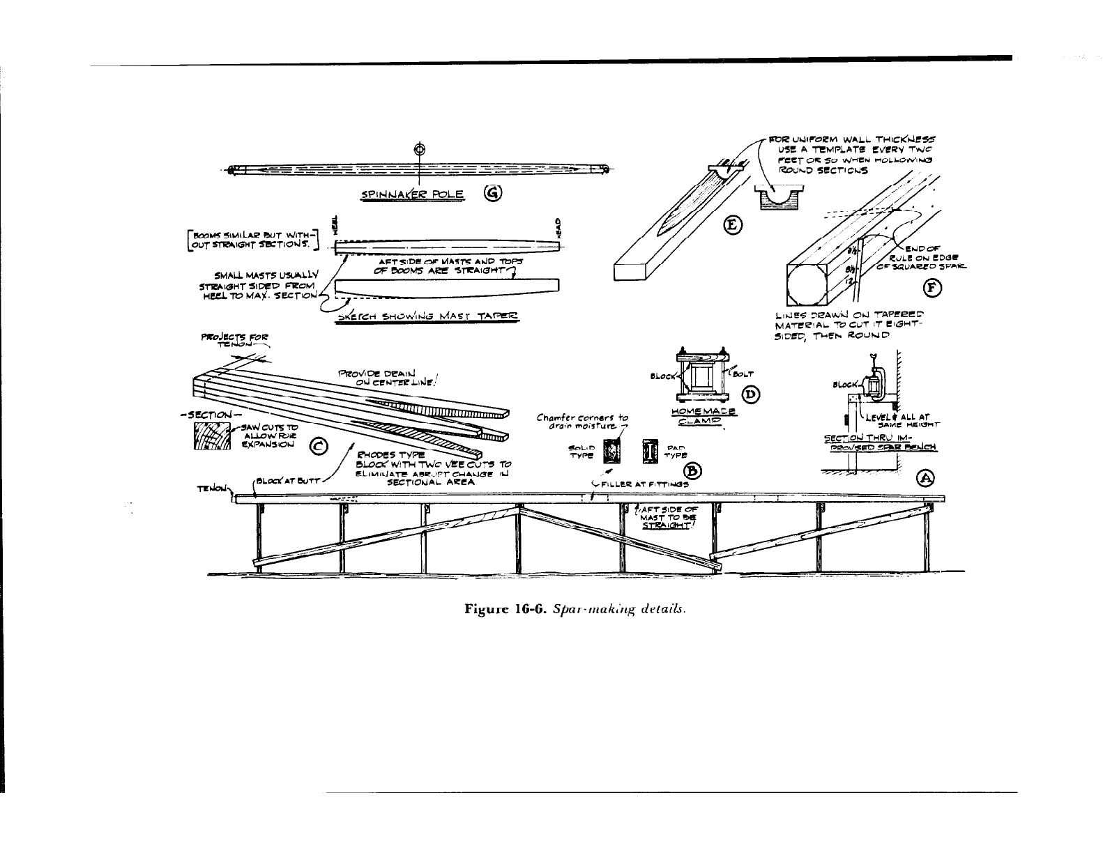
I Y-7
PVR ub.l~~~PhI WALL THIC~A?SS
USe: A TEMPL’ICITiZ WCRY -l-WC
feey OR so vd-E*i HOLLONJIW
--------____
------ _____ - ---------- ROUhD SCCTICUS ,
I
SPIt4kJAdiR FVLE I
C %
Ou~WR4lGHT~Td~. ~.- ~ __ em+
AFTsIDC Of dhSl-5 Ak.JO -IDI-
OF COOUS ARE W?ZA’GHr3
Sl-RhlOHT SIIXD Fl?CWl 1
LdE5 XAWicl 0t.l -!-AWLCC
MA-We\ AL -‘V CUT I,- e @MT-
SICSC, rwh ROUND
Chamfer ~orndr5
droc moisture LL *T
k!EcJw-
&qOhl THRO IM-
Figure 16-6. Sbar-mak,‘rzg drfails.
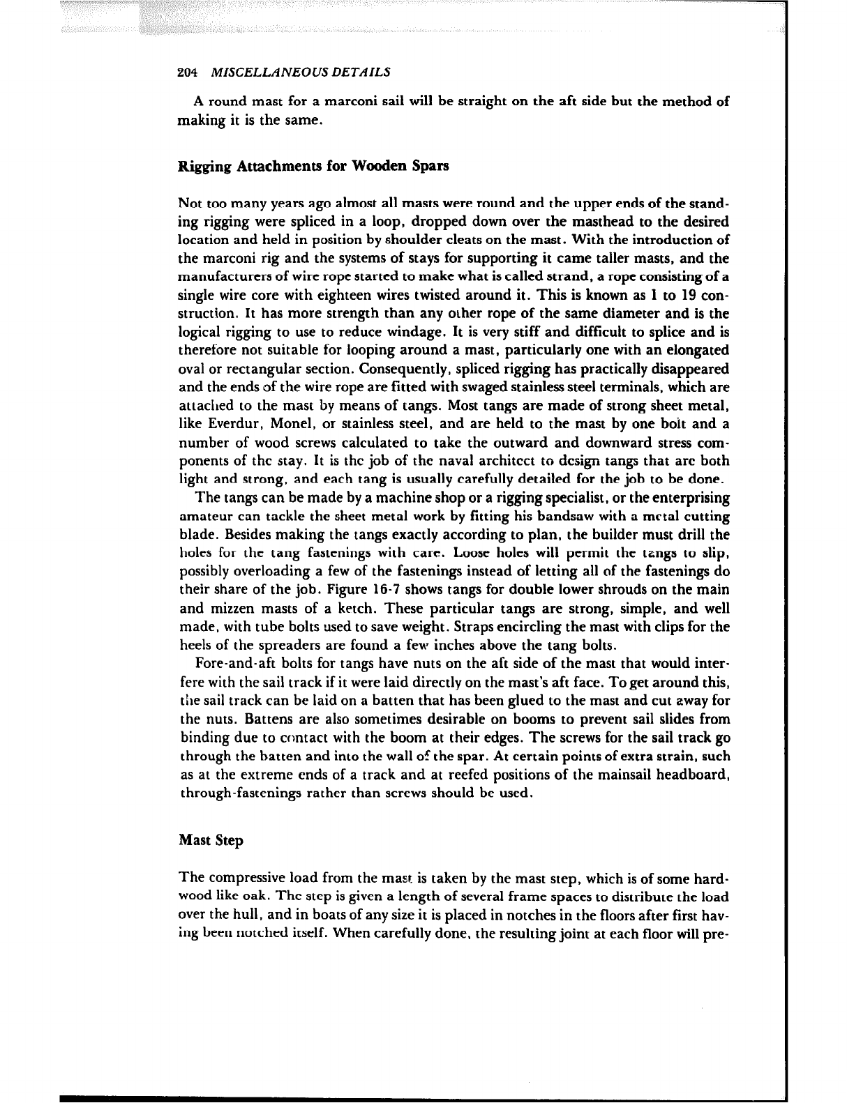
204 MISCELLANEOUS DETAILS
A round mast for a marconi sail will be straight on the aft side but the method of
making it is the same.
Rigging Atmchnents for Wooden Spars
Not too many years ago almost all masts were round and the upper ends of the stand-
ing rigging were spliced in a loop, dropped down over the masthead to the desired
location and held in position by shoulder cleats on the mast. With the introduction of
the marconi rig and the systems of stays for supporting it came taller masts, and the
manufacturers of wire rope started to make what is called strand, a rope consisting of a
single wire core with eighteen wires twisted around it. This is known as 1 to 19 con-
struction. It has more strength than any other rope of the same diameter and is the
logical rigging to use to reduce windage. It is very stiff and difficult to splice and is
therefore not suitable for looping around a mast, particularly one with an elongated
oval or rectangular section. Consequently, spliced rigging has practically disappeared
and the ends of the wire rope are fitted with swaged stainless steel terminals, which are
attached to the mast by means of tangs. Most tangs are made of strong sheet metal,
like Everdur, Monel, or stainless steel, and are held to the mast by one bdt and a
number of wood screws calculated to take the outward and downward stress com-
ponents of the stay. It is the job of the naval architect to design tangs that arc both
light and strong, and each tang is usually carefully detailed for the job to be done.
The tangs can be made by a machine shop or a rigging specialist, or the enterprising
amateur can tackle the sheet metal work by fitting his bandsaw with a metal cutting
blade. Besides making the tangs exactly according to plan, the builder must drill the
holes for the tang fastenings with care. Loose holes will permit the tangs to slip,
possibly overloading a few of the fastenings instead of letting all of the fastenings do
their share of the job. Figure 16-7 shows tangs for double lower shrouds on the main
and mizzen masts of a ketch. These particular tangs are strong, simple, and well
made, with tube bolts used to save weight. Straps encircling the mast with clips for the
heels of the spreaders are found a few inches above the tang bolts.
Fore-and-aft bolts for tangs have nuts on the aft side of the mast that would inter-
fere with the sail track if it were laid directly on the mast’s aft face. To get around this,
the sail track can be laid on a batten that has been glued to the mast and cut away for
the nuts. Battens are also sometimes desirable on booms to prevent sail slides from
binding due to contact with the boom at their edges. The screws for the sail track go
through the batten and imo the wall of the spar. At certain points of extra strain, such
as at the extreme ends of a track and at reefed positions of the mainsail headboard,
through-fastenings rather than screws should be used.
Mast Step
The compressive load from the mast is taken by the mast step, which is of some hard-
wood like oak. The step is given a length of several frame spaces to distribute the load
over the hull, and in boats of any size it is placed in notches in the floors after first hav-
ing been notched itself. When carefully done, the resulting joint at each floor will pre-
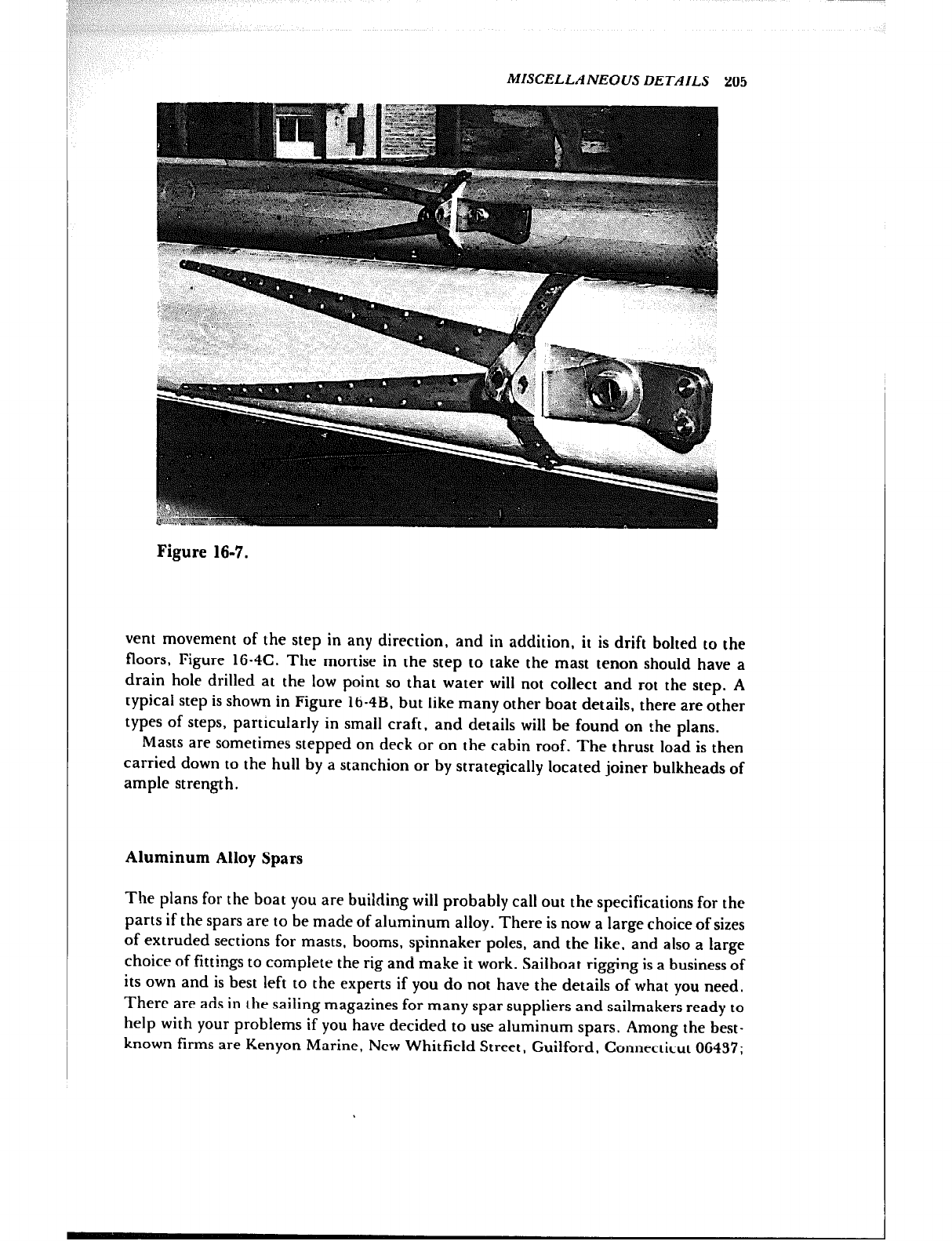
MISCELLANEOUS DETAILS 205
Figure 16-7.
vent movement of the step in any direction, and in addition, it is drift bolted to the
floors, Figure 16.4C. The mortise in the step to take the mast tenon should have a
drain hole drilled at the low point so that water will not collect and rot the step. A
typical step is shown in Figure ltj-4B. but like many other boat details, there are other
types of steps, particularly in small craft, and details will be found on the plans.
Masts are sometimes stepped on deck or on the cabin roof. The thrust load is then
carried down to the hull by a stanchion or by strategically located joiner bulkheads of
ample strength.
Aluminum Alloy Spars
The plans for the boat you are building will probably call out the specifications for the
parts if the spars are to be made of aluminum alloy. There is now a large choice of sizes
of extruded sections for masts, booms, spinnaker poles, and the like. and also a large
choice of fittings to complete the rig and make it work. Sailboat rigging is a business of
its own and is best left to the experts if you do not have the details of what you need.
There are ads in the sailing magazines for many spar suppliers and sailmakers ready to
help with your problems if you have decided to use aluminum spars. Among the best-
known firms are Kenyon Marine, New Whitfield Street, Guilford. Connecticut 06437;
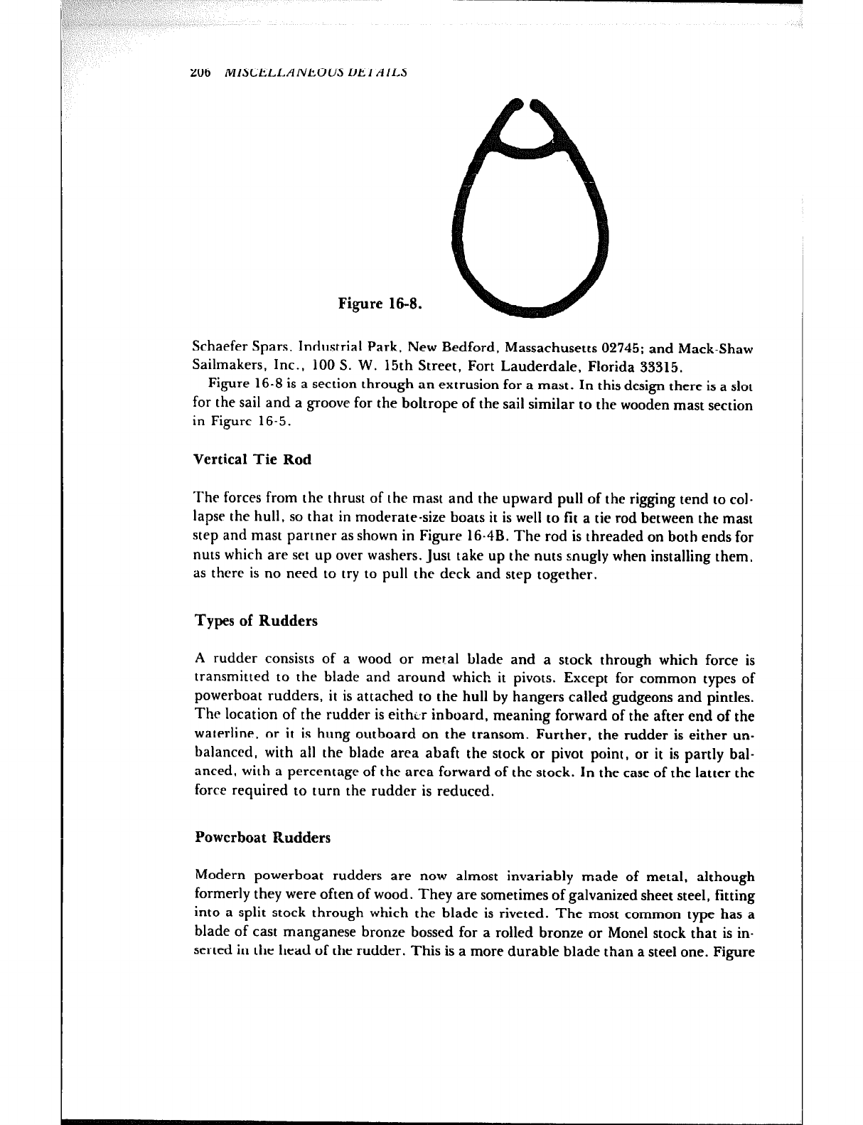
206 MISCELLANEOUS DETAILS
Figure 16-8.
Schaefer Spars, Industrial Park, New Bedford, Massachusetts 02745; and Mack-Shaw
Sailmakers, Inc., 100 S. W. 15th Street, Fort Lauderdale, Florida 33315.
Figure 16-8 is a section through an extrusion for a mast. In this design there is a slot
for the sail and a groove for the boltrope of the sail similar to the wooden mast section
in Figure 16-5.
Vertical Tie Rod
The forces from the thrust of the mast and the upward pull of the rigging tend to col-
lapse the hull, so that in moderate-size boats it is well to fit a tie rod between the mast
step and mast partner as shown in Figure 16.4B. The rod is threaded on both ends for
nuts which are set up over washers. Just take up the nuts snugly when installing them,
as there is no need to try to putt the deck and step together.
Types of Rudders
A rudder consists of a wood or metal blade and a stock through which force is
transmitted to the blade and around which it pivots. Except for common types of
powerboat rudders, it is attached to the hull by hangers called gudgeons and pintles.
The location of the rudder is eithtir inboard, meaning forward of the after end of the
waterline, or it is hung outboard on the transom. Further, the rudder is either un-
balanced, with all the blade area abaft the stock or pivot point, or it is partly bal-
anced, with a percentage of the area forward of the stock. In the case of the latter the
force required to turn the rudder is reduced.
Powerboat Rudders
Modern powerboat rudders are now almost invariably made of metal, although
formerly they were often of wood. They are sometimes of galvanized sheet steel, fitting
into a split stock through which the blade is riveted. The most common type has a
blade of cast manganese bronze bossed for a rolled bronze or None1 stock that is in-
serted in the head of the rudder. This is a more durable blade than a steel one. Figure
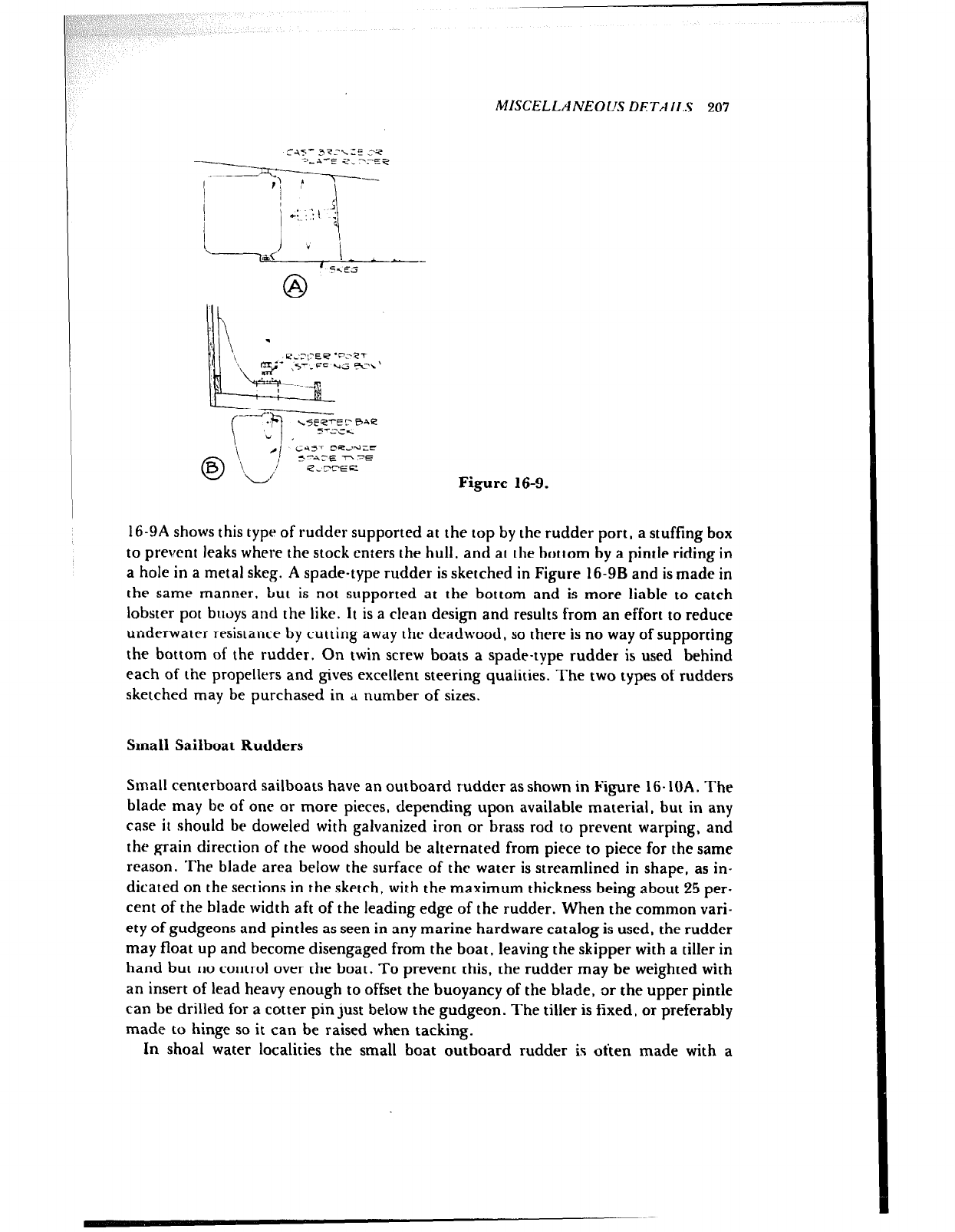
MISCELLANEOIJS DETAILS 207
C-i?’ 3?‘=\ZE 23
?>, ;-A-5 572,
j
I j I 5
1 i
.d:;:t ;
I
i -p< v( I- * --
5xE‘j
0 A
I \ .
L
\ ‘;cyy:gL,l
-
.,
c +=l
LsEetEr f3ne
-v , F-ZCK
0 ‘\ 4 yt;r-,“yfg-
a I\L,:
e,rtEEL Figure 16-9.
16-9A shows this type of rudder supported at the top by the rudder port, a stuffing box
to prevent leaks where the stock enters the hull, and at the bottom by a pintle riding in
a hole in a metal skeg. A spade-type rudder is sketched in Figure 16-9B and is made in
the same manner. but is not supported at the bottom and is more liable to catch
lobster pot buoys and the like. It is a clean design and results from an effort to reduce
underwater resistance by cutting away the deadwood, so there is no way of supporting
the bottom of the rudder. On twin screw boats a spade-type rudder is used behind
each of the propellers and gives excellent steering qualities. The two types of rudders
sketched may be purchased in 4 number of sizes.
Small Sailboat Rudders
Small centerboard sailboats have an outboard rudder as shown in Figure 16-10A. The
blade may be of one or more pieces, depending upon available material, but in any
case it should be doweled with galvanized iron or brass rod to prevent warping, and
the grain direction of the wood should be alternated from piece to piece for the same
reason. The blade area below the surface of the water is streamlined in shape, as in-
dicated on the sections in the sketch, with the maximum thickness being about 25 per-
cent of the blade width aft of the leading edge of the rudder. When the common vari-
ety of gudgeons and pintles as seen in any marine hardware catalog is used, the rudder
may float up and become disengaged from the boat, leaving the skipper with a tiller in
hand but no control over rhe boat. To prevent this, the rudder may be weighted with
an insert of lead heavy enough to offset the buoyancy of the blade, or the upper pintle
can be drilled for a cotter pin just below the gudgeon. The tiller is fixed, or preferably
made to hinge so it can be raised when tacking.
In shoal water localities the small boat outboard rudder is often made with a
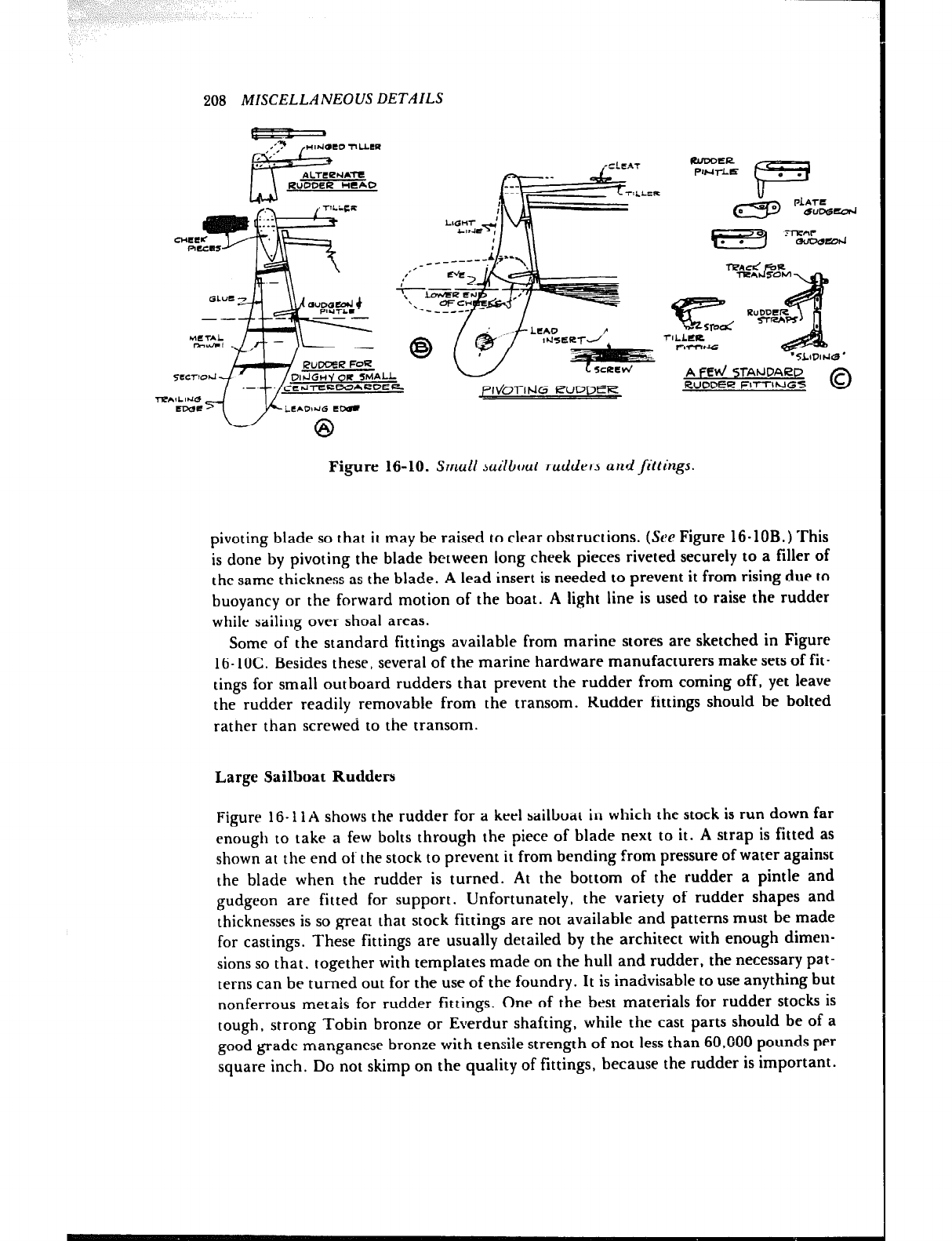
208 MISCELLANEOUS DETAILS
RUDDER HEAD
,,---
au
TZALL
OAROE(L ,P~vioTit.lG b3JDDER
FtlnxlER
PWl-l-E 0 .
F
7lLLClC
FlrnuG ‘5LllJlhll3’
A t=Ed 5TAtJDAc2C’
RUDDEI~ FITTINGS
Figure 16-10. Small sailboat rudders and fittings.
pivoting blade so that it may be raised to clear obstructions. (See Figure 16.10B.) This
is done by pivoting the blade between long cheek pieces riveted securely to a filler of
the same thickness as the blade. A lead insert is needed to prevent it from rising due to
buoyancy or the forward motion of the boat. A light line is used to raise the rudder
while sailing over shoal areas.
Some of the standard fittings available from marine stores are sketched in Figure
16- 1OC. Besides these, several of the marine hardware manufacturers make sets of fit-
tings for small outboard rudders that prevent the rudder from coming off, yet leave
the rudder readily removable from the transom. Rudder fittings should be bolted
rather than screwed to the transom.
Large Sailboat Rudders
Figure 16-11A shows the rudder for a keel sailboat in which the stock is run down far
enough to take a few bolts through the piece of blade next to it. A strap is fitted as
shown at the end of the stock to prevent it from bending from pressure of water against
the blade when the rudder is turned. At the bottom of the rudder a pintle and
gudgeon are fitted for support. Unfortunately, the variety of rudder shapes and
thicknesses is so great that stock fittings are not available and patterns must be made
for castings. These fittings are usually detailed by the architect with enough dimen-
sions so that, together with templates made on the hull and rudder, the necessary pat-
terns can be turned out for the use of the foundry. It is inadvisable to use anything but
nonferrous metals for rudder fittings. One of the best materials for rudder stocks is
tough, strong Tobin bronze or Everdur shafting, while the cast parts should be of a
good grade manganese bronze with tensile strength of not less than 60,000 pounds per
square inch. Do not skimp on the quality of fittings, because the rudder is important.
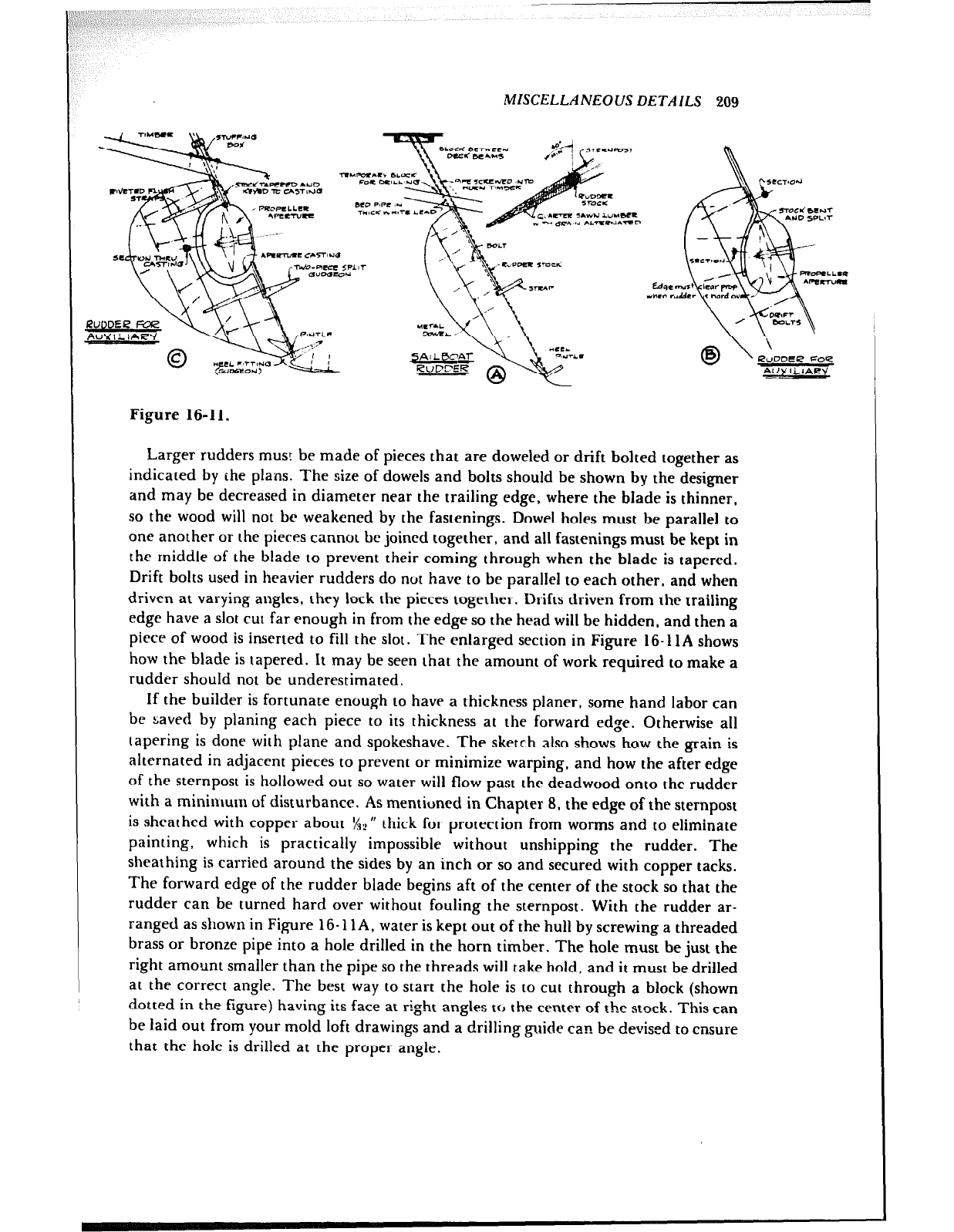
MISCELLANEOUS DETAILS 209
EC’ RuDDEP Foe
AL/V IL4AW
-
Figure 16-11.
Larger rudders mus! be made of pieces that are doweled or drift bolted together as
indicated by the plans. The size of dowels and bolts should be shown by the designer
and may be decreased in diameter near the trailing edge, where the blade is thinner,
so the wood will not be weakened by the fastenings. Dowel holes must be parallel to
one another or the pieces cannot bc joined together, and all fastenings must be kept in
the middle of the blade to prevent their coming through when the blade is tapered.
Drift bolts used in heavier rudders do nut have to be parallel to each other, and when
driven at varying angles, they lock the pieces together. Drifts driven from the trailing
edge have a slot cut far enough in from the edge so the head will be hidden, and then a
piece of wood is inserted to fill the slot. The enlarged section in Figure 16-11A shows
how the blade is tapered. It may be seen that the amount of work required to make a
rudder should not be underestimated.
If the builder is fortunate enough to have a thickness planer, some hand labor can
be saved by planing each piece to its thickness at the forward edge. Otherwise all
tapering is done with plane and spokeshave. The sketch also shows how the grain is
alternated in adjacent pieces to prevent or minimize warping, and how the after edge
of the sternpost is hollowed out so water will flow past the deadwood onto the rudder
with a minimum of disturbance. As mentioned in Chapter 8, the edge of the sternpost
is sheathed with copper about 1/?” thick for protection from worms and to eliminate
painting, which is practically impossible without unshipping the rudder. The
sheathing is carried around the sides by an inch or so and secured with copper tacks.
The forward edge of the rudder blade begins aft of the center of the stock so that the
rudder can be turned hard over without fouling the sternpost. With the rudder ar-
ranged as shown in Figure 16-11 A, water is kept out of the hull by screwing a threaded
brass or bronze pipe into a hole drilled in the horn timber. The hole must be just the
right amount smaller than the pipe so the threads will take hold, and it must be drilled
at the correct angle. The best way to start the hole is to cut through a block (shown
dotted in the figure) having its face at right angles fcJ the center of the stock. This can
be laid out from your mold loft drawings and a drilling guide can be devised to ensure
that the hole is drilled at the proper angle.
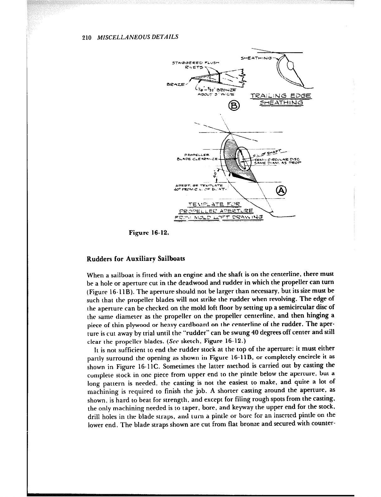
210 MISCELLANEOUS DETAILS
STAGGEPED FLUS-
.nEz~
B;*zEym iv)&
- 42’ BeorJZE
A0OuT 3“ W’I CE TL?AILiNG EC’GE
0
B SHEATHING
--
l-E \l PL ATE !=L?R
,=?I?“.\ hiJLC AFT CPA\\ IUEf
m. -. ---.- ._.. ----
Fi,gure 16-12.
Rudders for Auxiliary Sailboats
When a sailboat is fitted with an engine and the shaft is on the centerline, there must
be a hole or aperture cut in the deadwood and rudder in which the propeller can turn
(Figure 16- 11 B). The aperture should not be larger than necessary, but its size must be
such that the propeller blades will not strike the rudder when revolving. The edge of
the aperture can be checked on the mold loft floor by setting up a semicircular disc of
the same diameter as the propeller on the propeller centerline, and then hinging a
piece of thin plywood or heavy cardboard on the centerline of the rudder. The aper-
ture is cut away by trial until the “rudder” can bc swung 40 degrees off center and still
clear the propeller blades. (See sketch, Figure 16-12.)
It is not sufficient to end the rudder stock at the top of the aperture: it must either
partly surround the opening as shown in Figure 16-11B. or completely encircle it as
shown in Figure 16.1lC. Sometimes the latter method is carried out by casting the
complete stock in one piece from upper end to the pintle below the aperture, but a
long pattern is needed, the casting is not the easiest to make, and quite a lot of
machining is required to finish the job. A shorter casting around the aperture, as
shown, is hard to beat for strength, and except for filing rough spots from the casting,
the only machinin, = needed is to taper, bore, and keyway the upper end for the stock,
drill holes in the blade straps, and turn a pintle or b arc for an inserted pintle on the
lower end. The blade straps shown are cut from flat bronze and secured with counter-
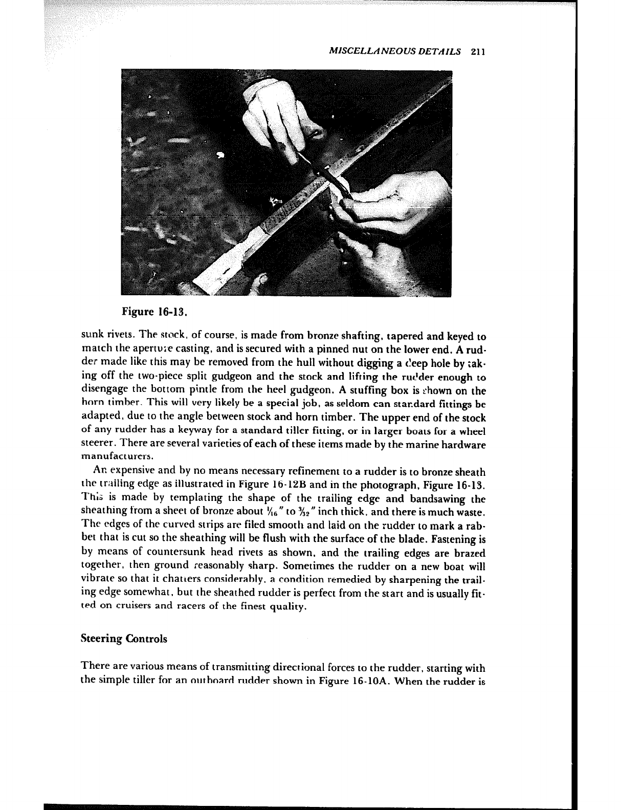
‘! /fl b >; :
MISCELLANEOUS DETAILS 211
Figure 16-13.
sunk rivets. The stock, of course, is made from bronze shafting, tapered and keyed to
match the apertui’e casting, and is secured with a pinned nut on the lower end. A rud-
der made like this may be removed from the hull without digging a cleep hole by ;ak-
ing off the two-piece split gudgeon and the stock and lifting the rur’der enough to
disengage the bottom pintle from the heel gudgeon. A stuffing box is shown on the
horn timber. This will very likely be a special job, as seldom can star.dard fittings be
adapted, due to the angle between stock and horn timber. The upper end of the stock
of any rudder has a keyway for a standard tiller fitting, or in larger boats for a wheel
steerer. There are several varieties of each of these items made by the marine hardware
manufacturers.
An expensive and by no means necessary refinement to a rudder is to bronze sheath
the trailing edge as illustrated in Figure 16-12B and in the photograph, Figure 16-13.
Thk is made by templating the shape of the trailing edge and bandsawing the
sheathing from a sheet of bronze about &, V to X2 M
inch thick. and there is much waste.
The edges of the curved strips are filed smooth and laid on the rudder to mark a rab-
bet that is cut so the sheathing wiil be flush with the surface of the blade. Fastening is
by means of countersunk head rivets as shown, and the trailing edges are brazed
together, then ground reasonably I;harp. Sometimes the rudder on a new boat will
vibrate so that it chatters considerably, a condition remedied by sharpening the trail-
ing edge somewhat, but the sheathed rudder is perfect from the start and is usually fit-
ted on cruisers and racers of the finest quality.
Steering Controls
There are various means of transmitting directional forces to the rudder, starting with
the simple tiller for an outboard rudder shown in Figure 16-10A. When the rudder is
212 MISCELLANEOUS DETAILS
inboard, more complicated methods must be used. Some sailboats have an Edson-type
steerer with the wheel and gearing attached to the upper end of the rudder stock.
These gears must be carefully aligned and securely fastened to the structure. Other
sailboats have the wheel farther away from the rudder and use a pedestal steerer con-
nected to a quadrant on the rudder stock with a length of sprocket and chain and wire
rope running over sheaves. The Edson Corp., 471 Industrial Park Road, New Bed-
ford, Massachusetts 02745, is one of the world’s largest producers of sailboat steerers
and issues a catalog that is practically a design handbook. A recent Edson innovation
utilizes husky push-pull cable steering from a pedestal in lieu of cable-over-pulley con-
nections to the rudder tiller. This greatly simplifies the installation.
There are several types of steerers for powerboats. One method uses a reduction
gear steerer at the wheel a.nd chain and wire rope similar to the sailboat pedestal
steerer. Others use a gearbox at the wheel or elsewhere in the system and connect to
the rudder arm with shafts, solid or pipe. A more modern type of steerer, suitable for
small to medium sizes of boats, uses a rack and pinion at the wheel and a heavy push-
pull cable from the rack to an arm at the rudder. This is by far the simplest type of
steerer and is seen in many boats because it is the least expensive to install.
The fortunate builder has good detail of the steering system on his plans: otherwise
he has been left on his own to work it out. The steering should be installed before too
much of the interior joinerwork has been built. It is most important that all steering
gear parts be securely fastened to prevent movement of units such as the steerer and
wire rope sheaves. The latter should be through-bolted and should be carefully
aligned to reduce friction and eliminate wear on the wire rope. All parts should aiso be
nonferrous whenever possible.
Due to the high cost of labor, manual hydraulic steering has almost become stan-
dard with the stock powerboat manufacturers. This type of steering consists essentially
of a pump that is turned by the steering wheel, a hydraulic cylinder, and a reservoir,
all connected by three tubes or hoses of small diameter. There cpn be two or more
steering stations-it makes little difference as long as there are no leaks in the pip-
ing-so the more the number of stations the more advantageous the system. One
drawback, and this is a matter of design, is the great zumber of steering wheel turns
from hard over to hard over of the rudder. In the larger boats, the number of turns
can be reduced by introducing a power-driven pump instead of a manually operated
one. One of the largest suppliers of hydraulic steering components is Hynautic, Inc.,
Box 668, Osprey, Florida 33559.
Fuel Tanks
Due to the danger of explosion and fire, the construction and installation of fuel tanks,
particularly gasoline tanks, should not be taken lightly. Both installation and con-
struction are well covered by standards set by the American Boat and Yacht Council,
written by people with long experience, and most recently (1977) by the U.S. Coast
Guard. The standards are only as good as your compliance with them, so heed them
well. (See Chapter 17 and Recommended Reading.)
The standards specify the all-important matter of tank materials. Monel Alloy 400
MISCELLANEOUS DETAILS 213
remains probably the finest metal from which to make tanks, either for gasoline or
diesel fuel, but it is extremely high in cost. Steel remains the most inexpensive material
for diesel fuel tanks but must not have a coating of any sort on the inside. A
breakthrough since the last edition of this book is the approval of certain alloys of
aluminum for the construction of fuel tanks. Now tanks can be welded of alloys 5052,
5083, or 5086.
When buying a fuel tank, be sure it bears the label of the manufacturer as called for
by the standards and that it shows it was tested. Also, be sure that it has a tab for con-
nection to the bonding system of the boat.
One caution about aluminum tanks concerns the connection of metal fittings, such
as metal tubing and metal ends of fuel hoses, to the tank, because the metal may not
be galvanically compatible with the aluminum alloy. One way to avoid trouble is to
weld half of an aluminum pipe coupling to the tank and then screw a stainless steel
pipe bushing into the female threads of the coupling half. The bushing reduces the
size of the opening; therefore you must start out with a coupling that is a size or two
larger than usual. Fill and vent connections to the tank are normally of hose, and these
can be slipped over and clamped to aluminum unthreaded nipples welded to the tank.
All valves in the fuel piping, including those at the tank for the fuel suction to the
engine (and fuel return line in diesel systems), must be of the approved packless type,
which do not leak at the stems.
And one final word: openings in the tank for any purpose are not permitted
anywhere except on the top surface of the tank.
A tank manufacturer that has made hundreds of aluminum alloy fuel tanks for
stock and custom boatbuilders as well as for the one-off people is Florida Marine
Tanks, Inc., 16480 N. W. 48th Avenue, Hialeah, Florida 33014.
Tank Capacity Calculation
Figure 16-14 shows tank shapes commonly used in boats and how to calculate their
capacity by figuring the volume in cubic inches and dividing by 231 to find contents in
U.S. gallons. Boatbuilders seem to always work the capacities from inch dimensions. If
dimensions are taken in feet, the cubic capacity is multiplied by 7.48 for the answer in
gallons.
The cylindrical and rectangular tanks A and B are straightforward to figure. Shape
C is typical of a tank installed under the cockpit of a sailboat. The sides are parallel
but the top and bottom are not, due to hull shape. The cross-sectional area W times H
is the average of the area of the ends, or the same as the area at midlength of the tank.
Shape D is often used for tanks located under the floor of a cabin, and again the
volume is the length times the average of the area of the ends. The W measurements
are taken at midheight of the ends.
Propeller Shafts and Bearings
Propeller shafts must be made from strong, non-corrosive material. At this writing two
of the best metals, Monel Alloy 400 and the higher strength Monel Alloy K-500 have
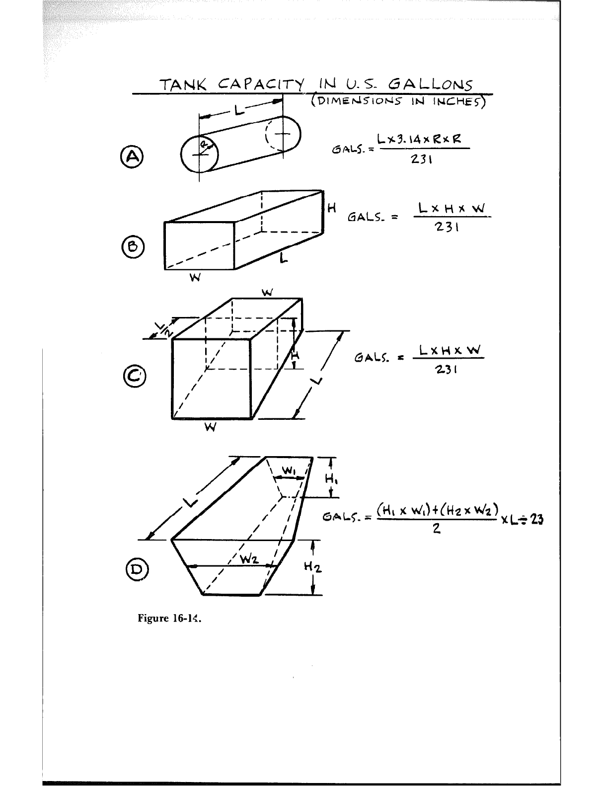
TAti< CApAC17-y 1b-i (J-s- fibLL0Fd.S
I (DlMEdSlo~5 Id INCH&)
0
A
0
0
L /
;
Q
e L%3.\4SCKlZ
. 6 ALJ. = 231
H CiALS_ = LXH%W
231 -
Figure 16-l<.

MISCELLANEOUS DETAILS 215
just about priced themselves out of the pleasure boat market. These are high in nickel
content, and this is probably the reason why little people, unlike governments, cannot
afford them. A somewhat weaker metal, although “standard” for many years, is Tobin
bronze, but this seems to have disappeared (but don’t overlook the possibility of find-
ing a used Tobin shaft) and been replaced by various stainless steel shafting
materials, notably Armco’s Aquamet 17, 18, and 22. If the shaft is going to be turning
most of the time, like in commercial boat use, then Aquamet 17 is a strong, suitable
metal, but in typical intermittent yacht service Aquamet 22 is a better choice.
If your boat plans do not specify the shaft diameter, American Boat and Yacht
Council standard P-6 has charts for selecting the sizes of shafts for the materials men-
tioned above and also for bearing spacing.
Typical shafts have a keyway machined on one end for the propeller shaft coupling
to the engine, while the outboard end has a taper with keyway to match the propeller
hub bore and threads for the propeller locking nuts. The tapering must be carefully
done so the propeller will fit properly and is best left to a shaft supplier who is set up
for this work. Dimensions for machining the shaft end and propeller hub have long
been standardized, at least in the U.S., and the SAE data for this is usually tabulated
and illustrated in the catalogs of the propeller makers. When setting up the length of
your shaft, allow one shaft diameter’s clearance between the propeller hub and the
strut.
Figure 16-15A shows a longitudinal section at the shaft centerline of a twin screw
motorboat. The same section applies to a common single screw motorboat with a keel
batten and cutaway skeg. It shows the usual modern arrangement of a rubber-necked
shaft log with a stuffing box inboard to prevent water from leaking into the boat
around the shaft, and a strut to support the shaft at the propeller. Intermediate struts
are used when the shaft is sufficiently long to require additional support.
The stuffing box and the shaft log are both of bronze and are connected by a short
length of rubber hose secured by clamps. The hose helps to reduce vibration due to
minor misalignment of the shaft. Shaft logs are made in the several angles that have
proven the most useful for the majority of boats, but they may have to be shimmed
with a wedge of wood in your boat to get the correct alignment. The base flange of the
shaft log must be made watertight by bedding the flange with a generous amount of
bedding compound, such as Dolfinite, or with one of the thiokol-base materials.
Wherever possible, the base should be through-fastened with silicon bronze bolts;
otherwise wood screws of the same metal should be used.
*a The shaft hole through the wood should be treated with polyester or epoxy resin,
because the hole is difficult to clean and paint later with the shaft in place and is
therefore susreptible to worm damage. This precaution is very important indeed.
Some shaft logs are designed with a tube integral with the base. The tube is a lining
for the shaft hole and is cut off flush with the outside of the hull. This type of shaft log
is rather special and is not used as frequently as the kind that terminates at the base.
Another type of special shaft log is sometimes used in moderate to large size boats
where the shaft is quite long in proportion to the diameter and it is desirable to have a
bearing between the first intermediate shaft strut and the engine. In this case shaft
logs are made that have a short length of bearing. The bearing is housed so the for- s
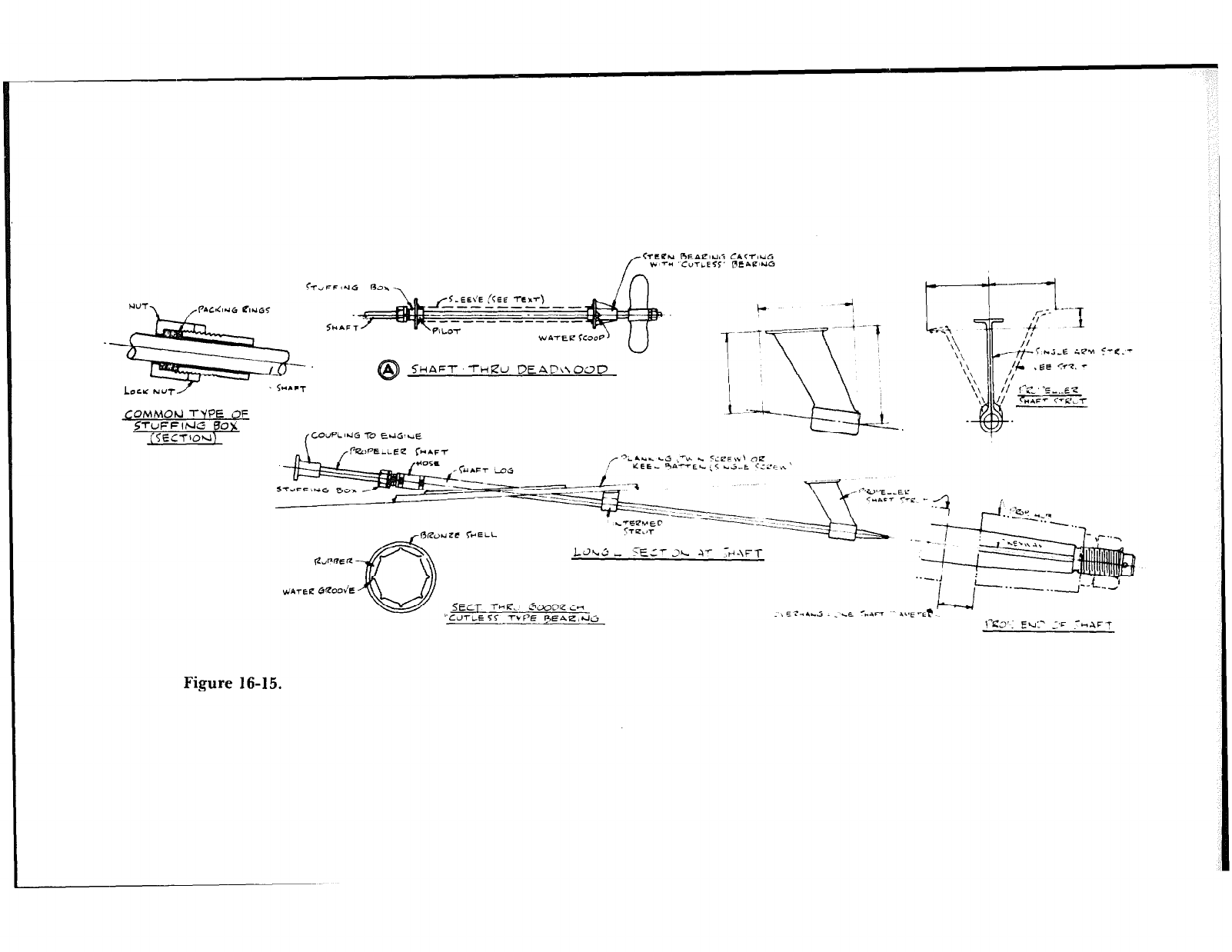
f <TTCPu BEAClUG CACTtUG
* 7” ‘CVTLE-X Pene’uG
/n
u-
SHAFT -n-i~u B~iiC\xoc~D
COMMOU TYPE OF
Figure 16-15.
t----t-Y
1 I
-k\ ,?-. ‘-1
‘$, .--&&E iP.4
‘\
‘\ I)&
-1.
,EE <Y-e. 7
\\ II/
‘\’ I/ I”C”C ..E7
,\ J/ cr,,m
LdL,3 - TE:r JL v Y~-\FT
.---.I 1 ,+..-..
5-e.-
SECT ~-HZ. ~~DZ;~
“COTIE 11 7-v PE FEPLz,rJlj l?Z.3’ F u-
- - ~. Z’C .--AFT
MISCELLANEOL’S DETAILS 217
ward end is not exposed to a flow of water; water lubrication is provided by engine
cooling water tapped into the log forward of the bearing. The water used is part of
that usually piped into the exhaust line for cooling, but the diversion is not detrimen-
tal, because only a small amount is sent to the shaft log bearing. This type of shaft log
is specially made up and not found in marine supply catalogs.
A part of the propulsion setup that is almost always a special item is the propeller
shaft strut. As specified by the plans, these are either the single amI or the v type, and
due to the angle of the shaft and the shape of the hull it is nearly impossible to find a
stock strut that will fit. There are, however, some adjustable struts on the market that
might just do the job. Otherwise, enough dimensions on a sketch as shown in Figure
16-15A or a mock-up must be sent to a strut manufacturer so he can make up one or a
pair to fit the boat. I am not advertising anybody in particular, but over the years Col-
umbian Bronze Corp., Freeport, New York 11520 has made thousands of special
struts, so they have many patterns that may be adapted with moderate alterations.
Most struts are made of cast manganese bronze.
Struts are fastened through the planking and the inside blocking with silicon bronze
or manganese bronze bolts. The heads of the bolts should be oval and countersunk and
should have a screwdriver slot to keep the bolt from turning while it is tightened.
These bolts are best oldered from the strut manufacturer, specifying the length
needed.
You might as well have the strut maker install the bearing in the strut. It is hard to
beat the Goodrich “Cutless”-type bearing, which is made of rubber bonded to an outer
shell of bronze or, if the hull is aluminum, to an optional plastic-type shell. This type
of bearing has grooves that channel in water for lubrication and for washing out silt
and sand, thus minimizing shaft wear. The shell of the bearing is lightly pressed into
the strut and secured with one or two set screws. The bearings are four times the shaft
diameter in length when used as the aftermost bearing, and they are often reduced to
half length in intermediate struts, so that one standard bearing can be cut to make two
intermediate ones.
Figure 16-15A also shows a typical arrangement when the shaft of a single-engine
boat goes through the deadwood. The stuffing box is inside the hull, the stern bearing
outside. The latter has a Cutless-type bearing and a water scoop on each side of the
casting for bearing lubrication. The stuffing box can be had “rubber necked,” with a
piece of hose between the stuffing box and the casting. Both stuffing box assembly and
the stern bearing are stock items of marine hardware and are readily available.
Water will fill the hole for the shaft and must be prevented from leaking into the
hull through joints in the deadwood structure. This is done by fitting a tube between
the stuffing box and stern bearing castings, either a lead sleeve as shown in A of the
figure (the lead is easily flanged by hammering) or a bronze tube special ordered from
a supplier like Columbiar. Bronze. The pilots of the castings can be tapped for the
ends of a threaded pipe. The castings should be fastened to the wood with hanger
bolts.
The stuffing box packing is square, either waxed braided flax or Teflon-
impregnated asbestos braid, and is installed as individual rings, with the joints stag-
gered so they are not all in line, thus preventing leaking.
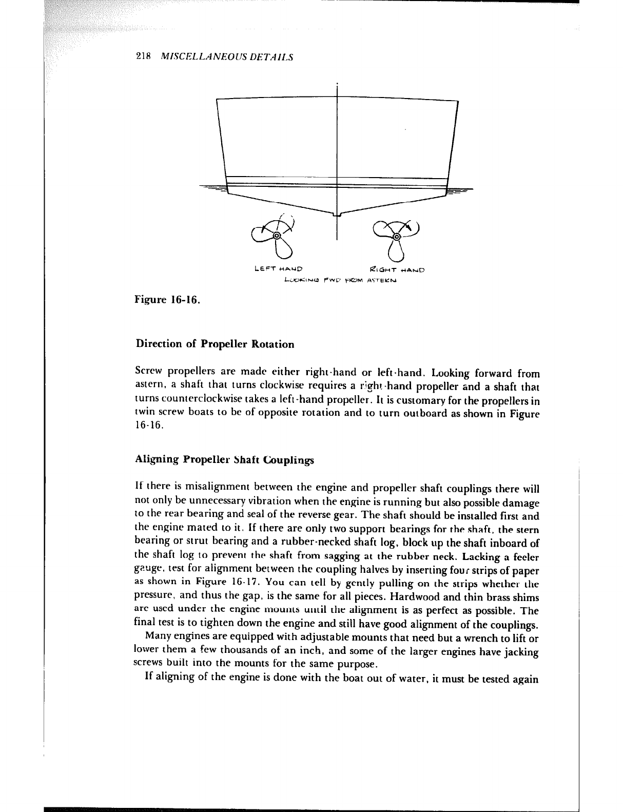
LEFT HAND $?IGHT r(4~D
kV<lNG fWD +M A$-+-EC?t.l
Fbgure 16-16.
Direction of Propeller Rotation
Screw propellers are made either right-hand or left-hand. Looking forward from
astern, a shaft that turns clockwise requires a r$ht-hand propeller and a shaft that
turns counterclockwise takes a left-hand propeller. It is customary for the propellers in
twin screw boats to be of opposite rotation and to turn outboard as shown in Figure
16-1G.
Aligning Propeller Shaft Couplings
If there is misalignment between the engine and propeller shaft couplings there will
not only be unnecessary vibration when the engine is running but also possible damage
to the rear bearing and seal of the reverse gear. The shaft should be installed first and
the engine mated to it. If there are only two support bearings for the shaft, the stern
bearing or strut bearing and a rubber-necked shaft log, block up the shaft inboard of
the shaft log to prevent the shaft from sagging at the rubber neck. Lacking a feeler
geuge, test for alignment between the coupling halves by inserting four strips of paper
as shown in Figure 16.17. You can tell by gently pulling on the strips whether the
pressure, and thus the gap, is the same for all pieces. Hardwood and thin brass shims
are used under the engine mounts until the alignment is as perfect as possible. The
final test is to tighten down the engine and still have good alignment of the couplings.
Many engines are equipped with adjustable mounts that need but a wrench to lift or
lower them a few thousands of an inch, and some of the larger engines have jacking
screws built into the mounts for the same purpose.
If aligning of the engine is done with the boat out of water, it must be tested again
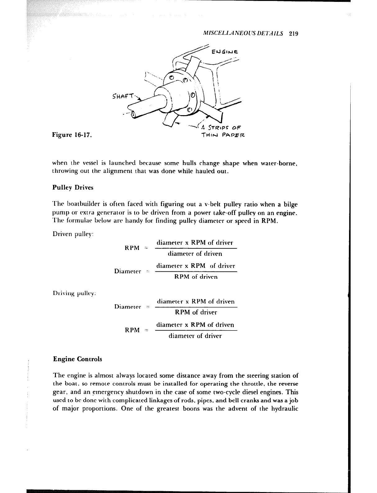
MI.~CEi~l.ANEOC~.S DE?,-IILS 219
when the vessel is launched because some hulls change shape when water-borne,
throwing out the alignment that was done while hauled out.
Pulley Drives
‘l’hc boatbuilder is often faced with figuring out a v-belt pulley ratio when a bilge
pump or rxtra generator is to br driven from a power take-off pulley on an engine.
‘l’he fortnulitt~ below art’ handy for finding pulley diameter or spcrd in RPM.
Driven pulley: diameter x RPM of drivel
RPM -_ diamctcr of driven
diameter x RPM of driver
Diameter = RPM of driven
Driving pullry: diameter x RPM of driven
Diameter = RPM of driver
diameter x RPM of driven
RPM = diameter of driver
Engine Controls
The engine is almost always located some distance away from the steering station of
the boat, so remote controls must be installed for operating the throttle, the reverse
gear, and an emergency shutdown in the case of some two-cycle diesel engines. This
used to be done with complicated linkages of rods, pipes, and bell cranks and was a job
of major proportions. One of the greatest boons was the advent of the hydraulic
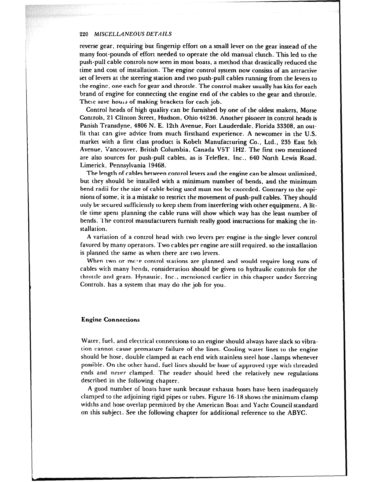
220 MISCELLANEOUS DETAILS
reverse gear, requiring but fingertip effort on a small lever on the gear instead of the
many foot-pounds of effort needed to operate the old manual clutch. This led to the
push-pull cable controls now seen in most boats, a method that drastically reduced the
time and cost of installation. The engine control system now consists of an attractive
set of levers at the steering station and two push-pull cables running from the levers to
the engine, one each for gear and throttle. The control maker usually has kits for each
brand of engine for connecting the engine end of the cables to the gear and throttle.
The5.e save hou1.z of making brackets for each job.
Control heads of high quality can be furnished by one of the oldest makers, Morse
Controls, 21 Clinton Street, Hudson, Ohio 44236. Another pioneer in control heads is
Panish Transdyne, 4806 N. E. 12th Avenue, Fort Lauderdale, Florida 33308, an out-
fit that can give advice from much firsthand experience. A newcomer in the U.S.
market with a first class product is Kobelt Manufacturing Co., Ltd., 235 East 5th
Avenue, Vancouver, British Columbia, Canada V5T lH2. The first two mentioned
are also sources for push-pull cables, as is Teleflex. Inc., 640 North Lewis Road,
Limerick, Pennsylvania 19468.
The length of cables between control levers and the engine can be almost unlimited,
but they should be installed with a minimum number of bends, and the minimum
bend radii for the size of cable being used must not be exceeded. Contrary to the opi-
nions of some, it is a mistake to restrict the movement of push-pull cables. They should
only be secured sufficiently to keep them from interfering with other equipment. A lit-
tle time spent planning the cable runs will show which way has the least number of
bends. The control manufacturers furnish really good instructions for making the in-
stallation.
A variation of a control head with two levers per engine is the single lever control
favored by many operators. Two cables per rngine are still required, so the installation
is planned the same as when there are two levers.
When two or rnc*e control stations are planned and would require long runs of
cables with many bends, consideration should be given to hydraulic controls for the
throttle and gears. Hynautic. Inc., mentioned earlier in this chapter under Steering
Controls, has a system that may do the job for you.
Engine Connections
Water, fuel, and electrical connections to an engine should always have slack so vibra-
tion cannot cause premature failure of the lines. Cooling water lines to the engine
should be hose, double clamped at each end with stainless steel hose clamps whenever
possible. On the other hand, fuel lines should be hose of approved type with threaded
ends and rtezler clamped. The reader should heed the relatively new regulations
described in the following chapter.
A good number of boats have sunk because exhaust hoses have been inadequately
clamped to the adjoining rigid pipes or tubes. Figure 16-18 shows the minimum clamp
widths and hose overlap permitted by the American Boat and Yacht Council standard
on this subject. See the following chapter for additional reference to the ABYC.
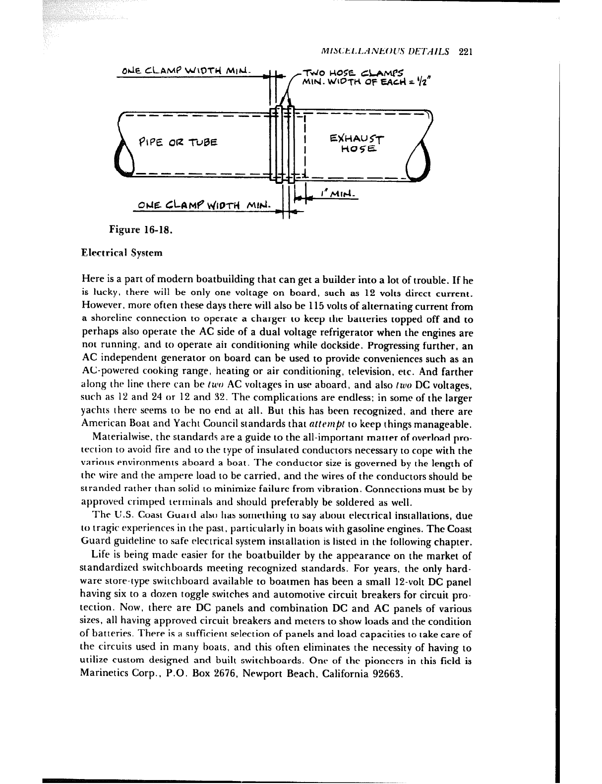
MISCEI.L.~lNEOI~S DETAILS 221
Ohk CLAM4 W\DTc( M~hd. I I 1 wo uo5e CLAMPS
Mlfd. WIOfH of ~%cI=! r ‘12”
Figure 16-18.
Electrical System
Here is a part of modern boatbuilding that can get a builder into a lot of trouble. If he
is lucky, there will be only one voltage on board, such as 12 volts direct current.
However, more often these days there will also be 115 volts of alternating current from
a shoreline connection to operate a charger to keep the batteries topped off and to
perhaps also operate the AC side of a dual voltage refrigerator when the engines are
not running, and to operate air conditioning while dockside. Progressing further, an
AC independent generator on board can be used to provide conveniences such as an
AC-powered cooking range, heating or air conditioning, television, etc. And farther
along the line there can be ~UW AC voltages in USC aboard, and also IWO DC voltages,
such as 12 and 24 or 12 and 32. The complications are endless: in some of the larger
yachts thrrc seems to be no end at all. But this has been recognized, and there are
American Boat and Yacht Council standards that alfe~tpl to keep things manageable.
Materialwise. the standards are a guide to the all-important matter of overload pro-
tection to avoid fire and to the type of insulated conductors necessary to cope with the
various environments aboard a boat. The conductor size is governed by the length of
thr wire and the ampere load to be carried, and the wires of the conductors should be
stranded rather than solid to minimize failure from vibration. Connections must be by
approved crimped terminals and should preferably be soldered as well.
The I1.S. Coast Guard also has something to say about electrical installations, due
IO tragic cxprriences in the past, particularly in boats with gasoline engines. The Coast
Guard guideline to safe electrical system installation is listed in the following chapter.
Life is being made easier for the boatbuilder by the appearance on the market of
standardized switchboards meeting recognized standards. For years, the only hard-
ware store-type switchboard availahle to boatmen has been a small 12-volt DC panel
having six to a dozen toggle switches and automotive circuit breakers for circuit pro-
tection. Now, there are DC panels and combination DC and AC panels of various
sizes, all having approved circuit breakers and meters to show loads and the condition
of batteries. There is a sufficient selection of panels and load capacities to take care of
the circuits used in many boats, and this often eliminates the necessity of having to
utilize custom designed and built switchboards. One of the pioneers in this field is
Marinetics Corp., P.O. Box 2676, Newport Beach, California 92663.
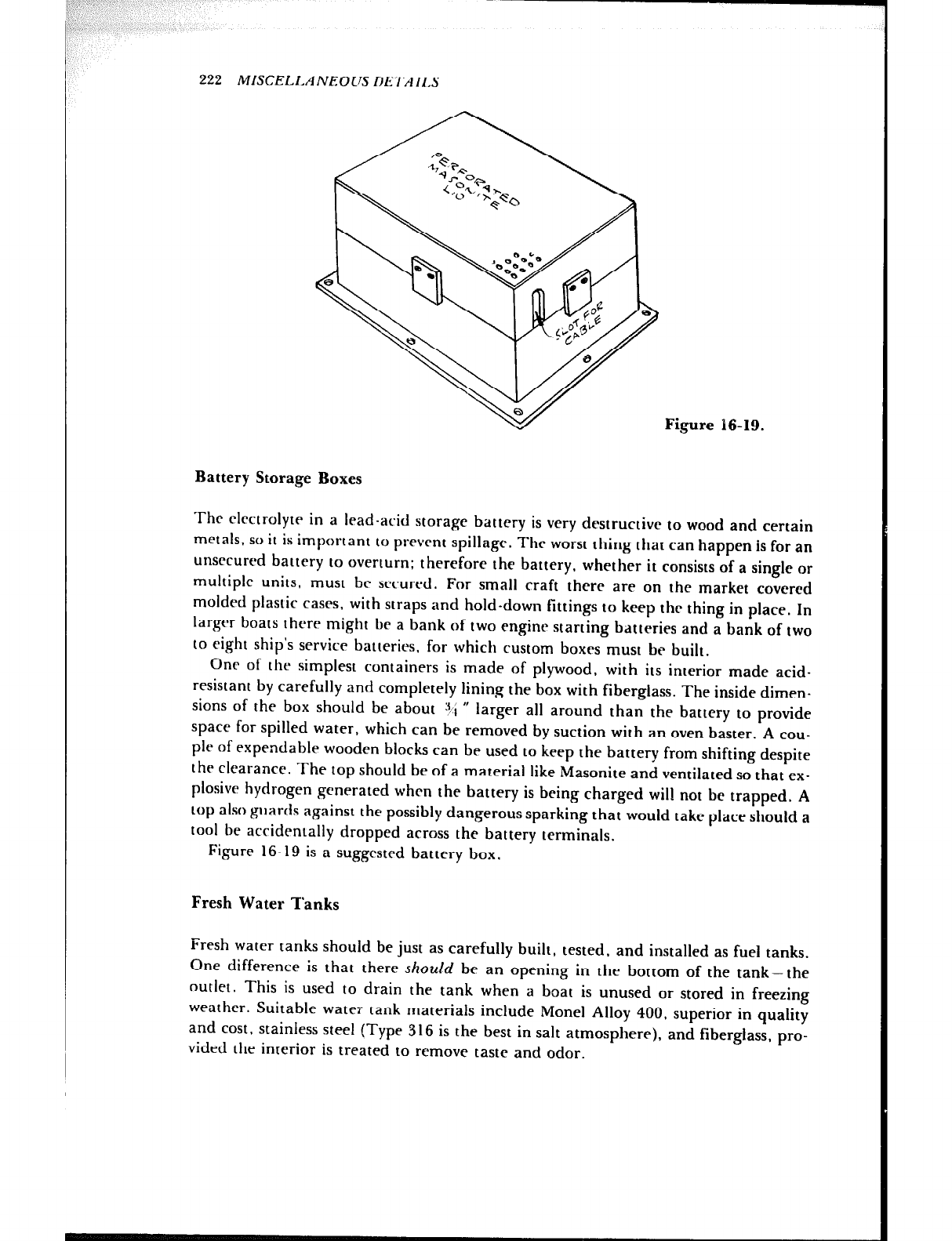
222 MISCELLA NEOLJS llET/lILS
Battery Storage Boxes
The clrctrolyte in a lead-arid storage battery is very destructive to wood and certain
metals, so it is important to prevent spillage. The worst thing that can happen is for an
unsecured battery to overturn: therefore the battery, whether it consists of a single or
multiple units, must bc secured. For small craft there are on the market coveted
molded plastic cases, with straps and hold-down fittings to keep the thing in place. In
larger boats there might be a bank of two engine starting batteries and a bank of two
to eight ship’s service batteries. for which custom boxes must be built.
Onr of the simplest containers is made of plywood, with its interior made acid-
resistant by carefully and completely lining the box with fiberglass. The inside dimen-
sions of the box should be about 3i W
larger all around than the battery to provide
space for spilled water, which can be removed by suction with an oven baster. A cou-
ple of expendable wooden blocks can be used to keep the battery from shifting despite
the clearance. The top should be of a material like Masonite and ventilated so that ex-
plosive hydrogen generated when the battery is being charged will not be trapped. A
top also guards against the possibly dangerous sparking that would take place should a
tool be accidentally dropped across the battery terminals.
Figure 16-19 is a suggested battery box.
Fresh Water Tanks
Fresh water tanks should be just as carefully built, tested, and installed as fuel tanks.
One difference is that there should be an opening in the bottom of the tank- the
outlet. This is used to drain the tank when a boat is unused or stored in freezing
weather. Suitable water tank materials include Monet Alloy 400. superior in quality
and cost, stainless steel (Type 316 is the best in salt atmosphere), and fiberglass, pro-
vided the interior is treated to remove taste and odor.
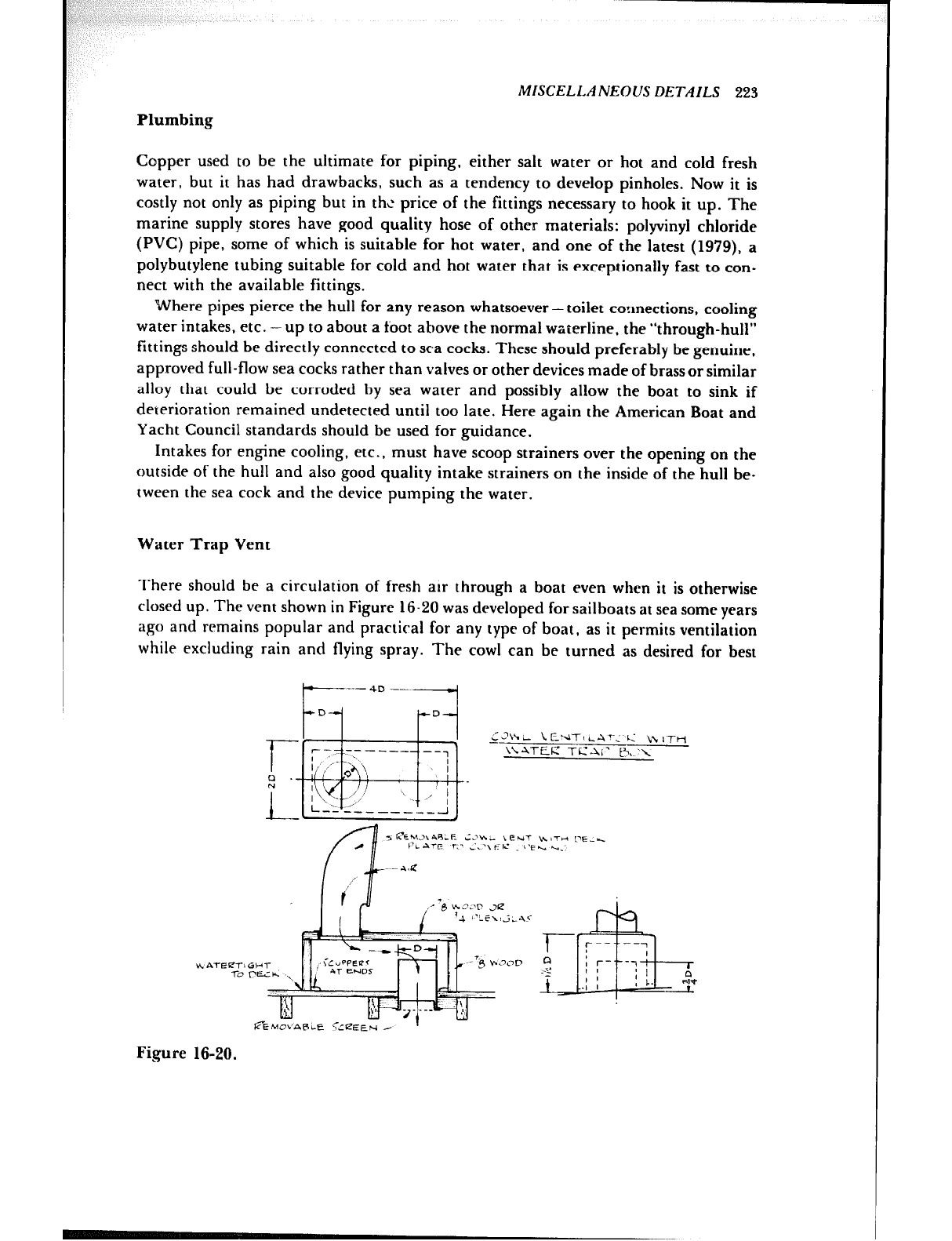
Plumbing
MISCELLANEOUS DETAILS 223
Copper used to be the ultimate for piping, either salt water or hot and cold fresh
water, but it has had drawbacks, such as a tendency to develop pinholes. Now it is
costly not only as piping but in thz price of the fittings necessary to hook it up. The
marine supply stores have good quality hose of other materials: polyvinyl chloride
(PVC) pipe, some of which is suitable for hot water, and one of the latest (1979), a
polybutylene tubing suitable for cold and hot water that is exceptionally fast to con-
nect with the available fittings.
Where pipes pierce the hull for any reason whatsoever-toilet connections, cooling
water intakes, etc. -up to about a foot above the normal waterline, the “through-hull”
fittings should be directly connected to sea cocks. These should preferably be genuine,
approved full-flow sea cocks rather than valves or other devices made of brass or similar
alloy that could be corroded by sea water and possibly allow the boat to sink if
deterioration remained undetected until too late. Here again the American Boat and
Yacht Council standards should be used for guidance.
Intakes for engine cooling, etc., must have scoop strainers over the opening on the
outside of the hull and also good quality intake strainers on the inside of the hull be-
tween the sea cock and the device pumping the water.
Water Trap Vent
There should be a circulation of fresh air through a boat even when it is otherwise
closed up. The vent shown in Figure 16-20 was developed for sailboats at sea some years
ago and remains popular and practical for any type of boat, as it permits ventilation
while excluding rain and flying spray. The cowl can be turned as desired for best
g.hi
~ENTILA~;‘C’ K ITH
\‘.ATEE TCAI’ I%.~‘\
Figure 16-20.
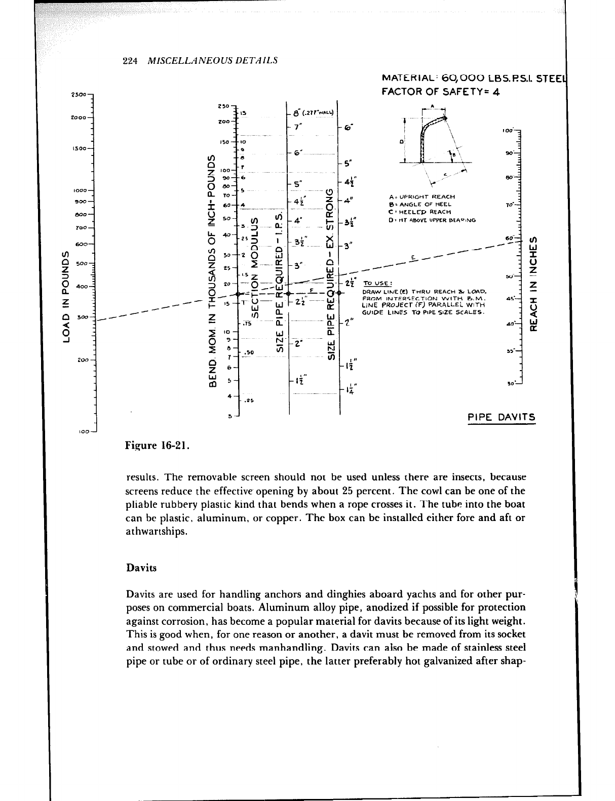
2500-
zooo-
Is*o-
,o*o-
300-
MO-
TOO -
630-
z 5007
r?
400
.-
z
-i
-- --
cl !.a, /-- --
3
224 MISCELLANEOUS DETAILS
6”
5”
4+
4”
3g
3”
MATERIAL’ 60,000 LBS.l?S.I. STE
FACTOR OF SAFETY= 4
r’L- 4
AZ “PKlCIrtr REACH
B= ANGLE OF HEEL
C - HCELCP REACH
0: nr m.oYE “PPLR BEAQING
-- --
/-
5--
--
TO USE :
DWW LlNE(2) THR” REACH s LOAD.
FROM INTERSECTION WITH B.M.
LINE PRoJEC7- (F) PARALLEL WITH
GUIDE LINES TO PIPE SIZE SCALES.
IO0
: 3
: z
50- -
- z
a-- I
: 2
al*- w
- a
55’
I ”
Ii
la 1
30’
PIPE DAVITS
Figure 16-21.
results. The removable screen should not be used unless there are insects, because
screens reduce the effective opening by about 25 percent. The cowl can be one of the
pliable rubbery plastic kind that bends when a rope crosses it. The tube into the boat
can be plastic, aluminum, or copper. The box can be installed either fore and aft or
athwartships.
Davits
Davits are used for handling anchors and dinghies aboard yachts and for other pur-
poses on commercial boats. Aluminum alloy pipe, anodized if possible for protection
against corrosion, has become a popular material for davits because of its light weight.
This is good when, for one reason or another, a davit must be removed from its socket
and stowed and thus needs manhandling. Davits can aiso be made of stainless steel
pipe or tube or of ordinary steel pipe, the latter preferably hot galvanized after shap-
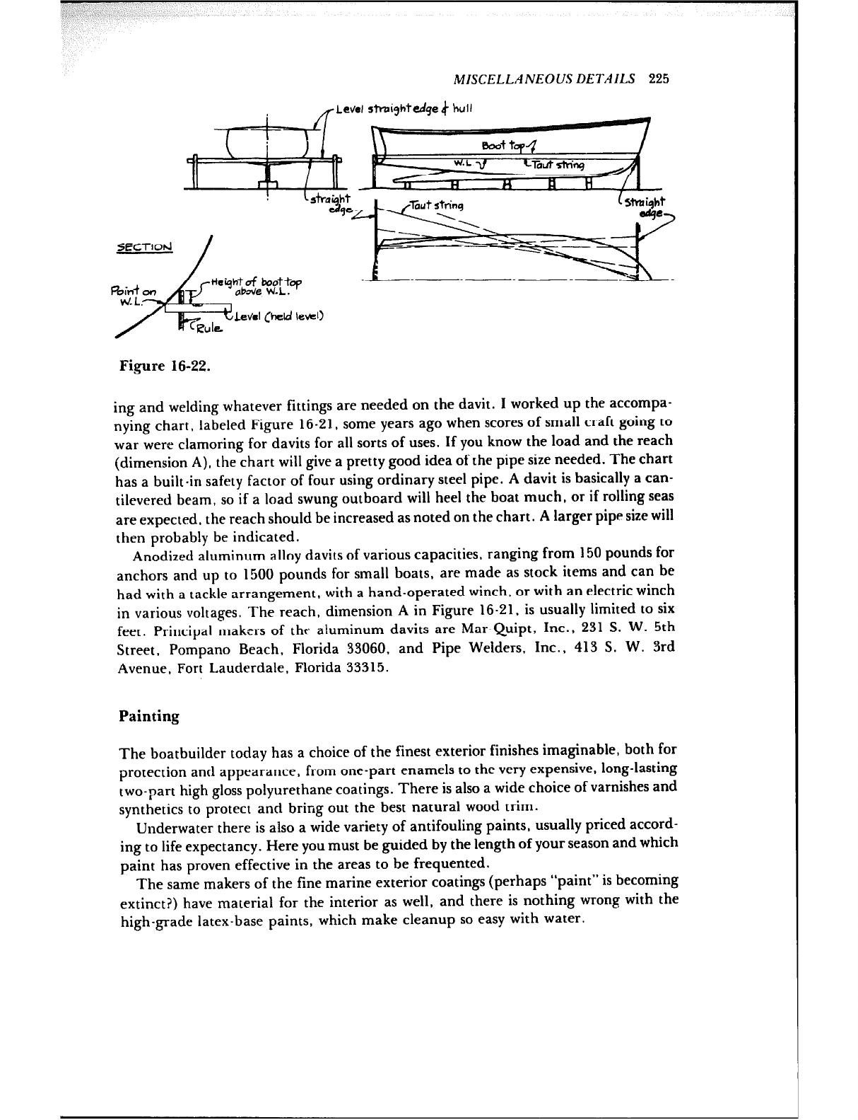
MISCELLANEOUS DETAILS 225
Level shpiyhfedge 4 kuli
Figure 16-22.
ing and welding whatever fittings are needed on the davit. I worked up the accompa-
nying chart, labeled Figure 16-21, some years ago when scores of small craft going to
war were clamoring for davits for all sorts of uses. If you know the load and the reach
(dimension A), the chart will give a pretty good idea of the pipe size needed. The chart
has a built-in safety factor of four using ordinary steel pipe. A davit is basically a can-
tilevered beam, so if a load swung outboard will heel the boat much, or if rolling seas
are expected, the reach should be increased as noted on the chart. A larger pipe size will
then probably be indicated.
Anodized aluminum alloy davits of various capacities, ranging from 150 pounds for
anchors and up to 1500 pounds for small boats, are made as stock items and can be
had with a tackle arrangement, with a hand-operated winch, or with an electric winch
in various voltages. The reach, dimension A in Figure 16-21. is usually limited to six
feet. Principal makers of the aluminum davits are Mar-Quipt. Inc., 231 S. W. 5th
Street, Pompano Beach, Florida 33060, and Pipe Welders, Inc., 413 S. W. 3rd
Avenue, Fort Lauderdale, Florida 33315.
Painting
The boatbuilder today has a choice of the finest exterior finishes imaginable, both for
protection and appearance, from one-part enamels to the very expensive, long-lasting
two-part high gloss polyurethane coatings. There is also a wide choice of varnishes and
synthetics to protect and bring out the best natural wood trim.
Underwater there is also a wide variety of antifouling paints, usually priced accord-
ing to life expectancy. Here you must be guided by the length of your season and which
paint has proven effective in the areas to be frequented.
The same makers of the fine marine exterior coatings (perhaps “paint” is becoming
extinct?) have material for the interior as well, and there is nothing wrong with the
high-grade latex-base paints, which make cleanup so easy with water.
226 MISCELLANEOUS DETAILS
Marking the Boot Top
Nothing looks worse to yachtsmen than a ragged division between the topside and bot-
tom paints. Assuming that the buiider has had the foresight to mark the designed
waterline at the stem and stern for reference during construction, just about the easiest
way to mark the boot top is to first plot the straight waterline at frequent intervals
along the hull and then lay off heights to the boot top as scaled from the plan of the
outboard profile. Level straightedges are set up at the ends of the boat as shown in
Figure 16-22, and then a length of thin, strong cord is stretched tightly between the
edges and moved inboard until it barely touches the hull and a point is marked there.
By moving the cord in and out on the straightedges alternately at opposite ends, points
on the waterline may be marked as often as desired. Be sure to keep the cord tight, for
if it is allowed to sag, the waterline will not come out straight. If the boat is level fore
and aft and there is room to work, a builder’s level or transit may be used to run in the
line. The boot top or stripe is usually curved (sheered) for appearance, and offsets
above the waterline can be taken from the plans and plotted as shown in the figure. A
batten is nailed on the hull to fair the points and mark the line, which is done by scrib-
ing with the broken end of a hacksaw blade or similar device or with a so-called race
knife made for scribing wood.
Chapter 17
SAFETY
A sound hull is only the beginning of a safe hoat. unless it is the simplest of craft like
one made to be paddled or rowed. As soon as holes are made in the hull underbody for
through-hull fittings or machinery and electrical installations are made, precautions
must be taken to prevent leaking, sinking, fire, or explosion. Newcomers to boat-
building are fortunate in having information available to keep them out of trouble.
Not too many years ago this knowledge was not so easy to come by. Many lessons were
learned the bard way sinking caused by a rotted hose attached to a valveless under-
water through-hull fitting, loss of fire control from the wrong kind or an inadequate
number of fire extinguishers, fire and/or explosion because a fuel line to an engine
was installed without slack and broke from vibration, loss of life because passengers
aboard a sinking boat could not find the life preservers. These occurrences and others
were and are preventable.
The very nnturc of boats calls for deck levels of varying heights to be accessible by
steps and ladders. Risk of injury can be reduced by having an adequate number of
hand rails and grabs that are securely fastened in place with through-fastenings
whenever possible. Similarly important are the adequate height and fasteningofsafety
rails and lifelines around the edges of all decks accessible to those aboard.
American Boat and Yacht Council
This non-profit council was formed in 1954 by members of the boating industry con-
cerned with safety. Over the years dozens of members have served countless hours in
the preparation of standards for safe practices in the general areas of hull, equipment,
machinery, electrical, and engineering standards. Ample time has been given for com-
ment and criticism of the standards before they have been approved: therefore the
standards do not represent one-sided opinions.
227
220 SAFETY STANDARDS
There are numerous standards in each of the divisions mentioned above and all are
available individually or as a complete book called Safety Standards for Small Craft.
For a list of these standards contact the Secretary, American Boat and Yacht Council,
P.O. Box 806, Amityville, New York 11701. Membership is open to all, in which case
the complete set of standards is included, as well as copies of new standards as issued
and revisions to those existing.
Federal Safe Boating Regulations
Poor design, construction, and equipment installations that resulted in explosions,
file, and loss of life have inevitably led to the enactment of laws in the U.S. governing
gasoline fuel systems, electrical systems in boats with gasoline-fueled engines, safe
loading and safe powering, and level flotation in case of swamping. The American
Boat and Yacht Council, under contract to the U.S. Coast Guard, prepared “com-
pliance guidelines” to ease the burden of the boatbuilder. whether he be a manufac-
turer or backyard builder, to determine whether his product will meet the regulations.
In my opinion, the standards required by law are the same as the practices recom-
mended by the ABYC.
Copies of the following booklets may be obtained from your nearest U.S. Coast
Guard District Office or from I1.S. Coast Guard, Office of Boating Safety,
Washington, D.C. 20590:
Electrical System Compliance Guideline applies to all inboard or inboard/out-
board gasoline-powered boats and boats that have gasoline auxiliary engines such as
generators.
Fuel System Compliance Guideline applies to all boats powered with gasoline
engines (except outboard engines), all boats with gasoline auxiliary engines, such as
generators, and to gasoline~fuel tanks that are permanently installed in inboard and
inboard/outboard boats.
Level Flotation Compliance Guide--applies to monohull boats less than 20 feet in
length. It does not apply to sailboats, canoes, kayaks, or inflatable boats.
Coast Guard publication CG-466, Safety Standards for Backyard Boat Builders, is a
boon to the home builder and includes directions as to how to work up the safe loading
calculations for boats under 20 feet long to which the law applies. In addition, it tells
how to go about attaching a “capacity label” and a “certification label” to the hull,
and how to obtain a hull identification number for your boat.
Hopefully all these things will not discourage a would-be backyard builder: a
careful study of the safety regulations will show that their intent is good.
Many government regulations seem to consist of endless pages of solid text, making
them boring to read, to say the least, but not so the guidelines put out by the Coast
Guard. These clearly illustrate with simple line drawings what is acceptable and what
is prohibited,

,,:,s,y * ,’ I
(3
SAFETY STANDARDS 229
Product Testing
A step for safety beyond mere words has also been taken. Manufacturers can now have
their products tested for compliance with American Boat and Yacht Council stan-
dards and so labeled when the product meets the requirements. The agency that does
the testing is the marine section of the well-known and respected Underwriter’s
Laboratories (UL), which succeeded the pioneering Yacht Safety Bureau.
The UL label on hardware and other items of equipment assures the purchaser that
the material has been tested and found suitable. Underwriter’s Laboratories, Inc. is
located at 1647 Jeffords Street, Clearwater, Florida 33516.
RECOMMENDED READING
Ruilding Cl~ssr’c S~lnll Crc#, by John Gardner, International Marine Publishing
Co., 2 1 Elm Street, Camden, Maine 04843. Brought together in one book are instruc-
tions for building a number of classic wooden boats.
Bouthuildi:rg with Stwl, by Gilbert C. Klingel. International Marine Publishing
Co., 21 Elm Street, Camden, Maine 04843. Written by an advocate of welded steel
construction for pleasure craft, covering the steps from start to finish. This volume
also contains a chapter entitled “Boatbuilding with Aluminum.” by Thomas Colvin.
Colvin is just as enthusiastic about aluminum alloy construction as is Klingrl about
steel. Both writers explain how to do quality work as opposed to commercial boat-type
construction.
Roat building with Plywoori and How to Fibq1a.u Boats. both from Glen -L
Marine Designs, 9152 Rosecrans, Bellflower. California 90706. Because plywood is
still one of the most inexpensive boatbuilding materials, the instructions in these book3
for handling and fiberglass covering plywood are useful.
Thr GOU.,~PON Brothcars on Boat Construction, Gougeon Brothers, Inc.. 706 Martin
Street. Bay City, Michigan 48iO6. This volume is a complete treatment of building
cold-molded wooden boats. with emphasis given to the WEST system developed by the
authors.
232 RECOMMENDED RE.4 DING
Laprake Boatbuilding, by Walter J. Simmons. Originally published by International
Marine Publishing Co., 21 Elm Street, Camden, Maine 04843. (Reprint published by
Walter J, Simmons, Lincolnville, Maine 04849.) A book specializing in the art of
building wooden boats with clinker planking.
Modr~rrr Woode~r Yacht Construction: Cold-Molding, Joinrry, Fitting Out, by John
Guzzwell, International Marine Publishing Co., 21 Elm Street, Camden, Maine
04843. One of the best books on boatbuilding from start to finish. Well illustrated with
photocgraphs and line drawings. The technique of cold-molding is described in depth.
Sq@ty Standards for Backyard Boat Builders, U.S. Coast Guard Publication
CC-466, availahle from nearest Coast Guard District Office. Best described by the
booklet foreword: “This pamphlet . . . (CC-466) is a simplified explanation of
Federal recreational boat construction requirements and is intended for the use of the
non-professional individual builder. ‘Che primary objective of these requirements is to
avoid certain safety hazards which have been found to be the cause of boating
accidents.”
.Sa/;sty Standards /i)r Small Crafi, American Boat and Yacht Council, Inc., Box
806. Amityvillc. New York 11701. industry standards for boat construction and the in-
stallation of equipment. This is of great value to the boatbuilder, especially the parts
on electrical wiring and circuit protcbrtion.
Sharpllin,q Small Tools, by Ian Bradley. Argus Books, Ltd., and Allied Publica-
tions, Station Road, Kings Langley, Herts, England. Keeping woodworking tools
sharp is vc*ry important to the enjoyment of boatbuilding. This little British book tells
how IO do it.
Shrj) and .-!ircrali Fairin,q and Dvzr~lopmcwt, by S.S. Rabl, Cornell Maritime Press,
Cc~ntrc*viIIc~. Maryland 21Gli. A good old book with clearly illusrrated details of some
Iofring rrchniqut~s.
Wood: A Manualfor Its Use as a Shipbuilding Material. Department of the Navy, Bureau
of Ships, 1957-1962. (Reprint: ‘Teaparty Books, Kingston, Massachusetts, 1983.) A
superb source of information, including specifications and storage of wood for boat-
building, moisture content, structural design of parts, wooden boat repairs, etc.
Wood Ilandbook (Ilandhook No. i2), Forest Products Laboratory, U.S. Depart-
ment of Agriculture. Available from Superintendent of Documents, U.S. Government
Printing Office, Washington, D. C. 20402. Contains much basic information about
woods of interest to the boatbuilder.
National Fisherman, 21 Elm Street, Camden, Maine 04843. A monthly newspaper
loaded with news, pictures, and plans of commercial fishing boats.
WoodenBoat, a bi-monthly magazine for wooden boat lovers and builders.
WoodenBoat Publications, Inc., Box 78, Brooklin, Maine 04616.

(I ’
EQUIVALENTS
Linear
1 in. = 25.4 mm = 2.54 cm
1 in. - 0.083 ft.
1 ft. = 12 in. = 30.48 cm
6 ft. = 1 fathom
1 ';tat.ute mile = 5280 ft.
1 statute mile = 1.6093 km
Area
1 sq. in. = 6.4516 sq. cm
1 sq. ft. = 144 sq. in.
1 sq. ft. = 0.0929 sq. m
1 mm = 0.03937 in.
1 cm = 0.3937 in.
1 m = 39.37 in. = 3.2809 ft.
1 fathom = 1.8288 m
1 nautical mile = 6080 ft.
1 km = 0.6214 statute mile
1 sq. cm = 0.1550 ft. sq.
1 sq. cm = 0.00108 ft. sq.
1 sq. m = 10.764 ft. sq.
Volume
1 cu. in. = 16.39 cu. cm 1 cu. cm = 0.061 cu. in.
1 cu. ft. = 1728 cu. in. 1 gal. =231 cu. in.
1 1. = 61.017 cu. in. 1 1. = 0.03531 cu. ft.
1 cu. ft. = 7.481 gal. = 0.0283 cu. m = 28.32 1.
1 pt. = 0.4732 I. 1 1. = 2.113 pts.
1 qt. = 0.9464 1. 1 I. = 1.057 qts.
1 gal. = 7.481 cu. ft. = 3.785 1.
Note: The gal. above = U.S. gal., and 1 pt. = & gal.; 1 qt. = % gal. 233

234 EQUIVALENTS
Weight
1 oz. = 28.35 g-r 1 g-r = 0.03537 oz.
1 oz. = 0.02835 kg 1 kg = 35.274 oz.
1 lb. = 16 oz. 1 oz. = 0.0625 lb.
1 lb. = 453.6 =
gr. 0.4536 kg 1 kg = 2.2046 lb.
Pressure
1 lb. per sq. in. = 0.0703 kg per sq. cm
1 kg per sq. cm = 14.223 lb. peh- sq. in.
Miscellaneous
1 Imp. gal. = 1.2 U.S. gal.
1 ft. high column of water = 0.434 lb. per sq. in.
1000 warts = 1 kilowatt = 1.34 hnrsepower
1 horsepower = 746 watts
1 long ton = 2240 lb. = 35 cu. ft. of sea water
1 cu. ft. fresh water = 62.5 lb.
1 cu. ft. sea water = 64 lb.
1 knot 1: 1 nautical mile per hour = 1.85318 km per hr.

DECIMALS OF AN INCH
FOR EACH 64TH OF AN INCH
WITH MILLIMETER EQUIVALENTS
--
I’ I I
Fraction ‘,&.dhs Dcclmal Mllhms*ars ,! Fraction 1 Milhmeters
,approx., ji %eths / Decimal Capprox.)
__---. ___ I/ --- ~ ~ ---____ -~
/I I
. 1 .015625 0.397 I/ ._._ 33 j .515625 : 13.097
%i 2 .03125 0.794 "A 34 53125 j 13.494
3 m6875 1.191 35 546875 I 13.891
'42 4 .0625 1.588 ii 36 .5625 ' 14.288
I
5 .07al25 ! 1.984 1 ;9/6 zt -578125 1 14.684
J&i 6 .09375 2.381 -59375 : 15.081
7 .109375 2.778 39 .609375 I 15.478
?4 a ,125 3.175 w 40 .625 i 15.875
9 .I40625 3.572 _._. 41 MO625 16.272
ii 10 .15625 3.969 %i 42 A5625 16.669
. . . . 11 .17la75 I 4.366 . . . . 43 .671875 17.066
%i 12 .la75 4.763 "X6 44 .6875 17.463
. . . 13 .203125 5.159 .._. 45 .703125 17.859
'4 14 .21875 5.556 as 46 .71875 18.256
. 15 .234375 5.953 . . . . 47 .734375 , 18.653
M 16 .250 ! 6.350 % 48 .750 ' 19.050
_... 17 .265625 6.747 ____ 49 .765625 19.447
gh 18 .28125 7.144 '% 50 .78125 19.a44
. . 19 .296875 7.541 51 .796875 20.241
%I '20 .3125 7.938 i&6 52 A125 20.638
. . . . 21 .328125 a.334 . . . . 53 .a28125 21.034
'% 22 .34375 a.731 a7A 54 .a4375 21.431
. . . . 23 .359375 9.128 ___. 55 .a59375 21.828
% 24 ,375 9.525 T-6 56 .a75 22.225
._.. 25 .390625 9.922 'I ._._ 57 .a90625 22.622
'xi 26 .40625 10.319 / agA 58 SO625 23.019
. . . . 27 .421875 10.716 ' 59 .921875 23.416
'/is 28 .4375 11.113 ;5& 60 .9375 23.813
._._ 29 .453125 11.509 _.._ 61 .953125 24.209
15h 30 .46875 11.906 % 62 .96875 1 24.606
__._ 31 .484375 12.303 63 .984375 , 25.003
M I 32 .5oo j 12.700 /i 1"" 64 l.OOO ; 25.400
I 'I

INDEX
Abcking & Rasmussen, 24
Abbreviations, lines plans, 69
ABYC standards: for electrical installa.
tions, 221; for exhaust hoses, 220; for
fuel tanks, 212-213; for sea cocks,
223; for propeller shafts, 213-217
Additives, epoxy rrsin, 36, 64. 165
Adhesives, 64-65: sources for, 65; water-
proof, 64. SW also Epoxy resins, Glue
Aerolite glue, 64, 65
Aircraft Spruce and Specialty Co.. 65
Airex foam core, 41
Allied Resin Corp., 65
Aluminum construction: davits.
224.225: fuel tanks, 212-213: hulls, 9.
43; spars, 205-206.
American Boat and Yacht Council
(ABYC). 227-228. SW n&o ABYC
standards
American Dureau of Shipping (ABS).
26
American Klegecell Corp., 41
Anchorfast nails, 48. 52, 58-59
Anti-fouling paints, 225
Arc-bottomed hulls. 2; frames for. 96;
setting up, 108
Arcon epoxies, 64
Ash. white, 25
Augers, 16
Backbone assembly, 105
Backbone structures. 101-105
Ballast keel, 195
Bahek Corp., 41
Batrs. Fred. 148
Battens: for fairing cutves, 73, 76-77,
78-79. 97. 110. 116; as pick-up sticks,
78, 79-80: in planking, 144.146: for
planking scale, 136-137: for spiling.
133-134
Batten seam planking, 144-146
Battery storage boxes. 222
Bearings, propeller shaft assembly.
213-217
Berths, 184
Bevel board, 98
Bevels. 94. 96-98: by computer, 99. of
floor timbers, 124; of lapstrake
planks, 142-143, of transom assembly,
99-100
Bilge stringers, 125
nont ou~rff’rs nuycr.5 ChidfJ, 9. 10
Body plan. 77-78
Bolts: carriage, 51; drift. 50-51. 105.
198, 209; hanger, 55; lag. 55: screw.
50
Boot top (waterline), 226
Breast hook, 154
Bruynreel plywood. 29
Bulkheads, 159. 183-186
Bulwark rail. 174-175
Butt blocks, 92. 131. 149

Buttocks, 67, 80, 83
Butts, plywood, 184
Cabin trunk, 171-173
Cabosil, 36, 165
Camber, deck beam, 153. 156-157
Cant frames, 120
Canvas deck covering, 163-165
Canvas duck, 162
Carve1 planking, 35, 130-131, 138-139
Cast fittings, 192-195: rudder stock,
210-211
Cast iron keel, 195-96
Caulking, 93, 138-140, 166-169
Cedar: Ala ka. 25: Port Orford. 23:
western rt 1, 23; white. 23
Ceiling, 188
C-Flex “plankir :.” 37-38
Chainplates. 19; 198
Champion Buildil T Products, 28. 29.
30
Chrm-Tech epoxy, h 1, 65
Chrm-‘I‘rrh. Inc., 65
Chine. 7
ClilmpS. 124, 153-156. 2t.l
Clench-nailing, 60.61
Clinker planking, 14 1
Coamings: cockpit. 173: hatch. 177-178
Cockpit roaming. 173
Cockpit, self-bailing. 179
Cockpit sole. 179
Cold-molded hulls. 32-33. 89. 150-151,
i.52
Computers: for fairing lines, 87; [or
lofting. 99
Condon. M.L., Company, 32
Contourkore bals;l core. 41
Corrosion, galvanic. 43, 48-50. 63
Cotton caulking, 138-140
Cotton wicking. 143
Countcrborcs. 16.17, 53
Countrrsinks. 16-17. 54
Counter stern. ! YO- I21
Couplings, propeller shaft. 218-219
Cowl ventilator, 223-224
Cradles, 41
Cross spalls. 92. 109
Cypress. 23
Davits. 224-225
Deadwood. 104
Dean Company, Thr. 33
Deck beams, 156-157
Deck coverings: canvas, 163-165:
fiberglass cloth, 165
mmx
Deckhouse, 17 1 - 173
Deck line, 76, 83
Decks: caulked, 166-169: plywood, 163;
strip-built, 162-163; teak, 166-169;
tongue-and-groove, 161-162
Deck shelf, 153
Defender Industries, Inc., 36
Developable-surface hull, 5, 149
Diagonal planking, 152
Diagonals, 67. 69. 78-80
Double planking. 143-144
Dowels, 96. 209
Drawers, 186
Drills, 16-17
Duck Trap Woodworking, 61
Duraply. 28-29. 183
Dynel. 35
Edson Corp.. The. 212
Electrical systems, 221
Electrolysis, 48-49
Elmer’s glues, 64, 65. 186
Engine: bed, 129; connections, 220:
controls. 219-220; stringers, 128:
vibration, 218
Epoxy resins, 36, 64. 147-148. 165
Evrrdur. 47
Fairing: of diagonals. 79-80: of lines.
76-77; computer-aided. 87. 99. .%Y
nlso Battens
Fastening materials: brass. 47: bronzr.
47; copper. 48; galvanized iron,
46-47: stainless steel, 48
Fastenings: in double planking, 143.
144: drilling for, 52-54: interior, 186:
plank, 137-138
Frrrocement hulls, 44
Fiberglass cloth, 37, 165
Fiberglass hulls. 9. 36-37, 39-41. 89
Fiberglass insulation. I89
Fiberglass sheathing, 35-36
Fillers. 36. 168
Fin keels, 104
Fir, Douglas, 22
Fir plywood, 28
Flat-bottomed hulls. 2-3. 71. 103. 108
Floor timbers, 123-124
Florida Marine Tanks. Inc.. 213
Foam core, 39
Formica, 28, 183
Frames. 88: bending. 119-123: cold-
fitted. 120-123: steaming, 119:
transvrrse. 117. v-bottomed 96-97
Framing. 3-5
237

238 INDEX
Fuel hose lines, 220
Fuel tanks, 212-213
Fuller, W.L.. Inc., 54
Galvanic corrosion, 43. 48-50. 63
Galvanic series, 49
Carboard, 134- I35
Gel coat, 37
Glue: batten seam, 144; Elmer’s 64.
65, 186: resorcinol, 64. 147-148
Gluing: plywood planking. 149: spars,
201-202. See also Laminatton
Cougeon Brothers, Inc., 32, 65, 150
Coufyon Rrothm m Rtrnl Comtruc-
Il’on. Thf~, 151
Graphite fibers. 44
Grids: for inverted hull construction,
109: for offsets, 73-74: for transom
plan, 81
Gripe, 105
Guzzwell. John, 151
Hackmatack, 25
Half beams. 157-158
Half-breadth plan, 93-95
Half-model, 69
Hanging knees, 158-159
Ilarbor Sales Company, 29. 30, 65
Harra. John, Wood & Supply Com-
IIilIlyq 32
Hatches: cabin sole, 188.189: [let-k,
176-179: flush, 179: sliding, 175.176
Headers, I57
Headliners, 189
Herreshoff & Kerwin. Inc.. 87
Horn timber, 105
Hull design, 2-5
Hull lines (terminology), 7. 66-69
Hull painting, 141
Hull repairs, 39
IHydraulic engine controls, 220
Hydraulic steering, 212
I-lynautic, Inc., 212, 220
Icebox, 189-191
Independent Nail Inc., 46, 58
Insulation. 189
Joinerwork: deck, 170- 181: interior.
182-191
Joints: mortise-.,nd-tenon, 107;
scarphed. 32, 105-106
Juniper. 23
Keel blocks, I12
Keel Makers, 196- 197
Keels: cast iron, 195-196; fin, 104;
lead, 195. 196-197; powerboat,
103-104: rabbeted, IO3
Kenyon Marine, 205
Krvlar, 36, 44
Kit boats. 9
Klegecel foam core, 41
Knees, 105; hanging, 158-159; lodging,
158: quarter, 154-156
Kobelt Manufacturing Co., Ltd., 220
Kristal Kraft. Inc., 65
Laminated beams, 157
Laminated planking, 150-151. 152
Lamination: of fiberglass hull. 37;
of stem assembly, 92; of wood, 31-32
Lapstrake planking, 108, 141-143
Larch, 25
Lauan. 24
Lead keels. 195, 196-197
Letcher. John, 87
Lexan, I78
Lines, hull (terminology), 66-69
Lodging knees, 158
Lofting: computer-aided, 99: of body
plan. 77-79; of half-breadth plan,
76-77: of long lines of profile, 76-77:
of transoms. 81-87, preparations for,
72-74; tools for, 72-73
Logan Lumber Company, 32
Lumber: drying, 21: sawing, 17-18.
21; seasoning, 18-Z 1; shrinkage, 2 I :
sources, 32-33
Mack-Shaw Sailmakers, Inc., 206
Mahogany: African, 24; Honduras, 24;
Mexican, 24; Philippine, 24
Marconi rig. 204
Mnrirw Iksign Mtrnunl. 37
Mar-Quipt, Inc., 225
Masonite, 186
Mast partners, I58
Mast step, 204-205
Modrm Woo&n Ydrt Carrstructiotl,
151
Mold construction 88-92
Mold loft, 72
Molds: for cast fittings, 193-194; for
fiberglass hulls, 36-37; for keels,
195-197; for strip-planked hulls, 148
Monel fastenings, 48. 50, 58, 62
Monel tanks, 212
Monkey rail, 175

Morse controls, 220
Motor Boating B Sailing, 10
Nails: copper, 55-56. 60; galvanized,
47, 57: threaded, 57-59
National Fisherman, 9. 32
Nomex honeycomb, 44
Non-skid sole, 189
Oak: red, 22; white, 22
Offsets, 69-72. 78
Painting: of deck joinerwork. 171: of
hull, 141
Paints: anti-fouling. 225; Pxterior. 225;
interior, I83
Panish Transdyne. 220
Patterns, casting: for fittings, 192-195,
for keels, 195-197
Pick-up sticks, 78
Pinr: longleaf. 22-23; Oregon, 22;
white, 23; yellow, 22-23
Pipe Wcldcrs. Inc.. 225
Planking: batten scam, 144. 146; carvel.
130-140; double. 143-144; laminated,
150-152: lapstrakc*, 111-1-13: plywood,
149-150; strip, 146-149: transom,
100-101
Planking dimensions. 132: thickness dr-
ducrion. #Y-Y0
Planking scale. 136. I37
Planksherr. I66
Plugs. wood. 53-5-l
Plumbing, 223
Plywood: bending, 30-31; cutting. :iO:
grading, 28-29: laminating, 31-32;
panel sizes, 29
Plywood decks, I63
Plywood interior structures, 182-183
Plywood planking, 149-150
Polybutylenr tubing, 223
Polypropylrnr cloth, 35, 36
Polyurethane coatii:g, 17 I
Polyvinyl chlnricle (PVC) pipes, 223
Powerboat construction: clamp, 158:
rngine beds. 129: keels, 103-104: rud-
ders. 206-207: shelf, 158; transom.
85-87: twin-screw, 218
Preservatives, wood, 34. 141
Profile plans. 77. 92
Propeller shafts, 213-219
Pulley drives, calculating, 21Y
Push-pull cables, 220
PVC pipes, 223
INDEX 239
Quarter knees. 154-156
Rabbet, 77, 78. 92. 103
Refrigerator. SIT Icebox
Resorcinol glue, 64. 147-148
Reverse curves. 122. 151
Rhodes, Philip, 149. 201
Ribbands. 88. 109. 1 IO. 112-l I6
Ribs, 117
Riveting, 62-63
Rivets: copper. 55-56, 143: “pop.”
62-63
Rot prevention, 33-34
Round-bottomed hulls, 2-3; bilge
stringers. 125: frames, 88. 118; lines,
71; planking, 38
Rudder fittings. 208
Rudders: outboard. 207-208; power-
boat, 206-207: sheathed. 211
Rules for Building und Clossiq RGn-
forced Plastic C’css&. 26
Safety: davit design for, 225: features,
227; product testing for. 229: regula-
tions, 228
Sn fbt,y Star ndri rds /or lkck yn rd Bon t
Buildm. 228
Safety Stnndarrls for Snr~ll Crcr/t. 228
Sail track, 204
Sandwich (fiberglass hull) construction.
36. 38.39
Scantlings (trrminolcqy). 34
Scarphs. 105.106. 147. 184. 199
Schaefer Spars, 206
Srrews. 16-17, 51-55: galvanized, 47:
lag, 55; machine, 61: stainless sreel.
54-55
Scribing of waterline, 226
Scuppers. 174, 176. 179
Sea cocks, 223
Sealers, 28, 168
Sea rails, 184
Scats. cockpit. 179-l HO
Sections: bocly plan, 67. 77-78: slrm.
94
Seemann Plastics, Inc.. 37
Self-bailing cockpits, 179
Shaft logs, 103-104. 215
Sheathing: copper. 104; fibc=rglass.
35-36
Sheer clamp, 126-128
Sheer guards, 180- 182
Sheerline. 76-77
Shelves. 153-156
Sole: cabin. 188-189: cockpit, 179

240 INDEX
Spars, aluminum, 205-206
Spars, wooden, 198-204; hollow rec-
tangular, 200-201, hollow round,
201-202
Spiling. 133-13’
Spiling frames, 135
Spinnaker poles, 20 l-202
Splines. 103
Spruce: northern white, 24; Sitka, 24,
198. 199
Stanley tools, 15-16
Star class sloop, 2
Stations, 78, 83
Stealer planks, 137
Steam box, 119-120
Steel hull construction, 9. 42-43
Steering controls, 211-212
Stem assembly, 92-95
Sternpost, 104
Stopwaters, 96, 105
Stringers, 124-128
Strip-planked hulls, setting up, 108
Strip planking, 146-149
Stronghold nails, 52, 58-59
Stuffing box, 211, 215, 217
Synthetic fabrics, 35-36
Table of offsets. 73
Tamarack. 25
Tangile. 24
Tangs, 204
Tank rapacity, calculating. 213
Tanks, fresh water. 222
Tanks, fuel, 212-213
Teak, 25, 168-169
Teleflex, Inc.. 220
Templates, 67; for bulkheads, 185; for
stem assembly, 92-95; for spinnaker
pole, 202
Tenons, 107
Thiokol sealers. 168. I69
Tie rods. 158. 206
Tillers, 2 I 1
Toe rails, 166, 174
Tools: caulking, 139: hand, 15-17:
lofting, 72-73; power, 17-18; sourres.
18
Torin, 41
Transom. connections to, 154-156
Transom, construction of. 99-101
Transom, lofting of: curved, 82-83:
flat, 81-82: powerboat, 85-87; raked,
81
Tremont Nail Co.. 61
Tributyl tin oxide (TBTO). 34
Twin keelsons. 103
Underwriter’s LaGoratories (UL). 229
“Unipoxy” glue. 65
U.S. Coast Guard regulations: for
passenger-carrying boats. 14; safety,
228
U.S. Coast Guard standards: for elec-
trical installations. 221: tanks, 212
Varnishing, 170-171. 182. 201
V-bottomed hulls. 2-3: clamps, 128:
floors, 123; frames, 88. 96. 117-118;
lines, 72; planking, 38: seam batten
construction. 144; setting up, 108
Veneers, 28
Ventilation, 187- 188. 223-224
Watrrlines. 67. 76. 80. 225-226
Water trap box, 223
WEST System (Wood Epoxy Saturation
Technique), 150
Wheel, steering, 2 12
Wicking, 105. 138
Wiley. Ralph, 148
Wire rigging, 204
Wood: A Manual FOT Its list ds A
Shiphui!di?lg Matcmal, 25
Wood: comparative strengths, 26; de-
sign stresses, 26-27; species for boat-
building. 22-25
Woodcraft Supply Corp., 65
WoodrnRoat, 32
Wood finishes, interior. 182.813
Wood Ilnndh~ol~. 26
Wood screws, 16.17. 51-55
Zinc plating. 46-47
