6904136 EN 07 06 OM S205 !! Bobcat 0
User Manual: !! Cat Lawn Mower Manuals - Lawn Mower Manuals – The Best Lawn Mower Manuals Collection
Open the PDF directly: View PDF ![]() .
.
Page Count: 145 [warning: Documents this large are best viewed by clicking the View PDF Link!]
© Bobcat Europe 2006
Printed in Europe
6904136-EN (09-06)
S/N 530611001 & Above
Operation
&
Maintenance
Manual
EN
EQUIPPED WITH
BOBCAT INTERLOCK
CONTROL SYSTEM (BICS)
U.S. Publication 6904136 (11-05) Revised (6-06) (2)
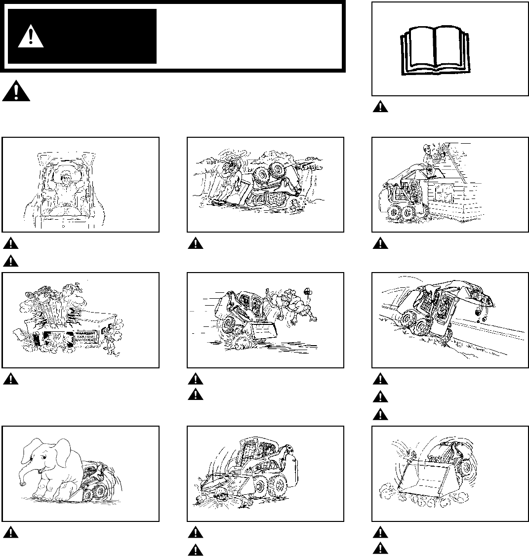
OPERATOR SAFETY WARNINGS
Operator must have instructions before
running the machine. Untrained
operators can cause injury or death.
Safety Alert Symbol: This symbol with a warning statement,
means: “Warning, be alert! Your safety is
involved!” Carefully read the message that
follows.
Never use the loader without
instructions. See machine signs
(decals), Operation & Maintenance
Manual, and Operator’s Handbook.
Always use the seat bar and fasten
seat belt snugly.
Always keep feet on the foot pedals
or foot rest when operating loader.
Never use loader without operator
cab with ROPS and FOPS approval.
Fasten your seat belt.
Never use loader as man lift or
elevating device for personnel.
Do not use loader in atmosphere
with explosive dust, explosive gas,
or where exhaust can contact
flammable material.
Never carry riders.
Keep bystanders away from work
area.
Always carry bucket or attachments
as low as possible.
Do not travel or turn with lift arms
up.
Load, unload, and turn on flat level
ground.
Never exceed Rated Operating
Capacity.
Never leave loader with engine
running or with lift arms up.
To park, engage parking brake and
put attachment flat on the ground.
Never modify equipment.
Use only attachments approved by
Bobcat Company for this model
loader.
SAFETY EQUIPMENT
The Bobcat Loader must be equipped with safety items necessary for each job. Ask your dealer about attachments and
accessories.
1. SEAT BELT: Check belt fasteners and check for damaged webbing or buckle.
2. SEAT BAR: When up, it must lock the loader controls.
3. OPERATOR CAB (ROPS and FOPS): It must be on the loader with all fasteners tight.
4. HANDBOOK: Must be in the cab.
5. SAFETY SIGNS (DECALS): Replace if damaged.
6. SAFETY TREADS: Replace if damaged.
7. GRAB HANDLES: Replace if damaged.
8. LIFT ARM SUPPORT DEVICE: Replace if damaged.
9. PARKING BRAKE
10. BOBCAT INTERLOCK CONTROL SYSTEM (BICS) OSW08-0805
WARNING
B-10731A
CORRECT
B-16245
CORRECT WRONG
B-15528
WRONG
B-15531
WRONG
B-15735
WRONG
B-15529
WRONG
B-15532
WRONG
B-15527
WRONG
B-15530 B-15533
WRONG
W-2001-1285

S205 Skid-Steer Loader
I Operation & Maintenance Manual
CONTENTS
REFERENCE INFORMATION
Write the correct information for YOUR Bobcat Loader in the spaces below. Always use
these numbers when referring to your Bobcat Loader.
Bobcat Europe
Drève Richelle 167
B-1410 WATERLOO
Belgium
FOREWORD ..............................................................................................III
SAFETY .................................................................................................... XI
OPERATING INSTRUCTIONS....................................................................1
PREVENTIVE MAINTENANCE ................................................................59
SYSTEM SETUP & ANALYSIS ...............................................................103
SPECIFICATIONS...................................................................................117
Loader Serial Number
Engine Serial Number
NOTES:
YOUR BOBCAT DEALER:
ADDRESS:
PHONE:
Safety &
FOREWORD
SAFETY
OPERATING
INSTRUCTIONS
PREVENTIVE
MAINTENANCE
SYSTEM SETUP
& ANALYSIS
SPECIFICATIONS

S205 Skid-Steer Loader
Operation & Maintenance Manual II

S205 Skid-Steer Loader
III Operation & Maintenance Manual
FOREWORD
This Operation & Maintenance Manual was written to give the owner / operator instructions
on the safe operation and maintenance of the Bobcat Loader. READ AND UNDERSTAND
THIS OPERATION & MAINTENANCE MANUAL BEFORE OPERATING YOUR
MACHINE. If you have any questions, see your Bobcat dealer.
BOBCAT COMPANY IS ISO 9001:2000 CERTIFIED................................. V
DELIVERY REPORT ................................................................................. VI
FEATURES, ACCESSORIES AND ATTACHMENTS .............................. VIII
Attachments ......................................................................................... IX
Buckets Available ................................................................................. IX
High Flow Attachments ........................................................................ IX
Options and Accessories ................................................................... VIII
Special Applications Kit......................................................................... X
Special Applications Kit Inspection And Maintenance .......................... X
Standard Items................................................................................... VIII
LOADER IDENTIFICATION...................................................................... VII
MOTOR OIL................................................................................................ V
REGULAR MAINTENANCE ITEMS........................................................... V
SERIAL NUMBER LOCATIONS................................................................ VI
Engine Serial Number.......................................................................... VI
Loader Serial Number.......................................................................... VI
FOREWORD

S205 Skid-Steer Loader
Operation & Maintenance Manual IV
S205 Skid-Steer Loader
V Operation & Maintenance Manual
BOBCAT COMPANY IS ISO 9001:2000 CERTIFIED
ISO 9001:2000 is an international standard that controls the processes and procedures which we use to design, develop,
manufacture and distribute Bobcat products.
British Standards Institute (BSI) is the Certified Registrar Bobcat Company chose to assess the Company’s compliance
with the ISO 9001:2000 standard. The BSI registration certifies that the two Bobcat manufacturing plants and the Bobcat
corporate offices (Gwinner, Bismarck & West Fargo) in North Dakota are in compliance with ISO 9001:2000. Only certified
assessors, like BSI, can grant registrations.
ISO 9001:2000 means that as a company we say what we do and do what we say. In other words, we have established
procedures and policies, and we provide evidence that the procedures and policies are followed.
REGULAR MAINTENANCE ITEMS
MOTOR OIL
ENGINE OIL FILTER (6 Pack)
6675517
HYDROSTATIC FILTER, In-Line
6661022
FUEL FILTER
6667352
BATTERY
6674687
AIR FILTER, Outer
6598492
FLUID, Hydraulic / Hydrostatic
6903117 - (9,5 L)
6903118 - (19 L)
6903119 - (208 L)
AIR FILTER, Inner
6598362
COOLANT PRESSURE CAP
6672491
HYDROSTATIC FILTER
6661248 (152 mm) - for Std. Flow
6668819 (241 mm) - for High Flow
PROPYLENE GLYCOL ANTI-FREEZE,
6724354 - Concentrate
6724094 - Premixed [-37°C (-34°F)]
6903105 - SAE 15W40 CE/SG (12 L) 6903106 - SAE 15W40 CE/ SG (3,8 L)
6903107 - SAE 10W30 CE/SG (12 L) 6903108 - SAE 10W30 CE/SG (3,8 L)
6903109 - SAE 30W CE/SG (12 L) 6903110 - SAE 30W CE/SG (3,8 L)
6903113 - SAE 15W40 CE/SG (9,5 L) 6903111 - SAE 30W CE/SG (9,5 L)
6903112 - SAE 10W30 CE/SG (9,5 L)
S205 Skid-Steer Loader
Operation & Maintenance Manual VI
SERIAL NUMBER LOCATIONS
Always use the serial number of the loader when
requesting service information or when ordering parts.
Early or later models (identification made by serial
number) may use different parts, or it may be necessary
to use a different procedure in doing a specific service
operation.
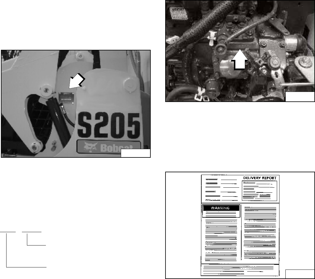
Figure 1
Loader Serial Number
The loader serial number plate is located on the outside
of the loader frame [Figure 1].
Explanation of loader Serial Number:
1. The four digit Model / Engine Combination Module
number identifies the model number and engine
combination.
2. The five digit Production Sequence Number identifies
the order which the loader is produced.
Engine Serial Number
Figure 2
The engine serial number is located on the side of the
engine [Figure 2] above the oil filter.
DELIVERY REPORT
Figure 3
The delivery report must be filled out by the dealer and
signed by the owner or operator when the Bobcat Loader
is delivered. An explanation of the form must be given to
the owner. Make sure it is filled out completely [Figure 3].
P-31843B
XXXX XXXXX
Module 2. - Production Sequence
(Series)
Module 1. - Model / Engine
Combination
P-48387
B-16315
S205 Skid-Steer Loader
VII Operation & Maintenance Manual
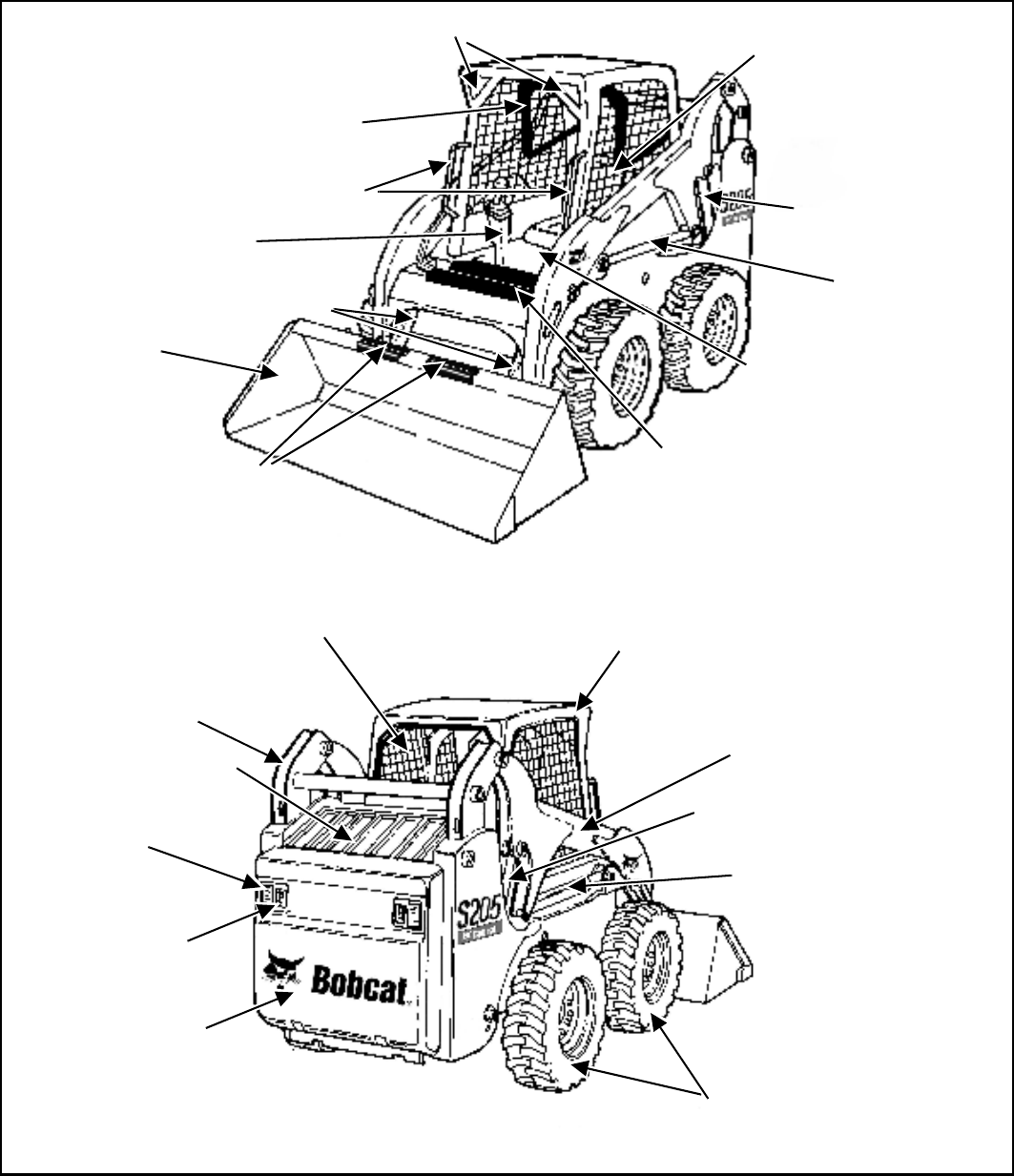
LOADER IDENTIFICATION
B-16604C
B-16605B
†
TILT CYLINDERS
BUCKET
z OPERATOR CAB
(ROPS & FOPS)
BUCKET STEPS
GRAB HANDLES
SAFETY TREAD
FRONT LIGHTS
OPERATOR SEAT
WITH SEAT BELT
REAR AUXILIARY
QUICK COUPLERS
STABILIZER ROD
SEAT BAR
STEERING
LEVER
REAR WINDOW
LIFT ARM
* TIRES
TAIL LIGHT
REAR DOOR
REAR
LIGHT
REAR GRILL
LIFT ARM SUPPORT
DEVICE
LIFT CYLINDER
LIFT ARM LINK
FRONT AUXILIARY
QUICK COUPLERS
◆Optional or Field Accessory (Not Standard Equipment)
*TIRES - Tires shown may not be standard. The machine is factory equipped with standard tires. Other tires are available.
✝BUCKET - Several different buckets and other attachments are available for this machine.
●ROPS, FOPS - Roll Over Protective Structure, per SAE and ISO 3471, and Falling Object Protective Structure per ISO 3449,
Level I. Level II is available.
S205 Skid-Steer Loader
Operation & Maintenance Manual VIII
FEATURES, ACCESSORIES AND ATTACHMENTS
Standard Items
Model S205 Bobcat Loaders are equipped with the
following standard items:
• 7-pin attachment control kit
• Attachment electrical control kit
• Automatically activated glow-plugs
• Auxiliary hydraulics: variable flow / maximum flow
• Bobcat Interlock Control System (BICS)
• Bob-Tach™ frame
• CE certification
• Deluxe operator cab*
Includes interior cab foam, side, top and rear
windows, Deluxe wire harness, dome light, and
electrical power port
• Electrically activated proportional front auxiliary
hydraulics
• Engine / hydraulics system shutdown
• High-back cushion suspension seat
• Hydraulic bucket positioning (including ON / OFF
switch)
• Instrumentation
• Lift arm support
• Operating lights, front and rear
• Parking brake
• Seat bar
• Seat belt
• Spark arrestor muffler
• Tyres - 31 x 12-16.5, 10-ply, Bobcat Heavy Duty Wide
Flotation
• Warranty: 12 months or 2000 hours
* Roll Over Protective Structure (ROPS) - meets
requirements of SAE-J1040 and ISO 3471; Falling
Object Protective Structure (FOPS) - meets
requirements of SAE-J1043 and ISO 3449, Level I
Options and Accessories
Below is a list of some equipment available from your
Bobcat Loader dealer as Dealer and / or Factory Installed
Accessories and Factory Installed Options. See your
Bobcat dealer for other available options, accessories
and attachments.
• Dealer Installed Accessories
• Air conditioning kit
• Back up alarm kit
• Cab enclosure kit
• Counterweight kit
• Deluxe instrument panel
• Door sensor kit
• FOPS kit**
• Four-point lift kit
• Fresh air heater kit
• Front door kit
• Fuel cap locking kit
• Operator cab, CE, enclosure kit
• Plumbing kit for fresh air heater
• Power Bob-Tach™ kit
• Rear auxiliary hydraulic kit
• Replacement Bob-Tach™
• Replacement operator cab structure
• Single-point lift kit
• Special applications kit
• Factory Options
• Advanced Control System (ACS)
• Advanced Hand Controls (AHC)
• Air conditioning
• Cab enclosure with heat
• Deluxe instrument panel
• High-flow auxiliary hydraulics
• High-flow hydraulics
• Power Bob-Tach™
• Selectable Joystick Control (SJC)
** Falling Objects Protective Structure (FOPS) -
meets requirements of SAE-J1043 and ISO 3449,
Level II
Specifications subject to change without notice.
S205 Skid-Steer Loader
IX Operation & Maintenance Manual
FEATURES, ACCESSORIES AND ATTACHMENTS
(CONT’D)
These and other attachments are approved for use on
this model loader. Do not use unapproved attachments.
Attachments not manufactured by Bobcat may not be
approved.
The versatile Bobcat Loader quickly turns into a multi-job
machine with a tight-fit attachment hook-up . . . from
bucket to grapple to pallet fork to backhoe and a variety
of other attachments.
See your Bobcat dealer for more details on these and
other attachments and field accessories.
Increase the versatility of your Bobcat Loader with a
variety of bucket styles and sizes.
Buckets Available
Many bucket styles, widths and different capacities are
available for a variety of different applications. They
include Construction & Industry, Low profile, Fertilizer
and Snow, to name a few. See your Bobcat dealer for the
correct bucket for your Bobcat Loader and application.
Attachments
For specific model availability, see Bobcat Product Price List.
• Angle blade
• Angle broom*†
• Auger
• Backhoe
• Box blade
• Brushcat rotary cutter
• Buckets
• Combination bucket
• Concrete pump*
• Cutter crusher*
• Digger
• Dozer blade*
• Dumping hopper
• Ejector bucket
• Farm grapple
• Grader*
• Hydraulic breaker**
• Industrial grapple
• Landplane
• Landscape rake
• Mixing bucket*
• Pallet fork - hydraulic
• Pallet fork - standard
•Planer*
• Rear stabiliser
•Scarifier
• Snow blower*
•Sod layer*
• Soil conditioner*
• Spreader
• Stump grinder*
• Super scraper
• Sweeper
• Three-point hitch
• Tiller
• Tilt-Tatch™
• Tracks, steel
• Tree transplanter*
• Trench compactor
• Trencher
• Utility forks
• Vibratory roller
• Water kit
• Whisker broom
* Attachment control kit required.
** When operating the loader with this attachment, a
Special Applications Kit, which includes a 12 mm
Lexan front door with 6 mm top and rear windows,
must be used.
† Optional water kit.
See your Bobcat dealer for these and other attachments
available for your loader.
High Flow Attachments
The following attachments are approved for use on
High Flow machines. See your Bobcat dealer for an
updated list of approved attachments.
• Chipper
•Planer
• Rotary Cutter (Brushcat)
• Snow Blower
• Tiller
• Trencher
• Wheel Saw
NOTE: Not all Bobcat High Flow Attachment models
are approved for use with 152 L/min flow.
Damage to attachment or machine can result
when using unapproved attachments.
BUCKET
S205 Skid-Steer Loader
Operation & Maintenance Manual X
FEATURES, ACCESSORIES AND ATTACHMENTS
(CONT’D)
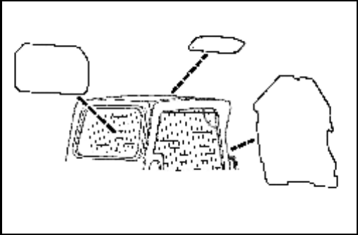
Special Applications Kit
Available for special applications to restrict material from
entering cab openings. Kit includes 12 mm Lexan™ front
door, top and rear windows.
See your Bobcat dealer for availability.
Special Applications Kit Inspection And Maintenance
• Inspect for cracks or damage. Replace if required.
• Pre-rinse with water to remove gritty materials.
• Wash with a mild household detergent and warm
water.
• Use a sponge or soft cloth. Rinse well with water and
dry with a clean soft cloth or rubber squeegee.
• Do not use abrasive or highly alkaline cleaners.
• Do not clean with metal blades or scrapers.
B-25286A

S205 Skid-Steer Loader
XI Operation & Maintenance Manual
SAFETY
MACHINE SIGNS (DECALS) ..................................................................XVI
SAFETY INSTRUCTIONS....................................................................... XIII
Before Operation................................................................................ XIII
Fire Prevention....................................................................................XV
Safe Operation Is The Operator’s Responsibility ...............................XIV
Safe Operation Needs A Qualified Operator......................................XIV
SAFETY

S205 Skid-Steer Loader
Operation & Maintenance Manual XII
S205 Skid-Steer Loader
XIII Operation & Maintenance Manual
SAFETY INSTRUCTIONS
Before Operation
Carefully follow the operating and maintenance
instructions in this manual.
The Bobcat Loader is highly maneuverable and compact.
It is rugged and useful under a wide variety of conditions.
This presents an operator with hazards associated with
off highway, rough terrain applications, common with
Bobcat Loader usage.
The Bobcat Loader has an internal combustion engine
with resultant heat and exhaust. All exhaust gasses can
kill or cause illness so use the Loader with adequate
ventilation.
The dealer explains the capabilities and restrictions of the
Bobcat Loader and attachment for each application. The
dealer demonstrates the safe operation according to
Bobcat instructional materials, which are also available to
operators. The dealer can also identify unsafe
modifications or use of unapproved attachments. The
attachments and buckets are designed for a Rated
Operating Capacity (some have restricted lift heights).
They are designed for secure fastening to the Bobcat
Loader. The user must check with the dealer, or Bobcat
literature, to determine safe loads of materials of
specified densities for the machine - attachment
combination.
The following publications and training materials provide
information on the safe use and maintenance of the
Bobcat machine and attachments:
• The Delivery Report is used to assure that complete
instructions have been given to the new owner and
that the machine and attachment is in safe operating
condition.
• The Operation & Maintenance Manual delivered with
the machine or attachment gives operating
information as well as routine maintenance and
service procedures. It is a part of the machine and can
be stored in a container provided on the machine.
Replacement Operation & Maintenance Manuals can
be ordered from your Bobcat dealer.
• Machine signs (decals) instruct on the safe operation
and care of your Bobcat machine or attachment. The
signs and their locations are shown in the Operation
& Maintenance Manual. Replacement signs are
available from your Bobcat dealer.
• An Operator’s Handbook is fastened to the operator
cab of the Loader. It’s brief instructions are
convenient to the operator. The Handbook is
available from your dealer in an English edition or one
of many other languages. See your Bobcat dealer for
more information on translated versions.
SI SSL-0206

S205 Skid-Steer Loader
Operation & Maintenance Manual XIV
SAFETY INSTRUCTIONS (CONT’D)
Safe Operation Is The Operator’s Responsibility
WARNING
Operator must have instructions before running the
machine. Untrained operators can cause injury or
death.
W-2001-1285
IMPORTANT
This notice identifies procedures which must be
followed to avoid damage to the machine.
I-2019-0284
WARNING
Warnings on the machine and in the manuals are for
your safety. Failure to obey warnings can cause
injury or death.
W-2044-1285
The Bobcat Loader and attachment must be in good
operating condition before use.
Check all of the items on the Bobcat Service Schedule
Decal under the 8-10 hour column or as shown in the
Operation & Maintenance Manual.
Safe Operation Needs A Qualified Operator
For an operator to be qualified, he or she must not use
drugs or alcoholic drinks which impair alertness or
coordination while working. An operator who is taking
prescription drugs must get medical advice to determine
if he or she can safely operate a machine.
A Qualified Operator Must Do The Following:
Understand the Written Instructions, Rules and
Regulations
• The written instructions from Bobcat Company
include the Delivery Report, Operation &
Maintenance Manual, Operator’s Handbook and
machine signs (decals).
• Check the rules and regulations at your location. The
rules may include an employer’s work safety
requirements. Regulations may apply to local driving
requirements or use of a Slow Moving Vehicle
emblem. Regulations may identify a hazard such as a
utility line.
Have Training with Actual Operation
• Operator training must consist of a demonstration and
verbal instruction. This training is given by your
Bobcat dealer before the product is delivered.
• The new operator must start in an area without
bystanders and use all the controls until he or she can
operate the machine and attachment safely under all
conditions of the work area. Always fasten seat belt
before operating.
Know the Work Conditions
• Know the weight of the materials being handled.
Avoid exceeding the Rated Operating Capacity of the
machine. Material which is very dense will be heavier
than the same volume of less dense material. Reduce
the size of the load if handling dense material.
• The operator must know any prohibited uses or work
areas, for example, he or she needs to know about
excessive slopes.
• Know the location of any underground lines.
• Wear tight fitting clothing. Always wear safety glasses
when doing maintenance or service. Safety glasses,
hearing protection or Special Applications Kits are
required for some work. See your Bobcat dealer
about Bobcat Safety Equipment for your model.
SI SSL-0206
Safety Alert Symbol
This symbol with a warning statement means:
“Warning, be alert! Your safety is involved!”
Carefully read the message that follows.
S205 Skid-Steer Loader
XV Operation & Maintenance Manual
SAFETY INSTRUCTIONS (CONT’D)
Fire Prevention
The machines and some attachments have components
that are at high temperatures under normal operating
conditions. The primary source of high temperatures is
the engine and exhaust system. The electrical system, if
damaged or incorrectly maintained, can be a source of
arcs or sparks.
Flammable debris (leaves, straw, etc.) must be removed
regularly. If flammable debris is allowed to accumulate, it
can cause a fire hazard. Clean often to avoid this
accumulation. Flammable debris in the engine
compartment is a potential fire hazard.
The spark arrestor exhaust system is designed to control
the emission of hot particles from the engine and exhaust
system, but the muffler and the exhaust gases are still
hot.
• Do not use the machine where exhaust, arcs, sparks
or hot components can contact flammable material,
explosive dust or gases.
• The operator cab, engine compartment and engine
cooling system must be inspected every day and
cleaned if necessary to prevent fire hazards and
overheating.
• Check all electrical wiring and connections for
damage. Keep the battery terminals clean and tight.
Repair or replace any damaged part.
• Check fuel and hydraulic tubes, hoses and fittings for
damage and leakage. Never use open flame or bare
skin to check for leaks. Tighten or replace any parts
that show leakage. Always clean fluid spills. Do not
use gasoline or diesel fuel for cleaning parts. Use
commercial nonflammable solvents.
• Do not use ether or starting fluids on any engine that
has glow plugs. These starting aids can cause
explosion and injure you or bystanders.
• Always clean the machine, disconnect the battery,
and disconnect the wiring from the Bobcat controllers
before welding. Cover rubber hoses, battery and all
other flammable parts. Keep a fire extinguisher near
the machine when welding. Have good ventilation
when grinding or welding painted parts. Wear dust
mask when grinding painted parts. Toxic dust or gas
can be produced.
• Stop the engine and let it cool before adding fuel.
No smoking!
• Use the procedure in the Operation & Maintenance
Manual for connecting the battery and for jump
starting.
• Use the procedure in the Operation & Maintenance
Manual for cleaning the spark arrestor muffler (if
equipped).
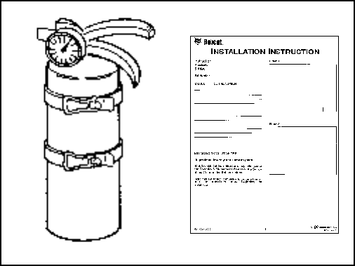
Figure 4
• Know where fire extinguishers and first aid kits are
located and how to use them. Fire extinguishers are
available from your Bobcat dealer [Figure 4].
Sl SSL-0206
S205 Skid-Steer Loader
Operation & Maintenance Manual XVI
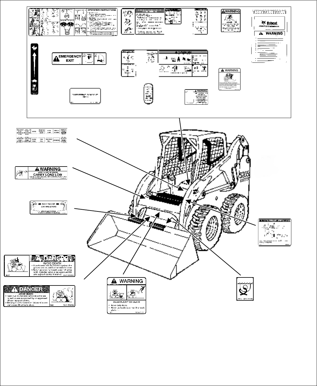
MACHINE SIGNS (DECALS)
Follow the instructions on all the Machine Signs (Decals) that are on the loader. Replace any damaged machine signs
and be sure they are in the correct locations. Machine signs are available from your Bobcat Loader dealer.
B-16604C
6710358
6702301
6702302
6727595 (5)
6731757
(ACS) - Advanced Control System
(SJC) - Selectable Joystick Controls
SJC - 7131518
SJC - 6737248
Standard and ACS - 6727926 SJC - 7131519
Door Opt. -
7110316
Inside Cab
ACS Only
6718706
6902600
6735140
Door Opt. - 6707852
6734179
Shoulder Belt
Opt. - 6735370
7117407
(Inside Fuse Cover)
6579528
(Behind Lift Arm Crossmember)
6561383
(Behind Bob-Tach)
S205 Skid-Steer Loader
XVII Operation & Maintenance Manual
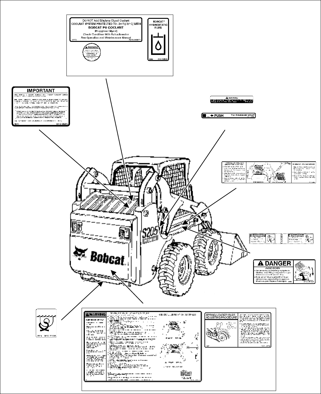
MACHINE SIGNS (DECALS) (CONT’D)
Follow the instructions on all the Machine Signs (Decals) that are on the loader. Replace any damaged machine signs
and be sure they are in the correct locations. Machine signs are available from your Bobcat Loader dealer.
6708929
6565990
Under Rear Grill
6560573
6719018
6717343 (2)
Under Cab
6727595 (2) Ref.
6709030
Inside Rear Door 6734534B B-16605B
6578368
6577754 (2)
6733996
6809511 (2)
(On Hose & Tubeline)

S205 Skid-Steer Loader
Operation & Maintenance Manual XVIII

S205 Skid-Steer Loader
1 Operation & Maintenance Manual
OPERATING INSTRUCTIONS
ATTACHMENTS ........................................................................................38
Choosing The Correct Bucket..............................................................38
Installing And Removing The Attachment (Hand Lever Bob-Tach)......39
Installing And Removing The Attachment (Power Bob-Tach Option)...41
Pallet Forks ..........................................................................................38
BOBCAT INTERLOCK CONTROL SYSTEM (BICS) ................................11
Operation .............................................................................................11
DAILY INSPECTION..................................................................................25
Daily Inspection and Maintenance.......................................................26
DRIVING AND STEERING THE LOADER ...............................................14
Available Controls Configurations ........................................................14
Operation (SJC) in ‘H’ Control Pattern.................................................15
Operation (SJC) in ‘ISO’ Control Pattern .............................................16
Operation (Standard and ACS)............................................................14
ENGINE SPEED CONTROL.....................................................................13
Operation .............................................................................................13
HYDRAULIC CONTROLS.........................................................................18
Advanced Control System (ACS) In HAND Control Mode ...................19
Attachment Control Device (ACD) (If Equipped)..................................24
Auxiliary Hydraulics Operation (MAXIMUM FLOW ONLY) ..................21
Auxiliary Hydraulics Operation (VARIABLE FLOW).............................21
Bucket Position Valve Operation (If Equipped) ....................................20
Description ...........................................................................................18
FRONT Auxiliary Hydraulics Operation (CONTINUOUS FLOW).........22
FRONT Auxiliary Hydraulics Operation (MAXIMUM FLOW) ...............21
FRONT Auxiliary Hydraulics Operation (VARIABLE FLOW)................21
High-Flow Hydraulics Operation (If Equipped).....................................23
Quick Couplers ....................................................................................22
REAR Auxiliary Hydraulics Operation (If Equipped) ............................22
Relieve Hydraulic Pressure (Loader and Attachment) .........................23
Secondary Front Auxiliary Hydraulics (If Equipped) ............................24
Selectable Joystick Control (SJC) In ‘H’ Control Pattern .....................19
Selectable Joystick Control (SJC) In ‘ISO’ Control Pattern..................20
Standard Controls (Also ACS In FOOT Pedal Mode) ..........................18
INSTRUMENT PANEL IDENTIFICATION ...................................................5
Cab Light................................................................................................8
Left Panel...............................................................................................5
Option And Field Accessory Panels.......................................................9
Right Panel (Key Switch) .......................................................................6
Right Panel (Keyless).............................................................................7
LIFT ARM BY-PASS CONTROL................................................................12
OPERATING
INSTRUCTIONS
S205 Skid-Steer Loader
Operation & Maintenance Manual 2
LIFTING THE LOADER ............................................................................ 56
Four Point Lift ...................................................................................... 56
Single Point Lift.................................................................................... 56
MONITORING THE DISPLAY PANELS .................................................... 34
Left Panel............................................................................................. 34
Right Panel (Key Switch) ..................................................................... 34
Right Panel (Keyless) .......................................................................... 35
Warning And Shutdown....................................................................... 35
OPERATING PROCEDURE ..................................................................... 44
Digging And Filling A Hole (ACS - Handles, SJC - ‘H’ Pattern) ........... 51
Digging And Filling A Hole (Foot Pedals)............................................. 48
Digging And Filling A Hole (SJC - ‘ISO’ Pattern) ................................. 54
Filling And Emptying The Bucket (ACS - Handles, SJC - ‘H’ Pattern)....49
Filling And Emptying The Bucket (Foot Pedals) .................................. 46
Filling And Emptying The Bucket (SJC - ‘ISO’ Pattern) ....................... 52
Inspect The Work Area........................................................................ 44
Leveling The Ground Using Float (ACS - Handles, SJC - ‘H’ Pattern) ...50
Leveling The Ground Using Float (Foot Pedals).................................. 47
Leveling The Ground Using Float (SJC - ‘ISO’ Pattern) ...................... 53
Operating With A Full Bucket............................................................... 44
Operating With An Empty Bucket ........................................................ 45
PARKING BRAKE ..................................................................................... 13
PRE-STARTING PROCEDURE................................................................ 27
Entering The Loader............................................................................ 27
Seat Adjustment .................................................................................. 27
Seat Bar............................................................................................... 28
Seat Belt Adjustment ........................................................................... 28
SEAT BAR RESTRAINT SYSTEM ........................................................... 10
Operation............................................................................................. 10
SPEED MANAGEMENT (SJC OPTION) .................................................. 17
Operation............................................................................................. 17
STARTING THE ENGINE ......................................................................... 29
Cold Temperature Starting................................................................... 32
Key Switch ........................................................................................... 29
Keyless ................................................................................................ 31
Warming The Hydraulic / Hydrostatic System ..................................... 33
STOPPING THE ENGINE AND LEAVING THE LOADER........................ 36
Emergency Exit ................................................................................... 37
Procedure ............................................................................................ 36
STOPPING THE LOADER........................................................................ 16
Using The Control Levers Or Joysticks................................................ 16
OPERATING INSTRUCTIONS (CONT’D)
S205 Skid-Steer Loader
3 Operation & Maintenance Manual
TOWING THE LOADER ............................................................................55
Procedure ............................................................................................55
TRACTION LOCK OVERRIDE..................................................................12
Operation .............................................................................................12
TRANSPORTING THE LOADER ON A TRAILER ....................................57
Fastening .............................................................................................57
Loading And Unloading........................................................................57
OPERATING INSTRUCTIONS (CONT’D)

S205 Skid-Steer Loader
Operation & Maintenance Manual 4
S205 Skid-Steer Loader
5 Operation & Maintenance Manual
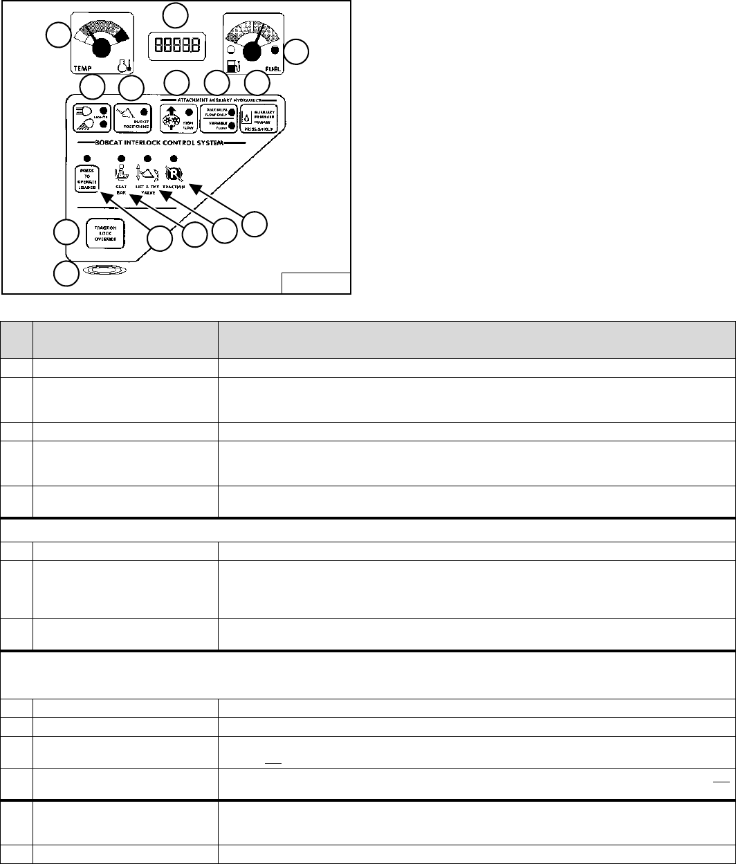
INSTRUMENT PANEL IDENTIFICATION
Left Panel
Figure 5
The left instrument panel is the same for both the Key
Switch and Keyless Instrument Panels [Figure 5].
The table below shows the DESCRIPTION and
FUNCTION / OPERATION for each of the components of
the left panel.
* See SYSTEM SETUP & ANALYSIS on Page 103 for further description of SERVICE CODES.
B-15551
1
456 7 8
3
2
14
13 910 11 12
REF.
NO DESCRIPTION FUNCTION / OPERATION
1TEMPERATURE GAUGE Shows the engine coolant temperature.
2HOURMETER / CODE
DISPLAY / GLOW PLUG
COUNTDOWN
HOURMETER - Records operating hours of loader. CODE DISPLAY - Display numeric SERVICE CODES*
relating to the loader monitoring system. COUNTDOWN - Preheat time remaining
3FUEL GAUGE Shows the amount of fuel in the tank.
4LIGHTS / HOLD FOR CODES LIGHTS - Press once for FRONT LIGHTS. Press a second time for FRONT AND REAR lights. Press a third time
to turn all lights off. HOLD FOR CODES - Press and hold two seconds for display of SERVICE CODES (2).
(CODES* show only when there is an error found by loader monitoring system.)
5 BUCKET POSITIONING (Option) Press to engage the BUCKET POSITIONING function. Press again to disengage. Press and hold 2 seconds to
view SHTDN (SHUTDOWN) feature & Operational Code Number in HOURMETER / CODE DISPLAY.
ATTACHMENT AUXILIARY HYDRAULICS
6HIGH FLOW (Option) Press to engage the HIGH FLOW auxiliary hydraulics. Press again to disengage.
7MAXIMUM FLOW / VARIABLE FLOW Press once to engage the VARIABLE FLOW auxiliary hydraulics. Press a second time to engage MAXIMUM
FLOW. Press a third time to disengage all auxiliary hydraulics. [VARIABLE FLOW allows for slow-to-fast
movement of auxiliary functions. (The farther you move the switch, the faster the movement of auxiliary
functions.) MAXIMUM FLOW allows for only fast movement.]
8AUXILIARY PRESSURE RELEASE Rear Auxiliary Only - With key ON or engine running, press and hold button for 5 seconds. (See Relieve
Hydraulic Pressure (Loader and Attachment) on Page 23 for front auxiliary pressure release.)
BOBCAT INTERLOCK CONTROL SYSTEM (BICS)
(See SYSTEM SETUP & ANALYSIS on Page 103 for more information.)
9PRESS TO OPERATE LOADER Press to activate BICS System when the Seat Bar is down and operator is seated in operating position.
10 SEAT BAR The light comes ON when the seat bar is down.
11 LIFT & TILT VALVE The light comes ON when the seat bar is down and the PRESS TO OPERATE Button is pressed. The lift and tilt
functions can be operated when the light is ON.
12 TRACTION The light comes ON when the seat bar is down, engine is running, and parking brake is released. The loader can
be moved forward or backward when the light is ON.
13 TRACTION LOCK OVERRIDE (Function Only When Seat Bar Is Raised And The Engine Is Running) Press to unlock the brakes. Allows you to
use the steering levers to move the loader forward or backward when using the backhoe attachment or for loader
service. (See TRACTION LOCK OVERRIDE on Page 12.) Press a second time to lock the brakes.
14 ALARM The ALARM beeps when there is an Error, WARNING or SHUTDOWN condition.
S205 Skid-Steer Loader
Operation & Maintenance Manual 6
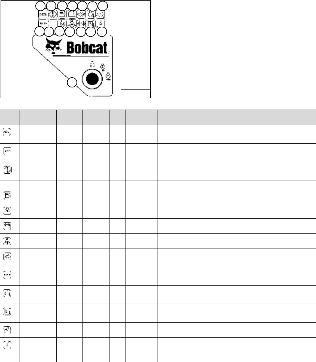
INSTRUMENT PANEL IDENTIFICATION (CONT’D)
Right Panel (Key Switch)
Figure 6
The right instrument panel shown [Figure 6] is the Key
Switch Panel.
The table below shows the Icons and other components
of the Right Key Switch Panel.
* These functions are monitored and have associated SERVICE CODES. See SYSTEM SETUP & ANALYSIS on Page 103 for
description of SERVICE CODES.
B-15552B
15 17 19 21 23 25 27
16 18 20 22 24 26 28
29
REF. FUNCTION ICON /
LIGHT ALARM CODE CONDITION DESCRIPTION
15
Advanced
Control System
(ACS) (Opt.)
ON 3 Beeps * Error Error with Advanced Control System (ACS)
or Selectable Joystick Control (SJC).
16
Attachment
Control Device
(ACD)
ON
FLASHING
- - -
3 Beeps
- - -
*
- - -
Error
Electrical controlled attachment is present.
Error with Attachment Control Device (ACD).
17
General
Warning
ON
ON
FLASHING
3 Beeps
3 Beeps
Continuous
*
*
*
Error
WARNING
SHUTDOWN
Error with one or more engine or hydraulic functions.
Engine speed high or in shutdown.
Engine speed very high. Engine will stop in 10 seconds.
18 NOT USED - - - - - - - - - - - - - - -
19
Fuel Level ON
FLASHING
3 Beeps
3 Beeps
*Error
WARNING
Fuel level sender system fault.
Fuel level low.
20
Glow Plugs ON
FLASHING
- - -
3 Beeps
- - -
*
- - -
Error
Glow plugs are energized.
Error with glow plugs.
21
System Voltage ON 3 Beeps * WARNING Voltage low, high or very high.
22
Seat Belt ON - - - - - - - - - Light stays on for 45 seconds to remind operator to fasten seat belt.
23
Engine Oil
Pressure
ON
ON
FLASHING
3 Beeps
3 Beeps
Continuous
*
*
*
Error
WARNING
SHUTDOWN
Engine oil pressure sender out of range.
Engine oil level low.
Engine oil pressure very low. Engine will stop in 10 seconds.
24
Hydrostatic
Charge
Pressure
ON
ON
FLASHING
3 Beeps
3 Beeps
Continuous
*
*
*
Error
WARNING
SHUTDOWN
Hydraulic oil pressure sender out of range.
Hydraulic oil pressure low.
Hydraulic charge pressure very low. Engine will stop in 10 seconds.
25
Engine Coolant
Temperature
ON
ON
FLASHING
3 Beeps
3 Beeps
Continuous
*
*
*
Error
WARNING
SHUTDOWN
Engine coolant sender out of range.
Engine coolant temperature high.
Engine coolant temperature very high. Engine will stop in 10 seconds.
26
Hydraulic Oil
Temperature
ON
ON
FLASHING
3 Beeps
3 Beeps
Continuous
*
*
Error
WARNING
SHUTDOWN
Hydraulic oil temperature out of range.
Hydraulic oil temperature high.
Hydraulic oil temperature very high. Engine will stop in 10 seconds.
27
Engine Air Filter ON
FLASHING
3 Beeps
3 Beeps
*
*
Error
WARNING
Air filter with high restriction.
Air filter switch not connected.
28
Hydraulic Filter ON
FLASHING
3 Beeps
3 Beeps
*
*
Error
WARNING
Hydraulic filter with high restriction.
Hydraulic filter switch not connected.
29 Key Switch - - - - - - - - - - - - Used to start and stop the engine.
S205 Skid-Steer Loader
7 Operation & Maintenance Manual
INSTRUMENT PANEL IDENTIFICATION (CONT’D)
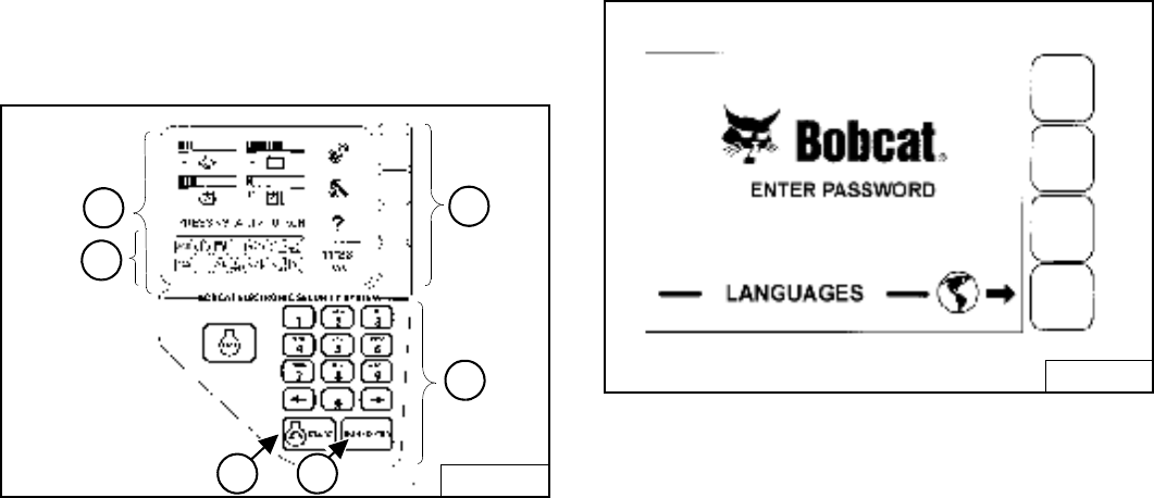
Right Panel (Keyless)
Figure 7
The right instrument panel shown [Figure 7] is the
Keyless Panel.
1. Display Panel: The Display Panel is where all system
setup, monitoring, troubleshooting, and error
conditions are displayed.
2. Function Icons: The lower left area of the Keyless
Panel has the same Icons as the Key Switch Panel.
These Icons are only visible when the monitoring
system has detected an error.
3. Selection Buttons: The four Selection Buttons allow
you to select items from the Display Panel and scroll
through screens.
4. Keypad: The numeric keypad (4) [Figure 7] has two
functions:
To enter a number code (password) to allow starting
the engine (Keyless Start).
To enter a number as directed for further use of the
Display Panel.
Figure 8
The first screen you will see on your new loader will be as
shown in [Figure 8].
When this screen is on the display you can enter the
password and start the engine or change the Display
Panel setup features.
NOTE: Your new loader (with Keyless Instrument
Panel) will have an Owner Password. Your
dealer will provide you with this password.
Change the password to one that you will
easily remember to prevent unauthorized use
of your loader. (See Panel Setup on Page 112.)
Keep your password in a safe place for future
needs.
Start Engine: Use the Keypad to enter the numbers
(letters) of your password and press the RUN / ENTER
key (5) [Figure 7].
Press and hold the START Button (6) [Figure 7] until the
engine starts.
Change Language: Press the Selection Button at the end
of the arrow [Figure 8] to go to the next screen.
B-15553B
1
2
6 5
3
4B-16165
S205 Skid-Steer Loader
Operation & Maintenance Manual 8
INSTRUMENT PANEL IDENTIFICATION (CONT’D)
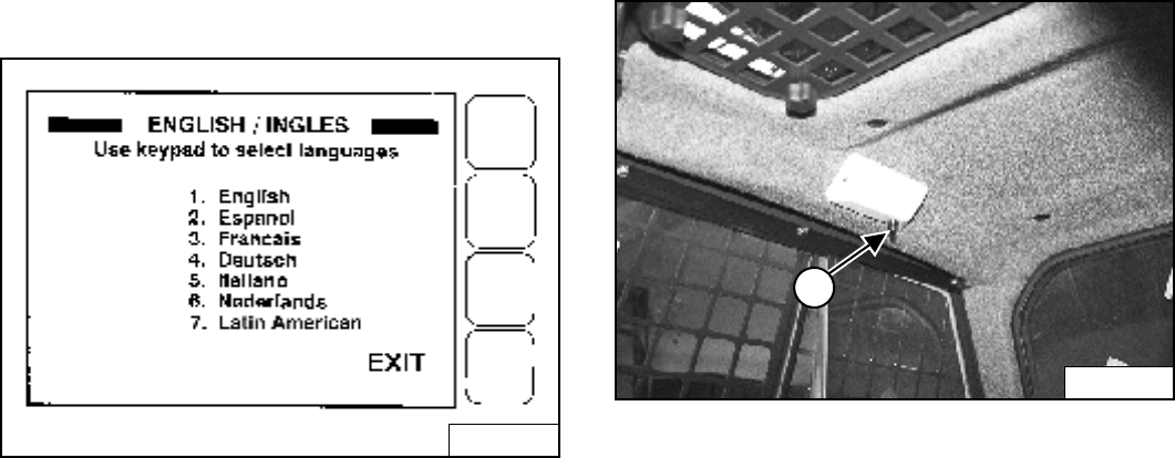
Right Panel (Keyless) (Cont’d)
Figure 9
Use the Keypad to select the number of the language
[Figure 9].
Press EXIT. The screen will return to [Figure 8]. You can
then enter the password and start the engine.
(See DISPLAY CONTROLLER PANEL SETUP on
Page 111) for further description of screens to setup the
system for your use.
NOTE: Pressing the EXIT key will go to the previous
screen and you can continue pressing until
you get to the initial (home) screen.
SHORTCUT: Press the “0” (zero) key to get to
the home screen immediately.
Cab Light
Figure 10
Push the button (1) [Figure 10] to turn the light ON. Push
the button again to turn OFF.
B-16655
N-22015
1
S205 Skid-Steer Loader
9 Operation & Maintenance Manual
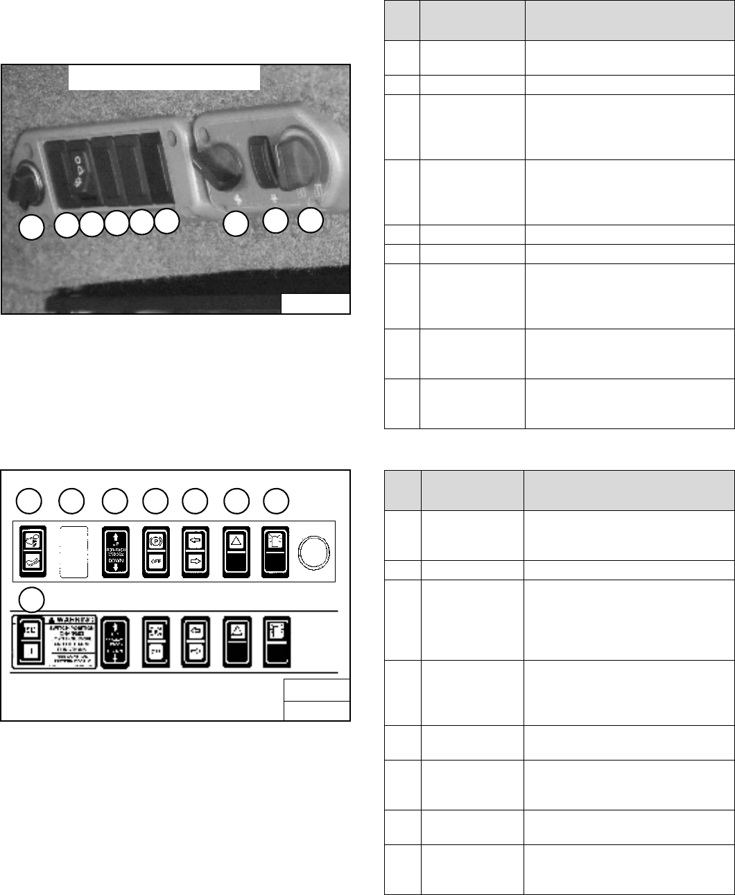
INSTRUMENT PANEL IDENTIFICATION (CONT’D)
Option And Field Accessory Panels
Figure 11
Figure 12
NOTE: Parking Brake (13) [Figure 12] is Standard on
all loaders.
Side Accessory Panel [Figure 11]
Front Accessory Panel [Figure 12]
P16000
SIDE ACCESSORY PANEL
3
1
2456789
B-15993C
OR
17
B-15993H
FRONT ACCESSORY PANEL
10 11 12 13 14 15 16
REF.
NO. DESCRIPTION FUNCTION / OPERATION
1POWER PLUG Provides a 12V receptacle for
accessories.
2NOT USED - - -
3FRONT WIPER Press the top of the switch to start
the front wiper (press and hold for
washer fluid). Press the bottom of
the switch to stop the wiper.
4REAR WIPER Press the bottom of the switch to
start the rear wiper. Press the top of
the switch to provide washer fluid to
clean the rear window.
5NOT USED - - -
6NOT USED - - -
7FAN MOTOR Turn clockwise to increase fan
speed; counterclockwise to
decrease. There are four positions;
OFF-1-2-3.
8AIR COND.
SWITCH
Press top of switch to start; bottom to
stop. Fan Motor (7) must be ON for
A/C to operate.
9TEMP.
CONTROL
Turn clockwise to increase the
temperature; counterclockwise to
decrease.
REF.
NO. DESCRIPTION FUNCTION / OPERATION
10 ADVANCED
CONTROL
SYSTEM (ACS)
Press the top to select Hand
Controls; bottom to select Foot
Controls.
11 NOT USED - - -
12 POWER
BOB-TACH
Press and hold the up arrow to
disengage the the Bob-Tach wedges.
Press and hold the down arrow to
engage the wedges into the
mounting frame holes.
13 PARKING
BRAKE
(Standard on all
Loaders)
Press the top to engage the
PARKING BRAKE; bottom to
disengage.
14 TURN SIGNAL
INDICATORS
Indicates left or right TURN
SIGNALS are ON.
15 HAZARD
LIGHTS
Press the top to turn the HAZARD
LIGHTS ON; right side bottom to turn
OFF.
16 ROTATING
BEACON
Press the top to turn the ROTATING
BEACON ON; bottom to turn OFF.
17 SELECTABLE
JOYSTICK
CONTROL (SJC)
Press the top to select ‘ISO’ Control
Pattern; bottom to select ‘H’ Control
Pattern.
S205 Skid-Steer Loader
Operation & Maintenance Manual 10
SEAT BAR RESTRAINT SYSTEM
Operation
Figure 13
The seat bar restraint system has a pivoting seat bar with
arm rests (1) [Figure 13].
The operator controls the use of the seat bar. The seat
bar in the down position helps to keep the operator in the
seat.
WARNING
AVOID INJURY OR DEATH
When operating the machine:
• Keep the seat belt fastened snugly.
• The seat bar must be lowered.
• Keep your feet on the pedal controls or footrests
and hands on steering levers.
W-2261-0799
When the seat bar is down, PRESS TO OPERATE
LOADER Button is activated, and the brake is released,
the lift, tilt, and traction drive functions can be operated.
(Traction drive will operate only when the engine is
running.)
When, the seat bar is up, the lift, tilt, and traction drive
functions are deactivated and both foot pedals (if
equipped) will be locked when returned to neutral
position.
WARNING
Before you leave the operator’s seat:
• Lower the lift arms, put the attachment flat on the
ground.
• Stop the engine.
• Engage the parking brake.
• Raise seat bar.
• (Foot Pedal Controls) Move pedals until both
lock.
• (Advanced Control system - ACS) Move the
hydraulic controls to the NEUTRAL POSITION to
make sure that both lift and tilt functions are
deactivated.
The seat bar system must deactivate the lift and
tilt control functions when the seat bar is up.
Service the system if hand controls do not
deactivate.
• (Selectable Joystick Controls - SJC) Move the
joysticks to the NEUTRAL POSITION to make
sure that travel and hydraulic functions are
deactivated.
The seat bar system must deactivate these
functions when the seat bar is up. Service the
system if controls do not deactivate.
W-2463-0603
P-45122
1
S205 Skid-Steer Loader
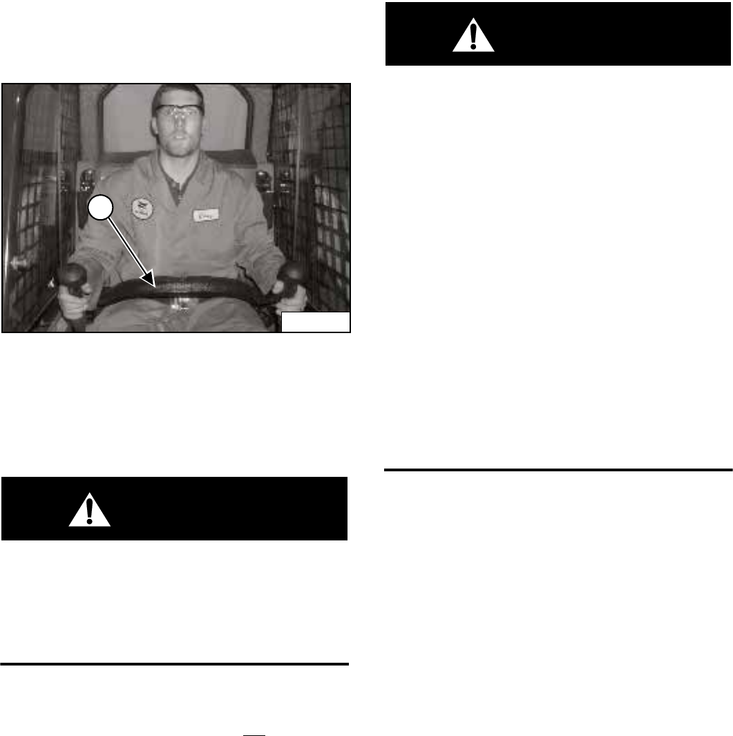
11 Operation & Maintenance Manual
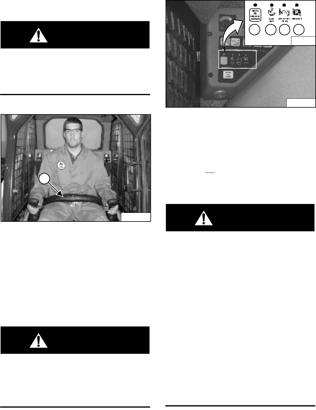
BOBCAT INTERLOCK CONTROL SYSTEM (BICS)
Operation
WARNING
AVOID INJURY OR DEATH
The Bobcat Interlock Control System (BICS) must
deactivate the lift, tilt and traction drive functions. If it
does not, contact your dealer for service. DO NOT
modify the system.
W-2151-0394
Figure 14
The Bobcat Interlock Control System (BICS) has a
pivoting seat bar with arm rests (1) [Figure 14].
The operator controls the use of the seat bar. The seat
bar in the down position helps to keep the operator in the
seat.
The BICS requires the operator to be seated in the
operating position with the Seat Bar (1) [Figure 14] fully
lowered before the lift, tilt, auxiliary hydraulics, and
traction functions can be operated. The seat belt must be
fastened anytime you operate the machine.
WARNING
AVOID INJURY OR DEATH
When operating the machine:
• Keep the seat belt fastened snugly.
• The seat bar must be lowered.
• Keep your feet on the pedal controls or footrests
and hands on steering levers.
W-2261-0799
Figure 15
There are display lights (1, 2, 3 and 4) [Figure 15]
located on the left instrument panel that must be ON to
operate the machine.
When the seat bar is down, PRESS TO OPERATE
LOADER Button is activated, and the parking brake is
released, the lift, tilt, auxiliary hydraulics, and traction
drive functions can be operated.
When, the seat bar is up, the lift, tilt, auxiliary hydraulics,
and traction drive functions are deactivated.
WARNING
Before you leave the operator’s seat:
• Lower the lift arms, put the attachment flat on the
ground.
• Stop the engine.
• Engage the parking brake.
• Raise seat bar.
• (Foot Pedal Controls) Move pedals until both
lock.
• (Advanced Control system - ACS) Move the
hydraulic controls to the NEUTRAL POSITION to
make sure that both lift and tilt functions are
deactivated.
The seat bar system must deactivate the lift and
tilt control functions when the seat bar is up.
Service the system if hand controls do not
deactivate.
• (Selectable Joystick Controls - SJC) Move the
joysticks to the NEUTRAL POSITION to make
sure that travel and hydraulic functions are
deactivated.
The seat bar system must deactivate these
functions when the seat bar is up. Service the
system if controls do not deactivate.
W-2463-0603
P-45116
1
N-18409
B-15551G
34
21
S205 Skid-Steer Loader
Operation & Maintenance Manual 12
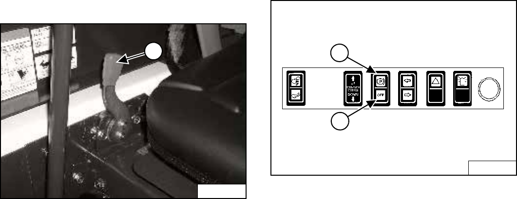
LIFT ARM BY-PASS CONTROL
Figure 16
The lift arm by-pass control (1) [Figure 16] is used to
lower the lift arms if the lift arms cannot be lowered
during normal operations.
• Sit in the operator's seat.
• Fasten the seat belt and lower the seat bar.
• Turn the knob (1) [Figure 16] clockwise 1/4 turn.
• Pull up and hold the knob until the lift arms slowly
lower.
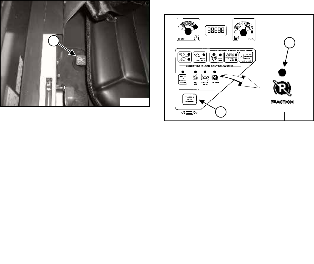
TRACTION LOCK OVERRIDE
Operation
Figure 17
(Functions Only When The Seat Bar Is Raised And The
Engine Is Running) There is a TRACTION LOCK
OVERRIDE Button (1) [Figure 17] on the left instrument
panel which will allow you to use the steering levers to
move the loader forward & backward when using the
backhoe attachment or for loader service.
Press the TRACTION LOCK OVERRIDE Button once to
unlock traction drive. The TRACTION light (2)
[Figure 17] will be ON.
Press the button a second time to lock the traction drive.
The TRACTION light (2) [Figure 17] will be OFF.
NOTE: The TRACTION LOCK OVERRIDE Button will
unlock the traction drive when seat bar is
raised and the engine is running.
The TRACTION LOCK OVERRIDE Button will
function if brake is in the engaged or
disengaged position and the engine is
running.
P-54406
1
B-15551
2
1
S205 Skid-Steer Loader
13 Operation & Maintenance Manual
ENGINE SPEED CONTROL
Operation
Figure 18
The speed control lever is at the right side of the
operator's seat (1) [Figure 18].
Move the lever forward to increase engine speed. Move
backward to decrease engine speed.
PARKING BRAKE
Figure 19
Press the top of the switch (1) [Figure 19] to engage the
parking brake. The traction drive system will be locked.
Press the bottom of the switch (2) [Figure 19] to
disengage the parking brake. The traction drive system
will be unlocked.
NOTE: The TRACTION light on the left instrument
panel will remain OFF until the engine is
started, the PRESS TO OPERATE LOADER
Button is pressed and the parking brake is
disengaged.
P-31864
1
B-15993C
2
1
S205 Skid-Steer Loader
Operation & Maintenance Manual 14
DRIVING AND STEERING THE LOADER
Available Controls Configurations
The loader has three configurations available:
•Standard Controls - Two Steering Levers control drive
and steering functions.
•Advanced Control System (ACS) (Option or Field
Accessory) - Two Steering Levers control drive and
steering functions.
•Selectable Joystick Controls (SJC) (Option) -
(‘ISO’ Pattern) Left joystick controls the drive and
steering functions.
(‘H’ Pattern) Left and right joysticks control left and
right side drive and steering functions.
Operation (Standard and ACS)
Figure 20
The control levers (1) [Figure 20] are on the left and right
side in front of the seat.
Move levers smoothly. Avoid sudden starting and
stopping.
WARNING
AVOID INJURY OR DEATH
When operating the machine:
• Keep the seat belt fastened snugly.
• The seat bar must be lowered.
• Keep your feet on the pedal controls or footrests
and hands on steering levers.
W-2261-0799
Figure 21
The levers control forward and reverse travel and turning
the loader [Figure 21].
Forward Travel - Push both levers forward.
Reverse Travel - Pull both levers backward.
Normal Turning - Move one lever farther forward than
the other.
Fast Turning - Push one lever forward and pull the other
lever backward.
For slow travel speed, push the steering levers forward
only a small amount.
To increase travel speed, push both levers farther
forward.
For maximum pushing force, push the levers forward only
a small amount with the engine at full speed.
P-45122
1
PI-1849A
Standard and ACS
RIGHT TURNLEFT TURN
RIGHT
FAST TURN
LEFT
FAST TURN
REVERSEFORWARD
S205 Skid-Steer Loader
15 Operation & Maintenance Manual
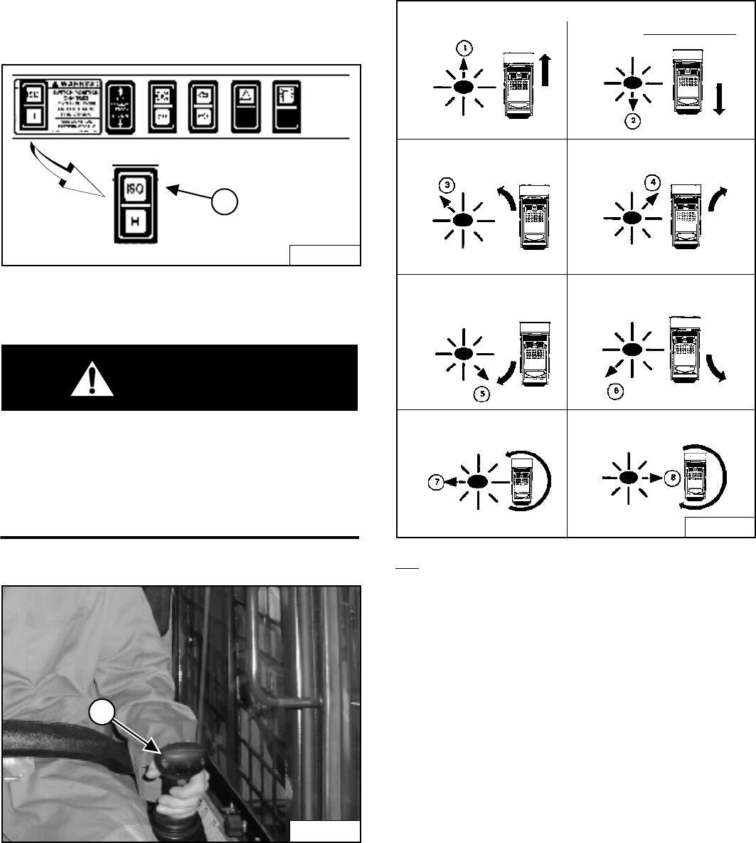
DRIVING AND STEERING THE LOADER (CONT’D)
Operation (SJC) in ‘H’ Control Pattern
Figure 22
Select the ‘H’ control pattern by pressing the bottom of
the switch (1) [Figure 22].
WARNING
AVOID INJURY OR DEATH
When operating the machine:
• Keep the seat belt fastened snugly.
• The seat bar must be lowered.
• Keep your feet on the foot rests and hands on
control levers.
W-2399-0501
Figure 23
Both joysticks control drive and steering and are located
on the right and left side in front of the seat (1)
[Figure 23].
Move the joysticks smoothly. Avoid sudden starting and
stopping.
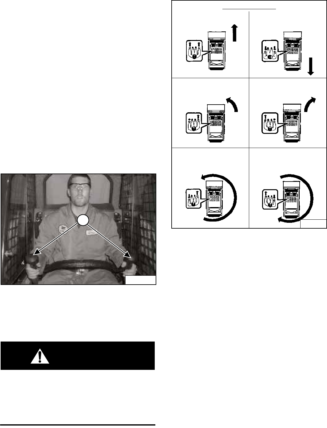
Figure 24
Hand Control Functions (Drive and Steering) [Figure 24]
1. Forward Travel - Move both joysticks forward.
2. Backward Travel - Move both joysticks backward.
3. Forward Left Turn - Move the right joystick farther
forward than the left joystick.
4. Forward Right Turn - Move the left joystick farther
forward than the right joystick.
5. Left Fast Turn - Move the left joystick backward and
the right joystick forward.
6. Right Fast Turn - Move the left joystick forward and
the right joystick backward.
B-15993H
1
P-45116
1
B-22029
1
2
3
4
5
6
NN
NN
NN
NN
NN
N
N
Left
Joystick
Right
Joystick
SJC in ‘H’ Control Pattern
FORWARD
BACKWARD
RIGHT
TURN
LEFT
TURN
LEFT
FAST
TURN
RIGHT
FAST
TURN
S205 Skid-Steer Loader
Operation & Maintenance Manual 16
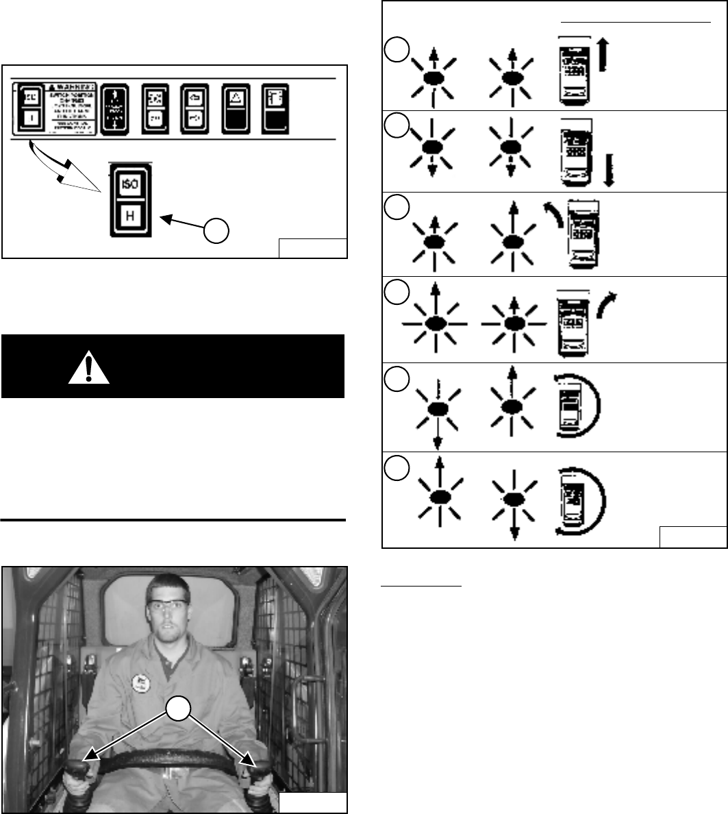
DRIVING AND STEERING THE LOADER (CONT’D)
Operation (SJC) in ‘ISO’ Control Pattern
Figure 25
Select the ‘ISO’ control pattern by pressing the top of the
switch (1) [Figure 25].
WARNING
AVOID INJURY OR DEATH
When operating the machine:
• Keep the seat belt fastened snugly.
• The seat bar must be lowered.
• Keep your feet on the foot rests and hands on
control levers.
W-2399-0501
Figure 26
The joystick which controls drive and steering is on the
left side in front of the seat (1) [Figure 26].
Figure 27
Left Joystick Functions (Drive and Steering) [Figure 27]
Move the joystick smoothly. Avoid sudden starting and
stopping.
1. Forward Travel - Move joystick forward.
2. Backward Travel - Move joystick backward.
3. Forward Left Turn - Move joystick forward and to the
left.
4. Forward Right Turn - Move joystick forward and to
the right.
5. Backward Left Turn - Move joystick backward and to
the right.
6. Backward Right Turn - Move joystick backward and
to the left.
7. Left Fast Turn - Move joystick to the left.
8. Right Fast Turn - Move joystick to the right.
STOPPING THE LOADER
Using The Control Levers Or Joysticks
When the control levers or joysticks are moved to the
neutral position, the hydrostatic transmission will act as a
service brake to stop the loader.
B-15993H
1
P-45116
1
B-21970
N
LEFT JOYSTICK
N
NN
NN
NN
SJC in ‘ISO’
Control Pattern
FORWARD
LEFT TURN
FORWARD
RIGHT TURN
BACKWARD
LEFT TURN
BACKWARD
RIGHT TURN
LEFT FAST TURN RIGHT FAST TURN
S205 Skid-Steer Loader
17 Operation & Maintenance Manual
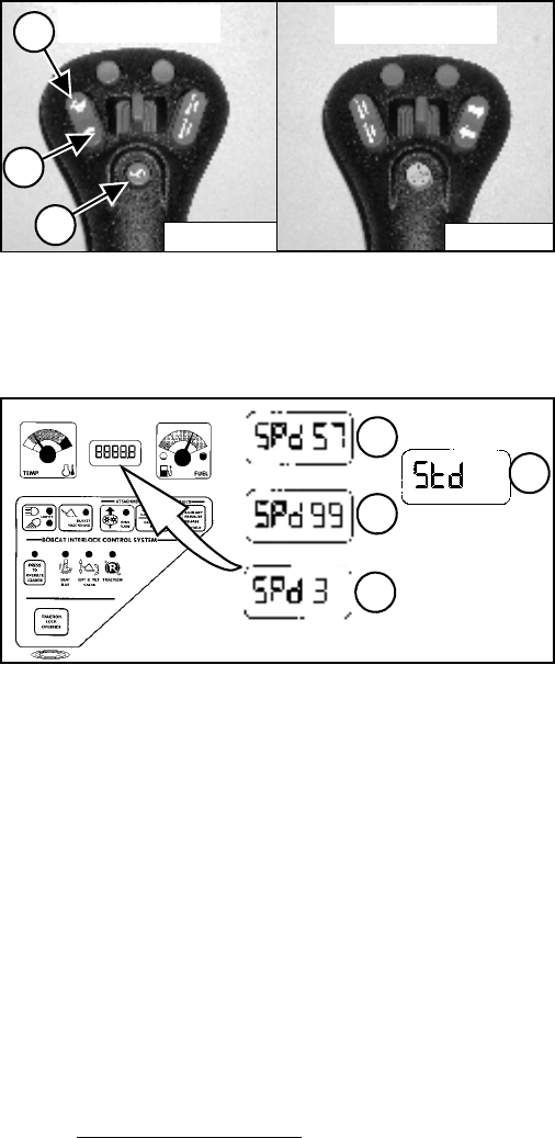
SPEED MANAGEMENT (SJC OPTION)
Operation
Speed Management allows the loader to be maneuvered
at slow travel speed for installing attachments, loading or
unloading, and work applications such as trenching,
tilling and landscaping.
Figure 28
Press the button (1) [Figure 28] on the left joystick once
to engage Speed Management.
Figure 29
When Speed Management is engaged, the machine will
travel at 57% of Standard travel speed and the
percentage [SPd 57] will appear in the display (1)
[Figure 29].
While Speed Management is engaged, press the top of
the Speed Control switch (2) [Figure 28] to increase the
speed up to 99% [SPd 99] or the bottom of the switch (3)
[Figure 28] to decrease the speed down to 3% [SPd 3].
The percentages will appear in the display (1, 2 and 3)
[Figure 29].
Press button (1) [Figure 28] again to disengage Speed
Management and return to Standard Travel Speed
([Std] (4) [Figure 29] will appear in display.)
NOTE: Early model loaders will show Snl in the
display [Figure 29] instead of SPd.
The system will retain the speed percentage as long as
the key remains ON (Key Switch Panel) or the STOP
button has not been pressed (Keyless Panel).
EXAMPLE: You can be using the machine at 40%
and then disengage Speed Management to
reposition the loader, then re-engage Speed
Management. The speed percentage will still be at
40%.
EXAMPLE: If you turn the key OFF or press the
STOP button, the next time you start the engine
and engage Speed Management, the speed will be
at 57% of Standard Travel Speed. Press button (1)
[Figure 28] to resume Speed Management
Operation.
P-24802
Right Joystick
1
P-24820
Left Joystick
2
1
3
B-15551-2A
B-15551-2B
B-15551-2C
B-15551-1D
1
2
3
4
B-15551
S205 Skid-Steer Loader
Operation & Maintenance Manual 18
HYDRAULIC CONTROLS
Description
Two foot pedals (or optional hand controls) control the
hydraulic cylinders for the lift and tilt functions.
Put your feet on the pedals (or footrests) and KEEP
THEM THERE any time you operate the loader.
Standard Controls (Also ACS In FOOT Pedal Mode)
Figure 30
Lift Arm Operation - (Left Pedal)
Push the heel (1) [Figure 30] of the pedal to raise the
lift arms.
Push the toe (2) [Figure 30] of the pedal to lower the
lift arms.
Lift Arm Float Position Operation - (Left Pedal)
Push the toe (2) [Figure 30] of the pedal all the way
forward until it locks into the float position.
Use the float position of the lift arms to level loose
material while driving backward.
Raise the lift arms to disengage the float position.
Lift Arm Float Position (With ACS) - (Left Pedal)
Press and hold the Float button (3) [Figure 30].
Push the toe (2) [Figure 30] of the pedal forward to
lower the lift arms. Then release the float button.
Use the float position of the lift arms to level loose
material while driving backward.
Raise the lift arms to disengage the float position.
Figure 31
Tilt Operation - (Right Pedal)
Push the heel (1) [Figure 31] of the pedal to tilt the
bucket backward.
Push the toe (2) [Figure 31] of the pedal to tilt the
bucket forward.
B-15541
3
B-15781
1
2
B-15518 B-15973
1
2
S205 Skid-Steer Loader
19 Operation & Maintenance Manual
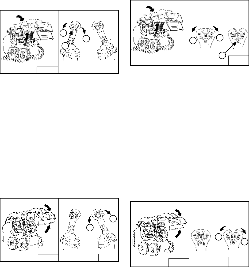
HYDRAULIC CONTROLS (CONT’D)
Advanced Control System (ACS) In HAND Control
Mode
Figure 32
Lift Arm Operation - (Left Hand Lever)
Move the lever outward (1) [Figure 32] to raise the lift
arms.
Move the lever inward (2) [Figure 32] to lower the lift
arms.
Lift Arm Float Position - (Left Hand Lever)
Press and hold the Float Button (3) [Figure 32] while
the lever is in neutral. Move the lever to lift arm down
position (2) [Figure 32], then release the button.
Press Float Button (3) [Figure 32] again or move the
lever to lift arm up position (1) [Figure 32].
Use the float position of the lift arms to level loose
material while driving backward.
Figure 33
Tilt Operation - (Right Hand Lever)
Move the lever inward (1) [Figure 33] to tilt the bucket
backward.
Move the lever outward (2) [Figure 33] to tilt the
bucket forward.
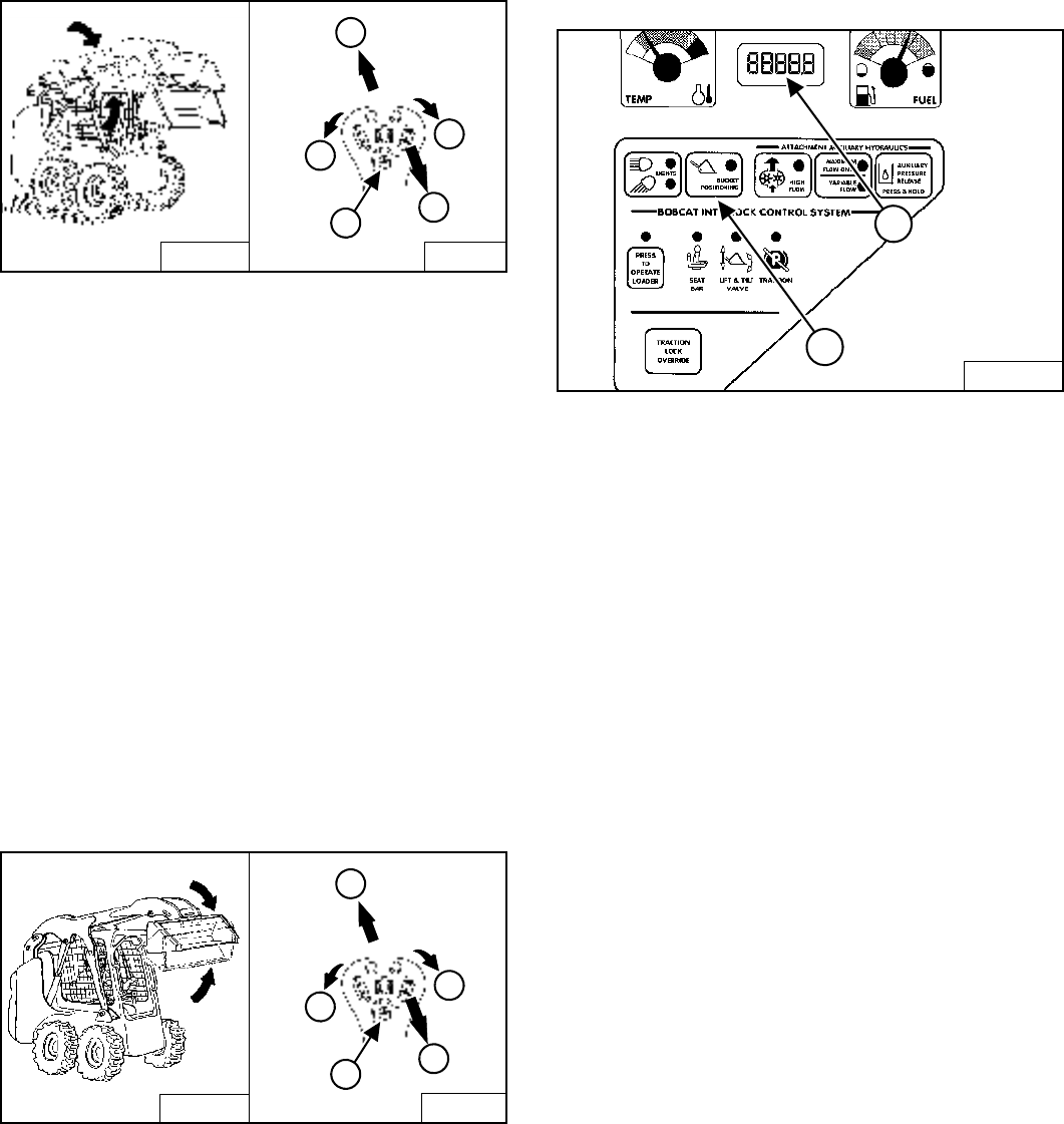
Selectable Joystick Control (SJC) In ‘H’ Control
Pattern
Figure 34
Lift Arm Operation - (Left Hand Joystick)
Move the joystick outward (1) [Figure 34] to raise the
lift arms.
Move the joystick inward (2) [Figure 34] to lower the
lift arms.
Lift Arm Float Position - (Left & Right Hand Joysticks)
Press and hold the Float Button (3) [Figure 34] while
the joysticks are in neutral. Move the left joystick to lift
arm down position (2) [Figure 34], then release the
button.
Press Float Button (3) [Figure 34] again or move the
left joystick to lift arm up position (1) [Figure 34] to
disengage.
Use the float position of the lift arms to level loose
material while driving backward.
Figure 35
Tilt Operation - (Right Hand Joystick)
Move the joystick inward (1) [Figure 35] to tilt the
bucket backward.
Move the joystick outward (2) [Figure 35] to tilt the
bucket forward.
B-15541 B-15781
1
2
3
B-15518 B-15781
2
1
B-15541 B-19873
B-19874
12
3
Right
Joystick
Left
Joystick
B-15518 B-19873
B-19874
2
1
Left
Joystick
Right
Joystick
S205 Skid-Steer Loader
Operation & Maintenance Manual 20
HYDRAULIC CONTROLS (CONT’D)
Selectable Joystick Control (SJC) In ‘ISO’ Control
Pattern
Figure 36
Lift Arm Operation - (Right Hand Joystick)
Move the joystick backward (1) [Figure 36] to raise
the lift arms.
Move the joystick forward (2) [Figure 36] to lower the
lift arms.
Lift Arm Float Position - (Right Hand Joystick)
Press and hold the Float Button (3) [Figure 36] while
the joystick is in neutral. Move the joystick to lift arm
down position (2) [Figure 36], then release the
button.
Press Float Button (3) [Figure 36] again or move the
joystick to lift arm up position (1) [Figure 36] to
disengage.
Use the float position of the lift arms to level loose
material while driving backward.
Figure 37
Tilt Operation - (Right Hand Joystick)
Move the joystick inward (4) [Figure 37] to tilt the
bucket backward.
Move the joystick outward (5) [Figure 37] to tilt the
bucket forward.
Bucket Position Valve Operation (If Equipped)
The function of the bucket position valve is to keep the
bucket in the same approximate position it is in before
you begin raising the lift arms.
Figure 38
Press BUCKET POSITIONING button (1) [Figure 38] to
engage the bucket position function. (The light will be on.)
Press again to disengage.
Bucket Positioning functions only during upward lift cycle.
If the Bucket Positioning button is pressed and held for
2 seconds, the Warning and Shutdown status will be
displayed (2) [Figure 38]. (See SHUTDOWN FEATURE
on Page 115.)
B-155541 B-15781
5
4
3
2
1
Right Joystick
B-15518 B-15781
5
4
3
2
1
Right Joystick
B-15551
1
2
S205 Skid-Steer Loader
21 Operation & Maintenance Manual
HYDRAULIC CONTROLS (CONT’D)
Auxiliary Hydraulics Operation (VARIABLE FLOW)
Figure 39
Figure 40
VARIABLE FLOW allows for slow-to-fast movement of
auxiliary functions. If you move the auxiliary switch (1)
[Figure 40] half-way, the auxiliary functions move at
approximately one-half speed.
Press the auxiliary hydraulics button (1) [Figure 39]
once.
The light (2) [Figure 39] will be ON.
To disengage, press the auxiliary hydraulics button (1)
[Figure 39] two more times.
Both lights (2 and 3) [Figure 39] will be OFF.
NOTE: When the operator is seated and raises the
seat bar, the Auxiliary Hydraulic System
(Front and Rear) will deactivate.
Auxiliary Hydraulics Operation (MAXIMUM FLOW
ONLY)
MAXIMUM FLOW ONLY allows for fast movement only. If
you move the auxiliary switch (1 or 3) [Figure 40], the
auxiliary functions move at fast speed; release the switch
to stop auxiliary functions.
Press the auxiliary hydraulics button (1) [Figure 39] two
times.
The light (3) [Figure 39] will be ON.
To disengage, press the auxiliary hydraulics button (1)
[Figure 39] again.
Both lights (2 and 3) [Figure 39] will be OFF.
NOTE: When the operator is seated and raises the
seat bar, the Auxiliary Hydraulic System
(Front and Rear) will deactivate.
FRONT Auxiliary Hydraulics Operation (VARIABLE
FLOW)
Press the auxiliary hydraulics button for VARIABLE
FLOW.
Push the switch (1) [Figure 40] to the right or left to
change the fluid flow direction of the front quick couplers.
(EXAMPLE: Open and close grapple teeth.)
FRONT Auxiliary Hydraulics Operation (MAXIMUM
FLOW)
Press the auxiliary hydraulics button for MAXIMUM
FLOW.
Push the switch (1) [Figure 40] to the right or left to
change the fluid flow direction of the front quick couplers.
(EXAMPLE: Open and close grapple teeth.)
Press again to disengage.
B-15551
2
1
3
P-31833
2
1
3
P-16537
S205 Skid-Steer Loader
Operation & Maintenance Manual 22
HYDRAULIC CONTROLS (CONT’D)
FRONT Auxiliary Hydraulics Operation
(CONTINUOUS FLOW)
After selecting VARIABLE or MAXIMUM FLOW, press
the front switch (2) [Figure 40] to give the front quick
couplers a constant flow of fluid with the female coupler
being pressurized. (EXAMPLE: Operate a backhoe.)
REVERSE CONTINUOUS FLOW - To set reverse flow
(male coupler pressurized), select VARIABLE or
MAXIMUM FLOW, then, while holding the auxiliary
switch (1) [Figure 40] to the left, press the front
switch (2) [Figure 40]. Reverse flow can be used only
with augers, power rakes, sweepers, tillers, and vibratory
rollers.
To release from continuous operation, press the front
switch (2) [Figure 40] a second time.
REAR Auxiliary Hydraulics Operation (If Equipped)
Figure 41
The switches on the left hand lever control the rear
auxiliary hydraulics.
Press the auxiliary hydraulics button for MAXIMUM
FLOW.
Push the switch (3) [Figure 40] to the right or left to
change the fluid flow direction to rear quick couplers
[Figure 41]. (EXAMPLE: Raise and lower rear
stabilizers.)
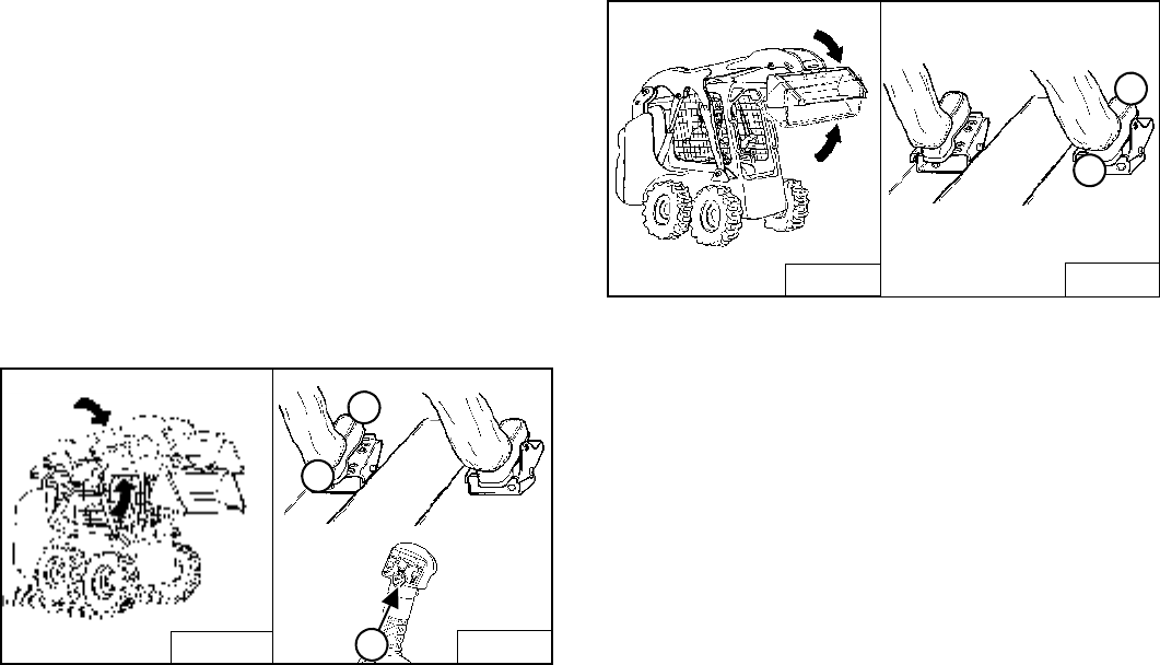
Quick Couplers
WARNING
Diesel fuel or hydraulic fluid under pressure can
penetrate skin or eyes, causing serious injury or
death. Fluid leaks under pressure may not be visible.
Use a piece of cardboard or wood to find leaks. Do
not use your bare hand. Wear safety goggles. If fluid
enters skin or eyes, get immediate medical attention
from a physician familiar with this injury.
W-2072-0496
Figure 42
To Connect: Remove dirt or debris from the surface of
both the male and female couplers, and from the outside
diameter of the male coupler. Visually check the couplers
for corroding, cracking, damage or excessive wear. If any
of these conditions exist, the coupler(s) [Figure 42] must
be replaced.
Install the male coupler into the female coupler. Full
connection is made when the ball release sleeve slides
forward on the female coupler.
To Disconnect: Hold the male coupler. Retract the sleeve
on the female coupler until the couplers disconnect.
P-31831C
P-31847A
P-43614
S205 Skid-Steer Loader
23 Operation & Maintenance Manual
HYDRAULIC CONTROLS (CONT’D)
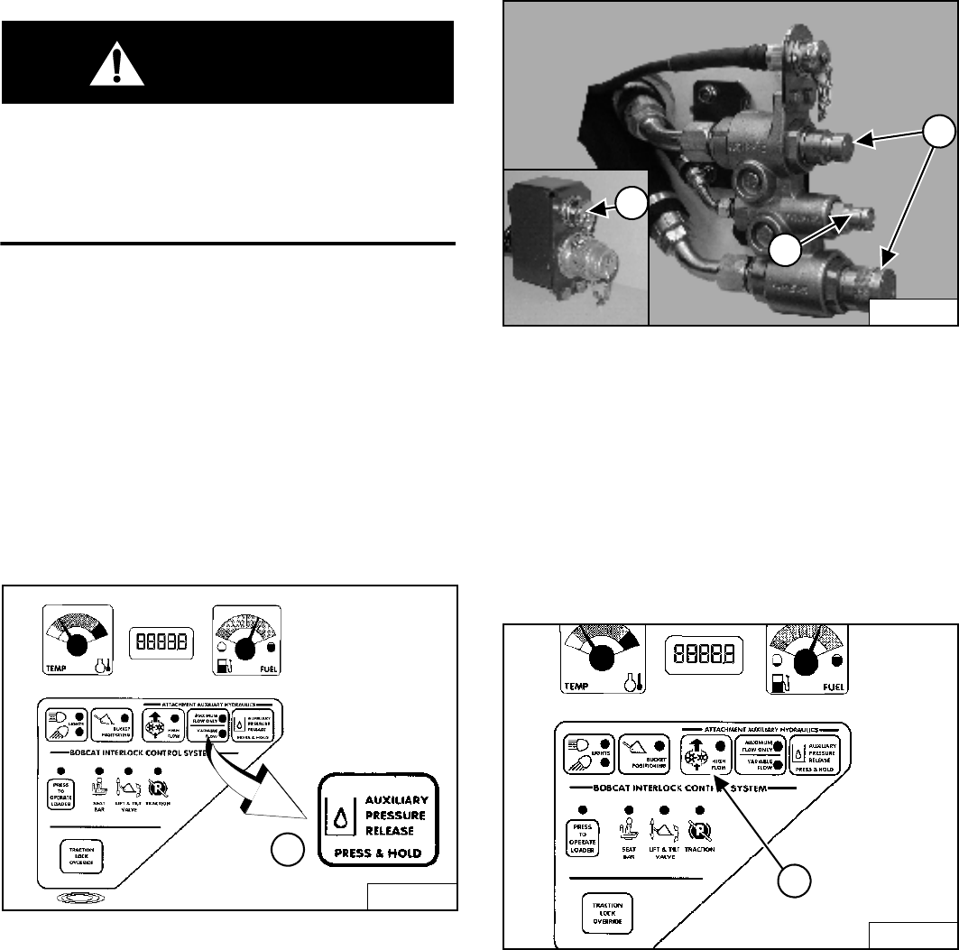
Relieve Hydraulic Pressure (Loader and Attachment)
WARNING
AVOID BURNS
Hydraulic fluid, tubes, fittings and quick couplers can
get hot when running machine and attachments. Be
careful when connecting and disconnecting quick
couplers.
W-2220-0396
Front Auxiliary Quick Couplers
When Connecting: Push the quick couplers tightly
together and hold for five seconds; the pressure is
automatically released as the couplers are installed.
When Disconnecting: Push the quick couplers tightly
together and hold for five seconds; then retract the sleeve
until the couplers disconnect.
Rear Auxiliary Quick Couplers
Figure 43
Press the AUXILIARY PRESSURE RELEASE Button (1)
[Figure 43]. Hold it for two seconds after the engine
comes to a complete stop. The pressure will be released.
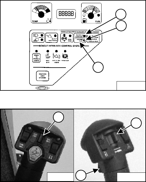
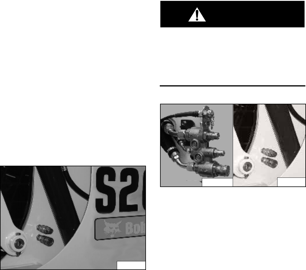
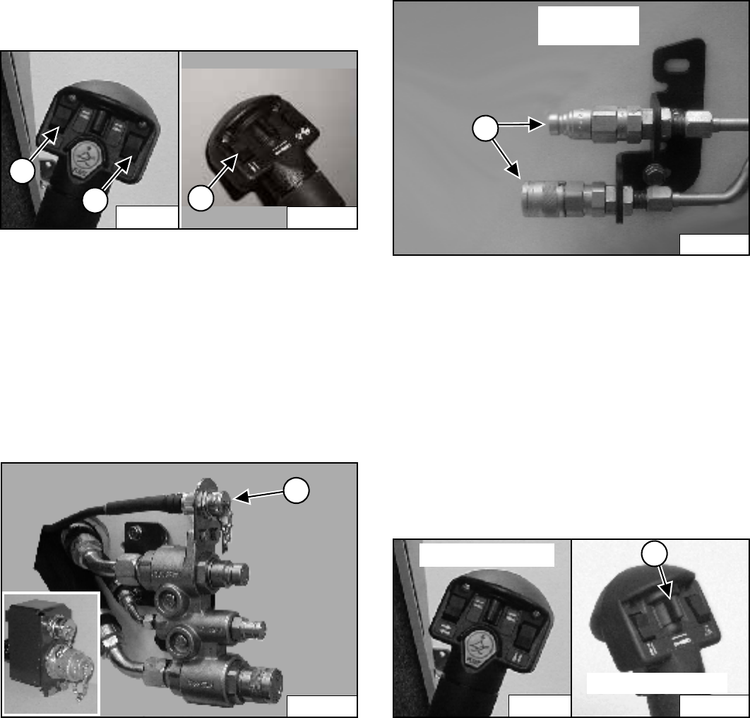
High-Flow Hydraulics Operation (If Equipped)
Figure 44
The High-Flow function provides additional flow to the
system to operate an attachment which requires more
hydraulic flow (EXAMPLE: Planer).
Connect the attachment to the quick couplers (1)
[Figure 44].
Some attachments may have a case drain which needs
to be connected to the small quick coupler (2)
[Figure 44].
Figure 45
Press the HIGH FLOW button (1) [Figure 45].
Press a second time to disengage.
B-15551
1
P-43614
P-19820
3
1
2
B-15551
1
S205 Skid-Steer Loader
Operation & Maintenance Manual 24
HYDRAULIC CONTROLS (CONT’D)
High-Flow Hydraulics Operation (If Equipped)
(Cont’d)
Figure 46
You can use additional switches (1, 2, and 3) [Figure 46]
on the right and left control handles for functions which
control some attachments.
See the appropriate Attachment Operation &
Maintenance Manual for control details.
Attachment Control Device (ACD) (If Equipped)
Figure 47
You will need the Dual-Connector (7-pin / 14-pin) kit (1)
[Figure 47] to operate early model attachments. See
your Bobcat Loader dealer.
Secondary Front Auxiliary Hydraulics (If Equipped)
Figure 48
The secondary front auxiliary quick couplers (1)
[Figure 48] are available as Field Installed Accessory.
These are used when there is a need for additional
auxiliary hydraulics (EXAMPLE: Planer side shift).
Connect the attachment to the secondary auxiliary
hydraulics (1) [Figure 48].
Set the Auxiliary Hydraulic Button for Variable Flow or
Maximum Flow Only. (See Auxiliary Hydraulics Operation
(VARIABLE FLOW) on Page 21) (See also Auxiliary
Hydraulics Operation (MAXIMUM FLOW ONLY) on
Page 21).
Figure 49
Push switch (1) [Figure 49] to the right or left to change
fluid flow direction. (EXAMPLE: Side shift on the Planer.)
NOTE: The secondary front auxiliary hydraulics and
the rear auxiliary hydraulics operate from the
same auxiliary section of the control valve. To
operate only one of these auxiliary functions,
disconnect the other.
P-13254
3
P-16537
1
2
P-43614
1
P-19820
P16291A
1
SECONDARY
COUPLERS
P-31833
1
Right Steering Lever
P-16537
Left Steering Lever
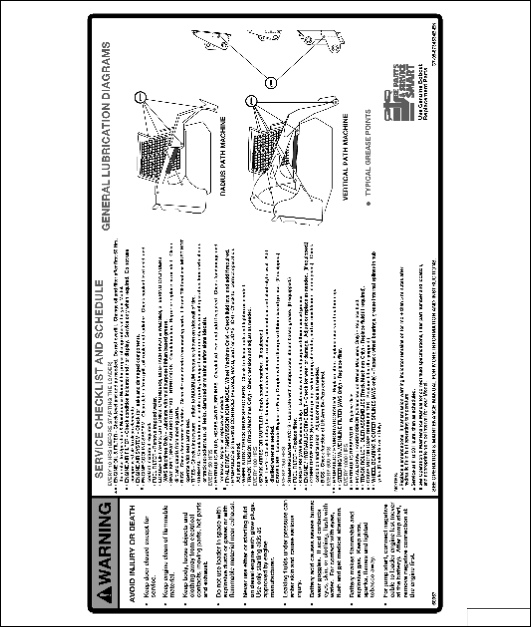
S205 Skid-Steer Loader
25 Operation & Maintenance Manual
DAILY INSPECTION
Figure 50
6734534B-V

S205 Skid-Steer Loader
Operation & Maintenance Manual 26
DAILY INSPECTION (CONT’D)
Daily Inspection and Maintenance
Maintenance work must be done at regular intervals.
Failure to do so will result in excessive wear and early
failures. The Service Schedule [Figure 50] is a guide for
correct maintenance of the Bobcat Loader. It is located
inside the rear door of the loader.
• Engine Oil Level
• Hydraulic / Hydrostatic Fluid Level
• Engine Air Filter, Check Air System for Damage or
Leaks
• Engine Coolant Level, Check System for Damage or
Leaks
• Operator Cab and Cab Mounting Hardware
• Seat Belt
• Seat Bar and Control Interlocks
• Grease Pivot Pins (Lift Arms, Bob-Tach, Cylinders,
Bob-Tach Wedges)
• Tires, Check for Wear, Damage, Correct Air Pressure
• Fuel Filter, Remove Trapped Water
• Loose or Broken Parts, Repair or replace as
necessary
• Safety Treads and Safety Signs (Decals), Replace as
necessary
• Lift Arm Support Device. Replace if damaged
• Bobcat Interlock Control System (BICS)
WARNING
Operator must have instructions before operating the
machine. Untrained operators can cause injury or
death.
W-2001-0502
NOTE: Fluids such as engine oil, hydraulic fluid,
coolant, etc. must be disposed of in an
environmentally safe manner. Some
regulations require that certain spills and
leaks on the ground must be cleaned in a
specific manner. See local, state and federal
regulations for correct disposal.
IMPORTANT
PRESSURE WASHING DECALS
• Never direct the stream at a low angle toward the
decal that could damage the decal causing it to
peel from the surface.
• Direct the stream at a 90 degree angle and at
least 300 mm from the decal. Wash from the
center of the decal toward the edges.
I-2226-0104
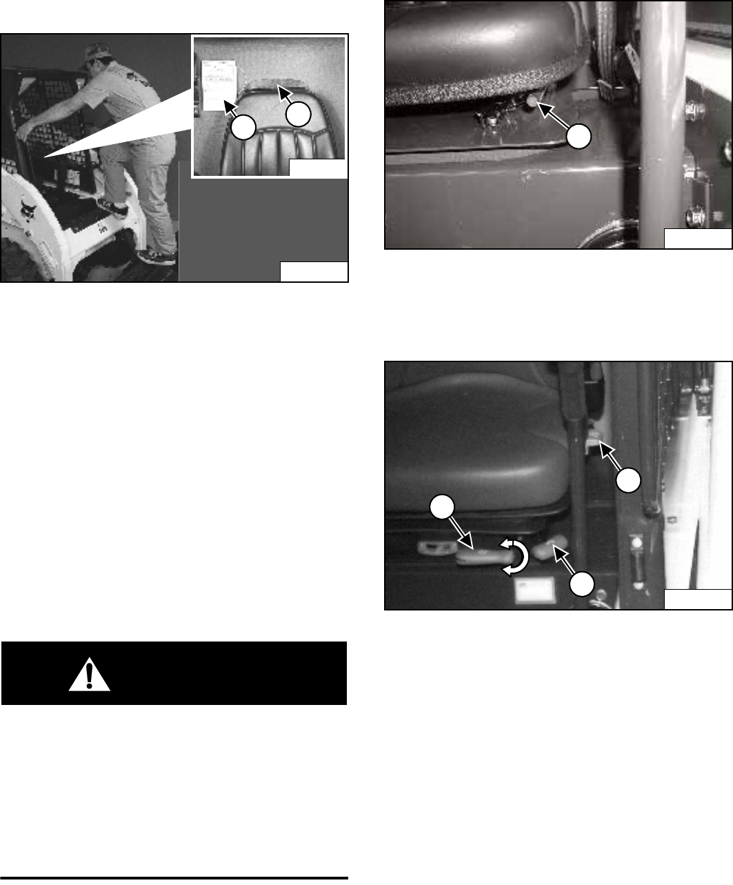
S205 Skid-Steer Loader
27 Operation & Maintenance Manual
PRE-STARTING PROCEDURE
Entering The Loader
Figure 51
Use the bucket or attachment steps, grab handles and
safety treads (on top of the loader lift arms and frame) to
get on and off the loader [Figure 51]. Do not jump.
Safety treads are installed on the Bobcat Loader to
provide a slip resistant surface for getting on and off the
loader.
Keep safety treads clean and replace when damaged.
Replacement treads are available from your Bobcat
Loader dealer.
Read and understand the Operation & Maintenance
Manual and the Operator's Handbook (1) [Figure 51]
before operating the loader.
The Operation & Maintenance Manual and other manuals
can be kept in a container (2) [Figure 51] provided
behind the operator seat.
WARNING
Instructions are necessary before operating or
servicing machine. Read and understand the
Operation & Maintenance Manual, Operator’s
Handbook and signs (decals) on machine. Follow
warnings and instructions in the manuals when
making repairs, adjustments or servicing. Check for
correct function after adjustments, repairs or
service. Untrained operators and failure to follow
instructions can cause injury or death.
W-2003-0903
Seat Adjustment
Figure 52
Release the seat lever (1) [Figure 52] and adjust the
seat position for comfortable operation of the loader
controls.
Figure 53
Suspension Seat - (Option) Release the lever (1)
[Figure 53] to adjust the seat distance from the steering
levers and foot pedals (if equipped).
Release the lever (2) [Figure 53] to adjust the angle of
the seat back.
Turn the lever (3) [Figure 53] to adjust the seat cushion
for weight of the operator.
N-20299
2
1
N-18529A
2
N-20299
1
P-31865
1
P-16052
1
2
3
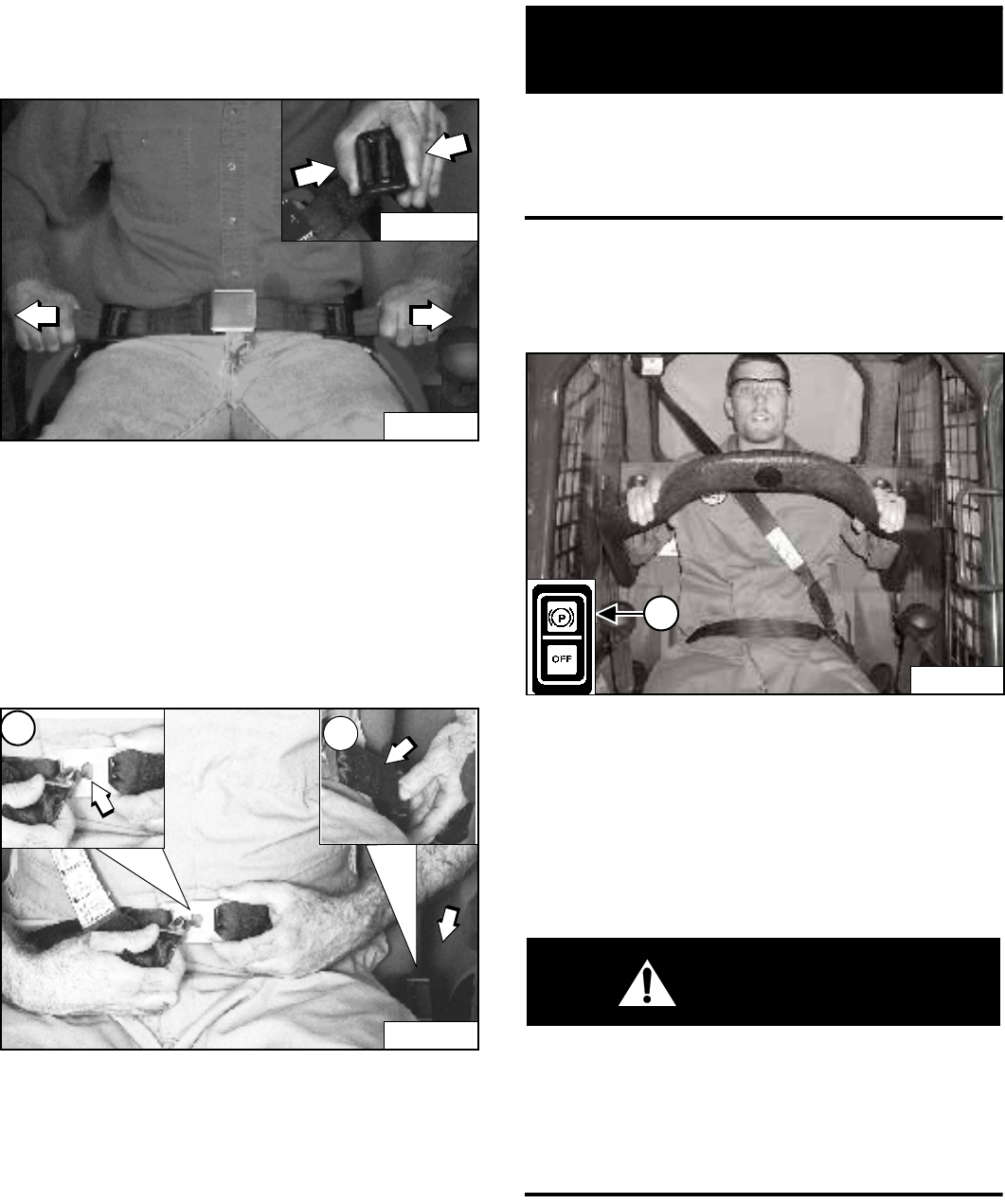
S205 Skid-Steer Loader
Operation & Maintenance Manual 28
PRE-STARTING PROCEDURE (CONT’D)
Seat Belt Adjustment
Figure 54
Squeeze both seat belt adjusters to release and lengthen
each half of the seat belt [Figure 54].
Fasten the seat belt.
Pull the ends of the belt through the belt adjusters so that
the seat belt is snug and the buckle is centered between
your hips [Figure 54].
Figure 55
3-Point Restraint - (Option) Connect the shoulder belt to
the lap belt (1) [Figure 55]. Pull the lap belt across to the
left side of the seat (2) [Figure 55] and fasten.
The shoulder belt must be positioned over your right
shoulder and the lap belt must be snug over your lower
hips [Figure 55].
IMPORTANT
Check the seat belt and shoulder belt retractors for
correct operation.
Keep retractors clean and replace as necessary.
I-2199-0200
Seat Bar
Figure 56
Lower the seat bar and engage the parking brake (1)
[Figure 56].
Put the foot pedals or hand controls in neutral position.
NOTE: Keep your hands on the steering levers and
your feet on the foot pedals (or footrests)
while operating the loader.
WARNING
AVOID INJURY OR DEATH
When operating the machine:
• Keep the seat belt fastened snugly.
• The seat bar must be lowered.
• Keep your feet on the pedal controls or footrests
and hands on steering levers.
W-2261-0799
P-16038
P-16041
N-21773
N-21774A
2
N-21773A
1
P-45114
1
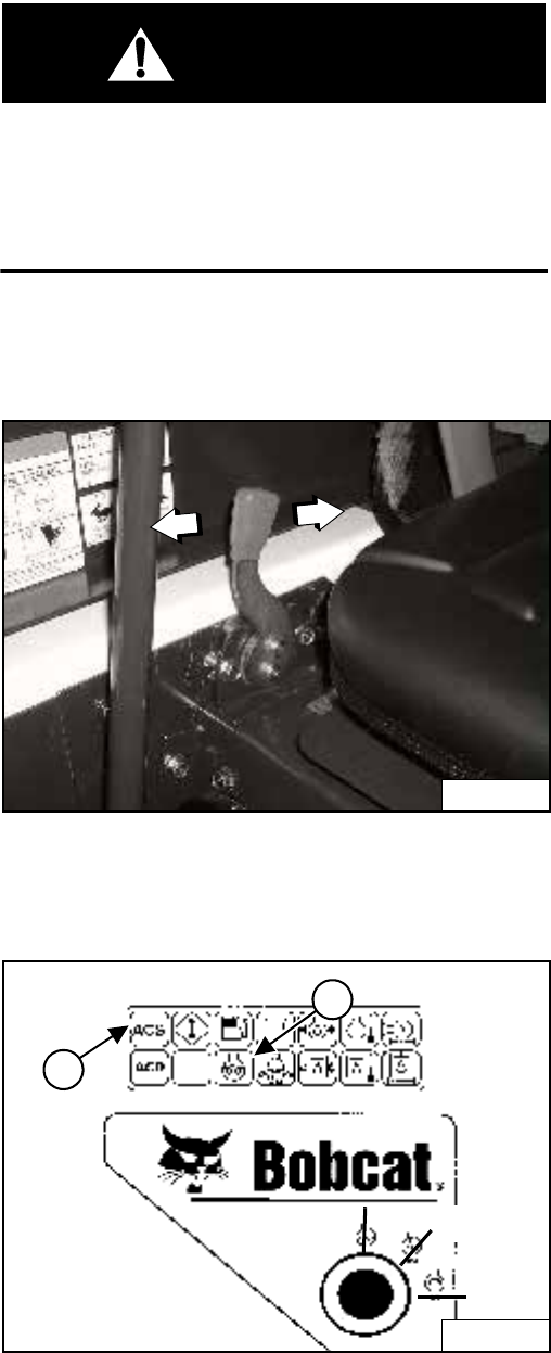
S205 Skid-Steer Loader
29 Operation & Maintenance Manual
STARTING THE ENGINE
Key Switch
WARNING
AVOID INJURY OR DEATH
• Engines can have hot parts and hot exhaust gas.
Keep flammable material away.
• Do not use machines in atmosphere containing
explosive gas.
W-2051-1086
Perform the PRE-STARTING PROCEDURE. (See PRE-
STARTING PROCEDURE on Page 27.)
Figure 57
Set the engine speed control to the 1/2 speed position
[Figure 57].
Figure 58
Turn the key switch to RUN [Figure 58]. The indicator
lights on the right instrument panel [Figure 58] will come
ON briefly and the Instrument Panel / monitoring system
will do a self test.
If the temperature is cold, the glow plugs will
automatically cycle. The Icon light (1) [Figure 58] will be
ON and the cycle time remaining will show in the
hourmeter.
When the Icon light goes OFF, turn the key switch to
START [Figure 58]. Release the key when the engine
starts. It will return to the RUN position.
NOTE: Make sure both hand controls (ACS) or
Joysticks (SJC) are in the neutral position
before starting the engine. Do not move the
levers or joysticks from the neutral position
when turning the key to RUN or START
[Figure 58].
If controls are moved:
a. The neutral position for the hydraulic valve
spool and hand control may not be correctly
calibrated. This can result in slight movement of
the lift or tilt hydraulic cylinders when the hand
control lever is returned to the neutral position
after start-up.
OR
b. ACS indicator light (2) [Figure 58] on right
instrument panel will be ON.
If either condition occurs, return key to STOP. Put
the controls in neutral position and re-start
engine.
P-31864
B-15552B
1
2
START
STOP RUN
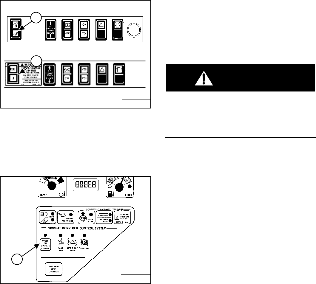
S205 Skid-Steer Loader
Operation & Maintenance Manual 30
STARTING THE ENGINE (CONT’D)
Key Switch (Cont’d)
Figure 59
(ACS) Select hand control or foot pedal operation (1)
[Figure 59].
OR
(SJC) Select ‘ISO’ or ‘H’ Control Pattern (2) [Figure 59].
Figure 60
Press the PRESS TO OPERATE LOADER Button (1)
[Figure 60] to activate the BICS system and to perform
hydraulic and loader functions. (See Cold Temperature
Starting on Page 32.)
NOTE: (SJC) The pending mode will flash which will
indicate PRESS TO OPERATE LOADER is
required. The light will flash when key is ON
and continue to flash until the PRESS TO
OPERATE LOADER button is pressed and
thereafter it will light solid. If the mode
(ISO / H) is changed while driving, the active
mode will be solid and the pending mode will
flash. When operation of the machine is
returned to neutral, the active mode will then
turn off and the pending mode will continue to
flash until the PRESS TO OPERATE LOADER
button is pressed.
WARNING
When an engine is running in an enclosed area, fresh
air must be added to avoid concentration of exhaust
fumes. If the engine is stationary, vent the exhaust
outside. Exhaust fumes contain odorless, invisible
gases which can kill without warning.
W-2050-1285
B-15993C
SJC
2
B-15993H
FRONT ACCESSORY PANEL
ACS
1
B-15551
1
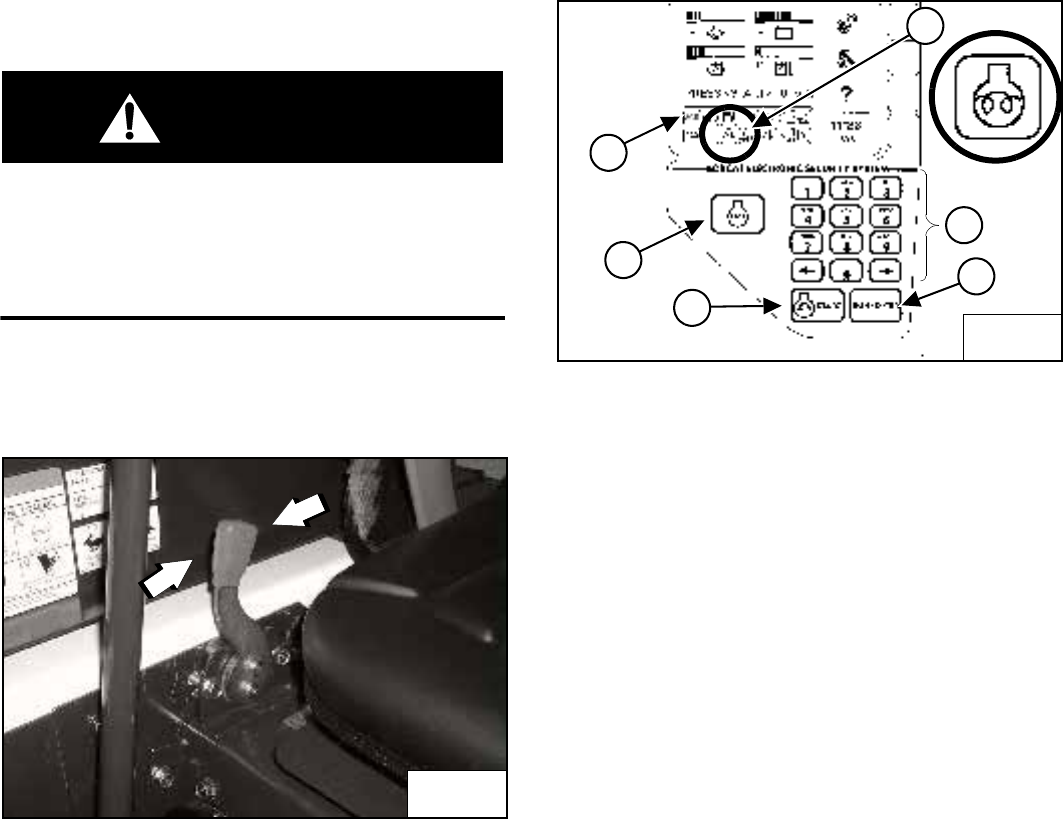
S205 Skid-Steer Loader
31 Operation & Maintenance Manual
STARTING THE ENGINE (CONT’D)
Keyless
WARNING
AVOID INJURY OR DEATH
• Engines can have hot parts and hot exhaust gas.
Keep flammable material away.
• Do not use machines in atmosphere containing
explosive gas.
W-2051-1086
Perform the PRE-STARTING PROCEDURE. (See PRE-
STARTING PROCEDURE on Page 27.)
Figure 61
Set the engine speed control to the 1/2 speed position
[Figure 61].
NOTE: Loaders with Keyless Instrument Panel have a
permanent, randomly generated Master
Password set at the factory. Your loader will
be assigned an Owner Password. Your dealer
will provide you with this password. Change
the password to one that you will easily
remember to prevent unauthorized use of
your loader. (See Passwords on Page 112.)
Keep your password in a safe place for future
needs.
Figure 62
Use the numeric keypad (1) [Figure 62] to enter the
password, then press the RUN / ENTER Button (2)
[Figure 62].
If the temperature is cold, the glow plugs will
automatically cycle and the Icon light (3) [Figure 62] will
be ON.
When the Icon light goes OFF, press the START
Button (4) [Figure 62]. Release the button when the
engine starts.
NOTE: Make sure both hand controls (ACS) or
Joysticks (SJC) are in the neutral position
before starting the engine. Do not move the
levers or joysticks from the neutral position
when attempting to start the engine.
If either hand control is moved:
a. The neutral position for the hydraulic valve
spool and hand control may not be correctly
calibrated. This can result in movement of the lift
or tilt hydraulic cylinders when the hand control
lever is returned to the neutral position after start-
up.
OR
b. ACS indicator light (5) [Figure 62] on right
instrument panel will be ON.
If either condition occurs, press the STOP
button (6) [Figure 62]. Put the controls in neutral
position and re-start the engine.
P-31864
B-15553B
B-22153
1
2
4
6
5
3
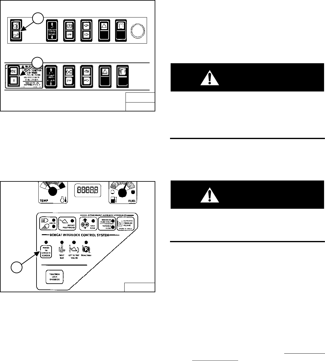
S205 Skid-Steer Loader
Operation & Maintenance Manual 32
STARTING THE ENGINE (CONT’D)
Keyless (Cont’d)
Figure 63
(ACS) Select hand control or foot pedal operation (1)
[Figure 63].
OR
(SJC) Select ‘ISO’ or ‘H’ Control Pattern (2) [Figure 63].
Figure 64
Press the PRESS TO OPERATE LOADER Button (1)
[Figure 64] to activate the BICS system and to perform
hydraulic and loader functions. (See Cold Temperature
Starting on Page 32.)
NOTE: (SJC) The pending mode will flash which will
indicate PRESS TO OPERATE LOADER is
required. The light will flash when key is ON
and continue to flash until the PRESS TO
OPERATE LOADER button is pressed and
thereafter it will light solid. If the mode
(ISO / H) is changed while driving, the active
mode will be solid and the pending mode will
flash. When operation of the machine is
returned to neutral, the active mode will then
turn off and the pending mode will continue to
flash until the PRESS TO OPERATE LOADER
button is pressed.
WARNING
When an engine is running in an enclosed area, fresh
air must be added to avoid concentration of exhaust
fumes. If the engine is stationary, vent the exhaust
outside. Exhaust fumes contain odorless, invisible
gases which can kill without warning.
W-2050-1285
Cold Temperature Starting
WARNING
Do not use ether with glow plug (preheat) systems.
Explosion can result which can cause injury, death,
or severe engine damage.
W-2071-0903
If the temperature is below freezing, perform the following
to make starting the engine easier:
• Replace the engine oil with the correct type and
viscosity for the anticipated starting temperature.
• Make sure the battery is fully charged.
• Install an engine heater, available from your Bobcat
Loader dealer.
NOTE: The LCD of the Keyless Panel may not be
immediately visible when the temperature is
below -26°C (-15°F). It may take 30 seconds to
several minutes for the Display Panel to warm
up. All systems remain monitored even when
the display is off.
B-15993C
SJC
2
B-15993H
FRONT ACCESSORY PANEL
ACS
1
B-15551
1
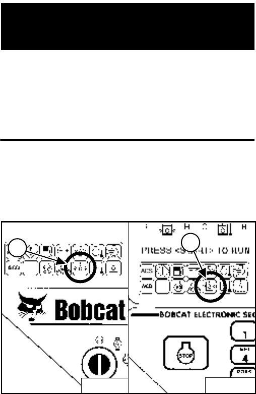
S205 Skid-Steer Loader
33 Operation & Maintenance Manual
STARTING THE ENGINE (CONT’D)
Warming The Hydraulic / Hydrostatic System
IMPORTANT
When the temperature is below -30°C (-20°F),
hydrostatic oil must be warmed before starting. The
hydrostatic system will not get enough oil at low
temperatures and will be damaged. Park the machine
in an area where the temperature will be above -18°C
(0°F) if possible.
I-2007-1285
Let the engine run for a minimum of 5 minutes to warm
the engine and hydrostatic transmission fluid before
operating the loader.
Figure 65
If the Fluid Pressure Icon light (1) [Figure 65] (Key
Switch Panel) or (2) [Figure 65] (Keyless Panel) comes
ON when operating the loader (cold), more warm up time
is needed.
B-15553B
1
B-15552B
2
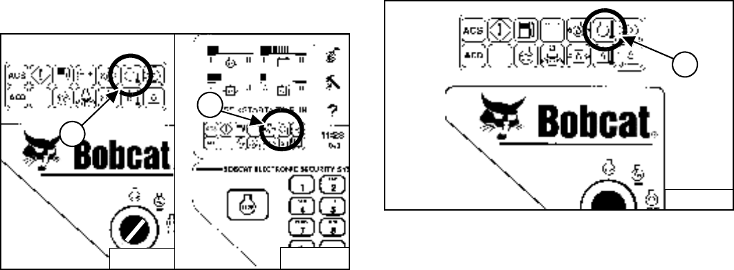
S205 Skid-Steer Loader
Operation & Maintenance Manual 34
MONITORING THE DISPLAY PANELS
Left Panel
Figure 66
Frequently monitor the temperature and fuel gauges and
BICS lights (all must be ON to operate loader)
[Figure 66].
Right Panel (Key Switch)
Figure 67
After the engine is running, frequently monitor the right
instrument panel [Figure 67] for error conditions.
The associated icon will be ON if there is an error
condition.
EXAMPLE: Engine Coolant Temperature is High
The Engine Temperature Icon (1) [Figure 67] will be ON.
Press and hold LIGHTS Button for 2 seconds. One of the
following SERVICE CODES will be displayed.
•08-10 Engine Coolant Temperature High
•08-11 Engine Coolant Temperature Extremely High
Find the cause of the error code and correct before
operating the loader again.
B-15553B
1
B-15552B
2
1
B-15553B
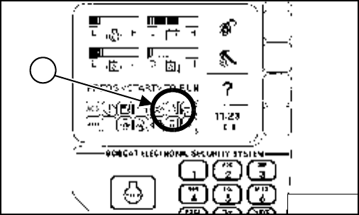
S205 Skid-Steer Loader
35 Operation & Maintenance Manual
MONITORING THE DISPLAY PANELS (CONT’D)
Right Panel (Keyless)
Figure 68
After the engine is running, frequently monitor the right
instrument panel [Figure 68] for error conditions.
The associated icon will be ON if there is an error
condition.
EXAMPLE: Engine Coolant Temperature is High
The Engine Temperature Icon (1) [Figure 68] will be ON.
Press and hold LIGHTS Button for 2 seconds. One of the
following SERVICE CODES will be displayed.
•08-10 Engine Coolant Temperature High
•08-11 Engine Coolant Temperature Extremely High
In addition, the Keyless Panel display screen will describe
the extreme condition that can cause damage to the
engine or loader systems [Figure 68].
Find the cause of the error code and correct before
operating the loader again.
Warning And Shutdown
When a WARNING condition exists, the associated Icon
light will come ON and there will be 3 beeps from the
alarm. Be aware that, if this condition is allowed to
continue, there may be damage to the engine or loader
hydraulic systems.
When a SHUTDOWN condition exists, the associated
Icon light will come ON and there will be a continuous
beep from the alarm and the monitoring system will
automatically stop the engine in 10 seconds. The engine
can be restarted to move or relocate the loader.
The SHUTDOWN feature is associated with the following
Icons:
General Warning
Engine Oil Pressure
Engine Coolant Temperature
Hydraulic Oil Temperature
Hydrostatic Charge Pressure
Whenever STOP appears on the display screen, lower
the lift arms all the way, put the attachment flat on the
ground and stop the engine to prevent damage to the
engine or loader systems.
B-15553B
1
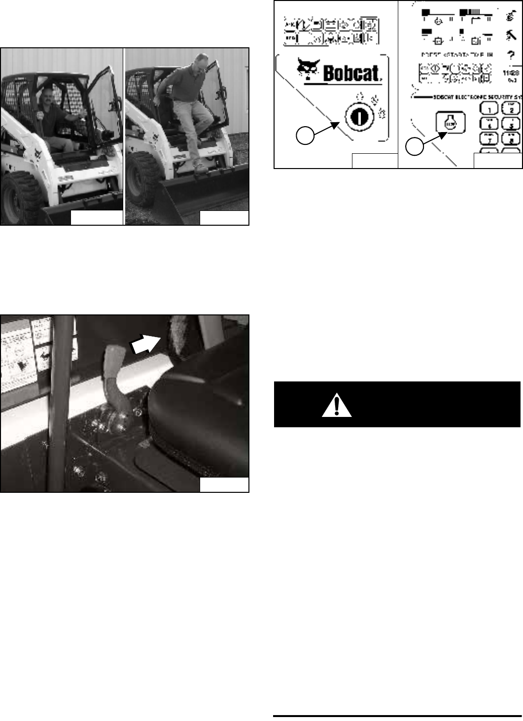
S205 Skid-Steer Loader
Operation & Maintenance Manual 36
STOPPING THE ENGINE AND LEAVING THE LOADER
Procedure
Figure 69
Stop the Bobcat Loader on level ground.
Lower the lift arms fully and put the attachment flat on the
ground [Figure 69].
Figure 70
Pull the engine speed control fully backward [Figure 70]
to decrease the engine speed.
Figure 71
Engage the parking brake.
Turn the key switch to the STOP position (1) [Figure 71]
(Key Switch) or press the STOP Button (2) [Figure 71]
(Keyless).
Lift the seat bar and make sure the lift and tilt functions
are deactivated.
Unbuckle the seat belt.
Remove the key from the switch (Key Switch) to prevent
operation of the loader by unauthorized personnel.
Exit the loader using grab handles, safety tread and steps
(maintaining a 3-point contact) [Figure 69].
WARNING
Before you leave the operator’s seat:
• Lower the lift arms, put the attachment flat on the
ground.
• Stop the engine.
• Engage the parking brake.
• Raise seat bar.
• (Foot Pedal Controls) Move pedals until both
lock.
• (Advanced Control system - ACS) Move the
hydraulic controls to the NEUTRAL POSITION to
make sure that both lift and tilt functions are
deactivated.
The seat bar system must deactivate the lift and
tilt control functions when the seat bar is up.
Service the system if hand controls do not
deactivate.
• (Selectable Joystick Controls - SJC) Move the
joysticks to the NEUTRAL POSITION to make
sure that travel and hydraulic functions are
deactivated.
The seat bar system must deactivate these
functions when the seat bar is up. Service the
system if controls do not deactivate.
W-2463-0603
P-66660
P-66659
P-31864
B-15553B
B-15552
1
2
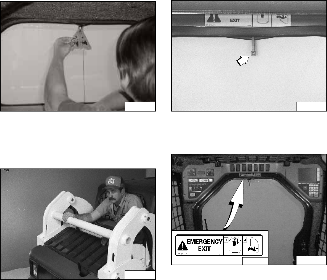
S205 Skid-Steer Loader
37 Operation & Maintenance Manual
STOPPING THE ENGINE AND LEAVING THE LOADER
(CONT’D)
Emergency Exit
The front opening on the operator cab and rear window
provide exits.
Rear Window (If Equipped)
Figure 72
Pull on the tag on the top of the rear window to remove
the rubber cord [Figure 72].
Push the rear window out of the rear of the operator cab.
Figure 73
Exit through the rear of the operator cab [Figure 73].
Front Door (If Equipped)
NOTE: When an Operator Cab Enclosure Kit is
installed, the window of the front door can be
used as an emergency exit [Figure 74].
NOTE: If the loader has a Special Application Door
Kit installed, the window of the front door is
NOT an emergency exit.
Figure 74
Pull the plastic loop at the top of the window in the front
door to remove the rubber cord [Figure 74].
Figure 75
Push the window out with your foot [Figure 75] at any
corner of the window.
Exit through the front door.
P-64994
N-18495
N-20171
P-24472
X
XX
X
6707852
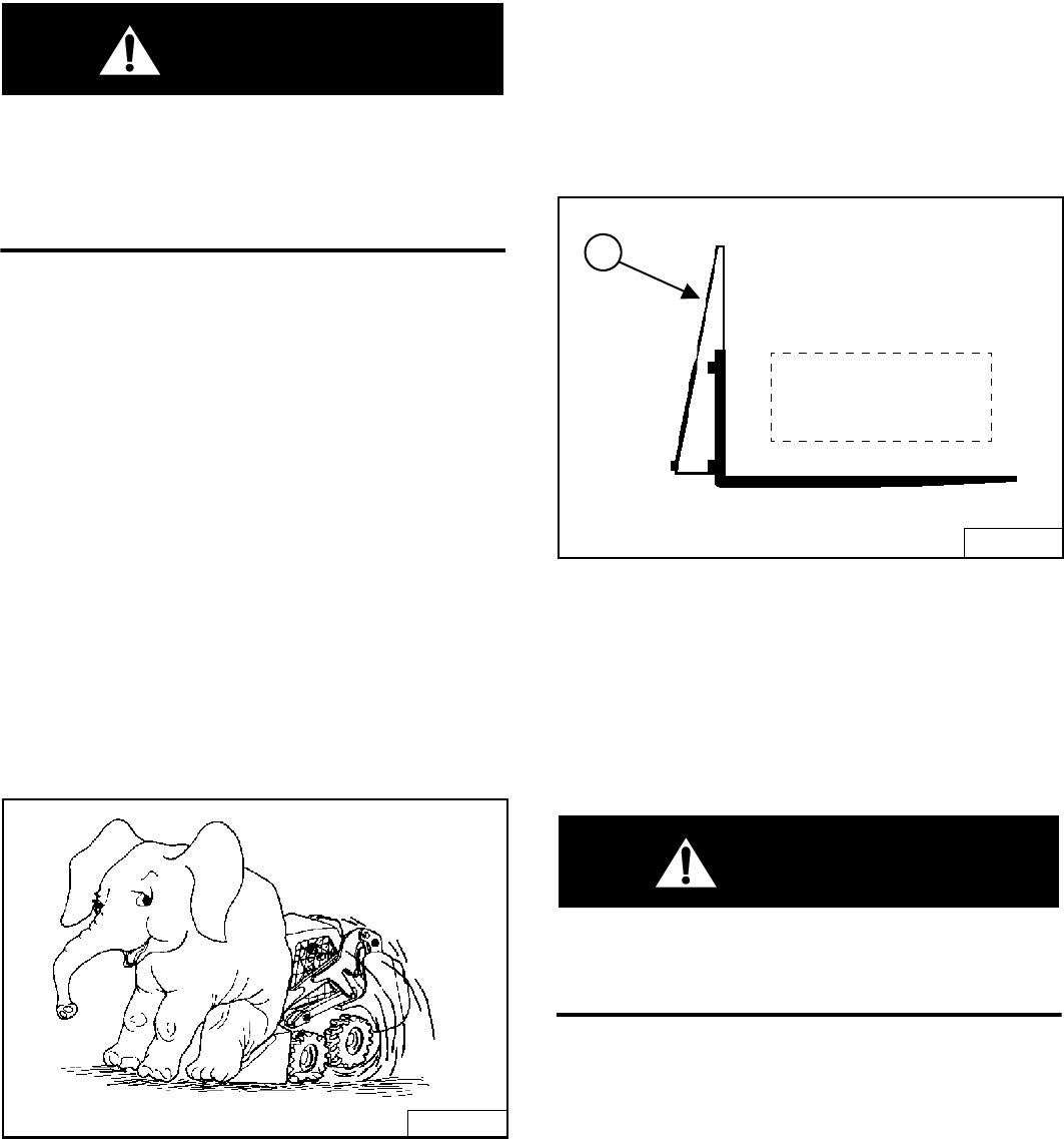
S205 Skid-Steer Loader
Operation & Maintenance Manual 38
ATTACHMENTS
Choosing The Correct Bucket
WARNING
Never use attachments or buckets which are not
approved by Bobcat Company. Buckets and
attachments for safe loads of specified densities are
approved for each model. Unapproved attachments
can cause injury or death.
W-2052-0500
NOTE: Warranty is void if non-approved attachments
are used on the Bobcat Loader.
The dealer can identify, for each model loader, the
attachments and buckets approved by Bobcat. The
buckets and attachments are approved for Rated
Operating Capacity and for secure fastening to the
Bob-Tach.
The Rated Operating Capacity for this loader is shown on
a decal in the operator cab. (See Fluid Capacities on
Page 122.)
The Rated Operating Capacity is determined by using a
standard dirt bucket, and material of normal density, such
as dirt or dry gravel. If longer buckets are used, the load
center moves forward and reduces the ROC. If very
dense material is loaded, the volume must be reduced to
prevent overloading.
Figure 76
Exceeding the Rated Operating Capacity [Figure 76] can
cause the following problems:
• Steering the loader may be difficult.
• Tracks will wear faster.
• There will be a loss of stability.
• The life of the Bobcat Loader will be reduced.
Use the correct size bucket for the type and density of
material being handled. For safe handling of materials
and avoiding machine damage, the attachment (or
bucket) should handle a full load without going over the
Rated Operating Capacity for the loader. Partial loads
make steering more difficult.
Pallet Forks
Figure 77
The maximum load to be carried when using a pallet fork
is shown on a decal located on the pallet fork frame (1)
[Figure 77].
See your Bobcat dealer for more information about pallet
fork inspection, maintenance and replacement. See your
Bobcat Loader dealer for Rated Operating Capacity when
using a pallet fork and for other available attachments.
WARNING
AVOID INJURY OR DEATH
Do not exceed Rated Operating Capacity. Excessive
load can cause tipping or loss of control.
W-2053-0903
B-15527
WRONG
B-17255
1
Load varies with
model of pallet fork
being used.
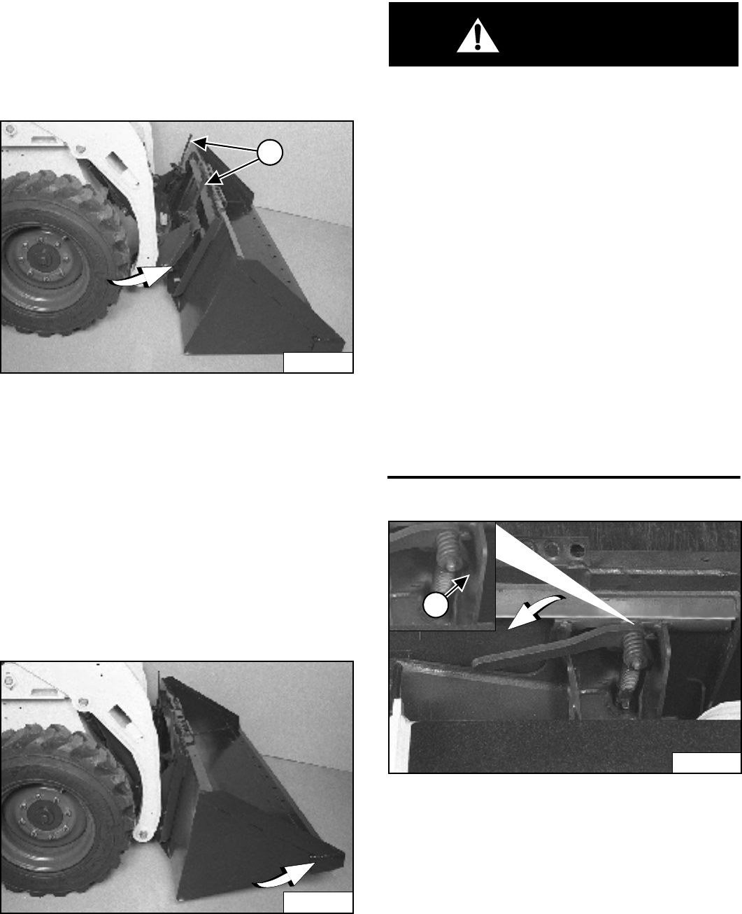
S205 Skid-Steer Loader
39 Operation & Maintenance Manual
ATTACHMENTS (CONT’D)
Installing And Removing The Attachment (Hand
Lever Bob-Tach)
The Bob-Tach is used for fast changing of buckets and
attachments. See the appropriate Attachment Operation
& Maintenance Manual to install other attachments.
Figure 78
Installing
Pull the Bob-Tach levers all the way up (1) [Figure 78].
Enter the loader and perform the PRE-STARTING
PROCEDURE. (See PRE-STARTING PROCEDURE on
Page 27.)
Lower the lift arms and tilt the Bob-Tach forward.
Drive the loader forward until the top edge of the
Bob-Tach is completely under the top flange of the bucket
[Figure 78] (or other attachment). Be sure the Bob-Tach
levers do not hit the bucket.
Figure 79
Tilt the Bob-Tach backward until the cutting edge of the
bucket (or other attachment) is slightly off the ground
[Figure 79].
Stop the engine and exit the loader.
WARNING
Before you leave the operator’s seat:
• Lower the lift arms, put the attachment flat on the
ground.
• Stop the engine.
• Engage the parking brake.
• Raise seat bar.
• (Foot Pedal Controls) Move pedals until both
lock.
• (Advanced Control system - ACS) Move the
hydraulic controls to the NEUTRAL POSITION to
make sure that both lift and tilt functions are
deactivated.
The seat bar system must deactivate the lift and
tilt control functions when the seat bar is up.
Service the system if hand controls do not
deactivate.
• (Selectable Joystick Controls - SJC) Move the
joysticks to the NEUTRAL POSITION to make
sure that travel and hydraulic functions are
deactivated.
The seat bar system must deactivate these
functions when the seat bar is up. Service the
system if controls do not deactivate.
W-2463-0603
Figure 80
Push down on the Bob-Tach levers until they are fully
engaged in the locked position (1) [Figure 80] (wedges
fully extended).
N-18515
1
N-18516
N-17058
1
P-17058A
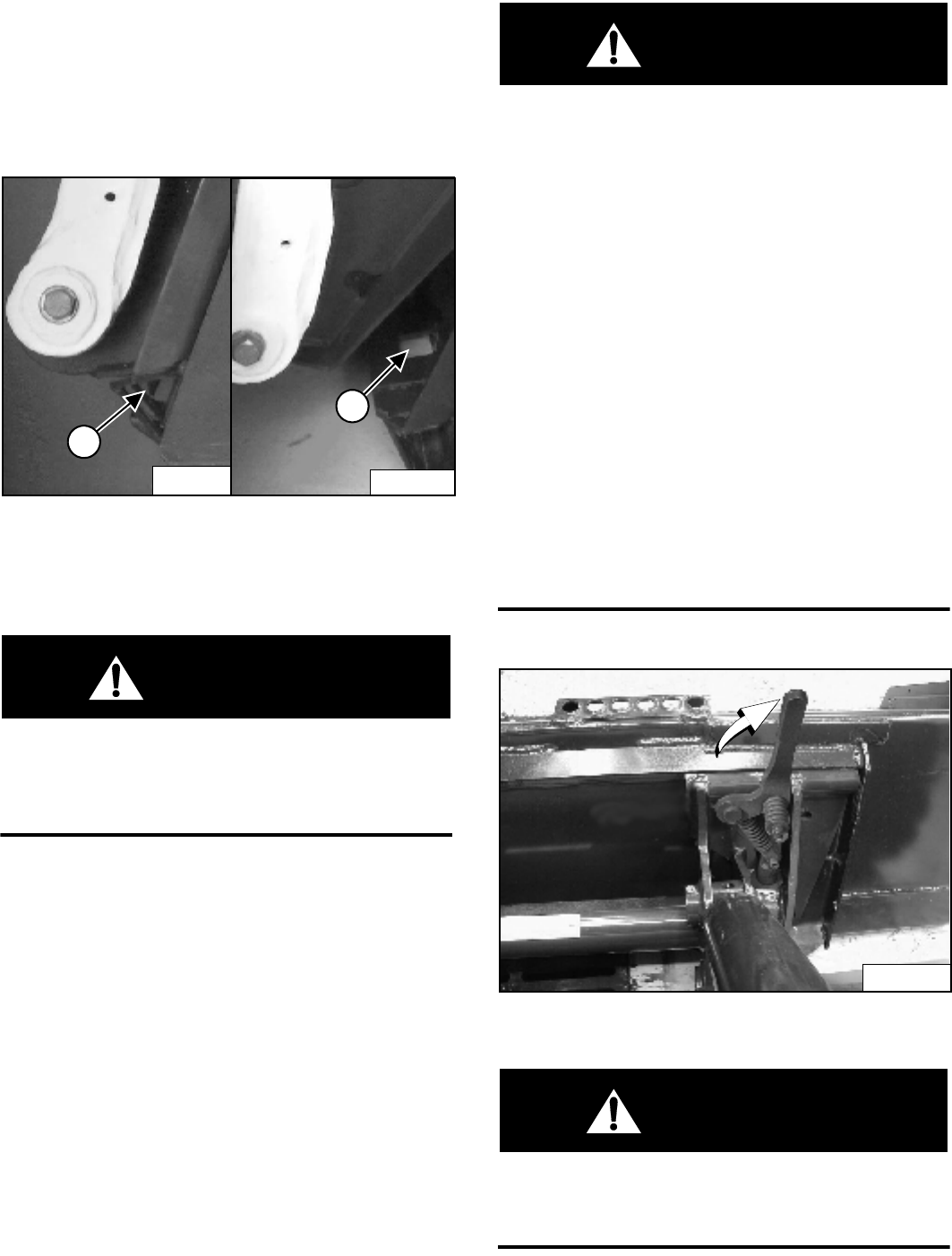
S205 Skid-Steer Loader
Operation & Maintenance Manual 40
ATTACHMENTS (CONT’D)
Installing And Removing The Attachment (Hand
Lever Bob-Tach) (Cont’d)
Installing (Cont’d)
Figure 81
The wedges (1) [Figure 81] must extend through the
holes (2) [Figure 81] in the mounting frame of the bucket
(or attachment), securely fastening the bucket to the
Bob-Tach.
WARNING
Bob-Tach wedges must extend through the holes in
attachment. Levers must be fully down and locked.
Failure to secure wedges can allow attachment to
come off and cause injury or death.
W-2102-0588
Removing
Lower the lift arms and put the attachment flat on the
ground and lower or close the hydraulic equipment.
• If the attachment is hydraulically controlled
(combination bucket, backhoe, etc.), stop the engine
and relieve hydraulic pressure at the quick couplers.
(See Relieve Hydraulic Pressure (Loader and
Attachment) on Page 23.)
Raise the seat bar, unfasten the seat belt, set the parking
brake and exit the loader.
WARNING
Before you leave the operator’s seat:
• Lower the lift arms, put the attachment flat on the
ground.
• Stop the engine.
• Engage the parking brake.
• Raise seat bar.
• (Foot Pedal Controls) Move pedals until both
lock.
• (Advanced Control system - ACS) Move the
hydraulic controls to the NEUTRAL POSITION to
make sure that both lift and tilt functions are
deactivated.
The seat bar system must deactivate the lift and
tilt control functions when the seat bar is up.
Service the system if hand controls do not
deactivate.
• (Selectable Joystick Controls - SJC) Move the
joysticks to the NEUTRAL POSITION to make
sure that travel and hydraulic functions are
deactivated.
The seat bar system must deactivate these
functions when the seat bar is up. Service the
system if controls do not deactivate.
W-2463-0603
Figure 82
Pull the Bob-Tach levers [Figure 82] all the way up.
WARNING
Bob-Tach levers have spring tension. Hold lever
tightly and release slowly. Failure to obey warning
can cause injury.
W-2054-1285
N-16043A
1
N-16044A
2
P-31693A
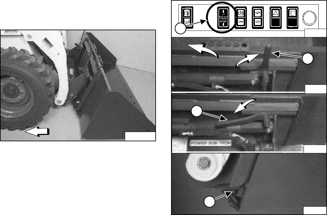
S205 Skid-Steer Loader
41 Operation & Maintenance Manual
ATTACHMENTS (CONT’D)
Installing And Removing The Attachment (Hand
Lever Bob-Tach) (Cont’d)
Removing (Cont’d)
Enter the loader.
Perform the PRE-STARTING PROCEDURE on Page 27.
Start the engine.
Release the parking brake.
Be sure the lift arms are all the way down. Tilt the
Bob-Tach forward.
Figure 83
Move the loader backward, away from the bucket or
attachment [Figure 83].
Installing And Removing The Attachment (Power
Bob-Tach Option)
Installing
The Bob-Tach is used for fast changing of buckets and
attachments. See the appropriate Attachment Operation
& Maintenance Manual to install other attachments.
Perform the PRE-STARTING PROCEDURE. (See PRE-
STARTING PROCEDURE on Page 27.)
Lower the lift arms and tilt the Bob-Tach forward.
Figure 84
Push and hold BOB-TACH “WEDGES UP” switch (Front
Accessory Panel) (1) [Figure 84] until levers are in
unlocked position (2) [Figure 84] (wedges fully raised).
N-18515
2
P-16045
N-
16043AP-
4
P-16043A
B-15993
1
3
P-16046
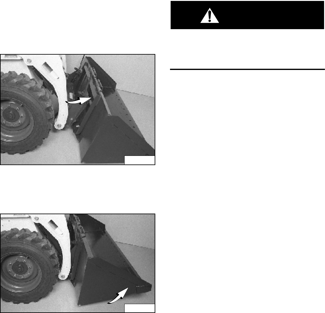
S205 Skid-Steer Loader
Operation & Maintenance Manual 42
ATTACHMENTS (CONT’D)
Installing And Removing The Attachment (Power
Bob-Tach Option) (Cont’d)
Installing (Cont’d)
Figure 85
Drive the loader forward until the top edge of the
Bob-Tach is completely under the top flange of the bucket
[Figure 85] (or other attachment).
Figure 86
Tilt the Bob-Tach backward until the cutting edge of the
bucket (or other attachment) is slightly off the ground
[Figure 86].
Push and hold BOB-TACH “WEDGES DOWN” switch
(Front Accessory Panel) (1) [Figure 84] until levers are
fully engaged in the locked position (3) [Figure 84]
(wedges fully extended).
The wedges (4) [Figure 84] must extend through the
holes in the mounting frame of the bucket (or
attachment), securely fastening the bucket to the
Bob-Tach.
WARNING
Bob-Tach wedges must extend through the holes in
attachment. Levers must be fully down and locked.
Failure to secure wedges can allow attachment to
come off and cause injury or death.
W-2102-0588
NOTE: The Power Bob-Tach system has continuous
pressurized hydraulic oil to keep the wedges
in the engaged position and prevent
attachment disengagement. Because the
wedges can slowly lower, the operator may
need to reactivate the switch (WEDGES UP)
before installing an attachment to be sure
both wedges are fully raised before installing
the attachment.
N-18515
N-18516
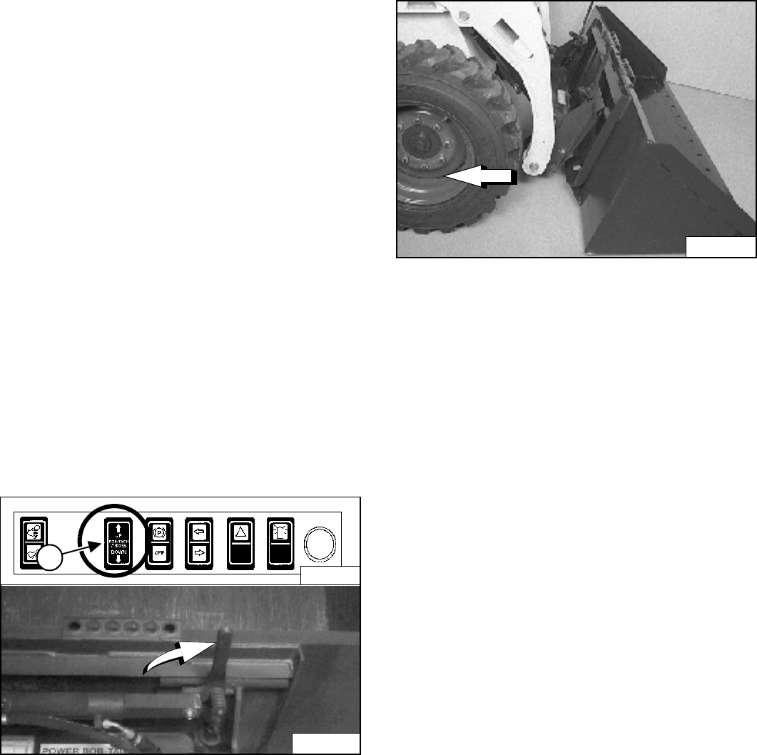
S205 Skid-Steer Loader
43 Operation & Maintenance Manual
ATTACHMENTS (CONT’D)
Installing And Removing The Attachment (Power
Bob-Tach Option) (Cont’d)
Removing
Lower the lift arms and put the attachment flat on the
ground and lower or close the hydraulic equipment.
• If the attachment is hydraulically controlled
(combination bucket, backhoe, etc.):
Stop the engine and relieve hydraulic pressure in the
auxiliary circuit. (See Relieve Hydraulic Pressure
(Loader and Attachment) on Page 23.)
Exit the loader and disconnect the hydraulic hoses
from the attachment.
Enter the loader.
Perform the PRE-STARTING PROCEDURE. (See
PRE-STARTING PROCEDURE on Page 27.)
Start the engine.
Release the parking brake.
Figure 87
Push and hold the BOB-TACH “WEDGES UP” Switch
(Front Accessory Panel) (1) [Figure 87] until the wedges
are fully raised.
Tilt the Bob-Tach forward.
Figure 88
Move the loader backward, away from the bucket or
attachment [Figure 88].
NOTE: The Power Bob-Tach system has continuous
pressurized hydraulic oil to keep the wedges
in the engaged position and prevent
attachment disengagement. Because the
wedges can slowly lower, the operator may
need to reactivate the switch (WEDGES UP)
before installing an attachment to be sure
both wedges are fully raised before installing
the attachment.
P-16045
1
B-15993
N-18515
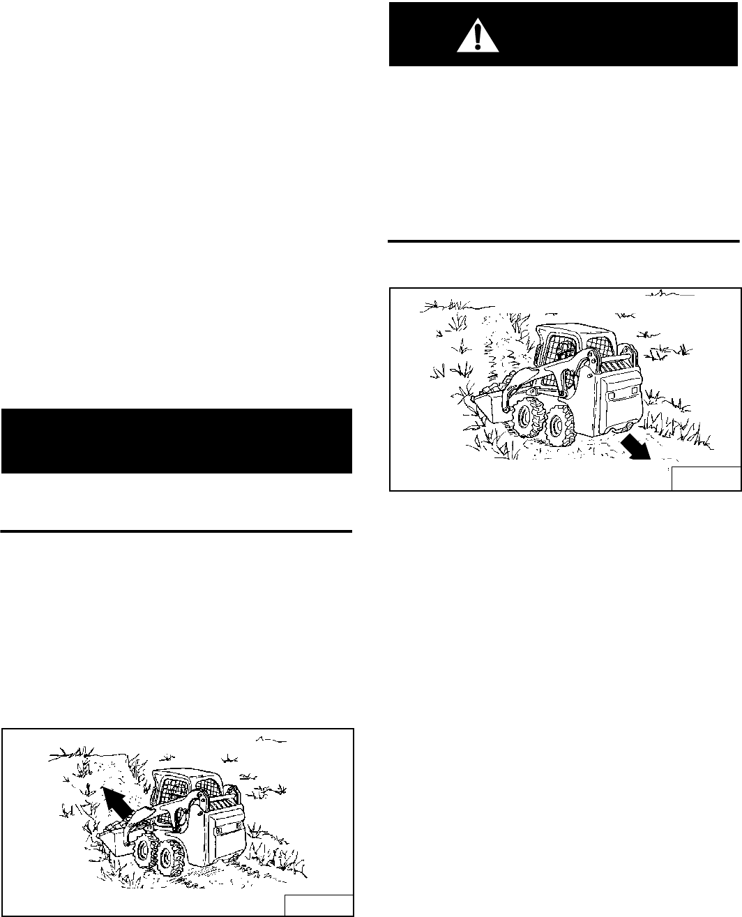
S205 Skid-Steer Loader
Operation & Maintenance Manual 44
OPERATING PROCEDURE
Inspect The Work Area
Before beginning operation, inspect the work area for
unsafe conditions.
Look for sharp drop-offs or rough terrain. Have
underground utility lines (gas, water, sewer, irrigation,
etc.) located and marked.
Remove objects or other construction material that could
damage the loader or cause personal injury.
Operating With A Full Bucket
When operating on a public road or highway, always
follow local regulations. For example: Slow Moving
Vehicle Sign or direction signals may be required.
Always warm the engine and hydrostatic system before
operating the loader.
IMPORTANT
Machines warmed up with moderate engine speed
and light load have longer life.
I-2015-0284
Operate the loader with the engine at full speed for
maximum horsepower. Move the steering levers only a
small amount to operate the loader slowly.
New operators must operate the loader in an open area
without bystanders. Operate the controls until the loader
can be handled at an efficient and safe rate for all
conditions of the work area.
Figure 89
WARNING
AVOID INJURY OR DEATH
• Keep the lift arms as low as possible.
• Do not travel or turn with the lift arms up.
• Turn on level ground.
• Go up and down slopes, not across them.
• Keep the heavy end of the machine uphill.
• Do not overload the machine.
Failure to obey warnings can cause the machine to
tip or roll over and cause injury or death.
W-2018-1187
Figure 90
With a full bucket, go up or down the slope with the heavy
end toward the top of the slope [Figure 89] and
[Figure 90].
B-15519
WITH BUCKET FULL
Going Up Slope
B-15548
WITH BUCKET FULL
Going Down Slope
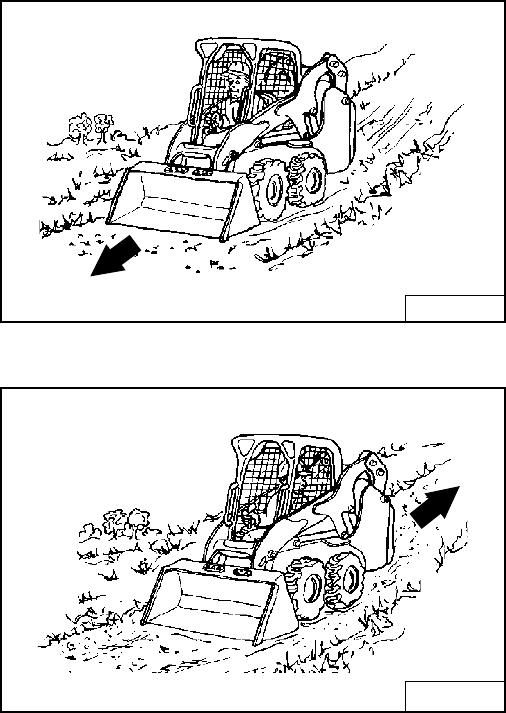
S205 Skid-Steer Loader
45 Operation & Maintenance Manual
OPERATING PROCEDURE (CONT’D)
Operating With An Empty Bucket
Figure 91
Figure 92
With empty bucket, go down or up the slope with the
heavy end toward the top of the slope [Figure 91] and
[Figure 92].
B-15540
WITH BUCKET EMPTY
Going Down Slope
B-15517
Going Up Slope
WITH BUCKET EMPTY
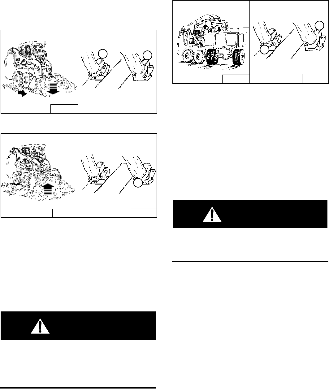
S205 Skid-Steer Loader
Operation & Maintenance Manual 46
OPERATING PROCEDURE (CONT’D)
Filling And Emptying The Bucket (Foot Pedals)
Filling
Figure 93
Figure 94
Lower the lift arms all the way (1) [Figure 93].
Tilt the bucket forward (2) [Figure 93] until the cutting
edge of the bucket is on the ground.
Drive slowly forward into the material. Tilt the bucket
backward (1) [Figure 94] all the way when the bucket is
full.
Drive backward away from the material.
WARNING
Load, unload and turn on flat level ground. Do not
exceed Rated Operating Capacity shown on sign
(decal) in cab. Failure to obey warnings can cause
the machine to tip or roll over and cause injury or
death.
W-2056-0903
Emptying
Figure 95
Keep the bucket low when moving to the area where you
want to empty the bucket.
Raise the lift arms (1) [Figure 95]. Level the bucket (2)
[Figure 95] while raising the lift arms to help prevent
material from falling off the back of the bucket.
Drive forward slowly until the bucket is over the top of the
truck box or bin.
Empty the bucket (2) [Figure 95]. If all the material is
near the side of the truck or bin, use the bucket tilt to
move it to the other side.
WARNING
Never dump over an obstruction, such as a post, that
can enter the operator cab. The machine could tip
forward and cause injury or death.
W-2057-0694
B-15520 B-15973
12
B-15521 B-15973
1
B-15534 B-15973
1
2
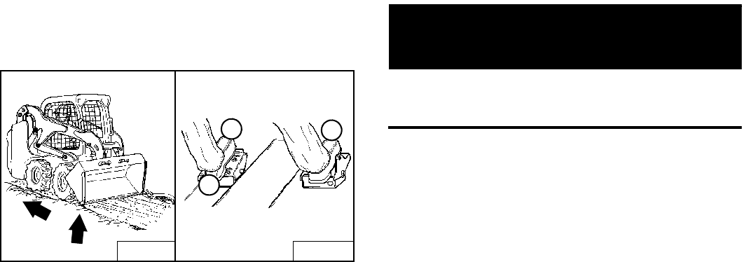
S205 Skid-Steer Loader
47 Operation & Maintenance Manual
OPERATING PROCEDURE (CONT’D)
Leveling The Ground Using Float (Foot Pedals)
Figure 96
Put the lift arms in float position by pushing the pedal all
the way forward (1) [Figure 96] until the pedal is locked
in the forward position.
Tilt the bucket forward (2) [Figure 96] to change the
position of the cutting edge of the bucket.
With the bucket tilted farther forward, there is more force
on the cutting edge and more loose material can be
moved.
Drive backward to level loose material.
Push the bottom of the lift pedal (3) [Figure 96] to unlock
the float position.
IMPORTANT
Never drive forward when the hydraulic control for lift
arms is in float position.
I-2005-1285
B-15522 B-15973
12
3
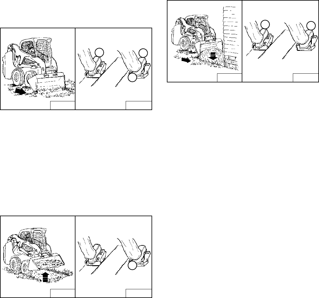
S205 Skid-Steer Loader
Operation & Maintenance Manual 48
OPERATING PROCEDURE (CONT’D)
Digging And Filling A Hole (Foot Pedals)
Digging
Figure 97
Lower the lift arms all the way (1) [Figure 97]. Put the
cutting edge of the bucket on the ground (2) [Figure 97].
Drive forward slowly and continue to tilt the bucket
down (2) [Figure 97] until it enters the ground.
Raise the cutting edge a small amount (3) [Figure 97] to
increase traction and keep an even digging depth.
Continue to drive forward until the bucket is full. When the
ground is hard, raise and lower the cutting edge of the
bucket (2 and 3) [Figure 97] while driving forward slowly.
Figure 98
Tilt the bucket backward (1) [Figure 98] as far as it will go
when the bucket is full.
Filling
Figure 99
Lower the lift arms (1) [Figure 99] and put the cutting
edge of the bucket on the ground (2) [Figure 99]. Drive
forward to the edge of the hole to push the material into
the hole.
Tilt the bucket forward (2) [Figure 99] as soon as it is
past the edge of the hole.
If necessary, raise the lift arms to empty the bucket.
B-15539 B-15973
1
3
2
B-15538 B-15973
1
B-15537 B-15973
2
1
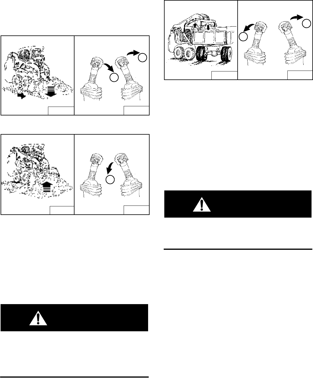
S205 Skid-Steer Loader
49 Operation & Maintenance Manual
OPERATING PROCEDURE (CONT’D)
Filling And Emptying The Bucket (ACS - Handles,
SJC - ‘H’ Pattern)
Filling
Figure 100
Figure 101
Lower the lift arms all the way (1) [Figure 100].
Tilt the bucket forward (2) [Figure 100] until the cutting
edge of the bucket is on the ground.
Drive slowly forward into the material. Tilt the bucket
backward (1) [Figure 101] all the way when the bucket is
full.
Drive backward away from the material.
WARNING
Load, unload and turn on flat level ground. Do not
exceed Rated Operating Capacity shown on sign
(decal) in cab. Failure to obey warnings can cause
the machine to tip or roll over and cause injury or
death.
W-2056-0903
Emptying
Figure 102
Keep the bucket low when moving to the area where you
want to empty the bucket.
Raise the lift arms (1) [Figure 102]. Level the bucket (2)
[Figure 102] while raising the lift arms to help prevent
material from falling off the back of the bucket.
Drive forward slowly until the bucket is over the top of the
truck box or bin.
Empty the bucket (2) [Figure 102]. If all material is near
the side of the truck or bin, use the bucket tilt to move it to
the other side.
WARNING
Never dump over an obstruction, such as a post, that
can enter the operator cab. The machine could tip
forward and cause injury or death.
W-2057-0694
B-15520 B-15781
1
2
B-15521 B-15781
1
B-15534 B-15781
1
2
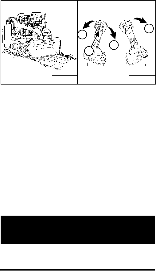
S205 Skid-Steer Loader
Operation & Maintenance Manual 50
OPERATING PROCEDURE (CONT’D)
Leveling The Ground Using Float (ACS - Handles,
SJC - ‘H’ Pattern)
Figure 103
Press and hold the float button (1) [Figure 103] while the
lever is in neutral. While lowering the lift arms (2)
[Figure 103], release the float button.
Tilt the bucket forward (3) [Figure 103] to change the
position of the cutting edge of the bucket.
With the bucket tilted farther forward, there is more force
on the cutting edge and more loose material can be
moved.
Drive backward to level loose material.
To disengage float, press the float button (1) again or
raise the lift arms (4) [Figure 103].
IMPORTANT
Never drive forward when the hydraulic control for lift
arms is in float position.
I-2005-1285
B-15522 B-15781
1
1
2
3
4
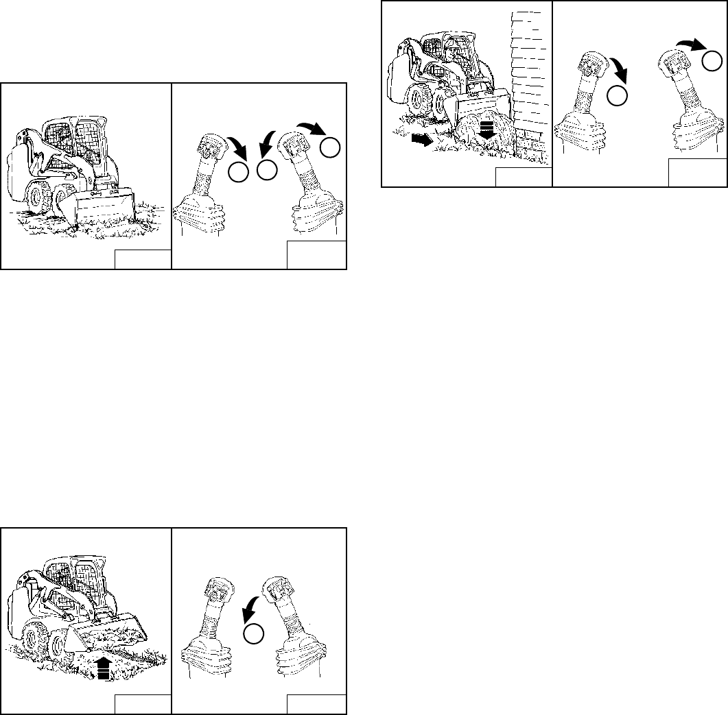
S205 Skid-Steer Loader
51 Operation & Maintenance Manual
OPERATING PROCEDURE (CONT’D)
Digging And Filling A Hole (ACS - Handles, SJC -
‘H’ Pattern)
Digging
Figure 104
Lower the lift arms all the way (1) [Figure 104]. Tilt the
bucket forward (2) [Figure 104] until the cutting edge of
the bucket is on the ground.
Drive forward slowly and continue to tilt the bucket
down (2) [Figure 104] until it enters the ground.
Tilt the bucket backward a small amount (3) [Figure 104]
to increase traction and keep an even digging depth.
Continue to drive forward until the bucket is full. When the
ground is hard, raise and lower the cutting edge (1 and 2)
[Figure 104] while driving forward.
Figure 105
Tilt the bucket backward (1) [Figure 105] as far as it will
go when the bucket is full.
Filling
Figure 106
Lower the lift arms (1) [Figure 106] and put the cutting
edge of the bucket on the ground (2) [Figure 106]. Drive
forward to the edge of the hole to push the material into
the hole.
Tilt the bucket forward (2) [Figure 106] as soon as it is
past the edge of the hole.
If necessary, raise the lift arms to empty the bucket.
B-15539 B-15781A
B-15781B
3
2
1
B-15538
1
B-15781
B-15537
1
2
B-15781A
B-15781B
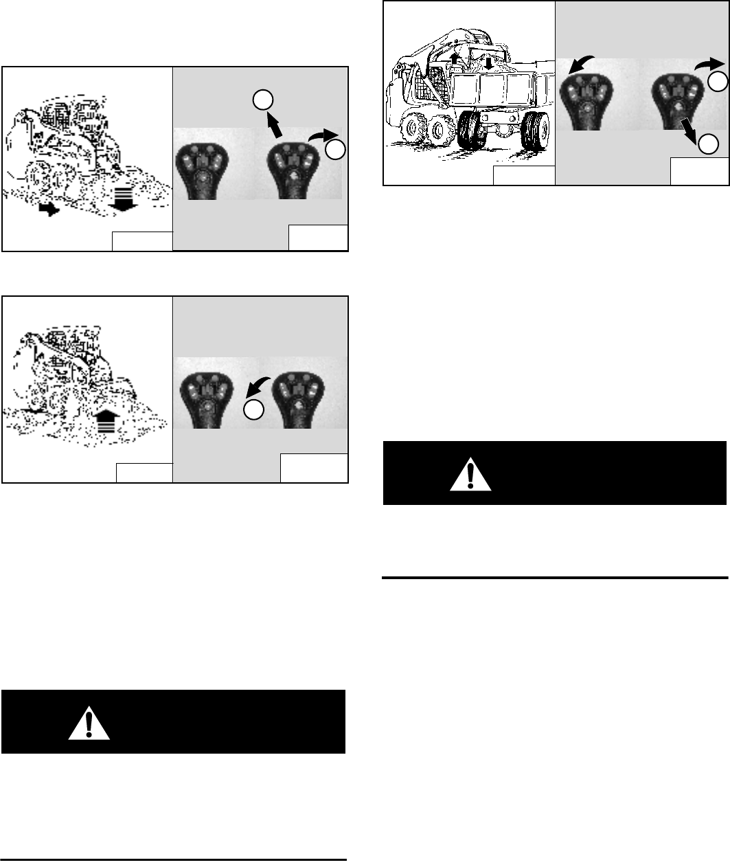
S205 Skid-Steer Loader
Operation & Maintenance Manual 52
OPERATING PROCEDURE (CONT’D)
Filling And Emptying The Bucket (SJC - ‘ISO’ Pattern)
Filling
Figure 107
Figure 108
Lower the lift arms all the way (1) [Figure 107].
Tilt the bucket forward (2) [Figure 107] until the cutting
edge of the bucket is on the ground.
Drive slowly forward into the material. Tilt the bucket
backward (1) [Figure 108] all the way when the bucket is
full.
Drive backward away from the material.
WARNING
Load, unload and turn on flat level ground. Do not
exceed Rated Operating Capacity shown on sign
(decal) in cab. Failure to obey warnings can cause
the machine to tip or roll over and cause injury or
death.
W-2056-0903
Emptying
Figure 109
Keep the bucket low when moving to the area where you
want to empty the bucket.
Raise the lift arms (1) [Figure 109]. Level the bucket (2)
[Figure 109] while raising the lift arms to help prevent
material from falling off the back of the bucket.
Drive forward slowly until the bucket is over the top of the
truck box or bin.
Empty the bucket (2) [Figure 109]. If all material is near
the side of the truck or bin, use the bucket tilt to move it to
the other side.
WARNING
Never dump over an obstruction, such as a post, that
can enter the operator cab. The machine could tip
forward and cause injury or death.
W-2057-0694
B-15520 P-24820
P-24802
1
2
B-15521
1
P-24820
P-24802
B-15534
1
2
P-24820
P-24802
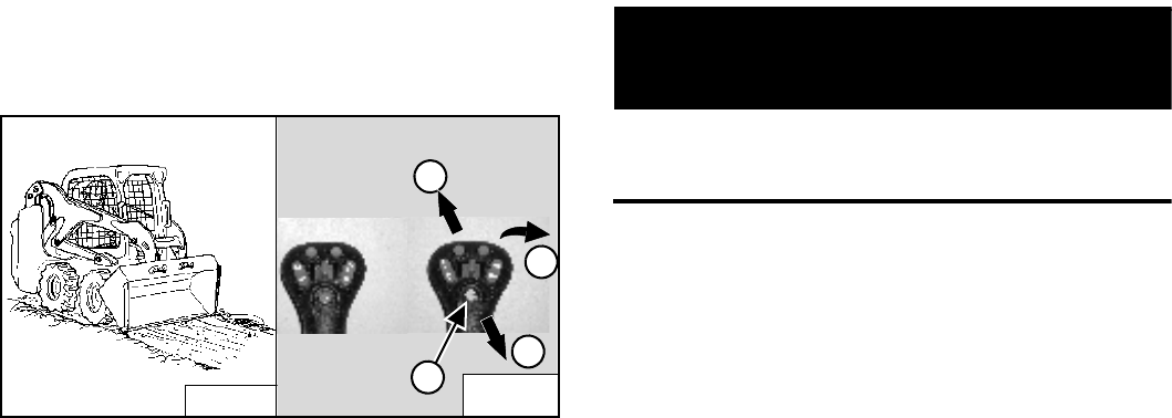
S205 Skid-Steer Loader
53 Operation & Maintenance Manual
OPERATING PROCEDURE (CONT’D)
Leveling The Ground Using Float (SJC - ‘ISO’ Pattern)
Figure 110
Press and hold the float button (1) [Figure 110] while the
joystick is in neutral. While lowering the lift arms (2)
[Figure 110], release the float button.
Tilt the bucket forward (3) [Figure 110] to change the
position of the cutting edge of the bucket.
With the bucket tilted farther forward, there is more force
on the cutting edge and more loose material can be
moved.
Drive backward to level loose material.
To disengage, press the float button again or raise the lift
arms (4) [Figure 110].
IMPORTANT
Never drive forward when the hydraulic control for lift
arms is in float position.
I-2005-1285
B-15522
2
1
3
4
P-24820
P-24802
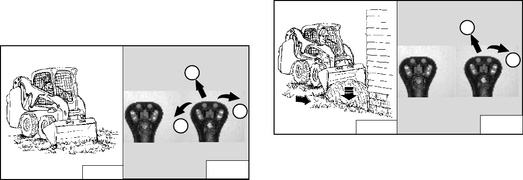
S205 Skid-Steer Loader
Operation & Maintenance Manual 54
OPERATING PROCEDURE (CONT’D)
Digging And Filling A Hole (SJC - ‘ISO’ Pattern)
Digging
Figure 111
Lower the lift arms all the way (1) [Figure 111]. Put the
cutting edge of the bucket on the ground (2)
[Figure 111].
Drive forward slowly and continue to tilt the bucket
down (2) [Figure 111] until it enters the ground.
Raise the cutting edge a small amount (3) [Figure 111]
to increase traction and keep an even digging depth.
Continue to drive forward until the bucket is full. When the
ground is hard, raise and lower the cutting edge (2 and 3)
[Figure 111] while driving forward.
Tilt the bucket backward (3) [Figure 111] as far as it will
go when the bucket is full.
Filling
Figure 112
Lower the lift arms (1) [Figure 112] and put the cutting
edge of the bucket on the ground (2) [Figure 112]. Drive
forward to the edge of the hole to push the material into
the hole.
Tilt the bucket forward (2) [Figure 112] as soon as it is
past the edge of the hole.
If necessary, raise the lift arms to empty the bucket.
B-15539 P-24820
P-24802
3
2
1
B-15537
2
P-24820
P-24802
1
S205 Skid-Steer Loader
55 Operation & Maintenance Manual
TOWING THE LOADER
Procedure
Because of the design of the loader, there is not a
recommended towing procedure.
• The loader can be lifted onto a transport vehicle.
• The loader can be skidded a short distance to move
for service (EXAMPLE: Move onto a transport
vehicle) without damage to the hydrostatic system.
(The tires / tracks will not turn.) There might be slight
wear to the tires / tracks when the loader is skidded.
The towing chain (or cable) must be rated at 1 &
1/2 times the weight of the loader. (See Machine
Rating on Page 120.)
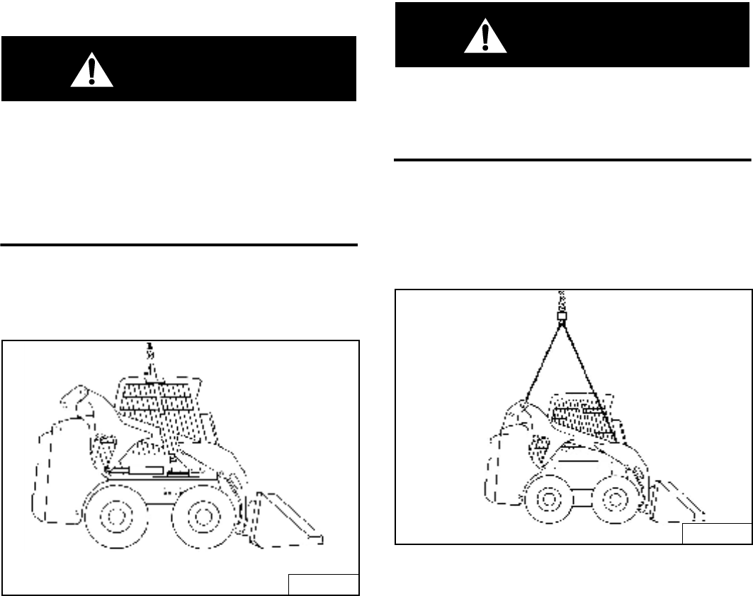
S205 Skid-Steer Loader
Operation & Maintenance Manual 56
LIFTING THE LOADER
Single Point Lift
WARNING
AVOID INJURY OR DEATH
• Before lifting, check fasteners on single point lift
and operator cab.
• Assemble front cab fasteners as shown in this
manual.
• Never allow riders in the cab or bystanders within
5 meters while lifting the machine.
W-2007-0497
The loader can be lifted with the Single Point Lift which is
available as a kit from your Bobcat Loader dealer.
Figure 113
Install the kit as explained in the Instructions with the kit
and attach lift as shown [Figure 113].
The Single Point Lift, supplied by Bobcat, is designed to
lift and support the Bobcat Loader without affecting roll
over and falling object protection features of the operator
cab.
Four Point Lift
WARNING
AVOID INJURY OR DEATH
• Before lifting, check fasteners on four point lift.
• Never allow riders in the cab or bystanders within
5 meters while lifting the machine.
W-2160-0694
The loader can be lifted with the Four Point Lift which is
available as a kit from your Bobcat Loader dealer. The
backhoe mounting kit must also be installed to provide lift
points at the front of the loader.
Figure 114
Attach cables or chains to lift eyes [Figure 114].
TS-1998B
TS-1998A
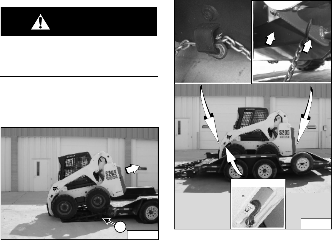
S205 Skid-Steer Loader
57 Operation & Maintenance Manual
TRANSPORTING THE LOADER ON A TRAILER
Loading And Unloading
WARNING
Adequately designed ramps of sufficient strength are
needed to support the weight of the machine when
loading onto a transport vehicle. Wood ramps can
break and cause personal injury.
W-2058-0494
Be sure the transport and towing vehicles are of
adequate size and capacity. (See Fluid Capacities on
Page 122.)
Figure 115
A loader with an empty bucket or no attachment must be
loaded backward onto the transport vehicle [Figure 115].
The rear of the trailer must be blocked or supported (1)
[Figure 115] when loading or unloading the loader to
prevent the front end of the trailer from raising up.
Fastening
Figure 116
Use the following procedure to fasten the Bobcat Loader
to the transport vehicle to prevent the loader from moving
during sudden stops or when going up or down slopes
[Figure 116].
• Lower the bucket or attachment to the floor.
• Stop the engine.
• Engage the parking brake.
• Install chains at the front and rear loader tie down
positions (Inset) [Figure 116].
• Fasten each end of the chain to the transport vehicle.
P-54213A
1
P-54214A
Alternate Front Tie Down
P-73276
N-19048A

S205 Skid-Steer Loader
Operation & Maintenance Manual 58

S205 Skid-Steer Loader
59 Operation & Maintenance Manual
PREVENTIVE MAINTENANCE
AIR CLEANER SERVICE..........................................................................77
Replacing Filter Elements ....................................................................77
AIR CONDITIONING BELT .......................................................................95
Belt Adjustment....................................................................................95
Belt Replacement.................................................................................95
ALTERNATOR BELT..................................................................................95
Belt Adjustment....................................................................................95
Belt Replacement.................................................................................95
BOB-TACH (HAND LEVER) ....................................................................100
Inspection And Maintenance..............................................................100
BOB-TACH (POWER - OPTION).............................................................101
Inspection And Maintenance..............................................................101
BOBCAT INTERLOCK CONTROL SYSTEM (BICS) ................................66
Inspecting Deactivation Of Lift And Tilt Functions (ACS and SJC) ......66
Inspecting Deactivation Of The Auxiliary Hydraulics System (Engine
STOPPED - Key ON) ...........................................................................66
Inspecting The BICS Controller (Engine STOPPED - Key ON) ...........66
Inspecting The Lift Arm By-Pass Control .............................................66
Inspecting The Seat Bar Sensor (Engine RUNNING)..........................66
Inspecting The Traction Lock (Engine RUNNING) ...............................66
DRIVE BELT..............................................................................................96
Belt Adjustment....................................................................................96
Belt Replacement.................................................................................96
ELECTRICAL SYSTEM ............................................................................84
Battery Maintenance ............................................................................85
Description ...........................................................................................84
Fuse And Relay Location / Identification..............................................84
Removing And Installing Battery..........................................................87
Using A Booster Battery (Jump Starting) .............................................85
ENGINE COOLING SYSTEM ...................................................................82
Checking Level.....................................................................................82
Cleaning...............................................................................................82
Removing And Replacing the Coolant .................................................83
ENGINE LUBRICATION SYSTEM ............................................................81
Checking And Adding Engine Oil.........................................................81
Engine Oil Chart...................................................................................81
Removing And Replacing Oil And Filter...............................................81
PREVENTIVE
MAINTENANCE
S205 Skid-Steer Loader
Operation & Maintenance Manual 60
FINAL DRIVE TRANSMISSION (CHAINCASE) ....................................... 94
Checking And Adding Oil..................................................................... 94
Removing Oil From The Chaincase..................................................... 94
FUEL SYSTEM ......................................................................................... 79
Filling the Fuel Tank............................................................................. 79
Fuel Filter............................................................................................. 80
Fuel Specifications .............................................................................. 79
Removing Air From The Fuel System.................................................. 80
HEATING AND AIR CONDITIONING ....................................................... 76
Air Conditioning Lubrication................................................................. 76
Cleaning and Maintenance.................................................................. 76
Evaporator ........................................................................................... 76
Filters................................................................................................... 76
Troubleshooting ................................................................................... 76
HYDRAULIC / HYDROSTATIC SYSTEM.................................................. 88
Breather Cap ....................................................................................... 91
Checking And Adding Fluid ................................................................. 88
Hydraulic / Hydrostatic Fluid Chart ...................................................... 88
Removing And Replacing Charge Filter .............................................. 90
Removing And Replacing Hydraulic Fluid And Case Drain Filters ...... 89
Removing And Replacing Hydraulic / Hydrostatic Filter ...................... 88
LIFT ARM SUPPORT DEVICE ................................................................. 69
Installing .............................................................................................. 69
Removing ............................................................................................ 70
LOADER STORAGE AND RETURN TO SERVICE................................ 102
Return to Service............................................................................... 102
Storage .............................................................................................. 102
LUBRICATING THE LOADER .................................................................. 97
Lubrication Locations........................................................................... 97
MAINTENANCE SAFETY......................................................................... 63
OPERATOR CAB ...................................................................................... 71
Cab Door Sensor (If Equipped) ........................................................... 73
Description........................................................................................... 71
Lowering .............................................................................................. 72
Raising................................................................................................. 71
PIVOT PINS .............................................................................................. 99
Inspection And Maintenance ............................................................... 99
REAR DOOR ............................................................................................ 74
Adjusting.............................................................................................. 74
Opening And Closing........................................................................... 74
PREVENTIVE MAINTENANCE (CONT’D)
S205 Skid-Steer Loader
61 Operation & Maintenance Manual
REAR GRILL .............................................................................................75
Installing...............................................................................................75
Removing.............................................................................................75
SEAT BAR RESTRAINT SYSTEM............................................................67
Description ...........................................................................................67
Inspecting.............................................................................................67
Maintaining...........................................................................................67
SEAT BELT................................................................................................68
Inspection and Maintenance ................................................................68
SERVICE SCHEDULE ..............................................................................65
Chart ....................................................................................................65
SPARK ARRESTOR MUFFLER................................................................92
Cleaning Procedure .............................................................................92
TIRE MAINTENANCE ...............................................................................93
Mounting ..............................................................................................93
Rotating................................................................................................93
Wheel Nuts ..........................................................................................93
PREVENTIVE MAINTENANCE (CONT’D)

S205 Skid-Steer Loader
Operation & Maintenance Manual 62
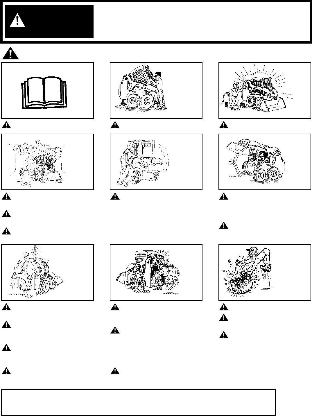
S205 Skid-Steer Loader
63 Operation & Maintenance Manual
MAINTENANCE SAFETY
Instructions are necessary before operating or servicing machine. Read and
understand the Operation & Maintenance Manual, Operator’s Handbook and signs
(decals) on machine. Follow warnings and instructions in the manuals when making
repairs, adjustments or servicing. Check for correct function after adjustments,
repairs or service. Untrained operators and failure to follow instructions can cause
injury or death.
Safety Alert Symbol: This symbol with a warning statement, means: “Warning, be alert! Your safety is
involved!” Carefully read the message that follows.
Never service the Bobcat Skid-
Steer Loader without instructions.
Use the correct procedure to lift
or lower operator cab.
Cleaning and maintenance are
required daily.
Have good ventilation when
welding or grinding painted
parts.
Wear dust mask when grinding
painted parts. Toxic dust and
gas can be produced.
Avoid exhaust fume leaks which
can kill without warning. Exhaust
system must be tightly sealed.
Disconnecting or loosening any
hydraulic tubeline, hose, fitting,
component or a part failure can
cause lift arms to drop. Do not
go under lift arms when raised
unless supported by an
approved lift arm support
device. Replace it if damaged.
Never work on loader with lift
arms up unless lift arms are
held by an approved lift arm
support device. Replace if
damaged.
Never modify equipment or add
attachments not approved by
Bobcat Company.
Stop, cool and clean engine of
flammable materials before
checking fluids.
Never service or adjust loader
with the engine running unless
instructed to do so in the
manual.
Avoid contact with leaking
hydraulic fluid or diesel fuel
under pressure. It can penetrate
the skin or eyes.
Never fill fuel tank with engine
running, while smoking or when
near open flame.
Keep body, jewelry and clothing
away from moving parts,
electrical contact, hot parts and
exhaust.
Wear eye protection to guard
from battery acid, compressed
springs, fluids under pressure
and flying debris when engines
are running or tools are used.
Use eye protection approved for
type of welding.
Keep rear door closed except
for service. Close and latch door
before operating the loader.
Lead-acid batteries produce
flammable and explosive gases.
Keep arcs, sparks, flames and
lighted tobacco away from
batteries.
Batteries contain acid which
burns eyes or skin on contact.
Wear protective clothing. If acid
contacts body, flush well with
water. For eye contact flush well
and get immediate medical
attention.
Maintenance procedures which are given in the Operation & Maintenance Manual can be performed by the owner /
operator without any specific technical training. Maintenance procedures which are not in the Operation &
Maintenance Manual must be performed ONLY BY QUALIFIED BOBCAT SERVICE PERSONNEL. Always use
genuine Bobcat replacement parts. The Service Safety Training Course is available from your Bobcat dealer. MSW07-0805
WARNING
B-10731A
CORRECT CORRECT
B-15535
CORRECT
B-15524
WRONG
B-15734
WRONG
B-15732
WRONG
B-15525
WRONG
B-15733
WRONG
B-15523
WRONG
B-6589
W-2003-0903

S205 Skid-Steer Loader
Operation & Maintenance Manual 64

S205 Skid-Steer Loader
65 Operation & Maintenance Manual
SERVICE SCHEDULE
Chart
Maintenance work must be done at regular intervals. Failure to do so will result in excessive wear and early failures. The
service schedule is a guide for correct maintenance of the Bobcat loader.
■Or every 12 months.
❏Check every 8-10 hours for the first 24 hours; then at 50 hour intervals.
❍Inspect new belt after first 50 hours.
✵First oil and filter change must occur at 50 hours; 250 hours thereafter.
▼Replace the hydraulic / hydrostatic filter element after the first 50 hours; and thereafter when the transmission warning light
comes ON while operating or at the 500 hour interval.
Instructions are necessary before operating or servicing machine. Read and
understand the Operation & Maintenance Manual, Operator’s Handbook and signs
(decals) on machine. Follow warnings and instructions in the manuals when making
repairs, adjustments or servicing. Check for correct function after adjustments,
repairs or service. Untrained operators and failure to follow instructions can cause
injury or death.
SERVICE SCHEDULE HOURS
ITEM SERVICE REQUIRED 8-10 50 100
■
250
■
500
■
1000
Engine Oil Check the oil level and add as needed. Do not overfill.
Engine Air Filter and Air System Check display panel. Service only when required. Check for leaks and damaged
components.
Engine Cooling System Clean debris from oil cooler, radiator & grill. Check coolant level COLD and add premixed
coolant as needed.
Fuel Filter Remove the trapped water.
Lift Arms, Cylinders, Bob-Tach Pivot
Pins and Wedges
Lubricate with multi-purpose lithium based grease.
Tires Check for damaged tires and correct air pressure. Inflate to MAXIMUM pressure shown on
sidewall of tire.
Seat Belt, Seat Bar, Control
Interlocks, Seat Belt Retractors
Check the condition of seat belt. Check the sear bar and control interlocks for correct
operation. Clean dirt and debris from moving parts. Clean or replace seat belt retractors as
needed.
Bobcat Interlock Control Systems
(BICS™)
Check that four BICS indicator lights and functions are activated. See details in this
Manual.
Safety Signs and Safety Treads Check for damaged signs (decals) and safety treads. Replace any signs or safety treads
that are damaged or worn.
Operator Cab Check the fastening bolts, washers and nuts. Check the condition of the cab.
Indicators and Lights Check for correct operation of all indicators and lights.
Heater and A/C Filters (If Equipped) Clean or replace filters as needed.
Hydraulic Fluid, Hoses and Tubelines Check fluid level and add as needed. Check for damage and leaks. See your Bobcat
dealer for repair or replacement as needed.
Final Drive Trans. (Chaincase), Foot
Pedals, Hand Controls or Steering
Levers
Check oil level and add oil as needed. Check for correct operation. See your Bobcat dealer
for repair or adjustment as needed.
Parking Brake Check operation.
Wheel Nuts Check for loose wheel nuts and tighten to correct torque. (See TIRE MAINTENANCE on
Page 93.) ❏
Spark Arrestor Muffler Clean the spark chamber.
Battery Check cables, connections and electrolyte level. Add distilled water as needed.
Steering Lever Pivots Grease fittings.
Fuel Filter Replace filter element.
Engine / Hydro. Drive Belt Check for wear or damage. ❍
Alternator Belt Check condition and tension. Adjust as needed.
Bobcat Interlock Control System
(BICS™)
Check the function of the lift arm by-pass control.
Engine Oil and Filter Replace oil and filter. Use CD or better grade oil and Bobcat filter. ✵
Hydraulic/Hydrostatic Filter, Charge
Filter, Reservoir Breather
Replace the hydrostatic filter, charge filter and the reservoir breather. ▼
Engine Valves Adjust the engine valves. See your Bobcat dealer for this service.
Final Drive Trans. (Chaincase) Replace the fluid.
Hydraulic Reservoir Replace the fluid.
Case Drain Filters Replace the filters.
Coolant Replace the coolant. Every 2 years
WARNING
W-2003-0903
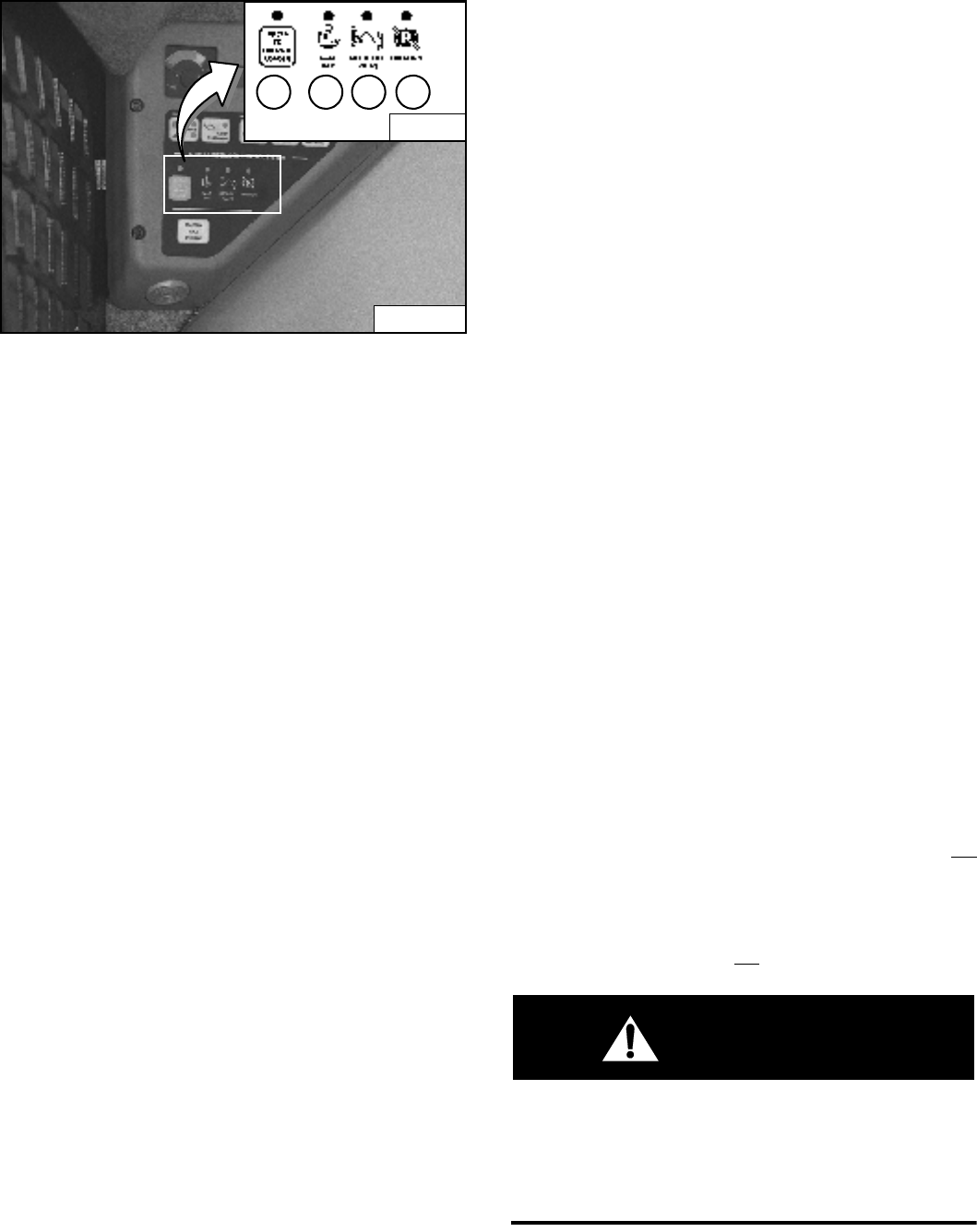
S205 Skid-Steer Loader
Operation & Maintenance Manual 66
BOBCAT INTERLOCK CONTROL SYSTEM (BICS)
Inspecting The BICS Controller (Engine STOPPED -
Key ON)
Figure 117
1. Sit in operator’s seat. Turn key ON (Key Switch
Panel), press RUN / ENTER Button (Keyless Panel),
lower seat bar and disengage parking brake. Press
the PRESS TO OPERATE LOADER Button. Three
BICS lights (1, 2 and 3) [PRESS TO OPERATE
LOADER, SEAT BAR, AND LIFT & TILT VALVE] on
left instrument panel should be ON [Figure 117].
2. Raise seat bar fully. All four BICS lights (1, 2, 3 and 4)
[PRESS TO OPERATE LOADER, SEAT BAR, LIFT &
TILT VALVE AND TRACTION*] on left instrument
panel should be OFF [Figure 117].
NOTE: Record what lights are blinking (if any) and
the number of light flashes. (See BOBCAT
INTERLOCK CONTROL SYSTEM (BICS) on
Page 105.)
Inspecting Deactivation Of The Auxiliary Hydraulics
System (Engine STOPPED - Key ON)
3. Sit in operator’s seat, lower seat bar, and press the
PRESS TO OPERATE LOADER Button. Press the
auxiliary hydraulics FLOW Button. The auxiliary
FLOW Button light will come ON. Raise the seat bar.
The light should be OFF.
Inspecting The Seat Bar Sensor (Engine RUNNING)
4. Sit in operator’s seat, lower seat bar, engage parking
brake and fasten seat belt.
5. Start engine and operate at low idle. Press the
PRESS TO OPERATE LOADER Button. While raising
the lift arms, raise the seat bar fully. The lift arms
should stop. Repeat using the tilt function.
Inspecting The Traction Lock (Engine RUNNING)
6. Fasten seat belt, disengage parking brake, press the
PRESS TO OPERATE LOADER Button and raise
seat bar fully. Move steering levers slowly forward
and backward. The TRACTION lock should be
engaged. Lower the seat bar. Press the PRESS TO
OPERATE LOADER Button.
7. Engage parking brake and move steering levers
slowly forward and backward. The TRACTION lock
should be engaged.
NOTE: *The TRACTION light on the left instrument
panel will remain OFF until the engine is
started, the PRESS TO OPERATE LOADER
Button is pressed and the parking brake is
disengaged.
Inspecting The Lift Arm By-Pass Control
8. Raise the lift arms 2 meters off the ground. Stop
engine. Turn lift arm by-pass control knob clockwise
1/4 turn. Pull up and hold lift arm by-pass control knob
until lift arms slowly lower.
Inspecting Deactivation Of Lift And Tilt Functions
(ACS and SJC)
9. Sit in operator’s seat and fasten seat belt. Lower seat
bar, start engine and press the PRESS TO OPERATE
LOADER Button.
10. Raise lift arms about 2 meters off the ground.
11. Turn key to OFF (Key Switch Panel), press STOP
Button (Keyless Panel), and wait for the engine to
come to a complete stop.
12. Turn key to ON (Key Switch Panel), press RUN /
ENTER Button (Keyless Panel). Press the PRESS
TO OPERATE LOADER Button, move hand control or
joystick to lower the lift arms. Lift arms should not
lower.
13. Move the control (foot pedal, hand control or joystick)
to tilt the bucket (or attachment) forward. The bucket
(or attachment) should not tilt forward.
WARNING
AVOID INJURY OR DEATH
The Bobcat Interlock Control System (BICS) must
deactivate the lift, tilt and traction drive functions. If it
does not, contact your dealer for service. DO NOT
modify the system.
W-2151-0394
N-18409
B-15551G
134
2
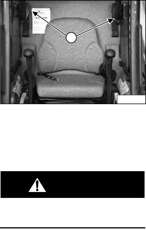
S205 Skid-Steer Loader
67 Operation & Maintenance Manual
SEAT BAR RESTRAINT SYSTEM
Description
The seat bar restraint system has a pivoting seat bar with
arm rests.
The operator controls the use of the seat bar. The seat
bar in the down position helps to keep the operator in the
seat.
Models with foot pedals have hydraulic valve spool
interlocks for the lift and tilt functions. The spool
interlocks require the operator to lower the seat bar in
order to operate the foot pedal controls.
When the seat bar is down, the PRESS TO OPERATE
LOADER Button is activated and the engine is running,
the lift, tilt and traction drive functions can be operated.
When the seat bar is up, the lift and tilt control pedals are
locked when returned to the NEUTRAL position.
Models with the Advanced Control System (ACS)
have mechanical interlocks for the handles and pedals.
The interlocks for the handles and pedals require the
operator to lower the seat bar in order to operate the
selected controls.
When the seat bar is down, the PRESS TO OPERATE
LOADER button is activated and the engine is running,
the lift, tilt and traction drive functions can be operated
using the selected controls (handles, or foot pedals).
When the seat bar is up, the handles and pedals are
locked when returned to the NEUTRAL position.
Models with Selectable Joystick Control (SJC) have
electrical deactivation of joystick functions. Activation of
functions require the operator to lower the seat bar.
When the seat bar is down, the PRESS TO OPERATE
LOADER button is activated and the engine is running,
the lift, tilt and traction drive functions can be operated.
When the seat bar is up, the joystick functions are
deactivated even though the joystick does not
mechanically lock.
Inspecting
Sit in the seat and fasten the seat belt. Engage the
parking brake. Pull the seat bar all the way down. Start
the engine. Press the PRESS TO OPERATE LOADER
Button.
Operate the hydraulic controls to check that both the lift
and tilt functions operate correctly. Raise the lift arms
until the attachment is about 600 mm off the ground.
Raise the seat bar. Move the hydraulic controls. Pedals
and handles (if equipped) must be firmly locked in the
NEUTRAL position (except joysticks). There must be no
motion of the lift arms or tilt (attachment) when the
controls are moved.
Lower the seat bar, press the PRESS TO OPERATE
LOADER Button, lower the lift arms. Operate the lift
control. While the lift arms are going up, raise the seat
bar. The lift arms must stop.
Lower the seat bar, press the PRESS TO OPERATE
LOADER Button, lower the lift arms and put the
attachment flat on the ground. Stop the engine. Raise the
seat bar. Operate the foot pedals and handles (if
equipped) to be sure they are firmly locked in the
NEUTRAL position (except joysticks).
Maintaining
(See SERVICE SCHEDULE on Page 65) and on the
loader for correct service interval.
Figure 118
Use compressed air to clean any debris or dirt from the
pivot parts (1) [Figure 118]. Do not lubricate. Inspect all
mounting hardware. The correct bolt torque is 35 Nm.
If the seat bar system does not function correctly, replace
parts that are worn or damaged. Use only genuine
Bobcat replacement parts.
WARNING
The seat bar system must deactivate the lift and tilt
control functions when the seat bar is up. Service the
system if hydraulic controls do not deactivate.
W-2465-0703
N-19225
1
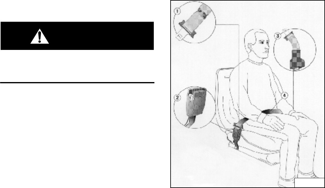
S205 Skid-Steer Loader
Operation & Maintenance Manual 68
SEAT BELT
Inspection and Maintenance
WARNING
Failure to properly inspect and maintain the seat belt
can cause lack of operator restraint resulting in
serious injury or death.
W-2466-0703
Check the seat belt daily for correct function.
Inspect the seat belt system thoroughly at least once
each year or more often if the machine is exposed to
severe environmental conditions or applications.
Any seat belt system that shows cuts, fraying, extreme or
unusual wear, significant discolorations due to ultraviolet
(UV) exposure, dusty / dirty conditions, abrasion to the
seat belt webbing, or damage to the buckle, latch plate,
retractor (if equipped), hardware or any other obvious
problem should be replaced immediately.
The items below are referenced in [Figure 119].
1. Check the webbing. If the system is equipped with a
retractor, pull the webbing completely our and inspect
the full length of the webbing. Look for cuts, wear,
fraying, dirt and stiffness.
2. Check the buckle and latch for correct operation.
Make sure latch plate is not excessively worn,
deformed or buckle is not damaged or casing broken.
3. Check the retractor web storage device (if equipped)
by extending webbing to determine if it looks correct
and that it spools out and retracts webbing correctly.
4. Check webbing in areas exposed to ultraviolet (UV)
rays from the sun or extreme dust or dirt. If the original
color of the webbing in these areas is extremely faded
and / or the webbing is packed with dirt, the webbing
strength may have deteriorated.
See your Bobcat dealer for seat belt system replacement
parts for your machine.
Figure 119
B-22283
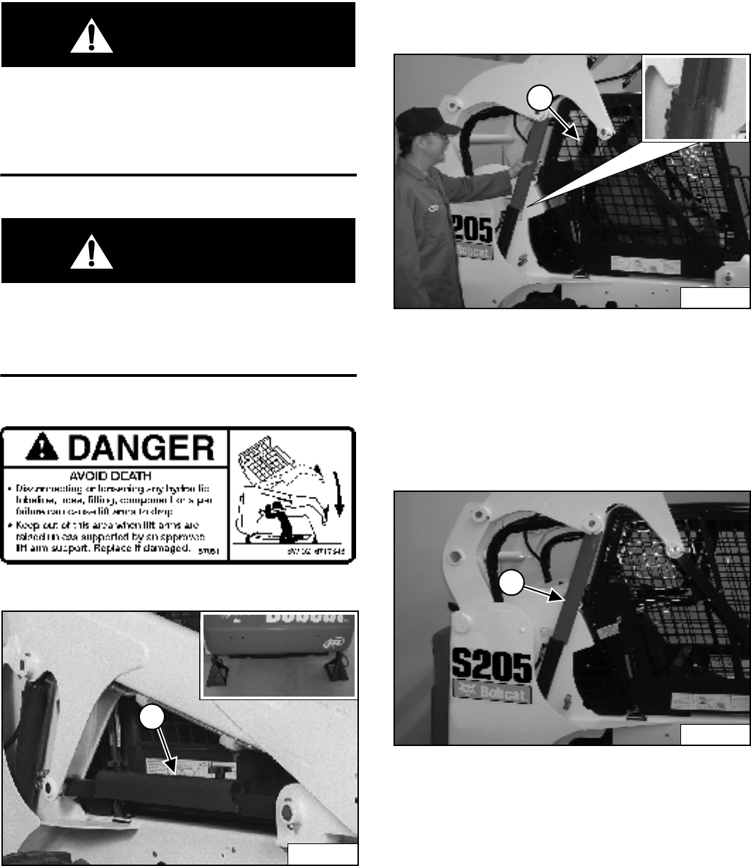
S205 Skid-Steer Loader
69 Operation & Maintenance Manual
LIFT ARM SUPPORT DEVICE
Installing
WARNING
Never work on a machine with the lift arms up unless
the lift arms are secured by an approved lift arm
support device. Failure to use an approved lift arm
support device can allow the lift arms or attachment
to fall and cause injury or death.
W-2059-0598
WARNING
Service lift arm support device if damaged or if parts
are missing. Using a damaged lift arm support or
with missing parts can cause lift arms to drop
causing injury or death.
W-2271-1197
Figure 120
Put jackstands under the rear corners of the loader frame
(Inset) [Figure 120].
Remove the lift arm support device (1) [Figure 120] from
storage position.
The operator must be in the operator's seat, with the seat
belt fastened and seat bar lowered, until the lift arm
support device is installed.
Start the engine, and raise the lift arms all the way up.
Figure 121
Have a second person install the lift arm support
device (1) [Figure 121] over the rod of one of the lift
cylinders.
The lift arm support device must be tight against the
cylinder rod. The tabs of the lift arm support device must
be under the cylinder as shown (Inset) [Figure 121].
Figure 122
Lower the lift arms slowly until the lift arm support
device (1) [Figure 122] is held between the lift arms and
lift cylinder.
N-18488
1
P-31849
P-31857B
1
N-18483
P-31856C
1
S205 Skid-Steer Loader
Operation & Maintenance Manual 70
LIFT ARM SUPPORT DEVICE (CONT’D)
Removing
The operator must be in the operator's seat, with the seat
belt fastened and seat bar lowered, until the lift arm
support device is removed and the lift arms are lowered
all the way.
Start the engine, raise the lift arms all the way up.
Have a second person remove the lift arm support
device.
Lower the lift arms all the way and stop the engine.
Return the lift arm support device to storage position and
secure with clamping knobs.
Remove the jackstands.
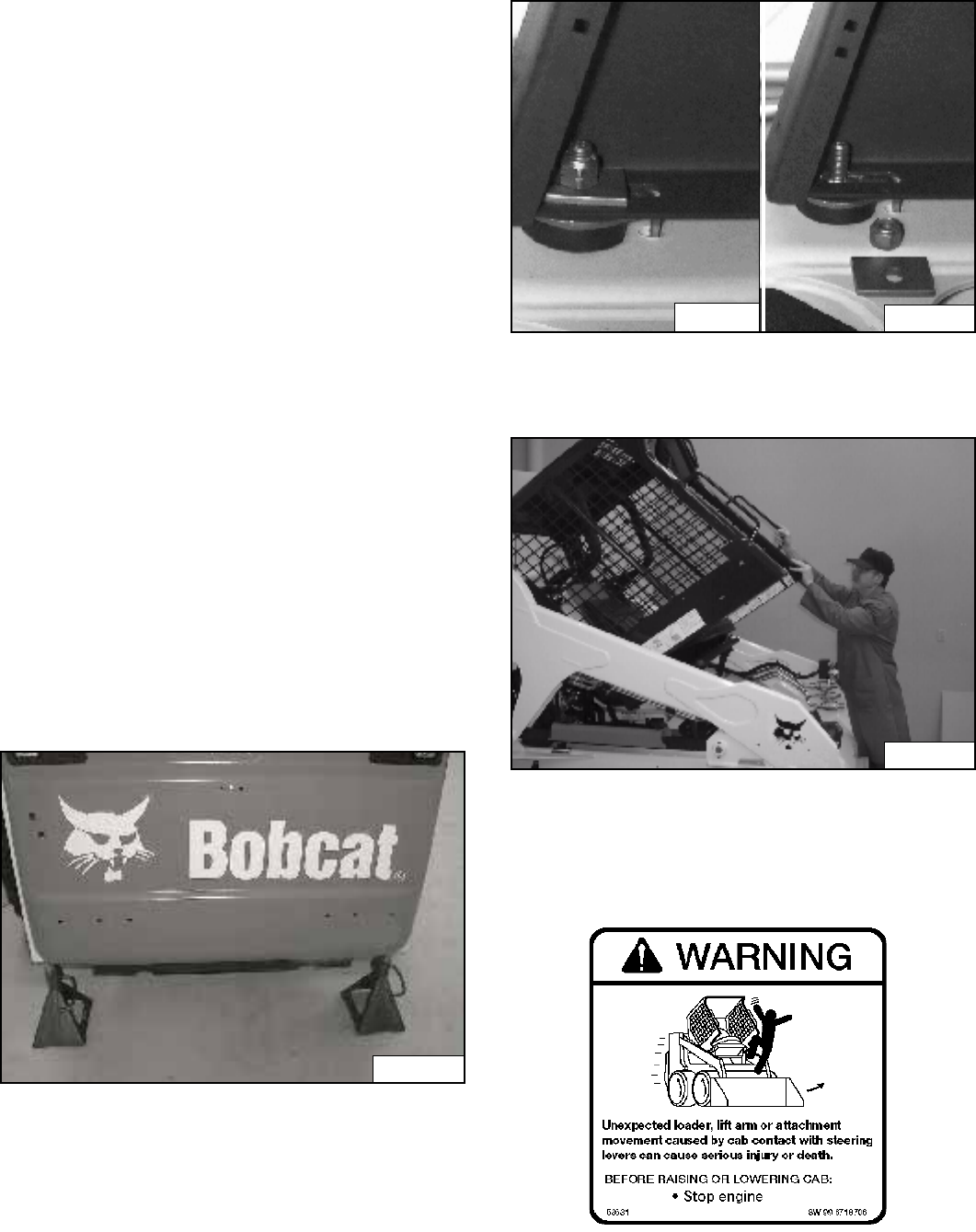
S205 Skid-Steer Loader
71 Operation & Maintenance Manual
OPERATOR CAB
Description
The Bobcat Loader has an operator cab (ROPS and
FOPS) as standard equipment to protect the operator
from rollover and falling objects. Check with your dealer if
the operator cab has been damaged. The seat belt must
be worn for roll over protection.
ROPS / FOPS - Roll Over Protective Structure per
SAE J1040 and ISO 3471, and Falling Object Protective
Structure per SAE J1043 and ISO 3449, Level I. Level II
is available.
Level I - Protection from falling bricks, small concrete
blocks, and hand tools encountered in operations such as
highway maintenance, landscaping, and other
construction site services.
Level II - Protection from falling trees, rocks; for machines
involved in site clearing, overhead demolition or forestry.
Raising
Always stop the engine before raising or lowering the cab.
Stop the loader on a level surface. Lower the lift arms. If
the lift arms must be up while raising the operator cab,
install the lift arm support device. (See LIFT ARM
SUPPORT DEVICE on Page 69.)
Figure 123
Install jackstands under the rear of the loader frame
[Figure 123].
Loosen the nut (both sides) at the front corners of the
operator cab [Figure 124].
Figure 124
Remove the nuts and plates [Figure 124] (both sides).
Figure 125
Lift on the grab handle and bottom of the operator cab
slowly until the cab is all the way up and the latching
mechanism engages [Figure 125].
Hand Controls Only (ACS)
P-31849
P10563
P10564
P-31858A
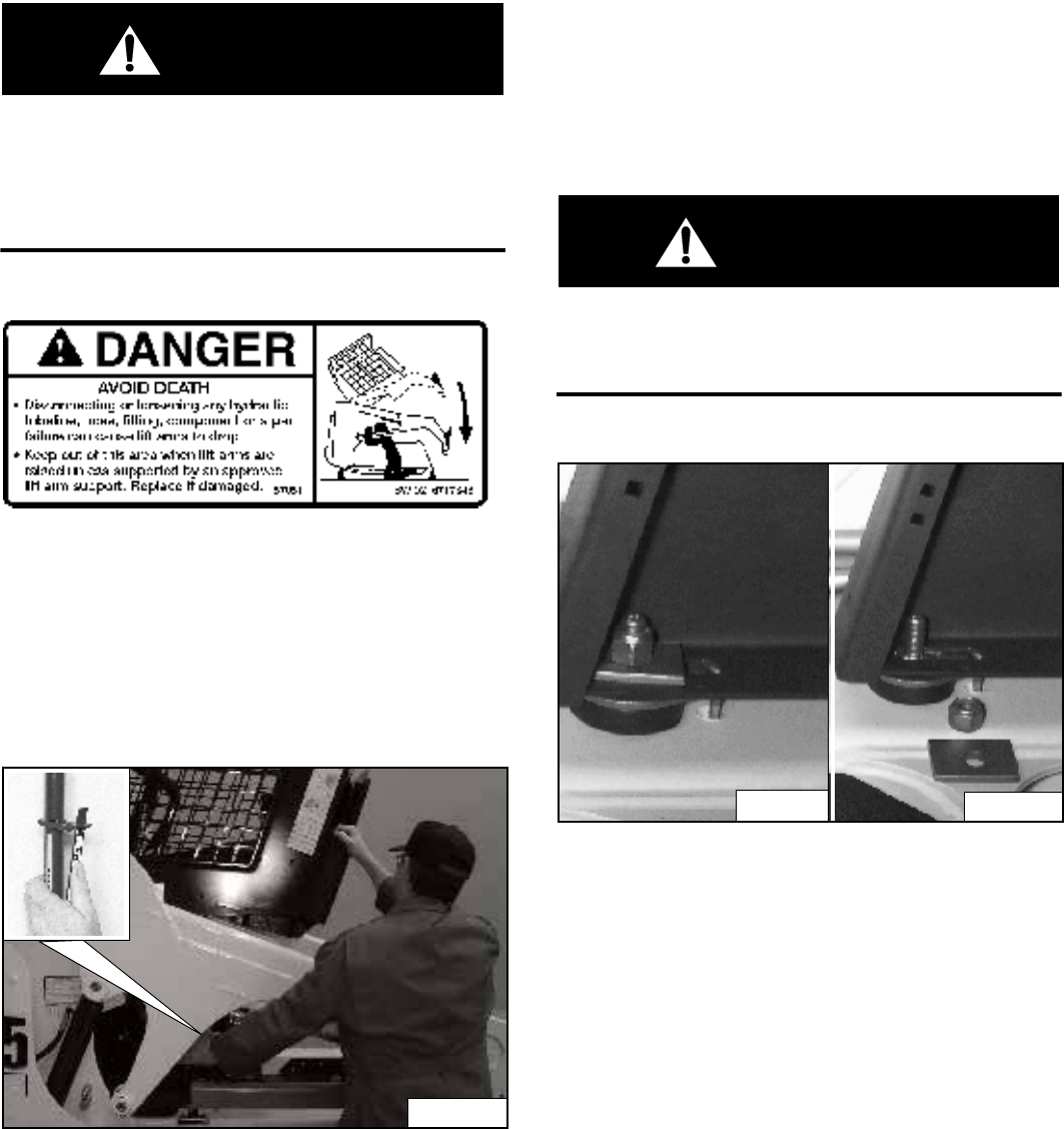
S205 Skid-Steer Loader
Operation & Maintenance Manual 72
OPERATOR CAB (CONT’D)
Raising (Cont’d)
WARNING
Never modify operator cab by welding, grinding,
drilling holes or adding attachments unless
instructed to do so by Bobcat. Changes to the cab
can cause loss of operator protection from rollover
and falling objects, and result in injury or death.
W-2069-1299
Lowering
Always stop the engine before raising or lowering the cab.
NOTE: Always use the grab handles to lower the cab.
Figure 126
Pull down on the bottom of the operator cab until it stops
at the latching mechanism [Figure 126].
NOTE: The weight of the cab increases when
equipped with options and accessories such
cab door, heater, air conditioning, etc. In
these cases, the cab may need to be raised
slightly from the latch to be able to release the
latch.
Support the cab and release the latching mechanism
(Inset) [Figure 126]. Remove your hand from latching
mechanism when the cab is past the latch stop. Use both
hands to lower the cab all the way.
WARNING
PINCH POINT CAN CAUSE INJURY
Remove your hand from the latching mechanism
when the cab is past the latch stop.
W-2469-0803
Figure 127
Install the plates and nuts [Figure 127] (both sides).
Tighten the nuts to 54-68 Nm torque.
P-31859A
N-20120
P10563
P10564
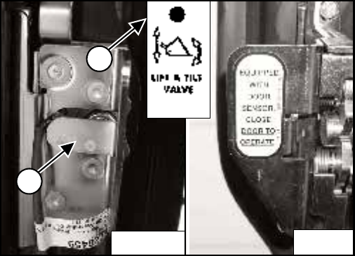
S205 Skid-Steer Loader
73 Operation & Maintenance Manual
OPERATOR CAB (CONT’D)
Cab Door Sensor (If Equipped)
Figure 128
Cab doors have a sensor (1) [Figure 128] installed which
deactivates the lift and tilt valves when the door is open.
CLOSE DOOR TO OPERATE lift and tilt valves.
The LIFT & TILT VALVE light (2) [Figure 128] will be ON
when the door is closed and the PRESS TO OPERATE
LOADER BUTTON is pressed.
P-68116
1
2
P-68115
B-15551J
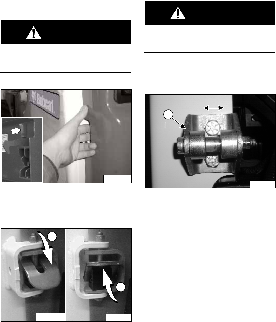
S205 Skid-Steer Loader
Operation & Maintenance Manual 74
REAR DOOR
Opening And Closing
WARNING
AVOID INJURY OR DEATH
Never service or adjust the machine when the engine
is running unless instructed to do so in the manual.
W-2012-0497
Figure 129
Reach into the slot in the rear door and pull the latch
handle [Figure 129].
Pull the rear door open.
Figure 130
Move the door stop into the engaged position (1)
[Figure 130] to hold the door open.
Move the door stop up (2) [Figure 130] to disengage the
door stop and allow the door to close.
Close the door.
WARNING
Keep the rear door closed when operating the
machine. Failure to do so could seriously injure a
bystander.
W-2020-1285
Adjusting
Figure 131
The door latch catch (1) [Figure 131] can be adjusted for
alignment with the door latch mechanism.
Close the rear door before operating the loader.
P-31848A
P-30806
P-16367
P-16366
1
2
1
P-31126
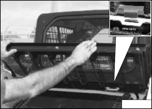
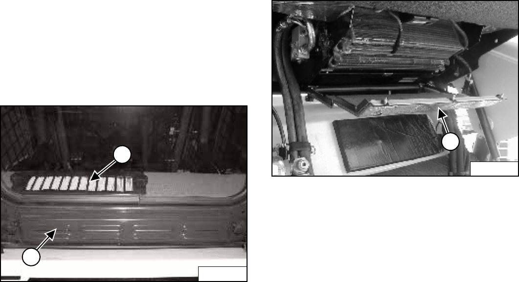
S205 Skid-Steer Loader
Operation & Maintenance Manual 76
HEATING AND AIR CONDITIONING
Cleaning and Maintenance
The heater and air conditioning system require regular
inspection and maintenance. See your SERVICE
SCHEDULE for intervals. (See SERVICE SCHEDULE on
Page 65.)
Filters
Figure 133
The Fresh Air Filter is located below the rear window of
the cab (1) [Figure 133].
Remove the bolts and remove the filter housing.
Shake the filter or use low air pressure to remove dirt.
Replace after cleaning three times or if filter becomes too
dirty to clean.
Reinstall the filter, housing and bolts.
The Recirculation Filter is located in front of the rear
window inside the cab (2) [Figure 133].
Remove the clamping knobs, grill and filter.
Clean the filter with water and mild detergent. Reinstall
the filter. Replace after cleaning three times, or if filter
becomes too dirty to clean.
Evaporator
Figure 134
Raise the cab and remove the evaporator cover (1)
[Figure 134].
Use low pressure water or air to remove debris from the
evaporator fins.
Install the cover.
Air Conditioning Lubrication
Run the air conditioner for about 5 minutes every week to
lubricate the internal components. (In winter too.)
Troubleshooting
If the fan does not run, or the air conditioning does not
turn on, Check the fuse. (See ELECTRICAL SYSTEM on
Page 84).
If the air conditioning system circulates warm air, the
refrigerant may need to be recharged.
P-48012
2
1
P19427
1
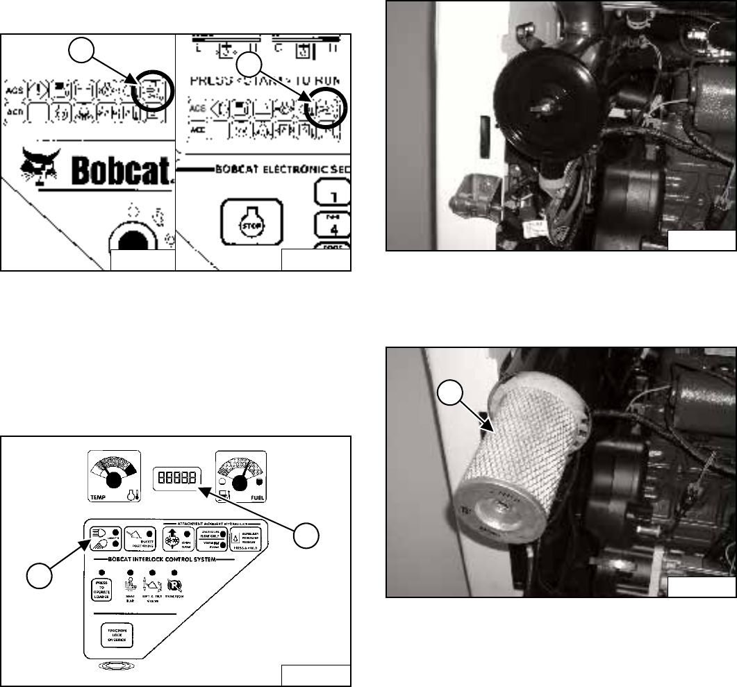
S205 Skid-Steer Loader
77 Operation & Maintenance Manual
AIR CLEANER SERVICE
Replacing Filter Elements
Figure 135
It is important to change the air filter element only when
the Air Cleaner Icon in the right panel is ON (1)
[Figure 135] and you hear three beeps from the alarm.
Replace the inner filter every third time the outer filter is
replaced or as indicated.
Figure 136
Press and hold the LIGHT Button (1) [Figure 136] for
two seconds.
If the filter element needs replacement, the
CODE [01-17] (Air Filter Plugged) will show in the
HOURMETER / CODE DISPLAY (2) [Figure 136].
Outer Filter
Figure 137
Remove the wing nut and remove the dust cover
[Figure 137].
Figure 138
Remove the wing nut and remove the outer filter
element (1) [Figure 138].
NOTE: Make sure all sealing surfaces are free of dirt
and debris. Do not use air pressure to clean.
Install a new outer element.
Install the dust cover and the wing nut [Figure 137] (Be
sure the evacuator is down).
Check the air intake hose and the air cleaner housing for
damage. Make sure all connections are tight.
B-15553B
B-15552B
1
1
B-15551
1
2
P-31836
P-31837
1
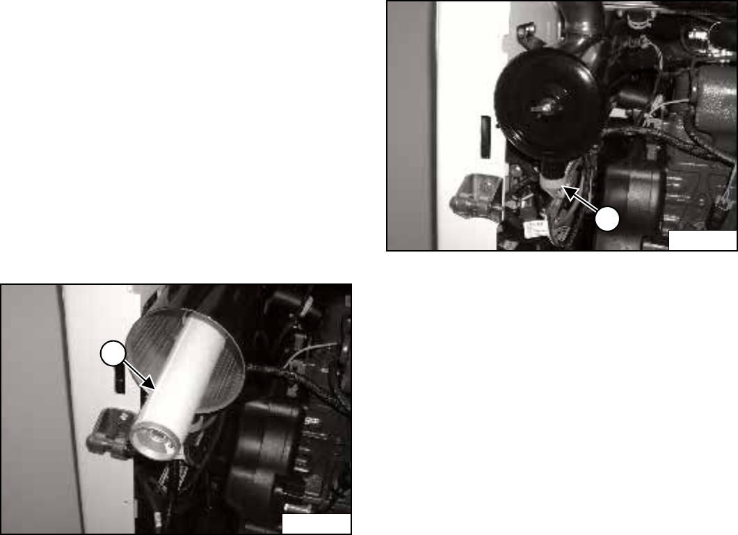
S205 Skid-Steer Loader
Operation & Maintenance Manual 78
AIR CLEANER SERVICE (CONT’D)
Replacing Filter Elements (Cont’d)
Inner Filter
Only replace the inner filter element under the following
conditions:
• Replace the inner filter element every third time the
outer filter is replaced.
• After the outer element has been replaced, start the
engine and run at full RPM. If the HOURMETER /
CODE DISPLAY shows [01-17] (Air Filter Plugged),
replace the inner filter element.
Figure 139
Remove the wing nut and remove the inner filter
element (1) [Figure 139].
NOTE: Make sure all sealing surfaces are free of dirt
and debris.
Install the new inner element.
Install the outer element.
Figure 140
Install the dust cover and the wing nut [Figure 140] (Be
sure the evacuator (1) [Figure 140] is down).
P-31838
1
P-31836
1
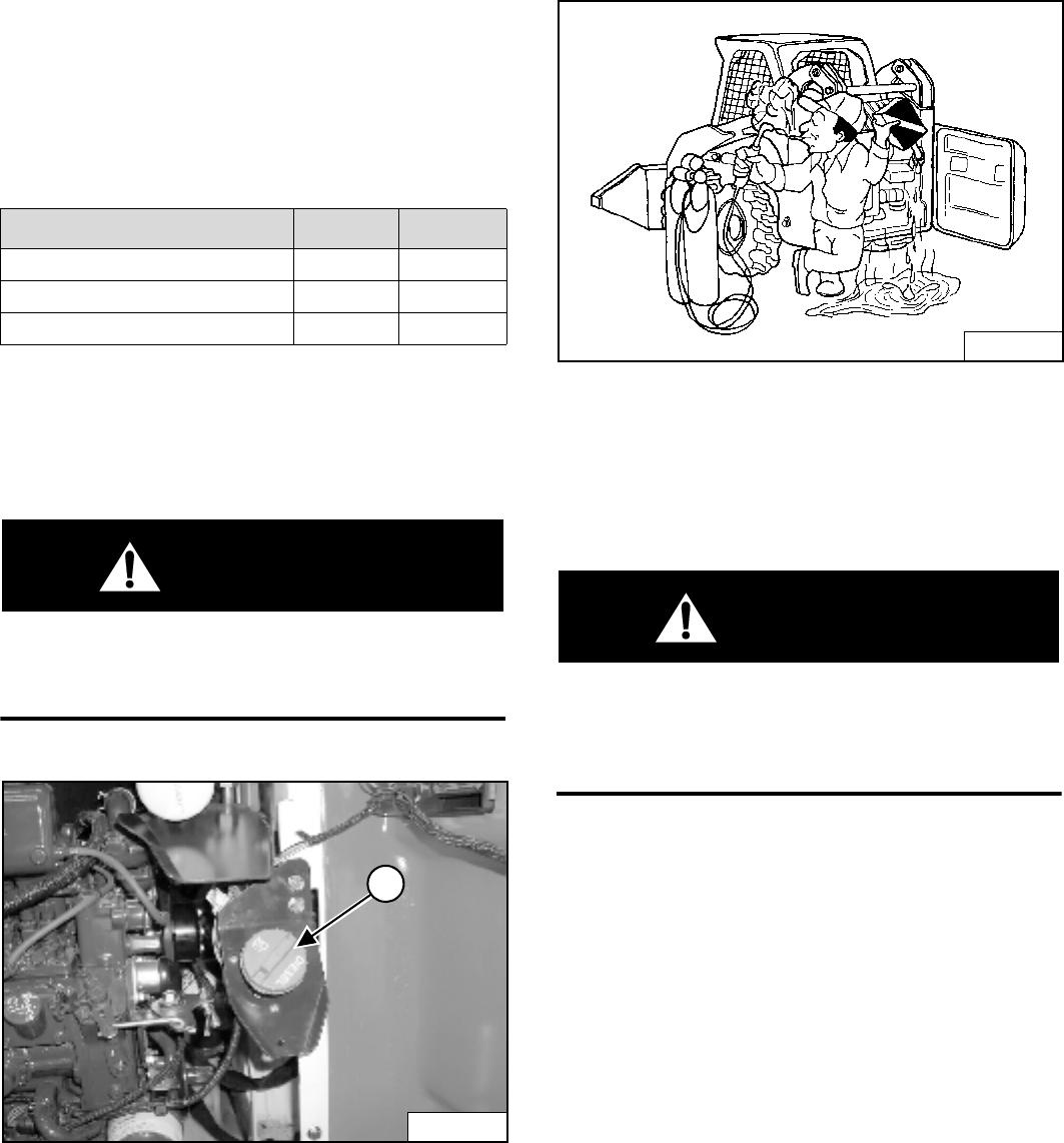
S205 Skid-Steer Loader
79 Operation & Maintenance Manual
FUEL SYSTEM
Fuel Specifications
Use only clean, high quality diesel fuel, Grade No. 2 or
Grade No. 1.
The following is one suggested blending guideline which
should prevent fuel gelling during cold temperatures:
Contact your fuel supplier for local recommendations.
Filling the Fuel Tank
WARNING
Stop and cool the engine before adding fuel.
NO SMOKING! Failure to obey warnings can cause
an explosion or fire.
W-2063-0887
Figure 141
Open the rear door.
Remove the fuel fill cap (1) [Figure 141].
Figure 142
Use a clean, approved safety container to add fuel of the
correct specifications. Add fuel only in an area that has
free movement of air and no open flames or sparks.
NO SMOKING! [Figure 142].
Install and tighten the fuel fill cap (1) [Figure 142].
WARNING
Always clean up spilled fuel or oil. Keep heat, flames,
sparks or lighted tobacco away from fuel and oil.
Failure to use care around combustibles can cause
explosion or fire which can result in injury or death.
W-2103-1285
TEMPERATURE °C (°F) No. 2 No. 1
-9° (+15°) 100% 0%
Down to -29° (-20°) 50% 50%
Below -29° (-20°) 0% 100%
P-48468
1
B-15650
WRONG
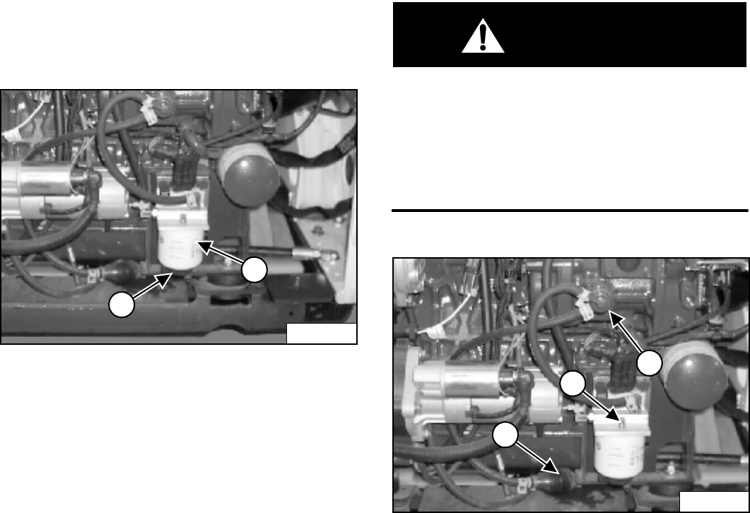
S205 Skid-Steer Loader
Operation & Maintenance Manual 80
FUEL SYSTEM (CONT’D)
Fuel Filter
See your SERVICE SCHEDULE for the service interval
for removing water from, or replacing the fuel filter. (See
SERVICE SCHEDULE on Page 65.)
Removing Water
Figure 143
Loosen the drain (1) [Figure 143] at the bottom of the
filter element to remove water from the filter.
Replacing Element
Remove the filter element (2) [Figure 143].
Clean the area around the filter housing. Put clean oil on
the seal of the new filter element. Install the fuel filter, and
hand tighten.
Remove the air from the fuel system. (See Below.)
Removing Air From The Fuel System
After replacing the filter element or when the fuel tank
has run out of fuel, the air must be removed from the fuel
system before starting the engine.
WARNING
Diesel fuel or hydraulic fluid under pressure can
penetrate skin or eyes, causing serious injury or
death. Fluid leaks under pressure may not be visible.
Use a piece of cardboard or wood to find leaks. Do
not use your bare hand. Wear safety goggles. If fluid
enters skin or eyes, get immediate medical attention
from a physician familiar with this injury.
W-2072-0496
Figure 144
Open the vent (1) [Figure 144] on the fuel filter housing.
Squeeze the hand pump (priming bulb) (2) [Figure 144]
until fuel flows from the vent with no air bubbles.
Close the vent (1) [Figure 144] on the fuel filter housing.
Open the vent (3) [Figure 144] on the fuel injection
pump.
Squeeze the hand pump (priming bulb) (2) [Figure 144]
until the pump feels solid.
Tighten the vent plug (3) [Figure 144].
Start the engine.
It may be necessary to open the vent plug (3)
[Figure 144] briefly while the engine is running. Close
the vent when the engine runs smoothly.
P-48469
1
2
1
2
P-48469
3
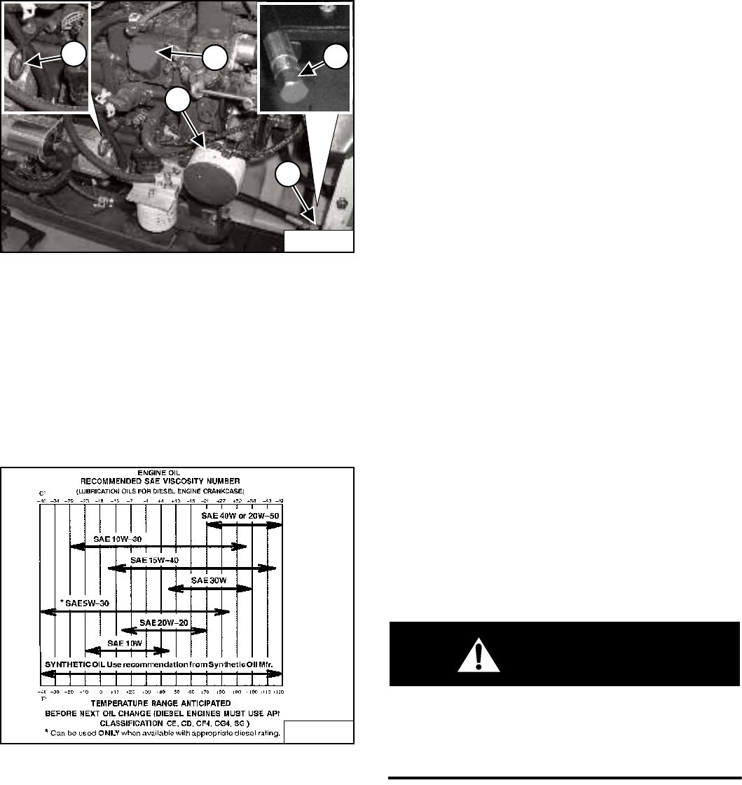
S205 Skid-Steer Loader
81 Operation & Maintenance Manual
ENGINE LUBRICATION SYSTEM
Checking And Adding Engine Oil
Check the engine oil level every day before starting the
engine for the work shift.
Figure 145
Park the machine on level ground. Open the rear door
and remove the dipstick (1) [Figure 145].
Keep the oil level between the marks on the dipstick. Do
not overfill.
Engine Oil Chart
Figure 146
Use a good quality motor oil that meets API Service
Classification of CD or better See Oil Chart [Figure 146].
Install the dipstick and close the rear door.
Removing And Replacing Oil And Filter
See your SERVICE SCHEDULE for the service interval
for replacing the engine oil and filter. (See SERVICE
SCHEDULE on Page 65.)
Run the engine until it is at operating temperature. Stop
the engine.
Open the rear door.
Remove the drain hose from the storage position (2)
[Figure 145].
Remove the drain plug (3) [Figure 145].
Drain the oil into a container and dispose of used oil in an
environmentally safe manner.
Remove the oil filter (4) [Figure 145].
Clean the filter housing surface.
Put clean oil on the new oil filter gasket.
Install the filter and hand tighten.
Install and tighten the drain plug.
Remove the fill cap (5) [Figure 145].
Put oil in the engine. (See Fluid Capacities on Page 122.)
(Also See Oil Chart [Figure 146].) Do not overfill.
Start the engine and let it run for several minutes.
Stop the engine and check for leaks at the oil filter.
Remove the dipstick and check the oil level.
Add oil as needed if it is not at the top mark (1) on the
dipstick.
Install the dipstick and close the rear door.
WARNING
Always clean up spilled fuel or oil. Keep heat, flames,
sparks or lighted tobacco away from fuel and oil.
Failure to use care around combustibles can cause
explosion or fire which can result in injury or death.
W-2103-1285
P-48472
2
4
5
P-48473
1
P-48473 P-24679
3
B-16320
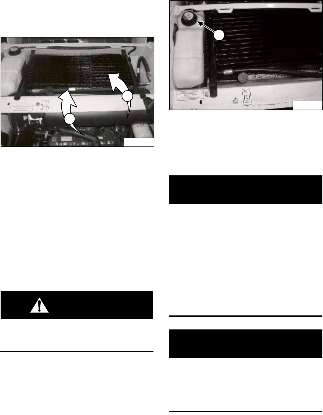
S205 Skid-Steer Loader
Operation & Maintenance Manual 82
ENGINE COOLING SYSTEM
Check the cooling system every day to prevent over-
heating, loss of performance or engine damage.
Cleaning
Figure 147
Open the rear door and raise the rear grill.
Use low air pressure or water pressure to clean the top of
the oil cooler (1) [Figure 147].
NOTE: Be careful when raising and lowering the oil
cooler so that the oil cooler does not fall on
the radiator and damage the fins.
Raise the oil cooler and use low air pressure or water
pressure to clean the top of the radiator (2) [Figure 148].
Lower the oil cooler.
Check cooling system for leaks.
Lower the rear grill and close the rear door.
WARNING
AVOID BURNS
Do not remove radiator cap when the engine is hot.
You can be seriously burned.
W-2070-1203
Checking Level
Open the rear door and raise the rear grill.
Figure 148
Remove the coolant fill cap (1) [Figure 148]. Check the
coolant level. The level markers are inside the tank.
Coolant must be at the bottom marker when the engine is
cold; top marker when hot.
Close the rear door before operating the loader.
IMPORTANT
AVOID ENGINE DAMAGE
Always use the correct ratio of water to antifreeze.
Too much antifreeze reduces cooling system
efficiency and may cause serious premature engine
damage.
Too little antifreeze reduces the additives which
protect the internal engine components; reduces the
boiling point and freeze protection of the system.
Always add a premixed solution. Adding full strength
concentrated coolant can cause serious premature
engine damage.
I-2124-0497
IMPORTANT
Wear safety glasses to prevent eye injury when any
of the following conditions exist:
• When fluids are under pressure.
• Flying debris or loose material is present.
• Engine is running.
• Tools are being used.
W-2019-1285
P-45101
1
2
P-39967
1
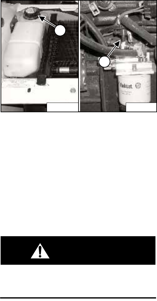
S205 Skid-Steer Loader
83 Operation & Maintenance Manual
ENGINE COOLING SYSTEM (CONT’D)
Removing And Replacing the Coolant
Open the rear door and remove the rear grill.
Figure 149
Remove the coolant fill cap (1) [Figure 149].
Connect a hose to the engine block drain valve (2)
[Figure 149]. Open the drain valve and drain the coolant
into a container.
After all the coolant is removed, close the drain valve and
remove the hose.
Recycle or dispose of coolant in an environmentally safe
manner.
Mix the coolant in a separate container. (See Fluid
Capacities on Page 122.)
WARNING
AVOID BURNS
Do not remove radiator cap when the engine is hot.
You can be seriously burned.
W-2070-1203
NOTE: The loader is factory filled with propylene
glycol coolant (purple color). DO NOT mix
propylene glycol with ethylene glycol.
Add premixed coolant, 47% water and 53% propylene
glycol to the recovery tank. (See Checking Level on
Page 82.)
4,3 L of propylene glycol mixed with 3,8 L of water is the
correct mixture of coolant to provide a -37°C (-34°F)
freeze protection.
Remove the coolant fill cap. Fill the tank until it is at the
lower marker on the tank.
Use a refractometer to check the condition of propylene
glycol in your cooling system.
Run the engine until it is at operating temperature. Stop
the engine. Check the coolant level when cool. Add
coolant as needed.
Install the rear grill and close the rear door.
P-45490
2
P-45245
1
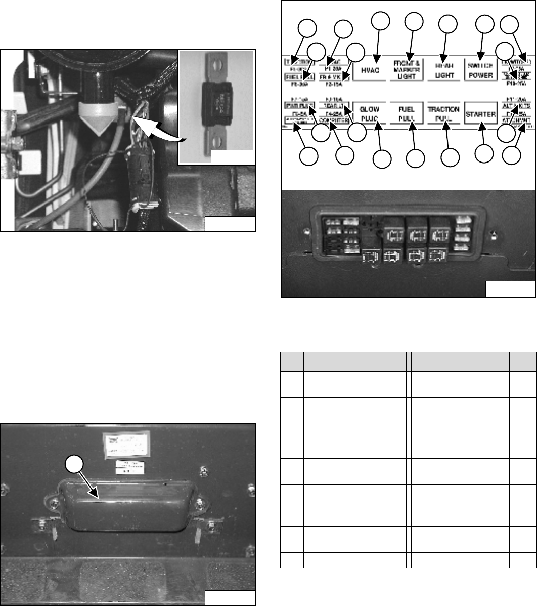
S205 Skid-Steer Loader
Operation & Maintenance Manual 84
ELECTRICAL SYSTEM
Description
Figure 150
The loader has a 12 volt, negative ground alternator
charging system. The electrical system is protected by
fuses located in the cab on the steering control panel and
a 100 amp. master fuse [Figure 150] in the engine
compartment on the left side of the engine. The fuses will
protect the electrical system when there is an electrical
overload. The reason for the overload must be found
before starting the engine again.
Fuse And Relay Location / Identification
Figure 151
The electrical system is protected from overload by fuses
and relays under the fuse panel cover (1) [Figure 151]. A
decal is inside the cover to show location and amp
ratings.
Remove the cover to check or replace the fuses.
Figure 152
The location and sizes are shown below and in
[Figure 152].
R - Relay
P-24651
P-13849
P-26323
1
REF DESCRIPTION AMP REF DESCRIPTION AMP
1Traction 30 11 Front & Marker
Lights
R
2Fuel Shutoff 30 12 Fuel Shutoff R
3Power Plug - - 13 Rear Lights R
4ACS/AWS/SJC - - 14 Tr a c t i o n R
5Heater 25 15 Switch Power R
6Front & Marker
Lights
15 16 Starter R
7Rear Lights 15 17 Unswitched
Attach.
25
8Bobcat Controller 25 18 Switched Attach. 25
9Heater & Air
Conditioning
- - 19 Alternator &
Accessories
25
10 Glow Plugs R 20 Accessory Plug 25
7117407
1
2
5
6
917
11 13 15
4
3
8
7
10 20
19
12 14 16
18
N-19660
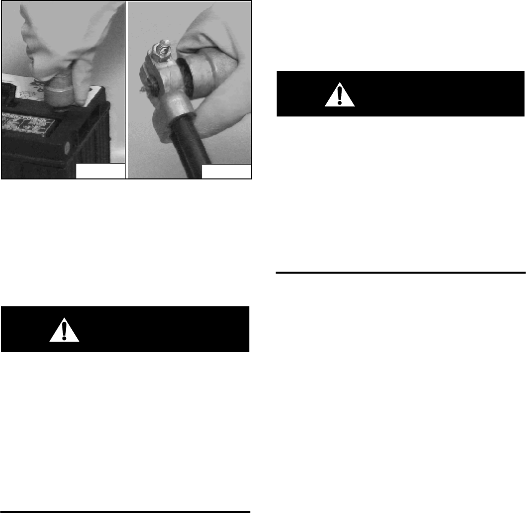
S205 Skid-Steer Loader
85 Operation & Maintenance Manual
ELECTRICAL SYSTEM (CONT’D)
Battery Maintenance
Figure 153
The battery cables must be clean and tight. Check the
electrolyte level in the battery. Add distilled water as
needed. Remove acid or corrosion from the battery and
cables with a sodium bicarbonate and water solution
[Figure 153].
Put Battery Saver (6664458) or grease on the battery
terminals and cable ends to prevent corrosion.
WARNING
Batteries contain acid which burns eyes and skin on
contact. Wear goggles, protective clothing and
rubber gloves to keep acid off body.
In case of acid contact, wash immediately with water.
In case of eye contact get prompt medical attention
and wash eye with clean, cool water for at least
15 minutes.
If electrolyte is taken internally drink large quantities
of water or milk! DO NOT induce vomiting. Get
prompt medical attention.
W-2065-1296
Using A Booster Battery (Jump Starting)
If it is necessary to use a booster battery to start the
engine, BE CAREFUL! There must be one person in the
operator's seat and one person to connect and
disconnect the battery cables.
The key switch must be OFF (Key Switch Panel) OR the
STOP Button must be pressed (Keyless Panel). The
booster battery must be 12 volts.
WARNING
Keep arcs, sparks flames and lighted tobacco away
from batteries. When jumping from booster battery
make final connection (negative) at machine frame.
Do not jump start or charge a frozen or damaged
battery. Warm battery to 16°C (60°F) before
connecting to a charger. Unplug charger before
connecting or disconnecting cables to battery. Never
lean over battery while boosting, testing or charging.
Battery gas can explode and cause serious injury.
W-2066-0705
P-09590
P-09589
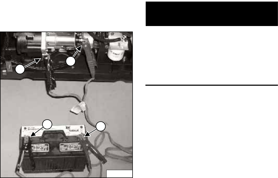
S205 Skid-Steer Loader
Operation & Maintenance Manual 86
ELECTRICAL SYSTEM (CONT’D)
Using A Booster Battery (Jump Starting) (Cont’d)
Figure 154
Connect the end of the first cable (1) [Figure 154] to the
positive (+) terminal of the booster battery. Connect the
other end of the same cable (2) [Figure 154] to the
positive terminal on the loader starter.
Connect the end of the second cable (3) [Figure 154] to
the negative (-) terminal of the booster battery. Connect
the other end of the same cable (4) [Figure 154] to the
engine.
Keep cables away from moving parts. Start the engine.
(See STARTING THE ENGINE on Page 29.)
After the engine has started, remove the ground (-)
cable (4) [Figure 154] first.
Remove the cable from the positive (+) terminal (2)
[Figure 154].
IMPORTANT
Damage to the alternator can occur if:
• Engine is operated with battery cables
disconnected.
• Battery cables are connected when using a fast
charger or when welding on the loader. (Remove
both cables from the battery.)
• Extra battery cables (booster cables) are
connected wrong.
I-2023-1285
P-31860
1
3
4
2
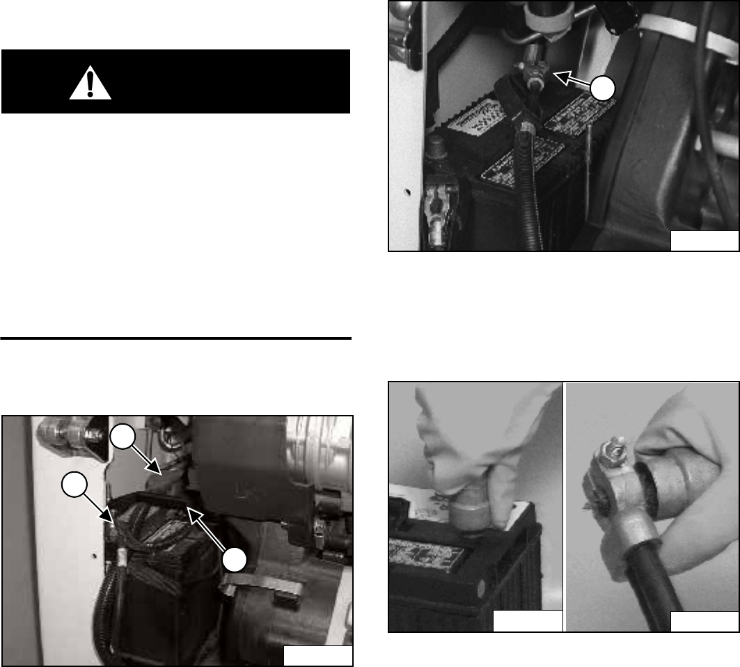
S205 Skid-Steer Loader
87 Operation & Maintenance Manual
ELECTRICAL SYSTEM (CONT’D)
Removing And Installing Battery
WARNING
Batteries contain acid which burns eyes and skin on
contact. Wear goggles, protective clothing and
rubber gloves to keep acid off body.
In case of acid contact, wash immediately with water.
In case of eye contact get prompt medical attention
and wash eye with clean, cool water for at least
15 minutes.
If electrolyte is taken internally drink large quantities
of water or milk! DO NOT induce vomiting. Get
prompt medical attention.
W-2065-1296
Open the rear door.
Figure 155
Disconnect the negative (-) battery cable (1)
[Figure 155].
Remove the battery hold down clamp (2) [Figure 155].
Disconnect the positive (+) battery cable (3)
[Figure 155].
Remove the battery from the loader.
Figure 156
Disconnect the positive (+) battery cable (1)
[Figure 156].
Remove the battery from the loader.
Figure 157
Always clean the battery terminals and cable ends when
installing a new or used battery [Figure 157].
When installing the battery in the loader, do not touch any
metal parts with the battery terminals.
Connect the negative (-) cable last to prevent sparks.
Connect and tighten the battery cables.
Close the rear door before operating the loader.
P-48477
1
2
3
N-18458
1
P-09590
P-09589
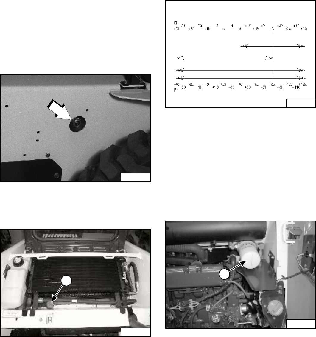
S205 Skid-Steer Loader
Operation & Maintenance Manual 88
HYDRAULIC / HYDROSTATIC SYSTEM
Checking And Adding Fluid
Use only recommended fluid in the hydraulic system.
(See Hydraulic System on Page 121.)
Stop the loader on a level surface.
Lower the lift arms and tilt the Bob-Tach fully back.
Stop the engine.
Figure 158
Check the fluid level in the sight gauge [Figure 158].
Open the rear door and raise the rear grill.
Figure 159
Remove the fill cap (1) [Figure 159].
Add the fluid as needed to bring the level to the center of
the sight gauge [Figure 158].
Install the fill cap.
Hydraulic / Hydrostatic Fluid Chart
Figure 160
Use the correct hydraulic / hydrostatic fluid shown in
chart [Figure 160].
Removing And Replacing Hydraulic / Hydrostatic
Filter
See your SERVICE SCHEDULE for the correct service
intervals. (See SERVICE SCHEDULE on Page 65.)
Open the rear door.
Figure 161
Remove the filter element (1) [Figure 161].
Clean the surface of the filter housing where the seal
contacts the housing.
Put clean oil on the seal of the new filter element.
Install and hand tighten the filter element.
Close the rear door before operating the loader.
N-18445
P-48011
1
P-64023A
ISO Viscosity Grade (VG)
Viscosity Index (VI)
BOBCAT HYDRAULIC / HYDROSTATIC FLUID
SYNTHETIC HYDRAULIC FLUID
Use recommendation from Synthetic Oil Mfr.
VG 46
Minimum VI 140
VG 100
Minimum VI 120
HYDRAULIC / HYDROSTATIC FLUID
TEMPERATURE RANGE
ANTICIPATED DURING MACHINE USE
P-48470
1
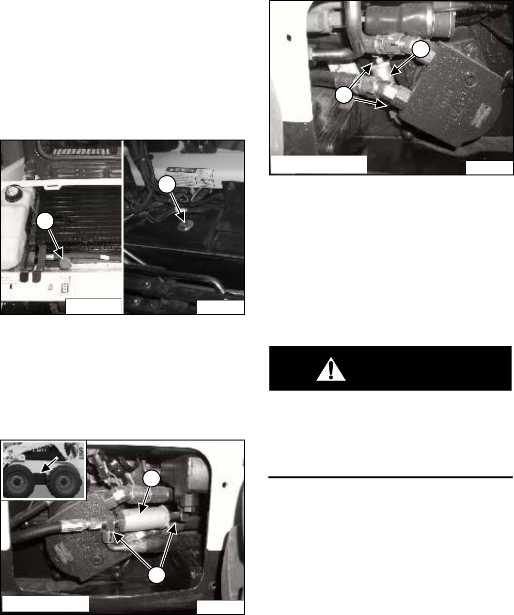
S205 Skid-Steer Loader
89 Operation & Maintenance Manual
HYDRAULIC / HYDROSTATIC SYSTEM (CONT’D)
Removing And Replacing Hydraulic Fluid And Case
Drain Filters
See your SERVICE SCHEDULE for the service interval.
(See SERVICE SCHEDULE on Page 65.)
The fluid must be replaced if it becomes contaminated or
after major repairs. If the fluid is replaced, the hydrostatic
filter and both case drain filters must be replaced.
Figure 162
Raise the cab (See Raising on Page 71).
Open the rear door, remove the rear grill and remove the
reservoir fill cap (1) [Figure 162].
Remove the plug (2) [Figure 162] and use a pump to
remove the oil from the reservoir. Install the plug again.
Figure 163
Remove the motor access covers (Inset) [Figure 163]
from both sides of the loader.
Disconnect the fittings (1) [Figure 163] and remove the
case drain filter (2) [Figure 163]. Use a plug and cap to
prevent leakage.
Figure 164
Disconnect the fittings (1) [Figure 164] and remove the
case drain filter (2) [Figure 164]. Use a plug and cap to
prevent leakage.
Replace the hydraulic / hydrostatic filter element. (See
HYDRAULIC / HYDROSTATIC SYSTEM on Page 88.)
Replace both hydrostatic motor case drain filters (2)
[Figure 163] and [Figure 164].
Add the correct fluid to the reservoir until the fluid level is
at the center of the sight gauge (Do not overfill).
WARNING
Hydraulic fluid escaping under pressure can have
sufficient force to enter a person’s body by
penetrating the skin. This can cause serious injury
and possible death if proper medical treatment by a
physician familiar with this injury is not received
immediately.
W-2145-0290
Install the rear grill and close the rear door.
Lower the cab (See Lowering on Page 72).
P-54217
P-48011
1
2
2
1
P-54216
Left Side Shown
2
1
P-54215
Right Side Shown
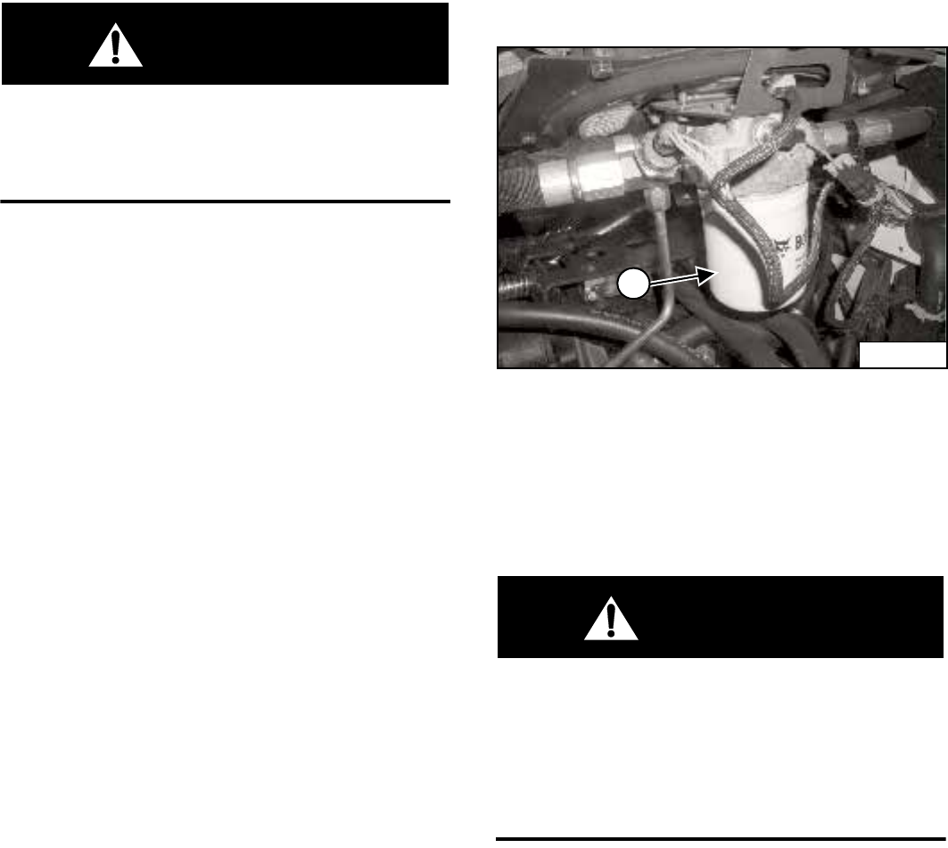
S205 Skid-Steer Loader
Operation & Maintenance Manual 90
HYDRAULIC / HYDROSTATIC SYSTEM (CONT’D)
Removing And Replacing Hydraulic Fluid And Case
Drain Filters (Cont’d)
WARNING
Always clean up spilled fuel or oil. Keep heat, flames,
sparks or lighted tobacco away from fuel and oil.
Failure to use care around combustibles can cause
explosion or fire which can result in injury or death.
W-2103-1285
Start the engine and operate the loader hydraulic
controls. Stop the engine and check for leaks.
Check the fluid level in the reservoir and add as needed.
Removing And Replacing Charge Filter
The charge filter is located under the cab.
Raise the cab (See Raising on Page 71).
Figure 165
Remove the filter (1) [Figure 165].
Clean the surface of the filter housing where the filter seal
contacts the housing.
Put clean oil on the seal of the new filter. Install and hand
tighten the new filter.
WARNING
Diesel fuel or hydraulic fluid under pressure can
penetrate skin or eyes, causing serious injury or
death. Fluid leaks under pressure may not be visible.
Use a piece of cardboard or wood to find leaks. Do
not use your bare hand. Wear safety goggles. If fluid
enters skin or eyes, get immediate medical attention
from a physician familiar with this injury.
W-2072-0496
Start the engine and operate the loader hydraulic
controls.
Stop the engine and check for leaks at the filter.
Check the fluid level in the reservoir and add as needed.
P-66884
1
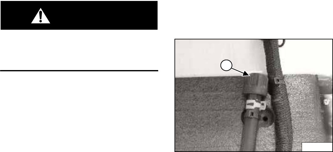
S205 Skid-Steer Loader
91 Operation & Maintenance Manual
HYDRAULIC / HYDROSTATIC SYSTEM (CONT’D)
Removing And Replacing Charge Filter (Cont’d)
WARNING
Always clean up spilled fuel or oil. Keep heat, flames,
sparks or lighted tobacco away from fuel and oil.
Failure to use care around combustibles can cause
explosion or fire which can result in injury or death.
W-2103-1285
Lower the cab. (See Lowering on Page 72.)
Breather Cap
See your SERVICE SCHEDULE for the correct
replacement interval. (See SERVICE SCHEDULE on
Page 65.)
Raise the cab. (See Raising on Page 71.)
Figure 166
Remove the breather cap (1) [Figure 166] and discard.
Install new cap.
Lower the cab. (See Lowering on Page 72.)
P-68218
1
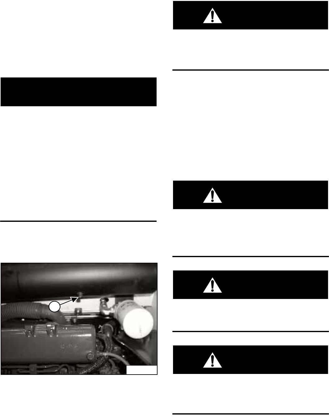
S205 Skid-Steer Loader
Operation & Maintenance Manual 92
SPARK ARRESTOR MUFFLER
Cleaning Procedure
See your SERVICE SCHEDULE for service the interval
for cleaning the spark arrestor muffler. (See SERVICE
SCHEDULE on Page 65.)
Do not operate the loader with a defective exhaust
system.
IMPORTANT
This loader is factory equipped with a spark arrestor
muffler. It is necessary to do maintenance on this
spark arrestor muffler to keep it in working condition.
The spark arrestor muffler must be serviced by
dumping the spark chamber every 100 hours of
operation.
If this machine is operated on flammable forest,
brush or grass covered land, it must be equipped
with a spark arrestor attached to the exhaust system
and maintained in working order.
Make reference to local laws and regulations for
spark arrestor requirements.
I-2022-0595
Stop the engine. Open the rear door and raise the rear
grill.
Figure 167
Remove the plug (1) [Figure 167] from the bottom of the
muffler.
WARNING
When the engine is running during service, the
steering levers must be in neutral and the parking
brake engaged. Failure to do so can cause injury or
death.
W-2006-0284
Start the engine and run for about 10 seconds while a
second person, wearing safety glasses, holds a piece of
wood over the outlet of the muffler.
This will force contaminants out through the cleanout
hole.
Stop the engine.
Install and tighten the plug.
Lower the rear grill and close the rear door.
WARNING
When an engine is running in an enclosed area, fresh
air must be added to avoid concentration of exhaust
fumes. If the engine is stationary, vent the exhaust
outside. Exhaust fumes contain odorless, invisible
gases which can kill without warning.
W-2050-1285
WARNING
Stop engine and allow the muffler to cool before
cleaning the spark chamber. Wear safety goggles.
Failure to obey can cause serious injury.
W-2011-1285
WARNING
Never use machine in atmosphere with explosive
dust or gases or where exhaust can contact
flammable material. Failure to obey warnings can
cause injury or death.
W-2068-1285
P-48476
1
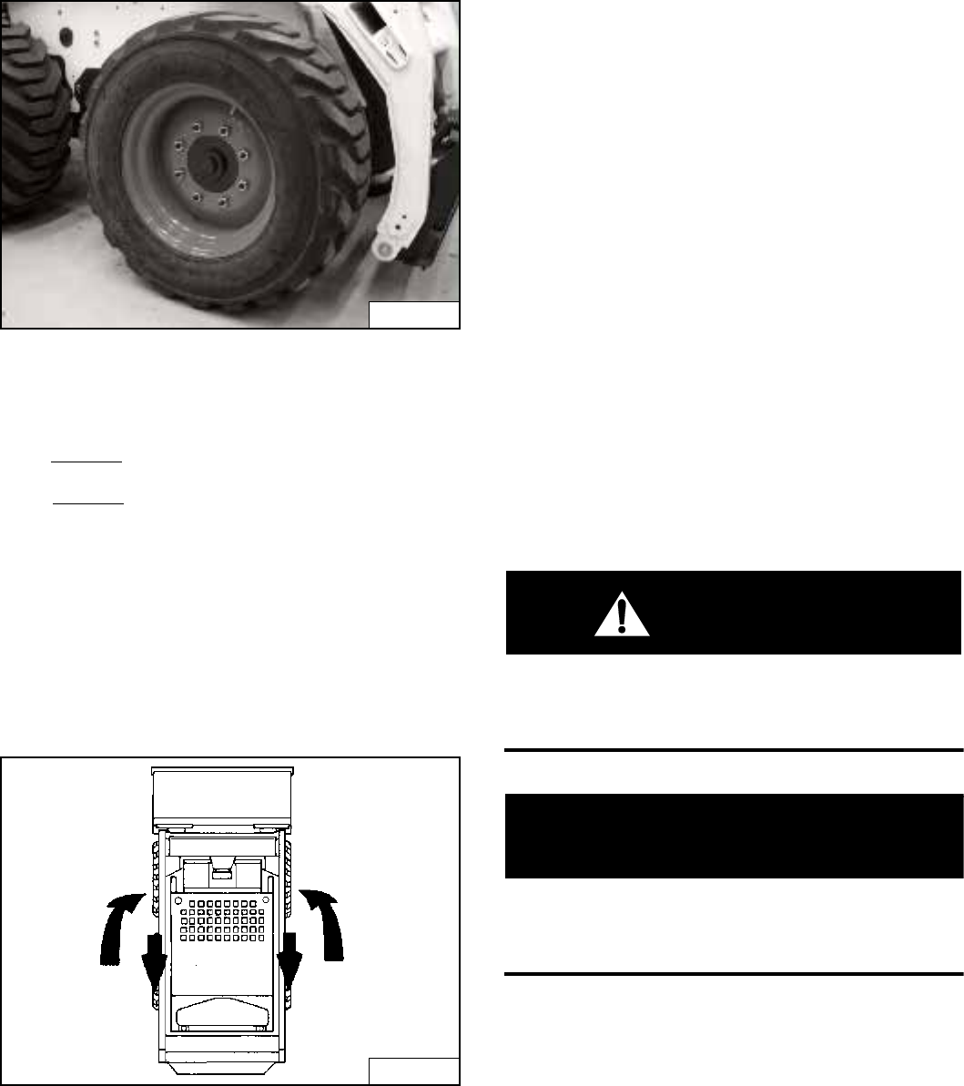
S205 Skid-Steer Loader
93 Operation & Maintenance Manual
TIRE MAINTENANCE
Wheel Nuts
Figure 168
See your SERVICE SCHEDULE for the service interval
to check the wheel nuts [Figure 168]. (See SERVICE
SCHEDULE on Page 65.)
When installing wheel nuts, tighten to 217 Nm torque.
When checking wheel nut torque, set the torque wrench
to 190 Nm to prevent over-tightening.
Rotating
Check the tires regularly for wear, damage and pressure.
Inflate tires to the maximum pressure shown on the
sidewall of the tire.
Figure 169
Rear tires usually wear faster than front tires. To keep tire
wear even, move the front tires to the rear and rear tires
to the front [Figure 169].
It is important to keep the same size tires on each side of
the loader. If different sizes are used, each tire will be
turning at a different rate and cause excessive wear. The
tread bars of all the tires must face the same direction.
Recommended tire pressure must be maintained to avoid
excessive tire wear and loss of stability and handling
capability. Check for the correct pressure before
operating the loader.
Mounting
Tires are to be repaired only by an authorized person
using the proper procedures and safety equipment.
Tires and rims must always be checked for correct size
before mounting. Check rim and tire bead for damage.
The rim flange must be cleaned and free of rust.
The tire bead and rim flange must be lubricated with a
rubber lubricant before mounting the tire.
Avoid excessive pressure which can rupture the tire and
cause serious injury or death.
During inflation of the tire, check the tire pressure
frequently to avoid over inflation.
WARNING
Do not inflate tires above specified pressure. Failure
to use correct tire mounting procedure can cause an
explosion which can result in injury or death.
W-2078-1285
IMPORTANT
Inflate tires to the MAXIMUM pressure shown on the
sidewall of the tire. DO NOT mix brands of tires used
on the same loader.
I-2057-0794
P-54291
B-9976
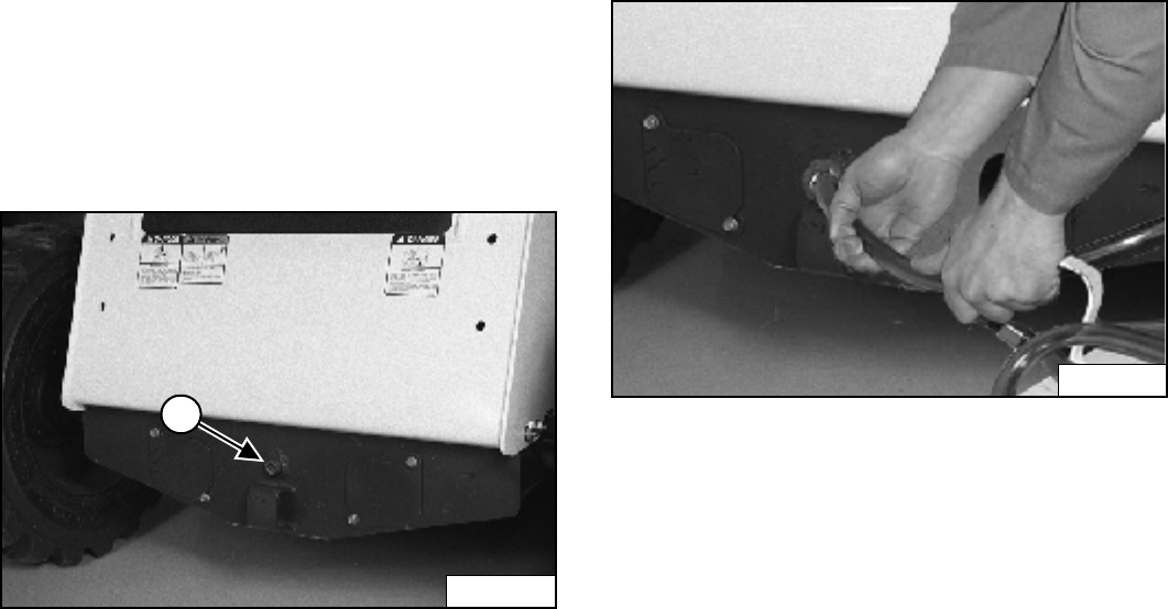
S205 Skid-Steer Loader
Operation & Maintenance Manual 94
FINAL DRIVE TRANSMISSION (CHAINCASE)
Checking And Adding Oil
The chaincase contains the final drive sprockets and
chains. Use the same type of oil as the hydraulic /
hydrostatic system. (See (S205) LOADER
SPECIFICATIONS on Page 119.)
Stop the loader on a level surface.
Stop the engine.
Figure 170
Remove the plug (1) [Figure 170] from the front of the
chaincase housing.
If oil can be reached with the tip of the your finger through
the hole, the oil level is correct.
If the level is low, add oil through the check plug hole until
the oil flows from the hole.
Install and tighten the plug.
Removing Oil From The Chaincase
Remove the check plug (1) [Figure 170] from the front of
the chaincase housing.
Figure 171
Remove the oil from the chaincase [Figure 171].
Recycle or dispose of the used oil in an environmentally
safe manner.
N-18438
1
P-31287B
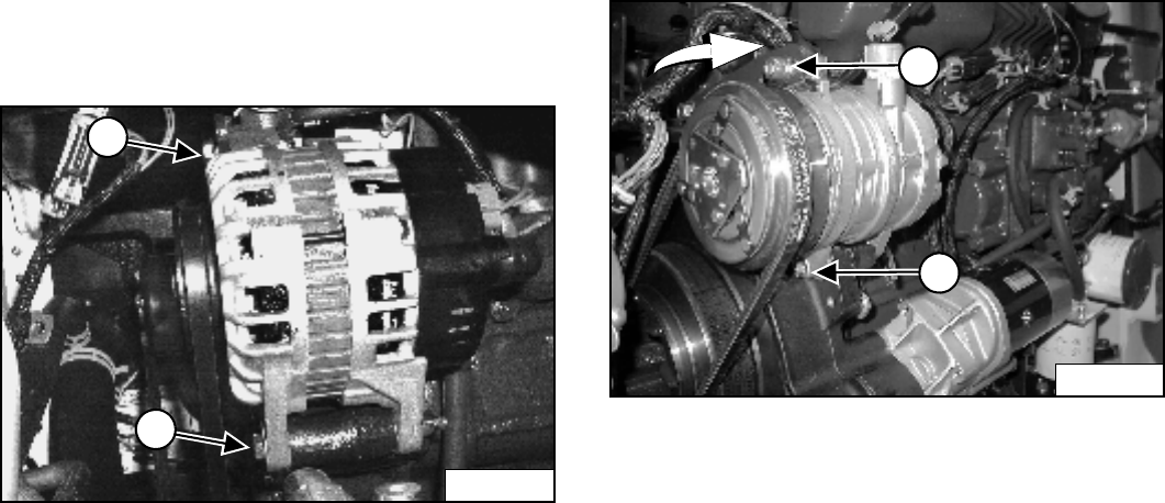
S205 Skid-Steer Loader
95 Operation & Maintenance Manual
ALTERNATOR BELT
Belt Adjustment
Stop the engine.
Raise the operator cab. (See Raising on Page 71.)
Figure 172
Loosen the alternator mounting bolt (1) [Figure 172].
Loosen the adjustment bolt (2) [Figure 172].
Move the alternator until the belt has 8,0 mm movement
at the middle of the belt span with 66 N of force.
Tighten the adjustment bolt and mounting bolt.
Lower the operator cab. (See Lowering on Page 72.)
Belt Replacement
Loosen the alternator mounting and adjustment bolts (1
and 2) [Figure 172] and loosen the belt all the way.
Remove the belt and install a new belt.
Adjust the belt as shown above.
AIR CONDITIONING BELT
Belt Adjustment
Figure 173
Inspect the drive belt regularly for wear. (See SERVICE
SCHEDULE on Page 65.)
Open the rear door. Remove the drive belt cover.
Remove the compressor belt cover.
Loosen the mounting bolt (1) and the adjustment bolt (2)
[Figure 173].
Move the compressor to the rear until the belt has
8,0 mm movement at the middle of the belt span with
66 N force.
Tighten the adjustment bolt and the mounting bolt.
Install the covers and close the rear door.
Belt Replacement
Open the rear door. Remove the drive belt cover and the
compressor belt cover.
Loosen the mounting bolt (1) and the adjustment bolt (2)
[Figure 173] and move the compressor all the way
forward.
Remove the belt and install a new belt.
Adjust the belt as shown above.
P-24543
1
2
P-24288
1
2
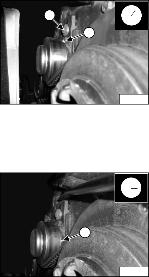
S205 Skid-Steer Loader
Operation & Maintenance Manual 96
DRIVE BELT
Belt Adjustment
Stop the engine.
Open the rear door and disconnect the negative (-) cable
from the battery.
Remove three belt shield fasteners and remove the belt
shield.
Figure 174
Loosen the bolt (1) [Figure 174] on the spring loaded
drive idler.
NOTE: The pointer will be at the 1 o'clock position (2)
[Figure 174] when the belt tensioner is not
under spring tension.
Figure 175
Push the idler pulley against the belt, using a pry bar
[Figure 175]. The pointer will be at the 3 o'clock
position (1) [Figure 175] when the idler pulley is against
the stop (maximum movement).
Raise the idler assembly slightly so that the pulley is
operating on spring tension and not against the stop.
NOTE: Do not set the idler against the travel stop in
the 3 o'clock position.
Tighten the mounting bolt (1) [Figure 174] to 34-38 Nm
torque.
Run the engine for a few minutes. Stop the engine and
recheck the pointer position.
Readjust if necessary.
After the idler has been in service, readjust when the
pointer reaches the 1 o'clock position.
Install the belt shield and fasteners.
Connect the negative (-) battery cable.
Close the rear door.
Belt Replacement
Follow the steps above to loosen the drive belt tensioner.
Remove the bolt (1) [Figure 174] from the tensioner and
remove the tensioner assembly.
Remove the fan drive belt.
Remove the drive belt from the pump pulley and flywheel
and remove the belt from the loader.
Install the new drive belt. Install the belt tensioner
assembly.
Install the fan drive belt.
Adjust the drive belt, reinstall previously removed
components and continue procedure from Belt
Adjustment above.
P-48478A
2
1
P-48479A
1
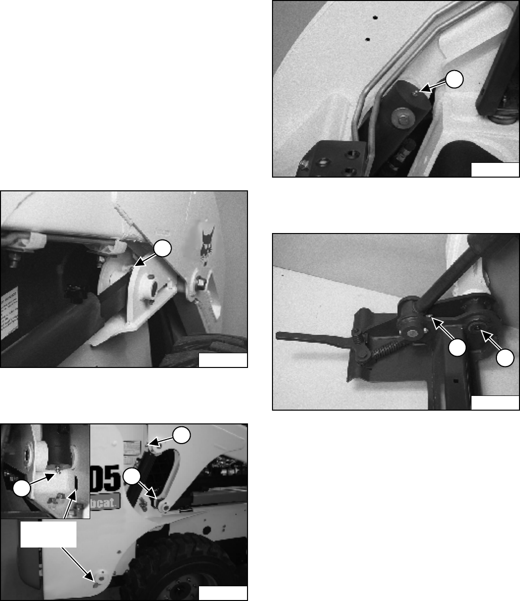
S205 Skid-Steer Loader
97 Operation & Maintenance Manual
LUBRICATING THE LOADER
Lubrication Locations
Lubricate the loader as specified for the best
performance of the loader. (See SERVICE SCHEDULE
on Page 65.)
Record the operating hours each time you lubricate the
Bobcat Loader.
Always use a good quality lithium based multi-purpose
grease when you lubricate the loader. Apply lubricant
until extra grease shows.
Lubricate the following locations on the loader:
Figure 176
1. Stabilizer Rod - Front (Both Sides) [Figure 176].
Figure 177
2. Stabilizer Rod - Rear (Both Sides) [Figure 177].
3. Lift Cylinder Rod End (Both Sides) [Figure 177].
4. Lift Cylinder Base End (Both Sides) [Figure 177].
Figure 178
5. Tilt Cylinder Base End (Both Sides) [Figure 178].
Figure 179
6. Tilt Cylinder Rod End (Both Sides) [Figure 179].
7. Bob-Tach Pivot Pin (Both Sides) [Figure 179].
N-18505
1
P-31841C
Access
Hole
3
2
4
N-18506
N-18510
5
N-18509
6
7
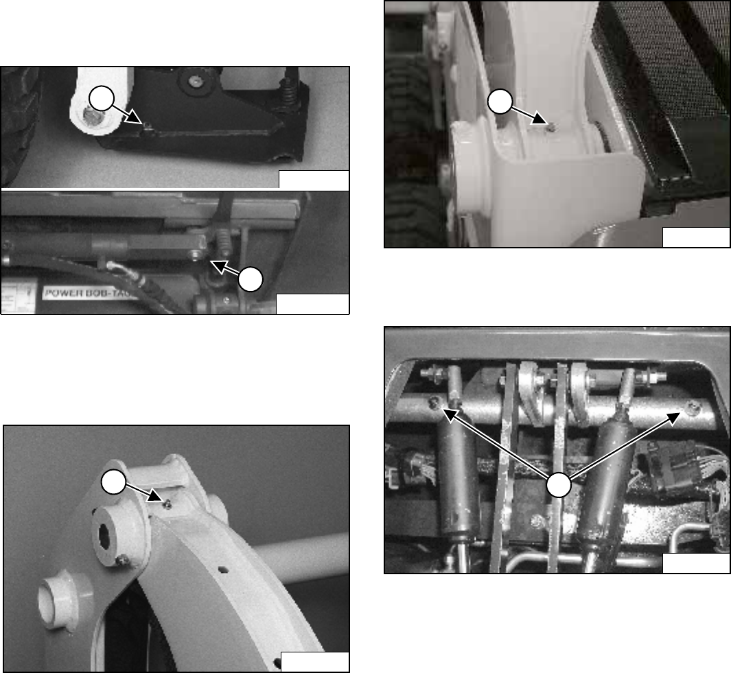
S205 Skid-Steer Loader
Operation & Maintenance Manual 98
LUBRICATING THE LOADER (CONT’D)
Lubrication Locations (Cont’d)
Figure 180
8. Bob-Tach Wedge (Both Sides) [Figure 180].
9. Power Bob-Tach Cylinder (Both Sides) [Figure 180].
Figure 181
10. Lift Arm Pivot Pin (Both Sides) [Figure 181].
Figure 182
11. Lift Arm Link Pivot Pin (Both Sides) [Figure 182].
Figure 183
12. 250 Hours: Steering Lever Shaft (2) [Figure 183].
8
N-18511
P-16045
9
N-18508
10
P-31839
11
P-24703
12
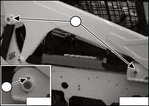
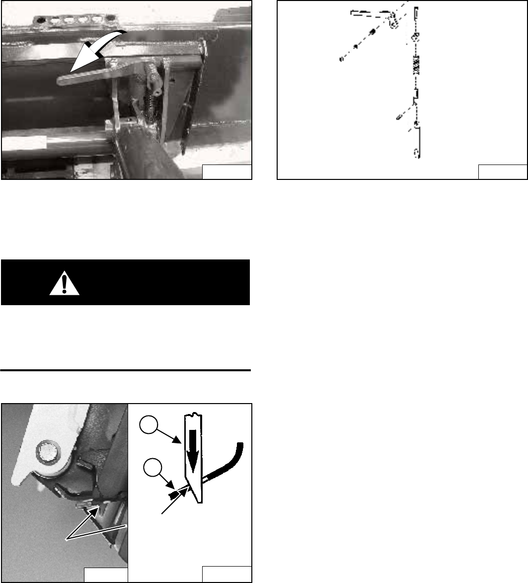
S205 Skid-Steer Loader
Operation & Maintenance Manual 100
BOB-TACH (HAND LEVER)
Inspection And Maintenance
Figure 185
Move the Bob-Tach levers down to engage the wedges
[Figure 185].
The levers and wedges must move freely.
WARNING
Bob-Tach wedges must extend through the holes in
attachment. Levers must be fully down and locked.
Failure to secure wedges can allow attachment to
come off and cause injury or death.
W-2102-0588
Figure 186
The wedges (1) must extend through the holes in the
attachment mounting frame (2) [Figure 186].
The spring loaded wedge (1) [Figure 186] must contact
the lower edge of the hole in the attachment (2)
[Figure 186].
If the wedge does not contact the lower edge of the hole
[Figure 186], the attachment will be loose and can come
off the Bob-Tach.
Figure 187
Inspect the mounting frame on the attachment and the
Bob-Tach, linkages and wedges for excessive wear or
damage [Figure 187]. Replace any parts that are
damaged, bent, or missing. Keep all fasteners tight.
Look for cracked welds. Contact your Bobcat dealer for
repair or replacement parts.
Lubricate the wedges. (See SERVICE SCHEDULE on
Page 65). (See LUBRICATING THE LOADER on
Page 97).
P-31693
N-17022 B-15177
2
1
Wedge must contact
lower edge of hole in
the attachment.
TS-1062
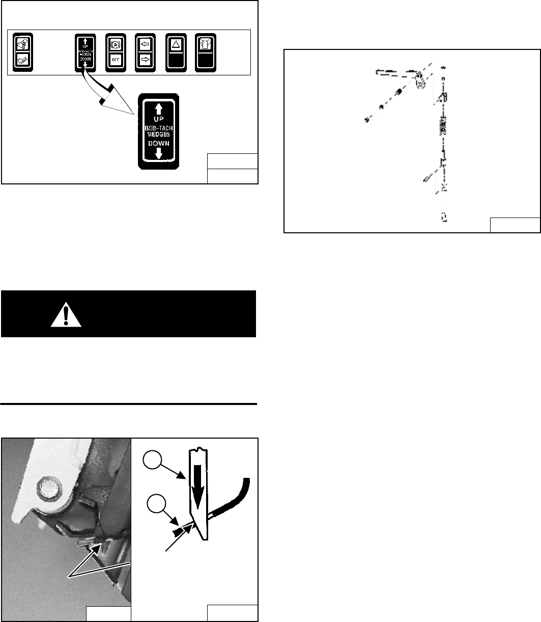
S205 Skid-Steer Loader
101 Operation & Maintenance Manual
BOB-TACH (POWER - OPTION)
Inspection And Maintenance
Figure 188
Push and hold the BOB-TACH “WEDGES UP” switch
[Figure 188] until wedges are fully raised. Push and hold
the BOB-TACH “WEDGES DOWN” switch [Figure 188]
until the wedges are fully down.
The levers and wedges must move freely.
WARNING
Bob-Tach wedges must extend through the holes in
attachment. Levers must be fully down and locked.
Failure to secure wedges can allow attachment to
come off and cause injury or death.
W-2102-0588
Figure 189
The wedges (1) must extend through the holes in the
attachment mounting frame (2) [Figure 189].
The spring loaded wedge (1) [Figure 189] must contact
the lower edge of the hole in the attachment (2)
[Figure 189].
If the wedge does not contact the lower edge of the hole
[Figure 189], the attachment will be loose and can come
off the Bob-Tach.
Figure 190
Inspect the mounting frame on the attachment and the
Bob-Tach, linkages and wedges for excessive wear or
damage [Figure 190]. Replace any parts that are
damaged, bent, or missing. Keep all fasteners tight.
Look for cracked welds. Contact your Bobcat dealer for
repair or replacement parts.
Lubricate the wedges (See SERVICE SCHEDULE on
Page 65). (See LUBRICATING THE LOADER on
Page 97).
B-22965
B-15891
N-17022 B-15177
2
1
Wedge must contact
lower edge of hole in
the attachment.
TS-1062B
S205 Skid-Steer Loader
Operation & Maintenance Manual 102
LOADER STORAGE AND RETURN TO SERVICE
Storage
Sometimes it may be necessary to store your Bobcat
Loader for an extend period of time. Below is a list of
items to perform before storage.
• Thoroughly clean the loader including the engine
compartment.
• Lubricate the loader.
• Replace worn or damaged parts.
• Park the loader in a dry protected shelter.
• Lower the lift arms all the way and put the bucket flat
on the ground.
• Put blocks under the frame to remove weight from the
tires.
• Put grease on any exposed cylinder rods.
• Put fuel stabilizer in the fuel tank and run the engine a
few minutes to circulate the stabilizer to the pump and
fuel injectors.
• Drain and flush the cooling system. Refill with
premixed coolant.
• Replace all fluids and filters (engine, hyd. / hydro.).
• Replace air cleaner, heater and air conditioning filters.
• Put all controls in neutral position.
• Remove the battery. Be sure the electrolyte level is
correct then charge the battery. Store it in a cool dry
place above freezing temperatures and charge it
periodically during storage.
• Cover the exhaust pipe opening.
• Tag the machine to indicate that it is in storage
condition.
Return to Service
After the Bobcat Loader has been in storage, it is
necessary to follow a list of items to return the loader to
service.
• Check the engine and hydraulic oil levels; check
coolant level.
• Install a fully charged battery.
• Remove grease from exposed cylinder rods.
• Check all belt tensions.
• Be sure all shields and guards are in place.
• Lubricate the loader.
• Check tire inflation and remove blocks from under
frame.
• Remove cover from exhaust pipe opening.
• Start the engine and let run for a few minutes while
observing the instrument panels and systems for
correct operation.
• Operate machine, check for correct function.
• Stop the engine and check for leaks. Repair as
needed.

S205 Skid-Steer Loader
103 Operation & Maintenance Manual
SYSTEM SETUP & ANALYSIS
BOBCAT INTERLOCK CONTROL SYSTEM (BICS) ..............................105
Troubleshooting..................................................................................105
DIAGNOSTIC SERVICE CODES............................................................106
Service Codes List .............................................................................106
DISPLAY CONTROLLER PANEL SETUP...............................................111
Panel Setup........................................................................................112
Panel Upgrade ...................................................................................111
Passwords..........................................................................................112
Viewing Service Codes (Key Switch) .................................................114
Viewing Service Codes (Keyless) ......................................................114
SHUTDOWN FEATURE ..........................................................................115
Procedure ..........................................................................................115
SYSTEM SETUP
& ANALYSIS

S205 Skid-Steer Loader
Operation & Maintenance Manual 104

S205 Skid-Steer Loader
105 Operation & Maintenance Manual
BOBCAT INTERLOCK CONTROL SYSTEM (BICS)
Troubleshooting
The following list shows the effects which can happen to the loader, and the probable causes when the BICS System lights
are off or flashing and associated service code.
* Normal BICS operating voltage is less than electrical system voltage.
Indicator
Light Light ON Light OFF
Effect on
Operation of
Loader When
Light is OFF
SERVICE CODES Means System Error
(See Your Bobcat Dealer For Service)
No. of
Flashes
Service
Code Causes
PRESS TO
OPERATE
LOADER Button
is pressed.
PRESS TO
OPERATE
LOADER Button
is not pressed.
- - - - - - - - - - - - - - - -
Seat Bar is
down.
Seat Bar is up. Lift and tilt
functions will
not operate.
2 11-05 Seat Bar sensor circuit shorted to battery
voltage*.
3 11-06 Seat Bar sensor circuit shorted to ground.
Continuous
Flashing
03-09
03-10
System voltage low
System voltage high
Control valve can
be used.
Control valve
cannot be used.
Lift, tilt and
traction
functions will
not operate.
1 17-07 Valve output circuit is open.
2 17-05 Valve output circuit shorted to battery voltage*.
3 17-06 Valve output circuit shorted to ground.
3 17-06 Controller not grounded or intermittent ground.
Continuous
Flashing
03-09
03-10
System voltage low
System voltage high
Loader can be
moved forward &
backward.
Loader cannot
be moved
forward and
backward.
Loader cannot
be moved
forward and
backward.
1 16-07 Traction lock hold solenoid circuit is open.
2 16-05 Traction lock hold solenoid circuit shorted to
battery voltage*.
3 16-06 Traction lock hold solenoid circuit shorted to
ground.
5 15-02 Traction lock pull solenoid circuit is shorted to
battery voltage* - ERROR ON (Should be
OFF).
6 15-03 Traction lock pull solenoid circuit ERROR OFF
(Should be ON).
Continuous
Flashing
03-09
03-10
System voltage low
System voltage high
1
2
3
4

S205 Skid-Steer Loader
Operation & Maintenance Manual 106
DIAGNOSTIC SERVICE CODES
Service Codes List
CODE CODE
01-16 Air filter not connected 11-05 Seat bar sensor short to battery
01-17 Air filter plugged 11-06 Seat bar sensor short to ground
02-16 Hydraulic charge filter not connected 12-21 Front auxiliary PWM switch out of range high
02-17 Hydraulic charge filter plugged 12-22 Front auxiliary PWM switch out of range low
12-23 Front auxiliary PWM switch not in neutral
03-09 Battery voltage low
03-10 Battery voltage high 13-05 Fuel shut-off hold solenoid short to battery
03-11 Battery voltage extremely high 13-06 Fuel shot-off hold solenoid short to ground
03-14 Battery voltage extremely low 13-07 Fuel shut-off solenoid open circuit
03-22 Battery voltage out of range low
14-02 Fuel shut-off pull solenoid error ON
04-09 Engine oil pressure low 14-03 Fuel shut-off pull solenoid error OFF
04-14 Engine oil pressure extremely low
04-15 Engine oil pressure shutdown level 15-02 Traction lock pull solenoid error ON
04-21 Engine oil pressure out of range high 15-03 Traction lock pull solenoid error OFF
04-22 Engine oil pressure out of range low
16-05 Traction lock hold solenoid short to battery
05-09 Hydraulic charge pressure low 16-06 Traction lock hold solenoid short to ground
05-14 Hydraulic charge pressure extremely low 16-07 Traction lock hold solenoid open circuit
05-15 Hydraulic charge pressure shutdown level
05-21 Hydraulic charge pressure out of range high 17-05 Hydraulic lock valve solenoid short to battery
05-22 Hydraulic charge pressure out of range low 17-06 Hydraulic lock valve solenoid short to ground
17-07 Hydraulic lock valve solenoid open circuit
06-10 Engine speed high
06-11 Engine speed extremely high 18-05 Spool Lock Solenoid short to battery
06-13 Engine speed no signal 18-06 Spool Lock Solenoid short to ground
06-15 Engine speed shutdown level 18-07 Spool Lock Solenoid open circuit
06-18 Engine speed out of range
19-02 Bucket position solenoid error ON
07-10 Hydraulic oil temperature high 19-03 Bucket position solenoid error OFF
07-11 Hydraulic oil temperature extremely high
07-15 Hydraulic oil temperature shutdown level 20-02 Two-speed solenoid error ON
07-21 Hydraulic oil temperature out of range high 20-03 Two-speed solenoid error OFF
07-22 Hydraulic oil temperature out of range low
21-02 Glow plug error ON
08-10 Engine coolant temperature high 21-03 Glow plug error OFF
08-11 Engine coolant temperature extremely high
08-15 Engine coolant temperature shutdown level 22-02 Starter error ON
08-21 Engine coolant temperature out of range high 22-03 Starter error OFF
08-22 Engine coolant temperature out of range low
23-02 Rear base solenoid error ON
09-09 Fuel level low 23-03 Rear base solenoid error OFF
09-21 Fuel level out of range high
09-22 Fuel level out of range low 24-02 Rear rod solenoid error ON
24-03 Rear rod solenoid error OFF
10-16 Hydraulic implement filter not connected
10-17 Hydraulic implement filter plugged

S205 Skid-Steer Loader
107 Operation & Maintenance Manual
DIAGNOSTIC SERVICE CODES (CONT’D)
Service Codes List (Cont’d)
CODE CODE
25-02 Rear auxiliary relief solenoid error ON 32-61 Handle lock short to ground
25-03 Rear auxiliary relief solenoid error OFF 32-62 Handle lock short to battery
32-63 Pedal lock short to ground
26-02 Front base solenoid error ON 32-64 Pedal lock short to battery
26-03 Front base solenoid error OFF 32-65 Sensor supply voltage out of range
32-66 Battery voltage out of range
27-02 Front rod solenoid error ON 32-67 Switch flipped while operating
27-03 Front rod solenoid error OFF 32-68 Lift handle information error
32-69 Control pattern switch flipped while operating
28-02 Diverter solenoid error ON 32-70 Right drive handle short to ground
28-03 Diverter solenoid error OFF 32-71 Right drive handle short to battery
29-02 High flow solenoid error ON 33-23 Main Controller (Bobcat Controller) not programmed
29-03 High flow solenoid error OFF
34-04 Keyless panel no communication to Bobcat
controller
30-28 Controller memory failure
35-02 Two-speed fan error ON
31-28 Interrupted power failure 35-03 Two-speed fan error OFF
32-04 ACS not communicating with Bobcat Controller 36-48 ACD multiple controllers present
32-23 ACS Not calibrated
32-31 Tilt actuator fault 37-02 Two-speed secondary error ON
32-32 Tilt actuator wiring fault 37-03 Two-speed secondary error OFF
32-33 Tilt handle wiring fault
32-34 Tilt actuator not in neutral
32-35 Tilt handle / pedal not in neutral
32-36 Lift actuator fault
32-37 Lift actuator wiring fault
32-38 Lift handle wiring fault
32-39 Lift actuator not in neutral
32-40 Lift handle / pedal not in neutral
32-41 No communication
32-49 Lift actuator short to ground
32-50 Tilt actuator short to ground
32-51 Lift actuator short to battery
32-52 Tilt actuator short to battery
32-53 Lift handle / pedal short to ground
32-54 Tilt handle / pedal short to ground
32-55 Lift handle / pedal short to battery
32-56 Tilt handle / pedal short to battery
32-57 Lift actuator reduced performance
32-58 Tilt actuator reduced performance
32-59 Lift actuator wrong direction
32-60 Tilt actuator wrong direction

S205 Skid-Steer Loader
Operation & Maintenance Manual 108
DIAGNOSTIC SERVICE CODES (CONT’D)
Service Codes List (Cont’d)
CODE CODE
38-04 No communication from joystick controller 38-53 Left forward drive solenoid error OFF
38-05 Left joystick X axis not in neutral 38-54 Left reverse drive solenoid error OFF
38-06 Right joystick X axis not in neutral 38-55 Right forward drive solenoid error OFF
38-07 Left joystick Y axis not in neutral 38-56 Right reverse drive solenoid error OFF
38-08 Right joystick Y axis not in neutral 38-57 Front right extend steering solenoid error OFF
38-09 Control pattern switch - Short to Battery or Ground 38-58 Front right retract steering solenoid error OFF
38-11 Lift actuator not in neutral 38-59 Front left extend steering solenoid error OFF
38-12 Tilt actuator not in neutral 38-60 Front left retract steering solenoid error OFF
38-13 Lift actuator fault 38-61 Rear right extend steering solenoid error OFF
38-14 Tilt actuator fault 38-62 Rear right retract steering solenoid error OFF
38-15 Right wheel speed fault 38-63 Rear left extend steering solenoid error OFF
38-16 Left wheel speed fault 38-64 Rear left retract steering solenoid error OFF
38-17 Tilt actuator reduced performance 38-65 Steering pressure solenoid error OFF
38-18 Lift actuator reduced performance 38-66 Back-up alarm error OFF
38-19 Left joystick X axis out of range high 38-67 No communication from Bobcat controller
38-20 Right joystick X axis out of range low 38-68 Wheel angles (alignment) not calibrated
38-21 Left joystick Y axis out of range high 38-69 Lift & tilt actuators not calibrated
38-22 Right joystick Y axis out of range high 38-70 Interrupted power
38-23 Front right steering sensor out of range high 38-71 Battery out of range
38-24 Front left steering sensor out of range high 38-72 Drive pump not calibrated
38-25 Rear right steering sensor out of range high 38-73 Steering mode / drive mode switch flipped while
operating
38-26 Rear left steering sensor out of range high 38-74 Uncommanded right wheel speed error ON
38-27 Lift actuator out of range high 38-75 Uncommanded left wheel speed error ON
38-28 Tilt actuator out of range high 38-76 Undercurrent steer pressure solenoid
38-29 Left joystick X axis out of range low 38-77 Undercurrent front right extend steer solenoid
38-30 Right joystick X axis out of range low 38-78 Undercurrent front right retract steer solenoid
38-31 Left joystick Y axis out of range low 38-79 Undercurrent front left extend steer solenoid
38-32 Right joystick Y axis out of range low 38-80 Undercurrent front left retract steer solenoid
38-33 Front right steering sensor out of range low 38-81 Undercurrent rear right extend steer solenoid
38-34 Front left steering sensor out of range low 38-82 Undercurrent rear right retract steer solenoid
38-35 Rear right steering sensor out of range low 38-83 Undercurrent rear left extend steer solenoid
38-36 Rear left steering sensor out of range low 38-84 Undercurrent rear left retract steer solenoid
38-37 5 volt sensor supply 1 out of range low 38-85 5 Volt sensor supply 1 out of range high
38-38 5 volt sensor supply 2 out of range low 38-86 5 Volt sensor supply 2 out of range high
38-39 Lift actuator short to ground / out of range low 38-87 Front right wheel blocked (steering mechanical failure)
38-40 Tilt actuator short to ground / out of range low 38-88 Front left wheel blocked (steering mechanical failure)
38-41 Tilt actuator wrong direction 38-89 Rear right wheel blocked (steering mechanical failure)
38-42 Lift actuator wrong direction 38-90 Rear left steering error
38-43 Left forward drive solenoid error ON 38-91 Right speed sensor missing pulses
38-44 Left reverse drive solenoid error ON 38-92 Left speed sensor missing pulses
38-45 Right forward drive solenoid error ON 38-93 Unresponsive right speed sensor
38-46 Right reverse drive solenoid error ON 38-94 Unresponsive left speed sensor
38-47 Front right steering solenoid error ON 38-98 Controller in drive calibration mode
38-48 Front left steering solenoid error ON 38-99 Controller in wheel position calibration mode.
38-49 Rear right steering solenoid error ON
38-50 Rear left steering solenoid error ON
38-51 Steering pressure solenoid error ON
38-52 Back-up alarm error ON

S205 Skid-Steer Loader
109 Operation & Maintenance Manual
DIAGNOSTIC SERVICE CODES (CONT’D)
Service Codes List (Cont’d)
CODE CODE
39-04 Left joystick no communication to Bobcat controller 75-22 Right Joystick Y-Axis Out of Range High (H-Pattern
Only)
75-27 Left Swash Plate Out of Position
40-04 Right joystick no communication to Bobcat controller 75-28 Right Swash Plate Out of Position
75-29 Left Joystick X-Axis Out of Range Low
44-02 Horn error ON 75-31 Left Joystick Y-Axis Out of Range Low
44-03 Horn error OFF 75-32 Right Joystick Y-Axis Out of Range Low (H-Pattern
Only)
75-37 5 Volt Sensor Supply 1 Out of Range Low
45-02 Right blinker error ON 75-39 Left Swash Plate Sensor Out of Range High
45-03 Right blinker error OFF 75-40 Left Swash Plate Sensor Out of Range Low
75-41 Right Swash Plate Out of Range High
46-02 Left blinker error ON 75-42 Right Swash Plate Sensor Out of Range Low
46-03 Left blinker error OFF 75-43 Left Forward Drive Solenoid Error ON
75-44 Left Reverse Drive Solenoid Error ON
47-21 8 volt sensor supply out of range high 75-45 Right Forward Drive Solenoid Error ON
47-22 8 volt sensor supply out of range low 75-46 Right Reverse Drive Solenoid Error ON
75-52 Backup Alarm Error ON
48-02 Front light relay error ON 75-53 Left Forward Drive Solenoid Error OFF
48-03 Front light relay error OFF 75-54 Left Reverse Drive Solenoid Error OFF
75-55 Right Forward Drive Solenoid Error OFF
49-02 Rear light relay error ON 75-56 Right Reverse Drive Solenoid Error OFF
49-03 Rear light relay error OFF 75-66 Backup Alarm Error OFF
75-67 No Communication from Bobcat Controller
60-21 Rear auxiliary control out of range high 75-69 Battery Voltage Out of Range High
60-22 Rear auxiliary control out of range low 75-70 Interrupted Power (also occurs after software
updates)
60-23 Rear auxiliary control not returning to neutral 75-71 Battery Voltage Out of Range Low
75-72 Drive Pump Not Calibrated
64-02 Switched power relay error ON 75-73 ISO / H Pattern Switch Flipped While Operating
64-03 Switched power relay error OFF 75-74 Right Wheel Speed Uncommanded Motion
75-75 Left Wheel Speed Uncommanded Motion
74-72 Bobcat controller in boot code 75-76 No Communication from ACS Controller
74-73 Left hand panel system RX error 75-77 Left Speed Sensor Out of Range High
75-78 Right Speed Sensor Out of Range High
75-4 No Communication from Drive Controller 75-79 Left Speed Sensor Out of Range Low
75-5 Left Joystick X-Axis Not in Neutral 75-80 Right Speed Sensor Out of Range Low
75-7 Left Joystick Y-Axis Not in Neutral 75-85 5-Volt Sensor Supply 1 Out of Range High
75-8 Right Joystick Y-Axis Not in Neutral (H-Pattern Only) 75-91 Left Swash Sensor Reversed
75-9 ISO / H Pattern Switch Short to Ground or Battery 75-92 Right Swash Sensor Reversed
75-17 Left Swash Plate Not in Neutral 75-93 Unresponsive Right Speed Sensor
75-18 Right Swash Plate Not in Neutral 75-94 Unresponsive Left Speed Sensor
75-21 Left Joystick Y-Axis Out of Range High 75-95 Left Speed Sensor Reverse Direction
75-19 Left Joystick X-Axis Out of Range High 75-96 Right Speed Sensor Reverse Direction
75-21 Left Joystick Y-Axis Out of Range High (H-Pattern
Only)
75-98 Controller in Calibration Mode

S205 Skid-Steer Loader
Operation & Maintenance Manual 110
DIAGNOSTIC SERVICE CODES (CONT’D)
Service Codes List (Cont’d)
CODE CODE
77-48 Key Switch
78-74 Door / Transport Lock
80-02 ACD output ‘A’ error ON Door Transport Lock
80-03 ACD output ‘A’ error OFF
81-02 ACD output ‘B’ error ON
81-03 ACD output ‘B’ error OFF
82-02 ACD output ‘C’ error ON
82-03 ACD output ‘C’ error OFF
83-02 ACD output ‘D’ error ON
83-03 ACD output ‘D’ error OFF
84-02 ACD output ‘E’ error ON
84-03 ACD output ‘E’ error OFF
85-02 ACD output ‘F’ error ON
85-03 ACD output ‘F’ error OFF
86-02 ACD output ‘G’ error ON
86-03 ACD output ‘G’ error OFF
87-02 ACD output ‘H’ error ON
87-03 ACD output ‘H’ error OFF
90-02 Service tool output ‘C’ error ON
90-03 Service tool output ‘C’ error OFF
91-02 Service tool output ‘D’ error ON
91-03 Service tool output ‘D’ error OFF
92-02 Service tool output ‘E’ error ON
92-03 Service tool output ‘E’ error OFF
93-02 Service tool output ‘F’ error ON
93-03 Service tool output ‘F’ error OFF
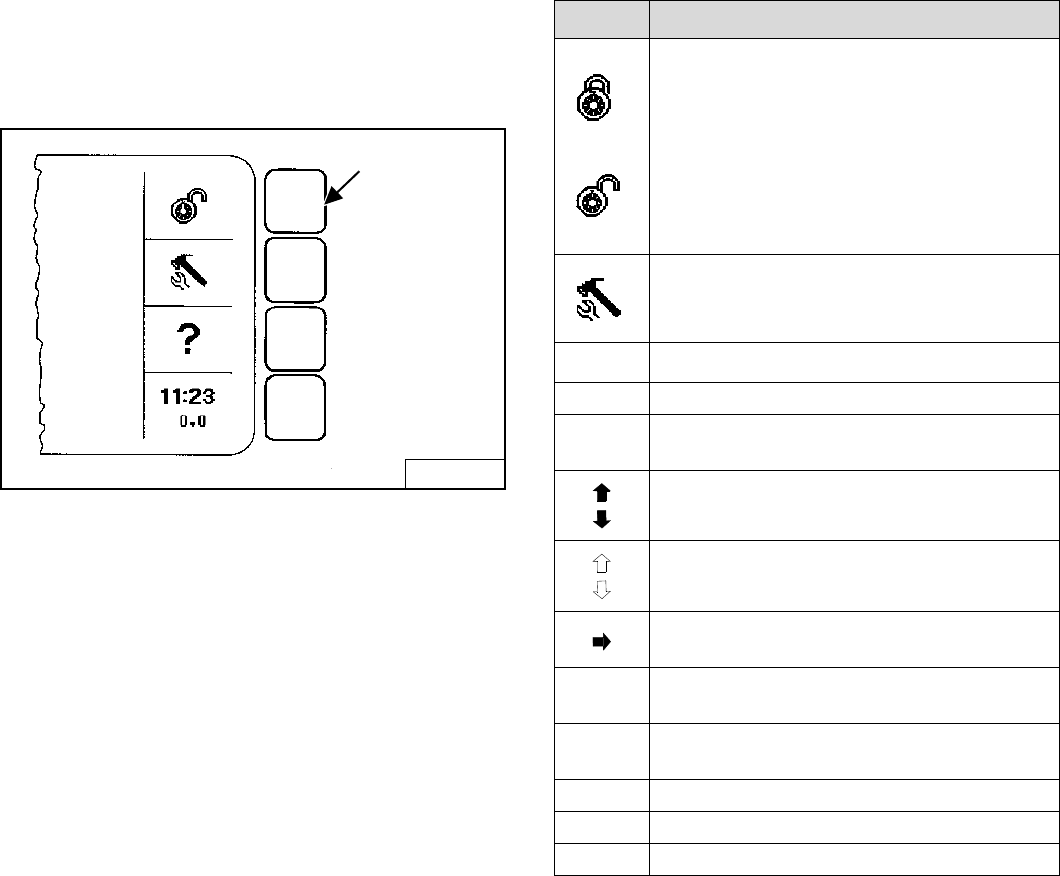
S205 Skid-Steer Loader
111 Operation & Maintenance Manual
DISPLAY CONTROLLER PANEL SETUP
Panel Upgrade
Icon Identification
Figure 191
Make selection by pressing SELECTION BUTTON
opposite the Icon [Figure 191].
B-16162
EXAMPLE
SELECTION BUTTON
ICON DESCRIPTION
LOCK / UNLOCK: Allows machine to be
locked / unlocked. You must lock machine to
activate security system.
When system is unlocked, the user can press
RUN / ENTER then press START to begin
operation.
A valid password will need to be entered at
startup to run a locked machine.
TOOL / SETUP: Access system options.
Use to set clock, check system warnings,
select language, set passwords, etc.
?HELP: Access help on current menu item.
EXIT EXIT returns you to previous level menu.
11:23
0.0
CLOCK / JOB CLOCK: Press to clear or lock
job clock; TOOL / SETUP to set time.
UP ARROW: Goes backward one screen.
DOWN ARROW: Goes forward one screen.
OUTLINE ARROWS: No screen available
(backward / forward).
SELECTION ARROW: Use to select menu
item.
NEXT Goes to the NEXT screen in series.
EXAMPLE: the next Active Warning screen.
INFO Goes to more information about an
attachment.
YES / NO Answer yes / no to current setup question.
CLEAR Removes previously installed password.
SET Set accepts current installed password.
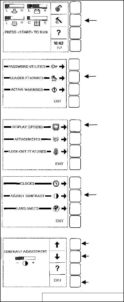
S205 Skid-Steer Loader
Operation & Maintenance Manual 112
DISPLAY CONTROLLER PANEL SETUP (CONT’D)
Panel Setup
Display Options
Figure 192
All new machines with Keyless Instrumentation arrive at
Bobcat dealerships with the panel in locked mode. This
means that a password must be used to start the engine
[Figure 192].
Passwords
For security purposes, your dealer may change the
password and also set it in the locked mode. Your
dealer will provide you with the password.
Owner Password:
Allows for full use of the loader and to setup the
Keyless Panel. Owner can select a password to allow
starting & operating the loader and modify the setup
of the Keyless Panel. Owner should change the
password as soon as possible for security of the
loader.
User Password:
Allows starting and operating the loader; cannot
change password or any of the other setup features.
B-16163/B16164/B-16161/B-16166/B-16167
Press
TOOL / SETUP
Press
ADJUST
CONTRAST
Press UP OR
DOWN arrow
to change
contrast.
Press EXIT to
return to
previous level
menu.
Press
LOADER
FEATURES
Press
DISPLAY
OPTIONS
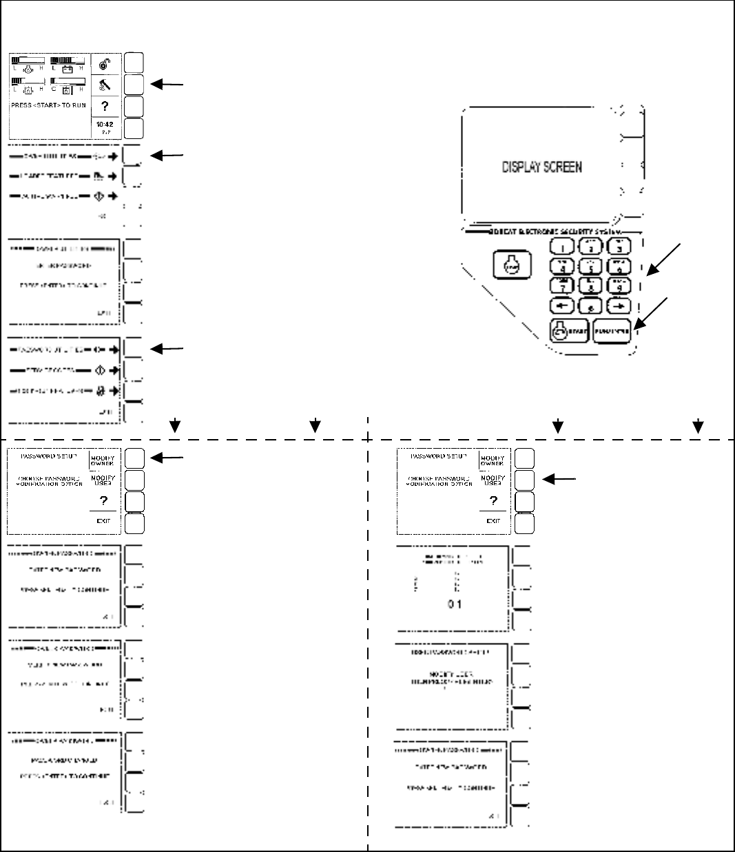
S205 Skid-Steer Loader
113 Operation & Maintenance Manual
DISPLAY CONTROLLER PANEL SETUP (CONT’D)
Passwords (Cont’d)
Figure 193
Keypad
ENTER
B-16163
B-24288
B-24290
B-24291
B-16171
B-24292
B-24293
B-24294
B-16171
B-24295
B-24296
B-24297
B-24289
Changing the Password - Right Instrument Panel
Display Screen
Press TOOL / SETUP
Press OWNER UTILITIES
Enter PASSWORD (owner or master)
on Keypad then press ENTER to
Continue.
Press PASSWORD UTILITIES
OWNER
PASSWORD
USER
PASSWORD
Press MODIFY OWNER
Enter new OWNER
PASSWORD on Keypad then
press ENTER to Continue.
Re-Enter new OWNER
PASSWORD on Keypad then
press ENTER to Continue.
OWNER PASSWORD
procedure is now complete.
Press MODIFY USER
Enter USER number on
Keypad (There can be up to
8 different Users, each with
their own password) then press
ENTER to Continue.
Enter USER PASSWORD
on Keypad then press ENTER
to Continue.
USER PASSWORD procedure
is now complete.
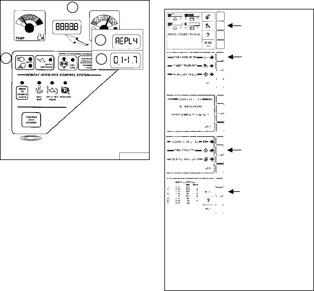
S205 Skid-Steer Loader
Operation & Maintenance Manual 114
DISPLAY CONTROLLER PANEL SETUP (CONT’D)
Viewing Service Codes (Key Switch)
Figure 194
Press and hold the LIGHTS Button (1) [Figure 194] for
two seconds to view SERVICE CODES in the
HOURMETER / CODE DISPLAY (2). If more than one
SERVICE CODE is present, the codes will scroll on the
HOURMETER / CODE DISPLAY.
NOTE: Corroded or loose grounds can cause
multiple service codes and / or abnormal
symptoms. All instrument panel lights
flashing, alarm sounding, headlights and
taillights flashing, could indicate a bad
ground. The same symptoms could apply if
the voltage is low, such as loose or corroded
battery cables. If you observe these
symptoms, check grounds and positive leads
first.
SERVICE CODES may be either a word (3) [Figure 194]
or a number (4).
The following word errors may be displayed.
REPLY One or both instrument panel(s) not
communicating with the controller.
INPUT The controller not communicating with the
left instrument panel.
CODE The controller is asking for a password.
(Keyless instrument panel only.)
ERROR The wrong password was entered.
(Keyless instrument panel only.)
Viewing Service Codes (Keyless)
The Service Codes will aid your dealer in diagnosing
conditions which can damage your machine.
Figure 195
B-15551
1
2
3
4
B-16163
B-24288
B-24290
B-24291
B-24298
The Display Panel will list the Code Number, (CODE)
hourmeter reading when the error occurred (HOUR),
and the User (USER) who was logged in to operate the
machine when the error occurred.
A total of 40 Codes can be stored. When more than
40 codes occur, the oldest code will disappear and the
newest code will be in No. 1 position.
Press NEXT to view the next
8 Service Codes. (A total of
40 Codes can be stored.)
Press TOOL / SETUP
Press OWNER UTILITIES
Enter PASSWORD (owner or
master) on Keypad then press
ENTER to Continue.
Press SERVICE CODES
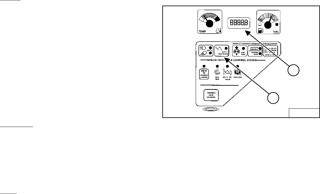
S205 Skid-Steer Loader
115 Operation & Maintenance Manual
DISPLAY CONTROLLER PANEL SETUP (CONT’D)
More EXAMPLES:
Clocks
TOOL / SETUP
LOADER FEATURES
DISPLAY OPTIONS
CLOCKS
SET CLOCK
Use the keypad to set time.
Press RUN / ENTER to set clock.
Press EXIT to return to previous level menu.
RESET JOB CLOCK (Password required)
Press CLEAR to reset job clock to zero.
Press LOCK / UNLOCK to unlock.
Enter Password and press RUN / ENTER.
Languages
TOOL / SETUP
LOADER FEATURES
DISPLAY OPTIONS
LANGUAGES
Select the language, press RUN / ENTER.
Press EXIT to return to previous level menu.
Vitals (Monitor the engine, hydraulic / hydrostatic,
electrical functions when engine is running.)
TOOL / SETUP
LOADER FEATURES
VITALS
Press SELECTION ARROW to select METRIC or
ENGLISH (M/E) readouts
You can monitor real-time readouts of:
Engine Oil Pressure
Engine Coolant Temperature
Hydraulic Charge Pressure
Hydraulic Oil Temperature
System Voltage
Engine Speed
The Display Panel is easy to use. Continue to set
your own preferences for running / monitoring your
Bobcat Loader.
SHUTDOWN FEATURE
Procedure
Figure 196
Press and hold the BUCKET POSITIONING Button (1)
[Figure 196] for two seconds. If the SHUTDOWN feature
is installed, Shtdn will appear in the HOURMETER /
CODE DISPLAY (2) [Figure 196]. If it is not installed,
BASE will appear.
The Operational Code (Software version) will also
appear.
See your Bobcat dealer about installation of this feature.
B-15551
2
1

S205 Skid-Steer Loader
Operation & Maintenance Manual 116

S205 Skid-Steer Loader
117 Operation & Maintenance Manual
SPECIFICATIONS
(S205) LOADER SPECIFICATIONS .......................................................119
Controls..............................................................................................122
Drive System......................................................................................121
Electrical ............................................................................................120
Engine................................................................................................120
Environmental ....................................................................................121
Fluid Capacities .................................................................................122
Fluid Specifications............................................................................122
Function Time ....................................................................................120
Hydraulic Cylinders ............................................................................121
Hydraulic System...............................................................................121
Instrumentation ..................................................................................123
Loader Dimensions............................................................................119
Machine Rating..................................................................................120
Traction ..............................................................................................121
Weights ..............................................................................................120
SPECIFICATIONS

S205 Skid-Steer Loader
Operation & Maintenance Manual 118
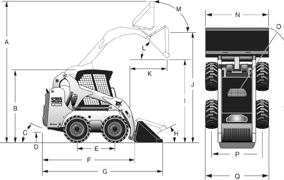
S205 Skid-Steer Loader
119 Operation & Maintenance Manual
(S205) LOADER SPECIFICATIONS
Loader Dimensions
• Dimensions are given for loader equipped with standard dirt bucket and may vary with other bucket types. All
dimensions are shown in millimeters.
• Where applicable, specifications conform to SAE or ISO standards and are subject to change without notice.
Changes of structure or weight distribution of the loader can cause changes in control and steering response
and can cause failure of the loader parts.
(C) Angle of Departure ........................................................ 23°
Carry position ...................................................................... 228 mm
(L) Dump angle at maximum height .................................... 42°
(I) Dump height with standard bucket .................................. 2310 mm
(K) Dump reach at maximum height.................................... 753 mm
(D) Ground clearance .......................................................... 191 mm
(J) Height to bucket hinge pin .............................................. 3002 mm
(B) Height with operator cab................................................ 1938 mm
(F) Length without attachment............................................. 2588 mm
(G) Length with standard bucket.......................................... 3309 mm
(A) Operating height ............................................................ 3862 mm
(H) Rollback at ground position ........................................... 25°
(M) Rollback fully raised at maximum height....................... 95°
(E) Wheelbase..................................................................... 1030 mm
(O) Turning radius with standard bucket .............................. 2001 mm
(Q) Width over tyres, 31 x 12-16.5, 10 ply ........................... 1676 mm
(P) Track, 31 x 12-16.5 tyres - 10 ply................................... 1382 mm
(N) Bucket width, 68-inch .................................................... 1727 mm
Bucket width, 74-inch .......................................................... 1880 mm
B-24268A

S205 Skid-Steer Loader
Operation & Maintenance Manual 120
(S205) LOADER SPECIFICATIONS (CONT’D)
Machine Rating
Function Time
Weights
Engine
Electrical
Lift breakout force 1690 daN
Tilt breakout force 1701 daN
Rated operating capacity 930 kg
Tipping load 2019 kg
Axle torque 5423 Nm
Raise lift arms 3,50 s
Lower lift arms 2,30 s
Bucket rollback 1,90 s
Bucket dump 2,50 s
Operating weight 3023 kg
Shipping weight 2658 kg
Make / Model Kubota / V2403-M-DI-TE2B-BC-I
Fuel Diesel
Cooling Liquid
Power at 2700 RPM 45,5 kW
Rated speed (EEC 80/1269,
ISO 9249) 2700 RPM
Low idle speed 1195-1245 RPM
High idle speed 2860-3000 RPM
Torque at 1475 RPM
(SAE JI 995 Gross) 218 Nm
Number of cylinders 4
Displacement 2433 cm3
Bore 87,1 mm
Stroke 102,3 mm
Lubrication Gear pump pressure
Crankcase ventilation Open
Air filter Dry replaceable cartridge with separate safety element
Ignition Diesel-compression
Starting aid Glow plugs
Alternator Belt driven - 90 A - open
Battery 12 V - 600 cold cranking A at -18°C - 115 min reserve capacity
Starter 12 V - gear reduction type - 2,7 kW

S205 Skid-Steer Loader
121 Operation & Maintenance Manual
(S205) LOADER SPECIFICATIONS (CONT’D)
Hydraulic System
Hydraulic Cylinders
Drive System
Traction
Environmental
Pump type Engine driven, gear type
Pump capacity at 3028 RPM 62,0 l/min
Pump capacity at 3028 RPM -
high flow option 96,5 l/min
System relief at Quick Couplers 22,4-23,1 MPa
Control valve Three-spool, open-centre type with float detent on lift and electrically controlled
auxiliary spool
Hydraulic filter Full-flow replaceable - 3 µm synthetic media element
Fluid lines SAE standard tubelines, hoses, and fittings
Lift cylinder (2) Double-acting
Lift cylinder bore 63,5 mm
Lift cylinder rod 38,1 mm
Lift cylinder stroke 601,2 mm
Tilt cylinder (2) Double-acting with cushioning feature on dump and rollback
Tilt cylinder bore 69,9 mm
Tilt cylinder rod 34,9 mm
Tilt cylinder stroke 335,0 mm
Transmission Infinitely variable tandem hydrostatic piston pumps, driving two fully reversing
hydrostatic motors
Final drive chains Pre-stressed #80 HSOC endless roller chain (no master link) and sprockets in sealed
chaincase with oil lubrication. (Chains do not require periodic adjustments.) Two
chains per side with no idler sprocket.
Main drive Fully hydrostatic; four-wheel drive
Axle size 50,8 mm, heat treated. Axle tubes welded to chaincase. Labyrinth axle seal protection.
Wheel bolts Eight 9/16-inch wheel bolts fixed to axle hubs
Standard tyres 31 x 12-16.5, 10-ply, Bobcat Heavy Duty Wide Flotation
Travel speed 0-11,27 km/h
Operator LpA (98/37 & 474-1) 85 dB(A)
Noise level LWA
(EU Directive 2000/14/EC) 101 dB(A)
Whole body vibration
(ISO 2631-1) 0,77 ms-2
Hand-arm vibration (ISO 5349-1) 1,27 ms-2

S205 Skid-Steer Loader
Operation & Maintenance Manual 122
(S205) LOADER SPECIFICATIONS (CONT’D)
Fluid Capacities
Fluid Specifications
Controls
Chaincase reservoir capacity 30,3 l
Cooling system capacity with
heater 11,4 l
Cooling system capacity without
heater 10,2 l
Engine oil with filter capacity 8,7 l
Fuel tank capacity 90,8 l
Hydraulic reservoir capacity 18,2 l
Hydraulic / Hydrostatic system
capacity 34,1 l
Engine coolant Polypropylene glycol/water mix (53% - 47%) with freeze protection to -37°C
Engine oil Oil must meet API Service Classification of CD, CE, CF4, CG4, or better.
Recommended SAE viscosity number for anticipated temperature range.
* Can by used only when available with appropriate diesel rating.
For synthetic oil use the recommendation from the oil manufacturer.
Hydraulic fluid Bobcat Fluid (P/N 6563328).
Engine Hand lever throttle
Starting Key-type starter switch and shutdown. Glow plugs automatically activated by Standard
or Deluxe instrument panel.
Front auxiliary (standard) Electrical switch on right-hand steering lever
Rear auxiliary (optional) Electrical switch on left-hand steering lever
Loader hydraulics tilt and lift Separate foot pedals, optional Advanced Control System (ACS) or Advanced Hand
Controls (AHC) or Selectable Joystick Control (SJC)
Service brake Two independent hydrostatic systems controlled by two hand-operated steering levers
Secondary brake One of the hydrostatic transmissions
Parking brake Mechanical disc, hand operated rocker-switch on dash panel
Vehicle steering Direction and speed controlled by two hand levers
Auxiliary pressure release Pressure is relieved through the coupler block. Push in and hold for 5 s.
S205 Skid-Steer Loader
123 Operation & Maintenance Manual
(S205) LOADER SPECIFICATIONS (CONT’D)
Instrumentation
The following loader functions are monitored by a combination of gauges and warning lights in the operator's line of sight.
The system alerts the operator of monitored loader malfunctions by way of audible alarm and visual warning lights.
Standard Instrument Panel
• Gauges
• Engine coolant temperature
•Fuel
• Hour-meter
• Indicators
• Attachment Control Device
• Bobcat Interlock Control System
• Glow plugs
• Warning lights
• Advanced Control System (ACS)
• Selectable Joystick Control (SJC)
• Engine air filter
• Engine coolant temperature
• Engine oil pressure
• Fuel level
• General warning
• Hydraulic filter
• Hydraulic oil temperature
• Hydrostatic charge temperature
• Seat belt
• System voltage
Deluxe Instrument Panel (Option)
Same gauges, warning lights and other features as Standard Instrument Panel, plus:
• Bar-type gauges
• Engine oil pressure
• System voltage
• Hydrostatic charge pressure
• Hydraulic oil temperature
• Additional features
• Keyless start with password capability
• Digital clock
• Job clock
• Attachments information
• Digital tachometer
• High Flow lockouts
• Multi-language display
• Help screens
• Diagnostic capability
• Engine/hydraulic systems shutdown function

S205 Skid-Steer Loader
Operation & Maintenance Manual 124

WARRANTY
BOBCAT LOADERS
INGERSOLL RAND INTERNATIONAL warrants to its authorised dealers who in turn warrant to the
end-user/owner that each new Bobcat loader will be free from proven defects in material and
workmanship for twelve months from the date of delivery to the end-user/owner or 2000 hours of
machine usage, whichever occurs first.
During the warranty period, the authorised selling Bobcat dealer shall repair or replace, at
INGERSOLL RAND INTERNATIONAL's option, without charge for parts, labour and travel time of
mechanics, any part of the Bobcat product which fails because of defects in material and
workmanship. The end-user/owner shall provide the authorised Bobcat dealer with prompt written
notice of the defect and allow reasonable time for replacement or repair. INGERSOLL RAND
INTERNATIONAL may, at its option, request failed parts to be returned to the factory.
Transportation of the Bobcat product to the authorized Bobcat dealer for warranty work is the
responsibility of the end-user/owner.
The warranty does not apply to tyres or other trade accessories not manufactured by INGERSOLL
RAND INTERNATIONAL. The owner shall rely solely on the warranty, if any, of the respective
manufacturers thereof. The warranty does not cover replacement of scheduled service items such
as oil, filters, tune-up parts, and other high-wear items. The warranty does not cover damages
resulting from abuse, accidents, alterations, use of the Bobcat product with any bucket or
attachment not approved by INGERSOLL RAND INTERNATIONAL, air flow obstructions, or failure
to maintain or use the Bobcat product according to the instructions applicable to it.
INGERSOLL RAND INTERNATIONAL EXCLUDES OTHER CONDITIONS, WARRANTIES OR
REPRESENTATIONS OF ALL KINDS, EXPRESSED OR IMPLIED, STATUTORY OR OTHERWISE
(EXCEPT THAT OF TITLE) INCLUDING ALL IMPLIED WARRANTIES AND CONDITIONS RELATING
TO MERCHANTABILITY, SATISFACTORY QUALITY AND FITNESS FOR A PARTICULAR PURPOSE.
CORRECTIONS BY INGERSOLL RAND INTERNATIONAL OF NONCONFORMITIES WHETHER
PATENT OR LATENT, IN THE MANNER AND FOR THE TIME PERIOD PROVIDED ABOVE, SHALL
CONSTITUTE FULFILMENT OF ALL LIABILITIES OF INGERSOLL RAND INTERNATIONAL FOR
SUCH NONCONFORMITIES, WHETHER BASED ON CONTRACT, WARRANTY, TORT,
NEGLIGENCE, INDEMNITY, STRICT LIABILITY OR OTHERWISE WITH RESPECT TO OR ARISING
OUT OF SUCH PRODUCT.
THE REMEDIES OF THE END-USER/OWNER SET FORTH UNDER THE PROVISIONS OF THE
WARRANTY OUTLINED ABOVE ARE EXCLUSIVE AND THE TOTAL LIABILITY OF INGERSOLL
RAND INTERNATIONAL INCLUDING ANY HOLDING, SUBSIDIARY, ASSOCIATED OR AFFILIATED
COMPANY OR DISTRIBUTOR WITH RESPECT TO THIS SALE OR THE PRODUCT AND SERVICE
FURNISHED HEREUNDER IN CONNECTION WITH THE PERFORMANCE OR BREACH THEREOF,
OR FROM DELIVERY, INSTALLATION, REPAIR OR TECHNICAL DIRECTION COVERED BY OR
FURNISHED UNDER THIS SALE, WHETHER BASED ON CONTRACT, WARRANTY, TORT,
NEGLIGENCE, INDEMNITY, STRICT LIABILITY OR OTHERWISE SHALL NOT EXCEED THE
PURCHASE PRICE OF THE PRODUCT UPON WHICH SUCH LIABILITY IS BASED.
INGERSOLL RAND INTERNATIONAL INCLUDING ANY HOLDING, SUBSIDIARY, ASSOCIATED OR
AFFILIATED COMPANY AND DISTRIBUTOR SHALL IN NO EVENT BE LIABLE TO THE END-USER/
OWNER, ANY SUCCESSORS IN INTEREST OR ANY BENEFICIARY OR ASSIGNEE RELATING TO
THIS SALE FOR ANY CONSEQUENTIAL, INCIDENTAL, INDIRECT, SPECIAL OR PUNITIVE
DAMAGES ARISING OUT OF THIS SALE OR BY ANY BREACH THEREOF, OR ANY DEFECT IN, OR
FAILURE OF, OR MALFUNCTION OF THE PRODUCT UNDER THIS SALE, WHETHER BASED UPON
LOSS OF USE, LOST PROFITS OR REVENUE, INTEREST, LOST GOODWILL, WORK STOPPAGE,
IMPAIRMENT OF OTHER GOODS, LOSS BY REASON OF SHUTDOWN OR NON-OPERATION,
INCREASED EXPENSES OF OPERATION OR CLAIMS OF USER OR CUSTOMERS OF THE USER
FOR SERVICE INTERRUPTION WHETHER OR NOT SUCH LOSS OR DAMAGE IS BASED ON
CONTRACT, WARRANTY, TORT, NEGLIGENCE, INDEMNITY, STRICT LIABILITY OR OTHERWISE.
4700002-EN (07-06) Printed in Europe
