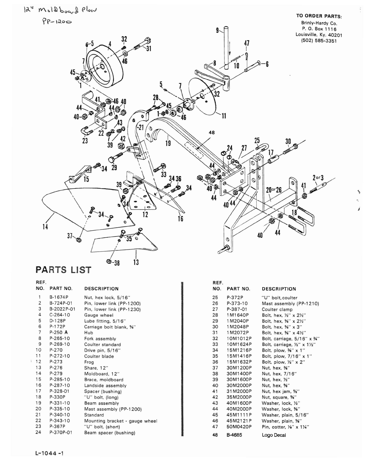
Brinly 12in 3pt Mouldboard Plow (PP 1200) Plow(PP
User Manual: Brinly 12in 3pt Mouldboard Plow (PP-1200) WFMFiles.com
Open the PDF directly: View PDF ![]() .
.
Page Count: 6
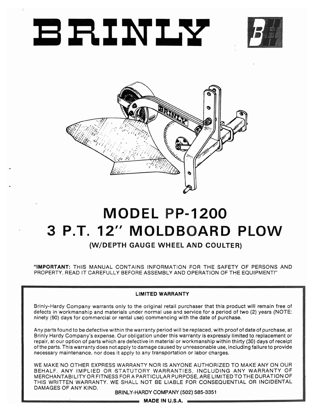
MODEL
PP-1200
3P.T. 12"
MOLDB
OARD
PLOW
(W/DEPTH
GAUGE
WHEEL
AND
COULTER)
"IMPORTANT:
THIS
MANUAL
CONTAINS
INFORMATION
FOR
THE
SAFETY
OF PERSONS
AND
PROPERTY. READ IT CAREFULLY BEFORE ASSEMBLY AND
OPERATION
OF
THE
EQUIPMENT!"
LIMITED WARRANTY
Brinly-Hardy
Company
warrants
only
to the
original
retail
purchaser
that
this
product
will remain free
of
defects in
workmanship
and materials
under
normal
use and service
for
a
period
of
two
(2) years (NOTE:
ninety (90) days
for
commercial
or rental use)
commencing
with
the date of purchase.
Any parts
found
to be
defective
within
the
warranty
period
will be replaced,
with
proof
of
date
of
purchase
, at
Brinly
Hardy
Company
's expense.
Our
obligation
under
this
warranty
is expressly
limited
to replacement
or
repair, at
our
option
of
parts
which
are defective in material or
workmanship
within
thirty
(30) days
of
receipt
of the parts.
This
warranty
does
not
apply to damage caused by unreasonable use,
including
failureto
provide
necessary
maintenance,
nor
does it apply to any
transportat
ion or
labor
charges.
WE MAKE NO
OTHER
EXPRESS WARRANTY NOR IS
ANYONE
AUTHORIZED
TO
MAKE
ANY ON
OUR
BEHALF
.
ANY
IMPLIED
ORBTATUTORY
WARRANTIES
,
INCLUDING
ANY
WARRANTY
OF
MERCHANTABILITY
OR FITNESS FOR A
PARTICULAR
PURPOSE, ARE
LIMITED
TO
THE
DURATION
OF
THIS WRITTEN WARRANTY. WE SHA LL
NOT
BE
LIABLE
FOR
CONSEQUENTIAL
OR
INCIDENTAL
DAMAGES OF
ANY
KIND
.BRINLY-HARDY COMPANY (502) 585-3351
MADE IN U.S.A.
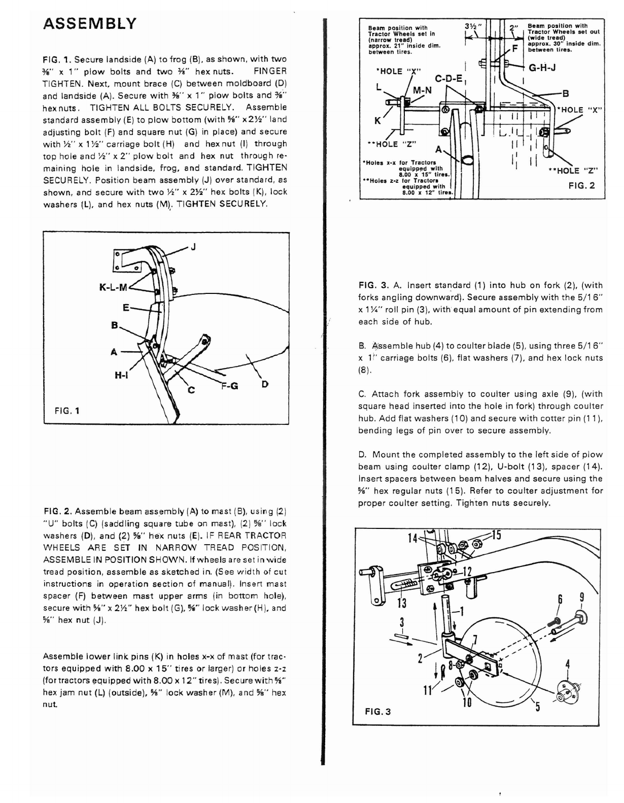
"X"
FIG. 2
·'HO
LE "z"
I-..."':lo_-B
II
L...
.lr
II
I'
I
2"
~~a~~o~~~~~~
1
w~~
~
out
~->-rt-+'*-J"i~
(w
ide
tread)
approx
. 30" Inside
dim.
between
tires.
Beam posit ion with
Tractor
Wneels
set In
(narrow
tread)
approx. 21" ins ide dim.
between
tires.
L
'HOLE
"
X"
-Holes
x-x for Tractor.
equipp~d
with
8.00 x15" tir
..
.
··Hoies
z-z for Tractors
equipped
witn
B.OO
x12" tlr
...
ASSEMBLY
FIG. 1. Secure
lands
ide (A) to f rog (B), as
shown
,
with
two
%" x1"
plow
bo lts and
two
'W'
hex
nuts. FINGER
TIGHTEN .
Next,
mount
brace
(C)
between
moldboard
(D)
and
landside
(A). Secure
with
%" x1" p
low
bolts
and %"
hex nuts .TIGHTEN ALL BOLTS SECURELY .
Assemble
standard
assembly
(E) to
plow
bottom
(w
ith
%"
x2W'
land
adjusting
bolt
(F) and square
nut
(G) in place) and secure
with
W'
x1
Y2
"carriage
bolt
(H) and hex
nut
(I)
through
top
hole and Y2" x2"
plow
bol t and hex
nut
thro
ugh
reo
main ing
hole
in landside,
frog,
and standard.
TIGHTE
N
SECURELY. Pos
it
ion
beam
assembly
(J)
over
standard, as
shown
, and secure
with
two
W ' x2Y2" hex
bolts
(K),
lock
washers (L). and hex
nuts
(M).. TIGHTEN SECURELY.
FIG.l
FIG . 3 . A.
Insert
sta~dard
(1)
into
hub
on
fork
(2),
(with
forks
angling
downward).
Secure
assembly
with
the
5/1 6"
x 1W ' roll pin (3),
with
equal
amount
of
pin
extend
ing
from
each side of hub .
B.
t}
sse
mb
le hub (4) to
coulter
blade
(5), using
three
5/1 6"
x1" carriage
bolts
(6).
flat
washers
(7). and he x
lock
nuts
(8).
C.
Attach
fork
assembly to
cou
lter
us ing axle (9 ), (
wit
h
square head insert ed int o the
hole
in fork)
through
co
ulter
hub .
Add
flat
washers (10) and
secure
with
cotter
pin
(11 ),
bending
legs
of pin over to secure
assembly
.
FIG. 2.
Assemb
le beam ass.emb ly (A) to mas t (B), us
ing
(2 )
"U
"
bolts
(C) (sad
dli
ng square
tube
on mas t), (2 )
%"
lock
washers
(0
).
and
(2) %" hex nu ts IE). IF REAR TRACTOR
WHEELS ARE SET IN
NARROW
TREAD POSIT ION,
ASSEMBLE IN POSITION
SHOWN.
If
wheels
are set i n w id e
tread
position
,
assemble
as
sketched
in. (Se e w
idth
of
cut
instruct
ions
in
operat
ion
section
of
manual
). Inse rt mas t
spacer (F)
between
mast
upper
arms (in
bott
om hole),
secure
with
}fa" x2W' hex
bolt
(G), %"
lock
washer(H). and
%" hex
nut
(J ).
Assemble
lower
link
pins
(K) in holes x-x
of
mast
(for
trac-
tors
equipped
with
8.00
x
15"
tires or larger) or ho les z-z
(for
tractors
equipped
with
8
.00
x
12"
tires
).
Securewit
h %"
hex jam
nut
(l)
(outside). }fa" lock
washe
r(M), and %" hex
nut.
D.
Mount
the
completed
assemb
ly to
the
left
side of p
low
beam
using
coulter
clamp
(12),
U-bolt
(13)
.
spacer
(14)
.
Insert
spacers
between
beam
halves
and secure
using
the
%" hex regular nuts
(15)
. Refer to
coulter
adj
ustment
for
proper
coulter
se
tt
ing. T
ighten
nuts
securely
.
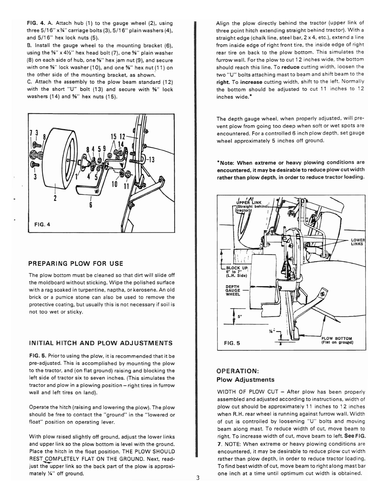
FIG . 4 . A.
Attach
hub
(1) to
the
gauge
wheel
(2), using
three 5
/16
"
x*
" carr
iage
bo
lts
(3), 5
/16
"plain
washers
(4),
and 5/ 16" hex lock n
uts
(5).
B. Insta ll t he gauge w hee l to th e
mount
ing brac ket (6) ,
usin g th e %" x
4W'
hex head bo lt (7).
one
%" plain
was
her
(8 ) on eac h si de of
hub
,
one
%" hex jam nut (9). and se
cure
w it h one %" lock
was
her
(10). and
one
%"
hex nut (11) on
th e othe r side of the
mount
ing
bracket,
as
show
n:
C.
Attac
h the
assembly
to t he p
low
beam
s
tandard
(12)
w it h t he s
hort
"
U"
bo lt (13)
and
secure
w
ith
%"
lock
washe rs (14) and
%"
hex
nuts (15).
PREPARING
PLOW
FOR
USE
The p
low
bo ttom m
ust
be cl eaned so t hat
dirt
w ill sl ide
off
the
moldboa
rd wi
thou
t st ick
ing.
W ipe
the
pol
ished
surface
w
it
h a rag soaked in
turpent
ine
, nap tha , or kerosen e. An
old
b
rick
or a pumice
stone
can aIso be
used
to remove t he
protective
coating,
but
us
ually
thi s is no t
necessary
if so il is
not
too
we t or st ic ky.
INITIAL
HITCH
AND
PLOW
ADJUSTMENTS
FIG.
5. Pr
ior
to usi ng th e p
low
, it is rec
omm
end ed th at it be
pre -ad j usted. This is acco
mp
l
ished
by m
ount
ing
the
p
low
t o th e tr act or, and (on flat g round) raisin g and bl o
ckin
g the
le
ft
side of tracto r six to
seven
inches.
(Thi
s s
im
ulates the
trac
tor
and p
low
in a p
low
ing
pos
it
ion
- rig
ht
tires in furro w
wa ll and l
eft
tir
es on lan d).
Operate the
hitch
(raisin g and low eri ng the p
low
). Th e pl ow
s
hou
ld be fr ee to
con
tac
t t he " gro un d" in th e "
lowe
red or
fl oat" posit io n on
operat
ing lever.
W
ith
plow
raised
slightly
off
ground
, ad
just
the
lower
li nks
and
upper
lin k so the
plow
bottom
is level w
ith
t he
ground.
Place
the
hit
ch in
the
float
position
. THE
PLOW
SHOULD
REST.,.£9MPLETELY FLAT ON
THE
GROUND
.Next, read-
just
the
upper link so
the
back
part
of
the
plow
is
approxi
-
mately
Y4
" off
ground.
3
Al
ign
the
plow
d
irect
ly
behind
the
trac
tor
(upper li nk of
three
point
hitch
extend
ing
s
traight
behind
tr act or). W ith a
straigh
t
edge
(ch al k li ne, s
teel
bar
, 2 x 4. etc.).
extend
a li n e
from insi de
edge
of rig
ht
fro
nt
tir
e. th e inside
edge
of rig ht
rear t ire on bac k t o
the
plo w b
ott
om. Th is s
imu
lates
th e
furrow
wa
ll. For t he p lo w t o c ut 12 inches w ide .
the
bo
tto
m
sho uld reach
thi
s line. To reduc e
cutt
ing
w
idth
, loo sen th e
tw o " U" bo lts a
ttac
hing ma st to be,am and sh ift
beam
to th e
right.
To
increase
cuttin
g w i
dt
h, shift to
the
left . N orm
ally
t he bo t
tom
should
be ad
justed
to cu t 11 inches to 12
in ch es w
ide.
*
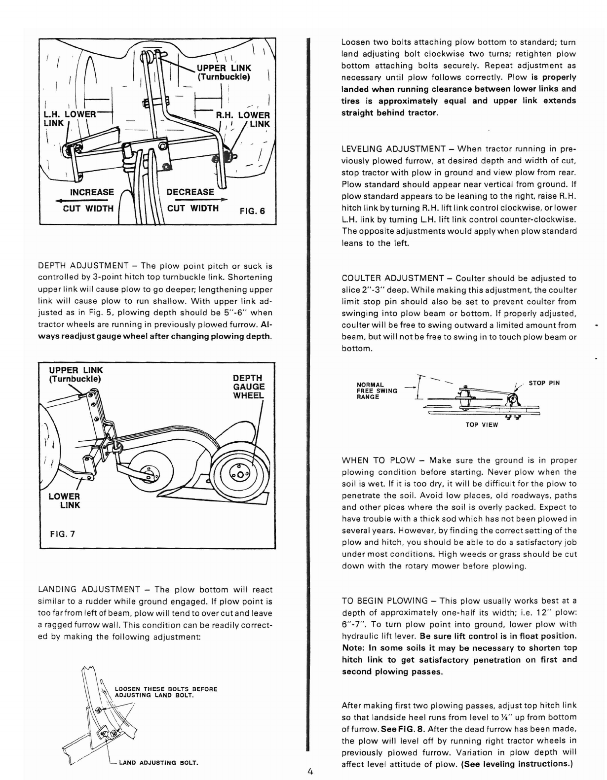
The
dep
t h
gauge
whee
l, w
hen
prope
rly adju
sted
, w ill pre-
vent
p
low
fro
m go
ing
too
deep
w he n soh or w et sp o ts are
encountered
. For a co ntro
lled
6 inch p
low
dept h. set
gauge
wheel
approx
imatel
y 5 inches
off
groun
d.
*Note
:
When
extreme
or
heavy
plowing
cond
it
ions
are
encountered
.
it
may
be
desirable
to
reduce
plow
cu
t w idt h
rather
than
plow
depth.
in
order
to
reduce
tractor
loa
din
g.
:
~
~~~
if9
rt
~
-!j
:t
f-=
"::::J
~
-
LOWER
~
LINKS
1 ,: ::
ho~~
'~
'P
I
6" to 7" I
(L.H. S
ide)
DEPTH
GAUGE
-
WHEEL
FIG
.5
OPERATION:
Plow
Adjustments
WIDTH
OF
PLOW
CUT -
Af
ter
p
low
has bee n p
rop
erly
assembled
and
ad
juste
d
accord
ing
to inst ruct io ns, w idt h of
p
low
cut
shou
ld be
approx
ima
te ly 11 inches to 12 inches
w
hen
R.H. rear
whe
el is r
unning
aga ins t fu rrow w al l. W idt h
of cu t is co
ntr
oll
ed by loos
enin
g
"U
" bo lts an d m ov in g
beam
alo ng mas t. To red uce w id t h of cut.
move
be am to
righ
t. To incr ease w
idth
of cut,
move
beam
to l
eft.
See
FIG.
7 . NOTE:
When
extrem e or
heavy
plowi
ng cond iti o ns are
encountered,
it
may
be
desirable
to reduce
plow
c
ut
w
idth
rather
than
plow
depth
, in
order
to reduce
tractor
loading.
To f
ind
best
width
of cut,
move
beam
to right
along
mast
bar
one
inc h at a ti m e
unt
il
opt
imum
cut w
idth
is
obt
ained.
DEPTH
ADJUSTMENT
- The
plow
point
pitch
or
suck
is
controlled
by
3-point
hitch
top
turnbuckle
link.
Shortening
upper
l
ink
will
cause
plow
to go
deeper;
lengthening
upper
link
will
cause
plow
to run
shallow
.
With
upper
link
ad-
justed
as in Fig. 5,
plowing
depth
should
be
5"-6
"
when
tractor
wheels
are
running
in
prev
iously
plowed
furrow.
Al -
ways
readjust
gauge
wheel
after
changing
plowing
depth.
Loosen
two
bolts
attach
ing
plow
bottom
to standard;
turn
land
adjust
ing
bolt
clockw
ise
two
turns; ret
ighten
plow
bottom
attaching
bolts
securely.
Repeat
adjustment
as
necessary
until
plow
follows
correctly.
Plow
is
prope
rly
landed
when
running
clearance
between
lower
links
and
tires
is
approximately
equal
and
upper
link
extends
straight
behind
tractor.
LEVELING
ADJUSTMENT
-
When
tractor
running
in pre-
viously
plowed
furrow
, at
desired
depth
and
width
of cut,
stop
tractor
with
plow
in
ground
and
view
plow
from
rear.
Plow
standard
should
appear
near
vertical
from
g
round
. If
plow
standard
appears to be
leaning
to
the
right
, raise R.H.
hitch
link
by
turning
R.H.
lift
link
control
clockwise
, or
lower
L.H.
link
by
turning
L.H.
lift
link
control
counter-clockw
ise.
The
opposi
te ad
justments
would
apply
when
plow
standard
leans to
the
left
.
COULTER
ADJUSTMENT
-
Coulter
should
be
adjusted
to
slice
2
"-3"
deep.
While
making
this
adjustment,
the
coulter
limit
stop
pin
should
also be
set
to prevent
coulte
r
from
swinging
into
plow
beam
or
bottom.
If
properly
adjusted,
coulter
will
be free to
swing
outward
a
lim
ited
amount
from
beam,
but
will
not
be free to
swing
in to
touch
plow
beam or
bottom
.
UPPER LINK
(Turnbuckle)
FIG.7
DEPTH
GAUGE
WHEEL
TOP VIEW
WHEN
TO PLOW -
Make
sure
the
ground
is in
proper
plowing
condit
ion
before
start
ing.
Never
plow
when
the
soil
is
wet
. If it is
too
dry
, it
wil
l be
difficult
for
the
p
low
to
penetrate
the
soil.
Avoid
low
places
, old roadways,
paths
and
other
plces
where
the
soil
is
overly
pac ked. Expect to
have
trouble
with
a
thick
sod
which
has
not
been
plowed
in
several years.
However
, by
finding
the
correct
setting
of
the
plow
and
hitch,
you
should
be able to do a
satisfactory
job
under
most
cond
itions.
H
igh
weeds
or grass
should
be
cut
down
with
the
rotary
mower
before
plowing
.
LANDING
ADJUSTMENT
- The
plow
bottom
w ill
react
s
imilar
to a
rudder
wh ile
ground
engaged
. If
plow
po
int
is
too
fa
rf
rom left of beam,
plow
will
tend
to
over
cut
and leave
aragged furrow
wal
l.
This
cond
ition
can be read
ily
correct-
ed by
making
the
following
adjustment:
- LAND
ADJUSTING
BOLT. 4
TO BEGIN PLOWING -
This
plow
usually
works
best
at a
depth
of
appro
x
imately
one
-half
its w
idth
; i.e.
12
"
plow
:
6
"-7"
. To
turn
plow
po
int
into
ground,
lower
plow
w
ith
hydraulic
lift
lever
. Be
sure
lift
control
is in
float
position.
Note
: In
some
soils
it
may
be
necessary
to
shorten
t op
hitch
link
to
get
satisfactory
penetration
on
first
and
second
plowing
passes
.
After
making
first
two
plowing
passes,
adjust
top
hi
tch
l
ink
so
that
landside
heel
runs
from
level to
)14"
up
from
bottom
offurrow.
See FIG . 8 .
After
the
dead
furrow
has
been
mad
e,
the
plow
will
level
off
by runn
ing
right
tractor
wheels
in
previous
ly
plowed
furrow
.
Variation
in
plow
depth
will
affect
level
attitude
of
plow
.
(See
leveling
instructions.)
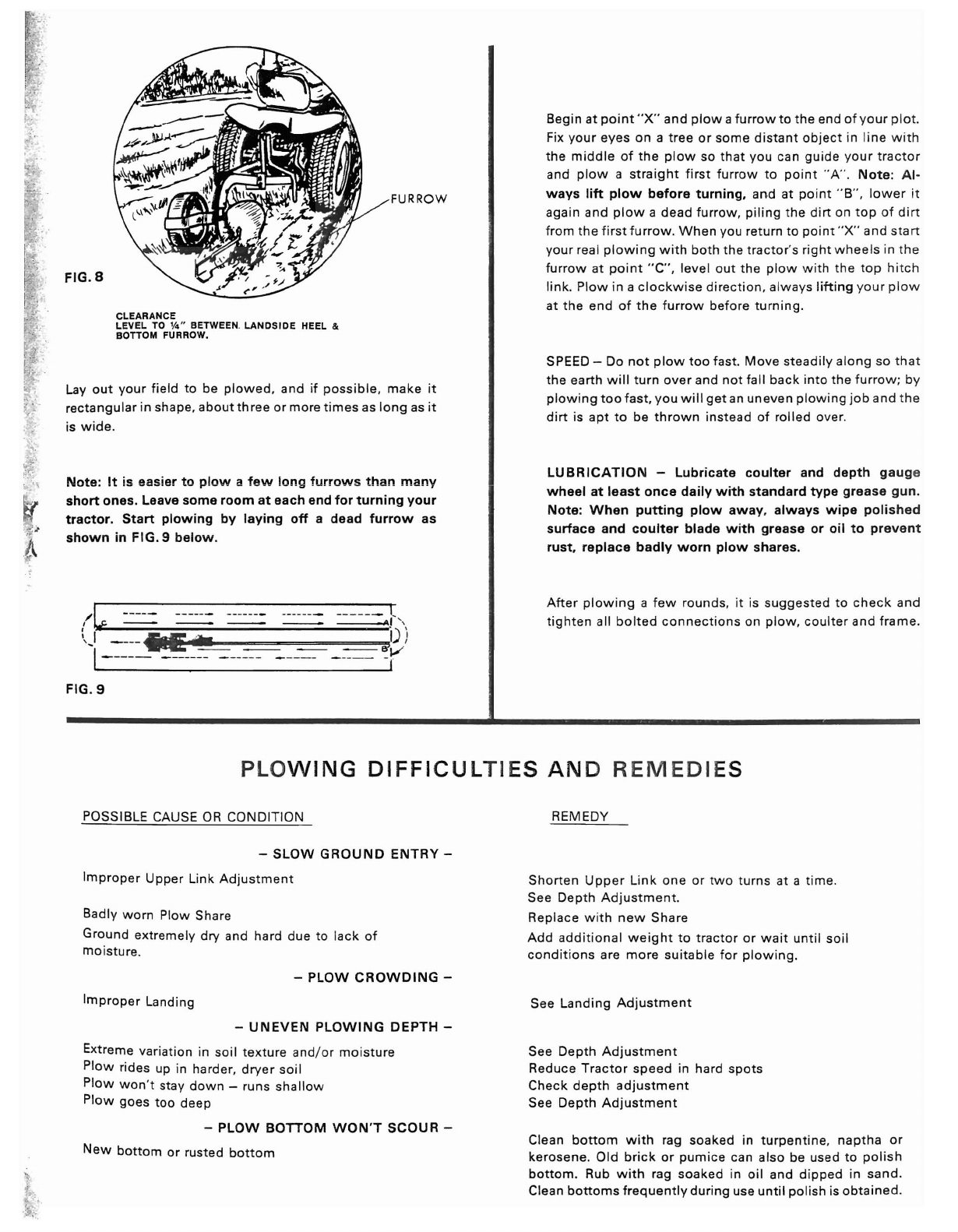
FURROW
FIG.S
CLEARANCE
LEVEL TO
Yo
"BETWEEN. LANDSIDE HEEL &
BOTTOM FURROW.
Layout
your
field
to be
plowed,
and if poss
ible
,
make
it
rectangular
in shape,
about
three
or more t
imes
as
long
as
it
is
wide
.
Note:
It
is eas
ier
to
plow
a
few
long
furrows
t han
many
short
ones.
Leave
some
room
at
each
end
for
turning
your
tractor.
Start
plowing
by
laying
off
a
dead
furrow
as
shown
in
FIG.
9
below.
/,
,,,
r
--
---
_nn_
_
__
n_
C
~
."
\
I
,)
.-;
.....
111
·
~~==========~i)
)
1_ ____
--
-----
----
--
--
---
-
---
~V
. I
FIG.9
Begin at
point
"
X"
and
plow
a
furrow
to
the
end
of
you
r
plot
.
Fix
your
eyes on a
tree
or
some
d
istant
object
in line
wi
th
the
m
iddle
of
the
plow
so
that
you can
guide
yo
ur
tracto
r
and
plow
a
straight
first
furrow
to po
int
"A
" ,
No
te:
Al -
ways
lift
plow
before
turning,
and at
point
"B
" ,
lower
it
again and
plow
a
dead
furrow
,
piling
the
dirt
on
top
of
dirt
from
the
fi rst
furrow.
When
you return to po
int
" X" and
start
your
real
plowing
with
both
the
tractor's
right
wheels
in th e
furrow
at po
int
" C", level
out
the
plow
wi
th
the
top
hitch
link.
Plow
in a clockw ise
direction
, a
lways
lifting
your
plo
w
at
the
end
of
the
furrow
before
turning
.
SPEED - Do
not
plow
too
fast.
Move
steadily
along
so
that
the
earth
will
turn
over
and
not
fall
back
int o
the
furrow
; by
plow
ing
too
fast
,
you
will
get
an
uneven
plowing
job
and t he
dirt
is
apt
to be
thrown
instead
of
rolled
over.
LU
BRICATION
-
Lubricate
coulter
and
depth
ga uge
wheel
at
least
once
daily
with
standard
type
grease
gun.
Note
:
When
putting
plow
away
,
always
wipe
polis
he d
surface
and
coulter
blade
with
grease
or
oil
to
preve
nt
rust
,
replace
badly
worn
plow
shares
.
After
plow
ing
a
few
rounds, it is
suggested
to
check
and
tighten
all bo
lted
connect
ions
on
plow
,
coulter
and
frame
.
PLOW ING
DIFFICU
LT IES AN D
REMEDI
ES
POSSIBLE CAUSE OR CONDITION
-
SLOW
GROUND
ENTRY-
Improper
Upper
Link
Adjustment
Badly
worn
Plow
Share
Ground
extremely
dry and hard due to lack of
moisture
.
-
PLOW
CROWDING
-
Improper
Landing
-
UNEVEN
PLOWING
DEPTH
-
Extreme variation in
soil
tex
ture
and
/or
moistu
re
P
low
rides up in harder,
dryer
so il
Plow
won
't stay
down
-runs
shallow
Plow
goes
too
deep
-
PLOW
BOTTOM
WON'T
SCOUR
-
New
bottom
or rusted
bottom
REMEDY
Shorten
Upper
Lin k
one
or
two
turns
at a
time
.
See
Depth
Ad
justment
.
Replace w
ith
new
Share
Add
add
it
ional
we
ight
to
tractor
or wa it
until
soil
condit
ions
are
more
sui
table
for
plowing.
See
Landing
Ad
justment
See
Depth
Adjustment
Reduce
Tractor
speed
in hard
spots
Check
depth
adjustment
See
Depth
Adjustment
Clean
bottom
with
rag
soaked
in
turpentine
, nap
tha
or
kerosene.
Old
br
ick
or
pumice
can
also
be used to
polish
bottom
. Rub
with
rag
soaked
in
oil
and
dipped
in
sand.
Clean
bottoms
frequently
during
use
unt
il pol ish is
obtained.
i
-;
Y
2or 3
41
\,.
I
.@'
TO
ORDER
PA RTS:
Brinly- Hardy Co.
P. O. Box
1116
lou
isville
, Ky.
40201
(50 2) 58
5·
33 51
I
~
7
'~
~
10
- 6
~-
""
='"
III
9
32
A
4~/jr~
1
46
\\
I
~
-
38
13
PARTS
LIST
REF. REF.
NO. PART NO , DESCR IP
TION
NO. PAR T NO.
DESCRIPTION
1
B-1674P
Nut. hex lock, 5
/16"
25 P-372 P " U" bolt,
coulter
2B-724P-01 Pin, low er li nk (PP-1200 ) 26
P-373-
10
Mast
assemb
ly (PP-12 10)
3 B-2022P-01 Pin, lower lin k (PP-1230 ) 27 P-387-01
Coulter
c
lamp
4C
-264-10
Gauge
wheel
28 1
M1640P
Bolt, hex, y," x2 y,"
5 D-128P l ube
fit
ti ng, 5
/16
" 29 1
M2040P
Bolt, hex, %" x 2 y,"
6 P-172P Carriage bolt blan k, %" 30 1
M2048P
Bolt, hex, %" x
3"
7P-
250
AHub 31 1
M2072P
Bolt, hex, %" x 4Y
i'
8 P
-265-
10
Fork assembly 32 10 M1 01 2 P Bolt,
carr
iage , 5
/16"
x %"
9 P
-269
-10
Coulter
standard
33
10M1624P
Bolt,
carr
iage ,
y,"
x 1y,"
10 P-2 70 Drive pin, 5/
16"
34 1
5M1216P
Bolt,
plow
,
W'
x 1"
11 P-272- 10
Coult
er blade 35 15 M 14 16P
Bolt
, pl ow, 7/ 16 " x l "
12 P
-273
Frog 36 15
M1632
P Bolt,
plo
w, Yi' x
2"
13 P
-276
Share , 12 " 37
30M
1200 P Nut, hex,
¥S
"
14 P-2 79
Moldboard
,
12"
38
30M1400P
Nut
, hex , 7/1
6"
15 P-2
85-10
Brace,
moldboard
39
30M1600P
Nut, hex, y,"
16 P-2
87-10
lands
ide
assembly
40 30 M20 00 P Nut. hex , %"
17 P
·328
-01
Spacer
(bushi ng) 41 31
M2000P
Nut, hex jam , %"
18 P-
330P
" U"
bolt
, (long)
42
35 M2000 P Nut, square,%"
19 P-331-10 Beam
assemb
ly 43
40M1600P
Washer
, lock, y,"
20
P
-335-
10 Mas t assem bl y (PP-1200)
44
40M2000P
Washer
,
lock
, %"
2 1 P-340 -10 Standard
45
45M1111
P
Washer,
pla in , 5
/16"
22
P-343-10
Mount
ing bracket - gauge
whee
l
46
45M2
12 1P
Washe
r, plain, %"
23 P-367P " U" bolt. (short)
47
50
M0
420P Pin, cotter, Ye' x 1
Yo
"
24 P-370 P-01 Beam
spacer
(bu
shin
g) 48
8-4685
l ogo Decal
L- 10 4 4 - 1
1c)..\1
yY\~lSlboe:v~
rlot-J
yp-
\:l.Oc>
