Broadcast Electronics Dura Trak 90A Series Cartridge Machine Manual
User Manual: Broadcast Electronics Dura Trak 90A Series Cartridge Machine Manual
Open the PDF directly: View PDF ![]() .
.
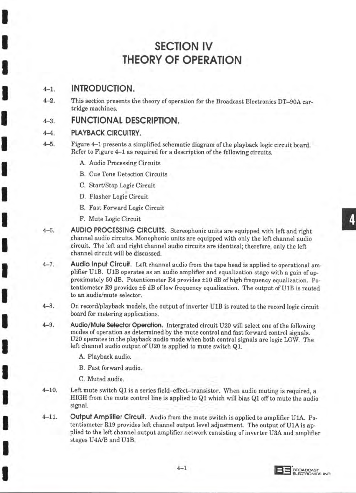
Page Count: 124 [warning: Documents this large are best viewed by clicking the View PDF Link!]
STEAM POWERED RADIO.COM
STEAM POWERED RADIO.COM
STEAM POWERED RADIO.COM
STEAM POWERED RADIO.COM
STEAM POWERED RADIO.COM
STEAM POWERED RADIO.COM
STEAM POWERED RADIO.COM
STEAM POWERED RADIO.COM
STEAM POWERED RADIO.COM
STEAM POWERED RADIO.COM
STEAM POWERED RADIO.COM
STEAM POWERED RADIO.COM
STEAM POWERED RADIO.COM
STEAM POWERED RADIO.COM
STEAM POWERED RADIO.COM
STEAM POWERED RADIO.COM
STEAM POWERED RADIO.COM
STEAM POWERED RADIO.COM
STEAM POWERED RADIO.COM
STEAM POWERED RADIO.COM
STEAM POWERED RADIO.COM
STEAM POWERED RADIO.COM
STEAM POWERED RADIO.COM
STEAM POWERED RADIO.COM
STEAM POWERED RADIO.COM
STEAM POWERED RADIO.COM
STEAM POWERED RADIO.COM
STEAM POWERED RADIO.COM
STEAM POWERED RADIO.COM
STEAM POWERED RADIO.COM
STEAM POWERED RADIO.COM
STEAM POWERED RADIO.COM
STEAM POWERED RADIO.COM
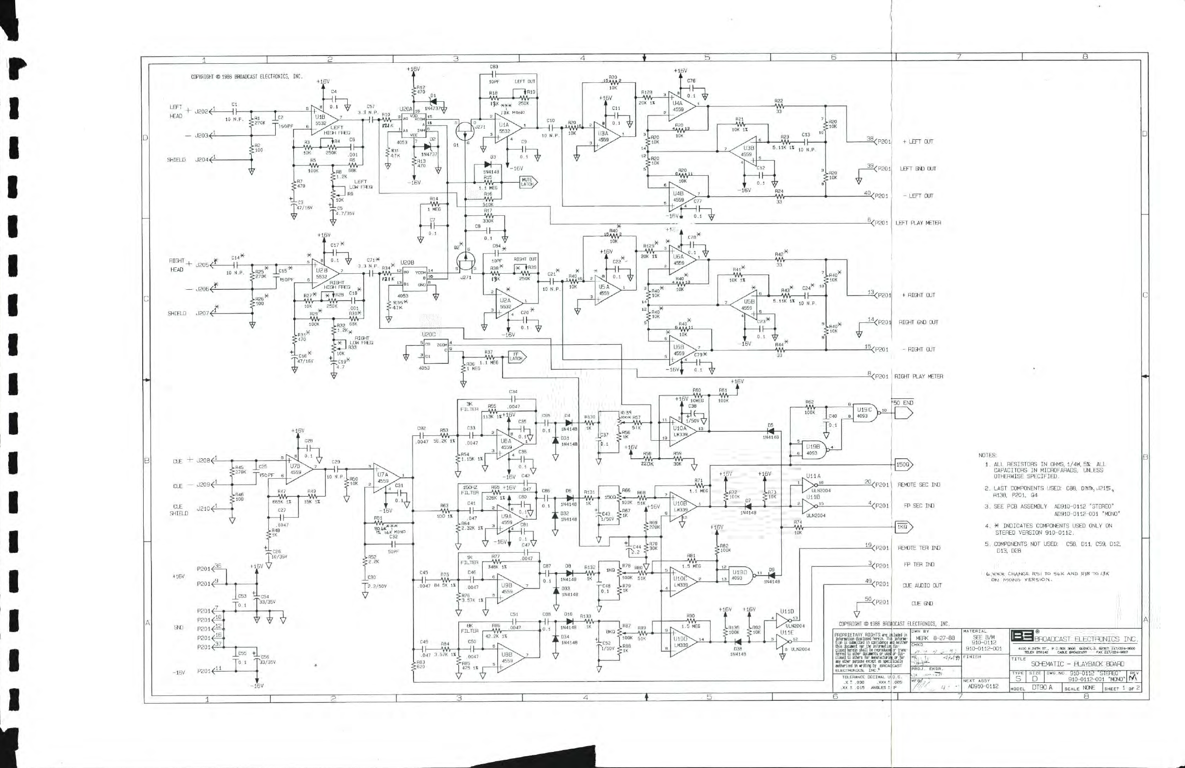
PLAYBACK AUDIO PROCESSING
CIRCUITS-
+>-
LEFT
CHANNEL
I
AUDIO
INPUT
LOW
FREQUENCY
CONTROL
HIGH FREQUENCY
EQUALIZATION
CONTROL
RIGHT
CHANNEL
AUDIO
INPUT
A
->-
LEFT
CHANNEL
AMPLIFIER
AND
EQUALIZATION
NETWORK
LOW
FREQUENCY
EQUALIZATION
CONTROL
HIGH FREQUENCY
EQUALIZATION
CONTROL
pLEFT
CHANNEL
OUTPUT
AMPLIFIER
R19
V
,
o '
RIGHT
CHANNEL
AMPLIFIER
AND
EQUALIZATION
NETWORK
CONTROL
LOGIC
MODE OF
OPERATION
MUTE
COMMAND
FF
COMAND
MODE OF
OPERATION
LOW LOW
PLAYBACK AUDIO
LOW
HIGH
FAST
FORWARD
AUDIO
HIGH HIGH
MUTE
U20
AUDIO/MUTE
SELECTOR
T-
CONTROL
LEFT
MUTE
SWITCH
LEFT
CHANNEL
OUTPUT
LEVEL
CONTROL
xCUE
AUDIO
"7
OUTPUT
CUE
TONE
FILTER
CIRCUITS
USA
UOB
USB
U9A
RIGHT
MUTE
SWITCH
R39
RIGHT
CHANNEL
OUTPUT
LEVEL
CONTROL
I
PRIGHT
CHANNEL
OUTPUT
AMPLIFIER
AMPLIFIER
^QMUTE
COMMAND
/
nn
FAST
FORWARD
Y
LHJ COMMAND
INVERTER
-
CUE
TONE
DETECTION
CIRCUITS
-
3
KHz
CUE
LEVEL
CONTROL
3000Hz
CUE
TONE
DETECTOR
R78y.
1
KHz
CUE
LEVEL
CONTROL
UlSA
y^—
8
KHz
CUE
LEVEL
CONTROL
PRIMARY
CUE
TONE
DETECTOR
U19D
'So—>
TERTI
AfY
CUE
TONE
RELAY
\
>
CONTACT
S
_x 171
PRIMARY
CUE
/
l±J
TONE
DETECTION
R66y
y
150
Hz
CUE
LEVEL
CONTROL
COMPARATOR
TERTIARY
CUE
TONE
DETECTOR
UUO
p
..UllE
UIOD
COMPARATOR
SECONDARY
CUE
^TONE
DETECTOR
COMPARATOR
UUA
,^U11B
V
REMOTE
TERITIARY
7
CUE
TONE
INDICATOR
n FRONT-PANEL
—!=
>
TERITARY
CUE
TONE
INDICATOR
_\
fTfl
SECONDARY
CUE
7
LdJ
TONE
DETECTION
-+-
K2
TERITIARY
CUE
TONE
RELAY
J
LOCATED
ON
MOTHERBOARD
71
TO
RECORD
LOGIC
CIRCUIT
BOARD
LEFT
CHANNEL
I
AUDIO
OUTPUT
RIGHT
CHANNEL
I
AUDIO
OUTPUT
TO
RECORD
LOGIC
CIRCUIT
BOARD
FRONT-PANEL
SECONDARY
CUE
TONE
INDICATOR
X
REMOTE SECONDARY
7
cue
TONE
INDICATOR
•>
SECONDARY
CUE
O CUE
TONE
RELAY
H
>
CONTACtS
\—
END
OF
TONE
DETECTOR
UlSB.
U19C
>
^[g]
END
OF
J
EDM
TONE
Kl
SECONDARY
CUE
TONE
RELAY
LOCATED
ON
MOTHERBOARD
COPYRIGHT
©
1990 BROADCAST ELECTRONICS, INC
597-9100-7A
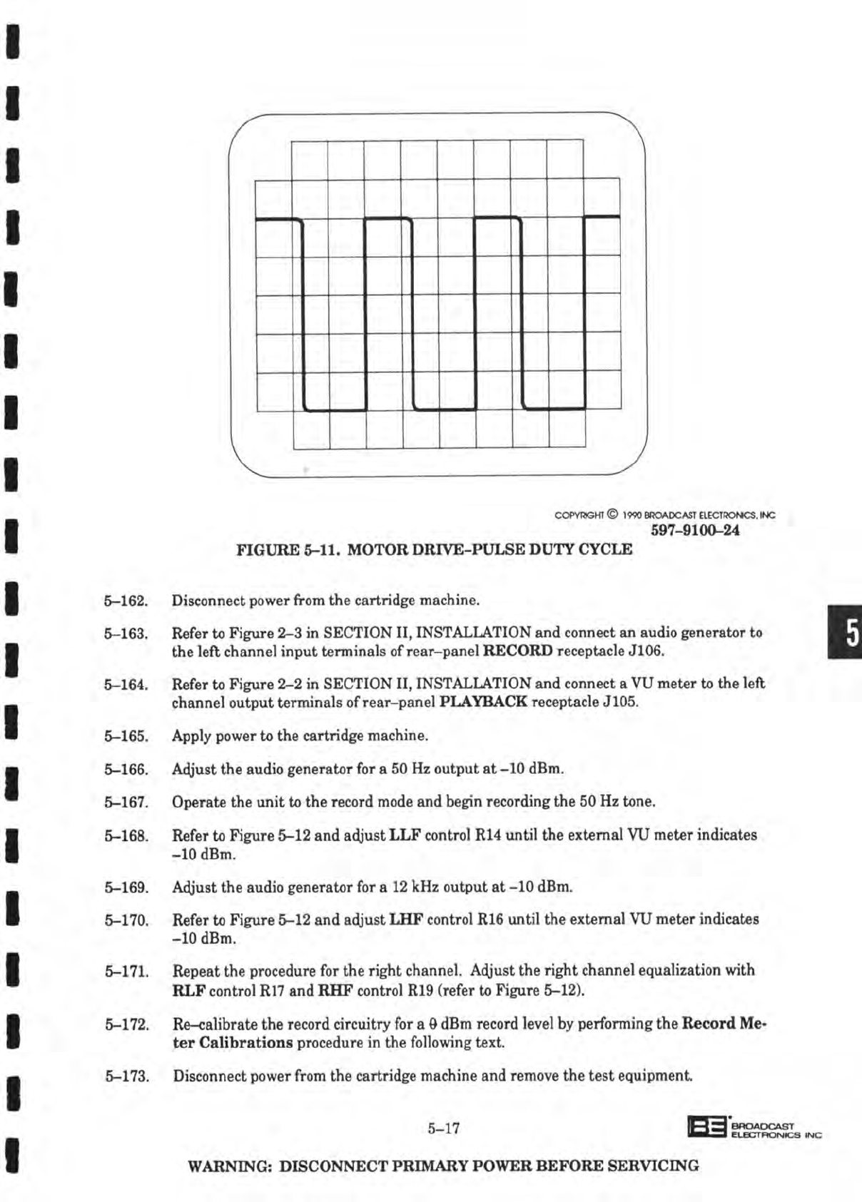
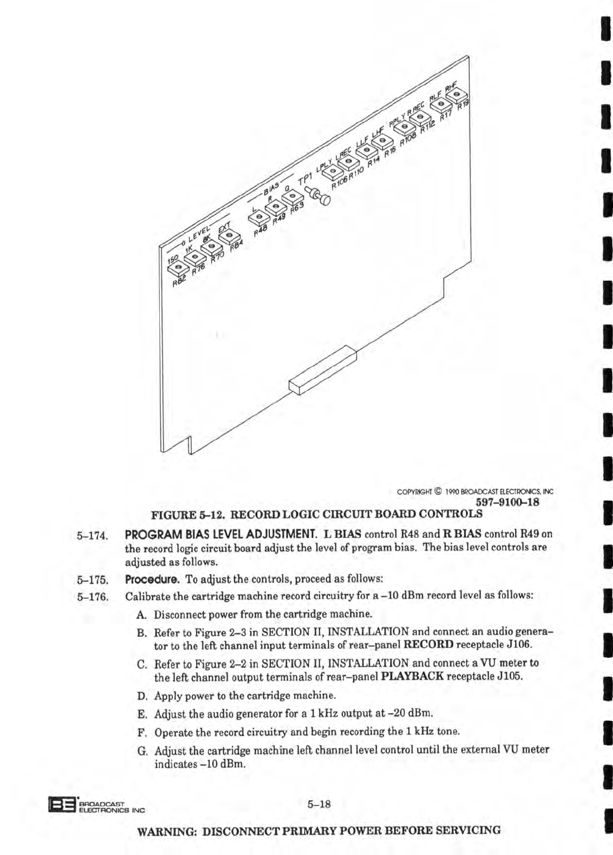
FIGURE
4-1.
PLAYBACK CIRCUIT
BOARD
SIMPLIFIED
SCHEMATIC
(Sheet
1
of
2)
4-3/4-4
STEAM POWERED RADIO.COM
/-
•START/STOP
LOGIC
CIRCUIT-
TO RECORD
LOBIC
/
CIRCUIT
BOARD
^
CARTRIDGE
PRESENT
XT-
SWITCH
START=HIGH
START
SWITCH
I
STOP
SWITCH
FAST
xA
FORWARD
C
SWITCH
PRIMARY
CUE
TONE
DETECTION
FAST
FORWARD
COMMAND
TO RECORD
LOGIC
4-
CIRCUIT
BOARD
FAST
FORWARD
INHIBIT
FROM
RECORD
LOGIC
CIRCUIT
BOARD
END
OF
EOM
TONE
'''^RONT-PANEL
START
INDICATOR
START
PULSE
^FOR EXTERNAL
EQUIPMENT
AUXILIARY
-> START STATUS
TO
MUTE
_
LOGIC
CIRCUIT
\
ENABLE
COMMAND
/
TO
SOLENOID
CIRCUIT
AND
RECORD
LOGIC
CIRCUIT
BOARD
START STATUS
>
TO
MUTE
LOGIC
CIRCUIT
MUTE
COMMAND TO
AUDIO/MUTE
SELECTOR
STEAM POWERED RADIO.COM
4-24. The start/stop logic circuit consists of: 1) start/stop logic U14A, U15A, and U16A, 2) start/
stop
latch U13B, 3) auxiliary start
one-shot
U18A,
4) inhibit
one-shot
U18B,
and 5) inver-
ters
U12AaJ12B.
4-25.
Start
and
Start
Lock-out
Operations.
A start operation is initiated when the front-panel
start
switch/indicator is depressed. A
LOW
from the start switch/indicator is applied to
the start/stop logic for decoding.
If
the start lock-out and cartridge present switch status
lines are
LOW,
the start output line of the start/stop logic
will
apply a
LOW
to start/stop
latch
U13B.
4-26.
With
the
LOW
from the start/stop logic, U13B
will
output a continuous
HIGH
through di-
ode D17 to energize the solenoid.
This
HIGH
is also routed to the
primary
cue inhibit
cir-
cuit,
auxiliary start
circuit,
start indicator
circuit,
mute logic
circuit,
and flasher logic
cir-
cuit.
4-27. A start lock-out condition
will
occur when deck operation is terminated by a
primary
cue
tone
detection and the start lock-out status line from the flasher logic
circuit
is
HIGH.
This
HIGH
indicates a cartridge played condition and is applied to the start/stop logic to
prevent consecutive start operations.
4-28.
Start
Indicator
Operation.
With
the
HIGH
from the start/stop latch, inverters
U12A/U12B
will
output a
LOW
to illuminate the start and remote start indicator.
4-29. Auxiliary
Start
Operation.
With
the
HIGH
from the start/stop latch, the auxiliary start
one-shot
will
apply a momentary
HIGH
to the mute logic circuit and inverter
U12E.
U12E
will
output a momentary
LOW
for external equipment operations.
4-30.
Manual
and
Automatic
Stop
Operation.
A manual
stop
operation is initiated when the
stop
switch is depressed. A
LOW
from the
stop
switch is routed to the start/stop logic for
decoding. The
stop
output line of the start/stop logic
will
apply a
LOW
to start/stop latch
U13B.
U13B
will
toggle
LOW
to disable the solenoid and extinguish the start indicators.
4-31. An automatic
stop
operation is initiated when a
primary
cue
tone
is detected. A
HIGH
from
the
primary
cue
tone
status line is routed through
primary
cue detect
jumper
J211 to
the start/stop logic for decoding. The
stop
output line
will
go
LOW
to terminate deck op-
erations.
This
LOW
is also routed to the
record
logic
circuit
board through diode D36 to
terminate a record operation.
4-32. Primary
Cue
inhibit
Operation.
During
a start operation, a
HIGH
from the start/stop
latch
is applied to inhibit
one-shot
U18B.
The output of
U18B
is connected to the
primary
cue detection status line. U18B
will
apply a momentary
HIGH
for approximately 1.75 sec-
onds to the
primary
cue status line to delay a
stop
operation.
4-33.
Maintenance
Mode
Operation.
The start/stop logic
will
also
decode
a special mainte-
nance mode command to energize the solenoid without a cartridge inserted into the deck.
This
command is applied to the start/stop logic when the start and
stop
switches are simul-
taneously depressed and the
stop
switch released
prior
to the start switch.
4-34.
FLASHER
LOGIC
CIRCUIT. The flasher logic circuit generates the start lock-out status
and
controls the operation of the
stop
indicator depending on start lock-out
jumper
J213.
This
circuit consists of
NOR
gate
U17B, AND
gates
U15C
and
U15D,
inverters
U12C/U12D,
latch U13D, and
NAND
gate
U17A.
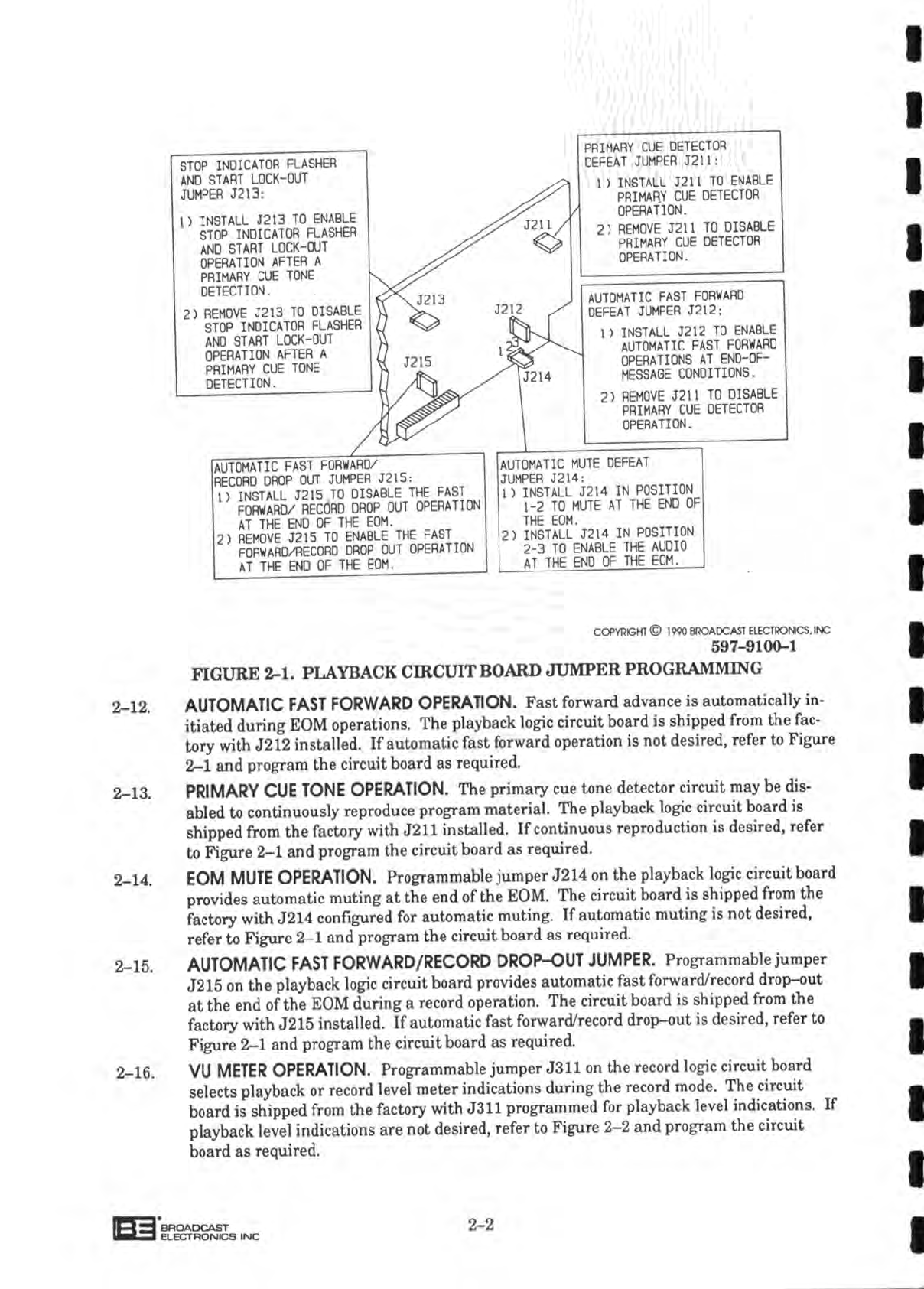
4-35. Jumper
installed.
When
jumper
J213 is installed, the start lock-out operation is enabled.
A LOW
from the
primary
cue
tone
detection status line
will
be applied to start lock-out
latch
U13D. U13D
will
apply a
HIGH
to the start/stop logic and flasher oscillator U17A.
U17A
will
apply pulses at a 1 Hz rate to flasher
gate
U15D.
4-36.
With
the unit in the
stop
mode, U17B
will
gate
a
LOW
from U13B and a
LOW
from the
cartridge
present switch status line to output a
HIGH
to U15D. U15D
will
gate
the oscilla-
tor pulses from U17A for application to the
stop
indicator through inverters
U12C/U12D.
The
stop
indicator
will
flash at a 1 Hz rate for a cartridge played condition.
4-7
ii_i-a
BROADCAST
I
ELECTRONICS
INC
STEAM POWERED RADIO.COM
4-37. The start lock-out latch is cleared by
AND
gate
U15C.
The
stop
switch and cartridge pre-
sent switch status lines are applied to
U15C.
With
a
LOW
from either the
stop
switch or
cartridge
present switch,
U15C
will
output a
LOW
to reset to latch U13D.
4-38. Jumper
Removed.
When
jumper
J213 is removed, the start lock-out function is disabled.
U13D
will
apply a continuous
LOW
to U17A which
will
output a
HIGH
to U15D.
With
the
unit
in the
stop
mode, U17B
will
apply a
HIGH
to U15D which outputs a continuous
HIGH
through inverters
U12CAJ12D
to illuminate the
stop
indicator.
4-39.
FAST
FORWARD
LOGIC
CIRCUIT. The fast
forward
logic
circuit
controls the speed of the
capstan
motor and operation of the solenoid. Depending
on
jumper
J212, the automatic
fast
forward
operation is enabled or disabled. The fast
forward
logic
circuit
consists of: 1)
fast
forward
logic
U14B,
U15B, and
U16B,
2) fast
forward
latch U13A, and 3) inverters
U12F
andUllF/UllG.
4-40. Automatic Fast Forward
Operation.
The automatic fast
forward
function is enabled when
jumper
J212 is installed. A fast
forward
operation is initiated when a secondary cue
tone
is detected. A
LOW
from the FND of
FOM
tone
status line
will
be applied to the fast for-
ward
logic for decoding.
4-41.
With
the
LOW
from the FND of
FOM
tone
status line and a
LOW
from the cartridge pre-
sent switch status line, the fast
forward
output line of the fast
forward
logic
will
output a
LOW
to start/stop latch U13B through
diode
D29, and fast
forward
latch U13A The
LOW
at U13B
will
extinguish only the start indicator. U13A
will
output a
HIGH
through
diode
D18 to maintain solenoid operation.
4-42. The
HIGH
fast
forward
command from U13A is also routed to inverters
UllF/UllG
to il-
luminate the fast
forward
indicator and the motor control
circuit
board
through inverter
U12F.
4-43. In a
record/playback
unit, a
HIGH
applied to the fast
forward
logic through J215 inhibits a
fast
forward
function when an
FND
of
FOM
tone
is
detected
during a
record
operation.
With
J215 removed during a record operation, an FND of
FOM
tone
will
initiate a fast for-
ward
function and also disable the record operation by applying a
LOW
through
diode
D39.
4-44.
Manual
Fast Forward
Operation.
A manual fast
forward
operation is identical to an auto-
matic
except the manual operation is initiated when the fast
forward
switch is depressed.
A LOW
from the fast
forward
switch
will
be applied to the fast
forward
logic to begin a fast
forward
operation.
4-45.
Automatic/Manual
Termination of Fast Forward
Operation.
Automatic termination of the
fast
forward
operation is initiated when a
LOW
from the
primary
cue
tone
detection line is
applied
to the fast
forward
logic for decoding. The normal output line of the fast
forward
logic
will
apply a
LOW
to
U13A.
U13A
will
route a
LOW
to the motor control
circuit
board
to terminate the fast
forward
operation.
4—46.
Manual
termination of the fast
forward
operation is identical to an automatic except the
manual
operation is initiated when the start switch is depressed. A
LOW
from the start
switch
will
be applied to the fast
forward
logic to begin a termination operation.
4-47.
MUTE
LOGIC
CIRCUIT. The mute logic
circuit
generates the mute command, controls the
operation of the audio indicator, and provides an audio delay.
This
circuit consists of mute
logic
U14C
and
U16C,
mute latch
U13C,
NAND
gate
U17C,
transistor
Q3,
and inverter
UllC.
4-48. Mute
Operation.
A mute operation is initiated when a
LOW
from the
stop
switch bus, or
the fast
forward
switch bus is applied to the mute logic for decoding. A
LOW
from the
FND
of
FOM
through J214
will
also initiate a mute operation. The mute logic
will
apply a
LOW
to
U13C. U13C
will
output a
HIGH
to the audio/mute selector and transistor Q3.
The HIGH
will
bias Q3 ON which routes a
LOW
through inverter
UllC
to extinguish the
audio indicator.
4-8
STEAM POWERED RADIO.COM
4-49. A mute operation is also initiated by a
LOW
on the
primary
cue
tone
detection bus.
This
LOW
is directly applied to mute latch
U13C
which outputs a mute command.
4-50. In addition, an
auxiliary
mute bus provides external mute operations.
If
both the secon-
dary
cue
tone
detection and auxiliary start status lines are
LOW,
the mute logic
will
de-
code
a
LOW
on the
auxiliary
mute bus to generate a mute command.
4-51. Audio
Enable
Operation,
The motor control
circuit
board
applies a
LOW
to the input of
U17C
which momentarily inhibits audio until the motor attains proper speed. When the
start
switch is depressed, a
HIGH
from start/stop latch U13B
will
be applied to
U17C
and
073.
U17C
will
output a momentary
LOW
to
U13C
for a duration established by capaci-
tor
C73
and resistor
R121.
This
LOW
resets
U13C
to enable the audio.
4-52. Audio can also be enabled during a fast
forward
operation. When the fast
forward
switch
is continuously depressed, a
LOW
is directly applied to the output of mute latch
U13C
to
enable the audio.
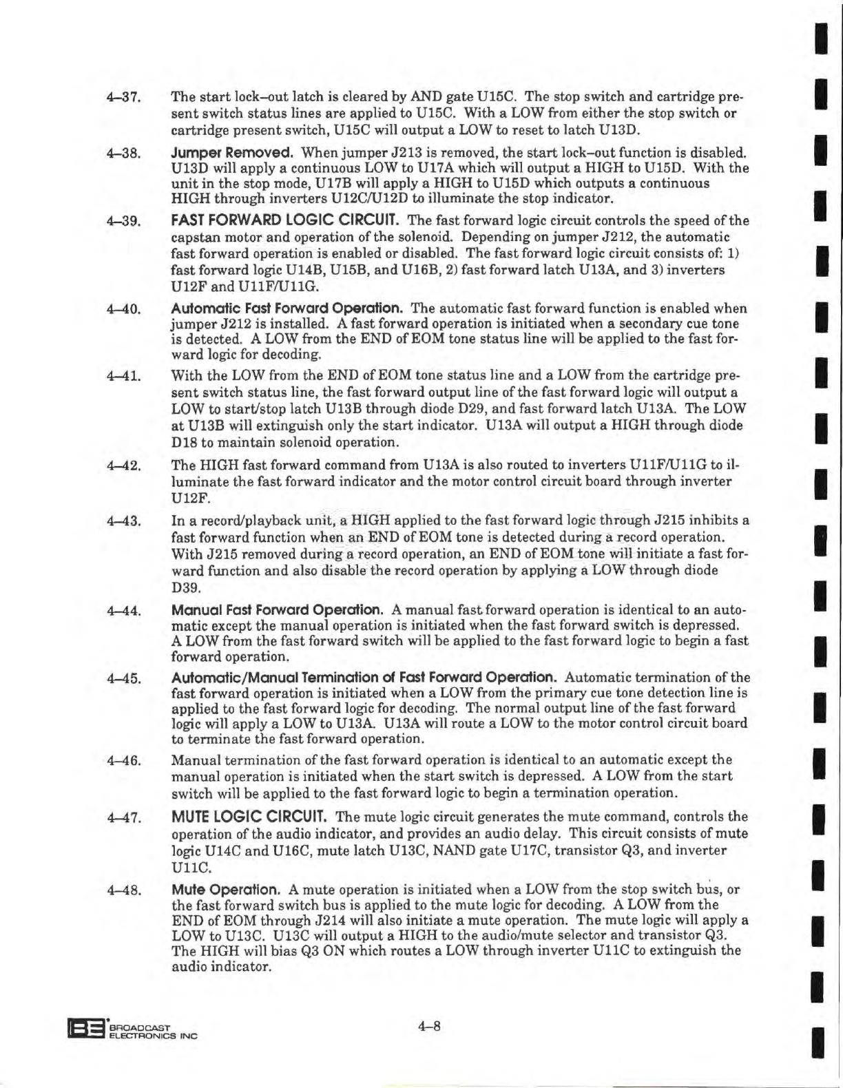
4-53. SOLENOID AND
POWER
SUPPLY
CIRCUITS.
Figure
4-2 presents a simplified schematic
diagram
of the solenoid and power supply
circuits.
Refer to Figure 4-2 as
required
for a
description of the circuits.
4-54. Soldnoid
Operation.
Prior
to solenoid operation, transistor Q3 is biased ON which routes
+28 volts through the solenoid winding to the collector of
transistor
Ql and the base of
transistor
Q2.
With
a
HIGH
from the start/stop latch, Ql
will
conduct to rapidly operate
the solenoid.
4-55.
With
Ql conducting, a
LOW
is applied to the base of
Q2
which biases Q2 Off. The collector
of
Q2
will
go
HIGH
which disables Q3 and allows +12 volts from solenoid driver U3 to be
applied
to the solenoid.
4-56. Power Supply
Circuit.
Primary
power is applied to the
DT-90A
through line fuse Fl and
switch
Si to the
primary
of power transformer
Tl.
The secondaries of
Tl
provide 25 volt,
40 volt, and 9 volt ac potentials.
4-57. The 40 volt ac potential is routed to a full-wave rectifier and filter network to provide +20
volt and -20 volt dc potentials at the output. The +20 volt dc is applied to the input of
regulator Ul which supplies a regulated +16 volts to the logic
circuit
board,
front>-panel
switches, and cue relays.
The
-20 volt dc is applied to the input of regulator U2 which
supplies a regulated -16 volts to the logic
circuit
board.
4-58. The 9 volt ac potential is routed to a full-wave rectifier and filter network to provide an
unregulated +10 volt supply for fronl^panel status indicators.
4-59. The 25 volt ac potential is routed to a full-wave rectifier and filter network to provide an
unregulated +28 volt supply for solenoid operation. +28 volts is also routed to a lamp
driver
which supplies +28 volts to the
rear-panel
for external applications, and operating
voltage
for front-panel switch/indicators.
4-9
STEAM POWERED RADIO.COM
-SOLENOID
CIRCUIT'
-I28V>
ENABLE
COMMAND
FROM
START/STOP >
LATCH
SOLENOID DRIVER
+
12V
Q3
k/Q2 k/Q2
POWER
SUPPLY
CIRCUIT-
Tl
117/230VAC
50/60HZ
Fl
SI
FULL
WAVE
RECTIFIER
AND
FILTER
NETWORK
FULL
WAVE
RECTIFIER
AND
FILTER
NETWORK
FULL
WAVE
RECTIFIER
AND
FILTER
NETWORK
LAMP
DRIVER
05,
015. C3
+16V REG.
Ul
-IBV
RES.
U2
\
+28V
SUPPLY TO
FRONT
PANEL
SWITCH/INDICATORS AND
REAR-PANEL
CONNECTORS
•f28V
SUPPLY TO
SOLENOID
CIRCUIT
•UBV
SUPPLY TO LOGIC
CIRCUIT
BOARDS.
CUE RELAYS. AND
FRONT-PANEL
SWITCHES.
-IBV
SUPPLY TO LOGIC
CIRCUIT
BOARDS
•HOV
SUPPLY TO
FRONT-PANEL
->
METER
DISPLAY AND STATUS
INDICATORS
COPYRIGHT© 1990 BROADCAST ELECTRONICS. INC
597-910O-7C
FIGURE
4-2.
POWER
SUPPLY
AND
SOLENOID
CIRCUITS
4-60.
MOTOR
CONTROL CIRCUIT BOARD.
4-61.
Figure
4-3
presents
a
simplified
schematic
diagram
of the
motor
control
circuit
board.
Re-
fer to
Figure
4-3 as
required
for a
description
of the
following
circuits.
BROADCAST
I
ELBCTHCNICS
INC 4-10
STEAM POWERED RADIO.COM
A.
Reference
Circuit.
B.
Tachometer Processing
Circuit.
C.
Frequency
Comparator
Circuit.
D.
Motor
Driver
Circuit.
E.
Motor Protection
Circuit.
F.
Motor
Lock
Detector
Circuit.
G.
Motor Commutator
Control
Circuit.
H.
Vari-Speed
Circuit.
J.
Power Supply
Circuit.
4-62. REFERENCE CIRCUIT. A precision reference signal for servo circuit operation is generated
by a
460.8
kHz
crystal
controlled oscillator circuit consisting of
crystal
Yl,
capacitors C30,
C31,
and resistor
R54.
The oscillator circuit output is applied to divider Ull.
4-63. Divider Ull is
designed
to
generate
motor frequency references. The output of Ull and
motor
speed
jumper
network Wl is applied to divide-by-three
stage
U12A/B.
The output
of
divider
U12A/B
is routed to multiplexer network
U13A/B.
U13A/B
is
designed
to switch
between
normal and fast
forward
motor frequency references. Jumper network W3 pro-
vides input information for the multiplexer network. The output of multiplexer
U13A/B
is
routed for application to a frequency comparator
circuit.
The following list provides motor
reference frequencies and corresponding motor
speeds.
MOTOR
REFERENCE
FREQUENCY
(Hz) MOTOR SPEED
(Inches-Per-Second)
NORMAL FAST FORWARD NORMAL FAST FORWARD
1200
3600
15
600 1800 7.5 22.5
300 900 3.75 11.25
4-64. Normal/Fast Forward
Operation.
With
the imit in the normal
mode
and programmed for
7.5
IPS
operation, divider Ull
will
output an 1800 Hz reference to divider
U12A/B
and
multiplexer
U13A/B
via
jumper
network
W3.
U12A/U12B
will
output a 600 Hz reference
to multiplexer
U13A/B.
The vari-speed and fast forward control lines
will
be
HIGH
to
instruct
multiplexer
U13A/B
to output a 600 Hz motor reference frequency for application
to a frequency comparator
circuit.
4-65. When the unit is operated to the fast forward
mode,
the fast forward control line
will
go
LOW.
The
LOW
instructs multiplexer
U13A/B
to output an 1800 Hz reference for applica-
tion to a frequency comparator
circuit.
4-66.
TACHOMETER
PROCESSING CIRCUIT. An indication of
cartridge
machine motor
speed
is generated by a tachometer winding. When the unit is programmed for 7.5 IPS operation
and
the motor is at
full
speed, the tachometer
will
output a sinusoidal 600 Hz signal to
high gain amplifier
stage
U2A. U2A is configured for a gain of approximately 1000. The
output of
U2A
is applied to inverter
U15G. U15G
generates
square-wave tachometer
pulses for application to a frequency comparator
circuit.
4-67. FREQUENCY CCMPARATCR CIRCUIT. The frequency comparator circuit consists of a
one-shot
network, a frequency comparator, and a shift register. The
one-shot
network
consists of integrated circuits
U3A/B.
The reference circuit output (600 Hz for 7.5
IPS
op-
eration) is applied to
one-shot
U3B.
The motor tachometer reference is applied to one-
shot
U3A.
The
one-shots
are
designed
to
generate
precision square-wave signals for ap-
plication to the frequency comparator.
4-11
STEAM POWERED RADIO.COM
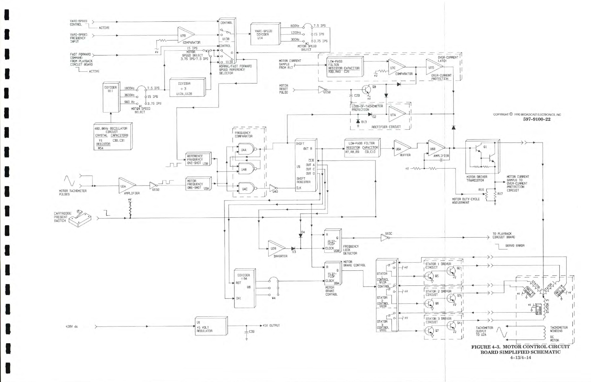
4-68. The frequency comparator network consists of
NAND
gates
U4A/B/C.
The circuit com-
pares the applied frequencies and generates corresponding shift and clock signals to shift
register U5 and a rectifier network. Shift register U5
will
generate four outputs which
represent operating parameters such as motor load and speed. The outputs provide infor-
mation for a motor driver
circuit,
a motor brake control circuit, and a motor protection
cir-
cuit.
4-69.
Motor
Run Circuit. The
CLR
input of shift register U5 determines motor operation. When
the deck switch is open (cartridge not present), a
LOW
is applied to the
CLR
input to in-
hibit
motor operation. When the deck switch is closed (cartridge present), a
HKJIH
is ap-
plied to the
CLR
input to initiate motor operation.
4-70.
MOTOR
DRIVER
CIRCUIT. One output from shift register U5 is filtered into a dc level by
a
passive low-pass filter consisting of resistors
R7, R8,
R9 and capacitors C9 and
CIO.
The
dc level is buffered by operational amplifier U6A and applied to amplifier
stage
U6B.
U6B
will
output a
varying
bias
voltage
to motor driver transistor
Ql.
Ql is designed to provide
a
dc supply
voltage
which controls the speed of the motor. Potentiometer R16 provides mo-
tor drive calibration.
4-71.
MOTOR
PROTECTION CIRCUIT. The motor is monitored for
loss
of tachometer signals
and
over-current conditions by a protection
circuit.
A rectifier circuit consisting of
diodes
D2
and D13 and operational amplifier
U7A
function as a tachometer monitor network.
With
the application of tachometer signals, the output of
U7A
will
be
HIGH
to allow nor-
mal
motor drive operation. With the
loss
of tachometer pulses, the output of
U7A
will
go
LOW
to bias Ql off
and
terminate motor operation.
4-72. Motor over-current conditions are monitored by a circuit consisting of
a
passive low-pass
filter, comparator
U7C,
and latch U7D. A motor current sample is filtered into a dc level
by a low-pass filter consisting of resistors
R39,
R40, and capacitor
C26.
The dc signal is
applied to comparator
U7C
and latch U7D. When the motor current sample is below the
reference level at
U7C, U7C
will
output a
HIGH
to latch U7D. U7D
will
output a
HIGH
to
allow normal motor drive operation. When the motor current sample increases above the
comparator reference level,
U7C
will
output a
LOW
to latch U7D. U7D
will
output a
LOW
to bias Ql off
and
terminate motor operation. A timing circuit consisting of
inverter
U15B,
transistor
Q8, and capacitor
C29
disables the over-current protection circuit for approxi-
mately 3 seconds during
initial
motor operation.
4-73.
MOTOR
LOCK
DETECTOR
CIRCUIT. Samples from U5 are monitored for motor unlocked
conditions by inverter
U2B,
diode
D4, and fiip-fiop U9B. When the motor is operating in a
locked condition, a
HIGH
is applied to inverter U2B and a
LOW
to Diode D4. U2B
will
output a
LOW
to frequency lock detector
U9B.
The output of
U9B
will
go
LOW.
The
LOW
is routed to inverter
U15C
which outputs a
HIGH
to the playback
circuit
board.
When an
unlocked condition exists, the output of
U2B
will
go
HIGH
or
diode
D4
will
conduct to gen-
erate a clock pulse for fiip-fiop U9B. The output U9B
will
go
HIGH.
Inverter
U15C
will
route a
LOW
to the playback
circuitry
to inhibit audio output until the motor speed is syn-
chronized.
4-74.
MOTOR
COMMUTATOR CONTROL CIRCUIT. The motor commutator control circuit
consists of a stator control/driver network and a brake control
circuit.
Multiplexer
UlOA/
B/C
and transistors Q2 through Q7 operate
together
to control the direction of the motor
stators. Divider U8 and motor brake control fiip-fiop U9A initiate motor
braking
opera-
tions when: 1) the motor is operating at a fast forward rate and required to return to the
normal
operating speed and 2) at motor termination.
4-12
STEAM POWERED RADIO.COM
VARI-SPEED
y.
CONTROL —
MOTOR
TACHOMETER
PULSES
CARTRIDGE
PRESENT
SWITCH
COPYRIGHT
©
1990
BROADCAST ELECTRONICS, INC
597-9100-22
+28V
dc
Ul
>
*• •
+5 VOLT
REGULATOR
FIGURE
4-3.
MOTOR
CONTROL CIRCUIT
BOARD
SIMPLIFIED SCHEMATIC
4-13/4-14
STEAM POWERED RADIO.COM
4-75. When the motor is in normal or fast forward operation, output samples from U5
will
force
the output of
divider
U8
LOW.
The
LOW
is applied to motor brake control flip-flop U9A.
The
output of
U9A
will
go
LOW.
With the output of
U9A LOW,
stator control logic
UlOA/
B/C
and the transistor driver circuits operate individually to control each motor stator. A
signal from
hall
effect
sensor 1
will
be routed through stator control device
UlOA
to the
stator 1 driver
circuit.
The driver circuit
will
output the signal to control the operation of
stator 1. Stator 2 and 3 control/driver networks operate in an identical manner. The sta-
tor control/driver
circuitry
will
respond in the appropriate
sequence
to initiate and control
motor commutator rotation.
4-76. When a motor braking operation is required, the motor drive samples from U5
will
produce
a
square-wave clock signal from U8. The clock signal is applied to flip-flop U9A which
outputs
a corresponding square-wave control signal to the stator control logic. The stator
control logic
will
respond by simultaneously applying a +28 volt pulse to each stator to pro-
vide a motor braking action. When the motor returns to a locked condition, the output of
U9A
will
go
LOW
to terminate motor
braking
operation and provide normal stator control.
4-77.
VARI-SPEED
CIRCUIT. The cartridge machine motor may be varied a minimum
±10%
for
special
audio applications by a vari-speed feature. The vari-speed
circuitry
consists of
comparator
U7B,
divider U14,
and
jumper
network U2. The circuit operates from a nomi-
nal
9600
Hz external signal source.
4-78. The vari-speed signal source is applied to comparator
U7B.
U7B is
designed
to
generate
a
square-wave reference signal for application to multiplexer
U13B.
When a
LOW
is ap-
plied to the vari-speed control line, multiplexer U13B
will
route the reference signal to
divider
U14. U14
will
output a corresponding reference signal for application to U13A and
the reference circuitry.
4-79.
POWER
SUPPLY
CIRCUIT. The motor control
circuit
board power supply circuit consists
of regulator Ul and capacitor
C39.
Ul and capacitor C39 regulate the +28V dc
voltage
into
a +5 volt supply for circuit operations.
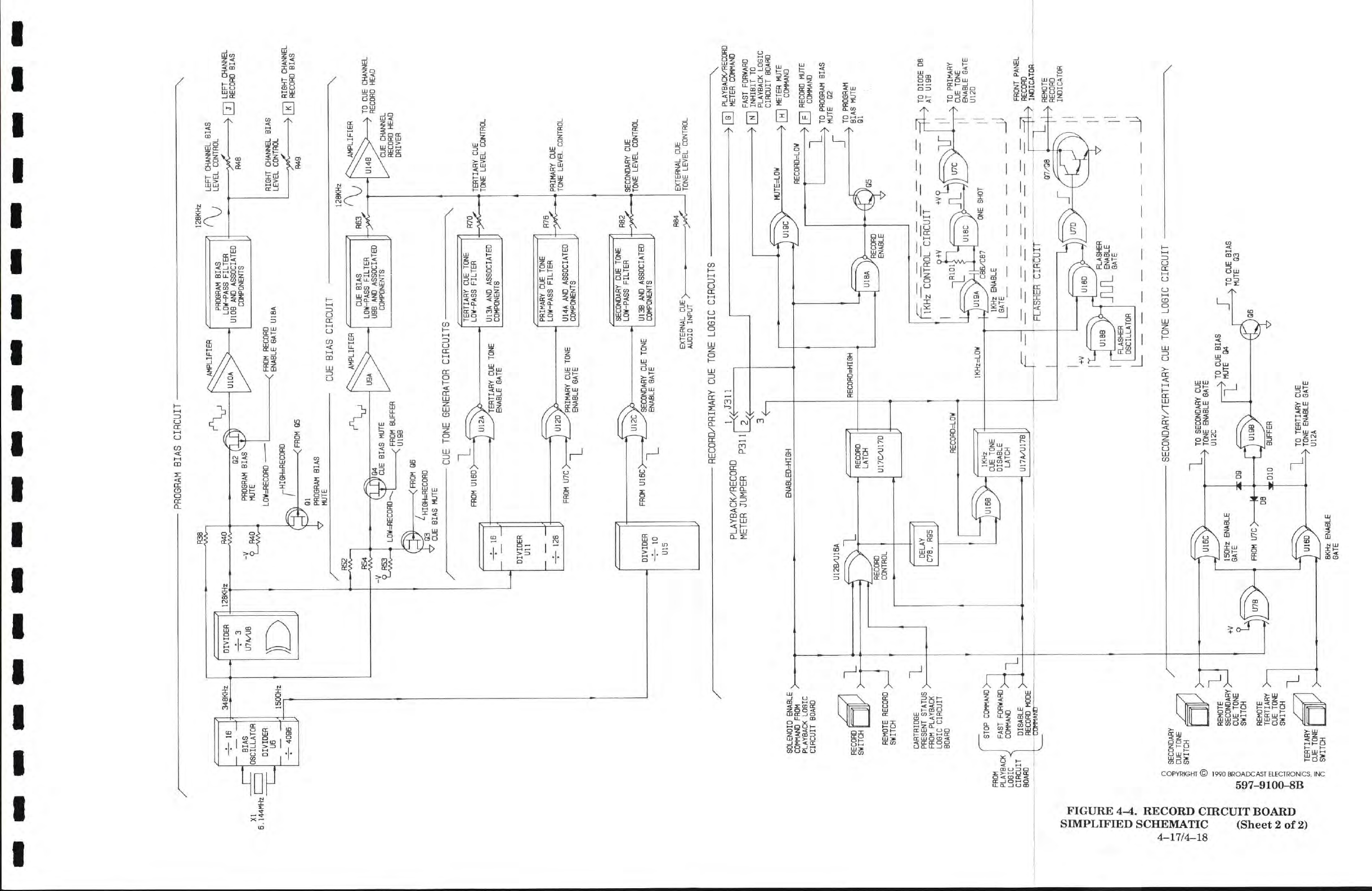
4-81. Figure 4-4 presents a simplified schematic diagram of the record logic circuit
board.
Refer
to Figure 4-4 as
required
for a description of the following circuits.
A.
Record
Audio Processing
Circuits.
B.
Metering
Circuits.
C.
Program Bias
Circuit.
D.
Cue Bias
Circuit.
E.
Cue Tone Generator
Circuits.
F.
Record/Primary
Cue Tone Logic
Circuits.
G.
Secondary/Tertiary
Cue Tone Logic
Circuits.
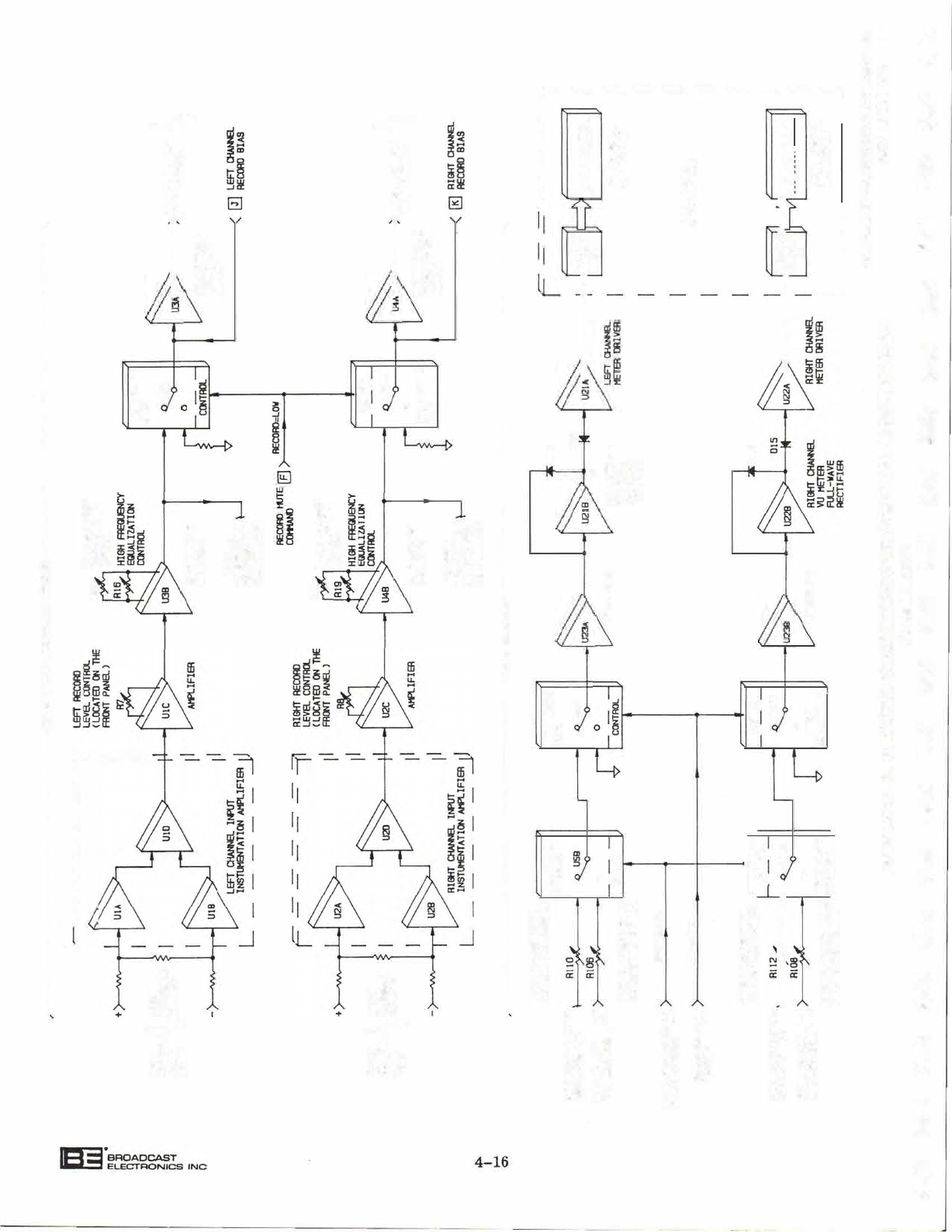
4-82. RECORD AUDIO PROCESSING CIRCUITS. Stereophonic units are equipped with
left
and
right channel record audio circuits. Monophonic units are equipped with only the
left
channel
audio circuit. The
left
and right channel audio circuits are identical; therefore,
only the
left
channel record circuit
will
be discussed.
4-83.
Input
Amplifier
Circuit.
Left
channel record audio from the rear-panel record connector is
applied to a 600 Ohm impedance matching network. Audio from the impedance network is
applied to integrated circuits
UlA, UIB
and
UID
which operate as an instrumentation
amplifier.
The amplifier provides maximum
noise
rejection with a gain of one.
4-80.
RECORD
CIRCUITRY.
4-15
Bl
BROADCAST
ELECTRONICS
INC
STEAM POWERED RADIO.COM
0
0
0
L __
J
©
FIGU . CO CCUIT BOA SLIFD SCTIC
(Sheet 1 of 2)
597-91A
STEAM POWERED RADIO.COM
PROGRAM
BIAS CIRCUIT
XI
I 1
6.144MHz
i
1
16
BIAS
OSCILLATOR
DIVIDER
U5
4095
348KHZ
1500Hz
R38
12BKHZ
DIVIDER
-f-
3
U7AAJ8
128KHZ
R40
--VW-
Q2
PROGRAM
BIAS
MUTE
LOW=RECORO
PROGRAM
BIAS
J
LOW-PASS
FILTER
UlOB
AND
ASSOCIATED
COMPONENTS
^
FROM
RECORD
^
r'
HIGH=RECORD
-(FROM
05
Ql
PROGRAM
BIAS
MUTE
/" R52
R54
—AA^
"L5S4
TY
J
04
'CUE BIAS
MUTE
-ENABLE
GATE
U18A
CUE BIAS CIRCUIT
. AMPLIFIER
UQA
LEFT
CHANNEL
BIAS
LEVEL
CONTROL
—
R48
^
j-^
LEFT
CHANNEL
RECORD
BIAS
RIGHT
CHANNEL
BIAS
LEVa
CONTROL
y>)C—
R49
N
nn
RIGHT
CHANNEL
7
ULI
RECORD
BIAS
128KHZ
LOW=HECORD-
_y
FROM
BUFFER
^U19B
CUE BIAS
LOW-PASS
FILTER
USB
AND
ASSOCIATED
COMPONENTS
-Q3
'•HIGH=RECORD
CUE BIAS
MUTE
<FROM
06
CUE
TONE GENERATOR
CIRCUITS-
FROM
U16D>
U12A
TERTIARY
CUE TONE
ENABLE
GATE
TERTIARY
CUE TONE
LOW-PASS
FILTER
U13A
AND
ASSOCIATED
COMPONENTS
FROM
U7C>^
U120
PRIMARY
CUE TONE
ENABLE
GATE
PRIMARY
CUE TONE
LOW-PASS
FILTER
U14A
AND
ASSOCIATED
COMPONENTS
R76
DIVIDER
-4-
10
U15
FROM
U16C>
U12C
SECONDARY
CUE TONE
ENABLE
GATE
SECONDARY
CUE TONE
LOW-PASS
FILTER
U13B
AND
ASSOCIATED
COMPONENTS
EXTERNAL
CUEy.
AUDIO
INPUT
7
R84
—yy^C—
A
TO CUE CHANNEL
7
RECORD HEAD
TERTIARY
CUE
TONE
LEVEL
CONTROL
PRIMARY
CUE
TONE
LEVEL
CONTROL
SECONDARY
CUE
TONE
LEVEL
CONTROL
EXTERNAL
CUE
TONE
LEVEL
CONTROL
22
w
o
J.
o
o
B
o
^
P
to
g
O
H
to
x
SOLENOID
ENABLE
,
COMMAND
FROM
7—"
PLAYBACK
LOGIC
CIRCUIT
BOARD
x:
RECORD
SWITCH
REMOTE RECORD
I
SWITCH
T'
CARTRIDGE
~\
PRESENT
STATUS
\ T-
FROM
PLAYBACK
7
L08IC
CIRCUIT
BOARD
FROM
PLAYBACK
LOGIC
<
CIRCUIT
BOARD
STOP
CDtWIANO;
FAST
FORWARD
\
j
COMMAND TT
DISABLE
RECORD
MODE
'
COmAND
SECONDARY
CUE
TONE
/
SWITCH
n
Q
S
•
y
REMOTE
L
SECONDARY
>-
CUE
TONE
SWITCH
REMOTE
TERTIARY
>
CUE
TONE
SWITCH
+V
•
RECORD/PRIMARY
CUE
TONE
LOGIC
CIRCUITS
PLAYBACK/RECORD
METER
JUMPER
P31
ENABLEO=HIGH
k4-
U12BAJ16A
RECORD
CONTROL
(
DELAY
C78.
R95
ui6e
U16C
TERTIARY
CUE
TONE
SWITCH
y^
150Hz
ENABLE
GATE
RECORD
LATCH
U17CAI170
HEC0RO=L0W
IKHz
CUE
TONE
DISABLE
LATCH
U17AAJ17B
RECORO=HISH
U19C
MUTEaOW
RECORD=L0W
U18A
RECORD
ENABLE
T
\
s
nq
PLAYBACK/RECORD
'7
UL) METER
COMMAND
—FAST
FORWARD
-7INJ
INHIBIT
TO
PLAYBACK
LOGIC
CIRCUIT
BOARD
_^
rrn
METER
MUTE
7
COMMAND
_^
rr\
RECORD
MUTE
7
UU COMMAND
A
TO
PROGRAM
BIAS
^
MUTE
Q2
\
TO
PROGRAM
7 BIAS
MUTE
Ql
ITKHZ
CONTROL
CIRCUIT
IKHzaOW
r
+v
+V(
x)F>
XI
\ TO
DIODE
08
I
1
^
AT U19B
V
TO
PRIMARY
7
CUE TONE
ENABLE
GATE
U12D
C86/Ce7
ONE SHOT
IKHz
ENAaE
I
GATE
!
ENABLE
FLSSHER
OIRCUn
Q7/Qa
N,
RECORD
L,
FRONT
PANEL
RECORD
INDICATOR
_^
REMOTE
U18B
U18D
RECORD
INDICATOR
FLASHER
^OSCILLATOR
| ^^J
„
,-,
FLASHER
JUL ^"^^
GATE
SECONOARY/TERTIARY
CUE
TONE
LOGIC
CIRCUIT X
FROM
U7C>-
08
J
01^^
B s TO
SECONDARY
CUE
>
TONE
ENABLE
GATE
U12C
09
U19B
X
TO
CUE
BIAS
MUTE
Q4
;010
BUFFER
\
TO CUE
BIAS
7
MUTE
Q3
TO
TERTIARY
CUE
^
TONE
ENABLE
GATE
U12A
8KHz
ENABLE
GATE
STEAM POWERED RADIO.COM
STEAM POWERED RADIO.COM
STEAM POWERED RADIO.COM
STEAM POWERED RADIO.COM
STEAM POWERED RADIO.COM
STEAM POWERED RADIO.COM
STEAM POWERED RADIO.COM
STEAM POWERED RADIO.COM
STEAM POWERED RADIO.COM
STEAM POWERED RADIO.COM
STEAM POWERED RADIO.COM
STEAM POWERED RADIO.COM
STEAM POWERED RADIO.COM
STEAM POWERED RADIO.COM
STEAM POWERED RADIO.COM
STEAM POWERED RADIO.COM
STEAM POWERED RADIO.COM
STEAM POWERED RADIO.COM
STEAM POWERED RADIO.COM
STEAM POWERED RADIO.COM
STEAM POWERED RADIO.COM
STEAM POWERED RADIO.COM
STEAM POWERED RADIO.COM
STEAM POWERED RADIO.COM
STEAM POWERED RADIO.COM
STEAM POWERED RADIO.COM
STEAM POWERED RADIO.COM
STEAM POWERED RADIO.COM
STEAM POWERED RADIO.COM
STEAM POWERED RADIO.COM
STEAM POWERED RADIO.COM
STEAM POWERED RADIO.COM
STEAM POWERED RADIO.COM
STEAM POWERED RADIO.COM
STEAM POWERED RADIO.COM
STEAM POWERED RADIO.COM
STEAM POWERED RADIO.COM
STEAM POWERED RADIO.COM
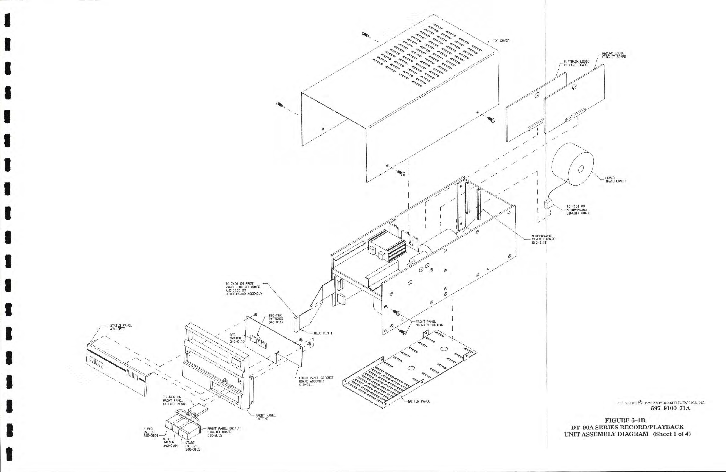
RECORD
L03IC
CIRCUIT BOARD
COPYRIGHT ©
1990
BROADCAST ELECTRONICS, INC
597-9100-71A
FIGURE
6-lB.
DT-90A
SERIES RECORD/PLAYBACK
UNIT ASSEMBLY DIAGRAM
(Sheet 1 of
4)
STEAM POWERED RADIO.COM
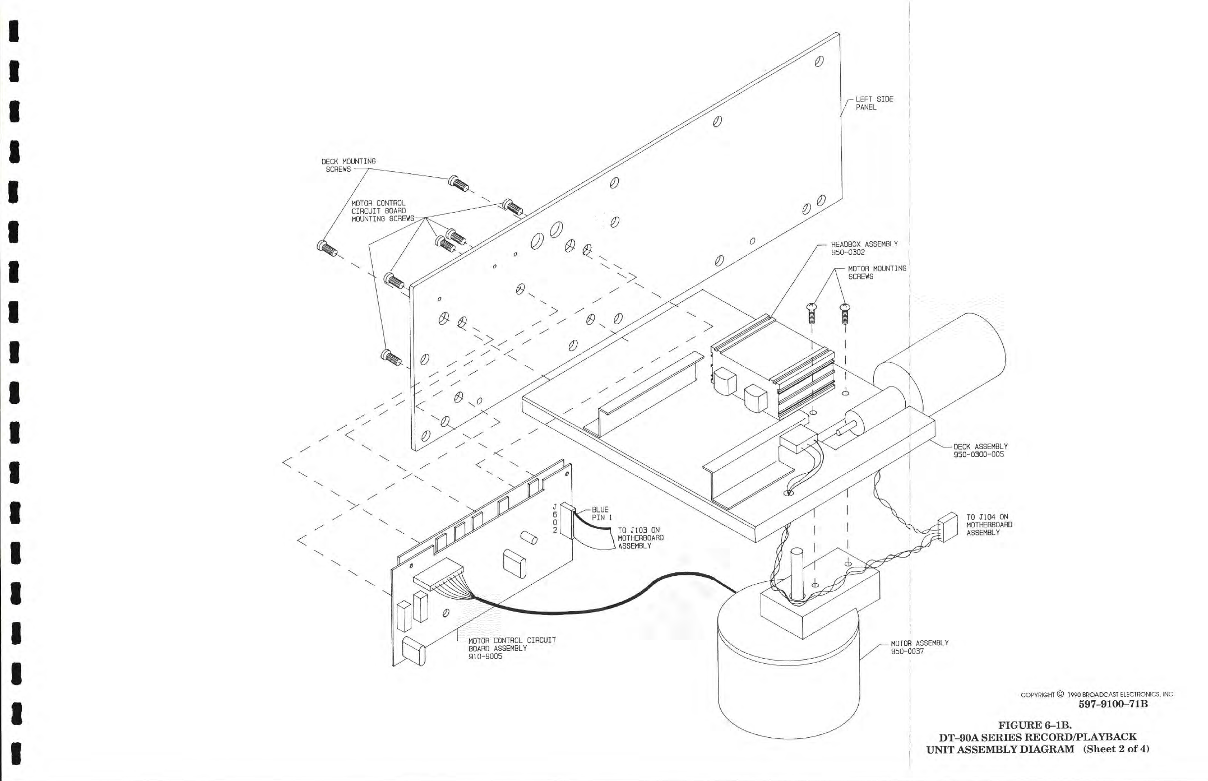
COPYRIGHT ©
1990
BROADCAST ELECTRONICS, INC
597-9100-71B
FIGURE 6-lB.
DT-90A
SERIES RECORD/PLAYBACK
UNIT ASSEMBLY DIAGRAM
(Sheet
2 of 4)
STEAM POWERED RADIO.COM
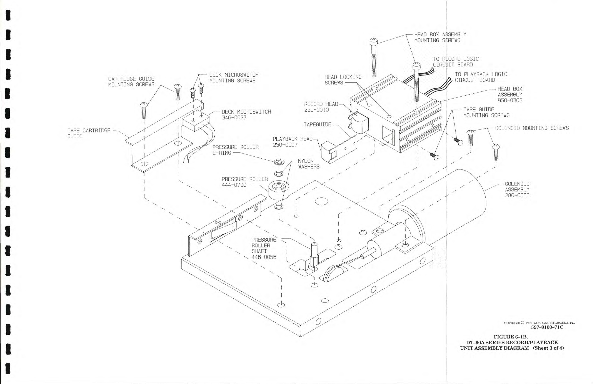
CARTRIDGE GUIDE
MOUNTING
SCREWS
TAPE CARTRIDGE
GUIDE
HEAD
BOX
ASSEMBLY
MOUNTING
SCREWS
TG
RECORD
LOGIC
CIRCUIT
BOARD
DECK
MICROSWITCH
MOUNTING
SCREWS
TO PLAYBACK
LOGIC
CIRCUIT
BOARD
DECK
MICROSWITCH
34B-GG27
TAPE GUIDE
MOUNTING
SCREWS
PRESSURE
ROLLER
E-RING
HEAD
BOX
ASSEMBLY
95G-G302
SOLENOID
MOUNTING
SCREWS
SOLENOID
ASSEMBLY
28G-00G3
COPYRIGHT
©
1990
BROADCAST
ELECTRONICS,
INC
597-9100-71C
FIGURE
6-lB.
DT-90A
SERIES RECORD/PLAYBACK
UNIT ASSEMBLY DIAGRAM
(Sheet
3
of 4)
STEAM POWERED RADIO.COM
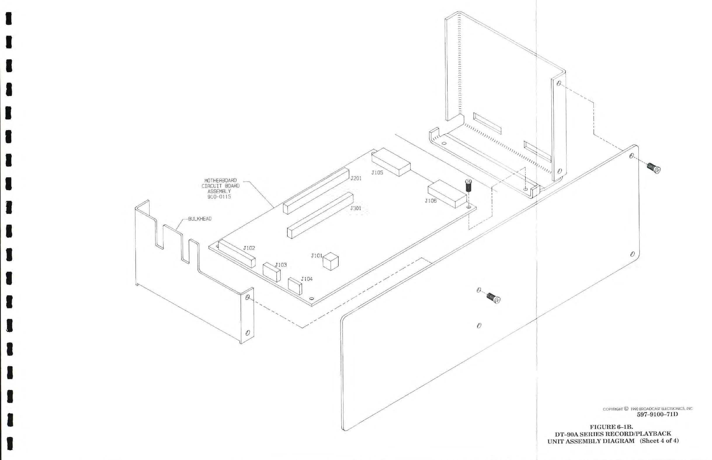
COPYRIGHT ©
1990
BROADCAST ELECTRONICS, INC
597-9100-71D
FIGURE
6-lB.
DT-90A
SERIES RECORD/PLAYBACK
UNIT ASSEMBLY DIAGRAM
(Sheet
4
of
4)
STEAM POWERED RADIO.COM
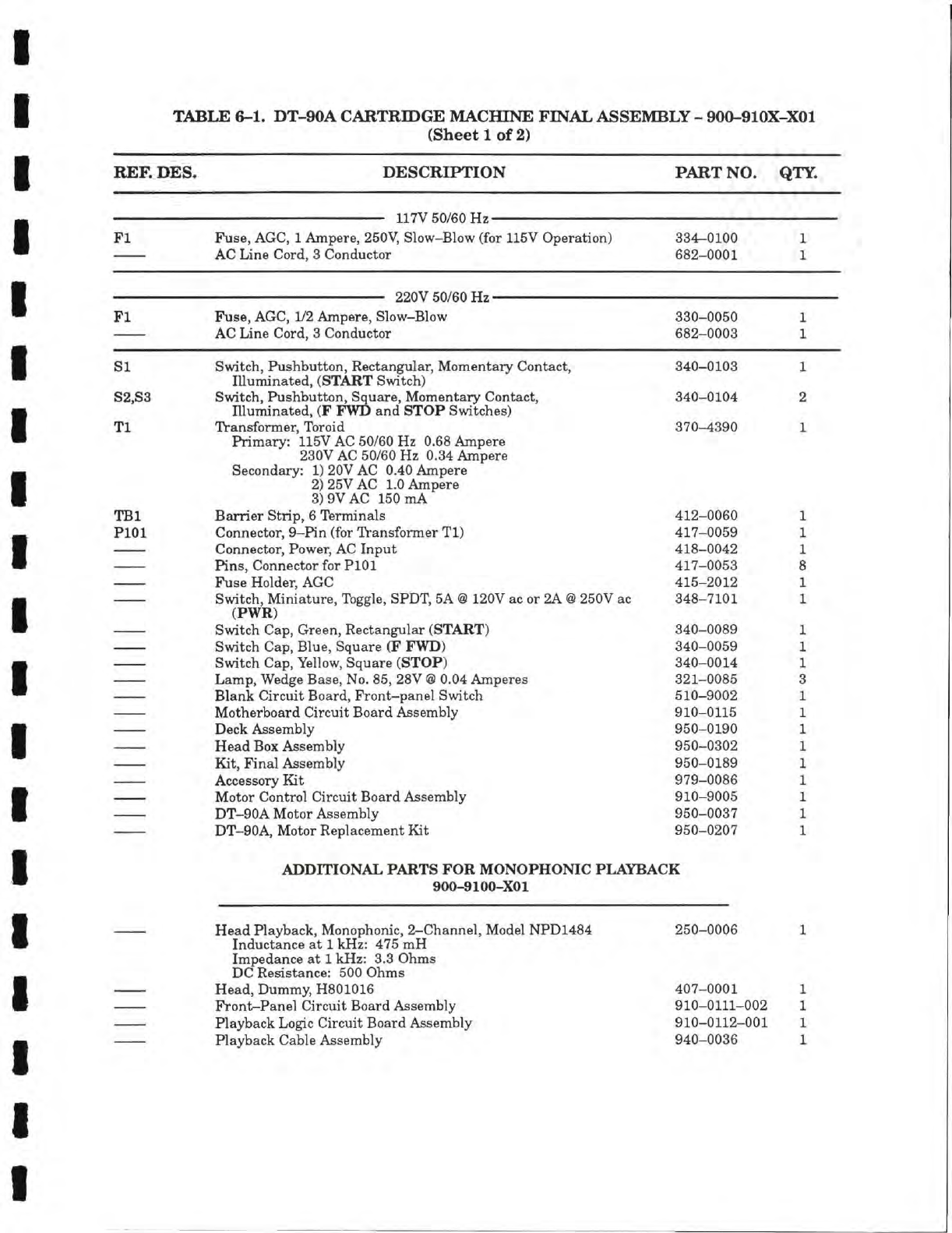
TABLE
6-1.
DT-90A
CARTRIDGE
MACHINE
FINAL
ASSEMBLY
-
900-910X-X01
(Sheet
1 of 2)
REF.
DES.
DESCRIPTION
PART
NO.
QTY.
Fl
Fuse,
AGC,
1
Ampere,
250V,
Slow-Blow (for
115V
Operation)
AC
Line Cord,
3
Conductor
334-0100
682-0001
1
1
Fl
Fuse,
AGC, 1/2 Ampere, Slow-Blow
AC
Line Cord,
3
Conductor
330-0050
682-0003
1
1
SI
82,83
Switch,
Pushbutton, Rectangular, Momentary Contact,
Illuminated,
(START Switch)
Switch,
Pushbutton,
Square,
Momentary Contact,
Illuminated,
(F
FWD and
STOP
Switches)
340-0103
340-0104
1
2
Tl
TBI
PlOl
Transformer, Toroid
Primary:
115V AC
50/60
Hz
0.68
Ampere
230V
AC
50/60
Hz
0.34
Ampere
Secondary:
1) 20V
AC
0.40
Ampere
2)
25V
AC
1.0
Ampere
3) 9VAC
150
mA
370-4390
Barrier Strip,
6
Terminals
412-0060
1
Connector, 9-Pin (for Transformer
Tl)
417-0059
1
Connector, Power, AC
Input
418-0042
1
Pins, Connector for PlOl
417-0053
8
Fuse
Holder, AGC
415-2012
1
Switch,
Miniature,
Toggle,
SPDT,
5A @
120V ac or
2A @
250V
ac
348-7101
1
(PWR)
Switch
Cap, Green, Rectangular (START)
340-0089
1
Switch
Cap, Blue,
Square
(F
FWD)
340-0059
1
Switch
Cap, Yellow,
Square
(STOP)
340-0014
1
Lamp,
Wedge
Base,
No.
85, 28V
@
0.04
Amperes
321-0085
3
Blank Circuit Board, Front-panel Switch
510-9002
1
Motherboard
Circuit Board Assembly
910-0115
1
Deck Assembly
950-0190
1
Head
Box
Assembly
950-0302
1
Kit,
Final Assembly
950-0189
1
Accessory Kit
979-0086
1
Motor
Control Circuit Board Assembly
910-9005
1
DT-90A Motor Assembly
950-0037
1
DT-90A, Motor Replacement Kit
950-0207
1
ADDITIONAL
PARTS
FOR
MONOPHONIC
PLAYBACK
900-9100-XOl
Head
Playback, Monophonic, 2-Channel, Model NPD1484
250-0006
1
Inductance
at 1
kHz:
475
mH
Impedance
at 1
kHz:
3.3
Ohms
DC
Resistance:
500
Ohms
Head,
Dummy,
H801016
407-0001
1
Front-Panel Circuit Board Assembly
910-0111-002
1
Playback Logic Circuit Board Assembly
910-0112-001
1
Playback Cable Assembly
940-0036
1
STEAM POWERED RADIO.COM
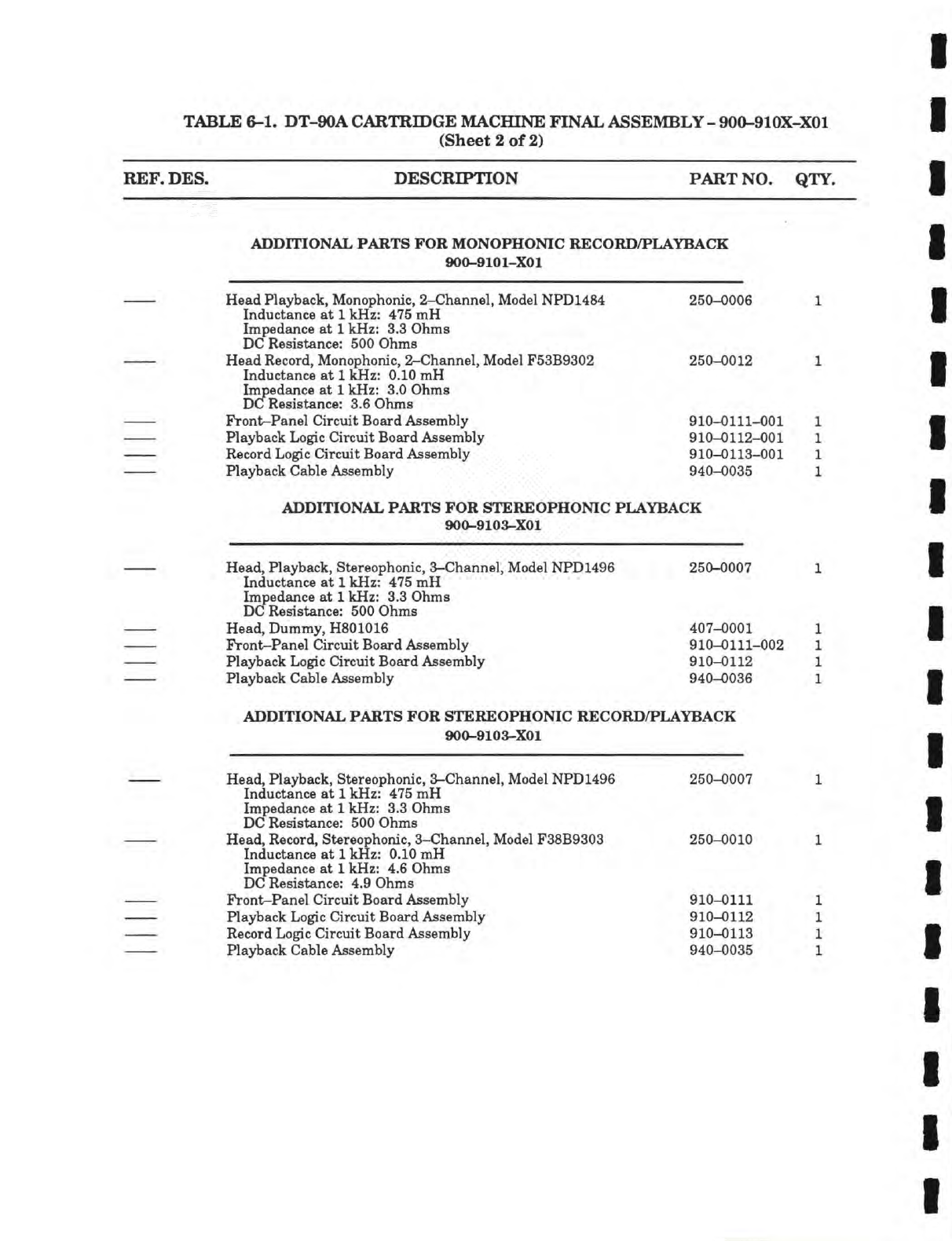
TABLE
6-1.
DT-90A
CARTRIDGE
MACfflNE FINAL ASSEMBLY
-
900-910X-X01
(Sheet
2 of 2)
REF.
DES.
DESCRIPTION
PART NO.
QTY.
ADDITIONAL
PARTS
FOR
MONOPHONIC RECORD/PLAYBACK
900-9101-XOl
Head
Playback,
Monophonic,
2-Channel,
Model
NPD1484
Inductance
at 1
kHz:
475
mH
Impedance
at 1
kHz:
3.3
Ohms
DC
Resistance: 500
Ohms
Head
Record, Monophonic, 2-Channel,
Model
F53B9302
Inductance
at 1
kHz:
0.10
mH
Iinpedance
at 1
kHz:
3.0
Ohms
DC
Resistance: 3.6
Ohms
Front-Panel
Circuit
Board Assembly
Playback Logic
Circuit
Board Assembly
Record Logic
Circuit
Board Assembly
Playback
Cable
Assembly
250-0006
250-0012
910-0111-001
910-0112-001
910-0113-001
940-0035
ADDITIONAL
PARTS
FOR
STEREOPHONIC PLAYBACK
900-9103-XOl
Head,
Playback, Stereophonic, 3-Channel,
Model
NPD1496
Inductance
at 1
kHz:
475
mH
Impedance
at 1
kHz:
3.3
Ohms
DC!
Resistance: 500
Ohms
Head,
Dummy,
H801016
Front-Panel
Circuit
Board Assembly
Playback Logic
Circuit
Board Assembly
Playback
Cable
Assembly
250-0007
407-0001
910-0111-002
910-0112
940-0036
ADDITIONAL
PARTS
FOR
STEREOPHONIC RECORD/PLAYBACK
900-9103-XOl
Head,
Playback, Stereophonic, 3-Channel,
Model
NPD1496
Inductance
at 1
kHz:
475
mH
Impedance
at 1
kHz:
3.3
Ohms
DC
Resistance: 500
Ohms
Head,
Record, Stereophonic, 3-Channel,
Model
F38B9303
Inductance
at 1
kHz:
0.10
mH
Impedance
at 1
kHz:
4.6
Ohms
DC
Resistance: 4.9
Ohms
Front-Panel
Circuit
Board Assembly
Playback Logic
Circuit
Board Assembly
Record Logic
Circuit
Board Assembly
Playback
Cable
Assembly
250-0007
250-0010
910-0111
910-0112
910-0113
940-0035
STEAM POWERED RADIO.COM
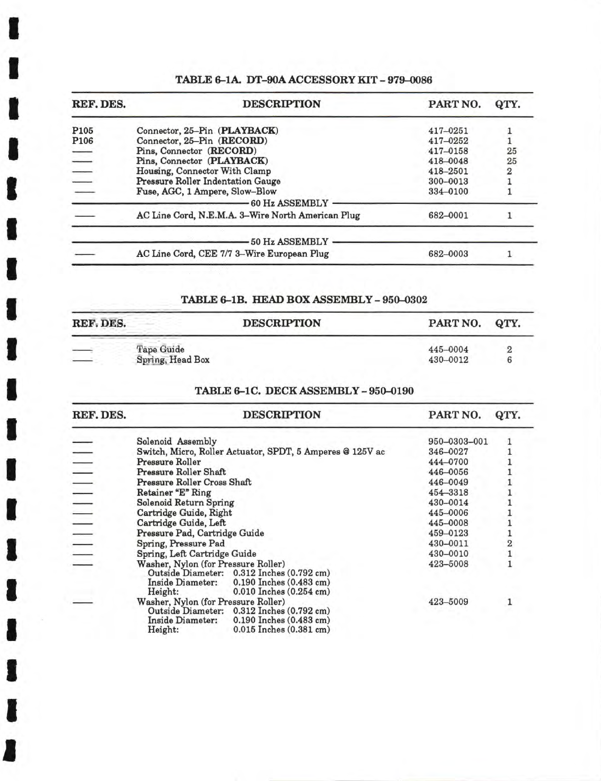
TABLE
6-lA. DT-90A
ACCESSORY
KIT
-
979-0086
REF.
DES.
DESCRIPTION
PART
NO.
QTY.
P105
P106
Connector, 25-Pin (PLAYBACK)
Connector, 25-Pin
(RECORD)
Pins, Connector
(RECORD)
Pins, Connector (PLAYBACK)
Housing,
Connector
With
Clamp
Pressure
Roller Indentation
Gauge
Fuse,
AGC,
1
Ampere, Slow-Blow
60
Hz
ASSEMBLY
AC
Line Cord,
N.E.M.A.
3-Wire
North
American Plug
417-0251
417-0252
417-
0158
418-
0048
418-2501
300-0013
334-0100
682-0001
1
1
25
25
2
1
1
50
Hz
ASSEMBLY
AC
Lane
Cord,
CEE 7/7
3-Wire European Plug
682-0003
TABLE
6-lB.
HEAD
BOX
ASSEMBLY
-
950-0302
REF.
DES.
DESCRIPTION
PART
NO.
QTY.
Tape
Guide
Spring, Head
Box
445-0004
430-0012
2
6
TABLE
6-1C.
DECK
ASSEMBLY
-
950-0190
REF.
DES.
DESCRIPTION
PART
NO.
QTY.
Solenoid Assembly
Switch, Micro, Roller Actuator,
SPDT,
5
Amperes
@ 125V ac
Pressure
Roller
Pressure
Roller
Shaft
Pressure
Roller
Cross
Shaft
Retainer
"E" Ring
Solenoid Return Spring
Cartridge Guide, Right
Cartri<%e Guide, Left
Pressure
Pad, Cartridge Guide
Spring,
Pressure
Pad
Spring, Left Cartridge Guide
Washer,
Nylon
(for
Pressure
Roller)
Outside Diameter:
0.312
Inches
(0.792 cm)
Inside Diameter:
0.190
Inches
(0.483 cm)
Height:
0.010
Inches
(0.254 cm)
Washer,
Nylon
(for
Pressure
Roller)
Outside Diameter:
0.312
Inches
(0.792 cm)
Inside Diameter:
0.190
Inches
(0.483 cm)
Height:
0.015
Inches
(0.381
cm)
950-0303-001
346-0027
444-
0700
446-0056
446-0049
454-3318
430-0014
445-
0006
445-0008
459-0123
430-0011
430-0010
423-5008
423-5009
STEAM POWERED RADIO.COM
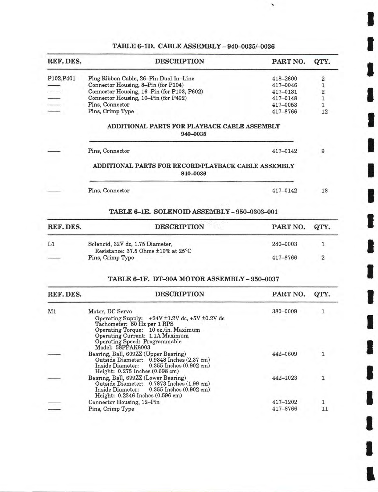
TABLE
6-lD.
CABLE ASSEMBLY
- 940-0035/-0036
REF.
DES. DESCRIPTION PART
NO.
QTY.
P102,P401
Plug Ribbon Cable, 26-Pin
Dual
In-Line
418-2600
2
Connector
Housing,
8-Pin (for
P104) 417-0046
1
Connector
Housing,
16-Pin (for
P103, P602) 417-0131
2
Connector
Housing,
10-Pin (for
P402) 417-0148
1
Pins, Connector
417-0053
1
Pins,
Chimp
Type
417-8766
12
ADDITIONAL PARTS
FOR
PLAYBACK CABLE ASSEMBLY
940-0035
Pins, Connector
417-0142
9
ADDITIONAL PARTS
FOR
RECORD/PLAYBACK CABLE ASSEMBLY
940-0036
Pins, Connector
417-0142
18
TABLE
6-lE.
SOLENOID ASSEMBLY
- 950-0303-001
REF.
DES. DESCRIPTION PART
NO.
QTY.
LI
Solenoid,
32V
do,
1.75
Diameter,
280-0003
1
Resistance:
37.5
Ohms ±10%
at
25°C
Pins,
Crimp
Type
417-8766
2
TABLE
6-lF. DT-90A
MOTOR ASSEMBLY
- 950-0037
REF.
DES. DESCRIPTION PART
NO.
QTY.
Ml
Motor,
DC Servo
380-0009
1
Operating
Supply: +24V ±1.2V dc, +5V ±0.2V do
Tachometer: 80HzperlRPS
Operating
Torque:
10
ozYin.
Maximum
Operating
Current:
I.IA
Maximum
Operating
Speed:
Programmable
Model:
58FPAK8003
Bearing, Ball, 609ZZ (Upper Bearing)
442-0609
1
Outside
Diameter:
0.9348
Inches
(2.37 cm)
Inside
Diameter:
0.355
Inches
(0.902 cm)
Height:
0.275
Inches
(0.698 cm)
Bearing, Ball, 699ZZ (Lower Bearing)
442-1023
1
Outside
Diameter:
0.7873
Inches
(1.99 cm)
Inside
Diameter:
0.355
Inches
(0.902 cm)
Height:
0.2346
Inches
(0.596 cm)
Connector
Housing,
12-Pin
417-1202
1
Pins,
Crimp
Type
417-8766
11
STEAM POWERED RADIO.COM
J102>^
J102>^
J102>^
J102>1^
J102>^
J102>^
J102>^
-^2301
-^J301
-^J201
^J301
-i<J201
G^jaoi
•^J301
-^JBOl
-^J301
^J201
J104>^
KJ103
k[j201
k;j301
J106>^
J106>-*
J106>^^
1
J106>-^
-4
J10B>i5
J106>^S
J106>^2
J106>^3
J10B>^^
-^J301
-^i<J301
-^J301
-S<J301
-i2<J301
-^2301
-^2301
2201
>5-
2201
>2-
2201
>ia
2201
2201
>^
2201
>^
2301>i2-
2301
>^
2201
>^
2201
>^
-^2301
-^2301
-^2301
-^2301
+
16V +28V
UNHEG
,R2B
>
lOOK
2103
>^
2201
>ii-
2301
>^
2106
>^
2201>^
2201)42-
2201
2201
>^
2201
>^
2301
>^
2301
>^
2301
)3-
2301
)3-
2301)3-
2104>2
2201
>2
1N4005
D17
\
iR13
C16
•10UF/35V
2201
)4
2102)4
-3;2105
1N4005
DIB
-
9
7
?4
--<2105
<200
CIS
10UF/35V
2201)4
2102)4
2<2105
i<2105
.
1 PS . V S Hlb PI p V S R18 17 p V 7 HdU 19 p ^
2105)4
1
2L/J201
2105)4 f
2i<2201
2108
>4
VW f
14(2301
210B>4
WV—•
'-^J^Oi
^
100 J^C17 ^ 100 J_C19 100 J_C21 100 J_C23 ^ ^
R20
-3(2103
-4^2103
-i<J103>
-^;jio3
-3;jio3
-3;2103
=<2103
1<2103
kjio
-3(210;
-3(jio;
ip.luF
V
V ? bib p4 p .15 Ml/
2105>4
•
3J201
2105
>4
9
^
100
J_C1B
100
j_C20
ip
s6 R'9
KJ201
J10B)4
f
^
^ 100 T C22
—L-
42<2301
2106)4 Y«)--T 3(2301
-A«V
1
100
1
C24
BROADCAST
ELECTRONICS.
INC.
2301
>4
2301)4
2201
)3
2301
>3
2301
)3
2301
)3
2201
3
2201
3
2201
3
2201
>4
J201>^
J201>4
220
3
2107)4
2201
)4
2107
>^
220l)4
2107
>4
220
3
220
3
220
3
NOTES:
T16V
1_
21DB>-^—I
J20l3bi-
2108
>4
1
2201
3-*-
JIOB)4
2201
>i3l-
2201)43-
2201
3
3J102
3J102
-3(J102
-4-<J102
-3J102
-3(2102
-3J102
-3(2102
-3(2102
4(2102
L(2102
4(J104
4(J105
4(J105
^2105
32105
-3(2105
—4<2105
-3(2105
-3<j,05
-3(2105
-3(2105
-32105
4<J105
4(2105
-3<J105
-3(2105
K2105
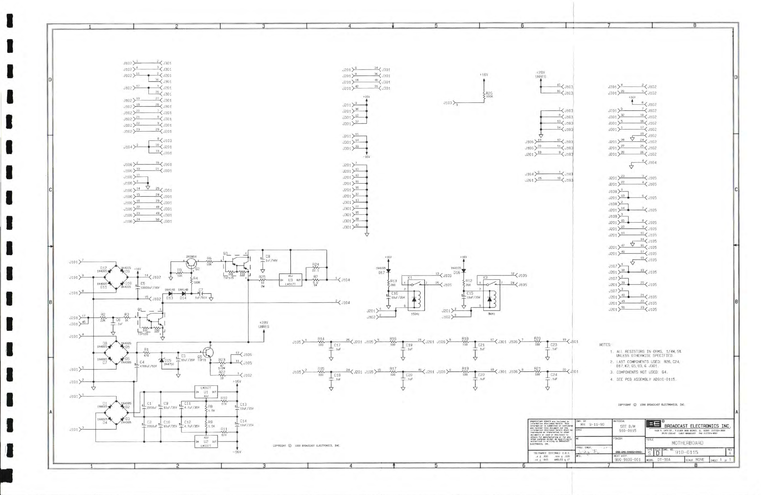
1.
ALL RESISTORS IN
OHMS.
1/4W. 5%
UNLESS
OTHERWISE
SPECIFIED.
2.
LAST
COMPONENTS
USED:
R26,
C24.
D17.
K2.
05.
U3,
S
J301
.
3.
COMPONENTS
NOT
USED:
04.
4.
SEE PCB
ASSEMBLY
AD910-0115.
1990
aflOADCAST ELECTRONICS.
INC.
Inlor.Atlon
aisclasid
herelr
shill
b|
reproddcefl
dd
trandferrdd
tc
dider
dthdra
fop
•dddfscturlno
dp fdP dny
nthep
pdppdse
eicdpt
as
spaplMcsUy
authdpliad
In
orltlno
by
BflOADCAST
ELECTRONICS.
INC.
TOLERANCE
(DECIMAL)
U.D.S.
.X + .030 .XXX ± 005
XX ± .015 ANGLES t 1*
DWN. BY
MH
9-11-90
MATERIAL
SEE B/M
910-0115
CHKD
MATERIAL
SEE B/M
910-0115
ME
FINISH
PflOJ.
ENGR.
. ' •.4
;7L^-T.-.t-Y
FINISH
MFG. ^' NEXT
ASSY.
900-9100-001
BROADCAST
ELECTRONICS
INC.
MOTHERBOARD
TYPE
SIZE
DWG. ND.
S D 910-0115
MODEL
DT-90A
NONE
STEAM POWERED RADIO.COM
COPYHIGHI
©
1990
BROADCAST
FLECTRONICS.
INC
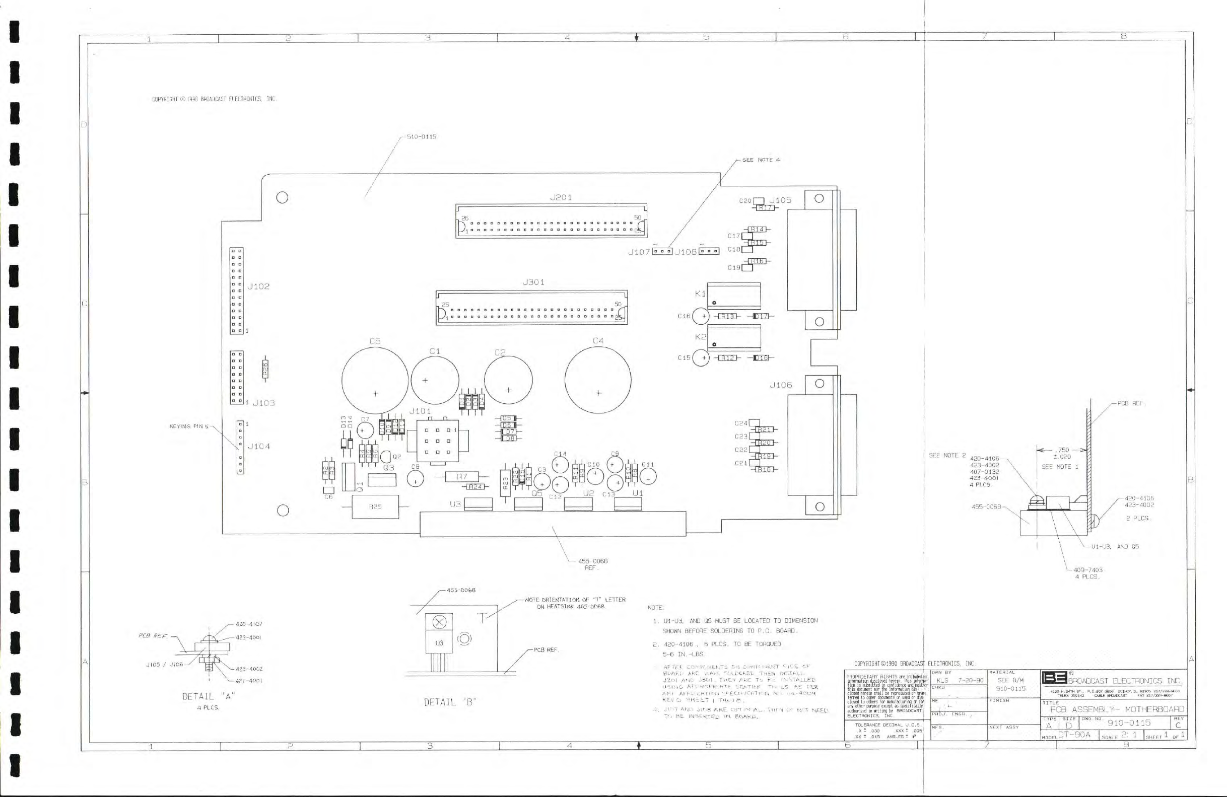
,—
510-0115
-SEE
NOTE
4
KEYING
PIN 5-
o J201
J107IIZZ1
JiosEZZl
^
J102 J301
,26 50
•
• • D O D
otiiiDODn2l
r
1
J103
1
J104
4-3
-CH23>-
o
+
)
nn CIO +
) rHrCi
C
1
1
C12
4Z0-4IO7
/IX
.——423-4001
JI05
/
JI06-
(X)
U3
-423-4002
-421 -4001
(O)
-
455-0068
HEP.
-NOTE
ORIENTATION
OF
"T" LETTER
ON
HEATSTNK
455-0068
-PCB
REF.
DETAIL
"A"
4
PLCS.
DETAIL
1.
U1-U3.
AND 05 MUST BE
LOCATED
TO
DIMENSION
SHOWN
BEFORE
SOLDERING
TO P.O. BOARD.
2. 420-4106
,
6
PLCS.
TO BE TOROUED
5-6 IN.-LBS.
'
AFTLL
COi-il/NLML
CM
COM/
NLMT
SirE
CF
BCAFP
AFC
AAVL
FOLOCKCL
ThSN
IMSTALL
J2.01
AMP
J3C)|
.
THCV
ARC
Tc FL
INSTALLEO
ILLIL.G
ALLROrRlFTE
SEATL/. Tc.LS
.
AS
PER.
AFT
AL.FLICATICTI
SPECIF/CATION
Nr..
•iiA-qocoT
RC-J
C!
SHEET
1
TH,i.ci
61 .
4. JICT
ANL
Tlr.a
ARE
OFTioc lA.E
.
TTAFY
L^
•
T
NEED
To
EC
IFISERTCD
Tl
BOAKL.
SEE
NOTE 2
420-4106-
4.23-4002
407-0132
423-400I
4 PLCS.
455-0068-N
SF
- .
750 —C
+ .020
SEE
NOTE 1
420-4106
423-4002
^~U1-U3.
AND Q5
L-409-7403
4
PLCS.
C0PYRIGHT©199[)
BROADCAST
ELECTRONICS,
INC.
PROPRIETARY RIGHTS
are
included
in
information
disclosed herein. This inforna-
tion
is
submitted
in
confidence
and
neither
this
docuirent nor the
information
dis-
closed herein shall be reproduced
or
trans-
ferred
to other documents
or
used
or d
Si
closed to others for manufacturing
or
a
any other pirpose except
as
specirical
y
authorized
in
writing
by
BnoADCAST
ELECTRONICS.
INC.
TOLERANCE DECIMAL
U.O.S.
.X
*
.030 .XXX
-
,005
,XX
T
.015 ANGLES
*
1°
:
DWN
BY
KLS
7-20-90
PROJ-. ENSR.
MATERIAL
SEE
B/M
910-0115
FINISH
NEXT ASSY
IBHOADCAST
ELECTRONICS
INC.
PCB
ASSEMBLY-
MOTHERBOARD
TYPE
I
SIZE
I
DWG.NO
D
910-0115
e,DT-90A
Uc.LE
2:
1
ET
i
OF
i
STEAM POWERED RADIO.COM
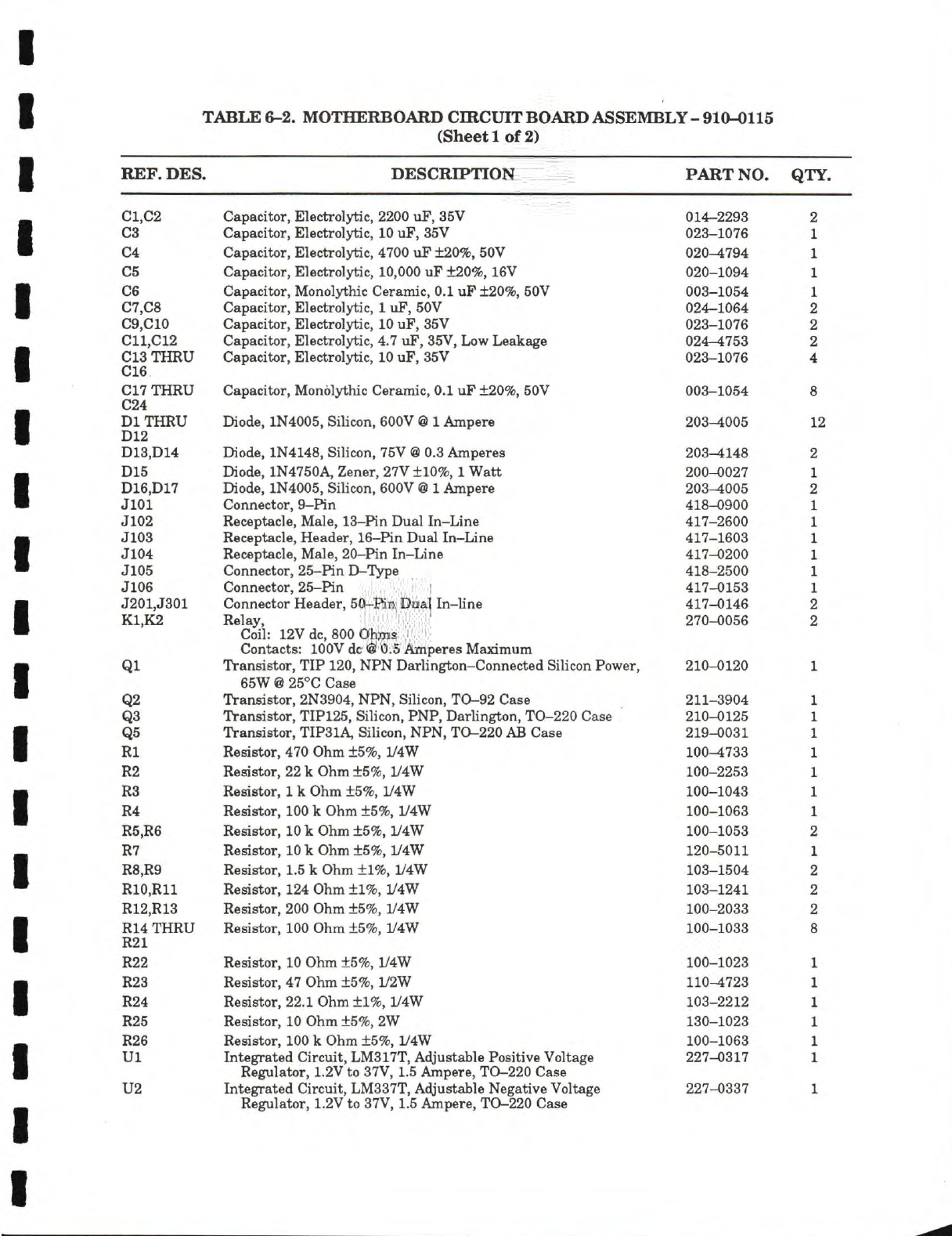
TABLE 6-2. MOTHERBOARD CHICUIT BOARD ASSEMBLY - 910-0115
(Sheet 1 of 2)
REF. DES. DESCRIPTION PART NO. QTY.
C1,C2
C3
C4
C5
C6
C7,C8
C9,C10
C11,C12
C13THRU
C16
C17THRU
C24
DITHRU
D12
D13,D14
D15
D16,D17
JlOl
J102
J103
J104
J105
J106
J201,J301
K1,K2
Ql
02
Q3
Q5
Rl
R2
R3
R4
R5,R6
R7
R8,R9
R10,R11
R12,R13
R14 THRU
R21
R22
R23
R24
R25
R26
Ul
U2
Capacitor, Electrolytic, 2200 uF, 35V
Capacitor, Electrolytic,
10
uF, 35V
Capacitor, Electrolytic, 4700 uF ±20%, 50V
Capacitor, Electrolytic, 10,000 uF
db20%,
16V
Capacitor, Monolythic Ceramic, 0.1 uF ±20%, 50V
Capacitor, Electrolytic,
1
uF, 50V
Capacitor, Electrolytic,
10
uF, S5V
Capacitor, Electrolytic, 4.7 uF, 35V, Low Leakage
Capacitor, Electrolytic,
10
uF, 35V
Capacitor, Monolythic Ceramic, 0.1 uF ±20%, 50V
Diode, 1N4005, Silicon, 600V
@ 1
Ampere
Diode, 1N4148, Silicon, 75V
®
0.3
Amperes
Diode, 1N4750A Zener, 27V ±10%,
1
Watt
Diode, 1N4005, Silicon, 600V
@ 1
Ampere
Connector,
9-Pin
Receptacle, Male, 13-Pin Dual In-Line
Receptacle, Header, 16-Pin Dual In-Line
Receptacle, Male, 20-Pin In-Line
Connector, 25-Pin
D-Type
Connector, 25-Pin
Connector Header, 50-Pin Dual In-hne
Relay,
Coil: 12V
dc,
800 Ohms
Contacts:
lOOV dc @
0.5 Amperes Maximum
Transistor, TIP
120,
NPN Darlington-Connected Silicon Power,
65W
@
25°C
Case
Transistor, 2N3904, NPN, Silicon, TO-92 Case
Transistor, TIP125, Silicon, PNP, Darhngton, TO-220 Case
Transistor, TIP31A, Silicon, NPN, TQ-220
AB
Case
Resistor, 470 Ohm ±5%, 1/4W
Resistor,
22
k Ohm ±5%, 1/4W
Resistor,
1
k Ohm ±5%, 1/4W
Resistor,
100
k Ohm ±5%, 1/4W
Resistor,
10
k Ohm ±5%, 1/4W
Resistor,
10
k Ohm ±5%, 1/4W
Resistor, 1.5 k Ohm ±1%, 1/4W
Resistor, 124 Ohm ±1%, 1/4W
Resistor, 200 Ohm ±5%, iy4W
Resistor, 100 Ohm ±5%, 1/4W
Resistor, 10 Ohm ±5%, 1/4W
Resistor, 47 Ohm ±5%, 1/2W
Resistor, 22.1 Ohm ±1%, 1/4W
Resistor, 10 Ohm ±5%, 2W
Resistor, 100 k Ohm ±5%, 1/4W
Integrated Circuit, LM317T, Adjustable Positive Voltage
Regulator, 1.2V to 37V, 1.5 Ampere, TO-220 Case
Integrated Circuit, LM337T, Adjustable Negative Voltage
Regulator, 1.2V to 37V, 1.5 Ampere, TO-220 Case
014-2293 2
023-1076 1
020-4794 1
AOA
1AA A
020—1094 1
^
A\ A^
4
y\ fA d
003-1054 1
024-1064 2
023-1076 2
024-4753 2
023-1076 4
A A A m m\ W A
003-1054 8
OAO
A(\f\C
203-4005
Ia
203—4148 2
200-0027 1
203-4005 2
418-0900 1
417-2600 1
417-1603 1
A
m
mm
A
A~\
A A
417-0200 1
4ic5—ZOUU
1
1
417-0153 1
417-0146 2
270-0056 2
210-0120 1
211-3904 1
210-0125 1
219-0031 1
1
00—47'^8
J.
100-2253 1
100-1043 1
100-1063 1
100-1053 2
120-5011 1
103-1504 2
103-1241 2
100-2033 2
100-1033 8
100-1023
110-4723
103-2212
130-1023
100-1063
227-0317
227-0337 1
STEAM POWERED RADIO.COM
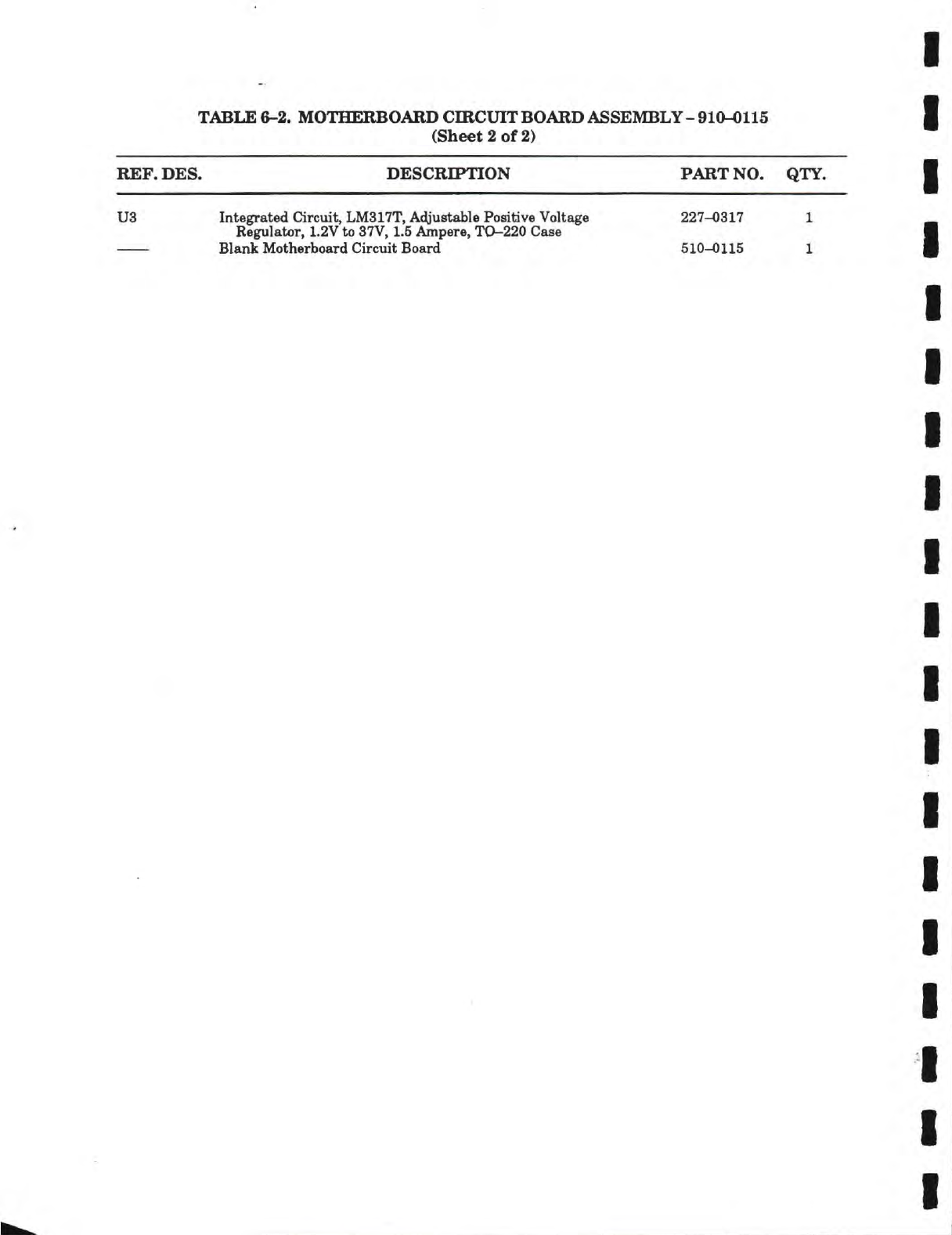
TABLE 6-2. MOTHERBOARD CmCUIT BOARD ASSEMBLY
-
910-0115
(Sheet 2 of 2)
REF.
DES.
DESCRn»TION
PART NO. QTY.
U3 Integrated Circuit, LM317T, Adjustable Positive Voltage 227-0317
1
Regulator,
1.2V
to
37V,
1.5 Ampere, TO-220 Case
Blank Motherboard Circuit Board 510-0115
1
STEAM POWERED RADIO.COM
STEAM POWERED RADIO.COM
STEAM POWERED RADIO.COM
COPYRIGHT
©19B8
BROADCAST
PLECTRONICS,
INC.
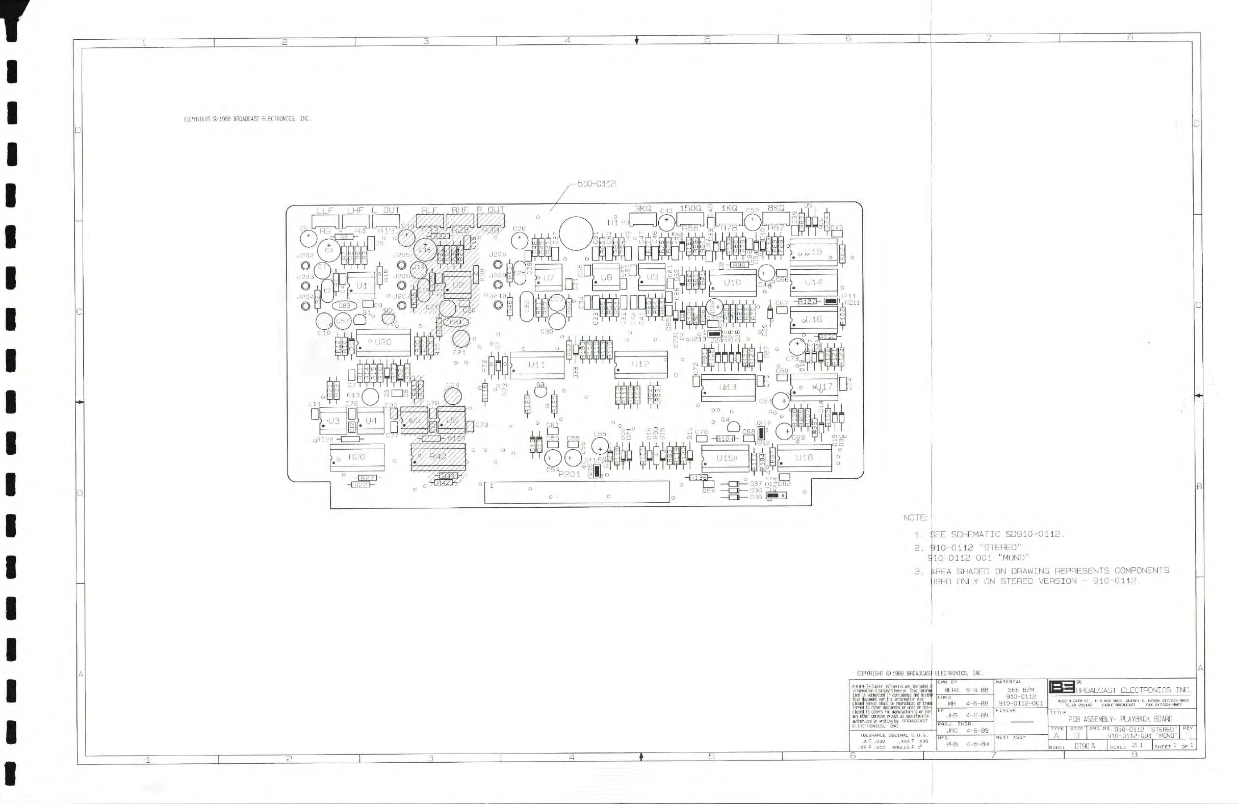
510-0112
NOTE:
1 .
2.
(SEE
SCHEMATIC
80910-0112.
310-0112
"STEREO"
10-0112-001
"MONO"
\REA
SHADED
ON DRAWING
REPRESENTS
COMPONENTS
JSEO
QNLY
ON
STEREO
VERSION
- 910-0112.
COPYRIGHT
©
1988
BROAOCAS
ELECTRONICS,
INC.
PHOPRIETARY
RIGHTS
arc
included
,
inforwtion disclosed derein. This infornil
tion
is
subBitted in confidence and neithf
this dncuiiBnt nor the intnnBtim dis-
closed herein shall he reproduced or Irani
terred to other dhcuments or used or
d-
closed to others
for
eenutacturing or
anv other purpose except as specltical
authorited
in
riting
hy
BROADCAST
ELECTRONICS,
INC
TOLERANCE
DECIMAL U.OS,
.X -•
.030
.XXX
t .005
.XX
t .015
ANGLES
t f
OWN
BY
MERK
9-
CHKD
MH
JHS
4-6-89
PROJ.
ENGR.
JRC
4-6-B9
PRB
4-6-89
lATERIAL
SEE
B/M
910-0112
910-0112-001
FINISH
NEXT
ASSY
IBROADCAST
ELECTRONICS
INC.
PCB
ASSEHBLY-
PLAYBACK BOARD
TYPE
I
SIZE
I
DUG.NO. giQ-QllO
"STEREO"
|
"^v |
A
•
910-0112-001
"MONO"
MODEL
DT90A
EI
I
CE
1
STEAM POWERED RADIO.COM
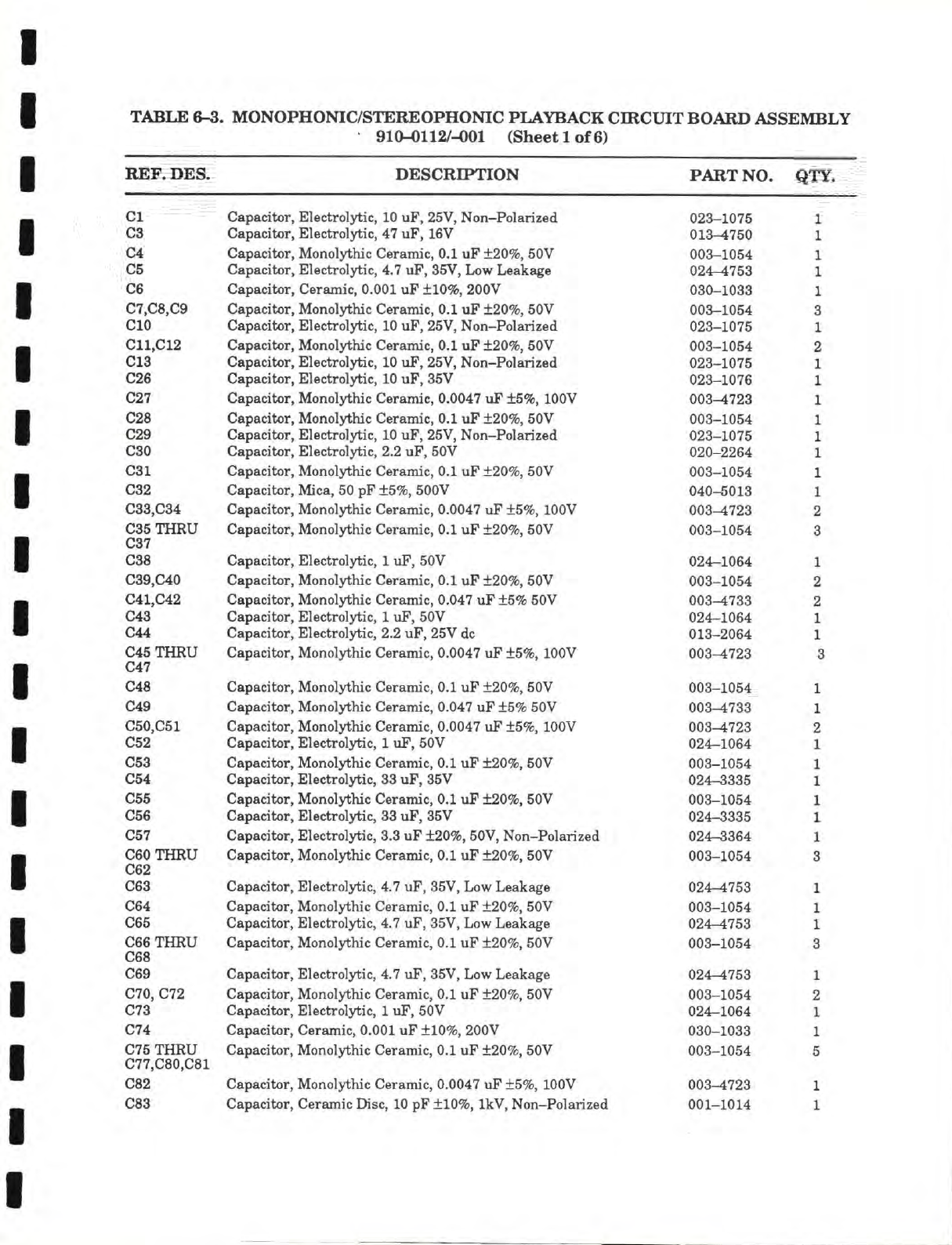
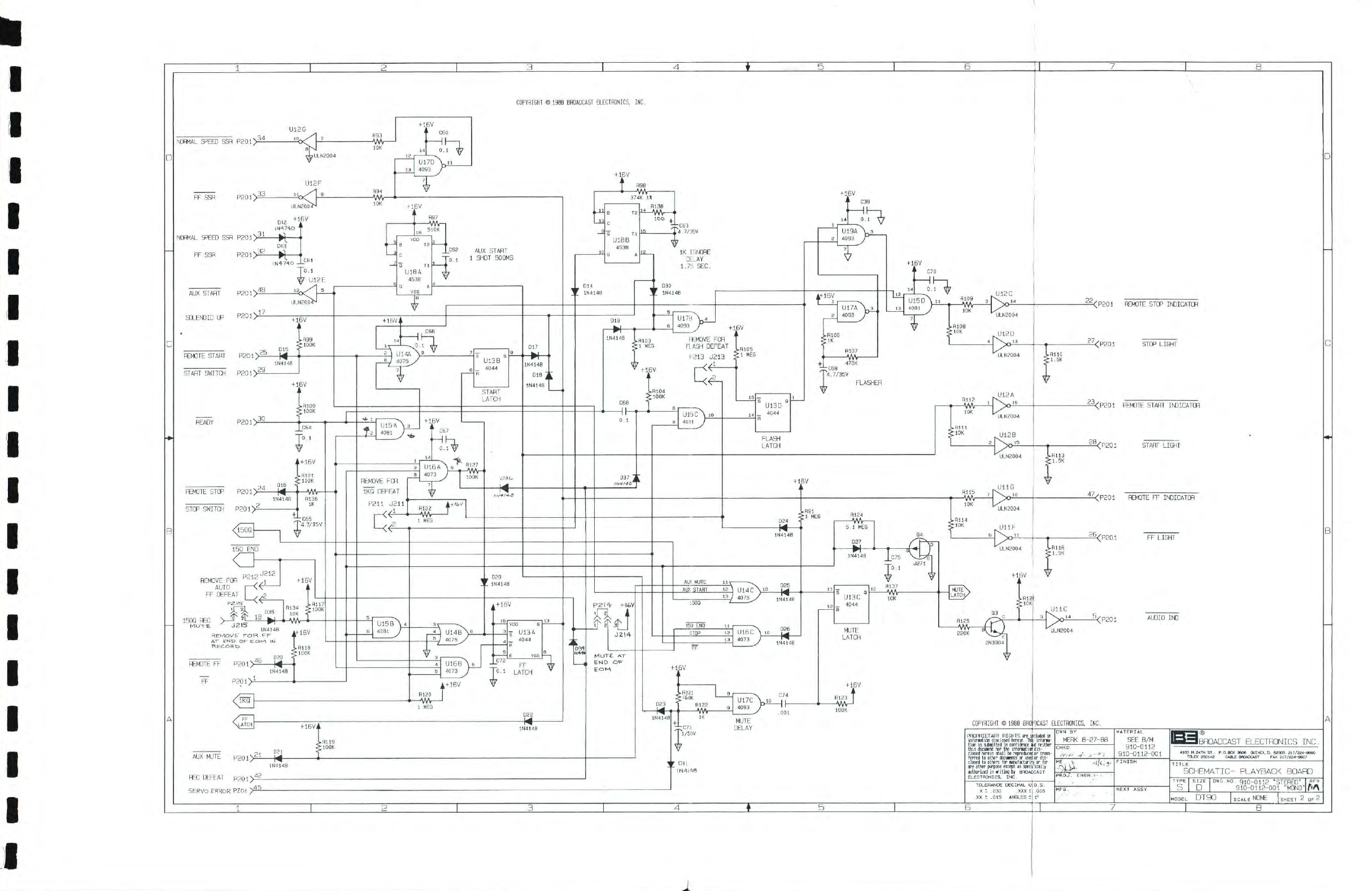
TABLE 6-3. MONOPHONIC/STEREOPHONIC PLAYBACK CIRCUIT BOARD ASSEMBLY
910-0112/-001 (Sheet
1
of 6)
REF. DES. DESCRIPTION PART NO.
QTY.
CI
03
04
05
06
07,08,09
OlO
011,012
013
026
027
028
029
O30
031
032
033,034
035 THRU
037
038
039,040
041,042
043
044
045 THRU
047
048
049
050,051
052
053
054
065
056
057
C60THRU
062
063
064
065
066 THRU
068
069
O70,
072
073 074 075 THRU 077,080,081 082
083
Capacitor, Electrolytic, 10 uF, 25V, Non-Polarized
Capacitor, Electrolytic, 47 uF, 16V
Capacitor, Monolythic Ceramic, 0.1 uF
±20%,
50V
Capacitor, Electrolytic, 4.7 uF, 35V, Low Leakage
Capacitor, Ceramic, 0.001 uF
±10%,
200V
Capacitor, Monolythic Ceramic, 0.1 uF
±20%,
50V
Capacitor, Electrolytic,
10
uF, 25V, Non-Polarized
Capacitor, Monolythic Ceramic, 0.1 uF
±20%,
50V
Capacitor, Electrolytic,
10
uF, 25V, Non-Polarized
Capacitor, Electrolytic,
10
uF, 35V
Capacitor, Monolythic Ceramic,
0.0047
uF
±5%,
lOOV
Capacitor, Monolythic Ceramic, 0.1 uF
±20%,
50V
Capacitor, Electrolytic, 10 uF, 25V, Non-Polarized
Capacitor, Electrolytic, 2.2 uF, 50V
Capacitor, Monolythic Ceramic, 0.1 uF
±20%,
50V
Capacitor, Mica, 50 pF
±5%,
500V
Capacitor, Monolythic Ceramic,
0.0047
uF
±5%,
lOOV
Capacitor, Monolythic Ceramic, 0.1 uF
±20%,
50V
Capacitor, Electrolytic,
1
uF, 50V
Capacitor, Monolythic Ceramic, 0.1 uF
±20%,
50V
Capacitor, Monolythic Ceramic,
0.047
uF
±5%
50V
Capacitor, Electrolytic,
1
uF, 50V
Capacitor, Electrolytic, 2.2 uF, 25V dc
Capacitor, Monolythic Ceramic,
0.0047
uF
±5%,
lOOV
Capacitor, Monolythic Ceramic, 0.1 uF
±20%,
50V
Capacitor, Monolythic Ceramic,
0.047
uF
±5%
50V
Capacitor, Monolythic Ceramic,
0.0047
uF
±5%,
lOOV
Capacitor, Electrolytic,
1
uF, 50V
Capacitor, Monolythic Ceramic, 0.1 uF
±20%,
50V
Capacitor, Electrolytic,
33
uF, 35V
Capacitor, Monolythic Ceramic, 0.1 uF
±20%,
50V
Capacitor, Electrolytic,
33
uF, 35V
Capacitor, Electrolytic, 3.3 uF
±20%,
50V, Non-Polarized
Capacitor, Monolythic Ceramic, 0.1 uF
±20%,
50V
Capacitor, Electrolytic, 4.7 uF, 35V, Low Leakage
Capacitor, Monolythic Ceramic, 0.1 uF
±20%,
50V
Capacitor, Electrolytic, 4.7 uF, 35V, Low Leakage
Capacitor, Monolythic Ceramic, 0.1 uF
±20%,
50V
Capacitor, Electrolytic, 4.7 uF, 35V, Low Leakage
Capacitor, Monolythic Ceramic, 0.1 uF
±20%,
50V
Capacitor, Electrolytic,
1
uP, 50V
Capacitor, Ceramic, 0.001 uF
±10%,
200V
Capacitor, Monolythic Ceramic, 0.1 uF
±20%,
50V
Capacitor, Monolythic Ceramic,
0.0047
uF
±5%,
lOOV
Capacitor, Ceramic
Disc,
10
pF
±10%,
IkV, Non-Polarized
1
1
UXo—4/OU
1
003—1054 1
noii d7t;n
yJAi't—*t
/ OO
1
n<in
mm 1
UUO—J-OOft
Q
O
023-1075 1
003-1054 2
AAA
Arr^
023-1075 1
023—1076
1
X
vUo—4
t ZO 1
X
003-1054 1
023—1075 1
020-2264 1
003-1054 1
040-5013 1
A A A
A rm
r^
a
003^723 2
003-1054 3
UZ4—XUD4 i.
AAA
lAC,*
003-1054 2
A A A
A
rr
A A
003-4733 2
AO
X
-!
AC/I
1
1
013-2064
1
X
003^723 3
AAA
^f\C.A
UUo—iUo4
1
AAA
4rTAA
003^733 1
003-4723 2
024-1064 1
003-1054 1
024-3335 1
003-1054 1
024-3335 1
024-3364 1
00.3-1054 0
V
/\n
A
A rt f n
024-4753 1
003-1054 1
024-4753 1
003-1054 3
024-4753 1
003-1054 2
024-1064 1
030-1033 1
003-1054 5
003^723 1
001-1014 1
STEAM POWERED RADIO.COM
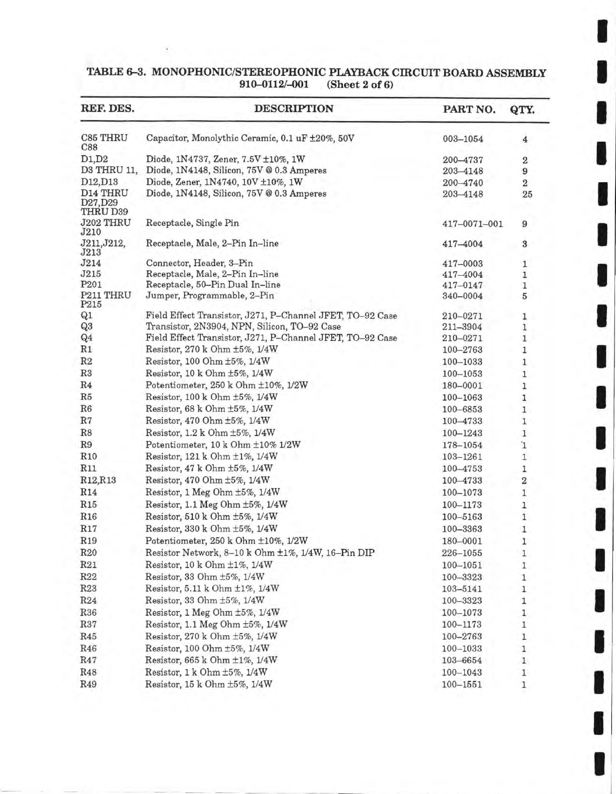
TABLE 6-3. MONOPHONIC/STEREOPHONIC PLAYBACK CIRCUIT BOARD ASSEMBLY
910-0112/-001 (Sheet 2 of 6)
REF. DES. DESCRIPTION PART NO. QTY.
C85
THRU
088
D1,D2
D3
THRU
11,
D12,D13
D14 THRU
D27,D29
THRU D39
J202 THRU
J210
J211,J212,
J213
J214
J215
P201
P211
THRU
P215
Ql
Q3
Q4
Rl
R2
R3
R4
R5
R6
R7
R8
R9
RIO
Rll
R12,R13
R14
R15
R16
R17
R19
R20
R21
R22
R23
R24
R36
R37
R45
R46
R47
R48
R49
Capacitor,
Mcnol3±hic
Ceramic, 0.1 uF ±20%, 50V
Diode, 1N4737, Zener, 7.5V ±10%, IW
Diode, 1N4148, Silicon,
75V @
0.3
Amperes
Diode, Zener, 1N4740,
lOV
±10%, IW
Diode, 1N4148, Silicon, 75V
@
0.3
Amperes
Receptacle, Single Pin
Receptacle, Male,
2-Pin
In-line
Connector, Header,
3-Pin
Receptacle, Male,
2-Pin
In-line
Receptacle, 50-Pin Dual In-line
Jumper, Programmable,
2-Pin
Field Effect Transistor,
J271,
P-Channel JFET, TO-92 Case
Transistor, 2N3904, NPN, Silicon, TO-92 Case
Field Effect Transistor,
J271,
P-Channel JFET, TO-92 Case
Resistor,
270
k Ohm ±5%, 1/4W
Resistor, 100 Ohm ±5%, 1/4W
Resistor,
10
k Ohm ±5%, 1/4W
Potentiometer, 250 k Ohm ±10%, 1/2W
Resistor,
100
k Ohm ±5%, 1/4W
Resistor, 68 k Ohm ±5%, 1/4W
Resistor, 470 Ohm ±5%, 1/4W
Resistor, 1.2 k Ohm ±5%, 1/4W
Potentiometer,
10
k Ohm ±10% 1/2W
Resistor,
121
k Ohm ±1%, 1/4W
Resistor, 47 k Ohm ±5%, iy4W
Resistor, 470 Ohm ±5%, 1/4W
Resistor,
1
Meg Ohm ±5%, 1/4W
Resistor, 1.1 Meg Ohm ±5%, 1/4W
Resistor, 510 k Ohm ±5%, 1/4W
Resistor,
330
k Ohm ±5%, 1/4W
Potentiometer, 250 k Ohm ±10%, 1/2W
Resistor Network, 8-10 k Ohm ±1%, 1/4W, 16-Pin DIP
Resistor,
10
k Ohm ±1%, 1/4W
Resistor, 33 Ohm ±5%, 1/4W
Resistor, 5.11 k Ohm ±1%, 1/4W
Resistor, 33 Ohm ±5%, 1/4W
Resistor,
1
Meg Ohm ±5%, 1/4W
Resistor, 1.1 Meg Ohm ±5%, 1/4W
Resistor, 270 k Ohm ±5%, iy4W
Resistor, 100 Ohm ±5%, 1/4W
Resistor,
665
k Ohm ±1%, 1/4W
Resistor,
1
k Ohm ±5%, 1/4W
Resistor,
15
k Ohm ±5%, 1/4W
003-1054
200-4737
203-4148
200-4740
203-4148
417-0071-001
417-4004
417-0003
417-4004
417-0147
340-0004
210-
0271
211-
3904
210-0271
100-2763
100-1033
100-1053
180-0001
100-1063
100-6853
100-4733
100-1243
178-1054
103-1261
100-4753
100-4733
100-1073
100-1173
100-5163
100-3363
180-0001
226-1055
100-1051
100-3323
103-5141
100-3323
100-1073
100-1173
100-2763
100-1033
103-6654
100-1043
100-1551
2
9
2
25
9
3
STEAM POWERED RADIO.COM
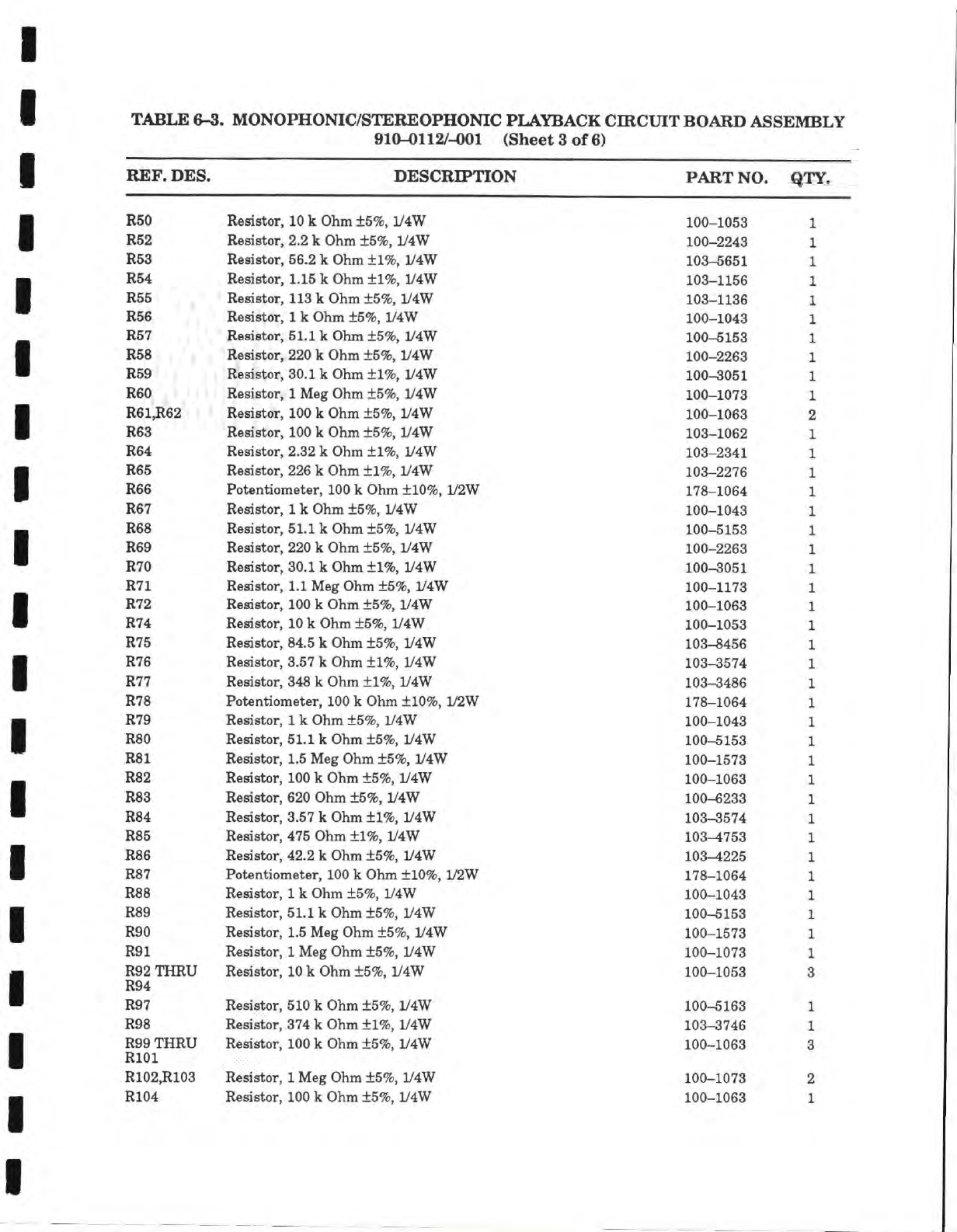
TABLE
6-3.
MONOPHONIC/STEREOPHONIC PLAYBACK CIRCUIT BOARD ASSEMBLY
910-0112/-001 (Sheet
3 of 6)
REF. DES.
DESCRIPTION PART
NO. QTY.
R50
Resistor,
10
k Ohm ±5%, 1/4W
100-1053
R52
Resistor,
2.2 k Ohm ±5%, 1/4W
100-2243
R53
Resistor,
56.2 k Ohm ±1%, 1/4W
103-5651
R54
Resistor,
1.15 k Ohm ±1%, 1/4W
103-1156
R55
Resistor,
113
k Ohm ±5%, 1/4W
103-1136
R56
Resistor,
1
k Ohm ±5%, 1/4W
100-1043
R57
Resistor,
51.1
k Ohm ±5%, 1/4W
100-5153
R58
Resistor,
220 k Ohm ±5%, 1/4W
100-2263
R59
Resistor,
30.1
k Ohm ±1%, V4W
100-3051
R60
Resistor,
1
Meg Ohm ±5%, 1/4W
100-1073
R61,R62
Resistor,
100
k Ohm ±5%, 1/4W
100-1063
R63
Resistor,
100 k Ohm ±5%, y4W
103-1062
R64
Resistor,
2.32 k Ohm ±1%, 1/4W
103-2341
R65
Resistor,
226 k Ohm ±1%, 1/4W
103-2276
R66
Potentiometer,
100
k Ohm ±10%, 1/2W
178-1064
R67
Resistor,
1
k Ohm ±5%, 1/4W
100-1043
R68
Resistor,
51.1
k Ohm ±5%, 1/4W
100-5153
R69
Resistor,
220 k Ohm ±5%, 1/4W
100-2263
R70
Resistor,
30.1
k Ohm ±1%, 1/4W
100-3051
R71
Resistor,
1.1 Meg Ohm ±5%, 1/4W
100-1173
R72
Resistor,
100 k Ohm ±5%, 1/4W
100-1063
R74
Resistor,
10
k Ohm ±5%, 1/4W
100-1053
R75
Resistor,
84.5 k Ohm ±5%, 1/4W
103-8456
R76
Resistor,
3.57 k Ohm ±1%, 1/4W
103-3574
R77
Resistor,
348
k Ohm ±1%, 1/4W
103-3486
R78
Potentiometer,
100
k Ohm ±10%, L/2W
178-1064
R79
Resistor,
1
k Ohm ±5%, 1/4W
100-1043
R80
Resistor,
51.1
k Ohm ±5%, 1/4W
100-5153
R81
Resistor,
1.5 Meg Ohm ±5%, 1/4W
100-1573
R82
Resistor,
100
k Ohm ±5%, 1/4W
100-1063
R83
Resistor,
620 Ohm ±5%, 1/4W
100-6233
R84
Resistor,
3.57 k Ohm ±1%, 1/4W
103-3574
R85
Resistor,
475 Ohm ±1%, 1/4W
103-4753
Roaiatnr
49
9 Ir OVim
+"1%
1/4W
R87
PntAnHnmptpr
100 k
OVim
+10% 1/9W
X
/
O—XUDft
R88
Resistor 1
k Ohm
+5%
L/4W inn
^(\±'k
R89
Resistor,
51.1
k Ohm ±5%, 1/4W
100-5153
R90
Resistor,
1.5 Meg Ohm ±5%,
iy4W 100-1573
R91
Resistor,
1
Meg Ohm ±5%, L/4W
100-1073
R92
THRU
R94
Resistor,
10
k Ohm ±5%, 1/4W
100-1053
R97
Resistor,
510 k Ohm ±5%, 1/4W
100-5163
R98
Resistor,
374 k Ohm ±1%, 1/4W
103-3746
R99
THRU
RlOl
Resistor,
100
k Ohm ±5%, 1/4W
100-1063
3
R102,R103
Resistor,
1
Meg Ohm ±5%, 1/4W
100-1073
2
R104
Resistor,
100 k Ohm ±5%, 1/4W
100-1063
1
STEAM POWERED RADIO.COM
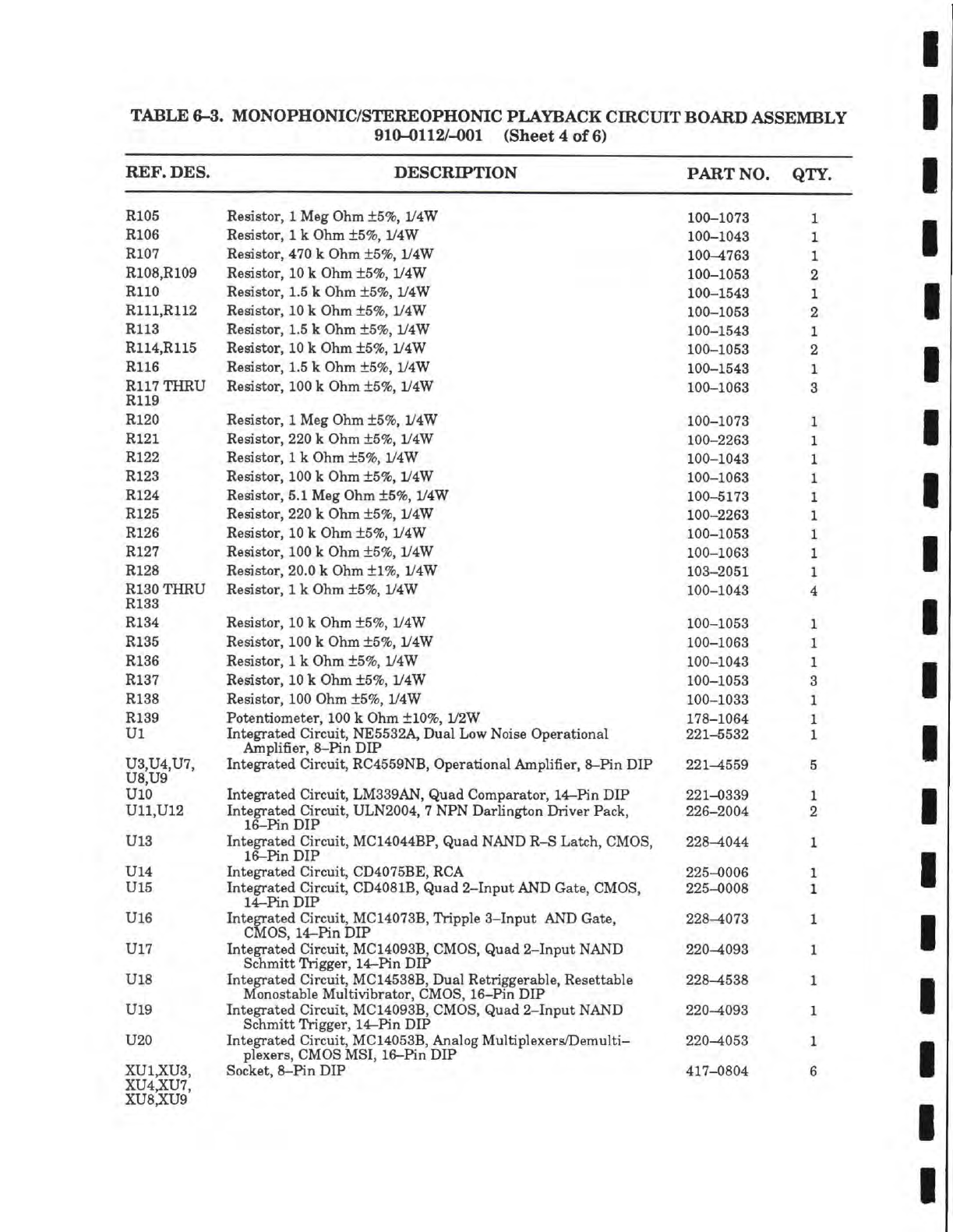
TABLE 6-3. MONOPHONIC/STEREOPHONIC PLAYBACK CIRCUIT BOARD ASSEMBLY
910-0112/-001 (Sheet 4 of 6)
REF. DES. DESCRIPTION PART NO. QTY.
R105
R106
R107
R108,R109
RllO
R111,R112
R113
R114,R115
R116
R117 THRU
R119
R120
R121
R122
R123
R124
R125
R126
R127
R128
R130 THRU
R133
R134
R135
R136
R137
R138
R139
Ul
U3,U4,U7,
U8,U9
UlO
U11,U12
U13
U14
U15
U16
U17
U18
U19
U20
XUi;XU3,
XU4,XU7,
XU8,XU9
Resistor,
1
Meg Ohm ±5%, 1/4W 100-1073
Resistor,
1
k Ohm ±5%, 1/4W 100-1043
Resistor, 470 k Ohm ±5%, 1/4W 100-1763
Resistor,
10
k Ohm
+5%,
1/4W 100-1053
Resistor, 1.5 k Ohm
+5%,
1/4W 100-1543
Resistor,
10
k Ohm
+5%,
1/4W 100-1053
Resistor, 1.5 k Ohm ±5%, 1/4W 100-1543
Resistor,
10
k Ohm
+5%,
1/4W 100-1053
Resistor, 1.5 k Ohm
+5%,
1/4W 100-1543
Resistor,
100
k Ohm ±5%, 1/4W 100-1063
Resistor,
1
Meg Ohm ±5%, L/4W 100-1073
Resistor, 220 k Ohm ±5%, 1/4W 100-2263
Resistor,
1
k Ohm ±5%, 1/4W 100-1043
Resistor, 100 k Ohm ±5%, 1/4W 100-1063
Resistor, 5.1 Meg Ohm ±5%, 1/4W 100-5173
Resistor, 220 k Ohm ±5%, 1/4W 100-2263
Resistor,
10
k Ohm
+5%,
1/4W 100-1053
Resistor, 100 k Ohm ±5%, 1/4W 100-1063
Resistor, 20.0 k Ohm ±1%, 1/4W 103-2051
Resistor,
1
k Ohm
+5%,
1/4W 100-1043
Resistor,
10
k Ohm ±5%, 1/4W 100-1053
Resistor,
100
k Ohm ±5%, 1/4W 100-1063
Resistor,
1
k Ohm ±5%, 1/4W 100-1043
Resistor,
10
k Ohm ±5%, 1/4W 100-1053
Resistor, 100 Ohm ±5%, 1/4W 100-1033
Potentiometer, 100 k Ohm ±10%, 1/2W 178-1064
Integrated Circuit, NE5532A, Dual Low Noise Operational 221-5532
Amplifier,
8-Pin
DIP
Integrated Circuit, RC4559NB, Operational Amplifier,
8-Pin
DIP 221-4559
Integrated Circuit, LM339AN, Quad Comparator, 14-Pin DIP 221-0339
Integrated Circuit, ULN2004,
7
NPN Darhngton Driver Pack, 226-2004
16-Pin DIP
Integrated Circuit, MC14044BP, Quad NAND R-S Latch, CMOS, 228-i044
16-Pin DIP
Integrated Circuit, CD4075BE, RCA 225-0006
Integrated Circuit, CD4081B, Quad
2-Input
AND Gate, CMOS, 225-0008
14-Pin DIP
Integrated Circuit, MC14073B, Tripple
3-Input
AND Gate, 228-4073
CMOS,
14-Pin DIP
Integrated Circuit, MC14093B, CMOS, Quad
2-Input
NAND 220^093
Schmitt Trigger, 14-Pin DIP
Integrated Circuit, MC14538B, Dual Retriggerable, Resettable 228-1538
Monostable Multivibrator, CMOS, 16-Pin DIP
Integrated Circuit, MC14093B, CMOS, Quad
2-Input
NAND 220^093
Schmitt Trigger, 14-Pin DIP
Integrated Circuit, MC14053B, Analog Multiplexers/Demulti- 220^053
plexers, CMOS MSI, 16-Pin DIP
Socket,
8-Pin
DIP 417-0804
STEAM POWERED RADIO.COM
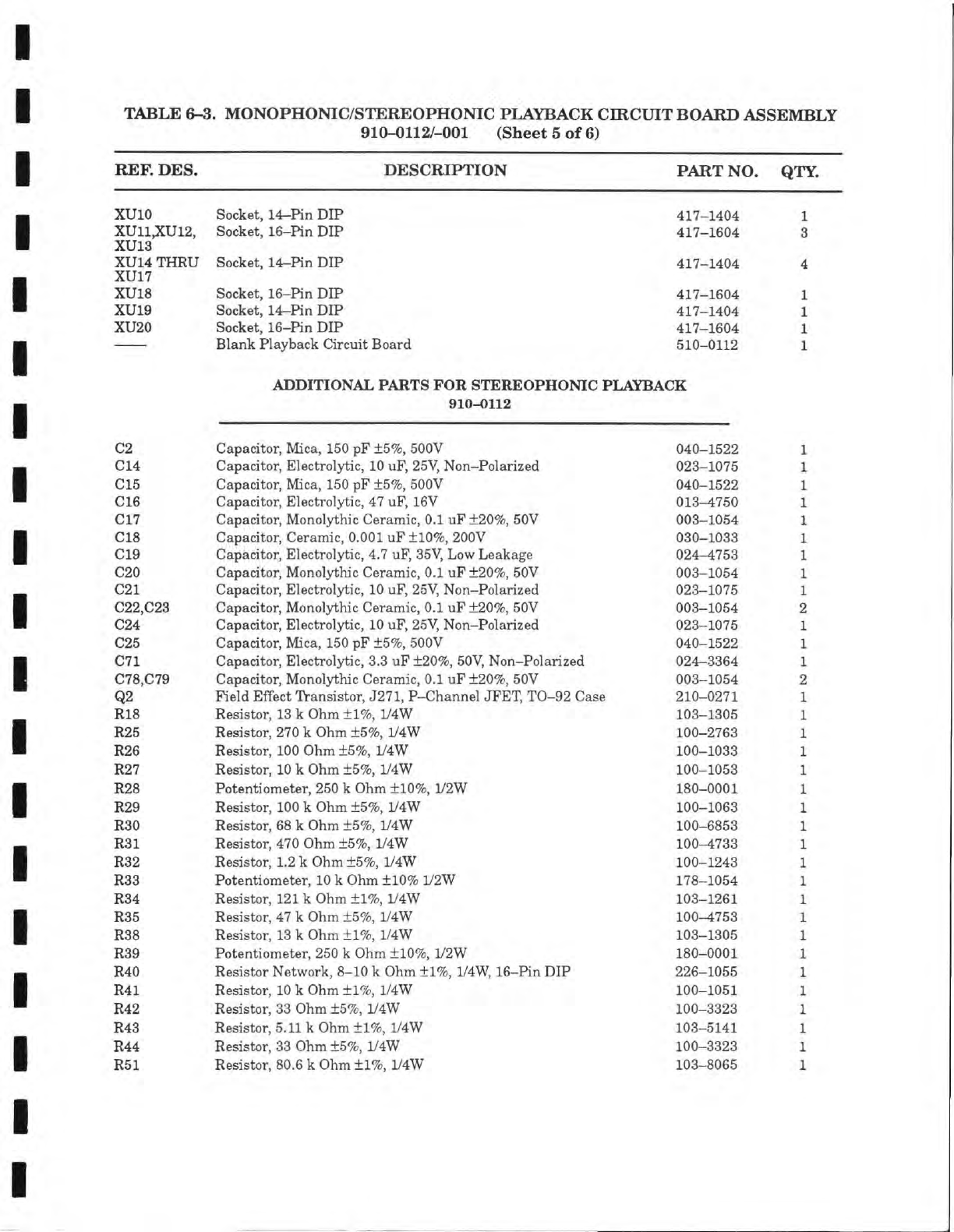
TABLE 6-3. MONOPHONIC/STEREOPHONIC PLAYBACK CIRCUIT BOARD ASSEMBLY
910-0112/-001 (Sheet 5 of 6)
REF. DES. DESCRIPTION PART NO. QTY.
XUlO Socket, 14-Pin DIP 417-1404 1
XU11,XU12, Socket, 16-Pin DIP 417-1604 3
XU13
XU14 THRU Socket, 14-Pin DIP 417-1404 4
XU17
XU18 Socket, 16-Pin DIP 417-1604 1
XUlO Socket, 14-Pin DIP 417-1404 1
XU20 Socket, 16-Pin DIP 417-1604 1
Blank Playback Circuit Board 510-0112 1
ADDITIONAL PARTS FOR STEREOPHONIC PLAYBACK
910-0112
C2 Capacitor, Mica, 150 pF ±5%, 500V 040-1522
C14 Capacitor, Electrolytic,
10
uF,
25V,
Non-Polarized 023-1075
C15 Capacitor, Mica, 150 pF ±5%, 500V 040-1522
C16 Capacitor, Electrolytic, 47
uF,
16V 013-4750
C17 Capacitor, Monolythic Ceramic, 0.1 uF ±20%, 50V 003-1054
C18 Capacitor, Ceramic, 0.001 uF ±10%, 200V 030-1033
C19 Capacitor, Electrolytic, 4.7 uF,
35V,
Low Leakage 024-4753
C20 Capacitor, Monolythic Ceramic, 0.1 uF ±20%, 50V 003-1054
C21 Capacitor, Electrolytic,
10
uF,
25V,
Non-Polarized 023-1075
C22,C23 Capacitor, Monolythic Ceramic, 0.1 uF ±20%, 50V 003-1054
C24 Capacitor, Electrolytic,
10
uF,
25V,
Non-Polarized 023-1075
C25 Capacitor, Mica,
150
pF ±5%, 500V 040-1522
C71 Capacitor, Electrolytic, 3.3 uF ±20%,
50V,
Non-Polarized 024-3364
C78,C79 Capacitor, Monolythic Ceramic, 0.1 uF ±20%, 50V 003-1054
Q2 Field Effect Transistor, J271,P-ChannelJFET, TO-92 Case 210-0271
R18 Resistor,
13
k Ohm ±1%, 1/4W 103-1305
R25 Resistor, 270 k Ohm ±5%, iy4W 100-2763
R26 Resistor, 100 Ohm ±5%, 1/4W 100-1033
R27 Resistor,
10
k Ohm ±5%, 1/4W 100-1053
R28 Potentiometer, 250 k Ohm ±10%, 1/2W 180-0001
R29 Resistor,
100
k Ohm ±5%, y4W 100-1063
R30 Resistor,
68
k Ohm ±5%, 1/4W 100-6853
R31 Resistor, 470 Ohm ±5%, 1/4W 100-4733
R32 Resistor, 1.2 k Ohm ±5%, 1/4W 100-1243
R33 Potentiometer,
10
k Ohm ±10% iy2W 178-1054
R34 Resistor,
121
k Ohm ±1%, 1/4W 103-1261
R35 Resistor, 47 k Ohm ±5%, 1/4W 100-4753
R38 Resistor,
13
k Ohm ±1%, 1/4W 103-1305
R39 Potentiometer, 250 k Ohm ±10%, iy2W 180-0001
R40 Resistor Network, 8-10 k Ohm ±1%, 1/4W, 16-Pin DIP 226-1055
R41 Resistor,
10
k Ohm ±1%, 1/4W 100-1051
R42 Resistor, 33 Ohm ±5%, 1/4W 100-3323
R43 Resistor, 5.11k Ohm ±1%, 1/4W 103-5141
R44 Resistor, 33 Ohm ±5%, 1/4W 100-3323
R51 Resistor, 80.6 k Ohm ±1%, 1/4W 103-8065
STEAM POWERED RADIO.COM
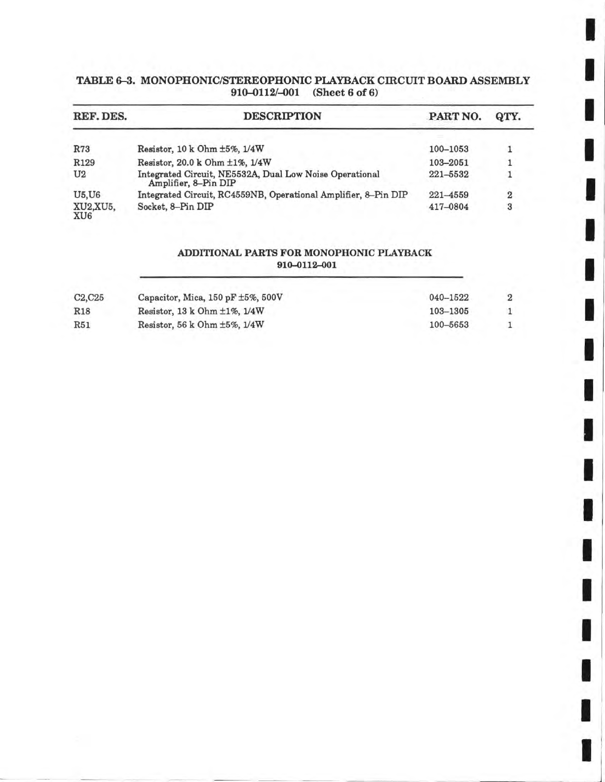
TABLE 6-3. MONOPHONIC/STEREOPHONIC PLAYBACK CIRCUIT BOARD ASSEMBLY
910-0112/-001 (Sheet 6 of 6)
REF.
DES. DESCRIPTION PART NO. QTY.
R73 Resistor,
10
k
Ohm
+5%,
1/4W
100-1053 1
R129 Resistor, 20.0
k
Ohm
±1%, 1/4W
103-2051 1
U2 Integrated Circuit, NE5532A, Dual Low Noise Operational
Amplifier,
8-Pin
DIP 221-5532 1
U5,U6 Integrated Circuit, RC4559NB, Operational Amplifier,
8-Pin
DIP 221-4559 2
XU2;iCU5,
Socket,
8-Pin
DIP 417-0804 3
XU6
ADDITIONAL PARTS FOR MONOPHONIC PLAYBACK
910-0112-001
C2,C25
R18
R51
Capacitor, Mica,
150
pF
±5%,
500V
Resistor,
13
k
Ohm
±1%, 1/4W
Resistor, 56
k
Ohm
±5%, 1/4W
040-1522
103-1305
100-5653
2
1
1
STEAM POWERED RADIO.COM
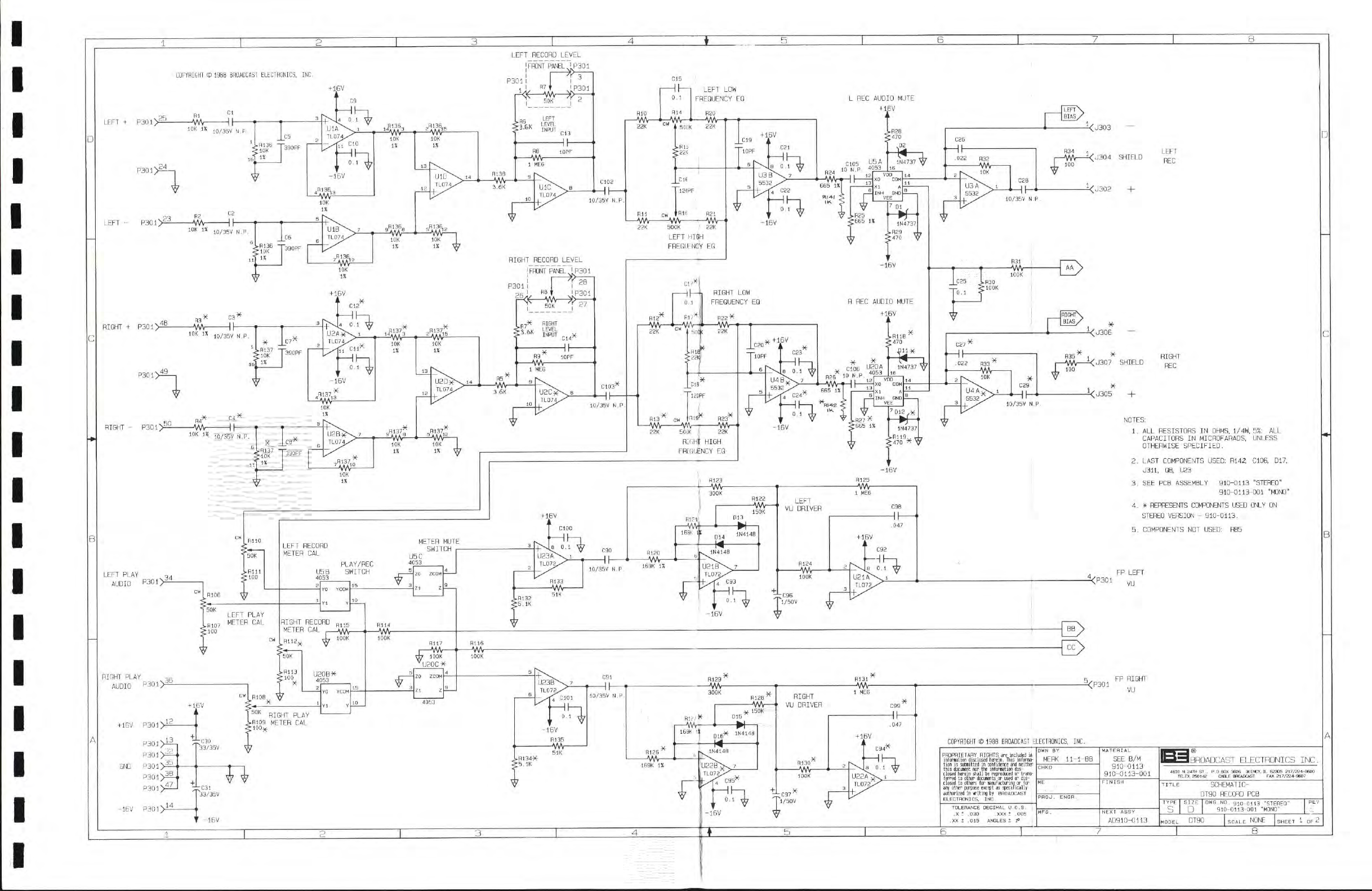
CUPYRIGHT
©
1988
BROADCAST
ELECTHONICS,
INC,
LEFT +
P301>
25
P301>
24
LEFT -
P301>£
RIGHT +
P301>^
P301>
49
RIGHT - P301,
LEFT PLAY
AUDIO
P301>
34
RIGHT PLAY
AUDIO
P301>
36
+
16V
P301>i
P301>
13
P301>3E-
35
NB
GND
P301>
P301_
P301)4
-16V
P301>i
+
16V
Rl
-Wy-
Cl
HI-
.H136
"T-
lOK
1%
C5
390PF
R3
.B136
•lOK
1%
C6
390PF
.J813B,
lOK
1%
i5iv^
lOK
1*
-E5JV^
lOK
IX
lOK
IX
lOK
IX
R3
—Wv-
lOK
IX
j(,/35v
N.P.
Hh-
3F
• R137
-p,,
•lOK
IX
R4*
-JWV-10/35V
N.P.
.fil37
-r„
•lOK
IX
lOK
IX
lOK
IX
lOK
IX
.R137"
=VVY^
lOK
IX
RllO
'SGK
• RUi
•100
.R107
;100
LEFT PLAY
METER
CAL
LEFT
RECORD
METER
CAL
U5B
4053
PLAY/REC
SWITCH
METER
MUTE
SWITCH
U5C
4053
YO
YCOM
ZO
ZOOM
RIGHT
RECORD
METER
CAL ^
R115
-VW-
R113
100
3F
U20B3F
4053
RlOe
W
3F
^
YO
YODM
RIGHT PLAY
.R109
METER
CAL
R114
-AM
h
lOOK
''U20C3F
I
LEFT
RECORD
LEVEL
P301
I
He-
!FRONT
PANEL
I
P301
FIT
I
-Wr-
3
i
P301
.R6
:3,6K
LEFT
LEVEL
INPUT C13
C102
HI-
RIO
-AM-
C15
Hh
R14
zMN-
LEFT LOW
FREQUENCY
EQ
.R15
•22K
CIS
TSIPF
Rll
22K 500K
R16
LEFT HIGH
FREQUENCY
EQ
RIGHT
RECORD
LEVEL
P301
I
26
'
I
FRONT
PANEL
I P301
PB
t
-AM-
28
P301
C103T*
Hh-
L REG AUDIO
MUTE
+
1BV
4AV—hHYW
22K
RIGHT LOW
FREQUENCY
EQ
•
50|
.Rll
:22i
H22V
-AW-
-16V
H REG AUDIO
MUTE
+
16V
R13
-AW-
C,9^
'lEOPF
R23^
-AVV-H
-AW-
50CK
22K
RIGHT HIGH
FREQUENCY
EQ
C2B
Hh
R31
-AW-
_C25
0.1
LR30
TIOOK
+
1.6V
C90
Hh
B120
-AW-
.R132
:5.1K
R125
-AM-
C9B
Hh
+
1BV
'
' C92
0.1
UElh
TL072,
MA
—f
WV-
fll35
-AW-
C91
Hh
R129
-AW-
RIGHT
AA—1 VU DRIVER
.R134X
:5.1K
R126
~vwv-
R12/31
1B9K
Ii
-16V
; 150K
R131
-MA-
P130
-AVr-
C99
Hh
+1.6V
1/50V
LEFT
BIAS
-H<J303
—
R34
, LEFT
-i<J304
SHIELD
100
REG
-H<;j302
[RIGHT\
'BIAS/
1<J306
—
,
77
-i<U307
SHIELD REG
-H<J305
^P301
NOTES:
1.
ALL RESISTORS IN
OHMS,
1/4W,
5%:
ALL
CAPACITORS
IN
MICROFARADS,
UNLESS
OTHERWISE
SPECIFIED.
2.
LAST
COMPONENTS
USED:
R142, C106, 017,
U311,
Q8, U23
3.
SEE PCB
ASSEMBLY
910-0113
"STEREO"
910-0113-001
"MONO"
4.
*
REPRESENTS
COMPONENTS
USED
ONLY
ON
STEREO
VERSION -
910-0113.
5.
COMPONENTS
NOT
USED:
RB5
PR LEFT
VU
5,
FP RIGHT
-2/P301
^
VU
COPYHICHT
©
1988
BHOADCAST
ELECTRONICS,
INC.
PROPRIETARY RIGHTS
ire
teluiled
il
inforBation disclosed herein. This infornia-
tion
is
suhiitted
in
confidence and neither
ferred
ta
other docufients
sr
used
sr
dis-
closed
to
others
for
nanufactiring
or for;
any other purpose except
as
specifically
•,
authorited
in
ariting hy
BROADCAST
)
ELECTRONICS. INC. I
TOLERANCE
DECIMAL
U.O.S.
]
.X I .030 .XXX t .005
.XX t .015 ANGLES 1 1° \
OWN av
MERK
11-1-88
MATERIAL
SEE B/M
910-0113
910-0113-001
CHKD
MATERIAL
SEE B/M
910-0113
910-0113-001
ME
FINISH
PROJ.
ENGR._
FINISH
MPS
.
NEXT
ASSY
AD910-0113
IBROADCAST
ELECTRONICS
INC.
TITLE
SCHEMATIC-
DlgO
RECORD
PCB
TYPE SIZE
DUG.NO.
910-0113
-STEREO-
PE^X
S
•
910-0113-001
"MDNO-
DT90
NONE
B
STEAM POWERED RADIO.COM
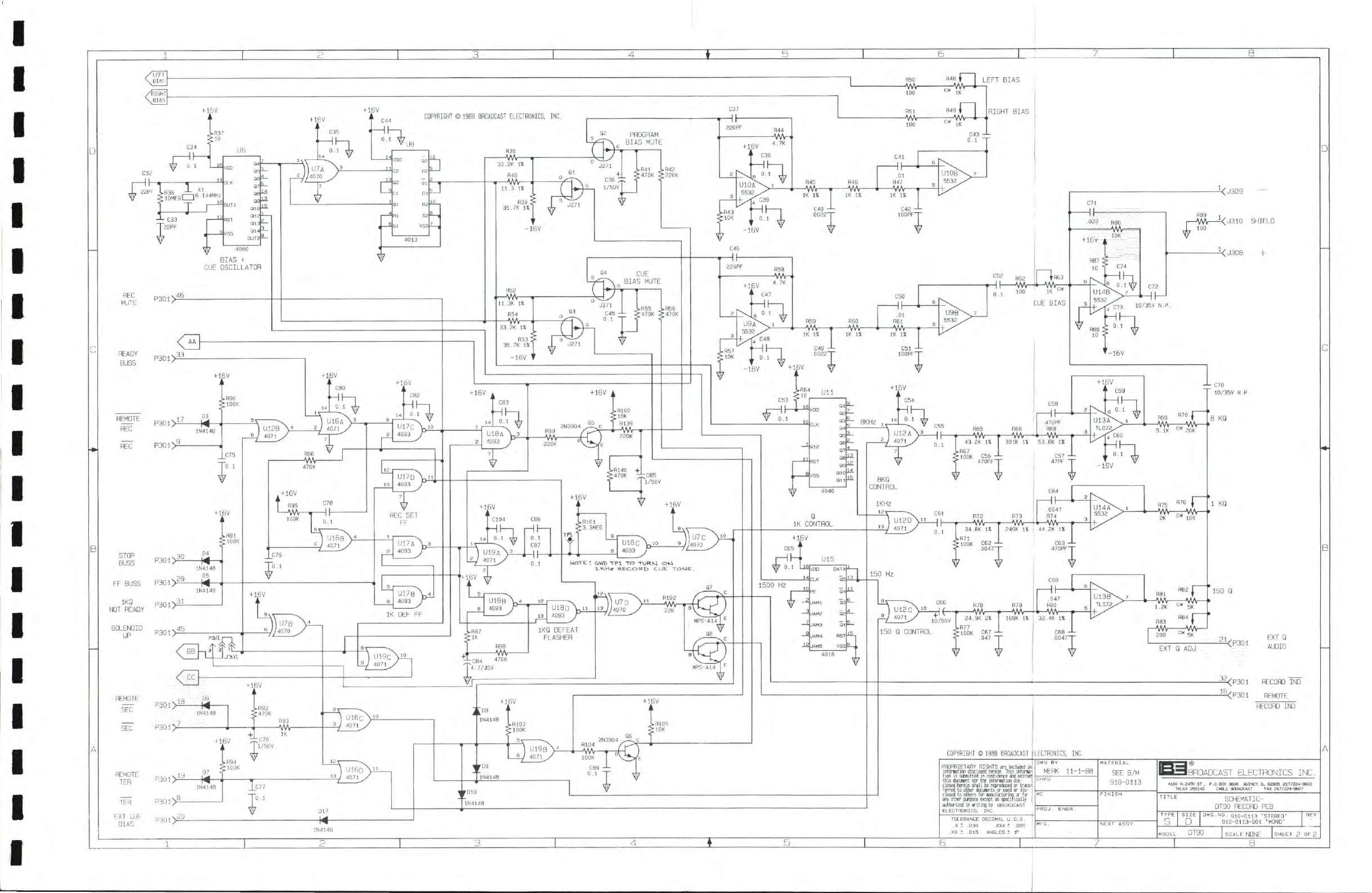
STEAM POWERED RADIO.COM
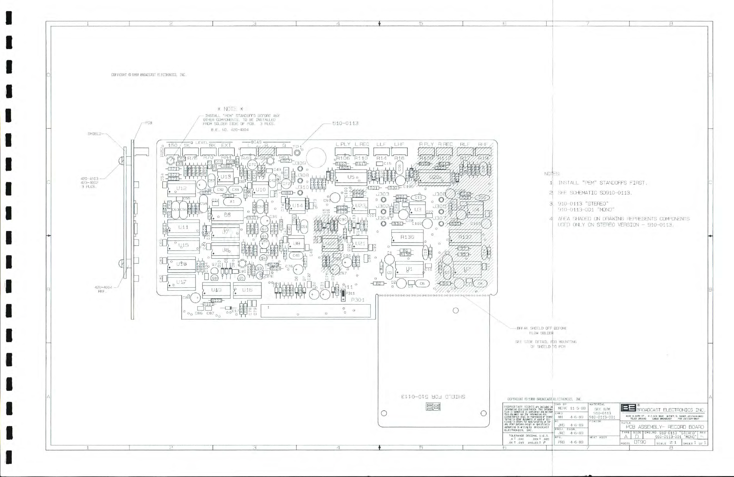
COPYRIGHT
©
1988
BROADCAST
ELECTRONICS,
INC.
420-4103
—
423-4002
3
PLCS.
426-4004
-
REF.
•
r
1
T
•
X
NOTE
X
INSTALL
"PEM"
STANDOFFS BEFORE
ANY
,/
OTHER
COMPONENTS,
TO BE
INSTALLED
FROM
SOLDER
SIDE
OF
PCB.
3
PLCS.
510-0113
EITG-Gig
HOd
OddlHS
o o
NO
INSTALL
"PEM"
STANDOFFS
FIRST.
SEE SCHEMATIC
SD91G-G113.
3t.
910-0113
"STEREO"
910-0113-001
"MONO"
AMF..A SF1ADED
ON
DRAWING REPRESENTS
COMPONENTS
USED ONLY
ON
STEREO
VERSION
-
910-0113.
BREAK
SHIELD
OFF
BEEOHE
FLOW
SOLDEli
SEE
SIDE
DETAIL
FDR
MGIJNflNO
COPYRIGHT
©
1988
BROADCAST
ELECIRONICS,
INC
PROPMETARY RIGHTS
are included
iri
infdrBation disclosed herein. This inforraaf
tion
is
suhiitted
in
confidence and neithel
this decuient nor the information dis-
)
closed herein shall he reproduced or transt
'erred
to
other docinents
or
used or
' "
any other pi/pose except as specificaT,
authorized
in
witing hy
BROADCAST
ELECTRONICS.
INC.
TOLERANCE
DECIMAL U.O.S.
.X
-
.030
.XXX
T .005
.XX
t .015
ANGLES
t 1°
OWN
BY
MERK
11-5-88
CHKD
MH
4-6-89
JHS 4-6-89
PROJ.
ENGR.
JRC 4-6-89
MFG.
PRB
4-6-B9
MATERIAL
SEE
B/M
910-0113
910-0113-001
FINISH
NEXT
ASSY
IBHOADCAST
ELECTHONICS
INC.
"pCB
ASSEMBLY-
RECORD
BOARD
TYPE
I
SIZE
I
DWG.NO.
910-0113
"STEREO"
I
HEV
A
D
910-0113-001
"MONO"
DT90
I
SHEET
^
OF •
STEAM POWERED RADIO.COM
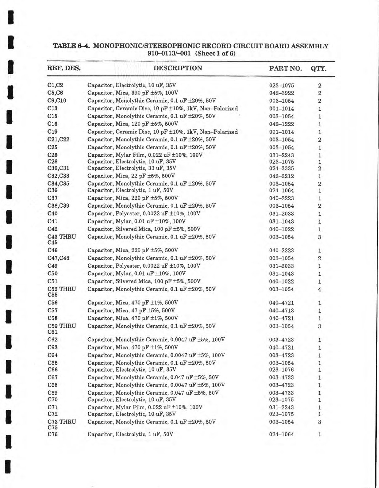
TABLE 6-4. MONOPHONIC/STEREOPHONIC RECORD CIRCUIT BOARD ASSEMBLY
910-0113/-001 (Sheet 1 of 6)
REF. DES. DESCRIPTION PART NO.
QTY.
C1,C2 Capacitor, Electrolytic,
10
uF, 35V 023-1075 2
C5,C6 Capacitor, Mica, 390 pF
±5%,
lOOV 042-3922 2
C9,C10 Capacitor, Monolythic Ceramic, 0.1 uF
±20%,
50V 003-1054 2
C13 Capacitor, Ceramic
Disc,
10
pF
±10%,
IkV, Non-Polarized 001-1014
CIS Capacitor, Monolythic Ceramic, 0.1 uF
±20%,
50V 003-1054
016 Capacitor, Mica,
120
pF
±5%,
500V 042-1222
019 Capacitor, Ceramic
Disc,
10
pF
±10%,
IkV, Non-Polarized 001-1014
021,022 Capacitor, Monolythic Ceramic, 0.1 uF
±20%,
50V 003-1054
025 Capacitor, Monolythic Ceramic, 0.1 uF
±20%,
50V 003-1054
026 Capacitor, Mylar Film,
0.022
uF
±10%,
lOOV 031-2243
C!28
v/ciucli.1
lAji, jT.it?v.i.i ui,y Liv, ux^,
tjaj
y
09'? in7l?
030,031 Capacitor, Electrolytic,
33
uF, 35V 024-3335
032,033 Capacitor, Mica, 22 pF
±5%,
500V 042-2212
034,035 Capacitor, Monolythic Ceramic, 0.1 uF
±20%,
50V 003-1054
036 Capacitor, Electrolytic,
1
uF, 50V 024-1064
037 Capacitor, Mica, 220 pF
±5%,
500V 040-2223
038,039 Capacitor, Monolythic Ceramic, 0.1 uF
±20%,
50V 003-1054
O40 Canacitor Polvester 0 0022 uF
±10%
lOOV 031-20.8.3
041 Capacitor, Mylar, 0.01 uF
±10%,
lOOV 031-1043
042 Capacitor, Silvered
Mica,
100 pF
±5%,
500V 040-1022
043 THRU
045 Capacitor, Monolythic Ceramic, 0.1 uF
±20%,
50V 003-1054
046 Canacitor Mica 220
DF
+5%
500V
m,^%A^mA%A^VA VXAA.
y
myAaA\A%my
AWIWv
m-A
A. ^^\m /
V/.
W^
V V r
040-2223
047,048 Capacitor, Monolythic Ceramic, 0.1 uF
±20%,
50V 003-1054
049 Capacitor, Polyester,
0.0022
uF
±10%,
lOOV 031-2033
050 Capacitor, Mylar, 0.01 uF
±10%,
lOOV 031-1043
051 Capacitor, Silvered Mica, 100 pF
±5%,
500V 040-1022
052 THRU
055 Capacitor, Monolythic Ceramic, 0.1 uF
±20%,
50V 003-1054
056 Capacitor, Mica, 470 pF ±1%, 500V 040^721
057 Capacitor, Mica, 47 pF
±5%,
500V 040^713
058 Capacitor, Mica, 470 pF ±1%, 500V 040-1721
059 THRU
061 Capacitor, Monolythic Ceramic, 0.1 uF
±20%,
50V 003-1054
062 Capacitor, Monolythic Ceramic,
0.0047
uF
±5%,
lOOV 008-4723
063 Capacitor, Mica, 470 pF ±1%, 500V
m\
d d\ d
n m
040—1721
064 Capacitor, Monolythic Ceramic,
0.0047
uF
±5%,
lOOV 003-4723
065 Capacitor, Monolythic Ceramic, 0.1 uF
±20%,
50V 003-1054
066 Capacitor, Electrolytic,
10
uF, 35V 023-1076
067 Capacitor, Monolythic Ceramic,
0.047
uF
±5%,
50V 003^733
068 Capacitor, Monolythic Ceramic,
0.0047
uF
±5%,
lOOV 003-4723
069 Capacitor, Monolythic Ceramic,
0.047
uF
±5%,
50V 003-4733
070 Capacitor, Electrolytic,
10
uF, 35V 023-1075
071 Capacitor, Mylar Film,
0.022
uF
±10%,
lOOV 031-2243
072 Capacitor, Electrolytic,
10
uF, 35V 023-1075
073 THRU
075 Capacitor, Monolythic Ceramic, 0.1 uF
±20%,
50V 003-1054 3
076 Capacitor, Electrolytic,
1
uF, 50V 024-1064 1
STEAM POWERED RADIO.COM
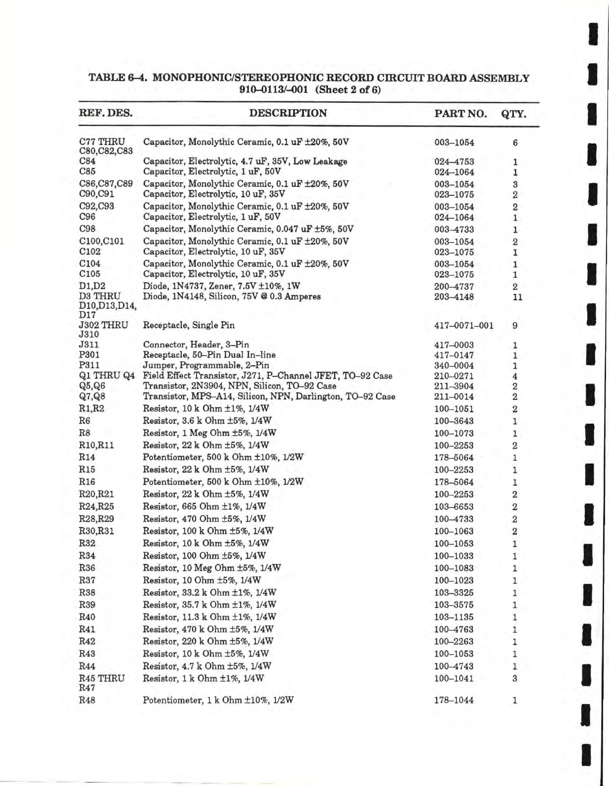
TABLE
6-4.
MONOPHONIC/STEREOPHONIC RECORD CIRCUIT BOARD ASSEMBLY
910-0113/-O01 (Sheet
2 of 6)
REF.
DES.
DESCRIPTION PART
NO.
QTY.
C77
THRU
Capacitor,
Monolythic
Ceramic, 0.1 uF
±20%,
50V
003-1054
6
C80,C82,C83
Capacitor,
Monolythic
Ceramic, 0.1 uF
±20%,
50V
C84
Capacitor,
Electrolytic, 4.7 uF, 35V, Low
Leakage 024-4753
1
C85
Canacitor.
Electrolytic.
1
uF. 50V
024—1064
V/X.GC
X
L. V/
.
1
X
csm
r'a'7 naa
UapaciLor,
ivionoij'xnic
L/eranuc, u.i
ur XZUTO, OUV
003—1054
3
Capacitor,
Electrolytic,
10
uF, 35V
023—1075
2
C92,C93
Capacitor,
Monolythic
Ceramic, 0.1 uF
±20%,
50V
003-1054
2
C96
Capacitor,
Electrolytic,
1
uF, 50V
024-1064
1
C98
Capacitor,
Monolythic
Ceramic,
0.047
uF
±5%,
50V
003^733
1
ClOO.ClOl
Capacitor,
Monolythic
Ceramic, 0.1 uF
±20%,
50V
003-1054
2
C102
Capacitor,
Electrolytic,
10
uF, 35V
023-1075
1
C104
Capacitor,
Monolythic
Ceramic, 0.1 uF
±20%,
50V
003-1054
1
C105
Capacitor,
Electrolytic,
10
uF,
35V
023-1075
1
D1,D2 Diode, 1N4737,
Zener,
7.5V
±10%,
IW
200-4737
2
D3
THRU
Diode, 1N4148,
Silicon,
75V
@
0.3
Amperes 203-4148
1]
D10,D13,D14, Diode, 1N4148,
Silicon,
75V
@
0.3
Amperes
TYI
7
J302 THRU Racatitacla Sincrle
Pin
mm
%f%am\dAmA
y
m^^lXmyAV
^ xxx
417-0071-001
^ X 1 ^^J\J
IX
W X
g
J310
Racatitacla Sincrle
Pin
mm
%f%am\dAmA
y
m^^lXmyAV
^ xxx
J311
Connector,
Header,
3-Pin
417-0003
1
P301 Receptacle,
50-Pin Dual In-line 417-0147
1
P311
Jumper,
Programmable,
2—Pin
t\
A
l\ AAA
A
340-0004
1
Ol
THRU
04
rimiKx
NJIIEI/T
XICULSIBLA/I,
U^I
x,
x—V/IIOJIIIEI
urcx,
±\m Y.5
x>a&e
91n_n97i
^XU—\}Ai
1 X
Q5,Q6
Transistor,
2N3904, NPN,
Silicon,
TO-92 Case 211-3904
2
Q7,Q8
Transistor,
MPS-A14,
Silicon,
NPN,
Darlington,
TO-92 Case 211-0014
2
R1,R2
Resistor,
10
k Ohm ±1%, 1/4W
100-1051
2
R6
Resistor,
3.6 k Ohm
±5%,
1/4W
100-3643
1
R8
Resistor,
1
Meg Ohm
±5%,
1/4W
100-1073
1
R10,R11
Resistor,
22
k Ohm
±5%,
1/4W
100-2253
2
R14
Potentiometer,
500 k Ohm
±10%,
1/2W
178-5064
1
R15
Resistor,
22
k Ohm
±5%,
1/4W
100-2253
1
R16
Potentiometer,
500 k Ohm
±10%,
L/2W
178-5064
1
R20,R21
Resistor,
22
k Ohm
±5%,
1/4W
100-2253
2
R24,R25
Resistor,
665 Ohm
±1%,
1/4W
103-6653
2
R28,R29
Resistor,
470 Ohm
±5%,
1/4W
100-1733
2
R30,R31
Resistor,
100
k Ohm
±5%,
iy4W 100-1063
2
R32
Resistor,
10
k Ohm
±5%,
1/4W
100-1053
1
R34
Resistor,
100 Ohm
±5%,
1/4W
100-1033
R36
Resistor.
10
Mee Ohm
+5%.
1/4W
100-1083
AvXX
AV>iX^^
J
R37
Resistor,
10 Ohm
±5%,
1/4W
100-1023
R38
Resistor,
33.2 k Ohm ±1%, 1/4W
103-3325
R39
Resistor,
35.7 k Ohm ±1%, 1/4W
103-3575
R40
Resistor,
11.3
k Ohm ±1%, 1/4W
103-1135
R41
Resistor,
470 k Ohm
±5%,
1/4W
100-1763
R42
Resistor,
220 k Ohm
±5%,
1/4W
100-2263
R43
Resistor,
10
k Ohm
±5%,
1/4W
100-1053
R44
Resistor,
4.7 k Ohm
±5%,
1/4W
100-1743
R45
THRU
R47
Resistor,
1
k Ohm
±1%,
1/4W
100-1041
3
R48
Potentiometer,
1
k Ohm
±10%,
1/2W
178-1044
1
STEAM POWERED RADIO.COM
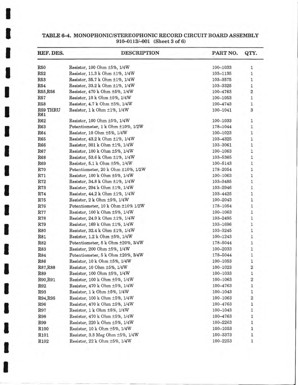
TABLE 6-4. MONOPHONIC/STEREOPHONIC RECORD CIRCUIT BOARD ASSEMBLY
910-0113/-001 (Sheet 3 of 6)
REF. DES. DESCRIPTION PART NO. QTY.
R50 Resistor, 100 Ohm ±5%, 1/4W 100-1033
R52 Resistor, 11.3 k Ohm ±1%, 1/4W 103-1135
R53 Resistor, 35.7 k Ohm ±1%, 1/4W 103-3575
R54 Resistor, 33.2 k Ohm ±1%, 1/4W 103-3325
R55,R56 Resistor, 470 k Ohm
+5%,
1/4W 100-4763
R57 Resistor, 10 k Ohm ±5%, 1/4W 100-1053
R58 Resistor, 4.7 k Ohm
+5%,
1/4W 100-4743
R59 THRU Resistor,
1
k Ohm ±1%, 1/4W 100-1041
R61
R62 Resistor, 100 Ohm ±5%, 1/4W 100-1033
R63 Potentiometer,
1
k Ohm ±10%, 1/2W 178-1044
R64 Resistor, 10 Ohm ±5%, 1/4W 100-1023
R65 Resistor, 43.2 k Ohm ±1%, 1/4W 103-4325
R66 Resistor,
301
k Ohm ±1%, 1/4W 103-3061
R67 Resistor,
100
k Ohm ±5%, 1/4W 100-1063
R68 Resistor, 53.6 k Ohm ±1%, 1/4W 103-5365
R69 Resistor,
5.1
k Ohm ±5%, 1/4W 100-5143
R70 Potentiometer,
20
k Ohm ±10%, 1/2W 178-2054
R71 Resistor, 100 k Ohm ±5%, 1/4W 100-1063
R72 Resistor, 34.8 k Ohm ±1%, 1/4W 103-3485
R73 Resistor, 294 k Ohm ±1%, 1/4W 103-2946
R74 Resistor, 44.2 k Ohm ±1%, 1/4W 103^425
R75 Resistor,
2
k Ohm ±5%, 1/4W 100-2043
R76 Potentiometer,
10
k Ohm ±10% 1/2W 178-1054
R77 Resistor, 100 k Ohm ±5%, 1/4W 100-1063
R78 Resistor, 24.9 k Ohm ±1%, 1/4W 103-2495
R79 Resistor,
169
k Ohm ±1%, 1/4W 103-1696
R80 Resistor, 32.4 k Ohm ±1%, 1/4W 103-3245
R81 Resistor, 1.2 k Ohm ±5%, 1/4W 100-1243
R82 Potentiometer,
5
k Ohm ±20%, 3/4W 178-5044
R83 Resistor, 200 Ohm ±5%, 1/4W 100-2033
R84 Potentiometer,
5
k Ohm ±20%, 3/4W 178-5044
R86 Resistor,
10
k Ohm ±5%, iy4W 100-1053
R87,R88 Resistor, 10 Ohm ±5%, 1/4W 100-1023
R89 Resistor, 100 Ohm ±5%, 1/4W 100-1033
R90,R91 Resistor, 100 k Ohm ±5%, 1/4W 100-1063
R92 Resistor, 470 k Ohm ±5%, 1/4W 100^763
R93 Resistor,
1
k Ohm ±5%, 1/4W 100-1043
R94,R95 Resistor,
100
k Ohm ±5%, 1/4W 100-1063
R96 Resistor, 470 k Ohm ±5%, 1/4W 100-4763
R97 Resistor,
1
k Ohm ±5%, 1/4W 100-1043
R98 Resistor, 470 k Ohm ±5%, 1/4W 100-4763
R99 Resistor, 220 k Ohm ±5%, 1/4W 100-2263
RlOO Resistor,
10
k Ohm ±5%, 1/4W 100-1053
RlOl Resistor, 3.3 Meg Ohm ±5%, 1/4W 100-3373
R102 Resistor,
22
k Ohm ±5%, 1/4W 100-2253
STEAM POWERED RADIO.COM
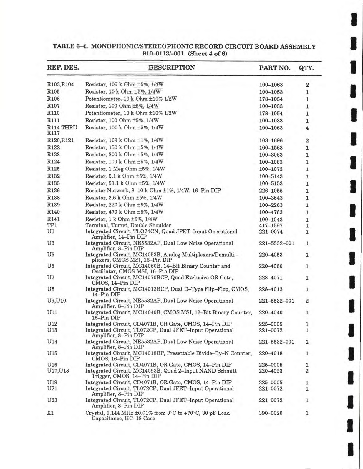
TABLE
6-4.
MONOPHONIC/STEREOPHONIC
RECORD CIRCUIT
BOARD
ASSEMBLY
910-0113/-001
(Sheet
4 of 6)
REF. DES.
DESCRIPTION
PART
NO. QTY.
R103,R104 Resistor, 100 k Ohm ±5%, 1/4W 100-1063 2
R105 Resistor,
10
k Ohm ±5%, 1/4W 100-1053 1
R106 Potentiometer,
10
k Ohm ±10% 1/2W 178-1054 1
R107 Resistor, 100 Ohm ±5%, 1/4W 100-1033 1
RllO Potentiometer,
10
k Ohm ±10% L/2W 178-1054 1
Rill Resistor, 100 Ohm ±5%, 1/4W 100-1033 1
R114 THRU Resistor,
100
k Ohm ±5%, 1/4W 100-1063 4
R117
R120,R121 Resistor, 169 k Ohm ±1%, 1/4W 103-1696 2
R122 Resistor,
150
k Ohm ±5%, 1/4W 100-1563 1
R123 Resistor, 300 k Ohm ±5%, 1/4W 100-3063 1
R124 Resistor, 100 k Ohm ±5%, 1/4W 100-1063 1
R125 Resistor,
1
Meg Ohm ±5%, iy4W 100-1073 1
R132 Resistor, 5.1 k Ohm ±5%, 1/4W 100-5143 1
R133 Resistor,
51.1
k Ohm ±5%, 1/4W 100-5153 1
R136 Resistor Network, 8-10 k Ohm ±1%, 1/4W, 16-Pin DIP 226-1055 1
R138 Resistor, 3.6 k Ohm ±5%, 1/4W 100-3643 1
R139 Resistor, 220 k Ohm ±5%, 1/4W 100-2263 1
R140 Resistor, 470 k Ohm ±5%, 1/4W 100-4763 1
R141 Resistor,
1
k Ohm ±5%, 1/4W 100-1043 1
TPl Terminal, Turret, Double Shoulder 417-1597 1
Ul Integrated Circuit, TL074CN, Quad JFET-Input Operational 221-0074 1
Amplifier, 14-Pin DIP
U3 Integrated Circuit, NE5532AP, Dual Low Noise Operational 221-5532-001 1
Amplifier,
8-Pin
DIP
U5 Integrated Circuit,
MC14053B,
Analog Multiplexers/Demulti- 220-4053 1
plexers,
CMOS MSI, 16-Pin DIP
US Integrated Circuit, MC14060B, 14-Bit Binary Counter and 220-4060 1
Oscillator, CMOS MSI, 16-Pin DIP
U7 Integrated Circuit, MC14070BCP, Quad Exclusive OR Gate, 228^071 1
CMOS,
14-Hn DIP
US Integrated Circuit, MC14013BCP, Dual D-Type Flip-Flop, CMOS, 228-4013 1
14-Pin DIP
U9,U10 Integrated Circuit, NE5532AP, Dual Low Noise Operational 221-5532-001 2
Amplifier,
8-Pin
DIP
Ull Integrated Circuit, MC14040B, CMOS
MSI,
12-Bit Binary Counter, 220-4040 1
16-Pin DIP
U12 Integrated Circuit, CD4071B, OR Gate, CMOS,
14r-Pin
DIP 225-0005 1
U13 Integrated Circuit, TL072CP, Dual JFET-Input Operational 221-0072 1
Amplifier,
8-Pin
DIP
U14 Integrated Circuit, NE5532AP, Dual Low Noise Operational 221-5532-001 1
Amplifier,
8-Pin
DIP
U15 Integrated Circuit, MC14018BP, Presettable Divide-By-N Counter, 220-4018 1
CMOS,
16-Pin DIP
U16 Integrated Circuit, CD4071B, OR Gate, CMOS, 14-Pin DIP 225-0005 1
U17,U18 Integrated Circuit, MC14093B, Quad 2-Input
NAND
Schmitt 220-4093 2
Trigger, CMOS, 14-Pin DIP
U19 Integrated Circuit, CD4071B, OR Gate, CMOS, 14-Hn DIP 225-0005 1
U21 Integrated Circuit, TL072CP, Dual JFET-Input Operational 221-0072 1
Amplifier, 8-Hn DIP
U23 Integrated Circuit, TL072CP, Dual JFET-Input Operational 221-0072 1
Amplifier, 8-Hn DIP
XI Crystal, 6.144 MHz
±0.01%
from 0°C
to+70°C,
30 pF Load 390-0020 1
Capacitance,
HC—18
Case
STEAM POWERED RADIO.COM
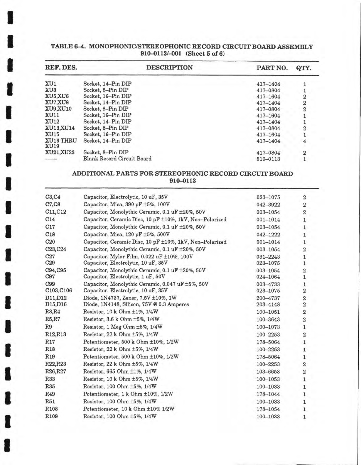
TABLE
6^.
MONOPHONIC/STEREOPHONIC RECORD CIRCUIT BOARD ASSEMBLY
910-0113/-001 (Sheet
5 of 6)
REF. DES.
DESCRIPTION PART
NO. QTY.
XUl
Socket,
14-Pin
DIP
417-1404
1
XU3
Socket,
8-Pin
DIP
417-0804
1
XU5,XU6
Socket,
16-Pin
DIP
417-1604
2
XU7,XU8
Socket,
14-Pin
DIP
417-1404
2
XU9,XU10
Socket,
8-Pin
DIP
417-0804
2
XUll
Socket,
16-Pin
DIP
417-1604
1
XU12
Socket,
14-Pin
DIP
417-1404
1
XU13,XU14
Socket,
8-Pln
DIP
417-0804
2
XU15
Socket,
16-Pin
DIP
417-1604
1
XU16
THRU
Socket,
14-Pin
DIP
417-1404
4
XU19
XU21PCU23
Socket,
8-Pin
DIP
417-0804
2
Blank Record Circuit Board 510-0113
1
ADDITIONAL PARTS
FOR
STEREOPHONIC RECORD CIRCUIT BOARD
910-0113
1/0,04
oapacitor,
jLiectroiytic, lu ur, Oo v AOO 1AlC
Ozo—1075
2
o/,ot>
PAnnfllX/...
TV/Ti'/irt
OQA 1-.1?
l-Czy
1
AAir
oapacitor,
jvuca,
ouu pr xo%,
luuv 042—3922
2
PI 1 PI
0
011,010
oapacitor,
ivionoiytnic
oeramic, u.i ur xzuyo, ouv AAO 1AC4
003—1054
2
Pi >f
014
Pn/inrti+rt-..
PrturtwiiTYi«rt
1A «1? 4-1 AXX 1 l.ir
XT—«
13—1—14>.
—4
Oapacitor,
Oeramic
Uisc,
10
pr ±10%, IkV,
Won—Polarized
A A1
1
A1 4
001-1014
Pi •?
017
P
—.1——1+—-.1
XT—M—1i4-1ii—
P—N—-W11— A 1 1.1?
-4-OAX!/
CA1T
oapacitor,
Monoiytmc
oeramic, u.i ur ±zu%, ouv
AAO
1
AC 4
003—1054
C18
Oapacitor,
Mica,
120 pF ±5%,
500V 042-1222
€20
Oapacitor,
Oeramic
Disc,
10 pF ±10%, IkV,
Non-Polarized 001-1014
023,024
Oapacitor,
Monolythic
Oeramic, 0.1 uF ±20%, 50V
003-1054
027
Oapacitor,
Mylar
Film,
0.022
uF ±10%,
lOOV 031-2243
029
Oapacitor,
Electrolytic, 10 uF, 35V
023-1075
094,095
Oapacitor,
Monolythic
Ceramic, 0.1 uF ±20%, 50V
003-1054
097
Oapacitor,
Electrolytic,
1
uF, 50V
024-1064
099
Oapacitor,
Monolythic
Ceramic,
0.047
uF ±5%, 50V
003^733
0103,0106
Oapacitor,
Electrolytic,
10
uF, 35V
023-1075
2
D11,D12
Diode, 1N4737,
Zener,
7.5V ±10%, IW
200-^737
2
D15,D16
Diode, 1N4148,
Silicon,
75V
@
0.3
Amperes 203-4148
2
R3,R4
Resistor,
10
k Ohm ±1%, 1/4W
100-1051
2
R5,R7
Resistor,
3.6 k Ohm ±5%, 1/4W
100-3643
2
R9
Resistor,
1
Meg Ohm ±5%, 1/4W
100-1073
1
R12,R13
Resistor,
22
k Ohm ±5%, 1/4W
100-2253
2
R17
Potentiometer,
500 k Ohm ±10%, 1/2W
178-5064
1
R18
Resistor,
22
k Ohm ±5%, 1/4W
100-2253
1
R19
Potentiometer,
500 k Ohm ±10%, 1/2W
178-5064
1
R22,R23
Resistor,
22
k Ohm ±5%, 1/4W
100-2253
2
R26,R27
Resistor,
665 Ohm ±1%, 1/4W
103-6653
2
R33
Resistor,
10
k Ohm ±5%, 1/4W
100-1053
1
R35
Resistor,
100 Ohm ±5%, 1/4W
100-1033
1
R49
Potentiometer,
1
k Ohm ±10%, l/ZW
178-1044
1
R51
Resistor,
100 Ohm ±5%, 1/4W
100-1033
1
R108
Potentiometer,
10
k Ohm ±10% 1/2W
178-1054
1
R109
Resistor,
100 Ohm ±5%, 1/4W
100-1033
1
STEAM POWERED RADIO.COM
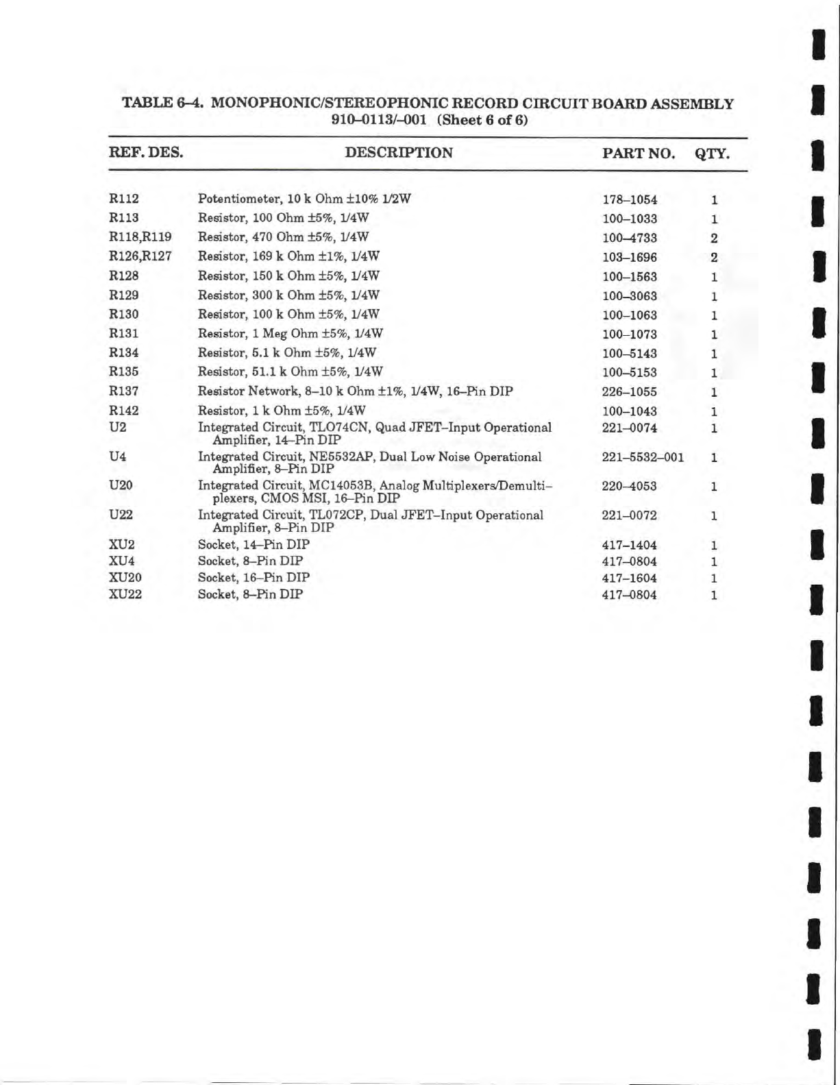
TABLE 6-4. MONOPHONIC/STEREOPHONIC RECORD CIRCUIT BOARD ASSEMBLY
910-0113/-4)01 (Sheet 6 of 6)
REF. DES. DESCRIPTION PART NO. QTY.
R112 Potentiometer,
10
k Ohm ±10% 1/2W 178-1054
R113 Resistor, 100 Ohm ±5%, 1/4W 100-1033
R118,R119 Resistor, 470 Ohm ±5%, 1/4W 100-1733
R126,R127 Resistor,
169
k Ohm ±1%, 1/4W 103-1696
R128 Resistor,
150
k Ohm ±5%, iy4W 100-1563
R129 Resistor, 300 k Ohm ±5%, 1/4W 100-3063
R130 Resistor, 100 k Ohm ±5%, 1/4W 100-1063
R131 Resistor,
1
Meg Ohm ±5%, iy4W 100-1073
R134 Resistor,
5.1
k Ohm ±5%, 1/4W 100-5143
R135 Resistor,
51.1
k Ohm ±5%, 1/4W 100-5153
R137 Resistor Network, 8-10 k Ohm ±1%, 1/4W, 16-Pin DIP 226-1055
R142 Resistor,
1
k Ohm ±5%, 1/4W 100-1043
U2 Integrated Qrcuit, TL074CN, Quad JFET-Input Operational 221-0074
Amplifier, 14-Rn DIP
U4 Integrated Circuit, NE5532AP, Dual Low Noise Operational 221-5532-001
Amplifier,
8-Pin
DIP
U20 Integrated Circuit, MC14053B, Analog Multiplexers/Demulti- 220-4053
plexers, CMOS MSI, 16-Pin DIP
U22 Integrated Circuit, TL072CP, Dual JFET-Input Operational 221-0072
Amplifier,
8-Pin
DIP
XU2 Socket, 14-Hn DIP 417-1404
XU4 Socket, 8-Hn DIP 417-0804
XU20 Socket, 16-Hn DIP 417-1604
XU22 Socket, 8-Hn DIP 417-0804
STEAM POWERED RADIO.COM
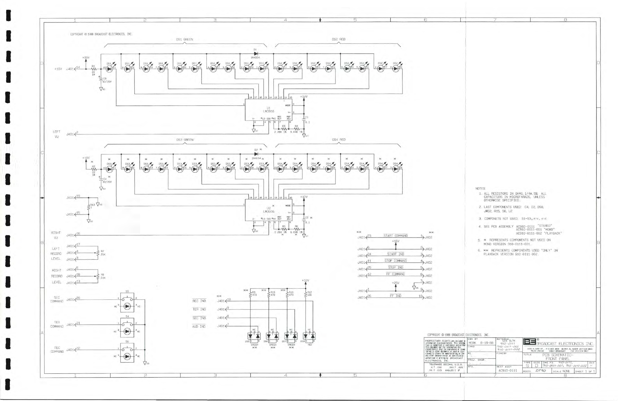
COPYHIGHr
®
1388
BROADCAST
ELECTRONICS,
INC.
DSl
GREEN
DS2
RED
tlOV
J401^
LEFT
^?
VU
J401^
15
MODE
U2
MODE
LM3916
REF
REF
V- BLO SIG RHI
CXJT
AOJ
RIGHT
^16
VU
_C2
K
"o.l
J401<:
•23
START
COMMAND
J401<-
RECORD
J401<-
17
LEFT
J401
LEVEL
J40l^
RIGHT
J401<5
RECORD
J401^
LEVEL
J40i^
J401<^
J401<ii
J401<f
START
IND
STOP
COMMAND
•25
STOP IND
J40l4
12 FF
COMMAND
13
COMMAND
TEH
.21
COMMAND
J^01<^
RFC
COMMAND
J401<£F-
XX
XX T
J.H9
J.B10
>470 >470
LHII
>470
REC
IND
TER
IND
SEC
IND
AUD
IND
J401<Ji
J401<2_
J401<§-
J401<AL
J401^
J401<2
GREEN
XX
GREEN
XX
GREEN
XX
-J>J402
-£>J402
-^J402
-^U402
-§>J402
-§>J402
+25V
I-
-A>J402
-5>J402
!>J402
10^
NOTES:
1,
ALL RESISTORS IN
OHMS,
1/4W,
5%:
ALL
CAPACITORS
IN MICROFARADS. UNLESS
OTHERWISE
SPECIFIED.
2,
LAST
COMPONENTS
USED: 04,
02,
DS8.
U402.
R15, SB, 02
3,
COMPONETS
NOT USED:
S1-S3
,
K(4,
s->5
4,
SEE PCB ASSEMBLY
AC910-0111
"STEREO"
AC910-0111-001
"MONO"
AC910-0111-002
"PLAYBACK"
5,
X REPRESENTS
COMPONENTS
NOT USED ON
MONO
VERSION
910-0111-001,
6,
XX REPRESENTS
COMPONENTS
USED "ONLY" ON
PLAYBACK
VERSION
910-0111-002,
COPYRIGHT
©
1988
BROADCAST
ELECTRONICS,
INC
PHOPBIETABV BIGHTS are includea
in
inforiation dlsclo ed herein. This infornfi-
tion
is
sutMitted n confidence and neittier
this document nor he informatim dis-
closed herein shal he reproduced or trans-
ferred to other docunents or used or dis-
closed to others for nanufacturing or
for'
any other purpose except as specitically
authorized in iriting by
BROADCAST
ELECTRONICS,
INC. '
TOLERANCE
DECIMAL U.O.S.
X
I ,030 XXX t ,005
,XX
t ,015
ANGLES
1 P
OWN BY
MERK
8-19-88
""!fa/WM
'=f10'
Ot
(1
•^io -om
-oo\
9io-
0/1I-O0Z
CHKD
""!fa/WM
'=f10'
Ot
(1
•^io -om
-oo\
9io-
0/1I-O0Z
ME
FINISH
PRDJ.
ENGR.
FINISH
MFG ,
NEXT
ASSY
AC910-0111
IBROADCAST
ELECTRONICS
INC.
TITLE
PCB
SCHEMATIC-
FRONT
PANEL
TYPE
SIZE
DWG
.
6*0
.
9/(3-
Ol
il,
REV
S •
'=fiO'Of/t-oor> 9!o-o/a-ooz
Dr90
SCALE
NONE
SHEET
1 DF 1
•
STEAM POWERED RADIO.COM
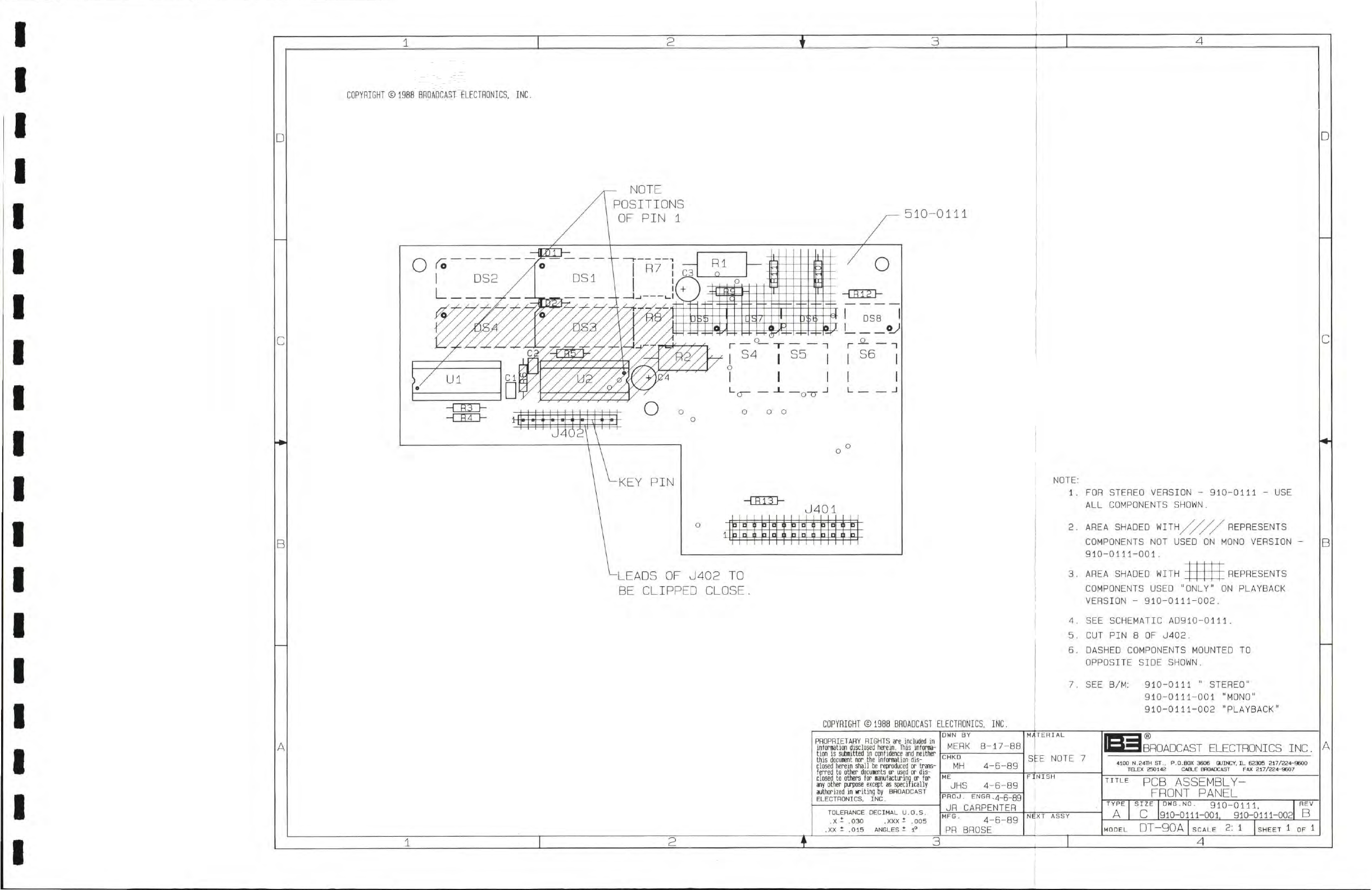
3
4
COPYRIGHT
©
1988
BROADCAST
ELECTRONICS,
INC.
D
NOTE
POSITIONS
OF
PIN
1
C
B
510-0111
-TTTTTh
J401
• •
I
i
• •
I
1
•
1
3
a II
]
1
0
•
1
• •
1 1
•
1
3 a 3
D
NOTE:
1
.
-LEADS
OF
J402
TO
BE CLIPPED
CLOSE.
FOR STEREO
VERSION
-
910-0111
- USE
ALL
COMPONENTS
SHOWN.
AREA SHADED
WITH//^//^
REPRESENTS
COMPONENTS
NOT
USED
ON
MONO
VERSION
-
910-0111-001 .
B
3.
AREA SHADED
WITH
REPRESENTS
COPYRIGHT
©
1988
BROADCAST
ELECTHONICS,
INC.
A
2
PHOPRIETARY
RIGHTS
are
included
in
information
disclosed herein.
This
informa-
tion
is
submitted
in
confidence and neither
this
document
nor the
information dis-
closed herein shall
be
reproduced
or
trans-
ferred
to
other documents
or
used
or
dis-
closed
to
others
for
manufacturing
or for
any other purpose except
as
specitically
authorized
in
writing
by
BROADCAST
ELECTRONICS,
INC.
TOLERANCE
DECIMAL
U.O.S.
.X i .030 .XXX t
.005
.XX
1
.015
ANGLES
i 1°
DWN BY
MERK
a-17-E
CHKD
MH
4-6-89
UHS
4-6-89
PROJ.
ENGR.4_5_gg
JR
CARPENTER
MFG
.
4-6-89
PR
BROSE
3
COMPONENTS
USED "ONLY"
ON
PLAYBACK
VERSION
-
910-0111-002.
4.
SEE
SCHEMATIC
AD910-0111.
5.
CUT
PIN
8 OE
J402.
6.
DASHED
COMPONENTS
MOUNTED
TO
OPPOSITE
SIDE
SHOWN.
7.
SEE
B/M:
910-0111
"
STEREO"
910-0111-001
"MONO"
910-0111-002
"PLAYBACK"
MATERIAL
SEE
NOTE
7
FINISH
NEXT
ASSY
IBROADCAST
ELECTRONICS INC.
4100
N.24-m ST.. P.O.BOX 3606 QUINCY.
IL
62305 217/224-9600
TELEX
250142 CABLE BBOADCAST FAX 217/224-9607
PCB
ASSEMBLY-
FRONT
PANEL
TYPE
A
SIZE
c
DWG.NO.
910-0111,
910-0111-001, 910-0111-002
MODEL
DT-gOA
SCALE
2: 1
4
REV
B
STEAM POWERED RADIO.COM
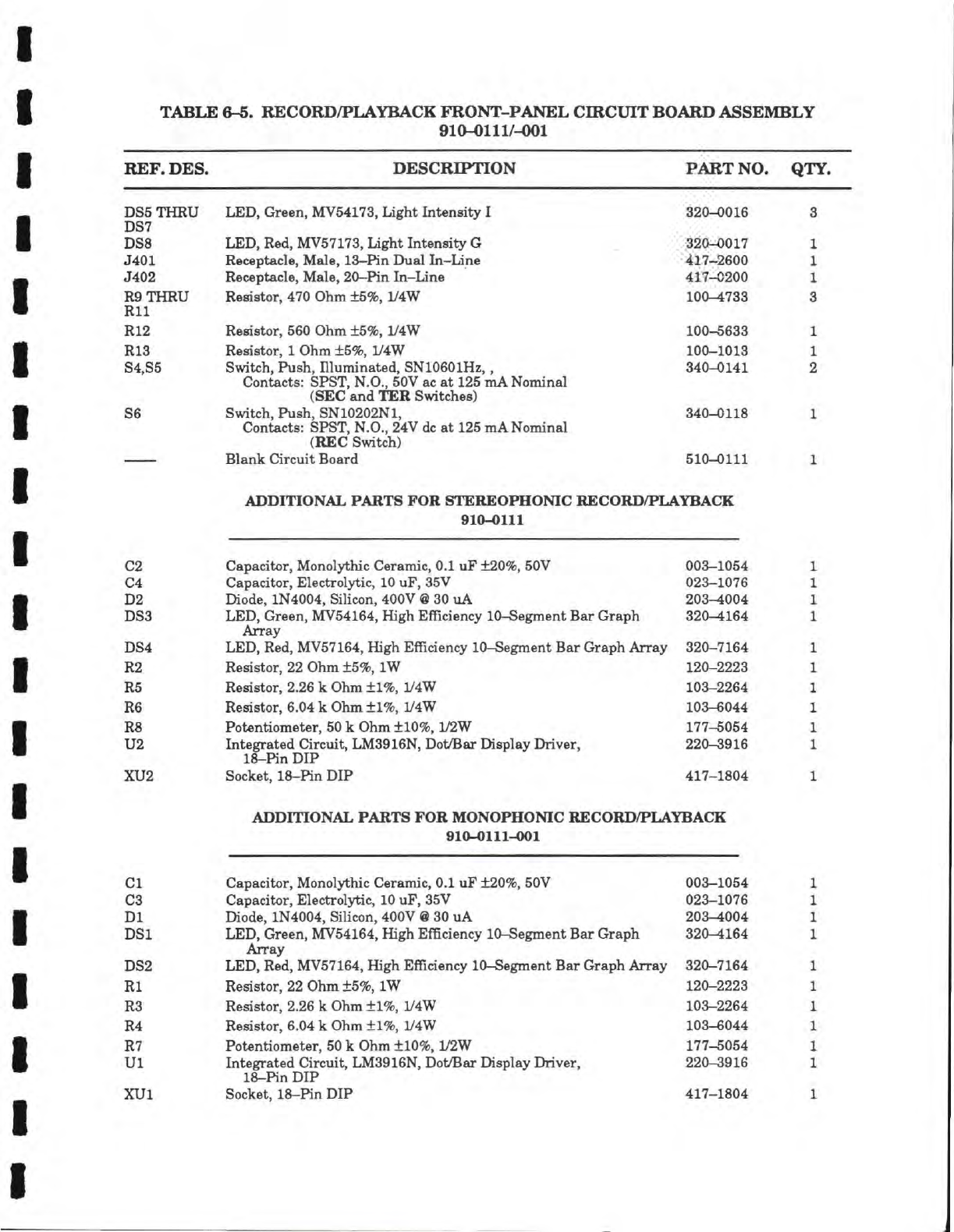
TABLE 6-6. RECORD/PLAYBACK FRONT-PANEL CIRCUIT BOARD ASSEMBLY
910-0111/-001
REF. DES. DESCRIPTION PART NO. QTY.
DS5THRU
DS7
DS8
J401
J402
R9THRU
Rll
R12
R13
S4,S5
S6
LED,
Green,
MV54173,
Light Intensity I
LED,
Red,
MV57173,
light Intensity G
Receptacle, Male, 13-Pin Dual In-line
Receptacle, Male, 20-Pin In-line
Resistor, 470 Ohm
+5%,
iy4W
Resistor, 560 Ohm ±5%, iy4W
Resistor, 1 Ohm ±5%, L'4W
Switch, Push, Illuminated, SN10601Hz,,
Contacts: SPST,
N.O.,
50V ac at 125 mA Nominal
(SEC and TER Switches)
Switch, Push, SN10202N1,
Contacts: SPST, N.O., 24V
dc
at
125
mA Nominal
(REC Switch)
Blank Circuit Board
320-0016
320-0017
417-2600
417-0200
100-4733
100-5633
100-1013
340-0141
340-0118
510-0111
1
1
1
3
1
1
2
ADDITIONAL PARTS FOR STEREOPHONIC RECORD/PLAYBACK
910-0111
C2
C4
D2
DS3
DS4
R2
R5
R6
R8
U2
XU2
Capacitor, Monolythic Ceramic, 0.1 uF ±20%, 50V 003-1054
Capacitor, Electrolytic,
10
uF, 35V 023-1076
Diode, 1N4004, Silicon, 400V
@
30 uA 203-4004
LED,
Green, MV54164, High Efficiency 10-Segment Bar Graph 320-4164
Array
LED,
Red, MV57164, High Efficiency 10-Segment Bar Graph Array 320-7164
Resistor, 22 Ohm ±5%, IW 120-2223
Resistor, 2.26 k Ohm ±1%, 1/4W 103-2264
Resistor, 6.04 k Ohm ±1%, 1/4W 103-6044
Potentiometer,
50
k Ohm ±10%, 1/2W 177-5054
Integrated Circuit, LM3916N, Dot/Bar Display Driver, 220-3916
18-Pin DIP
Socket, 1&-Pin DIP 417-1804
ADDITIONAL PARTS FOR MONOPHONIC RECORD/PLAYBACK
910-0111-001
CI
C3
Dl
DSl
DS2
Rl
R3
R4
R7
Ul
XUl
Capacitor, Monolythic Ceramic, 0.1 uF ±20%, 50V 003-1054
Capacitor, Electrolytic,
10
uF,
35V 023-1076
Diode, 1N4004, Silicon, 400V
@
30 uA 203-4004
LED,
Green, MV54164, High Efficiency 10-Segment Bar Graph 320-4164
Array
LED,
Red, MV57164, High Efficiency 10-Segment Bar Graph Array 320-7164
Resistor, 22 Ohm ±5%, IW 120-2223
Resistor, 2.26 k Ohm ±1%, 1/4W 103-2264
Resistor, 6.04 k Ohm ±1%, iy4W 103-6044
Potentiometer,
50
k Ohm ±10%, 1/2W 177-5054
Integrated Circuit, LM3916N, Dot/Bar Display Driver, 220-3916
18-Pin DIP
Socket, 18-Hn DIP 417-1804
STEAM POWERED RADIO.COM
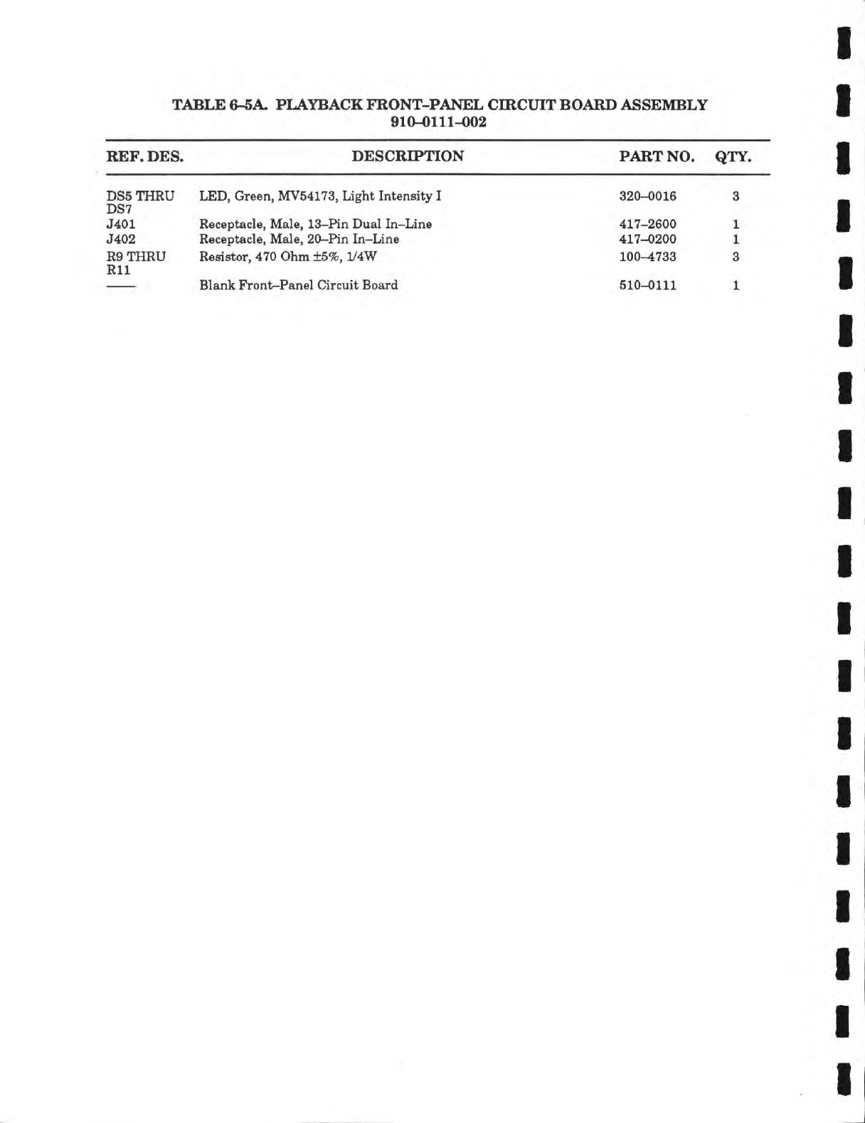
TABLE
6-5A.
PLAYBACK FRONT-PANEL CIRCUIT BOARD ASSEMBLY
910-0111-002
REF.
DES.
DESCRIPTION PART
NO. QTY.
DS5THRU
DS7
J401
J402
R9THRU
Rll
LED,
Green,
MV54173,
Light Intensity
I
Receptacle, Male, 13-Pin Dual In-Line
Receptacle, Male, 20-Pin In-Line
Resistor, 470 Ohm
±5%,
iy4W
Blank Front-Panel Circuit Board
320-0016
417-2600
417-0200
100-4733
510-0111
STEAM POWERED RADIO.COM
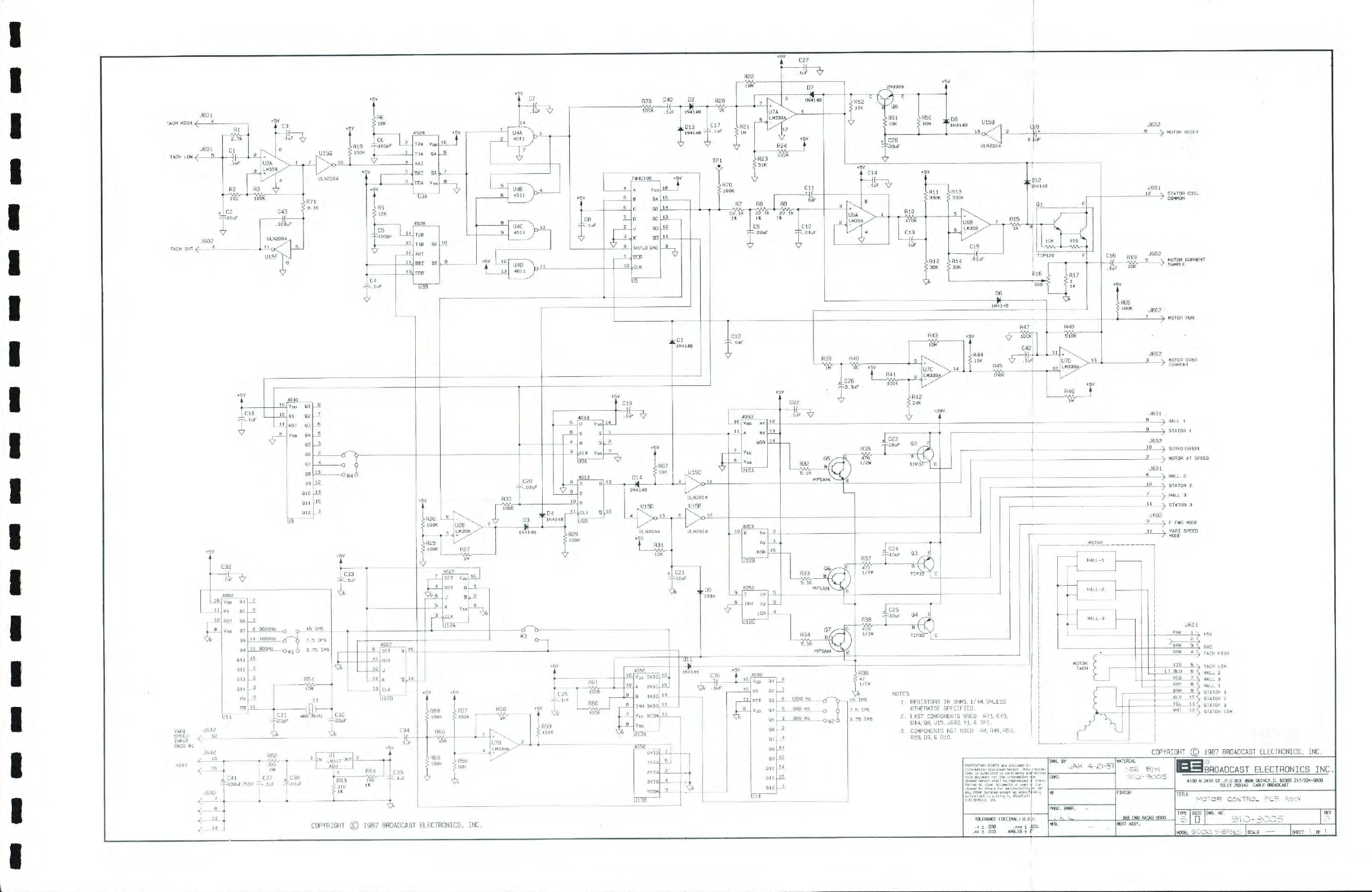
I
STEAM POWERED RADIO.COM
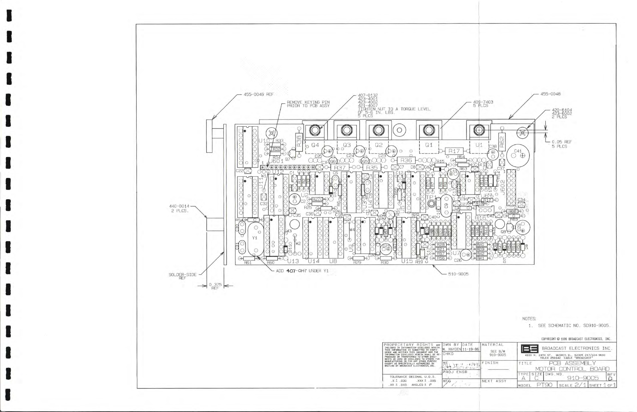
455-0048
REF
455-0048
420-6104
423-6002
2
PLCS
0.05
REF
5 PLCS
ADD
407-014-7
UNDER
Yl
510-9005
PROPRIETARY RIGHTS ARE
INCLUDED
IN
INFORMATION
DISCLOSED HEREIN.
THIS
INFORMATION
IS
SUBMITTED
IN
CONFI-
DENCE
AND
NEITHER
THIS
DOCUMENT
NOR THE
INFORMATION
DISCLOSED HEREIN
SHALL
BE RE-
PRODUCED
OB
TRANSFEHHEO
TO OTHER DOCU-
MENTS
OR
USED
OH
DISCLOSED
TO
OTHERS
FOR
MANUFACTURING
OH
FOR ANY OTHER
PURPOSE
EXCEPT
AS
SPECIFICALLY
AUTHORIZED
IN
MRITING
BY BROADCAST
ELECTHONICS. INC.
TOLERANCE
DECIMAL
U.O.S.
.X I .030 .XXX
t
.005
.XX
I
.015
ANGLES
I
1°
DWN BY
M.
HAYDEN
TE
-19-86
CHKD
-.
J,
i743
PROJ
ENGR
NOTES:
1.
SEE
SCHEMATIC
NO.
S0910-9005.
COPYRIGHT
©
1986
BROADCAST
ELECTRONICS.
INC.
MATERIAL
SEE
B/M
910-9005
FINISH
NEXT
ASSY
PJ
BROADCAST
ELECTRONICS
INC.
4100
N.
24TH ST. QUINCY. IL. 52305 217/224-9600
TELEX 250142 CABLE -BHOADCAST'
TITLE
PCB
ASSEMBLY
MOTOR
CONTROL
BOARD
TYPE
A
SIZE
0
DWG.NO.
910-9005
MODEL
PT90
SCALE
2/1
SHEET
1
OF
1
HFV
STEAM POWERED RADIO.COM
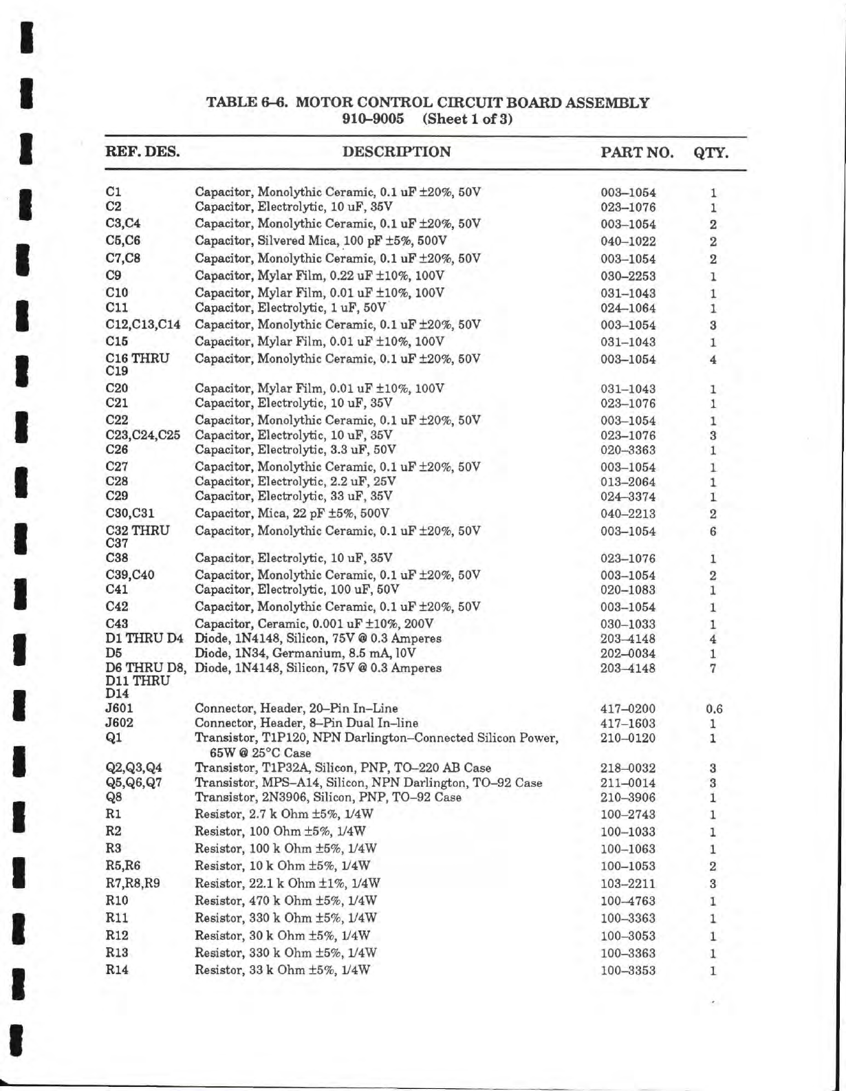
TABLE 6-6. MOTOR CONTROL CIRCUIT BOARD ASSEMBLY
910-9005 (Sheet
1
of 3)
REF.
DES.
DESCRIPTION PART NO. QTY.
/Hl1
CI Capacitor, Monolythic Ceramic,
0.1
uF±20%,
50V A A A . A
mr
J
003-1054 1
02 Capacitor, Electrolytic,
10
uF, 35V 023-1076 1
03,04 Capacitor, Monolythic Ceramic,
0.1
uF ±20%, 50V 003-1054 2
05,06 Capacitor, Silvered
Mica,
100 pF ±5%, 500V 040-1022 2
07 08 PnnflritAr Mrtnnlv+hir Pftrnmir ft
1
iiF+9ft<^
KVtJ
V^ct^CLClLUI,
ITXUllUij/LILLC
clXXllC,
V/.X UJ;
/v, V
nm
ini?xi Z
LAapacitor, jviyiar riim, \j,zz ur ziUvfc, iuuv AQA OOCO
UoU—ZZOO
1
CIO Capacitor, Mylar Film,
0.01
uF ±10%, lOOV A A
M
X
J
A
031-1043 1
Oil Capacitor, Electrolytic,
1
uF, 50V
Arr
J 4 AA A
024-1064 1
^ m.
ma.
^ ^ ^ .
012,013,014
WW. -1 ^ m 1
T
. y". . A ^ V . 1 .
ma. mmt
A V
T
Capacitor, Monolythic Ceramic,
0.1
uF ±20%, 50V 003-1054 3
015 Capacitor, Mylar Film, 0.01 uF ±10%, lOOV 031-1043 1
016 THRU
019 Canacitor Monolvthic Ceramic 0
1
uF
+20%
50V
y.^VXmm\jmVA
WA , Ay^\m
X
XVXV
v...-.
V vm VA
mmXXXAA
Vy V * ^ A
mAmmA
V /m/, Xm V T
003-1054
u v u
A\JyJ
A
•*
O20 Capacitor, Mylar Film,
0.01
uF ±10%, lOOV 031-1043 1
021 Capacitor, Electrolytic,
10
uF, 35V 023-1076 1
022 Capacitor, Monolythic Ceramic,
0.1
uF ±20%, 50V 003-1054 1
mam
m^ m.
maa.
my .
vwiw^
v
023,024,025 Capacitor, Electrolytic,
10 uF,
35V 023-1076 3
026 Capacitor, Electrolytic, 3.3 uF, 50V 020-3363 1
027 Capacitor, Monolythic Ceramic,
0.1
uF ±20%, 50V 003-1054 1
028 Capacitor, Electrolytic, 2.2 uF, 25V 013-2064 1
029 Capacitor, Electrolytic,
33
uF, 35V 024-3374 1
030,031 Capacitor, Mica, 22 pF ±5%, 500V 040-2213
V Av
Am Am
^
mm
2
CV>
THRU
037 OnAftAifnT
TWAnAlv+lrip
r^Afdmip ft
1
nTT*
4-Oft^
'^ftV ftftQ
^(\KA
UUO—J.UO^
c
D
038 Capacitor, Electrolytic,
10
uF, 35V 023-1076
V
Ammm
-A am • vy
1
039 C40
y~>KA%j
yKaj^yj
riflnflritAr IVfnnnlvfhiV nprfunip ft
1
uP+00*^
KftV
\jai^a\mk\AJi.
y
VfX\ji.\.\i\.y
\i\.\A\j
v>t;L cxiiuu, v.x \xs:
j-£A\t
fVy ouv
ftft^-ift'=;4
UUO~-"XUO**
9
041 Canacitor Electrolytic 100 uF 50V
m^XJX^mXJXVA
V\m A y - - * A/\m VA \MAJ
YdAXJ
y JA \f V * -
1
, mm V T
020-1083
\J
AmmJ
A.\J \J%j
1
X
yi'tA
f^rxY^e%M^d\^
TiJf/\r\n\xT4-\%i
mi
mx-xirt-rvxi
m*
f\
1
iiTT
-X-OACK.
KA\7
oapacitor, Monoiytmc ueramic, u.i ur
XZUTO,
OUV
UUo—lUo4 1
m.*n
043 Capacitor, Ceramic, 0.001 uF ±10%, 200V AAA .AAA
030-1033 1
rjl THRU
Wi.
L/ioue,
iiN^i^o, oiiicon, /ov
tsi
u.o
Amperes ZUO—4i4o 4
D5 Diode, 1N34, Germanium, 8.5
mA, lOV
202-0034
Am
V
Am \m v mm
A
1
D6 THRU D8, Diode, 1N4148, Silicon,
75V
@
0.3 Amperes 203^148 7
DllTHRU Diode, 1N4148, Silicon,
75V
@
0.3 Amperes
D14
t^AT^
A A4-A*. UAAAAT*
Ofl^^^A
TA
T T
A A
v-'Onnector, neaaer, zu—nn in—Liine
4a/—UZUU
U.t
J602 Connector. Header
8—Pin
Dual In—line
m^VX
XA
xmmv
WA , A *
W%*v.%/1
, mm A AAA
mAAAX
AX A AAX Amm
417-1603 1
Ql Transistor, T1P120, NPN Darlington-Connected Silicon Power, 210-0120 1
65W
@
25*0 Case
Q2,Q3,Q4 Transistor, T1P32A, Silicon, PNP, TO-220
AB
Case 218-0032 3
Q5,Q6,Q7 Transistor, MPS-A14, Silicon, NPN Darlington, TO-92 Case 211-0014 3
Q8
rA_
• 1 AXT A A A A
CI*"!'
TTXTTT
m/^v A A m-i
Transistor, 2N3906, Silicon, PNP, TO-92 Case
OlA
AOAA
210-3906 1
Rl Resistor, 2.7 k Ohm ±5%, 1/4W 100-2743 1
R2 Resistor, 100 Ohm ±5%, iy4W 100-1033 1
R3 Resistor,
100
k Ohm ±5%, 1/4W 100-1063 1
R5,R6 Resistor,
10
k Ohm ±5%, 1/4W 100-1053 2
R7,R8,R9 Resistor,
22.1
k Ohm ±1%, 1/4W 103-2211 3
RIO Resistor, 470 k Ohm ±5%, 1/4W 100-4763 1
Rll Resistor, 330 k Ohm ±5%, iy4W 100-3363 1
R12 Resistor,
30
k Ohm ±5%, iy4W 100-3053 1
R13 Resistor, 330 k Ohm ±5%, iy4W 100-3363 1
R14 Resistor,
33
k Ohm ±5%, iy4W 100-3353 1
STEAM POWERED RADIO.COM
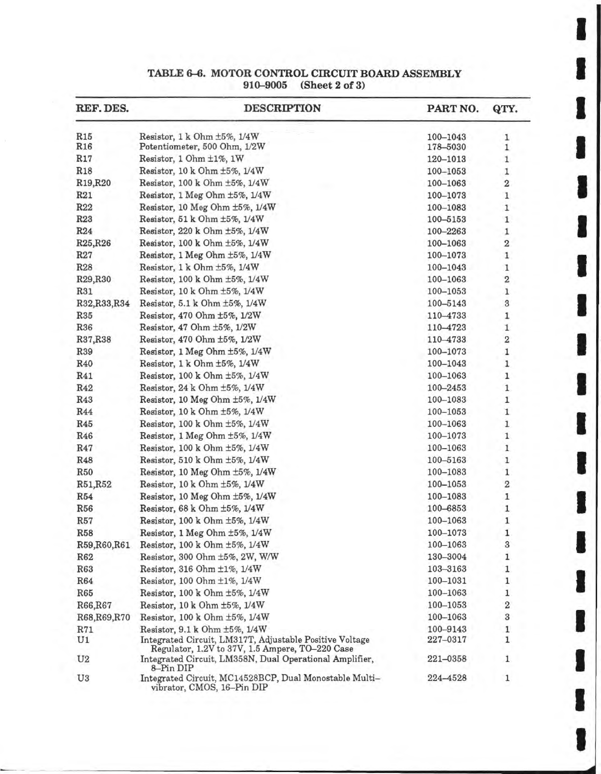
TABLE 6-6. MOTOR CONTROL CIRCUIT BOARD ASSEMBLY
910-9005 (Sheet 2 of 3)
REF. DES. DESCRIPTION PART NO. QTY.
R15 Resistor,
1
k Ohm ±5%, 1/4W 100-1043
R16 Potentiometer, 500 Ohm, 1/2W 178-5030
R17 Resistor,
1
Ohm+1%,
IW 120-1013
R18 Resistor,
10
k Ohm ±5%, iy4W 100-1053
R19,R20
Resistor,
100
k Ohm ±5%, iy4W 100-1063
R21 Resistor,
1
Meg Ohm ±5%, iy4W 100-1073
R22 Resistor,
10
Meg Ohm ±5%, 1/4W 100-1083
R23 Resistor, 51k Ohm ±5%, iy4W 100-5153
R24 Resistor, 220 k Ohm ±5%, 1/4W 100-2263
R25,R26 Resistor,
100
k Ohm ±5%, 1/4W 100-1063
R27 Resistor,
1
Meg Ohm ±5%, 1/4W 100-1073
R28 Resistor,
1
k Ohm ±5%, iy4W 100-1043
R29,R30 Resistor,
100
k Ohm ±5%, 1/4W 100-1063
R31 Resistor,
10
k Ohm ±5%, 1/4W 100-1053
R32,R33,R34 Resistor, 5.1 k Ohm ±5%, 1/4W 100-5143
R35 Resistor, 470 Ohm ±5%, 1/2W 110-4733
R36 Resistor, 47 Ohm ±5%, 1/2W 110-4723
R37,R38 Resistor, 470 Ohm
+5%,
1/2W 110-4733
R39 Resistor,
1
Meg Ohm ±5%, 1/4W 100-1073
R40 Resistor,
1
k Ohm ±5%, 1/4W 100-1043
R41 Resistor,
100
k Ohm ±5%, 1/4W 100-1063
R42 Resistor,
24
k Ohm ±5%, iy4W 100-2453
1143 Resistor,
10
Meg Ohm
+5%,
1/4W 100-1083
R44 Resistor,
10
k Ohm ±5%, iy4W 100-1053
R45 Resistor,
100
k Ohm ±5%, 1/4W 100-1063
R46 Resistor,
1
Meg Ohm ±5%, 1/4W 100-1073
R47 Resistor,
100
k Ohm ±5%, 1/4W 100-1063
R48 Resistor, 510 k Ohm ±5%, 1/4W 100-5163
R50 Resistor,
10
Meg Ohm ±5%, 1/4W 100-1083
R51,R52 Resistor,
10
k Ohm ±5%, 1/4W 100-1053
R54 Resistor,
10
Meg Ohm ±5%, 1/4W 100-1083
R56 Resistor,
68
k Ohm ±5%, iy4W 100-6853
R57 Resistor,
100
k Ohm ±5%, 1/4W 100-1063
R58 Resistor,
1
Meg Ohm ±5%, 1/4W 100-1073
R59,R60,R61 Resistor,
100
k Ohm ±5%, 1/4W 100-1063
R62 Resistor, 300 Ohm ±5%,
2W,
WAV
130-3004
R63 Resistor, 316 Ohm ±1%, 1/4W 103-3163
R64 Resistor, 100 Ohm ±1%, 1/4W 100-1031
R65 Resistor, 100 k Ohm ±5%, 1/4W 100-1063
R66,R67 Resistor,
10
k Ohm ±5%, 1/4W 100-1053
R68,R69,R70 Resistor,
100
k Ohm ±5%, iy4W 100-1063
R71 Resistor, 9.1 k Ohm ±5%, y4W 100-9143
Ul Integrated Circuit, LM317T, Adjustable Positive Voltage 227-0317
Regulator, 1.2V to 37V, 1.5 Ampere, TO-220 Case
U2 Integrated Circuit, LM358N, Dual Operational Amplifier, 221-0358
8-Pin
DIP
U3 Integrated Circuit, MC14528BCP, Dual Monostable Multi- 224-4528
vibrator, CMOS, 16-Pin DIP
STEAM POWERED RADIO.COM
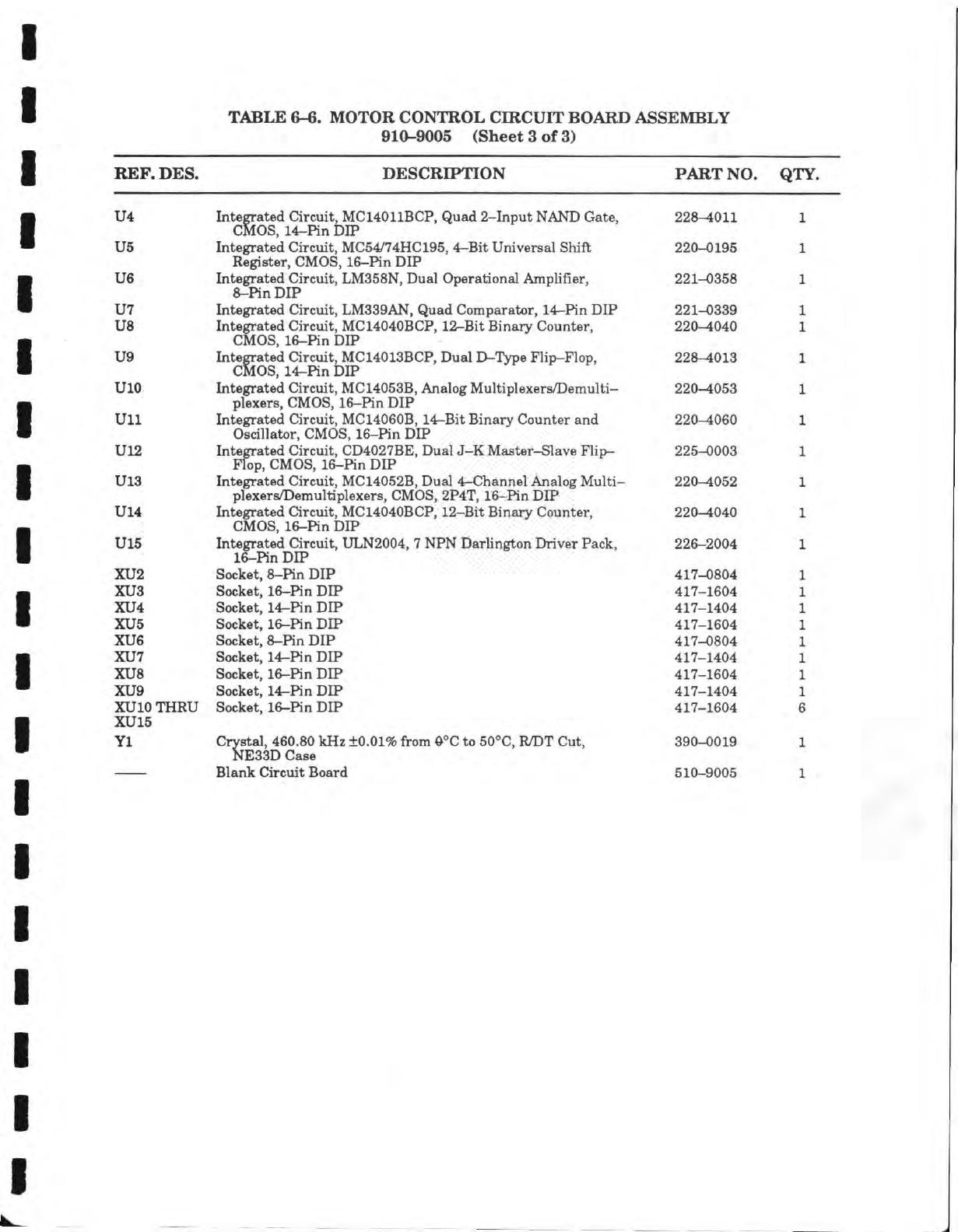
TABLE
6-6.
MOTOR CONTROL CIRCUIT BOARD ASSEMBLY
910-9005 (Sheet
3 of
3)
REF. DES.
DESCRIPTION
PART
NO.
QTY.
U4 Integrated Circuit, MC14011BCP, Quad 2-Input
NAND
Gate,
CMOS,
14-Pin DIP 228-4011
U5 Integrated Circuit, MC54/74HC195,
4-Bit
Universal Shift
Redster. CMOS 16-Pin DIP
Axrv
^AAWv
A • mm
Ay
A
mm Am « ^mm A AX A Am
A A
220-0195
U6 Integrated Circuit, LM358N, Dual Operational Amphfier,
8-Pin
DIP 221-0358
U7 Integrated Circuit, LM339AN, Quad Comparator, 14-Pin DIP 221-0339
uo
Tntttcrvafof?
Pir/»iiif
MPIZnAnTtPP
19
Ttif
"Rino-n/Pminfor
XlllfO^lateU
V/JlCUlb,
IVlVyJ.tV±VIJV/i
,
±A—DIL
Dlllciiy
v/UUlll/ei,
CMOS,
16-Pin DIP
£i£m\J—
*±\Jt\J
CMOS,
14-Pin DIP
99S—d.ni
/?
^^O—±Vi.O
UlO Intecrated Circuit MC14053B Analoe MultiDlexers/Demulti-
MmAA
vmm^AA
.p* v^%A mm A
A
w....^
V.
Ay
A
mm
mA
AV
mm
mm
Am y A
AX
xmAxmm^^
Ay A
XA
X VA
xmxmmxAmj
X imi Am ym XXX mAX %/x
plexers,
CMOS, 16-Pin DIP
220-4053
Ull Integrated Circuit, MC14060B, 14-Bit Binary Counter and
Oscillator, CMOS, 16-Pin DIP 220-4060
U12 Integrated Circuit, CD4027BE, Dual J-K Master-Slave Flip-
Flop,
CMOS, 16-Pin DIP 225-0003
U13 Integrated Circuit,
MC14052B,
Dual 4-Channel Analog Multi-
plexers/Demultiplexers, CMOS, 2P4T, 16-Pin DIP 220-4052
U14 Integrated Circuit, MC14040BCP, 12-Bit Binary Counter,
CMOS,
16-Pin DIP 220^040
U15 Integrated Circuit, ULN2004, 7 NPN Darhngton Driver Pack,
16—Pm
DIP
mm mm m% mm
A A m
226-2004
XU2 Socket,
8—Pin
DIP 417-0804
XU3 Socket, 16-Pin DIP 417-1604
XU4 Socket,
14r-Pin
DIP 417-1404
XU5 Socket, 16-Pin DIP 417-1604
XU6 Socket,
8-Pin
DIP 417-0804
XU7 Socket,
14-Pin
DIP 417-1404
XU8 Socket, 16-Pin DIP 417-1604
XU9 Socket, 14-Pin DIP 417-1404
XUlO
THRU Socket, 16-Pin DIP 417-1604
XU15 Socket, 16-Pin DIP
Yl Crystal, 460.80 kHz
±0.01%
from
0°C
to
50°C,
R/DT Cut,
NE33D Case 390-0019
Crystal, 460.80 kHz
±0.01%
from
0°C
to
50°C,
R/DT Cut,
NE33D Case
Blank Circuit Board 510-9005
STEAM POWERED RADIO.COM
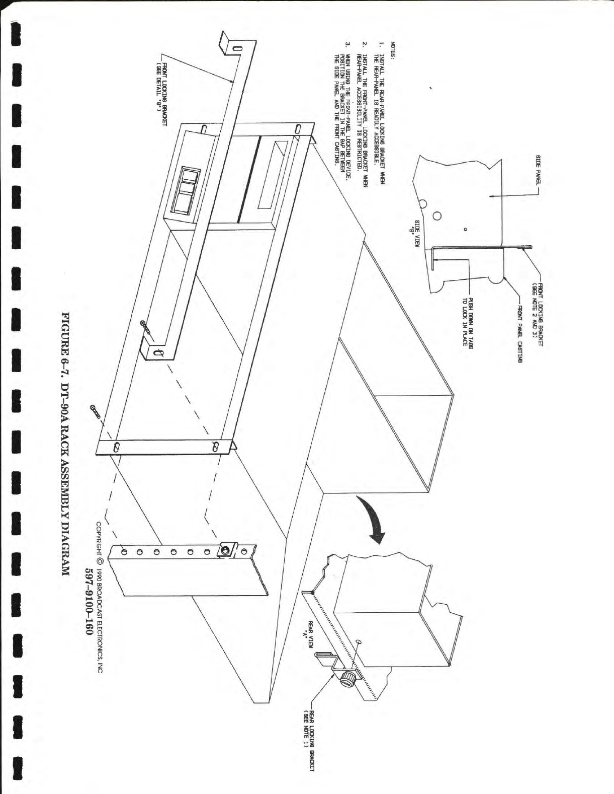
FIGURE
6-7.
DT-90A RACK ASSEMBLY DIAGRAM
STEAM POWERED RADIO.COM
PRODUCT WARRANTY
LIMITED
TWO
YEAR
While this warranty gives Purchaser specif Ic legal rights, which terminate two (2) years (one year on turntable,
cartridge and blower motors) from
the
date
of
shipment, Purchaser may also have other rights which vary state
to state.
Broadcast Electronics,
Inc.
("Seller") hereby warrants cartridge machines, consoles,
and
other
new
Equipment manufactured
by
Seller against
any
defects
in
material
or
workmanship
at the
time
of
delivery
thereof, that develop under normal
use
within
a
period
of two (2)
years
(one
year
for
turntable, cartridge
and
blower motors) from
the
date
of
shipment, as such term Is defined herein. Other manufacturer's and suppliers'
Equipment
and
services.
If any.
Including electronic tubes, solid state devices, transmission line, antennas,
towers, related equipment and installation
and
erection services, shall carry only such manufacturer's
or
sup-
pliers' standard warranty. This warranty extends
to
the original user and any subsequent purchaser during
the
warranty period. Seller's sole responsibility with respect
to any
equipment
or
parts
not
conforming
to
this war-
ranty
is to
replace such equipment
or
parts upon
the
return thereof F.O.B. Seller's factory
or
authorized repair
depot within
the
period aforesaid.
In
the
event
of
replacement pursuant
to the
foregoing warranty, only
the
unexpired portion
of the
war-
ranty from
the
time
of the
original purchase will remain
In
effect
for any
such replacement. However,
the
war-
ranty period will
be
extended
for
the length
of
time that Purchaser Is without the services
of
the Equipment
due
to
Its
being serviced pursuant
to
this warranty. The terms
of
the foregoing warranty shall
be
null
and
void
If the
Equipment has been altered
or
repaired without specific written authorization
of
Seller,
or If
Equipment Is oper-
ated under environmental conditions
or
circumstances otherthan those specif Ically described
In
Seller's prod-
uct literature
or
Instruction manual which accompany the Equipment. Seller shall
not be
liable
for any
expense
of
any
nature whatsoever incurred
by the
original user without prior written consent
of
Seller.
Seller shall
not be
liable
to
Purchaser
for any and all
Incidental
or
consequential damages
for
breach
of
either expressed
or
Implied warranties. However, some states
do not
allow
the
exclusion
or
limitation
of
Inci-
dental
or
consequential damages, sothe above limitation
or
exclusion
may not
apply to Purchaser.
All
express
and Implied warranties shall terminate
at the
conclusion
of the
period
set
forth herein.
Any
card which
is en-
closed with
the
equipment will
be
used
by
Seller
for
survey purposes only.
If
the
Equipment
Is
described
as
used.
It Is
sold
as Is
and where Is.
If the
contract covers equipment
not
owned
by
Seller
at
this date.
It Is
sold subject
to
Seller's acquisition
of
possession
and
title.
EXCEPT
AS SET
FORTH HEREIN,
AND
EXCEPT
AS TO
TITLE, THERE
ARE NO
WARRANTIES,
OR
ANY AFFIRMATIONS OF FACT OR PROMISES BY SELLER, WITH REFERENCE TO THE EQUIPMENT,
OR TO MERCHANTABILITY, FITNESS FOR
A
PARTICULAR APPLICATION, SIGNAL COVERAGE,
IN-
FRINGEMENT, OR OTHERWISE, WHICH EXTEND BEYOND THE DESCRIPTION OF THE EQUIPMENT
ON
THE
FACE HEREOF.
BROADCAST
ELECTRONICS, INC.
4100 North 24th Street,
P.O. Box
3606, Quincy, Illinois 62305
L
STEAM POWERED RADIO.COM

•ADCAST ELECTRONICS, INC. 4100N.24THSTREET P.O. BOX 3606 QUINCY. IL 62305
•
TELEX 250142/CABLE'BROADCAST' (217) 224-9600
STEAM POWERED RADIO.COM
