FREE RANGE VHDL Bryan Mealy, Fabrizio Tappero The No Frills Guide To Writing Powerful Code For
User Manual:
Open the PDF directly: View PDF ![]() .
.
Page Count: 189 [warning: Documents this large are best viewed by clicking the View PDF Link!]
- Acknowledgments
- Purpose of this book
- Introduction To VHDL
- VHDL Invariants
- VHDL Design Units
- VHDL Programming Paradigm
- Standard Models in VHDL Architectures
- VHDL Operators
- Logical Operators
- Relational Operators
- Shift Operator
- Other Operators
- Concatenation Operator
- Modulus and Remainder Operators
- Review of Almost Everything Up to Now
- Using VHDL for Sequential Circuits
- Simple Storage Elements Using VHDL
- Inducing Memory: Data-flow vs. Behavioral Modeling
- Important Points
- Exercises: Basic Memory Elements
- Finite State Machine Design Using VHDL
- Structural Modeling In VHDL
- Registers and Register Transfer Level
- Data Objects
- Looping Constructs
- Standard Digital Circuits in VHDL
- RET D Flip-flop - Behavioral Model
- FET D Flip-flop with Active-low Asynchronous Preset - Behavioral Model
- 8-Bit Register with Load Enable - Behavioral Model
- Synchronous Up/Down Counter - Behavioral Model
- Shift Register with Synchronous Parallel Load - Behavioral Model
- 8-Bit Comparator - Behavioral Model
- BCD to 7-Segment Decoder - Data-Flow Model
- 4:1 Multiplexer - Behavioral Model
- 4:1 Multiplexer - Data-Flow Model
- Decoder
- Appendix VHDL Reserved Words
- Appendix Standard VHDL Packages
- Appendix VHDL Reference Cards
- Appendix Contributors to This Book

Free Range VHDL
Bryan Mealy, Fabrizio Tappero

Free Range VHDL
Copyright 2012 B. Mealy, F. Tappero
Release: 1.09
Date: 23 April 2012
Book size: 160 mm by 240 mm
Pages: approx. 190
The electronic version of this book can be downloaded free of charge from:
http://www.freerangefactory.org
The authors have taken great care in the preparation of this book, but make no ex-
pressed or implied warranty of any kind and assume no responsibility for errors or
omissions. No liability is assumed for incidental or consequential damages in connec-
tion with or arising out of the use of the information or programs contained in this book.
This book is licensed under the Creative Commons Attribution-ShareAlike Unported
License, which permits unrestricted use, distribution, adaptation and reproduction in
any medium, provided the original work is properly cited. If you build upon this work,
you may distribute the resulting work only under the same, similar or a compatible
license. To view a copy of this license, visit:
http://creativecommons.org/licenses/by-sa/3.0/
Feedback and Contribution
We are more than happy to consider your contribution in improving, extending or
correcting any part of this book. For any communication or feedback that you might
have about the content of this book you can contact the authors at the following address:
contact@freerangefactory.org
Cover and Artwork by Robert Ash.
To everyone who helped

Table of Contents
Acknowledgments ii
Purpose of this book 1
1 Introduction To VHDL 5
1.1 Golden Rules of VHDL 8
1.2 Tools Needed for VHDL Development 8
2 VHDL Invariants 11
2.1 Case Sensitivity 11
2.2 White Space 11
2.3 Comments 12
2.4 Parentheses 12
2.5 VHDL Statements 13
2.6 if,case and loop Statements 13
2.7 Identifiers 14
2.8 Reserved Words 15
2.9 VHDL Coding Style 15
3 VHDL Design Units 17
3.1 Entity 18
3.2 VHDL Standard Libraries 22
ii
3.3 Architecture 23
3.4 Signal and Variable Assignments 23
3.5 Summary 25
3.6 Exercises 25
4 VHDL Programming Paradigm 29
4.1 Concurrent Statements 30
4.2 Signal Assignment Operator “<=” 33
4.3 Concurrent Signal Assignment Statements 34
4.4 Conditional Signal Assignment when 38
4.5 Selected Signal Assignment with select 42
4.6 Process Statement 46
4.7 Summary 47
4.8 Exercises 48
5 Standard Models in VHDL Architectures 51
5.1 Data-flow Style Architecture 52
5.2 Behavioral Style Architecture 53
5.3 Process Statement 53
5.4 Sequential Statements 55
5.4.1 Signal Assignment Statement 57
5.4.2 if Statement 57
5.4.3 case Statement 62
5.5 Caveats Regarding Sequential Statements 66
5.6 Summary 68
5.7 Exercises: Behavioral Modeling 68
6 VHDL Operators 71
6.1 Logical Operators 72
6.2 Relational Operators 72
6.3 Shift Operator 72
6.4 Other Operators 73
6.5 Concatenation Operator 74
6.6 Modulus and Remainder Operators 74
6.7 Review of Almost Everything Up to Now 75

iii
6.8 Using VHDL for Sequential Circuits 76
6.9 Simple Storage Elements Using VHDL 77
6.10 Inducing Memory: Data-flow vs. Behavioral Modeling 84
6.11 Important Points 85
6.12 Exercises: Basic Memory Elements 86
7 Finite State Machine Design Using VHDL 89
7.1 VHDL Behavioral Representation of FSMs 92
7.2 One-Hot Encoding for FSMs 101
7.3 Important Points 106
7.4 Exercises: Behavioral Modeling of FSMs 107
8 Structural Modeling In VHDL 117
8.1 VHDL Modularity with Components 119
8.2 Generic Map 127
8.3 Important Points 128
8.4 Exercises: Register Transfer Level Circuits 129
9 Registers and Register Transfer Level 131
9.1 Important Points 138
10 Data Objects 139
10.1 Types of Data Objects 139
10.2 Data Object Declarations 140
10.3 Variables and Assignment Operator “:=” 141
10.4 Signals vs. Variables 141
10.5 Standard Data Types 143
10.6 User-Defined Types 143
10.7 Commonly Used Types 144
10.8 Integer Types 144
10.9 signed and unsigned Types 146
10.10 std logic Types 147
10.11 Important Points 150
iv
11 Looping Constructs 151
11.1 for and while Loops 151
11.1.1 for Loops 152
11.1.2 while Loops 154
11.1.3 Loop Control: next and exit Statements 154
12 Standard Digital Circuits in VHDL 157
12.1 RET D Flip-flop - Behavioral Model 158
12.2 FET D Flip-flop with Active-low Asynchronous Preset -
Behavioral Model 158
12.3 8-Bit Register with Load Enable - Behavioral Model 159
12.4 Synchronous Up/Down Counter - Behavioral Model 159
12.5 Shift Register with Synchronous Parallel Load - Behavioral
Model 160
12.6 8-Bit Comparator - Behavioral Model 161
12.7 BCD to 7-Segment Decoder - Data-Flow Model 161
12.8 4:1 Multiplexer - Behavioral Model 162
12.9 4:1 Multiplexer - Data-Flow Model 162
12.10 Decoder 163
Appendix A VHDL Reserved Words 165
Appendix B Standard VHDL Packages 167
B.1 IEEE Standard Libraries 169
B.2 Non-standard Libraries 170
Appendix C VHDL Reference Cards 171
Appendix D Contributors to This Book 177

Acknowledgments
The authors would like to thank Christina Jarron for her invaluable con-
tribution to proofreading this book and for her useful suggestions. Special
thanks also to Rob Ash for helping us make the cover of the book distinc-
tive with his original artwork. Finally, a massive thank you goes to Keith
Knowles for his time and effort in reviewing and editing the final draft of
this book.

Purpose of this book
The purpose of this book is to provide students and young engineers with
a guide to help them develop the skills necessary to be able to use VHDL
for introductory and intermediate level digital design. These skills will also
give you the ability and the confidence to continue on with VHDL-based
digital design. In this way, you will also take steps toward developing
the skills required to implement more advanced digital design systems.
Although there are many books and on-line tutorials dealing with VHDL,
these sources are often troublesome for several reasons. Firstly, much of
the information regarding VHDL is either needlessly confusing or poorly
written. Material with these characteristics seems to be written from the
standpoint of someone who is either painfully intelligent or has forgotten
that their audience may be seeing the material for the first time. Secondly,
the common approach for most VHDL manuals is to introduce too many
topics and a lot of extraneous information too early. Most of this material
would best appear later in the presentation. Material presented in this
manner has a tendency to be confusing, is easily forgotten if misunderstood
or simply is never applied. The approach taken by this book is to provide
only what you need to know to quickly get up and running in VHDL.
As with all learning, once you have obtained and applied some useful
information, it is much easier to build on what you know as opposed
to continually adding information that is not directly applicable to the
2
subjects at hand.
The intent of this book is to present topics to someone familiar with
digital logic design and with some skills in algorithmic programming lan-
guages such as Java or C. The information presented here is focused on
giving a solid knowledge of the approach and function of VHDL. With a
logical and intelligent introduction to basic VHDL concepts, you should be
able to quickly and efficiently create useful VHDL code. In this way, you
will see VHDL as a valuable design, simulation and test tool rather than
another batch of throw-away technical knowledge encountered in some
forgotten class or lab.
Lastly, VHDL is an extremely powerful tool. The more you understand as
you study and work with VHDL, the more it will enhance your learning
experience independently of your particular area of interest. It is well
worth noting that VHDL and other similar hardware design languages
are used to create most of the digital integrated circuits found in the
various electronic gizmos that overwhelm our modern lives. The concept
of using software to design hardware that is controlled by software will
surely provide you with endless hours of contemplation. VHDL is a very
exciting language and mastering it will allow you to implement systems
capable of handling and processing in parallel ns-level logic events in a
comfortable software environment.
This book was written with the intention of being freely available to
everybody. The formatted electronic version of this book is available from
the Internet. Any part of this book can be copied, distributed and modified
in accordance with the conditions of its license.
DISCLAIMER: This book quickly takes you down the path toward
understanding VHDL and writing solid VHDL code. The ideas presented
herein represent the core knowledge you will need to get up and running
with VHDL. This book in no way presents a complete description of the
VHDL language. In an effort to expedite the learning process, some of
the finer details of VHDL have been omitted from this book. Anyone who
has the time and inclination should feel free to further explore the true
depth of the VHDL language. There are many on-line VHDL reference
3
books and free tutorials. If you find yourself becoming curious about what
this book is not telling you about VHDL, take a look at some of these
references.

1
Introduction To VHDL
VHDL has a rich and interesting history1. But since knowing this history
is probably not going to help you write better VHDL code, it will only be
briefly mentioned here. Consulting other, lengthier texts or search engines
will provide more information for those who are interested. Regarding the
VHDL acronym, the V is short for yet another acronym: VHSIC or Very
High-Speed Integrated Circuit. The HDL stands for Hardware Description
Language. Clearly, the state of technical affairs these days has done away
with the need for nested acronyms. VHDL is a true computer language
with the accompanying set of syntax and usage rules. But, as opposed to
higher-level computer languages, VHDL is primarily used to describe hard-
ware. The tendency for most people familiar with a higher-level computer
language such as C or Java is to view VHDL as just another computer lan-
guage. This is not altogether a bad approach if such a view facilitates the
understanding and memorization of the language syntax and structure.
The common mistake made by someone with this approach is to attempt
to program in VHDL as they would program a higher-level computer lan-
guage. Higher-level computer languages are sequential in nature; VHDL
is not.
VHDL was invented to describe hardware and in fact VHDL is a con-
current language. What this means is that, normally, VHDL instructions
are all executed at the same time (concurrently), regardless of the size of
1VHDL-Wikipedia: http://en.wikipedia.org/wiki/VHDL

6 Chapter 1: Introduction To VHDL
your implementation. Another way of looking at this is that higher-level
computer languages are used to describe algorithms (sequential execution)
and VHDL is used to describe hardware (parallel execution). This inher-
ent difference should necessarily encourage you to re-think how you write
your VHDL code. Attempts to write VHDL code with a high-level lan-
guage style generally result in code that nobody understands. Moreover,
the tools used to synthesize2this type of code have a tendency to gener-
ate circuits that generally do not work correctly and have bugs that are
nearly impossible to trace. And if the circuit does actually work, it will
most likely be inefficient due to the fact that the resulting hardware was
unnecessarily large and overly complex. This problem is compounded as
the size and complexity of your circuits becomes greater.
There are two primary purposes for hardware description languages such
as VHDL. First, VHDL can be used to model digital circuits and systems.
Although the word “model” is one of those overly used words in engi-
neering, in this context it simply refers to a description of something that
presents a certain level of detail. The nice thing about VHDL is that the
level of detail is unambiguous due to the rich syntax rules associated with
it. In other words, VHDL provides everything that is necessary in order
to describe any digital circuit. Likewise, a digital circuit/system is any
circuit that processes or stores digital information. Second, having some
type of circuit model allows for the subsequent simulation and/or test-
ing of the circuit. The VHDL model can also be translated into a form
that can be used to generate actual working circuits. The VHDL model is
magically3interpreted by software tools in such a way as to create actual
digital circuits in a process known as synthesis.
There are other logic languages available to model the behavior of dig-
ital circuit designs that are easy to use because they provide a graphical
method to model circuits. For them, the tendency is to prefer the graph-
ical approach because it has such a comfortable learning curve. But, as
you can easily imagine, your growing knowledge of digital concepts is ac-
2Synthesis: the process of interpreting the VHDL code and output a definition of the
physical implementation of the circuit to be programmed in a device such as a FPGA.
3It is not really magic. There is actually a well-defined science behind it.
7
companied by the ever-increasing complexity of digital circuits you are
dealing with. The act of graphically connecting a bunch of lines on the
computer screen quickly becomes tedious. The more intelligent approach
to digital circuit design is to start with a system that is able to describe
exactly how your digital circuit works (in other words, modeling it) with-
out having to worry about the details of connecting large quantities of
signal lines. Having a working knowledge of VHDL will provide you with
the tools to model digital circuits in a much more intelligent manner.
Finally, you will be able to use your VHDL code to create actual func-
tioning circuits. This allows you to implement relatively complex circuits
in a relatively short period of time. The design methodology you will be
using allows you to dedicate more time to designing your circuits and less
time “constructing” them. The days of placing, wiring and troubleshooting
multiple integrated circuits on a proto-board are gone.
VHDL is a very exciting language that can allow the design and im-
plementation of functions capable of processing an enormous amount of
data by employing a relatively low-cost and low-power hardware. More-
over, what is really impressive is that, via simple VHDL modules, you can
have direct access to basic ns-level logic events as well as communicate
using a USB port or drive a VGA monitor to visualize graphics of modest
complexity.
Modeling digital circuits with VHDL is a form of modern digital design
distinct from schematic-based approaches. The programmer writes a loose
description of what the final logic circuit should do and a language com-
piler, in this case called a synthesizer, attempts to “infer” what the actual
final physical logic circuit should be. Novice programmers are not always
able to convince the synthesizer to implement something that seems very
clear in their minds. A somehow old-fashioned alternative to a descriptive
language such as VHDL is one in which the programmer simply intercon-
nects a finite number of digital blocks that he has pooled from a library
in an attempt to reach the same objective. This approach is not only very
time consuming but also inherently limiting and very error prone.
Modern digital design is more about appropriately modeling digital cir-
cuits and maintaining a quality description of the circuit. All that is left
8 Chapter 1: Introduction To VHDL
now is to learn how to properly use VHDL to describe what you want to
implement.
1.1 Golden Rules of VHDL
Before you start, here are a couple of points that you should never forget
when working with VHDL.
VHDL is a hardware-design language. Although most people have
probably already been exposed to some type of higher-level computer lan-
guage, these skills are only indirectly applicable to VHDL. When you are
working with VHDL, you are not programming, you are “designing hard-
ware”. Your VHDL code should reflect this fact. What does this mean? It
means that unless you are inside certain constructs, your code lines will
be executed almost all at once. If your VHDL code appears too similar to
code of a higher-level computer language, it is probably bad VHDL code.
This is vitally important.
Have a general concept of what your hardware should look like.
Although VHDL is vastly powerful, if you do not understand basic dig-
ital constructs, you will probably be unable to generate efficient digital
circuits. Digital design is similar to higher-level language programming in
that even the most complicated programming at any level can be broken
down into some simple programming constructs. There is a strong analogy
to digital design in that even the most complicated digital circuits can be
described in terms of basic digital constructs. In other words, if you are
not able to roughly envision the digital circuit you are trying to model
in terms of basic digital circuits, you will probably misuse VHDL, thus
angering the VHDL gods. VHDL is cool, but it is not as magical as it
initially appears to be.
1.2 Tools Needed for VHDL Development
VHDL is a language used to implement hardware which will run other
software (for example C). A Field Programmable Gate Array (FPGA)
is probably the most common device that you can use for your VHDL

1.2 Tools Needed for VHDL Development 9
implementations. If you want to do VHDL coding for FPGAs you will have
to play within the rules that current major FPGA manufacturers have
drawn up to help you (rules which also ensure their continued existence
in the market).
The successful implementation of a VHDL-based system roughly calls for
the following steps: VHDL code writing, compiling, simulation and synthe-
sis. All major FPGA manufacturers have a set of software and hardware
tools that you can use to perform the mentioned steps. Most of these soft-
ware tools are free of charge but are not open-source. Nevertheless, the
same tools follow a license scheme, whereby paying a certain amount of
money allows you to take advantage of sophisticated software features or
get your hands on proprietary libraries with lots of components (e.g. a
32-bit processor) that you can easily include in your own project.
If your have no interest in proprietary libraries you can use open-source
solutions (e.g. GHDL4) which will allow you to compile and simulate your
VHDL code using the open-source tool gcc5. At the time of writing, no
open-source solution is available for the synthesis process. However syn-
thesis can be accomplished using a free-license version of any major FPGA
manufacturer’s software tool (e.g. Xilinx ISE Design Suite).
Thanks to the open-source community, you can write, compile and sim-
ulate VHDL systems using excellent open-source solutions. This book will
show you how to get up and running with the VHDL language. For further
tasks such as synthesis and upload of your code into an FPGA, the free
of charge Xilinx ISE Design Suite6or the Altera equivalent tool Quartus,
can be employed.
4Open-source VHDL simulator GHDL: http://ghdl.free.fr
5Multi-language open-source compiler GCC: http://gcc.gnu.org
6Xilinx ISE Design Suite: http://www.xilinx.com/tools/designtools.htm

2
VHDL Invariants
There are several features of VHDL that you should know before moving
forward. Although it is rarely a good idea for people to memorize anything,
you should memorize the basic concepts presented in this section. This
should help eliminate some of the drudgery involved in learning a new
programming language and lay the foundation that will enable you to
create visually pleasing and good VHDL source code.
2.1 Case Sensitivity
VHDL is not case sensitive. This means that the two statements shown
in Listing 2.1 have the exact same meaning (don’t worry about what the
statement actually means though). Keep in mind that Listing 2.1 shows an
example of VHDL case sensitivity and not good VHDL coding practices.
Listing 2.1: An example of VHDL case insensitivity.
Dout <= Aand B; doUt <= aAnD b;
2.2 White Space
VHDL is not sensitive to white space (spaces and tabs) in the source
document. The two statements in Listing 2.2 have the exact same meaning.
Once again, Listing 2.2 is not an example of good VHDL coding style. Note
that Listing 2.2 once again indicates that VHDL is not case sensitive.
Listing 2.2: An example showing VHDL’s indifference to white space.
nQ <= In_a or In_b; nQ <=in_a OR in_b;

12 Chapter 2: VHDL Invariants
2.3 Comments
Comments in VHDL begin with the symbol “--” (two consecutive dashes).
The VHDL synthesizer ignores anything after the two dashes and up to
the end of the line in which the dashes appear. Listing 2.3 shows two types
of commenting styles. Unfortunately, there are no block-style comments
(comments that span multiple lines but do not require comment marks on
every line) available in VHDL.
Listing 2.3: Two typical uses of comments.
-- This next section of code is used to blah-blah
-- This type of comment is the best fake for block-style commenting.
PS_reg <= NS_reg; -- Assign next_state value to present_state
Appropriate use of comments increases both the readability and the
understandability of VHDL code. The general rule is to comment any line
or section of code that may not be clear to a reader of your code besides
yourself. The only inappropriate use of a comment is to state something
that is patently obvious. It is hard to imagine code that has too few
comments so don’t be shy: use lots of comments. Research has shown that
using lots of appropriate comments is actually a sign of high intelligence.
2.4 Parentheses
VHDL is relatively lax on its requirement for using parentheses. Like other
computer languages, there are a few precedence rules associated with the
various operators in the VHDL language. Though it is possible to learn
all these rules and write clever VHDL source code that will ensure the
readers of your code are left scratching their heads, a better idea is to
practice liberal use of parentheses to ensure the human reader of your
source code understands the purpose of the code. Once again, the two
statements appearing in Listing 2.4 have the same meaning. Note that
extra white space has been added along with the parentheses to make the
lower statement clearer.

2.5 VHDL Statements 13
Listing 2.4: Example of parentheses that can improve clarity.
if x='0' and y='0'orz='1' then
blah; -- some useful statement
blah; -- some useful statement
end if;
if (((x='0')and (y='0')) or (z='1'))then
blah; -- some useful statement
blah; -- some useful statement
end if;
2.5 VHDL Statements
Similar to other algorithmic computer languages, every VHDL statement
is terminated with a semicolon. This fact helps when attempting to remove
compiling errors from your code since semicolons are often omitted dur-
ing initial coding. The main challenge then is to know what constitutes
a VHDL statement in order to know when to include semicolons. The
VHDL synthesizer is not as forgiving as other languages when superfluous
semicolons are placed in the source code.
2.6 if,case and loop Statements
As you will soon find out, the VHDL language contains if,case and
loop statements. A common source of frustration that occurs when learn-
ing VHDL are the classic mistakes involving these statements. Always
remember the rules stated below when writing or debugging your VHDL
code and you will save yourself a lot of time. Make a note of this section as
one you may want to read again once you have had a formal introduction
to these particular statements.
Every if statement has a corresponding then component
Each if statement is terminated with an end if;
If you need to use an else if construct, the VHDL version is elsif
Each case statement is terminated with an end case;
Each loop statement has a corresponding end loop; statement
In general, you should not worry too much about memorizing code syntax
as chances are you will use an editor sophisticated enough to have code
14 Chapter 2: VHDL Invariants
snippets (namely Gedit1). A good programmer distinguishes himself by
other means than perfectly remembering code syntax.
2.7 Identifiers
An identifier refers to the name given to various items in VHDL. Examples
of identifiers in higher-level languages include variable names and function
names. Examples of identifiers in VHDL include variable names, signal
names and port names (all of which will be discussed soon). Listed below
are the hard and soft rules (i.e. you must follow them or you should follow
them), regarding VHDL identifiers.
Identifiers should be self-describing. In other words, the text you apply
to identifiers should provide information as to the use and purpose of
the item the identifier represents.
Identifiers can be as long as you want (contain many characters).
Shorter names make for better reading code, but longer names present
more information. It is up to the programmer to choose a reasonable
identifier length.
Identifiers can only contain a combination of letters (A-Z and a-z),
digits (0-9) and the underscore character (“ ”).
Identifiers must start with an alphabetic character.
Identifiers must not end with an underscore and must never have two
consecutive underscores.
The best identifier for a function that calculates the position of the
Earth is CalcEarthPosition or calc earth position. Try to be con-
sistent.
The best identifier for a variable that stores the age of your car is
AgeMyCar or age my car. Again, try to be consistent.
Remember, intelligent choices for identifiers make your VHDL code more
readable, understandable and more impressive to coworkers, superiors,
1Gedit, the official Linux GNOME text editor. http://projects.gnome.org/
gedit
2.8 Reserved Words 15
family and friends. A few examples of both good and bad choices for
identifier names appear in Listing 2.5 and in Listing 2.6.
Listing 2.5: Valid identifies.
data_bus --descriptive name
WE --classic write enable
div_flag --real winner
port_A --provides some info
in_bus --input bus
clk --classic clock
clk_in
clk_out
mem_read_data
--
--
--
Listing 2.6: Invalid identifies.
3Bus_val -- begins with a number
DDD -- not self commenting
mid_$num -- illegal character
last__val-- consec. underscores
str_val_ -- ends with underscore
in -- uses VHDL reserved word
@#$%% -- total garbage
it_sucks -- try to avoid
Big_vAlUe-- valid but ugly
pa -- possibly lacks meaning
sim-val -- illegal character(dash)
DDE_SUX -- no comment
2.8 Reserved Words
There is a list of words that have been assigned special meaning by
the VHDL language. These special words, usually referred to as reserved
words, can not be used as identifiers when writing VHDL code. A partial
list of reserved words that you may be inclined to use appears in Listing
2.7. A complete list of reserved words appears in the Appendix. Notably
missing from Listing 2.7 are standard operator names such as AND, OR,
XOR, etc.
Listing 2.7: A short list of VHDL reserved words.
access after alias all attribute block
body buffer bus constant exit file
for function generic group in is
label loop mod new next null
of on open out range rem
return signal shared then to type
until use variable wait while with
2.9 VHDL Coding Style
Coding style refers to the appearance of the VHDL source code. Obviously,
the freedom provided by case insensitivity, indifference to white space
and lax rules on parentheses creates a coding anarchy. The emphasis in
coding style is therefore placed on readability. Unfortunately, the level
of readability of any document, particularly coding text, is subjective.
Writing VHDL code is similar to writing code in other computer languages
such as C and Java where you have the ability to make the document more

16 Chapter 2: VHDL Invariants
readable without changing the functioning of the code. This is primarily
done by indenting certain portions of the program, using self-describing
identifiers and provided proper comments when and where necessary.
Instead of stating here a bunch of rules for you to follow as to how your
code should look, you should instead strive to simply make your source
code readable. Listed below are a few thoughts on what makes readable
source code.
Chances are that if your VHDL source code is readable to you, it will
be readable to others who may need to peruse your document. These
other people may include someone who is helping you get the code
working properly, someone who is assigning a grade to your code, or
someone who signs your paycheck at the end of the day. These are
the people you want to please. These people are probably very busy
and more than willing to make a superficial glance at your code. Nice
looking code will slant such subjectivity in your favor.
If in doubt, your VHDL source code should be modeled after some
other VHDL document that you find organized and readable. Any code
you look at that is written down somewhere is most likely written by
someone with more VHDL experience than a beginner such as yourself.
Emulate the good parts of their style while on the path to creating an
even more readable style.
Adopting a good coding style helps you write code without mistakes.
As with other compilers you have experience with, you will find that
the VHDL compiler does a great job of knowing a document has an
error but a marginal job at telling you where or what the error is.
Using a consistent coding style enables you to find errors both before
compilation and after the compiler has found an error.
A properly formatted document explicitly presents information about
your design that would not otherwise be readily apparent. This is par-
ticularly true when using proper indentation and sufficient comments.

3
VHDL Design Units
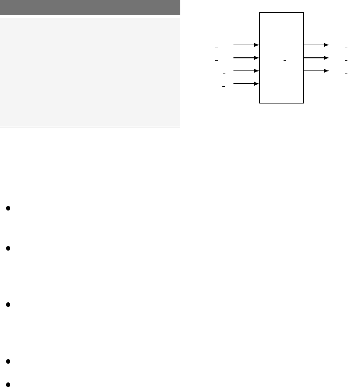
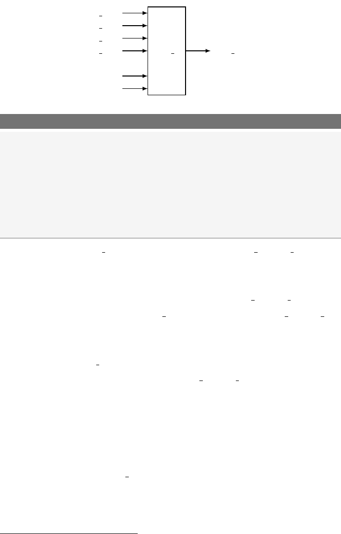
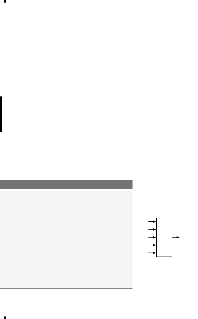
The “black-box” approach to any type of design implies a hierarchical
structure in which varying amounts of detail are available at each of the
different levels of the hierarchy. In the black-box approach, units of action
which share a similar purpose are grouped together and abstracted to a
higher level. Once this is done, the module is referred to by its inherently
more simple black-box representation rather than by the details of the
circuitry that actually performs that functionality. This approach has two
main advantages. First, it simplifies the design from a systems standpoint.
Examining a circuit diagram containing appropriately named black boxes
is much more understandable than staring at a circuit containing a count-
less number of logic gates. Second, the black-box approach allows for the
reuse of previously written code.
Not surprisingly, VHDL descriptions of circuits are based on the black-
box approach. The two main parts of any hierarchical design are the black
box and the stuff that goes in the black box (which can of course be other
black boxes). In VHDL, the black box is referred to as entity and the stuff
that goes inside it is referred to as the architecture. For this reason, the
VHDL entity and architecture are closely related. As you can probably
imagine, creating the entity is relatively simple while a good portion of
the VHDL coding time is spent on properly writing the architecture. Our
approach here is to present an introduction to writing VHDL code by
describing the entity and then moving on to the details of writing the
18 Chapter 3: VHDL Design Units
architecture. Familiarity with the entity will hopefully aid in your learning
of the techniques to describe the architecture.
3.1 Entity
The VHDL entity construct provides a method to abstract the functional-
ity of a circuit description to a higher level. It provides a simple wrapper
for the lower-level circuitry. This wrapper effectively describes how the
black box interfaces with the outside world. Since VHDL describes digital
circuits, the entity simply lists the various inputs and outputs of the un-
derlying circuitry. In VHDL terms, the black box is described by an entity
declaration. The syntax of the entity declaration is shown in Listing 3.1.
Listing 3.1: The entity declaration in VHDL.
entity my_entity is
port(
port_name_1 : in std_logic ;
port_name_2 : out std_logic;
port_name_3 : inout std_logic ); --do not forget the semicolon
end my_entity; -- do not forget this semicolon either
my entity defines the name of the entity. The next section is nothing
more than the list of signals from the underlying circuit that are available
to the outside world, which is why it is often referred to as an interface
specification. The port name x is an identifier used to differentiate the
various signals. The next keyword (the keyword in) specifies the direction
of the signal relative to the entity where signals can either enter, exit or do
both. These input and output signals are associated with the keywords in,
out and inout1respectively. The next keyword (the keyword std logic)
refers to the type of data that the port will handle. There are several data
types available in VHDL but we will primarily deal with the std logic
type and derived versions. More information regarding the various VHDL
data types will be discussed later.
When you attempt to write fairly complicated VHDL code, you will need
to split your code into different files, functions and packages constructors
which will help you better deal with your code. In this scenario, the entity
body will not only host the port definition statements but, most likely,
other procedures as well. We will talk about this later in the book.
1The inout data mode will be discussed later on in the book.
3.1 Entity 19
Listing 3.2: VHDL entity declaration.
------------------------------
-- interface description --
-- of killer_ckt --
------------------------------
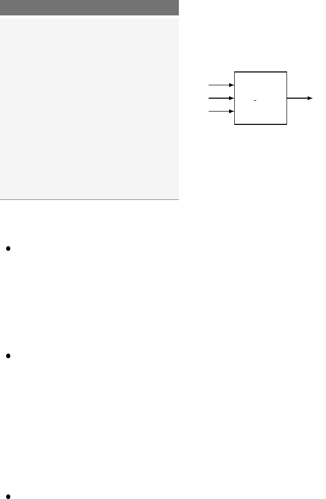
entity killer_ckt is
port (
life_in1 : in std_logic;
life_in2 : in std_logic;
crtl_a, ctrl_b : in std_logic;
kill_a : out std_logic;
kill_b, kill_c : out std_logic);
end killer_ckt;
killer ckt
life in1
life in2
ctrl a
ctrl b
kill a
kill b
kill c
Listing 3.2 shows an example of a black box and the VHDL code used to
describe it. Listed below are a few points to note about the code in Listing
3.2. Most of the points deal with the readability and understandability of
the VHDL code.
Each port name is unique and has an associated mode and data type.
This is a requirement.
The VHDL compiler allows several port names to be included on a
single line. Port names are separated by commas. Always strive for
readability.
Port names are somewhat lined up in a feeble attempt to increase read-
ability. This is not a requirement but you should always be striving for
readability. Remember that white spaces are ignored by the compiler.
A comment, which tells us what this this entity does, is included.
A black-box diagram of the circuit is also provided. Once again, draw-
ing some type of diagram helps with any VHDL code that you may be
writing. Remember: do not be scared, draw a picture.
Hopefully, you are not finding these entity specifications too challenging.
In fact, they are so straightforward, we will throw in one last twist before
we leave the realm of VHDL entities. Most of the more meaningful circuits
that you will be designing, analyzing and testing have many similar and
closely related inputs and outputs. These are commonly referred to as “bus
signals” in computer lingo. Bus lines are made of more than one signal
that differ in name by only a numeric character. In other words, each

20 Chapter 3: VHDL Design Units
separate signal in the bus name contains the bus name plus a number to
separate it from other signals in the bus. Individual bus signals are referred
to as elements of the bus. As you would imagine, buses are often used
in digital circuits. Unfortunately, the word bus also refers to established
data transfer protocols. To disambiguate the word bus, we will be using
the word “bundle” to refer to a set of similar signals and bus to refer to a
protocol.
Bundles are easily described in the VHDL entity. All that is needed is
a new data type and a special notation to indicate when a signal is a
bundle or not. A few examples are shown in Listing 3.3. In these exam-
ples note that the mode remains the same but the type has changed. The
std logic data type has now been replaced by the word std logic vector
to indicate that each signal name contains more than one signal. There
are ways to reference individual members of each bundle, but we will get
to those details later.
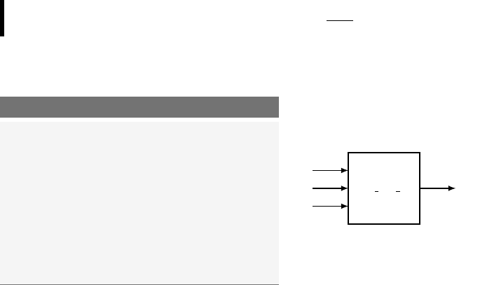
As you can see by examining Listing 3.3, there are two possible methods
to describe the signals in a bundle. These two methods are shown in the
argument lists that follow the data type declaration. The signals in the
bus can be listed in one of two orders which are specified by the to and
downto keywords. If you want the most significant bit of your bundle to
be on the the first bit on the left you use downto keyword. Be sure not to
forget the orientation of signals when you are using this notation in your
VHDL model.
In the black box of Listing 3.3 you can see the formal notation for a
bundle. Note that the black box uses a slash-and-number notation. The
slash across the signal line indicates the signal is a bundle and the asso-
ciated number specifies the number of signals in the bundle. Worthy of
mention regarding the black box relative to Listing 3.3 is that the input
lines sel1 and sel0 could have been made into one bundle containing
the two signals.
3.1 Entity 21
mux 4
a data 8
/
b data 8
/
c data 8
/
d data 8
/
sel0
sel1
data out
8
/
Listing 3.3: Entity declaration with bundles.
-------------------------------------------------------------
-- Unlike the other examples, this is actually an interface
-- for a MUX that selects one of four bus lines for the output.
-------------------------------------------------------------
entity mux4 is
port ( a_data : in std_logic_vector(0 to 7);
b_data : in std_logic_vector(0 to 7);
c_data : in std_logic_vector(0 to 7);
d_data : in std_logic_vector(0 to 7);
sel1,sel0 : in std_logic;
data_out : out std_logic_vector(0 to 7));
end mux4;
The data type std logic and the data type std logic vector is
what the IEEE has standardized for the representation of digital signals.
Normally, you should consider that these data types assume the logic value
1or the logic value 0. However, as specified in the std logic 1164 pack-
age, the implementation of the std logic type (and the std logic vector
type) is a little more generous and includes 9 different values, specifically:
0,1,U,X,Z,W,L,H,-.
The data type std logic becomes available to you soon after the decla-
ration library IEEE; use IEEE.std logic 1164.all; at the be-
ginning of your code.
The reason for all these values is the desire for modeling three-state
drivers, pull-up and pull-down outputs, high impedance state and a few
others types of inputs/outputs. For more details refer to the IEEE 1164
Standard2.
Alternatively to the std logic data type, VHDL programmers some-
times use the much simpler data type bit which has only the logic values
1and 0.
2IEEE 1164 Standard http://en.wikipedia.org/wiki/IEEE_1164

22 Chapter 3: VHDL Design Units
3.2 VHDL Standard Libraries
The VHDL language as many other computer languages, has gone through
a long and intense evolution. Among the most important standardization
steps we can mention are the release of the IEEE Standard 1164 pack-
age as well as some child standards that further extended the functionality
of the language. In order to take advantage of the main implementable fea-
ture of VHDL you just need to import the two main library packages as
shown in lines 2∼4 of Listing 3.4.
Listing 3.4: Typical inclusions of IEEE standard libraries.
1-- library declaration
2library IEEE;
3use IEEE.std_logic_1164.all;-- basic IEEE library
4use IEEE.numeric_std.all;-- IEEE library for the unsigned type and
5-- various arithmetic operators
6
7-- WARNING: in general try NOT to use the following libraries
8-- because they are not IEEE standard libraries
9-- use IEEE.std_logic_arith.all;
10 -- use IEEE.std_logic_unsigned.all;
11 -- use IEEE.std_logic_signed
12
13 -- entity
14 entity my_ent is
15 port ( A,B,C : in std_logic;
16 F : out std_logic);
17 end my_ent;
18 -- architecture
19 architecture my_arch of my_ent is
20 signal v1,v2 : std_logic_vector (3 downto 0);
21 signal u1 : unsigned (3 downto 0);
22 signal i1 : integer;
23 begin
24 u1 <= "1101";
25 i1 <= 13;
26 v1 <= std_logic_vector(u1); -- = "1101"
27 v2 <= std_logic_vector(to_unsigned(i1, v2'length)); -- = "1101"
28
29 -- "4" could be used instead of "v2'length", but the "length"
30 -- attribute makes life easier if you want to change the size of v2
31
32 F<= NOT (A AND BAND C);
33 end my_arch;
Once these packages have been included, you will have access to a very
large set of goodies: several data types, overloaded operators, various con-
version functions, math functions and so on. For instance, the inclusion of
the package numeric std.all will give you the possibility of using the
unsigned data type and the function to unsigned shown in Listing
3.4. For a detailed description of what these libraries include, refer to the
Language Templates of your favorite synthesis software tool (e.g. the
3.3 Architecture 23
yellow light bulb in the top panel of the Xilinx ISE software tool).
For more information on VHDL standard libraries refer to the Appendix.
3.3 Architecture
The VHDL entity declaration, introduced before, describes the interface
or the external representation of the circuit. The architecture describes
what the circuit actually does. In other words, the VHDL architecture
describes the internal implementation of the associated entity. As you can
probably imagine, describing the external interface to a circuit is generally
much easier than describing how the circuit is intended to operate. This
statement becomes even more important as the circuits you are describing
become more complex.
There can be any number of equivalent architectures describing a sin-
gle entity. As you will eventually discover, the VHDL coding style used
inside the architecture body has a significant effect on the way the cir-
cuit is synthesized (how the circuit will be implemented inside an actual
silicon device). This gives the VHDL programmer the flexibility of design-
ing systems with specific positive or negative features such as particular
physical size (measuring the number of needed basic digital elements) or
operational speed.
For various reasons, such as facilitating code re-usability and connectibil-
ity, an architecture can be modeled in different ways. Understanding the
various modeling techniques and understanding how to use them represent
the first important steps in learning VHDL.
An architecture can be written by means of three modeling techniques
plus any combination of these three. There is the data-flow model, the
behavioral model, the structural model and the hybrid models.
These models will be described throughout the book. Listing 3.5 gives a
sneak preview of what a simple but complete VHDL code block looks like.
3.4 Signal and Variable Assignments
In VHDL there are several object types. Among the most frequently used
we will mention the signal object type, the variable object type and the
constant object type. The signal type is the software representation of a

24 Chapter 3: VHDL Design Units
Listing 3.5: Example of a simple VHDL block.
1---------------------- FILE: my_sys.vhd ----------------------
2-- library declaration
3library ieee;
4use ieee.std_logic_1164.all;
5
6-- the ENTITY
7entity circuit1 is
8port (
9A,B,C : in std_logic;
10 F : out std_logic);
11 end circuit1;
12
13 -- the ARCHITECTURE
14 architecture circuit1_arc of circuit1 is
15 signal sig_1 : std_logic; -- signal definition
16 variable var_1 : integer; -- variable definition
17 begin
18 F<= not (A and Band C): -- signal assignment
19 sig_1 <= A; -- another signal assignment
20 var_1 := 34; -- variable assignment
21 end circuit1_arc;
wire. The variable type, like in C or Java, is used to store local information.
The constant is like a variable object type, the value of which cannot be
changed. A signal object can be of different types; we saw before, for
example, that a signal object can be of type std logic or of other types
like integer, custom types, etc. The same applies for variable objects.
Before using any signal or variable, it is mandatory to declare them (gen-
erally at the top of the architecture body, before its beginning) as shown
in line 15 and 16 of Listing 3.5. Such declarations could alternatively be
placed inside the entity. Refer to the VHDL cheat sheet in the Appendix.
As seen in line 18 and line 19 of Listing 3.5 when you want to assign
a new value to an object of type signal you use the operator “<=”. Al-
ternatively, when you want to assign a new value to an object of type
variable you will use the operator “:=”, shown in line 20. It is also im-
portant to remember that the type std logic only exists if you use the
library ieee.std logic 1164.all as done in line 4 of Listing 3.5.
Always remember that all signal and variable assignments of Listing 3.5
going from line 18 to line 20, are not executed consecutively but instead
concurrently (all at the same time). The variable assignment (line 20)
is executed instantaneously. Despite this, remember that all other signal
assignments (line 18 and line 19) are executed after a certain time, not

3.5 Summary 25
entirely predictable. Any hope that the execution of line 18 will happen
before the execution of line 19 or before the execution of line 20 will only
result in great disappointment.
We will see later on in the book that any time we need a non-concurrent
execution environment where code lines are executed one after the other
(like in C or Java), we will be able to use the process construct. Inside a
process, all instructions are executed consecutively from top to bottom.
3.5 Summary
The entity declaration describes the inputs and outputs of your circuit.
This set of signals is often referred to as the interface to your circuit
since these signals are what the circuitry, external to the entity, uses
to interact with your circuit.
Signals described in the entity declaration include a mode specifier and
atype. The mode specifier can be either an in or an out (or, as we will
see later on, even an inout ) while the type is either a std logic or
std logic vector.
The word bundle is preferred over the word bus when dealing with
multiple signals that share a similar purpose. The word bus has other
connotations that are not consistent with the bundle definition.
Multiple signals that share a similar purpose should be declared as
a bundle using a std logic vector type. Bundled signals such as
these are always easier to work with in VHDL compared to scalar types
such as std logic.
The architecture describes what your circuit actually does and what
its behavior is. Several possible implementations (models) of the same
behavior are possible in VHDL. These are the data-flow model, the
behavioral model, the structural model as well as any combination
of them, generally called hybrid model.
3.6 Exercises
1. What is referred to by the word bundle?
26 Chapter 3: VHDL Design Units
2. What is a common method of representing bundles in black-box
diagrams?
3. Why is it considered a good approach to always draw a black-box
diagram when using VHDL to model digital circuits?
4. Write VHDL entity declarations that describe the following black-
box diagrams:
a)
sys1
a in1
b in2
clk
ctrl int
out b
b)
sys2
input w
a data 8
/
b data 8
/
clk
dat 4
8
/
dat 5
3
/
5. Provide black-box diagrams that are defined by the following VHDL
entity declarations:
a)
entity ckt_c is
port (
bun_a,bun_b_bun_c : in std_logic_vector(7 downto 0);
lda,ldb,ldc : in std_logic;
reg_a, reg_b, reg_c : out std_logic_vector(7 downto 0);
end ckt_c;
b)
entity ckt_e is
port (
RAM_CS,RAM_WE,RAM_OE : in std_logic;
SEL_OP1, SEL_OP2 : in std_logic_vector(3 downto 0);
RAM_DATA_IN : in std_logic_vector(7 downto 0);
RAM_ADDR_IN : in std_logic_vector(9 downto 0);
RAM_DATA_OUT : in std_logic_vector(7 downto 0);
end ckt_e;
6. The following two entity declarations contain two of the most com-
mon syntax errors made in VHDL. What are they?
a)
entity ckt_a is
port (
J,K : in std_logic;
CLK : in std_logic
Q : out std_logic;)
end ckt_a;

3.6 Exercises 27
b)
entity ckt_b is
port (
mr_fluffy : in std_logic_vector(15 downto 0);
mux_ctrl : in std_logic_vector(3 downto 0);
byte_out : out std_logic_vector(3 downto 0);
end ckt_b;

4
VHDL Programming Paradigm
The previous chapter introduced the idea of the basic design units of
VHDL: the entity and the architecture. Most of the time was spent de-
scribing the entity simply because there is so much less involved compared
to the architecture. Remember, the entity declaration is used to describe
the interface of a circuit to the outside world. The architecture is used to
describe how the circuit is intended to function.
Before we get into the details of architecture specification, we must step
back for a moment and remember what it is we are trying to do with
VHDL. We are, for one reason or another, describing a digital circuit. Re-
alizing this is very important. The tendency for young VHDL programmers
with computer programming backgrounds is to view VHDL as just another
programming language they want or have to learn. Although many uni-
versity students have used this approach to pass the basic digital classes,
this is a not a good idea.
When viewed correctly, VHDL represents a completely different ap-
proach to programming while still having many similarities to other pro-
gramming languages. The main similarity is that they both use a syn-
tactical and rule-based language to describe something abstract. But, the
difference is that they are describing two different things. Most program-
ming languages are used to implement functionalities in a sequential man-
ner, one instruction at a time. VHDL however describes hardware and so

30 Chapter 4: VHDL Programming Paradigm
instructions are executed in a concurrent manner1, meaning that all in-
structions are executed at once. Realizing this fact will help you to truly
understand the VHDL programming paradigm and language.
4.1 Concurrent Statements
At the heart of most programming languages are the statements that
form a majority of the associated source code. These statements represent
finite quantities of actions to be taken. A statement in an algorithmic
programming language such as C or Java represents an action to be taken
by the processor. Once the processor finishes one action, it moves onto the
next action specified somewhere in the associated source code. This makes
sense and is comfortable to us as humans because just like the processor,
we are generally only capable of doing one thing at a time. This description
lays the foundation for an algorithmic method where the processor does
a great job of following a set of rules which are essentially the direction
provided by the source code. When the rules are meaningful, the processor
can do amazing things.
VHDL programming is significantly different. Whereas a processor steps
one by one through a set of statements, VHDL has the ability to exe-
cute a virtually unlimited number of statements at the same time and in
a concurrent manner (in other words, in parallel). Once again, the key
thing to remember here is that we are designing hardware. Parallelism,
or things happening concurrently, in the context of hardware is a much
more straightforward concept than it is in the world of software. If you
have had any introduction to basic digital hardware, you are most likely
already both familiar and comfortable with the concept of parallelism,
albeit not within a programming language.
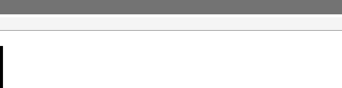
Figure 4.1 shows a simple example of a circuit that operates in parallel.
As you know, the output of the gates are a function of the gate inputs.
Any time that any gate input changes, there is a possibility that, after an
opportune delay, the gate output will change. This is true of all the gates
in Figure 4.1 or in any digital circuit in general. Once changes to the gate
inputs occur, the circuit status is re-evaluated and the gate outputs may
1In VHDL there are actually ways to obtain sequential execution as well.
4.1 Concurrent Statements 31
C
D
B
A
E E out
A 1
A 2
B 1
B 2
D 1
my circuit
Figure 4.1: Some common circuit that is well known to execute parallel op-
erations.
change accordingly. Although the circuit in Figure 4.1 only shows a few
gates, this idea of concurrent operation of all the elements in the circuit is
the same in all digital circuits no matter how large or complex they are.
Since most of us are human, we are only capable of reading one line of
text at a time and in a sequential manner. We have the same limitation
when we try to write some text, not to mention enter some text into a
computer. So how then are we going to use text to describe a circuit that is
inherently parallel? We did not have this problem when discussing some-
thing inherently sequential such as standard algorithmic programming.
When writing code using an algorithmic programming language, there is
generally only one processing element to focus on at each given time. Ev-
erything more or less follows up in a sequential manner, which fits nicely
with our basic limitation as humans.
The VHDL programming paradigm is built around the concept of ex-
pression parallelism and concurrency with textual descriptions of circuits.
The heart of VHDL programming is the concurrent statement. These are
statements that look a lot like the statements in algorithmic languages
but they are significantly different because the VHDL statements, by def-
inition, express concurrency of execution.
Listing 4.1 shows the code that implements the circuit shown in Figure
4.1. This code shows four concurrent signal assignment statements. As
seen before, the “<=” construct refers to the signal assignment operator.
It is true that we cannot write these four statements at the same time but

32 Chapter 4: VHDL Programming Paradigm
Listing 4.1: VHDL code for the circuit of Figure 4.1.
-- library declaration
library IEEE;
use IEEE.std_logic_1164.all;
-- entity
entity my_circuit is
port (
A_1,A_2,B_1,B_2,D_1 : in std_logic;
E_out : out std_logic;
end my_circuit;
-- architecture
architecture my_circuit_arc of my_circuit is
signal A_out, B_out, C_out : std_logic;
begin
A_out <= A_1 and A_2;
B_out <= B_1 or B_2;
C_out <= (not D_1) and B_2;
E_out <= A_out or B_out or C_out;
end my_circuit_arc;
we can interpret these statements as actions that occur concurrently. Re-
member to keep in mind that the concept of concurrency is a key concept
in VHDL. If you feel that the algorithmic style of thought is creeping into
your soul, try to snap out of it quickly. The concurrent signal assignment
is discussed in greater detail in the next section.
As a consequence of the concurrent nature of VHDL statements, the
three chunks of code appearing below are 100% equivalent to the code
shown in Listing 4.1. Once again, since the statements are interpreted as
occurring concurrently: the order that these statements appear in your
VHDL source code makes no difference. Generally speaking, it would be a
better idea to describe the circuit as shown in Listing 4.1 since it somewhat
reflects the natural organization of statements.

4.2 Signal Assignment Operator “<=” 33
Listing 4.2: Equivalent VHDL code for the circuit of Figure 4.1.
C_out <= (not D_1) and B_2;
A_out <= A_1 and A_2;
B_out <= B_1 or B_2;
E_out <= A_out or B_out or C_out;
Listing 4.3: Equivalent VHDL code for the circuit of Figure 4.1.
A_out <= A_1 and A_2;
E_out <= A_out or B_out or C_out;
B_out <= B_1 or B_2;
C_out <= (not D_1) and B_2;
Listing 4.4: Equivalent VHDL code for the circuit of Figure 4.1.
B_out <= B_1 or B_2;
A_out <= A_1 and A_2;
E_out <= A_out or B_out or C_out;
C_out <= (not D_1) and B_2;
4.2 Signal Assignment Operator “<=”
Algorithmic programming languages always have some type of assignment
operator. In C or Java, this is the well-known “=” sign. In these languages,
the assignment operator signifies a transfer of data from the right-hand
side of the operator to the left-hand side. VHDL uses two consecutive
characters to represent the assignment operator: “<=”. This combination
was chosen because it is different from the assignment operators in most
other common algorithmic programming languages. The operator is offi-
cially known as a signal assignment operator to highlight its true purpose.
The signal assignment operator specifies a relationship between signals.
In other words, the signal on the left-hand side of the signal assignment
operator is dependent upon the signals on the right-hand side of the op-
erator.
With these new insights into VHDL, you should be able to understand
the code of Listing 4.1 and its relationship to its schematic shown in Figure
4.1. The statement “G<=A AND B;” indicates that the value of the
signal named Grepresents an AND logic operation between the signals A
and B.
There are four types of concurrent statements that are examined in this
chapter. We have already briefly discussed the concurrent signal assign-
34 Chapter 4: VHDL Programming Paradigm
ment statement which we will soon examine further and put it into the
context of an actual circuit. The three other types of concurrent state-
ments that are of immediate interest to us are the process statement, the
conditional signal assignment and the selected signal assignment.
In essence, the four types of statements represent the tools that you will
use to implement digital circuits in VHDL. You will soon be discovering
the versatility of these statements. Unfortunately, this versatility effec-
tively adds a fair amount of steepness to the learning curve. As you know
from your experience in other programming languages, there are always
multiple ways to do the same things. Stated differently, several seemingly
different pieces of code can actually produce the same result. The same is
true for VHDL code: several considerably different pieces of VHDL code
can actually generate the exact same hardware. Keep this in mind when
you look at any of the examples given in this tutorial. Any VHDL code
used to solve a problem is more than likely one of many possible solutions
to that problem. Some of the VHDL models in this tutorial are presented
to show that something can be done a certain way, but that does not
necessarily mean they can only be done in that way.
4.3 Concurrent Signal Assignment Statements
The general form of a concurrent signal assignment statement is shown in
Listing 4.5. In this case, the target is a signal that receives the values of
the expression. An expression is defined by a constant, by a signal, or by
a set of operators that operate on other signals. Examples of expressions
used in VHDL code are shown in the examples that follow.
Listing 4.5: Syntax for the concurrent signal assignment statement.
<target> <= <expression>;
EXAMPLE 1. Write the VHDL code that implements a three-input
NAND gate. The three input signals are named A, B and C and the
output signal name is F.
SOLUTION. It is good practice to always draw a diagram of the circuit
you are designing. Furthermore, although we could draw a diagram show-
ing the familiar symbol for the NAND gate, we will choose to keep the
4.3 Concurrent Signal Assignment Statements 35
diagram general and take the black-box approach instead. Remember, the
black box is a nice aid when it comes to writing the entity declaration.
The solution to Example 1 is provided in Listing 4.6.
Listing 4.6: Solution of Example 1.
1-- library declaration
2library IEEE;
3use IEEE.std_logic_1164.all;
4-- entity
5entity my_nand3 is
6port ( A,B,C : in std_logic;
7F : out std_logic);
8end my_nand3;
9-- architecture
10 architecture exa_nand3 of my_nand3
is
11 begin
12 F<= ANAND BNAND C;
13 end exa_nand3;
14 -- alternative architecture
15 architecture exb_nand3 of my_nand3
is
16 begin
17 F<= NOT(NOT((A AND B) AND C));
18 end exb_nand3;
my nand3
A
B
C
F
This example contains a few new ideas that are worth further clarifica-
tion.
There are header files and library files that must be included in your
VHDL code in order for your code to correctly compile. These few
lines of code are listed at the top of the code in Listing 4.6. The listed
lines are more than what is needed for this example but they will be
required in later examples. To save space, these lines will be omitted
in some of the coming examples.
This example highlights the use of several logic operators. The logic
operators available in VHDL are AND, OR, NAND, NOR, XOR and
XNOR. The NOT operator is technically speaking not a logic operator
but is also available. Moreover, these logic operators are considered to
be binary operators in that they operate on the two values appearing
on the left and right-hand side of the operator. The NOT operator is
a unary operator and for that, it only operates on the value appearing
to the right of the operator.
Two architectures have been provided in this solution; they are both
associated with the same entity. This is fairly common practice in
36 Chapter 4: VHDL Programming Paradigm
complex circuits but is not overly useful in most VHDL design.
Example 1 demonstrates the use of the concurrent signal assignment (CSA)
statement in a working VHDL program (refer to line 12 and 17 of Listing
4.6). But since there is only one CSA statement, the concept of concur-
rency is not readily apparent. The idea behind any concurrent statement
in VHDL is that the output is changed any time one of the input signals
changes. In other words, the output F is re-evaluated any time a signal on
the input expression changes. This is a key concept in truly understanding
the VHDL, so you may want to read that sentence a few more times. The
idea of concurrency is more clearly demonstrated in Example 2.
EXAMPLE 2. Write the VHDL code to implement the function ex-
pressed by the following logic equation: F3 = LMN +LM
SOLUTION. The black box diagram and associated VHDL code is
shown in Listing 4.7.
Listing 4.7: Solution of Example 2.
-- library declaration
library IEEE;
use IEEE.std_logic_1164.all;
-- entity
entity my_ckt_f3 is
port ( L,M,N : in std_logic;
F3 : out std_logic);
end my_ckt_f3;
-- architecture
architecture f3_2 of my_ckt_f3 is
begin
F3<=((NOT L)AND(NOT M)AND N)OR(L AND M);
end f3_2;
my ckt f3
L
M
N
F3
This example shows a one-line implementation of the given logic equa-
tion.
An alternative solution to Example 2 is provided in Figure 4.8. This
example represents an important concept in VHDL. The solution shown
in Listing 4.8 uses some special statements in order to implement the cir-
cuit. These special statements are used to provide what is often referred
to as intermediate results. This approach is equivalent to declaring extra
variables in an algorithmic programming language to be used for storing
intermediate results. The need for intermediate results is accompanied by
the declaration of extra signal values, which are often referred to inter-
mediate signals. Note in Listing 4.8 that the declaration of intermediate

4.3 Concurrent Signal Assignment Statements 37
Listing 4.8: Alternative solution of Example 2.
-- library declaration
library IEEE;
use IEEE.std_logic_1164.all;
-- entity
entity my_ckt_f3 is
port ( L,M,N : in std_logic;
F3 : out std_logic);
end my_ckt_f3;
-- architecture
architecture f3_1 of my_ckt_f3 is
signal A1, A2 : std_logic; -- intermediate signals
begin
A1 <= ((NOT L) AND (NOT M) AND N);
A2 <= LAND M;
F3 <= A1 OR A2;
end f3_1;
signals is similar to the port declarations appearing in the entity declara-
tion, except that the mode specification (in,our or inout) is missing.
The intermediate signals must be declared within the body of the archi-
tecture because they have no link to the outside world and thus do not
appear in the entity declaration. Note that the intermediate signals are
declared in the architecture body but appear before the begin statement.
Despite the fact that the architectures f3 2 and f3 1 of Listing 4.7
and Listing 4.8 appear different, they are functionally equivalent. This is
because all the statements are concurrent signal assignment statements.
Even though the f3 1 architecture contains three CSAs, they are function-
ally equivalent to the CSA in f3 2 because each of the three statements
is effectively executed concurrently.
Although the approach of using intermediate signals is not mandatory
for this example, their use brings up some good points. First, the use
of intermediate signals is the norm for most VHDL models. The use of
intermediate signals was optional in Listing 4.8 due to the fact that the
example was modeling a relatively simple circuit. As circuits become more
complex, there are many occasions in which intermediate signals must be
used. Secondly, intermediate signals are something of a tool that you will
often need to use in your VHDL models. The idea here is that you are
trying to describe a digital circuit using a textual description language:
you will often need to use intermediate signals in order to accomplish
38 Chapter 4: VHDL Programming Paradigm
your goal of modeling the circuit. The use of intermediate signals allows
you to more easily model digital circuits but does not make the generated
hardware more complicated. The tendency in using VHDL is to think that
since there is more text written on your page, the circuit you are describing
and/or the resulting hardware is larger or more complex. This is simply
not true. The main theme of VHDL is that you should use the VHDL
tools at your disposal in order to model your circuits in the simplest way
possible. Simple circuits have a higher probability of being understood and
synthesized. But most importantly, a simple VHDL model is not related
to the length of the actual VHDL code.
In Example 2 the conversion of the logic function to CSAs was relatively
straightforward. The ease with which these functions can be implemented
into VHDL code was almost trivial. Then again, the function in Exam-
ple 2 was not overly complicated. As functions become more complicated
(more inputs and outputs), an equation entry approach becomes tedious.
Luckily, there are a few other types of concurrent construct that can ease
its implementation.
4.4 Conditional Signal Assignment when
Concurrent signal assignment statements, seen before, associate one tar-
get with one expression. The term conditional signal assignment is used
to describe statements that have only one target but can have more than
one associated expression assigned to the target. Each of the expressions
is associated with a certain condition. The individual conditions are evalu-
ated sequentially in the conditional signal assignment statement until the
first condition evaluates as true. In this case, the associated expression is
evaluated and assigned to the target. Only one assignment is applied per
assignment statement.
The syntax of the conditional signal assignment is shown in Listing 4.9.
The target in this case is the name of a signal. The condition is based
upon the state of some other signals in the given circuit. Note that there
is only one signal assignment operator associated with the conditional
signal assignment statement.
4.4 Conditional Signal Assignment when 39
Listing 4.9: The syntax for the conditional signal assignment statement.
<target> <= <expression> when <condition> else
<expression> when <condition> else
<expression>;
The conditional signal assignment statement is probably easiest to un-
derstand in the context of a circuit. For our first example, let us simply
redo Example 2 using conditional signal assignment instead of concurrent
signal assignment.
EXAMPLE 3. Write the VHDL code to implement the function ex-
pressed in Example 2. Use only conditional signal assignment state-
ments in your VHDL code.
SOLUTION. The entity declaration does not change from Example 2 so
the solution only needs a new architecture description. By reconsidering
the same logic equation of Example 2, F3 = LMN +LM, the solution to
Example 3 is shown in Listing 4.10.
Listing 4.10: Solution of Example 3.
architecture f3_3 of my_ckt_f3 is
begin
F3 <= '1' when (L= '0' AND M='0' AND N='1')else
'1' when (L= '1' AND M='1')else
'0';
end f3_3;
There are a couple of interesting points to note about this solution.
It is not much of an improvement over the VHDL code written using
concurrent signal assignment. In fact, it looks a bit less efficient in
terms of the number of instructions.
If you look carefully at this code you will notice that there is in fact
one target and a bunch of expressions and conditions. The associated
expressions are the single digits surrounded by single quotes; the as-
sociated conditions follow the when keyword. In other words, there is
only one signal assignment operator used for each conditional signal
assignment statement.
The last expression in the signal assignment statement is the catch-all
condition. If none of the conditions listed above the final expression
evaluate as true, the last expression is assigned to the target.
40 Chapter 4: VHDL Programming Paradigm
The solution uses relational operators. There are actually six differ-
ent relational operators available in VHDL. Two of the more common
relational operators are the “=” and “/=” relational operators which
are the “is equal to” and the “is not equal to” operators, respectively.
Operators are discussed at greater length in further sections.
There are more intelligent uses of the conditional signal assignment state-
ment. One of the classic uses is for the implementation of a multiplexer
(MUX). The next example is a typical conditional signal assignment im-
plementation of a MUX.
EXAMPLE 4. Write the VHDL code that implements a 4:1 MUX
using a single conditional signal assignment statement. The inputs to
the MUX are data inputs D3, D2, D1, D0 and a two-input control bus
SEL. The single output is MX OUT.
SOLUTION. For this example we need to start from scratch. This of
course includes the now famous black-box diagram and the associated
entity statement. The VHDL portion of the solution is shown in Listing
4.11.
Listing 4.11: Solution of Example 4.
-- library declaration
library IEEE;
use IEEE.std_logic_1164.all;
-- entity
entity my_4t1_mux is
port(D3,D2,D1,D0 : in std_logic;
SEL: in std_logic_vector(1 downto 0);
MX_OUT : out std_logic);
end my_4t1_mux;
-- architecture
architecture mux4t1 of my_4t1_mux is
begin
MX_OUT <= D3 when (SEL = "11")else
D2 when (SEL = "10")else
D1 when (SEL = "01")else
D0 when (SEL = "00")else
'0';
end mux4t1;
my 4to1 mux
D3
D2
D1
D0
SEL 2
/
MX OUT
There are a couple of things to note in the solution provided in Listing
4.11.
The solution looks somewhat efficient compared to the amount of logic
that would have been required if CSA statements were used. The

4.4 Conditional Signal Assignment when 41
VHDL code looks good and is pleasing to the eye, qualities required
for readability.
The “=” relational operator is used in conjunction with a bundle. In
this case, the values on the bundle SEL are accessed using double
quotes around the specified values. In other word, signal quotes are
used to describe values of single signals while double quotes are used
to describe values associated with multiple signals, or bundles.
For the sake of completeness, we have included every possible condi-
tion for the SEL signal plus a catch-all else statement. We could
have changed the line containing ’0’ to D0 and removed the line as-
sociated with the SEL condition of “00”. This would be functionally
equivalent to the solution shown but would not be nearly as impressive
looking. Generally speaking, you should clearly provide all the options
in the code and not rely on a catch-all statement for intended signal
assignment.
Remember, a conditional signal assignment is a type of concurrent state-
ment. In this case, the conditional signal assignment statement is executed
any time a change occurs in the conditional signals (the signals listed in
the expressions on the right-hand side of the signal assignment operator).
This is similar to the concurrent signal assignment statement where the
statement is executed any time there is a change in any of the signals
listed on the right-hand side of the signal assignment operator.
Though it is still early in the VHDL learning game, you have been ex-
posed to a lot of concepts and syntax. The conditional signal assignment
is maybe a bit less intuitive than the concurrent signal assignment. There
is however an alternative way to make sense of it. If you think about
it, the conditional signal assignment statement is similar in function to
the if-else constructs in algorithmic programming languages. We will
touch more upon this relationship once we start talking about sequential
statements.
The concept of working with bundles is very important in VHDL. Gener-
ally speaking, if you can use a bundle as opposed to individual signals, you
should. You will often need to access individual signals within a bundle.

42 Chapter 4: VHDL Programming Paradigm
Listing 4.12: Alternative solution to Example 4 accessing individual signals.
-----------------------------------------------------------------
-- entity and architecture of 4:1 Multiplexor implemented using
-- conditional signal assignment. The conditions access the
-- individual signals of the SEL bundle in this model.
-----------------------------------------------------------------
-- library declaration
library IEEE;
use IEEE.std_logic_1164.all;
-- entity
entity my_4t1_mux is
port (D3,D2,D1,D0 : in std_logic;
SEL : in std_logic_vector(1 downto 0);
MX_OUT : out std_logic);
end my_4t1_mux;
-- architecture
architecture mux4t1 of my_4t1_mux is
begin
MX_OUT <= D3 when (SEL(1) = '1' and SEL(0) ='1')else
D2 when (SEL(1) = '1' and SEL(0) ='0')else
D1 when (SEL(1) = '0' and SEL(0) ='1')else
D0 when (SEL(1) = '0' and SEL(0) ='0')else
'0';
end mux4t1;
When this is the case, a special syntax is used (e.g. SEL(1)). Be sure to
note that the code shown in Listing 4.12 is equivalent to but probably not
as clear as the code shown in Listing 4.11. Be sure to note the similarities
and differences.
4.5 Selected Signal Assignment with select
Selected signal assignment statements are the third type of signal assign-
ment that we will examine. As with conditional signal assignment state-
ments, selected signal assignment statements only have one assignment
operator. Selected signal assignment statements differ from conditional
assignment statements in that assignments are based upon the evaluation
of one expression. The syntax for the selected signal assignment statement
is shown in Listing 4.13.
Listing 4.13: Syntax for the selected signal assignment statement.
with <choose_expression> select
target <= <expression> when <choices>,
<expression> when <choices>;

4.5 Selected Signal Assignment with select 43
EXAMPLE 5. Write VHDL code to implement the function expressed
by the following logic equation: F3 = LMN +LM. Use only selected
signal assignment statements in your VHDL code.
SOLUTION. This is yet another version of the my ckt f3 example that
first appeared in Example 2. The solution is shown in Listing 4.14.
Listing 4.14: Solution of Example 5.
-- yet another solution to the previous example
architecture f3_4 of my_ckt_f3 is
begin
with ((L ='0' and M ='0'and N ='1')or(L='1' and M='1')) select
F3 <= '1' when '1',
'0' when '0',
'0' when others;
end f3_4;
One thing to notice about the solution shown in Listing 4.14 is the use
of the when others clause as the final entry in the selected signal as-
signment statement. In reality, the middle clause ’0’ when ’0’ could
be removed from the solution without changing the meaning of the state-
ment. In general, it is considered good VHDL programming practice to
include all the expected cases in the selected signal assignment statement
followed by the when others clause.
EXAMPLE 6. Write the VHDL code that implements a 4:1 MUX
using a single selected signal assignment statement. The inputs to the
MUX are data inputs D3, D2, D1, D0 and a two-input control bus SEL.
The single output is MX OUT.
SOLUTION. This is a repeat of Example 4 except that a selected signal
assignment operator is used instead of a conditional signal assignment
operator. The solution of Example 6 is shown in Listing 4.15. The black-
box diagram for this example is the same as before and is not repeated
here.
Once again, there are a few things of interest in the solution for Example
6 which are listed below.
The VHDL code has several similarities to the solution of Example
5. The general appearance is the same. Both solutions are also much
more pleasing to the eye than the one where the MUX was modeled
using only concurrent signal assignment statements.
44 Chapter 4: VHDL Programming Paradigm
Listing 4.15: Solution of Example 6.
-- library declaration
library IEEE;
use IEEE.std_logic_1164.all;
-- entity
entity my_4t1_mux is
port (D3,D2,D1,D0 : in std_logic;
SEL : in std_logic_vector(1 downto 0);
MX_OUT : out std_logic);
end my_4t1_mux;
-- architecture
architecture mux4t1_2 of my_4t1_mux is
begin
with SEL select
MX_OUT <= D3 when "11",
D2 when "10",
D1 when "01",
D0 when "00",
'0' when others;
end mux4t1_2;
Awhen others clause is used again. In the case of Example 6, the
output is assigned the constant value of ’0’ when the other listed
conditions of the chooser expression are not met.
The circuit used in this example was a 4:1 MUX. In this case, each of
the conditions of the chooser expression is accounted for in the body
of the selected signal assignment statement. However, this is not a
requirement. The only requirement here is that the line containing the
when others keywords appears in the final line of the statement.
EXAMPLE 7. Write the VHDL code that implements the following
circuit. The circuit contains an input bundle of four signals and an
output bundle of three signals. The input bundle, D IN, represents a
4-bit binary number. The output bus, SZ OUT, is used to indicate the
magnitude of the 4-bit binary input number. The relationship between
the input and output is shown in the table below. Use a selected signal
assignment statement in the solution.
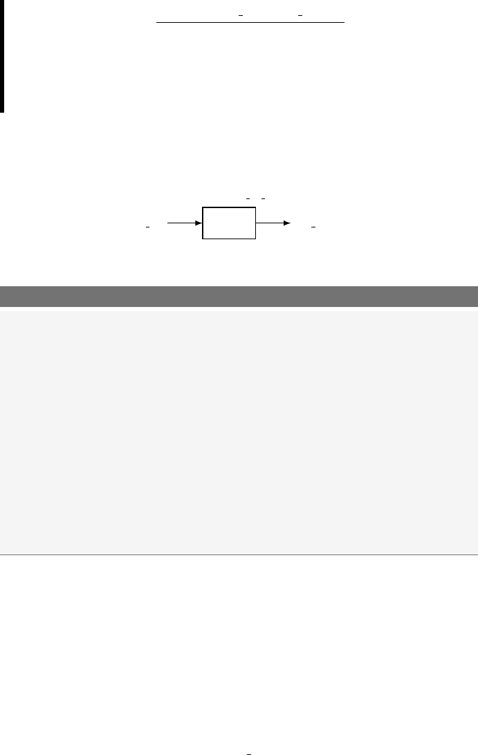
4.5 Selected Signal Assignment with select 45
range of D IN SZ OUT
0000 →0011 100
0100 →1001 010
1001 →1111 001
unknown value 000
SOLUTION. This is an example of a generic decoder-type circuit. The
solution to Example 7 is shown in Listing 4.16.
my sz ckt
D IN 4
/SZ OUT
3
/
Listing 4.16: Solution of Example 7.
-------------------------------------------------------------
-- A decoder-type circuit using selected signal assignment --
-------------------------------------------------------------
-- library declaration
library IEEE;
use IEEE.std_logic_1164.all;
-- entity
entity my_sz_ckt is
port ( D_IN : in std_logic_vector(3 downto 0);
SX_OUT : out std_logic_vector(2 downto 0));
end my_sz_ckt;
-- architecture
architecture spec_dec of my_sz_ckt is
begin
with D_IN select
SX_OUT <= "100" when "0000"|"0001"|"0010"|"0011",
"010" when "0100"|"0101"|"0110"|"0111"|"1000"|"1001",
"001" when "1010"|"1011"|"1100"|"1101"|"1110"|"1111",
"000" when others;
end spec_dec;
The only comment for the solution of Example 7 is that the vertical bar
is used as a selection character in the choices section of the selected signal
assignment statement. This increases the readability of the code as do the
similar constructs in algorithmic programming languages.
Once again, the selected signal assignment statement is one form of a
concurrent statement. This is verified by the fact that there is only one
signal assignment statement in the body of the selected signal assignment
statement. The selected signal assignment statement is evaluated each
time there is a change in the chooser expression listed in the first line of
46 Chapter 4: VHDL Programming Paradigm
the selected signal assignment statement.
The final comment regarding the selected signal assignment is similar
to the final comment regarding selected signal assignment. You should
recognize the general form of the selected signal assignment statement
as being similar to the switch statements in algorithmic programming
languages such as C and Java. Once again, this relationship is examined
in much more depth once we are ready to talk about sequential statements.
EXAMPLE 8. Write VHDL code to implement the function expressed
by the following logic equation: F3 = LMN +LM .
SOLUTION. This is the same problem examined before. The problem
with the previous solutions to this example is that they required the user
to somehow reduce the function before it was implemented. In this modern
day of digital circuit design, you score the most points when you allow the
VHDL synthesizer to do the work for you. The solution to this example
hopefully absolves you from ever again having to use a Karnaugh map,
or God forbid, boolean algebra, to reduce a function. The equivalent ex-
pression for F3(L, M, N) = LMN +LM and its Karnaugh map is shown
below. The solution of Example 8 in shown in Listing 4.17.
F3(L, M, N) = X(1,6,7)
L M N F3
0 0 0 0
0 0 1 1
0 1 0 0
0 1 1 0
1 0 0 0
1 0 1 0
1 1 0 1
1 1 1 1
4.6 Process Statement
The process statement is the final signal assignment type we will look at.
Before we do that, however, we need to take a few steps back and explore
a few other VHDL principles and definitions that we have excluded up
to now. Remember, there are a thousand ways to learn things. This is
especially true when learning programming languages, where there are

4.7 Summary 47
Listing 4.17: Solution of Example 8.
-- library declaration
library IEEE;
use IEEE.std_logic_1164.all;
-- entity
entity my_ckt_f3 is
port ( L,M,N : in std_logic;
F3 : out std_logic);
end my_ckt_f3;
-- architecture
architecture f3_8 of my_ckt_f3 is
signal t_sig : std_logic_vector(2 downto 0); -- local bundle
begin
t_sig <= (L&M&N);-- concatenation operator
with (t_sig) select
F3 <= '1' when "001" |"110" |"111",
'0' when others;
end f3_8;
usually many different and varied solutions to the same problem. This is
highlighted by the many different and varied approaches that appear in
VHDL books and by the many tutorials.
So, now is not the time to learn about the process statement. We will do
that right after we pick up a few more VHDL concepts. Now just remem-
ber that the process statement is a statement which contains a certain
number of instructions that, when the process statement is executed, are
executed sequentially. In other words, the process statement is a tool that
you can use any time you want to execute a certain number of instruc-
tions in a sequential manner (one instruction after the other, from top to
bottom). Do not forget, however, that the process statement in itself is
a concurrent statement and therefore will be executed together with the
other concurrent statements in the body of the architecture where it sits.
4.7 Summary
The entity/architecture pair is the interface description and behavior
description of how a digital circuit operates.
The main design consideration in VHDL modeling supports the fact
that digital circuits operate in parallel. In other words, the various
design units in a digital design process and store information indepen-
dently of each other. This is the major difference between VHDL and
48 Chapter 4: VHDL Programming Paradigm
higher-level computer programming languages.
The major signal assignment types in VHDL are: concurrent signal
assignment, conditional signal assignment, selected signal assignment
and process statements. Each concurrent statement is interpreted as
acting in parallel (concurrently) to other concurrent statements.
The process statement is a concurrent statement that contains a series
of statements which will be executed in a sequential manner, one after
the other. A programmer uses a process statement when he wants to
execute some commands in a sequential manner.
The architecture body can contain any or all of the mentioned concur-
rent statements.
Signals that are declared as outputs in the entity declaration cannot
appear on the right-hand side of a signal assignment operator. This
characteristic is prevented from being a problem by the declaration
and use of intermediate signals. Intermediate signals are similar to
signals declared in entities except that they contain no mode specifier.
Intermediate signals are declared inside the architecture body just
before the begin statement.
Generally speaking, there are multiple approaches in modeling any
given digital circuit. In other words, various types of concurrent state-
ments can be used to describe the same circuit. The designer should
strive for clarity in digital modeling and allow the VHDL synthesizer
to sort out the details.
4.8 Exercises
1. For the following function descriptions, write VHDL models that
implement these functions using concurrent signal assignment.
a) F(A, B) = AB +A+AB
b) F(A, B, C, D) = ACD +BC +BCD
c) F(A, B, C, D)=(A+B)·(B+C+D)·(A+D)
d) F(A, B, C, D) = Y(3,2)

4.8 Exercises 49
e) F(A, B, C) = Y(5,1,4,3)
f) F(A, B, C, D) = X(1,2)
2. For the following function descriptions, write VHDL models that
implement these functions using both conditional and selected signal
assignment.
a) F(A, B, C, D) = ACD +BC +BCD
b) F(A, B, C, D)=(A+B)·(B+C+D)·(A+D)
c) F(A, B, C, D) = Y(3,2)
d) F(A, B, C, D) = X(1,2)
3. Provide a VHDL model of an 8-input AND gate using concurrent,
conditional and selected signal assignment as well as a process state-
ment.
4. Provide a VHDL model of an 8-input OR gate using concurrent,
conditional and selected signal assignment as well as a process state-
ment.
5. Provide a VHDL model of an 8:1 MUX using conditional signal as-
signment, selected signal assignment and two different process state-
ments.
6. Provide a VHDL model of a 3:8 decoder using conditional signal as-
signment, selected signal assignment and a process statement; con-
sider the decoder’s outputs to be active-high.
7. Provide a VHDL model of a 3:8 decoder using conditional signal as-
signment, selected signal assignment and a process statement; con-
sider the decoder’s outputs to be active-low.

5
Standard Models in VHDL Architectures
As you may remember, the VHDL architecture describes how your VHDL
system will behave. The architecture body is comprised of two parts: the
declaration section and the begin-end section where a collection of (con-
current) signal assignments appear. We have studied three types of signal
assignment so far: concurrent signal assignment, conditional signal assign-
ment and selected signal assignment. We were about to describe another
concurrent statement, the process statement, before we got side-tracked.
Now, let us quickly introduce a new topic before we jump into the process
statement.
There are three different approaches to writing VHDL architectures.
These approaches are known as data-flow style, structural style and be-
havioral style architectures. The standard approach to learning VHDL is
to introduce each of these architectural styles individually and design a few
circuits using that style. Although this approach is good from the stand-
point of keeping things simple while immersed in the learning process,
it is also somewhat misleading because more complicated VHDL circuits
generally use a mixture of these three styles. Keep this fact in mind in
the following discussion of these styles. We will, however, put most of our
focus on data-flow and behavioral architectures. Structural modeling is
essentially a method to combine an existing set of VHDL models. In other
words, structural modeling supports the interconnection of black boxes
but does not have the ability to describe the logic functions used to model
52 Chapter 5: Standard Models in VHDL Architectures
the circuit operation. For this reason, it is less of a design method and
more of an approach for interfacing previously designed modules.
The reason we choose to slip the discussion of the different architectures
at this point is that you already have some familiarity with one of the
styles. Up to this point, all of our circuits have been implemented using
the data-flow style. We are now at the point of talking about the be-
havioral style of architectures which is primarily centered around another
concurrent statement known as the process statement. If it seems con-
fusing, some of the confusion should go away once we start dealing with
actual circuits and real VHDL code.
5.1 Data-flow Style Architecture
A data-flow style architecture specifies a circuit as a concurrent represen-
tation of the flow of data through the circuit. In the data-flow approach,
circuits are described by showing the input and output relationships be-
tween the various built-in components of the VHDL language. The built-in
components of VHDL include operators such as AND, OR, XOR, etc. The
three forms of concurrent statements we have talked about up until now
(concurrent signal assignment, conditional signal assignment and selected
signal assignment) are all statements that are found in data-flow style ar-
chitectures. In other words, if you exclusively used concurrent, conditional
and selected signal assignment statement in your VHDL models, you have
used a data-flow model. If you were to re-examine some of the examples
we have done so far, you can in fact sort of see how the data flows through
the circuit. To put this in other words, if you have a working knowledge of
digital logic, it is fairly straightforward to imagine the underlying circuitry
in terms of standard logic gates. These signal assignment statements ef-
fectively describe how the data flows from the signals on the right-hand
side of the assignment operator (the “<=”) to the signal on the left-hand
side of the operator.
The data-flow style of architecture has its strong points and weak points.
It is good that you can see the flow of data in the circuit by examining the
VHDL code. The data-flow models also allow you to make an intelligent
guess as to how the actual logic will appear when you decide to synthesize
5.2 Behavioral Style Architecture 53
the circuit. Data-flow modeling works fine for small and relatively simple
circuits. But as circuits become more complicated, it is often advantageous
to switch to behavioral style models.
5.2 Behavioral Style Architecture
In comparison to the data-flow style architecture, the behavioral style ar-
chitecture provides no details as to how the design is implemented in actual
hardware. VHDL code written in a behavioral style does not necessarily
reflect how the circuit is implemented when it is synthesized. Instead, the
behavioral style models how the circuit outputs will react to the circuit
inputs. Whereas in data-flow modeling you somewhat need to have a feel
for the underlying logic in the circuit, behavioral models provide you with
various tools to describe how the circuit will behave and leave the im-
plementation details up to the synthesis tool. In other words, data-flow
modeling describes how the circuit should look in terms of logic gates
whereas behavioral modeling describes how the circuit should behave. For
these reasons, behavioral modeling is considered higher up on the circuit
abstraction level as compared to data-flow models. It is the VHDL syn-
thesizer tool that decides the actual circuit implementation. In one sense,
behavioral style modeling is the ultimate “black box” approach to design-
ing circuits.
The heart of the behavioral style architecture is the process statement.
This is the fourth type of concurrent statement that we will work with.
As you will see, the process statement is significantly different from the
other three concurrent statements in several ways. The major difference
lies in the process statement’s approach to concurrency, which is the major
sticking point when you deal with this new concurrent statement.
5.3 Process Statement
The process statement itself is a concurrent statement identified by its
label, its sensitivity list, a declaration area and a begin-end area containing
instructions executed sequentially. An example of the process statement
is shown in Listing 5.1.
The main point to remember about the process statement is that its

54 Chapter 5: Standard Models in VHDL Architectures
Listing 5.1: Syntax for the process statement.
-- this is my first process
my_label:process(sensitivity_list) is
<item_declaration>
begin
<sequential_statements>
end process my_label;
body is comprised of sequential statements. The main difference between
concurrent signal assignment statements and process statements lies with
these sequential statements. But once again, let us stick to the similarities
before we dive into the differences. The process label, listed in Listing 5.1
is optional but should always be included to promote the self-description
of your VHDL code.
Listing 5.2 and 5.3 show a data-flow architecture and a behavioral style
architecture for the same XOR port. The main difference between the two
architectures is the presence of the process statement in the listed code.
Let us remember that the concurrent signal assignment statement in the
data-flow description operates as follows. Since it is a concurrent state-
ment, any time there is a change in any of the signals listed on the right-
hand side of the signal assignment operator, the signal on the left-hand
side of the operator is re-evaluated. For the behavioral architecture de-
scription, any time there is a change in signals in the process sensitivity
list, all of the sequential statements in the process are re-evaluated. Evalu-
ation of the process statement is controlled by the signals that are placed
in the process sensitivity list. These two approaches are effectively the
same except the syntax is significantly different.
So here is where it gets strange. Even though both of the architectures
listed in 5.2 and 5.3 have the exact same signal assignment statement
(F<=A XOR B;), execution of the statement in the behavioral style
architecture is controlled by which signals appear in the process sensitivity
list. The statement appearing in the data-flow model is re-evaluated any
time there is a change in signal A or in the signal B. This is a functional
difference rather than a cosmetic difference.

5.4 Sequential Statements 55
Listing 5.2: Data-flow architecture.
-- library declaration
library IEEE;
use IEEE.std_logic_1164.all;
-- entity
entity my_xor is
port (A,B:in std_logic;
F : out std_logic);
end my_xor;
-- architecture
architecture dataflow of my_xor is
begin
F<= AXOR B;
end dataflow;
--
--
--
Listing 5.3: Behavioral architecture.
-- library declaration
library IEEE;
use IEEE.std_logic_1164.all;
-- entity
entity my_xor is
port (A,B:in std_logic;
F : out std_logic);
end my_xor;
-- architecture
architecture behav of my_xor is
begin
xor_proc: process(A,B) is
begin
F<= AXOR B;
end process xor_proc;
end behav;
The process statement should be considered a way the programmer has
at his disposal to execute a series of sequential statements (i.e. in a behav-
ioral manner); never forget that the process statement is itself a concurrent
statement; therefore when you place two processes inside the architecture
body, their execution will be concurrent.
In Listing 5.4, you can see what a complete process statement looks like.
Remember that all variables defined inside the process body will only
be visible within the process body itself. Furthermore, notice that the
statement at line 24 is placed inside the architecture body but outside
the process body; therefore its execution happens concurrently with the
process statement.
5.4 Sequential Statements
Now that we have the process statement at our disposal, we have a way
to execute some code in a sequential manner.
Within a process, the execution of the sequential statements is initiated
when a change in the signal contained in the process sensitivity list occurs.
Generally speaking, execution of statements within the process body con-
tinues until the end of the process body is reached. The strangeness evokes
a philosophical dilemma: the process statement is a concurrent statement
yet it is comprised of sequential statements. This is actually a tough con-
cept to grasp. After years of contemplation, I am only starting to grasp
the reality of this strange contradiction.
The key to understand sequential evaluation of statements occurring in a

56 Chapter 5: Standard Models in VHDL Architectures
Listing 5.4: Use of the process statement.
1-- library declaration
2library IEEE;
3use IEEE.std_logic_1164.all;
4-- entity
5entity my_system is
6port ( A,B,C : in std_logic;
7F,Q : out std_logic);
8end my_system;
9-- architecture
10 architecture behav of my_system is
11 signal A1 : std_logic;
12 begin
13 some_proc: process(A,B,C) is
14 variable a,b : integer;
15 begin
16 a:=74;
17 b:=67;
18 A1 <= Aand Band C;
19 if a>b then
20 F<= A1 or B;
21 end if;
22 end process some_proc;
23 -- we are outside the process body
24 Q<= not A;
25 end behav;
concurrent statement remains hidden in the interpretation of VHDL code
by the synthesizer. And since the ins and outs of this interpretation are
not always readily apparent, some implementation details must be taken
for granted until the time comes when you really need to fully understand
the process. The solution is to keep your process statements as simple as
possible. The tendency is to use the process statement as a repository for a
bunch of loosely-related sequential statements. Although syntactically cor-
rect, the code is not intelligible (understandable) in the context of digital
circuit generation. You should strive to keep your process statements sim-
ple. Divide up your intended functionality into several process statements
that communicate with each other rather than one giant, complicated,
bizarre process statement. Remember, process statements are concurrent
statements: they all can be executed concurrently. Try to take advantage
of this feature in order to simplify your circuit descriptions.
There are three types of sequential statements that we will be discussing.
The first one is the signal assignment statement: the “<=”. We will
not say too much about the first type though because we have already
been dealing with its analogue in the data-flow models. The other two

5.4 Sequential Statements 57
types of statements are the if statement and the case statement. The
nice part about all of these statements is that you have worked with them
before in algorithmic programming languages. The structure and function
of the VHDL if and case statements is strikingly similar. Keep this in
mind when you read the descriptions that follow.
5.4.1 Signal Assignment Statement
The sequential style of a signal assignment statement is syntactically
equivalent to the concurrent signal assignment statement. Another way
to look at it is that if a signal assignment statement appears inside of a
process then it is a sequential statement; otherwise, it is a concurrent sig-
nal assignment statement. To drive the point home, the signal assignment
statement “F <=A XOR B;” in the data-flow style architecture of Listing
5.2 is a concurrent signal assignment statement while the same statement
in the behavioral style architecture, Listing 5.3, is a sequential signal as-
signment statement. The functional differences were already covered in
the discussion regarding process statements.
5.4.2 if Statement
The if statement is used to create a branch in the execution flow of the
sequential statements. Depending on the conditions listed in the body of
the if statement, either the instructions associated with one or none of
the branches is executed when the if statement is processed. The general
form of the if statement is shown in Listing 5.5.
Listing 5.5: Syntax of the if statement.
if (condition) then
<statements>
elsif (condition) then
<statements>
else
<statements>
end if;
The concept of the if statement should be familiar to you in two re-
gards. First, its form and function are similar to the if-genre of statements
found in most algorithmic programming languages. The syntax, however,
is a bit different. Secondly, the VHDL if statement is the sequential
equivalent to the VHDL conditional signal assignment statement. These
58 Chapter 5: Standard Models in VHDL Architectures
two statements essentially do the same thing but the if statement is a
sequential statement found inside a process body while the con-
ditional signal assignment statement is one form of concurrent
signal assignment.
Yet again, there are a couple of interesting things to note about the
listed syntax of the if statement.
The parentheses placed around the condition expressions are optional.
They should be included in most cases to increase the readability of
the VHDL source code.
Each if-type statement contains an associated then keyword. The
final else clause does not have the then keyword associated with it.
As written in Listing 5.5, the else clause is a catch-all statement. If
none of the previous conditions is evaluated as true, then the sequence
of statements associated with the final else clause is executed. The
way the if statement is shown in Listing 5.5 guarantees that at least
one of the listed sequence of statements will be executed.
The final else clause is optional. Not including the final else clause
presents the possibility that none of the sequence of statements asso-
ciated with the if statement will be evaluated. This has deep ramifi-
cations that we will discuss later.
Let us see now some examples that will help us to better understand how
to use the if statement.
EXAMPLE 9. Write some VHDL code using an if statement that
implements the following logic function: F OUT (A, B, C) = ABC+BC
SOLUTION. Although it is not directly stated in the problem descrip-
tion, the VHDL code for this solution must use a behavioral architecture.
This is because the problem states that an if statement should be used.
The VHDL code for the solution is shown in Listing 5.6. We have opted
to leave out the black-box diagram in this case since the problem is rela-
tively simple and thus does not really demonstrate the power of behavioral
modeling.

5.4 Sequential Statements 59
Listing 5.6: Solution to Example 9.
-- library declaration
library IEEE;
use IEEE.std_logic_1164.all;
-- entity
entity my_ex is
port (A,B,C : in std_logic;
F_OUT : out std_logic);
end my_ex;
-- architecture
architecture silly_example of my_ex is
begin
proc1: process(A,B,C) is
begin
if (A='1' and B='0' and C='0')then
F_OUT <= '1';
elsif (B='1' and C='1')then
F_OUT <= '1';
else
F_OUT <= '0';
end if;
end process proc1;
end silly_example;
This is probably not the best way to implement a logic function but it
does show an if statement in action. An alternate architecture for the
solution of Example 9 is shown in Listing 5.7.
Listing 5.7: Alternative solution to Example 9.
-- architecture
architecture bad_example of my_ex_7 is
begin
proc1: process(A,B,C)
begin
if (A='0' and B='0' and C='0')or (B='1' and C='1')then
F_OUT <= '1';
else
F_OUT <= '0';
end if;
end process proc1;
end bad_example;
One final comment on process statements. Process statements can be
preceded with an optional label. A label should always be included with
process statements as a form of self-description. This of course means
that the label should be meaningful in terms of describing the purpose of
the process statement. Providing good label names is somewhat of an art
form but keep in mind that it is easier to provide a meaningful name to
a process that is not trying to do too much. A more intelligent use of the
if statement is demonstrated in the next example.
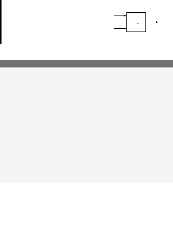
60 Chapter 5: Standard Models in VHDL Architectures
EXAMPLE 10. Write some
VHDL code that implements
the 8:1 MUX shown below.
Use an if statement in your
implementation.
mux 8t1
Data in 8
/
SEL 3
/
F CTRL
SOLUTION. The solution to Example 10 is shown in Listing 5.8.
Listing 5.8: Solution to Example 10.
-- library declaration
library IEEE;
use IEEE.std_logic_1164.all;
-- entity
entity mux_8t1 is
port ( Data_in : in std_logic_vector (7 downto 0);
SEL : in std_logic_vector (2 downto 0);
F_CTRL : out std_logic);
end mux_8t1;
-- architecture
architecture mux_8t1_arc of mux_8t1 is
begin
my_mux: process (Data_in,SEL)
begin
if (SEL = "111")then F_CTRL <= Data_in(7);
elsif (SEL = "110")then F_CTRL <= Data_in(6);
elsif (SEL = "101")then F_CTRL <= Data_in(5);
elsif (SEL = "100")then F_CTRL <= Data_in(4);
elsif (SEL = "011")then F_CTRL <= Data_in(3);
elsif (SEL = "010")then F_CTRL <= Data_in(2);
elsif (SEL = "001")then F_CTRL <= Data_in(1);
elsif (SEL = "000")then F_CTRL <= Data_in(0);
else F_CTRL <= '0';
end if;
end process my_mux;
end mux_8t1_arc;
The solution to Example 10 shown in Listing 5.8 uses some new syntax.
The entity uses the bundle signal but the associated architecture needs
to access individual elements of these bundles. The solution is to use the
bus index operator to access internal signals of the bus. This is comprised
of a number representing an index placed inside parentheses (for example
Data in(7)). Bus index operators are used extensively in VHDL and
were previously mentioned. The solution to Example 10 shows a more
typical use of the operator than was previously mentioned.
One other thing to notice about the solution in Example 10 is that every
possible combination of the select variable is accounted for in the code.
It would be possible to remove the final elsif statement in the code
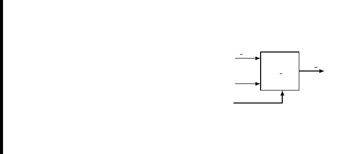
5.4 Sequential Statements 61
shown in Listing 5.8 and place the associated signal assignment in the
else clause. But this is not considered good VHDL practice and should
be avoided at all costs. The justification for this is that it will modify the
readability of the code but not alter the hardware generated by the code.
EXAMPLE 11. Write some VHDL
code that implements the 8:1 MUX
shown here. Use as many if state-
ments as you deem necessary to im-
plement your design. In the black-
box diagram, the CE input is a chip
enable. When CE = ’1’, the output
acts like the MUX of Example 10.
When CE is ’0’, the output of the
MUX is ’0’.
mux 8to1
Data in 8
/
SEL 3
/
CE
F CTRL
SOLUTION. The solution to Example 11 is strangely similar to the
solution of Example 10. Note that in this solution the if statements can
be nested to attain various effects. The solution to Example 11 is shown
in Listing 5.9.

62 Chapter 5: Standard Models in VHDL Architectures
Listing 5.9: Solution to Example 11.
-- library declaration
library IEEE;
use IEEE.std_logic_1164.all;
-- entity
entity mux_8to1_ce is
port ( Data_in : in std_logic_vector (7 downto 0);
SEL : in std_logic_vector (2 downto 0);
CE:in std_logic;
F_CTRL : out std_logic);
end mux_8to1_ce;
-- architecture
architecture mux_8to1_ce_arch of mux_8to1_ce is
begin
my_mux: process (Data_in,SEL,CE)
begin
if (CE = '0')then
F_CTRL <= '0';
else
if (SEL = "111")then F_CTRL <= Data_in(7);
elsif (SEL = "110")then F_CTRL <= Data_in(6);
elsif (SEL = "101")then F_CTRL <= Data_in(5);
elsif (SEL = "100")then F_CTRL <= Data_in(4);
elsif (SEL = "011")then F_CTRL <= Data_in(3);
elsif (SEL = "010")then F_CTRL <= Data_in(2);
elsif (SEL = "001")then F_CTRL <= Data_in(1);
elsif (SEL = "000")then F_CTRL <= Data_in(0);
else F_CTRL <= '0';
end if;
end if;
end process my_mux;
end mux_8to1_ce_arch;
5.4.3 case Statement
The case statement is somewhat similar to the if statement in that a
sequence of statements is executed if an associated expression is true. The
case statement differs from the if statement in that the resulting choice
is made depending upon the value of the single control expression. Only
one of the sequential statements is executed for each execution of the case
statement. The syntax for the case statement is shown in Listing 5.10.
Listing 5.10: Syntax for the case statement.
case (expression) is
when choices =>
<sequential statements>
when choices =>
<sequential statements>
when others =>
<sequential statements>
end case;
Once again, the concept of the case statement should be familiar to
you in several regards. Firstly, it can somewhat be considered the compact

5.4 Sequential Statements 63
form of the if statement. It is not as functional, however, for the reason
described above. Secondly, the case statement is similar in both form and
function to the case statement or the switch statement in other algo-
rithmic programming languages. And finally, the VHDL case statement
is the sequential equivalent of the VHDL selected signal assignment state-
ment. These two statements essentially have the same capabilities but the
case statement is a sequential statement found in a process body while
the selected signal assignment statement is one form of concurrent signal
assignment. The when others line is not required but should be used
as good programming practice.
EXAMPLE 12. Write some VHDL code that implements the follow-
ing function using the case statement: F OUT (A, B, C) = ABC +BC
SOLUTION. This solution falls into the category of not being the best
way to implement a circuit using VHDL. It does, however, illustrate an-
other useful feature in the VHDL. The first part of this solution requires
that we list the function as a sum of minterm. This is done by multiplying
the non-minterm product term given in the example by 1. In this case, 1
is equivalent to (A+A). This factoring operation is shown as:
F OU T (A, B, C) = ABC +BC
F OU T (A, B, C) = ABC +BC(A+A)
F OU T (A, B, C) = ABC +ABC +ABC
The solution is shown in Listing 5.11. An interesting feature of this
solution is the grouping of the three input signals which allows the use of a
case statement in the solution. This approach requires the declaration of
an intermediate signal which is appropriately labeled “ABC”. Once again,
this is probably not the most efficient method to implement a function but
it does highlight the need to be resourceful and creative when describing
the behavior of digital circuits.

64 Chapter 5: Standard Models in VHDL Architectures
Listing 5.11: Solution to Example 12.
-- library declaration
library IEEE;
use IEEE.std_logic_1164.all;
-- entity
entity my_example is
port (A,B,C : in std_logic;
F_OUT : out std_logic);
end my_example;
-- architecture
architecture my_soln_exam of my_example is
signal ABC: std_logic_vector(2 downto 0);
begin
ABC <= A&B&C;-- group signals for case statement
my_proc: process (ABC)
begin
case (ABC) is
when "100" => F_OUT <= '1';
when "011" => F_OUT <= '1';
when "111" => F_OUT <= '1';
when others => F_OUT <= '0';
end case;
end process my_proc;
end my_soln_exam;
Another similar approach to Example 12 is to use the don’t care feature
built into VHDL. This allows the logic function to be implemented without
having to massage the inputs. As with everything, if you have to modify
the problem before you arrive at the solution, you stand a finite chance of
creating an error that would not have otherwise been created if you had
not taken a more clever approach. A different architecture for the solution
of Example 12 is shown in Listing 5.12. One possible drawback of using a
don’t care feature in your VHDL code is that some synthesizers and some
simulators do not handle it very well. I would avoid them at all costs and
seek a more definitive method of modeling the circuits I am dealing with.
Listing 5.12: Alternative solution to Example 12.
architecture my_soln_exam2 of my_example is
signal ABC: std_logic_vector(2 downto 0);
begin
ABC <= A&B&C;-- group signals for case statement
my_proc: process (ABC)
begin
case (ABC) is
when "100" => F_OUT <= '1';
when "-11" => F_OUT <= '1';
when others => F_OUT <= '0';
end case;
end process my_proc;
end my_soln_exam2;
One of the main points that should be emphasized in any VHDL program
is readability. In the next problem, we will redo Example 11 using a case
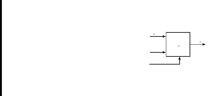
5.4 Sequential Statements 65
statement instead of if statements.
EXAMPLE 13. Write some
VHDL code that implements the
8:1 MUX shown below. Use a case
statement in your design. In the
black-box diagram shown below,
the CE input is a chip enable.
When CE = ’1’, the output acts
like the MUX of Example 10. When
CE is ’0’, the output of the MUX
is ’0’.
mux 8to1
Data in 8
/
SEL 3
/
CE
F CTRL
SOLUTION. This solution to Example 13 is shown in Listing 5.13. The
entity declaration is repeated below for your convenience. This solution
places the case statement in the body of an if construct. In case you
have not noticed it yet, the number of possible solutions to a given problem
increases as the circuits you are implementing become more complex.

66 Chapter 5: Standard Models in VHDL Architectures
Listing 5.13: Solution to Example 13.
-- library declaration
library IEEE;
use IEEE.std_logic_1164.all;
-- entity
entity mux_8to1_ce is
port ( Data_in : in std_logic_vector (7 downto 0);
SEL : in std_logic_vector (2 downto 0);
CE:in std_logic;
F_CTRL : out std_logic);
end mux_8to1_ce;
-- architecture
architecture my_case_ex of mux_8to1_ce is
begin
my_mux: process (SEL,Data_in,CE)
begin
if (CE = '1')then
case (SEL) is
when "000" => F_CTRL <= Data_in(0);
when "001" => F_CTRL <= Data_in(1);
when "010" => F_CTRL <= Data_in(2);
when "011" => F_CTRL <= Data_in(3);
when "100" => F_CTRL <= Data_in(4);
when "101" => F_CTRL <= Data_in(5);
when "110" => F_CTRL <= Data_in(6);
when "111" => F_CTRL <= Data_in(7);
when others => F_CTRL <= '0';
end case;
else
F_OUT <= '0';
end if;
end process my_mux;
end my_case_ex;
One very important point in the solution to Example 13 is the fact that
acase statement was embedded into an if statement. The technical
term for this style of coding is, as you would guess, nesting. Nesting se-
quential statements is typical in behavioral models and is used often. This
is actually one of the features that make behavioral modeling so much
more powerful than data-flow modeling. The reality is that conditional
and selective signal assignment statements can not be nested.
5.5 Caveats Regarding Sequential Statements
As you begin to work with sequential statements, you tend to start getting
the feeling that you are doing algorithmic programming using a higher-
level language. This is due to the fact that sequential statements have a
similar look and feel to some of the programming constructs in higher-level
languages. The bad part of this tendency is when and if your VHDL cod-
ing approach becomes similar to that of the higher-level language. Since
5.5 Caveats Regarding Sequential Statements 67
this happens very often with people who are learning VHDL, it is appro-
priate to remind once again that VHDL is not programming: VHDL
is hardware design. You are, generally speaking, not implementing al-
gorithms in VHDL, you are describing hardware: this is a totally different
paradigm.
It is not uncommon to see many, not so good, pieces of VHDL code
that attempt to use a single process statement in order to implement a
relatively complex circuit. Although the code appears like it should work
in terms of the provided statements, this is an illusion based on the fact
that your mind is interpreting the statements in terms of a higher-level
language. The reality is that VHDL is somewhat mysterious in that you
are trusting the VHDL synthesizer to magically know what you are trying
to describe. If you do not understand the ins and outs of VHDL at a
low level, your circuit is not going to synthesize properly. Most likely
you understand simple VHDL behavioral models. But once the models
become complex, your understanding quickly fades away. The solution to
this problem is really simple: keep your VHDL models simple, particularly
your process statements.
In VHDL, the best approach is to keep your process statements centered
around a single function and have several process statements that com-
municate with each other. The bad approach is to have one big process
statement that does everything for you. The magic of VHDL is that if
you provide simple code to the synthesizer, it is more than likely going to
provide you with a circuit that works and with an implementation that
is simple and eloquent. If you provide the synthesizer with complicated
VHDL code, the final circuit may work and may even be efficient in both
speed and real estate, but probably not. As opposed to higher-level lan-
guages where small amounts of code often translate directly to code of
relatively high efficiency, efficiency in VHDL code is obtained by compact
and simple partitioning of the VHDL code based on the underlying hard-
ware constructs. In other words, simple VHDL models are better but the
simplicity is generally obtained by proper partitioning and description of
the model. So try to fight off the urge to impress your friends with the
world’s shortest VHDL model; your hardware friends will know better.
68 Chapter 5: Standard Models in VHDL Architectures
5.6 Summary
Let us now review some of the important concepts that have been intro-
duced in this chapter.
The three main flavors of VHDL modeling styles include data-flow,
behavioral and structural models.
VHDL behavioral models, by definition, use process statements.
VHDL data-flow models by definition use concurrent signal assign-
ment, conditional signal assignment and/or selected signal assignment.
The process statement is a concurrent statement. Statements appear-
ing within the process statement are sequential statements.
The if statement has a direct analogy to the conditional signal as-
signment statement used in data-flow modeling.
The case statement has a direct analogy to the selected signal assign-
ment statement used in data-flow modeling.
Both the case statement and the if statement can be nested. Con-
current, conditional and selected signal assignment statements
can not be nested.
The simplest concurrent statement is the concurrent signal assignment
statement (e.g. “F <=A;”). Its sequential equivalent is the sequential
signal assignment statement and it looks identical.
5.7 Exercises: Behavioral Modeling
1. For the following function, write VHDL behavioral models that im-
plement these functions using both case statements and if state-
ments (two separate models for each function).
a) F(A, B) = AB +A+AB
b) F(A, B, C, D) = ACD +BC +BCD
c) F(A, B, C, D)=(A+B)·(B+C+D)·(A+D)
d) F(A, B, C) = Y(5,1,4,3)
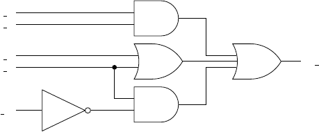
5.7 Exercises: Behavioral Modeling 69
e) F(A, B, C, D) = X(1,2)
2. For the circuit below, write the VHDL behavioral model that im-
plements it using both case statements and if statements (two
separate models).
C
D
B
A
E E out
A 1
A 2
B 1
B 2
D 1
3. Model the previous circuit using concurrent, conditional, or selected
signal assignment.
4. Provide a VHDL model of an 8-input AND gate using a process
statement.
5. Provide a VHDL model of an 8-input OR gate using a process state-
ment.
6. Provide a VHDL model of an 8:1 MUX using a process statement.
Include a model that uses if statements and case statements (two
separate models).
7. Provide a VHDL model of a 3:8 decoder using a process statement.
Include a model that uses if statements and case statements (two
separate models). Consider the outputs to be active low.
6
VHDL Operators
So far we have only implicitly mentioned the operators available in VHDL.
This section presents a complete list of operators as well as a few examples
of their use. A complete list of operators is shown in Table 6.1. This
is followed by brief descriptions of some of the less obvious operators.
Although you may not have an immediate need to use some of these
operators, you should be aware that they exist. And although there are
some special things you should know about some of these operators, not
too much information is presented in this section.
Operators in VHDL are grouped into seven different types: logical, re-
lational, shift, addition, unary, multiplying and others. The ordering of
this operator list is somewhat important because it presents the operators
in the order of precedence. We said somewhat because your VHDL code
should never rely on operator precedence to describe circuit behavior. Re-
Operator type
logical and or nand nor xor xnor not
relational = /= < <=> >=
shift sll srl sla sra rol ror
addition + -
unary + -
multiplying * / mod rem
others ** abs /
Table 6.1: VHDL operators.

72 Chapter 6: VHDL Operators
Operator Name Explanation
=equivalence is some value equivalent to some other value?
/=non-equivalence is some value not equivalent to some other value?
<less than is some value less than some other value?
<=less than or equal is some value less than or equal to some other value?
>greater than is some value greater than some other value?
>=greater than or equal is some value greater than or equal to some other value?
Table 6.2: VHDL relational operators with brief explanations.
liance on obscure precedence rules tends to make the VHDL code cryptic
and hard to understand. A liberal use of parentheses is a better approach
to VHDL coding.
The first column of Table 6.1 lists the operators in precedence order with
the logical operators having the highest precedence. Although there is a
precedence order in the types of operators, there is no precedence order
within each type of operator. In other words, the operators appearing
in the rows are presented in no particular order. This means that the
operators are applied to the given operands in the order they appear in
the associated VHDL code.
6.1 Logical Operators
The logical operators are generally self-explanatory in nature. They have
also been used throughout this book. The only thing worthy to note here is
that the not operator has been included in the group of logical operators
despite the fact that it is not technically a logic operation.
6.2 Relational Operators
The relational operators are generally self-explanatory in nature too. Many
of them have been used in this book. A complete list of relational operators
is provided in Table 6.2.
6.3 Shift Operator
Available from ieee.numeric std or ieee.numeric bit, there are
three types of shift operators: logical shift, arithmetic shift and rotations.
6.4 Other Operators 73
Operator Name Example Result
logical sll shift left logical result <=”10010101” sll 2 ”01010100”
srl shift right logical result <=”10010101” srl 3 ”00010010”
arithmetic sla shift left arithmetic result <=”10010101” sla 3 ”10101111”
sra shift right arithmetic result <=”10010101” sra 2 ”11100101”
rotate rol rotate left result <=”101000” rol 2 ”100010”
ror rotate right result <=”101001” ror 2 ”011010”
Table 6.3: VHDL shift operators with examples.
Although these operators basically shift bits either left-to-right or right-
to-left, there are a few basic differences which are listed below. The shift
operators are listed in Table 6.3.
Both logical shifts introduce zeros into one end of the operand that
is affected by the shift operation. In other words, zeros are fed into
one end of the operand while bits are essentially lost from the other
end. The difference between logical and arithmetic shifts is that in
arithmetic shift, the sign-bit is never changed and the bit that is fed
into one end can differ. Hence, for arithmetic shift lefts, the last right
bit is stuffed to the right end of the operand. For arithmetic shift
rights, the sign-bit (the left-most bit) is propagated right (the value of
the left-most bit is fed into the left end of the operand).
Rotate operators grab a bit from one end of the word and stuff it into
the other end. This operation is done independently of the value of the
individual bits in the operand.
6.4 Other Operators
The other groups of operators are generally used with numeric types. Since
this section does not present numerical operations in detail, the operators
are briefly listed below in Table 6.4. Special attention is given to the mod,
rem and &operators. These operators are also limited to operating on
specific types which are also not listed here.

74 Chapter 6: VHDL Operators
6.5 Concatenation Operator
The concatenation operator &is often a useful operator when dealing with
digital circuits. There are many times when you will find a need to tack
together two separate values. The concatenation operator has been seen
in some previous example solutions. Some more examples of the concate-
nation operators are presented in Listing 6.1.
Listing 6.1: Examples of the concatenation operator.
signal A_val, B_val : std_logic_vector(3 downto 0);
signal C_val : std_logic_vector(5 downto 0);
signal D_val : std_logic_vector(7 downto 0);
------
C_val <= A_val & "00";
C_val <= "11" & B_val;
C_val <= '1'& A_val & '0';
D_val <= "0001" & C_val(3 downto 0);
D_val <= A_val & B_val;
6.6 Modulus and Remainder Operators
There is often confusion about the differences between the remainder op-
erator and the modulus operator, rem and mod and the difference in their
operation on negative and positive numbers. The definitions that VHDL
uses for these operators are shown in Table 6.5 while a few examples
of these operators are provided in Table 6.6. A general rule followed by
many programmers is to avoid using the mod operator when dealing with
Operator Name Comment
addition +addition
-subtraction
unary +identity
-negation
multiplying
*multiplication
/division often limited to powers of two
mod modulus can operate only on specific types
rem remainder can operate only on specific types
other
** exponentiation often limited to powers of two
abs absolute value
&concatenation can operate only on specific types
Table 6.4: All the other VHDL operators not listed so far.
6.7 Review of Almost Everything Up to Now 75
Operator Name Satisfies this Conditions Comment
rem remainder 1. sign of (X rem Y) is the same as X
2. abs (X rem Y) <abs (X) abs = absolute value
3. X = (X/Y)*Y+(X rem Y)
mod modulus 1. sign of (X mod Y) is the same as X
2. abs (X mod Y) <abs (X) abs = absolute value
3. X = Y*N+(X mod Y)
Table 6.5: Definitions of rem and mod operators.
negative numbers. As you can see from the examples below, answers are
sometime counter-intuitive.
6.7 Review of Almost Everything Up to Now
VHDL is a language used to design, test and implement digital circuits.
The basic design units in VHDL are the entity and the architecture which
exemplify the general hierarchical approach of VHDL. The entity repre-
sents the black-box diagram of the circuit or the interface of the circuit to
the outside world while the architecture encompasses all the other details
of how the circuit behaves.
The VHDL architecture is comprised of statements that describe the
behavior of the digital circuit. Because this is a hardware description lan-
guage, statements in VHDL are primarily considered to execute concur-
rently. The idea of concurrency is one of the main themes of VHDL as one
would expect since a digital circuit can be modeled as a set of logic gates
that operate concurrently.
The main concurrent statement types in VHDL are the concurrent sig-
nal assignment statement, the conditional signal assignment statement,
the selected signal assignment statement and the process statement. The
rem mod
8 rem 5 = 3 8 mod 5 = 3
-8 rem 5 = -3 -8 mod 5 = 2
8 rem -5 = 3 8 mod -5 = -2
-8 rem -5 = -3 -8 mod -5 = -3
Table 6.6: Example of rem and mod operators.
76 Chapter 6: VHDL Operators
process statement is a concurrent statement which is comprised of sequen-
tial statements exclusively. The main types of sequential statements are
the signal assignment statement, the if statement and the case state-
ment. The if statement is a sequential version of conditional signal as-
signment statement while the case statement is a sequential version of
the selected signal assignment statement. The syntax of these statements
and examples are given in the following table.
Coding styles in VHDL fall under the category of data-flow, behavioral
and structural models. Exclusive use of process statements indicates a
behavioral model. The use of concurrent, conditional and selective signal
assignment indicate the use of a data-flow model. VHDL code describing
more complex digital circuits will generally contain both features of all of
these types of modeling.
Since you should make no effort whatsoever to memorize VHDL syntax,
it is recommended that a cheat sheet always be kept next to you as you
perform VHDL modeling. Developing a true understanding of VHDL is
what is going to make you into a good hardware designer. The ability to
memorize VHDL syntax proves almost nothing.
6.8 Using VHDL for Sequential Circuits
All the circuits we have examined up until now have been combinatorial
logic circuits. In other words, none of the circuits we have examined so far
are actually able to store information. This section show some of the var-
ious methods used to describe sequential circuits. We limit our discussion
to VHDL behavioral models for several different flavors of D flip-flops. It
is possible and in some cases desirable to use data-flow models to describe
storage elements in VHDL, but it is much easier to use behavior models.
The few approaches for designing flip-flops shown in the next section
cover just about all the possible functionality you could imagine when
you make use of a D flip-flop. Once you understand these basics, you will
be on your way to understand how to use VHDL to design Finite State
Machines (FSMs). This book will examine FSMs in a later chapter.
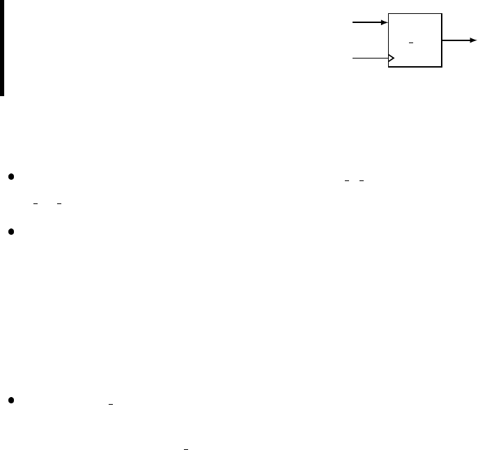
6.9 Simple Storage Elements Using VHDL 77
6.9 Simple Storage Elements Using VHDL
The general approach for learning how to implement storage elements in
digital design is to study the properties of a basic cross-coupled cell. The
cross coupled cell forms what is referred to as a latch. The concept of a
clocking signal is added to the device in order to enhance its controllability.
Finally, some type of pulse narrowing circuitry is added to the clocking
signal to get to the flop-flop. The flip-flop is nothing more than an edge-
sensitive bit-storage device.
The study of a VHDL implementation of storage elements starts with
the edge-triggered D flip-flop. The VHDL examples presented are the basic
edge-triggered D flip-flop with an assortment of added functionality.
EXAMPLE 14. Write the VHDL
code that describes a D flip-flop
shown on the right. Use a behav-
ioral model in your description.
d ff
D
CLK
Q
SOLUTION. The solution to Example 14 is shown in Listing 6.2. Listed
below are a few interesting things to note about the solution.
The given architecture body describes the my d ff version of the
d ff x entity.
Because this example requires the use of a behavioral model, the ar-
chitecture body is comprised primarily of a process statement. The
statements within the process are executed sequentially. The process
is executed each time a change is detected in any of the signals in the
process’ sensitivity list. In this case, the statements within the process
are executed each time there is a change in logic level of the Dor CLK
signals.
The rising edge() construct is used in the if statement to indicate
that changes in the circuit output happen only on the rising edge of the
CLK input. The rising edge() construct is actually an example of a
VHDL function which has been defined in one of the included libraries.
The way the VHDL code has been written makes the whole circuit

78 Chapter 6: VHDL Operators
synchronous; in fact, changes in the circuit’s output are synchronized
with the rising edge of the clock signal. In this case, the action is a
transfer of the logic level on the Dinput to the Qoutput.
The functionality of rising edge(CLK) can be achieved using the
quite popular VHDL “event” attribute via the construct:
CLK’event and CLK=’1’.
Please keep this in mind.
The process has the label dff. This is not required by the VHDL
language but the addition of process labels promotes a self-describing
nature of the code and increases its readability and understandability.
Listing 6.2: Solution to Example 14.
-----------------------------------
-- Model of a simple D Flip-Flop --
-----------------------------------
-- library declaration
library IEEE;
use IEEE.std_logic_1164.all;
-- entity
entity d_ff is
port (D,CLK:in std_logic;
Q : out std_logic);
end d_ff;
-- architecture
architecture my_d_ff of d_ff is
begin
dff: process(CLK)
begin
if (rising_edge(CLK)) then
--or if (CLK'event and CLK='1') then
Q<= D;
end if;
end process dff;
end my_d_ff;
The D flip-flop is best known and loved for its ability to store (save,
remember) a single bit. The way that the VHDL code in Listing 6.2 is
able to store a bit is not however obvious. The bit-storage capability in the
VHDL is implied by the way the VHDL code is interpreted. The implied
storage capability comes about as a result of not providing a condition
that indicates what should happen if the listed if condition is not met.
In other words, if the if condition is not met, the device does not change
the value of Qand therefore it must remember the current value. The
memory feature of the current value, or state, constitutes the famous bit
storage quality of a flip-flop. If you have not specified what the output
6.9 Simple Storage Elements Using VHDL 79
should be for every possible set of input conditions, the option taken by
VHDL is to not change the current output. By definition, if the input
changes to an unspecified state, the output remains unchanged. In this
case, the output associated with the previous set of input can be thought
of as being remembered. It is this mechanism, as strange and interesting
as it is, that is used to induce memory in the VHDL code.
In terms of the D flip-flop shown in Example 14, the only time the
output is specified is for that delta time associated with the rising edge of
the clock. The typical method used to provide a catch-all condition in case
the if condition is not met is with an else clause. Generally speaking, a
quick way to tell if you have induced a memory element is to look for the
presence of an else clause associated with the if statement.
The previous two paragraphs are vastly important for understanding
VHDL; the concept of inducing memory in VHDL is very important to
digital circuit design. The design of sequential circuits is dependent on
this concept. This somewhat cryptic method used by VHDL to induce
memory elements is a byproduct of behavioral modeling based solely on
the interpretation of the VHDL source code. Even if you will only be using
VHDL to design combinatorial circuits, you will most likely be faced with
the comprehension of these concepts. One of the classic warnings generated
by the VHDL synthesizer is the notification that your VHDL code has
generated a latch. Despite the fact that this is only a warning, if you did
not intend to generate a latch, you should strive to modify your VHDL
code in such as way as to remove this warning. Assuming you did not
intend to generate a latch, the cause of your problem is that you have not
explicitly provided an output state for all the possible input conditions.
Because of this, your circuit will need to remember the previous output
state so that it can provide an output in the case where you have not
explicitly listed the current input condition.
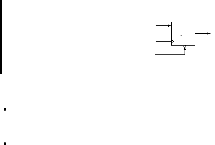
80 Chapter 6: VHDL Operators
EXAMPLE 15. Write the VHDL
code that describes a D flip-flop
shown on the right. Use a be-
havioral model in your description.
Consider the Sinput to be an
active-low, synchronous input that
sets the Dflip-flop outputs when as-
serted.
D F F
D
CLK
S
Q
SOLUTION. The solution to Example 15 is shown in Listing 6.3. There
are a few things of interest regarding this solution.
The Sinput to the flip-flop is made synchronous by only allowing it
to affect the operation of the flip-flop on the rising edge of the system
clock.
On the rising edge of the clock, the Sinput takes precedence over the
Dinput because the state of the Sinput is checked prior to examining
the state of the Dinput. In an if-else statement, once one condition
evaluates as true, none of the other conditions is checked. In other
words, the Dinput is transferred to the output only the rising edge of
the clock and only if the Sinput is not asserted.
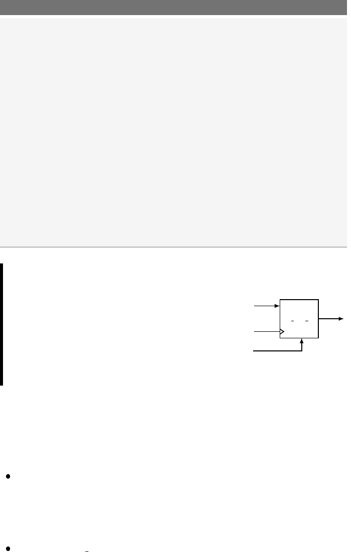
6.9 Simple Storage Elements Using VHDL 81
Listing 6.3: Solution to Example 15.
------------------------------------------------------------------
-- RET D Flip-flop model with active-low synchronous set input. --
------------------------------------------------------------------
-- library declaration
library IEEE;
use IEEE.std_logic_1164.all;
-- entity
entity d_ff_ns is
port ( D,S : in std_logic;
CLK : in std_logic;
Q : out std_logic);
end d_ff_ns;
-- architecture
architecture my_d_ff_ns of d_ff_ns is
begin
dff: process (S,CLK)
begin
if (rising_edge(CLK)) then
if (S='0')then
Q<= '1';
else
Q<= D;
end if;
end if;
end process dff;
end my_d_ff_ns;
EXAMPLE 16. Write the VHDL
code that describes a D flip-flop
shown on the right. Use a be-
havioral model in your descrip-
tion. Consider the Rinput to be
an active-high, asynchronous input
that resets the Dflip-flop outputs
when asserted.
d ff r
D
CLK
R
Q
SOLUTION. The solution to Example 16 is shown in Listing 6.4. You
can probably glean the most information about asynchronous input and
synchronous inputs by comparing the solutions to Example 15 and Exam-
ple 16. A couple of interesting points are listed below.
The reset input is independent of the clock and takes priority over the
clock. This prioritization is done by making the reset condition the
first condition in the if statement. Evaluation of the other conditions
continues if the Rinput does not evaluate to a ’1’.
The falling edge() function is used to make the D flip-flop falling-
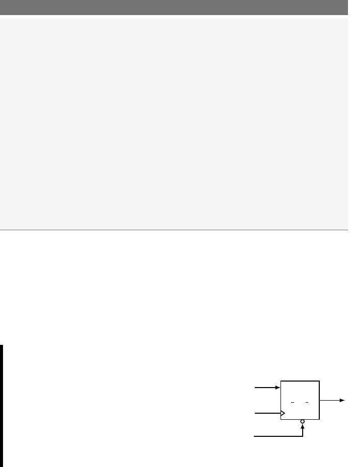
82 Chapter 6: VHDL Operators
edge-triggered. Once again, this function is defined in one of the in-
cluded libraries.
Listing 6.4: Solution to Example 16.
----------------------------------------------------------------------
-- FET D Flip-flop model with active-high asynchronous reset input. --
----------------------------------------------------------------------
-- library declaration
library IEEE;
use IEEE.std_logic_1164.all;
-- entity
entity d_ff_r is
port ( D,R : in std_logic;
CLK : in std_logic;
Q : out std_logic);
end d_ff_r;
-- architecture
architecture my_d_ff_r of d_ff_r is
begin
dff: process (R,CLK)
begin
if (R='1')then
Q<= '0';
elsif (falling_edge(CLK)) then
Q<= D;
end if;
end process dff;
end my_d_ff_r;
The solutions of Example 15 and Example 16 represent what can be
considered the standard VHDL approaches to handling synchronous and
asynchronous inputs, respectively. The general forms of these solutions are
actually considered templates for synchronous and asynchronous inputs by
several VHDL references. As you will see later, these solutions form the
foundation to finite state machine design using VHDL.
EXAMPLE 17. Write the VHDL
code that describes a T flip-flop
shown on the right. Use a be-
havioral model in your description.
Consider the Sinput to be an
active-low, asynchronous input that
sets the T flip-flop outputs when as-
serted.
t ff s
T
CLK
S
Q
SOLUTION. The solution to Example 17 is shown in Listing 6.5. This
example has some very important techniques associated with it that are
well worth mentioning below.

6.9 Simple Storage Elements Using VHDL 83
A unique quality of the D flip-flop is demonstrated in this implementa-
tion of a T flip-flop. The output of a D flip-flop is only dependent upon
the Dinput and is not a function of the present output of the flip-flop.
The output of a T flip-flop is dependent upon both the Tinput and
the current output of the flip-flop. This adds a certain amount of extra
complexity to the T flip-flop model as compared to the D flip-flop as
is shown in Listing 6.5. The T flip-flop model in Listing 6.5 uses a
temporary signal in order to use the current state of the flip-flop as in
input. In other words, since Qappears as a port to the entity it must
be assigned a mode specifier and in this case, it has been assigned
a mode specifier of “out”. Signals that are declared as outputs
can therefore not appear on the right-hand side of a signal
assignment operator. The standard approach to bypassing this ap-
parent limitation in VHDL is to use intermediate signals which,
as opposed to port signals, do not have mode specifications and can
thus be used as either inputs or outputs (can appear on both sides of
the signal assignment operator) in the body of the architecture. The
approach is to manipulate the intermediate signal in the body of the
architecture but to also use a concurrent signal assignment statement
to assign the intermediate signal to the appropriate output. Note that
in the key statement in the solution shown in 6.5 that the intermediate
signal appears on both sides of the signal assignment operator. This is
a widely used approach in VHDL: please take time to understand and
absorb it. And lastly on this note, there are other mode specifications
that would allow you a different approach to bypassing this problem
(namely, the use of the “buffer” mode specification), but you should
never use these in VHDL. The approach presented here is considered
a good use of VHDL.
This code uses the characteristics equation of a T flip-flop in its im-
plementation. We technically used a characteristic equation when we
implemented the D flip-flop but since the characteristic equation of a
D flip-flop is relatively trivial, you may not have been aware of it.
There are certain advantages to using T flip-flops in some conditions,

84 Chapter 6: VHDL Operators
D flip-flops are generally the storage element of choice using VHDL. If
you do not have a specific reason for using some type of flip-flop other
than a D flip-flop, you probably should not.
Listing 6.5: Solution to Example 17.
-------------------------------------------------------------------
-- RET T Flip-flop model with active-low asynchronous set input. --
-------------------------------------------------------------------
-- library declaration
library IEEE;
use IEEE.std_logic_1164.all;
-- entity
entity t_ff_s is
port ( T,S,CLK : in std_logic;
Q : out std_logic);
end t_ff_s;
-- entity
architecture my_t_ff_s of t_ff_s is
signal t_tmp : std_logic; -- intermediate signal declaration
begin
tff: process (S,CLK)
begin
if (S='0')then
t_tmp <= '1';
elsif (rising_edge(CLK)) then
t_tmp <= TXOR t_tmp; -- temp output assignment
end if;
end process tff;
Q<= t_tmp; -- final output assignment
end my_t_ff_s;
6.10 Inducing Memory: Data-flow vs. Behavioral Modeling
A major portion of digital design deals with sequential circuits. Generally
speaking, most sequential circuit design is about synchronizing events to
a clock edge. In other words, output changes only occur on a clock edge.
The introduction to memory elements in VHDL presented in this section
may lead the reader to think that memory in VHDL is only associated
with behavioral modeling, but this is not the case. The same concept
of inducing memory holds for data-flow modeling as well: not explicitly
specifying an output for every possible input condition generates a latch
(a storage element). And on this note, checking for unintended memory
element generation is one of the duties of the digital designer. As you
would imagine, memory elements add an element of needless complexity
to the synthesized circuit.
One common approach for learning the syntax and mechanics of new

6.11 Important Points 85
computer languages is to implement the same task in as many different
ways as possible. This approach utilizes the flexibility of the language and
is arguably a valid approach to learning a new language. This is also the
case in VHDL. But, probably more so in VHDL than other languages,
there are specific ways of doing things and these things should always be
done in these specific ways. Although it would be possible to generate
flip-flops using data-flow models, most knowledgeable people examining
your VHDL code would not initially be clear as to what exactly you are
doing. As far as generating synchronous memory elements go, the methods
outlined in this section are simply the optimal method of choice. This is
one area not to be clever with.
6.11 Important Points
Storage elements in VHDL are induced by not specifying output con-
ditions for every possible input condition.
Unintended generation of storage elements is generally listed by the
synthesizer as latch generation. Once again, latches are generated when
there is an existing input condition to a circuit that does not have a
corresponding output specification.
Memory elements can be induced by both data-flow and behavioral
models.
If a signal declared in the entity declaration has a mode specifier of out,
that signal cannot appear on the right-hand side of a signal assignment
operator. This limitation is bypassed by using intermediate signals for
any functional assignments and later assigning the intermediate signal
to the output signal using a concurrent signal assignment statement.
The mode specification of buffer should never be used in VHDL
unless you are somebody who does not know any better and you are
not interested in learning the best VHDL approach in this regard.
86 Chapter 6: VHDL Operators
6.12 Exercises: Basic Memory Elements
EXERCISE 1. Provide a VHDL behav-
ioral model of the D flip-flop shown on the
right. The Sand Rinputs are an active low
asynchronous preset and clear. Assume both
the Sand Rinputs will never be asserted si-
multaneously.
S
D
CLK
R
Q
Q
EXERCISE 2. Provide a VHDL behav-
ioral model of the D flip-flop shown on the
right. The Sand Rinputs are an active low
asynchronous preset and clear. Assume the
Sinput takes precedence over the Rinput in
the case where both are asserted simultane-
ously.
S
D
CLK
R
Q
Q
EXERCISE 3. Provide a VHDL behav-
ioral model of the D flip-flop shown on the
right. The Sand Rinputs are synchronous
preset and clear. Assume both the Sand R
inputs will never be asserted simultaneously.
S
D
CLK
R
Q
Q
EXERCISE 4. Provide a VHDL behav-
ioral model of the D flip-flop shown on the
right. The Sand Rinputs are an active low
asynchronous preset and clear. If both the
Sand Rinputs are asserted simultaneously,
the output of the flip-flop will toggle.
S
D
CLK
R
Q
Q
6.12 Exercises: Basic Memory Elements 87
EXERCISE 5. Provide a VHDL behav-
ioral model of the T flip-flop shown on the
right. The Sand Rinputs are an active low
asynchronous preset and clear. Assume both
the Sand Rinputs will never be asserted si-
multaneously. Implement this flip-flop first
using an equation description of the outputs
and then using a behavioral description of
the outputs.
S
T
CLK
R
Q
Q
EXERCISE 6. Provide a VHDL behav-
ioral model of the T flip-flop shown on the
right. The Sand Rinputs are an active low
asynchronous preset and clear. Assume both
the Sand Rinputs will never be asserted si-
multaneously.
S
T
CLK
R
Q
Q
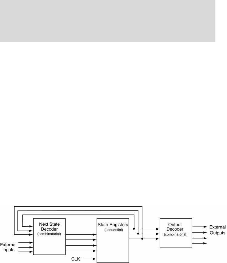
7
Finite State Machine Design Using VHDL
Finite state machines (FSMs) are mathematical abstractions that are used
to solve a large variety of problems, among which are electronic design au-
tomation, communication protocol design, parsing and other engineering
applications. At this point in your digital design career, you might have
probably designed quite a few state machines on paper. You are now at
the point where you can implement and test them using actual hardware
if you so choose. The first step in this process is to learn how to model
FSMs using VHDL.
As you will see in the next section, simple FSM designs are just a step
beyond the sequential circuit design described in the previous section. The
techniques you learn in this section will allow you to quickly and easily
design relatively complex FSMs which can be very useful in many number
of ways.
Figure 7.1: Block diagram for a Moore-type FSM.
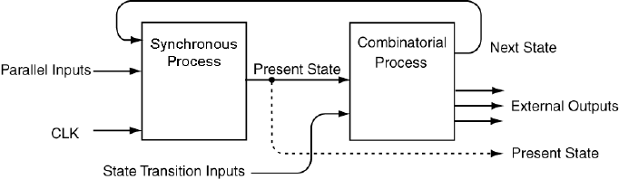
90 Chapter 7: Finite State Machine Design Using VHDL
Figure 7.2: Model for VHDL implementations of FSMs.
A block diagram for a standard Moore-type FSM is shown in Fig. 7.1.
This diagram looks fairly typical but some different names are used for the
some of the blocks in the design. The Next State Decoder is a block
of combinatorial logic that uses the current external inputs and the current
state to decide upon the next state of the FSM. In other words, the inputs
to the Next State Decoder block are decoded to produce an output
that represents the next state of the FSM. The circuitry in Next State
Decoder is generally the excitation equations for the storage elements
(flip-flops) in the State Register block. The next state becomes the
present state of the FSM when the clock input to the state registers block
becomes active. The state registers block is a storage element that stores
the present state of the machine. The inputs to the Output Decoder are
used to generate the desired external outputs. The inputs are decoded via
combinatorial logic to produce the external outputs. Because the external
outputs are only dependent upon the current state of the machine, this
FSM is classified as a Moore-type FSM.
The FSM model shown in Fig. 7.1 is probably the most common model
for describing a Moore-type FSM. That is most likely because students
are often asked to generate the combinatorial logic required to implement
the Next State Decoder and the Output Decoder; however here
we want to think about FSMs in the context of VHDL. The true power
of VHDL starts to emerge in its dealings with FSMs. As you will see, the
versatility of VHDL behavioral modeling removes the need for large paper
designs of endless K-maps and endless combinatorial logic elements.
There are several different approaches used to model FSMs using VHDL.

91
The many different possible approaches are a result of the general versa-
tility of VHDL as a language. What we will describe in this section is
probably the clearest approach for FSM implementation. A block dia-
gram of the approach we will use in the implementation of FSMs is shown
in Fig. 7.2.
Although it does not look that much clearer, you will soon be finding
the FSM model shown in Fig. 7.2 to be a straightforward method to im-
plement FSMs. The approach we will use divides the FSM into two VHDL
processes. One process, referred to as the Synchronous Process han-
dles all the matters regarding clocking and other controls associated with
the storage element. The other process, the Combinatorial Process,
handles all the matters associated with the Next State Decoder and
the Output Decoder of Fig. 7.1. Note that the two blocks in Fig. 7.1
are both comprised of solely the combinatorial logic.
There is some new lingo used in the description of signals used in Fig. 7.2;
this description is outlined and described below:
The inputs labelled Parallel Inputs are used to signify inputs
that act in parallel to each of the storage elements. These inputs would
include enables, presets, clears, etc.
The inputs labelled State Transition Inputs include external
inputs that control the state transitions. These inputs also include
external inputs used to decode Mealy-type external outputs.
The Present State signals are used by the Combinatorial Process
box for both next state decoding and output decoding. The diagram
of Fig. 7.2 also shows that the Present State variables can also be
provided as outputs to the FSM but they are not required.
One final comment before we begin. Although there are many different
methods that can be used to described FSMs using VHDL, two of the more
common approaches are the dependent and independent PS/NS styles.
This book only covers the dependent style because it is clearer than the
independent PS/NS style. The model shown in Fig. 7.2 is actually a model
of the dependent PS/NS style of FSMs. Once you understand the VHDL
modeling of the dependent PS/NS style of FSM, the understanding of the
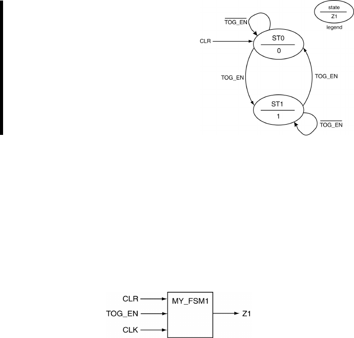
92 Chapter 7: Finite State Machine Design Using VHDL
independent PS/NS style or any other style is relatively painless. More
information on the other FSM coding styles is found in various VHDL
texts or on the web.
7.1 VHDL Behavioral Representation of FSMs
EXAMPLE 18. Write the VHDL
code that implements the FSM
shown on the right. Use a depen-
dent PS/NS coding style in your im-
plementation.
SOLUTION. This problem represents a basic FSM implementation. It
is somewhat instructive to show the black-box diagram which is an aid in
writing the entity description. Starting FSM problems with the drawing of
a black box diagram is always a healthy approach particularly when deal-
ing with FSMs. Oftentimes with FSM problems, it becomes challenging to
discern the FSM inputs from the outputs. Drawing a diagram partially al-
leviates this problem. The black box diagram and the code for the solution
of Example 18 is shown in Listing 7.1.

7.1 VHDL Behavioral Representation of FSMs 93
Listing 7.1: Solution to Example 18.
-- library declaration
library IEEE;
use IEEE.std_logic_1164.all;
-- entity
entity my_fsm1 is
port ( TOG_EN : in std_logic;
CLK,CLR : in std_logic;
Z1:out std_logic);
end my_fsm1;
-- architecture
architecture fsm1 of my_fsm1 is
type state_type is (ST0,ST1);
signal PS,NS : state_type;
begin
sync_proc: process(CLK,NS,CLR)
begin
-- take care of the asynchronous input
if (CLR = '1')then
PS <= ST0;
elsif (rising_edge(CLK)) then
PS <= NS;
end if;
end process sync_proc;
comb_proc: process(PS,TOG_EN)
begin
Z1 <= '0';-- pre-assign output
case PS is
when ST0 => -- items regarding state ST0
Z1 <= '0';-- Moore output
if (TOG_EN = '1')then NS <= ST1;
else NS <= ST0;
end if;
when ST1 => -- items regarding state ST1
Z1 <= '1';-- Moore output
if (TOG_EN = '1')then NS <= ST0;
else NS <= ST1;
end if;
when others => -- the catch-all condition
Z1 <= '0';-- arbitrary; it should never
NS <= ST0; -- make it to these two statements
end case;
end process comb_proc;
end fsm1;
And of course, this solution has many things worth noting in it. The
more interesting things are listed below.
We have declared a special VHDL type named state type to repre-
sent the states in this FSM. This is an example of how enumeration
types are used in VHDL. As with enumeration types in other higher-
level computer languages, there are internal numerical representations
for the listed state types but we only deal with the more expressive
symbolic equivalent. In this case, the type we have created is called a
state type and we have declared two variables of this type: PS and

94 Chapter 7: Finite State Machine Design Using VHDL
NS. The key thing to note here is that a state type is something we
have created and is not a native VHDL type.
The synchronous process is equal in form and function to the simple
D flip-flops we examined in the section about sequential circuits. The
only difference is that we have substituted PS and NS for D and Q,
respectively. Something to note here is that the storage element is
associated with the PS signal only. Note that PS is not specified for
every possible combination of inputs.
Even though this example is of the simplest FSM you could hope for,
the code looks somewhat complicated. But if you examine it closely,
you can see that everything is nicely compartmentalized in the solu-
tion. There are two processes; the synchronous process handles the
asynchronous reset and the assignment of a new state upon the arrival
of the system clock. Additionally, the combinatorial process handles
the outputs not handled in the synchronous process, the outputs and
the generation of the next state of the FSM.
Because the two processes operate concurrently, they can be consid-
ered as working in a lock-step manner. Changes to the NS signal that
are generated in the combinatorial process force an evaluation of the
synchronous process. When the changes are actually instituted in the
synchronous process on the next clock edge, the changes in the PS sig-
nal causes the combinatorial process to be evaluated. And so on and
so forth.
The case statement in the combinatorial process provides a when
clause for each state of the FSM. This is the standard approach for
the dependent PS/NS coding style. A when others clause has also
been used. The signal assignments that are part this catch-all clause
are arbitrary since the code should never actually make it there. This
statement is provided for a sense of completeness and represents good
VHDL coding practice.
The Moore output is a function of only the present state. This is ex-
pressed by the fact that the assignment of the Z1 output is uncon-
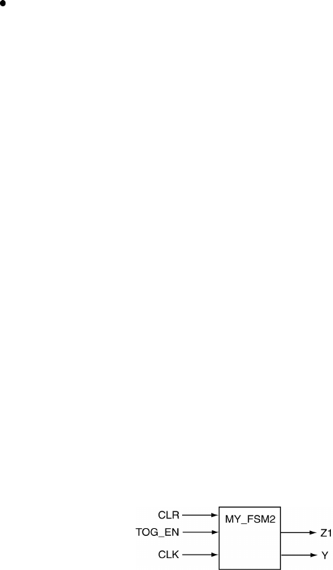
7.1 VHDL Behavioral Representation of FSMs 95
ditionally evaluated in each when clause of the case statement in the
combinatorial process. In other words, the Z1 variable is inside the
when clause but outside of the if statement in the when clause. This
is of course because the Moore outputs are only a function of the
states and not the external inputs. Note that it is the external input
that controls the which state the FSM transitions to from any given
state. You will see later that Mealy outputs, due their general nature,
are assigned inside the if statement.
The Z1 output is pre-assigned as the first step in the combinatorial
process. Pre-assigning it in this fashion prevents the unexpected latch
generation for the Z1 signal. When dealing with FSMs, there is a nat-
ural tendency for the FSM designer to forget to specify an output for
the Z1 variable in each of the states. Pre-assigning it prevents latches
from being generated and can arguably clean up the source code. The
pre-assignment makes no difference to the VHDL code because if mul-
tiple assignments are made within the code, only the final assignment
takes effect. In other words, only the final assignment is considered
once the process terminates.
There is one final thing to note about Example 18. In an effort to keep
the example simple, we disregarded the digital values of the state variables.
This is indicated in the black-box diagram of Listing 7.1 by the fact that
the only output of the FSM is the signal Z1. This is reasonable in that it
could be considered that only one output was required in order to control
some other device or circuit. The state variable is represented internally
and its precise representation is not important since the state variable is
not provided as an output.
In some FSM designs, the state variables are provided as outputs. To
show this situation, we will provide a solution to Example 18 with the
state variables as outputs. The black-box diagram and the VHDL code of
this solution is shown in Listing 7.2.

96 Chapter 7: Finite State Machine Design Using VHDL
Listing 7.2: Solution to Example 18 that include state variable as output.
-- library declaration
library IEEE;
use IEEE.std_logic_1164.all;
-- entity
entity my_fsm2 is
port ( TOG_EN : in std_logic;
CLK,CLR : in std_logic;
Y,Z1 : out std_logic);
end my_fsm2;
-- architecture
architecture fsm2 of my_fsm2 is
type state_type is (ST0,ST1);
signal PS,NS : state_type;
begin
sync_proc: process(CLK,NS,CLR)
begin
if (CLR = '1')then
PS <= ST0;
elsif (rising_edge(CLK)) then
PS <= NS;
end if;
end process sync_proc;
comb_proc: process(PS,TOG_EN)
begin
case PS is
Z1 <= '0';
when ST0 => -- items regarding state ST0
Z1 <= '0';-- Moore output
if (TOG_EN = '1')then NS <= ST1;
else NS <= ST0;
end if;
when ST1 => -- items regarding state ST1
Z1 <= '1';-- Moore output
if (TOG_EN = '1')then NS <= ST0;
else NS <= ST1;
end if;
when others => -- the catch-all condition
Z1 <= '0';-- arbitrary; it should never
NS <= ST0; -- make it to these two statements
end case;
end process comb_proc;
-- assign values representing the state variables
with PS select
Y<= '0' when ST0,
'1' when ST1,
'0' when others;
end fsm2;
Note that the VHDL code shown in Listing 7.2 differs in only two areas
from the code shown in Listing 7.1. The first area is the modification of
the entity declaration to account for the state variable output Y. The
second area is the inclusion of the selective signal assignment statement
which assigns a value of state variable output Y based on the condition of
the state variable. The selective signal assignment statement is evaluated
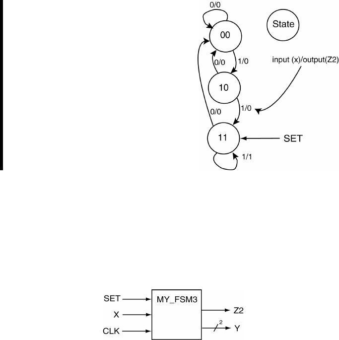
7.1 VHDL Behavioral Representation of FSMs 97
each time a change in signal PS is detected. Once again, since we have
declared an enumeration type for the state variables, we have no way of
knowing exactly how the synthesizer will decide to represent the state
variable. The selective signal assignment statement in the code of Listing
7.2 only makes it appear like there is one state variable and the states are
represented with a ’1’ and a ’0’. In reality, there are methods we can use
to control how the state variables are represented and we will deal with
those soon.
Lastly, there are three concurrent statements in the VHDL code shown
in Listing 7.1: two process statements and a selective signal assignment
statement.
EXAMPLE 19. Write the VHDL
code that implements the FSM
shown on the right. Use a depen-
dent PS/NS coding style in your
implementation. Consider the state
variables as outputs of the FSM.
SOLUTION. The state diagram shown in this problem indicates that
this is a three-state FSM with one Mealy-type external output and one
external input. Since there are three states, the solution requires at least
two state variables to handle the three states. The black-box diagram of
the solution is shown in Listing 7.3. Note that the two state variables are
handled as a bundled signal.

98 Chapter 7: Finite State Machine Design Using VHDL
Listing 7.3: Solution to Example 19.
-- library declaration
library IEEE;
use IEEE.std_logic_1164.all;
-- entity
entity my_fsm3 is
port ( X,CLK,SET : in std_logic;
Y:out std_logic_vector(1 downto 0);
Z2:out std_logic);
end my_fsm3;
-- architecture
architecture fsm3 of my_fsm3 is
type state_type is (ST0,ST1,ST2);
signal PS,NS : state_type;
begin
sync_proc: process(CLK,NS,SET)
begin
if (SET = '1')then
PS <= ST2;
elsif (rising_edge(CLK)) then
PS <= NS;
end if;
end process sync_proc;
comb_proc: process(PS,X)
begin
case PS is
Z2 <= '0';-- pre-assign FSM outputs
when ST0 => -- items regarding state ST0
Z2 <= '0';-- Mealy output always 0
if (X='0')then NS <= ST0;
else NS <= ST1;
end if;
when ST1 => -- items regarding state ST1
Z2 <= '0';-- Mealy output always 0
if (X='0')then NS <= ST0;
else NS <= ST2;
end if;
when ST2 => -- items regarding state ST2
-- Mealy output handled in the if statement
if (X='0')then NS <= ST0; Z2 <= '0';
else NS <= ST2; Z2 <= '1';
end if;
when others => -- the catch all condition
Z2 <= '1';NS<= ST0;
end case;
end process comb_proc;
-- faking some state variable outputs
with PS select
Y<= "00" when ST0,
"10" when ST1,
"11" when ST2,
"00" when others;
end fsm3;
As usual, there are a couple of fun things to point out about the solu-
tion for Example 19. Most importantly, you should note the similarities
between this solution and the previous solution.
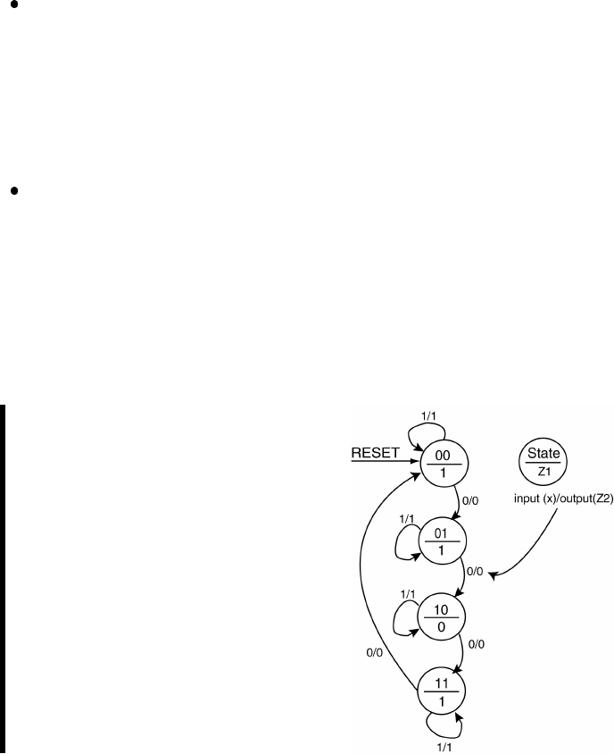
7.1 VHDL Behavioral Representation of FSMs 99
The FSM has one Mealy-type output. The solution essentially treats
this output as a Moore-type output in the first two when clauses of the
case statement. In the final when clause, the Z2 output appears in
both sections of the if statement. The fact the Z2 output is different
in the context of state ST2 that makes it a Mealy-type output and
therefore a Mealy-type FSM.
When faking the state variable outputs (keeping in mind that the
actual state variables are represented with enumeration types), two
signals are required since the state diagram contains more than two
states (and less than five states). The solution opted is to represent
these outputs as a bundle which has the effect of slightly changing the
form of the selected signal assignment statement appearing at the end
of the architecture description.
EXAMPLE 20. Write the VHDL
code that implements the FSM
shown on the right. Use a depen-
dent PS/NS coding style in your
implementation. Consider the listed
state variables as output.
SOLUTION. The state diagram indicates that its implementation will
contain four states, one external input and two external outputs. This is a
hybrid FSM in that the if contains both a Mealy and Moore-type output
but in this case, the FSM would be considered a Mealy-type FSM. The
black-box diagram and the actual solution for the solution is shown in
Listing 7.4.
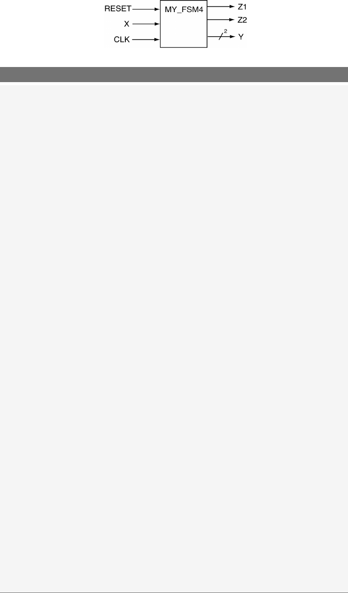
100 Chapter 7: Finite State Machine Design Using VHDL
Listing 7.4: Solution to Example 20.
-- library declaration
library IEEE;
use IEEE.std_logic_1164.all;
-- entity
entity my_fsm4 is
port ( X,CLK,RESET : in std_logic;
Y:out std_logic_vector(1 downto 0);
Z1,Z2 : out std_logic);
end my_fsm4;
-- architecture
architecture fsm4 of my_fsm4 is
type state_type is (ST0,ST1,ST2,ST3);
signal PS,NS : state_type;
begin
sync_proc: process(CLK,NS,RESET)
begin
if (RESET = '1')then PS <= ST0;
elsif (rising_edge(CLK)) then PS <= NS;
end if;
end process sync_proc;
comb_proc: process(PS,X)
begin
-- Z1: the Moore output; Z2: the Mealy output
Z1 <= '0'; Z2 <= '0';-- pre-assign the outputs
case PS is
when ST0 => -- items regarding state ST0
Z1 <= '1';-- Moore output
if (X='0')then NS <= ST1; Z2 <= '0';
else NS <= ST0; Z2 <= '1';
end if;
when ST1 => -- items regarding state ST1
Z1 <= '1';-- Moore output
if (X='0')then NS <= ST2; Z2 <= '0';
else NS <= ST1; Z2 <= '1';
end if;
when ST2 => -- items regarding state ST2
Z1 <= '0';-- Moore output
if (X='0')then NS <= ST3; Z2 <= '0';
else NS <= ST2; Z2 <= '1';
end if;
when ST3 => -- items regarding state ST3
Z1 <= '1';-- Moore output
if (X='0')then NS <= ST0; Z2 <= '0';
else NS <= ST3; Z2 <= '1';
end if;
when others => -- the catch all condition
Z1 <= '1'; Z2 <= '0'; NS <= ST0;
end case;
end process comb_proc;
with PS select
Y<= "00" when ST0,
"01" when ST1,
"10" when ST2,
"11" when ST3,
"00" when others;
end fsm4;

7.2 One-Hot Encoding for FSMs 101
If you haven’t noticed by now, implementing FSMs using the VHDL
behavioral model is remarkably straightforward. In reality, I rarely code a
FSM from scratch; I usually opt to grab some previous FSM I have coded
and start from there. Keep in mind that real engineering is rarely based
on a cookbook. For FSM problems, the engineering is in the testing and
creation of the state diagram. Do not get too comfortable with behavioral
modeling of FSMs; the real fun is actually generating a FSM that solves
a given problem.
7.2 One-Hot Encoding for FSMs
Truth told, there are many different methods that can be used to encode
state variables1. If the exact form of the representation used is important
to you, then you will need to take the necessary steps in order to control
how the state variables are represented by the synthesizer. There are two
approaches to control state variable representation. The first approach is
to allow the synthesizing tool to handle the details. Since every FSM we
have seen up to this point has used enumeration types to represent the
state variables, the synthesizer could choose to actually represent them
with an encoding scheme of its own choosing. The reality is that the
tools generally have an option to select the desired encoding scheme. The
downside of this approach is that you are denied the learning experience
associated with implementing the VHDL code that explicitly induces your
desired encoding scheme. After all, you may have some special encoding
scheme you need to use but is not supported by the development tools.
The second approach to encoding the state variables is to specify them
directly in VHDL. The approach of specifying the state variables in the
VHDL code is presented in this section.
One-hot encoding uses one bit in the state register for each state of the
FSM. For a one-hot encoding FSM with 16 states, 16 flip flops are required.
However only four flip flops are required if the same FSM is implemented
using a binary encoding. One-hot encoding simplifies the logic and the
interconnections between overall logic. Despite looking quite wasteful in
1In this case, encoding refers to the act of assigning a unique pattern of 1’s and 0’s
to each of the state in order to make them unambiguous from other states.

102 Chapter 7: Finite State Machine Design Using VHDL
terms of employed logic, one-hot encoding often results in smaller and
faster FSMs.
The approach taken in the previous FSM examples was to pretend we
were using full encoding for the state variables of the FSM. The full encod-
ing approach minimizes the number of storage elements (flip-flops) used to
store the state variables. The closed form equation describing the number
of flip-flops required for a given FSM as a function of the number of states
is shown in equation 7.1. The bracket-like symbols used in equation 7.1
indicate a ceiling function2. The binary nature expressed by this equation
is so apparent that this encoding is often referred to as binary encoding.
#(flip f lops) = dlog2(#states)e(7.1)
For one-hot encoded FSMs, only one flip-flop is asserted at any given
time. This requires that each distinct state be represented by one flip-flop.
In one-hot encoding, the number of flip-flops required to implement a FSM
is therefore equal to the number of states in the FSM. The closed form of
this relationship is shown in equation 7.2.
#(flip f lops) = d#(states)e(7.2)
The question naturally arises as to how VHDL can be used to implement
one-hot encoded FSMs. If you want total control of the process, you will
need to grab control away from the synthesizer. And since we are con-
cerned with learning VHDL, we need to look at the process of explicitly
encoding one-hot FSMs.
The modular approach we used to implement FSMs expedites the con-
version process from using enumeration types to actually specifying how
the state variables are represented. These changes required from our pre-
vious approach are limited to how the outputs are assigned to the state
variables and how the state variables are forced to be represented by cer-
tain bit patterns. Modifications to the full encoded approach are thus
limited to the entity declaration (you will need more variables to repre-
sent the states), the declaration of the state variables (you will need to
2The ceiling function y=dxeassigns yto the smallest integer that is greater or
equal to x.
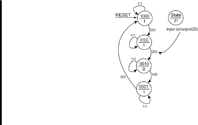
7.2 One-Hot Encoding for FSMs 103
explicitly declare the bit patterns associated with each state) and the as-
signment of the state variables to the outputs (in this case, we are actually
not faking it like we were in other examples).
EXAMPLE 21. Write the VHDL
code that implements the FSM
shown on the right. Use a depen-
dent PS/NS coding style in your
implementation. Consider the listed
state variables as output. Use one-
hot encoding for the state variables.
This problem is Example 20 all over
again but uses true one-hot encod-
ing for the state variables.
SOLUTION. The state diagram shows four states, one external input X,
two external outputs Z1 and Z2 with the Z2 output being a Mealy output.
This is a Mealy machine that indicates one-hot encoding should be used
to encode the state variables. We will approach the implementation of this
FSM one piece at the time.
Listing 7.5 shows the modifications to the entity declaration required
to convert the full encoding used in Example 20 to a pseudo one-hot en-
coding. Listing 7.6 shows the required modifications to the state variable
output assignment in order to move from enumeration types to a special
form of assigned types. Forcing the state variables to be truly encoded
using one-hot encoding requires these two extra lines of code as is shown
in Listing 7.6. These two lines of code essentially force the VHDL synthe-
sizer to represent each state of the FSM with its own storage element. In
other words, each state is represented by the ”string” modifier as listed.
This forces four bits per state to be remembered by the FSM implemen-
tation which essentially requires four flip-flops. Note in Listing 7.7 that
the default case is assigned a valid one-hot state instead of the customary

104 Chapter 7: Finite State Machine Design Using VHDL
all zero state. You should strongly consider comparing these three figures.
The total solution is shown in Listing 7.8
Listing 7.5: Modifications to convert Example 20 to one-hot encoding.
-- full encoded approach
entity my_fsm4 is
port ( X,CLK,RESET : in std_logic;
Y:out std_logic_vector(1 downto 0);
Z1,Z2 : out std_logic);
end my_fsm4;
----------------------------------------------------------------------
-- one-hot encoding approach
entity my_fsm4 is
port ( X,CLK,RESET : in std_logic;
Y:out std_logic_vector(3 downto 0);
Z1,Z2 : out std_logic);
end my_fsm4;
Listing 7.6: Modifications to convert state variables to use one-hot encoding.
-- the approach for enumeration types
type state_type is (ST0,ST1,ST2,ST3);
signal PS,NS : state_type;
----------------------------------------------------------------------
-- the approach used for explicitly specifying state bit patterns
type state_type is (ST0,ST1,ST2,ST3);
attribute ENUM_ENCODING: STRING;
attribute ENUM_ENCODING of state_type: type is "1000 0100 0010 0001";
signal PS,NS : state_type;
Listing 7.7: Modifications to convert state output to pseudo one-hot encoding.
-- fake full encoded approach
with PS select
Y<= "00" when ST0,
"01" when ST1,
"10" when ST2,
"11" when ST3,
"00" when others;
end fsm4;
----------------------------------------------------------------------
-- one-hot encoded approach
with PS select
Y<= "1000" when ST0,
"0100" when ST1,
"0010" when ST2,
"0001" when ST3,
"1000" when others;
end fsm4;

7.2 One-Hot Encoding for FSMs 105
Listing 7.8: The final solution to Example 21.
-- library declaration
library IEEE;
use IEEE.std_logic_1164.all;
-- entity
entity my_fsm4_oh is
port ( X,CLK,RESET : in std_logic;
Y:out std_logic_vector(3 downto 0);
Z1,Z2 : out std_logic);
end my_fsm4_oh;
-- architeture
architecture fsm4_oh of my_fsm4_oh is
type state_type is (ST0,ST1,ST2,ST3);
attribute ENUM_ENCODING: STRING;
attribute ENUM_ENCODING of state_type: type is "1000 0100 0010 0001";
signal PS,NS : state_type;
begin
sync_proc: process(CLK,NS,RESET)
begin
if (RESET = '1')then PS <= ST0;
elsif (rising_edge(CLK)) then PS <= NS;
end if;
end process sync_proc;
comb_proc: process(PS,X)
begin
-- Z1: the Moore output; Z2: the Mealy output
Z1 <= '0'; Z2 <= '0';-- pre-assign the outputs
case PS is
when ST0 => -- items regarding state ST0
Z1 <= '1';-- Moore output
if (X='0')then NS <= ST1; Z2 <= '0';
else NS <= ST0; Z2 <= '1';
end if;
when ST1 => -- items regarding state ST1
Z1 <= '1';-- Moore output
if (X='0')then NS <= ST2; Z2 <= '0';
else NS <= ST1; Z2 <= '1';
end if;
when ST2 => -- items regarding state ST2
Z1 <= '0';-- Moore output
if (X='0')then NS <= ST3; Z2 <= '0';
else NS <= ST2; Z2 <= '1';
end if;
when ST3 => -- items regarding state ST3
Z1 <= '1';-- Moore output
if (X='0')then NS <= ST0; Z2 <= '0';
else NS <= ST3; Z2 <= '1';
end if;
when others => -- the catch all condition
Z1 <= '1'; Z2 <= '0'; NS <= ST0;
end case;
end process comb_proc;
-- one-hot encoded approach
with PS select
Y<= "1000" when ST0,
"0100" when ST1,
"0010" when ST2,
"0001" when ST3,
"1000" when others;
end fsm4_oh;

106 Chapter 7: Finite State Machine Design Using VHDL
7.3 Important Points
Modeling FSMs from a state diagram is a straightforward process using
VHDL behavioral modeling. The process is so straightforward that
it is often considered cookie cutter. The real engineering involved in
implementing FSM is in the generation of the state diagram that solved
the problem at hand.
Due to the general versatility of VHDL, there are many approaches
that can be used to model FSMs using VHDL. The approach used
here details only one of those styles but is generally considered the
most straightforward of all styles.
The actual encoding of the FSM’s state variables when enumeration
types are used is left up to the synthesis tool. If a preferred method
of variable encoding is desired, using the attribute approach detail in
this section is a simple but viable alternative.
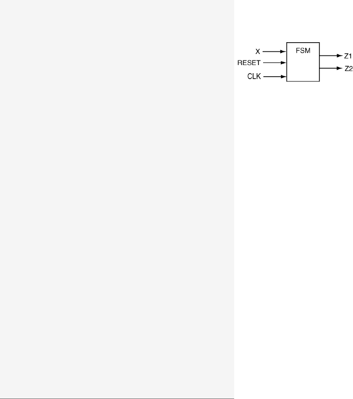
7.4 Exercises: Behavioral Modeling of FSMs 107
7.4 Exercises: Behavioral Modeling of FSMs
EXERCISE 1. Draw the state diagram associated with the following
VHDL code. Be sure to provide a legend and completely label everything.
-- library declaration
library IEEE;
use IEEE.std_logic_1164.all;
-- entity
entity fsm is
port ( X,CLK : in std_logic;
RESET : in std_logic;
Z1,Z2 : out std_logic;
end fsm;
-- architecture
architecture fsm of fsm is
type state_type is (A,B,C);
signal PS,NS : state_type;
begin
sync_proc: process(CLK,NS,RESET)
begin
if (RESET = '0')then PS <= C;
elsif (rising_edge(CLK)) then PS <= NS;
end if;
end process sync_proc;
comb_proc: process(PS,X)
begin
case PS is
Z1 <= '0'; Z2 <= '0';
when A=>
Z1 <= '0';
if (X='0')then NS<=A; Z2<='1';
else NS <= B; Z2 <= '0';
end if;
when B=>
Z1 <= '1';
if (X='0')then NS<=A; Z2<='0';
else NS <= C; Z2 <= '1';
end if;
when C=>
Z1 <= '1';
if (X='0')then NS<=B; Z2<='1';
else NS <= A; Z2 <= '0';
end if;
when others =>
Z1 <= '1'; NS<=A; Z2<='0';
end case;
end process comb_proc;
end fsm;
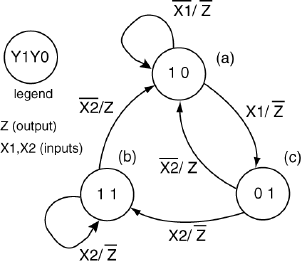
108 Chapter 7: Finite State Machine Design Using VHDL
EXERCISE 2. Write a VHDL be-
havioral model that could be used
to implement the state diagram as
shown on the right. The state vari-
ables should be encoded as listed and
also provided as outputs of the FSM.
EXERCISE 3. Draw the state diagram associated with the following
VHDL code. Be sure to provide a legend and remember to label everything.
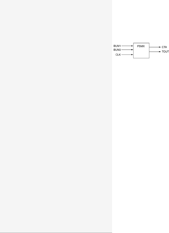
7.4 Exercises: Behavioral Modeling of FSMs 109
-- library declaration
library IEEE;
use IEEE.std_logic_1164.all;
-- entity
entity fsmx is
Port ( BUM1,BUM2 : in std_logic;
CLK : in std_logic;
TOUT,CTA : out std_logic);
end fsmx;
-- architecture
architecture my_fsmx of fsmx is
type state_type is (S1,S2,S3);
signal PS,NS : state_type;
begin
sync_p: process (CLK,NS)
begin
if (rising_edge(CLK)) then
PS <= NS;
end if;
end process sync_p;
comb_p: process (CLK,BUM1,BUM2)
begin
case PS is
when S1 =>
CTA <= '0';
if (BUM1 = '0')then
TOUT <= '0';
NS <= S1;
elsif (BUM1 = '1')then
TOUT <= '1';
NS <= S2;
end if;
when S2 =>
CTA <= '0';
TOUT <= '0';
NS <= S3;
when S3 =>
CTA <= '1';
TOUT <= '0';
if (BUM2 = '1')then
NS <= S1;
elsif (BUM2 = '0')then
NS <= S2;
end if;
when others => CTA <= '0';
TOUT <= '0';
NS <= S1;
end case;
end process comb_p;
end my_fsmx;
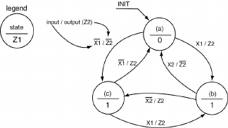
110 Chapter 7: Finite State Machine Design Using VHDL
EXERCISE 4. Write the VHDL
behavioral model code that could be
used to implement the state diagram
on shown in the right.
EXERCISE 5. Draw the state diagram associated with the following
VHDL code. Consider the outputs Yto be representative of the state
variables. Be sure to provide a legend. Indicate the states with both state
variables and their symbolic equivalents.

7.4 Exercises: Behavioral Modeling of FSMs 111
-- library declaration
library IEEE;
use IEEE.std_logic_1164.all;
-- entity
entity fsm is
port ( X,CLK : in std_logic;
RESET : in std_logic;
Z1,Z2 : out std_logic;
Y:out std_logic_vector(2 downto 0));
end fsm;
-- architecture
architecture my_fsm of fsm is
type state_type is (A,B,C);
attribute ENUM_ENCODING: STRING;
attribute ENUM_ENCODING of state_type: type is "001 010 100";
signal PS,NS : state_type;
begin
sync_proc: process(CLK,NS,RESET) -- process
begin
if (RESET = '0')then PS <= C;
elsif (rising_edge(CLK)) then PS <= NS;
end if;
end process sync_proc;
comb_proc: process(PS,X) -- process
begin
case PS is
when A=>
Z1 <= '0';
if (X='0')then NS <= A; Z2 <= '1';
else NS <= B; Z2 <= '0';
end if;
when B=>
Z1 <= '1';
if (X='0')then NS <= A; Z2 <= '0';
else NS <= C; Z2 <= '1';
end if;
when C=>
Z1 <= '1';
if (X='0')then NS <= B; Z2 <= '1';
else NS <= A; Z2 <= '0';
end if;
when others =>
Z1 <= '1';NS<= A; Z2 <= '0';
end case;
end process comb_proc;
with PS select
Y<= "001" when A,
"010" when B,
"100" when C,
"001" when others;
end my_fsm;
112 Chapter 7: Finite State Machine Design Using VHDL
EXERCISE 6. Write a VHDL be-
havioral model code that can be
used to implement the state diagram
shown on the right. All state vari-
ables should be encoded as listed and
also provided as outputs of the FSM.
EXERCISE 7. Draw the state diagram that corresponds to the following
VHDL model and state whether the FSM is a Mealy machine or a Moore
machine. Be sure to label everything.
7.4 Exercises: Behavioral Modeling of FSMs 113
-- library declaration
library IEEE;
use IEEE.std_logic_1164.all;
-- entity
entity fsm is
Port ( CLK,CLR,SET,X1,X2 : in std_logic;
Z1,Z2 : out std_logic);
end fsm;
-- architecture
architecture my_fsm of fsm is
type state_type is (sA,sB,sC,sD);
attribute ENUM_ENCODING: STRING;
attribute ENUM_ENCODING of state_type: type
is "1000 0100 0010 0001";
signal PS,NS : state_type;
begin
sync_p: process (CLK,NS,CLR,SET) -- process
begin
if (CLR = '1' and SET = '0')then
PS <= sA;
elsif (CLR = '0' and SET = '1')then
PS <= sD;
elsif (rising_edge(CLK)) then
PS <= NS;
end if;
end process sync_p;
comb_p: process (X1,X2,PS) -- process
begin
case PS is
when sA =>
if (X1='1')then
Z1 <= '0';Z2<= '0';
NS <= sA;
else
Z1 <= '0';Z2<= '0';
NS <= sB;
end if;
when sB =>
if (X2='1')then
Z1 <= '1';Z2<= '1';
NS <= sC;
else
Z1 <= '1';Z2<= '0';
NS <= sB;
end if;
when sC =>
if (X2='1')then
Z1 <= '0';Z2<= '0';
NS <= sB;
else
Z1 <= '0';Z2<= '1';
NS <= sC;
end if;
when sD =>
if (X1='1')then
Z1 <= '1';Z2<= '1';
NS <= sD;
else
Z1 <= '1';Z2<= '1';
NS <= sC;
end if;
end case;
end process comb_p;
end my_fsm;
114 Chapter 7: Finite State Machine Design Using VHDL
EXERCISE 8. Write the VHDL
behavioral model code that can be
used to implement the state diagram
shown on the right. The state vari-
ables should be encoded as listed and
also provided as outputs of the FSM.
EXERCISE 9. Write the VHDL
behavioral model code that can be
used to implement the state diagram
shown on the right. The state vari-
ables should be encoded as listed and
also provided as outputs of the FSM.
EXERCISE 10. Write the VHDL
behavioral model code that can be
used to implement the state diagram
shown on the right. The state vari-
ables should be encoded as listed and
also provided as outputs of the FSM.
7.4 Exercises: Behavioral Modeling of FSMs 115
EXERCISE 11. Write the VHDL
behavioral model code that can be
used to implement the state diagram
shown on the right. The state vari-
ables should be encoded as listed and
also provided as outputs of the FSM.
EXERCISE 12. Write the VHDL behavioral model code that can be
used to implement the state diagram shown on the right. The state vari-
ables should be encoded as listed and also provided as outputs of the
FSM.
EXERCISE 13. Write the VHDL
behavioral model code that can be
used to implement the state diagram
shown on the right. The state vari-
ables should be encoded as listed and
also provided as outputs of the FSM.
EXERCISE 14. Write the VHDL
behavioral model code that can be
used to implement the state diagram
shown on the right. The state vari-
ables should be encoded as listed and
also provided as outputs of the FSM.

8
Structural Modeling In VHDL
As was mentioned earlier, there are generally three approaches to writ-
ing VHDL code: data-flow modeling, behavioral modeling and structural
modeling.
Up to this point, this book has only dealt with data-flow and behavioral
models. This section presents an introduction to structural modeling.
As digital designs become more complex, it becomes less likely that any
one design can be implemented with any one of the three types of VHDL
models. We have already seen this property in dealings with FSMs where
we mixed process statements (behavioral modeling) with selective sig-
nal assignment statements (data-flow modeling). The result was a hybrid
VHDL model. By its very nature, structural modeling is likewise a hy-
brid VHDL model. Most complex designs could be considered structural
models, i.e. if they are implemented using sound coding procedures.
The design of complex digital circuits using VHDL should closely resem-
ble the structure of complex computer programs. Many of the techniques
and practices used to construct large and well structured computer pro-
grams written in higher-level languages should also be applied when using
VHDL. This common structure we are referring to is the ever so popular
modular approach to coding. The term structural modeling is the ter-
minology that VHDL uses for the modular design. The VHDL modular
design approach directly supports hierarchical design which is essentially
employed when attempting to understand complex digital designs.
118 Chapter 8: Structural Modeling In VHDL
The benefits of modular design to VHDL are similar to the benefits that
modular design or object-oriented design provides for higher-level com-
puter languages. Modular designs promote understandability by packing
low-level functionality into modules. These modules can be easily reused
in other designs thus saving the designer time by removing the need to
reinvent and re-test the wheel. The hierarchical approach extends beyond
code written on file level. VHDL modules can be placed in appropriately
named files and libraries in the same way as higher-level languages. More-
over, there are often libraries out there that contain useful modules that
can only be accessed using a structural-modeling approach. Having access
to these libraries and being fluent in their use will serve to increase your
perception as a VHDL guru.
After all the commentary regarding complex designs, we present a few
simple examples. Though the structural approach is most appropriately
used in complex digital designs, the examples presented in this section are
rather simplistic in nature. These examples show the essential details of
VHDL structural modeling. It is up to the designer to conjure up digital
designs where a structural modeling approach would be more appropriate.
Keep in mind that your first exposure to structural modeling may be
somewhat rough. Although there is some new syntax to become familiar
with, once you complete a few structural designs, this new syntax becomes
ingrained in your brain and it becomes second nature to apply where
required.
The tendency at this juncture in your VHDL programming career is
to use some type of schematic capture software instead of learning the
structural modeling approach. The fact is that no one of consequence uses
the schematic capture software except for tired old university professors
who are more interested in selling books than they are in teaching modern
approach to VHDL modeling. The funny part about this entire process is
that the schematic capture software is a tool that allows you to visually
represent circuits but in the end generates VHDL code (the only thing the
synthesizer understands is VHDL code).
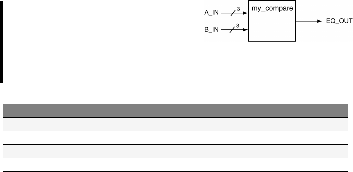
8.1 VHDL Modularity with Components 119
8.1 VHDL Modularity with Components
The main tool for modularity in higher-level languages such as C is the
function. In other computer languages, similar modularity is accomplished
through the use of methods, procedures and subroutines. The approach
used in C is to 1) name the function interface you plan on writing (the
function declaration), 2) code what the function will do (the function
body), 3) let the program know it exists and is available to be called (the
prototype) and 4) call the function from the main portion of the code.
In VDHL modularity is achieved via the use of packages,components
and functions. In the following sections we are going to see how to use
components.
The approach to use a component in VHDL is: 1) name the module
you plan to describe (the entity), 2) describe what the module will do (the
architecture), 3) let the program know the module exists and can be used
(component declaration) and 4) use the module in your code (component
instantiation, or mapping). The similarities between these two approaches
are listed in Table 8.1.
Let us now use these principles in a practical example. Our approach is
to describe a template-type approach to VHDL structural design using a
simple and well-known combinational circuit.
EXAMPLE 22. Design a 3-bit
comparator using a VHDL structural
modeling. The interface to this cir-
cuit is described in the diagram be-
low.
C programming language VHDL
Describe function interface The entity
Describe what the function does (coding) The architecture
Provide a function prototype to main program Component declaration
Call the function from main program Component instantiation or mapping
Table 8.1: Similarities between modules in C and VHDL.
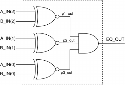
120 Chapter 8: Structural Modeling In VHDL
SOLUTION. A comparator is one of the classic combinatorial circuits
that every digital design engineer must derive at some point in his career.
The solution presented here implements the discrete gate version of the
circuit which is shown in Fig. 8.1. Once again, the solution presented here
is primarily an example of a VHDL structural model and does not repre-
sent the most efficient method to represent a comparator using VHDL.
The approach of this solution is to model each of the discrete gates
as individual blocks. In this case, they are actually simple gates but the
interfacing requirements of the VHDL structural approach are the same
regardless of whether the circuit elements are simple gates or complex
digital subsystems.
The circuit shown in Fig. 8.1 contains some extra information that re-
lates to its VHDL structural implementation. First, the dashed line rep-
resents the boundary of the top-level VHDL entity; therefore signals that
cross this boundary must appear in the entity declaration for this imple-
mentation. Second, each of the internal signals is given a name. In this
case, internal signals are defined to be signals that do not cross the dashed
entity boundary. This is a requirement for VHDL structural implementa-
tions as these signals must be assigned to the various sub-modules in the
interior of the design (somewhere in the architecture).
Figure 8.1: Discrete gate implementation of a 3-bit comparator.
The first part of the solution is to provide entity and architecture imple-
mentations for the individual gates shown in Fig. 8.1. We need to provided
as least one definition of an XNOR gate and a 3-input AND gate. We only

8.1 VHDL Modularity with Components 121
need to provide one definition of the XNOR gate despite the fact that actu-
ally three are shown in the diagram. The modular VHDL approach allows
us to reuse circuit definitions and we take advantage of this feature. These
definitions are shown in Listing 8.1.
Listing 8.1: Entity and Architecture definitions for discrete gates.
----------------------------------
-- Description of XNOR function --
----------------------------------
entity big_xnor is
Port (A,B:in std_logic;
F:out std_logic);
end big_xnor;
architecture ckt1 of big_xnor is
begin
F<= not ((Aand (not B)) or ( (not A) and B) );
end ckt1;
-----------------------------------------
-- Description of 3-input AND function --
-----------------------------------------
entity big_and3 is
Port ( A,B,C : in std_logic;
F:out std_logic);
end big_and3;
architecture ckt1 of big_and3 is
begin
F<= (Aand Band C );
end ckt1;
The implementations shown in Listing 8.1 present no new VHDL de-
tails. The new information is contained in how the circuit elements listed
in Fig. 8.1 are used as components in a larger circuit. The procedures for
implementing a structural VHDL design can be summarized in the follow-
ing steps. These steps assume that the entity declarations for the interior
modules already exist.
Step 1. Generate the top-level entity declaration.
Step 2. Declare the lower-level design units used in design.
Step 3. Declare required internal signals used to connect the design units.
Step 4. Instantiate the design units.
This is how you therefore proceed:
Step One: The first step in a structural implementation is identical to the
standard approach we have used for the implementing other VHDL cir-
cuits: the entity. The entity declaration is derived directly from dashed
box in Fig. 8.1 and is shown in Listing 8.2. In other words, signals that
intersect the dashed lines are signals that are known to the outside world

122 Chapter 8: Structural Modeling In VHDL
and must be included in the entity declaration.
Listing 8.2: Entity declaration for 3-bit comparator.
-----------------------------------------------
-- Interface description of 3-bit comparator --
-----------------------------------------------
entity my_compare is
Port ( A_IN : in std_logic_vector(2 downto 0);
B_IN : in std_logic_vector(2 downto 0);
EQ_OUT : out std_logic);
end my_compare;
Step Two: The next step is to declare the design units that are used
in the circuit. In VHDL lingo, declaration refers to the act of making a
particular design unit available for use in a particular design. Note that
the act of declaring a design unit, by definition, transforms your circuit
into a hierarchical design. The declaration of a design unit makes the unit
available to be placed into the design hierarchy. Design units are essentially
modules that are used in the lower levels of the design. For our design, we
need to declare two separate design units: the XOR gate and a 3-input
AND gate.
There are two factors involved in declaring a design unit: 1) how to do
it and, 2) where to place it. A component declaration can be viewed as
a modification of the associated entity declaration. The difference is that
the word entity is replaced with the word component and the word
component must also be followed by the word end component to ter-
minate the declaration. The best way to do this is by copying, pasting and
modifying the original entity declaration. The resulting component decla-
ration is placed in the architecture declaration after the architecture
line and before the begin line. The two component declarations and their
associated entity declarations are shown in the next listing. Listing 8.3
shows the component declarations as they appear in working VHDL code.
entity big_xnor is
Port (A,B:in std_logic;
F:out std_logic);
end big_xnor;
entity big_and3 is
Port ( A,B,C : in std_logic;
F:out std_logic);
end big_and3;
component big_xnor
Port (A,B:in std_logic;
F:out std_logic);
end component;
component big_and3
Port ( A,B,C : in std_logic;
F:out std_logic);
end component;
8.1 VHDL Modularity with Components 123
Step Three: The next step is to declare internal signals used by your de-
sign. The required internal signals for this design are the signals that are
not intersected by the dashed line shown in Fig. 8.1. These three signals are
similar to local variables used in higher-level programming languages in
that they must be declared before they can be used in the design. These
signals effectively provide an interface between the various design units
that are instantiated in the final design. For this design, three signals are
required and used as outputs of the XOR gates and as inputs to the AND
gate. Internal signal declarations such as these appear with the component
declarations in the architecture declaration after the architecture line
and before the begin line. Note that the declaration of intermediate sig-
nals is similar to the signal declaration contained in the entity body. The
only difference is that the intermediate signal declaration does not contain
the mode specifier. We have previously dealt with intermediate signals in
other sections of this book. Signal declarations are included as part of the
final solution shown in Listing 8.3.
Step Four: The final step is to create instances of the required modules
and map the instances of the various components in the architecture body.
Technically speaking, as the word instantiation implies, the appearance of
instances of design units is the main part of the instantiation process. In
some texts, the process of instantiation includes what we have referred
to as component declaration but we have opted not to do this here. The
approach presented here is to have the declaration refer to the component
declarations before the begin line while instantiation refers to the cre-
ation of individual instances after the begin line. The mapping process
is therefore included in our definition of component instantiation.
The process of mapping provides the interface requirements for the in-
dividual components in the design. This mapping step associates exter-
nal connections from each of the components to signals in the next step
upwards in the design hierarchy. Each of the signals associated with in-
dividual components maps to either an internal or external signal in the
higher-level design. Each of the individual mappings includes a unique
name for the particular instance as well as the name of the original entity.
The actual mapping information follows the VHDL key words of port

124 Chapter 8: Structural Modeling In VHDL
map. All of this information appears in the final solution shown in Listing
8.3.
One key point to note in the instantiation process is the inclusion of
labels for all instantiated design units. Labels should always be used as
part of design unit instantiation because the use of appropriate labels
increases the understandability of your VHDL model. In other words, the
proper choice of labels increases the self-describing nature of your design
and is considered a good VHDL programming approach.
Listing 8.3: VHDL code for the design hierarchy for the 3-bit comparator.
-- library declaration
library IEEE;
use IEEE.std_logic_1164.all;
-- entity
entity my_compare is
Port ( A_IN : in std_logic_vector(2 downto 0);
B_IN : in std_logic_vector(2 downto 0);
EQ_OUT : out std_logic);
end my_compare;
-- architecture
architecture ckt1 of my_compare is
-- XNOR gate --------------------
component big_xnor is
Port (A,B:in std_logic;
F:out std_logic);
end component;
-- 3-input AND gate -------------
component big_and3 is
Port ( A,B,C : in std_logic;
F:out std_logic);
end component;
-- intermediate signal declaration
signal p1_out,p2_out,p3_out : std_logic;
begin
x1: big_xnor port map (A => A_IN(2),
B=> B_IN(2),
F=> p1_out);
x2: big_xnor port map (A => A_IN(1),
B=> B_IN(1),
F=> p2_out);
x3: big_xnor port map (A => A_IN(0),
B=> B_IN(0),
F=> p3_out);
a1: big_and3 port map (A => p1_out,
B=> p2_out,
C=> p3_out,
F=> EQ_OUT);
end ckt1;
It is worth noting that the solution shown in Listing 8.3 is not the only
8.1 VHDL Modularity with Components 125
approach to use for the mapping process. The approach shown in Listing
8.3 uses what is referred to as a direct mapping of components. In
this manner, each of the signals in the interface of the design units are
listed and are directly associated with the signals they connect to in the
higher-level design by use of the =>operator. This approach has several
potential advantages: it is explicit, complete, orderly and allows signals to
be listed in any order. The only possible downside of this approach is that
it uses up more space in your VHDL source code.
The alternative approach to mapping is to use implied mapping. In
this approach, connections between external signals from the design units
are associated with signals in the design unit by order of their appear-
ance in the mapping statement. This differs from direct mapping because
only signals from the higher-level design appear in the mapping state-
ment instead. The association between signals in the design units and the
higher-level design are implied by the ordering of the signal as they ap-
pear in the component or entity declaration. This approach uses less space
in the source code but requires signals to be placed in the proper order.
An alternative but equivalent architecture for the previous example using
implied mapping is shown in Listing 8.4.
To successfully simulate and synthesize the design shown in Listing 8.3,
the code of Listing 8.1 needs to be included in your VHDL project as well.
It is normal practice to keep the two listings in two distinctive files. The
same is true for the implementation of Listing 8.4.

126 Chapter 8: Structural Modeling In VHDL
Listing 8.4: Alternative architecture for Example 22 using implied mapping.
-- library declaration
library IEEE;
use IEEE.std_logic_1164.all;
-- entity
entity my_compare is
Port ( A_IN : in std_logic_vector(2 downto 0);
B_IN : in std_logic_vector(2 downto 0);
EQ_OUT : out std_logic);
end my_compare;
-- architecture
architecture ckt2 of my_compare is
component big_xnor is
Port (A,B:in std_logic;
F:out std_logic);
end component;
component big_and3 is
Port ( A,B,C : in std_logic;
F:out std_logic);
end component;
signal p1_out,p2_out,p3_out : std_logic;
begin
x1: big_xnor port map (A_IN(2),B_IN(2),p1_out);
x2: big_xnor port map (A_IN(1),B_IN(1),p2_out);
x3: big_xnor port map (A_IN(0),B_IN(0),p3_out);
a1: big_and3 port map (p1_out,p2_out,p3_out,EQ_OUT);
end ckt2;
Due to the fact that this design was relatively simple, it was possible
to bypass one of the interesting issues that arises when using structural
modeling. Often when dealing with structural designs, different levels of
the design will contain the same signal name. The question arises as to
whether the synthesizer is able to differentiate between the signal names
across the hierarchy. VHDL synthesizers, like compilers for higher-level
languages, are able to handle such instances. Signals with the same names
are mapped according to the mapping presented in the component in-
stantiation statement. Probably the most common occurrence of this is
with clock signals. In this case, a component instantiation such as the one
shown in Listing 8.5 is both valid and commonly seen in designs contain-
ing a system clock. Name collision does not occur because the signal name
on the left-hand side of the =>operator is understood to be internal to
the component while the signal on the right-hand side is understood to
reside in the next level up in the hierarchy.
Listing 8.5: Example of the same signal name crossing hierarchical boundaries.
x5: some_component port map (CLK => CLK,
CS => CS);

8.2 Generic Map 127
8.2 Generic Map
As we have seen in the previous section, the use of the keyword component
allows us to declare a VHDL module for further instantiation.
Often it is desirable to write code that is generic. For instance a routine
that perform a certain task on an input array of a generic size. Let us
suppose that we want to implement a piece of code of a parity check
routine that returns ’1’ when the input N-size array is an even number
and ’0’ when the input N-size array is an odd number. The Listing 8.6
shows such an implementation.
Listing 8.6: Parity check implementation with generic input array size.
1-- library declarations
2library IEEE;
3use IEEE.std_logic_1164.all;
4-- entity
5entity gen_parity_check is
6generic ( n: positive);
7port (x:in std_logic_vector(n-1 downto 0);
8y: out std_vector);
9end entity;
10 -- architecture
11 architecture arch of gen_parity_check is
12 begin
13 process(x)
14 variable temp: std_logic;
15 begin
16 temp:=0;
17 for iin input'range loop
18 temp := temp XOR input(i);
19 end loop;
20 y<= temp;
21 end process
22 end arch;
Listing 8.7 shows how the code above can be declared and instantiated
in your own code via the already see component method. Specifically, In
Listing 8.7 the above generic parity check module is used to create a 4-bit
parity check module.
To achieve the mentioned modularity the keyword generic was used
inside the entity field in the code above and again inside the component
field during its declaration in the code below. The generic field it is used
to allow you to control all generic variables.
Notice how during instantiation, Listing 8.7 line 20, the keyword generic
map was used in conjunction with the keyword port map to define the
generic variables.

128 Chapter 8: Structural Modeling In VHDL
Listing 8.7: Use of generic for the construct of a generic parity check code.
1-- library declaration
2library IEEE;
3use IEEE.std_logic_1164.all;
4-- entity
5entity my_parity_chk is
6Port ( input : in std_logic_vector(3 downto 0);
7output : out std_logic);
8end my_parity_chk;
9
10 -- architecture
11 architecture arch of my_parity_chk is
12 --------------- component declaration --------------------
13 component gen_parity_check is
14 generic ( std_logic : positive);
15 port ( input : in std_logic_vector(N-1 downto 0);
16 output : out std_logic);
17 end component;
18 begin
19 -------------- component instantiation -------------------
20 cp1: my_parity_chk generic map (4) port map (input, output);
21 end arch;
Once again, to successfully simulate and synthesize the design shown in
Listing 8.7, the code of Listing 8.6 needs to be included in your VHDL
project as well.
8.3 Important Points
Structural modeling in VHDL supports hierarchical design concepts.
The ability to abstract digital circuits to higher levels is the key to
understanding and designing complex digital circuits.
Digital design using schematic capture is an outdated approach: you
should resist the inclination and/or directive at all costs.
The VHDL structural model supports the reuse of design units. This
includes units you have previously designed as well as the ability to
use predefined module libraries.
If you use one FPGA software development tool from one of the major
FPGA players in the market, you will be able to use digital blocks
already developed once you declare them. In this case the entity decla-
ration is not the one of Listing 8.2 but instead a simple library inclusion
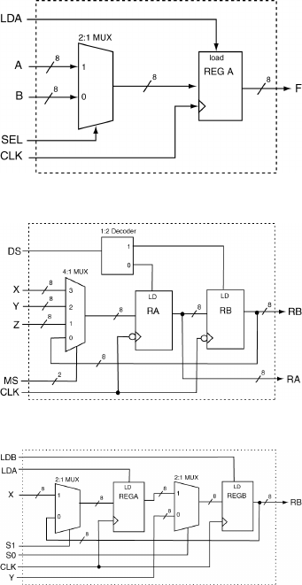
8.4 Exercises: Register Transfer Level Circuits 129
in your VHDL code that looks like:
library UNISIM;
use UNISIM.VComponents.all;
All digital blocks available from this library package are described in
the documentation of the FPGA software development tool (e.g. Xilinx
ISE).
8.4 Exercises: Register Transfer Level Circuits
EXERCISE 1. Provide a VHDL
model that can be used to implement
the following circuit.
EXERCISE 2. Provide a VHDL
model that can be used to implement
the following circuit.
EXERCISE 3. Provide a VHDL
model that can be used to implement
the following circuit.
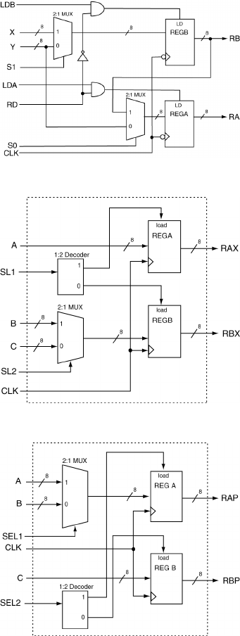
130 Chapter 8: Structural Modeling In VHDL
EXERCISE 4. Provide a VHDL
model that can be used to implement
the following circuit.
EXERCISE 5. Provide a VHDL
model that can be used to implement
the following circuit.
EXERCISE 6. Provide a VHDL
model that can be used to implement
the following circuit.

9
Registers and Register Transfer Level
The concept of a register in VHDL and its subsequent use in digital circuit
design is probably one of the more straightforward concepts in VHDL. A
register in VHDL is simply a vector version of a D flip-flop in which all
operations on the flip-flops occur simultaneously. The “register transfer
level”, or RTL, is a flavor of design that is primarily concerned with how
and when data is transferred between the various registers in a digital
system. RTL-level design in often associated with ”data-path” designs
which require the careful control and timing of the data that is being
transferred between registers. The controls associated with even simple
registers are sufficient to ensure that some outside entity has adequate
control over the ”sequencing” of data through the circuit associated with
the data-path. In these cases, the proper sequencing of data transfers is
controlled by a FSM.
The study of RTL-level design is best accomplished in the context of a
data-path design. The design of data-paths is best accomplished in the
context of a digital circuit that has some purpose such as an arithmetic
logic unit design. Both of these topics are beyond what needs to be men-
tioned here. The good news is that the simplicity of the registers makes
for a quick introduction to the matter. Major circuit implementations are
saved for some other time.
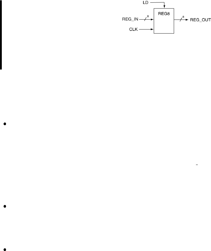
132 Chapter 9: Registers and Register Transfer Level
EXAMPLE 23. Use VHDL behav-
ioral modeling to design the 8-bit reg-
ister that has a synchronous active
high parallel load signal LD. Con-
sider the load of the register to be
synchronized to rising edges of the
clock.
SOLUTION. The solution for the 8-bit register looks amazingly similar
to a model of a D flip-flop. The full solution to Example 23 is shown in
Listing 9.1. As usual, there are a couple of things worth noting in this
solution.
Note that there is an if statement that does not contain a corre-
sponding else which is what generates the memory element. For this
example, there are considered to be eight bit-sized memory elements
(flip-flops). For this example the flip flops are considered to be D-
type flip-flops. The storage elements are associated with the REG OUT
bundle. The ease in using VHDL code to generate D flip-flops in this
manner makes D flip-flops the most widely used type of flip-flop in
digital design.
The code uses a bundle signal for both the input and output. The
assignment of the bundles to other bundles is straightforward in VHDL
as is shown in the code. In many cases, such as the one in this example,
there is no need to use a bundle access operator in the VHDL model.
The assignment of the input to the output is based on characteristics of
both the clock edge and the state of the LD signal. The approach taken
in the VHDL model shown in Listing 9.1 is to provide a separate if
clause for both the LD and CLK signals. Only one if statement could
have been used by making both conditions associated with the single
if clause but this is not considered good VHDL programming practice
when dealing with synchronized elements. In other words, you should
always strive to keep special conditions associated with the clocking
signal separate from all other conditions associated with the action in
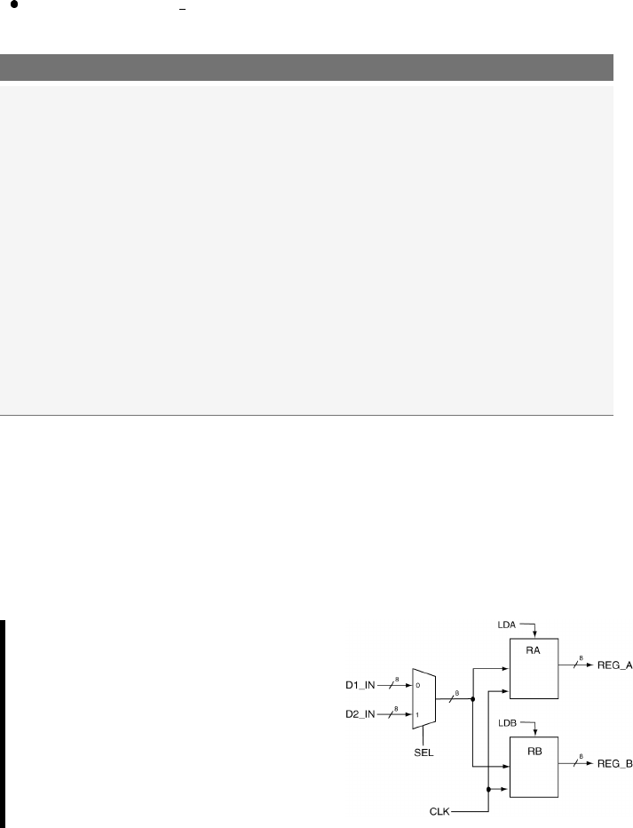
133
question. Clock signals are somewhat special in the VHDL land; you
should get into the habit of treating them gently.
Since signals REG IN and LD are required to be synchronous they do
not appear inside the process sensitivity list.
Listing 9.1: Solution to Example 23.
-- library declaration
library IEEE;
use IEEE.std_logic_1164.all;
-- entity
entity reg8 is
Port ( REG_IN : in std_logic_vector(7 downto 0);
LD,CLK : in std_logic;
REG_OUT : out std_logic_vector(7 downto 0));
end reg8;
-- architecture
architecture reg8 of reg8 is
begin
reg: process(CLK)
begin
if (rising_edge(CLK)) then
if (LD = '1')then
REG_OUT <= REG_IN;
end if;
end if;
end process;
end reg8;
The circuit in the following example is slightly more complex than most
of the examples seen so far. Additionally, remember that there are many
different solutions to the same problem. This is a common occurrence in
VHDL; in fact, many times there is no best method for implementing a
given circuit. The following examples are essentially the same problem
solved using two different but functionally equivalent solutions.
EXAMPLE 24. Use VHDL be-
havioral modeling to design the cir-
cuit shown on the right. Consider
both the loading signals to be ac-
tive high. Consider the circuit to be
synchronized to the rising edge of
the clock signal.
SOLUTION. The circuit shown in Example 24 includes two 8-bit regis-
ters and a 2:1 MUX. This is an example of a bus-based data transfer in the

134 Chapter 9: Registers and Register Transfer Level
output of the MUX that is connected to the inputs of the two registers.
Each of the two registers has its own independent load control input. The
solution to Example 24 is shown in Listing 9.1. And as we have grown to
expect, there are a couple of things worth noting about this solution.
There are three concurrent statements in this solution: two behavioral
models and one data-flow model.
There is a separate process for each of the two registers. Although it
would have been possible to represent both registers using one pro-
cess, it would have been somewhat complicated and somewhat hard
to understand. The better approach in VHDL is always to break tasks
down into their logically separate functions and use the various VHDL
modeling techniques as tools to keep the tasks separate and simple.
The reality is that the synthesizer becomes your friend if you provide
it with simple models. The quantity of VHDL code describing a certain
design is immaterial; the complexity of any given model is determined
by the most complex piece of code in the model. Simple is always better
in VHDL.
All of signals shown in the Example 24 have external linkage except for
the output of the MUX. The MUX output is connected to the inputs
of both registers. The final approach taken in this solution is typical
in VHDL: many processes that communicate with each other through
shared signals. In this example, there is only one shared signal but
this is a fairly simple program. The same inter-process communication
model is used in more complicated circuits.
The model for the 2:1 MUX uses the terminology (others => ’0’).
This is a short-hand terminology for assigning all of the outputs to ’0’.
The real nice part about this instruction is that you do not need to
know how many 0’s you need to write. This is a nice feature in that if
the width of the associated bundle were to change, this particular line
of code would not need to be modified.
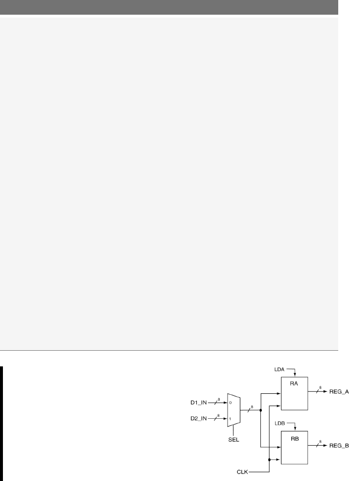
135
Listing 9.2: Solution to Example 24.
-- library declaration
library IEEE;
use IEEE.std_logic_1164.all;
-- entity
entity ckt_rtl is
port (D1_IN,D2_IN : in std_logic_vector(7 downto 0);
CLK,SEL : in std_logic;
LDA,LDB : in std_logic;
REG_A,REG_B : out std_logic_vector(7 downto 0));
end ckt_rtl;
-- architecture
architecture rtl_behavioral of ckt_rtl is
-- intermediate signal declaration ---------------
signal s_mux_result : std_logic_vector(7 downto 0);
begin
ra: process(CLK) -- process
begin
if (rising_edge(CLK)) then
if (LDA = '1')then
REG_A <= s_mux_result;
end if;
end if;
end process;
rb: process(CLK) -- process
begin
if (rising_edge(CLK)) then
if (LDB = '1')then
REG_B <= s_mux_result;
end if;
end if;
end process;
with SEL select
s_mux_result <= D1_IN when '1',
D2_IN when '0',
(others => '0')when others;
end rtl_behavioral;
EXAMPLE 25. Use VHDL struc-
tural modeling to design the circuit
shown on the right. Consider both
of the loading signals to be active
high. Consider the circuit to be syn-
chronized to the rising edge of the
clock signal.
SOLUTION. The solution to Example 25 is shown in Listing 9.3. There
is not too much interesting to note here. This is a more realistic example
of a structural model compared to the example presented in the section

136 Chapter 9: Registers and Register Transfer Level
on structural modeling. There are only a few new and wonderful things
to note about this solution.
The very important thing to note about the solution in Listing 9.3 is
to not be intimidated by the sheer quantity of code listed. The code
is well structured; if you are able to recognize this structure, you will
be more apt to understand the solution. And better yet, you will be
more on your way to being able to write your own amazing chunks of
VHDL code.
The VHDL source code shown in Listing 9.3 is nicely formatted. In par-
ticular, the code is nicely indented. Properly indented code is highly
desirable in that it nicely presents information based on the indenta-
tion. No surprise here but properly formatted code is easier to under-
stand. Better yet, good looking code leads people who may or may not
know otherwise into thinking your code is as actually as good as it
looks. In this busy world of ours, a quick glance is just about all the
time people (bosses and teachers) have to dedicate to perusing your
VHDL source code.

137
Listing 9.3: Solution to Example 25 using a structural modeling approach.
entity mux2t1 is --- ENTITY
port ( A,B : in std_logic_vector(7 downto 0);
SEL : in std_logic;
M_OUT : out std_logic_vector(7 downto 0));
end mux2t1;
architecture my_mux of mux2t1 is --- ARCHITECTURE
begin
with SEL select
M_OUT <= Awhen '1',
Bwhen '0',
(others => '0')when others;
end my_mux;
entity reg8 is --- ENTITY
Port ( REG_IN : in std_logic_vector(7 downto 0);
LD,CLK : in std_logic;
REG_OUT : out std_logic_vector(7 downto 0));
end reg8;
architecture reg8 of reg8 is --- ARCHITECTURE
begin
reg: process(CLK)
begin
if (rising_edge(CLK)) then
if (LD = '1')then
REG_OUT <= REG_IN;
end if;
end if;
end process;
end reg8;
entity ckt_rtl is --- ENTITY
port (D1_IN,D2_IN : in std_logic_vector(7 downto 0);
CLK,SEL : in std_logic;
LDA,LDB : in std_logic;
REG_A,REG_B : out std_logic_vector(7 downto 0));
end ckt_rtl;
architecture rtl_structural of ckt_rtl is --- ARCHITECTURE
-- component declaration
component mux2t1
port ( A,B : in std_logic_vector(7 downto 0);
SEL : in std_logic;
M_OUT : out std_logic_vector(7 downto 0));
end component;
component reg8
Port ( REG_IN : in std_logic_vector(7 downto 0);
LD,CLK : in std_logic;
REG_OUT : out std_logic_vector(7 downto 0));
end component;
-- intermediate signal declaration
signal s_mux_result : std_logic_vector(7 downto 0);
begin
ra: reg8
port map ( REG_IN => s_mux_result,
LD => LDA,
CLK => CLK,
REG_OUT => REG_A );
rb: reg8
port map ( REG_IN => s_mux_result,
LD => LDB,
CLK => CLK,
REG_OUT => REG_B );
m1: mux2t1
port map ( A => D1_IN,
B=> D2_IN,
SEL => SEL,
M_OUT => s_mux_result);
end rtl_structural;

138 Chapter 9: Registers and Register Transfer Level
9.1 Important Points
VHDL can be used to easily implement circuits at the register transfer
level. The corresponding VHDL models can be implemented in either
structural of full behavioral format.
RTL level VHDL models should strive for simplicity in their designs.
If the behavioral models in the RTL design become complicated, the
chances that your circuit works correctly greatly diminish due to the
synthesis of the complicated circuit.

10
Data Objects
Many of the concepts presented so far have been implicitly presented in
the context of example problems. In this way, you have probably been able
to generate quality VHDL code but were constrained to use the VHDL
style presented in these examples. In this section, we will present some
of the underlying details and theories that surround VHDL as a back-
door approach for presenting tools that will allow you to use VHDL for
describing the behavior of more complex digital circuits.
In order to move into more sophisticated VHDL, a good place to start
is with the definition of VHDL objects (e.g. data types). An object is an
item in VHDL that has both a name (associated identifier) and a specific
type. There are four types of objects and many different data types in
VHDL. Up to this point, we have only used signal data objects and
std logic data types. Two new data objects and several new data types
are introduced and discussed in this section.
10.1 Types of Data Objects
There are four types of data objects in VHDL: signals,variables,con-
stants and files. One of the purposes of this section is to present some
background information regarding variables which will be used later in this
tutorial. The idea of constants will also be briefly mentioned since they
are generally straightforward to understand and use once the concepts of
signals and variables are understood. File data objects, exclusively used
140 Chapter 10: Data Objects
in simulations, are not discussed in this chapter.
Mind that VHDL is a vast language that goes well beyond the VHDL
code that is used to program an FPGA or a CPLD. In fact the actual
VHDL that can be translated into an FPGA/CPLD bit-stream is called
RTL VHDL and represents only a small subset of what is included in the
current VHDL standard. The file data objects are an example of a data
object that can not be implemented in a silicon device.
Just as side note, it is interesting to point out that it is also possible to
compile VHDL code into an executable file that can be executed, generally
for simulation purposes, with any general purpose Intel PC. For more
details refer to the open-source work of T. Gingold available at:
http://ghdl.free.fr.
10.2 Data Object Declarations
The first thing to note about data objects is the similarity in their dec-
larations. The forms for the three data objects we will be discussing are
listed in Table 10.1. For each of these declarations, the bold-face font is
used to indicate VHDL keywords. The form for the signal object should
seem familiar since we have used it extensively up to this point.
VHDL data object Declaration form
Signal signal sig name : sig type:=initial value;
Variable variable var name : var type:=initial value;
Constant constant const name : const type:=initial value;
Table 10.1: Data object declaration forms.
Note that each of the data objects can optionally be assigned initial
values. Signal declarations do not usually include initial values as opposed
to constants which generally do.
Initial values for signals are in fact not implementable on silicon by the
synthesizing tools but are taken into consideration by VHDL simulation
tools. Example declarations for these three flavors of data objects are
provided in Table 10.2. These examples include several new data types
which will be discussed in the next section.
10.3 Variables and Assignment Operator “:=” 141
Data object Declaration form
Signal signal sig var1 : std logic := ’0’;
signal tmp bus : std logic vector(3 downto 0):="0011";
signal tmp int : integer range -128 to 127 := 0;
signal my int : integer;
Variable variable my var1, my var2 : std logic;
variable index a : integer range (0 to 255) := 0;
variable index b : integer := -34;
Constant constant sel val : std logic vector(2 downto 0):="001";
constant max cnt : integer := 12;
Table 10.2: Example declarations for signal, variable and constant data objects.
10.3 Variables and Assignment Operator “:=”
Although variables are similar to signals, variables are not as functional
for the several reasons mentioned in this section. Variables can only be
declared and used inside of processes, functions and procedures (functions
and procedures will not be discussed here). Implied in this statement is the
sequential nature of variable assignment statements in that all statements
appearing in the body of a process are sequential. One of the early mistakes
made by VHDL programmers is attempting to use variables outside of
processes.
The signal assignment operator, <=, was used to transfer the value of
one signal to another while dealing with signal data objects. When working
with variables, the assignment operator := is used to transfer the value
of one variable data object to another. As you can see from Table 10.2,
the assignment operator is overloaded which allows it to be used to assign
initial values to the three listed forms of data objects.
10.4 Signals vs. Variables
The use of signals and variables can be somewhat confusing because of
their similarities. Generally speaking, a signal can be thought of as rep-
resenting a wire or some type of physical connection in a design. Signals
thus represent a means to interface VHDL modules which include connec-
tions to the outside world. In terms of circuit simulation, signals can be
scheduled to take on multiple values at specific times in the simulation.
142 Chapter 10: Data Objects
The specifics of simulating circuits using VHDL are not covered here so
the last statement may not carry much meaning to you. The important
difference here is that events can be scheduled for signals while for vari-
ables, they cannot. The assignment of variables is considered to happen
immediately and cannot have a list of scheduled events.
With relatively simple circuits, signal objects are generally sufficient. As
your digital designs become more complex, there is a greater chance that
you will need more control of your models than signals alone can provide.
The main characteristic of signals that leave them somewhat limited in
complex designs is when and how they are scheduled. More specifically,
assignments made to signals inside a process are actually only
scheduled when the same process is completed. The actual as-
signment is not made until after the process terminates. This is
why multiple signal assignments can be made to the same signal during
the execution of a process without generating any type of synthesis error.
In the case of multiple signal assignments inside the process, only the most
recent assignment to the signal during process execution is assigned. The
important thing here is that the signal assignment is not made until after
the process terminates. The potential problem that you might face is that
the new result (the new value assigned to the signal) is not available to
use inside the process.
Variable assignment within processes is different. When a variable is
assigned a value inside of a process, the assignment is immediate and the
newly assigned value can be used immediately inside of the process. In
other words, the variable assignment is not scheduled as it was for the
signal. This is a giant difference and has very important ramifications in
both the circuit simulation and synthesis realm.
Variables cannot always be modeled as wires in a circuit. They also have
no concept of memory since they cannot store events. With all this in
mind, you may wonder what is the appropriate place to use variables.
The answer is variables should only be used as iteration counters in loops
or as temporary values when executing an algorithm that performs some
type of calculation. It is possible to use variables outside of these areas,
but it should be avoided.

10.5 Standard Data Types 143
Even though instructions inside a process are executed consecutively,
this should not fool you in thinking that a process environment is similar
to apiece of C code. Remember that while lines of C code require some
tens of clock cycles each to be executed, VHDL instructions require very
little time to be executed, less than one clock cycle. The price to pay for
this enormously fast execution time is that any signal assignment inside a
process only takes place at the end of the process. It is therefore advisable
that your processes are short and simple.
10.5 Standard Data Types
Not only does VHDL have many defined data types but VHDL also allows
you to define your own types. Here however we will only deal with few of
the most widely used types. Among the most popular VHDL data type
we would like to mention the following data types:
bit: It is a two-value enumerated type. Replaced by the std logic type.
bit vector: Replaced by the more powerful std logic vector type.
boolean: As expected, it is a two-value enumerated type.
boolean vector: It is the vector form of a boolean type.
integer: Refer to the Integer Types section.
natural: It is a subtype of integer because it is a non-negative integer.
positive: It is a subtype of integer because it is a positive integer.
integer vector: It is the vector form of an integer type.
character: A 256-symbol enumerated type.
string: It is the vector form of a character type.
In the following sections, a few more popular and useful types are intro-
duces.
10.6 User-Defined Types
VHDL allows you to define your own data type. A typical example of
custom integer type is:
type my type is range 0 to 100;
constant my const : my type := 31;
144 Chapter 10: Data Objects
Obviously it is possible to define more complex data structures. For in-
stance it is a common practice to use a custom data type when you want
to implement a ROM (read-only memory) in VHDL.
-- typical custom data type for a 20-byte ROM
type memory is array (0 to 19 of std_logic_vector(7 downto 0);
constant my_rom : memory := (
1=> "11111111"
2=> "11110111"
5=> "11001111"
12 => "10110101"
18 => "10001101"
others => "00000000");
10.7 Commonly Used Types
The types already introduced in previous chapters as well as two new types
are listed in Table 10.3. The std logic and std logic vector types
have been extensively used so far. These types are more complex than has
been previously stated and will be discussed further in this chapter. The
enumerated type was used during the previous discussion of finite state
machines. The integer type was cryptically mentioned before but it will
be discussed further along with the boolean type in this chapter.
Type Example Usage
std logic signal my sig : std logic;all examples
std logic vectors signal busA : std logic vector(3 downto 0); all examples
enumerated type state type is (ST0,ST1,ST2,ST3); Example 18
boolean variable my test : boolean := false;None
integer signal iter cnt : integer := 0; Example 26
Table 10.3: Some popular data types already introduced in previous chapters.
10.8 Integer Types
The use of integer types aids in the design of algorithmic-type VHDL code.
This type of coding allows VHDL to describe the behaviour of complex
digital circuits. As you progress in your digital studies, you will soon find
yourself in need of more complex descriptive VHDL tools. Data types such
as integers partially fill that desire. This section briefly looks at integer
types as well as the definition of user-specified integer types.

10.8 Integer Types 145
The range of the integer type is (-2,147,483,647 to 2,147,483,647). These
numbers should seem familiar since they represent the standard 32-bit
range for a signed number: from −(231 −1) to +(231 −1). Other types
similar to integers include natural and positive types. These types are ba-
sically integers with shifted ranges. For example, the natural and positive
types range from 0 and 1 to the full 31-bit range, respectively. Examples
of integer declarations are shown in the following listing.
-- integer declarations
signal my_int : integer range 0to 255 := 0;
variable max_range : integer := 255;
constant start_addr : integer := 512;
Although it could be possible to use only basic integer declarations in
your code, as we have seen before, VHDL allows you to define your own
data types with their own personalized range constraints. These special
types should be used wherever possible to make your code more readable.
The custom integer-type definition uses the type range construct and the
to or the downto keywords for the definition. Some examples of integer-
type declarations are provided in the following listing.
-- integer type declarations
type scores is range 0to 100;
type years is range -3000 to 3000;
type apples is range 0to 15;
type oranges is range 0to 15;
Although each of the types listed in the previous listing are basically
integers, they are still considered different types and cannot be assigned to
each other. In addition to this, any worthy VHDL synthesizer will do range
checks on your integer types. In the context of the definitions previously
presented, each of the statements in the following listing is illegal.
-- Illegal assignment statements
signal score1 : scores := 100;
signal my_apple : apples := 0;
signal my_orange : oranges := 0;
my_apple <= my_orange; -- different types
my_orange <= 24; -- out of range
my_score <= 110; -- out of range

146 Chapter 10: Data Objects
10.9 signed and unsigned Types
signed and unsigned data types are available once you declare the
standard IEEE ieee.numeric std package. Mind that these two data
types are also defined in the non-standard std logic arith package.
The use of non-standard libraries is however highly discouraged.
Asigned value ranges from −2N−1to 2N−1−1 and an unsigned
value ranges from 0 to 2N−1 where Nis the number of bits.
signed and unsigned types can be conveniently used for internal vari-
ables as well as for entity ports. Additionally the ieee.numeric signed
library and the ieee.numeric unsigned library offer arithmetic and
type conversion for both types.
signed and unsigned types, in a way, look like std logic vector
types, especially in how they are declared and so the question that you
might have is:
Why would I need to use a signed or unsigned
type in place of a std logic vector type?
The answer to this question is in Listing 10.1, specifically in line 17 and
in line 18. The std logic vector type should not be used to define a
numerically meaningful1signal or variable. The std logic vector type
should be only employed for defining “bags of bits”.
The use of signed/unsigned types is desirable any time your bags
of bits (signals, variables or constants) stop being “bags” and become
numbers of type signed, unsigned or even integers.
1Numerically meaningful signal: a signal that looks and behave like a number.

10.10 std logic Types 147
Listing 10.1: Use of unsigned types in your code.
1-- library declaration
2library IEEE;
3use IEEE.std_logic_1164.all;-- defines std_logic_vector type
4use IEEE.numeric_std.all;-- defines signed and unsigned types
5-- entity
6entity double_sum is
7Port (
8in1 : in std_logic_vector (7 downto 0);
9in2 : in std_logic_vector (7 downto 0);
10 out1 : out std_logic_vector (7 downto 0));
11 unsig_in : in unsigned(7 downto 0);
12 unsig_out : out unsigned(7 downto 0));
13 end double_sum;
14 -- architecture
15 architecture arch of sum is
16 begin
17 out1 <= in1 + 1; -- ILLEGAL OPERATION, 1 is an integer
18 out1 <= in1 + in2;-- ILLEGAL OPERATION, addition is not defined
19 unsig_out <= unsig_in + 1; -- legal operation
20 unsig_out <= unsigned(in1) + 1; -- legal operation
21 out1 <= std_logic_vector(unsigned(in1) + 1);-- legal operation
22 end arch;
As final note, we should mention that the inclusion of the non-standard
std logic arith library could have given us the possibility of doing
out1 <= in1 + 1; in line 17 of Listing 10.1, making things much sim-
pler. However, once again, the use of non-standard library is highly dis-
couraged.
10.10 std logic Types
For the representation of digital signals so far in this book, we have
used the std logic type. However, one of the data types, similar to
std logic, neither used not endorsed in this book is the bit type. This
type can take on only the values of ’1’ or ’0’. While this set of values
seems appropriate for designing digital circuits, it is actually somewhat
limited. Due to its versatility and a more complete range of possible values,
the std logic type is preferred over bit types. The std logic type
is defined in the VHDL package ieee.std logic 1164 and provides a
common standard that can be used by all VHDL programmers.
The std logic type is officially defined as an enumerated type. Two
of the possible enumerations of course include ’1’ and ’0’. The ac-
tual definition is shown in the Listing 10.2. The std logic type is a
resolved version of the std ulogic type. Resolved means that unlike for
std ulogic types, when you use std logic type signals, you can use
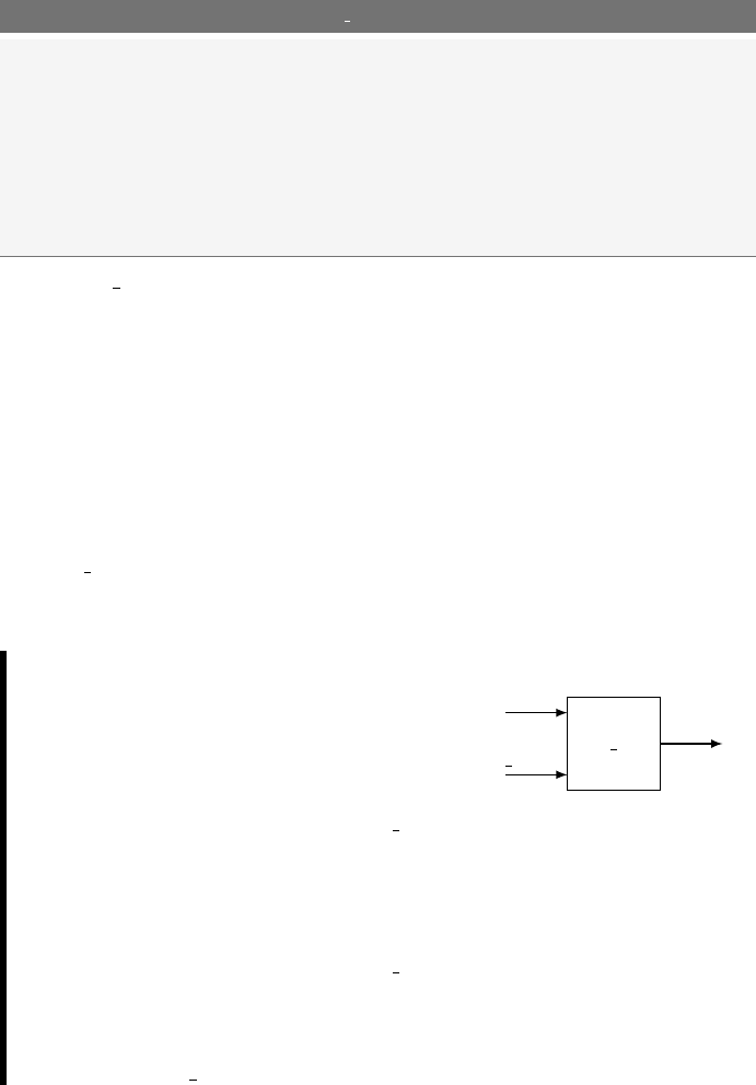
148 Chapter 10: Data Objects
multiple assignments to the same signal without having the compile to
complain about it.
Listing 10.2: Declaration of the std logic enumerated type.
type std_logic is ('U',-- uninitialised
'X',-- forcing unknown
'0',-- forcing 0
'1',-- forcing 1
'Z',-- high impedance
'W',-- weak unknown
'L',-- weak 0
'H',-- weak 1
'-'-- unspecified (do not care)
);
The std logic type uses the VHDL character type in its definition.
Although there are nine values in the definition shown in Listing 10.2, this
book only deals with ’0’,’1’,’Z’ and ’-’. The ’Z’ is generally used
when dealing with bus structures. This allows a signal or set of signals (a
bus) to have the possibility of being driven by multiple sources without
the need to generate resolution functions. When a signal is driven to its
high-impedance state, the signal is not driven from that source and is
effectively removed from the circuit. Finally, since the characters used in
the std logic type are part of the definition, they must be used as listed.
Mind the use of lower-case letters will generate an error.
EXAMPLE 26. Design a clock di-
vider circuit that reduces the fre-
quency of the input signal by a factor
of 64. The circuit has two inputs as
shown in the diagram. The div en
input allows the clk signal to be di-
vided when asserted and the sclk
output will exhibit a frequency 1/64
that of the clk signal. When div en
is not asserted, the sclk output re-
mains low. Frequency division resets
when the div en signal is reasserted.
clk div
clk
div en
sclk
SOLUTION. As usual for more complex concepts and circuits, there are

10.10 std logic Types 149
a seemingly infinite number of solutions. A solution that uses several of
the concepts discussed in this section is presented in Listing 10.3. Some
of the more important issues in this solution are listed below.
The type declaration for my count appears in the architecture body
before the begin statement.
A constant is used for the max count variable. This allows for quick
adjustments in the clock frequency. In this example, this concept is
somewhat trivial because the max count variable is used only once.
The variable is declared inside of the process, after the process begin
line.
Listing 10.3: Solution to Example 26.
1
2-- library declaration
3library IEEE;
4use IEEE.std_logic_1164.all;
5use IEEE.numeric_std.all;
6
7-- entity
8entity clk_div is
9Port (
10 clk : in std_logic;
11 div_en : in std_logic;
12 sclk : out std_logic);
13 end clk_div;
14
15 -- architecture
16 architecture my_clk_div of clk_div is
17 type my_count is range 0to 100; -- user-defined type
18 constant max_count : my_count := 31; -- user-defined constant
19 signal tmp_sclk : std_logic; -- intermediate signal
20 begin
21 my_div: process (clk,div_en)
22 variable div_count : my_count := 0;
23 begin
24 if (div_en = '0')then
25 div_count := 0;
26 tmp_sclk <= '0';
27 elsif (rising_edge(clk)) then
28 -- divider enabled
29 if (div_count = max_count) then
30 tmp_sclk <= not tmp_sclk; -- toggle output
31 div_count := 0; -- reset count
32 else
33 div_count := div_count + 1; -- count
34 end if;
35 end if;
36 end process my_div;
37 sclk <= tmp_sclk; -- final assignment
38 end my_clk_div;
The VHDL implementation of frequency divider that takes a certain
150 Chapter 10: Data Objects
clock signal and generates a second clock signal of higher or lower fre-
quency is quite common practise in VHDL. Such an implementation is
normally done using clock management blocks built in the FPGA fabric
specifically for this purpose. Digital Clock Managers (DCM), Mixed Mode
Clock Managers (MMCM) or Phase Locked Loops (PLL) are just some
examples.
The use of clock management blocks will guarantee your design meets
timing requirements or clock phase noise constraints that will make your
job a lot easier in the long run. Try to remember this.
10.11 Important Points
The use of signed/unsigned types is desirable any time your “bags
of bits” (signals, variables or constants) stop being “bags” and become
numbers of type signed, unsigned or even integers. A typical example
is the variable used for a counter for which there is really no reason
to use a std logic vector type for. Refer to line 17, 22 and 33 of
Listing 10.3.
The standard IEEE library numeric std is needed when you want
to use signed and/or unsigned types. The standard IEEE library
numeric std is almost always preferred over the non-standard
std logic arith library.
Any use of the non-standard Synopsys libraries: std logic signed,
std logic unsigned and std logic arith is highly discouraged.
You cannot increment a std logic vector type signal, you need to
first convert it into an unsigned, a signed or an integer:
library IEEE;
use IEEE.std_logic_1164.all;
use ieee.numeric_std.all
signal val1, val2 : std_logic_vector( 31 downto 0 );
val2 <= val1 + 1; -- ILLEGAL OPERATION
val2 <= std_logic_vector( unsigned(val1) + 1 );

11
Looping Constructs
As the circuits you are required to design become more and more com-
plex, you will find yourself searching for more functionality and versatility
from VHDL. You will probably find what you are looking for in various
looping constructs which are yet another form of VHDL statement. This
chapter provides descriptions of several types of looping constructs and
some details regarding their use.
There are two types of loops in VHDL: for loops and while loops.
The names of these loops should seem familiar from your experience with
higher-level computer programming languages. Generally speaking, you
can leverage your previous experience with these loop types when describ-
ing the behavior of digital circuits. The comforting part is that since these
two types of loops are both sequential statements, they can only appear
inside processes. You will also be able to apply to the circuits you will be
describing using VHDL the algorithmic thinking and designing skills you
developed in coding with higher-level computer languages. The syntax is
slightly different but the basic structured programming concepts are the
same.
11.1 for and while Loops
The purpose of a loop construct is to allow some coding instructions to
happen iteratively (over and over again). These two types of loops of
course share this functionality. As you probably remember from higher-

152 Chapter 11: Looping Constructs
level language programming, the syntax of the language is such that you
can use either type of loop in any given situation by some modification of
the code. The same is true in VHDL. But although you can be clever in the
way you design your VHDL code, the best approach is to make the code
readable and understandable. Keeping this concept in mind lets us see the
functional differences between for and while loops. This basic difference
can be best highlighted by examining the code provided in Listing 11.1.
Listing 11.1: The basic structure of the for and while loops.
-- for loop | -- while loop
my_label:for index in a_range loop |my_label:while (condition) loop
sequential statements... | sequential statements...
end loop my_label; | end loop my_label;
The major difference between these two loops lies in the number of
iterations the loops will perform. This difference can be classified as under
what conditions the circuit will terminate its iterations. If you know the
number of iterations the loop requires, you should use a for loop. As you
will see in the examples that follow, the for loop allows you to explicitly
state the number of iterations that the loop performs.
The while loop should be used when you do not know the number of
iterations the loop needs to perform. In this case, the loop stops iterating
when the terms stated in the condition clause are not met. Using these
loops in this manner constitutes a good programming practice. The loop
labels are listed in italics to indicate that they are optional. These labels
should be always used to clarify the associated VHDL code. Use of loop
labels is an especially good idea when nested loops are used and when
loop control statements are applied.
11.1.1 for Loops
The basic form of the for loop was shown in Listing 11.1. This loop uses
some type of index value to iterate through a range of discrete values.
There are two options that can be applied as to the range of discrete
values: 1) the range can be specified in the for loop statement or 2) the
loop can use a previously declared range. Hereafter you find an example.
11.1 for and while Loops 153
for cnt_val in 0to 24 loop
-- sequential_statements
end loop;
type my_range is range 0to 24;
--
for cnt_val in my_range loop
-- sequential_statements
end loop;
for cnt_val in 24 downto 0loop
-- sequential_statements
end loop;
type my_range is range 24 downto 0;
--
for cnt_val in my_range loop
-- sequential_statements
end loop
The index variable used in the for loop contains some strange qualities
which are listed below. Although your VHDL synthesizer should be able
to flag these errors, you should still keep these in mind when you use a
for loop and you will save yourself a bunch of debugging time. Also note
that the loop body has been indented to make the code more readable.
Enhanced readability of the code is always a good thing.
The index variable does not need to be declared, it is in fact done
implicitly.
Assignments cannot be made to the index variable. The index variable
can, however, be used in calculations within the loop body.
The index variable can only step through the loop in increments of
one.
The identifier used for the index variable can be the same as another
variable or signal; no name collisions will occur. The index variable
will effectively hide identifiers with the same name inside the body of
the loop. Using the same identifier for two different values constitutes
bad programming practice and should be avoided.
The specified range for the index (when specified outside of the loop
declaration) can be of any enumerated type.
And lastly, as shown in the previous listing, for loops can also be im-
plemented using the downto option. This option makes more sense when
the range is specified in the for loop declaration.

154 Chapter 11: Looping Constructs
11.1.2 while Loops
while loops are somewhat simpler than for loops due to the fact that
they do not contain an index variable. The major difference between the
for and while loops is that the for loop declaration contains a built-
in loop termination criteria. The first thing you should remember about
while loops is that the associated code should contain some way of exiting
the loop. Examples of while loops are shown in the following listing.
Needless to say that the VHDL code appearing in the next listing on the
right should have been made with a for loop instead of a while loop
because the number of iterations is actually known.
constant max_fib : integer := 2000;
variable fib_sum : integer := 1;
variable tmp_sum : integer := 0;
while (fib_sum < max_fib) loop
fib_sum := fib_sum + tmp_sum;
tmp_sum := fib_sum;
end loop;
--
constant max_num : integer := 10;
variable fib_sum : integer := 1;
variable tmp_sum : integer := 0;
variable int_cnt : integer := 0;
while (int_cnt < max_num) loop
fib_sum := fib_sum + tmp_sum;
tmp_sum := fib_sum;
int_cnt := int_cnt + 1;
end loop;
11.1.3 Loop Control: next and exit Statements
Similarly to higher-level computer languages, VHDL provides some extra
loop control options. These options include the next statement and the
exit statement. These statements are similar to their counterparts in
higher-level languages in the control they can exert over loops. These two
loop-control constructs are available for use in either the for or the while
loop.
next Statement
The next statement allows for the loop to bypass the remaining statements
within the body of the loop and start immediately at the next iteration. In
for loops, the index variable is incremented automatically before the start
of the upcoming iteration. In while loops, it is up to the programmer to
ensure that the loop operates properly when the next statement is used.
There are two forms of the next statement and both forms are shown
in the next listing. These are two examples that use the next statement
11.1 for and while Loops 155
and do not necessarily represent a good programming practice nor really
contain meaningful code.
variable my_sum : integer := 0;
--
for cnt_val in 0to 50 loop
if (my_sum = 20) then
next;
end if;
my_sum := my_sum + 1;
end loop;
variable my_sum : integer := 0;
--
while (my_sum < 300) loop
next when (my_sum = 20);
my_sum := my_sum + 1;
end loop;
--
--
exit Statement
The exit statement allows for the immediate termination of the loop and
can be used in both for loops and while loops. Once the exit statement
is encountered in the flow of the code, control is returned to the statement
following the end loop statement associated with the given loop. The
exit statement works in nested loops as well. The two forms of the exit
statement are similar to the two forms of the next statement. Examples
of these forms are provided in the next listing.
variable my_sum : integer := 0;
--
for cnt_val in 0to 50 loop
if (my_sum = 20) then
exit;
end if;
my_sum := my_sum + 1;
end loop;
variable my_sum : integer := 0;
--
while (my_sum < 300) loop
exit when (my_sum = 20);
my_sum := my_sum + 1;
end loop;
--
--

12
Standard Digital Circuits in VHDL
As you know or as you will be finding out soon, even the most complex
digital circuit is comprised of a relatively small set of standard digital
circuits plus some associated control signals. This list of standard dig-
ital circuits is a mixed bag of combinatorial sequential devices such as
MUXes, decoders, counters, comparators, registers, etc. The art of digital
design using VHDL is centered around the proper selection and interfac-
ing of these devices. The actual creation and testing of these devices is
de-emphasized.
The most efficient approach to utilizing standard digital circuits using
VHDL is to use existing code for these devices and modify them according
to the needs of your particular design. This approach allows you to utilize
your current knowledge of VHDL to quickly and efficiently design complex
digital circuits. The following listings show a set of standard digital devices
and the VHDL code used to describe them. The following circuits are
represented in various sizes and widths. Note that the following circuit
descriptions represent possible VHDL descriptions but are by no means
the only descriptions. They do however provide starting points for you to
modify for your own design needs.

158 Chapter 12: Standard Digital Circuits in VHDL
12.1 RET D Flip-flop - Behavioral Model
---------------------------------------------------
-- D flip-flop: RET D flip-flop with single output
--
-- Required signals:
---------------------------------------------------
-- CLK,D: in STD_LOGIC;
-- Q: out STD_LOGIC;
---------------------------------------------------
process (CLK)
begin
if (rising_edge(CLK)) then
Q<= D;
end if;
end process;
--
12.2 FET D Flip-flop with Active-low Asynchronous Preset - Be-
havioral Model
---------------------------------------------------------------
-- D flip-flop: FET D flip-flop with asynchronous preset. The
-- preset input takes precedence over the synchronous input.
--
-- Required signals:
---------------------------------------------------------------
-- CLK,D,S: in STD_LOGIC;
-- Q: out STD_LOGIC;
---------------------------------------------------------------
process (CLK,S)
begin
if (S='0')then
Q<= '1';
elsif (falling_edge(CLK)) then
Q<= D;
end if;
end process;
--

12.3 8-Bit Register with Load Enable - Behavioral Model 159
12.3 8-Bit Register with Load Enable - Behavioral Model
-----------------------------------------------
-- Register: 8-bit Register with load enable.
--
-- Required signals:
-----------------------------------------------
-- CLK,LD: in STD_LOGIC;
-- D_IN: in STD_LOGIC_VECTOR(7 downto 0);
-- D_OUT: out STD_LOGIC_VECTOR(7 downto 0);
-----------------------------------------------
process (CLK)
begin
if (rising_edge(CLK)) then
if (LD = '1')then -- positive logic for LD
D_OUT <= D_IN;
end if;
end if;
end process;
--
12.4 Synchronous Up/Down Counter - Behavioral Model
1
2----------------------------------------------------------
3-- Counter: synchronous up/down counter with asynchronous
4-- reset and synchronous parallel load.
5----------------------------------------------------------
6-- library declaration
7library IEEE;
8use IEEE.std_logic_1164.all;
9use IEEE.numeric_std.all;
10
11 entity COUNT_8B is
12 port ( RESET,CLK,LD,UP : in std_logic;
13 DIN : in std_logic_vector (7 downto 0);
14 COUNT : out std_logic_vector (7 downto 0));
15 end COUNT_8B;
16 architecture my_count of COUNT_8B is
17 signal t_cnt : unsigned(7 downto 0); -- internal counter signal
18 begin
19 process (CLK, RESET)
20 begin
21 if (RESET = '1')then
22 t_cnt <= (others => '0'); -- clear
23 elsif (rising_edge(CLK)) then
24 if (LD = '1')then t_cnt <= unsigned(DIN); -- load
25 else
26 if (UP = '1')then t_cnt <= t_cnt + 1; -- incr
27 else t_cnt <= t_cnt - 1; -- decr
28 end if;
29 end if;
30 end if;
31 end process;
32 COUNT <= std_logic_vector(t_cnt);
33 end my_count;
34 --
Refer to Appendix C for a comprehensive list of type conversion func-

160 Chapter 12: Standard Digital Circuits in VHDL
tions like the ones in line 24 and line 32 of the code above.
12.5 Shift Register with Synchronous Parallel Load - Behavioral
Model
------------------------------------------------------------------
-- Shift Register: unidirectional shift register with synchronous
-- parallel load.
--
-- Required signals:
------------------------------------------------------------------
-- CLK, D_IN: in STD_LOGIC;
-- P_LOAD: in STD_LOGIC;
-- P_LOAD_DATA: in STD_LOGIC_VECTOR(7 downto 0);
-- D_OUT: out STD_LOGIC;
--
-- Required intermediate signals:
signal REG_TMP: STD_LOGIC_VECTOR(7 downto 0);
------------------------------------------------------------------
process (CLK)
begin
if (rising_edge(CLK)) then
if (P_LOAD = '1')then
REG_TMP <= P_LOAD_DATA;
else
REG_TMP <= REG_TMP(6 downto 0) & D_IN;
end if;
end if;
D_OUT <= REG_TMP(3);
end process;
--

12.6 8-Bit Comparator - Behavioral Model 161
12.6 8-Bit Comparator - Behavioral Model
------------------------------------------------------------------
-- Comparator: Implemented as a behavioral model. The outputs
-- include equals, less than and greater than status.
--
-- Required signals:
------------------------------------------------------------------
-- CLK: in STD_LOGIC;
-- A_IN, B_IN : in STD_LOGIC_VECTOR(7 downto 0);
-- ALB, AGB, AEB : out STD_LOGIC
------------------------------------------------------------------
process(CLK)
begin
if ( A_IN < B_IN ) then ALB <= '1';
else ALB <= '0';
end if;
if ( A_IN > B_IN ) then AGB <= '1';
else AGB <= '0';
end if;
if ( A_IN = B_IN ) then AEB <= '1';
else AEB <= '0';
end if;
end process;
--
12.7 BCD to 7-Segment Decoder - Data-Flow Model
--------------------------------------------------------------------
-- BCD to 7-Segment Decoder: Implemented as combinatorial circuit.
-- Outputs are active low; Hex outputs are included. The SSEG format
-- is ABCDEFG (segA, segB etc.)
--
-- Required signals:
--------------------------------------------------------------------
-- BCD_IN : in STD_LOGIC_VECTOR(3 downto 0);
-- SSEG : out STD_LOGIC_VECTOR(6 downto 0);
--------------------------------------------------------------------
with BCD_IN select
SSEG <= "0000001" when "0000",-- 0
"1001111" when "0001",-- 1
"0010010" when "0010",-- 2
"0000110" when "0011",-- 3
"1001100" when "0100",-- 4
"0100100" when "0101",-- 5
"0100000" when "0110",-- 6
"0001111" when "0111",-- 7
"0000000" when "1000",-- 8
"0000100" when "1001",-- 9
"0001000" when "1010",-- A
"1100000" when "1011",-- b
"0110001" when "1100",-- C
"1000010" when "1101",-- d
"0110000" when "1110",-- E
"0111000" when "1111",-- F
"1111111" when others;-- turn off all LEDs
--

162 Chapter 12: Standard Digital Circuits in VHDL
12.8 4:1 Multiplexer - Behavioral Model
----------------------------------------------------------------
-- A 4:1 multiplexer implemented as behavioral model using case
-- statement.
--
-- Required signals:
----------------------------------------------------------------
-- SEL: in STD_LOGIC_VECTOR(1 downto 0);
-- A, B, C, D:in STD_LOGIC;
-- MUX_OUT: out STD_LOGIC;
----------------------------------------------------------------
process (SEL, A, B, C, D)
begin
case SEL is
when "00" => MUX_OUT <= A;
when "01" => MUX_OUT <= B;
when "10" => MUX_OUT <= C;
when "11" => MUX_OUT <= D;
when others => (others => '0');
end case;
end process;
--
12.9 4:1 Multiplexer - Data-Flow Model
------------------------------------------------------------
-- A 4:1 multiplexer implemented as data-flow model using a
-- selective signal assignment statement.
--
-- Required signals:
------------------------------------------------------------
-- SEL: in STD_LOGIC_VECTOR(1 downto 0);
-- A, B, C, D:in STD_LOGIC;
-- MUX_OUT: out STD_LOGIC;
------------------------------------------------------------
with SEL select
MUX_OUT <= Awhen "00",
Bwhen "01",
Cwhen "10",
Dwhen "11",
(others => '0')when others;
--

12.10 Decoder 163
12.10 Decoder
-------------------------------------------------------------------
-- Decoder: 3:8 decoder with active high outputs implemented as
-- combinatorial circuit with selective signal assignment statement
--
-- Required signals:
-------------------------------------------------------------------
-- D_IN: in STD_LOGIC_VECTOR(2 downto 0);
-- FOUT: out STD_LOGIC_VECTOR(7 downto 0);
-------------------------------------------------------------------
with D_IN select
F_OUT <= "00000001" when "000",
"00000010" when "001",
"00000100" when "010",
"00001000" when "011",
"00010000" when "100",
"00100000" when "101",
"01000000" when "110",
"10000000" when "111",
"00000000" when others;
--

A
VHDL Reserved Words
Table A.1 provides a complete list of VHDL reserved words.
abs downto library postponed srl
access else linkage procedure subtype
after elsif literal process then
alias end loop pure to
all entity map range transport
and exit mod record type
architecture file nand register unaffected
array for new reject units
assert function next rem until
attribute generate nor report use
begin generic not return variable
block group null rol wait
body guarded of ror when
buffer if on select while
bus impure open severity with
case in or signal xnor
component inertial others shared xor
configuration inout out sla
constant is package sll
disconnect label port sra
Table A.1: A complete list of VHDL reserved words.

B
Standard VHDL Packages
After years of development by the US Department of Defense, in February
1986 all VHDL rights were transferred to the Institute of Electrical and
Electronics Engineers (IEEE) which since then has carried on the process
of standardization of the language.
After three main language standardization steps that took place in 1987,
1993 and in 2002, VHDL now includes a large set of packages that, once
included in your code, give you the possibility of using several mathemat-
ical constants, numerical functions, overloaded operators, type conversion
functions, enhanced signal types and much more.
The main VHDL language library packages that you will probably need
to use in your career as an engineer can be included in your code via the
following statements:
library IEEE;
-- essential IEEE libraries
use IEEE.std_logic_1164.all;
use IEEE.numeric_std.all;
-- more IEEE libraries
use IEEE.numeric_signed.all;
use IEEE.numberic_unsigned.all;
use IEEE.numeric_bit.all;
use IEEE.math_real.all;
use IEEE.math_complex.all;
For instance, the inclusion of the package std logic 1164 in your

168 Chapter B: Standard VHDL Packages
code, will give you the ability to use the several data types like the
std logic or the std logic vector. The following listing shows a
simple coding example of some of the many advantages of using these
libraries.
Listing B.1: Example of operators and types available with some IEEE packages.
-- typical packages declaration
library IEEE;
use ieee.std_logic_1164.all ;
use ieee.numeric_std.all ;
-- entity
entity my_blk is
port ( IN1, IN2 : in std_logic;
CLK, CLR : in std_logic;
OUT1 : out std_logic);
end my_blk;
-- architecture
architecture arch of my_blk is
signal A,B: unsigned(7 downto 0);--note how for internal signals the
signal Y1 : unsigned(7 downto 0);--unsigned and integer types replaced
signal Y2 : unsigned(8 downto 0);--the simpler std_logic_vector
signal X : integer range 0to 255;
begin
sync_proc: process(CLK,CLR)
begin
if CLR = '1' then
OUT1 <= '0';
elsif rising_edge(CLK) then --std_logic_1164 gives rising_edge()
Y1 <= A + B + unsigned("0" & IN1);--numeric_std defines addition
--for unsigned types.
Y2<= resize(A, Y2'length) + B + ("0" & IN1);
X<= to_integer(A); --numeric_std gives to_integer()
OUT1 <= IN1 AND IN2;
end if;
end process sync_proc;
end arch;
As it becomes clear from the previous listing, the inclusion of the main
standard libraries allows you to write very powerful VHDL code. A quite
useful cheat-sheet about VHDL standard libraries and what they can offer
is available from here:
http://www.vhdl.org/rassp/vhdl/guidelines/vhdlqrc.pdf
http://www.vhdl.org/rassp/vhdl/guidelines/1164qrc.pdf
The IEEE standardized libraries heavily enhance the VHDL language
capability giving you a long list of functions that you can freely use in
your VHDL source code. A list of these libraries cannot be included here

B.1 IEEE Standard Libraries 169
for copyright reasons but all IEEE libraries source code is freely available
to you from the following link:
http://standards.ieee.org/downloads/1076/1076.2-1996/
Alternatively, the same VHDL libraries can be browsed and downloaded
from the GHDL website:
http://ghdl.free.fr
Finally, the software development tool (e.g. Xilinx ISE) that you use for
the synthesis of your VHDL code will include these libraries. A quick look
at the source code will give you a pretty good idea of what is available to
you and how to use it. For instance, a quick look at the math real.vhdl
library, available from:
http://standards.ieee.org
will show you that the constant of type real MATH PI = 3.1415926 is
available to you as soon as you include the "use IEEE.math real.all;"
line. The square root function SQRT() is just another example.
B.1 IEEE Standard Libraries
In VHDL, basic arithmetics is defined for the integer data type and for
the natural data type. In order to have more control during synthesis
over the various data formats, other libraries were developed and included
into the IEEE standard.
The library numeric std extended the standard VHDL by adding the
signed and the unsigned data types as well as the arithmetics for them.
These libraries are IEEE standard packages and their behaviour is gov-
erned by the standard, therefore assuring compatibility. In this book, we
highly recommend the use of the numeric std library over the Synopsys
std logic arith library.
As a natural consequence, we recommend using the types unsigned,
signed and integer instead of the simpler std logic vector type
for the many needs you might have. Refer to listing B.1 for en example of
the wise use of the type unsigned or the type integer over the type
std logic vector.
170 Chapter B: Standard VHDL Packages
B.2 Non-standard Libraries
If you often use google for learning purposes, you will soon discover that
the use of the non-standard library:
library ieee;
ieee.std logic arith.all;
is amazingly common among VHDL programmers.
The std logic arith library, as well as the std logic unsigned
and the std logic signed libraries, were written and packaged by
Synopsys to provide extended VHDL programming functionalities. Using
these libraries eliminates the need for data conversion and, for instance,
it allows you to write:
alogic vector <= a logic vector + 1;
Despite the great advantage that these non-standard libraries seem to give
you, their use is not considered a good practice. Because of compatibility
issues during synthesis, we strongly discourage the use of these libraries.

C
VHDL Reference Cards
Hereafter you can find two sets of very useful VHDL reference cards made
by Qualis Design Corporation.
http://www.vhdl.org/rassp/vhdl/guidelines/vhdlqrc.pdf
http://www.vhdl.org/rassp/vhdl/guidelines/1164qrc.pdf

VHDL QUICK
REFERENCE CARD
REVISION 1.1
() Grouping [ ] Optional
{} Repeated | Alternative
bold As is CAPS User Identifier
italic VHDL-1993
1. LIBRARY UNITS
[{use_clause}]
entity ID is
[generic ({ID : TYPEID [:= expr];});]
[port ({ID : in | out | inout TYPEID [:= expr];});]
[{declaration}]
[begin
{parallel_statement}]
end [entity] ENTITYID;
[{use_clause}]
architecture ID of ENTITYID is
[{declaration}]
begin
[{parallel_statement}]
end [architecture] ARCHID;
[{use_clause}]
package ID is
[{declaration}]
end [package] PACKID;
[{use_clause}]
package body ID is
[{declaration}]
end [package body] PACKID;
[{use_clause}]
configuration ID of ENTITYID is
for ARCHID
[{block_config | comp_config}]
end for;
end [configuration] CONFID;
use_clause::=
library ID;
[{use LIBID.PKGID.all;}]
block_config::=
for LABELID
[{block_config | comp_config}]
end for;
comp_config::=
for all | LABELID : COMPID
(use entity [LIBID.]ENTITYID [( ARCHID )]
[[generic map ( {GENID => expr ,} )]
port map ({PORTID => SIGID | expr ,})];
[for ARCHID
[{block_config | comp_config}]
end for;]
end for;) |
(use configuration [LIBID.]CONFID
[[generic map ({GENID => expr ,})]
port map ({PORTID => SIGID | expr,})];)
end for;
2. DECLARATIONS
2.1. TYPE DECLARATIONS
type ID is ( {ID,} );
type ID is range number downto | to number;
type ID is array ( {range | TYPEID ,})
of TYPEID | SUBTYPID;
type ID is record
{ID : TYPEID;}
end record;
type ID is access TYPEID;
type ID is file of TYPEID;
subtype ID is SCALARTYPID range range;
subtype ID is ARRAYTYPID( {range,})
subtype ID is RESOLVFCTID TYPEID;
range ::=
(integer | ENUMID to | downto
integer | ENUMID) | (OBJID’[reverse_]range) |
(TYPEID range <>)
2.2. OTHER DECLARATIONS
constant ID : TYPEID := expr;
[shared] variable ID : TYPEID [:= expr];
signal ID : TYPEID [:= expr];
file ID : TYPEID (is in | out string;) |
(open read_mode | write_mode
| append_mode is string;)
alias ID : TYPEID is OBJID;
attribute ID : TYPEID;
attribute ATTRID of OBJID | others | all : class
is expr;
class ::=
entity | architecture | configuration |
procedure | function | package | type |
subtype | constant | signal | variable |
component | label
component ID [is]
[generic ( {ID : TYPEID [:= expr];} );]
[port ({ID : in | out | inout TYPEID [:= expr];});
end component [COMPID];
[impure] function ID
[( {[constant | variable | signal] ID :
in | out | inout TYPEID [:= expr];})]
return TYPEID [is
begin
{sequential_statement}
end [function] ID];
procedure ID[({[constant | variable | signal] ID :
in | out | inout TYPEID [:= expr];})]
[is begin
[{sequential_statement}]
end [procedure] ID];
for LABELID | others | all : COMPID use
(entity [LIBID.]ENTITYID [( ARCHID )]) |
(configuration [LIBID.]CONFID)
[[generic map ( {GENID => expr,} )]
port map ( {PORTID => SIGID | expr,} )];
3. EXPRESSIONS
expression ::=
(relation and relation) |
(relation or relation) |
(relation xor relation)
relation ::= shexpr [relop shexpr]
shexpr ::= sexpr [shop sexpr]
sexpr ::= [+|-] term {addop term}
term ::= factor {mulop factor}
factor ::=
(prim [** prim]) | (abs prim) | (not prim)
prim ::=
literal | OBJID | OBJID’ATTRID | OBJID({expr,})
| OBJID(range) | ({[choice [{| choice}] =>] expr,})
| FCTID({[PARID =>] expr,}) | TYPEID’(expr) |
TYPEID(expr) | new TYPEID[‘(expr)] | ( expr )
choice ::= sexpr | range | RECFID | others
3.1. OPERATORS, INCREASING PRECEDENCE
logop and | or | xor
relop = | /= | < | <= | > | =>
shop sll | srl | sla | sra | rol | ror
addop + | - | &
mulop * | / | mod | rem
miscop ** | abs | not
© 1995 Qualis Design Corporation © 1995 Qualis Design Corporation
© 1995 Qualis Design Corporation. Permission to
reproduce and distribute strictly verbatim copies of this
document in whole is hereby granted.
See reverse side for additional information.

4. SEQUENTIAL STATEMENTS
wait [on {SIGID,}] [until expr] [for time];
assert expr
[report string] [severity note | warning |
error | failure];
report string
[severity note | warning | error |
failure];
SIGID <= [transport] | [reject TIME inertial]
{expr [after time]};
VARID := expr;
PROCEDUREID[({[PARID =>] expr,})];
[LABEL:] if expr then
{sequential_statement}
[{elsif expr then
{sequential_statement}}]
[else
{sequential_statement}]
end if [LABEL];
[LABEL:] case expr is
{when choice [{| choice}] =>
{sequential_statement}}
end case [LABEL];
[LABEL:] [while expr] loop
{sequential_statement}
end loop [LABEL];
[LABEL:] for ID in range loop
{sequential_statement}
end loop [LABEL];
next [LOOPLBL] [when expr];
exit [LOOPLBL] [when expr];
return [expression];
null;
5. PARALLEL STATEMENTS
[LABEL:] block [is]
[generic ( {ID : TYPEID;} );
[generic map ( {GENID => expr,} );]]
[port ( {ID : in | out | inout TYPEID } );
[port map ( {PORTID => SIGID | expr,} )];]
[{declaration}]
begin
[{parallel_statement}]
end block [LABEL];
[LABEL:] [postponed] process [( {SIGID,} )]
[{declaration}]
begin
[{sequential_statement}]
end [postponed] process [LABEL];
[LBL:] [postponed] PROCID({[PARID =>] expr,});
[LABEL:] [postponed] assert expr
[report string] [severity note | warning |
error | failure];
[LABEL:] [postponed] SIGID <=
[transport] | [reject TIME inertial]
[{{expr [after time]} | unaffected when expr
else}] {expr [after time]} | unaffected;
[LABEL:] [postponed] with expr select
SIGID <= [transport] | [reject TIME inertial]
{{expr [after time]} |
unaffected when choice [{| choice}]};
LABEL: COMPID
[[generic map ( {GENID => expr,} )]
port map ( {PORTID => SIGID,} )];
LABEL: entity [LIBID.]ENTITYID [(ARCHID)]
[[generic map ( {GENID => expr,} )]
port map ( {PORTID => SIGID,} )];
LABEL: configuration [LIBID.]CONFID
[[generic map ( {GENID => expr,} )]
port map ( {PORTID => SIGID,} )];
LABEL: if expr generate
[{parallel_statement}]
end generate [LABEL];
LABEL: for ID in range generate
[{parallel_statement}]
end generate [LABEL];
6. PREDEFINED ATTRIBUTES
TYPID’base Base type
TYPID’left Left bound value
TYPID’right Right-bound value
TYPID’high Upper-bound value
TYPID’low Lower-bound value
TYPID’pos(expr)Position within type
TYPID’val(expr)Value at position
TYPID’succ(expr)Next value in order
TYPID’prec(expr)Previous value in order
TYPID’leftof(expr)Value to the left in order
TYPID’rightof(expr)Value to the right in order
TYPID’ascending Ascending type predicate
TYPID’image(expr)String image of value
TYPID’value(string)Value of string image
ARYID’left[(expr)] Left-bound of [nth] index
ARYID’right[(expr)] Right-bound of [nth] index
ARYID’high[(expr)] Upper-bound of [nth] index
ARYID’low[(expr)] Lower-bound of [nth] index
ARYID’range[(expr)] ‘left down/to ‘right
ARYID’reverse_range[(expr)] ‘right down/to ‘left
ARYID’length[(expr)] Length of [nth] dimension
ARYID’ascending[(expr)] ‘right >= ‘left ?
SIGID’delayed[(expr)] Delayed copy of signal
SIGID’stable[(expr)] Signals event on signal
SIGID’quiet[(expr)] Signals activity on signal
SIGID’transaction[(expr)]
Toggles if signal active
SIGID’event Event on signal ?
SIGID’active Activity on signal ?
SIGID’last_event Time since last event
SIGID’last_active Time since last active
SIGID’last_value Value before last event
SIGID’driving Active driver predicate
SIGID’driving_value Value of driver
OBJID’simple_name Name of object
OBJID’instance_name Pathname of object
OBJID’path_name Pathname to object
7. PREDEFINED TYPES
BOOLEAN True or false
INTEGER 32 or 64 bits
NATURAL Integers >= 0
POSITIVE Integers > 0
REAL Floating-point
BIT ‘0’, ‘1’
BIT_VECTOR(NATURAL) Array of bits
CHARACTER 7-bit ASCII
STRING(POSITIVE) Array of characters
TIME hr, min, sec, ms,
us, ns, ps, fs
DELAY_LENGTH Time => 0
8. PREDEFINED FUNCTIONS
NOW Returns current simulation time
DEALLOCATE(ACCESSTYPOBJ)
Deallocate dynamic object
FILE_OPEN([status], FILEID, string, mode)
Open file
FILE_CLOSE(FILEID)Close file
9. LEXICAL ELEMENTS
Identifier ::= letter { [underline] alphanumeric }
decimal literal ::= integer [. integer] [E[+|-] integer]
based literal ::=
integer # hexint [. hexint] # [E[+|-] integer]
bit string literal ::=B|O|X “ hexint “
comment ::= -- comment text
© 1995 Qualis Design Corporation © 1995 Qualis Design Corporation
© 1995 Qualis Design Corporation. Permission to
reproduce and distribute strictly verbatim copies of this
document in whole is hereby granted.
Qualis Design Corporation
Beaverton, OR USA
Phone: +1-503-531-0377 FAX: +1-503-629-5525
E-mail: info@qualis.com
Also available: 1164 Packages Quick Reference Card
Verilog HDL Quick Reference Card

1164 PACKAGES QUICK
REFERENCE CARD
REVISION 1.0
() Grouping [ ] Optional
{} Repeated | Alternative
bold As is CAPS User Identifier
b ::= BIT
u/l ::= STD_ULOGIC/STD_LOGIC
bv ::= BIT_VECTOR
uv ::= STD_ULOGIC_VECTOR
lv ::= STD_LOGIC_VECTOR
un ::= UNSIGNED
sg ::= SIGNED
na ::= NATURAL
in ::= INTEGER
sm ::= SMALL_INT
(subtype INTEGER range 0 to 1)
c::= commutative
1. IEEE’S STD_LOGIC_1164
1.1. LOGIC VALUES
‘U’ Uninitialized
‘X’/’W’ Strong/Weak unknown
‘0’/’L’ Strong/Weak 0
‘1’/’H’ Strong/Weak 1
‘Z’ High Impedance
‘-’ Don’t care
1.2. PREDEFINED TYPES
STD_ULOGIC Base type
Subtypes:
STD_LOGIC Resolved STD_ULOGIC
X01 Resolved X, 0 & 1
X01Z Resolved X, 0, 1 & Z
UX01 Resolved U, X, 0 & 1
UX01Z Resolved U, X, 0, 1 & Z
STD_ULOGIC_VECTOR(na to | downto na)
Array of STD_ULOGIC
STD_LOGIC_VECTOR(na to | downto na)
Array of STD_LOGIC
1.3. OVERLOADED OPERATORS
Description Left Operator Right
bitwise-and u/l,uv,lv and u/l,uv,lv
bitwise-or u/l,uv,lv or u/l,uv,lv
bitwise-xor u/l,uv,lv xor u/l,uv,lv
bitwise-not not u/l,uv,lv
1.4. CONVERSION FUNCTIONS
From To Function
u/l b TO_BIT(from, [xmap])
uv,lv bv TO_BITVECTOR(from, [xmap])
b u/l TO_STDULOGIC(from)
bv,ul lv TO_STDLOGICVECTOR(from)
bv,lv uv TO_STDULOGICVECTOR(from)
1.5. PREDICATES
RISING_EDGE(SIGID)Rise edge on signal ?
FALLING_EDGE(SIGID)Fall edge on signal ?
IS_X(OBJID)Object contains ‘X’ ?
2. IEEE’S NUMERIC_STD
2.1. PREDEFINED TYPES
UNSIGNED(na to | downto na)
SIGNED(na to | downto na)
Arrays of STD_LOGIC
2.2. OVERLOADED OPERATORS
Left Op Right Return
abs sg sg
-sg sg
un +,-,*,/,rem,mod un un
sg +,-,*,/,rem,mod sg sg
un +,-,*,/,rem,mod c na un
sg +,-,*,/,rem,mod c in sg
un <,>,<=,>=,=,/= un bool
sg <,>,<=,>=,=,/= sg bool
un <,>,<=,>=,=,/= c na bool
sg <,>,<=,>=,=,/= c in bool
2.3. PREDEFINED FUNCTIONS
SHIFT_LEFT(un, na) un
SHIFT_RIGHT(un, na)un
SHIFT_LEFT(sg, na)sg
SHIFT_RIGHT(sg, na)sg
ROTATE_LEFT(un, na)un
ROTATE_RIGHT(un, na)un
ROTATE_LEFT(sg, na)sg
ROTATE_RIGHT(sg, na)sg
RESIZE(sg, na)sg
RESIZE(un, na)un
2.4. CONVERSION FUNCTIONS
From To Function
un,lv sg SIGNED(from)
sg,lv un UNSIGNED(from)
un,sg lv STD_LOGIC_VECTOR(from)
un,sg in TO_INTEGER(from)
na un TO_UNSIGNED(from)
in sg TO_SIGNED(from)
3. IEEE’S NUMERIC_BIT
3.1. PREDEFINED TYPES
UNSIGNED(na to | downto na)Array of BIT
SIGNED(na to | downto na) Array of BIT
3.2. OVERLOADED OPERATORS
Left Op Right Return
abs sg sg
-sg sg
un +,-,*,/,rem,mod un un
sg +,-,*,/,rem,mod sg sg
un +,-,*,/,rem,mod c na un
sg +,-,*,/,rem,mod c in sg
un <,>,<=,>=,=,/= un bool
sg <,>,<=,>=,=,/= sg bool
un <,>,<=,>=,=,/= c na bool
sg <,>,<=,>=,=,/= c in bool
3.3. PREDEFINED FUNCTIONS
SHIFT_LEFT(un, na) un
SHIFT_RIGHT(un, na)un
SHIFT_LEFT(sg, na)sg
SHIFT_RIGHT(sg, na)sg
ROTATE_LEFT(un, na)un
ROTATE_RIGHT(un, na)un
ROTATE_LEFT(sg, na)sg
ROTATE_RIGHT(sg, na)sg
RESIZE(sg, na)sg
RESIZE(un, na)un
3.4. CONVERSION FUNCTIONS
From To Function
un,bv sg SIGNED(from)
sg,bv un UNSIGNED(from)
un,sg bv BIT_VECTOR(from)
un,sg in TO_INTEGER(from)
na un TO_UNSIGNED(from)
in sg TO_SIGNED(from)
© 1995 Qualis Design Corporation © 1995 Qualis Design Corporation
© 1995 Qualis Design Corporation. Permission to
reproduce and distribute strictly verbatim copies of this
document in whole is hereby granted.
See reverse side for additional information.

4. SYNOPSYS’ STD_LOGIC_ARITH
4.1. PREDEFINED TYPES
UNSIGNED(na to | downto na)
SIGNED(na to | downto na)
Arrays of STD_LOGIC
SMALL_INT Integer, 0 or 1
4.2. OVERLOADED OPERATORS
Left Op Right Return
abs sg sg,lv
+un un,lv
+,-sg sg,lv
un +,-,*,/un un,lv
sg +,-,*,/ sg sg,lv
sg +,-,*,/ c un sg,lv
un +,- c in un,lv
sg +,- c in sg,lv
un +,- c u/l un,lv
sg +,- c u/l sg,lv
un <,>,<=,>=,=,/= un bool
sg <,>,<=,>=,=,/= sg bool
un <,>,<=,>=,=,/= c in bool
sg <,>,<=,>=,=,/= c in bool
4.3. PREDEFINED FUNCTIONS
SHL(un, un) un
SHR(un, un)un
SHL(sg, un)sg
SHR(sg, un)sg
EXT(lv, in)lv zero-extend
SEXT(lv, in)lv sign-exten
4.4. CONVERSION FUNCTIONS
From To Function
un,lv sg SIGNED(from)
sg,lv un UNSIGNED(from)
sg,un lv STD_LOGIC_VECTOR(from)
un,sg in CONV_INTEGER(from)
in,un,sg,u un CONV_UNSIGNED(from, size)
in,un,sg,u sg CONV_SIGNED(from, size)
in,un,sg,u lv
CONV_STD_LOGIC_VECTOR(from, size)
5. SYNOPSYS’ STD_LOGIC_MISC
5.1. PREDEFINED FUNCTIONS
AND_REDUCE(lv | uv)u/l
OR_REDUCE(lv | uv)u/l
XOR_REDUCE(lv | uv)u/l
6. SYNOPSYS’ STD_LOGIC_UNSIGNED
6.1. OVERLOADED OPERATORS
Left Op Right Return
+lv lv
lv +,-,*lv lv
lv +,-c in lv
lv +,- c u/l lv
lv <,>,<=,>=,=,/= lv bool
lv <,>,<=,>=,=,/= c in bool
6.2. CONVERSION FUNCTIONS
From To Function
lv in CONV_INTEGER(from)
7. SYNOPSYS’ STD_LOGIC_SIGNED
7.1. OVERLOADED OPERATORS
Left Op Right Return
abs lv lv
+,-lv lv
lv +,-,*lv lv
lv +,-c in lv
lv +,- c u/l lv
lv <,>,<=,>=,=,/= lv bool
lv <,>,<=,>=,=,/= c in bool
7.2. CONVERSION FUNCTIONS
From To Function
lv in CONV_INTEGER(from)
8. SYNOPSYS’ STD_LOGIC_TEXTIO
Read/write binary values
READ(line, u/l, [good]);
READ(line, uv, [good]);
READ(line, lv, [good]);
WRITE(line, u/l, [justify], [width]);
WRITE(line, uv, [justify], [width]);
WRITE(line, lv, [justify], [width]);
Read/write octal values
OREAD(line, uv, [good]);
OREAD(line, lv, [good]);
OWRITE(line, uv, [justify], [width]);
OWRITE(line, lv, [justify], [width]);
Read/write hexadecimal values
HREAD(line, uv, [good]);
HREAD(line, lv, [good]);
HWRITE(line, uv, [justify], [width]);
HWRITE(line, lv, [justify], [width]);
9. CADENCE’S STD_LOGIC_ARITH
9.1. OVERLOADED OPERATORS
Left Op Right Return
+uv uv
+lv lv
u/l +,-,*,/ u/l u/l
lv +,-,*,/ lv lv
lv +,-,*,/cu/l lv
lv +,-c in lv
uv +,-,* uv uv
uv +,-,*cu/l uv
uv +,-c in uv
lv <,>,<=,>=,=,/= c in bool
uv <,>,<=,>=,=,/= c in bool
9.2. PREDEFINED FUNCTIONS
C-like ?: replacements:
COND_OP(bool, lv, lv)lv
COND_OP(bool, uv, uv)uv
COND(bool, u/l, u/l)u/l
Shift operations:
SH_LEFT(lv, na)lv
SH_LEFT(uv, na)uv
SH_RIGHT(lv, na)lv
SH_RIGHT(uv, na)uv
Resize functions:
ALIGN_SIZE(lv, na)lv
ALIGN_SIZE(uv, na)uv
ALIGN_SIZE(u/l, na)lv
ALIGN_SIZE(u/l, na)uv
9.3. CONVERSION FUNCTIONS
From To Function
lv,uv,u/l in TO_INTEGER(from)
in lv
TO_STDLOGICVECTOR(from, size)
in uv
TO_STDULOGICVECTOR(from, size)
© 1995 Qualis Design Corporation © 1995 Qualis Design Corporation
© 1995 Qualis Design Corporation. Permission to
reproduce and distribute strictly verbatim copies of this
document in whole is hereby granted.
Qualis Design Corporation
Beaverton, OR USA
Phone: +1-503-531-0377 FAX: +1-503-629-5525
E-mail: info@qualis.com
Also available: VHDL Quick Reference Card
Verilog HDL Quick Reference Card

D
Contributors to This Book
Bryan Mealy is an associate professor at the California Polytechnic State
University, San Luis Obispo, USA. His technical interests include designing
new courses, embedded systems and digital hardware. His real interests
are developing his luthier skills and making noise on bass guitar and piano.
Fabrizio Tappero is a passionate embedded system developer with ex-
perience in academic research on satellite-based navigation systems and
GNSS receiver design. Among other things, he enjoys very much coding
in VHDL and Python.
Christina Jarron is an Aussie technical writer and editor. When she
is not busy running after her customers, she spends her time wandering
around the beautiful city of Barcelona.
Rob Ash lives on the South Coast of the UK; originally a sign painter he
now spends his time completing art, design and illustration work; when
not at his easel or digital tablet he enjoys photography, music and playing
bass guitar.
