Build Instructions
User Manual:
Open the PDF directly: View PDF ![]() .
.
Page Count: 20
Building a TTN node
Identifying the components
Our bill of materials (set available at TinyTronics)
● RFM Module RFM95W (868 Mhz)
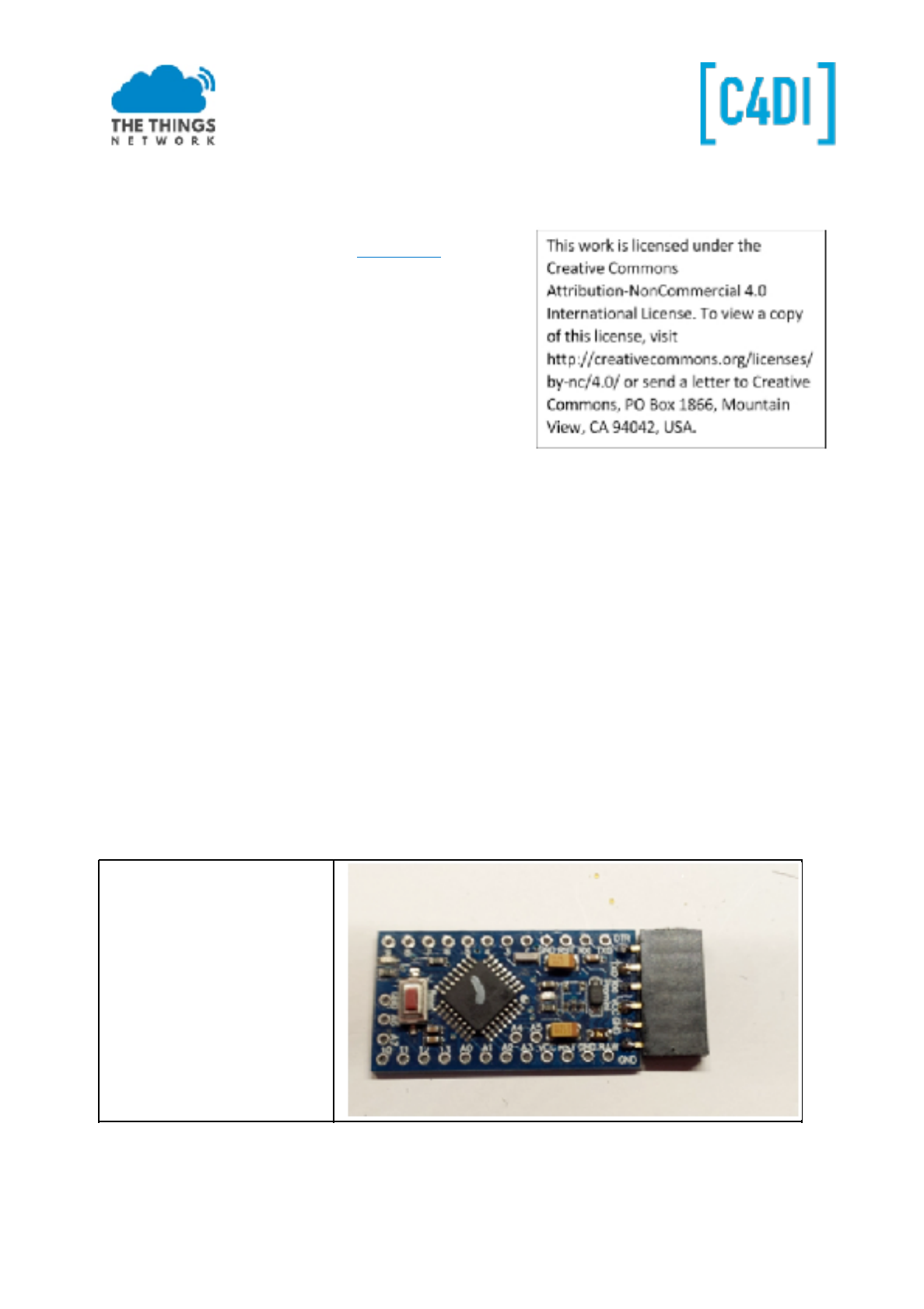
● Pro Mini 3.3V 8Mhz (5V will NOT work!!)
● FT232RL-3.3v-5v-TTL-USB-Serial-Port-Adapter (has
to have a 3.3V option!)
● USB cable for FTDI
● 1x Led 3mm red
● 1x resistor 1k (brown-black-red)
● Header 6p female (Arduino programming)
● Header 40p divided in: 2x 4p, 1x 6p, 1x 3p and 1x
2p
● PCB ‘DougLarue’
● Sensor BME280 (Temperature, humidity and air pressure)
● Battery holder 2 x AA
● 2 AA batteries
● optional: 2 x female headers 2p (battery and led connection)
Low Power the Arduino?
There is an option to ‘low power’ the Arduino. BUT this requires some precise soldering! The setup
will work without removing the components. So if you are a novice solderer, skip the first part! It
requires a sharp knife to remove the power converter, and to cut the connections for the two on
board leds. If you want to battery power your node for a longer time (weeks or more) this is the
option for you. Current in sleep mode will be reduced to <100uA. Look at the instructions at the end
of this manual
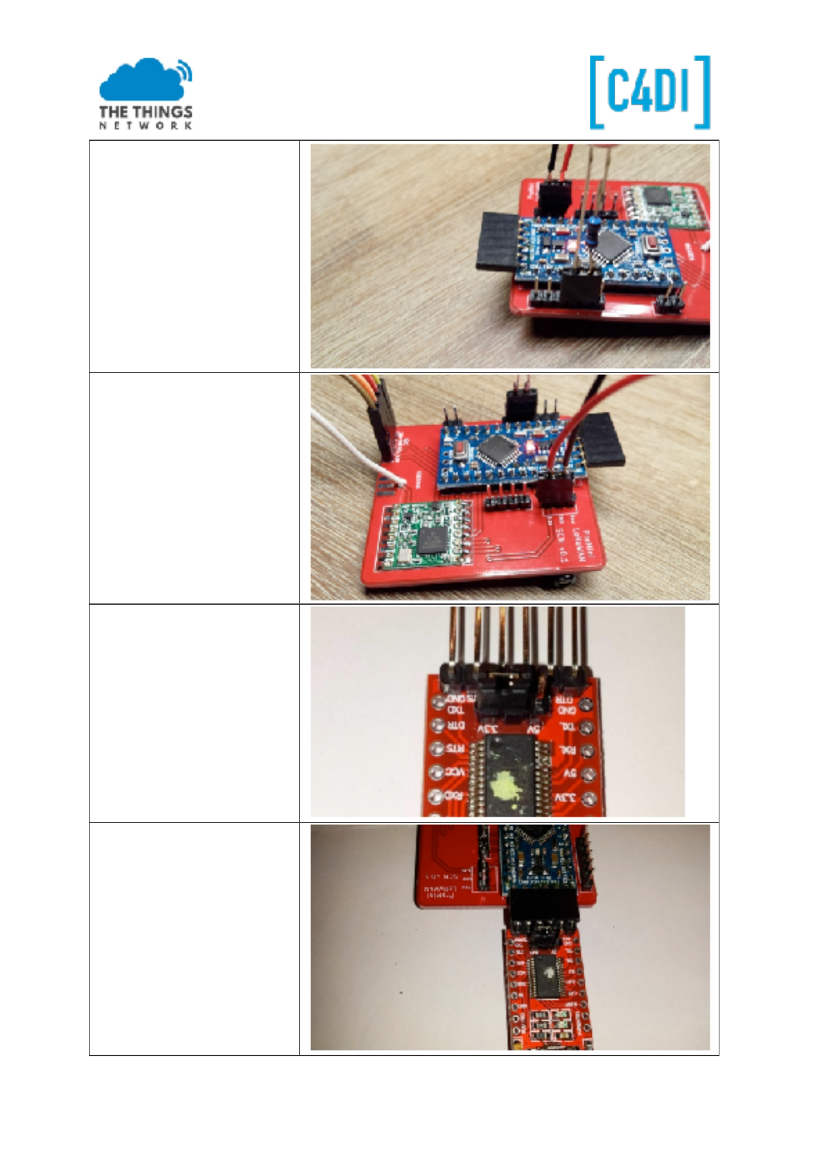
Building the Node
Connect the 6p female header
to the Arduino. To get it low
profile bow it so it is straight
with the PCB.
This work is licensed under the Creative Commons Attribution-NonCommercial 4.0 International License. Page 1
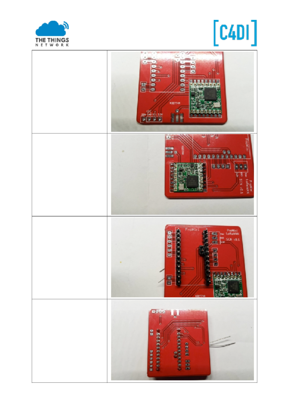
Position the RFM95 radio chip.
The crystal should be in the
right lower corner (as shown
in the picture). Start with just
a little solder in two opposite
corners.
Align the solder pads and if the
module is in place, solder the
other pads. Do use as little as
possible solder! Check the
connections carefully!
Put two 12p headers into the
ProMini socket. Also put the
2p header inside the ProMini
area. By holding them with a
piece of paper you can turn
around the PCB. (You can also
use the ProMini to keep the
pins in place by using an
elastic band.)
First solder the end pins, align
the headers straight and
solder all the other pins.
This work is licensed under the Creative Commons Attribution-NonCommercial 4.0 International License. Page 2
This work is licensed under the Creative Commons Attribution-NonCommercial 4.0 International License. Page 3
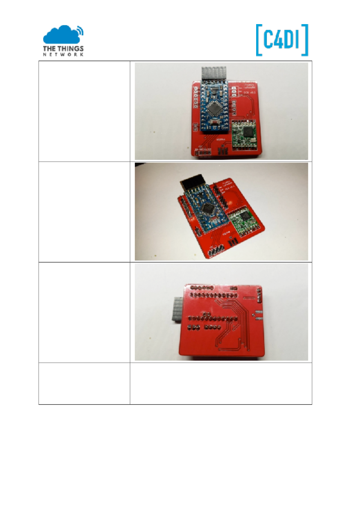
Turn around the PCB and
solder the ProMini in place. Do
not forget the two pin header!
Now solder the 6p, 2p, 3p and
4p header.
Cut a piece of wire, length
82.2 mm. This is a ¼ wave
length antenna. You may add
some short soldering end.
Wavelength =300/868 = 0.3456m
Wavelength /4 = 0,0864 m
correction 0.95*0.0864=0.0822m (to determine the precise
length you can do some experiments, or use proper test
equipment like a SWR meter)
This work is licensed under the Creative Commons Attribution-NonCommercial 4.0 International License. Page 4
Solder the Antenna into the
hole near the connector pins.
It is also possible to solder a
SMA edge connector.
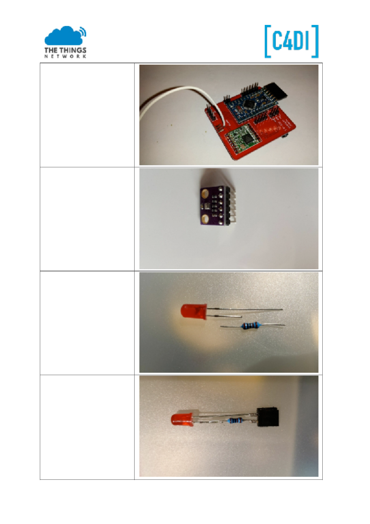
Solder a header on the
BME280 barometric sensor
Prepare the LED, this requires a
‘helping hand’ for soldering.
Cut the longest wire of the LED
(‘+’), and the 1K resistor as
shown
Now solder the resistor, you
may use a spare female header
to create a ‘connector’ or
some female jumper wires
This work is licensed under the Creative Commons Attribution-NonCommercial 4.0 International License. Page 5
Put the LED ‘connector’ to pins
4 and 5 of the 6 pin jumper, as
shown (Pin 4: GND, PIN 5 -
D2), the resistor pin (‘+’) goes
to pin 5 / D2. You may even
solder the pins directly
You can solder the battery
holder on the pins GND (black)
and 3.3V (red), you may use a
female header here as well
Put the Jumper on the FTDI
board on 3.3V position!
Connect the USB cable to the
FTDI board, the FTDI board to
the Arduino as shown.
Starting up the Arduino Environment
https://www.arduino.cc/en/Guide/HomePage
Install the Arduino IDE on your favourite platform (Mac, Linux or Windows). These examples work
only with the latest Arduino IDE (tested on 1.6.9)!
https://www.arduino.cc/en/Guide/ArduinoProMini
Use the FTDI, ensure that the jumper is on the ‘3V’ side. Battery power turned off (check the switch)
Connect the FTDI and the Pro Mini so that the components are both facing up.
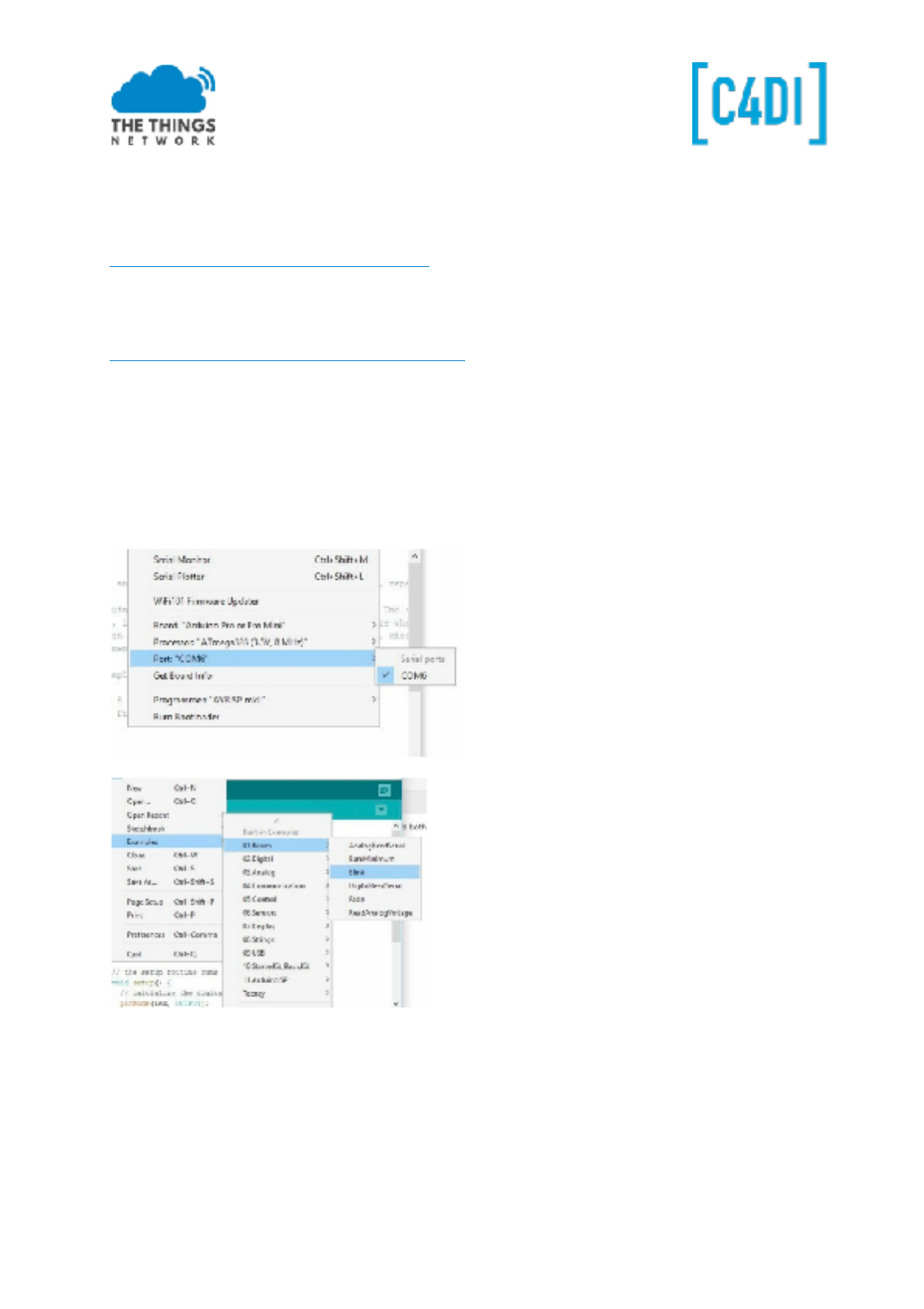
● Start the Arduino IDE
● Select the board: ‘Arduino Pro or Pro mini’
● Select the Processor ‘ATmega328 (3.3V, 8Mhz)
● Select the COM port given
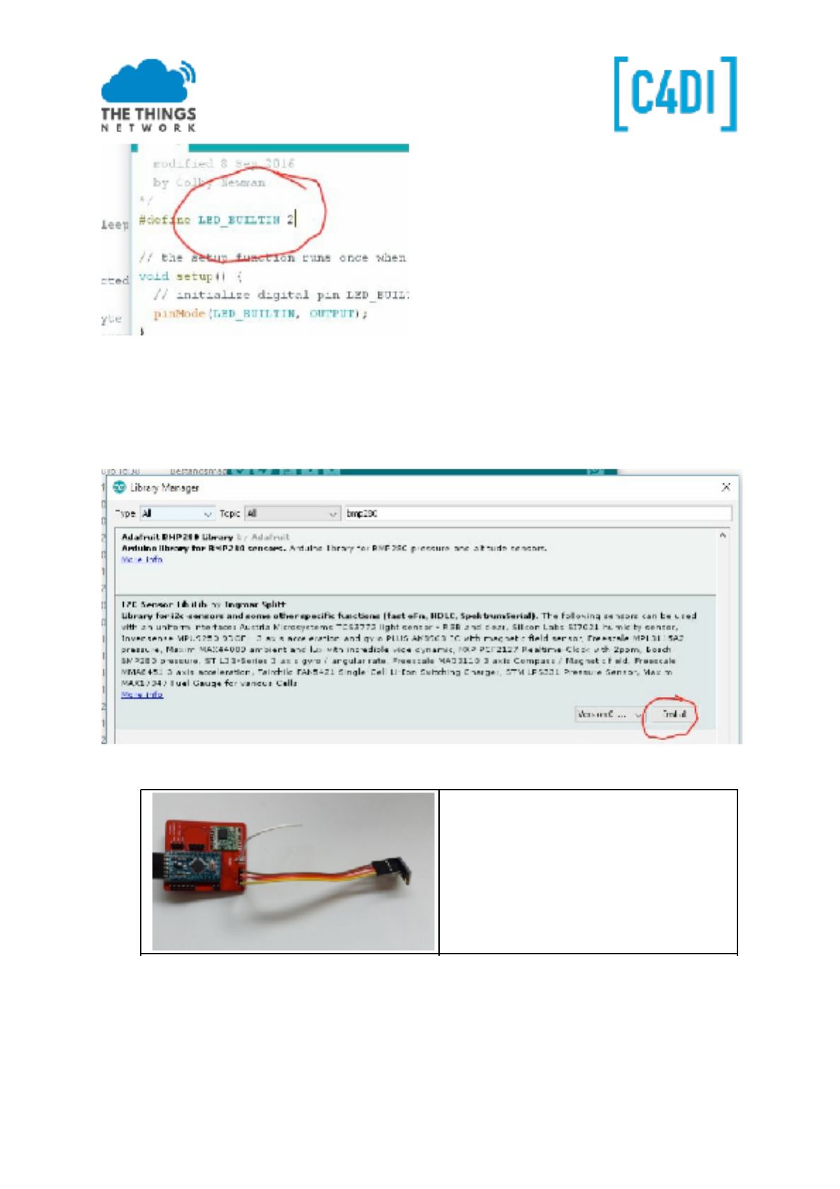
Select the default ‘BLINK’ example, change the LED pin from 13 to 2, in the newest blink example you
may change ‘LED_BUILTIN’ to 2.
This work is licensed under the Creative Commons Attribution-NonCommercial 4.0 International License. Page 6
Load the code with CTRL-U to the Pro Mini. After compilation and uploading the led on the board
should blink at 1 Hz. Great: we have a working programming environment!
Testing the sensors
1. Install the Adafruit_BME280 library: Sketch-> include library -> manage libraries
2. Search for BME280:
3. Install the library ‘I2C-Sensor-Lib’
4. Connect the BME280 sensor:
Connect the BME280 sensor with female-
female jumper wires to the I2C connector:
GND-> GND, SDA->SDA, SCL->SCL, VCC-
>+3.3V. The CSB en SDO are left open (only
used in SPI connection). You can not
connect straight forward, but you should
twist the two wires in the middle.
5. Load the the i2c_BME280 example (File->Examples->Adafruit BME280 Library>BME280test).
Yo u wi ll n ee d to c ha ng e th e Ad af ru it _B ME 28 0. h fi le ( in y ou r Ar du in o Li br ar ie s fo ld er ).
Edit it with your favourite editor - change line 32 from 0x77 to 0x76.
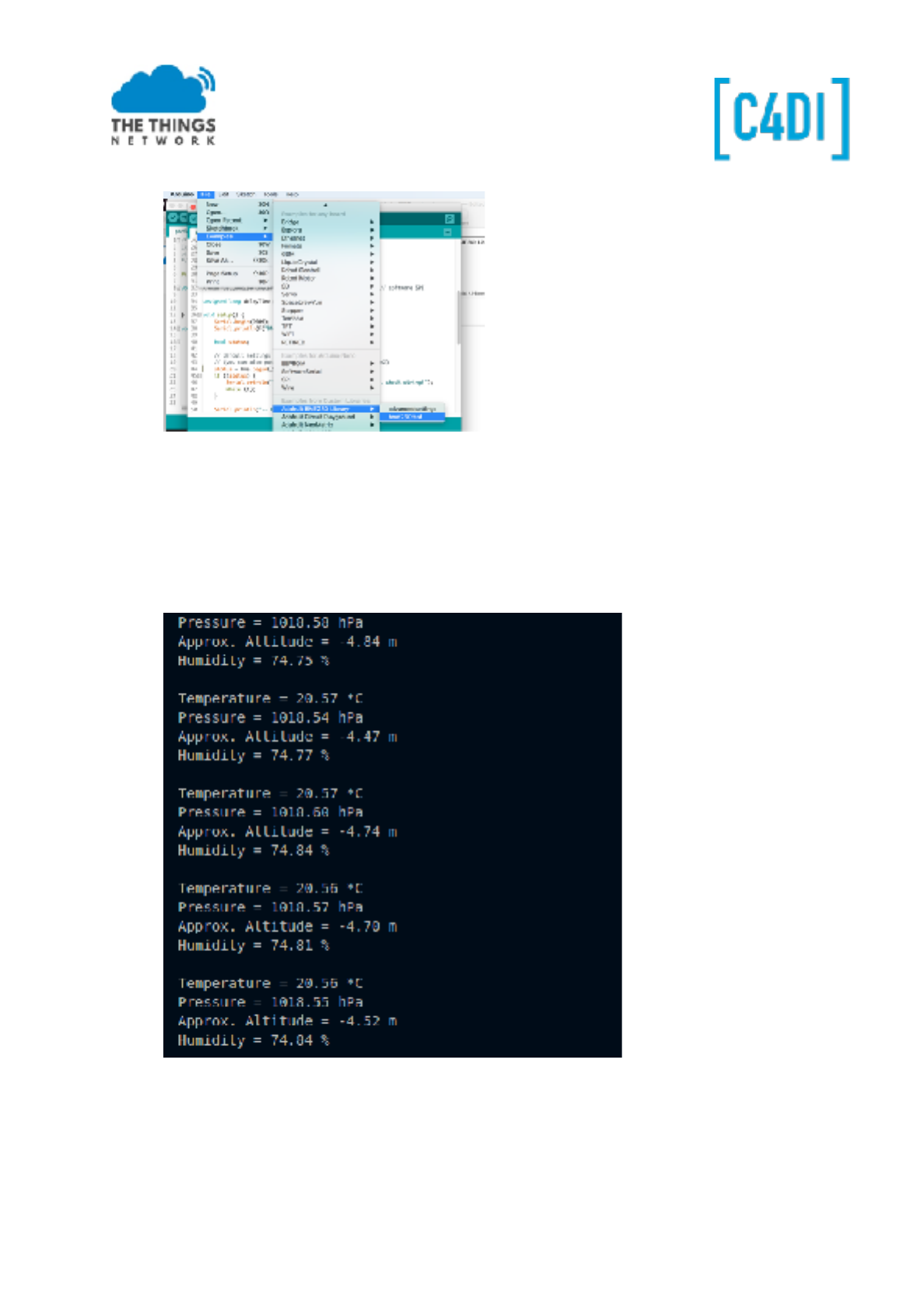
!
opening the Serial Monitor (115200 bps) you will see the humidity, pressure and
temperature of the sensor. Put your finger on the sensor (the small metal unit) and see the
temperature rise.
The Serial Monitor should display something like this:
Getting things started on ‘The Things Network’
Download the LMIC library from Github:
1. Goto https://github.com/matthijskooijman/arduino-lmic
2. Choose ‘Clone or download’
3. Download ZIP
4. Mark the location
5. Go to Arduino IDE
6. Select ‘Sketch->Include Library->Add .ZIP Library’
7. Select the downloaded Arduino-lmic-master.zip file from your download location
8. Goto https://github.com/rocketscream/Low-Power
9. Choose ‘Clone or Download’
10. Download ZIP
11. Mark the location
12. Go to Arduino IDE
13. Select ‘Sketch->Include Library->Add .ZIP Library’
14. Select the downloaded low-power-master.zip file from your download location
To help joining OTAA faster (seconds in stat of 7 minutes) you may alter the LMIC library. You can
find LMIC.C file in <My Documents>\Arduino\Libraries\Arduino-lmic-master\src\lmic
1. Open the file in your favourite source code browser (or use WordPad)
2. Go to line 684 (or find ‘setDrJoin’ to find the line below)
3. Change setDrJoin(DRCHG_SET, DR_SF7); to: setDrJoin(DRCHG_SET, DR_SF9);
4. Save LMIC.C
The Things Network Dashboard
Your applications and devices can be managed by The Things Network Dashboard.
Create an Account
To use the dashboard, you need a The Things Network account. You can create an account here:
https://account.thethingsnetwork.org/users/login .
After registering and validating your email address, you will be able to log in to The Things Network
Dashboard.
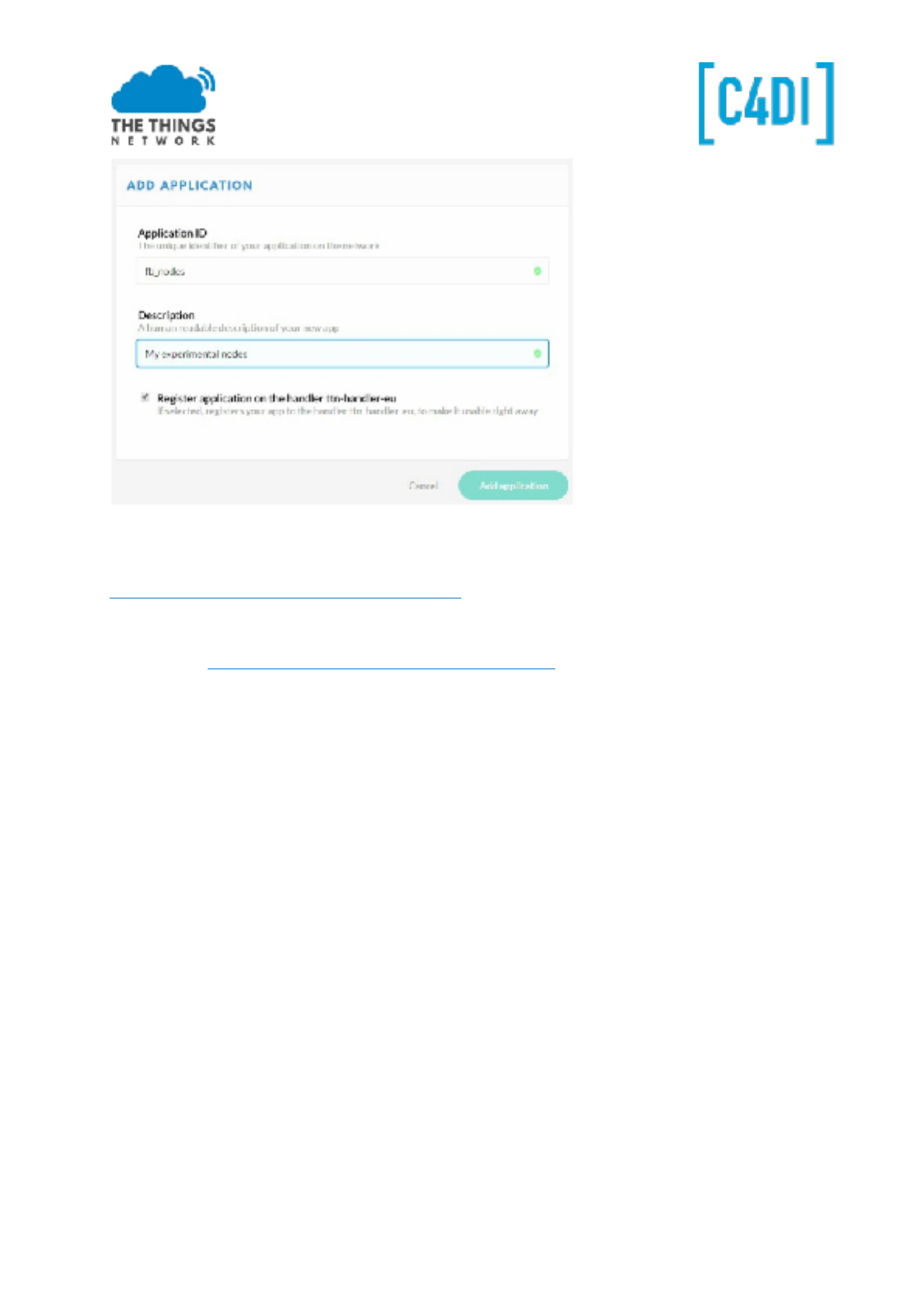
Create an Application
https://console.thethingsnetwork.org/applications
Choose ‘add application’
Give your Application a unique ID. You can use ONLY lowercase! You can add an unique number to
get uniqueness over the ttn network (this is a global ID)
Your description can be any description you like.
This work is licensed under the Creative Commons Attribution-NonCommercial 4.0 International License. Page 9
First download the code for ttn_bmp280i.ino from
https://github.com/galagaking/ttn_nodeworkshop
You can download the ZIP and unzip the file to get the examples:
1. Goto https://github.com/galagaking/ttn_nodeworkshop
2. Choose ‘Clone or download’
3. Download ZIP
4. Open the ZIP in explorer
5. Open the example ttn_bmp280.ino
6. Create the sketch folder for the application
Register the device
Now register your device. We will use OTAA in this example. This is ‘Over the Air Authentication’. You
have to define an address for yourself. This is a kind of MAC address, but because there is no
registration yet of these, define some RANDOM 8 byte value, using your postcode and some values in
between.
This work is licensed under the Creative Commons Attribution-NonCommercial 4.0 International License. Page 10
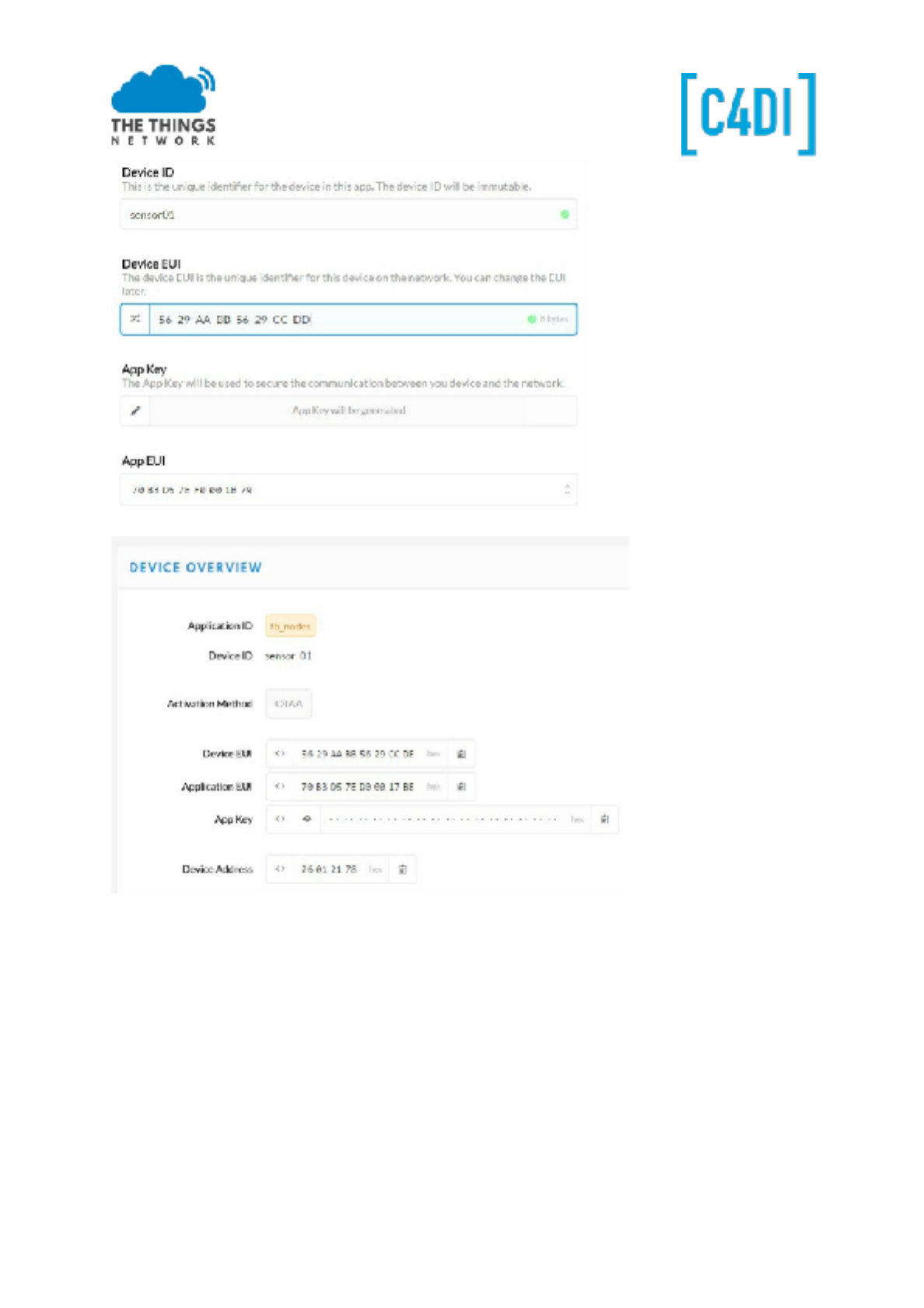
There are three values you should copy into your Arduino Code. Dev EUI (the device identifier), App
EUI (The application identifier) and the App key.
Dev EUI
With the <> sign you can select different ‘views’. We need the ‘LSB’ view, also called little Endian or
Least Significant Byte First.
NOTE: For the App Key we need MSB, not LSB.
This work is licensed under the Creative Commons Attribution-NonCommercial 4.0 International License. Page 11
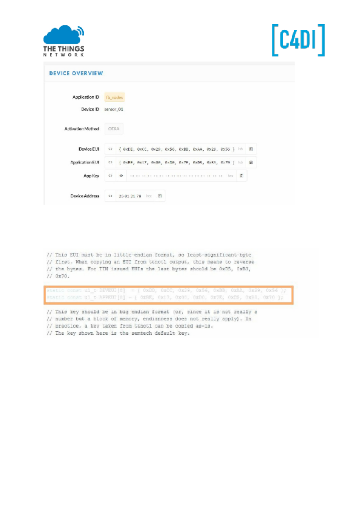
Both Dev EUI and App EUI will be used in LSB or little Endian format.
First copy the Dev EUI with the clip board sign on the right. Paste the string into your code at the
static const u1_t DEVEUI. Remember to respect the semicolon at the end of the line.
APP EUI
Next copy APP EUI, select LSB for this one as well. Copy to APPEUI in your code.
APP KEY
The last key is a secret hash, so this one just shows when you click the ‘EYE’ icon. After that you can
copy this to the clipboard. This one can be copied in MSB format.
Copy the 16 bytes APPKEY after static const u1_t APPKEY[16] = .
The BME280 sensor should be connected!
Upload your code to the Arduino.
The LED will blink during the JOIN process. The Arduino gets his keys from TTN, thereby all
information sent will be encrypted with these keys.
This work is licensed under the Creative Commons Attribution-NonCommercial 4.0 International License. Page 12
You can also follow this process by activating the ‘data’ view:
After a few minutes, the LED will stop blinking. You will see the information coming in into the
dashboard. This is coded information, because some algorithm is used to put temperature and
humidity in two bytes.
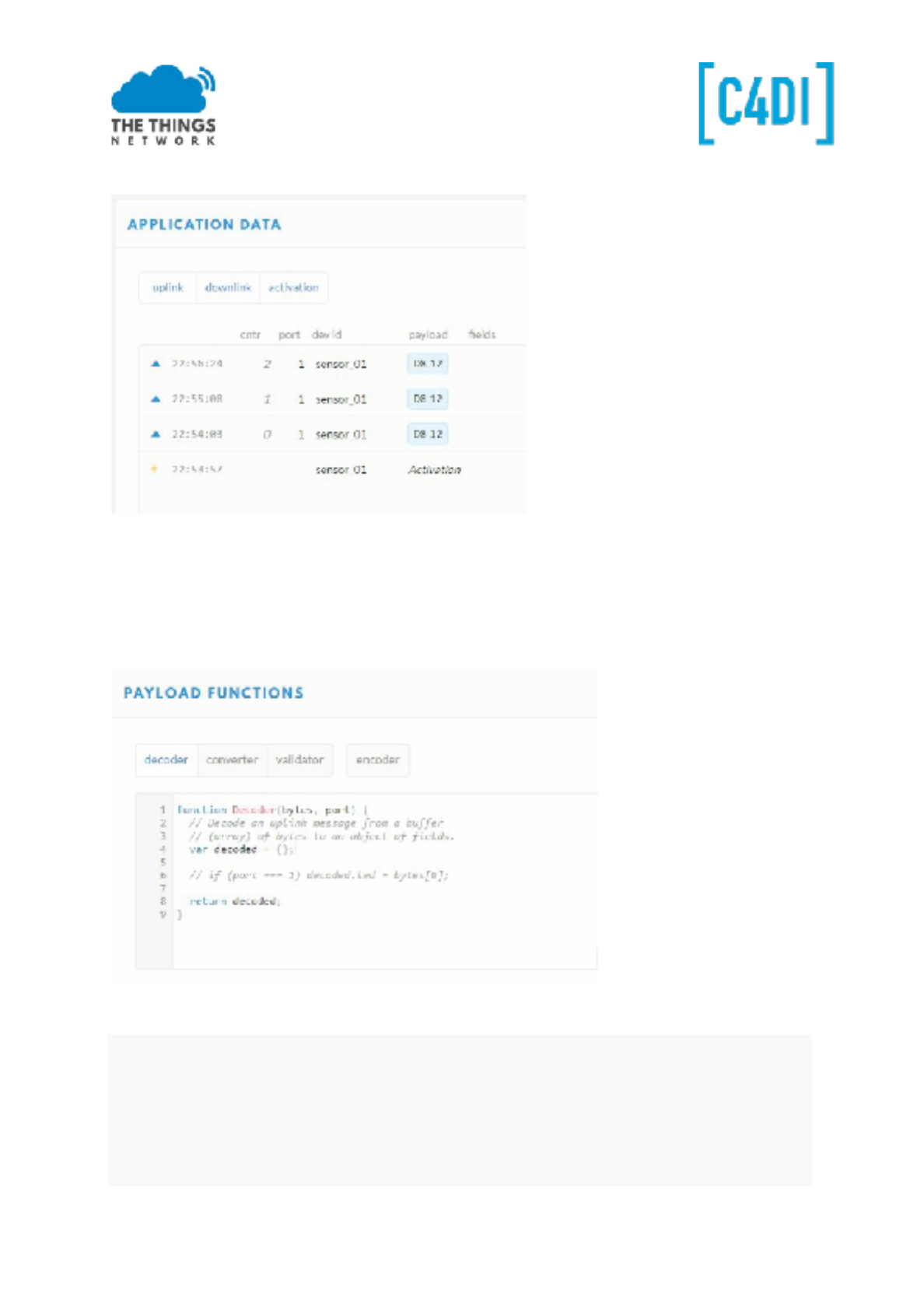
To get the right display format, we can create a decoder in our application. Select your application
and open the ‘Payload Functions’:
Enter the function below, overwriting the standard function
function Decoder(bytes, port) {
var mbar = 970+((bytes[1] >> 2) & 0x3F);
var temperature = - 2400+6.25*(((bytes[1] & 0x03) << 8) | bytes[0]);
return {
mbar: mbar,
celcius: temperature / 100.0
};
}
This work is licensed under the Creative Commons Attribution-NonCommercial 4.0 International License. Page 13
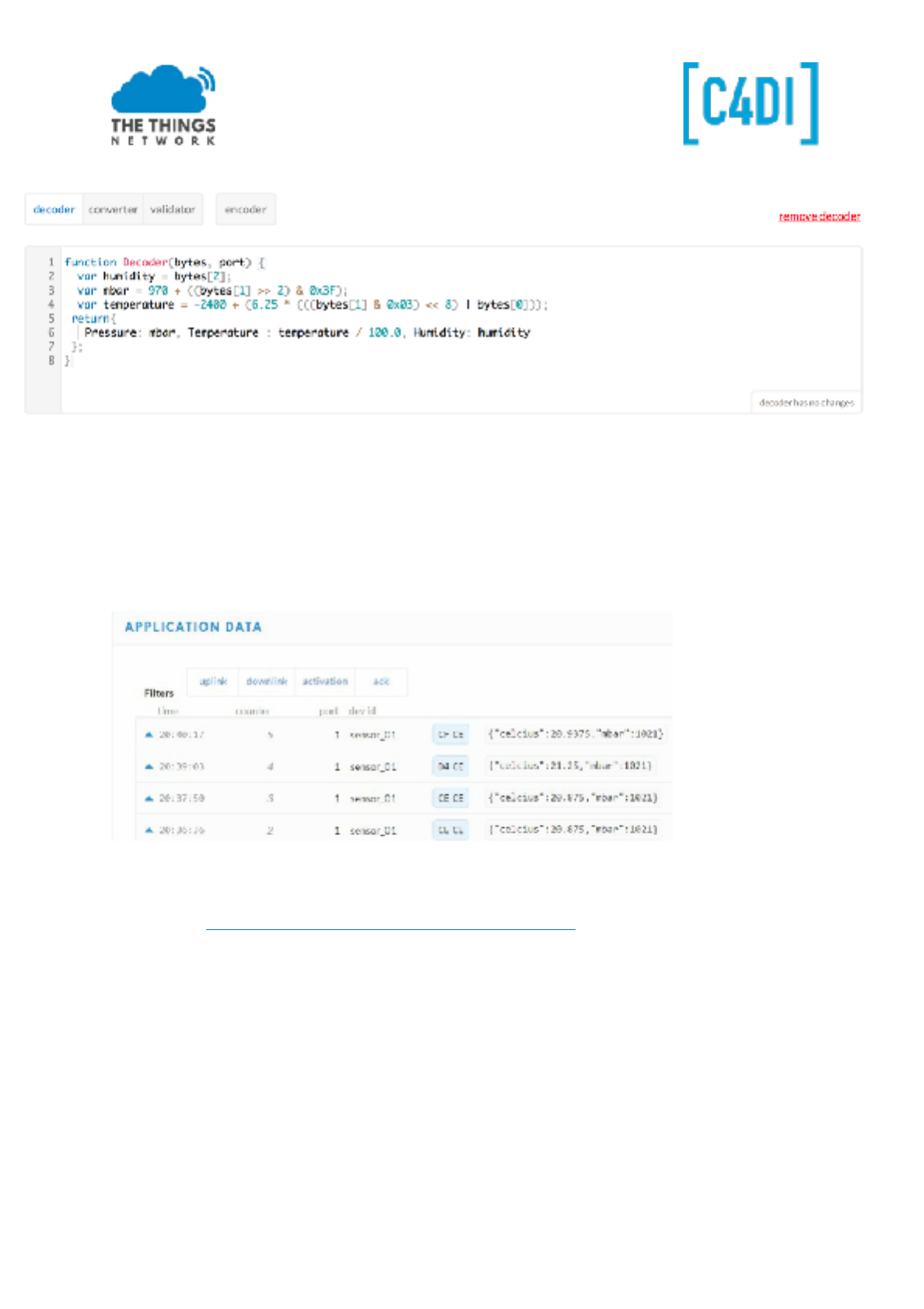
!
First test the function with three dummy bytes EF C6 3B, And then Save the
function. Return to your data and look what happens:
This way you can put several values into a byte string. Sending in clear ASCII is possible but due to
bandwidth limitations not preferable in production environments. To make this even more scalable
take a look athttps://github.com/thesolarnomad/lora-serialization.
DOWNLINK
To send bytes to our node we can use the ‘Downlink’ section: in the console, click on your device and
scroll down in the Overview page . Enter one byte (two hex digits, 05 for example) and click Send.
This work is licensed under the Creative Commons Attribution-NonCommercial 4.0 International License. Page 14
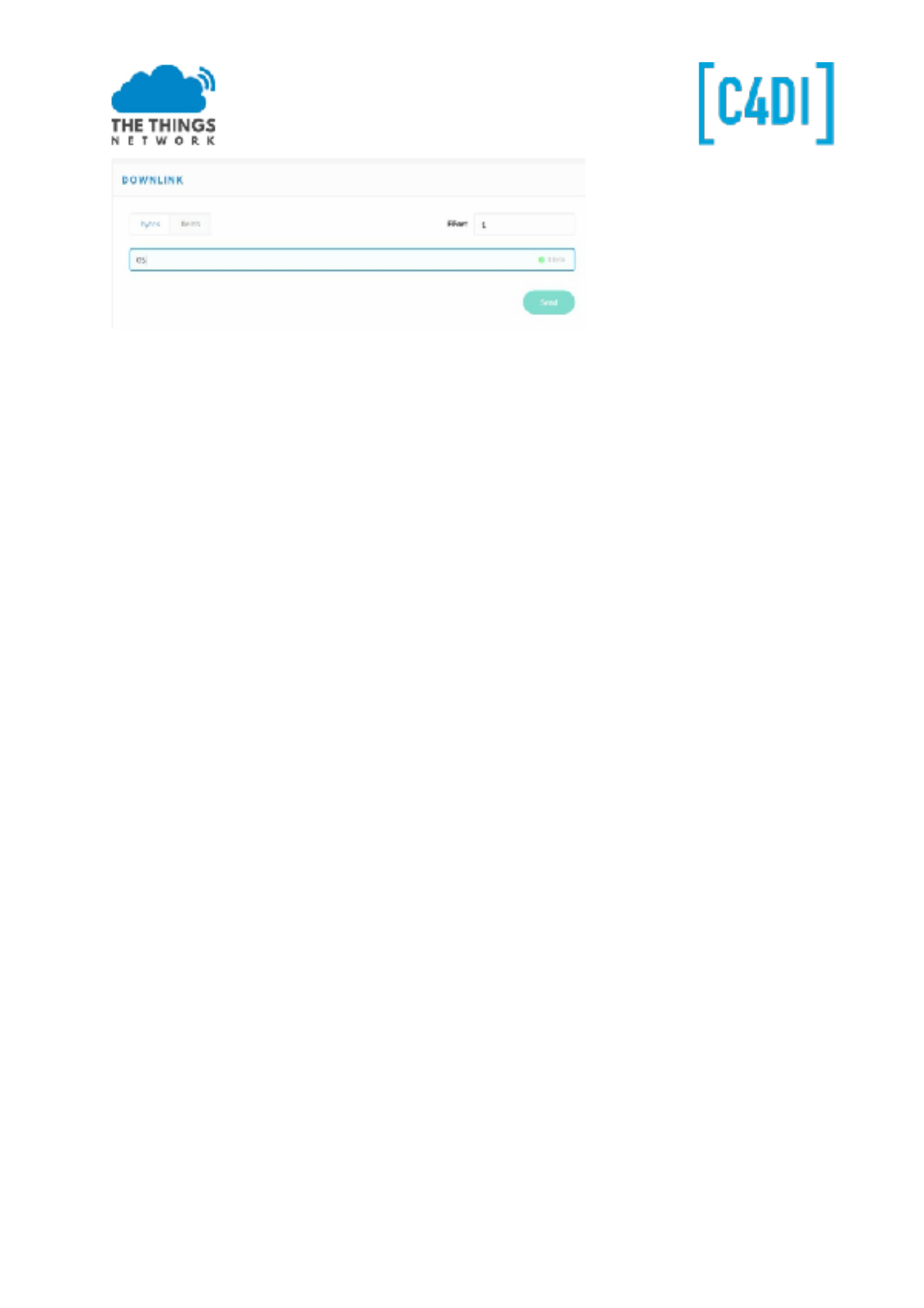
The information will be send to the node after the next time the node contacts the gateway. With a
sample rate of approx. 60 seconds, that is the maximum time this data will be received. The Led will
blink this amount of times, with a maximum of 10 (0x0A).
Congratulations! Yo u successfully completed the workshop.
The Moment of truth
Now, it's time for a live demonstration. It's important to gather a small audience which you can
impress with your node. Also, don’t forget to make a picture and post it on Twitter using
@thethingsntwrk
This work is licensed under the Creative Commons Attribution-NonCommercial 4.0 International License. Page 15
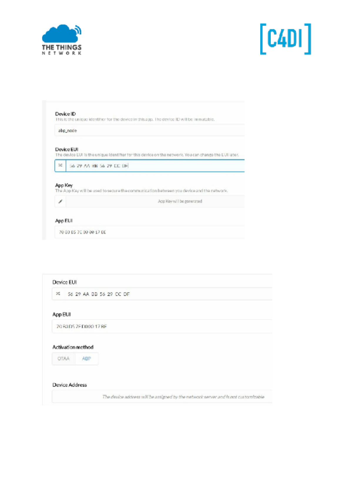
ABP
Activation by Personalization (ABP) is a method where the security keys are stored in the device. Not
as safe as the OTAA method, but for experiments it works OK. There is no join procedure, nodes will
work right away.
Register the device.
Now edit the settings of the device and choose ABP (OTAA will be selected by default)
Select ‘save’. Now some values are system generated and we have to copy them to our code. We use
the ttn_bmp280_abp.ino example here.
This work is licensed under the Creative Commons Attribution-NonCommercial 4.0 International License. Page 16
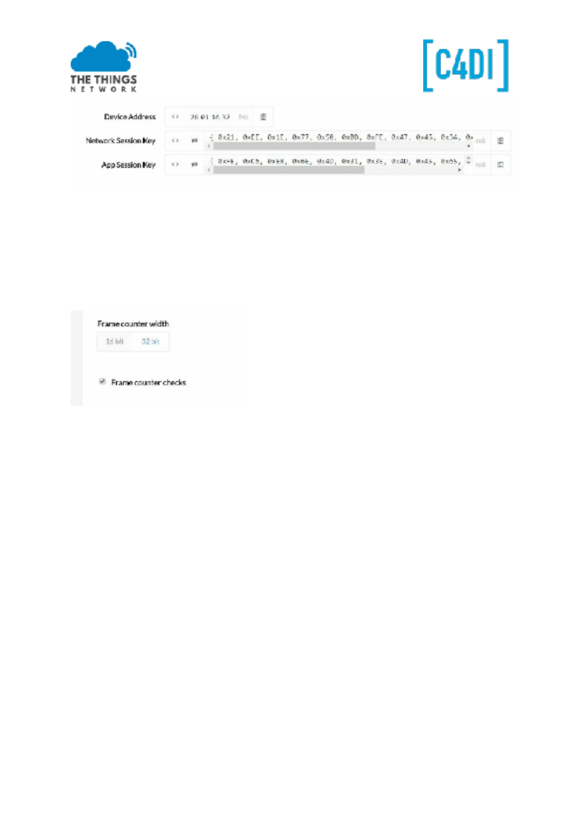
● Copy the Device Address as a HEX value to DEVADDR in the example, so 26 01 1A 32 will be
0x26011A32.
● Copy the Network Session Key as MSB to NWSKEY.
● Copy the App Session Key as MSB to APPSKEY.
Compile and upload the code. Check in the dashboard the working.
You might want to uncheck the frame counter check
If the frame counter is checked, you must respect the sequence number, and probably copied
packages are refused on the network. Though restarting you node, and thereby resetting the frame
counter, will disable your node. So to get this working, you have to disable this check by unchecking
this box. You can integrate the code of ttn_bmp280 in the abp example.
This work is licensed under the Creative Commons Attribution-NonCommercial 4.0 International License. Page 17
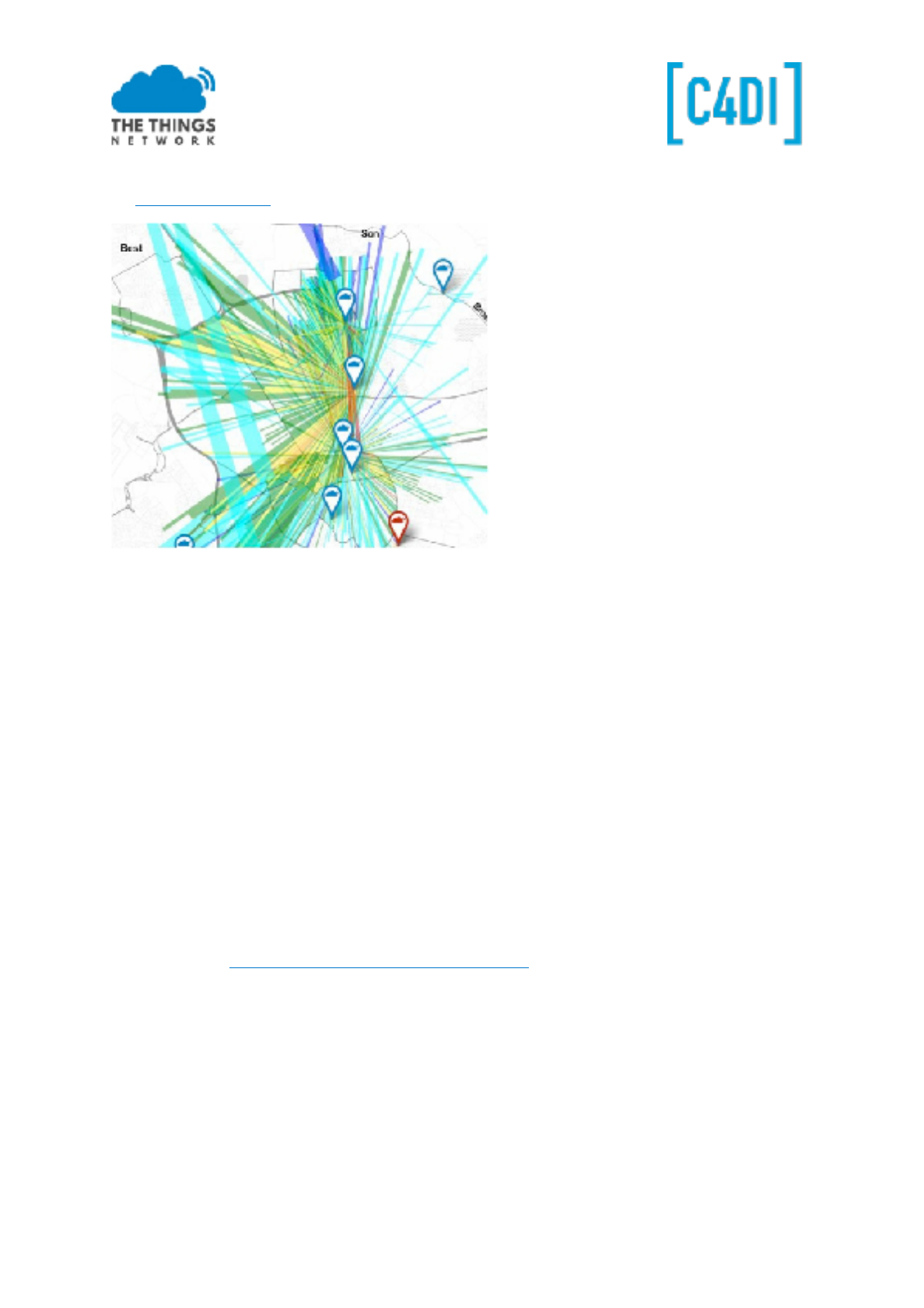
TTN Mapper
On www.ttnmapper.org you can look at the coverage of The Things Network in your neighbourhood.
You can even contribute to this map by using the ttnmapper app on your Android Smartphone. You
can use your TTN credentials to select your sensor
LMIC Pin Mapping
If you are using other ‘LMIC’ or TTN examples, there is ONE part to take care of, the pin setting of the
RFM95 module. Most times you have to adjust this to the pinout of the board:
// Pin mapping is hardware specific
const lmic_pinmap lmic_pins = {
.nss = 10,
.rxtx =
LMIC_UNUSED_PIN, .rst =
.dio = {4, 5, 7}, //DIO0, DIO1 and DIO2 connected
};
And even more…
● You can add professional Antenna’s on the PCB by using the appropriate connector.
● Support: https://www.thethingsnetwork.org/forum/
Thanks to Doug Larue for his PCB design and sharing his manuals.
Frank Beks
March 2017
This work is licensed under the Creative Commons Attribution-NonCommercial 4.0 International License. Page 18
Low Power the Arduino (Optional)
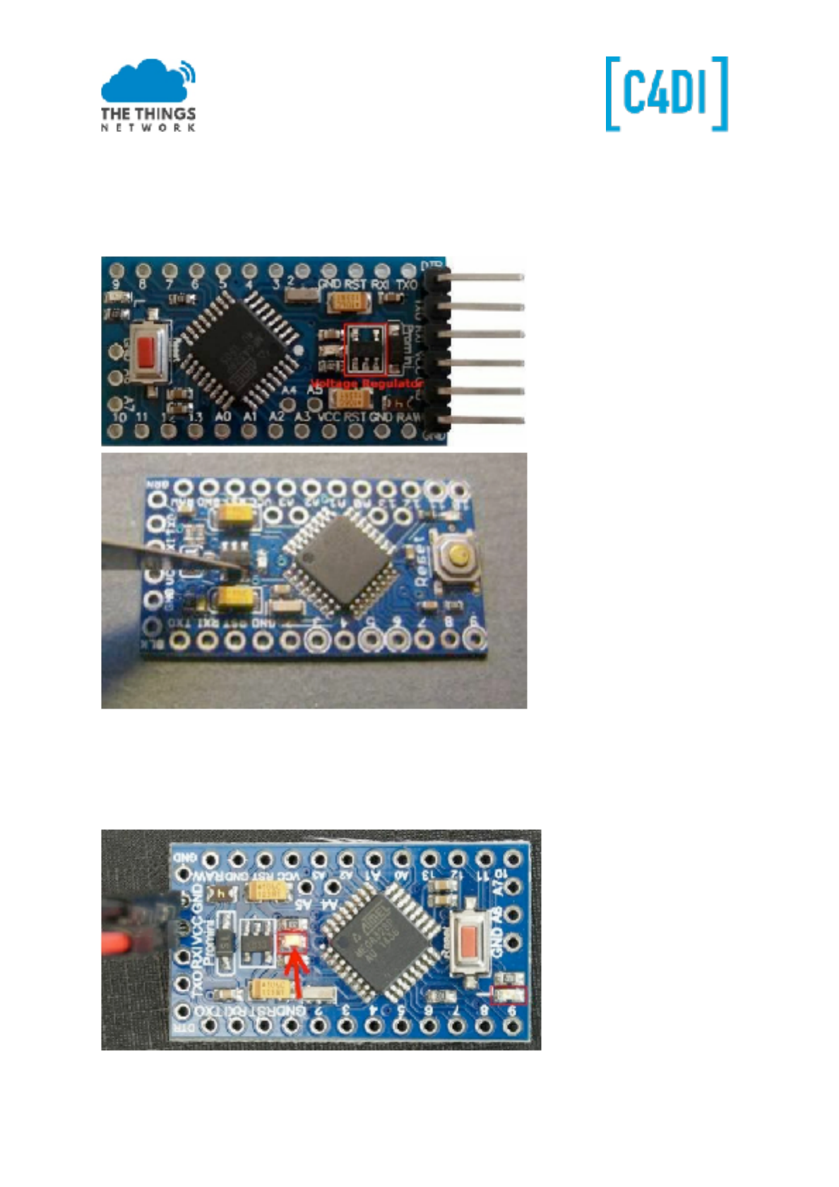
Remove the Regulator
The easiest way to remove the regulator and not damage the board is to use a very sharp scalpel to
cut through the regulator leads at the point they join the regulator body.
Remove the LEDs
There are two LEDs on the Pro Mini board. The two LEDs are marked with a red square in the
following picture. The power LED is marked with an arrow. If you are not sure where the power LED
is on your board, then you can just power it and you will see the LED.
When you found the power LED, then try to locate at least one trace that leads to the LED. In the
This work is licensed under the Creative Commons Attribution-NonCommercial 4.0 International License. Page 19
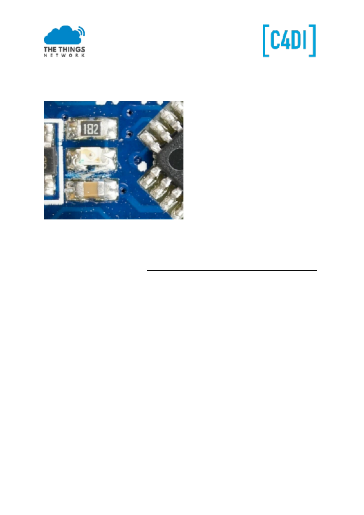
second picture below, I marked the traces on my board. A high-resolution picture
with a lot of light helps to find the traces.
When you found a trace to the power LED, then you take a knife and break the trace, so that it will
not conduct any more. You can see my result in the third picture below.
Removing the LEDs can be tricky, so it’s easier to remove the series resistors for the LEDs instead.
This version of Pro Mini also has a resistor feedback network for the regulator across VCC, these
consume power so should be removed. Just push the resistors aside with a soldering iron. The
picture shows the Pro Mini with unwanted parts removed, locations of the removed components are
circled in red.
More on this subject you may find at: https://andreasrohner.at/posts/Electronics/How-to-modify-an-
Arduino-Pro-Mini-clone-for-low-powe r-consumption/
This work is licensed under the Creative Commons Attribution-NonCommercial 4.0 International License. Page 20
