INSTRUCTION MANUAL C1.0A OM HH 10 18 00
User Manual: C1.0A-OM-HH-10-18-00
Open the PDF directly: View PDF ![]() .
.
Page Count: 69
- October, 2000
- Document No. 4080410 Rev. A
- 1231 TCS
- 3. OPERATING THEORY AND PRACTICE
- 4. START-UP PROCEDURE
- 5. PRODUCT FUNCTIONAL DETAILS
- 6. SPECIFICATIONS
- 7. DIMENSIONS AND VIEWS OF PANELS
- 8. INSTALLATION
- 9. SET-UP AND INITIAL OPERATION
- 10. OPERATING THE TCS CONTROLLER
- LIQUID PUMP OPERATION
- TROUBLE-SHOOTING THE 1231
- APPENDIX

INTRODUCTION
The model 1231-CCN-DI-001 and 1231-CCN-GL-001 temperature control systems
(TCS) are two channel systems made by Advanced Thermal Sciences Corp., a
subsidiary of B/E Aerospace, Inc. It is designed to provide two independently
temperature controlled flows of heat transfer fluids (either 50% DI water/50% ethylene
glycol or Galden®) at a nominal pressure of 100 psi; flow is nominally 5 gallons per
minute (gpm) on one channel and 8 gpm on the second channel. Both channels are
chilled by a low temperature refrigeration system. The channels can supply fluid as cold
as –20°C to absorb up to 5000 watts on the high flow and 2500 watts on the standard
flow channel.
The 1231-CCN-DI-001 and 1231-CCN-GL-001 use a unique system to obtain two
chilled channels from a single refrigeration source. This concept is proprietary to B/E
Aerospace. The manual describes some details and elementary theory of the system.
It shows how to operate the TCS as well as perform elementary troubleshooting.
The 1231-CCN-DI-001 and 1231-CCN-GL-001 are set up to communicate with an
Applied Materials central controller. The TCS communicates via the RS485 port and
CHX communication protocol for this purpose. The TCS can be controlled either by the
tool controller or, when set in LOCAL mode, with a controller mounted in the TCS itself.
The Watlow Anafaze CLS200 Series USER’S GUIDE with supplement is an
integral part of this manual.
This manual is designed to provide information sufficient to install, operate and maintain
the 1231-CCN-DI-001 or 1231-CCN-GL-001. Enough knowledge about the basic
function and theory is also given to enable the operator to understand the TCS.
TABLE OF CONTENTS
1. TCS 1231 1-1
1.1. Scope of the manual 1-1
1.2. Description of the 1231 TCS 1-1
1.3. Safety controls and features 1-1
1.4 Lock Out Procedure 1-1
1.5 Customer Service Contacts 1-2
1.6. Emergency Off Switch (EMO) Operation 1-2
1.7. Generated Waste 1-2
1.8. Seismic Tie Down Provision 1-2
1.9. Fluid Leak Containment Provision 1-3
1.10. Warnings and Cautions 1-4
2. OPERATING PANEL 2-1
3. OPERATING THEORY AND PRACTICE 3-1
4. START-UP PROCEDURE 4-1
4.1. Power up 4-1
4.2. Temperature set point verification. 4-2
5. PRODUCT FUNCTIONAL DETAILS 5-1
5.1. Refrigeration and coolant circuits 5-1
5.2. Installation Drawings 5-1
6. SPECIFICATIONS 6-1
7. DIMENSIONS AND VIEWS OF PANELS 7-1
8. INSTALLATION 8-1
8.1. Receiving the 1231 TCS 8-1
8.2. Securing the unit 8-1
8.3. Stacking 8-1
8.4. Facilities 8-1
8.5. REMOTE mode 8-3
8.6. LOCAL mode 8-3
8.7. Filling the reservoir 8-3
8.8. Filling the lines from the reservoir 8-3
8.9. Draining the coolant reservoir 8-3
9. SET-UP AND INITIAL OPERATION 9-1
9.1. Filling a tool channel. 9-1
9.2. Purging gas from a tool channel 9-7
9.3. Draining a tool channel 9-9
9.4. Fluid Line Connections 9-9
9.5. Draining the TCS for Removal 9-9
9.6. Instructions for filling a TCS with Galden® 9-10
10. OPERATING THE TCS CONTROLLER 10-1
10.1. Setting up the controller 10-1
10.2. Address set-up 10-1
10.3. Proportional Integral Derivative settings 10-1
10.4. Capacity regulation 10-3
10.5. Process Control Limit Settings 10-3
10.6. Changing the Process Set Points 10-3
10.7. Changing the Safety and Reference Set Points 10-3
11. LIQUID PUMP OPERATION 11-1
12. TROUBLE-SHOOTING THE 1231 12-1
13. APPENDIX 13-1
1. 1231 TCS
1.1 Scope of the manual
This manual provides information on the detailed function, installation, start-up and operation of
ATS Model 1231-CCN-DI-001 and 1231-CCN-GL-001 Temperature Control Systems (1231 TCS).
Instructions for installation are provided. The technician performing the installation must have
sufficient understanding of electrical wiring and refrigeration systems to be able to use this
information.
1.2 Description of the 1231 TCS
The 1231 TCS is a two channel temperature control unit designed to control the temperature of
remote heat loads; specifically Semi tools such as electrostatic cathodes and chamber walls.
From distances up to 75 feet, the 1231 TCS can absorb heat generated by the process
equipment. Coolant fluid (Galden® HT 70 or DI Water/Glycol) circulates through heat exchangers
in the 1231 TCS where it is cooled or heated in a controlled process. The fluid is then passed, in
a closed loop, to the process equipment. The 1231 TCS maintains supply coolant at a
temperature between -20°C and +40°C, within ±1°C.
1.3 Safety controls and features
The 1231’s TCS safety features are listed in the Safety Features Table 1-1 and are followed by
system warnings and cautions.
1.4 Lock Out Procedure
Prior to performing service on the TCS, the Main Circuit Breaker and the ball valve(s) must be
locked out to protect personnel and equipment. Reference Applied Materials document 293-200-
01 Chapter 9 for approved Applied Materials Lock out Tag Out procedures. The multi pole circuit
breaker uses AMAT P/N 3920-01284. The ball valve handles use ATS P/N 4081617-001, for the
lock out device.
1.5 Customer Service Contacts
If the chiller operator is in need of assistance regarding the operation of the B/E Aerospace chiller,
the following information should be useful.
a. Prior to contacting B/E Aerospace, obtain the following information from the
chiller: part number, serial number, fluid type (50/50 water-glycol or Galden®) and
hours of operation (hour meter located on front panel).
b. The primary method of contact with ATS is by e-mail. E-mails should be sent to
ATS_Chiller@beaerospace.com where they will be handled by the Product
Support Engineer.
c. Incoming phone calls are made to the Product Support Engineer at 714-688-
4201.
d. Written Correspondence should be addressed to:
Advanced Thermal Sciences Corporation
Attn: Product Support Engineer
3355 East La Palma Avenue
Anaheim, California 92806 USA
e. Faxes are sent to the attention of the Product Support Engineer at 714-688-4153.
1.6 Emergency Off Switch (EMO) Operation
The EMO switch located on the front of the TCS is to be wired to be part of the Applied
Materials 24vac daisy chain circuit. The TCS contains two circular connectors on the rear
panel that are used to create the EMO daisy chain circuit. Once wired, depressing this or
other EMO switches on other components will cut off power to the main contactor and shut
down the entire system. Reference Applied Materials document GPS-IX-006 Chapter 1.
See ATS wiring diagrams 4081575 and 4081567, connector P1/J1, pins 19 &20.
1.7 Generated Waste
The TCS manufactured by ATS, produces no waste products, nor are waste products
generated as a result of operating the equipment.
1.8 Seismic Tie Down Provision
Reference ATS drawing no. 4081362 for the installation of seismic tie down brackets and
the provisions required. TCS chillers manufactured after May 2000 have the mounting
holes provided in the lower tubular frame members.
1.9 Fluid Leak Containment Provision
To be prepared in the event of a leak or rupture in the fluid systems, a Fluid Containment
System can be adapted to the TCS. This is comprised of a stainless steel drip pan and
deflectors. Reference ATS drawing 4081536. The drip pan is to be inserted beneath the
TCS between the casters, extending behind the unit approximately 4 inches. The
deflectors are to be mounted to the rear panel of the TCS using the screws that hold on
the rear panel, second up from the bottom. They should be positioned to deflect any fluid
from the supply and return fittings into the pan.
On models manufactured after June, 2000, a one inch diameter hole exists in the middle of
the bottom panel of the TCS. A rubber sealing plug is installed at the factory. If the fluid
containment system is installed, remove this plug to allow fluid to exit the TCS.
Transfer the fluid accumulated in the drip pan to a container that can be easily carried.
Attempting to carry a filled or partially filled drip pan may be difficult and may result in
spillage of the contents. Dispose of the fluid in accordance with applicable federal, state
and local requirements. Refer to the applicable MSDS if the fluid is ethylene glycol/water
mix or Galden®.
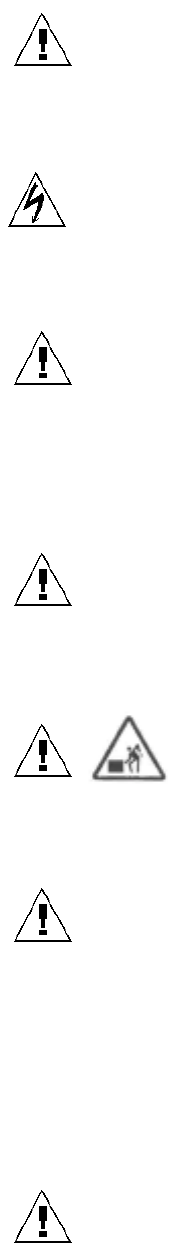
1.10 Warnings and Cautions
This symbol indicates a potentially hazardous situation, which if not avoided, could
result in severe injury or death.
This symbol indicates a potentially hazardous electrical situation which, if not
avoided, could result in severe electrical shock and damage to equipment.
Warning: The mechanical BURST DISK will operate independently of the controller’s
REMOTE/LOCAL function in the event of extreme pressures for the Refrigerant Circuit. A
fault or warning will be communicated to the host computer operating the system while in
the REMOTE MODE in the event of compressor safety device activation.
Warning: The refrigerant R507 will be suddenly released in the event of a ruptured
BURST DISK. Consult your MSDS for proper handling and safety precautions.
Warning: The 1231 TCS weighs approximately 700 pounds (315 kg). Failure
to take proper care in handling can result in serious bodily injury.
Warning: Operating with cooling water flow below 10 GPM may cause damage to the
unit and void the warranty.
Caution: The Refrigeration Circuit is a sealed loop system. Service, if required, must be
performed by an authorized refrigeration technician. Do not tamper with or open circuit.
Violating system will void unit warranty.
Warning: Any semiconductor equipment must be completely purged of all dissimilar
coolant fluids including water/glycol coolant, HT110, etc. before connection to the TCS.
Typically this requires the Etch System to be first flushed with air, then with clean water,
followed by air again.

Warning: The TCS is a heavy object. It can cause muscle strain or back
injury. Use lifting aids and proper lifting techniques when removing or replacing.
Warning: Tip over hazard. Tip over may cause severe injury or death. Do
not exceed 10-degree angle of tilt.
Warning: Hot surfaces inside TCS. Contact may cause burn. Either do not
touch hot surfaces or wear protective gear before servicing internal parts.
Warning: Moving parts present. Moving parts can crush and cut. Keep hands
away from moving parts.
Warning: Hazardous Voltage. Contact may cause electric shock or burn. Turn off and
lock out system before servicing.
Warning: For Protection Against Risk of Fire. Replace only with fuse of the
specified type and current rating. For installations outside of the United States, replacement
fuses are to be provided solely by ATS. Reference paragraph 1.5 for ATS Contacts.
Caution: In-line, 100micron filters must be installed on each return line immediately prior to
the chiller’s return connection. The lack of a filter will allow contamination to enter the
system and may void warranty.
Caution: Insure that cooling water is particulate free and non-corrosive. Corrosive cooling
water may shorten the life of internal components and void warranty. Particulate
contamination may clog the flow switch and allow for conditions that may damage the
system and void warranty.

Table 1-1 Safety Features (see schematics in Section 5.)
Component Operation
EMERGENCY
OFF
button (EMO)
Pressing button on front of unit places process equipment in safe
non-operable mode by shutting off power to all major system
components in either REMOTE or LOCAL modes. Must be reset
to return to operating mode. Part of AMAT 24 v daisy chain circuit.
High pressure
switch Protects the compressor against high discharge pressure. Switch
opens at 375 psig: Stops compressor in LOCAL or Remote
modes, and alerts central control of impending problem in
REMOTE mode. Auto reset, backed up by burst disk (see below).
Burst disk Vents refrigerant to surrounding environment when pressure rises
above 500 psig. Fail safe for high-pressure switch. Completely
passive component independent of power or operation. Non-
resettable.
Coolant
temperature
shutoff
A thermocouple measuring the temperature of the coolant causes
the unit Watlow controller to shut off power to the heater elements.
Controller requires manual reset of itself (ALARM ACK) for
continued operation.
Electric heater
overtemp. switch Switch in contact with heater housing opens when temperature of
140 °C is reached, shutting off power to the heater elements via
relay. Activation causes latching relay to open, requiring manual
reset.
Reservoir
pressure relief
valve
Vents air/vapor in space over the fluid reservoir to the surrounding
atmosphere when pressure is in excess of 100 psig.
Coolant flow
switches Opens in the event that fluid flow is below minimum in particular
cooling channel. Watlow controller shuts down power to heaters
in that channel. If flow fails to return within ten seconds, the
appropriate pump is shut down and the Watlow requires a manual
reset of itself (ALARM ACK). A latching relay will not allow
energizing of the heater until a manual reset switch is activated.
Facilities water
flow switch Opens in the event that facilities water flow is below minimum.
Stops compressor in LOCAL or REMOTE modes, and alerts
central control of impending problem in REMOTE mode. If switch
should fail, refrigerant pressure will increase until high pressure
switch activates
Coolant level
sensors (2) Alerts central control as to level in fluid reservoir. First warning
indicates reservoir should be filled. Second warning indicates
immediate need for filling.
Coolant pump
overtemp switch Bimetallic switch on pump housing opens when sensing an
excessive temperature, opening the relay supplying power to the
pump and shutting it down. The resulting low coolant flow
condition is sensed by the coolant flow switch (see above).

Compressor
temperature
switch
Protects the compressor against high temperature operation.
Stops compressor in LOCAL or Remote modes, and alerts central
control of impending problem in REMOTE mode. Switch is auto
resetting, but compressor module requires manual resetting of
main circuit breaker for continued operation.

Preventative Maintenance Schedule
Issue
After
service in
the coolant
flow path
Weekly
Monthly
Annually
Comments
Check coolant fluid
level x x x x Add as necessary per Fill/Drain procedure
Check reservoir
pressure x x x x Adjust per Fill/Drain procedure
Check DI
water/ethylene
glycol ratio is
50%/50%
x for
the
1st
month
of
opera
tion
x x This is not required for Galden based systems.
This check is important regardless of process
operating temperature
Check refrigerant
level in sight glass x x Level at steady state operation should be
“sightglass full”. Requires qualified refrigeration
service technician to add refrigerant to eliminate
bubbles.
Check oil level in
compressor x x Level should be visible in sightglass. Requires
qualified refrigeration technician to add oil to
system. Contact ATS for oil type.
Check cooling
water flow,
facilities filters and
cooling water
temperature
x x 1. Seasonal temperature changes often affect
cooling water temperature. High temperatures will
reduce chiller performance. 2. Cooling water
filters often become plugged due to algae growth
on the filter element. Insure that flow
specifications are maintained for optimum
performance.
Purge air from
system x Chamber service procedures often allow air into
the coolant lines. Purge lines before restarting
the system to prevent pump damage.
Check Watlow PID
settings x x Each chiller is shipped with a manual that
contains an appendix with the PID information for
that serial number system. Contact ATS if you do
not have the correct information for your system.
Check and either
replace or clean
Applied coolant
return line filters
x The duty cycle is low on this part unless external
components and/or lines have been changed or
maintained. Clean or replace filter element
annually. Galden® systems can use a brass or
Stainless Steel filter element. DI/EG systems use
SS elements only.
Check insulation
on external
manifolds
,
fittin
g
s
x x Confirm that insulation is complete and frost is not
accumulating on hoses and fittings

and hoses
Check Schrader
valve caps x x x x Check to insure all Schrader valve caps are in
place and secure.
Check inlet air
filters on side
panels. Condition
of dirt entrapment
can be seen
without removing
panels.
x x Filters are attached to insides of side panels via
hook&loop (Velcro) strips. Use Philips
screwdriver to remove side panels; carefully pull
filter material from Velcro, clean (or replace) and
install by pushing onto Velcro.
Check cooling fans x x Two fans are located on the back of the unit.
Verify air is moved toward outside of unit.
Replace if non-operational.
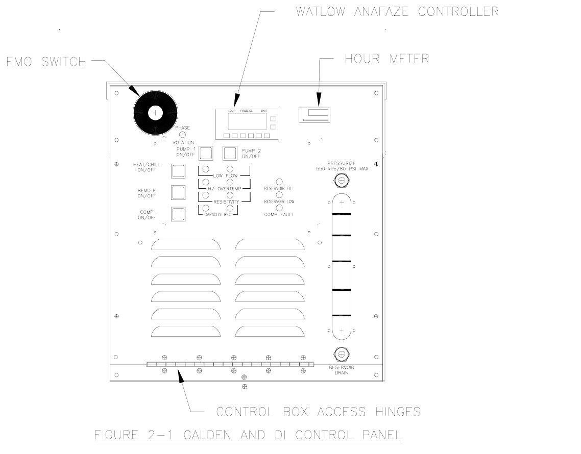
2. OPERATING PANEL
The operating panel of the 1231 is shown below.

Table 2-1 Controls and LEDs with their effect or information transmitted.
CONTROL;
INDICATOR ACTION OR READING
Compressor; on/off Turns compressor on or off in LOCAL or REMOTE modes, and in the
REMOTE mode sends an indication to central control that the switch is in off
position.
E.M.O. Cuts off power to the TCS as it turns off all components in tool string. Is
connected to central control and works in either REMOTE or LOCAL mode.
Remote; on/off Toggles the unit between REMOTE and LOCAL modes.
Heat/Chill; on/off Turns heating or chilling of the selected channel on or off when TCS is in the
LOCAL mode. In REMOTE mode the switch is always activated.
Pumps; on/off Turn individual fluid pumps on or off in LOCAL mode. Have no effect in
REMOTE mode.
Green LEDs on pump
switches. Indicate when the pumps are turned on in either REMOTE or LOCAL mode.
Amber Low flow LEDs Indicate when the flow in each channel is inadequate for proper operation.
Amber capacity regulation
LEDs Indicate when the capacity in a chilled channel is approaching or exceeding
the capabilities of the refrigeration circuit.
(2) Amber reservoir fill
LEDs Indicate when the fluid reservoir needs filling. The first to light indicates that
routine service is required. If the two are lit it shows that immediate attention
is required.
Amber compressor fault
LED Indicates that one of the switches in the compressor safety chain has
opened due to a fault or the compressor on/off switch is in the off position. In
LOCAL or Remote modes this will indicate the compressor has been shut
off. In REMOTE mode an alarm is sent to the central control.
Circuit breakers These safeguard the compressor, pumps, heaters, and system.
Temperature controller
and communicator This monitors temperature and other parameters of the system and controls
the delivered fluid temperature to pre-set limits in each channel. This device
also communicates data and control information between the TCS and the
central control.
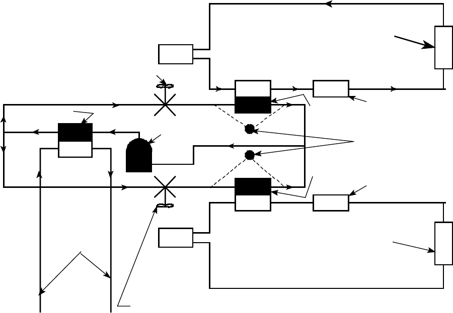
3. OPERATING THEORY AND PRACTICE
A schematic description of the operation of the two chilled channels is shown below.
COMPRESSOR
EVAPORATOR
HEX
HEX
ELECTRICAL HEATER
CONTROLLABLE EXPANSION VALVE
CONTROLLABLE EXPANSION VALVE
PUMP
PUMP
SEMI TOOL
SEMI TOOL
HEX
CONDENSER
FACILITIES
WATER
REFRIGERATION
ELECTRICAL HEATER
EVAPORATOR
CAPACITY REG. SENSORS
The diagram is simplified for the purposes of this explanation. The system consists of a
single 10 HP “REFRIGERATION COMPRESSOR” which supplies high pressure
refrigerant to a “CONDENSER”. In this latter unit the refrigerant is liquefied, being
cooled by a flow of “FACILITIES WATER” through a condenser/heat exchanger
(“HEX”). This liquefied refrigerant at high pressure then splits into two streams. Each
separate stream passes through a “CONTROLLABLE EXPANSION VALVE” wherein
the refrigerant pressure is reduced. This process cools the refrigerant to a mixture of
vapor and liquid at a temperature of –37°C. As the refrigerant boils off it can cool the
fluid being passed through the “HEX” side of the “EVAPORATOR”. Fluid is driven in
each closed circuit by a “PUMP(s)”. The controllable expansion valve is opened just
enough to cool the fluid to a desired set temperature. The temperature controller
regulates the opening of the controllable expansion valve to maintain the temperature
of the pumped fluid at the set value ±1°C. In the closed fluid circuit the fluid is passed
through an “ELECTRICAL HEATER” after traveling through the evaporator. The
temperature controller supplies power to this heater as needed to maintain the
temperature of the fluid being sent to the “SEMI TOOL”. The temperature can be
controlled at any level between –20°C to +40°C.
The “CAPACITY REGULATION SENSORS” sense temperature in the refrigeration loop
and ascertain whether the refrigeration demand is within the capacity of the system. At
some times, such as during cool down of a tool after servicing, the demand of a
channel can be for everything that is available. This would steal output from the other
channel that might be operating at another temperature. The capacity regulation
system in the TCS controller adjusts the output of the channel that is over demanding
cooling to bring the demand in line with supply.

4. START-UP PROCEDURE
This describes the method for starting and operating an installed and operable 1231
TCS. To install a 1231 (see Section 8).
Warning: When utilizing a perfluorinated fluid (Galden®) the
semiconductor equipment system must be completely purged of all water/glycol
coolant before connection to the TCS. Typically this requires the Etch System to
be first flushed with air, then with clean water, followed by air again, and finally
with the perfluorinated fluid that will be used as the coolant.
Note: If at any time an alarm occurs, turn off the TCS and correct the fault
indicated by the display as directed in the Troubleshooting Guide in Section 8.
4.1 Power up
Before applying power, verify that all water and coolant lines are connected to the
system. The handles on both coolant line valves should be in the open position. For
the location of these connections, refer to Figure 7-2 &7-3 in Section 7.
To power up the 1231 TCS:
1.Verify facilities water flow (approximately 10 gpm).
2.Confirm sufficient fluid level in the reservoir (above 1/2 full), all lines and tools are
filled with fluid, and that the reservoir pressure is 40 psi.
3.Establish that all switches and circuit breakers are in their off positions.
4.Turn on the Main Circuit Breaker and check the Watlow CLS216 for any faults.
5.Confirm set points per the Watlow PID Factory Setting Matrix, included with this
manual.
6.Correct any faults before continuing.
7.Activate Channel 1(Pump 1) switch. Note: The pump will not start with the circuit
breaker off.
8.Rapidly verify the applicable green ON Indicator light and the amber Low Flow light
are lit. Proceed to step 9 within 10 seconds to avoid system shut down.
9.Turn on Pump 1 circuit breaker.
Note: Confirm the TCS phase rotation is correct by observing a rise in pump
pressure on the corresponding gauge. A drop in pressure indicates the incoming
power has been wired incorrectly. This condition is sensed by the phase monitor
as well.
10.Confirm that the green On Indicator light remains on and that the amber Low Flow
light extinguishes before proceeding. If not turn off the pump circuit breaker and consult
your trouble-shooting guide.
11.Verify the pump pressure using the corresponding gauge.
12.Purge all entrapped air by opening the appropriate purge valve for 3 to 5 minutes.
Note the sightglass level and modulate the valve to prevent any reintroduction of air,
which can occur if the sightglass when the level goes too low. If excessive air is present
it may be necessary to add fluid. See filling instructions if necessary.
13.Activate Channel 2 (Pumps 2 and 3) switch. Note: The pumps will not start with the
circuit breakers off.
14.Repeat steps 7 through 11 for the remaining channel. Note: activate pump 2 and 3
circuit breakers at step 9.
15.Activate the Compressor On/Off switch. Note: The Compressor will not start with
circuit breaker off.
16.Verify the green Compressor On Indicator light ignites.
17.Turn on the Compressor Circuit breaker.
18.Confirm that the green ON Indicator light remains lit and the compressor is running.
If not turn off the compressor circuit breaker and consult your troubleshooting guide.
Caution: Extended operation of the chilled channel pumps, while the compressor
is off may cause damage to the system or tool.
19.Once the compressor starts activate the Main (process control) switch.
20.Scroll the Watlow controller to loop 15 and observe for 60 seconds. The temperature
should decline. If not turn off the compressor circuit breaker and consult your
troubleshooting guide.
21.Confirm channel stabilization utilizing the Watlow controller. See the Watlow manual
for instructions.
Note: Subsequent start ups will require less attention once all air has been
purged from the system.
4.2 Temperature set point verification.
Verify that the set point displayed on the TCS controller for each of the two channels
are those desired. Locations for each channel are listed in the Appendix I. To change
these set points see Section 10. Do not exceed the limits of the TCS, which are −20°C
to +40°C. Note: The Watlow controller may be adjusted for each channel to
protect the tool from excessive temperatures. Temperature ranges may be selected
for each channel. The controller will not allow the channel temperature to exceed its
selected range. However, it will respond to the extremes as nearly as possible within
the allowed ranges. Consult your Watlow manual for directions.
Note: Allow stabilization of the channel set points for a minimum of 3 to 5
minutes before processing (striking plasma).
5. PRODUCT FUNCTIONAL DETAILS
5.1 Refrigeration and Coolant Circuits
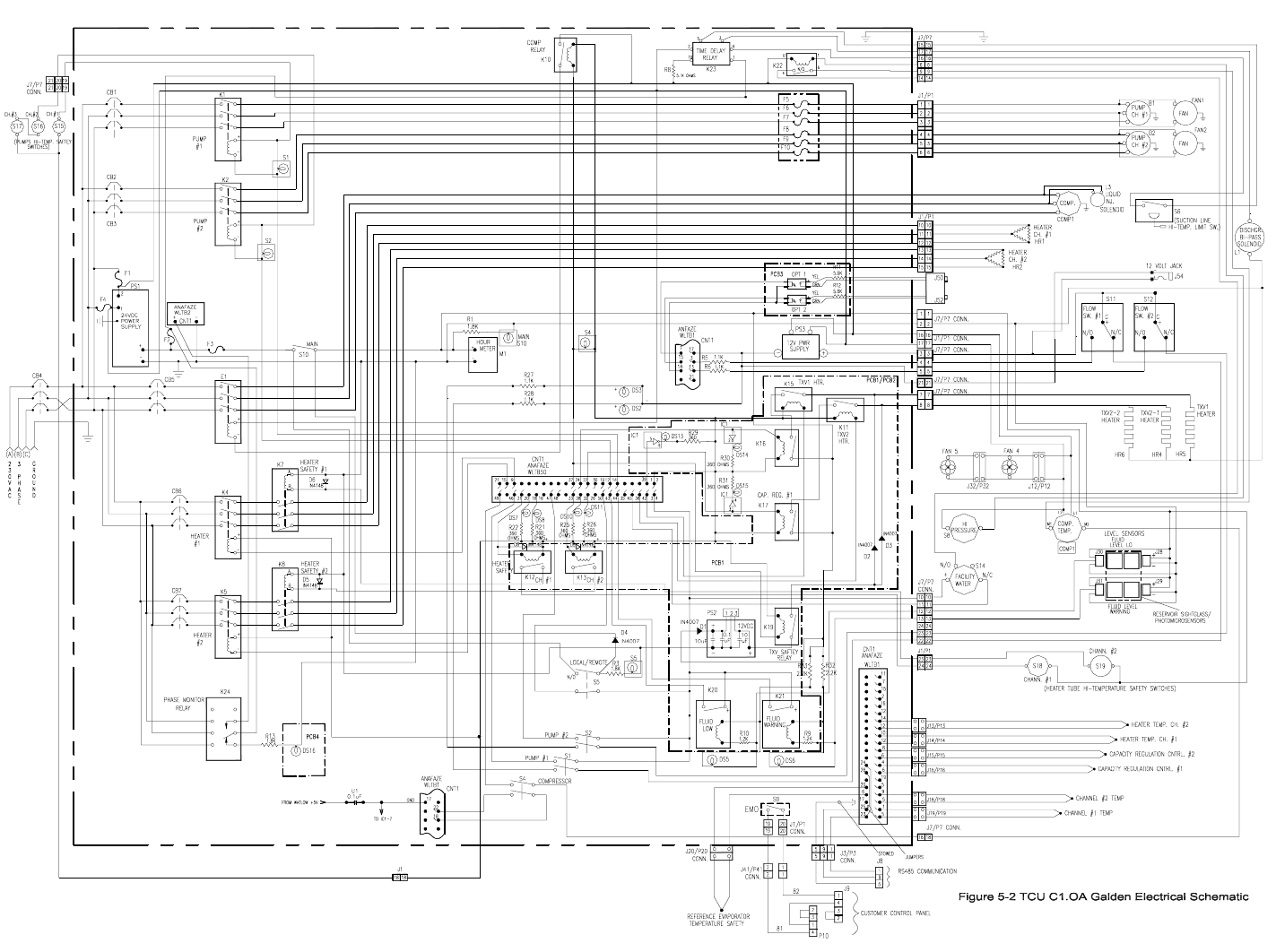
Following are the Refrigeration and Fluid Flow Schematic Diagram (Figure 5-1), Electrical Schematic Diagram (Figure 5-2),
Refrigeration and Coolant Components (Table 5.1) and Significant Electrical Components & Functions (Table 5-2); they briefly
describe the function and purpose of each component in the 1231-CCN-01.
5.2 Installation Drawings
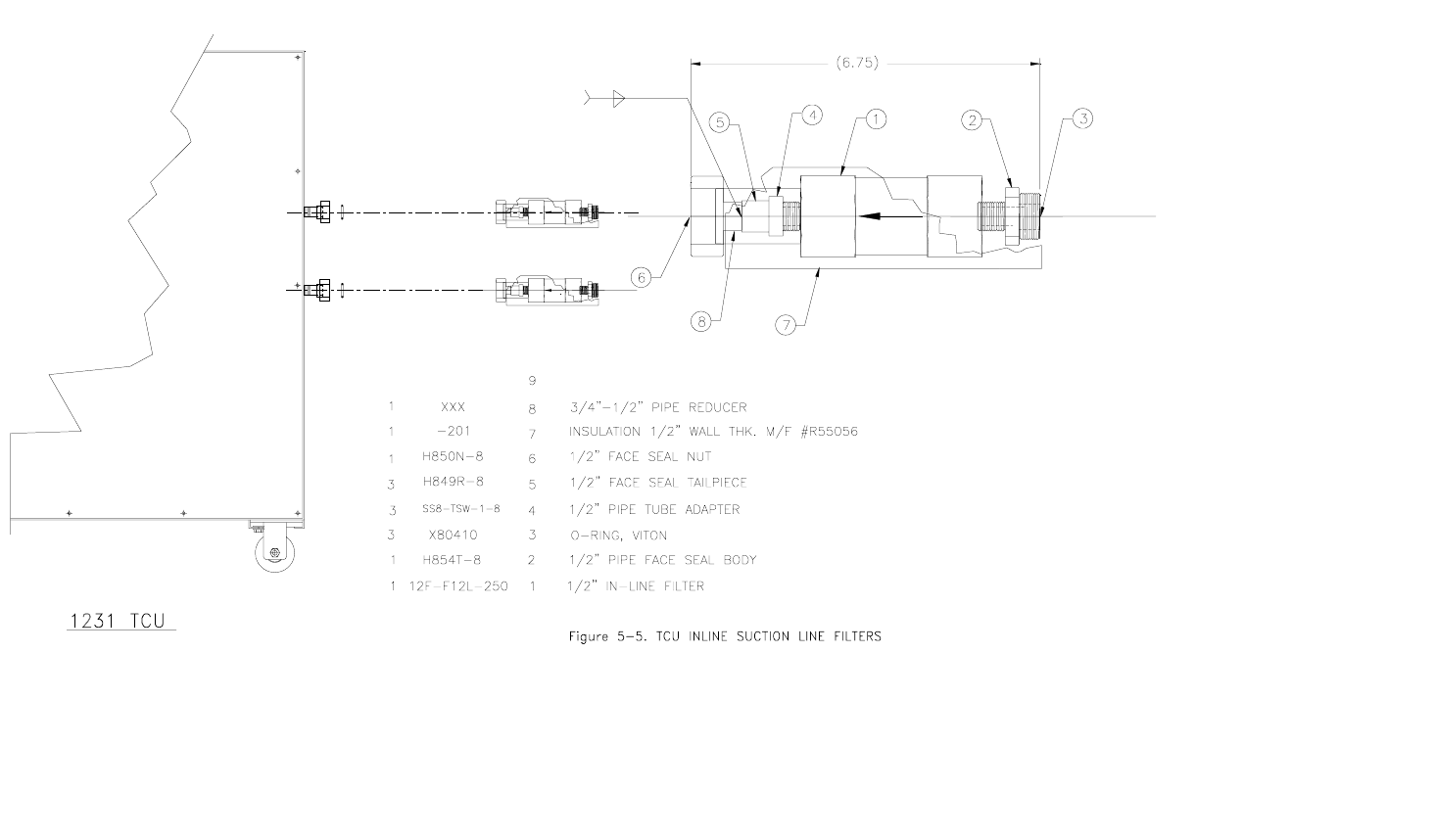
Following are the In-line Filter Installation Drawing (Figure 5-5) and the Temperature Controlled Unit (TCS) Installation Drawing
(Figure 5-4); they show the general overall mounting details.
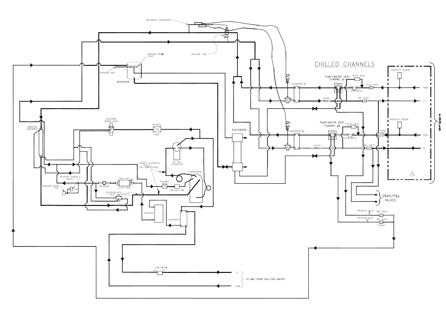
Figure 5-1a DI Refrigeration and Fluid Flow Schematic
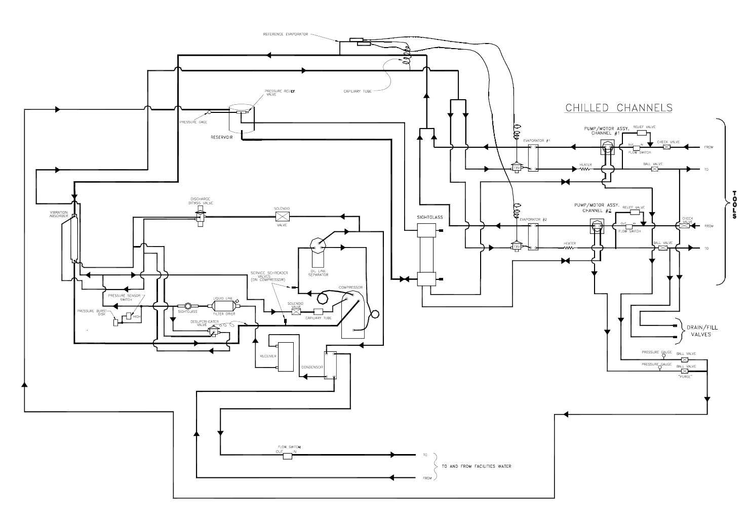
Figure 5-1b Galden Refrigeration and Fluid Flow Schematic
5-4
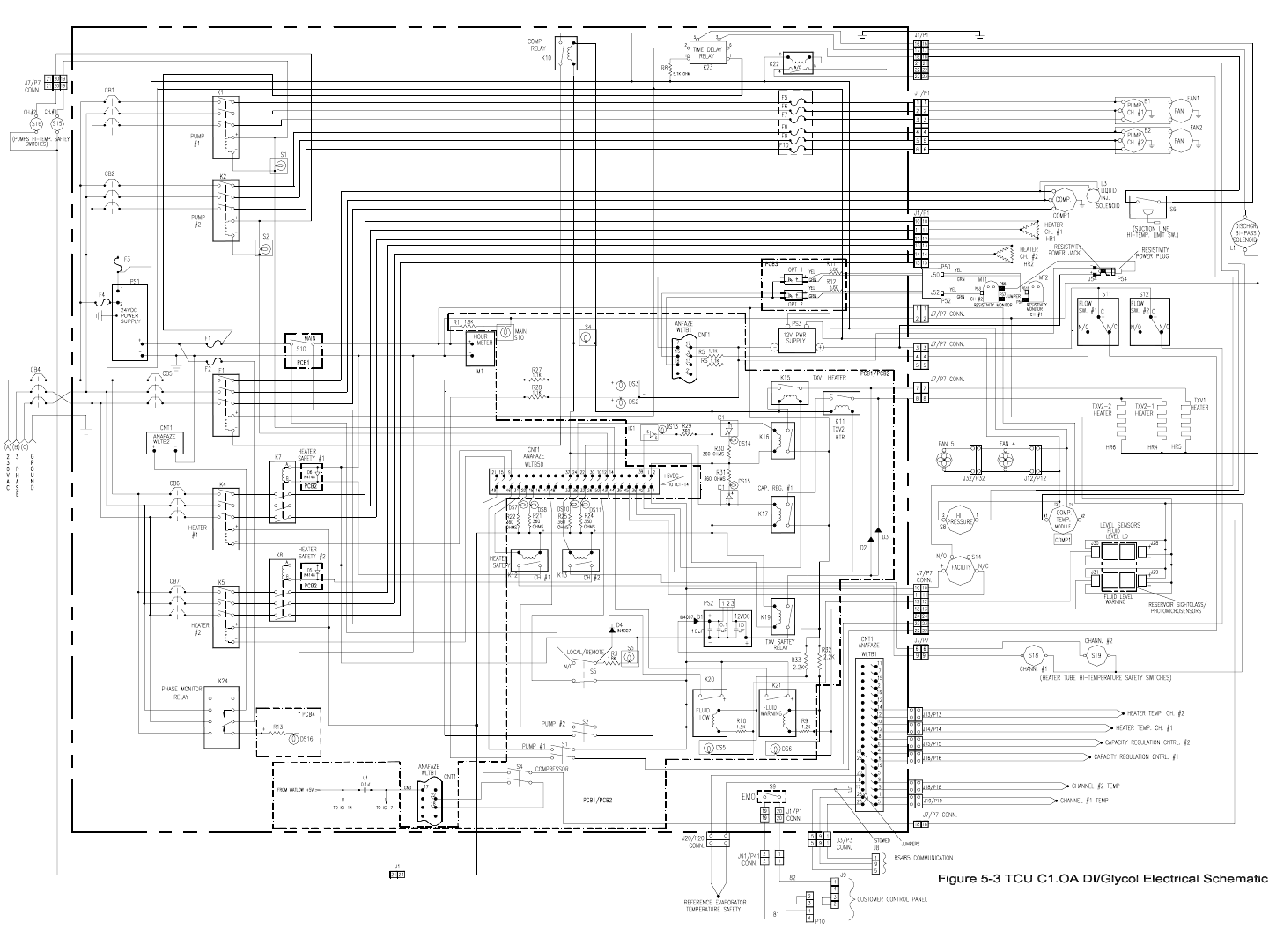
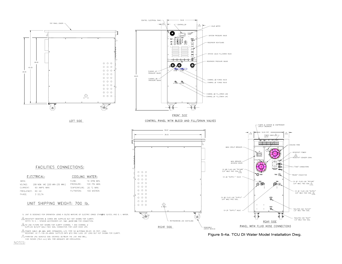
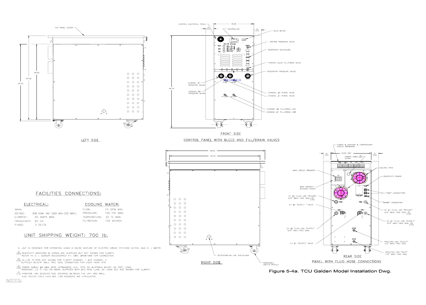

Table 5-1 Refrigeration and coolant components
Item Component Name Function
1 Reservoir A holding tank for the fluid transfer fluid (DI Water-Glycol or
Galden®).
2 Level sensors (2) Monitors fluid level in the reservoir.
3 Compressor Compresses the refrigerant fluid.
4 Discharge bypass valve Regulates the pressure at the compressor input and prevents the
pressure from becoming too low.
5 Service Schrader valves Allows service of system refrigerant.
6 Solenoid valve/capillary tube Provides cooling to the compressor.
7 Pressure sensor switches Protects the compressor against too high or too low refrigerant
pressure.
8 Pressure burst disk Protects the system with a static guard against too high
refrigerant pressure.
9 Condenser Liquefies the refrigerant by transferring heat from the
compressed gas to the facility water.
10 Liquid line filter dryer Removes contaminants and moisture from the refrigerant.
11 Desuperheater valve Limits the compressor input temperature to 18°C.
12 Reservoir pressure relief
valve Limits pressure within the closed fluid circulation system.
13 Pump/motor assemblies Circulate the fluid coolant.
14 Pump relief valve Regulates fluid coolant pressure.
15 Sightglass, Compressor Shows proper level of liquid refrigerant.
16 Receiver Allows excess liquid refrigerant volume when system is not using
all available cooling.
17 Solenoid valve SVC1 Allows refrigerant to pass through the hot gas bypass valve.
18 Solenoid valve SVC2 Allows liquid refrigerant to pass to the compressor.
19 Oil line separator Separates liquid oil from the compressor output.
20 (2) TXV (Thermal expansion
valve) Controls refrigerant flow as it expands from liquid to gas.
21 Heaters Raise temperature of the coolant when the process requires
heating.
22 Flow switches Monitor the flow rate.
23 Evaporators Extract heat from fluid coolant and transfers it to the refrigerant.
24 Ball valves Isolate fluid flow to and from the TCS.
25 Sightglass, Reservoir Shows the fluid level within the system’s reservoir.

Table 5-2-Significant electrical components & function
Item Component Name Function
1 CB 4 60 amp circuit breaker for main input power.
2 P 2/J 2 CONN Connecting jack and plug for main power.
3 FH 4; FH 5; F 4; F5 Fuses (FH) associated with cooling fans (F) that cool the cabinet.
4 CB: PUMPS 1; 2; 3 Circuit breakers (CB) that protect the pump motors.
5 LT 8; 9 Lights that indicate that PUMP CH1 etc. are operating.
6 RL 1; 2; 3 Relays that turn on pump motors in response to inputs from TCS
controller * (LOCAL) or central controller (REMOTE).
7 RL 4; 5 Relays that turn on heaters in response to TCS temperature
controller.
8 RL 7; 8 Relays associated with heater safety: Power is interrupted when
heater overheats (LOCAL mode) or signals to central controller
(REMOTE mode).
9 PS 1; FH 1; 6 Power supply (PS1) for DC control voltages protected by fuses.
10 CNT 1; FH 2 TCS controller (CNT1) protected by fuse (FH).
11 FH 3 Fuse protecting 12 VDC output.
12 SW 10 Heat/Chill on-off switch that activates TCS system process when
in LOCAL mode.
13 E 1; CB 5; COMP Relay (E), circuit breaker (CB) that turns on and protects the
refrigeration compressor (COMP).
14 HM 1 Hour meter (HM1), establishes the operation time of the TCS.
15 RL 10: HI PRESSURE; LOW
PRESSURE; COMP. TEMP.;
FACILITY WATER
(SWITCHES)
Relay (RL) that protects the refrigeration compressor when
deactivated by safety (HI PRESSURE etc.) switches. RL10 turns
refrigeration compressor off directly in LOCAL or REMOTE
modes and sends signal to central controller when TCS is in
REMOTE mode.
16 SW 5 Switches TCS between REMOTE and LOCAL modes.
17 SW 1; 2 Switches that turn pumps on in response to inputs from TCS
controller.
18 RL 12; 13 Relays that turn on safety relays for heaters for channel 1 and 2
respectively driven by inputs from TCS controller.
19 RL 20, 21, LS 1; 2, LT 5; 6,
R6; 7 Relays (RL) that close circuits connected to TCS controller
inputs to signal that the fluid in the system reservoir is low
enough to need service or quick filling. Relays are driven by
level sensors (LS) that trigger the relay signal when the liquid
falls below the location of the sensors. Lights (LT) on the control
panel indicates when these sensors have triggered. Resistors ®
decrease the supply voltage to that suitable for the lights.
20 LT 5; 6, R 6; 7 Lights (LT) that show that level sensors LS1or LS2 have been
activated. R6; 7 are used to drop the voltage to the value correct
for the lights used.
21 LS1; 2; 3, J 7/P 7 Temperature limit switches, communicating with the TCS
controller via connector J7/P7 that protect pumps for each
channel. These switches will shut off the pumps in LOCAL or
REMOTE modes and tell the host controller that a pump has
overheated in REMOTE mode.

22 SW 4 Switch that shuts off the compressor in LOCAL or REMOTE
modes and informs the host controller that someone has turned
this switch off when the TCS is in REMOTE mode.
23 REFERENCE
EVAPORATOR
TEMPERATURE SAFETY, J
6/P 6, TXV 1; 2.
This is a temperature sensor that protects the heaters for the
thermal expansion valves (TXV). Through the action of the TCS
controller the TXV heaters cannot be activated until the
reference evaporator is below a safe temp. of about -29°C for
DI-Water/Glycol.
24 EMO SW 9, J 7/P 7, J 9; 10 EMO switch sends signal to host controller to shut down entire
semi tool system because an emergency is perceived to be
present. Connects to customer jacks J9; 10 through J7/P7
connection.
25 J 8 RS485
COMMUNICATION Through J8 the TCS communicates with the host controller via
the TCS controller.
26 HEATER TEMP CH 1; 2
CAPACITY REG. CH 1; 2
CHANNEL 1; 2 TEMP, J 6/P
6
Type T thermocouples that measure temperatures as denoted.
Information about these values is supplied as input to the TCS
controller. The capacity regulation temperature sensors drive
the TCS controller in case of over demand on the refrigeration
system (See Section 3.1).
27 PS 2, D 1, RL 19 PS 2 is a 12 VDC power supply that derives its input from PS 1.
It supplies the correct voltage to the TXV heaters in the dormant
state thru relay RL 19: This relay prevents power from being
supplied to the TXV heaters until the compressor is powered.
28 RL 16; 17 These relays activate to cut the voltage to the TXV heaters in
response to signals from the TCS controller when capacity
regulation is called for.
29 RL 11; 15 Relays that control process power to the TXV heaters.
31 H 1; 2, ILF 1 thru 6 Heaters for each of the three channels. In-line fuses (ILF) are to
protect the heaters in case of short-term over-current.
32 CB 5, SVC 2, COMP Circuit breaker (CB) that protects the compressor. SVC 2 is the
solenoid valve that allows liquid refrigerant into the compressor
to cool the mechanism.
33 PUMPS (3) and F 1; 2; 3 Pump motors and the cooling fans that keep the motors from
overheating.
34 SW 6, SVC 1 Switch is a compressor safety device. If the gas entering the
compressor is at a temperature higher than 55°C SW 6 will cut
electrical power to the discharge bypass solenoid (SVC 1)
thereby shutting off discharge bypass flow.
35 LT 2; 3; 4, R 2; 3; 4 Lights indicating lack of flow in each of the three channels.
Resistors drop the 24VDC to the 12 VDC suitable for the lights.
36 FSW: 1, 2, 3, 4; R: 8, 9, 10 Flow switches (FSW) for each of the three pumps and the
facilities water. These feed inputs to the TCS controller. The
resistances ® produce the correct current for the controller input.
• See Appendix for guide to TCS controller inputs and outputs.

6. SPECIFICATIONS
Table 6-1 General Specifications 1231-CCN-01
Parameter Conditions Specification
Temperature ramp
(chilled channels) Coolant short circuit conditions 25 feet of fluid line or less between
TCS and semi tool
+25°C to +80°C Elapsed time: <5 minutes
-20°C to +25°C Elapsed time: <5 minutes
Cooling @ TCS chilled
channels Coolant @ -20°C Ch1 @ 2,500 watts and Ch2 @ 5,000
watts with 60 seconds on; 30
seconds off.
Heating available 3,750 watts/channel
System flow @ 20°C, 80 psig Ch1 @ 6/4 gpm (27/18 lpm) and Ch2
@ 12/8 gpm (54/36 lpm) with DI -
Water/Glycol or Galden respectively
Process temperature
range-chilled channels -20°C to + 40°C
Set-point resolution 0.1°C
Temperature regulation ± 1.0°C typical
Facility water
requirements 10 GPM maximum at 100 PSI
maximum @ +20°C maximum with
100 Micron filtration and non-
corrosive
System Pressure Drop is 25 PSI
Power requirements 3 phase delta (balanced load), 4 wire
(3 phases & earth ground), 200 to
208 VAC, 50/60 Hz
60 amp
Ambient operating
temperature +10°C to +37°C
Weight 700 pounds (315 kg)
Dimensions See Figure 7-1
Transient over-voltage IEC 664, Installation Category II 2.5 kV
Pollution degree IEC 664 2II
Sound pressure level At a distance of 1 meter 75 dB(a)
7. DIMENSIONS AND VIEWS OF PANELS
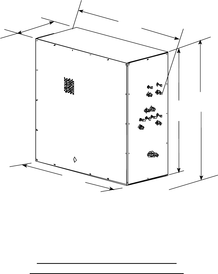
Figure 7-1 Overall View of TCS With Dimensions
Without Castors, Castors Add Nominally 4” to Height
36.1"
42" OVERALL
40"
44" TO FLOOR
16"
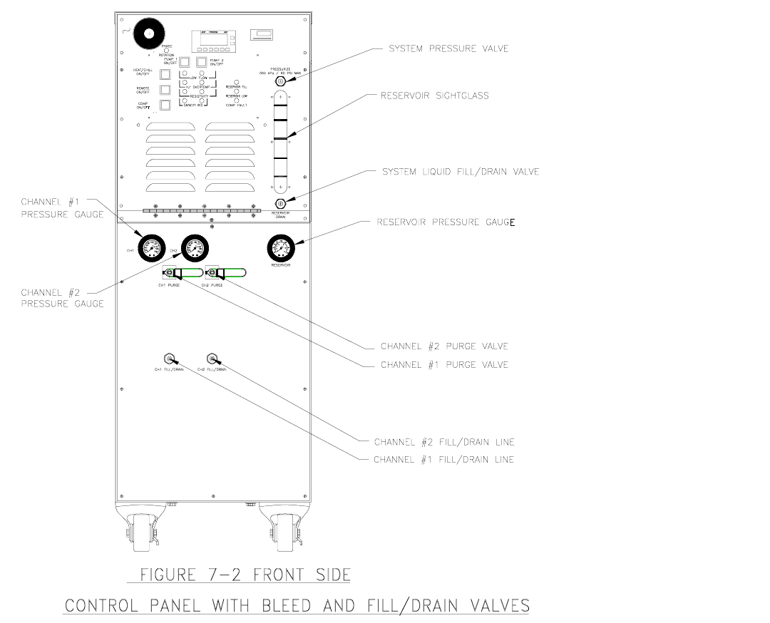
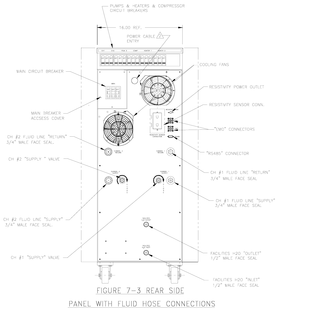
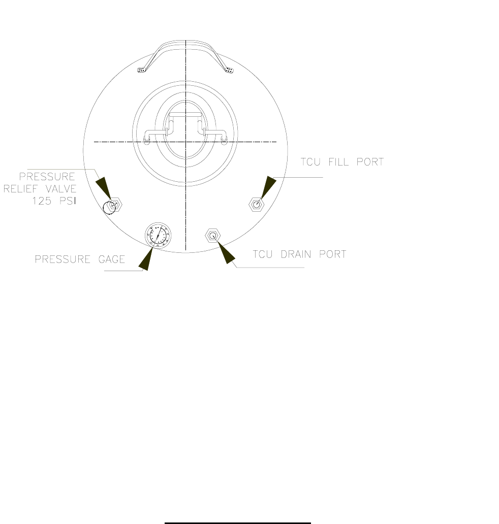
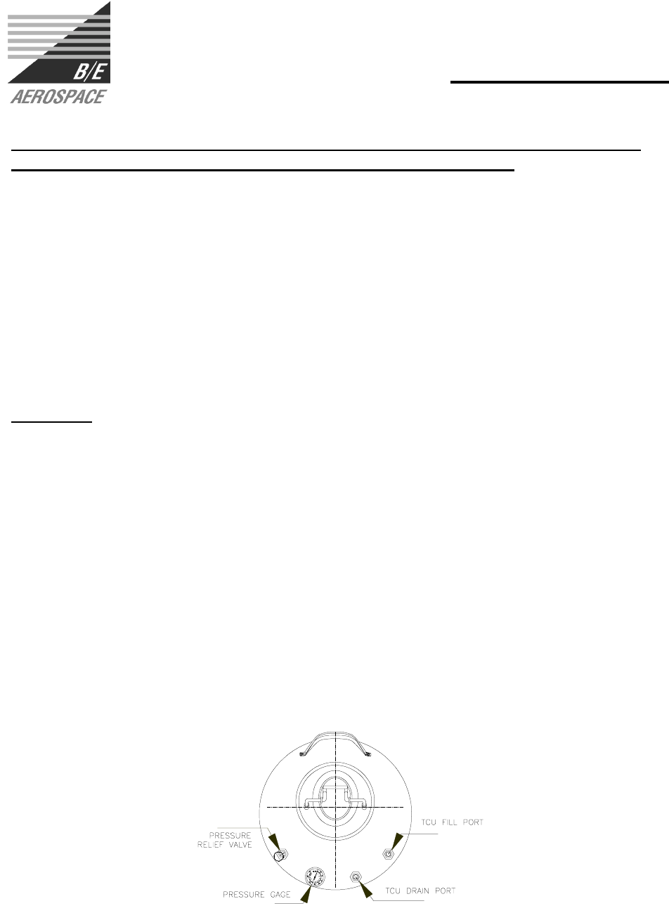
Figure 7-4 Fill/Drain Tank
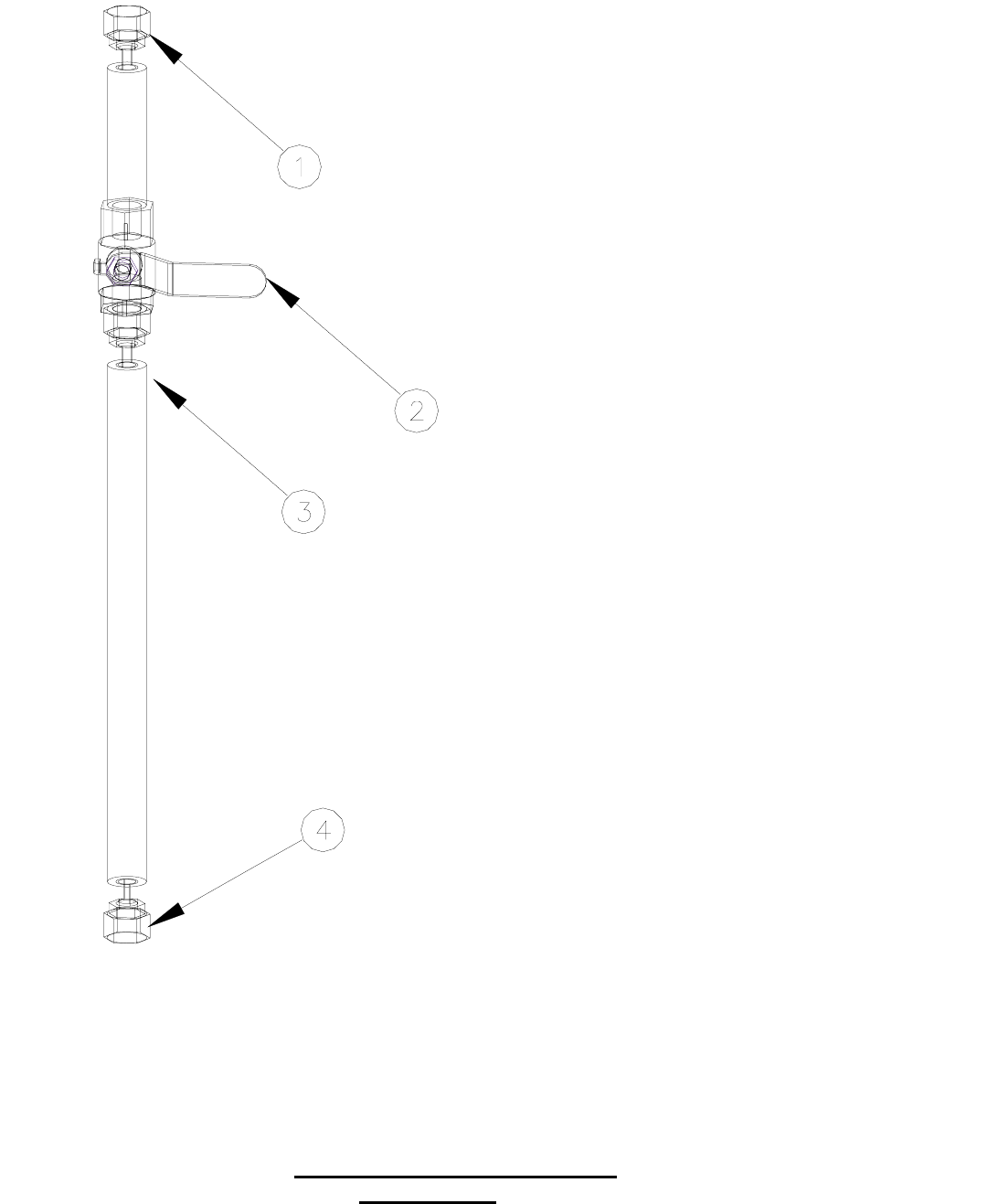
1. ¼” FLARE NUT W/ SCHRAEDER VALVE CONNECT THIS END TO THE TCS FOR
FILLING AND DRAINING PROCEDURES (P/N 4028142-00X)
2. ¼ TURN BALL VALVE
3. INTERNAL CONNECT (NO SCHRAEDER VALVE)
4. ¼” FLARE NUT W/ SCHRAEDER VALVE CONNECT THIS FITTING TO THE
TANK FOR FILLING AND DRAINING PROCEDURES (P/N 4028141-00X)
Figure 7-5 Fill/Drain Tank Hose
* not to scale
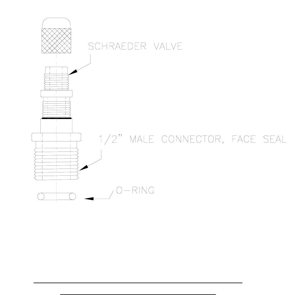
Figure 7-6 ATS Special Adapter Fitting for Draining Tool Lines
via ATS Fill/Drain Tank (ATS dwg. 4081147-1)_
TECHNICAL DATA for:
FILL/DRAIN VESSEL
4081080
WARNING: THIS EQUIPMENT IS TO BE FILLED WITH ITS DESIGNATED FLUID,
MIXING FLUIDS MAY DAMAGE THE TCS AND/OR EQUIPMENT.
DESCRIPTION:
Modulated drain/fill vessel designed for use with ATS TCS.
MAIN FEATURES:
Rugged, precision fabricated, 316 stainless steel vessel to perform fill and drain operations
without the loss of fluid or vapors. The pressure sealing, wide-mouth Tank opening is captive
and cannot open while the vessel is pressurized. Four ¼” ports accommodate fluid in/out, multi-
use valve, pressure relief valve and pressure gage. The fluid in/out line has a double safety
interlocked tube section to facilitate fluid drain/fill operations. The base is protected by an acid
and chemical resistant rubber foot ring. Tank meets OSHA and ASME boiler and pressure
vessel codes.
CAUTION: The information contained in this document is subject to engineering
improvements. Obtain an official configuration drawing and manual from ATS, for current
detailed information.
RATED OPERATION SPECIFICATIONS
• Maximum operating temperature……………………...…300°F @ 130psi (149°C @ 8.96 bar)
• Maximum pressure……………………………………..……………….………150 psi (10.34 bar)
• Designated heat transfer fluid……………………..……….…Water/Ethylene Glycol or Galden
• Vessel volume capacity………………….……………………..………………..5 gallons (18.9 L)
• Pressure relief valve setting………………..……………………..…………….125 psi (8.60 bar)
DIMENSIONS
• Overall Diameter ………..…………………………………………….………………9 in (22.9 cm)
• Height………………………………………….……………………………………22.5 in (57.2 cm)
• Perimeter Fitting ………..………………………………..………………….1/4 in (0.64 cm), qty 4
ATS 3355 E. La Palma Ave. , Anaheim, CA 92806
(714) 688-4201 Phone; (714) 688-4153 Fax
8. INSTALLATION
8.1 Receiving the 1231 TCS
Do a complete visual inspection of the TCS 1231 for any damage. Do not use the TCS
1231 if physical damage is evident. If there is visible damage, notify your supplier and
the carrier within three days; state the serial number of the TCS 1231 together with your
order number and supplier’s invoice number. Retain all packing materials for
inspection.
Allow a space 22” wide for the TCS 1231, cable and coolant connections. The TCS
1231 should have at least three feet of clearance at the front and rear and three inches
along each side of the unit. Be sure that the mounting surface can safely support the
weight of the TCS 1231 (700 pounds evenly distributed). The center of gravity is
approximately the center of the unit.
When using a forklift to move the TCS 1231, position the forks from the side of the unit.
Warning: The TCS 1231 weighs 700 pounds (315 kg). Failure to
take proper care in moving or lifting these units can result in serious bodily
injury.
8.2 Securing the unit
The two lockable casters of the TCS 1231 swivel to provide maximum maneuverability.
Make sure that both lockable casters are parallel to the sides of the unit and locked in
position once the TCS 1231 is situated.
8.3 Stacking
The TCS 1231 may be stacked in an approved mounting rack. Be sure that the
mounting surface can safely support the weight of the two units stacked vertically
(700lbs/system, 318 kg/system).
8.4 Facilities
The TCS 1231 requires a filtered water supply (filtration ≤ 100 microns) with a flow rate
of 10 gallons per minute at an inlet pressure between 30 and 100 psig, and an inlet
temperature range of 17°C to 22°C. The system is interlocked and will not operate if
phases are incorrectly wired.
Power input is by a fused, suitable isolating electrical outlet, 208 VAC, 50/60 Hz, 100
amp, 3-phase delta (balanced load), 3-wire and earth. Note: Check 3-phase rotation
using phase rotation checking device.
8.4.1. Facility connections
Figure 7-3 shows a rear view of the TCS 1231 with its water and coolant connections.
8.4.2. Three Phase Main Power Cord Installation
This procedure outlines the steps necessary to install the accompanying power cord harness
onto the TCS.
WARNING: Proper phase arrangement is critical, mis-wiring can
shock personnel and/or cause damage to the unit and FAB.
1. Remove four screws from the circuit breaker access panel.
2. Unscrew main power compression nut and nylon gland.
3. Insert four 6 gage cable ends with lug rings through nylon gland.
4. Insert four 6 gage cable ends with lug rings through compression nut with the threaded side
open to the nylon gland.
5. Put green line with lug ring through power cord port and secure to the screw adjacent to the
circuit breaker using the attached groundnut and lock washer.
6. Secure the three line phase cords to the appropriate port as shown in Figure 8.1 by
loosening the circuit breaker phase locking screw, inserting the phase line and locking the
screw for the three phases. Required torque is 40 in-lb for each terminal.
7. Tighten strain relief.
8. Reinstall circuit breaker access panel.
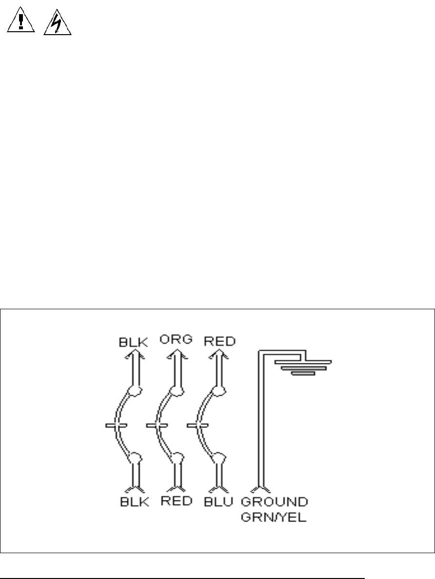
Figure 8.1 shows the proper three phase wire connection arrangement where the wires
are A, B, C, left to right, as viewed from the front per NEC standards. Phase inputs A,
B, C; from the wall are black, red, and blue, respectively. The TCS phase inputs A, B,
C, are black, red, and blue respectively. Pretest wall socket with NRTL listed phase
tester prior to installation and verify clockwise rotation.
Figure 8.1 Three Phase wire diagram with designated lead colors.
Note: Units with the phase monitor are protected against under voltage and
potential phase miswiring damage. In the event of incorrect input voltage or
miswiring, the phase checker senses the discrepancy and opens the relay that
supplies power to the Watlow Controller.

8.5 REMOTE mode
In REMOTE mode (see Section 9.4) all control of the unit is given to the system central
controller. None of the controls on the control panel face of the 1231 have any effect
except: EMO switch and circuit breakers. If any work is attempted on the 1231 it is
essential for proper system operation to place the 1231 in LOCAL mode; see Section
9.4 for instructions on accomplishing this.
The AUX LED on the control panel (see Section 2) will illuminate indicating the
REMOTE has been chosen.
8.6 LOCAL mode
In LOCAL mode (see Section 9.3) control of the unit is passed to the control panel (see
Section 2). Service of any kind requires that the 1231 unit being serviced be in LOCAL
mode. It is also desirable to place the 1231 unit in LOCAL mode when a tool is being
flushed and filled (see Section 9.2).
8.7 Filling the reservoir
Warning: When retrofitting a TCS 1231 in place of a water/glycol unit, the
coolant lines must be thoroughly flushed with nitrogen to remove moisture prior
to installation. The humidity of the emerging flush N2 must be checked to ensure
that all moisture is removed. The N2 leaving the system during flush must be
contain less than 1 mm partial pressure of H2O vapor before the system can be
considered dry.
To fill the reservoir it is necessary to have a supply of 50% water/50% ethylene glycol
(water/glycol) or Galden® in a fill/drain tank that can be pressurized to 60 psi (4 bar).
This can be supplied from ATS if desired. Check with your supplier for further
information.
8.8 Filling the lines from the reservoir
This procedure is identical with that of Section 9.1; filling a coolant channel including
the TCS and semiconductor equipment. See this section for operating instructions.
8.9 Draining the coolant reservoir
Note: If it is desired to completely remove all 50% water/50% ethylene glycol
(water/glycol) or Galden® fluid from the system of the TCS and tool all the tools must
be drained. This procedure is covered in Section 9.2; flushing the Semi Tools. See this
section for operating instructions and drain all fluid from the tools before attempting to
drain the fluid reservoir.

9. SET-UP AND INITIAL OPERATION
9.1 Filling a Coolant Channel including the TCS and semiconductor equipment.
Before the 1231 can be used all the channel circuits including the lines from TCS to
tools must be filled. This task should to be accomplished using a ATS approved
Fill/Drain Tank charged with 50% DI Water/50% Ethylene Glycol (DI/Glycol) or Galden.
Whenever a tool is removed from the TCS for service that channel circuit needs to have
its fluid drained from the lines and tool. The following procedures are to be used for
both processes.
Prior to operating the1231 the Fluid Line inline filters must be installed in both channels.
The filters are shipped ready for installation with their insulation mounted. Use care
when attaching the filters to avoid damaging the insulation. Mount the filters to the
return line connections for both fluid channels on the rear panel of the TCS chassis.
Warning: Do not use the pumps to purge air from the system, hoses or
chamber lines or damage will occur and warranty will be voided.
Warning: Before filling any channel with fluid be sure to purge and flush
out all remaining dissimilar fluids from the connecting tool and its associated
lines.
Warning: Use only clean, particulate free coolant fluids or damage may
result to the temperature control system and void warranty.
Caution: When connecting stainless steel fittings use of anti-seize compound is
recommended.
Note: ATS supplied Fill/Drain Tanks are sized for approximately 75 feet of service
hose. If longer hoses are required contact ATS for review.
Caution: Ensure that fluid system is pressurized to at least 25 psi throughout fill,
purge or drain procedure.
Caution: DI/EG may change over time. Periodically check the DI/EG ratio.
Note: For DI Water/Ethylene Glycol (EG) units it is recommended that the
instructions in this note are followed to achieve the recommended 50/50 DI
Water/Ethylene Glycol (EG) ratio.

Caution: EG may be initially absorbed by the DI filters. In order to
compensate for this effect the following steps are recommended.
1. Fill the system with 60/40 (2 gallons EG to 1.5 gallons DI).
2. Drain and refill with 100% EG about 0.5 gallon at a time until the mixture
reaches or exceeds 50/50 using an appropriate EG or specific gravity
hydrometer. (The scale on the Hydrometer should be 1.00 (100 % DI
Water) to 1.22, with a 50/50 target reading of 1.058)
3. Run unit for approximately 10 minutes at -20°
°°
°C to stabilize unit.
4. Check for freezing after every EG input by watching the coolant
temperature as the chiller removes heat at -20°
°°
°C setpoint. (Be sure to
"mix" the coolant by purging through the reservoir and turn up the flow
through the DI bed to max.)
To fill the ATS fill/drain tank
1. It is first required to fill the Fill/Drain tank with the filling fluid (DI Water/Glycol or
Galden®) by lifting the lever on the top of the cap, pushing the cap down and
orienting the cap so it can be removed from the tank.
2. The pressure inside the tank must be at 0 psi per the pressure gauge on the tank.
Verify this by pulling the ring on the pressure relief valve. Depressurize the tank by
pulling the ring on the pressure relief valve.
3. Fill the tank with the required fluid (DI Water/Glycol or Galden®). Reinsert the cap
into the tank and close the lever so that the tank is sealed. The tank will now be
pressurized using 80psi with N2 by connecting the tank to an 80psi N2 source using
the shraeder valve fitting supplied in the Fill/Drain Tank kit.
Note: A spare shraeder valve fitting is included in the Fill/Drain Tank Kit. The
fitting is provided for adapting local installation nitrogen or CDA pressure
regulators to the Fill/Drain Tank hoses for the purpose of pressurizing the lines
for operations. Caution: High Pressure. Please use appropriate fitting
installation sealant if this fitting is required.
Pressurizing the fill/drain Tank
Note: The tags “Fill Port” and “Drain Port” may be ambiguous. The 80psi source
should be connected to the port marked “Drain Port” and the fitting tagged “Fill
Port” will be the port used to fill the TCS chiller. By looking inside the tank this
can be understood as the “Fill Port” is connected to a standpipe that draws from
the bottom and “Drain Port” is a short standpipe, which pressurize the top of the
tank.
1. Connect the 80psi N2 source to the “Drain Port” of the tank using the hose (Fig. 7-5)
and pressurize the Fill/Drain tank to 40-60psi per the pressure gauge.
2. Disconnect the tank from the hose and move the tank to the front of the ATS chiller.

Charging the ATS TCS (chiller) and cooling lines to Tool.
Connect the ATS chiller to the tool using the insulated hoses (50ft or 75ft).
There are 3 stages to filling the cooling loops to the system:
1. Filling the hoses connected between the chiller and the tool.
2. Filling the internal cooling loops of the chiller.
3. Filling the reservoir and sightglass of the chiller.
Caution: Do not turn on any of the pumps for the chiller until all 3 filling steps are
completed. As damage will result and warranty may be voided.
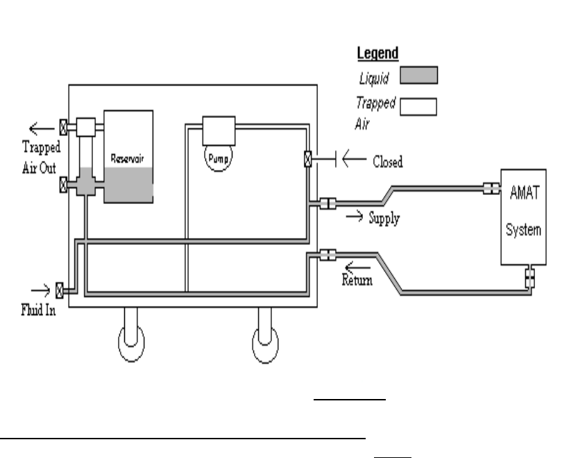
Filling the hoses between the chiller and tool.
1. To fill the hoses connected between the chiller and the tool first close the supply
valve for that channel at the back of the TCS.
2. Connect the “Fill Port” of the Fill/Drain tank to the Fill/Drain connection at the front of
the chiller using the blue hose. Make sure the manual valve in the hose is all the
way closed to prevent liquid being sprayed out of the hose.
3. Now open the valve hose and charge the loop watching as the pressure in the tank
drops slowly. Simultaneously using a flashlight view the sightglass on the front panel
of the chiller to see if any liquid appears from the bottom. Doing this you are filling
the hoses and tool by pushing the air from the hoses and chamber cooling channels
into the reservoir.
4. If no liquid appears and the pressure gauge on the Fill/Drain tank has stopped
dropping the reservoir is pressurized with air and this needs to be released. The air
in the reservoir is released by compressing the middle nipple of the schraeder fitting
at the top of the sightglass labeled “Pressurize 80psi max”. This will release the air
previously in the hoses and tool to atmosphere. This is shown in the figure a. For
maximum liquid transfer it is better to maintain the pressure in the reservoir viewed
on the gauge marked reservoir at zero.
Figure “a”
5. Repeat this until liquid is seen filling the sightglass without bubbles. The cooling
lines are now filled as shown in figure b and the next step is to fill the internal cooling
loop of the chiller.
Warning: Whenever a new component which contains air is introduced into the
cooling loop the chiller should be turned off and the above procedure should be
followed until no bubbles are visible in the sightglass. Air introduced into the
system while running will travel through the loop and potentially the chiller pump
to fail.
Figure “b”
Filling the internal cooling loops of the chiller.
1. To fill the internal cooling loop of each channel open the “supply valve” of the
channel being filled at the back of the TCS unit.
2. Connect the “Fill Port” of the Fill/Drain tank to the Fill/Drain connection at the front of
the chiller for each channel using the blue hose. Make sure the manual valve in the
hose is all the way closed to prevent liquid being sprayed out of the hose.
3. Now open the valve hose and charge the loop watching as the pressure in the tank
drops slowly. For maximum liquid transfer rate it is better to maintain the pressure
in the reservoir viewed on the gauge marked reservoir at zero. This is achieved by
compressing the middle nipple of the schraeder fitting at the top of the sightglass
labeled “Pressurize 80psi max”. The state of the chiller loop at the start is shown in
figure “c”.
4. For channel 1 only, fill that channel cooling loop while observing the fluid in the
sightglass using a flashlight, until no bubbles appear in the liquid of the sightglass.
The bubbles signify the air that is being purged from channel 1 internal chiller loop
into the reservoir.

5. For channel 2 only, fill the channel cooling loop with the manual valve marked “Ch2
Purge” open. The air inside this channel is vented to the top of the reservoir and
cannot be viewed in the sightglass. It is sufficient to do this for 2 minutes as liquid
fills the loop and the reservoir.
Note: To prevent the risk of introducing air back into the internal chilling loop
maintain a liquid level above the standpipe opening of the Fill Port in the
Fill/Drain tank.
6. When the internal cooling loop of the chiller loop is filled as shown in Figure “c”
close the Ch2 Purge valve.
7. Disconnect the Fill/Drain tank from the channel “Fill/Drain” connection.
Filling the reservoir and sightglass of the chiller
To fill the reservoir of the chiller connect the “Fill Port” of the Fill/Drain tank to the
connection at the bottom of the sightglass marked “Reservoir Drain”.
1. Open the manual valve in the hose and transfer fluid from the “Fill/Drain” tank to the
reservoir. Again for maximum liquid transfer it is better to maintain the pressure in
the reservoir viewed on the gauge marked “Reservoir” at zero.
2. Fill the reservoir until the reservoir is full or the tank is empty which will be indicated
by bubbles appearing in the sightglass of the reservoir. Air introduced at this point is
not harmful to the chiller.
3. Each white horizontal indicator on the sightglass corresponds to 25 feet of supply
and return ½” hose (50 feet total).
4. It is now required to pressurize the reservoir and the complete chiller loops.
Connecting the 80psi N2 source to the schraeder connection at the top of the sight
glass marked “Pressurize 80psi max” , gently introduced N2 into the reservoir until
20 psi is indicated on the gauge marked “Reservoir”. The entire system is now at
reservoir pressure and the corresponding gauges on channels 1 and 2 should
indicate that pressure.
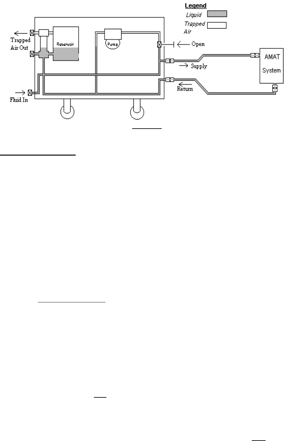
Figure “c”
Operating the chiller.
To start operating the chiller, ensure that the supply valve at the back of the chiller for
each connected channel has been opened.
1. Turn on main circuit breaker and individual breaker for each pump, the compressor
and heater.
2. Pumps 2 and 3 pump channel 2 fluid. Pump 1 pumps channel 1.
3. Start the pump for the channel being purged and check for flow by observing that
the appropriate “Low Flow” indicating led on the control panel extinguishes and the
pressure increases on the pressure gauge at the front panel.
4. If no flow has been established within 5 seconds turn the pump off. This indicates
that air still remains in the system at the pump head and must be removed by the
steps above in “Filling the internal cooling loops of the chiller”. It is important to hit
“Alarm Ack” on the Watlow TCS control unit should the pump trip off independently.
5. Repeat Operating the chiller Step 2-4 until flow and pressure have been established.
It is interesting to note the pressure in the chilled loop with the pump running is now
approximately 60-100 psi greater than the pressure indicated in the reservoir.
6. After flow and pressure have been established open “Purge Valve” for the channel
under observation. If flow stops, close the purge valve, stop the pump and repeat
step 3.
7. Hold purge valve open for approximately 3 minutes to remove remaining air in chiller
loop. Close the purge valve.
8. Turn on the compressor and the Heat/Chill processing. A green light on is an
indication the component is activated. A green light off even if the button is
depressed means the component is faulted.
9. Monitor the chiller in local mode to ensure that it chills adequately in that it goes
from ambient to setpoint in 15 minutes. It is strongly recommended that only Loop 1
and Loop 4 temperature setpoints on the Watlow be changed as these are the
temperature setpoints for channel 1 and 2 respectively. All other loops are set at the
factory and should not be adjusted.
10. Refer to the CHX documentation to set the chiller operating in remote mode.
Note: A rapid increase in gauge pressure indicates the fluid has been purged
from the tool and its service lines.
Caution: Use care when removing fitting as the lines may be under pressure.
Note: When in a non-sensitive area the recovery tank need not be sealed. Thereby
reducing the time required for purging.
Note: When using a recovery Fill/Drain Tank it should be at normal atmospheric
pressure.
Note: Consult your MSDS for proper handling of the perfluorinated fluid.
Note: Ensure that system pressure never goes below 25 psi if the TCS is
operating on the remaining channels during this process.
Note: The preceding step purges Galden® vapor from the TCS.
9.2 Purging Gas from a Tool Channel
Note: These steps are to be done subsequent to the operation shown in Section
9.1.
Note: Any reference to a recovery tank is recommended for tanks filled with
Galden®, for they can trigger air quality detectors at high air concentrations. The
recovery tank is optional for inert fluids.
1. Open “supply” valves at the TCS rear panel (Figure 7-3).
2. Start pump for the channel being purged and check for flow by observing that the
appropriate “Low Flow LED” on the control panel extinguishes (Figure 2-1) and the
pressure by checking the pressure gage on the front panel (Figure 7-2).
3. If no flow or pressure has been established within 5 seconds turn the pump off and
repeat steps in filling the internal cooling loops of the chiller in section 9.1.
4. Repeat check for flow (step 2 of section 9.2). If flow and pressure do not establish
repeat cycle until flow is steady.
5. After flow and pressure have been established open “Purge Valve” (Figure 7-2) for
the channel under observation. If flow stops, close the purge valve and stop the pump.
Repeat steps 23 through 35 of section 9.1 and step 2 of section 9.2 until flow continues
when the channel’s purge valve is opened.
6. Hold purge valve open for approximately 3 minutes to remove remaining air in tool
circuit.
Caution: Do not leave chilled channel pumps running very long without running
the compressor and activating the Heat/Chill switch to avoid overheating the
fluid.
9.2.1 Channel Flow Switch Adjustment Procedure
Note: The purpose of this procedure is to adjust the Channel 2 flow switches.
1. Remove left side panel. (Facing front of TCS)
2. Disconnect connector#36(flow switch for pump#3).
3. Jumper across the female side of connector 36 at pins 1 and 2.
4. Monitor continuity of the flow switch(pump#3) across pins 1 and 3 on the male side
of connector 36(green and yellow). Pumps are off.
5. Activate on/off switch for channel 2 on front panel to on position.
6.
a. If the low flow light for channel 2 turns off and continuity across pins 1 and 3
remains constant, adjust flow switch#3 by going to step 10. Flow may be
confirmed on loop 5 of the Watlow controller; top number is actual, bottom is set
point; which is 2.5.
b. If the low flow light does not extinguish and there is no continuity across pins 1
and 3, adjust flow switch#2 as described in step 7. No flow signal is established
on loop 5 of the Watlow controller while pumps are running.
c. If the low flow light extinguishes, flow is established on loop 5 of the Watlow
controller and there is no continuity across pins 1 and 3, the system is
functioning correctly- skip to step 12.
7. Remove right side panel.
Caution: Avoid contact with Hi/Low pressure switch bare terminal; high voltage.
NOTE: For easier access, turn off circuit breakers for all heaters and disconnect
heater connectors (#s 24 and 25).
8. Locate flow switch for pump#2(below pump#3).
9. With pumps running (channel 2), adjust flow switch setting on pump#2 with a 5/32”
allen wrench (clockwise decreases flow rate set point) until low flow light

extinguishes and flow is established on loop 5 of the Watlow controller (above 2.5
set point). Note: If continuity across pins 1 and 3 is open, skip step 10.
10. With pumps running (channel 2), adjust flow switch setting on pump # 3(clockwise
decreases flow rate set point) with a 5/32” allen wrench until continuity across pins 1
and 3 opens. Note: Loop 5 on Watlow controller should be above the 2.5 set point
while adjusting the flow switch for pump#3.
11. Re-connect connector#36 and check flow (loop 5 on Watlow) and low flow light on
front panel extinguishes.
12. While you have the panels off, turn channel 2 pumps on and off 2 or 3 times to
ensure proper flow switch set point.
13. Check to be sure all electrical connections are securely attached.
14. Re-install panels.
If further assistance is required, please call ATS product support at the following
telephone number, 714-688-4201.
9.3 Draining a Tool Channel
Warning: Do not drain a channel that is over 60°C. First cool the channel
by reducing the set temperature on the TCS control to 60°C or less.
Note: Maintain system pressure at 25 psi minimum during the channel draining
process if the unit is operating on its remaining channel.
1. Be sure the pump is stopped for the intended channel to be drained.
2. Close TCS “Supply” valve for the appropriate channel (Figure 7-3).
3. Connect a source of clean N2 at a pressure of 25-50 psi to the “Fill/Drain Line”
(Figure 7-2) for the corresponding channel using a Fill/Drain Tank Hose (Figure 7-5).
4. Open “Fill/Drain Valve” (Figure 7-2) for that channel, allowing N2 into the line.
5. Remove over-pressure between the N2 and the tank from the system by connecting
a tank hose (Figure 7-5) from the System Pressure valve at the top of the sightglass
(Figure 7-2) to the Fill/Drain Tank “Drain Port”.
6. Monitor the liquid showing in the sightglass and continue the process until bubbles
appear in liquid.
7. Continue introducing N2 through the “Fill/Drain Valve” for approximately 30 seconds
per 25 feet of hose to be drained.
8. Close TCS “Return” valve for the channel being serviced.
9. Close the “Fill/Drain Valve”.
10. The tool or the lines to the tool can now be removed.
Note: There will be little more than traces of fluid left in the lines after the drain
process has been correctly carried out.
Note: Clean Dry Air (CDA) may be substituted for N2 if needed.
9.4 Fluid Line Connections
Prior to operating the1231 the Fluid Line inline filters must be installed in both channels.
The filters are shipped ready for installation with their insulation mounted. Use care
when attaching the filters to avoid damaging the insulation. Mount the filters to the
return line connections for both fluid channels on the rear panel of the TCS chassis.
9.5 Draining the TCS for Removal
Note: Before draining the TCS drain the Tool and its service lines per section 9.3.
Caution: Close all valves and remove all service lines before draining the TCS.
1. Cap the Fluid Line “Supply” (Figure 7-3) for the channel to be drained using an
appropriate face seal cap.
2. Open the “Supply” valve (Figure 7-3) for the selected channel using a 9/16” wrench.
3. Attach a ATS recommended recovery Fill/Drain Tank to the TCS channel to be
drained by connecting the tank’s hose (Figure 7-5) between the selected channel TCS
Fill/Drain Line (Figure 7-2) and the recovery tank’s “Fill Port” (Figure 7-4).
Note: The tank should be empty and at atmospheric pressure.
4. Open the recovery tank hose and TCS Fill/Drain valves (Figure 7-2).
5. Connect another hose to a source of clean N2 at a pressure of 25-50 psi and to the
“System Pressure Valve” (Figure 7-2).
6. Open the N2 hose valve and begin introducing N2.
7. Monitor the recovery tank’s pressure gauge. A rapid increase in pressure indicates
that the channel has been emptied.
Caution: Close all valves before removing any hoses or fittings.
8. Repeat the above steps for the remaining channel.
9.6 INSTRUCTIONS FOR FILLING A TCS WITH GALDEN®
Note: Due to the sensitivity of FAB air quality measuring devices to Galden®
special procedures must be followed to prevent alarms. These procedures were
designed to minimize the exposure of Galden fumes to the FAB environment. Two
fill/drain tanks (a supply and recovery tank) are key to this.
9.6.1 Filling a Tool Channel including the TCS.
Before the 1231 can be used all the channel circuits including the lines from TCS to
tools must be filled. This task should be accomplished using an ATS approved Fill/Drain
Tank charged with Galden®. Whenever a TCS is removed from the tool for service that
channel circuit needs to have its fluid drained from the lines and tool. The following
procedures are to be used for both processes.
Caution: Ensure that the heat transfer fluid system is pressurized to at least 25
psi throughout fill, purge, or drain procedure.
Warning: Before filling any channel with Galden®, be sure to purge all
remaining fluids from the connecting tool and its associated lines.
Warning: Use only clean, particulate free coolant fluids or damage may
result to the temperature control system.
Caution: When connecting stainless steel fittings use of anti-seize compound is
recommended.
1. When initially connecting the TCS to the tool begin by attaching the special adapter
fittings (Figure 7-6), using 15/16” and 7/8” wrenches, to the appropriate tool supply and
return line ends for each channel to be used.
2. Fill the ATS recommended Supply Fill/Drain Tank with an approved low grade
Galden fluid or clean water.
3. Connect the selected supply line to the Supply Fill/Drain Tank’s “Fill Port” (Figure 7-
4) using a Fill/Drain Tank Hose (Figure 7-5).
Note: ATS supplied Fill/Drain Tanks are sized for approximately 75 feet of service
hose. If longer hoses are required contact ATS for review.
4. Connect the matching return line to a second empty Recovery Fill/Drain Tank’s
“Drain Port” (Figure 7-4) using a second Fill/Drain Tank Hose (Figure 7-5).
5. Pressurize the filled Supply Fill/Drain Tank to approximately 50 psi by introducing N2
into its “Drain Port” using a Fill/Drain Tank Hose.
6. Open the Fill/Drain Tank hose valves (Figure 7-5) and begin purging the tool with
low grade Galden® or clean water.
7. Monitor the pressure gauges on both tanks.
8. When the gauge on the recover tank approaches the reading on the supply tank,
close the recovery tank’s hose valve and remove the recovery tank from the Fab area
for venting in an approved location.
9. Vent the recovery tank by actuating the pressure relief valve’s finger ring.
10. Reattach the Fill/Drain tank hose to the recovery tank.
11. Close supply tank’s hose valve and remove the supply tank, leaving the hose
connected to the tool supply line.
12. Attach the loose end of the supply tank’s hose to a N2 source of approximately 50
psi.
13. Open both hose valves and begin introducing N2.
14. Monitor the recovery tank’s pressure gauge.
Note: A rapid increase in gauge pressure indicates the fluid has been purged
from the tool and its service lines.
15. Once the purging has been completed close both hose valves.
16. Remove the adapter fittings from the supply and return lines.
Caution: Use care when removing fitting as the lines may be under pressure.
Note: When in a non-sensitive area the recovery tank need not be sealed. Thereby
reducing the time required for purging.
17. Connect the selected channel’s supply and return lines to the TCS.
18. Close TCS “Supply” (using a 9/16” wrench) valve on the rear panel.
19. Close the valve of all Fill/Drain Tank hoses.
20. Connect a hose (Figure 7-5) between a B/E Fill/Drain Tank’s “Fill Port” (used as a
supply tank source of Galden® HT 135 or DI-Water/Glycol at a pressure of 25-50 psi)
and the TCS “Fill/Drain Line” connection (Figure 2) for the corresponding channel.
21. Connect a hose (Figure 7-5) between an empty B/E Fill/Drain Tank’s “Drain Port”
(used as a recovery tank for Galden® vapors) and the TCS “System Pressure Valve”
(Figure 7-2).
22. Open the appropriate channel’s hose valves to start introducing Galden®.
Note: When using a recovery Fill/Drain Tank it should be at normal atmospheric
pressure.
23. Open the recovery tank’s hose valve to remove excess pressure from the system.
24. Observe the fluid entering the TCS Sightglass while step 23 is in process.
25. If the pressure in the recovery Fill/Drain Tank approaches that in the supply
Fill/Drain Tank, it is necessary to interrupt this process by closing all related valves and
removing the recovery tank.
26. Bleed the Fill/Drain Tank outside the fab area (fumes from perfluorinated fluids can
set off false fluorine alarms inside fabs) to remove excess pressure.
Note: Consult your MSDS for proper handling of the perfluorinated fluid.
28. Reattach the recovery tank and hose, then open all related valves before continuing
the process.
Note: Ensure that system pressure never goes below 25 psi if the TCS is
operating on the remaining channels during this process.
29. Open the “Supply” valve when the liquid flow as viewed in the TCS Sightglass no
longer contains bubbles.
Note: The preceding step purges Galden® vapor from the TCS.
30. Continue to monitor the TCS Sightglass for bubbles.
31. When the liquid flow no longer contains bubbles, close all related hose valves and
remove both Fill/Drain Tanks.
32. Repeat the above steps for the remaining channel.
33. Pressurize the system through the “System Pressure Valve” (Figure 7-2) using
a 25-50 psi source of N2 connected through a tank hose (Figure 7-5).
35. Open TCS the “Supply” valve before starting a pump.
9.6.2 Purging Gas from a Tool Channel
Note: These steps are to be done subsequent to the operation shown in Section
9.1. of the TCS manual
1. Open “Supply” valves at the TCS rear panel (Figure 7-3).
2. Start pump for the channel being purged and check for flow by observing that the
appropriate “Low Flow LED” on the control panel extinguishes (Figure 2-1) and the
pressure by checking the pressure gage on the front panel (Figure 7-2).
3. If no flow or pressure has been established within 5 seconds turn the pump off and
repeat steps 23 through 35 in section 9.1 of the TCS manual.
4. Repeat check for flow (step 2 of section 9.2 of the TCS manual). If flow and
pressure do not establish repeat cycle until flow is steady.
5. After flow and pressure have been established open “Purge Valve” (Figure 7-2) for
the channel under observation. If flow stops, close the purge valve and stop the pump.
Repeat steps 23 through 35 of section 9.1 and step 2 of section 9.2 until flow continues
when the channel’s purge valve is opened.
6. Hold purge valve open for approximately 3 minutes to remove remaining air in tool
circuit.
Caution: Do not leave chilled channel pumps running very long to avoid
overheating the fluid.
9.6.3 Draining a Tool Channel
Warning: Do not drain a channel that is over 60°C. First cool the channel by
reducing the set temperature on the TCS control to 60°C or less.
Note: Maintain system pressure at 25 psi minimum during the channel draining
process if the unit is operating on its remaining channel.
1. Be sure the pump is stopped for the intended channel to be drained.
2. Close TCS “Supply” valve for the appropriate channel (Figure 7-3).
3. Connect a source of clean N2 at a pressure of 25-50 psi to the “Fill/Drain Line”
(Figure 2) for the corresponding channel using a Fill/Drain Tank Hose (Figure 7-5).
4. Open “Fill/Drain Valve” (Figure 7-2) for that channel, allowing N2 into the line.
5. Remove over-pressure between the N2 and the tank from the system by connecting
a tank hose (Figure 7-5) from the System Pressure valve at the top of the sightglass
(Figure 7-2) to the Fill/Drain Tank “Drain Port”.
6. Monitor the liquid showing in the sightglass and continue the process until bubbles
appear in liquid.
7. Continue introducing N2 through the “Fill/Drain Valve” for approximately 30 seconds
per 25 feet of hose to be drained.
8. Close TCS “Return” valve for the channel being serviced.
9. Close the “Fill/Drain Valve”.
10. The tool or the lines to the tool can now be removed.
Note: There will be little more than traces of fluid left in the lines after the drain
process has been correctly carried out.
Note: Clean Dry Air (CDA) may be substituted for N2 if needed.
9.6.4 Fluid Line Connections
Prior to operating the1231 the Fluid Line inline filters must be installed in all channels.
The filters are shipped ready for installation with their insulation mounted. Use care
when attaching the filters to avoid damaging the insulation. Mount the filters to the
return line connections for both fluid channels on the rear panel of the TCS chassis.
9.6.5 Draining the TCS for Removal
Note: Before draining the TCS drain the Tool and its service lines per section 9.3.
of the TCS manual
Caution: Close all valves and remove all service lines before draining the TCS.
Note: The Reservoir fluid can be drained through any channel.
1. Cap the Fluid Line “Supply” (Figure 7-3) for the channel to be drained using an
appropriate face seal cap.
2. Open the “Supply” valve (Figure 7-3) for the selected channel using a 9/16” wrench.
3. Attach a B/E recommended recovery Fill/Drain Tank to the TCS channel to be
drained by connecting the tank’s hose (Figure 7-5) between the selected channel TCS
Fill/Drain Line (Figure 7-2) and the recovery tank’s “Fill Port” (Figure 7-4).
Note: The tank should be empty and at atmospheric pressure.
4. Open the recovery tank hose and TCS Fill/Drain valves (Figure 7-2).
5. Connect another hose to a source of clean N2 at a pressure of 25-50 psi and to the
“System Pressure Valve” (Figure 7-2).
6. Open the N2 hose valve and begin introducing N2.
7. Monitor the recovery tank’s pressure gauge. A rapid increase in pressure indicates
that the channel has been emptied.
Caution: Close all valves before removing any hoses or fittings.
8. Repeat the above steps for the remaining channel.
10. OPERATING THE TCS CONTROLLER
As noted in the Introduction to this manual the Watlow Anafaze manual CLS200 Series
USER’S GUIDE is an integral part of this operating manual. The instructions found in
this section are excerpted from that manual and are provided as a short introduction to
the operating procedures needed by the 1231 operator. Any more detailed questions
that are not answered in this manual can normally be found in the CLS200 Series
USER’S GUIDE. The operator should gain thorough familiarity with the USER’S
GUIDE. Reference to page numbers given in Section 10 refer to the page numbers in
the USER’S GUIDE.
10.1 Setting up the controller
See Appendix I for description of inputs, outputs and functions of the TCS
controller.
1. Set up controller address if unit is used with the Applied central controller and CHX
communication is in use. If the TCS is to be used as a stand-alone TCS with no tie-in
to a central controller for a cluster tool set the TCS controller to LOCAL mode and leave
it set thus (see Section 8.6).
2. Proportional Integral Derivative (PID) settings are factory preset and should not
require adjustment. if the default settings are not adequate discuss with a
knowledgeable trained technician or ATS personnel.
3. Change the Capacity Regulation settings if the default settings do not prove
adequate.
10.2 Address set-up
(Ref. page 56) Access the Setup Menus: Press; ENTER then ALARM/ACK then CHNG
SP.
“Setup Global Parameters” appears: Press YES.
Press NO to advance the menu selection to “Controller Address” menu: Press YES to
select this menu.
Press YES to increase the address number to a selection between 1 and 244 that is
desired for the first controller address. The next higher number will be automatically
assigned to each subsequent controller. Press ENTER to retain settings. Press BACK
to abort editing and return to Setup Global Parameters menu. Press BACK again to
return to the control menus.
10.3 Proportional Integral Derivative settings
The PID settings are set up to match the needs of a typical 200 mm tool with a thermal
mass equivalent to about 15 kg of aluminum. The default settings for Channel 1 and 2
are:

Heat Control PB, 4 Heat Control Filter, 0 Cool Control TD, 60
Heat Control TI, 20 Cool Control PB, 4 Cool Control Filter, 0
Heat Control TD, 50 Cool Control TI, 20 Heat/Cool Spread, 0
Note: For additional default settings see the appendix.
10.3.1 Setting up to change the PID settings
To change these settings when in the proper loop of the control panel first press “Enter”
(see Figure 10-1) then “Alarm Ack” then “Chng Sp” all within three seconds. This will
change the control panel to read “Setup Global Parameters?”: Press “No” in response.
“Setup Loop Inputs?” appears: No is the proper response “Setup Loop Control
Params?” appears: Press “Yes”. Press “Yes” to any parameter that should be changed
and “No” to any that should remain unchanged. Pressing “No” will advance the control
to the next parameter. Pressing “No” to the last parameter will return to “Setup Loop
Control Params?”. The operator can then repeat the above menu or get back to the
main display.
10.3.2 Changing the PID settings.
When it is desired to change a setting of a given menu, for example “Cool Control PB”,
After pressing “Yes” to so indicate press “Yes” to increase the number after the = sign
or “No” to decrease its value. Press “Enter” to store the chosen value. The next step in
the menu will appear for changing if so desired. When finished with the changes press
”Back” enough times to return to the main display.
10.3.3 Guidance for setting PID settings.
If control is unsatisfactory enough to indicate a change in the PID settings is needed,
the following can be used as a rough guide.
Heat Control PB: Increasing will
decrease the strength of control;
decreasing PB will turn more heat or
cooling at temperatures a small distance
from set point.
Cool Control TI: See Heat Control TI.
Heat Control TI: Increasing this makes
the setting more stable but less accurate;
conversely, decreasing will make the
approach to set temperature closer but
will oscillate more as TI is reduced.
Cool Control TD: See Heat Control TD.
Heat Control TD: Increasing this makes
the setting slower to respond but with
less overshoot when the set temperature
is changed. Decreasing TD will make
the response quicker but with more
overshoot and resultant oscillation after
set temperature is achieved.
Cool Control Filter: See Heat Control Filter
Heat Control Filter: Generall
y
this should Heat/Cool S
p
read: Generall
y
this value

remain set at 0. Increasing the value will
dampen response. See page 75 in the
USER’S GUIDE.
should always be 0. Any larger value will
affect the closeness of temperature control.
To achieve ± 1°C this setting of 0 must be
maintained.
Cool Control PB: See Heat Control PB
above.
10.4 Capacity regulation
Generally the settings for Capacity Regulation should not be changed. These are PID
settings for Cool only. If it seems that the capacity regulation light is on (see Section 2)
too long and it is desired to change these settings check with Engineering at B/E
Aerospace, Inc. before proceeding.
10.5 Process Control Limit Settings
The Anafaze Controller provides system protection through Process Limit Settings in its
Global Parameters. All 16 loops are limited by one setting for the “Setup Global
Parameters”. The “Setup Global Parameters” are factory set to the Chiller specification
of -20°C and +40°C. New values should be discussed with the ATS factory engineering
before the limits are changed to ensure satisfactory unit operation.
Changing the limits is accomplished as follows:
1. Access the “Setup Global Parameters” menu as described in section 10.2.
2. Once the “Setup Global Parameters” menu has been accessed press NO to
advance the selection to “Minimum Set Point”.
3. Press YES to indicate appropriate heading is ready for data entry.
4. Press the “Up Arrow” to increase the value or the “Down Arrow” to decrease the
value, until the appropriate new value is achieved.
5. Press the Enter to accept the value and advance to the “Maximum Set Point”
heading.
6. If changing only the maximum limit, continue advancing the selection by pressing
NO until “Maximum Set Point” appears.
7. Press YES to indicate appropriate heading is ready for data entry.
8. Press the “Up Arrow” to increase the value or the “Down Arrow” to decrease the
value, until the appropriate new value is achieved.
9. Press the Enter to accept the value and advance to the next heading.
10. Press Back twice to return to normal operation.
10.6 Changing the Process Set Points
All 16 Loops can be altered locally through the Anafaze front control panel buttons as
follows:
1. Scroll to the appropriate Loop by using the “Up” or “Down” arrow until the correct
number appears.
2. Press the “CHNG SP” button followed by the YES button.
3. Press the “Up” or “Down” arrow until the new set point is reached.
4. Press enter to accept the value and reset to the normal operation mode.
10.7 Changing the Safety and Reference Set Points
Changes to the Safety and Reference Set Points should not be made without
discussing the changes with the ATS factory engineering before to ensure safe unit
operation.
Safety Set Points are set at the factory per the following values:
• Flow Switch Safety Limits (Loop 2, and 4) are set to the reference value of 2.5.
• Heater Safety Limits (Loops 12, and 13) are set to 100°C.
Reference Set Points for the Reference Evaporator and the Compressor are set at the
factory. Their initial values are listed in the Watlow PID Setting Matrix included with this
manual.
Note: The Safety and Reference Set Points can be altered locally through the
Anafaze front control panel buttons as described in section 9.5.

11.LIQUID PUMP OPERATION
Figure 11-1 shows the basic layout of the ATS liquid pump design.
Figure 11-1 Liquid pump layout
The pump is a regenerative turbine style pump driven by a 3 phase induction motor, the
rotor of which is enclosed inside a stainless steel shell.

12.TROUBLE-SHOOTING THE 1231
Note: To trouble-shoot the 1231 the TCS controller should be in LOCAL mode.
Table 12-1 Trouble-shooting the TCS
Symptom Cause & Corrective Action
1. Capacity regulation lights are on
continuously in steady-state
operation.
Refrigeration circuit is being overloaded: Increase set
temperature or reduce heat load on chilled channels. If all
settings are within specifications refrigeration system is not
cooling per design and system must be examined for
cause. Most likely reason is loss of refrigerant due to a
leak.
2. Low Flow LED will not extinguish. A. Pump is malfunctioning: Replace with new or rebuilt
pump if power is correctly applied to pump (Note whether
pump LED is on.). Check connection phase rotation.
Confirm circuit breaker position and fuse status.
B. Channel circuit is blocked: Remove obstruction. Output
valve may be shut off or another blockage is in channel
circuit.
C. Pump is vapor locked: Either the fluid is boiling because
the type of fluid used boils at less than the operating
temperature or the channel temperature is set over the
maximum operating range. In the first case flush out
the fluid (see Section 9) from all channels and refill with
the correct fluid. In the second case set the
temperature to the correct value.
D. On channel 2, the flow switches are improperly set for
the application. If you suspect the flow switches contact
ATS for instructions.
3. Low Flow LED will not illuminate. A. Flow switch malfunction: Remove switch and clean or
replace.
B. Damage Wiring: Check and repair as necessary.
4. Absence of cooling. A. Main Heat/Cool Switch activation: Turn on switch.
B. Loop 15 set point too low: Reset with higher value.
C. Compressor off due to fault: Correct fault. Note: high
cooling water flow (above 10 gpm) may cause loss of
function. Lower cooling water flow (below 10 gpm) and
recheck.
D. Refrigerant Low: Contact authorized refrigeration
technician for service.
E. TXV not opening: a) Confirm power supplied to TXV
bulb heater, if not, correct supply. b) Check for damaged
TXV bulb heater, replace if necessary. C) Replace TXV if
needed.
5. Heater over-temperature LED stays
activated. Channel heater cluster is overheating: Cause must be
diagnosed. Possibilities are:
A. Heater over-temperature setting is set too low: Correct
at the TCS controller and reset controller
B. Channel temperature is set too high for the TCS or the
fluid used. Galden® HT 110 or equivalent is
recommended. The limit of this fluid is 120°C: Reset

controller
C. Heater relay has failed (closed) and must be replaced.
6. Prolonged gradual heating A. Main Heat/Cool switch activation: Turn on switch.
B. Heater Safety Loops (12 and 13) set point too low:
Increase set point.
C. Failed heater: a) Confirm power supplied to heater, if
not, correct supply. b) Check for damaged heater, replace
complete assembly if necessary.
D. Exceeding design capacity of TCS: Consult factory for
assistance.
7. Drop in heating capability A. Temperature set point altered: Correct set point.
B. Failed heater: a) Confirm power supplied to heater, if
not, correct supply. b) Check for damaged heater, replace
complete assembly if necessary.
8. TCS controller fails to give proper
readings. This is difficult to predict where the fault lays. The TCS
controller can fail and this is recognized when all channels
of control are giving wrong readings. Thermocouples can
be broken and this will show on the TCS controller readout.
If the controller needs replacing the TCS will have to be
removed from service to allow this to be done.
9. Increase in TCS cover temperature. A. Vent Fan failure: a) Check for free wheeling of fan
blades, remove blockage if required. b) Confirm power
supplied to fan if not, correct supply. c) Check for damaged
fan motor, replace if necessary.
B. Blocked inlet vents: a) Remove blockage, if present.
b) Ensure 2” clearance between TCS and nearest
obstruction.
10. No increase in channel pressure
during pump operation. See Low Flow LED will not go off symptom (2).
11. Communications faults A. Wrong cable: confirm a serial cable not a null modem
cable was used.
B. Check that the 485/232 converter is wired correctly.
C. Confirm the Watlow configuration is correct.
D. Reference Watlow manual check ATS wiring is
compliant.
12. Poor and/or erratic cooling
performance 50/50 mixture of ethylene glycol and deionized water is out
of balance. DI System may be absorbing the ethylene glycol
out of the solution thereby raising the freezing point.
A. Check the ethylene glycol concentration using a
hydrometer.
B.
A
dd ethylene glycol to reach proper concentration.
I.e. evaporator min temp. -35C
13. Watlow senses flow when the pump
is off Loose calibration of magnetic read switch in Malema flow
switch. Install longer spring into magnetic read switch port
and recalibrate.
14. Pump motors do not turn on A. Without Power do a basic visual inspection of the
connectors that have been disassembled and
reassembled to make sure that a pin hasn’t been
pushed out of a connector or a wire pulled out of a pin.
B. Without Powe
r
Jum
p
er the flow switches between
p
ins

1 & 2 on each of the channel 2 pumps (pumps 2 & 3)
C. Without Power Jumper the thermal switches on the
pump which are pins 4 & 5 on connector J23/P23 and
J22/P22 (thermal switches 16 and 17.)
D. Without Power Make sure that pump switches are
seated completely on the P/C board. We have seen 1
or 2 others not fully clipped into place.
E. Make sure all circuit breakers are off. Then turn on
main circuit breaker. Activate circuit breakers for
pumps 2 & 3 to see if they run. If they do not verify that
PS 2 is generating 12V. Test this voltage at Switch 13,
which is J36 pin 1 to ground (on the female side of the
connection).
F. If you have voltage on J36 pin 1 then jumper switch 13
between pins 1 & 2 on the female side of the
connection. Then check the voltage on flow switch 2,
which is switch 12, pin 1 to ground, which should read
12 V.
G. If you are not getting power at either steps 5 or 6 above
check the output of the power supply. If you have 12 V
at the power supply but not at the switches check the
continuity of the circuit. To do this shut off power to
the unit and ohm the line between PS2 + terminal to
J36/P36 pin 1(a pushed out pin or pulled out wire is
most likely cause).
H. If all these work then check the voltage at the Watlow
WLTB1 #13, voltage from this pin to ground should be
2-6 VDC or so. If you get voltage the Watlow is
receiving the signal.

13.APPENDIX
12.1 Appendix I. Inputs and outputs of the TCS controller
Loop
# Input Type Function Heat
Output Cool
Output Output
Type H/C
1 T-Type T/C Chan. 1
Temperature D/O # 1 D/O # 18 DZC /
DZC
2 4 - 20 ma Chan. 1 Flow
Rate Disabled
3 0 - 5 V Chan. 1
Resistivity D/O # 20 Off /On-
Off
4 T-Type T/C Chan. 2
Temperature D/O # 4 D/O # 21 DZC /
DZC
5 4 - 20 ma Chan. 2 Flow
Rate Disabled
6 0 - 5 V Chan. 2
Resistivity D/O # 23 Off / On-
Off
7 Not used Disabled
8 Not used Disabled
9 Not used Disabled
10 T-Type (No C/J) Capacity
Regulation D/O # 27 Off / DZC
11 T-Type (No C/J) Capacity
Regulation D/O # 28 Off / DZC
12 T-Type T/C Chan. 1 Heater
Temp D/O # 12 D/O # 29 On-Off
13 T-Type T/C Chan. 2 Heater
Temp D/O # 13 D/O # 30 On-Off
14 Not used Disabled
15 T-Type T/C Cool channels
control Disabled
16 0 - 5 V Compressor On
Indicator Disabled
Digital Type Function
1 Output Channel 1 Heat
2 Output Not Used
3 Output Not Used
4 Output Channel 2 Heat
5 Output Not Used
6 Output Not Used

7 Output Not Used
8 Output Not Used
9 Output Not Used
10 Output Not Used
11 Output Not Used
12 Output Channel 1 Heater Over Temp.
13 Output Channel 2 Heater Over Temp.
14 Output Not Used
15 Output Compressor On/Off
16 Output Not Used
17 Output Not Used
18 Output Channel 1 Cool
19 Output Not Used
20 Output Channel 1 Resistivity
21 Output Channel 2 Cool
22 Output Not Used
23 Output Channel 2 Resistivity
24 Output Not Used
25 Output Not Used
26 Output Not Used
Digital Type Function
27 Output Channel #1 Capacity Regulation
28 Output Channel #2 Capacity Regulation
29 Output Heater 1 Over Temp. LED
30 Output Heater 2 Over Temp. LED
31 Output Not Used
32 Output Pump 1 On/Off
33 Output Pump 2 On/Off
34 Output Pump 3 On/Off
1 Input Fluid Level Low
2 Input Fluid Level Warning
3 Input Facility Water
4 Input Pump 1 On/Off Switch
5 Input Pump 2 On/Off Switch
6 Input Not Used
7 Input Compressor On/Off Switch / Interlock
8 Input Remote / Local switch
4X Memory Addresses
100 Digit #1 = Fault Summary, Digit #2 = Warning Summary
101 Channel # Process Value
102 Digit #1 = Fluid Level, #2 = Flow Rate alarm, #3 = Resistivity alarm, #4 = Facility
Water, #5 = Compressor Off, #6 = Heater Over Temp., #7 = Fluid Over Temp, #8 =
Capacity regulation active, #9 = Thermocouple Break.

103 Not Used
104 Channel # Resistivity
105 Channel # Flow Rate
106 Not Used
107 Not Used
108 Not Used
109 Channel # On / Off
10A Channel # Setpoint
10B Compressor On/Off
10C Not Used
10D Not Used
10E Not Used
Warning and Fault Settings
Conditions Fault Warn
. 4X
Address Trigger
Fluid Level Low (#1) 102 - 1 Level sensor reaches low trigger
Fluid Level Low (#2) X 102 - 1 Level sensor reaches bottom level
Fluid Flow Rate Low X 102 - 2 Flow rate reaches 1 gpm
Resistivity Low X 102 - 3 When resistivity reaches 2 MΩ•cm
Facility Water Lost X 102 - 4 When facility cooling water is lost
Heater Overtemp X 102 - 6 When heater temp is > setpoint
Fluid Overtemp X 102 - 7 When Fluid temp is > setpoint
Capacity Regulation
Active X 102 - 8 When capacity regulation activated
conditions occur
Thermocouple Break X 102 - 9 Channel T/C break Alarm
Compressor Off X 102 - 10 When Compressor is off
Communication Lost X Set by Host
Setpoint Out of
Range Modbus Exception Response Sent
to Host: Setpoint >Setpoint Max or
Setpoint < Setpoint Min
Digital inputs are closed when tied to Controller Common. Digital outputs pull outputs to
Controller Common and can sink 20 ma.
When the Digital input #8 is closed, the controller is in Local mode and no
communications with the Host will occur. When the Digital input #8 is open, the
controller is in Remote mode and its keys are disabled.
