C26 5875 2_1620 1311_Sort_Merge_Reference_Feb66 2 1620 1311 Sort Merge Reference Feb66
C26-5875-2_1620-1311_Sort_Merge_Reference_Feb66 C26-5875-2_1620-1311_Sort_Merge_Reference_Feb66
User Manual: C26-5875-2_1620-1311_Sort_Merge_Reference_Feb66
Open the PDF directly: View PDF ![]() .
.
Page Count: 20
Systems
Reference Library
IBM
1620-1311
Sort/Merge
Program
Reference Manual
This
publication
presents
the
specifications
and
operating
procedures
for
the
1620-1311
Sort/Merge
program.
This
program
is
a
general
purpose
sort
and
merge
program
that
is
designed
to
operate
under
control
of
any
of
the
1620
Monitor
Systems.
File
No.
1620-33
Form
C26-5875-2
This
is a
reprint
of
the
previous
edition
(C26-5875-1)
incorporating
the
changes
released
in
Newsletter
N26-0125.
Copies
of
this
and
other
mM
publications
can
be
obtained
through
mM
Branch Offices.
Comments
conceming
the
contents
of
this
publication
may
be
addressed
to:
ffiM, Product
Publications
Department,
San
Jose,
Callf.
95114
© 1964
by
International
Business
Machines
Corporation
ii
PROGRAM
DESCRIPTION
••••••••••••••••••••••••
Data
Control
Fields'
•••••••.••.••••••••••••••.••
Disk
Storage
Areas
•••••••••••••••••••••••••••.•
Allowable
Data
Record
Configurations
••••••••••••••••
Collating
Sequence·
••••••••••••••••••••••••••.•
Program Phases
••••••••
"
.•
""
.....
"
•••••
"
•••••
".
Phase
0
(Assignment
Phase)
•••••••••••••.•••••••
Phase
1
(Input
and
Tag
Generation)
•••••••••••••••
Phase
2
(Sort)
•••••••••••••••••••••••••••••
Phase
3
(Merge)
••••••••••••••••••••••••••••
Phase
4
(Output)
•••••.••••••••••••••••••••.•
Interrupt
and
Restart
••••••••••••••••••••••••••••
Restart·
•••••••••••••••••••••••••••••••••
2
2
2
2
3
3
3
3
4
4
Checking
FeatW'es
••••••••••••••••••••••••••
4
User-
Written
Routines
•••••••••••••••••••••••••••
Timing
•••••
It • • • • • • • ., • •
..
• • "
II
• " •
'"
• II'
•••
III • "
....
4
5
iii
CONTENTS
CONTROL
RECORDS
•••••••••••••••••••••••.•••
7
Control
Record
1
•••.•••••••••••••••••••••••
7
Control
Record
2
•••••••••.•••••••••••••••••
8
Control
Record
3
•••••••••.••••••.•••.••••
9
Restart
Records
••.•••••••
' . • • • • • • • • • • • • • • • • • •
••
9
Restart
Record
1
•••••••••••••••••••••••••••
10
Restart
Record
2
•••.•••••••••••••••••••••••
10
EXECUTThI"G
THE
SORT/MERGE
PROGRAM·
• . • • . • • • • •
••
11
Error
Messages
• • • • • • • • • • • • • • . • • • • • • • • • • . • • • • 11
Message
and
Cause
• • • • . • • • • • • • • • • • • • • • . • • •
••
11
LOADThI"G
TIIE
SORT/MERGE
PROGRAM
••••••••••••••
12
APPENDIX A • • • • • • • . . • • • • • • • • • • • • . • • • • • • • . •
••
13
PREFACE
This
publication
is
intended
to
serve
as
a
reference
manual
for
the
1620-1311
Sort/Merge
program.
The
program
specifications,
previously
published
in
a
separate
manual,
are
included
as
well
as
specific
instructions
on
the
operation
and
use
of
the
program.
The
last
section
of
the
manual
gives
the
steps
to
fol-
low
when
loading
the
different
sections
of
the
pro-
gram
to
disk
storage.
The
Sort/Merge
program
is
designed
to
operate
under
control
of
the
1620
Moni-
tor
Systems
that
are
described
in
the
following
public
ations:
IBM 1620
Monitor
I
System,
Reference
Manual
(Form
C26-5739)
IBM 1620
Monitor
II
System,
Reference
Manual
(Form
C26-5774)
The
Sort/Merge
program
is
a
general-purpose
sort
and
merge
program
which
is
tailored,
by
use
of
control
cards,
to
meet
the
user's
particular
needs
and
applications.
In
general,
the
1620
Sort/Merge
program:
1.
Sorts
and
merges
blocked
or
unblocked,
fixed-length
or
variable-length
records.
2.
Sorts
and
merges
up
to
99,999
numeric
or
alphameric
records.
3.
Sorts
and
merges
in
either
ascending
or
de-
scending
order.
4.
Sorts
by
control
data
in
up
to
ten
fields
of
each
record.
5.
Sorts
records
of
up
to
2500
core
positions
in
length.
6.
Sorts
one
or
two
data
files.
7.
Merges
two
data
files.
8.
Provides
interrupt
and
restart
procedures.
iv
9.
Provides
for
input
from
cards,
paper
tape,
or
disk.
10.
Provides
for
disk
output.
11. Allows
the
file
starting
addresses
to
be
specified
by
either:
(a)
Actual
disk
address
(b) DIM (Disk
Identification
Map)
entry
number
(c)
Equivalence
Table
name.
12. Allows
exit
points
to
user
I s
programs
for
the
purpose
of
editing
input
data,
or
for
the
output
of
data
to
units
other
than
disk.
13.
Can
be
called
for
execution
from
a
user's
program,
or
by
a
Monitor
XEQ
operation.
14.
Can
return
upon
completion
to
a
user's
program.
15.
Utilizes
the
Monitor
System
I/O
Routine
with
accompanying
error
procedures.
Machine
Requirements
The
minimum
machine
configuration
required
for
operation
of
the
Sort/Merge
program
is
the
same
as
that
for
the
1620
Monitor
System:
• IBM 1620
Data
Processing
System,
Modell
or
2,
with
a
minimum
of
20,000
positions
of
core
storage
•
Indirect
Addressing
(standard
on 1620 Model
2)
• IBM 1311
Disk
Storage
Drive
• ffiM 1621
Paper
Tape
Unit
or
1622
Card
Read-
Punch
Sorting
and
merging
is
performed
on
control
words
(tags)
extracted
from
the
data
records,
rather
than
on
the
entire
records.
This
usually
reduces
the
time
and
space
required
for
data
manipulation.
The
tag
file
contains
one
entry
for
each
data
record.
Each
tag
is
made
up
of
the
user-specified
control
fields
extracted
from
the
data
record,
to-
gether
with
a
location
field
identifying
the
disk
stor-
age
location
of
the
corresponding
data
record.
For
variable-length
records,
the
location
field
contains
eight
digits;
six
digits
are
for
the
disk
sec-
tor
address,
and two
digits
are
used
to
specify
the
starting
location
within
the
sector.
For
fixed-length
records,
the
location
field
contains
a
sequence
num-
ber
from
which
the
location
can
be
calculated.
The
size
of
this
field
may
range
from
2
to
5
digits
(speci-
fied
by
the
user).
The
maximum
number
of
input
records
is
99, 999.
DATA CONTROL
FIELDS
The
program
sorts
on
as
many
as
ten
control
fields.
The
control
fields
can
be
located
anywhere
within
the
record
as
long
as
they
do
not
overlap.
The
length
of
each
control
field
may
be
from
1
to
100
characters
in
numeric
mode
or
from
1
to
50
characters
in
alpha-
meric
mode.
If
the
total
control
field
size
is
one
core
position,
the
Sort/Merge
program
will
expand
this
to
two
positions.
The
maximum
total
tag
size
(control
fields
plus
location
field)
is
900
characters
in
numeric
mode
or
450
characters
in
alphameric
mode.
To
reduce
sort
time,
the
user
should
limit
the
number
of
characters
in
each
control
field
when-
ever
possible.
The
location
of
each
control
field
is
specified
by
the
user
in
a
control
card.
If
more
than
one
control
field
is
to
be
used,
the
most
significant
field
is
listed
first,
the
next
Significant
second,
and
so
on.
If
two
files
are
to
be
sorted
and/or
merged,
the
control
fields
must
be
the
same.
DISK STORAGE AREAS
The
Sort/Merge
program
requires
the
following
disk
storage
areas:
1. One
or
two
input
data
storage
areas.
These
areas
are
used
for
storage
of
the
records
that
are
to
be
sorted
or
merged.
If
only one
file
of
records
is
to
be
sorted,
only
one
PROGRAM DESCRIPTION
input
area
is
required.
If
it
is
not
necessary
to
store
the
record,
no input
data
area
need
be
specified.
For
example,
all
of
the
user-
needed
information
may
be
used
as
control
field
data.
The
size
of
each
input
data
area
can
be
up
to
99
cylinders
of one IBM 1316
Disk
Pack.
2.
Tag
file
work
area.
This
area
is
used
for
storing, sorting,
and
merging
tags
during
program
execution.
Tags
are
stored
on
the
disk
in
blocks
of
quarter
cylinders;
each
quarter
cylinder
contains
the
number
of
tags
(minus
one)
that
will
fit
into
5000
core
stor-
age
positions.
The
work
area
must
be
twice
the
size
of
the
tag
file
and
cannot
be
less
than
2
cylinders
or
more
than
98
cylinders
of
one
IBM 1316
Disk
Pack.
The
size
of
the
tag
file
work
area
can
be
com-
puted
as
follows:
The
number
of
cylinders
for
the
tag
file
work
area
is
two
times
the
number
of
cylinders
required
for
the
tag
file.
The
number
of
cylinders
required
for
the
tag
file
is
determined
as
follows:
N
number
of
tags
4X
N
is
the
number
of
cylinders
of
the
tag
file.
If
N
is
not an
integer,
round
to
the
next
larger
integer.
X
is
the
number
of whole
tags
(minus
one)
that
WIll
fit
into 5000
core
positions.
In
other
words,
x =
5000-tag
size
tag
size
trunc
ated
to
an
integer.
For
example,
6000
tags
of
15
positions
each
would
be
stored
in
blocks
of 332
tags
on
quarter
cylinders.
The
tag
file
would occupy
5
cylinders,
and a
total
tag
file
work
area
of
10
cylinders
would
be
required.
The
user
may
specify
the
disk
location
of
this
area
in
a
control
card.
If
the
area
is
not
specified,
the
program
uses
the
Form
C26-5875-2
Page
Revised
2/7/66
By
TNt
N26-0552
Monitor
work
area.
The
address
of
the
tag
file
work
area
must
be
the
beginning
of
a
cylinder.
If
the
user
exercises
the
option
to
inter-
rupt
the
Sort/Merge
program
to
execute
other
programs,
the
tag
file
work
area
must
have
a DIM
number
to
protect
the
con-
tents
of
the
area
while
other
programs
are
being
executed.
At
the
completion
of
the
Sort/Merge
program,
the
tags
will
be
lo-
cated
in
either
the
first
or
second
half
of
the
tag
file
work
area.
3. Output
area.
The
user
may
elect
to
end
operation
of
the
Sort/Merge
after
the
tags
are
sorted
and/or
merged.
However,
if
the
data
records
are
also
to
be
sorted,
an
out-
put
area
must
be
specified.
The
size
of
the
output
area
must
be a
multiple
of 50
sectors;
it
must
be
at
least
as
large
as
the
total
size
of
the
input
areas,
but
it
cannot
exceed
99
cylinders.
The
input
data
records
may
be
moved
after
being
sorted
to
the
same
area
from
which
they
were
removed,
in
which
case
the
output
area
is
used
for
intermediate
storage.
Each
of
the
areas
described
above
must
be
a
single
contiguous
area;
however,
each
may
be
on a
different
disk
drive.
DIM
numbers
or
Equivalence
Table
names
may
be
assigred
for
the
input,
tag,
or
output
areas
by
using
the
DLOAD
routine
of
the
Disk
Utility
Program.
Areas
larger
than
five
cylinders
must
be
specified
with
more
than
one
DIM
entry.
ALLOWABLE DATA RECORD CONFIGURATIONS
Input
data
records
can
be
from
cards,
paper
tape,
or
records
previously
stored
on
disk.
Data
records
on
tape
must
simulate
card
input;
1.
e.,
there
must
be
80
data
characters
between
the
end-of-line
charac-
ters.
Records
in
disk
storage
may
be
blocked
or
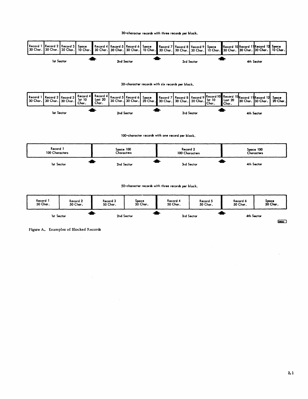
unblocked.
1.
Unblocked
records
are
stored
contiguously
on
the
disk
and
may
overlap
from
one
sec-
tor
to
another.
,
2.
Blocked
records
are
stored
..
:ih
groups
(blocks)
of
contiguous
records,
with
the
following
requirements:
a.
Each
block
begins
at
the
start
of
a
new
sector
b.
A
space
separates
one
block
from
another
Figure
A
shows
examples
of
blocked
records.
2
Input
data
records
may
be
of
three
types:
1.
Fixed
length.
The
number
of
characters
is
the
same
for
each
record.
The
user
sup-
plies
the
record
length
in
a
control
card.
2.
Variable
length
with
count.
The
number
of
characters
is
variable
for
each
record.
The
core
positions
required
for
each
record
are
recorded
in
a
count
field
-
the
count
field
is
the
first
three
characters
of
each
record.
3.
Variable
length
with
record
mark.
The
records
vary
in
length,
with
the
last
charac-
ter
being
a
record
mark.
Data
records
may
be
of
any
length
up
to
2500
nu-
meric
characters
(1250
alphameric).
Records
must
not
contain
group
marks
or
record
marks
in
any
po-
sition
within
the
record;
variable-length
records
with
record
mark
must
contain
a
record
mark
in
the
last
position.
In
numeric
mode,
there
must
not
be
a
flag
in
any
position
of a
control
field
except
the
high-order
position.
This
condition
also
applies
in
alphameric
mode
jf
the
input
file
location
is
disk.
The
program
can
handle
a
maximum
of
99,999
records.
The
last
user's
record
of
any
file
must
be
followed
by
a 0**
record.
COLLATING SEQUENCE
The
records
of a
file
may
be
sorted
in
ascending
or
descending
sequence.
The
result
of
an
ascending
sort
operation
is
based
on
the
following
character-
collating
sequence:
Numeric
o 1 2
345
6 7 8 9
Alphameric
b (blank) .
)+
$ * - / ,
(=
@
ABC
D E F G H I
o
(minus
zero)
J K L M N 0 P Q R
STU
V W X
Y
Z.
0 1 2 3 4 5 6 7 8 9
(minus
1
through
minus
9
occupy
the
same
locations
as
J
through
R).
PROGRAM PHASES
The
1620-1311
Sort/Merge
program
consists
of
five
phases
(numbered
0-4).
Phase
0
(Assignment
Phase)
The
assignment
phase
begins
operation
by
first
check.-
ing
to
ascertain
if
the
required
control
record
infor-
mation
has
been
previously
placed
on
disk
by
the
user.
If
the
control
records
are
not
on
disk,
the
assignment
phase
reads
in
the
control
records
from
the
Monitor
input
unit
(card
or
paper
tape),
analyzes
and
makes
Record 1
100 Characters
Record 1
50 Char.
1st
Sector
1st
Sector
Record 2
50
Char.
Figure
A.
Examples
of
Blocked
Records
30-character records with three records per block.
30-character records with six records per block.
lOO-character records with one record per block.
Space
100
Characters Record 2
100 Characters
Record 3
50 Char.
2nd Sector 3rd Sector
50-character records with three records per block.
2nd Sector
Space
50 Char. Record 4
50 Char.
3rd Sector
Record 5
50 Char. Record 6
50 Char.
Space 100
Characters
4th Sector
4th Sector
Space
50
Char.
2.1
checks
on
the
control
record
information
for
errors,
and
types
error
messages
if
applicable.
The
pro-
gram
then
computes
the
tag
size,
determines
the
absolute
addresses
of
the
input,
output,
and
tag
file
work
areas;
then
checks
to
determine
which
phase
should
be
executed
next,
and
calls
in
that
phase.
Phase
1 (Input
and
Tag
Generation)
During
Phase
1,
the
data
records
are
read
into
core
storage
and
tags
are
formed
and
stored
in
the
tag
file
work
area.
In
addition,
if
the
data
records
are
read
in
from
cards
or
paper
tape,
they
may
also
be
stored
on
disk.
A
user-written
program
of not
larger
than
1000
core
positions
on
a
20,000
position
machine
may
be
read
in
by
Phase
1.
The
DIM
entry
and
the
entry
address
are
specified
in
a
control
record.
The
user's
program
will
be
executed
after
each
data
record
is
read
in
and
before
the tag
if
formed~
This
provides
the
user
with
the
ability
to
perform
any
editing
or
checking
function
desired.
The
user's
program
may
re-enter
the
Sort/Merge
program
at
either
of two
places:
the
first
entry
point
allows
the
record
to
be
processed
normally
while
the
second
entry
point
allows
the
record
to
be
bypassed
(no
tag
is
formed).
The
phase
operates
in
the
following
manner:
The
first
record
is
read
into
core
storage
from
the
input
unit
and
is
loaded
into
the
work
area.
If
records
are
read
from
the
disk,
several
are
read
at
a
time
and
each,
in
turn,
is
moved
to
the
core
storage
work
area.
If
a
user-written
program
accompanies
Phase
1,
it
is
branched
to
at
this
time.
Tag
construction
is
performed
by
moving
the
data
control
fields
(in
specified
order
of
significance)
to
a
core
storage
tag
file
output
area,
thus
forming
one
continuous
control
field.
A
"record
address"
is
then
added
to
the
tag.
For
variable-length
records
the
actual
disk
address
plus
a
character
adjustment
is
used.
For
fixed-length
records
a
sequence
num-
ber
is
used.
Tags
are
stored
on
the
disk
in
quarter
cylinder
blocks.
Each
block
contains
the
number
of
tags
(minus
one)
that
will
fit
into a
quarter
cylinder.
If
the
data
records
are
read
in
from
cards
or
paper
tape,
the
records
may
be
stored
on
the
disk
at
the
user's
option.
If
all
of
the
user-required
in-
formation
is
specified
as
control
field
data,
it
is
not
necessary
to
store
the
record.
The
user
must
re-
m
ember
that
if
all
required
information
is
specified
as
control
record
data,
the
information
will
be
in
the
specified
order
of
sequence
of
the
control
fields.
If
a
merge-only
operation
has
been
called
for,
control
is
passed
to
Phase
3,
and
Phase
2
is
bypassed.
Phase
2 (Sort)
Phase
2
performs
an
internal
sort
on
the
tags
-
proc-
essing
a
quarter
of a
cylinder
area
of
tags
at
one
time.
The
internal
sort
is
performed
by
forming
sorted
strings
of
12
tags
and
merging
the
small
strings
(using
2-way
and
3-way
merges)
to
form
one
sequenced
string
of
tags.
Quarter
cylinder
strings
of
sorted
tags
are
then
placed
back
in
disk
storage.
If
the
size
of
the
tag
file
is
less
than
a
quarter
of
a
cylinder,
control
is
passed
to
Phase
4.
Phase
3
(Merge)
Phase
3
performs
a
series
of
merge
passes
on
the
sorted
strings
of
tags
and
produces
one
sequenced
string
on
the
disk
pack.
A
4-way
merge
is
performed
first
on
each
cylinder.
If
needed,
the
cylinders
are
then
merged
using
4-,
3-,
and
2-way
merges,
ac-
cording
to
a
merge
design
calculated
by
Phase
3.
The
merge
design
was
developed
to
minimize
the
number
of
merge
passes
and
at
the
same
time
to
keep
the
sorted
string
sizes
as
equal
as
possible.
For
ex-
ample,
the
first
whole
cylinder
pass
for
merging
16
cylinders
would
consist
of
four
4-way
merges.
The
first
whole
cylinder
pass
for
merging
17
cylinders
would
require
five
3-way
merges
and
one
2-way
merge.
At
the
conclusion
of
Phase
3,
the
tags
may
be
in
the
first
or
second
half
of
the tag
file
work
area.
The
disk
address
of
the
final
sequenced
string
of
tags
is
looated
in
core
positions
02462
through
02467.
Control
is
passed
to
Phase
4
at
the
end
of
Phase
3.
Phase
4 (Output)
Phase
4
is
divided
into
two
operations.
The
first
operation
always
punches
restart
information
into
cards
or
paper
tape
and
reads
in
the
Phase
4
user's
routine
(if
specified).
Upon
completion
of
the
punch-
ing
operation,
the
Sort/Merge
program
may
be
termi-
nated
if
specified
in
Control
Record
3.
During
the
second
operation,
data
records
are
read
into
core
storage
in
sorted
order,
and
then
are
placed
in
the
disk
output
area.
The
user's
routine
may
perform
any
editing
or
modification
of
the
rec-
ords
that
may
be
desired;
however,
it
should
be
re-
membered
that
modification
may
(and
deletion
of
a
record
Will)
result
in
an
error
if
record
hash
total
checks
are
being
performed.
Upon
completion
of
Phase
4
(after
either
the
first
or
second
operation),
control
can
be
returned
to
the
Monitor
Supervisor
program
or
to
the
user's
program.
3
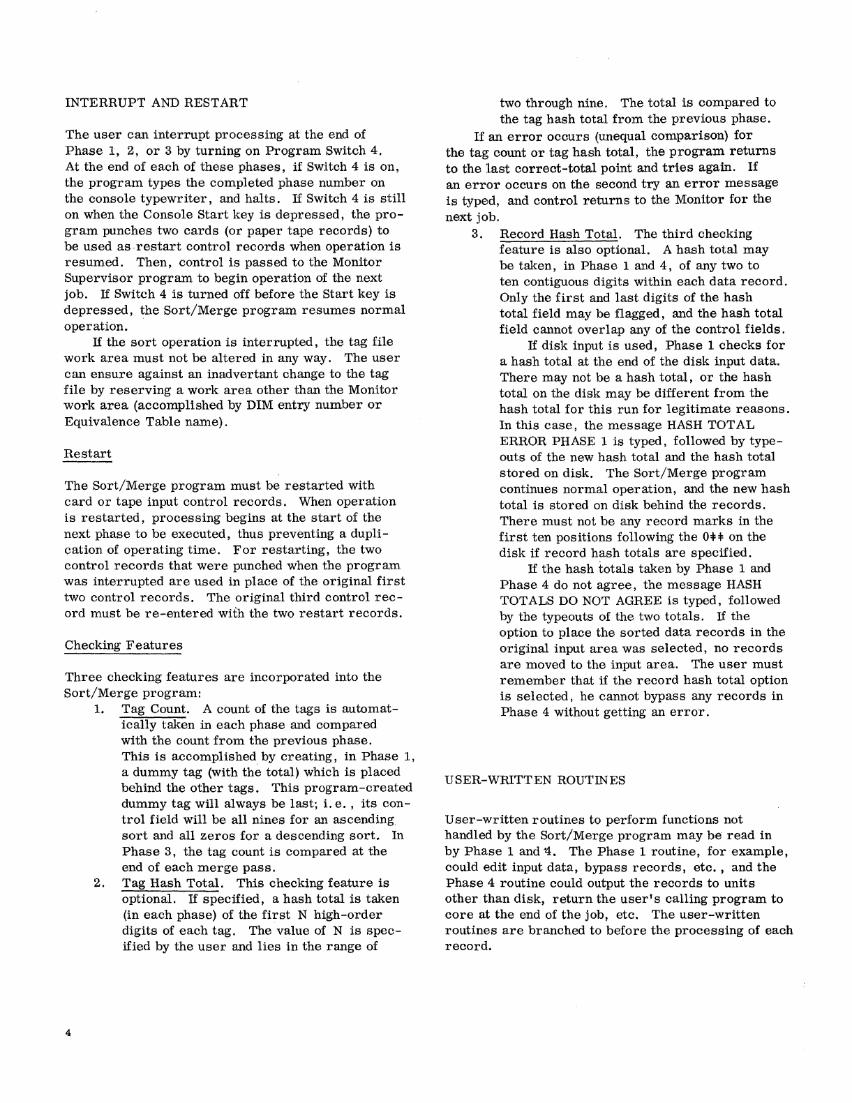
INTERRUPT
AND
RESTART
The
user
can
interrupt
processing
at
the
end of
Phase
1, 2,
or
3
by
turning
on
Program
Switch
4.
At
the
end
of
each
of
these
phases,
if
Switch 4
is
on,
the
program
types
the
completed
phase
number
on
the
console
typewriter,
and
halts.
If
Switch
4
is
still
on
when
the
Console
Start
key
is
depressed,
the
pro-
gram
punches
two
cards
(or
paper
tape
records)
to
be
used
as·
restart
control
records
when
operation
is
resumed.
Then,
control
is
passed
to
the
Monitor
Supervisor
program
to
begin
operation
of
the
next
job.
If
Switch
4
is
turned
off
before
the
Start
key
is
depressed,
the
Sort/Merge
program
resumes
normal
operation.
If
the
sort
operation
is
interrupted.
the
tag
file
work
area
must
not
be
altered
in
any
way.
The
user
can
ensure
against
an
inadvertant
change
to
the
tag
file
by
reserving
a
work
area
other
than
the
Monitor
work
area
(accomplished
by DIM
entry
number
or
Equivalence
Table
name).
Restart
The
Sort/Merge
program
must
be
restarted
with
card
or
tape
input
control
records.
When
operation
is
restarted,
processing
begins
at
the
start
of
the
next
phase
to
be
executed,
thus
preventing
a
dupli-
cation
of
operating
time.
For
restarting,
the
two
control
records
that
were
punched
when
the
program
was
interrupted
are
used
in
place
of
the
original
first
two
control
records.
The
original
third
control
rec-
ord
must
be
re-entered
with
the
two
restart
records.
Checking
Features
Three
checking
features
are
incorporated
into
the
Sort/Merge
program:
4
1.
Tag
Count. A
count
of
the
tags
is
automat-
ically
taken
in
each
phase
and
compared
with
the
count
from
the
previous
phase.
This
is
accomplished
by
creating,
in
Phase
1,
a
dummy
tag
(with
the
total)
which
is
placed
behind
the
other
tags.
This
program-created
dummy
tag
will
always
be
last;
i.
e.,
its
con-
trol
field
will
be
all
nines
for
an
ascending
sort
and
all
zeros
for
a
descending
sort.
In
Phase
3,
the
tag
count
is
compared
at
the
end
of
each
merge
pass.
2.
Tag
Hash
Total.
This
checking
feature
is
optional.
If
specified,
a
hash
total
is
taken
(in
each
phase)
of
the
first
N
high-order
digits
of
each
tag.
The
value
of N
is
spec-
ified
by
the
user
and
lies
in
the
range
of
two
through
nine.
The
total
is
compared
to
the tag
hash
total
from
the
previous
phase.
If
an
error
occurs
(unequal
comparison)
for
the
tag
count
or
tag
hash
total,
the
program
returns
to
the
last
correct-total
point
and
tries
again.
If
an
error
occurs
on
the
second
try
an
error
message
is
typed,
and
control
returns
to
the
Monitor
for
the
next
job.
3.
Record
Hash
Total.
The
third
checking
feature
is
also
optional.
A
hash
total
may
be
taken.
in
Phase
1 and
4,
of
any two
to
ten
contiguous
digits
within
each
data
record.
Only
the
first
and
last
digits
of
the
hash
total
field
may
be
flagged,
and
the
hash
total
field
cannot
overlap
any of
the
control
fields.
If
disk
input
is
used,
Phase
1
checks
for
a
hash
total
at
the
end of
the
disk
input
data.
There
may
not
be
a
hash
total,
or
the
hash
total
on
the
disk
may
be
different
from
the
hash
total
for
this
run
for
legitimate
reasons.
In
this
case,
the
message
HASH
TOTAL
ERROR PHASE 1
is
typed,
followed
by
type-
outs
of
the
new
hash
total
and
the
hash
total
stored
on
disk.
The
Sort/Merge
program
continues
normal
operation,
and
the
new
hash
total
is
stored
on
disk
behind
the
records.
There
must
not
be
any
record
marks
in
the
first
ten
pOSitions following
the
0:1:
=t:
on
the
disk
if
record
hash
totals
are
specified.
If
the
hash
totals
taken
by
Phase
1 and
Phase
4 do
not
agree,
the
message
HASH
TOT
ALS
DO
NOT AGREE
is
typed,
followed
by
the
typeouts
of
the
two
totals.
If
the
option
to
place
the
sorted
data
records
in
the
original
input
area
was
selected,
no
records
are
moved
to
the
input
area.
The
user
must
remember
that
if
the
record
hash
total
option
is
selected,
he
cannot
bypass
any
records
in
Phase
4
without
getting
an
error.
USER-WRITTEN
ROUTINES
User-written
routines
to
perform
functions
not
handled
by
the
Sort/Merge
program
may
be
read
in
by
Phase
1 and
~4.
The
Phase
1
routine,
for
example,
could
edit
input
data,
bypass
records,
etc.,
and
the
Phase
4
routine
could
output
the
records
to
units
other
than
disk,
return
the
user's
calling
program
to
core
at
the
end of
the
job,
etc.
The
user-written
routines
are
branched
to
before
the
processing
of
each
record.
Listed
below
are
some
notes
and
rules
concerning
user-written
routines.
1.
User's
routines
for
Phase
1
and
4
must
be
stored
on
disk
in
core-image
format.
2.
Phase
1
and
4
routines
may
not
extend
below
core
location
18950.
3.
The
Phase
1
routine
is
destroyed
by
Phase
2
or
3.
4.
The
Phase
4
routine
is
called
even
if
data
records
are
not
re-sorted.
5.
The
calling
program
will
be
overlaid
by
the
Sort/Merge
program
if
the
calling
program
is
below
core
location
20000.
6. At
the
end of
the
Sort/Merge
program,
con-
trol
can
be
returned
to:
a.
the
calling
program
if
it
is
above
core
location
20000
b.
a
special
entry
in
the
Phase
4
routine
(which
the
user
writes
to
call
back
the
calling
program)
c.
the
Monitor
Supervisor
program.
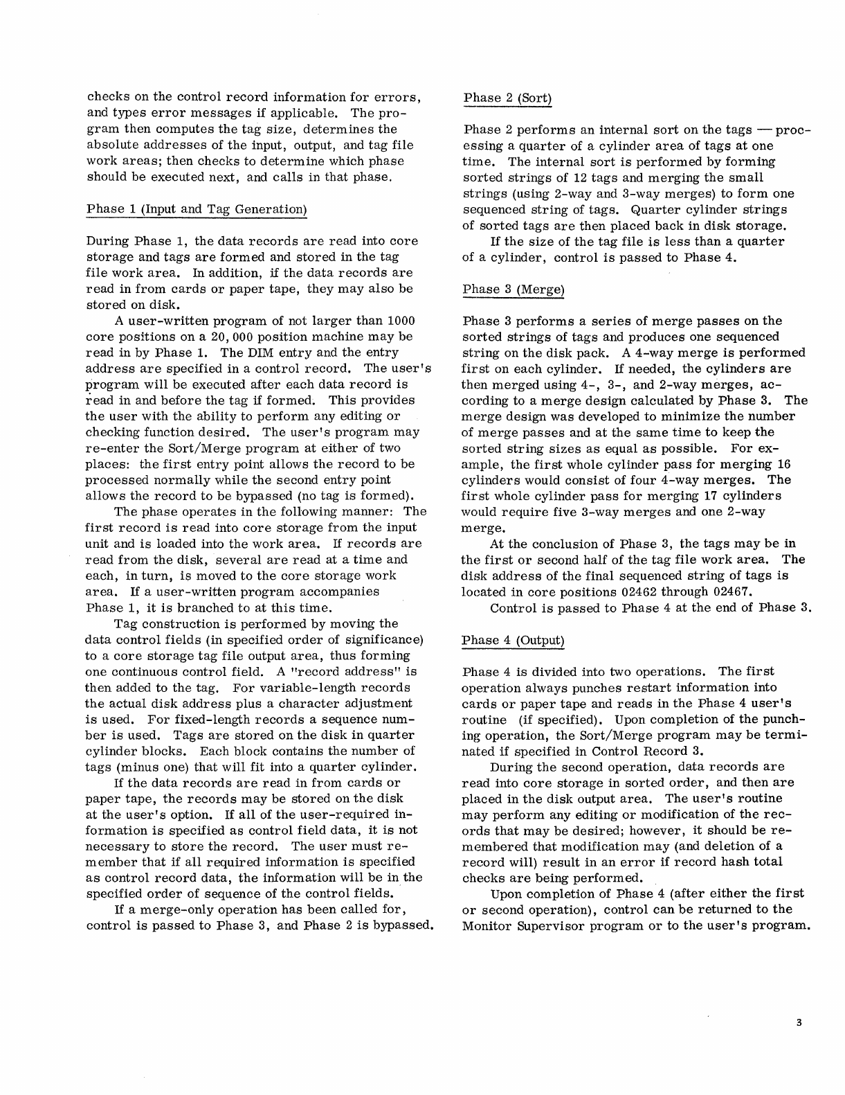
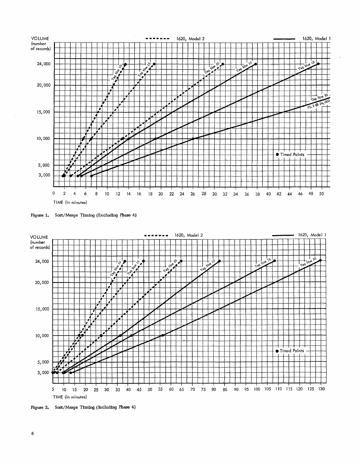
TIMING
Figures
1 and 2 show
the
average
processing
time
required
by
the
Sort/Merge
program
for
the
indicated
tag
sizes
and
for
the
number
of
records
in
the
file.
These
timings
are
based
on
the
following
assumptions:
1.
The
input
area,
output
area,
and
disk
work
area
are
located
so
as
to
require
an
aver-
age
seek
time
of
250
ms.
!~.
The
records
are
in
fixed-length
form,
are
80
positions
long,
and
have
previously
been
stored
on
disk.
3.
There
are
no
hash
totals
and no
user's
programs.
4.
The
number
of
fields
sorted
is
3.
Figure
1
shows
the
timing
with
Phase
4
excluded
(i.
e.,
no
re-sorting
of
the
data
records
themselves).
Figure
2
timing
includes
the
operation
time
of
Phase
4.
Card
or
paper
tape
record
input
time
is
not
included.
Data
input
in
these
forms
can
be
accomplished
at
read
speed.
5
VOLUME
(number
of
records)
24,000
20,000
15,000
10,000
5,000
3,000
•••
-._.
1620, Model:2 1620, Model 1
1_
~
.,,<'0
•
...
'0
...
...
S
~
1----
$'"
.,f
#
s~;'-
S\'!l1-~
'tg.C)s~';"-
,l)~
C:)#
~~;
::~
...,.fIII"
~r§'l
f..,~.
#
,;
.-.;t,;'
...,..
,
~,-
#
~~
~
...... 1'"
~
.~
;~
[...,.0010"""
fill"
#
.....
.JI~
....i-'
~
~
,<r ;
",
.,1.,,;'
1:9-9
cPo
~
#<r ;
i."o"
.."
~
~<\o.
....
1~.~@l
,-1-
# #
~.;
""'"
..".
, -
""",
-
~
#
...
~
~
~
1".000
",.,..
~~
,
~~
"
~jJ"
-~
io"""
. 4
...
~
~"
" -
1".000
-
~
L4r
;~
~
....
~
-
""",-
!
.1
,4r
;
:"'"
...,.~
.-""",
~
~
.#
••
V
:...,..
"".
".
~
# 4 #'
~,
...,.'"
""".
io'
, ;
./
"'"
",
""".
".
~~
#'r
,~;
V"
",
".'"
--
-
I--
• Timed Points
"'"
......
,,~-
;~
~fIII"
""".
",.
.-
#
~
~~
",
...,
,
".
"".
'#
.#.
....
~
~
""". """.
...
o 2 4 6 8
10
12 14 16
18
20
22
24 26
28
30
32 34 36 38 40 42 44 46 48 50
TIME
(in minutes)
FiglU'e 1.
Sort/Merge
Timing
(Excluding Phase
4)
VOLUME
(number
of
records)
24,000
20,000
15,000
10,000
5,000
I~
If.
~
..
;
~~
;,&
-
......
-1620, Model 2
$:"'-f-~
#
",<0
\,'0
-§'
.#
(':,'\.'!l1-~
,<J'
#f--C;4'
"""..+-
r§'l
#'
~'If>;'5.#
~~A"
f..,J>
~
4
,~
I~
~
1,/
.<r
1#-'
17
~io"""'
~4
[,<r
, 7
~io"""'
,
#4"
#
~
Jl'1o"""
# #
4#
,/
~
100'
"I.,,;'
I #
4~
7
.JII'
P
..".~
l#'
# _ 4
~'r'
~7
...,.'tII"'"
I~t
#'
/
~"ii'
...,.
",
,
..
~
;I'
....
fIII"
.."..
~
t
~#
;~
~,
....
~
l,...ooo
"".
#
,.#
#
./
",
,,'"
~.
#
i'
",
-"
#
,~
#
./
"""
~,.
...,..
",
##
;
)~
...,.'
"
i'""'"
#
.~
,/
)~
......
""""
.....
;1'",
""",,'"
~
'#
~
:......
J';I"""
~~
"..
...,..
i'"
~
~",
1620,
Modell
\.s
'.
",S
~
-t.p)s\,'!l1-
"
S\~;...-.
't.p)
;..--'
~""""
" "
"
I.,,;'
,,"
• Timed Points
5
10
15
20 25
30
35 40 45 50 55 60 65 70 75 80
85
90
95
100 105 110
115 120
125 130
TIME
(in minutes)
Figure 2.
Sort/Merge
Timing
(Including Phase
4)
6
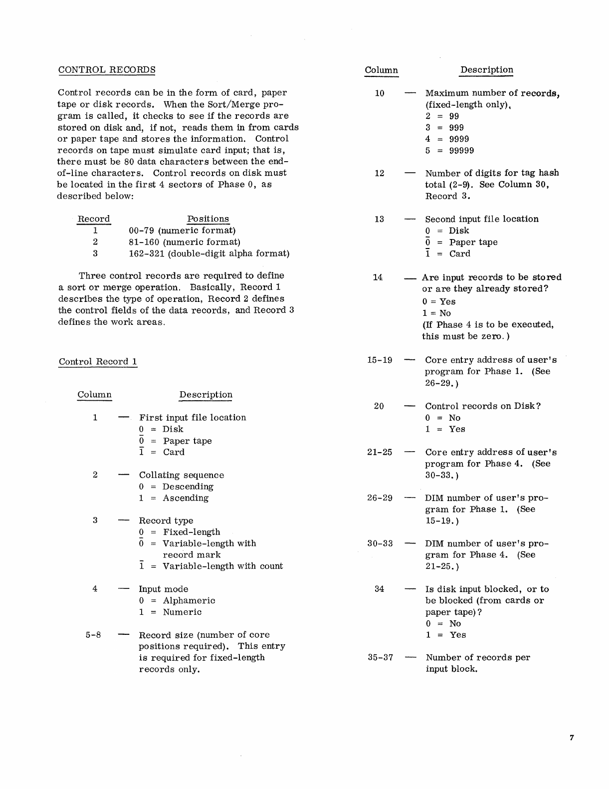
CONTROL RECORDS
Control
records
can
be
in
the
form
of
card,
paper
tape
or
disk
records.
When
the
Sort/Merge
pro-
gram
is
called,
it
checks
to
see
if
the
repords
are
stored
on
disk
and,
if
not,
reads
them
in
from
cards
or
paper
tape
and
stores
the
information.
Control
records
on
tape
must
simulate
card
input;
that
is,
there
must
be
80
data
characters
between
the
end-
of-line
characters.
Control
records
on
disk
must
be
located
in
the
fir
st
4
sectors
of
Phase
0,
as
described
below:
Record
1
2
3
Positions
00-79
(numeric
format)
81-160
(numeric
format)
162-321
(double-digit
alpha
format)
Three
control
records
are
required
to
define
a
sort
or
merge
operation.
Basically,
Record
1
describes
the
type
of
operation,
Record
2
defines
the
control
fields
of
the
data
records,
and
Record
3
defines
the
work
areas.
Control
Record
1
Column
1
2
3
4
5-8
Description
First
input
file
location
o
Disk
o
Paper
tape
r
Card
Collating
sequence
o
Descending
1 =
Ascending
Record
type
o
Fixed-length
o
Variable-length
with
record
mark
1
Variable-length
with
count
Input
mode
o
Alphameric
1 =
Numeric
Record
size
(number
of
core
positions
required).
This
entry
is
required
for
fixed-length
records
only.
Column
10
12
13
14
15-19
20
21-25
26-29
30-33
34
35-37
Description
Maximum
number
of
records,
(fixed
-length
only)_
2 99
3 999
4 9999
5 99999
Number
of
digits
for
tag
hash
total
(2-9). See
Column
30,
Record
3.
Second input
file
location
o
Disk
o
Paper
tape
1
Card
Are
input
records
to
be
stored
or
are
they
already
stored?
0=
Yes
1 =
No
(If
Phase
4
is
to
be
executed,
this
must
be
zero.
)
Core
entry
address
of
user's
program
for
Phase
1.
(See
26-29.
)
Control
records
on
Disk?
o
No
1 =
Yes
Core
entry
address
of
user's
program
for
Phase
4.
(See
30-33.
)
DIM
number
of
user's
pro-
gram
for
Phase
1.
(See
15-19.
)
DIM
number
of
user's
pro-
gram
for
Phase
4.
(See
21-25.
)
Is
disk
input
blocked,
or
to
be
blocked
(from
cards
or
paper
tape)?
o
No
1 =
Yes
Number
of
records
per
input
block.
7
8
Column
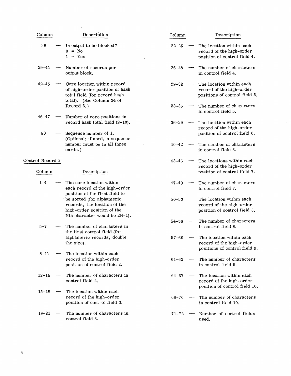
Description
38
Is
output
to
be
blocked?
o
No
1 =
Yes
39-41
Number
of
records
per
output
block.
42-45
Core
location
within
record
of
high-order
position
of
hash
total
field
(for
record
hash
total).
(See
Column
34
of
Record
3.)
46-47
Number
of
core
positions
in
record
hash
total
field
(2-10).
80
Sequence
number
of 1.
(Optional;
if
used,
a
sequence
number
must
be
in
all
three
cards.
)
Control
Record
2
Column
Description
1-4
The
core
location
within
5-7
8-11
12-14
15-18
19-21
each
record
of
the
high-order
position
of
the
first
field
to
be
sorted
(for
alphameric
records,
the
location
of
the
high-order
position
of
the
Nth
character
would
be
2N
-1).
The
number
of
characters
in
the
first
control
field
(for
alphameric
records,
double
the
size).
The
location
within,
each
record
of
the
high-order
position
of
control
field
2.
The
number
of
characters
in
control
field
2.
The
location
within
each
record
of
the
high-order
pOSition of
control
field
3.
The
number
of
character
s
in
control
field
3.
Column
22-25
26-28
29-32
33-35
36-39
40-42
43-46
47-49
50-53
54-56
57-60
61-63
64-67
68-70
71-72
Description
The
location
within
each
record
of
the
high-order
position
of
control
field
4.
The
number
of
character
s
in
control
field
4.
The
location
within
each
record
of
the
high-order
positions
of
control
field
5.
The
number
of
characters
in
contro
I
field
5.
The
location
within
each
record
of
the
high-order
position
of
control
field
6.
The
rlumber
of
character
s
in
control
field
6.
The
locations
within
each
record
of
the
high-order
position
of
control
field
7.
The
number
of
character
s
in
control
field
7.
The
location
within
each
record
of
the
high-order
position
of
control
field
8.
The
number
of
characters
in
control
field
8.
The
location
within
each
record
of
the
high-order
positions
of
control
field
9.
The
number
of
characters
in
control
field
9.
The
location
within
each
record
of
the
high-order
position
of
control
field
10.
The
number
of
characters
in
control
field
10.
Number
of
control
fields
used.
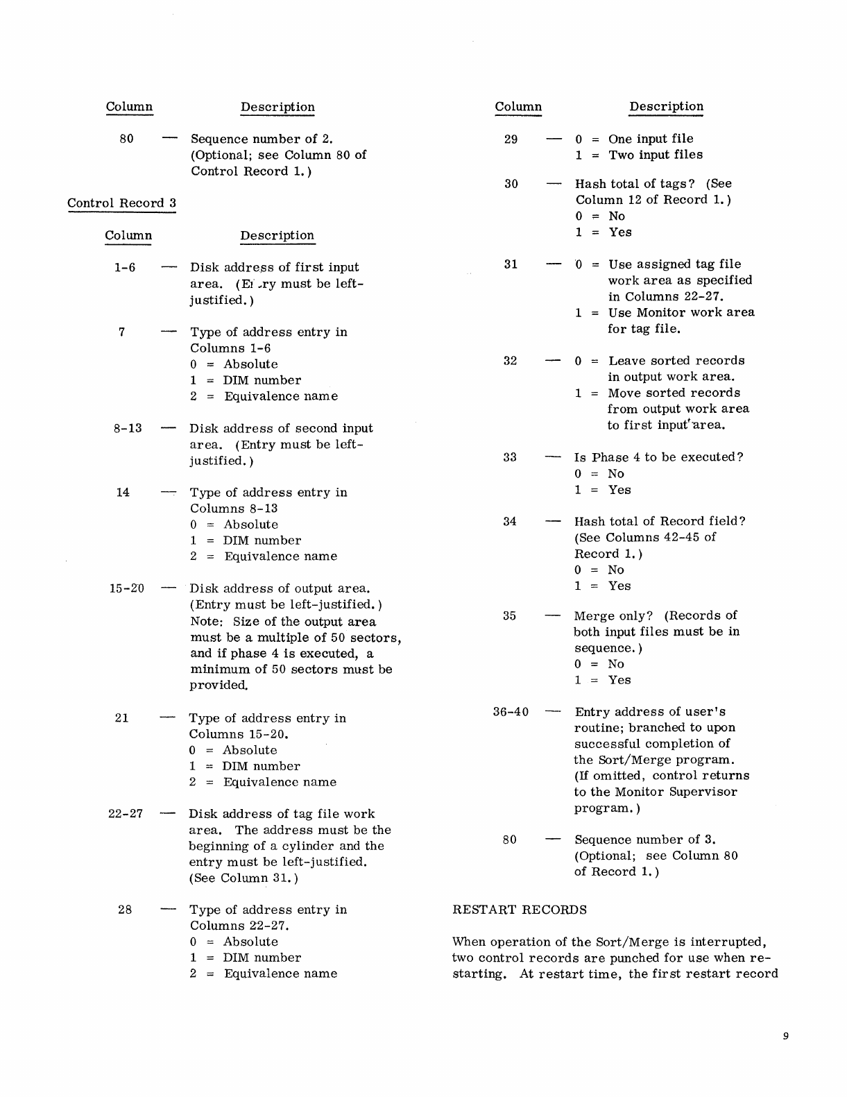
Column
80
Control
Record
3
Column
1-6
7
8-13
14
15-Z0
21
22-27
28
Description
Sequence
number
of
2.
(Optional;
see
Column
80
of
Control
Record
1.)
Description
Disk
address
of
first
input
area.
(El'
..
ry
must
be
left-
justified.
)
Type
of
address
entry
in
Columns
1-6
o
Absolute
1 DIM
number
2
Equivalence
name
Disk
address
of
second
input
area.
(Entry
must
be
left-
justified.
)
Type
of
address
entry
in
Columns
8-13
o
Absolute
1 DIM
number
2
Equivalence
name
Disk
address
of
output
area.
(Entry
must
be
left-justified.
)
Note:
Size
of
the
output
area
must
be
a
multiple
of
50
sectors,
and
if
phase
4
is
executed,
a
minimum
of
50
sectors
must
be
provided.
Type
of
address
entry
in
Columns
15-20.
o
Absolute
1 DIM
number
2
Equivalence
name
Disk
address
of
tag
file
work
area.
The
address
must
be
the
beginning
of
a
cylinder
and
the
entry
must
be
left-justified.
(See
Column
31.
)
Type
of
address
entry
in
Columns
2'2-27.
o
Absolute
1 DIM
number
2
Equivalence
name
Column
29
30
31
32
33
34
35
36-40
80
o
1
Description
One
input
file
Two
input
files
Hash
total
of
tags?
(See
Column
12
of
Record
1.)
o
~
No
1
'0
1
o
1
Yes
Use
assigned
tag
file
work
area
as
specified
in
Columns
22-27.
Use
Monitor
work
area
for
tag
file.
Leave
sorted
records
in
output
work
area.
Move
sorted
records
from
output
work
area
to
first
inpue-area.
Is
Phase
4
to
be
executed?
o No
1 =
Yes
Hash
total
of
Record
field?
(See
Columns
42-45
of
Record
1.)
o No
1 =
Yes
Merge
only?
(Records
of
both
input
files
must
be
in
sequence.
)
o No
1 =
Yes
Entry
address
of
user's
routine;
branched
to
upon
successful
completion
of
the
Sort/Merge
program.
(If
omitted,
control
returns
to
the
Monitor
Supervisor
program.
)
Sequence
number
of
3.
(Optional;
see
Column
80
of
Record
1.)
RESTART
RECORDS
When
operation
of
the
Sort/Merge
is
interrupted,
two
control
records
are
punched
for
use
when
re-
starting.
At
restart
time,
the
first
restart
record
9
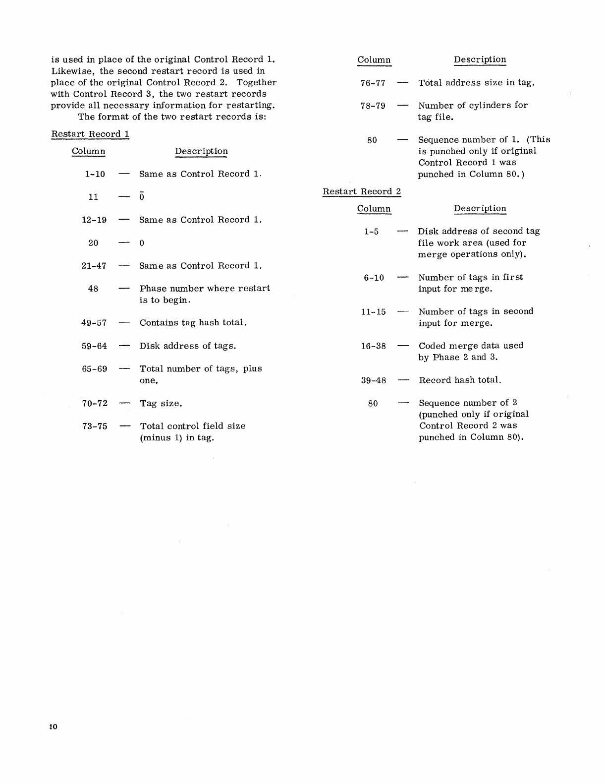
is
used
in
place
of
the
original
Control
Record
1.
Likewise,
the
second
restart
record
is
used
in
place
of
the
original
Control
Record
2.
Together
with
Control
Record
3,
the
two
restart
records
provide
all
necessary
information
for
restarting.
The
format
of
the
two
restart
records
is:
Restart
Record
1
Column
Description
1-10
Same
as
Control
Record
1.
11
12-19
Same
as
Control
Record
1.
20 0
21-47
Same
as
Control
Record
1.
48
Phase
number
where
restart
is
to
begin.
49-57
Contains
tag
hash
total.
59-64
Disk
address
of
tags.
65-69
Total
number
of
tags,
plus
one.
70-72
Tag
size.
73-75
Total
control
field
size
(minus
1)
in
tag.
10
Column
76-77
78-79
80
Restart
Record
2
Column
1-5
6-10
11-15
16-38
39-48
80
Description
Total
address
size
in
tag.
Number
of
cylinders
for
tag
file.
Sequence
number
of
1.
(This
is
punched
only
if
original
Control
Record
1
was
punched
in
Column
80. )
Description
Disk
address
of
second
tag
file
work
area
(used
for
merge
operations
only).
Number
of
tags
in
first
input
for
me
rge.
Number
of
tags
in
second
input
for
merge.
Coded
merge
data
used
by
Phase
2 and 3.
Record
hash
total.
Sequence
number
of
2
(punched
only
if
original
Control
Record
2
was
punched
in
Column
80).
The
Sort/Merge
program
can
be
called
for
execution
by
a
Monitor
XEQ
statement
(from
card
or
paper
tape)
or
by
a
CALL
statement
in
a
user's
program.
When
the
XEQ
statement
is
used,
the
order
of
the
stacked
input
is
as
follows:
:j::j:JOB
**XEQ SORT
Sort
Control
Records
(3)
Input
:J::j::\::j:
(end
of
job)
ERROR MESSAGES
During
execution
of
the
Sort/Merge
program,
certain
error
messages
may
appear.
A
list
of
the
messages
and
the
conditions
which
cause
them,
follows.
Unless
otherwise
noted,
control
is
returned
to
the
Monitor
Supervisor
routine
as
soon
as
the
message
is
typed.
Message
and
Cause
CAN
NOT
FIND
LABEL
IN
EQUIVALENCE
TABLE
The
name
given
for
an
input
or
output
area
or
the
name
SORT
is
not
in
the
Equivalence
Table.
CONTROL
CARDS
OUT
OF
SEQUENCE
The
sort
control
records
(card
or
paper
tape)
are
not
in
sequence.
COUNT
ERR
Pn
The
tag
count
total
taken
in
Phase
n (n = 2
or
3)
is
not
equal
to
the
tag
count
total
taken
in
the
previous
phase.
COUNT
ERROR
PHASE
4
The
number
of
tags
does
not
agree
with
the
record
count.
Two
trys
have
been
made.
ERROR
IN
TAG
HASH
TOTAL
The
tag
hash
totals
from
this
pass
and
the
previous
pass
are
not
equal.
This
message
appears
in
Phase
1
or
4.
EXECUTING
THE
SORT/MERGE
PROGRAM
FIXED
LENGTH
RECORD
COUNT
SPECIFIED
INCORRECTLY
The
digit
in
Column
10 of
Control
Record
1
is
out-
side
the
range
of
2
through
5.
HASH
ERR
Pn
XXXXXXXXX
The
tag
hash
total
taken
in
Phase
n (n
:::;
2
or
3)
is
not
equal
to
the tag
hash
total
taken
in
the
previous
phase.
HASH
TOTAL
ERROR
PHASE
1
XXXXXXXXXX
(New
hash
total
of
records)
XXXXXXXXXX
(Hash
total stored
on
disk)
Hash
total
on
disk
does
not
agree
with
new
hash
total
of
records
developed
in
Phase
1.
Action:
The
Sort/Merge
program
continues
operation.
HASH
TOTAL
SIZE
SPEC.
INCORRECTLY
The
size
of
the
tag
or
record
hash
total
field
has
been
specified
incorrectly.
HASH
TOTALS
DO
NOT
AGREE
XXXXXXXXXX
(Phase
1
hash
total)
XXXXXXXXXX
(Phase
4
hash
total)
The
record
hash
totals
from
Phase
1
and
Phase
4
are
not
equal.
Action:
The
Sort/Merge
program
stores
the
new
hash
total
with
the
records.
The
sorted
records
will
not
be
moved
from
the
output
to
the
input
area.
The
Sort/Merge
program
will
branch
to
the
address
specified
in
Columns
36-40
of
Control
Record
3.
NO
FIELD
SIZE SPECIFIED
A
control
field
size
was
omitted
in
Control
Record
2.
NUMBER
OF
FIELDS
TO
SORT
INCORRECTLY
SPECIFIED
The
number
of
control
fields
exceeds
ten
or is
zero.
SIZE
OF
TAG
EXCEEDS
THE
MAX
The
tag
size
exceeds
900
positions.
TYPE
INPUT
SPECIFIED
INCORRECTLY
Column
1
or
13
of
Record
1
does
not
properly
indicate
input
by
card,
paper
tape,
or
disk.
WRONG
UNIT
FOR
CALLING
SORT
The
Sort/Merge
program
was
called
from
the
console
typewriter.
11
LOADING
THE
SORT/MERGE
PROGRAM
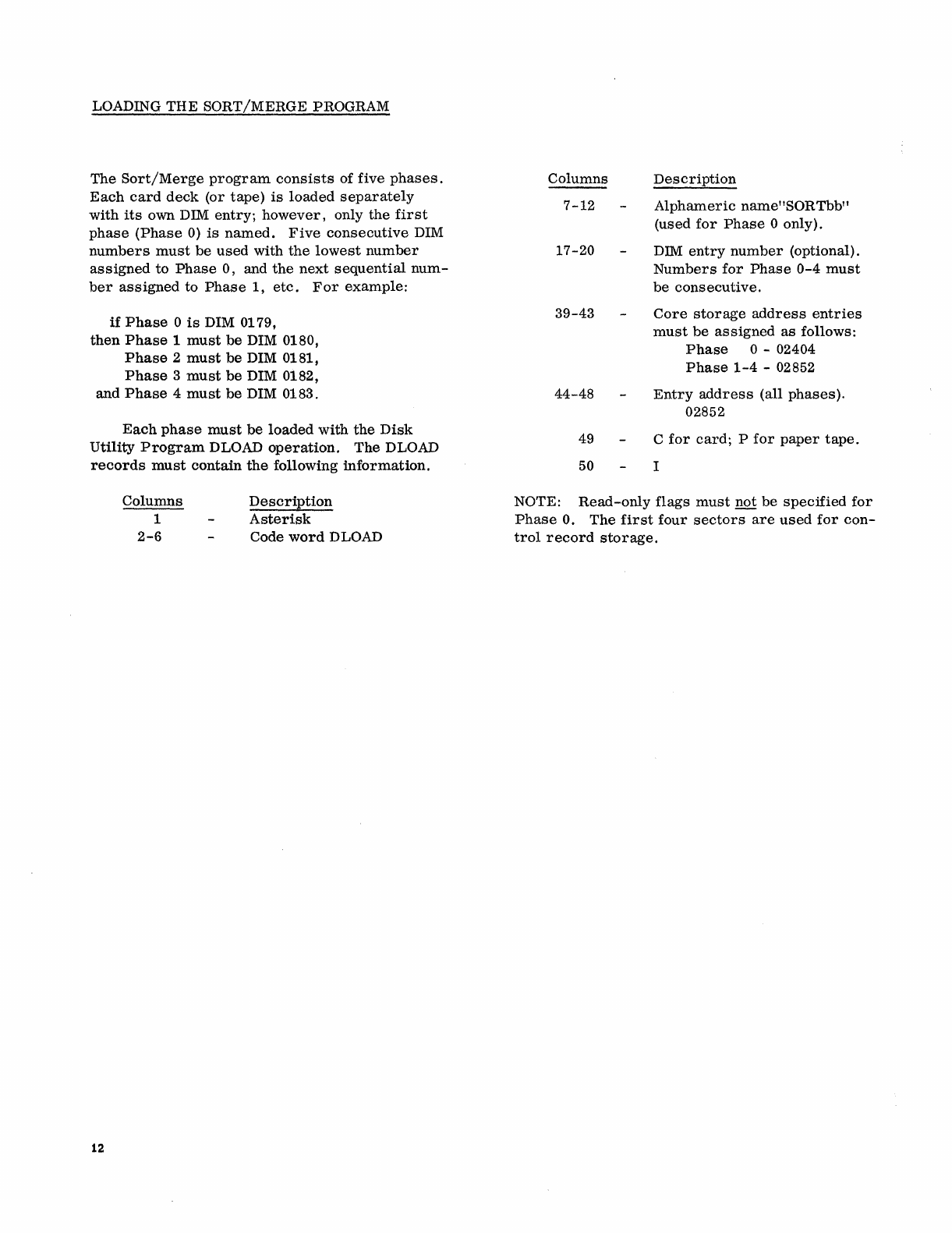
The
Sort/Merge
program
consists
of
five
phases.
Each
card
deck
(or
tape)
is
loaded
separately
with
its
own DIM
entry;
however,
only
the
first
phase
(Phase
0)
is
named.
Five
consecutive
DIM
numbers
must
be
used
with
the
lowest
number
assigned
to
Phase
0,
and
the
next
sequential
num-
ber
assigned
to
Phase
1,
etc.
For
example:
if
Phase
0
is
DIM 01 79,
then
Phase
1
must
be
DIM
0180,
Phase
2
must
be
DIM
0181,
Phase
3
must
be
DIM
0182,
and
Phase
4
must
be
DIM
0183.
Each
phase
must
be
loaded
with
the
Disk
Utility
Program
DLOAD
operation.
The
DLOAD
records
must
contain
the
following
information.
12
Columns
1
2-6
Description
Asterisk
Code
word
DLOAD
Columns
7-12
17-20
39-43
44-48
49
50
Description
Alphameric
name"SORTbb"
(used
for
Phase
0 only).
DIM
entry
number
(optional).
Numbers
for
Phase
0-4
must
be
consecutive.
Core
storage
address
entries
must
be
assigned
as
follows:
Phase
0 - 02404
Phase
1-4
-02852
Entry
address
(all
phases).
02852
C
for
card;
P
for
paper
tape.
I
NOTE:
Read-only
flags
must
not
be
specified
for
Phase
O.
The
first
four
sectors
are
used
for
con-
trol
record
storage.
The
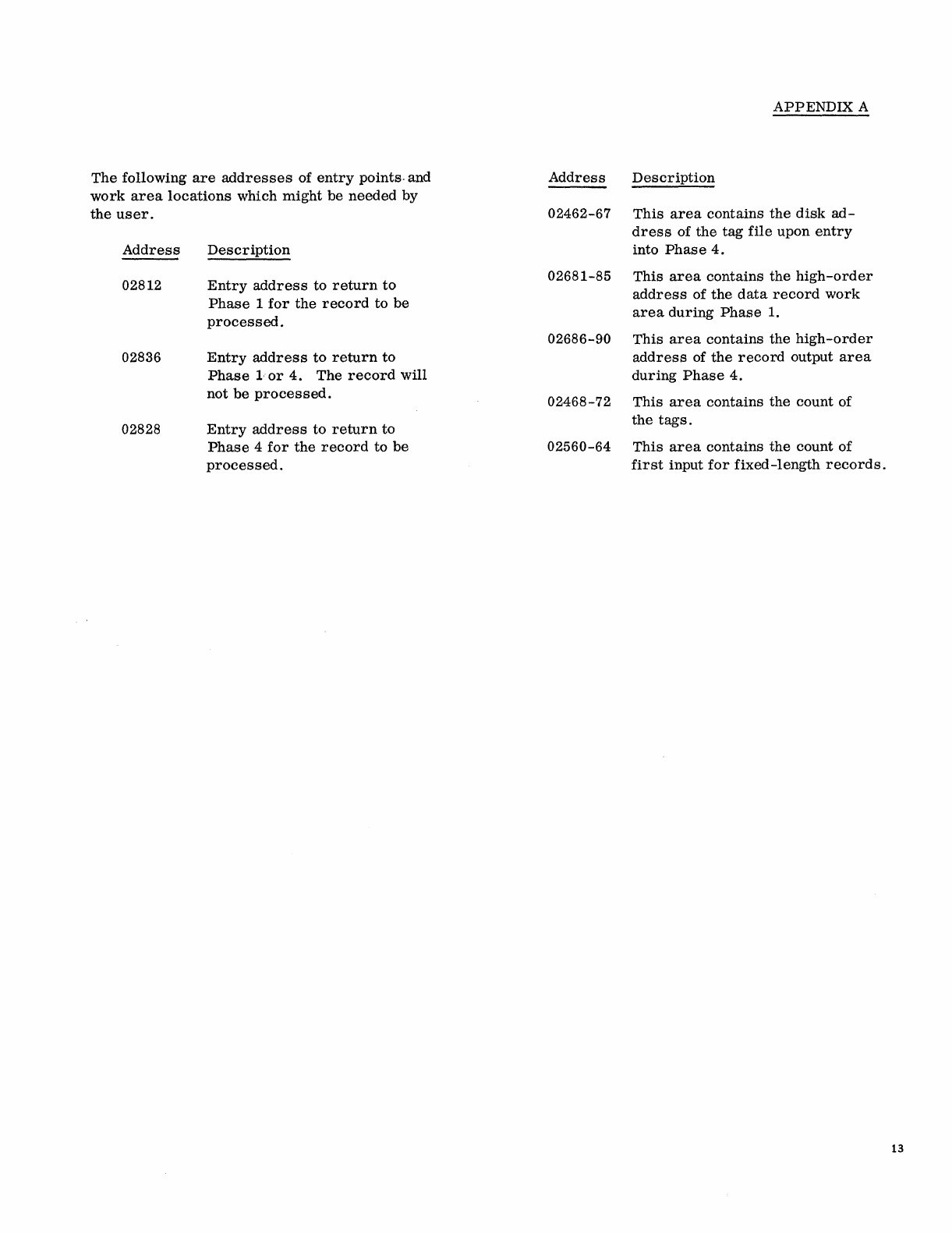
following
are
addresses
of
entry
points- and
work
area
locations
which
might
be
needed
by
the
user.
Address
02812
02836
02828
Description
Entry
address
to
return
to
Phase
1
for
the
record
to
be
processed.
Entry
address
to
return
to
Phase
1
or
4.
The
record
will
not
be
processed.
Entry
address
to
return
to
Phase
4
for
the
record
to
be
processed.
APPENDIX
A
Address
Description
02462-67
This
area
contains
the
disk
ad-
dress
of
the
tag
file
upon
entry
into
Phase
4.
02681-85
This
area
contains
the
high-order
address
of
the
data
record
work
area
during
Phase
1.
02686-90
This
area
contains
the
high-order
address
of
the
record
output
area
during
Phase
4.
02468-72
This
area
contains
the
count
of
the
tags.
02560-64
This
area
contains
the
count
of
first
input
for
fixed-length
records.
13
C26-5875-2
TIrn~
(!)
International
Business
Machines Corporation
Data
Processing
Division
112
East
Post
Road, White Plains, New York
Technical Newsletter File
Number
1620-33
Re:
Form
No.
C26-5875-2
This
Newsletter
No.
N26-0552
Date
February
7, 1966
Previous
Newsletter
Nos. N26-0125
The
purpose
of
this
newsletter
is
to
make
changes
to
the
publication
IBM
1620-1311
Sort/Merge
Program
Reference
Manual
(Form
C26-5875-2).
Changes
are
indicated
by
a
vertical
line
to
the
left
of
the
affected
text.
REPLACE
PAGES:
1
and
2
File
this
newsletter
at
the
back
of
the
manual.
It
will
provide
a
reference
to
changes,
a
method
of
determining
that
all
amendments
have
been
received,
and a
check
for
determining
if
the
manual
contains
the
proper
pages.
IBM
Corporation,
Programming
Publications,
Dept.
452,
San Jose, Calif.
95114
PRINTED
IN
U.S.A.
N26-0552(C26-5875-2)
