C28 6553 2_Telecommunications_Preliminary_Specifications_Dec65 2 Telecommunications Preliminary Specifications Dec65
C28-6553-2_Telecommunications_Preliminary_Specifications_Dec65 C28-6553-2_Telecommunications_Preliminary_Specifications_Dec65
User Manual: C28-6553-2_Telecommunications_Preliminary_Specifications_Dec65
Open the PDF directly: View PDF ![]() .
.
Page Count: 94
Systems
Reference Library
IBM
Operating
System/360
Telecommunications:
Preliminary SpecificatiDns
This
publication
contains
preliminary
information
on
how
to
apply
and
use
the
IBM
System/360
Operating
System
for
remote
mes-
sage
processing
and
how
to
use
the
control
program
for
performinq
the
input/output
operations
of
a
data
communications
system.
Guidance
is
provided
for
problem
pro-
gramming
within
the
system.
Descriptions
of
applicable
macro-instructions,
suggest-
ing
how,
when,
and
where
to
use
them,
are
also
included.
File
No.
S360-30
Form
C28-6553-2
PREFACE'
This
publication
contains
preliminary
information
on
planning
and
implementing
a
system
for
remote
rr.essage
handling
and/or
processing
under
the
System/360
Operating
System.
IBM
Gystem/360
Operating
System:
Assem-
bler
Language,
Form
C28-6514
IBM
System/360
Operating
System:
Data
Management,
Form
C28-6537
Completion
of
a
basic
course
in
program-
ming
Computing
System/360
is
a
prerequisite
to
using
this
publication.
It
is
also
required
that
the
reader
be
familiar
with
the
overall
programming
concepts
and
termi-
nology
introduced
in
the
following
publica-
tions:
IBM
System/360
Operating
System:
Control
Program
Services,
Form
C28-6541
It
is
suggested
that
the
reader
be
familiar
with
the
following
additional
pub-
lications:
IBM
System/360
Operating
System:
Intro-
duction,
Form
C28-6534
IBM
2701
Data
Adapter
Unit,
PrinciEles
IBM
System/360
Operating
System:
Con-
cepts
and
Facilities,
Form
C28-6535
IBM
System/360
Operating
System:
Job
Control
Language,
Form
C28-6539
~inor
Revision
(December
1965)
This
publication
is
a
minor
revisicn
of
IBM
2£erati~~
System/360,
Telecommunications,
For~
C28-C553-1,
and
incor~orates
Technic~l
Newsletter
N27-1233
into
the
publication.
Information
in
this
publication
is
still
classified
as
preliminary.
of
Operation,
Form
A22-6864
IBM
2702
Transmission
Control,
A22-6846
This
publication
was
prepared
for
production
using
an
IBM
computer
to
update
the
text
and
to
control
the
page
and
line
format.
Paqe-impres-
sions
for
photo-offset
printing
were
obtained
from
an
IBM
1403
Printer
using
a
special
print
chain.
Copies
of
this
and
other
IBM
publications
can
be
obtained
through
IBM
Branch
Offices.
A
form
for
reader's
comments
appears
at
the
back
of
this
publication.
Address
any
additional
comments
concerning
the
contents
of
this
publica-
tion
to:
IBM
Corporation,
Programming
Documentation,
Department
840,
P.O.
Box
9361,
Raleigh,
North
Carolina
27603
©
1965.by
Internati~nal
Business
Machines
Corporation
Form
INTRODUCTION • • • •
..
• • • • • 7
Queued
Telecorrmunications
Access
Method.
• • • • •
..
••
• • • • 7
Inquiry
processing.
• . • • 9
Data
Collection
• • • • • • • •
10
Job
Processing.
•
••
• •
••
10
Message
Switching
• • • • •
10
constructing
a
Message
Control
Program
With
the
QTAM
Language
• • •
10
Data
Set
Definition
.........
10
Control
Information.
• • • • • • •
11
Line
Procedure
Specifications
•••
11
Message
Processing
:tvlacro-Instructions
• • • • • • • . •
12
Basic
Telecommunications
Access
Method
•
12
QUEUED
TELECOMMUNICATIONS
ACCESS
METHOD.
• • • • . • •
Data
Set
Definition.
.
13
• •
15
Data
Control
Block
(DCB)
Macro-Instruction
• • • • . • • •
16
OPEN
and
CLOSE
Macro-Instructions
• •
22
OPEN
Macro-Instruction
• • . •
23
CLOSE
Macro-Instruction..
••
24
Message
Control
Task
• • • • • •
25
Control
Information
• • • • •
26
Terminal
Table
Specifications.
26
Terminal
Table
(TERMTBL)
Macro-
Instruction
• • • • . • • •
26
Terminal
Table
Optional
Field
(OPTION)
Macro-Instruction.
• • •
27
Terminal
Table
Entry
(TERM)
Macro-Instruction
• • • •
•.
27
Terminal
Table
List
(LIST)
Macro-Instruction
• •
28
Terminal
Table
Process
(PROCESS)
Macro-Instruction
• • • •
..
• • .
28
Polling
List
Definition.
• • • • •
29
Polling
Table
Definition
(POLL)
Macro-Instruction
• •
..
•
••
30
Buffer
Assignment.
•
..
•
30
BUFFER
Macro-Instruction
• • •
30
Data
Set
Initialization
Macro-Instructions
•
..
• • .
Line
Procedure
Specifications
Delimiter
Macro-Instructions.
Line
Procedure
Specification
Start
(LPSTART)
Macro-Instruction
.. ..
• • •
• •
31
• •
31
• •
33
•
34
Receive
Segment
(RCVSEG)
Macro-Instruction
..
• • • • • • .
34
Receive
Header
(RCVHDR)
Macro-
Instruction
• • • . . • • •
35
End
Receive
(ENDRCVE)
~acro-Instruction
•••
Post
Receive
(POSTRCVE)
Macro-Instruction
•••
35
• •
35
Send
Header
(SENDHDR)
Macro-Instruction
• • .
Send
Segment
(SENDSEG)
Macro-Instruction
• •
End
Send
(ENDSEND)
CONTENTS
•
35
• •
35
Macro-Instruction
• • . •
35
Post
Send
(POSTSEND)
Macro-Instruction
. • • . • . . .
36
Functional
Macro-Instructions
.
36
Receive
Functional
Macro-Instructions
• . •
36
Sequence
In
(SEQIN)
Macro-Instruction
• • • • • • • •
36
SOURCE
Macro-Instruction
.
••
36
Routing
(ROUTE)
Macro-Instruction
• • .
37
End-of-Address
(EOA)
Macro-Instruction
. •
DIRECT
Macro-Instruction
Polling
Limit
(POLLIMIT)
Macro-Instruction
• • • .
Halt
Receive
(BREAKOFF)
Macro-Instruction
• • •
Receive
or
Send
Functional
Macro-Instructions
•
..
•
·
37
• •
37
·
38
·
38
·
38
Date
Stamp
(DATESTMP)
Macro-Instruction
. • • . • • . ·
38
Time
Stamp
(TIMESTMP)
Macro-Instruction
• •
SKIP
Macro-Instruction
.
Message
Mode
(MODE)
Macro-Instruction
End-of-Block
(EOB)
·
38
·
39
•
39
Macro-Instruction
.
39
End-of-Block
and
Line
Correction
(EOBLC)
Macro-Instruction
• .
40
Logging
(LOGSEG)
Macro-Instruction
• • • •
40
Message
Type
(MSGTYPE)
Macro-Instruction
• . •
40
Translate
(TRANS)
Macro-Instruction
•
40
Send
Functional
Macro-Instructions
••
41
PAUSE
Macro-Instruction.
• •
41
Sequence
out
(SEQOUT)
Macro-Instruction
• . • • . • • .
41
Error
3andling
Functional
Macro-Instructions
. . •
Cancel
Message
(CANCELM)
Macro-Instruction
• •
Error
Message
(ERRMSG)
Macro-Instruction
. .
Intercept
(INTERCPT)
Macro-Instruction
• •
REROUTE
Macro-Instruction.
Message
processing
Tasks
• •
Queue
Access.
• • • . • • •
GET
Macro-Instruction.
•
PUT
Macro-Instruction.
RETRIEVE
Macro-Instruction
.
·
42
·
42
· .
42
·
44
44
. . •
44
· .
44
• •
45
•
45
•
46
3
CONTENTS
(~ontinued)
Release
Intercept
(RELEASEM)
Macro-
Instruction
• • • . • •
Telecommunications
System
Status.
Copy
Polling
List
(CPYPL)
Macro-
Instruction
• • • • • •
Change
Polling
List
(CHNGPL)
Macro-Instruction.
Start
Line
(STRTLN)
Macro-Instruction.
Stop
Line
(STOPLN)
Macro-Instruction
••••
Copy
Terminal
Table
(COPYT)
Macro-Instruction
•••••
Change
Terminal
Table
(CHNGT)
Macro-Instruction
••••
Copy
Queue
Status
(CPYQ)
Macro-Instruction
••••••
Message
Processing
Task
Applications
.
Data
Collection
Application
• .
Message
Switching
Application
•
Inquiry
Application
• • • . • • •
Operator
Control.
• • • • • • • •
Remote
Stacked
Job
Application.
•
47
47
47
48
48
48
49
49
54
•
55
.
55
55
56
57
57
Summary
Charts
• • • • • • • • • • •
59
EASIC TELECOMMUNICATIONS
ACCESS
METHOD
.
62
Telecommunications
System
Specif
ica
tions.
• • • • • • • •
Data
Control
Block
(DCB)
Macro-Instruction
••
OPEN
Macro-
Instruction
'.
•
4
62
62
64
WAIT
and
WAITR
Macro-Instructions.
CLOSE
Macro-Instruction.
Message
Control.
• • • • • • .
Polling
• • • • • • • • •
READ
Macro-Instruction
•
Addressing..
. . . . . .
WRITE
Macro-Instruction.
•
Answering
• • • . • • • • • • •
Reset
(RESEI'PL)
Macro-Instruction
• •
Terminal
List
Structures.
Direct
Polling
and
Addressing
Li
sts
• • • • • • . • • • • • •
Dialing
and
Answering
Lists.
. •
Define
Terminal
List
(DFTRMLST)
Macro-Instruction
• • • • . • .
Change
Terminal
Entry
(CHGNTRY)
Macro-Instruction
Buff
ering
• • • . • • • •
Error
Handlino.
• • • • •
r'ree
Buffer
(FREEBUF)
Macro-Instruction
. •
APPENDIX A:
QUEUED
TELECOMMUNICATION
64
·
65
·
65
•
66
66
67
•
68
•
69
•
69
69
•
69
•
70
·
72
·
72
•
73
•
73
·
74
ACCESS
METHOD
SAMPLE
PROBLEM. • .
75
System
Configuration.
• • • • • • . .
75
APPENDIX
B:
BASIC
TELECOMMUNICATIONS
ACCESS
METHOD
SAMPLE
PROBLEH.
System
Configuration.
INDEX. • . • • • • • • . •
•
83
•
83
•
87
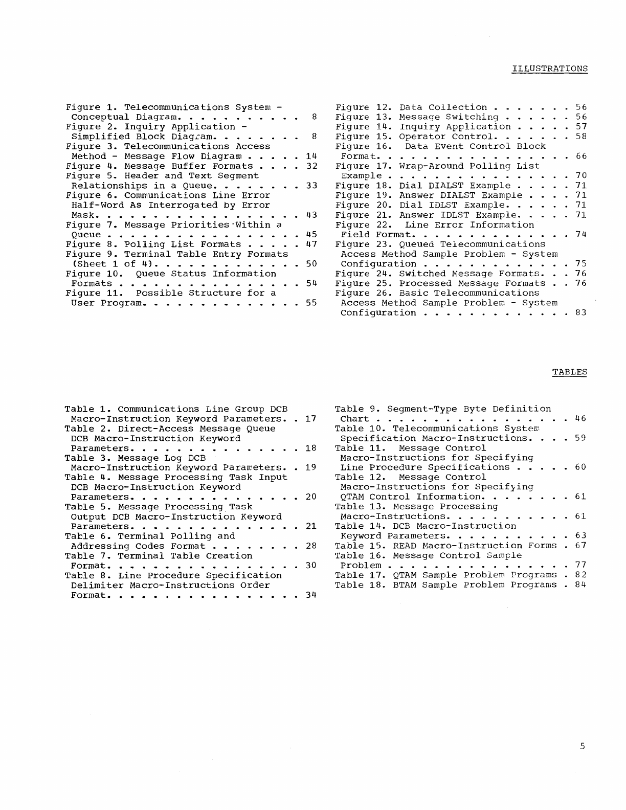
Figure
1.
Telecommunications
System
-
Conceptual
Diagram.
• • • • • . 8
Figure
2.
Inquiry
Application
-
Simplified
Block
Diag~am.
• • • • 8
Figure
3.
Telecommunications
Access
Method
-
Message
Flow
Diagram
• • • • •
14
Figure
4.
Message
Buffer
Formats
••
32
Figure
5.
Header
and
Text
Segment
Relationships
in
a
Queue.
• • •
••
33
Figure
6.
Communications
Line
Error
Half-Word
As
Interrogated
by
Error
Mask.
• • • • • • • • • • • • •
••
43
Figure
7.
Message
Priorities
'Within
a
Queue
• • • • • • • • •
..
• • • • • • •
45
Figure
8.
Polling
List
Formats
••.••
47
Figure
9.
Terminal
Table
Entry
Formats
<Sheet
1
of
4).
• • • •
50
Figure
10.
Queue
Status
Information
Formats
• • • • •
..
54
Figure
11.
Possible
Structure
for
a
User
Program.
..
• • • • •
...
••
•
55
Table
1.
communications
Line
Group
DCB
Macro-Instruction
Keyword
Parameters
••
17
Table
2.
Direct-Access
Message
Queue
DCB
Macro-Instruction
Keyword
Parameters.
• • • •
••
•
18
Table
3.
Message
Log
DCB
Macro-Instruction
Keyword
Parameters
•.
19
Table
4.
Message
Processing
Task
Input
DCB
Macro-Instruction
Keyword
Parameters.
• • • • • • • • • • •
20
Table
5.
Message
Processing,Task
Output
DCB
Macro-Instruction
Keyword
Parameters.
•
..
• • • • • • • •
21
Table
6.
Terminal
Polling
and
Addressing
Codes
Format
•
..
• • • • 28
Table
7.
Terminal
Table
Creation
Format.
•
..
••
..
• •
..
• • . • . .
30
Table
8.
Line
Procedure
Specification
Delimiter
Macro-Instructions
Order
Format.
• •
..
• • • • • • •
..
• • • • •
34
ILLUSTRATIONS
Figure
12.
Data
Collection
• • •
Figure
13.
Message
Switching
.
Figure
14.
Inquiry
Application
.
Figure
15.
Operator
Control.
• .
Figure
16.
Data
Event
Control
Block
· .
56
·
56
• .
57
• •
58
Forma
t.
• • • • • . . • • • • • . • • ·
66
Figure
17.
Wrap-Around
Polling
List
Example
• • • • • • • • • • • •
Figure
18.
Dial
DIALST
Example
.
Figure
19.
Answer
DIALST
Example
•
Figure
20.
Dial
IDLST
Example
..
Figure
21.
Answer
IDLST
Example.
.
Figure
22.
Line
Error
Information
• •
70
·
71
• • .
71
· .
71
. . .
71
Field
Format.
• • • • • •
..
• • .
Figure
23.
Queued
Telecommunications
Access
Method
Sample
Problem
-
System
Configuration
. . • . • . • • • . • •
Figure
24.
switched
Message
Formats
.•
Figure
25.
Processed
Message
Formats.
Figure
26.
Basic
Telecommunications
Access
Method
Sample
Problem
-
System
Configuration
. • • • • • • • . . . •
·
74
•
7S
·
76
·
76
·
83
TABLES
Table
9.
Segment-Type
Byte
Definition
Chart
• • . • • • • . . • • • •
•.
.
46
Table
10.
Telecommunications
System
Specification
Macro-Instructions.
.
59
Table
11.
Message
Control
Macro-Instructions
for
Specifying
Line
Procedure
Specifications
• • . • .
60
Table
12.
Message
Control
Macro-Instructions
for
Specif}ing
QTAM
Control
Information.
• .
61
Table
13.
Message
Processing
Macro-Instructions.
. • . . • . • • • .
61
Table
14.
DCB
Macro-Instruction
Keyword
Parameters.
• . . . . . .
63
Table
15.
READ
Macro-Instruction
Forms
.
67
Table
16.
Message
Control
Sample
Problem
• • • • • • . . • . • . .
77
Table
17.
QTAM
Sample
Problem
Programs.
82
Table
18.
BTAM
Sample
Problem
Programs
.
84
5

Systern/360
is
designed
to
provide
a
variety
of
programming
and
data
processing
services
that
can
be
requested
and
used
from
a
local
or
a
remote
location,
or
both.
Any
of
the
services
provided
by
System/360
Operating
System
for
local
use
are
also
available
for
use
from
geographically
dis-
persed
locations
via
telecommunications
networks.
In
addition,
the
operating
sys-
tem
can
also
provide
services
that
are
peculiar
to
telecommunications,
such
a3
message
switching
and
data
collection.
This
publication
describes
how
the
opera-
ting
system
can
be
extended
to
remote
locations
in
order
to:
•
Decrease
the
response
time
to
individ-
ual
requests
for
services.
•
Share
the
extensive
programming
and
data
processing
facilities
of
System/360
with
other
locations.
• Make
the
system
an
integral
and
more
natural
part
of
the
activity
it
sup-
ports.
Depending
on
the
specific
application,
the
operating
system
can
be
used
to
process
messages
from
remote
locations
exclusively,
process
messages
and
execute
local
jobs
concurrently,
or
alternate
between
the
processing
of
messages
and
the
executing
of
local
jobs.
To
extend
the
operating
system
for
tele-
communications
applications,
a
queued
and
a
basic
telecommunications
access
method
are
available
for
controlling
the
sending
and
receiving
of
messages
to
and
from
remote
terminals.
The
queued
telecommunications
access
method
(QTAM)
can
be
used
in
a
variety
of
applications
ranging
from
a
message
switching
application
to
a
high-
volume
inquiry
or
transaction
processing
application
such
as
a
banking
or
airline
reservation
system.
The
basic
telecommunications
access
method
(BTAM)
is
designed
for
limited
applications,
which
do
not
require
extensive
message
control
facilities.
Either
access
method
(QTAM
or
BTAM)
can
be
used
to
receive
messages
from
and
send
messages
to
the
following
terminal
devices:
•
IBM
1030
Data
Collection
System.
•
IBM
1050
Data
Communications
System
(leased
line
or
dial
service).
•
IBM
1060
Data
Communications
System.
•
AT&T
83B2
Selective
Calling
Stations.
•
Western
Union
Plan
liSA
Outstations.
•
Common
Carrier
(8-level
code)
TWX
Sta-
tions;
e.g.,
AT&T
Model
33
or
35
Tele-
typewriter
Terminal
(dial
service).
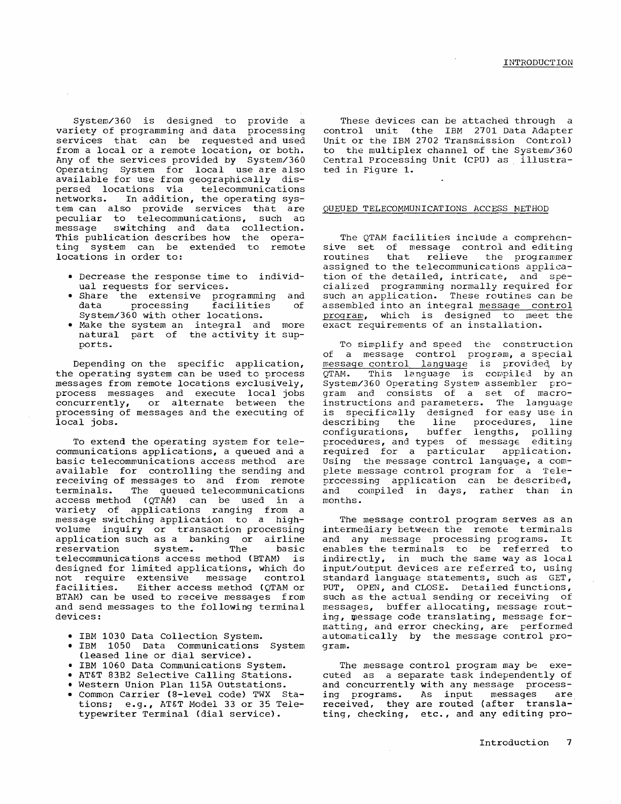
INTRODUCTION
These
devices
can
be
attached
through
a
control
unit
(the
IBM
2701
Data
Adapter
Unit
or
the
IBM
2702
Transmission
Control)
to
the
multiplex
channel
of
the
System/360
Central
processing
Unit
(CPU)
as
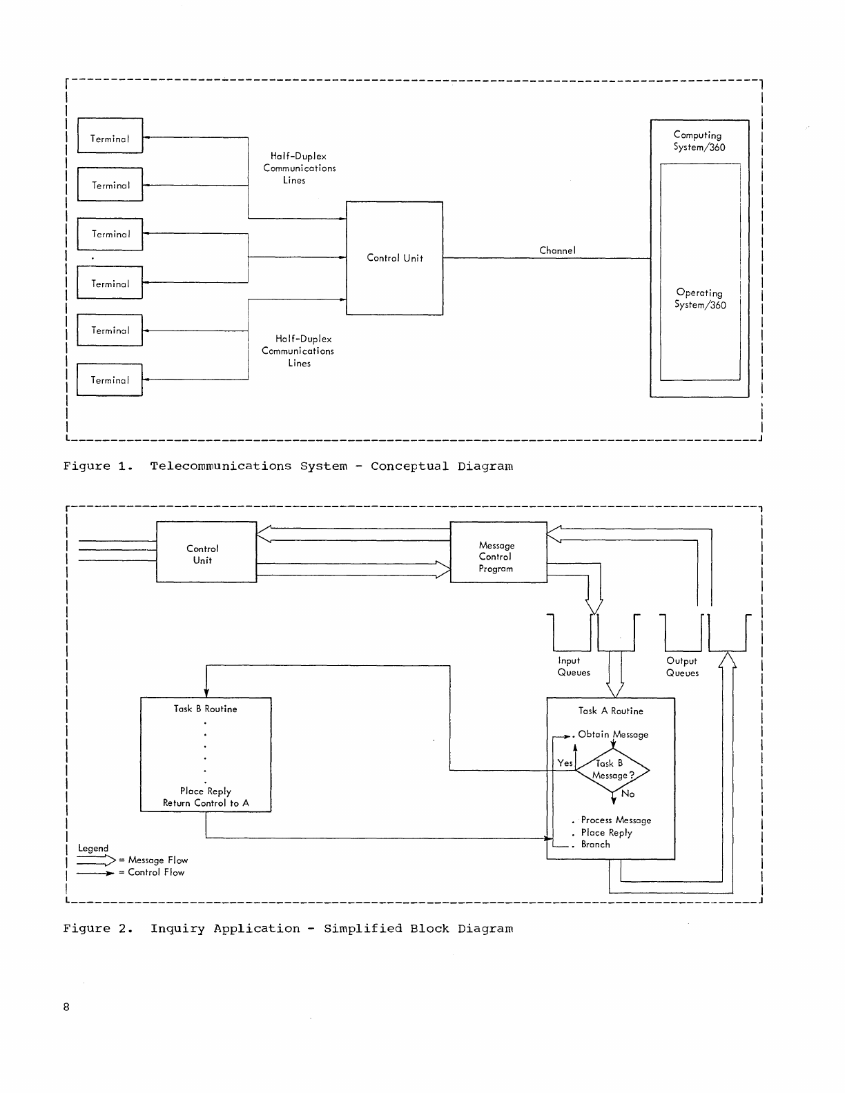
illustra-
ted
in
Figure
1.
QUEUED
TELECOMMUNICATIONS
ACCESS
t-1ETHOD
The
QTAM
facilities
include
a
comprehen-
sive
set
of
message
control
and
editing
routines
that
relieve
the
programmer
assigned
to
the
telecommunications
applica-
tion
of
the
detailed,
intricate,
and
spe-
cialized
programming
normally
required
for
such
an
application.
These
routines
can
be
assembled
into
an
integral
message
control
program,
which
is
designed
to
meet
the
exact
requirements
of
an
installation.
To
simplify
and
speed
the
construction
of
a
message
control
program,
a
special
message
control
language
is
provide~
by
QTAM.
This
lcnguage
is
cOIi1pilEd
by
an
System/360
Operating
System
assembler
pro-
gram
and
consists
of
a
set
of
macro-
instructions
and
parameters.
The
language
is
specifically
designed
for
easy
use
in
describing
the
line
procedures,
line
configurations,
buffer
lengths,
polling
procedures,
and
types
of
message
editing
required
for
a
particular
application.
Using
the
message
control
language,
a
com-
plete
message
control
program
for
a
Tele-
processing
application
can
be
described,
and
compiled
in
days,
rather
than
in
months.
The
message
control
program
serves
as
an
intermediary
between
the
remote
terminals
and
any
message
processing
programs.
It
enables
the
terminals
to
be
referred
to
indirectly,
in
much
the
same
way
as
local
input/output
devices
are
referred
to,
using
standard
language
statements,
such
as
GET,
PUT, OPEN,
and
CLOSE.
Detailed
functions,
such
as
the
actual
sending
or
receiving
of
messages,
buffer
allocating,
message
rout-
ing,
~essage
code
translating,
message
for-
matting,
and
error
checking,
are
performed
automatically
by
the
message
control
pro-
gram.
The
message
control
program
may
be
exe-
cuted
as
a
separate
task
independently
of
and
concurrently
with
any
message
process-
ing
programs.
As
input
messages
are
received,
they
are
routed
(after
transla-
ting,
checking,
etc.,
and
any
editing
pro-
Introduction
7
r-------------------~-------------------------------------------------------------------,
I
Terminal
I
I
I
Terminal
l
I
I
Terminal
L
I
I
Terminal
I
I
I
Terminal
I
I
I I
Terminal
I
Half-Duplex
Communications
Lines
Control
Unit
Channel
Ha
If-Duplex
Communications
Lines
Computing
System/360
Operating
System/360
I
I
I
I
I
I
I
I
I
I
I
I
I
I
I
I
I
L
_______________________________________________________________________________________
J
Figure
1.
Telecommunications
System
-
Conceptual
Diagram
r---------------------------------------------------------------------------------------,
I
I
I
I
I
Legend
Control
Unit
Task B
Routine
Place
Reply
Return
Control
to
A
I
===:>
=
Message
Flow
~
=
Control
Flow
..
Message
Control
Program
~~------------------~
Input
Queues
\1
Task A Routine
No
Process
Message
Place
Reply
Branch
u
Output
Queues
I
I
I
I
I
I
I
I
I I
L
_______________________________________________________________________________________
J
Figure
2.
Inquiry
Application
-
Simplified
Block
Diagram
8
vided
by
the
user)
to
one
or
more
message
queues
in
main
or
direct--access
:"torage.
Message
processing
programs
take
them
from
there
as
in
ordinary
processing.
When a
message
is
to
be
sent
to
a
terminal
by
a
processing
program,
it
is
placed
on
an
output
queue
in
main
or
direct-access
stor-
age.
The
message
is
then
sent
by
the
message
control
program
to
its
destination.
In
the
case
of
message
switching,
a
message
processing
program
may
not
be
required
--
the
message
control
program
can
route
an
inbound
message
directly
to
an
appropriate
output
queue.
A
telecommunications
job
can
be
entered
into
the
system
in
the
same
way
as
any
other
job.
The
job
scheduler
of
the
opera-
ting
system,
therefore,
can
be
used
to
allocate
any
input/output
devices
and
direct-access
storage
space
required
for
message
logs
and
message
queues,
and
to
prepare
and
schedule
the
job
for
process-
ing.
A
message
control
program
and
any
message
processing
programs
associated
with
it
can
be
entered
into
the
system
as
separate
jobs
or
they
can
be
combined
and
entered
as
a
single
job.
With
some
opera-
ting
system
configurations,
more
than
one
job
can
be
run
concurrently.
Therefore,
other
jobs
can
share
the
physical
resource~
of
the
system
with
a
telecommunications
job,
and
thereby
improve
efficiency,
par-
ticularly
during
periods
when
message
traf-
fic
is
low.
A
message
control
program
can
be
designed
for
one
or
more
types
of
applica-
tions
including
inquiry
(or
transaction)
processing,
data
collection,
job
process-
ing,
and
message
switching.
Each
of
these
is
briefly
described
below
followed
by
a
brief
explanation
of
the
procedure
required
to
construct
a
message
control
program
for
one
or
more
of
the
applications.
INQUIRY
PROCESSING
Inquiry
processing
is
an
application
in
which
inquiries
in
the
form
of
messages
are
received
from
a
number
of
remote
terminals
and
are
routed
by
the
message
control
program
to
one
or
more
input
queues.
The
m~~sages
are
picked
up
from
the
input
queue
and
processed
by
a
message
processing
pro-
gram.
After
the
message
is
processed,
a
reply
can
be
sent
to
the
terminal
from
which
the
inquiry
originated
or
to
any
other
terminal.
The
reply
is
placed
on
an
output
queue
by
the
message
processing
program
and
transmitted
to
the
terminal
by
the
message
control
program.
With
this
type
o~
application,
the
sys-
tem
can
directly
participate
in
and
control
d
variety
of
cow~ercial
and
scientific
activities
as
they
are
carried
on.
For
example,
the
system
may
be
used
to
service,
from
a
central
location,
a
geographically
dispersed
banking
activity.
In
such
a
system,
master
files
that
contain
account
records
for
thousands
of
depositors
are
stored
in
direct-access
storage.
By
enter-
ing
pertinent
data
into
the
system,
tellers
at
remote
locations
can
check
balances,
update
passbook
records,
and
handle
similar
transactions,
all
within
a
few
seconds.
The
message
processing
program
that
res-
ponds
to
inquiries
must
be
designed
for
the
specific
application.
In
designing
the
program,
all
of
the
facilities
of
the
operating
system
are
available
including
the
language
processors,
the
service
pro-
grams,
and
the
data
and
task
management
facilities.
The
processing
of
messages
can
be
per-
formed
sequentially
as
a
single
task
or
more
than
one
message
can
be
processed
concurrently.
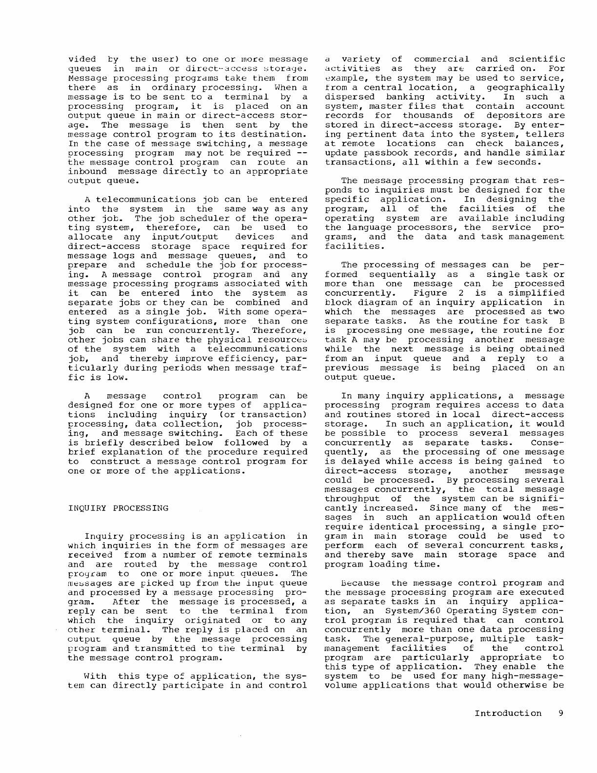
Figure
2
is
a
simplified
block
diagram
of
an
inquiry
application
in
which
the
messages
are
processed
as
two
separate
tasks.
As
the
routine
for
task
B
is
processing
one
message,
the
routine
for
task
A may
be
processing
another
message
while
the
next
message
is
being
obtained
from
an
input
queue
and
a
reply
to
a
previous
message
is
being
placed
on
an
output
queue.
In
many
inquiry
applications,
a
message
processing
program
requires
access
to
data
and
routines
stored
in
local
direct-access
storage.
In
such
an
application,
it
would
be
possible
to
process
several
messages
concurrently
as
separate
tasks.
Conse-
quently,
as
the
processing
of
one
message
is
delayed
while
access
is
being
gained
to
direct-access
storage,
another
message
could
be
processed.
By
processing
several
messages
concurrently,
the
total
message
throughput
of
the
system
can
be
signifi-
cantly
increased.
Since
many
of
the
mes-
sages
in
such
an
application
would
often
require
identical
processing,
a
single
pro-
gram
in
main
storage
could
be
used
to
perform
each
of
several
concurrent
tasks,
and
thereby
save
main
storage
space
and
program
loading
time.
Because
the
message
control
program
and
the
message
processing
program
are
executed
as
separate
tasks
in
an
inquiry
applica-
tion,
an
System/360
Operating
System
con-
trol
program
is
required
that
can
control
concurrently
more
than
one
data
processing
task.
The
general-purpose,
multiple
task-
management
facilities
of
the
control
program
are
particularly
appropriate
to
this
type
of
application.
They
enable
the
system
to
be
used
for
many
high-mess
age-
volume
applications
that
would
otherwise
be
Introduction
9
imfractical
without
a
specjally
designed
control
program.
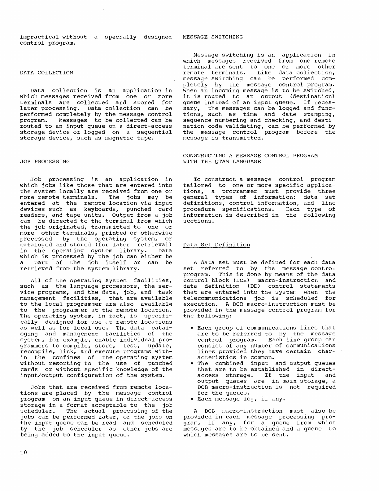
DATA
COLLECTION
Data
collection
is
an
application
in
which
messages
received
from
one
or
more
terminals
are
collected
and
stored
for
later
processing.
Data
collection
can
be
performed
completely
by
the
message
control
program.
Messages
to
be
collected
can
be
routed
to
an
input
queue
on
a
direct-access
storage
device
or
logged
on
a
sequential
storage
device,
such
as
magnetic
tape.
JOB PROCESSING
Job
processing
is
an
application
in
which
jobs
like
those
that
are
entered
into
the
system
locally
are
received
from
one
or
more
remote
terminals.
The
jobs
may
be
entered
at
the
remote
location
via
input
devices
such
as
keyboards,
punched
card
readers,
and
tape
units.
output
from
a
job
can
be
directed
to
the
terminal
from
which
the
jot
originated,
transmitted
to
one
or
more
other
terminals,
printed
or
otherwise
processed
by
the
operating
system,
or
cataloged
and
stored
(for
later
retrieval)
in
the
operating
system
library.
Data
which
is
processed
by
the
job
can
either
be
a
part
of
the
job
itself
or
can
be
retrieved
from
the
system
library.
All
of
the
operating
system
facilities,
such
as
the
language
processors,
the
ser-
vice
programs,
and
the
data,
job,
and
task
management
facilities,
that
are
available
to
the
local
programmer
are
also
available
to
the
programmer
at
the
remote
location.
The
operating
system,
in
fact,
is
specifi-
cally
dtsigned
for
use
at
remote
locations
as
well
as
for
local
use.
The
data
catal-
oging
and
management
facilities
of
the
system,
for
example,
enable
individuai
fro-
grammers
to
compile,
store,
test,
update,
recompile,
link,
and
execute
programs
with-
in
the
confines
of
the
operating
system
without
resorting
to
the
use
of
punched
cards
or
without
specific
knowledge
of
the
input/output
configuration
of
the
system.
Jobs
that
are
received
frow.
remote
loca-
tions
are
placed
by
the
message
control
frogram
on
an
input
queue
in
direct-access
storage
in
a
format
acceptable
to
the
job
scheduler.
The
actual
processing
of
the
jobs
can
be
performed
later,
or
the
jobs
on
the
input
queue
can
be
read
and
scheduled
ty
the
job
scheduler
as
other
jobs
are
teing
added
to
the
input
queue.
10
MESSAGE
SWITCHING
Message
switching
is
an
application
in
which
messages
received
from
one
remote
terminal
are
sent
to
one
or
more
other
remote
terminals.
Like
data
collection,
message
switching
can
be
performed
com-
pletely
by
the
message
control
program.
When
an
incoming
message
is
to
be
switched,
it
is
routed
to
an
output
(destination)
queue
instead
of
an
input
queue.
If
neces-
sary,
the
messages
can
be
logged
and
func-
tions,
such
as
time
and
date
stamping,
sequence
numbering
and
checking,
and
desti-
nation
code
validating,
can
be
performed
by
the
message
control
program
before
the
message
is
transmitted.
CONSTRUCTING
A
MESSAGE
CONTROL
PROGRAM
WITH
THE
QTAM
LANGUAGE
To
construct
a
message
control
program
tailored
to
one
or
more
specific
applica-
tions,
a
programmer
must
provide
three
general
types
of
information:
data
set
definitions,
control
information,
and
line
procedure
specifications.
Each
type
of
information
is
described
in
the
following
sections.
Data
Set
Definition
A
data
set
must
be
defined
for
each
data
set
referred
to
by
the
message
control
program.
This
is
done
by
means
of
the
data
control
block
(DCB)
macro-instruction
and
data
definition
(DD)
control
statements
that
are
entered
into
the
system
when
the
telecommunications
JOD
is
scheduled
for
execution.
A
DCB
macro-instruction
must
be
provided
in
the
message
control
program
for
the
following:
•
Each
group
of
communications
lines
that
are
to
be
referred
to
by
the
message
control
program.
Each
line
group
can
consist
of
any
number
of
communications
lines
provided
they
have
certain
char-
acteristics
in
common.
•
The
combined
input
and
output
queues
that
are
to
be
established
in
direct-
access
storage.
If
the
input
and
output
queues
are
in
main
storage,
a
DCB
macro-instruction
is
not
required
for
the
queues.
•
Each
message
log,
if
any.
A
DCB
macro-instruction
must
also
be
provided
in
each
message
processing
pro-
gram,
if
any,
for
a
queue
from
which
messages
are
to
be
obtained
and
a
queue
to
which
messages
are
to
be
sent.
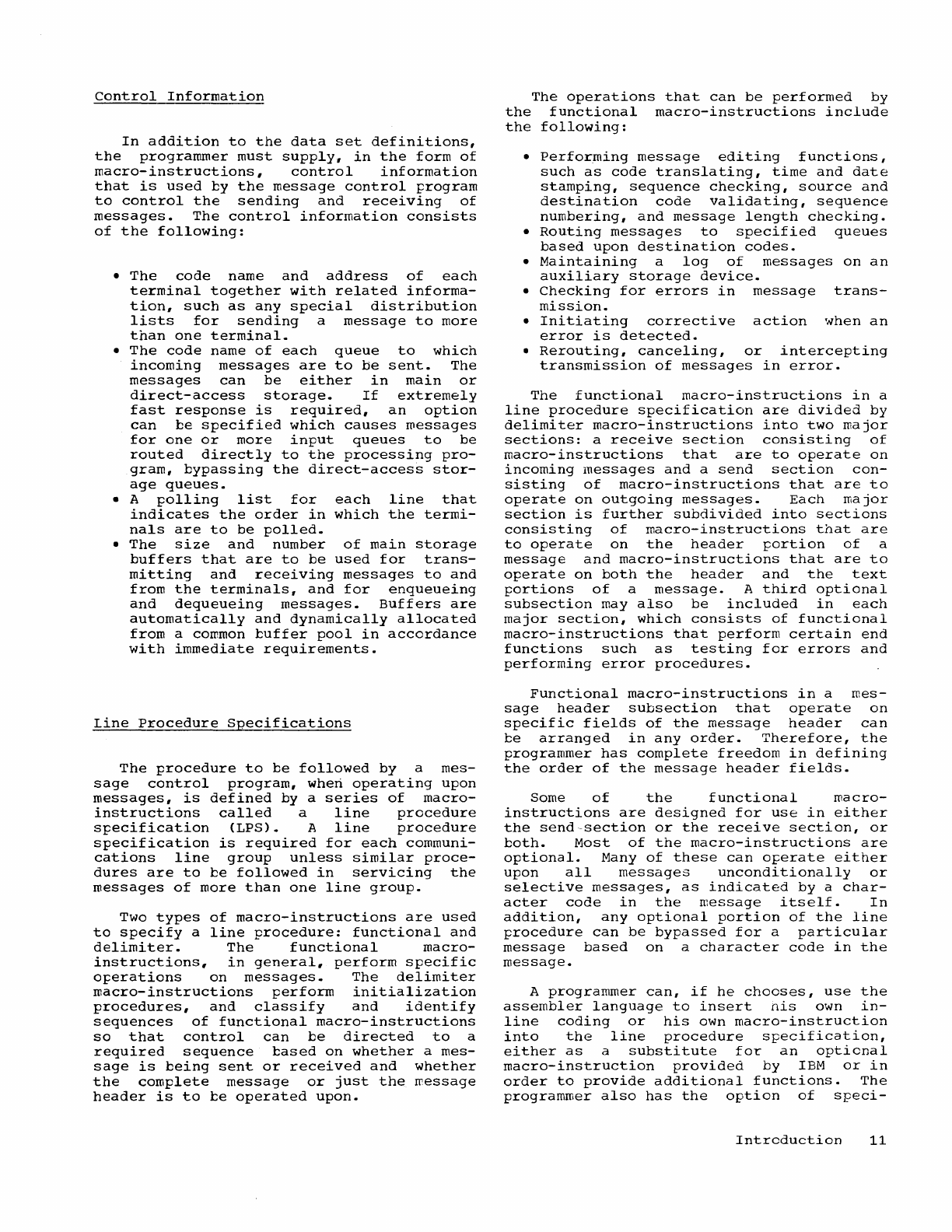
control
Information
In
addition
to
the
data
set
definitions,
the
programmer
must
supply,
in
the
form
of
macro-instructions,
control
information
that
is
used
by
the
message
control
program
to
control
the
sending
and
receiving
of
messages.
The
control
information
consists
of
the
following:
•
The
code
name
and
address
of
each
terminal
together
with
related
informa-
tion,
such
as
any
special
distribution
lists
for
sending
a
message
to
more
than
one
terminal.
•
The
code
name
of
each
queue
to
which
incoming
messages
are
to
be
sent.
The
messages
can
be
either
in
main
or
direct-access
storage.
If
extremely
fast
response
is
required,
an
option
can
be
specified
which
causes
messages
for
one
or
more
input
queues
to
be
routed
directly
to
the
processing
pro-
gram,
bypassing
the
direct-access
stor-
age
queues.
• A
polling
list
for
each
line
that
indicates
the
order
in
which
the
termi-
nals
are
to
be
polled.
•
The
size
and
number
of
main
storage
buffers
that
are
to
be
used
for
trans-
mitting
and
receiving
messages
to
and
from
the
terminals,
and
for
enqueueing
and
dequeueing
messages.
Buffers
are
automatically
and
dynamically
allocated
from
a common
buffer
pool
in
accordance
with
immediate
requirements.
Line
Procedure
Specifications
The
procedure
to
be
followed
by
a
mes-
sage
control
program,
when
operating
upon
messages,
is
defined
by
a
series
of
macro-
instructions
called
a
line
procedure
specification
(LPS).
A
line
procedure
specification
is
required
for
each
communi-
cations
line
group
unless
similar
proce-
dures
are
to
be
followed
in
servicing
the
messages
of
more
than
one
line
group.
Two
types
of
macro-instructions
are
used
to
specify
a
line
procedure:
functional
and
delimiter.
The
functional
macro-
instructions,
in
general,
perform
specific
operations
on
messages.
The
delimiter
macro-instructions
perform
initialization
procedures,
and
classify
and
identify
sequences
of
functional
macro-instructions
so
that
control
can
be
directed
to
a
required
sequence
based
on
whether
a
mes-
sage
is
being
sent
or
received
and
whether
the
complete
message
or
just
the
message
header
is
to
be
operated
upon.
The
operations
that
can
be
performed
by
the
functional
macro-instructions
include
the
following:
•
performing
message
editing
functions,
such
as
code
translating,
time
and
date
stamping,
sequence
checking,
source
and
destination
code
validating,
sequence
numbering,
and
message
length
checking.
•
Routing
messages
to
specified
queues
based
upon
destination
codes.
•
Maintaining
a
log
of
messages
on
an
auxiliary
storage
device.
•
Checking
for
errors
in
message
trans-
mission.
•
Initiating
corrective
action
when
an
error
is
detected.
•
Rerouting,
canceling,
or
intercepting
transmission
of
messages
in
error.
The
functional
macro-instructions
in
a
line
procedure
specification
are
divided
by
delimiter
macro-instructions
into
two
major
sections:
a
receive
section
consisting
of
macro-instructions
that
are
to
operate
on
incoming
messages
and
a
send
section
con-
sisting
of
macro-instructions
that
are
to
operate
on
outgoing
messages.
Each
major
section
is
further
subdivided
into
sections
consisting
of
macro-instructions
that
are
to
operate
on
the
header
portion
of
a
message
and
macro-instructions
that
are
to
operate
on
both
the
header
and
the
text
portions
of
a
message.
A
third
optional
subsection
may
also
be
included
in
each
major
section,
which
consists
of
functional
macro-instructions
that
perform
certain
end
functions
such
as
testing
for
errors
and
performing
error
procedures.
Functional
macro-instructions
in
a
mes-
sage
header
subsection
that
operate
on
specific
fields
of
the
message
header
can
be
arranged
in
any
order.
Therefore,
the
programmer
bas
complete
freedom
in
defining
the
order
of
the
message
header
fields.
Some
of
the
functional
macro-
instructions
are
designed
for
use
in
either
the
send-section
or
the
receive
section,
or
both.
Most
of
the
macro-instructions
are
optional.
Many
of
these
can
operate
either
upon
all
messages
unconditionally
or
selective
messages,
as
indicated
by
a
char-
acter
code
in
the
message
itself.
In
addition,
any
optional
portion
of
the
line
procedure
can
be
bypassed
for
a
particular
message
based
on
a
character
code
in
the
message.
A
programmer
can,
if
he
chooses,
use
the
assembler
language
to
insert
his
own
in-
line
coding
or
his
own
macro-instruction
into
the
line
procedure
specification,
either
as
a
substitute
for
an
optional
macro-instruction
provided
by
IBM
or
in
order
to
provide
additional
functions.
The
programmer
also
has
the
option
of
speci-
Introduction
11
fying
that
his
own
code
conversion
tables
be
used.to
translate
messages
instead
of
the
o~tional
code
conversion
tables
sup-
~lied
by
IBM.
An
of
tiona
I
macro-instruction
is
provid-
ed
that
can
be
used
to
direct
control,
at
different
points
in
the
line
procedure
specification,
to
an
out-of-line
subroutine
supplied
either
by
IBM
or
by
the
user.
The
transfer
of
control
can
be
either
uncondi-
tional
or
conditional
depending
on
the
presence
of
a
character
code
in
a
message.
IBM
routines,
which
perform
the
following
functions,
are
provided
for
use
with
the
optional
macro-instruction:
•
Assigning
priority
to
a
message
based
on
an
alphameric
character
in
the
mes-
sage
header.
The
priority
order
of
the
characters
that
define
priority
corres-
pond
to
the
standard
collating
sequence.
•
Holding
the
communications
line
open
until
a
complete
message
has
been
received
and
a
reply
has
been
sent.
This
subroutine
may
be
used
for
a
"conversational"
type
of
application.
•
Routing
message
segments
to
their
des-
tination
before
the
entire
message
has
been
received.
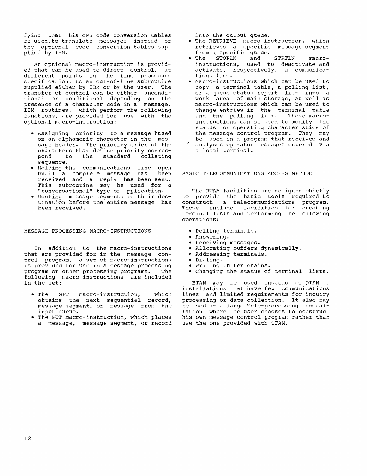
MESSAGE
PROCESSING MACRO-INSTRUCTIONS
In
addition
to
the
macro-instructions
that
are
provided
for
in
the
message
con-
trol
program,
a
set
of
macro-instructions
is
provided
for
use
in
a
message
processing
program
or
other
processing
programs.
The
following
macro-instructions
are
included
in
the
set:
12
•
The
GET
macro-instruction,
which
obtains
the
next
sequential
record,
message
segment,
or
message
from
the
input
queue.
•
The
PUT
macro-instruction,
which
places
a
message,
message
segment,
or
record
into
the
output
queue.
•
The
RETRIEVE
macro-instruction,
which
retrieves
a
specific
message
segment
frem
~
specific
queue.
•
The
STOPLN
and
STRTLN
macro-
instructions,
used
to
deactivate
and
activate,
respectively,
a
communica-
tions
line.
•
Macro-instructions
which
can
be
used
to
co~y
a
terminal
table,
a
~olling
list,
or
a
queue
status
report
list
into
a
work
area
of
main
storage,
as
well
as
macro-instructions
which
can
be
used
to
change
entries
in
the
terminal
table
and
the
polling
list.
These
macro-
instructions
can
be
used
to
modify
the
status
or
operating
characteristics
of
the
message
control
program.
They
may
be
used
in
a
program
that
receives
and
analyzes
operator
messages
entered
via
a
local
terminal.
BASIC
TELECOMMUNICATIONS
ACCESS
METHOD
The
BTAM
facilities
are
designed
chiefly
to
provide
the
basic
tools
required
to
construct
a
telecommunications
program.
These
include
facilities
for
creating
terminal
lists
and
performing
the
following
operations:
•
Polling
terminals.
•
Answering.
•
Receiving
messages.
•
Allocating
buffers
dynamically.
o
Addressing
terminals.
•
Dialing.
•
Writing
buffer
chains.
•
Changing
the
status
of
terminal
lists.
BTAM
may
be
used
instead
of
QTAM
at
installations
that
have
few
communications
lines
and
limited
requirements
for
inquiry
?rocessing
or
data
collection.
It
also
may
be
used
at
a
large
Tele-processing
instal-
lation
where
the
user
chooses
to
construct
his
own
message
control
program
rather
than
use
the
one
provided
with
QTAM.

QTAM
is
one
of
the
data
management
facilities
provided
in
System/360
Operating
System.
It
is
specified
as
a
high-level
macro-instruction
language
that
enables
operation
of
communications
lines
in
a
ITanner
similar
to
directly
attached
input/output
devices.
Selection
of
appropriate
instructions
within
QTAM
provides
a
that
performs
the
following:
macro-
system
o
Polls
terminals
(contacts
remote
terminals
to
request
that
they
send
messages).
o
Receives
messages
from
terminals.
•
Addresses
terminals
(contacts
terminals
to
request
that
they
receive
messages).
o
Sends
messages
to
terminals.
o
Provides
storage
allocation
for
message
buffering.
•
Performs
such
message
editing
functions
as
code
translating,
time
and
date
stamping,
sequence
checking,
source
and
destination
code
validating,
sequence
numtering,
and
message
length
checking.
•
Routes
messages
to
specified
queues
tased
upon
destination
codes
(a
queue
may
te
used
for
a
processing
task,
a
terminal,
or
a
group
of
terminals).
•
Queues
messages
either
on
a
direct-
access
storage
device
(to
provide
for
handling
long
messages
without
requiring
large
buffers)
or
in
main
storage.
•
Maintains
a
log
of
messages
on
an
auxiliary
storage
device.
•
Checks
for
errors
in
message
transmis-
sion.
o
Initiates
corrective
action
when
an
error
is
detected.
o
Reroutes
messages.
o
Intercepts
transmission
of
messages
in
error.
o
Cancels
messages
that
contain
an
error.
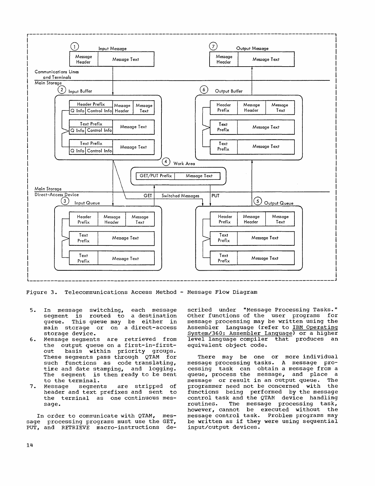
Message
flow~
as
controlled
by
QTAM,
is
illustrated
in
Figure
3.
It
involves
input/output
buffering
and
message
queueing.
Euffering
is
dynamically
handled
ty
QTAM.
A
user
need
only
specify
the
number
of
buffers
and
the
length
of
each
tuffer
to
be
used.
(Refer
to
"Buffer
Assignment.")
If
the
supply
of
buffers
is
depleted
during
system
operation,
an
error
indication
on
one
or
more
lines
will
result.
For
this
reason,
a
user
must
specify
sufficient
buffer
space
to
meet
his
system
requirements.
QUEUED
TELECOMMUNICATIONS
ACCESS
METHOD
Queues
must
be
specified
for
various
processing
tasks
and
destination
terminals.
These
queues
are
the
primary
connection
between
the
user-supplied
message
proces-
sing
tasks
and
the
QTAM
message
control
task.
Message
flow
(Figure
3)
can
be
considered
in
the
following
seven
steps:
1.
The
input
message,
consisting
of
mes-
sage
header
and
text,
is
prepared
at
the
remote
source
terminal.
The
head-
er
portion
contains
source
terminal
code,
destination
codes,
message
sequence
number,
and
message
priority
information.
When
the
source
terminal
is
polled,
the
message
is
sent
to
the
computer
via
a
communications
line.
2.
The
variable
length
message
enters
the
computer
and
is
placed
in
user-
defined,
fixed-size
buffers.
As
many
buffers
as
are
necessary
to
handle
the
message
are
"filled.
QTAM
attaches
a
header
prefix
that
contains
control
information
(24
bytes)
and
queueing
information
(8
bytes).
The
header
prefix
and
the
message
header
must
all
be
contained
within
the
first
buffer.
Each
of
the
remaining
buffers
assigned
to
the
message
has
a
text
prefix
that
contains
queueing
information
(8
bytes)
and
control
information
(14
bytes).
These
buffers
also
contain
the
message
text.
As
soon
as
each
buffer
is
filled,
QTAM
performs
such
user-selected
functions
as
code
translating,
routing,
time
and
date
stamping,
and
sequence
checking.
3.
When a
message
requires
additional
processing,
each
segment
is
sent
to
a
process
queue.
This
queue
may
be
either
in
main
storage
or
on
a
direct-
access
storage
device.
4.
The
user's
message
processing
program
can
issue
a
GET
macro-instruction
to
obtain
messages,
segments,
or
records
from
the
process
queue.
The
message
ottained
by
the
processing
program
contains
a
modified
prefix
(4
bytes).
(Refer
to
"GET
Macro-Instruction.")
This
message
can
then
be
frocessed.
A
user
in
his
processing
program
can
send
replies
by
forrring
a
message
with
the
4-byte
prefix
and
by
issuing
a
PUT
macro-instruction.
The
message
is
then
placed
on
an
output
(destination)
queue
and
handled
as
in
message
switching
(Step
5).
Queued
Telecommunications
Access
Method
13
r---------------------------------------------------------------------------------------,
Communications
lines
and
Terminals
Main
Storage
CD
Input Buffer
Input Message
Message Text
Message Text
Message Text
Output
Message
Message
Text
CD
Output
Buffer
Message Text
Message
Text
8 Work
Area
GET/PUT Prefix I Message Text
Mai n
Storage
GET
PUT
Direct-Access
Device
o Input
Queue
Switched Messages
Message Text Message
Text
Message Text Message Text
Figure
3.
Telecommunications
Access
Method
-
Message
Flow
Diagram
5.
In
message
switching,
each
message
segment
is
routed
to
a
destination
queue.
This
queue
may
be
either
in
main
storage
or
on
a
direct-access
storage
device.
6.
Message
segments
are
retrieved
from
the
output
queue
on
a
first-in-first-
out
basis
within
priority
groups.
These
segments
pass
through
QTAM
for
such
functions
as
code
translating,
tirr.e
and
date
stamping,
and
logging.
The
segment
is
then
ready
to
be
sent
to
the
terminal.
7.
Message
segments
are
stripped
of
header
and
text
prefixes
and
sent
to
the
terminal
as
one
continuous
mes-
sage.
In
order
to
communicate
with
QTAM,
mes-
sage
processing
programs
must
use
the
GET,
PUT,
and
RETRIEVE
macro-instructions
de-
14
scribed
under
"Message
Processing
Tasks."
Other
fUnctions
of
the
user
programs
for
message
processing
may
be
written
using
the
Assembler
Language
(refer
to
IBM
Operating
System/360:
Assembler
Language>
or
a
higher
level
language
compiler
that
produces
an
equivalent
object
code.
There
may
be
one
or
more
individual
message
processing
tasks.
A
message
pro-
cessing
task
can
obtain
a
message
from
a
queue,
process
the
message,
and
place
a
message
or
result
in
an
output
queue.
The
programmer
need
not
be
concerned
with
the
functions
being
performed
by
the
message
control
task
and
the
QTAM
device
handling
routines.
The
message
processing
task,
however,
cannot
be
executed
without
the
message
control
task.
Problem
programs
may
be
written
as
if
they
were
using
sequential
input/output
devices.
Message
processing
programs
that
use
directly
attached
input/oQtput
devices
may
use
the
macro-instruction
language
of
the
appropriate
access
method.
System
status
macro-instructions
are
provided
to
enable
a
user
to
obtain
infor-
mation
that
concerns
the
terminal
polling
sequence,
the
terminal
table
entries,
and
the
present
status
of
message
queues.
Macro-instructions
can
be
used
in
a
message
processing
task
to
extract
system
status
information
and
to
change
the
system
sta-
tus.
In
specifying
QTAM
for
his
system,
the
user
must
provide
information
in
the
fol-
lowing
areas:
•
Data
set
definition
-
The
user
must
use
macro-instructions
provided
by
System/360
Operating
System
and
QTAM
control
statements
to
define
the
data
sets
used
in
his
telecommunications
system.
•
Control
information
The
user
must
provide
detailed
information,
in
the
form
of
tables
and
lists,
concerning
the
terminals
in
the
system,
the
desired
sequence
of
polling
for
each
line,
the
queueing
technique,
and
the
message
buffers
provided.
•
Message
control
task
-
The
user
must
select
and
place
into
order
macro-
instructions
provided
by
QTAM
to
create
the
message
control
task.
These
macro-
instructions
perform
the
message
code
translating,
the
editing,
the
format
checking,
the
logging,
and
the
routing
functions.
•
Message
processing
tasks
The
user
must
write
the
programs
necessary
to
meet
his
requirements.
These
programs
operate
as
one
or
more
individual
tasks.
Wherever
macro-instructions
are
de-
scribed
in
this
publication,
the
following
conventions
are
used
to
illustrate
the
coding
format:
•
Upper
case
letters
and
punctuation
marks
(except
for
the
brackets
and
braces
described)
represent
information
that
rrust
be
coded
exactly
as
shown.
•
Lower
case
letters
and
words
are
generic
terms
that
represent
informa-
tion
to
be
supplied;
i.e.,
a
substitu-
tion
must
be
wade
when
coding
a
param-
eter
or
option
so
represented.
•
Information
within
brackets
[]
rep-
resents
an
option
that
can
be
either
included
or
omitted
entirely,
depending
upon
program
requirements.
• When
options
are
enclosed
in
braces
{ }
one
of
the
enclosed
options
must
be
included,
and
the
others
omitted
according
to
the
programmer's
discre-
tion.
One
of
several
options
enclosed
in
the
braces
may
be
underlined,
indi-
cating
that
the
operating
system
auto-
matically
assumes
this
option
if
the
parameter
is
omitted.
•
An
ellipsis
(
.•.
)
indicates
that
a
variable
number
of
items
may
be
listed.
DATA
SET DEFINITION
Before
a
telecommunications
system
can
use
QTAM,
the
data
sets
of
the
system
IT.ust
be
specified.
A
description
of
the
four
types
of
data
sets
that
can
be
associated
with
QTAM
and
the
means
by
which
they
may
be
defined
follows.
Four
types
of
data
sets
are
supported
directly
by
the
QTAM
message
control
task:
•
Data
sets
that
consist
of
messages
transmitted
via
communications
lines.
One
or
IT.ore
data
sets
of
this
type
are
required.
•
Data
sets
that
consist
of
message
queues
on
direct-access
storage
devices
(IBM
2302
Disk
Storage,
IBM
2311
Disk
Storage
Drive,
and
IBM
2314
Direct
Access
Storage
Facility).
The
require-
ment
for
this
type
of
data
set
depends
on
the
requirements
of
the
user.
•
Data
sets
that
consist
of
message
logs
on
a
secondary
storage
device.
The
requirement
for
this
type
of
data
set
depends
on
the
requirements
of
the
user.
•
Data
sets
that
consist
of
queues
of
messages.
This
type
of
data
set
is
used
in
the
message
processing
tasks.
Available
sources
for
information
con-
cerning
a
data
set
include
the
data
control
block
(DCB)
macro-instruction,
the
data
definition
(DD)
statement,
and
the
data
set
label
(DSL).
The
DCB
macro-instruction
provides
for
assembly
time
definition
of
a
data
control
block.
This
data
control
block
is
the
primary
source
of
data
set
characteristics
and
control
information
for
the
QTAM
routines.
The
DCB
IT.acro-
instruction
reserves
space
for
the
data
control
block
and
assigns
values
to
those
fields
for
which
the
user
provides
parameters.
Note:
Information
provided
in
the
DCB
macro-instruction
takes
precedence
over
information
provided
in
the
DD
statement
or
the
DSL.
For
general
information
concern-
ing
the
DD
statement
and
the
DSL,
refer
to
the
publications
IBM
Operating
System/360:
Job
Control
Language
and
IBM
Operating
System/360:
Data
Management.
Queued
Telecommunications
Access
Method
15
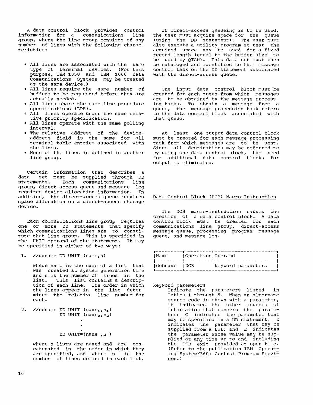
A
data
control
information
for
group,
where
the
number
of
lines
teristics:
block
provides
control
a
communications
line
line
group
consists
of
any
with
the
following
charac-
•
All
lines
are
associated
with
the
same
type
of
terminal
devices.
(For
this
purpose,
IEM
1050
and
IBM
1060
Data
Communications
Systems
may
be
treated
as
the
same
device.)
•
All
lines
require
the
same
number
of
buffers
to
be
requested
before
they
are
actually
needed.
•
All
lines
share
the
same
line
procedure
specifications
(LPS).
o
All
lines
operate
under
the
same
rela-
tive
priority
specification~
o
All
lines
operate
with
the
same
polling
interval.
•
The
relative
address
of
the
device-
address
field
is
the
same
for
all
terminal
table
entries
associated
with
the
lines.
•
None
of
the
lines
is
defined
in
another
line
group.
Certain
information
that
describes
a
data
set
must
be
su~plied
through
DD
statements.
Each
communications
linE
group,
direct-access
queue
and
message
log
requires
device
allocation
information.
In
addition,
the
direct-access
queue
requires
space
allocation
on
a
direct-access
storage
device.
Each
communications
line
group
requires
one
or
more
DD
statements
that
specify
which
communications
lines
are
to
consti-
tute that
line
group.
This
is
specified
in
the
UNIT
operand
of
the
statement.
It
may
be
specified
in
either
of
two
ways:
1.
//ddname
DD
UNIT=(name,ri)
where
name
is
the
name
of
a
list
that
was
created
at
system
generation
time
and
n
is
the
number
of
lines
in
the
list.
This
list
contains
a
descrip-
tion
of
each
line.
The
order
in
which
the
lines
appear
in
the
list
deter-
mines
the
relative
line
number
for
each.
2.
//ddname
DD
UNIT=(name1,n1)
DO
UNIT=(name2,n2)
16
DD
UNIT=(name
,n
)
where
x
lists
are
named
and
are
con-
catenated
in
the
order
in
which
they
are
specified,
and
where
n
is
the
number
of
lines
defined
in
each
list.
If
direct-access
queueing
is
to
be
used,
the
user
must
acquire
space
for
the
queue
(using
the
DD
statement).
The
user
must
also
execute
a
utility
program
so
that
the
acquired
space
may
be
used
for
a
fixed
record
length
(equal
to
the
buffer
size
to
be
used
by
QTAM).
This
data
set
must
then
be
cataloged
and
identified
to
the
message
control
task
on
the
DD
statement
associated
with
the
direct-access
queue.·
One
input
data
control
block
must
"be
created
for
each
queue
from
which
messages
are
to
be
obtained
by
the
message
process-
ing
tasks.
To
obtain
a
message
from
a
queue,
the
message
processing
task
refers
to
the
data
control
block
associated
with
that
queue.
At
least
one
output
data
control
block
must
be
created
for
each
message
processing
task
from
which
messages
are
to
be
sent.
Since
all
destinations
may
be
referred
to
by
using
one
data
control
block,
the
need
for
additional
data
control
blocks
for
output
is
eliminated.
Data
Control
Block
<DCB)
Macro-Instruction
The
DCB
macro-instruction
causes
the
creation
of
a
data
control
block.
A
data
control
block
must
be
created
for
each
communications
line
group,
direct-access
message
queue,
processing
program
message
queue,
and
message
log.
r---------T---------T---------------------,
\Name
\Operation\Operand
I
~---------+---------+---------------------~
Idcbname
IDCB
Ikeyword
parameters
\
l
_________
~
_________
~
_____________________
J
keyword
parameters
Indicate
the
parameters
listed
in
Tables
1
through
5.
When
an
alternate
source
code
is
shown
with
a
parameter,
it
indicates
the
other
sources
of
information
that
concern
the
parame-
ter:
C
indicates
the
parameter
that
may
be
specified
in
a
DD
statement;
D
indicates
the
parameter
that
may
be
supplied
from
a DSL;
and
E
indicates
the
parameter
whose
value
may
be
sup-
plied
at
any
time
up
to
and
including
the
DCB
exit
provided
at
open
tirne.
(Refer
to
the
publication
IBM
Operat-
ing
System/360:
Control
Program
Servi-
ces.
)
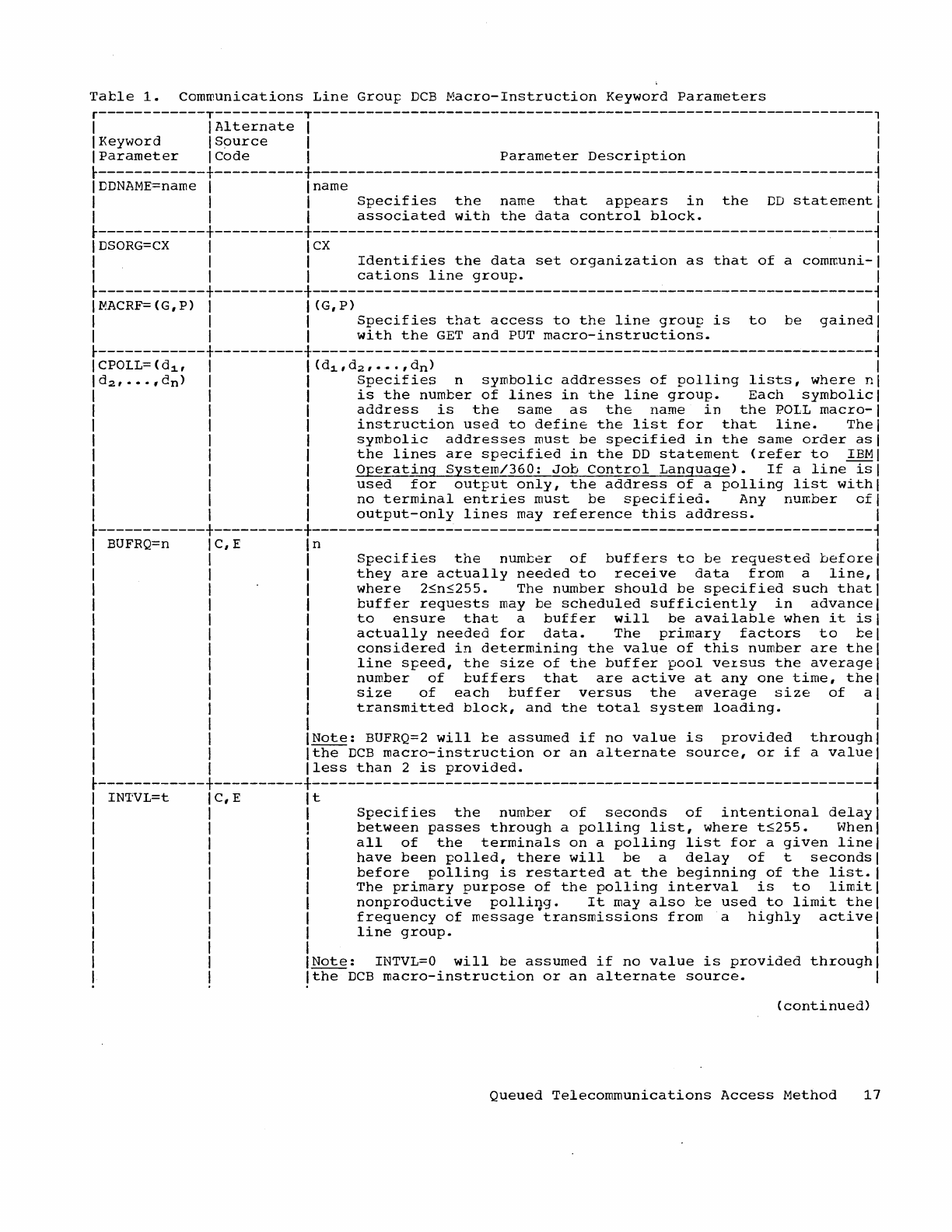
Tacle
1.
Communications
Line
Group
DCB
Macro-Instruction
Keyword
Parameters
r------------T----------T---------------------------------------------------------------,
I
IAlternate
I I
I
Keyword
I
Source
I I
I
Parameter
I
Code
I
Parameter
Description
I
~------------+----------+---------------------------------------------------------------~
I
DDNAME=name
I I name I
I I I
Specifies
the
name
that
appears
in
the
DD
statement
I
I I I
associated
with
the
data
control
block.
I
~------------+----------+---------------------------------------------------------------~
I
DSORG=CX
I I
CX
I
I I I
Identifies
the
data
set
organization
as
that
of
a
communi-I
I I I
cations
line
group.
I
~------------+----------+---------------------------------------------------------------~
I
~ACRF=
(G,
P)
I I (G,
P)
I
I I I
Specifies
that
access
to
the
line
group
is
to
be
gainedl
I I I
with
the
GET
and
PUT
macro-instructions.
I
~------------+----------+---------------------------------------------------------------~
ICPOLL=(d1, I
l(d
1
,d
2
,···,d
n) I
Id
2,
•••
,d
n) I I
Specifies
n
symbolic
addresses
of
polling
lists,
where
nl
I I I
is
the
number
of
lines
in
the
line
group.
Each
symbolic
I
I I I
address
is
the
same
as
the
name
in
the
POLL
macro-I
I I I
instruction
used
to
define
the
list
for
that
line.
Thel
I I I
symbolic
addresses
must
be
specified
in
the
same
order
asl
I I I
the
lines
are
specified
in
the
DD
statement
(refer
to
IBMI
I I I
Operating
System/360:
Job
Control
Language).
If
a
line
isl
I I I
used
for
output
only,
the
address
of
a
polling
list
with
I
I I I
no
terminal
entries
must
be
specified.
Any
number
ofl
I I I
output-only
lines
may
reference
this
address.
I
~------------+----------+---------------------------------------------------------------~
BUFRQ=n
C,E
n
Specifies
the
number
of
buffers
to
be
requested
before
they
are
actually
needed
to
receive
data
from
a
line,
where
2~n~255.
The
number
should
be
specified
such
that
buffer
requests
may
be
scheduled
sufficiently
in
advance
to
ensure
that
a
buffer
will
be
available
when
it
is
actually
needed
for
data.
The
primary
factors
to
ce
considered
in
determining
the
valQe
of
this
number
are
the
line
speed,
the
size
of
the
buffer
pool
veLSUS
the
average
number
of
cuffers
that
are
active
at
anyone
time,
the
size
of
each
buffer
versus
the
average
size
of
a
transmitted
block,
and
the
total
system
loading.
Note:
BUFRQ=2
will
ce
assumed
if
no
value
is
provided
through
Ithe
DCB
macro-instruction
or
an
alternate
source,
or
if
a
value
Iless
than
2
is
provided.
~------------+----------+---------------------------------------------------------------~
INTVL=t
C,E
t
Specifies
the
number
of
seconds
of
intentional
delay
between
passes
through
a
polling
list,
where
t~255.
When
all
of
the
terminals
on
a
polling
list
for
a
given
line
have
been
polled,
there
will
be
a
delay
of
t
seconds
before
polling
is
restarted
at
the
beginning
of
the
list.
The
primary
purpose
of
the
polling
interval
is
to
limit
nonproductive
polli~g.
It
may
also
ce
used
to
limit
the
frequency
of
message
transmissions
from
a
highly
active
line
group.
Note:
INTVL=O
will
be
assumed
if
no
value
is
provided
through
Ithe
DCB
macro-instruction
or
an
alternate
source.
(continued)
Queued
Telecommunications
Access
Method
17
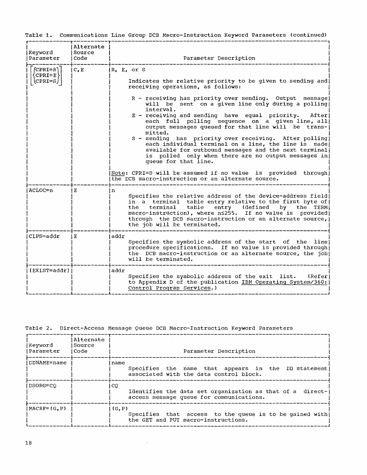
Tatle
1.
Communications
Line
Group
DCB
Macro-Instruction
Keyword
Parameters
(continued)
r------------T----------T---------------------------------------------------------------,
I I
Alternate
I I
I
Keyword
I
Source
I I
I
Parameter
I
Code
I
Parameter
Description
I
~------------+----------+---------------------------------------------------------------~
[{
CPRI=R}~
C,
E
R"
E,
or
S
CPRI=E
CPRI=S
Indicates
the
relative
priority
to
be
given
to
sending
and
receiving
operations,
as
follows:
R -
receiving
has
priority
over
sending.
Output
message
will
be
sent
on
a
given
line
only
during
a
polling
interval.
E -
recelvlng
and
sending
have
equal
priority.
After
each
full
polling
sequence
on
a
given
line,
all
output
messages
queued
for
that
line
will
be
trans-
mitted.
S -
sending
has
priority
over
receiving.
After
polling
each
individual
terminal
on
a
line,
the
line
is
rr.ade
available
for
outbound
messages
and
the
next
terminal
is
polled
only
when
there
are
no
output
messages
in
queue
for
that
line.
Note:
CPRI=S
will
te
assumed
if
no
value
is
provided
through
Ithe
DCB
macro-instruction
or
an
alternate
source.
~------------+----------+---------------------------------------------------------------~
I
ACLOC=n
I E I n I
I I I
Specifies
the
relative
address
of
the
device-address
fieldl
I I I
in
a
terminal
table
entry
relative
to
the
first
byte
ofl
I I I
the
terminal
table
entry
(defined
by
the
TERM
I
I I I
macro-instruction),
where
n~255.
If
no
value
is
provided
I
I I I
through
the
DCB
roacro-instruction
or
an
alternate
source,
I
I I I
the
job
will
te
terminated.
I
~------------+----------+---------------------------------------------------------------~
I
CLPS=addr
I E I
addr
I
I I I
Specifies
the
symbolic
address
of
the
start
of
the
linel
I I I
procedure
specifications.
If
no
value
is
provided
through
I
I I I
the
DCB
macro-instruction
or
an
alternate
source,
the
jobl
I I I
will
be
terminated.
I
~------------+----------+---------------------------------------------------------------~
I
[EXLST=addr]
I I
addr
I
I I I
Specifies
the
symbolic
address
of
the
exit
list.
(Referl
I I I
to
Appendix
D
of
the
publication
IBM
Operating
System/360:
I
I I I
Control
Program
Services.)
I
l
____________
i
__________
L
_____________________________
__________________________________
J
Table
2.
Direct-Access
Message
Queue
DCB
Macro-Instruction
Keyword
Parameters
r------------T----------T---------------------------------------------------------------,
I I
Al
ternate
I I
I KeY'v'lord I
Source
I I
I
Parameter
ICode
I
Parameter
Description
I
~------------+----------+---------------------------------------------------------------~
IDDNAME=name I I
name
I
I I I
Specifies
the
name
that
appears
in
the
DD
statement
I
I I I
associated
with
the
data
control
block.
I
~------------+----------+---------------------------------------------------------------~
I
DSORG=CQ
I I
CQ
I
I I I
Identifies
the
data
set
organization
as
that
of
a
direct-I
I I I
access
message
queue
for
communications.
j
~------------+----------+---------------------------------------------------------------~
IMACRF={G,P) I I
(G,P)
I
I I I
Specifies
that
access
to
the
queue
is
to
be
gained
withl
I I I
the
GET
and
PUT
macro-instructions.
I
l
____________
L
__________
L
_____________________________
__________________________________
J
18
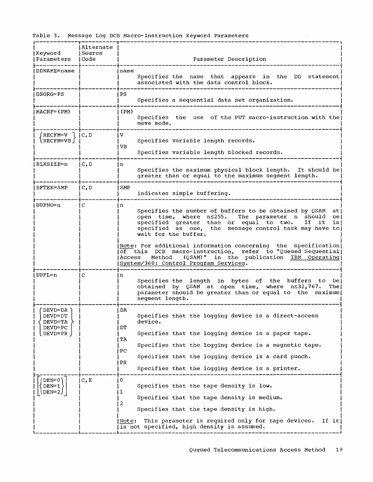
Table
3.
Message
Log
DCB
Macro-Instruction
Keyword
Parameters
r------------T----------T---------------------------------------------------------------,
I I
Alternate
I I
I
Keyword
I
Source
I I
I
Parameters
I
Code
I
Parameter
Description
I
~------------+----------+---------------------------------------------------------------~
I
DDNA~E=name
I I name I
I I I
Specifies
the
name
that
appears
in
the
DD
statement
I
I I I
associated
with
the
data
control
block.
I
~------------+----------+---------------------------------------------------------------~
I
DSORG=PS
I I PS I
I I I
Specifies
a
sequential
data
set
organization.
I
~------------+----------+---------------------------------------------------------------~
I
MACRF=
(PM)
I I
(PM)
I
I I I
Specifies
the
use
of
the
PUT
macro-instruction
with
thel
I I I move
mode.
I
~------------+----------+---------------------------------------------------------------~
I
{RECFM=V
} I C, D I V I
I
RECFM=VB
I I
Specifies
variable
length
records.
I
I I
IVB
I
I I I
Specifies
variable
length
blocked
records.
I
~------------+----------+---------------------------------------------------------------~
. I BLKSIZE=n I C,
Din
I
I I I
Specifies
the
maximum
physical
block
length.
It
should
bel
I I I
greater
than
or
equal
to
the
maximum
segment
length.
I
~------------+----------+---------------------------------------------------------------~
I
BFTEK=SMP
I C, D I
SMP
I
I I I
indicates
simple
tuffering.
I
~------------+----------+---------------------------------------------------------------~
I
BUFNO=n
I C I n I
I I I
Specifies
the
number
of
buffers
to
be
obtained
by
QSAM
atl
I I I
open
time,
where
n~255.
The
parameter
n
should
bel
I I I
specified
greater
than
or
equal
to
two.
If
it
isl
I I I
specified
as
one,
the
message
control
task
may
have
tol
I I I
wait
for
the
buffer.
I
I I I I
I I
INote:
For
additional
information
concerning
the
specification
I
I I
lof
this
DCB
macro-instruction,
refer
to
"Queued
Sequential
I
I I
IAccess
Method
(QSAM)"
in
the
publication
IBM
Operating
I
I I
ISystem/360:
Control
Program
Services.
I
~------------+----------+---------------------------------------------------------------~
I BUFL=n I C I n I
I I I
Specifies
the
length
in
bytes
of
the
buffers
to
bel
I I I
obtained
by
QSAM
at
open
time,
where
n~32,767.
Thel
I I I
parameter
should
be
greater
than
or
equal
to
the
maximum I
I I I
segment
length.
I
~------------+----------+---------------------------------------------------------------~
I
{~i~~~~~}
I
iDA
Specifies
that
the
logging
device
is
a
direct-access
I
I
DEVD=TA
I I
device.
I
I
DEVD=PC
I I
DT
I
I
DEVD=PR
I I
Specifies
that
the
logging
device
is
a
paper
tape.
I
I I
ITA
I
I I I
Specifies
that
the
logging
device
is
a
magnetic
tape.
I
I I IPC I
I I I
Specifies
that
the
logging
device
is
a
card
punch.
I
I I
IPR
I
I I I
Specifies
that
the
logging
device
is
a
printer.
I
rl{~;~~~}]---r~~~-------r:----:::::~:::-::::-:::-::::-::::::~-::-:::~-------------------1
I I I
Specifies
that
the
tape
density
is
medium.
I
I I 12 I
I I I
Specifies
that
the
tape
density
is
high.
I
I I I I
I I
INote:
This
parameter
is
required
only
for
tape
devices.
If
itl
I I I
is
not
specified,
high
density
is
assumed.
I
L
____________
~
__________
~
_______________________________________________________________
J
Queued
Telecommunications
Access.
Method
19
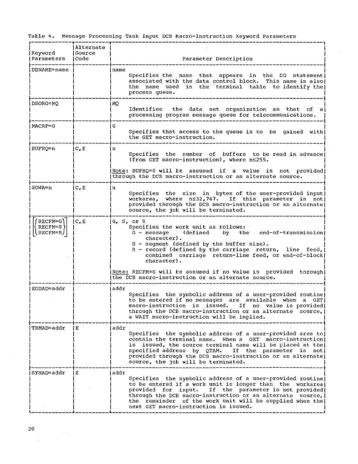
Table
4.
Message
Processing
Task
Input
DCB
Macro-Instruction
Keyword
Parameters
r------------T----------T---------------------------------------------------------------,
I I
Alternate
I I
I
Keyword
I
Source
I I
I
Parameters
ICode
I
Parameter
Description
I
~------------+----------+---------------------------------------------------------------~
I
DDNAME=name
I I name I
I I I
Specifies
the
name
that
appears
in
the
DD
statement
I
I I I
associated
with
the
data
control
block.
This
name
is
alsol
I I I
the
name
used
in
the
terminal
table
to
identify
thel
I I I
process
queue.
I
~------------+----------+---------------------------------------------------------------~
I
DSORG=MQ
I
11>1Q
I
I I I
Identifies
the
data
set
organization
as
that
of
al
I I I
processing
program
message
queue
for
telecommunications.
I
~------------+----------+---------------------------------------------------------------~
I
MACRF=G
I I G I
I I I
Specifies
that
access
to
the
queue
is
to
be
gained
withl
I I I
the
GET
macro-instruction.
I
~------------+----------+---------------------------------------------------------------~
I
BUFRQ=n
I C, E I n I
I I I
Specifies
the
number
of
buffers
to
be
read
in
advance
I
I I I
(from
GET
macro-instruction),
where
nS255.
I
I I I I
I I
INote:
BUFRQ=O
will
be
assumed
if
a
value
is
not
provided
I
I I
Ithrough
the
DCB
macro-instruction
or
an
alternate
source.
I
~------------+----------+---------------------------------------------------------------~
I
SOWA=n
I C, E I n I
I I I
Specifies
the
size
in
bytes
of
the
user-provided
input
I
I I I
workarea,
where
nS32,767.
If
this
parameter
is
notl
I I I
provided
through
the
DCB
macro-instruction
or
an
alternate
I
I I I
source,
the
jcb
will
be
terminated.
I
~------------+----------+---------------------------------------------------------------~
I
~RECFM=G}~
I C, E I
G,
S,
or
R I
I
RECFM=S
I I
Specifies
the
~ork
unit
as
~ollows:
I
I
RECFM=R
I I G -
message
(defined
by
the
end-of-transmissionl
I I I
character)
. I
I I I S -
segment
(defined
by
the
buffer
size).
I
I I I R -
record
(defined
by
the
carriage
return,
line
feed,
I
I I I
combined
carriage
return-line
feed,
or
end-of-blockl
I I I
character)
. I
I I I I
I I
INote:
RECFM=S
will
be
assumed
if
no
value
is
provided
tnroughl
I I
Ithe
DCB
macro-instruction
or
an
alternate
source.
I
~------------+----------+---------------------------------------------------------------~
I EODAD=addr I I
addr
I
I I I
Specifies
the
symbolic
address
of
a
user-provided
routine
I
I I I
to
be
entered
if
no
messages
are
available
when
a
GET
I
I I I
macro-instruction
is
issued.
If
no
value
is
provided
I
I I I
through
the
DCB
macro-instruction
or
an
alternate
source,
I
I I I a
WAIT
macro-instruction
will
be
implied.
I
~------------+----------+---------------------------------------------------------------~
I TRMAD=addr I E I
addr
I
I I I
Specifies
the
symbolic
address
of
a
user-provided
area
tol
I I I
contain
the
terminal
name.
When a
GET
macro-instruction
I
I I I
is
issued,
the
source
terminal
name
will
be
placed
at
thel
I I I
specified
address
by
QTAM.
If
the
parameter
is
notl
I I I
provided
through
the
DCB
macro-instruction
or
an
alternate
I
I I I
source,
the
jeb
will
be
terminated.
I
~------------+----------+---------------------------------------------------------------~
I SYNAD=addr I E I
addr
I
I I I
Specifies
the
symbolic
address
of
a
user-provided
routine
I
I I I
to
be
entered
if
a
work
unit
is
longer
than
the
workareal
I I I
provided
for
input.
If
the
parameter
is
not
provided
I
I I I
through
the
DCB
macro-instruction
or
an
alternate
source,
I
I I I
the
remainder
of
the
work
unit
will
be
supplied
when
thel
I I I
next
GET
macro-instruction
is
issued.
I
L
____________
~
__________
L
_______________________________________________________________
J
20
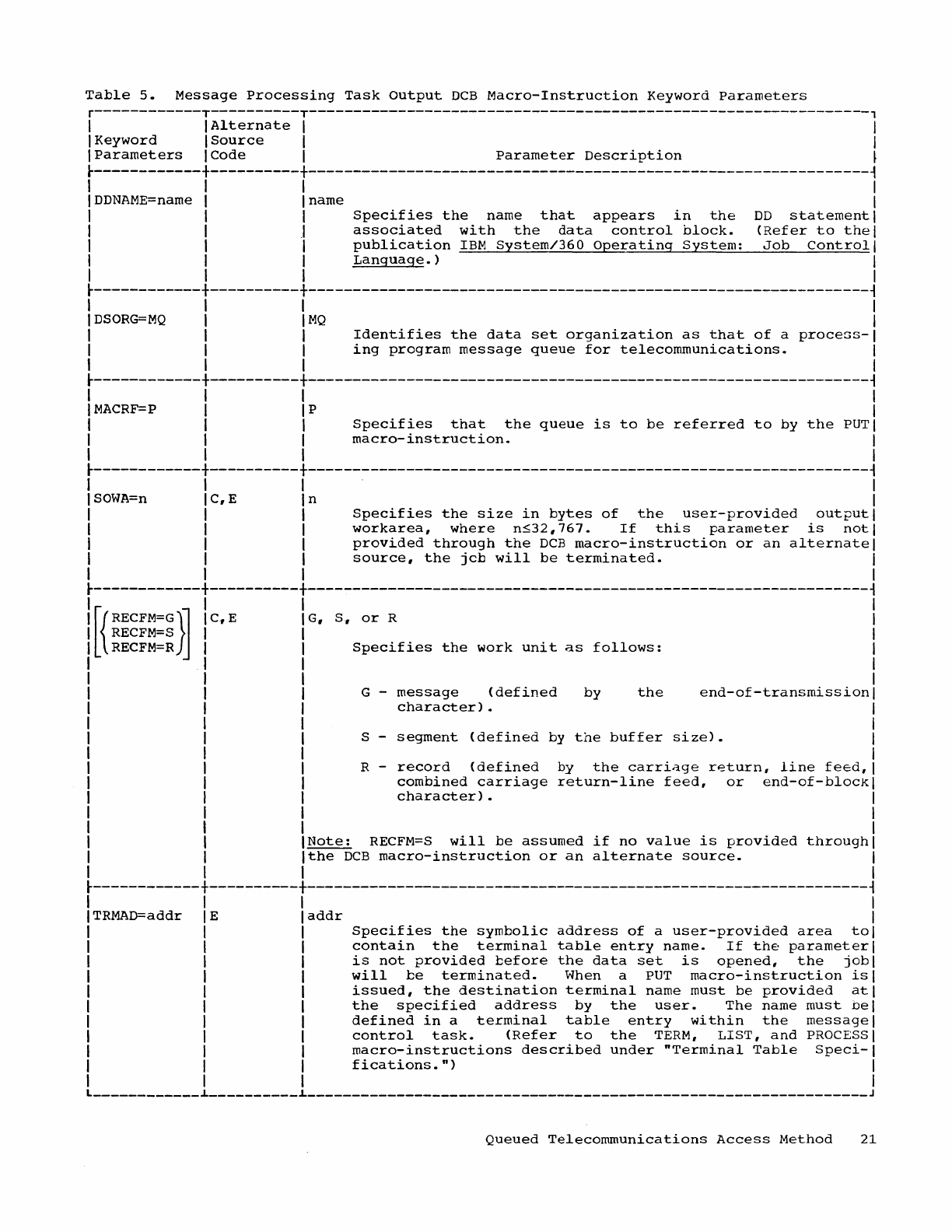
Table
5.
Message
processing
Task
output
DCB
Macro-Instruction
Keyword
Parameters
r------------T----------T---------------------------------------------------------------,
I I
Alternate
I I
I
Keyword
I
Source
I I
I
Parameters
I
Code
I
Parameter
Description
~
~------------+----------+---------------------------------------------------------------~
I I I I
IDDNAME=name
I I name I
I I I
Specifies
the
name
that
appears
in
the
DD
statement
I
I I J
associated
with
the
data
control
block.
(Refer
to
thel
I I I
publication
IBM
System/360
Operating
System:
Job
Control
I
I I I
Language.)
I
I I I I
~------------+----------+---------------------------------------------------------------~
I I I I
I
DSORG=MQ
I I
MQ
I
I I I
Identifies
the
data
set
organization
as
that
of
a
process-I
I I I
ing
program
message
queue
for
telecommunications.
I
I I I I
~------------+----------+---------------------------------------------------------------~
I I I I
I
MACRF=P
I I P I
I I I
Specifies
that
the
queue
is
to
be
referred
to
by
the
PUTI
I I I
macro-instruction.
I
I I I I
~------------+----------+---------------------------------------------------------------~
I I I I
I
SOWA=n
I C, E I n I
I I I
Specifies
the
size
in
bytes
of
the
user-provided
output
I
I I I
workarea,
where
n~32,767.
If
this
parameter
is
not
I
I I I
provided
through
the
DCB
macro-instruction
or
an
alternate
I
I I I
source,
the
j
cb
will
be
terminated.
I
I I I I
~------------+----------+---------------------------------------------------------------~
[{
RECFM=G}~
RECFM=S
RECFM=R
c.,
E G,
S,
or
R
Specifies
the
work
unit
as
follows:
G -
message
(defined
character)
•
by
the
end-of-transmission
S -
segment
(defined
by
the
buffer
size).
R -
record
(defined
by
the
carri~ge
r~turn,
line
feed,
combined
carriage
return-line
feed,
or
end-of-bloCk
character)
•
Note:
RECFM=S
will
be
assumed
if
no
value
is
provided
through
Ithe
DCB
macro-instruction
or
an
alternate
source.
I
~------------+----------+---------------------------------------------------------------~
I I
TRMAD=addr E
addr
I
Specifies
the
symbolic
address
of
a
user-provided
area
tol
contain
the
terminal
table
entry
name.
If
the
parameter
I
is
not
provided
before
the
data
set
is
opened,
the
jobl
will
be
terminated.
When a
PUT
macro-instruction
isl
issued,
the
destination
terminal
name
must
be
provided
atl
the
specified
address
by
the
user.
The
name
must
bel
defined
in
a
terminal
table
entry
within
the
message
I
control
task.
(Refer
to
the
TERM,
LIST,
and
PROCESS
I
macro-instructions
described
under
"Terminal
Table
Speci-I
fications.")
I
I
____________
~
__________
L
______________________________
_________________________________
J
Queued
Telecommunications
Access
Method
21
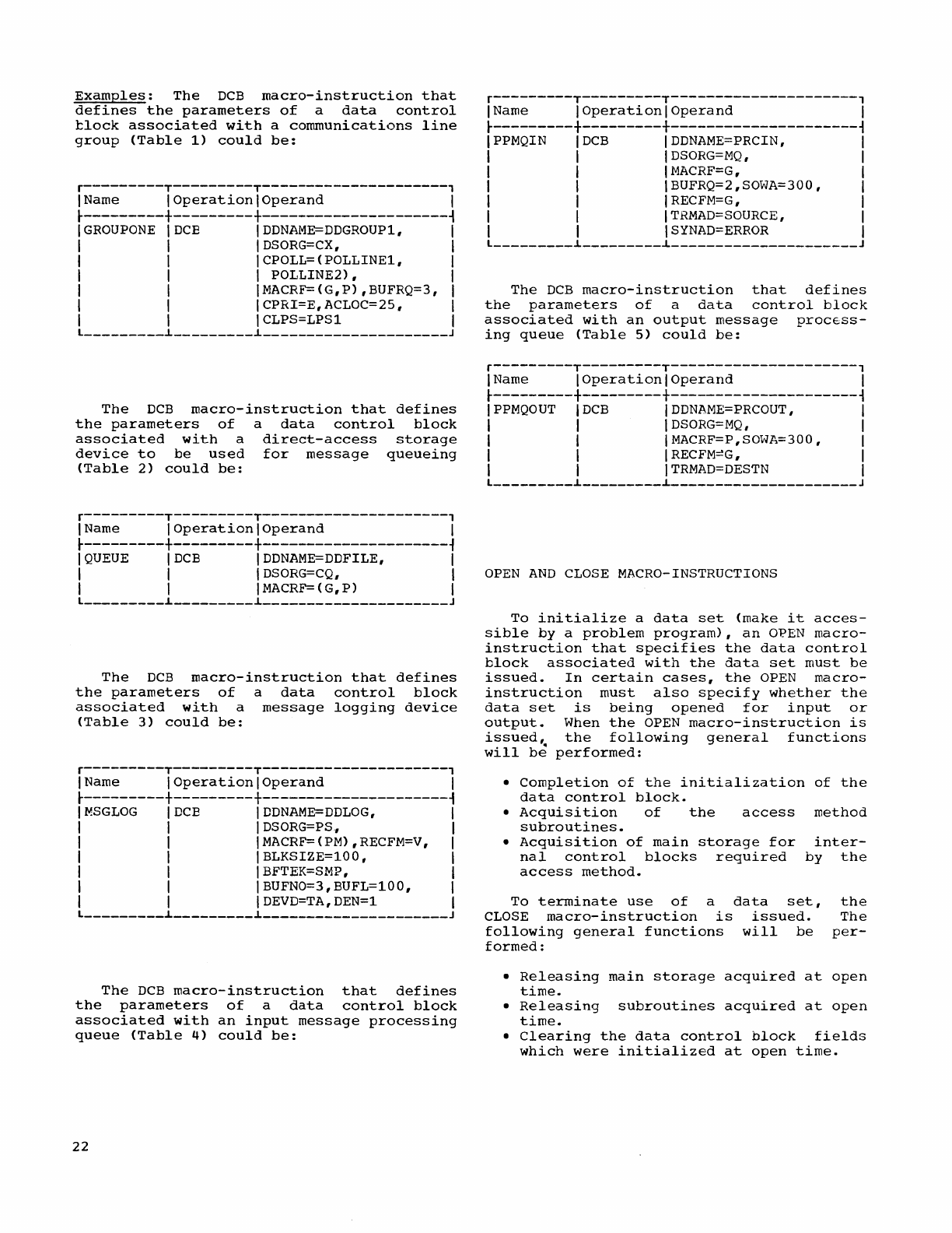
Examples:
The
DCB
macro-instruction
that
defines
the
parameters
of
a
data
control
tlock
associated
with
a
communications
line
group
(Table
1)
could
be:
r---------T---------T---------------------,
I Name I
Operation
I
Operand
I
~---------+---------+---------------------~
IGROUPONE
IDCE
IDDNAME=DDGROUP1,
I
I I I
DSORG=CX,
I
I I I
CPOLL=
(POLLINE1, I
I I I POLLINE2), I
I I IMACRF=(G,P),BUFRQ=3, I
I I ICPRI=E,ACLOC=25, I
I I ICLPS=LPS1 I
L
_________
i
_________
i
_____________________
J
The
DCB
macro-instruction
that
defines
the
parameters
of
a
data
control
block
associated
with
a
direct-access
storage
device
to
be
used
for
message
queueing
(Table
2)
could
be:
r---------T---------T---------------------,
I Name I
Operation
I
Operand
I
~---------+---------+---------------------~
I
QUEUE
IDCB
IDDNAME=DDFILE,
I
I I I
DSORG=CQ,
I
I I I
MACRF=
(
G,
P)
I
L
_________
~
_________
i
_____________________
J
The
DCB
macro-instruction
that
defines
the
parameters
of
a
data
control
block
associated
with
a
message
logging
device
(Table
3)
could
be:
r---------T---------T---------------------,
I Name I
Operation
I
Operand
I
~---------+---------+---------------------~
I
MSGLOG
IDCE
IDDNAME=DDLOG,
I
I I I
DSORG=PS,
I
I I IMACRF=(PM),RECFM=V, I
I I IBLKSIZE=100, I
I I IBFTEK=SMP, I
I I I BUFNO=3,BUFL=100, I
I I IDEVD=TA,DEN=l I
L
_________
~
_________
i
_____________________
J
The
DCB
macro-instruction
that
defines
the
parameters
of
a
data
control
block
associated
with
an
input
message
processing
queue
(Table
4)
could
be:
22
r---------T---------T---------------------,
I Name I
Operation
I
Operand
I
~---------+---------+---------------------~
IPPMQIN
IDCB
IDDNAME=PRCIN,
I
I I I
DSORG=MQ,
I
I I
INACRF=G,
I
I I I BUFRQ=2,SOWA=300, I
I I I
RECFM=G,
I
I I I
T
RMAD=SOURCE,
I
I I I
SYNAD=ERROR
I
L
_________
~
_________
i
_____________________
J
The
DCB
macro-instruction
that
defines
the
parameters
of
a
data
control
block
associated
with
an
output
message
procEss-
ing
queue
(Table
5)
could
be:
r---------T---------T---------------------,
I Name I
Operation
I
Operand
I
~---------+---------+---------------------~
IPPMQOUT
IDCB
IDDNAME=PRCOUT,
I
I I I
DSORG=MQ,
I
I I IMACRF=P,SOWA=300, I
I I
IRECFM~G,
I
I I
ITRMAD=DESTN
I
L
_________
i
_________
i
_____________________
J
OPEN
AND
CLOSE
MACRO-INSTRUCTIONS
To
initialize
a
data
set
(make
it
acces-
sible
by
a
problem
program),
an
OPEN
macro-
instruction
that
specifies
the
data
control
block
associated
with
the
data
set
must
be
issued.
In
certain
cases,
the
OPEN
macro-
instruction
must
also
specify
whether
the
data
set
is
being
opened
for
input
or
output.
When
the
OPEN
macro-instruction
is
issued,
the
following
general
functions
will
be
performed:
•
Completion
of
the
initialization
of
the
data
control
block.
•
Acquisition
of
the
access
method
subroutines.
•
Acquisition
of
main
storage
for
inter-
nal
control
blocks
required
by
the
access
method.
To
terminate
use
of
a
data
set,
CLOSE
macro-instruction
is
issued.
following
general
functions
will
be
formed:
the
The
per-
•
Releasing
main
storage
acquired
at
open
time.
•
Releasing
subroutines
acquired
at
open
time.
•
Clearing
the
data
control
block
fields
which
were
initialized
at
open
time.
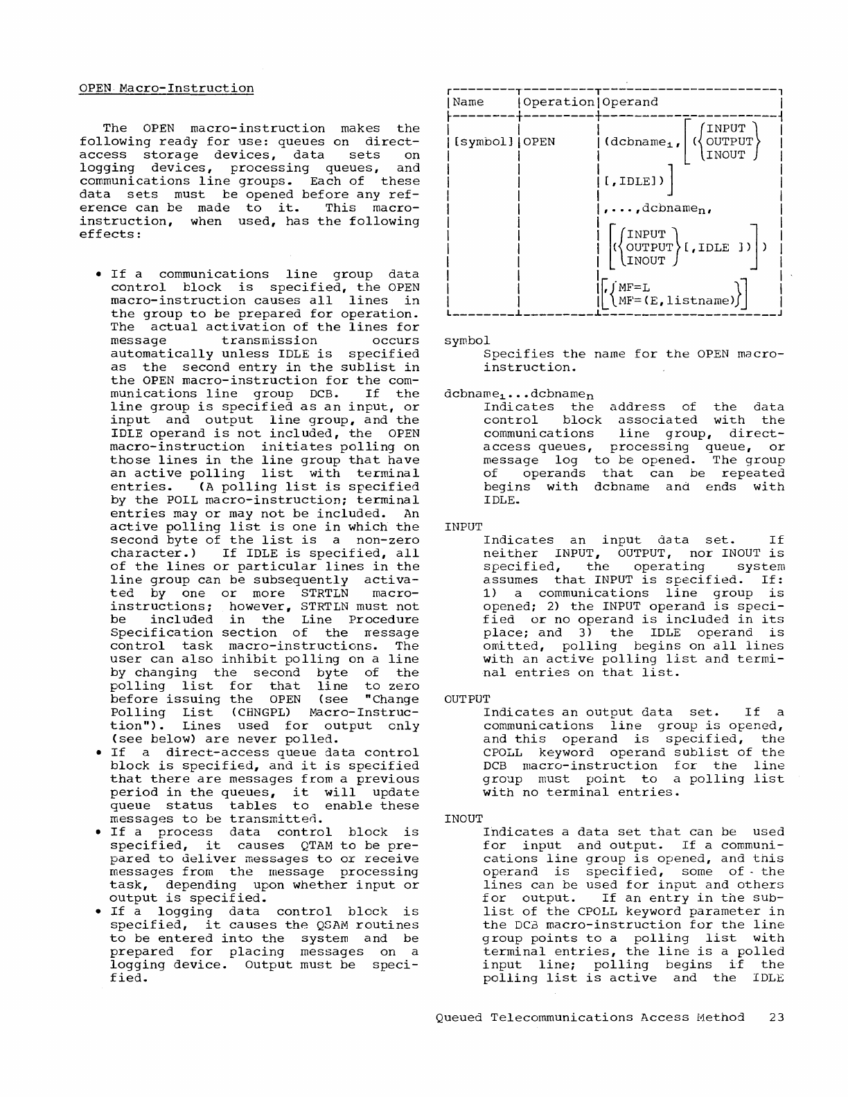
OPEN
Macro-Instruction
The
OPEN
macro-instruction
makes
the
following
ready
for
use:
queues
on
direct-
access
storage
devices,
data
sets
on
logging
devices,
processing
queues,
and
communications
line
groups.
Each
of
these
data
sets
must
be
opened
before
any
ref-
erence
can
be
made
to
it.
This
macro-
instruction,
when
used,
has
the
following
effects:
•
If
a
communications
line
group
data
control
block
is
specified,
the
OPEN
macro-instruction
causes
all
lines
in
the
group
to
be
prepared
for
operation.
The
actual
activation
of
the
lines
for
message
transmission
occurs
automatically
unless
IDLE
is
specified
as
the
second
entry
in
the
sublist
in
the
OPEN
macro-instruction
for
the
com-
munications
line
group
DCB.
If
the
line
group
is
specified
as
an
input,
or
input
and
output
line
group,
and
the
IDLE
operand
is
not
included,
the
OPEN
macro-instruction
initiates
polling
on
those
lines
in
the
line
group
that
have
an
active
polling
list
with
terminal
entries.
(A
polling
list
is
specified
by
the
POLL
macro-instruction;
terminal
entries
mayor
may
not
be
included.
An
active
polling
list
is
one
in
which
the
second
byte
of
the
list
is
a
non-zero
character.)
If
IDLE
is
specified,
all
of
the
lines
or
particular
lines
in
the
line
group
can
be
subsequently
activa-
ted
by
one
or
more
STRTLN
macro-
instructions;
however,
STRTLN
must
not
be
included
in
the
Line
Procedure
Specification
section
of
the
rressage
control
task
macro-instructions.
The
user
can
also
inhibit
polling
on
a
line
by
changing
the
second
byte
of
the
polling
list
for
that
line
to
zero
before
issuing
the
OPEN
(see
"Change
Polling
List
<CHNGPL)
Macro-Instruc-
tion").
Lines
used
for
output
only
(see
below)
are
never
polled.
•
If
a
direct-access
queue
data
control
block
is
specified,
and
it
is
specified
that
there
are
messages
from
a
previous
period
in
the
queues,
it
will
update
queue
status
tables
to
enable
these
messages
to
be
transmitten.
•
If
a
process
data
control
block
is
specified,
it
causes
QTAM
to
be
pre-
pared
to
deliver
messdges
to
or
receive
messages
from
the
message
processing
task,
depending
upon
whether
input
or
output
is
specified.
•
If
a
logging
data
control
block
is
specified,
it
causes
the
QSAM
routines
to
be
entered
into
the
system
and
be
prepared
for
placing
messages
on
a
logging
device.
output
must
be
speci-
fied.
r--------T---------T----------------------,
IName I
Operation
I
Operand
I
~~::::::~+::::-----+~::::::::~-[~{-~~~~~:}---~
INOUT
[,
IDLE])
]
,
...
,dcbname
n,
[{
INPUT}
(
OUTPUT
[,
IDLE
INOUT
.
f,{'MF=L
}]
L
ME'=
(E,
listnarne)
________
L
_________
L
______________________
J
symbol
Specifies
the
name
for
the
OPEN
macro-
instruction.
dcbname~
...
dcbnarnen
INPUT
Indicates
the
address
of
the
data
control
block
associated
with
the
communications
line
group,
direct-
access
queues,
processing
queue,
or
message
log
to
be
opened.
The
group
of
operands
that
can
be
repeated
begins
with
dcbname
and
ends
with
IDLE.
Indicates
an
input
data
set.
If
neither
INPUT,
OUTPUT,
nor
INOUT
is
specified,
the
operating
system
assumes
that
INPUT
is
specified.
If:
1)
a
communications
line
group
is
opened;
2)
the
INPUT
operand
is
speci-
fied
or
no
operand
is
included
in
its
place;
and
3)
the
IDLE
operand
is
omitted,
polling
begins
on
all
lines
with
an
active
polling
list
and
termi-
nal
entries
on
that
list.
OUTPUT
INOUT
Indicates
an
output
data
set.
If
a
communications
line
group
is
opened,
and
this
operand
is
specified,
the
CPOLL
keyword
operand
sublist
of
the
DCB
macro-instruction
for
the
line
group
must
point
to
a
polling
list
with
no
terminal
entries.
Indicates
a
data
set
that
can
be
used
for
input
and
output.
If
a
communi-
cations
line
group
is
opened,
and
this
operand
is
specified,
some
of·
the
lines
can
be
used
for
input
and
others
for
output.
If
an
entry
in
the
sub-
list
of
the
CPOLL
keyword
parameter
in
the
DCb
macro-instruction
for
the
line
group
points
to
a
polling
list
with
terminal
entries,
the
line
is
a
polled
input
line;
polling
begins
if
the
polling
list
is
active
and
the
IDLE
Queued
Telecommunications
Access
Method
23
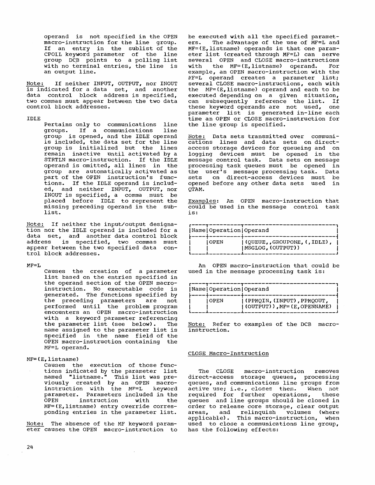
operand
is
not
specified
in
the
OPEN
macro-instruction
for
the
line
group.
If
an
entry
in
the
sublist
of
the
CPOLL
keyword
parameter
of
the
line
group
DC~
points
to
a
polling
list
with
no
terminal
entries,
the
line
is
an
output
line.
Note:
If
neither
INPUT,
OUTPUT,
nor
INOUT
is
indicated
for
a
data
set,
and
another
data
control
block
address
is
specified,
two
commas
must
appear
between
the
two
data
control
block
addresses.
IDLE
Pertains
only
to
communications
line
groups.
If
a
communications
line
group
is
opened,
and
the
IDLE
operand
is
included,
the
data
set
for
the
line
group
is
initialized
but
the
lines
remain
inactive
until
activated
by
a
STRTLN
macro-instruction.
If
the
IDLE
operand
is
omitted,
all
lines
in
the
group
are
automatically
activated
as
part
of
the
OPEN
instruction's
func-
tions.
If
the
IDLE
operand
is
includ-
ed,
and
neither
INPUT,
OUTPUT,
nor
INOUT
is
specified,
a comma
must
be
placed
before
IDLE
to
represent
the
missing
preceding
operand
in
the
sub-
list.
Note:
If
neither
the
input/output
designa-
tion
nor
the
IDLE
operand
is
included
for
a
data
set,
and
another
data
control
block
address
is
specified,
two
commas
must
appear
cetween
the
two
specified
data
con-
trol
block
addresses.
~F=L
Causes
the
creation
of
a
parameter
list
cased
on
the
entries
specified
in
the
operand
section
of
the
OPEN
macro-
instruction.
No
executable
code
is
generated.
The
fUnctions
specified
by
the
preceding
parameters
are
not
performed
until
the
problem
program
encounters
an
OPEN
macro-instruction
with
a
keyword
parameter
referencing
the
parameter
list
(see
below).
The
name
assigned
to
the
parameter
list
is
specified
in
the
name
field
of
the
OPEN
macro-instruction
containing
the
MF=L
operand.
MF=(E,listname)
Causes
the
execution
of
those
func-
tions
indicated
by
the
parameter
list
named
"listname."
This
list
was
pre-
viously
created
by
an
OPEN
macro-
instruction
with
the
MF=L
keyword
parameter.
Parameters
included
in
the
OPEN
instruction
with
the
MF=(E,listname)
entry
override
corres-
ponding
entries
in
the
parameter
list.
Note:
The
absence
of
the
MF
keyword
param-
eter
causes
the
OPEN
macro-instruction
to
24
be
executed
with
all
the
specified
paramet-
ers.
The
advantage
of
the
use
of
MF=L
and
MF=(E,listname)
operands
is
that
one
param-
eter
list
(created
through
MF=L)
can
serve
several
OPEN
and
CLOSE
macro-instructions
with
the
MF=(E,listname)
operand.
For
example,
an
OPEN
macro-instruction
with
the
~F=L
operand
creates
a
parameter
list;
several
CLOSE
macro-instructions,
each
with
the
MF=(E,listname)
operand
and
each
to
be
executed
depending
on
a
given
situation,
can
subsequently
reference
the
list.
If
these
keyword
operands
are
not
used,
one
parameter
list
is
generated
in-line
each
time
an
OPEN
or
CLOSE
macro-instruction
for
the
line
group
is
specified.
Note:
Data
sets
transmitted
over
communi-
cations
lines
and
data
sets
on
direct-
access
storage
devices
for
queueing
and
on
logging
devices
must
be
opened
in
the
message
control
task.
Data
sets
on
message
processing
task
queues
must
be
opened
in
the
user's
message
processing
task.
Data
sets
on
direct-access
devices
must
be
opened
before
any
other
data
sets
used
in
QTAM.
Examples:
An
OPEN
macro-instruction
that
could
be
used
in
the
message
control
task
is:
r----T---------T--------------------------,
INameloperationlOperand
I
~----+---------+--------------------------~
I I
OPEN
I (QUEUE"GROUPONE,
(,IDLE),
I
I I I
MSGLOG,
(OUTPUT»
I
L
____
~
_________
~
__________________________
J
An
OPEN
macro-instruction
that
could
be
used
in
the
message
processing
task
is:
r----T---------T--------------------------,
INameloperationloperand
I
~----+---------+--------------------------~
I I
OPEN
I (PPMQIN,(INPUT),PPMQOUT, I
I I I (OUTPUT»,MF=(E,OPENNAME) I
L
____
~
_________
~
__________________________
J
Note:
Refer
to
examples
of
the
DCB
macro-
instruction.
CLOSE
Macro-Instruction
The
CLOSE
macro-instruction
removes
direct-access
storage
queues,
processing
queues,
and
communications
line
groups
from
active
use;
i.e.,
closes
them.
When
not
required
for
further
operations,
these
queues
and
line
groups
should
be
closed
in
order
to
release
core
storage,
clear
output
areas,
and
relinquish
volumes
(where
applicable).
This
macro-instruction,
when
used
to
close
a
communications
line
group,
has
the
following
effects:
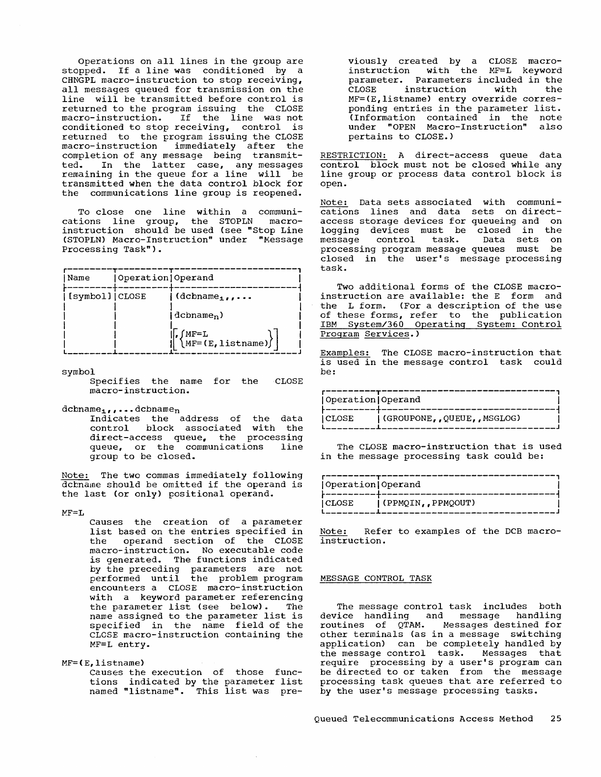
Operations
on
all
lines
in
the
group
are
stopped.
If
a
line
was
conditioned
by a
CHNGPL
macro-instruction
to
stop
receiving,
all
messages
queued
for
transmission
on
the
line
will
be
transmitted
before
control
is
returned
to
the
program
issuing
the
CLOSE
macro-instruction.
If
the
line
was
not
conditioned
to
stop
receiving,
control
is
returned
to
the
program
issuing
the
CLOSE
macro-instruction
immediately
after
the
completion
of
any
message
being
transmit-
ted.
In
the
latter
case,
any
messages
remaining
in
the
queue
for
a
line
will
be
transmitted
when
the
data
control
block
for
the
communications
line
group
is
reopened.
To
close
one
line
within
a
communi-
cations
line
group,
the
STOPLN
macro-
instruction
should
be
used
(see
"Stop
Line
(STOPLN)
Macro-Instruction"
under
"Message
Processing
Task").
r--------T---------T----------------------,
I Name I
Operationl
Operand
I
r--------+---------+----------------------~
I
[symboIJICLOSE
I
(dcbname1"···
I
I I I I
I I I
dcbname
n) I
I I I I
I I 1r.{MF=L
}]
I
I I
IL
MF=(E,listname)
I
L
________
~
_________
~
______________________
J
symbol
Specifies
the
name
for
the
macro-instruction.
CLOSE
dcbname1,,···dcbnamen
Indicates
the
address
of
the
data
control
block
associated
with
the
direct-access
queue,
the
processing
queue,
or
the
communications
line
group
to
be
closed.
Note:
The
two
commas
immediately
following
dcbname
should
be
omitted
if
the
operand
is
the
last
(or
only)
positional
operand.
l-':F=L
Causes
the
creation
of
a
parameter
list
based
on
the
entries
specified
in
the
operand
section
of
the
CLOSE
macro-instruction.
No
executable
code
is
generated.
The
functions
indicated
by
the
preceding
parameters
are
not
performed
until
the
problem
program
encounters
a
CLOSE
macro-instruction
with
a
keyword
parameter
referencing
the
parameter
list
(see
below).
The
name
assigned
to
the
parameter
list
is
specified
in
the
name
field
of
the
CLOSE
macro-instruction
containing
the
MF=L
entry.
MF=(E,listname)
Causes
the
execution
of
those
func-
tions
indicated
by
the
parameter
list
named
"listname".
This
list
was
pre-
viously
created
by
a
CLOSE
macro-
instruction
with
the
MF=L
keyword
parameter.
Parameters
included
in
the
CLOSE
instruction
with
the
MF=(E,listname)
entry
override
corres-
ponding
entries
in
the
parameter
list.
(Information
contained
in
the
note
under
"OPEN
Macro-Instruction"
also
pertains
to
CLOSE.)
RESTRICTION: A
direct-access
queue
data
control
block
must
not
be
closed
while
any
line
group
or
process
data
control
block
is
open.
Note:
Data
sets
associated
with
communi-
cations
lines
and
data
sets
on
direct-
access
storage
devices
for
queueing
and
on
logging
devices
must
be
closed
in
the
message
control
task.
Data
sets
on
processing
program
message
queues
must
be
closed
in
the
user's
message
processing
task.
Two
additional
forms
of
the
CLOSE
macro-
instruction
are
available:
the
E
form
and
the
L
form.
(For
a
description
of
the
use
of
these
forms,
refer
to
the
publication
IBM
System/360
Operating
System:
Control
Program
Services.)
Examples:
The
CLOSE
macro-instruction
that
is
used
in
the
message
control
task
could
be:
r---------T-------------------------------,
I
Operation
I
Operand
I
r---------+-------------------------------~
I
CLOSE
I
(GROUPONE,
,
QUEUE,
,
MSGLOG)
I
L
_________
~
_______________________________
J
The
CLOSE
macro-instruction
that
is
used
in
the
message
processing
task
could
be:
r---------T-------------------------------,
I
Operation
I
Operand
I
r---------+-------------------------------~
I
CLOSE
I (PPMQIN"PPMQOUT) I
L
_________
~
_______________________________
J
Note:
Refer
to
examples
of
the
DCB
macro-
instruction.
MESSAGE
CONTROL
TASK
The
message
control
task
includes
both
device
handling
and
message
handling
routines
of
QTAM.
Messages
destined
for
other
terminals
(as
in
a
message
switching
application)
can
be
completely
handled
by
the
message
control
task.
Messages
that
require
processing
by
a
user's
program
can
be
directed
to
or
taken
from
the
message
processing
task
queues
that
are
referred
to
by
the
user's
message
processing
tasks.
Queued
Telecommunications
Access
Method
25
f.Jessages
arriving
from
terminals
are
coded
according
to
the
transmission
code
of
the
particular
terrrinal.
The
message
con-
trol
task
includes
facilities
that
convert
these
transmission
codes
to
the
extended
tinary-coded
decimal
interchange
code
(EBCDIC)
which
results
in
simplification
of
message
analysis.
In
addition,
the
message
control
task
can
perform
the
following
functions:
•
Terminal
polling.
•
Time
and
date
stamping
of
incoming
messages.
•
Sequence
checking
of
incoming
messages
•
Logging
of
message
traffic
on
a
secon-
dary
storage
device
(disk,
tape,
or
drum)
•
•
Checking
validity
of
source
terminal
code.
•
Routing
of
incoming
messages
to
their
destination
(processing
queue
or
terminal).
Messages
received
from
terminals
can
be
routed
to
one
or
more
destinations.
The
routines
check
the
validity
of
the
destina-
tion
codes
and
place
messages
in
queues
according
to
their
destinations.
A
priori-
ty
scheme
may
be
included
so
that
process-
ing
of
certain
messages
can
be
expedited.
Messages
being
sent
to
a
terminal
must
be
converted
to
the
appropriate
transmis-
sion
line
code.
The
following
functions
are
also
provided
for
processing
outgoing
messages:
•
Terminal
addressing.
•
Time
and
date
stamping.
•
Sequence
numbering.
•
Logging
on
secondary
storage
devices
such
as
disks,
tapes,
or
drums.
To
define
the
message
control
task,
a
user
must
specify
appropriate
system-
supplied
macro-instructions.
The
message
control
task
must
operate
as
a
high-
priority
task.
A
message
control
task
for
Tele-processing
operations
need
remain
in
main
storage
only
as
long
as
message
processing
is
going
on.
There
are
two
major
categories
of
macro-
instructions
that
may
be
selected
for
inclusion
in
the
message
control
task:
control
information
and
line
procedure
specifications.
Control
information
macro-
instructions
create
tables,
lists,
and
buffer
areas
needed
in
the
system;
line
procedure
specification
macro-instructions
provide
for
such
functions
as
message
head-
er
analysis,
routing,
and
error
handling.
26
CONTROL
INFORMATION
To
use
the
optional
functions
of
QTAM,
a
user
must
provide
certain
control
informa-
tion.
This
data
includes
the
following:
• A
terminal
table
that
contains
all
of
the
valid
terminal
codes
as
well
as
complete
information
about
the
termi-
nals
connected
to
the
system.
• A
polling
list
that
provides
the
sequence
in
which
terminals
on
a
line
ar,
to
be
polled.
•
~uffer
specifications
that
provide
the
definition
of
message
segment
sizes,
the
type
of
buffering,
and
the
maximum
number
of
segments
needed
by
QTAM.
Terminal
Table
Specifications
The
terminal
table
consists
of
the
fol-
lowing
parts:
• A
control
field
that
defines
the
length
of
the
terminal
table.
•
Optional
fields
that
contain
informa-
tion
defined
by
the
programmer.
•
Terminal
descriptions
that
contain
the
terminal,
the
message
processing
queue,
and
the
distribution
list
codes,
as
well
as
other
pertinent
control
infor-
mation.
(All
terminal
table
entry
names
must
have
the
same
number
of
characters.
)
The
macro-instructions
presented
below
may
be
used
to
create
the
terminal
table.
Terminal
Table
(TERMTBL)
Macro-Instruction
The
TERMTBL
macro-instruction
causes
a
control
field
to
be
created
for
the
termi-
nal
table.
It
provides
a
definition
of
the
length
of
the
table.
Only
one
such
instruction
is
necessary
for
the
table.
r---------T---------T---------------------,
I
Name
I
Operation
I
Operand
I
t---------+---------+---------------------~
I
ITERMTBL
I
entry
I
L
_________
~
_________
~
_____________________
J
entry
Specifies
the
terminal
name
of
the
last
entry
in
the
terminal
table.
RESTRICTION:
The
TERMTBL
macro-instruction
must
be
the
first
of
those
specified
to
create
the
terminal
table.
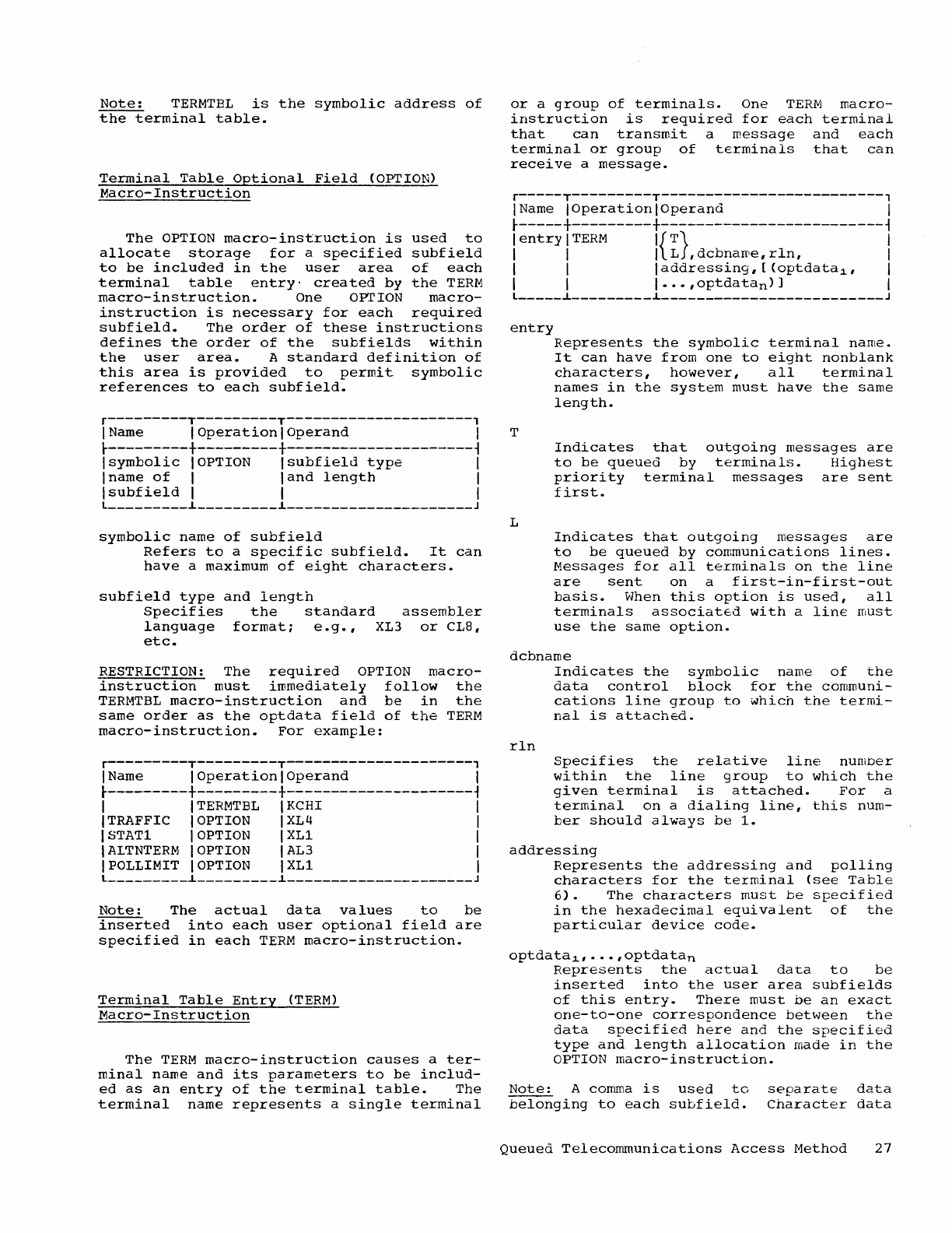
Note:
TERMTBL
is
the
symbolic
address
of
the
terminal
table.
Terminal
Table
Optional
Field
(OPTION)
Macro-Instruction
The
OPTION
macro-instruction
is
used
to
allocate
storage
for
a
specified
subfield
to
be
included
in
the
user
area
of
each
terminal
table
entry'
created
by
the
TERM
macro-instruction.
One OPTION
macro-
instruction
is
necessary
for
each
required
subfield.
The
order
of
these
instructions
defines
the
order
of
the
subfields
within
the
user
area.
A
standard
definition
of
this
area
is
provided
to
permit
symbolic
references
to
each
subfield.
r---------T---------T---------------------,
I Name I
Operation
I
Operand
I
t---------+---------+---------------------~
Isymbolic
IOPTION
Isubfield
type
I
Iname
of
I
land
length
I
Isubfield
I I I
l
_________
~
_________
~
_____________________
J
symbolic
name
of
subfield
Refers
to
a
specific
subfield.
It
can
have
a maximum
of
eight
characters.
subfield
type
and
length
Specifies
the
standard
assembler
language
format;
e.g.,
XL3
or
CL8,
etc.
RESTRICTION:
The
required
OPTION
macro-
instruction
must
immediately
follow
the
TERMTBL
macro-instruction
and
be
in
the
same
order
as
the
optdata
field
of
the
TERM
macro-instruction.
For
example:
r---------T---------T---------------------,
I Name I
Operation
I
Operand
I
t---------+---------+---------------------~
I
ITERMTBL
IKCBI I
I TRAFFIC I OPTION IXL4 I
ISTAT1 I OPTION IXL1 I
IALTNTERM
IOPTION IAL3 I
IPOLLIMIT IOPTION IXL1 I
l
_________
~
_________
~
_____________________
J
Note:
The
actual
data
values
to
be
inserted
into
each
user
optional
field
are
specified
in
each
TERM
macro-instruction.
Terminal
Table
Entry
(TERM)
Macro-Instruction
The
TERM
macro-instruction
causes
a
ter-
minal
name
and
its
parameters
to
be
includ-
ed
as
an
entry
of
the
terminal
table.
The
terminal
name
represents
a
single
terminal
or
a
group
of
terminals.
One
TERM
macro-
instruction
is
required
for
each
terminal
that
can
transmit
a
message
and
each
terminal
or
group
of
terminals
that
can
receive
a
message.
r-----T---------T-------------------------,
IName
IOperationlOperand
I
t-----+---------+-------------------------~
I
entry
I
TERM
I{
T}
I
I I I L
,dcbnaroe,rln,
I
I I I
addressing,
[
(optdata~,
I
I I
I···,optdatan)]
I
l
_____
~
_________
~
_________________________
J
entry
T
L
Represents
the
symbolic
terminal
name.
It
can
have
from
one
to
eight
nonblank
characters,
however,
all
terminal
names
in
the
system
must
have
the
same
length.
Indicates
that
outgoing
messages
are
to
be
queued
by
terminals.
Hig-hest
priority
terminal
messages
are
sent
first.
Indicates
that
outgoing
messages
are
to
be
queued
by
communications
lines.
Messages
fOI
all
terminals
on
the
line
are
sent
on
a
first-in-first-out
basis.
When
this
option
is
used,
all
terminals
associated
with
a
line
must
use
the
same
option.
dcbname
rln
Indicates
the
symbolic
name
of
the
data
control
block
for
the
communi-
cations
line
group
to
which
the
termi-
nal
is
attached.
Specifies
the
relative
line
number
within
the
line
group
to
which
the
given
terminal
is
attached.
For
a
terminal
on
a
dialing
line,
this
num-
ber
should
always
be
1.
addressing
Represents
the
addressing
and
polling
characters
for
the
teIminal
(see
Table
6).
The
characters
must
be
specified
in
the
hexadecimal
equivalent
of
the
particular
device
code.
optdata~,
...
,optdatan
Represents
the
actual
data
to
be
inserted
into
the
user
area
subfields
of
this
entry.
There
must
be
an
exact
one-to-one
correspondence
between
the
data
specified
here
and
the
specified
type
and
length
allocation
made
in
the
OPTION
macro-instruction.
Note:
A comma
is
used
to
belonging
to
each
subfield.
separate
data
Character
data
Queued
Telecommunications
Access
Method
27
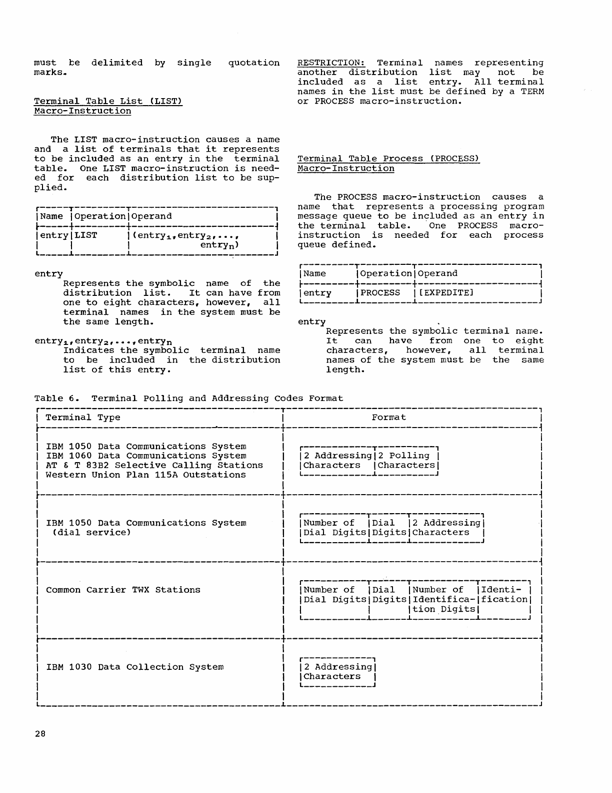
must
be
delimited
by
single
marks
..
quotation
Terminal
Table
List
(LIST)
Macro-Instruction
The
LIST
macro-instruction
causes
a name
and
a
list
of
terminals
that
it
represents
to
be
included
as
an
entry
in
the
terminal
table.
One
LIST
macro-instruction
is
need-
ed
for
each
distribution
list
to
be
sup-
plied.
r-----y---------T-------------------------,
IName
IOperationlOperand
1
~-----+---------+-------------------------~
lentry\LIST
I
(entrY1.
entr
Y2,··.,
1
1 1 1
entrYn)
1
L
_____
~
_________
~
_________________________
J
entry
Represents
the
symbolic
name
of
the
distribution
list.
It
can
have
from
one
to
eight
characters,
however,
all
terminal
names
in
the
system
must
be
the
same
length.
entry
1,
entry
2'
•••
"
entryn
Indicates
the
symbolic
terminal
name
to
be
included
in
the
distribution
list
of
this
entry.
RESTRICTION:
Terminal
names
representing
another
distribution
list
may
not
be
included
as
a
list
entry.
All
terminal
names
in
the
list
must
be
defined
by
a
TERM
or
PROCESS
macro-instruction.
Terminal
Table
Process
(PROCESS)
Macro-Instruction
The
PROCESS
macro-instruction
causes
a
name
that
represents
a
processing
program
message
queue
to
be
in~luded
as
an
entry
in
the
terminal
table.
One
PROCESS
macro-
instruction
is
needed
for
each
process
queue
defined.
r---------T---------T---------------------,
1
Name
IOperationlOperand
1
t---------+---------+---------------------~
1
entry
1
PROCESS
1 [EXPEDITE] 1
L
_________
~
_________
i
_____________________
J
entry
Represents
the
symbolic
terminal
name.
It
can
have
from
one
to
eight
characters,
however,
all
terminal
names
of
the
system
must
be
the
same
length.
Table
6.
Terminal
Polling
and
Addressing
Codes
Format
r------------------------------------------T--------------------------------------------,
1
Terminal
Type
1
Format
1
~------------------------------------------+--------------------------------------------~
1 1 1
1
IBM
1050
Data
Communications
System
1 r------------T----------, 1
1
IBM
1060
Data
Communications
system
1
12
Addressing
1 2
Polling
1 1
1
AT
& T 83B2
Selective
Calling
Stations
1 1
Characters
1
Characters
1 1
I
western
Union
Plan
115A
Outstations
I L
____________
i
__________
J 1
I I I
~------------------------------------------+--------------------------------------------~
I I 1
I 1 r-----------T------T------------, 1
I
IBM
1050
Data
Communications
System
1 INumber
of
IDial
12
Addressing
I 1
I
(dial
service)
I
IDial
Digits
1
Digits
\
Characters
1 1
1 I L
___________
~
______
~
____________
J 1
1 1 1
~------------------------------------------+--------------------------------------------~
1 1 1
I 1 r-----------T--"----T-----------T--------, 1
I
Common
Carrier
TWX
Stations
I
INumber
of
IDial
INumber
of
IIdenti-
1 I
I I
IDial
Digits
I
Digits
1
Identifica-Ificationl
I
I I I I
ItionDigitsl
I I
I 1 L
___________
i
______
i
___________
i
________
J 1
I I I
~------------------------------------------+--------------------------------------------~
I I I
I I r------------, I
I
IBM
1030
Data
Collection
System
1
12
Addressing
I 1
1 1 \
Characters
1 1
I 1 L
____________
J 1
I 1 I
L
__________________________________________
~
____________________________________________
J
28
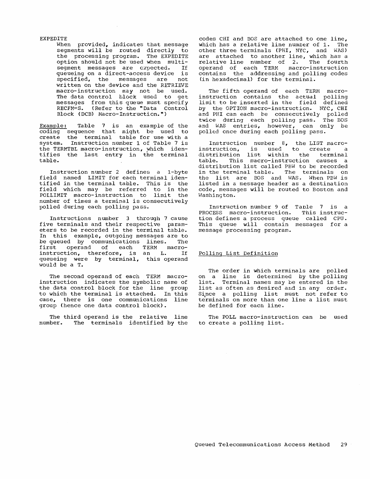
EXPEDITE
When
provided.
indicates
that
message
segments
will
be
routed
directly
to
the
processing
program.
The
EXPEDITE
option
should
not
be
used
when
mUlti-
segment
messages
are
cxpected.
If
queueing
on
a
direct-access
device
is
specified,
the
messages
are
not
written
on
the
device
and
the
RETRIEVE
macro-instruction
may
not
be
used.
The
data
control
block
used
to
get
messages
from
this
queue
must
specify
RECFM=S.
(Refer
to
the
"Data
Control
Block
(DCB)
Macro-Instruction.")
Example:
Table
7
is
an
example
of
the
coding
sequence
that
might
be
used
to
create
the
terminal
table
for
use
with
a
system.
Instruction
number
1
of
Table
7
is
the
TERMTBL
macro-instruction,
which
iden-
tifies
the
last
entry
in
the
terminal
table.
Instruction
number
2
defines
a
i-byte
field
named
LIMIT
for
each
terminal
iden-
tified
in
the
terminal
table.
This
is
the
field
which
may
be
referred
to
in
the
POILIMIT
macro-instruction
to
limit
the
number
of
times
a
terminal
is
consecutively
polled
during
each
polling
pass.
Instructions
number
3
through
7
cause
five
terminals
and
their
respective
param-
eters
to
be
recorded
in
the
terminal
table.
In
this
example,
outgoing
messages
are
to
be
queued
by
communications
lines.
The
first
operand
of
each
TERM
macro-
instruction,
therefore,
is
an
L.
If
queueing
were
by
terminal,
this
operand
would
be
a T.
The
second
operand
of
each
TERM
macro-
instruction
indicates
the
symbolic
name
of
the
data
control
block
for
the
line
group
to
which
the
terminal
is
attached.
In
this
case,
there
is
one
communications
line
group
(hence
one
data
control
block).
The
third
operand
is
the
relative
line
number.
The
terminals
identified
by
the
codes
CHI
and
BaS
are
attached
to
one
line,
which
has
a
relative
line
number
of
1.
The
other
three
terminals
(PHI,
NYC,
and
WAS)
are
attached
to
another
line,
which
has
a
relative
line
number
of
2.
The
fourth
operand
of
each
TERM
macro-instruction
contains
the
addressing
and
polling
codes
(in
hexadecimal)
for
the
terminal.
The
fifth
operand
of
each
TERM
macro-
instruction
contains
the
actudl
polling
limit
to
be
inserted
in
the
field
defined
by
the
OPTION
macro-instruction.
NYC,
CHI
and
PHI
can
each
be
consecutively
polled
twice
during
each
polling
pass.
The
BOS
and
WAS
entries,
however,
can
only
be
polled
once
during
each
polling
pass.
Instruction
number
8,
the
LIST
macro-
instruction,
is
used
to
create
a
distribution
list
within
the
terminal
table.
This
macro-instruction
causes
a
distribution
list
called
PBW
to
be
recorded
in
the
terminal
table.
The
terminals
on
the
list
are
BOS
and
WAS.
When
PEW
is
listed
in
a
message
header
as
a
destination
code,
messages
will
be
routed
to
Boston
and
Hashington.
Instruction
number
9
of
Table
7
is
a
PROCESS
macro-instruction.
This
instruc-
tion
defines
a
process
queue
called
cpu.
This
queue
will
contain
messages
for
a
message
processing
program.
Polling
List
Definition
The
order
in
which
terminals
are
polled
on
a
line
is
determined
by
the
polling
list.
Terminal
names
may
be
entered
in
the
list
as
often
as
desired
and
in
any
order.
Since
a
polling
list
must
not
refer
to
terminals
on
more
than
one
line
a
list
must
be
defined
for
each
line.
The
POLL
macro-instruction
can
be
used
to
create
a
polling
list.
Queued
Telecommunications
Access
Method
29
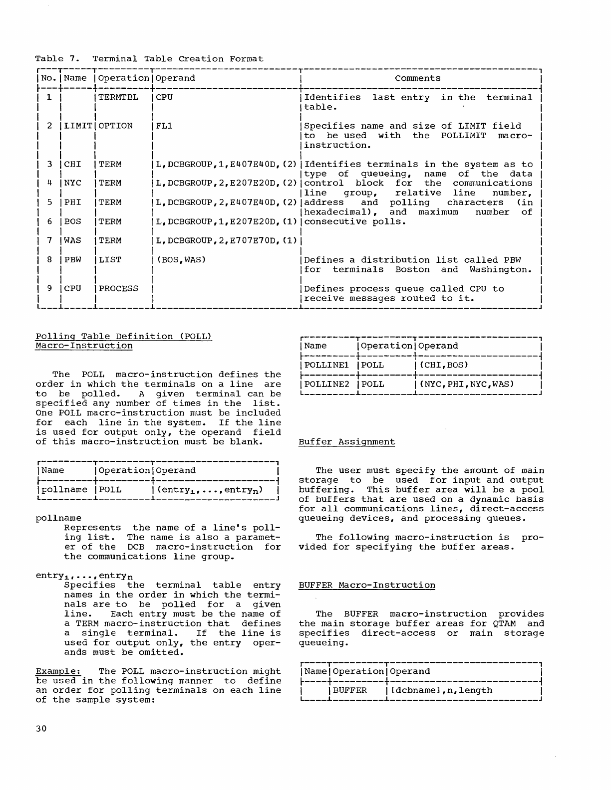
Table
7.
Terminal
Table
Creation
Format
r---T-----T---------T-------------------------T-----------------------------------------,
INo·IName
IOperationlOperand
I
Comments
I
~---+-----+---------+-------------------------+-----------------------------------------~
1
TERMTBL
I
CPU
Identifies
last
entry
in
the
terminal
I
table.
2 LIMIT OPTION
3 CHI
4
NYC
5 PHI
I
I 6
BOS
I
I 7
WAS
I
I 8
PBW
I
I
I 9
CPU
TERM
TERM
TERM
TERM
TERM
LIST
PROCESS
I
IFL1
I
I
I
I L,DCBGROUP,1,E407E40D,
(2)
L,DCBGROUP,2,E207E20D,
(2)
L,DCBGROUP,2,E407E40D,
(2)
L,DCBGROUP,1,E207E20D,
(1)
L,DCBGROUP,2~E707E70D,
(1)
(BOS,WAS)
Specifies
name
and
size
of
LIMIT
field
to
be
used
with
the
POLLIMIT
macro-
instruction.
Identifies
terminals
in
the
system
as
to
type
of
queueing,
name
of
the
data
control
block
for
the
communications
line
group,
relative
line
number,
address
and
polling
characters
(in
hexadecimal),
and
maximum
number
of
consecutive
polls.
Defines
a
distribution
list
called
PBW
for
terminals
Boston
and
Washington.
Defines
process
queue
called
CPU
to
I
receive
messages
routed
to
it.
L
___
~
_____
~
_________
~
_________________________
~
_________________________________________
J
Polling
Table
Definition
(POLL)
Macro-Instruction
The
POLL
macro-instruction
defines
the
order
in
which
the
terminals
on
a
line
are
to
be
polled.
A
given
terminal
can
be
specified
any
number
of
times
in
the
list.
One
POLL
macro-instruction
must
be
included
for
each
line
in
the
system.
If
the
line
is
used
for
output
only,
the
operand
field
of
this
macro-instruction
must
be
blank.
r---------T---------T---------------------,
I Name I
Operation
I
Operand
I
~---------+---------+---------------------~
Ipollnarne
IPOLL I
(entrY1,···,entrYn)
I
L
_________
~
_________
~
_____________________
J
pollname
Represents
the
name
of
a
line's
poll-
ing
list.
The
name
is
also
a
paramet-
er
of
the
DCB
macro-instruction
for
the
communications
line
group.
entrY1,···,entrYn
Specifies
the
terminal
table
entry
names
in
the
order
in
which
the
termi-
nals
are
to
be
polled
for
a
given
line.
Each
entry
must
be
the
name
of
a
TERM
macro-instruction
that
defines
a
single
terminal.
If
the
line
is
used
for
output
only,
the
entry
oper-
ands
must
be
omitted.
Example:
The
POLL
macro-instruction
might
te
used
in
the
following
manner
to
define
an
order
for
polling
terminals
on
each
line
of
the
sample
system:
30
r---------T---------T---------------------,
I Name I
Operation
I
Operand
I
~---------+---------+---------------------~
IPOLLINE1 IPOLL I (CHI,BOS) I
~---------+---------+---------------------~
IPOLLINE2 IPOLL I CNYC,PHI,NYC,WAS) I
L
_________
~
_________
~
_____________________
J
Buffer
Assignment
The
user
must
specify
the
amount
of
main
storage
to
be
used
for
input
and
output
buffering.
This
buffer
area
will
be
a
pool
of
buffers
that
are
used
on
a
dynamic
basis
for
all
communications
lines,
direct-access
queueing
devices,
and
processing
queues.
The
following
macro-instruction
is
pro-
vided
for
specifying
the
buffer
areas.
BUFFER
Macro-Instruction
The
BUFFER
macro-instruction
provides
the
main
storage
buffer
areas
for
QTAM
and
specifies
direct-access
or
main
storage
queueing.
r----T---------T--------------------------,
INamelOperationlOperand
I
~----+---------+--------------------------~
I I
BUFFER
I
[dcbnamel,n,length
I
L
____
~
_________
~
__________________________
J
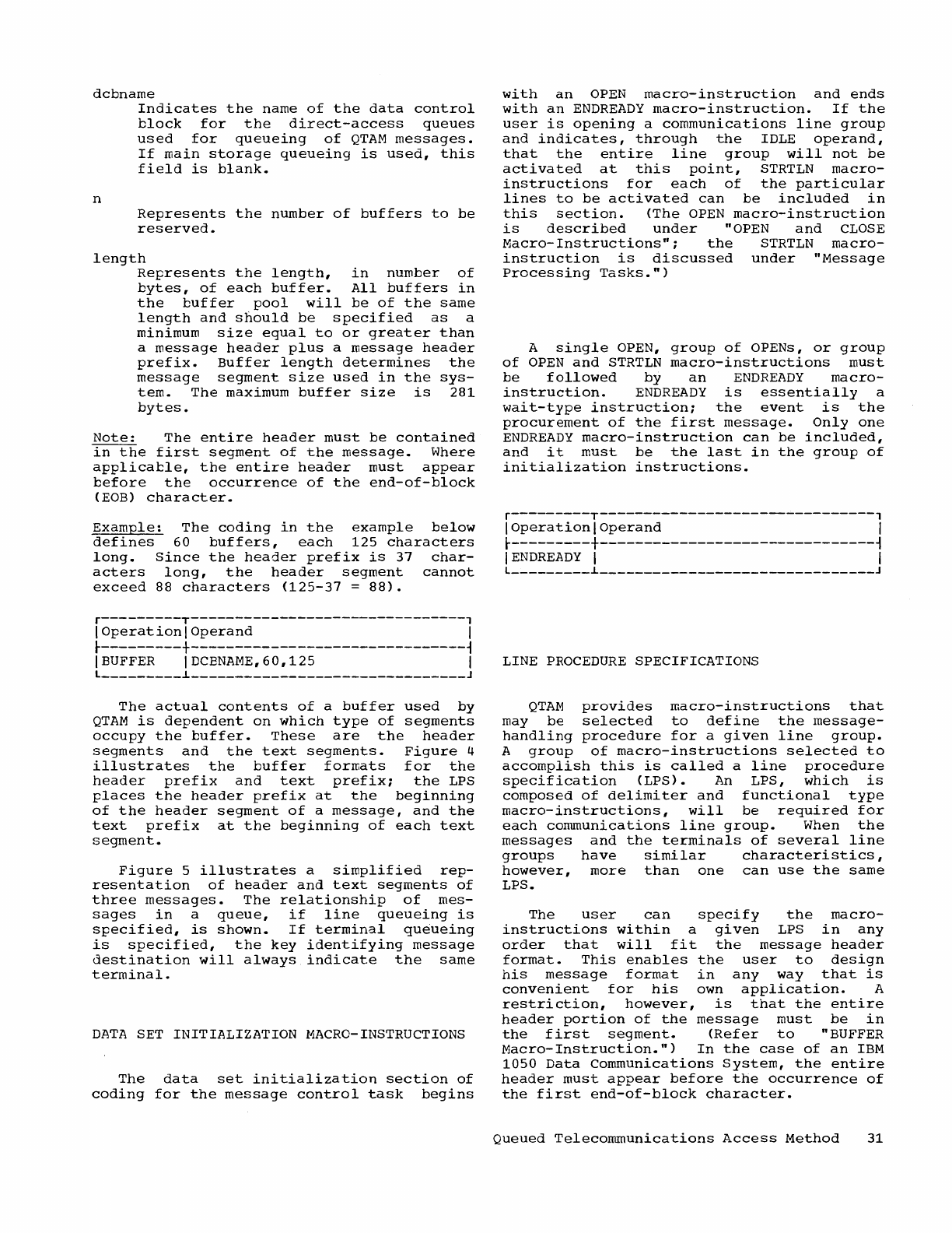
dcbname
n
Indicates
the
name
of
the
data
control
block
for
the
direct-access
queues
used
for
queueing
of
QTAM
messages.
If
main
storage
queueing
is
used,
this
field
is
blank.
Represents
the
number
of
buffers
to
be
reserved.
length
Represents
the
length,
in
number
of
bytes,
of
each
buffer.
All
buffers
in
the
buffer
pool
will
be
of
the
same
length
and
should
be
specified
as
a
minimum
size
equal
to
or
greater
than
a
message
header
plus
a
message
header
prefix.
Buffer
length
determines
the
message
segment
size
used
in
the
sys-
tem.
The
maximum
buffer
size
is
281
bytes.
Note:
The
entire
header
must
be
contained
in
the
first
segment
of
the
message.
Where
applicable,
the
entire
header
must
appear
before
the
occurrence
of
the
end-of-block
(EOB)
character.
Example:
The
coding
in
the
example
below
defines
60
buffers,
each
125
characters
long.
Since
the
header
prefix
is
37
char-
acters
long,
the
header
segment
cannot
exceed
88
characters
(125-37
=
88).
r---------T-------------------------------,
I
Operation
I
Operand
I
t---------+-------------------------------~
I
BUFFER
I DCENAME,60,125 I
L
_________
~
_______________________________
J
The
actual
contents
of
a
buffer
used
by
QTAM
is
dependent
on
which
type
of
segments
occupy
the
buffer.
These
are
the
header
segments
and
the
text
segments.
Figure
4
illustrates
the
buffer
formats
for
the
header
prefix
and
text
prefix;
the
LPS
places
the
header
prefix
at
the
beginning
of
the
header
segment
of
a
message,
and
the
text
prefix
at
the
beginning
of
each
text
segment.
Figure
5
illustrates
a
simplified
rep-
resentation
of
header
and
text
segments
of
three
messages.
The
relationship
of
mes-
sages
in
a
queue,
if
line
queueing
is
specified,
is
shown.
If
terminal
queueing
is
specified,
the
key
identifying
message
destination
will
always
indicate
the
same
terminal.
DATA
SET
INITIALIZATION
MACRO-INSTRUCTIONS
The
data
set
initialization
section
of
coding
for
the
message
control
task
begins
with
an
OPEN
macro-instruction
and
ends
with
an
ENDREADY
macro-instruction.
If
the
user
is
opening
a
communications
line
group
and
indicates,
through
the
IDLE
operand,
that
the
entire
line
group
will
not
be
activated
at
this
point,
STRTLN
macro-
instructions
for
each
of
the
particular
lines
to
be
activated
can
be
included
in
this
section.
(The
OPEN
macro-instruction
is
described
under
"OPEN
and
CLOSE
Macro-Instructions";
the
STRTLN
macro-
instruction
is
discussed
under
"Message
Processing
Tasks.")
A
single
OPEN,
group
of
OPENs,
or
group
of
OPEN
and
STRTLN
macro-instructions
must
be
followed
by
an
ENDREADY
macro-
instruction.
ENDREADY
is
essentially
a
wait-type
instruction;
the
event
is
the
procurement
of
the
first
message.
Only
one
ENDREADY
macro-instruction
can
be
included,
and
it
must
be
the
last
in
the
group
of
initialization
instructions.
r---------T-------------------------------,
I
Operation
I
Operand
I
~---------+-------------------------------~
I
ENDREADY
I I
L
_________
L
_______________________________
J
LINE
PROCEDURE
SPECIFICATIONS
QTAM
provides
macro-instructions
that
may
be
selected
to
define
the
message-
handling
procedure
for
a
given
line
group.
A
group
of
macro-instructions
selected
to
accomplish
this
is
called
a
line
procedure
specification
(LPS).
An
LPS,
which
is
composed
of
delimiter
and
functional
type
macro-instructions,
will
be
required
for
each
communications
line
group.
When
the
messages
and
the
terminals
of
several
line
groups
have
similar
characteristics,
however,
more
than
one
can
use
the
same
LPS.
The
user
can
specify
the
macro-
instructions
within
a
given
LPS
in
any
order
that
will
fit
the
message
header
format.
This
enables
the
user
to
design
his
message
format
in
any
way
that
is
convenient
for
his
own
application.
A
restriction,
however,
is
that
the
entire
header
portion
of
the
message
must
be
in
the
first
segment.
(Refer
to
"BUFFER
Macro-Instruction.")
In
the
case
of
an
IBM
1050
Data
Communications
System,
the
entire
header
must
appear
before
the
occurrence
of
the
first
end-of-block
character.
Queued
Telecommunications
Access
Method
31
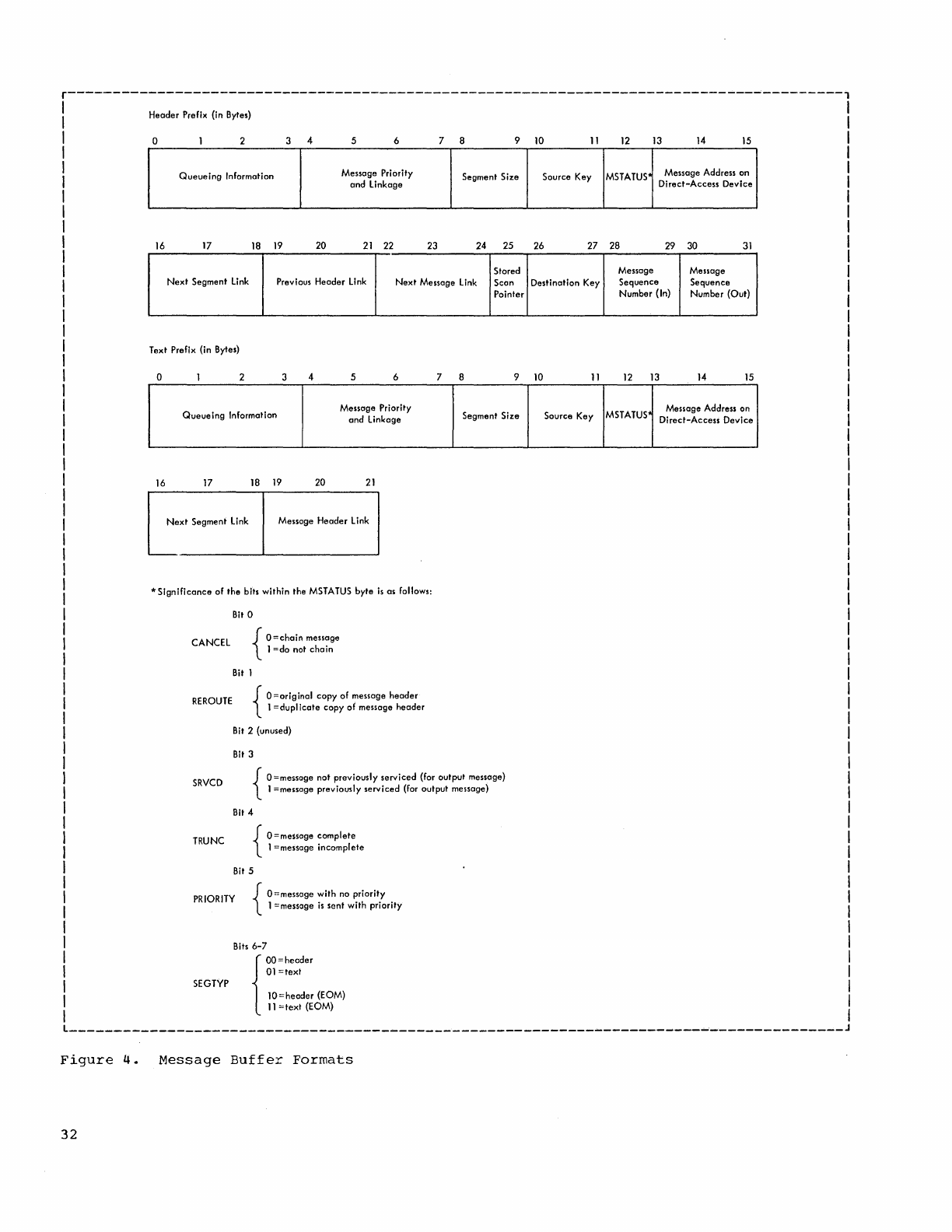
r---------------------------------------------------------------------------------------,
I
I
I
I
I
Header
Prefix (in Bytes)
o 4 5 6 7 8 9
10
11
12
13
14
15
Queueing
Informotion
Message
Priority Segment
Size
Source
Key
MSTATUS'
Message
Address
on
and
linkage
Direct-Access
Device
16
17
18
19
20
21
22
23
24 25
26 27
28
29 30
31
Stored Message
Message
Next
Segment
link
Previous
Header
Link
Next
Message
link
Scan
Destination
Key
Sequence
Sequence
Pointer
Number
(In)
Number
(Out)
Text Prefix (in Bytes)
o 4 5 6 7 8 9
10
11
12
13
14 15
Queueing
Information Message Priority Segment
Size
and
linkage
16
17
18 19
20
21
Next
Segment
link
Message
Header
link
..
Significance
of
the
bits
within
the MSTATUS
byte
is
as follows:
CANCEL
REROUTE
SRVCD
TRUNC
Bit 0
Bit 1
{
O=chain
message
I
=do
nat
chain
{
O=original
copy
of
message
header
1
=dupllcate
copy
of
message
header
Bit 2 (unused)
Bit 3
{
O=message not
previously
serviced
(for
output
message)
1 =messoge
previously
serviced
(for
output
message)
Bit 4
{
O=message
complete
I =message
incomplete
Bit 5
PRIORITY {
O=message
with
no
priority
1 =message
is
sent
with
priority
Bits
6-7
{
OO=heoder
01
=text
SEGTYP
10=header
(EOM)
11
=text
(EOM)
Source
Key
MSTATUS' Message Address on
Direct-Access
Device
_______________________________________________________________________
~
_______________
J
Figure
4.
Message
Buffer
Formats
32
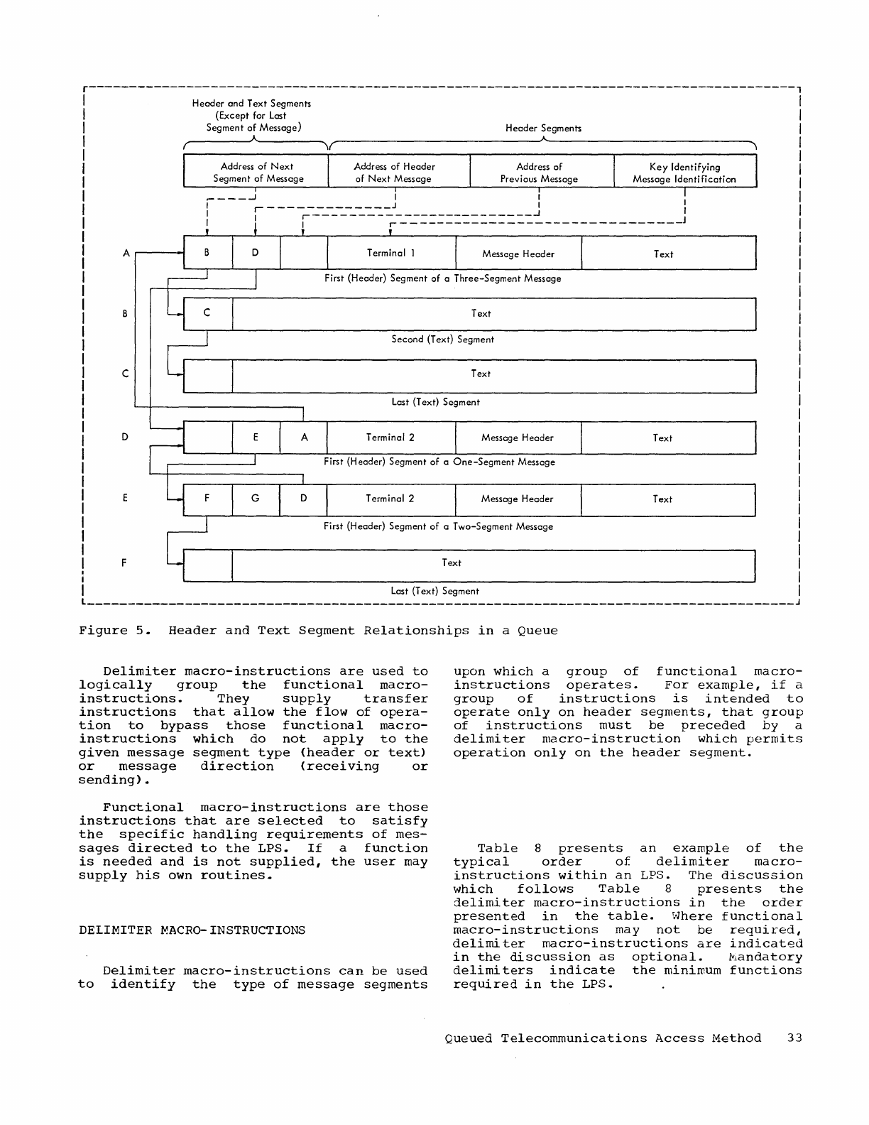
r---------------------------------------------------------------------------------------,
Header
and
Text
Segments
(Except for Last
Segment
of
Message)
Header
Segments
r~--------~A~--------~\(~-----------------------------JA~----------------------------~,
Address
of
Next
Segment
of
Message
Address
of
Header
of
Next
Message Address
of
~---~
I I I
i -
--
-i-----------:.::·:::~----=-===========:.-=-~
_______________
1
A
.-----..j
Message
Header
Text
B Text
Second (Text) Segment
c Text
Last (Text) Segment
D Terminal 2 Message
Header
Text
First (Header) Segment of a
One-Segment
Message
Terminal 2 Message
Header
Text
First (Header) Segment
of
a Two-Segment Message
F Text
Last (Text) Segment
_______________________________________________________________________________________
J
Figure
5.
Header
and
Text
Segment
Relationships
in
a
Queue
Delimiter
macro-instructions
are
used
to
logically
group
the
functional
macro-
instructions.
They
supply
transfer
instructions
that
allow
the
flow
of
opera-
tion
to
bypass
those
functional
macro-
instructions
which
do
not
apply
to
the
given
message
segment
type
(header
or
text)
or
message
direction
(receiving
or
sending)
•
Functional
macro-instructions
are
those
instructions
that
are
selected
to
satisfy
the
specific
handling
requirements
of
mes-
sages
directed
to
the
LPS.
If
a
function
is
needed
and
is
not
supplied,
the
user
may
supply
his
own
routines.
DELIMITER
MACRO-INSTRUCTIONS
Delimiter
macro-instructions
can
be
used
to
identify
the
type
of
message
segments
upon
which
a
group
of
functional
macro-
instructions
operates.
For
example,
if
a
group
of
instructions
is
intended
to
operate
only
on
header
segments,
that
group
of
instructions
must
be
preceded
by
a
delimiter
macro-instruction
which
permits
operation
only
on
the
header
segment.
Table
8
presents
an
example
of
the
typical
order
of
delimiter
macro-
instructions
within
an
LPS.
The
discussion
which
follows
Table
8
presents
the
jelimiter
macro-instructions
in
the
order
presented
in
the
table.
Where
functional
macro-instructions
may
not
be
reqUired,
delimiter
macro-instructions
are
indicated
in
the
discussion
as
optional.
~andatory
delimiters
indicate
the
minimum
fUnctions
required
in
the
LPS.
Queued
Telecommunications
Access
Method
33
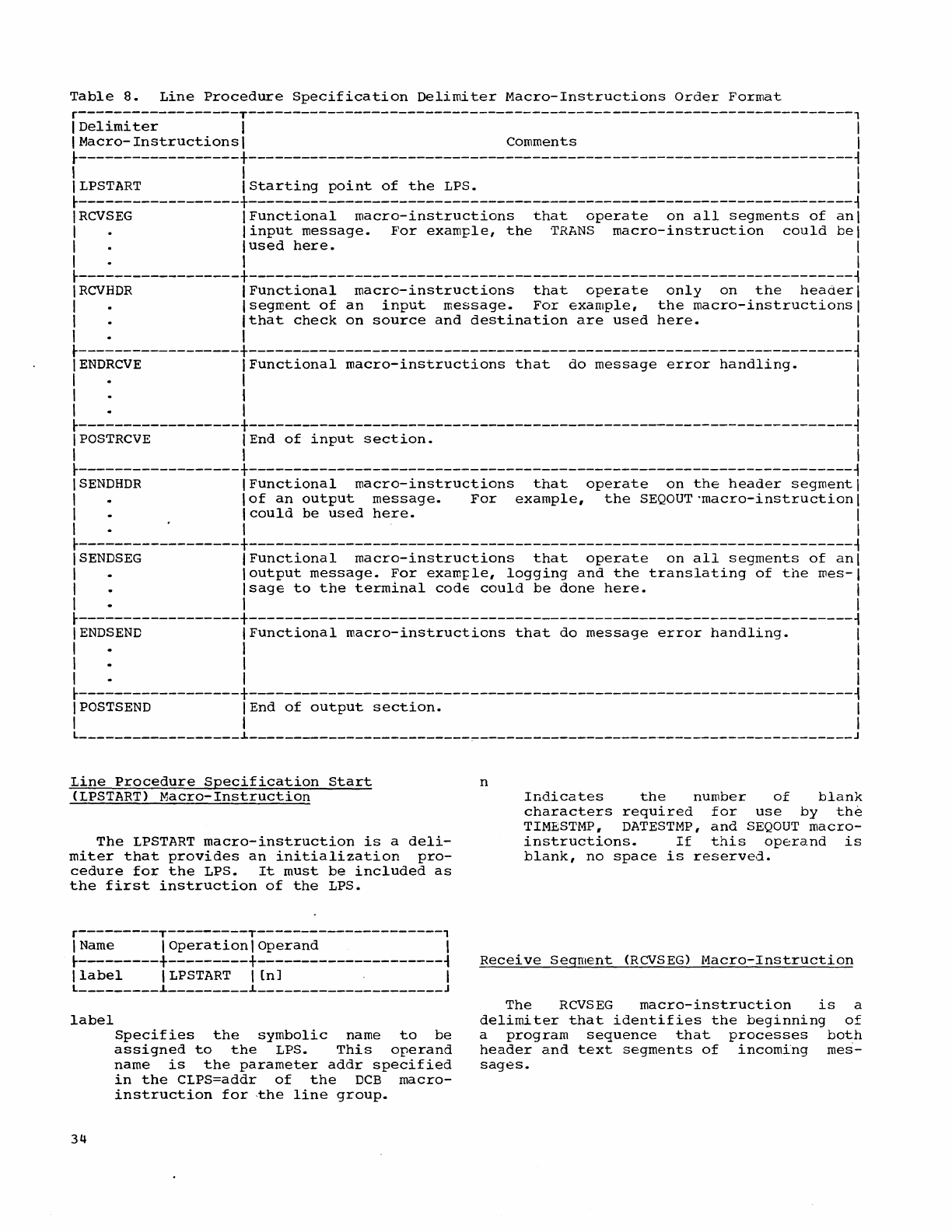
Table
8.
Line
Procedure
Specification
Delimiter
Macro-Instructions
Order
Format
r------------------T--------------------------------------------------------------------,
I
Delimi
ter
I I
I
Macro-Instructions
I Comments I
~------------------+--------------------------------------------------------------------~
I I I
I
LPSTART
IStarting
point
of
the
LPS. I
~------------------+--------------------------------------------------------------------~
I
RCVSEG
IFunctional
macro-instructions
that
operate
on
all
segments
of
ani
I I
input
message.
For
example,
the
TRANS
macro-instruction
could
bel
I
lused
here.
I
I I I
~------------------+--------------------------------------------------------------------~
I
RCVHDR
IFunctional
macro-instructions
that
operate
only
on
the
headerl
I
Isegment
of
an
input
message.
For
example,
the
macro-instructions
I
I
Ithat
check
on
source
and
destination
are
used
here.
I
I I I
~------------------+--------------------------------------------------------------------~
IENDRCVE
I
Functional
macro-instructions
that
do
message
error
handling.
I
I I I
I I I
I I I
~------------------+--------------------------------------------------------------------~
IPOSTRCVE
lEnd
of
input
section.
I
I I I
~------------------+--------------------------------------------------------------------~
ISENDHDR
I
Functional
macro-instructions
that
operate
on
the
header
segment
I
I
lof
an
output
message.
For
example,
the
SEQOUT"macro-instructionl
I
Icould
be
used
here.
I
I I I
~------------------+--------------------------------------------------------------------~
ISENDSEG
I
Functional
macro-instructions
that
operate
on
all
segments
of
ani
I I
output
message.
For
example,
logging
and
the
translating
of
the
mes-I
I
Isage
to
the
terminal
code
could
be
done
here.
I
I I I
~------------------+--------------------------------------------------------------------~
I
ENDS
END
IFunctional
macro-instructions
that
do
message
error
handling.
I
I I I
I I I
I I I
~------------------+--------------------------------------------------------------------~
IPOSTSEND
lEnd
of
output
section.
I
I I I
L
__________________
~
____________________________________________________________________
J
Line
Procedure
Specification
Start
(LPSTART)
Macro-Instruction
The
LPSTART
macro-instruction
is
a
deli-
miter
that
provides
an
initialization
pro-
cedure
for
the
LPS.
It
must
be
included
as
the
first
instruction
of
the
LPS.
r---------T---------T---------------------,
I
Name
I
Operation
I
Operand
I
~---------+---------+---------------------~
I
label
ILPSTART I
[n]
I
L
_________
~
_________
~
_____________________
J
label
34
Specifies
the
symbolic
name
to
be
assigned
to
the
LPS.
This
operand
name
is
the
parameter
addr
specified
in
the
CLPS=addr
of
the
DCB
macro-
instruction
for
,the
line
group.
n
Indicates
the
number
of
blank
characters
required
for
use
by
the
TIMBSTMP,
DATESTMP,
and
SEQ
OUT
macro-
instructions.
If
this
operand
is
blank,
no
space
is
reserved.
Receive
Segment
(RCVSEG)
Macro-Instruction
The
RCVSEG
macro-instruction
is
a
delimiter
that
identifies
the
beginning
of
a
program
sequence
that
processes
both
header
and
text
segments
of
incoming
mes-
sages.
r---------T-------------------------------,
I
Operation
I
Operand
I
t---------+-------------------------------~
I
R~VSEG
I I
L
_________
~
_______________________________
J
Receive
Header
(RCVHCR)
Macro-Instruction
The
RCVHDR
macro-instruction
is
a
delim-
iter
that
identifies
the
beginning
of
a
program
sequence
to
process
the
header
segment
of
incoming
messages.
r---------T-------------------------------,
I
Operation
I
Operand
I
t---------+-------------------------------~
I
RCVHDR
I I
L
_________
~
_______________________________
J
End
Receive
(ENDRCVE)
Macro-Instruction
The
ENDRCVE
macro-instruction
is
a
delimiter
that
identifies
the
beginning
of
a
program
sequence
to
process
end
condi-
tions
for
incoming
messages.
r---------T-------------------------------,
I
Operation
I
Operand
I
t---------+-------------------------------~
I
ENDRCVE
I I
L
_________
~
_______________________________
J
The
functional
macro-instructions
between
the
E~DRCVE
and
POSTRCVE
macro-
instructions
are
user-selected
to
test
for
errors
and
to
control
polling
if
necessary.
When
such
instructions
are
not
selected,
this
delimiter
is
not
required.
With
an
IBM
1050
Data
Communications
System,
the
user
can
choose
to
continue
receiving
a
message
after
an
end-of-block
character
causes
a
transmission
interruption.
When
required,
the
user
can
also
provide
line
correction
procedures.
(Refer
to
"End-of-Block
and
Line
Correction
(EOBLC)
Macro-Instruction.")
Post
Receive
(POSTRCVE)
Macro-Instruction
The
POSTRCVE
delimiter
that
macro-instruction
is
a
identifies
the
end
of
a
program
sequence
to
process
inccming
mes-
sages.
This
delimiter
is
always
required
in
an
LPS.
r---------T-------------------------------,
IOperationlOperand
I
t---------+-------------------------------~
I
POSTRCVE
I I
L
_________
~
_______________________________
J
Send
Header
(SENDHDR)
Macro-Instruction
The
SENDHDR
macro-instruction
is
a
deli-
miter
that
identifies
the
beginning
of
a
prograrr
sequence
to
process
the
header
segrrent
of
an
outgoing
message.
When
this
service
is
not
required,
this
delimiter
is
not
required.
r---------T-------------------------------,
I
Operation
I
Operand
I
t---------+-------------------------------~
ISENDhDR
I I
L
_________
~
_______________________________
J
Send
Segment
(SENDSEG)
Macro-Instruction
The
SENDSEG
macro-instruction
is
a
deli-
miter
that
identifies
the
beginning
of
a
program
sequence
to
process
both
header
and
text
segments
of
outgoing
messages.
r---------T-------------------------------,
I
Operation
I
Operand
I
t---------+-------------------------------~
ISENDSEG
I I
L
_________
~_~
_____________________________
J
End
Send
(ENDS
END)
Macro-Instruction
The
ENDSEND
macro-instruction
is
a
deli-
miter
that
identifies
the
beginning
of
a
program
sequence
to
prOCESS
end
conditions
for
outgoing
messages.
r---------T-------------------------------,
IOperationlOperand
I
t---------+-------------------------------~
I
ENDS
END
I I
L
_________
~
_______________________________
J
The
fUnctional
macro-instructions
between
the
ENDS
END
and
POSTS
END
macro-
instructions
are
selected
by
the
user
for
error
testing
and
(if
needed)
error
procedures.
When
such
instructions
are
not
selected,
this
delimiter
is
not
require9.
Hith
an
IBH
1050
Data
Communications
System,
the
user
can
choose
to
continue
sending
a
message
after
an
end-of-block
character
causes
a
transmission
interrup-
tion.
(Refer
to
"End-of-Dlock
(EOB)
Macro-
Instruction.
")
Queued
Telecommunications
Access
Method
35
Post
Send
"(POSTSEND)
lVJacro-Instruction
The
POSTS
END
macro-instruction
is
a
delimiter
that
identifies
the
end
of
a
program
sequence
to
process
outgoing
mes-
sages.
This
delimiter
is
always
required
in
an
LPS.
r---------T-------------------------------,
I
Operation
I
Operand
I
~---------+-------------------------------~
I
POSTSEND
I I
L
_________
L
_______________________________
J
FUNCTIONAL
MACRO-INSTRUCTIONS
Functional
macro-instructions
can
be
used
to
process
message
header
information.
They
use
a
QTAM
subroutine
to
scan
the
message
header
and
move
the
characters
of
header
fields
into
a
workarea.
Since
header
scanning
is
always
left
to
right,
the
functional
roacro-instructions
must
appear
in
the
LPS
in
an
order
corresponding
to
the
order
of
the
header
fields
they
service.
A
scan
pOinter
used
to
locate
each
successive
header
character
is
maintained
in
a
general
register
and
is
incremented
as
the
header
fields
are
scanned.
When
the
LPS
is
entered
to
process
a
message
being
received
or
sent,
the
scan
pointer
is
automatically
initialized.
If
the
user
desires
to
eliminate
the
need
for
header
field
delimiters
within
the
message
header,
the
user
must
specify
the
length
of
each
header
field
serviced
by
a
functional
macro-instruction.
When
lengths
of
header
fields
are
specified,
the
scanner
ignores
blank
characters
erroneously
embed-
ded
within
a
valid
field.
If
it
is
desired
to
include
variable
length
fields
in
the
message
header
(for
example,
when
omission
of
leading
zeros
is
desired
in
fields
that
contain
numeric
data),
the
end
of
the
field
must
be
defined
with
a
field
delimiter.
If
the
length
of
a
field
is
not
specified,
it
is
handled
as
a
variable
length
field.
The
scanner
treats
a
blank
character
erroneously
embedded
within
a
variable
length
field
as
a
field
delimiter.
Functional
macro-instructions
are
divid-
ed
into
the
following
four
groups
to
aid
the
user
in
placing
them
under
the
correct
delimiters:
36
•
Receive~
which
indicates
those
macro-
instructions
that
can
be
placed
only
under
the
receive
•
Receive
or
send,
macro-instructions
under
either
the
delimiters.
delimiters.
which
indicates
those
that
can
be
placed
receive
or
the
send
•
Send,
which
indicates
those
macro-
instructions
that
can
be
placed
only
under
the
send
delimiters.
•
Error
handling,
which
indicates
those
macro-instructions
that
can
be
used
to
handle
given
error
conditions.
Note:
For
additional
information
on
where
each
macro-instruction
can
be
used
and
restrictions
that
might
affect
their
use,
refer
to
"Summary
Charts."
RECEIVE
FUNCTIONAL
MACRO-INSTRUCTIONS
Seguence
In
(SEQIN)
Macro-Instruction
The
SEQIN
macro-instruction
checks
the
sequence
number
of
each
message
from
the
same
terminal
as
the
message
arrives
in
the
system.
If
the
sequence
number
is
incorrect,
an
error
flag
is
set
in
the
error
half-word.
If
the
terminals
are
non-polled
devices
<e.g.,
dial
devices),
the
SEQIN
macro-instruction,
if
used,
must
be
preceded
by
a
SOURCE
macro-instruction.
r---------T-------------------------------,
I
Operation
I
Operand
I
~---------+-------------------------------~
I SEQIN I
[n]
I
L
_________
L
_______________________________
J
n
Specifies
the
number
of
characters
in
the
header
sequence
number
field.
The
maximum
value
of
n
is
four.
If
this
parameter
is
not
specified
a
variable
length
field
is
assumed.
Variable
length
fields
must
be
followed
by
a
blank
character
used
as
a
field
delim-
iter.
Note:
The
sequence
number
message
from
a
te~minal
maximum
number
is
99~9.
of
the
first
must
be
1.
The
SOURCE
Macro-Instruction
The
SOURCE
macro-instruction
checks
the
validity
of
the
contents
of
the
source
terminal
code
field
received
in
the
message
header.
If
an
invalid
source
terminal
code
is
detected,
an
error
is
indicated
in
the
error
half-word
for
the
line.
r---------T-------------------------------,
I
Operation
I
Operand
I
~---------+-------------------------------~
I
SOURCE
I n I
L
_________
~
_______________________________
J
n
Indicates
the
(decimal)
number
of
characters
in
the
source
terminal
code
field
of
the
message
header.
The
maximum
value
of
n
is
eight.
Routing
(ROUTE)
Macro-Instruction
The
ROUTE
macro-instruction
causes
a
validity
check
of
the
destination
code
field
in
the
message
header.
If
the
desti-
nation
code
is
valid,
the
ROUTE
macro-
instruction
causes
the
message
to
be
queued
for
the
specified
destination.
If
an
invalid
destination
code
is
detected
in
the
header
field,
an
error
is
indicated
in
the
error
half-word.
This
macro-instruction,
used
in
conjunction
with
the
EOA
macro-
instruction,
permits
multiple
routing.
r---------T-------------------------------,
I
Operationl
Operand
I
~---------+-------------------------------~
I
ROUTE
I n I
L
_________
~
_______________________________
J
n
Specifies
the
number
of
characters
in
the
destination
code
field.
The
maximum
value
of
n
is
eight.
The
terminal
tatle
that
includes
all
valid
destination
terminal
codes
must
be
provided.
(Refer
to
"Control
Informa-
tion.")
A
message
can
be
directed
to
multiple
destinations
by
including
more
than
one
terminal
code
in
the
destination
code
field.
It
is
not
necessary
to
state
the
number
of
destination
codes
in
the
message.
An
end-of-address
character,
as
described
under
"End-of-Address
(EOA)
Macro-
Instruction,"
is
used
to
define
the
end
of
the
destination
field.
Multiple
destinations
can
also
be
specified
by
using
a
single
terminal
code
to
identify
a
distribution
list
in
the
terminal
table.
Each
terminal
in
the
dis-
tribution
list
receives
the
message.
Where
special
hardware
features
are
available,
"group
code"
transmission
is
another
multi~le
addressing
method
that
can
te
used.
By
using
unique
address
charac-
ters,
a
single
message
can
be
sent
simulta-
neously
to
a
prespecified
group
of
termi-
nals
on
the
same
line.
Any
combination
of
terminal
codes
may
be
used
in
a
header
destination
field
to
route
a
message.
RESTRICTION:
Only
one
ROUTE
macro-
instruction
can
be
specified
for
a
message
type.
If
the
DIRECT
macro-instruction
is
used
for
the
message,
the
ROUTE
macro-
instruction
cannot
be
used.
End-of-Address
(EOA)
Macro-Instruction
The
EOA
macro-instruction
must
immediately
instruction
expected.
determines
to
receive
follow
the
ROUTE
macro-
when
multiple
routing
can
be
This
macro-instruction
if
any
additional
terminals
are
the
message.
r---------T-------------------------------,
I
Operation
I
Operand
I
~---------+-------------------------------~
I
EOA
I
C'
char'
I
L
_________
~
_______________________________
J
char
Indicates
the
EOA
character
that
must
appear
in
the
message
header
after
the
last
destination
code.
DIRECT
Macro-Instruction
The
DIRECT
macro-instruction
causes
a
message
to
be
queued
for
the
destination
specified
in
the
operand.
This
macro-
instruction
may
be
used
in
place
of
the
ROUTE
macro-instruction
when
there
is
no
destination
data
in
the
message
header.
r---------T-------------------------------,
I
Operation
I
Operand
I
~---------+-------------------------------~
I DIRECT
I{
=C'
dest
'}
I
I I
field
I
L
_________
~
_______________________________
J
dest
Represents
the
destination
code,
which
may
be
any
terminal
name
in
a
terminal
table
entry.
field
Indicates
the
symbolic
name
of
an
optional
field
in
a
terminal
table
entry;
this
field,
defined
by
the
OPTION
macro-instruction,
contains
the
name
of
the
terminal
to
which
the
message
should
be
sent.
If
the
source
terminal
is
a
non-polled
device
(e.g.,
a
dial
device),
the
SOURCE
macro-
instruction
must
be
specified
in
order
for
the
"field"
entry
to
be
used.
Queued
Telecon~unications
Access
Method
37
Note:
Only
one
DIRECT
macro-instruction
may
be
specified
for
a
message
type.
The
DIRECT
macro-instruction
cannot
be
used
if
the
ROUTE
macro-instruction
is
used
for
the
same
lliessage.
Polling
Limit
(POLLIMIT)
Macro-Instruction
The
POLLIMIT
rr.acro-instruction
is
used
to
determine
whether
a
terminal
has
sent
the
maximum
number
of
messages
allowed
on
a
single
polling
pass.
When
this
rraximum
limit
is
reached,
the
next
terminal
is
polled.
r---------T-------------------------------,
I
Operation
I
Operand
I
~---------+-------------------------------~
I POLLIMIT I{
FLl
' n
'}
I
I I
field
\
L
_________
~
_______________________________
J
n
field
Specifies
a
limit
for
all
of
the
terminals
using
the
LPS.
This
option
can
only
be
used
when
the
number
of
consecutive
polls
is
the
same
for
all
terminals.
Specifies
the
symbolic
name
of
an
optional
field
in
the
terminal
table
that
contains
the
limit
of
consecutive
polls
for
each
terminal.
This
method
of
specifying
the
polling
limit
allows
a
different
polling
limit
to
be
set
for
each
terminal.
Note:
If
no
polling
limit
is
set
(POLLIMIT
macro-instruction
is
not
used),
each
terminal
is
polled
until
the
terminal
has
nc
more
messages
for
the
polling
pass.
RESTRICTION:
The
POLLIMIT
macro-
instruction
has
no
effect
when
used
with
a
dialing
line.
Halt
Receive
(BREAKOFF)
Macro-Instruction
The
BREAKOFF
macro-instruction
determines
if
the
length
of
the
received
message
exceeds
the
specified
maximum num-
ber
of
characters
(n).
It
also
checks
to
see
if
the
input
buffer
is
filled
with
identical
characters.
If
either
of
these
conditions
is
found,
an
error
flag
is
set
in
the
error
half-word
and
reception
of
the
message
is
terminated.
(Refer
to
"Error
Handling
Functional
Macro-Instructions.")
38
r---------T-------------------------------,
I
Operation
\
Operand
I
~---------+-------------------------------~
I
BREAKOFF
I n I
L
_________
~
_______________________________
J
n
Specifies
the
maximum
allowed,
expressed
(n::532,767).
message
length
in
characters
RECEIVE
OR
SEND
FUNCTIONAL
MACRO-INSTRUCTIONS
Date
Stamp
(DATESTMP)
Macro-Instruction
The
DATESTMP
macro-instruction
inserts
the
date
in
the
header
field
of
incoming
or
outgoing
messages
in
the
form
byy.ddd,
where
b=blank,
yy=year,
and
ddd=day
of
year
(for
example,
b64.325).
r---------T-------------------------------,
I
Operation
I
Operand
I
~---------+-------------------------------~
I
DATESTMP
I I
L
_________
~
_______________________________
J
The
user
must
reserve
seven
spaces
for
the
date
stamp
in
the
buffer.
(Refer
to
"Line
Procedure
Specification
Start
(LPSTART)
Macro-Instruction.")
Time
Stame
(TINESTMP)
Macro-Instruction
The
TIMESTMP
macro-instruction
inserts
the
time
of
day
in
the
header
field
of
incoming
or
outgoing
messages
in
the
form
bHH.!-lM.SS.th,
where
b=blank,
HH=hours,
MM=minutes,
SS=seconds,
t=tenths
of
sec-
onds,
and
h=hundredths
of
seconds.
When
less
than
twelve
spaces
are
reserved
the
time
will
be
truncated
from
the
right.
r---------T-------------------------------,
I
Operation
I
Operand
I
~---------+-------------------------------~
ITIMESTMP
In
I
L
_________
~
_______________________________
J
n
Indicates
the
number
of
characters
to
be
inserted
in
the
message
header
stamp.
The
maximum
value
of
n
is
twelve.
The
first
character
of
the
time
stamp
is
always
a
blank.
The
user
must
reserve
the
necessary
space
for
the
time
stamp
in
the
message
buffer.
(Refer
to
"Line
Procedure
Specification
Start
(LPSTART)
Macro-
Instruction.")
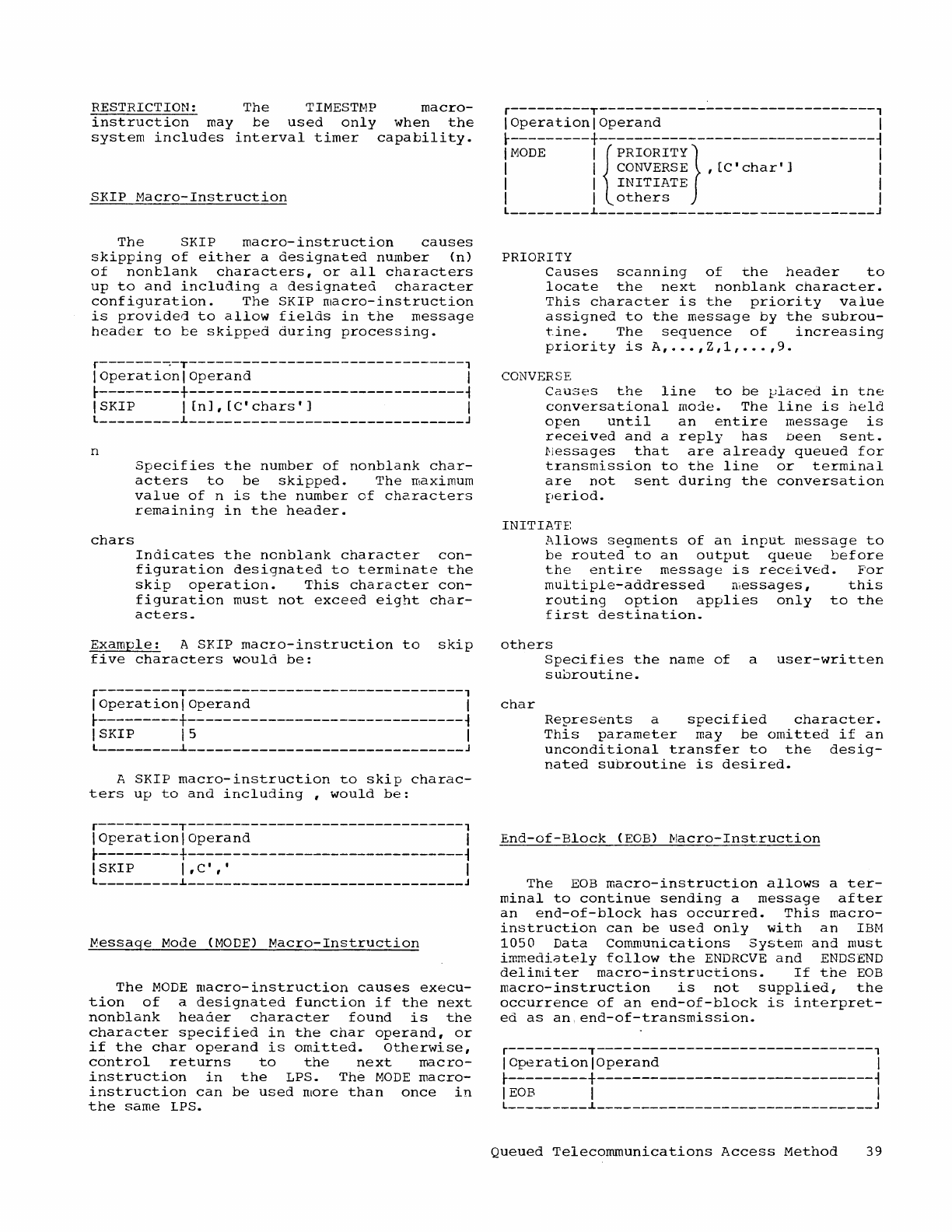
RESTRICTION:
The
TIMESTMP
macro-
instruction
may
be
used
only
when
the
system
includes
interval
timer
capability.
SKIP
Macro-Instruction
The
SKIP
macro-instruction
causes
skipping
of
either
a
designated
number
(n)
of
non
blank
characters,
or
all
characters
up
to
and
including
a
designated
character
configuration.
The
SKIP
macro-instruction
is
provided
to
allow
fields
in
the
message
header
to
be
skipped
during
processing.
r-------~-T-------------------------------,
I
Operation
I
Operand
I
t---------+-------------------------------~
I
SKIP
I
[n],
[C'
chars'
] I
l
_________
L
_______________________________
J
n
chars
Specifies
the
number
of
nonblank
char-
acters
to
be
skipped.
The
maximum
value
of
n
is
the
number
of
characters
remaining
in
the
header.
Indicates
the
nonblank
character
con-
figuration
designated
to
terminate
the
skip
operation.
This
character
con-
figuration
must
not
exceed
eight
char-
acters.
Example:
A
SKIP
macro-instruction
to
skip
five
characters
would
be:
r---------T-------------------------------,
I
Operation
I
Operand
I
t---------+-------------------------------~
I
SKIP
15
I
l
_________
~
_______________________________
J
A
SKIP
macro-instruction
to
skip
charac-
ters
up
to
and
including,
would
be:
r---------T-------------------------------,
I
Operation
I
Operand
I
t---------+-------------------------------~
I
SKIP
I ,
C'
, , I
l
_________
L
_______________________________
J
~essage
Mode
(MODE)
Macro-Instruction
The
MODE
macro-instruction
causes
execu-
tion
of
a
designated
function
if
the
next
nonblank
header
character
found
is
the
character
specified
in
the
char
operand,
or
if
the
char
operand
is
omitted.
Otherwise,
control
returns
to
the
next
macro-
instruction
in
the
LPS.
The
MODE
macro-
instruction
can
be
used
more
than
once
in
the
same
LPS.
r---------T-------------------------------,
I
Operation
I
Operand
I
t---------+-------------------------------~
I
MODE
I
{PRIORITY}
I
I I
CONVERSE
,
[C'
char']
I
I I
INITIATE
I
I I
others
I
l
_________
L
_______________________________
J
PRIORITY
Causes
scanning
of
the
header
to
locate
the
next
nonblank
character.
This
character
is
the
priority
value
assigned
to
the
message
by
the
subrou-
tine.
The
sequence
of
increasing
priority
is
A,
..•
,Z,1,
...
,9.
CONVERSE
Causes
the
line
to
be
vlaced
in
tne
conversational
moje.
The
line
is
held
open
until
an
entire
message
is
received
and
a
reply
has
been
sent.
i'lessages
that
ar'e
already
queued
for
transmission
to
the
line
or
terminal
are
not
sent
during
the
conversation
period.
INITIATE
Allows
segments
of
an
input
message
to
be
routed
to
an
output
queue
before
the
entire
message
is
received.
For
multiple-addressed
messages,
this
routing
option
applies
only
to
the
first
destination.
others
char
Specifies
the
name
of
a
user-written
subroutine.
Represents
a
specified
character.
This
parameter
may
be
omitted
if
an
unconditional
transfer
to
the
desig-
nated
subroutine
is
desired.
End-of-Block
(EGB)
!vlacro-Inst.ruction
The
EOB
macro-instruction
allows
a
ter-
minal
to
continue
sending
a
message
after
an
end-of-block
has
occurred.
This
macro-
instruction
can
be
used
only
with
an
IBM
1050
Data
Communications
System
and
must
immediately
follow
the
ENDRCVE
and
ENDS
END
delimiter
macro-instructions.
If
the
EOB
macro-instruction
is
not
supplied,
the
occurrence
of
an
end-of-block
is
interpret-
ed
as
an,end-of-transmission.
r---------T-------------------------------,
IOperationlOperand
I
r---------+-------------------------------~
IEOB
I I
l
_________
~
_______________________________
J
Queued
Telecommunications
Access
Method
39
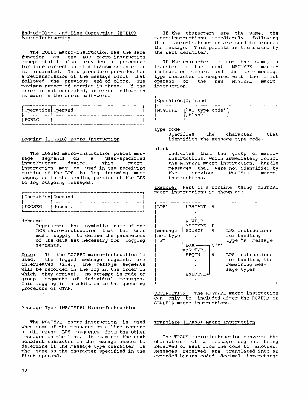
End-of-Block
and
Line
Correction
(EOBLC)
Macro-Instruction
The
EOBLC
macro-instruction
has
the
same
function
as
the
EOB
macro-instruction
except
that
it
also
provides
a
procedure
for
line
correction
if
a
transmission
error
is
indicated.
This
procedure
provides
for
a
retransmission
of
the
message
block
that
followed
the
previous
end-of-block.
The
maximum
number
of
retries
is
three.
If
the
error
is
not
corrected,
an
error
indication
is
made
in
the
error
half-word.
r---------T-------------------------------,
I
Operation
I
Operand
I
t---------+-------------------------------~
I
EOBLC
I I
L
_________
~
_______________________________
J
Logg1ng
(LOGSEG)
Macro-Instruction
The
LOGSEG
macro-instruction
places
mes-
sage
segments
on
a
user-specified
input/output
device.
This
macro-
instruction
may
be
used
in
the
receiving
portion
of
the
LPS
to
log
incoming
mes-
sages,
or
in
the
sending
portion
of
the
LPS
to
log
outgoing
messages.
r---------T-------------------------------,
I
Operation
I
Operand
I
t---------+-------------------------------~
IIOGSEG
Idcbname
I
L
_________
~
_______________________________
J
dcbname
Represents
the
symbolic
name
of
the
DCB
macro-instruction
that
the
user
must
supply
to
define
the
parameters
of
the
data
set
necessary
for
logging
segments.
Note:
If
the
LOGSEG
macro-instruction
is
used,
the
logged
message
segments
are
interleaved
(i.e.,
the
message
segments
will
be
recorded
in
the
log
in
the
order
in
which
they
arrive).
No
attempt
is
made
to
group
segments
of
individual
messages.
This
logging
is
in
addition
to
the
queueing
procedure
of
QTAM.
Message
Type
CMSGTYPE}
Macro-Instruction
The
MSGTYPE
macro-instruction
is
used
when
some
of
the
messages
on
a
line
require
a
different
LPS
sequence
from
the
other
messages
on
the
line.
It
examines
the
next
nonblank
character
in
the
message
header
to
determine
if
the
message
type
character
is
the
same
as
the
character
specified
in
the
first
operand.
If
the
characters
are
the
same,
the
macro-instructions
immediately
following
this
macro-instruction
are
used
to
process
the
message.
This
process
is
terminated
by
the
next
delimiter.
If
the
character
is
not
the
same,
a
transfer
to
the
next
MSGTYPE
macro-
instruction
occurs
and
the
same
message
type
character
is
compared
with
the
first
operand
of
the
new
MSGTYPE
macro-
instruction.
r---------T-------------------------------,
IOperationlOperand
I
t---------+-------------------------------~
I
MSGTYPE
I{=cttype
cOdet}
I
I I
blank
I
L
_________
~
_______________________________
J
type
code
blank
Specifies
the
character
that
identifies
the
message
type
code.
Indicates
that
the
group
of
macro-
instructions,
which
immediately
follow
the
MSGTYPE
macro-instruction,
handle
messages
that
were
not
identified
by
the
previous
MSGTYPE
macro-
instructions.
Example:
Part
of
a
routine
using
MSGTtPE
macro-instructions
is
shown
as:
r-----------------------------------------,
LPSl
LPSTART
4
RCVHDR
[
MSGTYPE
P
message
SOURCE
4
not
type
.
"P"
~igi~PE]
:'.,
ENDRCVE
LPS
instructions
for
handling
type
"P"
message
LPS
instructions
for
handling
the
remaining
mes-
sage
types
L
_________________________________________
J
RESTRICTION:
The
MSGTYPE
macro-instruction
can
only
be
included
after
the
RCVHDR
or
SENDHDR
macro-instructions.
Translate
(TRANS)
l-lacro-Instruction
The
TRANS
macro-instruction
converts
the
characters
of
a
message
segment
being
received
or
sent
from
one
code
to
another.
Messages
received
are
translated
into
an
extended
binary
coded
decimal
interchange
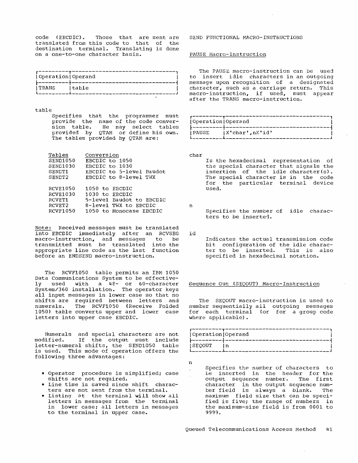
code
(EBCDIC).
Those
that
are
sent
are
translated
from
this
code
to
that
of
the
destination
terminal.
Translating
is
done
on
a
one-to-one
character
basis.
r---------T-------------------------------,
I
Operation
I
Operand
I
t---------+-------------------------------~
I
TRANS
I
table
I
L
_________
i
_______________________________
J
table
Specifies
that
the
programmer
must
provide
the
name
of
the
code
conver-
sion
table.
He
may
select
tables
provided
by
QTAM
or
define
his
own.
The
tables
provided
by
QTAM
are:
Tables
Conversion
SEND1050
EBCDIC
to
1050
SEND1030
EBCDIC
to
1030
SENCT1
EBCDIC
to
5-level
Baudot
SENDT2
EBCDIC
to
8-level
TWX
RCVE1050
1050
to
EBCDIC
RCVE1030
1030
to
EBCDIC
RCVET1
5-level
Baudot
to
EBCDIC
RCVET2
8-level
TWX
to
EBCDIC
RCVF1050
1050
to
Monocase
EBCDIC
Note:
Received
messages
must
be
translated
into
EBCDIC
immediately
after
an
RCVSEG
macro-instruction,
and
messages
to
be
transmi,tted
must
be
translated
into
the
appropriate
line
code
as
the
last
fUnction
before
an
ENDS
END
macro-instruction.
The
RCVF1050
table
permits
an
IBIvl
1050
Data
Communications
System
to
be
effective-
ly
used
with
a
48-
or
60-character
System/360
installation.
The
operator
keys
all
input
messages
in
lower
case
so
that
no
shifts
are
required
between
letters
and
numerals.
The
RCVF1050
(Receive
Folded
1050)
table
converts
upper
and
lower
case
letters
into
upper
case
EBCDIC.
Numerals
and
special
characters
are
not
modified.
If
the
output
must
include
letter-numeral
shifts,
the
SEND1050
table
is
used.
This
mode
of
operation
offers
the
following
three
advantages:
•
Operator
procedure
is
simplified;
case
shifts
are
not
required.
.
•
Line
time
is
saved
since
shift
charac-
ters
are
not
sent
from
the
terminal.
•
Listing
at
the
terminal
wil1
show
all
letters
in
messages
from
the
terminal
in
lower
case;
all
letters
in
messages
to
the
terminal
in
upper
case.
SEND
FUNCTIONAL
MACRO-INSTRUCTIONS
PAUSE
Macro-Instruction
The
PAUSE
macro-instruction
can
be
used
to
insert
idle
characters
in
an
outgoing
message
upon
recognition
of
a
designated
character,
such
as
a
carriage
return.
This
macro-instruction,
if
used,
must
appear
after
the
TRANS
macro-instruction.
r---------T-------------------------------,
I
Operation
I
Operand
I
t----~----+-------------------------------~
I
PAUSE
IX'char',nX'id'
I
L
_________
i
_______________________________
J
char
n
id
Is
the
hexadecimal
representation
of
the
special
character
that
signals
the
insertion
of
the
idle
character(s).
The
special
character
is
in
the
code
for
the
particular
terminc.l
device
used.
Specifies
the
number
of
idle
charac-
ters
to
be
inserted.
Indicates
the
actual
transmission
code
bit
configuration
of
the
idle
charac-
ter
to
be
inserted.
This
is
also
specified
in
hexadecimal
notation.
Seguence
Out
(SEQOUT)
Macro-Instruction
The
SEQOUT
macro-instruction
is
used
to
number
sequentially
all
outgoing
messages
for
each
terminal
(or
for
a
group
code
where
applicable).
r---------T-------------------------------,
ICperationlOperand
I
t---------+-------------------------------~
ISEQOUT
In
I
L
_________
i
_______________________________
J
n
Specifies
the
number
of
characters
to
be
inserted
in
the
header
for
the
output
sequence
number.
The
first
character
in
the
output
sequence
num-
ber
field
is
always
a
blank.
The
maximum
field
size
that
can
be
speci-
fied
is
five;
the
range
of
numbers
in
the
maximum-size
field
is
from
0001
to
9999.
Queued
Telecommunications
Access
Method
41
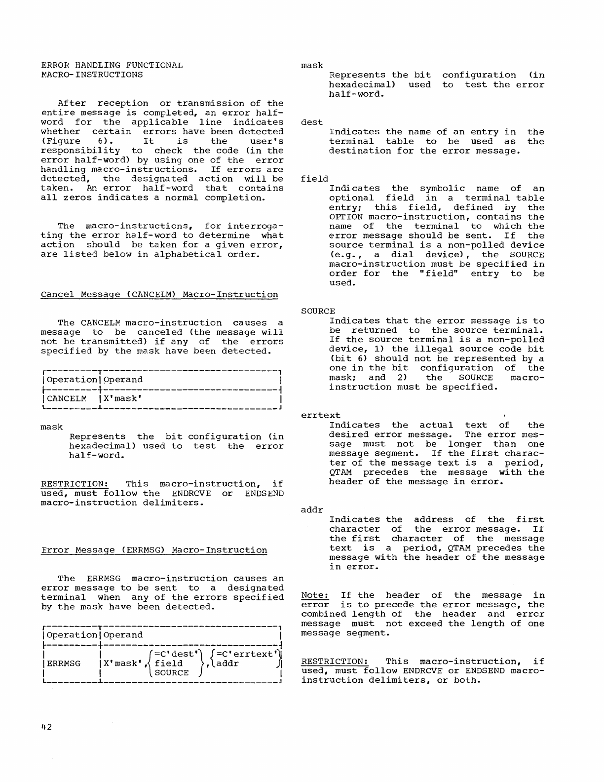
ERROR
HANDLING
FUNCTIONAL
MACRO-INSTRUCTIONS
After
reception
or
transmission
of
the
entire
message
is
completed,
an
error
half-
word
for
the
applicable
line
indicates
whether
certain
errors
have
been
detected
(Figure
6).
It
is
the
user's
responsibility
to
check
the
code
(in
the
error
half-word)
by
using
one
of
the
error
handling
macro-instructions.
If
errors
are
detected,
the
designated
action
will
be
taken.
An
error
half-word
that
contains
all
zeros
indicates
a
normal
completion.
The
macro-instructions,
for
interroga-
ting
the
error
half-word
to
determine
what
action
should
be
taken
for
a
given
error,
are
listed
below
in
alphabetical
order.
Cancel
Message
(CANCELM)
Macro-Instruction
The
CANCEL~
macro-instruction
causes
a
message
to
be
canceled
(the
message
will
not
be
transmitted)
if
any
of
the
errors
specified
by
the
mask
have
been
detected.
r---------T-------------------------------,
I
Operation
I
Operand
I
t---------+-------------------------------~
ICANCELM
IX'mask'
I
l
_________
L
_______________________________
J
mask
Represents
the
bit
configuration
(in
hexadecimal)
used
to
test
the
error
half-word.
RESTRICTION:
This
macro-instruction,
if
used,
must
follow
the
ENDRCVE
or
ENDSEND
macro-instruction
delimiters.
Error
Message
(ERRMSG)
Macro-Instruction
The
ERRMSG
macro-instruction
causes
an
error
message
to
be
sent
to
a
designated
terminal
when
any
of
the
errors
specified
by
the
mask
have
been
detected.
r---------T-------------------------------,
I
Operation
I
Operand
I
t---------+-------------------------------~
I I
{=C'
dest
'}
{=C'
errtext
'II
IERRMSG
IX'mask',
field
,addr
~
I I
SOURCE
I
l
_________
L
_______________________________
J
42
mask
dest
field
Represents
the
bit
hexadecimal)
used
half-word.
configuration
(in
to
test
the
error
Indicates
the
name
of
an
entry
in
the
terminal
table
to
be
used
as
the
destination
for
the
error
message.
Indicates
the
symbolic
name
of
an
optional
field
in
a
terminal
table
entry;
this
field,
defined
by
the
OPTION
macro-instruction,
contains
the
name
of
the
terminal
to
which
the
error
message
should
be
sent.
If
the
source
terminal
is
a
non-polled
device
(e.g.,
a
dial
device),
the
SOURCE
macro-instruction
must
be
specified
in
order
for
the
"field"
entry
to
be
used.
SOURCE
Indicates
that
the
error
message
is
to
be
returned
to
the
source
terminal.
If
the
source
terminal
is
a
non-polled
device,
1)
the
illegal
source
code
bit
(bit
6)
should
not
be
represented
by
a
one
in
the
bit
configuration
of
the
mask;
and
2)
the
SOURCE
macro-
instruction
must
be
specified.
errtext
addr
Indicates
the
actual
text
of
the
desired
error
message.
The
error
mes-
sage
must
not
be
longer
than
one
message
segment.
If
the
first
charac-
ter
of
the
message
text
is
a
period,
QTAM
precedes
the
message
with
the
header
of
the
message
in
error.
Indicates
the
address
of
the
first
character
of
the
error
message.
If
the
first
character
of
the
message
text
is
a
period,
QTAM
precedes
the
message
with
the
header
of
the
message
in
error.
Note:
If
the
header
of
the
message
in
error
is
to
precede
the
error
message,
the
combined
length
of
the
header
and
error
message
must
not
exceed
the
length
of
one
message
segment.
RESTRICTION:
This
macro-instruction,
if
used,
must
follow
ENDRCVE
or
ENDS
END
macro-
instruction
delimiters,
or
both.
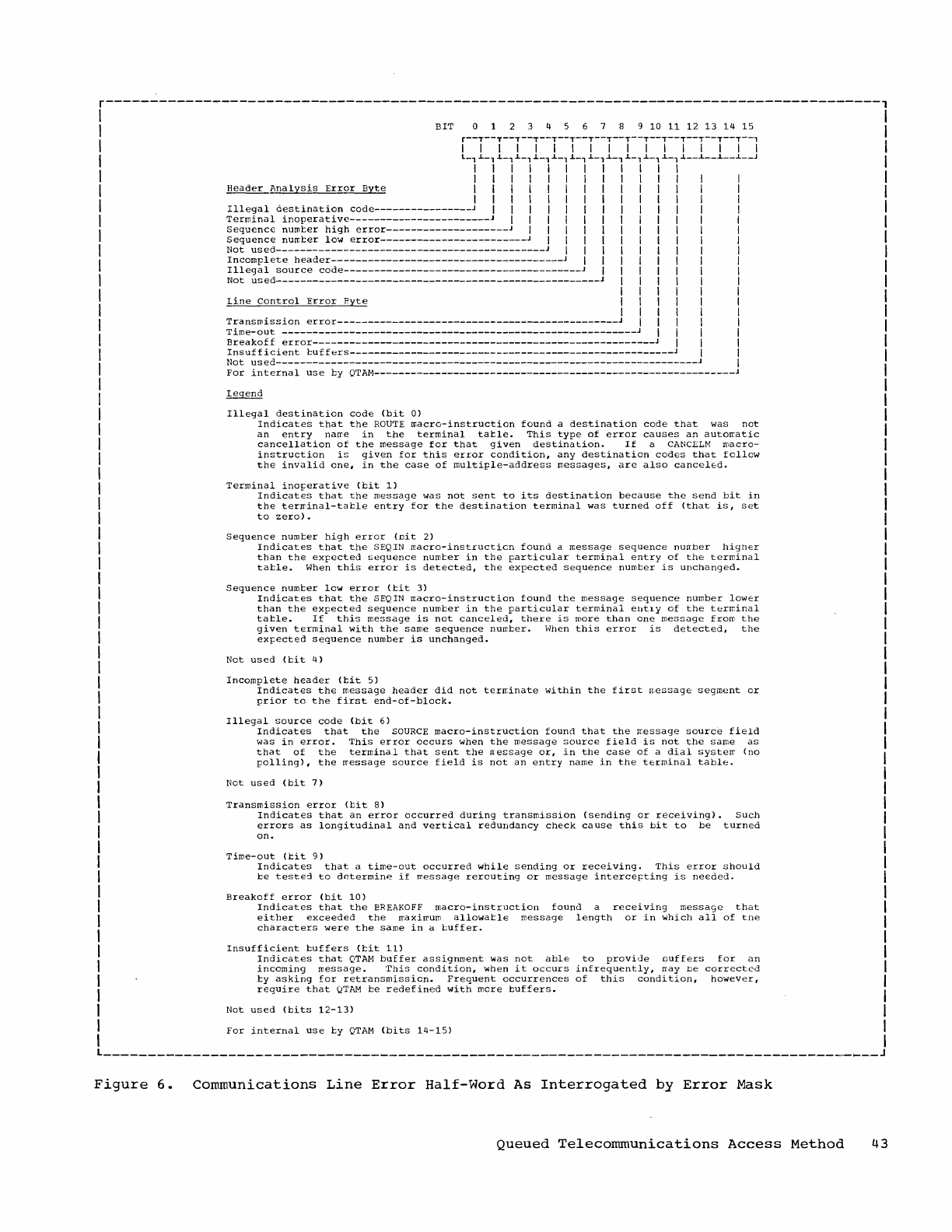
r---------------------------------------------------------------------------------------,
I I
I
BIT
0 9
10
11
12
13
14 15
I
I r--I--I--I--I--I--I--I--I--I--I--I--I--I--I--I--l I
I
l-'~-l~-'~-l~-'~-l~-'~-l~-'~-l~-l~-,~--~--~--~--J
I
I I I I I I I I I I I I I
I I I I I I I I I I I
I
Header
Analysis
Error
Byte
I I I I I I I I I I I I
I I I I I I I I I I I
Illegal
aestination
code----------------
J I I I I I I I I I I
I
Terminal
inoperative-----------------------
J I I I I I I I I
I
SequencE
number
high
error--------------------J
I I I I I I I
Sequence
numter
10'.<1
error------------------------J
I I I I I
I
Not
used--------------------------------------------
J I I I I I
Incomplete
header--------------------------------------J
I I I I
Illegal
source
code---------------------------------------
J I I
Not
used--------------------------------------------------
___
J I I
line
Control
Error
Byte
I I
I I
Transmission
error----------------------------------------------J
I
Time-out
----------------------------------------------------------
I
Breakoff
error--------------------------------------------------------
I
Insufficient
buffers-----------------------------------------------
______
J
Not
used--------------------------------------------------
___________________
J
For
internal
use
ty
QTAM-----------------------------------------------------------
legend
Illegal
destination
code
(bit
0)
Indicates
that
the
ROUTE
macro-instruction
found
a
destination
code
that
was
not
an
entry
name
in
the
terminal
table.
This
type
of
error
causes
an
automatic
cancellation
of
the
message
for
that
given
destination.
If
a
CANCELM
macro-
instruction
is
given
for
this
error
condition,
any
destination
codes
that
follow
the
invalid
one,
in
the
case
of
multiple-address
messages,
are
also
canceled.
Terminal
inoperative
(bit
1)
Indicates
that
the
message
was
not
sent
to
its
destination
because
the
send
bit
in
the
terminal-tatle
entry
for
the
destination
terminal
was
turned
off
(that
is,
set
to
zero).
Sequence
number
high
error
(nit
2)
Indicates
that
the
SEQIN
macro-instruction
found
a
message
sequence
nurrber
higher
than
the
expected
sequence
number
in
the
particular
terminal
entry
of
the
terminal
table.
When
this
error
is
detected,
the
expected
sequence
numter
is
unchanged.
Sequence
numter
low
error
(bit
3)
Indicates
that
the
SEQIN
macro-instruction
found
the
message
sequence
number
lower
than
the
expected
sequence
number
in
the
particular
terminal
ellt1y
of
the
terminal
table.
If
this
message
is
not
canceled,
there
is
more
than
one
message
from
the
given
terminal
with
the
same
sequence
number.
When
this
error
is
detected,
the
expected
sequence
number
is
unchanged.
Not
used
(bit
4)
Incomplete
header
(bit
5)
Indicates
the
message
header
did
not
terminate
within
the
first
message
segment
or
prior
to
the
first
end-of-block.
Illegal
source
code
(bit
6)
Indicates
that
the
SOURCE
macro-instruction
found
that
the
message
source
field
was
in
error.
This
error
occurs
when
the
message
source
field
is
not
the
same
as
that
of
the
terminal
that
sent
the
rressage
or,
in
the
case
of
a
dial
system
(no
polling),
the
message
source
field
is
not
an
entry
name
in
the
terminal
table.
Not
used
(bit
7)
Transmission
error
(bit
8)
Indicates
that
an
error
occurred
during
transmission
(sending
or
receiving).
Such
errors
as
longitudinal
and
vertical
redundancy
check
cause
this
bit
to
be
turned
on.
Time-out
(bit
9)
Indicates
that
a
time-out
occurred
while
sending
or
recelvlng.
This
error
shOUld
be
testej
to
determine
if
message
rerouting
or
message
intercepting
is
needed.
Breakoff
error
(bit
10)
Indicates
that
the
BREAKOFF
macro-instruction
found
a
receiving
message
that
either
exceeded
the
maximum
allowable
message
length
or
in
which
all
of
the
characters
were
the
same
in
a
buffer.
Insufficient
tuffers
(bit
11)
Indicates
that
QTAM
buffer
assignment
was
not
able
incoming
message.
This
condition,
when
it
occurs
by
asking
for
retransmission.
Frequent
occurrences
require
that
QTAM
be
redefined
with
more
tuffers.
Not
used
(tits
12-13)
For
internal
use
by
QTAM
(bits
14-15)
to
provide
Duffers
for
an
infrequently,
may
be
corrected
of
this
condition,
however,
______________________________________________________
_____________________________
._~--J
Figure
6.
Communications
Line
Error
Half-Word
As
Interrogated
by
Error
Mask
Queued
Telecommunications
Access
Method
43
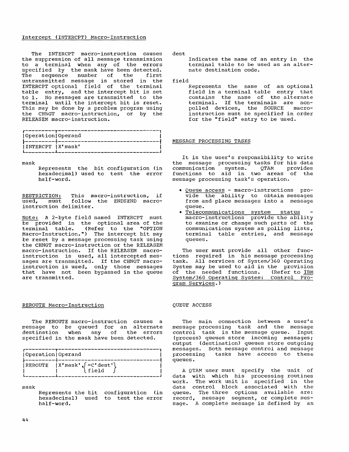
Intercept
(INTERCPT)
Macro-Instruction
The
INTERCPT
macro-instruction
causes
the
suppression
of
all
message
transmission
to
a
terminal
when
any
of
the
errors
specified
by
the
mask
have
been
detected.
The
sequence
number
of
the
first
untransmitted
message
is
stored
in
the
INTERCPT
optional
field
of
the
terminal
table
entry,
and
the
intercept
bit
is
set
to
1.
No
messages
are
transmitted
to
the
terminal
until
the
intercept
bit
is
reset.
This
may
be
done
by
a
problem
program
using
the
CHNGT
macro-instruction,
or
by
the
RELEASEM
macro-instruction.
r---------T-------------------------------,
I
Operation
I
Operand
I
~---------+-------------------------------~
IINTERCPT
IX'mask'
I
L
_________
l
_______________________________
J
mask
Represents
the
bit
configuration
(in
hexadecimal)
used
to
test
the
error
half-word.
RESTRICTION:
This
macro-instruction,
if
used,
must
follow
the
ENDS
END
macro-
instruction
delimiter.
Note:
A
2-byte
field
named
INTERCPT
must
be
provided
in
the
optional
area
of
the
terminal
table.
(Refer
to
the
"OPTION
Macro-Instruction.")
The
intercept
bit
may
be
reset
by a
message
processing
task
using
the
CHNGT
macro-instruction
or
the
RELEASEM
macro-instruction.
If
the
RELEASEM
macro-
instruction
is
used,
all
intercepted
mes-
sages
are
transmitted.
If
the
CHNGT
macro-
instruction
is
used,
only
those
messages
that
have
not
been
bypassed
in
the
queue
are
transmitted.
REROUTE
Macro-Instruction
The
REROUTE
macro-instruction
causes
a
message
to
be
queued
for
an
alternate
destination
when
any
of
the
errors
specified
in
the
mask
have
been
detected.
r---------T-------------------------------,
I
Operation
I
Operand
I
~---------+-------------------------------~
I
REROUTE
IX'mask'
,{=C'dest'}
I
I I
field
I
L
_________
l
_______________________________
J
mask
44
Represents
the
cit
hexadecimal)
used
half-word.
configuration
(in
to
test
the
error
dest
field
Indicates
the
name
of
an
entry
in
the
terminal
table
to
be
used
as
an
alter-
nate
destination
code.
Represents
the
name
of
an
optional
field
in
a
terminal
table
entry
that
contains
the
name
of
the
alternate
terminal.
If
the
terminals
are
non-
polled
devices,
the
SOURCE
macro-
instruction
must
be
specified
in
order
for
the
"field"
entry
to
be
used.
MESSAGE
PROCESSING
TASKS
It
is
the
user's
responsibility
the
message
processing
tasks
for
communication
system.
QTAM
to
write
his
data
provides
functions
to
aid
in
two
areas
message
processing
task's
operation.
of
the
•
Queue
access
-
macro-instructions
pro-
vide
the
ability
to
obtain
messages
from
and
place
messages
into
a
message
queue.
•
Telecommunications
system
status
macro-instructions
provide
the
ability
to
examine
or
change
such
parts
of
the
communications
system
as
polling
lists,
terminal
table
entries,
and
message
queues.
The
user
must
provide
all
other
fUnc-
tions
required
in
his
message
processing
task.
All
services
of
System/360
Operating
System
may
be
used
to
aid
in
the
provision
of
the
needed
functions.
(Refer
to
IBM
System/360
Operating
System:
Control
prQ=
gram
Services.)
QUEUE
ACCESS
The
main
connection
between
a
user's
message
processing
task
and
the
message
control
task
is
the
message
queue.
Input
(process)
queues
store
incoming
messages;
output
(destination)
queues
store
outgoing
messages.
Both
message
control
and
message
processing
tasks
have
access
to
these
queues.
A
QTAM
user
must
specify
the
unit
of
data
with
which
his
processing
routines
work.
The
work
unit
is
specified
in
the
data
control
block
associated
with
the
queue.
The
three
options
available
are:
record,
message
segment,
or
complete
mes-
sage.
A
complete
message
is
defined
by
an
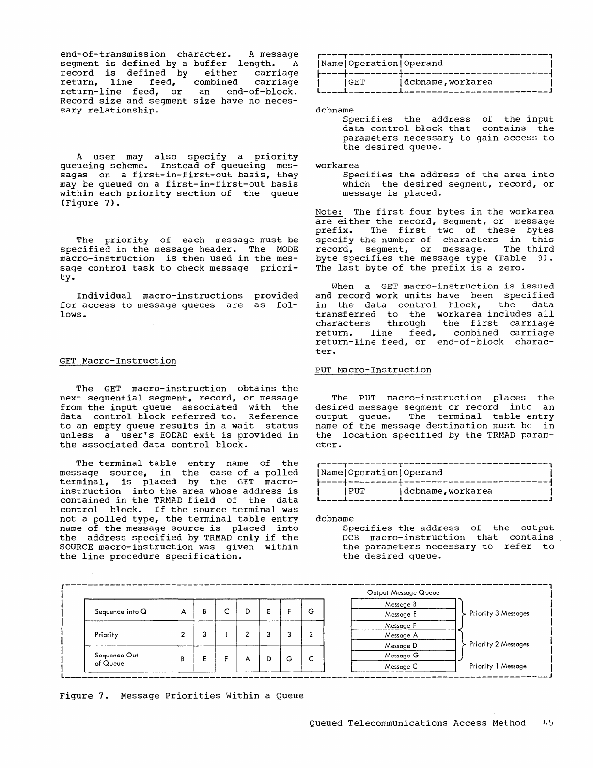
end-of-transmission
character.
A
message
segment
is
defined
by
a
buffer
length.
A
record
is
defined
by
either
carriage
return.,
line
feed.,
combined
carriage
return-line
feed,
or
an
end-of-block.
Record
size
and
segment
size
have
no
neces-
sary
relationship.
A
user
may
also
specify
a
priority
queueing
scheme.
Instead
of
queueing
mes-
sages
on
a
first-in-first-out
basis,
they
may
be
queued
on
a
first-in-first-out
basis
within
each
priority
section
of
the
queue
(Figure
7).
The
priority
of
each
message
must
be
specified
in
the
message
header.
The
MODE
macro-instruction
is
then
used
in
the
mes-
sage
control
task
to
check
message
priori-
ty.
Individual
macro-instructions
for
access
to
message
queues
are
lows.
GET
Macro-Instruction
provided
as
fol-
The
GET
macro-instruction
obtains
the
next
sequential
segment"
record"
or
message
from
the
input
queue
associated
with
the
data
control
block
referred
to.
Reference
to
an
empty
queue
results
in
a
wait
status
unless
a
user's
EOLAD
exit
is
provided
in
the
associated
data
control
block.
The
terminal
table
entry
name
of
the
message
source,
in
the
case
of
a
polled
terminal,
is
placed
by
the
GET
macro-
instruction
into
the
area
whose
address
is
contained
in
the
TRMAD
field
of
the
data
control
block.
If
the
source
terminal
was
not
a
polled
type,
the
terminal
table
entry
name
of
the
message
source
is
placed
into
the
address
specified
by
TRMAD
only
if
the
SOURCE
macro-instruction
was
given
within
the
line
procedure
specification.
r----T---------T--------------------------,
IName I
Operation
I
Operand
I
~----+---------+--------------------------~
I
IGET
Idcbname,workarea
I
L
____
~
_________
~
__________________________
J
dcbname
Specifies
the
address
of
the
input
data
control
block
that
contains
the
parameters
necessary
to
gain
access
to
the
desired
queue.
workarea
Specifies
the
address
of
the
area
into
which
the
desired
segment,
record,
or
message
is
placed.
Note:
The
first
four
bytes
in
the
workarea
are
either
the
record,
segment,
or
message
prefix.
The
first
two
of
these
bytes
specify
the
number
of
characters
in
this
record,
segment,
or
message.
The
third
byte
specifies
the
message
type
(Table
9).
The
last
byte
of
the
prefix
is
a
zero.
When a
GET
macro-instruction
is
issued
and
record
work
units
have
been
specified
in
the
data
control
block,
the
data
transferred
to
the
workarea
includes
all
characters
through
the
first
carriage
return,
line
feed,
combined
carriage
return-line
feed,
or
end-of-block
charac-
ter.
PUT
Macro-Instruction
The
PUT
macro-instruction
places
the
desired
message
seqment
or
record
into
an
output
queue.
The
terminal
table
entry
name
of
the
message
destination
must
be
in
the
location
specified
by
the
TRMAD
param-
eter.
r----T---------T--------------------------,
INamelOperationlOperand
I
~----+---------+--------------------------~
I
IPUT
Idcbname,workarea
I
L
____
~
_________
~
__________________________
J
dcbname
Specifies
the
address
of
the
output
DCB
macro-instruction
that
contains
the
parameters
necessary
to
refer
to
the
desired
queue.
r---------------------------------------------------------------------------------------,
I
Output
Message
Queue
I
I I
I
Priority
3 Messages I
I I
I I
I Priority 2 Messages I
I I
I Priority I Message I
L
_______________________________________________________________________________________
J
Figure
7.
Message
Priorities
Within
a
Queue
Queued
Telecommunications
Access
Method
45
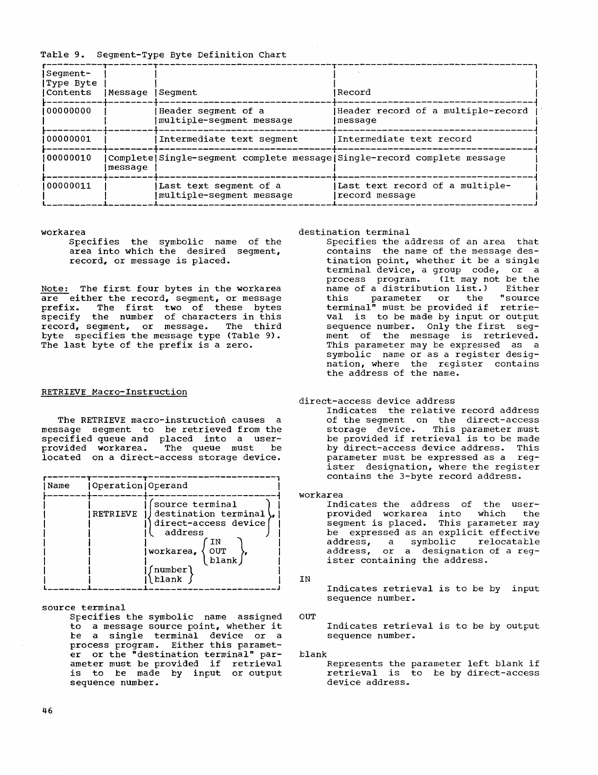
Tatle
9.
Segment-Type
Byte
Definition
Chart
r----------T--------T-------------------------------T------------------~----------------,
1
Segment-
1 1 1 1
IType
Byte
1 I 1 I
1
Contents
IMessage
ISegment
I
Record
I
~----------+--------+-------------------------------+-----------------------------------~
100000000
1
IHeader
segment
of
a
IHeader
record
of
a
multiple-record
I'
I I
Imultiple-segment
message
Imessage
I
~----------+--------+-------------------------------+---------------~-------------------~
100000001
I
IIntermediate
text
segment
IIntermediate
text
record
I
~----------+--------+-------------------------------+-----------------------------------~
100000010
I
Complete
1
Single-segment
complete
messagelSingle-record
complete
message
I
I I
message
I I I
r----------+--------+-------------------------------+-----------------------------------~
100000011
I
ILast
text
segment
of
a
ILast
text
record
of
a
multiple-
I
I I
Imultiple-segment
message
Irecord
message
I
L
__________
~
________
~
_______________________________
~
___________________________________
J
workarea
Specifies
the
symbolic
name
of
the
area
into
which
the
desired
segment,
record~
or
message
is
placed.
Note:
The
first
four
bytes
in
the
workarea
are
either
the
record,
segment,
or
message
prefix.
The
first
two
of
these
bytes
specify
the
number
of
characters
in
this
record,
segment,
or
message.
The
third
tyte
specifies
the
message
type
(Table
9).
The
last
tyte
of
the
prefix
is
a
zero.
RETRIEVE
Macro-Instruction
The
RETRIEVE
macro-instruction
causes
a
message
segment
to
be
retrieved
from
the
specified
queue
and
placed
into
a
user-
provided
workarea.
The
queue
must
be
located
on
a
direct-access
storage
device.
r-------T---------T-----------------------,
I Name I
Operation
I
Operand
I
~-------+---------+-----------------------~
I I
I{source
terminal
} I
I IRETRIEVE I.
destination
terminal
,1
I I I
direct-access
device
I
I I I
address
I
I 1 I
{IN}
I
I I I
workarea"
OUT,
I
I I I
blank
I
I I I
{number}
I
I I I
tlank
I
L
_______
~
_________
~
_______________________
J
source
terminal
46
Specifies
the
symbolic
name
assigned
to
a
message
source
point,
whether
it
te
a
single
terminal
device
or
a
process
program.
Either
this
paramet-
er
or
the
"destination
terminal"
par-
ameter
must
be
provided
if
retrieval
is
to
te
made
by
input
or
output
sequence
number.
destination
terminal
Specifies
the
address
of
an
area
that
contains
the
name
of
the
message
des-
tination
point,
whether
it
be
a
single
terminal
device,
a
group
code,
or
a
process
program.
(It
may
not
be
the
name
of
a
distribution
list.)
Either
this
parameter
or
the
"source
terminal"
must
be
provided
if
retrie-
val
is
to
be
made
by
input
or
output
sequence
number.
Only
the
first
seg-
ment
of
the
message
is
retrieved.
This
parameter
may
be
expressed
as
a
symbolic
name
or
as
a
register
desig-
nation,
where
the
register
contains
the
address
of
the
name.
direct-access
device
address
Indicates
the
relative
record
address
of
the
segment
on
the
direct-access
storage
device.
This
parameter
must
be
provided
if
retrieval
is
to
be
made
by
direct-access
device
address.
This
parameter
must
be
expressed
as
a
reg-
ister
designation,
where
the
register
contains
the
3-byte
record
address.
workarea
IN
OUT
blank
Indicates
the
address
of
the
user-'
provided
workarea
into
which
the
segment
is
placed.
This
parameter
may
be
expressed
as
an
explicit
effective
address,
a
symbolic
relocatable
address,
or
a
designation
of
a
reg-
ister
containing
the
address.
Indicates
retrieval
is
to
be
by
input
sequence
number.
Indicates
retrieval
is
to
be
by
output
sequence
number.
Represents
the
parameter
left
blank
if
retrieval
is
to
te
by
direct-access
device
address.
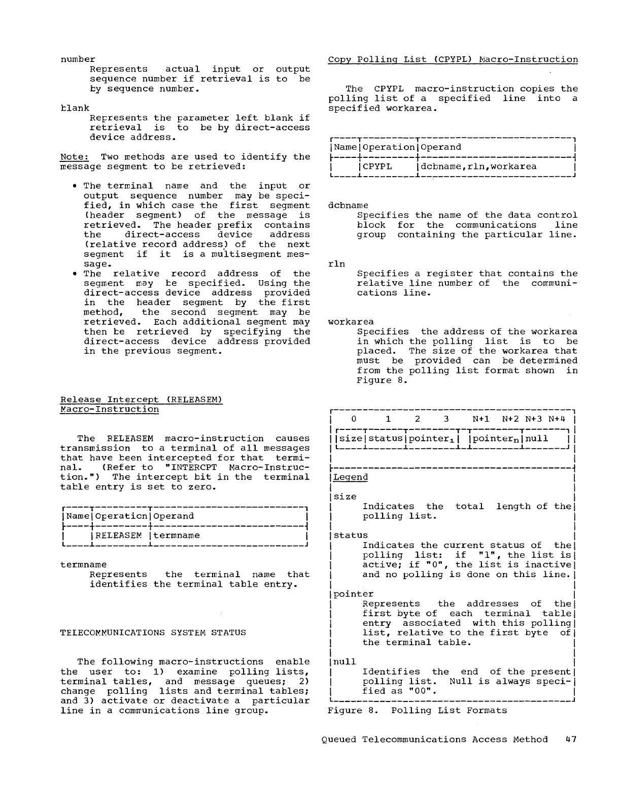
number
blank
Represents
actual
input
or
output
sequence
number
if
retrieval
is
to
be
by
sequence
number.
Represents
the
parameter
left
blank
if
retrieval
is
to
be
by
direct-access
device
address.
Note:
Two
reethods
are
used
to
identify
the
message
segment
to
be
retrieved:
•
The
terminal
name
and
the
input
or
output
sequence
number
may
be
speci-
fied,
in
which
case
the
first
segment
(header
segment)
of
the
message
is
retrieved.
The
header
prefix
contains
the
direct-access
device
address
(relative
record
address)
of
the
next
segment
if
it
is
a
multisegrnent
mes-
sage
•
•
The
relative
record
address
of
the
segment
may
be
specified.
Using
the
direct-access
device
address
provided
in
the
header
segment
by
the
first
method,
the
second
segment
may
be
retrieved.
Each
additional
segment
may
then
be
retrieved
by
specifying
the
direct-access
device
address
provided
in
the
previous
segment.
Release
Intercept
(RELEASEM)
~acro-Instruction
The
RELEASEM
macro-instruction
causes
transmission
to
a
terminal
of
all
messages
that
have
been
intercepted
for
that
termi-
nal.
(Refer
to
"INTERCPT
Macro-Instruc-
tion.")
The
intercept
bit
in
the
terminal
table
entry
is
set
to
zero.
r----T---------T--------------------------,
INamelo~erationlOperand
I
r----+---------+--------------------------~
I
IRELEASEM
Itermname
I
L
____
~
_________
~
__________________________
J
termname
Represents
the
terminal
name
that
identifies
the
terminal
table
entry.
TELECO~MUNICATIONS
SYSTEM
STATUS
The
following
macro-instructions
enable
the
user
to:
1)
examine
polling
lists,
terminal
tables,
and
message
queues;
2)
change
polling
lists
and
terminal
tables;
and
3)
activate
or
deactivate
a
particular
line
in
a
comreunications
line
group.
copy
Polling
List
(CPYPL)
Macro-Instruction
The
CPYPL
macro-instruction
copies
the
polling
list
of
a
specified
line
into
a
specified
workarea.
r----T---------T--------------------------,
IName I
Operation
I
Operand
I
r----+---------+--------------------------~
I ICPYPL
Idcbname,rln,workarea
I
L
____
i
_________
i
__
~-----------------------J
dcbname
rln
Specifies
the
name
of
the
data
control
block
for
the
communications
line
group
containing
the
particular
line.
Specifies
a
register
that
contains
the
relative
line
number
of
the
communi-
cations
line.
workarea
Specifies
the
address
of
the
workarea
in
which
the
polling
list
is
to
be
placed.
The
size
of
the
workarea
that
must
be
provided
can
be
determined
from
the
polling
list
format
shown
in
Figure
8.
r-----------------------------------------,
I 0 1 2 3
N+1
N+2 N+3
N+4
I
I r----T------T--------T-T--------T-------, I
Ilsizelstatuslpointer~1
Ipointernlnull
I I
I L
____
i
______
~
________
~_~
________
~
_______
J I
I I
r-----------------------------------------~
Legend
size
Indicates
the
total
length
of
the
polling
list.
status
Indicates
the
current
status
of
the
polling
list:
if
"1",
the
list
is
active;
if
"0",
the
list
is
inactive
and
no
polling
is
done
on
this
line.
pointer
Represents
the
addresses
of
the
first
byte
of
each
terminal
table
entry
associated
with
this
polling
list,
relative
to
the
first
byte
of
the
terminal
table.
Inull
I
Identifies
the
end
of
the
present
I
polling
list.
Null
is
always
speci-I
I
I
fied
as
"00".
I
L
_________________________________________
J
Figure
8.
Polling
List
Formats
Queued
Telecommunications
Access
Method
47
Change
Polling
List
(CHNGPL)
Macro-Instruction
The
CHNGPL
macro-instruction
places
a
new
polling
list
into
the
polling
list
area
specified
for
the
line
or
changes
the
line
status
with
regard
to
polling.
r----T---------T--------------------------,
INamelOperationlOperand
I
~----+---------+--------------------------~
I I
CHNGPL
I
dcbname,
rln,{
workarea}
I
I I I
=C'O'
I
I I I
=C
'1'
I
L
____
~
_________
~
__________________________
J
dcbname
rln
Specifies
the
name
of
the
data
control
block
that
provides
control
informa-
tion
that
pertains
to
a
line
polling
list.
specifies
a
register
that
contains
the
binary
relative
line
number
within
the
communications
line
group
for
which
the
polling
list
is
defined.
workarea
o
1
Specifies
the
address
of
the
area
that
contains
the
new
polling
list.
The
new
polling
list
must
not
contain
more
entries
than
the
original
polling
list.
It
must
be
of
the
format
shown
in
Figure
8.
If
the
new
polling
list
is
larger#
it
is
not
used.
Bit
1
of
the
first
byte
of
the
workarea,
howev-
er,
is
used
as
a
return
code
to
indicate
the
error.
Conditions
the
line
not
to
receive
incoming
messages.
Conditions
the
line
to
start
polling
with
the
previously
specified
polling
list.
Note:
For
common
carrier
TWX
networks,
only
the
condition
change
can
apply
(i.e.,
o
or
1
can
be
specified).
start
Line
<STRTLN)
Macro-Instruction
The
STRTLN
macro-instruction
can
be
used
to:
1)
allow
message
transmission
to
com-
mence
or
resume
on
a
particular
line
in
a
communications
line
group;
and
2)
allow
message
transmission
to
occur
on
all
lines
in
a
communications
line
group.
The
user
must
previously
have
issued
an
OPEN
macro-
instruction
for
the
line
group.
48
If
the
IDLE
entry
is
specified
in
the
OPEN
macro-instruction
for
the
line
group,
the
STRTLN
macro-instruction
must
be
issued
before
initial
message
transmission
can
take
place.
If
the
IDLE
entry
is
not
included
in
the
OPEN
for
the
line
group,
STRTLN
is
not
required
for
initial
message
transmission.
If
a
line
is
deactivated
by
a
STOPLN
macro-instruction,
STRTLN
must
be
issued
before
message
transmission
on
that
particular
line
can
resume.
In
all
the
above
cases,
if
polling
is
used,
the
presence
of
an
active
polling
list
is
a
prerequisite
for
message
transmission.
(An
active
polling
list
is
one
in
which
the
second
byte
of
the
list
is
a
non-zero
character
--
this
character
is
initialized
as
a 1
and
can
be
changed
by
the
CHNGPL
macro-instruction.)
If
STRTLN
is
used,
polling
begins
after
the
execution
of
that
macro-instruction.
If
the
IDLE
entry
is
not
specified
in
the
OPEN
for
the
line
group,
polling
begins
following
the
execution
of
the
OPEN
macro-instruction.
r--------T---------T----------------------,
I Name I
Operation
I
Operand
I
~--------+---------+----------------------i
I I I
{rln}
I
I
[symboIJISTRTLN
Idcbname,
ALL
I
L
________
~
_________
~
______________________
J
symbol
Specifies
the
name
for
the
STRTLN
macro-instruction.
dcbname
rln
ALL
Specifies
the
name
of
the
data
control
block
for
the
communications
line
group
containing
the
line
to
be
acti-
vated.
Specifies,
in
decimal,
the
relative
line
number
of
the
line
to
be
activa-
ted.
If
this
number
is
enclosed
in
parentheses,
it
is
interpreted
as
specifying
the
number
of
a
register
containing,
in
binary
form,
the
rela-
tive
line
number
of
the
line
to
be
activated.
Specifies
that
all
communications
line
activated.
the
lines
in
the
group
should
be
Stop
Line
(STOPLN)
Macro-Instruction
The
STOPLN
macro-instruction
removes
,a
communications
line
from
active
use.
This
macro-instruction
has
the
following
effects:
Operations
on
the
line
designated
are
stopped.
If
the
line
was
conditioned
by a
CHNGPL
macro-instruction
to
stop
receiving,
all
messages
queued
for
transmission
on
the
line
are
transmitted
before
control
is
returned
to
the
program
issuing
the
STOPLN
macro-instruction.
If
the
line
was
not
conditioned
to
stop
receiving,
control
is
returned
to
the
program
issuing
the
STOPLN
macro-instruction
immediately
after
the
completion
of
any
message
being
transmit-
ted.
In
the
latter
case,
transmission
of
any
messages
remaining
in
the
queue
for
the
line
resumes
when
a
STRTLN
macro-
instruction
reactivates
the
line.
r--------T---------T----------------------,
IName I
operation
I
operand
I
~--------+---------+----------------------~
I
[symcoIJISTOPLN
Idcbname,rln
I
L
________
i
_________
i
______________________
J
symbol
Specifies
the
name
for
the
STOPLN
macro-instruction.
dcbname
rln
Specifies
the
name
of
the
data
control
clock
for
the
communications
line
group
containing
the
line
to
be
deactivated.
Specifies,
in
.
decimal,
the
relative
line
nuwber
of
the
line
to
be
deacti-
vated.
If
this
number
is
enclosed
in
parentheses,
it
is
interpreted
as
specifying
the
number
of
a
register
containing,
in
binary
form,
the
rela-
tive
line
number
of
the
line
to
be
deactivated.
Copy
Terminal
Table
(COPYT)
V.acro-Instruction
The
COPYT
macro-instruction
causes
the
information
contained
in
a
specified
entry
of
the
terminal
tacle
to
be
moved
into
a
designated
area.
r----T---------T--------------------------,
INamelOperationlOperand
I
~----+---------+--------------------------~
I
ICOPYT
Itermname,area
I
L
____
L
_________
L
__________________________
J
termname
Specifies
the
name
of
the
terminal
with
which
the
entry
is
associated.
An
invalid
name
will
cause
the
macro-
instruction
to
be
terminated.
Bit
0
of
the
first
bytes
in
the
workarea
will
ce
wade
a
return
code
to
indicate
the
error.
area
specifies
the
address
of
the
area
into
which
the
information
is
to
be
placed.
The
first
byte
of
the
area
is
reserved
for
a
return
code.
The
table
data
always
starts
in
the
second
byte.
The
format
of
the
terminal
table
entry
copied
by
a
COPYT
macro-instruction
depends
on
whether
it
is
a
single
entry
terminal,
a
group
code
entry,
a
distribution
list
entry,
or
a
process
program
entry.
Since
the
maximum
size
of
a
terminal
table
entry
is
255
bytes,
the
maximum
size
of
the
workarea
that
must
be
provided
for
a
type
of
entry
is
256
bytes
(255
bytes
plus
return
code
byte).
The
user
may,
however,
conserve
storage
space
by
determining
the
actual
size
of
each
entry
type
from
the
terminal
table
entry
formats
illustrated
in
Figure
9
and
provide
workareas
for
those
sizes
only.
Change
Terminal
Table
(CHNGT)
Macro-Instruction
The
CHNGT
macro-instruction
causes
a
complete
terminal
table
entry
to
be
moved
from
a
designated
area
into
a
specified
entry
of
the
terminal
table.
r----T---------T--------------------------,
INamel
Operation
I
Operand
I
~----+---------+--------------------------~
I
ICHNGT
Itermname,area
I
L
____
i
_________
i
__________________________
J
termname
area
Specifies
the
terminal
name
with
which
the
entry
is
associated.
An
invalid
terminal
name
causes
the
macro-
instruction
request
to
be
terminated.
Bit
0
of
the
first
byte
in
the
workarea
is
used
as
a
return
code
to
indicate
the
error.
Specifies
the
address
of
the
area
from
which
the
information
is
to
be
moved.
The
first
byte
of
the
area
is
reserved
for
a
return
code.
The
new
table
data
must
always
start
in
the
second
byte.
Note:
The
CHNGT
macro-instruction
causes
the
entire
contents
of
a
current
entry
to
be
overlaid.
It
is
normally
preceded
by
a
COPYT
macro-instruction
and
some
modifica-
tion
to
the
copied
entry.
If
the
new
entry
is
larger
than
the
current
one,
it
is
not
used
and
bit
1
of
the
first
byte
of
the
workarea
is
used
as
a
return
code
to
indicate
the
error.
Queued
Telecommunications
Access
Method
49
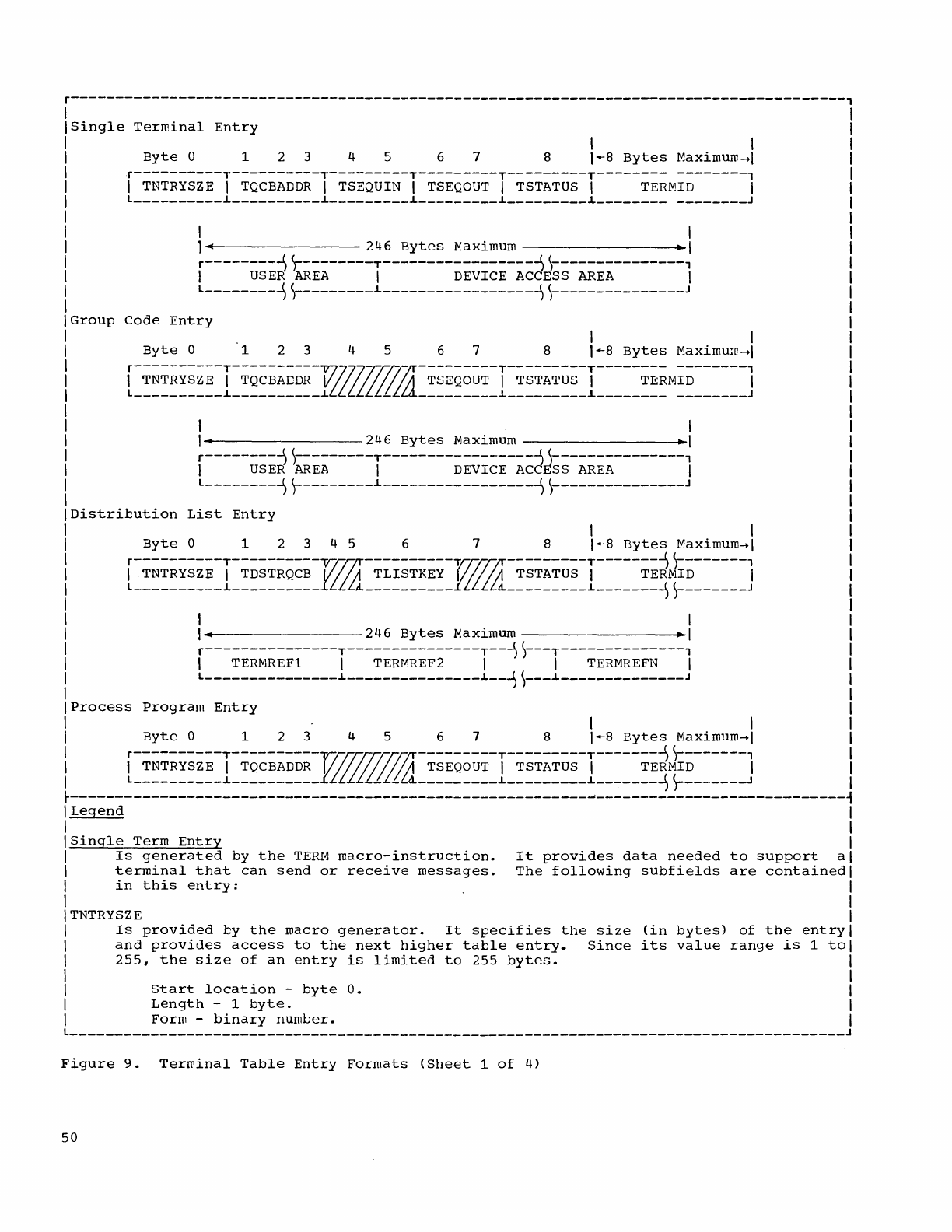
r---------------------------------------------------------------------------------------,
Single
Terminal
Entry
I I
Byte
0 1 2 3 4 5 6 7 8
1-8
Bytes
Maximuro_1
r----------T----------T---------T---------T---------T-------- --------,
I
TNTRYSZE
I
TQCBADDR
I TSEQUIN I
TSEQOUT
I
TSTATUS
I
TERMID
I
l
__________
~
__________
~
_________
~
_________
~
_________
~________
_
_______
J
I
1
~
246
Bytes
Maximum • I
r-----;~~~~~~~-----T--------~;~~~;-~~d~~~-~;~--------l
l--------1r--------~-----------------~r--------------J
Group
Code
Entry
I I
Byte
0 1 2 3 4 5 6 7 8
1-8
Bytes
Maximuro_1
[~~~~~~~~~~I~~~~~~~~~~17~~~~~~~~~~~I~~~~~~~~~I~~~~~~~~M~~~~~~~~J
I
I~
246
Bytes
Maximum .1
r-----;~;d~~;~-----T--------~;~~;;-~~d~~~-~~~~--------1
l--------~r--------~-----------------~~--------------J
Distribution
List
Entry
I
I~
246
Bytes
Maximum • I
r---------------T---------------T--~r--T--------------,
I TERMREFl I
TERMREF2
I I
TERMREFN
I
l
_______________
~
_______________
~
__
~~---~-------------_J
Process
Program
Entry
I
Byte
0 1 2 3 4 5 6 7 8
1-8
Bytes
Maximum~1
[~~~~~~~~~~I~~~~~~~~~~~~~~~~~~~~I~~~~~~~~~I~~~~~~~~~~~~~~~~J
~----------------------------------------------------------~----------------------------~
I
legend
I
I I
ISingle
Term
Entry
I
I
Is
generated
by
the
TERM
macro-instruction.
It
provides
data
needed
to
support
al
I
terminal
that
can
send
or
receive
messages.
The
following
subfields
are
contained
I
I
in
this
entry:
I
I I
ITNTRYSZE I
I
Is
provided
by
the
roacro
generator.
It
specifies
the
size
(in
bytes)
of
the
entry
I
I
and
provides
access
to
the
next
higher
table
entry.
Since
its
value
range
is
1
tol
I
255,
the
size
of
an
entry
is
limited
to
255
bytes.
I
I I
I
Start
location
-
byte
O.
I
I
Length
-1
byte.
I
I Form -
binary
number.
I
l
_______________________________________________________________________________________
J
Figure
9.
Terminal
Table
Entry
Formats
(Sheet
1
of
4)
50
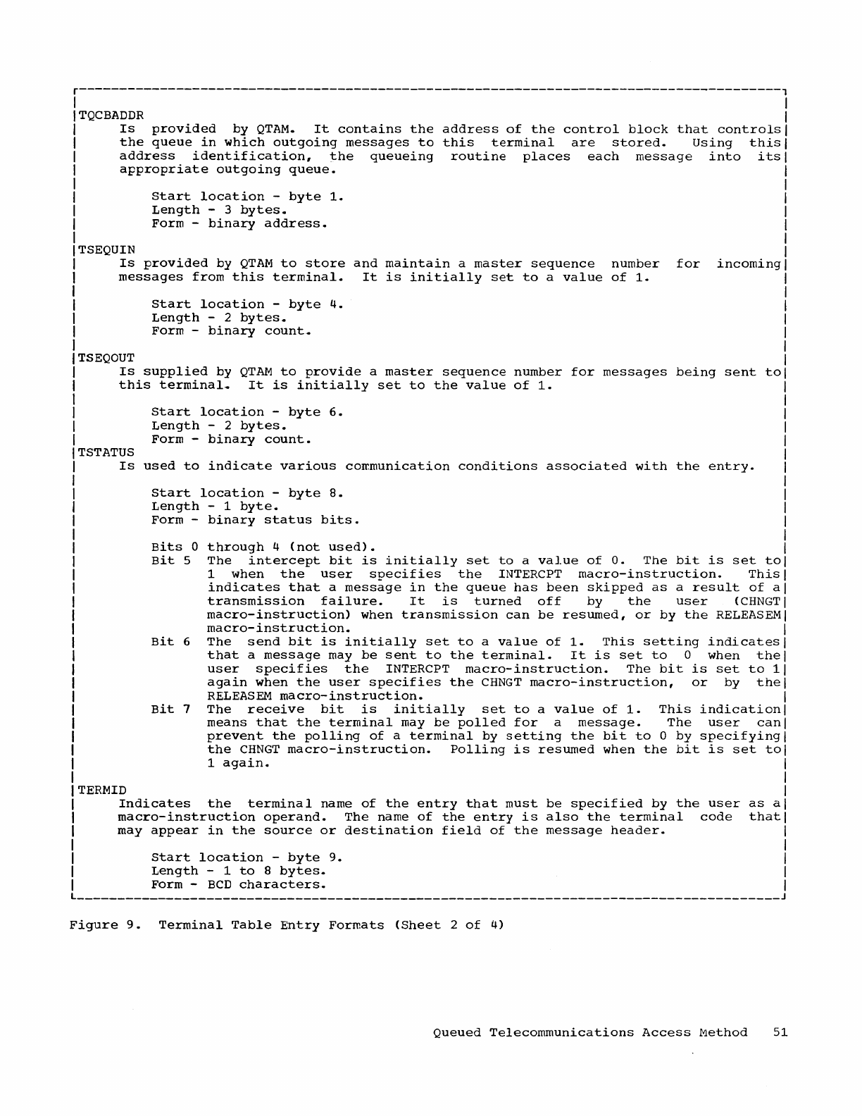
r---------------------------------------------------------------------------------------,
TQCBADDR
Is
provided
by
QTAM.
It
contains
the
address
of
the
control
block
that
controls
the
queue
1n
which
outgoing
messages
to
this
terminal
are
stored.
Using
this
address
identification,
the
queueing
routine
places
each
message
into
its
appropriate
outgoing
queue.
TSEQUIN
Start
location
-
byte
1.
Length
- 3
bytes.
Form
-
binary
address.
Is
provided
by
QTAM
to
store
and
maintain
a
master
sequence
number
for
incoming
messages
from
this
terminal.
It
is
initially
set
to
a
value
of
1.
TSEQOUT
start
location
-
byte
4.
Length
- 2
bytes.
Form
-
binary
count
.•
Is
supplied
by
QTAM
to
provide
a
master
sequence
number
for
messages
being
sent
to
this
terminal.
It
is
initially
set
to
the
value
of
1.
TSTATUS
start
location
-
byte
6.
Length
- 2
bytes.
Form
-
binary
count.
Is
used
to
indicate
various
coremunication
conditions
associated
with
the
entry.
start
location
-
byte
8.
Length
-1
byte.
Form
-
binary
status
bits.
Bits
0
Bit
5
Bit
6
Bit
7
through
4
(not
used).
The
intercept
bit
is
initially
set
to
a
value
of
o.
The
bit
is
set
to
1
when
the
user
specifies
the
INTERCPT
macro-instruction.
This
indicates
that
a
message
in
the
queue
has
been
skipped
as
a
result
of
a
transmission
failure.
It
is
turned
off
by
the
user
(CHNGT
macro-instruction)
when
transmission
can
be
resumed,
or
by
the
RELEASEM
macro-instruction.
The
send
bit
is
initially
set
to
a
value
of
1.
This
setting
indicates
that
a
message
may
be
sent
to
the
terminal.
It
is
set
to
0
when
the
user
specifies
the
INTERCPT
macro-instruction.
The
bit
is
set
to
1
again
when
the
user
specifies
the
CHNGT
macro-instruction,
or
by
the
RELEASEM
macro-instruction.
The
receive
bit
is
initially
set
to
a
value
of
1.
This
indication
means
that
the
terminal
may
be
polled
for
a
message.
The
user
can
prevent
the
polling
of
a
terminal
by
setting
the
bit
to
0
by
specifying
the
CHNGT
macro-instruction.
Polling
is
resumed
when
the
bit
is
set
to
1
again.
ITERMID
I
Indicates
the
terminal
name
of
the
entry
that
must
be
specified
by
the
user
as
a
I
macro-instruction
operand.
The
name
of
the
entry
is
also
the
terminal
code
that
I
may
appear
in
the
source
or
destination
field
of
the
message
header.
I
I
I
start
location
-
byte
9.
Length
-1
to
8
bytes.
I
Form
-
BCD
characters.
I
L
_______________________________________________________________________________________
J
Figure
9.
Terminal
Table
Entry
Formats
(Sheet
2
of
4)
Queued
Telecommunications
Access
Method
51
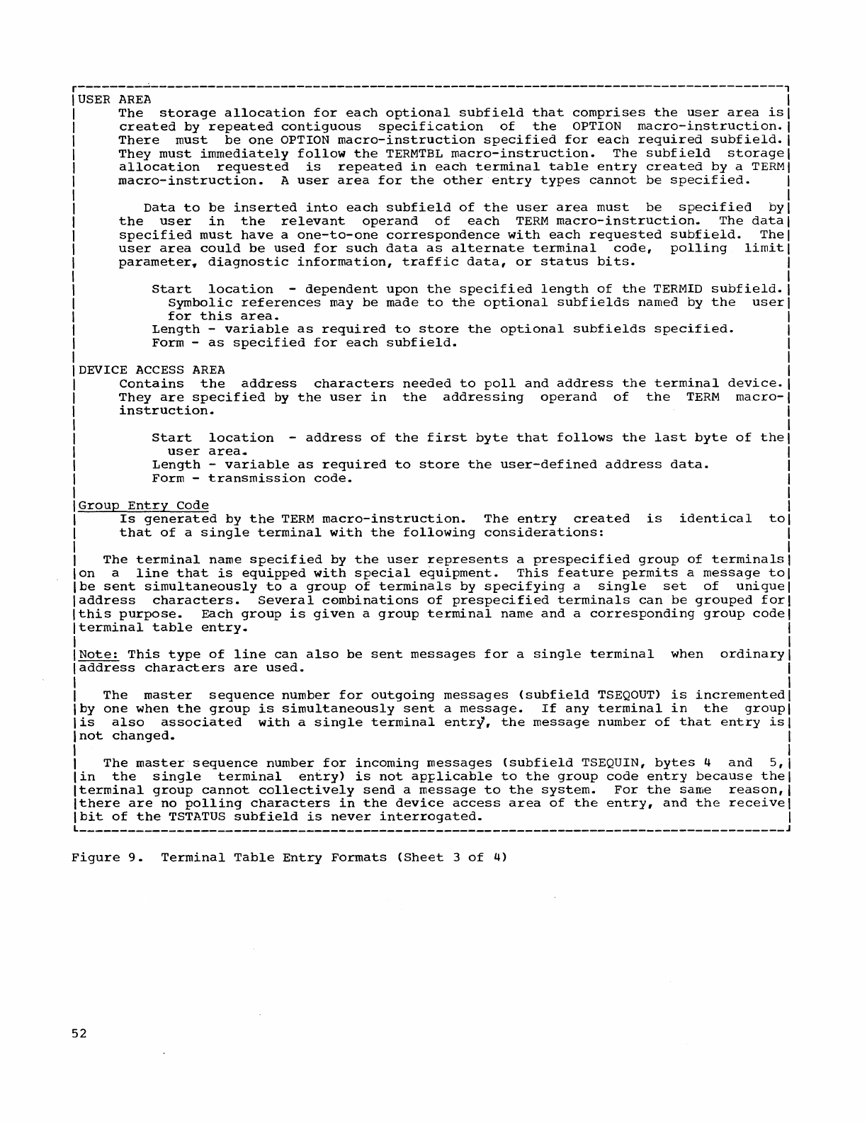
r--------~------------------------------------------------------------------------------,
USER
AREA
The
storage
allocation
for
each
optional
subfield
that
comprises
the
user
area
is
created
by
repeated
contiguous
specification
of
the
OPTION
macro-instruction.
There
must
be
one
OPTION
macro-instruction
specified
for
each
required
subfield.
They
must
immediately
follow
the
TERMTBL
macro-instruction.
The
subfield
storage
allocation
requested
is
repeated
in
each
terminal
table
entry
created
by
a
TERM
macro-instruction.
A
user
area
for
the
other
entry
types
cannot
be
specified.
Data
to
be
inserted
into
each
subfield
of
the
user
area
must
be
specified
by
the
user
in
the
relevant
operand
of
each
TERM
macro-instruction.
The
data
specified
must
have
a
one-to-one
correspondence
with
each
requested
subfield.
The
user
area
could
be
used
for
such
data
as
alternate
terminal
code,
polling
limit
parameter,
diagnostic
information,
traffic
data,
or
status
bits.
Start
location
-
dependent
upon
the
specified
length
of
the
TERMID
subfield.
Symbolic
references
may
be
made
to
the
optional
subfields
named
by
the
user
for
this
area.
Length
-
variable
as
required
to
store
the
optional
subfields
specified.
Form
-
as
specified
for
each
subfield.
DEVICE
ACCESS
AREA
Contains
the
address
characters
needed
to
poll
and
address
the
terminal
device.
They
are
specified
by
the
user
in
the
addressing
operand
of
the
TERM
macro-
instruction.
Start
location
-
address
of
the
first
byte
that
follows
the
last
byte
of
the
user
area.
Length
-
variable
as
required
to
store
the
user-defined
address
data.
Form
-
transmission
code.
Group
Entry
Code
Is
generated
by
the
TERM
macro-instruction.
The
entry
created
is
identical
to
that
of
a
single
terminal
with
the
following
considerations:
The
terminal
name
specified
by
the
user
represents
a
prespecified
group
of
terminals
on
a
line
that
is
equipped
with
special
equipment.
This
feature
permits
a
message
to
be
sent
simultaneously
to
a
group
of
terminals
by
specifying
a
single
set
of
unique
address
characters.
Several
combinations
of
prespecified
terminals
can
be
grouped
for
this
purpose.
Each
group
is
given
a
group
terminal
name
and
a
corresponding
group
code
terminal
table
entry.
Note:
This
type
of
line
can
also
be
sent
messages
for
a
single
terminal
when
ordinary
laddress
characters
are
used.
I
I
The
master
sequence
number
for
outgoing
messages
(subfield
TSEQOUT)
is
incremented
Iby
one
when
the
group
is
simultaneously
sent
a
message.
If
any
terminal
in
the
group
lis
also
associated
with
a
single
terminal
entry,
the
message
number
of
that
entry
is
Inot
changed.
I
I I
I
The
master
sequence
number
for
incoming
messages
(subfield
TSEQUIN,
bytes
4
and
5,
I
lin
the
single
terminal
entry)
is
not
apFlicable
to
the
group
code
entry
because
thel
Iterminal
group
cannot
collectively
send
a
message
to
the
system.
For
the
same
reason,
I
Ithere
are
no
polling
characters
in
the
device
access
area
of
the
entry,
and
the
receive
I
Ibit
of
the
TSTATUS
subfield
is
never
interrogated.
I
L
_______________________________________________________________________________________
J
Figure
9.
Terminal
Table
Entry
Formats
(Sheet
3
of
4)
52
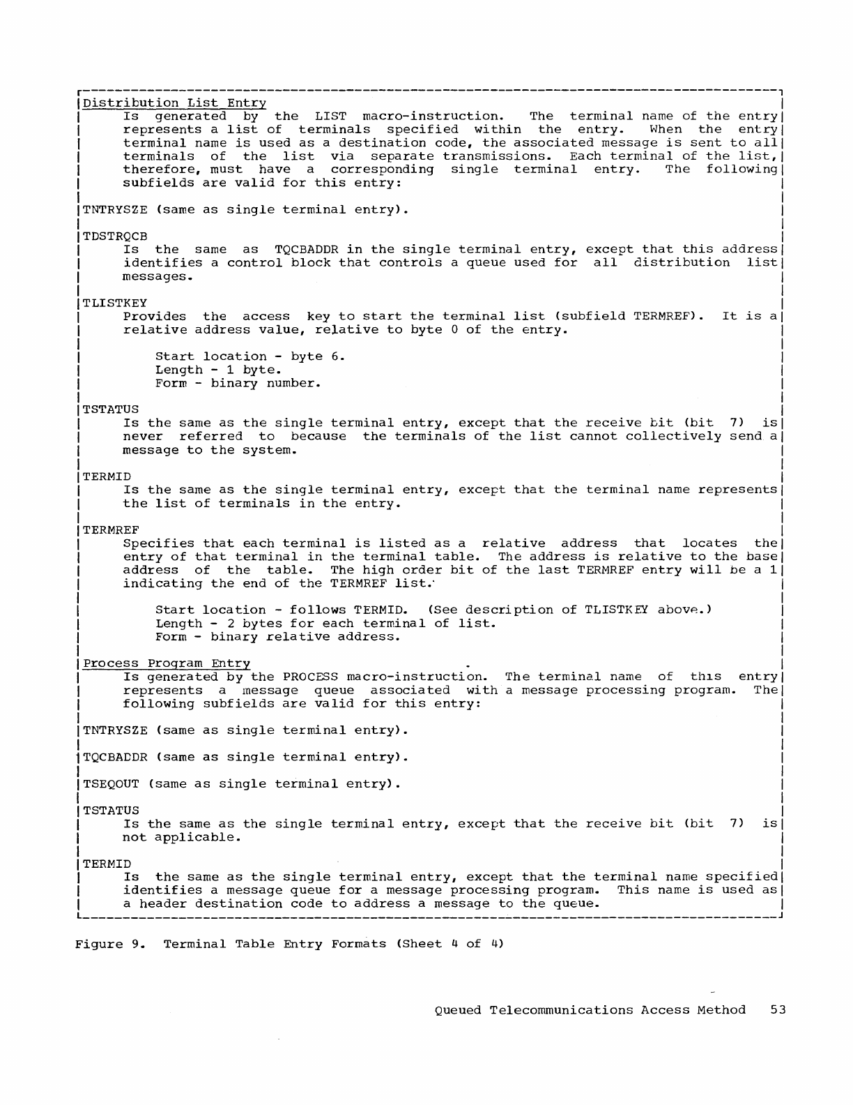
r---------------------------------------------------------------------------------------,
Distribution
List
Entry
Is
generated
by
the
LIST
macro-instruction.
The
terminal
name
of
the
entry
represents
a
list
of
terminals
specified
within
the
entry.
When
the
entry
terminal
name
is
used
as
a
destination
code,
the
associated
message
is
sent
to
all
terminals
of
the
list
via
separate
transmissions.
Each
terminal
of
the
list,
therefore,
must
have
a
corresponding
single
terminal
entry.
The
following
subfields
are
valid
for
this
entry:
TNTRYSZE
(same
as
single
terminal
entry).
TDSTRQCB
Is
the
same
as
TQCBADDR
in
the
single
terminal
entry,
except
that
this
address
identifies
a
control
block
that
controls
a
queue
used
for
all
distribution
list
messages.
TLISTKEY
Provides
the
access
key
to
start
the
terminal
list
(subfield
TERMREF).
It
is
a
relative
address
value,
relative
to
byte
0
of
the
entry.
TSTATUS
Start
location
-
byte
6.
Length
-1
byte.
Form -
binary
number.
Is
the
same
as
the
single
terminal
entry,
except
that
the
receive
bit
(bit
7)
is
never
referred
to
because
the
terminals
of
the
list
cannot
collectively
send
a
message
to
the
system.
TERMID
Is
the
same
as
the
single
terminal
entry,
except
that
the
terminal
name
represents
the
list
of
terminals
in
the
entry.
TERMREF
Specifies
that
each
terminal
is
listed
as
a
relative
address
that
locates
the
entry
of
that
terminal
in
the
terminal
table.
The
address
is
relative
to
the
base
address
of
the
table.
The
high
order
bit
of
the
last
TERMREF
entry
will
be
a 1
indicating
the
end
of
the
TERMREF
list.'
Start
location
-
follows
TERMID.
(See
description
of
TLISTKEY
abovp..)
Length
- 2
bytes
for
each
terminal
of
list.
Form -
binary
relative
address.
Process
Program
Entry
Is
generated
by
the
PROCESS
macro-instruction.
The
terminal
name
of
thlS
entry
represents
a
message
queue
associated
with
a
message
processing
program.
The
following
subfields
are
valid
for
this
entry:
TNTRYSZE
(same
as
single
terminal
entry).
1TQCBADDR
(same
as
single
terminal
entry).
I
ITSEQOUT
(same
as
single
terminal
entry).
I
I
TSTATUS
I
Is
the
same
as
the
single
terminal
entry,
except
that
the
receive
bit
(bit
7)
is
I
not
applicable.
I
ITERMID
I
Is
the
same
as
the
single
terminal
entry,
except
that
the
terminal
name
specified
I
identifies
a
message
queue
for
a
message
processing
program.
This
name
is
used
asl
I a
header
destination
code
to
address
a
message
to
the
queue.
I
L
_____________________________________________________
~
_________________________________
J
Figure
9.
Terminal
Table
Entry
Formats
(Sheet
4
of
4)
Queued
Telecommunications
Access
Method
53
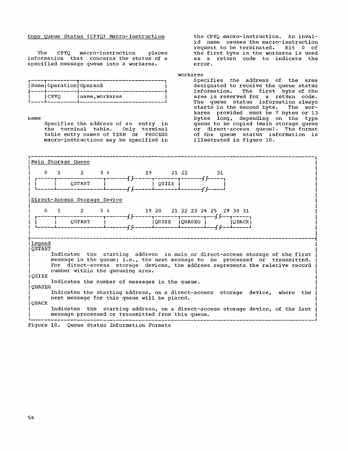
copy
Queue
Status
(CPYQ)
Macro-Instruction
The
CPYQ
macro-instruction
places
information
that
concerns
the
status
of
a
specified
message
queue
into
a
workarea.
r----T---------T--------------------------,
I Name I
Operationl
Operand
I
~----+---------+--------------------------~
I
ICPYQ
Iname,workarea
I
l
____
L
_________
L
__________________________
J
name
Specifies
the
address
of
an
entry
in
the
terminal
table.
Only
terminal
table
entry
names
of
TERM
or
PROCESS
macro-instructions
may
be
specified
in
the
CPYQ
macro-instruction.
An
inval-
id
name
causes
the
macro-instruction
request
to
be
terminated.
Bit
0
of
the
first
byte
in
the
workarea
is
used
as
a
return
code
to
indicate
the
error.
workarea
Specifies
the
address
of
the
area
designated
to
receive
the
queue
status
information.
The
first
byte
of
the
area
is
reserved
for
a
return
code.
The
queue
status
information
always
starts
in
the
second
byte.
The
wor-
karea
provided
must
be
7
bytes
or
13
bytes
long,
depending
on
the
type
queue
to
be
copied
(main
storage
queue
or
direct-access
queue).
The
format
of
the
queue
status
information
is
illustrated
in
Figure
10.
r---------------------------------------------------------------------------------------,
Main
Storage
Queue
o 1 2 3 4
19
21 22
31
r-----T--------------T-------f
~-----T-------T-------f
f-----,
I I
QSTART
I I QSIZE I I
l
_____
L
______________
L
______
~
f------L-------L------~
J-----J
Direct-Access
Storage
Device
o 1 2 3 4
19
20 21 22 23 24 25 29
30 31
r-----T--------------T-------{
r-----T-------T-------T---f
J---T-----'
I I
QSTART
I IQSIZE
IQNASEG
I
IQBACKI
l
_____
L
______________
L
______
-j
f------L-------L-------L---f
j-
__
L
_____
J
~---------------------------------------------------------------------------------------~
I
Legend
I
QSTART
I
Indicates
the
starting
address
in
main
or
direct-access
storage
of
the
first
I
message
in
the
queue;
i.e.,
the
next
message
to
be
processed
or
transmitted.
I
For
direct-access
storage
devices,
the
address
represents
the
relative
record
I
number
within
the
queueing
area.
I QSIZE
I
Indicates
the
number
of
messages
in
the
queue.
IQNASEG
I
Indicates
the
starting
address,
on
a
direct-access
storage
device,
where
the
I
next
message
for
this
queue
will
be
placed.
IQBACK
I
Indicates
the
starting
address,
on
a
direct-access
storage
device,
of
the
last
I
message
processed
or
transmitted
from
this
queue.
l
_______________________________________________________________________________________
J
Figure
10.
Queue
Status
Information
Formats
54
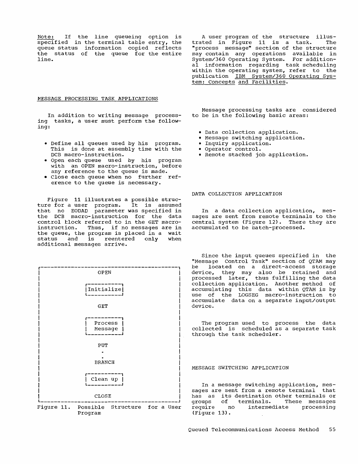
Note:
If
the
line
queueing
option
is
specified
in
the
terminal
table
entry,
the
queue
status
information
copied
reflects
the
status
of
the
queue
for
the
entire
line.
MESSAGE
PROCESSING
TASK
APPLICATIONS
In
addition
to
writing
message
process-
ing
tasks,
a
user
must
perform
the
follow-
ing:
•
Define
all
queues
used
by
his
program.
This
is
done
at
assembly
time
with
the
DCB
macro-instruction.
•
Open
each
queue
used
by
his
program
with
an
OPEN
macro-instruction,
before
any
reference
to
the
queue
is
made.
•
Close
each
queue
when
no
further
ref-
erence
to
the
queue
is
necessary.
Figure
11
illustrates
a
possible
struc-
ture
for
a
user
program.
It
is
assumed
that
no
EODAD
parameter
was
specified
in
the
DCB
macro-instruction
for
the
data
control
tlock
referred
to
in
the
GET
macro-
instruction.
Thus,
if
no
messages
are
in
the
queue,
the
program
is
placed
in
a
wait
status
and
is
reentered
only
whe~
additional
messages
arrive.
r-----------------------------------------,
OPEN
r----------,
I
Initializel
L
__________
J
GET
r----------,
I
Process
I
I
Message
I
L
__________
J
PUT
BRANCH
r----------,
I
Clean
up
I
L
__________
J
CLOSE
_________________________________________
J
Figure
11.
Possible
Structure
for
a
User
Program
A
user
program
of
the
structure
illus-
trated
in
Figure
11
is
a
task.
The
"process
message"
section
of
the
structure
may
contain
any
operations
available
in
System/360
Operating
System.
For
addition-
al
information
regarding
task
scheduling
within
the
operating
system,
refer
to
the
publication
IBM
System/360
Operating
Sys-
tem:
Concepts
and
Facilities.
Message
processing
tasks
are
considered
to
be
in
the
following
basic
areas:
•
Data
collection
application.
•
Message
switching
application.
•
Inquiry
application.
•
Operator
control.
•
Remote
stacked
job
application.
DATA
COLLECTION
APPLICATION
In
a
data
collection
application,
mes-
sages
are
sent
from
remote
terminals
to
the
central
system
(Figure
12).
There
they
are
accumulated
to
be
batch-processed.
Since
the
input
queues
specified
in
the
"Message
Control
Task"
section
of
QTAM
may
be
located
on
a
direct-access
storage
device,
they
may
also
be
retained
and
processed
later,
thus
fulfilling
the
data
collection
application.
Another
method
of
accumulating
this
data
within
QTAM
is
by
use
of
the
LOGSEG
macro-instruction
to
accumulate
data
on
a
separate
input/output
device.
The
program
used
to
process
the
data
collected
is
scheduled
as
a
separate
task
through
the
task
scheduler.
MESSAGE
SWITCHING
APPLICATION
In
a
message
switching
application,
mes-
sages
are
sent
from
a
remote
terminal
that
has
as
its
destination
other
terminals
or
groups
of
terminals.
These
messages
require
no
intermediate
processing
(Figure
13).
Queued
Telecommunications
Access
Method
55
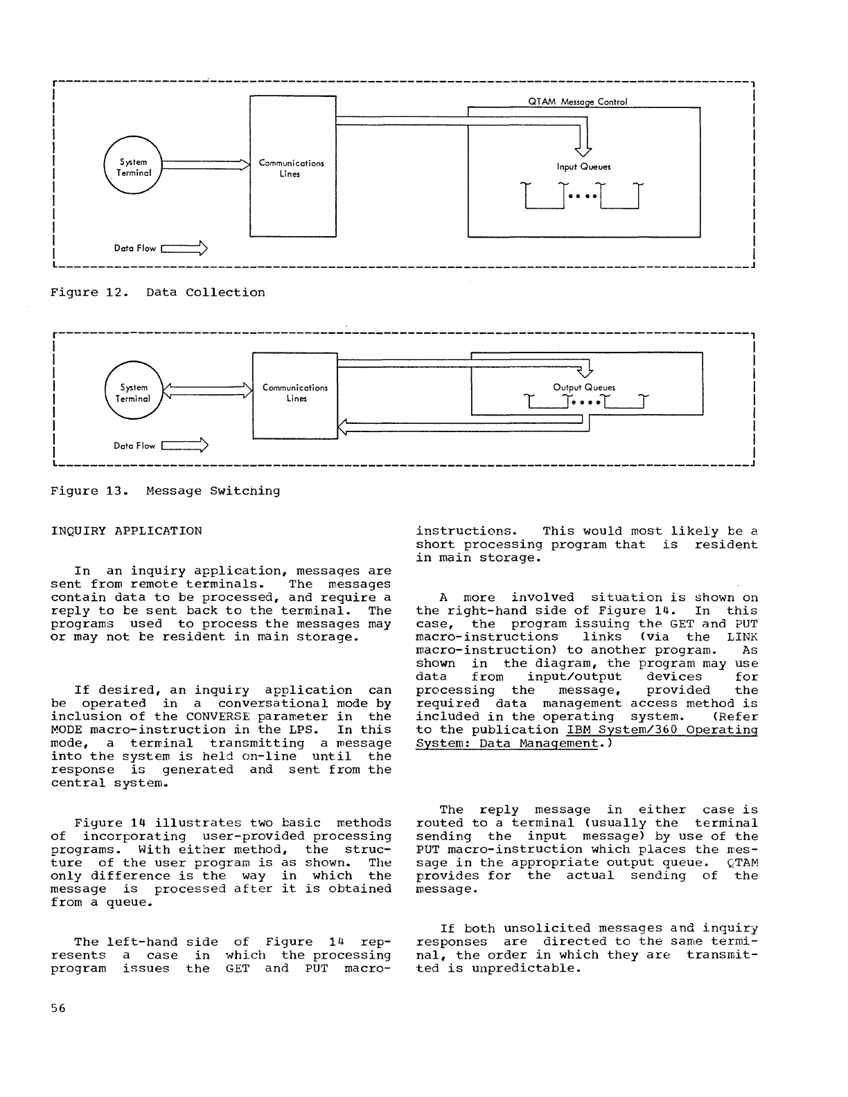
r------------------~--------------------------------------------------------------------,
DataFlow~
Communications
Lines
Figure
12.
Data
Collection
Control
Input
Queues
LJ····LJ
r---------------------------------------------------------------------------------------,
I I
I I
I I
I
Communications
Output
Queues
I
I
lines
~
••••
~
I
I I
I I
I
Data
Flow
c==)
I
L
_______________________________________________________________________________________
J
Figure
13.
Message
Switching
INQUIRY APPLICATION
In
an
inquiry
application,
messages
are
sent
from
remote
terminals.
The
messages
contain
data
to
be
processed,
and
require
a
reply
to
te
sent
back
to
the
terminal.
The
programs
used
to
process
the
messages
may
or
may
not
te
resident
in
main
storage.
If
desired,
an
inquiry
application
can
be
operated
in
a
conversational
mode
by
inclusion
of
the
CONVERSE
parameter
in
the
MODE
macro-instruction
in
the
LPS.
In
this
mode,
a
terminal
transmitting
a
roessage
into
the
system
is
held
on-line
until
the
response
is
generated
and
sent
from
the
central
system.
Figure
14
illustrates
two
tasic
methods
of
incorporating
user-provided
processing
programs.
With
either
method,
the
struc-
ture
of
the
user
program
is
as
shown.
The
only
difference
is
the
way
in
which
the
message
is
processed
after
it
is
obtained
from
a
queue.
The
left-hand
side
resents
program
56
a
case
in
issues
the
of
Figure
14
rep-
which
the
processing
GET
and
PUT
macro-
instructions.
This
would
most
likely
be
a
short
processing
program
that
is
resident
in
main
storage.
A
more
involved
situation
is
shown
on
the
right-hand
side
of
Figure
14.
In
this
case,
the
program
issuing
the
GET
and
PUT
macro-instructions
links
(via
the
LINK
macro-instruction)
to
another
program.
As
shown
in
the
diagram,
the
program
may
use
data
from
input/output
devices
for
processing
the
message,
provided
the
required
data
management
access
method
is
included
in
the
operating
system.
(Refer
to
the
publication
IBM
System/360
Operating
System:
Data
Management.)
The
reply
message
in
either
case
is
routed
to
a
terminal
(usually
the
terminal
sending
the
input
message)
by
use
of
the
PUT
macro-instruction
which
places
the
mes-
sage
in
the
appropriate
output
queue.
QTAM
provides
for
the
actual
sending
of
the
message.
If
both
unsolicited
messages
and
inquiry
responses
are
directed
to
the
same
termi-
nal,
the
order
in
which
they
are
transmit-
ted
is
unpredictable.
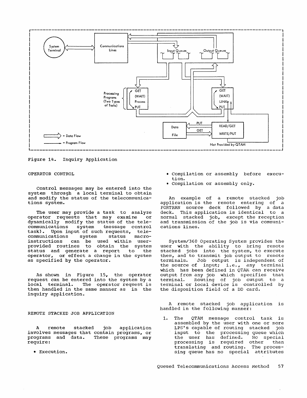
r---------------------------------------------------------------------------------------,
~=DatcFlow
---_
= Program Flow
Communications
Lines
{
l
GET
Processing
Programs
(WAIT)
(T
wo
T)'pes Process
of
Tasks)
PUT
Figure
14.
Inquiry
Application
OPERATOR
CONTROL
Control
messages
may
be
entered
into
the
system
through
a
local
terminal
to
obtain
and
modify
the
status
of
the
telecommunica-
tions
system.
The
user
may
provide
a
task
to
analyze
operator
requests
that
may
examine
or
dynamically
modify
the
status
of
the
tele-
communications
system
(message
control
task).
Upon
input
of
such
requests,
tele-
communications
system
status
macro-
instructions
can
be
used
within
user-
provided
routines
to
obtain
the
system
status
and
generate
a
report
to
the
operator,
or
effect
a
change
in
the
system
as
specified
by
the
operator.
As
shown
in
Figure
15,
the
operator
request
can
be
entered
into
the
system
by
a
local
terminal.
The
operator
request
is
then
handled
in
the
same
manner
as
in
the
inquiry
application.
REMOTE
STACKED
JOB APPLICATION
A
remote
stacked
job
application
involves
messages
that
contain
programs,
or
programs
and
data.
These
programs
may
require:
•
Execution.
Input Queues
LJLJ
Data
File
Output
Queues
LJLJ
GET
READ/GET
WRITE/PUT
Not
Provided
by
QT
J;.M
•
Compilation
or
assembly
before
execu-
tion
.
•
Compilation
or
assembly
only.
An
example
of
a
remote
stacked
job
application
is
the
remote
entering
of
a
FORTRAN
source
deck
followed
by
a
data
deck.
This
application
is
identical
to
a
normal
stacked
job,
except
the
reception
and
transmission
of
the
job
is
via
communi-
cations
lines.
System/360
Operating
System
provides
the
user
with
the
ability
to
bring
remote
stacked
jobs
into
the
system,
to
execute
them,
and
to
transmit
job
output
to
remote
terminals.
Job
output
is
independent
of
the
source
of
input;
i.e.,
any
terminal
which
has
been
defined
in
QT~l
can
receive
output
from
any
job
which
specifies
tnat
terminal.
Routing
of
job
output
to
a
terminal
or
local
device
is
controlled
by
the
disposition
field
of
a
DD
card.
A
remote
stacked
job
application
is
handled
in
the
following
manner:
1.
The
QTAM
message
control
task
is
assembled
by
the
user
with
one
or
more
LPS's
capable
of
routing
stacked
job
input
to
the
processing
queue
which
the
user
has
defined.
No
special
processing
is
required
other
than
translating
and
routing.
The
proces-
sing
queue
has
no
special
attributes
Queued
Telecommunications
Access
Method
57
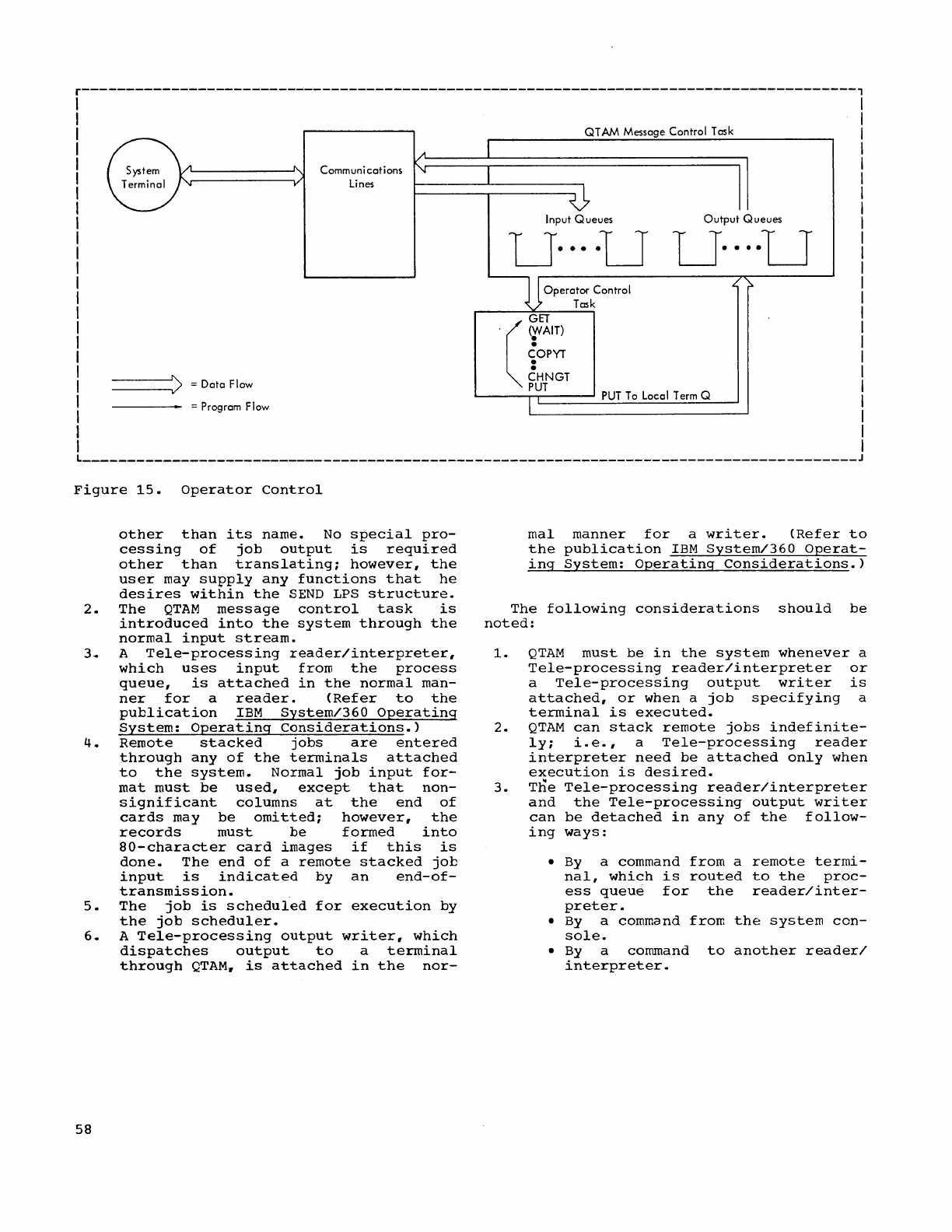
r---------------------------------------------------------------------------------------,
QT
ANI
Message
Contro
T
os
k
A
~
"-
System Communi
cations
'\j
I
Terminal
'"
v Lines
~
Input
Queues
Output
Queues
U····U
U····U
D
Ope,o'",
Co""ol ,(,
;:.
Task
GET
.
(r
A1T
)
COPYT
•
•
:>
=
Data
Flow
CHNGT
PUT
PUT
To Local Term Q
=
Program
Flow
l
_______________________________________________________________________________________
J
Figure
15.
Operator
Control
other
than
its
name.
No
special
pro-
cessing
of
job
output
is
required
other
than
translating;
however,
the
user
may
su~ply
any
functions
that
he
desires
within
the
SEND
LPS
structure.
2.
The
QTAM
message
control
task
is
introduced
into
the
system
through
the
normal
input
stream.
3.
A
Tele-processing
reader/interpreter,
which
uses
input
from
the
process
queue,
is
attached
in
the
normal
man-
ner
for
a
reader.
(Refer
to
the
publication
IBM
System/360
Operating
System:
Operating
considerations.)
4.
Remote
stacked
jobs
are
entered
through
any
of
the
terminals
attached
to
the
system.
Normal
job
input
for-
mat
must
be
used,
except
that
non-
significant
columns
at
the
end
of
cards
may
be
omitted;
however,
the
records
must
be
formed
into
80-character
card
images
if
this
is
done.
The
end
of
a
remote
stacked
job
input
is
indicated
by
an
end-of-
transmission.
5.
The
job
is
scheduled
for
execution
by
the
job
scheduler.
6.
A
Tele-processing
output
writer,
which
dispatches
output
to
a
terminal
through
QTAM.
is
attached
in
the
nor-
58
mal
manner
for
a
writer.
(Refer
to
the
publication
IBM
System/360
Operat-
ing
System:
Operating
Considerations.)
The
following
considerations
should
be
noted:
1.
QTAM
must
be
in
the
system
whenever
a
Tele-processing
reader/interpreter
or
a
Tele-processing
output
writer
is
attached,
or
when
a
job
specifying
a
terminal
is
executed.
2.
QTAM
can
stack
remote
jobs
indefinite-
ly;
i.e.,
a
Tele-processing
reader
interpreter
need
be
attached
only
when
execution
is
desired.
3.
The
Tele-processing
reader/interpreter
and
the
Tele-processing
output
writer
can
be
detached
in
any
of
the
follow-
ing
ways:
•
By
a command
from
a
remote
termi-
nal,
which
is
routed
to
the
proc-
ess
queue
for
the
reader/inter-
preter.
•
By
a command
from
the
system
con-
sole.
•
By
a command
to
another
reader/
interpreter.
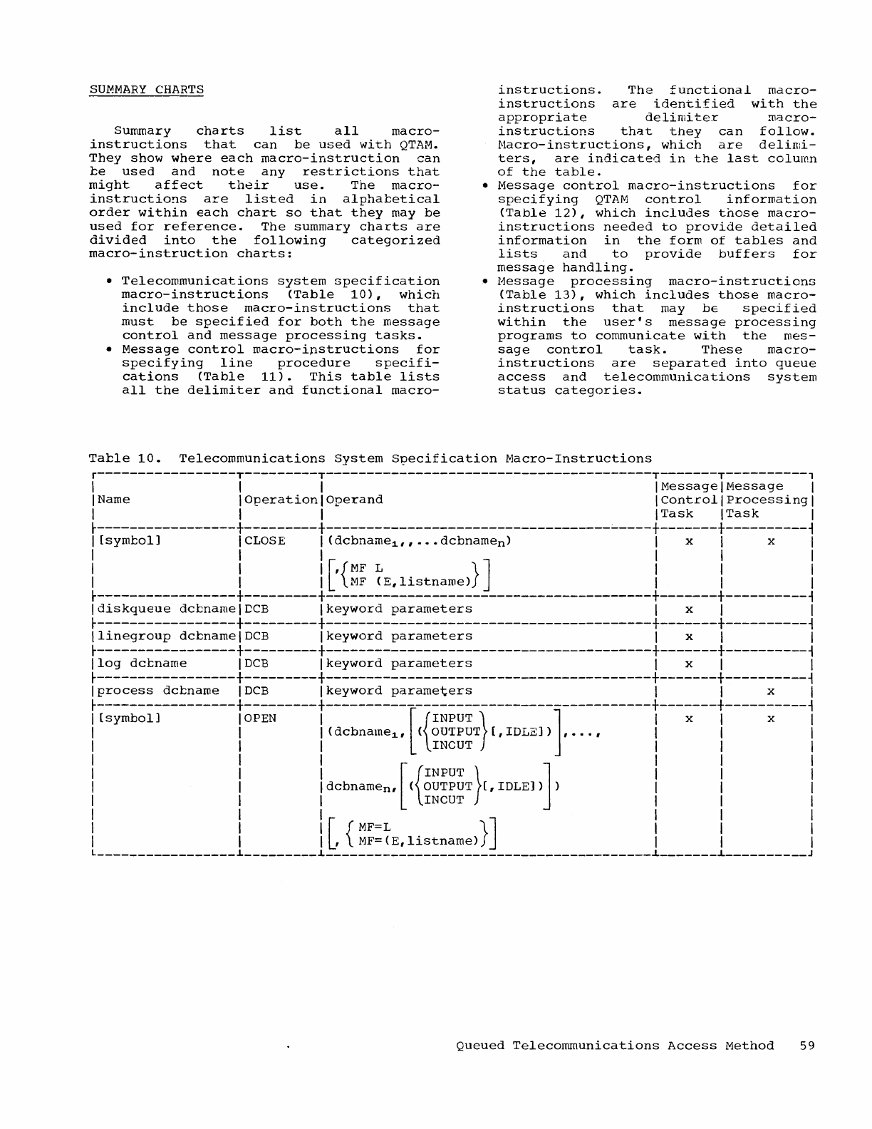
SUMMARY
CHARTS
Summary
charts
list
all
macro-
instructions
that
can
be
used
with
QTAM.
They
show
where
each
macro-instruction
can
be
used
and
note
any
restrictions
that
might
affect
their
use.
The
macro-
instructions
are
listed
in
alphabetical
order
within
each
chart
so
that
they
may
be
used
for
reference.
The
summary
charts
are
divided
into
the
following
categorized
macro-instruction
charts:
•
Telecommunications
system
specification
macro-instructions
(Table
10),
which
include
those
macro-instructions
that
must
be
specified
for
both
the
message
control
and
message
processing
tasks.
•
Message
control
macro-ipstructions
for
specifying
line
procedure
specifi-
cations
(Table
11).
This
table
lists
all
the
delimiter
and
functional
macro-
instructions.
The
functional
macro-
instructions
are
identified
with
the
appropriate
delimiter
macro-
instructions
that
they
can
follow.
f'.1acro-
instructions,
which
are
d
elin:i-
ters,
are
indicated
in
the
last
column
of
the
table.
•
Message
control
macro-instructions
for
specifying
QTAM
control
information
(Table
12),
which
includes
those
macro-
instructions
needed
to
provide
detailed
information
in
the
form
of
tables
and
lists
and
to
provide
buffers
for
message
handling
.
•
Message
processing
macro-instructions
(Table
13),
which
includes
those
macro-
instructions
that
may
be
specified
within
the
user's
message
processing
programs
to
communicate
with
the
mes-
sage
control
task.
These
macro-
instructions
are
separated
into
queue
access
and
telecommunications
system
status
categories.
Table
10.
Telecommunications
System
S?ecification
Macro-Instructions
r-----------------T---------T----------------------------------------T-------T----------,
\ \ \
\Message\Message
\
\ Name \
Operation
I
Operand
\
Control
\
Processing
\
\ \ \
\Task \Task
\
~-----------------+---------+-----------------------------------~----+-------+----------~
\
[symbol]
\
CLOSE
\ (dcbname:1."
•••
dcbnamen)
\ x \ x \
\ \ \ \ \ I
\ I I
[,{MF
L
}]
I \ \
I I I
MF
(E,listname)
\ I I
~-----------------+---------+----------------------------------------+-------+----------~
Idiskqueue
dcbnamelDCB
Ikeyword
parameters
I x I I
~-----------------+---------+----------------------------------------+-------+----------~
Ilinegroup
dcbnamelDCB
I
keyword
parameters
\ x I I
~-----------------+---------+----------------------------------------+-------+----------~
Ilog
dcbname
IDCB
Ikeyword
parameters
I x I I
~-----------------+---------+----------------------------------------+-------+----------~
Iprocess
dcbname
IDCB
Ikeyword
parameters
I I x I
~-----------------+---------+----------------------------------------+-------+----------~
I
[symbol]
IOPEN
I [
{INPUT}
] I x I x I
I I I (dcbname:1., (
OUTPUT
[,
IDLE])
,
•..
, I I I
I I I INCUT I I \
!
!!
dcbnamen.
[({~~i~~T}['
IDLE]
)]
)
!!
!
I \ \ IN
CUT
\ \ \
I I I [
{MF=L}]
I I I
I I
I,
MF=(E,listname)
\ \ \
L
_________________
~
_________
~
________________________________________
~
_______
~
__________
J
Queued
Telecommunications
Access
Method
59
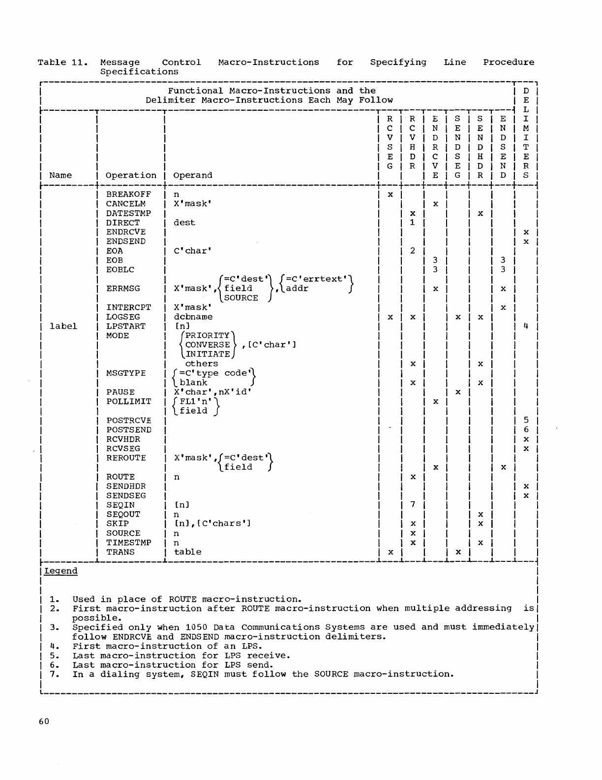
Table
11.
Message
Control
Macro-Instructions
for
Specifying
Line
Procedure
Specifications
r-----------------------------------------------------------------------------------T---'
I
Functional
Macro-Instructions
and
the
I D I
I
Delimiter
Macro-Instructions
Each
May
Follow
I E I
~---------T-----------T-------------------------------------T---T---T---T---T---T---~
L I
I I I I R I R I E I
SIS
I E I I I
I I I I C I C I N I E I E I N I M I
I I I I V I V I
DIN
I N I D I I I
I I I
ISIHIRIDIDISITI
I I I I E I D I
CIS
I
HIE
I E I
I I I I G I R I V I E I
DIN
I R I
I Name I
Operation
I
Operand
I I I E I G I
RID
I S I
~---------+-----------+-------------------------------------+---+---+---+---+---+---+---~
label
BREAKOFF
n x
CANCELM
X'mask'
x
DATESTMP
x x
DIRECT
dest
1
ENDRCVE
x
ENDS
END
x
EOA
C'char'
2
EOB
3 3
EOBLC
3 3
ERRMSG
INTERCPT
LOGSEG
LPSTART
MODE
MSGTYPE
PAUSE
POLLIMIT
POSTRCVE
POSTS
END
RCVHDR
RCVSEG
REROUTE
ROUTE
SENDHDR
SENDSEG
{
=C'dest'}
{=c'errtext'}
X'mask',
field
,
addr
SOURCE
X'mask'
dcbname
en]
{
PRIORITY}
CONVERSE
,[C'char']
INITIATE
others
{
=c'type
cOde'}
blank
X'char',nX'id'
{FL1
'n'}
field
X'
mask'
,{=C'
dest
'}
field
n
SEQIN
en]
SEQOUT
n
x x
x
x
x
7
SKIP
(n],[C'chars']
x
SOURCE
n x
TIMESTMP n x
x
x
x
x
x
TRANS
table
x x
x
x
x
x
x
x
x
x
x
4
5
6
x
x
x
x
~---------~-----------~-------------------------------------~---~---~---~---~--~---~---~
Legend
I
1.
2.
3.
4.
5.
6.
7.
I
I
Used
in
place
of
ROUTE
macro-instruction.
I
First
macro-instruction
after
ROUTE
macro-instruction
when
multiple
addressing
isl
possible.
Specified
only
when
1050
Data
Communications
follow
ENDRCVE
and
ENDS
END
macro-instruction
First
macro-instruction
of
an
LPS.
Last
macro-instruction
for
LPS
receive.
Last
macro-instruction
for
LPS
send.
I
Systems
are
used
and
must
immediately
I
delimiters.
I
I
I
I
In
a
dialing
system,
SEQIN
must
follow
the
SOURCE
macro-instruction.
I
I
_______________________________________________________________________________________
J
60
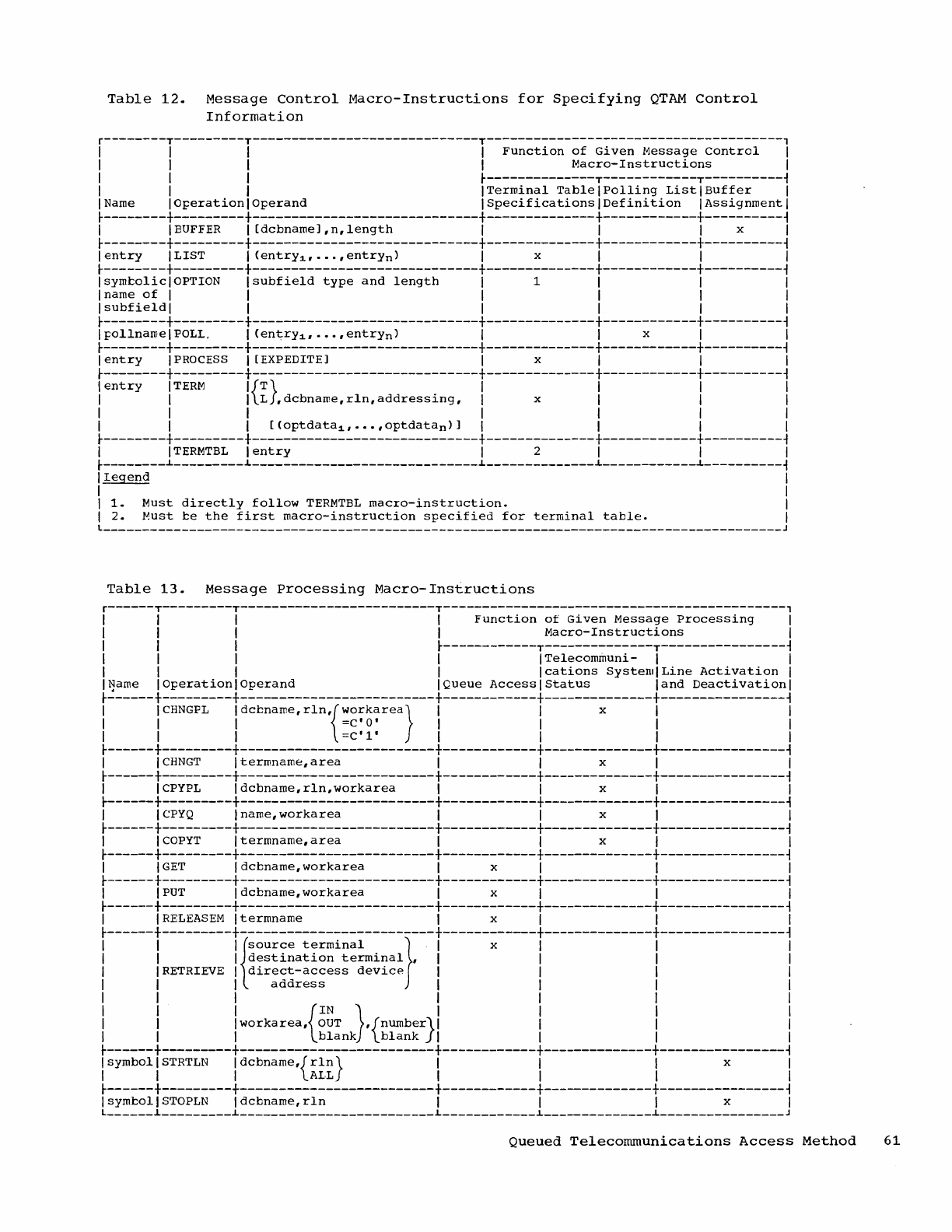
Table
12.
Message
Control
Macro-Instructions
for
Specifying
QTAM
Control
Information
r--------T---------T-----------------------------T--------------------------------------,
I I I I
Function
of
Given
Message
Control
I
I I I I
Macro-Instructions
I
I I I
~--------------T------------T----------~
I I I
ITerminal
TablelPolling
ListlBuffer
I
I
Name
I
Operation
I
Operand
I
Specifications
I
Definition
I
Assignment
I
~--------+---------+-----------------------------+--------------+------------+----------~
I I
BUFFER
I
[dcbnameJ,n,length
I I I x I
~--------+---------+-----------------------------+--------------+------------+----------~
I
entry
ILIST I
(entrY1,··.
,entrYn)
I x I I I
~--------+---------+-----------------------------+--------------+------------+----------~
IsymcoliclOPTION
Isubfield
type
and
length
I 1 I I I
I name
of
I I I I I I
Isubfieldl
I I I I I
~--------+---------+-----------------------------+--------------+------------+----------~
I
pollname
I
POLL.
I
(entrY1,
•••
,
entrYn)
I I x I I
~--------+---------+-----------------------------+--------------+------------+----------~
I
entry
IPROCESS
I [EXPEDITE] I x I I I
~--------+---------+-----------------------------+--------------+------------+----------~
I
entry
ITERM
I{T}
I I I I
I I I L
,dcbname,rln,addressing,
I x I I I
I I I I I I I
I I I
[(optdata
1
,···,optdata
n
)]
I I I I
~--------+---------+-----------------------------+--------------+------------+----------~
I
ITERMTBL
I
entry
I 2 I I I
~--------~---------~-----------------------------~--------------~------------~----------~
I
legend
I
I I
I
1.
Must
directly
follow
TERMTBL
macro-instruction.
I
I
2.
Must
ce
the
first
macro-instruction
specified
for
terminal
table.
I
L
_______________________________________________________________________________________
J
Table
13.
Message
Processing
Macro-Instructions
r------T---------T-------------------------T--------------------------------------------,
I I I I
FUnction
of
Given
Message
Processing
I
I I I I
Macro-Instructions
I
I I I
~------------T--------------T----------------~
I I I I I
Telecomrnuni-
I I
I I I I
Ications
SysterulLine
Activation
I
I~ame
I
Operation
I
Operand
IQueue
Access
I
Status
land
Deactivation
I
~------+---------+-------------------------+------------+--------------+----------------~
I I
CHNGFL
I
dccname,
rln,{
workarea}
I I x I I
I I I
=C'
0'
I I I I
I I I
=C'l'
I I I I
~------+---------+-------------------------+------------+--------------+----------------~
I I
CHNGT
I
termname,
area
I I x I I
~------+---------+-------------------------+------------+--------------+----------------~
I
ICPYPL
Idcbname,rln,workarea
I I x I I
~------+---------+-------------------------+------------+--------------+----------------~
I I
CPYQ
I name,
workarea
I I x I I
~------+---------+-------------------------+------------+--------------+----------------~
I I
COPYT
I
termname,
area
I I x I I
~------+---------+-------------------------+------------+--------------+----------------~
I
IGET
Idcbname,workarea
I x I I I
~------+---------+-------------------------+------------+--------------+----------------~
I I
PUT
I
dcbname,
workarea
I x I I I
~------+---------+-------------------------+------------+--------------+----------------~
I
IRELEASEM
Itermname
I x I I I
~------+---------+-------------------------+------------+--------------+----------------~
I I I
{source
terminal
} I x I I I
I I I
destination
terminal,
I I I I
I IRETRIEVE I
direct-access
device
I I I I
I I I
address
I I I I
I I I I I I I
I I I
{IN}
I I I I
I I
Iworkarea,
OUT
,{number}
I I I I
I I I
blank
blank
I I I I
~------+---------+-------------------------+------------+--------------+----------------~
I
symbol
I
STRTLN
I
dCbname,{rln}
I I I x I
I I I
ALL
I I I I
~------+---------+-------------------------+------------+--------------+----------------~
IsymcollSTOPLN
Idcbname,rln
I I I x I
L
______
~
_________
~
_________________________
~
____________
~
______________
~
________________
J
Queued
Telecommunications
Access
Method
61
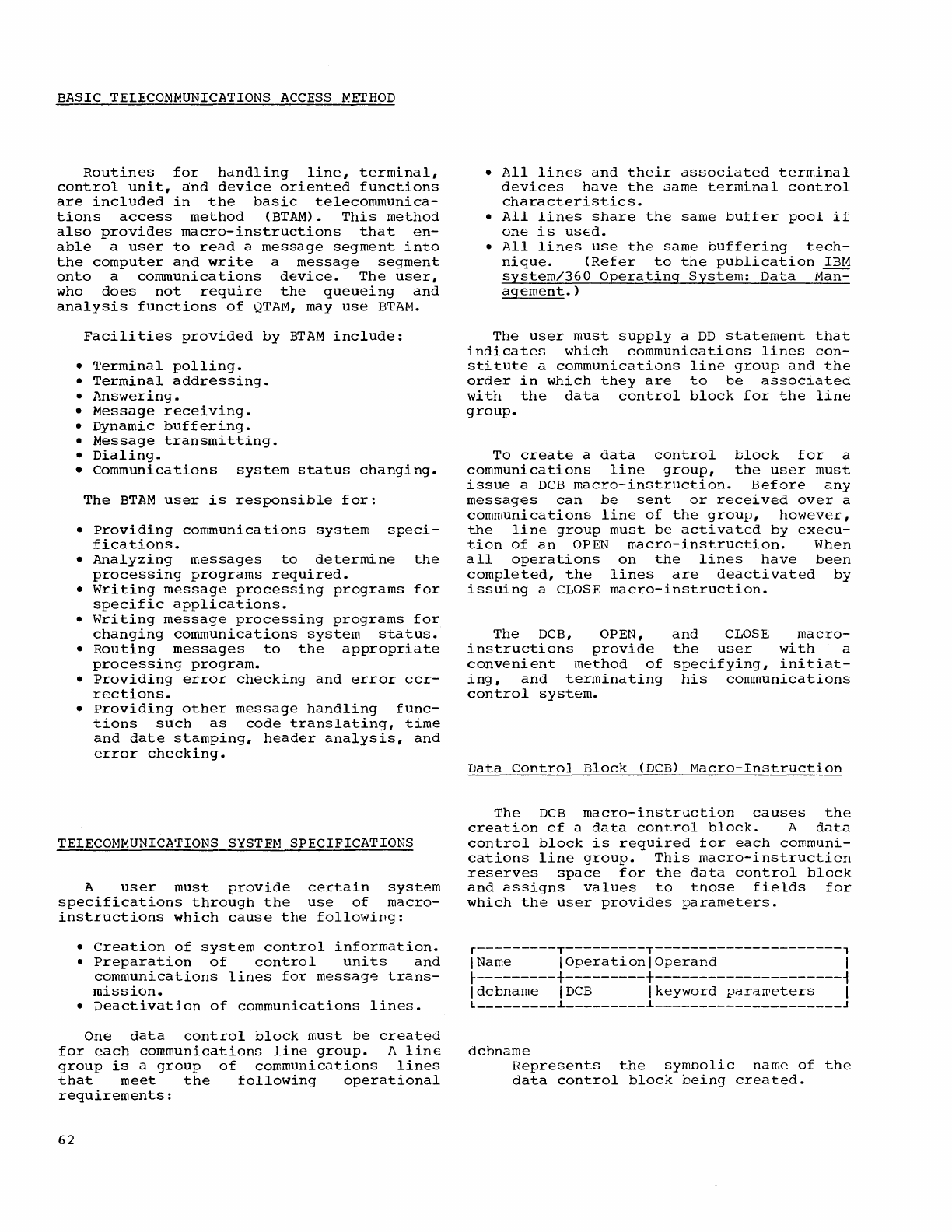
EASIC
TELECOM~UNICATIONS
ACCESS
~ETHOD
Routines
for
handling
line,
terminal,
control
unit,
and
device
oriented
fUnctions
are
included
in
the
basic
telecommunica-
tions
access
method
(BTAM).
This
method
also
provides
macro-instructions
that
en-
able
a
user
to
read
a
message
segment
into
the
computer
and
write
a
message
segment
onto
a
communications
device.
The
user,
who
does
not
require
the
queueing
and
analysis
functions
of
QTAM,
may
use
BTAM.
Facilities
provided
by
BTAM
include:
•
Terminal
polling.
•
Terminal
addressing.
•
Answering.
•
Message
receiving.
•
Dynamic
buffering.
•
Message
transmitting.
•
Dialing.
•
Communications
system
status
changing.
The
BTAM
user
is
responsible
for:
•
Providing
con~unications
system
speci-
fications.
•
Analyzing
messages
to
determine
the
processing
programs
required.
•
Writing
message
processing
programs
for
specific
applications.
•
Writing
message
processing
programs
for
changing
communications
system
status.
•
Routing
messages
to
the
appropriate
processing
program.
•
Providing
error
checking
and
error
cor-
rections.
•
Providing
other
message
handling
fUnc-
tions
such
as
code
translating,
time
and
date
stamping,
header
analysis,
and
error
checking.
TELECOMMUNICATIONS
SYSTEM
SPECIFICATIONS
A
user
must
provide
certain
system
specifications
through
the
use
of
macro-
instructions
which
cause
the
following:
•
Creation
of
system
control
information.
•
Preparation
of
control
units
and
communications
lines
for
message
trans-
mission.
•
Deactivation
of
communications
lines.
One
data
control
block
must
be
created
for
each
communications
line
group.
A
line
group
is
a
group
of
communications
lines
that
meet
the
following
operational
requirements:
62
•
All
lines
and
their
associated
terminal
devices
have
the
same
terminal
control
characteristics.
•
All
lines
share
the
same
buffer
pool
if
one
is
uSed.
•
All
lines
use
the
same
buffering
tech-
nique.
(Refer
to
the
publication
IBM
system/360
Operating
System:
Data
Mall=
agement.)
The
user
must
supply
a
DD
statement
that
indicates
which
communications
lines
con-
stitute
a
communications
line
group
and
the
order
in
which
they
are
to
be
associated
with
the
data
control
block
for
the
line
group.
To
create
a
data
control
block
for
a
communications
line
group,
the
user
must
issue
a
DCB
macro-instruction.
Before
any
messages
can
be
sent
or
received
over
a
communications
line
of
the
group,
however,
the
line
group
must
be
activated
by
execu-
tion
of
an
OPEN
macro-instruction.
When
all
operations
on
the
lines
have
been
completed,
the
lines
are
deactivated
by
issuing
a
CLOSE
macro-instruction.
The
DCB,
OPEN,
and
CLOSE
macro-
instructions
provide
the
user
with
a
convenient
method
of
specifying,
initiat-
ing,
and
terminating
his
communications
control
system.
Data
Control
Block
(DCB)
Macro-Instruction
The
DCB
macro-instruction
causes
the
creation
of
a
data
control
block.
A
data
control
block
is
required
for
each
communi-
cations
line
group.
This
macro-instruction
reserves
space
for
the
data
control
block
and
assigns
values
to
those
fields
for
which
the
user
provides
parameters.
r---------T---------T---------------------,
I Name I
Operation
I
Operand
I
r---------+---------+---------------------~
Idcbname
IDCB
Ikeyword
paraweters
I
L
_________
~
_________
~
_____________________
J
dcbname
Represents
the
symbolic
name
of
the
data
control
block
being
created.
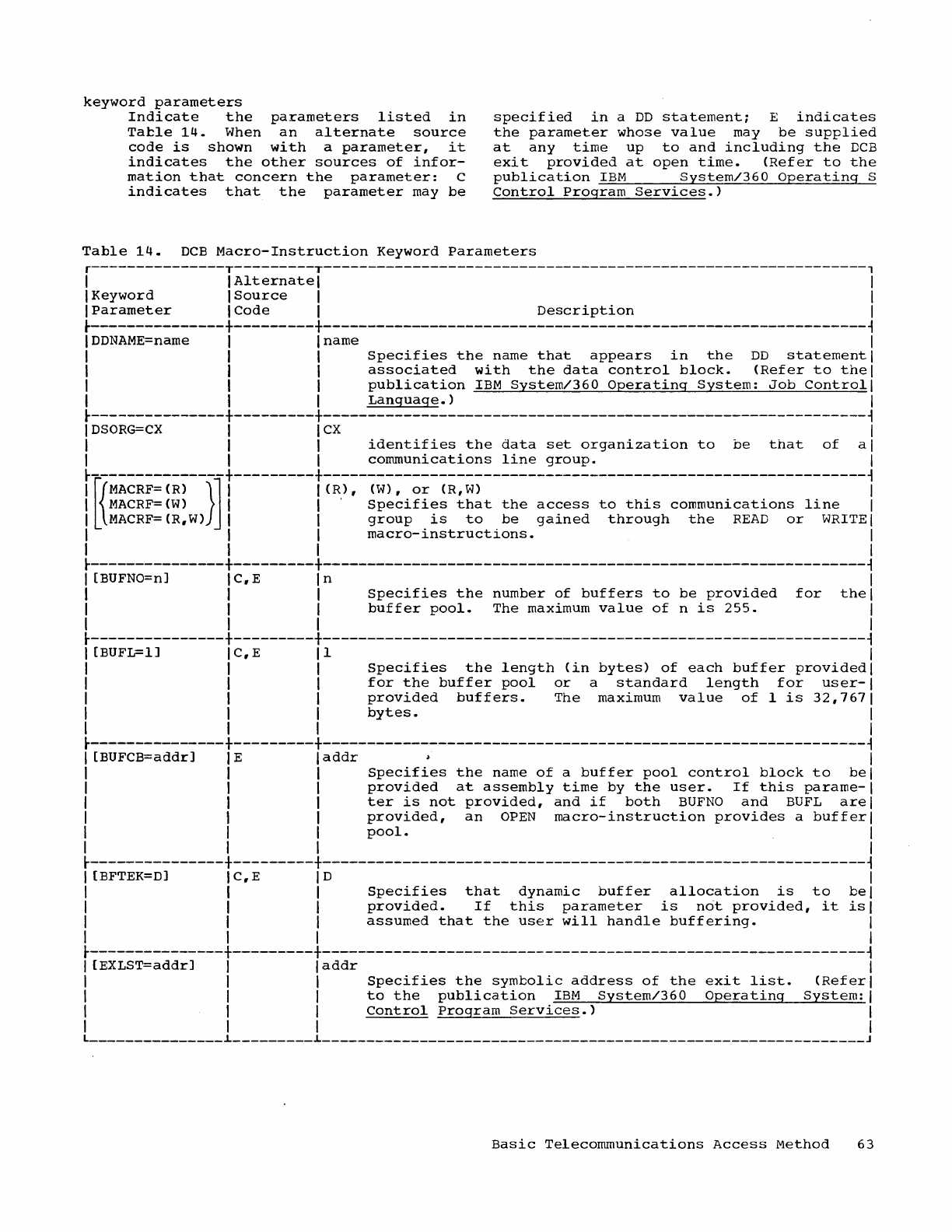
keyword
parameters
Indicate
the
parameters
listed
in
Tatle
14.
When
an
alternate
source
code
is
shown
with
a
parameter,
it
indicates
the
other
sources
of
infor-
mation
that
concern
the
parameter:
C
indicates
that
the
parameter
may
be
specified
in
a
DD
statement;
E
indicates
the
parameter
whose
value
may
be
supplied
at
any
time
up
to
and
including
the
DCB
exit
provided
at
open
time.
(Refer
to
the
publication
IBM
System/360
Operating
S
control
Program
Services.)
Table
14.
DCB
Macro-Instruction
Keyword
Parameters
r---------------T---------T-------------------------------------------------------------,
I I
Alternate
I I
I
Keyword
I
Source
I I
I
Parameter
ICode
I
Description
I
r---------------+---------+-------------------------------------------------------------~
I
DDNAME=name
I I
name
I
I I I
Specifies
the
name
that
appears
in
the
DD
statement
I
I I I
associated
with
the
data
control
block.
(Refer
to
thel
I I I
publication
IBM
System/360
Operating
System:
Job
Control
I
I I I
Language.)
I
~---------------+---------+-------------------------------------------------------------~
I
DSORG=CX
1 I
CX
I
1 1 I
identifies
the
data
set
organization
to
be
that
of
al
1 I I
communications
line
group.
I
~---------------+---------+-------------------------------------------------------------~
I
[{MACRF=
(R)
}]
1 I
(R),
(W),
or
(R,
W)
I
I
MACRF=(W)
I I .
Specifies
that
the
access
to
this
communications
line
I
I MACRF=(R.W) I I
group
is
to
be
gained
through
the
READ
or
WRITE
I
I I I
macro-instructions.
I
I I I I
~---------------+---------+-------------------------------------------------------------~
I [BUFNO=nJ I
C.
E I n I
I 1 I
Specifies
the
number
of
buffers
to
be
provided
for
the
I
I 1 1
buffer
pool.
The
maximum
value
of
n
is
255.
I
I I I I
~---------------+---------+-------------------------------------------------------------~
1 [BUFL=lJ
IC,E
11
I
I 1 I
Specifies
the
length
(in
bytes)
of
each
buffer
provided
I
I I I
for
the
buffer
pool
or
a
standard
length
for
user-I
I 1 1
provided
buffers.
The
maximum
value
of
1
is
32,7671
I 1 I
bytes.
I
I I I I
~---------------+---------+-------------------------------------------------------------~
I [BUFCB=addrJ I E I
addr
I
1 I I
Specifies
the
name
of
a
buffer
pool
control
block
to
bel
I I I
provided
at
assembly
time
by
the
user.
If
this
parame-I
I I I
ter
is
not
provided,
and
if
both
BUFNO
and
BUFL
arel
I I I
provided,
an
OPEN
macro-instruction
provides
a
bufferl
I I I
pool.
I
I I I I
~---------------+---------+-------------------------------------------------------------~
I [BFTEK=DJ I
c.
E I D I
I I I
Specifies
that
dynamic
buffer
allocation
is
to
bel
I I I
provided.
If
this
parameter
is
not
provided,
it
isl
I I I
assumed
that
the
user
will
handle
buffering.
I
I I I I
r---------------+---------+-------------------------------------------------------------~
I
[EXLST=addrJ
I I
addr
I
I I I
Specifies
the
symbolic
address
of
the
exit
list.
(Referl
I I I
to
the
publication
IBM
System/360
Operating
System:
I
I I I
Control
Program
Services.)
I
I I I I L
_______________
~
_________
~
_____________________________________________________________
J
Basic
Telecommunications
Access
Method
63
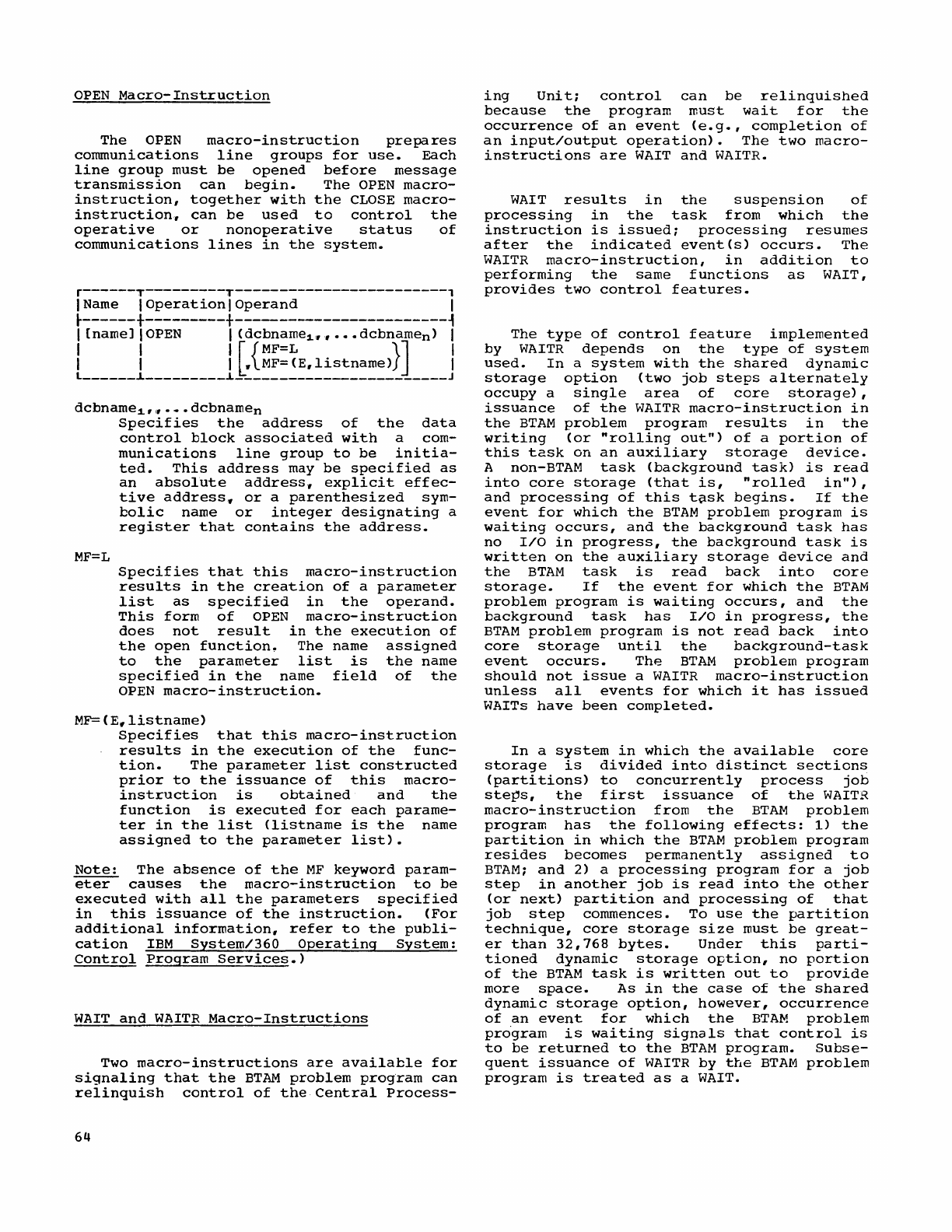
OPEN
Macro-Instruction
The
OPEN
macro-instruction
prepares
communications
line
groups
for
use.
Each
line
group
must
be
opened
before
message
transmission
can
begin.
The
OPEN
macro-
instruction,
together
with
the
CLOSE
macro-
instruction
y
can
be
used
to
control
the
operative
or
nonoperative
status
of
communications
lines
in
the
system.
r------T---------T------------------------,
I Name I
Operation
I
Operand
I
~------+---------+------------------------~
I
[namel
I
OPEN
I
(dcbname1yy
•••
dcbnamen)
I
I I I r {MF=L
}]
I
I I I
~
MF=(E,listname)
I
L
______
~
_________
~
________________________
J
dcbname1,~···dcbnamen
MF=L
Specifies
the
address
of
the
data
control
block
associated
with
a
com-
munications
line
group
to
be
initia-
ted.
This
address
may
be
specified
as
an
absolute
address,
explicit
effec-
tive
address~
or
a
parenthesized
sym-
bolic
name
or
integer
designating
a
register
that
contains
the
address.
Specifies
that
this
macro-instruction
results
in
the
creation
of
a
parameter
list
as
specified
in
the
operand.
This
form
of
OPEN
macro-instruction
does
not
result
in
the
execution
of
the
open
function~
The name
assigned
to
the
parameter
list
is
the
name
specified
in
the
name
field
of
the
OPEN
macro-instruction.
MF=(Elllistname)
Specifies
that
this
macro-instruction
results
in
the
execution
of
the
func-
tion.
The
parameter
list
constructed
prior
to
the
issuance
of
this
macro-
instruction
is
obtained
and
the
function
is
executed
for
each
parame-
ter
in
the
list
(listname
is
the
name
assigned
to
the
parameter
list).
Note:
The
absence
of
the
MF
keyword
param-
eter
causes
the
macro-instruction
to
be
executed
with
all
the
parameters
specified
in
this
issuance
of
the
instruction.
(For
additional
information,
refer
to
the
publi-
cation
IBM
System/360
Operating
System:
Control
Program
Services.)
WAIT
and
WAITR
Macro-Instructions
Two
macro-instructions
are
available
for
signaling
that
the
BTAM
problem
program
can
relinquish
control
of
the
Central
Process-
64
ing
Unit;
control
can
be
relinquished
because
the
program
must
wait
for
the
occurrence
of
an
event
(e.g.,
completion
of
an
input/output
operation).
The
two
macro-
instructions
are
WAIT
and
WAITR.
WAIT
results
in
the
suspension
of
processing
in
the
task
from
which
the
instruction
is
issued;
processing
resumes
after
the
indicated
event(s)
occurs.
The
WAITR
macro-instruction,
in
addition
to
performing
the
same
functions
as
WAIT,
provides
two
control
features.
The
type
of
control
feature
implemented
by
WAITR
depends
on
the
type
of
system
used.
In
a
system
with
the
shared
dynamic
storage
option
(two
job
steps
alternately
occupy
a
single
area
of
core
storage),
issuance
of
the
WAITR
macro-instruction
in
the
BTAM
problem
program
results
in
the
writing
(or
"rolling
out")
of
a
portion
of
this
task
on
an
auxiliary
storage
device.
A non-BTAM
task
(background
task)
is
read
into
core
storage
(that
is,
"rolled
in"),
and
processing
of
this
t~sk
begins.
If
the
event
for
which
the
BTAM
problem
program
is
waiting
occurs,
and
the
background
task
has
no
I/O
in
progress,
the
background
task
is
written
on
the
auxiliary
storage
device
and
the
BTAM
task
is
read
back
into
core
storage.
If
the
event
for
which
the
BTAM
problem
program
is
waiting
occurs,
and
the
background
task
has
I/O
in
progress,
the
BTAM
problem
program
is
not
read
back
into
core
storage
until
the
background-task
event
occurs.
The
BTAM
problem
program
should
not
issue
a
WAITR
macro-instruction
unless
all
events
for
which
it
has
issued
WAITs
have
been
completed.
In
a
system
in
which
the
available
core
storage
is
divided
into
distinct
sections
(partitions)
to
concurrently
process
job
ste~s,
the
first
issuance
of
the
WAITR
macro-instruction
from
the
BTAM
problem
program
has
the
following
effects:
1)
the
partition
in
which
the
BTAM
problem
program
resides
becomes
permanently
assigned
to
BTAM;
and
2) a
processing
program
for
a
job
step
in
another
job
is
read
into
the
other
(or
next)
partition
and
processing
of
that
job
step
commences.
To
use
the
partition
technique,
core
storage
size
must
be
great-
er
than
32,768
bytes.
Under
this
parti-
tioned
dynamic
storage
option,
no
portion
of
the
BTAM
task
is
written
out
to
provide
more
space.
As
in
the
case
of
the
shared
dynamic
storage
option,
however,
occurrence
of
an
event
for
which
the
BTAM
problem
program
is
waiting
Signals
that
control
is
to
be
returned
to
the
BTAM
program.
Subse-
quent
issuance
of
WAITR
by
the
BTAM
problem
program
is
treated
as
a
WAIT.
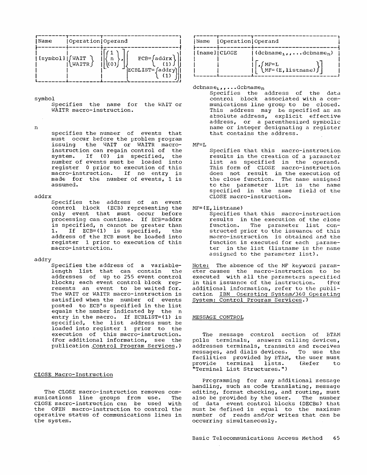
r--------T---------T----------------------,
I Name
IOperationlOperand
I
~--------+---------+----------------------~
I
[symbol]
I{WAIT}
I
fr
~
}
Jl
ECB={addrx}jl
I I
WA
ITR
Il\(
0 ) (
1)
I
I I I .
ECBLIST={addr
y} I
I I I
(1)
I
L
________
i
_________
i
______________________
J
symbol
n
addrx
addry
Specifies
the
name
for
the
WAIT
or
WAITR
macro-instruction.
specifies
the
number
of
events
that
must
occur
before
the
problem
program
issuing
the
WAIT
or
WAITR
macro-
instruction
can
regain
control
of
the
system.
If
(0)
is
specified,
the
number
of
events
must
be
loaded
into
register
0
prior
to
execution
of
this
macro-instruction.
If
no
entry
is
made
for
the
number
of
events,
1
is
assumed.
Specifies
the
addres~
of
an
event
control
block
(ECB)
representing
the
only
event
that
must
occur
before
processing
can
continue.
If
ECB=addrx
is
specified,
n
cannot
be
greater
than
1.
If
ECB=(l)
is
specified,
the
address
of
the
ECB
must
be
loaded
into
register
1
prior
to
execution
of
this
macro-instruction.
Specifies
the
address
~f
a
variable-
length
list
that
can
contain
the
addresses
of
up
to
255
event
control
blocks;
each
event
control
block
rep-
resents
an
event
to
be
waited
for.
The
WAIT
or
WAITR
macro-instruction
is
satisfied
when
the
number
of
events
posted
to
ECB's
specified
in
the
list
equals
the
number
indicated
by
the
n
entry
in
the
macro.
If
ECBLIST=(l)
is
specified,
the
list
address
must
be
loaded
into
register
1
prior
to
the
execution
of
this
macro-instruction.
(For
additional
information,
see
the
putlication
~ontrol
Program
Services.)
CLOSE
Macro-Instruction
The
CLOSE
macro-instruction
removes
com-
ffiunications
line
groups
from
use.
The
CLOSE
macro-instruction
can
be
used
with
the
OPEN
macro-instruction
to
control
the
operative
status
of
communications
lines
in
the
system.
r------T---------T------------------------,
IName I
Operation
I
Operand
I
~------+---------+------------------------~
I [nameJICLOGE I
(dcbname~"
...
dcbnamen)
I
I I I I
I I I
[,{MF=L
}]
I
I I I
MF=(E,listnan,e)
I
L
______
L
_________
i
________________________
J
dcbname1,,···dcbnamen
MF=L
Specifies
the
address
of
the
data
control
block
associated
with
a
com-
munications
line
group
to
be
closed.
This
address
may
be
specified
as
an
absolute
address,
explicit
effective
address,
or
a
parenthesized
symbolic
name
or
integer
designating
a
register
that
contains
the
address.
Specifies
that
this
macro-instruction
results
in
the
creation
of
a
paramete~
list
as
specified
in
the
operand.
This
form
of
CLOSE
macro-instruction
does
not
result
in
the
execution
of
the
close
function.
The
name
assigned
to
the
parameter
list
is
the
name
specified
in
the
name
field
of
the
CLOSE
macro-instruction.
MF=(E,listname)
Specifies
that
this
macro~instruction
results
in
the
execution
of
the
close
function.
The
parameter
list
con-
structed
prior
to
the
issuance
of
this
macro-instruction
is
obtained
and
the
function
is
executed
for
each
parame-
ter
in
the
list
(listname
is
the
name
assigned
to
the
parameter
list).
Note:
The
absence
of
the
MF
keyword
param-
eter
causes
the
macro-instruction
to
be
executed
with
all
the
parameters
specified
in
this
issuance
of
the
instruction.
(For
additional
information,
refer
to
the
publi-
cation
IBM
Operating
System/360
Operating
System:
Control
Program
Services.)
MESSAGE
CONTROL
The
message
control
section
of
BTAM
polls
terminals,
answers
calling
devices,
addresses
terminals,
transmits
and
receives
messages,
and
dials
devices.
To
use
the
facilities
provided
by
BTAM,
the
user
must
provide
terminal
lists.
(Refer
to
"Terminal
List
Structures.")
Programming
for
any
additional
rr.essage
handling,
such
as
code
translating,
message
editing,
format
checking,
and
routing,
must
also
be
provided
by
the
user.
The
number
of
data
event
control
blocks
(DECBs)
that
must
be
defined
is
equal
to
the
maximum
number
of
reads
and/or
writes
that
can
be
occurring
simultaneously.
Basic
Telecommunications
Access
Method
65
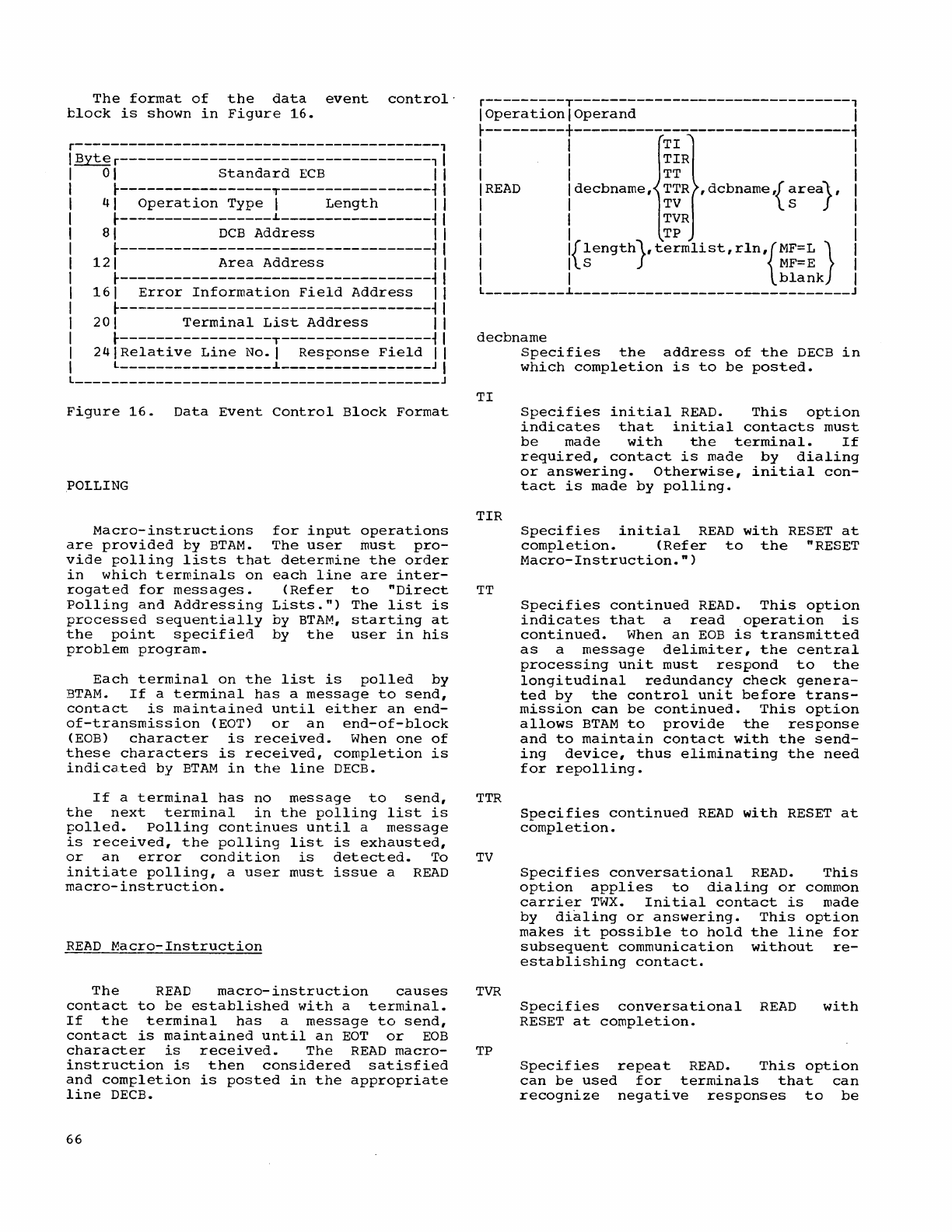
The
format
of
the
data
event
control'
block
is
shown
in
Figure
16.
r-----------------------------------------,
1
Byter-----------------------------------,
01
Standard
ECB
1
r-----------------T-----------------~
41
Operation
Type
1
Length
1
r-----------------L-----------------~
81
DCB
Address
1
r-----------------------------------~
121
Area
Address
1
r-----------------------------------~
161
Error
Information
Field
Address
1
r-----------------------------------~
201
Terminal
List
Address
1
r-----------------T-----------------~
24 1
Relative
Line
No.1
Response
Field
1
L
_________________
L
_________________
J
Figure
16.
Data
Event
Control
Block
Format
POLLING
Macro-instructions
for
input
operations
are
provided
by
BTAM.
The
user
must
pro-
vide
polling
lists
that
determine
the
order
in
which
terminals
on
each
line
are
inter-
rogated
for
messages.
(Refer
to
"Direct
Polling
and
Addressing
Lists.")
The
list
is
precessed
sequentially
by
BTAM,
starting
at
the
point
specified
by
the
user
in
his
problem
program.
Each
terminal
on
the
list
is
polled
by
BTAM.
If
a
terminal
has
a
message
to
send,
contact
is
maintained
until
either
an
end-
of-transmission
(EOT)
or
an
end-of-block
(EOB)
character
is
received.
When
one
of
these
characters
is
received,
completion
is
indicated
by
BTAM
in
the
line
DECB.
If
a
terminal
has
no
message
to
send,
the
next
terminal
in
the
polling
list
is
polled.
Polling
continues
until
a
message
is
received,
the
polling
list
is
exhausted,
or
an
error
condition
is
detected.
To
initiate
polling,
a
user
must
issue
a
READ
macro-instruction.
READ
Macro-Instruction
The
READ
macro-instruction
causes
contact
to
be
established
with
a
terminal.
If
the
terminal
has
a
message
to
send,
contact
is
maintained
until
an
EOT
or
EOB
character
is
received.
The
READ
macro-
instruction
is
then
considered
satisfied
and
completion
is
posted
in
the
appropriate
line
DECB.
66
r---------T-------------------------------,
1
Operation
1
Operand
1
r---------+-------------------------------~
1 1
TI
1
1 1
TIR
1
1 1
TT
1
1
READ
1
decbname,
TTR
,
dCbname,{
as
rea}
, 1
1 1
TV
1
1 1
TVR
1
1 1
TP
1
1
l{length},termlist,rln,{MF=L}
1
liS
MF=E
1
1 I
blank
1
L
_________
L
_______________________________
J
decbname
TI
TIR
TT
TTR
TV
TVR
TP
Specifies
the
address
of
the
DECB
in
which
completion
is
to
be
posted.
Specifies
initial
READ.
This
option
indicates
that
initial
contacts
must
be
made
with
the
terminal.
If
required,
contact
is
made
by
dialing
or
answering.
Otherwise,
initial
con-
tact
is
made
by
polling.
Specifies
initial
READ
with
RESET
at
completion.
(Refer
to
the
"RESET
Macro-Instruction.")
Specifies
continued
READ.
This
option
indicates
that
a
read
operation
is
continued.
When
an
EOB
is
transmitted
as
a
message
delimiter,
the
central
processing
unit
must
respond
to
the
longitudinal
redundancy
check
genera-
ted
by
the
control
unit
before
trans-
mission
can
be
continued.
This
option
allows
BTAM
to
provide
the
response
and
to
maintain
contact
with
the
send-
ing
device,
thus
eliminating
the
need
for
repolling.
Specifies
continued
READ
with
RESET
at
completion.
Specifies
conversational
READ.
This
option
applies
to
dialing
or
common
carrier
TWX.
Initial
contact
is
made
by
dialing
or
answering.
This
option
makes
it
possible
to
hold
the
line
for
subsequent
communication
without
re-
establishing
contact.
Specifies
conversational
READ
RESET
at
completion.
with
Specifies
repeat
READ.
This
option
can
be
used
for
terminals
that
can
recognize
negative
responses
to
be
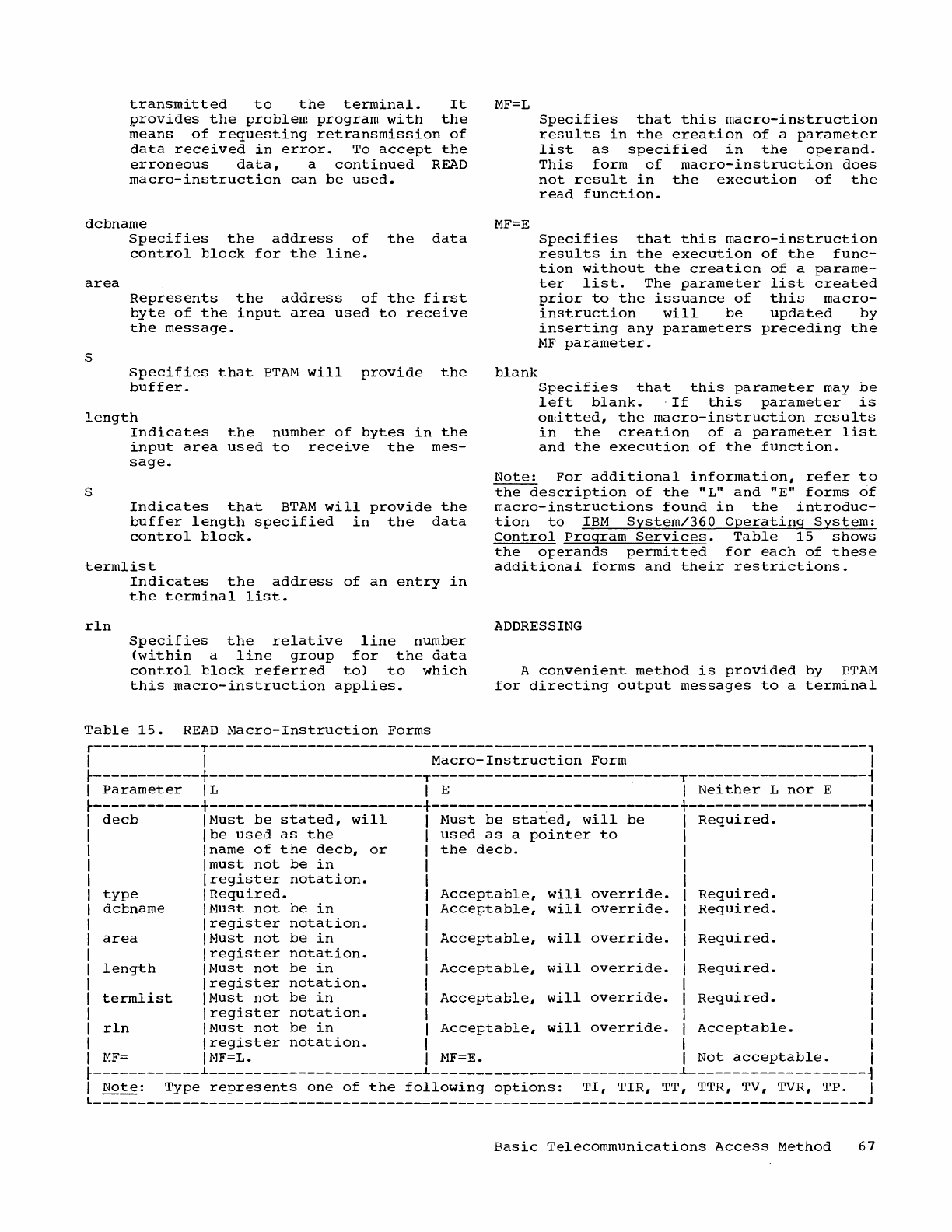
transmitted
to
the
terminal.
It
provides
the
problem
program
with
the
means
of
requesting
retransmission
of
data
received
in
error.
To
accept
the
erroneous
data,
a
continued
READ
macro-instruction
can
be
used.
MF=L
Specifies
that
this
macro-instruction
results
in
the
creation
of
a
parameter
list
as
specified
in
the
operand.
This
form
of
macro-instruction
does
not
result
in
the
execution
of
the
read
function.
dcbname
MF=E
Specifies
the
address
of
the
data
control
tlock
for
the
line.
area
Specifies
that
this
macro-instruction
results
in
the
execution
of
the
fUnc-
tion
without
the
creation
of
a
parame-
ter
list.
The
parameter
list
created
prior
to
the
issuance
of
this
macro-
instruction
will
be
updated
by
inserting
any
parameters
preceding
the
MF
parameter.
s
Represents
the
address
of
the
first
byte
of
the
input
area
used
to
receive
the
message.
Specifies
that
BTAM
will
provide
the
buffer.
blank
length
Specifies
that
this
parameter
may
be
left
blank.
·If
this
parameter
is
omitted,
the
macro-instruction
results
in
the
creation
of
a
parameter
list
and
the
execution
of
the
fUnction.
S
Indicates
the
number
of
bytes
in
the
input
area
used
to
receive
the
mes-
sage.
Indicates
that
BTAM
will
provide
the
buffer
length
specified
in
the
data
control
block.
termlist
Note:
For
additional
information,
refer
to
the
description
of
the
"L"
and
"E"
forms
of
macro-instructions
found
in
the
introduc-
tion
to
IBM
System/360
Operating
System:
control
Program
Services.
Table
15
shows
the
operands
permitted
for
each
of
these
additional
forms
and
their
restrictions.
rln
Indicates
the
address
of
an
entry
in
the
terminal
list.
ADDRESSING
Specifies
the
relative
line
number
(within
a
line
group
for
the
data
control
tlock
referred
to)
to
which
this
macro-instruction
applies.
A
convenient
method
is
provided
by
BTAM
for
directing
output
messages
to
a
terminal
Table
15.
READ
Macro-Instruction
Forms
r------------T--------------------------------------------------------------------------,
I I
Macro-Instruction
Form
I
~------------+------------------------T----------------------------T--------------------~
I
Parameter
IL I E I
Neither
L
nor
E I
~------------+------------------------+------------~---------------+--------------------~
decb
Must
be
stated,
will
Must
be
stated,
will
be
Required.
type
dcbname
area
length
termlist
rln
be
used
as
the
used
as
a
pointer
to
name
of
the
decb,
or
the
decb.
must
not
be
in
register
notation.
Required.
Must
not
be
in
register
notation.
Must
not
be
in
register
notation.
Must
not
be
in
register
notation.
Must
not
be
in
register
notation.
Must
not
be
in
register
notation.
Acceptable,
will
override.
Acceptable,
will
override.
Acceptable,
will
override.
Acceptable,
will
override.
Acceptable,
will
override.
Acceptable,
will
override.
Required.
Required.
Required.
Required.
Required.
Acceptable.
MF=
l-1F=L.
MF=E.
Not
acceptable.
~------------~------------------------~----------------------------~--------------------~
I
Note:
Type
represents
one
of
the
following
options:
TI,
TIR,
TT,
TTR, TV, TVR,
TP.
I
L
_______________________________________________________________________________________
J
Basic
Telecommunications
Access
Method
67
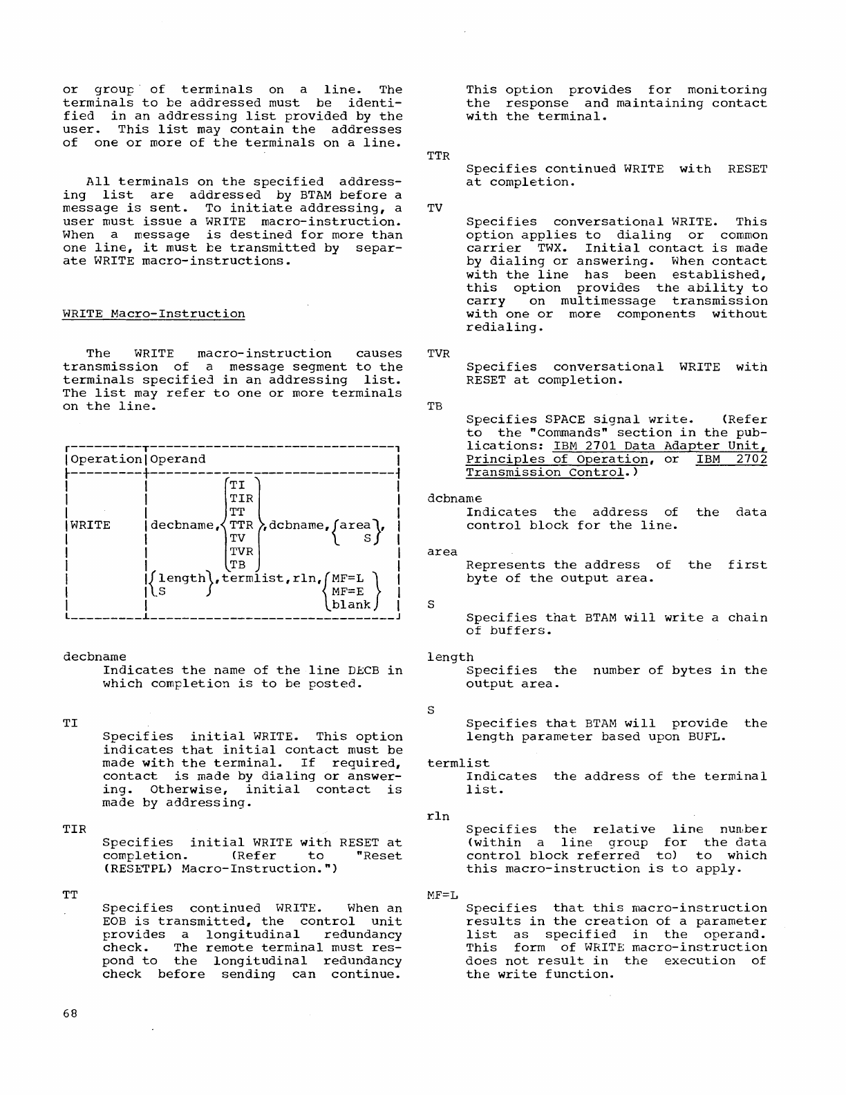
or
grou~·
of
terminals
on
a
line.
The
terminals
to
be
addressed
must
be
identi-
fied
in
an
addressing
list
provided
by
the
user.
This
list
may
contain
the
addresses
of
one
or
more
of
the
terminals
on
a
line.
All
terminals
on
the
specified
address-
ing
list
are
addressed
by
BTAM
before
a
message
is
sent.
To
initiate
addressing,
a
user
must
issue
a
WRITE
macro-instruction.
When a
message
is
destined
for
more
than
one
line,
it
must
be
transmitted
by
separ-
ate
WRITE
macro-instructions.
WRITE
Macro-Instruction
The
WRITE
macro-instruction
causes
transmission
of
a
message
segment
to
the
terminals
specified
in
an
addressing
list.
The
list
may
refer
to
one
or
more
terminals
on
the
line.
r---------T-------------------------------,
I
Operation
I
Operand
I
~---------+-------------------------------~
I I
TI
I
I I
TIR
I
I I
TT
I
I WRITE
Idecbname,
TTR
,dcbname,{area
s
},
I
I I
TV
I
I I
TVR
I
I I
TB
I
I
l{length},termlist,rln,{MF=L}
I
I I
_S
MF=E
I
I I
blank
I
l
_________
L
_______________________________
J
decbname
TI
TIR
TT
68
Indicates
the
name
of
the
line
DBCB
in
which
completion
is
to
be
posted.
Specifies
initial
WRITE.
This
option
indicates
that
initial
contact
must
be
made
with
the
terminal.
If
required,
contact
is
made
by
dialing
or
answer-
ing.
Otherwise,
initial
contact
is
made
by
addressing.
Specifies
initial
WRITE
with
RESET
at
completion.
(Refer
to
"Reset
(RESETPL)
Macro-Instruction.")
Specifies
continued
WRITE. When
an
EOB
is
transmitted,
the
control
unit
provides
a
longitudinal
redundancy
check.
The
remote
terminal
must
res-
pond
to
the
longitudinal
redundancy
check
before
sending
can
continue.
TTR
TV
TVR
TB
This
option
provides
for
monitoring
the
response
and
maintaining
contact
with
the
terminal.
Specifies
continued
WRITE
with
RESET
at
completion.
Specifies
conversational
WRITE.
This
option
applies
to
dialing
or
common
carrier
TWX.
Initial
contact
is
made
by
dialing
or
answering.
When
contact
with
the
line
has
been
established,
this
option
provides
the
ability
to
carryon
multimessage
transmission
with
one
or
more
components
without
redialing.
Specifies
conversational
WRITE
with
RESET
at
completion.
Specifies
SPACE
signal
write.
(Refer
to
the
"Commands"
section
in
the
pub-
lications:
IBM
2701
Data
Adapter
Unit,
Principles
of
Operation,
or
IBM
2702
Transmission
Control.)
dcbname
area
S
Indicates
the
address
of
the
data
control
block
for
the
line.
Represents
the
address
of
the
first
byte
of
the
output
area.
Specifies
that
BTAM
will
write
a
chain
of
buffers.
length
S
Specifies
the
number
of
bytes
in
the
output
area.
Specifies
that
BTAM
will
provide
the
length
parameter
based
upon
BUFL.
termlist
rln
MF=L
Indicates
the
address
of
the
terminal
list.
Specifies
the
relative
line
nun,ber
(within
a
line
group
for
the
data
control
block
referred
to)
to
which
this
macro-instruction
is
to
apply.
Specifies
that
this
macro-instruction
results
in
the
creation
of
a
parameter
list
as
specified
in
the
operand.
This
form
of
WRITE
macro-instruction
does
not
result
in
the
execution
of
the
write
function.
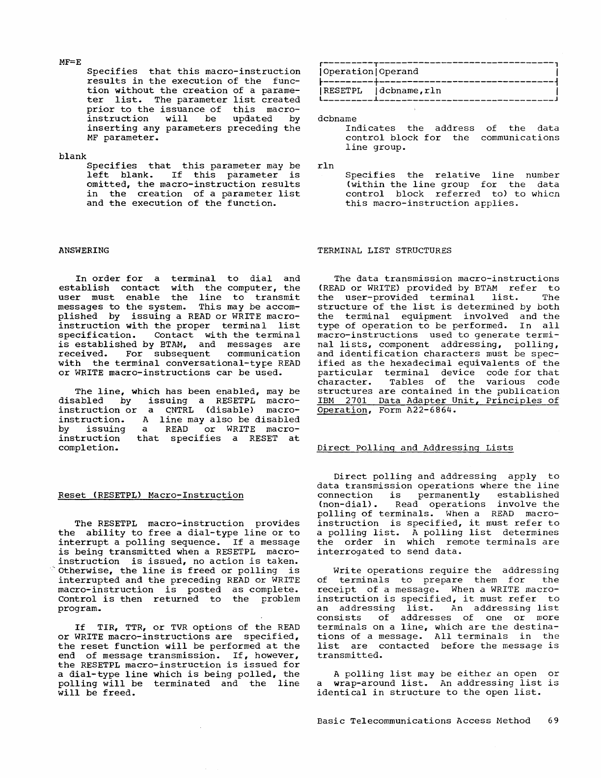
MF=E
blank
Specifies
that
this
macro-instruction
results
in
the
execution
of
the
fUnc-
tion
without
the
creation
of
a
parame-
ter
list.
The
parameter
list
created
prior
to
the
issuance
of
this
macro-
instruction
will
be
updated
by
inserting
any
parameters
preceding
the
MF
parameter.
Specifies
that
this
parameter
may
be
left
blank.
If
this
parameter
is
omitted,
the
macro-instruction
results
in
the
creation
of
a
parameter
list
and
the
execution
of
the
fUnction.
ANSWERING
In
order
for
a
terminal
to
dial
and
establish
contact
with
the
computer,
the
user
must
enable
the
line
to
transmit
messages
to
the
system.
This
may
be
accom-
plished
by
issuing
a
READ
or
WRITE
macro-
instruction
with
the
proper
terminal
list
specification.
Contact
with
the
terminal
is
established
by
BTAM,
and
messages
are
received.
For
subsequent
communication
with
the
terminal
conversational-ty~e
READ
or
WRITE
macro-instructions
car
be
used.
The
line.,
which
has
been
enabled,
may
be
disabled
by
issuing
a RESETPL
macro-
instruction
or
a
CNTRL
(disable)
macro-
instruction.
A
line
may
also
be
disabled
by
issuing
a
READ
or
WRITE
macro-
instruction
that
specifies
a RESET
at
completion.
Reset
(RESETPL)
Macro-Instruction
The
RESETPL
macro-instruction
provides
the
ability
to
free
a
dial-type
line
or
to
interrupt
a
polling
sequence.
If
a
message
is
being
transmitted
when a RESETPL
macro-
instruction
is
issued,
no
action
is
taken.
'.
otherwise,
the
line
is
freed
or
polling
is
interrupted
and
the
preceding
READ
or
WRITE
macro-instruction
is
posted
as
complete.
Control
is
then
returned
to
the
~roblem
program,.
If
TIR,
TTR,
or
TVR
options
of
the
READ
or
WRITE
macro-instructions
are
specified,
the
reset
function
will
be
performed
at
the
end
of
message
transmission.
If,
however,
the
RESETPL
macro-instruction
is
issued
for
a
dial-type
line
which
is
being
polled,
the
polling
will
be
terminated
and
the
line
will
be
freed.
r---------T-------------------------------,
I
Operation
I
Operand
I
~---------+-------------------------------~
IRESETPL
Idcbname,rln
I
L
_________
~
_______________________________
J
dcbname
rln
Indicates
the
address
of
the
data
control
block
for
the
communications
line
group.
Specifies
the
relative
line
number
(within
the
line
group
for
the
data
control
block
referred
to)
to
whicn
this
macro-instruction
a~plies.
TERMINAL
LIST
STRUCTURES
The
data
transmission
macro-instructions
(READ
or
WRITE)
provided
by
BTAM
refer
to
the
user-provided
terminal
list.
The
structure
of
the
list
is
determined
by
both
the
terminal
equipment
involved
and
the
type
of
operation
to
be
performed.
In
all
macro-instructions
used
to
generate
termi-
nal
lists,
component
addressing,
polling,
and
identification
characters
must
be
spec-
ified
as
the
hexadecimal
equivalents
of
the
particular
terminal
device
code
for
that
character.
Tables
of
the
various
code
structures
are
contained
in
the
publication
IBM
2701
Data
Adapter
Unit,
Principles
of
Operation,
Form
A22-6864.
Direct
Polling
and
Addressing
Lists
Direct
polling
and
addressing
apply
to
data
transmission
operations
where
the
line
connection
is
permanently
established
(non-dial).
Read
operations
involve
the
polling
of
terminals.
When a
READ
macro-
instruction
is
specified,
it
must
refer
to
a
polling
list.
A
polling
list
determines
the
order
in
which
remote
terminals
are
interrogated
to
send
data.
Write
operations
require
the
addressing
of
terminals
to
prepare
them
for
the
receipt
of
a
message.
When a
WRITE
macro-
instruction
is
specified,
it
must
refer
to
an
addressing
list.
An
addressing
list
consists
of
addresses
of
one
or
more
terminals
on
a
line.
which
are
the
destina-
tions
of
a
message.
All
terminals
in
the
list
are
contacted
before
the
message
is
transmitted.
A
polling
list
may
be
either
an
open
or
a
wrap-around
list.
An
addressing
list
is
identical
in
structure
to
the
open
list.
Basic
Telecommunications
Access
Method
69
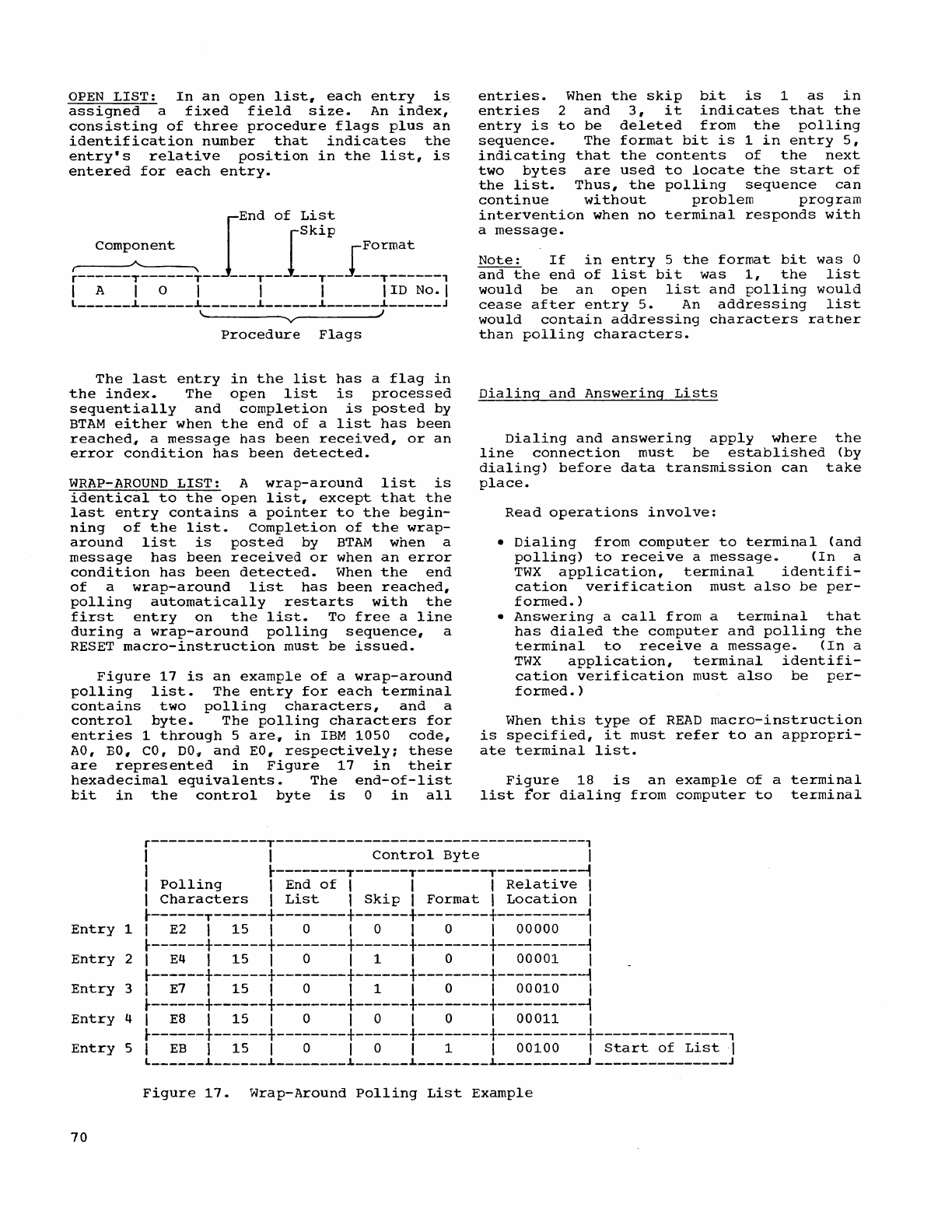
OPEN
LIST:
In
an
open
list.
each
entry
is
assigned
a
fixed
field
size.
An
index,
consisting
of
three
procedure
flags
plus
an
identification
number
that
indicates
the
entry's
relative
position
in
the
list,
is
entered
for
each
entry.
lEnd
of
List
I
Ski
P
~--:::~~::::--~--
---T--
---T--J[::::::_--,
I A I 0 I I I I ID No. I
l
______
~
______
~
______
~
______
~
______
~
______
J
\ J
V
Procedure
Flags
The
last
entry
in
the
list
has
a
flag
in
the
index.
The
open
list
is
processed
sequentially
and
completion
is
posted
by
BTAM
either
when
the
end
of
a
list
has
been
reached~
a
message
has
been
received,
or
an
error
condition
has
been
detected.
WRAP-AROUND
LIST:
A
wrap-around
list
is
identical
to
the
open
list,
except
that
the
last
entry
contains
a
pointer
to
the
begin-
ning
of
the
list.
Completion
of
the
wrap-
around
list
is
posted
by
BTAM
when
a
message
has
been
received
or
when
an
error
condition
has
been
detected.
When
the
end
of
a
wrap-around
list
has
been
reached,
polling
automatically
restarts
with
the
first
entry
on
the
list.
To
free
a
line
during
a
wrap-around
polling
sequence,
a
RESET
macro-instruction
must
be
issued.
Figure
17
is
an
example
of
a
wrap-around
polling
list.
The
entry
for
each
terminal
contains
two
polling
characters,
and
a
control
byte.
The
polling
characters
for
entries
1
through
5
are.
in
IBM
1050
code.
AO,
EO,
CO,
DO
"
and
EO
,
respectively
i
these
are
represented
in
Figure
17
in
their
hexadecimal
equivalents.
The
end-of-list
bit
in
the
control
byte
is
a
in
all
entries.
When
the
skip
bit
is
1
as
in
entries
2
and
3,
it
indicates
that
the
entry
is
to
be
deleted
from
the
polling
sequence.
The
format
bit
is
1
in
entry
5,
indicating
that
the
contents
of
the
next
two
bytes
are
used
to
locate
the
start
of
the
list.
Thus,
the
polling
sequence
can
continue
without
problem
program
intervention
when
no
terminal
responds
with
a
message.
Note:
If
in
entry
5
the
format
bit
was
a
and
the
end
of
list
bit
was
1,
the
list
would
be
an
open
list
and
polling
would
cease
after
entry
5.
An
addressing
list
would
contain
addressing
characters
rather
than
polling
characters.
Dialing
and
Answering
Lists
Dialing
and
answering
apply
where
the
line
connection
must
be
established
(by
dialing)
before
data
transmission
can
take
place.
Read
operations
involve:
•
Dialing
from
computer
to
terminal
(and
polling)
to
receive
a
message.
(In
a
TWX
application,
terminal
identifi-
cation
verification
must
also
be
per-
formed.
)
•
Answering
a
call
from
a
terminal
that
has
dialed
the
computer
and
polling
the
terminal
to
receive
a
message.
(In
a
TWX
application,
terminal
identifi-
cation
verification
must
also
be
per-
formed.
)
When
this
type
of
READ
macro-instruction
is
specified,
it
must
refer
to
an
appropri-
ate
terminal
list.
Figure
18
is
an
example
of
a
terminal
list
for
dialing
from
computer
to
terminal
r-------------T-----------------------------------,
I I
Control
Byte
I
I
~--------T------T--------T---------~
I
Polling
I End
of
I I I
Relative
I
I
Characters
I
List
I
Skip
I
Format
I
Location
I
~------T------+--------+------+--------+----------~
Entry
1 I
E2
I
15
I a I a I a I
00000
I
~------+------+--------+------+--------+----------~
Entry
2 I
E4
I
15
I a I 1 I a I
00001
I
~------+------+--------+------+--------+----------~
Entry
3 I
E7
I
15
I a I 1 I a I
00010
I
~------+------+--------+------+--------+----------~
Entry
4 I
E8
I
15
I a I a I a I
00011
I
~------+------+--------+------+--------+----------+---------------,
Entry
5 I
EB
I
15
I a I a I 1 I
00100
I
Start
of
List
I
l
______
~
______
~
________
~
______
~
________
~
_________
~
_______________
J
Figure
17.
Wrap-Around
Polling
List
Example
70
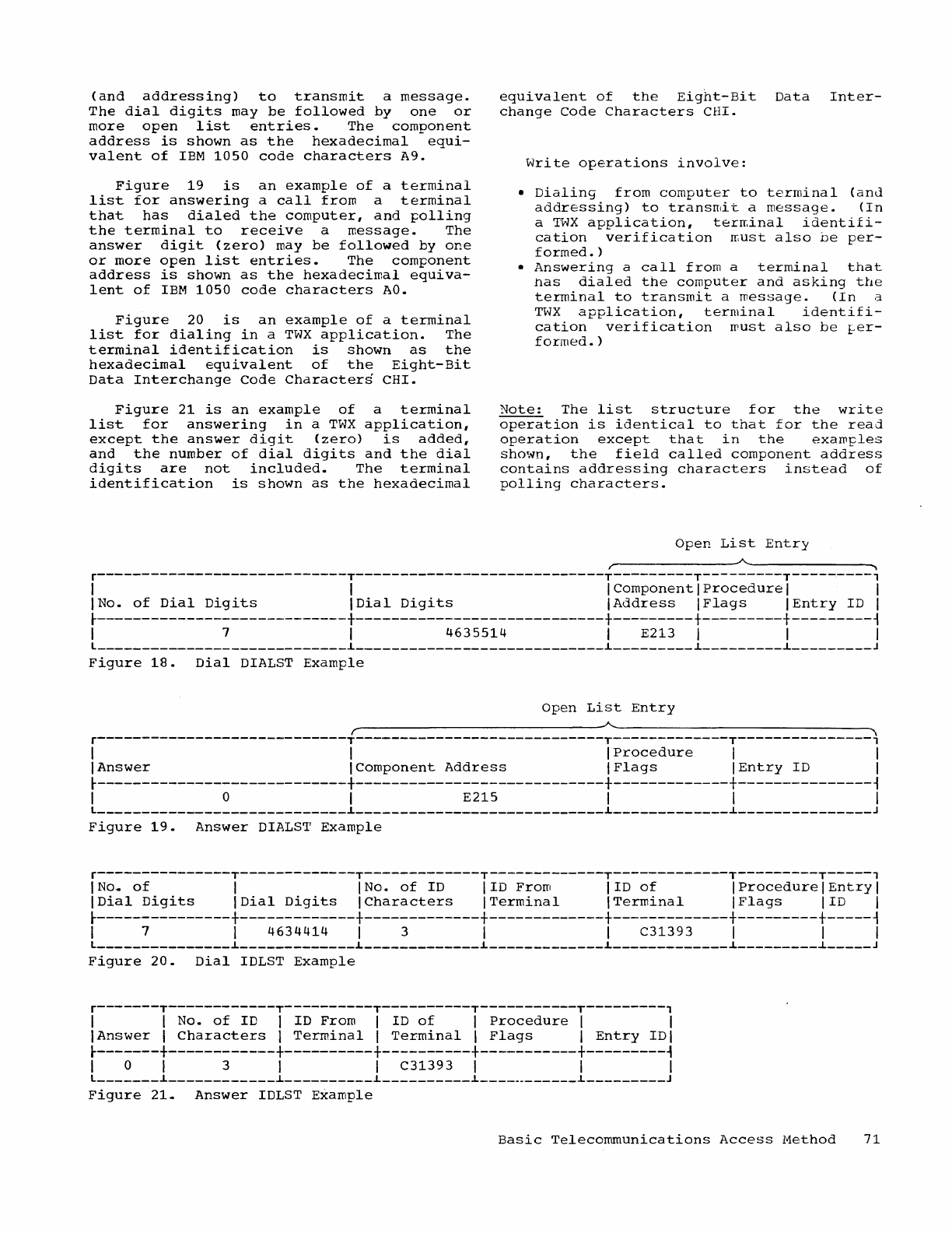
(and
addressing)
to
transmit
a
message.
The
dial
digits
may
be
followed
by
one
or
more
open
list
entries.
The
component
address
is
shown
as
the
hexadecimal
equi-
valent
of
IBM
1050
code
characters
A9.
Figure
19
is
an
example
of
a
terminal
list
for
answering
a
call
from
a
terminal
that
has
dialed
the
computer,
and
polling
the
terminal
to
receive
a
message.
The
answer
digit
(zero)
may
be
followed
by
one
or
more
open
list
entries.
The
component
address
is
shown
as
the
hexadecimal
equiva-
lent
of
IBM
1050
code
characters
AO.
Figure
20
is
an
example
of
a
terminal
list
for
dialing
in
a
TWX
application.
The
terminal
identification
is
shown
as
the
hexadecimal
equivalent
of
the
Eight-Bit
Data
Interchange
Code
Characters
CHI.
Figure
21
is
an
example
of
a
terminal
list
for
answering
in
a
TWX
application,
except
the
answer
digit
(zero)
is
added,
and
the
number
of
dial
digits
and
the
dial
digits
are
not
included.
The
terminal
identification
is
shown
as
the
hexadecimal
equivalent
of
the
Eight-Bit
Data
Inter-
change
code
Characters
CHI.
Write
operations
involve:
•
Dialing
from
computer
to
terminal
(anJ
addressing)
to
transmit
a
message.
(In
a
TWX
application,
ter~inal
identifi-
cation
verification
ffiUSt
also
be
per-
formed.
)
•
Answering
a
call
from
a
terminal
that
has
dialed
the
computer
and
asking
the
terminal
to
transmit
a
message.
(In
a
TWX
application,
terminal
identifi-
cation
verification
must
also
be
~er
formed.
)
Note:
The
list
structure
for
the
write
operation
is
identical
to
that
for
the
read
operation
except
that
in
the
examples
shown,
the
field
called
component
address
contains
addressing
characters
instead
of
polling
characters.
Open
List
Entry
/
~~---------------~
r----------------------------T----------------------------T---------T---------T---------,
I I I
Component
I
Procedure
I I
INo.
of
Dial
Digits
IDial
Digits
IAddress
IFlags
IEntry
ID I
~----------------------------+----------------------------+---------+---------+---------~
I 7 I
4635514
I E213 I I I
L
____________________________
L
____________________________
L
_________
L
_________
~
_________
J
Figure
18.
Dial
DIALST
Example
Open
List
Entry
r--------------------------------~~------------------------------~\
r----------------------------T----------------------------T-------------T---------------,
I I I
Procedure
I I
I
Answer
IComponent
Address
I
Flags
IEntry
ID I
~----------------------------+----------------------------+-------------+---------------~
I 0 I
E215
I I I
L
____________________________
L
____________________________
L
_____________
~
_______________
J
Figure
19.
Answer
DIALST
Example
r---------------T-------------T-------------T-------------T-------------T---------T-----'
INa.
of
I INo.
of
ID
lID
From
lID
of
I
Procedure
I
Entry
I
IDial
Digits
IDial
Digits
I
Characters
I
Terminal
I
Terminal
IFlags
lID
I
~---------------+-------------+-------------+-------------+-------------+---------+-----~
I 7 I
4634414
I 3 I I
C31393
I I I
L
_______________
L
_____________
L
_____________
L
_________
____
L
_____________
~
_________
~
_____
J
Figure
20.
Dial
IDLST
Example
r-------T------------T----------T----------T-----------T---------,
I I No.
of
ID I ID From I ID
of
I
Procedure
I I
IAnswer
I
Characters
I
Terminal
I
Terminal
I
Flags
I
Entry
IDI
~-------+------------+----------+----------+-----------+---------~
I 0 I 3 I I
C31393
I I I
L
_______
L
____________
L
__________
L
__________
L
__________
__
L
_________
J
Figure
21.
Answer
IDLST
Example
Basic
Telecommunications
Access
Method
71
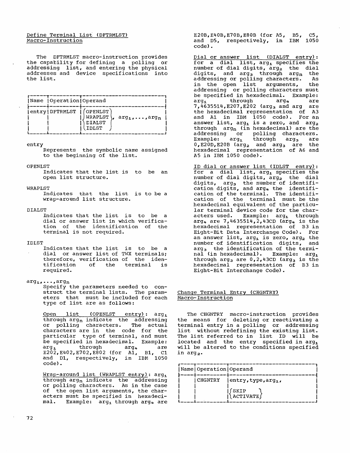
Define
Terminal
List
(DFTRMLST)
Macro-Instruction
The
DFTRMLST
macro-instruction
provides
the
capability
for
defining
a
polling
or
addressing
list,
and
entering
the
physical
addresses
and
device
specifications
into
the
list.
r-----T---------T-------------------------,
IName
IOperationlOperand
I
r-----+---------+-------------------------1
lentrylDFTRMLST
I{OPENLST} I
I I I
WRAPLST
,
arg1,···,argn
I
I I I DIALST I
I I I IDLST I
l
_____
i
_________
i
_________________________
J
entry
Represents
the
symbolic
name
assigned
to
the
beginning
of
the
list.
OPENLST
Indicates
that
the
list
is
to
be
an
open
list
structure.
WRAPLST
Indicates
that
the
list
is
to
be
a
wrap-around
list
structure.
DIALST
Indicates
that
the
list
is
to
be
a
dial
or
answer
list
in
which
verifica-
tion
of
the
identification
of
the
terminal
is
not
required.
IDLST
Indicates
that
the
list
is
to
be
a
dial
or
answer
list
of
TWX
terminals;
therefore,
verification
of
the
iden-
tification
of
the
terminal
is
required.
arg1,···,argn
72
Specify
the
parameters
needed
to
con-
struct
the
terminal
lists.
The
param-
eters
that
must
be
included
for
each
type
of
list
are
as
follows:
Open
list
(OPENLST
entry):
arg1
through
argn
indicate
the
addressing
or
polling
characters.
The
actual
characters
are
in
the
code
for
the
particular
type
of
terminal,
and
must
be
specified
in
hexadecimal.
Example:
arg1
through
arg4
are
E202,E402,E702,E802
(for
Al,
Bl,
Cl
and
Dl,
respectively,
in
IBM
1050
code).
Wrap-around
list
(WRAPLST
entry):
arg1
through
argn
indicate
the
addressing
or
polling
characters.
As
in
the
case
of
the
open
list
arguments,
the
char-
acters
must
be
specified
in
hexadeci-
mal.
Example:
arg1
through
arg4
are
E20B,E40B,E70B,E80B
(for
A5,
and
D5,
respectively,
in
code).
B5,
C5,
IBM
1050
Dial
or
answer
list
(DIALST
entry):
for
a
dial
list,
arg1
specifies
the
number
of
dial
digits,
arg2
the
dial
digits,
and
arg3
through
argn
the
addressing
or
polling
characters.
As
in
the
open
list
arguments,
the
addressing
or
polling
characters
must
be
specified
in
hexadecimal.
Example:
arg1
through
arg4
are
7,4635514,E207,E202
(arg3
and
arg
are
the
hexadecimal
representation
of
A3
and
Al
in
IBM
1050
code).
For
an
answer
list,
arg1
is
a
zero,
and
arg
2
through
argn
(in
hexadecimal)
are
the
addressing
or
polling
characters.
Example:
arg
1
through
arg3
are
0,E20D,E20B
(arg2
and
arg3
are
the
hexadecimal
representation
of
A6
and
A5
in
IBM
1050
code).,
ID
dial
or
answer
list
(IOLST
entry):
for
a
dial
list,
arg1
specifies
the
number
of
dial
digits,
arg2
the
dial
digits,
arg3
the
number
of
identifi-
cation
digits,
and
arg4
the
identifi-
cation
of
the
terminal.
The
identifi-
cation
of
the
terminal
must
be
the
hexadecimal
equivalent
of
the
particu-
lar
terminal
device
code
for
the
char-
acters
used.
Example:
arg1
through
arg4
are
7,4635514,2,43CD
(arg4
is
the
hexadecimal
representation
of
B3
in
Eight-Bit
Data
Interchange
Code).
For
an
answer
list,
arg1
is
zero,
arg2
the
number
of
identification
digits,
and
arg3
the
identification
of
the
termi-
nal
(in
hexadecimal).
Example:
arg
1
through
arg3
are
0,2,43CD
(arg3
is
the
hexadecimal
representation
of
B3
in
Eight-Bit
Interchange
Code).
Change
Terminal
Entry
(CHGNTRY)
Macro-Instruction
The
CHGNTRY
macro-instruction
provides
the
means
for
deleting
or
reactivating
a
terminal
entry
in
a
polling
or
addressing
list
without
redefining
the
existing
list.
The
list
referred
to
in
list
10
will
be
located
and
the
entry
specified
in
arg1
will
be
altered
to
the
conditions
specified
in
arg
2.
r----T---------T--------------------------,
I
Name
I
Operation
I
Operand
I
r----+---------+--------------------------~
I
ICHGNTRY
lentry,type,arg1'
I
I I I I
I I
I{SKIP}
I
I I I
ACTIVATE
I
L
____
i
__
~
______
i
__________________________
J
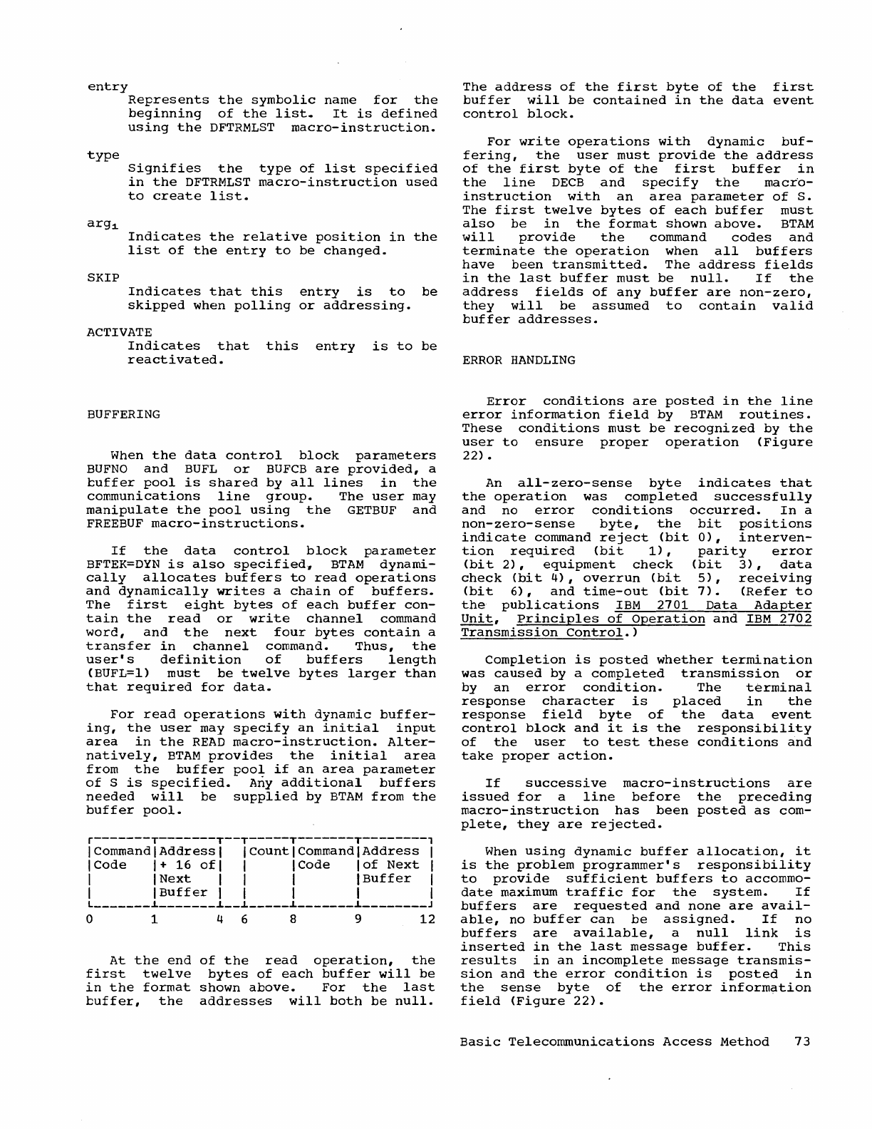
entry
type
arg1.
SKIP
Represents
the
symbolic
name
for
the
beginning
of
the
list.
It
is
defined
using
the
DFTRMLST
macro-instruction.
Signifies
the
type
of
list
specified
in
the
DFTRMLST
macro-instruction
used
to
create
list.
Indicates
the
relative
position
in
the
list
of
the
entry
to
be
changed.
Indicates
that
this
entry
is
to
be
skipped
when
polling
or
addressing.
ACTIVATE
Indicates
that
this
entry
is
to
be
reactivated.
BUFFERING
When
the
data
control
block
parameters
BUFNO
and
BUFL
or
BUFCB
are
provided,
a
cuffer
pool
is
shared
by
all
lines
in
the
communications
line
group.
The
user
may
manipulate
the
pool
using
the
GETBUF
and
FREEBUF
macro-instructions.
If
the
data
control
block
parameter
BFTEK=DYN
is
also
specified,
BTAM
dynami-
cally
allocates
buffers
to
read
operations
and
dynamically
writes
a
chain
of
buffers.
The
first
eight
bytes
of
each
buffer
con-
tain
the
read
or
write
channel
command
word,
and
the
next
four
bytes
contain
a
transfer
in
channel
command.
Thus,
the
user's
definition
of
buffers
length
(BUFL=I)
must
be
twelve
bytes
larger
than
that
required
for
data.
For
read
operations
with
dynamic
buffer-
ing,
the
user
may
specify
an
initial
input
area
in
the
READ
macro-instruction.
Alter-
natively,
BTAM
provides
the
initial
area
from
the
buffer
pool
if
an
area
parameter
of
S
is
specified.
Any
additional
buffers
needed
will
be
supplied
by
BTAM
from
the
buffer
pool.
r-------T-------T--T-----T-------T--------,
I Command I
Address
I
ICountlCommandlAddress
I
ICode
1+
16
ofl
I I Code
lof
Next
I
I I
Next
I I I I
Buf
f
er
I
I I
Buffer
I I I I I
L
_______
i
_______
i
__
i
_____
i
_______
i
________
J
o 1 4 6 8 9
12
At
the
end
of
the
read
operation,
the
first
twelve
bytes
of
each
buffer
will
be
in
the
format
shown
above.
For
the
last
buffer,
the
addresses
will
both
be
nUll.
The
address
of
the
first
byte
of
the
first
buffer
will
be
contained
in
the
data
event
control
block.
For
write
operations
with
dynamic
buf-
fering,
the
user
must
provide
the
address
of
the
first
byte
of
the
first
buffer
in
the
line
DECB
and
specify
the
macro-
instruction
with
an
area
parameter
of
S.
The
first
twelve
bytes
of
each
buffer
must
also
be
in
the
format
shown
above.
BTAM
will
provide
the
command
codes
and
terminate
the
operation
when
all
buffers
have
been
transmitted.
The
address
fields
in
the
last
buffer
must
be
nUll.
If
the
address
fields
of
any
buffer
are
non-zero,
they
will
be
assumed
to
contain
valid
buffer
addresses.
ERROR
HANDLING
Error
conditions
are
posted
in
the
line
error
information
field
by
BTAM
routines.
These
conditions
must
be
recognized
by
the
user
to
ensure
proper
operation
(Figure
22).
An
all-zero-sense
byte
indicates
that
the
operation
was
completed
successfully
and
no
error
conditions
occurred.
In
a
non-zero-sense
byte,
the
bit
positions
indicate
command
reject
(bit
0),
interven-
tion
required
(bit
1),
parity
error
(bit
2),
equipment
check
(bit
3),
data
check
(bit
4),
overrun
(bit
5),
receiving
(bit
6),
and
time-out
(bit
7).
(Refer
to
the
publications
IBM
2701
Data
Adapter
Unit,
Principles
of
Operation
and
IBM
2702
Transmission
Control.)
Completion
is
posted
whether
termination
was
caused
by
a
completed
transmission
or
by
an
error
condition.
The
terminal
response
character
is
placed
in
the
response
field
byte
of
the
data
event
control
block
and
it
is
the
responsibility
of
the
user
to
test
these
conditions
and
take
proper
action.
If
successive
macro-instructions
are
issued
for
a
line
before
the
preceding
macro-instruction
has
been
posted
as
com-
plete,
they
are
rejected.
When
using
dynamic
buffer
allocation,
it
is
the
problem
programmer's
responsibility
to
provide
sufficient
buffers
to
accommo-
date
maximum
traffic
for
the
system.
If
buffers
are
requested
and
none
are
avail-
able,
no
buffer
can
be
assigned.
If
no
buffers
are
available,
a
null
link
is
inserted
in
the
last
message
buffer.
This
results
in
an
incomplete
message
transmis-
sion
and
the
error
condition
is
posted
in
the
sense
byte
of
the
error
information
field
(Figure
22).
Basic
Telecommunications
Access
Method
73
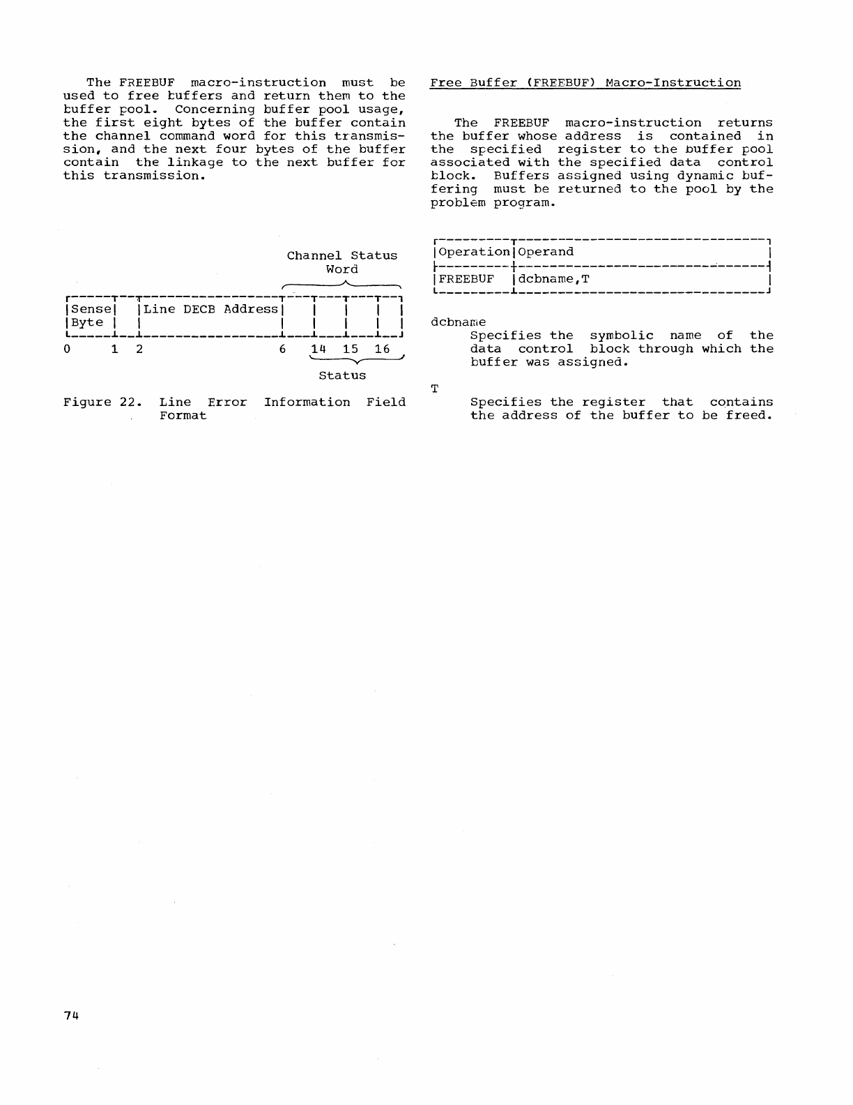
The
FREEBUF
macro-instruction
must
be
used
to
free
tuffers
and
return
them
to
the
tuffer
pool.
Concerning
buffer
pool
usage,
the
first
eight
bytes
of
the
buffer
contain
the
channel
command
word
for
this
transmis-
sion,
and
the
next
four
bytes
of
the
buffer
contain
the
linkage
to
the
next
buffer
for
this
transmission.
Channel
Status
Word
r~-------A------~
r-----T--T-----------------T---T---T---T--'
ISensel
ILine
DECB
Address
I I I I I
IByte
I I I I I I I
l
_____
~
__
~
_________________
~
___
~
___
~
___
~
__
J
o 1 2 6
14
15
16
~
Status
Figure
22.
Line
Error
Information
Field
Format
74
Free
Buffer
(FREEBUF)
Macro-Instruction
The
FREEBUF
macro-instruction
returns
the
buffer
whose
address
is
contained
in
the
specified
register
to
the
Duffer
pool
associated
with
the
specified
data
control
tlock.
Buffers
assigned
using
dynamic
buf-
fering
must
be
returned
to
the
pool
by
the
problem
program.
r---------T-------------------------------,
I
Operation
I
Operand
I
t---------+------------------------~------~
IFREEBUF
Idcbname,T
I
l
_________
~
_______________________________
J
dcbnarne
T
Specifies
the
symbolic
name
of
the
data
control
block
through
which
the
buffer
was
assigned.
Specifies
the
register
that
contains
the
address
of
the
buffer
to
be
freed.
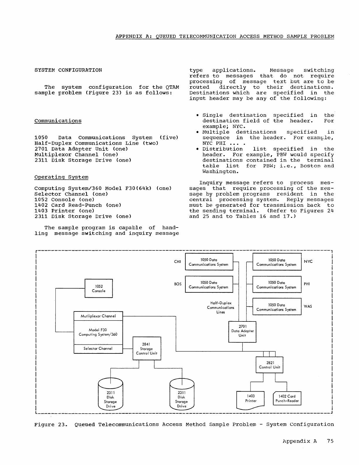
APPENDIX
A:
QUEUED
TELECOMMUNICATION
ACCESS
METHOD
SAMPLE
PROBLEM
SYSTEM
CONFIGURATION
The
system
configuration
for
the
QTAM
sample
problem
(Figure
23)
is
as
follows:
Communications
1050
Data
Communications
System
(five)
Half-Duplex
Communications
Line
(two)
2701
Data
Adapter
Unit
(one)
Multiplexor
Channel
(one)
2311
Disk
Storage
Drive
(one)
Operating
System
Computing
System/360
Model
F30(64k)
(one)
Selector
Channel
(one)
1052
Console
(one)
1402
card
Read-Punch
(one)
1403
Printer
(one)
2311
Disk
Storage
Drive
(one)
The
sample
program
is
capable
of
hand-
ling
message
switching
and
inquiry
message
type
applications.
Message
switching
refers
to
messages
that
do
not
require
processing
of
message
text
but
are
to
be
routed
directly
to
their
destinations.
Destinations
which
are
specified
in
the
input
header
may
be
any
of
the
following:
•
Single
destination
specified
in
the
destination
field
of
the
header.
For
example~
NYC.
•
Multiple
destinations
specified
in
sequence
in
the
header.
For
exarn~le,
NYC
PHI
.••
.
•
Distribution
list
specified
in
the
header.
For
example,
PBW
would
specify
destinations
contained
in
the
terminal
table
list
for
PBW;
i.e.,
Boston
and
Washington.
Inquiry
message
refers
to
process
mes-
sages
that
require
processing
of
the
rr.es-
sage
by
problem
programs
resident
in
the
central
processing
system.
Reply
messages
must
be
generated
for
transmission
back
to
the
sending
terminal.
(Refer
to
Figures
24
and
25
and
to
Tables
16
and
17.)
r---------------------------------------------------------------------------------------,
1052
Console
Mutliplexor
Channel
Model
F30
Computing
System/360
Selector
Channel
2841
Storage
Control
Unit
CHI
BOS
1050
Data
Communications System
1050Dcta
Communications System
Half-Duplex
Communications
Lines
2701
Data
Adapter
Unit
1050Dcta
Communications
System
1050
Octo
Communications
System
1050
Dato
Communications
System
NYC
PHI
WAS
L
_______________________________________________________________________________________
J
Figure
23.
Q~eued
Telecommunications
Access
Method
Sample
Problem
-
System
Configuration
Appendix
A
75
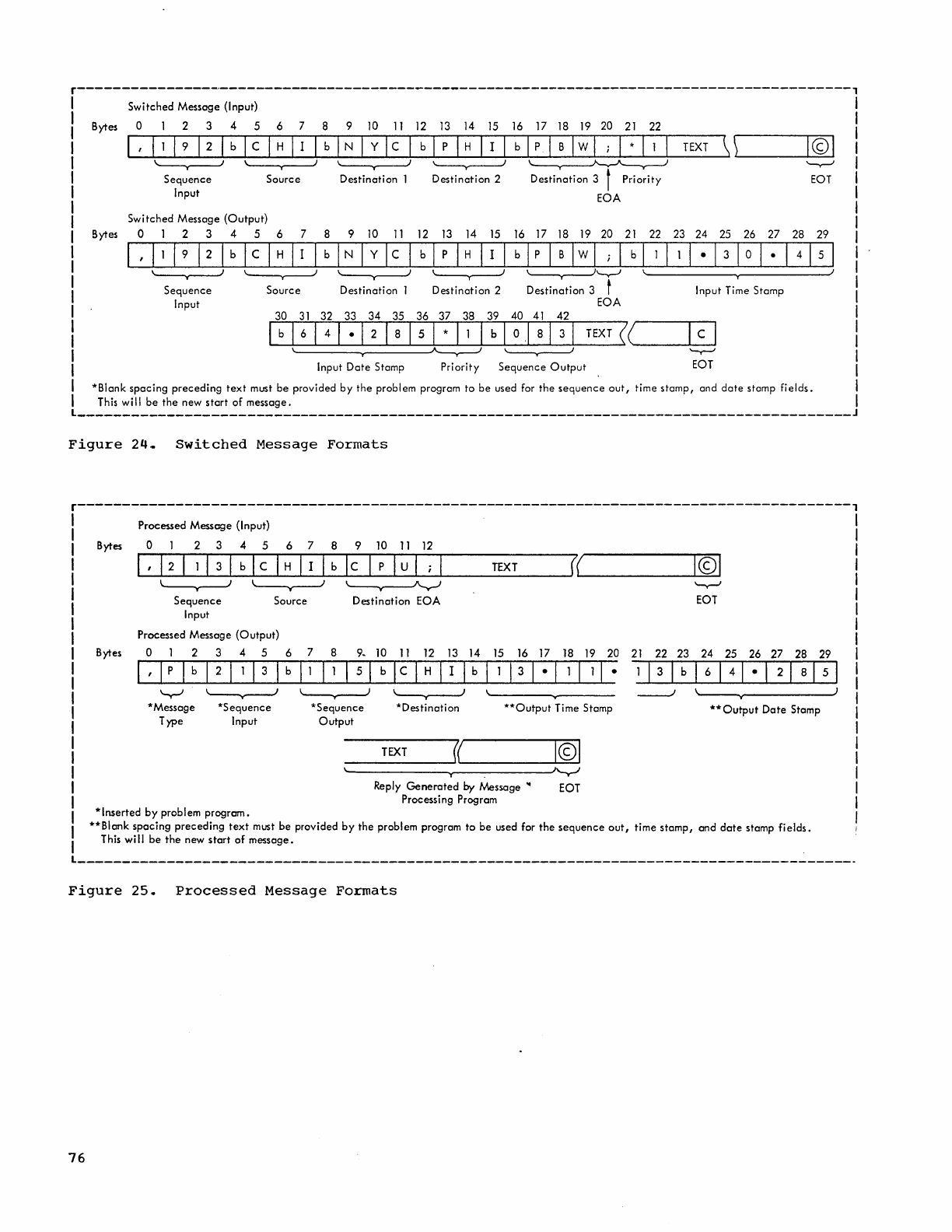
r----------------.-----------------------------------------------------------------------,
Bytes
Bytes
Switched
Message (Input)
o 1 2 3 4 5 6 7 8 9
10
11
12 13
14
15
16
17
18
19
20
21
22
~1,~I~I~I_9~12~I~b~l_c~IH~II~I-b~IN~ly~l_c~l-b~l-p~IH~I-I~I-b~lp~I-B~1w~1
;~I-*~I-l~I-TE-XT~\\~------~I©~1
\ J \ ) \ )
'------y----J
~
"-r--"
Sequence
Input
Source
Switched
Message
(Output)
0123456
7
\ )
\~----v---~
Sequence
Input
Source
Destination
8 9
10
11
\ ,
Destination
1
Destination
2
Destination
3 t
Priority
EOT
EOA
12
13
14
15
16
17
18
19
20
21
22 23 24 25 26
27
28 29
\ ) \
''-v-'
\ J
Destination
2
Destin~tion
3 t Input Time Stamp
EOA
30
31
32 33
34
35
36 37
38 39
40
41
42
l~b~I_6~14~1_.~12~1_8~1_5~1*~I-l~lb~1_0~.1~81_3~I_TE_XT~«~
__
~c~1
\
~'I
'-y--'
Input
Date
Stamp
Priority
Sequence
Output
EOT
*Blank
spacing
preceding
text
must
be
provided
by
the
problem program
to
be
used for
the
sequence
out,
time
stamp,
and
date
stamp
fields.
This will
be
the
new
start
of
message.
_______________________________________________________________________________________
J
Figure
24
..
Switched
Message
Formats
r---------------------------------------------------------------------------------------,
Bytes
Bytes
Processed Message (Input)
o 1 2 3 4 5 6 7 8 9 10
11
12
~1,~1_2~1~11~3~I_b~lc_I~H~I_I~lb~l~C~I_p~IU~I_;~I
______
rr
__
XT
___
~0(~
_________
~I©~1
--v--'-'
'--v---J
~
'--y-J
Sequence
Input
Source
Destination
EOA
EOT
Processed Message
(Output)
o 1 2 3 4 5
1,lplb1211131
*Message
Type
*Sequence
Input
6 7 8 9.
10
11
12 13
14
15 16
17
18 19
20
21
22 23
24
25 26
27
28 29
b 11 I 1 I 5 I b I c I H I I I b I 1 I 3 1 • I 1 I 1
I·
--'-1
3--Ir--"
b
-rI-
6
"";1
;;';""4
~I
·'1";;;;"'2-r1
~8 ~I
5~1
*Sequence
Output
1
*Destination
TEXT
((
**Output
Time Stamp
I©I
~------------------------~
Reply
Generated
by
Message
..
EOT
Processing Program
----./
'---v--------J
**
Output
Date
Stamp
*Inserted
by
problem
program.
**Blank
spacing
preceding
text
must
be
provided
by
the
problem program
to
be
used for
the
sequence
out,
time
stamp,
and
date
stamp
fields.
This
will
be
the
new
start
of
message.
Figure
25.
Processed
Message
Formats
76
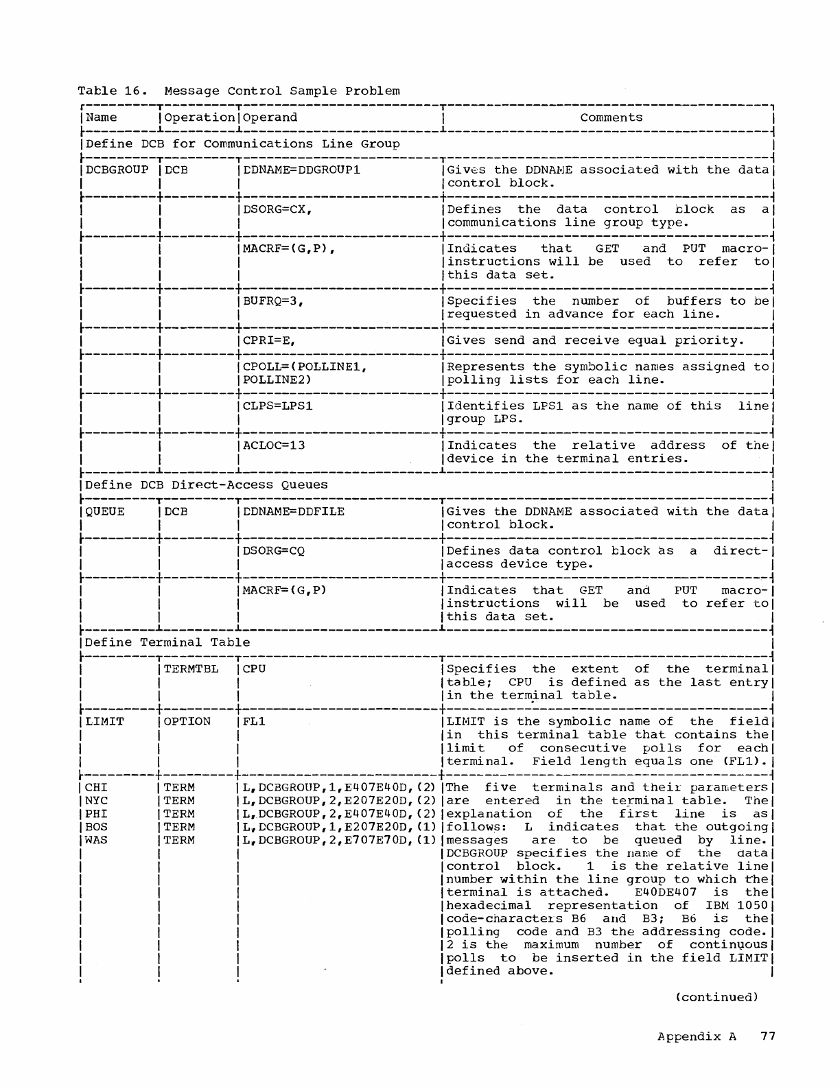
Table
16.
Message
Control
Sample
Problem
r---------T---------T-------------------------T-----------------------------------------,
I Name I
Operation
I
Operand
I
Comments
I
~---------~---------~-------------------------~-----------------------------------------~
IDefine
DCB
for
Communications
Line
Group
I
~---------T---------T-------------------------T-----------------------------------------~
IDCBGROUP
IDCB
ICDNAME=DDGROUPl
IGives
the
DDNAME
associated
with
the
datal
I I I I
control
block.
I
~---------+---------+-------------------------+-----------------------------------------~
I I I
DSORG=CX,
I
Defines
the
data
control
block
as
al
I I I
Icommunications
line
group
type.
I
~---------+---------+-------------------------+-----------------------------------------~
I I IMACRF=(G,P), I
Indicates
that
GET
and
PUT
macro-I
I I I
linstructions
will
be
used
to
refer
tol
I I I
Ithis
data
set.
I
~---------+---------+-------------------------+-----------------------------------------~
I I I BUFRQ=3, I
Specifies
the
number
of
buffers
to
bel
I I I
Irequested
in
advance
for
each
line.
I
~---------+---------+-------------------------+-----------------------------------------~
I I ICPRI=E,
IGives
send
and
receive
equal
priority.
I
~---------+---------+-------------------------+-----------------------------------------~
I I ICPOLL=(POLLINE1,
IRepresents
the
symbolic
names
assigned
tol
I I IPOLLINE2)
Ipolling
lists
for
each
line.
I
~------.---+---------+-------------------------+-----------------------------------------~
I I ICLPS=LPSl
IIdentifies
LPSl
as
the
name
of
this
linel
I I I I
group
LPS. I
r---------+---------+-------------------------+-----------------------------------------~
I I I
ACLOC=13
I
Indicates
the
relative
address
of
thel
I I I
Idevice
in
the
terminal
entries.
I
~---------~---------~-------------------------~-----------------------------------------~
IDefine
DCB
Direct-Access
Queues
I
~---------T---------T-------------------------T-----------------------------------------~
I
QUEUE
IDCB
ICDNAME=DDFILE
IGives
the
DDNAME
associated
with
the
datal
I I I I
control
block.
I
r---------+---------+-------------------------+-----------------------------------------~
I I I
DSORG=CQ
IDefines
data
control
block
as
a
direct-I
I I I
laccess
device
type.
I
~---------+---------+-------------------------+----------------------------------------~~
I I IMACRF=(G,P) I
Indicates
that
GET
and
PUT
macro-I
I I I I
instructions
will
be
used
to
refer
tol
I I I
Ithis
data
set.
I
~---------~---------~-------------------------~-----------------------------------------~
IDefine
Terminal
Table
I
r---------T---------T-------------------------T-----------------------------------------~
I
ITERMTBL
ICPU
ISpecifies
the
extent
of
the
terminal
I
I I I
Itable;
CPU
is
defined
as
the
last
entry
I
I I I
lin
the
terminal
table.
I
r---------+---------+-------------------------+-----------~-----------------------------~
I LIMIT I OPTION
IFLl
ILIMIT
is
the
symbolic
name
of
the
fieldl
I I I
lin
this
terminal
table
that
contains
thel
I I I I
limit
of
consecutive
polls
for
each
I
I I I I
terminal.
Field
length
equals
one
(FL1).
I
r---------+---------+-------------------------+-----------------------------------------~
CHI
TERM
L,
DCBGROUP,
1,E407E40D,
(2)
The
five
terminals
and
thei~
parameters
NYC
TERM
L,DCBGROUP,2,E207E20D,
(2)
are
entered
in
the
teT-minal
table.
The
PHI
TERM
L,.DCBGROUP,2,E407E40D,(2)
explanation
of
the
first
line
is
as
BOS
TERM
L,DCBGROUP,1,E207E20D,
(1)
follows:
L
indicates
that
the
outgoing
WAS
TERM
L,DCBGROUP,2,E707E70D,
(1)
messages
are
to
be
queued
by
line.
DCBGROUP
specifies
the
name
of
the
data
control
block.
1
is
the
relative
line
number
within
the
line
group
to
which
the
terminal
is
attached.
E40DE407
is
the
hexadecimal
representation
of
IBM
1050
code-charactel.s
B6
and
B3;
B6
is
the
polling
code
and
B3
the
addressing
code.
2
is
the
maximum
number
of
continQous
polls
to
be
inserted
in
the
field
LIMIT
defined
above.
(continued)
Appendix
A
77
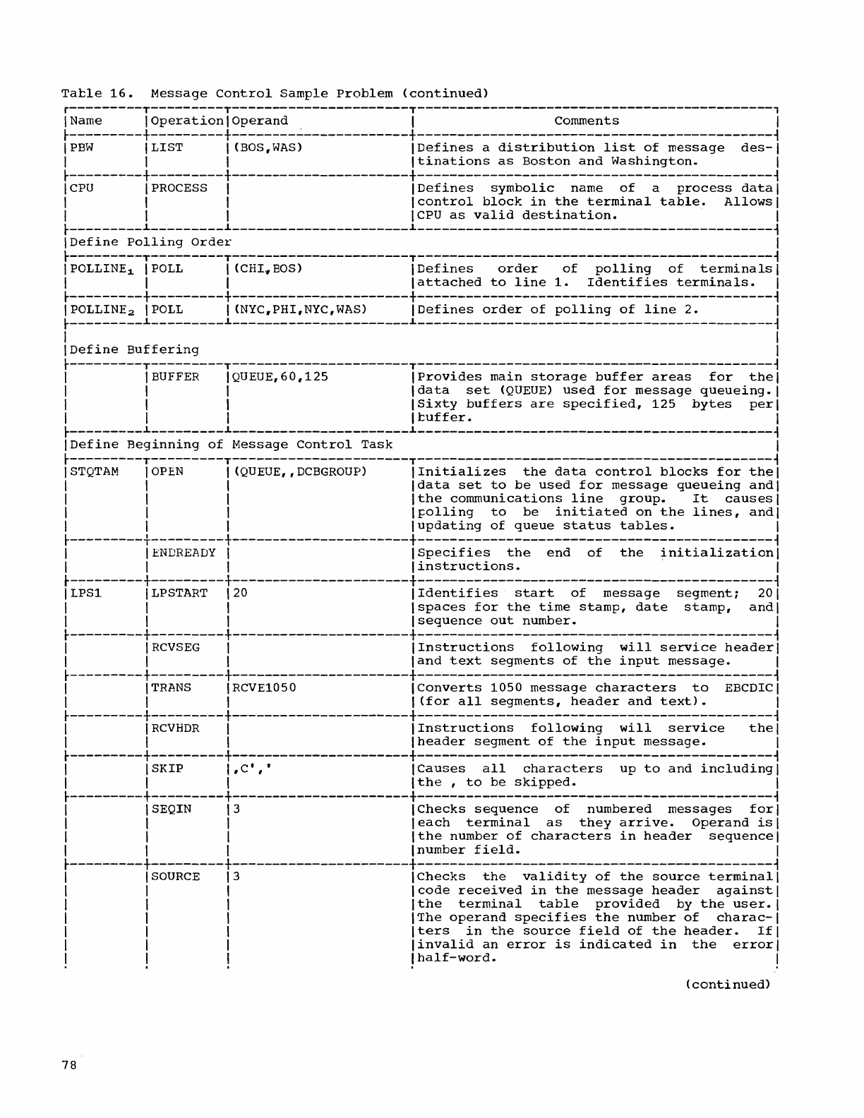
Tatle
16.
Message
Control
Sample
Problem
(continued)
r---------T---------T----------------------T--------------------------------------------,
I Name 1
Operation
1
Operand
1
comments
I
~---------+---------+--------~-------------+--------------------------------------------~
IPBW
ILIST
I (BOS,WAS)
IDefines
a
distribution
list
of
message
des-I
I I I
Itinations
as
Boston
and
Washington.
I
~---------+---------+----------------------+--------------------------------------------~
ICPU
I
PROCESS
I I
Defines
symbolic
name
of
a
process
datal
I I I
Icontrol
block
in
the
terminal
table.
Allows
I
I I I
ICPU
as
valid
destination.
I
~---------~---------~----------------------~--------------------------------------------~
IDefine
Polling
Order
I
~---------T---------T----------------------T--------------------------------------------~
IPOLLINE1 IPOLL I (CHI.BOS) I
Defines
order
of
polling
of
terminals
I
I I I
lattached
to
line
1.
Identifies
terminals.
I
~---------+---------+----------------------+--------------------------------------------~
IPOLLINE2 IPOLL I
(NYC~PHI,NYC,WAS)
IDefines
order
of
polling
of
line
2.
I
~---------~---------~----------------------~----------------------------~---------------~
I I
IDefine
Buffering
I
~---------T---------T----------------------T--------------------------------------------~
I I
BUFFER
IQUEUE,60,125
IProvides
main
storage
buffer
areas
for
thel
I I I
Idata
set
(QUEUE)
used
for
message
queueing.
I
I I 1
ISixty
buffers
are
specified~
125
bytes
perl
I I 1 I
tuffer.
I
~---------~---------~----------------------~--------------------------------------------~
IDefine
Beginning
of
Message
Control
Task
I
~---------T---------T----------------------T--------------------------------------------~
ISTQTAM
1
OPEN
1 (QUEUE"DCBGROUP) 1
Initializes
the
data
control
blocks
for
th~1
I 1 I
Idata
set
to
be
used
for
message
queueing
andl
I 1 1
Ithe
communications
line
group.
It
causes
I
I I I I
foIling
to
be
initiated
on
the
lines,
andl
I I I
lupdating
of
queue
status
tables.
I
~---------+---------+----------------------+--------------------------------------------~
I
IENDREADY
I
ISpecifies
the
end
of
the
initialization
I
I I I I
instructions.
. I
t---------+---------+----------------------+--------------------------------------------~
I LPS1 I
LPSTART
120 I
Identifies
start
of
message
segment;
201
I I I
Ispaces
for
the
time
stamp,
date
stamp,
andl
I I I
Isequence
out
number.
I
t---------+---------+----------------------+--------------------------------------------~
I I
RCVSEG
I I
Instructions
following
will
service
headerl
I I 1
land
text
segments
of
the
input
message.
I
t---------t---------+----------------------+--------------------------------------------~
I I
TRANS
1 RCVE1050
IConverts
1050
message
characters
to
EBCDIC I
I I 1 I
(for
all
segments,
header
and
text).
I
~---------+---------+----------------------+--------------------------------------------~
I 1
RCVHDR
1 I
Instructions
following
will
service
thel
I I 1
Iheader
segment
of
the
input
message.
I
t---------+---------+----------------------+--------------------------------------------~
I I SKIP I , C· , , I
Causes
all
characters
up
to
and
including
I
I I I I
the
,
to
be
skipped.
I
~---------+---------+----------------------+--------------------------------------------~
I ISEQIN 13
IChecks
sequence
of
numbered
messages
fori
I 1 1
leach
terminal
as
they
arrive.
Operand
isl
I I I
Ithe
number
of
characters
in
header
sequence
I
I I I I
number
field.
I
~---------+---------+----------------------+--------------------------------------------~
I I
SOURCE
13 I
Checks
the
validity
of
the
source
terminal
I
I I I
Icode
received
in
the
message
header
against
I
I I I
Ithe
terminal
table
provided
by
the
user.
I
I I I
IThe
operand
specifies
the
number
of
charac-I
I I I
Iters
in
the
source
field
of
the
header.
Ifl
I I I
linvalid
an
error
is
indicated
in
the
error
I
!
!!
~
half-word.
!
(
conti
nued)
78
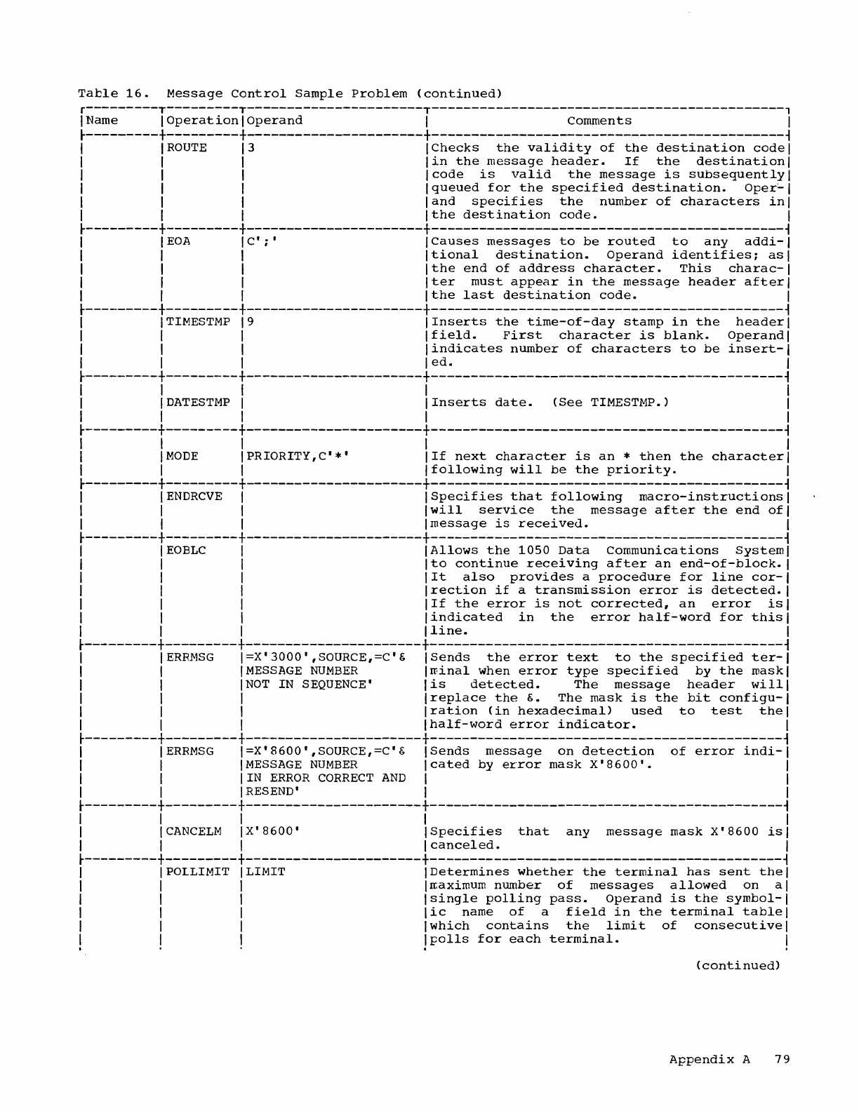
Table
16.
Message
Control
Sample
Problem
(continued)
r---------T---------T----------------------T--------------------------------------------,
I Name I
Operation
I
Operand
I
Comments
I
~---------+---------+----------------------+--------------------------------------------~
I I
ROUTE
13
IChecks
the
validity
of
the
destination
codel
I I I
lin
the
message
header.
If
the
destination
I
I I I
Icode
is
valid
the
message
is
subsequently
I
I I I
Iqueued
for
the
specified
destination.
Oper~1
I I I
land
specifies
the
number
of
characters
inl
I I I
Ithe
destination
code.
I
~---------+---------+----------------------+--------------------------------------------~
I
IEOA
IC';'
ICauses
messages
to
be
routed
to
any
addi-I
I I I
Itional
destination.
Operand
identifies;
asl
I I I
Ithe
end
of
address
character.
This
charac-I
I I I
Iter
must
appear
in
the
message
header
afterl
I I I
Ithe
last
destination
code.
I
~---------+---------+----------------------+--------------------------------------------~
I ITIMESTMP
19
IInserts
the
time-of-day
stamp
in
the
headerl
I I I
Ifield.
First
character
is
blank.
Operandi
I I I I
indicates
number
of
characters
to
be
insert-I
I I I I
ed.
I
~---------+---------+----------------------+--------------------------------------------~
I I I I I
I
IDATESTMP
I
IInserts
date.
(See
TIMESTMP.) I
I I I I I
~---------+---------+----------------------+--------------------------------------------~
I I I I I
I
IMODE
IPRIORITY,C'*'
IIf
next
character
is
an
*
then
the
character
I
I I I I
following
will
be
the
priority.
I
~---------+---------+----------------------+--------------------------------------------~
I
IENDRCVE
I I
Specifies
that
following
macro-instructions
I
I I I
Iwill
service
the
message
after
the
end
ofl
I I I
Imessage
is
received.
I
~---------+---------+----------------------+--------------------------------------------~
I I
EOBLC
I
IAllows
the
1050
Data
Communications
Systeml
I I I
Ito
continue
receiving
after
an
end-of-block.
I
I I I
lIt
also
provides
a
procedure
for
line
cor-I
I I I
Irection
if
a
transmission
error
is
detected.
I
I I I
IIf
the
error
is
not
corrected
r
an
error
isl
I I I
lindicated
in
the
error
half-word
for
this
I
I I I
Iline.
I
~---------+---------+----------------------+--------------------------------------------~
I
IERRMSG
I=X'3000',SOURCE,=C'&
I
Sends
the
error
text
to
the
specified
ter-I
I I
IMESSAGE
NUMBER
Iminal
when
error
type
specified
by
the
maskl
I I
INOT
IN
SEQUENCE'
lis
detected.
The
message
header
willi
I I I
Ireplace
the
&.
The
mask
is
the
bit
configu-I
I I I
Iration
(in
hexadecimal)
used
to
test
the
I
I I I I
half-word
error
indicator.
I
~---------+---------+----------------------+--------------------------------------------~
I
IERRMSG
I=X'8600',SOURCE,=C'&
I
Sends
message
on
detection
of
error
indi-I
I I
IMESSAGE
NUMBER
Icated
by
error
mask
X'8600'.
I
I I
lIN
ERROR
CORRECT
AND
I I
I I I
RES
END
'I
I
~---------+---------+----------------------+--------------------------------------------~
I I I I I
I
ICANCELM
IX'8600'
ISpecifies
that
any
message
mask
X'8600
isl
I I I I
canceled.
I
~---------+---------+----------------------+--------------------------------------------~
I IPOLLIMIT ILIMIT
IDetermines
whether
the
terminal
has
sent
thel
I I I Irr.aximum
number
of
messages
allowed
on
al
I I I
Isingle
polling
pass.
Operand
is
the
symbol-I
I I I
lic
name
of
a
field
in
the
terminal
table
I
I I I
Iwhich
contains
the
limit
of
consecutive
I
!
!!
!polls
for
each
terminal.
!
(conti
nued)
Appendix
A
79
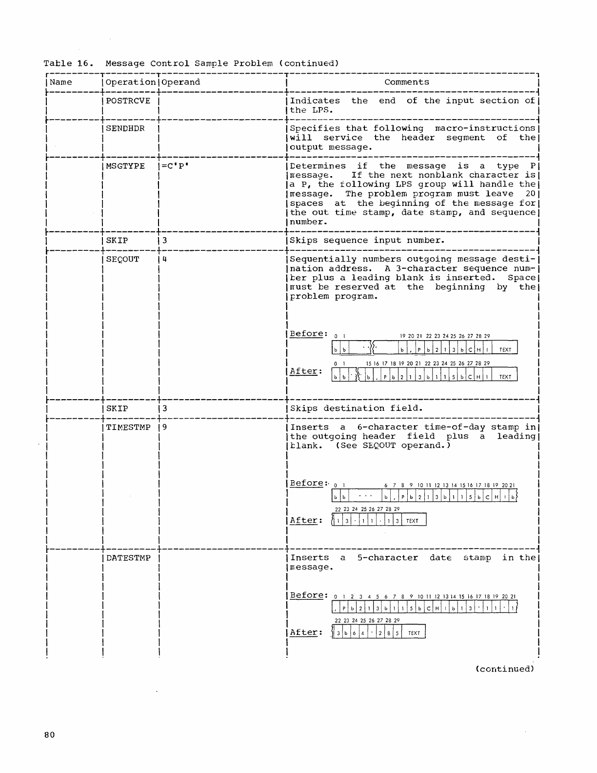
Table
16.
Message
Control
Sample
Problem
(continued)
r---------T---------T----------------------T--------------------------------------------,
IName I
Operation
I
Operand
I Comments I
~---------+---------+----------------------+--------------------------------------------~
I
IPOSTRCVE
I I
Indicates
the
end
of
the
input
section
ofl
I I
lithe
LPS. I
~---------+---------+----------------------+---------------------------------------------~
I
\SENDHDR
\
ISpecifies
that
following
macro-instructions
I
I \ \
\will
service
the
header
segment
of
thel
I \ \
\output
message.
I
~---------+---------+----------------------+--------------------------------------------~
I I
MSGTYPE
\=C'P'
\
Determines
if
the
message
is
a
type
PI
\ \ \
\~essage.
If
the
next
nonblank
character
isl
I \ \
la
P,
the
following
LPS
group
will
handle
thel
I I I
Irressage.
The
problem
program
must
leave
201
I I \ I
spaces
at
the
beginning
of
the
message
fori
I I \
Ithe
out
time
stamp,
date
stamp,
and
sequence
I
I \ I \
number.
I
~---------+---------+----------------------+--------------------------------------------~
\ I
SKIP
13
ISkips
sequence
input
number.
I
~---------+---------+----------------------+--------------------------------------------~
SEQOUT
14
Sequentially
numbers
outgoing
message
desti-
\
nation
address.
A
3-character
sequence
nurn-
1
ter
plus
a
leading
blank
is
inserted.
Space
1
rrust
be
reserved
at
the
beginning
by
the
I
froblem
program.
I
I
I
I
I
1
Before:
0 1
192021
22 23
2425
26 27
28
29
I
bib
I .
·}r
I b
I,
I P / b
12/1
13/
b I c I H
I,
I
\ o 1 1516
17
18
192021
22
2324
25
26
272829
1
After:
1 1
Gill{'
I b I , I P \ b
\2
\1
\31
b
11
\1 151 b \ C \ H
I,
\
1 1
TEXT
TEXT
~---------+---------+----------------------+--------------------------------------------~
1 1 SKIP
13
I
Skips
destination
field.
I
~---------+---------+----------------------+--------------------------------------------~
TIMESTMP
19
I
Inserts
a
6-character
time-of-day
stamp
in
1
Ithe
outgoing
header
field
plus
a
leading
1
Itlank.
(See
SEQ
OUT
operand.)
1 1
I 1
I I
I
\Before:,
0 1
6789101112131415161718192021
I I
l~bl~bl--~lb~I,~lpl~bI2~ll~13~lbl~111~15~lbl~cl~HII~lb~
1 I
22 23 24 25
26 27
28
29
1 1
After:
(11
131·11
11
1·11
131
TEXT
I
1 1
I 1
~---------+---------+----------------------+--------------------------------------------~
DATESTMP
I 1
Inserts
a
5-character
date
stamp
in
the
I I
rr,essage.
I I
I I
1 I
Before:
0 1 2 3 4 5 6 7 8 9
10
11
12
1314
15
16
17 18
19
20
21
! !
I;!:!:::!
:!
:!
:1
:!
'
151
b I c I
HI,
I b
I,
1,1
·1,
I,
II,
I
1 I
After:
.{131 b
16141·12/8/51
TEXT
/
I I
1 1
(continued)
80
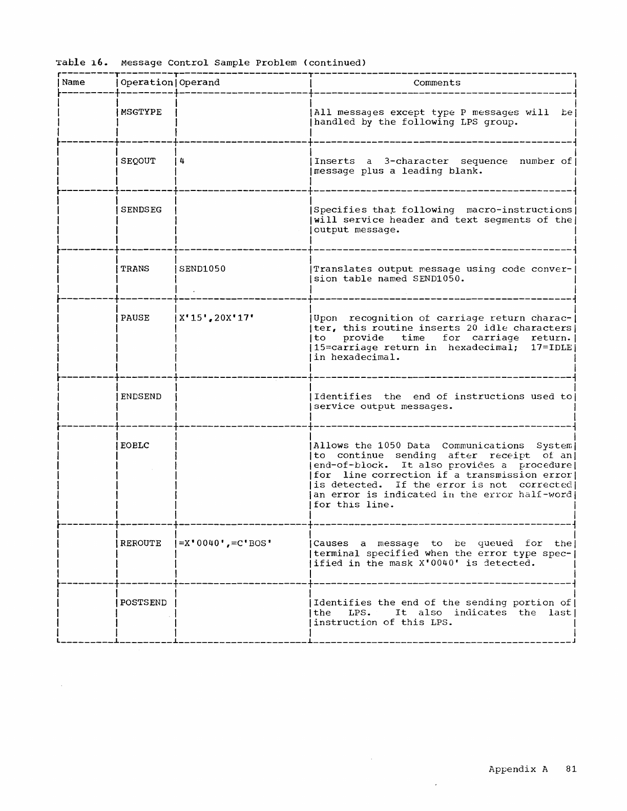
Table
16.
Message
Control
Sample
Problem
(continued)
r---------T---------T----------------------T--------------------------------------------,
I Name I
Operation
I
Operand
I
comments
I
~---------+---------+----------------------+--------------------------------------------~
I I I I I
I I
MSGTYPE
I
IAII
messages
except
type
P
messages
will
bel
I I I
Ihandled
by
the
following
LPS
group.
I
I I I I I
~---------+---------+----------------------+--------------------------------------------~
I I I I I
I ISEQOUT 14 I
Inserts
a
3-character
sequence
number
ofl
I I I
Imessage
plus
a
leading
blank.
I
I I I I I
~---------+---------+----------------------+--------------------------------------------~
I I I I I
I ISENDSEG I
ISpecifies
that
following
macro-instructions
I
I I I
Iwill
service
header
and
text
segments
of
thel
I I I
loutput
message.
I
I I I I I
~---------+---------+----------------------+--------------------------------------------~
I I I I I
I I
TRANS
ISEND1050
ITranslates
output
message
using
code
conver-I
I I I
Ision
table
named
SEND1050.
I
I I
I.
I I
~---------+---------+----------------------+--------------------------------------------~
I I I I I
I I PAUSE
IX'15'.,20X'17'
IUpon
recognition
of
carriage
return
charac-I
I I I
Iter,
this
routine
inserts
20
idle
characters
I
I I I
Ito
provide
time
for
carriage
return.
I
I I I
115=carriage
return
in
hexadecimal;
17=IDLEI
I I I I
in
hexadecimal.
I
I I I I I
~---------+---------+----------------------+--------------------------------------------~
I I I I I
I IENDSEND I I
Identifies
the
end
of
instructions
used
tol
I I I I
service
output
messages.
I
I I I I I
~---------+---------+----------------------+--------------------------------------------~
I I I I I
I I
EOBLC
I
IAllows
the
1050
Data
Communications
Systerrol
I I I
Ito
continue
sending
after
receipt
of
ani
I I I
lend-of-block.
It
also
provides
a
procedure
I
I I I
Ifor
line
correction
if
a
transmission
errorl
I I I
lis
detected.
If
the
error
is
not
corrected
I
I I I
Ian
error
is
indicated
in
the
error
half-word
I
I I I I
for
this
line.
I
I I I I I
~---------+---------+----------------------+--------------------------------------------~
I I I I I
I I
REROUTE
I=X'0040',=C'BOS'
ICauses
a
message
to
be
queued
for
thel
I I I
Iterminal
specified
when
the
error
type
spec-I
I I I
lified
in
the
mask
X'0040'
is
detected.
I
I I I I I
~---------+---------+----------------------+--------------------------------------------~
I I I I I
I IPOSTSEND I
IIdentifies
the
end
of
the
sending
portion
ofl
I I I
Ithe
LPS.
It
also
indicates
the
lastl
I I I
linstruction
of
this
LPS.
I
I I I I I
L
_________
~
_________
~
______________________
L
____________________________________________
J
Appendix
A
81
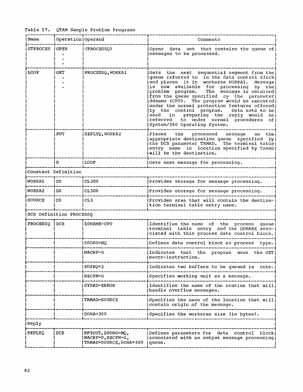
Table
17.
QTAM
Sample
Problem
Programs
r---------T---------T----------------------T--------------------------------------------,
I Name I
Operation
I
Operand
I Comments I
~---------+---------+----------------------+--------------------------------------------~
ISTPROCES
IOPEN
I
(PROCESSQ)
I
Opens
data
set
that
contains
the
queue
ofl
I I I
Imessages
to
be
processed.
1
1 1 1 1 1
1 I I I 1
~---------+---------+----------------------+--------------------------------------------~
LOOP
GET
PROCESSQ~WORKAl
Gets
the
next
sequential
segment
from
the
queue
referred
to
in
the
data
control
block
and
places
it
in
workarea
WORKA1.
Message
is
now
available
for
processing
by
the.
~roblem
program.
The
message
is
obtained
from
the
queue
specified
by
the
parameter
ddname
<CPU).
The
program
would
be
executed
under
the
normal
protection
features
offered
ty
the
control
program.
Data
sets
to
be
used
in
preparing
the
reply
would
be
referred
to
under
normal
procedures
of
System/360
Operating
System.
~---------+---------+----------------------+--------------------------------------------~
1 I
PUT
IREPLYQ,WORKA2
1
Places
the
processed
message
on
the
1
I I I
la~propriate
destination
queue
specified
byl
I I I
Ithe
DCB
parameter
TRMAD.
The
terminal
table
1
I I I
lentry
name
in
location
specified
by
TRMADI
I I I
Iwill
be
the
destination.
1
~---------+---------+----------------------+--------------------------------------------~
I
IB
I
LOOP
IGets
next
message
for
processing.
I
~---------~---------~----------------------~--------------------------------------------~
IConstant
Definition
I
~---------T---------T----------------------T--------------------------------------------~
IWORKA1
IDS
ICL300
IProvides
storage
for
message
processing.
1
~---------+---------+----------------------+--------------------------------------------~
IWORKA2
IDS
ICL300
IProvides
storage
for
message
processing.
1
~---------+---------+----------------------+--------------------------------------------~
I
SOURCE
IDS
ICL3
IProvides
area
that
will
contain
the
destina-I
I I I I
tion
terminal
table
entry
Ilame. I
~---------~---------~------------~---------~--------------------------------------------~
IDCB
Definition
PROCESSQ
1
~---------T---------T----------------------T--------------------------------------------~
IPROCESSQ
IDCB
IDDNAME=CPU
IIdentifies
the
name
of
the
process
queuel.
I I I I
terminal
table
entry
and
the
DDNAME
asso-I
I I
I.
Iciated
with
this
process
data
control
block.
I
~---------+---------+----------------------+--------------------------------------------~
I I I
DSORG=MQ
IDefines
data
control
block
as
process
type.
I
~---------+---------+----------------------+--------------------------------------------~
I I
IMACRF=G
I
Indicates
that
the
program
uses
the
GET
I
I I I I
macro-instruction.
I
~---------+---------+----------------------+--------------------------------------------~
I I I
BUFRQ=2
IIndicates
two
buffers
to
be
queued
in
core.
1
~---------+---------+----------------------+--------------------------------------------~
I I
IRECFM=G
ISpecifies
working
unit
as
a
message.
I
~---------+---------+----------------------+--------------------------------------------~
I I
ISYNAD=ERROR
IIdentifies
the
name
of
the
routine
that
willi
I I I
Ihandle
overflow
messages.
1
~---------+---------+----------------------+--------------------------------------------~
I I
ITRMAD=SOURCE
ISpecifies
the
name
of
the
location
that
willi
I I I
Icontain
origin
of
the
message.
I
~---------+---------+----------------------+--------------------------------------------~
I I I
SOWA=300
I
Specifies
the
workarea
size
(in
bytes).
I
~---------~---------~----------------------~--------------------------------------------~
I
Reply
1
~---------T---------T----------------------T--------------------------------------------~
IREPLYQ
IDCB
I
RPYOUT,
DSORG=MQ,
IDefines
parameters
for
data
control
blockl
I I
IMACRF=P,RECFM=G~
lassociated
with
an
output
message
processing
I
I I
ITRMAD=SOURCE,SOWA=300
I
queue.
1
L
_________
~
_________
~
______________________
~
____________________________________________
J
82
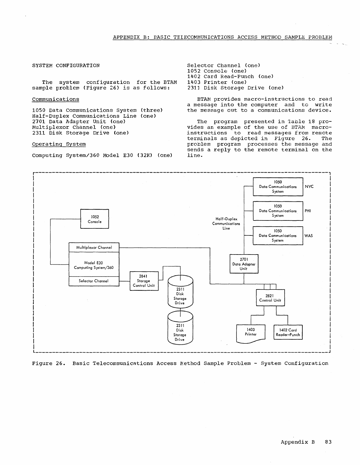
APPENDIX
B:
BASIC
TELECOMMUNICATIONS
ACCESS
METHOD
SAMPLE
PROBLEM
SYSTEM
CONFIGURATION
The
system
configuration
for
the
BTAM
sample
problem
(Figure
26)
is
as
follows:
communications
1050
Data
Communications
System
(three)
Half-Duplex
Communications
Line
(one)
2701
Data
Adapter
Unit
(one)
Multiplexor
Channel
(one)
2311
Disk
Storage
Drive
(one)
operating
System
Computing
System/360
Model
E30 (32K)
(one)
Selector
Channel
(one)
1052
Console
(one)
1402
Card
Read-Punch
(one)
1403
Printer
(one)
2311
Disk
Storage
Drive
(one)
BTAM
provides
macro-instructions
to
read
a
message
into
the
computer
and
to
write
the
roessage
out
to
a
communications
device.
The
program
presented
in
~able
18
pro-
vides
an
example
of
the
use
of
BTAM
macro-
instructions
to
read
messages
from
remote
terminals
as
depicted
in
Figure
26.
The
problem
program
processes
the
message
and
sends
a
reply
to
the
remote
terminal
on
the
line.
r---------------------------------------------------------------------------------------,
I
I
I
1052
Console
Multiplexor
Channe'l
Model E30
Computing
System/360
Selector
Channel
2841
Storage
Control
Unit
Half-Duplex
Communications
line
2701
Data
Adapter
Unit
1050
Data
Communications
NYC
System
1050
Data
Communications
System
1050
PHI
Data
Communications
WAS
System
L
_______________________________________________________________________________________
J
Figure
26.
Basic
Telecommunications
Access
~ethod
Sample
Problem
-
System
Configuration
Appendix
B
83
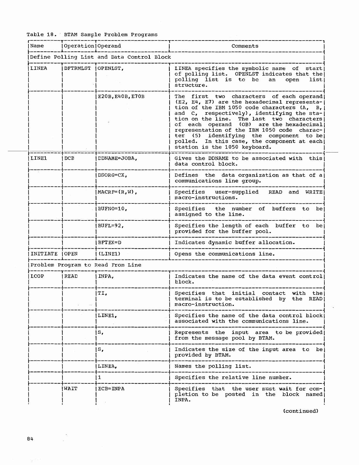
Table
18.
BTAM
Sample
Problem
Programs
r---------T---------T---------------------T---------------------------------------------,
I Name I
Operation
I
Operand
I Comments I
~---------~---------~---------------------L-----------
__________________________________
~
IDefine
Polling
List
and
Data
Control
Block
I
~---------T---------T---------------------T---------------------------------------------~
I LINEA
IDFTRMLST
IOPENLST, I LINEA
specifies
the
symbolic
name
of
start
I
I I I I
of
polling
list.
OPENLST
indicates
that
thel
I I I I
polling
list
is
to
be
an
open
listl
I I . I I
structure.
I
~---------+---------+---------------------+---------------------------------------------~
I I
IE20B,E40B,E70B
I
The
first
two
characters
of
each
operandi
I I I I
(E2,
E4,
E7)
are
the
hexadecimal
representa-I
I I I I
tion
of
the
IBM
1050
code
characters
(A, B, I
I I I I
and
C,
respectively),
identifying
the
sta-I
I I I I
tion
on
the
line.
The
last
two
characters
I
I I I I
of
each
operand
COB)
are
the
hexadecimal
I
I I I I
representation
of
the
IBM
1050
code
charac-I
I I I
Iter
(5)
identifying
the
component
to
bel
I I I I
polled.
In
this
case,
the
component
at
eachl
I I I I
station
is
the
1050
keyboard.
I
---~
+- +-
+ ---- -....;....;-----------------------i--
ILINEl
IDCE
IDDNAME=JOBA,
I
Gives
the
DDNAME
to
be
associated
with
this
I
I I I I
data
control
block.
I
~--~------+---------+---------------------+---------------------------------------------~
I I I
DSORG=CX,
I
Defines
the
data
organization
as
that
of
al
I I I I
communications
line
group.
I
~---------+---------+---------------------+---------------------------------------------~
I I IMACRF=(R,W), I
Specifies
user-supplied
READ
and
WRITE
I
I I I I
macro-instructions.
I
~---------+---------+---------------------+---------------------------------------------~
I I I BUFNO=10, I
Specifies
the
number
of
buffers
to
bel
I I I I
assigned
to
the
line.
I
~---------+---------+-~-------------------+---------------------------------------------~
I I I BUFL=92 , I
Specifies
the
length
of
each
buffer
to
bel
I I I I
provided
for
the
buffer
pool.
I
~---------+---------+---------------------+---------------------------------------------~
I I
IBFTEK=D
I
Indicates
dynamic
buffer
allocation.
I
~---------+---------+---------------------+---------------------------------------------~
IINITIATE
IOPEN
I (LINE1) I
Opens
the
co~munications
line.
I
~---------~---------~---------------------L-----------
__________________________________
~
IProblem
Program
to
Read
From
Line
I
~---------T---------T---------------------T---------------------------------------------~
I
LOOP
I
READ
IINPA, I
Indicates
the
name
of
the
data
event
control
I
I I I I
block.
I
~---------+---------+---------------------+---------------------------------------------~
I I
ITI,
I
Specifies
that
initial
contact
with
thel
I I I I
terminal
is
to
be
established
by
the
READ
I
I I I I
macro-instruction.
I
~---------+---------+---------------------+---------------------------------------------~
I I ILINE1, I
Specifies
the
name
of
the
data
control
blockl
I I I . I
associated
with
the
communications
line.
I
~---------+---------+---------------------+---------------------------------------------~
I I I
S,
I
Represents
the
input
area
to
be
provided
I
I I I I
from
the
message
pool
by
BTAM.
I
~---------+---------+---------------------+---------------------------------------------~
I I
IS,
I
Indicates
the
size
of
the
input
area
to
bel
I I I I
provided
by
BTAM.
I
~---------+---------+---------------------+--~------------------------------------------~
I I I LINEA, I Names
the
polling
list.
I
~---------+---------+---------------------+---------------------------------------------~
I 1 11 I
Specifies
the
relative
line
number.
I
~---------+---------+---------------------+---------------------------------------------~
I
IWAIT
1 ECB=INPA I
Specifies
that
the
user
must
wait
for
com-I
I I I I
pletion
to
be
posted
in
the
block
named
I
I I I I INPA. I
• • I I
(continued)
84
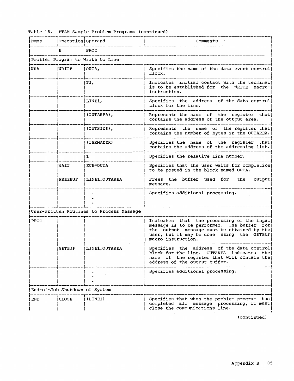
Table
18.
ETAM
Sample
Problem
Programs
(continued)
r---------T---------T---------------------T---------------------------------------------,
I Name I
Operation
I
Operand
I
comments
I
r---------~---------~---------------------~---------------------------------------------~
I B
PROC
I
r---------------------------------------------------------------------------------------~
I
Problem
Program
to
Write
to
Line
I
r---------T---------T---------------------T---------------------------------------------~
IWRA
IWRITE IOUTA, I
Specifies
the
name
of
the
data
event
control
I
I I I I
1::
lock.
I
r---------+---------+---------------------+---------------------------------------------~
I I
ITI,
I
Indicates
initial
contact
with
the
terminal
I
I I I I
is
to
be
established
for
the
WRITE
macro-I
I I I I
instruction.
I
r---------+---------+---------------------+---------------------------------------------~
I I I LINE1" I
Specifies
the
address
of
the
data
control
I
I I I I 1::lock
for
the
line.
I
r---------+---------+---------------------+---------------------------------------------~
I I I (OUTAREA), I
Represents
the
name
of
the
register
that
I
I I I I
contains
the
address
of
the
output
area.
I
r---------+---------+---------------------+---------------------------------------------~
I I I (OUTSIZE) , I
Represents
the
name
of
the
register
that
I
I I I I
contains
the
number
of
bytes
in
the
OUT
AREA.
I
r---------+---------+---------------------+---------------------------------------------~
I I I
(TERMADDR)
I
Specifies
the
name
of
the
register
that
I
I I I I
contains
the
address
of
the
addressing
list.
I
r---------+--~------+---------------------+---------------------------------------------~
I I 11 I
Specifies
the
relative
line
number.
I
t---------+---------+---------------------+---------------------------------------------~
I
IWAIT
I
ECB=OUTA
I
Specifies
that
the
user
waits
for
completion
I
I I I I
to
be
posted
in
the
block
named
OUTA.
I
t---------+---------+---------------------+---------------------------------------------~
I IFREEBUF ILINE1,OUTAREA I
Frees
the
buffer
used
for
the
output
I
I I I I
message.
I
r---------+---------+---------------------+---------------------------------------------~
I I I I
Specifies
additional
processing.
I
I I I I I
I I I I I
t---------~---------~---------------------~---------------------------------------------~
IUser-Written
Routines
to
Process
Message
I
r---------T---------T---------------------T---------------------------------------------~
IPROC
I I I
Indicates
that
the
processing
of
the
input
I
I I I I
message
is
to
be
performed.
The
buffer
fori
I I I I
the
output
message
must
be
obtained
by
the
I
I I I I
user,
but
it
may
be
done
using
the
GETBUFI
I I I I
macro-instruction.
I
r---------+---------+---------------------+---------------------------------------------~
I IGETEUF ILINE1,OUTAREA I
Specifies
the
address
of
the
data
control
I
I I I I 1::lock
for
the
line.
OUTAREA
indicates
the
I
I I I I
name
of
the
register
that
will
contain
the
I
I I I I
address
of
the
output
buffer.
I
r---------+---------+---------------------+---------------------------------------------~
I I I I
Specifies
additional
processing.
I
I I I I I
I I I I I
t---------~---------~---------------------~---------------------------------------------~
I
End-of-Job
Shutdown
of
System
I
r---------T---------T---------------------T---------------------------------------------~
I
END
I
CLOSE
I
(LINE1)
I
Specifies
that
when
the
problem
program
has
I
I I I I
completed
all
message
processing,
it
must
I
I I I I
close
the
communications
line.
I
J
(continued)
Appendix
B
85
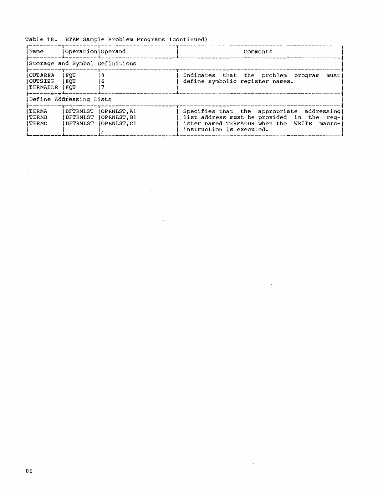
Table
18.
BTAM
Sample
Problem
Programs
(continued)
r---------T---------T---------------------T---------------------------------------------,
1 Name 1
Operation
1
Operand
1
Comments
1
~---------~---------~---------------------~---------------------------------------------~
IStorage
and
Symbol
Definitions
1
~---------T---------T---------------------T---------------------------------------------~
IOUTAREA
IEQU
14
1
Indicates
that
the
problem
program
must
1
1 OUTSIZE 1
EQU
16
1
define
symbolic
register
names.
1
1
TERMA[)DR
1
EQU
17
1 1
~-----~=~---------~---------------------~---------------------------------------------~
1
Define
Addies,sing
Lists
1
~---------T-~~--~---T---------------------T---------------------------------------------~
ITERMA
\DFTRMLST
IOPENLST,A1 1
Specifies
that
the
appropriate
addressing
1
ITERMB
IDFT~MLST
IOPENLST,B1 \
list
address
must
be
provided
in
the
reg-I
ITERMC
\DFTRNLST IOPENLST,C1 \
ister
named
TERMADDR
when
the
WRITE
macro-\
1 \
I.
\
instruction
is
executed.
1
L
_________
~
_________
~~
____________________
L
_____________________________________________
J
86
Where
more
than
one
page
reference
is
listed,
the
major
reference
is
given
first.
Access
key
•••••••••••••••••••••••••••••
54
Access
methods
application
••••••••••••••
7
Activation
of
communications
lines
••••••••••••••••••••••••••.
23,48,62
Addressing
characters
••••••••••••••••••••••••
28,70
code
•••••••••••••••••••••••••••••••••
28
list
••••••••••••••••••••••••••.•••
70-71
terminals
•••••••••••••••••••••••••
12-13
Allocating
buffers
dynamically
(see
also
buffer)
•••••••••••••••••••••••
12,63
Alternate
source
code
••••••••••••••••••
16
AnalYSis
functions
•••••••••••••••••••••
62
Answer
DIALIST
••••••••••••••••••••••
71-72
Answer
IDLST
•••••••••••••••••••••••.
71-72
Answer
list
argument
••••••••••••.••••••
72
Answering
••••••.••••••••••••••••••••.
12,62
Answering
lists
•••••••••••••••••••••
70-72
Application
access
methods
••••••••••••••••••••••••
7
conversational
type
••••••••••••••••••
12
data
collection
••••••••••••••••••••••
55
inquiry
message
••••••••••••••••••••••
75
inquiry
(or
transaction)
processing
•••
7
message
switching
••••••••••••••••••
7,75
Tele-processing
•••••••••••••••••••••••
7
Assembler
language
••••••••••••••••••
11,14
Assembler
program
•••••••••••••••••••••••
7
AT&T
Model
33
or
35
Teletypewriter
Terminal
(see
Common
carrier
TWX
Stations)
AT&T
83B2
Selective
Calling
Stations.
7,28
Basic
telecommunications
access
method
••••••••••••••••••
62-74,7,12,83-86
Braces,
when
used
••••••••••••••••••••••
15
Brackets,
when
used
•••••••••••••••••••
15
Breakoff
error
••••••••••••••••••••••
38,43
BREAKOFF
macro-instruction
••••••••••
43,38
BTAM
(Basic
Telecommunications
Access
Method)
•••••••••••••••••
62-74,7.12,83-86
Buffer
••••••••••••
12.15,17,73-74,77,78,84
allocating
••••••••••
7,12,30-31,63,73,84
areas
••••••••••••••••••••••••••••••••
78
assignment
••••••••••.••••••••••.
31,43,62
chains,
writing
of
•••••••••••••••••••
12
formats
••••••••••••••••••••••••••••••
32
insufficient
•••••••••••••••••••••••••
43
lengths
•••••••••••••••••••.••••••••
7,45
pool
•••••••••••••••
70,71,81,62,63,74,84
BUFFER
macro-instruction
••••••••••••
30-31
Buffering
•••••••••••••••
30-31,73,13,19,62
CANCELM
macro-instruction
•••••••••••
42,43
Card
punch
•••••••••••••••••••••••••••••
19
Carriage
return
••••••••••••
20,21,41,45,80
Carriage
return-line
feed,
combined
•••••••••••••••••••••
20,21,45,80
Character
code
••••••••••••••••••••••
11,12
Characters,
priority
of
••••••••••••••••
12
CHGNTRY
macro-instruction
.•••.•••••.
72-73
CHNGPL
macro-instruction
.•••••.••.•.
48,25
CHNGT
macro-instruction
••.•••.••.
49,44,51
CLOSE
macro-instruction
•••••••
22,24-25,65
E
form
•.•.••.••••••••••••••••.••..
25,65
L
fornl
•...••..•.........•......••.
25,65
message
control
task
use
•.••••.•••••.
26
message
processing
task
use
..••••.•••
26
Code
addressing
••.•••••.••.••••••.•••.••..
28
al
terna
t"e
source
•••••••••.•.•••...••.
16
character
.•••••••.•••.•.•..••..••.
11,12
conversion
tables
••••.••••••••.
12,41,81
distribution
list
••.•••.••••••.••.
26,53
extended
binary-coded
decimal
interchange
•••.•.••••..•••••..••.
26,41
message
type
•••..••.•••••....••....•.
40
polling
.•.••..••••••••.••.•..••••.••.
28
source
terminal
••••••••••••..••••••••
36
terminal
••••.•••••••••.••
49,50,26,51,52
translating
••.•.•••.•••••.••
13,14,62,65
transmission
•••••••••••••••••••••..•.
52
Collating
sequence,
standard
•.••.••.••.
12
Common
Carrier
TWX
stations
••.•••••••••..••
7,28,48,66,68,70
Communica
tions
line
group
••••••
15-17,11,22-24,31,62-64
lines,
activation
of
•.•••...•••
23,48,62
lines,
deactivation
of
••.••••••
48-49,62
system
specifications
•..•.•.•..••••..
62
system
status
changing
..•.•.••••••••.
62
Configuration,
system
(sample)
•••..•
75,83
Con
tin
ued
READ
.••••.•••••••.•.•••.•••..
66
Continued
READ
witn
RESET
•..•.••••••••.
66
Continued
WRITE
••••••••••.••.••..••••..
68
Continued
WRITE
with
RESET
•..•.•••••••.
68
Control
block
(see
specific
item)
information
..••••.•••••••••.
10,11,15,26
messages
•.•••••••••.••.••.•.•••••.•..
57
operator
•.•••••••••••.••.•••••.•••.•.
57
programs
•••••••••••••••••••••••••.•
9,10
unit
(see
also
IBM
Data
Adapter
Unit
or
IBM
Transmission
Control)
•••••..•.
7
Conventions,
used
to
illustrate
coding
format
.................................
15
Conversational
mode
•••.••••.••••..••
39,56
Conversational
READ
•••••••..•.•.•...••.
66
Conversational
READ
with
RESET
.•..••••.
66
Conversational
type
application
•.••.•..
12
Conversational
WRITE
•••••••.•.•.••••.••
68
Conversational
WRITE
with
RESET
•.••..•.
63
Conversion
tables
••.••.•••..••.•.
12,41,81
COPYT
macro-instruction
••••.•••••••••..
49
CPYPL
macro-instruction
•••..••••••••.•.
47
CPYQ
macro-instruction
••.••.•••••••.
54-55
Data
cataloging
facilities
•.•••••••.•.•
10
Data
collection
••••••.•••••.•••.
7,9,10,55
Data
control
block
••••••••
15-22,62-63,23,
25,45,46,47,48,49,64,66
Data
control
block
exit
••••.•••••••••••
63
Index
87
Data
definition
statement
(DD
statement)
••••••••••••
15-21,10,62,63
Data
event
control
block
•••••••••
66,67,68
Data
management
facilities
••••••••
9,10,13
Data
processing
task
••••••••••••••••••••
9
Data
set
definition
••••••••••••••••••••••••
10,15
initialization
••••••••••••••••••••
22,31
label
••••••••••••••••••••••••••••••••
15
logging
device
•••••••••••••••••••••••
23
organization
•••••••••••••
17,19,20,21,63
sequential
•••••••••••••••••••••••••••
19
termination
••••••••••••••••••••••••••
22
Data
set
initialization
macro-
instructions
••••••••••••••••••••••••••
31
Date
stamp
•••••••••••••••••••••••••••••
38
Date
stamping
••••••••••••••••••••
13,14,62
DATESTMP
macro-instruction
••••••••••
38,34
DCB
exit
.................................
63
DCB
macro-instruction
•••••••••
16-21,10;15
22,23,25,45,46,47,48,49,64,66
DD
statement
•••••••••••••••
15-21,10,62-63
Deactivation
of
coremunications
lines
•••••••••••••••••••••••••••
48-49,62
DECB
(data
event
control
block)
••
66,67,68
Delimiter
•••••••••••••••••••••••••••
33-36
Delimiter
macro-
instructions
••••••••••••••
33-36,11,59,60
Destination
code
•••••••••••
13,37,38,43,53
illegal
••••••••••••••••••••••••••••••
43
validating
•••••••••••••••••••••••••••
10
Destination
queue
(see
output
queue)
Device-address
field
•••••••••••••••••••
16
Device
allocation
information
••••••
~
•••
16
Device
oriented
functions
••••••••••••••
62
DFTRMLST
macro-instruction
•••••••••••••
72
Dial
DIALST
••••••••••••••••••••••••••••
72
Dial
IDLST
•••••••••••••••••••••••••••••
72
Dial
list
argument
••••••••••••••
~
••••••
72
Dialing
•••••••••••••••••••••••••••••
12,62
DIALST
answer
•••••••••••••••••••••••••••••.
:
72
dial
•••••••••••••••••••••••••••••••••
72
Direct-access
device
••••••••••••••••
19,29
address
••••••••••••••••••••••••••••••
47
Direct-access
message
queue
••••••
16,18,25
Direct-access
storage
••••••••••••••
9-11,14-16,22,23,47
DIRECT
macro-instruction
••••••••••••
37-38
Distribution
list
••••••••••
28,29,37,50,53
DSL
(data
set
label)
•••••••••••••••••••
15
Dynamic
buffer
allocation
••••••••
12~63,74
Dynamic
buffering
•••••••••••••••••••
62,73
EBCDIC
(extended
binary-coded
decimal
interchange
code)
••••••••••••••••••
26,41
ECB
•••••••••••••
'
••
"
•••••••••••••••••••••
66
Ellipsis,
when
used
••••••••••••••••••••
15
Enable
•••••••••••••••••••
_
••••••••••
~
••
69
End-of-address
character
•••••••••••••••
37
End-of-address
macro-instruction
•••••••
37
End-of-block
character
••
20,21,31,35,39,66
End-of-block
macro-instruction
•••••••••
39
End-of-transmission
•••••••••••••••••
39,58
End-of-transmission
character
(EOT
character)
••••••••••••••
20,21,44,66
ENDRCVE
macro-instruction
•••••••••••
35,34
ENDREADY
macro-instruction
•••••••••••••
31
88
ENDS
END
macro-instruction
.••••••••••
35,34
Entry
distribution
list
•••••••••••.••••.
50,53
group
code
••••••••••••••••••••••••
50,52
process
program
•••••••••••••.•••••
50,53
single
terminal
•••••••.•••••.•••••
50-51
EOA
character
•••••••••.•••••••.••••.•••
37
EOA
macro~instruction
••••••••••••••••••
37
EOB
character
•••••••••••
20,21,31,35,39,66
EOB
macro-instruction
•••••••••.••••.•••
39
EOBLC
macro-instruction
••••••••.•••.••.
40
EODAD
exi
t
..................................
45
parameter
••••••••••••••••••••••••••.•
55
EOT
character
•••••••••••••••••
20,21,44,66
ERRMSG
macro-instruction
•••••••••••••.•
42
Error
checking
••••••••••••••••••••
7,13,62
Error,condition
•••.•••.••.••.•..•••.
62,73
Error
correcting
•••••.•••••••••••••.•••
13
Error
hal
f
-word
.........................
43
Error
handling
(BTAM)
•.••.••••••••••
73-74
Error
handling
macro-instructions
(QTAM)
•••••••••••••••••••••••••••••
42-44
Error
information
field
address
.•••••.•
66
Error
message,
transreission
of
•••.•.•••
11
Event
control
block
(ECB)
••••••••••••••
66
Exit
list
••••••••.•••••••••
~
••••••••
18,63
Extended
binary-coded
decimal
interchange
code
•••••••••••••.••••.
26,41
Fixed
record
length
•.••••••••••••••••.•
16
Format
checking
..........................
66
FREEBUF
macro-instruction
•••••••••••••.
74
Functional
macro-instructions
•••••••
36-44
GET
macro-
instruction
••••••
45,12-14,17,18,20,55,56
Group
code
•••••••••••••••••••••.••..
37,42
Header
pref
ix
.............................
13
,
32
scanning
..............................
36
Header,
incomplete
........................
43
Header
analysis
••••.•••••••••••••••••••
62
Header
analysis
error
byte
•••••••..••••
43
IBM
lQ~O
Data
Collection
System
•••
7,28,41
IBM
1050
Data
Collection
System
••••••••••••••••••
7,28,35,41,42,71
IBM
2701
Data
Adapter
Unit
.............
7,75
IBM
Transmission
Control
••••••••••••••..
7
ID
list
argument
........................
72
Idle
characters
.........................
41
IDLST
answer
..................................
72
dial
..................................
72
Illegal
source
code
••••••••••••••••••••
43
Initial
READ
••••••••••••.•••••.••••••••
66
Initial
READ
with
RESET
•••••••••••••.••
66
Initial
WRITE
••••••••••••••••••••••••••
68
Initial
WRITE
with
RESET
•••••••••••••••
68
Input
devices
•••••••••.••••••••••••••••
10
Input
message
processing
queue
.••••••.••
22
Input
(process)
queues
•••••••••
9-11,44-45
Inquiry
application
•••••••••••••••
57-58
/7
Inquiry
processing
(see
also
a~plication,
inquiry
processing)
••••••••••••••••••
7,9
INTERCPT
macro-instruction
••••••••••
44,51
Interval
timer
capatility
•••.••.•••••••
38
Jot
management
facilities
••.••••
~
••••••
10
Job
process
ing
.........................
9,10
Job
scheduler
••.•••••••..••••••.••
9,10,58
Keyword
parameters
•••••••••••••••
16,62,63
language
assembler
••••••••••••••••••••..•••
11,14
roessage
control
••••••••••••••.••••••••
7
standard
statements
••••••.••••.•••••••
7
language
compiler
••••••••••••••.•••••••
14
Language
processor
•••••••••.•••••••••
9,10
I.etters
lower
case
•••••••••••••••
-
•••••
~
•••
15,41
upper
case
.........................
15,41
Library,
operating
system
•••••••.••.•••
10
Line
configurations
......................
7
Line
control
error
byte
••••••••••••••••
43
I.ine
error
information
field
.............
74
Line
feed
..........................
20,21,45
Line
procedure
specification
•••••.•••.
31,44,11-12,16,18
Line
f:rocedures
...........
'
...............
~
7
List
argument
answer
••••••••••
~
••••••••••••••••••••
72
dial
........
4O............................
72
LIST
macro-instruction
•.
~
...........
28,21,53
List
structure,
specification
of
........
72
Lists
addressing
......................
69-70,68
answering
••••••••••••••••••••••
70,71,72
distribution
..................
28,37,50,53
exit
•••••••••••••••••••••••.••••••
18,63
open
••••••.••••••.•••.•••••••••
70,71,72
parameter
•••••••••••••••••••
24,25,64,65
polling
•••
29-30,11,17,23,47,48,66,69-70
terminal
.....................
12,69-73,66
wrap-around
•••••••••••••••••••••••
70,72
Local
direct-access
storage
(see
direct-access
storage)
Logging
•••••••••••••••••••••••••••••••.
14
LOGSEG
macro-instruction
••••••••••••
40,55
Longitudinal
redundancy
check
•••••••
43,66
LPSTART
macro-instruction
••••••••.•••••
34
~acro-instructions
message
processing
•••••••••••••••••••
12
system
status
......................
12,14
Main
storage
buffers,
size
and
number
.................................
11
Marks,
use
of
punctuation
••••••••••••••
15
Mask
.....................................
42
Master
sequence
number
•••••••••••••••••
52
~essage,
unsolicited
•••••••••••••••••••
56
Message
buffering
storage
allocating
•••
13
Message
cancelling
•••••••••••••••••••••
13
Message
code
translating
•••••••.••••••••
7
~essage
control
language
(see
also
routines)
••••••••••••••••••••••••••••••
7
Message
control
macro-instructions,
summary
of
•••••••••••••••••••••••••
59,61
Message
control
program
(see
also
routines)
••••••••••••••••••••••
7,9,10,12
how
to
construct
•••••••••••••••••••
9,10
types
of
application
••••••••••••••••••
9
Message
control
routines
•••••••••.••.•••
7
Message
control
sample
problem
••.•••
77-81
Message
control
section
of
BTAM
•••..
65-66
Message
control
task
••••
25-44,14-16,21-23
Message
delimiter
.••••••.•••••••••..•.•
66
Message
editing
••••.••••.••••••
7,11,13,66
Message
enqueueing
and
dequeueing
••••••
11
Message
forroat
•••••.•••.•••••••••••••
7,76
Message
handling
functions
••••••.•.••.••••••••.•••.••.
62
procedure
•••••••••.•••.••••••••.•.••.
31
Message
header
•••••••••.••••••••••..
32,33
Message
header
stamp
••••.••••••.••.••••
38
Message
intercepting
••••.•••••••••••
13,44
Messag8
log
•••••••••••••.•••
9-11,13,16,26
Message
logging
device
•.••••••••••••••.
22
Message
priority
information
•••.•••••••
13
Message
processing
macro-instructions,
summary
of
••••••••.••••••••••••••••••.
61
Message
processing
program
•••••••.••••••....
7,9,10,13,14,62
Message
processing
task
.•.•
44-58,14-16,23
applica
tions
•••••••.••••••••••••.•
55-58
Message
queueing
•••••.••.••.••••••••
13,22
Message
receiving
.••••••••••••••••
7,13,62
Message
rerouting
.......................
13
Message
routing
•••••••
7,11-13,26,37,44,66
Message
segments
..................
45,46,62
retrieving
within
priority
groups
••••
14
sent
as
continuous
message
•••••••••••
14
Message
sending
••••••••••••••••..••••
7,13
Message
sequence
number
••••••••••••••••
13
Message
switching
(see
also
application,
message
switching)
••.•••.•.••••
55-56,7,9
10,13,14,75-76
Message
transmitting
•••••••••••••••••••
62
Message
type
•••••••••••••.•••••••••••••
40
MF
keyword
parameter
••••••••..
24,25,64,65
Mode
conversational
•.•••••••••.••••.
39,66,68
move
•••.••.•.••••••••.•••••••••••••••
19
MODE
macro-instruction
•••••••••••••••••
39
MSGTYPE
macro-instruction
•••••••..•••••
40
Multiple
addressing
.•••••••••••••.••.•.
37
Multiplex:
channel
•.••.•.••.••••••••••
7,75
Object
code
••••••••••••.•.•••••••••••••
14
Open
list
••••••••••••••••••••••••
70,71,72
Open
list
argument
••••••.•••••••••••••.
70
OPEN
macro-instruction
•••••
22-24,64,60-62
E
form
•••••••••.
,
•••.••••••••.•••••
24,64
L
form
••••••••••••••.••••••••••••.
2 4 , 6 4
message
control
task
use
•••••••.•••••
23
message
processing
task
use
••••••••••
23
Operating
system
library
•••••.•••••••••
10
Operator
control
•••••.•••••••••••.•••••
58
OPTION
macro-instruction
•••
27,29,30,42,52
Optiohal
fields
•••••••••••••••••••••••.
27
Output
message
processing
queue
••.••.••
22
Paper
tape
••••••••••••.••••••••••.••
..••
19
Parameter
list
•.••••••••••••••
24,25,'64,65
PAUSE
macro-instruction
••••••••••••••••
41
POLL
macro-instruction
•••••••••••.•••••
30
POLLIMIT
macro-instruction
•••••••••••••
38
Polling
•••••••••••••••••
17,18,51,66,68-69
characters
•.••••••••••.•••••.•••••
28,70
interval
••••••••••••••••••••.••••..••.
16
Index:
89
procedures
••••••••••••••••••••••••••••
7
terminals
••••••••••••••••••••••••••••
12
Polling
list
•••••••
11,17,23,26,30,47-48,68-69,70
POSTRCVE
macro-instruction
•••••••••••••
35
POSTS
END
macro-instruction
•.•••••••••••
36
Prefix,
modified
•••••••••••••••••••••••
13
Printer
••••••••••••••••••••••••••••••••
19
Priority
processing
•••••••••••••••••••••••••••
26
queueing
•••••••••••••••••••••••••••••
45
specifications
•••••••••••.•••••••••••
16
PROCESS
reacro-instruction
••••••••
28-29,21
Processing
program
••••••••.•••••••••
55-58
Program,
assemcler
••••••••••••••••••••••
7
PUT
macro-
instruction
•••••••••
45-46,12-14,17-19,21
CSAM
(queued
sequential
access
method)
••••••••••••••••••••••••••••
19,23
QTAM
•••••••••••••••••••••••••••
13-59,7-12
Queue
code
name
of
••••••••••••.••••••••••••
11
where
required
•••••••••••••••••••.•••
13
Queue
access
••••••••••••••••••••••••
44-45
Queue
status
information
••••••••••••
54-55
Queued
sequential
access
method
•••••
19,23
Queued
telecorrmunications
access
method
••••••••••••••••••••••••
13-59,7-12
Quotation
marks,
when
used
••••••••••••.
27
RCVF
1050
table
••••••••••••••••••••••••
39
RCVHDR
macro-instruction
••••••••••••
35,34
RCVSEG
macro-instruction
••••••••••••
34,35
READ
continued
••••••••••••••••••••••••••••
66
continued
with
RESET
•••••••••••••••••
66
conversational
•••••••••••••••••••••••
66
conversational
with
RESET
••••.•••.•••
66
initial
•••••••••••••••••.••••••••••••
66
initial
with
RESET
•••••••••••••••••••
66
macro-instruction
••••••••••••••
66-68,63
repeat
•••••••••••••••••••••••••••••••
67
Receive
delimiters
••••••••••••••••••
34-35
Receive
functional
macro-
instructions
••••••••••••••.••••••••
36-38
Receive
or
send
delimiters
.0.........
34-35
Receive
or
send
functional
macro-
instructions
........................
38-41
Receiving
messages
•••••••••••••••••••••
12
Redundance
check
longitudinal
••••••••••••••••••••••
43,66
vertical
••••••.••.•••••••.••••••••..•
43
Relative
line
number
••••••.••••
16.27,29,47,48,49,67,68
RELEASE~
macro-instruction
••••••••••
47,51
Remote
stacked
job
application
••••••
57-58
Repeat
READ
••••••••••••••••••••••••••••
66
Repolling
••••••••••••••••••••••••••••••
66
REROUTE
m~cro-instruction
••••••••••..••
44
RESETPL
macro-instruction
••••••••••••••
69
Response
field,
DECB
•••••••••••••••••••
66
Response
time
••••••••••••••••••.••••••••
7
Retransmission
•••••••••••••••••••••••••
67
RETRIEVE
macro-instruction
•••••••
46,12,29
ROUTE
macro-instruction
••••••••••••••••
37
Routines
device
handling
of
QTAM
••••••••••••••
25
90
message
control
•••••••••••••••••••••••
7
message
editing
••.••••••••••••••••••••
7
message
handling
of
QTAM
••••.••••••••
25
(see
also
message
control
task)
Routing
messages
••••••••••••••••••••
13,62
Sample
problem
basic
telecommunications
access
method
•••••••••••••••••••••••••••••.
83
queued
telecommunications
access
method
••••••••••••••••••••••••••••••
75
system
configuration
.•.•••••••••••
75-83
Scan
pointer
•••••••••••••••.•••••••••••
36
Send
delimiters
••••••••••••••••••••••••
35
Send
functional
macro-instructions
•••••
41
SEND1050
table
•••••••••••••••••••••••••
41
SENDHDR
macro-instruction
••••••••••••••
35
SENDSEG
macro-instruction
••••••••••••••
35
SEQ
IN
macro-instruction
••••••••••••••••
36
SEQOUT
macro-instruction
•••••••••••••••
41
Sequence
checking
•••••••••••••••••••
10,13
Sequence
number
low
error
••••.•••.•••••••••••••••••••
43
high
error
............................
43
Sequence
numbering
••••••••••••••••••
10,26
Sequential
input/output
devices
••••••••
14
Sequential
storage
device
••••••.•••••••
10
Service
programs
•••••••••••••••••••••
9,10
SKIP
macro-instruction
•••••••••••••••••
39
Source
code
alternate
••••••••••••••••••••••••••••
16
illegal
•••••••••••••••••••••••••••••.
43
SOURCE
macro-instruction
••••••••••••
36-37
Source
terminal
••••••••••••••••••••••••
42
code
••••••••••••••••••••••••••••••
13,36
code
checking
••••••••••••••••••••••••
26
Space
allocation
•••••••••••••••••••••••
16
Standard
collating
sequence
.•••••••
~
•••
12
Standard
language
statements
••••••••••••
7
STOPLN
macro-instruction
•••••••.••••
48-49
STRTLN
macro-instruction
•••••••••
48,24,31
System
configuration
BTAM
•••••••••••••••••••••••••••••••••
83
QTAM
•••••••••••••••••••••••••••••••••
75
System
specifications
••••••••••••••••••
62
System
status
changing
••••••••••••••••.
62
Tape
density
•••••••••••••••••••••••••••
19
Tape
units
•••••••••••••••••••••••••••••
10
'Task
•••••••••••••••••••••••.••••••••••••
7
Task
management
facilities
•••••••••••
9,10
Telecommunications
program,
constructing
of
•••••••••••••••.••••••.
12
Telecommunications
system
specifications
macro-instructions
•••.••••••••••••••••
59
Telecommunications
system
status
••••••••••••••••••••••••••
44,47-50
Tele-processing
application
•••.•••••••••
7
Tele-processing
output
writer
••••••.••.
58
Tele-processing
reader/interpreter
•••••
58
TERM
macro-instruction
••••••••••••••
27-28
Terminal
addressing
•••••••••••
12,13,26,62
Terminal
code,
name
and
address
of
•••••
11
Terminal
entry,
single
••••••••••••••
50-51
Terminal
list
•••••••••••••••.•••••••
66,71
address
of
••••••••••••••••••••••••••.
69
changing
status
of
••••••••••••••••••.
12
facilities
for
creating
••••••••••••••
12
structure
of
•••••••••••••••••••••••••
70
Terminal
polling
'.................
13,26,62
Terminal
tatle
•••••••••••••••••••.••
26-29
entry
.....•..•.........•..........
50-53
specification,
macro-
instruction
for
•.•••.•••
;
.••.•••••••
69
Terminal
response
character
••••••••.•••
73
TERMTEL
roacro-instruction
••.•••.••••
26-27
Text
prefix
•••••••••••••••••••••••••••.
13,32
segment
••••
'..
• • • •
••
• • • •
••
•
••
• . • • • • •
••
32
Time
stamp
••••••••••••.••••••••••.••
38-39
Time
starrping
••••••••••••••.•.
13,14,26,62
TI~EST~P
macro-instruction
••••••••••
38-39
TRANS
macro-instruction
••••••••••.••
40-41
Transaction
processing
••••••••••..••••
7,9
Translating
•••••••••••••••••••••••••
40-41
Transmission
error
•••••••••••.••.••••..
43
Unsolicited
message
••••••••.•••••••••••
55
Variable
length
Llocked
records
.•.•••.•••••••.
19
length
field
•••••.••••••••••••••••••.
36
length
message
•••.••••••.••.•••...••.
13
length
records
•••••••.•••••••••••.•••
19
Vertical
redundance
check
••••••••••••.•
43
WAIT
macro-instruction
•••.••.•••.••.
64-65
WAITR
macro-instruction
•••••.••••••.
64-65
Western
Union
Plan
liSA
Outstations
•.•••
7
Workarea
•••.••.••••••••••••••.••.••.
45-47
Wrap-around
list
•..•..•.•••.•••••••••••.••.•••.•.
70
list
argument
•••••••••.••.••...•••.•.
72
WRITE
continued
.•..••••••••••.•••••••••••••
68
continued
with
RESET
••..••••••••.•••.
68
conversational
•.••••••.•.•••.••••.••.
68
conversational
with
RESET
•••....•••..
68
initial
••.•.•••••••.••••••••••••••.•.
68
ini
tial
with
RESE.T
•.•.•••••••.•••..•.
68
macro-instruction
.•••••.•••••.•••.
68-69
Index
91
READER'S
COMMENTS
IBM
Operating
System/360,
Telecommunications:
Preliminary
Specifications
C28-6553-2
Your
comments
will
help
us
to
produce
better
publications
for
your
use.
Please
check
or
fill
in
the
items
below
and
add
explanations
and
other
comments
in
the
space
provided.
Name: __________________________________________________________________________________________ __
Address:
______________________________________________________________________________________ ___
Which
of
the
following
terms
best
describes
your
job?
n
Programmer
n
Manager
n
Operator
n
Instructor
n
Systems
Analyst
n
Engineer
n
Mathematician
n
Student/Trainee
n
Customer
Engineer
n
Systems
Engineer
n
Sales
Representative
n
Other
(explain)
________________
__
Does
your
installation
subscribe
to
the
SRL
Revision
Service?
n Yes
How
did
you
use
this
publication?
n
No
n As
an
introduction
n
As
a
reference
manual
n As a
text
(student)
n As a
text
(instructor)
n
For
another
purpose
(explain)
________________________________________________________
__
Did
you
find
the
material
easy
to
read
and
understand?
Did
you
find
the
material
organized
for
convenient
use?
Specific
Criticisms
(explain
below)
Clarifications
on
pages
Additions
on
pages
Deletions
on
pages
Errors
on
pages
Explanations
and
Other
Comments
n Yes
n Yes
n
No
(explain
below)
n
No
(explain
below)
No
postage
necessary
if
mailed
in
U.S.A.
C28-6553-2
~OLD
FOLD
--
--
--
--
-
----
--
...
------------
...
--_
.......
_---------
OLD
BUSINESS
REPLY
MAIL
NO
POSTAGE
STAMP
NECESSARY
IF
MAILED
IN
U.
S.
A.
POSTAGE
WILL
BE
PAID
BY
IBM
CORPORATION
P.O.
BOX
9361
RALEIGH,
NORTH
CAROLINA
27603
ATTN:
PROGRAMMING
DOCUMENTATION
DEPARTMENT
840
International
Business
Machines
Corporation
Data
Processing
Division
112
East
Past
Road, White Plains,
N.
Y.
1060t
FIRST
CLASS
PERMIT
NO. 155
RALEIGH,
N.
C.
FOLD
(')
N
co
I
Cl'
Vl
Vl
(.oJ
I
N

C28-6553-2
International
Business
Machines
Corporation
Data
Processing
Division
112
East Post Road, White
Plains,
N.
Y.
10601
'tl
11
....
::s
rr
CD
0.
....
::s
c •
Ul
)0
()
N
CO
I
0'1
IJI
IJI
W
I
N
,/
