C64 PSU DIY Kit Guide
User Manual:
Open the PDF directly: View PDF ![]() .
.
Page Count: 10
C64 / Vic20
PSU DIY Kit
from
http://retro-commodore.eu
Table of Contents
Introduction:........................................................................................................ 3
Warning:.............................................................................................................. 3
Solder guide:....................................................................................................... 3
DIN connector................................................................................................. 3
Print Circuit Board (PCB):..............................................................................4
Trafo:............................................................................................................... 5
5v supply:........................................................................................................ 6
Fuse holder:..................................................................................................... 7
Wires:.............................................................................................................. 8
Enclosure:........................................................................................................ 9
Page 2
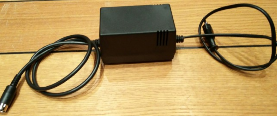
Introduction:
This is the http://retro-commodore version of a C64 PSU.
The project can be found and downloaded for free at https://github.com/Retro-
Commodore/
Warning:
Warning! as the psu works with 230v you shouldn’t be soldering this project
unless you know what you’re doing. No one but yourself are responsible if the
PSU catches fire due to bad/cold soldering joints, so be warned.
Solder guide:
If you haven’t read the warning, please do so before continuing.
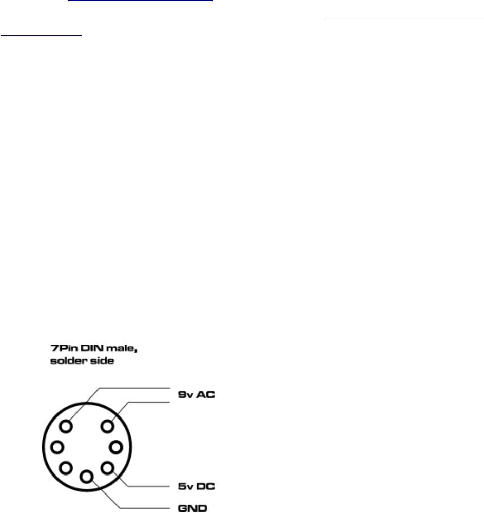
DIN connector
Page 3
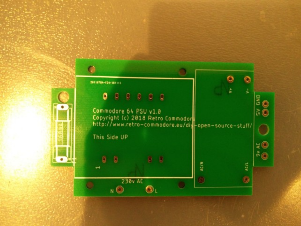
Print Circuit Board (PCB):
The PCB can mistakenly be solder from both sides, so make sure that you
attach the components on top of the PCB hat says ”This Side UP”.
Page 4
Trafo:
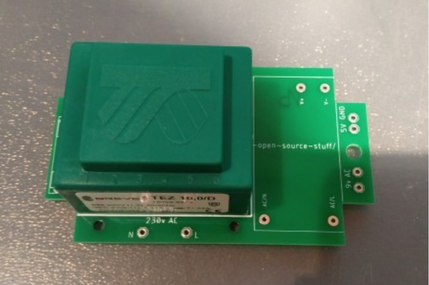
Insert the trafo on top of the pcb, with the side thats written ”This side up”. The
trafo is key coded so you can only insert it one way.
Solder it to the PCB.
The trafo generates the 9v AC needed for the SID, if you measure the output
you might get around 10v AC, thats fine. The voltage will drop once connected
and powered on.
Page 5
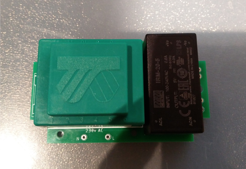
5v supply:
After soldering the trafo, you can now add the 5v psu to the pcb.
This model can deliver up to 4A on the 5V, so it’s more than powerful enough
to be used with 1541 Ultimate, 17xx Ram expansions, C128 with 17xx Ram
expansion etc.
Page 6
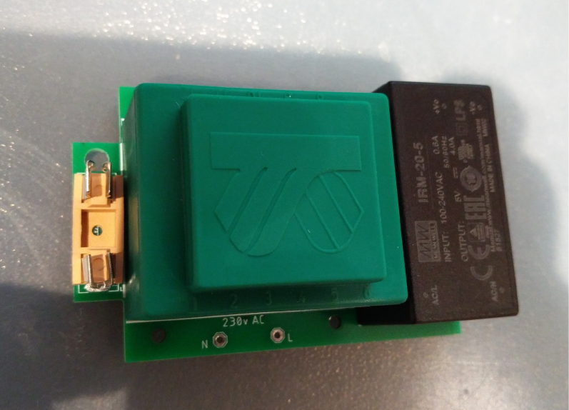
Fuse holder:
Lastly solder the fuse holder. Make sure the fuse isn’t inserted yet as the heat of
the solder iron might damage the fuse.
The fuse is a 160mA T 250V (slow burn) glass fuse. If you’re having problems,
or want to have a ”C128” psu, you can upgrade it to a 250mA T 250V.
Page 7
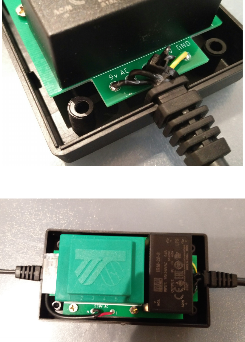
Wires:
First off, even pros forget this from time to time. Make sure the DIN house is on
the cable in the right direction, the same goes with the cable relif’s. Check the
directions before soldering the last open end of the cable
This should be self explained, the 230V cable’s red/brown should be soldered to
L, and the black/blue should be soldered to N.
Depending on the 4 wire cable you’ve received, just make sure that the AC
output next to the 5V psu are connected to the AC solderpins on the DIN
connector.
The 5V is connected to the 5V pin on the DIN connector, and of course lastly
the GND is connected to GND on the DIN connector.
Put the shield around the DIN connector, make sure it’s mounted correctly.
Tighten the metal flippers around the cable and move the house over the shield
to close the connector.
Page 8
Enclosure:
Use a ziptie to attach the 5/9V cable to the PCB using the hole in the PCB.
This isn’t needed for the 230V cable, but you can do so if you want. it.
Screw in 4x3mm screws to fasten the PCB to the enclosue.
Page 9
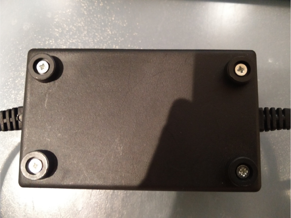
Put the plastic feet on each screw, close the enclosure, insert each screw into each
hole in the bottom of the enclosure and screw in the screws till they are tight.
Enjoy your newly created power supply.
Page 10
