Copley Controls Corp CANopen Programmers Manual
User Manual: CANopenProgrammersManual
Open the PDF directly: View PDF ![]() .
.
Page Count: 249 [warning: Documents this large are best viewed by clicking the View PDF Link!]
- 2 About This Manual
- 2.1 Overview and Scope
- 1.1 Product Warnings
- 2.2 References
- 2.2.1 Defining Documents
- CiA 301: CANopen Application Layer and Communication Profile
- CiA 402 Part 1: Device Profile for Drives and Motion Control, General Definitions
- CiA 402 Part 2: Device Profile for Drives and Motion Control, Operation Modes and Application Data
- CiA 402 Part 3: Device Profile for Drives and Motion Control, PDO Mapping
- IEC 61800-7-1: Adjustable Speed Power Drive Systems
- IEC 61800-7: ETG Implementation Guideline for the CiA402 Drive Profile
- 2.2.1 Defining Documents
- 2.3 Object Description Conventions
- 3 Introduction
- 3.1 CAN and CANopen
- 3.2 Defining and Accessing CANopen Devices
- 3.3 Object Dictionary Structure
- 4 How to Map (or Remap) a PDO
- Process Overview
- 4.2 To Map a Receive PDO
- 4.3 Objects that Define SDOs and PDOs
- SDO receive COB-ID Index 0x1200, Sub-Index 1
- SDO transmit COB-ID Index 0x1200, Sub-Index 2
- PDO COB-ID Index 0x1400 – 0x1407, Sub-Index 1
- Default Values
- PDO type Index 0x1400 – 0x1407, Sub-Index 2
- Number of mapped objects Index 0x1600 – 0x1607, Sub-index 0
- PDO mapping Index 0x1600 – 0x1607, Sub-Index 1 – 8
- Number of mapped objects Index 0x1700, Sub-index 0
- PDO mapping Index 0x1700, Sub-Index 1 – 4
- Number of mapped objects Index 0x, Sub-index 0
- PDO mapping Index 0x1701, Sub-Index 1 – 3
- Number of mapped objects Index 0x1702, Sub-index 0
- PDO mapping Index 0x1702, Sub-Index 1 – 2
- Number of mapped objects Index 0x1703, Sub-index 0
- PDO mapping Index 0x1703, Sub-Index 1 – 2
- Number of mapped objects Index 0x1704, Sub-index 0
- PDO mapping Index 0x1704, Sub-Index 1 – 2
- PDO COB-ID Index 0x1800 – 0x1807, Sub-index 1
- Default Values
- PDO type Index 0x1800 – 0x1807, Sub-index 2
- PDO Events
- Number Of Mapped Objects Index 0x1A00 – 0x1A07, Sub-index 0
- PDO mapping Index 0x1A00 – 0x1A07, Sub-Index 1 – 8
- Number Of Mapped Objects Index 0x1B00, Sub-index 0
- PDO mapping Index 0x1B00, Sub-Index 1 – 5
- Number of mapped objects Index 0x1C12 – 0x1C13, Sub-index 0
- PDO mapping Index 0x1C12 – 0x1C13, Sub-Index 1 – 8
- 5 Network Management
- 5.1 Network Management Overview: CANopen
- 5.2
- 5.3 Network Management Objects: CANopen
- 5.4 Network Management Overview: EtherCAT / CANopen
- 5.5 Sending Serial Commands over CANopen
- 6 Device Control, Configuration, and Status
- 6.1 Device Control and Status Overview
- 6.2 Device Control and Status Objects
- 6.3 Error Management Objects
- 6.4 Basic Amplifier Configuration Objects
- Save All Objects Index 0x1010, Sub-index 1 or string
- Save Communication Parameters Index 0x1010, Sub-index 2
- Save Device Profile Parameters Index 0x1010, Sub-index 3
- Save Manufacturer Specific Parameters Index 0x1010, Sub-Index 4
- Vendor ID Index 0x1018, Sub-index 1
- Product Code Index 0x1018, Sub-index 2
- Revision Number Index 0x1018, Sub-Index 3
- Serial Number Index 0x1018, Sub-Index 4
- Amplifier Serial Number Index 0x2384, Sub-Index 1
- Amplifier Manufacturing Info Index 0x2384, Sub-Index 2
- Amplifier Peak Current Limit Index 0x2384, Sub-Index 3
- Amplifier Continuous Current Index 0x2384, Sub-Index 4
- Amplifier Peak Current Time Index 0x2384, Sub-Index 5
- Amplifier Maximum Voltage Index 0x2384, Sub-Index 6
- Amplifier Minimum Voltage Index 0x2384, Sub-Index 7
- Amplifier Voltage Hysteresis Index 0x2384, Sub-Index 8
- Amplifier Maximum Temperature Index 0x2384, Sub-Index 9
- Amplifier Temperature Hysteresis Index 0x2384, Sub-Index 10
- Amplifier Current Loop Period Index 0x2384, Sub-Index 11
- Amplifier Servo Loop Period Index 0x2384, Sub-Index 12
- Amplifier Type Code Index 0x2384, Sub-Index 13
- Current Corresponding to Max A/D Reading Index 0x2384, Sub-Index 14
- Voltage Corresponding to Max A/D Reading Index 0x2384, Sub-Index 15
- Analog Input Scaling Factor Index 0x2384, Sub-Index 16
- Amplifier Minimum PWM Off Time Index 0x2384, Sub-Index 17
- PWM Dead Time At Continuous Current Limit Index 0x2384, Sub-Index 18
- PWM Dead Time At Zero Current Index 0x2384, Sub-Index 19
- Peak Current Internal Regen Resistor Index 0x2384, Sub-Index 20
- Continuous Current Internal Regen Resistor Index 0x2384, Sub-Index 21
- Time at Peak Current Internal Regen Resistor Index 0x2384, Sub-Index 22
- Analog Encoder Scaling Factor Index 0x2384, Sub-Index 23
- Firmware Version Number Index 0x2384, Sub-Index 24
- Axis Count Index 0x2384, Sub-Index 25
- Internal Regen Current Limit Index 0x2384, Sub-Index 26
- FPGA Image Version Number Index 0x2384, Sub-Index 27
- NIOS Processor Firmware Version Index 0x2384, Sub-Index 28
- Misc Hardware Options Index 0x2384, Sub-Index 29
- Current Level for Minimum PWM Deadtime Index 0x2384, Sub-Index 30
- 6.5 Basic Motor Configuration Objects
- Motor Type Index 0x2383, Sub-Index 1
- Motor Pole Pairs Index 0x2383, Sub-Index 2
- Motor Wiring Configuration Index 0x2383, Sub-Index 3
- Motor Hall Type Index 0x2383, Sub-Index 4
- Motor Hall Wiring Index 0x2383, Sub-Index 5
- Motor Hall Offset Index 0x2383, Sub-Index 6
- Motor Resistance Index 0x2383, Sub-Index 7
- Motor Inductance Index 0x2383, Sub-Index 8
- Motor Inertia Index 0x2383, Sub-Index 9
- Motor Back EMF Constant Index 0x2383, Sub-index 10
- Motor Maximum Velocity Index 0x2383, Sub-Index 11
- Motor Torque Constant Index 0x2383, Sub-Index 12
- Motor Peak Torque Index 0x2383, Sub-Index 13
- Motor Continuous Torque Index 0x2383, Sub-Index 14
- Motor Has Temperature Sensor Index 0x2383, Sub-Index 15
- Motor Has Brake Index 0x2383, Sub-Index 16
- Delay from Error to Brake Active Index 0x2383, Sub-Index 17
- Motor Brake Delay Index 0x2383, Sub-Index 18
- Motor Brake Velocity Index 0x2383, Sub-Index 19
- Motor Encoder Type Index 0x2383, Sub-Index 20
- Encoder Units Index 0x2383, Sub-Index 21
- Motor Encoder Direction Index 0x2383, Sub-Index 22
- Motor Encoder Counts/Rev Index 0x2383, Sub-Index 23
- Motor Encoder Resolution Index 0x2383, Sub-Index 24
- Motor Electrical Distance Index 0x2383, Sub-Index 25
- Encoder Index Pulse Distance Index 0x2383, Sub-Index 26
- Motor Units Index 0x2383, Sub-Index 27
- Analog Encoder Shift Index 0x2383, Sub-Index 28
- Microsteps/Rev Index 0x2383, Sub-Index 29
- Load Encoder Type Index 0x2383, Sub-Index 30
- Load Encoder Direction Index 0x2383, Sub-Index 31
- Load Encoder Resolution Index 0x2383, Sub-Index 32
- Motor Gear Ratio Index 0x2383, Sub-Index 33
- Number of Resolver Cycles/Motor Rev Index 0x2383, Sub-Index 34
- Algorithmic Phase Init Mode Details
- 6.6 Real-time Amplifier and Motor Status Objects
- 6.7 Digital I/O Configuration Objects
- 7 Control Loop Configuration
- 7.1 Control Loop Configuration Overview
- 7.1.1 Nested Position, Velocity, and Current Loops
- 7.1.2 The Position Loop
- 7.1.3 The Velocity Loop
- Overview of the Velocity Loop
- Velocity Loop Limits
- Velocity Loop Input
- Velocity Loop Gains
- Velocity Loop Proportional Gain Index 0x2381, Sub-Index 1
- Velocity Loop Integral Gain Index 0x2381, Sub-Index 2
- Velocity Loop Acceleration Feed Forward Index 0x2381, Sub-Index 3
- Velocity Loop Gain Scaler Index 0x2381, Sub-Index 4
- Velocity Loop Vi Drain (Integral Bleed) Index 0x2381, Sub-Index 5
- Velocity Loop Command Feed Forward Index 0x2381, Sub-Index 6
- Minimum Position Range Limit Index 0x607B, Sub-Index 1
- Maximum Position Range Limit Index 0x607B , Sub-Index 2
- Minimum Software Position Limit Index 0x607D, Sub-Index 1
- Maximum Software Position Limit Index 0x607D, Sub-Index 2
- Profile Jerk 1 Index 0x60A4 Sub-Index 1
- Velocity Loop Filters
- Velocity Loop Output
- 7.1.4 The Current Loop
- 7.2 Position Loop Configuration Objects
- Position Loop Proportional Gain Index 0x2382, Sub-Index 1
- Position Loop Velocity Feed Forward Index 0x2382, Sub-Index 2
- Position Loop Acceleration Feed Forward Index 0x2382, Sub-Index 3
- Position Loop Output Gain Multiplier Index 0x2382, Sub-Index 4
- Position Loop Integral Gain (KI) Index 0x2382, Sub-Index 5
- Position Loop Derivative Gain (KD) Index 0x2382, Sub-Index 6
- Position Loop Pi Drain (Integral Bleed) Index 0x2382, Sub-Index 7
- Position Loop Proportional Gain Index 0x60FB, Sub-Index 1
- Position Loop Velocity Feed Forward Index 0x60FB, Sub-Index 2
- Position Loop Acceleration Feed Forward Index 0x60FB, Sub-Index 3
- Position Loop Output Gain Multiplier Index 0x60FB, Sub-Index 4
- Position Loop Integral Gain (KI) Index 0x60FB , Sub-Index 5
- Position Loop Derivative Gain (KD) Index 0x60FB , Sub-Index 6
- Position Loop Pi Drain (Integral Bleed) Index 0x60FB , Sub-Index 7
- 7.3 Xenus Regen Resistor Objects
- 7.4 Velocity Loop Configuration Objects
- Velocity Loop Proportional Gain Index 0x2381, Sub-Index 1
- Velocity Loop Integral Gain Index 0x2381, Sub-Index 2
- Velocity Loop Acceleration Feed Forward Index 0x2381, Sub-Index 3
- Velocity Loop Gain Scaler Index 0x2381, Sub-Index 4
- Velocity Loop Vi Drain (Integral Bleed) Index 0x2381, Sub-Index 5
- Velocity Loop Command Feed Forward Index 0x2381, Sub-Index 6
- Minimum Position Range Limit Index 0x607B, Sub-Index 1
- Maximum Position Range Limit Index 0x607B , Sub-Index 2
- Minimum Software Position Limit Index 0x607D, Sub-Index 1
- Maximum Software Position Limit Index 0x607D, Sub-Index 2
- Profile Jerk 1 Index 0x60A4 Sub-Index 1
- 7.5 Current Loop Configuration Objects
- 7.6 Gain Scheduling Configuration
- 7.7 Chained Biquad Filters
- 7.1 Control Loop Configuration Overview
- 8 Stepper Mode Support
- 9 Homing Mode Operation
- 9.1 Homing Overview
- 9.2 Homing Methods Overview
- Legend to Homing Method Descriptions
- 9.2.2 Home is Current Position
- 9.2.3 Home is Current Position; Move to New Zero
- 9.2.4 Next Index
- 9.2.5 Limit Switch
- 9.2.6 Limit Switch Out to Index
- 9.2.7 Hardstop
- 9.2.8 Hardstop Out to Index
- 9.2.9 Home Switch
- 9.2.10 Home Switch Out to Index
- 9.2.11 Home Switch In to Index
- 9.2.12 Lower Home
- 9.2.13 Upper Home
- 9.2.14 Lower Home Outside Index
- 9.2.15 Lower Home Inside Index
- 9.2.16 Upper Home Outside Index
- 9.2.17 Upper Home Inside Index
- 9.2.18 Immediate Home
- 9.2.19 Home Configuration Object for Custom Homing Methods
- 9.3 Homing Mode Operation Objects
- Home Velocity – Fast Index 0x6099, Sub-Index 1
- Home Velocity – Slow Index 0x6099, Sub-Index 2
- Input 1~15 Capture Control Index 2408 Sub-Index 1~15
- Input 1~15 Capture Status Index 0x2409 Sub-Index 1~15
- Input 1~15 Captured Rising Edge Position Index 0x240A Sub-Index 1~15
- Input 1~15 Captured Falling Edge Position Index 0x240B Sub-Index 1~15
- Input 1~15 Captured Rising Edge Time Index 0x240C Sub-Index 1~15
- Input 1~15 Captured Rising Edge Time Index 0x240D Sub-Index 1~15
- 10 Touch Probe Operation
- 11 Profile Position, Velocity, Torque & Factor Group Operation
- 11.1 Profile Position Mode Operation
- 11.2 Profile Velocity Mode Operation
- 11.3 Profile Torque Mode Operation
- 11.4 Profile Mode Objects
- 11.5 Factor Group Objects
- Contents of this Section
- Position encoder resolution – Encoder increments Index 0x608F, Sub-Index 1
- Position encoder resolution – motor revolutions Index 0x608F, Sub-Index 2
- ratio – motor revolutions Index 0x6091, Sub-Index 1
- Gear ratio – Shaft revolutions Index 0x6091, Sub-Index 2
- Feed constant – feed Index 0x6092, Sub-Index 1
- Feed Constant – Shaft revolutions Index 0x6092, Sub-Index 2
- Velocity Factor - Numerator Index 0x6096, Sub-Index 1
- Velocity Factor - Divisor Index 0x6096, Sub-Index 2
- Numerator Index 0x6097, Sub-Index 1
- Divisor Index 0x6097, Sub-Index 2
- Jerk Factor Numerator Index 0x60A2, Sub-Index 1
- Jerk Factor Divisor Index 0x60A2, Sub-Index 2
- 12 Interpolated Position Operation
- 12.1 Interpolated Position Mode Overview
- 12.1.1 Coordinated Motion
- 12.1.2 CANopen Standard IP Move Objects
- 12.1.3 Copley Controls Alternative Objects for IP Moves
- 12.1.4 Interpolated Position Trajectory Buffer
- 12.1.5 Starting an Interpolated Position Move
- 12.1.6 Ending an Interpolated Position Move
- 12.1.7 Synchronization
- 12.1.8 PVT Profile Moves Using the Copley Controls Alternative Objects
- 12.2 Interpolated Position Mode Objects
- Overview
- Byte 1: Header Byte
- Buffer Command Mode
- PVT Segment Mode
- Format of Data Bytes in PVT Segment Mode
- Segment Integrity Counter
- Interpolation Position Index 0x60C1, Sub-Index 1
- Interpolation Time Index 0x60C1, Sub-Index 2
- Interpolation Velocity Index 0x60C1, Sub-Index 3
- Interpolation Time Value Index 0x60C2, Sub-Index 1
- Interpolation Time Units Index 0x60C2, Sub-Index 2
- Maximum Buffer Size Index 0x60C4 Sub-Index 1
- Actual Buffer Size Index 0x60C4 Sub-Index 2
- Buffer Organization Index 0x60C4 Sub-Index 3
- Buffer Position Index 0x60C4 Sub-Index 4
- Size of Data Record Index 0x60C4 Sub-Index 5
- Buffer Clear Index 0x60C4 Sub-Index 6
- 12.1 Interpolated Position Mode Overview
- 13 Cyclic Synchronous Modes
- 14 Only for EtherCAT Objects
- Configurated Station Alias Register Value Index 0x10e0, Sub-Index 1
- Write Configured Station Alias Persistent Index 0x10e0, Sub-Index 2
- reload ID-Selector Value Index 0x10e0, Sub-Index 3
- CRC of Parameter Storage Index 0x10F0, Sub-Index 1
- Sync Manager 2, Synchronization type Index 0x1C32 Sub-Index 1
- Sync Manager 2, Cycle Time Index 0x1C32 Sub-Index 2
- Sync Manager 2, Shift Time Index 0x1C32 Sub-Index 3
- Sync Manager 2, Sync Types Supported Index 0x1C32 Sub-Index 4
- Sync Manager 2, Minimum Cycle Time Index 0x1C32 Sub-Index 5
- Sync Manager 2, Calc and Copy Time Index 0x1C32 Sub-Index 6
- Sync Manager 2, Minimum Hardware Delay Index 0x1C32 Sub-Index 7
- Sync Manager 2, Reserved Index 0x1C32 Sub-Index 8
- Sync Manager 2, Hardware Delay Time Index 0x1C32 Sub-Index 9
- Sync Manager 2, Sync0 Cycle Time Index 0x1C32 Sub-Index 10
- Sync Manager 3, Synchronization type Index 0x1C33 Sub-Index 1
- Sync Manager 3, Cycle Time Index 0x1C33 Sub-Index 2
- Sync Manager 3, Shift Time Index 0x1C33 Sub-Index 3
- Sync Manager 3, Sync Types Supported Index 0x1C33 Sub-Index 4
- Sync Manager 3, Minimum Cycle Time Index 0x1C33 Sub-Index 5
- Sync Manager 3, Calc and Copy Time Index 0x1C33 Sub-Index 6
- Sync Manager 3, Minimum Hardware Delay Index 0x1C33 Sub-Index 7
- Sync Manager 3, Reserved Index 0x1C33 Sub-Index 8
- Sync Manager 3, Hardware Delay Time Index 0x1C33 Sub-Index 9
- Sync Manager 3, Sync0 Cycle Time Index 0x1C33 Sub-Index 10
- 15 Alternative Control Sources
- 16 Trace Tool
- 17 Objects By Function
- 17.1.1 Objects that Define SDOs and PDOs
- 17.1.2 Network Management Objects
- 17.1.3 Device Control and Status Objects
- 17.1.4 Error Management Objects
- 17.1.5 Basic Amplifier Configuration Objects
- 17.1.6 Basic Motor Configuration Objects
- 17.1.7 Real-time Amplifier and Motor Status Objects
- 17.1.8 Digital I/O Configuration Objects
- 17.1.9 Position Loop Configuration Objects
- 17.1.10 Velocity Loop Configuration Objects
- 17.1.11 Current Loop Configuration Objects
- 17.1.12 Profile Current Configuration Objects
- 17.1.13 Stepper Mode Objects
- 17.1.14 Homing Mode Operation Objects
- 17.1.15 Profile Mode Objects
- 17.1.16 Interpolated Position Mode Objects
- 17.1.17 Alternative Control Source Objects
- 17.1.18 Trace Tool Objects
- 17.1.19 EtherCAT only Objects
- 17.1.20 Factor Group Objects
- 17.1.21 Touch Probe Objects
- 18 Objects By Index ID

CANopen Programmer’s Manual
Part Number 16-01195
Revision 00
June 13, 2017
CANopen Programmer’s Manual
16-01195 Rev 00 3
1 Table of Contents
2 About This Manual .................................................................................................................... 10
2.1 Overview and Scope ......................................................................................................................... 10
Comments ................................................................................................................................................ 10
Copyrights ................................................................................................................................................ 10
Document Validity .................................................................................................................................... 10
1.1 Product Warnings.............................................................................................................................. 10
Revision History ....................................................................................................................................... 10
2.2 References ........................................................................................................................................ 11
2.2.1 Defining Documents ...................................................................................................................... 11
CiA 301: CANopen Application Layer and Communication Profile ................................................... 11
CiA 402 Part 1: Device Profile for Drives and Motion Control, General Definitions ............................. 11
CiA 402 Part 2: Device Profile for Drives and Motion Control, Operation Modes and Application Data 11
CiA 402 Part 3: Device Profile for Drives and Motion Control, PDO Mapping ..................................... 11
IEC 61800-7-1: Adjustable Speed Power Drive Systems ........................................................................ 11
IEC 61800-7: ETG Implementation Guideline for the CiA402 Drive Profile ......................................... 11
2.3 Object Description Conventions ........................................................................................................ 12
2.3.1 Default Values ............................................................................................................................... 12
2.3.2 CANopen Data Types ................................................................................................................... 13
2.3.3 EtherCAT Data Types ................................................................................................................... 14
3 Introduction ................................................................................................................................ 15
3.1 CAN and CANopen ........................................................................................................................... 15
3.1.1 Copley Controls Amplifiers in CANopen Networks ....................................................................... 15
Copley’s CANopen Amplifiers .................................................................................................................. 15
CAN and CANopen .................................................................................................................................. 15
Architecture .............................................................................................................................................. 15
3.1.2 Addressing Drives on a CANopen Network .................................................................................. 16
3.1.3 Example of a CANopen Move Sequence ...................................................................................... 17
3.1.4 Overview of the CAN Protocol....................................................................................................... 17
A Network for Distributed Control............................................................................................................. 17
CAN Benefits ............................................................................................................................................ 17
Physical Layer .......................................................................................................................................... 17
3.1.5 The CAN Message ........................................................................................................................ 18
Overview .................................................................................................................................................. 18
CAN Message Format .............................................................................................................................. 18
CRC Error Checking ................................................................................................................................ 18
CAN Message ID ..................................................................................................................................... 18
CAN Message Priority .............................................................................................................................. 18
For More Information ................................................................................................................................ 18
3.1.6 Overview of the CANopen Profiles ................................................................................................ 19
Communication and Device Profiles ........................................................................................................ 19
Communication Profile ............................................................................................................................. 19
Profile for Drives and Motion Control ....................................................................................................... 19
3.1.7 EtherCAT CoE ............................................................................................................................... 19
3.2 Defining and Accessing CANopen Devices ...................................................................................... 20
3.2.1 Defining a Device: CANopen Objects and Object Dictionaries ..................................................... 20
Objects and Dictionaries .......................................................................................................................... 20
Object Dictionary as Interface .................................................................................................................. 20
CANopen Profiles and the Object Dictionary ........................................................................................... 20
3.2.2 Addressing Drives on a EtherCAT Network: Device ID ................................................................ 21
3.3 Object Dictionary Structure ............................................................................................................... 22
3.3.1 Accessing the Object Dictionary.................................................................................................... 23
Two Basic Channels ................................................................................................................................ 23
SDOs and PDOs ...................................................................................................................................... 23
Copley SDOs and PDOs .......................................................................................................................... 24
3.3.2 SDOs: Description and Examples ................................................................................................. 25
Table of Contents CANopen Programmer’s Manual
4 16-01195 Rev 00
Overview .................................................................................................................................................. 25
SDO CAN Message IDs ........................................................................................................................... 25
Client/Server Communication .................................................................................................................. 25
SDO Message Format ............................................................................................................................. 25
Confirmation ............................................................................................................................................. 25
Confirmation Example .............................................................................................................................. 25
Segmented, Expedited and Block Transfers ............................................................................................ 26
3.3.3 PDOs: Description and Examples for CANopen ........................................................................... 27
Overview .................................................................................................................................................. 27
Default PDO Message Identifiers ............................................................................................................. 27
PDO Peer- to-Peer Communication ......................................................................................................... 27
PDO Peer-to- Peer Example .................................................................................................................... 27
PDO Mapping ........................................................................................................................................... 27
Mappable Objects .................................................................................................................................... 27
Dynamic PDO Mapping ............................................................................................................................ 27
PDO Transmission Modes ....................................................................................................................... 27
PDO Triggering Modes ............................................................................................................................ 28
Default PDO Mappings ............................................................................................................................ 28
PDO Examples ......................................................................................................................................... 29
3.3.4 PDOs: Timing Considerations for EtherCAT ................................................................................. 30
Fixed PDOs .............................................................................................................................................. 30
Non-fixed PDO (Mappable) ...................................................................................................................... 30
Sync Managers ........................................................................................................................................ 30
Default PDO Mappings ............................................................................................................................ 30
3.3.5 PDOs: Description and Examples for EtherCAT ........................................................................... 30
Non-fixed, empty RxPdo, Mappable ........................................................................................................ 31
Fixed RxPdo with contents assigned, Not-Mappable .............................................................................. 31
Non-fixed, empty TxPdo, Mappable ......................................................................................................... 31
Fixed TxPdo with contents assigned, Not-Mappable ............................................................................... 31
Mailbox / CoE / InitCmd SDO ................................................................................................................... 31
3.3.6 SDO vs. PDO: Design Considerations .......................................................................................... 32
Differences Between SDO and PDO ....................................................................................................... 32
4 How to Map (or Remap) a PDO ................................................................................................ 33
Process Overview .................................................................................................................................... 33
4.2 To Map a Receive PDO .................................................................................................................... 33
Example: Mapping a Receive PDO ......................................................................................................... 34
4.3 Objects that Define SDOs and PDOs ............................................................................................... 35
Default Values .......................................................................................................................................... 35
Default Values .......................................................................................................................................... 41
PDO Events.............................................................................................................................................. 42
5 Network Management ............................................................................................................... 46
5.1 Network Management Overview: CANopen ..................................................................................... 46
Contents of this Section ........................................................................................................................... 46
5.1.2 Overview ........................................................................................................................................ 46
Network Management Services and Objects ........................................................................................... 46
Network Manager Node ........................................................................................................................... 46
5.1.3 General Device State Control........................................................................................................ 47
State Machine .......................................................................................................................................... 47
Device States ........................................................................................................................................... 47
State Control Messages ........................................................................................................................... 47
5.1.4 Device Monitoring .......................................................................................................................... 47
CANopen .................................................................................................................................................. 47
Monitoring Protocols ................................................................................................................................ 47
Heartbeat Protocol ................................................................................................................................... 47
Node-guarding Protocol ........................................................................................................................... 47
5.1.5 SYNC and High-resolution Time Stamp Messages ...................................................................... 48
Time Stamp PDOs ................................................................................................................................... 48
5.1.6 Emergency Messages ................................................................................................................... 48
Table of Contents CANopen Programmer’s Manual
Copley Controls 5
EMCY Message Structure ........................................................................................................................ 48
EMCY Message Error Codes ................................................................................................................... 49
EMCY Message Copley-Specific Error Conditions .................................................................................. 49
5.3 Network Management Objects: CANopen ........................................................................................ 50
SYNC ID Format ...................................................................................................................................... 50
5.4 Network Management Overview: EtherCAT / CANopen .................................................................. 52
5.5 Sending Serial Commands over CANopen ...................................................................................... 54
5.5.1 Overview ........................................................................................................................................ 54
5.5.2 Byte order ...................................................................................................................................... 54
6 Device Control, Configuration, and Status ............................................................................. 55
6.1 Device Control and Status Overview ................................................................................................ 55
6.1.1 Control Word, Status Word, and Device Control Function ............................................................ 55
Device Control Function Block ................................................................................................................. 55
Control and Status Words ........................................................................................................................ 55
Operation Modes ...................................................................................................................................... 55
State Machine Nesting ............................................................................................................................. 55
State Machine and States ........................................................................................................................ 56
6.1.2 State Changes Diagram ................................................................................................................ 57
Diagram .................................................................................................................................................... 57
State Changes Diagram Legend .............................................................................................................. 57
6.2 Device Control and Status Objects ................................................................................................... 59
6.2.1 Control & Status Objects ............................................................................................................... 59
Control Word Bit Mapping ........................................................................................................................ 59
6.2.2 Status Registers for Multi-Axis Drives ........................................................................................... 62
6.2.3 Error Codes ................................................................................................................................... 63
6.3 Error Management Objects ............................................................................................................... 68
6.4 Basic Amplifier Configuration Objects............................................................................................... 71
6.5 Basic Motor Configuration Objects ................................................................................................... 85
Algorithmic Phase Init Mode Details ........................................................................................................ 96
6.6 Real-time Amplifier and Motor Status Objects ................................................................................ 100
6.7 Digital I/O Configuration Objects ..................................................................................................... 103
7 Control Loop Configuration ................................................................................................... 117
7.1 Control Loop Configuration Overview ............................................................................................. 117
7.1.1 Nested Position, Velocity, and Current Loops ............................................................................. 117
Nesting of Control Loops and Modes ..................................................................................................... 117
Basic Attributes of All Control Loops ...................................................................................................... 117
7.1.2 The Position Loop ....................................................................................................................... 118
Position Loop Diagram ........................................................................................................................... 118
Trajectory Generator Inputs and Limits .................................................................................................. 118
Position Loop Inputs ............................................................................................................................... 119
Position Loop Feedback ......................................................................................................................... 119
Position Loop Gains ............................................................................................................................... 119
Position Loop Output .............................................................................................................................. 119
Modulo Count (Position Wrap) ............................................................................................................... 119
7.1.3 The Velocity Loop ........................................................................................................................ 120
Overview of the Velocity Loop................................................................................................................ 120
Velocity Loop Limits ............................................................................................................................... 120
Velocity Loop Input ................................................................................................................................. 120
Velocity Loop Gains ............................................................................................................................... 121
Velocity Loop Filters ............................................................................................................................... 129
Velocity Loop Output .............................................................................................................................. 129
7.1.4 The Current Loop ........................................................................................................................ 130
Overview of the Current Loop ................................................................................................................ 130
Current Loop Limits ................................................................................................................................ 130
Current Loop Input ................................................................................................................................. 130
Current Loop Gains ................................................................................................................................ 130
Current Loop Output .............................................................................................................................. 130
7.2 Position Loop Configuration Objects .............................................................................................. 131
Table of Contents CANopen Programmer’s Manual
6 16-01195 Rev 00
7.3 Xenus Regen Resistor Objects ....................................................................................................... 138
7.4 Velocity Loop Configuration Objects ............................................................................................... 140
7.5 Current Loop Configuration Objects ............................................................................................... 149
7.6 Gain Scheduling Configuration ....................................................................................................... 152
7.7 Chained Biquad Filters .................................................................................................................... 153
8 Stepper Mode Support ............................................................................................................ 154
8.1 Stepper Mode Operation ................................................................................................................. 154
8.1.1 Copley Controls Amplifiers and Stepper Mode Operation .......................................................... 154
8.1.2 Stepper vs. Servo ........................................................................................................................ 154
8.1.3 Microstepping .............................................................................................................................. 154
Microstepping ......................................................................................................................................... 154
Current Control in Microstepping Mode ................................................................................................. 155
8.2 Stepper Mode Objects .................................................................................................................... 156
9 Homing Mode Operation ......................................................................................................... 158
9.1 Homing Overview ............................................................................................................................ 158
The Homing Function ............................................................................................................................. 158
Initiating and Verifying a Homing Sequence .......................................................................................... 158
Home Offset ........................................................................................................................................... 158
Homing Speeds ...................................................................................................................................... 158
Homing Acceleration .............................................................................................................................. 158
9.2 Homing Methods Overview ............................................................................................................. 159
Legend to Homing Method Descriptions ................................................................................................ 159
9.2.2 Home is Current Position ............................................................................................................ 160
9.2.3 Home is Current Position; Move to New Zero ............................................................................. 160
9.2.4 Next Index ................................................................................................................................... 160
Direction of Motion: Positive ................................................................................................................... 160
Direction of Motion: Negative ................................................................................................................. 160
9.2.5 Limit Switch ................................................................................................................................. 161
Direction of Motion: Positive ................................................................................................................... 161
Direction of Motion: Negative ................................................................................................................. 161
9.2.6 Limit Switch Out to Index ............................................................................................................. 162
Direction of Motion: Positive ................................................................................................................... 162
Direction of Motion: Negative ................................................................................................................. 162
9.2.7 Hardstop ...................................................................................................................................... 163
Direction of Motion: Positive ................................................................................................................... 163
Direction of Motion: Negative ................................................................................................................. 163
9.2.8 Hardstop Out to Index ................................................................................................................. 164
Direction of Motion: Positive ................................................................................................................... 164
Direction of Motion: Negative ................................................................................................................. 164
9.2.9 Home Switch ............................................................................................................................... 165
Direction of Motion: Positive ................................................................................................................... 165
Direction of Motion: Negative ................................................................................................................. 165
9.2.10 Home Switch Out to Index ........................................................................................................... 166
Direction of Motion: Positive ................................................................................................................... 166
Direction of Motion: Negative ................................................................................................................. 166
9.2.11 Home Switch In to Index ............................................................................................................. 167
Direction of Motion: Positive ................................................................................................................... 167
Direction of Motion: Negative ................................................................................................................. 167
9.2.12 Lower Home ................................................................................................................................ 168
Direction of Motion: Positive ................................................................................................................... 168
Direction of Motion: Negative ................................................................................................................. 168
9.2.13 Upper Home ................................................................................................................................ 169
Direction of Motion: Positive ................................................................................................................... 169
Direction of Motion: Negative ................................................................................................................. 169
9.2.14 Lower Home Outside Index ......................................................................................................... 170
Direction of Motion: Positive ................................................................................................................... 170
Direction of Motion: Negative ................................................................................................................. 170
9.2.15 Lower Home Inside Index ............................................................................................................ 171
Table of Contents CANopen Programmer’s Manual
Copley Controls 7
Direction of Motion: Positive ................................................................................................................... 171
Direction of Motion: Negative ................................................................................................................. 171
9.2.16 Upper Home Outside Index ......................................................................................................... 172
Direction of Motion: Positive ................................................................................................................... 172
Direction of Motion: Negative ................................................................................................................. 172
9.2.17 Upper Home Inside Index ............................................................................................................ 173
Direction of Motion: Positive ................................................................................................................... 173
Direction of Motion: Negative ................................................................................................................. 173
9.2.18 Immediate Home ......................................................................................................................... 174
Immediate Home with Absolute Encoder ............................................................................................... 174
9.2.19 Home Configuration Object for Custom Homing Methods .......................................................... 174
9.3 Homing Mode Operation Objects.................................................................................................... 175
10 Touch Probe Operation ........................................................................................................ 182
11 Profile Position, Velocity, Torque & Factor Group Operation .......................................... 185
11.1 Profile Position Mode Operation ................................................................................................. 185
11.1.1 Point-to-Point Motion Profiles ...................................................................................................... 185
Jerk ......................................................................................................................................................... 185
Trapezoidal and S-curve Motion Profiles ............................................................................................... 185
Relative vs. Absolute Moves .................................................................................................................. 186
Handling a Series of Point-to-Point Moves ............................................................................................ 186
A Series of Discrete Profiles .................................................................................................................. 186
One Continuous Profile .......................................................................................................................... 186
Set of set-points ..................................................................................................................................... 187
Move Parameters ................................................................................................................................... 188
The Point-to-Point Move Buffer .............................................................................................................. 188
Move-Related Control Word and Status Word Bit Settings ................................................................... 189
11.1.2 Point-To-Point Move Sequence Examples ................................................................................. 190
Overview ................................................................................................................................................ 190
Series of Discrete Profiles ...................................................................................................................... 191
One Continuous Profile .......................................................................................................................... 192
11.1.3 ......................................................................................................................................................... 192
11.1.4 Trapezoidal vs. S-Curve Profile: Some Design Considerations .................................................. 193
Difference Between Trapezoidal and S-Curve Profiles ......................................................................... 193
11.2 Profile Velocity Mode Operation .................................................................................................. 194
11.2.1 Position and Velocity Loops ........................................................................................................ 194
11.2.2 Stepper Motor Support ................................................................................................................ 194
11.2.3 Encoder Used as Velocity Sensor ............................................................................................... 194
11.2.4 Starting and Stopping Profile Velocity Moves ............................................................................. 194
11.2.5 Profile Velocity Mode vs. Profile Position Special Velocity Mode ............................................... 194
Profile Position Special Velocity Mode ................................................................................................... 194
Profile Velocity Mode ............................................................................................................................. 194
11.3 Profile Torque Mode Operation ................................................................................................... 195
11.3.1 Current Loop................................................................................................................................ 195
11.3.2 Starting and Stopping Profile Torque Moves .............................................................................. 195
11.4 Profile Mode Objects ................................................................................................................... 197
11.5 Factor Group Objects .................................................................................................................. 198
Contents of this Section ......................................................................................................................... 198
12 Interpolated Position Operation ........................................................................................... 201
12.1 Interpolated Position Mode Overview ......................................................................................... 201
12.1.1 Coordinated Motion ..................................................................................................................... 201
Linear Interpolation with a Constant Time ............................................................................................. 201
Linear Interpolation with Variable Time .................................................................................................. 201
Cubic Polynomial (PVT) Interpolation .................................................................................................... 201
Standard and Copley Custom Objects for Interpolated Position Mode ................................................. 201
12.1.2 CANopen Standard IP Move Objects .......................................................................................... 202
Linear Interpolation with a Constant Time ............................................................................................. 202
Linear Interpolation with Variable Time .................................................................................................. 202
Cubic Polynomial (PVT) Interpolation .................................................................................................... 202
Table of Contents CANopen Programmer’s Manual
8 16-01195 Rev 00
12.1.3 Copley Controls Alternative Objects for IP Moves ...................................................................... 202
12.1.4 Interpolated Position Trajectory Buffer ........................................................................................ 203
Guidelines for Buffer Use ....................................................................................................................... 203
12.1.5 Starting an Interpolated Position Move ....................................................................................... 204
12.1.6 Ending an Interpolated Position Move ........................................................................................ 204
12.1.7 Synchronization ........................................................................................................................... 204
12.1.8 PVT Profile Moves Using the Copley Controls Alternative Objects ............................................ 205
12.2 Interpolated Position Mode Objects ............................................................................................ 206
Overview ................................................................................................................................................ 206
Byte 1: Header Byte ............................................................................................................................... 206
Buffer Command Mode .......................................................................................................................... 206
PVT Segment Mode ............................................................................................................................... 207
Format of Data Bytes in PVT Segment Mode ........................................................................................ 207
Segment Integrity Counter ..................................................................................................................... 207
13 Cyclic Synchronous Modes ................................................................................................. 212
13.1 Cyclic Synchronous Position Mode (CSP) .................................................................................. 212
13.2 Cyclic Synchronous Velocity Mode (CSV) .................................................................................. 213
13.3 Cyclic Synchronous Torque Mode (CST) .................................................................................... 215
14 Only for EtherCAT Objects ................................................................................................... 216
15 Alternative Control Sources ................................................................................................. 221
15.1 Alternative Control Sources Overview ........................................................................................ 221
15.2 Alternative Control Source Objects ............................................................................................. 222
15.3 Running CAM Tables from RAM ................................................................................................. 227
15.3.1 Cam Tables in Amplifier RAM ..................................................................................................... 227
Using the Trace Buffer RAM Area for Cam Tables ................................................................................ 227
RAM Cam Table Capacity ...................................................................................................................... 227
CAM Table Structure .............................................................................................................................. 227
Example: Single Cam Table ................................................................................................................... 228
Example: Multiple Cam Tables .............................................................................................................. 228
Compressed Format for Uniform Master Increments............................................................................. 228
Example: A Table in Compressed Format ............................................................................................. 228
15.3.2 Procedures for Running Cam Tables from RAM......................................................................... 229
1. Allocate RAM for Cam Tables ............................................................................................................ 229
2. Load a Cam Table into RAM .............................................................................................................. 229
3. Configure the Camming Parameters ................................................................................................. 229
4. Run a Cam Table from RAM .............................................................................................................. 229
16 Trace Tool .............................................................................................................................. 230
16.1 Trace Tool Overview ................................................................................................................... 230
16.1.1 Overview ...................................................................................................................................... 230
17 Objects By Function.............................................................................................................. 234
17.1.1 Objects that Define SDOs and PDOs ......................................................................................... 234
17.1.2 Network Management Objects .................................................................................................... 234
17.1.3 Device Control and Status Objects ............................................................................................. 235
17.1.4 Error Management Objects ......................................................................................................... 235
17.1.5 Basic Amplifier Configuration Objects ......................................................................................... 235
17.1.6 Basic Motor Configuration Objects .............................................................................................. 237
17.1.7 Real-time Amplifier and Motor Status Objects ............................................................................ 238
17.1.8 Digital I/O Configuration Objects ................................................................................................. 239
17.1.9 Position Loop Configuration Objects ........................................................................................... 239
17.1.10 Velocity Loop Configuration Objects ....................................................................................... 240
17.1.11 Current Loop Configuration Objects ........................................................................................ 241
17.1.12 Profile Current Configuration Objects ...................................................................................... 241
17.1.13 Stepper Mode Objects ............................................................................................................. 241
17.1.14 Homing Mode Operation Objects ............................................................................................ 242
17.1.15 Profile Mode Objects ............................................................................................................... 242
17.1.16 Interpolated Position Mode Objects ......................................................................................... 243
17.1.17 Alternative Control Source Objects ......................................................................................... 243
17.1.18 Trace Tool Objects .................................................................................................................. 243
Table of Contents CANopen Programmer’s Manual
Copley Controls 9
17.1.19 EtherCAT only Objects ............................................................................................................ 244
17.1.20 Factor Group Objects .............................................................................................................. 244
17.1.21 Touch Probe Objects ............................................................................................................... 245
18 Objects By Index ID ............................................................................................................... 246
---
CANopen Programmer’s Manual
16-01195 Rev 00 10
2 ABOUT THIS MANUAL
2.1 Overview and Scope
This manual describes the CANopen implementation developed by Copley Controls for the
Accelnet, Xenus, R-Series, Stepnet, and Argus amplifiers. It contains useful information for anyone
who participates in the evaluation or design of a distributed motion control system. The reader
should have prior knowledge of motion control, networks, and CANopen.
Comments
Copley Controls welcomes your comments on this manual.
See http://www.copleycontrols.com for contact information.
Copyrights
No part of this document may be reproduced in any form or by any means, electronic or
mechanical, including photocopying, without express written permission of Copley Controls.
Accelnet, Stepnet, Xenus, and CME 2 are registered trademarks of Copley Controls.
Document Validity
We reserve the right to modify our products. The information in this document is subject to change
without notice and does not represent a commitment by Copley Controls.
Copley Controls assumes no responsibility for any errors that may appear in this document.
1.1 Product Warnings
WARNING
Use caution in designing and programming machines that affect
the safety of operators.
The programmer is responsible for creating program code that operates safely for the
amplifiers and motors in any given machine.
Failure to heed this warning can cause equipment damage, injury, or death.
Revision History
Revision
Date
Comments
00
June 13, 2017
Initial Release
!

CANopen Programmer’s Manual
Copley Controls 11
2.2 References
Readers of this book should also read information on CAN and CANopen at the
“CAN in Automation” website at http://www.can-cia.org.
EtherCAT standards can be found on the EtherCAT Technolody Group (ETG) website:
https://www.ethercat.org/default.htm
EtherCAT is a registered trademark and patented technology, licensed by Beckhoff Automation Gmbh, Germany
Those interested in Running CAM Tables from RAM should also see
the Copley Camming User Guide.
Information on Copley Controls Software can be found at:
http://www.copleycontrols.com/Motion/Products/Software/index.html
2.2.1 Defining Documents
CiA 301: CANopen Application Layer and Communication Profile
Includes the physical and data link layers of the ISO 7-layer reference model. Physical
connections, electical characteristics of network sighals, and bit-leve communications.
Grouping of data into frames, error detection, and confirmation of data received by slaves.
Master/slave protocols, data types, and communication objects.
PDO, SDO, Time Stamps, Emergency object, network management.
Object definitions in Communication Profile: 0x1000 to 0x1FDFF.
CiA 402 Part 1: Device Profile for Drives and Motion Control, General Definitions
Specifies the mapping of the drive and motion control profile onto the generic power drive
system (PDS) interface as defined in IEC 61800-7-1. Introduces objects in Standardized
Device Profile Area, 0x6000 to 0x9FFF.
CiA 402 Part 2: Device Profile for Drives and Motion Control,
Operation Modes and Application Data
Detailed object definitions for control of the power drive system. Factor Groups, Profile
Position Mode, Homing mode, Position control function, Interpolated Position Mode,
Profile Velocity Mode, Profile Torque Mode, Velocity Mode, Cyclic Synchronous Position
Mode, Cyclic Synchronous Torque Mode, Inputs and Outputs.
Shows object dictionary addressing for multi-axis drives.
CiA 402 Part 3: Device Profile for Drives and Motion Control, PDO Mapping
Specifies the PDO sets for servo drives and stepper drives.
Mandatory RPDO and TPDO for control of drive.
IEC 61800-7-1: Adjustable Speed Power Drive Systems
Generic interface and use of profiles for power drive systems.
IEC 61800-7: ETG Implementation Guideline for the CiA402 Drive Profile
Specifications for using the IEC 61800-7 withing EtherCAT based servo drives.
Function groups for Position, Velocity, Torque, Torque Limiting, Homing, and Touch
Probe. Factor Groups, and PDOs.

CANopen Programmer’s Manual
12 16-01195 Rev 00
2.3 Object Description Conventions
The sample below shows an Object, Sub-Object, and tables of the data in the objects.
Object descriptions are set off by bold type and a heavy separator line. Sub-index object
descriptions have regular typeface and a thinner line.
Sub-index object 0 contains the number of elements contained by the record.
Objects used only in CANopen will be identified with this color.
Objects used only in EtherCAT will be identified with this color.
Objects used in both CANopen and EtherCAT will be identified with this color.
TRANSMIT PDO COMMUNICATION PARAMETERS INDEX 0X1800 – 0X1807
Type
Access
Units
Range
Map PDO
Memory
Record
RW
-
-
NO
-
Description:
These objects allow configuration of communication parameters of each transmit PDO object. Sub-
index 0 contains the number of sub-elements of this record.
PDO COB-ID INDEX 0X1800 – 0X1807, SUB-INDEX 1
Type
Access
Units
Range
Map PDO
Memory
UNSIGNED32
RW
-
See Default Values, below.
NO
R
Description:
This object holds the CAN object ID used by the PDO. The ID is formatted as follows:
Bit
Description
0-10
11-bit identifier for standard (CAN 2.0A) identifiers, or the lower 11 bits
for extended (CAN 2.0B) identifiers.
11-28
Upper 18 bits of extended identifiers. For standard identifiers,
these bits should be written as zeros.
29
Identifier format. This bit is clear for standard (11-bit) identifiers,
and set for extended (29-bit) identifiers.
30
If set, remote transmit requests (RTR) are not allowed on this PDO. If clear, the PDO is
transmitted in response to a remote request.
31
Identifies the PDO as valid if clear. If set, the PDO is disabled and its mapping may be changed.
2.3.1 Default Values
The default values for this object are specified in the DS-301 CANopen specification.
These values are:
Index
Default ID
0x1800
0x00000180 + amplifier CAN node ID.
0x1801
0x00000280 + amplifier CAN node ID.
0x1802
0x00000380 + amplifier CAN node ID.
0x1803
0x00000480 + amplifier CAN node ID.
0x1804 0x80000000
0x1805 0x80000000
0x1806 0x80000000
0x1807
0x80000000

CANopen Programmer’s Manual
Copley Controls 13
2.3.2 CANopen Data Types
These are the standard CANopen data types that are in Copley EDS (for CANopen) files.
They are found in 0x0001~0x001F of the OD (Object Dictonary) for Static Data Types.
Type
OD Index
Remarks
Non-Numeric Groups of Bits
BOOLEAN
0x0001
Integer Numbers
INTEGER8
0x0002
INTEGER16
0x0003
INTEGER24
0x0010
INTEGER32
0x0004
INTEGER40
0x0012
INTEGER48
0x0013
INTEGER56
0x0014
INTEGER64
0x0015
UNSIGNED8
0x0005
UNSIGNED16
0x0006
UNSIGNED24
0x0016
UNSIGNED32
0x0007
UNSIGNED40
0x0018
UNSIGNED48
0x0019
UNSIGNED56
0x001A
UNSIGNED64
0x001B
Floating Point (Real) Numbers
REAL32
0x0008
32-bit single precision number
REAL64
0x0011
64-bit single precision number
Groups of Numbers
OCTET_STRING
0x000A
Array of 8-bit unsigned integers
UNICODE_STRING
0x000B
Array of 16-bit unsigned integers
Groups of Characters
VISIBLE_STRING
0x0009
A string of ASCII characters
Other Numbers
TIME_OF_DAY 0x000C
A 48-bit integer of number of days since
January 1, 1984 and milliseconds since
midnight of the current day.
TIME_DIFFERENCE 0x000D
A 48-bit integer of the number of days
and milliseconds since midnight
DOMAIN
0x000F
A block of data

CANopen Programmer’s Manual
14 16-01195 Rev 00
2.3.3 EtherCAT Data Types
These data types are the same in both IEC 61131-3 (PLC Open) and in
Copley EDS (for CANopen) and ESI (for EtherCAT) files.
Type
Size
Remarks
Non-Numeric Groups of Bits
BYTE
8 bits (1 byte)
Also 1 OCTET
WORD
16 bits (2 byte)
Also 2 OCTET
DWORD
32 bits (4 byte)
Also 4 OCTET
LWORD
64 bits, (8 byte)
Also 8 OCTET
Integer Numbers
SINT
8 bits (1 byte)
Signed short integer
INT
16 bits (2 byte)
Signed integer
DINT
8 bits (1 byte)
Signed double integer
LINT
64 bits, (8 byte)
Signed 64-bit integer
USINT
32 bits (4 byte)
Unsigned short integer
UINT
16 bits (2 byte)
Unsigned integer
UDINT
32 bits (4 byte)
Unsigned double integer
ULINT
64 bits, (8 byte)
Unsigned 64-bit integer
Floating Point (Real) Numbers
REAL
32 bit (4 byte)
A single real number
LREAL
64 bit (8 byte)
A double real number
Groups of Numbers
ARRAY [0..N] OF UINT [1..N+1] * 16 Bits
A grouping of UINT that can hold up to
16384 members.
Characters (ASCII)
CHAR 8 bits (1 byte)
ASCII coding for letters, numbers,
symbols, and non-printing characters
Groups of Characters
STRING(40)
320 bits (40 bytes)
Contains 40 8-bit ASCII characters
STRING (N)
N * 8 bits (N bytes)
Contains N * 8, 8-bit ASCII characters
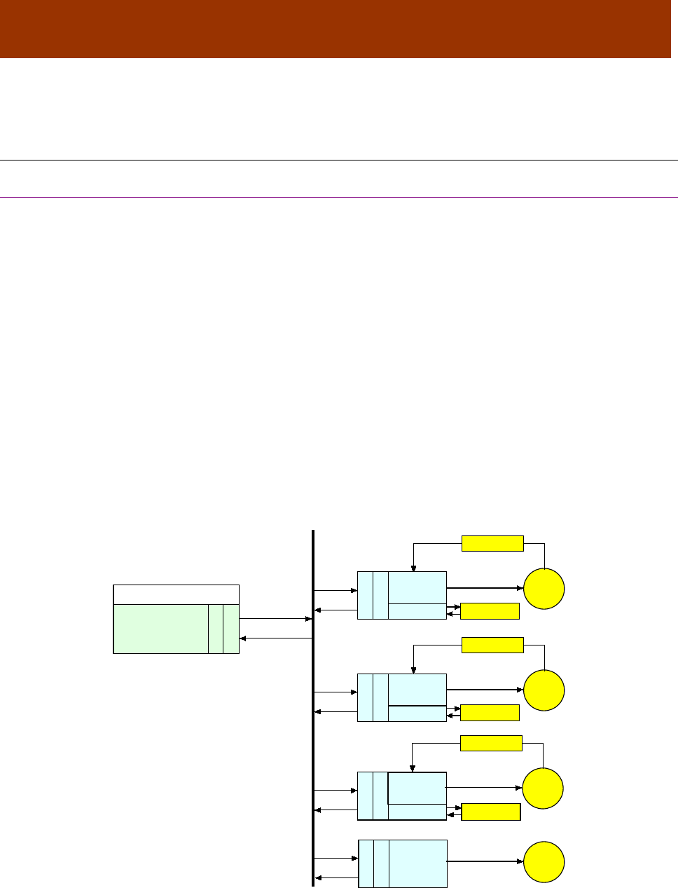
16-01195 Rev 00 15
CHAPTER
3 INTRODUCTION
3.1 CAN and CANopen
3.1.1 Copley Controls Amplifiers in CANopen Networks
Copley’s CANopen Amplifiers
Several lines of Copley Controls amplifiers, including Accelnet, Stepnet, Xenus, Argus, and the
ruggedized R-Series, offer distributed motion control through support of the Controller Area
Network (CAN) and the CANopen network profiles. Using CANopen, the amplifiers can take
instruction from a master application to perform homing operations, point-to-point motion, profile
velocity motion, profile torque, and interpolated motion. (These amplifiers also support serial
communication.)
CAN and CANopen
CAN specifies the data link and physical connection layers of a fast, reliable network. The
CANopen profiles specify how various types of devices, including motion control devices, can use
the CAN network in a highly efficient manner.
Architecture
As illustrated below, in a CANopen motion control system, control loops are closed on the
individual amplifiers, not across the network. A master application coordinates multiple devices,
using the network to transmit commands and receive status information. Each device can transmit
to the master or any other device on the network. CANopen provides the protocol for mapping
device and master internal commands to messages that can be shared across the network.
A CANopen network can support up to 127 nodes. Each node has a seven-bit node ID in the
range of 1-127. Node ID 0 is reserved for the master and slave addresses can be 1~127.
CAN port
CANopen
Softw are Application
Master Controller
CAN port
CANopen
Stepnet
Amplifier
(Servo Mode)
Status
Local Control Motor
Sensor
Feedback
CAN port
CANopen
Xenus
Amplifier
I/O
Control
CAN Network
Local Control Motor
Sensor
Feedback
CAN port
CANopen
Accelnet
Amplifier
I/O
CAN port
CANopen
Stepnet
Amplifier
(Step Mode)
Local Control Motor
I/O Sensor
Local Control Motor
Feedback
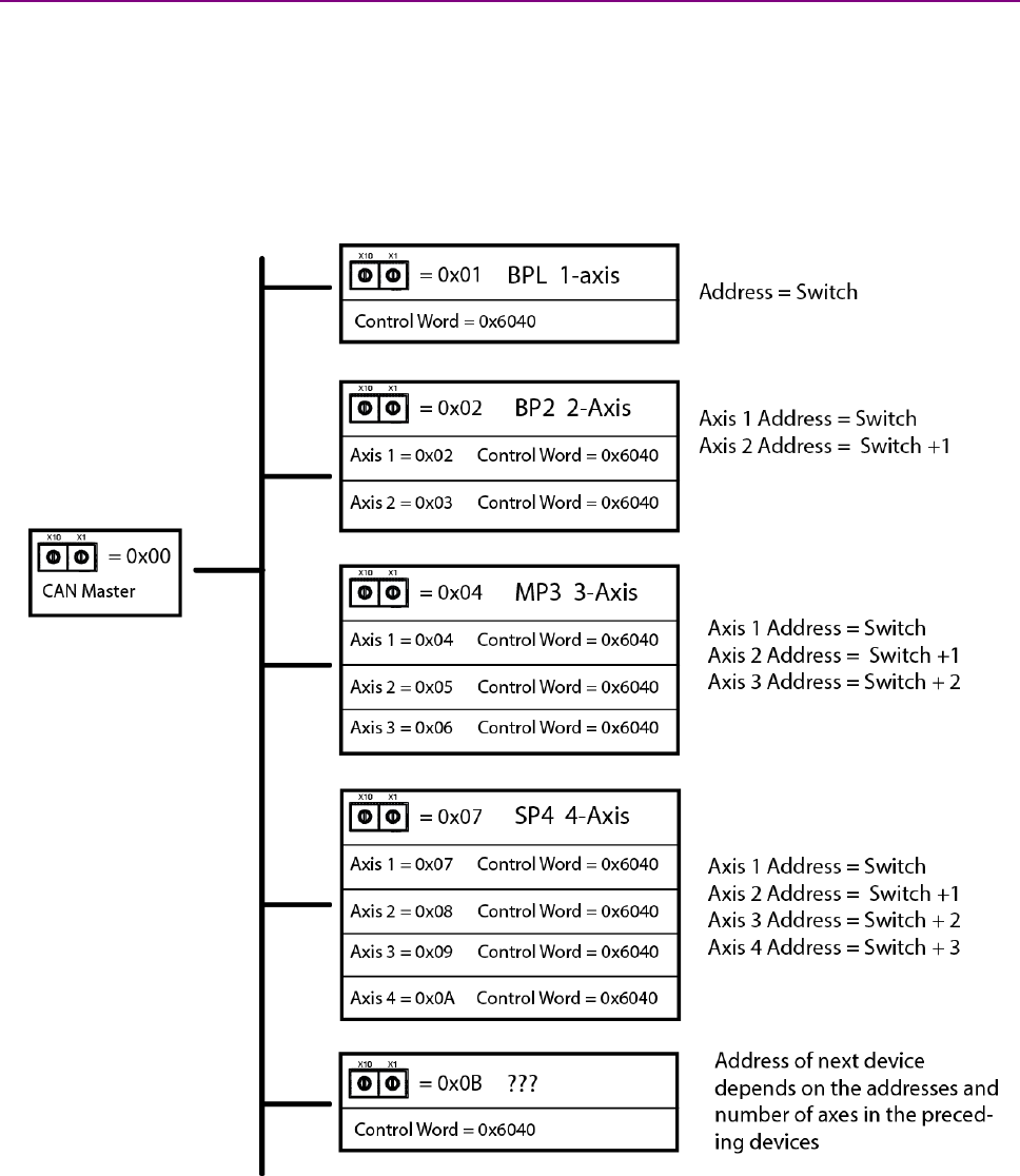
CANopen Programmer’s Manual
16 16-01195 Rev 00
3.1.2 Addressing Drives on a CANopen Network
The CANopen Master always has an address = 0. Slave address are always greater than 0.
In Copley multi-axis drives, Axis 1 will have a node address equal to the address switch setting.
The following axes in the drive appear as independent nodes on the network, each with an
incrementing address greater than the switch address.
Using the Control Word as an example, it will be the same in all of the drives and axes.
When setting the address switches for multi-axis drives in a network, keep in mind that the
effective addresses of a multi-axis drive will be greater than what is shown on the switches.
,

CANopen Programmer’s Manual
Copley Controls 17
3.1.3 Example of a CANopen Move Sequence
CANopen master transmits a control word to initialize all devices.
Devices transmit messages indicating their status (in this example, all are operational).
CANopen master transmits a message instructing devices to perform homing operations.
Devices indicate that homing is complete.
CANopen master transmits messages instructing devices to enter position profile mode (point-to-
point motion mode) and issues first set of point-to-point move coordinates.
Devices execute their moves, using local position, velocity, and current loops, and then transmit
actual position information back to the network.
CANopen master issues next set of position coordinates.
3.1.4 Overview of the CAN Protocol
A Network for Distributed Control
The backbone of CANopen is CAN, a serial bus network originally designed by Robert Bosch
GmbH to coordinate multiple control systems in automobiles.
The CAN model lends itself to distributed control. Any device can broadcast messages on the
network. Each device receives all messages and uses filters to accept only the appropriate
messages. Thus, a single message can reach multiple nodes, reducing the number of messages
that need to be sent. This also greatly reduces bandwidth required for addressing, allowing
distributed control at real-time speeds across the entire system.
CAN Benefits
Other benefits of CAN include:
Wide use of CAN in automobiles and many other industries assures availability of inexpensive
hardware and continued support. Ready availability of standard components also reduces system
design effort.
CAN’s relative simplicity reduces training requirements.
By distributing control to devices, CAN eliminates the need for multiple wire connections between
devices and a central controller. Fewer connections enable increased reliability in harsh operating
conditions.
Device-based error checking and handling methods make CAN networks even more reliable.
Physical Layer
The physical layer of CAN is a differentially driven, two-wire bus, terminated by 120-Ohm resistors
at each end. The maximum bit rate supported by CAN is 1,000,000 bits/second for up to 25
meters. Lower bit rates are required for longer network lengths.

CANopen Programmer’s Manual
18 16-01195 Rev 00
3.1.5 The CAN Message
Overview
CANopen messages are transmitted within CAN messages (a CAN message is also known as a
communication object or COB).
CAN Message Format
CAN messages are communicated over the bus in the form of network packets. Each packet
consists of an identifier (CAN message ID), control bits, and zero to eight bytes of data.
CRC Error Checking
Each packet is sent with CRC (cyclic redundancy check) information to allow controllers to identify
and re-send incorrectly formatted packets.
CAN Message ID
Every CAN message has a CAN message ID (also known as COB-ID). The message ID plays two
important roles.
It provides the criteria by which the message is accepted or rejected by a node.
It determines the message’s priority, as described below.
CAN Message Priority
The priority of a CAN message is encoded in the message ID. The lower the value of the message
ID, the higher the priority of the message. When two or more devices attempt to transmit packets
at the same time, the packet with the highest priority succeeds. The other devices back off and
retry.
This method of collision handling allows for a high bandwidth utilization compared to other network
technologies. For instance, Ethernet handles collisions by requiring both devices to abort
transmission and retry.
For More Information
For more information on the CAN protocol, see CAN Specification 2.0, Robert Bosch GmbH, and
ISO 11898, Road Vehicles, Interchange of Digital Information, Controller Area Network (CAN) for
high-speed communication.

CANopen Programmer’s Manual
Copley Controls 19
3.1.6 Overview of the CANopen Profiles
Communication and Device Profiles
CANopen is a set of profiles built on a subset of the CAN application layer protocol. The CANopen
profiles achieve two basic objectives:
They specify methods for packaging multiple CAN messages to send large blocks of data as a
single entity.
They standardize and simplify communication between devices within several application types,
including motion control.
Developed by the CAN In Automation (CiA) group, CANopen includes the underlying CANopen
Application Layer and Communication Profile (DS 301) and several device profiles, including
CANopen Profile for Drives and Motion Control (DSP 402).
Communication Profile
The Application Layer and Communication Profile describes the communication techniques used
by devices on the network. All CANopen applications must implement this profile.
Profile for Drives and Motion Control
Each of the CANopen device profiles describes a standard device for a certain application. Copley
Controls CANopen amplifiers comply with the Profile for Drives and Motion Control. This profile
specifies a state machine and a position control function. It also supports several motion control
modes, including:
Homing
Profile position
Profile velocity
Profile torque
Interpolated position
CSP: Cyclic synchronous position
CSV: Cyclic synchronous velocity
CST: Cyclic synchronous torque
CSTCA: Cyclic synchronous torque with commutation angle
The amplifier’s operating mode is set using the Mode Of Operation object (index 0x6060).
(The Profile for Drives and Motion Control also supports other modes that are not supported by
Copley Controls amplifiers at this time.)
3.1.7 EtherCAT CoE
EtherCAT is a communication and control network based on the EtherNet hardware layer.
It supports the following communication profiles:
• CAN application profile over EtherCAT (CoE)
• File Accesss over EtherCAT (FoE)
• Ethernet over EtherCAT (EoE)
• Servo drive profile, according to IEC 61800-7-201 (SoE)
Copley’s EtherCAT drives support CoE and FoE. Most of the CANopen objects are in common with
the CoE objects. Those that are not are identified by coloring of the object name in red.
CANopen objects that are not supported by CoE are identified in green.
Here is an example of object coloring:
Objects used only in CANopen will be identified with this color.
Objects used only in EtherCAT will be identified with this color.
Objects used in both CANopen and EtherCAT will be identified with this color
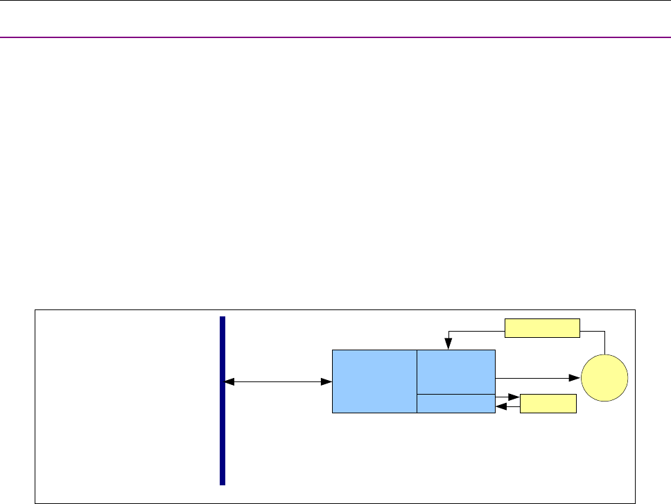
CANopen Programmer’s Manual
20 16-01195 Rev 00
3.2 Defining and Accessing CANopen Devices
3.2.1 Defining a Device: CANopen Objects and Object Dictionaries
Objects and Dictionaries
The primary means of controlling a device on a CANopen network is by writing to device
parameters, and reading device status information. For this purpose, each device defines a group
of parameters that can be written, and status values that can be read. These parameters and
status values are collectively referred to as the device's objects.
These objects define and control every aspect of a device’s identity and operation. For instance,
some objects define basic information such as device type, model, and serial number. Others are
used to check device status and deliver motion commands.
The entire set of objects defined by a device is called the device’s object dictionary. Every device
on a CANopen network must define an object dictionary, and nearly every CANopen network
message involves reading values from or writing values to the object dictionaries of devices on the
network.
Object Dictionary as Interface
The object dictionary is an interface between a device and other entities on the network.
AccelNet
Amplifier
CAN Network
Motor
Sensor
I/O
Feedback
Local Control
Object
Dictionary
CANopen Profiles and the Object Dictionary
The CANopen profiles specify the mandatory and optional objects that comprise most of an object
dictionary. The Communication Profile specifies how all devices must communicate with the CAN
network. For instance, the Communication Profile specifies dictionary objects that set up a device’s
ability to send and receive messages. The device profiles specify how to access particular
functions of a device. For instance, the CANopen Profile for Drives and Motion Control (DSP 402)
specifies objects used to control device homing and position control.
In addition to the objects specified in the Application Layer and Communication Profile and device
profiles, CANopen allows manufacturers to add device-specific objects to a dictionary.
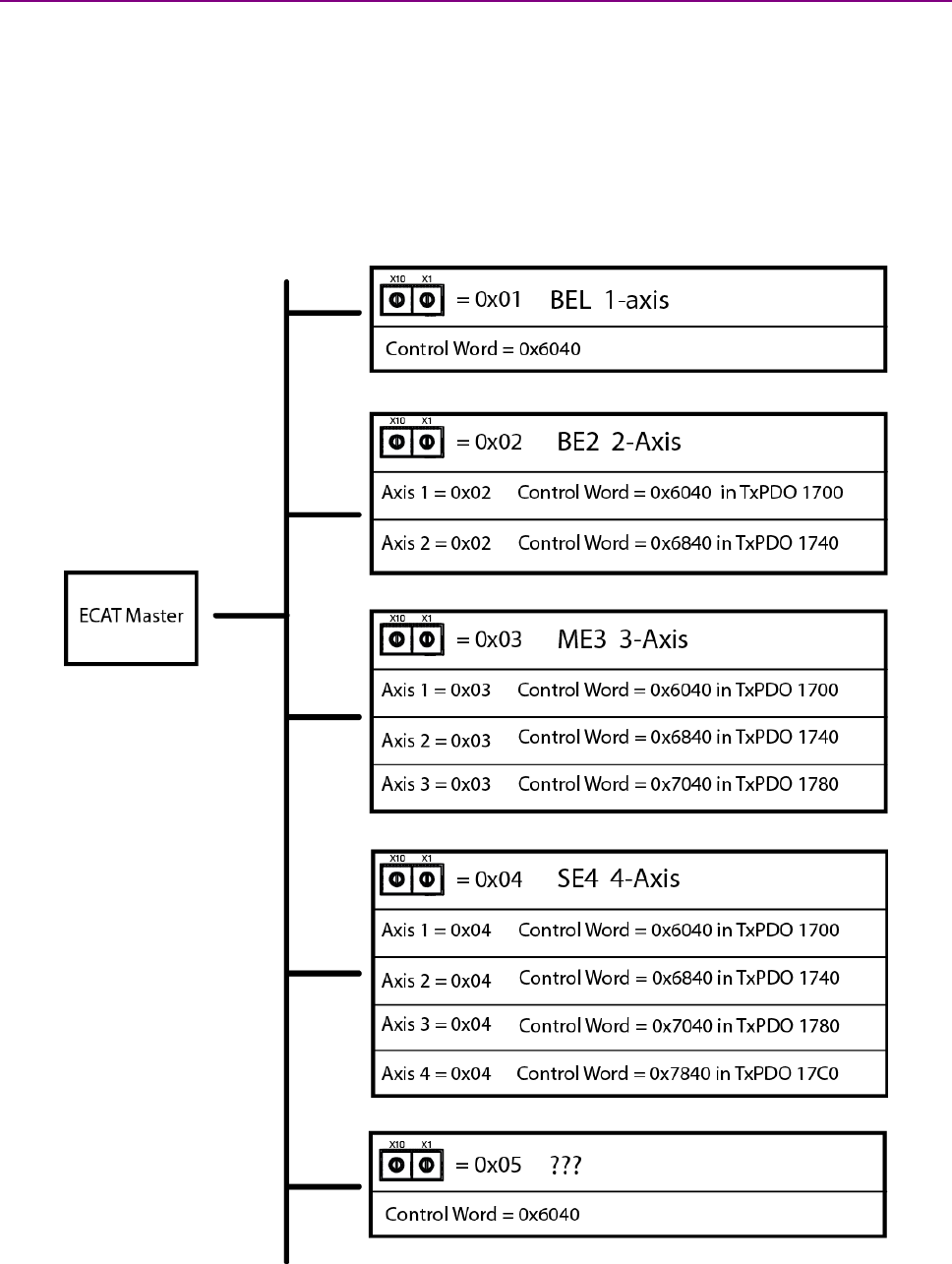
CANopen Programmer’s Manual
Copley Controls 21
3.2.2 Addressing Drives on a EtherCAT Network: Device ID
There are two forms of identifying devices on a network. The first is done by the master, scanning the
network and assigning addresses that begin with -1 and incrementing thereafter.
But, if cables are swapped, then a drive cannot be addressed uniquely and absolutely.
For explicit device identification, switches on each drive are used. These produce the Device Identification
Value (Device ID). This is also saved in the SII (Slave Information Interface) eeprom as the Configured
Station Alias parameter. Address 0 is not allowed. Each drive must have address that is unique, but the
difference between addresses will not be affected by the number of axes in a drive. Instead the object
addresses for each axis will increment by 0x800. And, the PDO addresses for each axis will increment by
0x40. The graphic below shows the switch settings and access to the objects and PDOs.

CANopen Programmer’s Manual
22 16-01195 Rev 00
3.3 Object Dictionary Structure
An object dictionary is a lookup table. Each object is identified by a 16-bit index with an eight-bit
sub-index. Most objects represent simple data types, such as 16-bit integers, 32-bit integers, and
strings. These can be accessed directly by the 16-bit index.
Other objects use the sub-index to represent groups of related parameters. For instance, the Motor
Data object (index 0x2383) has 24 sub-index objects defining basic motor characteristics such as
motor type, motor wiring configuration, and Hall sensor type. (The sub-index provides up to 255
subentries for each index.)
The organization of the dictionary is specified in the profiles, as shown below.
Index Range Objects
0000 not used
0001-001F Static Data Types
0020-003F
Complex Data Types
0040-005F Manufacturer Specific Complex Data Types
0060-007F Device Profile Specific Static Data Types (including those specific to motion control)
0080-009F Device Profile Specific Complex Data Types (including those specific to motion control)
00A0-0FFF
Reserved for future use
1000-1FFF Communication Profile Area (DS 301)
2000-5FFF Manufacturer Specific Profile Area
6000-9FFF Standardized Device Profile Area (including Profile for Motion Control)
A000-FFFF
Reserved for further use
Objects in the range of 0x2000~0x27FF and 0x6000~0x67FF use an offset of 0x800
to add to the base object address for multi-axis drives. These are the ranges of object addresses
for multi-axis drives. The items with “n/a” are not defined in DS-402:
Address DS-402 Copley
0x2000 to 0x27FF n/a Axis A
0x2800 to 0x2FFF n/a Axis B
0x3000 to 0x37FF n/a Axis C
0x3800 to 0x3FFF n/a Axis D
0x6000 to 0x67FF Axis 0 Axis A
0x6800 to 0x6FFF Axis 1 Axis B
0x7000 to 0x77FF Axis 2 Axis C
0x7800 to 0x7FFF Axis 3 Axis D

CANopen Programmer’s Manual
Copley Controls 23
3.3.1 Accessing the Object Dictionary
Two Basic Channels
CANopen provides two ways to access a device’s object dictionary:
The Service Data Object (SDO)
The Process Data Object (PDO)
Each can be described as a channel for access to an object dictionary.
SDOs and PDOs
Here are the basic characteristics of PDOs and SDOs.
SDO
PDO
The SDO protocol allows any object in the object
dictionary to be accessed, regardless of the object's size.
This comes at the cost of significant protocol overhead.
One PDO message can transfer up to eight bytes of data
in a CAN message. There is no additional protocol
overhead for PDO messages.
Transfer is always confirmed.
PDO transfers are unconfirmed.
Has direct, unlimited access to the object dictionary.
Requires prior setup, wherein the CANopen master
application uses SDOs to map each byte of the PDO
message to one or more objects. Thus, the message itself
does not need to identify the objects, leaving more bytes
available for data.
Employs a client/server communication model, where the
CANopen master is the sole client of the device object
dictionary being accessed.
Employs a peer-to-peer communication model. Any
network node can initiate a PDO communication, and
multiple nodes can receive it.
An SDO has two CAN message identifiers: a transmit
identifier for messages from the device to the CANopen
master, and a receive identifier for messages from the
CANopen master.
Transmit PDOs are used to send data from the device,
and receive PDOs are used to receive data.
SDOs can be used to access the object dictionary
directly.
A PDO can be used only after it has been configured
using SDO transfers.
Best suited for device configuration, PDO mapping, and
other infrequent, low priority communication between the
CANopen master and individual devices. Such transfers
tend to involve the setting up of basic node services; thus,
the term service data object.
Best suited for high-priority transfer of small amounts of
data, such as delivery of set points from the CANopen
master or broadcast of a device’s status. Such transfers
tend to relate directly to the application process; thus, the
term process data object.
For more information about SDOs,
see SDOs: Description and Examples
For more information about PDOs,
see PDOs: Description and Examples
For help deciding whether to use an SDO or a PDO see SDO vs. PDO: Design Considerations
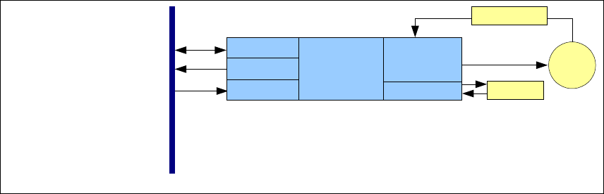
CANopen Programmer’s Manual
24 16-01195 Rev 00
Copley SDOs and PDOs
The Communication Profile requires the support of at least one SDO per device. (Without an SDO,
there would be no way to access the object dictionary.) It also specifies default parameters for four
PDOs. Copley Controls CANopen amplifiers each support 1 SDO and 16 PDOs (eight transmit
PDOs and eight receive PDOs).
AccelNet
Amplifier
CAN Network
8 TxPDO's
1 SDO
Motor
Sensor
I/O
Feedback
Local Control
8 RxPDO's
Object
Dictionary

CANopen Programmer’s Manual
Copley Controls 25
3.3.2 SDOs: Description and Examples
Overview
Each amplifier provides one SDO. The CANopen master can use this SDO to configure, monitor,
and control the device by reading from and writing to its object dictionary.
SDO CAN Message IDs
The SDO protocol uses two CAN message identifiers. One ID is used for messages sent from the
CANopen master (SDO client) to the amplifier (SDO server). The other ID is used for messages
sent from the SDO server to the SDO client.
The CAN message ID numbers for these two messages are fixed by the CANopen protocol. They
are based on the device's node ID (which ranges from 1 to 127). The ID used for messages from
the SDO client to the SDO server (i.e. from the CANopen master to the amplifier) is the hex value
0x600 + the node ID. The message from the SDO server to the SDO client is 0x580 + the node ID.
For example, an amplifier with node ID 7 uses CAN message IDs 0x587 and 0x607 for its SDO
protocol.
Client/Server Communication
The SDO employs a client/server communication model. The CANopen master is the sole
client. The device is the server. The CANopen master application should provide a client SDO for
each device under its control.
The CAN message ID of an SDO message sent from the CANopen master to a device should
match the devices receive SDO message identifier. In response, the CANopen master should
expect an SDO message whose CAN message ID matches the devices transmit SDO message
identifier.
SDO Message Format
The SDO uses a series of CAN messages to send the segments that make up a block of data. The
full details of the SDO protocol are described in the CANopen Application Layer and
Communication Profile.
Confirmation
Because an SDO transfer is always confirmed, each SDO transfer requires at least two CAN
messages (one from the master and one from the slave).
Confirmation Example
For instance, updating an object that holds an eight-byte long value requires six CAN messages:
1 The master sends a message to the device indicating its intentions to update an object in the
device’s dictionary. The message includes the object’s index and sub-index values as well as
the size (in bytes) of the data to be transferred.
2 The device responds to the CANopen master indicating that it is ready to receive the data.
3 The CANopen master sends one byte of message header information and the first 7 bytes of
data. (Because SDO transfers use one byte of the CAN message data for header information,
the largest amount of data that can be passed in any single message is 7 bytes.)
4 The device responds indicating that it received the data and is ready for more.
5 The CANopen master sends the remaining byte of data along with the byte of header
information.
6 The device responds indicating success.
CANopen Programmer’s Manual
26 16-01195 Rev 00
Segmented, Expedited and Block Transfers
As in the example above, most SDO transfers consist of an initiate transfer request from the client,
followed by series of confirmed eight-byte messages. Each message contains one byte of header
information and a segment (up to seven bytes long) of the data being transferred.
For the transfer of short blocks of data (four bytes or less), the Communication Profile specifies an
expedited SDO method. The entire data block is included in the initiate SDO message (for
downloads) or in the response (for uploads). Thus, the entire transfer is completed in two
messages.
The Communication Profile also describes a method called block SDO transfers, where many
segments can be transferred with a single acknowledgement at the end of the transfer. Copley
Controls CANopen amplifiers do not require use of the block transfer protocol.

CANopen Programmer’s Manual
Copley Controls 27
3.3.3 PDOs: Description and Examples for CANopen
Overview
Each amplifier provides eight transmit PDOs and eight receive PDOs. A transmit PDO is used to
transmit information from the device to the network. A receive PDO is used to update the device.
Default PDO Message Identifiers
The Communication Profile reserves four CAN message identifiers for transmit PDOs and four
identifiers for receive PDOs. These addresses are described later in this chapter (see Receive
PDO Communication Parameters).
The first four transmit PDOs and receive PDOs provided in Copley Controls CANopen amplifiers
use these default addresses. The addresses of the remaining four transmit PDOs and receive
PDOs are null by default. The designer can reconfigure any PDO message identifier.
PDO Peer- to-Peer Communication
Peer-to-peer relationships are established by matching the transmit PDO identifier of the sending
node to a receive PDO identifier of one or more other nodes on the network.
Any device can broadcast a PDO message using one of its eight transmit PDOs. The CAN
identifier of the outgoing message matches the ID of the sending PDO. Any node with a matching
receive PDO identifier will accept the message.
PDO Peer-to- Peer Example
For instance, Node 1, transmit PDO 1, has a CAN message ID of 0x0189. Node 2, receive PDO 1
has a matching ID, as does Node 3. They both accept the message. Other nodes do not have a
matching receive PDO, so no other nodes accept the message.
PDO Mapping
PDO mapping allows optimal use of the CAN message’s eight-byte data area.
Mapping uses the SDO to configure dictionary objects in both the sending and the receiving node
to know, for each byte in the PDO message:
The index and sub-index which objects are to be accessed
The type of data
The length of the data
Thus, the PDO message itself carries no transfer control information, leaving all eight bytes
available for data. (Contrast this with the SDO, which uses one byte of the CAN message data
area to describe the objects being written or read, and the length of the data.)
Mappable Objects
Not all objects in a device’s object dictionary can be mapped to a PDO. If an object can be
mapped to a PDO, the MAP PDO field in the object’s description in this manual contains the word
EVENT or the word YES.
Dynamic PDO Mapping
Copley supports the CANopen option of dynamic PDO mapping, which allows the CANopen
master to change the mapping of a PDO during operation. For instance, a PDO might use one
mapping in Homing Mode, and another mapping in Profile Position Mode.
PDO Transmission Modes
PDOs can be sent in one of two transmission modes:
Synchronous. Messages are sent only after receipt of a specified number of synchronization
(SYNC) objects, sent at regular intervals by a designated synchronization device. (For more
information on the SYNC object, see SYNC and High-resolution Time Stamp Messages)
Asynchronous. The receipt of SYNC messages does not govern message transmission.
Synchronous transmission can be cyclic, where the message is sent after a predefined number of
SYNC messages, or acyclic, where the message is triggered by some internal event but does not
get sent until the receipt of a SYNC message.

CANopen Programmer’s Manual
28 16-01195 Rev 00
PDO Triggering Modes
The transmission of a transmit PDO message from a node can be triggered in one of three ways:
Trigger
Description
Event
Message transmission is triggered by the occurrence of an object specific event. For synchronous PDOs
this is the expiration of the
specified transmission period, synchronized by the reception of the SYNC
object. For acyclically transmitted synchronous PDOs and asynchronous PDOs the triggering of a
message transmission is a device
-specific event specified in the device profile.
SYNC
message
For synchronous PDOs, the message is transmitted after a specified number of SYNC cycles have
occurred.
Remote
Request
The transmission of an asynchronous PDO is initiated on receipt of a remote request initiated by any
other device.
Default PDO Mappings
Copley Controls CANopen amplifiers are shipped with the default PDO mappings specified in the
Profile for Drives and Motion Control. These mappings are:
RECEIVE PDOs
TRANSMIT PDOs
PDO
Default mapping
PDO
Default mapping
1
0x6040 (Control Word)
1
0x6041(Status Word)
2
0x6040, 0x6060 (Mode Of Operation)
2
0x 6041, 0x 6061
3
0x6040, 0x607A (Target Position)
3
0x 6041, 0x6064 (Position Actual Value)
4
0x6040, 0x60FF (Target Velocity)
4
0x 6041, 0x606C (Actual Velocity)
5
0x6040, 0x6071 (Target Torque)
5
0x 6041, 0x6077 (Torque Actual Value)
6
0x6040
6
0x 6041
7
0x6040
7
0x 6041, 0x60FD (Digital Inputs)
8
0x6040, 0x6060
8
no default mapping
For more information see the CANopen Profile for Drives and Motion Control (DSP 402).

CANopen Programmer’s Manual
Copley Controls 29
PDO Examples
The designer has broad discretion in the use of PDOs. For example:
On the device designated as the SYNC message and time stamp producer, map a transmit PDO
to transmit the high-resolution time stamp message on a periodic basis. Map receive PDOs on
other devices to receive this object.
On each amplifier, map a transmit PDO to transmit PVT buffer status updates in interpolated
position mode. Map a receive PDO to receive PVT segments.
Another transmit PDO could transmit general amplifier status updates.
The Copley Controls CANopen Motion Libraries product (CML) uses these default mappings:
RECEIVE PDOs
TRANSMIT PDOs
PDO
Default mapping
PDO
Default mapping
1 IP move segment command (index 0x2010)
Used to receive the PVT segments. 4
Trajectory Buffer Status object (index 0x2012).
This is also used with transmission type 255.
The PDO will be transmitted each time a
segment is read from the buffer, or on an error
condition.
5
High-resolution Time Stamp (index 0x1013) on
the amplifier designated as the time-stamp
transmitter. CML programs this object with
transmit type 10 (transmit every 10 sync cycles).
The sync cycle is 10 milliseconds. Thus, the
timestamp is transmitted every 100 milliseconds.
5 High-resolution Time Stamp (index 0x1013) on
all but the time-stamp transmitter.
2
Various status information:
Status Word (index 0x6041), Manufacturer
Status Register object (index 0x1002), and Input
Pin States (index 0x2190).
CML programs this PDO to transmit on an event
(transmission type 255). This causes the PDO
to be transmitted any time an input pin changes
or a status bit changes. Note that Copley input
pins have a programmable debounce time, so if
one of the inputs is connected to something that
might change rapidly, then the debounce time
can be used to keep it from overloading the
CANopen network.
PDO REQUEST OBJECT 0X2002
Type
Access
Units
Range
Map PDO
Memory
UNSIGNED8
RW
-
1~7
NO
R
Description:
Writing a PDO number 1~7 to this object will cause that transmit PDO to be sent.
Find the PDO numbering and details here: Default PDO Mappings.

CANopen Programmer’s Manual
30 16-01195 Rev 00
3.3.4 PDOs: Timing Considerations for EtherCAT
Under EtherCAT control, PDOs are typically exchanged at a synchronous rate determined by the
EtherCAT master software. Copley drives for EtherCAT have two internal operating frequencies.
• Current loop 16 kHz “PWM”
• Velocity / Position loops 4 kHz “Servo”
Fixed PDOs
• Guaranteed to operate at the Servo frequency and are mandated when
process data must be updated with constant timing.
• Not accessible for user customization.
Non-fixed PDO (Mappable)
• Not guaranteed to pass data consistently at the Servo frequency
• Lower priority tasks than Fixed PDOs
• Configurable by users.
Sync Managers
• SM 0: Master sends SDO to slave mailbox
• SM 1: Master receives SDO from slave mailbox
• SM 2: Master sends PDOs to slave
• SM 3: Master receives PDOs from slave
Default PDO Mappings
These mappings are:
RECEIVE PDO, Sync Manager 2
TRANSMIT PDO, Sync Manager 3
Index
RxPDO
Default mapping
Index
TxPDO
Default mapping
0x1600
1
Non-Fixed PDOs
User Mappable
0x1A00
1
Non-Fixed PDOs
User Mappable
0x1601
2
0x1A01
2
0x1602
3
0x1A02
3
0x1603
4
0x1A03
4
0x1700 5
0x6040, 0x607A (Target
Position), 0x60B1 (Velocity
Offset), 0x60B2 (Torque
Offset)
For CSP mode
0x1B00 5
0x 6041 (Status Word), 0x6064 (Actual
Motor Position), 0x60F4 (Position Following
Error), 0x606C (Actual Motor Velocity),
0x6077 (Torque Actual Value)
0x1701 6
0x6040, 0x60FF, 0x60B2
For CSV mode
0x1702 7
0x6040, 0x6071 (Target
Torque),
For CST mode
0x1703 8 0x2327 ( U Input), 0x2328
(V Input)
For UV Current mode
0x1704 9
0x6040, 0x6071, 0x60EA
(Commutation Angle)
For CSTCA mode
3.3.5 PDOs: Description and Examples for EtherCAT
Transmit and Receive labels in the ESI (XML) file apply to the EtherCAT slave (Copley drive)
RxPDO = Master -> Slave
TXPDO = Master <- Slave
The ESI files are set up to configure drives in the CSP (Cyclic Synchronous Position) mode by
default. Items in Bold are the RxPdo, TXPDO, and SDO that are used in this configuration.
CANopen Programmer’s Manual
Copley Controls 31
Non-fixed, empty RxPdo, Mappable
Type Object Name Fixed SM
RxPdo 0x1600 Receive PDO 1 no n/a
RxPdo 0x1601 Receive PDO 2 no n/a
RxPdo 0x1602 Receive PDO 3 no n/a
RxPdo 0x1603 Receive PDO 4 no n/a
Fixed RxPdo with contents assigned, Not-Mappable
Type Object Name Fixed SM Used for mode
RxPdo 0x1700 Receive PDO 5 yes 2 CSP Cyclic Synchronous Position
0x6040 Control word
0x607A Profile target position
0x60B1 Velocity offset (feedforward)
0x60B2 Torque offset (acceleration feedforward)
RxPdo 0x1701 Receive PDO 6 yes n/a CSV Cyclic Synchronous Velocity
0x6040 Control word
0x60FF Target velocity
0x60B2 Torque offset (acceleration feedforward)
RxPdo 0x1702 Receive PDO 7 yes n/a CST Cyclic Synchronous Torque
0x6040 Control word
0x6071 Target torque
0x60B2 Torque offset (acceleration feedforward)
RxPdo 0x1703 Receive PDO 8 yes n/a UV Current Control
0x2327 UV mode U input
0x2328 UV mode V input
RxPdo 0x1704 Receive PDO 9 yes n/a CSTCA Cyclic Sync Torque + Commutation Angle
0x6040 Control word
0x6071 Target torque
0x60EA Commutation Angle
Non-fixed, empty TxPdo, Mappable
Type Object Name Fixed SM
TxPdo 0x1A00 Transmit PDO 1 no n/a
TxPdo 0x1A01 Transmit PDO 2 no n/a
TxPdo 0x1A02 Transmit PDO 3 no n/a
TxPdo 0x1A03 Transmit PDO 4 no n/a
Fixed TxPdo with contents assigned, Not-Mappable
Type Object Name Fixed SM Used for
TXPDO 0x1B00 Transmit PDO 5 yes 3 CSP, CSV, CST, UV, CSTCA
0x6041 Status word
0x6064 Actual motor position
0x60F4 Position loop error (following error)
0x606C Actual motor velocity
0x6077 Torque actual value
Mailbox / CoE / InitCmd SDO
0x6060 Mode of operation = 8 (CSP mode)
Configured by SDO and is set on Pre-Op to Safe-Op transition (PS)

CANopen Programmer’s Manual
32 16-01195 Rev 00
3.3.6 SDO vs. PDO: Design Considerations
Differences Between SDO and PDO
As stated earlier, SDOs and PDOs can both be described as channels through which CAN
messages are sent, and both provide access to a device’s object dictionary, but each has
characteristics that make it more appropriate for certain types of data transfers.
Here is a review of the differences between SDOs and PDOs, and some design considerations
indicated by those differences:
SDO PDO Design Considerations
The accessed device always
confirms SDO messages. This
makes SDOs slower.
PDO messages are unconfirmed.
This makes PDOs faster.
To transfer 8 bytes or less at real-
time speed, use a PDO. For
instance, to receive control
instructions and transmit status
updates.
To transfer large amounts of low
priority data, use the SDO.
Also, if confirmation is absolutely
required, use an SDO.
One SDO transfer can send long
blocks of data, using as many CAN
messages as required.
A PDO transfer can only send small
amounts of data (up to eight bytes)
in a single CAN message. Mapping
allows very efficient use of those
eight bytes.
Asynchronous. Synchronous or asynchronous.
Cyclic or acyclic.
Use PDO when synchronous or
broadcast communications are
required.
For instance, to communicate set
points from the master to multiple
devices for a multi-axis move, or to
have a device broadcast its status.
The SDO employs a client-server
communication model. The
CANopen master is the client. It
reads from and writes to the object
dictionaries of devices. The device
being accessed is the server.
The PDO employs a peer-to-peer
communication model. Any device
can send a PDO message, and a
PDO message can be received and
processed by multiple devices.
All communications can be
performed through the SDO without
using any PDOs.
The CANopen master application
uses SDO messages to map the
content of the PDO, at a cost of
increased CPU cycles on the
CANopen master and increased
bus traffic.
If the application does not benefit
from the use of a PDO for a certain
transfer, consider using SDO to
avoid the extra overhead.
For instance, if an object’s value is
updated only once (as with many
configuration objects), the SDO is
more efficient. If the object’s value
is updated repeatedly, a PDO is
more efficient.

CANopen Programmer’s Manual
Copley Controls 33
4 HOW TO MAP (OR REMAP) A PDO
Process Overview
Two objects in the device’s object dictionary define a PDO:
A PDO’s communication object defines the PDO’s CAN message ID and its communication type
(synchronous or asynchronous) and triggering type (event-drive or cyclic).
A PDOs mapping object maps every data byte in the PDO message to an object in the device’s
object dictionary.
Mapping a PDO is the process of configuring the PDO’s communication and mapping objects.
Note: Drives that use Firmware Feature Set C, cannot handle remote request PDOs.
4.2 To Map a Receive PDO
The general procedure for mapping a receive PDO follows. (The procedure for mapping a transmit
PDO is similar).
Stage
Step
Sub-steps/Comments
1 Disable the PDO.
In the PDO’s mapping object (Receive PDO Mapping Parameters,
index 0x1601), set the sub-index 0 (NUMBER OF MAPPED
OBJECTS) to zero. This disables the PDO.
2 Set the communication
parameters.
If necessary, set the PDO’s CAN message ID (PDO COB-ID) using
sub-index 1 of the PDO’s RECEIVE PDO Communication
Parameters (index 0x1401).
Choose the PDO’s transmission type (PDO TYPE) in sub-index 2 of
object 0x1401. A value in the range
[0-240] = synchronous; [254-255] = asynchronous.
3 Map the data.
Using the PDO’s mapping parameters (sub-indexes 1-4 of Receive
PDO Mapping Parameters, index 0x1601), you can map up to 4
objects (whose contents must total to no more than 8 bytes), as
follows:
In bits 0-7 of the mapping value, enter the size (in bits) of the object
to be mapped, as specified in the object dictionary.
In bits 8-15, enter the sub-index of the object to be mapped. Clear
bits 8-15 if the object is a simple variable.
In bits 16-31, enter the index of the object to be mapped.
4. Set the number of mapped
objects and enable the PDO.
In the PDO’s Receive PDO Mapping Parameters (index 0x1601), set
sub-index 0 (NUMBER OF MAPPED OBJECTS) to the actual
number of objects mapped. This properly configures the PDO. Also,
the presence of a non-zero value in the NUMBER OF MAPPED
OBJECTS object enables the PDO.
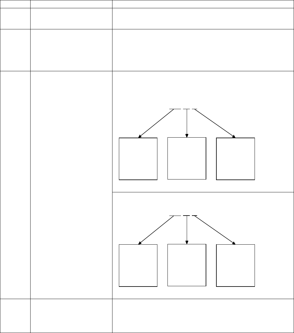
CANopen Programmer’s Manual
34 16-01195 Rev 00
Example: Mapping a Receive PDO
This example illustrates the general procedure for mapping a receive PDO. In the example, the
second receive PDO is mapped to the device’s Control Word object (index 0x6040) to receive
device state change commands and to the Mode Of Operation object (index 0x6060) to receive
mode change commands.
Stage
Step
Sub-steps/Comments
1
Disable the PDO.
In the PDO’s mapping object (Receive PDO Mapping Parameters,
index 0x1601), set the sub-index 0 (NUMBER OF MAPPED
OBJECTS) to zero. This disables the PDO.
2
Set the communication
parameters.
In this case, it is not necessary to set the CAN message ID of the
PDO, because the default value is acceptable.
In the PDO TYPE object (sub-index 2 of RECEIVE PDO
Communication Parameters, index 0x1401) choose a value in the
range [254-255] so that the PDO transmits immediately upon request
(without waiting for a synchronization message).
3
Map the data.
In the device’s Receive PDO Mapping Parameters object (index
0x1601):
1: To map the Control Word to the PDO, set object 1601, sub-index 1
to:
2: To map the Mode Of Operation object to the PDO, set sub-index 2
to:
4.
Set the number of mapped
objects and enable the PDO.
In the PDO’s Receive PDO Mapping Parameters object (index
0x1601), set sub-index 0 (NUMBER OF MAPPED OBJECTS) to 2, the
actual number of objects mapped. This properly configures the PDO.
Also, the presence of a non-zero value in the NUMBER OF MAPPED
OBJECTS object enables the PDO.
0x 6040 00 10
Bits 16-31
contain the
index of the
object to be
mapped
Bits 8-15
clear; the
mapped
object has no
subindex
Bits 0-7 show
the size of the
Control Word
(16 bits) in hex
Bits 16-31
contain the
index of the
object to be
mapped
Bits 8-15
clear; the
mapped
object has no
subindex
Bits 0-7 show
the size of the
Change of
Mode object
(16 bits) in hex
0x 6060 00 08

CANopen Programmer’s Manual
Copley Controls 35
4.3 Objects that Define SDOs and PDOs
SERVER SDO PARAMETERS INDEX 0X1200
Type
Access
Units
Range
Map PDO
Memory
Record
RO
-
-
NO
R
Description
Holds the COB-ID (communication object ID, also known as CAN message ID) values used to
access the amplifier's SDO. Sub-index 0 contains the number of sub-elements of this record.
SDO RECEIVE COB-ID INDEX 0X1200, SUB-INDEX 1
Type
Access
Units
Range
Map PDO
Memory
UNSIGNED32
RO
-
0x600-0x67F
NO
R
Description
CAN object ID used by the amplifier to receive SDO packets. The value is 0x600 + the amplifier's
CAN node ID.
SDO TRANSMIT COB-ID INDEX 0X1200, SUB-INDEX 2
Type
Access
Units
Range
Map PDO
Memory
UNSIGNED32
RO
-
0x580-0x5FF
NO
R
Description
This value gives the CAN object ID used by the amplifier to transmit SDO packets. The value is
0x580 + the amplifier's CAN node ID.
RECEIVE PDO COMMUNICATION PARAMETERS INDEX 0X1400 – 0X1407
Type
Access
Units
Range
Map PDO
Memory
Record
RW
-
-
NO
R
Description
These objects allow configuration of the communication parameters of each of receive PDO. Sub-
index 0 contains the number of sub-elements of this record.
PDO COB-ID INDEX 0X1400 – 0X1407, SUB-INDEX 1
Type
Access
Units
Range
Map PDO
Memory
UNSIGNED32
RW
-
See Default Values, below.
NO
R
Description
CAN message ID used by the PDO. The ID is formatted as follows:
Bit
Description
0-10
Give the 11-bit identifier for standard (CAN 2.0A) identifiers, or the lower 11 bits for extended (CAN 2.0B)
identifiers.
11-28
Give the upper 18 bits of extended identifiers. For standard identifiers, these bits should be written as zeros.
29
Defines the identifier format. This bit is clear for standard (11-bit) identifiers, and set for extended (29-bit)
identifiers.
30
Reserved for future use.
31
Identifies the PDO as valid if clear. If set, the PDO is disabled and its mapping may be changed.
Default Values
The default values for this object are specified in the DS-301 CANopen specification. These values
are:
Index
Default ID
0x1400
0x00000200 + amplifier CAN node ID.
0x1401
0x00000300 + amplifier CAN node ID.
0x1402
0x00000400 + amplifier CAN node ID.
CANopen Programmer’s Manual
36 16-01195 Rev 00
Continued…
…continued:
0x1403
0x00000500 + amplifier CAN node ID.
0x1404
0x80000000
0x1405
0x80000000
0x1406
0x80000000
0x1407
0x80000000
PDO TYPE INDEX 0X1400 – 0X1407, SUB-INDEX 2
Type
Access
Units
Range
Map PDO
Memory
Unsigned 8
RW
-
See Description, below
NO
R
Description:
This object controls the behavior of the PDO when new data is received. The following codes are
defined for receive PDOs:
Code
Behavior
0-240
The received data is held until the next SYNC message. When the SYNC message is received the data is
applied.
241-253
Reserved.
254-255
The received data is applied to its mapped objects immediately upon reception.
RECEIVE PDO MAPPING PARAMETERS INDEX 0X1600 – 0X1607
Type
Access
Units
Range
Map PDO
Memory
Record
RW
-
-
NO
R
Description
EtherCAT drives support 0x1600-0x1603, CAN drives support all. These objects allow the
mapping of each of the receive PDO objects to be configured.
NUMBER OF MAPPED OBJECTS INDEX 0X1600 – 0X1607, SUB-INDEX 0
Type
Access
Units
Range
Map PDO
Memory
Unsigned 8
RW
-
0-4
NO
R
Description
This value gives the total number of objects mapped to this PDO. It can be set to 0 to disable the
PDO operation, and must be set to 0 before changing the PDO mapping.
Once the PDO mapping has been established by configuring the objects in sub-indexes 1 – 4, this
value should be updated to indicate the actual number of objects mapped to the PDO.
PDO MAPPING INDEX 0X1600 – 0X1607, SUB-INDEX 1 – 8
Type
Access
Units
Range
Map PDO
Memory
UNSIGNED32
RW
-
See Description, below
NO
R
Description
When a PDO message is received, the data passed with the PDO message (up to 8 bytes) is used
to update the objects mapped to the PDO. The values in the PDO mapping objects identify which
object(s) the PDO data maps to. The first object is specified by the value in sub-index 1; the
second object is identified by sub-index 2, etc.
Each of the PDO mapping values consist of a 32-bit value structured as follows:
Bit
Description
0-7
Size (in bits) of the object being mapped. Must match the actual object size as defined in the object dictionary.
8-15
Sub-index of the object to be mapped.
16-31
Index of the object to be mapped.

CANopen Programmer’s Manual
Copley Controls 37
RECEIVE PDO MAPPING PARAMETERS INDEX 0X1700
Type
Access
Units
Range
Map PDO
Memory
Record
R
-
-
NO
R
Description
These objects allow the mapping of each of the receive PDO objects to be configured.
NUMBER OF MAPPED OBJECTS INDEX 0X1700, SUB-INDEX 0
Type
Access
Units
Range
Map PDO
Memory
Unsigned 8
R
-
0-4
NO
R
Description
EtherCAT drives only. This value gives the total number of objects mapped to this PDO.
PDO MAPPING INDEX 0X1700, SUB-INDEX 1 – 4
Type
Access
Units
Range
Map PDO
Memory
UNSIGNED32
R
-
See Description, below
NO
R
Description
When a PDO message is received, the passed data (up to 8 bytes) is used to update the objects
mapped to the PDO. The values in the PDO mapping objects identify which object(s) the PDO
data maps to. The first object is specified by the value in sub-index 1; the second object is
identified by sub-index 2, etc.
Each of the PDO mapping values consist of a 32-bit value structured as follows:
Bit
Description
0-7
Size (in bits) of the object being mapped. Must match the actual object size as defined in the object dictionary.
8-15
Sub-index of the object to be mapped.
16-31
Index of the object to be mapped.
Because Index 0x1700 is read only, the available mapped objects are fixed. They include the
following:
Sub-index
Value
Description
0
4
Number of mapped objects.
1
0x60400010
Control word
2
0x607A0020
Target position
3
0x60B10020
Offset added to the velocity command in CSP or CSV mode.
4
0x60B20010
Offset added to the torque command in CSP, CSV or CST modes.

CANopen Programmer’s Manual
38 16-01195 Rev 00
RECEIVE PDO MAPPING PARAMETERS INDEX 0X1701
Type
Access
Units
Range
Map PDO
Memory
Record
R
-
-
NO
R
Description:
These objects allow the mapping of each of the receive PDO objects to be configured.
NUMBER OF MAPPED OBJECTS INDEX 0X, SUB-INDEX 0
Type
Access
Units
Range
Map PDO
Memory
Unsigned 8
R
-
0-4
NO
R
Description:
This value gives the total number of objects mapped to this PDO.
PDO MAPPING INDEX 0X1701, SUB-INDEX 1 – 3
Type
Access
Units
Range
Map PDO
Memory
UNSIGNED32
R
-
See Description, below
NO
R
Description:
When a PDO message is received, the data passed with the PDO message (up to 8 bytes) is used
to update the objects mapped to the PDO. The values in the PDO mapping objects identify which
object(s) the PDO data maps to. The first object is specified by the value in sub-index 1; the
second object is identified by sub-index 2, etc.
Each of the PDO mapping values consist of a 32-bit value structured as follows:
Bit
Description
0-7
Size (in bits) of the object being mapped. Must match the actual object size as defined in the object dictionary.
8-15
Sub-index of the object to be mapped.
16-31
Index of the object to be mapped.
Because Index 0x1701 is read only, the available mapped objects are fixed. They include the
following:
Sub-index
Value
Description
0
3
Number of mapped objects.
1
0x60400010
Control word
2
0x60FF0020
Target velocity
3
0x60B20010
Offset added to the torque command in CSP, CSV or CST modes.
RECEIVE PDO MAPPING PARAMETERS INDEX 0X1702
Type
Access
Units
Range
Map PDO
Memory
Record
R
-
-
NO
R
Description:
These objects allow the mapping of each of the receive PDO objects to be configured.
NUMBER OF MAPPED OBJECTS INDEX 0X1702, SUB-INDEX 0
Type
Access
Units
Range
Map PDO
Memory
Unsigned 8
R
-
0-4
NO
R
Description:
This value gives the total number of objects mapped to this PDO.

CANopen Programmer’s Manual
Copley Controls 39
PDO MAPPING INDEX 0X1702, SUB-INDEX 1 – 2
Type
Access
Units
Range
Map PDO
Memory
UNSIGNED32
R
-
See Description, below
NO
R
Description
When a PDO message is received, the data passed with the PDO message (up to 8 bytes) is used
to update the objects mapped to the PDO. The values in the PDO mapping objects identify which
object(s) the PDO data maps to. The first object is specified by the value in sub-index 1; the
second object is identified by sub-index 2, etc. Each is structured as follows:
Bit
Description
0-7
Size (in bits) of the object being mapped. Must match the actual object size as defined in the object dictionary.
8-15
Sub-index of the object to be mapped.
16-31
Index of the object to be mapped.
Index 0x1702 is read only, the available mapped objects are fixed. They include the following:
Sub-index
Value
Description
0
2
Number of mapped objects.
1
0x60400010
Control word
2
0x60710010
Target torque
RECEIVE PDO MAPPING PARAMETERS INDEX 0X1703
Type
Access
Units
Range
Map PDO
Memory
Record
R
-
-
NO
R
Description:
These objects allow the mapping of each of the receive PDO objects to be configured.
NUMBER OF MAPPED OBJECTS INDEX 0X1703, SUB-INDEX 0
Type
Access
Units
Range
Map PDO
Memory
Unsigned 8
R
-
0-4
NO
R
Description:
This value gives the total number of objects mapped to this PDO.
PDO MAPPING INDEX 0X1703, SUB-INDEX 1 – 2
Type
Access
Units
Range
Map PDO
Memory
UNSIGNED32
R
-
See Description, below
NO
R
Description:
When a PDO message is received, the data passed with the PDO message (up to 8 bytes) is used
to update the objects mapped to the PDO. The values in the PDO mapping objects identify which
object(s) the PDO data maps to. The first object is specified by the value in sub-index 1; the
second object is identified by sub-index 2, etc.
Each of the PDO mapping values consist of a 32-bit value structured as follows:
Bit
Description
0-7
Size (in bits) of the object being mapped. Must match the actual object size as defined in the object dictionary.
8-15
Sub-index of the object to be mapped.
16-31
Index of the object to be mapped.
Index 0x1703 is read only, the available mapped objects are fixed. They include the following:
Sub-index
Value
Description
0
2
Number of mapped objects.
1
0x23270010
V command
2
0x23280010
U command

CANopen Programmer’s Manual
40 16-01195 Rev 00
RECEIVE PDO MAPPING PARAMETERS INDEX 0X1704
Type
Access
Units
Range
Map PDO
Memory
Record
R
-
-
NO
R
Description:
These objects allow the mapping of each of the receive PDO objects to be configured.
NUMBER OF MAPPED OBJECTS INDEX 0X1704, SUB-INDEX 0
Type
Access
Units
Range
Map PDO
Memory
Unsigned 8
R
-
0-4
NO
R
Description:
This value gives the total number of objects mapped to this PDO.
PDO MAPPING INDEX 0X1704, SUB-INDEX 1 – 2
Type
Access
Units
Range
Map PDO
Memory
UNSIGNED32
R
-
See Description, below
NO
R
Description:
When a PDO message is received, the data passed with the PDO message (up to 8 bytes) is used
to update the objects mapped to the PDO. The values in the PDO mapping objects identify which
object(s) the PDO data maps to. The first object is specified by the value in sub-index 1; the
second object is identified by sub-index 2, etc.
Each of the PDO mapping values consist of a 32-bit value structured as follows:
Bit
Description
0-7
Size (in bits) of the object being mapped. Must match the actual object size as defined in the object dictionary.
8-15
Sub-index of the object to be mapped.
16-31
Index of the object to be mapped.
Because Index 0x1704 is read only, the available mapped objects are fixed. They include the
following:
Sub-index
Value
Description
0
2
Number of mapped objects.
1
0x60400010
Control word
2
0x60710010
Target Torque
3
0x60EA0010
Phase angle

CANopen Programmer’s Manual
Copley Controls 41
TRANSMIT PDO COMMUNICATION PARAMETERS INDEX 0X1800 – 0X1807
Type
Access
Units
Range
Map PDO
Memory
Record
RW
-
-
NO
R
Description:
These objects allow configuration of communication parameters of each transmit PDO object. Sub-
index 0 contains the number of sub-elements of this record.
PDO COB-ID INDEX 0X1800 – 0X1807, SUB-INDEX 1
Type
Access
Units
Range
Map PDO
Memory
UNSIGNED32
RW
-
See Default Values, below.
NO
R
Description:
This object holds the CAN object ID used by the PDO. The ID is formatted as follows:
Bit
Description
0-10
11-bit identifier for standard (CAN 2.0A) identifiers, or the lower 11 bits for extended (CAN 2.0B) identifiers.
11-28
Upper 18 bits of extended identifiers. For standard identifiers, these bits should be written as zeros.
29
Identifier format. This bit is clear for standard (11-bit) identifiers, and set for extended (29-bit) identifiers.
30
If set, remote transmit requests (RTR) are not allowed on this PDO. If clear, the PDO is transmitted in
response to a remote request.
31
Identifies the PDO as valid if clear. If set, the PDO is disabled and its mapping may be changed.
Default Values
The default values for this object are specified in the DS-301 CANopen specification. These values
are:
Index
Default ID
0x1800
0x00000180 + amplifier CAN node ID.
0x1801
0x00000280 + amplifier CAN node ID.
0x1802
0x00000380 + amplifier CAN node ID.
0x1803
0x00000480 + amplifier CAN node ID.
0x1804
0x80000000
0x1805
0x80000000
0x1806
0x80000000
0x1807
0x80000000
PDO TYPE INDEX 0X1800 – 0X1807, SUB-INDEX 2
Type
Access
Units
Range
Map PDO
Memory
Unsigned 8
RW
-
See Description, below
EVENT
R
Description:
This object identifies which events trigger a PDO transmission:
Code
Behavior
0
The PDO is transmitted on the next SYNC message following a PDO event. See PDO Events, below, for a
descrip
tion of a PDO event.
1-240
The PDO is transmitted every N SYNC messages, where N is the PDO type code. For example, a PDO with
type code 7 would be transmitted on every 7th SYNC message.
241-251
Reserved.
252
The PDO is transmitted on the SYNC message following a remote request.
253
The PDO is transmitted immediately in response to a remote request.
254-255
The PDO is transmitted immediately in response to an internal PDO event.
CANopen Programmer’s Manual
42 16-01195 Rev 00
PDO Events
Some objects in the object dictionary have special PDO events associated with them. If such an
object is mapped to a transmit PDO, then the PDO may be configured with a code that relies on
this event to trigger its transmission. The codes that use PDO events are 0 and 255.
An example of an object that has a PDO event associated with it is the Device Status object (index
0x6041). This object triggers an event to any mapped transmit PDO each time its value changes.
A transmit PDO which included this object in its mapping would have its event signaled each time
the status register changed.
Most objects in the object dictionary do not have PDO events associated with them. Those that do
are identified by the word EVENT in the PDO Mapping fields of their descriptions.

CANopen Programmer’s Manual
Copley Controls 43
TRANSMIT PDO MAPPING PARAMETERS INDEX 0X1A00 – 0X1A07
Type
Access
Units
Range
Map PDO
Memory
Record
RW
-
-
NO
R
Description
EtherCAT drives support 0x1A00-0x1A03, CAN drives support all. These objects allow the
mapping of each of the transmit PDO objects to be configured.
NUMBER OF MAPPED OBJECTS INDEX 0X1A00 – 0X1A07, SUB-INDEX 0
Type
Access
Units
Range
Map PDO
Memory
Unsigned 8
RW
-
0-4
NO
R
Description
Total number of objects mapped to this PDO. It can be set to 0 to disable the PDO operation, and
must be set to 0 before changing the PDO mapping.
Once the PDO mapping has been established by configuring the objects in sub-indexes 1 – 4, this
value should be updated to indicate the actual number of objects mapped to the PDO.
PDO MAPPING INDEX 0X1A00 – 0X1A07, SUB-INDEX 1 – 8
Type
Access
Units
Range
Map PDO
Memory
UNSIGNED32
RW
-
See Description, below
NO
R
Description
When a PDO message is transmitted, the data passed with the PDO message (up to 8 bytes) is
gathered from the objects mapped to the PDO. The values in the PDO Mapping objects identify
which object(s) the PDO data maps to. The first object is specified by the value in sub-index 1; the
second object is identified by sub-index 2, etc.
Each of the PDO mapping values consist of a 32-bit value structured as follows:
Bit
Description
0-7
Size (in bits) of the object being mapped. This value must match the actual object size as defined in the
object dictionary.
8-15
Sub-index of the object to be mapped.
16-31
Index of the object to be mapped.

CANopen Programmer’s Manual
44 16-01195 Rev 00
TRANSMIT PDO MAPPING PARAMETERS INDEX 0X1B00
Type
Access
Units
Range
Map PDO
Memory
Record
RW
-
-
NO
R
Description:
These objects allow the mapping of each of the transmit PDO objects to be configured.
NUMBER OF MAPPED OBJECTS INDEX 0X1B00, SUB-INDEX 0
Type
Access
Units
Range
Map PDO
Memory
Unsigned 8
RW
-
0-4
NO
R
Description:
Total number of objects mapped to this PDO. Once the PDO mapping has been established by
configuring the objects in sub-indexes 1 – 4, this value should be updated to indicate the actual
number of objects mapped to the PDO.
PDO MAPPING INDEX 0X1B00, SUB-INDEX 1 – 5
Type
Access
Units
Range
Map PDO
Memory
UNSIGNED32
RW
-
See Description, below
NO
R
Description:
When a PDO message is transmitted, the data passed with the PDO message (up to 8 bytes) is
gathered from the objects mapped to the PDO. The values in the PDO Mapping objects identify
which object(s) the PDO data maps to. The first object is specified by the value in sub-index 1; the
second object is identified by sub-index 2, etc.
Each of the PDO mapping values consist of a 32-bit value structured as follows:
Bit
Description
0-7
Size (in bits) of the object being mapped. This value must match the actual object size as defined in the
object dictionary.
8-15
Sub-index of the object to be mapped.
16-31
Index of the object to be mapped.
Because Index 0x1B00 is read only, the objects that can be mapped are fixed. The available
mapped objects are as follows:
Sub-index
Value
Description
0
4
Number of mapped objects.
1
0x60400010
Control word
2
0x60640020
Actual position
3
0x60F40020
Position error
4
0x606C0020
Actual velocity
5
0x60770010
Actual torque
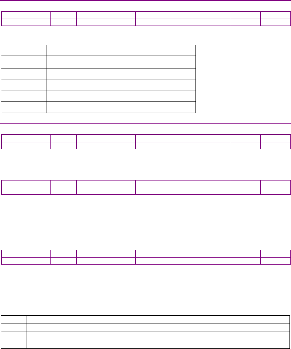
CANopen Programmer’s Manual
Copley Controls 45
SYNC MANAGER TYPE INDEX 0X1C00
Type
Access
Units
Range
Map PDO
Memory
UINT8
RO
-
-
NO
R
Description:
This object gives the number and type of the communication channels.
Sub-index Value
0 4: number of another available sub-index
1 SM 0: Mailbox Write
2
SM 1: Mailbox Read
3
SM 2: Process Data Write
4 SM 3: Process Data Read
SYNC MANAGER 2 PDO ASSIGNMENT OBJECT INDEX 0X1C12-0X1C13
Type
Access
Units
Range
Map PDO
Memory
Record
R
-
-
NO
R
Description:
This object is used to assign a sync manager to PDOs.
NUMBER OF MAPPED OBJECTS INDEX 0X1C12 – 0X1C13, SUB-INDEX 0
Type
Access
Units
Range
Map PDO
Memory
Unsigned 8
RW
-
0-4
NO
R
Description:
This value gives the total number of objects mapped to this PDO. It can be set to 0 to disable the
PDO operation, and must be set to 0 before changing the PDO mapping.
Once the PDO mapping has been established by configuring the objects in sub-indexes 1 – 4, this
value should be updated to indicate the actual number of objects mapped to the PDO.
PDO MAPPING INDEX 0X1C12 – 0X1C13, SUB-INDEX 1 – 8
Type
Access
Units
Range
Map PDO
Memory
UNSIGNED32
RW
-
See Description, below
NO
R
Description:
When a PDO message is received, the data passed with the PDO message (up to 8 bytes) is used
to update the objects mapped to the PDO. The values in the PDO mapping objects identify which
object(s) the PDO data maps to. The first object is specified by the value in sub-index 1; the
second object is identified by sub-index 2, etc.
Each of the PDO mapping values consist of a 32-bit value structured as follows:
Bit
Description
0-7
Size (in bits) of the object being mapped. Must match the actual object size as defined in the object dictionary.
8-15
Sub-index of the object to be mapped.
16-31
Index of the object to be mapped.

16-01195 Rev 00 46
CHAPTER
5 NETWORK MANAGEMENT
5.1 Network Management Overview: CANopen
Contents of this Section
This section describes the objects, messages, and methods used to control the CANopen network.
Topics include:
5.1.2 Overview
Network Management Services and Objects
Network management services on the CANopen network include device state control, device
monitoring, synchronization, and emergency handling. Special communication objects, as
summarized below, provide these services.
Object
Description
Network
Management
(NMT)
This object provides services to control the state of the device, including the initialization,
starting, monitoring, resetting, and stopping of nodes. It also provides device-monitoring
services (node-guarding and heartbeat).
Synchronization
(SYNC)
Broadcast periodically by a specified device or the CANopen master to allow synchronized
activity among multiple devices. The CAN message ID of the SYNC message is 80.
Time Stamp
Broadcast periodically by a specified device or the CANopen master to allow devices to
synchronize their clocks.
Emergency
Transmitted by a device when an internal error occurs.
Network Manager Node
Normally, a single node (such as a PC) is designated as the network manager. The network
manager runs the software that issues all NMT messages. The network manager node can be the
same node that runs the CANopen master application.

CANopen Programmer’s Manual Network Management
Copley Controls 47
5.1.3 General Device State Control
State Machine
Every CANopen device implements a simple state machine. The machine defines three states
(described below). The network manager application uses NMT messages to interact with the
state machine and control state changes.
Device States
The following states are defined for Copley Controls CANopen amplifiers:
State
Description
Pre-operational
Every node enters this state after power-up or reset. In this state, the device is not functional,
but will communicate over the CANopen network. PDO transfers are not allowed in pre-
operational state, but SDO transfers may be used.
Operational
This is the normal operating state for all devices. SDO and PDO transfers are both allowed.
Stopped
No communication is allowed in this state except for network management messages. Neither
SDO nor PDO transfers may be used.
State Control Messages
One use of NMT messages is to control state changes on network devices. The following NMT
messages are sent by the network manager to control these state changes. Each of these
messages can be either sent to a single node (by node ID), or broadcast to all nodes.
Message
Effect
Reset
Causes each receiving node to perform a soft reset and come up in pre-operational state.
Reset
communications
Causes each receiving node to reset its CANopen network interface to power-on state, and
enter pre-operational state. This is not a full device reset, just a reset of the CANopen interface.
Pre-operational
Causes the receiving node(s) to enter pre-operational state. No reset is performed.
Start
Causes the node(s) to enter operational state.
Stop
Causes the node(s) to enter stopped state.
5.1.4 Device Monitoring
CANopen
Monitoring Protocols
In addition to controlling state machines, NMT messages provide services for monitoring devices
on the network. Monitoring services use one of two protocols: heartbeat and node guarding.
Heartbeat Protocol
The heartbeat protocol allows the network manager application to detect problems with a device or
its network connection. The CANopen master configures the device to periodically transmit a
heartbeat message indicating the device’s current state (pre-operational, operational, or stopped).
The network manager monitors the heartbeat messages. Failure to receive a node’s heartbeat
messages indicates a problem with the device or its connection to the network. See 0x1017.
Node-guarding Protocol
The node-guarding protocol is similar to the heartbeat, but it allows both the device and the
network manager to monitor the connection between them. The network manager configures the
device (node) to expect node-guarding messages at some interval. The network manager then
sends a message to the configured device at that frequency, and the device responds with a node-
guarding message. This allows both the network manager and the device to identify a network
failure if the guarding messages stop. See 0x100C, and 0x100D.
EtherCAT
The EtherCAT master controls a Watchdog function that is sent with each Sync Manager.
Via the master, settings can be made for the time-out, and to enable/disable the WD.
These are below the level of SDO and PDO and are not covered in this document.

Network Management CANopen Programmer’s Manual
48 16-01195 Rev 00
5.1.5 SYNC and High-resolution Time Stamp Messages
The SYNC message is a standard CANopen message used to synchronize multiple devices and to
trigger the synchronous transmission of PDOs.
In addition, to allow more accurate synchronization of device clocks, Copley Controls CANopen
amplifiers use the optional high-resolution time stamp message specified in the Communication
Profile.
Normally, a single device produces both the SYNC message and the high-resolution time stamp
message. Copley amplifiers can produce the SYNC and high-resolution time stamp messages.
We recommend using an amplifier as the master sync generator. This assures greater timing
accuracy and allows the amplifier PVT segment buffer to be filled with the minimum number of
PVT segments at all times during operation.
Time Stamp PDOs
The device designated as the time stamp producer should have a transmit PDO mapped for the
high-resolution time stamp message. This PDO should be configured for synchronous
transmission, based on the SYNC message. We recommend sending this message approximately
every 100 milliseconds.
Every other device (all time stamp consumers) should have a receive PDO mapped for the high-
resolution time stamp message. The message ID of each receive PDO used to receive a time
stamp should match the ID of the transmit PDO used to send the time stamp.
Configuring the devices in this fashion causes the time stamp producer to generate a transmit
PDO for every N sync messages. This PDO is received by each of the time stamp consumers on
the network and causes them to update their internal system times based on the message content.
The result is that all devices on the network act as though they share the same clock input, and
remain tightly synchronized.
5.1.6 Emergency Messages
A device sends an 8-byte emergency message (EMCY) when an error occurs in the device. It
contains information about the error type, and Copley-specific information. A device need only
send one EMCY message per event. Any device can be configured to accept EMCY messages.
EMCY Message Structure
The EMCY message is structured as follows:
Bytes
Description
0, 1
Standard CANopen emergency error code for errors active on the amplifier.
See
EMCY Message Error Codes
2
Error register object value See Error Register
3
Reserved for future use (0 for now).
4, 5
Bit mask representing the Copley Controls codes for active error conditions on the amplifier
(see EMCY Message Copley-Specific Error Conditions).
6, 7
Reserved for future use (0 for now).

CANopen Programmer’s Manual Network Management
Copley Controls 49
EMCY Message Error Codes
Bytes 0 and 1 of the EMCY message describe the standard CANopen error codes used by Copley
Amplifiers:
Error
Code
(hex)
Description
2280
Encoder Feedback Error
2310
Current Limited
2320
Short Circuit
3110
Mains Over Voltage
3120
Mains Under Voltage
3310
Output Voltage Limited
4210
Amplifier Over Temperature
4300
Motor Temperature Sensor
5080
Amplifier error
7122
Phasing Error
7380
Positive Limit Switch
7381
Negative Limit Switch
7390
Tracking Error
73A0
Position Wrapped Around +/- 2
31
Counts
8130
Node Guarding Error or Heartbeat Error
EMCY Message Copley-Specific Error Conditions
The bit mask in bytes 4 and 5 of the EMCY message maps 1 bit for each error condition active on
the amplifier. The mapped bits have the following meanings:
Bit
Description
0
Output short circuit
1
Amplifier over temperature
2
Amplifier over voltage
3
Amplifier under voltage
4
Motor over temperature input active
5
Encoder power error (indicates the 5V encoder supply over current)
6
Motor phasing error
7
Output current limited
8
Output voltage limited
9
Positive limit switch
10
Negative limit switch
11
Tracking error
12
Position input wrapped around +/- 231 bits
13
Amplifier internal hardware error (contact Copley Controls customer support)
14
Node guarding error

Network Management CANopen Programmer’s Manual
50 16-01195 Rev 00
5.3 Network Management Objects: CANopen
COB-ID SYNC MESSAGE INDEX 0X1005
Type
Access
Units
Range
Map PDO
Memory
UNSIGNED32
RW
-
See SYNC ID Format, below.
NO
R
Description:
This object defines the CAN object ID (COB-ID) associated with the SYNC message. The SYNC
message is a standard CANopen message type used to synchronize multiple devices on a
CANopen network.
SYNC ID Format
The SYNC message ID is formatted as follows:
Bits
Description
0-10
Give the 11-bit identifier for standard (CAN 2.0A) identifiers, or the lower 11 bits for extended (CAN 2.0B)
identifiers.
11-28
Give the upper 18 bits of extended identifiers. For standard identifiers, these bits should be written as zeros.
29
Identifier format. This bit is clear for standard (11-bit) identifiers, and set for extended (29-bit) identifiers.
30
If set, the amplifier is configured as the SYNC message producer. This bit should be set in at most one
amplifier on a network.
31
Reserved
COMMUNICATION CYCLE PERIOD INDEX 0X1006
Type
Access
Units
Range
Map PDO
Memory
UNSIGNED32
RW
microseconds
-
NO
R
Description:
This object defines the interval between SYNC messages in units of microseconds.
An amplifier configured as a SYNC message producer will not produce SYNC messages unless
this object contains a non-zero value. A value of zero in this object disables SYNC message
production.
Amplifiers not configured to produce SYNC messages ignore the value of this object.
GUARD TIME INDEX 0X100C
Type
Access
Units
Range
Map PDO
Memory
UNSIGNED16
RW
milliseconds
-
NO
R
Description:
This object gives the time between node-guarding requests that are sent from the network master
to this amplifier. The amplifier will respond to each request with a node-guarding message
indicating the internal state of the amplifier.
If the amplifier has not received a node-guarding request within the time period defined by the
product of the guard time and the Life Time Factor (index 0x100D, p. 51), the amplifier will treat
this lack of communication as a fault condition.

CANopen Programmer’s Manual Network Management
Copley Controls 51
LIFE TIME FACTOR INDEX 0X100D
Type
Access
Units
Range
Map PDO
Memory
Unsigned 8
RW
-
-
NO
R
Description:
This object gives a multiple of the GUARD Time (index 0x100C, p. 50). The amplifier expects to
receive a node-guarding request within the time period defined by the product of the guard time
and the lifetime factor. If the amplifier has not received a node-guarding request within this time
period, it treats this condition as a fault.
HIGH-RESOLUTION TIME STAMP INDEX 0X1013
Type
Access
Units
Range
Map PDO
Memory
UNSIGNED32
RW
microseconds
0 - 294,967,295
YES
R
Description:
This object holds a time stamp indicating the amplifier's internal time (in microseconds) when the
last SYNC message was received (or transmitted for the SYNC producer). Writing to this object
will cause the amplifier to adjust its internal clocks to reconcile the difference between the value
passed and the internal value of the time stamp.
The purpose of this object is to allow multiple amplifiers to synchronize their clocks across the
CANopen network. To enable this feature, one amplifier should be selected as a high-resolution
time stamp producer. This amplifier should have a transmit PDO configured to transmit this object
to the rest of the network at a rate of approximately 10 Hertz (once every 100 milliseconds).
Every other amplifier should have a receive PDO configured (using the same COB-ID as the
producer's transmit PDO) to update its time stamp using the value passed by the producer.
EMERGENCY OBJECT ID INDEX 0X1014
Type
Access
Units
Range
Map PDO
Memory
UNSIGNED32
RW
-
-
NO
R
Description:
CAN message ID used with the emergency object. See Emergency Messages, p. 48 and the
CANopen Application Layer and Communication Profile (DS 301).
EMERGENCY OBJECT ID INHIBIT TIME INDEX 0X1015
Type
Access
Units
Range
Map PDO
Memory
UNSIGNED16
RW
milliseconds
-
NO
R
Description:
Inhibit time for the emergency object. See Emergency Messages, p. 48 and the CANopen
Application Layer and Communication Profile (DS 301).
PRODUCER HEARTBEAT TIME INDEX 0X1017
Type
Access
Units
Range
Map PDO
Memory
UNSIGNED16
RW
milliseconds
-
NO
R
Description:
This object gives the frequency at which the amplifier will produce heartbeat messages. This
object may be set to zero to disable heartbeat production. Note that only one of the two node-
guarding methods may be used at once. If this object is non-zero, then the heartbeat protocol is
used regardless of the settings of the node-guarding time and lifetime factor.

Network Management CANopen Programmer’s Manual
52 16-01195 Rev 00
5.4 Network Management Overview: EtherCAT /
CANopen
NETWORK OPTIONS INDEX 0X21B3
Type
Access
Units
Range
Map PDO
Memory
INTEGER16
RW
Bits
Bit Mapped
NO
RF
Description
Network options. Configures the amplifier’s network.
CANopen
Bits
Meaning
0
Must be clear to select CANopen networking.
1~15
Reserved
EtherCAT
Bits
Meaning
0
If set, disable some extra checks of the SYNC0 configuration which were added
for improved network conformance.
1
If set, the drive will follow the EtherCAT state machine even when running in a
non EtherCAT mode of operation.
2
If set, object 0x1002 is the bit-wise OR of all axes event status for multi-axis drives.
If clear, 0x1002 is for axis 1 only.
3~15
Reserved
Note: 0x1002 is not in the range of objects that can use the 0x800 offset for axes in multi-axis drives.
For a multi-axis drive, setting bit 2 of the Network Options combines the individual axis events into a single
register, 0x1002, by ORing the events of all axes.

CANopen Programmer’s Manual Network Management
Copley Controls 53
NETWORK STATUS WORD INDEX 0X21B4
Type
Access
Units
Range
Map PDO
Memory
UNSIGNED16
RO
-
-
T
R
Description
Network status word. Bit mapped as follows:
CANopen
Bits
Meaning
0-1
CANopen node status. This field will take one of the following values:
Value
Status
0
The CANopen interface is disabled.
1
Stopped mode.
2
Preoperational mode.
3
Operational mode.
4
Set if the CANopen SYNC message is missing.
5
Set on a CANopen guard error.
8
Set if the CAN port is in 'bus off' state.
9
Set if the CAN port is in 'transmit error passive' state.
10
Set if the CAN port is in 'receive error passive' state.
11
Set if the CAN port is in 'transmit warning' state.
12
Set if the CAN port is in 'receive warning' state.
DeviceNet
Bit
Meaning
0
Set if duplicate MAC ID check failed.
1
Set if device is online.
2
Set if at least one communication object timed out.
3
Set if at least one communication object has been established.
4-7
Reserved.
8-14
Same bit mapping as for CANopen.
15
Always set for DeviceNet.
MACRO
Bit
Meaning
0
Set if the MACRO network is detected,
1
Set if the amplifier is being disabled by the MACRO master.
2
Set if the MACRO network has been broken (i.e. once detected but now gone).
3
Set on heartbeat error.
4-15
Reserved.
EtherCAT
Bit
Meaning
0
Set if distributed clock is enabled (SYNC0 enabled and period set to a legal value).
1
Set if distributed clock is locked.
2 If the distributed clock is locked, this bit identifies whether it is locked to the current loop period (0), or
position loop period (1).
3-15
Reserved

Network Management CANopen Programmer’s Manual
54 16-01195 Rev 00
5.5 Sending Serial Commands over CANopen
5.5.1 Overview
CANopen object 0x2000 (sub-index 0) is used to send serial commands and retrieve the response
from the amplifier. Each serial command consists of two parts, a command message sent to the
amplifier, and a response message retrieved from it.
Sending a command to the amplifier is done by writing to CANopen object 0x2000. The first byte
sent is the command code of the serial command to be executed. This is followed by any data
bytes that are required for the command. Then, the response from the amplifier is retrieved by
reading from object 0x2000. The first byte received will be an error code (same error codes as
used in the serial interface). This is followed by zero or more bytes of response data.
For example:
To read actual position, the following bytes would be written to object 0x2000 using an SDO
transfer:
0x0C 0x17 0x00
The first byte (0x0C) is the command code for a GET command. The second and third bytes
(0x17 0x00) make up the one word of data passed to a GET command. This data word (0x0017)
is the variable ID that is to be read (in this case, variable 0x17, which is the actual position). The
response is read from an SDO reading back the value of object 0x2000.
For example:
If the following data bytes were read from 0x2000:
0x00 0x34 0x12 0x78 0x56
The first byte gives an error code. A zero here indicates no error. The next four bytes are the
position read back from the amplifier. In this case, the position read back is 0x12345678.
5.5.2 Byte order
The byte order of data sent to or from the amplifier requires some further explanation.
The amplifier (serial port interface) works internally with 16-bit words of data. All serial commands
take zero or more words of data and return zero or more words. When 32-bit values are passed to
or from the amplifier, they are always sent most significant word first. When this array of 16-bit
words of data is sent over the CANopen interface, each word of data is split into two bytes.
CANopen always sends data least significant byte first. Therefore, when a 32-bit value is sent over
the CANopen interface, it's first split into two 16-bit words (most significant word followed by least
significant word). Then, each word is split into two bytes using the CANopen standard of least
significant byte followed by most significant.
For example:
The 32-bit value 0x12345678 would first be split into the words 0x1234 0x5678. These two words
would then be split into the bytes 0x34 0x12 0x78 0x56.
Any serial command that is processed by the main amplifier firmware (as opposed to the boot
loader) can be sent over the CANopen interface using this method. Any command that needs to
be sent to the boot loader (such as a firmware upload) cannot be sent using this method.
SERIAL PORT COMMAND SEND INDEX 0X2000
Type
Access
Bits
Range
Map PDO
Memory
ARRAY [0..16383]
of UNSIGNED16
RW 262144
0 to 216-1
for each entry
No RF
Description
Used to send serial port commands over a CANopen/EtherCAT bus.
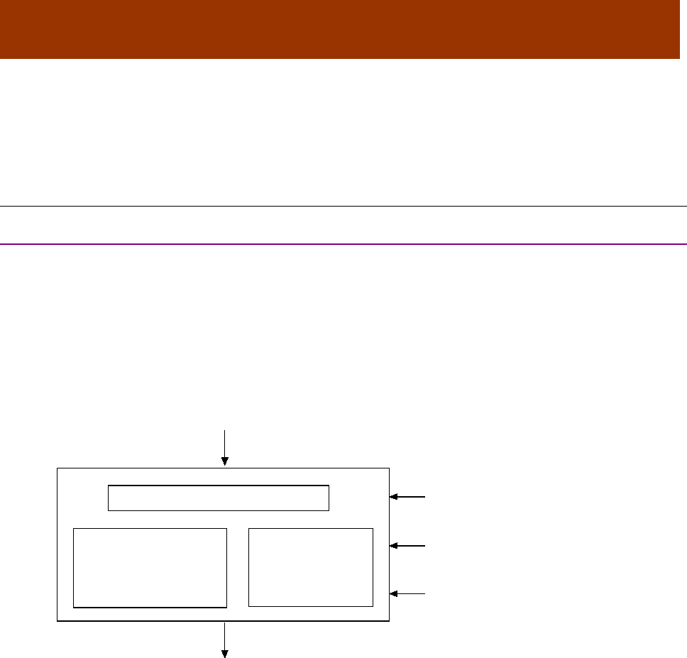
16-01195 Rev 00 55
CHAPTER
6 DEVICE CONTROL, CONFIGURATION,
AND STATUS
6.1 Device Control and Status Overview
6.1.1 Control Word, Status Word, and Device Control Function
Device Control Function Block
The CANopen Profile for Drives and Motion Control (DSP 402) describes control of the amplifier in
terms of a control function block with two major sub-elements: the operation modes and the state
machine.
Control and Status Words
As illustrated below, the Control Word object (index 0x6040, p. 59) manages device mode and
state changes. The Status Word object (index 0x6041, p. 60) identifies the current state of the
amplifier. The Mode Of Operation object (index 0x6060, p. 65) sets the amplifier’s operating mode.
Other factors affecting control functions include: digital input signals, fault conditions, and settings
in various dictionary objects.
Operation Modes
As controlled by the Mode Of Operation object (index 0x6060, p. 65), Copley Controls CANopen
amplifiers support homing, profile position, profile velocity, profile torque, and interpolated position
modes.
State Machine Nesting
Note that the Communication Profile also specifies a state machine, with three states: pre-
operational, operational, and stopped. The entire device control function block described in this
chapter, including the device state machine, operates in the operational state of the
Communication Profile state machine.
Device Control Function
Homing, Profile Position
Profile Velocity,
Interpolated Position
CSP,CSV, CST
Operation Mode
State Machine
Digital Inputs
Fault
Modes of Operation (0x6060)
Control Word (0x6040)
Status Word (0x6041)

Device Control, Configuration, and Status CANopen Programmer’s Manual
56 16-01195 Rev 00
State Machine and States
The state machine describes the status and possible control sequences of the drive. The state
also determines which commands are accepted.
States are described below:
State
Description
Not Ready to Switch On
Low-level power (e.g. _ 15V, 5V) has been applied to the drive.
The drive is being initialized or is running self-test.
A brake, if present, is applied in this state.
The drive function is disabled.
Switch On Disabled
Drive initialization is complete.
The drive parameters have been set up.
Drive parameters may be changed.
The drive function is disabled.
Ready to Switch On
The drive parameters may be changed.
The drive function is disabled.
Switched On
High voltage has been applied to the drive.
The power amplifier is ready.
The drive parameters may be changed.
The drive function is disabled.
Operation Enable
No faults have been detected.
The drive function is enabled and power is applied to the motor.
The drive parameters may be changed.
(This corresponds to normal operation of the drive.)
Quick Stop Active
The drive parameters may be changed.
The quick stop function is being executed.
The drive function is enabled and power is applied to the motor.
If the ‘Quick-Stop-Option-Code’ is switched to 5 (Stay in Quick-Stop), the amplifier cannot
exit the Quick-Stop-State, but can be transmitted to ‘Operation Enable’ with the command
‘Enable Operation.”
Fault Reaction Active
The drive parameters may be changed.
A non-fatal fault has occurred in the drive.
The quick stop function is being executed.
The drive function is enabled and power is applied to the motor.
Fault
The drive parameters may be changed.
A fault has occurred in the drive.
The drive function is disabled.
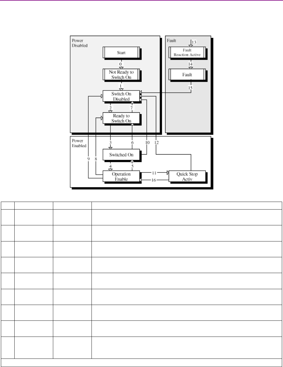
CANopen Programmer’s Manual Device Control, Configuration, and Status
Copley Controls 57
6.1.2 State Changes Diagram
Diagram
The following diagram from the CANopen Profile for Drives and Motion Control (DSP 402) shows
the possible state change sequences of an amplifier. Each transition is numbered and described in
the legend below.
State Changes Diagram Legend
From State
To State
Event/Action
0 Startup Not Ready to
Switch On
Event: Reset.
Action: The drive self-tests and/or self-initializes.
1 Not Ready to
Switch On Switch On
Disabled
Event: The drive has self-tested and/or initialized successfully.
Action: Activate communication and process data monitoring
2 Switch On
Disabled Ready to
Switch On
Event: 'Shutdown' command received from host.
Action: None
3
Ready to
Switch On Switched On
Event: 'Switch On' command received from host.
Action: The power section is switched on if it is not already switched on.
4 Switched On Operation
Enable
Event: 'Enable Operation' command received from host.
Action: The drive function is enabled.
5 Operation
Enable Switched On
Event: 'Disable Operation' command received from host.
Action: The drive operation is disabled.
6 Switched On Ready to
Switch On
Event: 'Shutdown' command received from host.
Action: The power section is switched off.
7 Ready to
Switch On Switch On
Disabled
Event: 'Quick stop' command received from host.
Action: None
8 Operation
Enable Ready to
Switch On
Event: 'Shutdown' command received from host.
Action: The power section is switched off immediately, and the motor is free to
rotate if unbraked
Continued….

Device Control, Configuration, and Status CANopen Programmer’s Manual
58 16-01195 Rev 00
…State Changes Diagram Legend, continued:
From State
To State
Event/Action
9 Operation
Enable Switch On
Disabled
Event: 'Disable Voltage' command received from host.
Action: The power section is switched off immediately, and the motor is free to
rotate if unbraked
10 Switched On Switch On
Disabled
Event: 'Disable Voltage' or 'Quick Stop' command received from host.
Action: The power section is switched off immediately, and the motor is free to
rotate if unbraked
11
Operation
Enable
Quick Stop
Active
Event: 'Quick Stop' command received from host.
Action: The Quick Stop function is executed.
12 Quick Stop
Active Switch On
Disabled
Event: 'Quick Stop' is completed or 'Disable Voltage' command received from
host. This transition is possible if the Quick-Stop-Option-Code is not 5 (Stay in
Quick-Stop)
Action: The power section is switched off.
13 FAULT
Fault
Reaction
Active
A fatal fault has occurred in the drive.
Action: Execute appropriate fault reaction.
14
Fault
Reaction
Active Fault Event: The fault reaction is completed.
Action: The drive function is disabled. The power section may be switched off.
15 Fault Switch On
Disabled
Event: 'Fault Reset' command received from host.
Action: A reset of the fault condition is carried out if no fault exists currently on
the drive.
After leaving the 'Fault' state the Bit 'Fault Reset' of the Control Word has to be
cleared by the host.
16 Quick Stop
Active Operation
Enable
Event: 'Enable Operation' command received from host. This transition is
possible if the Quick-Stop-Option-Code is 5, 6, 7, or 8 (see the Quick Stop
Option Code object, index 0x6085, p. 63).
Action: The drive function is enabled.

CANopen Programmer’s Manual Device Control, Configuration, and Status
Copley Controls 59
6.2 Device Control and Status Objects
6.2.1 Control & Status Objects
CONTROL WORD INDEX: 0X6040
Type
Access
Units
Range
Map PDO
Memory
UNSIGNED16
RW
-
See Description, below.
EVENT
R
Description
This object is used to controls the state of the amplifier. It can be used to enable / disable the
amplifier output, start, and abort moves in all operating modes, and clear fault conditions.
Control Word Bit Mapping
The value programmed into this object is bit-mapped as follows:
Bits Description
0 Switch On. This bit must be set to enable the amplifier.
1 Enable Voltage. This bit must be set to enable the amplifier.
2 Quick Stop. If this bit is clear, then the amplifier is commanded to perform a quick stop.
3 Enable Operation. This bit must be set to enable the amplifier.
4-6 Operation mode specific. Descriptions appear in the sections that describe the various operating modes.
Also see Mode Of Operation (index 0x6060, p. 65).
7 Reset Fault. A low-to-high transition of this bit makes the amplifier attempt to clear any latched fault condition.
8 Halt. If the bit is set, the amplifier will perform a halt.
9-15 Reserved for future use.

Device Control, Configuration, and Status CANopen Programmer’s Manual
60 16-01195 Rev 00
STATUS WORD INDEX 0X6041
Type
Access
Units
Range
Map PDO
Memory
UNSIGNED16
RO
-
See Description, below.
Event
R
Description
This object identifies the current state of the amplifier and is bit-mapped as follows:
Bits
Description
0
Ready to switch on.
1
Switched on.
2
Operation Enabled. Set when the amplifier is enabled.
3
Fault. If set, a latched fault condition is present in the amplifier.
4
Voltage enabled. Set if the amplifier bus voltage is above the minimum necessary for normal operation.
5
Quick Stop. When clear, the amplifier is performing a quick stop.
6
Switch on disabled.
7
Warning. Set if a warning condition is present on the amplifier. Read the Manufacturer Status Register object
(index 0x1002, p. 61) for details of what warning is bit indicates.
8
Set if the last trajectory was aborted rather than finishing normally.
9
Remote. Set when the amplifier is being controlled by the CANopen interface. When clear, the amplifier may
be monitored through this interface, but some other input source is controlling it. Other input sources include
the serial port, amplifier CVM program, analog reference input, digital command signals (i.e. PWM input or
master controller), and internal function generator. The input source is controlled by the 'amplifier desired
state' value, which is normally programmed by the CME-2 software. This setting can be manipulated through
the CANopen interface through the Desired State object (index 0x2300, p. 66).
10
Target Reached. This bit is set when the amplifier is finished running a trajectory, and the Position Error (index
0x60F4, p. 134) has been within the Position Tracking Window (index 0x6067, p. 132) for the programmed
time. The bit is not cleared until a new trajectory is started.
11
Internal Limit Active. This bit is set when one of the amplifier limits (current, voltage, velocity or position) is
active. The specific bits from the Manufacturer Status Register (index 0x1002, p. 61) that cause this bit to be
set can be customized by using the mask defined in the Limit Status Mask object (index 0x2184, p. 62).
12-13
The meanings of these bits are operation mode specific:
Bit
Profile Position
Mode
Profile Velocity
Mode
Profile Torque
Mode Homing Mode
Interpolated
Position Mode
12
Set point
acknowledge. Speed = 0. Reserved Homing attained.
Interpolated pos.
mode active.
13 Following error.
Maximum
slippage error. Reserved. Homing error. Reserved.
For information on operation modes, see Mode Of Operation (index 0x6060, p. 65).
14
Set when the amplifier is performing a move and cleared when the trajectory finishes. This bit is cleared
immediately at the end of the move, not after the motor has settled into position.
15
Set if the home position has been captured, cleared if it hasn't.

CANopen Programmer’s Manual Device Control, Configuration, and Status
Copley Controls 61
MANUFACTURER STATUS REGISTER INDEX 0X1002
Type
Access
Units
Range
Map PDO
Memory
UNSIGNED32
RO
-
See Description, below.
T
R
Description
This object only is used with single-axis drives. For multi-axis drives, use 0x2185
This 32-bit object is a bit-mapped status register with the following fields:
Bit Description
0 Short circuit detected
1 Amplifier over temperature
2 Over voltage
3 Under voltage
4 Motor temperature sensor active
5 Feedback error
6 Motor phasing error
7 Current output limited
8 Voltage output limited
9 Positive limit switch active
10 Negative limit switch active
11 Enable input not active
12 Amp is disabled by software
13 Trying to stop motor
14 Motor brake activated
15 PWM outputs disabled
16 Positive software limit condition
17 Negative software limit condition
18 Tracking error
19 Tracking warning
20 Amplifier is currently in a reset condition
21 Position has wrapped. The Position variable cannot increase indefinitely. After reaching a certain value the
variable rolls back. This type of counting is called position wrapping or modulo count.
22 Amplifier fault. See the fault latch for more info.
23 Velocity limit has been reached.
24 Acceleration limit has been reached.
25 Position Error (index 0x60F4, p. 134) is outside Position Tracking Window (index 0x6067, p. 132).
26 Home switch is active.
27 In motion. This bit is set when the amplifier is finished running a trajectory, and the Position Error (index
0x60F4, p. 134) has been within the Position Tracking Window (index 0x6067, p. 132) for the programmed
time. The bit is not cleared until a new trajectory is started.
28 Velocity window. Set if the absolute velocity error exceeds the velocity window value.
29 Phase not yet initialized. If the amplifier is phasing with no Halls, this bit is set until the amplifier has
initialized its phase.
30 Command fault. PWM or another command signal not present. If Allow 100% Output option is enabled, by
a setting Bit 3 of Digital Input Command Configuration (Object 0x2320, p. 110), this fault will not detect a
missing PWM command.

Device Control, Configuration, and Status CANopen Programmer’s Manual
62 16-01195 Rev 00
6.2.2 Status Registers for Multi-Axis Drives
Object 0x1002 shows the Event Status for single axis drives. Optionally, setting bit 2 of 0x21B3 will
configure 0x1002 to be a logical OR of the Event Status objects of all of the axes of EtherCAT
drives. To show the Event Status of individual axes in multi-axis EtherCAT drives, use the objects
shown below. Multi-axis CANopen drives use 0x1001 for each axis which look like
independent nodes on the network.
AMPLIFIER EVENT WORD INDEX 0X2185
Type
Access
Bits
Range
Map PDO
Memory
UDINT
RO
32
Bit mapped
T
R
Description
Holds the same status register as 0x1002, but is in the object range that allows it to be used
for multi-axis products.
Example:
Axis A 0x2185
Axis B 0x2985
Axis C 0x3185
Axis D 0x3985
'STICKY' EVENT STATUS REGISTER INDEX 0X2180
Type
Access
Bits
Range
Map PDO
Memory
UNSIGNED32
RO
32
Bit mapped
T
R
Description
Sticky Amplifier Event Status Register. This read-only parameter is bit-mapped in exactly the same
way as the Manufacturer Status Register (index 0x1002, p. 61), but instead of giving the present
status of the amplifier, the sticky version indicates any bits in the Manufacturer Status Register that
have been set since the last reading of the sticky register.
The sticky register is similar to the Latched Event Status Register (index 0x2181, p. 62), but the
latched register must be cleared explicitly, whereas the sticky register is cleared automatically
each time it is read.
LATCHED EVENT STATUS REGISTER INDEX 0X2181
Type
Access
Bits
Range
Map PDO
Memory
UNSIGNED32
RW
32
Bit mapped
TR
R
Description
This is a latched version of the Manufacturer Status Register object (index 0x1002, p. 61). Bits are
set by the amplifier when events occur. Bits are cleared only by a set command.
When writing to the Latched Event Status Register, any bit set in the written value will cause the
corresponding bit in the register to be cleared. For example, writing the value 0x0010020C would
clear bits 2, 3, 9, and 20. To clear the short circuit detected bit, write a 1 to the register. To clear all
bits, write 0xFFFFFFFF to the register.
LIMIT STATUS MASK INDEX 0X2184
Type
Access
Units
Range
Map PDO
Memory
UNSIGNED32
RW
-
-
TR
RF
Description
This parameter defines which bits in the Manufacturer Status Register object (index 0x1002, p. 61)
can set the limit bit (bit 11) of the Status Word object (index 0x6041, p. 60). If a Manufacturer
Status Register bit and its corresponding Limit Mask bit are both set, then the CANopen Status
Word limit bit is set. If all selected a Manufacturer Status Register bits are clear, then the limit bit is
clear.

CANopen Programmer’s Manual Device Control, Configuration, and Status
Copley Controls 63
6.2.3 Error Codes
ABORT OPTION CODE INDEX 0X6007
Type
Access
Units
Range
Map PDO
Memory
INTEGER16
RW
Values
0 to 3
TR
RF
Description
Abort option code for CANopen / EtherCAT drives.
Value
Description
0
No action
1
Fault signal
2
Disable voltage command
3
Quick Stop command
4 to 215-1
Reserved
ERROR CODE INDEX 0X603F
Type
Access
Bits
Range
Map PDO
Memory
UNSIGNED16
RO
16
-
R
Description
Provides the error code of the last error that occurred in the drive.
These are the supported error types for Copley drives:
0x2320 Short circuit 0x7380 Positive position limit
0x4210 Amp over temp 0x7381 Negative position limit
0x3110 Amp over voltage 0x7390 Tracking error
0x3120 Amp under voltage 0x73A0 Position wrap
0x4300 Motor over temp 0x5080 Used for faults with no other emergency
0x2280 Feedback error 0x8130 Node guarding error
0x7122 Phasing error 0x61FF Command error
0x2310 Current limit 0x5440 STO fault
0x3310 Voltage limit
QUICK STOP OPTION CODE INDEX 0X605A
Type
Access
Units
Range
Map PDO
Memory
INTEGER16
RW
Bits
See Description, below.
TR
RF
Description
This object defines the behavior of the amplifier when a quick stop command is issued. The
following values are defined
Value
Description
0
Disable the amplifier's outputs
1
Slow down using the normal slow down ramp programmed in Profile Deceleration (index 0x6084, p. 147).
When the move has been successfully aborted the amplifier's state will transition to the 'switch on disabled'
state.
2
Slow down using the quick stop ramp programmed in Quick Stop Deceleration (index 0x6085, p. 147) then
transition to 'switch on disabled'.
3
Stop the move abruptly and transition to 'switch on disabled'.
5
Slow down using the slow down ramp. The amplifier state will remain in the 'quick stop' state after the move
has been finished.
6
Slow down using the quick stop ramp and stay in 'quick stop' state.
7
Stop the move abruptly and stay in 'quick stop' state.
All other values will produce unspecified results and should not be used.

Device Control, Configuration, and Status CANopen Programmer’s Manual
64 16-01195 Rev 00
SHUTDOWN OPTION CODE INDEX 0X605B
Type
Access
Units
Range
Map PDO
Memory
INTEGER16
RW
Integers
See Description, below.
TR
RF
Description
This object defines the behavior of the amplifier when the amplifier's state is changed from
“operation enabled” to “ready to switch on.” The following values are defined:
Value
Description
0
Disable the amplifier's outputs.
1
Slow down using the slow down ramp (i.e. the normal move deceleration value), then disable outputs.
All other values will produce unspecified results and should not be used.
DISABLE OPERATION OPTION CODE INDEX 0X605C
Type
Access
Units
Range
Map PDO
Memory
INTEGER16
RW
-
See Description, below.
TR
RF
Description
This object defines the behavior of the amplifier when the amplifier's state is changed from
“operation enabled” to “switched on.” The following values are defined.
Value
Description
0
Disable the amplifier's outputs.
1
Slow down using the slow down ramp (i.e. the normal move deceleration value), then disable outputs.
All other values will produce unspecified results and should not be used.
HALT OPTION CODE INDEX 0X605D
Type
Access
Units
Range
Map PDO
Memory
INTEGER16
RW
-
See Description, below.
TR
RF
Description
This object defines the behavior of the amplifier when a halt command is issued. The following
values are defined.
Value
Description
0
Disable the amplifier's outputs.
1
Slow down using the slow down ramp (i.e. the normal move deceleration value),
then stay in Operation Enabled.
2
Slow down using the quick stop ramp, then stay in Operation Enabled.
3
Slow down on current limit, then stay in Operation Enabled.
4
Slow down on voltage limit, then stay in Operation Enabled.
All other values will produce unspecified results and should not be used.
FAULT REACTION OPTION CODE INDEX 0X605E
Type
Access
Units
Range
Map PDO
Memory
INTEGER16
RW
0
See Description, below.
TR
R
Description
This object defines the behavior when a fault occurs, currently we only support the Disable Drive
Function (value = 0).

CANopen Programmer’s Manual Device Control, Configuration, and Status
Copley Controls 65
MODE OF OPERATION INDEX 0X6060
Type
Access
Units
Range
Map PDO
Memory
INTEGER8
RW
Integers
See Description, below.
TR
R
Description
This object selects the amplifier's mode of operation. The modes of operation presently supported
by this device are:
Mode
Description
1
Profile Position mode.
3
Profile Velocity mode.
4
Profile Torque mode.
6
Homing mode.
7
Interpolated Position mode.
8
CSP: Cyclic Synchronous Position mode.
9
CSV: Cyclic Synchronous Velocity mode.
10
CST: Cyclic Synchronous Torque mode.
11
CSTCA: Cyclic Synchronous Torque with Commutation Angle
The amplifier will not accept other values.
Note that there may be some delay between setting the mode of operation and the amplifier
assuming that mode. To read the active mode of operation, use object 0x6061.
MODE OF OPERATION DISPLAY INDEX 0X6061
Type
Access
Units
Range
Map PDO
Memory
INTEGER8
RO
Integers
See Description, below.
T
R
Description
This object displays the current mode of operation.

Device Control, Configuration, and Status CANopen Programmer’s Manual
66 16-01195 Rev 00
DESIRED STATE INDEX 0X2300
Type
Access
Units
Range
Map PDO
Memory
UNSIGNED16
RW
Integers
0 to 42
TR
R
Description
This object defines what input source controls the amplifier, and what general mode the amplifier
runs in. It is encoded as follows:
Code
Description
0
Disabled.
1
The current loop is driven by the programmed current value.
2
The current loop is driven by the analog command input.
3
The current loop is driven by the PWM & direction input pins.
4
The current loop is driven by the internal function generator.
5
The current loop is driven by UV commands via PWM inputs.
11
The velocity loop is driven by the programmed velocity value.
12
The velocity loop is driven by the analog command input.
13
The velocity loop is driven by the PWM & direction input pins.
14
The velocity loop is driven by the internal function generator.
21
In servo mode, the position loop is driven by the trajectory generator.
22
In servo mode, the position loop is driven by the analog command input.
23
In servo mode, the position loop is driven by the digital inputs (pulse & direction, master encoder, etc.).
24
In servo mode, the position loop is driven by the internal function generator.
25
In servo mode, the position loop is driven by the camming function.
30
In servo mode, the position loop is driven by the CANopen interface.
31
In microstepping mode, the position loop is driven by the trajectory generator.
33
In microstepping mode, the position loop is driven by the digital inputs (pulse & direction, master encoder,
etc.).
34
In microstepping mode, the position loop is driven by the internal function generator.
35
In microstepping mode, the position loop is driven by the camming function.
40
In microstepping mode, the amplifier is driven by the CANopen interface.
42
Micro-stepping diagnostic mode. The current loop is driven by the programmed current value, and the
phase angle is micro-stepped.
Unlisted codes are reserved.
Note that this object should normally be programmed to 30 (or 40 for stepper motors) for use
under the CANopen interface.

CANopen Programmer’s Manual Device Control, Configuration, and Status
Copley Controls 67
SUPPORTED DRIVE MODES INDEX 0X6502
Type
Access
Units
Range
Map PDO
Memory
UNSIGNED32
RO
-
See Description, below.
T
R
Description
This bit-mapped value gives the modes of operation supported by the amplifier.
The standard device profile (DSP402) defines several modes of operation. Each mode is assigned
one bit in this variable. A drive indicates its support for the mode of operation by setting the
corresponding bit. The modes of operation supported by this device, and their corresponding bits
in this object, are as follows:
Bit
Description
0
Position profile mode (pp).
2
Profile velocity mode (pv).
3
Profile torque mode (tq).
5
Homing mode (hm).
6
Interpolated position mode (ip).
7
Cyclic sync position mode (csp).
8
Cyclic sync velocity mode (csv).
9
Cyclic sync torque mode(cst).
10
Cyclic sync torque with commutation angle (CSTCA)
The current version of amplifier firmware supports only these five modes of operation and the
corresponding bits are the only ones set in the object. Therefore the expected value of this object
is 0x000003ED. Future versions of Copley Controls CANopen amplifier firmware might support
additional operating modes. If so, those versions will return additional values

Device Control, Configuration, and Status CANopen Programmer’s Manual
68 16-01195 Rev 00
6.3 Error Management Objects
ERROR REGISTER INDEX 0X1001
Type
Access
Units
Range
Map PDO
Memory
UNSIGNED8
RO
-
See Description, below.
T
R
Description
This object is a bit-mapped list of error conditions present in the amplifier. The bits used in this
register are mapped as follows:
Bits
Description
0
Generic error. This bit is set any time there is an error condition in the amplifier.
1
Current error. Indicates either a short circuit on the motor outputs, or excessive current draw by the encoder.
2
Voltage error. The DC bus voltage supplied to the amplifier is either over or under the amplifier's limits.
3
Temperature error. Either the amplifier or motor is over temperature. Note that the amplifier will only detect a
motor over temperature condition if an amplifier input has been configured to detect this condition.
4
Communication error. The amplifier does not presently use this bit.
5-6
Reserved for future use.
7
The following errors cause this bit to be set; Motor phasing error, tracking error, limit switch active.
PRE-DEFINED ERROR OBJECT INDEX 0X1003
Type
Access
Units
Range
Map PDO
Memory
Array
RW
-
-
NO
R
Description:
This object provides an error history. Each sub-index object holds an error that has occurred on
the device and has been signaled via the Emergency Object. See Emergency Messages (p. 48).
The entry at sub-index 0 contains the number of errors that are recorded in the array starting at
sub-index 1. Each new error is stored at sub-index 1. Older errors move down the list.
NUMBER OF ERRORS INDEX 0X1003, SUB-INDEX 0
Type
Access
Units
Range
Map PDO
Memory
UNSIGNED8
RW
-
0-8
NO
R
Number of errors in the error history (number of sub-index objects 1-8). Writing a 0 deletes the
error history (empties the array). Writing a value higher than 0 results in an error.
STANDARD ERROR FIELD INDEX 0X1003, SUB-INDEX 1-8
Type
Access
Units
Range
Map PDO
Memory
UNSIGNED32
RO
-
-
NO
R
Description:
One sub-index object for each error found, up to 8 errors. Each is composed of a 16-bit error code
and a 16-bit additional error information field. The error code is contained in the lower 2 bytes
(LSB) and the additional information is included in the upper 2 bytes (MSB).
TRACKING ERROR WINDOW INDEX 0X2120
Type
Access
Units
Range
Map PDO
Memory
INTEGER32
RW
Counts
0 to 232-1
TR
RF
Description
Also known as Position Tracking Error Limit. Specifies the maximum absolute Position Error (index
0x60F4, p. 134) allowed before a tracking error event is triggered. If the Position Error exceeds this
value, then the tracking warning bit (bit 18) is set in the Manufacturer Status Register (index
0x1002, p. 61).Using the Fault Mask object (index 0x2182, p. 69), the tracking error event can be
configured to either disable the amplifier immediately, or abort the present move and continue
holding position.

CANopen Programmer’s Manual Device Control, Configuration, and Status
Copley Controls 69
FAULT MASK INDEX 0X2182
Type
Access
Units
Range
Map PDO
Memory
UNSIGNED32
RW
-
See Description, below.
TR
RF
Description
This variable is used to configure which amplifier events cause latching faults. Setting a fault mask
bit to 1 causes the associated amplifier event to cause a latching fault when it occurs. Setting a
fault mask bit to 0 disables fault latching on the associated event.
Latched faults may cleared using the Latching Fault Status Register Object (index 0x2183, p. 70).
The fault mask is bit-mapped as follows:
Bits
Contents
0
Data flash CRC failure. This bit is read only and cannot be cleared. It indicates that the amplifier detected
corrupted flash data values on startup. The amplifier will remain disabled and indicate a fault condition.
1
Amplifier internal error. This bit is read only and cannot be cleared. It indicates that the amplifier failed its
power-on self-test. The amplifier will remain disabled and indicate a fault condition.
2
Short circuit. If set, then the amplifier will latch a fault condition when a short circuit is detected on the motor
outputs. If clear, the amplifier will disable its outputs for 100 milliseconds and then re-enable.
3
Amplifier over temperature. If set, this bit will cause an amplifier over temperature condition to act as a
latching fault. If clear, the amplifier will re-enable as soon as it cools sufficiently.
4
Motor over temperature. If set, an active input on a motor temperature sensor will cause the amplifier to
latch a fault condition. If clear, the amplifier will re-enable as soon as the over temperature input becomes
inactive.
5
Over voltage. Determines whether excessive bus voltage will cause a latching fault.
6
Under voltage. Determines whether inadequate bus voltage will cause a latching fault.
7
Feedback fault. Allows encoder power errors to cause latching faults. Feedback faults occur if: a digital
encoder draws too much current from the 5-volt source on the amplifier; a resolver or analog encoder is
disconnected; a resolver or analog encoder has levels out of tolerance. This is not available for all amps.
8
Phasing error. If set, phasing errors are latched. If clear, the amplifier is re-enabled when the phasing error
is removed.
9
Tracking error. If set, a tracking error will cause the amplifier to latch in the disabled state. If clear, a tracking
error will cause the present move to be aborted, but the amplifier will remain enabled.
10
Output current limited by I2T algorithm.
11
FPGA failure. This bit is read only and cannot be cleared. It indicates that the amplifier detected an FPGA
failure. The amplifier will remain disabled and indicate a fault condition.
12
Command input lost fault. If set: programs the amplifier to latch in the disabled state when the command
input is lost. This fault is currently only available on special amplifiers.
13-31
Reserved
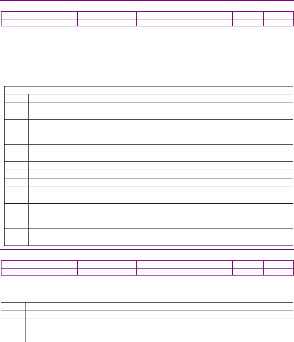
Device Control, Configuration, and Status CANopen Programmer’s Manual
70 16-01195 Rev 00
LATCHING FAULT STATUS REGISTER INDEX 0X2183
Type
Access
Units
Range
Map PDO
Memory
UNSIGNED32
RW
Bits
Bit mapped
TR
R
Description
Bit-mapped to show which latching faults have occurred in the amplifier. When a latching fault has
occurred, the fault bit (bit 22) of the Manufacturer Status Register object (index 0x1002, p. 61) is
set. The cause of the fault can be read from this register.
To clear a fault condition, write a 1 to the associated bit in this register.
The events that cause the amplifier to latch a fault are programmable. See Fault Mask object
(index 0x2182, p. 69) for details.
Latched Faults
Bit
Fault Description
0
Data flash CRC failure. This fault is considered fatal and cannot be cleared.
1
Amplifier internal error. This fault is considered fatal and cannot be cleared.
2
Short circuit.
3
Amplifier over temperature.
4
Motor over temperature.
5
Over voltage.
6
Under voltage.
7
Feedback fault.
8
Phasing error.
9
Tracking error.
10
Over Current,
11
FPGA failure.
12
Command input lost.
13
FPGA failure (yes, there are two bits for this, they mean slightly different things)
14
Safety circuit fault.
15
Unable to control current.
16-31
Reserved.
STATUS OF SAFETY CIRCUIT INDEX 0X219D
Type
Access
Units
Range
Map PDO
Memory
UNSIGNED32
RW
Integers
0 to 8
R
Description
This parameter allows the status of the safety circuit in Plus family amplifiers to be queried.
For amplifiers without a safety circuit, this parameter is reserved.
Bit
Description
0
Set when safety input 0 is preventing the amplifier from enabling.
1
Set when safety input 1 is preventing the amplifier from enabling.
8
This read/write bit can be used to force the ‘amplifier is unsafe’ output of the safety circuit to go active for
testing purposes. Write 1 to force.

CANopen Programmer’s Manual Device Control, Configuration, and Status
Copley Controls 71
6.4 Basic Amplifier Configuration Objects
DEVICE TYPE INDEX 0X1000
Type
Access
Units
Range
Map PDO
Memory
UNSIGNED32
RO
-
See Description, below.
NO
R
Description
Describes the type of device and its functionality.
This 32-bit value is composed of two 16-bit components. The lower two bytes identify the device
profile supported by the device. This amplifier supports the DSP402 device profile, indicated by the
value 0x0192.
The upper two bytes give detailed information about the type of motors the drive can control. The
bit mapping of this value is defined by the CANopen Profile for Drives and Motion Control (DSP
402). For Copley Controls CANopen amplifiers, this value is 0x0006, indicating that Copley
Controls supports servo and stepper devices.
DEVICE NAME INDEX 0X1008
Type
Access
Bits
Range
Map PDO
Memory
STRING[40]
RO
320
-
NO
R
Description
An ASCII string which gives the amplifier's model number.
HARDWARE VERSION STRING INDEX 0X1009
Type
Access
Bits
Range
Map PDO
Memory
STRING[40]
RO
320
-
NO
R
Description
Describes amplifier hardware version.
SOFTWARE VERSION NUMBER INDEX 0X100A
Type
Access
Bits
Range
Map PDO
Memory
STRING[40]
RO
320
-
NO
R
Description
Contains an ASCII string listing the software version number of the amplifier.
SAVE PARAMETERS INDEX 0X1010
Type
Access
Bits
Range
Map PDO
Memory
RECORD
RW
144
-
NO
RF
Description
Allows the current values programmed into the amplifier's objects to be saved to flash memory.
The various sub-index values of this object allow either all objects, or specific groups of objects to
be saved. Sub-index 0 contains the number of sub-elements of this record.
SAVE ALL OBJECTS INDEX 0X1010, SUB-INDEX 1 OR STRING
Type
Access
Bits
Range
Map PDO
Memory
UNSIGNED32
RW
32
-
NO
R
Description
When read, this object will return the value 1 indicating that the device is able to save objects in
this category. When the ASCII string “save” (or, the corresponding 32-bit value 0x65766173) is
written to this object, all objects in the object dictionary that can be saved to flash are written.
Objects written to flash will resume the stored value after an amplifier reset.

Device Control, Configuration, and Status CANopen Programmer’s Manual
72 16-01195 Rev 00
Note that not every object in the object dictionary may be written to flash. Presently, the objects
that define the amplifier's CANopen communication interface are not stored to flash and will
resume default values on startup. Most other objects may be stored to flash.
SAVE COMMUNICATION PARAMETERS INDEX 0X1010, SUB-INDEX 2
Type
Access
Bits
Range
Map PDO
Memory
UNSIGNED32
RW
32
-
NO
R
Description
When read, this object returns the value 1, indicating that the device can save objects in this
category. When the ASCII string “save” (or, the corresponding 32-bit value 0x65766173) is written
to this object, all objects in the object dictionary that can be saved to flash are written. Objects
written to flash resume the stored value after an amplifier reset.
Objects in the category are the objects with indexes in the range 0x1000 – 0x1FFF.
SAVE DEVICE PROFILE PARAMETERS INDEX 0X1010, SUB-INDEX 3
Type
Access
Bits
Range
Map PDO
Memory
UNSIGNED32
RW
32
-
NO
R
Description
When read, this object returns the value 1, indicating that the device can save objects in this
category. When the ASCII string “save” (or, the corresponding 32-bit value 0x65766173) is written
to this object, all objects in the object dictionary that can be saved to flash are written.
Objects written to flash resume the stored value after an amplifier reset.
Objects in the category are the objects with indexes in the range 0x6000 – 0x9FFF.
SAVE MANUFACTURER SPECIFIC PARAMETERS INDEX 0X1010, SUB-INDEX 4
Type
Access
Bits
Range
Map PDO
Memory
UNSIGNED32
RW
32
-
NO
R
Description
When read, this object returns the value 1 indicating that the device is able to save objects in this
category. When the ASCII string “save” (or, the corresponding 32-bit value 0x65766173) is written
to this object, all objects in the object dictionary that can be saved to flash are written. Objects
written to flash resume the stored value after an amplifier reset.Objects in the category are the
objects with indexes in the range 0x2000 – 0x5FFF.
IDENTITY OBJECT INDEX 0X1018
Type
Access
Bits
Range
Map PDO
Memory
RECORD
RO
144
-
NO
R
Description
This object can uniquely identify an amplifier by unique manufacturer ID, serial number, and
product revision information. Sub-index 0 contains the number of sub-elements of this record.
VENDOR ID INDEX 0X1018, SUB-INDEX 1
Type
Access
Units
Range
Map PDO
Memory
UNSIGNED32
RO
-
0x000000AB
NO
R
Description
A unique identifier assigned to Copley Controls.
The value of this identifier is fixed at: 0x000000AB

CANopen Programmer’s Manual Device Control, Configuration, and Status
Copley Controls 73
PRODUCT CODE INDEX 0X1018, SUB-INDEX 2
Type
Access
Units
Range
Map PDO
Memory
UNSIGNED32
RO
-
See Description, below.
NO
R
Description
Identifies the specific amplifier model. Also known as Amplifier Hardware Type. Identical to
(Index 0x2384, Sub-Index 13
, p. 80). The currently defined values for this object are:
Value
Product
0x0000
ASC: Accelus Card.
0x0002
ASP: Accelus Panel.
0x0100
JSP: Junus Panel.
0x0200
ACM: Accelnet Module.
0x0201
XSL: Xenus Panel (obsolete).
0x0203
ACP: Accelnet Panel (obsolete).
0x0206
XSL-R: Xenus Panel, resolver version.
0x0207
XSL: Xenus Panel.
0x0209
ACJ: Accelnet Micro Panel.
0x020b
ACP: Accelnet Panel.
0x020c
ACK: Accelnet Micro Module.
0x020e
Special.
0x020f
Special.
0x0210
ACJ-S: Accelnet Micro Panel, analog encoder version.
0x0240
STM: Stepnet Module.
0x0242
STP: Stepnet Panel.
0x0243
STL: Stepnet Micro Module.
0x0300
ASP: Accelnet Panel, 2 axis.
0x0310
XSJ(S): Xenus Micro Panel.
0x0320
XTL: Xenus Panel, resolver version.
0x0330
XTL(S): Xenus Panel.
0x0340
XSJ-R: Xenus Micro Panel, resolver version.
0x0380
AEP: Accelnet EtherCat Panel.
0x0391
AMP: Accelnet Macro Panel.
0x0350
STX: Stepnet AC Panel.
0x0370
ACK-R: Accelnet Micro Module, resolver version.
0x03a0
ADP: Accelnet Panel.
0x1000
XEL: Xenus Plus EtherCAT.
0x1010
XML: Xenus Plus MACRO.
0x1020
XPL: Xenus Plus CAN.
0x1030
AEM: Accelnet module EtherCAT.
0x1040
APM: 1 axis Servo CAN module.
0x1050
AE2: 2 axis EtherCAT module.
0x1060
AP2: 2 axis Servo CAN module.
0x1070
1 axis Stepper EtherCAT module.
0x1080
1 axis Stepper CAN module.
0x1090
2 axis Stepper EtherCAT module.
0x10A0
SP2: 2 axis Stepnet Plus Module CAN.
0x10B0
XE2: 2 axis Xenus Plus Dual EtherCAT
0x10B8
XE2-R: 2 axis Xenus Plus Dual EtherCAT resolver version
0x10C0
BE2: 2 axis Accelnet Plus Panel EtherCAT
0x10C8
BE2-R: 2 axis Accelnet Plus Panel EtherCAT resolver version
0x10D0
XP2: 2 axis Xenus Plus Dual CAN
0x10D8
XP2-R: 2 axis Xenus Plus Dual CAN resolver version
0x10E0
BP2: 2 axis Accelnet Plus Panel CAN
0x10A0
SP2: 2 axis Stepnet Plus Module CAN.
0x10B0
XE2: 2 axis Xenus Plus Dual EtherCAT
0x10B8
XE2-R: 2 axis Xenus Plus Dual EtherCAT resolver version
0x10C0
BE2: 2 axis Accelnet Plus Panel EtherCAT
0x10C8
BE2-R: 2 axis Accelnet Plus Panel EtherCAT resolver version

Device Control, Configuration, and Status CANopen Programmer’s Manual
74 16-01195 Rev 00
0x10D0
XP2: 2 axis Xenus Plus Dual CAN
0x10D8
XP2-R: 2 axis Xenus Plus Dual CAN resolver version
0x10E0
BP2: 2 axis Accelnet Plus Panel CAN
0x10E8
BP2-R: 2 axis Accelnet Plus Panel CAN resolver version
0x10F0
TE2: 2 axis Stepnet Plus Panel EtherCAT
0x1100
TP2: 2 axis Stepnet Plus Panel CAN
0x1110
BEL: 1 axis Accelnet Plus Panel EtherCAT
0x1118
BEL-R: 1 axis Accelnet Plus Panel EtherCAT resolver version
0x1120
BPL: 1 axis Accelnet Plus Panel CAN
0x1128
BPL-R: 1 axis Accelnet Plus Panel CAN resolver version
0x1130
TEL: 1 axis Stepnet Plus Panel EtherCAT
0x1150
SP4: 4 axis Stepnet Plus Module CAN
REVISION NUMBER INDEX 0X1018, SUB-INDEX 3
Type
Access
Units
Range
Map PDO
Memory
UNSIGNED32
RO
-
-
NO
R
Description
Identifies the revision of the CANopen interface.
SERIAL NUMBER INDEX 0X1018, SUB-INDEX 4
Type
Access
Units
Range
Map PDO
Memory
UNSIGNED32
RO
-
-
NO
R
Description
The amplifier's serial number. Holds the same value as Amplifier Serial Number (Index 0x2384,
Sub-Index 1
, p. 79).
AMPLIFIER SCALING CONFIGURATION INDEX 0X2080
Type
Access
Units
Range
Map PDO
Memory
UNSIGNED32
RO
Bits
Bit mapped
NO
F
Description
This read-only parameter defines the units used for current and voltage readings
from the amplifier:
Bits
Description
0 -1 Identify units for current readings:
0 0.01 A
1
0.001 A
2
0.0001 A
3
0.00001 A
2 - 7
Reserved
8 - 9 Identify units for voltage readings:
0 0.1 V
1 0.01 V
2
0.001 V
3
0.0001 V
10 - 31
Reserved

CANopen Programmer’s Manual Device Control, Configuration, and Status
Copley Controls 75
AMPLIFIER NAME INDEX 0X21A0
Type
Access
Bits
Range
Map PDO
Memory
STRING[40]
RW
320
NO
F
Description
This object may be used to assign a name to an amplifier. The data written here is stored to flash
memory and is not used by the amplifier. Although this object is documented as holding a string
(i.e. ASCII data), any values may be written here. Up to 40 bytes are stored.
MISC AMPLIFIER OPTIONS REGISTER INDEX 0X2420
Type
Access
Bits
Range
Map PDO
Memory
INTEGER32
RW
32
Bit mapped
TR
RF
Description
Miscellaneous Amplifier Options Register. Bit-mapped as follows:
Bit
Description
0
If set, input pins 1, 2, and 3 are pulled high on the amplifier. If clear the pins are not pulled up. This option
is only available on the Junus amplifier.
1
Reserved.
2
If set, limit switch inputs will only abort a trajectory in progress, but will not affect current output.
If clear, limit switches limit current.
3
If set, save PDO configuration to a file in the CVM file system when a “Save to Flash” command is
received over the CANopen network. If clear, a PDO is not saved.
4
If set, a limit switch activation will be treated as a fault in the CANopen Status Word (CANopen index
0x6041).
5-6
When encoder wrap is enabled, these bits control the direction of
motion for absolute moves in trapezoidal and S-curve
profile modes.
0 – move in the shortest direction
1 – Always move in the positive direction
2 – Always move in the negative direction
3 – reserved
7
If set, analog command values will use digital data written to an SPI serial interface connected
to drive input pins & multimode port. This is available on some plus drives for use in digitally
interfacing with a Delta Tau controller
8-31
Reserved
FLASH PROGRAM UPDATER 0X2001
Type
Access
Units
Range
Map PDO
Memory
UNSIGNED32
RW
-
-
NO
R
Description:
For updating firmware on products that are not Plus family products. CME 2 is the preferred
method for this. Contact Copley for more information if your application requires this.

Device Control, Configuration, and Status CANopen Programmer’s Manual
76 16-01195 Rev 00
NETWORK NODE ID CONFIGURATION INDEX 0X21B0
Type
Access
Units
Range
Map PDO
Memory
INTEGER16
RW
-
See Description, below.
NO
RF
Description
This object is used to configure the CANopen network bit rate and node ID for the amplifier.
The bit rate is read only at power-up or reset.
Likewise, the ID is calculated at power-up or reset (and only then) using a combination of general-
purpose input pins and a programmed offset value. On certain models, an address switch is also
used. The resulting value is clipped to a 7-bit ID in the range 0 to 127.
The configuration parameter is bit-mapped as follows. Values written here are stored to flash
memory. The new network configuration will not take effect until the amplifier is reset.
Bit
Description
0-6
Give the node ID offset value.
7
Used only on DeviceNet firmware. If this bit is set, then the drive will be software disabled on startup and
will remain disabled until it is enabled by a DeviceNet I/O message with the enable bit set.
8-10
Number of input pins (0-7) to read on startup for the node ID value. If input pins are used (i.e., the value in
bits 8-10 is not zero), the inputs can be mapped to node ID bits through the object
Input Mapping for Network Node ID (index 0x21B1, p. 77).
11
This bit is ignored on amplifiers that do not have an address switch.
On amplifiers with an address switch, setting this bit programs the amplifier to use the address selector
switch as part of the address calculation. In this case, the node ID value is equal to the sum of:
The value read from the designated input pins, shifted up 4 bits.
The address switch value.
The programmed offset value.
Note that since the node ID is always clipped to the lowest 7 bits, no more than 3 input pins will ever have
an effect on the node address when the address switch is used.
12-15
Network bit rate setting.
The network bit rate is encoded as one of the following values:
Code
Bit Rate (bits / second)
0
1,000,000
1
800,000
2
500,000
3
250,000
4
125,000
5
50,000
6
20,000
7-15
Reserved for future use
CANopen Programmer’s Manual Device Control, Configuration, and Status
Copley Controls 77
INPUT MAPPING FOR NETWORK NODE ID INDEX 0X21B1
Type
Access
Bits
Range
Map PDO
Memory
UNSIGNED32
RW
32
See Description, below.
NO
F
Description
When the Network Node ID Configuration object (index 0x21B0, p. 76) indicates that 1 or more
input pins will be used to select the CAN node ID, this mapping register is used to select which
input pins will be mapped to which ID bit. Fields include:
Bit
Description
0-3
Identify the general purpose input pin associated with ID bit 0.
4-7
Identify the general purpose input pin associated with ID bit 1.
8-11
Identify the general purpose input pin associated with ID bit 2.
12-15
Identify the general purpose input pin associated with ID bit 3.
16-19
Identify the general purpose input pin associated with ID bit 4.
20-23
Identify the general purpose input pin associated with ID bit 5.
24-27
Identify the general purpose input pin associated with ID bit 6.
28-30
Reserved for future use.
31
Set to enable this register. Clear to use default mapping.
If bit 31 is zero, then a default bit mapping is used and the rest of this register is ignored. The
default bit mapping uses the top N input pins and maps them such that the high-numbered pins
are used for higher-numbered bits in the ID. For example, the Accelnet panel amplifier has 12
general purpose input pins (0 to 11). If 3 of these pins are used for ID configuration and the default
mapping is used, then the highest 3 pins (9, 10 and 11) will be used for the ID. In this case, pin 9 is
bit 0, pin 10 is bit 1 and pin 11 is bit 2. If bit 31 is set, then the rest of this register is used to define
which input pin is assigned to which bit of the ID. The input pins are numbered from 0 to 15 and
each nibble of the register gives the input pin number associated with one bit of the ID.
For example, if three input pins are configured for address selection and the mapping register is
set to 0x80000012, then input pin 2 is used for ID bit 0, input pin 1 is used for ID bit 1, and input
pin 0 is used for ID bit 2.
Note that the CAN node ID is calculated at startup only. The input pins assigned to the node ID are
sampled once during power up and used to calculate the ID. These pins may be assigned other
uses after power up if necessary.
CURRENT STATE OF THE CAN ID SELECTION SWITCH INDEX 0X2197
Type
Access
Units
Range
Map PDO
Memory
INTEGER16
RO
-
0 - 15
YES
R
Description
This object gives the current value of the CAN address switch.
For amplifiers that do not have a switch, the value returned is undefined.

Device Control, Configuration, and Status CANopen Programmer’s Manual
78 16-01195 Rev 00
BUFFERED ENCODER OUTPUT CONFIGURATION (MULTI-PORT) INDEX 0X2241
Type
Access
Units
Range
Map PDO
Memory
INTEGER16
RW
-
-
TR
RF
Description
Multi-mode Port Configuration. The available settings are:
Value
Description
0
Output buffered primary encoder (hardware buffering).
1
Configure pins as inputs.
2
Output simulated encoder outputs tracking motor encoder.
3
Output simulated encoder outputs tracking position encoder.
AMPLIFIER MODEL NUMBER INDEX 0X6503
Type
Access
Bits
Range
Map PDO
Memory
STRING[40]
RO
320
-
NO
R
Description
This ASCII string gives the amplifier model number.
AMPLIFIER MANUFACTURER INDEX 0X6504
Type
Access
Units
Range
Map PDO
Memory
VISIBLE_STRING
RO
-
-
NO
R
Description
This ASCII string identifies the amplifier's manufacturer as “Copley Controls ”.
MANUFACTURER'S WEB ADDRESS INDEX 0X6505
Type
Access
Units
Range
Map PDO
Memory
VISIBLE_STRING
RO
-
-
NO
R
Description
This ASCII string gives the web address of Copley Controls.

CANopen Programmer’s Manual Device Control, Configuration, and Status
Copley Controls 79
SERVO LOOP CONFIG INDEX 0X2301
Type
Access
Units
Range
Map PDO
Memory
UNSIGNED32
RW
Bits
Bit mapped
TR
RF
Description
This parameter allows various parts of the amplifier servo loops to be enabled/disabled. It’s
mapped as follows:
Bit
Description
0
If set, this disables the velocity loop gains. The velocity loop command feed forward gain (parameter 0x157)
is still active as are the velocity loop output filters.
1
If set, this enables the position loop I and D gains (parameters 0x155 and 0x156). If clear, these parameters
are treated as zeros.
2-31
Reserved for future use.
DRIVE DATA INDEX 0X2384
Type
Access
Bits
Range
Map PDO
Memory
RECORD
RW
848
-
NO
F
Description:
This record lists various amplifier parameters. Sub-index 0 contains the number of sub-elements of
this record.
AMPLIFIER SERIAL NUMBER INDEX 0X2384, SUB-INDEX 1
Type
Access
Bits
Range
Map PDO
Memory
UNSIGNED32
RO
32
0 to 232-1
NO
F
Description:
Gives the amplifier serial number.
AMPLIFIER MANUFACTURING INFO INDEX 0X2384, SUB-INDEX 2
Type
Access
Bits
Range
Map PDO
Memory
STRING[40]
RO
320
NO
F
Description:
Date of manufacture of the amplifier.
AMPLIFIER PEAK CURRENT LIMIT INDEX 0X2384, SUB-INDEX 3
Type
Access
Units
Range (Adc)
Map PDO
Memory
INTEGER16
RO
0.01 amps
(0 to 216-1) / 100
NO
F
Description:
The amplifier's peak current rating.
AMPLIFIER CONTINUOUS CURRENT INDEX 0X2384, SUB-INDEX 4
Type
Access
Units
Range (Adc)
Map PDO
Memory
INTEGER16
RO
0.01 amps
(0 to 216-1) / 100
NO
F
Description:
The amplifier's continuous current rating.
AMPLIFIER PEAK CURRENT TIME INDEX 0X2384, SUB-INDEX 5
Type
Access
Units
Range (ms)
Map PDO
Memory
INTEGER16
RO
milliseconds
0 to 216-1
NO
F
Description:
The maximum time for which the amplifier is rated to output peak current.

Device Control, Configuration, and Status CANopen Programmer’s Manual
80 16-01195 Rev 00
AMPLIFIER MAXIMUM VOLTAGE INDEX 0X2384, SUB-INDEX 6
Type
Access
Units
Range (Vdc)
Map PDO
Memory
INTEGER16
RO
0.1 volts
(0 to 216-1) / 10
NO
F
Description:
Maximum bus voltage rating for amplifier.
AMPLIFIER MINIMUM VOLTAGE INDEX 0X2384, SUB-INDEX 7
Type
Access
Units
Range (Vdc)
Map PDO
Memory
INTEGER16
RO
0.1 volts
(0 to 216-1) / 10
NO
F
Description:
Minimum bus voltage rating for amplifier.
AMPLIFIER VOLTAGE HYSTERESIS INDEX 0X2384, SUB-INDEX 8
Type
Access
Units
Range (Vdc)
Map PDO
Memory
INTEGER16
RO
0.1 volts
(0 to 216-1) / 10
NO
F
Description:
Hysteresis for maximum bus voltage cut-out.
AMPLIFIER MAXIMUM TEMPERATURE INDEX 0X2384, SUB-INDEX 9
Type
Access
Units
Range (deg C)
Map PDO
Memory
INTEGER16
RO
degrees centigrade
0 to 216-1
NO
F
Description:
Temperature limit for amplifier.
AMPLIFIER TEMPERATURE HYSTERESIS INDEX 0X2384, SUB-INDEX 10
Type
Access
Units
Range (deg C)
Map PDO
Memory
INTEGER16
RO
degrees centigrade
0 to 216-1
NO
F
Description:
Hysteresis value for amplifier over temperature cut-out.
AMPLIFIER CURRENT LOOP PERIOD INDEX 0X2384, SUB-INDEX 11
Type
Access
Units
Range (ns)
Map PDO
Memory
UNSIGNED16
RW
10 nanoseconds
( 0 to 216-1) x 10
NO
F
Description:
Current loop update period in 10-nanosecond units.
AMPLIFIER SERVO LOOP PERIOD INDEX 0X2384, SUB-INDEX 12
Type
Access
Units
Range
Map PDO
Memory
INTEGER16
RW
Integer
0 to 216-1
NO
F
Description:
Servo loop update period as a multiple of the current loop period. Default value is 4.
AMPLIFIER TYPE CODE INDEX 0X2384, SUB-INDEX 13
Type
Access
Units
Range
Map PDO
Memory
INTEGER16
RO
-
See Description, below.
NO
F
Description:
Identifies the specific amplifier model. Also known as Amplifier Hardware Type. Identical to
Product Code (index 0x1018, Sub-index 2, p. 73). Go to page 73 (index 0x1018, Sub-index 2)
for a table of current defined values.

CANopen Programmer’s Manual Device Control, Configuration, and Status
Copley Controls 81
CURRENT CORRESPONDING TO MAX A/D READING INDEX 0X2384, SUB-INDEX 14
Type
Access
Units
Range (Adc)
Map PDO
Memory
INTEGER16
RO
0.01 amps
(0 to 216-1) / 100
NO
F
Description:
Amplifier current corresponding to maximum A/D reading.
VOLTAGE CORRESPONDING TO MAX A/D READING INDEX 0X2384, SUB-INDEX 15
Type
Access
Units
Range (Vdc)
Map PDO
Memory
INTEGER16
RO
0.1 volts
(0 to 216-1) / 10
NO
F
Description:
Amplifier voltage corresponding to maximum A/D reading.
ANALOG INPUT SCALING FACTOR INDEX 0X2384, SUB-INDEX 16
Type
Access
Units
Range
Map PDO
Memory
INTEGER16
RO
-
-
NO
F
Description:
Amplifier analog input scaling factor.
AMPLIFIER MINIMUM PWM OFF TIME INDEX 0X2384, SUB-INDEX 17
Type
Access
Units
Range (ns)
Map PDO
Memory
UNSIGNED16
RO
10 ns
( 0 to 216-1) x 10
NO
F
Description:
This fixed amplifier parameter gives the minimum amount of time for which all PWM outputs must
be disabled for each current loop cycle.
PWM DEAD TIME AT CONTINUOUS CURRENT LIMIT INDEX 0X2384, SUB-INDEX 18
Type
Access
Units
Range
Map PDO
Memory
UNSIGNED16
RO
CPU cycles
0 to 216-1
NO
F
Description:
This fixed amplifier parameter gives the PWM dead time used at or above the continuous current
limit. The dead time below the continuous current limit is a linear function of this parameter and
PWM Dead Time At Zero Current (Index 0x2384, Sub-Index 19, p. 81).
PWM DEAD TIME AT ZERO CURRENT INDEX 0X2384, SUB-INDEX 19
Type
Access
Units
Range
Map PDO
Memory
INTEGER16
RO
CPU cycles
0 to 216-1
NO
F
Description:
This fixed amplifier parameter gives the PWM dead time used at or above the continuous current
limit. The dead time below the continuous current limit is a linear function of this parameter and
PWM Dead Time At Continuous Current Limit (Index 0x2384, Sub-Index 18 p. 81).
PEAK CURRENT INTERNAL REGEN RESISTOR INDEX 0X2384, SUB-INDEX 20
Type
Access
Units
Range (Adc)
Map PDO
Memory
INTEGER16
RO
0.01 amps
(0 to 216-1) / 100
NO
F
Description:
The amplifier’s peak current rating for its internal regen resistor.

Device Control, Configuration, and Status CANopen Programmer’s Manual
82 16-01195 Rev 00
CONTINUOUS CURRENT INTERNAL REGEN RESISTOR INDEX 0X2384, SUB-INDEX 21
Type
Access
Units
Range (Adc)
Map PDO
Memory
INTEGER16
RO
0.01 amps
(0 to 216-1) / 100
NO
F
Description:
The amplifier’s continuous current rating for its internal regen resistor.
TIME AT PEAK CURRENT INTERNAL REGEN RESISTOR INDEX 0X2384, SUB-INDEX 22
Type
Access
Units
Range (ms)
Map PDO
Memory
UNSIGNED16
RO
ms
0 to 216-1
NO
F
Description:
The amplifier’s maximum time at peak current rating for its internal regen resistor.
ANALOG ENCODER SCALING FACTOR INDEX 0X2384, SUB-INDEX 23
Type
Access
Units
Range
Map PDO
Memory
INTEGER16
RO
-
-
NO
F
Description:
This parameter selects the resolution of an analog encoder input. The parameter is not used for
other encoder types.
FIRMWARE VERSION NUMBER INDEX 0X2384, SUB-INDEX 24
Type
Access
Units
Range
Map PDO
Memory
INTEGER16
RO
Bytes
NO
R
Description:
The version number consists of a major version number and a minor version number. The minor
number is passed in bits 0-7; the major number is in bits 8-15. For example, the version 1.12
would be encoded 0x010C.
AXIS COUNT INDEX 0X2384, SUB-INDEX 25
Type
Access
Units
Range
Map PDO
Memory
INTEGER16
RO
Integers
1 to 4
NO
R
Description:
Returns the number of axis implemented by this amplifier.
INTERNAL REGEN CURRENT LIMIT INDEX 0X2384, SUB-INDEX 26
Type
Access
Units
Range (Adc)
Map PDO
Memory
INTEGER16
RO
mA
(0 to 215-1) / 1000
NO
F
Description:
Amplifier internal maximum regen current.
FPGA IMAGE VERSION NUMBER INDEX 0X2384, SUB-INDEX 27
Type
Access
Units
Range
Map PDO
Memory
INTEGER16
RO
Integer
0 to 215-1
NO
R
Description:
FPGA firmware version number (available on certain amplifier models).
NIOS PROCESSOR FIRMWARE VERSION INDEX 0X2384, SUB-INDEX 28
Type
Access
Units
Range
Map PDO
Memory
UNSIGNED32
RO
Integer
-
NO
R
Description:
Firmware version of second processor for amplifiers equipped with two processors.

CANopen Programmer’s Manual Device Control, Configuration, and Status
Copley Controls 83
MISC HARDWARE OPTIONS INDEX 0X2384, SUB-INDEX 29
Type
Access
Units
Range
Map PDO
Memory
UNSIGNED32
RO
Integer
0 to 232-1
NO
F
Description:
Firmware version of second processor for amplifiers equipped with two processors.
CURRENT LEVEL FOR MINIMUM PWM DEADTIME INDEX 0X2384, SUB-INDEX 30
Type
Access
Units
Range
Map PDO
Memory
UNSIGNED32
RO
-
-
NO
F
Description:
Firmware version of second processor for amplifiers equipped with two processors.
AMPLIFIER DATA INDEX 0X6510
Type
Access
Units
Range
Map PDO
Memory
RECORD
RO
-
-
NO
R
Description
The contents of this object are the same as those of 0x2384 (Index 0x2384).
This object is provided for compatibility with CANopen applications. Refer to 0x2384 for details.
FIRMWARE VERSION NUMBER (EXTENDED) INDEX 0X2422
Type
Access
Units
Range
Map PDO
Memory
UNSIGNIED32
RO
Words
Upper, lower words
NO
R
Description
Firmware Version Number (extended). The upper 16 bits give the same major/minor version
number as Firmware Version Number (Index 0x2384, Sub-Index 24
, p. 82).
The lower 16 bits hold a release number (upper byte) and a reserved byte (lower).
DEVICE TYPE INDEX 0X67FF
Type
Access
Units
Range
Map PDO
Memory
UNSIGNED32
RO
-
-
NO
R
Description
Holds the same data as object 0x1000. Repeated as required by the CANopen specification.
PWM MODE INDEX 0X2140
Type
Access
Units
Range
Map PDO
Memory
INTEGER16
RW
Bits
See Description, below.
TR
RF
Description
PWM mode and status. This bit-mapped register allows some details of the PWM output to be
controlled and monitored. Fields are described below:
Bit
Description
0
Force bus clamping if set, disable bus clamping if clear. Note that if bit 1 is set, then this bit is ignored.
1
Automatic bus clamping mode if set. Setting this bit causes bus clamping mode to be automatically selected
based on the output voltage. Bit 0 is ignored if this bit is set.
3
Factory reserved. If set, DBrk mode is enabled.
4
Use hex voltage limiting if set, circular limiting if clear. This setting is only used with brushless motors.
6
Double PWM frequency if set.
8
Status bit, set when bus clamping is active.

Device Control, Configuration, and Status CANopen Programmer’s Manual
84 16-01195 Rev 00
RUNNING SUM OF USER CURRENT LIMIT INDEX 0X2116
Type
Access
Units
Range (Percent)
Map PDO
Memory
INTEGER16
RO
0.01%
(0 to 215-1) / 100
T
R
Description
Running sum of user current limit.
RUNNING SUM OF AMP CURRENT LIMIT INDEX 0X2117
Type
Access
Units
Range
Map PDO
Memory
INTEGER16
RO
0.01%
(0 to 215-1) / 100
T
R
Description
Running sum of the amp current limit.
D/A CONVERTER CONFIGURATION. INDEX 0X21E0
Type
Access
Units
Range
Map PDO
Memory
INTEGER32
RW
Bits
Bit mapped
NO
RF
Description
This parameter sets the mode for the D/A converter on drives so equipped.
The bits are mapped as follows:
Bit
Description
0-3
Define the mode of the D/A converter
16-17
Identify the axis associated with the D/A converter
Mode
Description
0
Manual configuration (set using parameter 0x135)
1
Actual current of configured axis
D/A CONVERTER OUTPUT VALUE INDEX 0X21E1
Type
Access
Units
Range
Map PDO
Memory
INTEGER16
RW
mV
-215 to +215-1
TR
R
Description
For drives that support an auxiliary D/A converter, this parameter sets the output value in mV units
when the D/A is in manual mode. In other modes, the current value being output on the D/A can be
read here.

CANopen Programmer’s Manual Device Control, Configuration, and Status
Copley Controls 85
6.5 Basic Motor Configuration Objects
MOTOR TYPE INDEX 0X6402
Type
Access
Units
Range
Map PDO
Memory
UNSIGNED16
RW
See Description, below.
NO
R
Description
Defines the type of motor connected to the amplifier:
Value
Description
0x8000
Not specified.
0x8010
Brushed servo motor.
0x8020
Microstepper
0x8030
Brushless servo motor.
MOTOR MODEL NUMBER INDEX 0X6403
Type
Access
Units
Range
Map PDO
Memory
STRING[40]
RW
ASCII
See Description, below.
NO
F
Description
The motor's model number.
MOTOR MANUFACTURER INDEX 0X6404
Type
Access
Units
Range
Map PDO
Memory
STRING[40]
RW
ASCII
See Description, below.
NO
F
Description
The motor's manufacturer name.
MOTOR DATA INDEX 0X2383
Type
Access
Units
Range
Map PDO
Memory
RECORD
RW
-
-
NO
F
Description:
This record holds a variety of motor parameters. Note that all motor parameters are stored to non-
volatile memory on the amplifier. The programmed values are preserved across power cycles.
Sub-index 0 contains the number of sub-elements of this record.
MOTOR TYPE INDEX 0X2383, SUB-INDEX 1
Type
Access
Units
Range
Map PDO
Memory
UNSIGNED16
RW
-
See Description, below.
NO
F
Description:
Defines the type of motor connected to the amplifier:
Type
Description
0
Rotary motor.
1
Linear motor.
MOTOR POLE PAIRS INDEX 0X2383, SUB-INDEX 2
Type
Access
Units
Range
Map PDO
Memory
INTEGER16
RW
-
0 to 215-1
NO
F
Description:
Number of motor pole pairs (electrical cycles) per rotation. For example, a 1.8 deg/step motor
would require setting motor poll pairs to 50. This parameter is only used for rotary motors.
For linear motors its value is ignored.

Device Control, Configuration, and Status CANopen Programmer’s Manual
86 16-01195 Rev 00
MOTOR WIRING CONFIGURATION INDEX 0X2383, SUB-INDEX 3
Type
Access
Units
Range
Map PDO
Memory
UNSIGNED16
RW
Integers
See Description, below.
NO
F
Description:
Defines the direction of the motor wiring:
Type
Description
0
Standard wiring.
1
Motor's U and V wires are swapped.
MOTOR HALL TYPE INDEX 0X2383, SUB-INDEX 4
Type
Access
Units
Range
Map PDO
Memory
INTEGER16
RW
Integers
See Description, below.
NO
F
Description:
Defines the type of Hall Effect sensors attached to the motor:
Type
Description
0
No Hall sensors available.
1
Digital Hall sensors.
2
Analog Hall sensors.
MOTOR HALL WIRING INDEX 0X2383, SUB-INDEX 5
Type
Access
Units
Range
Map PDO
Memory
INTEGER16
RW
Integers
See Description, below.
NO
F
Description:
Defines the wiring of the Hall sensors. Bit-mapped as follows
(when analog Halls are used, only bit 8 is relevant):
Bits
Description
0-2
The Hall wiring code (see below).
3
Reserved.
4
Invert W Hall input if set. Inversion occurs after Halls wiring has been modified by bits 0-2.
5
Invert V Hall input if set. Inversion occurs after Halls wiring has been modified by bits 0-2.
6
Invert U Hall input if set. Inversion occurs after Halls wiring has been modified by bits 0-2.
7
Reserved.
8
Swap analog Halls if set.
9-15
Reserved.
The Hall wiring codes define the order of the Hall connections:
Code
Hall ordering
0
U V W
1
U W V
2
V U W
3
V W U
4
W V U
5
W U V
6
Reserved
7
Reserved

CANopen Programmer’s Manual Device Control, Configuration, and Status
Copley Controls 87
MOTOR HALL OFFSET INDEX 0X2383, SUB-INDEX 6
Type
Access
Units
Range
Map PDO
Memory
INTEGER16
RW
degrees
-360 to +360
NO
RF
Description:
Offset angle to be applied to the Hall sensors.
MOTOR RESISTANCE INDEX 0X2383, SUB-INDEX 7
Type
Access
Units
Range (ohm)
Map PDO
Memory
INTEGER16
RW
0.01 Ohm
0 to 327.67
NO
F
Description:
Motor winding resistance, in 0.01-Ohm units.
MOTOR INDUCTANCE INDEX 0X2383, SUB-INDEX 8
Type
Access
Units
Range (mH)
Map PDO
Memory
INTEGER16
RW
0.01 millihenry
0 – 327.67
NO
F
Description:
Motor winding inductance, in 0.01 milliHenry units.
MOTOR INERTIA INDEX 0X2383, SUB-INDEX 9
Type
Access
Units
Range
Map PDO
Memory
INTEGER32 RW
Rotary:
0.000001 Kg / cm2
Linear: 0.0001 Kg.
Rotary: 0 to 4295 Kg / cm2
Linear: 0 to 429 x 103 kg NO F
Description:
Motor inertia.
MOTOR BACK EMF CONSTANT INDEX 0X2383, SUB-INDEX 10
Type
Access
Units
Range
Map PDO
Memory
UNSIGNED32 RW
Rotary: 0.01 V/KRPM
Linear: 0.01 V/m/s
Rotary: 0 to 21.47 x 10⁶ V/KRPM
Linear: 0 to 21.47 x 10
6
V/m/s
NO F
Description:
Motor back-EMF constant.
MOTOR MAXIMUM VELOCITY INDEX 0X2383, SUB-INDEX 11
Type
Access
Units
Range
Map PDO
Memory
UNSIGNED32
RW
0.1 counts / second
0 to 215 x 106 count/sec
NO
F
Description:
Maximum motor velocity.
MOTOR TORQUE CONSTANT INDEX 0X2383, SUB-INDEX 12
Type
Access
Units
Range
Map PDO
Memory
INTEGER32 RW
Rotary: 0.001 Nm / Amp
Linear: 0.00001 N.
Rotary: 0 to 2.15 x 10⁶ Nm/Amp
Linear: 0 to 21.5 x 10
3
V/m/s
NO F
Description:
Motor Torque (Force) constant.

Device Control, Configuration, and Status CANopen Programmer’s Manual
88 16-01195 Rev 00
MOTOR PEAK TORQUE INDEX 0X2383, SUB-INDEX 13
Type
Access
Units
Range
Map PDO
Memory
INTEGER32
RW
Rotary: 0.001 Nm
Linear: 0.00001 N
Rotary: 0 to 2.15 x 10⁶ Nm
Linear: 0 to 21.5 x 10
3
N
NO
F
Description:
Motor Peak Torque (Force).
MOTOR CONTINUOUS TORQUE INDEX 0X2383, SUB-INDEX 14
Type
Access
Units
Range
Map PDO
Memory
INTEGER32
RW
Rotary: 0.001 Nm/Amp
Linear: 0.00001 N/Amp
Rotary: 0 to 2.15 x 10⁶ Nm/A
Linear: 0 to 21.5 x 10
3
Nm/A
NO
F
Description:
Motor Continuous Torque (Force).
MOTOR HAS TEMPERATURE SENSOR INDEX 0X2383, SUB-INDEX 15
Type
Access
Units
Range
Map PDO
Memory
UNSIGNED16
RW
Integer
See Description, below.
NO
F
Description:
Value
Description
0
No temperature sensor available.
1
Temperature sensor is available.
MOTOR HAS BRAKE INDEX 0X2383, SUB-INDEX 16
Type
Access
Units
Range
Map PDO
Memory
UNSIGNED16
RW
Integer
See Description, below.
NO
F
Description:
Value
Description
0
The motor has a brake.
1
The motor does not have a brake.
DELAY FROM ERROR TO BRAKE ACTIVE INDEX 0X2383, SUB-INDEX 17
Type
Access
Units
Range
Map PDO
Memory
UNSIGNED16
RW
milliseconds
0 - 10,000
NO
F
Description:
Also known as Brake/Stop Delay Time. When the amplifier is disabled, it will actively decelerate
the motor for this amount of time (in milliseconds) before activating the brake output.
This delay may be cut short if the motor velocity falls below the value programmed in Motor Brake
Velocity (Index 0x2383, Sub-Index 19, p. 89).
MOTOR BRAKE DELAY INDEX 0X2383, SUB-INDEX 18
Type
Access
Units
Range
Map PDO
Memory
UNSIGNED16
RW
milliseconds
0 - 10,000
NO
F
Description:
After the brake output is activated, the amplifier will stay enabled for this amount of time to allow
the brake to engage.

CANopen Programmer’s Manual Device Control, Configuration, and Status
Copley Controls 89
MOTOR BRAKE VELOCITY INDEX 0X2383, SUB-INDEX 19
Type
Access
Units
Range
Map PDO
Memory
UNSIGNED32
RW
0.1 counts / second
0 to 429 x 106 count/sec
NO
F
Description:
During the Delay from Error to Brake Active (Index 0x2383, Sub-Index 17, p. 88), if the motor's
actual velocity falls below this value the brake output is activated immediately.
MOTOR ENCODER TYPE INDEX 0X2383, SUB-INDEX 20
Type
Access
Units
Range
Map PDO
Memory
UNSIGNED16
RW
-
See Description, below.
NO
F
Description:
Also known as Motor Encoder Type. Identifies the type of encoder attached to the motor:
Value
Description
0
Primary incremental quadrature encoder.
1
No encoder.
2
Analog encoder.
3
Multi-mode port incremental quadrature encoder
4
Analog Halls used for position feedback.
5
Resolver input.
6
Digital Halls.
7
Analog encoder, special.
8
Reserved.
9
Panasonic Minas-A.
10
SPI Command
11
SSI
12
EnDat 2.2
ENCODER UNITS INDEX 0X2383, SUB-INDEX 21
Type
Access
Units
Range
Map PDO
Memory
INTEGER16
RW
-
See Description, below.
NO
F
Description:
This value defines the units used to describe linear motor encoders. It is not used with rotary
motors.
Value
Description
0
microns
1
nanometers
2
millimeters
MOTOR ENCODER DIRECTION INDEX 0X2383, SUB-INDEX 22
Type
Access
Units
Range
Map PDO
Memory
UNSIGNED16
RW
-
See Description, below.
NO
F
Description:
Motor encoder direction. Value 0 for standard, value 1 to reverse direction.

Device Control, Configuration, and Status CANopen Programmer’s Manual
90 16-01195 Rev 00
MOTOR ENCODER COUNTS/REV INDEX 0X2383, SUB-INDEX 23
Type
Access
Units
Range
Map PDO
Memory
UNSIGNED32
RW
counts / rev
0 – 4,294,967,295
NO
F
Description:
For rotary motors gives the number of counts/motor revolution. When a resolver is used as the
motor feedback device, this parameter sets the resolution of the interpolated position.
This parameter is not used for linear motors.
MOTOR ENCODER RESOLUTION INDEX 0X2383, SUB-INDEX 24
Type
Access
Units
Range
Map PDO
Memory
INTEGER16
RW
encoder units / count
0 - 32,767
NO
F
Description:
Number of Encoder Units (sub-index 21) / count. Only used with linear motors.
MOTOR ELECTRICAL DISTANCE INDEX 0X2383, SUB-INDEX 25
Type
Access
Units
Range
Map PDO
Memory
INTEGER32
RW
encoder units / cycle
0 - 2,147,483,647
NO
F
Description:
Number of Encoder Units (sub-index 21) / motor electrical cycle. Only used with linear motors.
ENCODER INDEX PULSE DISTANCE INDEX 0X2383, SUB-INDEX 26
Type
Access
Units
Range
Map PDO
Memory
INTEGER32
-
-
0 - 2,147,483,647
NO
F
Description:
Reserved.
MOTOR UNITS INDEX 0X2383, SUB-INDEX 27
Type
Access
Units
Range
Map PDO
Memory
INTEGER32
-
-
-
NO
F
Description:
Reserved: Only used by CME 2 for display. 0 = metric, 1 = English.
ANALOG ENCODER SHIFT INDEX 0X2383, SUB-INDEX 28
Type
Access
Units
Range
Map PDO
Memory
UNSIGNED16
RW
Integers
0 -8
NO
F
Description:
This value gives the number of bits of interpolation to be applied to an analog encoder.
The fundamental encoder resolution will be increased by a multiplier of 2n where n is the value
programmed in this parameter.
The range of this value is 0 to 8 giving possible multipliers of 1 to 256.
MICROSTEPS/REV INDEX 0X2383, SUB-INDEX 29
Type
Access
Units
Range
Map PDO
Memory
UNSIGNED32
RW
microsteps
0 to 232-1
NO
F
Description:
Microsteps per revolution for microstepping motors.

CANopen Programmer’s Manual Device Control, Configuration, and Status
Copley Controls 91
LOAD ENCODER TYPE INDEX 0X2383, SUB-INDEX 30
Type
Access
Units
Range
Map PDO
Memory
UNSIGNED16
RW
-
See Description, below.
NO
F
Description:
Also known as Position Encoder Type. This bit-mapped value defines the type of encoder attached
to the load:
Bits
Description
0-2
Encoder Type (see below).
3
Reserved.
4
Linear encoder if set, rotary encoder if clear.
5
Passive load encoder if set.
The encoder type codes define the type of encoder.
Code
Encoder Type
0
No load encoder present.
1
Primary incremental quadrature encoder.
2
Analog encoder.
3
Multi-mode port incremental quadrature encoder.
4
Low frequency analog encoder
5
Resolver.
LOAD ENCODER DIRECTION INDEX 0X2383, SUB-INDEX 31
Type
Access
Units
Range
Map PDO
Memory
INTEGER16
RW
-
See Description, below.
NO
F
Description:
Also known as Position Encoder Direction. Load encoder direction. Value 0 for standard, value 1 to
reverse direction.
LOAD ENCODER RESOLUTION INDEX 0X2383, SUB-INDEX 32
Type
Access
Units
Range
Map PDO
Memory
UNSIGNED32
RW
encoder units / count
0 – 4,294,967,295
NO
F
Description:
Only used with linear motors. Also known as Position Encoder Resolution. Number of Encoder
Units / encoder count. For information, see Encoder Units (Index 0x2383, Sub-Index 21, p. 89).
MOTOR GEAR RATIO INDEX 0X2383, SUB-INDEX 33
Type
Access
Units
Range
Map PDO
Memory
UNSIGNED32
RW
-
0 – 4,294,967,295
NO
F
Description:
Reserved.
NUMBER OF RESOLVER CYCLES/MOTOR REV INDEX 0X2383, SUB-INDEX 34
Type
Access
Units
Range
Map PDO
Memory
UNSIGNED16
RW
Integers
0 – 65,535
NO
F
Description:
Number of Resolver Cycles/Motor Rev. This parameter is only used with resolver feedback
devices.

Device Control, Configuration, and Status CANopen Programmer’s Manual
92 16-01195 Rev 00
MOTOR DATA INDEX 0X6410
Type
Access
Units
Range
Map PDO
Memory
RECORD
RW
-
-
NO
F
Description
The contents of this object are the same as those of 0x2383 (p.85). This object is provided for
compatibility with CANopen applications. Refer to 0x2383 for details.
MOTOR BRAKE ENABLE DELAY TIME INDEX 0X2199
Type
Access
Units
Range
Map PDO
Memory
INTEGER16
RW
milliseconds
0 to 32,767
NO
F
Description
This parameter gives a delay between enabling the drive PWM outputs and releasing the brake.
Positive values mean the PWM is enabled first and then the brake is released N milliseconds later.
Negative values cause the brake to be released before PWM outputs are enabled.
MOTOR ENCODER WRAP INDEX 0X2220
Type
Access
Units
Range
Map PDO
Memory
INTEGER32
RW
Counts
-215 to +215-1
NO
RF
Description
Actual motor position will wrap back to zero when this value is reached. Setting this value to zero
disables this feature.
LOAD ENCODER WRAP INDEX 0X2221
Type
Access
Units
Range
Map PDO
Memory
INTEGER32
RW
Counts
-215 to +215-1
NO
RF
Description
Actual load position will wrap back to zero when this value is reached. Setting this value to zero
disables this feature.

CANopen Programmer’s Manual Device Control, Configuration, and Status
Copley Controls 93
MOTOR ENCODER OPTIONS INDEX 0X2222
Type
Access
Units
Range
Map PDO
Memory
UNSIGNED32
RW
-
-
NO
F
Description
Specifies various configuration options for the motor encoder. The mapping of option bits to
function depends on the encoder type.
Quadrature Encoder
Bit
Description
0
If set, ignore differential signal errors (if detected in hardware).
1
If set, select single ended encoder inputs (if available in hardware).
2
Ignore differential signal errors on index input only (if supported by hardware).
EnDat Encoder
Bit
Description
0-4
Number of bits of single turn data available from encoder.
8-12
Number of bits of multiturn data available from encoder.
16
Set if analog inputs are supplied by encoder.
SSI Encoder
Bits
Description
0-5
Number of bits of position data available.
8-10
Extra bits after position containing fault info.
12
If set, ignore first received bit.
13
If set. gray code encoded data.
16-21
Encoder bit rate in 100 kHz units
24
If set, first bit is 'data valid'.
Encoded Type 14 (Tamagawa, Panasonic, Harmonic Drives, etc.)
Bits
Description
0-5
Number of bits of single turn data.
8-12
Number of bits of multi-turn data.
16-19
Number of LSB to discard from reading.
20-22
Number of consecutive CRC errors to ignore.
24-27
Encoder sub-type (0=Tamagawa, 1=Panasonic absolute, 2=HD systems, 3=Panasonic Incremental,
4=Sanyo Denki).
28
Bit rate (set for 4 Mbit, clear for 2.5 Mbit).
BiSS
Bits
Description
0-5
Number of bits of single turn data.
8-12
Number of bits of multi-turn data.
16
Set for mode-C.
17
Sample at servo loop rate. (Default is at the current loop.) This should only be set if the encoder can not
handle the quicker sampling.
20
If set, error bits are active low.
21
If set, error bits are sent before position, after position (if clear).
24-26
Number of alignment bits.

Device Control, Configuration, and Status CANopen Programmer’s Manual
94 16-01195 Rev 00
LOAD ENCODER OPTIONS INDEX 0X2223
Type
Access
Units
Range
Map PDO
Memory
UNSIGNED32
RW
-
-
NO
F
Description
Specifies various configuration options for the motor encoder. The mapping of option bits to
function depends on the encoder type.
Quadrature Encoder
Bit
Description
0
If set, ignore differential signal errors (if detected in hardware).
1
If set, select single ended encoder inputs (if available in hardware).
EnDat Encoder
Bit
Description
0-4
Number of bits of single turn data available from encoder.
8-12
Number of bits of multiturn data available from encoder.
16
Set if analog inputs are supplied by encoder.

CANopen Programmer’s Manual Device Control, Configuration, and Status
Copley Controls 95
MOTOR ENCODER STATUS INDEX 0X2224
Type
Access
Units
Range
Map PDO
Memory
UNSIGNED32
RO
-
-
YES
R
Description
Motor encoder status. This parameter gives additional status information for the encoder. Bits set
in the status word are latched and cleared when the status value is read. The format of this status
word is dependent on the encoder type. Many error bits are taken directly from encoder data
stream. For a full description of what these error bits mean, please consult the encoder
manufacturer.
BiSS
Bits
Description
0
CRC error on data received from encoder
1
Encoder failed to transmit data to amp
2
Error bit on encoder stream is active
3
Warning bit on encoder stream is active
4
Encoder transmission delay is too long
EnDAT
Bits
Description
0
CRC error on data received from encoder
1
Failed to detect encoder connected to amplifier
2
Error bit on encoder stream is active
3
Encoder failed to respond to request for position
Tamagawa & Panasonic
Bits
Description
0
Over speed error reported by encoder
1
Absolute position error reported by encoder
2
Counting error reported by encoder
3
Counter overflow reported by encoder
5
Multi-turn error reported by encoder
6
Battery error reported by encoder
7
Battery warning reported by encoder
8
Error bit 0 reported by encoder
9
Error bit 1 reported by encoder
10
Comm error 0
11
Comm error 1
15
CRC error on data received from encoder
Sanyo Denki & Harmonic Drives (encoder type 14)
Bits
Description
0
Battery warning reported by encoder
1
Battery error reported by encoder
3
Over speed reported by encoder
4
Memory error reported by encoder
5
STERR reported by encoder
6
PSERR reported by encoder
7
Busy error reported by encoder

Device Control, Configuration, and Status CANopen Programmer’s Manual
96 16-01195 Rev 00
LOAD ENCODER STATUS INDEX 0X2225
Type
Access
Units
Range
Map PDO
Memory
UNSIGNED32
RO
-
-
YES
R
Description
Load encoder status. Same as parameter 0x12E, but for the load encoder.
PHASING MODE INDEX 0X21C0
Type
Access
Units
Range
Map PDO
Memory
UNSIGNED16
RW
-
See Description, below.
NO
F
Description
Controls the mechanism used by the amplifier to compute the motor phasing angle. Determines
what inputs the amplifier uses to initialize and maintain the phase angle. This variable is normally
set using CME and stored to flash, but it can also be accessed via object 0x21C0.
The values that can be programmed into this object are as follows:
Code
Description
0
Standard mode. Use digital Hall inputs to initialize phase, then switch to an encoder to maintain it. The
encoder is the primary sensing device with the Hall effect sensors used to monitor and adjust the phase
angle as necessary during operation. This mode gives smooth operation and should be selected for most
applications.
1
Trapezoidal (hall based) phasing. The Hall sensors are used for phasing all the time. This mode can be
used if no encoder is available.
2
Like mode 0 except that the phase angle is not adjusted based on the Hall inputs. Hall sensors are still
required to initialize the phase angle at startup.
3
Analog Halls (90°). Only available on amplifiers with the necessary analog inputs.
4
DC Brush.
5
Algorithmic phase init mode (wake & wiggle).
6
Encoder based phasing. Use with resolver or Servo Tube motor.
7
Trapezoidal commutation with phase angle interpolation.
Algorithmic Phase Init Mode Details
When mode 5 is selected the amplifier enters a state machine used to initialize its phase. While
the amplifier is performing this operation, bit 29 of the Manufacturer Status Register (0x1002) is
set.
At the start of the phase init algorithm the amplifier will wait to be enabled. Once enabled, the main
algorithm will start. If the amplifier is disabled during the phase initialization, it will wait to be
enabled again and start over.
When the phase init algorithm ends successfully, bit 29 the Manufacturer Status Register (0x1002)
is cleared and the amplifier will start using the encoder input to maintain its phasing info. If the
algorithm fails for any reason, bit 29 remains set and bit 6 (phase error) is also set in the status
word. The amplifier is then disabled.
To restart the phase init algorithm, object 0x21C0 can be written with the value 5. Bit 29 of the
status register will immediately be set and the phase init algorithm will restart as soon as the
amplifier is enabled.
Note that no profiles can be started until the phase init algorithm is completed.

CANopen Programmer’s Manual Device Control, Configuration, and Status
Copley Controls 97
MAX CURRENT TO USE WITH ALGORITHMIC PHASE INITIALIZATION INDEX 0X21C2
Type
Access
Units
Range
Map PDO
Memory
INTEGER16
RW
0.01 amps
--215 to +215-1
TR
RF
Description
See Algorithmic Phase Init Mode Details (p. 96).
ALGORITHMIC PHASE INITIALIZATION TIMEOUT INDEX 0X21C3
Type
Access
Units
Range
Map PDO
Memory
UNSIGNED16
RW
milliseconds
0 to +216-1
TR
RF
Description
See Algorithmic Phase Init Mode Details (p. 96).
ALGORITHMIC PHASE INITIALIZATION CONFIG INDEX 0X21C4
Type
Access
Units
Range
Map PDO
Memory
INTEGER16
RW
milliseconds
--215 to +215-1
TR
RF
Description
See Algorithmic Phase Init Mode Details (p. 96). Bit-mapped:
Bits
Description
0 If clear, use algorithmic phase initialization.
If set force the phase angle to zero degrees.
1
If set, increment the initial phase angle by 90 degrees after each failed attempt.
2 If set, use the Motor Hall Offset (Index 0x2383, Sub-Index 6, p. 87), as the initial angle for the first
attempt.
3-15
Reserved.
SECONDARY ANALOG REFERENCE OFFSET INDEX 0X2314
Type
Access
Units
Range
Map PDO
Memory
INTEGER16
RW
millivolts
--215 to +215-1
TR
F
Description
Offset for secondary analog reference input.
SECONDARY ANALOG REFERENCE CALIBRATION INDEX 0X2315
Type
Access
Units
Range
Map PDO
Memory
INTEGER16
RW
millivolts
--215 to +215-1
NO
F
Description
Calibration offset for second analog reference input.
ANALOG ENCODER SINE OFFSET INDEX 0X220B
Type
Access
Units
Range
Map PDO
Memory
INTEGER16
RW
A/D Units
--215 to +215-1
NO
F
Description
Encoder sine offset. This is set in A/D units and only used with resolvers and servo-tube motors. It
gives an offset which is added to the encoder sine signal before calculating position.

Device Control, Configuration, and Status CANopen Programmer’s Manual
98 16-01195 Rev 00
ANALOG ENCODER COSINE OFFSET INDEX 0X220C
Type
Access
Units
Range
Map PDO
Memory
INTEGER16
RW
A/D Units
-32,768 to +32,767
NO
F
Description
Encoder cosine offset. This is set in A/D units and only used with resolvers and servo-tube motors.
It gives an offset which is added to the encoder sine signal before calculating position.
ANALOG ENCODER COSINE SCALING FACTOR INDEX 0X220D
Type
Access
Units
Range
Map PDO
Memory
UNSIGNED16
RW
BOOL
0 to +216-1
NO
F
Description
Used by the resolver & servo tube encoder calculations. This scaler is used to adjust the cosine
signal amplitude so that it's the same as the sine signal amplitude. If set to zero, both the scaling
and offsets (0x18F,0x190) will be ignored. If non-zero the cosine is scaled by N/32768
where N is the value of this parameter.
ANALOG ENCODER SIGNAL MAGNITUDE INDEX 0X220E
Type
Access
Units
Range
Map PDO
Memory
INTEGER16
RO
0.1 mV2
-215 to +215-1
T
.R
Description
Returns the magnitude squared of the analog encoder signals (sin*sin + cos*cos).
This scaler is used to adjust the sin/cos signal amplitude.
MOTOR ENCODER CALIBRATION SETTINGS INDEX 0X2226
Type
Access
Units
Range
Map PDO
Memory
INTEGER32
RW
-
-
NO
RF
Description
The meaning of this object is dependent on the encoder type.
LOAD ENCODER CALIBRATION SETTINGS INDEX 0X2227
Type
Access
Units
Range
Map PDO
Memory
INTEGER32
RW
-
-
NO
RF
Description
The meaning of this object is dependent on the encoder type.
OPEN MOTOR WIRING CURRENT CHECK INDEX 0X2142
Type
Access
Units
Range
Map PDO
Memory
INTEGER32
RW
0.01 Adc
-215 to +215-1
NO
RF
Description
If object 0x2199 is greater then zero, then during that time period on enable this current will be
applied to the motor wiring to check to ensure that the motor is connected. If the programmed
current can not be applied to the motor, then a motor disconnected fault will be flagged.

CANopen Programmer’s Manual Device Control, Configuration, and Status
Copley Controls 99
MOTOR TEMP THERMISTOR CONSTANTS INDEX 0X220F
Type
Access
Bits
Range
Map PDO
Memory
ARRAY[0..4]
OF UINT
RW
80
-
R
RF
Description
Steinhart constants for motor analog motor temperature sensor. This parameter is only used on drives that
include a motor temperature sensor analog input (XEL, XPL, XML). For such drives, this parameter can be
used to define the type of NTC thermistor connected to the analog input. If nonzero, the motor temperature
(in deg C) will be read from parameter 0x2209 rather then the analog voltage. The parameter uses the same
format as an output pin configuration, a 16-bit Integer followed by two 32-bit integers. The three integer
values contain the A, B and C Steinhart coefficients for the motor thermistor. The three coefficients are
scaled by the following constants: A: 1.0e6, B : 1.0e7, C: 1.0e10
For example, A thermistor with coefficients 1.4626e3, 2.4024e4 and 8.0353e8 would be configured with the
three integer values: 1463, 2402 and 804.
MOTOR ENCODER SHIFT INDEX 0X2228
Type
Access
Bits
Range
Map PDO
Memory
UNSIGNED16
RW
16
0 to 216-1
NO
RF
Description
Motor encoder down-shift. This parameter is useful when using very high resolution encoders that would
otherwise have limited speed and travel distance due to the range of position and velocity parameters.
Setting the down-shift causes the position read from the encoder to be right-shifted before being used.
For example, setting this parameter to a value of 2 effectively cuts the encoder resolution by a factor of 4.
When this parameter is set, the servo loops use fractional encoder counts, therefore the encoder resolution
is not completely lost.
LOAD ENCODER SHIFT INDEX 0X2229
Type
Access
Bits
Range
Map PDO
Memory
UNSIGNED16
RW
16
0 to 216-1
NO
RF
Description
Load encoder down-shift. Same as parameter 0x2228, but for the load encoder.
CONFIGURATION FOR ENCODER ADJUSTMENT TABLE INDEX 0X222A
Type
Access
Bits
Range
Map PDO
Memory
UDINT
RW
32
0,1
NO
RF
Description
Bit Description
0 Set to enable encoder adjustment table
1 Set for resolver angle adjustment tables, clear for normal encoder adjustment tables.
MOTOR TEMP THERMISTOR CONSTANTS INDEX 0X220F
Type
Access
Bits
Range
Map PDO
Memory
ARRAY[0..4]
OF UINT
RW
80
-
R
RF
Description
Steinhart constants for motor analog motor temperature sensor. This parameter is only used on drives that
include a motor temperature sensor analog input (XEL, XPL, XML). For such drives, this parameter can be
used to define the type of NTC thermistor connected to the analog input. If nonzero, the motor temperature
(in deg C) will be read from parameter 0x2209 rather then the analog voltage. The parameter uses the same
format as an output pin configuration, a 16-bit Integer followed by two 32-bit integers. The three integer
values contain the A, B and C Steinhart coefficients for the motor thermistor. The three coefficients are
scaled by the following constants: A: 1.0e6, B : 1.0e7, C: 1.0e10
For example, A thermistor with coefficients 1.4626e3, 2.4024e4 and 8.0353e8 would be configured with the
three integer values: 1463, 2402 and 804.

Device Control, Configuration, and Status CANopen Programmer’s Manual
100 16-01195 Rev 00
6.6 Real-time Amplifier and Motor Status Objects
ANALOG/DIGITAL REFERENCE INPUT VALUE INDEX 0X2200
Type
Access
Units
Range
Map PDO
Memory
INTEGER16
RO
millivolts
--215 to +215-1
T
R
Description
Most recent value read from the reference A/D input (millivolts). Available on certain amplifiers.
HIGH VOLTAGE REFERENCE INDEX 0X2201
Type
Access
Units
Range (Vdc)
Map PDO
Memory
INTEGER16
RO
0.1 volts
--215 to +215-1
T
R
Description
The voltage present on the high-voltage bus. Also known as Bus Voltage.
AMPLIFIER TEMPERATURE INDEX 0X2202
Type
Access
Units
Range
Map PDO
Memory
INTEGER16
RO
degrees centigrade
--215 to +215-1
T
R
Description
The amplifier temperature.
SYSTEM TIME INDEX 0X2141
Type
Access
Units
Range
Map PDO
Memory
UNSIGNED32
RO
milliseconds
0 to 232-1
T
R
Description
Time since startup.
WINDING A CURRENT INDEX 0X2203
Type
Access
Units
Range
Map PDO
Memory
INTEGER16
RO
0.01 amps
--215 to +215-1
T
R
Description
The current present on one of the motor windings (0.01-amp units).
WINDING B CURRENT INDEX 0X2204
Type
Access
Units
Range
Map PDO
Memory
INTEGER16
RO
0.01 amps
--215 to +215-1
T
R
Description
The current present on one of the motor windings (0.01-amp units).
SINE FEEDBACK VOLTAGE INDEX 0X2205
Type
Access
Units
Range
Map PDO
Memory
INTEGER16
RO
millivolts
--215 to +215-1
T
R
Description
The voltage present on the analog feedback, sine input (millivolts). Not available on all amplifiers.
Also known as analog Sine Input Voltage.

CANopen Programmer’s Manual Device Control, Configuration, and Status
Copley Controls 101
COSINE FEEDBACK VOLTAGE INDEX 0X2206
Type
Access
Units
Range
Map PDO
Memory
INTEGER16
RO
millivolts
--215 to +215-1
T
R
Description
Voltage present on the analog feedback, cosine input (millivolts). Available on certain amplifiers.
A/D OFFSET VALUE INDEX 0X2207
Type
Access
Units
Range
Map PDO
Memory
INTEGER16
RO
millivolts
--215 to +215-1
YES
R
Description
Primarily of diagnostic interest, this object gives the offset value applied to the internal A/D unit. It
is part of a continuous calibration routine that the amplifier performs on itself while running.
CURRENT OFFSET A INDEX 0X2210
Type
Access
Units
Range
Map PDO
Memory
INTEGER16
RW
0.01 amps
--215 to +215-1
YES
R
Description
A calibration offset value, calculated at startup, and applied to the winding A current reading.
CURRENT OFFSET B INDEX 0X2211
Type
Access
Units
Range
Map PDO
Memory
INTEGER16
RW
0.01 amps
--215 to +215-1
YES
R
Description
A calibration offset value, calculated at startup, and applied to the winding B current reading.
X AXIS OF CALCULATED STATOR CURRENT VECTOR INDEX 0X2212
Type
Access
Units
Range
Map PDO
Memory
INTEGER16
RO
0.01 amps
--215 to +215-1
T
R
Description:
X axis of calculated stator current vector. Units: 0.01 A.
Y AXIS OF CALCULATED STATOR CURRENT VECTOR INDEX 0X2213
Type
Access
Units
Range
Map PDO
Memory
INTEGER16
RO
0.01 amps
--215 to +215-1
T
R
Description
Y axis of calculated stator current vector. Units: 0.01 A.
STATOR VOLTAGE- X AXIS INDEX 0X221A
Type
Access
Units
Range
Map PDO
Memory
INTEGER16
RO
0.1 volt
--215 to +215-1
YES
R
Description
X axis of stator output voltage vector.
STATOR VOLTAGE- Y AXIS INDEX 0X221B
Type
Access
Units
Range
Map PDO
Memory
INTEGER16
RO
0.1 volt
--215 to +215-1
YES
R
Description
Y axis of stator output voltage vector.

Device Control, Configuration, and Status CANopen Programmer’s Manual
102 16-01195 Rev 00
RMS CURRENT CALCULATION PERIOD INDEX 0X2114
Type
Access
Units
Range
Map PDO
Memory
INTEGER16
RW
milliseconds
--215 to +215-1
TR
F
Description
This sets the period over which the RMS current is calculated. If this value is set to zero, then the
RMS current will be updated each time it is read for the period since the last read. In this case, the
RMS current must be read at least once every 65536 current loop periods (about every 4 seconds)
for the returned RMS values to be accurate.
RMS CURRENT OVER SET PERIOD INDEX 0X2115
Type
Access
Units
Range
Map PDO
Memory
INTEGER16
RO
0.01 amps
--215 to +215-1
T
R
Description
RMS current over the period set in parameter 0x130.
MOTOR PHASE ANGLE INDEX 0X2260
Type
Access
Units
Range
Map PDO
Memory
INTEGER16
RW
degrees
0 - 360
T
R
Description
Motor phase angle, derived from motor commutation.
MOTOR PHASE ANGLE INDEX 0X2262
Type
Access
Units
Range
Map PDO
Memory
INTEGER16
RW
degrees
0 - 360
TR
R
Description
Same as 0x2260 but writeable. Writes are only useful when running in diagnostic micro-stepping
mode.
ENCODER PHASE ANGLE INDEX 0X2263
Type
Access
Units
Range
Map PDO
Memory
INTEGER16
RO
degrees
0 - 360
T
R
Description
For feedback types, such as resolver, that can also calculate phase angle information.
This parameter allows the phase information to be read directly.
HALL STATE INDEX 0X2261
Type
Access
Units
Range
Map PDO
Memory
INTEGER16
RO
Bits 0~2
0 - 15
T
R
Description
The lower three bits of the returned value give the present state of the Hall input pins.
The Hall state is the value of the Hall lines AFTER the ordering and inversions specified in the Hall
wiring configuration have been applied.

CANopen Programmer’s Manual Device Control, Configuration, and Status
Copley Controls 103
DIGITAL COMMAND INPUT SCALING FACTOR INDEX 0X2321
Type
Access
Units
Range
Map PDO
Memory
INTEGER32
RW
-
-
TR
RF
Description
Digital Command Input Scaling Factor. This value gives the amount of current to command at
100% PWM input. The scaling depends on what the PWM input is driving:
Current mode: 0.01 A Velocity (Accelus): 0.1 counts/s
In position mode the scaling factor is a ratio of two 16-bit values. The first word passed gives
the numerator and the second word gives the denominator. This ratio determines the number
of encoder units moved for each pulse (or encoder count) input. For example, a ratio
of 1/3 would cause the motor to move 1 encoder unit for every three input steps..
6.7 Digital I/O Configuration Objects
INPUT PIN STATES INDEX 0X2190
Type
Access
Units
Range
Map PDO
Memory
UNSIGNED16
RO
-
See Description, below
T
R
Description
The 16-bit value returned by this command gives the current state (high/low) of the amplifier’s
input pins after debouncing. The inputs are returned one per bit as shown below.
Bits
Description
0
Input 1
1
Input 2
2
Input 3
3
Input 4
4
Input 5
5
Input 6
6
Input 7
7
Input 8
8
Input 9
9
Input 10
10
Input 11
11
Input 12
12
Input 13
13
Input 14
14
Input 15
15
Input 16
There is a PDO event associated with the input states object that can transmit a PDO any time an
input pin changes state.

Device Control, Configuration, and Status CANopen Programmer’s Manual
104 16-01195 Rev 00
INPUT PIN STATE INDEX 0X219A
Type
Access
Units
Range
Map PDO
Memory
UNSIGNED32
R0
Bits
Bit mapped
T
R
Description
32-bit version of parameter 0x2190. Useful on drives with more than 16 input pins.
Some amplifiers have one or more pull-up resistors associated with their general-purpose input
pins. On these amplifiers, the state of the pull-ups can be controlled by writing to this register.
This register has one bit for each pull-up resistor available on the amplifier. Setting the bit causes
the resistor to pull any inputs connected to it up to the high state when they are not connected. Bits
0 – 7 of this register are used to control pull-up resistor states. Each bit represents an input
number. Bit 0 = IN1, bit 1 = IN2, etc.
On amplifiers that allow groups of inputs to be configured as either single ended or differential, bit
8 controls this feature. Set bit 8 to 0 for single ended, 1 for differential.
INPUT PIN CONFIG REGISTER (16 BIT) INDEX 0X2191
Type
Access
Units
Range
Map PDO
Memory
UNSIGNED16
RW
-
See Description, below
TR
RF
Description
Some amplifiers have one or more pull-up resistors associated with their general-purpose input
pins. On these amplifiers, the state of the pull-ups can be controlled by writing to this register.
This register has one bit for each pull-up resistor available on the amplifier. Setting the bit causes
the resistor to pull any inputs connected to it up to the high state when they are not connected. Bits
0 – 7 of this register are used to control pull-up resistor states. Each bit represents an input
number. Bit 0 = IN1, bit 1 = IN2, etc.
On amplifiers that allow groups of inputs to be configured as either single ended or differential, bit
8 controls this feature. Set bit 8 to 0 for single ended, 1 for differential.
INPUT PIN CONFIG REGISTER (32 BIT) INDEX 0X219C
Type
Access
Units
Range
Map PDO
Memory
UNSIGNED32
RW
-
See Description, below
TR
RF
Description
Some amplifiers have one or more pull-up resistors associated with their general-purpose input
pins. On these amplifiers, the state of the pull-ups can be controlled by writing to this register.
This register has one bit for each pull-up resistor available on the amplifier. Setting the bit causes
the resistor to pull any inputs connected to it up to the high state when they are not connected. Bits
0 – 7 of this register are used to control pull-up resistor states. Each bit represents an input
number. Bit 0 = IN1, bit 1 = IN2, etc.
On amplifiers that allow groups of inputs to be configured as either single ended or differential, bit
8 controls this feature. Set bit 8 to 0 for single ended, 1 for differential.

CANopen Programmer’s Manual Device Control, Configuration, and Status
Copley Controls 105
INPUT PIN CONFIGURATION INDEX 0X2192
Type
Access
Bits
Range
Map PDO
Memory
Array
RW
256
-
NO
RF
Description
This object consists of N identical sub-elements, where N is the number of input pins available on
the amplifier. Sub-index 0 contains the number of sub-elements of this array.
INPUT PIN CONFIGURATION INDEX 0X2192, SUB-INDEX 1-N
Type
Access
Units
Range
Map PDO
Memory
UNSIGNED16
RW
-
See Description, below
TR
RF
These values allow functions to be assigned to each of the input pins. The available functions are:
Code
Description
0
No function
1
Reserved for future use (no function)
2
Reset the amplifier on the rising edge of the input.
3
Reset the amplifier on the falling edge of the input.
4
Positive side limit switch. Active high. See Misc Amplifier Options Register (index 0x2420, p. 75).
5
Positive side limit switch. Active low. See Misc Amplifier Options Register (index 0x2420, p. 75).
6
Negative side limit switch. Active high. See Misc Amplifier Options Register (index 0x2420, p. 75).
7
Negative side limit switch. Active low. See Misc Amplifier Options Register (index 0x2420, p. 75).
8
Motor temperature sensor. Active high.
9
Motor temperature sensor. Active low.
10
Disable amplifier when high. Clear latched faults on low to high transition.
11
Disable amplifier when low. Clear latched faults on high to low transition.
12
Reset on rising edge. Disable amplifier when high.
13
Reset on falling edge. Disable amplifier when low.
14
Home switch. Active high.
15
Home switch. Active low.
16
Disable amplifier when high.
17
Disable amplifier when low.
19
PWM synchronization. Only for high speed inputs; see amplifier data sheet.
20
Halt motor and prevent a new trajectory when high.
21
Halt motor and prevent a new trajectory when low.
22
High resolution analog divide when high.
23
High resolution analog divide when low.
24
High speed position capture on rising edge. Only for high speed inputs.
25
High speed position capture on falling edge. Only for high speed inputs.
26
Counter input, rising edge.
Note: Upper byte of this parameter designates which Indexer register to store the count in.
27
Counter input, falling edge.
Note: Upper byte of this parameter designates which Indexer register to store the count in.

Device Control, Configuration, and Status CANopen Programmer’s Manual
106 16-01195 Rev 00
INPUT PIN DEBOUNCE VALUES INDEX 0X2195
Type
Access
Units
Range
Map PDO
Memory
ARRAY
RW
-
-
TR
RF
Description
This object consists of N identical sub-index objects, where N is the number of input pins available
on the amplifier. (Sub-index object 0 contains the number of elements of this record.) These
values allow debounce times to be assigned to each of the input pins. Each sub-index object can
be described as shown below:
INPUT PIN DEBOUNCE VALUES INDEX 0X2195, SUB-INDEX 1-N
Type
Access
Units
Range
Map PDO
Memory
UNSIGNED16
RW
milliseconds
0 - 10,000
TR
RF
Description
The debounce time for the input identified by the sub-index in milliseconds. This time specifies how
long an input must remain stable in a new state before the amplifier recognizes the state.
RAW INPUT PIN VALUE (16 BIT) INDEX 0X2196
Type
Access
Units
Range
Map PDO
Memory
UNSIGNED16
RO
-
See Description, below.
T
R
Description
This object shows the current state of the input pins before debouncing.
The inputs are returned one per bit. The value of IN1 is returned in bit 0 (1 if high, 0 if low), IN2 in
bit 1, etc. For input states with debouncing, see Input Pin States (index 0x2190, p. 103).
RAW INPUT PIN VALUE (32 BIT) INDEX 0X219B
Type
Access
Units
Range
Map PDO
Memory
UNSIGNED32
RO
-
See Description, below.
T
R
Description
The 32-bit value returned by this command gives the current state (high/low) of the amplifier’s
input pins. Unlike input pin states, no debounce is applied when reading the inputs using this
variable. The inputs are returned one per bit. The value of IN1 is returned in bit 0 (1 if high, 0 if
low), IN2 in bit 1, etc. For input states with debouncing, see Input Pin States
(index 0x2190, p. 103).

CANopen Programmer’s Manual Device Control, Configuration, and Status
Copley Controls 107
OUTPUT PIN CONFIGURATION INDEX 0X2193
Type
Access
Bits
Range
Map PDO
Memory
ARRAY
RW
496
-
NO
RF
Description
This array consists of N identical sub-elements, where N is the number of outputs. Sub-index 0
contains the number of sub-elements of this array.
OUTPUT PIN CONFIGURATION INDEX 0X2193, SUB-INDEX 1-N
Type
Access
Units
Range
Map PDO
Memory
Variable
RW
-
See Description, below.
NO
RF
Description
The values programmed into these objects allow the amplifier’s digital outputs to be driven by
internal amplifier events, or externally driven.
Each output configuration consists of a 16-bit configuration word (bits 0-15), followed by a variable
number of words (2-4), depending on the configuration code chosen. The configuration word is
defined as follows:
Bits
Configuration
0-2
Define which internal register drives the output. The acceptable values for these bits are as follows:
Value
Description
0
Word 2 (bits 16-32) is used as a mask of the amplifier's Manufacturer Status Register object (index
0x1002, p. 61). When any bit set in the mask is also set in the Manufacturer Status Register object,
the output goes active.
1
Word 2 (bits 16-32) is used as a mask of the amplifier's Latched Event Status Register (index
0x2181, p. 62). When any bit set in the mask is also set in the Latched Event Status Register, the
output goes active and remains active until the necessary bit in the Latched Event Status Register
is cleared.
2
Puts the output in manual mode. Additional words are not used in this mode, and the output's state
follows the value programmed in the manual output control register.
3
Word 2 (bits 16-32) is used as a mask of the amplifier's Trajectory Generator Status object (index
0x2252, p. 197). When any bit set in the mask is also set in the Trajectory Generator Status object
the output goes active.
4
Output goes active if the actual axis position is between the low position specified in words 2 and 3
(bits 16-47) and the high position specified in words 4 and 5 (bits 48-80).
5
Output goes active if the actual axis position crosses, with a low to high transition; the position
specified in words 2 and 3 (bits 16-47). The output will stay active for number of milliseconds
specified in words 4 and 5 (bits 48-80).
6
Same as 5 but for a high to low crossing.
7
Same as 5 but for any crossing.
3-7
Reserved for future use.
8
If set, the output is active low. If clear, the output is active high.
9-15
Reserved for future use.

Device Control, Configuration, and Status CANopen Programmer’s Manual
108 16-01195 Rev 00
OUTPUT STATES AND PROGRAM CONTROL INDEX 0X2194
Type
Access
Units
Range
Map PDO
Memory
UNSIGNED16
RW
-
See Description, below.
TR
R
Description
When read, this parameter gives the active/inactive state of the amplifier’s general-purpose digital
outputs. Each bit represents an input number. Bit 0 = digital output 1 (OUT1), bit 1 = OUT2, etc.,
up to OUTn, the number of digital outputs on the amplifier. Additional bits are ignored.
Outputs that have been configured for program control can be set by writing to this parameter (see
the Output pin configuration object, index 0x2193, p. 107 for pin configuration details). Set a bit to
activate the output. It will be activated high or low according to how it was programmed. Clear a bit
to make the output inactive. If an output was not configured for program control it will not be
affected.
OUTPUT COMPARE CONFIGURATION INDEX 0X2160
Type
Access
Bits
Range
Map PDO
Memory
UDINT
RW
32
Bit mapped
R
R
Description
Bits Description
0 Set to enable compare module
1 Set to invert the active state of the output
2 If set, toggle output on compare match.
If clear, pulse output for a programmable time
3~4 Define mode of compare module (see 0x2161 below)
5~31 Reserved for future use. Should be set to zero.
OUTPUT COMPARE STATUS INDEX 0X2161
Type
Access
Bits
Range
Map PDO
Memory
UDINT
RW
32
Bit mapped
T
R
Description
Bits Description
0 Current value of compare output (read only)
1 Set when position matches compare register 0. Write 1 to clear
2 Set when position matches compare register 1. Write 1 to clear
3~31 Reserved
OUTPUT COMPARE VALUE 0 INDEX 0X2162
Type
Access
Bits
Range
Map PDO
Memory
DINT
RW
32
-231 to +231-1
R
R
Description
Compare value 0
OUTPUT COMPARE VALUE 1 INDEX 0X2163
Type
Access
Bits
Range
Map PDO
Memory
DINT
RW
32
-231 to +231-1
R
R
Description
Compare value 1
OUTPUT COMPARE INCREMENT INDEX 0X2164
Type Access Units Range Map PDO
Memory
DINT RW Encoder counts -231 to +231-1 R R
Description
Signed 32-bit value used to update compare values in some modes.

CANopen Programmer’s Manual Device Control, Configuration, and Status
Copley Controls 109
OUTPUT COMPARE PULSE WIDTH INDEX 0X2165
Type
Access
Units
Range
Map PDO
Memory
DINT RW 10 ns -231 to +231-1 R R
Description
Compare pulse period The lower 20-bits of this parameter give the period
of the compare output pulse in 10 ns units.

Device Control, Configuration, and Status CANopen Programmer’s Manual
110 16-01195 Rev 00
DIGITAL CONTROL INPUT CONFIGURATION INDEX 0X2320
Type
Access
Units
Range
Map PDO
Memory
INTEGER16
RW
-
See Description, below.
TR
RF
Description
Defines the configuration of the digital control inputs when the amplifier is running in a mode that
uses them as a control source.
The lower 8 bits control the PWM input configuration for controlling current and velocity modes.
The upper 8 bits configure the digital inputs when running in position mode.
Bits
Description
0
If set, use PWM in signed/magnitude mode. If clear, use PWM in 50% duty cycle offset mode.
1
Invert the PWM input if set.
2
Invert the sign bit if set.
3
Allow 100% duty cycle if set. If clear, treat 100% duty cycle as a zero command, providing a measure of
safety in case of controller failure or cable break.
4-7
Reserved for future use.
8-9
Input pin interpretation for position mode (see below).
Value
Description
0
Step & Direction mode.
1
Separate up & down counters.
2
Quadrature encoder input.
10-11
Reserved for future use.
12
Count falling edges if set, rising edges if clear.
13
Invert command signal.
14-15
Selects source of digital position input command.
Value
Description
0
Single ended high speed inputs.
1
Multi-mode encoder port.
2
Differential high speed inputs.
3
Motor encoder port.

CANopen Programmer’s Manual Device Control, Configuration, and Status
Copley Controls 111
DIGITAL CONTROL INPUT SCALING INDEX 0X2321
Type
Access
Units
Range
Map PDO
Memory
INTEGER32
RW
See Description, below.
See Description, below.
TR
RF
Description
When the amplifier is running in a mode that takes input from the digital control input pins (as
determined by the setting of object 0x2300, Desired State), this object gives the amount of current
to command at 100% PWM input. The scaling depends on what the PWM input is driving:
Current mode: 0.01 A
Velocity: 0.1 counts/s
In position mode the scaling factor is a ratio of two 16-bit values. The first word passed gives the
numerator and the second word gives the denominator. This ratio determines the number of
encoder units moved for each pulse (or encoder count) input.
For example, a ratio of 1/3 would cause the motor to move 1 encoder unit for every three input
steps.
DIGITAL INPUTS INDEX 0X60FD
Type
Access
Units
Range
Map PDO
Memory
UNSIGNED32
RO
-
See Description, below.
T
R
Description
This object gives the present value of the digital inputs of the amplifier. The lower 16 bits are
defined by the device profile and show the value of input based on the function associated with
them. The upper 16 bits give the raw values of the inputs connected to the amplifier in the same
ordering as Input Pin States (index 0x2190, p. 103).
Bits
Description
0
Negative limit switch is active when set.
1
Positive limit switch is active when set.
2
Home switch is active when set.
3
Amplifier enable input is active when set.
4-15
Reserved.
16-31
Raw input mapping. These bits contain the same data as Input Pin States (index 0x2190, p. 103).
INPUT SHAPING FILTER INDEX 0X2254
Type
Access
Bits
Range
Map PDO
Memory
ARRAY[0..23] of
UNSIGNED16
RW
384
RECORD
NO
F
Description
This filter is used to modify the trajectory before its input to the position loop. This can be used to
compensate for low frequency resonances in the load. The parameter is an array of 32-bit values. The first
four values are used to store information about the input shaping filter (filter type, frequency, etc.) and are
mostly unused by the firmware. The only exception is that the MSB of the first word should not be set to
ensure compatibility with future firmware versions. The remaining 32-bit values are pairs of IEEE floating
point values. Each pair defines a time (first value) and an impulse amplitude (second value).
Up to eight pairs may be passed for up to 8 impulses in the input shaping filter.
The time values are specified in seconds and must be >= 0.0. The impulse values are unit-less and must
have an absolute magnitude of < 16.0.
TRAJECTORY GENERATION OPTION INDEX 0X2255
Type Access Bits Range Map PDO
Memory
DINT
RW
32
Bit mapped
NO
RF

Device Control, Configuration, and Status CANopen Programmer’s Manual
112 16-01195 Rev 00
Description
Trajectory options. This parameter is used to modify the behavior of some trajectory modes.
Its interpretation depends on the trajectory mode being used.
The following trajectory modes currently make use of this parameter:
EtherCAT CSP Mode
Bits
Description
0~7
Number of extra loop cycles to extrapolate trajectories if input
data from the master is not received.
8~15
Reserved
16
If set, jump to quick stop mode if master data is not received
within the number of cycles set in bits 0-7.
17
If set, and the interpolation time object (0x60C2) is non-zero, then the calculated velocity will
be filtered, and a trajectory acceleration will also be calculated. If not set, velocity is unfiltered
and acceleration is not calculated (zero).
18~31 Reserved
REGISTRATION OFFSET FOR STEP & DIRECTION MODE INDEX 0X2325
Type
Access
Bits
Range
Map PDO
Memory
DINT
RW
32
-231 to +231-1
NO
R
Description
Registration Offset For Pulse & Direction Mode. When running in pulse & direction mode (Desired State
(0x24) = 23), this parameter may be used to inject an offset into the master position. The offset will
immediately be cleared once it has been applied to the master position, so this parameter will normally be
read back as zero when running in pulse and direction mode 23.
UV MODE CONFIGURATION INDEX 0X2326
Type
Access
Bits
Range
Map PDO
Memory
UNSIGNED32
RW
32
Bit mapped
NO
RF
Description
UV configuration. This parameter is used to configure the drive when running in UV mode
(desired state 5). Bit-mapped as follows (undocumented bits are reserved for future use):
Bits
Meaning
0~1
Define the source of the UV command inputs
Value
Description
0
PWM inputs.
1
Analog reference inputs (for drives with two analog reference pins).
2
Analog encoder inputs.
3
Directly set over the serial/network interface.
2~7
Reserved
8~9
Define the format of the UV inputs:
Value
Description
0
120 degree current commands.
1
90 degree current commands.
2
Angle/Magnitude form. U input gives magnitude, V gives angle.
10~15
Define the format of the UV inputs
16
If set, the value of the Motor Hall Offset (0x4F) is added to the UV angle .
17
If set, the drive will use field oriented control. Normally FOC is disabled in UV mode due to the
ambiguity of the phase angle with zero inputs. This is best used when running in angle/magnitude
format.

CANopen Programmer’s Manual Device Control, Configuration, and Status
Copley Controls 113
UV MODE U INPUT INDEX 0X2327
Type
Access
Bits
Range
Map PDO
Memory
INTEGER16
RW
16
-215 to +215-1
TR
R
Description
U input when running in UV mode. This parameter can be used to read the calculated U value, or to set a U
value when the UV inputs are being directly set over the serial/network interface.
UV MODE V INPUT INDEX 0X2328
Type
Access
Bits
Range
Map PDO
Memory
INTEGER16
RW
16
-215 to +215-1
TR
R
Description
V input when running in UV mode. This parameter can be used to read the calculated V value, or
to set a V value when the UV inputs are being directly set over the serial/network interface.
PULSE & DIRECTION COUNTER INDEX 0X2329
Type
Access
Bits
Range
Map PDO
Memory
INTEGER16
RW
16
-215 to +215-1
NO
R
Description
Raw counter value from pulse & direction input hardware. This can be read when running in
any mode, not just pulse & direction modes. This parameter can be written also, but should
not be written when the amp is being driven by the pulse & direction inputs. Writing in that
mode will cause the amp to treat the change in the counter as real pulse inputs resulting in
possible unexpected motion
PWM INPUT DUTY CYCLE INDEX 0X232A
Type
Access
Bits
Range
Map PDO
Memory
INTEGER16
RO
16
-215 to +215-1
T
R
Description
PWM input duty cycle. This parameter can be used to read the duty cycle of the PWM input.
The returned 16-bit value gives the duty cycle in the range +/-32k. Parameter 0x2320 is used to
configure the PWM input.
CROSS COUPLING POSITION LOOP KP INDEX 0X2378
Type
Access
Bits
Range
Map PDO
Memory
INTEGER16
RW
16
-215 to +215-1
NO
RF
Description
Cross coupling KP gain. On dual axis drives this gain is applied to the
difference in position error of the two axes.
POSITION OFFSET INDEX 0X60B0
Type
Access
Units
Range
Map PDO
Memory
INTEGER32
RW
-
-231 to +231-1
TR
R
Description
This object provides the offset for a target position in user-defined units.

Device Control, Configuration, and Status CANopen Programmer’s Manual
114 16-01195 Rev 00
VELOCITY OFFSET INDEX 0X60B1
Type
Access
Units
Range
Map PDO
Memory
INTEGER32
RW
-
-231 to +231-1
TR
R
Description
This object provides the offset for the target velocity in user-defined units. In CSP mode of
operation this is the velocity feedforward value. In CSV mode, it is added to the commanded
velocity from the drive.
TORQUE OFFSET INDEX 0X60B2
Type
Access
Units
Range
Map PDO
Memory
INTEGER32
RW
Rated Torque / 1000
-231 to +231-1
TR
R
Description
This object provides the offset for a target torque in user-defined units. Used in CSV and CSP
modes of operation. In CSP & CSV modes, this provides torque feedforward. In CST mode, it
holds the commanded additive torque value from the drive plus the target torque value
COMMUTATION ANGLE INDEX 0X60EA
Type Access Units Range Map PDO
Memory
UNSIGNED16 RW 360° / 216 0 to 216-1 TR R
Description
Space vector modulation Q-axis phase angle.

CANopen Programmer’s Manual Device Control, Configuration, and Status
Copley Controls 115
CONFIGURE I/O OPTIONS INDEX 0X2198
Type
Access
Units
Range
Map PDO
Memory
INTEGER32
RW
-
-
NO
RF
Description
This parameter is used to configure optional features of the general purpose I/O for Plus module
drives. Supported drives are AEM, APM, AE2, AP2, GEM, GPM,
ME3, MP3, ME4, MP4, SEM, SPM, SE2, SP2, SE4, SP4. Bit-mapped:
Bit
Description
0 Set to enable the I/O extension function. Clear to use the I/O as general purpose I/O.
1
When in the I/O extension mode, this bit determines whether the CANopen/EtherCAT status
LED is treated as a single bi-color status LED, or whether it's two different LEDs
(one red error LED, one green state LED).
24-31
Reserved for future use.

Device Control, Configuration, and Status CANopen Programmer’s Manual
116 16-01195 Rev 00
I/O EXTENSION OPTIONS INDEX 0X21A1
Type
Access
Units
Range
Map PDO
Memory
UNSIGNED32
RW
Bit Mapped
-
TR
RF
Description
This parameter is used to configure the features of I/O extension when it is enabled. Bit-mapped:
Bit
Description
0-7
Number of bits to transfer less 1 (E.g. set to 19 to transfer 20 bits)
8
Reserved
9
Automatically restart transmission if set
10
Leave the CS line low after transfer if set
11
Status bit indicating new receive data is available.
Auto cleared when data is read via parameter 0x18E
12
Clock polarity setting
13
Data phase setting
14-15
Reserved
16-23
Clock period (100 ns units)
24-27
Reserved
28
Set to enable SPI I/O extension feature. Clear for LED & switches interface.
29-31
Reserved
I/O EXTENSION TRANSMIT DATA INDEX 0X21A2
Type
Access
Bits
Range
Map PDO
Memory
Array [0..15] of
Unsigned16
RW
256
-
R
R
Description
This parameter contains data to be sent to the SPI network.
I/O EXTENSION RECEIVE DATA INDEX 0X21A3
Type
Access
Units
Range
Map PDO
Memory
Array [0..15] of
Unsigned16
RO
-
-
T
R
Description
This parameter contains data received from the SPI network.
Additional information on I/O extension is available on the Copley Controls web-site.
Application note AN102: http://www.copleycontrols.com/Motion/pdf/IO-Extension.pdf
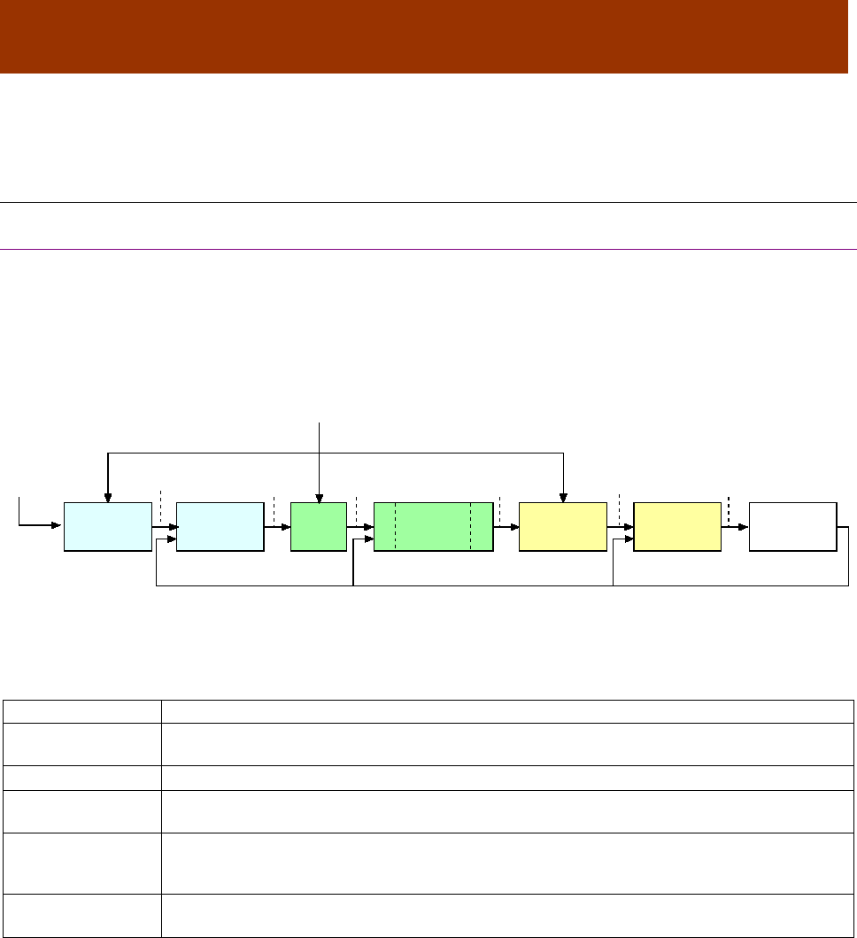
16-01195 Rev 00 117
CHAPTER
7 CONTROL LOOP CONFIGURATION
7.1 Control Loop Configuration Overview
7.1.1 Nested Position, Velocity, and Current Loops
Nesting of Control Loops and Modes
Copley Controls amplifiers use up to three nested control loops - current, velocity, and position - to
control a motor in three associated operating modes.
In position mode, the amplifier uses all three loops. As shown in the typical system illustrated
below, the position loop drives the nested velocity loop, which drives the nested current loop.
In velocity mode, the velocity loop drives the current loop. In current mode, the current loop is
driven directly by external or internal current commands.
Basic Attributes of All Control Loops
These loops (and servo control loops in general) share several common attributes:
Loop Attribute
Description
Command input
Every loop is given a value to which it will attempt to control. For example, the velocity loop
receives a velocity command that is the desired motor speed.
Limits
Limits are set on each loop to protect the motor and/or mechanical system.
Feedback
The nature of servo control loops is that they receive feedback from the device they are
controlling. For example, the position loop uses the actual motor position as feedback.
Gains
These are constant values that are used in the mathematical equation of the servo loop. The
values of these gains can be adjusted during amplifier setup to improve the loop
performance. Adjusting these values is often referred to as tuning the loop.
Output
The loop generates a control signal. This signal can be used as the command signal to another
control loop or the input to a power amplifier.
Target
Position
Position
Command
Actual CurrentDerived VelocityActual Position
Velocity
Command
Current
Command
Limited
Velocity
Limited
Current
PWM
Command
Trajectory
Generator
Position
Loop
Velocity
Limiter
Current
Limiter
Current
Loop
Motor/
Sensors
Limits
Velocity
Loop
FILTER
FILTER
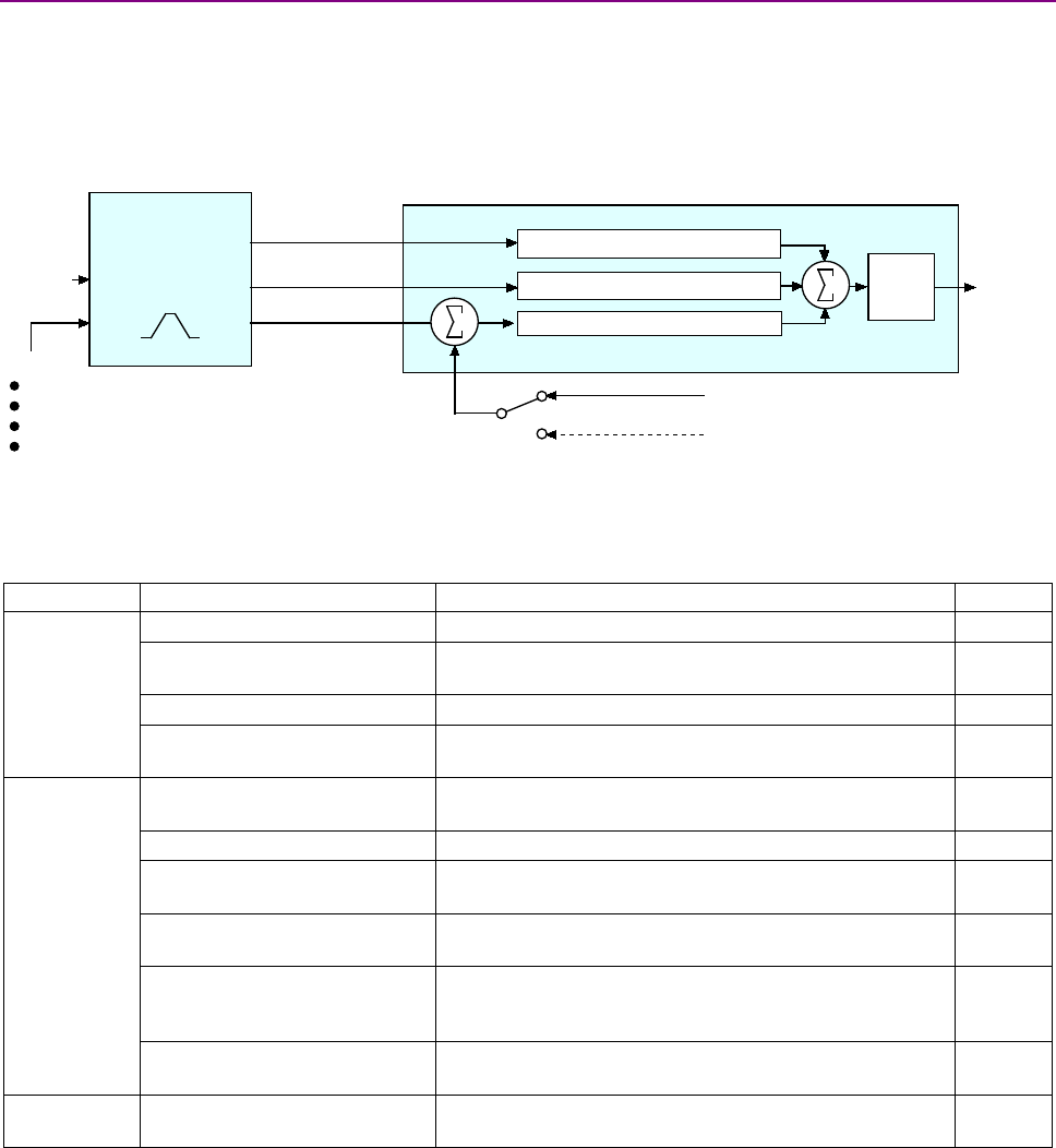
Control Loop Configuration CANopen Programmer’s Manual
118 16-01195 Rev 00
7.1.2 The Position Loop
Position Loop Diagram
The CANopen master provides a target position to the amplifier’s internal trajectory generator. In
turn the generator provides the position loop a position command and velocity and acceleration
limit values. The position loop applies corrective gains in response to feedback to forward a
velocity command to the velocity loop. The inputs to the position loop vary with different operating
modes. The following diagram summarizes the position loop in position profile mode.
Trajectory Generator Inputs and Limits
The inputs to the trajectory generator include profile position, velocity, and acceleration values.
They are accessed through different sets of mode-specific objects as summarized below.
Mode
Input Object Name/ID
Description
Page #
Homing
Homing Method / 0x6098
Defines the method to find the motor home position
175
Homing Speeds / 0x6099
The sub-index objects of 0x6099 hold the two velocities
(fast and slow) used when homing.
176
Homing Acceleration / 0x609A
Defines the acceleration used for all homing moves.
176
Home Offset / 0x607C
Used in homing mode as an offset between the home
sensor position and the zero position.
176
Profile
Position
Motion Profile Type / 0x6086
Selects the type of trajectory profile to use. Choices are
trapezoidal, S-curve, and velocity.
147
Target Position / 0x607A
Destination position of the move.
193
Profile Velocity / 0x6081
The velocity that the trajectory generator attempts to
achieve when running in position profile mode.
146
Profile Acceleration / 0x6083
Acceleration that the trajectory generator attempts to
achieve when running in position profile mode
146
Profile Deceleration / 0x6084
Deceleration that the trajectory generator attempts to
achieve at the end of a trapezoidal profile when running
in position profile mode.
146
Trajectory Jerk Limit / 0x2121
Defines the maximum jerk (rate of change of
acceleration) for use with S-curve profile moves.
197
Interpolated
Position
IP move segment command /
0x2010
Used to send PVT segment data and buffer commands
when running in interpolated position mode.
206
Target
Position Velocity
Command
Trajectory
Generator
Position Loop
Feedback
Limits:
Max velocity
Max accel
Max decel
Abort decel
Position Proportional Gain (Pp)
Velocity Feed Forw ard (Vff)
Acceleration Feed Forw ard (Aff)
Profile Acceleration
Profile Velocity
Limited Position
+
+
-
+
+
Gain
Multiplier
from motor encoder or resolver
from optional position encoder (on load)

CANopen Programmer’s Manual Control Loop Configuration
Copley Controls 119
Position Loop Inputs
Inputs from the trajectory generator to the position loop are described below.
Input Object Name/ID
Description
Page #
Instantaneous Commanded
Velocity / 0x2250
Velocity to which the position loop's velocity feed forward gain is
applied.
131
Instantaneous Commanded
Acceleration / 0x2251
Acceleration to which the position loop's acceleration feed forward
gain is applied.
131
Position Demand Value /
0x6062
Motor position (in units of counts) to which the amplifier is currently
trying to move the axis.
131
Position Loop Feedback
The feedback to the loop is the actual motor position, obtained from a position sensor attached to
the motor (most often a quadrature encoder). This is provided by Position Actual Value object
(index 0x6063, p. 131).
Position Loop Gains
The following gains are used by the position loop to calculate the output value:
Gain
Description
Pp - Position loop proportional
The loop calculates its Position Error (index 0x60F4, p. 134) as the difference
between the Position Actual Value and the Position Demand Value. This error in
turn is multiplied by the proportional gain value. The primary effect of this gain is
to reduce the following error.
Vff - Velocity feed forward
The value of the Instantaneous Commanded Velocity object is multiplied by this
value. The primary effect of this gain is to decrease following error during constant
velocity.
Aff - Acceleration feed forward
The value of the Instantaneous Commanded Acceleration object is multiplied by
this value. The primary effect of this gain is to decrease following error during
acceleration and deceleration.
These gains are accessed through the sub-index objects of the Position Loop Gains object (index
0x2382, sub-index 1-6, p. 134).
Position Loop Output
The output of the position loop is a velocity value that is fed to the velocity loop as a command
input. This output is associated with two objects, as described below.
Output Object Name/ID
Description
Page #
Velocity Command Value /
Index 0x606B
Velocity that the velocity loop is currently trying to attain. In normal
operation, this value is provided by the position loop and is identical to
the Position loop control effort.
Optionally, the velocity loop can be controlled by one of several
alternate control sources. In this case, the Velocity command value
comes from the analog reference input, the digital PWM inputs, or the
internal function generator.
143
Position Loop Control Effort /
Index 0x60FA
Normally, this value is provided by the position loop. When the velocity
loop is driven by an alternate control source, the Position loop control
effort object does not hold a meaningful value.
134
Modulo Count (Position Wrap)
The position variable cannot increase indefinitely. After reaching a certain value the variable rolls
back. This type of counting is called modulo count. See bit 21 of the Manufacturer Status Register
object (index 0x1002, p. 61).
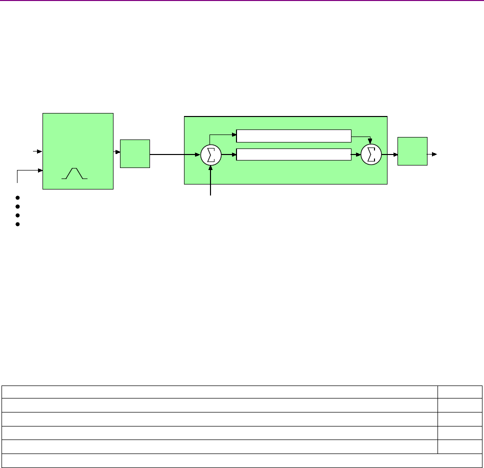
Control Loop Configuration CANopen Programmer’s Manual
120 16-01195 Rev 00
7.1.3 The Velocity Loop
Overview of the Velocity Loop
As shown below, the velocity loop limiting stage accepts a velocity command, applies limits, and
passes a limited velocity command to the input filter. The filter then passes a velocity command to
the summing junction. The summing junction subtracts the actual velocity, represented by the
feedback signal, and produces an error signal. (The velocity loop feedback signal is always from
the motor feedback device even when an additional encoder is attached to the load.) The error
signal is then processed using the integral and proportional gains to produce a current command.
Programmable digital filters are provided on both the input and output command signals.
Velocity Loop Limits
The velocity loop starts with a command limiter. This is useful because the position loop may
produce large spikes in its output velocity command value that are beyond the safe operating
range of the motor. During normal operation, with the velocity loop driven by the position loop, the
limiter requires and accepts only a maximum velocity value.
Optionally, the velocity loop can be driven by an alternate source of control (such as such as the
device’s serial port, digital I/O channels, analog reference, or internal generator), without input
from the position loop. (See Alternative Control Sources Overview) In these cases, the velocity
loop limiter also requires and accepts maximum acceleration and deceleration values. Velocity
limiter parameters are accessed through the following objects:
Limiter Object Name/ID
Page #
Velocity Loop – Maximum Velocity / 0x2103 (used in all control modes)
140
*Velocity Loop Maximum Acceleration / Index 0x2100 (used only without position loop)
140
*Velocity Loop Maximum Deceleration/ Index 0x2101 or 0x60C6 (used only without position loop)
140
Velocity Loop Emergency Stop Deceleration / 0x2102 (used only without position loop)
140
*Not used when velocity loop is controlled by position loop.
Velocity Loop Input
The output of the velocity loop limiter is the input of the velocity loop. It is accessed through the
object Limited Velocity (index 0x2230, p. 141).
Velocity
Command Current
Command
Velocity Limiter
Velocity Loop
Feedback (Derived Velocity)
Limits:
Velocity
Acceleration*
Deceleration*
Emergency Stop Deceleration*
*Not used w hen velocity loop is controlled by position loop. See "Velocity Loop Limits" for details.
Velocity Integral Gain (Vi)
Velocity Proportional Gain (Vp)
Limited
Velocity +
-
+
+
Filter
Filter

CANopen Programmer’s Manual Control Loop Configuration
Copley Controls 121
Velocity Loop Gains
The velocity loop uses the velocity gains. See Velocity Loop Configuration Objects
VELOCITY LOOP MAXIMUM ACCELERATION INDEX 0X2100
Type
Access
Units
Range
Map PDO
Memory
UNSIGNED32
RW
1000 enc counts / sec2
0 to 232-1
TR
RF
Description
This acceleration value limits the maximum rate of change of the commanded velocity input to the
velocity loop. This limit only applies when the absolute value of the velocity change is positive (i.e.
the speed is increasing in either direction).
VELOCITY LOOP MAXIMUM DECELERATION INDEX 0X2101 OR 0X60C6
Type
Access
Units
Range
Map PDO
Memory
UNSIGNED32
RW
1000 enc counts / sec2
0 to 232-1
TR
RF
Description
This acceleration value limits the maximum rate of change of the commanded velocity input to the
velocity loop. This limit only applies when the absolute value of the velocity change is negative
(i.e. the speed is decreasing in either direction). With 0x60C6, user-defined units are possible
using the factor group variables.
VELOCITY LOOP EMERGENCY STOP DECELERATION INDEX 0X2102
Type
Access
Units
Range
Map PDO
Memory
UNSIGNED32
RW
1000 enc counts / sec2
0 to 232-1
TR
RF
Description
The deceleration rate used during the time that the amplifier is trying to actively stop a motor
before applying the brake output.
Also known as the Velocity Loop Fast Stop Ramp.
Note that this feature is not used when the position loop is driving the velocity loop. In that case,
the trajectory generator's abort acceleration is used.
VELOCITY LOOP – MAXIMUM VELOCITY INDEX 0X2103
Type
Access
Units
Range
Map PDO
Memory
INTEGER32
RW
0.1 counts/sec
0 to 232-1
TR
RF
Description
This velocity value is a limit on the commanded velocity used by the velocity loop.
Also known as the Velocity Loop Velocity Limit. The velocity loop's commanded velocity can be
generated by several sources, including the output of the position loop. Velocity Loop-Maximum
Velocity allows that velocity to be limited to a specified amount.
VELOCITY ERROR WINDOW – PROFILE POSITION INDEX 0X2104
Type
Access
Units
Range
Map PDO
Memory
INTEGER32
RW
0.1 counts/sec
0 to 232-1
TR
RF
Description
Also known as the Velocity Tracking Window, this object defines the velocity loop error window. If
the absolute velocity error exceeds this value, then the velocity window bit of the Manufacturer
Status Register object (index 0x1002, p. 61) is set. The Velocity Window bit will only be cleared
when the velocity error has been within the Velocity Error Window for the timeout period defined in
the Velocity Error Window Time object (index 0x2120, p. 68).

Control Loop Configuration CANopen Programmer’s Manual
122 16-01195 Rev 00
VELOCITY ERROR WINDOW TIME INDEX 0X2105
Type
Access
Units
Range
Map PDO
Memory
UNSIGNED16
RW
milliseconds
0 to 216-1
TR
RF
Description
Also known as Velocity Tracking Time. When the absolute velocity error remains below the limit
set in the Velocity Error Window – Profile Position object (index 0x2104, p. 143) the Velocity
Window bit (bit 28) in the Manufacturer Status Register object (index 0x1002, p. 61) is cleared.
VELOCITY LOOP OUTPUT FILTER COEFFICIENTS INDEX 0X2106
Type
Access
Bits
Range
Map PDO
Memory
ARRAY[0..13]
of UINT
RW
224
-
NO
RF
Description
Programs the filter coefficients of a bi-quad filter structure that acts on the velocity loop output.
Contact Copley Controls for more information.
HALL VELOCITY MODE SHIFT VALUE INDEX 0X2107
Type
Access
Units
Range
Map PDO
Memory
UNSIGNED16
RW
-
0 to 65,535
TR
RF
Description
This parameter is only used in Hall velocity mode. It specifies a left shift value for the position and
velocity information calculated in that mode.
VELOCITY LOOP COMMAND FILTER COEFFICIENTS INDEX 0X2108
Type
Access
Units
Range
Map PDO
Memory
ARRAY[0..13]
of UINT
RW
224
-
NO
RF
Description
Programs the filter coefficients of a bi-quad filter structure that acts on the velocity loop input.
Contact Copley Controls for more information.
ANALOG INPUT FILTER COEFFICIENTS INDEX 0X2109
Type
Access
Units
Range
Map PDO
Memory
ARRAY[0..13]
of UINT
RW
224
-
NO
F
Description
Programs the filter coefficients of a bi-quad filter structure that acts on the analog reference input
at servo loop update rate (3 kHz). Contact Copley Controls for more information.
LIMITED VELOCITY INDEX 0X2230
Type
Access
Units
Range
Map PDO
Memory
INTEGER32
RO
0.1 counts/sec
-231 to +231-1
T
R
Description
This is the commanded velocity after it passes through the velocity loop limiter and the velocity
command filter. It is the velocity value that the velocity loop will attempt to achieve.

CANopen Programmer’s Manual Control Loop Configuration
Copley Controls 123
LOAD ENCODER VELOCITY INDEX 0X2231
Type
Access
Units
Range
Map PDO
Memory
INTEGER32
RO
0.1 counts / sec
-231 to +231-1
T
R
Description
Also known as Position Encoder Velocity. Copley Controls supports the use of two encoders on a
system, where the motor encoder is on the motor and the load or position encoder is on the load
(the device being controlled). In such a system, the actual velocity objects read the motor encoder
velocity, and the velocity loop acts on the motor encoder input. Object 0x2231 reads the load
encoder velocity.
UNFILTERED MOTOR ENCODER VELOCITY INDEX 0X2232
Type
Access
Units
Range
Map PDO
Memory
INTEGER32
RO
0.1 enc counts / sec
-231 to +231-1
T
R
Description
Unfiltered motor velocity.
PROGRAMMED VELOCITY COMMAND INDEX 0X2341
Type
Access
Units
Range
Map PDO
Memory
INTEGER32
RW
0.1 counts/sec
-231 to +231-1
TR
RF
Description
Gives the commanded velocity value when running in programmed velocity mode (see mode 11,
Desired State object, p. 66, and Alternative Control Sources Overview, p. 225).
VELOCITY LOOP GAINS INDEX 0X2381
Type
Access
Bits
Range
Map PDO
Memory
Record
RW
112
-
NO
RF
Description
This object contains the various gain values used to optimize the velocity control loop.
VELOCITY LOOP PROPORTIONAL GAIN INDEX 0X2381, SUB-INDEX 1
Type
Access
Units
Range
Map PDO
Memory
UNSIGNED16
RW
-
0 to 65,535
TR
RF
Description
This gain value is multiplied by the velocity loop error. The velocity loop error is the difference
between the desired and actual motor velocity.
VELOCITY LOOP INTEGRAL GAIN INDEX 0X2381, SUB-INDEX 2
Type
Access
Units
Range
Map PDO
Memory
UNSIGNED16
RW
-
0 to 65,535
TR
RF
Description
This gain value is multiplied by the integral of the velocity loop error.
VELOCITY LOOP ACCELERATION FEED FORWARD INDEX 0X2381, SUB-INDEX 3
Type
Access
Units
Range
Map PDO
Memory
UNSIGNED16
RW
-
0 to 65,535
TR
RF
Description
This gain value is multiplied by the Instantaneous Commanded Acceleration (index 0x2251, p.
134) from the trajectory generator. The result is added to the output of the velocity loop.

Control Loop Configuration CANopen Programmer’s Manual
124 16-01195 Rev 00
VELOCITY LOOP GAIN SCALER INDEX 0X2381, SUB-INDEX 4
Type
Access
Units
Range
Map PDO
Memory
INTEGER16
RW
-
-1, 0, +8
TR
RF
Description
Velocity loop output is shifted this many times to arrive at the commanded current value. Positive
values result in a right shift while negative values result in a left shift. The shift allows the velocity
loop gains to have reasonable values for very high or low resolution encoders.
Recommended values for this parameter are 8, 0 or -1.
VELOCITY LOOP VI DRAIN (INTEGRAL BLEED) INDEX 0X2381, SUB-INDEX 5
Type
Access
Units
Range
Map PDO
Memory
UNSIGNED16
RW
-
0 to 65,535
TR
RF
Description
Modifies the effect of velocity loop integral gain. The higher the Vi Drain value, the faster the
integral sum is lowered.
VELOCITY LOOP COMMAND FEED FORWARD INDEX 0X2381, SUB-INDEX 6
Type
Access
Units
Range
Map PDO
Memory
INTEGER16
RW
-
-215 to +215-1
TR
RF
Description
The input command (after limiting) to the velocity loop is scaled by this value and added in to the
output of the velocity loop.
ACTUAL MOTOR VELOCITY INDEX 0X6069
Type
Access
Units
Range
Map PDO
Memory
INTEGER32
RO
0.1 enc counts / sec
-231 to +231-1
T
R
Description
Actual motor velocity.
VELOCITY SENSOR SELECTION INDEX 0X606A
Type
Access
Units
Range
Map PDO
Memory
See description
RW
-
0
TR
R
Description
This object specifies how actual velocity is measured. Currently, Copley Controls drives support
only the use of position encoders for calculation of actual velocity. This should be set to zero.
Any value other than zero will return an error
VELOCITY COMMAND VALUE INDEX 0X606B
Type
Access
Units
Range
Map PDO
Memory
INTEGER32
RO
0.1 counts/sec
-231 to +231-1
T
R
Description
Also known as commanded velocity. The velocity that the velocity loop is currently trying to attain.
When the amplifier is running in homing, profile position, or interpolated position mode, the velocity
command value is the output of the position loop, and the input to the velocity loop.
Copley Controls CANopen amplifiers support some modes in which the velocity command is
produced from a source other than the position loop. In these modes, the command velocity
comes from the analog reference input, the digital PWM inputs, or the internal function generator.
User defined units are achievable using the factor group objects.

CANopen Programmer’s Manual Control Loop Configuration
Copley Controls 125
ACTUAL VELOCITY INDEX 0X606C
Type
Access
Units
Range
Map PDO
Memory
INTEGER32
RO
0.1 counts/sec
-231 to +231-1
T
R
Description
This object contains exactly the same information as object 0x6069.
User defined units are achievable using the factor group objects.
VELOCITY ERROR WINDOW – PROFILE VELOCITY INDEX 0X606D
Type
Access
Units
Range
Map PDO
Memory
UNSIGNED16
RW
0.1 counts/sec
0 to 216-1
TR
R
Description
Object 0x606D holds the same value as index 0x2104. It is included because the CANopen Profile
for Drives and Motion Control (DSP 402) mandates it for support of profile velocity mode operation.
In the Copley Controls implementation, 0x2104 and 0x606D differ only in the data type. Object
0x606D is UNSIGNED16 and 0x2104 is INTEGER32. Changes made to either object affect both
VELOCITY ERROR WINDOW TIME INDEX 0X606E
Type
Access
Units
Range
Map PDO
Memory
UNSIGNED16
RW
milliseconds
0 to 216-1
TR
R
Description
Object 606E holds the same value as 0x2105. It is included because the CANopen Profile for
Drives and Motion Control (DSP 402) mandates it for support of profile velocity mode operation.
Changes made to either 0x606E or 0x2105 affect both objects
VELOCITY THRESHOLD INDEX 0X606F
Type
Access
Units
Range
Map PDO
Memory
UNSIGNED16
RW
0.1 enc counts / sec
0 to 216-1
R
R
Description
This object determines the threshold to use when considering the state of the
speed=0 bit of the status word. User defined units are achievable using the factor group objects
VELOCITY THRESHOLD TIME INDEX 0X6070
Type
Access
Units
Range
Map PDO
Memory
UNSIGNED16
RW
ms
0 to 216-1
R
R
Description
This object shall indicate the configured velocity threshold time.
POSITION RANGE LIMIT INDEX 0X607B
Type
Access
Bits
Range
Map PDO
Memory
RECORD
RW
80
-
R
R
Description
This object indicates the maximum and minimum position range limits applied to the Position
Demand values. On reaching either limit the drive will wrap to the other. Wrap-around can be
prevented by setting the Software Position Limits inside the Position Range Limits.
Sub-index 0 contains the number of sub-elements in this record.
MINIMUM POSITION RANGE LIMIT INDEX 0X607B, SUB-INDEX 1
Type
Access
Units
Range
Map PDO
Memory
INTEGER32
RW
counts
-231 to +231-1
R
R
Description
User defined units are achievable using the factor group objects.

Control Loop Configuration CANopen Programmer’s Manual
126 16-01195 Rev 00
MAXIMUM POSITION RANGE LIMIT INDEX 0X607B , SUB-INDEX 2
Type
Access
Units
Range
Map PDO
Memory
INTEGER32
RW
counts
-231 to +231-1
R
R
Description
User defined units are achievable using the factor group objects.
SOFTWARE POSITION LIMITS INDEX 0X607D
Type
Access
Bits
Range
Map PDO
Memory
ARRAY
RW
80
-
R
RF
Description
This object holds the maximum and minimum absolute position limits for the Position Demand
value and Position Actual value. They are only in effect after the drive has been referenced
(Homing is successful). User defined units are achievable using the factor group objects.
MINIMUM SOFTWARE POSITION LIMIT INDEX 0X607D, SUB-INDEX 1
Type
Access
Units
Range
Map PDO
Memory
INTEGER32
RW
counts
-231 to +231-1
TR
RF
Description
Software limits are only in effect after the amplifier has been referenced (i.e. homing has been
successfully completed). Set to less than negative software limit to disable.
MAXIMUM SOFTWARE POSITION LIMIT INDEX 0X607D, SUB-INDEX 2
Type
Access
Units
Range
Map PDO
Memory
INTEGER32
RW
counts
-231 to +231-1
TR
RF
Description
Software limits are only in effect after the amplifier has been referenced (i.e. homing has been
successfully completed). Set to greater than positive software limit to disable.
MAXIMUM PROFILE VELOCITY INDEX 0X607F
Type
Access
Units
Range
Map PDO
Memory
UNSIGNED32
RW
User Defined
0 to 232-1
R
R
Description
The maximum allowed velocity in either direction during a profile velocity move.
The units are user-defined via Factor Group settings.
VELOCITY LOOP GAINS INDEX 0X60F9
Type
Access
Units
Range
Map PDO
Memory
RECORD
RW
-
-
YES
R
Description:
This object is no longer recommended. Use object 0x2381 (p.145). This object contains the
various gain values used to optimize the velocity control loop.

CANopen Programmer’s Manual Control Loop Configuration
Copley Controls 127
TARGET VELOCITY INDEX 0X60FF
Type
Access
Units
Range
Map PDO
Memory
INTEGER32
RW
0.1 counts/sec
-231 to +231-1
TR
R
Description
In profile velocity mode, this object is an input to the amplifier’s internal trajectory generator. Any
change to the target velocity triggers an immediate update to the trajectory generator.
Note that this is different from the way the profile position works. In that mode, changing the
trajectory input parameters doesn't affect the trajectory generator until bit 4 of the Control Word
object (index 0x6040, p. 59) has been changed from 0 to 1.
User defined units are achievable using the factor group objects
MAXIMUM MOTOR SPEED INDEX 0X6080
Type
Access
Units
Range
Map PDO
Memory
UNSIGNED32
RW
RPM
0 to 232-1
NO
R
Description
The maximum motor speed allowable in either direction. Typically found in the motor’s
specifications.
PROFILE VELOCITY INDEX 0X6081
Type
Access
Units
Range
Map PDO
Memory
UNSIGNED32
RW
0.1 counts/sec
0 to 232-1
TR
R
Description
In profile position mode, this value is the velocity that the trajectory generator will attempt to
achieve. Note that the value programmed here is not passed to the internal trajectory generator
until the move has been started or updated using the Control Word. See Profile Position Mode
Operation, p. 189, for more information.
END VELOCITY INDEX 0X6082
Type
Access
Units
Range
Map PDO
Memory
UNSIGNED32
RW
0.1 counts/sec
0 to 232-1
NO
R
Description
This object indicates the targeted velocity that the drive shall have upon reaching the target
position. Normally, the drive would use an end velocity of 0.
User defiend units are achievable using the factor group objects.
Note: This object is only supported with the trapazoidal trajectory generator.
PROFILE ACCELERATION INDEX 0X6083
Type
Access
Units
Range
Map PDO
Memory
UNSIGNED32
RW
10 counts/sec2
0 to 232-1
TR
RF
Description
In profile position mode, this value is the acceleration that the trajectory generator attempts to
achieve. For S-curve moves, this value is also used to decelerate at the end of the move.
Note that the value programmed here is not passed to the internal trajectory generator until the
move has been started or updated using the Control Word. See Profile Position Mode Operation,
p. 189, for more information.
User defined units are achievable using the factor group objects.

Control Loop Configuration CANopen Programmer’s Manual
128 16-01195 Rev 00
PROFILE DECELERATION INDEX 0X6084
Type
Access
Units
Range
Map PDO
Memory
UNSIGNED32
RW
10 counts/sec2
0 to 232-1
TR
RF
Description
Deceleration that the trajectory generator uses at the end of a trapezoidal profile when running in
position profile mode.
Note that this value is only used when running trapezoidal or profile position special velocity mode
profiles. The S-curve profile generator uses the Profile Acceleration object (index 0x6083, p. 149)
as the acceleration target for both the start and end of moves.
Note that the value programmed here is not passed to the internal trajectory generator until the
move has been started or updated using the Control Word. See Profile Position Mode Operation,
p. 189, for more information.
User defined units are achievable using the factor group objects.
QUICK STOP DECELERATION INDEX 0X6085
Type
Access
Units
Range
Map PDO
Memory
UNSIGNED32
RW
10 counts/sec2
0 to 232-1
TR
RF
Description
Also known as Trajectory Abort Deceleration. This object gives the deceleration value used when
a trajectory needs to be stopped as the result of a quick stop command.
When a quick stop command is issued, the command velocity is decreased by this value until it
reaches zero. This occurs in all position modes (homing, profile position, and interpolated position
modes), and for all trajectory generators (trapezoidal and S-curve).
Note that unlike most trajectory configuration values, this value is NOT buffered. Therefore, if the
value of this object is updated during an abort, the new value is used immediately.
Also note that setting this object to zero causes the abort to run with unlimited deceleration. The
command velocity is immediately set to zero.
User defined units are achievable using the factor group objects.
MOTION PROFILE TYPE INDEX 0X6086
Type
Access
Units
Range
Map PDO
Memory
INTEGER16
RW
-
See Description, below.
TR
R
Description
This object selects the type of trajectory profile to use when running in profile position mode. The
supported values for this object are:
Mode
Description
0
Trapezoidal profile mode.
3
S-curve profile mode (Jerk limited).
-1
Velocity mode.
The amplifier will not accept other values. See Profile Position Mode Operation, p. 189, for more
information.
Note that the value programmed here is not passed to the internal trajectory generator until the
move has been started or updated using the Control Word. See Profile Position Mode Operation,
p. 189, for more information.
CANopen Programmer’s Manual Control Loop Configuration
Copley Controls 129
PROFILE JERK INDEX 0X60A4
Type
Access
Bits
Range
Map PDO
Memory
ARRAY
RW
48
-
NO
R
Description
Indicates the configured set of jerk parameters that can be used during profile moves.
Sub-index 0 holds the number of elements in this object.
PROFILE JERK 1 INDEX 0X60A4 SUB-INDEX 1
Type
Access
Units
Range
Map PDO
Memory
UNSIGNED32
RW
User Defined
0 to 232-1
NO
R
Description
Operates the same as 0x2121, but uses Factor Group units which are user-defined.
VELOCITY LOOP MAXIMUM ACCELERATION INDEX 0X60C5
Type
Access
Units
Range
Map PDO
Memory
UNSIGNED32
RW
User Defined
0 to 232-1
R
R
Description
This acceleration value limits the maximum rate of change of the commanded velocity input to the
velocity loop. This limit only applies when the absolute value of the velocity change is positive (i.e.
the speed is increasing in either direction).
VELOCITY LOOP MAXIMUM DECELERATION INDEX 0X60C6
Type
Access
Units
Range
Map PDO
Memory
UNSIGNED32
RW
User Defined
0 to 232-1
R
R
Description
This acceleration value limits the maximum rate of change of the commanded velocity input to the
velocity loop. This limit only applies when the absolute value of the velocity change is negative (i.e.
the speed is decreasing in either direction).
(index 0x2381, p. 142).
Gain
Description
Vp - Velocity loop
proportional
The velocity error (the difference between the actual and the limited commanded velocity) is
multiplied by this gain. The primary effect of this gain is to increase bandwidth (or decrease the
step-response time) as the gain is increased.
Vi - Velocity loop
integral
The integral of the velocity error is multiplied by this value. Integral gain reduces the velocity error
to zero over time. It controls the DC accuracy of the loop, or the flatness of the top of a square
wave signal. The error integral is the accumulated sum of the velocity error value over time.
Velocity Loop Filters
The velocity loop contains two programmable digital filters. The input filter should be used to
reduce the effects of a noisy velocity command signal. The output filter can be used to reduce the
excitation of any resonance in the motion system.
Two filter classes can be programmed: the Low-Pass and the Custom Bi-Quadratic. The Low-Pass
filter class includes the Single-Pole and the Two-Pole Butterworth filter types. The Custom Bi-
Quadratic filter allows advanced users to define their own filters incorporating two poles and two
zeros.
Program the filters using Velocity Loop Output Filter Coefficients (index 0x2106, p. 141) and
Velocity Loop Command Filter Coefficients (index 0x2108, p. 141).
Velocity Loop Output
The output of the velocity loop is accessed in the Commanded Current object (index 0x221D, p.
150).
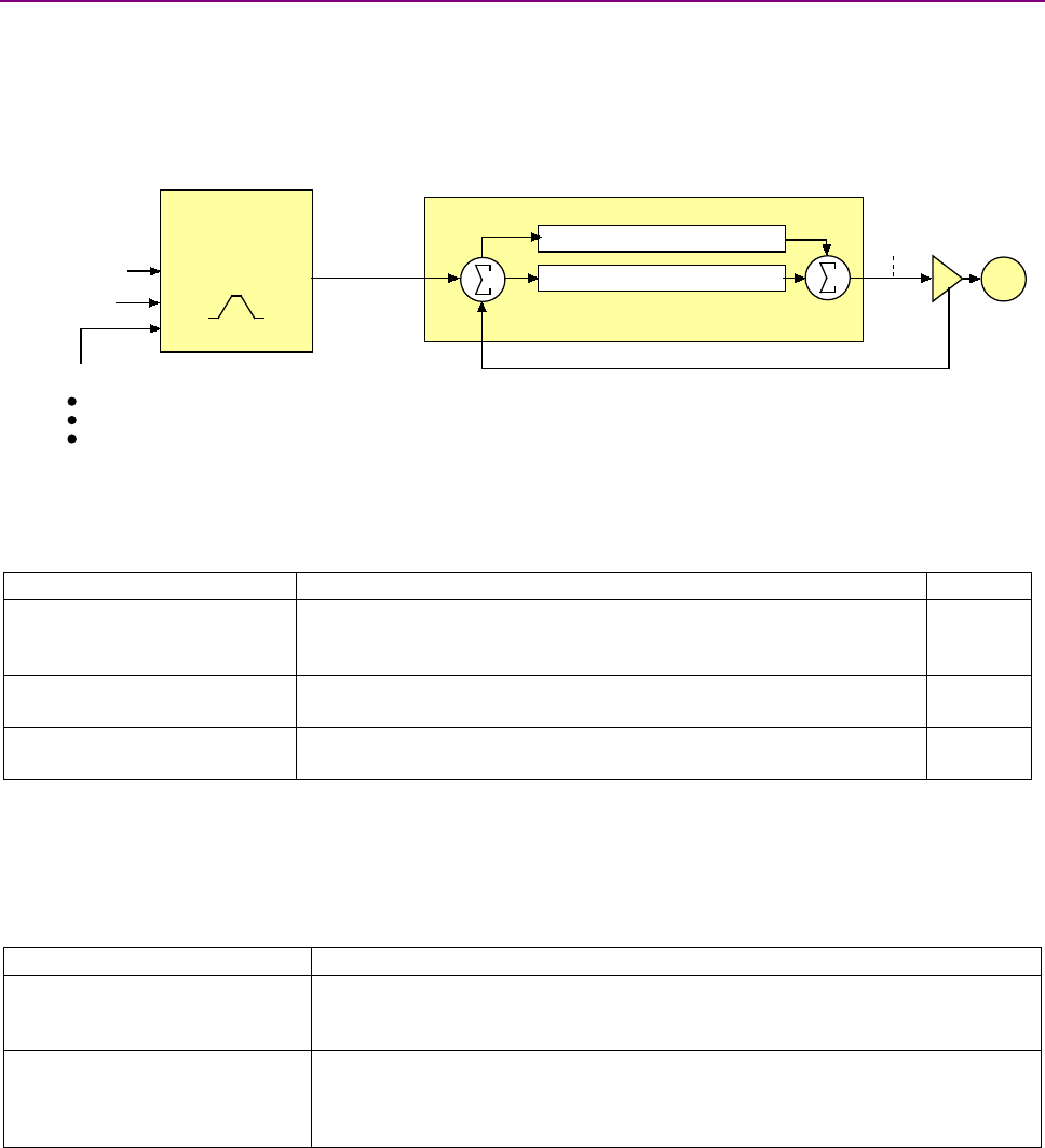
Control Loop Configuration CANopen Programmer’s Manual
130 16-01195 Rev 00
7.1.4 The Current Loop
Overview of the Current Loop
As shown below, the current limiter accepts a current command from the velocity loop, applies
limits, and passes a limited current value to the summing junction. The summing junction takes the
commanded current, subtracts the actual current (represented by the feedback signal), and
produces an error signal. This error signal is then processed using the integral and proportional
gains to produce a command. This command is then applied to the amplifier’s power stage.
Current Loop Limits
The commanded current value is first reduced based on a set of current limit parameters designed
to protect the motor. These current limits are accessed through the following objects:
Output Object Name/ID
Description
Page #
User Peak Current Limit /
0x2110
Maximum current that can be generated by the amplifier for a short
duration of time. This value cannot exceed the peak current rating of
the amplifier.
149
User Continuous Current Limit
/ 0x2111
Maximum current that can be constantly generated by the amplifier.
149
User Peak Current Limit Time /
0x2112
Maximum amount of time that the peak current can be applied to the
motor before it must be reduced to the continuous limit.
149
Current Loop Input
The output of the current limiting block is the input to the current loop. It is accessed through the
object Limited Current object (index 0x221E, p. 150).
Current Loop Gains
The current loop uses these gains:
Gain
Description
Cp - Current loop proportional
The current error (the difference between the actual and the limited commanded
current) is multiplied by this value. The primary effect of this gain is to increase
bandwidth (or decrease the step-response time) as the gain is increased.
Ci - Current loop integral
The integral of the current error is multiplied by this value. Integral gain reduces
the current error to zero over time. It controls the DC accuracy of the loop, or the
flatness of the top of a square wave signal. The error integral is the accumulated
sum of the current error value over time.
These gains are represented by Current Loop Gains (index 0x2380, p.151) and its sub-index
objects.
Current Loop Output
The output of the current loop is a command that sets the duty cycle of the PWM output stage of
the amplifier.
Current Command
PWM
Command
Current Limiter
Current Loop
Feedback (Actual Current)
Limits:
Peak Current
Continuous Current
Peak Current Limit Time
Current Integral Gain (Ci)
Current Proportional Gain (Cp)
Limited Current +
-
+
+Motor
Current Offset

CANopen Programmer’s Manual Control Loop Configuration
Copley Controls 131
7.2 Position Loop Configuration Objects
INSTANTANEOUS COMMANDED VELOCITY INDEX 0X2250
Type
Access
Units
Range
Map PDO
Memory
INTEGER32
RO
0.1 counts / sec
0 to 232-1
T
R
Description
This is the velocity output from the trajectory generator. It is the velocity by which the position
loop's Position Loop Velocity Feed Forward gain (Index 0x2382, Sub-Index 2, p. 134) is multiplied.
INSTANTANEOUS COMMANDED ACCELERATION INDEX 0X2251
Type
Access
Units
Range
Map PDO
Memory
UNSIGNED32
RO
10 counts / sec2
0 to (232-1)/10 counts/sec2
T
R
Description
This is the acceleration output from the trajectory generator. It is the acceleration by which the
position loop's gain (Index 0x2382, Sub-Index 3, p. 134) is multiplied.
POSITION DEMAND VALUE INDEX 0X6062
Type
Access
Units
Range
Map PDO
Memory
INTEGER32
RO
counts
-231 to +231 -1
T
R
Description
This is the motor position (in units of counts) to which the amplifier is currently trying to move the
axis. This value is updated every servo cycle based on the amplifier's internal trajectory generator.
Identical to Position Demand Value (index 0x60FC. p. 145).
POSITION ACTUAL VALUE INDEX 0X6063
Type
Access
Units
Range
Map PDO
Memory
INTEGER32
RW
counts
-231 to +231 -1
T
R
Description
This is the actual motor position as calculated by the amplifier every servo cycle based on the
state of the encoder input lines, and as used by the position loop. For single encoder systems, this
is the same as the Motor Encoder Position object (index 0x2240). For dual encoder systems, it is
the same as Load Encoder Position (index 0x2242, p. 138).
POSITION ACTUAL VALUE INDEX 0X6064
Type
Access
Units
Range
Map PDO
Memory
INTEGER32
RW
counts
-231 to +231 -1
T
R
Description
This object holds the same value as Position Actual Value object (index 0x6063, p. 131). User
defined units are achievable using the factor group objects.

Control Loop Configuration CANopen Programmer’s Manual
132 16-01195 Rev 00
TRACKING WARNING WINDOW INDEX 0X6065
Type
Access
Units
Range
Map PDO
Memory
UNSIGNED32
RW
counts
0 to +232 -1
TR
RF
Description
This object holds the maximum position error that the amplifier will tolerate before indicating a
tracking warning. If the absolute position error (defined as the difference between the actual motor
position and the position command value) exceeds this window, then the warning bit (bit 19) of the
Manufacturer Status Register (index 0x1002, p. 61) is set.
Note that this following error window generates a warning, not an amplifier fault. A separate
tracking error window may be programmed which will cause an amplifier fault condition if
exceeded. See the Tracking Error Window object (index 0x2120, p. 68) for details.
User defined units are achievable using the factor group objects.
FOLLOWING ERROR TIMEOUT INDEX 0X6066
Type
Access
Units
Range
Map PDO
Memory
UNSIGNED16
RW
ms
0 – 32,768
TR
RF
Description
This object shall indicate the configured time for a following error condition.
POSITION TRACKING WINDOW INDEX 0X6067
Type
Access
Units
Range
Map PDO
Memory
UNSIGNED32
RW
counts
0 to +232 -1
TR
RF
Description
Size of the amplifier's tracking window. When the absolute position error of the motor is less than
or equal to the position tracking window value, the motor is considered to be tracking the desired
position correctly. This is true both when moving and when resting in position.
The target reached bit (bit 10) is set in the Status Word (index 0x6041, p. 60) when the amplifier
has finished running a trajectory, and the position error has been within the position tracking
window for the programmed time.
The Manufacturer Status Register (index 0x1002, p. 61) has two bits that are affected by the
tracking window. Bit 25 is set any time the motor position has fallen outside the position tracking
window (whether in motion or not), and bit 27 is set when the motor position is outside the position
tracking window, or the amplifier is in motion.
User defined units are achievable using the factor group objects.
POSITION TRACKING WINDOW TIME INDEX 0X6068
Type
Access
Units
Range
Map PDO
Memory
UNSIGNED16
RW
milliseconds
0 to +216 -1
TR
RF
Description
Accesses the time component of the position tracking window. The motor will only be treated as
tracking properly when the position error has been within the Position Tracking Window (index
0x6067, p. 132) for at least this long. The tracking window bit (bit 25) in the Manufacturer Status
Register (index 0x1002, p. 61) will not be cleared until the position has been within the position
tracking window for at least this long.

CANopen Programmer’s Manual Control Loop Configuration
Copley Controls 133
MAXIMUM SLIPPAGE-PROFILE VELOCITY MODE INDEX 0X60F8
Type
Access
Units
Range
Map PDO
Memory
UNSIGNED32
RW
counts
0 - 2,147,483,647
TR
R
Description
Object 60F8 is included because the CANopen Profile for Drives and Motion Control (DSP 402)
mandates it for support of profile velocity mode operation. This object is identical to Tracking
Warning Window (index 0x6065, p. 132). A change to either object is reflected in the other.
User defined units are achievable using the factor group objects.

Control Loop Configuration CANopen Programmer’s Manual
134 16-01195 Rev 00
POSITION ERROR (FOLLOWING ERROR ACTUAL VALUE) INDEX 0X60F4
Type
Access
Units
Range
Map PDO
Memory
INTEGER32
RO
counts
-231 to +231 -1
T
R
Description
Also known as following error. This object gives the difference, in units of counts, between the
Position Actual Value object (index 0x6063, p. 131) and the Position Demand Internal Value object
(index 0x60FC, p. 137).
This value is calculated as part of the position control loop. It is also the value that the various
tracking windows are compared to. See Tracking Warning Window object (index 0x60FC, p. 137),
Position Tracking Window object (index 0x6067, p. 132), and Tracking Error Window object (index
0x2120, p. 68).
User defined units are achievable using the factor group objects.
POSITION LOOP CONTROL EFFORT INDEX 0X60FA
Type
Access
Units
Range
Map PDO
Memory
INTEGER32
RO
-
-231 to +231 -1
T
R
Description
The position loop produces a command effort as the output of the position control loop. This object
gives access to that value. Most common, this value represents the input to the velocity loop.
When the velocity loop is enabled the default units are 0.1 counts/sec.
POSITION LOOP GAINS INDEX 0X2382
Type
Access
Bits
Range
Map PDO
Memory
RECORD
RW
128
-
YES
RF
Description
This object contains the various gain values used to optimize the position control loop. Sub-index 0
contains the number of sub-elements of this record.
POSITION LOOP PROPORTIONAL GAIN INDEX 0X2382, SUB-INDEX 1
Type
Access
Units
Range
Map PDO
Memory
UNSIGNED16
RW
Integers
0 to 65,535
TR
RF
Description
This gain value is multiplied by the position loop error. The position loop error is the difference
between the Position Demand Value (index 0x60FC, p. 137) and the Position Actual Value (index
0x6064, p. 131).
POSITION LOOP VELOCITY FEED FORWARD INDEX 0X2382, SUB-INDEX 2
Type
Access
Units
Range
Map PDO
Memory
UNSIGNED16
RW
Integers
0 to 65,535
TR
RF
Description
This value is multiplied by the Instantaneous Commanded Velocity (index 0x2250, p. 131)
generated by the trajectory generator. The product is added to the output of the position loop.
This gain is scaled by 1/16384. Therefore, setting this gain to 0x4000 (16384) would cause the
input velocity to be multiplied by 1.0, and the result added to the output of the position loop.
POSITION LOOP ACCELERATION FEED FORWARD INDEX 0X2382, SUB-INDEX 3
Type
Access
Units
Range
Map PDO
Memory
UNSIGNED16
RW
-
0 to 65,535
TR
RF
Description
This value is multiplied by the Instantaneous Commanded Acceleration (index 0x2251, p. 131)
generated by the trajectory generator. The product is added to the output of the position loop.

CANopen Programmer’s Manual Control Loop Configuration
Copley Controls 135
POSITION LOOP OUTPUT GAIN MULTIPLIER INDEX 0X2382, SUB-INDEX 4
Type
Access
Units
Range
Map PDO
Memory
UNSIGNED16
RW
Integers
0 to 65,535
TR
RF
Description
The output of the position loop is multiplied by this value before being passed to the velocity loop.
This scaling factor is calculated such that a value of 100 is a 1.0 scaling factor.
This parameter is most useful in dual loop systems.
POSITION LOOP INTEGRAL GAIN (KI) INDEX 0X2382, SUB-INDEX 5
Type
Access
Units
Range
Map PDO
Memory
INTEGER16
RW
Integers
0 to 32,767
TR
RF
Description
This gain value is multiplied by the integral of the position loop error.
POSITION LOOP DERIVATIVE GAIN (KD) INDEX 0X2382, SUB-INDEX 6
Type
Access
Units
Range
Map PDO
Memory
INTEGER16
RW
Integers
0 to 32,767
TR
RF
Description
This gain value is multiplied by the derivative of the position loop error.
POSITION LOOP PI DRAIN (INTEGRAL BLEED) INDEX 0X2382, SUB-INDEX 7
Type
Access
Units
Range
Map PDO
Memory
INTEGER16
RW
Integers
0 to 32,767
TR
RF
Description
Modifies the effect of position loop integral gain. The higher the Pi Drain value, the faster the
integral sum is lowered.

Control Loop Configuration CANopen Programmer’s Manual
136 16-01195 Rev 00
POSITION LOOP GAINS INDEX 0X60FB
Type
Access
Units
Range
Map PDO
Memory
Record
RW
-
-
YES
R
Description:
This object is no longer recommended. Use object 0x2382 (p.134). This object contains the
various gain values used to optimize the position control loop. Sub-index 0 contains the number of
sub-elements of this record.
POSITION LOOP PROPORTIONAL GAIN INDEX 0X60FB, SUB-INDEX 1
Type
Access
Units
Range
Map PDO
Memory
INTEGER16
RW
Integers
0 to 32,767
TR
R
Description:
This gain value is multiplied by the position loop error. The position loop error is the difference
between the Position Demand Value (index 0x60FC, p. 137) and the Position Actual Value (index
0x6064, p. 131).
POSITION LOOP VELOCITY FEED FORWARD INDEX 0X60FB, SUB-INDEX 2
Type
Access
Units
Range
Map PDO
Memory
INTEGER16
RW
Integers
0 to 32,767
TR
R
Description:
This value is multiplied by the Instantaneous Commanded Velocity (index 0x2250, p. 131)
generated by the trajectory generator. The product is added to the output of the position loop.
This gain is scaled by 1/16384. Therefore, setting this gain to 0x4000 (16384) would cause the
input velocity to be multiplied by 1.0, and the result added to the output of the position loop.
POSITION LOOP ACCELERATION FEED FORWARD INDEX 0X60FB, SUB-INDEX 3
Type
Access
Units
Range
Map PDO
Memory
INTEGER16
RW
Integers
0 to 32,767
TR
R
Description:
This value is multiplied by the Instantaneous Commanded Acceleration (index 0x2251, p. 131)
generated by the trajectory generator. The product is added to the output of the position loop.
POSITION LOOP OUTPUT GAIN MULTIPLIER INDEX 0X60FB, SUB-INDEX 4
Type
Access
Units
Range
Map PDO
Memory
UNSIGNED16
RW
Integers
0 to 65,535
TR
R
Description
The output of the position loop is multiplied by this value before being passed to the velocity loop.
This scaling factor is calculated such that a value of 100 is a 1.0 scaling factor.
This parameter is most useful in dual loop systems.
POSITION LOOP INTEGRAL GAIN (KI) INDEX 0X60FB , SUB-INDEX 5
Type
Access
Units
Range
Map PDO
Memory
UNSIGNED16
RW
Integers
0 to 65,535
TR
R
Description
This gain value is multiplied by the integral of the position loop error.
POSITION LOOP DERIVATIVE GAIN (KD) INDEX 0X60FB , SUB-INDEX 6
Type
Access
Units
Range
Map PDO
Memory
UNSIGNED16
RW
-
0 to 65,535
TR
R
Description
This gain value is multiplied by the derivative of the position loop error.

CANopen Programmer’s Manual Control Loop Configuration
Copley Controls 137
POSITION LOOP PI DRAIN (INTEGRAL BLEED) INDEX 0X60FB , SUB-INDEX 7
Type
Access
Units
Range
Map PDO
Memory
UNSIGNED16
RW
-
0 to 65,535
TR
R
Description
Modifies the effect of position loop integral gain. The higher the Pi Drain value, the faster the
integral sum is lowered.
CROSS COUPLING PROPORTIONAL (KP) GAIN INDEX 0X2378
Type
Access
Units
Range
Map PDO
Memory
INTEGER16
RW
-
-32,768 to +32,767
NO
RF
Description
Only supported on dual axis drives. This gain is applied to the difference in position error of the
two axes.
CROSS COUPLING INTEGRAL (KI ) GAIN INDEX 0X2379
Type
Access
Units
Range
Map PDO
Memory
INTEGER16
RW
-
-32,768 to +32,767
NO
RF
Description
Only supported on dual axis drives. This gain is applied to the difference in position error of the
two axes.
CROSS COUPLING DRAIN (KD) GAIN INDEX 0X237A
Type
Access
Units
Range
Map PDO
Memory
INTEGER16
RW
-
-32,768 to +32,767
NO
RF
Description
Only supported on dual axis drives. This gain is applied to the difference in position error of the
two axes.
POSITION DEMAND INTERNAL VALUE INDEX 0X60FC
Type
Access
Units
Range
Map PDO
Memory
INTEGER32
RO
counts
-231 to +231-1
T
R
Description
This value is the output of the trajectory generator, and represents the commanded position input
to the position control loop. Each servo cycle the trajectory generator will update this value, and
the position loop will attempt to drive the motor to this position. Identical to Position Demand Value
(index 0x6062, p. 131).

Control Loop Configuration CANopen Programmer’s Manual
138 16-01195 Rev 00
SOFTWARE LIMIT DECELERATION INDEX 0X2253
Type
Access
Units
Range
Map PDO
Memory
UNSIGNED32
RW
10 counts / sec2
0 to 232-1
TR
RF
Description
The deceleration rate used when approaching a software limit.
MOTOR ENCODER POSITION INDEX 0X2240
Type
Access
Units
Range
Map PDO
Memory
INTEGER32
RW
counts
0 to 232-1
TR
R
Description
For single-encoder systems, this is the same as the Position Actual Value object (index 0x6063, p.
131). For dual-encoder systems this gives the motor position rather than the load encoder position.
For more information, see Load Encoder Velocity (index 0x2231, p. 142).
LOAD ENCODER POSITION INDEX 0X2242
Type
Access
Units
Range
Map PDO
Memory
INTEGER32
RW
counts
0 to 232-1
TR
R
Description
For dual encoder systems, this object gives the load (position) encoder position and is the same as
the Position Actual Value object (index 0x6063, p. 131). For single encoder systems, this object is
not used.
MINIMUM PWM PULSE WIDTH INDEX 0X2323
Type
Access
Units
Range
Map PDO
Memory
INTEGER16
RW
microseconds
-32,768 to +32,767
NO
RF
Description
Minimum PWM pulse width in microseconds. Used when running in PWM position mode. In this
mode the PWM input pulse width is captured by the drive and used to calculate an absolute
position using the following formula:
pos = ((PW-MIN) / (MAX-MIN)) * SCALE + OFFSET
where this parameter is the minimum pulse width (MIN), parameter 0x13D is the maximum pulse
width (MAX), parameter 0xA9 is the scaling factor (SCALE) and parameter 0x10F is the offset
(OFFSET).
MAXIMUM PWM PULSE WIDTH INDEX 0X2324
Type
Access
Units
Range
Map PDO
Memory
INTEGER16
RW
microseconds
-32,768 to +32,767
NO
RF
Description
Maximum PWM pulse width used when running in PWM position mode.
7.3 Xenus Regen Resistor Objects
XENUS REGEN RESISTOR RESISTANCE INDEX 0X2150
Type
Access
Units
Range (ohm)
Map PDO
Memory
UNSIGNED16
RW
0.01 Ω
0 to 655 ohm
TR
RF
Description
Regen resistor resistance.

CANopen Programmer’s Manual Control Loop Configuration
Copley Controls 139
XENUS REGEN RESISTOR CONTINUOUS POWER INDEX 0X2151
Type
Access
Units
Range
Map PDO
Memory
UNSIGNED16
RW
watts
0 to 65,535
TR
RF
Description
Regen resistor, continuous power.
XENUS REGEN RESISTOR PEAK POWER INDEX 0X2152
Type
Access
Units
Range
Map PDO
Memory
UNSIGNED16
RW
watts
0 to 65,535
TR
RF
Description
Regen resistor, peak power.
XENUS REGEN RESISTOR PEAK TIME INDEX 0X2153
Type
Access
Units
Range
Map PDO
Memory
UNSIGNED16
RW
milliseconds
0 to 65,535
TR
RF
Description
This parameter contains data to be sent to the SPI network. Bit-mapped:
Regen resistor, peak time at peak power.
XENUS REGEN RESISTOR TURN-ON VOLTAGE INDEX 0X2154
Type
Access
Units
Range (Vdc)
Map PDO
Memory
UNSIGNED16
RW
0.1 Vdc
0 to 6,554
TR
RF
Description
Regen resistor, turn-on voltage.
XENUS REGEN RESISTOR TURN-OFF VOLTAGE INDEX 0X2155
Type
Access
Units
Range (Vdc)
Map PDO
Memory
UNSIGNED16
RW
0.1 Vdc
0 to 6,554
TR
RF
Description
Regen resistor, turn-off voltage.
XENUS REGEN RESISTOR MODEL STRING INDEX 0X2156
Type
Access
Bits
Range
Map PDO
Memory
STRING[40]
RW
320
-
NO
F
Description
Regen resistor model number string.
XENUS REGEN RESISTOR STATUS INDEX 0X2157
Type
Access
Units
Range
Map PDO
Memory
INTEGER16
RO
-
See Description, below.
T
R
Description
Describes regen system status. Bit-mapped as follows:
Bit
Description
0
Set if the regen circuit is currently closed.
1
Set if regen is required based on bus voltage.
2
Set if the regen circuit is open due to an overload condition. The overload may be caused by either the
resistor settings or the internal amplifier protections.
3-15
Reserved for future use.

Control Loop Configuration CANopen Programmer’s Manual
140 16-01195 Rev 00
7.4 Velocity Loop Configuration Objects
VELOCITY LOOP MAXIMUM ACCELERATION INDEX 0X2100
Type
Access
Units
Range
Map PDO
Memory
UNSIGNED32
RW
1000 enc counts / sec2
0 to 232-1
TR
RF
Description
This acceleration value limits the maximum rate of change of the commanded velocity input to the
velocity loop. This limit only applies when the absolute value of the velocity change is positive (i.e.
the speed is increasing in either direction).
VELOCITY LOOP MAXIMUM DECELERATION INDEX 0X2101 OR 0X60C6
Type
Access
Units
Range
Map PDO
Memory
UNSIGNED32
RW
1000 enc counts / sec2
0 to 232-1
TR
RF
Description
This acceleration value limits the maximum rate of change of the commanded velocity input to the
velocity loop. This limit only applies when the absolute value of the velocity change is negative
(i.e. the speed is decreasing in either direction). With 0x60C6, user-defined units are possible
using the factor group variables.
VELOCITY LOOP EMERGENCY STOP DECELERATION INDEX 0X2102
Type
Access
Units
Range
Map PDO
Memory
UNSIGNED32
RW
1000 enc counts / sec2
0 to 232-1
TR
RF
Description
The deceleration rate used during the time that the amplifier is trying to actively stop a motor
before applying the brake output.
Also known as the Velocity Loop Fast Stop Ramp.
Note that this feature is not used when the position loop is driving the velocity loop. In that case,
the trajectory generator's abort acceleration is used.
VELOCITY LOOP – MAXIMUM VELOCITY INDEX 0X2103
Type
Access
Units
Range
Map PDO
Memory
INTEGER32
RW
0.1 counts/sec
0 to 232-1
TR
RF
Description
This velocity value is a limit on the commanded velocity used by the velocity loop.
Also known as the Velocity Loop Velocity Limit. The velocity loop's commanded velocity can be
generated by several sources, including the output of the position loop. Velocity Loop-Maximum
Velocity allows that velocity to be limited to a specified amount.
VELOCITY ERROR WINDOW – PROFILE POSITION INDEX 0X2104
Type
Access
Units
Range
Map PDO
Memory
INTEGER32
RW
0.1 counts/sec
0 to 232-1
TR
RF
Description
Also known as the Velocity Tracking Window, this object defines the velocity loop error window. If
the absolute velocity error exceeds this value, then the velocity window bit of the Manufacturer
Status Register object (index 0x1002, p. 61) is set. The Velocity Window bit will only be cleared
when the velocity error has been within the Velocity Error Window for the timeout period defined in
the Velocity Error Window Time object (index 0x2120, p. 68).

CANopen Programmer’s Manual Control Loop Configuration
Copley Controls 141
VELOCITY ERROR WINDOW TIME INDEX 0X2105
Type
Access
Units
Range
Map PDO
Memory
UNSIGNED16
RW
milliseconds
0 to 216-1
TR
RF
Description
Also known as Velocity Tracking Time. When the absolute velocity error remains below the limit
set in the Velocity Error Window – Profile Position object (index 0x2104, p. 140) the Velocity
Window bit (bit 28) in the Manufacturer Status Register object (index 0x1002, p. 61) is cleared.
VELOCITY LOOP OUTPUT FILTER COEFFICIENTS INDEX 0X2106
Type
Access
Bits
Range
Map PDO
Memory
ARRAY[0..13]
of UINT
RW
224
-
NO
RF
Description
Programs the filter coefficients of a bi-quad filter structure that acts on the velocity loop output.
Contact Copley Controls for more information.
HALL VELOCITY MODE SHIFT VALUE INDEX 0X2107
Type
Access
Units
Range
Map PDO
Memory
UNSIGNED16
RW
-
0 to 65,535
TR
RF
Description
This parameter is only used in Hall velocity mode. It specifies a left shift value for the position and
velocity information calculated in that mode.
VELOCITY LOOP COMMAND FILTER COEFFICIENTS INDEX 0X2108
Type
Access
Units
Range
Map PDO
Memory
ARRAY[0..13]
of UINT
RW
224
-
NO
RF
Description
Programs the filter coefficients of a bi-quad filter structure that acts on the velocity loop input.
Contact Copley Controls for more information.
ANALOG INPUT FILTER COEFFICIENTS INDEX 0X2109
Type
Access
Units
Range
Map PDO
Memory
ARRAY[0..13]
of UINT
RW
224
-
NO
F
Description
Programs the filter coefficients of a bi-quad filter structure that acts on the analog reference input
at servo loop update rate (3 kHz). Contact Copley Controls for more information.
LIMITED VELOCITY INDEX 0X2230
Type
Access
Units
Range
Map PDO
Memory
INTEGER32
RO
0.1 counts/sec
-231 to +231-1
T
R
Description
This is the commanded velocity after it passes through the velocity loop limiter and the velocity
command filter. It is the velocity value that the velocity loop will attempt to achieve.

Control Loop Configuration CANopen Programmer’s Manual
142 16-01195 Rev 00
LOAD ENCODER VELOCITY INDEX 0X2231
Type
Access
Units
Range
Map PDO
Memory
INTEGER32
RO
0.1 counts / sec
-231 to +231-1
T
R
Description
Also known as Position Encoder Velocity. Copley Controls supports the use of two encoders on a
system, where the motor encoder is on the motor and the load or position encoder is on the load
(the device being controlled). In such a system, the actual velocity objects read the motor encoder
velocity, and the velocity loop acts on the motor encoder input. Object 0x2231 reads the load
encoder velocity.
UNFILTERED MOTOR ENCODER VELOCITY INDEX 0X2232
Type
Access
Units
Range
Map PDO
Memory
INTEGER32
RO
0.1 enc counts / sec
-231 to +231-1
T
R
Description
Unfiltered motor velocity.
PROGRAMMED VELOCITY COMMAND INDEX 0X2341
Type
Access
Units
Range
Map PDO
Memory
INTEGER32
RW
0.1 counts/sec
-231 to +231-1
TR
RF
Description
Gives the commanded velocity value when running in programmed velocity mode (see mode 11,
Desired State object, p. 66, and Alternative Control Sources Overview, p. 221).
VELOCITY LOOP GAINS INDEX 0X2381
Type
Access
Bits
Range
Map PDO
Memory
Record
RW
112
-
NO
RF
Description
This object contains the various gain values used to optimize the velocity control loop.
VELOCITY LOOP PROPORTIONAL GAIN INDEX 0X2381, SUB-INDEX 1
Type
Access
Units
Range
Map PDO
Memory
UNSIGNED16
RW
-
0 to 65,535
TR
RF
Description
This gain value is multiplied by the velocity loop error. The velocity loop error is the difference
between the desired and actual motor velocity.
VELOCITY LOOP INTEGRAL GAIN INDEX 0X2381, SUB-INDEX 2
Type
Access
Units
Range
Map PDO
Memory
UNSIGNED16
RW
-
0 to 65,535
TR
RF
Description
This gain value is multiplied by the integral of the velocity loop error.
VELOCITY LOOP ACCELERATION FEED FORWARD INDEX 0X2381, SUB-INDEX 3
Type
Access
Units
Range
Map PDO
Memory
UNSIGNED16
RW
-
0 to 65,535
TR
RF
Description
This gain value is multiplied by the Instantaneous Commanded Acceleration (index 0x2251, p.
131) from the trajectory generator. The result is added to the output of the velocity loop.

CANopen Programmer’s Manual Control Loop Configuration
Copley Controls 143
VELOCITY LOOP GAIN SCALER INDEX 0X2381, SUB-INDEX 4
Type
Access
Units
Range
Map PDO
Memory
INTEGER16
RW
-
-1, 0, +8
TR
RF
Description
Velocity loop output is shifted this many times to arrive at the commanded current value. Positive
values result in a right shift while negative values result in a left shift. The shift allows the velocity
loop gains to have reasonable values for very high or low resolution encoders.
Recommended values for this parameter are 8, 0 or -1.
VELOCITY LOOP VI DRAIN (INTEGRAL BLEED) INDEX 0X2381, SUB-INDEX 5
Type
Access
Units
Range
Map PDO
Memory
UNSIGNED16
RW
-
0 to 65,535
TR
RF
Description
Modifies the effect of velocity loop integral gain. The higher the Vi Drain value, the faster the
integral sum is lowered.
VELOCITY LOOP COMMAND FEED FORWARD INDEX 0X2381, SUB-INDEX 6
Type
Access
Units
Range
Map PDO
Memory
INTEGER16
RW
-
-215 to +215-1
TR
RF
Description
The input command (after limiting) to the velocity loop is scaled by this value and added in to the
output of the velocity loop.
ACTUAL MOTOR VELOCITY INDEX 0X6069
Type
Access
Units
Range
Map PDO
Memory
INTEGER32
RO
0.1 enc counts / sec
-231 to +231-1
T
R
Description
Actual motor velocity.
VELOCITY SENSOR SELECTION INDEX 0X606A
Type
Access
Units
Range
Map PDO
Memory
See description
RW
-
0
TR
R
Description
This object specifies how actual velocity is measured. Currently, Copley Controls drives support
only the use of position encoders for calculation of actual velocity. This should be set to zero.
Any value other than zero will return an error
VELOCITY COMMAND VALUE INDEX 0X606B
Type
Access
Units
Range
Map PDO
Memory
INTEGER32
RO
0.1 counts/sec
-231 to +231-1
T
R
Description
Also known as commanded velocity. The velocity that the velocity loop is currently trying to attain.
When the amplifier is running in homing, profile position, or interpolated position mode, the velocity
command value is the output of the position loop, and the input to the velocity loop.
Copley Controls CANopen amplifiers support some modes in which the velocity command is
produced from a source other than the position loop. In these modes, the command velocity
comes from the analog reference input, the digital PWM inputs, or the internal function generator.
User defined units are achievable using the factor group objects.

Control Loop Configuration CANopen Programmer’s Manual
144 16-01195 Rev 00
ACTUAL VELOCITY INDEX 0X606C
Type
Access
Units
Range
Map PDO
Memory
INTEGER32
RO
0.1 counts/sec
-231 to +231-1
T
R
Description
This object contains exactly the same information as object 0x6069.
User defined units are achievable using the factor group objects.
VELOCITY ERROR WINDOW – PROFILE VELOCITY INDEX 0X606D
Type
Access
Units
Range
Map PDO
Memory
UNSIGNED16
RW
0.1 counts/sec
0 to 216-1
TR
R
Description
Object 0x606D holds the same value as index 0x2104. It is included because the CANopen Profile
for Drives and Motion Control (DSP 402) mandates it for support of profile velocity mode operation.
In the Copley Controls implementation, 0x2104 and 0x606D differ only in the data type. Object
0x606D is UNSIGNED16 and 0x2104 is INTEGER32. Changes made to either object affect both
VELOCITY ERROR WINDOW TIME INDEX 0X606E
Type
Access
Units
Range
Map PDO
Memory
UNSIGNED16
RW
milliseconds
0 to 216-1
TR
R
Description
Object 606E holds the same value as 0x2105. It is included because the CANopen Profile for
Drives and Motion Control (DSP 402) mandates it for support of profile velocity mode operation.
Changes made to either 0x606E or 0x2105 affect both objects
VELOCITY THRESHOLD INDEX 0X606F
Type
Access
Units
Range
Map PDO
Memory
UNSIGNED16
RW
0.1 enc counts / sec
0 to 216-1
R
R
Description
This object determines the threshold to use when considering the state of the
speed=0 bit of the status word. User defined units are achievable using the factor group objects
VELOCITY THRESHOLD TIME INDEX 0X6070
Type
Access
Units
Range
Map PDO
Memory
UNSIGNED16
RW
ms
0 to 216-1
R
R
Description
This object shall indicate the configured velocity threshold time.
POSITION RANGE LIMIT INDEX 0X607B
Type
Access
Bits
Range
Map PDO
Memory
RECORD
RW
80
-
R
R
Description
This object indicates the maximum and minimum position range limits applied to the Position
Demand values. On reaching either limit the drive will wrap to the other. Wrap-around can be
prevented by setting the Software Position Limits inside the Position Range Limits.
Sub-index 0 contains the number of sub-elements in this record.
MINIMUM POSITION RANGE LIMIT INDEX 0X607B, SUB-INDEX 1
Type
Access
Units
Range
Map PDO
Memory
INTEGER32
RW
counts
-231 to +231-1
R
R
Description
User defined units are achievable using the factor group objects.

CANopen Programmer’s Manual Control Loop Configuration
Copley Controls 145
MAXIMUM POSITION RANGE LIMIT INDEX 0X607B , SUB-INDEX 2
Type
Access
Units
Range
Map PDO
Memory
INTEGER32
RW
counts
-231 to +231-1
R
R
Description
User defined units are achievable using the factor group objects.
SOFTWARE POSITION LIMITS INDEX 0X607D
Type
Access
Bits
Range
Map PDO
Memory
ARRAY
RW
80
-
R
RF
Description
This object holds the maximum and minimum absolute position limits for the Position Demand
value and Position Actual value. They are only in effect after the drive has been referenced
(Homing is successful). User defined units are achievable using the factor group objects.
MINIMUM SOFTWARE POSITION LIMIT INDEX 0X607D, SUB-INDEX 1
Type
Access
Units
Range
Map PDO
Memory
INTEGER32
RW
counts
-231 to +231-1
TR
RF
Description
Software limits are only in effect after the amplifier has been referenced (i.e. homing has been
successfully completed). Set to less than negative software limit to disable.
MAXIMUM SOFTWARE POSITION LIMIT INDEX 0X607D, SUB-INDEX 2
Type
Access
Units
Range
Map PDO
Memory
INTEGER32
RW
counts
-231 to +231-1
TR
RF
Description
Software limits are only in effect after the amplifier has been referenced (i.e. homing has been
successfully completed). Set to greater than positive software limit to disable.
MAXIMUM PROFILE VELOCITY INDEX 0X607F
Type
Access
Units
Range
Map PDO
Memory
UNSIGNED32
RW
User Defined
0 to 232-1
R
R
Description
The maximum allowed velocity in either direction during a profile velocity move.
The units are user-defined via Factor Group settings.
VELOCITY LOOP GAINS INDEX 0X60F9
Type
Access
Units
Range
Map PDO
Memory
RECORD
RW
-
-
YES
R
Description:
This object is no longer recommended. Use object 0x2381 (p.142). This object contains the
various gain values used to optimize the velocity control loop.

Control Loop Configuration CANopen Programmer’s Manual
146 16-01195 Rev 00
TARGET VELOCITY INDEX 0X60FF
Type
Access
Units
Range
Map PDO
Memory
INTEGER32
RW
0.1 counts/sec
-231 to +231-1
TR
R
Description
In profile velocity mode, this object is an input to the amplifier’s internal trajectory generator. Any
change to the target velocity triggers an immediate update to the trajectory generator.
Note that this is different from the way the profile position works. In that mode, changing the
trajectory input parameters doesn't affect the trajectory generator until bit 4 of the Control Word
object (index 0x6040, p. 59) has been changed from 0 to 1.
User defined units are achievable using the factor group objects
MAXIMUM MOTOR SPEED INDEX 0X6080
Type
Access
Units
Range
Map PDO
Memory
UNSIGNED32
RW
RPM
0 to 232-1
NO
R
Description
The maximum motor speed allowable in either direction. Typically found in the motor’s
specifications.
PROFILE VELOCITY INDEX 0X6081
Type
Access
Units
Range
Map PDO
Memory
UNSIGNED32
RW
0.1 counts/sec
0 to 232-1
TR
R
Description
In profile position mode, this value is the velocity that the trajectory generator will attempt to
achieve. Note that the value programmed here is not passed to the internal trajectory generator
until the move has been started or updated using the Control Word. See Profile Position Mode
Operation, p. 185, for more information.
END VELOCITY INDEX 0X6082
Type
Access
Units
Range
Map PDO
Memory
UNSIGNED32
RW
0.1 counts/sec
0 to 232-1
NO
R
Description
This object indicates the targeted velocity that the drive shall have upon reaching the target
position. Normally, the drive would use an end velocity of 0.
User defiend units are achievable using the factor group objects.
Note: This object is only supported with the trapazoidal trajectory generator.
PROFILE ACCELERATION INDEX 0X6083
Type
Access
Units
Range
Map PDO
Memory
UNSIGNED32
RW
10 counts/sec2
0 to 232-1
TR
RF
Description
In profile position mode, this value is the acceleration that the trajectory generator attempts to
achieve. For S-curve moves, this value is also used to decelerate at the end of the move.
Note that the value programmed here is not passed to the internal trajectory generator until the
move has been started or updated using the Control Word. See Profile Position Mode Operation,
p. 185, for more information.
User defined units are achievable using the factor group objects.

CANopen Programmer’s Manual Control Loop Configuration
Copley Controls 147
PROFILE DECELERATION INDEX 0X6084
Type
Access
Units
Range
Map PDO
Memory
UNSIGNED32
RW
10 counts/sec2
0 to 232-1
TR
RF
Description
Deceleration that the trajectory generator uses at the end of a trapezoidal profile when running in
position profile mode.
Note that this value is only used when running trapezoidal or profile position special velocity mode
profiles. The S-curve profile generator uses the Profile Acceleration object (index 0x6083, p. 146)
as the acceleration target for both the start and end of moves.
Note that the value programmed here is not passed to the internal trajectory generator until the
move has been started or updated using the Control Word. See Profile Position Mode Operation,
p. 185, for more information.
User defined units are achievable using the factor group objects.
QUICK STOP DECELERATION INDEX 0X6085
Type
Access
Units
Range
Map PDO
Memory
UNSIGNED32
RW
10 counts/sec2
0 to 232-1
TR
RF
Description
Also known as Trajectory Abort Deceleration. This object gives the deceleration value used when
a trajectory needs to be stopped as the result of a quick stop command.
When a quick stop command is issued, the command velocity is decreased by this value until it
reaches zero. This occurs in all position modes (homing, profile position, and interpolated position
modes), and for all trajectory generators (trapezoidal and S-curve).
Note that unlike most trajectory configuration values, this value is NOT buffered. Therefore, if the
value of this object is updated during an abort, the new value is used immediately.
Also note that setting this object to zero causes the abort to run with unlimited deceleration. The
command velocity is immediately set to zero.
User defined units are achievable using the factor group objects.
MOTION PROFILE TYPE INDEX 0X6086
Type
Access
Units
Range
Map PDO
Memory
INTEGER16
RW
-
See Description, below.
TR
R
Description
This object selects the type of trajectory profile to use when running in profile position mode. The
supported values for this object are:
Mode
Description
0
Trapezoidal profile mode.
3
S-curve profile mode (Jerk limited).
-1
Velocity mode.
The amplifier will not accept other values. See Profile Position Mode Operation, p. 185, for more
information.
Note that the value programmed here is not passed to the internal trajectory generator until the
move has been started or updated using the Control Word. See Profile Position Mode Operation,
p. 185, for more information.

Control Loop Configuration CANopen Programmer’s Manual
148 16-01195 Rev 00
PROFILE JERK INDEX 0X60A4
Type
Access
Bits
Range
Map PDO
Memory
ARRAY
RW
48
-
NO
R
Description
Indicates the configured set of jerk parameters that can be used during profile moves.
Sub-index 0 holds the number of elements in this object.
PROFILE JERK 1 INDEX 0X60A4 SUB-INDEX 1
Type
Access
Units
Range
Map PDO
Memory
UNSIGNED32
RW
User Defined
0 to 232-1
NO
R
Description
Operates the same as 0x2121, but uses Factor Group units which are user-defined.
VELOCITY LOOP MAXIMUM ACCELERATION INDEX 0X60C5
Type
Access
Units
Range
Map PDO
Memory
UNSIGNED32
RW
User Defined
0 to 232-1
R
R
Description
This acceleration value limits the maximum rate of change of the commanded velocity input to the
velocity loop. This limit only applies when the absolute value of the velocity change is positive (i.e.
the speed is increasing in either direction).
VELOCITY LOOP MAXIMUM DECELERATION INDEX 0X60C6
Type
Access
Units
Range
Map PDO
Memory
UNSIGNED32
RW
User Defined
0 to 232-1
R
R
Description
This acceleration value limits the maximum rate of change of the commanded velocity input to the
velocity loop. This limit only applies when the absolute value of the velocity change is negative (i.e.
the speed is decreasing in either direction).

CANopen Programmer’s Manual Control Loop Configuration
Copley Controls 149
7.5 Current Loop Configuration Objects
USER PEAK CURRENT LIMIT INDEX 0X2110
Type
Access
Units
Range
Map PDO
Memory
INTEGER16
RW
0.01 amps
-215 to +215-1
TR
RF
Description
User peak current limit. Known as boost current on stepper amplifiers. This value cannot exceed the peak
(or boost) current rating of the amplifier.
USER CONTINUOUS CURRENT LIMIT INDEX 0X2111
Type
Access
Units
Range
Map PDO
Memory
INTEGER16
RW
0.01 amps
-215 to +215-1
TR
RF
Description
User Continuous Current Limit (Run Current on stepper amplifiers). This value should be less than the User
Peak Current Limit. The amplifier uses this value as an input to an I2T current limiting algorithm to prevent
over stressing the load.
USER PEAK CURRENT LIMIT TIME INDEX 0X2112
Type
Access
Units
Range
Map PDO
Memory
UNSIGNED16
RW
milliseconds
0 to 216-1
TR
RF
Description
Specifies the maximum time at peak current. The amplifier uses this value as an input to an I2T current
limiting algorithm to prevent over stressing the load. (Also: Time at Boost Current on stepper amplifiers).
COMMANDED CURRENT RAMP RATE INDEX 0X2113
Type
Access
Units
Range
Map PDO
Memory
INTEGER32
RW
mA/second
-231 to +231-1
TR
F
Description
Setting this to zero disables slope limiting in Profile Torque mode. It is also used when the amplifier is
running in Programmed Current mode (Desired State object [index 0x2300, p. 66] = 1).
ACTUAL CURRENT, D AXIS INDEX 0X2214
Type
Access
Units
Range
Map PDO
Memory
INTEGER16
RO
0.01 amps
-215 to +215-1
T
R
Description
Part of the internal current loop calculation.
ACTUAL CURRENT, Q AXIS INDEX 0X2215
Type
Access
Units
Range
Map PDO
Memory
INTEGER16
RO
0.01 amps
-215 to +215-1
T
R
Description
Part of the internal current loop calculation.
CURRENT COMMAND, D AXIS INDEX 0X2216
Type
Access
Units
Range
Map PDO
Memory
INTEGER16
RO
0.01 amps
-215 to +215-1
T
R
Description
Part of the internal current loop calculation.
CURRENT COMMAND, Q AXIS INDEX 0X2217
Type
Access
Units
Range
Map PDO
Memory
INTEGER16
RO
0.01 amps
-215 to +215-1
T
R

Control Loop Configuration CANopen Programmer’s Manual
150 16-01195 Rev 00
Description
Part of the internal current loop calculation.
CURRENT LOOP OUTPUT, D AXIS INDEX 0X2218
Type
Access
Units
Range
PDO
Memory
INTEGER16
RO
0.1 V
-215 to +215-1
T
R
Description
Part of the internal current loop calculation. Also known as Terminal Voltage Stepper.
CURRENT LOOP OUTPUT, Q AXIS INDEX 0X2219
Type
Access
Units
Range
Map PDO
Memory
INTEGER16
RO
0.1 V
-215 to +215-1
T
R
Description
Part of the internal current loop calculation. Also known as Terminal Voltage Servo.
ACTUAL MOTOR CURRENT INDEX 0X221C
Type
Access
Units
Range
Map PDO
Memory
INTEGER16
RO
0.01 amps
-215 to +215-1
T
R
Description
Actual motor current.
COMMANDED CURRENT INDEX 0X221D
Type
Access
Units
Range
Map PDO
Memory
INTEGER16
RO
0.01 amps
-215 to +215-1
T
R
Description
Instantaneous commanded current as applied to the current limiter.
LIMITED CURRENT INDEX 0X221E
Type
Access
Units
Range
Map PDO
Memory
INTEGER16
RO
0.01 amps
-215 to +215-1
T
R
Description
Output of the current limiter (input to the current loop).
PROGRAMMED CURRENT COMMAND INDEX 0X2340
Type
Access
Units
Range
Map PDO
Memory
INTEGER16
RW
0.01 amps
-215 to +215-1
T
RF
Description
This object gives the programmed current value used when running in programmed current mode
(mode 1) or diagnostic micro-stepping mode (mode 42). (See Desired State object, p. 66, and
Alternative Control Sources Overview)

CANopen Programmer’s Manual Control Loop Configuration
Copley Controls 151
CURRENT LOOP GAINS INDEX 0X2380
Type
Access
Bits
Range
Map PDO
Memory
RECORD
RW
64
-
YES
-
Description
This object contains the various gain values used to optimize the current control loop.
Sub-index 0 contains the number of sub-elements of this record.
CURRENT LOOP PROPORTIONAL GAIN INDEX 0X2380, SUB-INDEX 1
Type
Access
Units
Range
Map PDO
Memory
UNSIGNED16
RW
-
0 to 65,535
TR
F
Description
This gain value is multiplied by the current error value. The current error is the
difference between the desired current and the actual current.
CURRENT LOOP INTEGRAL GAIN INDEX 0X2380, SUB-INDEX 2
Type
Access
Units
Range
Map PDO
Memory
UNSIGNED16
RW
-
0 to 65,535
TR
F
Description
This gain value is multiplied by the integral of current error.
CURRENT OFFSET INDEX 0X2380, SUB-INDEX 3
Type
Access
Units
Range
Map PDO
Memory
INTEGER16
RW
0.01 amps
--215 to +215-1
TR
RF
Description
This offset value is added to the commanded motor current. It can be used to compensate for a
directional bias affecting the current loop.
CURRENT LOOP GAINS INDEX 0X60F6
Type
Access
Units
Range
Map PDO
Memory
RECORD
RW
-
-
YES
R
Description:
This object is for backward compatibility and is no longer recommended.
Use object 0x2380 which has the same content.

Control Loop Configuration CANopen Programmer’s Manual
152 16-01195 Rev 00
7.6 Gain Scheduling Configuration
The Gain Scheduling feature allows you to schedule gain adjustments based on changes to a key
parameter. For instance, Pp, Vp, and Vi could be adjusted based on changes to commanded
velocity.
Gain adjustments are specified in a Gain Scheduling Table. Each table row contains a key
parameter value and the corresponding gain settings. The amplifier uses linear interpolation to
make smooth gain adjustments between the programmed settings.
Gain Scheduling Tables are stored in the Copley Virtual Machine (CVM) memory space. They can
be created and modified using CME 2 software.
The following objects are used to configure Gain Scheduling.
GAIN SCHEDULING CONFIG INDEX 0X2370
Type
Access
Units
Range
Map PDO
Memory
UNSIGNED32
RW
-
-
YES
RF
Description
Bits Meaning
0-2 Key parameter for gain scheduling.
Value Description
0 None. Setting the key parameter to zero disables gain scheduling.
1
Use value written to Gain Scheduling Key Parameter (index 0x2371, p. 152) as the
key.
2
Use Instantaneous Commanded Velocity (index 0x2250, p. 131).
3
Use Load Encoder Velocity (index 0x2231, p. 142).
4 Use Position Demand Internal Value object (index 0x60FC, p. 137).
5 Use Position Actual Value object (index 0x6063, p. 131).
6-7
Reserved.
3-7
Reserved.
8
If set, use the absolute value of key parameter for gain lookup.
9
If set, disable gain scheduling until the axis is referenced (homed).
GAIN SCHEDULING KEY PARAMETER INDEX 0X2371
Type
Access
Units
Range
Map PDO
Memory
INTEGER32
RW
-
-231 to +231-1
TR
R
Description
Gain scheduling key parameter value. When gain scheduling is enabled, the current value of the
key parameter is stored here. When this parameter is selected as the key parameter for gain
scheduling, then it may be written to manually move through entries in the gain scheduling table.

CANopen Programmer’s Manual Control Loop Configuration
Copley Controls 153
7.7 Chained Biquad Filters
SECOND CHAINED BIQUAD FILTER INDEX 0X210A
Type
Access
Bits
Range
Map PDO
Memory
ARRAY[[0..13]
of UINT
RW
224
-
NO
RF
Description
Second chained biquad filter on output of velocity loop.
THIRD CHAINED BIQUAD FILTER INDEX 0X210B
Type
Access
Bits
Range
Map PDO
Memory
ARRAY[[0..13]
of UINT
RW
224
-
NO
RF
Description
Third chained biquad filter on output of velocity loop.
FIRST CHAINED BIQUAD FILTER INDEX 0X210C
Type
Access
Bits
Range
Map PDO
Memory
ARRAY[[0..13]
of UINT
RW
224
-
NO
RF
Description
First chained biquad filter on input of current loop.
SECOND CHAINED BIQUAD FILTER INDEX 0X210D
Type
Access
Bits
Range
Map PDO
Memory
ARRAY[[0..13]
of UINT
RW
224
-
NO
RF
Description
Second chained biquad filter on input of current loop.

16-01195 Rev 00 154
CHAPTER
8 STEPPER MODE SUPPORT
8.1 Stepper Mode Operation
8.1.1 Copley Controls Amplifiers and Stepper Mode Operation
Copley Controls supports the use of stepper motors over a CANopen network.
The Stepnet amplifier can drive a two-phase stepper motor in stepper or servo mode.
The Accelnet and Xenus amplifiers can drive a three-phase stepper motor in stepper mode.
8.1.2 Stepper vs. Servo
In a closed-loop servo system, sensors feedback the actual position and/or velocity of the motor,
and the amplifier calculates how much torque to apply to the motor to move it to the target
destination.
An open-loop stepper system does not typically have sensors to feed back actual position or
velocity information. Nor does it use the position and velocity loops used in servo systems.
Instead, the amplifier moves the motor in steps by applying fixed current to the motor’s windings in
measured intervals. Position and velocity commands can be derived but not measured.
8.1.3 Microstepping
The type of stepper motor supported by the Copley Controls Stepnet amplifier has two windings. It
can be driven using the simple full stepping method or the more precise microstepping method.
Copley Controls supports microstepping as described in Microstepping (p. 154).
The Accelnet and Xenus amplifiers support three-phase, three-winding stepper motors. The
Accelnet and Xenus also use microstepping to drive these three-phase stepper motors.
Microstepping
Copley Controls’ microstepping amplifiers provide a much higher degree of control over a motor’s
position than does a full stepping system. The microstepping amplifier applies varying amounts of
current into both windings of the motor at the same time, making it possible to rest the motor not
only at the full step locations, but at points between them, and thus allowing a high degree of
control over the motor’s position.
In microstepping mode it is necessary to program the following CANopen objects:
Object
Description
Motor Pole Pairs
(Index 0x2383, Sub-Index 2, p. 85)
Number of motor pole pairs (electrical phases) per rotation. For example, for
a 1.8 deg/step motor, set Motor Pair Polls to 50.
Microsteps/Rev
(Index 0x2383, Sub-Index 29, p. 90)
Microsteps per revolution.
There is virtually no limit on the number of microsteps/rev. Programming a very high value does
not mean that the amplifier can actually move the motor to that many distinct positions, because
the ability to control current in the windings is limited. The practical limit depends on the motor, but
something on the order of 1000 microsteps/electrical cycle is generally reasonable. It is sometimes
advantageous to program a large number of microsteps, so the system works as expected when
connected to a high-resolution encoder.
Some drive manufacturers require that the number of microsteps/rev be an integer multiple of the
number of electrical cycles. Copley Controls amplifiers do not have such a limitation.
CANopen Programmer’s Manual Stepper Mode Support
Copley Controls 155
Current Control in Microstepping Mode
Servo systems use their servo loops to determine how much current (and in which direction) to
apply to the motor. For a stepper motor, the amount of current is typically a constant value
programmed by the user.
In addition, Copley Controls amplifiers use different current values for different states of motor
activity. During constant speed moves, the Run Current is applied.
During the acceleration / deceleration portion of the move, the Boost Current is used. After a move
completes (the velocity reaches zero) the amplifier continues to apply the Run Current to the motor
for the amount of time programmed in the Run to Hold Time object. Once that timeout has expired,
the Hold Current is applied.
While Boost Current is applied to the motor, an I2T limit is used to protect the motor from
overheating. If the move remains in the acceleration phase for longer than the boost current time,
then the current applied to the motor falls back to the run current. This allows the system to set the
Run Current value equal to the motor’s continuous current limit, and set the Boost Current to a
value larger than the motor’s continuous limit.
Once the move has finished and the holding current has been applied to the motor, an optional
voltage control mode of operation can be entered. In this mode of operation, the motor is held in
position with extremely low jitter at the expense of a slightly looser control of the current in the
motor's windings. The Voltage Control Mode Time Delay object can be programmed to control the
delay between entering hold current mode and entering the voltage control mode.
If the Voltage Control Mode Time Delay is set to zero, the voltage control mode is disabled.

Stepper Mode Support CANopen Programmer’s Manual
156 16-01195 Rev 00
8.2 Stepper Mode Objects
BOOST CURRENT INDEX 0X2110
Type
Access
Units
Range
Map PDO
Memory
INTEGER16
RW
0.01 amps
-215 to +215-1
TR
RF
Description
Functions as boost current in stepper mode and peak current in servo mode. Current used during
acceleration and deceleration in stepper mode. Specifies a boost or peak current limit in 0.01-amp
units.
RUN CURRENT INDEX 0X2111
Type
Access
Units
Range
Map PDO
Memory
INTEGER16
RW
0.01 amps
-215 to +215-1
TR
RF
Description
Functions as run current in stepper mode and continuous current in servo mode. Output of the
current limiter (0.01-amp units). This is the current that the current loop will attempt to apply to the
stepper motor during continuous velocity portion of moves.
TIME AT BOOST CURRENT INDEX 0X2112
Type
Access
Units
Range
Map PDO
Memory
UNSIGNED16
RW
milliseconds
0 to 216-1
TR
RF
Description
Functions as time at boost current in stepper mode and time at peak current in servo mode.
Specifies the maximum time at boost or peak current. The amplifier uses this value as an input to
an I2T current limiting algorithm to prevent over stressing the load.
HOLD CURRENT INDEX 0X21D0
Type
Access
Units
Range
Map PDO
Memory
INTEGER16
RW
0.01 amps
-215 to +215-1
TR
RF
Description
Current used to hold the motor at rest. Used in stepper mode only.
RUN TO HOLD TIME INDEX 0X21D1
Type
Access
Units
Range
Map PDO
Memory
UNSIGNED16
RW
milliseconds
0 to 216-1
TR
RF
Description
The period of time, beginning when a move is completed, during which the output stays at run
current level before switching to hold current level. Used in stepper mode only.
DETENT CORRECTION GAIN FACTOR FOR MICROSTEPPING MODE INDEX 0X21D2
Type
Access
Units
Range
Map PDO
Memory
UNSIGNED16
RW
-
0 to 216-1
TR
RF
Description
Can be used to reduce detent noise.

CANopen Programmer’s Manual Stepper Mode Support
Copley Controls 157
VOLTAGE CONTROL MODE TIME DELAY INDEX 0X21D5
Type
Access
Units
Range
Map PDO
Memory
UNSIGNED16
RW
milliseconds
0 to 216-1
TR
RF
Description
Time delay from entering hold current before entering the special voltage control mode of
operation. This mode trades the normal tight control of current for very low jitter on the motor
position. Used in stepper mode only. Set to 0 to disable this feature.
STEPPER CONFIGURATION AND STATUS INDEX 0X21D6
Type
Access
Units
Range
Map PDO
Memory
INTEGER16
RW
-
-215 to +215-1
TR
RF
Description
Bit-mapped as follows:
Bit
Description
0
Use the encoder input for phase compensation if enabled. Pure stepper mode if disabled.
1 Use on outer position loop to adjust the stepper position based on Position Error (index 0x60F4, p. 134).
When this bit is set, the gain value Maximum Velocity Adjustment (index 0x21D5, p. 157) is multiplied by
the Position Error, and the result is a velocity that is added to the microstepping position.
2-15
Reserved.
PROPORTIONAL GAIN FOR STEPPER OUTER LOOP INDEX 0X21D7
Type
Access
Units
Range
Map PDO
Memory
UNSIGNED16
RW
-
0 to 216-1
TR
RF
Description
This parameter gives the gain used for calculating a velocity adjustment based on Position Error
(index 0x60F4, p. 134). This parameter is only used when the stepper outer loop is engaged,
which occurs when bit 1 of Stepper Configuration and Status (index 0x21D6, p. 157) is set.
MAXIMUM VELOCITY ADJUSTMENT INDEX 0X21D8
Type
Access
Units
Range
Map PDO
Memory
UNSIGNED32
RW
0.1 steps/sec
0 to 232-1
TR
RF
Description
This is the maximum velocity adjustment made by the stepper outer position loop when enabled.
This parameter is only used when the stepper outer loop is engaged, which occurs when bit 1 of
Stepper Configuration and Status (index 0x21D6, p. 157) is set.
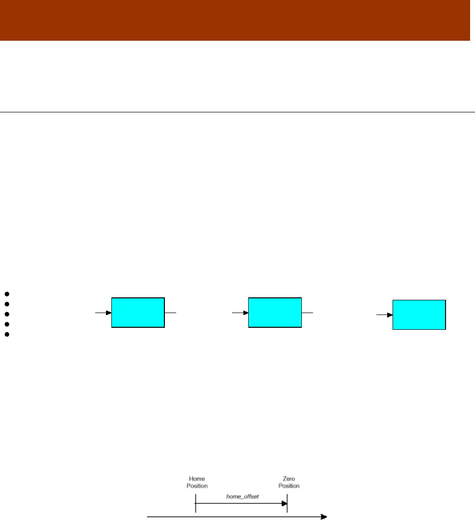
16-01195 Rev 00 158
CHAPTER
9 HOMING MODE OPERATION
9.1 Homing Overview
Homing is the method by which a drive seeks the home position (also called the datum, reference
point, or zero point). There are various methods of achieving this using:
limit switches at the ends of travel, or
a dedicated home switch.
Most of the methods also use the index pulse input from an incremental encoder.
The amplifier performs homing operations in Homing Mode (Mode Of Operation [index 0x6060, p.
65] =6).
The Homing Function
The homing function provides a set of trajectory parameters to the position loop, as shown below.
The parameters are generated by the homing function and are not directly accessible through
CANopen dictionary objects. They include the profile mode and velocity, acceleration, and
deceleration data.
Initiating and Verifying a Homing Sequence
A homing move is started by setting bit 4 of the Control Word object (index 0x6040, p. 59). The
results of a homing operation can be accessed in the Status Word (index 0x6041, p. 60).
Home Offset
The home offset is the difference between the zero position for the application and the machine
home position (found during homing). During homing the home position is found and once the
homing is completed the zero position is offset from the home position by adding the Home Offset
to the home position. All subsequent absolute moves shall be taken relative to this new zero
position. This is illustrated in the following diagram.
Homing Speeds
There are two homing speeds: fast and slow. The fast speed is used to find the home switch and
the slow speed is used to find the index pulse. (See the Homing Speeds object [index 0x6099, p.
176])
Homing Acceleration
Homing Acceleration (index 0x609A, p. 176) establishes the acceleration to be used for all
accelerations and decelerations with the standard homing modes.
Note that in homing, it is not possible to program a separate deceleration rate.
Position Demand
Trajectory
Generator Position
Loop
Homing
Function
Home Offset
Homing Method
Homing Speeds
Home Velocity Fast / Slow
Homing Acceleration
Trajectory
Parameters
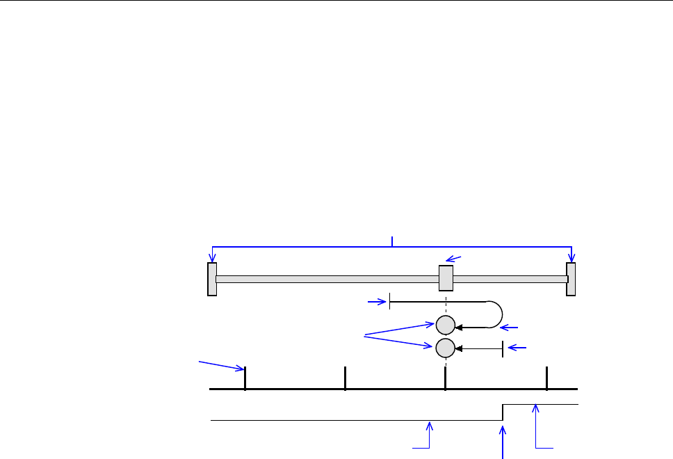
CANopen Programmer’s Manual Homing Mode Operation
Copley Controls 159
9.2 Homing Methods Overview
There are several homing methods. Each method establishes the:
Home reference (limit or home switch transition or encoder index pulse)
Direction of motion and, where appropriate, the relationship of the index pulse to limit
or home switches.
Legend to Homing Method Descriptions
As highlighted in the example below, each homing method diagram shows the starting position on
a mechanical stage. The arrow line indicates direction of motion, and the circled H indicates the
home position. Solid line stems on the index pulse line indicate index pulse locations. Longer
dashed lines overlay these stems as a visual aid. Finally, the relevant limit switch is represented,
showing the active and inactive zones and transition.
Note that in the homing method descriptions, negative motion is leftward and positive motion is
rightward.
Index Pulse
H
Positive Limit
Switch
H
Starting position
Axis
Sw itch inactive Sw itch active
Sw itch transition
Index pulse location
Direction of motion
Mechanical Stage Limits
Home position
Starting position
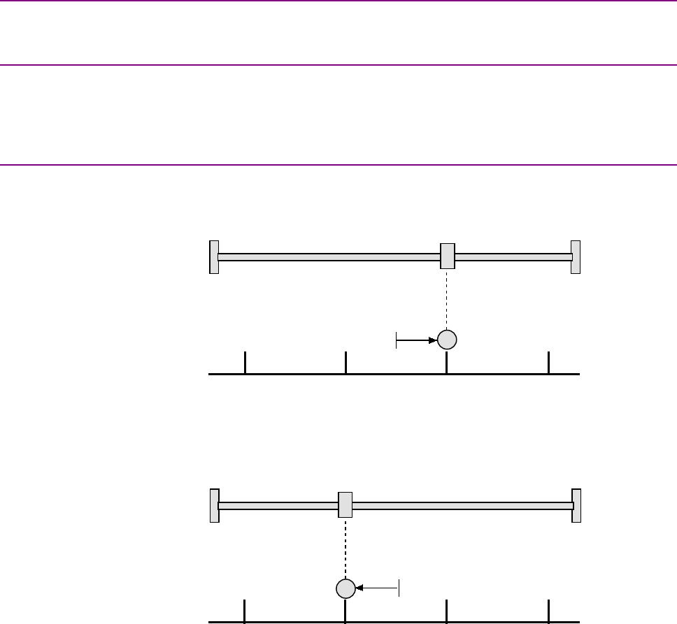
Homing Mode Operation CANopen Programmer’s Manual
160 16-01195 Rev 00
9.2.2 Home is Current Position
Using this method, home is the current position.
Set Homing Method (index 0x6098, p. 175) to: 0.
9.2.3 Home is Current Position; Move to New Zero
Set current position to home and move to new zero position (including home offset). This is the
same as Home is Current Position except that mode 0 does not do the final move to the home
position.
Set Homing Method (index 0x6098, p. 175) to: 35.
9.2.4 Next Index
Direction of Motion: Positive
Home is the first index pulse found in the positive direction. Direction of motion is positive. If a
positive limit switch is activated before the index pulse, an error is generated.
Set Homing Method (index 0x6098, p. 175) to: 34.
Direction of Motion: Negative
Home is the first index pulse found in negative direction. Direction of motion is negative. If a
negative limit switch is activated before the index pulse, an error is generated.
Set Homing Method (index 0x6098, p. 175) to: 33.
Index Pulse
H
Index Pulse
H

CANopen Programmer’s Manual Homing Mode Operation
Copley Controls 161
9.2.5 Limit Switch
Direction of Motion: Positive
Home is the transition of the positive limit switch. Initial direction of motion is positive if the positive
limit switch is inactive.
Set Homing Method (index 0x6098, p. 175) to: 18.
Direction of Motion: Negative
Home is the transition of negative limit switch. Initial direction of motion is negative if the negative
limit switch is inactive.
Set Homing Method (index 0x6098, p. 175) to: 17.
H
Positive Limit
Switch
H
Negative Limit
Switch
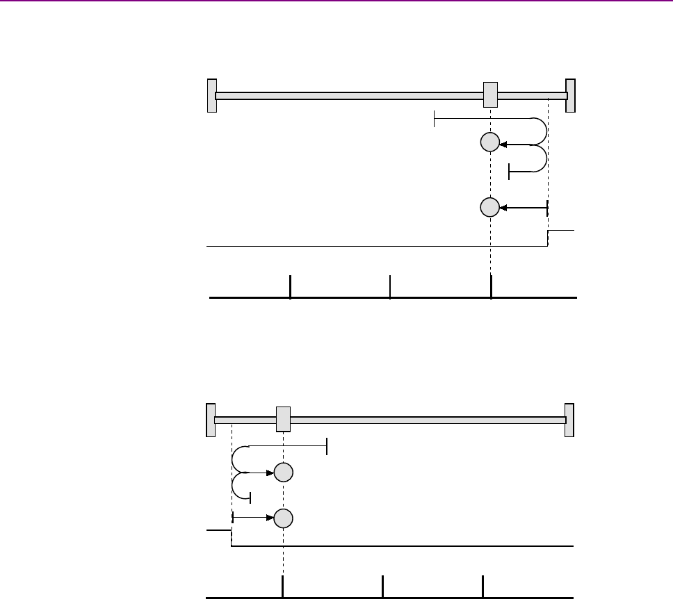
Homing Mode Operation CANopen Programmer’s Manual
162 16-01195 Rev 00
9.2.6 Limit Switch Out to Index
Direction of Motion: Positive
Home is the first index pulse to the negative side of the positive limit switch transition. Initial
direction of motion is positive if the positive limit switch is inactive (shown here as low).
Set Homing Method (index 0x6098, p. 175) to: 2.
Direction of Motion: Negative
Home is the first index pulse to the positive side of the negative limit switch transition. Initial
direction of motion is negative if the negative limit switch is inactive (shown here as low).
Set Homing Method (index 0x6098, p. 175) to: 1.
Index Pulse
H
Positive Limit
Switch
H
Index Pulse
Negative Limit
Switch
H
H
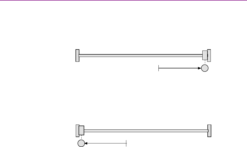
CANopen Programmer’s Manual Homing Mode Operation
Copley Controls 163
9.2.7 Hardstop
Direction of Motion: Positive
Home is the positive hard stop. Direction of motion is positive. The hard stop is reached when the
amplifier outputs the homing Current Limit continuously for the amount of time specified in the
Delay Time. If a positive limit switch is activated before the hard stop, an error is generated.
In stepper amplifiers in stepper mode, the hard stop is reached when the following error exceeds
the tracking window.
Set Homing Method (index 0x6098, p. 175) to: -1.
Direction of Motion: Negative
Home is the negative hard stop. Direction of motion is negative. The hard stop is reached when
the amplifier outputs the homing Current Limit continuously for the amount of time specified in the
Delay Time. If a negative limit switch is activated before the hard stop, an error is generated.
Set Homing Method (index 0x6098, p. 175) to: -2.
H
H
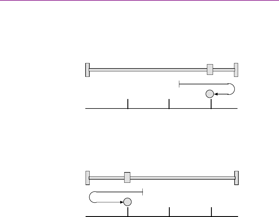
Homing Mode Operation CANopen Programmer’s Manual
164 16-01195 Rev 00
9.2.8 Hardstop Out to Index
Direction of Motion: Positive
Home is the first index pulse on the negative side of the positive hard stop. Initial direction of
motion is positive. The hard stop is reached when the amplifier outputs the homing Current Limit
continuously for the amount of time specified in the Delay Time. If a positive limit switch is
activated before the hard stop, an error is generated.
In stepper amplifiers in stepper mode, the hard stop is reached when the following error exceeds
the tracking window.
Set Homing Method (index 0x6098, p. 175) to: -4.
Direction of Motion: Negative
Home is the first index pulse on the positive side of the negative hard stop. Initial direction of
motion is negative. The hard stop is reached when the amplifier outputs the homing Current Limit
continuously for the amount of time specified in the Delay Time. If a negative limit switch is
activated before the hard stop, an error is generated.
Set Homing Method (index 0x6098, p. 175) to:-3.
H
Index Pulse
H
Index Pulse
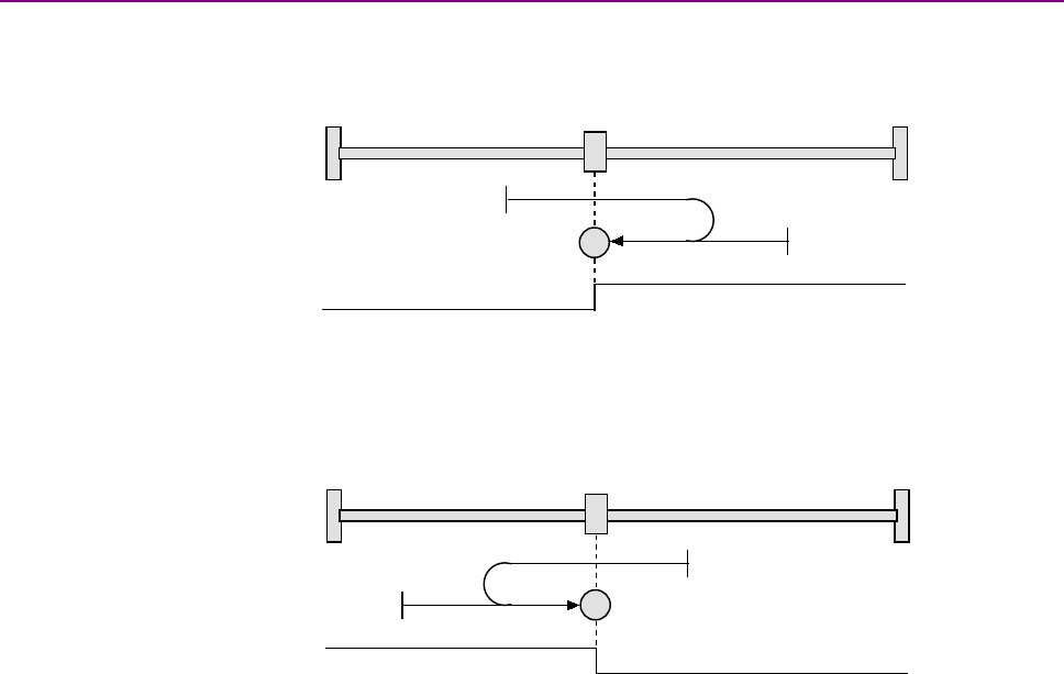
CANopen Programmer’s Manual Homing Mode Operation
Copley Controls 165
9.2.9 Home Switch
Direction of Motion: Positive
Home is the home switch transition. Initial direction of motion is positive if the home switch is
inactive. If a limit switch is activated before the home switch transition, an error is generated.
Set Homing Method (index 0x6098, p. 175) to: 19.
Direction of Motion: Negative
Home is the home switch transition. Initial direction of motion is negative if the home switch is
inactive. If a limit switch is activated before the home switch transition, an error is generated.
Set Homing Method (index 0x6098, p. 175) to: 21.
H
Home Switch
H
Home Switch
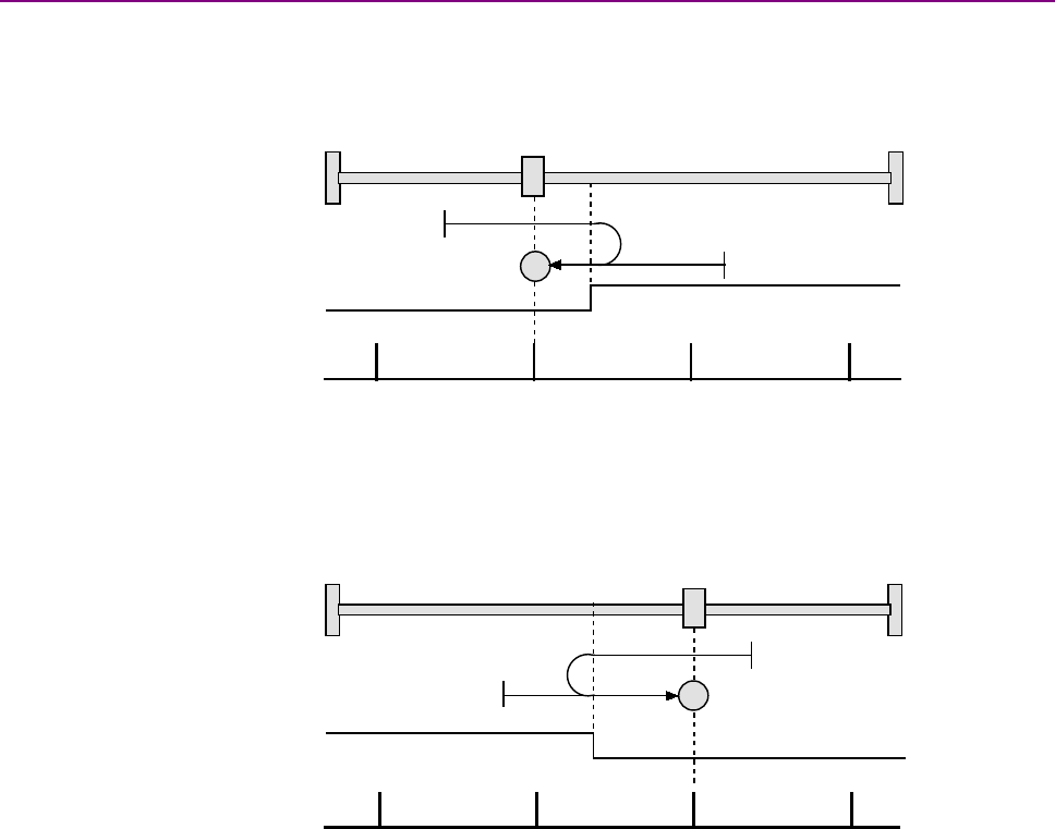
Homing Mode Operation CANopen Programmer’s Manual
166 16-01195 Rev 00
9.2.10 Home Switch Out to Index
Direction of Motion: Positive
Home is the first index pulse to the negative side of the home switch transition. Initial direction of
motion is positive if the home switch is inactive. If a limit switch is activated before the home switch
transition, an error is generated.
Set Homing Method (index 0x6098, p. 175) to: 3.
Direction of Motion: Negative
Home is the first index pulse to the positive side of the home switch transition.
Initial direction of motion is negative if the home switch is inactive. If a limit switch is activated
before the home switch transition, an error is generated.
Set Homing Method (index 0x6098, p. 175) to: 5.
H
Home Switch
Index Pulse
H
Home Switch
Index Pulse
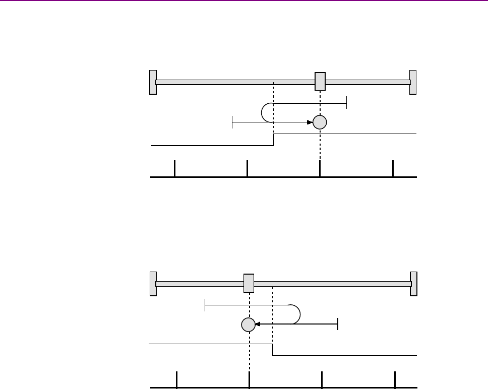
CANopen Programmer’s Manual Homing Mode Operation
Copley Controls 167
9.2.11 Home Switch In to Index
Direction of Motion: Positive
Home is the first index pulse to the positive side of the home switch transition. Initial direction of
motion is positive if the home switch is inactive. If a limit switch is activated before the home switch
transition, an error is generated.
Set Homing Method (index 0x6098, p. 175) to: 4.
Direction of Motion: Negative
Home is the first index pulse to the negative side of the home switch transition. Initial direction of
motion is negative if the home switch is inactive. If a limit switch is activated before the home
switch transition, an error is generated.
Set Homing Method (index 0x6098, p. 175) to: 6.
H
Home Switch
Index Pulse
H
Home Switch
Index Pulse
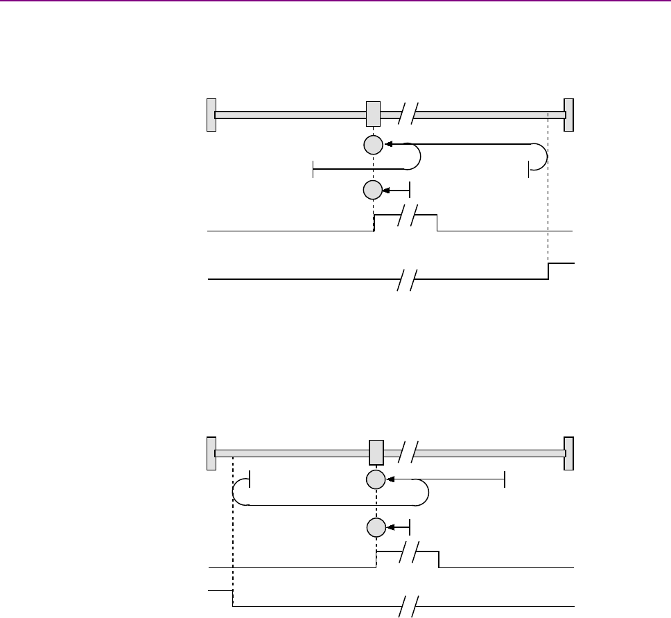
Homing Mode Operation CANopen Programmer’s Manual
168 16-01195 Rev 00
9.2.12 Lower Home
Direction of Motion: Positive
Home is the negative edge of a momentary home switch. Initial direction of motion is positive if the
home switch is inactive. Motion will reverse if a positive limit switch is activated before the home
switch; then, if a negative limit switch is activated before the home switch, an error is generated.
Set Homing Method (index 0x6098, p. 175) to: 23.
Direction of Motion: Negative
Home is the negative edge of a momentary home switch. Initial direction of motion is negative. If
the initial motion leads away from the home switch, the axis reverses on encountering the negative
limit switch; then, if a positive limit switch is activated before the home switch, an error is
generated.
Set Homing Method (index 0x6098, p. 175) to: 29.
Home Switch
Positive Limit
Switch
H
H
Home Switch
Negative Limit
Switch
H
H
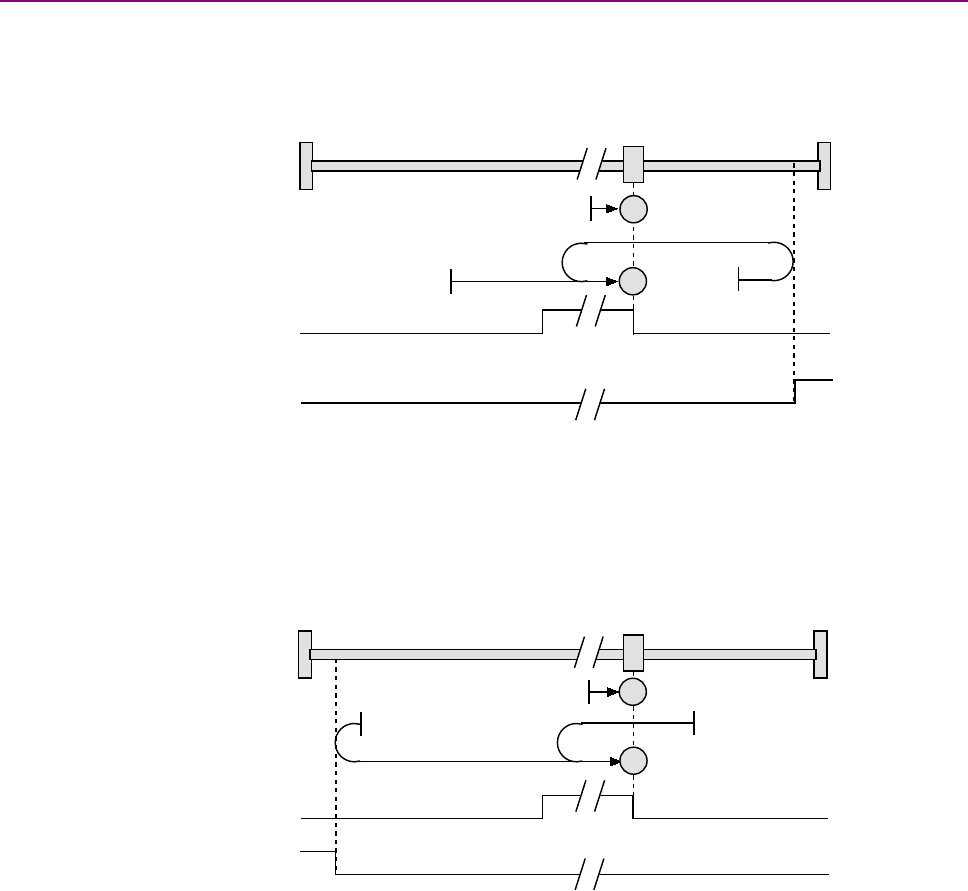
CANopen Programmer’s Manual Homing Mode Operation
Copley Controls 169
9.2.13 Upper Home
Direction of Motion: Positive
Home is the positive edge of a momentary home switch. Initial direction of motion is positive. If the
initial motion leads away from the home switch, the axis reverses on encountering the positive limit
switch; then, if a negative limit switch is activated before the home switch, an error is generated.
Set Homing Method (index 0x6098, p. 175) to: 25
Direction of Motion: Negative
Home is the positive edge of momentary home switch. Initial direction of motion is negative if the
home switch is inactive. If the initial motion leads away from the home switch, the axis reverses on
encountering the negative limit switch; then, if a positive limit switch is activated before the home
switch, an error is generated.
Set Homing Method (index 0x6098, p. 175) to: 27
H
Home Switch
Positive Limit
Switch
H
Home Switch
Negative Limit
Switch
H
H
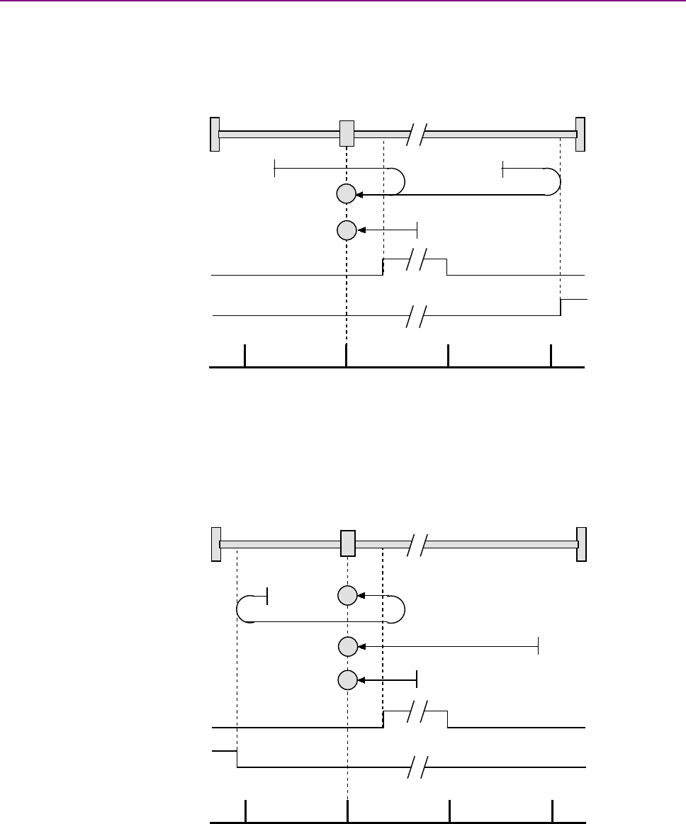
Homing Mode Operation CANopen Programmer’s Manual
170 16-01195 Rev 00
9.2.14 Lower Home Outside Index
Direction of Motion: Positive
Home is the first index pulse on the negative side of the negative edge of a momentary home
switch. Initial direction of motion is positive if the home switch is inactive. If the initial motion leads
away from the home switch, the axis reverses on encountering the positive limit switch; then, if a
negative limit switch is activated before the home switch, an error is generated.
Set Homing Method (index 0x6098, p. 175) to: 7.
Direction of Motion: Negative
Home is the first index pulse on the negative side of the negative edge of a momentary home
switch. Initial direction of motion is negative. If the initial motion leads away from the home switch,
the axis reverses on encountering the negative limit switch; then, if a negative limit switch is
activated before the home switch, an error is generated.
Set Homing Method (index 0x6098, p. 175) to: 14.
Home Switch
Index Pulse
Positive Limit
Switch
H
H
Home Switch
Index Pulse
Negative Limit
Switch
H
H
H
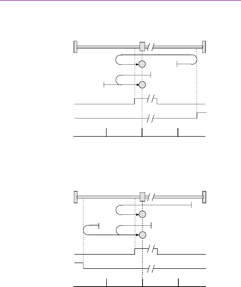
CANopen Programmer’s Manual Homing Mode Operation
Copley Controls 171
9.2.15 Lower Home Inside Index
Direction of Motion: Positive
Home is the first index pulse on the positive side of the negative edge of a momentary home
switch. Initial direction of motion is positive if the home switch is inactive. If the initial motion leads
away from the home switch, the axis reverses on encountering the positive limit switch; then, if a
negative limit switch is activated before the home switch, an error is generated.
Set Homing Method (index 0x6098, p. 175) to: 8.
Direction of Motion: Negative
Home is the first index pulse on the positive side of the negative edge of a momentary home
switch. Initial direction of motion is negative. If the initial motion leads away from the home switch,
the axis reverses on encountering the negative limit switch; then, if a negative limit switch is
activated before the home switch, an error is generated.
Set Homing Method (index 0x6098, p. 175) to: 13.
Home Switch
Index Pulse
Positive Limit
Switch
H
H
Home Switch
Index Pulse
Negative Limit
Switch
H
H
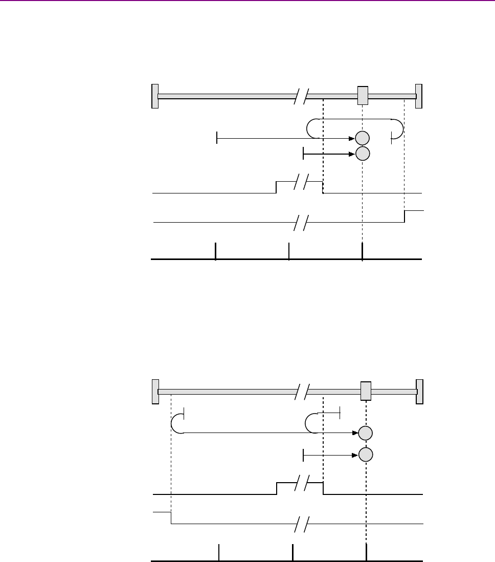
Homing Mode Operation CANopen Programmer’s Manual
172 16-01195 Rev 00
9.2.16 Upper Home Outside Index
Direction of Motion: Positive
Home is the first index pulse on the positive side of the positive edge of a momentary home switch.
Initial direction of motion is positive. If the initial motion leads away from the home switch, the axis
reverses on encountering the positive limit switch; then, if a negative limit switch is activated before
the home switch, an error is generated.
Set Homing Method (index 0x6098, p. 175) to: 10.
Direction of Motion: Negative
Home is the first index pulse on the positive side of the positive edge of a momentary home switch.
Initial direction of motion is negative if the home switch is inactive. If the initial position is right of
the home position, the axis reverses on encountering the home switch.
Set Homing Method (index 0x6098, p. 175) to: 11.
Home Switch
Index Pulse
H
H
Positive Limit
Switch
Home Switch
Index Pulse
Negative Limit
Switch
H
H

CANopen Programmer’s Manual Homing Mode Operation
Copley Controls 173
9.2.17 Upper Home Inside Index
Direction of Motion: Positive
Home is the first index pulse on the negative side of the positive edge of momentary home switch.
Initial direction of motion is positive. If initial motion leads away from the home switch, the axis
reverses on encountering the positive limit switch; then, if a negative limit switch is activated before
the home switch, an error is generated.
Set Homing Method (index 0x6098, p. 175) to: 9.
Direction of Motion: Negative
Home is the first index pulse on the negative side of the positive edge of a momentary home
switch. Initial direction of motion is negative if the home switch is inactive. If initial motion leads
away from the home switch, the axis reverses on encountering the negative limit; then, if a
negative limit switch is activated before the home switch, an error is generated.
Set Homing Method (index 0x6098, p. 175) to: 12.
Home Switch
Index Pulse
Positive Limit
Switch
H
H
Negative Limit
Switch
Home Switch
Index Pulse
H
H

Homing Mode Operation CANopen Programmer’s Manual
174 16-01195 Rev 00
9.2.18 Immediate Home
Immediate Home with Absolute Encoder
On startup, the drive is immediately homed using the position data from an absolute encoder. This
homing method uses Object 0x607C (Home Offset), to apply an offset, if desired.
Set Homing Method (index 0x6098, p. 175) to: 25
9.2.19 Home Configuration Object for Custom Homing Methods
Copley Controls provides an object that provides access to the amplifier’s internal home
configuration register. When a standard CANopen homing method is used, the software
automatically sets a value in this register.
To specify homing options that are not supported by the standard CANopen methods, the
application can directly program this configuration register. This provides finer control of the
homing methods then the standard CANopen ones allow.
For example, all of the standard CANopen homing methods will cause a move to the new zero
position after it has been found. With a large home offset, this could be a large or slow move. This
final move can be avoided by programming the internal home configuration register directly.

CANopen Programmer’s Manual Homing Mode Operation
Copley Controls 175
9.3 Homing Mode Operation Objects
HOMING METHOD INDEX 0X6098
Type
Access
Units
Range
Map PDO
Memory
Integer 8
RW
-
See Description, below.
YES
RF
Description
The method for finding the motor home position in homing mode. Program a method described
below by writing its code to 0x6098. Most of the methods are paired. Each member of a pair uses
the same basic method but starts in the opposite direction and has a distinct code. For a full
description of any method, see the referenced pages.
Homing Method
Initial Motion
Code
Full Description
#
Hardstop Out to Index
Positive
-4
p. 164
Negative
-3
Hardstop
Negative
-2
p. 163
Positive
-1
Home is Current Position
Any
0
p. 160
Home is Current Position; Move to New Zero
Any
35
p. 160
Limit Switch Out to Index
Negative
1
p. 162
Positive
2
Home Switch Out to Index
Positive
3
p. 166
Negative
5
Home Switch In to Index
Positive
4
p. 167
Negative
6
Lower Home Outside Index
Positive
7
p. 170
Negative
14
Lower Home Inside Index
Positive
8
p. 171
Negative
13
Upper Home Inside Index
Positive
9
p. 173
Negative
12
Upper Home Outside Index
Positive
10
p. 172
Negative
11
Limit Switch
Negative
17
p. 161
Positive
18
Home Switch
Positive
19
p. 165
Negative
21
Lower Home
Positive
23
p. 168
Negative
29
Upper Home
Positive
25
p. 169
Negative
27
Next Index
Positive
34
p. 160
Negative
33
Immediate Home
37
Reserved for future use.
15-16, 20, 22, 24, 26, 28, 30-32
Note that these homing methods only define the location of the home position. The zero position is
always the home position adjusted by the homing offset. See Homing Methods Overview, p.159.

Homing Mode Operation CANopen Programmer’s Manual
176 16-01195 Rev 00
HOMING SPEEDS INDEX 0X6099
Type
Access
Bits
Range
Map PDO
Memory
ARRAY
RW
80
-
YES
RF
Description
This array holds the two velocities used when homing. Sub-index 0 contains the number of sub-
elements of this record.
HOME VELOCITY – FAST INDEX 0X6099, SUB-INDEX 1
Type
Access
Units
Range
Map PDO
Memory
UNSIGNED32
RW
0.1 counts/sec
0 to 232-1
TR
RF
Description
This velocity value is used during segments of the homing procedure that may be handled at high
speed. Generally, this means move in which the home sensor is being located, but the edge of the
sensor is not being found.
User defined units are achievable using the factor group objects.
HOME VELOCITY – SLOW INDEX 0X6099, SUB-INDEX 2
Type
Access
Units
Range
Map PDO
Memory
UNSIGNED32
RW
0.1 counts/sec
0 to 232-1
TR
RF
Description
This velocity value is used for homing segment that require low speed such as cases where the
edge of a homing sensor is being sought.
User defined units are achievable using the factor group objects.
HOMING ACCELERATION INDEX 0X609A
Type
Access
Units
Range
Map PDO
Memory
UNSIGNED32
RW
10 counts/sec2
0 to 232-1
TR
RF
Description
This value defines the acceleration used for all homing moves. The same acceleration value is
used at the beginning and ending of moves (i.e. there is no separate deceleration value).
User defined units are achievable using the factor group objects.
HOME OFFSET INDEX 0X607C
Type
Access
Units
Range
Map PDO
Memory
INTEGER32
RW
counts
-231 to +231-1
TR
RF
Description
The home offset is the difference between the zero position for the application and the machine
home position (found during homing). During homing the home position is found. Once the homing
is completed the zero position is offset from the home position by adding the Home Offset to the
home position. All subsequent absolute moves shall be taken relative to this new zero position.
See Home Offset (p. 158) for more information.
User defined units are achievable using the factor group objects.

CANopen Programmer’s Manual Homing Mode Operation
Copley Controls 177
HARD STOP MODE HOME CURRENT INDEX 0X2350
Type
Access
Units
Range
Map PDO
Memory
INTEGER16
RW
0.01A
-215 to +215-1
TR
RF
Description
Home current in hard stop mode, in which the amplifier drives the motor to the mechanical end of
travel (hard stop). End of travel is recognized when the amplifier outputs the Hard Stop Mode
Home Current for the Hard Stop Mode Home Delay time (index 0x2351, p. 177).
HARD STOP MODE HOME DELAY INDEX 0X2351
Type
Access
Units
Range
Map PDO
Memory
UNSIGNED16
RW
milliseconds
0 to 216-1
TR
RF
Description
Delay used for homing to a hard stop mode.
HOME CONFIG INDEX 0X2352
Type
Access
Units
Range
Map PDO
Memory
INTEGER16
RW
-
See Description, below.
TR
RF
Description
Alternate method for configuring the homing mode. Provides more flexibility than the standard
CANopen method does. Bit-mapped as follows:
Bits
Description
0-3
Home function.
Value
Description
0
If bit 5 is not set, then just set the current position as home. If bit 5 is set, then move in the
direction specified by bit 4 and set the location of the first index pulse as home. Bit 6 is not
used in this mode.
1
Move in the direction specified by bit 4 until a limit switch is encountered. Then move in the
other direction out of limit. If bit 5 is clear, then the edge location is home. If bit 5 is set, then
the next index pulse is home. Bit 6 is not used in this mode.
2
Home on a constant home switch. The initial move is made in the direction specified by bit 4.
When the home switch is encountered, the direction is reversed. The edge of the home switch
is set as home if bit 5 is clear. If bit 5 is set, then an index pulse is used as the home position.
Bit 6 is used to define which index pulse is used.
3
Home on an intermittent home switch. This mode works the same as mode 2 except that if a
limit switch is encountered when initially searching for home, then the direction is reversed. In
mode 2, hitting a limit switch before finding home would be considered an error. Bit 8 identifies
which edge of the home to search for (positive or negative).
4
Home to a hard stop. This moves in the direction specified in bit 4 until the home current limit
is reached. It then presses against the hard stop using that current value until the home delay
time expires. If bit 5 (index) is set, drive away from the hard stop until an index is found.
4
Initial move direction (0=positive, 1=negative).
5
Home on index pulse if set.
6
Selects which index pulse to use. If set, use the pulse on the DIR side of the sensor edge. DIR is the
direction specified by bit 4 of this word.
7
If set, capture falling edge of index. Capture rising edge if clear.
8
When using a momentary home switch, this bit identifies which edge of the home switch to reference on. If
set, then the negative edge is used; if clear the positive edge is used.
9
If set, make a move to the zero position when homing is finished. If clear, the zero position is found, but not
moved to.
10
If set, the homing sequence will run as normal, but the actual position will not be adjusted at the end. Note
that even though the actual position is not adjusted, the Homing Adjustment (index 0x2353, p. 181) is
updated with the size of the adjustment (in counts) that would have been made.
Also, if bit 10 is set then no move to zero is made regardless of the setting of bit 9.

Homing Mode Operation CANopen Programmer’s Manual
178 16-01195 Rev 00
POSITION CAPTURE CONTROL REGISTER INDEX 0X2400
Type
Access
Units
Range
Map PDO
Memory
INTEGER16
RW
-
See Description, below.
TR
RF
Description
Sets up position capture features for the encoder index home switch input and high speed position
capture input. Bit-mapped as follows:
Bit
Description
0
If set, the Captured Index Position (index 0x2402, p. 179) is captured on the falling edge of the index.
1
If set, the Captured Index Position is captured on the rising edge of the index.
2
If set, a Captured Index Position value will not be overwritten by a new position until it has been read. If
clear, new positions will overwrite old positions.
3,4
Reserved.
5
If set, Home Capture Position (index Index 0x2403, p. 179) captures falling edges of the home switch input
transition; if clear, it captures rising edges.
6
If set, Home Capture Position will not be overwritten by a new position until it has been read.
If clear, new positions will overwrite old positions.
8
If set, enable high speed input position capture. The position value is written to Position of Last High Speed
Motor Capture (index 0x2405, p. 179).
9
If set, don't overwrite high speed input capture positions.
10
If set, a Position of Last High Speed Motor Capture value will not be overwritten by a new position until it
has been read. If clear, new positions will overwrite old positions.
12
Clear actual position on every encoder index pulse.
POSITION CAPTURE STATUS REGISTER INDEX 0X2401
Type
Access
Units
Range
Map PDO
Memory
INTEGER16
RO
-
See Description, below.
T
R
Description
Shows the current status of the index or home switch capture mechanism. Bit-mapped as follows:
Bit
Description
0
If set, an index position has been captured. Cleared when the captured position is read.
1,2
Reserved.
3
If set, a new index transition occurred when a captured position was already stored.
The existing Captured Index Position (index 0x2402, p. 179) will be overwritten or preserved as
programmed in bit 2 of the
4
If set, new home switch transition data has been captured.
5,6
Reserved.
7
If set, a new home switch input transition occurred when a captured position was already stored. The
existing Home Capture Position (index Index 0x2403, p. 179) will be overwritten or preserved as
programmed in bit 6 of the
8
If set, a new high speed input position has been captured. Cleared when the captured position is read.
10
If set, high speed input position overflow.
11
If set, a new high speed input transition occurred when a Position of Last High Speed Motor Capture (index
0x2405, p. 179) was already stored.
The existing Position of Last High Speed Motor Capture will be overwritten or preserved as programmed in
bit 10 of the

CANopen Programmer’s Manual Homing Mode Operation
Copley Controls 179
CAPTURED INDEX POSITION INDEX 0X2402
Type
Access
Units
Range
Map PDO
Memory
INTEGER32
RO
counts
-231 to +231-1
T
R
Description
Reading this variable resets bits 0 & 3 of the Position Capture Status Register (index 0x2401, p.
178). Provides the position that the axis was in when an index pulse was captured. Configured by
setting bits in the Position Capture Control Register (index 0x2400, p. 187), and the status of the
captured data can be checked in the Position Capture Status Register. Reading this variable
resets bits 0 & 3 of the Position Capture Status Register.
HOME CAPTURE POSITION INDEX 0X2403
Type
Access
Units
Range
Map PDO
Memory
INTEGER32
RO
counts
-231 to +231-1
T
R
Description
Provides the position that the axis was in when an input pin configured as a home switch input
became active. This function can be configured by setting bits in the Position Capture Control
Register (index 0x2400, p. 187), and the status of the captured data can be checked in Position
Capture Status Register (index 0x2401, p. 187).
TIME STAMP OF LAST HIGH SPEED POSITION CAPTURE INDEX 0X2404
Type
Access
Units
Range
Map PDO
Memory
INTEGER32
RW
microseconds
-231 to +231-1
TR
R
Description
Provides the time when an input pin configured as a high-speed capture input became active (and
the axis position was captured).
POSITION OF LAST HIGH SPEED MOTOR CAPTURE INDEX 0X2405
Type
Access
Units
Range
Map PDO
Memory
INTEGER32
RO
Counts
-231 to +231-1
T
R
Description
Provides the position that the axis was in when an input pin configured as a high-speed capture
input became active.
POSITION OF LAST HIGH SPEED LOAD CAPTURE INDEX 0X2406
Type
Access
Units
Range
Map PDO
Memory
INTEGER32
RO
counts
-231 to +231-1
T
R
Description
Provides the position that the axis was in when an input pin configured as a high-speed capture
input became active.

Homing Mode Operation CANopen Programmer’s Manual
180 16-01195 Rev 00
INPUT CAPTURE CONTROL INDEX 0X2408
Type
Access
Bits
Range
Map PDO
Memory
RECORD
RW
136
-
NO
R
Description
Provides the position that the axis was in when an input pin configured as a high-speed capture
input became active. Sub-index 0 holds the number of elements in this object.
INPUT 1~15 CAPTURE CONTROL INDEX 2408 SUB-INDEX 1~15
Type
Access
Units
Range
Map PDO
Memory
UNSIGNED8
RW
-
0 to 28-1
NO
R
Configures the capture settings for IN1~IN15.
INPUT CAPTURE STATUS INDEX 0X2409
Type
Access
Bits
Range
Map PDO
Memory
RECORD
RW
136
-
TR
R
Description
Provides the status of capture from IN1~IN15.
Sub-index 0 holds the number of elements in this object.
INPUT 1~15 CAPTURE STATUS INDEX 0X2409 SUB-INDEX 1~15
Type
Access
Units
Range
Map PDO
Memory
UNSIGNED8
RW
-
0 to 28-1
TR
R
Description
Reports the status of the capture for IN1~IN15.
CAPTURED RISING EDGE POSITION INDEX 0X240A
Type
Access
Bits
Range
Map PDO
Memory
RECORD
RW
496
-
T
R
Description
Position at the time of capture for IN1~IN15.
Sub-index 0 holds the number of elements in this object.
INPUT 1~15 CAPTURED RISING EDGE POSITION INDEX 0X240A SUB-INDEX 1~15
Type
Access
Units
Range
Map PDO
Memory
INTEGER32
RW
-
-231 to +231-1
T
R
Description
Each sub-index is the position at the time of capture for the input of the sub-index number.
CAPTURED FALLING EDGE POSITION INDEX 0X240B
Type
Access
Bits
Range
Map PDO
Memory
RECORD
RW
496
-
T
R
Description
Position at the time of capture for IN1~IN15.
Sub-index 0 holds the number of elements in this object.
INPUT 1~15 CAPTURED FALLING EDGE POSITION INDEX 0X240B SUB-INDEX 1~15
Type
Access
Units
Range
Map PDO
Memory
INTEGER32
RW
-
-231 to +231-1
T
R
Description
Each sub-index is the position at the time of capture for the input of the sub-index number.

CANopen Programmer’s Manual Homing Mode Operation
Copley Controls 181
CAPTURED RISING EDGE TIME INDEX 0X240C
Type
Access
Bits
Range
Map PDO
Memory
RECORD
RW
976
-
EVENT
R
Description
The time at the rising edge of the capture for IN1~IN15.
Sub-index 0 holds the number of elements in this object.
INPUT 1~15 CAPTURED RISING EDGE TIME INDEX 0X240C SUB-INDEX 1~15
Type
Access
Units
Range
Map PDO
Memory
UNSIGNED64
RW
-
0 to +264-1
T
R
Each sub-index is the time at rising edge of the capture for the input of the sub-index number.
CAPTURED FALLING EDGE TIME INDEX 0X240D
Type
Access
Bits
Range
Map PDO
Memory
RECORD
RW
976
-
T
R
Description
The time at the falling edge of the capture for IN1~IN15.
Sub-index 0 holds the number of elements in this object.
INPUT 1~15 CAPTURED RISING EDGE TIME INDEX 0X240D SUB-INDEX 1~15
Type
Access
Units
Range
Map PDO
Memory
UNSIGNED64
RW
-
0 to +264-1
T
R
Each sub-index is the time at the falling edge of the capture for the input of the sub-index number.
CME2 SOFTWARE USE INDEX 0X2421
Type
Access
Bits
Range
Map PDO
Memory
STRING(40)
RW
320
-
F
Description
Reserved for use by CME2 software.
TIME OF LAST POSITION SAMPLE INDEX 0X2410
Type
Access
Units
Range
Map PDO
Memory
UNSIGNED32 RO ms 0 to 232-1 T R
Description
This object provides a 32-bit time stamp, in microseconds, that corresponds to the time that the encoder was
most recently sampled. When this object is read, the position is latched and saved into object 0x2411. If
mapping this object and 0x2411 to a PDO, object 0x2410 should be mapped first so the objects match data
from one reading.
POSITION DURING TIME SAMPLE READING INDEX 0X2411
Type
Access
Units
Range
Map PDO
Memory
INTEGER32
RO
counts
-231 to +231-1
T
R
Description
This object provides the position read the corresponds to the time of the last position sampled, object
0x2410. Object 0x2410 must be read for a new position to be latched.
HOMING ADJUSTMENT INDEX 0X2353
Type
Access
Units
Range
Map PDO
Memory
INTEGER32
RO
counts
-231 to +231-1
T
R
Description
This parameter is updated after each successful homing operation. The value it contains is the size of the
actual position adjustment made in the last home sequence.

Homing Mode Operation CANopen Programmer’s Manual
182 16-01195 Rev 00
CHAPTER
10 TOUCH PROBE OPERATION
TOUCH PROBE FUNCTION INDEX 0X60B8
Type
Access
Units
Range
Map PDO
Memory
UNSIGNED16
RW
-
See Description, below.
TR
R
Description
This object sets up the function of the touch probes.
Bit
Value
Definition
0
0
Switch off touch probe 1
1
Enable touch probe 1
1
0
Trigger first event (latching)
1
Continuous
2,3
0
Use input pin 1 as first touch probe input
1
Use encoder index as first touch probe
2
Use value programmed in 0x60D0 sub-index 1 to specify first touch probe input
3
Reserved
4
0
Switch off sampling at positive edge of touch probe 1
1
Enable sampling at positive edge of touch probe 1
5
0
Switch off sampling at negative edge of touch probe 1
1
Enable sampling at negative edge of touch probe 1
6,7
Reserved
Reserved
8
0
Switch off touch probe 2
1
Enable touch probe 2
9
0
Trigger first event (latching)
1
Continuous
10,11
0
Use input pin 2
1
Use encoder index as second touch probe
2
Use value programmed in 0x60D0 sub-index 2 to specify second touch probe input
3
Reserved
12
0
Switch off sampling at positive edge of touch probe 2
1
Enable sampling at positive edge of touch, probe 2
13
0
Switch off sampling at negative edge of touch probe 2
1
Enabled sampling at negative edge of touch probe 2
14,15
Reserved
Reserved

CANopen Programmer’s Manual Homing Mode Operation
Copley Controls 183
TOUCH PROBE STATUS INDEX 0X60B9
Type
Access
Units
Range
Map PDO
Memory
UNSIGNED16
RO
-
See Description, below.
T
R
Description
This object sets up the function of the touch probes.
Bit Value Definition
0 0 Touch probe 1 is switched off
1 Touch probe 1 is enabled
1 0 Touch probe 1 no positive edge value stored
1 Touch probe 1 positive edge value stored
2 0 Touch probe 1 no negative edge value stored
1 Touch probe 1 negative edge value stored
3-7 Reserved Reserved
8 0 Touch probe 2 is switched off
1 Touch probe 2 is enabled
9 0 Touch probe 2 no positive edge value stored
1 Touch probe 2 positive edge value stored
10 0 Touch probe 2 no negative edge value stored
1 Touch probe 2 negative edge value stored
11-15 Reserved Reserved
TOUCH PROBE POS1 POS VALUE INDEX 0X60BA
Type
Access
Units
Range
Map PDO
Memory
INTEGER32
RO
counts
-231 to +231-1
T
R
Description
This object provides the position value of the touch probe 1 at the positive edge. User defined units
are achievable using the factor group objects.
TOUCH PROBE POS1 NEG VALUE INDEX 0X60BB
Type
Access
Units
Range
Map PDO
Memory
INTEGER32
RO
counts
-231 to +231-1
T
R
Description
This object provides the position value of the touch probe 1 at the negative edge. User defined
units are achievable using the factor group objects.
TOUCH PROBE POS2 POS VALUE INDEX 0X60BC
Type
Access
Units
Range
Map PDO
Memory
INTEGER32
RO
counts
-231 to +231-1
T
R
Description
This object provides the position value of the touch probe 2 at the positive edge. User defined units
are achievable using the factor group objects.

Homing Mode Operation CANopen Programmer’s Manual
184 16-01195 Rev 00
TOUCH PROBE POS2 NEG VALUE INDEX 0X60BD
Type
Access
Units
Range
Map PDO
Memory
INTEGER32
RO
counts
-231 to +231-1
T
R
Description
This object provides the position value of the touch probe 2 at the negative edge. User defined
units are achievable using the factor group objects.
TOUCH PROBE SELECT INDEX 0X60D0
Type
Access
Bits
Range
Map PDO
Memory
RECORD
RW
48
See Description, below.
NO
R
Description
This object is used to select the inputs that are used for the touch probes. Accepted manufacturer
specific values -1 for pin 1, -2 for pin 2, etc. This array holds the two values.
Sub-index 0 contains the number of sub-elements for this record.
TOUCH PROBE SELECT – PROBE 1 INDEX 0X60D0, SUB-INDEX 1
Type
Access
Units
Range
Map PDO
Memory
INTEGER16
RW
-
-215 to +215-1
NO
R
TOUCH PROBE SELECT – PROBE 2 INDEX 0X60D0, SUB-INDEX 2
Type
Access
Units
Range
Map PDO
Memory
INTEGER16
RW
-
-215 to +215-1
NO
R
TOUCH PROBE TIME 1 POS VALUE INDEX 0X60D1
Type
Access
Units
Range
Map PDO
Memory
UNSIGNED32
RO
ns
0 to 232-1
T
R
Description
This object provides the time value of the touch probe 1 at the positive edge.
TOUCH PROBE TIME 1 NEG VALUE INDEX 0X60D2
Type
Access
Units
Range
Map PDO
Memory
UNSIGNED32
RO
ns
0 to 232-1
T
R
Description
This object provides the time value of the touch probe 1 at the negative edge.
TOUCH PROBE TIME 2 POS VALUE INDEX 0X60D3
Type
Access
Units
Range
Map PDO
Memory
UNSIGNED32
RO
ns
0 to 232-1
T
R
Description
This object provides the time value of the touch probe 1 at the positive edge.
TOUCH PROBE TIME 2 NEG VALUE INDEX 0X60D4
Type
Access
Units
Range
Map PDO
Memory
UNSIGNED32
RO
ns
0 to 232-1
T
R
Description
This object provides the time value of the touch probe 1 at the negative edge.
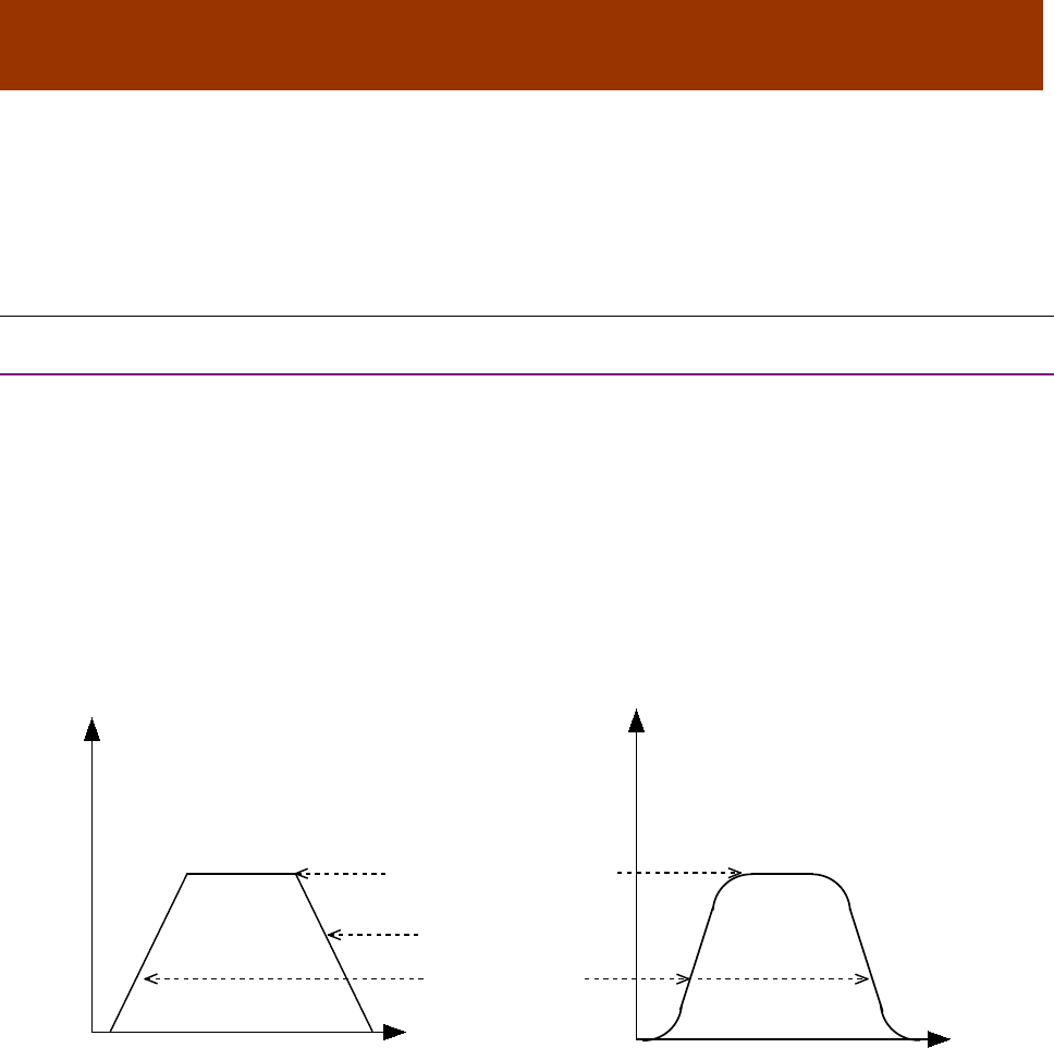
16-01195 Rev 00 185
*CHAPTER
11 PROFILE POSITION, VELOCITY,
TORQUE & FACTOR GROUP OPERATION
11.1 Profile Position Mode Operation
11.1.1 Point-to-Point Motion Profiles
In profile position mode, an amplifier receives set points from the trajectory generator to define a
target position and moves the axis to that position at a specified velocity and acceleration. This is
known as a point-to-point move.
The amplifier performs profile position moves in Profile Position Mode (Mode Of Operation [index
0x6060, p. 65] =1).
Jerk
In a point-to-point move, the rate of change in acceleration is known as jerk. In some applications,
high rates of jerk can cause excessive mechanical wear or material damage.
Trapezoidal and S-curve Motion Profiles
To support varying levels of jerk tolerance, the profile position mode supports two motion profiles:
the trapezoidal profile, which has unlimited jerk, and the jerk-limited S-curve (sinusoidal) profile.
In a trapezoidal profile, jerk is unlimited at the corners of the profile (start of the move, when the
target velocity is reached, when deceleration begins, and at the end of the move). S-curve profiling
limits jerk or “smooths” the motion.
Note that an S-curve profile move does not support an independent deceleration rate. Instead, the
acceleration rate is applied to both the acceleration and deceleration of the move. Further,
trapezoidal and profile position special velocity mode profiles support changing of the parameters
of the current move, whereas an S-curve profile does not. This difference is discussed in Handling
a Series of Point-to-Point Moves
The Motion Profile Type object (index 0x6086) controls which type of profile is used.
For guidance in choosing a trapezoidal or S-curve profile, read the following sections and then
refer to Trapezoidal vs. S-Curve Profile: Some Design Considerations.
Time
Velocity
Acceleration Rate
Deceleration Rate
Target Velocity (Run Speed)
Velocity
Time
Trapezoidal S-Curve
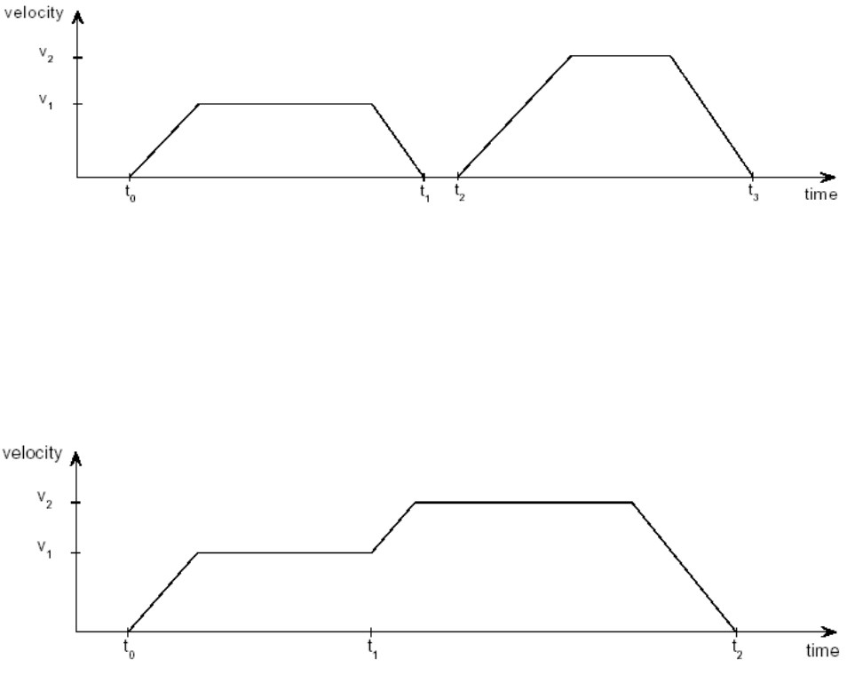
Profile Position, Velocity, Torque & Factor Group Operation CANopen Programmer’s Manual
186 16-01195 Rev 00
(Copley Controls CANopen amplifiers also support a profile position special velocity mode. This
7obeys the acceleration, deceleration, and velocity limits, but continues to move as though the
target position were infinite.)
Relative vs. Absolute Moves
In a relative move, the target position is added to the instantaneous commanded position, and the
result is the destination of the move. In an absolute move, the target position is offset from the
home position.
Handling a Series of Point-to-Point Moves
There are two methods for handling a series of point-to-point moves:
As a series of discrete profiles (supported in both trapezoidal and S-curve profile moves)
As one continuous profile (supported in trapezoidal profile moves only)
General descriptions of the two methods follow. Detailed procedures and examples appear later in
the chapter.
A Series of Discrete Profiles
The simplest way to handle a series of point-to-point moves is to start a move to a particular
position, wait for the move to finish, and then start the next move. As shown below, each move is
discrete. The motor accelerates, runs at target velocity, and then decelerates to zero before the
next move begins.
The CANopen Profile for Drives and Motion Control (DSP 402) refers to this method as the “single
set point” method.
Copley Controls CANopen amplifiers allow use of this method with both trapezoidal and S-curve
profile moves.
One Continuous Profile
Alternately, a series of trapezoidal profile moves can be treated as a continuous move. As shown
below, the motor does not stop between moves. Instead, the move parameters (target position,
velocity, acceleration, and deceleration) are updated immediately at the end of the previous move
(when bit 4 of the Control Word is set, as described later in this section).
The CANopen Profile for Drives and Motion Control (DSP 402) refers to this method as the “set of
set points” method.
Copley Controls CANopen amplifiers allow use of this method with trapezoidal profile moves only.
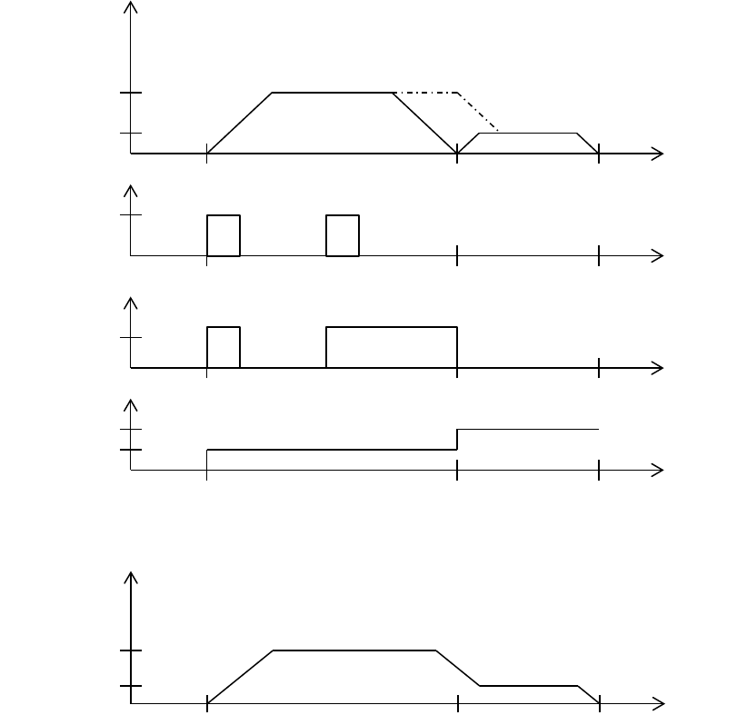
CANopen Programmer’s Manual Profile Position, Velocity, Torque & Factor Group
Operation
Copley Controls 187
Set of set-points
When a drive is in trapezoidal profile position mode, a feature called set of set-points is available.
This enables the drive to keep an additional set-point in a buffer, which is executed when the
currently executing move is finished. The figure below shows how the feature is used, and how
corresponding bits in the status word and control word are used.
The dashed line in the first graph represents the velocity if the change of set point bit (bit 9 of the
control word) is set.
Using the end velocity object may be helpful to achieve functionality as show in the graph below.
V1
V2
New set-
point
Bit 4 control
word
Set-point Ack
Bit 12 status
word
time
time
time
Velocity
Target
Position
processed
time
V1
V2
time
Velocity

Profile Position, Velocity, Torque & Factor Group Operation CANopen Programmer’s Manual
188 16-01195 Rev 00
Overview of Point-to-Point Move Parameters and Related Data
Move Parameters
Each point-to-point move is controlled by a set of parameters, accessed through the following
objects.
Object Name/ID
Description
Page #
Trajectory Jerk Limit / 0x2121
Maximum rate of change of acceleration. Used with S-curve profiles
only. 197
Target Position / 0x607A
When running in position profile mode, this object holds the
destination position of the trajectory generator. Note that for profile
position special velocity mode profiles, the target position only
specifies the direction of motion, not a true position.
193
Profile Velocity / 0x6081
Velocity that the trajectory generator will attempt to achieve when
running in position profile mode. 146
Profile Acceleration / 0x6083
Acceleration that the trajectory generator attempts to achieve when
running in position profile mode. 146
Profile Deceleration / 0x6084
Note that an S-curve profile move does not use a deceleration rate.
Instead, the acceleration rate is applied to both the acceleration and
deceleration of the move.
147
Quick Stop Deceleration /
0x6085
Deceleration value used when a trajectory needs to be stopped as the
result of a quick stop command. Note that unlike most trajectory
configuration values, this value is NOT buffered. Therefore, if the
value of this object is updated during an abort, the new value is used
immediately.
147
Motion Profile Type / 0x6086
Trapezoidal, S-curve, or special velocity mode.
147
The Point-to-Point Move Buffer
In profile position mode, the amplifier uses a buffer to store the parameters (listed in Move
Parameters, above) for the next point-to-point move, or for a modification of the current trapezoidal
profile move. The move buffer can be modified at any point before a control sequence (described
in following sections) copies the “next-move” parameters to the active move registers.

CANopen Programmer’s Manual Profile Position, Velocity, Torque & Factor Group
Operation
Copley Controls 189
Move-Related Control Word and Status Word Bit Settings
An amplifier’s Control Word (index 0x6040) and Status Word (index 0x6041) play an important role
in the initiation and control of point-to-point move sequences, as described below.
Object Name / Index
Bit #
Bit Name
Description/Comments
Control Word / 0x6040
4 new set point
The transition of bit 4 from 0 to 1 is what causes the
amplifier to copy a set of move parameters from the
buffer to the active register, thus starting the next move.
5 change set
immediately
Allows or prevents attempt to perform a series of moves
as one continuous profile (change move parameters
while move is in progress).
Value = 0: Amplifier will ignore a 0 to 1 transition on bit 4
if there is currently a move in progress.
Value = 1 and Motion Profile Type (index 0x6086, p.
147) = trapezoidal or velocity mode: Allow new move to
begin immediately after bit 4 low-to-high transition.
Value = 1 and Motion Profile Type is S-curve: Ignore
update and continue move with old parameters.
6 absolute/relative
Value = 0: Move is absolute (based on home position).
Value = 1: Move is relative (based on current
commanded position).
8 halt
Value = 1: Interrupts the motion of the drive. Wait for
release to continue.
Status Word / 0x6041
10 target reached
Amplifier sets bit 10 to 1 when target position has been
reached. Amplifier clears bit 10 to zero when new target
is received.
If quick stop option code (p. 63) is 5, 6, 7, or 8, this bit is
set when the quick stop operation is finished and the
drive is halted.
Bit 10 is also set when a Halt occurs.
12 set point acknowledge
Set by the amplifier when Control Word bit 4 goes from 0
to 1. Cleared when Control Word bit 4 is cleared. An
invalid transition on Control Word bit 4 will not cause this
bit to be set. Invalid transitions include those made while
drive is in motion and in S-curve mode, or made while
drive in motion with Control Word bit 5 not set.

Profile Position, Velocity, Torque & Factor Group Operation CANopen Programmer’s Manual
190 16-01195 Rev 00
11.1.2 Point-To-Point Move Sequence Examples
Overview
The following sections illustrate how to perform:
A series of moves treated as a Series of Discrete Profiles
A series of trapezoidal or profile position special velocity moves treated as One Continuous Profile
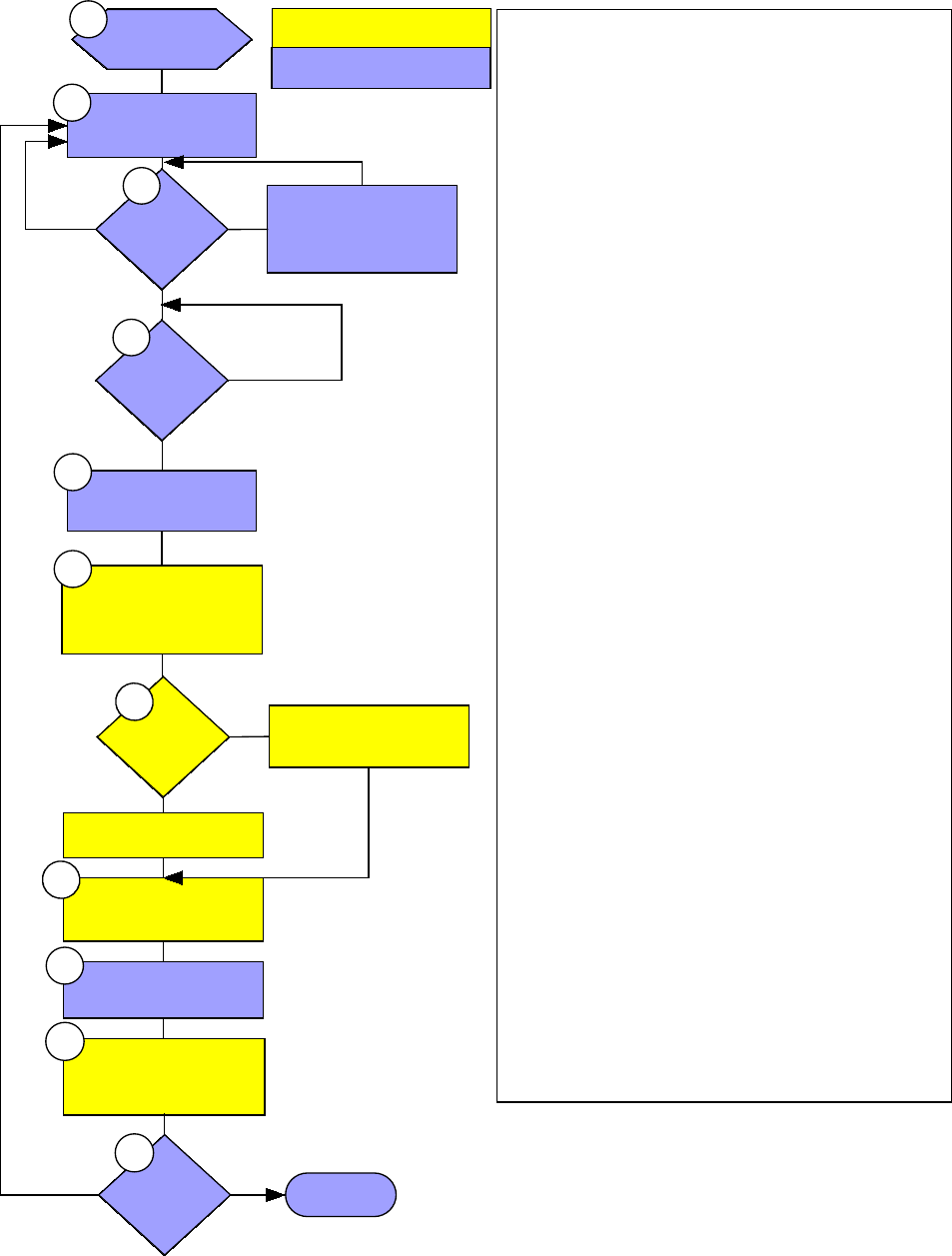
CANopen Programmer’s Manual Profile Position, Velocity, Torque & Factor Group
Operation
Copley Controls 191
Series of Discrete Profiles
This diagram illustrates how to implement a series of moves as a series of discrete profiles.
action or query done by amplifier
action or query done by CANopen
master
Control
Word
bit 4
Status
Word
bit 10
Set Control Word bit 4
(to 1).
Amplifier sees bit 4 0-1
transition;
copies buffered move to
active registers.
Control
Word bit
6
Amplifier starts relative move.
Amplifier starts
absolute move.
0
1
Clear Control Word bit 4
(to 0).
Amplifier clears bit 12 (to 0).
When target position is
reached, amplifier sets bit 10
of Status Word (to 1).
Set move parameters.
Set profile type to 0 for
trapezoid; 1 for s-curve.
Clear Control Word bit 4
(to 0).
0
1
Amplifier sets Status Word bit
12 (to 1).
1
0
2
3
4
5
6
7
9
10
More
moves?
Finished.
no
yes
11
Clear Control Word
bit 5 (to 0).
1
8
Notes:
1. Control Word bit 5 is “change set immediately.”
Clearing it tells the amplifier to treat a series of
moves as a series of discrete profiles.
2. Move Parameters are described on page 188.
3. Control Word bit 4 is “new set point.” It needs to
be 0 because the move is triggered by a 0->1
transition.
4. Status Word bit 10 is “target reached.” Value is 0
when move is in progress; 1 when move is finished.
5. Value of 1 indicates that valid data has been sent
to amplifier and new move should begin.
6. Amplifier must detect 0-1 transition to begin move.
7. Control word bit 6: value 0 causes absolute move;
value 1 causes relative move.
8. Status Word bit 12 is “set point acknowledge.” A
value of 1 indicates the amplifier has received a set
point and has started the move.
9. Control Word bit 4 is “new set point.” It needs to
be 0 to allow the next move is triggered by a
0->1 transition. Also, the 1->0 transition causes the
amplifier to clear bit 13.
10. Amplifier detects 0->1 transition of Control Word
bit 4 and clears bit 13 in response.
When the motor reaches the target position, the
amplifier sets Status Word bit 10 (“target reached”) to
1.
11. CANopen master returns to step 2 if there are
more moves to complete; otherwise, the series of
moves is finished.
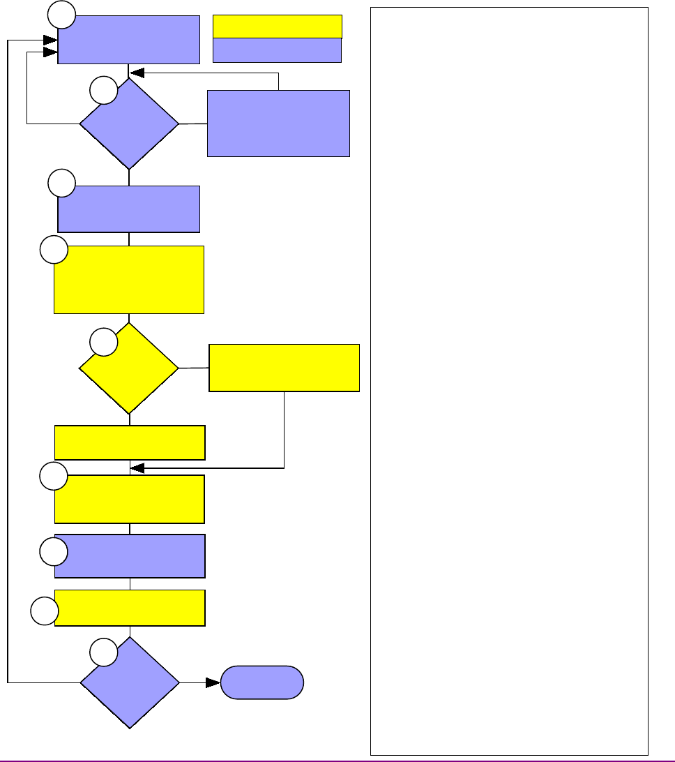
Profile Position, Velocity, Torque & Factor Group Operation CANopen Programmer’s Manual
192 16-01195 Rev 00
One Continuous Profile
This diagram illustrates how to implement a series of moves as one continuous profile.
11.1.3
Control
Word
bit 4
Set Control Word
bits 4 and 5 (to 1).
Amplifier sees bit 4 0-1
transition; sees that bit 5 is set;
copies buffered move to
active registers.
Control
Word bit
6
Amplifier begins relative
move.
Amplifier begins
absolute move.
0
1
Clear Control Word bit 4
(to 0).
Amplifier clears Status Word
bit 12 (to 0).
Set move parameters;
Set profile type to 0 (for
trapezoidal move).
Clear Control Word bit 4
(to 0).
0
1
Amplifier Status Word bit 12
(to 1).
Another
move?
yes Finished.
no
1
action or query done by amplifier
action or query done by CANopen
master
2
3
4
5
6
7
9
8
Notes:
1. Move Parameters are described on page
188. This type of move is only supported as a
trapezoidal profile.
2. Control Word bit 4 is “new set point.” It
needs to be 0 because the move will be
triggered by a 0->1 transition.
3. Bit 4, value of 1 indicates that valid data
has been sent to amplifier and new move
should begin.
Bit 5 is “change set immediately.” A value of 1
tells the amplifier to update the current profile
immediately by copying the contents of the
move buffer to the active registers (without
waiting for move to finish).
4. Amplifier must detect bit 4 0-1 transition to
begin move. Bit 5 value 1 allows immediate
update.
5. Control word bit 6: value 0 causes absolute
move; value 1 causes relative move.
6. Status Word bit 13 is “set point
acknowledge.” A value of 1 indicates the
amplifier has received a set point and has
started the move.
7. Control Word bit 4 is “new set point.” It
needs to be 0 to allow the next move will be
triggered by a 0->1 transition. Also, the 1->0
transition causes the amplifier to clear bit 13.
8. Amplifier detects 0->1 transition of Control
Word bit 4 and clears bit 13 in response.
When the motor reaches the target position,
the amplifier sets Status Word bit 10 (“target
reached”) to 1.
9. CANopen master returns to step 1 if there
are more moves to complete; otherwise, the
series of moves is finished.

CANopen Programmer’s Manual Profile Position, Velocity, Torque & Factor Group
Operation
Copley Controls 193
11.1.4 Trapezoidal vs. S-Curve Profile: Some Design Considerations
Difference Between Trapezoidal and S-Curve Profiles
Here is a review of the differences between trajectory and S-curve profiles, and some design
considerations indicated by those differences:
Trapezoidal Profile
S-Curve Profile
Design Considerations
Unlimited jerk, operation not as
smooth.
Limited jerk, smoother operation.
If the application cannot tolerate jerk,
use S-curve.
If the application can tolerate jerk,
other features available exclusively in
trapezoidal profile may indicate its use.
Supports separate acceleration and
deceleration rates.
Does not support separate
deceleration rate; uses acceleration
rate for acceleration and deceleration.
If a separate deceleration rate is
critical, the trapezoidal profile is
indicated.
Supports modification of current move
parameters during current move,
allowing the execution of a series of
moves as a continuous profile.
Does not support modification of
current move. A series of moves
requires a series of discrete profiles.
If current move modification is critical,
the trapezoidal profile is indicated.
Generally requires less torque than the
S-curve profile to complete an equal
move in equal time.
Generally requires more torque than a
trapezoidal profile to complete an
equal move in equal time, to make up
for time sacrificed for gentler starts and
stops.
Designers switching a profile from
trapezoidal to S-curve or lowering the
value of Trajectory Jerk Limit (index
0x2121, p. 197) might notice some
slowing. A higher Profile Acceleration
can be applied to compensate, but
watch out for amplifier and motor
limits.
TARGET POSITION INDEX 0X607A
Type
Access
Units
Range
Map PDO
Memory
INTEGER32
RW
counts
-
YES
RF
Description
When running in position profile mode, this object defines the destination of the trajectory
generator.
The object’s meaning varies with the move type, as set in Motion Profile Type (index 0x6086, p.
147):
Move Type
Meaning
Relative
Move distance.
Absolute
Target position.
Velocity
Direction: 1 for positive, -1 for negative.
Note that the target position programmed here is not passed to the internal trajectory generator
until the move has been started or updated using the Control Word. See Profile Position Mode
Operation, p. 185, for more information.

Profile Position, Velocity, Torque & Factor Group Operation CANopen Programmer’s Manual
194 16-01195 Rev 00
11.2 Profile Velocity Mode Operation
11.2.1 Position and Velocity Loops
In profile velocity mode, both the velocity and position loops are used to reach the velocity
programmed in the Target Velocity object (index 0x60FF.Target Velocity., p. 192 ). Profile velocity
moves are controlled by some of the same gains and limits objects used in profile position mode.
The amplifier performs profile velocity moves in Profile Velocity Mode (Mode Of Operation [index
0x6060, p. 65] =3).
11.2.2 Stepper Motor Support
The profile velocity mode can be used with a stepper motor.
11.2.3 Encoder Used as Velocity Sensor
The actual velocity is not measured with a velocity sensor. It is derived using position feedback
from the encoder.
11.2.4 Starting and Stopping Profile Velocity Moves
As in Profile Position (and Interpolated Position) modes, motion is started by a low-to-high
transition of bit 4 of the Control Word (index 0x6040, p. 59). Motion is stopped by a low-to-high
transition of bit 8, the Halt bit.
11.2.5 Profile Velocity Mode vs. Profile Position Special Velocity Mode
Profile Position Special Velocity Mode
As described earlier, the profile position mode supports a special velocity mode, in which the
velocity trajectory generator takes the place of the trapezoidal generator. The two generators are
identical with the exception that in the velocity trajectory generator, the Target Position object
(index 0x607A, p. 193) indicates direction, not a target position. Any positive number (including
zero) gives positive motion and any negative number gives negative motion. In this special velocity
mode, the move continues at the Profile Velocity (index 0x6081, p. 146) until a new target velocity
is set or until the move is halted.
To start a move in this mode, program all the profile parameters (trajectory mode, profile velocity,
acceleration, deceleration, and direction) and then program a 0-to-1 transition on Control Word bit
4. You can then clear bit 4 without effecting the trajectory, modify any of the parameters (direction,
velocity, acceleration, etc.), and set Control Word bit 4 (with bit 5 set also) to update the profile.
The normal way to stop motion in this mode is to set a profile velocity of 0.
Profile Velocity Mode
In profile velocity mode, the target velocity is updated as soon as the Target Velocity object (index
Error! 0x60FF., p. 192, p. 146) is set.
In this mode, Control Word bits 4, 5, and 6 are not used.
To start a move in profile velocity mode, set the profile parameters (profile acceleration, profile
deceleration, and target velocity). The amplifier will generate a move as long as the halt bit
(Control Word bit 8) is not set. If the halt bit is set, the amplifier will stop the move using the
deceleration value.

CANopen Programmer’s Manual Profile Position, Velocity, Torque & Factor Group
Operation
Copley Controls 195
11.3 Profile Torque Mode Operation
11.3.1 Current Loop
In profile torque mode, the current loop is used to reach the torque programmed in the Target
Torque object (index 0x6071, p.195). When the amplifier is enabled, or the torque command is
changed, the motor torque ramps to the new value at the rate programmed in Torque Slope (index
0x6087, p. 196). When the amplifier is halted, the torque ramps down at the same rate.
Profile torque moves are controlled by Current Loop Gains (index 0x2380, p. 151).
The amplifier performs profile torque moves in Profile Torque Mode (Mode Of Operation [index
0x6060, p. 65] =4).
Notes:
1: The profile torque mode cannot be used with a stepper motor.
2: To convert torque commands to the current commands that actually drive the motor, the
amplifier performs calculations based on the motor’s Motor Torque Constant (Index 0x2383, Sub-
Index 12, p. 87) and Motor Continuous Torque (Index 0x2383, Sub-Index 14
11.3.2 Starting and Stopping Profile Torque Moves
To start a move in profile torque mode, set the profile parameters. The amplifier will generate a
move as long as the halt bit (Control Word bit 8) is not set. If the halt bit is set, the amplifier will
stop the move using the torque_slope value.
TARGET TORQUE INDEX 0X6071
Type
Access
Units
Range
Map PDO
Memory
INTEGER16
RW
rated torque/1000
-215 to +215-1
TR
R
Description
In profile torque mode, this object is an input to the amplifier’s internal trajectory generator. Any
change to the target torque triggers an immediate update to the trajectory generator.
MAX TORQUE INDEX 0X6072
Type
Access
Units
Range
Map PDO
Memory
UNSIGNED16
RW
rated torque/1000
0 to 216-1
T
R
Description
The max torque the drive will exert.
MAX CURRENT INDEX 0X6073
Type
Access
Units
Range
Map PDO
Memory
UNSIGNED16
RW
rated current/1000
0 to 216-1
T
R
Description
This is the maximum torque-creating current permissible in the motor.
TORQUE DEMAND INDEX 0X6074
Type
Access
Units
Range
Map PDO
Memory
INTEGER16
RO
rated torque/1000
-215 to +215-1
T
R
Description
Output value of the trajectory generator.

Profile Position, Velocity, Torque & Factor Group Operation CANopen Programmer’s Manual
196 16-01195 Rev 00
MOTOR RATED CURRENT INDEX 0X6075
Type
Access
Units
Range
Map PDO
Memory
UNSIGNED32
RW
0.001A
0 to 232-1
NO
R
Description
The motor’s rated current (see motor name plate or motor documentation.)
MOTOR RATED TORQUE INDEX 0X6076
Type
Access
Units
Range
Map PDO
Memory
UNSIGNED32
RW
0.001 N-m
0 to 232-1
NO
R
Description
Motor’s rated torque (see motor name plate or documentation).
TORQUE ACTUAL VALUE INDEX 0X6077
Type
Access
Units
Range
Map PDO
Memory
INTEGER16
RO
Rated Torque/1000
-215 to +215-1
T
R
Description
Instantaneous torque in the motor.
CURRENT ACTUAL VALUE INDEX 0X6078
Type
Access
Units
Range
Map PDO
Memory
INTEGER16
RO
Rated Current/1000
-215 to +215-1
T
R
Description
Instantaneous current in the motor.
TORQUE SLOPE INDEX 0X6087
Type
Access
Units
Range
Map PDO
Memory
UNSIGNED32 RW
Rated Torque/1000
/second
0 to 232-1 TR R
Description
Torque acceleration or deceleration. Set to zero to disable slope limiting for instant response.
TORQUE PROFILE TYPE INDEX 0X6088
Type
Access
Units
Range
Map PDO
Memory
INTEGER16
RW
--
0
TR
R
Description
Type of torque profile used to perform a torque change. Set to zero to select trapezoidal profile.
No other types are supported.
POSITIVE TORQUE LIMIT INDEX 0X60E0
Type
Access
Units
Range
Map PDO
Memory
UNSIGNED16 RW Rated Torque / 1000 0 to 216-1 R R
Description
Motor maximum torque limit in the positive rotation or movement direction.
NEGATIVE TORQUE LIMIT INDEX 0X60E1
Type Access Units Range Map PDO
Memory
UNSIGNED16 RW Rated Torque / 1000 0 to 216-1 R R
Description
Motor maximum torque limit in the negative rotation or movement direction.

CANopen Programmer’s Manual Profile Position, Velocity, Torque & Factor Group
Operation
Copley Controls 197
11.4 Profile Mode Objects
TRAJECTORY JERK LIMIT INDEX 0X2121
Type
Access
Units
Range
Map PDO
Memory
UNSIGNED32
RW
100 counts / sec3
0 to 232-1
TR
RF
Description
This object defines the maximum jerk (rate of change of acceleration) for use with
S-curve profile moves. Other profile types do not use the jerk limit.
TRAJECTORY GENERATOR DESTINATION POSITION INDEX 0X2122
Type
Access
Units
Range
Map PDO
Memory
INTEGER32
RO
counts
-231 to +231-1
TR
R
Description
The position that the trajectory generator uses as its destination. Mostly useful when driving the amplifier
using the pulse & direction inputs.
JERK – TRAJECTORY ABORT INDEX 0X2123
Type
Access
Units
Range
Map PDO
Memory
UNSIGNED32
RW
100 counts/sec3
0 to 232-1
NO
RF
Description
Jerk value to use during trajectory aborts. If this is zero, then the abort will be calculated without
any jerk limits.
TRAJECTORY GENERATOR STATUS INDEX 0X2252
Type
Access
Units
Range
Map PDO
Memory
INTEGER16
RO
Bits
See Description, below.
T
R
Description
This variable gives status information about the trajectory generator. It is bit-mapped as follows:
Bit
Description
0-10
Reserved for future use.
11
Homing error. If set an error occurred in the last home attempt. Cleared by a home command.
12
Referenced. Set if a homing command has been successfully executed. Cleared by a home command.
13
Homing. Set when the amplifier is running a home command.
14
Set when a move is aborted. This bit is cleared at the start of the next move.
15
In motion bit. If set, the trajectory generator is presently generating a profile.

Profile Position, Velocity, Torque & Factor Group Operation CANopen Programmer’s Manual
198 16-01195 Rev 00
11.5 Factor Group Objects
Contents of this Section
This section describes the objects that are defined by the Factor Group. It allows user-defined
units for several objects.
position actual value = position internal value x feed constants
position encoder resolution x gear ratio
POSITION ENCODER RESOLUTION INDEX 0X608F
Type
Access
Bits
Range
Map PDO
Memory
UNSIGNED32
RW
80
NO
R
Description
This array holds the two values. Sub-index 0 contains the number of sub-elements of this record.
Position encoder resolution = encoder increments / motor revolutions. Typical use is with geared
rotary motors, or lead-screw linear systems where the position encoder is the load encoder.
Sub-index 0 indicates the highest sub-index supported.
POSITION ENCODER RESOLUTION – ENCODER INCREMENTS INDEX 0X608F, SUB-INDEX 1
Type
Access
Units
Range
Map PDO
Memory
UNSIGNED32
RW
counts
0 to 232-1
NO
R
Description
The number of encoder counts.
POSITION ENCODER RESOLUTION – MOTOR REVOLUTIONS INDEX 0X608F, SUB-INDEX 2
Type
Access
Units
Range
Map PDO
Memory
UNSIGNED32
RW
-
0 to 232-1
NO
R
Description
The number of revolutions.
GEAR RATIO INDEX 0X6091
Type
Access
Bits
Range
Map PDO
Memory
UNSIGNED32
RW
80
0 to 232-1
NO
R
Description
This array holds the two values. Gear ratio = motor shaft revolutions / driving shaft revolutions
Sub-index 0 contains the number of sub-elements of this record.
RATIO – MOTOR REVOLUTIONS INDEX 0X6091, SUB-INDEX 1
Type
Access
Units
Range
Map PDO
Memory
UNSIGNED32
RW
Revolutions
0 to 232-1
NO
R
Description
Gear box input (motor) shaft revolutions for numerator of gear-ratio fraction.
GEAR RATIO – SHAFT REVOLUTIONS INDEX 0X6091, SUB-INDEX 2
Type
Access
Units
Range
Map PDO
Memory
UNSIGNED32
RW
Revolutions
0 to 232-1
NO
R
Description
Gear box output (drive) shaft revolutions for denominator of gear-ratio fraction.

CANopen Programmer’s Manual Profile Position, Velocity, Torque & Factor Group
Operation
Copley Controls 199
FEED CONSTANT INDEX 0X6092
Type
Access
Bits
Range
Map PDO
Memory
ARRAY
RW
80
RECORD
NO
R
Description
The measurement distance for one revolution of the gear box output shaft.
Feed constant = Feed / driving Shaft Revolutions.
This array holds the two values. Sub-index 0 contains the number of sub-elements of this record.
FEED CONSTANT – FEED INDEX 0X6092, SUB-INDEX 1
Type
Access
Units
Range
Map PDO
Memory
UNSIGNED32
RW
-
0 to 232-1
NO
R
Description
The measurement distance in user-defined units.
FEED CONSTANT – SHAFT REVOLUTIONS INDEX 0X6092, SUB-INDEX 2
Type
Access
Units
Range
Map PDO
Memory
UNSIGNED32
RW
-
0 to 232-1
NO
R
The number of shaft revolutions for the measured distance.
VELOCITY FACTOR INDEX 0X6096
Type
Access
Bits
Range
Map PDO
Memory
ARRAY
RW
80
RECORD
NO
R
Description
The velocity factor is used to match the velocity units to user defined velocity units.
Velocity Factor = Velocity Units / User Defined Velocity Units
This array holds the two values. Sub-index 0 contains the number of sub-elements of this record.
VELOCITY FACTOR - NUMERATOR INDEX 0X6096, SUB-INDEX 1
Type
Access
Units
Range
Map PDO
Memory
UNSIGNED32
RW
-
0 to 232-1
NO
R
VELOCITY FACTOR - DIVISOR INDEX 0X6096, SUB-INDEX 2
Type
Access
Units
Range
Map PDO
Memory
UNSIGNED32
RW
-
0 to 232-1
NO
R
ACCELERATION FACTOR INDEX 0X6097
Type
Access
Bits
Range
Map PDO
Memory
ARRAY
RW
80
RECORD
NO
R
Description
The acceleration factor is used to scale acceleration units in the drive.
This array holds the two values. Sub-index 0 contains the number of sub-elements of this record.
NUMERATOR INDEX 0X6097, SUB-INDEX 1
Type
Access
Units
Range
Map PDO
Memory
UNSIGNED32
RW
-
0 to 232-1
NO
R
DIVISOR INDEX 0X6097, SUB-INDEX 2
Type
Access
Units
Range
Map PDO
Memory
UNSIGNED32
RW
-
0 to 232-1
NO
R

Profile Position, Velocity, Torque & Factor Group Operation CANopen Programmer’s Manual
200 16-01195 Rev 00
JERK FACTOR INDEX 0X60A2
Type
Access
Bits
Range
Map PDO
Memory
ARRAY
RW
80
RECORD
NO
R
Description
The jerk factor is used to match the jerk units to the defined jerk units.
This array holds the two values. Sub-index 0 contains the number of sub-elements of this record.
JERK FACTOR NUMERATOR INDEX 0X60A2, SUB-INDEX 1
Type
Access
Units
Range
Map PDO
Memory
UNSIGNED32
RW
100 Count / s3
0 to 232-1
NO
R
Description
Jerk Units .
JERK FACTOR DIVISOR INDEX 0X60A2, SUB-INDEX 2
Type
Access
Units
Range
Map PDO
Memory
UNSIGNED32
RW
100 Count / s3
0 to 232-1
NO
R
Description
Defined Jerk Units.
POLARITY INDEX 0X607E
Type
Access
Units
Range
Map PDO
Memory
UNSIGNED8
RW
-
See description
R
R
Description
This object indicates if the position or velocity demand shall be multiplied by 1 or by -1. This
polarity is only used in specific modes, including Profile Position, CSP, Profile Velocity and CSV.
If value = 0, then multiply by 1. If value = 1 then multiply by -1.

16-01195 Rev 00 201
CHAPTER
12 INTERPOLATED POSITION OPERATION
12.1 Interpolated Position Mode Overview
12.1.1 Coordinated Motion
Interpolated position mode is used to control multiple coordinated axes or a single axis with the
need for time-interpolation of set point data. In interpolated position mode, the trajectory is
calculated by the CANopen master and passed to the amplifier’s interpolated position buffer as a
set of points. The amplifier reads the points from the buffer and performs linear or cubic
interpolation between them.
Copley Controls CANopen amplifiers support three interpolation sub-modes: linear interpolation
with constant time, linear interpolation with variable time, and cubic polynomial interpolation, which
is also known as position, velocity, and time (PVT) interpolation. The amplifier can switch between
linear and PVT interpolation on the fly.
Linear Interpolation with a Constant Time
In this mode, trajectory position points are assumed to be spaced at a fixed time interval. The
amplifier drives the axis smoothly between two points within the fixed time.
Linear Interpolation with Variable Time
In this linear interpolation mode, each trajectory segment can have a different time interval.
Cubic Polynomial (PVT) Interpolation
In PVT mode, the CANopen master describes the trajectory points as a position, velocity, and time
until the next point.
Given two such points, the amplifier can interpolate smoothly between them by calculating a cubic
polynomial function, and evaluating it repeatedly until the next point is encountered.
Cubic polynomial interpolation produces much smoother curves than linear interpolation. Thus, it
can describe a complex profile with many fewer reference points. This allows a profile to be
compressed into a small number of reference points which can be sent over the CAN bus using
only a small amount of its total bandwidth.
Standard and Copley Custom Objects for Interpolated Position Mode
Copley Controls CANopen amplifiers provide two sets of objects for performing IP moves:
The CANopen DSP-402 profile standard IP move objects: 0x60C0, 0x60C1, and 0x60C2.
The Copley Controls alternative objects for PVT and linear interpolation with variable time:
0x 2010, 0x 2011, 0x 2012, and 0x 2013. These objects use bandwidth in a more efficient manner,
and feature an integrity counter to identify lost packets.

Cyclic Synchronous Modes CANopen Programmer’s Manual
202 16-01195 Rev 00
12.1.2 CANopen Standard IP Move Objects
When the CANopen DSP-402 profile standard IP move objects are used, the interpolation
submode is chosen by setting a code in Interpolation Submode Select (index 0x60C0 p. 208) as
described here:
IP Submode
Description
0
Linear interpolation with a constant time. The drive will adjust the constant times of segments to
prevent buffer over/underflows. The adjustment can be as much as one servo cycle. This lowers
burden of master to maintain accurate constant timings. But interpolated segment can be slightly
different than intended due to the adjustments in segment lengths.
-1
Linear interpolation with constant time. Master monitors 0x2012 (buffer status) to maintain points in
buffer without overflowing
-2
Linear interpolation with variable times for segments.
-3
Cubic Polynomial (PVT) Interpolation
Linear Interpolation with a Constant Time
In IP submode 0, the trajectory target position of each segment is written to Interpolation Position
(index 0x60C1, Sub-Index 1. Each time Interpolation Position is written to, the entire record is
written to the amplifier’s internal buffers. (In mode 0, Sub-Index 2 and Sub-Index 3 are ignored).
The time interval is set in Interpolation Time Value (index 0x60C2, Sub-Index 1, p. 209).
Linear Interpolation with Variable Time
In IP submode -1, each trajectory segment can have a different time interval. The trajectory target
position of each segment is written to Interpolation Position , which is Sub-Index 1 of the
Interpolation Data Record (index 0x60C1, p. 209). With each update to Interpolation Time (index
0x60C1, Sub-Index 2, p. 209), the entire record is written to the amplifier’s internal buffers.
(In mode -1, Sub-Index 3 is ignored.)
Cubic Polynomial (PVT) Interpolation
In IP submode -2, the trajectory target position of each segment is written to Interpolation Position
(index 0x60C1, Sub-Index 1, p. 209) and the segment time is written to Interpolation Time (index
0x60C1, Sub-Index 2). When the segment velocity is written to Interpolation Velocity (index
0x60C1, Sub-Index 3, p. 209), the entire record is written to the amplifier’s internal buffers.
12.1.3 Copley Controls Alternative Objects for IP Moves
The Copley Controls alternative objects use bandwidth in a highly efficient manner. They also
feature an integrity counter to identify lost packets.
Each profile segment is packed into a single 8-byte object in the object dictionary (IP move
segment command, index 0x2010, p. 206). If a PDO is used to transmit the object, then a segment
may be transmitted in a single CAN message.
For a PVT example, see PVT Profile Moves Using the Copley Controls Alternative Objects.

CANopen Programmer’s Manual Cyclic Synchronous Modes
Copley Controls 203
12.1.4 Interpolated Position Trajectory Buffer
A typical profile contains a large number of segments. These segments must be passed to the
amplifier over the CANopen network quickly enough to ensure that the next point is received
before the amplifier needs it to calculate the intermediate motor positions.
To reduce the tight timing requirements of sending trajectory segments over the network, the
amplifier maintains a buffer of trajectory segments in its memory. This allows the controller to send
trajectory segments in bursts, rather than one at a time, as the profile is executing. The amplifier
can hold 32 trajectory segments. See the Trajectory Buffer Free Count object (index 0x2011, p.
207).
Guidelines for Buffer Use
The amplifier needs a minimum of 2 trajectory segments to perform interpolation. Thus, a
successful move requires at least two segments in the buffer. Generally, it is best to keep the
buffer at least one step ahead of the interpolation, so it is best to keep at least three segments in
the buffer at any time during a move.
For instance, suppose a PVT trajectory includes the three segments:
P0, V0, T0
P1, V1, T1
P2, V2, T2
While the move is between the points P0 and P1, the amplifier needs access to both of these
segments to do the interpolation. When that segment is finished (at point P1) the amplifier needs
the next segment in order to continue interpolating toward point P2.
So, between P0 and P1, the amplifier does not yet need P2. At P1, the amplifier no longer needs
P0, but does need P2 to continue. Strictly speaking, there is no time when the amplifier needs all
three segments at once. However, in practice it is best to make sure that P2 is available when the
move is getting close to it.

Cyclic Synchronous Modes CANopen Programmer’s Manual
204 16-01195 Rev 00
12.1.5 Starting an Interpolated Position Move
An interpolated position move is started using Control Word settings (index 0x6040, p. 59) and
Status Word settings (index 0x6041, p. 60) settings. The transition of Control Word bit 4 from 0 to
1 causes the amplifier to start the move using the points stored in the interpolated move trajectory
buffer. For an example, see PVT Profile Moves Using the Copley Controls Alternative Objects
(below) and Format of Data Bytes in PVT Segment Mode.
12.1.6 Ending an Interpolated Position Move
Interpolated position moves can be stopped by adding a zero-time value to the buffer. This method
allows the amplifier to reach the present set point before motion stops.
When using the CANopen standard interpolation objects, send the zero-time value using one the
methods described below.
IP
Submode
Description
Method
0
Linear interpolation with a constant
time.
Send a zero value to Interpolation Time Value (index
0x60C2, Sub-Index 1, p. 209) before sending a segment to
the buffer.
-1
Linear interpolation with variable time.
Send a zero in Interpolation Time (index 0x60C1, Sub-Index
2, p. 209).
-2
PVT move using standard CANopen
objects.
Sending a segment with a zero-time value is the recommended way to end an interpolation profile
that uses the Copley Controls alternate objects. See IP move segment command object (index
0x2010, p. 206), and Format of Data Bytes in PVT Segment Mode.
An Interpolated position move can also be ended in one of several other ways:
Clear bit 4 of the Control Word (index 0x6040, p. 59).
Clear the quick stop bit (bit 2) of the Control Word.
Set the halt bit (bit 8) of the Control Word.
Stop adding segments to the buffer. This will cause a buffer underflow, stopping interpolation.
Note that each of these methods stops motion immediately, even if the axis has not reached the
set point.
12.1.7 Synchronization
An amplifier can run in synchronized mode or asynchronous mode. Synchronized mode should be
used when doing multi-axis interpolated position moves. (See PDO Transmission Modes, p. 27,
and SYNC and High-resolution Time Stamp Messages.)

CANopen Programmer’s Manual Cyclic Synchronous Modes
Copley Controls 205
12.1.8 PVT Profile Moves Using the Copley Controls Alternative Objects
As mentioned earlier, Copley Controls CANopen amplifiers provide an alternate set of objects for
more efficient execution of PVT moves and linear interpolation moves with variable time.
The basic method for sending PVT profile data over the CANopen network is:
1 Configure a transmit PDO to send out the Trajectory Buffer Status object (index 0x2012, p.
208). The preferred transmit type for this PDO is 255 (event driven). This causes the PDO to
be transmitted every time a segment is read from the buffer, or on error.
2 Configure a receive PDO to receive the PVT buffer data via the IP move segment command
(index 0x2010, p. 206).
3 Use either PDO or SDO transfers to fill the PVT buffer with the first N points of the profile
(where N is the size of the PVT buffer).
4 If using synchronization, start synchronization before starting motion.
5 Start the move by causing a 0-to-1 transition of bit 4 of the Control Word object (index 0x6040,
p. 59).
6 Each time a new Trajectory Buffer Status object (index 0x2012, p. 208) is received, first check
for error bits. If no errors have occurred, then one or more additional segments of PVT data
should be transmitted (until the trajectory has finished).
If the Trajectory Buffer Status object indicates that an error has occurred, then the reaction of the
controller will depend on the type of error:
Underflow errors indicate that the master controller is not able to keep up with the trajectory
information. When an amplifier detects a buffer underflow condition while executing an interpolated
profile, it will immediately abort the profile. In this case, using longer times between segments is
advisable.
Overflow errors indicate an error in the CANopen master software.
Segment sequencing errors suggest either an error in the CANopen master software or a lost
message, possibly due to noise on the bus. Since the next segment identifier value is passed with
the PVT status object, it should be possible to resend the missing segments starting with the next
expected segment. Note that the sequencing error code must be cleared with the appropriate IP
move segment command Buffer Command Mode message (p. 206) before any new segments of
PVT data are accepted.
7 End the move by setting the PVT segment time to zero. See IP move segment command
object (index 0x2010, p. 206), and Format of Data Bytes in PVT Segment Mode.

Cyclic Synchronous Modes CANopen Programmer’s Manual
206 16-01195 Rev 00
12.2 Interpolated Position Mode Objects
IP MOVE SEGMENT COMMAND INDEX 0X2010
Type
Access
Bytes
Range
Map PDO
Memory
UNSIGNED64
RW
8
RECORD
R
R
Overview
This object is used to send PVT segment data and buffer control commands in interpolated
position mode. This object is write only.
Byte 1: Header Byte
The first byte of the object identifies the type of information contained in the rest of the message.
Among other things, it determines whether the PVT Segment Command object operates in a PVT
buffer command mode or carries a PVT profile segment.
Buffer Command Mode
If the most significant bit of the header byte is set to 1, then the PVT segment command object is a
PVT buffer command. In this case, the command code is located in the remaining 7 bits of the
header byte and should take one of the following codes:
Code
Description
0
Clear the buffer and abort any move in progress.
1
Pop the N most recently sent segments off the buffer. PVT profiles will continue to run as long as the buffer
doesn't underflow. The number of segments to pop (N) is passed in the next byte (byte 1 of the message).
If there are less
than N segmen
ts on the buffer, this acts the same as a buffer clear except that the profile is not
stopped except by underflow.
2
Clear buffer errors. The next byte of data gives a mask of the errors to be cleared (any set bit clears the
corresponding error). Error bi
t locations are the same as the top byte of the status value.
3
Reset the segment ID code to zero.
4
No operation. Used with EtherCAT

CANopen Programmer’s Manual Cyclic Synchronous Modes
Copley Controls 207
PVT Segment Mode
If the most significant bit of the first byte of the message is a zero, then the message contains a
segment of the PVT profile. The remaining bits of this first byte contain the following values:
Bits
Description
0-2
Segment integrity counter. This three-bit value increases for each segment sent and is used by the amplifier to
identify missing profile
segments. More details of the use of this value are provided below.
3-6
These bits hold a buffer format code. This code identifies how the PVT data is packed into the remaining 7
bytes of the message. See the table below for details.
7
Zero. This bit is always zero identifying the message as containing PVT data.
Format of Data Bytes in PVT Segment Mode
Buffer segments hold the PVT information to be added to the buffer. The PVT data is stored in the
remaining 7 bytes of the message. The format of this data is indicated by the buffer format code
encoded in byte 0.
Code
Description
0
Bytes
Contents
1
The time (in milliseconds) until the start of the next PVT segment. Set to zero to end the move.
2-4
A 24-bit absolute position (counts). This is the starting position for this profile segment.
5-7
A 24-bit velocity given in 0.1 counts / second units.
1
Same as for code 0, except velocity is in 10 ct/sec units. This allows greater velocity range with less precision.
2
Same as for code 0, except the position is relative to the previous segment's position. If this is the first segment of
a move, the position is relative to the starting commanded position.
3
Same as for code 2, except velocity is in 10 ct/sec units.
4
Bytes 1-4 hold a 32-bit absolute position (counts). This is not a full segment itself, but is useful at the start of a
move when a full 32
-bit position must be specified. If the next segment is a relative position segment (code 2 or
3), its position is relative to this value.
5
Bytes
Contents
1
The time (in milliseconds) until the start of the next linear IP segment. Set to zero to end the move.
2-5
A 32-bit absolute position (counts). This is the starting position for this profile segment.
6
Same as for code 5, except the position is relative to the previous segment's position. If this is the first segment of
a move, the position is relative to the starting commanded position.
7-15
Reserved for future use.
Segment Integrity Counter
Each segment of a move is given a 16-bit numeric identifier. The first segment is given the
identifier 0, and each subsequent segment is given the next higher ID.
The three-bit integrity counter sent in byte zero of the segment should correspond to the lowest
three bits of the ID code (i.e. zero for the first segment and increasing by 1 for each subsequent
segment). If the amplifier receives non-consecutive segments, an error is flagged and no further
segments are accepted until the error is cleared. This allows the amplifier to identify missing
segments in the move and stop processing data at that point. Because the PVT buffer status
message includes the ID of the next expected segment, it should be possible to clear this error and
resend the missing data before the buffer is exhausted.
TRAJECTORY BUFFER FREE COUNT INDEX 0X2011
Type
Access
Units
Range
Map PDO
Memory
UNSIGNED16
RO
-
0 to 216-1
T
R
Description
This object gives the number of locations in the IP trajectory buffer that are currently available to
accept new trajectory segments. It contains the same information as bits 16-23 of the Trajectory
Buffer Status object (index 0x2012), below.

Cyclic Synchronous Modes CANopen Programmer’s Manual
208 16-01195 Rev 00
TRAJECTORY BUFFER STATUS INDEX 0X2012
Type
Access
Units
Range
Map PDO
Memory
UNSIGNED32
RO
-
See Description, below.
T
R
Description
This object gives access to status information about the IP trajectory buffer. The status value is bit-
mapped as follows:
Bit(s)
Description
0-15
These bits hold the 16-bit segment identifier of the next IP move segment expected. If a segment error has
occurred (i.e. the segment integrity counter of a received message was out of order), then these bits may
be cons
ulted to determine the ID of the segment that should have been received.
16-23
The number of free locations in the IP buffer.
24
Set if a segment sequence error is in effect. A segment sequence error occurs when an IP segment is
received with the incorre
ct value in its integrity counter.
25
Set if a buffer overflow has occurred.
26
Set if a buffer underflow has occurred.
27-30
Reserved for future use.
31
This bit is set if the IP buffer is empty.
This object is intended to be read using a PDO, and has a PDO event associated with it. The event
occurs when one of the error bits (24 – 26) is set, or when the trajectory generator removes a
segment from the trajectory buffer.
NEXT TRAJECTORY SEGMENT ID INDEX 0X2013
Type
Access
Units
Range
Map PDO
Memory
UNSIGNED16
RO
-
0 to 216-1
T
R
Description
This object gives the full 16-bit value of the next trajectory segment expected by the buffer
interface. It contains the same information as bits 0-15 of the Trajectory Buffer Status object (index
0x2012).
INTERPOLATION SUBMODE SELECT INDEX 0X60C0
Type
Access
Units
Range
Map PDO
Memory
INTEGER16
RW
-
Bit mapped
TR
R
Description
Determines which interpolation submode to use.
Submode
Description
0
Linear interpolation with constant time which is set in 0x60C2. Positions are added to the buffer by
writing to 0x60C1, sub-index 0. In this mode the drive will make small adjustments to the constant
time value to keep the buffer from under or overflowing. The drive can adjust the constant time of
any particular segment by as much as 1 servo cycle.
-1
Linear interpolation with constant time for every point added. In order to prevent over under or
overflowing of the buffer, new points must be added while keeping the master and slave
synchronized. The master must monitor the PVT buffer status (0x2012) to ensure that there are
adequate updates which is likely if there are small differences between the master and drive clocks.
Constant timing ensures that the trajectory will follow the path defined by the position updates.
-2
Linear interpolation with variable time. Positions are added to the buffer by writing to 0x60C1, sub-
index 0, then time (ms) is written to 0x60C1, sub-index 1. Position and time are both added to the
buffer when the sub-index 1 is written.
-3
Cubic polynomial interpolation. Position is first written to 0x60C1, sub-index 0, then time is written to
0x60C1, sub-index 1. Velocity is written to 0x60C1, sub-index 2. The new data will be latched when
the velocity sub-index is written. NOTE: Copley Controls provides a set of alternate objects
(0x 2010, 0x 2011, 0x 2012, and 0x 2013) for efficient PVT move handling. When using the
alternate objects, it is not necessary to set a linear interpolation submode using this object 0x60C0.

CANopen Programmer’s Manual Cyclic Synchronous Modes
Copley Controls 209
INTERPOLATION DATA RECORD INDEX 0X60C1
Type
Access
Bits
Range
Map PDO
Memory
ARRAY
RW
88
RECORD
TR
R
Description
This object is used to send interpolation data to the amplifier’s interpolation buffer.
Sub index 0 contains the number of sub-index entries.
INTERPOLATION POSITION INDEX 0X60C1, SUB-INDEX 1
Type
Access
Units
Range
Map PDO
Memory
INTEGER32
RW
Counts
0 to 232 -1
TR
R
Description
A target position. Used in all three interpolation modes.
INTERPOLATION TIME INDEX 0X60C1, SUB-INDEX 2
Type
Access
Units
Range
Map PDO
Memory
UNSIGNED8
RW
milliseconds
0 to 28 -1
TR
R
Description
The time interval of the move segment that starts with the Interpolation Position (Sub-Index 1),
and extends to the next segment. Not used with interpolation mode 0 (linear interpolation with a
constant time). In interpolation mode -1 (linear interpolation with variable time), writing to this
object causes the entire record to be written to the interpolation buffer. Writing a value of zero to
this object indicates the end of the interpolated move.
INTERPOLATION VELOCITY INDEX 0X60C1, SUB-INDEX 3
Type
Access
Units
Range
Map PDO
Memory
INTEGER32
RW
0.1 counts/sec
0 to 232 -1
TR
R
Description
Used only in interpolation mode -2 (PVT). This is the velocity used to drive the axis to the
Interpolation Position Target (Sub-Index 1) within the Interpolation Time (Sub-Index 2). Writing to
this object causes the entire record to be written to the interpolation buffer.
INTERPOLATION TIME PERIOD INDEX 0X60C2
Type
Access
Bits
Range
Map PDO
Memory
ARRAY
RW
32
RECORD
TR
R
Description
Used only in interpolation mode 0 (linear interpolation with a constant time). Defines the segment
interval. Sub index 0 contains the number of sub-index entries.
INTERPOLATION TIME VALUE INDEX 0X60C2, SUB-INDEX 1
Type
Access
Units
Range
Map PDO
Memory
UNSIGNED8
RW
variable
0 to 28 -1
TR
R
Description
This object sets the constant time that is associated with each trajectory segment in interpolation
mode 0.

Cyclic Synchronous Modes CANopen Programmer’s Manual
210 16-01195 Rev 00
INTERPOLATION TIME UNITS INDEX 0X60C2, SUB-INDEX 2
Type
Access
Units
Range
Map PDO
Memory
INTEGER8
RW
-
-3 to -6
TR
R
Description
This object indicates the Interpolation Time Units.
The formula is, seconds = Interpolation Time Value * Interpolation Time Units
Time Units
-3
0.001
-4
0.0001
-5
0.00001
-6
0.000001
INTERPOLATION DATA CONFIGURATION INDEX 0X60C4
Type
Access
Bits
Range
Map PDO
Memory
ARRAY
RW
136
RECORD
R
Description
Data is used to enable the drive to receive interpolation data before a move. Also can be used to
store positions and other data received from the master.
Sub-index 0 holds the number of elements in this object.
MAXIMUM BUFFER SIZE INDEX 0X60C4 SUB-INDEX 1
Type
Access
Bits
Range
Map PDO
Memory
UNSIGNED32 RW 32 0 to 232 -1 NO R
Description
The number of interpolation records that can be stored.
ACTUAL BUFFER SIZE INDEX 0X60C4 SUB-INDEX 2
Type
Access
Bits
Range
Map PDO
Memory
UNSIGNED32 RW 32 0 to 232 -1 R R
Description
The number of interpolation records that have been stored.
BUFFER ORGANIZATION INDEX 0X60C4 SUB-INDEX 3
Type
Access
Bits
Range
Map PDO
Memory
UNSIGNED8 RW 8 0 to 28 -1 R R
Description
0x00 = FIFO organization, 0x01 = ring buffer organization. Other values are not allowed.
BUFFER POSITION INDEX 0X60C4 SUB-INDEX 4
Type Access Bits Range Map PDO
Memory
UNSIGNED32 RW 32 0 to 232 -1 R R
Description
Dimensionless, indicating the next free buffer entry point.

CANopen Programmer’s Manual Cyclic Synchronous Modes
Copley Controls 211
SIZE OF DATA RECORD INDEX 0X60C4 SUB-INDEX 5
Type
Access
Bits
Range
Map PDO
Memory
UNSIGNED8
RW
8
0 to 28-1
R
R
Description
The number of bytes in the data record.
BUFFER CLEAR INDEX 0X60C4 SUB-INDEX 6
Type Access Bits Range Map PDO
Memory
UNSIGNED8 RW 8 0,1 R R
Description
0x00 = Clear buffer inputs, disable access, and clear all IP data records.
0x01 = Enable access to input buffers. All other values are not allowed.
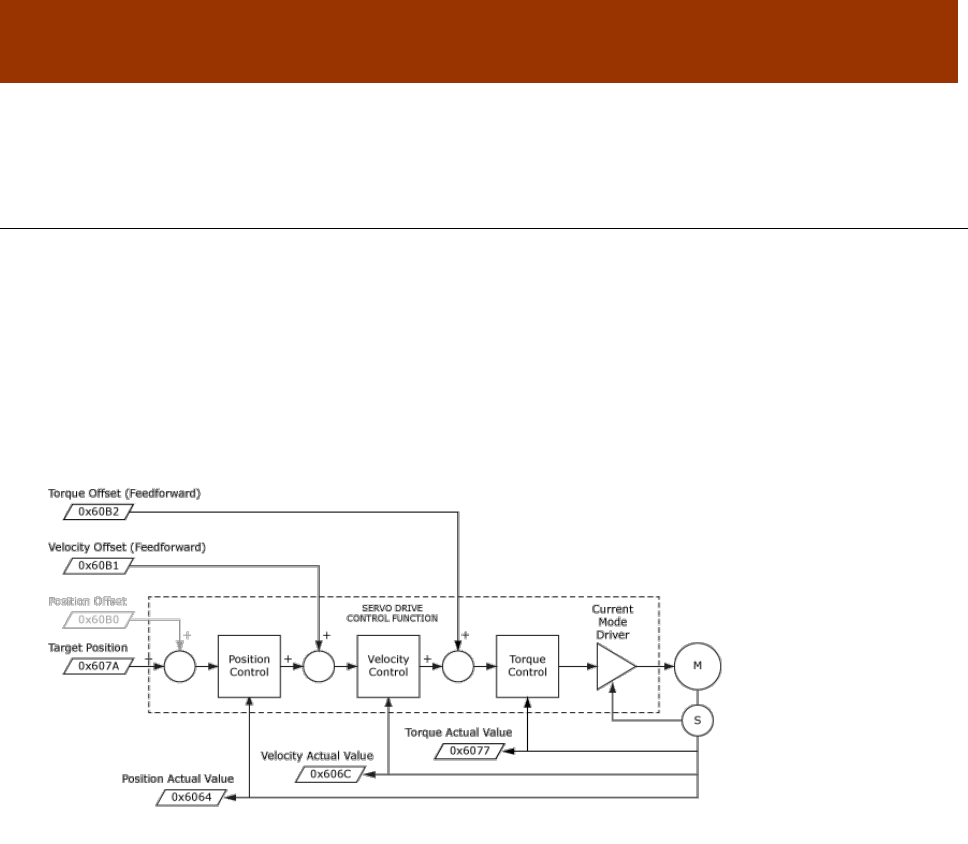
16-01195 Rev 00 212
CHAPTER
13 CYCLIC SYNCHRONOUS MODES
13.1 Cyclic Synchronous Position Mode (CSP)
In this mode the controller generates a trajectory and sends increments of position, along with
velocity and current feed-forward values, to the drive. The primary feedback from the drive is the
actual motor position and optionally, actual motor velocity and torque. Position, velocity, and
torque control loops are all closed in the servo drive which acts as a follower for the position
commands.
The diagram below shows an overview of the cascading control structure in CSP mode. Objects in
parallelograms are real-time PDO data. Other objects in rectangles are usually configured SDOs,
non-synchronously.
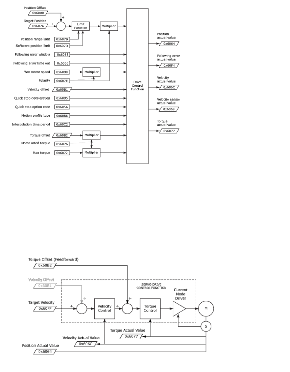
CANopen Programmer’s Manual Cyclic Synchronous Modes
Copley Controls 213
This diagram shows the CSP control function with real-time and other configuration parameters.
13.2 Cyclic Synchronous Velocity Mode (CSV)
CSV mode is frequently used with controllers that close the position loop and use the position error
to command the velocity of the servo drive (which can also accept a torque feedward value).
Velocity and torque loops are closed in the servo drive.
The diagram below shows an overview of the cascading control structure in cyclic synchronous
velocity mode (CSV).
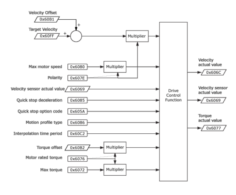
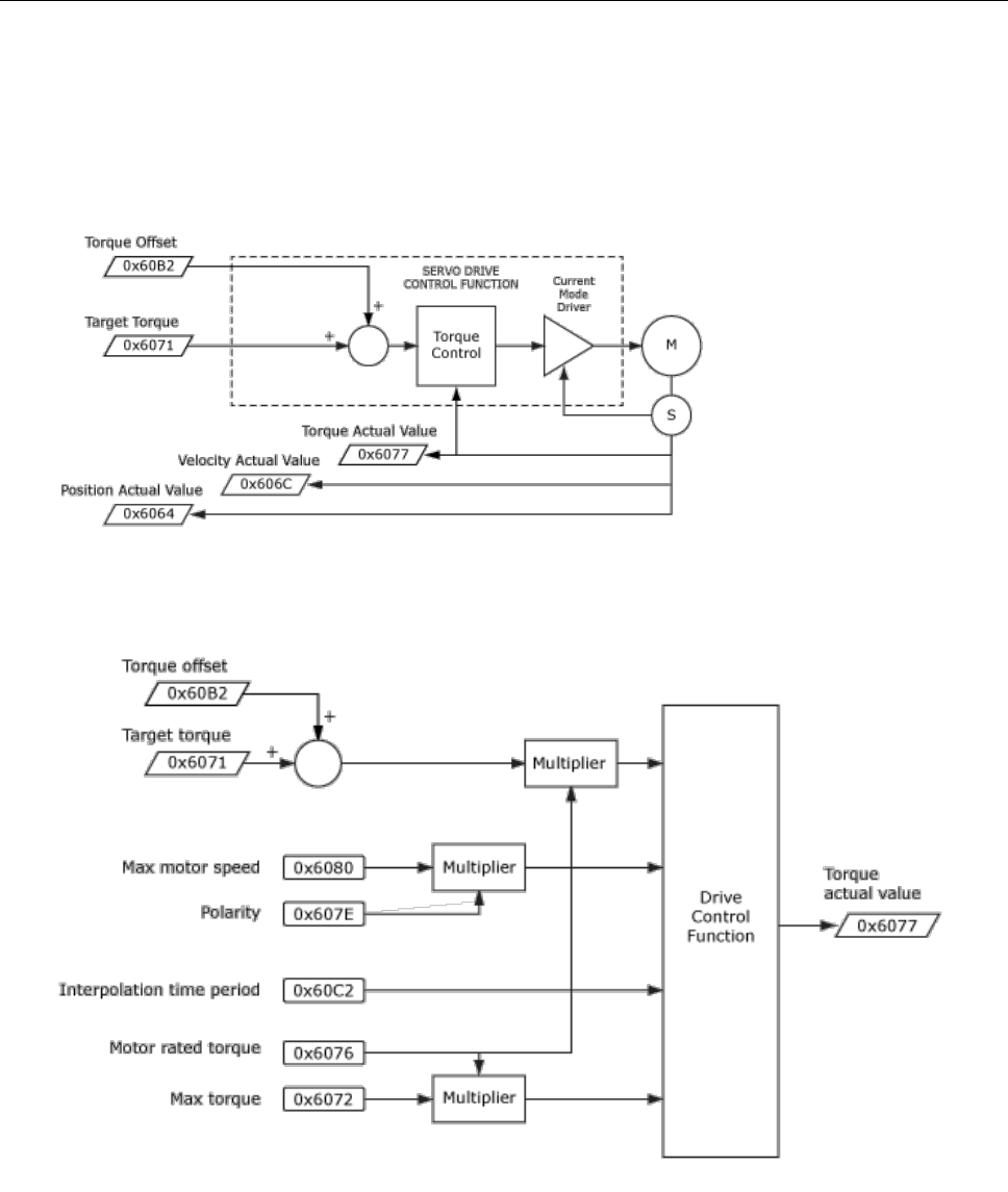
CANopen Programmer’s Manual Cyclic Synchronous Modes
Copley Controls 215
13.3 Cyclic Synchronous Torque Mode (CST)
When the controller has a full PID compensator to control position and velocity, the output is a
torque command to the servo drive. A torque offset value is used for vertical loads to balance
against gravity so that the torque command from the controller produces symmetrical acceleration
up and down.
The diagram below shows an overview of the cascading control structure in cyclic synchronous
torque mode (CST).
This diagram shows the CST control function with real-time and other configuration parameters.

Cyclic Synchronous Modes CANopen Programmer’s Manual
216 16-01195 Rev 00
CHAPTER
14 ONLY FOR ETHERCAT OBJECTS
DEVICE IDENTIFICATION RELOAD OBJECT (DEVICE ID) INDEX 0X10E0
Type
Access
Bits
Range
Map PDO
Memory
ARRAY
RW
56
RECORD
NO
R
Description: ETG1020
This object is used to explicitly reload register 0x0012 in the ESC (EtherCAT Slave Controller) that contains
the Configured Station Alias (Device ID). Sub-index 0 contains the number of sub-elements of this record.
Register addresses shown below refer to ETG 1100 Slave Controller.
CONFIGURATED STATION ALIAS REGISTER VALUE INDEX 0X10E0, SUB-INDEX 1
Type
Access
Bits
Range
Map PDO
Memory
UNSIGNED16
RW
16
0 to 216-1
NO
R
Description:
Write: write a value into register 0x0012. Read: read current value of register 0x0012
This enables changing of the Device ID value without resetting (power-cycle) the drive.
WRITE CONFIGURED STATION ALIAS PERSISTENT INDEX 0X10E0, SUB-INDEX 2
Type
Access
Bits
Range
Map PDO
Memory
UNSIGNED8
RW
8
0,1
NO
R
Description:
FALSE(0): Write access to SI 1 will write value to register 0x0012 only
TRUE(1): Write access to SI 1 will write value to register 0x0012 and to the SII (Slave Information Interface)
RELOAD ID-SELECTOR VALUE INDEX 0X10E0, SUB-INDEX 3
Type
Access
Bits
Range
Map PDO
Memory
UNSIGNED16
RW
16
NO
R
Description:
Write: writing 0x0000 to the subindex updates the current ID-selector (switches) value into register 0x0012
Read: read current value of ID-selector
BACKUP PARAMETER INFO INDEX 0X10F0
Type
Access
Bits
Range
Map PDO
Memory
UNSIGNED8
RO
48
-
NO
R
Description
Sub-index 0 contains the number of sub-elements of this record.
CRC OF PARAMETER STORAGE INDEX 0X10F0, SUB-INDEX 1
Type
Access
Bits
Range
Map PDO
Memory
UMSIGNED32
RO
32
0 to 4.3G
NO
R
Description
This value will be compared to the CRC of the drive flash memory to verify its integrity after a reset
or power-on event. If they are different it will set bit 0 of 0x2183 to indicate a fatal fault.

CANopen Programmer’s Manual Cyclic Synchronous Modes
Copley Controls 217
SYNC MANAGER 2 SYNCHRONIZATION INDEX 0X1C32
Type
Access
Bits
Range
Map PDO
Memory
ARRAY
RW
288
RECORD
NO
R
Description:
Sub-index 0 contains the number of sub-elements of this record.
SYNC MANAGER 2, SYNCHRONIZATION TYPE INDEX 0X1C32 SUB-INDEX 1
Type
Access
Bits
Range
Map PDO
Memory
UINT
RW
16
0~3
NO
R
Description:
0: Free Run
1: Synchron with SM 2 event
2: DC Mode, Synchron with SYNC0 event
3: DC Mode, Synchron with SYNC1 event
SYNC MANAGER 2, CYCLE TIME INDEX 0X1C32 SUB-INDEX 2
Type
Access
Bits
Range
Map PDO
Memory
UDINT
RO
32
NO
R
Description:
Cycle time in ns:
Free run: cycle time of local timer
Sychron with SM 2 Event: cycle time of the master
DC Mode: SYNC0/SYNC1 Cycle Time
SYNC MANAGER 2, SHIFT TIME INDEX 0X1C32 SUB-INDEX 3
Type
Access
Bits
Range
Map PDO
Memory
UDINT
RO
32
:
NO
R
Description:
Time between SYNC0 Event and Outputs Valid (in ns, only in DC-Mode)
SYNC MANAGER 2, SYNC TYPES SUPPORTED INDEX 0X1C32 SUB-INDEX 4
Type
Access
Bits
Range
Map PDO
Memory
UINT
RO
16
Bit mapped
NO
R
Description:
Supported synchronization modes:
Bit 0 = 1: Free Run is supported
Bit 1 = 1: Synchron with SM 2 Event is supported
Bit 2-3 = 01: DC-Mode is supported
Bit 4-5 = 10: Output Shift with SYNC1 Event (only DC-Mode)
Bit 14 = 1: dynamic times (could be measured Messen by writing 0x1C32:08)
SYNC MANAGER 2, MINIMUM CYCLE TIME INDEX 0X1C32 SUB-INDEX 5
Type
Access
Bits
Range
Map PDO
Memory
UDINT
RO
32
0~4.295 seconds
NO
R
Description:
Minimum cycle time supported (in ns)
SYNC MANAGER 2, CALC AND COPY TIME INDEX 0X1C32 SUB-INDEX 6
Type
Access
Bits
Range
Map PDO
Memory
UDINT
RO
32
0~4.295 seconds
NO
R
Description:
Minimal time between SYNC0 and SYNC1 Event (in ns, only in DC-Mode)

Cyclic Synchronous Modes CANopen Programmer’s Manual
218 16-01195 Rev 00
SYNC MANAGER 2, MINIMUM HARDWARE DELAY INDEX 0X1C32 SUB-INDEX 7
Type
Access
Bits
Range
Map PDO
Memory
UDINT
RO
32
0~4.295 seconds
NO
R
Description:
Time in ns
SYNC MANAGER 2, RESERVED INDEX 0X1C32 SUB-INDEX 8
Type
Access
Bits
Range
Map PDO
Memory
UINT
RO
16
NO
R
Description:
Not supported
SYNC MANAGER 2, HARDWARE DELAY TIME INDEX 0X1C32 SUB-INDEX 9
Type
Access
Bits
Range
Map PDO
Memory
UDINT
RO
32
0~4.295 seconds
NO
R
Description:
Time between SYNC1 Event and Outputs Valid (in ns, only in DC-Mode)
SYNC MANAGER 2, SYNC0 CYCLE TIME INDEX 0X1C32 SUB-INDEX 10
Type
Access
Bits
Range
Map PDO
Memory
UDINT
RO
32
0~4.295 seconds
NO
R
Description:
Sync 0 cycle time
SYNC MANAGER 3 SYNCHRONIZATION INDEX 0X1C33
Type
Access
Bits
Range
Map PDO
Memory
ARRAY
RW
-
-
NO
R
Description:
Sub-index 0 contains the number of sub-elements of this record. ?
SYNC MANAGER 3, SYNCHRONIZATION TYPE INDEX 0X1C33 SUB-INDEX 1
Type
Access
Bits
Range
Map PDO
Memory
UINT
RW
16
0~3
NO
R
Description:
0: Free Run
1: Synchron with SM 3 event
2: DC Mode, Synchron with SYNC0 event
3: DC Mode, Synchron with SYNC1 event
34: Sychron with SM 2 Event (Outputs available)
SYNC MANAGER 3, CYCLE TIME INDEX 0X1C33 SUB-INDEX 2
Type
Access
Bits
Range
Map PDO
Memory
UDINT
RO
32
NO
R
Description:
Cycle time in ns:
Free run: cycle time of local timer
Sychron with SM 3 Event: cycle time of the master
DC Mode: SYNC0/SYNC1 Cycle Time

CANopen Programmer’s Manual Cyclic Synchronous Modes
Copley Controls 219
SYNC MANAGER 3, SHIFT TIME INDEX 0X1C33 SUB-INDEX 3
Type
Access
Bits
Range
Map PDO
Memory
UDINT
RO
32
:
NO
R
Description:
Time between SYNC0 Event and Outputs Valid (in ns, only in DC-Mode)
SYNC MANAGER 3, SYNC TYPES SUPPORTED INDEX 0X1C33 SUB-INDEX 4
Type
Access
Bits
Range
Map PDO
Memory
UINT
RO
16
Bit mapped
NO
R
Description:
Supported synchronization modes:
Bit 0 = 1: Free Run is supported
Bit 1 = 1: Synchron with SM 2 Event is supported (Outputs available)
Bit 2-3 = 01: DC-Mode is supported
Bit 4-5 = 01: Input Shift with local event (Outputs available)
Bit 4-5 = 10: Input Shift with SYNC1 Event (no Outputs available)
Bit 14 = 1: dynamic times (could be measured Messen by writing 0x1C32:08 or 0x1C33:08)
SYNC MANAGER 3, MINIMUM CYCLE TIME INDEX 0X1C33 SUB-INDEX 5
Type
Access
Bits
Range
Map PDO
Memory
UDINT
RO
32
0~4.295 seconds
NO
R
Description:
Minimum cycle time supported (in ns)
SYNC MANAGER 3, CALC AND COPY TIME INDEX 0X1C33 SUB-INDEX 6
Type
Access
Bits
Range
Map PDO
Memory
UDINT
RO
32
0~4.295 seconds
NO
R
Description:
Time between Input Latch and the availability of the inputs for the master (in ns, only in DC-Mode)
SYNC MANAGER 3, MINIMUM HARDWARE DELAY INDEX 0X1C33 SUB-INDEX 7
Type
Access
Bits
Range
Map PDO
Memory
UDINT
RO
32
0~4.295 seconds
NO
R
Description:
Time in ns
SYNC MANAGER 3, RESERVED INDEX 0X1C33 SUB-INDEX 8
Type
Access
Bits
Range
Map PDO
Memory
UINT
RO
16
NO
R
Description:
Not supported
SYNC MANAGER 3, HARDWARE DELAY TIME INDEX 0X1C33 SUB-INDEX 9
Type
Access
Bits
Range
Map PDO
Memory
UDINT
RO
32
0~4.295 seconds
NO
R
Description:
Time between SYNC1 Event and Outputs Valid (in ns, only in DC-Mode)
SYNC MANAGER 3, SYNC0 CYCLE TIME INDEX 0X1C33 SUB-INDEX 10
Type
Access
Units
Range
Map PDO
Memory
UDINT
RO
32
0~4.295 seconds
NO
R
Description:
Time in ns

Cyclic Synchronous Modes CANopen Programmer’s Manual
220 16-01195 Rev 00
NODE GUARDING ERROR ACTION INDEX 0X21B2
Type
Access
Bits
Range
Map PDO
Memory
UNSIGNED16
RW
16
0~1
R
R
Description:
This parameter can be set to stop and hold or disable the drive when a heartbeat error occurs..
0 = stop and hold, 1 = disable drive.

16-01195 Rev 00 221
APPENDIX
15 ALTERNATIVE CONTROL SOURCES
15.1 Alternative Control Sources Overview
Typically, when a Copley amplifier is used on a CANopen network, the CANopen master uses the
network to send commands that drive the amplifier’s position, velocity, or current loop.
Alternately, an amplifier on a CANopen network can accept position, velocity, or current
commands over the device’s serial port, digital I/O channels, or analog reference inputs, or run
under the control of the amplifier’s internal generator or a Copley Virtual Machine (CVM) program.
Use the Indexer Register Values object (index 0x2600, p. 226) to read and write the CVM Indexer
program registers.
An amplifier can also run in camming mode to execute moves programmed in camming tables.
The Camming Configuration object (index 0x2360, p. 224) and several other objects described in
this chapter are used to configure and operate the amplifier in camming mode.
Even while operating under an alternative control source, a device’s status can still be monitored
over the CANopen network.
Specify a control source by choosing a mode in the Desired State object (index 0x2300). For more
information, see page 66.
Other objects affect the amplifier under alternative control sources. They are described in the next
section.

Alternative Control Sources CANopen Programmer’s Manual
222 16-01195 Rev 00
15.2 Alternative Control Source Objects
MICRO-STEPPING RATE INDEX 0X21C1
Type
Access
Units
Range
Map PDO
Memory
INTEGER16
RW
degrees / sec
-215 to +215-1
TR
RF
Description
This value is only used when running in diagnostic micro-stepping mode. It gives the step angle
update rate. See Desired State object (index 0x2300, p. 66), code 42.
ANALOG REFERENCE SCALING FACTOR INDEX 0X2310
Type
Access
Units
Range
Map PDO
Memory
INTEGER32
RW
See Description, below.
-231 to +231-1
TR
F
Description
When running in a mode that relies on the analog reference as an input, this object defines the
scaling that is applied to the analog reference input. See Desired State object (index 0x2300, p.
66, codes 2, 12, 22.
Mode
Scaling
Current
0.01 Amps /10 volt.
Velocity
0.1 counts / second / 10 volt.
Position
1 Count /10 volt.
ANALOG REFERENCE OFFSET INDEX 0X2311
Type
Access
Units
Range
Map PDO
Memory
INTEGER16
RW
millivolts
-215 to +215-1
TR
F
Description
This is one of two offset values applied to the analog reference input before it is used in
calculations.
ANALOG REFERENCE CALIBRATION OFFSET INDEX 0X2312
Type
Access
Units
Range
Map PDO
Memory
INTEGER16
RW
millivolts
-215 to +215-1
TR
F
Description
This voltage is added to the analog command input and is calibrated at the factory to give a zero
reading for zero input voltage. It is one of two offset values applied to the analog reference input
before the input is used in calculations.
ANALOG REFERENCE DEADBAND INDEX 0X2313
Type
Access
Units
Range
Map PDO
Memory
INTEGER16
RW
millivolts
-215 to +215-1
TR
F
Description
The analog reference input is subject to a non-linear adjustment to clip reading around zero. This
object defines the size of that window.
SECONDARY ANALOG REFERENCE VALUE INDEX 0X2208
Type
Access
Units
Range
Map PDO
Memory
INTEGER16
RO
mV
-215 to +215-1
T
R
Description
Secondary analog reference value.

CANopen Programmer’s Manual Alternative Control Sources
Copley Controls 223
MOTOR TEMP SENSOR VOLTAGE INDEX 0X2209
Type
Access
Units
Range
Map PDO
Memory
INTEGER16
RO
mV
-215 to +215-1
T
R
Description
Present voltage at analog motor temperature sensor.
MOTOR TEMP SENSOR LIMIT INDEX 0X220A
Type
Access
Units
Range
Map PDO
Memory
INTEGER16
RW
mV
-215 to +215-1
TR
F
Description
Limit for analog motor temperature sensor.
If this parameter is set to zero, then the analog motor temperature sensor is disabled.
If this parameter is set to a positive value, then a motor temperature error will occur any time the
voltage on the motor temperature input exceeds this value (in millivolts).
If this parameter is negative, then a motor temperature error will occur any time the voltage on the
motor temperature input is lower than the absolute value of this limit in millivolts.
PWM INPUT FREQUENCY INDEX 0X2322
Type
Access
Units
Range
Map PDO
Memory
UNSIGNED16
RW
10 Hz
0 to 216-1
TR
RF
Description
This is the frequency of the PWM for use only in UV commutation mode
(Desired State object [index 0x2300, p. 66].
FUNCTION GENERATOR CONFIGURATION INDEX 0X2330
Type
Access
Units
Range
Map PDO
Memory
INTEGER16
RW
Bit mapped
See Description, below.
TR
RF
Description
Configures the amplifier’s internal function generator, which can drive the current, velocity, or
position loop. Bit-mapped:
Bits
Description
0-1
Function code.
2-11
Reserved for future use.
12
One-shot mode. If set, the function code is reset to zero (disabled) after one complete waveform.
13
Invert every other waveform if set.
14-15
Reserved for future use.
The function code programmed into bits 0-1 defines the type of waveform to be generated:
Code
Describe
0
None (disabled)
1
Square wave.
2
Sine wave.
Note that the amplifier is placed under control of the function generator by setting the Desired
State object (index 0x2300, p. 66) to one of the following values:
4 Function generator drives current loop
14 Function generator drives velocity loop
24 Function generator drives position loop in servo mode
34 Function generator drives position loop in stepper mode

Alternative Control Sources CANopen Programmer’s Manual
224 16-01195 Rev 00
FUNCTION GENERATOR FREQUENCY INDEX 0X2331
Type
Access
Units
Range
Map PDO
Memory
UNSIGNED16
RW
Hz
0 to 216-1
TR
RF
Description
This object gives the frequency of the internal function generator.
FUNCTION GENERATOR AMPLITUDE INDEX 0X2332
Type
Access
Units
Range
Map PDO
Memory
INTEGER32
RW
See Description, below
-231 to +231-1
TR
RF
Description
The amplitude of the signal generated by the internal function generator.
The units depend on the servo operating mode:
Mode
Units
Current
0.01 Amps
Velocity
0.1 counts/second
Position
Counts
FUNCTION GENERATOR DUTY CYCLE INDEX 0X2333
Type
Access
Units
Range
Map PDO
Memory
UNSIGNED16
RW
0.1 percent
0 to 1000
TR
RF
Description
This object gives the function generator duty cycle for use with the square wave function.
It has no effect when running the sine function.
CAMMING CONFIGURATION INDEX 0X2360
Type
Access
Units
Range
Map PDO
Memory
UNSIGNED16
RW
Bits
Bit mapped
TR
RF
Description
Configures Camming Mode operation:
Bits
Description
0-3
ID Number of the Cam Table to use (0-9)
4
Reserved.
5
If set, exit table in forward direction.
6
If set, use the Camming Internal Generator. The internal generator runs at the constant velocity
programmed in Cam Master Velocity (index 0x2363, p. 225).
If clear, use digital command input as configured in using Copley’s CME 2 software camming controls or
Input Pin States (index 0x2190, p. 103)
7
If set, run tables stored in RAM. If clear, use tables stored in the flash file system.
8-11
Input number to use as Cam Trigger.
Note: a value of 0 selects IN1, value of 1 selects IN2, etc.
12-13
Cam Trigger type:
Value
Type
0
None (Continuous): The active Cam Table is repeated continuously.
1
Use Input, Edge: The active Cam Table begins executing on the rising edge of the input pin
selected by bits 8-11.
2
Use Input, Level: The active Cam Table will run as long as the input selected by bits 8-11 is
high.
3
Use Master (Secondary) Encoder Index: The active Cam Table is executed when the amplifier
receives an index pulse from the Master encoder. Index pulses received during execution are
ignored.

CANopen Programmer’s Manual Alternative Control Sources
Copley Controls 225
CAM DELAY FORWARD INDEX 0X2361
Type
Access
Units
Range
Map PDO
Memory
INTEGER16
RW
Master Counts.
-215 to +215-1
TR
RF
Description
The delay applied before beginning a camming profile after the trigger has been activated, in a
forward direction.
CAM DELAY REVERSE INDEX 0X2362
Type
Access
Units
Range
Map PDO
Memory
INTEGER16
RW
Master Counts.
-215 to +215-1
TR
RF
Description
The delay (in master counts) applied before beginning a camming profile after
the trigger has been activated, in a reverse direction.
CAM MASTER VELOCITY INDEX 0X2363
Type
Access
Units
Range
Map PDO
Memory
INTEGER32
RW
0.1 counts/second
-231 to +231-1
TR
RF
Description
Virtual master encoder velocity for camming mode.
TRACE BUFFER RESERVED SIZE INDEX 0X250A
Type
Access
Units
Range
Map PDO
Memory
UNSIGNED16
RW
RAM Words
0 to 216-1
TR
R
Description
The number of RAM words in the amplifier Trace Buffer to reserve for
Trace Buffer Data (such as CAM tables).
TRACE BUFFER ADDRESS INDEX 0X250B
Type
Access
Units
Range
Map PDO
Memory
UNSIGNED16
RW
Data RAM address
0 to 216-1
TR
R
Description
An offset from the beginning of the memory reserved for Trace Buffer Data (index 0x250C, p. 225).
Designates the location where the next Trace Buffer Data write (such as a CAM table master/slave
value pair) will be stored.
TRACE BUFFER DATA INDEX 0X250C
Type
Access
Units
Range
Map PDO
Memory
INTEGER32
RW
Trace data
-231 to +231-1
TR
R
Description
The first value written to this object will be stored in trace buffer RAM at the location specified by
Trace Buffer Address (index 0x250B). On each subsequent write to this object, an internal pointer
is incremented and the value will be written to the next memory location. One use of this data
object is the storage of CAM Table master/slave position value pairs.

Alternative Control Sources CANopen Programmer’s Manual
226 16-01195 Rev 00
INDEXER REGISTER VALUES INDEX 0X2600
Type
Access
Bits
Range
Map PDO
Memory
ARRAY
RW
1040
RECORD
TR
R
Description
This array object holds the values of the 32 programmable registers (0-31) maintained by the CVM
Indexer Program. Each sub-index object 1-32 contains the value of an Indexer Program register
(sub-index object 1 contains the value of Indexer Program register 0, sub-index object 32 contains
the value of register 31). Sub-index 0 contains the number of sub-indexes.
Note: When the CVM Indexer program is started, all registers are initialized to zero.
INDEXER REGISTER VALUES INDEX 0X2600, SUB-INDEX 1-32
Type
Access
Bits
Range
Map PDO
Memory
UNSIGNED32
RW
32
0 to 232-1
TR
R
Description
One sub-index object for each Indexer program register.

CANopen Programmer’s Manual Alternative Control Sources
Copley Controls 227
15.3 Running CAM Tables from RAM
Normally, Cam Tables are stored in the amplifier’s flash memory, allowing the Cam Tables to be
uploaded once and persist between power cycles.
In applications where flash storage is not appropriate or optimal, up to 16 Cam Tables can be
loaded into and run from amplifier RAM.
(For a full description of camming, see the Copley Camming User Guide.)
15.3.1 Cam Tables in Amplifier RAM
NOTE: Increments vs. Positions. When entering Cam Table data in CME 2, the user enters pairs
of absolute master and slave positions. CME 2 then converts the absolute position values to
increment values. When writing Cam Table data to amplifier RAM, the controller program must
write increment values (not absolute position values).
Using the Trace Buffer RAM Area for Cam Tables
Cam tables can be stored in and run from the area of amplifier RAM called the trace buffer. This
RAM area is normally reserved for trace data collected by the CME 2 Scope Tool. When not
needed for trace data, it may be used for other purposes, including the storage of Cam Tables.
RAM Cam Table Capacity
The Trace Buffer is 2048 16-bit words long. It can store up to 16 Cam Tables.
The maximum number of master/slave increment value pairs that can be stored in RAM varies. If
the master increment is constant, a compressed format can be used.
Furthermore, each Cam Table requires two words of metadata, so using 16 tables would reduce
the data allocation by 32 words.
Using one table in compressed format, about 2,000 master/slave increment value pairs can be
represented. A typical maximum is about 1000 value pairs.
CAM Table Structure
When used for Cam Tables, the trace buffer begins with Cam Table metadata consisting of up to
16 word pairs (32 words). The first word in each pair defines the address (offset from the beginning
of the buffer). The second word contains the length of the Cam Table.
The metadata is followed by Cam Table data, starting at the address (offset) specified in the
metadata.
In standard format, Cam Table data consists of master/slave increment value pairs. The first word
in a pair contains a master increment and the second word contains the corresponding slave
increment.
A compressed format may be used when the master increment changes at a constant rate as
described in Compressed Format for Uniform Master Increments (p. 228).
NOTE: The controller program must make sure that there is a pair of metadata words for each
Cam Table. The metadata rows must start at address (offset) 0 and must be in table ID order. For
instance, the metadata pair that begins at address 0 defines Cam Table 0, the metadata pair that
begins at address 2 defines Cam Table 1, etc. When configured to run Cam Table 0, the amplifier
will look at address 0 for a metadata pair. When configured to run Cam Table 1, the amplifier will
look at address 2, and so on.

Alternative Control Sources CANopen Programmer’s Manual
228 16-01195 Rev 00
Example: Single Cam Table
The following example shows a single Cam Table (identified at run time as Cam Table 0) stored in
the trace buffer RAM area. The first pair of words contains the Cam Table’s metadata. Word 1
contains the address (offset) to the beginning of Cam Table 0. The second word contains the
length of the table.
The remaining words begin at address 2 and contain Cam Table data in the form of master/slave
increment value pairs.
Address
Data
Data Description
0
2
Address of the start of Cam Table 0.
1
30
Length of Cam Table 0.
2
100
A master/slave increment value pair. For each 100 master increments, the slave
axis is incremented 50 encoder counts.
3
50
4--31
xxxx
Additional master/slave increment value pairs.
Example: Multiple Cam Tables
The following example shows three Cam Tables stored in the trace buffer RAM area. The first pair
of words contains the metadata for Cam Table 0. The second and third word pairs contain the
metadata for Cam Tables 1 and 2, respectively.
The remaining words begin at address 6 and contain Cam Table data, in the form of master/slave
increment value pairs, for the three Cam Tables.
Address
Data
Data Description
0
2
Address of the start of the Cam Table 0.
1
30
Length of Cam Table 0.
2
36
Address of the start of Cam Table 1.
3
24
Length of Cam Table 1.
4
60
Address of the start of Cam Table 2.
5
64
Length of Cam Table 2.
6—35
xxxx
Cam Table 0 data in the form of master/slave increment value pairs.
36—59
xxxx
Cam Table 1 data in the form of master/slave increment value pairs.
60—123
xxxx
Cam Table 2 data in the form of master/slave increment value pairs.
Compressed Format for Uniform Master Increments
When the Cam Master increments at a constant rate, a compressed format may be used to save
RAM space.
In standard format, each master/slave increment value pair is expressed using two words, one for
the master and one for the slave.
In the compressed format, the constant master increment is stored in the table’s first data word
and the slave increments are stored in the subsequent data words.
To indicate that the compressed format is used, set bit 14 of the first data word (which contains the
master increment value). Clear bit 15.
Example: A Table in Compressed Format
Address
Data
Data Description
0
2
Address of the start of Cam Table 0.
1
30
Length of Cam Table 0.
2
50
The constant master increment. To indicate that this is a constant master
increment for a compressed table, bit 14 is set and bit 15 is clear.
3—31
xxxx
A series of slave increment values.

CANopen Programmer’s Manual Alternative Control Sources
Copley Controls 229
15.3.2 Procedures for Running Cam Tables from RAM
Process overview:
1. Allocate RAM for Cam Tables
Write to coder velocity for camming mode.
Trace Buffer Reserved Size (index 0x250A, p. 225) the number of memory words to reserve for
Cam Tables.
2. Load a Cam Table into RAM
Write to Trace Buffer Address (index 0x250B, p. 225) the Cam Table’s initial offset value.
Write a series of values to Trace Buffer Data (index 0x250C, p. 225).
For standard table format, the series starts with a master increment value followed by the
corresponding slave increment, and the master/slave pairing sequence is repeated for each row of
Cam Table data.
For compressed table format, the first value is the constant master increment value. Bit 14 of this
first word is set, and bit 15 is clear. Subsequent values written to Trace Buffer Data represent the
series of slave increments.
Each time a value is written to or read from Trace Buffer Data, the amplifier increments the offset
pointer in Trace Buffer Address.
3. Configure the Camming Parameters
To configure the amplifier to run Cam Tables from RAM, set bit 7 in the Camming Configuration
object (index 0x2360, p. 224). Set other parameters as needed.
4. Run a Cam Table from RAM
Set the Desired State object (index 0x2300, p. 66) to 25 (camming mode).
The Cam Table selected in bits 0-3 of the Camming Configuration object will be run in response to
the trigger events specified in bits 12-13 of the Camming Configuration object.
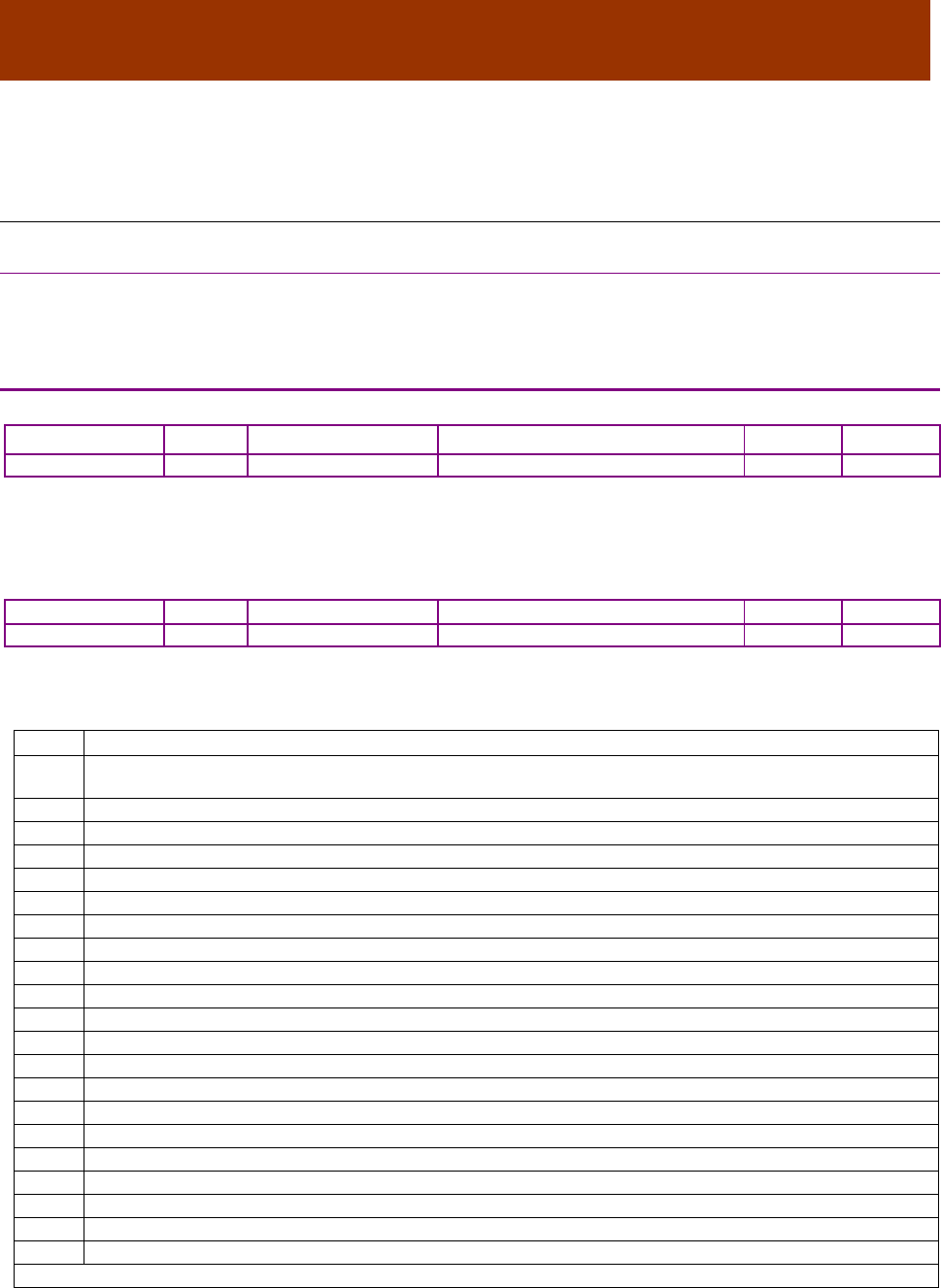
16-01195 Rev 00 230
APPENDIX
16 TRACE TOOL
16.1 Trace Tool Overview
16.1.1 Overview
The Copley Controls trace tool allows the programmer to configure and monitor up to 6 motion
trace channels. Each channel can be configured to monitor any of a number of trace variables.
Other configuration choices include the trace period and trace trigger.
TRACE CHANNEL CONFIGURATION INDEX 0X2500
Type
Access
Bits
Range
Map PDO
Memory
ARRAY
RW
112
See Description, below.
NO
R
Description
This object uses 6 sub-indices configure up to 6 trace channels.
Sub-index 0 holds the number of trace channels.
TRACE CHANNELS INDEX 0X2500, SUB-INDEX 1-6
Type
Access
Units
Range
Map PDO
Memory
UNSIGNED16
RW
Code values
0 to 55
NO
R
Description
Sub-object x configures trace channel x. Each channel can be configured to monitor one of the
trace variables described below by programming the sub-object with the code.
Code
Trace Variable
0
No data. Setting a channel to this value disables it.
Disabling unused channels saves space in the trace buffer.
3
Current reading winding A (0.01 amps)
4
Current reading winding B (0.01 amps)
5
Reference A/D reading (millivolts)
6
High voltage reference (0.1 volts)
7
Commanded torque
8
Limited torque
9
Commanded current (D rotor axis) (0.01 amps)
10
Commanded current (Q rotor axis) (0.01 amps)
11
Actual current (X stator axis) (0.01 amps)
12
Actual current (Y stator axis) (0.01 amps)
13
Actual current (D rotor axis) (0.01 amps)
14
Actual current (Q rotor axis) (0.01 amps)
15
Current Error (D rotor axis) (0.01 amps)
16
Current Error (Q rotor axis) (0.01 amps)
17
Current Integral (D rotor axis)
18
Current Integral (Q rotor axis)
19
Current loop output (D rotor axis)
20
Current loop output (Q rotor axis)
21
Current loop output (X stator axis)
22
Current loop output (Y stator axis)
Continued…

CANopen Programmer’s Manual Trace Tool
Copley Controls 231
…continued:
23
Actual motor velocity (0.1 counts/sec or 0.01 RPM if using back EMF velocity estimate).
24
Commanded motor velocity.
25
Limited motor velocity command.
26
Velocity loop error.
27
Velocity loop integral.
28
Actual load position (counts).
29
Commanded position.
30
Position loop error
31
Motor encoder position (counts)
32
Position loop output velocity
33
Raw input pin readings (no debounce)
34
reserved
35
reserved
36
Motor phase angle (1 degree units)
37
Amplifier temperature (degrees C)
38
Amplifier Manufacturer Status Register (index 0x1002, p. 61)
39
Amplifier event latch word
40
Hall sensor state
41
Position Capture Status Register (index 0x2401, p. 178)
42
Index capture register
43
Load encoder velocity (0.1 counts / second).
44
Velocity command from trajectory generator (0.1 counts/sec)
45
Acceleration command from trajectory generator (10 counts/sec
2
)
46
The analog encoder sine input. Only valid for amplifiers with analog encoder support.
47
The analog encoder cosine input. Only valid for amplifiers with analog encoder support.
48
The value of the digital inputs (after debounce)
49
The destination position input to the trajectory generator.
50
Actual motor velocity as seen by velocity loop. This is an unfiltered version of trace variable.
51
Load encoder position (counts).
52
Gain scheduling key parameter value.
53
Position loop P gain
54
Velocity loop P gain
55
Velocity loop I gain
TRACE SYSTEM STATUS INDEX 0X2501
Type
Access
Units
Range
Map PDO
Memory
UNSIGNED16
R0
Bit
Bit mapped
T
R
Description
Get trace status:
Bits
Description
0
Set if trace data is currently being collected.
1
Set if trigger has occurred.
2-15
Reserved for future use.
TRACE REFERENCE PERIOD INDEX 0X2502
Type
Access
Units
Range
Map PDO
Memory
UNSIGNED32
RO
nanoseconds
0 to 232-1
NO
R
Description
Get fundamental period. Returns a 32-bit value containing the fundamental trace period in units of
nanoseconds. The fundamental period is the maximum frequency at which the trace system can
sample data. The actual trace period is set in integer multiples of this value using
the Trace Period object (0x2505).

Trace Tool CANopen Programmer’s Manual
232 16-01195 Rev 00
TRACE SAMPLE COUNT INDEX 0X2503
Type
Access
Units
Range
Map PDO
Memory
UNSIGNED16
RO
Samples
0 to 216-1
T
R
Description
Returns the number of samples collected so far.
TRACE MAX SAMPLES INDEX 0X2504
Type
Access
Units
Range
Map PDO
Memory
UNSIGNED16
RO
Samples
0 to 216-1
NO
R
Description
The maximum number of samples that the internal trace memory buffer can hold is calculated and returned
as a 16-bit value. Note that the maximum number of samples is dependent on the number and type of active
trace variables. Set the trace variables first; then read the maximum number of samples available.
TRACE PERIOD INDEX 0X2505
Type
Access
Units
Range
Map PDO
Memory
UNSIGNED16
RW
See description.
0 to 216-1
NO
R
Description
The trace period, in integer multiples of the Trace Reference Period (0x2502).
TRACE TRIGGER CONFIGURATION INDEX 0X2506
Type
Access
Units
Range
Map PDO
Memory
ARRAY[0..2] of
UNSIGNED16
RW
Bit mapped
RECORD
NO
R
Description
Set/get the trace trigger configuration. Three additional words of data are supplied that identify the type of
trigger used to start the trace. The first word has the following format:
Bits
Description
0-3 Channel number to trigger on (if applicable).
4-7 Reserved.
8-11 Trigger type (may be interpreted differently for some trigger types):
Type
Description
0
No trigger in use.
1
Trigger as soon as the selected channel's input is greater than or equal to the trigger level.
2
Trigger as soon as the selected channel's input is less than or equal to the trigger level.
3 Trigger when the selected channel's input changes from below to above the trigger level.
4 Trigger when the selected channel's input changes from above to below the trigger level.
5
Trigger when any selected bits in the channel value are set. The bits are selected using the
trigger level value as a mask.
6
Trigger when any selected bits in the channel value are clear. The bits are selected using the
trigger level value as a mask.
7 Trigger any time the selected channel value changes.
8 The trigger level mask selects one or more bits in the Manufacturer Status Register (index
0x1002, p. 61). The trigger occurs when any of these bits change from to 1. In this mode, the
channel number selected by the trigger is not used.
9 Like type 8, but the trigger occurs when the bit(s) change from 1 to 0.
10
Trigger on the start of the next function generator cycle. This trigger type is only useful when
running in function generator mode. The trigger channel number isn't used.
12-14
Reserved.
15
If set, take one sample per trigger event.

CANopen Programmer’s Manual Trace Tool
Copley Controls 233
Normally, the two following data words specify a 32-bit trigger level (sent high word first).
These data values may be interpreted differently for some trigger types.
The trigger types are shown below:
Type
Description
0
No trigger in use.
1
Trigger as soon as the selected channel's input is greater than or equal to the trigger level.
2
Trigger as soon as the selected channel's input is less than or equal to the trigger level.
3
Trigger when the selected channel's input changes from below to above the trigger level.
4
Trigger when the selected channel's input changes from above to below the trigger level.
5
Trigger when any selected bits in the channel value are set. The bits are selected using the
trigger level value as a mask.
6
Trigger when any selected bits in the channel value are clear. The bits are selected using the
trigger level value as a mask.
7
Trigger any time the selected channel value changes.
8
The trigger level mask selects one or more bits in the event status word. The trigger occurs
when any of these bits change from 0 to 1. In this mode, the channel number selected by the
trigger is not used.
9
Like type 8, but the trigger occurs when the bit(s) change from 1 to 0.
10
Trigger on the start of the next function generator cycle. This trigger type is only useful when
running in function generator mode. The trigger channel number isn't used.
11
The trigger level mask selects one or more bits in the capture status word (parameter 0x6d).
The trigger occurs when any select bit in the status word is set. This also clears the selected
bits in the capture status which makes it useful for triggering on a new capture value even if the
captured value didn't change.
TRACE TRIGGER DELAY INDEX 0X2507
Type
Access
Units
Range
Map PDO
Memory
INTEGER16
RW
Trace Period
-215 to +215 -1
NO
R
Description
Set/get the delay between the trigger occurring and the start of captured data. The delay is given
in units of trace periods (0x2505).
Note that the delay may be either positive or negative. A negative delay means that the data
captured will precede the trigger event by the specified number of cycles. Although any input value
is accepted, the number of samples preceding the trigger is limited to the length of the trace buffer
and the number (and size) of channels being captured.
TRACE START/STOP INDEX 0X2508
Type
Access
Bits
Range
Map PDO
Memory
UNSIGNED16
RW
16
0 to 216-1
TR
R
Description
Write 0 to stop trace collection or a non-zero value to restart it.
TRACE DATA INDEX 0X2509
Type
Access
Bits
Range
Map PDO
Memory
ARRAY[0..16383]
of UINT
RO
262144
0 to 216-1 for each sample
NO
R
Description
After a trace has been collected, the trace data can be downloaded by reading from this object. The
downloaded data should be viewed as an array of 32-bit samples.

16-01195 Rev 00 234
APPENDIX
17 OBJECTS BY FUNCTION
17.1.1 Objects that Define SDOs and PDOs
Server SDO parameters Index 0x1200 ..................................................................................................... 35
SDO receive COB-ID Index 0x1200, Sub-Index 1 ................................................................................ 35
SDO transmit COB-ID Index 0x1200, Sub-Index 2 ............................................................................... 35
Receive PDO Communication Parameters Index 0x1400 – 0x1407 ........................................................ 35
PDO COB-ID Index 0x1400 – 0x1407, Sub-Index 1 ............................................................................. 35
PDO type Index 0x1400 – 0x1407, Sub-Index 2 ................................................................................. 36
Receive PDO Mapping Parameters Index 0x1600 – 0x1607 ................................................................... 36
Number of mapped objects Index 0x1600 – 0x1607, Sub-index 0 ....................................................... 36
PDO mapping Index 0x1600 – 0x1607, Sub-Index 1 – 8 ..................................................................... 36
Receive PDO Mapping Parameters Index 0x1700 ................................................................................... 37
Number of mapped objects Index 0x1700, Sub-index 0 ....................................................................... 37
PDO mapping Index 0x1700, Sub-Index 1 – 4 ..................................................................................... 37
Receive PDO Mapping Parameters Index 0x1701 ................................................................................... 38
Number of mapped objects Index 0x, Sub-index 0 ............................................................................... 38
PDO mapping Index 0x1701, Sub-Index 1 – 3 ..................................................................................... 38
Receive PDO Mapping Parameters Index 0x1702 ................................................................................... 38
Number of mapped objects Index 0x1702, Sub-index 0 ....................................................................... 38
PDO mapping Index 0x1702, Sub-Index 1 – 2 ..................................................................................... 39
Receive PDO Mapping Parameters Index 0x1703 ................................................................................... 39
Number of mapped objects Index 0x1703, Sub-index 0 ....................................................................... 39
PDO mapping Index 0x1703, Sub-Index 1 – 2 ..................................................................................... 39
Receive PDO Mapping Parameters Index 0x1704 ................................................................................... 40
Number of mapped objects Index 0x1704, Sub-index 0 ....................................................................... 40
PDO mapping Index 0x1704, Sub-Index 1 – 2 ..................................................................................... 40
Transmit PDO Communication Parameters Index 0x1800 – 0x1807 ....................................................... 41
PDO COB-ID Index 0x1800 – 0x1807, Sub-index 1 ............................................................................. 41
PDO type Index 0x1800 – 0x1807, Sub-index 2 ................................................................................. 41
Transmit PDO mapping parameters Index 0x1A00 – 0x1A07 ................................................................. 43
Number Of Mapped Objects Index 0x1A00 – 0x1A07, Sub-index 0 ..................................................... 43
PDO mapping Index 0x1A00 – 0x1A07, Sub-Index 1 – 8 ..................................................................... 43
Transmit PDO mapping parameters Index 0x1B00 ................................................................................. 44
Number Of Mapped Objects Index 0x1B00, Sub-index 0 ..................................................................... 44
PDO mapping Index 0x1B00, Sub-Index 1 – 5 ..................................................................................... 44
Sync Manager Type Index 0x1C00 ........................................................................................................... 45
Sync Manager 2 PDO Assignment Object Index 0x1C12-0x1C13 ........................................................... 45
Number of mapped objects Index 0x1C12 – 0x1C13, Sub-index 0 ...................................................... 45
PDO mapping Index 0x1C12 – 0x1C13, Sub-Index 1 – 8 .................................................................... 45
17.1.2 Network Management Objects
COB-ID Sync Message Index 0x1005 ...................................................................................................... 50
Communication Cycle Period Index 0x1006 ............................................................................................. 50
Guard Time Index 0x100C ..................................................................................................................... 50
Life Time Factor Index 0x100D ................................................................................................................. 51
High-resolution Time Stamp Index 0x1013............................................................................................... 51
Emergency Object ID Index 0x1014 ......................................................................................................... 51
Emergency Object ID Inhibit Time Index 0x1015 ..................................................................................... 51
Producer Heartbeat Time Index 0x1017 ................................................................................................... 51
Network Options Index 0x21B3 ................................................................................................................ 52

CANopen Programmer’s Manual Objects By Function
Copley Controls 235
Network Status Word Index 0x21B4 ......................................................................................................... 53
Serial Port Command Send Index 0x2000 ............................................................................................... 54
17.1.3 Device Control and Status Objects
Control Word Index: 0x6040 ..................................................................................................................... 59
Status Word Index 0x6041 ...................................................................................................................... 60
Manufacturer Status Register Index 0x1002 ............................................................................................ 61
Amplifier Event Word Index 0x2185 ......................................................................................................... 62
'Sticky' Event Status Register Index 0x2180 ............................................................................................ 62
Latched Event Status Register Index 0x2181 .......................................................................................... 62
Limit Status Mask Index 0x2184 ............................................................................................................... 62
Abort Option Code Index 0x6007 ............................................................................................................. 63
Error Code Index 0x603F ......................................................................................................................... 63
Quick Stop Option Code Index 0x605A .................................................................................................... 63
Shutdown Option Code Index 0x605B...................................................................................................... 64
Disable Operation Option Code Index 0x605C ........................................................................................ 64
Halt Option Code Index 0x605D ............................................................................................................... 64
Fault Reaction Option Code Index 0x605E .............................................................................................. 64
Mode Of Operation Index 0x6060 ............................................................................................................. 65
Mode Of Operation Display Index 0x6061 ................................................................................................ 65
Desired State Index 0x2300 ..................................................................................................................... 66
Supported Drive Modes Index 0x6502 ..................................................................................................... 67
17.1.4 Error Management Objects
Error Register Index 0x1001 ..................................................................................................................... 68
Pre-Defined Error Object Index 0x1003 .................................................................................................... 68
Number of Errors Index 0x1003, Sub-Index 0 ..................................................................................... 68
Standard Error Field Index 0x1003, Sub-Index 1-8 .............................................................................. 68
Tracking Error Window Index 0x2120 ....................................................................................................... 68
Fault Mask Index 0x2182 .......................................................................................................................... 69
Latching Fault Status Register Index 0x2183 ........................................................................................... 70
Status of Safety Circuit Index 0x219D ...................................................................................................... 70
17.1.5 Basic Amplifier Configuration Objects
Device Type Index 0x1000 ...................................................................................................................... 71
Device Name Index 0x1008 ...................................................................................................................... 71
Hardware Version String Index 0x1009 .................................................................................................... 71
Software Version Number Index 0x100A .................................................................................................. 71
Save Parameters Index 0x1010 ................................................................................................................ 71
Save All Objects Index 0x1010, Sub-index 1 or string .......................................................................... 71
Save Communication Parameters Index 0x1010, Sub-index 2 ............................................................ 72
Save Device Profile Parameters Index 0x1010, Sub-index 3 ............................................................... 72
Save Manufacturer Specific Parameters Index 0x1010, Sub-Index 4 .................................................. 72
Identity Object Index 0x1018..................................................................................................................... 72
Vendor ID Index 0x1018, Sub-index 1 ................................................................................................. 72
Product Code Index 0x1018, Sub-index 2 ............................................................................................ 73
Revision Number Index 0x1018, Sub-Index 3 ...................................................................................... 74
Serial Number Index 0x1018, Sub-Index 4 ........................................................................................... 74
Amplifier Scaling Configuration Index 0x2080 .......................................................................................... 74
Amplifier Name Index 0x21A0 .................................................................................................................. 75
Misc Amplifier Options Register Index 0x2420 ......................................................................................... 75
Flash Program Updater 0x2001 ................................................................................................................ 75
Network Node ID Configuration Index 0x21B0 ......................................................................................... 76
Input Mapping for Network Node ID Index 0x21B1 .................................................................................. 77
Current State of the CAN ID Selection Switch Index 0x2197 ................................................................... 77
Buffered Encoder Output Configuration (Multi-Port) Index 0x2241 .......................................................... 78
Amplifier Model Number Index 0x6503 ..................................................................................................... 78
Amplifier Manufacturer Index 0x6504 ....................................................................................................... 78
Objects By Function CANopen Programmer’s Manual
236 16-01195 Rev 00
Manufacturer's Web Address Index 0x6505 ............................................................................................. 78
Servo Loop Config Index 0x2301 .............................................................................................................. 79
Drive Data Index 0x2384 .......................................................................................................................... 79
Amplifier Serial Number Index 0x2384, Sub-Index 1 ............................................................................ 79
Amplifier Manufacturing Info Index 0x2384, Sub-Index 2 ..................................................................... 79
Amplifier Peak Current Limit Index 0x2384, Sub-Index 3 ..................................................................... 79
Amplifier Continuous Current Index 0x2384, Sub-Index 4 .................................................................... 79
Amplifier Peak Current Time Index 0x2384, Sub-Index 5 ..................................................................... 79
Amplifier Maximum Voltage Index 0x2384, Sub-Index 6 ...................................................................... 80
Amplifier Minimum Voltage Index 0x2384, Sub-Index 7 ....................................................................... 80
Amplifier Voltage Hysteresis Index 0x2384, Sub-Index 8 ..................................................................... 80
Amplifier Maximum Temperature Index 0x2384, Sub-Index 9 .............................................................. 80
Amplifier Temperature Hysteresis Index 0x2384, Sub-Index 10 .......................................................... 80
Amplifier Current Loop Period Index 0x2384, Sub-Index 11 ................................................................ 80
Amplifier Servo Loop Period Index 0x2384, Sub-Index 12 ................................................................... 80
Amplifier Type Code Index 0x2384, Sub-Index 13 ............................................................................... 80
Current Corresponding to Max A/D Reading Index 0x2384, Sub-Index 14 .......................................... 81
Voltage Corresponding to Max A/D Reading Index 0x2384, Sub-Index 15 .......................................... 81
Analog Input Scaling Factor Index 0x2384, Sub-Index 16 .................................................................... 81
Amplifier Minimum PWM Off Time Index 0x2384, Sub-Index 17 .......................................................... 81
PWM Dead Time At Continuous Current Limit Index 0x2384, Sub-Index 18 ....................................... 81
PWM Dead Time At Zero Current Index 0x2384, Sub-Index 19 ........................................................... 81
Peak Current Internal Regen Resistor Index 0x2384, Sub-Index 20 .................................................... 81
Continuous Current Internal Regen Resistor Index 0x2384, Sub-Index 21 .......................................... 82
Time at Peak Current Internal Regen Resistor Index 0x2384, Sub-Index 22 ....................................... 82
Analog Encoder Scaling Factor Index 0x2384, Sub-Index 23 .............................................................. 82
Firmware Version Number Index 0x2384, Sub-Index 24 ...................................................................... 82
Axis Count Index 0x2384, Sub-Index 25 .............................................................................................. 82
Internal Regen Current Limit Index 0x2384, Sub-Index 26 ................................................................... 82
FPGA Image Version Number Index 0x2384, Sub-Index 27 ................................................................ 82
NIOS Processor Firmware Version Index 0x2384, Sub-Index 28 ......................................................... 82
Misc Hardware Options Index 0x2384, Sub-Index 29 ........................................................................... 83
Current Level for Minimum PWM Deadtime Index 0x2384, Sub-Index 30 ........................................... 83
Amplifier Data Index 0x6510 ..................................................................................................................... 83
Firmware Version Number (Extended) Index 0x2422 ............................................................................... 83
Device Type Index 0x67FF ...................................................................................................................... 83
PWM Mode Index 0x2140 ...................................................................................................................... 83
Running Sum of User Current Limit Index 0x2116 ................................................................................... 84
Running Sum of Amp Current Limit Index 0x2117 ................................................................................... 84
D/A Converter Configuration. Index 0x21E0 ............................................................................................. 84
D/A Converter Output Value Index 0x21E1 .............................................................................................. 84

CANopen Programmer’s Manual Objects By Function
Copley Controls 237
17.1.6 Basic Motor Configuration Objects
Motor Type Index 0x6402 ...................................................................................................................... 85
Motor Model Number Index 0x6403 .......................................................................................................... 85
Motor Manufacturer Index 0x6404 ............................................................................................................ 85
Motor Data Index 0x2383 .......................................................................................................................... 85
Motor Type Index 0x2383, Sub-Index 1 ................................................................................................ 85
Motor Pole Pairs Index 0x2383, Sub-Index 2 ....................................................................................... 85
Motor Wiring Configuration Index 0x2383, Sub-Index 3 ....................................................................... 86
Motor Hall Type Index 0x2383, Sub-Index 4 ......................................................................................... 86
Motor Hall Wiring Index 0x2383, Sub-Index 5 ...................................................................................... 86
Motor Hall Offset Index 0x2383, Sub-Index 6 ....................................................................................... 87
Motor Resistance Index 0x2383, Sub-Index 7 ...................................................................................... 87
Motor Inductance Index 0x2383, Sub-Index 8 ...................................................................................... 87
Motor Inertia Index 0x2383, Sub-Index 9 .............................................................................................. 87
Motor Back EMF Constant Index 0x2383, Sub-index 10 ...................................................................... 87
Motor Maximum Velocity Index 0x2383, Sub-Index 11......................................................................... 87
Motor Torque Constant Index 0x2383, Sub-Index 12 ........................................................................... 87
Motor Peak Torque Index 0x2383, Sub-Index 13 ................................................................................. 88
Motor Continuous Torque Index 0x2383, Sub-Index 14 ....................................................................... 88
Motor Has Temperature Sensor Index 0x2383, Sub-Index 15 ............................................................. 88
Motor Has Brake Index 0x2383, Sub-Index 16 ..................................................................................... 88
Delay from Error to Brake Active Index 0x2383, Sub-Index 17 ............................................................ 88
Motor Brake Delay Index 0x2383, Sub-Index 18 .................................................................................. 88
Motor Brake Velocity Index 0x2383, Sub-Index 19 ............................................................................... 89
Motor Encoder Type Index 0x2383, Sub-Index 20 ............................................................................... 89
Encoder Units Index 0x2383, Sub-Index 21 ......................................................................................... 89
Motor Encoder Direction Index 0x2383, Sub-Index 22 ......................................................................... 89
Motor Encoder Counts/Rev Index 0x2383, Sub-Index 23 .................................................................... 90
Motor Encoder Resolution Index 0x2383, Sub-Index 24 ...................................................................... 90
Motor Electrical Distance Index 0x2383, Sub-Index 25 ........................................................................ 90
Encoder Index Pulse Distance Index 0x2383, Sub-Index 26 ................................................................ 90
Motor Units Index 0x2383, Sub-Index 27 .............................................................................................. 90
Analog Encoder Shift Index 0x2383, Sub-Index 28 .............................................................................. 90
Microsteps/Rev Index 0x2383, Sub-Index 29 ....................................................................................... 90
Load Encoder Type Index 0x2383, Sub-Index 30 ................................................................................. 91
Load Encoder Direction Index 0x2383, Sub-Index 31 .......................................................................... 91
Load Encoder Resolution Index 0x2383, Sub-Index 32........................................................................ 91
Motor Gear Ratio Index 0x2383, Sub-Index 33 .................................................................................... 91
Number of Resolver Cycles/Motor Rev Index 0x2383, Sub-Index 34 .................................................. 91
Motor Data Index 0x6410 .......................................................................................................................... 92
Motor Brake Enable Delay Time Index 0x2199 ........................................................................................ 92
Motor Encoder Wrap Index 0x2220 .......................................................................................................... 92
Load Encoder Wrap Index 0x2221 ........................................................................................................... 92
Motor Encoder Options Index 0x2222 ...................................................................................................... 93
Load Encoder Options Index 0x2223 ........................................................................................................ 94
Motor Encoder Status Index 0x2224 ......................................................................................................... 95
Load Encoder Status Index 0x2225 .......................................................................................................... 96
Phasing Mode Index 0x21C0 .................................................................................................................... 96
Max Current to Use with Algorithmic Phase Initialization Index 0x21C2 .................................................. 97
Algorithmic Phase Initialization Timeout Index 0x21C3 ............................................................................ 97
Algorithmic Phase Initialization Config Index 0x21C4 .............................................................................. 97
Secondary Analog Reference Offset Index 0x2314 .................................................................................. 97
Secondary Analog Reference Calibration Index 0x2315 .......................................................................... 97
Analog Encoder Sine Offset Index 0x220B............................................................................................... 97
Analog Encoder Cosine Offset Index 0x220C .......................................................................................... 98
Analog Encoder Cosine Scaling Factor Index 0x220D ............................................................................. 98
Analog Encoder Signal Magnitude Index 0x220E .................................................................................... 98
Motor Encoder Calibration Settings Index 0x2226 ................................................................................... 98

Objects By Function CANopen Programmer’s Manual
238 16-01195 Rev 00
Load Encoder Calibration Settings Index 0x2227 ..................................................................................... 98
Open Motor Wiring Current Check Index 0x2142 ..................................................................................... 98
Motor Temp Thermistor Constants Index 0x220F .................................................................................... 99
Motor Encoder Shift Index 0x2228 ............................................................................................................ 99
Load Encoder Shift Index 0x2229 ............................................................................................................. 99
Configuration for Encoder Adjustment Table Index 0x222A ..................................................................... 99
Motor Temp Thermistor Constants Index 0x220F .................................................................................... 99
17.1.7 Real-time Amplifier and Motor Status Objects
Analog/Digital Reference Input Value Index 0x2200 .............................................................................. 100
High Voltage Reference Index 0x2201 ................................................................................................... 100
Amplifier Temperature Index 0x2202 ...................................................................................................... 100
System Time Index 0x2141 .................................................................................................................... 100
Winding A Current Index 0x2203 ............................................................................................................ 100
Winding B Current Index 0x2204 ............................................................................................................ 100
Sine Feedback Voltage Index 0x2205 .................................................................................................... 100
Cosine Feedback Voltage Index 0x2206 ................................................................................................ 101
A/D Offset Value Index 0x2207 .............................................................................................................. 101
Current Offset A Index 0x2210 ............................................................................................................... 101
Current Offset B Index 0x2211 ............................................................................................................... 101
X Axis of Calculated Stator Current Vector Index 0x2212 ...................................................................... 101
Y Axis of Calculated Stator Current Vector Index 0x2213 ...................................................................... 101
Stator Voltage- X Axis Index 0x221A ...................................................................................................... 101
Stator Voltage- Y Axis Index 0x221B ...................................................................................................... 101
RMS Current Calculation Period Index 0x2114 ...................................................................................... 102
RMS current over set period Index 0x2115 ............................................................................................ 102
Motor Phase Angle Index 0x2260 ........................................................................................................... 102
Motor Phase Angle Index 0x2262 ........................................................................................................... 102
Encoder Phase Angle Index 0x2263 ...................................................................................................... 102
Hall State Index 0x2261 ........................................................................................................................ 102
Digital Command Input Scaling Factor Index 0x2321 ............................................................................ 103

CANopen Programmer’s Manual Objects By Function
Copley Controls 239
17.1.8 Digital I/O Configuration Objects
Input Pin States Index 0x2190 ................................................................................................................ 103
Input Pin State Index 0x219A ................................................................................................................. 104
Input Pin Config register (16 Bit) Index 0x2191 ...................................................................................... 104
Input Pin Config Register (32 bit) Index 0x219C..................................................................................... 104
Input Pin Configuration Index 0x2192 ..................................................................................................... 105
Input Pin Configuration Index 0x2192, Sub-Index 1-N........................................................................ 105
Input Pin Debounce Values Index 0x2195 .............................................................................................. 106
Input Pin Debounce Values Index 0x2195, Sub-Index 1-N ................................................................ 106
Raw Input Pin Value (16 bit) Index 0x2196 ............................................................................................. 106
Raw Input Pin Value (32 bit) Index 0x219B ............................................................................................ 106
Output pin configuration Index 0x2193 ................................................................................................... 107
Output Pin Configuration Index 0x2193, Sub-Index 1-N ..................................................................... 107
Output States and Program Control Index 0x2194 ................................................................................. 108
Output Compare Configuration Index 0x2160 ........................................................................................ 108
Output Compare Status Index 0x2161 .................................................................................................... 108
Output Compare Value 0 Index 0x2162 .................................................................................................. 108
Output Compare Value 1 Index 0x2163 .................................................................................................. 108
Output Compare Increment Index 0x2164 .............................................................................................. 108
Output Compare Pulse Width Index 0x2165 ........................................................................................... 109
Digital Control Input Configuration Index 0x2320 ................................................................................... 110
Digital Control Input Scaling Index 0x2321 ............................................................................................. 111
Digital Inputs Index 0x60FD ................................................................................................................... 111
Input Shaping Filter Index 0x2254 .......................................................................................................... 111
trajectory generation option Index 0x2255 .............................................................................................. 111
Registration Offset for Step & Direction Mode Index 0x2325 ................................................................. 112
UV Mode Configuration Index 0x2326 .................................................................................................... 112
UV Mode U Input Index 0x2327 .............................................................................................................. 113
UV Mode V Input Index 0x2328 .............................................................................................................. 113
Pulse & Direction Counter Index 0x2329 ................................................................................................ 113
PWM Input Duty Cycle Index 0x232A ..................................................................................................... 113
Cross Coupling Position Loop KP Index 0x2378 .................................................................................... 113
Position Offset Index 0x60B0 .................................................................................................................. 113
Velocity Offset Index 0x60B1 ................................................................................................................. 114
Torque Offset Index 0x60B2 ................................................................................................................... 114
Commutation Angle Index 0x60EA ......................................................................................................... 114
Configure I/O Options Index 0x2198 ....................................................................................................... 115
I/O Extension Options Index 0x21A1 ...................................................................................................... 116
I/O Extension Transmit Data Index 0x21A2 ............................................................................................ 116
I/O Extension Receive Data Index 0x21A3 ............................................................................................. 116
17.1.9 Position Loop Configuration Objects
Instantaneous Commanded Velocity Index 0x2250 ............................................................................... 131
Instantaneous Commanded Acceleration Index 0x2251 ........................................................................ 131
Position Demand Value Index 0x6062 .................................................................................................... 131
Position Actual Value Index 0x6063 ....................................................................................................... 131
Position Actual Value Index 0x6064 ....................................................................................................... 131
Tracking Warning Window Index 0x6065 ............................................................................................... 132
Following Error Timeout Index 0x6066 ................................................................................................... 132
Position Tracking Window Index 0x6067 ................................................................................................ 132
Position Tracking Window Time Index 0x6068 ....................................................................................... 132
Maximum Slippage-Profile Velocity Mode Index 0x60F8 ....................................................................... 133
Position Error (Following Error Actual Value) Index 0x60F4 .................................................................. 134
Position Loop Control Effort Index 0x60FA ............................................................................................. 134
Position Loop Gains Index 0x2382 ......................................................................................................... 134
Position Loop Proportional Gain Index 0x2382, Sub-Index 1 ............................................................. 134
Position Loop Velocity Feed Forward Index 0x2382, Sub-Index 2 ..................................................... 134
Position Loop Acceleration Feed Forward Index 0x2382, Sub-Index 3 .............................................. 134

Objects By Function CANopen Programmer’s Manual
240 16-01195 Rev 00
Position Loop Output Gain Multiplier Index 0x2382, Sub-Index 4 ...................................................... 135
Position Loop Integral Gain (KI) Index 0x2382, Sub-Index 5 .............................................................. 135
Position Loop Derivative Gain (KD) Index 0x2382, Sub-Index 6 ........................................................ 135
Position Loop Pi Drain (Integral Bleed) Index 0x2382, Sub-Index 7 ................................................... 135
Position Loop Gains Index 0x60FB ......................................................................................................... 136
Position Loop Proportional Gain Index 0x60FB, Sub-Index 1 ............................................................ 136
Position Loop Velocity Feed Forward Index 0x60FB, Sub-Index 2 .................................................... 136
Position Loop Acceleration Feed Forward Index 0x60FB, Sub-Index 3 ............................................. 136
Position Loop Output Gain Multiplier Index 0x60FB, Sub-Index 4 ...................................................... 136
Position Loop Integral Gain (KI) Index 0x60FB , Sub-Index 5 ............................................................ 136
Position Loop Derivative Gain (KD) Index 0x60FB , Sub-Index 6 ...................................................... 136
Position Loop Pi Drain (Integral Bleed) Index 0x60FB , Sub-Index 7 ................................................. 137
Cross Coupling Proportional (Kp) Gain Index 0x2378 ............................................................................ 137
Cross Coupling Integral (Ki ) Gain Index 0x2379.................................................................................... 137
Cross Coupling Drain (Kd) Gain Index 0x237A ...................................................................................... 137
Position Demand Internal Value Index 0x60FC ...................................................................................... 137
Software Limit Deceleration Index 0x2253 ............................................................................................. 138
Motor Encoder Position Index 0x2240 .................................................................................................... 138
Load Encoder Position Index 0x2242 ..................................................................................................... 138
Minimum PWM Pulse Width Index 0x2323 ............................................................................................. 138
Maximum PWM Pulse Width Index 0x2324 ............................................................................................ 138
Xenus Regen Resistor Resistance Index 0x2150 .................................................................................. 138
Xenus Regen Resistor Continuous Power Index 0x2151 ....................................................................... 139
Xenus Regen Resistor Peak Power Index 0x2152 ................................................................................. 139
Xenus Regen Resistor Peak Time Index 0x2153 ................................................................................... 139
Xenus Regen Resistor Turn-On Voltage Index 0x2154 .......................................................................... 139
Xenus Regen Resistor Turn-Off Voltage Index 0x2155 .......................................................................... 139
Xenus Regen Resistor Model String Index 0x2156 ................................................................................ 139
Xenus Regen Resistor Status Index 0x2157 .......................................................................................... 139
17.1.10 Velocity Loop Configuration Objects
Velocity Loop Maximum Acceleration Index 0x2100 .............................................................................. 140
Velocity Loop Maximum Deceleration Index 0x2101 or 0x60C6 ............................................................ 140
Velocity Loop Emergency Stop Deceleration Index 0x2102 ................................................................... 140
Velocity Loop – Maximum Velocity Index 0x2103 .................................................................................. 140
Velocity Error Window – Profile Position Index 0x2104 .......................................................................... 140
Velocity Error Window Time Index 0x2105 ............................................................................................. 141
Velocity Loop Output Filter Coefficients Index 0x2106 ........................................................................... 141
Hall Velocity Mode Shift Value Index 0x2107 ......................................................................................... 141
Velocity Loop Command Filter Coefficients Index 0x2108 ..................................................................... 141
Analog Input Filter Coefficients Index 0x2109 ........................................................................................ 141
Limited Velocity Index 0x2230 ................................................................................................................ 141
Load Encoder Velocity Index 0x2231 ..................................................................................................... 142
Unfiltered Motor Encoder Velocity Index 0x2232 .................................................................................... 142
Programmed Velocity Command Index 0x2341 ..................................................................................... 142
Velocity Loop Gains Index 0x2381 ......................................................................................................... 142
Actual Motor Velocity Index 0x6069 ........................................................................................................ 143
Velocity Sensor Selection Index 0x606A ................................................................................................ 143
Velocity Command Value Index 0x606B ................................................................................................. 143
Actual Velocity Index 0x606C ................................................................................................................. 144
Velocity Error Window – Profile Velocity Index 0x606D ......................................................................... 144
Velocity Error Window Time Index 0x606E ............................................................................................. 144
Velocity Threshold Index 0x606F ............................................................................................................ 144
Velocity Threshold Time Index 0x6070 ................................................................................................... 144
Position Range Limit Index 0x607B ........................................................................................................ 144
Software Position Limits Index 0x607D .................................................................................................. 145
Maximum Profile Velocity Index 0x607F ................................................................................................. 145
Velocity Loop Gains Index 0x60F9 ......................................................................................................... 145
Target Velocity Index 0x60FF ................................................................................................................. 146

CANopen Programmer’s Manual Objects By Function
Copley Controls 241
Maximum Motor Speed Index 0x6080 .................................................................................................... 146
Profile Velocity Index 0x6081 .................................................................................................................. 146
End Velocity Index 0x6082 .................................................................................................................... 146
Profile Acceleration Index 0x6083 .......................................................................................................... 146
Profile Deceleration Index 0x6084 .......................................................................................................... 147
Quick Stop Deceleration Index 0x6085 ................................................................................................... 147
Motion Profile Type Index 0x6086 .......................................................................................................... 147
Profile Jerk Index 0x60A4 .................................................................................................................... 148
Velocity Loop Maximum Acceleration Index 0x60C5 .............................................................................. 148
Velocity Loop Maximum Deceleration Index 0x60C6 ............................................................................. 148
17.1.11 Current Loop Configuration Objects
User Peak Current Limit Index 0x2110 ................................................................................................... 149
User Continuous Current Limit Index 0x2111 ......................................................................................... 149
User Peak Current Limit Time Index 0x2112 .......................................................................................... 149
Commanded Current Ramp Rate Index 0x2113 .................................................................................... 149
Actual Current, D Axis Index 0x2214 ...................................................................................................... 149
Actual Current, Q Axis Index 0x2215 ...................................................................................................... 149
Current Command, D Axis Index 0x2216 ............................................................................................... 149
Current Command, Q Axis Index 0x2217 ............................................................................................... 149
Current Loop Output, D Axis Index 0x2218 ............................................................................................ 150
Current Loop Output, Q Axis Index 0x2219 ............................................................................................ 150
Actual Motor Current Index 0x221C ........................................................................................................ 150
Commanded Current Index 0x221D ....................................................................................................... 150
Limited Current Index 0x221E ................................................................................................................ 150
Programmed Current Command Index 0x2340 ..................................................................................... 150
Current Loop Gains Index 0x2380 .......................................................................................................... 151
Current Loop Proportional Gain Index 0x2380, Sub-Index 1 .............................................................. 151
Current Loop Integral Gain Index 0x2380, Sub-Index 2 ..................................................................... 151
Current Offset Index 0x2380, Sub-Index 3 ......................................................................................... 151
Current Loop Gains Index 0x60F6 .......................................................................................................... 151
Gain Scheduling Config Index 0x2370 .................................................................................................... 152
Gain Scheduling Key Parameter Index 0x2371 ...................................................................................... 152
Second Chained Biquad Filter Index 0x210A ......................................................................................... 153
Third Chained Biquad Filter Index 0x210B ............................................................................................. 153
First Chained Biquad Filter Index 0x210C .............................................................................................. 153
Second Chained Biquad Filter Index 0x210D ......................................................................................... 153
17.1.12 Profile Current Configuration Objects
Target Torque Index 0x6071 ................................................................................................................... 195
Max Torque Index 0x6072 .................................................................................................................... 195
Max Current Index 0x6073 .................................................................................................................... 195
Torque Demand Index 0x6074 ............................................................................................................... 195
Motor Rated Current Index 0x6075 ......................................................................................................... 196
Motor Rated Torque Index 0x6076 ......................................................................................................... 196
Torque Actual Value Index 0x6077 ......................................................................................................... 196
Current Actual Value Index 0x6078 ........................................................................................................ 196
Torque Slope Index 0x6087 .................................................................................................................... 196
Torque Profile Type Index 0x6088 .......................................................................................................... 196
Positive Torque Limit Index 0x60E0 ....................................................................................................... 196
Negative Torque Limit Index 0x60E1 ...................................................................................................... 196
17.1.13 Stepper Mode Objects
Boost Current Index 0x2110 ................................................................................................................... 156
Run Current Index 0x2111 .................................................................................................................... 156
Time at Boost Current Index 0x2112 ...................................................................................................... 156
Hold Current Index 0x21D0 ................................................................................................................... 156

Objects By Function CANopen Programmer’s Manual
242 16-01195 Rev 00
Run to Hold Time Index 0x21D1 ............................................................................................................. 156
Detent Correction Gain Factor For Microstepping Mode Index 0x21D2 ................................................ 156
Voltage Control Mode Time Delay Index 0x21D5 .................................................................................. 157
Stepper Configuration and Status Index 0x21D6 ................................................................................... 157
Proportional Gain For Stepper Outer Loop Index 0x21D7 ..................................................................... 157
Maximum Velocity Adjustment Index 0x21D8 ........................................................................................ 157
17.1.14 Homing Mode Operation Objects
Homing Method Index 0x6098 ................................................................................................................ 175
Homing Speeds Index 0x6099 ................................................................................................................ 176
Home Velocity – Fast Index 0x6099, Sub-Index 1 .............................................................................. 176
Home Velocity – Slow Index 0x6099, Sub-Index 2 ............................................................................. 176
Homing Acceleration Index 0x609A ........................................................................................................ 176
Home Offset Index 0x607C ................................................................................................................... 176
Hard Stop Mode Home Current Index 0x2350........................................................................................ 177
Hard Stop Mode Home Delay Index 0x2351 .......................................................................................... 177
Home Config Index 0x2352 .................................................................................................................... 177
Position Capture Control Register Index 0x2400 .................................................................................... 178
Position Capture Status Register Index 0x2401 ..................................................................................... 178
Captured Index Position Index 0x2402 ................................................................................................... 179
Home Capture Position Index 0x2403 .................................................................................................... 179
Time Stamp of Last High Speed Position Capture Index 0x2404........................................................... 179
Position of Last High Speed Motor Capture Index 0x2405 ..................................................................... 179
Position of Last High Speed Load Capture Index 0x2406 ...................................................................... 179
Input Capture Control Index 0x2408 ....................................................................................................... 180
Input 1~15 Capture Control Index 2408 Sub-Index 1~15 ................................................................... 180
Input Capture Status Index 0x2409 ........................................................................................................ 180
Input 1~15 Capture Status Index 0x2409 Sub-Index 1~15 ................................................................. 180
Captured Rising Edge Position Index 0x240A ........................................................................................ 180
Input 1~15 Captured Rising Edge Position Index 0x240A Sub-Index 1~15 ....................................... 180
Captured Falling Edge Position Index 0x240B ....................................................................................... 180
Input 1~15 Captured Falling Edge Position Index 0x240B Sub-Index 1~15 ...................................... 180
Captured Rising Edge Time Index 0x240C ............................................................................................. 181
Input 1~15 Captured Rising Edge Time Index 0x240C Sub-Index 1~15 ............................................ 181
Captured Falling Edge Time Index 0x240D ............................................................................................ 181
Input 1~15 Captured Rising Edge Time Index 0x240D Sub-Index 1~15 ............................................ 181
CME2 Software Use Index 0x2421 ......................................................................................................... 181
Time of Last Position Sample Index 0x2410 ........................................................................................... 181
Position During Time Sample Reading Index 0x2411 ............................................................................ 181
Homing Adjustment Index 0x2353 .......................................................................................................... 181
17.1.15 Profile Mode Objects
Trajectory Jerk Limit Index 0x2121 ......................................................................................................... 197
Trajectory Generator Destination Position Index 0x2122 ....................................................................... 197
Jerk – Trajectory Abort Index 0x2123 ..................................................................................................... 197
Trajectory Generator Status Index 0x2252 ............................................................................................. 197

CANopen Programmer’s Manual Objects By Function
Copley Controls 243
17.1.16 Interpolated Position Mode Objects
IP move segment command Index 0x2010 ............................................................................................. 206
Trajectory Buffer Free Count Index 0x2011 ............................................................................................ 207
Trajectory Buffer Status Index 0x2012 .................................................................................................... 208
Next Trajectory Segment ID Index 0x2013 ............................................................................................. 208
Interpolation Submode Select Index 0x60C0.......................................................................................... 208
Interpolation Data Record Index 0x60C1 ................................................................................................ 209
Interpolation Position Index 0x60C1, Sub-Index 1 ............................................................................. 209
Interpolation Time Index 0x60C1, Sub-Index 2 .................................................................................. 209
Interpolation Velocity Index 0x60C1, Sub-Index 3 .............................................................................. 209
Interpolation Time Period Index 0x60C2 ................................................................................................. 209
Interpolation Time Value Index 0x60C2, Sub-Index 1 ....................................................................... 209
Interpolation Time Units Index 0x60C2, Sub-Index 2 ....................................................................... 210
Interpolation Data Configuration Index 0x60C4 ...................................................................................... 210
Maximum Buffer Size Index 0x60C4 Sub-Index 1 .............................................................................. 210
Actual Buffer Size Index 0x60C4 Sub-Index 2 .................................................................................... 210
Buffer Organization Index 0x60C4 Sub-Index 3 ................................................................................. 210
Buffer Position Index 0x60C4 Sub-Index 4 ......................................................................................... 210
Size of Data Record Index 0x60C4 Sub-Index 5 ................................................................................ 211
Buffer Clear Index 0x60C4 Sub-Index 6 ............................................................................................. 211
17.1.17 Alternative Control Source Objects
Micro-Stepping Rate Index 0x21C1 ........................................................................................................ 222
Analog Reference Scaling Factor Index 0x2310 .................................................................................... 222
Analog Reference Offset Index 0x2311 .................................................................................................. 222
Analog Reference Calibration Offset Index 0x2312 ................................................................................ 222
Analog Reference Deadband Index 0x2313 ........................................................................................... 222
Secondary Analog Reference Value Index 0x2208 ................................................................................ 222
Motor Temp Sensor Voltage Index 0x2209 ............................................................................................ 223
Motor Temp Sensor Limit Index 0x220A ................................................................................................. 223
PWM Input Frequency Index 0x2322 ...................................................................................................... 223
Function Generator Configuration Index 0x2330 .................................................................................... 223
Function Generator Frequency Index 0x2331 ........................................................................................ 224
Function Generator Amplitude Index 0x2332 ......................................................................................... 224
Function Generator Duty Cycle Index 0x2333 ........................................................................................ 224
Camming Configuration Index 0x2360 .................................................................................................... 224
Cam Delay Forward Index 0x2361 ......................................................................................................... 225
Cam Delay Reverse Index 0x2362 ......................................................................................................... 225
Cam Master Velocity Index 0x2363 ........................................................................................................ 225
Trace Buffer Reserved Size Index 0x250A ............................................................................................. 225
Trace Buffer Address Index 0x250B ...................................................................................................... 225
Trace Buffer Data Index 0x250C ............................................................................................................ 225
Indexer Register Values Index 0x2600 ................................................................................................... 226
Indexer Register Values Index 0x2600, Sub-Index 1-32 .................................................................... 226
17.1.18 Trace Tool Objects
Trace Channel Configuration Index 0x2500 ........................................................................................... 230
Trace Channels Index 0x2500, Sub-Index 1-6 ................................................................................... 230
Trace System Status Index 0x2501 ........................................................................................................ 231
Trace Reference Period Index 0x2502 ................................................................................................... 231
Trace Sample Count Index 0x2503 ........................................................................................................ 232
Trace Max Samples Index 0x2504 ......................................................................................................... 232
Trace Period Index 0x2505 .................................................................................................................... 232
Trace Trigger Configuration Index 0x2506 ............................................................................................. 232
Trace Trigger Delay Index 0x2507 .......................................................................................................... 233
Trace Start/Stop Index 0x2508 ............................................................................................................... 233
Trace Data Index 0x2509 ........................................................................................................................ 233

Objects By Function CANopen Programmer’s Manual
244 16-01195 Rev 00
17.1.19 EtherCAT only Objects
Device identification reload object (Device ID) Index 0x10E0 ................................................................ 216
Configurated Station Alias Register Value Index 0x10e0, Sub-Index 1.............................................. 216
Write Configured Station Alias Persistent Index 0x10e0, Sub-Index 2 ............................................... 216
reload ID-Selector Value Index 0x10e0, Sub-Index 3 ......................................................................... 216
Backup Parameter Info Index 0x10F0 .................................................................................................... 216
CRC of Parameter Storage Index 0x10F0, Sub-Index 1 .................................................................... 216
Sync Manager 2 Synchronization Index 0x1C32 .................................................................................... 217
Sync Manager 2, Synchronization type Index 0x1C32 Sub-Index 1 ................................................... 217
Sync Manager 2, Cycle Time Index 0x1C32 Sub-Index 2 .................................................................. 217
Sync Manager 2, Shift Time Index 0x1C32 Sub-Index 3 .................................................................... 217
Sync Manager 2, Sync Types Supported Index 0x1C32 Sub-Index 4................................................ 217
Sync Manager 2, Minimum Cycle Time Index 0x1C32 Sub-Index 5 .................................................. 217
Sync Manager 2, Calc and Copy Time Index 0x1C32 Sub-Index 6 ................................................... 217
Sync Manager 2, Minimum Hardware Delay Index 0x1C32 Sub-Index 7........................................... 218
Sync Manager 2, Reserved Index 0x1C32 Sub-Index 8 ..................................................................... 218
Sync Manager 2, Hardware Delay Time Index 0x1C32 Sub-Index 9 ................................................. 218
Sync Manager 2, Sync0 Cycle Time Index 0x1C32 Sub-Index 10 ..................................................... 218
Sync Manager 3 Synchronization Index 0x1C33 .................................................................................... 218
Sync Manager 3, Synchronization type Index 0x1C33 Sub-Index 1 ................................................... 218
Sync Manager 3, Cycle Time Index 0x1C33 Sub-Index 2 .................................................................. 218
Sync Manager 3, Shift Time Index 0x1C33 Sub-Index 3 .................................................................... 219
Sync Manager 3, Sync Types Supported Index 0x1C33 Sub-Index 4................................................ 219
Sync Manager 3, Minimum Cycle Time Index 0x1C33 Sub-Index 5 .................................................. 219
Sync Manager 3, Calc and Copy Time Index 0x1C33 Sub-Index 6 ................................................... 219
Sync Manager 3, Minimum Hardware Delay Index 0x1C33 Sub-Index 7........................................... 219
Sync Manager 3, Reserved Index 0x1C33 Sub-Index 8 ..................................................................... 219
Sync Manager 3, Hardware Delay Time Index 0x1C33 Sub-Index 9 ................................................. 219
Sync Manager 3, Sync0 Cycle Time Index 0x1C33 Sub-Index 10 ..................................................... 219
17.1.20 Factor Group Objects
Position encoder resolution Index 0x608F 198
Position encoder resolution – Encoder increments Index 0x608F, Sub-Index 1 ................................ 198
Position encoder resolution – motor revolutions Index 0x608F, Sub-Index 2 .................................... 198
Gear ratio Index 0x6091 ........................................................................................................................ 198
ratio – motor revolutions Index 0x6091, Sub-Index 1 ......................................................................... 198
Gear ratio – Shaft revolutions Index 0x6091, Sub-Index 2 ................................................................. 198
Feed constant Index 0x6092 ................................................................................................................... 199
Feed constant – feed Index 0x6092, Sub-Index 1 .............................................................................. 199
Feed Constant – Shaft revolutions Index 0x6092, Sub-Index 2 ......................................................... 199
Velocity Factor Index 0x6096 .................................................................................................................. 199
Velocity Factor - Numerator Index 0x6096, Sub-Index 1 .................................................................... 199
Velocity Factor - Divisor Index 0x6096, Sub-Index 2 .......................................................................... 199
Acceleration Factor Index 0x6097 .......................................................................................................... 199
Numerator Index 0x6097, Sub-Index 1 .............................................................................................. 199
Divisor Index 0x6097, Sub-Index 2 .................................................................................................. 199

CANopen Programmer’s Manual Objects By Function
Copley Controls 245
17.1.21 Touch Probe Objects
Touch Probe Function Index 0x60B8 182
Touch Probe Status Index 0x60B9 ......................................................................................................... 183
Touch Probe Pos1 Pos Value Index 0x60BA ......................................................................................... 183
Touch Probe Pos1 Neg Value Index 0x60BB ......................................................................................... 183
Touch Probe Pos2 Pos Value Index 0x60BC ......................................................................................... 183
Touch Probe Pos2 Neg Value Index 0x60BD ......................................................................................... 184
Touch Probe Select Index 0x60D0 ......................................................................................................... 184
Touch Probe Select – Probe 1 Index 0x60D0, Sub-Index 1 ............................................................... 184
Touch Probe Select – Probe 2 Index 0x60D0, Sub-Index 2 ............................................................... 184
Touch Probe Time 1 Pos Value Index 0x60D1 ...................................................................................... 184
Touch Probe Time 1 Neg Value Index 0x60D2 ..................................................................................... 184
Touch Probe Time 2 Pos Value Index 0x60D3 ...................................................................................... 184
Touch Probe Time 2 Neg Value Index 0x60D4 ..................................................................................... 184

Objects By Function CANopen Programmer’s Manual
246 16-01195 Rev 00
APPENDIX
18 OBJECTS BY INDEX ID
This chapter lists the objects in order of index ID. Bold page numbers indicate that the top-level object’s
general description appears on that page. Regular page numbers indicate that a reference to the object (or
one of its sub-objects) appears on that page.
0x1000, 71, 72, 83
0x1001, 68
0x1002, 29, 60, 61, 62, 68, 70,
96, 107, 119, 121, 122, 132,
140, 141, 231, 232
0x1003, 68
0x1005, 50
0x1006, 50
0x1008, 71
0x1009, 71
0x100A, 71
0x100C, 50
0x100D, 50, 51
0x1010, 71, 72
0x1013, 29, 51
0x1014, 51
0x1015, 51
0x1017, 51
0x1018, 72, 73, 74, 80
0x10e0, 216
0x10F0, 216
0x1200, 35
0x1400, 35, 36
0x1401, 33, 34, 35
0x1402, 35
0x1403, 36
0x1404, 36
0x1405, 36
0x1406, 36
0x1407, 35, 36
0x1600, 36, 45
0x1601, 33, 34
0x1607, 36
0x1700, 37
0x1701, 38
0x1702, 38, 39
0x1703, 39
0x1704, 40
0X1800, 12, 41
0x1A00, 43
0x1A07, 43
0x1B00, 44
0x1C00, 45
0x1C12, 45
0x1C32, 217, 218
0x1C33, 218, 219
0x2000, 54, 72
0x2001, 75
0x2002, 29
0x2010, 118, 202, 204, 205,
206
0x2011, 203, 207
0x2012, 205, 207, 208
0x2013, 208
0x2080, 74
0x2100, 120, 121, 140
0x2101, 120, 121, 140
0x2102, 120, 121, 140
0x2103, 120, 121, 126, 140,
145
0x2104, 121, 122, 125, 140,
141, 144
0x2105, 122, 125, 141, 144
0x2106, 122, 129, 141
0x2107, 122, 141
0x2108, 122, 129, 141
0x2109, 122, 141
0x210A, 153
0x210B, 153
0x210C, 153
0x210D, 153
0x2110, 130, 149, 156
0x2111, 130, 149, 156
0x2112, 130, 149, 156
0x2113, 149
0x2114, 102
0x2115, 102
0x2116, 84
0x2117, 84
0x2120, 68, 121, 132, 134,
140
0x2121, 118, 188, 193, 197
0x2122, 197
0x2123, 197
0x2140, 83
0x2141, 100
0x2142, 98
0x2150, 138
0x2151, 139
0x2152, 139
0x2153, 139
0x2154, 139
0x2155, 139
0x2156, 139
0x2157, 139
0x2160, 108
0x2161, 108
0x2162, 108
0x2163, 108
0x2164, 108
0x2165, 109
0x2180, 62
0x2181, 62, 107
0x2182, 68, 69, 70
0x2183, 69, 70
0x2184, 60, 62
0x2185, 62
0x2190, 29, 103, 106, 111,
224
0x2191, 104
0x2192, 105
0x2193, 107, 108
0x2194, 108
0x2195, 106
0x2196, 106
0x2197, 77
0x2198, 115
0x2199, 92
0x219A, 104
0x219B, 106
0x219C, 104
0x219D, 70
0x21A0, 75
0x21A1, 116
0x21A2, 116
0x21A3, 116
0x21B0, 76, 77
0x21B1, 76, 77
0x21B2, 220
0x21B3, 52
0x21B4, 53
0x21C0, 96
0x21C1, 222
0x21C2, 97
0x21C3, 97
Copley Controls 247
0x21C4, 97
0x21D0, 156
0x21D1, 156
0x21D2, 156
0x21D5, 157
0x21D6, 157
0x21D7, 157
0x21D8, 157
0x21E0, 84
0x21E1, 84
0x2200, 100
0x2201, 100
0x2202, 100
0x2203, 100
0x2204, 100
0x2205, 100
0x2206, 101
0x2207, 101
0x2208, 222
0x2209, 223
0x220A, 223
0x220B, 97
0x220C, 98
0x220D, 98
0x220E, 98
0x220F, 99
0x2210, 101
0x2211, 101
0x2212, 101
0x2213, 101
0x2214, 149
0x2215, 149
0x2216, 149
0x2217, 149
0x2218, 150
0x2219, 150
0x221A, 101
0x221B, 101
0x221C, 150
0x221D, 129, 150
0x221E, 130, 150
0x2220, 92
0x2221, 92
0x2222, 93
0x2223, 94
0x2224, 95
0x2225, 96
0x2226, 98
0x2227, 98
0x2228, 99
0x2229, 99
0x222A, 99
0x2230, 120, 122, 141
0x2231, 123, 138, 142, 152
0x2232, 123, 142
0x2240, 131, 138
0x2241, 78
0x2242, 131, 138
0x2250, 119, 131, 134, 136,
152
0x2251, 119, 123, 131, 134,
136, 142
0x2252, 107, 197
0x2253, 138
0x2254, 111
0x2255, 111
0x2260, 102
0x2261, 102
0x2262, 102
0x2263, 102
0x2300, 60, 66, 111, 149, 221,
222, 223, 229
0x2301, 79
0x2310, 222
0x2311, 222
0x2312, 222
0x2313, 222
0x2314, 97
0x2315, 97
0x2320, 110, 113
0x2321, 103, 111
0x2322, 223
0x2323, 138
0x2324, 138
0x2325, 112
0x2326, 112
0x2327, 113
0x2328, 113
0x2329, 113
0x232A, 113
0x2330, 223
0x2331, 224
0x2332, 224
0x2333, 224
0x2340, 150
0x2341, 123, 142
0x2350, 177
0x2351, 177
0x2352, 177
0x2353, 177, 181
0x2360, 221, 224, 229
0x2361, 225
0x2362, 225
0x2363, 224, 225
0x2370, 152
0x2371, 152
0x2378, 113
0x2378, 137
0x2379, 137
0x237A, 137
0x2380, 151
0x2381, 123, 124, 129, 142,
143
0x2382, 131, 134, 135
0x2383, 85, 86, 87, 88, 89, 90,
91, 97, 154, 195
0x2384, 73, 74, 79, 80, 81, 82,
83
0x2400, 178
0x2401, 178, 179, 231
0x2402, 178, 179
0x2403, 178, 179
0x2404, 179
0x2405, 178, 179
0x2406, 179
0x2408, 180
0x2409, 180
0x240A, 180
0x240B, 180
0x240C, 181
0x240D, 181
0x2410, 181
0x2411, 181
0x2420, 75, 105
0x2421, 181
0x2422, 83
0x2500, 230
0x2501, 231
0x2502, 231, 232
0x2503, 232
0x2504, 232
0x2505, 231, 232, 233
0x2506, 232
0x2507, 233
0x2508, 233
0x2509, 233
0x250A, 225, 229
0x250B, 225, 229
0x250C, 225, 229
0x2600, 221, 226
0x6007, 63
0x603F, 63
0x6040, 28, 30, 34, 55, 59,
127, 146, 158, 189, 194,
204, 205
0x6041, 28, 29, 42, 55, 60, 62,
132, 158, 189, 204
0x605A, 63
0x605B, 64
0x605C, 64
0x605D, 64
0x605E, 64
0x6060, 19, 28, 30, 34, 55, 59,
60, 65, 158, 185, 194, 195
0x6061, 28, 65
0x6062, 119, 131, 137
0x6063, 119, 131, 134, 138,
152
0x6064, 28, 131, 134, 136
0x6065, 132, 133
0x6066, 132
0x6067, 60, 61, 132, 134
0x6068, 132
0x6069, 124, 125, 143, 144
248 16-01195 Rev 00
0x606A, 124, 143
0x606B, 119, 124, 143
0x606C, 28, 125, 144
0x606D, 125, 144
0x606E, 125, 144
0x606F, 125, 144
0x6070, 125, 144
0x6071, 28, 30, 195
0x6072, 195
0x6073, 195
0x6074, 195
0x6075, 196
0x6076, 196
0x6077, 28, 30, 196
0x6078, 196
0x607A, 28, 30, 118, 188,
193, 194
0x607B, 125, 126, 144, 145
0x607C, 118, 176
0x607D, 126, 145
0x607E, 200
0x607F, 126, 145
0x6080, 127, 146
0x6081, 118, 127, 146, 188,
194
0x6082, 127, 146
0x6083, 118, 127, 128, 146,
147, 188
0x6084, 63, 118, 128, 147,
188
0x6085, 58, 63, 128, 147, 188
0x6086, 118, 128, 147, 185,
188, 189, 193
0x6087, 195, 196
0x6088, 196
0x608F, 198
0x6091, 198
0x6092, 199
0x6096, 199
0x6097, 199
0x6098, 118, 160, 161, 162,
163, 164, 165, 166, 167,
168, 169, 170, 171, 172,
173, 174, 175
0x6099, 118, 158, 176
0x609A, 118, 158, 176
0x60A2, 200
0x60A4, 129, 148
0x60B0, 113
0x60B1, 114
0x60B2, 114
0x60B8, 182
0x60B9, 183
0x60BA, 183
0x60BB, 183
0x60BC, 183
0x60BD, 184
0x60C0, 201, 202, 208
0x60C1, 201, 202, 204, 209
0x60C2, 201, 202, 204, 209,
210
0x60C4, 210, 211
0x60C5, 129, 148
0x60C6, 121, 129, 140, 148
0x60D0, 184
0x60D1, 184
0x60D2, 184
0x60D3, 184
0x60D4, 184
0x60E0, 196
0x60E1, 196
0x60EA, 30, 114
0x60F4, 60, 61, 68, 119, 134,
157
0x60F6, 130, 151, 195
0x60F8, 133
0x60F9, 126, 145
0x60FA, 119, 134
0x60FB, 119, 131, 134, 136,
137
0x60FC, 134, 136, 137, 152
0x60FD, 28, 111
0x60FF, 28, 127, 146, 194
0x6402, 85
0x6403, 85
0x6404, 85
0x6410, 22, 92
0x6502, 67
0x6503, 78
0x6504, 78
0x6505, 78
0x6510, 83
0x67FF, 83

CANopen Programmer’s Manual
P/N 16-01195
Revision 00
June 13, 2017
2017
Copley Controls
20 Dan Road
Canton, MA 02021 USA
All rights reserved
