CC2650 SensorTag User's Guide Texas Instruments Wiki Sensor Tag
User Manual:
Open the PDF directly: View PDF ![]() .
.
Page Count: 18
CC2650 SensorTag User's Guide
From Texas Instruments Wiki
Back to CC2650 SensorTag main wiki page.
IMPORTANT: When replacing the CR2032 coin cell battery please check the replacement battery temperature ratings and do not use the
SensorTag outside of the battery manufacturer specified temperature range. The CC2650 SensorTag is not designed for use in outdoor or
extreme environmental conditions, such as but not limited to condensation, moisture, shock, etc.
This wiki page refers to software available through BLE Stack 2.1, available for download here (http://www.ti.com/ble-stack). Please visit
the SensorTag portal (http://www.ti.com/sensortag) where, under the "Teardown" tab, you can find smartphone application source code,
design files (schematics, layout, BOM, etc.) and links to the sensor data sheets.
The CC2650 SensorTag evaluation kit operates as a Bluetooth low energy (BLE) peripheral slave device based on CC2650 multi-standard
wireless MCU platform including five peripheral sensors with a complete software solution for sensor drivers interfaced to a GATT server
running on TI BLE-Stack v2. The GATT server contains a primary service for each sensor for configuration and data collection.
Contents
1 Power on
2 Operation
2.1 When disconnected
2.2 When connected
2.3 Connecting to multiple SensorTags
2.3.1 Use of buttons
2.4 Connecting to the SensorTag without a Smartphone
3 Sensors
3.1 Calibration
4 Gatt Server
4.1 IR Temperature Sensor
4.1.1 Configuration
4.1.2 Data
4.2 Movement Sensor
4.2.1 Configuration
4.2.2 Data
4.3 Humidity Sensor
4.3.1 Configuration
4.3.2 Data
4.4 Barometric Pressure Sensor
4.4.1 Configuration
4.4.2 Data
4.5 Optical Sensor
4.5.1 Configuration
4.5.2 Data
4.6 IO Service
4.6.1 Configuration
4.6.2 Data
4.6.2.1 Power on self test
4.6.2.2 Activating IO
4.7 Simple Keys Service
4.8 OAD Service
4.9 OAD Execution
4.10 Connection Control Service
4.11 Register Service
4.11.1 Accessing I2C devices
4.11.2 I2C Examples
4.11.2.1 Reading OPT3001 "manufacturer ID" register
4.11.2.2 Reading MPU9250 "Power Management 2" register
4.11.3 Accessing MCU address space
4.11.4 GPIO examples
4.11.4.1 Read GPIO
CC2650 SensorTag User's Guide - Texas Instruments Wiki http://processors.wiki.ti.com/index.php/CC2650_SensorTag_User's_Guide
1 von 18 31.05.2016 11:57

4.11.4.2 Write GPIO
5 Firmware Upgrade
5.1 JTAG Upgrade
5.1.1 Using SmartRF Flash Programmer 2
5.2 Over the Air Download (OAD)
5.2.1 Generating Binary Files for Mobile App OAD
5.2.2 OAD using the SensorTag iOS App
5.2.3 OAD using the SensorTag Android App
5.2.4 OAD using BLE Device Monitor
6 Building the SensorTag Firmware
6.1 Building SensorTag SuperHex File
6.2 Building SimpleBLEPeripheral OAD_IMAGE_FULL SuperHex File
7 Running other Sample Applications on the SensorTag
Power on
After inserting the battery the LEDs are used to indicate the status of the power on self test. If all sensors AND the external flash pass the
self test the green LED will blink 5 times in rapid succession. If any of the tested units failed, the red LED will blink. After completing
initialisation the green LED will blink every second as long as the device is advertising.
Operation
When disconnected
On start-up, the SensorTag advertises with a 100 millisecond interval indicated by the green LED blinking at a 1 Hz rate. Advertising can
be stopped/started by pressing the power (right) button. The SensorTag MUST be advertising for the device to be discoverable by a smart
phone or any other BLE central device. The central device (e.g., smartphone) can only connect to a SensorTag that is advertising. In the
advertising state the central device can:
Scan and discover the Sensor Tag. (Scan response contain name “CC2650 SensorTag”)
Establish connection based on user defined Connection Parameters
To conserve battery power, the SensorTag uses Limited Advertising and will advertise for approximately 2 minutes (120 sec) after
pressing the power (right) button. When the SensorTag is not advertising or established in a BLE connection, the on board sensors are
powered down into a low power state and not collecting sensor data.
When connected
The connection is established by a Central Device and the sensors can then be configured to provide measurement data. The Central
Device could be any BLE compliant device and the main focus is on BLE compliant mobile phones, running either Android (4.3+) or
iOS. When connected the central device can
Perform Service Discovery – Discover Characteristic by UUID
Operate as a GATT Client - Write to and read from Characteristic Value (configure sensors and read data)
Disconnect the device and return it to an advertising state (see 'When disconnected' above)
To obtain the data, the corresponding sensor must first be activated, which is done via a Characteristic Value write to appropriate service.
The most power efficient way to obtain measurements for a sensor is to
Enable notification1.
Enable Sensor2.
When notification with data is obtained at the Master side, disable the sensor (notification still on though)3.
Connecting to multiple SensorTags
The SensorTag is configured as a BT4.0 Peripheral device and can thus be connected to at most one Central device (e.g., Smartphone,
CC2540USB dongle + BTool, etc.) at a time. A Central device may allow connections to multiple Peripheral devices, so if supported, a
Central can connect to multiple SensorTags simultaneously. The multiple connection behavior is determined by the Central and may not
be supported by the Central. Consult the documentation for your Central device to see if multiple connections are supported. Note that TI
sample Smartphone applications do not support multiple simultaneous connections to SensorTags.
Use of buttons
CC2650 SensorTag User's Guide - Texas Instruments Wiki http://processors.wiki.ti.com/index.php/CC2650_SensorTag_User's_Guide
2 von 18 31.05.2016 11:57

In a connected state the buttons operated differently from when the device is disconnected. Short key presses has no special interpretation,
the state of the buttons is simply fed to the Simple Key Service. There are however two key press sequences that are dealt with is a
separate way
Power button pressed for three seconds: the SensorTag is disconnected
Both buttons pressed for six seconds: factory settings are restored, i.e. the BLE image programmed at the factory is loaded from
external flash and executed. This operation is only recommended if you have are using a ZigBee image and want to return to BLE
operation.
The LEDs are not used unless they are directly operated via the IO service.
Connecting to the SensorTag without a Smartphone
Since the SensorTag is a Bluetooth low energy accessory, any compliant Central (Master) device can connect to the SensorTag and view
its sensor data. All that is required is for the Central device to implement the respective custom sensor service(s) which are documented in
the following sections. Note that with Operating Systems that natively support Bluetooth low energy, such as Win8.1 & OSX, an
application is required to access data from any custom services (e.g. TI Movement Service). The following is a list of some
non-smartphone devices & applications that support reading SensorTag sensor data:
Raspberry Pi with BlueZ (https://developer.ibm.com/recipes/tutorials/ti-sensor-tag-and-raspberry-pi/)
BLE Device Monitor PC application with CC2540USB Dongle (http://www.ti.com/tool/cc2540emk-usb)
TI Sensor Tag Reader [Microsoft Store (https://www.microsoft.com/en-us/store/apps/ti-sensor-tag-reader/9wzdncrdcr29)]
Sensors
The SensorTag has IoT connectivity support for the following sensors:
IR Temperature, both object and ambient temperature
Movement, 9 axis (accelerometer, gyroscope, magnetometer)
Humidity, both relative humidity and temperature
Barometer, both pressure and temperature
Optical, light intensity
Sensor Overview
Sensor Name Data size Manufacturer
IR Temperature TMP007 2 x 16bit Texas Instruments
Movement MPU9250 9 x 16 bit InvenSense
Humidity HDC1000 2 x 16bit Texas Instruments
Pressure BMP280 2 x 24bit Bosch
Optical OPT3001 1 x 16bit Texas Instruments
The SensorTag can be configured to send notifications for every sensor by writing 0x0001 to the characteristic configuration <
GATT_CLIENT_CHAR_CFG_UUID> for the corresponding sensor data, the data is then sent as soon as the data has been updated. The
sensors are enabled by writing 0x01 (NB: The movement sensor uses a bitmap to control individual axes) to the corresponding
configuration characteristic and then disabled by writing 0x00. For regular data collection the SensorTag does not use any interrupt
features provided by the sensors, but the movement sensor (MPU9250) uses interrupt for the wake-on-movement (shake detection).
The SensorTag uses I2C to interface to the sensors. The MPU9250 is assigned a separate I2C-bus (bus #1), and also also separately
powered. Also note that the MPU9250 consists of two separate devices in the same package; the magnetometer has its own I2C address.
The movement sensor has a WOM (Wake-On-Motion) feature that optionally may be used, so that movement data is only reported when
the device is touched. When WOM is enabled the SensorTag reports movement data for 10 seconds after the device has detected a
movement.
For infrequent measurements it is advisable not to use notifications at all, then simply
Enable sensor1.
Read data and verify2.
Disable sensor3.
For the latter alternative please keep in mind that sensor take different amount of time to perform measurement. Depending on the
connection interval (7.5 – 3200 ms) set by the Central Device, the time for achieving measurement data can vary. The individual sensors
require varying delays to complete measurements. Recommended setting is 100 ms for fast movement data updates, if only the
environmental data is of interest, the interval can be slower to increase battery life time. Notifications can be stopped and the sensors
CC2650 SensorTag User's Guide - Texas Instruments Wiki http://processors.wiki.ti.com/index.php/CC2650_SensorTag_User's_Guide
3 von 18 31.05.2016 11:57

turned on/off. Note that when using iOS or Android the application has no direct control of the connection parameters. The SensorTag
does however provide a Connection Control Service to circumvent this limitation.
Calibration
Since the SensorTag reference platform supplies the raw, uncalibrated sensor outputs to the IoT enabled BLE Client (e.g., Smart Device
Application), it is up to the system designer to implement & perform the necessary calibration for the intended operating environment.
Implementation may require cooperation with the specific sensor supplier(s). Specific calibration may be implemented directly in the
CC2640 firmware and/or in the BLE Client. For example, to implement a precision movement sensor solution, e.g., a MPU9250 vibration
detection algorithm, TI recommends connecting with the InvenSense Developers Corner (http://www.invensense.com/developers/login/).
Gatt Server
The GATT server contains several services and following are used:
GAP
GATT
Device Information
IR Temperature
Movement
Humidity
Barometer
Simple Keys
IO Service
Display
LED Light
Register Service
OAD Service
Connection Control Service
GAP, GATT, and Device Information Service conform with the official SIG profiles, whilst the other serves as examples of profile service
implementation. The complete Attribute Table for the SensorTag can be found in TBD. The sensor profile is a custom profile with 128 bit
unique UUIDs. The profile enables a device that has a set of specific sensors to expose status and data measurements to another device.
The profile also provides configuration interface to the individual sensors, each supporting a configuration characteristic (enable/disable)
and a period characteristic.
The TI Base 128-bit UUID is: F0000000-0451-4000-B000-000000000000. All sensor services use 128-bit UUIDs, but for practical
reasons only the 16-bit part is listed in this document. It is embedded in the 128-bit UUID as shown by example. Example: 0xAA01 maps
as F000AA01-0451-4000-B000-000000000000. All UUIDs that are mapped to 128-bit values are marked *.
ANDROID Users: If you add, modify or remove a Service, these changes may not be reflected in your phone's application. Please see this
E2E post (https://e2e.ti.com/support/wireless_connectivity/f/538/p/458550/1659400#1659400) for guidance on how to clear your phone's
GATT cache.
IR Temperature Sensor
The temperature sensor used on the SensorTag is Texas Instrument's TMP007 (http://www.ti.com/product/tmp007).
IR Temperature Sensor
Type UUID Access Size
(bytes) Description
Data AA01* R/N 4 Object[0:7], Object[8:15], Ambience[0:7],
Ambience[8:15]
Notification 2902 R/W 2 Write 0x0001 to enable notifications, 0x0000 to
disable.
Configuration AA02* R/W 1 Write 0x01 to enable data collection, 0x00 to
disable.
Period AA03* R/W 1 Resolution 10 ms. Range 300 ms (0x1E) to 2.55 sec
(0xFF). Default 1 second (0x64)
Configuration
CC2650 SensorTag User's Guide - Texas Instruments Wiki http://processors.wiki.ti.com/index.php/CC2650_SensorTag_User's_Guide
4 von 18 31.05.2016 11:57

When an enable command (0x01) is written to the configuration characteristic, the sensor starts to perform measurements each second
(average over four measurements) and the data is stored in the data characteristic. When the disable command (0x00) is issued, the sensor
is put in stand-by mode and the no data are cleared and no longer reported.
Data
To obtain data either use notifications or read the data directly. The raw data value read from this sensor are two unsigned 16 bit values,
one for die (ambience) temperature and one for object temperature. To convert to temperature in degrees (Celsius), use the algorithm
below:
void sensorTmp007Convert(uint16_t rawAmbTemp,uint16_t rawObjTemp,float *tAmb,float *tObj)
{
const float SCALE_LSB =0.03125;
float t;
int it;
it =(int)((rawObjTemp)>> 2);
t =((float)(it)) * SCALE_LSB;
*tObj = t;
it =(int)((rawAmbTemp)>> 2);
t =(float)it;
*tTgt = t * SCALE_LSB;
}
Movement Sensor
The movement sensor used on the SensprTag is MPU9250 (http://www.invensense.com/products/motion-tracking/9-axis/mpu-9250/)
from InvenSense.
Movement
Type UUID Access Size
(bytes) Description
Data AA81* R/N 18
GyroX[0:7], GyroX[8:15], GyroY[0:7], GyroY[8:15], GyroZ[0:7],
GyroZ[8:15], AccX[0:7], AccX[8:15], AccY[0:7], AccY[8:15],
AccZ[0:7], AccZ[8:15], MagX[0:7], MagX[8:15], MagY[0:7],
MagY[8:15], MagZ[0:7], MagZ[8:15]
Notification 2902 R/W 2 Write 0x0001 to enable notifications, 0x0000 to disable.
Configuration AA82* R/W 2
One bit for each gyro and accelerometer axis (6), magnetometer
(1), wake-on-motion enable (1), accelerometer range (2). Write any
bit combination top enable the desired features. Writing 0x0000
powers the unit off.
Period AA83* R/W 1 Resolution 10 ms. Range 100 ms (0x0A) to 2.55 sec (0xFF).
Default 1 second (0x64).
Configuration
The configuration characteristic is used to decide which data (axis) should be activated, if wake-on-motion is to be enabled, and the
range of the accelerometer (2, 4, 8 and 16 G).
CC2650 SensorTag User's Guide - Texas Instruments Wiki http://processors.wiki.ti.com/index.php/CC2650_SensorTag_User's_Guide
5 von 18 31.05.2016 11:57

Bits Usage
0 Gyroscope z axis enable
1 Gyroscope y axis enable
2 Gyroscope x axis enable
3 Accelerometer z axis enable
4 Accelerometer y axis enable
5 Accelerometer x axis enable
6 Magnetometer enable (all axes)
7 Wake-On-Motion Enable
8:9 Accelerometer range (0=2G, 1=4G, 2=8G, 3=16G)
10:15 Not used
The Wake-On-Motion (WOM) feature allows the MPU to operate with only the accelerometer enabled, but will give an interrupt to the
CC2650 when motion is detected. After a shake is detected, the SensorTag will provide movement data for 10 seconds before entering the
MPU re-enters low power WOM state.
Data
Note that this is raw data, the motion processing capabilities of the MPU9250 have not been invoked. The data consists of nine 16-bit
signed values, one for each axis. The order in the data is Gyroscope, Accelerometer, Magnetomer.
Gyroscope raw data make up 0-5 of the data from the movement service, in the order X, Y, Z axis. Data from each axis consists of two
bytes, encoded as a signed integer. For conversion from gyroscope raw data to degrees/second, use the algorithm below on each of the
first three 16-bit values in the incoming data, one for each axis. Note that the axis data from a disabled axis will be 0, so the size of the
incoming data is always 18 bytes. When the WOM feature is enabled, the latest measured data will be continuously transmitted.
float sensorMpu9250GyroConvert(int16_t data)
{
//-- calculate rotation, unit deg/s, range -250, +250
return (data *1.0)/(65536 /500);
}
Accelerometer
raw data make up bytes 6-11 of the data from the movement service, in the order X, Y, Z axis. Data from each axis consists
of two bytes, encoded as a signed integer. For conversion from accelerometer raw data to Gravity (G), use the algorithm below on each
the three 16-bit values in the incoming data, one for each axis.
// Accelerometer ranges
#define ACC_RANGE_2G 0
#define ACC_RANGE_4G 1
#define ACC_RANGE_8G 2
#define ACC_RANGE_16G 3
float sensorMpu9250AccConvert(int16_t rawData)
{
float v;
switch (accRange)
{
case ACC_RANGE_2G:
//-- calculate acceleration, unit G, range -2, +2
v =(rawData *1.0)/(32768/2);
break;
case ACC_RANGE_4G:
//-- calculate acceleration, unit G, range -4, +4
v =(rawData *1.0)/(32768/4);
break;
case ACC_RANGE_8G:
//-- calculate acceleration, unit G, range -8, +8
v =(rawData *1.0)/(32768/8);
break;
case ACC_RANGE_16G:
//-- calculate acceleration, unit G, range -16, +16
v =(rawData *1.0)/(32768/16);
CC2650 SensorTag User's Guide - Texas Instruments Wiki http://processors.wiki.ti.com/index.php/CC2650_SensorTag_User's_Guide
6 von 18 31.05.2016 11:57

break;
}
return v;
}
Magnetometer
raw data make up bytes 7-12 of the data from the movement service, in the order X, Y, Z axis. Data from each axis consists
of two bytes, encoded as a signed integer. The conversion is done in the SensorTag firmware so there is no calculation involved apart
from changing the integer to a float if required. The measurement unit is uT (micro Tesla).
float sensorMpu9250MagConvert(int16_t data)
{
//-- calculate magnetism, unit uT, range +-4900
return 1.0 * data;
}
Humidity Sensor
The humidity sensor used on the SensorTag is HDC1000 (http://www.ti.com/product/hdc1000) from Texas Instruments.
Humidity Sensor
Type UUID Access Size
(bytes) Description
Data AA21* R/N 4 Temp[0:7], Temp[8:15], Hum[0:7], Hum[8:15]
Notification 2902 R/W 2 Write 0x0001 to enable notifications, 0x0000 to
disable.
Configuration AA22* R/W 1 Write 0x01 to enable data collection, 0x00 to
disable.
Period AA23* R/W 1 Resolution 10 ms. Range 100 ms (0x0A) to 2.55 sec
(0xFF). Default 1 second (0x64).
Configuration
When an enable command (0x01) is written to the configuration characteristic, the sensor starts to perform measurements each second
and the data is stored in the data characteristic. When the disable command (0x00) is issued, the sensor's measurement cycle is stopped,
the data are cleared and no longer reported.
Data
The data from the humidity sensor consists of two 16-bit unsigned integers: the temperature in bytes 0 and 1, and the pressure in bytes 2
and 3. Conversion to temperature and relative humidity is done as shown below. The temperature unit is degrees Celsius (°C), the
humidity unit is relative humidity (%RH).
void sensorHdc1000Convert(uint16_t rawTemp,uint16_t rawHum,
float *temp,float *hum)
{
//-- calculate temperature [°C]
*temp =((double)(int16_t)rawTemp /65536)*165 -40;
//-- calculate relative humidity [%RH]
*hum =((double)rawHum /65536)*100;
}
Barometric Pressure Sensor
The pressure sensor used on the SensorTag is BMP280 (https://www.bosch-sensortec.com/bst/products/all_products/bmp280) from Bosch
Sensortec.
CC2650 SensorTag User's Guide - Texas Instruments Wiki http://processors.wiki.ti.com/index.php/CC2650_SensorTag_User's_Guide
7 von 18 31.05.2016 11:57

Humidity Sensor
Type UUID Access Size
(bytes) Description
Data AA41* R/N 6 Temp[0:7], Temp[8:15], Temp[16:23], Press[0:7],
Press[8:15], Press[16:23]
Notification 2902 R/W 2 Write 0x0001 to enable notifications, 0x0000 to
disable.
Configuration AA42* R/W 1 Write 0x01 to enable data collection, 0x00 to
disable.
Period AA44* R/W 1 Resolution 10 ms. Range 100 ms (0x0A) to 2.55 sec
(0xFF). Default 1 second (0x64).
Configuration
When an enable command (0x01) is written to the configuration characteristic, the sensor starts to perform measurements each second
and the data is stored in the data characteristic. When the disable command (0x00) is issued, the sensor's measurement cycle is stopped,
the data are cleared and no longer reported.
Data
The data from the pressure sensor consists of two 24-bit unsigned integers: the temperature in bytes 0-2, the pressure in bytes 3-5. The
conversion and adjustment calculations is done in firmware, so the application in effect only has to divide the incoming values by 100.
Conversion to temperature and pressure is done as shown below. The temperature unit is degrees Celsius, the pressure in hectopascal
(hPa).
float calcBmp280(uint32_t rawValue)
{
return rawValue /100.0f;
}
Optical Sensor
The optical sensor used on the SensorTag is OPT3001 (http://www.ti.com/product/opt3001) from Texas Instruments.
Optical Sensor
Type UUID Access Size
(bytes) Description
Data AA71* R/N 2 LightLSB:LightMSB
Notification 2902 R/W 2 Write 0x0001 to enable notifications, 0x0000 to
disable
Configuration AA72* R/W 1 Write 0x01 to enable data collection, 0x00 to
disable.
Period AA73* R/W 1 Resolution 10 ms. Range 100 ms (0x0A) to 2.55 sec
(0xFF). Default is 800 milliseconds (0x50).
Configuration
When an enable command (0x01) is written to the configuration characteristic, the sensor starts to perform measurements each 800
milliseconds and the data is stored in the data characteristic. When the disable command (0x00) is issued, the sensor's measurement cycle
is stopped, the data are cleared and no longer reported.
Data
The data from the optical sensor consists of a single 16-bit unsigned integer. Conversion to light intensity (LUX (https://en.wikipedia.org
/wiki/Lux)) is shown below.
float sensorOpt3001Convert(uint16_t rawData)
{
uint16_t e, m;
CC2650 SensorTag User's Guide - Texas Instruments Wiki http://processors.wiki.ti.com/index.php/CC2650_SensorTag_User's_Guide
8 von 18 31.05.2016 11:57

m = rawData &0x0FFF;
e =(rawData &0xF000)>> 12;
return m *(0.01 *pow(2.0,e));
}
IO Service
The IO service is an interface to digital IO lines on the SensorTag and to the power on self test results. The IO's that can be controlled
from this service are the two LEDs and the buzzer. The power on self test result is a bitmap of 7 bits, where each bit represents a sensor's
passed/fail status.
IO Service
Type UUID Access Size
(bytes) Description
Data AA65
*R/W 1 Depending on mode set in configuration
characteristic.
Configuration AA66
*R/W 1 0: local mode, 1: remote mode, 2: test mode
Configuration
This service operate in three modes, defined by the setting of the configuration characteristic.
IO Service
Mode Name Description
0 Local
In local mode the application itself controls the use of the LEDs. By default the
green led blinks when advertising, and is also used at start-up to indicate a
successful self test.
The red LED is used to indicate any error in the power on self test, under
normal operation it is not used. The buzzer is not used by any built in
functionality of the firmware.
1 Remote In remote mode the BLE host overrides the IO usage and can activate the
LEDs and the buzzer directly.
2 Test In test mode the values of the power on self test can be read.
Reading the characteristic will always yield the value that was previously written to it. After connecting first time it will contain the
power on self test result. Writing is permitted irrespective of mode, but will only take effect in remote mode.
Data
Power on self test
The self-test result is available in the data characteristic in test mode and always after start-up. It should always show the value 0x7F
which indicates that all sensors are functioning.
CC2650 SensorTag User's Guide - Texas Instruments Wiki http://processors.wiki.ti.com/index.php/CC2650_SensorTag_User's_Guide
9 von 18 31.05.2016 11:57

Power on Self Test
Bit Number Description
0 IR temperature sensor
1 Humidity sensor
2 Optical sensor
3 Pressure sensor
4 MPU
5 Magnetometer
6 External Flash
7 Dev Pack
Activating IO
When configured in remote mode the BLE host has direct access to the LEDs and the buzzer through the data characteristic.
Power on Self Test
Bit Number Description
0 Red LED (LED1)
1 Green LED (LED2)
2 Buzzer
Note for controlling the Buzzer frequency in BLE-Stack V2.1: See this E2E
Buzzer Update (https://e2e.ti.com/support
/wireless_connectivity/f/538/t/475610) for updates to the buzzer driver.
Simple Keys Service
The Simple Key service reports key and reed relay activity.
Simple Key Service
Type UUID Access Size
(bytes) Description
Data FFE1 N 1 Bit 0: left key (user button), Bit 1: right key (power button),
Bit 2: reed relay
It is a notification only service, read and write access is not permitted. Note that this service operates on key presses of a duration of less
than 6 seconds.
Longer key presses always has the following effect:
Power button > 6 seconds: disconnect device
Both buttons > 6 seconds: restore factory settings, i.e. apply the flash image that was programmed at production
OAD Service
The SensorTag supports over the air download (OAD) of new firmware images. This allows a peer device or OAD manager (which could
be a central BT Smart device such as a smartphone) to push a new firmware image onto the SensorTag (OAD target) and update the
firmware. The firmware is first downloaded do the SensorTag's external flash, when this operation has finished and verified (checksum),
the new image is copied into the on-chip flash, the device is reset and starte executing the new image.
CC2650 SensorTag User's Guide - Texas Instruments Wiki http://processors.wiki.ti.com/index.php/CC2650_SensorTag_User's_Guide
10 von 18 31.05.2016 11:57

OAD Service
Type UUID Access Size (bytes) Description
OAD
Image
Identify
FFC1* W/N 1-16 (write), 8
(notification)
Writing to this characteristic causes either an 8 byte "image identification" notifications
to be sent back (about the current image), or an Image Block Request notification at
OAD Image Block characteristic (if the new image passes the acceptance criteria).
OAD
Image
Block
FFC2* W/N 18 (write), 2
(notification)
Write (2 bytes block number, 16 bytes OAD image data), notification (2 bytes requested
block number)
The OAD Image Identify characteristic is used to determine if the new image to be downloaded is accepted. If the image is accepted the
OAD Image Block characteristic gets a Bock Request notification for block 0 and the OAD can start. For any OAD to start this operation
must be done when initialising the OAD.
The OAD Image Block characteristic is used for the actual transfer of the image and can optionally be used for handshaking.
Programming is done in 16 byte blocks written to the OAD Image Block characteristic, and these must be preceded by a two 'block ID'
bytes. A block is a unit of 16 bytes.
OAD Execution
In order to start transfer, information about the new image has to be sent to the OAD server running in the SensorTag. The image
information consists of 16 bytes of data that must be written to the OAD Image Block characteristic. The content of the image
information (header) is as follows:
Byte no Description Value
0-1 CRC CRC16 calculated by client
2-3 CRC shadow Not used, set to 0xFFFF
4-5 Version Always '0 for SensorTag
6-7 Length Length of image in blocks (block size = 16 bytes)
8-11 User ID 'E','E', 'E', 'E' for SensorTag
12-13 Address Starts address of image in block units (block size = 16 bytes)
14 Image type Always '1' (application) for SensorTag
15 Reserved Not used, set to 0xFF
The CRC calculation is CRC16 with a polynomial of 0x1021. The CRC is calculated across the header (bytes 4-15) AND the entire
image.
Connection Control Service
Connection Control Service
Type UUID Access Size
(bytes) Description
Connection
Parameters CCC1* R/N 6 connection interval, slave latency, supervision
time-out (2 bytes each)
Request
connection
parameters
CCC2* W 8 bytes
write
Max connection interval, min connection
interval, slave latency, supervision time-out (2
bytes each)
Request disconnect CCC3* W 1 Change the value to disconnect.
This service is a work-around for limitations in the BLE stacks of iOs and Android. Those do not allow the mobile application to modify
the connection parameters which in turn places severe limitations on OAD. On iOs the connection interval is not optimal for speedy OAD
and on Android it is in some cases too long, and others so short the OAD fails due to flash access timing limitations. The optimal
connection interval for OAD is around 15-25 ms which allows enough time for flash write to complete and is also short enough to not
slow down the transfer unduly.
The connection parameters are changed by writing four values (8 bytes) to characteristic 0xCCC2. Characteristic 0xCCC1 will give a
notification when the values have been updated. After this it is safe to start OAD.
CC2650 SensorTag User's Guide - Texas Instruments Wiki http://processors.wiki.ti.com/index.php/CC2650_SensorTag_User's_Guide
11 von 18 31.05.2016 11:57

Register Service
The Register Service provides a method for accessing registers of the individual sensors via the RF link. This can be useful for diagnostics
purposes, particularly when optimising power consumption.
Register Service
Type UUID Access Size
(bytes) Description
Register
Data AC01* R/W/N 1-4 Data to read or write to the register.
Register
Address AC02* R/W 1-5 Byte 0: access size, typically 1 or 2 for an I2C sensor
(max 16). Byte 1:4: register address (32 bits).
Register
Device ID AC03* R/W 1-2 Byte 0: Interface ID. Byte 1: Device Address
Overview of interface IDs (byte 0 of Register Device ID characteristic)
Interface ID
Value Description
0 I2C bus 0 (humidity sensor, IR temperature sensor, pressure sensor, light sensor)
1 I2C bus 1 (movement sensor)
2 SPI
3 Not used
4 Not used
5 MCU
6 Not used
7 Not used
Device ID
Device ID (interface + address) Device Functionality
00:43 HDC1000 Humidity sensor
00:44 TMP007 IR temperature sensor
00:45 OPT3001 Light sensor
00:77 BMP280 Pressure sensor
01:0B Magnetometer MPU9250
01:68 MPU9250 Gyroscope/Accelerometer
05 MCU CC2650
Accessing I2C devices
Select the bus/device (characteristic Register Device ID)
Select internal device address (characteristic Register Device Address)
Read or write data from/to the selected register (characteristic Register Data)
I2C Examples
Reading OPT3001 "manufacturer ID" register
Write 00:45 to Register Device ID (this selects I2C bus 0 and Optical sensor)
Write 02:7E to Register Device Address (this selected OPT3001 register "Manufacturer ID", access length 2)
Read from Register Data - this should yield the result 54:49 (The manufacturer ID of Texas Instruments)
Reading MPU9250 "Power Management 2" register
CC2650 SensorTag User's Guide - Texas Instruments Wiki http://processors.wiki.ti.com/index.php/CC2650_SensorTag_User's_Guide
12 von 18 31.05.2016 11:57

Start data collection magnetometer enabled and Wake On Motion disabled
Write 01:68 to Register Device ID (this selects I2C bus 1 and Movement sensor)
Write 01:6C to Register Device Address (this selected MPU9250 register "Power Management 2", access length 1)
Read from Register Data - this should yield the 0x3F (all axes disabled)
Enable Acceleromter
Read from Register Data - this should yield the 0x07 (Accelerometer enabled)
NB! Do not access the MPU9250 unless either magnetometer, gyroscope or accelerometer are producing data. The MPU9250 is powered
off when all the axes are disabled.
Accessing MCU address space
The register service can also be used to access the MCU address space, for instance to set/clear an LED. The MCU access feature is
intended for accessing GPIO to observe the power consumption effects of the state of the GPIO. NB! It is strongly discouraged to use it
for anything else (RAM access etc.) unless you know exactly what you are doing...
GPIO examples
Read GPIO
This small tutorial demonstrates how the register service can be used to observe the status of GPIO inputs, using the two buttons and the
reed relay to change the GPIO values.
Write 05 to Register Device ID (this selects MCU address space)
Write 1:C0:20:02:40 (0x400220C0) to Register Device Address. This selects the GPIO data input register bits 0:7, access length 1
The read value is expected to be 0x73
Enabled notifications on the Register Data' characteristic
Press the User Button and observe that the value changes to 0x72 when pressed and reverts to 0x73 when released
Press the Power Button and observe that the value changes to 0x63 when pressed and reverts to 0x73 when released
Apply a magnet next to the Power Button' and observe that the value changes to 0x7B and reverts to 0x73 when the magnet is
removed.
NB! Pressing the power button for more than 3 seconds will cause a disconnect.
Write GPIO
This small tutorial demonstrates how the register service can be used to change the value of GPIO outputs, using the green and the red
LED to observe the effect.
Write 05 to Register Device ID (this selects MCU address space)
Write 1:81:20:02:40 (0x40022081) to Register Device Address. This selects the GPIO output register bits 8:15, access length 1
Write 0xC0 to the Register Data characteristic and observe that the green LED goes on
Write 0xC4 to the Register Data characteristic and observe that the red LED goes on
Write 0x40 to the Register Data characteristic and observe that both LEDs go off
Firmware Upgrade
The SensorTag is shipped with a pre-production firmware version (i.e, v0.89) and should be updated to the latest release to ensure the best
IoT experience. SensorTag firmware can be upgraded directly over JTAG using the DevPack Debugger (XDS110) or via the Over the Air
Download (OAD) feature using supported devices.
JTAG Upgrade
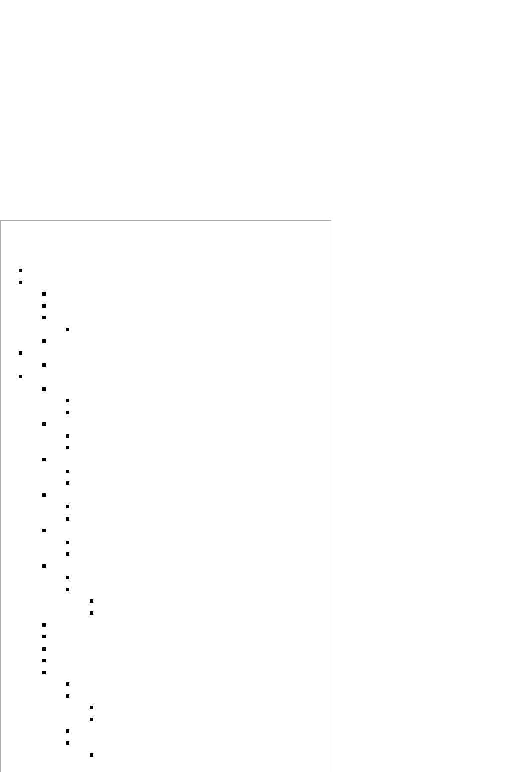
Using SmartRF Flash Programmer 2
To upgrade, install the latest SmartRF Flash Programmer 2 and obtain the DevPack Debugger (CC-DEVPACK-DEBUG) which uses the
XDS110. Obtain the latest SensorTag Hex firmware image file. For example, the pre-built SensorTag hex file for BLE 2.1 is located in
C:/ti/simplelink/ble_cc26xx_2_01_00_44423/Accessories/HexFiles
CC2650 SensorTag User's Guide - Texas Instruments Wiki http://processors.wiki.ti.com/index.php/CC2650_SensorTag_User's_Guide
13 von 18 31.05.2016 11:57
Attach the DevPack Debugger to the SensorTag1.
Insert a fresh or sufficiently charged CR2032 coin cell battery into the SensorTag2.
Attach the micro USB cable to the DevPack Debugger and PC (this step must be performed after inserting the battery)3.
Open SmartRF Flash Programmer 2
Under Connected Devices, select "Refresh" and then highlight the XDS110 / CC26501.
Under Flash Images, browse to the desired hex file. (e.g., C:/ti/simplelink/ble_cc26xx_2_01_00_44423/Accessories/HexFiles
/CC2640_SensorTag.hex)
2.
Under Actions, select Erase (All unprotected pages), Program (Entire source file), Verify (Readback)3.
Select Go (Play button) to start the flash programming4.
If successful, a green bar will display "Success!".5.
4.
Over the Air Download (OAD)
SensorTag firmware can be upgraded via the BLE radio link by means of the OAD service. For a description of the OAD service, refer to
the "CC2640 BLE OAD User's Guide.pdf" located in Documents folder of the BLE 2.1 SDK. The SensorTag uses the "off-chip" OAD
method. When the FW image is sent to the SensorTag, it is first stored in external SPI flash memory. Once the entire image is sent, the
SensorTag will reboot and install the new image from the external flash memory. Both the iOS and Android SensorTag apps have
example firmware files included in the app.
Though similar, there are differences between the OAD method used by SensorTag and the one described in the CC2640 BLE
OAD User's Guide. They are listed below:
Only off chip OAD is supported by the SensorTag project, a 512kB external SPI flash is already connected on the STK dev kit.1.
The Boot Image Manager (BIM) is different for the SensorTag project than the one described in the users guide
SensorTag's BIM is more of a Baseloader and works different internally.
2.
Flash page 0 is not protected in the SensorTag project. This is to retain compatibility with other RF stacks and legacy devices.
Applications must include reset vectors that jump to page 31 where the BIM resides.
Because of this all OAD types are considered to be "app" for the SensorTag project, but it is possible to bundle app and stack
together, as long as reset vectors are present.
3.
It is important to remember when using BLE the above OAD only applies to the SensorTag project. For example, the
SimpleBLEPeripheral project can be loaded onto the SensorTag dev kit, and it would follow the OAD method detailed in the BLE OAD
User's guide with none of the modifications above modifications. The reason for having two OAD methods is to preserve compatibility
with older devices and other RF stacks.
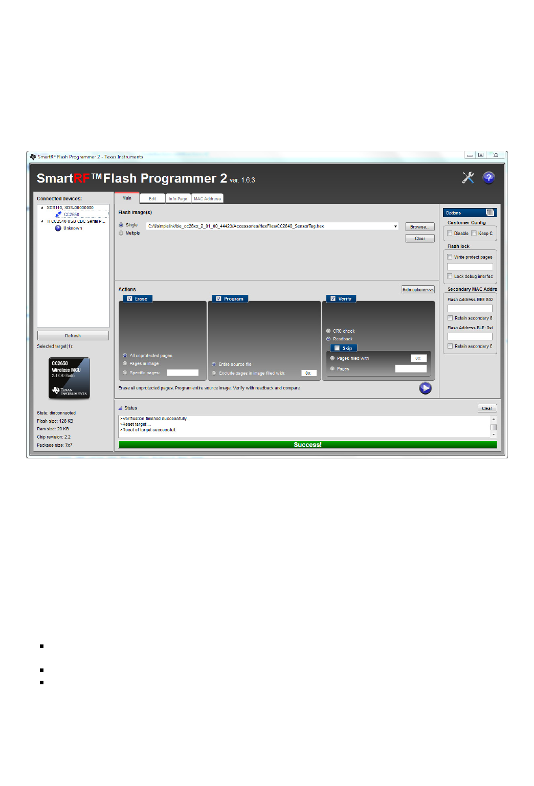
See below for memory layouts of the SensorTag project in both internal and external Flash.
CC2650 SensorTag User's Guide - Texas Instruments Wiki http://processors.wiki.ti.com/index.php/CC2650_SensorTag_User's_Guide
14 von 18 31.05.2016 11:57
Internal Flash Layout
SensorTag OAD
External Flash Layout
SensorTag OAD
Generating Binary Files for Mobile App OAD
The iOS and Android SensorTag applications take an application image in a binary(*.bin) form. In order to generate these files, the post
build steps of the SensorTag IAR and CCS projects need to be updated.
IAR
right click on project > options > Output Converter:
Ensure Generate additional output is clicked1.
Set output format to binary2.
CCS
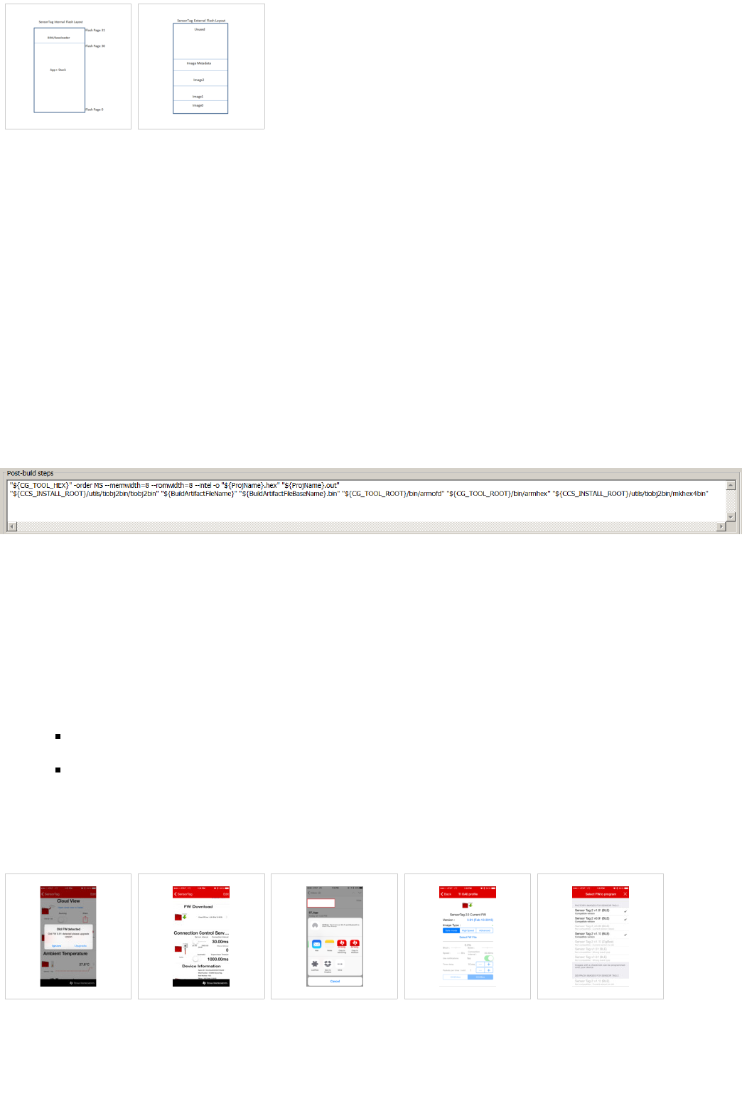
Right click on project > properties > Build > steps > post build steps
Add this line (must be a single line):
"${CCS_INSTALL_ROOT}/utils/tiobj2bin/tiobj2bin" "${BuildArtifactFileName}" "${BuildArtifactFileBaseName}.bin"
"${CG_TOOL_ROOT}/bin/armofd" "${CG_TOOL_ROOT}/bin/armhex" "${CCS_INSTALL_ROOT}/utils/tiobj2bin/mkhex4bin"
Final post-build setting should look like this:
Rebuild the project after applying the above settings and the .bin files should be in your output directory.
OAD using the SensorTag iOS App
To update the SensorTag using the iOS, first install the latest SensorTag app from the Apple App Store. The following procedure applies
to iOS app version v4.2.
Press the power button to initiate advertising and connect to the SensorTag using the "Sensor View" option in the App.1.
If prompted with "Old FW detected", select "Upgrade". Otherwise, scroll down to the FW Download menu.2.
On the FW Download page, the current FW version is shown. Tap "Select FW File" to select a newer image for download.
Note that you can import bin files generated by CCS or IAR to the SensorTag app. They will appear at the bottom of the
page.
One easy way to import a file is to e-mail it to yourself and then select open in SensorTag app.
3.
Select the newest FW file that is marked as compatible. The FW will begin to download as soon as selected.4.
Once complete, the SensorTag will disconnect and automatically install the new FW image from the external flash memory.5.
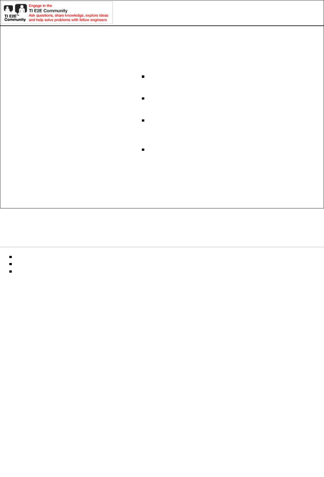
Note: SensorTags running FW versions prior to v1.01 must use "Safe Mode" to upgrade. Once v1.01 or later is installed, High Speed
Mode can be used. The following screen shots depict the upgrade from v0.91 to v1.12. Click on an image to see an larger version.
FW Upgrade Prompt Manually Select FW
Download
Import Custom bin file
to SensorTag App
FW Download (OAD)
Menu
FW Selection Menu
CC2650 SensorTag User's Guide - Texas Instruments Wiki http://processors.wiki.ti.com/index.php/CC2650_SensorTag_User's_Guide
15 von 18 31.05.2016 11:57

FW Download Progress FW Upgrade Complete
OAD using the SensorTag Android App
TBD
OAD using BLE Device Monitor
NB! This section is not yet complete
A new firmware can be uploaded using the BLE Device Monitor. Follow the connection set up in the BLE Device Monitor User Guide
(http://processors.wiki.ti.com/index.php/BLE_Device_Monitor_User_Guide). When the SensorTag is connected to the BLE Device
Monitor select 'File' and 'Program (OAD)'. The input are HEX files, and there is by default a restriction on which files can by uploaded by
a certain firmware version. If you want to download any file, the filter can be changed to *.* (All files) in the file open dialogue. Before
overriding the default file filter, be aware that if you download an image that is not BLE/OAD you can not reset the device to a its original
state. The only exception is the provided ZigBee image - factory state may be recovered by pressing both buttons for 6 seconds.
SensorTag images are available in the default location \\Program Files\Texas Instruments\BLE Device Monitor\firmware\cc26xx.
Building the SensorTag Firmware
The SensorTag firmware can be built using the source code & project included in the BLE-Stack (http://www.ti.com/ble-stack) SDK.
Building the firmware is useful for making changes to the default driver behavior, adding additional DevPacks, as well as source level
debugging using the DevPack Debugger to better understand the operation of the SensorTag. The build procedure listed below assumes
the developer is familiar with the IDE and build environment concepts described in the CC2640 BLE SW Developer's Guide
(SWRU393).
In addition to the dual Application & Stack images, the SensorTag uses a Boot Image Manager (BIM) to facilitate upgrades via OAD. The
BIM must be programmed first and must be present before programming the Application and Stack images. In the SensorTag IAR
project, the BIM workspace is included, however for CCS, the BIM must be explicitly imported into the workspace. Refer to the
"CC2640 BLE OAD User's Guide.pdf" located in Documents folder of the BLE 2.1 SDK for more details on the BIM and OAD.
SensorTag Project: $SDK_INSTALL_PATH$\Projects\ble\SensorTag
BIM_extflash (for CCS): $SDK_INSTALL_PATH$\Projects\ble\util\BIM_extflash
Where $SDK_INSTALL_PATH$ is the default SDK install path, e.g., C:\ti\simplelink\ble_cc26xx_2_01_00_44423
Build & Download Procedure:
Open/Import the SensorTag project in IAR or CCS
CCS Only: Import the BIM_extflash project1.
1.
Build & download the BIM_extflash project2.
Build & download the Application project [FlashOnlyOAD Configuration]3.
Build & download the Stack project4.
When downloading the project, verify that each workspace is configured to use the TI XDS110 if the DevPack Debugger is used. All
SensorTag related projects in the BLE 2.1 SDK are configured to use the XDS110 as the default debugger option.
Note: If the SensorTag is erased (or the BIM is erased), the BIM must be programmed before reprogramming the Application & Stack
images. The pre-built hex file included in the BLE-Stack SDK Accessories folder contains the BIM, Application & Stack in a super hex
file.
CC2650 SensorTag User's Guide - Texas Instruments Wiki http://processors.wiki.ti.com/index.php/CC2650_SensorTag_User's_Guide
16 von 18 31.05.2016 11:57

Building SensorTag SuperHex File
To create a single, “super hex” SensorTag firmware file consisting of the BIM_extflash, Application & Stack images, the individual hex
files for the respective projects need to be merged into one file. As hex files use an open standard, any merge tool can be used provided it
supports the appropriate hex standard. TI uses the IntelHex python tools which assumes each hex file in the Intel hex format. To confirm
that the resulting hex file in the Intel format, each line should begin with a colon ‘:’.
For CCS projects, the Intel hex output format must be enabled in the BIM_extflash project. This can be done in each project’s Project
Properties: Build “Steps” tab, under ‘Post-build steps’:
"${CG_TOOL_HEX}" -order MS --memwidth=8 --romwidth=8 --intel -o "${ProjName}.hex" "${ProjName}.out"
To merge the files, the procedure as documented in the BLE SW Developer Guide (SWRU393) can be used. When the BIM is used, the
Application image should start at flash address 0x1000. Refer to the “Working with Hex Files” section. Example procedure to generate a
SensorTagSuper.hex file:
$ C:\Python27\Scripts>python hexmerge.py -o SensorTagSuper.hex -r 0000:1FFFF SensorTag.hex:0000:1EFFF SensorTagStack.hex
BIM_ExtFlash.hex:1F000:1FFFF --overlap=error
Where “SensorTag.hex” is the Application; “SensorTagStack.hex “ is the Stack; and “BIM_ExtFlash.hex” is the BIM input hex files. Note
that the names of the input hex files may differ. Use the actual App, Stack & BIM_extflash hex files generated by the respective build
environment.
Building SimpleBLEPeripheral OAD_IMAGE_FULL SuperHex File
Use similar procedure as above to generate a OAD_IMAGE_FULL.hex file:
python "C:/Python27/Scripts/hexmerge.py" -o "${PROJECT_LOC}/FlashOnly_ST_OAD_ExtFlash/OAD_IMAGE_FULL.hex" -r
"1000:1EFFF" --overlap=error "${PROJECT_LOC}/FlashOnly_ST_OAD_ExtFlash/${ProjName}.hex" "${PROJECT_LOC}/..
/SimpleBLEPeripheralStack/FlashROM/SimpleBLEPeripheralStack
Modify this in your CCS project post build settings to build the correct image to be used for Off-chip OAD.
Running other Sample Applications on the SensorTag
Since the SensorTag incorporates a CC2650 wireless MCU, you can run any CC2640 BLE sample application on the SensorTag HW. This
list includes all simpleBLExxx projects, HostTest, Heart Rate, Eddystone, etc. The following items must be considered when porting a
sample application to the SensorTag (or any custom board):
It is recommended to use the SensorTag board file. For example, simpleBLEPeripheral uses the SmartRF06EBK board file by
default, so switching the IDE project to use the SensorTag board file is required for proper IO pin mapping.
1.
Use of external peripherals (e.g., LCD, buttons) needs to be disabled or modified in the code or project Preprocessor options to use
the available HW on the SensorTag board. For example, when using simpleBLECentral, the default LCD and button usage from the
SmartRF06EBK must be disabled when this sample application is built for the SensorTag.
2.
Accessing external IOs needs to match what is available on the SensorTag board or DevPack accessories.3.
Optional: Since the SensorTag has many sensors populated on the PCB, maximum board power saving will only occur when these
sensors are placed in their lowest power state. This requires having some drivers in your project to configure/control these sensors.
Refer to this E2E thread (https://e2e.ti.com/support/wireless_connectivity/f/538/p/460305/1663262) for a functional example. Note
that the power usage of the CC2640/50 is optimized, sensors on the SensorTag PCB may consume additional power thus leading to
higher overall board current consumption.
4.
Refer to the CC2640 BLE SW Developer's Guide (SWRU393) for guidance on how to configure the board file and modify certain
Preprocessor options.
Example projects that use the SensorTag:
SimpleBLEPeripheral OAD Example - see the "Building the SensorTag Firmware" section
SimpleBLEPeripheral in the SimpleLink Academy (http://software-dl.ti.com/lprf/simplelink_academy/overview.html)
"TrainingTag" project
HostTest (e.g., allows connection to BTool) in the SimpleLink Academy (http://software-dl.ti.com/lprf/simplelink_academy
/overview.html) "HostTestTag" project
Eddystone Beacon - BLE Peripheral + Broadcaster
CC2640 UART to BLE Bridge Reference Design - uses modified BLE Peripheral & Central.
Back to Bluetooth SensorTag main page (http://processors.wiki.ti.com/index.php/Bluetooth_SensorTag)
CC2650 SensorTag User's Guide - Texas Instruments Wiki http://processors.wiki.ti.com/index.php/CC2650_SensorTag_User's_Guide
17 von 18 31.05.2016 11:57
For technical support please post your questions at http://e2e.ti.com. Please post only
comments about the article CC2650 SensorTag User's Guide here.
Links
Amplifiers & Linear
(http://www.ti.com/lsds/ti
/analog
/amplifier_and_linear.page)
Audio (http://www.ti.com
/lsds/ti/analog/audio
/audio_overview.page)
Broadband RF/IF & Digital
Radio (http://www.ti.com
/lsds/ti/analog/rfif.page)
Clocks & Timers
(http://www.ti.com/lsds/ti
/analog/clocksandtimers
/clocks_and_timers.page)
Data Converters
(http://www.ti.com/lsds/ti
/analog/dataconverters
/data_converter.page)
DLP & MEMS
(http://www.ti.com
/lsds/ti/analog
/mems/mems.page)
High-Reliability
(http://www.ti.com
/lsds/ti/analog
/high_reliability.page)
Interface
(http://www.ti.com
/lsds/ti/analog
/interface
/interface.page)
Logic
(http://www.ti.com
/lsds/ti/logic
/home_overview.page)
Power Management
(http://www.ti.com
/lsds/ti/analog
/powermanagement
/power_portal.page)
Processors (http://www.ti.com
/lsds/ti
/dsp/embedded_processor.page)
ARM Processors
(http://www.ti.com/lsds/ti
/dsp/arm.page)
Digital Signal Processors
(DSP) (http://www.ti.com
/lsds/ti/dsp/home.page)
Microcontrollers (MCU)
(http://www.ti.com/lsds/ti
/microcontroller
/home.page)
OMAP Applications
Processors
(http://www.ti.com/lsds/ti
/omap-applications-
processors/the-omap-
experience.page)
Switches & Multiplexers (http://www.ti.com
/lsds/ti/analog
/switches_and_multiplexers.page)
Temperature Sensors & Control ICs
(http://www.ti.com/lsds/ti/analog
/temperature_sensor.page)
Wireless Connectivity (http://focus.ti.com
/wireless
/docs/wirelessoverview.tsp?familyId=2003&
sectionId=646&tabId=2735)
Retrieved from "http://processors.wiki.ti.com/index.php?title=CC2650_SensorTag_User%27s_Guide&oldid=216798"
Category: SensorTag
This page was last modified on 26 May 2016, at 16:33.
This page has been accessed 51,849 times.
Content is available under Creative Commons Attribution-ShareAlike unless otherwise noted.
CC2650 SensorTag User's Guide - Texas Instruments Wiki http://processors.wiki.ti.com/index.php/CC2650_SensorTag_User's_Guide
18 von 18 31.05.2016 11:57
