CCF Manual
User Manual:
Open the PDF directly: View PDF ![]() .
.
Page Count: 17

CCF Manual
2
Table of Contents
1. CCF ..................................................................................................................................................... 4
1.1. Overview of CCF ........................................................................................................................ 4
1.2. Organization of Source Code Directories ................................................................................ 5
2. Code Generation and Validation Using CCF .................................................................................... 6
2.1. Loop Annotation ....................................................................................................................... 6
2.2. Make ........................................................................................................................................... 6
2.3. Simulate Heterogeneous Execution ........................................................................................ 7
3. CCF’s Code Generation Steps ........................................................................................................... 8
3.1. Extraction of the Annotated Loop(s)....................................................................................... 8
3.2. Generation of DDG and Communication of the Live Data ...................................................... 8
3.3. Mapping of DDG on the Target CGRA .................................................................................... 12
3.4. Generation of Machine Instructions ...................................................................................... 13
3.4.1. Instruction Formats ............................................................................................................. 14
3.5. Architectural Simulation ......................................................................................................... 16
3.6. Techniques Implemented ....................................................................................................... 16
3.7. Acknowledgements ................................................................................................................ 16
3.8. Contact Us ............................................................................................................................... 16
4. References ...................................................................................................................................... 17
3
List of Figures
Figure 1: A High-Level Overview of CCF ............................................................................................... 4
Figure 2: Loop Annotation for Execution on CGRA ................................................................................ 6
Figure 3: Required Modifications in the Makefile .................................................................................... 7
Figure 4: Modifying the Command to Simulate CPU+CGRA Execution on gem5 ................................. 7
Figure 5: Part of the IR Corresponding to the Annotated Loop ................................................................ 8
Figure 6: DDG of Targeted Loop ............................................................................................................. 9
Figure 7: IR Modification for Transferring the Control of Execution to CGRA .................................... 10
Figure 8: Snapshot of the Generated Schedule After Mapping the DDG ............................................... 12
Figure 9: A Snapshot of the Output File Describing Generated CGRA Machine Instructions .............. 13
4
1. CCF
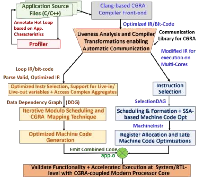
CCF (CGRA Compilation Framework) is an end-to-end prototype demonstrating the code generation
and simulation process for CGRA (or Coarse-Grained Reconfigurable Array) accelerators. Through CCF
infrastructure, the users can simulate acceleration of loops of general-purpose applications on a
heterogeneous processor core+CGRAs architecture.
1.1. Overview of CCF
With LLVM 5.0 [1,2] as a foundation, the implementation of CCF-compiler includes numerous compiler
analysis and transformation passes, along with a customized code generation CGRA back-end. The user
only needs to mark the performance-critical loops that they want to execute on CGRA, by using the
annotation: #pragma CGRA, and the CCF-compiler automatically extracts the marked loops and maps
them to the CGRA, generates code to communicate live data between the processor core and CGRA,
pre-load the live values into CGRA registers, and generates the machine instructions to configure the
PEs to execute the loop, and finally generates a binary that will execute on the CCF-simulator. The CCF-
simulator is built by modifying cycle-accurate processor simulator Gem5 [3], and it models CGRA as a
separate core coupled to ARM Cortex-like processor core with ARMv7a profile.
Figure 1: A High-Level Overview of CCF
This open-source platform has been developed at Arizona State University and through CCF, we target
accelerating the CGRA research by developing and making accessible a community-wide CGRA
compilation infrastructure. While current release of CCF supports code generation for several
performance-critical loops of embedded MiBench benchmark suite, we hope to integrate the enhanced
functionality in the future release.
5
1.2. Organization of Source Code Directories
Before realizing the code generation process through CCF, let’s quickly see that which directories of the
source code correspond to what part of the framework. Directory 'llvm' is a bit modified version of the
LLVM compiler, which serves as a front and middle end of the current CCF release. The LLVM front end
is modified to enable extracting of the loops for their acceleration on CGRA. It also contains the passes
responsible for the data communication between CPU and CGRA, supporting the communication
interface (directories DDGGen, InvokeCGRA, CGRAGen in the transformations).
Directory 'RAMP' is responsible for mapping the loop on the CGRA, and the directory
'InstructionGenerator' delivers the necessary machine instructions. Together, they both forms the back-
end of the framework. The directory gem5 models the execution of CPU-CGRA platform via a system
emulation mode. The directory 'scripts' contains the installation script, the CGRA library functions, and
few other shell scripts to automate the code generation process.
The directory 'benchmarks’ contains examples of the code generation process using CCF for the given
benchmarks. Since the CCF is a prototype of emerging general-purpose CGRA accelerator, current
release of the CCF supports few performance critical loops of MiBench [4], an embedded benchmark
suite. It also supports execution of all the loops from few MiBench applications. For example, directory
'basicmath' contains the different sub-directories, where each sub-directory corresponds to one
distinct loop from the application source code, annotated for its execution on CGRA.
For the demonstration of the code generation process throughout this document, we refer to the
example of 'basicmath', an application taken from the MiBench. In particular, we refer to the sub-
directory 'basicmath13' which corresponds to the annotated loop for computing the square root.
6
2. Code Generation and Validation Using CCF
Let’s see how we can generate the code for the target application that we want to execute on
core+CGRA architecture. The steps are as follows:
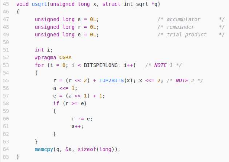
2.1. Loop Annotation
Once the programmer has profiled the compute-intensive application, and have identified a
performance-critical loop, (s)he can annotate it with #pragma CGRA. Then, the CCF compiler can
generate the code for the application's execution on the heterogeneous platform.
Figure 2: Loop Annotation for Execution on CGRA
For example, as shown in Fig. 2, we can annotate the loop computing a square root, for its execution
on CGRA (source file isqrt.c of basicmath benchmark, from MiBench).
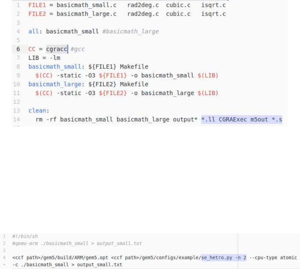
2.2. Make
Once the target loop(s) have been annotated, the code can be generated by compiler through the
Makefile. As shown in Fig. 3, the user has to just to replace the target compiler (gcc in our case) with
cgracc (CCF's CGRA Compiler Collection). (Often, it decently supports complex makefiles.) Then, typing
'make' will generate the required executable.
The CCF compiler will inform that whether it would be executing the loop on the CGRA or not. For
example, for the current release of the compilation infrastructure, if the annotated loop contains the
system calls, it is not executed on CGRA. Or, if the compiler was able to vectorize the code (which may
imply that the loop can be efficiently accelerated by SIMDization or on chip multi-processors), it will
not generate the code for CGRA. Thus, CCF compiler will inform that why it currently did not generate
7
the code for the CGRA. On the other hand, if the CCF compiler generated the code for CGRA, then we
can find it in the directory 'CGRAExec'. This directory contains information about all the loops compiled
for their execution on CGRA.
Figure 3: Required Modifications in the Makefile
Once the compilation process is terminated, you can see that the target executable is generated.
Then, we can simulate the execution on the heterogeneous platform.
2.3. Simulate Heterogeneous Execution
Our simulation platform is built in gem5, where we have modeled the CGRA as a separate core coupled
to ARM Cortex like processor. Instead of executing file se.py for system emulation mode, we can
execute a file se_hetro.py, which models the heterogeneous execution. For example, Fig. 4 shows that
how we can launch simulation using CPU+CGRA gem5 model. If we want to simulate the execution with
n=2 cores, 1 core is specified as a CGRA, and another n-1=1 is the processor core.
Figure 4: Modifying the Command to Simulate CPU+CGRA Execution on gem5
If you are interested to do a detailed debug, you can turn on the debug flags, i.e., --debug-
flags=CGRA,CGRA_Detailed. Such command will show comprehensively all the details about
the status of the CGRA’s micro-architectural components.
8
3. CCF’s Code Generation Steps
In this section, we describe the intermediate steps of the code generation process, elaborating the
overview provided in section 1.
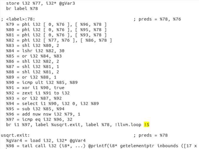
3.1. Extraction of the Annotated Loop(s)
CCF compiler’s front-end (implemented by modifying clang) identifies and extracts the loops from
C/C++ code, annotated by the programmer. Then, it generates the intermediate representation (IR)
('temporary.ll'). In compiling the application, CCF targets the highest optimization, i.e. optimization
level 3, including auto-vectorization enabled. Part of the IR corresponding to the annotated loop
contains metadata ('llvm.loop.CGRA.enable', shown in Fig. 5) so that CCF compiler can perform analysis
and transformations on it. CCF compiler analyzes whether it will generate the code for this loop for its
execution on CGRA, or not. If it can, it acts on the part of the IR corresponding to the loop, generating
the data dependency graph (DDG).
Input: application.c, Makefile
Output: temporary.ll
Figure 5: Part of the IR Corresponding to the Annotated Loop
3.2. Generation of DDG and Communication of the Live Data
An LLVM pass (DDGGen) generates the DDG of the loop, which can be visualized using the dot tool [5].
In DDG, the circles show the operations to be performed and the arcs show the data dependencies. Fig.
6 shows one such DDG for our target loop of 'basicmath' benchmark.
9
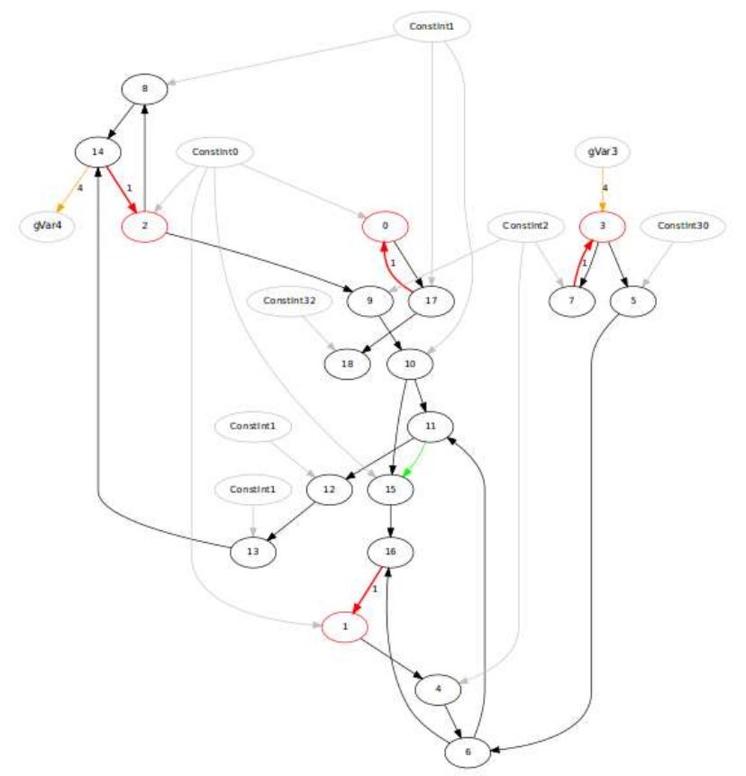
Figure 6: DDG of Targeted Loop
The red arc shows a loop-carried dependence, with an arc weight equals to the dependence distance.
For example, there is a loop-carried dependence between operations 7 and 3, forming a cycle with a
path delay of 2 cycles (if the operations have a latency of 1 cycle each). Similarly, there is a recurrence
between operations 16 and 1, with the path delay of the 6 cycles. The loop-carried dependencies limits
minimizing the total cycles required to finish executing a single loop iteration on the CGRA (For more
details, refer to the iterative modulo scheduling (IMS) literature [6] for determining recurrence-
constrained II).
The gray faced operations represent the constants or live-in values. The yellow arc indicates the live
edges that is the input is a live-in value or a store to live-out variable (e.g. gVar3→3, or 14→gVar4).
The memory accesses to the live variables occur typically just once, since the CCF compiler manages
them in the CGRA registers. The alignment of the memory access is indicated by the weight of the arc
(typically 4, for 32-bit system).
To communicate the necessary variables or the live data, our CCF compiler inserts instructions to
10
manage the data automatically through global variables. For example, Fig. 5 shows that live data is
replaced by using communication through global variables/pointers gVar3 and gVar4. Such
compilation strategy avoids inserting mem copies, rather by adopting a shared memory model. It is
because we visualize CGRA accelerator as tightly coupled with the core, at the interface of level 2 cache,
or by sharing a scratch-pad with the processor.
Finally, the library call pertaining to the loop execution on CGRA is inserted and IR corresponding to the
loop body is purged. This modified IR (temporaryIR.ll) is then taken to the machine code generation for
the CPU.
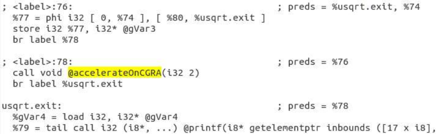
Figure 7: IR Modification for Transferring the Control of Execution to CGRA
For example, Fig. 7 shows the new IR, in which the part corresponding to the target loop is now purged.
We can see that a library call is automatically inserted, which is to accelerate the loop on the CGRA. The
argument is the loop number, and along with the help of our CGRA library functions, our CCF compiler
will generate the code for the application execution on heterogeneous CPU+CGRA platform.
Input: temporary.ll
Output: temporaryIR.ll, loop_DFG.dot, loop_node.txt, loop_edge.txt
livein_node.txt, livein_edge.txt, liveout_node.txt, liveout_edge.txt
Format of an entry in the node file: <node number> <vopc> <node name> <mem alignment>
Format of an entry in the edge file: <from node #> <to node #> <arc weight> <edge type> <op order>
Here, vopc implies virtual opcode for the operations in the DDG. Table 1 summarizes the various opcode
numbers and corresponding operations. It also shows corresponding opcodes of LLVM instructions.
Please note that this vopc is not the actual opcode embedded in the CGRA machine instructions. They
are described later along with a discussion on CGRA microarchitecture. It is important to note that many
other LLVM opcodes are realized using these VOPCs, e.g. Trunc or ZExt is translated to andop, or
GetElementPtr is realized using add etc.
Memory alignment is for the memory access operations, and 0 otherwise. Node name is often same as
the node number, except for the constants or for live values.
For edge file, arc weight denotes the dependence distance for a loop-carried dependency. Edge types
are TRU (true dependency for most of the arcs, including for loop-carried dependencies), LRE for load
11
Table 1: Translation of LLVM IR Opcode to CCF Virtual Opcode
Opcode
VOPC
LLVM Opcode
0
add
Add
1
sub
Sub
2
mult
Mul
3
div
SDiv
4
shiftl
Shl
5
shiftr
Ashr
6
andop
And
7
orop
Or
8
xorop
Xor
9
cmpSGT
ICMP_SGT
10
cmpEQ
ICMP_EQ
11
cmpNEQ
ICMP_NE
12
cmpSLT
ICMP_SLT
13
cmpSLEQ
ICMP_SLE
14
cmpSGEQ
ICMP_SGE
15
cmpUGT
ICMP_UGT
16
cmpULT
ICMP_ULT
17
cmpULEQ
ICMP_ULE
18
cmpUGEQ
ICMP_UGE
19
ld_add
Load
20
ld_data
21
st_add
Store
22
st_data
23
ld_add_cond
reserved
24
ld_data_cond
reserved
25
loopctrl
special function
26
cond_select
Select
27
route
special function
28
llvm_route
reserved
29
select
PHI
30
constant
ConstantIntVal
31
rem
SRem
32
sext
SExt
33
shiftr_logical
LShr
34
rest
default
operation (an arc between operations with VOPC ld_add and ld_data), SRE for store operation (an arc
between operations with VOPC st_add and st_data), LIE for the data dependency from live-in operation,
and PRE for the data dependency indicating predicated execution. Typically, operation with VOPC
cond_select has an input arc of the type PRE, from the operation corresponding to a condition. <Op
Order> denotes the operand order, in case an operation having more than one operands.
12
3.3. Mapping of DDG on the Target CGRA
The mapping technique maps the DDG on the target CGRA, and generates the prologue, kernel, and
the epilogue of the mapping. Mapping process includes iterative modulo scheduling of the DDG and a
place and route of scheduled DDG on the CGRA's architectural resources. Register allocation is also
done during the mapping.
Input: loop_node.txt, loop_edge.txt
Output: loop.sch (prolog.sch + kernel.sch + epilog.sch), dump_node.txt, dump_edge.txt,
rfConfig.txt
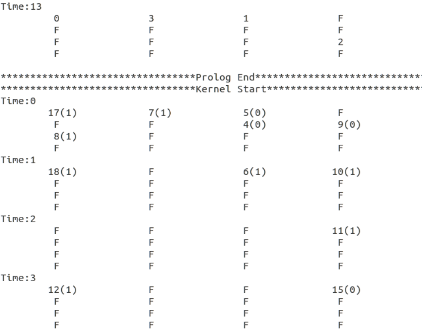
Figure 8: Snapshot of the Generated Schedule After Mapping the DDG
Let’s see the schedule file generated after the mapping. The prologue, kernel, and the epilogue of the
mapping are laid down in the generated schedule file (loop.sch). As shown in Fig. 8, the vertical axis is
the time scale, and the horizontal expansion shows the spatial execution on PEs. Here, at every time
instance, we can see execution for 16 different PEs. This is because, our compilation target is set as a
4x4 CGRA by default, where each PE has 4 local registers.
The source code of our framework is parameterized and can model different CGRA configurations.
Certainly, this can be more generalized through an XML based input for target configuration, we plan
to do it in future release. This is because, we rather focus on enhancing the functionalities of our code
generation framework CCF, making support for more general-purpose applications.
13
We can see that each spot of the PE is represented by an operation that a PE would execute. For
example, in the prologue, operation 0 is mapped first onto PE1 at time 6, and then at time 13. The letter
F indicates that corresponding PEs are free at that time. After time 13, all the operations are mapped,
and the schedule corresponding to prologue ends. Then, the file shows the mapping corresponding to
the kernel. II of the mapping DDG (of Fig. 6) is 7 cycles (due to a loop-carried dependence with the path
delay of 7 cycles), meaning, every operation will repeat its execution after 7 cycles.
This loop iterates in total for 32 times, and the kernel will repeat for 30 times, when executed. In the
kernel shown, we can see that the operations are labeled a number inside a parenthesis, which
indicates the rotating register occupied for the loop execution. Operation values scheduled at distance,
or several loop-carried dependencies, are typically routed through the register file. For example, the
dependency 10→15 is routed through a register; 10 produces the value at modulo time 1, which is read
by the operation 15 at modulo time 3. Finally, the mapping file shows the part corresponding to the
epilogue.
Note that the mapping phase generates the node and edge files (dump_node.txt and dump_edge.txt),
which included additional routing (or spilling) operations, inserted to map the DDG. Moreover, these
files contain information about the mapped operations only, i.e., they do not contain information about
the static constants, which might be supplied as immediates in the CGRA instructions.
3.4. Generation of Machine Instructions
This phase generates the machine instructions to configure the PEs, to pre-load the live values into
CGRA registers during the prologue, and to store live-out data during the epilogue. Our current CGRA
instruction-set architecture (ISA) supports two different formats, including several important opcodes
and including, support for the byte level memory accesses.
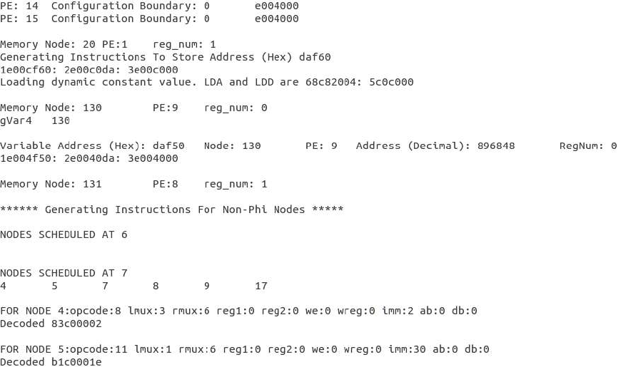
Figure 9: A Snapshot of the Output File Describing Generated CGRA Machine Instructions
14
Fig. 9 shows the snippet of the output file describing decoded CGRA instructions. All the machine
instructions and the breakdown of the corresponding instruction fields are shown in this file. The
directory <CGRAExec/$loopnum> also contains the binaries corresponding to the prologue, kernel and
the epilogue.
Input: loop_node.txt, loop_edge.txt, dump_node.txt, dump_edge.txt, liveout_node.txt,
liveout_edge.txt, prolog.sch, kernel.sch, epilog.sch, app.exe
Output: cgra_instructions.txt, prolog_ins.bin, kernel_ins.bin, epilog_ins.bin
3.4.1. Instruction Formats
CGRA Instructions are generated based on the two formats: i) R-Type (Regular) and ii) P-Type.
Instruction formats are decided based on the VOPC (virtual opcodes), or based on the desired
functionality of the instruction. For example, for most of the operations, R-Type instruction is
generated. However, for pre-loading live values, or in setting RF configuration at the beginning of the
prologue, or for predicated execution for a conditional statement, a P-Type instruction is generated.
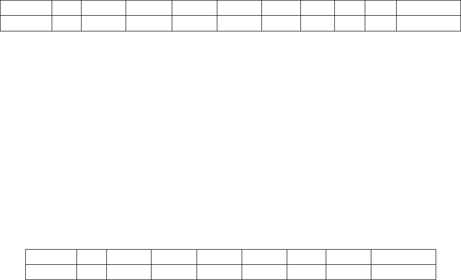
R-Type Instruction Format:
31:28
27
26:24
23:21
20:19
18:17
16:15
14
13
12
11:0
Opcode
P
LMux
RMux
R1
R2
RW
WE
AB
DB
Immediate
Here, the field Opcode defines the functionality performed by the CGRA PEs (see Table 2).
P determines the instruction format. If 1, instruction is decoded as P-Type.
LMux indicates the input source for the left multiplexer of the PE (see Table 3).
RMux indicates the input source for the right multiplexer of the PE (see Table 3).
R1 indicates the register number for input1, if LMux indicates register file as source
R2 indicates the register number for input2, if RMux indicates register file as source
RW indicates the register number of register file to which result should be written
WE determines whether the PE should write the result back to register file or not.
AB indicates asserting address bus for the memory access.
DB indicates asserting data bus for the memory access.
Immediate defines the static constant value, which can be supplied to the PE.
P-Type Instruction Format:
31:28
27
26:24
23:21
20:19
18:17
16:15
14:12
11:0
Opcode
P
LMux
RMux
R1
R2
RP
PMux
Immediate
Here, the field Opcode defines the functionality performed by the CGRA PEs (see Table 2).
PMux indicates the input source for the predicated multiplexer of the PE (see Table 3).
RP indicates the register number for input3, if PMux indicates register file as source
Table 2 summarized functionalities performed by PEs. PEs perform fixed-point signed arithmetic, logical
and memory operations, with 1-cycle latency.
15
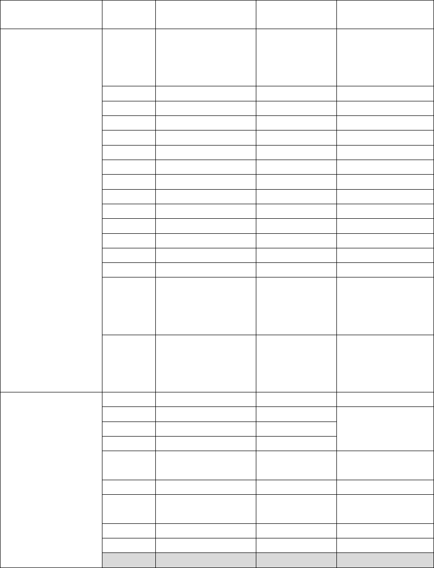
Table 2: Translation of CCF Virtual Opcode to CCF Machine Opcode
Instruction Format
Opcode#
Machine Opcode
VOPC (from
Table 1)
Note
R-Type
0
Add
add,
ld_data,
st_data,
route
1
Sub
sub
2
Mult
mult
3
AND
andop
4
OR
orop
5
XOR
xorop
6
cgraASR
shiftr
7
NOP
-
8
cgraASL
shiftl
9
Div
div
10
Rem
rem
11
LSHR
shiftr_logical
12
EQ
cmpEQ
13
NEQ
cmpNEQ
14
GT
cmpSGT,
cmpSGEQ,
cmpUGT,
cmpUGEQ
15
LT
cmpSLT,
cmpSLEQ,
cmpULT,
cmpULEQ
P-Type
0
setConfigBoundary
-
1
LDI
select
Pre-load Live
values in CGRA
Registers
2
LDMI
-
3
LDUI
-
4
sel
cond_select
Predicated
Execution
5
loopexit
loopctrl
6
address_generator
ld_add,
st_add
7
NOP
-
8
signExtend
sext
9-15
Reserved
-
Table 3 defines the various type of the source inputs for the multiplexers of the PEs.
16
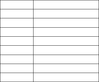
Table 3: Input Sources for Multiplexers of the PE
#
Source
0
Register
1
Left Neighboring PE
2
Right Neighbor
3
Upper Neighbor
4
Bottom Neighbor
5
Data Bus
6
Immediate
7
Self (Output Latch)
3.5. Architectural Simulation
Our simulation platform is built in gem5, where we have modeled the CGRA as a separate core coupled
to ARM Cortex like processor. CCF simulator allows simulating the execution of the generated code on
the core+CGRA heterogeneous platform.
Input: app.exe
Output: output.txt
3.6. Techniques Implemented
Following techniques/heuristics are implemented completely in CCF or in part. To understand the
specifics of the techniques, please refer to them.
• CCF: A CGRA Compilation Framework
• RAMP: Resource-Aware Mapping for CGRAs
• URECA: A Compiler Solution to Manage Unified Register File for CGRAs
• REGIMap: Register-aware Application Mapping on Coarse-grained Reconfigurable Architectures
(CGRAs) (for implementation of clique-based mapping heuristic, routing through registers)
• Power-Efficient Predication Techniques for Acceleration of Control Flow Execution on CGRA (partial
predication based execution of conditional operations)
If you use the implementation pertaining to any of these techniques in your research, we would
appreciate a citation to that.
3.7. Acknowledgements
We gratefully acknowledge the contributions of these student developers - Dipal Saluja, Mahdi Hamzeh,
Mahesh Balasubramanian, Shail Dave, and Shrihari Rajendran Radhika.
3.8. Contact Us
For any questions or comments on CCF development, please email us at cmlasu@gmail.com
CML's CGRA Webpage - http://aviral.lab.asu.edu/coarse-grain-reconfigurable-arrays/
17
4. References
[1] Chris Lattner and Vikram Adve. Llvm: A compilation framework for lifelong program analysis &
transformation. In CGO, 2004.
[2] The LLVM Compiler Infrastructure (online). http://llvm.org/
[3] Nathan Binkert et al. The gem5 simulator. In ACM SIGARCH Computer Architecture News, 2011.
[4] Matthew Guthaus et al. Mibench: A free, commercially representative embedded benchmark suite.
In WWC, 2001.
[5] Graphviz tool (online). http://www.graphviz.org/
[6] Shail Dave and Aviral Shrivastava. Ccf: A cgra compilation framework. In Design Automation & Test
in Europe Conference, Univ. Booth (DATE'18). 2018.
[7] Shail Dave, Mahesh Balasubramanian, and Aviral Shrivastava. RAMP: Resource-Aware Mapping for
CGRAs. In Proceedings of the 55th Annual Design Automation Conference (DAC), 2018.
[8] Shail Dave, Mahesh Balasubramanian, and Aviral Shrivastava. URECA: A Compiler Solution to
Manage Unified Register File for CGRAs. In Design, Automation & Test in Europe Conference &
Exhibition (DATE), 2018.
[9] Mahdi Hamzeh, Aviral Shrivastava, and Sarma Vrudhula. REGIMap: Register-aware Application
Mapping on Coarse-grained Reconfigurable Architectures (CGRAs). In Design Automation
Conference (DAC), 2013.
[10] Kyuseung Han, Junwhan Ahn, and Kiyoung Choi. Power-Efficient Predication Techniques for
Acceleration of Control Flow Execution on CGRA. In ACM TACO, 2013.
