Command Control Interface Installation And Configuration Guide CCI V01 46 03 02 Install MK 90RD7008 22
User Manual:
Open the PDF directly: View PDF ![]() .
.
Page Count: 138 [warning: Documents this large are best viewed by clicking the View PDF Link!]
- Command Control Interface Installation and Configuration Guide
- Contents
- Preface
- Installation requirements for Command Control Interface
- System requirements for CCI
- CCI operating environment
- Requirements and restrictions for CCI on z/Linux
- Requirements and restrictions for CCI on VM
- About platforms supporting IPv6
- Startup procedures using detached process on DCL for OpenVMS
- Start-up procedures in bash for OpenVMS
- Using CCI with Hitachi and other storage systems
- Installing and configuring CCI
- Upgrading CCI
- Removing CCI
- Troubleshooting for CCI installation
- Fibre-to-SCSI address conversion
- Sample configuration definition files
- Sample configuration definition files
- Examples of CCI configurations
- Example of CCI commands for TrueCopy remote configuration
- Example of CCI commands for TrueCopy local configuration
- Example of CCI commands for TrueCopy configuration with two instances
- Example of CCI commands for ShadowImage configuration
- Example of CCI commands for ShadowImage cascade configuration
- Example of CCI commands for TC/SI cascade configuration
- Correspondence of the configuration definition file for cascading volume and mirror descriptors
- Configuration definition files for cascade configurations
- Index

Command Control Interface
01-46-03/02
Installation and Configuration Guide
This document describes and provides instructions for installing the Command Control Interface (CCI)
software for the Hitachi RAID storage systems, including upgrading and removing CCI.
MK-90RD7008-22
March 2018

© 2010, 2018 Hitachi, Ltd. All rights reserved.
No part of this publication may be reproduced or transmitted in any form or by any means, electronic or mechanical, including copying and
recording, or stored in a database or retrieval system for commercial purposes without the express written permission of Hitachi, Ltd., or
Hitachi Vantara Corporation (collectively “Hitachi”). Licensee may make copies of the Materials provided that any such copy is: (i) created as an
essential step in utilization of the Software as licensed and is used in no other manner; or (ii) used for archival purposes. Licensee may not
make any other copies of the Materials. “Materials” mean text, data, photographs, graphics, audio, video and documents.
Hitachi reserves the right to make changes to this Material at any time without notice and assumes no responsibility for its use. The Materials
contain the most current information available at the time of publication.
Some of the features described in the Materials might not be currently available. Refer to the most recent product announcement for
information about feature and product availability, or contact Hitachi Vantara Corporation at https://support.hitachivantara.com/en_us/contact-
us.html.
Notice: Hitachi products and services can be ordered only under the terms and conditions of the applicable Hitachi agreements. The use of
Hitachi products is governed by the terms of your agreements with Hitachi Vantara Corporation.
By using this software, you agree that you are responsible for:
1. Acquiring the relevant consents as may be required under local privacy laws or otherwise from authorized employees and other
individuals; and
2. Verifying that your data continues to be held, retrieved, deleted, or otherwise processed in accordance with relevant laws.
Notice on Export Controls. The technical data and technology inherent in this Document may be subject to U.S. export control laws, including
the U.S. Export Administration Act and its associated regulations, and may be subject to export or import regulations in other countries. Reader
agrees to comply strictly with all such regulations and acknowledges that Reader has the responsibility to obtain licenses to export, re-export, or
import the Document and any Compliant Products.
Hitachi is a registered trademark of Hitachi, Ltd., in the United States and other countries.
AIX, AS/400e, DB2, Domino, DS6000, DS8000, Enterprise Storage Server, eServer, FICON, FlashCopy, IBM, Lotus, MVS, OS/390, PowerPC, RS/6000,
S/390, System z9, System z10, Tivoli, z/OS, z9, z10, z13, z/VM, and z/VSE are registered trademarks or trademarks of International Business
Machines Corporation.
Active Directory, ActiveX, Bing, Excel, Hyper-V, Internet Explorer, the Internet Explorer logo, Microsoft, the Microsoft Corporate Logo, MS-DOS,
Outlook, PowerPoint, SharePoint, Silverlight, SmartScreen, SQL Server, Visual Basic, Visual C++, Visual Studio, Windows, the Windows logo,
Windows Azure, Windows PowerShell, Windows Server, the Windows start button, and Windows Vista are registered trademarks or trademarks
of Microsoft Corporation. Microsoft product screen shots are reprinted with permission from Microsoft Corporation.
All other trademarks, service marks, and company names in this document or website are properties of their respective owners.
Command Control Interface Installation and Conguration Guide ii

Contents
Preface..................................................................................................... 7
Intended audience............................................................................................... 7
Product version....................................................................................................7
Release notes......................................................................................................7
Changes in this revision.......................................................................................8
Referenced documents........................................................................................8
Document conventions........................................................................................ 8
Conventions for storage capacity values........................................................... 10
Accessing product documentation..................................................................... 11
Getting help........................................................................................................12
Comments..........................................................................................................12
Chapter 1: Installation requirements for Command Control
Interface................................................................................................. 13
System requirements for CCI.............................................................................13
CCI operating environment................................................................................17
Platforms that use CCI................................................................................. 17
Applicable platforms for CCI on VM ............................................................ 20
Supported platforms for IPv6........................................................................22
Requirements and restrictions for CCI on z/Linux............................................. 22
Requirements and restrictions for CCI on VM................................................... 25
Restrictions for VMware ESX Server............................................................25
Restrictions for Windows Hyper-V (Windows 2012/2008)............................26
Restrictions for Oracle VM............................................................................28
About platforms supporting IPv6........................................................................29
Library and system call for IPv6................................................................... 29
Environment variables for IPv6.....................................................................29
HORCM start-up log for IPv6........................................................................30
Contents
Command Control Interface Installation and Conguration Guide 3

Startup procedures using detached process on DCL for OpenVMS................. 30
Command examples in DCL for OpenVMS..................................................33
Start-up procedures in bash for OpenVMS........................................................37
Using CCI with Hitachi and other storage systems............................................39
Chapter 2: Installing and configuring CCI.......................................... 41
Installing the CCI hardware............................................................................... 41
Installing the CCI software.................................................................................42
UNIX installation...........................................................................................42
Installing the CCI software into the root directory................................... 42
Installing the CCI software into a non-root directory............................... 43
Changing the CCI user (UNIX systems)................................................. 43
Windows installation.....................................................................................45
Changing the CCI user (Windows systems)........................................... 46
Installing CCI on the same PC as the storage management software ........48
OpenVMS installation...................................................................................49
In-band and out-of-band operations............................................................. 50
Setting up UDP ports.............................................................................. 53
Setting the command device........................................................................ 53
Specifying the command device and virtual command device in the
configuration definition file...................................................................... 55
About alternate command devices..........................................................56
Creating and editing the configuration definition file.....................................57
Notes on editing configuration definition file........................................... 59
Chapter 3: Upgrading CCI.................................................................... 60
Upgrading CCI in a UNIX environment..............................................................60
Upgrading CCI in a Windows environment........................................................61
Upgrading CCI installed on the same PC as the storage management
software............................................................................................................. 62
Upgrading CCI in an OpenVMS environment....................................................63
Chapter 4: Removing CCI.....................................................................65
Removing CCI in a UNIX environment.............................................................. 65
Removing the CCI software on UNIX using RMuninst............................... 65
Contents
Command Control Interface Installation and Conguration Guide 4

Removing the CCI software manually on UNIX........................................... 66
Removing CCI on a Windows system................................................................67
Removing CCI installed on the same PC as the storage management
software ............................................................................................................ 68
Removing CCI on an OpenVMS system........................................................... 69
Chapter 5: Troubleshooting for CCI installation................................ 71
Contacting support.............................................................................................71
Appendix A: Fibre-to-SCSI address conversion................................72
Fibre/FCoE-to-SCSI address conversion...........................................................72
LUN configurations on the RAID storage systems............................................ 74
Fibre address conversion tables........................................................................75
Appendix B: Sample configuration definition files............................79
Sample configuration definition files.................................................................. 79
Configuration file parameters....................................................................... 80
HORCM_MON........................................................................................ 81
HORCM_CMD (in-band method)............................................................81
HORCM_CMD (out-of-band method)......................................................86
HORCM_VCMD......................................................................................88
HORCM_DEV......................................................................................... 89
HORCM_INST........................................................................................ 92
HORCM_INSTP......................................................................................95
HORCM_LDEV....................................................................................... 96
HORCM_LDEVG.................................................................................... 96
HORCM_ALLOW_INST..........................................................................97
Examples of CCI configurations........................................................................ 97
Example of CCI commands for TrueCopy remote configuration.................. 97
Example of CCI commands for TrueCopy local configuration....................102
Example of CCI commands for TrueCopy configuration with two
instances.................................................................................................... 106
Example of CCI commands for ShadowImage configuration..................... 110
Example of CCI commands for ShadowImage cascade configuration.......118
Example of CCI commands for TC/SI cascade configuration.................... 122
Contents
Command Control Interface Installation and Conguration Guide 5

Correspondence of the configuration definition file for cascading volume
and mirror descriptors......................................................................................127
Configuration definition files for cascade configurations..................................129
Configuration definition files for ShadowImage cascade configuration...... 129
Configuration definition files for TrueCopy/ShadowImage cascade
configuration ..............................................................................................131
Index................................................................................................. 135
Contents
Command Control Interface Installation and Conguration Guide 6

Preface
This document describes and provides instructions for installing the Command Control
Interface (CCI) software for the Hitachi RAID storage systems, including upgrading and
removing CCI.
Please read this document carefully to understand how to use this product, and maintain
a copy for your reference.
Intended audience
This document is intended for system administrators, Hitachi Vantara representatives,
and authorized service providers who install, congure, and use the Command Control
Interface software for the Hitachi RAID storage systems.
Readers of this document should be familiar with the following:
■Data processing and RAID storage systems and their basic functions.
■The Hitachi RAID storage systems and the manual for the storage system (for
example, Hardware Guide of your storage system).
■The management software for the storage system (for example, Hitachi Command
Suite, Hitachi Device Manager - Storage Navigator, Storage Navigator) and the applicable
user manuals (for example, Hitachi Command Suite User Guide, System Administrator
Guide for VSP, HUS VM, USP V/VM.
■The host systems attached to the Hitachi RAID storage systems.
Product version
This document revision applies to the Command Control Interface software version
01-46-03/02 or later.
Release notes
Read the release notes before installing and using this product. They may contain
requirements or restrictions that are not fully described in this document or updates or
corrections to this document. Release notes are available on Hitachi Vantara Support
Connect: https://knowledge.hitachivantara.com/Documents.
Preface
Command Control Interface Installation and Conguration Guide 7

Changes in this revision
■Added support information for Windows 8.1 and Windows 10 (Platforms that use CCI
(on page 17) , Requirements and restrictions for CCI on Windows 8.1 and Windows
10).
■Added instructions for disabling the command device settings after removing CCI.
■Removed restrictions for number of instances per command device.
Referenced documents
Command Control Interface documents:
■Command Control Interface Command Reference, MK-90RD7009
■Command Control Interface User and Reference Guide, MK-90RD7010
Storage system documents:
■Hardware Guide or User and Reference Guide for the storage system
■Open-Systems Host Attachment Guide, MK-90RD7037
■Hitachi Command Suite User Guide, MK-90HC172
■System Administrator Guide or Storage Navigator User Guide for the storage system
■Hitachi Device Manager - Storage Navigator Messages for the storage system
■Provisioning Guide for the storage system (VSP Gx00 models, VSP Fx00 models, VSP
G1x00, VSP F1500, VSP, HUS VM)
■LUN Manager User Guide and Virtual LVI/LUN User Guide for the storage system (USP
V/VM)
Document conventions
This document uses the following storage system terminology conventions:
Convention Description
VSP G series Refers to the following storage systems:
■Hitachi Virtual Storage Platform G1x00
■Hitachi Virtual Storage Platform G200
■Hitachi Virtual Storage Platform G400
■Hitachi Virtual Storage Platform G600
■Hitachi Virtual Storage Platform G800
Changes in this revision
Preface
Command Control Interface Installation and Conguration Guide 8

Convention Description
VSP F series Refers to the following storage systems:
■Hitachi Virtual Storage Platform F1500
■Hitachi Virtual Storage Platform F400
■Hitachi Virtual Storage Platform F600
■Hitachi Virtual Storage Platform F800
VSP Gx00 models Refers to all of the following models, unless otherwise noted.
■Hitachi Virtual Storage Platform G200
■Hitachi Virtual Storage Platform G400
■Hitachi Virtual Storage Platform G600
■Hitachi Virtual Storage Platform G800
VSP Fx00 models Refers to all of the following models, unless otherwise noted.
■Hitachi Virtual Storage Platform F400
■Hitachi Virtual Storage Platform F600
■Hitachi Virtual Storage Platform F800
This document uses the following typographic conventions:
Convention Description
Bold ■Indicates text in a window, including window titles, menus,
menu options, buttons, elds, and labels. Example:
Click OK.
■Indicates emphasized words in list items.
Italic ■Indicates a document title or emphasized words in text.
■Indicates a variable, which is a placeholder for actual text
provided by the user or for output by the system. Example:
pairdisplay -g group
(For exceptions to this convention for variables, see the entry for
angle brackets.)
Monospace Indicates text that is displayed on screen or entered by the user.
Example: pairdisplay -g oradb
Document conventions
Preface
Command Control Interface Installation and Conguration Guide 9
Convention Description
< > angle
brackets
Indicates variables in the following scenarios:
■Variables are not clearly separated from the surrounding text or
from other variables. Example:
Status-<report-name><file-version>.csv
■Variables in headings.
[ ] square
brackets
Indicates optional values. Example: [ a | b ] indicates that you can
choose a, b, or nothing.
{ } braces Indicates required or expected values. Example: { a | b } indicates
that you must choose either a or b.
| vertical bar Indicates that you have a choice between two or more options or
arguments. Examples:
[ a | b ] indicates that you can choose a, b, or nothing.
{ a | b } indicates that you must choose either a or b.
This document uses the following icons to draw attention to information:
Icon Label Description
Note Calls attention to important or additional information.
Tip Provides helpful information, guidelines, or suggestions for
performing tasks more eectively.
Caution Warns the user of adverse conditions and/or consequences
(for example, disruptive operations, data loss, or a system
crash).
WARNING Warns the user of a hazardous situation which, if not
avoided, could result in death or serious injury.
Conventions for storage capacity values
Physical storage capacity values (for example, disk drive capacity) are calculated based
on the following values:
Conventions for storage capacity values
Preface
Command Control Interface Installation and Conguration Guide 10

Physical capacity unit Value
1 kilobyte (KB) 1,000 (103) bytes
1 megabyte (MB) 1,000 KB or 1,0002 bytes
1 gigabyte (GB) 1,000 MB or 1,0003 bytes
1 terabyte (TB) 1,000 GB or 1,0004 bytes
1 petabyte (PB) 1,000 TB or 1,0005 bytes
1 exabyte (EB) 1,000 PB or 1,0006 bytes
Logical capacity values (for example, logical device capacity, cache memory capacity) are
calculated based on the following values:
Logical capacity unit Value
1 block 512 bytes
1 cylinder Mainframe: 870 KB
Open-systems:
■OPEN-V: 960 KB
■Others: 720 KB
1 KB 1,024 (210) bytes
1 MB 1,024 KB or 1,0242 bytes
1 GB 1,024 MB or 1,0243 bytes
1 TB 1,024 GB or 1,0244 bytes
1 PB 1,024 TB or 1,0245 bytes
1 EB 1,024 PB or 1,0246 bytes
Accessing product documentation
Product user documentation is available on Hitachi Vantara Support Connect: https://
knowledge.hitachivantara.com/Documents. Check this site for the most current
documentation, including important updates that may have been made after the release
of the product.
Accessing product documentation
Preface
Command Control Interface Installation and Conguration Guide 11

Getting help
Hitachi Vantara Support Connect is the destination for technical support of products and
solutions sold by Hitachi Vantara. To contact technical support, log on to Hitachi Vantara
Support Connect for contact information: https://support.hitachivantara.com/en_us/
contact-us.html.
Hitachi Vantara Community is a global online community for Hitachi Vantara customers,
partners, independent software vendors, employees, and prospects. It is the destination
to get answers, discover insights, and make connections. Join the conversation today!
Go to community.hitachivantara.com, register, and complete your prole.
Comments
Please send us your comments on this document to
doc.comments@hitachivantara.com. Include the document title and number, including
the revision level (for example, -07), and refer to specic sections and paragraphs
whenever possible. All comments become the property of Hitachi Vantara Corporation.
Thank you!
Getting help
Preface
Command Control Interface Installation and Conguration Guide 12
Chapter 1: Installation requirements for
Command Control Interface
The installation requirements for the Command Control Interface (CCI) software include
host requirements, storage system requirements, and requirements and restrictions for
specic operational environments.
System requirements for CCI
The following table lists and describes the system requirements for Command Control
Interface.
Item Requirement
Command
Control
Interface
software
product
The CCI software is supplied on the media for the product (for
example, DVD-ROM). The CCI software les require 2.5 MB of space,
and the log les require 3 MB of space.
Chapter 1: Installation requirements for Command Control Interface
Command Control Interface Installation and Conguration Guide 13

Item Requirement
Hitachi RAID
storage systems
The requirements for the RAID storage systems are:
■Microcode. The availability of features and functions depends on
the level of microcode installed on the storage system.
■Command device. The CCI command device must be dened
and accessed as a raw device (no le system, no mount
operation).
■License keys. The software products to be used (for example,
Universal Replicator, Dynamic Tiering) must be enabled on the
storage system.
■System option modes. Before you begin operations, the system
option modes (SOMs) must be set on the storage system by your
Hitachi Vantara representative. For details about the SOMs,
contact customer support.
Note: Check the appropriate manuals (for example, Hitachi
TrueCopy® for Mainframe User Guide) for SOMs that are required
or recommended for your operational environment.
■Hitachi software products. Make sure that your system meets
the requirements for operation of the Hitachi software products.
For example:
●TrueCopy, Universal Replicator, global-active device: Bi-
directional swap must be enabled between the primary and
secondary volumes. The port attributes (for example, initiator,
target, RCU target) and the MCU-RCU paths must be dened.
●Copy-on-Write Snapshot: ShadowImage is a prerequisite for
Copy-on-Write Snapshot.
●Thin Image: Dynamic Provisioning is a prerequisite for Thin
Image.
Note: Check the appropriate manuals (for example, Hitachi
Universal Replicator User Guide) for the system requirements for
your operational environment.
System requirements for CCI
Chapter 1: Installation requirements for Command Control Interface
Command Control Interface Installation and Conguration Guide 14

Item Requirement
Host platforms CCI operations are supported on the following host platforms:
■AIX®
■HP-UX
■Red Hat Enterprise Linux (RHEL)
■Oracle Linux (OEL)
■Solaris
■SUSE Linux Enterprise Server (SLES)
■Tru64 UNIX
■Windows
■z/Linux
When a vendor discontinues support of a host OS version, CCI that
is released at or after that time will not support that version of the
host software.
For detailed host support information (for example, OS versions),
refer to the interoperability matrix at https://
support.hitachivantara.com.
I/O interface For details about I/O interface support (Fibre, SCSI, iSCSI), refer to
the interoperability matrix at https://support.hitachivantara.com.
Host access Root/administrator access to the host is required to perform host-
based CCI operations.
System requirements for CCI
Chapter 1: Installation requirements for Command Control Interface
Command Control Interface Installation and Conguration Guide 15

Item Requirement
Host memory CCI requires static memory and dynamic memory for executing the
load module.
■Static memory capacity: minimum 600 KB, maximum 1200 KB
■Dynamic memory capacity: determined by the description of the
conguration le. The minimum is:
(number_of_unit_IDs × 200 KB) + (number_of_LDEVs ×
360 B) + (number_of_entries × 180 B)
where:
■number_of_unit_IDs: number of storage chassis
■number_of_LDEVs: number of LDEVs (each instance)
■number_of_entries: number of paired entries (pairs)
Example: For a 1:3 pair conguration, use the following values for
number_of_LDEVs and number_of_entries for each instance:
■number_of_LDEVs in the primary instance = 1
■number_of_entries (pairs) in the primary instance = 3
■number_of_LDEVs in the secondary instance = 3
■number_of_entries (pairs) in the secondary instance = 3
Host disk ■Capacity required for running CCI: 20 MB (varies depending on
the platform: average = 20 MB, maximum = 30 MB)
■Capacity of the log le that is created after CCI starts: 3000 KB
(when there are no failures, including command execution
errors)
IPv6, IPv4 The minimum OS platform versions for CCI/IPv6 support are:
■HP-UX: HP-UX 11.23 (PA/IA) or later
■Solaris: Solaris 9/Sparc or later, Solaris 10/x86/64 or later
■AIX®: AIX® 5.3 or later
■Windows: Windows 2008(LH)
■Linux: Linux Kernel 2.4 (RH8.0) or later
■Tru64: Tru64 v5.1A or later. Note that v5.1A does not support the
getaddrinfo() function, so this must be specied by IP address
directly.
■OpenVMS: OpenVMS 8.3 or later
System requirements for CCI
Chapter 1: Installation requirements for Command Control Interface
Command Control Interface Installation and Conguration Guide 16
Item Requirement
UDP ports: Contact your network administrator for appropriate
UDP port numbers to use in your network. The network
administrator must enable these ports to allow trac between CCI
servers.
Supported guest
OS for VMware
CCI needs to use guest OS that is supported by CCI, and also
VMware supported guest OS (for example, Windows Server 2008,
Red Hat Linux, SUSE Linux). For details about guest OS support for
VMware, refer to the interoperability matrix at https://
support.hitachivantara.com.
Failover CCI supports many industry-standard failover products. For details
about supported failover products, refer to the interoperability
matrix at https://support.hitachivantara.com.
Volume
manager
CCI supports many industry-standard volume manager products.
For details about supported volume manager products, refer to the
interoperability matrix at https://support.hitachivantara.com.
High availability
(HA)
congurations
The system that runs and operates TrueCopy in an HA conguration
must be a duplex system having a hot standby or mutual hot
standby (mutual takeover) conguration. The remote copy system
must be designed for remote backup among servers and congured
so that servers cannot share the primary and secondary volumes at
the same time. The HA conguration does not include fault-tolerant
system congurations such as Oracle Parallel Server (OPS) in which
nodes execute parallel accesses. However, two or more nodes can
share the primary volumes of the shared OPS database, and must
use the secondary volumes as exclusive backup volumes.
Host servers that are combined when paired logical volumes are
dened should run on operating systems of the same architecture.
If not, one host might not be able to recognize a paired volume of
another host, even though CCI runs properly.
CCI operating environment
This section describes the supported operating systems, failover software, and I/O
interfaces for CCI. For the latest information about CCI host software version support,
refer to the interoperability matrix at https://support.hitachivantara.com.
Platforms that use CCI
The following tables list the host platforms that support CCI.
CCI can run on the OS version listed in the table or later.
CCI operating environment
Chapter 1: Installation requirements for Command Control Interface
Command Control Interface Installation and Conguration Guide 17

For the latest information about host software version and storage system connectivity
support, contact customer support.
Note: When a vendor discontinues support of a host software version, CCI
that is released at or after that time will not support that version of the host
software.
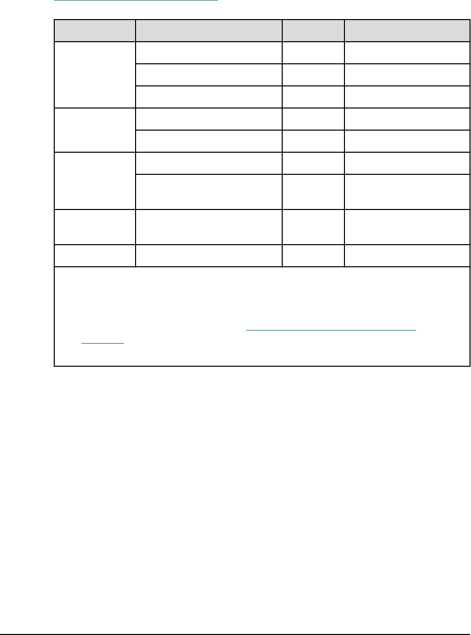
Supported platforms for VSP G1x00, VSP F1500, VSP Gx00 models, and VSP Fx00
models
Vendor Operating system*
Failover
software
Volume
manager
I/O
interface
Oracle Solaris 9 First Watch VxVM Fibre
Solaris 10, 11 – – Fibre
Solaris 10 on x86 – VxVM Fibre
Solaris 11 on x64 – – Fibre/iSCSI
OEL 6.x (6.2 or later) – – Fibre/iSCSI
HP HP-UX 11.1x MC/Service
Guard
LVM,
SLVM
Fibre
HP-UX 11.2x/11.3x on IA64
IA64: using IA-32EL on IA64
(except CCI for Linux/IA64)
MC/Service
Guard
LVM,
SLVM
Fibre
Tru64 UNIX 5.0 TruCluster LSM Fibre
IBM®AIX® 5.3, 6.1, 7.1 HACMP LVM Fibre
z/Linux (SUSE 8)
For details, see Requirements
and restrictions for CCI on z/
Linux (on page 22) .
– – Fibre (FCP)
Microso
ft
Windows Server
2008/2008(R2)/2012/2012(R2)
– LDM Fibre
Windows Server 2008(R2) on
IA64
– LDM Fibre
Windows Server 2008/2012 on
x64
– LDM Fibre
Windows Server 2008(R2)/
2012(R2) on x64
– LDM Fibre/iSCSI
Windows Server 2016 on x64 – LDM Fibre/iSCSI
Platforms that use CCI
Chapter 1: Installation requirements for Command Control Interface
Command Control Interface Installation and Conguration Guide 18

Vendor Operating system*
Failover
software
Volume
manager
I/O
interface
Red Hat RHEL AS/ES 3.0, 4.0, 5.0, 6, 7
If you use RHEL 4.0 with kernel
2.6.9.xx, see "Deprecated SCSI
ioctl" in the troubleshooting
chapter of the Command
Control Interface User and
Reference Guide.
– – Fibre
RHEL AS/ES 3.0 Update2, 4.0,
5.0 on x64 / IA64
IA64: using IA-32EL on IA64
(except CCI for Linux/IA64)
– – Fibre
RHEL 6 on x64 – – Fibre/iSCSI
RHEL 7 on x64 – – Fibre
Novell
(SUSE)
SLES 10, 11 – – Fibre
SLES 10 on x64 – – Fibre
SLES 11 on x64 – – Fibre/iSCSI
SLES 12 on x64 – – Fibre
* Service packs (SP), update programs, or patch programs are not considered as
requirements if they are not listed.
Supported platforms for VSP and HUS VM
Vendor Operating system*
Failover
software
Volume
manager
I/O
interface
Oracle Solaris 9 First Watch VxVM Fibre
Solaris 10 on x86 – VxVM Fibre
OEL 6.x – – Fibre
HP HP-UX 11.1x MC/Service
Guard
LVM,
SLVM
Fibre
HP-UX 11.2x/11.3x on IA64
IA64: using IA-32EL on IA64
(except CCI for Linux/IA64)
MC/Service
Guard
LVM,
SLVM
Fibre
Tru64 UNIX 5.0 TruCluster LSM Fibre
Platforms that use CCI
Chapter 1: Installation requirements for Command Control Interface
Command Control Interface Installation and Conguration Guide 19

Vendor Operating system*
Failover
software
Volume
manager
I/O
interface
IBM®AIX® 5.3 HACMP LVM Fibre
z/Linux (SUSE 8)
For details see Requirements
and restrictions for CCI on z/
Linux (on page 22) .
– – Fibre (FCP)
Microso
ft
Windows 2008 MSCS LDM Fibre
Windows 2008(R2) on IA64
IA64: using IA-32EL on IA64
(except CCI for Linux/IA64)
MSCS LDM Fibre
Windows Server
2008/2012/2012(R2) on EM64T
MSCS LDM Fibre
Windows Server 2016 on x64 – LDM Fibre
Red Hat RHEL AS/ES 3.0, 4.0, 5.0
If you use RHEL 4.0 with kernel
2.6.9.xx, see "Deprecated SCSI
ioctl" in the troubleshooting
chapter of the Command
Control Interface User and
Reference Guide.
– – Fibre
RHEL AS/ES 3.0 Update2, 4.0,
5.0 on EM64T / IA64
IA64: using IA-32EL on IA64
(except CCI for Linux/IA64)
– – Fibre
Novell
(SUSE)
SLES 10 – – Fibre
* Service packs (SP), update programs, or patch programs are not considered as
requirements if they are not listed.
Applicable platforms for CCI on VM
The following table lists the applicable platforms for CCI on VM.
CCI can run on the guest OS of the version listed in the table or later. For the latest
information on the OS versions and connectivity with storage systems, contact customer
support.
Applicable platforms for CCI on VM
Chapter 1: Installation requirements for Command Control Interface
Command Control Interface Installation and Conguration Guide 20

VM vendor1Layer Guest OS2, 3
Volume
mapping
I/O
interface
VMware ESX
Server 2.5.1 or
later (Linux Kernel
2.4.9)
For details, see
Restrictions for
VMware ESX
Server (on
page 25) .
Guest Windows Server 2008 RDM4Fibre
RHEL5.x/6.x
SLES10 SP2
RDM4Fibre
Solaris 10 u3 (x86) RDM4Fibre
VMware ESXi 5.5 Guest Windows Server
2008(R2)
RDM4Fibre/iSCSI
Windows Server
2008/2012 Hyper-
V
For details, see
Restrictions for
Windows Hyper-V
(Windows
2012/2008) (on
page 26) .
Child Windows Server 2008 Path-thru Fibre
SLES10 SP2 Path-thru Fibre
Hitachi Virtage
(58-12)
Windows Server
2008(R2)
Use LPAR Fibre
RHEL5.4
Oracle VM 3.1 or
later (Oracle VM
Server for SPARC)
Guest Solaris 11.1 See Restrictions
for Oracle VM
(on page 28)
See
Restriction
s for Oracle
VM (on
page 28)
HPVM 6.3 or later Guest HP-UX 11.3 Mapping by
NPIV
Fibre
IBM® VIOS 2.2.0.0 VIOC AIX® 7.1 TL01 Mapping by
NPIV
Fibre
Notes:
1. VM must be versions listed in this table or later.
2. Service packs (SP), update programs, or patch programs are not considered as
requirements if they are not listed.
3. Operations on the guest OS that is not supported by VM are not supported.
4. RDM: Raw Device Mapping using Physical Compatibility Mode is used.
Applicable platforms for CCI on VM
Chapter 1: Installation requirements for Command Control Interface
Command Control Interface Installation and Conguration Guide 21
Supported platforms for IPv6
The IPv6 functionality for CCI can be used on the OS versions listed in the following table
or later. For details about the latest OS versions, refer to the interoperability matrix at
https://support.hitachivantara.com.
Vendor OS1IPv62IPv4 mapped to IPv6
Oracle Solaris 9/10/11 Supported Supported
Solaris10/11 on x86 Supported Supported
OEL 6.x Supported Supported
HP HP-UX 11.23(PA/IA) Supported Supported
Tru64 UNIX 5.1A3Supported Supported
IBM®AIX® 5.3 Supported Supported
z/Linux (SUSE 8, SUSE 9) on
Z990
Supported Supported
Microsoft Windows 2008(R2) on x86/
EM64T/IA64
Supported Not supported
Red Hat RHEL AS/ES3.0, RHEL 5.x/6.x Supported Supported
Notes:
1. Service packs (SP), update programs, or patch programs are not considered as
requirements if they are not listed.
2. For details about IPv6 support, see About platforms supporting IPv6 (on
page 29) .
3. Performed by typing the IP address directly.
Requirements and restrictions for CCI on z/Linux
In the following example, z/Linux denes the open volumes that are connected to FCP
as /dev/sd*. Also, the mainframe volumes (3390-xx) that are connected to FICON® are
dened as /dev/dasd*.
The following gure is an example of a CCI conguration on z/Linux.
Supported platforms for IPv6
Chapter 1: Installation requirements for Command Control Interface
Command Control Interface Installation and Conguration Guide 22
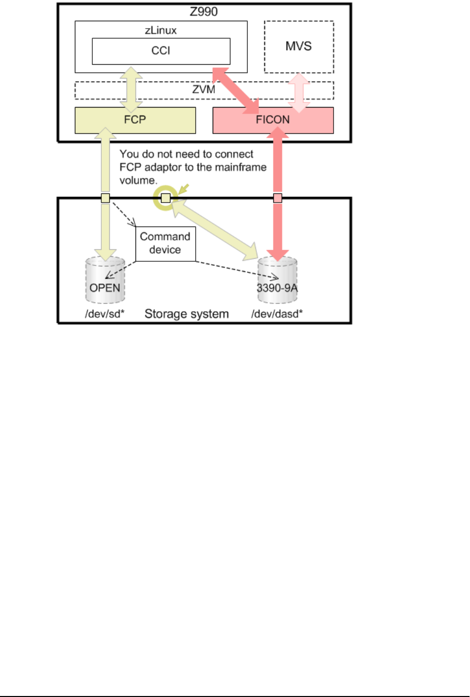
The restrictions for using CCI with z/Linux are:
■SSB information. SSB information might not be displayed correctly.
■Command device. CCI uses a SCSI Path-through driver to access the command
device. As such, the command device must be connected through FCP adaptors.
■Open Volumes via FCP. Same operation as the other operating systems.
Requirements and restrictions for CCI on z/Linux
Chapter 1: Installation requirements for Command Control Interface
Command Control Interface Installation and Conguration Guide 23

■Mainframe (3390-9A) Volumes via FICON®. You cannot control the volumes
(3390-9A) that are directly connected to FICON® for ShadowImage pair operations.
Also, mainframe volumes must be mapped to a CHF(FCP) port to access target
volumes using a command device, as shown in the above gure. The mainframe
volume does not have to be connected to an FCP adaptor.
Note: ShadowImage supports only 3390-9A multiplatform volumes.
TrueCopy and Universal Replicator do not support multiplatform volumes
(including 3390-9A) via FICON®.
■Volume discovery via FICON®. When you discover volume information, the inqraid
command uses SCSI inquiry. Mainframe volumes connected by FICON® do not
support the SCSI interface. Because of this, information equivalent to SCSI inquiry is
obtained through the mainframe interface (Read_device_characteristics or
Read_conguration_data), and the available information is displayed similarly as the
open volume. As a result, information displayed by executing the inqraid command
cannot be obtained, as shown below. Only the last ve digits of the FICON® volume's
serial number, which is displayed by the inqraid command, are displayed.
sles8z:/HORCM/usr/bin# ls /dev/dasd* | ./inqraid
/dev/dasda -> [ST] Unknown Ser = 1920 LDEV = 4 [HTC ]
[0704_3390_0A]
/dev/dasdaa -> [ST] Unknown Ser = 62724 LDEV =4120 [HTC ]
[C018_3390_0A]
/dev/dasdab -> [ST] Unknown Ser = 62724 LDEV =4121 [HTC ]
[C019_3390_0A]
sles8z:/HORCM/usr/bin# ls /dev/dasd* | ./inqraid -CLI
DEVICE_FILE PORT SERIAL LDEV CTG H/M/12 SSID R:Group PRODUCT_ID
dasda - 1920 4 - - 00C0 -
0704_3390_0A
dasdaa - 62724 4120 - - 9810 -
C018_3390_0A
dasdab - 62724 4121 - - 9810 - C019_3390_0A
The inqraid command displays only ve-digit number at the end of serial number of
the FICON® volume.
In the previous example, the Product_ID, C019_3390_0A, has the following associations:
■C019: Serial number
■3390: System type
■0A: System model
Requirements and restrictions for CCI on z/Linux
Chapter 1: Installation requirements for Command Control Interface
Command Control Interface Installation and Conguration Guide 24
The following commands cannot be used because there is no PORT information:
■raidscan -pd <raw_device>
■raidar -pd <raw_device>
■raidvchkscan -pd <raw_device>
■raidscan -find
■raidscan -find conf
■mkconf
Requirements and restrictions for CCI on VM
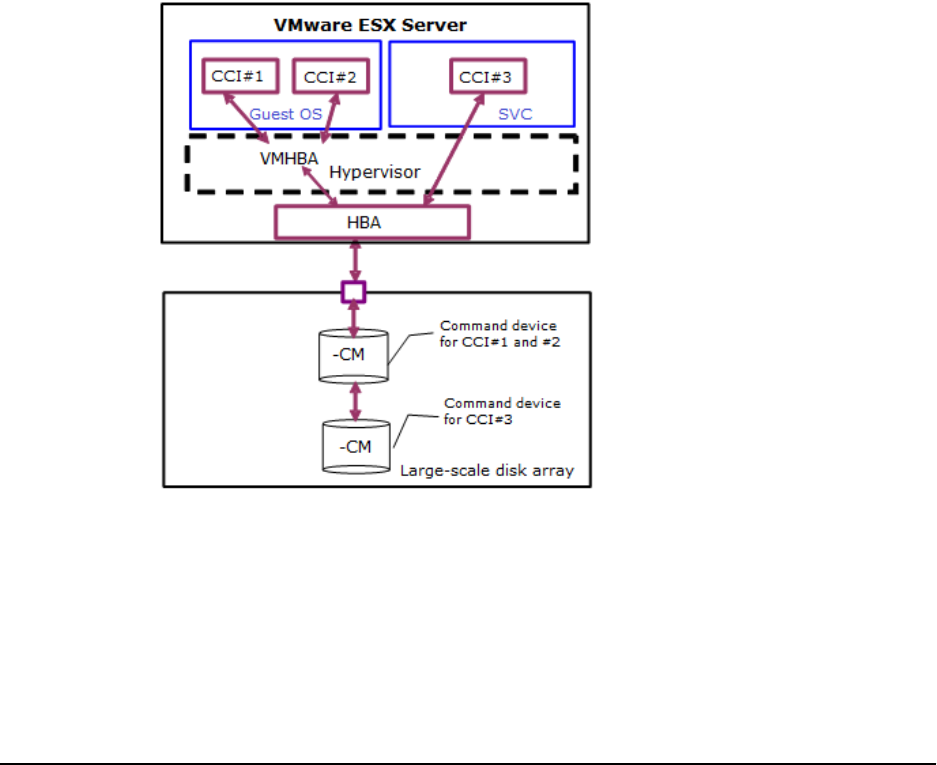
Restrictions for VMware ESX Server
Whether CCI can run properly depends on the support of guest OS by VMware. In
addition, the guest OS depends on VMware support of virtual hardware (HBA). Therefore,
the guest OS supporting VMware and supported by CCI (such as Windows Server 2003,
Red Hat Linux, or SUSE Linux) must be used, and the restrictions below must be followed
when using CCI on VMware.
The following gure shows the CCI conguration on guest OS/VMware.
Requirements and restrictions for CCI on VM
Chapter 1: Installation requirements for Command Control Interface
Command Control Interface Installation and Conguration Guide 25

The restrictions for using CCI with VMware are:
■Guest OS. CCI needs to use guest OS that is supported by CCI, and also VMware
supported guest OS (for example, Windows, Red Hat Linux). For specic support
information, refer to the Hitachi Vantara interoperability matrix at https://
support.hitachivantara.com.
■Command device. CCI uses SCSI path-through driver to access the command device.
Therefore, the command device must be mapped as Raw Device Mapping using
Physical Compatibility Mode. At least one command device must be assigned for each
guest OS.
CCI instance numbers among dierent guest OS must be dierent, even if the
command device is assigned for each guest OS, because the command device cannot
distinguish a dierence among guest OS due to the same WWN as VMHBA.
■About invisible LUN. Assigned LUN for the guest OS must be visible from SCSI
Inquiry when VMware (host OS) is started. For example, the S-VOL on VSS is used as
Read Only and Hidden, and this S-VOL is hidden from SCSI Inquiry. If VMware (host
OS) is started on this volume state, the host OS will hang.
■LUN sharing between Guest and Host OS. It is not supported to share a command
device or a normal LUN between guest OS and host OS.
■About running on SVC. The ESX Server 3.0 SVC (service console) is a limited
distribution of Linux based on Red Hat Enterprise Linux 3, Update 6 (RHEL 3 U6). The
service console provides an execution environment to monitor and administer the
entire ESX Server host. The CCI user can run CCI by installing "CCI for Linux" on SVC.
The volume mapping (/dev/sd) on SVC is a physical connection without converting
SCSI Inquiry, so CCI will perform like running on Linux regardless of guest OS.
However, VMware protects the service console with a rewall. According to current
documentation, the rewall allows only PORT# 902, 80, 443, 22(SSH) and ICMP(ping),
DHCP
, DNS as defaults, so the CCI user must enable a PORT for CCI (HORCM) using
the iptables command.
Restrictions for Windows Hyper-V (Windows 2012/2008)
Whether CCI can run properly depends on the support of the guest OS by Windows
Hyper-V, and then the guest OS depends on how Hyper-V supports front-end SCSI
interfaces.
The following gure shows the CCI conguration on Hyper-V.
Restrictions for Windows Hyper-V (Windows 2012/2008)
Chapter 1: Installation requirements for Command Control Interface
Command Control Interface Installation and Conguration Guide 26
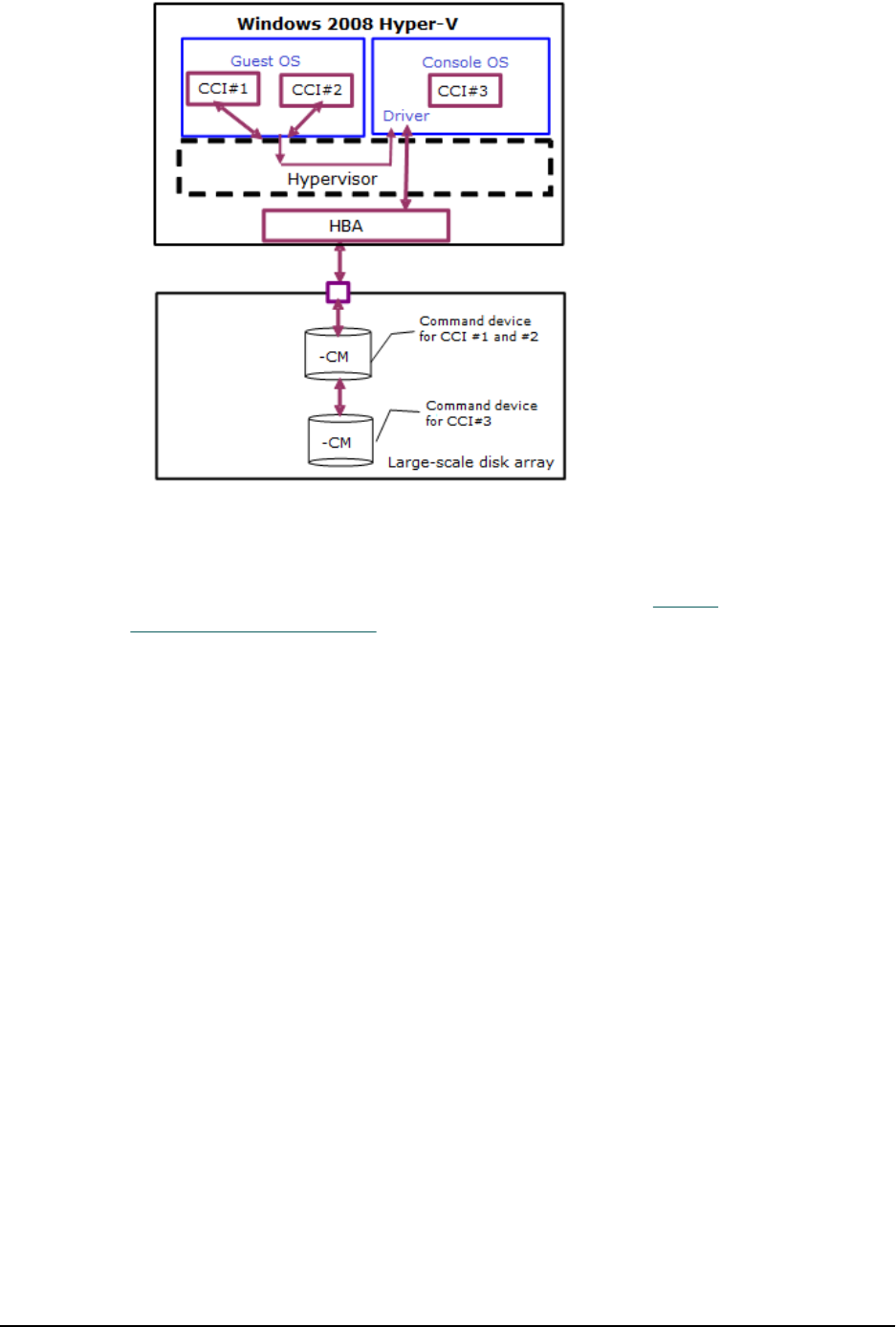
The restrictions for using CCI on Hyper-V are:
■Guest OS. CCI needs to use the guest OS that is supported by CCI and also the Hyper-
V supported guest OS (for example, Windows Server 2012, SUSE Linux). For specic
support information, refer to the interoperability matrix at https://
support.hitachivantara.com.
■Command device. CCI uses the SCSI path-through driver to access the command
device. Therefore the command device must be mapped as RAW device of the path-
through disk. At least one command device must be assigned for each guest OS (Child
Partition).
The CCI instance number among dierent guest OSs must be used as a dierent
instance number even if the command is assigned for each guest OS. This is because
the command device cannot distinguish a dierence among the guest OSs because
the same WWN via Fscsi is used.
■LUN sharing between guest OS and console OS. It is not possible to share a
command device as well as a normal LUN between a guest OS and a console OS.
■Running CCI on console OS. The console OS (management OS) is a limited Windows,
like Windows 2008/2012 Server Core, and the Windows standard driver is used. Also
the console OS provides an execution environment to monitor and administer the
entire Hyper-V host.
Therefore, you can run CCI by installing "CCI for Windows NT" on the console OS. In
that case, the CCI instance number between the console OS and the guest OS must
be a dierent instance number, even if the command is assigned for each console
and guest OS.
Restrictions for Windows Hyper-V (Windows 2012/2008)
Chapter 1: Installation requirements for Command Control Interface
Command Control Interface Installation and Conguration Guide 27
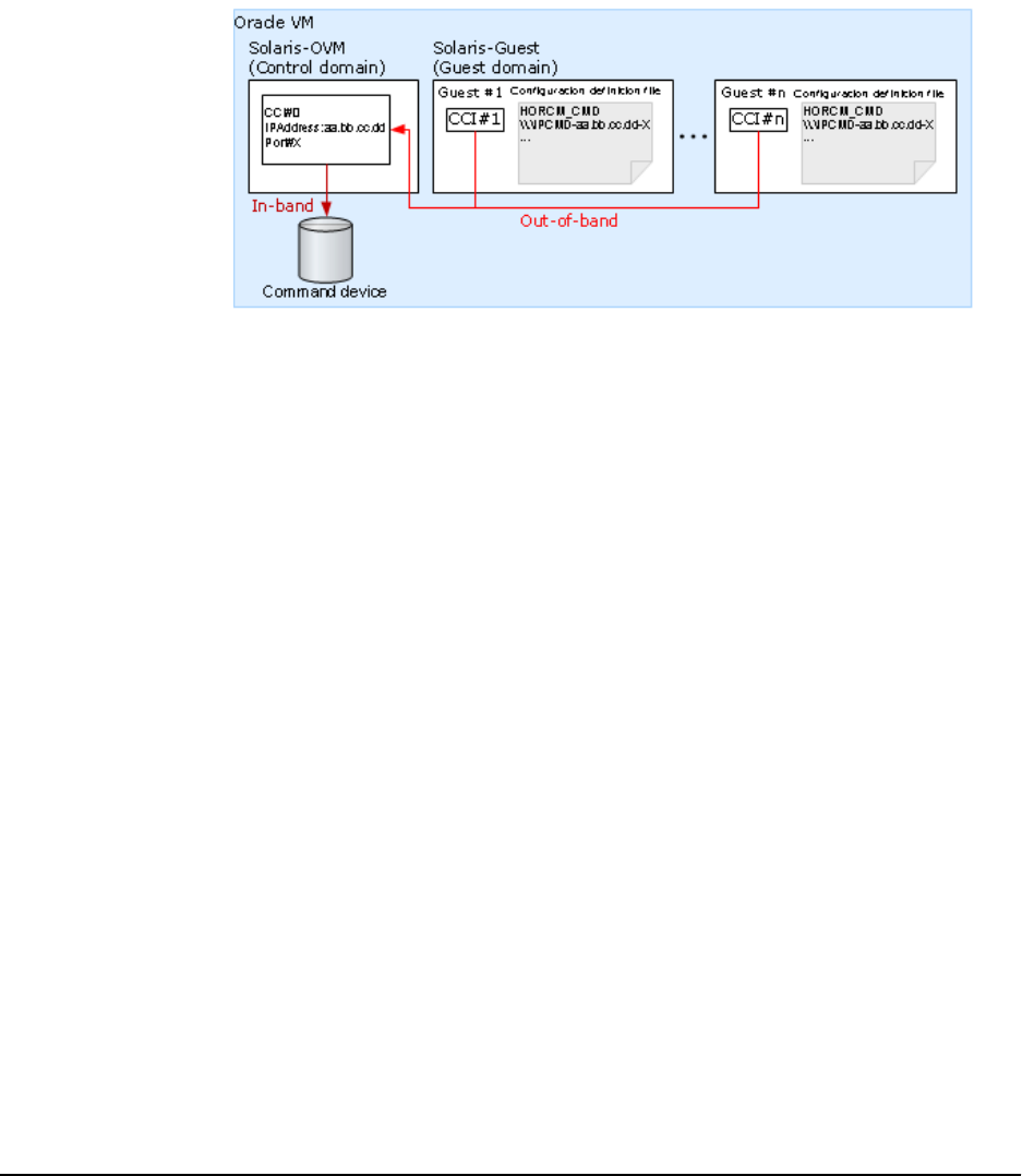
Restrictions for Oracle VM
Whether Command Control Interface can run properly depends on the guest OS
supported by Oracle VM.
The restrictions for using CCI with Oracle VM are:
■Guest OS. CCI must use the guest OS supported by CCI and the guest OS supported
by Oracle VM.
■Command device. You cannot connect the command device of Fibre Channel directly
to the guest OS. If you have to execute commands by the in-band method, you must
congure the system as shown in the following gure.
In this conguration, CCI on the guest domain (CCI#1 to CCI#n) transfers the
command to another CCI on the control domain (CCI#0) by an Out-of-Band method.
CCI#0 executes the command by In-Band method, and then transfer the result to
CCI#1 to CCI#n. CCI#0 fullls the same role as a virtual command device in the
SVP/GUM/CCI server.
■Volume mapping. Volumes on the guest OS must be mapped physically to the LDEVs
on the disk machine.
■System disk. If you specify the OS system disk as an object of copying, the OS might
not start on the system disk of the copy destination.
Restrictions for Oracle VM
Chapter 1: Installation requirements for Command Control Interface
Command Control Interface Installation and Conguration Guide 28
About platforms supporting IPv6
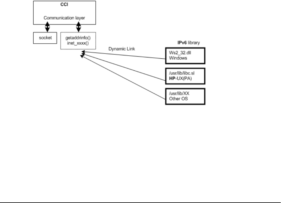
Library and system call for IPv6
CCI uses the following functions of IPv6 library to get and convert from hostname to IPv6
address.
■IPv6 library to resolve hostname and IPv6 address:
●getaddrinfo()
●inet_pton()
●inet_ntop()
■Socket System call to communicate using UDP/IPv6:
●socket(AF_INET6)
●bind(), sendmsg(), sendto(), rcvmsg(), recvfrom()…
If CCI links above function in the object(exe), a core dump might occur if an old platform
(for example, Windows NT, HP-UX 10.20, Solaris 5) does not support it. So CCI links
dynamically above functions by resolving the symbol after determining whether the
shared library and function for IPv6 exists. It depends on supporting of the platform
whether CCI can support IPv6 or not. If platform does not support IPv6 library, then CCI
uses its own internal function corresponding to inet_pton(),inet_ntop(); in this
case, IPv6 address is not allowed to describe hostname.
The following gure shows the library and system call for IPv6.
Environment variables for IPv6
CCI loads and links the library for IPv6 by specifying a PATH as follows:
■For Windows systems: Ws2_32.dll
■For HP-UX (PA/IA) systems: /usr/lib/libc.sl
About platforms supporting IPv6
Chapter 1: Installation requirements for Command Control Interface
Command Control Interface Installation and Conguration Guide 29

However, CCI might need to specify a dierent PATH to use the library for IPv6. After this
consideration, CCI also supports the following environment variables for specifying a
PATH:
■$IPV6_DLLPATH (valid for only HP-UX, Windows): This variable is used to change the
default PATH for loading the Library for IPv6. For example:
export IPV6_DLLPATH=/usr/lib/hpux32/lib.so
horcmstart.sh 10
■$IPV6_GET_ADDR: This variable is used to change "AI_PASSIVE" value as default for
specifying to the getaddrinfo() function for IPv6. For example:
export IPV6_GET_ADDR=9
horcmstart.sh 10
HORCM start-up log for IPv6
Support level of IPv6 feature depends on the platform and OS version. In certain OS
platform environments, CCI cannot perform IPv6 communication completely, so CCI logs
the results of whether the OS environment supports the IPv6 feature or not.
/HORCM/log/curlog/horcm_HOST NAME.log
*****************************************************************
- HORCM STARTUP LOG - Fri Aug 31 19:09:24 2007
******************************************************************
19:09:24-cc2ec-02187- horcmgr started on Fri Aug 31 19:09:24 2007
:
:
19:09:25-3f3f7-02188- ***** starts Loading library for IPv6 ****
[ AF_INET6 = 26, AI_PASSIVE = 1 ]
19:09:25-47ca1-02188- dlsym() : Symbl = 'getaddrinfo' : dlsym: symbol
"getaddrinfo" not found in "/etc/horcmgr"
getaddrinfo() : Unlinked on itself
inet_pton() : Linked on itself
inet_ntop() : Linked on itself
19:09:25-5ab3e-02188- ****** finished Loading library *******
:
HORCM set to IPv6 ( INET6 value = 26)
:
Startup procedures using detached process on DCL for
OpenVMS
Procedure
1. Create the shareable Logical name for RAID if undened initially.
HORCM start-up log for IPv6
Chapter 1: Installation requirements for Command Control Interface
Command Control Interface Installation and Conguration Guide 30

CCI needs to dene the physical device ($1$DGA145…) as either DG* or DK* or GK*
by using the show device and DEFINE/SYSTEM commands, but then does not
need to be mounted in CCI version 01-12-03/03 or earlier.
$ show device
Device Device Error Volume Free Trans Mnt
Name Status Count Label Blocks Count Cnt
$1$DGA145: (VMS4) Online 0
$1$DGA146: (VMS4) Online 0
:
:
$1$DGA153: (VMS4) Online 0
$
$ DEFINE/SYSTEM DKA145 $1$DGA145:
$ DEFINE/SYSTEM DKA146 $1$DGA146:
:
:
$ DEFINE/SYSTEM DKA153 $1$DGA153:
2. Dene the CCI environment in LOGIN.COM.
You need to dene the Path for the CCI commands to DCL$PATH as the foreign
command. See the section about Automatic Foreign Commands in the OpenVMS
user documentation.
$ DEFINE DCL$PATH SYS$POSIX_ROOT:[horcm.usr.bin],SYS$POSIX_ROOT:
[horcm.etc]
If CCI and HORCM are executing in dierent jobs (dierent terminal), then you must
redene LNM$TEMPORARY_MAILBOX in the LNM$PROCESS_DIRECTORY table as
follows:
$ DEFINE/TABLE=LNM$PROCESS_DIRECTORY LNM$TEMPORARY_MAILBOX LNM$GROUP
3. Discover and describe the command device on SYS$POSIX_ROOT:
[etc]horcm0.conf.
$ inqraid DKA145-151 -CLI
DEVICE_FILE PORT SERIAL LDEV CTG H/M/12 SSID R:Group PRODUCT_ID
DKA145 CL1-H 30009 145 - - - - OPEN-9-CM
DKA146 CL1-H 30009 146 - s/S/ss 0004 5:01-11 OPEN-9
DKA147 CL1-H 30009 147 - s/P/ss 0004 5:01-11 OPEN-9
DKA148 CL1-H 30009 148 - s/S/ss 0004 5:01-11 OPEN-9
DKA149 CL1-H 30009 149 - s/P/ss 0004 5:01-11 OPEN-9
DKA150 CL1-H 30009 150 - s/S/ss 0004 5:01-11 OPEN-9
DKA151 CL1-H 30009 151 - s/P/ss 0004 5:01-11 OPEN-9
SYS$POSIX_ROOT:[etc]horcm0.conf
HORCM_MON
#ip_address service poll(10ms) timeout(10ms)
127.0.0.1 30001 1000 3000
HORCM_CMD
Startup procedures using detached process on DCL for OpenVMS
Chapter 1: Installation requirements for Command Control Interface
Command Control Interface Installation and Conguration Guide 31

#dev_name dev_name dev_name
DKA145
You will have to start HORCM without a description for HORCM_DEV and
HORCM_INST because the target ID and LUN are Unknown. You can determine a
mapping of a physical device with a logical name easily by using the raidscan -
find command.
4. Execute an 'horcmstart 0'.
$ run /DETACHED SYS$SYSTEM:LOGINOUT.EXE /PROCESS_NAME=horcm0 -
_$ /INPUT=VMS4$DKB100:[SYS0.SYSMGR.][horcm]loginhorcm0.com -
_$ /OUTPUT=VMS4$DKB100:[SYS0.SYSMGR.][horcm]run0.out -
_$ /ERROR=VMS4$DKB100:[SYS0.SYSMGR.][horcm]run0.err
%RUN-S-PROC_ID, identification of created process is 00004160
5. Verify a physical mapping of the logical device.
$ HORCMINST := 0
$ raidscan -pi DKA145-151 -find
DEVICE_FILE UID S/F PORT TARG LUN SERIAL LDEV PRODUCT_ID
DKA145 0 F CL1-H 0 1 30009 145 OPEN-9-CM
DKA146 0 F CL1-H 0 2 30009 146 OPEN-9
DKA147 0 F CL1-H 0 3 30009 147 OPEN-9
DKA148 0 F CL1-H 0 4 30009 148 OPEN-9
DKA149 0 F CL1-H 0 5 30009 149 OPEN-9
DKA150 0 F CL1-H 0 6 30009 150 OPEN-9
DKA151 0 F CL1-H 0 7 30009 151 OPEN-9
$ horcmshutdown 0
inst 0:
HORCM Shutdown inst 0 !!!
6. Describe the known HORCM_DEV on SYS$POSIX_ROOT:[etc]horcm*.conf.
For horcm0.conf
HORCM_DEV
#dev_group dev_name port# TargetID LU# MU#
VG01 oradb1 CL1-H 0 2 0
VG01 oradb2 CL1-H 0 4 0
VG01 oradb3 CL1-H 0 6 0
HORCM_INST
#dev_group ip_address service
VG01 HOSTB horcm1
For horcm1.conf
HORCM_DEV
#dev_group dev_name port# TargetID LU# MU#
VG01 oradb1 CL1-H 0 3 0
VG01 oradb2 CL1-H 0 5 0
VG01 oradb3 CL1-H 0 7 0
Startup procedures using detached process on DCL for OpenVMS
Chapter 1: Installation requirements for Command Control Interface
Command Control Interface Installation and Conguration Guide 32

HORCM_INST
#dev_group ip_address service
VG01 HOSTA horcm0
Denes the UDP port name for HORCM communication in the SYS$SYSROOT:
[000000.TCPIP$ETC]SERVICES.DAT le, as in the example below.
horcm0 30001/udp horcm1 30002/udp
7. Start horcm0 and horcm1 as the Detached process.
$ run /DETACHED SYS$SYSTEM:LOGINOUT.EXE /PROCESS_NAME=horcm0 -
_$ /INPUT=VMS4$DKB100:[SYS0.SYSMGR.][horcm]loginhorcm0.com -
_$ /OUTPUT=VMS4$DKB100:[SYS0.SYSMGR.][horcm]run0.out -
_$ /ERROR=VMS4$DKB100:[SYS0.SYSMGR.][horcm]run0.err
%RUN-S-PROC_ID, identification of created process is 00004160
$
$$ run /DETACHED SYS$SYSTEM:LOGINOUT.EXE /PROCESS_NAME=horcm1 -
_$ /INPUT=VMS4$DKB100:[SYS0.SYSMGR.][horcm]loginhorcm1.com -
_$ /OUTPUT=VMS4$DKB100:[SYS0.SYSMGR.][horcm]run1.out -
_$ /ERROR=VMS4$DKB100:[SYS0.SYSMGR.][horcm]run1.err
%RUN-S-PROC_ID, identification of created process is 00004166
You can verify that HORCM daemon is running as Detached Process by using the
show process command.
$ show process horcm0
25-MAR-2003 23:27:27.72 User: SYSTEM Process ID: 0004160
Node: VMS4 Process name:"HORCM0"
Terminal:
User Identifier: [SYSTEM]
Base priority: 4
Default file spec: Not available
Number of Kthreads: 1
Soft CPU Affinity: off
Command examples in DCL for OpenVMS
(1) Setting the environment variable by using Symbol
$ HORCMINST := 0$ HORCC_MRCF := 1
$ raidqry -l
No Group Hostname HORCM_ver Uid Serial# Micro_ver Cache(MB)
1 --- VMS4 01-29-03/05 0 30009 50-04-00/00 8192
$
$ pairdisplay -g VG01 -fdc
Group PairVol(L/R) Device_File M,Seq#,LDEV#.P/S,Status, % ,P-LDEV# M
VG01 oradb1(L) DKA146 0 30009 146..S-VOL PAIR, 100 147 -
Command examples in DCL for OpenVMS
Chapter 1: Installation requirements for Command Control Interface
Command Control Interface Installation and Conguration Guide 33

VG01 oradb1(R) DKA147 0 30009 147..P-VOL PAIR, 100 146 -
VG01 oradb2(L) DKA148 0 30009 148..S-VOL PAIR, 100 149 -
VG01 oradb2(R) DKA149 0 30009 149..P-VOL PAIR, 100 148 -
VG01 oradb3(L) DKA150 0 30009 150..S-VOL PAIR, 100 151 -
VG01 oradb3(R) DKA151 0 30009 151..P-VOL PAIR, 100 150 -
$
(2) Removing the environment variable
$ DELETE/SYMBOL HORCC_MRCF
$ pairdisplay -g VG01 -fdc
Group PairVol(L/R) Device_File ,Seq#,LDEV#.P/S,Status,Fence, % ,P-LDEV# M
VG01 oradb1(L) DKA146 30009 146..SMPL ---- ------,----- ---- -
VG01 oradb1(R) DKA147 30009 147..SMPL ---- ------,----- ---- -
VG01 oradb2(L) DKA148 30009 148..SMPL ---- ------,----- ---- -
VG01 oradb2(R) DKA149 30009 149..SMPL ---- ------,----- ---- -
VG01 oradb3(L) DKA150 30009 150..SMPL ---- ------,----- ---- -
VG01 oradb3(R) DKA151 30009 151..SMPL ---- ------,----- ---- -
$
(3) Changing the default log directory
$ HORCC_LOG := /horcm/horcm/TEST
$ pairdisplay
PAIRDISPLAY: requires '-x xxx' as argument
PAIRDISPLAY: [EX_REQARG] Required Arg list
Refer to the command log(SYS$POSIX_ROOT:[HORCM.HORCM.TEST]HORCC_VMS4.LOG (/
HORCM
/HORCM/TEST/horcc_VMS4.log)) for details.
(4) Turning back to the default log directory
$ DELETE/SYMBOL HORCC_LOG
(5) Specifying the device described in scandev.LIS
$ define dev_file SYS$POSIX_ROOT:[etc]SCANDEV
$ type dev_file
DKA145-150
$
$ pipe type dev_file | inqraid -CLI
DEVICE_FILE PORT SERIAL LDEV CTG H/M/12 SSID R:Group PRODUCT_ID
DKA145 CL1-H 30009 145 - - - - OPEN-9-CM
DKA146 CL1-H 30009 146 - s/S/ss 0004 5:01-11 OPEN-9
DKA147 CL1-H 30009 147 - s/P/ss 0004 5:01-11 OPEN-9
DKA148 CL1-H 30009 148 - s/S/ss 0004 5:01-11 OPEN-9
DKA149 CL1-H 30009 149 - s/P/ss 0004 5:01-11 OPEN-9
DKA150 CL1-H 30009 150 - s/S/ss 0004 5:01-11 OPEN-9
Command examples in DCL for OpenVMS
Chapter 1: Installation requirements for Command Control Interface
Command Control Interface Installation and Conguration Guide 34

(6) Making the conguration le automatically
You can omit steps from (3) to (6) on the Start-up procedures by using the mkconf
command.
$ type dev_file
DKA145-150
$
$ pipe type dev_file | mkconf -g URA -i 9
starting HORCM inst 9
HORCM Shutdown inst 9 !!!
A CONFIG file was successfully completed.
HORCM inst 9 finished successfully.
starting HORCM inst 9
DEVICE_FILE Group PairVol PORT TARG LUN M SERIAL LDEV
DKA145 - - - - - - 30009 145
DKA146 URA URA_000 CL1-H 0 2 0 30009 146
DKA147 URA URA_001 CL1-H 0 3 0 30009 147
DKA148 URA URA_002 CL1-H 0 4 0 30009 148
DKA149 URA URA_003 CL1-H 0 5 0 30009 149
DKA150 URA URA_004 CL1-H 0 6 0 30009 150
HORCM Shutdown inst 9 !!!
Please check 'SYS$SYSROOT:[SYSMGR]HORCM9.CONF','SYS$SYSROOT:
[SYSMGR.LOG9.CURLOG]
HORCM_*.LOG', and modify 'ip_address & service'.
HORCM inst 9 finished successfully.
$
SYS$SYSROOT:[SYSMGR]horcm9.conf (/sys$sysroot/sysmgr/horcm9.conf)
# Created by mkconf on Thu Mar 13 20:08:41
HORCM_MON
#ip_address service poll(10ms) timeout(10ms)
127.0.0.1 52323 1000 3000
HORCM_CMD
#dev_name dev_name dev_name
#UnitID 0 (Serial# 30009)
DKA145
# ERROR [CMDDEV] DKA145 SER = 30009 LDEV = 145 [ OPEN-9-
CM `
HORCM_DEV
#dev_group dev_name port# TargetID LU# MU#
# DKA146 SER = 30009 LDEV = 146 [ FIBRE FCTBL = 3 ]
URA URA_000 CL1-H 0 2 0
# DKA147 SER = 30009 LDEV = 147 [ FIBRE FCTBL = 3 ]
URA URA_001 CL1-H 0 3 0
# DKA148 SER = 30009 LDEV = 148 [ FIBRE FCTBL = 3 ]
URA URA_002 CL1-H 0 4 0
# DKA149 SER = 30009 LDEV = 149 [ FIBRE FCTBL = 3 ]
Command examples in DCL for OpenVMS
Chapter 1: Installation requirements for Command Control Interface
Command Control Interface Installation and Conguration Guide 35

URA URA_003 CL1-H 0 5 0
# DKA150 SER = 30009 LDEV = 150 [ FIBRE FCTBL = 3 ]
URA URA_004 CL1-H 0 6 0
HORCM_INST
#dev_group ip_address service
URA 127.0.0.1 52323
(7) Using $1$* naming as native device name
You can use the native device without DEFINE/SYSTEM command by specifying $1$*
naming directly.
$ inqraid $1$DGA145-155 -CLI
DEVICE_FILE PORT SERIAL LDEV CTG H/M/12 SSID R:Group PRODUCT_ID
$1$DGA145 CL2-H 30009 145 - - - - OPEN-9-CM
$1$DGA146 CL2-H 30009 146 - s/P/ss 0004 5:01-11 OPEN-9
$1$DGA147 CL2-H 30009 147 - s/S/ss 0004 5:01-11 OPEN-9
$1$DGA148 CL2-H 30009 148 0 P/s/ss 0004 5:01-11 OPEN-9
$ pipe show device | INQRAID -CLI
DEVICE_FILE PORT SERIAL LDEV CTG H/M/12 SSID R:Group PRODUCT_ID
$1$DGA145 CL2-H 30009 145 - - - - OPEN-9-CM
$1$DGA146 CL2-H 30009 146 - s/P/ss 0004 5:01-11 OPEN-9
$1$DGA147 CL2-H 30009 147 - s/S/ss 0004 5:01-11 OPEN-9
$1$DGA148 CL2-H 30009 148 0 P/s/ss 0004 5:01-11 OPEN-9
$ pipe show device | MKCONF -g URA -i 9
starting HORCM inst 9
HORCM Shutdown inst 9 !!!
A CONFIG file was successfully completed.
HORCM inst 9 finished successfully.
starting HORCM inst 9
DEVICE_FILE Group PairVol PORT TARG LUN M SERIAL LDEV
$1$DGA145 - - - - - - 30009 145
$1$DGA146 URA URA_000 CL2-H 0 2 0 30009 146
$1$DGA147 URA URA_001 CL2-H 0 3 0 30009 147
$1$DGA148 URA URA_002 CL2-H 0 4 0 30009 148
HORCM Shutdown inst 9 !!!
Please check 'SYS$SYSROOT:[SYSMGR]HORCM9.CONF','SYS$SYSROOT:
[SYSMGR.LOG9.CURLOG]
HORCM_*.LOG', and modify 'ip_address & service'.
HORCM inst 9 finished successfully.
$
$ pipe show device | RAIDSCAN -find
DEVICE_FILE UID S/F PORT TARG LUN SERIAL LDEV PRODUCT_ID
$1$DGA145 0 F CL2-H 0 1 30009 145 OPEN-9-CM
$1$DGA146 0 F CL2-H 0 2 30009 146 OPEN-9
$1$DGA147 0 F CL2-H 0 3 30009 147 OPEN-9
$1$DGA148 0 F CL2-H 0 4 30009 148 OPEN-9
Command examples in DCL for OpenVMS
Chapter 1: Installation requirements for Command Control Interface
Command Control Interface Installation and Conguration Guide 36

$ pairdisplay -g BCVG -fdc
Group PairVol(L/R) Device_File M ,Seq#,LDEV#..P/S,Status, % ,P-LDEV# M
BCVG oradb1(L) $1$DGA146 0 30009 146..P-VOL PAIR, 100 147 -
BCVG oradb1(R) $1$DGA147 0 30009 147..S-VOL PAIR, 100 146 -
$
$ pairdisplay -dg $1$DGA146
Group PairVol(L/R) (Port#,TID, LU-M) ,Seq#,LDEV#..P/S,Status, Seq#,P-LDEV#
M
BCVG oradb1(L) (CL1-H,0, 2-0) 30009 146..P-VOL PAIR, 30009 147 -
BCVG oradb1(R) (CL1-H,0, 3-0) 30009 47..S-VOL PAIR, ----- 146 -
$
Start-up procedures in bash for OpenVMS
Do not use CCI through the bash, because the bash is not provided as an ocial release
in OpenVMS.
Procedure
1. Create the shareable Logical name for RAID if undened initially.
You need to dene the Physical device ($1$DGA145…) as either DG* or DK* or GK*
by using the show device command and the DEFINE/SYSTEM command, but then
it does not need to be mounted.
$ show device
Device Device Error Volume Free Trans Mnt
Name Status Count Label Blocks Count Cnt
$1$DGA145: (VMS4) Online 0
$1$DGA146: (VMS4) Online 0
:
:
$1$DGA153: (VMS4) Online 0
$$ DEFINE/SYSTEM DKA145 $1$DGA145:
$ DEFINE/SYSTEM DKA146 $1$DGA146:
:
:
$ DEFINE/SYSTEM DKA153 $1$DGA153:
2. Dene the CCI environment in LOGIN.COM.
If CCI and HORCM are executing in dierent jobs (dierent terminal), then you must
redene LNM$TEMPORARY_MAILBOX in the LNM$PROCESS_DIRECTORY table as
follows:
$ DEFINE/TABLE=LNM$PROCESS_DIRECTORY LNM$TEMPORARY_MAILBOX LNM$GROUP
Start-up procedures in bash for OpenVMS
Chapter 1: Installation requirements for Command Control Interface
Command Control Interface Installation and Conguration Guide 37

3. Discover and describe the command device on /etc/horcm0.conf.
bash$ inqraid DKA145-151 -CLI
DEVICE_FILE PORT SERIAL LDEV CTG H/M/12 SSID R:Group PRODUCT_ID
DKA145 CL1-H 30009 145 - - - - OPEN-9-CM
DKA146 CL1-H 30009 146 - s/S/ss 0004 5:01-11 OPEN-9
DKA147 CL1-H 30009 147 - s/P/ss 0004 5:01-11 OPEN-9
DKA148 CL1-H 30009 148 - s/S/ss 0004 5:01-11 OPEN-9
DKA149 CL1-H 30009 149 - s/P/ss 0004 5:01-11 OPEN-9
DKA150 CL1-H 30009 150 - s/S/ss 0004 5:01-11 OPEN-9
DKA151 CL1-H 30009 151 - s/P/ss 0004 5:01-11 OPEN-9
/etc/horcm0.conf
HORCM_MON
#ip_address service poll(10ms) timeout(10ms)
127.0.0.1 52000 1000 3000
HORCM_CMD
#dev_name dev_name dev_name
DKA145
HORCM_DEV
#dev_group dev_name port# TargetID LU# MU#
HORCM_INST
#dev_group ip_address service
You will have to start HORCM without a description for HORCM_DEV and
HORCM_INST because target ID and LUN are Unknown. You can determine a
mapping of a physical device with a logical name easily by using the raidscan -
find command.
4. Execute an 'horcmstart 0' as background.
bash$ horcmstart 0 &
18
bash$
starting HORCM inst 0
5. Verify a physical mapping of the logical device.
bash$ export HORCMINST=0
bash$ raidscan -pi DKA145-151 -find
DEVICE_FILE UID S/F PORT TARG LUN SERIAL LDEV PRODUCT_ID
DKA145 0 F CL1-H 0 1 30009 145 OPEN-9-CM
DKA146 0 F CL1-H 0 2 30009 146 OPEN-9
DKA147 0 F CL1-H 0 3 30009 147 OPEN-9
DKA148 0 F CL1-H 0 4 30009 148 OPEN-9
DKA149 0 F CL1-H 0 5 30009 149 OPEN-9
Start-up procedures in bash for OpenVMS
Chapter 1: Installation requirements for Command Control Interface
Command Control Interface Installation and Conguration Guide 38

DKA150 0 F CL1-H 0 6 30009 150 OPEN-9
DKA151 0 F CL1-H 0 7 30009 151 OPEN-9
6. Describe the known HORCM_DEV on /etc/horcm*.conf.
For horcm0.conf
HORCM_DEV
#dev_group dev_name port# TargetID LU# MU#
VG01 oradb1 CL1-H 0 2 0
VG01 oradb2 CL1-H 0 4 0
VG01 oradb3 CL1-H 0 6 0
HORCM_INST
#dev_group ip_address service
VG01 HOSTB horcm1
For horcm1.conf
HORCM_DEV
#dev_group dev_name port# TargetID LU# MU#
VG01 oradb1 CL1-H 0 3 0
VG01 oradb2 CL1-H 0 5 0
VG01 oradb3 CL1-H 0 7 0
HORCM_INST
#dev_group ip_address service
VG01 HOSTA horcm0
7. Start 'horcmstart 0 1'.
The subprocess(HORCM) created by bash is terminated when the bash is EXIT.
bash$ horcmstart 0 &
19
bash$
starting HORCM inst 0
bash$ horcmstart 1 &
20
bash$
starting HORCM inst 1
Using CCI with Hitachi and other storage systems
The following table shows the related two controls between CCI and the RAID storage
system type (Hitachi or HPE). The following gure shows the relationship between the
application, CCI, and RAID storage system.
Using CCI with Hitachi and other storage systems
Chapter 1: Installation requirements for Command Control Interface
Command Control Interface Installation and Conguration Guide 39
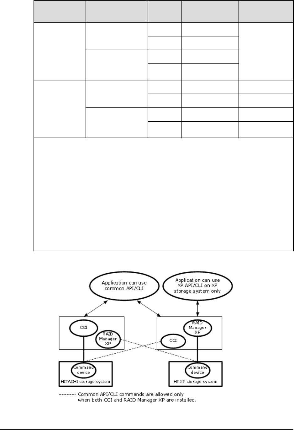
Version Installation order
RAID
system Common API/CLI XP API/CLI
CCI 01-08-03/00
or later
CCI Hitachi Allowed Cannot use (CLI
options can be
used)
HPE Allowed1
Install CCI after
installing RAID
Manager XP
Hitachi Allowed
HPE Allowed
RAID Manager
XP 01.08.00 or
later (provided
by HPE)
RAID Manager XP HPE Allowed Allowed
Hitachi Allowed1Allowed2
Install RAID
Manager XP after
installing CCI
HPE Allowed Allowed
Hitachi Allowed Allowed2
Notes:
1. The following common API/CLI commands are rejected with EX_ERPERM by
connectivity of CCI with RAID storage system:
horctakeover, paircurchk, paircreate, pairsplit, pairresync,
pairvolchk, pairevtwait, pairdisplay, raidscan (except the -find option),
raidar, raidvchkset, raidvchkdsp, raidvchkscan
2. The following XP API/CLI commands are rejected with EX_ERPERM on the storage
system even when both CCI and RAID Manager XP (provided by HPE) are installed:
pairvolchk -s, pairdisplay -CLI, raidscan -CLI, paircreate -m
noread for TrueCopy/TrueCopy Async/Universal Replicator, paircreate -m
dif/inc for ShadowImage
Using CCI with Hitachi and other storage systems
Chapter 1: Installation requirements for Command Control Interface
Command Control Interface Installation and Conguration Guide 40

Chapter 2: Installing and configuring CCI
This chapter describes and provides instructions for installing and conguring CCI.
Installing the CCI hardware
Installation of the hardware required for CCI is performed by the user and the Hitachi
Vantara representative.
Procedure
1. User:
a. Make sure that the UNIX/PC server hardware and software are properly
installed and congured. For specic support information, refer to the
interoperability matrix at https://support.hitachivantara.com.
b. If you will be performing remote replication operations (for example, Universal
Replicator, TrueCopy), identify the primary and secondary volumes, so that the
hardware and software components can be installed and congured properly.
2. Hitachi Vantara representative:
a. Connect the RAID storage systems to the hosts. See the Maintenance Manual
for the storage system and the Open-Systems Host Attachment Guide. Make sure
to set the appropriate system option modes (SOMs) and host mode options
(HMOs) for the operational environment.
b. Congure the RAID storage systems that will contain primary volumes for
replication to report sense information to the hosts.
c. Set the SVP time to the local time so that the time stamps are correct. For VSP
Gx00 models and VSP Fx00 models, use the maintenance utility to set the
system date and time to the local time.
d. Remote replication: Install the remote copy connections between the RAID
storage systems. For detailed information, see the applicable user guide (for
example, Hitachi Universal Replicator User Guide).
3. User and Hitachi Vantara representative:
a. Ensure that the storage systems are accessible via Hitachi Device Manager -
Storage Navigator. For details, see the System Administrator Guide for your
storage system.
b. (Optional) Ensure that the storage systems are accessible by the management
software (for example, Hitachi Storage Advisor, Hitachi Command Suite). For
details, see the user documentation for the software product.
c. Install and enable the applicable license key of your program product (for
example, TrueCopy, ShadowImage, LUN Manager, Universal Replicator for
Chapter 2: Installing and conguring CCI
Command Control Interface Installation and Conguration Guide 41

Mainframe, Data Retention Utility) on the storage systems. For details about
installing license keys, see the System Administrator Guide or Storage Navigator
User Guide.
4. User: Congure the RAID storage systems for operations as described in the user
documentation. For example, before you can create TrueCopy volume pairs using
CCI, you need to congure the ports on the storage systems and establish the MCU-
RCU paths.
Installing the CCI software
To install CCI, log in with "root user" or "administrator" privileges. The login user type is
determined by the operating system. You can install the CCI software on the host servers
with assistance as needed from the Hitachi Vantara representative.
The installation must be done in the following order:
1. Install the CCI software.
2. Set the command device.
3. Create the conguration denition les.
4. Set the environmental variables.
UNIX installation
If you are installing CCI from the media for the program product, use the RMinstsh and
RMuninst scripts on the program product media to automatically install and remove the
CCI software. (For LINUX/IA64 or LINUX/X64, move to the LINUX/IA64 or LINUX/X64
directory and then execute ../../RMinstsh.)
For other media, use the following instructions as given below in the two methods. The
following instructions refer to UNIX commands that might be dierent on your platform.
Consult your OS documentation (for example, UNIX man pages) for platform-specic
command information.
Installing the CCI software into the root directory
Procedure
1. Insert the installation media into the I/O device properly.
2. Move to the current root directory: # cd /
3. Copy all les from the installation media using the cpio command:
# cpio -idmu < /dev/XXXX
where XXXX = I/O device
Preserve the directory structure (d ag) and le modication times (m ag), and
copy unconditionally (u ag).
Installing the CCI software
Chapter 2: Installing and conguring CCI
Command Control Interface Installation and Conguration Guide 42

4. Execute the CCI installation command:
# /HORCM/horcminstall.sh
5. Verify installation of the proper version using the raidqry command:
# raidqry -h
Model: RAID-Manager/HP-UX
Ver&Rev: 01-40-03/03
Usage: raidqry [options]
Installing the CCI software into a non-root directory
Procedure
1. Insert the installation media into the proper I/O device.
2. Move to the desired directory for CCI. The specied directory must be mounted by a
partition of except root disk or an external disk.
# cd /Specified Directory
3. Copy all les from the installation media using the cpio command:
# cpio -idmu < /dev/XXXX XXXX = I/O device
Preserve the directory structure (d ag) and le modication times (m ag), and
copy unconditionally (u ag).
4. Make a symbolic link for /HORCM:
# ln -s /Specified Directory/HORCM /HORCM
5. Execute the CCI installation command:
# /HORCM/horcminstall.sh
6. Verify installation of the proper version using the raidqry command:
# raidqry -h
Model: RAID-Manager/HP-UX
Ver&Rev: 01-40-03/03
Usage: raidqry [options]
Changing the CCI user (UNIX systems)
Just after installation, CCI can be operated only by the root user. When operating CCI by
assigning a dierent user for CCI management, you need to change the owner of the CCI
directory and owner's privilege, specify environment variables, and so on. Use the
following procedure to change the conguration to allow a dierent user to operate CCI.
Installing the CCI software into a non-root directory
Chapter 2: Installing and conguring CCI
Command Control Interface Installation and Conguration Guide 43

Procedure
1. Change the owner of the following CCI les from the root user to the desired user
name:
■/HORCM/etc/horcmgr
■All CCI commands in the /HORCM/usr/bin directory
■/HORCM/log directory
■All CCI log directories in the /HORCM/log* directories
■/HORCM/.uds directory
2. Give the newly assigned user the privilege of writing to the following CCI directories:
■/HORCM/log
■/HORCM/log* (when the /HORCM/log* directory exists)
■/HORCM (when the /HORCM/log* directory does not exist)
3. Change the owner of the raw device le of the HORCM_CMD (control device)
command device in the conguration denition le from the root user to the
desired user name.
4. Optional: Establishing the HORCM (/etc/horcmgr) start environment: If you have
designation of the full environment variables (HORCM_LOG HORCM_LOGS), then
start the horcmstart.sh command without an argument. In this case, the
HORCM_LOG and HORCM_LOGS directories must be owned by the CCI
administrator. The environment variable (HORCMINST, HORCM_CONF) establishes
as the need arises.
5. Optional: Establishing the command execution environment: If you have
designation of the environment variables (HORCC_LOG), then the HORCC_LOG
directory must be owned by the CCI administrator. The environment variable
(HORCMINST) establishes as the need arises.
6. Establish UNIX domain socket: If the execution user of CCI is dierent from user of
the command, a system administrator needs to change the owner of the following
directory, which is created at each HORCM (/etc/horcmgr) start-up:
■/HORCM/.uds/.lcmcl directory
To reset the security of UNIX domain socket to OLD version, perform the following:
1. Give writing permission to /HORCM/.uds directory.
2. Start horcmstart.sh ., and set the "HORCM_EVERYCLI=1" environment variable.
Changing the CCI user (UNIX systems)
Chapter 2: Installing and conguring CCI
Command Control Interface Installation and Conguration Guide 44
Next steps
Note: A user account for the Linux system must have the "CAP_SYS_ADMIN"
and "CAP_SYS_RAWIO" privileges to use the SCSI Class driver (Command
device). The system administrator can apply these privileges by using the
PAM_capability module. However, if the system administrator cannot set
those user privileges, then use the following method. This method starts the
HORCM daemon only with the root user; as an alternative, you can execute
CCI commands.
■System administrator: Place the script that starts up horcmstart.sh in the
following directory so that the system can start HORCM from /etc/
rc.d/rc: /etc/init.d
■Users: When the log directory is only accessible by the system
administrator, you cannot use the inqraid or raidscan -find
commands. Therefore, set the command log directory by setting the
environment variables (HORCC_LOG), and executing the CCI command.
Note: AIX® does not allow ioctl() with the exception of the root user. CCI
tries to use ioctl(DK_PASSTHRU) or SCSI_Path_thru as much as possible,
if it fails, changes to RAW_IO follows conventional ways. Even so, CCI might
encounter the AIX® FCP driver, which does not support
ioctl(DK_PASSTHRU) fully in the customer site. After this consideration, CCI
also supports by dening either the following environment variable or /
HORCM/etc/USE_OLD_IOCTLfile(size=0) that uses the RAW_IO forcibly.
Example
export USE_OLD_IOCTL=1
horcmstart.sh 10
HORCM/etc:
-rw-r--r-- 1 root root 0 Nov 11 11:12 USE_OLD_IOCT
-r--r--r-- 1 root sys 32651 Nov 10 20:02 horcm.conf
-r-xr--r-- 1 root sys 282713 Nov 10 20:02 horcmgr
Windows installation
Use this procedure to install CCI on a Windows system.
Make sure to install CCI on all servers involved in CCI operations.
Caution:
■Installing CCI in multiple drives is not recommended. If you install CCI in
multiple drives, CCI installed in the smallest drive might be used
preferentially.
■If CCI is already installed and you are upgrading the CCI version, you must
remove the installed version rst and then install the new version. For
instructions, see Upgrading CCI in a Windows environment (on page 61) .
Windows installation
Chapter 2: Installing and conguring CCI
Command Control Interface Installation and Conguration Guide 45

Before you begin
The network of Windows attachment with TCP/IP protocol must already be installed and
established.
Procedure
1. Insert the media for the product into the proper I/O device.
2. Execute Setup.exe (\program\RM\WIN_NT\RMHORC\Setup.exe or \program\RM
\WIN_NT\RMHORC_X64\Setup.exe on the CD), and follow the instructions on the
screen to complete the installation. The installation directory is HORCM (xed value)
at the root directory.
3. Reboot the Windows server, and then start up CCI.
A warning message for security might appear at the initial start-up depending on
the OS settings. Specify "Temporarily Allow" or "Always Allow" in the dialog box.
4. Verify that the correct version of the CCI software is running on your system by
executing the raidqry command:
D:\HORCM\etc> raidqry -h
Model: RAID-Manager/WindowsNT
Ver&Rev: 01-41-03/xx
Usage: raidqry [options] for HORC
Next steps
Users who execute CCI commands need "administrator" privileges and the right to
access the log directory and the les in it. For instructions on specifying a CCI
administrator, see Changing the CCI user (Windows systems) (on page 46) .
Changing the CCI user (Windows systems)
Users who execute CCI commands need "administrator" privileges and the right to
access a log directory and the les under it. Use the following procedures to specify a
user who does not have "administrator" privileges as a CCI administrator.
■Specifying a CCI administrator: system administrator tasks (on page 46)
■Specifying a CCI administrator: CCI administrator tasks (on page 47)
Specifying a CCI administrator: system administrator tasks
Procedure
1. Add a user_name to the PhysicalDrive.
Add the user name of the CCI administrator to the Device objects of the command
device for HORCM_CMD in the conguration denition le. For example:
C:\HORCM\tool\>chgacl /A:RMadmin Phys
PhysicalDrive0 -> \Device\Harddisk0\DR0
\\.\PhysicalDrive0 : changed to allow 'RMadmin'
2. Add a user_name to the Volume{GUID}.
Changing the CCI user (Windows systems)
Chapter 2: Installing and conguring CCI
Command Control Interface Installation and Conguration Guide 46

If the CCI administrator needs to use the "-x mount/umount" option for CCI
commands, the system administrator must add the user name of the CCI
administrator to the Device objects of the Volume{GUID}. For example:
C:\HORCM\tool\>chgacl /A:RMadmin Volume
Volume{b0736c01-9b14-11d8-b1b6-806d6172696f} -> \Device\CdRom0
\\.\Volume{b0736c01-9b14-11d8-b1b6-806d6172696f} : changed to allow
'RMadmin'
Volume{b0736c00-9b14-11d8-b1b6-806d6172696f} -> \Device\HarddiskVolume1
\\.\Volume{b0736c00-9b14-11d8-b1b6-806d6172696f} : changed to allow
'RMadmin'
3. Add user_name to the ScsiX.
If the CCI administrator needs to use the "-x portscan" option for CCI commands,
the system administrator must add the user name of the CCI administrator to the
Device objects of the ScsiX. For example:
C:\HORCM\tool\>chgacl /A:RMadmin Scsi
Scsi0: -> \Device\Ide\IdePort0
\\.\Scsi0: : changed to allow 'RMadmin'
Scsi1: -> \Device\Ide\IdePort1
\\.\Scsi1: : changed to allow 'RMadmin '
Result
Because the ACL (Access Control List) of the Device objects is set every time Windows
starts-up, the Device objects are also required when Windows starts up. The ACL is also
required when new Device objects are created.
Specifying a CCI administrator: CCI administrator tasks
Procedure
1. Establish the HORCM (/etc/horcmgr) startup environment.
By default, copy the conguration denition le in the following directory:
%SystemDrive%:\windows\
Because users cannot write to this directory, the CCI administrator must change the
directory by using the HORCM_CONF variable. For example:
C:\HORCM\etc\>set HORCM_CONF=C:\Documents and Settings\RMadmin
\horcm10.conf
C:\HORCM\etc\>set HORCMINST=10
C:\HORCM\etc\>horcmstart [This must be started without arguments]
The mountvol command is denied use by user privilege, therefore "the directory
mount" option of CCI commands using the mountvol command cannot be
executed.
The inqraid "-gvinf" option uses the %SystemDrive%:\windows\ directory, so this
option cannot be used unless the system administrator allows you to write.
Specifying a CCI administrator: CCI administrator tasks
Chapter 2: Installing and conguring CCI
Command Control Interface Installation and Conguration Guide 47

However, CCI can be changed from the %SystemDrive%:\windows\ directory to
the %TEMP% directory by setting the "HORCM_USE_TEMP" environment variable.
For example:
C:\HORCM\etc\>set HORCM_USE_TEMP=1
C:\HORCM\etc\>inqraid $Phys -gvinf
2. Ensure that the CCI command and the HORCM have the same privileges. If CCI
command and the HORCM are executing dierent privileges (dierent users), then
CCI command can not attach to HORCM (CCI command and HORCM are denied
communication through the Mailslot).
However, CCI does permit a HORCM connection through the "HORCM_EVERYCLI"
environment variable, as shown in the following example:
C:\HORCM\etc\>set HORCM_CONF=C:\Documents and Settings\RMadmin
\horcm10.conf
C:\HORCM\etc\>set HORCMINST=10
C:\HORCM\etc\>set HORCM_EVERYCLI=1
C:\HORCM\etc\>horcmstart [This must be started without arguments]
In this example, users who execute CCI commands must be restricted to use only
CCI commands. This can be done using the Windows "explore" or "cacls"
commands.
Installing CCI on the same PC as the storage management software
CCI is supplied with the storage management software for VSP Gx00 models and VSP
Fx00 models. Installing CCI and the storage management software on the same PC
allows you to use CCI of the appropriate version.
Caution: If CCI is already installed and you are upgrading the CCI version, you
must remove the installed version rst and then install the new version. For
instructions, see Upgrading CCI installed on the same PC as the storage
management software (on page 62) .
Before you begin
The network of Windows attachment with TCP/IP protocol must already be installed and
established.
Procedure
1. Right-click <storage-management-software-installation-path>\wk
\supervisor\restapi\uninstall.bat to run as administrator.
2. Install CCI in the same drive as the storage management software as follows:
a. Insert the media for the product into the proper I/O device.
b. Execute Setup.exe (\program\RM\WIN_NT\RMHORC\Setup.exe or
\program\RM\WIN_NT\RMHORC_X64\Setup.exe on the CD), and follow the
Installing CCI on the same PC as the storage management software
Chapter 2: Installing and conguring CCI
Command Control Interface Installation and Conguration Guide 48

instructions on the screen to complete the installation. The installation
directory is HORCM (xed value) at the root directory.
c. Reboot the Windows server, and then start up CCI.
A warning message for security might appear at the initial start-up depending
on the OS settings. Specify "Temporarily Allow" or "Always Allow" in the dialog
box.
d. Verify that the correct version of the CCI software is running on your system by
executing the raidqry command:
D:\HORCM\etc> raidqry -h
Model: RAID-Manager/WindowsNT
Ver&Rev: 01-41-03/xx
Usage: raidqry [options] for HORC
3. Right-click <storage-management-software-installation-path>\wk
\supervisor\restapi\install.bat to run as administrator.
OpenVMS installation
Make sure to install CCI on all servers involved in CCI operations. Establish the network
(TCP/IP), if not already established. CCI is provided as the following PolyCenter Software
Installation (PCSI) le:
HITACHI-ARMVMS-RM-V0122-2-1.PCSI HITACHI-I64VMS-RM-V0122-2-1.PCSI
CCI also requires that POSIX_ROOT exist on the system, so you must dene the
POSIX_ROOT before installing the CCI software. It is recommended that you dene the
following three logical names for CCI in LOGIN.COM:
$ DEFINE/TRANSLATION=(CONCEALED,TERMINAL) SYS$POSIX_ROOT "Device:
[directory]"
$ DEFINE DCL$PATH SYS$POSIX_ROOT:[horcm.usr.bin],SYS$POSIX_ROOT:[horcm.etc]
$ DEFINE/TABLE=LNM$PROCESS_DIRECTORY LNM$TEMPORARY_MAILBOX LNM$GROUP
$ DEFINE DECC$ARGV_PARSE_STYLE ENABLE
$ SET PROCESS/PARSE_STYLE=EXTENDED
where Device:[directory] is dened as SYS$POSIX_ROOT
Follow the steps below to install the CCI software on an OpenVMS system.
Procedure
1. Insert and mount the provided CD or diskette.
2. Execute the following command:
$ PRODUCT INSTALL RM /source=Device:[PROGRAM.RM.OVMS]/LOG -
_$ /destination=SYS$POSIX_ROOT:[000000]
Device:[PROGRAM.RM.OVMS] where HITACH-ARMVMS-RM-V0122-2-
1.PCSI exists
OpenVMS installation
Chapter 2: Installing and conguring CCI
Command Control Interface Installation and Conguration Guide 49
3. Verify installation of the proper version using the raidqry command:
$ raidqry -h
Model: RAID-Manager/OpenVMS
Ver&Rev: 01-40-03/03
Usage: raidqry [options]
In-band and out-of-band operations
CCI operations can be performed using either the in-band method (all storage systems)
or the out-of-band method (VSP and later).
■In-band (host-based) method. CCI commands are transferred from the client or server
to the command device in the storage system via the host Fibre-Channel or iSCSI
interface. The command device must be dened in the conguration denition le (as
shown in the gure below).
■Out-of-band (LAN-based) method. CCI commands are transferred from a client PC via
the LAN. For CCI on USP V/VM, to execute a command from a client PC that is not
connected directly to a storage system, you must write a shell script to log in to a CCI
server (in-band method) via Telnet or SSH.
For CCI on VSP and later, you can create a virtual command device on the SVP by
specifying the IP address in the conguration denition le. For CCI on VSP Gx00
models and VSP Fx00 models, you can create a virtual command device on GUM in a
storage system by specifying the IP address of the storage system.
By creating a virtual command device, you can execute the same script as the in-band
method from a client PC that is not connected directly to the storage system. CCI
commands are transferred to the virtual command device from the client PC and then
executed in storage systems.
A virtual command device can also be created on the CCI server, which is a remote CCI
installation that is connected by LAN. The location of the virtual command device
depends on the type of storage system. The following table lists the storage system
types and indicates the allowable locations of the virtual command device.
Storage system type
Location of virtual command device
SVP GUM CCI server
VSP Gx00 models, VSP Fx00
models
OK* OK OK
HUS VM OK Not applicable OK
VSP G1x00, VSP F1500 OK Not applicable OK
VSP OK Not applicable OK
* CCI on the SVP must be congured as a CCI server in advance.
In-band and out-of-band operations
Chapter 2: Installing and conguring CCI
Command Control Interface Installation and Conguration Guide 50
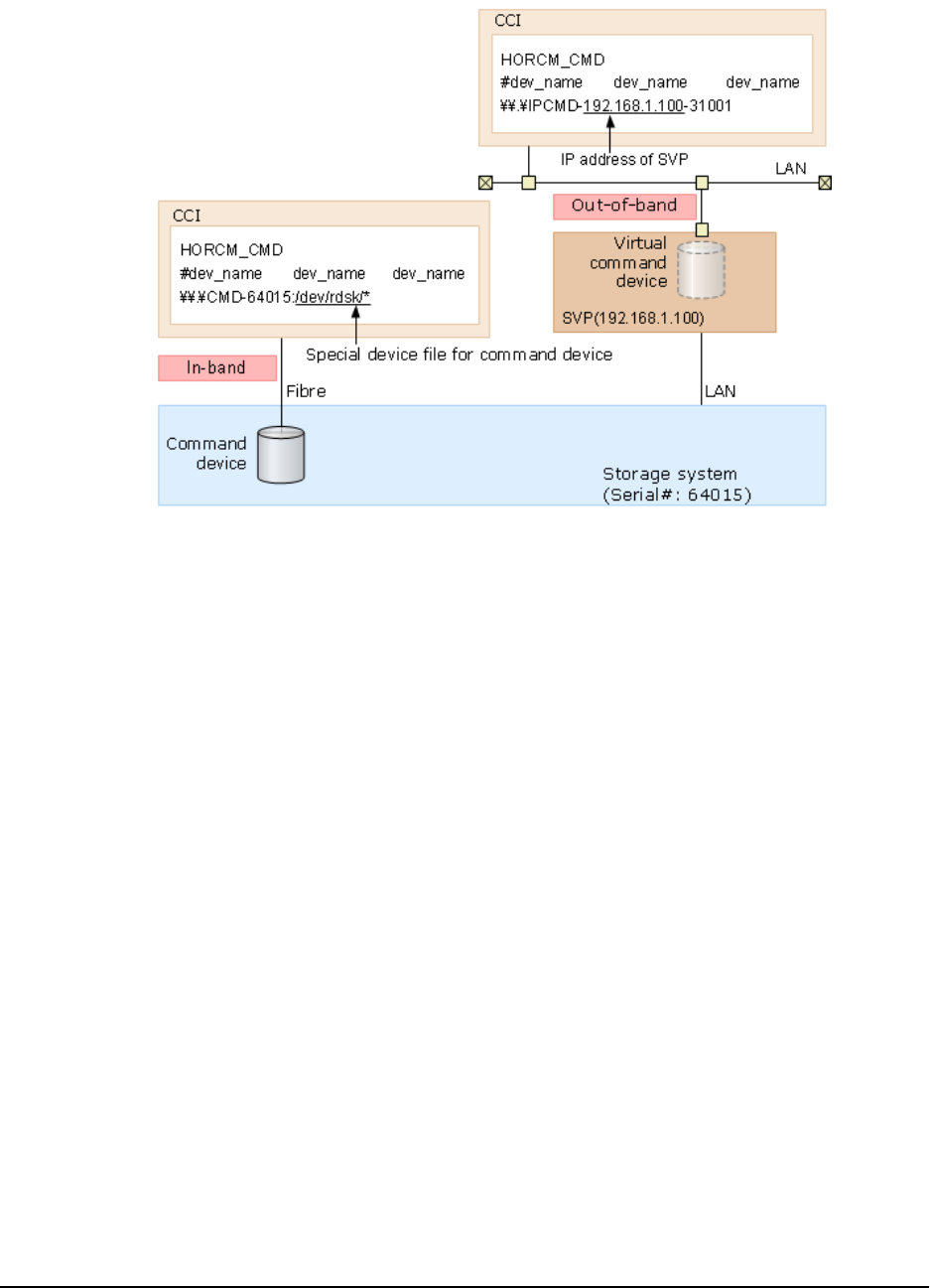
The following gure shows a sample system conguration with the command device and
virtual command device settings for the in-band and out-of-band methods on VSP Gx00
models, VSP Fx00 models, VSP G1x00, VSP F1500, VSP, and HUS VM.
The following gure shows a sample system conguration with the command device and
virtual command device settings for the in-band and out-of-band methods on VSP Gx00
models and VSP Fx00 models. In the following gure, CCI B is the CCI server for CCI A.
You can issue commands from CCI A to the storage system through the virtual command
device of CCI B. You can also issue commands from CCI B directly to the storage system
(without CCI A). When you issue commands directly from CCI B, CCI A is optional.
In-band and out-of-band operations
Chapter 2: Installing and conguring CCI
Command Control Interface Installation and Conguration Guide 51
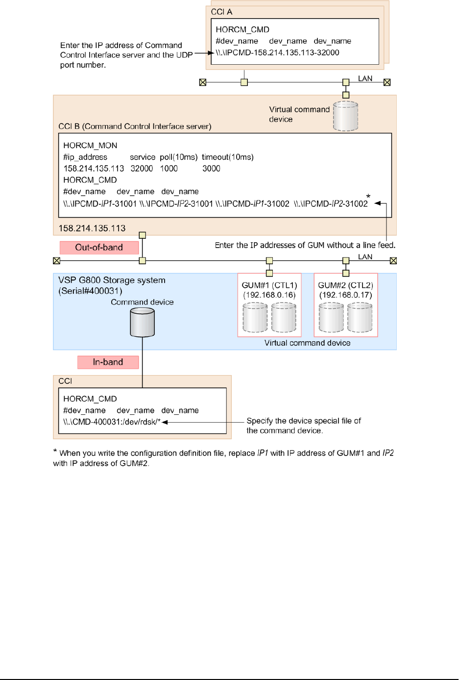
The following gure shows a sample system conguration with a CCI server connected
by the in-band method for VSP G1x00, VSP F1500, VSP, and HUS VM.
In-band and out-of-band operations
Chapter 2: Installing and conguring CCI
Command Control Interface Installation and Conguration Guide 52
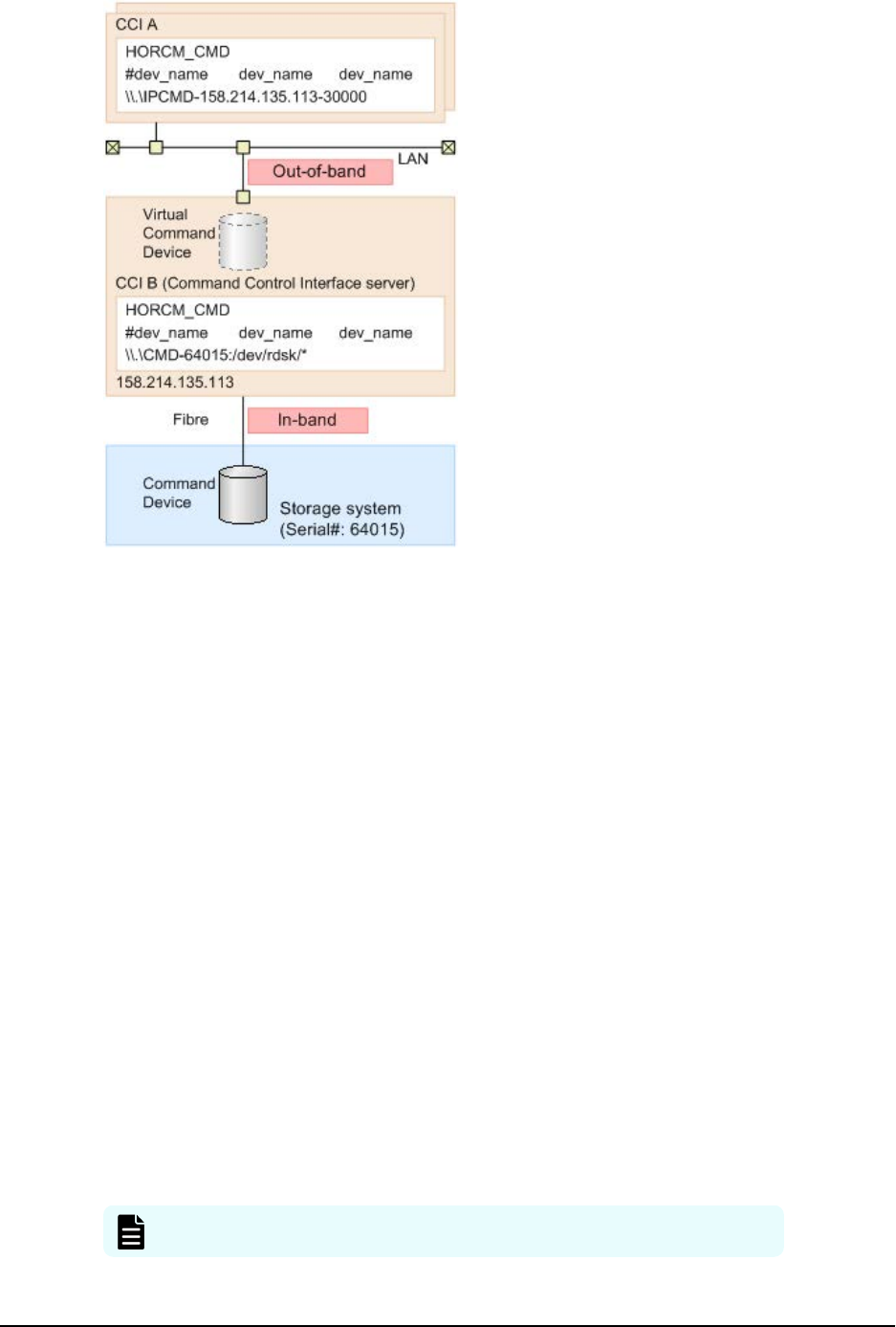
Setting up UDP ports
This section contains information about setting up strict rewalls.
If you do not have a HORCM_MON IP address in your conguration denition le, CCI
(horcm) opens the following ports on horcmstart:
■For in-band or out-of-band: [31000 + horcminstance + 1]
■For out-of-band: [34000 + horcminstance + 1]
If you have a HORCM_MON IP address in your conguration denition le, you need to
open up the port that is dened in this entry.
Setting the command device
For in-band CCI operations, commands are issued to the command device and then
executed on the RAID storage system. The command device is a user-selected, dedicated
logical volume on the storage system that functions as the interface to the CCI software
on the host. The command device is dedicated to CCI operations and cannot be used by
any other applications. The command device accepts read and write commands that are
executed by the storage system and returns read requests to the host.
The command device can be any OPEN-V device that is accessible to the host. A LUSE
volume cannot be used as a command device. The command device uses 16 MB, and the
remaining volume space is reserved for CCI and its utilities. A Virtual LUN volume as
small as 36 MB can be used as a command device.
Note: For Solaris operations, the command device must be labeled.
Setting up UDP ports
Chapter 2: Installing and conguring CCI
Command Control Interface Installation and Conguration Guide 53

First you set the command device using Device Manager - Storage Navigator, and then
you dene the command device in the HORCM_CMD section of the conguration
denition le for the CCI instance on the attached host.
For specifying the command device and the virtual command device, you can enter up to
511 characters on a line.
Procedure
1. Make sure the device that will be set as a command device does not contain any
user data. Once a volume is set as a command device, it is inaccessible to the host.
2. Log on to Storage Navigator, and connect to the storage system on which you want
to set a command device.
3. Congure the device as needed before setting it as a command device. For example,
you can create a custom-size device that has 36 MB of storage capacity for use as a
command device. For instructions, see the Provisioning Guide for your storage
system. For Universal Storage Platform V/VM, see the Hitachi Virtual LVI/LUN User's
Guide.
4. Locate and select the device, and set the device as a command device. For
instructions, see the Provisioning Guide for your storage system. For Universal
Storage Platform V/VM, see the Hitachi LUN Manager User's Guide.
If you plan to use the CCI Data Protection Facility, enable the command device
security attribute of the command device. For details about the CCI Data Protection
Facility, see the Command Control Interface User and Reference Guide.
If you plan to use CCI commands for provisioning (raidcom commands), enable the
user authentication attribute of the command device.
If you plan to use device groups, enable the device group denition attribute of the
command device.
5. Write down the system raw device name (character-type device le name) of the
command device (for example, /dev/rdsk/c0t0d1s2 in Solaris, \\.\CMD-Ser#-
ldev#-Port# in Windows). You will need this information when you dene the
command device in the conguration denition le.
6. If you want to set an alternate command device, repeat this procedure for another
volume.
7. If you want to enable dual pathing of the command device under Solaris systems,
include all paths to the command device on a single line in the HORCM_CMD section
of the conguration denition le.
The following example shows the two controller paths (c1 and c2) to the command
device. Putting the path information on separate lines might cause parsing issues,
and failover might not occur unless the HORCM startup script is restarted on the
Solaris system.
Example of dual path for command device for Solaris systems:
HORCM_CMD
#dev_name dev_name dev_name
/dev/rdsk/c1t66d36s2 /dev/rdsk/c2t66d36s2
Setting the command device
Chapter 2: Installing and conguring CCI
Command Control Interface Installation and Conguration Guide 54

Specifying the command device and virtual command device in the configuration
definition file
If you will execute commands by the in-band method to a command device on the
storage system, specify the LU path for the command device in the conguration
denition le. The command device in the storage system specied by the LU path
accepts the commands from the client and executes the operation.
If you will execute commands by the out-of-band method, specify the virtual command
device in the conguration denition le. The virtual command device is dened by the
IP address of the SVP or GUM, the UDP communication port number (xed at 31001),
and the storage system unit ID* in the conguration denition le. When a virtual
command device is used, the command is transferred from the client or server via LAN
to the virtual command device specied by the IP address of the SVP, and an operation
instruction is assigned to the storage system.
* The storage system unit ID is required only for congurations with multiple storage
systems.
The following examples show how a command device and a virtual command device are
specied in the conguration denition le. For details, see the Command Control
Interface User and Reference Guide.
Example of command device in conguration denition le (in-band method)
HORCM_CMD
#dev_name dev_name dev_name
\\.\CMD-64015:/dev/rdsk/*
Example of virtual command device in conguration denition le (out-of-band
method with SVP)
Example for SVP IP address 192.168.1.100 and UDP communication port number 31001:
HORCM_CMD
#dev_name dev_name dev_name
\\.\IPCMD-192.168.1.100-31001
Example of virtual command device in conguration denition le (out-of-band
method with GUM)
Example for GUM IP addresses 192.168.0.16, 192.168.0.17 and UDP communication port
numbers 31001, 31002. In this case, enter the IP addresses without line feed.
HORCM_CMD
#dev_name dev_name dev_name
\\.\IPCMD-192.168.0.16-31001 \\.\IPCMD-192.168.0.17-31001 \\.
\IPCMD-192.168.0.16-31002 \\.\IPCMD-192.168.0.17-31002
Specifying the command device and virtual command device in the conguration denition le
Chapter 2: Installing and conguring CCI
Command Control Interface Installation and Conguration Guide 55
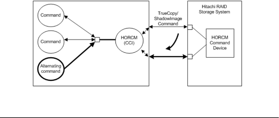
About alternate command devices
If CCI receives an error notication in reply to a read or write request to a command
device, the CCI software can switch to an alternate command device, if one is dened. If a
command device is unavailable (for example, blocked due to online maintenance), you
can switch to an alternate command device manually. If no alternate command device is
dened or available, all commands terminate abnormally, and the host cannot issue CCI
commands to the storage system. To ensure that CCI operations continue when a
command device becomes unavailable, you should set one or more alternate command
devices.
Because the use of alternate I/O pathing depends on the platform, restrictions are
placed upon it. For example, on HP-UX systems only devices subject to the LVM can use
the alternate path PV-LINK. To prevent command device failure, CCI supports an
alternate command device function.
■Denition of alternate command devices. To use an alternate command device,
dene two or more command devices for the HORCM_CMD item in the conguration
denition le. When two or more devices are dened, they are recognized as
alternate command devices. If an alternate command device is not dened in the
conguration denition le, CCI cannot switch to the alternate command device.
■Timing of alternate command devices. When the HORCM receives an error
notication in reply from the operating system via the raw I/O interface, the
command device is alternated. It is possible to alternate the command device forcibly
by issuing an alternating command provided by TrueCopy (horcctl -C).
■Operation of alternating command. If the command device is blocked due to online
maintenance (for example, microcode replacement), the alternating command should
be issued in advance. When the alternating command is issued again after
completion of the online maintenance, the previous command device is activated
again.
■Multiple command devices on HORCM startup. If at least one command device is
available and one or more command devices are specied in the conguration
denition le, then HORCM starts with a warning message to startup log by using
available command device. Conrm that all command devices can be changed by
using the horcctl -C command option, or HORCM has been started without warning
message to the HORCM startup log.
The following gure shows the workow for the alternate command device function.
About alternate command devices
Chapter 2: Installing and conguring CCI
Command Control Interface Installation and Conguration Guide 56

Creating and editing the configuration definition file
The conguration denition le is a text le that is created and edited using any standard
text editor (for example, UNIX vi editor, Windows Notepad). The conguration denition
le denes correspondences between the server and the volumes used by the server.
There is a conguration denition le for each host server. When the CCI software starts
up, it refers to the denitions in the conguration denition le.
The conguration denition le denes the devices in copy pairs and is used for host
management of the copy pairs, including ShadowImage, ShadowImage for Mainframe,
TrueCopy, TrueCopy for Mainframe, Copy-on-Write Snapshot, Thin Image, Universal
Replicator, and Universal Replicator for Mainframe. ShadowImage, ShadowImage for
Mainframe, Copy-on-Write Snapshot, and Thin Image use the same conguration les
and commands, and the RAID storage system determines the type of copy pair based on
the S-VOL characteristics and (for Copy-on-Write Snapshot and Thin Image) the pool
type.
The conguration denition le contains the following sections:
■HORCM_MON: Denes information about the local host.
■HORCM_CMD: Denes information about the command (CMD) devices.
■HORCM_VCMD: Denes information about the virtual storage machine.
■HORCM_DEV or HORCM_LDEV: Denes information about the copy pairs.
■HORM_INST or INSTP: Denes information about the remote host.
■HORCM_LDEVG: Denes information about the device group.
■HORCM_ALLOW_INST: Denes information about user permissions.
A sample conguration denition le, HORCM_CONF (/HORCM/etc/horcm.conf), is
included with the CCI software. This le should be used as the basis for creating your
conguration denition les. The system administrator should make a copy of the
sample le, set the necessary parameters in the copied le, and place the le in the
proper directory.
The following table lists the conguration parameters dened in the horcm.conf le and
species the default value, type, and limit for each parameter. For details about
parameters in the conguration le, see the Command Control Interface User and
Reference Guide.
Parameter Default Type Limit
ip_address None Character string 63 characters
service None Character string or numeric
value
15 characters
poll (10 ms) 1000 Numeric value* None
timeout (10 ms) 3000 Numeric value* None
Creating and editing the conguration denition le
Chapter 2: Installing and conguring CCI
Command Control Interface Installation and Conguration Guide 57

Parameter Default Type Limit
dev_name for
HORCM_DEV
None Character string 31 characters
dev_group None Character string 31 characters
Recommended value
= 8 char. or less
port # None Character string 31 characters
target ID None Numeric value* 7 characters
LU# None Numeric value* 7 characters
MU# 0 Numeric value* 7 characters
Serial# None Numeric value* 12 characters
CU:LDEV(LDEV#) None Numeric value 6 characters
dev_name for
HORCM_CMD
None Character string 63 characters
Recommended value
= 8 char. or less
*Use decimal notation (not hexadecimal) for these numeric values.
Creating and editing the conguration denition le
Chapter 2: Installing and conguring CCI
Command Control Interface Installation and Conguration Guide 58

Notes on editing configuration definition file
Follow the notes given below for editing conguration denition le.
■Do not edit the conguration denition le while CCI is running. Shut down CCI, edit
the conguration le as needed, and then restart CCI. When you change the system
conguration, it is required to shut down CCI once and rewrite the conguration
denition le to match with the change and then restart CCI. When you change the
storage system conguration (microprogram, cache capacity, LU path, and so on), you
must restart CCI regardless of the necessity of the conguration denition le editing.
When you restart CCI, conrm that there is no contradiction in the connection
conguration by using the "-c" option of the pairdisplay command and the
raidqry command. However, you cannot conrm the consistency of the P-VOL and
S-VOL capacity with the "-c" option of pairdisplay command. Conrm the capacity
of each volume by using the raidcom command.
■Do not mix pairs created with the "At-Time Split" option (-m grp) and pairs created
without this option in the same group dened in the CCI conguration le. If you do, a
pairsplit operation might end abnormally, or S-VOLs of the P-VOLs in the same
consistency group (CTG) might not be created correctly at the time the pairsplit
request is received.
■If the hardware conguration is changed during the time an OS is running in Linux,
the name of a special le corresponding to the command device might be changed. At
this time, if HORCM was started by specifying the special le name in the
conguration denition le, HORCM cannot detect the command device, and the
communication with the storage system might fail.
To prevent this failure, specify the path name allocated by udev to the conguration
denition le before booting HORCM. Use the following procedure to specify the path
name. In this example, the path name for /dev/sdgh can be found.
1. Find the special le name of the command device by using inqraid command.
Command example:
[root@myhost ~]# ls /dev/sd* | /HORCM/usr/bin/inqraid -CLI |
grep CM sda CL1-B 30095 0 - - 0000 A:00000 OPEN-V-CM sdgh CL1-
A 30095 0 - - 0000 A:00000 OPEN-V-CM [root@myhost ~]#
2. Find the path name from the by-path directory. Command example:
[root@myhost ~]# ls -l /dev/disk/by-path/ | grep sdgh
lrwxrwxrwx. 1 root root 10 Jun 11 17:04 2015 pci-0000:08:00.0-
fc-0x50060e8010311940-lun-0 -> ../../sdgh [root@myhost ~]#
In this example, "pci-0000:08:00.0-fc-0x50060e8010311940-lun-0" is the path
name.
3. Enter the path name to HORCM_CMD in the conguration denition le as
follows.
HORCM_CMD /dev/disk/by-path/pci-0000:08:00.0-
fc-0x50060e8010311940-lun-0
4. Boot the HORCM instance as usual.
Notes on editing conguration denition le
Chapter 2: Installing and conguring CCI
Command Control Interface Installation and Conguration Guide 59

Chapter 3: Upgrading CCI
For upgrading the CCI software, use the RMuninst scripts on the media for the program
product. For other media, please use the instructions in this chapter to upgrade the CCI
software. The instructions might be dierent on your platform. Please consult your
operating system documentation (for example, UNIX man pages) for platform-specic
command information.
Upgrading CCI in a UNIX environment
Use the RMinstsh script on the media for the program product to upgrade the CCI
software to a later version.
For other media, use the following instructions to upgrade the CCI software to a later
version. The following instructions refer to UNIX commands that might be dierent on
your platform. Please consult your operating system documentation (for example, UNIX
man pages) for platform-specic command information.
Follow the steps below to update the CCI software version on a UNIX system.
Procedure
1. Conrm that HORCM is not running. If it is running, shut it down.
One CCI instance: # horcmshutdown.sh
Two CCI instances: # horcmshutdown.sh 0 1
If CCI commands are running in the interactive mode, terminate the interactive
mode and exit these commands using the -q option.
2. Insert the installation media into the proper I/O device. Use the RMinstsh
(RMINSTSH) under the ./program/RM directory on the CD for the installation. For
LINUX/IA64 and LINUX/X64, execute ../../RMinstsh after moving to LINUX/IA64
or LINUX/X64 directory.
3. Move to the directory containing the HORCM directory (for example, # cd / for the
root directory).
4. Copy all les from the installation media using the cpio command: # cpio -idmu
< /dev/XXXX
where XXXX = I/O device. Preserve the directory structure (d ag) and le
modication times (m ag), and copy unconditionally (u ag).
5. Execute the CCI installation command. # /HORCM/horcminstall.sh
6. Verify installation of the proper version using the raidqry command.
# raidqry -h
Model: RAID-Manager/HP-UX
Chapter 3: Upgrading CCI
Command Control Interface Installation and Conguration Guide 60

Ver&Rev: 01-29-03/05
Usage: raidqry [options]
Next steps
After upgrading CCI, ensure that the CCI user is appropriately set for the upgraded/
installed les. For instructions, see Changing the CCI user (UNIX systems) (on page 43) .
Upgrading CCI in a Windows environment
Use this procedure to upgrade the CCI software version on a Windows system.
To upgrade the CCI version, you must rst remove the installed CCI version and then
install the new CCI version.
Caution: When you upgrade the CCI software, the sample script le is
overwritten. If you have edited the sample script le and want to keep your
changes, rst back up the edited sample script le, and then restore the data
of the sample script le using the backup le after the upgrade installation.
For details about the sample script le, see the Command Control Interface
User and Reference Guide.
Procedure
1. You can upgrade the CCI software only when CCI is not running. If CCI is running,
shut down CCI using the horcmshutdown command to ensure a normal end to all
functions.
2. Remove the installed CCI software using the Windows Control Panel.
For example, on a Windows 7 system:
a. Open the Control Panel.
b. Under Programs, click Uninstall a program.
c. In the program list, select RAID Manager for WindowsNT, and then click
Uninstall.
3. Insert the installation media for the product into the proper I/O device.
4. Execute Setup.exe (\program\RM\WIN_NT\RMHORC\Setup.exe or \program\RM
\WIN_NT\RMHORC_X64\Setup.exe on the CD), and follow the instructions on the
screen to complete the installation. The installation directory is HORCM (xed value)
at the root directory.
5. In the InstallShield window, follow the instructions on screen to install the CCI
software.
6. Reboot the Windows server, and verify that the correct version of the CCI software
is running on your system by executing the raidqry -h command.
Example:
C:\HORCM\etc>raidqry -h
Model : RAID-Manager/WindowsNT
Upgrading CCI in a Windows environment
Chapter 3: Upgrading CCI
Command Control Interface Installation and Conguration Guide 61
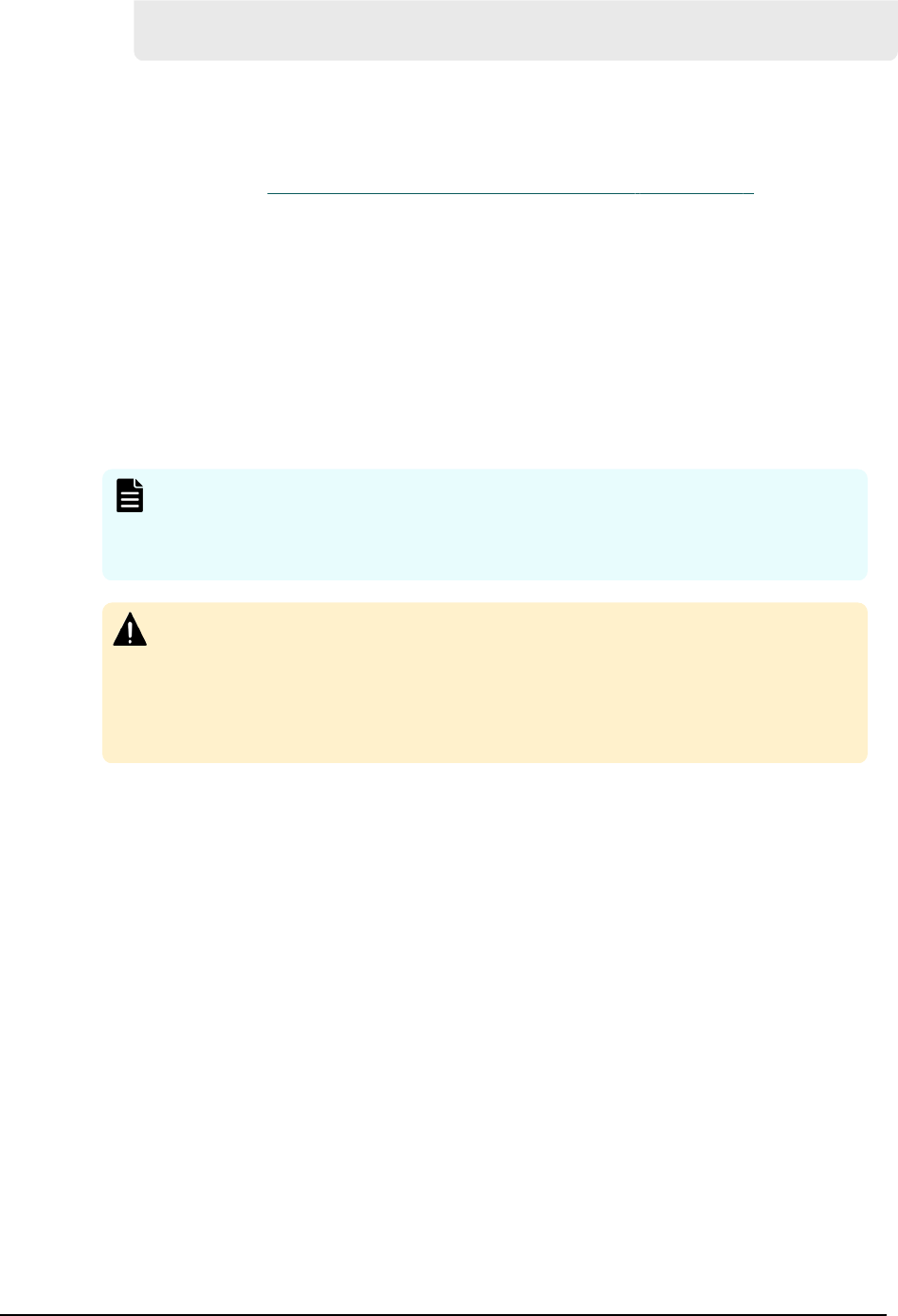
Ver&Rev: 01-40-03/xx
Usage : raidqry [options] for HORC
Next steps
Users who execute CCI commands need "administrator" privileges and the right to
access the log directory and the les in it. For instructions on specifying a CCI
administrator, see Changing the CCI user (Windows systems) (on page 46) .
Upgrading CCI installed on the same PC as the storage
management software
If CCI is installed on the same PC as the storage management software for VSP Gx00
models and VSP Fx00 models, use this procedure to upgrade the CCI software.
To upgrade the CCI version, you must rst remove the installed CCI version and then
install the new CCI version.
Note: Installing CCI on the same drive as the storage management software
allows you to use CCI of the appropriate version. If CCI and the storage
management software are installed on dierent drives, remove CCI, and then
install it on the same drive as the storage management software.
Caution: When you upgrade the CCI software, the sample script le is
overwritten. If you have edited the sample script le and want to keep your
changes, rst back up the edited sample script le, and then restore the data
of the sample script le using the backup le after the upgrade installation.
For details about the sample script le, see the Command Control Interface
User and Reference Guide.
Procedure
1. You can upgrade the CCI software only when CCI is not running. If CCI is running,
shut down CCI using the horcmshutdown command to ensure a normal end to all
functions.
2. Right-click <storage-management-software-installation-path>\wk
\supervisor\restapi\uninstall.bat to run as administrator.
3. Remove the installed CCI software using the Windows Control Panel.
For example, on a Windows 7 system:
a. Open the Control Panel.
b. Under Programs, click Uninstall a program.
c. In the program list, select RAID Manager for WindowsNT, and then click
Uninstall.
4. Insert the installation media for the product into the proper I/O device.
5. Execute Setup.exe (\program\RM\WIN_NT\RMHORC\Setup.exe or \program\RM
\WIN_NT\RMHORC_X64\Setup.exe on the CD), and follow the instructions on the
Upgrading CCI installed on the same PC as the storage management software
Chapter 3: Upgrading CCI
Command Control Interface Installation and Conguration Guide 62

screen to complete the installation. The installation directory is HORCM (xed value)
at the root directory.
Make sure to select the drive on which the storage management software is
installed.
6. In the InstallShield window, follow the instructions on screen to install the CCI
software.
7. Reboot the Windows server, and verify that the correct version of the CCI software
is running on your system by executing the raidqry -h command.
Example:
C:\HORCM\etc>raidqry -h
Model : RAID-Manager/WindowsNT
Ver&Rev: 01-40-03/xx
Usage : raidqry [options] for HORC
8. Right-click <storage-management-software-installation-path>\wk
\supervisor\restapi\install.bat to run as administrator.
Next steps
Users who execute CCI commands need "administrator" privileges and the right to
access the log directory and the les in it. For instructions on specifying a CCI
administrator, see Changing the CCI user (Windows systems) (on page 46) .
Upgrading CCI in an OpenVMS environment
Follow the steps below to update the CCI software version on an OpenVMS system:
Procedure
1. You can upgrade the CCI software only when CCI is not running. If CCI is running,
shut down CCI using the horcmshutdown command to ensure a normal end to all
functions:
$horcmshutdown for one HORCM instance $horcmshutdown 0 1 for two HORCM
instances. When a command is being used in interactive mode, terminate it using
the -q option.
2. Insert and mount the provided installation media.
3. Execute the following command:
$ PRODUCT INSTALL CCI /source=Device:[PROGRAM.CCI.OVMS]/LOG
Device:[PROGRAM.CCI.OVMS] where HITACH-ARMVMS-CCI-V0122-
2-1.PCSI exists
4. Verify installation of the proper version using the raidqry command.
$ raidqry -h
Model: CCI/OpenVMS
Upgrading CCI in an OpenVMS environment
Chapter 3: Upgrading CCI
Command Control Interface Installation and Conguration Guide 63

Ver&Rev: 01-29-03/05
Usage: raidqry [options]
Upgrading CCI in an OpenVMS environment
Chapter 3: Upgrading CCI
Command Control Interface Installation and Conguration Guide 64

Chapter 4: Removing CCI
This chapter describes and provides instructions for removing the CCI software.
Removing CCI in a UNIX environment
Removing the CCI software on UNIX using RMuninst
Use this procedure to remove the CCI software on a UNIX system using the RMuninst
script on the installation media.
Before you begin
■If you are discontinuing local or remote copy operations (for example, ShadowImage,
TrueCopy), delete all volume pairs and wait until the volumes are in simplex status.
If you will continue copy operations (for example, using Storage Navigator), do not
delete any volume pairs.
Procedure
1. If CCI commands are running in the interactive mode, use the -q option to
terminate the interactive mode and exit horcmshutdown.sh commands.
2. You can remove the CCI software only when CCI is not running. If CCI is running,
shut down CCI using the horcmshutdown.sh command to ensure a normal end to
all functions:
One CCI instance: # horcmshutdown.sh
Two CCI instances: # horcmshutdown.sh 0 1
3. Use the RMuninst script on the CCI installation media to remove the CCI software.
4. After the CCI software has been removed, the CCI command devices (used for the
in-band method) are no longer needed. If you want to congure the volumes that
were used by CCI command devices for operations from the connected hosts, you
must disable the command device setting on each volume.
To disable the command device setting:
a. Click Storage Systems, expand the Storage Systems tree, and click Logical
Devices.
On the LDEVs tab, the CCI command devices are identied by Command
Device in the Attribute column.
b. Select the command device, and then click More Actions > Edit Command
Devices.
c. For Command Device, click Disable, and then click Finish.
Chapter 4: Removing CCI
Command Control Interface Installation and Conguration Guide 65

d. In the Conrm window, verify the settings, and enter the task name.
You can enter up to 32 ASCII characters and symbols, with the exception of:
\ / : , ; * ? " < > |. The value "date-window name" is entered by default.
e. Click Apply.
If Go to tasks window for status is selected, the Tasks window appears.
Removing the CCI software manually on UNIX
If you do not have the installation media for CCI, use this procedure to remove the CCI
software manually on a UNIX system.
Before you begin
■If you are discontinuing local or remote copy operations (for example, ShadowImage,
TrueCopy), delete all volume pairs and wait until the volumes are in simplex status.
If you will continue copy operations (for example, using Storage Navigator), do not
delete any volume pairs.
Procedure
1. If CCI commands are running in the interactive mode, use the -q option to
terminate the interactive mode and exit horcmshutdown.sh commands.
2. You can remove the CCI software only when CCI is not running. If CCI is running,
shut down CCI using the horcmshutdown.sh command to ensure a normal end to
all functions:
One CCI instance: # horcmshutdown.sh
Two CCI instances: # horcmshutdown.sh 0 1
3. When HORCM is installed in the root directory (/HORCM is not a symbolic link),
remove the CCI software as follows:
a. Execute the horcmuninstall command: # /HORCM/horcmuninstall.sh
b. Move to the root directory: # cd /
c. Delete the product using the rm command: # rm -rf /HORCM
Example
#/HORCM/horcmuninstall.sh
#cd /
#rm -rf /HORCM
4. When HORCM is not installed in the root directory (/HORCM is a symbolic link),
remove the CCI software as follows:
a. Execute the horcmuninstall command: # HORCM/horcmuninstall.sh
b. Move to the root directory: # cd /
c. Delete the symbolic link for /HORCM: # rm /HORCM
d. Delete the product using the rm command: # rm -rf /Directory/HORCM
Removing the CCI software manually on UNIX
Chapter 4: Removing CCI
Command Control Interface Installation and Conguration Guide 66

Example
#/HORCM/horcmuninstall.sh
#cd /
#rm /HORCM
#rm -rf /<non-root_directory_name>/HORCM
5. After the CCI software has been removed, the CCI command devices (used for the
in-band method) are no longer needed. If you want to congure the volumes that
were used by CCI command devices for operations from the connected hosts, you
must disable the command device setting on each volume.
To disable the command device setting:
a. Click Storage Systems, expand the Storage Systems tree, and click Logical
Devices.
On the LDEVs tab, the CCI command devices are identied by Command
Device in the Attribute column.
b. Select the command device, and then click More Actions > Edit Command
Devices.
c. For Command Device, click Disable, and then click Finish.
d. In the Conrm window, verify the settings, and enter the task name.
You can enter up to 32 ASCII characters and symbols, with the exception of:
\ / : , ; * ? " < > |. The value "date-window name" is entered by default.
e. Click Apply.
If Go to tasks window for status is selected, the Tasks window appears.
Removing CCI on a Windows system
Use this procedure to remove the CCI software on a Windows system.
Before you begin
■If you are discontinuing local or remote copy operations (for example, ShadowImage,
TrueCopy), delete all volume pairs and wait until the volumes are in simplex status.
If you will continue copy operations (for example, using Storage Navigator), do not
delete any volume pairs.
Procedure
1. You can remove the CCI software only when CCI is not running. If CCI is running,
shut down CCI using the horcmshutdown command to ensure a normal end to all
functions:
One CCI instance: D:\HORCM\etc > horcmshutdown
Two CCI instances: D:\HORCM\etc > horcmshutdown 0 1
2. Remove the CCI software using the Windows Control Panel.
For example, perform the following steps on a Windows 7 system:
a. Open the Control Panel.
Removing CCI on a Windows system
Chapter 4: Removing CCI
Command Control Interface Installation and Conguration Guide 67

b. Under Programs, click Uninstall a program.
c. In the program list, select RAID Manager for WindowsNT, and then click
Uninstall.
3. After the CCI software has been removed, the CCI command devices (used for the
in-band method) are no longer needed. If you want to congure the volumes that
were used by CCI command devices for operations from the connected hosts, you
must disable the command device setting on each volume.
To disable the command device setting:
a. Click Storage Systems, expand the Storage Systems tree, and click Logical
Devices.
On the LDEVs tab, the CCI command devices are identied by Command
Device in the Attribute column.
b. Select the command device, and then click More Actions > Edit Command
Devices.
c. For Command Device, click Disable, and then click Finish.
d. In the Conrm window, verify the settings, and enter the task name.
You can enter up to 32 ASCII characters and symbols, with the exception of:
\ / : , ; * ? " < > |. The value "date-window name" is entered by default.
e. Click Apply.
If Go to tasks window for status is selected, the Tasks window appears.
Removing CCI installed on the same PC as the storage
management software
If CCI is installed on the same PC as the storage management software for VSP Gx00
models and VSP Fx00 models, use this procedure to remove the CCI software.
Before you begin
■If you are discontinuing local or remote copy operations (for example, ShadowImage,
TrueCopy), delete all volume pairs and wait until the volumes are in simplex status.
If you will continue copy operations (for example, using Storage Navigator), do not
delete any volume pairs.
Procedure
1. You can remove the CCI software only when CCI is not running. If CCI is running,
shut down CCI using the horcmshutdown command to ensure a normal end to all
functions:
One CCI instance: D:\HORCM\etc > horcmshutdown
Two CCI instances: D:\HORCM\etc > horcmshutdown 0 1
2. Right-click <storage-management-software-installation-path>\wk
\supervisor\restapi\uninstall.bat to run as administrator.
3. Remove the CCI software using the Windows Control Panel.
Removing CCI installed on the same PC as the storage management software
Chapter 4: Removing CCI
Command Control Interface Installation and Conguration Guide 68

For example, perform the following steps on a Windows 7 system:
a. Open the Control Panel.
b. Under Programs, click Uninstall a program.
c. In the program list, select RAID Manager for WindowsNT, and then click
Uninstall.
4. Perform the procedure for upgrading the storage management software, the SVP
software, and the rmware.
5. After the CCI software has been removed, the CCI command devices (used for the
in-band method) are no longer needed. If you want to congure the volumes that
were used by CCI command devices for operations from the connected hosts, you
must disable the command device setting on each volume.
To disable the command device setting:
a. Click Storage Systems, expand the Storage Systems tree, and click Logical
Devices.
On the LDEVs tab, the CCI command devices are identied by Command
Device in the Attribute column.
b. Select the command device, and then click More Actions > Edit Command
Devices.
c. For Command Device, click Disable, and then click Finish.
d. In the Conrm window, verify the settings, and enter the task name.
You can enter up to 32 ASCII characters and symbols, with the exception of:
\ / : , ; * ? " < > |. The value "date-window name" is entered by default.
e. Click Apply.
If Go to tasks window for status is selected, the Tasks window appears.
Removing CCI on an OpenVMS system
Use this procedure to remove the CCI software on an OpenVMS system.
Before you begin
■If you are discontinuing local or remote copy operations (for example, ShadowImage,
TrueCopy), delete all volume pairs and wait until the volumes are in simplex status.
If you will continue copy operations (for example, using Storage Navigator), do not
delete any volume pairs.
Procedure
1. If CCI commands are running in the interactive mode, use the -q option to
terminate the interactive mode and exit horcmshutdown.sh commands.
2. You can remove the CCI software only when CCI is not running. If CCI is running,
shut down CCI using the horcmshutdown command to ensure a normal end to all
functions:
For one instance: $ horcmshutdown
Removing CCI on an OpenVMS system
Chapter 4: Removing CCI
Command Control Interface Installation and Conguration Guide 69

For two instances: $ horcmshutdown 0 1
3. Remove the installed CCI software by using the following command:
$ PRODUCT REMOVE RM /LOG
4. After the CCI software has been removed, the CCI command devices (used for the
in-band method) are no longer needed. If you want to congure the volumes that
were used by CCI command devices for operations from the connected hosts, you
must disable the command device setting on each volume.
To disable the command device setting:
a. Click Storage Systems, expand the Storage Systems tree, and click Logical
Devices.
On the LDEVs tab, the CCI command devices are identied by Command
Device in the Attribute column.
b. Select the command device, and then click More Actions > Edit Command
Devices.
c. For Command Device, click Disable, and then click Finish.
d. In the Conrm window, verify the settings, and enter the task name.
You can enter up to 32 ASCII characters and symbols, with the exception of:
\ / : , ; * ? " < > |. The value "date-window name" is entered by default.
e. Click Apply.
If Go to tasks window for status is selected, the Tasks window appears.
Removing CCI on an OpenVMS system
Chapter 4: Removing CCI
Command Control Interface Installation and Conguration Guide 70

Chapter 5: Troubleshooting for CCI installation
If you have a problem installing or upgrading the CCI software, make sure that all system
requirements and restrictions have been met (see System requirements for CCI (on
page 13) ).
If you are unable to resolve an error condition, contact customer support for assistance.
Contacting support
If you need to call customer support, please provide as much information about the
problem as possible, including:
■The circumstances surrounding the error or failure.
■The content of any error messages displayed on the host systems.
■The content of any error messages displayed by Device Manager - Storage Navigator.
■The Device Manager - Storage Navigator conguration information (use the Dump
Tool).
■The service information messages (SIMs), including reference codes and severity
levels, displayed by Device Manager - Storage Navigator.
The customer support sta is available 24 hours a day, seven days a week. To contact
technical support, log on to Hitachi Vantara Support Connect for contact information:
https://support.hitachivantara.com/en_us/contact-us.html.
Chapter 5: Troubleshooting for CCI installation
Command Control Interface Installation and Conguration Guide 71
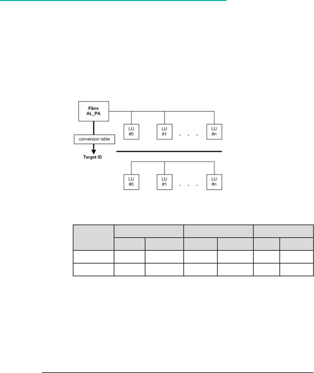
Appendix A: Fibre-to-SCSI address conversion
Disks connected with Fibre Channel display as SCSI disks on UNIX hosts. Disks connected
with Fibre Channel connections can be fully utilized. CCI converts Fibre-Channel physical
addresses to SCSI target IDs (TIDs) using a conversion table.
Fibre/FCoE-to-SCSI address conversion
The following gure shows an example of Fibre-to-SCSI address conversion.
For iSCSI, the AL_PA is the xed value 0xFE.
The following table lists the limits for target IDs (TIDs) and LUNs.
Port
HP-UX, other systems Solaris systems Windows systems
TID LUN TID LUN TID LUN
Fibre 0 to 15 0 to 1023 0 to 125 0 to 1023 0 to 31 0 to 1023
SCSI 0 to 15 0 to 7 0 to 15 0 to 7 0 to 15 0 to 7
Conversion table for Windows
The conversion table for Windows is based on conversion by an Emulex driver. If the
Fibre Channel adapter is dierent (for example, Qlogic, HPE), the target ID that is
indicated by the raidscan command might be dierent from the target ID on the
Windows host.
Appendix A: Fibre-to-SCSI address conversion
Command Control Interface Installation and Conguration Guide 72

The following shows an example of using the raidscan command to display the TID and
LUN of Harddisk6 (HP driver). You must start HORCM without the descriptions of
HORCM_DEV or HORCM_INST in the conguration denition le because of the unknown
TIDs and LUNs.
Using raidscan to display TID and LUN for FC devices
C:\>raidscan -pd hd6 -x drivescan hd6
Harddisk 6... Port[ 2] PhId[ 4] TId[ 3] Lun[ 5] [HITACHI ] [OPEN-3
]
Port[CL1-J] Ser#[ 30053] LDEV#[ 14(0x00E)]
HORC = SMPL HOMRCF[MU#0 = SMPL MU#1 = SMPL MU#2 = SMPL]
RAID5[Group 1- 2] SSID = 0x0004
PORT# /ALPA/C,TID#,LU#.Num(LDEV#....)...P/S, Status,Fence,LDEV#,P-Seq#,P-
LDEV#
CL1-J / e2/4, 29, 0.1(9).............SMPL ---- ------ ----, ----- ----
CL1-J / e2/4, 29, 1.1(10)............SMPL ---- ------ ----, ----- ----
CL1-J / e2/4, 29, 2.1(11)............SMPL ---- ------ ----, ----- ----
CL1-J / e2/4, 29, 3.1(12)............SMPL ---- ------ ----, ----- ----
CL1-J / e2/4, 29, 4.1(13)............SMPL ---- ------ ----, ----- ----
CL1-J / e2/4, 29, 5.1(14)............SMPL ---- ------ ----, ----- ----
CL1-J / e2/4, 29, 6.1(15)............SMPL ---- ------ ----, ----- ----
Specified device is LDEV# 0014
In this case, the target ID indicated by the raidscan command must be used in the
conguration denition le. This can be accomplished using either of the following two
methods:
■Using the default conversion table: Use the TID# and LU# indicated by the
raidscan command in the HORCM conguration denition le (TID=29 LUN=5 in the
example above).
■Changing the default conversion table: Change the default conversion table using
the HORCMFCTBL environmental variable (TID=3 LUN=5 in the following example).
Using HORCMFCTBL to change the default bre conversion table
C:\>set HORCMFCTBL=X <-- X=fibre conversion table #
C:\>horcmstart ... <-- Start of HORCM.
:
:
Result of "set HORCMFCTBL=X" command:
C:\>raidscan -pd hd6 -x drivescan hd6
Harddisk 6... Port[ 2] PhId[ 4] TId[ 3] Lun[ 5] [HITACHI ] [OPEN-3
]
Port[CL1-J] Ser#[ 30053] LDEV#[ 14(0x00E)]
HORC = SMPL HOMRCF[MU#0 = SMPL MU#1 = SMPL MU#2 = SMPL]
RAID5[Group 1- 2] SSID = 0x0004
PORT# /ALPA/C,TID#,LU#.Num(LDEV#....)...P/S,Status,Fence,LDEV#,P-Seq#,P-
LDEV#
CL1-J / e2/0, 3, 0.1(9).............SMPL ---- ------ ----, ----- ----
CL1-J / e2/0, 3, 1.1(10)............SMPL ---- ------ ----, ----- ----
CL1-J / e2/0, 3, 2.1(11)............SMPL ---- ------ ----, ----- ----
Fibre/FCoE-to-SCSI address conversion
Appendix A: Fibre-to-SCSI address conversion
Command Control Interface Installation and Conguration Guide 73
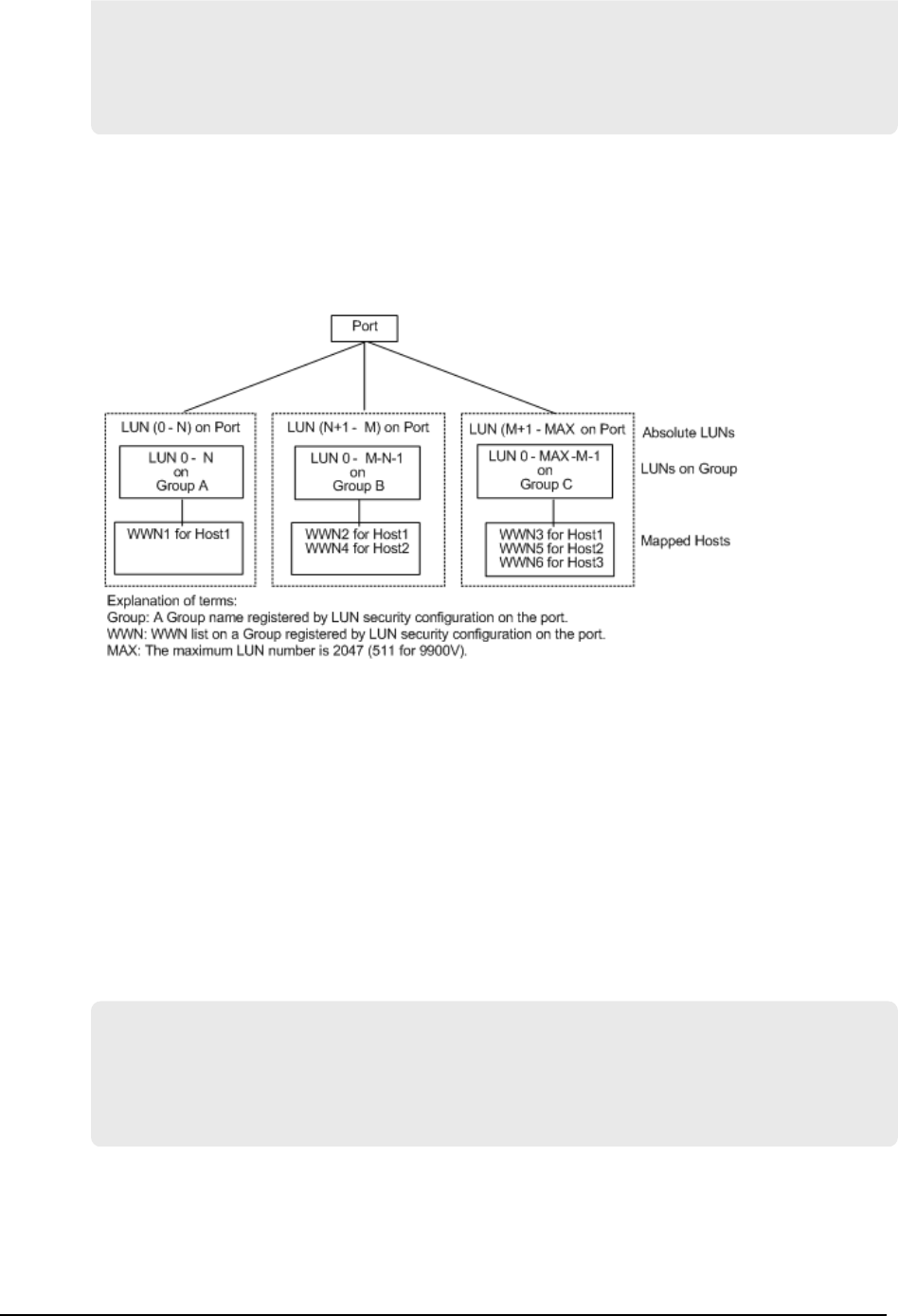
CL1-J / e2/0, 3, 3.1(12)............SMPL ---- ------ ----, ----- ----
CL1-J / e2/0, 3, 4.1(13)............SMPL ---- ------ ----, ----- ----
CL1-J / e2/0, 3, 5.1(14)............SMPL ---- ------ ----, ----- ----
CL1-J / e2/0, 3, 6.1(15)............SMPL ---- ------ ----, ----- ----
Specified device is LDEV# 0014
LUN configurations on the RAID storage systems
The RAID storage systems (9900V and later) manage the LUN conguration on a port
through the LUN security as shown in the following gure.
CCI uses absolute LUNs to scan a port, whereas the LUNs on a group are mapped to the
host system so that the TID and LUN indicated by the raidscan command are dierent
from the TID and LUN displayed by the host system. In this case, the TID and LUN
indicated by the raidscan command should be used.
In the following example, you must start HORCM without a description for HORCM_DEV
and HORCM_INST because the TID and LUN are not known. Use the port, TID, and LUN
displayed by the raidscan -find or raidscan -find conf command for
HORCM_DEV (see the example for displaying the port, TID, and LUN using raidscan).
For details about LUN discovery based on a host group, see Host Group Control in the
Command Control Interface User and Reference Guide.
Displaying the port, TID, and LUN using raidscan
# ls /dev/rdsk/* | raidscan -find
DEVICE_FILE UID S/F PORT TARG LUN SERIAL LDEV PRODUCT_ID
/dev/rdsk/c0t0d4 0 S CL1-M 0 4 31168 216 OPEN-3-CVS-CM
/dev/rdsk/c0t0d1 0 S CL1-M 0 1 31168 117 OPEN-3-CVS
/dev/rdsk/c1t0d1 - - CL1-M - - 31170 121 OPEN-3-CVS
UID: Displays the UnitID for multiple RAID conguration. A hyphen (-) is displayed when
the command device for HORCM_CMD is not found.
S/F: S indicates that the port is SCSI, and F indicates that the port is Fibre Channel.
LUN congurations on the RAID storage systems
Appendix A: Fibre-to-SCSI address conversion
Command Control Interface Installation and Conguration Guide 74
PORT: Displays the RAID storage system port number
TARG: Displays the target ID (converted by the bre conversion table)
LUN: Displays the logical unit number (converted by the bre conversion table).
SERIAL: Displays the production number (serial#) of the RAID storage system.
LDEV: Displays the LDEV# within the RAID storage system.
PRODUCT_ID: Displays product-id eld in the STD inquiry page.
Fibre address conversion tables
Following are the bre address conversion tables:
■Table number 0 = HP-UX systems
■Table number 1 = Solaris systems
■Table number 2 = Windows systems
The conversion table for Windows systems is based on the Emulex driver. If a dierent
Fibre-Channel adapter is used, the target ID indicated by the raidscan command might
be dierent than the target ID indicated by the Windows system.
Note: Table 3 for other Platforms is used to indicate the LUN without target
ID for unknown FC_AL conversion table or Fibre-Channel fabric (Fibre-Channel
worldwide name). In this case, the target ID is always zero, thus Table 3 is not
described in this document. Table 3 is used as the default for platforms
other than those listed above. If the host will use the WWN notation for the
device les, then this table number should be changed by using the
$HORCMFCTBL variable.
If the TID displayed on the system is dierent than the TID indicated in the bre
conversion table, you must use the TID (or LU#) returned by the raidscan command to
specify the device(s).
Fibre address conversion table for HP-UX systems (Table 0)
C0 C1 C2 C3 C4 C5 C6 C7
AL-
PA
TI
D
AL-
PA
TI
D
AL-
PA
TI
D
AL-
PA
TI
D
AL-
PA
TI
D
AL-
PA
TI
D
AL-
PA
TI
D
AL-
PA TID
EF 0 CD 0 B2 0 98 0 72 0 55 0 3A 0 25 0
E8 1 CC 1 B1 1 97 1 71 1 54 1 39 1 23 1
E4 2 CB 2 AE 2 90 2 6E 2 53 2 36 2 1F 2
E2 3 CA 3 AD 3 8F 3 6D 3 52 3 35 3 1E 3
E1 4 C9 4 AC 4 88 4 6C 4 51 4 34 4 1D 4
Fibre address conversion tables
Appendix A: Fibre-to-SCSI address conversion
Command Control Interface Installation and Conguration Guide 75

C0 C1 C2 C3 C4 C5 C6 C7
AL-
PA
TI
D
AL-
PA
TI
D
AL-
PA
TI
D
AL-
PA
TI
D
AL-
PA
TI
D
AL-
PA
TI
D
AL-
PA
TI
D
AL-
PA TID
E0 5 C7 5 AB 5 84 5 6B 5 4E 5 33 5 1B 5
DC 6 C6 6 AA 6 82 6 6A 6 4D 6 32 6 18 6
DA 7 C5 7 A9 7 81 7 69 7 4C 7 31 7 17 7
D9 8 C3 8 A7 8 80 8 67 8 4B 8 2E 8 10 8
D6 9 BC 9 A6 9 7C 9 66 9 4A 9 2D 9 0F 9
D5 10 BA 10 A5 10 7A 10 65 10 49 10 2C 10 08 10
D4 11 B9 11 A3 11 79 11 63 11 47 11 2B 11 04 11
D3 12 B6 12 9F 12 76 12 5C 12 46 12 2A 12 02 12
D2 13 B5 13 9E 13 75 13 5A 13 45 13 29 13 01 13
D1 14 B4 14 9D 14 74 14 59 14 43 14 27 14 - -
CE 15 B3 15 9B 15 73 15 56 15 3C 15 26 15 - -
Fibre address conversion table for Solaris systems (Table 1)
C0 C1 C2 C3 C4 C5 C6 C7
AL-
PA
TI
D
AL-
PA
TI
D
AL-
PA
TI
D
AL-
PA
TI
D
AL-
PA
TI
D
AL-
PA
TI
D
AL-
PA
TI
D
AL
-
PA TID
EF 0 CD 16 B2 32 98 48 72 64 55 80 3A 96 25 112
E8 1 CC 17 B1 33 97 49 71 65 54 81 39 97 23 113
E4 2 CB 18 AE 34 90 50 6E 66 53 82 36 98 1F 114
E2 3 CA 19 AD 35 8F 51 6D 67 52 83 35 99 1E 115
E1 4 C9 20 AC 36 88 52 6C 68 51 84 34 10
0
1D 116
E0 5 C7 21 AB 37 84 53 6B 69 4E 85 33 10
1
1B 117
DC 6 C6 22 AA 38 82 54 6A 70 4D 86 32 10
1
18 118
Fibre address conversion tables
Appendix A: Fibre-to-SCSI address conversion
Command Control Interface Installation and Conguration Guide 76

C0 C1 C2 C3 C4 C5 C6 C7
AL-
PA
TI
D
AL-
PA
TI
D
AL-
PA
TI
D
AL-
PA
TI
D
AL-
PA
TI
D
AL-
PA
TI
D
AL-
PA
TI
D
AL
-
PA TID
DA 7 C5 23 A9 39 81 55 69 71 4C 87 31 10
3
17 119
D9 8 C3 24 A7 40 80 56 67 72 4B 88 2E 10
4
10 120
D6 9 BC 25 A6 41 7C 57 66 73 4A 89 2D 10
5
0F 121
D5 10 BA 26 A5 42 7A 58 65 74 49 90 2C 10
6
08 122
D4 11 B9 27 A3 43 79 59 63 75 47 91 2B 10
7
04 123
D3 12 B6 28 9F 44 76 60 5C 76 46 92 2A 10
8
02 124
D2 13 B5 29 9E 45 75 61 5A 77 45 93 29 10
9
01 125
D1 14 B4 30 9D 46 74 62 59 78 43 94 27 11
0
- -
CE 15 B3 31 9B 47 73 63 56 79 3C 95 26 11
1
- -
Fibre address conversion table for Windows systems (Table 2)
C5
(PhId5
) C4 (PhId4) C3 (PhId3) C2 (PhId2) C1 (PhId1)
AL
-
PA
T
I
D
AL
-
PA
TI
D
AL
-
PA
TI
D
AL
-
PA
TI
D
AL
-
PA
TI
D
AL
-
PA
TI
D
AL
-
PA
TI
D
AL
-
PA
TI
D
AL
-
PA
TI
D
- - - - CC 15 - - 98 15 - - 56 15 - - 27 15
- - E4 30 CB 14 B1 30 97 14 72 30 55 14 3C 30 26 14
- - E2 29 CA 13 AE 29 90 13 71 29 54 13 3A 29 25 13
- - E1 28 C9 12 AD 28 8F 12 6E 28 53 12 39 28 23 12
Fibre address conversion tables
Appendix A: Fibre-to-SCSI address conversion
Command Control Interface Installation and Conguration Guide 77

C5
(PhId5
) C4 (PhId4) C3 (PhId3) C2 (PhId2) C1 (PhId1)
AL
-
PA
T
I
D
AL
-
PA
TI
D
AL
-
PA
TI
D
AL
-
PA
TI
D
AL
-
PA
TI
D
AL
-
PA
TI
D
AL
-
PA
TI
D
AL
-
PA
TI
D
AL
-
PA
TI
D
- - E0 27 C7 11 AC 27 88 11 6D 27 52 11 36 27 1F 11
- - DC 26 C6 10 AB 26 84 10 6C 26 51 10 35 26 1E 10
- - DA 25 C5 9 AA 25 82 9 6B 25 4E 9 34 25 1D 9
- - D9 24 C3 8 A9 24 81 8 6A 24 4D 8 33 24 1B 8
- - D6 23 BC 7 A7 23 80 7 69 23 4C 7 32 23 18 7
- - D5 22 BA 6 A6 22 7C 6 67 22 4B 6 31 22 17 6
- - D4 21 B9 5 A5 21 7A 5 66 21 4A 5 2E 21 10 5
- - D3 20 B6 4 A3 20 79 4 65 20 49 4 2D 20 0F 4
- - D2 19 B5 3 9F 19 76 3 63 19 47 3 2C 19 08 3
- - D1 18 B4 2 9E 18 75 2 5C 18 46 2 2B 18 04 2
EF 1 CE 17 B3 1 9D 17 74 1 5A 17 45 1 2A 17 02 1
E8 0 CD 16 B2 0 9B 16 73 0 59 16 43 0 29 16 01 1
Fibre address conversion tables
Appendix A: Fibre-to-SCSI address conversion
Command Control Interface Installation and Conguration Guide 78
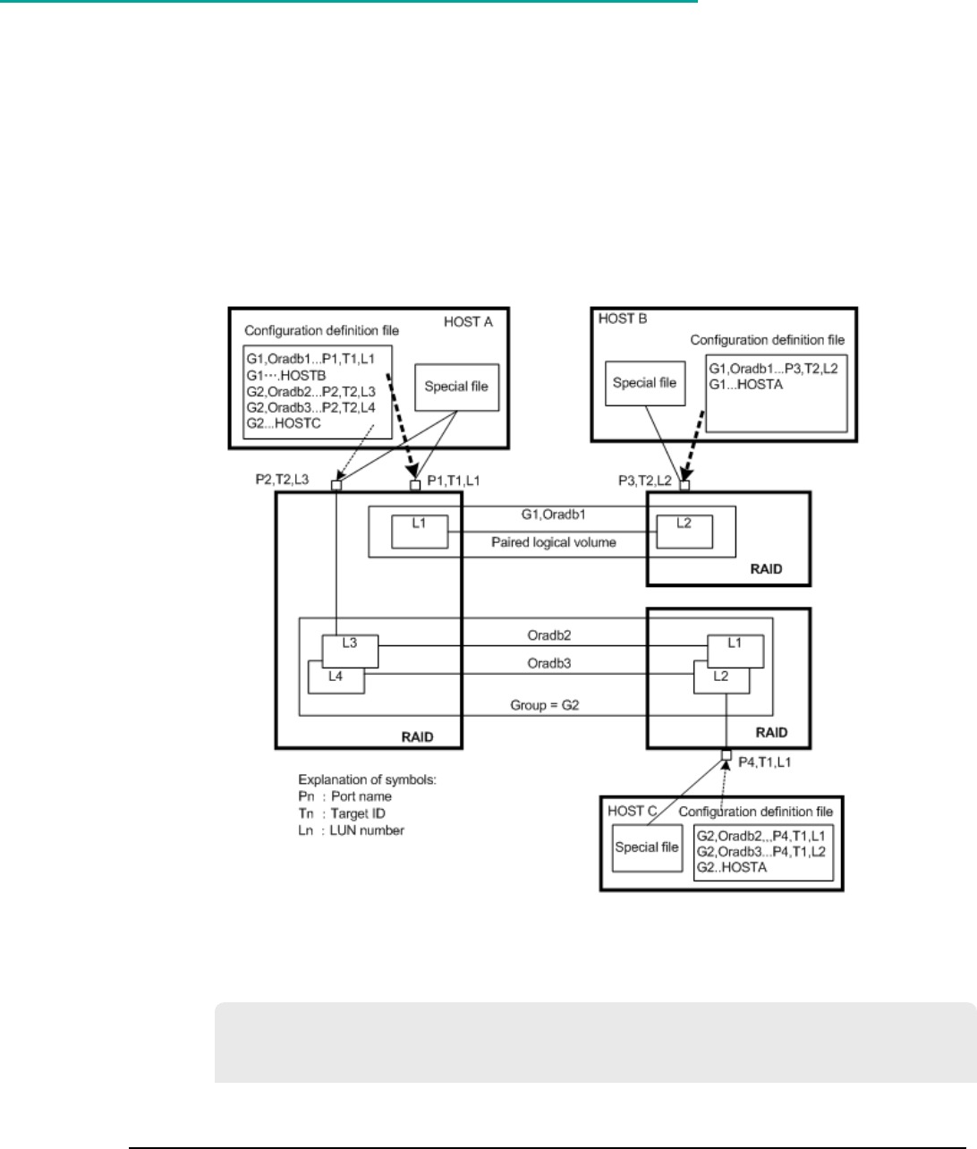
Appendix B: Sample configuration definition
files
This chapter describes sample conguration denition les for typical CCI congurations.
Sample configuration definition files
The following gure illustrates the conguration denition of paired volumes.
The following example shows a sample conguration le for a UNIX-based operating
system.
Conguration le example – UNIX-based servers (# indicates a comment)
HORCM_MON
#ip_address service poll(10ms) timeout(10ms)
HST1 horcm 1000 3000
Appendix B: Sample conguration denition les
Command Control Interface Installation and Conguration Guide 79
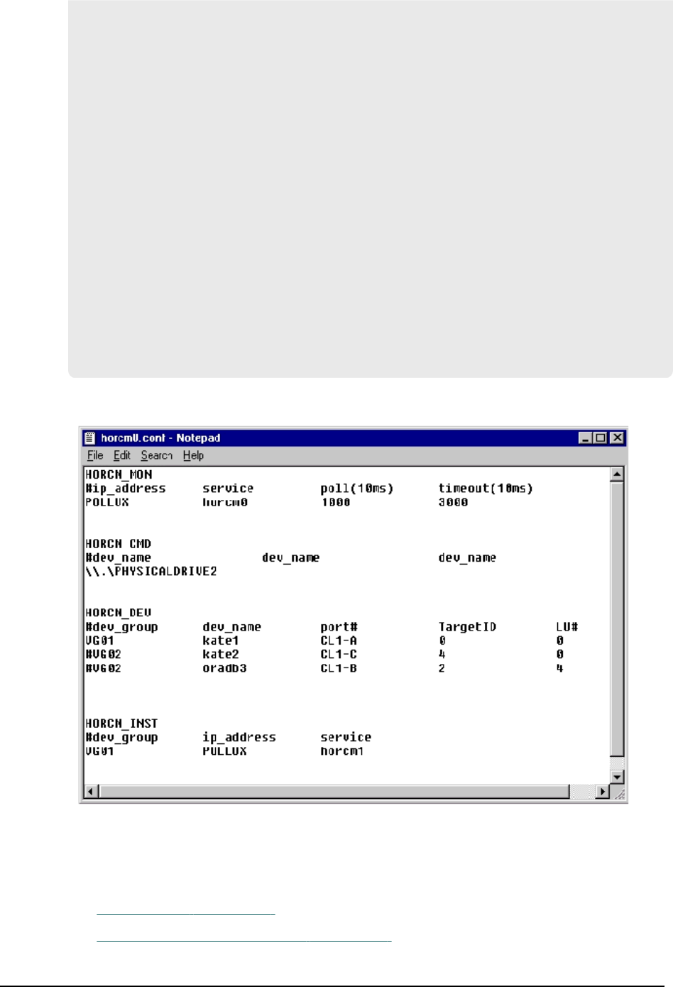
HORCM_CMD
#unitID 0... (seq#30014)
#dev_name dev_name dev_name
/dev/rdsk/c0t0d0
#unitID 1... (seq#30015)
#dev_name dev_name dev_name
/dev/rdsk/c1t0d0
HORCM_DEV
#dev_group dev_name port# TargetID LU# MU#
oradb oradb1 CL1-A 3 1 0
oradb oradb2 CL1-A 3 1 1
oralog oralog1 CL1-A 5 0
oralog oralog2 CL1-A1 5 0
oralog oralog3 CL1-A1 5 1
oralog oralog4 CL1-A1 5 1 h1
HORCM_INST
#dev_group ip_address service
oradb HST2 horcm
oradb HST3 horcm
oralog HST3 horcm
The following gure shows a sample conguration le for a Windows operating system.
Configuration file parameters
The conguration le sets the following parameters:
■HORCM_MON (on page 81)
■HORCM_CMD (in-band method) (on page 81)
Conguration le parameters
Appendix B: Sample conguration denition les
Command Control Interface Installation and Conguration Guide 80

■HORCM_CMD (out-of-band method) (on page 86)
■HORCM_VCMD (on page 88)
■HORCM_DEV (on page 89)
■HORCM_INST (on page 92)
■HORCM_INSTP (on page 95)
■HORCM_LDEV (on page 96)
■HORCM_LDEVG (on page 96)
■HORCM_ALLOW_INST (on page 97)
HORCM_MON
The monitor parameter (HORCM_MON) in the CCI conguration denition le denes the
following values:
■ip_address: Species the local host name or the IP address of the local host. When
you specify the name of a local host that has multiple IP addresses, one of the IP
addresses is selected at random and used. If you want to use all IP addresses, specify
NONE for IPv4 or NONE6 for IPv6.
■service: Species the UDP port name assigned to the HORCM communication path,
which is registered in /etc/services in UNIX (%windir%\system32\drivers\etc
\services in Windows, SYS$SYSROOT:[000000.TCPIP$ETC]SERVICES.DAT in
OpenVMS). If a port number is specied instead of a port name, the port number is
used.
■poll: Species the interval for monitoring paired volumes in increments of 10 ms. To
reduce the HORCM daemon load, make this interval longer. When the interval is set
to -1, the paired volumes are not monitored. The value of -1 is specied when two or
more CCI instances run on a single machine.
■timeout: The time-out period of communication with the remote server.
If HORCM_MON is not specied, then the following defaults are set:
#ip_address service poll(10ms) timeout(10ms)
NONE default_port 1000 3000
default_port:
■For no specied HORCM instance: 31000 + 0
■For instance HORCM X: 31000 + X + 1
HORCM_CMD (in-band method)
When the in-band method is used, the command device parameter (HORCM_CMD)
denes the UNIX device path or Windows physical device number of each command
device that can be accessed by CCI. You can specify multiple command devices in
HORCM_CMD to provide failover in case the primary command device becomes
unavailable.
HORCM_MON
Appendix B: Sample conguration denition les
Command Control Interface Installation and Conguration Guide 81

Tip:
■To enhance redundancy, you can make multiple command devices
available for a single storage system. This conguration is called alternate
command device conguration. For this conguration, command devices
are listed horizontally on a line in the conguration denition le. In the
following example, CMD1 and CMD2 are command devices in the same
storage system:
HORCM_CMD
CMD1 CMD2
■To control multiple storage systems in one conguration denition le, you
can list the command devices for each storage system in the conguration
denition le. In this case, the command devices are listed vertically. CMD1
and CMD2 in the following example are command devices in dierent
storage systems:
HORCM_CMD
CMD1
CMD2
■When you specify a command device, you can enter a maximum of 511
characters for each line.
The command device must be mapped to the SCSI/bre using LUN Manager rst. The
mapped command devices are identied by "-CM" appended to the PRODUCT_ID
displayed by the inqraid command, as shown in the following examples.
Viewing the command device using inqraid (UNIX host)
# ls /dev/rdsk/c1t0* | /HORCM/usr/bin/inqraid -CLI -sort
DEVICE_FILE PORT SERIAL LDEV CTG H/M/12 SSID R:Group PRODUCT_ID
c1t0d0s2 CL2-E 63502 576 - - - - OPEN-V-CM
c1t0d1s2 CL2-E 63502 577 - s/s/ss 0006 1:02-01 OPEN-V -SUN
c1t0d2s2 CL2-E 63502 578 - s/s/ss 0006 1:02-01 OPEN-V -SUN
In this example, the command device is /dev/rdsk/c1t0d2s2.
Viewing the command device using inqraid (Windows host)
D:\HORCM\etc>inqraid $Phys –CLI
\\.\PhysicalDrive1:
# Harddisk1 -> [VOL61459_449_DA7C0D92] [OPEN-3 ]
\\.\PhysicalDrive2:
# Harddisk2 -> [VOL61459_450_DA7C0D93] [OPEN-3-CM ]
In this example, the command device is \\.\PhysicalDrive2.
After mapping the command device, set the HORCM_CMD parameter in the
conguration denition le as follows:
HORCM_CMD (in-band method)
Appendix B: Sample conguration denition les
Command Control Interface Installation and Conguration Guide 82
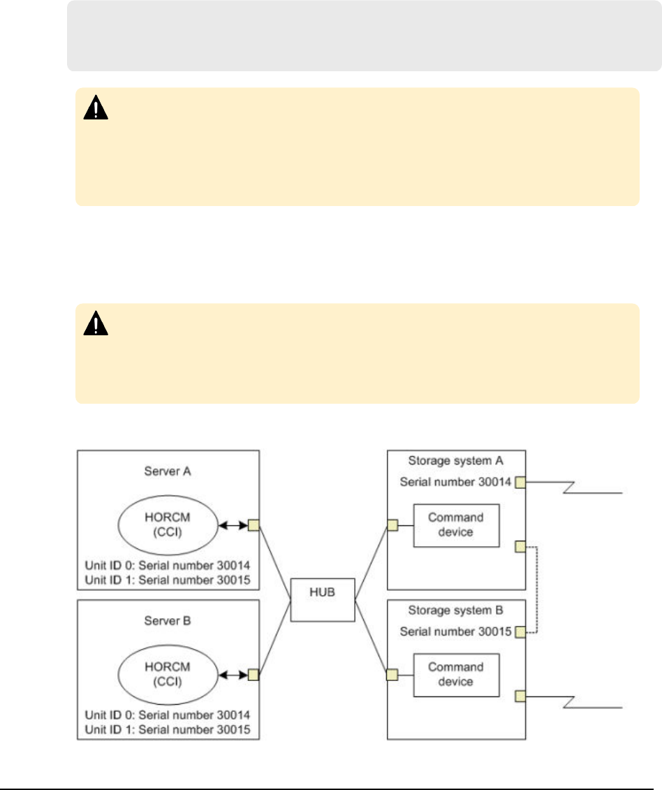
\\.\CMD-<Serial Number>:<Device special file name>
■<Serial Number>: Species the serial number of the storage system. For VSP G1x00
and VSP F1500, add a “3” at the beginning of the serial number. For example, for
serial number 12345, enter 312345.
■<Device special file name>: Species the device special le name of the
command device.
For example, specify the following for serial number 64015 and device special le
name /dev/rdsk/*:
HORCM_CMD
#dev_name dev_name dev_name
\\.\CMD-64015:/dev/rdsk/*
Caution: To enable dual path of the command device under UNIX systems,
make sure to include all paths to the command device on a single line in the
HORCM_CMD section of the conguration denition le. Entering path
information on separate lines might cause syntax parsing issues, and failover
might not occur unless the HORCM startup script is restarted on the UNIX
system.
When two or more storage systems are connected, CCI identies each storage system
using unit IDs. The unit ID is assigned sequentially in the order described in
HORCM_CMD of the conguration denition le. For a command device alternative
conguration, a special le for multiple command devices is written.
Caution: When storage systems are shared by two or more servers, unit IDs
and serial numbers must be consistent among the servers. List serial
numbers of the storage systems in HORCM_CMD of the conguration
denition le in the same order. The following gure illustrates unit IDs when
multiple servers share multiple storage systems.
The following gure shows the conguration and unit IDs for multiple storage systems.
HORCM_CMD (in-band method)
Appendix B: Sample conguration denition les
Command Control Interface Installation and Conguration Guide 83

For Windows 2000, 2003, 2008, and 2012
Normally, physical drives are specied for command devices in storage systems.
However, CCI provides a method that is not aected by changes of physical drives in
Windows 2000, 2003, 2008, and 2012 by using the following naming format to specify the
serial number, LDEV number, and port number in that order:
\\.\CMD-Ser#-ldev#-Port#
Note: For VSP G1x00 and VSP F1500, add a "3" to the beginning of the serial
number (for example, enter "312345" for serial number "12345").
The following example species 30095 for the storage system's serial number, 250 for
the LDEV number, and CL1-A for the port number:
HORCM_CMD
#dev_name dev_name dev_name
\\.\CMD-30095-250-CL1-A
■Minimum specication
For the command device with serial number 30095, specify as follows:
\\.\CMD-30095
■Command devices in the multi-path environment
Specify serial number 30095, and LDEV number 250 as follows:
\\.\CMD-30095-250
■Other specications
Specify serial number 30095, LDEV number 250, and port number CLI-A as follows:
\\.\CMD-30095-250-CL1-A
or
\\.\CMD-30095-250-CL1
For UNIX
Device les are specied for command devices in UNIX. However, CCI provides a method
that is not aected by changes of device les in UNIX by using the following naming
format specifying the serial number, LDEV number, and port number in that order:
\\.\CMD-Ser#-ldev#-Port#:HINT
Note: For VSP G1x00 and VSP F1500, add a "3" to the beginning of the serial
number (for example, enter "312345" for serial number "12345").
HORCM_CMD (in-band method)
Appendix B: Sample conguration denition les
Command Control Interface Installation and Conguration Guide 84

The following example species 30095 for the storage system's serial number, 250 for
the LDEV number, and CL1-A for the port number:
HORCM_CMD
#dev_name dev_name dev_name
\\.\CMD-30095-250-CL1-A:/dev/rdsk/
HINT provides a path to scan and species a directory ending with a slash (/) or a name
pattern including the directory. Device les are searched using a name lter similar to
the inqraid command.
■To nd command devices from ' /dev/rdsk/* , enter /dev/rdsk/.
■To nd command devices from ' /dev/rdsk/c10*, enter /dev/rdsk/c10.
■To nd command devices from ' /dev/rhdisk*, enter /dev/rhdisk.
For an alternate command device conguration, HINT of the second command device
can be omitted. In this case, command devices are searched from the device le that was
scanned rst.
HORCM_CMD
#dev_name dev_name dev_name
\\.\CMD-30095-CL1:/dev/rdsk/ \\.\CMD-30095-CL2
■Minimum specication
For the command device of a storage system with serial number 30095, specify as
follows:
\\.\CMD-30095:/dev/rdsk/
■Command devices in a multi-path environment
Specify storage system serial number 30095 and LDEV number 250 as follows:
\\.\CMD-30095-250:/dev/rdsk/
■Other specications
Specify an alternate path with storage system serial number 30095 and LDEV number
250 as follows:
\\.\CMD-30095-250-CL1:/dev/rdsk/ \\.\CMD-30095-250-CL2
\\.\CMD-30095:/dev/rdsk/c1 \\.\CMD-30095:/dev/rdsk/c2
For Linux
Note the following important information when using CCI on a Linux host.
HORCM_CMD (in-band method)
Appendix B: Sample conguration denition les
Command Control Interface Installation and Conguration Guide 85

Note: If the hardware conguration is changed while an OS is running in
Linux, the name of a special le corresponding to the command device might
be changed. At this time, if HORCM was started by specifying the special le
name in the conguration denition le, HORCM cannot detect the command
device, and the communication with the storage system might fail.
To prevent this failure, specify the path name allocated by udev to the
conguration denition le before booting HORCM. Use the following
procedure to specify the path name. In this example, the path name
for /dev/sdgh can be found.
1. Find the special le name of the command device by using inqraid
command:
[root@myhost ~]# ls /dev/sd* | /HORCM/usr/bin/inqraid -CLI |
grep CM sda CL1-B 30095 0 - - 0000 A:00000 OPEN-V-CM sdgh
CL1-A 30095 0 - - 0000 A:00000 OPEN-V-CM [root@myhost ~]#
2. Find the path name from the by-path directory:
[root@myhost ~]# ls -l /dev/disk/by-path/ | grep sdgh
lrwxrwxrwx. 1 root root 10 Jun 11 17:04 2015 pci-
0000:08:00.0- fc-0x50060e8010311940-lun-0 -> ../../sdgh
[root@myhost ~]#
In this example, pci-0000:08:00.0-fc-0x50060e8010311940-
lun-0 is the path name.
3. Enter the path name in HORCM_CMD in the conguration denition le
as follows:
HORCM_CMD /dev/disk/by-path/pci-0000:08:00.0-fc-
0x50060e8010311940-lun-0
4. Boot the HORCM instance as usual.
HORCM_CMD (out-of-band method)
For the out-of-band method, a virtual command device is used instead of a command
device. By specifying the location of the virtual command device in HORCM_CMD, you
can create a virtual command device.
The location where the virtual command device can be created is dierent according to
the type of the storage system. For details about locations, see the section System
conguration using CCI in the Command Control Interface User and Reference Guide.
Tip: When you specify a virtual command device, you can enter a maximum
of 511 characters for each line.
HORCM_CMD (out-of-band method)
Appendix B: Sample conguration denition les
Command Control Interface Installation and Conguration Guide 86

Create a virtual command device on an SVP (VSP, HUS VM, VSP G1x00, VSP F1500)
Specify the following to HORCM_CMD of the conguration denition le:
\\.\IPCMD-<SVP IP address>-<UDP communication port number>[-unit ID]
■<SVP IP address>: Sets an IP address of SVP.
■<UDP communication port number>: Sets the UDP communication port number.
This value (31001) is xed.
■[-unit ID]: Sets the unit ID of the storage system for the multiple units connection
conguration. This can be omitted.
Create a virtual command device on a GUM (VSP Gx00 models and VSP Fx00
models)
Specify the following to HORCM_CMD of the conguration denition le:
\\.\IPCMD-<GUM IP address>-<UDP communication port number>[-unit ID]
■<GUM IP address>: Sets an IP address of GUM.
■<UDP communication port number>: Sets the UDP communication port number.
These values (31001 and 31002) are xed.
■[-unit ID]: Sets the unit ID of the storage system for the multiple units connection
conguration. This can be omitted.
Note: To use GUM, we recommend that you set the combination of all
GUM IP addresses in the storage system and the UDP communication port
numbers by an alternate command device conguration. See the following
examples for how to set the combination.
Use a CCI server port as a virtual command device
Specify the following in HORCM_CMD of the conguration denition le:
\\.\IPCMD-<CCI server IP address>-<CCI port number>[-Unit ID]
■<CCI server IP address>: Sets the IP address of the CCI server.
■<CCI port number>: Sets the CCI port number.
■[-Unit ID]: Sets the unit ID of the storage system for the multiple units connection
conguration. This can be omitted.
Examples
This example shows the case of IPv4.
HORCM_CMD
#dev_name dev_name dev_name
\\.\IPCMD-158.214.135.113-31001
HORCM_CMD (out-of-band method)
Appendix B: Sample conguration denition les
Command Control Interface Installation and Conguration Guide 87

This example shows the case of IPv6.
HORCM_CMD
#dev_name dev_name dev_name
\\.\IPCMD-fe80::209:6bff:febe:3c17-31001
This example shows the case when both the in-band and out-band methods are used:
HORCM_CMD
#dev_name dev_name dev_name
\\.\CMD-64015:/dev/rdsk/* \\.\IPCMD-158.214.135.113-31001
This example shows the case when both the in-band and out-band methods are used in
an alternate command device conguration:
HORCM_CMD
#dev_name dev_name
\\.\CMD-64015:/dev/rdsk/* \\.\IPCMD-158.214.135.113-31001
HORCM_CMD
#dev_name dev_name
\\.\IPCMD-158.214.135.113-31001 \\.\CMD-64015:/dev/rdsk/*
This example shows the case of virtual command devices in a cascade conguration
(three units):
HORCM_CMD
#dev_name dev_name dev_name
\\.\IPCMD-158.214.135.113-31001
\\.\IPCMD-158.214.135.114-31001
\\.\IPCMD-158.214.135.115-31001
(VSP Gx00 models, VSP Fx00 models) This example shows the case of alternate
command device conguration of the combination of all GUM IP addresses in the
storage system and the UDP communication port numbers. In this case, enter the IP
addresses without a line feed.
HORCM_CMD
#dev_name dev_name dev_name
\\.\IPCMD-192.168.0.16-31001 \\.\IPCMD-192.168.0.17-31001 \\.\IPCMD-
192.168.0.16-31002 \\.\IPCMD-192.168.0.17-31002
An IP address and a port number can be expressed using a host name and a service
name.
HORCM_VCMD
The HORCM_VCMD parameter species the serial number of the virtual storage machine
to be operated by this CCI instance.
HORCM_VCMD
Appendix B: Sample conguration denition les
Command Control Interface Installation and Conguration Guide 88

You can only use virtual storage machines whose serial numbers are specied in
HORCM_VCMD. To use more than one virtual storage machine from a CCI instance,
specify each serial number on a separate line in HORCM_VCMD.
Note: If you want to use the virtual storage machine specied on the second
or subsequent line of HORCM_VCMD, you must use the command options
(for example, -s <seq#> or -u <unit id>). If you omit these command options,
the virtual storage machine specied on the rst line is used. If you specify a
virtual storage machine whose serial number is not specied in
HORCM_VCMD using the command option (-s <seq#> or -u <Unit ID>), the
EX_ENOUNT error occurs.
HORCM_DEV
The device parameter (HORCM_DEV) denes the RAID storage system device addresses
for the paired logical volume names. When the server is connected to two or more
storage systems, the unit ID is expressed by port number extension. Each group name is
a unique name discriminated by a server which uses the volumes, the data attributes of
the volumes (such as database data, log le, UNIX le), recovery level, and so on. The
group and paired logical volume names described in this item must reside in the remote
server. The hardware SCSI/bre port, target ID, and LUN as hardware components need
not be the same.
The following values are dened in the HORCM_DEV parameter:
■dev_group: Names a group of paired logical volumes. A command is executed for all
corresponding volumes according to this group name.
■dev_name: Names the paired logical volume within a group (i.e., name of the special
le or unique logical volume). The name of paired logical volume must be dierent
than the "dev name" on another group.
■Port#: Denes the RAID storage system port number of the volume that corresponds
with the dev_name volume.
For details about specifying Port#, see Specifying Port# (on page 90) below.
■Target ID: Denes the SCSI/bre target ID number of the physical volume on the
specied port.
■LU#: Denes the SCSI/bre logical unit number (LU#) of the physical volume on the
specied target ID and port.
For Fibre Channel, if the TID and LU# displayed on the system are dierent from the
TID in the bre address conversion table, then use the TID and LU# indicated by the
raidscan command in the CCI conguration denition le.
HORCM_DEV
Appendix B: Sample conguration denition les
Command Control Interface Installation and Conguration Guide 89
■MU# for ShadowImage/Copy-on-Write Snapshot: Denes the mirror unit number (0 to
2) if using redundant mirror for the identical LU on ShadowImage. If this number is
omitted it is assumed to be zero (0). The cascaded mirroring of the S-VOL is expressed
as virtual volumes using the mirror descriptors (MU#1 to 2) in the conguration
denition le. The MU#0 of a mirror descriptor is used for connection of the S-VOL.
The mirror descriptor (MU#0 to 2) can be used on ShadowImage and Copy-on-Write
Snapshot. MU#3 to 63 can be used only on Copy-on-Write Snapshot.
Note: When you enter the MU number for a ShadowImage/Copy-on-Write
Snapshot pair into the conguration denition le, enter only the number,
for example, “0” or “1”.
Feature
SMPL P-VOL S-VOL
MU#0 to
2
MU#3 to
63
MU#0 to
2
MU#3 to
63 MU#0
MU#1 to
63
ShadowImage Valid Not valid Valid Not valid Valid Not valid
Copy-on-Write
Snapshot
Valid Valid Valid Valid Valid Not valid
■MU# for TrueCopy/Universal Replicator/global-active device: Denes the mirror unit
number (0 to 3) if using redundant mirror for the identical LU on TC/UR/GAD. If this
number is omitted, it is assumed to be (MU#0). You can specify only MU#0 for
TrueCopy, and 4 MU numbers (MU#0 to 3) for Universal Replicator and global-active
device.
Note: When you enter the MU number for a TC/UR/GAD pair into the
conguration denition le, add an "h" before the number, for example,
"h0" or "h1".
State/
Feature
SMPL P-VOL S-VOL
MU#0 MU#1 to 3 MU#0 MU#1 to 3 MU#0 MU#1 to 3
TrueCopy Valid Not valid Valid Not valid Valid Not valid
Universal
Replicator/
global-active
device
Valid Valid Valid Valid Valid Valid
Specifying Port#
The following "n" shows unit ID when the server is connected to two or more storage
systems (for example, CL1-A1 = CL1-A in unit ID 1). If the "n" option is omitted, the unit ID
is 0. The port is not case sensitive (for example, CL1-A = cl1-a = CL1-a = cl1-A).
HORCM_DEV
Appendix B: Sample conguration denition les
Command Control Interface Installation and Conguration Guide 90

Port Basic Option Option Option
CL1 An B
n
Cn D
n
En Fn G
n
H
n
Jn Kn Ln Mn Nn Pn Qn Rn
CL2 An B
n
Cn D
n
En Fn G
n
H
n
Jn Kn Ln Mn Nn Pn Qn Rn
The following ports can only be specied for 9900V:
Port Basic Option Option Option
CL3 an bn cn dn en fn gn hn jn kn ln mn n
n
p
n
q
n
rn
CL4 an bn cn dn en fn gn hn jn kn ln mn n
n
p
n
q
n
rn
For 9900V, CCI supports four types of port names for host groups:
■Specifying the port name without a host group:
CL1-A for a RAID storage system
CL1-An, where n = unit ID for multiple RAID storage systems
■Specifying the port with a host group:
CL1-A-g, where g = host group
CL1-An-g, where n-g = host group g on CL1-A in unit ID n
The following ports can only be specied for TagmaStore USP/TagmaStore NSC and USP
V/VM:
Port Basic Option Option Option
CL5 an bn cn dn en fn gn hn jn kn ln mn n
n
p
n
q
n
rn
CL6 an bn cn dn en fn gn hn jn kn ln mn n
n
p
n
q
n
rn
CL7 an bn cn dn en fn gn hn jn kn ln mn n
n
p
n
q
n
rn
CL8 an bn cn dn en fn gn hn jn kn ln mn n
n
p
n
q
n
rn
CL9 an bn cn dn en fn gn hn jn kn ln mn n
n
p
n
q
n
rn
HORCM_DEV
Appendix B: Sample conguration denition les
Command Control Interface Installation and Conguration Guide 91

Port Basic Option Option Option
CLA an bn cn dn en fn gn hn jn kn ln mn n
n
p
n
q
n
rn
CLB an bn cn dn en fn gn hn jn kn ln mn n
n
p
n
q
n
rn
CLC an bn cn dn en fn gn hn jn kn ln mn n
n
p
n
q
n
rn
CLD an bn cn dn en fn gn hn jn kn ln mn n
n
p
n
q
n
rn
CLE an bn cn dn en fn gn hn jn kn ln mn n
n
p
n
q
n
rn
CLF an bn cn dn en fn gn hn jn kn ln mn n
n
p
n
q
n
rn
CLG an bn cn dn en fn gn hn jn kn ln mn n
n
p
n
q
n
rn
HORCM_INST
The instance parameter (HORCM_INST) denes the network address (IP address) of the
remote server (active or standby). It is used to refer to or change the status of the paired
volume in the remote server (active or standby). When the primary volume is shared by
two or more servers, there are two or more remote servers using the secondary volume.
Thus, it is necessary to describe the addresses of all of these servers.
The following values are dened in the HORCM_INST parameter:
■dev_group: The server name described in dev_group of HORC_DEV.
■ip_address: The network address of the specied remote server.
■service: The port name assigned to the HORCM communication path (registered in
the /etc/services le). If a port number is specied instead of a port name, the
port number is used.
A conguration for multiple networks can be found using raidqry -r <group>
command option on each host. The current network address of HORCM can be changed
using horcctl -NC <group> on each host.
When you use all IP addresses of the local host in the conguration for multiple
networks, specify NONE (IPv4) or NONE6 (IPv6) as the ip_address of HORCM_MON
parameter.
The following gure shows the conguration for multiple networks.
HORCM_INST
Appendix B: Sample conguration denition les
Command Control Interface Installation and Conguration Guide 92
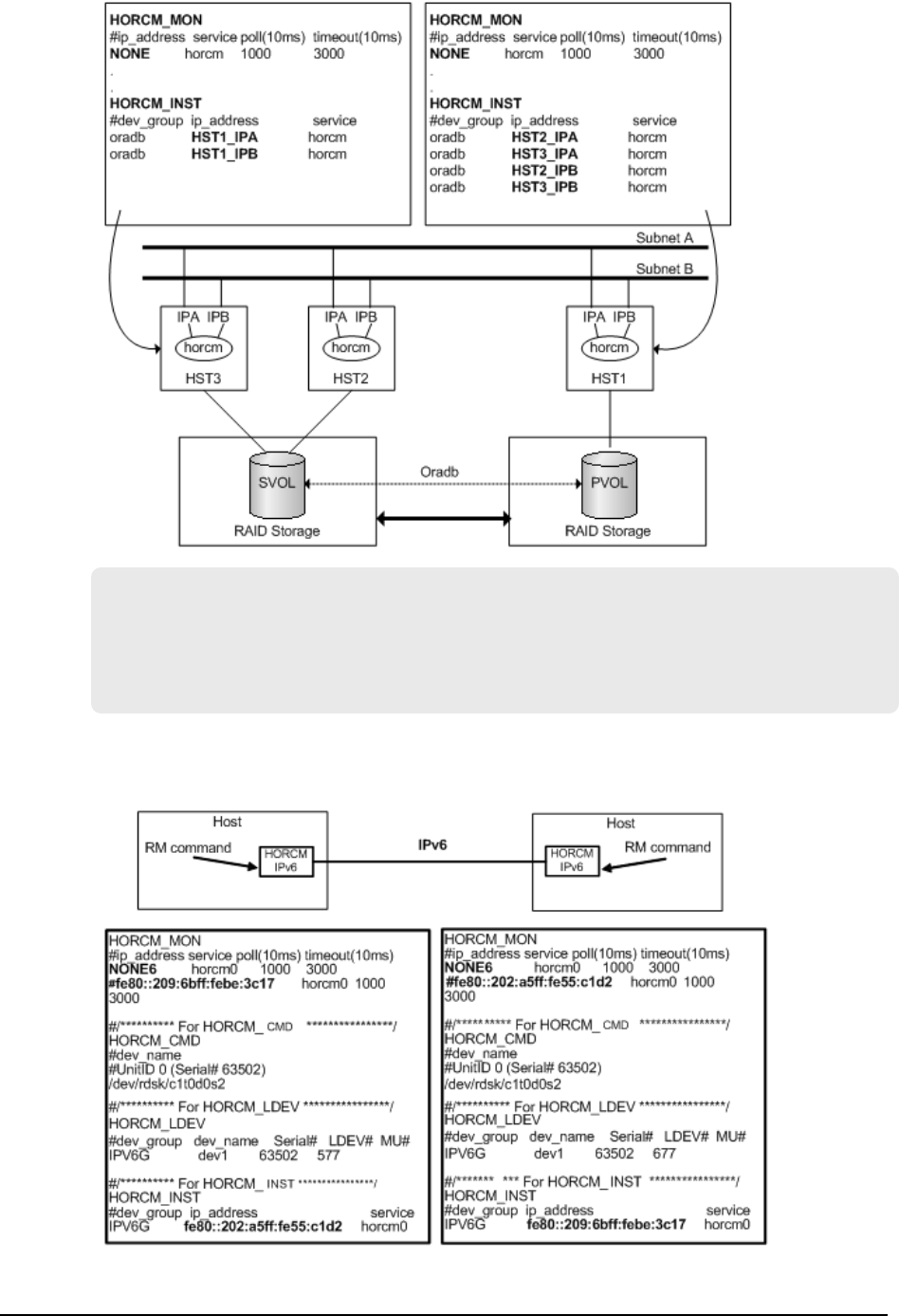
# horcctl -ND -g IP46G
Current network address = 158.214.135.106,services = 50060# horcctl -NC -g
IP46G
Changed network address(158.214.135.106,50060 -> fe80::39e7:7667:9897:2142,
50060)
For IPv6 only, the conguration must be dened as HORCM/IPv6. The following gure
shows the network conguration for IPv6.
HORCM_INST
Appendix B: Sample conguration denition les
Command Control Interface Installation and Conguration Guide 93
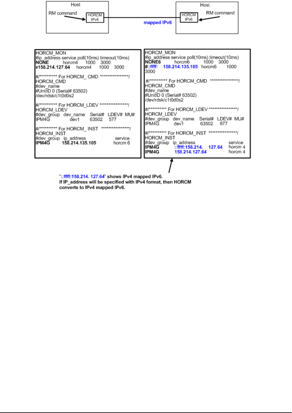
It is possible to communicate between HORCM/IPv4 and HORCM/IPv6 using IPv4
mapped to IPv6. The following gure shows the network conguration for mapped IPv6.
In the case of mixed IPv4 and IPv6, HORCM/IPv4 and HORCM/IPv6 can be connected via
IPv4 mapped IPv6, and native IPv6 is used for connecting HORCM/IPv6 and HORCM/IPv6.
The following gure shows the network conguration for mixed IPv4 and IPv6.
HORCM_INST
Appendix B: Sample conguration denition les
Command Control Interface Installation and Conguration Guide 94
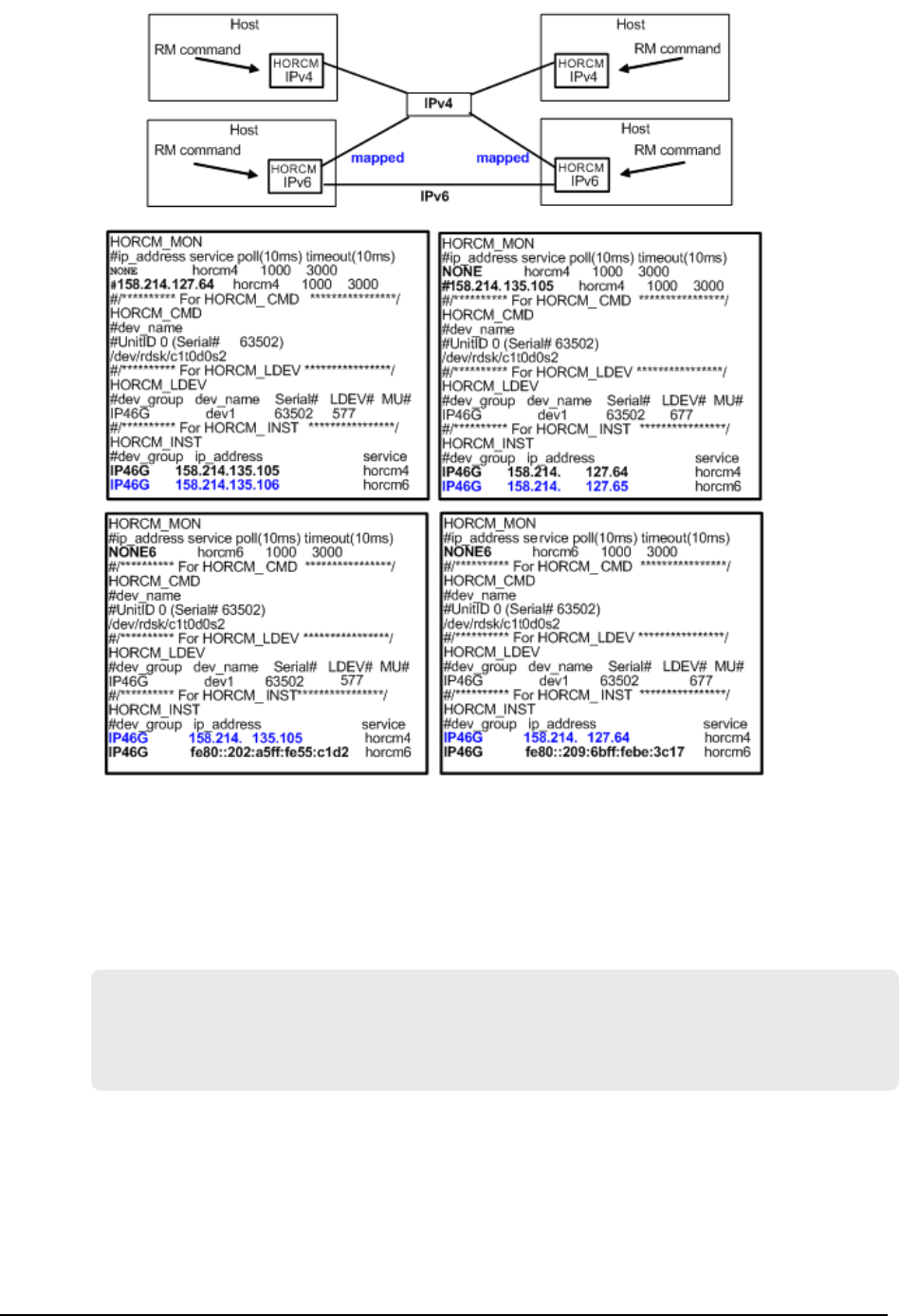
HORCM_INSTP
The HORCM_INSTP parameter is used to specify "pathID" for TrueCopy, Universal
Replicator, and global-active device link as well as HORCM_INST. The value for pathID
must be specied from 1 to 255. If you do not specify the pathID, the behavior is the
same as when HORCM_INST is used.
HORCM_INSTP
dev_group ip_address service pathID
VG01 HSTA horcm 1
VG02 HSTA horcm 2
HORCM_INSTP
Appendix B: Sample conguration denition les
Command Control Interface Installation and Conguration Guide 95

Note: The path ID can be specied for TrueCopy, Universal Replicator,
Universal Replicator for Mainframe, and global-active device. However, the
path ID cannot be specied for UR/URz when connecting TagmaStore USP/
TagmaStore NSC or USP V/VM.
The same path ID must be specied between the site of P-VOL and S-VOL
because the path ID is used by the paircreate command.
HORCM_LDEV
The HORCM_LDEV parameter is used for specifying stable LDEV# and Serial# as the
physical volumes corresponding to the paired logical volume names. Each group name is
unique and typically has a name tting its use (for example, database data, Redo log le,
UNIX le). The group and paired logical volume names described in this item must also
be known to the remote server.
■dev_group: (same as HORCM_DEV parameter) Names a group of paired logical
volumes. The command is executed for all corresponding volumes according to this
group name.
■dev_name: (same as HORCM_DEV parameter) Names the paired logical volume within
a group (i.e., name of the special le or unique logical volume). The name of paired
logical volume must be dierent than the "dev name" on another group.
■MU#: (same as HORCM_DEV parameter)
■Serial#: Describes the serial number of the RAID storage system. For VSP G1x00
and VSP F1500, add a “3” at the beginning of the serial number (for example, enter
“312345” for serial number 12345).
■CU:LDEV(LDEV#): Describes the LDEV number in the RAID storage system, and
supports three types of format as LDEV#.
●Specifying "CU:LDEV" in hex.
Example for LDEV# 260: 01:04
●Specifying "LDEV" in decimal used by the inqraid command.
Example for LDEV# 260: 260
●Specifying "LDEV" in hex used by the inqraid command.
Example for LDEV# 260: 0x104
#dev_group dev_name Serial# CU:LDEV(LDEV#) MU#
oradb dev1 30095 02:40 0
oradb dev2 30095 02:41 0
HORCM_LDEVG
The HORCM_LDEVG parameter denes the device group information that the CCI
instance reads. For details about device groups, see the Command Control Interface User
and Reference Guide.
HORCM_LDEV
Appendix B: Sample conguration denition les
Command Control Interface Installation and Conguration Guide 96

The following values are dened:
■Copy_Group: Species the name of the copy group. This is equivalent to dev_group
of the HORCM_DEV and HORCM_LDEV parameters.
CCI operates by using the information dened here.
■ldev_group: Species the name of the device group that the CCI instance reads.
■Serial#: Species the storage system serial number. For VSP G1x00 and VSP F1500,
add a “3” at the beginning of the serial number (for example, enter “312345” for serial
number 12345).
HORCM_LDEVG
#Copy_Group ldev_group Serial#
ora grp1 64034
HORCM_ALLOW_INST
The HORCM_ALLOW_INST parameter is used to restrict the users using the virtual
command device. The following IP addresses and port numbers are allowed:
For IPv4:
HORCM_ALLOW_INST
#ip_address service
158.214.135.113 34000
158.214.135.114 34000
For IPv6:
HORCM_ALLOW_INST
#ip_address service
fe80::209:6bff:febe:3c17 34000
service in the above example means the initiator port number of HORCM.
If CCI clients are not dened in HORCM_ALLOW_INST, HORCM instance starting up is
rejected by SCSI check condition (SKEY=0x05, ASX=0xfe) and CCI cannot be started up.
Examples of CCI configurations
The following examples show CCI congurations, the conguration denition le(s) for
each conguration, and examples of CCI command use for each conguration.
Example of CCI commands for TrueCopy remote configuration
The following gure shows the TrueCopy remote conguration that is used in the
following examples.
HORCM_ALLOW_INST
Appendix B: Sample conguration denition les
Command Control Interface Installation and Conguration Guide 97
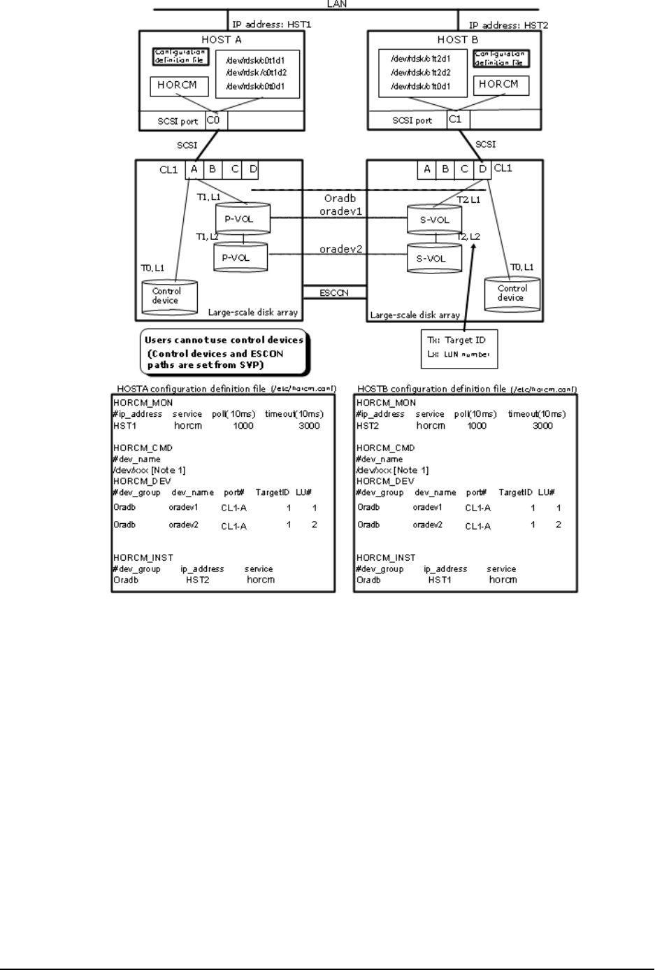
Example of CCI commands for TrueCopy remote conguration
Appendix B: Sample conguration denition les
Command Control Interface Installation and Conguration Guide 98

Example of CCI commands with HOSTA
■Designate a group name (Oradb) and a local host as P-VOL.
# paircreate -g Oradb -f never -vl
This command creates pairs for all LUs assigned to group Oradb in the conguration
denition le (two pairs for the conguration in the above gure).
■Designate a volume name (oradev1) and a local host as P-VOL.
# paircreate -g Oradb -d oradev1 -f never -vl
This command creates pairs for all LUs designated as oradev1 in the conguration
denition le (CL1-A,T1,L1 and CL1-D,T2,L1 for the conguration in the above gure).
■Designate a group name and display pair status.
# pairdisplay -g Oradb
Group PairVol(L/R) (P,T#,L#), Seq#, LDEV#..P/S, Status, Fence,
Seq#, P-LDEV# M
oradb oradev1(L) (CL1-A, 1,1) 30053 18...P-VOL COPY NEVER,
30054 19 -
oradb oradev1(R) (CL1-D, 2,1) 30054 19...S-VOL COPY NEVER, ---
-- 18 -
oradb oradev2(L) (CL1-A, 1,2) 30053 20...P-VOL COPY NEVER,
30054 21 -
oradb oradev2(R) (CL1-D, 2,2) 30054 21...S-VOL COPY NEVER , ---
-- 20 -
Example of CCI commands for TrueCopy remote conguration
Appendix B: Sample conguration denition les
Command Control Interface Installation and Conguration Guide 99

Example of CCI commands with HOSTB
■Designate a group name and a remote host as P-VOL.
# paircreate -g Oradb -f never -vr
This command creates pairs for all LU designated as Oradb in the conguration
denition le (two pairs for the conguration in the above gure).
■Designate a volume name (oradev1) and a remote host as P-VOL.
# paircreate -g Oradb -d oradev1 -f never -vr
This command creates pairs for all LUs designated as oradev1 in the conguration
denition le (CL1-A,T1,L1 and CL1-D,T2,L1 for the conguration in the above gure).
Example of CCI commands for TrueCopy remote conguration
Appendix B: Sample conguration denition les
Command Control Interface Installation and Conguration Guide 100

■Designate a group name and display pair status.
# pairdisplay -g Oradb
Group PairVol(L/R) (P,T#,L#), Seq#, LDEV#..P/S, Status, Fence,
Seq#, P-LDEV# M
oradb oradev1(L) (CL1-D, 2,1) 30054 19...S-VOL COPY NEVER, ----
- 18 -
oradb oradev1(R) (CL1-A, 1,1) 30053 18...P-VOL COPY NEVER,
30054 19 -
oradb oradev2(L) (CL1-D, 2,2) 30054 21...S-VOL COPY NEVER, ----
- 20 -
oradb oradev2(R) (CL1-A, 1,2) 30053 20...P-VOL COPY NEVER,
30054 21 -
The command device is dened using the system raw device name (character-type
device le name). For example, the command devices for the following gure would
be:
■HP-UX:
HORCM_CMD of HOSTA = /dev/rdsk/c0t0d1
HORCM_CMD of HOSTB = /dev/rdsk/c1t0d1
■Solaris:
HORCM_CMD of HOSTA = /dev/rdsk/c0t0d1s2
HORCM_CMD of HOSTB = /dev/rdsk/c1t0d1s2
For Solaris operations with CCI version 01-09-03/04 or later, the command device
does not need to be labeled during the format command.
■AIX®:
HORCM_CMD of HOSTA = /dev/rhdiskXX
HORCM_CMD of HOSTB = /dev/rhdiskXX
where XX = device number assigned by AIX®
■Tru64 UNIX:
HORCM_CMD of HOSTA = /dev/rdisk/dskXXc
HORCM_CMD of HOSTB = /dev/rdisk/dskXXc
where XX = device number assigned by Tru64 UNIX
■Windows:
HORCM_CMD of HOSTA = \\.\CMD-Ser#-ldev#-Port#
HORCM_CMD of HOSTB = \\.\CMD-Ser#-ldev#-Port#
■Linux, z/Linux:
Example of CCI commands for TrueCopy remote conguration
Appendix B: Sample conguration denition les
Command Control Interface Installation and Conguration Guide 101
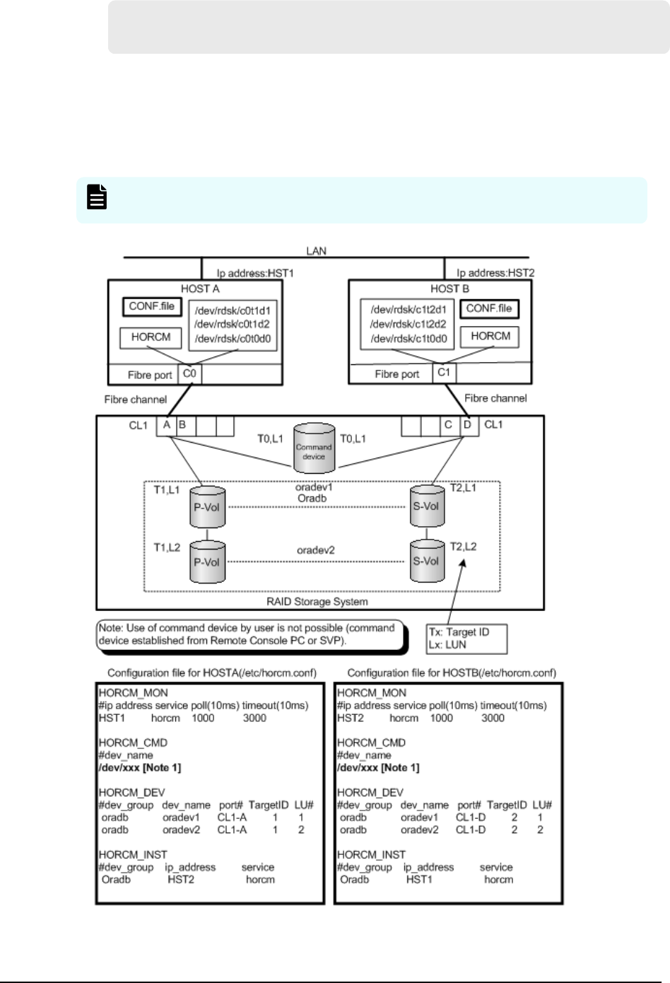
HORCM_CMD of HOSTA = /dev/sdX
HORCM_CMD of HOSTB = /dev/sdX
where X = disk number assigned by Linux, z/Linux
Example of CCI commands for TrueCopy local configuration
The following gure shows the TrueCopy local conguration example.
Note: Input the raw device (character device) name of UNIX/Windows system
for command device.
Example of CCI commands for TrueCopy local conguration
Appendix B: Sample conguration denition les
Command Control Interface Installation and Conguration Guide 102

Example of CCI commands with HOSTA
■Designate a group name (Oradb) and a local host as P-VOL.
# paircreate -g Oradb -f never -vl
This command creates pairs for all LUs assigned to group Oradb in the conguration
denition le (two pairs for the conguration in above gure).
■Designate a volume name (oradev1) and a local host as P-VOL.
# paircreate -g Oradb -d oradev1 -f never -vl
This command creates pairs for all LUs designated as oradev1 in the conguration
denition le (CL1-A,T1,L1 and CL1-D,T2,L1 for the conguration in above gure).
■Designate a group name and display pair status.
# pairdisplay -g Oradb
Group PairVol(L/R) (P,T#,L#), Seq#, LDEV#..P/S, Status, Fence,
Seq#, P-LDEV# M
oradb oradev1(L) (CL1-A, 1,1) 30053 18.. P-VOL COPY NEVER,
30053 19 -
oradb oradev1(R) (CL1-D, 2,1) 30053 19.. S-VOL COPY NEVER, ----
- 18 -
oradb oradev2(L) (CL1-A, 1,2) 30053 20.. P-VOL COPY NEVER,
30053 21 -
oradb oradev2(R) (CL1-D, 2,2) 30053 21.. S-VOL COPY NEVER, ----
- 20 -
Example of CCI commands for TrueCopy local conguration
Appendix B: Sample conguration denition les
Command Control Interface Installation and Conguration Guide 103

Example of CCI commands with HOSTB
■Designate a group name and a remote host as P-VOL.
# paircreate -g Oradb -f never -vr
This command creates pairs for all LU designated as Oradb in the conguration
denition le (two pairs for the conguration in gure above).
■Designate a volume name (oradev1) and a remote host as P-VOL.
# paircreate -g Oradb -d oradev1 -f never -vr
This command creates pairs for all LUs designated as oradev1 in the conguration
denition le (CL1-A,T1,L1 and CL1-D,T2,L1 for the conguration in above gure).
Example of CCI commands for TrueCopy local conguration
Appendix B: Sample conguration denition les
Command Control Interface Installation and Conguration Guide 104

■Designate a group name and display pair status.
# pairdisplay -g Oradb
Group PairVol(L/R) (P,T#,L#), Seq#,LDEV#..P/S, Status, Fence,Seq#,P-
LDEV# M
oradb oradev1(L) (CL1-D, 2,1) 30053 19.. S-VOL COPY NEVER ,-----
18 -
oradb oradev1(R) (CL1-A, 1,1) 30053 18.. P-VOL COPY NEVER ,30053
19 -
oradb oradev2(L) (CL1-D, 2,2) 30053 21.. S-VOL COPY NEVER ,-----
20 -
oradb oradev2(R) (CL1-A, 1,2) 30053 20.. P-VOL COPY NEVER ,30053
21 -
The command device is dened using the system raw device name (character-type
device le name). For example, the command devices can be dened as follows:
●HP-UX:
HORCM_CMD of HORCMINST0 = /dev/rdsk/c0t0d1
HORCM_CMD of HORCMINST1 = /dev/rdsk/c1t0d1
●Solaris:
HORCM_CMD of HORCMINST0 = /dev/rdsk/c0t0d1s2
HORCM_CMD of HORCMINST1 = /dev/rdsk/c1t0d1s2
For Solaris operations with CCI version 01-09-03/04 or later, the command device
does not need to be labeled during the format command.
●AIX®:
HORCM_CMD of HORCMINST0 = /dev/rhdiskXX
HORCM_CMD of HORCMINST1 = /dev/rhdiskXX
where XX = device number assigned by AIX®
●Tru64 UNIX:
HORCM_CMD of HORCMINST0 = /dev/rrzbXXc
HORCM_CMD of HORCMINST1 = /dev/rrzbXXc
where XX = device number assigned by Tru64 UNIX
●Windows:
HORCM_CMD of HORCMINST0 = \\.\CMD-Ser#-ldev#-Port#
HORCM_CMD of HORCMINST1 = \\.\CMD-Ser#-ldev#-Port#
●Linux, z/Linux:
Example of CCI commands for TrueCopy local conguration
Appendix B: Sample conguration denition les
Command Control Interface Installation and Conguration Guide 105
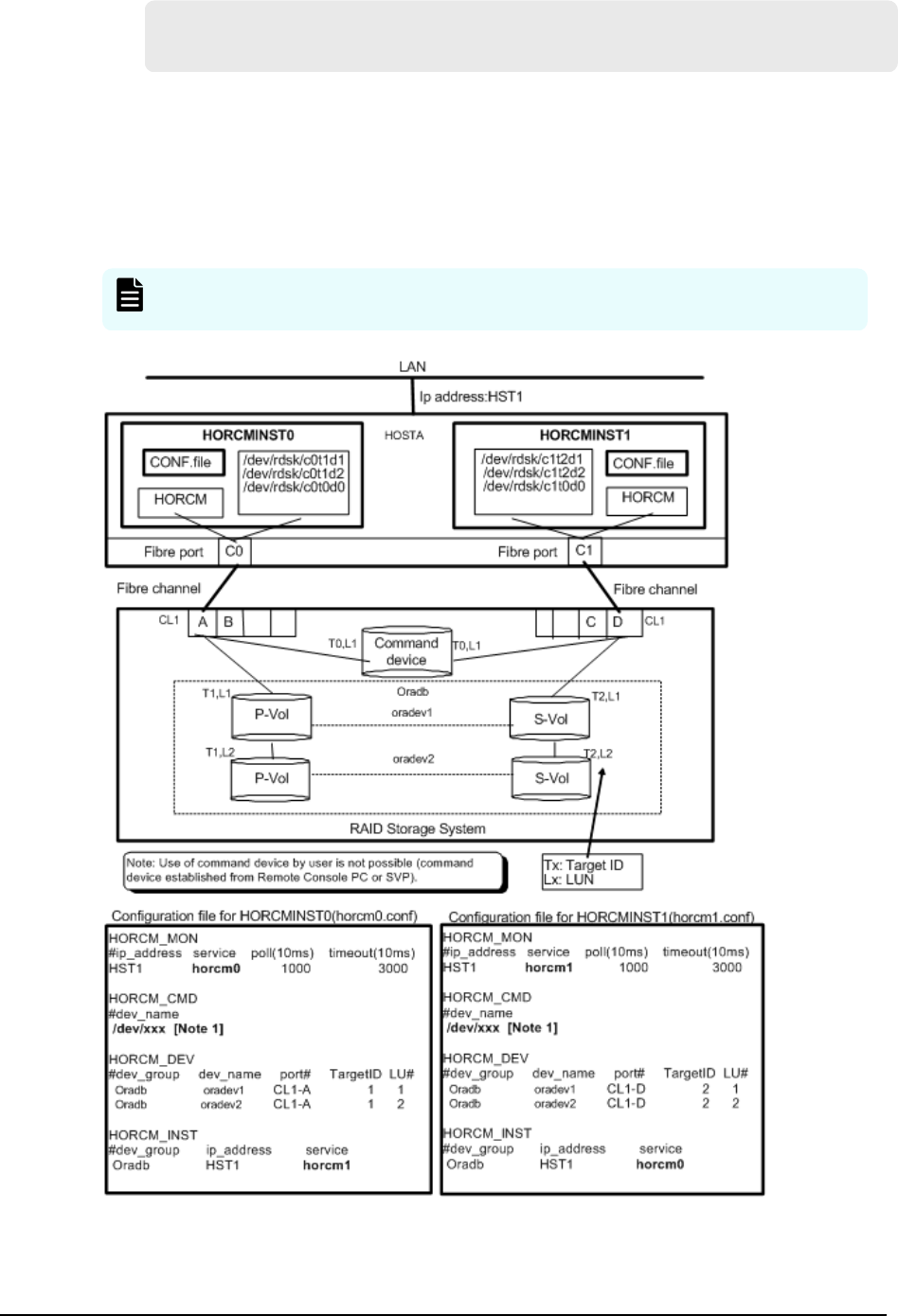
HORCM_CMD of HORCMINST0 = /dev/sdX
HORCM_CMD of HORCMINST1 = /dev/sdX
where X = device number assigned by Linux, z/Linux
Example of CCI commands for TrueCopy configuration with two
instances
The following gure shows the TrueCopy conguration example for two instances.
Note: Input the raw device (character device) name of UNIX/Windows system
for command device.
Example of CCI commands for TrueCopy conguration with two instances
Appendix B: Sample conguration denition les
Command Control Interface Installation and Conguration Guide 106

Example of CCI commands with Instance-0 on HOSTA
■When the command execution environment is not set, set an instance number.
For C shell: # setenv HORCMINST 0
For Windows: set HORCMINST=0
■Designate a group name (Oradb) and a local instance as P-VOL.
# paircreate -g Oradb -f never -vl
This command creates pairs for all LUs assigned to group Oradb in the conguration
denition le (two pairs for the conguration in above gure).
■Designate a volume name (oradev1) and a local instance as P-VOL.
# paircreate -g Oradb -d oradev1 -f never -vl
This command creates pairs for all LUs designated as oradev1 in the conguration
denition le (CL1-A,T1,L1 and CL1-D,T2,L1 for the conguration in above gure).
■Designate a group name and display pair status.
# pairdisplay -g Oradb
Group PairVol(L/R) (P,T#,L#), Seq#, LDEV#.. P/S, Status, Fence,
Seq#, P-LDEV# M
oradb oradev1(L) (CL1-A, 1,1) 30053 18.. P-VOL COPY NEVER,
30053 19 -
oradb oradev1(R) (CL1-D, 2,1) 30053 19.. S-VOL COPY NEVER, ----
- 18 -
oradb oradev2(L) (CL1-A, 1,2) 30053 20.. P-VOL COPY NEVER,
30053 21 -
oradb oradev2(R) (CL1-D, 2,2) 30053 21.. S-VOL COPY NEVER, ----
- 20 -
Example of CCI commands with Instance-1 on HOSTA
■When the command execution environment is not set, set an instance number.
For C shell: # setenv HORCMINST 1
For Windows: set HORCMINST=1
■Designate a group name and a remote instance as P-VOL.
# paircreate -g Oradb -f never -vr
This command creates pairs for all LU designated as Oradb in the conguration
denition le (two pairs for the conguration in above gure).
Example of CCI commands for TrueCopy conguration with two instances
Appendix B: Sample conguration denition les
Command Control Interface Installation and Conguration Guide 107

■Designate a volume name (oradev1) and a remote instance as P-VOL.
# paircreate -g Oradb -d oradev1 -f never -vr
This command creates pairs for all LUs designated as oradev1 in the conguration
denition le (CL1-A,T1,L1 and CL1-D,T2,L1 for the conguration in above gure).
■Designate a group name and display pair status.
# pairdisplay -g Oradb
Group PairVol(L/R) (P,T#,L#), Seq#, LDEV#.. P/S, Status, Fence,
Seq#, P-LDEV# M
oradb oradev1(L) (CL1-D, 2,1) 30053 19.. S-VOL COPY NEVER , -
---- 18 -
oradb oradev1(R) (CL1-A, 1,1) 30053 18.. P-VOL COPY NEVER ,
30053 19 -
oradb oradev2(L) (CL1-D, 2,2) 30053 21.. S-VOL COPY NEVER , -
---- 20 -
oradb oradev2(R) (CL1-A, 1,2) 30053 20.. P-VOL COPY NEVER ,
30053 21 -
Example of CCI commands for TrueCopy conguration with two instances
Appendix B: Sample conguration denition les
Command Control Interface Installation and Conguration Guide 108

The command device is dened using the system raw device name (character-type
device le name) of UNIX/Windows system. For example, the command devices for this
conguration would be:
■HP-UX:
HORCM_CMD of HOSTA = /dev/rdsk/c0t0d1
HORCM_CMD of HOSTB = /dev/rdsk/c1t0d1
HORCM_CMD of HOSTC = /dev/rdsk/c1t0d1
HORCM_CMD of HOSTD = /dev/rdsk/c1t0d1
■Solaris:
HORCM_CMD of HOSTA = /dev/rdsk/c0t0d1s2
HORCM_CMD of HOSTB = /dev/rdsk/c1t0d1s2
HORCM_CMD of HOSTC = /dev/rdsk/c1t0d1s2
HORCM_CMD of HOSTD = /dev/rdsk/c1t0d1s2
For Solaris operations with CCI version 01-09-03/04 or later, the command device
does not need to be labeled during the format command.
■AIX®:
HORCM_CMD of HOSTA = /dev/rhdiskXX
HORCM_CMD of HOSTB = /dev/rhdiskXX
HORCM_CMD of HOSTC = /dev/rhdiskXX
HORCM_CMD of HOSTD = /dev/rhdiskXX
where XX = device number created automatically by AIX®
■Tru64 UNIX:
HORCM_CMD of HOSTA = /dev/rrzbXXc
HORCM_CMD of HOSTB = /dev/rrzbXXc
HORCM_CMD of HOSTC = /dev/rrzbXXc
HORCM_CMD of HOSTD = /dev/rrzbXXc
where XX = device number dened by Tru64 UNIX
■Windows:
HORCM_CMD of HOSTA = \\.\CMD-Ser#-ldev#-Port#
HORCM_CMD of HOSTB = \\.\CMD-Ser#-ldev#-Port#
HORCM_CMD of HOSTC = \\.\CMD-Ser#-ldev#-Port#
HORCM_CMD of HOSTD = \\.\CMD-Ser#-ldev#-Port#
■Linux, z/Linux:
HORCM_CMD of HOSTA = /dev/sdX
HORCM_CMD of HOSTB = /dev/sdX
HORCM_CMD of HOSTC = /dev/sdX
HORCM_CMD of HOSTD = /dev/sdX
Example of CCI commands for TrueCopy conguration with two instances
Appendix B: Sample conguration denition les
Command Control Interface Installation and Conguration Guide 109
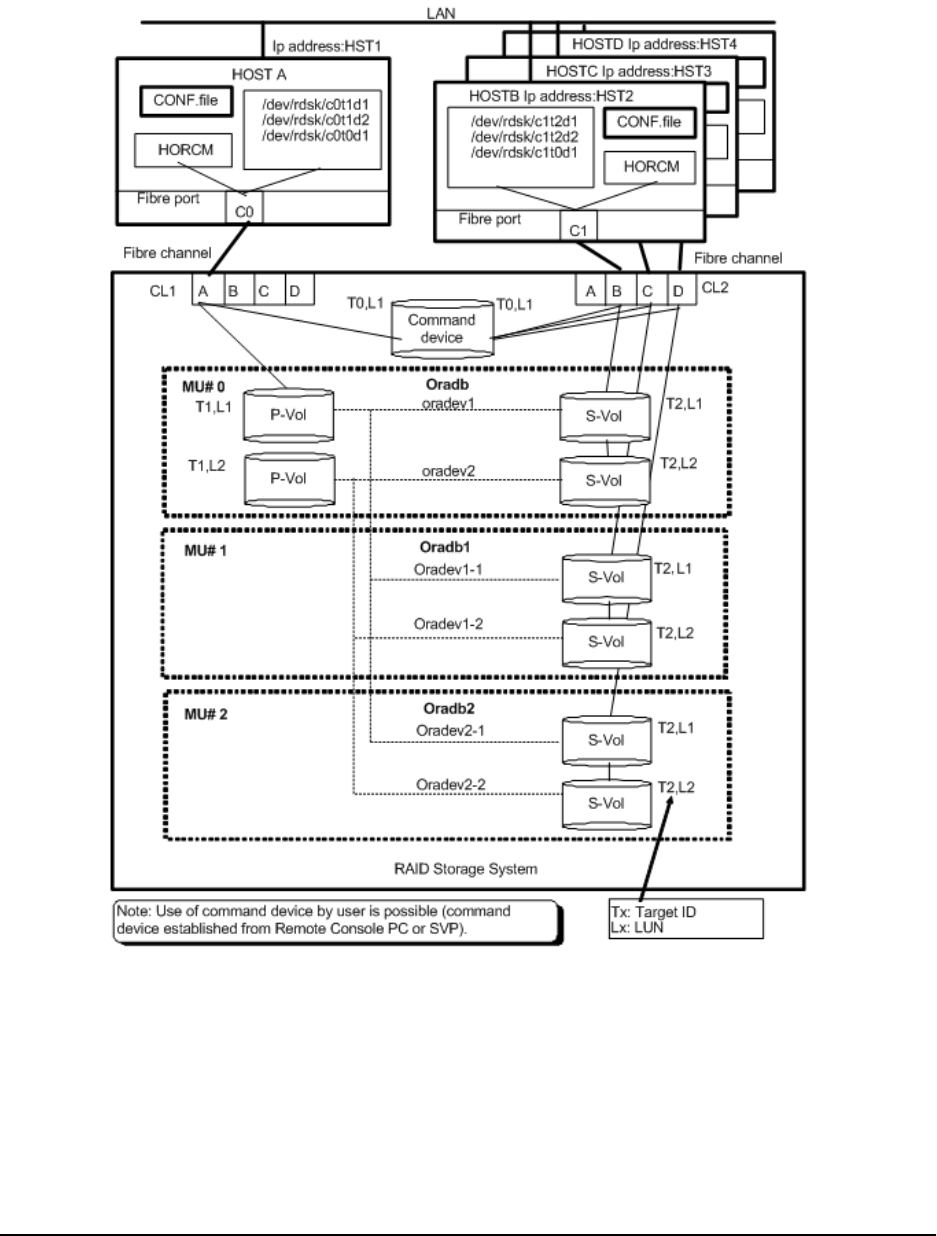
where X = disk number dened by Linux, z/Linux
Example of CCI commands for ShadowImage configuration
The following gure shows the ShadowImage conguration example.
Example of CCI commands for ShadowImage conguration
Appendix B: Sample conguration denition les
Command Control Interface Installation and Conguration Guide 110
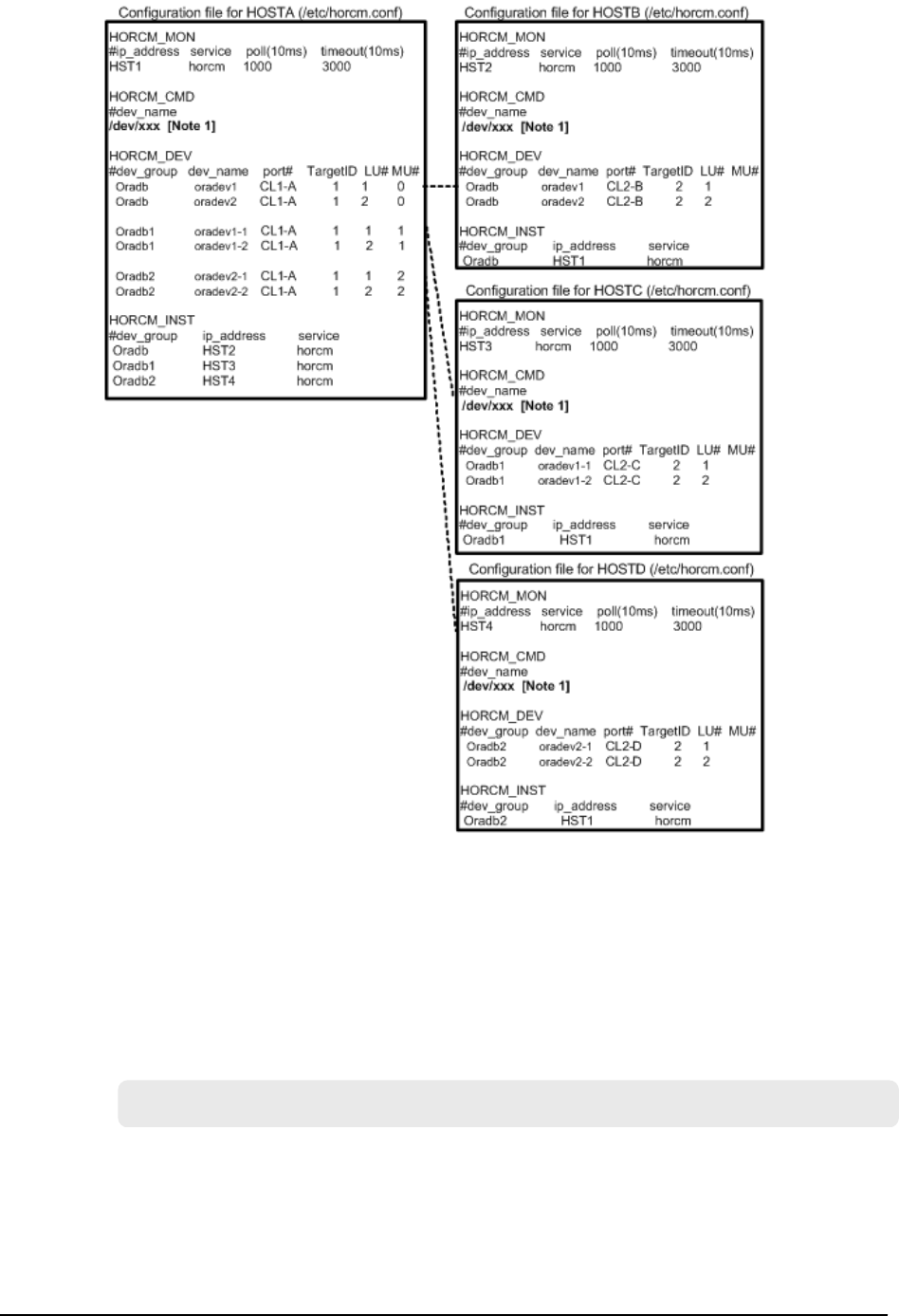
Example of CCI commands with HOSTA (group Oradb)
■When the command execution environment is not set, set HORCC_MRCF to the
environment variable.
For C shell: # setenv HORCC_MRCF 1
Windows: set HORCC_MRCF=1
■Designate a group name (Oradb) and a local host as P-VOL.
# paircreate -g Oradb -vl
This command creates pairs for all LUs assigned to group Oradb in the conguration
denition le (two pairs for the conguration in above gure).
Example of CCI commands for ShadowImage conguration
Appendix B: Sample conguration denition les
Command Control Interface Installation and Conguration Guide 111

■Designate a volume name (oradev1) and a local host as P-VOL.
# paircreate -g Oradb -d oradev1 -vl
This command creates pairs for all LUs designated as oradev1 in the conguration
denition le (CL1-A,T1,L1 and CL1-D,T2,L1 for the conguration in the above gure).
■Designate a group name and display pair status.
# pairdisplay -g Oradb
Group PairVol(L/R) (Port#,TID,LU-M), Seq#, LDEV#..P/S, Status,
Seq#, P-LDEV# M
oradb oradev1(L) (CL1-A, 1,1 - 0) 30053 18..P-VOL COPY 30053
20 -
oradb oradev1(R) (CL2-B, 2,1 - 0) 30053 20..S-VOL COPY -----
18 -
oradb oradev2(L) (CL1-A, 1,2 - 0) 30053 19..P-VOL COPY 30053
21 -
oradb oradev2(R) (CL2-B, 2,2 - 0) 30053 21..S-VOL COPY -----
19 -
Example of CCI commands with HOSTB (group Oradb)
■When the command execution environment is not set, set HORCC_MRCF to the
environment variable.
For C shell: # setenv HORCC_MRCF 1
Windows: set HORCC_MRCF=1
■Designate a group name and a remote host as P-VOL.
# paircreate -g Oradb -vr
This command creates pairs for all LUs assigned to group Oradb in the conguration
denition le (two pairs for the conguration in the above gure).
Example of CCI commands for ShadowImage conguration
Appendix B: Sample conguration denition les
Command Control Interface Installation and Conguration Guide 112

■Designate a volume name (oradev1) and a remote host as P-VOL.
# paircreate -g Oradb -d oradev1 -vr
This command creates pairs for all LUs designated as oradev1 in the conguration
denition le (CL1-A,T1,L1 and CL1-D,T2,L1 for the conguration in the above gure).
■Designate a group name and display pair status.
# pairdisplay -g Oradb
Group PairVol(L/R) (Port#,TID,LU-M), Seq#, LDEV#..P/S, Status,
Seq#, P-LDEV# M
oradb oradev1(L) (CL2-B, 2,1 - 0) 30053 20..S-VOL COPY -----
18 -
oradb oradev1(R) (CL1-A, 1,1 - 0) 30053 18..P-VOL COPY 30053
20 -
oradb oradev2(L) (CL2-B, 2,2 - 0) 30053 21..S-VOL COPY -----
19 -
oradb oradev2(R) (CL1-A, 1,2 - 0) 30053 19..P-VOL COPY 30053
21 -
Example of CCI commands with HOSTA (group Oradb1)
■When the command execution environment is not set, set HORCC_MRCF to the
environment variable.
For C shell: # setenv HORCC_MRCF 1
For Windows: set HORCC_MRCF=1
■Designate a group name (Oradb1) and a local host as P-VOL.
# paircreate -g Oradb1 -vl
This command creates pairs for all LUs assigned to group Oradb1 in the conguration
denition le (two pairs for the conguration in the above gure).
Example of CCI commands for ShadowImage conguration
Appendix B: Sample conguration denition les
Command Control Interface Installation and Conguration Guide 113

■Designate a volume name (oradev1-1) and a local host as P-VOL.
# paircreate -g Oradb1 -d oradev1-1 -vl
This command creates pairs for all LUs designated as oradev1-1 in the conguration
denition le (CL1-A,T1,L1 and CL1-D,T2,L1 for the conguration in the above gure).
■Designate a group name and display pair status.
# pairdisplay -g Oradb1
Group PairVol(L/R) (Port#,TID,LU-M), Seq#,LDEV#..P/S, Status,
Seq#,P-LDEV# M
oradb1 oradev1-1(L) (CL1-A, 1, 1 - 1) 30053 18..P-VOL COPY 30053
22 -
oradb1 oradev1-1(R) (CL2-C, 2, 1 - 0) 30053 22..S-VOL COPY -----
18 -
oradb1 oradev1-2(L) (CL1-A, 1, 2 - 1) 30053 19..P-VOL COPY 30053
23 -
oradb1 oradev1-2(R) (CL2-C, 2, 2 - 0) 30053 23..S-VOL COPY -----
19 -
Example of CCI commands with HOSTC (group Oradb1)
■When the command execution environment is not set, set HORCC_MRCF to the
environment variable.
For C shell: # setenv HORCC_MRCF 1
For Windows: set HORCC_MRCF=1
■Designate a group name and a remote host as P-VOL.
# paircreate -g Oradb1 -vr
This command creates pairs for all LUs assigned to group Oradb1 in the conguration
denition le (two pairs for the conguration in the above gure).
Example of CCI commands for ShadowImage conguration
Appendix B: Sample conguration denition les
Command Control Interface Installation and Conguration Guide 114

■Designate a volume name (oradev1-1) and a remote host as P-VOL.
# paircreate -g Oradb1 -d oradev1-1 -vr
This command creates pairs for all LUs designated as oradev1-1 in the conguration
denition le (CL1-A,T1,L1 and CL1-D,T2,L1 for the conguration in the above gure).
■Designate a group name and display pair status.
# pairdisplay -g Oradb1
Group PairVol(L/R) (Port#,TID,LU-M), Seq#, LDEV#..P/S, Status,
Seq#, P-LDEV# M
oradb1 oradev1-1(L) (CL2-C, 2, 1 - 0) 30053 22..S-VOL COPY ----
- 18 -
oradb1 oradev1-1(R) (CL1-A, 1, 1 - 1) 30053 18..P-VOL COPY
30053 22 -
oradb1 oradev1-2(L) (CL2-C, 2, 2 - 0) 30053 23..S-VOL COPY ----
- 19 -
oradb1 oradev1-2(R) (CL1-A, 1, 2 - 1) 30053 19..P-VOL COPY
30053 23 -
Example of CCI commands with HOSTA (group Oradb2)
■When the command execution environment is not set, set HORCC_MRCF to the
environment variable.
For C shell: # setenv HORCC_MRCF 1
For Windows: set HORCC_MRCF=1
■Designate a group name (Oradb2) and a local host as P-VOL.
# paircreate -g Oradb2 -vl
This command creates pairs for all LUs assigned to group Oradb2 in the conguration
denition le (two pairs for the conguration in above gure).
Example of CCI commands for ShadowImage conguration
Appendix B: Sample conguration denition les
Command Control Interface Installation and Conguration Guide 115

■Designate a volume name (oradev2-1) and a local host as P-VOL.
# paircreate -g Oradb2 -d oradev2-1 -vl
This command creates pairs for all LUs designated as oradev2-1 in the conguration
denition le (CL1-A,T1,L1 and CL1-D,T2,L1 for the conguration in the above gure).
■Designate a group name and display pair status.
# pairdisplay -g Oradb2
Group PairVol(L/R) (Port#,TID,LU-M), Seq#, LDEV#..P/S, Status,
Seq#, P-LDEV# M
oradb2 oradev2-1(L) (CL1-A, 1, 1 - 2) 30053 18..P-VOL COPY
30053 24 -
oradb2 oradev2-1(R) (CL2-D, 2, 1 - 0) 30053 24..S-VOL COPY ----
- 18 -
oradb2 oradev2-2(L) (CL1-A, 1, 2 - 2) 30053 19..P-VOL COPY
30053 25 -
oradb2 oradev2-2(R) (CL2-D, 2, 2 - 0) 30053 25..S-VOL COPY ----
- 19 -
Example of CCI commands with HOSTD (group Oradb2)
■When the command execution environment is not set, set HORCC_MRCF to the
environment variable.
For C shell: # setenv HORCC_MRCF 1
For Windows: set HORCC_MRCF=1
■Designate a group name and a remote host as P-VOL.
# paircreate -g Oradb2 -vr
This command creates pairs for all LUs assigned to group Oradb2 in the conguration
denition le (two pairs for the conguration in the above gure).
Example of CCI commands for ShadowImage conguration
Appendix B: Sample conguration denition les
Command Control Interface Installation and Conguration Guide 116

■Designate a volume name (oradev2-1) and a remote host as P-VOL.
# paircreate -g Oradb2 -d oradev2-1 -vr
This command creates pairs for all LUs designated as oradev2-1 in the conguration
denition le (CL1-A,T1,L1 and CL1-D,T2,L1 for the conguration in the above gure).
■Designate a group name and display pair status.
# pairdisplay -g Oradb2
Group PairVol(L/R) (Port#,TID,LU-M), Seq#, LDEV#..P/S, Status,
Seq#,P-LDEV# M
oradb2 oradev2-1(L) (CL2-D, 2, 1 - 0) 30053 24..S-VOL COPY -----
18 -
oradb2 oradev2-1(R) (CL1-A, 1, 1 - 2) 30053 18..P-VOL COPY 30053
24 -
oradb2 oradev2-2(L) (CL2-D, 2, 2 - 0) 30053 25..S-VOL COPY -----
19 -
oradb2 oradev2-2(R) (CL1-A, 1, 2 - 2) 30053 19..P-VOL COPY 30053
25 -
Example of CCI commands for ShadowImage conguration
Appendix B: Sample conguration denition les
Command Control Interface Installation and Conguration Guide 117

The command device is dened using the system raw device name (character-type
device le name) of UNIX/Windows system. For example, the command devices for this
conguration would be:
■HP-UX:
HORCM_CMD of HORCMINST0 = /dev/rdsk/c0t0d1
HORCM_CMD of HORCMINST1 = /dev/rdsk/c1t0d1
■Solaris:
HORCM_CMD of HORCMINST0 = /dev/rdsk/c0t0d1s2
HORCM_CMD of HORCMINST1 = /dev/rdsk/c1t0d1s2
For Solaris operations with CCI version 01-09-03/04 or later, the command device
does not need to be labeled during format command.
■AIX®:
HORCM_CMD of HORCMINST0 = /dev/rhdiskXX
HORCM_CMD of HORCMINST1 = /dev/rhdiskXX
where XX = device number assigned by AIX®
■Tru64 UNIX:
HORCM_CMD of HORCMINST0 = /dev/rrzbXXc
HORCM_CMD of HORCMINST1 = /dev/rrzbXXc
where XX = device number assigned by Tru64 UNIX
■Windows:
HORCM_CMD of HORCMINST0 = \\.\CMD-Ser#-ldev#-Port#
HORCM_CMD of HORCMINST1 = \\.\CMD-Ser#-ldev#-Port#
■Linux, z/Linux:
HORCM_CMD of HORCMINST0 = /dev/sdX
HORCM_CMD of HORCMINST1 = /dev/sdX
where X = disk number dened by Linux, z/Linux
Example of CCI commands for ShadowImage cascade configuration
The following gure shows the ShadowImage conguration example with cascade pairs.
Example of CCI commands for ShadowImage cascade conguration
Appendix B: Sample conguration denition les
Command Control Interface Installation and Conguration Guide 118
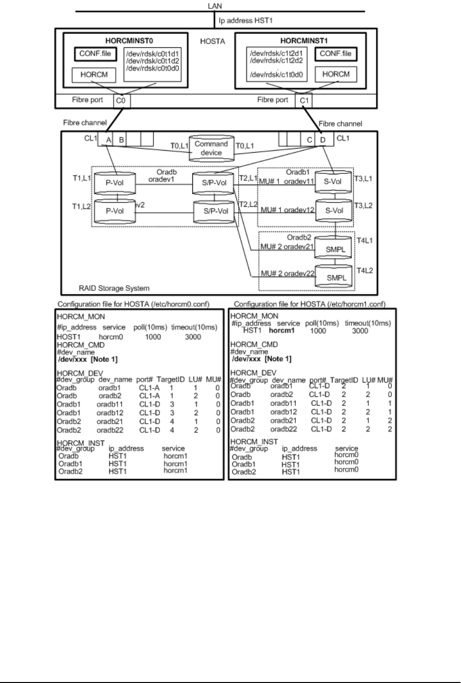
Example of CCI commands for ShadowImage cascade conguration
Appendix B: Sample conguration denition les
Command Control Interface Installation and Conguration Guide 119

Example of CCI commands with Instance-0 on HOSTA
■When the command execution environment is not set, set an instance number.
For C shell:# setenv HORCMINST 0 # setenv HORCC_MRCF 1
For Windows:set HORCMINST=0 set HORCC_MRCF=1
■Designate a group name (Oradb) and a local instance P- VOL.
# paircreate -g Oradb -vl
# paircreate -g Oradb1 -vr
These commands create pairs for all LUs assigned to groups Oradb and Oradb1 in the
conguration denition le.
■Designate a group name and display pair status.
# pairdisplay -g oradb -m cas
Group PairVol(L/R) (Port#,TID,LU-M), Seq#, LDEV#. P/S, Status,
Seq#, P-LDEV# M
oradb oradev1(L) (CL1-A , 1, 1-0) 30053 266.. P-VOL PAIR,
30053 268 -
oradb oradev1(R) (CL1-D , 2, 1-0) 30053 268.. S-VOL PAIR, -----
266 -
oradb1 oradev11(R) (CL1-D , 2, 1-1) 30053 268.. P-VOL PAIR,
30053 270 -
oradb2 oradev21(R) (CL1-D , 2, 1-2) 30053 268.. SMPL ----, -----
---- -
oradb oradev2(L) (CL1-A , 1, 2-0) 30053 267.. P-VOL PAIR,
30053 269 -
oradb oradev2(R) (CL1-D , 2, 2-0) 30053 269.. S-VOL PAIR, -----
267 -
oradb1 oradev12(R) (CL1-D , 2, 2-1) 30053 269.. P-VOL PAIR,
30053 271 -
oradb2 oradev22(R) (CL1-D , 2, 2-2) 30053 269.. SMPL ----, -----
---- -
Example of CCI commands for ShadowImage cascade conguration
Appendix B: Sample conguration denition les
Command Control Interface Installation and Conguration Guide 120

Example of CCI commands with Instance-1 on HOSTA
■When the command execution environment is not set, set an instance number.
For C shell:# setenv HORCMINST 1 # setenv HORCC_MRCF 1
For Windows:set HORCMINST=1 set HORCC_MRCF=1
■Designate a group name and a remote instance P-VOL.
# paircreate -g Oradb -vr
# paircreate -g Oradb1 -vl
These commands create pairs for all LUs assigned to groups Oradb and Oradb1 in the
conguration denition le.
■Designate a group name and display pair status.
# pairdisplay -g oradb -m cas
Group PairVol(L/R) (Port#,TID,LU-M),Seq#,LDEV#.P/S,Status, Seq#,P-
LDEV# M
oradb oradev1(L) (CL1-D , 2, 1-0)30053 268..S-VOL PAIR,----- 266
-
oradb1 oradev11(L) (CL1-D , 2, 1-1)30053 268..P-VOL PAIR,30053 270
-
oradb2 oradev21(L) (CL1-D , 2, 1-2)30053 268..SMPL ----,----- ----
-
oradb oradev1(R) (CL1-A , 1, 1-0)30053 266..P-VOL PAIR,30053 268
-
oradb oradev2(L) (CL1-D , 2, 2-0)30053 269..S-VOL PAIR,----- 267
-
oradb1 oradev12(L) (CL1-D , 2, 2-1)30053 269..P-VOL PAIR,30053 271
-
oradb2 oradev22(L) (CL1-D , 2, 2-2)30053 269..SMPL ----,----- ----
-
oradb oradev2(R) (CL1-A , 1, 2-0)30053 267..P-VOL PAIR,30053 269
-
Example of CCI commands for ShadowImage cascade conguration
Appendix B: Sample conguration denition les
Command Control Interface Installation and Conguration Guide 121

The command device is dened using the system raw device name (character-type
device le name) of UNIX/Windows system. For example, the command devices for this
conguration would be:
■HP-UX:
HORCM_CMD of HOSTA (/etc/horcm.conf) ... /dev/rdsk/c0t0d1
HORCM_CMD of HOSTB (/etc/horcm.conf) ... /dev/rdsk/c1t0d1
HORCM_CMD of HOSTB (/etc/horcm0.conf) ... /dev/rdsk/c1t0d1
■Solaris:
HORCM_CMD of HOSTA(/etc/horcm.conf) ... /dev/rdsk/c0t0d1s2
HORCM_CMD of HOSTB(/etc/horcm.conf) ... /dev/rdsk/c1t0d1s2
HORCM_CMD of HOSTB(/etc/horcm0.conf) ... /dev/rdsk/c1t0d1s2
For Solaris operations with CCI version 01-09-03/04 or later, the command device
does not need to be labeled during format command.
■AIX®:
HORCM_CMD of HOSTA(/etc/horcm.conf) ... /dev/rhdiskXX
HORCM_CMD of HOSTB(/etc/horcm.conf) ... /dev/rhdiskXX
HORCM_CMD of HOSTB(/etc/horcm0.conf)... /dev/rhdiskXX
where XX = device number assigned by AIX®
■Tru64 UNIX:
HORCM_CMD of HOSTA(/etc/horcm.conf) ... /dev/rrzbXXc
HORCM_CMD of HOSTB(/etc/horcm.conf) ... /dev/rrzbXXc
HORCM_CMD of HOSTB(/etc/horcm0.conf)... /dev/rrzbXXc
where XX = device number assigned by Tru64 UNIX
■Windows:
HORCM_CMD of HOSTA(/etc/horcm.conf) ... \\.\CMD-Ser#-ldev#-Port#
HORCM_CMD of HOSTB(/etc/horcm.conf) ... \\.\CMD-Ser#-ldev#-Port#
HORCM_CMD of HOSTB(/etc/horcm0.conf) ... \\.\CMD-Ser#-ldev#-Port#
■Linux, z/Linux:
HORCM_CMD of HOSTA(/etc/horcm.conf) ... /dev/sdX
HORCM_CMD of HOSTB(/etc/horcm.conf) ... /dev/sdX
HORCM_CMD of HOSTB(/etc/horcm0.conf) ... /dev/sdX
where X = device number assigned by Linux, z/Linux
Example of CCI commands for TC/SI cascade configuration
The following gure shows the TC/SI conguration example with cascade pairs.
Example of CCI commands for TC/SI cascade conguration
Appendix B: Sample conguration denition les
Command Control Interface Installation and Conguration Guide 122
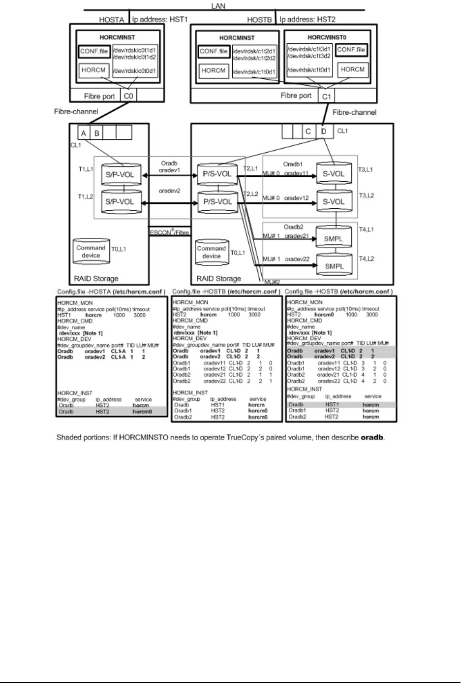
Example of CCI commands for TC/SI cascade conguration
Appendix B: Sample conguration denition les
Command Control Interface Installation and Conguration Guide 123

Example of CCI commands with HOSTA and HOSTB
■Designate a group name (Oradb) on TrueCopy environment of HOSTA.
# paircreate -g Oradb -vl
■Designate a group name (Oradb1) on ShadowImage environment of HOSTB. When
the command execution environment is not set, set HORCC_MRCF.
For C shell: # setenv HORCC_MRCF 1
For Windows: set HORCC_MRCF=1
# paircreate -g Oradb1 -vl
These commands create pairs for all LUs assigned to groups Oradb and Oradb1 in the
conguration denition le (four pairs for the conguration in the above gures).
■Designate a group name and display pair status on HOSTA.
# pairdisplay -g oradb -m cas
Group PairVol(L/R) (Port#,TID,LU-M),Seq#,LDEV#.P/S,Status, Seq#,P-
LDEV# M
oradb oradev1(L) (CL1-A , 1, 1-0)30052 266..SMPL ----,----- ----
-
oradb oradev1(L) (CL1-A , 1, 1) 30052 266..P-VOL COPY,30053 268
-
oradb1 oradev11(R) (CL1-D , 2, 1-0)30053 268..P-VOL COPY,30053 270
-
oradb2 oradev21(R) (CL1-D , 2, 1-1)30053 268..SMPL ----,----- ----
-
oradb oradev1(R) (CL1-D , 2, 1) 30053 268..S-VOL COPY,----- 266
-
oradb oradev2(L) (CL1-A , 1, 2-0)30052 267..SMPL ----,----- ----
-
oradb oradev2(L) (CL1-A , 1, 2) 30052 267..P-VOL COPY,30053 269
-
oradb1 oradev12(R) (CL1-D , 2, 2-0)30053 269..P-VOL COPY,30053 271
-
oradb2 oradev22(R) (CL1-D , 2, 2-1)30053 269..SMPL ----,----- ----
-
oradb oradev2(R) (CL1-D , 2, 2) 30053 269..S-VOL COPY,----- 267
-
Example of CCI commands for TC/SI cascade conguration
Appendix B: Sample conguration denition les
Command Control Interface Installation and Conguration Guide 124

Example of CCI commands with HOSTB
■Designate a group name (oradb) on TrueCopy environment of HOSTB.
# paircreate -g Oradb -vr
■Designate a group name (Oradb1) on ShadowImage environment of HOSTB. When
the command execution environment is not set, set HORCC_MRCF.
For C shell: # setenv HORCC_MRCF 1
For Windows: set HORCC_MRCF=1
# paircreate -g Oradb1 -vl
This command creates pairs for all LUs assigned to group Oradb1 in the conguration
denition le (four pairs for the conguration in the above gures).
■Designate a group name and display pair status on TrueCopy environment of HOSTB.
# pairdisplay -g oradb -m cas
Group PairVol(L/R) (Port#,TID,LU-M),Seq#,LDEV#.P/S,Status, Seq#,P-
LDEV# M
oradb1 oradev11(L) (CL1-D , 2, 1-0)30053 268..P-VOL PAIR,30053 270
-
oradb2 oradev21(L) (CL1-D , 2, 1-1)30053 268..SMPL ----,----- ----
-
oradb oradev1(L) (CL1-D , 2, 1) 30053 268..S-VOL PAIR,----- 266
-
oradb oradev1(R) (CL1-A , 1, 1-0)30052 266..SMPL ----,----- ----
-
oradb oradev1(R) (CL1-A , 1, 1) 30052 266..P-VOL PAIR,30053 268
-
oradb1 oradev12(L) (CL1-D , 2, 2-0)30053 269..P-VOL PAIR,30053 271
-
oradb2 oradev22(L) (CL1-D , 2, 2-1)30053 269..SMPL ----,----- ----
-
oradb oradev2(L) (CL1-D , 2, 2) 30053 269..S-VOL PAIR,----- 267
-
oradb oradev2(R) (CL1-A , 1, 2-0)30052 267..SMPL ----,----- ----
-
oradb oradev2(R) (CL1-A , 1, 2) 30052 267..P-VOL PAIR,30053 269
-
Example of CCI commands for TC/SI cascade conguration
Appendix B: Sample conguration denition les
Command Control Interface Installation and Conguration Guide 125

■Designate a group name and display pair status on ShadowImage environment of
HOSTB.
# pairdisplay -g oradb1 -m cas
Group PairVol(L/R) (Port#,TID,LU-M),Seq#,LDEV#.P/S,Status, Seq#,P-
LDEV# M
oradb1 oradev11(L) (CL1-D , 2, 1-0)30053 268..P-VOL PAIR,30053 270
-
oradb2 oradev21(L) (CL1-D , 2, 1-1)30053 268..SMPL ----,----- ----
-
oradb oradev1(L) (CL1-D , 2, 1) 30053 268..S-VOL PAIR,----- 266
-
oradb1 oradev11(R) (CL1-D , 3, 1-0)30053 270..S-VOL PAIR,----- 268
-
oradb1 oradev12(L) (CL1-D , 2, 2-0)30053 269..P-VOL PAIR,30053 271
-
oradb2 oradev22(L) (CL1-D , 2, 2-1)30053 269..SMPL ----,----- ----
-
oradb oradev2(L) (CL1-D , 2, 2) 30053 269..S-VOL PAIR,----- 267
-
oradb1 oradev12(R) (CL1-D , 3, 2-0)30053 271..S-VOL PAIR,----- 269
-
■Designate a group name and display pair status on ShadowImage environment of
HOSTB (HORCMINST0).
# pairdisplay -g oradb1 -m cas
Group PairVol(L/R) (Port#,TID,LU-M),Seq#,LDEV#.P/S,Status, Seq#,P-
LDEV# M
oradb1 oradev11(L) (CL1-D , 3, 1-0)30053 270..S-VOL PAIR,----- 268
-
oradb1 oradev11(R) (CL1-D , 2, 1-0)30053 268..P-VOL PAIR,30053 270
-
oradb2 oradev21(R) (CL1-D , 2, 1-1)30053 268..SMPL ----,----- ----
-
oradb oradev1(R) (CL1-D , 2, 1) 30053 268..S-VOL PAIR,----- 266
-
oradb1 oradev12(L) (CL1-D , 3, 2-0)30053 271..S-VOL PAIR,----- 269
-
oradb1 oradev12(R) (CL1-D , 2, 2-0)30053 269..P-VOL PAIR,30053 271
-
oradb2 oradev22(R) (CL1-D , 2, 2-1)30053 269..SMPL ----,----- ----
-
oradb oradev2(R) (CL1-D , 2, 2) 30053 269..S-VOL PAIR,----- 267
-
Example of CCI commands for TC/SI cascade conguration
Appendix B: Sample conguration denition les
Command Control Interface Installation and Conguration Guide 126
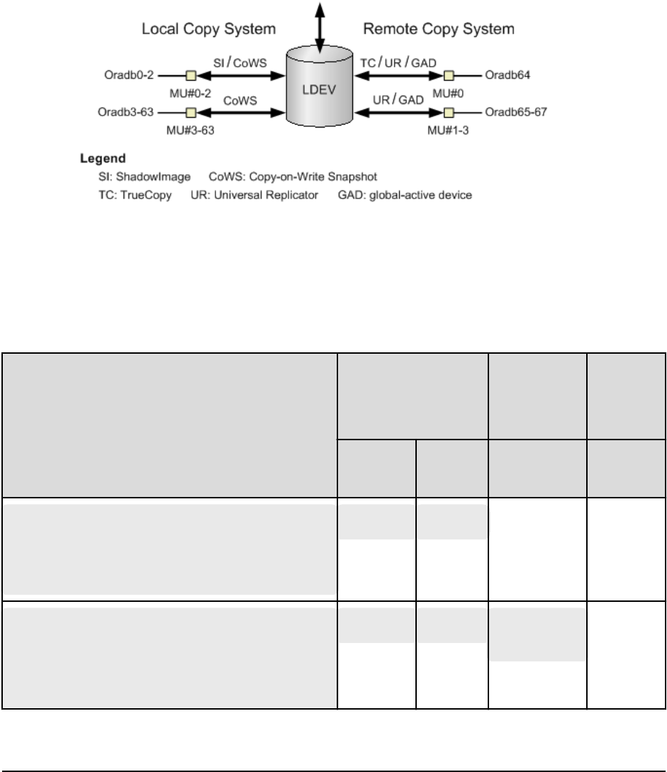
Correspondence of the configuration definition file for
cascading volume and mirror descriptors
The CCI software (HORCM) is capable of keeping a record of the multiple pair
congurations per LDEV. CCI distinguishes the records of the each pair conguration by
MU#. You can assign 64 MU#s (MU#0 to 63) for local copy products and 4 MU#s (MU#0
to 3) for remote copy products as the following gure, you can dene up to 68 device
groups (records of pair conguration) in the conguration denition le.
The following gure shows the management of pair conguration by mirror descriptors.
The group name and MU# that are noted in the HORCM_DEV section of the
conguration denition le are assigned to the corresponding mirror descriptors. This
outline is described in the following table. "Omission of MU#" is handled as MU#0, and
the specied group is registered to MU#0 on ShadowImage/Copy-on-Write Snapshot and
TrueCopy/Universal Replicator/global-active device. Also, when you note the MU# in
HORCM_DEV, the sequence of the MU# can be random (for example, 2, 1, 0).
HORCM_DEV Parameter in Configuration File
MU#0
SI/Copy-on-
Write
Snapshot
only UR/GAD
TC/
UR/GAD SI
MU#1 to 2
(MU#3 to 63)
MU#1 to
3
HORCM_DEV
#dev_group dev_name port# TargetID
LU# MU#
Oradb oradev1 CL1-D 2 1
oradev1 oradev1 - -
HORCM_DEV
#dev_group dev_name port# TargetID
LU# MU#
Oradb oradev1 CL1-D 2 1
Oradb1 oradev11 CL1-D 2 1
oradev1 oradev1 oradev11
oradev21
-
Correspondence of the conguration denition le for cascading volume and mirror descriptors
Appendix B: Sample conguration denition les
Command Control Interface Installation and Conguration Guide 127

HORCM_DEV Parameter in Configuration File
MU#0
SI/Copy-on-
Write
Snapshot
only UR/GAD
TC/
UR/GAD SI
MU#1 to 2
(MU#3 to 63)
MU#1 to
3
1
Oradb2 oradev21 CL1-D 2 1
2
HORCM_DEV
#dev_group dev_name port# TargetID
LU# MU#
Oradb oradev1 CL1-D 2 1
Oradb1 oradev11 CL1-D 2 1
0
Oradb2 oradev21 CL1-D 2 1
1
Oradb3 oradev31 CL1-D 2 1
2
oradev1 oradev1
1
oradev21
oradev31
-
HORCM_DEV
#dev_group dev_name port# TargetID
LU# MU#
Oradb oradev1 CL1-D 2 1
0
- oradev1 - -
HORCM_DEV
#dev_group dev_name port# TargetID
LU# MU#
Oradb oradev1 CL1-D 2 1
h0
oradev1 - - -
HORCM_DEV
#dev_group dev_name port# TargetID
LU# MU#
Oradb oradev1 CL1-D 2 1
0
Oradb1 oradev1 CL1-D 2 1
1
Oradb2 oradev21 CL1-D 2 1
2
-oradev1 oradev11
oradev21
-
Correspondence of the conguration denition le for cascading volume and mirror descriptors
Appendix B: Sample conguration denition les
Command Control Interface Installation and Conguration Guide 128
HORCM_DEV Parameter in Configuration File
MU#0
SI/Copy-on-
Write
Snapshot
only UR/GAD
TC/
UR/GAD SI
MU#1 to 2
(MU#3 to 63)
MU#1 to
3
HORCM_DEV
#dev_group dev_name port# TargetID
LU# MU#
Oradb oradev1 CL1-D 2 1
Oradb1 oradev11 CL1-D 2 1
0
Oradb2 oradev21 CL1-D 2 1
h1
Oradb3 oradev31 CL1-D 2 1
h2
Oradb4 oradev41 CL1-D 2 1
h3
oradev1 oradev1
1
-oradev21
oradev31
oradev41
Configuration definition files for cascade configurations
Each volume in a cascading connection is described by an entry in the conguration
denition le on each HORCM instance, and each connection of the volume is specied
by mirror descriptor. In the case of a ShadowImage/TrueCopy cascading connection, too,
the volume is described in the conguration denition le on the same instance. The
following topics present examples of ShadowImage and ShadowImage/TrueCopy
cascading congurations.
Configuration definition files for ShadowImage cascade configuration
The following gure shows an example of a ShadowImage cascade conguration and the
associated entries in the conguration denition les. ShadowImage is a mirror
conguration within one storage system, so the volumes are described in the
conguration denition le for each HORCM instance: volumes T3L0, T3L4, and T3L6 in
HORCMINST0, and volume T3L2 in HORCMINST1. As shown in this ShadowImage
cascading connection example, the specied dev group is assigned to the ShadowImage
mirror descriptor: MU#0 in HORCMINST0, and MU#0, MU#1, and MU#2 in HORCMINST1.
Conguration denition les for cascade congurations
Appendix B: Sample conguration denition les
Command Control Interface Installation and Conguration Guide 129
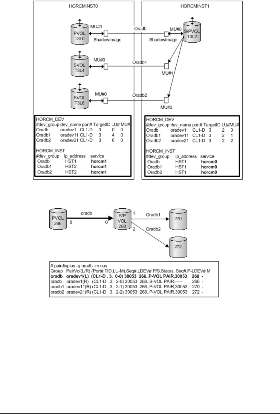
The following gures show the pairdisplay information for this example of a
ShadowImage cascading conguration.
Figure 1 Pairdisplay -g on HORCMINST0
Conguration denition les for ShadowImage cascade conguration
Appendix B: Sample conguration denition les
Command Control Interface Installation and Conguration Guide 130
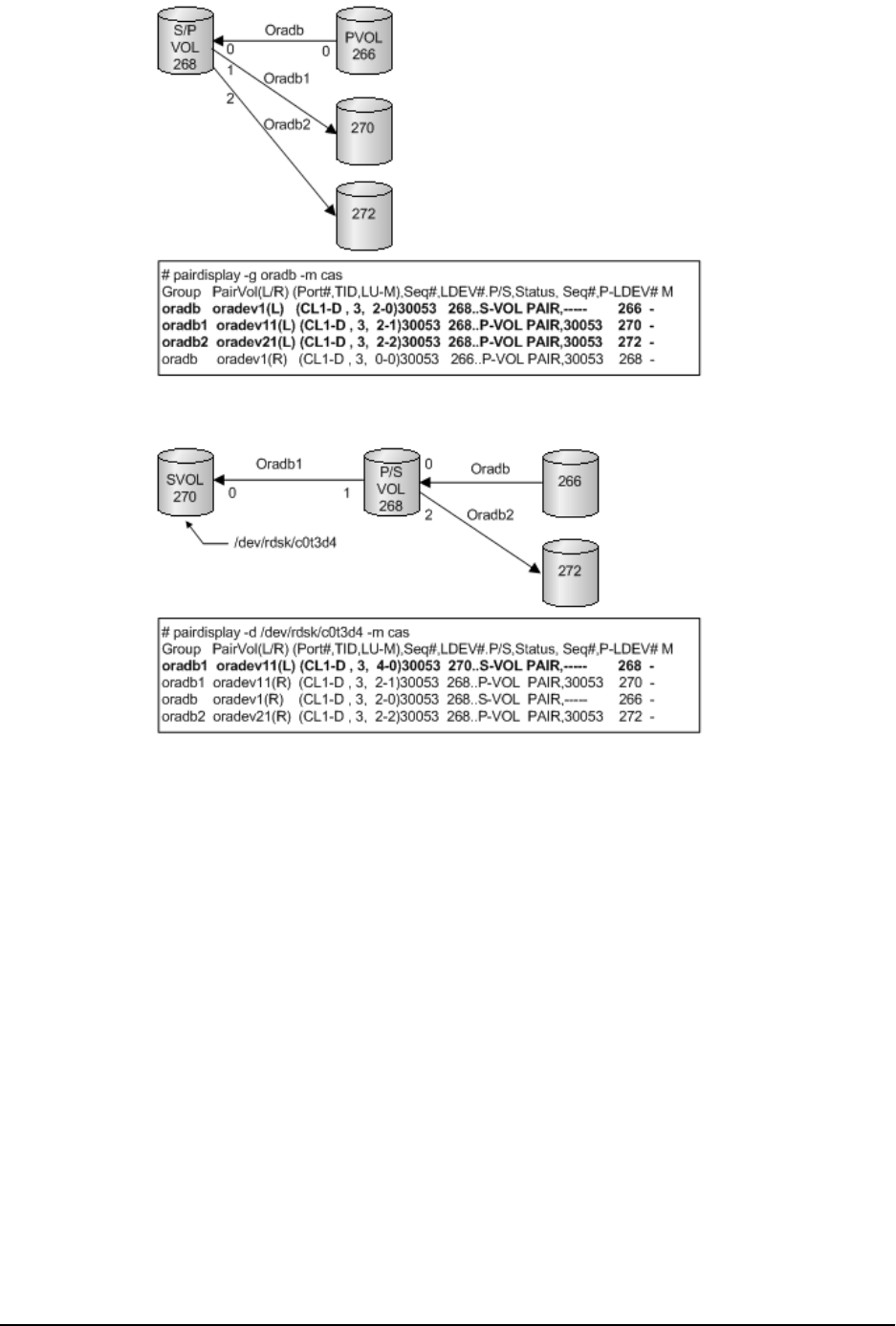
Figure 2 Pairdisplay -g on HORCMINST1
Figure 3 Pairdisplay -d on HORCMINST0
Configuration definition files for TrueCopy/ShadowImage cascade
configuration
The cascading connections for TrueCopy/ShadowImage can be set up by using three
conguration denition les that describe the cascading volume entity in a conguration
denition le on the same instance. The mirror descriptor of ShadowImage and
TrueCopy denitely describe "0" as MU#, and the mirror descriptor of TrueCopy does not
describe "0" as MU#.
The following gure shows the TC/SI cascading connection and conguration le.
Conguration denition les for TrueCopy/ShadowImage cascade conguration
Appendix B: Sample conguration denition les
Command Control Interface Installation and Conguration Guide 131
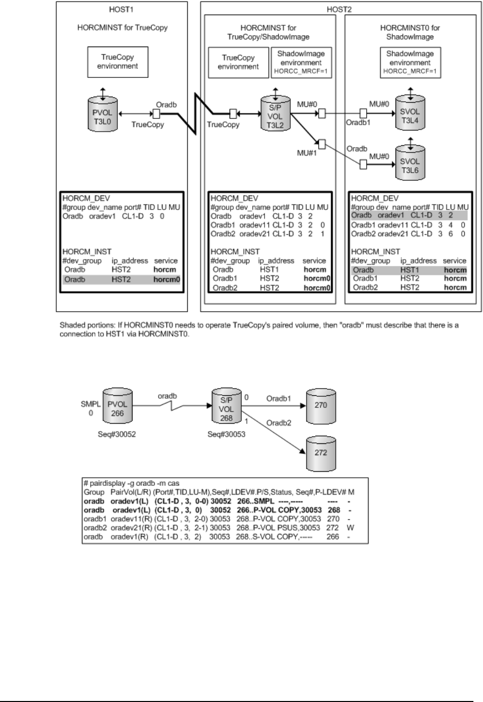
The following gures show the cascading congurations and the pairdisplay information
for each conguration.
Figure 4 Pairdisplay for TrueCopy on HOST1
Conguration denition les for TrueCopy/ShadowImage cascade conguration
Appendix B: Sample conguration denition les
Command Control Interface Installation and Conguration Guide 132
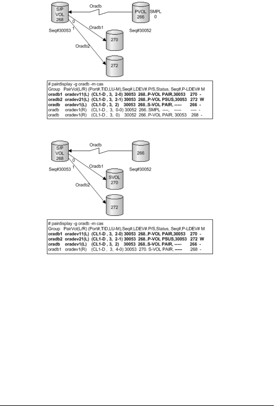
Figure 5 Pairdisplay for TrueCopy on HOST2 (HORCMINST)
Figure 6 Pairdisplay for ShadowImage on HOST2 (HORCMINST)
Conguration denition les for TrueCopy/ShadowImage cascade conguration
Appendix B: Sample conguration denition les
Command Control Interface Installation and Conguration Guide 133
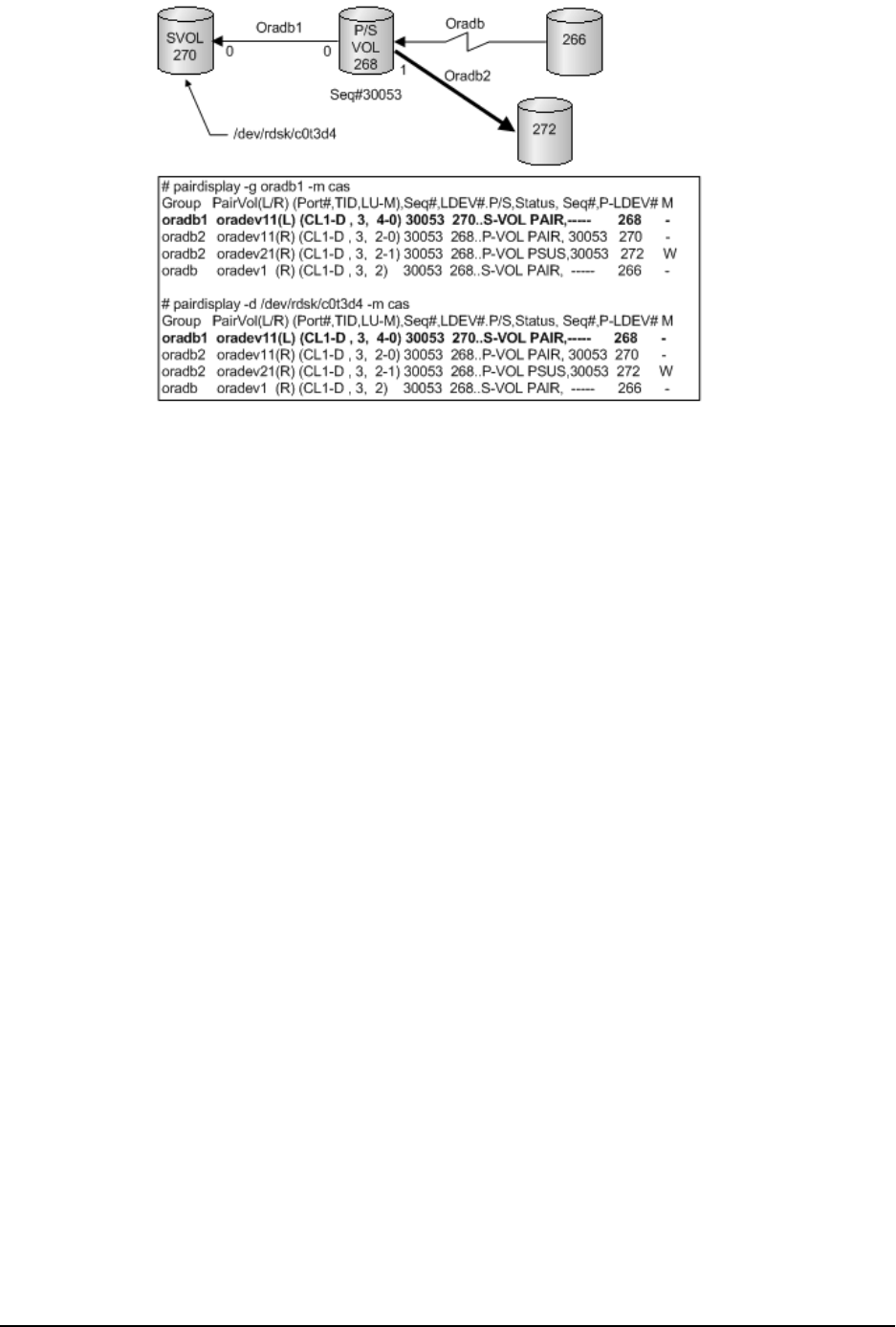
Figure 7 Pairdisplay for ShadowImage on HOST2 (HORCMINST0)
Conguration denition les for TrueCopy/ShadowImage cascade conguration
Appendix B: Sample conguration denition les
Command Control Interface Installation and Conguration Guide 134

Index
A
alternate command devices 56
C
CCI
installing on Windows 45
CCI administrator, specifying on Windows 46
CCI and RAID Manager XP 39
changing the user
UNIX environment 43
command devices
alternate 56
requirements 14
setting 53
specifying in conguration denition le 55
virtual 55
conguration denition le
cascade examples 129
HORCM_ALLOW_INST parameter 97
HORCM_CMD parameter for in-band method 81
HORCM_CMD parameter for out-of-band method
86
HORCM_DEV parameter 89
HORCM_INST parameter 92
HORCM_INSTP parameter 95
HORCM_LDEV parameter 96
HORCM_LDEVG parameter 96
HORCM_MON parameter 81
HORCM_VCMD parameter 88
specifying the command devices 55
conguration examples 97
conguration le
creating 57
editing 57
examples 79
parameters 57
sample le 57
conguration le parameters 57, 80
contacting support 71
conversion tables, bre-to-SCSI addresses 75
creating the conguration denition le 57
D
denition le, conguration
creating 57
editing 57
examples 79
parameters 57
sample le 57
denition le, conguration parameters 57, 80
E
editing the conguration denition le 57
example conguration les 79
F
failover software support 17
FCP, z/Linux restrictions 22
bre-to-SCSI address conversion
example 72
table for HP-UX 75
table for Solaris 75
table for Windows 75
FICON, z/Linux restrictions 22
H
hardware installation 41
HORCM_ALLOW_INST 97
HORCM_CMD (in-band method) 81
HORCM_CMD (out-of-band) 86
HORCM_CONF 57
HORCM_DEV 89
HORCM_INST 92
HORCM_INSTP 95
HORCM_LDEV 96
HORCM_LDEVG 96
HORCM_MON 81
HORCM_VCMD 88
HORCMFCTBL 72
Index
Command Control Interface Installation and Conguration Guide 135

host platform support 17
I
I/O interface support 17
in-band command execution 50
installation requirements 13
installing CCI
Windows system 45
installing CCI software
UNIX environment 42
UNIX root directory 42
installing hardware 41
installing software
OpenVMS environment 49
IPv6
environment variables 29
library and system call 29
supported platforms 22
L
license key requirements 14
LUN congurations 74
M
mirror descriptors
conguration le correspondence 127
O
OpenVMS
bash start-up 37
DCL command examples 33
DCL detached process start-up 30
installation 49
Oracle VM
restrictions 28
OS support 17
out-of-band command execution 50
P
parameters, conguration 57
program product requirements 14
R
RAID Manager XP and CCI 39
removing CCI
manually on UNIX 66
OpenVMS 69
removing CCI (continued)
PC with storage management software 68
using script on UNIX 65
Windows 67
requirements and restrictions
Oracle VM 28
system 13
VMWare ESX Server 25
Windows 2012/2008 Hyper-V 26
z/Linux 22
S
sample conguration les 79
sample denition le 57
setting the command devices 53
software installation
OpenVMS environment 49
UNIX environment 42
software upgrade
OpenVMS environment 63
UNIX environment 60
Windows environment 61
SVC, VMWare restrictions 25
system option modes 14
system requirements 13
T
tables, bre-to-SCSI address conversion 75
U
uninstalling CCI
manually on UNIX 66
OpenVMS 69
PC with storage management software 68
using script on UNIX 65
Windows 67
upgrading software
OpenVMS environment 63
UNIX environment 60
Windows environment 61
user, changing
UNIX environment 43
V
virtual command devices 55
VM
applicable platforms 20
VMWare ESX Server, restrictions 25
Index
Command Control Interface Installation and Conguration Guide 136


Hitachi Vantara Corporation
Corporate Headquarters
2845 Lafayette Street
Santa Clara, CA 95050-2639 USA
www.HitachiVantara.com | community.HitachiVantara.com
Regional Contact Information
Americas: +1 866 374 5822 or info@hitachivantara.com
Europe, Middle East, and Africa: +44 (0) 1753 618000 or info@emea@hitachivantara.com
Asia Pacific: + 852 3189 7900 or info.marketing.apac@hitachivantara.com
