CCNA Wireless 640 722 Official Cert Guide
User Manual:
Open the PDF directly: View PDF ![]() .
.
Page Count: 543 [warning: Documents this large are best viewed by clicking the View PDF Link!]
- Contents
- Introduction
- Chapter 1 RF Signals and Modulation
- Chapter 2 RF Standards
- Chapter 3 RF Signals in the Real World
- Chapter 4 Understanding Antennas
- Chapter 5 Wireless LAN Topologies
- Chapter 6 Understanding 802.11 Frame Types
- Chapter 7 Planning Coverage with Wireless APs
- Chapter 8 Using Autonomous APs
- Chapter 9 Understanding the CUWN Architecture
- Chapter 10 Initial Controller Configuration
- Chapter 11 Understanding Controller Discovery
- Chapter 12 Understanding Roaming
- Chapter 13 Understanding RRM
- Chapter 14 Wireless Security Fundamentals
- Chapter 15 Configuring a WLAN
- Chapter 16 Implementing a Wireless Guest Network
- Chapter 17 Understanding Wireless Clients
- Chapter 18 Managing Wireless Networks with WCS
- Chapter 19 Dealing with Wireless Interference
- Chapter 20 Troubleshooting WLAN Connectivity
- Chapter 21 Maintaining Controllers
- Chapter 22 Final Review
- Appendix A: Answers to “Do I Know This Already?” Quizzes
- Appendix B: Modulation and Coding Schemes
- Key Terms Glossary
- Index
ptg12542968

ptg12542968
Cisco Press
800 East 96th Street
Indianapolis, IN 46240
CCNA Wireless 640-722
Official Cert Guide
David Hucaby

ptg12542968
ii CCNA Wireless 640-722 Official Cert Guide
CCNA Wireless 640-722 Official Cert Guide
David Hucaby
Copyright© 2014 Cisco Systems, Inc.
Published by:
Cisco Press
800 East 96th Street
Indianapolis, IN 46240 USA
All rights reserved. No part of this book may be reproduced or transmitted in any form or by any means,
electronic or mechanical, including photocopying, recording, or by any information storage and retrieval
system, without written permission from the publisher, except for the inclusion of brief quotations in a
review.
Printed in the United States of America
First Printing February 2014
Library of Congress Control Number: 2014931706
ISBN-13: 978-1-58720-562-0
ISBN-10: 1-58720-562-9
Warning and Disclaimer
This book is designed to provide information about preparing for the CCNA Wireless 640-722 exam.
Every effort has been made to make this book as complete and as accurate as possible, but no warranty
or fitness is implied.
The information is provided on an “as is” basis. The author, Cisco Press, and Cisco Systems, Inc., shall
have neither liability nor responsibility to any person or entity with respect to any loss or damages
arising from the information contained in this book or from the use of the discs or programs that may
accompany it.
The opinions expressed in this book belong to the author and are not necessarily those of Cisco Systems,
Inc.
Trademark Acknowledgments
All terms mentioned in this book that are known to be trademarks or service marks have been appropri-
ately capitalized. Cisco Press or Cisco Systems, Inc. cannot attest to the accuracy of this information. Use
of a term in this book should not be regarded as affecting the validity of any trademark or service mark.

ptg12542968
iii
Special Sales
For information about buying this title in bulk quantities, or for special sales opportunities (which may
include electronic versions; custom cover designs; and content particular to your business, training goals,
marketing focus, or branding interests), please contact our corporate sales department at corpsales@pear-
soned.com or (800) 382-3419.
For government sales inquiries, please contact governmentsales@pearsoned.com.
For questions about sales outside the U.S., please contact international@pearsoned.com.
Feedback Information
At Cisco Press, our goal is to create in-depth technical books of the highest quality and value. Each book
is crafted with care and precision, undergoing rigorous development that involves the unique expertise
of members from the professional technical community.
Readers’ feedback is a natural continuation of this process. If you have any comments regarding how we
could improve the quality of this book, or otherwise alter it to better suit your needs, you can contact us
through e-mail at feedback@ciscopress.com. Please make sure to include the book title and ISBN in your
message.
We greatly appreciate your assistance.
Publisher: Paul Boger Business Operation Manager, Cisco Press: Jan Cornelssen
Associate Publisher: Dave Dusthimer Manager Global Certification: Sean Donovan
Executive Editor: Mary Beth Ray Senior Development Editor: Christopher Cleveland
Managing Editor: Sandra Schroeder Copy Editor: Keith Cline
Project Editor: Seth Kerney Technical Editor: Jerome Henry
Editorial Assistant: Vanessa Evans Proofreader: Jess DeGabriele
Cover Designer: Mark Shirar Indexer: Tim Wright
Composition: Jake McFarland

ptg12542968
iv CCNA Wireless 640-722 Official Cert Guide
About the Author
David Hucaby
, CCIE No. 4594, is a network architect for the University of Kentucky,
where he works with academic and healthcare networks based on the Cisco Unified
Wireless Network products. David has bachelor’s and master’s degrees in electrical engi-
neering from the University of Kentucky. He is the author of several Cisco Press titles,
including
CCNP SWITCH Exam Certification Guide
;
Cisco LAN Switching Video
Mentor
;
CCNP Security FIREWALL Exam Certification Guide
;
Cisco ASA, PIX,
and FWSM Firewall Handbook
, Second Edition; and
Cisco Firewall Video Mentor
.
David lives in Kentucky with his wife, Marci, and two daughters.

ptg12542968
v
About the Technical Reviewer
Jerome Henry
, CCIE Wireless No. 24750, is technical marketing engineer in the
Wireless Enterprise Networking Group at Cisco systems. Jerome has close to 15 years
experience teaching technical Cisco courses in more than 15 different countries and 4
different languages, to audiences ranging from bachelor degree students to networking
professionals and Cisco internal system engineers.
Focusing on his wireless experience, Jerome joined Cisco in 2012. Before that time, he
was consulting and teaching Heterogeneous Networks and Wireless Integration with
the European Airespace team, which was later acquired by Cisco to become their main
wireless solution. He then spent several years with a Cisco Learning partner, develop-
ing wireless courses, and working on training material for new wireless technologies. In
addition to his CCIE Wireless certification, Jerome is a certified wireless networking
expert (CWNE #45) and has developed several Cisco courses focusing on wireless top-
ics (IUWNE, IUWMS, IUWVN, CUWSS, IAUWS, LBS, CWMN lab guide, and so on)
and authored several Wireless books (IUWMS, CUWSS Quick Reference, and so on).
Jerome is also an IEEE 802.11 group member and participant of Wi-Fi Alliance work-
ing groups. With more than 10000 hours in the classroom, Jerome was awarded the IT
Training Award best Instructor silver medal in 2009. He is based in the Research Triangle
Park in North Carolina.

ptg12542968
vi CCNA Wireless 640-722 Official Cert Guide
Dedications
As always, this book is dedicated to the most important people in my life: my wife,
Marci, and my two daughters, Lauren and Kara. Their love, encouragement, and sup-
port carry me along. I’m so grateful to God, who gives endurance and encouragement
(Romans 15:5), and who has allowed me to enjoy networking and work on projects like
this.
I would also like to dedicate this book to the memory of my father-in-law, Ermel
Wilson. He helped me appreciate the simpler things in life—the outdoors, hikes in the
woods, and snow.

ptg12542968
vii
Acknowledgments
It has been my great pleasure to work on another Cisco Press project. I enjoy the net-
working field very much, and technical writing even more. And more than that, I’m
thankful for the joy and inner peace that Jesus Christ gives, making everything more
abundant and worthwhile. As much as I enjoy learning about wireless networking (there’s
no end to it!), I realize that God created the original wireless connection that has no
distance limits, unlimited capacity for clients (there’s always room for one more), is trust-
worthy, always available everywhere, and connects directly to the Source: prayer!
I’ve now been writing Cisco Press titles continuously for what will soon be 15 years. I
have physically worn out several laptop keyboards and probably several Cisco Press edi-
tors in the process. It has been a great pleasure to work with Chris Cleveland and Mary
Beth Ray. I should have a certification in schedule slipping by now. Keith Cline and Seth
Kerney have been great to work with and have made the whole review process smooth
and efficient. One important part of the book I never get to see is the index. I’m grateful
that Tim Wright worked on this one.
I am very grateful for the insight, knowledge, and helpful comments that Jerome Henry
has provided. He is a great resource for wireless networking expertise and training.
Jerome’s input has made this a more well-rounded book and me a more educated author.
Finally, I have enjoyed the good discussions with my dad, Reid Hucaby, a fellow EE and
a seasoned RF engineer, that this book has prompted about all things wireless.

ptg12542968
viii CCNA Wireless 640-722 Official Cert Guide
Contents at a Glance
Introduction xix
Chapter 1 RF Signals and Modulation 3
Chapter 2 RF Standards 37
Chapter 3 RF Signals in the Real World 67
Chapter 4 Understanding Antennas 85
Chapter 5 Wireless LAN Topologies 105
Chapter 6 Understanding 802.11 Frame Types 123
Chapter 7 Planning Coverage with Wireless APs 147
Chapter 8 Using Autonomous APs 163
Chapter 9 Understanding the CUWN Architecture 181
Chapter 10 Initial Controller Configuration 201
Chapter 11 Understanding Controller Discovery 221
Chapter 12 Understanding Roaming 239
Chapter 13 Understanding RRM 259
Chapter 14 Wireless Security Fundamentals 281
Chapter 15 Configuring a WLAN 307
Chapter 16 Implementing a Wireless Guest Network 323
Chapter 17 Understanding Wireless Clients 335
Chapter 18 Managing Wireless Networks with WCS 359
Chapter 19 Dealing with Wireless Interference 383
Chapter 20 Troubleshooting WLAN Connectivity 401
Chapter 21 Maintaining Controllers 427
Chapter 22 Final Review 447
Appendix A Answers to “Do I Know This Already?” Quizzes 457
Appendix B Modulation and Coding Schemes 473
Key Terms Glossary 481
Index 494

ptg12542968
ix
Contents
Introduction xix
Chapter 1 RF Signals and Modulation 3
“Do I Know This Already?” Quiz 3
Foundation Topics 7
Comparing Wired and Wireless Networks 7
Understanding Basic Wireless Theory 8
Understanding Frequency 10
Understanding Phase 14
Measuring Wavelength 14
Understanding RF Power and dB 15
Important dB Facts to Remember 17
Comparing Power Against a Reference: dBm 19
Measuring Power Changes Along the Signal Path 20
Understanding Power Levels at the Receiver 23
Carrying Data Over an RF Signal 24
FHSS 26
DSSS 27
1-Mbps Data Rate 28
2-Mbps Data Rate 29
5.5-Mbps Data Rate 30
11-Mbps Data Rate 30
OFDM 31
Modulation Summary 32
Exam Preparation Tasks 34
Review All Key Topics 34
Key Terms 34
Chapter 2 RF Standards 37
“Do I Know This Already?” Quiz 37
Foundation Topics 41
Regulatory Bodies 41
ITU-R 41
FCC 42
ETSI 44
Other Regulatory Bodies 45
IEEE Standards Body 45
802.11 Channel Use 47
Channels in the 2.4-GHz ISM Band 47
Channels in the 5-GHz U-NII Bands 49

ptg12542968
x CCNA Wireless 640-722 Official Cert Guide
IEEE 802.11 Standards 51
802.11-1997 52
802.11b 52
802.11g 52
802.11a 54
802.11n 55
Channel Aggregation 57
Spatial Multiplexing 58
MAC Layer Efficiency 59
Transmit Beam Forming (T×BF) 60
Maximal-Ratio Combining 61
802.11n Modulation and Coding Schemes 61
Beyond 802.11n 62
Wi-Fi Alliance 63
Exam Preparation Tasks 64
Review All Key Topics 64
Define Key Terms 64
Chapter 3 RF Signals in the Real World 67
“Do I Know This Already?” Quiz 67
Foundation Topics 70
Interference 70
Co-Channel Interference 70
Neighboring Channel Interference 71
Non-802.11 Interference 72
Free Space Path Loss 72
Mitigating the Effects of Free Space Path Loss 74
Effects of Physical Objects 76
Reflection 76
Absorption 78
Scattering 78
Refraction 79
Diffraction 80
Fresnel Zones 80
Exam Preparation Tasks 83
Review All Key Topics 83
Define Key Terms 83
Chapter 4 Understanding Antennas 85
“Do I Know This Already?” Quiz 85
Foundation Topics 88

ptg12542968
xi
Antenna Characteristics 88
Radiation Patterns 88
Gain 91
Beamwidth 92
Polarization 92
Antenna Types 93
Omnidirectional Antennas 94
Directional Antennas 97
Antenna Summary 101
Adding Antenna Accessories 101
Exam Preparation Tasks 103
Review All Key Topics 103
Define Key Terms 103
Chapter 5 Wireless LAN Topologies 105
“Do I Know This Already?” Quiz 105
Foundation Topics 108
Types of Wireless Networks 108
Wireless LAN Topologies 109
Basic Service Set 110
Distribution System 112
Extended Service Set 114
Independent Basic Service Set 115
Other Wireless Topologies 116
Repeater 116
Workgroup Bridge 117
Outdoor Bridge 118
Mesh Network 119
Exam Preparation Tasks 120
Review All Key Topics 120
Define Key Terms 120
Chapter 6 Understanding 802.11 Frame Types 123
“Do I Know This Already?” Quiz 123
802.11 Frame Format 126
802.11 Frame Addressing 128
Accessing the Wireless Medium 130
Carrier Sense 131
Collision Avoidance 132
802.11 Frame Types 134
Management Frames 134

ptg12542968
xii CCNA Wireless 640-722 Official Cert Guide
Control Frames 135
Data Frames 136
Client Housekeeping 136
A Client Scans for APs 137
A Client Joins a BSS 138
A Client Leaves a BSS 139
A Client Moves Between BSSs 140
A Client Saves Power 142
Exam Preparation Tasks 145
Review All Key Topics 145
Define Key Terms 145
Chapter 7 Planning Coverage with Wireless APs 147
“Do I Know This Already?” Quiz 147
AP Cell Size 150
Tuning Cell Size with Transmit Power 150
Tuning Cell Size with Data Rates 152
Adding APs to an ESS 153
The Roaming Process 155
WLAN Channel Layout 157
Exam Preparation Tasks 161
Review All Key Topics 161
Define Key Terms 161
Chapter 8 Using Autonomous APs 163
“Do I Know This Already?” Quiz 163
Foundation Topics 166
Autonomous Architecture 166
Configuring an Autonomous AP 167
Connecting the AP 167
Configuring the AP 170
Converting an Autonomous AP 174
Using the Autonomous to Lightweight Mode Upgrade Tool 174
Converting an Autonomous AP Manually 176
Exam Preparation Tasks 178
Review All Key Topics 178
Define Key Terms 178
Chapter 9 Understanding the CUWN Architecture 181
“Do I Know This Already?” Quiz 181
Foundation Topics 184
A Distributed Architecture 184

ptg12542968
xiii
A Centralized Architecture 186
Split-MAC Architecture 188
Traffic Patterns in a CUWN 190
CUWN Building Blocks 192
Cisco Wireless LAN Controllers 192
Cisco Lightweight APs 194
CUWN Management 197
Exam Preparation Tasks 198
Review All Key Topics 198
Chapter 10 Initial Controller Configuration 201
“Do I Know This Already?” Quiz 201
Foundation Topics 204
Connecting the Controller 204
Using Controller Ports 204
Using Controller Interfaces 206
Running the Initial Setup Wizard 208
Initial Setup with the Web Interface 208
Initial Setup with the CLI 216
Exam Preparation Tasks 218
Review All Key Topics 218
Define Key Terms 218
Chapter 11 Understanding Controller Discovery 221
“Do I Know This Already?” Quiz 221
Foundation Topics 224
Discovering a Controller 224
AP States 224
Discovering a WLC 226
Selecting a WLC 227
Designing High Availability 228
Detecting a Controller Failure 230
Building Redundancy 231
N+1 Redundancy 231
N+N Redundancy 232
N+N+1 Redundancy 232
AP SSO Redundancy 233
Exam Preparation Tasks 235
Review All Key Topics 235
Define Key Terms 236

ptg12542968
xiv CCNA Wireless 640-722 Official Cert Guide
Chapter 12 Understanding Roaming 239
“Do I Know This Already?” Quiz 239
Foundation Topics 242
Roaming with Autonomous APs 242
Intracontroller Roaming 244
Intercontroller Roaming 246
Layer 2 Roaming 247
Layer 3 Roaming 248
Using Mobility Groups 252
Exam Preparation Tasks 256
Review All Key Topics 256
Define Key Terms 256
Chapter 13 Understanding RRM 259
“Do I Know This Already?” Quiz 259
Foundation Topics 262
Configuring 802.11 Support 262
Configuring Data Rates 263
Configuring 802.11n Support 264
Understanding RRM 265
RF Groups 267
TPC 269
DCA 272
Coverage Hole Detection 274
Manual RF Configuration 276
Verifying RRM Results 278
Exam Preparation Tasks 279
Review All Key Topics 279
Define Key Terms 279
Chapter 14 Wireless Security Fundamentals 281
“Do I Know This Already?” Quiz 282
Foundation Topics 285
Anatomy of a Secure Connection 285
Authentication 286
Message Privacy 287
Message Integrity 288
Intrusion Protection 289
Wireless Client Authentication Methods 290
Open Authentication 290
WEP 291

ptg12542968
xv
802.1x/EAP 292
LEAP 294
EAP-FAST 294
PEAP 294
EAP-TLS 295
Wireless Privacy and Integrity Methods 295
TKIP 295
CCMP 296
WPA and WPA2 297
Securing Management Frames with MFP 298
Configuring Wireless Security 298
Configuring WPA or WPA2 Personal 299
Configuring WPA2 Enterprise Mode 300
Configuring WPA2 Enterprise with Local EAP 302
Exam Preparation Tasks 305
Review All Key Topics 305
Define Key Terms 305
Chapter 15 Configuring a WLAN 307
“Do I Know This Already?” Quiz 307
Foundation Topics 309
WLAN Overview 309
Configuring a WLAN 310
Configuring a RADIUS Server 310
Creating a Dynamic Interface 312
Creating a New WLAN 313
Configuring WLAN Security 315
Configuring WLAN QoS 317
Configuring Advanced WLAN Settings 318
Finalizing WLAN Configuration 319
Exam Preparation Tasks 320
Review All Key Topics 320
Chapter 16 Implementing a Wireless Guest Network 323
“Do I Know This Already?” Quiz 323
Foundation Topics 325
Guest Network Overview 325
Configuring a Guest Network 326
Scaling the Guest Network 329
Exam Preparation Tasks 332
Review All Key Topics 332
Define Key Terms 332

ptg12542968
xvi CCNA Wireless 640-722 Official Cert Guide
Chapter 17 Understanding Wireless Clients 335
“Do I Know This Already?” Quiz 335
Foundation Topics 338
Configuring Common Wireless Clients 338
Windows 7 and 8 338
Intel PROSet 341
Android 345
Apple OS X 346
Cisco AnyConnect 348
Cisco Compatible Extensions 352
Exam Preparation Tasks 356
Review All Key Topics 356
Define Key Terms 356
Chapter 18 Managing Wireless Networks with WCS 359
“Do I Know This Already?” Quiz 359
Foundation Topics 362
WCS Overview 362
Alarm Summary Dashboard 364
Main Navigation Area 366
WCS Home Area 366
Using WCS to Configure Devices 368
Using WCS Maps 370
Displaying Maps 370
Manipulating APs on Maps 373
Viewing Information on Maps 375
Generating Reports 377
Exam Preparation Tasks 381
Review All Key Topics 381
Chapter 19 Dealing with Wireless Interference 383
“Do I Know This Already?” Quiz 383
Understanding Types of Interference 386
Bluetooth 386
ZigBee 387
Cordless Phones 388
Microwave Ovens 388
WiMAX 388
Other Devices 389

ptg12542968
xvii
Using Cisco CleanAir to Manage Interference 390
Enabling CleanAir 392
Air-Quality Index 394
Using Event-Driven RRM 396
Exam Preparation Tasks 397
Review All Key Topics 397
Define Key Terms 398
Chapter 20 Troubleshooting WLAN Connectivity 401
“Do I Know This Already?” Quiz 401
Foundation Topics 405
Troubleshooting Client Connectivity 405
Troubleshooting Clients from the Controller 406
Performing a Link Test 411
Debugging a Client 412
Troubleshooting Clients from WCS/NCS 415
Troubleshooting AP Connectivity 420
Verifying AP-to-WLC Connectivity 420
Verifying AP-to-Network Connectivity 422
Exam Preparation Tasks 425
Review All Key Topics 425
Chapter 21 Maintaining Controllers 427
“Do I Know This Already?” Quiz 427
Accessing WLC and AP Management Interfaces 430
Accessing APs 432
Maintaining WLC Code Images 434
Maintaining WLC Configurations 437
Working with WLC Logs 439
Exam Preparation Tasks 444
Review All Key Topics 444
Chapter 22 Final Review 447
Advice About the Exam Event 447
Learn the Question Types Using the Cisco Certification Exam
Tutorial 447
Think About Your Time Budget 452
Other Pre-Exam Suggestions 453
Final Thoughts 455

ptg12542968
xviii CCNA Wireless 640-722 Official Cert Guide
Appendix A Answers to “Do I Know This Already?” Quizzes 457
Chapter 1 457
Chapter 2 458
Chapter 3 459
Chapter 4 459
Chapter 5 460
Chapter 6 461
Chapter 7 461
Chapter 8 462
Chapter 9 463
Chapter 10 464
Chapter 11 464
Chapter 12 465
Chapter 13 466
Chapter 14 467
Chapter 15 467
Chapter 16 468
Chapter 17 468
Chapter 18 469
Chapter 19 469
Chapter 20 470
Chapter 21 471
Appendix B Modulation and Coding Schemes 473
Key Terms Glossary 481
Index 494
ptg12542968
xix
Icons Used in This Book
Command Syntax Conventions
The conventions used to present command syntax in this book are the same conventions
used in the IOS Command Reference. The Command Reference describes these conven-
tions as follows:
■ Boldface indicates commands and keywords that are entered literally as shown. In
actual configuration examples and output (not general command syntax), boldface
indicates commands that are manually input by the user (such as a show command).
■Italic indicates arguments for which you supply actual values.
■Vertical bars (|) separate alternative, mutually exclusive elements.
■Square brackets ([ ]) indicate an optional element.
■Braces ({ }) indicate a required choice.
■Braces within brackets ([{ }]) indicate a required choice within an optional element.

ptg12542968
xx CCNA Wireless 640-722 Official Cert Guide
Introduction
Welcome to the world of Cisco Certified Network Associate (CCNA) Wireless! As tech-
nology continues to evolve, wireless technologies are finding their way to the forefront.
This clearly indicates the progression from a fixed wired type of connectivity to a more
fluid, mobile workforce that can work when, where, and how they want. Regardless of
your background, one of the primary goals of the CCNA Wireless certification is to
introduce you to the Cisco Unified Wireless Network (CUWN).
This book is designed to help you prepare for the Cisco CCNA Wireless 640-722
IUWNE (Implementing Cisco Unified Wireless Networking Essentials) certification
exam. To achieve the CCNA Wireless specialization, you must first pass the ICND1,
ICND2, or the CCNA Composite exam.

ptg12542968
xxi
Who Should Read This Book
Wireless networking is a complex business. The CCNA Wireless specialization was
developed to introduce wireless LANs, the CUWN, and Cisco’s wireless product line.
The certification tests for proficiency in designing, installing, configuring, monitoring,
and troubleshooting wireless networks in an enterprise setting.
How to Use This Book
The book consists of 22 chapters. Each chapter tends to build upon the chapter that pre-
cedes it. The chapters of the book cover the following topics:
■ Chapter 1, “RF Signals and Modulation”: This chapter covers the basic theory
behind radio frequency (RF) signals and the methods used to carry data wirelessly.
■ Chapter 2, “RF Standards”: This chapter covers the agencies that regulate, stan-
dardize, and validate the correct use of wireless LAN devices.
■ Chapter 3, “RF Signals in the Real World”: This chapter explores many of the con-
ditions that can affect wireless signal propagation.
■ Chapter 4, “Understanding Antennas”: This chapter explains some basic antenna
theory, in addition to various types of antennas and their application.
■ Chapter 5, “Wireless LAN Topologies”: This chapter explains the topologies that
can be used to control access to the wireless medium and provide data exchange
between devices.
■ Chapter 6, “Understanding 802.11 Frame Types”: This chapter covers the frame
format and frame types that APs and clients must use to communicate successfully.
It also discusses the choreography that occurs between an AP and its clients.
■ Chapter 7, “Planning Coverage with Wireless APs”: This chapter explains how wire-
less coverage can be adjusted to meet a need and how it can be grown to scale over
a greater area and a greater number of clients.
■ Chapter 8, “Using Autonomous APs”: This chapter discusses basic operation of an
autonomous AP and how you can connect to it and convert it to lightweight mode,
to become a part of a larger, more integrated wireless network.
■ Chapter 9, “Understanding the CUWN Architecture”: This chapter describes the
centralized or unified wireless architecture and how you can leverage its strengths to
solve some fundamental problems.
■ Chapter 10, “Initial Controller Configuration”: This chapter covers the wireless
controller’s role in linking wired and wireless networks. It also covers the minimal
initial configuration needed to get a controller up on the network where you can
manage it more fully.
■ Chapter 11, “Understanding Controller Discovery”: This chapter explains the
process that each lightweight AP must go through to discover and bind itself with a
controller before wireless clients can be supported.

ptg12542968
xxii CCNA Wireless 640-722 Official Cert Guide
■ Chapter 12, “Understanding Roaming”: This chapter discusses client mobility from
the AP and controller perspectives so that you can design and configure your wire-
less network properly as it grows over time.
■ Chapter 13, “Understanding RRM”: This chapter covers Radio Resource
Management (RRM), a flexible and automatic mechanism that Cisco wireless LAN
controllers can use to make wireless network operation more efficient.
■ Chapter 14, “Wireless Security Fundamentals”: This chapter covers many of the
methods you can use to secure a wireless network.
■ Chapter 15, “Configuring a WLAN”: This chapter explains how to define and tune
a wireless LAN to support wireless clients and connectivity with a wired infrastruc-
ture.
■ Chapter 16, “Implementing a Wireless Guest Network”: This chapter discusses
the steps you can take to configure a guest network as an extension to your wireless
infrastructure.
■ Chapter 17, “Understanding Wireless Clients”: This chapter introduces some of
the most common types of wireless clients and how to configure them to join a
wireless LAN.
■ Chapter 18, “Managing Wireless Networks with WCS”: This chapter provides
a brief overview of WCS, how you can configure controllers and APs with it, and
how you can use it to monitor a variety of things in your network.
■ Chapter 19, “Dealing with Wireless Interference”: This chapter covers some com-
mon types of devices that can cause interference and the Cisco CleanAir features
that can detect and react to the interference sources.
■ Chapter 20, “Troubleshooting WLANs”: This chapter helps you get some perspec-
tive about wireless problems, develop a troubleshooting strategy, and become com-
fortable using the tools at your disposal.
■ Chapter 21, “Maintaining Controllers”: This chapter explains how you can inter-
face with controllers and APs so that you can upload and download files needed for
their operation.
■ Chapter 22, “Final Review”: This short chapter lists the exam preparation tools
useful at this point in the study process. It also provides a suggested study plan now
that you have completed all of the earlier chapters in this book.
■ Appendix A, “Answers to the ‘Do I Know This Already?’ Quizzes”: This appendix
provides the correct answers to the “Do I Know This Already?” quizzes that you will
find at the beginning of each chapter. Brief explanations for the correct answers will
also help you complete your understanding of topics covered.
■ Appendix B, “Modulation and Coding Schemes”: This appendix outlines the direct
sequence spread spectrum (DSSS) and orthogonal frequency-division multiplexing
(OFDM) data rates used for 802.11b/g and 802.11a; the modulation and coding
schemes and data rates used for 802.11n; and the modulation, coding schemes, and
data rates used for 802.11ac.

ptg12542968
xxiii
■ Key Terms Glossary: The glossary defines all WLAN-related terms that you were
asked to define at the end of each chapter.
Each chapter follows the same format and incorporates the following tools to assist you
by assessing your current knowledge and emphasizing specific areas of interest within
the chapter:
■ Do I Already Know This Quiz?: Each chapter begins with a quiz to help you assess
your current knowledge of the subject. The quiz is divided into specific areas of
emphasis that enable you to best determine where to focus your efforts when work-
ing through the chapter.
■ Foundation Topics: The foundation topics are the core sections of each chapter.
They focus on the specific protocols, concepts, or skills that you must master to
successfully prepare for the examination.
■ Exam Preparation: Near the end of each chapter, this section highlights the key
topics from the chapter and the pages where you can find them for quick review.
This section also provides a list of key terms that you should be able to define in
preparation for the exam. It is unlikely that you will be able to successfully com-
plete the certification exam by just studying the key topics and key terms, although
they are a good tool for last-minute preparation just before taking the exam.
■ CD-ROM-based practice exam: This book includes a CD-ROM containing several
interactive practice exams. It is recommended that you continue to test your knowl-
edge and test-taking skills by using these exams. You will find that your test-taking
skills will improve by continued exposure to the test format. Remember that the
potential range of exam questions is limitless. Therefore, your goal should not be to
“know” every possible answer but to have a sufficient understanding of the subject
matter so that you can figure out the correct answer with the information provided.
Pearson IT Certification Practice Test Engine and
Questions on the CD-ROM
The CD-ROM in the back of the book includes the Pearson IT Certification Practice
Test engine—software that displays and grades a set of exam-realistic multiple-choice
questions. Using the Pearson IT Certification Practice Test engine, you can either study
by going through the questions in Study Mode, or take a simulated exam that mimics
real exam conditions. You can also serve up questions in a Flash Card Mode, which will
display just the question and no answers, challenging you to state the answer in your
own words before checking the actual answers to verify your work.
The installation process requires two major steps: installing the software and then acti-
vating the exam. The CD in the back of this book has a recent copy of the Pearson IT
Certification Practice Test engine. The practice exam (the database of exam questions) is
not on the CD.

ptg12542968
xxiv CCNA Wireless 640-722 Official Cert Guide
Note The cardboard CD case in the back of this book includes the CD and a piece of
paper. The paper lists the activation code for the practice exam associated with this book.
Do not lose the activation code. On the opposite side of the paper from the activation
code is a unique, one-time-use coupon code for the purchase of the Premium Edition
eBook and Practice Test.
Install the Software from the CD
The Pearson IT Certification Practice Test is a Windows-only desktop application. You
can run it on a Mac using a Windows virtual machine, but it was built specifically for the
PC platform. The minimum system requirements are as follows:
■Windows XP (SP3), Windows Vista (SP2), Windows 7, or Windows 8
■Microsoft .NET Framework 4.0 Client
■Pentium-class 1GHz processor (or equivalent)
■512MB RAM
■650MB disk space plus 50MB for each downloaded practice exam
■Access to the Internet to register and download exam databases
The software installation process is routine as compared with other software installation
processes. If you have already installed the Pearson IT Certification Practice Test soft-
ware from another Pearson product, there is no need for you to reinstall the software.
Simply launch the software on your desktop and proceed to activate the practice exam
from this book by using the activation code included in the CD sleeve.
The following steps outline the installation process:
1. Insert the CD into your PC.
2. The media interface that automatically runs allows you to access and use all
CD-based features, including the exam engine and sample content from other Cisco
self-study products. From the main menu, click the Install the Exam Engine option.
3. Respond to windows prompts as with any typical software installation process.
The installation process will give you the option to activate your exam with the activa-
tion code supplied on the paper in the CD sleeve. This process requires that you estab-
lish a Pearson website login. You need this login to activate the exam, so please do
register when prompted. If you already have a Pearson website login, there is no need to
register again. Just use your existing login.

ptg12542968
xxv
Activate and Download the Practice Exam
Once the exam engine is installed, you should then activate the exam associated with
this book (if you did not do so during the installation process) as follows:
1. Start the Pearson IT Certification Practice Test software from the Windows Start
menu or from your desktop shortcut icon.
2. To activate and download the exam associated with this book, from the My
Products or Tools tab, click the Activate Exam button.
3. At the next screen, enter the activation key from paper inside the cardboard CD
holder in the back of the book. Once entered, click the Activate
button.
4. The activation process will download the practice exam. Click Next, and then
click Finish.
When the activation process completes, the My Products tab should list your new exam.
If you do not see the exam, make sure that you have selected the My Products
tab on
the menu. At this point, the software and practice exam are ready to use. Simply select
the exam and click the Open Exam
button.
To update a particular exam you have already activated and downloaded, display
the Tools
tab and click the Update Products
button. Updating your exams will ensure
that you have the latest changes and updates to the exam data.
If you want to check for updates to the Pearson Cert Practice Test exam engine soft-
ware, display the Tools
tab and click the Update Application
button. You can then
ensure that you are running the latest version of the software engine.
Activating Other Exams
The exam software installation process, and the registration process, only has to happen
once. Then, for each new exam, only a few steps are required. For instance, if you buy
another Pearson IT Certification Cert Guide, extract the activation code from the CD
sleeve in the back of that book; you do not even need the CD at this point. From there ,
all you have to do is start the exam engine (if not still up and running) and perform Steps
2 through 4 from the previous list.
Certification Exam Topics and This Book
The questions for each certification exam are a closely guarded secret. However, we do
know which topics you must know to
successfully
complete this exam. Cisco pub-
lishes them as an exam blueprint for Implementing Cisco Unified Wireless Networking
Essentials (IUWNE), exam 640-722. Table I-1 lists each exam topic listed in the blueprint
along with a reference to the book chapter that covers the topic. These are the same
topics you should be proficient in when working with Cisco wireless LANs in the real
world.

ptg12542968
xxvi CCNA Wireless 640-722 Official Cert Guide
Table I-1 IUWNE Exam 640-722 Topics and Chapter References
Exam Topic Chapter Where
Topic is Covered
Describe WLAN Fundamentals
Describe basics of spread spectrum technology Chapter 1
Describe the impact of various wireless technologies (Bluetooth,
WiMAX, ZigBee, and cordless phone)
Chapter 19
Describe wireless regulatory bodies, standards and certifications (FCC,
ETSI, 802.11a/b/g/n, and WiFi Alliance)
Chapter 2
Describe Wireless LAN (WLAN) RF principles (antenna types, RF
gain/loss, Effective Isotropic Radiated Power (EIRP), refraction,
reflection, and so on)
Chapters 3-4
Describe networking technologies used in wireless (SSID to WLAN_
ID to Interface to VLAN, 802.1q trunking)
Chapter 5
Describe wireless topologies, such as Independent Basic Service Set
(IBSS), Basic Service Set (BSS), Extended Service Set (ESS), Point-to-
Point, Point-to-Multipoint, Mesh, and bridging)
Chapter 5
Describe 802.11 authentication and encryption methods (Open,
Shared, 802.1X, EAP, TKIP, and AES)
Chapter 14
Describe frame types (associated and unassociated, management,
control, and data)
Chapter 6
Describe basic RF deployment considerations related to site survey
design of data or VoWLAN applications, common RF interference
sources such as devices, building material, AP location, and basic RF
site survey design related to channel reuse, signal strength, and cell
overlap
Chapter 7
Install a Basic Cisco Wireless LAN
Identify the components of the Cisco Unified Wireless Network
architecture (Split MAC, LWAPP, stand-alone AP vs controller-based
AP, specific hardware examples)
Chapter 9
Install and configure autonomous access points in the small business
environment
Chapter 8
Describe the modes of controller-based AP deployment (local,
monitor, HREAP, sniffer, rogue detector, bridge, OEAP, and
SE-Connect)
Chapter 9
Describe controller-based AP discovery and association (DHCP, DNS,
Master-Controller, Primary-Secondary-Tertiary, and n+1 redundancy)
Chapter 11
Describe roaming (Layer 2 and Layer 3, intra-controller and inter-
controller, and mobility list)
Chapter 12

ptg12542968
xxvii
Exam Topic Chapter Where
Topic is Covered
Configure a WLAN controller and access points WLC: ports,
interfaces, WLANs, NTP, CLI and Web UI, CLI wizard, and link
aggregation group (LAG) AP: Channel and Power
Chapter 10, 15
Describe Radio Resource Management (RRM) fundamentals including
ED-RRM.
Chapter 13
Verify basic wireless network operation Chapter 20
Install Wireless Clients
Describe client WLAN configuration requirements, such as Service Set
Identifier (SSID), security selection, and authentication
Chapter 17
Identify basic configuration of common wireless supplicants
(Macintosh, Intel Wireless Pro, Windows, iOS, and Android)
Chapter 17
Describe basic AnyConnect 3.0 or above wireless configuration
parameters
Chapter 17
Identify capabilities available in CCX versions 1 through 5 Chapter 17
Implement Basic WLAN Security
Describe the general framework of wireless security and security
components (authentication, encryption, MFP, IPS)
Chapter 14
Describe and configure authentication methods (Guest, PSK, 802.1X,
WPA/WPA2 with EAP- TLS, EAP-FAST, PEAP, LEAP)
Chapters 14, 16
Describe and configure encryption methods (WPA/WPA2 with TKIP,
AES)
Chapter 14
Describe and configure the different sources of authentication (PSK,
EAP-local or -external, Radius)
Chapter 14
Operate Basic WCS
Identify key functions of Cisco Wireless Control System (WCS) and
Navigator (versions and licensing)
Chapter 18
Navigate WCS interface Chapter 18
Configure controllers and access points (APs) (using the Configuration
tab not templates)
Chapter 18
Use preconfigured maps in the WCS (adding/relocating/removing
access points, turn on/off heat maps, view client location, and view
CleanAir zones of influence)
Chapter 18
Use the WCS monitor tab and alarm summary to verify the WLAN
operations
Chapter 18
Generate standard WCS reports (inventory, CleanAir, client-related,
AP-related, and utilization)
Chapter 18

ptg12542968
xxviii CCNA Wireless 640-722 Official Cert Guide
Exam Topic Chapter Where
Topic is Covered
Conduct Basic WLAN Maintenance and Troubleshooting
Identify and use basic WLAN troubleshooting tools (WLC show
debug and logging) for client to AP connectivity, AP to controller
connectivity
Chapter 20
Use the WCS client troubleshooting tool Chapter 20
Transfer logs, configuration files, and O/S images to and from the
WLC via the GUI
Chapter 21
Differentiate and use WLC and AP (autonomous and LAP)
management access methods (console port, CLI, telnet, ssh, http,
https, and wired vs wireless management)
Chapter 21
Notice that not all the chapters map to a specific exam topic. Each version of the exam
can have topics that emphasize different functions or features, and some topics can be
rather broad and generalized. The goal of this book is to provide the most comprehen-
sive coverage to ensure that you are well prepared for the exam. Although some chap-
ters might not address specific exam topics, they provide a foundation that is necessary
for a clear understanding of important topics. Your short-term goal might be to pass this
exam, but your long-term goal should be to become a qualified wireless networking pro-
fessional.
It is also important to understand that this book is a “static” reference, whereas the exam
topics are dynamic. Cisco can and does change the topics covered on certification exams
often.
This exam guide should not be your only reference when preparing for the certifica-
tion exam. You can find a wealth of information available at Cisco.com that covers each
topic in great detail. If you think that you need more detailed information on a specific
topic, read the Cisco documentation that focuses on that topic.
Note that as wireless technologies continue to develop, Cisco reserves the right to
change the exam topics without notice. Although you can refer to the list of exam topics
in Table I-1, always check Cisco.com to verify the actual list of topics to ensure that you
are prepared before taking the exam. You can view the current exam topics on any cur-
rent Cisco certification exam by visiting the Cisco.com website, hovering over Training
& Events, and selecting from the Certifications list. Note also that, if needed, Cisco
Press might post additional preparatory content on the web page associated with this
book at http://www.ciscopress.com/title/9781587205620. It’s a good idea to check the
website a couple of weeks before taking your exam to be sure that you have up-to-date
content.

ptg12542968
xxix
Taking the CCNA Wireless Certification Exam
As with any Cisco certification exam, you should strive to be thoroughly prepared
before taking the exam. There is no way to determine exactly what questions are on the
exam, so the best way to prepare is to have a good working knowledge of all subjects
covered on the exam. Schedule yourself for the exam and be sure to be rested and ready
to focus when taking the exam.
The best place to find out the latest available Cisco training and certifications is under
the Training & Events section at Cisco.com.
Tracking Your Status
You can track your certification progress by checking http://www.cisco.com/go/
certifications/login. You must create an account the first time you log in to the site.
How to Prepare for an Exam
The best way to prepare for any certification exam is to use a combination of the prepa-
ration resources, labs, and practice tests. This guide has integrated some practice ques-
tions and example scenarios to help you better prepare. If possible, get some hands-on
experience with CUWN equipment. There is no substitute for real-world experience;
it is much easier to understand the designs, configurations, and concepts when you can
actually work with a live wireless network.
Cisco.com provides a wealth of information about wireless LAN controllers, access
points (APs), and wireless management products, and wireless LAN technologies and
features.
Assessing Exam Readiness
Exam candidates never really know whether they are adequately prepared for the exam
until they have completed about 30 percent of the questions. At that point, if you are
not prepared, it is too late. The best way to determine your readiness is to work through
the “Do I Know This Already?” quizzes at the beginning of each chapter and review
the foundation and key topics presented in each chapter. It is best to work your way
through the entire book unless you can complete each subject without having to do any
research or look up any answers.
Cisco Wireless Certifications in the Real World
Cisco has one of the most recognized names on the Internet. Cisco Certified wireless
specialists can bring quite a bit of knowledge to the table because of their deep under-
standing of wireless technologies, standards, and networking devices. This is why the

ptg12542968
xxx CCNA Wireless 640-722 Official Cert Guide
Cisco certification carries such high respect in the marketplace. Cisco certifications dem-
onstrate to potential employers and contract holders a certain professionalism, expertise,
and dedication required to complete a difficult goal. If Cisco certifications were easy to
obtain, everyone would have them.
Exam Registration
The CCNA Wireless IUWNE 640-722 exam is a computer-based exam, with around
75 to 85 multiple-choice, fill-in-the-blank, list-in-order, and simulation-based questions.
You can take the exam at any Pearson VUE (http://www.pearsonvue.com) testing center.
According to Cisco, the exam should last about 90 minutes. Be aware that when you reg-
ister for the exam, you might be told to allow a certain amount of time to take the exam
that is longer than the testing time indicated by the testing software when you begin.
This discrepancy is because the testing center will want you to allow for some time to
get settled and take the tutorial about the test engine.
Book Content Updates
Because Cisco occasionally updates exam topics without notice, Cisco Press might post
additional preparatory content on the web page associated with this book at http://www.
ciscopress.com/title/9781587205620. It is a good idea to check the website a couple of
weeks before taking your exam, to review any updated content that might be posted
online. We also recommend that you periodically check back to this page on the Cisco
Press website to view any errata or supporting book files that may be available.

ptg12542968
This page intentionally left blank

ptg12542968
This chapter covers the following topics:
■ Comparing Wired and Wireless Networks —This
section provides a brief overview of how a wireless
network differs from a wired network.
■ Understanding Basic Wireless Theory —This sec-
tion discusses radio frequency signals and their
properties, such as frequency, bandwidth, phase,
wavelength, and power level.
■ Carrying Data over an RF Signal —This section
covers the encoding and modulation methods that
are used in wireless LANs.
This chapter covers the following exam topics:
■ Describe basics of spread spectrum technology

ptg12542968
Wireless LANs must transmit a signal over radio frequencies (RF) to move data from one
device to another. Transmitters and receivers can be fixed in consistent locations or they
can be free to move around. This chapter covers the basic theory behind RF signals and
the methods used to carry data wirelessly.
“Do I Know This Already?” Quiz
The “Do I Know This Already?” quiz allows you to assess whether you should read this
entire chapter thoroughly or jump to the “Exam Preparation Tasks” section. If you are
in doubt about your answers to these questions or your own assessment of your knowl-
edge of the topics, read the entire chapter. Table 1-1 lists the major headings in this
chapter and their corresponding “Do I Know This Already?” quiz questions. You can
find the answers in Appendix A , “Answers to the ‘Do I Know This Already?’ Quizzes.”
Table 1-1 “Do I Know This Already?” Section-to-Question Mapping
Foundation Topics Section Questions
Comparing Wired and Wireless Networks 1
Understanding Basic Wireless Theory 2–8
Carrying Data Over an RF Signal 9–12
Caution The goal of self-assessment is to gauge your mastery of the topics in this chap-
ter. If you do not know the answer to a question or are only partially sure of the answer,
you should mark that question as wrong for purposes of the self-assessment. Giving your-
self credit for an answer you correctly guess skews your self-assessment results and might
provide you with a false sense of security.
CHAPTER 1
RF Signals and Modulation

ptg12542968
4 CCNA Wireless 640-722 Official Cert Guide
1.
Which one of the following is the common standard that defines wireless LAN
operation?
a. IEEE 802.1
b. IEEE 802.1x
c. IEEE 802.11
d. IEEE 802.3
2.
Which of the following represent the frequency bands commonly used for wireless
LANs? (Choose two.)
a. 2.4 MHz
b. 2.4 GHz
c. 5.5 MHz
d. 11 MHz
e. 5 GHz
3.
Two transmitters are each operating with a transmit power level of 100 mW. When
you compare the two absolute power levels, what is the result in dB?
a. 0 dB
b. 20 dB
c. 100 dB
d. You can’t compare power levels in dB.
4. A transmitter is configured to use a power level of 17 mW. One day it is reconfig-
ured to transmit at a new power level of 34 mW. How much has the power level
increased in dB?
a. 0 dB
b. 2 dB
c. 3 dB
d. 17 dB
e.
None of these answers are correct; you need a calculator to figure this out.
5.
Transmitter A has a power level of 1 mW, and transmitter B is 100 mW. Compare
transmitter B to A using dB, and then identify the correct answer from the following
choices.
a. 0 dB
b. 1 dB

ptg12542968
Chapter 1: RF Signals and Modulation 5
c. 10 dB
d. 20 dB
e. 100 dB
6.
A transmitter normally uses an absolute power level of 100 mW. Through the
course of needed changes, its power level is reduced to 40 mW. What is the power-
level change in dB?
a. 2.5 dB
b. 4 dB
c. –4 dB
d. –40 dB
e.
None of these answers are correct; where is that calculator?
7.
Consider a scenario with a transmitter and a receiver that are separated by some dis-
tance. The transmitter uses an absolute power level of 20 dBm. A cable connects the
transmitter to its antenna. The receiver also has a cable connecting it to its antenna.
Each cable has a loss of 2 dB. The transmitting and receiving antennas each have a
gain of 5 dBi. What is the resulting EIRP?
a. +20 dBm
b. +23 dBm
c. +26 dBm
d. +34 dBm
e. None of these answers are correct.
8. A receiver picks up an RF signal from a distant transmitter. Which one of the fol-
lowing represents the best signal quality received? Example values are given in
parentheses.
a. Low SNR (10 dBm), Low RSSI (–75)
b. High SNR (30 dBm), Low RSSI (–75)
c. Low SNR (10 dBm), High RSSI (–30)
d. High SNR (30 dBm), High RSSI (–30)
9. The typical data rates of 1, 2, 5.5, and 11 Mbps can be supported by which one of
the following modulation types?
a. OFDM
b. FHSS
c. DSSS
d. QAM

ptg12542968
6 CCNA Wireless 640-722 Official Cert Guide
10.
Put the following modulation schemes in order of the number of possible changes
that can be made to the carrier signal, from lowest to highest.
a. 16-QAM
b. DQPSK
c. DBPSK
d. 64-QAM
11.
64-QAM modulation alters which two of the following aspects of an RF signal?
a. Frequency
b. Amplitude
c. Phase
d. Quadrature
12.
OFDM offers data rates up to 54 Mbps, but DSSS supports much lower limits.
Compared with DSSS, which one of the following does OFDM leverage to achieve
its superior data rates?
a. Higher-frequency band
b. Wider 20-MHz channel width
c.
48 subcarriers in a channel
d. Faster chipping rates
e. Greater number of channels in a band

ptg12542968
Chapter 1: RF Signals and Modulation 7
Foundation Topics
Comparing Wired and Wireless Networks
In a wired network, any two devices that need to communicate with each other must be
connected by a wire. (That was obvious!) The “wire” might contain strands of metal or
fiber-optic material that run continuously from one end to the other. Data that passes
over the wire is bounded by the physical properties of the wire. In fact, the IEEE 802.3
set of standards defines strict guidelines for the Ethernet wire itself, in addition to how
devices may connect, send, and receive data over the wire.
Wired connections have been engineered with tight constraints and have few variables
that might prevent successful communication. Even the type and size of the wire strands,
the number of twists the strands must make around each other over a distance, and the
maximum length of the wire must adhere to the standard.
Therefore, a wired network is essentially a bounded medium; data must travel over what-
ever path the wire or cable takes between two devices. If the cable goes around a corner
or lies in a coil, the electrical signals used to carry the data must also go around a corner
or around a coil. Because only two devices may connect to a wire, only those two devic-
es may send or transmit data. Even better: The two devices may transmit data to each
other simultaneously because they each have a private, direct path to each other.
Wired networks also have some shortcomings. When a device is connected by a wire, it
cannot move around very easily or very far. Before a device can connect to a wired net-
work, it must have a connector that is compatible with the one on the end of the wire.
As devices get smaller and more mobile, it just is not practical to connect them to a wire.
As its name implies, a wireless network removes the need to be tethered to a wire or
cable. Convenience and mobility become paramount, enabling users to move around
at will while staying connected to the network. A user can (and often does) bring along
many different wireless devices that can all connect to the network easily and seamlessly.
Wireless data must travel through free space, without the constraints and protection of
a wire. In the free space environment, many variables can affect the data and its delivery.
To minimize the variables, wireless engineering efforts must focus on two things:
■ Wireless devices must adhere to a common standard.
■ Wireless coverage must exist in the area where devices are expected.
Wireless LANs are based on the IEEE 802.11 standard, which is covered in more detail
in Chapter 2 , “RF Standards.”
ptg12542968
8 CCNA Wireless 640-722 Official Cert Guide
Understanding Basic Wireless Theory
To send data across a wired link, an electrical signal is applied at one end and is carried
to the other end. The wire itself is continuous and conductive, so the signal can propa-
gate rather easily. A wireless link has no physical strands of anything to carry the signal
along.
How then can an electrical signal be sent across the air, or free space? Consider a simple
analogy of two people standing far apart, and one person wants to signal something to
other. They are connected by a long and somewhat-loose rope; the rope represents free
space. The sender at one end decides to lift his end of the rope high and hold it there so
that the other end of the rope will also raise and notify the partner. After all, if the rope
were a wire, he knows that he could apply a steady voltage at one end of the wire and it
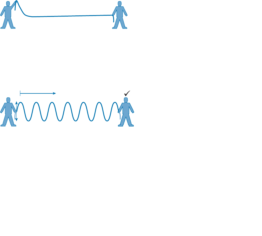
would appear at the other end. Figure 1-1 shows the end result; the rope falls back down
after a tiny distance, and the receiver never notices a change.
?
Sender Receiver
Figure 1-1 Failed Attempt to Pass a Message Down a Rope.
The sender tries a different strategy. He cannot push the rope, but when he begins to
wave it up and down in a steady, regular motion, a curious thing happens. A continuous
wave pattern appears along the entire length of the rope, as shown in Figure 1-2 . In fact,
the waves (each representing one up and down cycle of the sender’s arm) actually travel
from the sender to the receiver.
Sender Receiver
Figure 1-2 Sending a Continuous Wave Down a Rope.
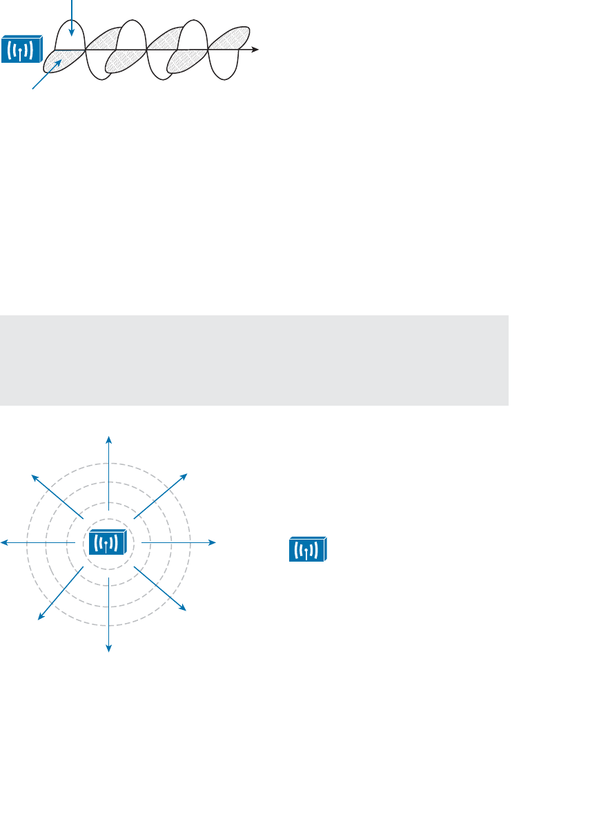
In free space, a similar principle occurs. The sender (a transmitter) can send an alternating
current into a section of wire (an antenna), which sets up moving electric and magnetic
fields that propagate out and away as traveling waves. The electric and magnetic fields
travel along together and are always at right angles to each other, as shown in Figure 1-3 .
The signal must keep changing, or alternating, by cycling up and down, to keep the elec-
tric and magnetic fields cycling and pushing ever outward.
ptg12542968
Chapter 1: RF Signals and Modulation 9
Electric Field
Magnetic Field
Figure 1-3 Traveling Electric and Magnetic Waves.
Electromagnetic waves do not travel in a straight line. Instead, they travel by expanding
in all directions away from the antenna. To get a visual image, think of dropping a peb-
ble into a pond when the surface is still. Where it drops in, the pebble sets the water’s
surface into a cyclic motion. The waves that result begin small and expand outward, only
to be replaced by new waves. In free space, the electromagnetic waves expand outward
in all three dimensions.
Figure 1-4 shows a simple idealistic antenna that is a single point at the end of a wire.
The waves produced expand outward in a spherical shape. The waves will eventually
reach the receiver, in addition to many other locations in other directions.
Tip The idealistic antenna does not really exist, but serves as a reference point to
understand wave propagation. In the real world, antennas can be made in various shapes
and forms that can limit the direction that the waves are sent. Chapter 4 , “Understanding
Antennas,” covers antennas in more detail.
Receiver
Sender
Figure 1-4 Wave Propagation with an Idealistic Antenna.
At the receiving end of a wireless link, the process is reversed. As the electromagnetic
waves reach the receiver’s antenna, they induce an electrical signal. If everything works
right, the received signal will be a reasonable copy of the original transmitted signal.
ptg12542968
10 CCNA Wireless 640-722 Official Cert Guide
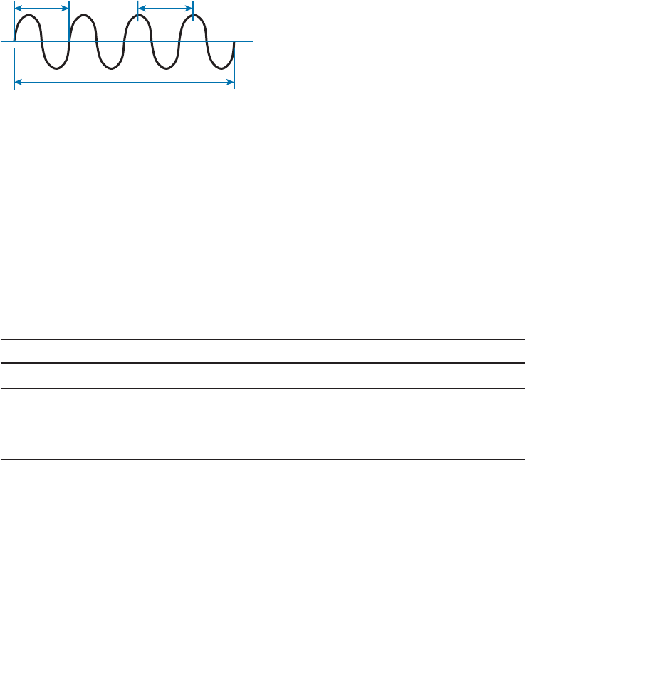
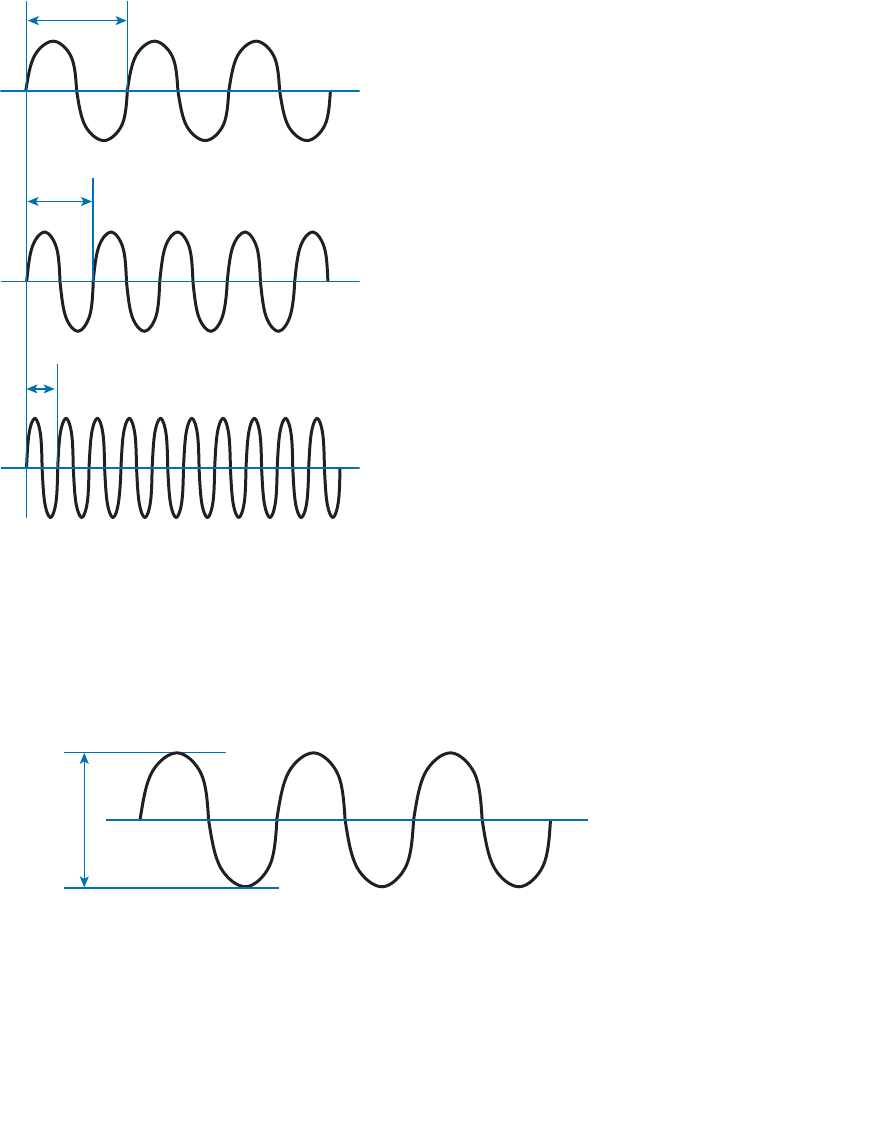
Understanding Frequency
The waves involved in a wireless link can be measured and described in several ways.
One fundamental property is the frequency of the wave, or the number of times the
signal makes one complete up and down cycle in 1 second. Figure 1-5 shows how a cycle
of a wave can be identified. A cycle can begin as the signal rises from the center line,
falls through the center line, and rises again to meet the center line. A cycle can also be
measured from the center of one peak to the center of the next peak. No matter where
you start measuring a cycle, the signal must make a complete sequence back to its start-
ing position where it is ready to repeat the same cyclic pattern again.
Cycle Cycle
1 Second
Frequency = 4 cycles/second
= 4 Hertz
Figure 1-5 Cycles Within a Wave.
In Figure 1-5 , suppose that 1 second has elapsed, as shown. During that 1 second, the
signal progressed through four complete cycles. Therefore, its frequency is 4 cycles/sec-
ond or 4 hertz. A hertz (Hz) is the most commonly used frequency unit and is nothing
other than one cycle per second.
Frequency can vary over a very wide range. As frequency increases by orders of mag-
nitude, the numbers can become quite large. To keep things simple, the frequency unit
name can be modified to denote an increasing number of zeros, as listed in Table 1-2 .
Table 1-2 Frequency Unit Names
Unit Abbreviation Meaning
Hertz Hz Cycles per second
Kilohertz kHz 1000 Hz
Megahertz MHz 1,000,000 Hz
Gigahertz GHz 1,000,000,000 Hz
Figure 1-6 shows a simple representation of the continuous frequency spectrum ranging
from 0 Hz to 10 22 (or 1 followed by 22 zeros) Hz. At the low end of the spectrum are
frequencies that are too low to be heard by the human ear, followed by audible sounds.
The highest range of frequencies contains light, followed by X, gamma, and cosmic rays.
ptg12542968
Chapter 1: RF Signals and Modulation 11
Frequency
(Hz)
Frequency
Notation
1022
1021
1020
1019
1018
1017
1016
1015
1014
1013
1012 100 GHz
1010 10 GHz
1091 GHz
108100 MHz
10710 MHz
1061 MHz
105100 kHz
10410 kHz
1031 kHz
102100 Hz
10110 Hz
00 Hz Subsonic
Sound
AM Radio
Shortwave Radio
Television and FM Radio
Microwave and Radar
Infrared Light
Visible Light
Ultraviolet Light
X-Rays
Gamma Rays
Cosmic Rays
5 GHz Wireless
2.4 GHz Wireless
Low Frequency Radio Radio Frequencies (RF)
Figure 1-6 Continuous Frequency Spectrum.
The frequency range from around 3 kHz to 300 GHz is commonly called radio fre-
quency (RF). It includes many different types of radio communication, including low-
frequency radio, AM radio, shortwave radio, television, FM radio, microwave, and radar.
The microwave category also contains the two frequency ranges that are used for wire-
less LAN communication: 2.4 and 5 GHz.
Because a range of frequencies might be used for the same purpose, it is customary to
refer to the range as a band of frequencies. For example, the range from 530 kHz to
around 1710 kHz is used by AM radio stations; therefore it is commonly called the AM
band or the AM broadcast band.
One of the two frequency ranges used for wireless LAN communication lies between
2.400 and 2.4835 GHz. This is usually called the 2.4-GHz band , even though it does not
encompass the entire range between 2.4 and 2.5 GHz. It is much more convenient to
refer to the band name instead of the specific range of frequencies included.
The other wireless LAN range is usually called the 5-GHz band because it lies between
5.150 and 5.825 GHz. The 5-GHz band actually contains the following four separate and
distinct bands:
5.150 to 5.250 GHz
5.250 to 5.350 GHz

ptg12542968
12 CCNA Wireless 640-722 Official Cert Guide
5.470 to 5.725 GHz
5.725 to 5.825 GHz
Tip You might have noticed that most of the 5-GHz bands are contiguous except for
a gap between 5.350 and 5.470. At the time of this writing, this gap exists and cannot be
used for wireless LANs (although it might become a useful band at some point.)
It is interesting that the 5-GHz band can contain several smaller bands. Remember that
the term band is simply a relative term that is used for convenience. At this point, do not
worry about memorizing the band names or exact frequency ranges; Chapter 2 covers
this in more detail.
A frequency band contains a continuous range of frequencies. If two devices require
a single frequency for a wireless link between them, which frequency can they use?
Beyond that, how many unique frequencies can be used within a band?
To keep everything orderly and compatible, bands are usually divided up into a number
of distinct channels . Each channel is known by a channel number and is assigned to a
specific frequency. As long as the channels are defined by a national or international
standards body, they can be used consistently in all locations.
For example, Figure 1-7 shows the channel assignment for the 2.4-GHz band that is used
for wireless LAN communication. The band contains 14 channels numbered 1 through
14, each assigned a specific frequency. First, notice how much easier it is to refer to
channel numbers than the frequencies. Second, notice that the channels are spaced at
regular intervals that are 0.005 GHz (or 5 MHz) apart. The channel spacing is known as
the channel separation or channel width.
2.412 2.417 2.422 2.427 2.432 2.437 2.442 2.447 2.452 2.457 2.462 2.467 2.472 2.484
12345678910111213 14Channel
GHz
Figure 1-7 An Example of Channel Spacing in the 2.4-GHz Band.
If devices use a specific frequency for a wireless link, why do the channels need to be
spaced apart at all? The reason lies with the practical limitations of RF signals, the elec-
tronics involved in transmitting and receiving the signals, and the overhead needed to
add data to the signal effectively.
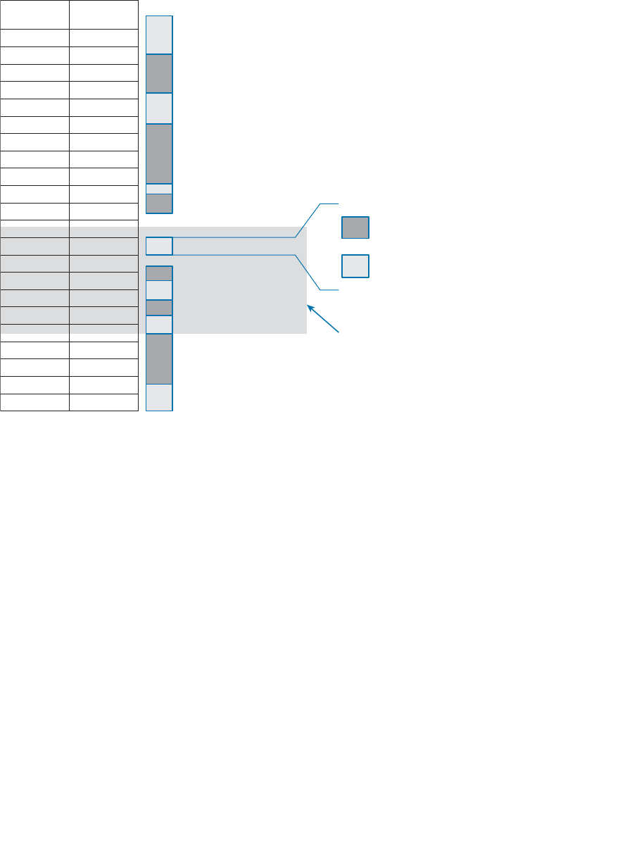
In practice, an RF signal is not infinitely narrow; instead, it spills above and below a cen-
ter frequency to some extent, occupying neighboring frequencies, too. It is the center
frequency that defines the channel location within the band. The actual frequency range
needed for the transmitted signal is known as the signal bandwidth , as shown in Figure
1-8 . As its name implies, bandwidth refers to the width of frequency space required
within the band. For example, a signal with a 22-MHz bandwidth is bounded at 11 MHz
above and below the center frequency. In wireless LANs, the signal bandwidth is defined
as part of a standard. Even though the signal might extend farther above and below the
ptg12542968
Chapter 1: RF Signals and Modulation 13
center frequency than the bandwidth allows, wireless devices will use something called a
spectral mask to ignore parts of the signal that fall outside the bandwidth boundaries.
Ideally, the signal bandwidth should be less than the channel width so that a different
signal could be transmitted on every possible channel with no chance that two signals
could overlap and interfere with each other.
Center Frequency
Bandwidth
Figure 1-8 Signal Bandwidth.
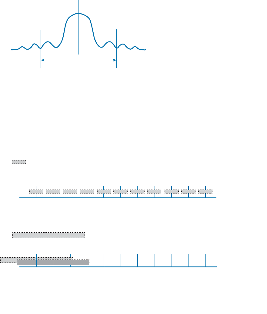
You should not assume that signals centered on the standardized channel assignments
will not overlap with each other. The upper portion of Figure 1-9 shows most of the 2.4-
GHz band, along with a signal bandwidth that is narrower than the channel spacing. A
signal can exist on every possible channel without overlapping with others. The bottom
portion of the figure shows the real world signal bandwidth, which is slightly wider than
four channels! Signals centered on adjacent channels cannot possibly coexist without
overlapping and interfering. Instead, the signals must be placed on more distant chan-
nels to prevent overlapping, thus limiting the number of channels that can be used in the
band.
2.412 2.417 2.422 2.427 2.432 2.437 2.442 2.447 2.452 2.457 2.462
1234567 891011
Channel
GHz
Signal Bandwidth Required
for Non-Overlapping Channels
2.412 2.417 2.422 2.427 2.432 2.437 2.442 2.447 2.452 2.457 2.462
1234567891011Channel
GHz
Actual Signal Bandwidth
Figure 1-9 Examples of Channel Spacing and Overlap.
ptg12542968
14 CCNA Wireless 640-722 Official Cert Guide
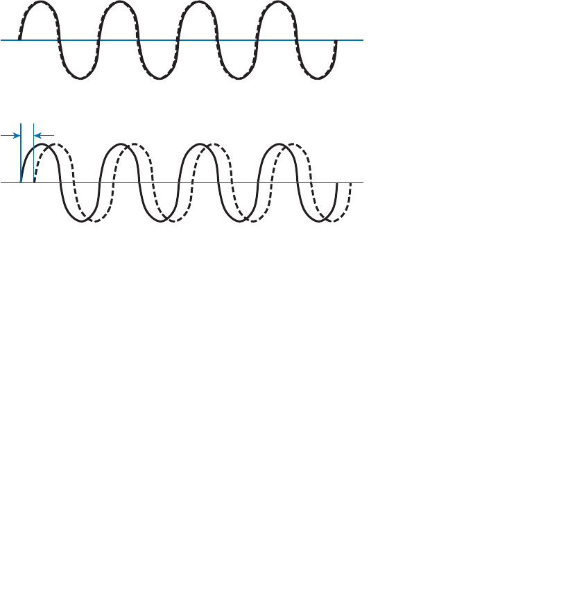
Understanding Phase
RF signals are very dependent upon timing because they are always in motion. By their
very nature, the signals are made up of electric and magnetic forces that vary over
time. The phase of a signal is a measure of shift in time relative to the start of a cycle.
Phase is normally measured in degrees, where 0 degrees is at the start of a cycle, and
one complete cycle equals 360 degrees. A point that is halfway along the cycle is at the
180-degree mark. Because an oscillating signal is cyclic, you can think of the phase trav-
eling around a circle again and again.
When two identical signals are produced at exactly the same time, their cycles match
up and they are said to be in phase with each other. If one signal is delayed from the
other, the two signals are said to be out of phase . Figure 1-10 shows examples of both
scenarios.
Phase Shift
Out of Phase
In Phase
Figure 1-10 Signals In and Out of Phase.
Phase becomes important as RF signals are received. Signals that are in phase tend to add
together, whereas signals that are 180 degrees out of phase tend to cancel each other
out. Chapter 3 , “RF Signals in the Real World,” explores signal phase in greater detail.
Measuring Wavelength
RF signals are usually described by their frequency; however, it is difficult to get a feel
for their physical size as they move through free space. The wavelength is a measure of
the physical distance that a wave travels over one complete cycle. Wavelength is usually
designated by the Greek symbol lambda (λ). To get a feel for the dimensions of a wire-
less LAN signal, assuming you could see it as it travels in front of you, a 2.4-GHz signal
would have a wavelength of 4.92 inches, while a 5-GHz signal would be 2.36 inches.
Figure 1-11 shows the wavelength of three different waves. The waves are arranged in
order of increasing frequency, from top to bottom. Regardless of the frequency, RF
waves travel at a constant speed. In a vacuum, radio waves travel at exactly the speed
of light; in air, the velocity is slightly less than the speed of light. Notice that the wave-
ptg12542968
Chapter 1: RF Signals and Modulation 15
length decreases as the frequency increases. As the wave cycles get smaller, they cover
less distance. Wavelength becomes useful in the design and placement of antennas.
λ
λ
λ
λ = Wavelength
Figure 1-11 Examples of Increasing Frequency and Decreasing Wavelength.
Understanding RF Power and dB
For an RF signal to be transmitted, propagated through free space, received, and under-
stood with any certainty, it must be sent with enough strength or energy to make the
journey. This strength can be measured as the amplitude , or the height from the top
peak to the bottom peak of the signal’s waveform, as shown in Figure 1-12 .
Amplitude
Figure 1-12 Signal Amplitude.
The strength of an RF signal is usually measured by its power, in watts (W). For example,
a typical AM radio station broadcasts at a power of 50,000 W; an FM radio station
might use 16,000 W. In comparison, a wireless LAN transmitter usually has a signal
strength between 0.1 W (100 mW) and 0.001 W (1 mW).
ptg12542968
16 CCNA Wireless 640-722 Official Cert Guide
When power is measured in watts or milliwatts, it is considered to be an absolute power
measurement. In other words, something has to measure exactly how much energy is
present in the RF signal. This is fairly straightforward when the measurement is taken at
the output of a transmitter because the transmit power level is usually known ahead of
time.
Sometimes you might need to compare the power level between two different transmit-
ters. For example, suppose that device T1 is transmitting at 1 mW, while T2 is transmit-
ting at 10 mW, as shown in Figure 1-13 . Simple subtraction tells you that T2 is 9 mW
stronger than T1. You might also notice that T2 is 10 times stronger than T1.
T1
1 mW
T2
10 mW
T3
100 mW
T2 – T1 = 9 mW
T2/T1 = 10
T2 – T1 = 90 mW
T2/T1 = 10
Figure 1-13 Comparing Power Levels Between Transmitters.
Now compare transmitters T2 and T3, which use 10 mW and 100 mW, respectively.
Using subtraction, T2 and T3 differ by 90 mW, but T3 is again 10 times stronger than
T2. In each instance, subtraction yields a different result than division. Which method
should you use?
Quantities like absolute power values can differ by orders of magnitude. A more sur-
prising example is shown in Figure 1-14 , where T4 is 0.00001 mW and T5 is 10 mW.
Subtracting the two values gives their difference as 9.99999 mW. However, T5 is
1,000,000 times stronger than T4!
T4
0.00001 mW
T5
10 mW
T5 – T4 = 9.99999 mW
T5/T4 = 1,000,000
Figure 1-14 Comparing Power Levels That Differ By Orders of Magnitude.
Because absolute power values can fall anywhere within a huge range, from a tiny deci-
mal number to hundreds, thousands, or greater values, we need a way to transform the
exponential range into a linear one. The logarithm function can be leveraged to do just
that. In a nutshell, a logarithm takes values that are orders of magnitude apart (0.001,
0.01, 0.1, 1, 10, 100, and 1000, for example) and spaces them evenly within a reasonable
range.

ptg12542968
Chapter 1: RF Signals and Modulation 17
Tip The base-10 logarithm function, denoted by log 10 , computes how many times 10
can be multiplied by itself to equal a number. For example, log 10 (10) equals 1 because
10 multiplied by itself exactly once equals 10. The log 10 (100) equals 2 because 10 × 10,
or 10 multiplied by itself twice, equals 100. Computing other log 10 values is difficult,
requiring the use of a calculator. The good news is that you will not need a calculator or a
logarithm on the CCNA Wireless exam. Even so, try to suffer through the few equations
in this chapter so that you get a better understanding power comparisons and measure-
ments.
The decibel (dB) is a handy function that uses logarithms to compare one absolute mea-
surement to another. It was originally developed to compare sound intensity levels, but
it applies directly to power levels, too. After each power value has been converted to the
same logarithmic scale, the two values can be subtracted to find the difference. The fol-
lowing equation is used to calculate a dB value, where P1 and P2 are the absolute power
levels of two sources:
dB = 10(log10P2–log10P1)
P2 represents the source of interest, and P1 is usually called the reference value or the
source of comparison.
The difference between the two logarithmic functions can be rewritten as a single loga-
rithm of P2 divided by P1, as follows:
dB = 10 · log10
P2
P1
Here, the ratio of the two absolute power values is computed first; then the result is
converted onto a logarithmic scale.
Oddly enough, we end up with the same two methods to compare power levels with dB:
a subtraction and a division. Thanks to the logarithm, both methods arrive at identical dB
values. Be aware that the ratio or division form of the equation is the most commonly
used in the wireless engineering world.
Important dB Facts to Remember
There are three cases where you can use mental math to make power-level comparisons
using dB. You should memorize the following three facts; you will be tested on them
in the CCNA Wireless exam. All other dB cases require a calculator, so you will not be
tested on those:
■ Fact 1 —A value of 0 dB means that the two absolute power values are equal.
If the two power values are equal, the ratio inside the logarithm is 1, and the log10(1) is
0. This fact is intuitive; if two power levels are the same, one is 0 dB more than the
other.
■ Fact 2 —A value of 3 dB means that the power value of interest is double the refer-
ence value; a value of –3 dB means the power value of interest is half the reference.
Key
Topic
Key
Topic
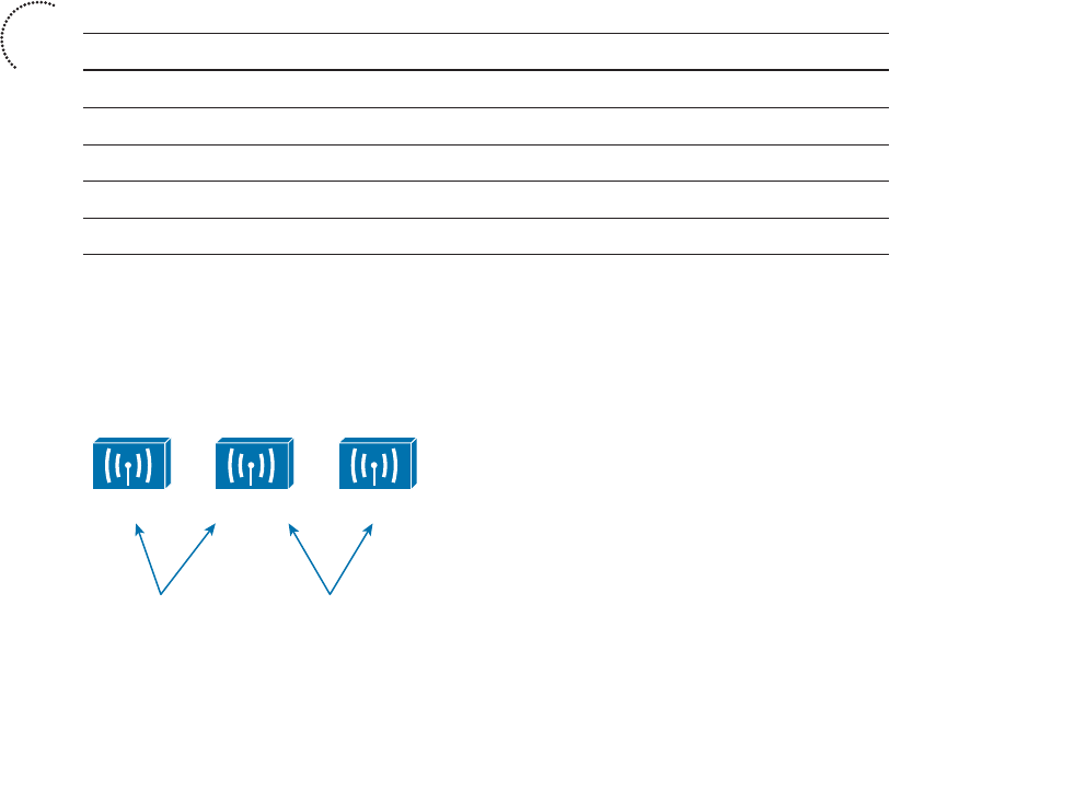
ptg12542968
18 CCNA Wireless 640-722 Official Cert Guide
When P2 is twice P1, the ratio is always 2. Therefore, 10log 10 (2) = 3 dB.
When the ratio is 1/2, 10log 10 (1/2) = –3 dB.
The 3 dB fact is not very intuitive, but is still easy to learn. Whenever a power level dou-
bles, it increases by 3 dB. Whenever it is cut in half, it decreases by –3 dB.
■ Fact 3 —A value of 10 dB means that the power value of interest is 10 times the
reference value; a value of –10 dB means the power value of interest is 1/10 of the
reference.
When P2 is 10 times P1, the ratio is always 10. Therefore, 10log 10 (10) = 10 dB.
When P2 is one tenth of P1, then the ratio is 1/10 and 10log 10 (1/10) = –10 dB.
The 10 dB fact is intuitive because multiplying or dividing by 10 adds or subtracts 10 dB,
respectively.
Notice another handy rule of thumb: When absolute power values multiply, the dB value
is positive and can be added. When the power values divide, the dB value is negative and
can be subtracted. Table 1-3 summarizes the useful dB comparisons.
Table 1-3 Power Changes and Their Corresponding dB Values
Power Change dB Value
= 0 dB
× 2 +3 dB
/ 2 –3 dB
× 10 +10 dB
/ 10 –10 dB
Try a few example problems to see whether you understand how to compare two power
values using dB. In Figure 1-15 , sources A, B, and C transmit at 4, 8, and 16 mW, respec-
tively. Source B is double the value of A, so it must be 3 dB greater than A. Likewise,
source C is double the value of B, so it must be 3 dB greater than B.
A
4 mW
B
8 mW
In mW: B is 2 x A
In dB: B = A + 3 dB
C
16 mW
In mW: C is 2 x B
In dB: C = B + 3 dB
Figure 1-15 Comparing Power Levels Using dB.
Key
Topic
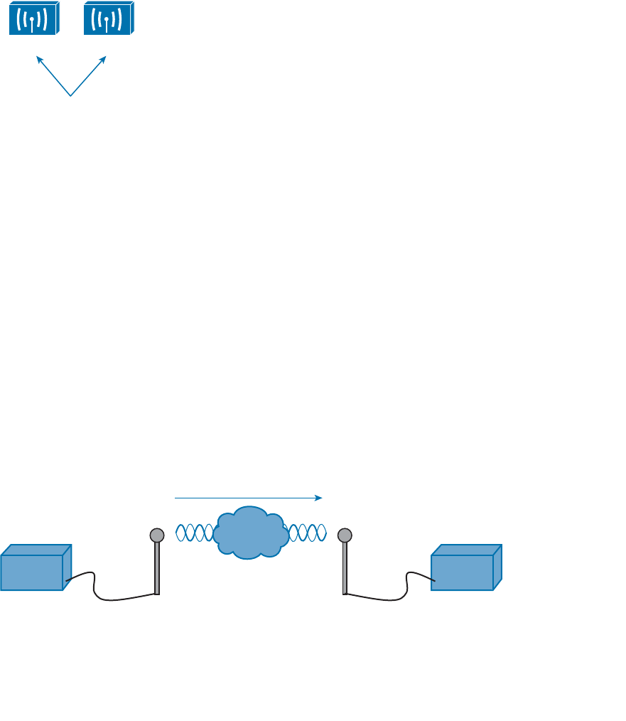
ptg12542968
Chapter 1: RF Signals and Modulation 19
You can also compare sources A and C. To get from A to C, you have to double A, and
then double it again. Each time you double a value, just add 3 dB. Therefore, C is 3 dB +
3 dB = 6 dB greater than A.
Next, try the more complicated example shown in Figure 1-16 . Keep in mind that dB
values can be added and subtracted in succession (in case several multiplication and divi-
sion operations involving 2 and 10 are needed).
D
5 mW
E
200 mW
In mW: E = D x 2 x 2 x 10
in dB: E = D + 3 + 3 + 10 dB
E = D + 16 dB
Figure 1-16 An Example of Computing dB with Simple Rules.
Sources D and E have power levels 5 and 200 mW. Try to figure out a way to go from 5
to 200 using only ×2 or ×10 operations. You can double 5 to get 10, then double 10 to
get 20, and then multiply by 10 to reach 200 mW. Next, use the dB facts to replace the
doubling and ×10 with the dB equivalents. The result is E = D + 3 + 3 + 10 or E = D + 16
dB.
Comparing Power Against a Reference: dBm
Beyond comparing two transmitting sources, a wireless LAN engineer must be concerned
about the RF signal propagating from a transmitter to a receiver. After all, transmitting a
signal is meaningless unless someone is there to receive it and make use of it.
Figure 1-17 shows a simple scenario with a transmitter and a receiver. Nothing in the
real world is ideal, so assume that something along the path of the signal will induce a
net loss. At the receiver, the signal strength will be degraded by some amount. Suppose
that you are able to measure the power level leaving the transmitter, which is 100 mW.
At the receiver, you measure the power level of the arriving signal. It is an incredibly low
0.000031623 mW.
Net Loss
Transmitter
Tx
Receiver
Rx
100 mW 0.000031623 mW
Figure 1-17 An Example of RF Signal Power Loss.
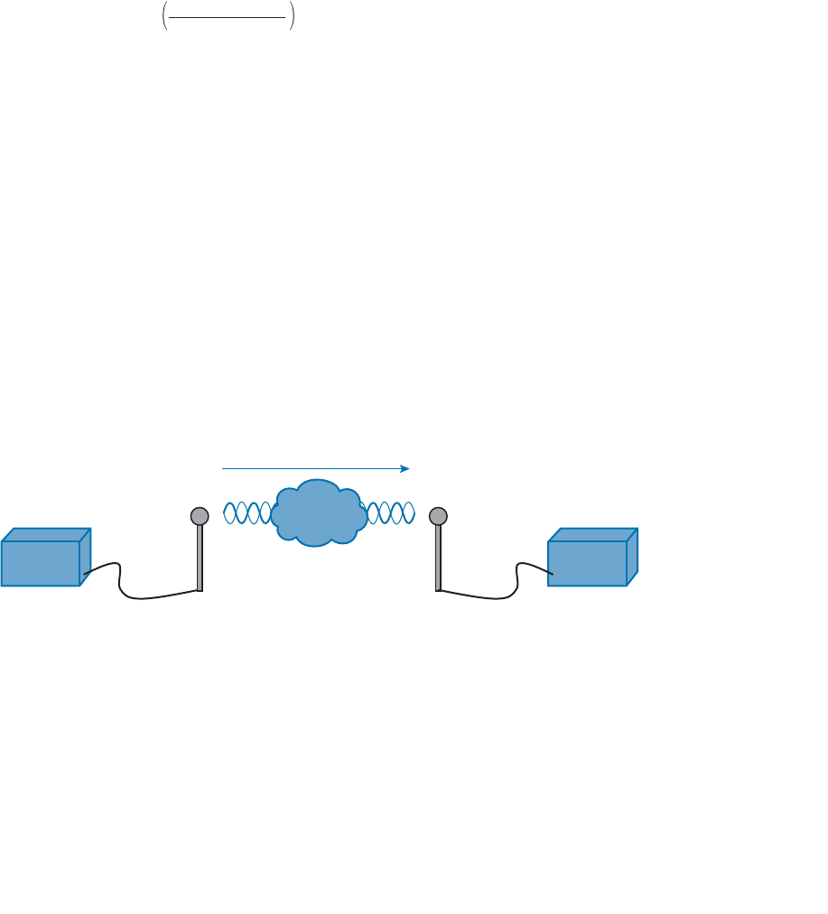
ptg12542968
20 CCNA Wireless 640-722 Official Cert Guide
Wouldn’t it be nice to quantify the net loss over the signal’s path? After all, you might
want to try several other transmit power levels or change something about the path
between the transmitter and receiver. To design the signal path properly, you would like
to make sure that the signal strength arriving at the receiver is at an optimum level.
You could leverage the handy dB formula to compare the received signal strength to the
transmitted signal strength, as long as you can remember the formula and have a calcula-
tor nearby:
dB = 10 · log10 =–65 d
B
0.000031623 mW
100 mW
The net loss over the signal path turns out to be a decrease of 65 dB. Knowing that, you
decide to try a different transmit power level to see what would happen at the receiver.
It does not seem very straightforward to use the new transmit power to find the new
signal strength at the receiver. That might require more formulas and more time at the
calculator.
A better approach is to compare each absolute power along the signal path to one com-
mon reference value. Then, regardless of the absolute power values, you could just focus
on the changes to the power values that are occurring at various stages along the signal
path. In other words, convert every power level to a dB value and simply add them up
along the path.
Recall that the dB formula puts the power level of interest on the top of the ratio, with a
reference power level on the bottom. In wireless networks, the reference power level is
usually 1 mW, so the units are designated by dBm (dB-milliwatt).
Returning to the scenario from Figure 1-17 , the absolute power values at the transmitter
and receiver can be converted to dBm, the results from which are shown in Figure 1-18 .
Notice that the dBm values can be added along the path: The transmitter dBm plus the
net loss in dB equals the received signal in dBm.
Transmitter
Tx Level
100 mW
Receiver
Rx Level
0.000031623 mW
20 dBm
65 dB
20 dBm – 65 dB = –45 dBm
–45 dBm
Net Loss
Figure 1-18 Subtracting dB to Represent a Loss in Signal Strength.
Measuring Power Changes Along the Signal Path
Up to this point, this chapter has considered a transmitter and its antenna to be a single
unit. That might seem like a logical assumption because many wireless access points have
built-in antennas. In reality, a transmitter, its antenna, and the cable that connects them
are all discrete components that not only propagate an RF signal but also affect its abso-
lute power level.
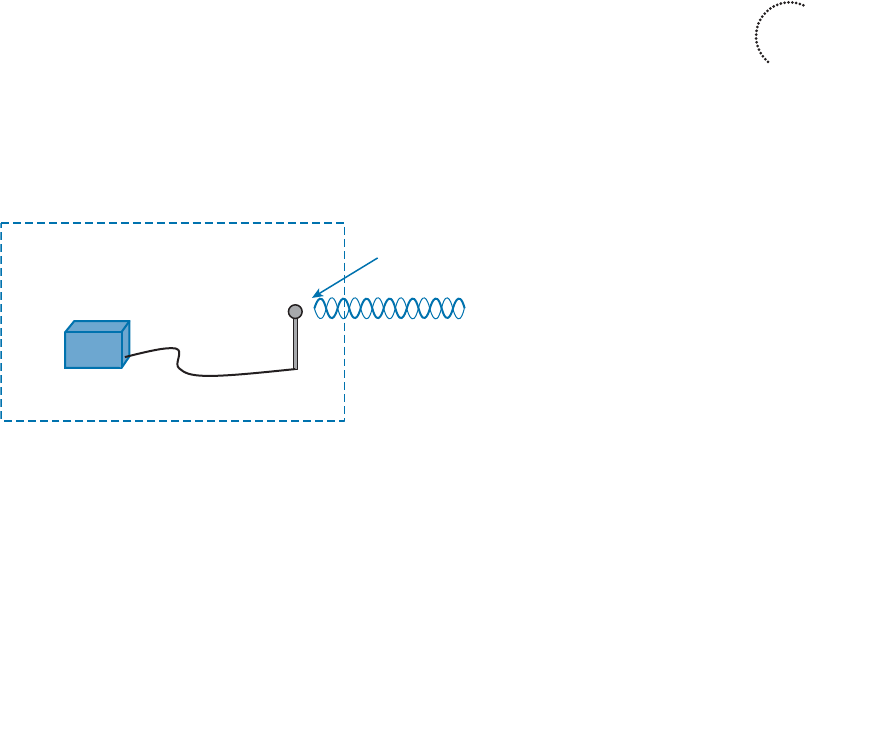
ptg12542968
Chapter 1: RF Signals and Modulation 21
When an antenna is connected to a transmitter, it provides some amount of gain to the
resulting RF signal. This effectively increases the dB value of the signal above that of the
transmitter alone. Chapter 4 explains this in greater detail; for now, just be aware that
antennas provide positive gain.
By itself, an antenna does not generate any amount of absolute power. In other words,
when an antenna is disconnected, no milliwatts of power are being pushed out of it. That
makes it impossible to measure the antenna’s gain in dBm. Instead, an antenna’s gain is
measured by comparing its performance with that of a reference antenna, then comput-
ing a value in dB.
Usually, the reference antenna is an isotropic antenna , so the gain is measured in dBi
(dB-isotropic). An isotropic antenna does not actually exist, because it is ideal in every
way. Its size is a tiny point, and it radiates RF equally in every direction. No physical
antenna can do that. The isotropic antenna’s performance can be calculated according to
RF formulas, making it a universal reference for any antenna.
Because the physical qualities of the cable that connects an antenna to a transmitter,
some signal loss always occurs. Cable vendors supply the loss in dB per foot or meter of
cable length for each type of cable manufactured.
Once you know the complete combination of transmitter power level, the length of
cable, and the antenna gain, you can figure out the actual power level that will be radi-
ated from the antenna. This is known as the effective isotropic radiated power (EIRP),
measured in dBm.
EIRP is a very important parameter because it is regulated by governmental agencies in
most countries. In those cases, a system cannot radiate signals higher than a maximum
allowable EIRP. To find the EIRP of a system, simply add the transmitter power level to
the antenna gain and subtract the cable loss, as illustrated in Figure 1-19 .
Transmitter
Tx
Tx Antenna
(Gain)
Tx Cable
(Loss)
EIRP = Tx Power – Tx Cable + Tx Antenna
EIRP
Figure 1-19 Calculating EIRP.
Suppose a transmitter is configured for a power level of 10 dBm (10 mW). A cable with
5-dB loss connects the transmitter to an antenna with an 8-dBi gain. The resulting EIRP
of the system is 10 dBm – 5 dB + 8 dBi, or 13 dBm.
You might notice that the EIRP is made up of decibel-milliwatt (dBm), dB relative to an
isotropic antenna (dBi), and decibel (dB) values. Even though the units appear to be dif-
Key
Topic
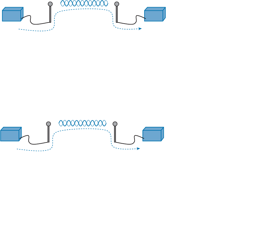
ptg12542968
22 CCNA Wireless 640-722 Official Cert Guide
ferent, you can safely combine them because they are all in the dB “domain.” The only
exception to this is when an antenna’s gain is measured in dBd (dB-dipole). In that case, a
dipole antenna has been used as the reference antenna, rather than an isotropic antenna.
A dipole is a simple actual antenna, which has a gain of 2.14 dBi. If an antenna has its
gain shown as dBi, you can add 2.14 dBi to that value to get its gain in dBi units instead.
Power-level considerations do not have to stop with the EIRP. You should also be con-
cerned with the complete path of a signal, to make sure that the transmitted signal has
sufficient power so that it can effectively reach and be understood by a receiver. This is
known as the link budget.
The dB values of gains and losses can be combined over any number of stages along a
signal’s path. Consider Figure 1-20 , which shows every component of signal gain or loss
along the path from transmitter to receiver.
Rx Signal = Tx Power – Tx Cable + Tx Antenna – Free Space + Rx Antenna – Rx Cable
Transmitter
Tx
Receiver
Rx
Free Space
(Loss)
Tx Antenna
(Gain)
Tx Cable
(Loss)
Rx Cable
(Loss)
Rx Antenna
(Gain)
Figure 1-20 Calculating Received Signal Strength Over the Path of an RF Signal.
At the receiving end, an antenna provides gain to increase the received signal power
level. A cable connecting the antenna to the receiver also introduces some loss.
Figure 1-21 shows some example dB values, as well as the resulting sum of the compo-
nent parts across the entire signal path. The signal begins at 20 dBm at the transmitter,
has an EIRP value of 22 dBm at the transmitting antenna (20 dBm – 2 dB + 4 dBi), and
arrives at the receiver with a level of –45 dBm.
Rx Signal = 20 dBm – 2 dB + 4 dBi – 69 dB + 4 dBi – 2 dB = – 45 dBm
Transmitter
Tx
Receiver
Rx
–45 dBm100 mW = 20 dBm
69 dB
(Loss)
4 dBi
(Gain)
2 dB
(Loss)
2 dB
(Loss)
4 dBi
(Gain)
Figure 1-21 An Example of Calculating Received Signal Strength.
If you always begin with the transmitter power expressed in dBm, it is a simple matter to
add or subtract the dB components along the signal path to find the signal strength that
arrives at the receiver.
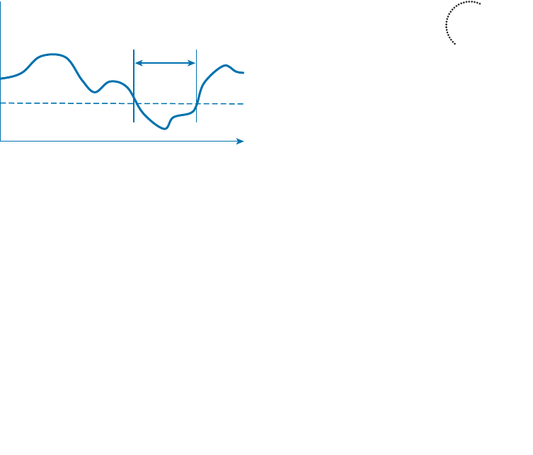
ptg12542968
Chapter 1: RF Signals and Modulation 23
Understanding Power Levels at the Receiver
At the receiving end of the signal path, a receiver expects to find a signal on a predeter-
mined frequency, with enough power to contain useful data. Receivers measure a signal’s
power in dBm according to the received signal strength indicator (RSSI) scale.
When you work with wireless LAN devices, the EIRP levels leaving the transmitter’s
antenna normally range from 100 mW down to 1 mW. This corresponds to the range
+20 dBm down to 0 dBm. At the receiver, the power levels are much, much less, ranging
from 1 mW all the way down to tiny fractions of a milliwatt, approaching 0 mW. The
corresponding range of received signal levels is from 0 dBm down to –100 dBm or less.
Therefore, the RSSI of a received signal can range from 0 to –100, where 0 is the stron-
gest and –100 is the weakest. The range of RSSI values can vary between one hardware
manufacturer and another. RSSI values are supposed to represent dBm values, but the
results are not standardized across all receiver manufacturers. An RSSI value can vary
from one receiver hardware to another.
Assuming a transmitter is sending an RF signal with enough power to reach a receiver,
what RSSI value is good enough? Every receiver has a sensitivity level or a threshold
that divides intelligible, useful signals from unintelligible ones. As long as a signal is
received with a power level that is greater than the sensitivity level, chances are that the
data from the signal can be understood correctly. Figure 1-22 shows an example of how
the signal strength at a receiver might change over time. The receiver’s sensitivity level is
–82 dBm.
0 dBm
–100 dBm
Sensitivity Level
–82 dBm
Unintelligible
RSSI
Time
Figure 1-22 An Example of Receiver Sensitivity Level.
The RSSI value focuses on the expected signal alone, without regard to any other signals
that may be received, too. All other signals that are received on the same frequency as
the one you are trying to receive are simply viewed as noise . The noise level, or the aver-
age signal strength of the noise, is called the noise floor .
It is easy to ignore noise as long as the noise floor is well below what you are trying to
hear. For example, two people can whisper in a library effectively because there is very
little competing noise. Those same two people would become very frustrated if they
tried to whisper to each other in a crowded sports arena.
Key
Topic

ptg12542968
24 CCNA Wireless 640-722 Official Cert Guide
Receiving an RF signal is no different; its signal strength must be greater than the noise
floor by a decent amount so that it can be received and understood correctly. The dif-
ference between the signal and the noise is called the signal-to-noise ratio (SNR), mea-
sured in dB . A higher SNR value is preferred.
Figure 1-23 shows the RSSI of a signal compared with the noise floor that is received.
The RSSI averages around –54 dBm. On the left side of the graph, the noise floor is –90
dBm. The resulting SNR is –54 dBm – (–90) dBm or 36 dB. Toward the right side of the
graph, the noise floor gradually increases to –65 dBm, reducing the SNR to 11 dB. The
signal is so close to the noise that it probably will not be usable.
0 dBm
–100 dBm
Noise Floor
–90 dBm
RSSI
RSSI
Signal to Noise Ratio
(SNR)
–54 dBm
Time
–65 dBm
Figure 1-23 An Example of a Changing Noise Floor and SNR.
Carrying Data Over an RF Signal
Up to this point in the chapter, only the RF characteristics of wireless signals have been
discussed. The RF signals presented have existed only as simple oscillations in the form
of a sine wave. The frequency, amplitude, and phase have all been constant. The steady,
predictable frequency is important because a receiver needs to tune to a known frequen-
cy to find the signal in the first place.
This basic RF signal is called a carrier signal because it is used to carry other useful
information. With AM and FM radio signals, the carrier signal also transports audio sig-
nals. TV carrier signals have to carry both audio and video. Wireless LAN carrier signals
must carry data.
To add data onto the RF signal, the frequency of the original carrier signal must be pre-
served. Therefore, there must be some scheme of altering some characteristic of the car-
rier signal to distinguish a 0 bit from a 1 bit. Whatever scheme is used by the transmitter
must also be used by the receiver so that the data bits can be correctly interpreted.
Figure 1-24 shows a carrier signal with a constant frequency. The data bits 1001 are to be
sent over the carrier signal, but how? One idea might be to simply use the value of each
data bit to turn the carrier signal off or on. The Bad Idea 1 plot shows the resulting RF
signal. A receiver might be able to notice when the signal is present and has an amplitude
and correctly interpret 1 bits, but there is no signal to receive during 0 bits. If the signal
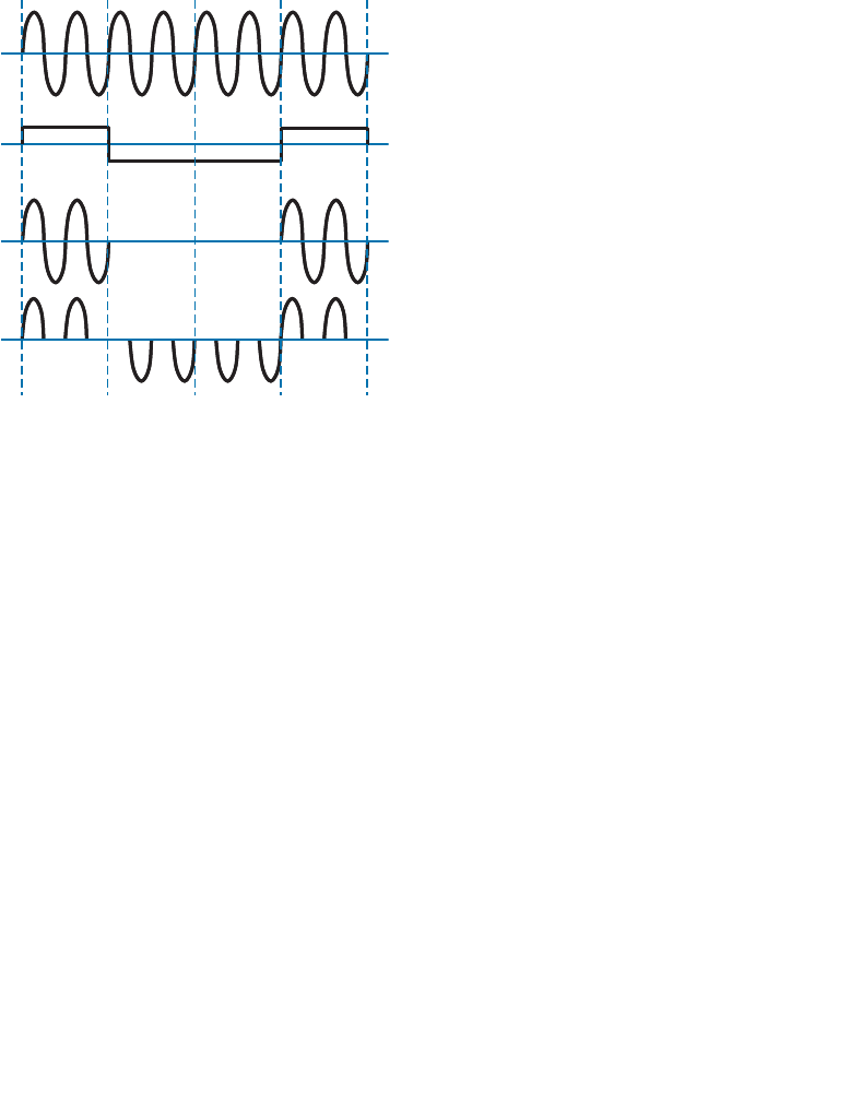
ptg12542968
Chapter 1: RF Signals and Modulation 25
becomes weak or is not available for some reason, the receiver will incorrectly think that
a long string of 0 bits have been transmitted. A different twist might be to transmit only
the upper half of the carrier signal during a 1 bit and the lower half during a 0 bit, as
shown in the Bad Idea 2 plot. This time, a portion of the signal is always available for the
receiver, but the signal becomes impractical to receive because important pieces of each
cycle are missing. In addition, it is very difficult to transmit RF with disjointed alternat-
ing cycles.
Carrier Signal
Data Stream 11
00
Bad Idea 1
Bad Idea 2
Figure 1-24 Poor Attempts at Sending Data Over an RF Signal.
Such naive approaches might not be successful, but they do have the right idea: to alter
the carrier signal in a way that indicates the information to be carried. This is known as
modulation , where the carrier signal is modulated or changed according to some other
source. At the receiver, the process is reversed; demodulation interprets the added infor-
mation based on changes in the carrier signal.
RF modulation schemes generally have the following goals:
■ Carry data at a predefined rate
■ Be reasonably immune to interference and noise
■ Be practical to transmit and receive
Due to the physical properties of an RF signal, a modulation scheme can alter only the
following attributes:
■ Frequency, but only by varying slightly above or below the carrier frequency
■ Phase
■ Amplitude
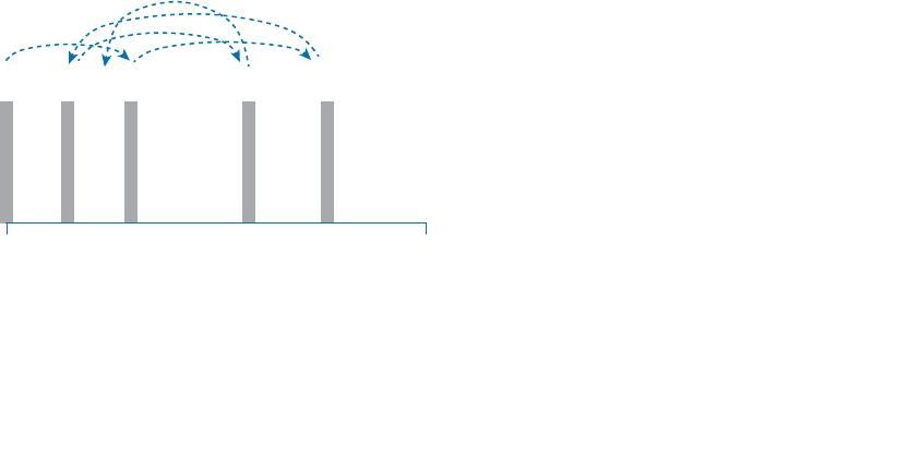
ptg12542968
26 CCNA Wireless 640-722 Official Cert Guide
The modulation techniques require some amount of bandwidth centered on the carrier
frequency. This additional bandwidth is partly due to the rate of the data being carried
and partly due to the overhead from encoding the data and manipulating the carrier
signal. If the data has a relatively low bit rate, such as an audio signal carried over AM
or FM radio, the modulation can be straightforward and requires little extra bandwidth.
Such signals are called narrowband transmissions.
In contrast, wireless LANs must carry data at high bit rates, requiring more bandwidth
for modulation. The end result is that the data being sent is spread out across a range
of frequencies. This is known as spread spectrum . At the physical layer, wireless LANs
can be broken down into the following three spread-spectrum categories, which are dis-
cussed in subsequent sections:
■ Frequency-hopping spread spectrum (FHSS)
■ Direct-sequence spread spectrum (DSSS)
■ Orthogonal frequency-division multiplexing (OFDM)
FHSS
Early wireless LAN technology took a novel approach as a compromise between avoid-
ing RF interference and needing complex modulation. The wireless band was divided
into 79 channels or fewer, with each channel being 1 MHz wide. To avoid narrowband
interference, where an interfering signal would affect only a few channels at a time,
transmissions would need to continuously “hop” between frequencies all across the
band. This is known as frequency-hopping spread spectrum .
Figure 1-25 shows an example of how the FHSS technique works, where the sequence
begins on channel 2, then moves to channels 25, 64, 10, 45, and so on, through an entire
predetermined sequence before repeating again. Hopping between channels has to occur
at regular intervals so that the transmitter and receiver can stay synchronized. In addi-
tion, the hopping order must be worked out in advance so that the receiver can always
tune to the correct frequency in use at any given time.
2.402 GHz
Channel 2
2.480 GHz
Channel 80
21025 45 64Channel
Figure 1-25 An Example FHSS Channel-Hopping Sequence.
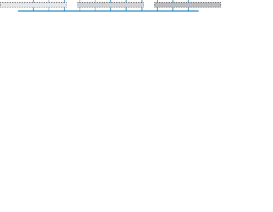
ptg12542968
Chapter 1: RF Signals and Modulation 27
Whatever advantage FHSS gained avoiding interference was lost because of the follow-
ing limitations:
■ Narrow 1-MHz channel bandwidth, limiting the data rate to 1 or 2 Mbps.
■ Multiple transmitters in an area could eventually collide and interfere with each
other on the same channels.
As a result, FHSS fell out of favor and was replaced by another, more robust and scal-
able spread-spectrum approach: DSSS. Even though FHSS is rarely used now, you should
be familiar with it and its place in the evolution of wireless LAN technologies.
DSSS
Direct-sequence spread spectrum uses a small number of fixed, wide channels that can
support complex modulation schemes and somewhat scalable data rates. Each channel
is 22 MHz wide—a much wider bandwidth compared with the maximum supported
11-Mbps data rate, but wide enough to augment the data by spreading it out and mak-
ing it more resilient to disruption. In the 2.4-GHz band where DSSS is used, there are 14
possible channels, but only 3 of them that do not overlap. Figure 1-26 shows how chan-
nels 1, 6, and 11 are normally used.
2.412 2.417 2.422 2.427 2.432 2.437 2.442 2.447 2.452 2.457 2.462
12345678910
11
Channel
GHz
Figure 1-26 Example Nonoverlapping Channels Used for DSSS.
DSSS transmits data in a serial stream, where each data bit is prepared for transmission
one at a time. It might seem like a simple matter to transmit the data bits in the order
that they are stored or presented to the wireless transmitter; however, RF signals are
often affected by external factors like noise or interference that can garble the data at
the receiver. For that reason, a wireless transmitter performs several functions to make
the data stream less susceptible to being degraded along the transmission path:
■ Scrambler —The data waiting to be sent is first scrambled in a predetermined man-
ner so that it becomes a randomized string of 0 and 1 bits rather than long sequenc-
es of 0 or 1 bits.
■ Coder —Each data bit is converted into multiple bits of information that contain
carefully crafted patterns that can be used to protect against errors due to noise or
interference. Each of the new coded bits is called a chip
. The complete group of
chips representing a data bit is called a symbol
. DSSS uses two encoding techniques:
Barker codes and Complementary Code Keying (CCK).
■ Interleaver —The coded data stream of symbols is spread out into separate blocks
so that bursts of interference might affect one block, but not many.
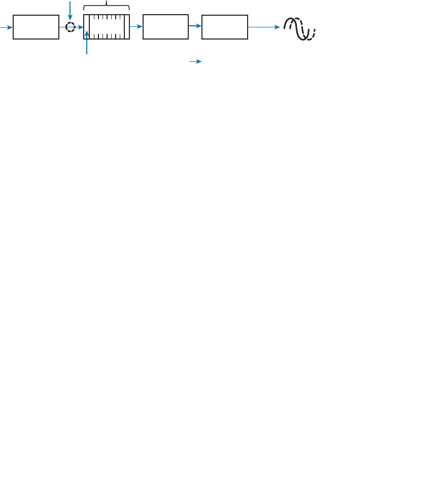
ptg12542968
28 CCNA Wireless 640-722 Official Cert Guide
■ Modulator —The bits contained in each symbol are used to alter or modulate the
phase of the carrier signal. This enables the RF signal to carry the binary data bit
values.
Figure 1-27 shows the entire data preparation process. At the receiver, the entire process
is reversed. The DSSS techniques discussed in this chapter focus only on the coder and
modulator functions.
Scrambler
Data
Bit
Interleaver Modulator
RF Signal
Coder
11 MHz Chipping RateChip
Symbol
22 MHz Channel
Data
Figure 1-27 Functional Blocks Used in a DSSS Transmitter.
DSSS has evolved over time to increase the data rate that is modulated onto the RF sig-
nal. This section describes each DSSS method and data rate, in progression. Regardless of
the data rate, DSSS always uses a chipping rate of 11 million chips per second.
1-Mbps Data Rate
To minimize the effect of a low SNR and data loss in cases of narrowband interference,
each bit of data is encoded as a sequence of 11 bits called a Barker 11 code . The goal
is to add enough additional information to each bit of data that its integrity will be pre-
served when it is sent in a noisy environment.
It might seem ridiculous to turn 1 bit into 11 bits. As an analogy, voice transmissions
over an RF signal can be subject to noise and interference, too. Spelling words letter by
letter can help, but even single letters can become garbled and ambiguous. For example,
the letters B , C , D , E, G , P , T , V , and Z can all sound similar when noise is present.
Phonetic alphabets have been developed to remove the ambiguity. Instead of saying the
letter B , the word Bravo is spoken; C becomes Charlie , D becomes Delta , and so on.
Replacing single letters with longer, unique words makes the listener’s job much easier
and more accurate.
There are only two possible values for the Barker chips—one corresponding to a 0
data bit (10110111000) and one for a 1 data bit (01001000111). The receiver must also
expect the Barker chips and convert them back into single bits of data. The number and
sequence of the Barker chip bits have been defined to allow data bits to be recovered if
some of the chip bits are lost. In fact, up to 9 of the 11 bits in a single chip can be lost
before the original data bit cannot be restored.
Each bit in a Barker chip can be transmitted by using the differential binary phase shift
keying (DBPSK) modulation scheme. The phase of the carrier signal is shifted or rotated
according to the data bit being transmitted, as follows:

ptg12542968
Chapter 1: RF Signals and Modulation 29
0: The phase is not changed.
1: The phase is “rotated” or shifted 180 degrees, such that the signal is suddenly
inverted.
DBPSK can modulate 1 bit of data at a time onto the RF signal. With a steady chipping
rate of 11 million chips per second, where each symbol (1 original bit) contains 11 chips,
the transmitted data rate is 1 Mbps.
2-Mbps Data Rate
It is possible to couple the 1-Mbps strategy with a different modulation scheme to
double the data rate. As before, each data bit is coded into an 11-bit Barker code with
an 11-MHz chipping rate. This time, chips are taken two at a time and modulated onto
the carrier signal by using differential quadrature phase shift keying (DQPSK). The
two chips are used to affect the carrier signal’s phase in four possible ways, each one
90 degrees apart (hence, the name quadrature). The bit patterns produce the following
phase shifts:
■ 00: The phase is not changed.
■ 01: Rotate the phase 90 degrees.
■ 11: Rotate the phase 180 degrees.
■ 10: Rotate the phase 270 degrees.
Because DQPSK can modulate data bits in pairs, it is able to transmit twice the data rate
of DBPSK, or 2 Mbps.
Figure 1-28 shows examples of DBPSK and DQPSK modulation. Each input data bit
combination is shown along with the carrier signal phase rotation that occurs. Phase
rotations can occur at several points along a cycle; for simplicity, only rotations at the
beginning of the cycle (0 degrees) are shown. Notice how abrupt the phase can change,
according to the bits being modulated. The receiver must detect these phase changes
when it demodulates the signal so that the original data bits can be recovered.
Tip As you read about wireless modulation techniques, you will often see DBPSK and
BPSK mentioned. The two forms reference the same type of modulation (BPSK, in this
case), but differ in the reference signal that the receiver uses to detect the phase changes.
The nondifferential form (without the initial D ) means the receiver must compare with
the original premodulated signal to find phase changes. The differential form (with the
D ) means the receiver must figure out phase changes by comparing with previous phases
already seen in received signal.
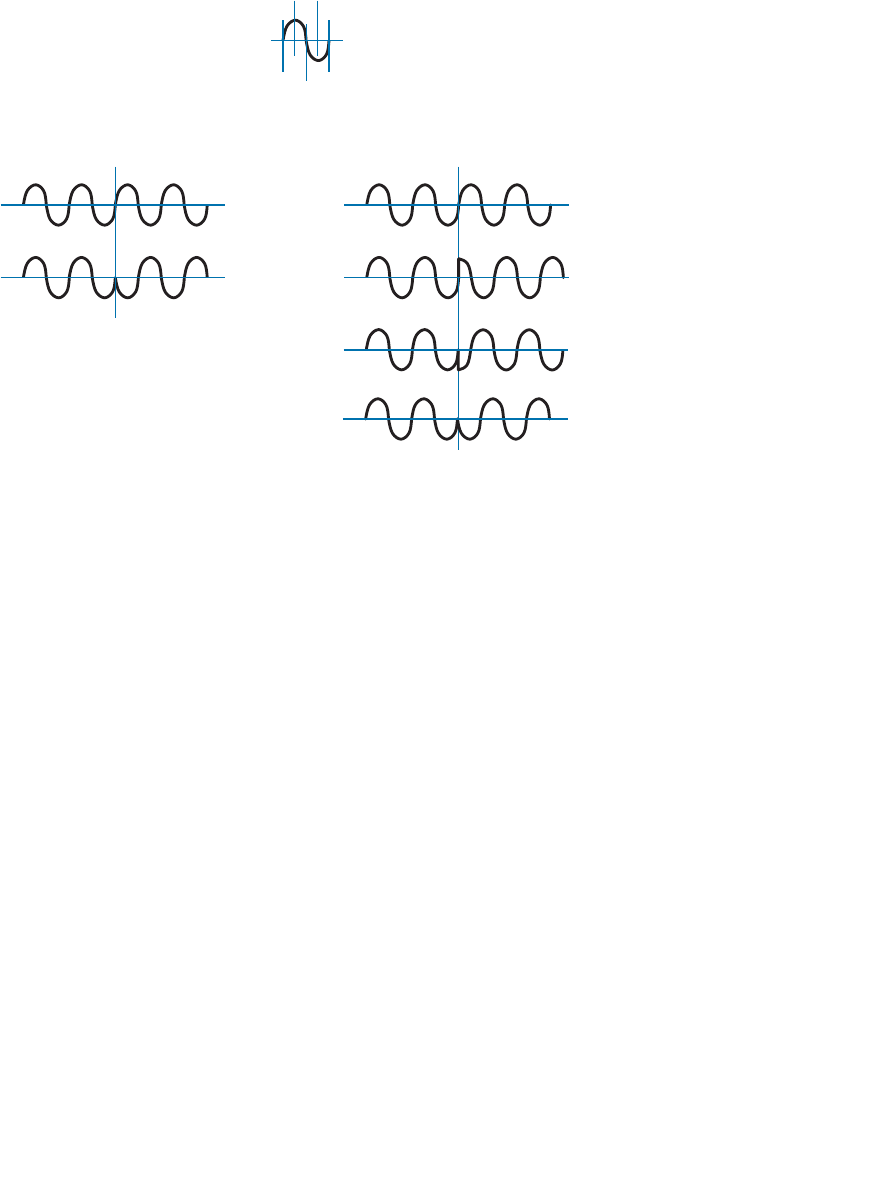
ptg12542968
30 CCNA Wireless 640-722 Official Cert Guide
180°
DBPSK Modulation DQPSK Modulation
0 bit
1 bit
00 bits
01 bits
0°
90°
180°
270°
360°
Phase
Rotation
11 bits
0° 0°
90°
10 bits
270°
180°
Figure 1-28 Example Phase Changes During DBPSK and DQPSK Modulation.
5.5-Mbps Data Rate
To gain more efficiency, Complementary Code Keying (CCK) can replace the Barker
code. CCK can take 4 bits of data at a time and build out redundant information to cre-
ate a unique 6-chip symbol. Two more bits are added to indicate the modulated phase
orientation for the symbol, resulting in 8 chips total. CCK is naturally coupled with
DQPSK modulation; the two-phase orientation bits determine four possible carrier signal
phase rotation values.
The chipping rate remains steady at 11 MHz, but each symbol contains 8 chips. This
results in a symbol rate of 1.375 MHz. Each symbol is based on 4 original data bits, so
the effective data rate is 5.5 Mbps.
11-Mbps Data Rate
The 5.5-Mbps CCK data rate can be doubled by making an adjustment to the coder.
Instead of taking 4 data bits at a time to make each coder symbol, data can be taken 8
bits at a time to create a unique 8-chip symbol. The CCK symbol rate is still 1.375 MHz,
so 8 data bits per symbol results in a data rate of 11 Mbps.
The smaller 8-chip CCK symbol is more efficient than the 11-bit Barker code because
more data bits can be sent with each new symbol. At the same time, CCK loses some
of the extra bits used by the Barker code to recover information received in a noisy or
low SNR environment. In other words, CCK achieves faster data rates at the expense of
requiring a stronger, less-noisy signal.
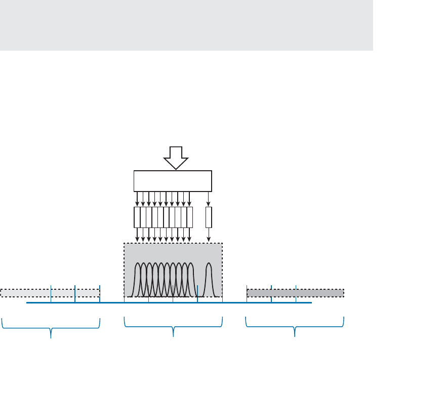
ptg12542968
Chapter 1: RF Signals and Modulation 31
OFDM
DSSS spreads the chips of a single data stream into one wide 22 MHz channel. It is
inherently limited to an 11 Mbps data rate because of the consistent 11-MHz chipping
rate that feeds into the RF modulation. To scale beyond that limit, a vastly different
approach is needed.
In contrast, orthogonal frequency division multiplexing (OFDM) sends data bits in par-
allel over multiple frequencies, all contained in a single 20 MHz channel. Each channel is
divided into 64 subcarriers (also called subchannels or tones) that are spaced 312.5 kHz
apart. The subcarriers are broken down into the following types:
■ Guard —12 subcarriers are used to help set one channel apart from another.
■ Pilot —4 subcarriers are equally spaced to help receivers lock onto the channel.
■ Data —48 subcarriers are devoted to carrying data.
Tip Sometimes you might see OFDM described as having 52 subcarriers (48 for data
and 4 for pilot). This is because the 12 guard frequencies are not actually transmitted, but
stay silent as channel spacing.
Figure 1-29 shows an example of OFDM, where channel 6 in the 2.4-GHz band is 20
MHz wide with 48 data subcarriers. OFDM is named for the way it takes one channel
and divides it into a set of distinct frequencies for its subcarriers. Notice that the subcar-
riers appear to be spaced too close together, causing them to overlap. In fact, that is the
case, but instead of interfering with each other, the overlapped portions are aligned so
that they cancel most of the potential interference.
2.412 2.417 2.422 2.427 2.432 2.437 2.442 2.447 2.452 2.457 2.462
Channel 1 Channel 11
GHz
Modulation
Subcarriers
Coded Data
Channel 6 1 48
20 MHz Channel
20 MHz Channel 20 MHz Channel
...
...
...
...
Figure 1-29 OFDM Operation with 48 Parallel Subcarriers.
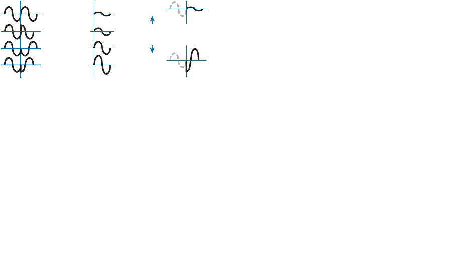
ptg12542968
32 CCNA Wireless 640-722 Official Cert Guide
OFDM has the usual scrambling, coding, interleaving, and modulating functions, but it
gains its scalability by leveraging so many data subcarriers in parallel. Even though the
data rates through each subcarrier are relatively low, the sum of all subcarriers results in
a high aggregate data rate.
OFDM offers many different data rates through several different modulation schemes.
Because OFDM is concerned with moving data in parallel at higher rates, the amount of
information that is repeated for resilience can be varied. The coders used with OFDM
are named according to the fraction of symbols that are new or unique, and not repeat-
ed. For example, BPSK 1/2 designates that one half of the bits are new and one half are
repeated. BPSK 3/4 uses a coder that presents three-fourths new data and repeats only
one fourth. As a rule of thumb, a greater fraction means a greater data rate, but a lower
tolerance for errors.
At the low end of the range, the familiar BPSK modulation can be used along with two
different coder ratios. In this case, OFDM still uses 48 subchannels or tones, with a
reduced tone rate of 250 Kbps. OFDM with BPSK 1/2 results in a 6-Mbps data rate,
whereas BPSK 3/4 gives 9 Mbps. QPSK 1/2 and 3/4 can be used to increase the data rate
to 12 and 18 Mbps, respectively.
Recall that QPSK uses 2 data bits to modulate the RF signal, resulting in four possible
phase shifts. To achieve data rates greater than 18 Mbps, more bits must be used to
modulate the signal. Quadrature amplitude modulation (QAM) combines QPSK phase
shifting ( quadrature ) with multiple amplitude levels to get a greater number of unique
alterations to the signal. For example, 16-QAM uses 2 bits to select the QPSK phase
rotation and 2 bits to select the amplitude level, giving 4 bits or 16 unique modulation
changes. Figure 1-30 illustrates a 16-QAM operation.
DQPSK (2 Bits) + Amplitude (2 Bits) = 16-QAM (4 Bits)
00
01
11
10
00
01
10
11
0000
1111
16 Unique
Changes
Figure 1-30 Examples of Phase and Amplitude Changes with 16-QAM.
The number of possible outcomes is always given as a prefix to the QAM name, fol-
lowed by the coder ratio of new data. In other words, 16-QAM is available in 1/2 and
3/4, providing data rates of 24 and 36 Mbps, respectively. Beyond that, 64-QAM 2/3
and 64-QAM 3/4 offer 48 and 54 Mbps, respectively.
Modulation Summary
Table 1-4 lists all the modulation techniques used in wireless LANs. There are quite a
few, and you will have to know them all for the CCNA Wireless exam. The modulation
types are broken down by DSSS and OFDM. This will become important as wireless

ptg12542968
Chapter 1: RF Signals and Modulation 33
standards are introduced in Chapter 2 .
Try to get a feel for the relative data rates, working from the lowest to the highest.
Remember that
■ B in DBPSK stands for binary (two outcomes).
■ Q in DQPSK stands for quadrature (four outcomes).
■ CCK is coupled with QPSK and replaces Barker 11 to go a bit faster.
■ OFDM generally wins out, except at the two slowest BPSK methods, which sit
between the two CCK methods.
■ QAM leverages both phase and amplitude changes to move the greatest amount of
data.
■ Higher fractions mean higher data rates.
Table 1-4 Wireless LAN Modulation Techniques
Modulation DSSS Data Rate (Mbps) OFDM Data Rate (Mbps)
DBPSK 1
DQPSK 2
CCK 4 5.5
OFDM BPSK 1/2 6
OFDM BPSK 3/4 9
CCK 8 11
OFDM QPSK 1/2 12
OFDM QPSK 3/4 18
OFDM 16-QAM 1/2 24
OFDM 16-QAM 3/4 36
OFDM 64-QAM 2/3 48
OFDM 64-QAM 3/4 54
To pass data over an RF signal successfully, both a transmitter and receiver have to use
the same modulation method. In addition, the pair should use the best data rate possible,
given their current environment. If they are located in a noisy environment, where a low
SNR or a low RSSI might result, a lower data rate might be preferable. If not, a higher
data rate is better.
With so many possible modulation methods available, how do the transmitter and
receiver select a common method? To complicate things, the transmitter, the receiver,
Key
Topic

ptg12542968
34 CCNA Wireless 640-722 Official Cert Guide
or both might be mobile. As they move around, the SNR and RSSI conditions will likely
change. The most effective approach is to have the transmitter and receiver negotiate a
modulation method (and the resulting data rate) dynamically, based on current RF condi-
tions.
Chapter 2 explains the industry standards that are used in wireless LANs and how they
influence the modulation techniques that are used.
Exam Preparation Tasks
As mentioned in the section “How to Use This Book” in the Introduction, you have a
couple of choices for exam preparation: the exercises here, Chapter 22 , “Final Review,”
and the exam simulation questions on the CD-ROM.
Review All Key Topics
Review the most important topics in this chapter, noted with the Key Topic icon in the
outer margin of the page. Table 1-5 lists a reference of these key topics and the page
numbers on which each is found.
Table 1-5 Key Topics for Chapter 1
Key Topic Element Description Page Number
Paragraph dB definition 17
List Important dB facts to remember 17
Table 1-3 Power changes and corresponding dB values 18
Paragraph EIRP calculation 21
Figure 1-22 Receiver sensitivity and noise floor 23
Table 1-4 Modulation technique summary 33
Key Terms
Define the following key terms from this chapter and check your answers in the
glossary:
amplitude, band, bandwidth, Barker code, carrier signal, channel, chip, coder,
Complementary Code Keying (CCK), decibel (dB), dBd, dBi, dBm, demodulation,
differential binary phase shift keying (DBPSK), differential quadrature phase shift
keying (DQPSK), direct-sequence spread spectrum (DSSS), effective isotropic radi-
ated power (EIRP), frequency, frequency-hopping spread spectrum (FHSS), hertz
Key
Topic

ptg12542968
Chapter 1: RF Signals and Modulation 35
(Hz), in phase, isotropic antenna, link budget, modulation, narrowband, noise floor,
orthogonal frequency division multiplexing (OFDM), out of phase, phase, quadra-
ture amplitude modulation (QAM), radio frequency (RF), received signal strength
indicator (RSSI), sensitivity level, signal-to-noise ratio (SNR), spread spectrum, sym-
bol, wavelength

ptg12542968
This chapter covers the following topics:
■ Regulatory Bodies —This section describes the
organizations that regulate radio frequency spec-
trum and its uses.
■ IEEE Standards Body —This section discusses the
IEEE and the 802.11 standards that define wireless
LAN operation.
■ 802.11 Channel Use —This section covers each of
the frequency bands used for 802.11 wireless LANs
and the encoding and modulation methods that are
used in wireless LANs.
■ IEEE 802.11 Standards —This section describes
the standards that define the progressive genera-
tions of 802.11 wireless LANs.
■ Wi-Fi Alliance —This section introduces the global
industry association that promotes and certifies
wireless LAN products to ensure interoperability.
This chapter covers the following exam topics:
■ Describe wireless regulatory bodies, standards and
certifications (FCC, ETSI, 802.11a/b/g/n, and WiFi
Alliance)

ptg12542968
To communicate successfully, wireless devices must first find each other in the radio fre-
quency (RF) spectrum and then use compatible methods to generate RF signals, modu-
late and encode data, negotiate communication parameters and features, and so on—all
without interfering with the operation of other wireless devices. This chapter covers the
agencies that regulate, standardize, and validate the correct use of wireless LAN devices.
“Do I Know This Already?” Quiz
The “Do I Know This Already?” quiz allows you to assess whether you should read this
entire chapter thoroughly or jump to the “Exam Preparation Tasks” section. If you are
in doubt about your answers to these questions or your own assessment of your knowl-
edge of the topics, read the entire chapter. Table 2-1 lists the major headings in this
chapter and their corresponding “Do I Know This Already?” quiz questions. You can
find the answers in Appendix A , “Answers to the ‘Do I Know This Already?’ Quizzes.”
Table 2-1 “Do I Know This Already?” Section-to-Question Mapping
Foundation Topics Section Questions
Regulatory Bodies 1–3
IEEE Standards Body 4
802.11 Channel Use 5–6
IEEE 802.11 Standards 7–12
Wi-Fi Alliance 13
Caution The goal of self-assessment is to gauge your mastery of the topics in this chap-
ter. If you do not know the answer to a question or are only partially sure of the answer,
you should mark that question as wrong for purposes of the self-assessment. Giving your-
self credit for an answer you correctly guess skews your self-assessment results and might
provide you with a false sense of security.
CHAPTER 2
RF Standards

ptg12542968
38 CCNA Wireless 640-722 Official Cert Guide
1.
Which regulatory body allocated the 2.4-2.5 GHz band for industrial, scientific, and
medical use?
a. IEEE
b. ETSI
c. ITU-R
d. FCC
2.
The U-NII-1 band is used for which one of the following purposes?
a. 2.4-GHz wireless LANs
b. 5-GHz wireless LANs
c. Medical applications
d. Point-to-point links
3.
In the 2.4-GHz band, the FCC limits the EIRP of a point-to-multipoint link to which
one of the following maximum values?
a. 100 mW
b. 20 dBm
c. 50 mW
d. 36 dBm
4.
Wireless LAN operation is defined in which one of the following standards?
a. 802.1
b. 802.2
c. 802.3
d. 802.11
e. 802.15
5.
Which one of the following specifies the correct list of non-overlapping channels
for DSSS use in the 2.4-GHz band?
a. 1, 2, 3
b. 1, 5, 10
c. 1, 6, 11
d. 1, 7, 14
e. All of channels 1–14

ptg12542968
Chapter 2: RF Standards 39
6.
The U-NII-1 band begins at which one of the following channel numbers?
a. 0
b. 1
c. 24
d. 3 6
7.
Which of the following standards apply to wireless LAN operation in the 5-GHz
band? (Choose multiple correct answers.)
a. IEEE 802.1
b. IEEE 802.11g
c. IEEE 802.11a
d. IEEE 802.11n
e. IEEE 802.11b
f. IEEE 802.11-2012
8.
Which of the following wireless LAN standards use OFDM for transmissions?
(Choose all that apply.)
a. 802.11-1997
b. 802.11b
c. 802.11g
d. 802.11a
9.
Which one of the following correctly specifies the maximum theoretical data rate
of the 802.11b, 802.11a, and 802.11n standards, respectively?
a.
11 Mbps, 54 Mbps, 600 Mbps
b.
54 Mbps, 54 Mbps, 150 Mbps
c.
1 Mbps, 11 Mbps, 54 Mbps
d. 11 Mbps, 20 Mbps, 40 Mbps
10.
A 2×3 MIMO device correctly describes which one of the following?
a.
A device with two radios and three antennas
b.
A device with two transmitters and three receivers
c.
A device with two bonded channels and three spatial streams
d.
A device with two receivers and three transmitters

ptg12542968
40 CCNA Wireless 640-722 Official Cert Guide
11.
An 802.11n device can aggregate channels to which one of the following maximum
widths?
a. 5 MHz
b. 20 MHz
c. 40 MHz
d. 80 MHz
12.
Which one of the following standards can make use of multiple spatial streams on a
transmitter and a receiver?
a. 802.11n
b. 802.11b
c. 802.11g
d. 802.11a
e. All of these answers are correct.
13.
Which one of the following organizations certifies 802.11 interoperability?
a. ITU-R
b. FCC
c. IEEE
d. Wi-Fi Alliance
e. Cisco

ptg12542968
Chapter 2: RF Standards 41
Foundation Topics
Regulatory Bodies
The RF portion of the frequency spectrum ranges from about 3 kHz to 300 GHz.
Frequencies within the RF spectrum are available because they exist everywhere, but it
would not be wise to use any frequency at will. For example, suppose someone decides
to set up a radio transmitter to broadcast a signal on 123.45 MHz. Unless other people
know about the transmitter’s frequency and have radio receivers that can tune to that
frequency, no one will be able to receive the signal. Even further, a frequency might be
used by one entity for a specific purpose, while another entity might try to use the same
frequency for a different purpose. To keep the RF spectrum organized and open for fair
use, regulatory bodies were formed.
ITU-R
A telecommunications regulatory body regulates or decides which part of the RF spec-
trum can be used for a particular purpose, in addition to how it can be used. A country
might have its own regulatory body that controls RF spectrum use within its borders, but
RF signals can be more far-reaching than that. For example, one purpose for shortwave
radio stations is to broadcast from one country around the earth to reach other coun-
tries. In a similar manner, one radio manufacturer might sell its equipment internation-
ally, where a transmitter or receiver might be used in any global location.
To provide a hierarchy to manage the RF spectrum globally, the United Nations set up
the International Telecommunication Union Radiocommunication Sector (ITU-R; http://
www.itu.int ). The ITU-R maintains spectrum and frequency assignments in three distinct
regions:
■ Region 1: Europe, Africa, and Northern Asia
■ Region 2: North and South America
■ Region 3: Southern Asia and Australasia
While the ITU-R strives to make the RF spectrum usable by all countries, it also tries
to make sure that the RF signals from one country do not interfere with the signals of
another country. The ITU-R even keeps track of geostationary satellite orbits and fre-
quencies so that signals for one country’s satellites do not harmfully interfere with those
of another country.
Most bands in the RF spectrum are tightly regulated, requiring you to apply for a license
from a regulatory body before using a specific frequency. Licensed bands might seem
restrictive, for a good reason: “Harmful” or disruptive interference is kept to a minimum
because frequencies are reserved for approved transmitters, purposes, and locations. To
use a frequency in a licensed band, someone has to submit an application to a regulatory

ptg12542968
42 CCNA Wireless 640-722 Official Cert Guide
body that governs frequency use in a given country, wait for approval, and then abide by
any restrictions that are imposed.
In contrast, the ITU-R allocated the following two frequency ranges specifically for
industrial, scientific, and medical (ISM) applications. Although there are other ISM
bands, too, these are the only two that apply to wireless LANs:
2.400 to 2.500 GHz
5.725 to 5.825 GHz
The purposes for these bands are broad and access is open to anyone who wants to use
them. In other words, the ISM bands are unlicensed and no registration or approval is
needed to transmit on one of the frequencies.
While unlicensed bands are more accessible and convenient to use, they are much more
vulnerable to interference and misuse. For example, suppose that you decide to set up a
transmitter in your office to use one frequency. The next day, someone in a neighboring
office sets up his own transmitter to broadcast on the same or an overlapping frequency.
Because the band is unlicensed, you can do little to relieve the interference other than
move your transmitter to a different frequency or use diplomacy to convince your
neighbor to move his transmitter instead.
Fortunately, all the frequency bands used for wireless LANs are unlicensed. You can
purchase a wireless LAN device and begin to use it immediately—provided you abide by
the rules set up by the regulatory agency that governs RF use in your country. Usually,
unlicensed transmitters must stay within an approved frequency range and transmit with-
in an approved maximum power level. Several national regulatory agencies are discussed
in the following sections.
FCC
In the United States and several other countries in the Americas, the Federal
Communications Commission (FCC; http://www.fcc.gov ) regulates RF frequencies, chan-
nels, and transmission power. In addition to the 2.4–2.5-GHz ISM band allocated by the
ITU-R, the FCC has allocated the Unlicensed National Information Infrastructure (U-NII)
frequency space in the 5-GHz band for wireless LAN use. U-NII is actually four separate
sub-bands, as follows:
U-NII-1 (Band 1): 5.15 to 5.25 GHz
U-NII-2 (Band 2): 5.25 to 5.35 GHz
U-NII-2 Extended (Band 3): 5.47 to 5.725 GHz
U-NII-3 (Band 4): 5.725 to 5.825 GHz (also allocated as ISM)
Tip As you read and work with the 5-GHz bands, be aware that you may see various
forms of the band names. For example, the 5.15- to 5.25-GHz band is often referenced
by names like U-NII-1, UNII-1, U-NII Low, and so on.
Key
Topic
Key
Topic
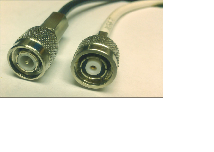
ptg12542968
Chapter 2: RF Standards 43
All transmitting equipment must be approved by the FCC before it can be sold to users.
For the 2.4- and 5-GHz unlicensed bands, the FCC requires strict limits on the effective
isotropic radiated power (EIRP). Recall from Chapter 1 , “RF Signals and Modulation,”
that the EIRP is the net power level that is being transmitted from an antenna that is con-
nected to a transmitter.
You must be aware of the EIRP limits and make sure that your wireless LAN equipment
does not exceed the limits. If the FCC has to approve wireless transmitters, it might
seem logical that the maximum EIRP of the equipment would have to be approved, too.
Why would you, as a wireless user, have to worry about staying within the limits? Some
transmitters are sold without antennas, so you are free to buy and install your own.
Without considering the EIRP limit, you might choose an antenna that has too much
gain, which would raise the EIRP too high.
In an effort to prevent users from exceeding the EIRP limits, the FCC requires all remov-
able antennas to have a unique, nonstandard connector, based on the transmitter manu-
facturer. The original idea was to require both transmitter and antenna to be purchased
from the same manufacturer, preventing the end user from mixing and matching parts
from different vendors.
Cisco uses a variant of the threaded Neill-Concelman (TNC) connector on its equipment.
The reverse polarity TNC (RP-TNC) connector is identical to the TNC, but has key male
and female parts reversed so that antennas with TNC connectors cannot be connected.
Figure 2-1 shows the male version of the regular TNC and RP-TNC connector side by
side.
Figure 2-1 A Comparison Between TNC (left) and Cisco RP-TNC Connector (right).
In practice, you can find all sorts of antennas from a wide variety of manufacturers that
all have RP-TNC connectors. In other words, you cannot depend on the FCC and the

ptg12542968
44 CCNA Wireless 640-722 Official Cert Guide
RP-TNC connector to limit the EIRP of your wireless equipment; you have to do that
yourself.
Transmitters in the 2.4-GHz band can be used indoors or outdoors. The power emit-
ted at the transmitter must be limited to 30 dBm and the EIRP limited to 36 dBm. An
antenna gain of +6 dBi is assumed. However, there is some flexibility according to the
following two rules, based on the intended spread of the signal:
■ Point-to-multipoint links —Where the transmitted signal propagates in all direc-
tions, you can make adjustments according to a 1:1
rule. For each dBm you remove
from the transmitter, one dBi can be added to the antenna gain, as long as the EIRP
is no greater than 36 dBm.
■ Point-to-point links —Where the transmitted signal propagates in one general direc-
tion, you can make adjustments according to a 3:1
rule. For each dBm you remove
from the transmitter, 3 dBi can be added to the antenna gain. The resulting EIRP can
exceed 36 dBm, but cannot be greater than 56 dBm.
Transmitters in the 5-GHz bands must follow the FCC limits listed in Table 2-2 . In each
of the U-NII bands, you can make power adjustments according to the 1:1 rule. Notice
that the U-NII-1 band is the only one restricted to indoor use.
Table 2-2 FCC Requirements in the 5-GHz U-NII Bands
Band Allowed Use Transmitter Max EIRP Max
U-NII-1 Indoor only 17 dBm (50 mW) 23 dBm
U-NII-2 Indoor or outdoor 24 dBm (250 mW) 30 dBm
U-NII-2 Extended Indoor or outdoor 24 dBm (250 mW) 30 dBm
U-NII-3 Indoor or outdoor 30 dBm (1 W) 36 dBm
Normally, transmitters operating in any of the 2.4- and 5-GHz unlicensed bands must
endure any interference caused by other transmitters. The FCC requires one exception
in the U-NII-2 and U-NII-2 Extended bands: When a signal from an approved device,
such as a military or weather radar, is detected on a frequency, all other transmitters
must move out of the way to a different frequency. This is known as dynamic frequency
selection (DFS).
ETSI
In Europe and several other countries, the European Telecommunication Standards
Institute (ETSI; http://www.etsi.org ) regulates radio transmitter use. Like the FCC, the
ETSI allows wireless LANs to be used in the 2.4-GHz ISM and most of the same 5-GHz
U-NII bands; however, the U-NII-3 band is a licensed band and cannot be used.
Key
Topic

ptg12542968
Chapter 2: RF Standards 45
Table 2-3 lists the transmitter requirements for each of the bands. The ETSI allows
adjustments to the transmit power and antenna gain, as long as the maximum EIRP is not
exceeded.
Table 2-3 ETSI Requirements in the 2.4- and 5-GHz Bands
Band Allowed Use EIRP Max
2.4 GHz ISM Indoor or outdoor 20 dBm
U-NII-1 Indoor only 23 dBm
U-NII-2 Indoor only 23 dBm
U-NII-2 Extended Indoor or outdoor 30 dBm
U-NII-3 Licensed N/A
The ETSI regulations also include DFS, which requires wireless LAN transmitters to
move to a random frequency after a radar signal is detected.
Other Regulatory Bodies
Wireless LAN equipment use is regulated outside the Americas and Europe, too. Does
each country have its own set of regulations? Not necessarily; a country might have its
own or it can adhere to all or parts of the regulations of a larger, more established regu-
latory body. Countries that use a common set of RF regulations are known as a regula-
tory domain.
For example, a Cisco wireless device that is compatible with the American regulatory
domain can also be used in Canada, many Latin and South American countries, and in
the Philippines.
Cisco manufactures wireless devices for use in at least 13 different regulatory domains.
The basic wireless LAN operation is identical in all domains, but the frequency ranges,
channels, and maximum transmit powers can differ.
IEEE Standards Body
To pass data over a wireless link, many parameters have to be defined and standardized.
Wireless LANs rarely involve just one transmitter and receiver; normally, many devices
must contend for use of airtime on a frequency. The Institute of Electric and Electronic
Engineers (IEEE; http://ieee.org ) maintains the industry standards that are used for wire-
less LANs, among many others.
The IEEE is a professional organization made up of engineers from around the world.
It is organized as a collection of “societies” that are focused on particular engineering
areas. For example, the IEEE Computer Society develops and maintains standards on a
variety of topics related to computing, including Ethernet and wireless LANs.

ptg12542968
46 CCNA Wireless 640-722 Official Cert Guide
The IEEE 802 standards all deal with local-area networks and metropolitan-area net-
works (LANs and MANs, respectively). The standards mainly deal with the physical and
data link layers of the OSI model, and with transporting variable-size data packets across
a network media. As you explore the portion of the 802 standards that are dedicated to
wireless LANs, you will find that they focus on accessing the shared RF media (physical
layer or Layer 1) and on sending and receiving data frames (data link layer or Layer 2).
Tip What is the significance of the number 802? The Local Network Standards
Committee of the IEEE Computer Society first met in February 1980, to begin work on
“Project 802,” the first LAN standard. The number 802 was the next sequential project
number, but also fit the odd coincidence of the date—year 80, second month.
To develop networking standards, the IEEE is organized into working groups, which
have an open membership. Each working group is assigned an index number that is
appended to the 802 standards family number. For example, 802.1 refers to the first
working group, which developed standards for network bridging. Table 2-4 lists a
few familiar 802 working groups. Notice that the eleventh working group, 802.11, is
responsible for the wireless LAN standards that are used by Cisco, many other wireless
vendors, and users like yourself. For the remainder of this chapter, the focus will be on
802.11.
Table 2-4 Example IEEE 802 Working Groups
Name Description
802.1 Network bridging (includes Spanning Tree Protocol)
802.2 Link-layer control
802.3 Ethernet
802.4 Token Bus
802.5 Token Ring MAC layer
...
802.11 Wireless LANs
...
802.15 Wireless PANs (personal-area networks such as Bluetooth, ZigBee, and so on)
As a new improvement is needed or the technology advances, a study group (SG)
researches the topic to see whether an amendment to the 802.11 standard is needed.
Each time a new amendment is necessary, a new task group (TG) is formed to collaborate
and develop it. Task groups are assigned a suffix letter in alphabetic order. For example,
as amendments are introduced, their names become 802.11a, 802.11b, 802.11c, and so
on. If there are enough amendments to reach letter z , any subsequent amendments are

ptg12542968
Chapter 2: RF Standards 47
given a two-letter suffix, beginning with the letter a followed by letters a through z . At
the time of this writing, the 802.11 working group had assigned amendments 802.11aa
through 802.11aq.
Once a draft amendment is completed, it must be voted on and ratified. At that point,
manufacturers can then begin to build products that operate according to all or a part of
the standard. For example, when the 802.11n amendment was finalized and published,
the new features of 802.11n were then added to many wireless LAN devices.
Sometimes an amendment takes a very long time to get through the development, vot-
ing, and final approval processes, so many manufacturers will decide to move ahead and
implement the draft amendment into their products early. Usually a manufacturer has to
decide if the draft amendment is stable enough to implement into device hardware or
whether it is likely to receive drastic changes before it is ratified. This scenario occurred
with the 802.11n amendment. Many manufacturers offered early implementations as
“Draft N-compliant” products, which may or may not have been compatible with similar
products from other manufacturers.
The 802.11 standards usually have the year they were ratified added to their names. For
example, the original 802.11 standard was issued in 1997, so it is now known as 802.11-
1997. Likewise, the name 802.11a-1999 means that the 802.11a amendment was ratified
in 1999.
Periodically, the IEEE 802 working group chooses to revise the 802.11 standard as a
whole. When this occurs, every amendment that has been ratified since the last 802.11
revision is “rolled up” and absorbed into the new updated standard. The idea is to main-
tain one document that defines the entire standard, as of a certain date, so that wireless
developers can find all of the technical details in one place.
Even though the amendments become part of the larger standard, their names are still
commonly used to reference the specific functions they introduced. Since its introduc-
tion in 1997, the 802.11 standard has been revised in 1999, 2007, and 2012. The current
802.11-2012 standard is over 2700 pages long.
802.11 Channel Use
Chapter 1 introduced RF frequency, bands, and channels in a generic fashion. Wireless
devices built around the 802.11 standard must also have a standardized concept of the
same RF parameters. As wireless devices move around, they should be able to detect and
participate in wireless LANs as they become available, regardless of geographic location.
The following sections describe the 802.11 channel definitions in the 2.4- and 5-GHz
bands.
Channels in the 2.4-GHz ISM Band
In the 2.4-GHz ISM band, the frequency space is divided up into 14 channels, numbered
1 through 14. With the exception of channel 14, the channels are spaced 5 MHz apart,
as listed in Table 2-5 .

ptg12542968
48 CCNA Wireless 640-722 Official Cert Guide
Table 2-5 IEEE 802.11 Channel Layout in the 2.4-GHz Band
Channel Frequency (GHz)
1 2.412
2 2.417
3 2.422
4 2.427
5 2.432
6 2.437
7 2.442
8 2.447
9 2.452
10 2.457
11 2.462
12 2.467
13 2.472
14 2.484
The 802.11 standard allows either direct-sequence spread spectrum (DSSS) or
Orthogonal frequency-division multiplexing (OFDM) modulation and coding schemes to
be used in the 2.4-GHz band. DSSS radios require each channel to be 22 MHz wide, and
OFDM requires 20 MHz. Either way, with only 5 MHz between channels, transmissions
on neighboring channels are bound to overlap and interfere with each other. (This condi-
tion is covered in Chapter 3 , “RF Signals in the Real World.”)
Even though the band is made up of 14 channels, not all of them may be used in all
countries. For example, the FCC limits the band to channels 1 through 11 only. The
ETSI permits channels 1 through 13. Japan permits all 14 channels to be used, but chan-
nel 14 has some restrictions.
Figure 2-2 shows how 802.11 signals can overlap on neighboring 2.4-GHz channels. The
only way to prevent transmitters on nearby channels from interfering with each other is
to keep them on channels that are spaced farther apart. The most common arrangement
is to use only channels 1, 6, and 11, which do not overlap with each other at all.
Tip One scheme uses channels 1, 5, 9, and 13 to gain an extra channel, but it is not
commonly used. With DSSS, the channels end up overlapping, which violates the 802.11
definition for adjacent channels and also raises the noise floor. Only the OFDM 20-MHz-
wide channels can avoid overlapping each other. Channel 13 presents an interesting case
because it is not supported on all wireless clients in all areas of the world.

ptg12542968
Chapter 2: RF Standards 49
2.412 2.417 2.422 2.427 2.432 2.437 2.442 2.447 2.452 2.457 2.462
1611
Channel
GHz 2.467 2.472 2.484
2345 7 8910 1213 14
DSSS: 22 MHz
OFDM: 20 MHz
Figure 2-2 Channel Layout in the 2.4-GHz Band.
Why should you be concerned about non-overlapping channels? After all, having three
non-overlapping channels might seem like plenty. Problems can arise when you need to
set up several wireless LAN transmitters in the same general area. You could set the first
three transmitters to each use a different channel, but the fourth or fifth ones would
have to reuse one of the three non-overlapping channels.
Reusing channels becomes a puzzle that you have to solve when you administer a grow-
ing wireless LAN. Chapter 7 , “Planning Coverage with Wireless APs,” covers channel
reuse in greater detail. Be aware that the three-channel limitation also applies to every
transmitter located in an area—regardless of whether you administer them. Because the
2.4-GHz band is unlicensed, anyone is free to bring up a transmitter on any of the three
non-overlapping channels without consulting you or anybody else. In fact, they might
decide to set their transmitter to use any of the 14 available channels, thinking that none
of them overlap.
Channels in the 5-GHz U-NII Bands
Recall that the 5-GHz band is organized as four separate, smaller bands: U-NII-1, U-NII-
2, U-NII-2 Extended, and U-NII-3. The bands are all divided into channels that are 20
MHz apart, as listed in Table 2-6 .
Table 2-6 IEEE 802.11 Channel Layout in the 5-GHz Bands
Band Channel Frequency (GHz)
U-NII-1 36 5.180
40 5.200
44 5.220
48 5.240
U-NII-2 52 5.260
56 5.380
60 5.300
64 5.320
Key
Topic

ptg12542968
50 CCNA Wireless 640-722 Official Cert Guide
Band Channel Frequency (GHz)
U-NII-2 Extended 100 5.500
104 5.520
108 5.540
112 5.560
116 5.580
120 5.600
124 5.620
128 5.640
132 5.660
136 5.680
140 5.700
U-NII-3 149 5.745
153 5.765
157 5.785
161 5.805
The fact that the 5-GHz space is divided into four different bands might seem confusing.
Even worse is the channel numbering. For instance, why is the first channel in the U-NII-
1 band called channel 36 instead of channel 1? And why are neighboring channels actu-
ally four channel numbers apart?
The answers lie in the 802.11 standard itself: The entire 5-GHz frequency space is
defined as a sequence of channels spaced 5 MHz apart, beginning with channel 0 at
5.000 GHz. Therefore, the first U-NII-1 channel is located at 5.180 GHz, which corre-
sponds to channel number 36. Each U-NII channel is 20 MHz wide, so an adjacent chan-
nel is located four 5-MHz channel widths, or four channel numbers, away.
The FCC originally allocated three separate bands as U-NII-1, U-NII-2, and U-NII-3,
each having four 20-MHz channels. In 2004, the FCC added the U-NII-2 Extended band,
which offered 11 additional 20-MHz channels. Figure 2-3 shows the complete frequency
layout of the four bands. Notice that the U-NII-1 and U-NII-2 bands are contiguous,
but that the U-NII-2 Extended and U-NII-3 bands are separated by a range of frequen-
cies that are unusable at the time of this writing but that might become available in the
future.
Tip The U-NII-1, -2, and -3 bands each have four channels. Sometimes you may find
802.11 devices that support a fifth channel in the U-NII-3 band as channel 165.
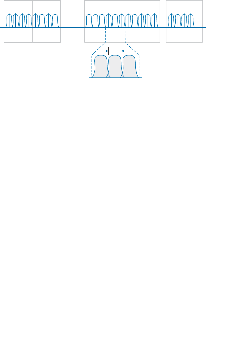
ptg12542968
Chapter 2: RF Standards 51
Because the FCC allocated the U-NII bands, no global consensus controls their use.
Some countries allow all four bands to be used, others allow only a few bands, and still
others permit none of the bands to be used.
The 802.11 standard allows only OFDM modulation and coding schemes to be used in
the U-NII bands. OFDM requires a 20-MHz channel width, which fits perfectly with the
20-MHz spacing in the U-NII bands. In other words, neighboring channels can be used in
the same area without overlap or interference.
With all four U-NII bands set aside for wireless LANs, a total of 23 non-overlapping
channels are available. This is quite a contrast to the three non-overlapping channels in
the 2.4-GHz band. Having 23 channels at your disposal gives you much more flexibility
in a crowded environment. The additional channels can also be leveraged to scale wire-
less LAN performance, as explained in the 802.11n and 802.11ac sections later in this
chapter.
IEEE 802.11 Standards
The 802.11 standard defines the mechanisms that devices can use to communicate wire-
lessly with each other. Through 802.11, RF signals, modulation, coding, bands, channels,
and data rates all come together to provide a robust communication medium.
Since the original IEEE 802.11 standard was published in 1997, there have been many
amendments added to it. The amendments cover almost every conceivable aspect of
wireless LAN communication, including things like quality of service (QoS), security,
RF measurements, wireless management, more efficient mobility, and ever-increasing
throughput.
By now, most of the amendments have been rolled up into the overall 802.11 standard
and no longer stand alone. Even so, the amendments may live on and be recognized in
the industry by their original task group names. For example, the 802.11b amendment
was approved in 1999, was rolled up into 802.11 in 2007, but is still recognized by its
name today. When you shop for wireless LAN devices, you will often find the 802.11a,
20
MHz
6436 40 44 48 52 56 60 100 104 108 112 116 120 124 128 132 136 140 149 153 157 161
Channel
5.180 5.240 5.260 5.320 5.500 5.700 5.745 5.825
GHz
U-NII-1 U-NII-2 U-NII-2 Extended U-NII-3
Figure 2-3 Channel Layout in the 5-GHz U-NII Bands.

ptg12542968
52 CCNA Wireless 640-722 Official Cert Guide
b, g, and n amendments listed in the specifications.
The following sections discuss the progression of 802.11 amendments that have allowed
wireless LANs to steadily increase in performance over time. The original amendment
names are used to distinguish each one. At the CCNA level, you should become familiar
with these amendments. As you read through the remainder of this chapter, notice how
the transmission types, modulation types, and data rates presented in Chapter 1 fit into
the 802.11 standard.
802.11-1997
The original 802.11 standard was ratified in 1997. It included the only transmission types
that were available at the time: FHSS and DSSS, for use only in the 2.4-GHz band. The
theoretical data rates included 1 and 2 Mbps, as listed in Table 2-7 .
Table 2-7 IEEE 802.11-1997 Data Rates
Band Transmission Type Modulation Data Rate
2.4 GHz FHSS — 1, 2 Mbps
DSSS DBPSK 1 Mbps
DQPSK 2 Mbps
802.11b
To increase throughput over the original 802.11-1997 standard, 802.11b was introduced
in 1999. It offered data rates of 5.5 and 11 Mbps through the use of Complementary
Code Keying (CCK). Because 802.11b was based on DSSS and was used in the 2.4-GHz
band, it was backward compatible with the original standard. Devices could select either
1, 2, 5.5, or 11 Mbps by simply changing the modulation and coding schemes. Table 2-8
lists the new data rates introduced in 802.11b.
Table 2-8 IEEE 802.11b Data Rates
Band Transmission Type Modulation Data Rate
2.4 GHz DSSS CCK 5.5 Mbps
11 Mbps
802.11g
With 802.11b, the DSSS maximum data rate was limited to 11 Mbps. To increase data
rates further, a different transmission type was needed. The 802.11g amendment was
based on OFDM and was introduced in 2003. It is commonly called Extended Rate PHY
(ERP) or ERP-OFDM. Whenever you see ERP , think of 802.11g in the 2.4-GHz band.
Key
Topic
Key
Topic

ptg12542968
Chapter 2: RF Standards 53
Table 2-9 lists the data rates available with 802.11g.
Table 2-9 IEEE 802.11g Data Rates
Band Transmission Type Modulation Data Rate
2.4 GHz ERP-OFDM BPSK 1/2 6 Mbps
BPSK 3/4 9 Mbps
QPSK 1/2 12 Mbps
QPSK 3/4 18 Mbps
16-QAM 1/2 24 Mbps
16-QAM 3/4 36 Mbps
64-QAM 2/3 48 Mbps
64-QAM 3/4 54 Mbps
By selecting one of eight different modulation schemes, wireless devices can choose
data rates of 6, 9, 12, 18, 24, 36, 48, or 54 Mbps. The higher data rates can be used when
the signal strength and signal-to-noise ratio (SNR) are optimal.
Clearly, 802.11g offers far superior throughput than 802.11b. It might seem logical to
simply use 802.11g and its higher data rates everywhere. Sometimes that is not pos-
sible because 802.11b-only devices are still being used on a wireless LAN. Notice that
802.11g and 802.11b use completely different transmission types—OFDM versus DSSS.
This means that 802.11g and 802.11b devices cannot communicate directly because they
cannot understand each other’s RF signals.
Oddly enough, 802.11g was designed to be backward compatible with legacy 802.11b
devices. Devices using 802.11g and OFDM are able to downgrade and understand
802.11b DSSS messages. However, the reverse is not true; 802.11b devices are limited to
DSSS, so they are not able to understand any OFDM data. When two 802.11g devices
are communicating with OFDM, 802.11b devices cannot understand any of the transmis-
sions, so they might interrupt with transmissions of their own.
To allow both OFDM and DSSS devices to coexist on a wireless LAN, 802.11g offers a
protection mechanism . The idea is to precede each 802.11g OFDM transmission with
DSSS flags that 802.11b devices can understand. Figure 2-4 compares the basic sequence
of events as data is transmitted in a native 802.11g OFDM network and when the
802.11g protection mechanism is enabled. When an 802.11g device is ready to transmit
data in protection mode, it first sends a Request to Send (RTS) and a Clear to Send (CTS)
message using DSSS (and a low data rate) that informs all 802.11b devices that an OFDM
transmission will follow. Any 802.11b devices that are listening must wait a predefined
time until the transmission is complete because the OFDM transmission is unintelligible.
Key
Topic

ptg12542968
54 CCNA Wireless 640-722 Official Cert Guide
Data Data Data Data Data Data
OFDM
RTS
OFDM
CTS RTS CTS
DSSS DSSS DSSS DSSS OFDM
OFDM OFDM OFDM OFDM OFDM
Native 802.11g
ERP-OFDM
802.11g
Protection Mode
Figure 2-4 A Comparison of 802.11g Native and Protected Mode Transmissions.
Protection mode is enforced if an 802.11b device is detected on a wireless LAN. If the
802.11b device leaves the local network, protection mode is lifted. While the protection
mechanism enables 802.11b and 802.11g devices to share the wireless medium, it also
reduces throughput significantly—often by one third to one half or more. To get the
most performance out of an 802.11g network, you should make sure that there are no
802.11b-only devices in use.
Be aware that 802.11g has the following limitations:
■ It is used in the 2.4-GHz band, which offers only three non-overlapping channels.
■ OFDM devices are limited to a maximum transmit power of 15 dBm, rather than the
20-dBm limit for DSSS.
802.11a
Both 802.11b and 802.11g share one problem: They live in the 2.4-GHz ISM band.
Having only three non-overlapping channels can limit wireless LAN growth in an area—
assuming that all 802.11 devices stay within those three channels and do not cause
unnecessary interference. Even worse, the ISM band is not limited to 802.11 devices. A
wide variety of transmitters—even microwave ovens—can use the 2.4-GHz band without
any regard for channels at all.
With too few channels and the potential for interference, the 802.11a amendment was
introduced to utilize the 5-GHz U-NII bands for wireless LANs. Only one of the four
U-NII bands is designated as ISM, so the chance for non-802.11 interference is very low.
In addition, many more channels are available for use.
The 802.11a amendment restricts devices to use OFDM only. The end result is a set of
modulation schemes and data rates that are identical to those used for 802.11g, but with
less chance for interference and more room for growth. Table 2-10 lists the data rates
available with 802.11a.

ptg12542968
Chapter 2: RF Standards 55
Table 2-10 IEEE 802.11a Data Rates
Band Transmission Type Modulation Data Rate
5 GHz OFDM BPSK 1/2 6 Mbps
BPSK 3/4 9 Mbps
QPSK 1/2 12 Mbps
QPSK 3/4 18 Mbps
16-QAM 1/2 24 Mbps
16-QAM 3/4 36 Mbps
64-QAM 2/3 48 Mbps
64-QAM 3/4 54 Mbps
802.11a was not designed to be backward compatible with anything else, so there is no
need to support data rates below 6 Mbps or to support DSSS at all. Wireless devices can
select one of the eight modulation schemes to support data rates of 6, 9, 12, 18, 24, 36,
48, or 54 Mbps.
802.11a is based on OFDM channels that are 20 MHz wide. Even though the U-NII
bands have channels that are spaced 20 MHz apart (a perfect fit), signals on adjacent
channels might still have a small amount of overlap. Therefore, 802.11a recommends that
transmitters in the same geographic space stay separated by one channel. In other words,
one transmitter might use channel 36, but another should use channel 44 rather than the
adjacent channel 40.
Tip If the 802.11 amendment letters come in chronological order, how could the
higher-performance 802.11a come before the lower-performance 802.11b? Actually,
interference on the 2.4-GHz ISM band was so prevalent that a move to the 5-GHz bands
was proposed right away. The 802.11a amendment was introduced in 1999—earlier in the
same year as 802.11b. OFDM did come to the 2.4-GHz band, too, with 802.11g in 2003,
mainly because migrating to 802.11a and 5 GHz required an investment in new hardware.
802.11n
Under the best conditions, both 802.11g and 802.11a are capable of offering a 54-Mbps
data rate. Each amendment was introduced in the days when wired Ethernet devices
used 10- or 100-Mbps connections. As the speed of Ethernet connections has pro-
gressed, 802.11 amendments have been introduced to keep in step.
The 802.11n amendment was published in 2009 in an effort to scale wireless LAN per-
formance to a theoretical maximum of 600 Mbps. The amendment defines a number
Key
Topic
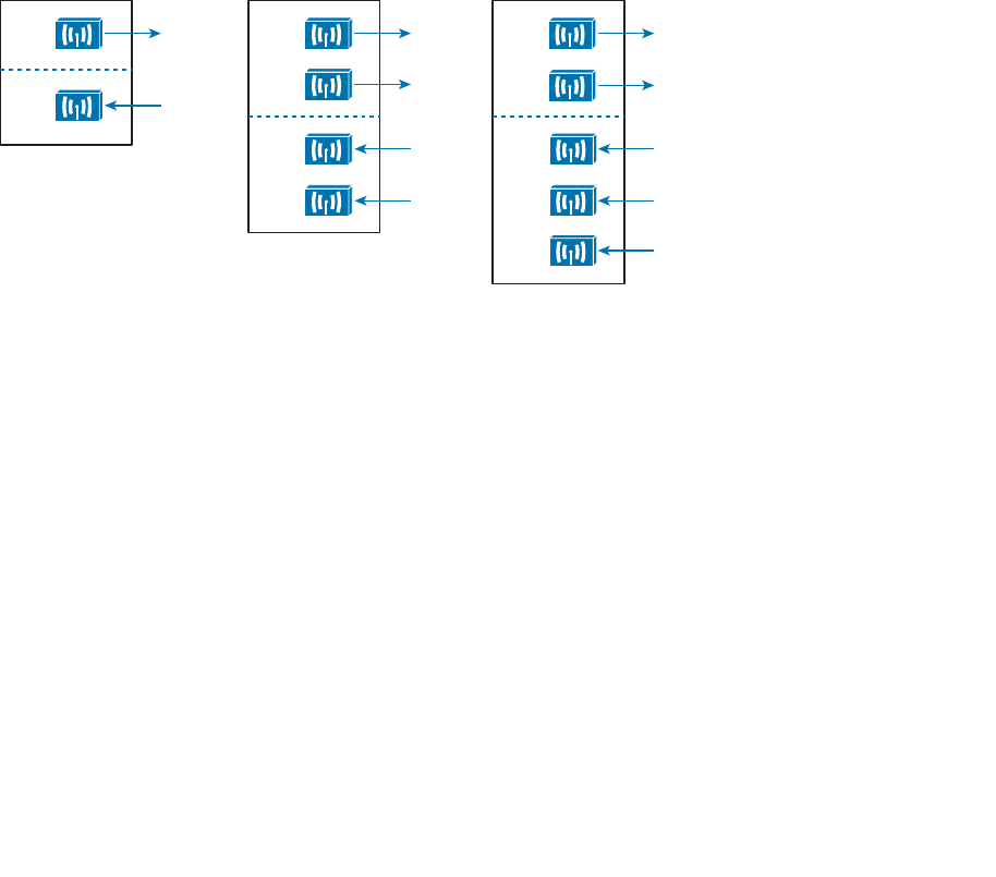
ptg12542968
56 CCNA Wireless 640-722 Official Cert Guide
of techniques known as high throughput (HT) that can be applied to either the 2.4- or
5-GHz band. 802.11n was designed to be backward compatible with 802.11b, 802.11g,
and 802.11a.
Before 802.11n, wireless devices used a single transmitter and a single receiver. In other
words, the components formed one radio, resulting in a single radio chain . This is also
known as a single-in, single-out (SISO) system. The secret to 802.11n’s better performance
is its use of multiple radio components, forming multiple radio chains. For example, an
802.11n device can have multiple antennas, multiple transmitters, and multiple receivers at
its disposal. This is known as a multiple-input, multiple-output (MIMO) system.
802.11n devices are characterized according to the number of radio chains available. This
is described in the form T×R, where T is the number of transmitters and R is the number
of receivers. A 2×2 MIMO device has two transmitters and two receivers, and a 2×3
device has two transmitters and three receivers. The 802.11n amendment requires at least
two radio chains (2×2), up to a maximum of four (4×4). Figure 2-5 compares the tradi-
tional 1×1 SISO device with 2×2 and 2×3 MIMO devices.
Tx 1
Tx 2
Rx 1
Rx 2
2 x 2 MIMO
Tx 1
Tx 2
Rx 1
Rx 2
2 x 3 MIMO
Rx 3
Tx
Rx
Traditional 802.11
1 x 1 SISO
Figure 2-5 Example SISO and MIMO Devices.
The multiple radio chains can be leveraged in a variety of ways. In fact, 802.11n has a
rich set of features that can make many aspects of wireless communication more effi-
cient. You should be familiar with the following features that improve throughput:
■ Channel aggregation
■ Spatial multiplexing (SM)
■ MAC layer efficiency
You should also become familiar with the following features that improve the reliability
of the 802.11n RF signals:
■ Transmit beam forming (T×BF)
■ Maximal-ratio combining (MRC)
Each of these features is described in the sections that follow.
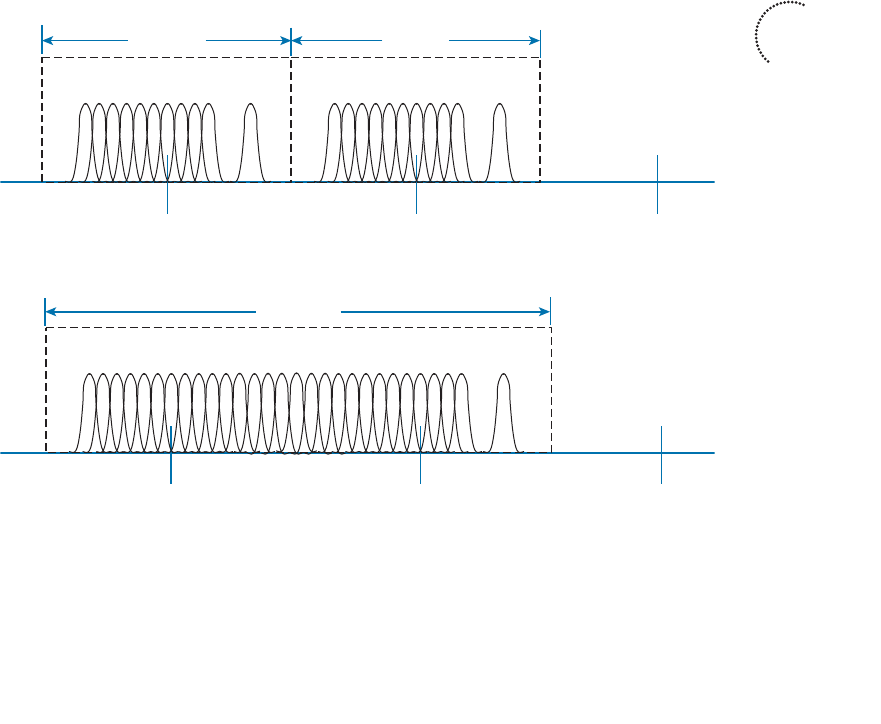
ptg12542968
Chapter 2: RF Standards 57
Channel Aggregation
Normally, an 802.11a or 802.11g wireless LAN device has one transmitter and one
receiver that operate on one 20-MHz channel only. The transmitter and receiver can be
configured or tuned to operate on different channels in a band, but only one channel at
a time. Each 20-MHz OFDM channel has 48 subcarriers to carry data in parallel.
The 802.11n amendment increased the 20-MHz channel throughput by increasing the
number of data subcarriers to 52. In addition, it introduced radios that could operate
on either a single 20-MHz channel or a single 40-MHz channel. By doubling the channel
width to 40 MHz, the throughput is also doubled.
Aggregated channels must always bond two adjacent 20-MHz channels. Figure 2-6
shows a comparison between two 20-MHz channels and one 40-MHz channel, formed
from channels 36 and 40 in the 5-GHz band. Notice that the 20-MHz channels have a
quiet space below and above, providing some separation between channels. When two
20-MHz channels are aggregated or bonded, the quiet space below and above remain,
separating 40-MHz channels from each other. However, the quiet space that used to sit
between the two 20-MHz channels can be used for additional subcarriers in the 40-MHz
channel, for a total of 108. As more subcarriers are utilized, more data can be carried
over time.
Channel 40
Subcarriers
Channel 36
1
...
52 Subcarriers1
...
52
Channel 44
Channel 40
Subcarriers
Channel 36
1
...
108
Channel 44
Individual Channel Operation
802.11n Channel Aggregation
20 MHz 20 MHz
40 MHz
Figure 2-6 Comparing 20-MHz Channels to a 802.11n 4-MHz Channel.
When channels are aggregated, the total number of available channels in a band decreas-
es. For example, the 5-GHz band is made up of 23 non-overlapping 20-MHz channels. If
Key
Topic

ptg12542968
58 CCNA Wireless 640-722 Official Cert Guide
aggregated 40-MHz channels are used instead, only 11 non-overlapping channels would
be possible. That still gives plenty of channels to work with.
Now consider the 2.4-GHz band, which has only three non-overlapping channels. It just
is not practical to try to aggregate any of them into 40-MHz channels. Therefore channel
aggregation is not recommended and not normally attempted on any 2.4-GHz channels.
Spatial Multiplexing
Channel aggregation can double the throughput by doubling the channel width—all
with a single radio chain. An 802.11n device can have multiple radio chains waiting to
be used. To increase data throughput even more, data can be multiplexed or distrib-
uted across two or more radio chains—all operating on the same channel, but separated
through spatial diversity. This is known as spatial multiplexing .
How can several radios transmit on the same channel without interfering with each
other? The key is to try to keep each signal isolated or easily distinguished from the
others. Each radio chain has its own antenna; if each antenna is spaced some distance
apart, the signals arriving at the receiver’s antennas (also appropriately spaced) will likely
be out of phase with each other or at different amplitudes. This is especially true if the
signals bounce off some objects along the way, making each antenna’s signal travel over a
slightly different path to reach the receiver.
In addition, data can be distributed across the transmitter’s radio chains in a known fash-
ion. In fact, several independent streams of data can be processed as spatial streams that
are multiplexed over the radio chains. The receiver must be able to interpret the arriving
signals and rebuild the original data streams by reversing the transmitter’s multiplexing
function.
Spatial multiplexing requires a good deal of digital signal processing on both the trans-
mitting and receiving end. This pays off by increasing the throughput over the chan-
nel—the more spatial streams that are available, the more data that can be sent over the
channel.
The number of spatial streams that a device can support is usually designated by adding
a colon and a number to the MIMO radio specification. For example, a 3×3:2 MIMO
device would have three transmitters, three receivers, and would support two unique
spatial streams. Figure 2-7 shows spatial multiplexing between two 3×3:2 MIMO devices.
A 3×3:3 device would be similar, but would support three spatial streams.
Tip Notice that a MIMO device can support a different number of unique spatial
streams than it has transmitters or receivers. It might seem logical that each spatial stream
is assigned to a transmitter/receiver, but that is not true. Spatial streams are processed
so that they are distributed across multiple radio chains. The number of possible spatial
streams depends on the processing capacity of the 802.11n device—not on the number
of its radios.
Key
Topic
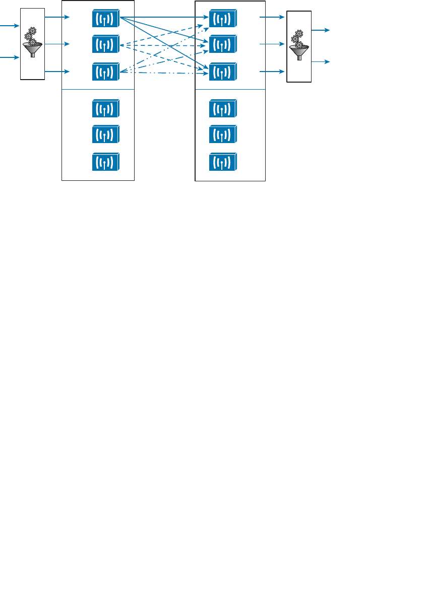
ptg12542968
Chapter 2: RF Standards 59
802.11n devices come with a variety of MIMO capabilities. Ideally, two devices should
support an identical number of spatial streams to multiplex and demultipex the data
streams correctly. That is not always possible or even likely because more spatial streams
usually translates to a greater cost. What happens when two devices have mismatched
spatial stream support? They negotiate the wireless connection by informing each other
of their capabilities. Then they can use the lowest number of spatial streams that they
have in common, but a transmitting device can leverage an additional spatial stream to
repeat some information for increased redundancy.
MAC Layer Efficiency
Even without multiple radio chains, 802.11n offers some important methods to make
data communication more efficient. Two of the methods are as follows:
■ Block acknowledgment —Normally, 802.11 requires that each frame of data trans-
mitted must be acknowledged by the recipient. If a frame goes unacknowledged,
the transmitter can assume that the frame was lost and needs to be resent. The over-
head of having acknowledgment messages interleaved with every transmitted frame
is inefficient; it uses up airtime on the shared media.
With 802.11n, data frames can be transmitted in one burst. Only one acknowledg-
ment is expected from the recipient after the burst is complete. More airtime can be
spent sending data, increasing the overall throughput.
■ Guard interval —As OFDM symbols are transmitted, they can take different paths
to reach the receiver. If two symbols somehow arrive too close together, they can
interfere with each other and corrupt the received data. This is known as intersym-
bol interference (ISI). The 802.11 standard requires a guard interval
(GI), a period
of 800 nanoseconds, between each OFDM symbol that is transmitted to protect
against ISI.
Tx 1
Tx 2
Tx 3
3 x 3:2 MIMO
Rx 1
Rx 2
3 x 3:2 MIMO
Rx 3
Rx 1
Rx 2
Rx 3
Tx 1
Tx 2
Tx 3
Spatial
Streams Spatial
Streams
S1
S2
S1
S2
Figure 2-7 Spatial Multiplexing Between Two 3×3:2 MIMO Devices.
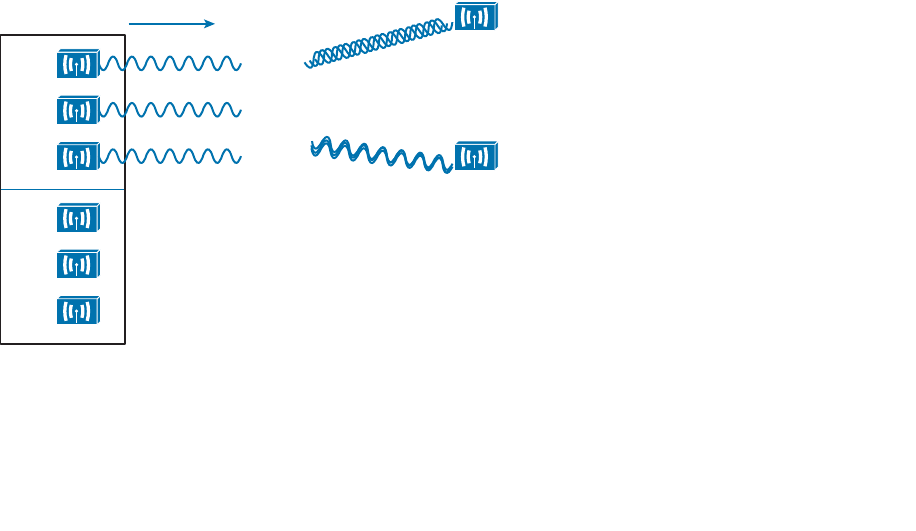
ptg12542968
60 CCNA Wireless 640-722 Official Cert Guide
As an option, you can configure 802.11n devices to use a much shorter 400-
nanosecond guard interval. This allows OFDM symbols to be transmitted more
often, increasing throughput by about 10 percent, at the expense of making data
corruption more likely.
Transmit Beam Forming (T×BF)
When a transmitter with a single radio chain sends an RF signal, any receivers that are
present have an equal opportunity to receive and interpret the signal. In other words, the
transmitter does nothing to prefer one receiver over another; each is at the mercy of its
environment and surrounding conditions to receive at a decent SNR.
The 802.11n amendment offers a method to customize the transmitted signal to prefer
one receiver over others. By leveraging MIMO, the same signal can be transmitted over
multiple antennas to reach specific client locations more efficiently.
Usually multiple signals travel over slightly different paths to reach a receiver, so they
can arrive delayed and out of phase with each other. This is normally destructive, result-
ing in a lower SNR and a corrupted signal. With transmit beamforming (T×BF), the
phase of the signal is altered as it is fed into each transmitting antenna so that the result-
ing signals will all arrive in phase at a specific receiver. This has a constructive effect,
improving the signal quality and SNR.
Figure 2-8 shows an 802.11n device using transmit beamforming to target device B. The
phase of each copy of the transmitted signal is adjusted so that all three signals arrive at
device B more or less in phase with each other. The same three signal copies also arrive
at device A, which is not targeted by T×BF. As a result, the signals arrive as is and are out
of phase.
Tx 1
Tx 2
Tx 3
3 x 3:2 MIMO
Rx 1
Rx 2
Rx 3
T x BF: Target Receiver B A
B
Figure 2-8 Using Transmit Beamforming to Target a Specific Receiving Device.

ptg12542968
Chapter 2: RF Standards 61
The location and RF conditions can be unique for each receiver in an area. Therefore,
transmit beamforming can use explicit feedback from an 802.11n device at the far end,
enabling the transmitter to make the appropriate adjustments to the transmitted signal
phase. As T×BF information is collected about each far end device, a transmitter can
keep a table of the devices and phase adjustments so that it can send focused transmis-
sions to each one dynamically. Although the feedback process sounds straightforward,
it is complex to implement. To date, no vendor has implemented a feedback mechanism
that makes T×BF practical and usable.
Cisco also offers ClientLink, which performs a similar transmit beamforming function;
however, ClientLink does not require explicit feedback from an 802.11n device at all.
Based on data that is received from a far end device, the phase values can be calculated
and performed on data transmissions that are returned to it. In this case, the far end
device can be 802.11n or legacy 802.11a/b/g.
Maximal-Ratio Combining
When an RF signal is received on a device, it may look very little like the original trans-
mitted signal. The signal may be degraded or distorted due to a variety of conditions.
If that same signal can be transmitted over multiple antennas, as in the case of a MIMO
device, then 802.11n can attempt to restore it to its original state.
An 802.11n device can use multiple antennas and radio chains to receive the multiple
transmitted copies of the signal. One copy might be better than the others, or one
copy might be better for a time, and then become worse than the others. In any event,
802.11n offers maximal-ratio combining (MRC), a feature that can combine the copies
to produce one signal that represents the best version at any given time. The end result is
a reconstructed signal with an improved SNR and receiver sensitivity.
802.11n Modulation and Coding Schemes
Recall that 802.11g and 802.11a are both based on OFDM and can use binary phase
shift keying (BPSK), quadrature phase shift keying (QPSK), 16-QAM (quadrature ampli-
tude modulation), and 64-QAM modulation schemes. Depending on conditions affect-
ing the RF signal, wireless devices can choose one of the eight possible modulation and
coding schemes. The 802.11n amendment is backward compatible with 802.11a and
802.11g, so it supports the same eight schemes. However, as the schemes are applied to
an increasing number of spatial streams, the number of combinations multiplies.
802.11n supports a total of 32 possible schemes (8 per spatial stream)—so many that
they are known by a modulation coding scheme (MCS) index number. Beyond that,
channel aggregation and guard interval selection add even more variables to the mix. In
all, 802.11n has 128 possible data rates. For your reference, Appendix B lists all of the
MCS and data rates.

ptg12542968
62 CCNA Wireless 640-722 Official Cert Guide
Beyond 802.11n
The many features and high throughput of 802.11n might make it seem like the end-all
wireless LAN technology. As with most any aspect of computing, the current state of
the art is never good enough. Two 802.11 draft amendments are being developed that
will take wireless performance to much greater heights. These amendments are not cov-
ered on the CCNA Wireless exam (yet), but are introduced here so that you can get a
feel for the continuing evolution of 802.11 capabilities.
The 802.11ac amendment takes the best of 802.11n and offers a new generation that
is much faster and more scalable. The goal is to bring wireless on a par with Gigabit
Ethernet. Some of the most notable improvements are as follows:
■ Better channel aggregation —40-MHz bonded channels can be bonded again into
channels that are 80 or 160 MHz wide.
■ More dense modulation —256-QAM will be used to modulate the RF signal in 256
different ways, taking more data at one time and boosting throughput. The 802.11n
modulation schemes (BPSK, QPSK, 16-QAM, and 64-QAM) will still be supported.
■ Scalable MIMO —Up to eight spatial streams will be used.
■ Multi-user MIMO (MU-MIMO) —An 802.11ac device will be able to send multiple
frames to multiple receiving devices simultaneously.
Because of the extensive use of channels, 802.11ac will be used only in the 5-GHz band.
Devices using 2.4 GHz will have to continue using 802.11n instead. With 802.11ac,
devices should have a selection of 40 modulation coding schemes, based on the number
of spatial streams. When channel aggregation and guard interval variables are figured in,
there should be a total of 320 possible data rates.
802.11ac hardware is expected to develop somewhat slowly, in phases or waves.
Products in the first wave will be able to reach a throughput of 1 to 2.4 Gbps. When
the second wave of product development peaks, those devices could reach a theoretical
maximum throughput of 6.93 Gbps.
In 2009, the Wireless Gigabit Alliance (WiGig) introduced a wireless specification that
would offer throughput of up to 7 Gbps over the unlicensed 60-GHz frequency space.
That specification became the 802.11ad amendment.
802.11ad is designed for very high throughput at shorter distances, making it a good fit
for wireless offices. Devices will be able to communicate directly with each other, with
support for interfaces like HDMI, DisplayPort, USB, and PCIe.
The 802.11ad amendment is meant to be backward compatible with 802.11 (including
802.11a, b, g, n, and ac), but will require new hardware because it operates in a com-
pletely different frequency band.
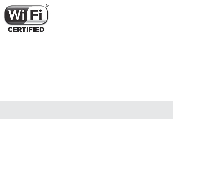
ptg12542968
Chapter 2: RF Standards 63
Wi-Fi Alliance
All wireless LAN products must adhere to the IEEE 802.11 set of standards to be
compatible with each other. Even though the 802.11 standards are very thorough and
lengthy, it is still possible for one manufacturer to build a product based on one inter-
pretation of a standard feature, while another manufacturer works with a different inter-
pretation. This is especially true when products are developed while an 802.11 amend-
ment is still in draft form. In addition, manufacturers are not obligated to implement
every function described in a standard; they may pick and choose certain parts or imple-
ment the entire standard, and may even add in some proprietary features.
The Wi-Fi Alliance ( http://wi-fi.org ) is a nonprofit industry association made up of wire-
less manufacturers around the world, all devoted to promoting wireless use. To address
the problem of incompatible wireless products, the Wi-Fi Alliance introduced the
Wi-Fi CERTIFIED program in 2000. Wireless products are tested in authorized testing
labs against stringent criteria that represent correct implementation of a standard. If a
product passes the tests, then it is certified and receives a Wi-Fi CERTIFIED stamp of
approval, using the logo shown in Figure 2-9 .
Figure 2-9 Wi-Fi Alliance Certification Logo.
For example, a Wi-Fi CERTIFIED 802.11n product must correctly implement the fol-
lowing features, among many others:
■ At least two spatial streams
■ Block acknowledgment
■ 2.4- and 5-GHz operation
■ Channel aggregation
Tip Remember that the IEEE develops and maintains the 802.11 set of standards and
the Wi-Fi Alliance tests and certifies product interoperability according to the standards.

ptg12542968
64 CCNA Wireless 640-722 Official Cert Guide
Exam Preparation Tasks
As mentioned in the section, “How to Use This Book,” in the Introduction, you have a
couple of choices for exam preparation: the exercises here, Chapter 22 , “Final Review,”
and the exam simulation questions on the CD-ROM.
Review All Key Topics
Review the most important topics in this chapter, noted with the Key Topic icon in the
outer margin of the page. Table 2-11 lists a reference of these key topics and the page
numbers on which each is found.
Table 2-11 Key Topics for Chapter 2
Key Topic Element Description Page Number
List ISM band allocation 42
List U-NII band allocation 42
List, Table 2-2 2.4-GHz and 5-GHz EIRP
rules
44
Figure 2-2 Channel layout in the 2.4-
GHz band
49
Table 2-7 802.11-1997 data rates 52
Table 2-8 802.11b data rates 52
Table 2-9 802.11g data rates 53
Table 2-10 802.11a data rates 55
Figure 2-6 802.11n channel aggregation 57
Paragraph 802.11n spatial stream
notation
58
Define Key Terms
Define the following key terms from this chapter and check your answers in the glos-
sary:
block acknowledgment, channel aggregations, guard interval (GI), high throughput
(HT), intersymbol interference (ISI), maximal-ratio combining (MRC), protection
mechanism, spatial multiplexing, spatial stream, transmit beamforming (TxBF)
Key
Topic

ptg12542968
This page intentionally left blank

ptg12542968
This chapter covers the following topics:
■ Interference —This section describes several types
of external interference that can adversely affect a
wireless signal.
■ Free Space Path Loss —This section explains why a
radio frequency signal degrades as it travels through
free space.
■ Effects of Physical Objects —This section explores
what happens when an RF signal meets various
physical objects, resulting in effects such as reflec-
tion, absorption, refraction, and diffraction.
This chapter covers the following exam topics:
■ Describe Wireless LAN (WLAN) RF principles
(antenna types, RF gain/loss, Effective Isotropic
Radiated Power (EIRP), refraction, reflection, and
so on)

ptg12542968
Radio frequency (RF) signals travel through the air as electromagnetic waves. In an ideal
setting, a signal would arrive at the receiver exactly as the transmitter sent it. In the real
world, this is not always the case. Many things affect RF signals as they travel from a
transmitter to a receiver. This chapter explores many of the conditions that can affect
wireless signal propagation.
“Do I Know This Already?” Quiz
The “Do I Know This Already?” quiz allows you to assess whether you should read this
entire chapter thoroughly or jump to the “Exam Preparation Tasks” section. If you are
in doubt about your answers to these questions or your own assessment of your knowl-
edge of the topics, read the entire chapter. Table 3-1 lists the major headings in this
chapter and their corresponding “Do I Know This Already?” quiz questions. You can
find the answers in Appendix A , “Answers to the ‘Do I Know This Already?’ Quizzes.”
Table 3-1 “Do I Know This Already?” Section-to-Question Mapping
Foundation Topics Section Questions
Interference 1–4
Free Space Path Loss 5–7
Effects of Physical Objects 8–10
Caution The goal of self-assessment is to gauge your mastery of the topics in this chap-
ter. If you do not know the answer to a question or are only partially sure of the answer,
you should mark that question as wrong for purposes of the self-assessment. Giving your-
self credit for an answer you correctly guess skews your self-assessment results and might
provide you with a false sense of security.
CHAPTER 3
RF Signals in the Real World

ptg12542968
68 CCNA Wireless 640-722 Official Cert Guide
1.
An 802.11 transmitter is configured to send a signal on channel 11. Someone reports
a problem receiving the signal, so you investigate and find a second transmitter
broadcasting on channel 11. Which one of the following best describes the prob-
lem?
a. Path interference
b. Adjacent channel interference
c. Co-channel interference
d. Cross-channel interference
2.
Suppose that you place a new 802.11 transmitter in a building, but notice that there
are other signals already coming from transmitters in the same general area. To
avoid interference problems, how much greater should your transmitter’s signal be
above all of the others?
a. 0 dBm
b. +3 dBm
c. +5 dBm
d. +10 dBm
e. +20 dBm
3.
An existing transmitter in your office sends its signal on 2.4-GHz channel 1.
Suppose that someone in a neighboring office sets up a new wireless router. He
notices your signal on channel 1, so he chooses channel 2 instead. Which one of the
following might adversely affect the wireless operation?
a. Co-channel interference
b. Neighboring channel interference
c. Wideband interference
d. Excessive SNR
4.
Which one of the following is the best strategy for avoiding interference between
neighboring channels in the 2.4-GHz band?
a.
Use any channel number that seems to be available
b.
Leverage 802.11n for 40-MHz aggregated channels
c.
Use only channels that are spaced four numbers apart, beginning with channel 1
d.
Use only channels that are spaced five numbers apart, beginning with channel 1
5.
Which one of the following is the primary cause of free space path loss?
a. Spreading
b. Absorption

ptg12542968
Chapter 3: RF Signals in the Real World 69
c. Humidity levels
d. Magnetic field decay
6.
Which one of the following has the shortest effective range in free space, assuming
that the same transmit power level is used for each?
a. An 802.11g device
b. An 802.11a device
c. An 802.11b device
d. None of these answers
7.
Suppose that an 802.11a device moves away from a transmitter. As the signal
strength decreases, which one of the following might the device or the transmitter
change to improve the signal quality along the way?
a. Aggregate more channels
b. Use more radio chains
c.
Switch to a more complex modulation scheme
d. Switch to a less-complex modulation scheme
8.
When RF signals are reflected by objects in a building, which one of the following
best describes the result that might be experienced at a receiver?
a. Fresnel loss
b. Multipath
c. Cross-channel fading
d. Free space path loss
9.
Which one of the following best describes the effect that a building material has as
an RF signal passes through a wall?
a. Reflection
b. Refraction
c. Diffraction
d. Absorption
e. Multipath
10.
Which one of the following best describes the purpose of the first Fresnel zone?
a.
The area covered by one transmitter on a channel
b.
The area around a signal path that should be kept clear of any obstructions
c.
The area around a signal path that is blocked by the earth’s curvature
d.
The area around a transmitter that represents the range of a signal
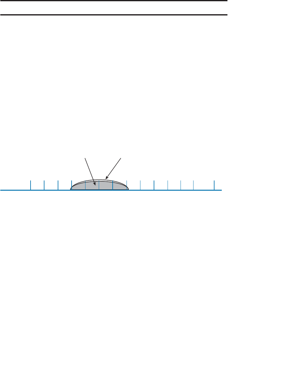
ptg12542968
70 CCNA Wireless 640-722 Official Cert Guide
Foundation Topics
Interference
The idea behind WLAN modulation is to pack as much data as possible into the wire-
less signal, and to minimize the amount of data that might be lost due to interference or
noise. When data is lost, it must be retransmitted, using more of the wireless resources.
Therefore, it is always best if a transmitter is configured to use a channel that is open
and is clear from any other transmitter.
Co-Channel Interference
Whenever one transmitter’s signal overlaps another on a frequency or channel, the sig-
nals interfere with each other. Interference can be described by the way the signals over-
lap. For example, co-channel interference occurs when two or more transmitters use the
same channel. In Figure 3-1 , Transmitters A and B are both transmitting an RF signal on
channel 6 in the 2.4-GHz band.
2.412 2.417 2.422 2.427 2.432 2.437 2.442 2.447 2.452 2.457 2.462
12345678910
11
Channel
GHz 2.467 2.472
12 13
2.484
14
Transmitter A
Channel 6
Transmitter B
Channel 6
Figure 3-1 Co-Channel Interference.
Because the two 802.11 transmitters are using the same channel, their signals completely
overlap and the whole 22-MHz channel bandwidth is affected. This might not be a
problem if the transmitters are not sending data at the same time. After all, wireless LAN
devices must contend for use of the airtime; if nobody is transmitting at a given time,
someone may use the channel.
When both transmitters are busy sending data, the channel can become very congested.
The two signals begin to interfere and cause data corruption, which causes devices to
retransmit lost data, which uses more airtime, and so on.
In the real world, co-channel interference is often a necessary evil. The 2.4-GHz band
offers only three non-overlapping channels. If you have many transmitters in a building
or area, you are bound to have some of them transmitting on the same channel as others.
The best solution is to use careful planning when you select the channel for each trans-
mitter. For instance, two nearby transmitters should never be placed on the same channel
because their strong signals would be more likely to interfere.
Instead, a transmitter should only share a channel with other distant transmitters whose
received signals are much weaker. A best practice is to place a transmitter on a channel
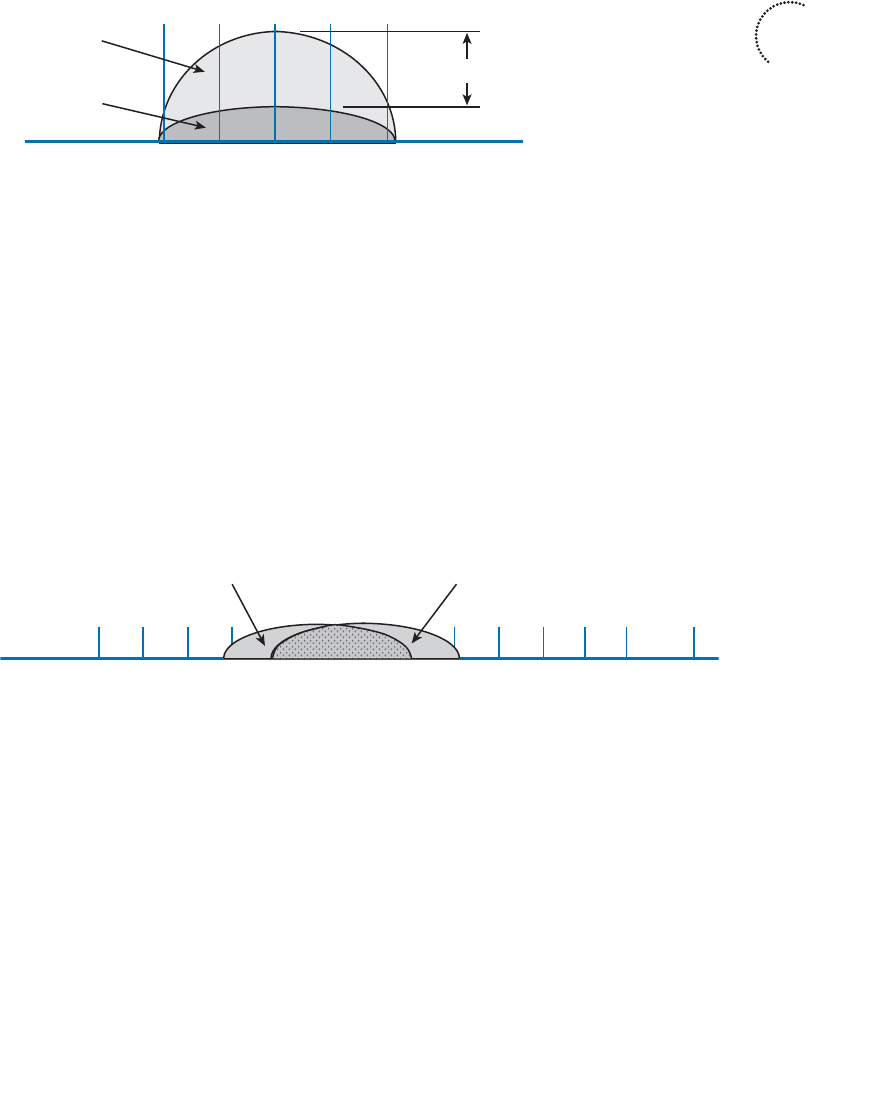
ptg12542968
Chapter 3: RF Signals in the Real World 71
only if its signal will be at least 19 dBm above any other received signal, as shown in
Figure 3-2 . Having at least 19 dBm separation helps maintain a healthy SNR in the area
surrounding the transmitter. Channel assignment is covered in more detail in Chapter 7 ,
“Planning Coverage with Wireless APs.”
2.427 2.432 2.437 2.442 2.447
45678
Transmitter A
Channel 6
Transmitter B
Channel 6
≥ 19 dBm
Figure 3-2 Maintaining Signal Separation to Minimize Co-Channel Interference.
Neighboring Channel Interference
Suppose that two transmitters are placed on two different channels. However, the chan-
nels are spaced too closely together such that they overlap each other. Perhaps someone
decided to use neighboring channels, rather than reuse the same channel, to avoid co-
channel interference. More likely, two different people have transmitters located in the
same general area and decided to use slightly different channel numbers—not realizing
that neighboring channels in the 2.4-GHz band overlap.
The end result is interference on both channels because a portion of one signal overlaps
a portion of another signal. In Figure 3-3 , transmitter A is using channel 6, while trans-
mitter B is using channel 7. The two signals do not completely overlap, but the interfer-
ence between them is enough to be detrimental to both.
2.412 2.417 2.422 2.427 2.432 2.437 2.442 2.447 2.452 2.457 2.462
12345678910
11
Channel
GHz 2.467 2.472
12 13
2.484
14
Transmitter A
Channel 6
Transmitter B
Channel 7
Figure 3-3 Adjacent Channel Interference.
Tip Do you think of neighboring channels as having adjacent channel numbers? You are
not alone; after all, channel numbers 1 and 2 are adjacent. Interference between neighbor-
ing channels is commonly called adjacent channel interference . Technically, this term
is incorrect and is often misused. The 802.11 standard defines adjacent channels as non-
overlapping channels. Therefore, by definition, it is impossible for adjacent channels to
overlap and interfere. Be aware that the CCNA Wireless exam strictly uses the terminol-
ogy found in the 802.11 standard. Adjacent channels cannot overlap, but neighboring
channels can.
Key
Topic
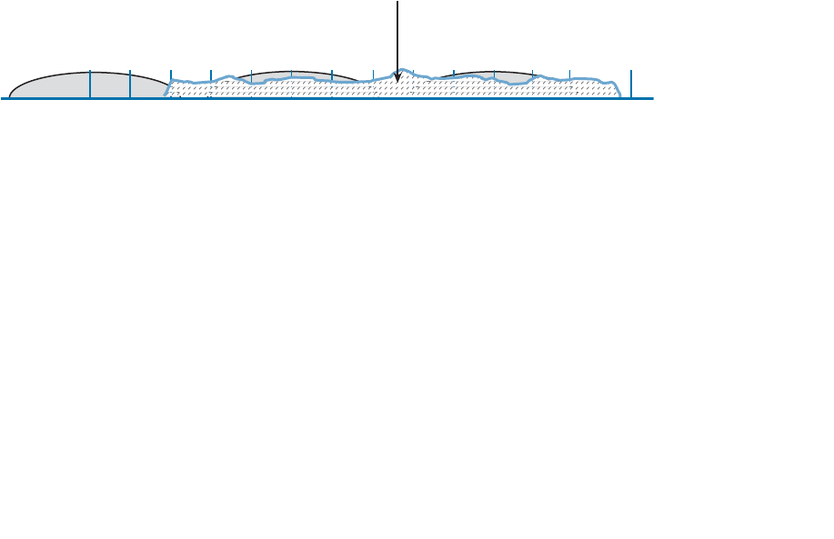
ptg12542968
72 CCNA Wireless 640-722 Official Cert Guide
To remedy the situation, all transmitters in an area should be configured to use the three
non-overlapping 2.4-GHz channels: 1, 6, and 11. In the 5-GHz band, adjacent channel
interference is not a problem because the channels do not significantly overlap; the
channels are 20 MHz wide, whereas the orthogonal frequency-division multiplexing
(OFDM) signals have a bandwidth of 20 MHz. As a best practice, you should still avoid
placing neighboring APs on neighboring 5 GHz channels, just to avoid the possibility of
raising the noise floor.
Non-802.11 Interference
Recall that the 2.4-GHz band is an ISM band. This means that your 802.11 wireless LAN
devices might share the same frequency space as non-802.11 devices. That might not
sound like a bad situation because the devices could simply be configured to use differ-
ent, non-overlapping channels.
In practice, such an elegant solution might not be possible. Many non-802.11 devices
do not sit on any one channel; they use frequency-hopping spread spectrum (FHSS) to
hop around on a variety of channels at any given time. Even worse, some devices do
not adhere to any channel scheme at all. Figure 3-4 shows transmitters A, B, and C using
channels 1, 6, and 11—a perfect world—until someone decides to warm up her lunch.
A nearby microwave oven also uses RF energy in the 2.4-GHz ISM band to radiate the
food. Because it is poorly shielded, the RF energy escapes and interferes with most of
the 802.11b/g channels. The microwave’s transmission is also constant, rendering the
wireless LAN channels mostly useless.
2.412 2.417 2.422 2.427 2.432 2.437 2.442 2.447 2.452 2.457 2.462
1234567891011Channel
GHz 2.467 2.472
12 13
2.484
14
Transmitter A
Channel 1
Microwave Oven
Most Channels
Transmitter B
Channel 6
Transmitter C
Channel 11
Figure 3-4 Non-802.11 Interference From a Microwave Oven.
To mitigate interference from non-802.11 devices, you have to eliminate the source.
Leaky microwave ovens should be replaced with better models that have proper RF
shielding. Devices like 2.4-GHz FHSS cordless phones or wireless video cameras should
be replaced with models that operate in a non-802.11 band.
Free Space Path Loss
Whenever an RF signal is transmitted from an antenna, its amplitude decreases as it trav-
els through free space. Even if there are no obstacles in the path between the transmitter
and receiver, the signal strength will weaken. This is known as free space path loss.
What is it about free space that causes an RF signal to be degraded? Is it the air or
maybe the earth’s magnetic field? No, even signals sent to and from spacecraft in the
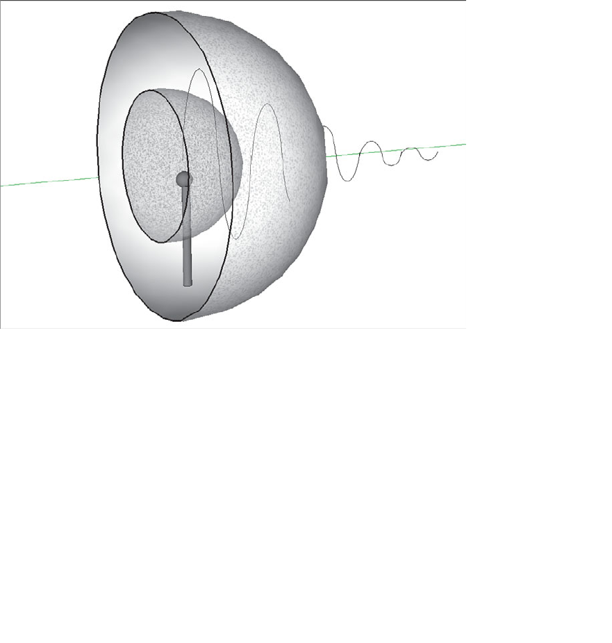
ptg12542968
Chapter 3: RF Signals in the Real World 73
vacuum of outer space are degraded.
Recall that an RF signal propagates through free space as a wave, not as a ray or straight
line. The wave has a three-dimensional curved shape that expands as it travels. It is this
expansion or spreading that causes the signal strength to weaken.
Figure 3-5 shows a cutaway view of the free space loss principle. Suppose the antenna is
a tiny point, such that the transmitted RF energy travels in every direction. The wave that
is produced would take the form of a sphere; as the wave travels outward, the sphere
increases in size. Therefore, the same amount of energy coming out of the tiny point
is soon spread over an ever expanding sphere in free space. The concentration of that
energy gets weaker as the distance from the antenna increases.
Figure 3-5 Free Space Loss Due to Wave Spreading.
Even if you could devise an antenna that could focus the transmitted energy into a tight
beam, the energy would still travel as a wave and would spread out over a distance.
Regardless of the antenna used, the amount of signal strength loss is consistent.
The free space path loss in dB can be calculated according to the following equation:
FSPL (dB) = 20log 10 (d) + 20log 10 (f) + 32.44
where d is the distance from the transmitter in kilometers and f is the frequency in mega-
hertz. Do not worry, though: you will not have to know this equation for the CCNA
Wireless exam. It is presented here to show two interesting facts:
■ Free space path loss is an exponential function; the signal strength falls off quickly
near the transmitter, but more slowly farther away.

ptg12542968
74 CCNA Wireless 640-722 Official Cert Guide
■ The loss is a function of distance and frequency only.
With the formula, you can calculate the free space path loss for any given scenario, but
you will not have to for the exam. Just be aware that the free space path loss is always an
important component of the link budget, along with antenna gain and cable loss.
You should also be aware that the free space path loss is greater in the 5-GHz band than
it is in the 2.4-GHz band. In the equation, as the frequency increases, so does the loss in
dB. This means that 802.11b/g/n devices (2.4 GHz) have a greater effective range than
802.11a/n (5 GHz) devices, assuming an equal transmitted signal strength. Figure 3-6
shows the range difference, where both transmitters have an effective isotropic radiated
power (EIRP) of 14 dBm and the effective range ends where a receiver’s received signal
strength indicator (RSSI) equals –67 dBm.
2.4 GHz
5 GHz
2.4 GHz
–67 dBm
5 GHz
–67 dBm
Figure 3-6 The Effective Range of 2.4-GHz and 5-GHz Transmitters.
Tip To get a feel for the actual range difference between 2.4 and 5 GHz, a receiver was
carried away from the two transmitters until the RSSI reached –67 dBm. On a 2.4-GHz
channel, the range was measured to be 140 feet, whereas at 5 GHz it was reduced to 80
feet.
Mitigating the Effects of Free Space Path Loss
One simple solution to overcome free space path loss is to increase the transmitter’s out-
put power. Increasing the antenna gain can also boost the EIRP. Having a greater signal
Key
Topic

ptg12542968
Chapter 3: RF Signals in the Real World 75
strength before the free space loss occurs translates to a greater RSSI value at a distant
receiver after the loss. This approach might work fine for an isolated transmitter, but can
cause interference problems when several transmitters are located in an area.
A more robust solution is to just cope with the effects of free space path loss. Wireless
devices are usually mobile and can move closer to or farther away from a transmitter
at will. As a receiver gets closer to a transmitter, the RSSI increases. This, in turn, trans-
lates to an increased signal-to-noise ratio (SNR). Recall from Chapter 1 , “RF Signals and
Modulation,” that more complex modulation and coding schemes can be used to trans-
port more data when the SNR is high. As a receiver gets farther away from a transmitter,
the RSSI (and SNR) decreases. More basic modulation and coding schemes are needed
there because of the increase in noise and the need to repeat more data.
802.11 devices have a clever way to adjust their modulation and coding schemes based
on the current RSSI and SNR conditions. If the conditions are favorable for good signal
quality and higher data rates, a complex modulation and coding scheme is used. As the
conditions deteriorate, less-complex schemes can be selected, resulting in a greater range
but lower data rates. The scheme selection is commonly known as dynamic rate shifting
(DRS). As its name implies, it can be performed dynamically with no manual interven-
tion.
Tip Although DRS is inherently used in 802.11 devices, it is not defined in the 802.11
standard. Each manufacturer can have its own approach to DRS; so all devices don’t
necessarily select the same scheme at the same location. DRS is also known by many
alternative names, such as link adaptation , adaptive modulation and coding (AMC), rate
adaptation , and so on.
Figure 3-7 illustrates DRS operation on the 2.4-GHz band. Each concentric circle repre-
sents the range supported by a particular modulation and coding scheme. The figure is
somewhat simplistic because it assumes a consistent power level across all modulation
types. Notice that the white circles denote OFDM modulation (802.11g) and that the
shaded circles contain DSSS modulation (802.11b). The data rates are arranged in order
of increasing circle size or range from the transmitter.
Suppose that a mobile user starts out near the transmitter, within the innermost circle,
where the received signal is strong and SNR is high. Most likely, wireless transmissions
will use the OFDM 64-QAM 3/4 modulation and coding scheme to achieve a data rate
of 54 Mbps. As the user walks away from the transmitter, the RSSI and SNR fall by some
amount. The new RF conditions will likely trigger a shift to a different modulation and
coding scheme, resulting in a lower data rate.
In a nutshell, each move into a larger concentric circle causes a dynamic shift to a
reduced data rate, in an effort to maintain the data integrity to the outer reaches of the
transmitter’s range.
The 5-GHz band looks very similar to Figure 3-7 , except that every circle uses an OFDM
modulation scheme corresponding to 802.11a.
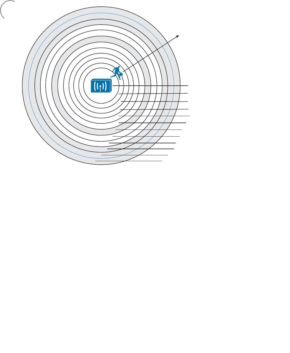
ptg12542968
76 CCNA Wireless 640-722 Official Cert Guide
Effects of Physical Objects
As an RF signal propagates through free space, it might encounter physical objects in
its path. Objects and materials can affect an RF signal in a variety of ways, mostly in a
degrading or destructive fashion. The following sections cover the most common
scenarios.
Reflection
If an RF signal traveling as a wave meets a dense reflective material, the signal can be
reflected. Think of the light emitted from a light bulb; while most of the light is traveling
in all directions away from the bulb, some might be reflected from objects in a room.
The reflected light might travel back toward the bulb or toward another area of the
room, making that area even brighter.
Figure 3-8 depicts a reflected RF signal. Indoor objects such as metal furniture, filing
cabinets, and metal doors can cause reflection. An outdoor wireless signal can be reflect-
ed by objects such as a body of water, reflective glass on a building, or the surface of the
earth.
6 Mbps
5.5 Mbps
2 Mbps
1 Mbps
11 Mbps
9 Mbps
OFDM 64-QAM 3/4
OFDM 64-QAM 2/3
OFDM 16-QAM 3/4
OFDM 16-QAM 1/2
OFDM QPSK 3/4
OFDM QPSK 1/2
DSSS CCK
OFDM BPSK 3/4
36 Mbps
24 Mbps
18 Mbps
12 Mbps
48 Mbps
54 Mbps
OFDM BPSK 1/2
DSSS CCK
DSSS DQPSK
DSSS DBPSK
Data Rate
Modulation/Coding Scheme
Figure 3-7 Dynamic Rate Shifting as a Function of Range.
Key
Topic
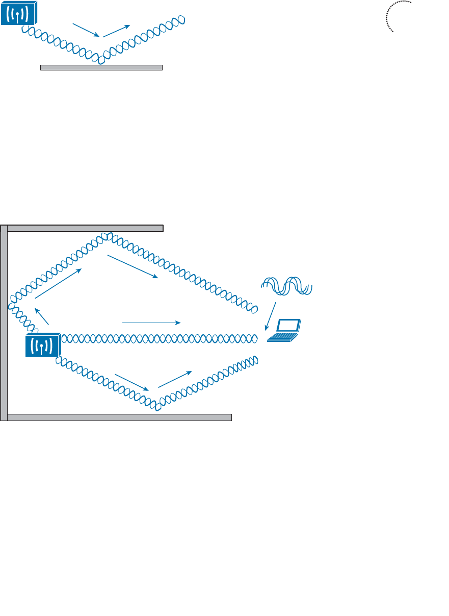
ptg12542968
Chapter 3: RF Signals in the Real World 77
Figure 3-8 Reflection of an RF Signal.
A reflection is not necessarily bad because it is just a copy of the original signal.
However, if both the copy and the original reach a receiver, they can arrive out of phase
with each other. This is because the reflection takes a different path than the original,
causing it to arrive slightly later. This is known as multipath . When the receiver com-
bines the two signals, the result is a poor representation of the original signal. The com-
bined signal can be weak and distorted, causing the data to be corrupted.
In Figure 3-9 , the original signal, along with two different reflections, arrive at the receiv-
er embedded in a laptop computer. The two reflections each take a different path and
arrive at different times.
Original Signal
Reflected Copy
Reflected Copy
Multipath Result
Figure 3-9 Multipath Transmissions.
When multipath transmissions occur, there can be two outcomes:
■ If the receiver has a single radio chain, then all of the arriving signals (original and
reflected) are combined into one poor, error prone composite signal.
■ If the receiver has multiple radio chains and supports multiple-input, multiple-out-
put (MIMO), each arriving signal might be received on a different antenna or radio.
Further processing can improve the signal quality or extract multiple data streams—
making something good out of a bad situation.
Key
Topic
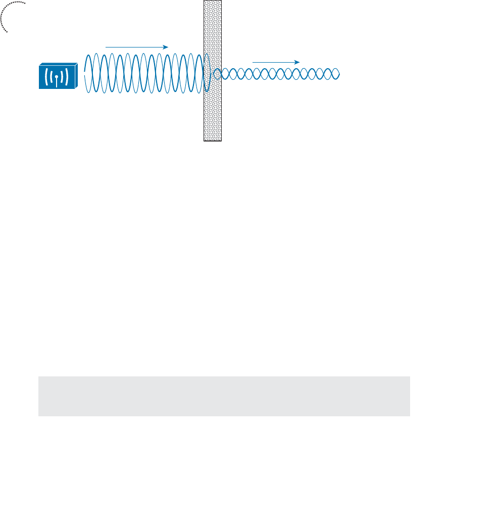
ptg12542968
78 CCNA Wireless 640-722 Official Cert Guide
Key
Topic
Absorption
If an RF signal passes into a material that can absorb some of its energy, the signal will
be attenuated. The more dense the material, the more the signal will be attenuated.
Figure 3-10 shows how a signal is affected by absorption and how a receiver might be
affected by the lower signal strength.
Figure 3-10 Absorption of an RF Signal.
One common example of absorption is when a wireless signal passes through a wall in
a building. Different wall materials absorb different amounts of energy. For example, a
wall constructed from gypsum or drywall might attenuate a signal by –4 dBm. A solid
concrete wall might attenuate it by –12 dBm. The thicker the wall or the more dense the
material, the greater the attenuation will be.
In outdoor wireless scenarios, RF signals frequently have to travel through water. The
water might be contained in tree leaves positioned along the wireless path. Even in unob-
structed space, the signal might encounter water in the form of rain, snow, hail, or fog.
As the air is filled with heavier rain or snow, the signal will be attenuated more.
Another less-obvious example of absorption is the human body, which is made up most-
ly of water. A person will usually hold a laptop computer, tablet PC, or a smartphone
close to his or her body. Depending on how the person is oriented with respect to the
transmitter, his body could sit between the transmitter and the receiver, attenuating the
signal. Likewise, a classroom or auditorium might be filled with human bodies, each with
the potential to attenuate the signal from a transmitter.
Tip To gain perspective, a quick experiment revealed that a human body attenuated a
2.4-GHz signal by –5 dBm.
Scattering
When an RF signal passes into a medium that is rough, uneven, or made up of very small
particles, the signal can be scattered into many different directions. This is because the
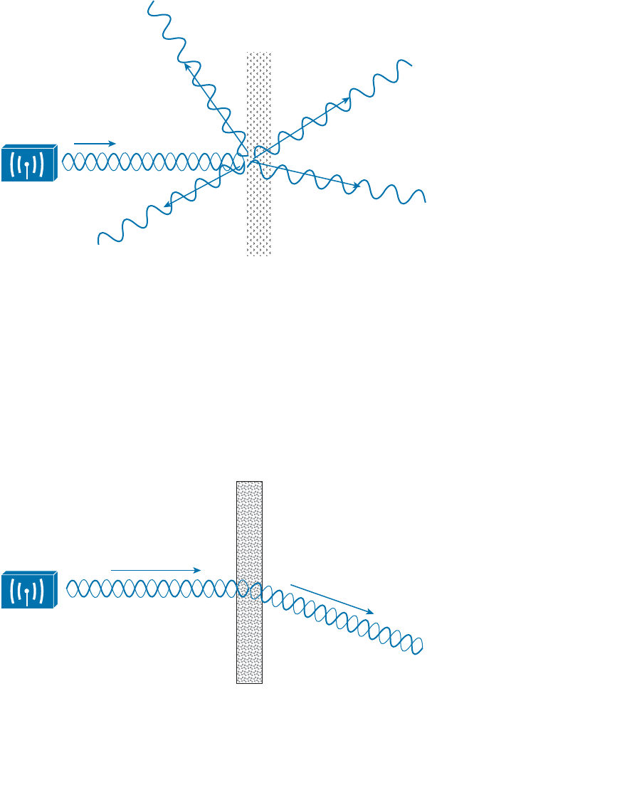
ptg12542968
Chapter 3: RF Signals in the Real World 79
tiny irregular surfaces of the medium can reflect the signal, as shown in Figure 3-11 .
Scattering can occur when a wireless signal passes through a dusty or sandy environment.
Figure 3-11 Scattering an RF Signal.
Refraction
When an RF signal meets the boundary between media of two different densities, it can
also be refracted. Think of reflection as bouncing off a surface and refraction as being
bent while passing through a surface.
A refracted signal will have a different angle from the original, as illustrated in Figure 3-
12 . The speed of the wave can also be affected as it passes through the different materi-
als. A signal can be refracted when it passes through layers of air having different densi-
ties or through building walls with different densities, for example.
Figure 3-12 Refraction of an RF Signal.
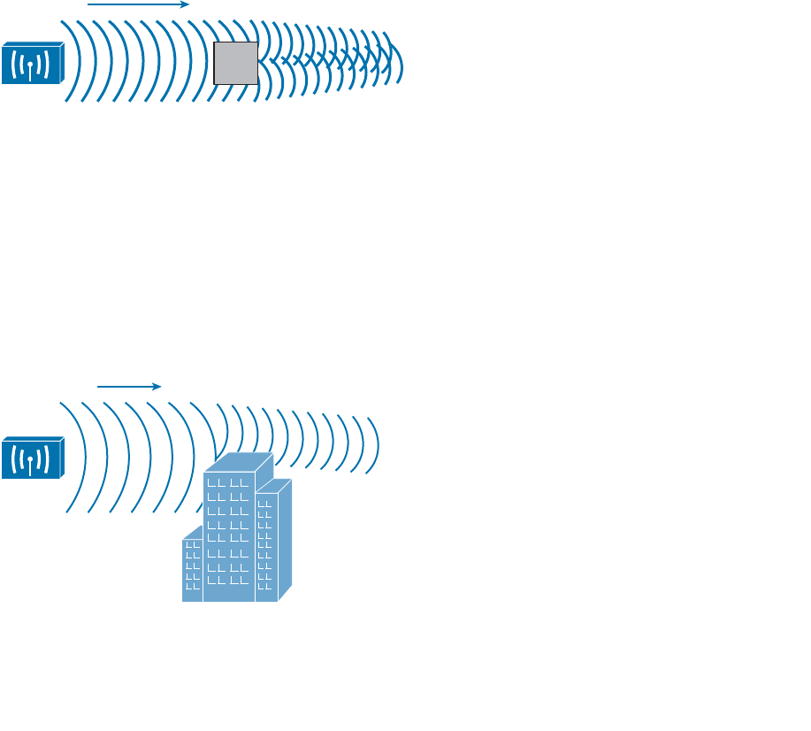
ptg12542968
80 CCNA Wireless 640-722 Official Cert Guide
Diffraction
Suppose an RF signal approaches an opaque object, or one that is able to absorb the
energy that strikes it. You might think that the object would produce a shadow in place
of the signal that is absorbed, much like an object might make a shadow as light shines
on it. If a shadow formed, it might make a dead or silent zone in the RF signal behind
the object.
With RF propagation, however, the signal tends to bend around the object and eventu-
ally rejoin to complete the wave. Figure 3-13 shows how a radio opaque object can cause
diffraction of an RF signal. Diffraction is best viewed as concentric waves, rather than
an oscillating signal, so that its effect on the actual waves can be seen. In the figure, dif-
fraction has caused the signal to “heal” itself around an absorbing object. This makes
reception possible even when a building stands between the transmitter and receiver.
However, the signal is never quite like the original again, as it has been distorted by the
diffraction.
Figure 3-13 Diffraction of an RF Signal.
Fresnel Zones
If an object is standing free, so that an RF signal traveling parallel with the ground is
diffracted around it on both sides, the signal will often fill in the object’s “shadow” as it
continues to propagate. However, if a standing object such as a building or a mountain
obstructs the signal, the signal can be adversely affected in the vertical direction.
In Figure 3-14 , a building partially obstructs the path of the signal. Because of diffrac-
tion along the front and top of the building, the signal is bent and also attenuated. This
causes the signal to be masked behind most of the height of the building.
Figure 3-14 A Standing Obstacle Diffracts a Signal.
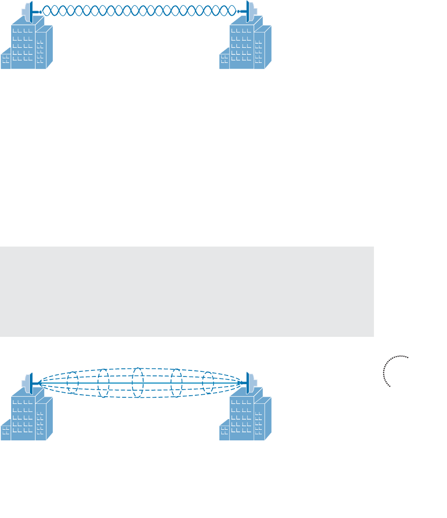
ptg12542968
Chapter 3: RF Signals in the Real World 81
This is especially important in narrow line-of-sight wireless transmission, which is suited
for very long distances. These signals do not propagate in all directions; rather, they are
focused into a tight cone-shaped pattern, as shown in Figure 3-15 . For a line-of-sight
path, the signal must be clear of any obstructions between the transmitter’s antenna and
the receiver’s antenna. Paths between buildings or between cities commonly have other
buildings, trees, or other objects that might block the signal. In those cases, the antennas
must be raised higher than the obstructions to get a clear path.
Transmitter Receiver
Figure 3-15 A Line-of-Sight Wireless Signal.
Over a very long distance, the curvature of the earth actually becomes an obstacle that
can affect the signal. Beyond a distance of about two miles, the far end cannot be seen
because it lies slightly below the horizon. Nevertheless, a wireless signal tends to propa-
gate along the same curve, following the atmosphere around the earth’s curvature.
Even narrow line-of-sight signals can be affected by diffraction, even if an object does
not directly block the signal. There is an elliptical-shaped volume around the line of sight
that must also remain free of obstructions. This is called the Fresnel zone , as shown in
Figure 3-16 . If an object penetrates the Fresnel zone anywhere along the path, some por-
tion of the RF signal can be diffracted by it. That portion of the signal gets bent, causing
it to be delayed or altered so that it affects the overall signal arriving at the receiver.
Tip Actually, there are many concentric Fresnel zones surrounding the line of sight
path. Only the innermost, or first, Fresnel zone is described in this section and taken into
account because it affects the transmitted signal the most. Fresnel zones are numbered
incrementally as their size increases. Oddly enough, the odd-numbered Fresnel zones
have a destructive effect on signals, whereas the even-numbered zones can have a con-
structive effect and add to the signal’s power.
Transmitter
Fresnel Zone
Receiver
Figure 3-16 The Fresnel Zone.
Key
Topic
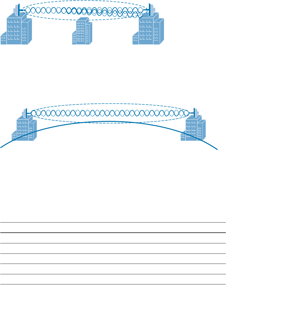
ptg12542968
82 CCNA Wireless 640-722 Official Cert Guide
In Figure 3-17 , a building lies along the signal’s path, but does not obstruct the beam
of the signal; however, it does penetrate the Fresnel zone, so the received signal will be
negatively affected.
Transmitter Receiver
Fresnel Zone
Figure 3-17 Signal Degradation Due to a Fresnel Zone Obstruction.
As a rule, you should raise the antennas of a line-of-sight system so that even the bottom
of the Fresnel zone is higher than any obstruction. Remember that as the path gets very
long, even the curvature of the earth can enter the Fresnel zone and cause problems, as
Figure 3-18 shows.
Figure 3-18 The Earth’s Curvature Enters the Fresnel Zone.
The radius of the Fresnel zone can be calculated according to a complex formula.
However, you should only be concerned with the idea that the Fresnel zone exists and
should remain clear. Table 3-2 gives some example values of the Fresnel zone radius at
the midpoint of some line-of-sight path lengths for wireless frequencies in the 2.4GHz
band.
Table 3-2 Fresnel Zone Radius Values
Path Length Fresnel Zone Radius at Path Midpoint
0.5 miles 16 feet
1.0 miles 23 feet
2.0 miles 33 feet
5.0 miles 52 feet
10.0 miles 72 feet

ptg12542968
Chapter 3: RF Signals in the Real World 83
Exam Preparation Tasks
As mentioned in the section, “How to Use This Book,” in the Introduction, you have a
couple of choices for exam preparation: the exercises here, Chapter 22 , “Final Review,”
and the exam simulation questions on the CD-ROM.
Review All Key Topics
Review the most important topics in this chapter, noted with the Key Topic icon in the
outer margin of the page. Table 3-3 lists a reference of these key topics and the page
numbers on which each is found.
Table 3-3 Key Topics for Chapter 3
Key Topic Element Description Page Number
Figure 3-2 Co-channel interference 71
Figure 3-6 Free space path loss affecting signal range 74
Figure 3-7 Changing modulation and coding schemes
with DRS
76
Figure 3-8 Reflection 77
Figure 3-10 Absorption 78
Figure 3-16 Fresnel zone 81
Define Key Terms
Define the following key terms from this chapter and check your answers in the glos-
sary:
absorption, adjacent channel interference, co-channel interference, diffraction,
dynamic rate shifting, free space path loss, Fresnel zone, multipath, reflection,
refraction, scattering
Key
Topic

ptg12542968
This chapter covers the following topics:
■ Antenna Characteristics —This section describes
the radiation pattern, gain, beamwidth, and polariza-
tion of an antenna.
■ Antenna Types —This section covers the two basic
types of antennas and their applications.
■ Adding Antenna Accessories —This section
explains several devices that can be added to an
antenna to increase or reduce signal strength and to
protect connected equipment from lightning
damage.
This chapter covers the following exam topics:
■ Describe Wireless LAN (WLAN) RF principles
(antenna types, RF gain/loss, Effective Isotropic
Radiated Power (EIRP), refraction, reflection, and
so on)

ptg12542968
Chapters 1 through 3 covered radio frequency (RF) signals, as used by 802.11 devices,
and their propagation from the perspective of a transmitter and a receiver. By consider-
ing the link budget, or the net signal strength gain between a transmitter and receiver,
you can make sure that a signal will arrive in good condition at its destination. The anten-
na gain is an important piece of the equation, but it does not completely describe an
antenna’s construction or performance. This chapter explains some basic antenna theory,
in addition to various types of antennas and their application.
“Do I Know This Already?” Quiz
The “Do I Know This Already?” quiz allows you to assess whether you should read this
entire chapter thoroughly or jump to the “Exam Preparation Tasks” section. If you are
in doubt about your answers to these questions or your own assessment of your knowl-
edge of the topics, read the entire chapter. Table 4-1 lists the major headings in this
chapter and their corresponding “Do I Know This Already?” quiz questions. You can
find the answers in Appendix A , “Answers to the ‘Do I Know This Already?’ Quizzes.”
Table 4-1 “Do I Know This Already?” Section-to-Question Mapping
Foundation Topics Section Questions
Antenna Characteristics 1–5
Antenna Types 6–9
Adding Antenna Accessories 10
Caution The goal of self-assessment is to gauge your mastery of the topics in this chap-
ter. If you do not know the answer to a question or are only partially sure of the answer,
you should mark that question as wrong for purposes of the self-assessment. Giving your-
self credit for an answer you correctly guess skews your self-assessment results and might
provide you with a false sense of security.
CHAPTER 4
Understanding Antennas

ptg12542968
86 CCNA Wireless 640-722 Official Cert Guide
1.
Which two of the following plots are used to show the radiation pattern of an
antenna?
a. A plane
b. E plane
c. XY plane
d. H plane
e. YZ-plane
2.
Which one of the following is another name for the H plane radiation pattern?
a. Horizon plane
b. Azimuth plane
c. Heat map
d. Lateral plane
3.
Which one of the following answers correctly identifies the antenna parameter that
is measured at 3 dB below the strongest point on a radiation pattern plot?
a. Half life
b. Decay point
c. Cut off point
d. Beamwidth
e. Sensitivity
4.
The orientation of an electromagnetic wave is best described by which one of the
following?
a. Phase
b. Amplitude
c. Modulation
d. Polarization
e. Azimuth
5.
A Cisco dipole antenna is mounted so that it points straight upward and has a radia-
tion pattern that extends far outward horizontally. Which one of the following best
describes the antenna’s polarization?
a. Horizontal polarization
b. Vertical polarization
c. Dual polarization
d. Elliptical polarization

ptg12542968
Chapter 4: Understanding Antennas 87
6.
Which one of the following antennas would probably have the greatest gain?
a. Patch
b. Dish
c. Yagi
d. Dipole
e. Integrated
7.
An omnidirectional antenna usually has which of the following characteristics?
(Choose two.)
a. Low gain
b. Small beamwidth
c. High gain
d. Zero gain
e. Large beamwidth
8.
A certain Cisco wireless access point model has antennas that are hidden inside the
case. Which one of the following describes the antennas?
a. Patch antennas
b. Monopole antennas
c. Omnidirectional antennas
d. Isotropic antennas
9.
A dipole antenna is connected to a transmitter. You would like to leverage the
directional quality of the antenna. Based on the radiation pattern of the antenna,
what would happen if you orient the antenna such that its cylindrical shape points
directly at a distant receiver?
a.
The receiver would pick up a stronger signal.
b.
The receiver would pick up a weaker signal.
c.
The antenna is omnidirectional, so the orientation would not matter.
d.
This is pointless unless the receiver’s dipole is also aimed directly at the trans-
mitter.
10.
Which one of the following is not
true about a lightning arrestor?
a.
It is connected inline between a transmitter and an antenna.
b.
It protects against large transient spikes of energy.
c.
It protects against lightning strikes on an antenna.
d.
It directs energy to the ground, rather than the transmitter equipment.
e. Every outdoor antenna needs one.

ptg12542968
88 CCNA Wireless 640-722 Official Cert Guide
Foundation Topics
Antenna Characteristics
The world of wireless LANs would be rather simple if all antennas were created equal—
too simple, in fact. To provide good wireless LAN coverage in a building, an outdoor
area, or between two locations, you might be faced with a number of variables. For
example, an office space might be arranged as a group of open cubicles or as a strip of
closed offices down a long hallway. You might have to cover a large open lobby, a large
open classroom, a section of a crowded sports arena, an oblong portion of a hospital
roof where helicopters land, a large expanse of an outdoor park, city streets where pub-
lic safety vehicles travel, and so on.
In other words, one type of antenna cannot fit every application. Instead, antennas come
in many sizes and shapes, each with its own gain value and intended purpose. The fol-
lowing sections describe antenna characteristics in more detail.
Radiation Patterns
Recall from Chapter 1 , “RF Signals and Modulation,” that antenna gain is normally a
comparison of one antenna against an isotropic antenna, and is measured in dBi (decibel-
isotropic). An isotropic antenna does not actually exist because it is ideal, perfect, and
impossible to construct. It is also the simplest, most basic antenna possible, which makes
it a good starting place for antenna theory.
An isotropic antenna is shaped like a tiny round point. When an alternating current is
applied, an RF signal is produced and the electromagnetic waves are radiated equally in
all directions. The energy produced by the antenna takes the form of an ever-expanding
sphere. If you were to move all around an isotropic antenna at a fixed distance, you
would find that the signal strength is the same.
To describe the antenna’s performance, you might draw a sphere with a diameter that is
proportional to the signal strength, as shown in Figure 4-1 . Most likely, you would draw
the sphere on a logarithmic scale so that very large and very small numbers could be
shown on the same linear plot. A plot that shows the relative signal strength around an
antenna is known as the radiation pattern .
It is rather difficult to show a three-dimensional plot or shape on a two-dimensional
document—especially if the shape is complex or unusual. After all, most physical anten-
nas are not ideal, so their radiation pattern is not a simple sphere. Instead, you could
slice through the three-dimensional plot with two orthogonal planes and show the two
outlines that are formed from the plot. In Figure 4-1 , the sphere is cut by the XY plane,
which lies flat along the horizon, and by the XZ plane, which lies vertically along the
elevation of the sphere. Figure 4-2 shows the resulting cuts.
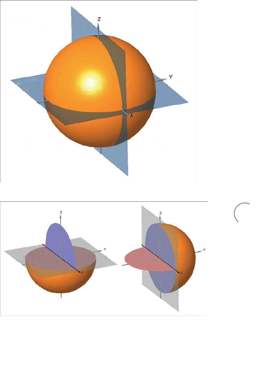
ptg12542968
Chapter 4: Understanding Antennas 89
Figure 4-2 Cutting the Radiation Pattern with Two Planes.
Figure 4-1 Plotting the Radiation Pattern of an Isotropic Antenna.
Key
Topic
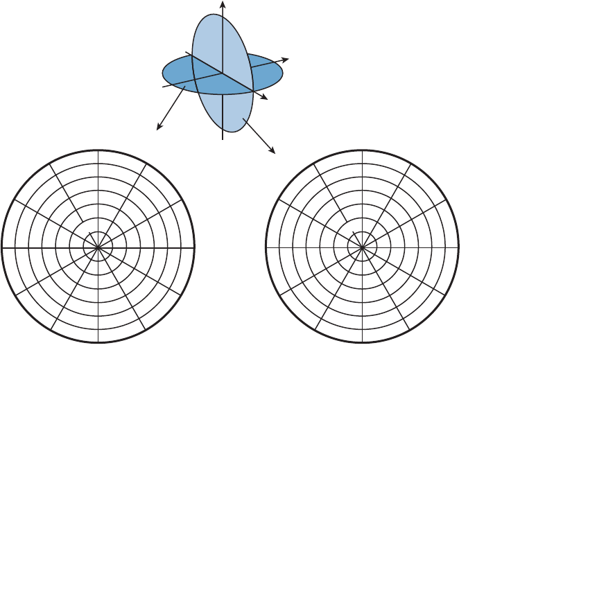
ptg12542968
90 CCNA Wireless 640-722 Official Cert Guide
The plane at the left is known as the H plane or the azimuth plane , and usually shows a
top down view of the radiation pattern through the center of the antenna. The plane at
the right is known as the E plane or elevation plane, and shows a side view of the same
radiation pattern.
The outline of each plot can be recorded on a polar plot, as shown by the heavy dark
lines in Figure 4-3 . A polar plot contains concentric circles that represent relative chang-
es in the signal strength as measured at a constant distance from the antenna. The out-
ermost circle usually represents the strongest signal strength, and the inner circles rep-
resent weaker signal strength. Although the circles are labeled with numbers like 0, –5,
–10, –15, and so on, they do not necessarily represent any absolute dB values. Instead,
they are measurements that are relative to the maximum value at the outside
circle. If the
maximum is shown at the outer ring, everything else will be less than the maximum and
will lie further inward.
60°
30°
90°
120°
150°
180°
210°
240°
270°
300°
330°
0 dB
–5
–10
–15
–20
–25
–30
60°
30°
90°
120°
150°
180°
210°
240°
270°
300°
330°
0°
0 dB
–5
–10
–15
–20
–25
–30
0°
H Plane
(Azimuth)
E Plane
(Elevation)
E Plane
X
Y
Z
H Plane
Figure 4-3 Recording an Isotropic Antenna Pattern on E and H Polar Plots.
The circles are also divided into sectors so that a full sweep of 360 degrees can be plot-
ted. This allows measurements to be taken at every angle around the antenna in the plane
shown.

ptg12542968
Chapter 4: Understanding Antennas 91
Are you confused? You aren’t alone. The E and H polar plots of the radiation pattern
are presented here because most antenna manufacturers include them in their product
literature. The antenna is always placed at the center of the polar plots, but you will not
always be able to figure out how the antenna is oriented with respect to the E and H
planes. Cisco usually includes a small picture of the antenna at the center of the plots as
a handy reference.
As a wireless engineer, you will have to look at various antenna patterns and try to figure
out whether the antenna is a good match for the environment you are trying to cover
with an RF signal. You will need a good bit of imagination to merge the two plots into
a 3D picture in your mind. As various antennas are described in this chapter, the plots,
planes, and a 3D rendering are presented to help you get a feel for the thinking process.
Gain
Antennas are passive devices; they do not amplify a transmitter’s signal with any circuitry
or external power. Instead, they amplify or add gain to the signal by shaping the RF
energy as it is propagated into free space. In other words, the gain of an antenna is a
measure of how effectively it can focus RF energy in a certain direction.
Because an isotropic antenna radiates RF energy in all directions equally, it cannot focus
the energy in any certain direction. Recall from Chapter 1 that the gain of an antenna in
dBi is measured relative to an isotropic antenna. When an isotropic antenna is compared
with itself, the result is a gain of 10log(1) or 0 dBi.
Think of a zero gain antenna producing a perfect sphere. If the sphere is made of rub-
ber, you could press on it in various locations and change its shape. As the sphere is
deformed, it expands in other directions. Figure 4-4 shows some simple examples, along
with some example gain values. As you work through this chapter and examine antennas
on your own, notice how the gain is lower for omnidirectional antennas, which are made
to cover a widespread area, and higher for directional antennas, which are built to cover
more focused areas.
Figure 4-4 Radiation Patterns for the Three Basic Antenna Types.
Tip The gain itself is not indicated on either E or H plane radiation pattern plots. The
only way to find an antenna’s gain is to look at the manufacturer’s specifications.
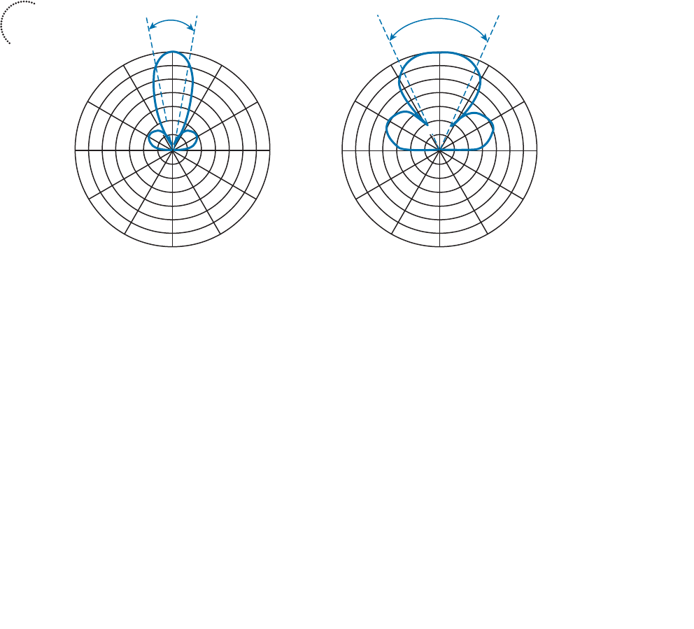
ptg12542968
92 CCNA Wireless 640-722 Official Cert Guide
Beamwidth
The antenna gain can be an indicator of how focused an antenna’s pattern might be, but
it is really more suited for link budget calculations. Instead, many manufacturers list the
beamwidth of an antenna as a measure of the antenna’s focus. Beamwidth is normally
listed in degrees for both the H and E planes.
The beamwidth is determined by finding the strongest point on the plot, which is usually
somewhere on the outer circle. Next, the plot is followed in either direction until the
value decreases by 3 dB, indicating the point where the signal is one-half the strongest
power. A line is drawn from the center of the plot to intersect each 3 dB point, and then
the angle between the two lines is measured. Figure 4-5 shows a simple example. The H
plane has a beamwidth of 30 degrees, and the E plane has a beamwidth of 55 degrees.
60°
30°
90°
120°
150°
180°
210°
240°
270°
300°
330°
H Beamwidth = 30°E Beamwidth = 55°
0 dBm
–5
–10
–15
–20
–25
–30
60°
30°
90°
120°
150°
180°
210°
240°
270°
300°
330°
0°
0 dBm
0°
H Plane
(Azimuth)
E Plane
(Elevation)
–5
–10
–15
–20
–25
–30
Figure 4-5 An Example of Antenna Beamwidth Measurement.
Polarization
When an alternating current is applied to an antenna, an electromagnetic wave is pro-
duced. From Chapter 1 , you learned that the wave has two components: an electrical
field wave and a magnetic field wave. The electrical portion of the wave will always leave
the antenna in a certain orientation. For example, most Cisco antennas produce a wave
that oscillates up and down in a vertical direction as it travels through free space. Other
antennas might be designed to produce waves that oscillate back and forth horizontally.
Still others might produce waves that actually twist in a three-dimensional spiral motion.
The wave’s orientation is called the antenna polarization. Antennas that produce vertical
oscillation are vertically polarized; ones that produce horizontal oscillation are horizon-
tally polarized. By itself, the antenna polarization is not of critical importance. However,
the antenna polarization at the transmitter must be matched to the polarization at the
Key
Topic
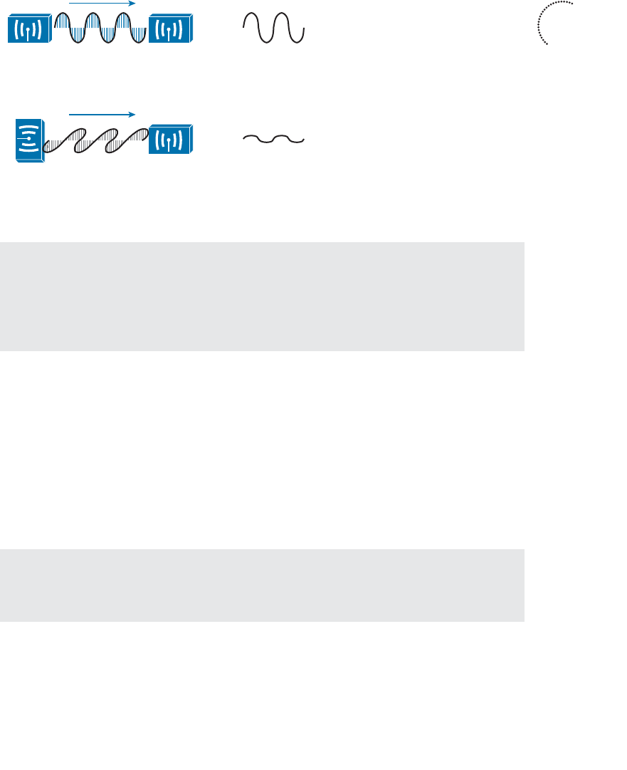
ptg12542968
Chapter 4: Understanding Antennas 93
receiver. If the polarization is mismatched, the received signal can be severely degraded.
Figure 4-6 illustrates antenna polarization. The transmitter and receiver along the top
both use vertical polarization, so the received signal is optimized. The pair along the bot-
tom is mismatched, causing the signal to be poorly received.
Vertical
Polarization
Vertical
Polarization
Horizontal
Polarization
Vertical
Polarization
Received
Signal
Received
Signal
Figure 4-6 Matching the Antenna Polarization Between Transmitter and Receiver.
Tip Even though Cisco antennas are designed to use vertical polarization, someone
might mount an antenna in an unexpected orientation. For example, suppose you mount
a transmitter with its antennas pointing upward. After you leave, someone knocks the
antennas so that they are turned sideways. Not only does that change the radiation pat-
tern you were expecting, it also changes the polarization.
Antenna Types
Wireless LAN antennas are available in a variety of styles, shapes, and radiation pat-
terns. In addition, antennas are normally rated for indoor or outdoor use, depending on
weather resistance and mounting options. Antennas are usually designed for a specific
frequency range and are approved by the local regulatory body, such as the FCC in the
US. There are two basic types of antennas, omnidirectional and directional, which are
discussed in the following sections.
Tip You can learn more about the full line of Cisco antennas in the
Cisco Aironet
Antennas and Accessories Reference Guide , at http://www.cisco.com/en/US/prod/col-
lateral/wireless/ps7183/ps469/at_a_glance_c45-513837.pdf .
Key
Topic
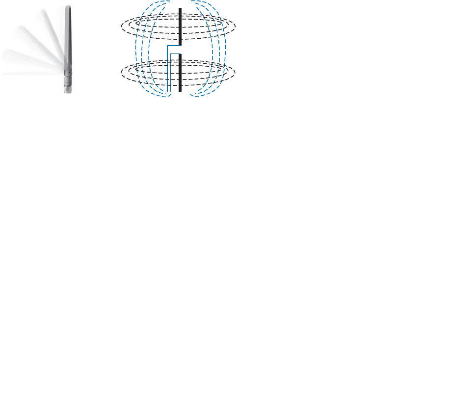
ptg12542968
94 CCNA Wireless 640-722 Official Cert Guide
Omnidirectional Antennas
An omnidirectional antenna is usually made in the shape of a thin cylinder. It tends to
propagate a signal equally in all directions away from the cylinder, but not along the
cylinder’s length. The result is a donut-shaped pattern that extends further in the H plane
than the E plane. This type of antenna is well suited for broad coverage of a large room
or floor area where the antenna is located in the center. Because an omnidirectional
antenna distributes the RF energy throughout a broad area, it has a relatively low gain.
A common type of omnidirectional antenna is the dipole , shown in the left portion of
Figure 4-7 . Some dipole models are articulated such that they can be folded up or down,
depending on the mounting orientation, whereas others are rigid and fixed. As its name
implies, the dipole has two separate wires that radiate an RF signal when an alternating
current is applied across them, as shown in the right portion of Figure 4-7 . Dipoles usu-
ally have a gain of around +2 to +5 dBi.
Figure 4-7 A Cisco Dipole Antenna.
The E and H plane radiation patterns for a typical dipole antenna are shown in Figure
4-8 . In the E plane, think of the dipole lying on its side in the center of the plot; the
H plane is looking down on the top of the dipole. Figure 4-9 takes the patterns a step
further, showing how the two planes are superimposed and merged to reveal the three-
dimensional radiation pattern.
Dipoles are often connected to wireless LAN devices that mount on the ceilings of
rooms and hallways. Most dipole antennas are between 3.5 and 5.5 inches long, so they
are not always aesthetically pleasing when they stick down from a ceiling. For this rea-
son, Cisco offers several monopole antennas as an alternative.
Monopole antennas are very short—less than 2 inches in length, as shown in Figure 4-10 .
To achieve such a small size, they contain only one short length of wire. You can think
of this as a compromised dipole antenna, where one of the antenna segments stands out
away from the wireless device. The other segment is moved down into the device, in
the form of a metal ground plane. Therefore, monopole antennas can be used only on
devices that have a large, flat metal casing. The radiation pattern is similar to that of a
dipole, but not quite as symmetrical. Monopole antennas have a typical gain of 2.2 dBi
in the 2.4-and 5-GHz bands.
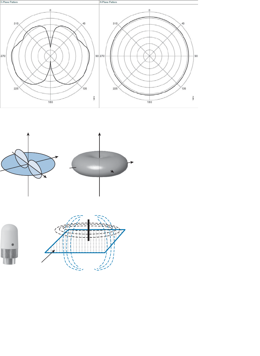
ptg12542968
Chapter 4: Understanding Antennas 95
Ground Plane
(Metal Case)
Figure 4-10 A Cisco Monopole Antenna.
To reduce the size of an omnidirectional antenna even further, many Cisco wireless
access points (APs) have integrated antennas that are hidden inside the device’s smooth
case. For example, the AP shown in Figure 4-11 has six tiny antennas hidden inside it.
Figure 4-8 E and H Radiation Patterns for a Typical Dipole Antenna.
Y
X
Y
ZZ
X
Figure 4-9 Dipole Radiation Pattern in Three Dimensions.
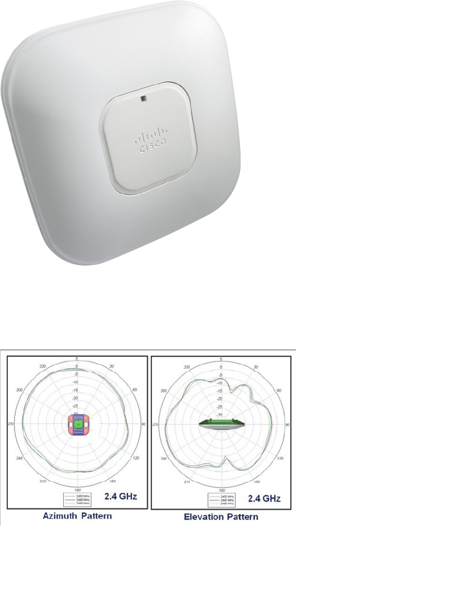
ptg12542968
96 CCNA Wireless 640-722 Official Cert Guide
Figure 4-11 A Cisco Wireless Access Point with Integrated Omnidirectional Antennas.
Integrated omnidirectional antennas typically have a gain of 2 dBi in the 2.4-GHz band
and 5 dBi in the 5-GHz band. The E and H plane radiation patterns are shown in Figure
4-12 . When the two planes are merged, the three-dimensional pattern shown in Figure
4-13 is revealed.
Figure 4-12 E and H Radiation Patterns for a Typical Integrated Omnidirectional
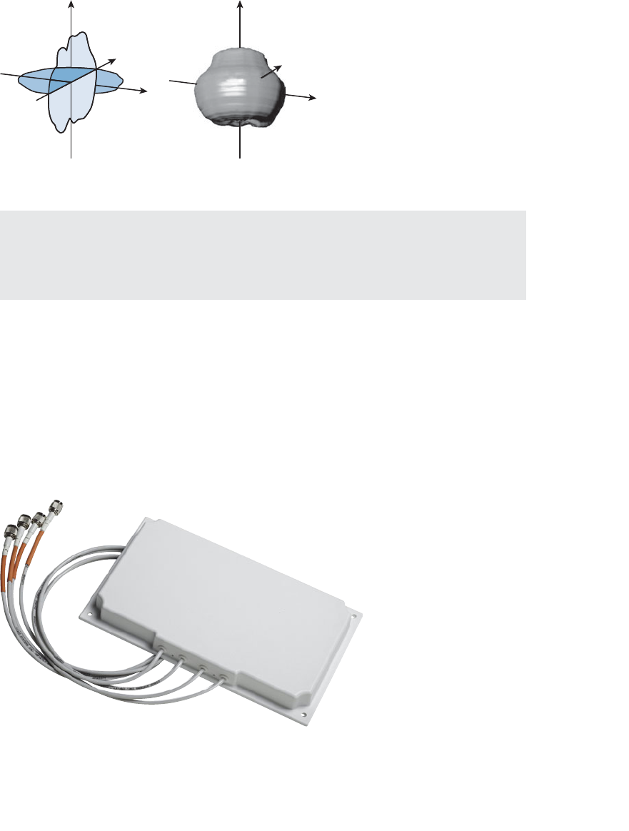
ptg12542968
Chapter 4: Understanding Antennas 97
Antenna.
Figure 4-13 Integrated Omnidirectional Antenna Radiation Pattern in 3D.
Tip What about wireless LAN adapters that are used in mobile devices like laptops and
smartphones? Because the adapters are so small, their antennas must also be tiny. As a
result, USB wireless adapters often have a gain of 0 dBi, while some smartphones even
have a negative gain!
Directional Antennas
Directional antennas have a higher gain than omnidirectional antennas because they
focus the RF energy in one general direction. Typical applications include elongated
indoor areas, such as the rooms along a long hallway or the aisles in a warehouse. They
can also be used to cover outdoor areas out away from a building or long distances
between buildings.
Patch antennas have a flat rectangular shape, as shown in Figure 4-14 , so that they can be
mounted on a wall.
Figure 4-14 A Typical Cisco Patch Antenna.
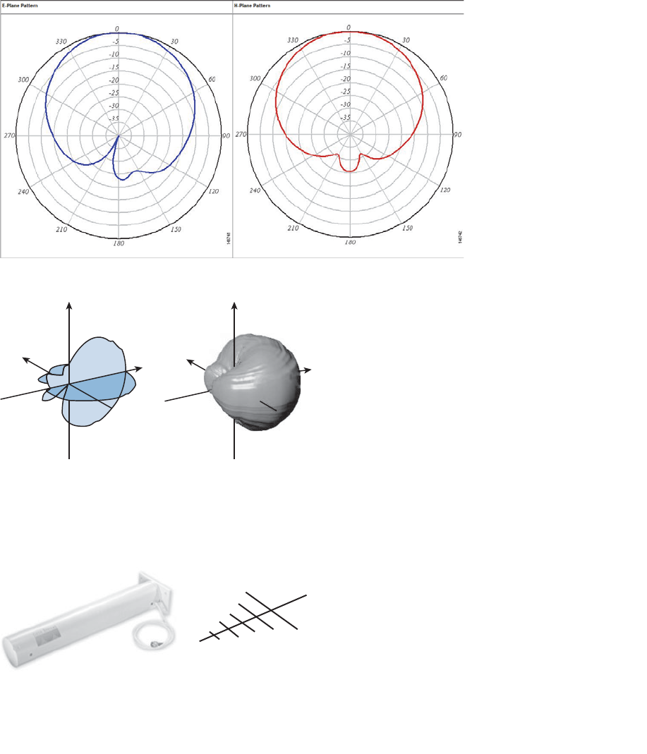
ptg12542968
98 CCNA Wireless 640-722 Official Cert Guide
Patch antennas produce a broad egg-shaped pattern that extends out away from the flat
patch surface. The E and H radiation pattern plots are shown in Figure 4-15 . When the
planes are merged as shown in Figure 4-16 , you can see the somewhat broad directional
pattern that results. Patch antennas have a gain of about 6 to 8 dBi in the 2.4-GHz band
and 7 to 10 dBi at 5 GHz.
Figure 4-15 E and H Radiation Patterns for a Typical Patch Antenna.
Figure 4-16 A Patch Antenna Radiation Pattern in Three Dimensions.
Figure 4-17 shows the Yagi-Uda antenna, named after its inventors, and more commonly
known as the Yagi. Although its outer case is shaped like a thick cylinder, the antenna is
actually made up of several parallel elements of increasing length.
Figure 4-17 A Cisco Yagi Antenna.
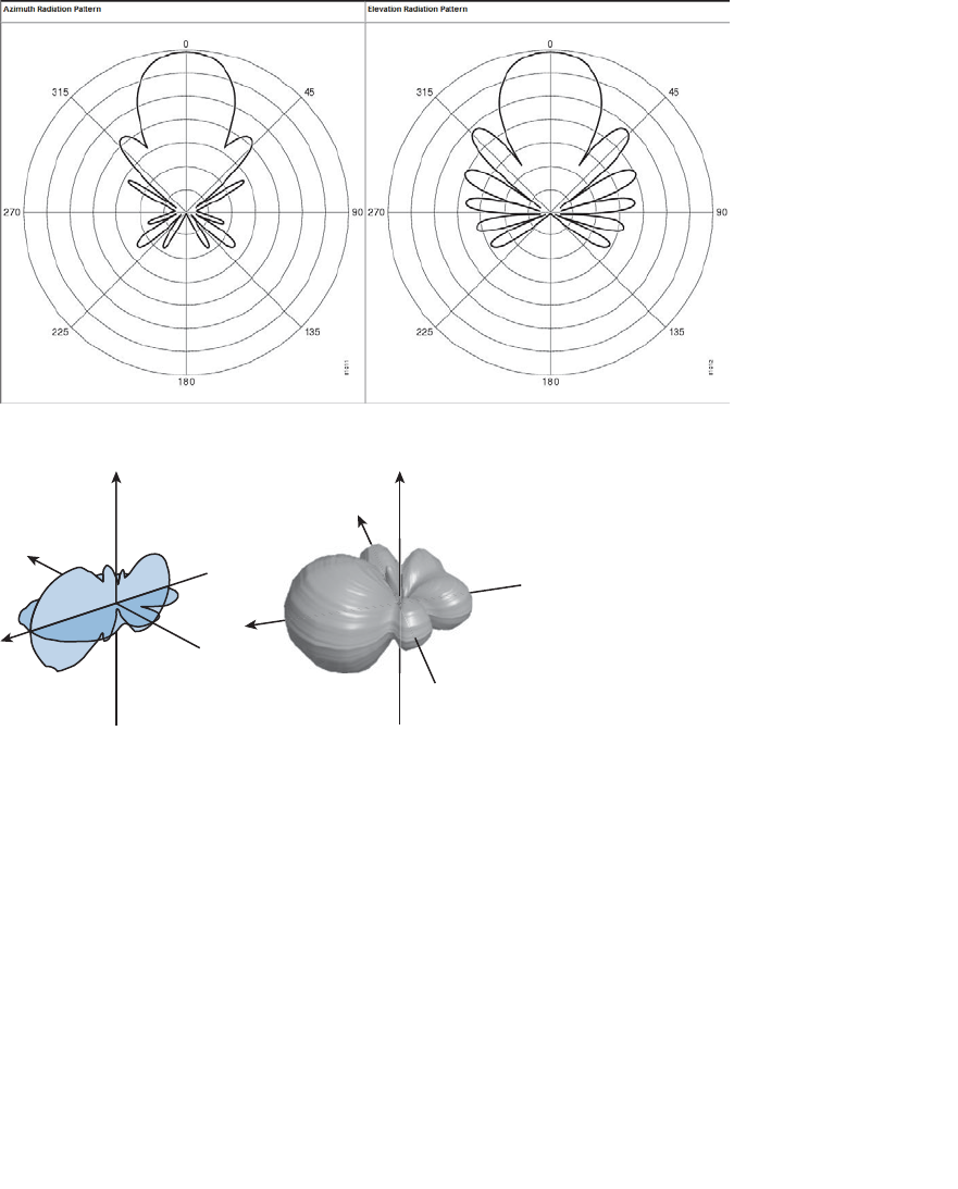
ptg12542968
Chapter 4: Understanding Antennas 99
Figure 4-18 shows the E and H radiation pattern plots. A Yagi produces a more focused
egg-shaped pattern that extends out along the antenna’s length, as shown in Figure 4-19 .
Yagi antennas have a gain of about 10-14 dBi in the 2.4-GHz band. Cisco does not offer
a 5-GHz Yagi.
Figure 4-18 E and H Radiation Patterns for a Typical Yagi Antenna.
Figure 4-19 A Yagi Antenna Radiation Pattern in Three Dimensions.
In a line-of-sight wireless path, an RF signal must be propagated a long distance using
a narrow beam. Highly directional antennas are tailored for that use, but focus the RF
energy along one narrow elliptical pattern. Because the target is only one receiver loca-
tion, the antenna does not have to cover any area outside of the line of sight.
Dish antennas, such as the one shown in Figure 4-20 , use a parabolic dish to focus
received signals onto an antenna mounted at the center. The parabolic shape is important
because any waves arriving from the line of sight will be reflected onto the center anten-
na element that faces the dish. Transmitted waves are just the reverse; they are aimed at
the dish and reflected such that they are propagated away from the dish along the line
of sight.
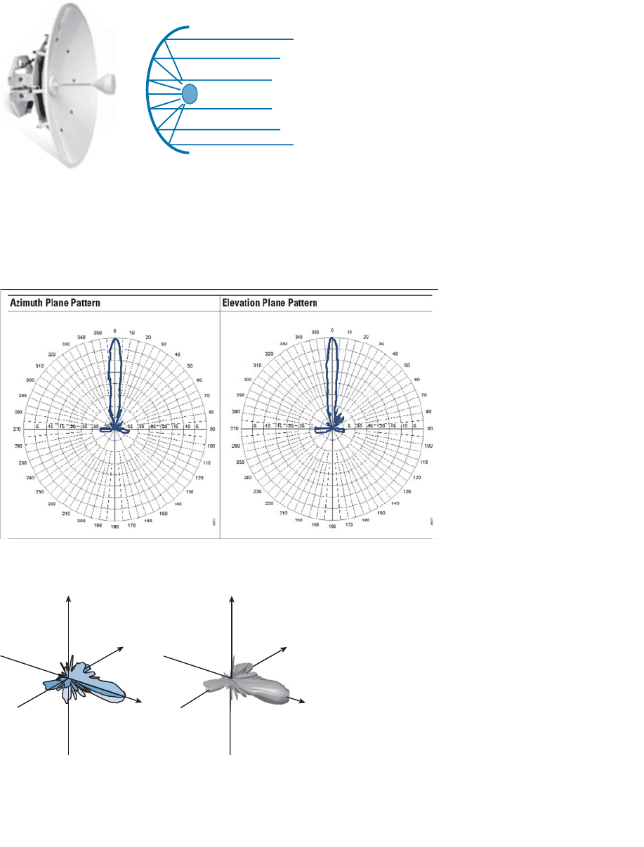
ptg12542968
100 CCNA Wireless 640-722 Official Cert Guide
Figure 4-20 A Cisco Parabolic Dish Antenna.
Figure 4-21 shows the radiation patterns in the E and H planes, which are merged into
three dimensions in Figure 4-22 . Notice how the antenna’s coverage pattern is long and
narrow, extending out away from the dish. The focused pattern gives the antenna a gain
of between 20 and 30 dBi—the highest gain of all the wireless LAN antennas.
Figure 4-21 E and H Radiation Patterns for a Parabolic Dish Antenna.
Z
Y
XX
Y
Z
Figure 4-22 A Parabolic Dish Antenna Radiation Pattern in Three Dimensions.
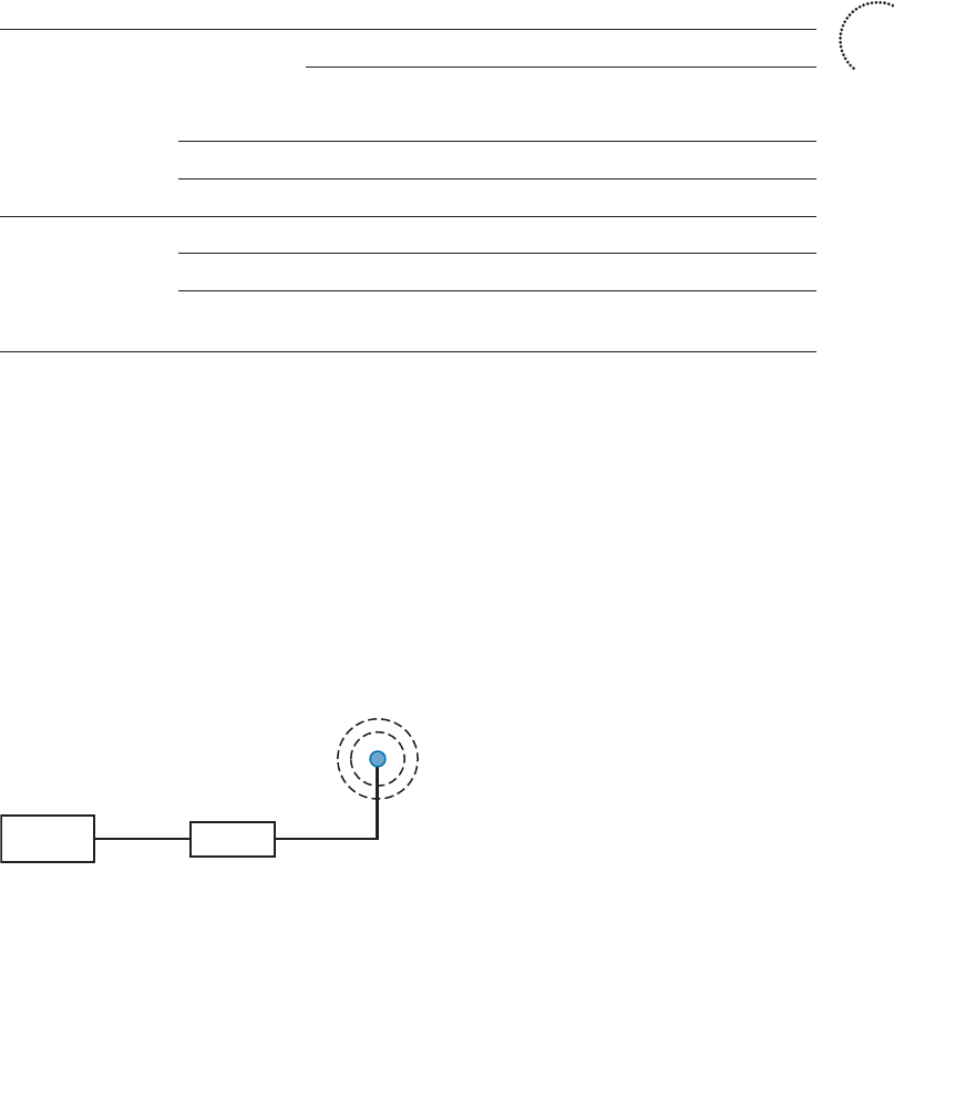
ptg12542968
Chapter 4: Understanding Antennas 101
Antenna Summary
Table 4-2 lists each antenna type and style, along with typical beamwidth and gain val-
ues. You can use this table as a summary to help compare the antennas side by side.
Notice that the beamwidth is the largest for omnidirectional antennas, and then begins
to narrow through the progression of directional antennas. The opposite is true of the
gain—omnidirectional antennas have the lowest gain, whereas directional antennas
increase gain as their beamwidth narrows.
Table 4-2 A Summary of Antenna Characteristics
Type Style Beamwidth Gain (dBi)
H Plane E Plane 2.4 GHz 5 GHz
Omnidirectional Dipole 360° 65° 2.2 3.5
Monopole 360° 50° 2.2 2.2
Integrated 360° 150° 2 5
Directional Patch 50° 50° 6–8 7–10
Yagi 30° 25° 10–14 —
Parabolic
dish
5° 5° 20–30 20–30
Adding Antenna Accessories
Occasionally, you may find that you are simply not able to meet the path link budget
between a transmitter and a receiver. This might be because the distance, and therefore
the free space path loss, is too great. Perhaps the transmitter does not offer enough
output power, or the cable connecting the transmitter to the antenna is too long or intro-
duces too much loss. You can add an amplifier to provide additional gain, provided the
EIRP does not exceed the maximum value allowed. An amplifier is an active, powered
device that is connected inline between a transmitter and an antenna, as shown in
Figure 4-23 .
Transmitter Amplifier
+5 dBm
Figure 4-23 Using an Amplifier to Add 5-dBm Gain.
Key
Topic
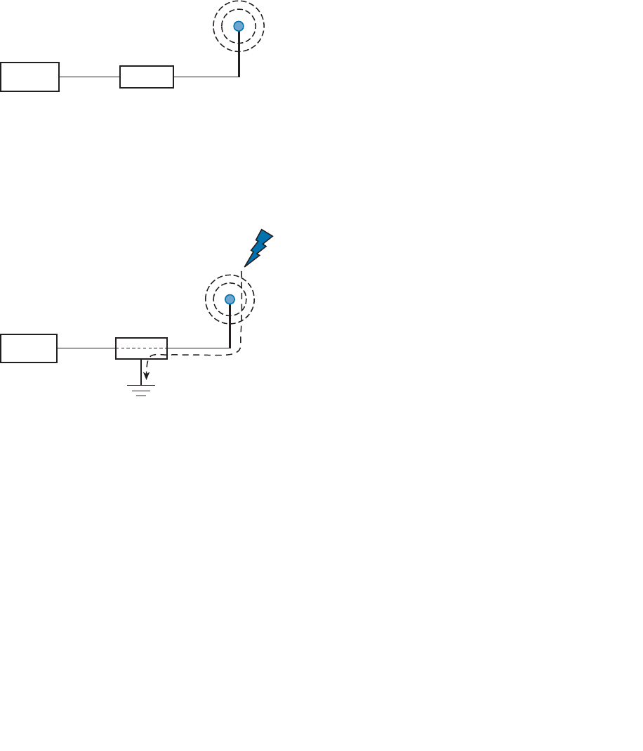
ptg12542968
102 CCNA Wireless 640-722 Official Cert Guide
At other times, you may need to reduce the signal strength of a transmitter beyond what
is possible with the transmitter settings. For example, the transmitter may already be
configured for its lowest possible transmit power level, but the signal strength is still too
great for nearby receivers. You can position an attenuator , a passive device that absorbs
part of the energy, inline between a transmitter and an antenna, as shown in Figure 4-24 .
Transmitter Attenuator
–5 dBm
Figure 4-24 Using an Attenuator to Add 5-dBm Loss.
When a transmitter or receiver is connected to an outdoor antenna, there is always
the possibility that lightning will induce a tremendous amount of energy through the
antenna—enough to damage the wireless LAN equipment and portions of the network.
To protect against such damage, you should always connect a lightning arrestor inline
between an outdoor antenna and a wireless LAN device, as shown in Figure 4-25 .
Transmitter Lightning
Arrestor
Figure 4-25 Using a Lightning Arrestor to Protect Sensitive Wireless LAN Equipment.
The lightning arrestor has two connectors that attach to the two ends of coaxial cable, in
addition to a grounding lug, which should connect to the nearest building or electrical
ground. The RF signal is allowed to pass on through the lightning arrestor, but sudden
spikes of electricity will be bypassed to ground. Contrary to its name, a lightning arres-
tor can never prevent the damage from a direct lightning strike. In can, however, prevent
damage that might occur due to static electricity discharges or transient voltage spikes
during thunderstorms.

ptg12542968
Chapter 4: Understanding Antennas 103
Exam Preparation Tasks
As mentioned in the section, “How to Use This Book,” in the Introduction, you have a
couple of choices for exam preparation: the exercises here, Chapter 22 , “Final Review,”
and the exam simulation questions on the CD-ROM.
Review All Key Topics
Review the most important topics in this chapter, noted with the Key Topic icon in the
outer margin of the page. Table 4-3 lists a reference of these key topics and the page
numbers on which each is found.
Table 4-3 Key Topics for Chapter 4
Key Topic Element Description Page Number
Figure 4-2 Cutting a radiation pattern into the E and H
planes
89
Figure 4-5 Determining the beamwidth of an antenna 92
Figure 4-6 Antenna polarization 93
Table 4-2 A summary of antenna characteristics 101
Define Key Terms
Define the following key terms from this chapter and check your answers in the
glossary:
amplifier, attenuator, beamwidth, dipole, directional antenna, E plane, gain, H plane,
integrated antenna, lightning arrestor, monopole, omnidirectional antenna, parabolic
dish antenna, patch antenna, polar plot, polarization, radiation pattern, Yagi antenna
Key
Topic

ptg12542968
This chapter covers the following topics:
■ Types of Wireless Networks —This section gives a
brief overview of several major network types and
their scales.
■ Wireless LAN Topologies —This section discusses
the basic building blocks of 802.11 wireless LANs
and how they work together.
■ Other Wireless Topologies —This section describes
some network topologies that can be used to solve
unique problems.
This chapter covers the following exam topics:
■ Describe networking technologies used in wireless
(SSID to WLAN_ID to Interface to VLAN, 802.1q
trunking)
■ Describe wireless topologies, such as independent
basic service set (IBSS), basic service set (BSS),
extended service set (ESS), point-to-point, point-to-
multipoint, mesh, and bridging)

ptg12542968
Wireless communication usually involves a data exchange between two devices. A wire-
less LAN goes even further; many devices can participate in sharing the medium for data
exchanges. This chapter explains the topologies that can be used to control access to the
wireless medium and provide data exchange between devices.
“Do I Know This Already?” Quiz
The “Do I Know This Already?” quiz allows you to assess whether you should read this
entire chapter thoroughly or jump to the “Exam Preparation Tasks” section. If you are
in doubt about your answers to these questions or your own assessment of your knowl-
edge of the topics, read the entire chapter. Table 5-1 lists the major headings in this
chapter and their corresponding “Do I Know This Already?” quiz questions. You can
find the answers in Appendix A , “Answers to the ‘Do I Know This Already?’ Quizzes.”
Table 5-1 “Do I Know This Already?” Section-to-Question Mapping
Foundation Topics Section Questions
Types of Wireless Networks 1
Wireless LAN Topologies 2–8
Other Wireless Topologies 9–10
Caution The goal of self-assessment is to gauge your mastery of the topics in this chap-
ter. If you do not know the answer to a question or are only partially sure of the answer,
you should mark that question as wrong for purposes of the self-assessment. Giving your-
self credit for an answer you correctly guess skews your self-assessment results and might
provide you with a false sense of security.
CHAPTER 5
Wireless LAN Topologies

ptg12542968
106 CCNA Wireless 640-722 Official Cert Guide
1.
Which two of the following types of wireless networks use the same frequency
band?
a. WPAN
b. WLAN
c. WMAN
d. WWAN
2.
Devices using a wireless LAN must operate in which one of the following modes?
a. Round-robin access
b. Half duplex
c. Full duplex
d. None of these answers
3.
An access point is set up to offer wireless coverage in an office. Which one of the
following is the correct 802.11 term for the resulting standalone network?
a. BSA
b. BSD
c. BSS
d. IBSS
4.
Which one of the following is used to uniquely identify an AP and the basic service
set it maintains with its associated wireless clients?
a. SSID
b. BSSID
c. Ethernet MAC address
d. Radio MAC address
5.
Which one of the following statements is true about a wireless BSS?
a.
A wireless client can send frames directly to any another client at any time.
b.
Once two clients are associated to the BSS, they may communicate directly
with each other with no further intervention.
c.
A client must send frames through the AP only when the destination client is
associated to a different AP.
d.
A client must send all frames through the AP to reach any other client or coor-
dinate with the AP to reach another client directly.

ptg12542968
Chapter 5: Wireless LAN Topologies 107
6.
In a Cisco wireless network, which of the following statements full of acronyms are
correct? (Choose two.)
a.
The DS connects two BSSs to form an ESS.
b.
The BSA of a BSS looks like a MAC address.
c.
The SSID of a STA must be unique within the ESS.
d.
The BSSID is unique for each SSID in a BSS.
7.
A wireless client is configured to associate with the wireless network called
BeMyGuest. For the client to roam successfully everywhere within a building, which
one of the following correctly identifies the WLAN topology that must be in place?
a. A basic service set
b. A distribution system
c. An extended service set
d.
The SSID BeMyGuest defined on every AP
e. All of these answers are correct.
8.
Which one of the following is also known as an ad hoc wireless network?
a. DS
b. ESS
c. BSA
d. IBSS
e. BSS
9.
Which one of the following can be used to provide wireless connectivity to a non-
wireless device?
a. Wireless repeater
b. Workgroup bridge
c. Transparent bridge
d. Adaptive bridge
10.
Which one of the following is not needed in a Cisco outdoor mesh network?
a. A BSS function
b.
Ethernet cabling to each AP
c. A wireless LAN controller
d. A backhaul network
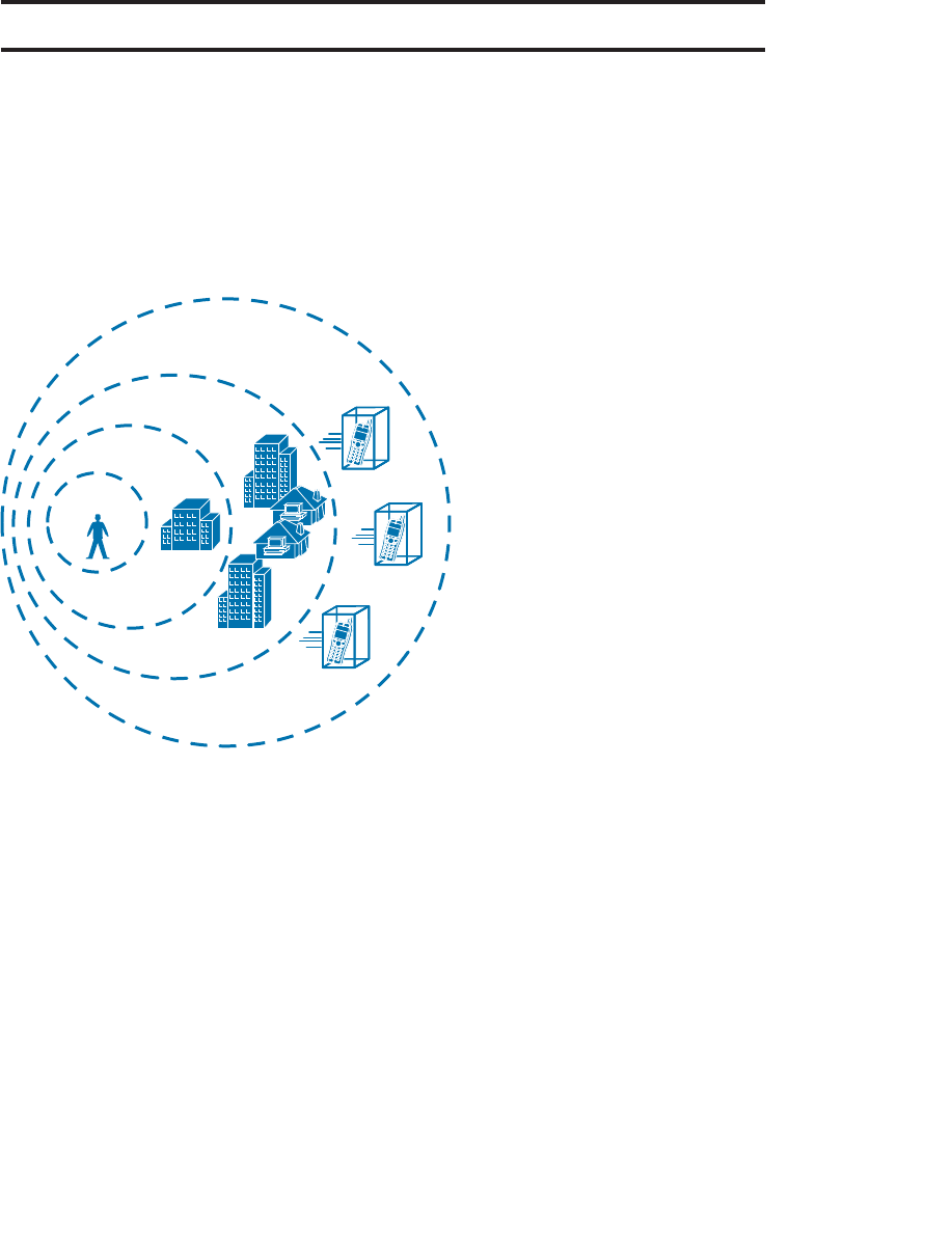
ptg12542968
108 CCNA Wireless 640-722 Official Cert Guide
Foundation Topics
Types of Wireless Networks
The term wireless LAN is used quite freely in this book. After all, it is the central theme
of the CCNA Wireless exam, but it is only one type of wireless network that you might
encounter. Wireless networks can be classified into four main types according to the
geographic scope where a signal and service is available. Figure 5-1 gives a general idea
of the network types and their scopes.
WLAN
WPAN
WMAN
WWAN
Figure 5-1 Wireless Network Types and Scopes.
■ Wireless personal-area network (WPAN) —As its name implies, a WPAN uses low-
powered transmitters to create a network with a very short range, usually 20 to 30
feet (7 to 10 meters). WPANs are based on the IEEE 802.15 standard and include
technologies like Bluetooth and ZigBee, although ZigBee can have a greater range.
Unlicensed ISM frequencies are used, including the 2.4-GHz band.
■ Wireless local-area network (WLAN) —A wireless service that connects multiple
devices using the IEEE 802.11 standard over a medium-sized range, usually up to
300 feet (100 meters). Unlicensed frequencies in the 2.4- and 5-GHz band are used.
■ Wireless metropolitan-area network (WMAN) —A wireless service over a large
geographic area, such as all or a portion of a city. One common example, WiMAX,
is based on the IEEE 802.16 standard. Licensed frequencies are commonly used.

ptg12542968
Chapter 5: Wireless LAN Topologies 109
■ Wireless wide-area network (WWAN) —A wireless data service for mobile phones
that is offered over a very large geographic area (regional, national, and even global)
by telecommunications carriers. Licensed frequencies are used.
The remainder of this chapter focuses on WLANs and how they are constructed.
Wireless LAN Topologies
Up to this point, this book has discussed radio frequency (RF) signals as they travel from
a transmitter to a receiver. As Figure 5-2 shows, the transmitter can contact the receiver
at any and all times, as long as both devices are tuned to the same frequency (or channel)
and use the same modulation and coding scheme. That all sounds simple, except that it is
not really practical.
Transmitter Receiver
Device A Device B
Figure 5-2 Unidirectional Communication.
To fully leverage wireless communication, data should travel in both directions, as
shown in Figure 5-3 . Sometimes Device A needs to send data to Device B, while Device
B would like to take a turn to send at other times.
Transmitter Receiver
TransmitterReceiver
Device A Device B
Figure 5-3 Bidirectional Communication.
Because the two devices are using the same channel, two phrases in the preceding sen-
tence become vitally important: Take a turn and send at other times . As you learned in
previous chapters, if multiple signals are received at the same time, they interfere with
each other. The likelihood of interference increases as the number of wireless devices
grows. For example, Figure 5-4 shows four devices tuned to the same channel and what
might happen if some or all of them transmit at the same time.
Device A Device B Device DDevice C
Figure 5-4 Interference from Simultaneous Transmissions.
All this talk about waiting turns and avoiding interference should remind you of an
Ethernet LAN, where multiple hosts can share common bandwidth and a collision
domain. To use the media effectively, all the hosts must operate in half-duplex mode
so that they avoid colliding with other transmissions. The side effect is that no host can
transmit and receive at the same time on a given frequency.

ptg12542968
110 CCNA Wireless 640-722 Official Cert Guide
Tip IEEE 802.11 WLANs are always half duplex because transmitting and receiving
stations use the same frequency. Only one station can transmit at any time; otherwise,
collisions occur. To achieve full-duplex mode, all transmitting would have to occur on
one frequency and all receiving would occur over a different frequency—much like full-
duplex Ethernet links work. Although this is certainly possible and practical, the 802.11-
2012 standard does not permit full-duplex operation. The 802.11ac amendment will ease
that restriction in its “wave 2” implementation.
A wireless LAN is very similar. Because multiple hosts can share the same channel, they
also share the “airtime” or access to that channel at any given time. Therefore, to keep
everything clean, only one device should transmit at any given time. To contend for use
of the channel, devices based on the 802.11 standard have to determine whether the
channel is clear and available before transmitting anything. This process is described in
more detail in Chapter 6 , “Understanding 802.11 Frame Types.”
At the most basic level, there is no inherent organization to a wireless medium or any
inherent control over the number of devices that can transmit and receive frames. Any
device that has a wireless network adapter can power up at any time and try to com-
municate. At a minimum, a wireless network should have a way to make sure that every
device using a channel can support a common set of parameters, including data rates,
802.11 modulation types, channel width, and so on. Beyond that, there should be a way
to control which devices (and users) are allowed to use the wireless medium, and the
methods that are used to secure the wireless transmissions.
Basic Service Set
The solution is to make every wireless service area a closed group—before a device can
participate, it must advertise its capabilities and then be granted permission to join. The
802.11 standard calls this a basic service set (BSS). At the heart of every BSS is a wire-
less access point (AP), as shown in Figure 5-5 . The AP operates in infrastructure mode ,
which means it offers the services that are necessary to form the infrastructure of a wire-
less network.
Because the operation of a BSS hinges on the AP, the BSS is bounded by the area where
the AP’s signal is usable. This is known as the basic service area (BSA) or cell . In Figure
5-5 , the cell is shown as a simple circular area that might result from the radiation pat-
tern of an omnidirectional antenna. Cells can have other shapes too, depending on the
antenna that is connected to the AP and on the physical surroundings.
The AP serves as a single point of contact for every device that wants to use the BSS. It
advertises the existence of the BSS so that devices can find it and try to join. To do that, the
AP uses a unique BSS identifier (BSSID) that is based on the AP’s own radio MAC address.
In addition, the AP advertises the wireless network with a service set identifier (SSID),
which is a text string containing a logical name. Think of the BSSID as a machine-
readable name tag that identifies the unique BSS ambassador (the AP), and the SSID as a
human readable name tag that identifies the wireless service.
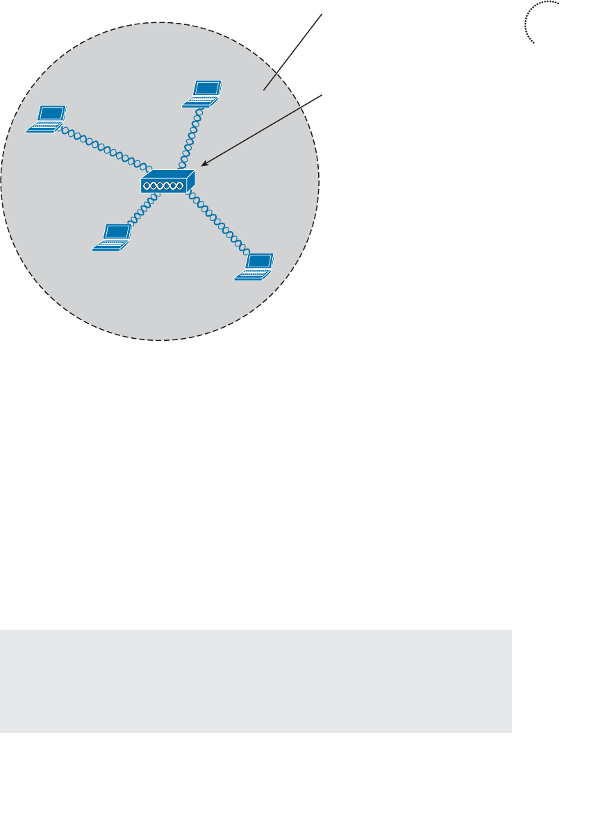
ptg12542968
Chapter 5: Wireless LAN Topologies 111
Membership with the BSS is called an association. A device must send an association
request and the AP must either grant or deny the request. Once associated, a device
becomes a client, or an 802.11 station (STA), of the BSS. What then? As long as a wire-
less client remains associated with a BSS, most communications to and from the client
must pass through the AP, as indicated in Figure 5-6 . By using the BSSID as a source or
destination address, data frames can be relayed to or from the AP.
You might be wondering why all client traffic has to traverse the AP at all. Why cannot
two clients simply transmit data frames directly to each other and bypass the middle-
man? If clients are allowed to communicate directly, then the whole idea of organizing
and managing a BSS is moot. By sending data through the AP first, the BSS remains sta-
ble and under control. The 802.11z amendment provides an exception to the rule, which
permits two clients to communicate directly without passing through an AP—only if the
communication is mediated by an AP.
Tip Even though data frames are meant to pass through an AP, keep in mind that other
devices in the same general area that are listening on the same channel can overhear the
transmissions. After all, frames are freely available over the air to anyone that is within
range to receive them. Only the BSSID value contained within the frames indicates that
the intended sender or recipient is the AP.
Key
Topic
BSS
AP
SSID: “MyNetwork”
BSSID:
d4:20:6d:90:ad:20
Figure 5-5 An 802.11 Basic Service Set.
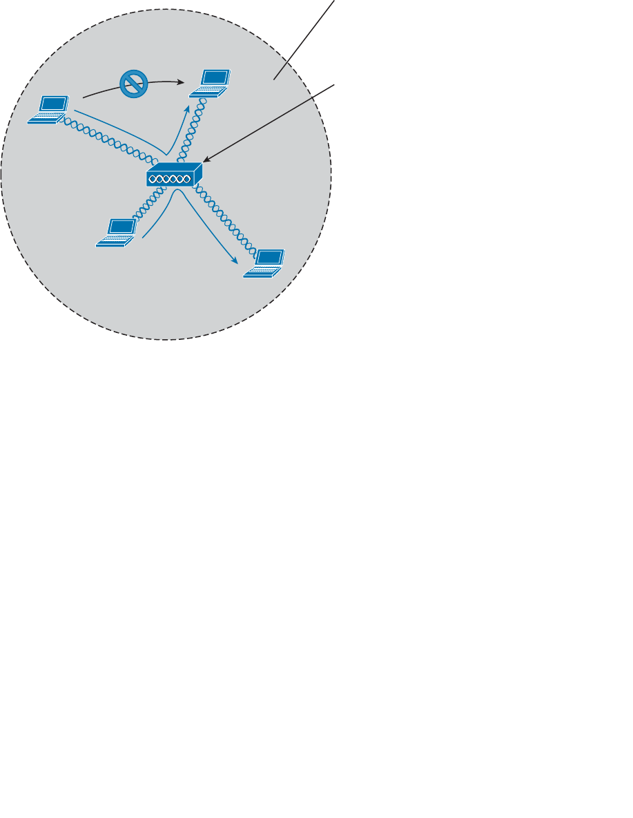
ptg12542968
112 CCNA Wireless 640-722 Official Cert Guide
Distribution System
Notice that a BSS involves a single AP and no explicit connection into a regular Ethernet
network. In that setting, the AP and its associated clients make up a standalone network.
But the AP’s role at the center of the BSS does not just stop with managing the BSS—
sooner or later, wireless clients will need to communicate with other devices that are
not members of the BSS. Fortunately, an AP can also uplink into an Ethernet network
because it has both wireless and wired capabilities. The 802.11 standard refers to the
upstream wired Ethernet as the distribution system (DS) for the wireless BSS, as shown
in Figure 5-7 .
You can think of an AP as a translational bridge, where frames from two dissimilar media
(wireless and wired) are translated and then bridged at Layer 2. In simple terms, the AP
is in charge of mapping a virtual local-area network (VLAN) to an SSID. In Figure 5-7 ,
the AP maps VLAN 10 to the wireless LAN using SSID “MyNetwork.” Clients associated
with the “MyNetwork” SSID will appear to be connected to VLAN 10.
This concept can be extended so that multiple VLANs are mapped to multiple SSIDs.
To do this, the AP must be connected to the switch by a trunk link that carries the
VLANs. In the Figure 5-8 , VLANs 10, 20, and 30 are trunked to the AP over the DS.
The AP uses the 802.1Q tag to map the VLAN numbers to the appropriate SSIDs. For
BSS
AP
SSID: “MyNetwork”
BSSID:
d4:20:6d:90:ad:20
Figure 5-6 Traffic Flows Within a BSS.
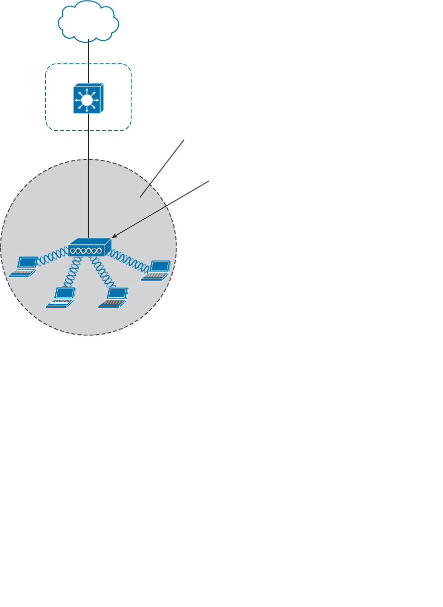
ptg12542968
Chapter 5: Wireless LAN Topologies 113
example, VLAN 10 is mapped to SSID “MyNetwork,” VLAN 20 is mapped to SSID
“YourNetwork,” and VLAN 30 to SSID “Guest.”
In effect, when an AP uses multiple SSIDs, it is trunking VLANs over the air to wireless
clients. The clients must use the appropriate SSID that has been mapped to the respec-
tive VLAN when the AP was configured. The AP then appears as multiple logical APs—
one per BSS—with a unique BSSID for each. With Cisco APs, this is usually accom-
plished by incrementing the last digit of the radio’s MAC address for each SSID.
Even though an AP can advertise and support multiple logical wireless networks, each of
the SSIDs covers the same geographic area. That is because the AP uses the same trans-
mitter, receiver, antennas, and channel for every SSID that it supports. Beware of one
misconception though: Multiple SSIDs can give an illusion of scale. Even though wireless
clients can be distributed across many SSIDs, all of those clients must share the same
AP’s hardware and must contend for airtime on the same channel.
BSS
AP
DS
BSSID:
d4:20:6d:90:ad:20
SSID: “MyNetwork”
VLAN 10
Figure 5-7 The Distribution System Supporting a BSS.
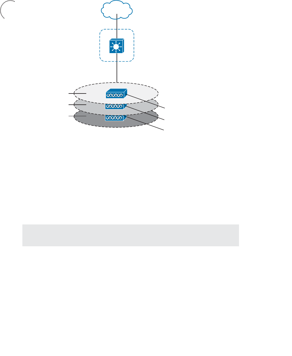
ptg12542968
114 CCNA Wireless 640-722 Official Cert Guide
Extended Service Set
Normally, one AP cannot cover the entire area where clients might be located. For
example, you might need wireless coverage throughout an entire floor of a business,
hotel, hospital, or other large building. To cover more area than a single AP’s cell, you
simply need to add more APs and spread them out geographically.
When APs are placed at different geographic locations, they can all be interconnected
by a switched infrastructure. The 802.11 standard calls this an extended service set (ESS),
as shown in Figure 5-9 .
Tip Chapter 7 , “Planning Coverage with Wireless APs,” discusses AP and cell placement
in greater detail.
The idea is to make multiple APs cooperate so that the wireless service is consistent and
seamless from the client’s perspective. Ideally, any SSIDs that are defined on one AP
should be defined on all the APs in an ESS; otherwise, it would be very cumbersome and
inconvenient for a client to be reconfigured each time it moves into a different AP’s cell.
Notice that each cell in Figure 5-9 has a unique BSSID, but both cells share one common
SSID. Regardless of a client’s location within the ESS, the SSID will remain the same but
the client can always distinguish one AP from another.
DS
BSSID: d4:20:6d:90:ad:20
802.1Q Trunk
VLANs 10, 20, 30
BSSID: d4:20:6d:90:ad:21
BSSID: d4:20:6d:90:ad:22
SSID: “MyNetwork”
SSID: “YourNetwork”
SSID: “Guest”
Figure 5-8 Supporting Multiple SSIDs on One AP.
Key
Topic
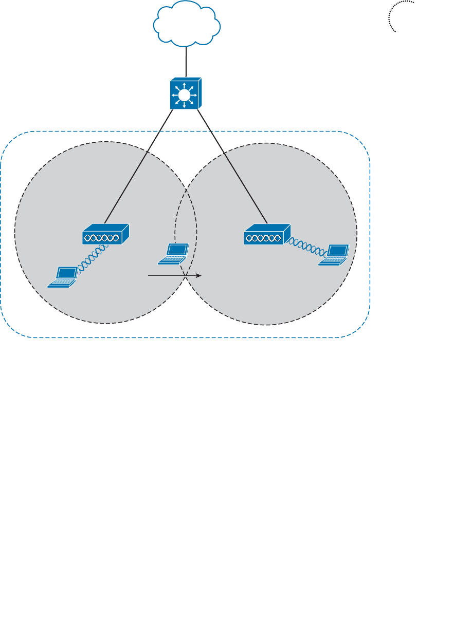
ptg12542968
Chapter 5: Wireless LAN Topologies 115
In an ESS, a wireless client can associate with one AP while it is physically located near
that AP. If the client later moves to a different location, it can associate with a different
nearby AP automatically. Passing from one AP to another is called roaming and is cov-
ered in Chapter 6 .
Independent Basic Service Set
Usually a wireless network leverages APs for organization, control, and scalability.
Sometimes that is not possible or convenient in an impromptu situation. For example,
two people might want to exchange electronic documents at a meeting, but they are
unable to find a BSS available. In addition, many personal printers have the capability to
print documents wirelessly, without relying on a regular BSS or AP.
The 802.11 standard allows two or more wireless clients to communicate directly with
each other, with no other means of network connectivity. This is known as an ad hoc
wireless network, or an independent basic service set (IBSS), as shown in Figure 5-10 .
Key
Topic
BSS-1
AP-1
BSSID:
d4:20:6d:90:ad:20
SSID: “MyNetwork”
VLAN 10
AP-2
BSS-2
BSSID:
e6:22:47:af:c3:70
SSID: “MyNetwork”
ESS
Figure 5-9 Scaling Wireless Coverage with an 802.11 Extended Service Set.

ptg12542968
116 CCNA Wireless 640-722 Official Cert Guide
For this to work, one of the devices must take the lead and begin advertising a network
name and the necessary radio parameters. Any other device can then join as needed.
IBSS
Figure 5-10 An 802.11 Independent Basic Service Set.
Regardless of their convenience, ad hoc networks are seldom recommended and used
because of their limitations. The 802.11 standard intended for IBSSs to be organized in
an impromptu, distributed fashion. Therefore, they do not scale well beyond eight to ten
devices.
Other Wireless Topologies
Wireless APs can be configured to operate in noninfrastructure modes when a normal
BSS cannot provide the functionality that is needed. The following sections cover the
most common modes.
Repeater
Normally, each AP in a wireless network has a wired connection back to the DS or
switched infrastructure. To extend wireless coverage, additional APs and their wired
connections are added. In some scenarios, it is not possible to run a wired connection to
a new AP because the cable distance is too great to support Ethernet communication.
In that case, you can add an additional AP that is configured for repeater mode . A wire-
less repeater takes the signal it receives and repeats or retransmits it. The idea is to move
the repeater out away from the AP so that it is still within range of both the AP and the
distant client, as shown in Figure 5-11 .
If the repeater has a single radio, there is a possibility that the AP’s signal will be received
and retransmitted by the repeater, only to be received again by the AP—halving the
effective throughput. As a remedy, some repeaters can use two radios to keep the origi-
nal and repeated signals isolated. One radio is dedicated to signals in the AP’s cell, while
the other radio is dedicated to signals in the repeater’s own cell.
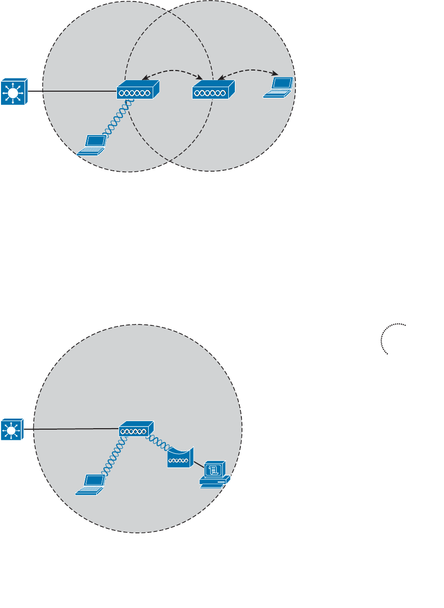
ptg12542968
Chapter 5: Wireless LAN Topologies 117
Workgroup Bridge
Suppose you have a device that supports a wired Ethernet link but is not capable of
having a wireless connection. You can use a workgroup bridge (WGB) to connect the
device’s wired network adapter to a wireless network.
Rather than providing a BSS for wireless service, a WGB becomes a wireless client of a
BSS. In effect, the WGB acts as an external wireless network adapter for a device that
has none. In Figure 5-12 , an AP provides a BSS; Client A is a regular wireless client, while
Client B is associated with the AP through a WGB.
BSS
AP
Client A
WGB
Client B
Figure 5-12 A Nonwireless Device Connects Through a Workgroup Bridge.
BSS
AP
Client A
Client B
Repeater
Figure 5-11 Extending the Range of an AP with a Wireless Repeater.
Key
Topic
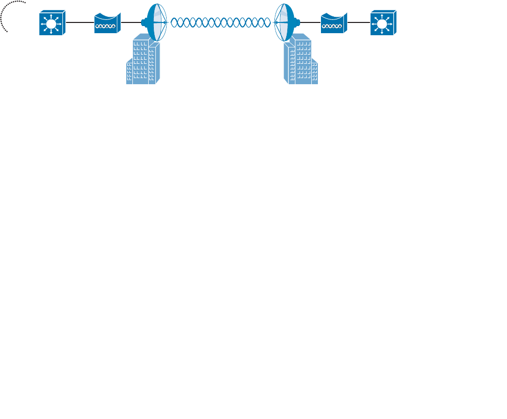
ptg12542968
118 CCNA Wireless 640-722 Official Cert Guide
You might encounter two types of workgroup bridges:
■ Universal workgroup bridge (uWGB) —A single wired device can be bridged to a
wireless network.
■ Workgroup bridge (WGB) —A Cisco-proprietary implementation that allows mul-
tiple wired devices to be bridged to a wireless network.
Outdoor Bridge
An AP can be configured to act as a bridge to form a single wireless link from one LAN
to another over a long distance. Outdoor bridged links are commonly used for connec-
tivity between buildings or between cities.
If the LANs at two locations need to be bridged, a point-to-point bridged link can be used.
One bridge mode AP is needed on each end of the wireless link. Directional antennas are
normally used with the bridges to maximize the link distance, as shown in Figure 5-13 .
BridgeLAN A Bridge LAN B
Figure 5-13 A Point-to-Point Outdoor Bridge.
Sometimes the LANs at multiple sites need to be bridged. A point-to-multipoint bridged
link allows a central site to be bridged to several other sites. The central site bridge
is connected to an omnidirectional antenna so that its signal can reach the other sites
simultaneously. The bridges at each of the other sites can be connected to a directional
antenna aimed at the central site. Figure 5-14 shows the point-to-multipoint scenario.
Key
Topic
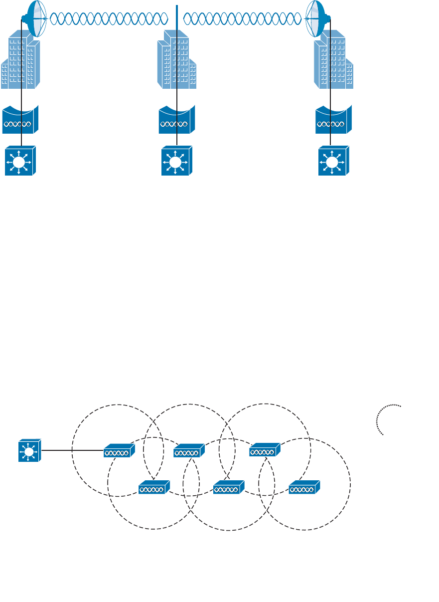
ptg12542968
Chapter 5: Wireless LAN Topologies 119
LAN A Central LAN B
Figure 5-14 A Point-to-Multipoint Outdoor Bridge.
Mesh Network
To provide wireless coverage over a large area, it is not always practical to run Ethernet
cabling to every AP that is needed. Instead, you could use multiple APs configured in
mesh mode. In a mesh topology, traffic is bridged from AP to AP, in a daisy-chain
fashion.
Mesh APs can leverage dual radios—one in the 2.4-GHz band and one in the 5-GHz
band. Each mesh AP usually maintains a BSS on a 2.4-GHz channel, with which wireless
clients can associate. Client traffic is then usually bridged from AP to AP over 5-GHz
channels as a backhaul network. At the edge of the mesh network, the backhaul traffic
is bridged to the wired LAN infrastructure. Figure 5-15 shows a typical mesh network.
With Cisco APs, you can build a mesh network indoors or outdoors. The mesh network
runs its own dynamic routing protocol to work out the best path for backhaul traffic to
take across the mesh APs.
LAN
Figure 5-15 A Typical Wireless Mesh Network.
Key
Topic

ptg12542968
120 CCNA Wireless 640-722 Official Cert Guide
Exam Preparation Tasks
As mentioned in the section, “How to Use This Book,” in the Introduction, you have a
couple of choices for exam preparation: the exercises here, Chapter 22 , “Final Review,”
and the exam simulation questions on the CD-ROM.
Review All Key Topics
Review the most important topics in this chapter, noted with the Key Topic icon in the
outer margin of the page. Table 5-2 lists a reference of these key topics and the page
numbers on which each is found.
Table 5-2 Key Topics for Chapter 5
Key Topic Element Description Page Number
Figure 5-5 Basic service set 111
Figure 5-8 Multiple SSIDs 114
Figure 5-9 Extended service set 115
Figure 5-12 Workgroup bridge 117
Figure 5-13 Point-to-point bridge 118
Figure 5-15 Mesh network 119
Define Key Terms
Define the following key terms from this chapter and check your answers in the
glossary:
access point (AP), ad hoc network, basic service set (BSS), basic service set identifier
(BSSID), cell, distribution system (DS), extended service set (ESS), independent basic
service set (IBSS), infrastructure mode, mesh network, point-to-point bridge, repeat-
er, roaming, service set identifier (SSID), station (STA), workgroup bridge (WGB)
Key
Topic

ptg12542968
This page intentionally left blank

ptg12542968
This chapter covers the following topics:
■ 802.11 Frame Format —This section describes
the basic format of wireless LAN frames and the
addressing fields they contain.
■ Accessing the Wireless Medium —This section
explains the mechanisms that wireless devices must
use to contend for use of a channel when transmit-
ting.
■ 802.11 Frame Types —This section discusses the
three basic types of 802.11 frames and their use.
■ Client Housekeeping —This section discusses many
common operations between a wireless client and
an access point, based on 802.11 management
frames.
This chapter covers the following exam topics:
■ Describe frame types (associated and unassociated,
management, control, and data)

ptg12542968
Wireless networks based on the 802.11 standard operate in a very organized and con-
trolled fashion. The standard defines the frame format and frame types that access
points (APs) and clients must use to communicate successfully. Before a device trans-
mits on a channel, it must cooperate with all other devices and contend for use of the
channel. This chapter covers these topics and the choreography that occurs between an
access point (AP) and its clients.
“Do I Know This Already?” Quiz
The “Do I Know This Already?” quiz allows you to assess whether you should read this
entire chapter thoroughly or jump to the “Exam Preparation Tasks” section. If you are
in doubt about your answers to these questions or your own assessment of your knowl-
edge of the topics, read the entire chapter. Table 6-1 lists the major headings in this
chapter and their corresponding “Do I Know This Already?” quiz questions. You can
find the answers in Appendix A , “Answers to the ‘Do I Know This Already?’ Quizzes.”
Table 6-1 “Do I Know This Already?” Section-to-Question Mapping
Foundation Topics Section Questions
802.11 Frame Format 1–3
Accessing the Wireless Medium 4–6
802.11 Frame Types 7–8
Client Housekeeping 9–12
Caution The goal of self-assessment is to gauge your mastery of the topics in this chap-
ter. If you do not know the answer to a question or are only partially sure of the answer,
you should mark that question as wrong for purposes of the self-assessment. Giving your-
self credit for an answer you correctly guess skews your self-assessment results and might
provide you with a false sense of security.
CHAPTER 6
Understanding 802.11 Frame Types

ptg12542968
124 CCNA Wireless 640-722 Official Cert Guide
1.
Which one of the following is the correct number of address fields defined in an
802.11 frame header?
a. 1
b. 2
c. 3
d. 4
2.
Every 802.11 frame contains 2 flag bits that designate whether the frame is headed
to or from which one of the following?
a. The AP
b. The DS
c. The BSS
d. The ESS
3. The Address1 field in an 802.11 frame always contains which one of the following?
a. The transmitter address (TA)
b. The BSSID
c.
The AP’s base radio MAC address
d. The receiver address (RA)
4. To access a wireless channel, 802.11 devices participate in which one of the follow-
ing?
a. DCF
b. GCF
c. LCM
d. BSD
5.
A wireless client maintains a NAV value that is used for which one of the following
purposes?
a.
To navigate the frame through the ESS
b.
To identify the MAC address of the next client to transmit
c.
To predict when the channel might become free
d.
To set the priority of the client’s ability to transmit
6.
Which one of the following specifies the default amount of time between succes-
sive 802.11 data frames?
a. CCA
b. IBSS
c. SIFS
d. DIFS

ptg12542968
Chapter 6: Understanding 802.11 Frame Types 125
7.
Which one of the following is the frame type sent to discover APs within the signal
range of a wireless client?
a. Scan
b. Probe
c. Beacon
d. Discovery
8.
An ACK frame is an example of which one of the following 802.11 frame types?
a. Management
b. Control
c. Administration
d. Data
9.
A wireless AP advertises mandatory data rates of 1, 2, 5.5, and 11 Mbps. Which of
the following represent client data rates that can successfully join the BSS? (Choose
all that apply.)
a.
Mandatory: 1 Mbps, Supported: 2, 5.5, 11 Mbps
b.
Mandatory: 2 Mbps, Supported: 1, 5.5, 11 Mbps
c. Mandatory: 1 Mbps, Supported: None
d. Mandatory: 5, 11 Mbps; Supported: None
10. In a passive scan, a wireless client uses which one of the following methods to dis-
cover nearby APs?
a. Beacons
b. Probe requests
c. ACKs
d. Discovers
11.
When a client attempts to join a BSS, which one of the following frame types is sent
first?
a. Beacon
b. Rate request
c. Association request
d. Authentication request
12.
Which one of the following frame types does a client use to roam seamlessly from
one BSS to another, within the same ESS and the same SSID?
a. Association request
b. Disassociation
c. Reassociation
d. Roam request
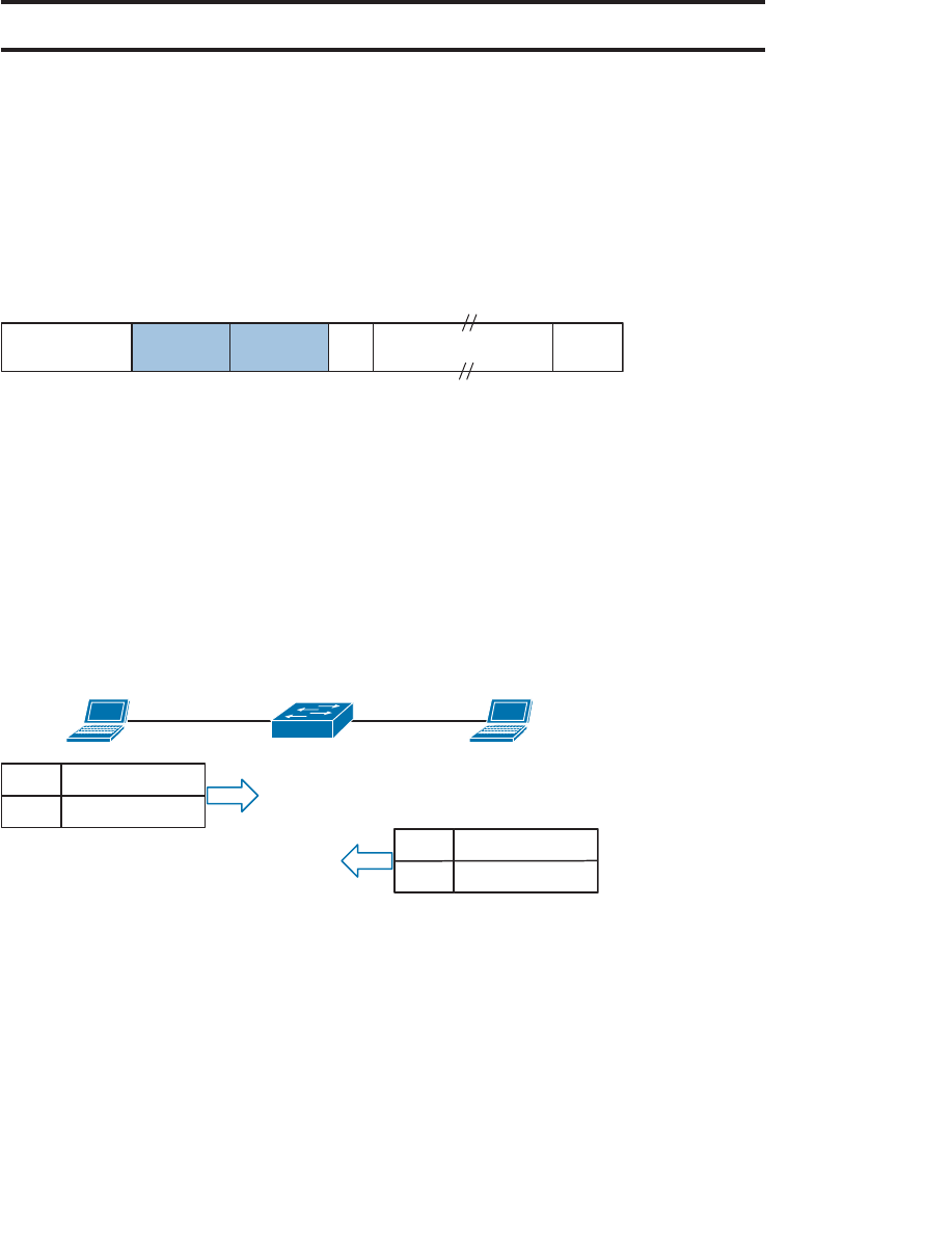
ptg12542968
126 CCNA Wireless 640-722 Official Cert Guide
802.11 Frame Format
To understand more about 802.11 frames and how they are transported, it might be use-
ful to compare them with the familiar 802.3 frames.
Ethernet devices based on IEEE 802.3 send and receive frames in the format shown in
Figure 6-1 . The sender and the intended recipient of a frame are identified by two MAC
addresses—a source and a destination. The source address is not used to deliver the
frame; rather, it is used for any return traffic that is sent back to the source. When the
recipient receives a frame that has its own MAC address as the destination, the frame is
then accepted and processed.
Preamble Destination
Address
Source
Address Type Data FCS
8 Bytes 6 Bytes 6 Bytes 2 Bytes 46–1500 Bytes 4 Bytes
Figure 6-1 IEEE 802.3 Ethernet Frame Format.
Suppose that the source and destination hosts are connected by a switched network, as
shown in Figure 6-2 . The switch that connects the two hosts forwards frames between
them as needed, but it does not intervene or actively participate in the exchange. In
other words, neither host has to be aware of the switch’s existence at all. Frames enter
and exit a switch simply because hosts are connected to it through wires or cables. The
switch silently forwards the frames based on the destination MAC addresses and the
device locations it has learned from the source MAC addresses.
DA
SA 0000.1111.1111
0000.2222.2222
Host 1
0000.1111.1111
Host 2
0000.2222.2222
DA
SA 0000.2222.2222
0000.1111.1111
Figure 6-2 Forwarding 802.3 Frames in a Switched Network.
In contrast, the APs in an 802.11 network are active participants. Recall from Chapter 5 ,
“Wireless LAN Topologies,” that an AP acts as the central “hub” or manager of a basic
service set (BSS). With the absence of wired connections, a client must join or associate
with a specific wireless network by first getting permission from the AP. Then the client
must send and receive every frame through the AP or coordinate with the AP for direct
client-to-client communication to use 802.11z - Direct Link Setup (DLS).
IEEE 802.11 networks are based on traditional MAC addresses. Each client’s radio inter-
face must have a unique MAC address so that frames can be sent from and received to
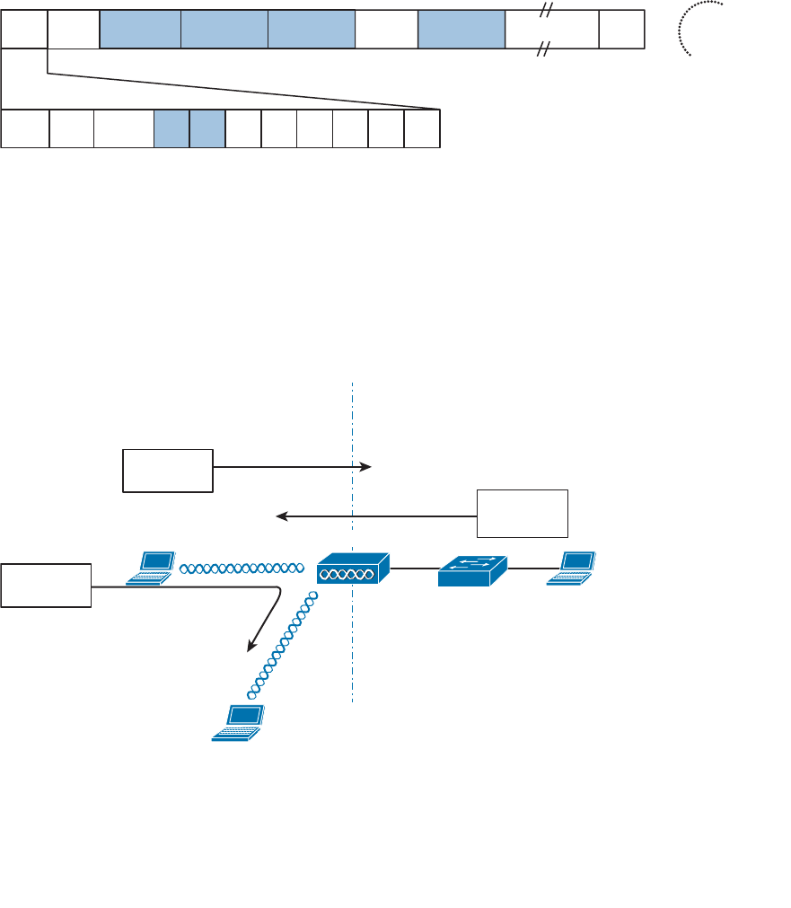
ptg12542968
Chapter 6: Understanding 802.11 Frame Types 127
that address. To direct frames through an AP, the AP must also have a MAC address of
its own. Wireless clients know the AP’s address as the BSS identifier (BSSID), which must
be included in each frame.
Figure 6-3 shows the basic format of 802.11 frames, which can be a maximum of 2346
bytes in length. The frame begins with a 2-byte Frame Control field, which identifies
such things as the frame type and the direction in which the frame is traveling as it
moves from one wireless device to another.
Frame
Control
Duration
/ID Address1 Sequence
Control
Address2 Address3 Address4 Data FCS
2 Bytes 2 Bytes 6 Bytes 6 Bytes 6 Bytes 2 Bytes 6 Bytes 4 Bytes
0–2312 Bytes
Protocol
Version Type Subtype To
DS
From
DS
More
Frag Retry Pwr
Mgmt
More
Data WEP Order
2 4 11111111Bits: 2
Figure 6-3 IEEE 802.11 Frame Format.
Consider a common scenario where several wireless clients are associated with an AP.
This is not a standalone BSS—the AP also connects to an upstream DS. Most of the
time, wireless frames pass through the AP, either coming from clients toward the DS or
coming from the DS toward the clients. Frame motion is indicated by 2 bits, To DS and
From DS , contained in the 802.11 frame header. On the surface, it seems that frames
travel in only one of two directions, relative to the DS, as shown in the simple examples
of Figure 6-4 .
Host 1 Host 2
Host 3
From: Host 1
To: Host 2
From: Host 2
To: Host 1
BSS DS
From: Host 1
To: Host 3
To DS: 1
From DS: 0
To DS: 0
From DS: 1
To DS: 1
From DS: 0
To DS: 0
From DS: 1
AP-1
Figure 6-4 Some Example 802.11 Frames Moving to and from the DS.
Key
Topic
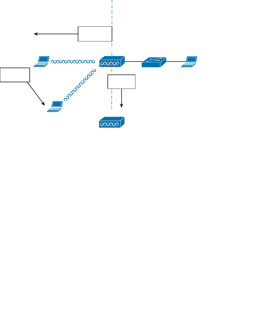
ptg12542968
128 CCNA Wireless 640-722 Official Cert Guide
With just two frame directions to indicate, a single bit would suffice. Why are there two
different direction bits in the frame header? There are two other special cases where
frames are destined for something other than a specific wireless client or somewhere in
the distribution system (DS), as shown in Figure 6-5 . This gives a total of four possible
destinations, or 2 bits worth of direction values.
Host 1 Host 2
Host 3
From: AP
To: All Clients
BSS DS
From: Host 1
To: Host 3
To DS: 0
From DS: 0
To DS: 0
From DS: 0
AP-1
AP-2
From: AP-1
To: AP-2
To DS: 1
From DS: 1
Figure 6-5 Examples of 802.1.1 Frames That Are Not Moving to and from the DS.
One special case commonly occurs when a frame is sourced or destined from a location
that cannot be clearly defined in relation to the DS. In the following examples, both the
To DS and From DS bits are set to 0:
■ An AP sends a management or control frame, which is broadcast to all wireless cli-
ents in the BSS. The AP, and not the DS, is the source of the frame.
■ A client sends a management frame to an AP, such that the AP itself is the destina-
tion.
■ One client sends a frame directly to another client via DLS. The frame is not des-
tined for the AP or the DS.
The other special case is related to mesh AP networks, where frames are relayed from
AP to AP over wireless backhaul links. A backhaul link is neither in the BSS nor in the
DS, so both direction bits are set to 1.
802.11 Frame Addressing
From an addressing viewpoint, an 802.11 frame header can contain up to four differ-
ent address fields. In Figure 6-3 , you can see them listed with the rather generic names

ptg12542968
Chapter 6: Understanding 802.11 Frame Types 129
Address1 through Address4. Wireless frames are always sent from a transmitting device
to a receiving device. Therefore, each frame header must contain a transmitter address
(TA) and a receiver address (RA). The Address1 field always contains the RA, though its
exact contents may vary depending on where the frame is headed. Likewise, Address2
always contains the TA.
Address3 contains the final destination address when the RA is not the final recipient.
For example, when a wireless client sends a frame to a destination on the DS, the frame
is transmitted from the client’s wireless adapter, is received by the AP, but still needs to
be forwarded on to the final destination on the DS. Likewise, Address3 can contain the
original source address when the TA is not the originator. Consider a frame sent from a
device on the DS to a wireless client. When the frame is sent over the wireless medium,
the AP’s radio is the transmitter address, but the AP did not originate the frame—a
device on the DS did.
Address4 does not come into play unless a frame is being transported from one AP to
another AP across a wireless link. In that case, the frame has to carry the original sender
and recipient addresses, in addition to the MAC addresses of a receiver and transmit-
ter—the APs relaying the frame over the air.
Table 6-2 lists the possible combinations of frame direction bits, along with the four
address field contents. You should become familiar with frame addressing, as the CCNA
Wireless exam may cover it. Try to break the table down into parts. First, get comfort-
able with the To/From DS bits and the reasons behind the frame directions. Next, think
about what happens to a frame each step along the way as it travels from its source to
its destination. Does it stop at the AP? Does the AP relay it to or from a more distant
location? Remember that Address1 and Address2 are always the receiver and transmitter
MAC addresses, respectively. Address3 will contain the address of an additional hop, if
one is needed.
Table 6-2 802.11 Frame Header Direction and Addressing
To DS From DS Address1
(RA)
Address2
(TA)
Address3 Address4
Management,
control, or DLS
0 0 Dest Addr Src Addr BSSID
DS to client 0 1 Dest Addr BSSID Src Addr
Client to DS 1 0 BSSID Src Addr Dest Addr
Wireless bridge
or mesh
1 1 Dest
Radio
Src Radio Dest Addr Src Addr
Figure 6-6 shows two example frames and their address fields. Frame1 at the top is being
sent from Host1 to Host2, while Frame2 at the bottom is coming from Host2 to Host1.
Fictitious MAC addresses are used for clarity.
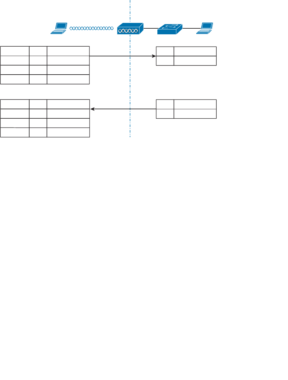
ptg12542968
130 CCNA Wireless 640-722 Official Cert Guide
BSSID
SA 0000.1111.1111
0000.9999.9999
DA 0000.2222.2222
Host 1
0000.1111.1111
Host 2
0000.2222.2222
BSSID
0000.9999.9999
To DS: 1
From DS: 0
DA
BSSID 0000.9999.9999
0000.1111.1111
SA 0000.2222.2222
To DS: 0
From DS: 1
Addr2 (TA)
Addr3
Addr4
Addr1 (RA) DA
SA 0000.1111.1111
0000.2222.2222
DA
SA 0000.2222.2222
0000.1111.1111
Frame 1
Frame 2
Addr2 (TA)
Addr3
Addr4
Addr1 (RA)
Figure 6-6 Examples of 802.11 Frame Addressing.
Host1 is sending the frame through the AP to the DS, so the Address1 (RA) contains the
BSSID 0000.9999.9999. Frame1 is sourced or transmitted by Host1, so the Address2
(TA) field contains Host1’s MAC address, 0000.1111.1111. The frame must pass
through the AP, so Host1 populates Address3 with the destination address of Host2,
0000.2222.2222. Once the AP receives Frame1, it finds that Host2 is located on the DS,
so the wireless frame is converted into an 802.3 wired frame. The original source and
destination addresses are copied into the new frame so that it can be forwarded on to
Host2.
On the return trip, Host2 fills in the source and destination addresses of Frame2 in 802.3
format. The switch forwards the frame to the AP, which knows that the destination
(Host1) is located within the wireless BSS. The AP populates Address1 (RA) with the des-
tination address of Host1. The AP is transmitting the frame, so Address2 (TA) contains
the BSSID. The address of the original source, Host2, is copied into the Address3 field.
Accessing the Wireless Medium
Once a wireless device has data to send, it must access the network medium and try to
send it. Remember that a wireless channel is a shared medium and that every device try-
ing to use it must share the airtime and contend for its use. There is no centralized func-
tion that coordinates the use of a wireless channel. Instead, this effort is distributed to
each device that uses a channel. This is known as a distributed coordination function
(DCF) .
With a shared medium, such as wired Ethernet or wireless, two or more stations trans-
mitting at the same time can cause collisions. A collision ruins the transmitted data,
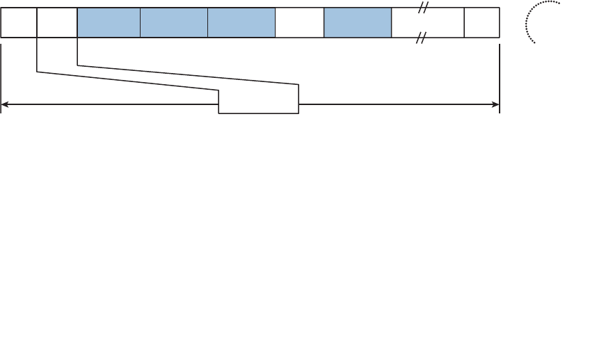
ptg12542968
Chapter 6: Understanding 802.11 Frame Types 131
wastes time on the medium, and causes the data to be retransmitted—wasting even more
time. When full-duplex operation isn’t possible, some collisions are inevitable; therefore,
every device should make its best attempt to mitigate and/or hopefully prevent colli-
sions in the first place.
Carrier Sense
Devices based on the 802.3 and 802.11 standards must use the carrier sense multiple
access (CSMA) technique to determine if the media is available before transmitting.
Wired devices are able to sense an electrical signal on the wire to detect a transmission
already in progress. Wireless devices can use a two-fold process to detect a channel in
use:
■ Physical Carrier Sense —When a wireless client is not transmitting, it can listen to
the channel to overhear any other transmissions that might be occurring. If it over-
hears a frame that is destined for its own MAC address, then it receives the frame
for processing. Otherwise, if a transmission is detected but the client cannot read
the transmitter’s MAC address in the header, the client decides that the channel is
busy. This process is also known as clear channel assessment (CCA)
. While CCA is
effective, it isn’t a proactive approach and must be used in conjunction with other
methods.
■ Virtual Carrier Sense —When a wireless client transmits a frame, it must include a
duration field in the Duration/ID frame header field. The duration indicates how
many microseconds are required for the whole frame to be sent over the channel,
and effectively reserves the channel for that length of time. As long as other wireless
clients can overhear a frame and its header, they can predict how long they should
wait for the frame to complete.
Figure 6-7
depicts the frame duration field and its
relationship to the frame length in time,
n Microseconds
Frame
Control
Duration
/ID Address1 Sequence
Control
Address2 Address3 Address4 Data FCS
2 Bytes 2 Bytes 6 Bytes 6 Bytes 6 Bytes 2 Bytes 6 Bytes 4 Bytes
0–2312 Bytes
Figure 6-7 The 802.11 Frame Duration Field.
Each wireless client must maintain a network allocation vector (NAV) timer that is used
to predict when the channel will become free. Each time a frame is overheard on the
channel, its Duration value is loaded into the NAV. The NAV timer then counts down
while the client waits to transmit.
The NAV timer must be at zero before a client can contend for use of the channel. That
sounds simple, but the contention process is still a bit more complex. Sensing the carrier
alone can alert a client when the medium is quiet and available—except that every cli-
Key
Topic

ptg12542968
132 CCNA Wireless 640-722 Official Cert Guide
ent on the channel will come to the same conclusion at the same time! If multiple clients
have frames to transmit and all decide that the channel is free at the same time, collisions
are still likely.
Collision Avoidance
The 802.3 and 802.11 standards differ when it comes to dealing with collisions. Wired
devices can detect collisions in real time so that they can back off and wait a random
time to try again. This is known as CSMA/CD (collision detection).
Wireless devices always operate in half-duplex mode, which prevents a client from
receiving signals on a channel while it is transmitting. This means that a transmitting wire-
less client can’t detect when a collision occurs at all. Therefore, 802.11 devices must try
to avoid collisions in the first place, resulting in the CSMA/CA (collision avoidance)
scheme.
Wireless clients avoid collisions by backing off and waiting a random time before trans-
mitting. If a client has a frame to transmit, it must then choose a random number (0 to
31) of timeslots to use as a backoff timer . If there are multiple clients with frames ready
to transmit, their random backoff timer values will lessen the likelihood that they will
contend to use a channel at the same time.
If the channel becomes busy before the backoff timer reaches zero, the timer is paused
and the overheard frame duration value is added to the NAV. The waiting client can
transmit only when every timer mechanism has expired and the channel is available. The
total time a client spends waiting to transmit is called the contention window .
Believe it or not, there is one more timing scheme that controls frame transmission. The
802.11 standard defines a few different interframe space periods that provide a safety
cushion between frames. These periods of silence give the channel enough time for sig-
nals to dampen out—especially when multipath is involved and some reflected copies
take longer to propagate than others.
Several different interframe space periods are used, according to the type and priority of
the frame being transmitted:
■ Reduced interframe space (RIFS) —The shortest period of time, used before each
data frame during a burst of 802.11n frames
■ Short Interframe Space (SIFS) —Used between data frames and frame acknowl-
edgements or, CTS 802.11g protection mode control frames
■ Distributed Interframe Space (DIFS) —The default period used after most standard
priority frame types
■ Extended interframe space (EIFS) —The longest period of time, used after colli-
sions and before retransmitted frames
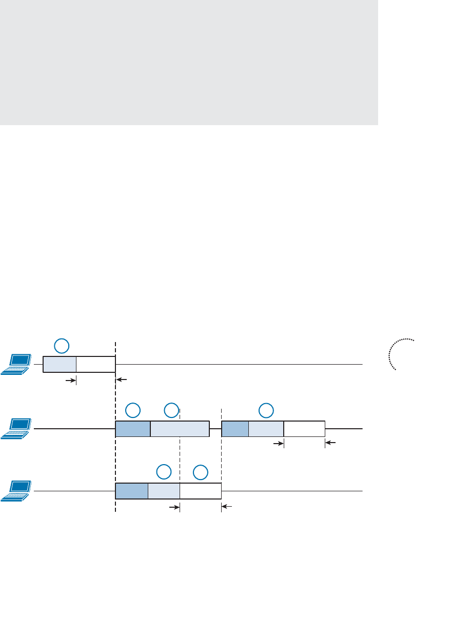
ptg12542968
Chapter 6: Understanding 802.11 Frame Types 133
Tip If you feel confused over all of the timer mechanisms, try to remember this simple
rule. Before a device can transmit on a channel, it must do the following:
1. Wait for DIFS.
2.
Wait for its own backoff timer.
3. Listen.
4.
Wait for contention window (backoff timer + NAV). If the channel is clear after-
ward, the client may transmit.
Assuming all of the carrier sense and collision avoidance methods have worked, how
does a transmitting client know that the frame it just sent arrived in good condition?
During transmission, the receiver must be off, so there is no way to listen to the channel.
Instead, every client must rely on a very rudimentary feedback mechanism. Each time
a client receives a unicast frame, it must send a unicast acknowledgement frame back
to the sender. The 802.11 standard requires this one-to-one response for every frame
received, except in the case of 802.11n and 802.11e (WMM) bursts of frames, which
require one acknowledgement for a whole block of frames.
If a transmitted frame fails and is not acknowledged, the sending client must try again by
retransmitting the frame. The client chooses a new backoff timer value that is double the
previous choice. In effect, this relaxes the conditions on the channel to give the retrans-
mitted frame a better chance of surviving. With every failed attempt, the backoff timer
is doubled, up to a maximum of 1023 timeslots.
Figure 6-8 shows an example of the DCF operation within a wireless cell.
Client A
Frame-ABackoff
DIFS
Client B
Backoff
Client C
Backoff Frame-C
DIFS Frame-B
1
2 3
45
6
Duration
Duration
Duration
DIFS
Backoff
Figure 6-8 Avoiding Collisions with the DCF Process.
Key
Topic

ptg12542968
134 CCNA Wireless 640-722 Official Cert Guide
The following sequence of events occurs:
1.
Client A listens and determines that no other devices are transmitting. Client A waits
a random backoff timer period before transmitting Frame-A. The frame’s duration is
advertised in the header’s Duration field.
2.
Client B has a frame to transmit. It must wait until Client A’s frame is completed and
then wait until a DIFS period has expired.
3. Client B waits a random backoff time before attempting to transmit.
4. While Client B is waiting, Client C has a frame to transmit. Like Client B, Client C
must wait until the DIFS period has elapsed. Client C then listens and detects that
no one else is transmitting. It then waits a random backoff time that is shorter than
Client B’s backoff timer.
5.
Client C transmits a frame and advertises the frame duration in the Duration field.
6.
Client B must now wait the duration of Client C’s frame plus a DIFS period plus the
remainder of its own backoff timer before attempting to transmit again.
802.11 Frame Types
The 802.11 standard defines three different frame types that can be used:
■ Management frames
■ Control frames
■ Data frames
The frame type is identified by a 2-bit Type field and a 4-bit SubType field in the Frame
Control portion of the header. This implies that each of the three frame types can have
several different subtypes that perform various functions. The frame types and their
most common subtypes are discussed in the following sections.
Management Frames
Management frames are used to advertise a BSS and to manage clients as they join or
leave the BSS. A client must first locate a candidate BSS to join, authenticate itself to an
AP, and associate itself with the BSS. Although there are 14 different management frame
subtypes available, you should become familiar with just the following for the CCNA
Wireless exam:
■ Beacon —A frame that is broadcast by the AP to advertise the BSS, the data rates
necessary and allowed in the BSS, an optional security set identifier (SSID) string,
and vendor-specific information when necessary. Beacons are sent to any and all
devices in the BSA about ten times per second (100 ms intervals). If the AP supports
multiple SSIDs, a different beacon is broadcast for each SSID.
Key
Topic

ptg12542968
Chapter 6: Understanding 802.11 Frame Types 135
A wireless device can learn about BSSs within range by listening to the beacons that are
received. This is known as passive scanning .
■ Probe —A wireless device can send probe request frames to ask any APs within
range or a specific AP to provide information about their BSSs. An AP answers by
sending a probe response that contains most of the beacon information. Probing for
BSS information is known as active scanning .
■ Authentication and deauthentication —To join a BSS, a wireless device must first
send an authentication request frame to an AP. The AP can support either Open
System authentication
, where any device is authenticated without any sort of
verification, or shared key authentication
, where a device must exchange a Wired
Equivalent Privacy (WEP) key that matches the key used by the AP. The AP sends
the result of the authentication in an authentication response frame.
If a device wants to leave the authenticated state, it can send a deauthentication
frame to the AP. However, the AP can force a device out of the authenticated state
by sending it a deauthentication frame.
Tip It might seem odd that Open System and WEP are the only two authentication
methods offered in authentication request frames, because both methods are known to
be very weak. Wireless networks can offer robust authentication methods through a dif-
ferent method of frame exchanges. Those methods are covered in Part III, “Implementing
Wireless LANs.”
■ Association, disassociation, and reassociation —Once a device is authenticated, it
can send an association request frame to the AP to ask permission to join the BSS. If
the device supports compatible parameters and is allowed to join, then the AP will
reply with an association response frame, along with a unique association identifier
(AID) for that client.
If a device wants to gracefully leave a BSS, it can send a disassociation frame to the
AP. An AP can also decide to drop a client by sending it a disassociation frame.
When a client wants to leave one BSS for another, while staying within the same
SSID, it can send a reassociation request frame to the new AP. In effect, the client
is attempting to reassociate with the SSID, not an AP. The new AP responds with a
reassociation response frame. (Moving from one BSS to another is covered in great-
er detail in Chapter 12 , “Understanding Roaming.”)
Control Frames
Control frames are used to gain control of and to help deliver data over a channel.
Control frames contain only frame header information and no data payload. There are
nine different control frames possible. Be familiar with the following four:

ptg12542968
136 CCNA Wireless 640-722 Official Cert Guide
■ ACK —A short frame that is sent as an acknowledgment of a unicast frame that has
been received.
■ Block ACK —A short frame that is sent as an acknowledgment of a burst of frames
send as a single block of data.
■ PS-Poll —The Power Save Poll frame is sent from a client to an AP to request the
next frame that was buffered while the client’s radio was powered down.
■ RTS/CTS —Frames that are used to reserve a channel during 802.11g protected
mode, while a legacy 802.11b client is transmitting. RTS/CTS frames carry a
Duration value that reserves the channel airtime for the frame they are protecting.
RTS/CTS may also be used to help avoid collisions between clients that cannot hear
each other because of the distance between them. When clients cannot hear each
other, they also cannot hear the Duration values or detect a carrier to know when
to cease transmitting. As long as the clients can hear the AP when it sends RTS/CTS
frames, they can remain silent while others are transmitting.
Data Frames
Data is sent to and from clients in data frames. A data frame contains up to four address
fields that identify the sender and recipient and identify the BSSID and any wireless link
involved with forwarding the frame. The 802.11 standard defines 15 different data frame
subtypes, but you should just be aware of a generic data frame and its addressing mecha-
nism.
Client Housekeeping
Recall from Chapter 1 , “RF Signals and Modulation,” that a client and an AP have to
use the same modulation and coding scheme (MCS) to successfully communicate. The
scheme can be changed dynamically, if needed, as long as both ends agree on the choice.
The MCS directly affects the data rate between the client and the AP.
An AP is configured with a set of data rates that it can use. Each data rate can be set to
one of the following states:
■ Disabled —The AP will not use the data rate for any client communication.
■ Supported —The AP can use the data rate if a client also supports its use, but the
client is not required to support it.
■ Mandatory —The AP can use the data rate and expects every client to support it.
This is also known as an 802.11 BSS basic rate .
At least one data rate must be mandatory to provide a common rate that can be used
for management and control frames. In fact, the AP will always send broadcast manage-
ment frames using the lowest mandatory rate. The idea is to leverage a lower data rate to
get better signal-to-noise ratio (SNR) and greater signal range to reliably manage client
devices within the BSS.

ptg12542968
Chapter 6: Understanding 802.11 Frame Types 137
Other data rates can be configured as supported. Normal data frames and unicast man-
agement frames will be sent at whatever supported rate is most optimal between the
client and the AP. Acknowledgment frames are sent at the first mandatory rate that is
below the current optimal data rate.
APs advertise their mandatory and supported data rates in each beacon frame so that
potential clients can know what is available. By default, 802.11b/g/n radios are config-
ured with 1-, 2-, 5.5-, and 11-Mbps data rates as mandatory; 802.11a/n radios consider 6,
12, and 24 Mbps to be mandatory.
Before a wireless device can join a BSS, it must announce its own set of mandatory and
supported data rates in an association request frame. The AP compares the client’s list of
data rates with its own. If the client can support all of the AP’s mandatory rates, the cli-
ent can take the next step to be associated with the BSS.
Wireless clients can be mobile and transient. The following sections describe how a wire-
less client and a BSS interact using management frames in a variety of common scenarios.
A Client Scans for APs
To join a BSS, a wireless device first has to scan its surroundings to look for any live APs
that might offer network service. Beyond that, the device might need to build a list of
SSIDs that are available. A device can scan the wireless horizon in two ways:
■ Passive scan —The device simply listens for any beacon frames broadcast from
nearby APs. Passive scanning has a couple of drawbacks—a device must wait until
beacons are broadcast at the next interval, which might not be soon enough in a
time critical situation; beacons don’t always contain specific SSID names, so a device
cannot always depend on learning that a desired SSID exists on an AP.
In Figure 6-9 , Host-1 is able to receive beacons from AP-1 and AP-2. The beacon
frames specify the BSSIDs and SSIDs that are offered, as well as supported data
rates and other information about their BSSs.
■ Active scan —The device must take an active role and broadcast a probe request
frame to ask any APs within range to identify themselves. The device can include
a specific SSID name in the request. Any APs that receive the probe request must
send a unicast probe response frame back to the device.
In Figure 6-10 , a device broadcasts a probe request to look for any APs that can
offer the “guest” SSID. Both AP-1 and AP-2 receive the request and send probe
responses containing their BSSIDs and other information about the BSS and SSID.
Key
Topic
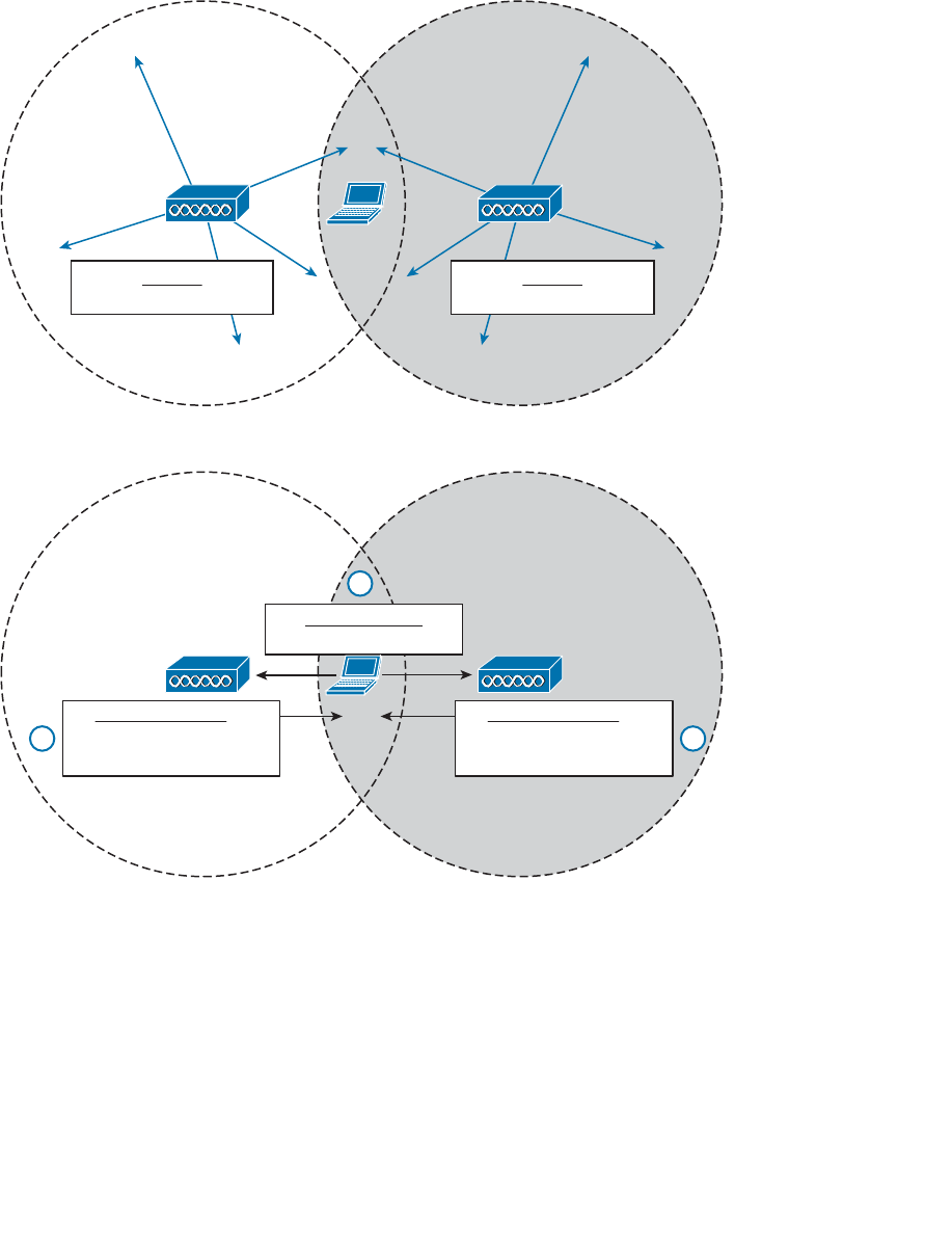
ptg12542968
138 CCNA Wireless 640-722 Official Cert Guide
AP-1 AP-2
Host-1
Beacon
BSSID: 0000.1111.1111
Beacon
BSSID: 0000.2222.2222
Figure 6-9 Using a Passive Scan to Discover BSSs.
AP-1 AP-2
BSSID 0000.1111.1111
has SSID guest
Probe Request
Who has SSID guest?
22
BSSID 0000.2222.2222
has SSID guest
1
Probe Response Probe Response
Figure 6-10 Using an Active Scan to Discover BSSs.
A Client Joins a BSS
Suppose a wireless device is not currently joined to a wireless network. The device
comes within range of two different APs that form a single ESS and offer a common
SSID. The device performs an active scan and discovers the two APs. Through some
algorithm, it decides that AP-1 is more preferable than AP-2. Figure 6-11 shows the steps
that the device takes to join the network offered by AP-1.
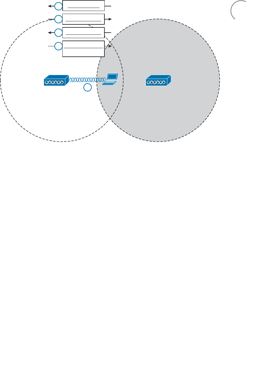
ptg12542968
Chapter 6: Understanding 802.11 Frame Types 139
AP-1 AP-2
Auth Request
Auth Response
Assoc Request
Host-1
(ACKs omitted
for clarity)
1
2
3
4
5
Assoc Response
AID
Figure 6-11 A Wireless Client Joins a BSS.
Step 1. Host-1 sends an authentication request frame to AP-1’s BSSID address.
Step 2. If AP-1 is satisfied with the host’s identity, it sends an authentication
response frame back to Host-1.
Step 3. Now that Host-1 is known to the AP, it must ask for BSS membership by
sending an association request frame to AP-1. Host-1 includes a list of its
802.11 capabilities, the SSID it wants to join, a list of data rates and channels
it supports, and any parameters that are needed to secure the wireless link to
the AP.
Step 4. If the AP is satisfied with the request, it sends an association response frame
back to Host-1.
Step 5. The response also contains the AID that uniquely identifies Host-1 as an
associated client. In effect, the AID is Host-1’s membership card while it
remains a part of the BSS.
A Client Leaves a BSS
Once a wireless device successfully becomes a client of a BSS, it keeps that relationship
with the AP until something happens to remove it. For example, a wireless client might
be removed if it violates a security policy, is recognized as a rogue device, has a session
that stays idle for too long, and so on.
Key
Topic
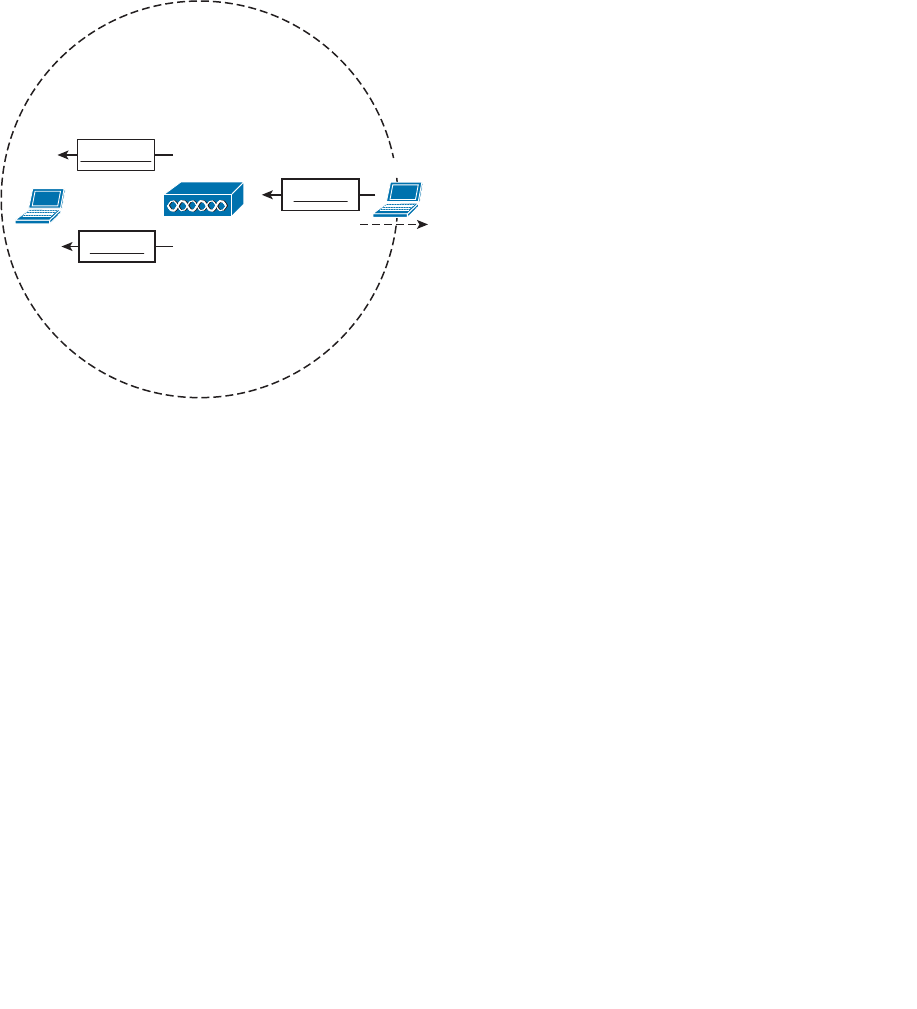
ptg12542968
140 CCNA Wireless 640-722 Official Cert Guide
A client can be removed from a BSS if the AP sends it a disassociation or a deauthentica-
tion frame. Once that happens, the device must start the whole association process over
again. In Figure 6-12 , Client-A has been forced to leave the BSS through either disasso-
ciation or deauthentication.
A client can gracefully remove itself from a BSS, when needed. To do this, the client
simply notifies the AP by sending it a deauthentication frame. In Figure 6-12 , Client-B
has sent a deauthentication for itself to AP-1.
AP-1 or
or
Disassoc
Deauth
Client-A
Deauth
Client-B
Figure 6-12 Disassociating and Deauthenticating—Two Ways to Leave a BSS.
What happens if a client physically leaves a BSS without informing the AP? For example,
suppose Client-B in Figure 6-12 reaches the edge of AP-1’s cell, but does not send a
deauthentication frame? Once it goes outside the cell range, the AP might not even
notice. Even before it leaves the cell, the client might just go into sleep mode and stop
communicating with the AP altogether. In this case, the AP maintains the AID entry for
the device, in case it returns to the cell or wakes up, but only for a certain amount of
time. Cisco APs age out unresponsive clients after 5 minutes. In case the client is still lis-
tening, the AP also sends a deauthentication frame to it.
A Client Moves Between BSSs
When a wireless client is within range of several APs, it must choose to associate with
only one of them. A client can join only one BSS at any given time. If the client changes
its location, it might stay within its original BSS or it might move out of range and into
the cell of an adjacent BSS. Moving seamlessly from one BSS to another is called
roaming .
The basic roaming process is not much different than finding and associating with a BSS,
except that the client does this while it is actively associated with another BSS. To switch
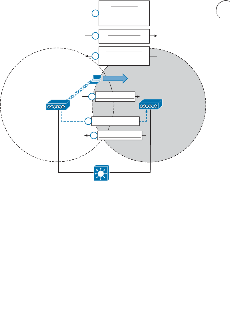
ptg12542968
Chapter 6: Understanding 802.11 Frame Types 141
BSSs seamlessly, the client must recognize that it is nearing the cell boundary and that it
needs to find other potential cells to move into before losing the signal completely.
Figure 6-13 illustrates the basic steps of the roaming process.
AP-1 AP-2
2
3
ESS: SSID “guest”
BSSID 0000.2222.2222
has SSID guest
Probe Request
Who has SSID guest?
Reassoc Request
4
Relay Buffered Data
5
Reassoc Response
RSSI is getting weak,
SNR is getting low;
Time to roam!
1
Client-1
(ACKs omitted
for clarity)
6
Note to Self:
Probe Response
Figure 6-13 Roaming Between Two BSSs.
The wireless client begins with an active association with AP-1 using SSID “guest”:
Step 1. Client-1 notices that the signal from AP-1 is degrading. Based on various con-
ditions like the received signal strength indicator (RSSI) and SNR, the client
will decide that it needs to roam.
Step 2. Client-1 begins to search for a successor BSS to move into. It broadcasts a
probe request frame to look for nearby APs that can offer the same “guest”
SSID.
Step 3. AP-2 receives the probe request and returns a probe response, advertising its
BSSID and the “guest” SSID. Other APs may also hear the request and send
probe responses of their own.
Key
Topic

ptg12542968
142 CCNA Wireless 640-722 Official Cert Guide
Step 4. Client-1 must decide which AP is the best candidate out of all probe respons-
es that are received. It then sends a reassociation request frame to the new
AP, asking to transfer its ESS membership from AP-1’s BSS to AP-2.
Step 5. AP-2 communicates with AP-1 over the wired DS network to begin the client
handoff. Client-1’s association will be moved from AP-1 to AP-2. Any frames
that are destined for the client during the handoff will be buffered on AP-1,
then relayed to AP-2 and transmitted to the client.
Step 6. If the reassociation is accepted, AP-2 will inform the client with a reassocia-
tion response frame.
A Client Saves Power
Wireless devices are commonly small in size and powered by batteries. Because the
devices are mobile and carried around, it is not very practical to stop and charge the bat-
teries. To maximize the battery life, the device should conserve as much power as pos-
sible.
By default, the radio (both transmitter and receiver) is powered on all the time, so that
the device is always ready to send and receive data. That might be good for perfor-
mance, but applies a constant drain on the battery. Fortunately, the 802.11 standard
defines some methods to save power by putting the radio to sleep when it is not needed.
Tip Be aware that a device’s radio sleeping is different than the whole device sleep-
ing, as when you close the lid on a laptop. While a radio is sleeping, its transmitter and
receiver are powered down for a short amount of time and cannot send or receive wire-
less frames. In contrast, when a laptop is sleeping, most of its functions are paused for a
long period of time. While asleep, a laptop can become disassociated from the AP; when
it wakes, it must probe and associate again. The “legacy” method was defined in the origi-
nal 802.11 standard and is described by Figure 6-14 and the following sequence of steps.
(For simplicity, the ACK frames that acknowledge each frame have been omitted.)
In a nutshell, the method works by letting the client’s radio power down and go to sleep
while the AP stores up any frames that are destined for the client. The client’s radio must
periodically wake up and fetch any buffered frames from the AP:
Step 1. The client informs the AP that it is entering power save mode by setting the
Power Management bit in the Frame Control field of the frame header (refer
to Figure 6-3 ).
Step 2. The client shifts its wireless radio into a very low power or “sleep” mode.
Step 3. The AP begins to buffer any unicast frames that are destined for the client
while it is in power save mode.
Step 4. To check for any potentially buffered frames, the client’s radio must wake up
in time to receive a beacon frame.
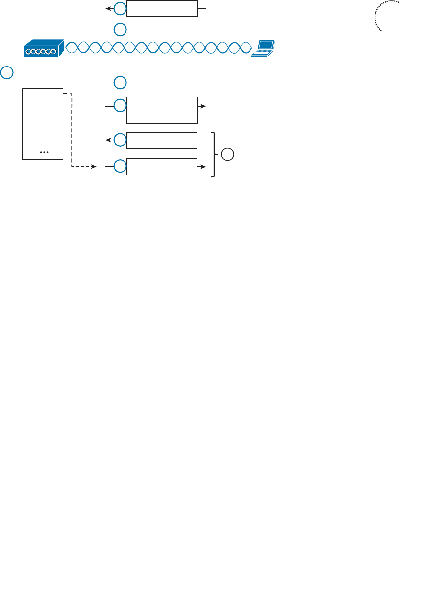
ptg12542968
Chapter 6: Understanding 802.11 Frame Types 143
Step 5. The beacon can contain a traffic indication map (TIM), or a list of AID
entries for clients that have buffered frames. The client, known as AID 7, has
frames available and is listed in the TIM.
Step 6. The client can begin to retrieve its buffered frames one by one. To do so, it
must send a PS-Poll management frame to the AP.
Step 7. The AP sends the next buffered frame to the client, along with a flag that
indicates more buffered frames are available.
Step 8. The client and AP continue the exchange in Steps 6 and 7 until no more
frames are available in the buffer.
Broadcast and multicast frames become special cases for clients that have radios in
power save mode. Such frames are not destined for any specific client; rather, they are
destined for mass delivery. Sleeping radios will miss the frames unless the AP somehow
intervenes.
An AP can also buffer broadcast and multicast frames and deliver them at regular inter-
vals. The delivery traffic indication message (DTIM) is a beacon that is sent at some
multiple of regular beacon periods. The DTIM period is advertised in every beacon so
that all clients know to wake up their radios in time to receive the next DTIM. At that
time, the DTIM is sent, followed by any buffered broadcast and multicast frames.
The legacy TIM and DTIM schemes have one drawback—they are AP-centric. Even
though a client needs to conserve its battery power, it is the AP that dictates when and
how often the client’s radio should wake up and consume more power.
Ideally, a client should have more control over its own power consumption. The 802.11e
amendment, certified by the Wi-Fi Alliance and known as Wireless Multimedia
Key
Topic
AP
Pwr Mgmt bit set
Client
AID = 7
Frames Waiting
For AID 7
Beacon: TIM
AID 7 has frames
Client’s Radio Sleeps
1
2
3
5
Client’s Radio Wakes
4
PS-Poll
6
Buffered Frame 1
7
Repeat Until No
More Data
(ACKs omitted for clarity)
8
Frame 1
Frame 2
Frame 3
Frame 4
Figure 6-14 Using the Legacy Power Save Delivery Method.
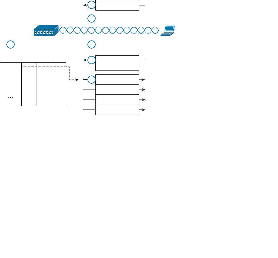
ptg12542968
144 CCNA Wireless 640-722 Official Cert Guide
(WMM), introduced a new quality of service (QoS) mechanism along with a new and
improved power save mode that is more client-centric.
Traffic to and from a wireless client can be handled according to four different catego-
ries, in order of decreasing time critical delivery: voice, video, best effort, and back-
ground. While a client is in a power save mode, the AP buffers its frames in four queues
that correspond to the QoS categories. When the client is ready to wake its radio up, it
sends a frame marked for one of the queues. The AP responds by sending the buffered
frames in that queue to the client in a burst.
This method is known as unscheduled automatic power save delivery (U-APSD), and
must be supported on both the client and the AP. The client does not have to request
each frame, and the client does not have to wake its radio up until it is ready to do so.
Figure 6-15 illustrates the sequence of steps involved in U-APSD, which are detailed in
the list that follows.
AP
Pwr Mgmt bit set
Client
AID = 7
Frames Waiting For AID 7
Client's Radio Sleeps
1
2
3Client’s Radio Wakes
4
Any frame marked
with Voice QoS
5
Buffered Frame 1
6
Voice Video Best
Effort Bkgnd
Frame 1
Frame 2
Frame 3
Frame 4 Buffered Frame 2
Buffered Frame 3
Buffered Frame 4
(ACKs omitted for clarity)
Figure 6-15 Using the U-APSD Power Save Delivery Method.
Step 1. The client informs the AP that it is entering power save mode by setting the
Power Management bit in a frame.
Step 2. The client puts its radio into power down or sleep mode.
Step 3. The AP buffers any frames destined for the client in the appropriate QoS
queues.
Step 4. The client decides to wake its radio.
Step 5. The client is ready to receive any buffered frames from the “voice” queue, so
it marks a frame as voice and signals the AP that it is awake.
Step 6. The AP sends the frames it has buffered in the voice queue in a burst.

ptg12542968
Chapter 6: Understanding 802.11 Frame Types 145
Exam Preparation Tasks
As mentioned in the section, “How to Use This Book,” in the Introduction, you have a
couple of choices for exam preparation: the exercises here, Chapter 22 , “Final Review,”
and the exam simulation questions on the CD-ROM.
Review All Key Topics
Review the most important topics in this chapter, noted with the Key Topic icon in the
outer margin of the page. Table 6-3 lists a reference of these key topics and the page
numbers on which each is found.
Table 6-3 Key Topics for Chapter 6
Key Topic Element Description Page Number
Figure 6-3 802.11 frame format 127
Figure 6-7 802.11 Frame Duration (NAV) field 131
Figure 6-8 Avoiding collisions with DCF 133
List 802.11 frame types 134
List Client scanning methods 137
Figure 6-11 Joining a BSS 139
Figure 6-13 Roaming between BSSs 141
Figure 6-14 Legacy power save mode 143
Define Key Terms
Define the following key terms from this chapter and check your answers in the glos-
sary:
active scanning, association, backoff timer, BSS basic rate, clear channel assessment
(CCA), collision avoidance, contention window, delivery traffic indication mes-
sage (DTIM), distributed coordination function (DCF), interframe space, network
allocation vector (NAV), open system authentication, passive scanning, physical
carrier sense, reassociation, shared key authentication, traffic indication map (TIM),
unscheduled automatic power save deliver (U-APSD), virtual carrier sense, Wireless
Multimedia (WMM)
Key
Topic

ptg12542968
This chapter covers the following topics:
■ AP Cell Size —This section discusses how the size
of a wireless cell affects things like coverage area,
performance, and efficiency.
■ Adding APs to an ESS —This section covers the
process of growing an extended service set, with an
emphasis on client roaming and proper layout of
wireless channels over an area.
This chapter covers the following exam topics:
■ Describe basic RF deployment considerations
related to site survey design of data or VoWLAN
applications; common RF interference sources such
as devices, building material, AP location; and basic
RF site survey design related to channel reuse, signal
strength, and cell overlap

ptg12542968
Chapters 1 through 6 covered wireless communication with a focus on a single access
point (AP) exchanging data with one or more clients. A single AP may be sufficient for
home or small office use, but most wireless LANs involve a greater geographic area and
require more APs. This chapter explains how wireless coverage can be adjusted to meet
a need and how it can be grown to scale over a greater area and a greater number of cli-
ents. As you work through this chapter, remember that two things are important: the size
of the BSA or AP cell and the location of cells in relation to each other.
“Do I Know This Already?” Quiz
The “Do I Know This Already?” quiz allows you to assess whether you should read this
entire chapter thoroughly or jump to the “Exam Preparation Tasks” section. If you are
in doubt about your answers to these questions or your own assessment of your knowl-
edge of the topics, read the entire chapter. Table 7-1 lists the major headings in this
chapter and their corresponding “Do I Know This Already?” quiz questions. You can
find the answers in Appendix A , “Answers to the ‘Do I Know This Already?’ Quizzes.”
Table 7-1 “Do I Know This Already?” Section-to-Question Mapping
Foundation Topics Section Questions
AP Cell Size 1–4
Adding APs to an ESS 5–10
Caution The goal of self-assessment is to gauge your mastery of the topics in this chap-
ter. If you do not know the answer to a question or are only partially sure of the answer,
you should mark that question as wrong for purposes of the self-assessment. Giving your-
self credit for an answer you correctly guess skews your self-assessment results and might
provide you with a false sense of security.
CHAPTER 7
Planning Coverage with Wireless APs

ptg12542968
148 CCNA Wireless 640-722 Official Cert Guide
1.
Which of the following parameters can be adjusted on an AP to change the size of
its cell or BSA? (Choose all that apply.)
a.
Channel number within a band
b. Transmit power
c.
Supported modulation and coding schemes
d. Supported data rates
2.
An AP has been configured to use channel 1 with a transmit power of 20 dBm. With
the AP located in the center of the lobby, you have determined that its signal will
reach all locations in the lobby area. However, some users with small battery-operat-
ed devices report connectivity problems when they move toward the outer walls of
the lobby. Which one of the following approaches will probably fix the problem?
a.
Increase the AP’s transmit power to increase its range
b. Increase the client device’s transmit power
c.
Adjust the client device’s roaming algorithm
d.
Enable some lower data rates on the AP
3.
Suppose that an AP is configured to offer the following data rates: 2-, 5.5-, 6-, 9-,
11-, 12-, 18-, 24-, 36-, and 48-Mbps data rates to its clients. Which one of the fol-
lowing strategies should be used to reduce the AP’s cell size?
a.
Enable the 1-Mbps data rate
b.
Enable the 54-Mbps data rate
c. Disable the 36- and 48-Mbps data rates
d. Disable the 2-Mbps data rate
4.
All the APs on the second floor of a building are part of a single ESS. Each AP has
been configured with a transmit power level of 14 dBm. In addition, each AP has
been configured to use a non-overlapping channel that is different from its adja-
cent neighbors. All APs have been configured to offer only the 24-, 36-, 48-, and
54-Mbps data rates; all other rates are disabled. One day, one of the APs fails and
someone replaces it. Afterward, users begin to call and complain about poor perfor-
mance and roaming. You discover that the problems are not occurring
in the area
covered by the failed AP; instead, they are occurring about two APs away from it.
Which one of the following could be causing the problem?
a. The replacement AP has its radios disabled.
b.
The replacement AP is using a transmit level of 1 dBm.
c.
The replacement AP is using the 1- and 2-Mbps data rates.
d.
The replacement AP is new and cannot be causing the problem.
5. Which one of the following determines when a wireless client will roam from one
AP to another?
a.
The current AP detects a weak signal coming from the client and forces the cli-
ent to roam.

ptg12542968
Chapter 7: Planning Coverage with Wireless APs 149
b.
The next AP overhears the client’s signal and asks it to roam.
c.
The client’s roaming algorithm reaches a threshold in signal quality.
d. The client loses its IP address.
6.
Which one of the following 802.11 frames is used to trigger a roam from one AP to
another?
a. Association request
b. Disassociation request
c. Probe
d. Reassociation request
7.
Which one of the following statements is true about roaming?
a.
All wireless clients use the same algorithms to trigger a roaming condition.
b.
Wireless clients can scan available channels to look for a new AP when roam-
ing.
c.
Wireless clients must roam from one AP to another on the same channel.
d.
The 802.11 standard defines a set of roaming algorithms for clients.
8.
Which one of the following statements is true about a good wireless LAN design?
a. Neighboring APs should use the same channel to promote good roaming.
b.
APs should be positioned so that their cells overlap.
c.
APs should be positioned so that their cells do not overlap at all.
d.
APs should use channels that overlap each other.
9. When you are designing the AP channel layout for an area, which one of the fol-
lowing is the most important consideration?
a.
The number of channels is conserved.
b.
APs in different areas use different channels.
c.
Adjacent APs use non-overlapping channels.
d. Clients are grouped into common channels.
10. An AP is located in the main office on the third floor of a building. The AP is con-
figured to use channel 6 in the 2.4-GHz band. Which of the following conditions
might hinder clients as they move around on the third floor and need to roam?
(Choose all that apply.)
a.
Two other APs in the third floor main office area use channel 6.
b. None of the fourth floor APs directly above the main office use channel 6.
c.
One of the second floor APs directly below the main office use channel 6.
d. All of these answers are correct.
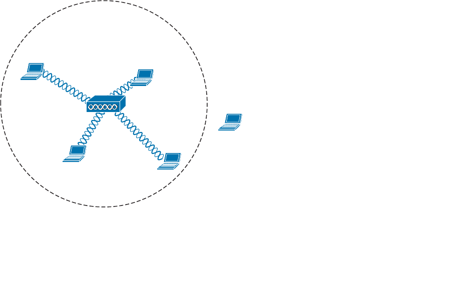
ptg12542968
150 CCNA Wireless 640-722 Official Cert Guide
AP Cell Size
The basic service area (BSA) or cell that is provided by an AP can vary, depending on
several factors. Obviously, the cell size determines the geographic area where wireless
service will be offered. AP cell size can also affect the performance of the APs as clients
move around or gather in one place.
Remember that a wireless LAN is a shared medium. Within a single AP cell, all of the cli-
ents associated with that AP must share the bandwidth and contend for access. If the cell
is large, a large number of clients could potentially gather and use that AP. If the cell size
is reduced, the number of simultaneous clients can also be reduced.
The signal from an AP does not simply stop at the boundary of its cell. Instead, the
signal continues to expand ad infinitum, growing exponentially weaker. Devices inside
the cell boundary can communicate with the AP. Devices outside the boundary cannot
because the signal strength of either the client or the AP is too weak for the pair to find
any usable modulation that can be used to exchange information. You can control the
size of a cell by changing the parameters that are described in the following sections.
Tuning Cell Size with Transmit Power
To use a wireless LAN, devices must be located within the range of an AP’s signal and
have an active association with the AP. This area is known as the BSA or cell. Consider
the scenario shown in Figure 7-1 . PCs 1 through 4 are within the cell’s perimeter and are
associated with the AP. PC-5, however, is outside the cell and cannot form an associa-
tion or participate in the basic service set (BSS).
AP-1
Channel 1
PC-1 PC-2
PC-3
PC-4
PC-5
Figure 7-1 An Example Cell That Includes All but One Client.
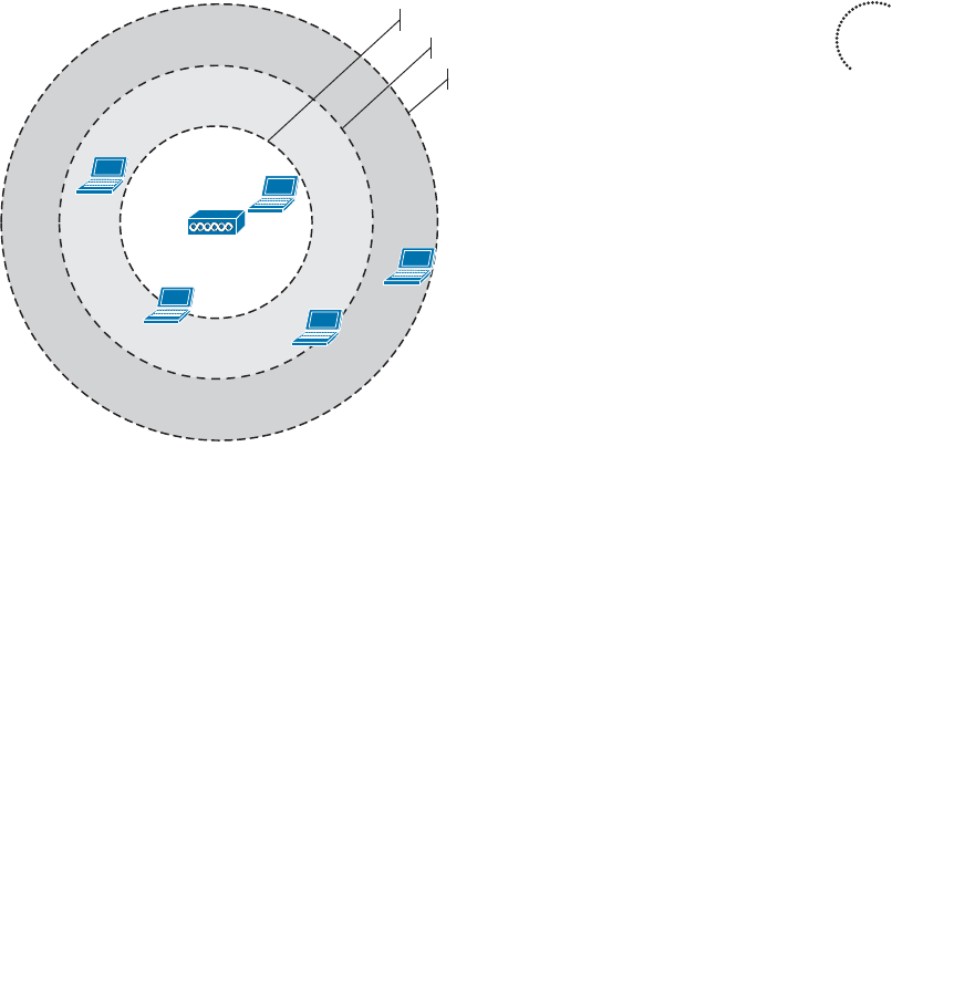
ptg12542968
Chapter 7: Planning Coverage with Wireless APs 151
If the area outside a cell is a legitimate location where wireless devices might be present,
the coverage area should probably be extended there. How can that be accomplished?
The most straightforward approach is to increase the transmit power or signal strength
leaving the AP’s antenna. A greater signal strength will overcome some of the free space
path loss so that the usable signal reaches farther away from the AP.
Figure 7-2 shows the effect of changing the AP’s transmit power level. The original cell
from Figure 7-1 is shown as the second concentric circle, where the transmit power level
was set to 17 dBm. If the level is increased to 20 dBm, the cell grows into the area shown
by the outermost circle. Notice that PC-5 now falls within the cell boundary. If the
transmit power level is decreased to 10 dBm, the cell shrinks and includes only clients
PC-2 and PC-3. Why would you ever want to decrease a cell’s size? That question will be
answered later in this section.
PC-1
PC-4
PC-5
AP-1
PC-2
PC-3
TX = 20 dBm
TX = 17 dBm
TX = 10 dBm
Channel 1
Figure 7-2 The Effects of the Transmit Power Level on Cell Size.
How should you decide on a transmit power level value? Cisco APs offer eight differ-
ent values for their 2.4-GHz radios and seven values for their 5-GHz radios. Most 802.11
scenarios fall within government regulations which limit the effective isotropic radiated
power (EIRP) to a maximum transmit power level of 20 dBm (100 mW). You could just
configure an AP to run wide open at maximum power, but that is not always appropriate
or beneficial.
One thing to consider is the two-way nature of wireless communications. By increasing
the AP’s transmit power, the AP might reach a distant client, but can the client’s own
signal reach the AP? Notice client PC-5 in Figure 7-3 . If the AP transmit power level is
increased to 20 dBm (the outermost circle), PC-5 is included in the cell. However, PC-5’s
wireless transmitter has a lesser power level; in its current location, PC-5 has a cover-
age area that falls short of including the AP. This scenario is known as the asymmetric
power problem, where the two communicating devices have differing transmit power
levels that might not reach each other.
Key
Topic
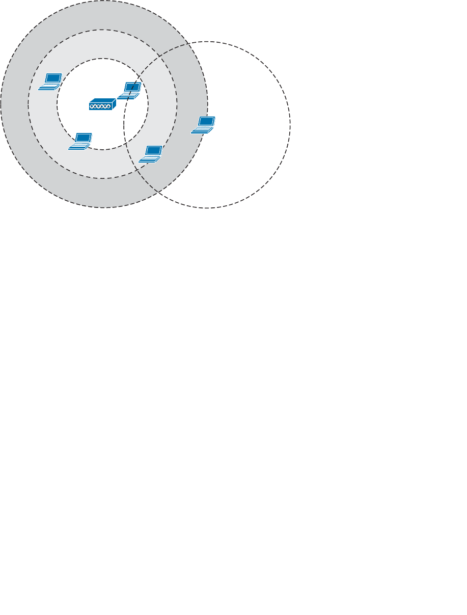
ptg12542968
152 CCNA Wireless 640-722 Official Cert Guide
PC-1
PC-4
PC-5
AP-1
PC-2
PC-3
Channel 1
Figure 7-3 The Asymmetric Power Problem.
Tuning Cell Size with Data Rates
Setting the transmit power level is a simplistic approach to defining the cell size, but
that is not the only variable involved. The cell size of an AP is actually a compromise
between its transmit power and the data rates that it offers.
Recall from Chapters 1 and 3 that the higher data rates or more complex modulation and
coding schemes (MCS) offer the greatest throughput but require the best signal condi-
tions—usually closer to the AP. The less complex schemes can work further away from
an AP, but offer slower data rates. Therefore, at the perimeter of a cell, a client is likely
to be using the least complex MCS and the lowest data rate. Figure 7-4 shows a simpli-
fied representation of the range of each data rate with concentric circles. At the outer
edge of the cell, a client will probably resort to a 1-Mbps data rate.
To design a wireless LAN for best performance, you would most likely need to disable
some of the lower data rates. For example, you could disable the 1-, 2-, and 5.5-Mbps
rates to force clients to use higher rates and better modulation and coding schemes. That
would improve throughput for individual clients and would also benefit the BSS as a
whole by eliminating the slower rates that use more time on a channel.
As you disable lower data rates, the respective concentric circles in Figure 7-4 become
irrelevant. This effectively reduces the usable size of the AP’s cell, even though the radio
frequency (RF) footprint remains the same. After all, you haven’t reduced the transmit
power level which would reduce the extent of the RF energy. Be aware that as smaller
usable cells are placed closer together, their available data rates are higher. At the same
time, their RF footprints can remain large and overlap each other, resulting in a higher
noise floor.
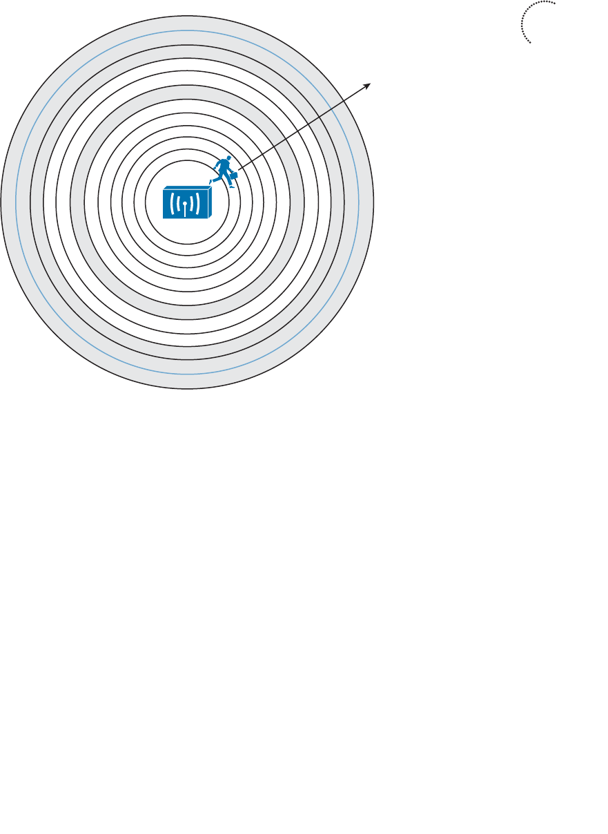
ptg12542968
Chapter 7: Planning Coverage with Wireless APs 153
To provide robust wireless coverage to an ever-increasing area, you should use the fol-
lowing two-pronged approach:
■ Tune the cell size based on data rates and performance.
■ Add additional APs to build an ESS that covers more area.
Adding APs requires careful consideration for client mobility and the use of wireless
channels. These topics are covered in the next section.
Adding APs to an ESS
If a client is associated with an AP, it can maintain the association as long as it stays
within range of the AP. Consider the cell shown in Figure 7-5 . As long as the client stays
within points A and B, three conditions are met:
■ The client is able to receive the AP’s signal at an acceptable level.
■ The AP is able to receive the client’s signal.
■ One of the acceptable modulations can be successfully used between the client and
the AP.
6 Mbps
5.5 Mbps
2 Mbps
1 Mbps
11 Mbps
9 Mbps
36 Mbps
24 Mbps
18 Mbps
12 Mbps
48 Mbps
54 Mbps
Data Rate
Figure 7-4 The Relationship of Data Rates and Cell Range.
Key
Topic
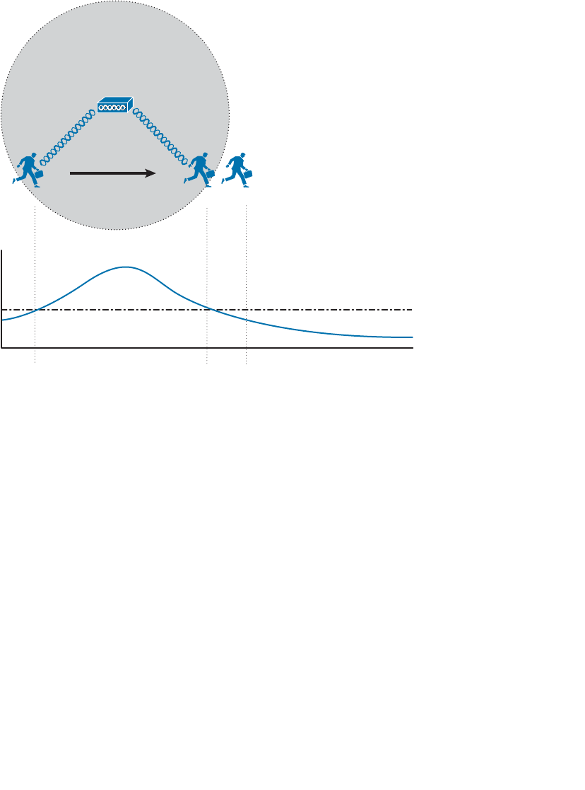
ptg12542968
154 CCNA Wireless 640-722 Official Cert Guide
As soon as the client goes outside the cell range at point C, one or more of the condi-
tions fails and the client loses the association. In the figure, the AP’s signal has fallen
below an acceptable threshold.
ABC
ABC
Signal Threshold
AP-1 Signal
AP-1
Figure 7-5 A Mobile Client Moves Within an AP Cell.
Other APs can be added so that the client can move within a larger area; however, the
APs must be carefully deployed to allow the client to roam from AP to AP. Roaming is
the process of moving an association from one AP to the next, so that the wireless con-
nection is maintained as the client moves.
In Figure 7-6 , a new AP has been added alongside AP-1, each using the same channel.
It might seem intuitive to build a larger coverage area by using a single channel. Usually
this turns out to be a bad idea because the client may experience an excessive amount of
frame collisions in the area between the two cells.
Remember that the signal from an AP does not actually stop at the edge of the cell; rath-
er, it continues to propagate as it eventually dies off. This is shown by the signal strength
graph of each AP. The client is able to form an association with AP-1 at point A. Even
at that location, some portion of AP-2’s signal can be received, albeit at a lower level.
Because AP-2 is using the same channel as AP-1, the two APs (and any clients within
range) can essentially interfere with each other through co-channel interference.
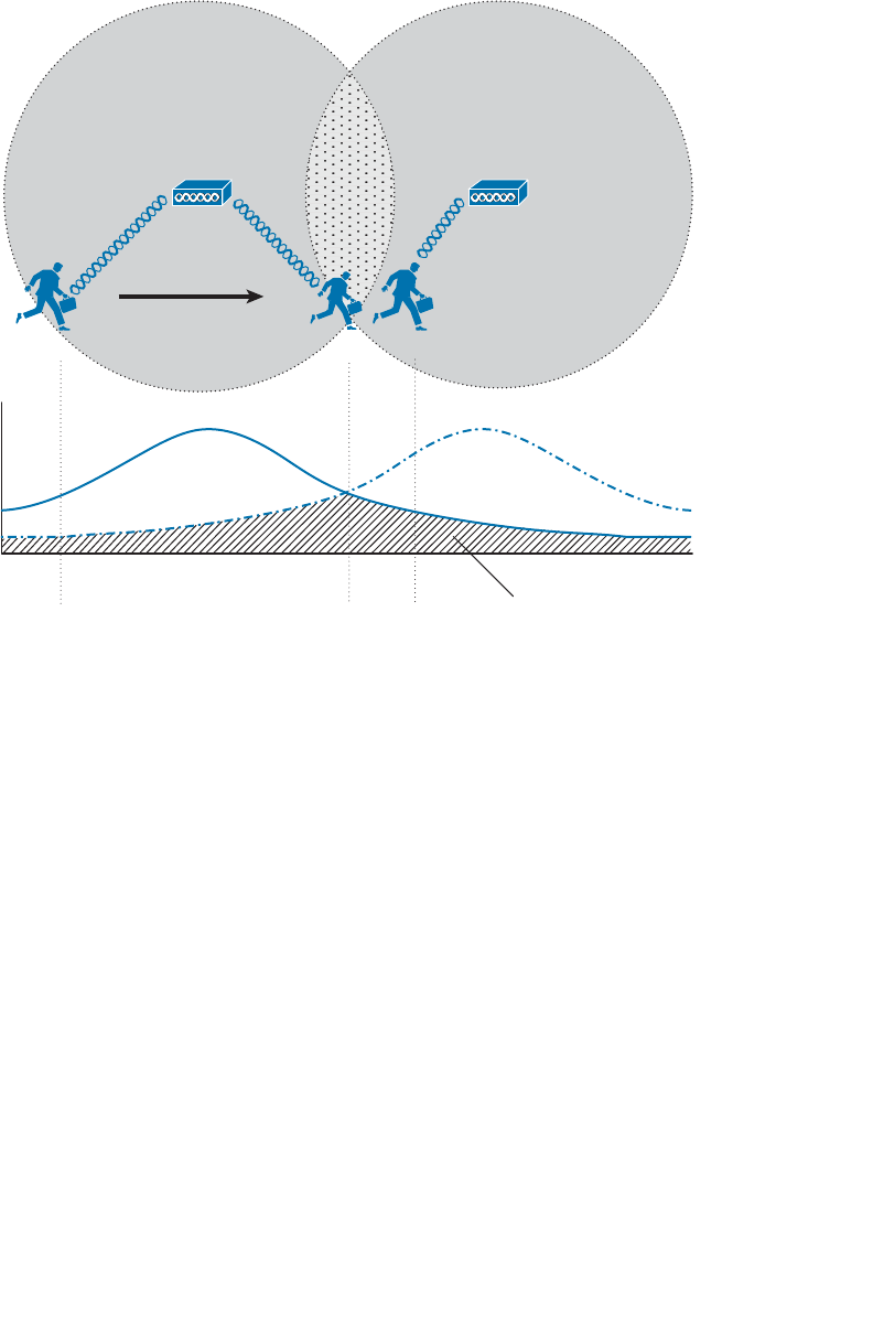
ptg12542968
Chapter 7: Planning Coverage with Wireless APs 155
Ideally, when the client in Figure 7-6 moves to location B, it should begin to anticipate
the need to roam or transfer its association from AP-1 to AP-2. Notice that AP-1 and
AP-2 are spaced appropriately for roaming, where their cells have some overlap. The
two APs are out of range of each other, so they are not aware of each other’s transmis-
sions on the same channel. Each AP will coordinate the use of the channel with devices
that are inside its own cell, but not with the other AP and devices in the other cell. As a
result, the client around location B will probably experience so many collisions that it
may never be able to roam cleanly.
The Roaming Process
What enables a client to roam in the first place? First, adjacent APs should be config-
ured to use different non-overlapping channels. For example, an AP using channel 1
must not be adjacent to other APs also using channel 1. Instead, a neighboring AP should
use channel 6 or higher to avoid any frequency overlap with channel 1. This ensures that
clients will be able to receive signals from a nearby AP without interference from other
APs. As you learned in Chapter 2 , “RF Standards,” the 5-GHz band is much more flex-
ible in this regard because it has many more non-overlapping channels available.
AP-2
ABC
ABC
Noise Due to
Channel Interference
Channel 1 Channel 1
AP-1
AP-1 Signal
AP-2 Signal
Figure 7-6 Pitfalls of Reusing Channels in Adjacent Aps.
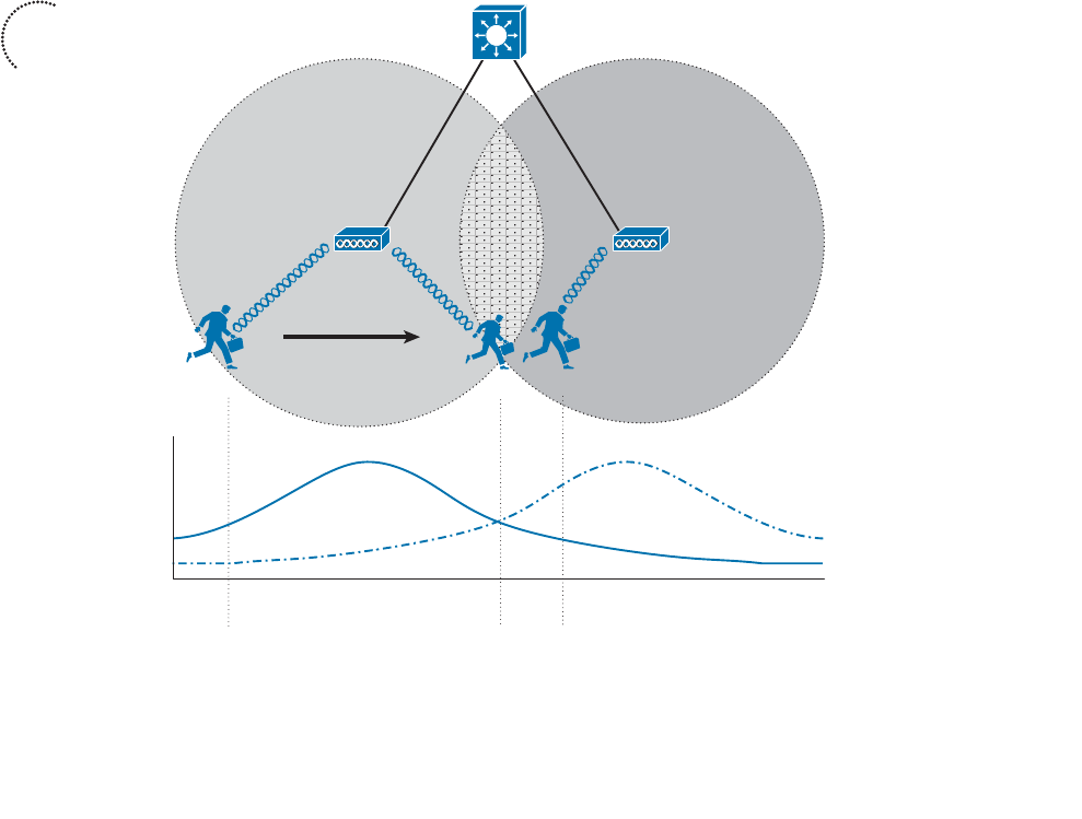
ptg12542968
156 CCNA Wireless 640-722 Official Cert Guide
The roaming process is driven entirely by the wireless client driver—not by the AP.
Wireless clients decide that it is time to roam based on a variety of conditions. The
802.11 standard does not address this at all, so roaming algorithms are vendor specific.
In addition, the roaming algorithms are usually “secret recipes,” so the exact thresholds
and conditions are hidden from view.
Some of the ingredients in the roaming algorithm are the received signal strength indica-
tor (RSSI), signal-to-noise ratio (SNR), a count of missed AP beacons, errors due to colli-
sions or interference, and so on. These are usually logical choices because they indicate
an inferior connection.
Because different clients use different thresholds, some will try to roam earlier than oth-
ers at a given location within a cell. Some clients will tend to “latch on” to an existing
association until the AP can hardly be heard, whereas others will attempt to roam when-
ever a better AP is discovered.
Figure 7-7 depicts a clean roam between two APs that have been correctly configured
with non-overlapping channels 1 and 6. The two AP signal strengths are also shown as a
graph corresponding to the client’s location. At location A, the client has a clear signal
from AP-1, so it maintains an association with that AP.
AP-2
ABC
ABC
Channel 1 Channel 6
AP-1
AP-1 Signal
AP-2 Signal
Figure 7-7 A Client Roaming Correctly Between Two APs.
Key
Topic

ptg12542968
Chapter 7: Planning Coverage with Wireless APs 157
As the client moves toward location B, it decides that AP-1’s signal is no longer opti-
mal. Somewhere along the way, the client begins to gather more information about any
neighboring AP cells. The client can passively scan by tuning its radio to another channel
and listening for beacons transmitted from other APs. During the time that the radio is
tuned away from the associated channel, the client might lose packets that have been
sent to it. A client might use active scanning instead, where it sends probe requests to
seek out a better AP where it can move its association. The client does not know what
channel is used on the next AP it encounters, so it must send the probes over every pos-
sible channel. Again, the client must take time to tune its radio away from the current
AP’s channel so it can scan other channels and send probes.
You might think of this as someone watching television. As the current program gets
boring or nears its end, the viewer begins to “channel surf” and scans other channels for
a better program. One thing to keep in mind: While the viewer is scanning channels, he
cannot keep watching the original program. Some of that program will be missed. This is
also true of wireless clients. While a radio is scanning other channels, packets arriving on
the original channel will be dropped because they cannot be received. Therefore, there
is a trade-off between staying available on a single channel and attempting to roam to
other APs.
After the client is satisfied with all of the beacons or probe responses it receives, it eval-
uates them to see which AP offers the most potential for a new association. Returning
to Figure 7-7 , when the client nears location B, it receives a probe response from AP-2
on channel 6. At location C, the client sends a reassociation frame to AP-2 and moves its
association to that BSS.
How much should cells overlap each other to promote good roaming? Cisco recom-
mends 15 percent to 20 percent overlap for most applications. The idea is to give a client
device some continued coverage even after the RSSI of its associated AP falls below a
threshold and a roam might be triggered. The client can probe and reassociate with the
next AP before it completely loses contact with the previous AP. Seamless roaming is
especially important for time critical applications like voice traffic.
WLAN Channel Layout
The previous section laid the foundation for roaming by describing movement between
two AP cells. Most scenarios require more than two APs to cover the appropriate area
within a building. Therefore, you need to consider the layout and configuration of more
and more APs to scale the design to fit your wireless environment.
For example, to cover the entire area of a warehouse or one floor of a building, APs
must be placed at regular intervals throughout that space. A site survey is a vital step
toward deciding on AP placement, as actual live measurements are taken with an AP
staged at various points in the actual space. This method also takes any factors like free
space loss and absorption into account, as the signal strength is measured within the
actual environment where clients are located.
To minimize channel overlap and interference, APs cells should be designed so that adja-
cent APs use different channels. For simplicity and a convenient design constraint, the
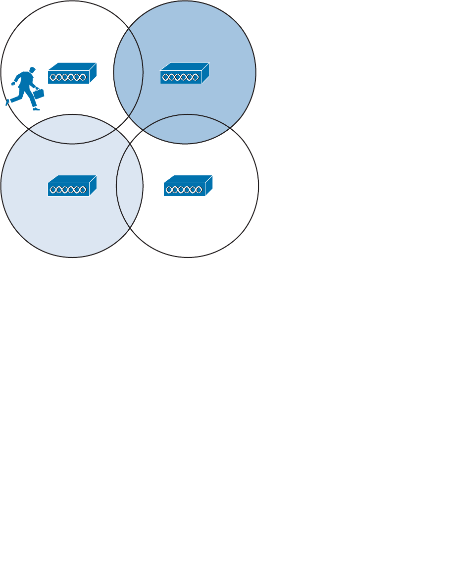
ptg12542968
158 CCNA Wireless 640-722 Official Cert Guide
examples in this section use the three non-overlapping 2.4-GHz channels. The cells could
be laid out in a regular, alternating pattern, as shown in Figure 7-8 .
16
11 1
Figure 7-8 Holes in an Alternating Channel Pattern.
However, notice what is happening in the center where the cells meet; there is a small
hole in RF coverage. If a client roams through that hole, his wireless signal could drop
completely. In addition, if the cells were brought closer together to close this hole, the
two cells using channel 1 would overlap and begin interfering with each other.
Instead, you should lay the cells out in a “honeycomb” fashion, as shown in Figure 7-9 .
This pattern is seamless, leaving no holes in coverage. In addition, notice how the two
cells using channel 1 are well separated, providing isolation from interference. As far as
ordering channels in the pattern, there are several different variations using combinations
of the three channels, but the result is basically the same.
Notice that as the client shown in the channel 1 cell moves around, it will roam into adja-
cent cells on different channels. For roaming to work properly, a client must be able to
move from one channel into a completely different channel.
Alternating channels to avoid overlap is commonly called channel reuse . The basic
pattern shown in Figure 7-9 can be repeated to expand over a larger area, as shown in
Figure 7-10 . Naturally, this ideal layout uses perfect circles that are positioned regularly
across the building. In practice, cells can take on different shapes and the AP locations
may end up being irregularly spaced.

ptg12542968
Chapter 7: Planning Coverage with Wireless APs 159
So far, only the channel layout of a two-dimensional area has been discussed. For exam-
ple, Figure 7-10 might represent only one floor of a building. What happens when you
need to design a wireless LAN for multiple floors in the same building?
Recall that an RF signal propagating from an antenna actually takes on a three-dimen-
sional shape. With an omnidirectional antenna, the pattern is somewhat like a donut
shape with the antenna at the center. The signal extends outward, giving the cell a cir-
cular shape along the floor. The signal also extends upward and downward to a lesser
extent—affecting AP cells on adjacent floors as well.
Consider the building with three floors shown in Figure 7-11 . The same two-dimensional
channel layout from Figure 7-10 is being used on the first floor. The floors in the figure
are shown greatly separated, so that you can see the channel patterns and numbers. In
reality, the cells on adjacent floors would touch or overlap, just as adjacent cells on the
same floor do.
11
6
1
1
Figure 7-9 A Better Alternating Channel Pattern.
Key
Topic
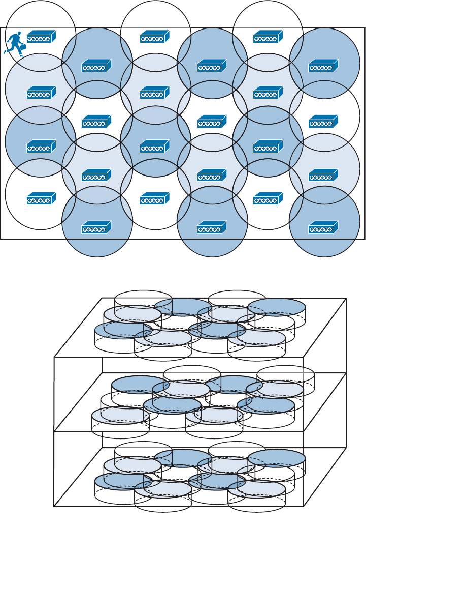
ptg12542968
160 CCNA Wireless 640-722 Official Cert Guide
First Floor
Second Floor
Third Floor
6
11
6
11
6
16
1111
1
11
6
1 1
6
11
6
1
6
1111
1
11
6
11 6
11
6
1
6
1111
1
11
Figure 7-11 Channel Layout in Three Dimensions.
1
1
6
11
6
6
11
1
1
1
6
11
6
6
11
1
1
1
6
11
6
6
11
1
Figure 7-10 Channel Reuse Over a Large Area.

ptg12542968
Chapter 7: Planning Coverage with Wireless APs 161
The pattern of alternating channels exists within the plane of a floor and between floors.
Channel 1 on the first floor should not overlap with channel 1 directly above it on the
second floor or below it in the basement.
When you consider each of the tasks involved in designing and maintaining a wireless
LAN, it can really become a puzzle to solve. The cell size, transmit power, and channel
assignment all have to be coordinated for each and every AP. Roaming also becomes an
issue on a large scale, if mobile clients can move throughout an entire campus wireless
network.
The good news is that Chapter 13 , “Understanding RRM,” explains how to solve many
of these puzzles automatically.
Exam Preparation Tasks
As mentioned in the section, “How to Use This Book,” in the Introduction, you have a
couple of choices for exam preparation: the exercises here, Chapter 22 , “Final Review,”
and the exam simulation questions on the CD-ROM.
Review All Key Topics
Review the most important topics in this chapter, noted with the Key Topic icon in the
outer margin of the page. Table 7-2 lists a reference of these key topics and the page
numbers on which each is found.
Table 7-2 Key Topics for Chapter 7
Key Topic Element Description Page Number
Figure 7-2 The effects of transmit power on cell size 151
Figure 7-4 The effects of data rate on cell size 153
Figure 7-7 Roaming between BSSs 156
Figure 7-9 Optimizing channel layout for roaming 159
Define Key Terms
Define the following key terms from this chapter and check your answers in the glos-
sary:
asymmetric power problem, channel reuse
Key
Topic

ptg12542968
This chapter covers the following topics:
■ Autonomous Architecture —This section describes
an autonomous access point and how it is used to
connect wireless clients to a wired network infra-
structure.
■ Configuring an Autonomous AP —This section
explains how to connect and configure an access
point to form a functional basic service set.
■ Converting an Autonomous AP —This section cov-
ers the steps needed to convert an access point from
autonomous mode to lightweight mode.
This chapter covers the following exam topics:
■ Install and configure autonomous access points in
the small business environment

ptg12542968
An autonomous wireless access point (AP) is self-contained and standalone, offering a
fully functional BSS. At the CCNA Wireless level, you are expected to be able to install
an autonomous AP, find its IP address, connect to it, and configure it. In addition, you
should know how to convert an autonomous AP to lightweight mode, to become a part
of a larger, more integrated wireless network. This chapter covers the skills you will need
to develop.
“Do I Know This Already?” Quiz
The “Do I Know This Already?” quiz allows you to assess whether you should read this
entire chapter thoroughly or jump to the “Exam Preparation Tasks” section. If you are
in doubt about your answers to these questions or your own assessment of your knowl-
edge of the topics, read the entire chapter. Table 8-1 lists the major headings in this
chapter and their corresponding “Do I Know This Already?” quiz questions. You can
find the answers in Appendix A , “Answers to the ‘Do I Know This Already?’ Quizzes.”
Table 8-1 “Do I Know This Already?” Section-to-Question Mapping
Foundation Topics Section Questions
Autonomous Architecture 1–2
Configuring an Autonomous AP 3–8
Converting an Autonomous AP 9–10
Caution The goal of self-assessment is to gauge your mastery of the topics in this chap-
ter. If you do not know the answer to a question or are only partially sure of the answer,
you should mark that question as wrong for purposes of the self-assessment. Giving your-
self credit for an answer you correctly guess skews your self-assessment results and might
provide you with a false sense of security.
CHAPTER 8
Using Autonomous APs

ptg12542968
164 CCNA Wireless 640-722 Official Cert Guide
1. Suppose that you need to set up an autonomous AP so that it will offer three dif-
ferent SSIDs to clients. The AP will be connected to a wired network infrastructure.
Which one of the following is a true statement about the AP?
a.
It can support only one SSID, which must be carried over an access link.
b.
It can support multiple SSIDs over an access link.
c.
It can support multiple SSIDs over an 802.1Q trunk link.
d.
An autonomous AP needs a centralized controller to support SSIDs.
2.
Which one of the following is a true statement?
a.
An autonomous AP cannot connect to a DS.
b.
An autonomous AP connects through a centralized controller.
c.
An autonomous AP operates in a standalone fashion.
d. None of these answers are correct.
3.
An autonomous AP has a console port. True or false?
a. True
b. False
4.
After looking at a sticker on the back of an autonomous AP, you see MAC
C4:7D:4F:12:34:56 listed. Which one of the following is a safe assumption?
a.
The string of numbers is the AP’s serial number.
b.
The string of numbers is the 2.4-GHz radio MAC address.
c.
The string of numbers is the 5-GHz radio MAC address.
d.
The string of numbers is the Ethernet port MAC address.
5.
Which methods can be used to assign an IP address to an autonomous AP? (Choose
all that apply.)
a. DHCP
b. Static through the CLI
c. TFTP
d. DNS

ptg12542968
Chapter 8: Using Autonomous APs 165
6. Which of the following methods can be used to obtain the IP address of an autono-
mous AP? (Choose all that apply.)
a. DHCP server logs
b. CDP
c. AP console CLI
d. IP Setup Utility
7.
In its default configuration, which of the following is true of an autonomous AP?
(Choose all that apply.)
a. Both radios are enabled.
b. Both radios are disabled.
c. No SSIDs are configured.
d. One SSID (“Cisco”) is configured.
8.
You can apply a separate SSID to different radios. True or false?
a. True
b. False
9.
If you are using the Autonomous to Lightweight Mode Upgrade tool, what else
must you obtain from Cisco?
a. A TFTP server
b. Cisco Prime Infrastructure
c.
An appropriate lightweight code image
d. An appropriate autonomous upgrade image
10.
To upgrade an autonomous AP to lightweight mode, which one of the following
initial command keywords should be used from the CLI?
a. upgrade download-sw
b. copy flash: tftp:
c. archive download-sw
d. download upgrade-sw
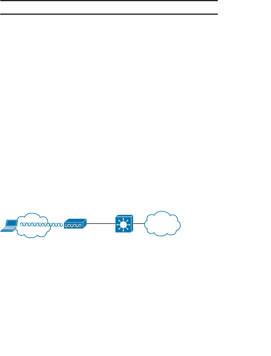
ptg12542968
166 CCNA Wireless 640-722 Official Cert Guide
Foundation Topics
Autonomous Architecture
An AP’s primary function is to bridge wireless data from the air to a normal wired net-
work. An AP can accept “connections” from a number of wireless clients so that they
become members of the LAN, as if the same clients were using wired connections.
APs act as the central point of access (hence the AP name), controlling client access to
the wireless LAN. An autonomous AP is self-contained; it is equipped with both wired
and wireless hardware so that the wireless client associations can be terminated onto a
wired connection locally at the AP.
Autonomous APs are commonly used in small networks, such as a small office or a
remote site. Because the APs are self-contained and self-sufficient, they are fairly easy
to set up and configure. The end result is a decentralized, distributed architecture, where
each wireless AP touches the wired network independently. Each AP is configured and
managed independently too, which can lead to a management nightmare as the number
of APs grows.
You can think of an AP as a translational bridge, where frames from two dissimilar
media are translated and then bridged at Layer 2. In simple terms, the AP is in charge of
mapping a service set identifier (SSID) to a VLAN, or in 802.11 terms, mapping a basic
service set (BSS) to a distribution system (DS). This is shown in Figure 8-1 , where the AP
connects a client that is associated to the SSID “Marketing” with the wired network on
VLAN 10. On the wired side, the AP’s Ethernet port is connected to a switch port con-
figured for access mode and mapped to VLAN 10.
AP-1
PC-1
VLAN 10
SSID
“Marketing”
VLAN 10
Figure 8-1 Bridging an SSID to a VLAN.
This concept can be extended so that multiple VLANs are mapped to multiple SSIDs. To
do this, the AP must be connected to the switch by a trunk link that carries the VLANs.
In Figure 8-2 , VLAN 10 and VLAN 20 are both trunked to the AP. The AP uses the
802.1Q tag to map the VLAN numbers to SSIDs. For example, VLAN 10 is mapped to
SSID “Marketing,” while VLAN 20 is mapped to SSID “Engineering.”
In effect, when an AP uses multiple SSIDs, it is trunking VLANs over the air to wireless
clients. In the 802.11 space, the VLAN tag is replaced by the SSID. The autonomous
AP then becomes an extension of an access layer switch because it bridges SSIDs and
VLANs right at the access layer.
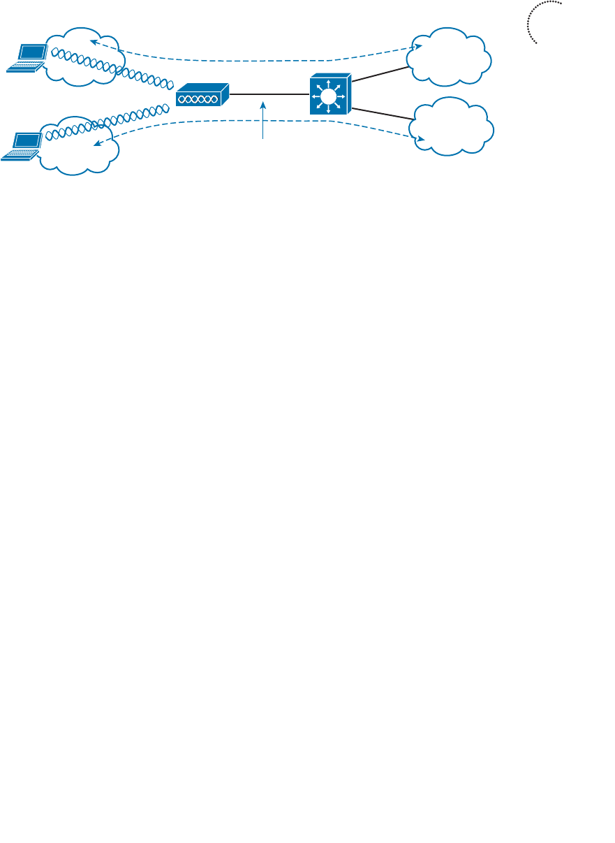
ptg12542968
Chapter 8: Using Autonomous APs 167
Configuring an Autonomous AP
As a wireless engineer, you will likely have to install and configure an autonomous AP.
Many Cisco APs can operate in autonomous mode by running an IOS image—much
like many other Cisco products. You can configure an AP through any of the following
methods:
■ A terminal emulator connected to the AP’s console port
■ Telnet or Secure Shell (SSH) to the AP’s IP address
■ Use a web browser to access a graphical user interface (GUI) at the AP’s IP address
As you read through this chapter, think about the different parameters you might have
to configure on an autonomous AP. At a minimum, you would have to configure one or
more SSIDs and some wireless security settings. In addition, you would have to set the
transmit power level and channel number for each of the AP’s radios. Now think about
your wireless network as it grows—manually configuring a handful of autonomous APs
might not be difficult, but working out the channel reuse layout for 50 or 100 APs in
the same building might become a nightmare. Fortunately, you can leverage a centralized
architecture to automate many configuration functions. Such architecture is covered in
more detail in Chapters 9 through 13 .
Connecting the AP
Figure 8-3 shows the ports that are available on a typical access point. You should con-
nect the Ethernet port to a switch port where the DS is located. The console port can
remain disconnected unless you need to use it. A sticker on the AP provides the model
and serial numbers, as well as the Ethernet port’s MAC address.
By default, an AP will try to use Dynamic Host Configuration Protocol (DHCP) to
request an IP address for itself. If it is successful, you can connect to it and interact with
its GUI or command-line interface (CLI). If not, the AP will use the static IP address
10.0.0.1/26. You can also use the console port to configure a static IP address on the
BVI1 interface of the AP, but it is usually more flexible and convenient to let it request
an address on its own.
AP-1
VLAN 10
SSID
“Marketing”
Dot1Q Trunk
VLANs 10,20
SSID
“Engineering”
VLAN 20
PC-1
PC-2
Figure 8-2 Bridging Multiple SSIDs to VLANs.
Key
Topic
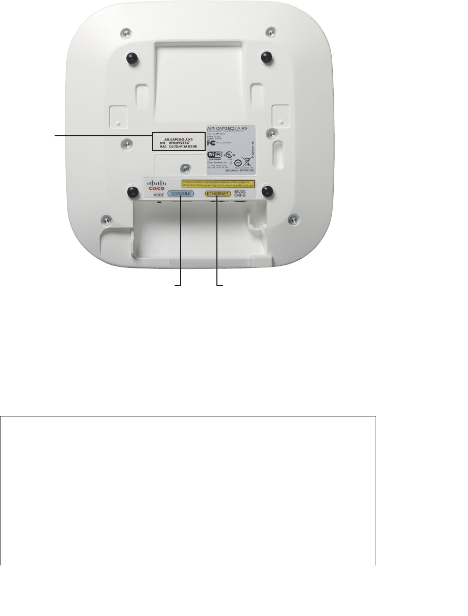
ptg12542968
168 CCNA Wireless 640-722 Official Cert Guide
The AP’s IP address will not be readily visible because the AP has no way to display it,
other than through its user interface and configuration. To find the IP address, you can
query the DHCP server that assigned it and look for the AP’s MAC address.
Suppose that an AP has MAC address 00:22:bd:19:28:dd. From the output listed in
Example 8-1 , the MAC address is bound to IP address 192.168.199.44.
Example 8-1 Finding an Autonomous AP’s IP address
Branch_Office# show ip dhcp binding
Bindings from all pools not associated with VRF:
IP address Client-ID/ Lease expiration Type
Hardware address/
User name
192.168.199.7 0020.6b77.9549 Infinite Manual
192.168.199.8 000e.3b00.b1a3 Infinite Manual
192.168.199.9 0004.00d0.378d Infinite Manual
192.168.199.14 0100.24f3.da9b.95 May 10 2013 01:09 AM Auto-
matic
192.168.199.20 0170.f1a1.131c.48 May 09 2013 09:25 PM Auto-
matic
AP Model
Serial Number
Ethernet
MAC Address
EthernetConsole
Figure 8-3 The Ports Available on an Autonomous AP.

ptg12542968
Chapter 8: Using Autonomous APs 169
192.168.199.23 0194.39e5.826c.38 May 09 2013 08:51 PM Auto-
matic
192.168.199.24 0100.216a.0ac3.a0 May 09 2013 11:21 PM Auto-
matic
192.168.199.34 0100.166f.6614.6d May 09 2013 09:33 PM Auto-
matic
192.168.199.43 01cc.fe3c.4d66.49 May 09 2013 04:59 PM Auto-
matic
192.168.199.44 01 00.22bd.1928.dd May 10 2013 11:20 AM Auto-
matic
Branch_Office#
As an alternative, you could also log in to the switch where the AP is connected and
display detailed Cisco Discovery Protocol (CDP) neighbor information. Example
8-2 shows the output that reveals the IP address of the AP connected to interface
GigabitEthernet1/0/1.
Example 8-2 Displaying CDP Neighbor Information to Find an Autonomous AP’s IP
Address
Switch# show cdp neighbor gigabitethernet1/0/1 detail
-------------------------
Device ID: ap
Entry address(es):
IP address: 192.168.199.44
Platform: cisco AIR-AP1142N-A-K9 , Capabilities: Trans-Bridge IGMP
Interface: GigabitEthernet1/0/1, Port ID (outgoing port): GigabitEthernet0
Holdtime : 160 sec
Version :
Cisco IOS Software, C1140 Software (C1140-K9W7-M), Version 12.4(25d)JA1,
RELEASE SOFTWARE (fc1)
Technical Support: http://www.cisco.com/techsupport
Copyright (c) 1986-2011 by Cisco Systems, Inc.
Compiled Thu 11-Aug-11 02:58 by prod_rel_team
advertisement version: 2
Duplex: full
Power drawn: 15.400 Watts
Switch#
You can also use the IP Setup Utility (IPSU), a Cisco tool that is available on Cisco.com.
The tool has a simple interface, as shown in Figure 8-4 —you provide the Ethernet MAC
address of an AP, click the Get Address button, and the tool returns the AP’s IP address.
An autonomous AP binds the IP address to its bridged-virtual interface (BVI), which is a
logical interface used to bridge the physical wired and wireless interfaces. If you are con-
nected to the AP’s console port, you can display the IP address with the show interface
bvi1 command, as shown in Example 8-3 .
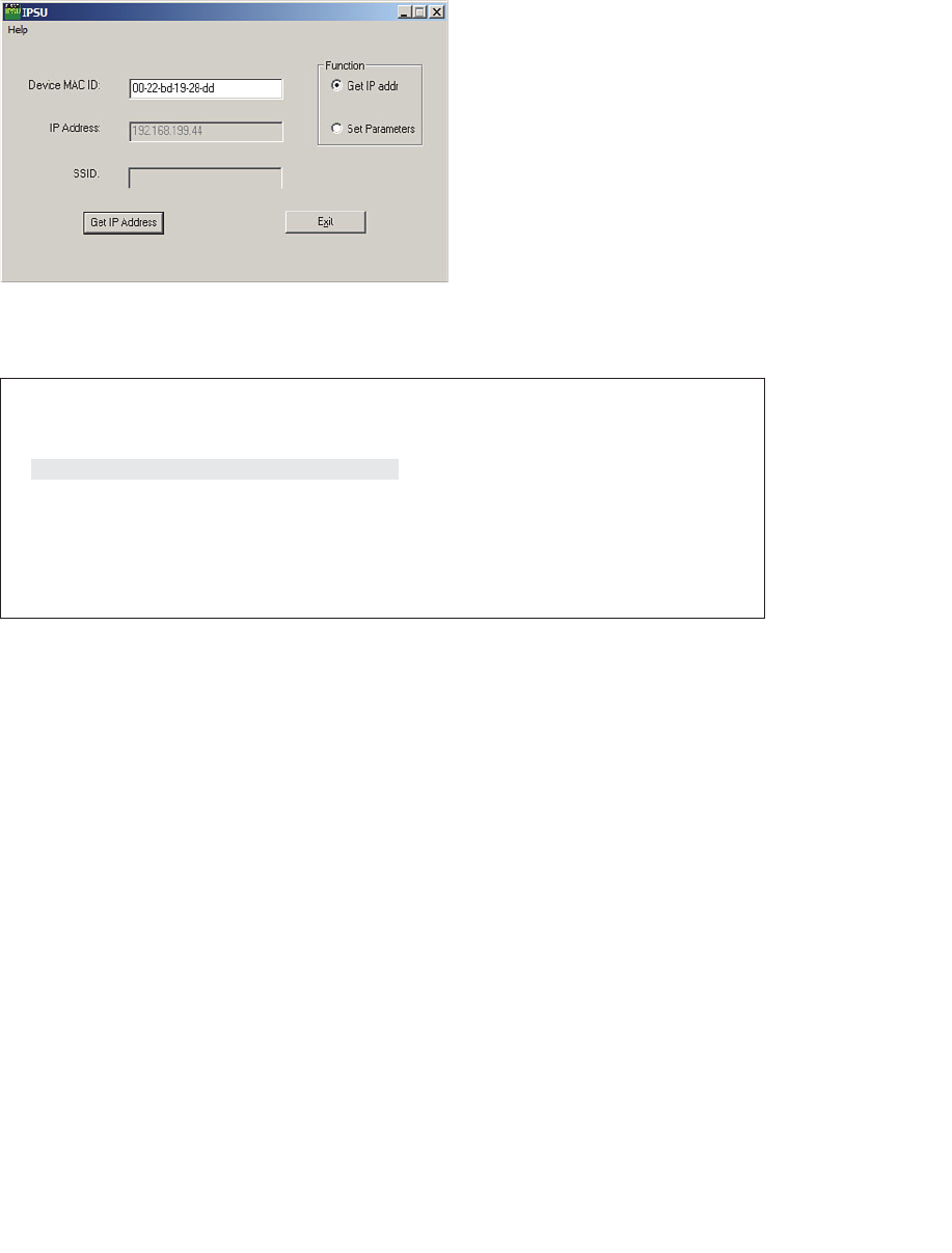
ptg12542968
170 CCNA Wireless 640-722 Official Cert Guide
Example 8-3 Displaying the BVI IP Address
ap# show interface bvi1
BVI1 is up, line protocol is up
Hardware is BVI, address is 0022.bd19.28dd (bia 0023.eb81.eb70)
Internet address is 192.168.199.44/24
MTU 1500 bytes, BW 54000 Kbit/sec, DLY 5000 usec,
reliability 255/255, txload 1/255, rxload 1/255
Encapsulation ARPA, loopback not set
ARP type: ARPA, ARP Timeout 04:00:00
[output truncated]
Configuring the AP
By default, any autonomous AP running IOS Release 12.3(4)JA or later has its radios dis-
abled and does not have any SSIDs configured. This is done to prevent the new AP from
interfering with any existing signals before you have a chance to configure it. This also
prevents anyone from inadvertently discovering a wireless signal coming from the AP
before you can secure it.
Perhaps the easiest method you can use to configure an autonomous AP is to use its web
interface. Once you know the AP’s IP address, you can open a web browser to it. By
default, you can leave the username blank and enter the password as Cisco. The home
page, as shown in Figure 8-5 , displays a summary of associated clients, the AP’s Ethernet
and radio interfaces, and an event log.
At the CCNA Wireless level, Cisco expects candidates to be able to perform basic con-
figuration tasks on autonomous APs. Therefore, you should be familiar with only the
Express Setup and Express Security tabs at the upper-left corner of the web page.
To use the Express Setup tab, as shown in Figure 8-6 , you need to enter the following
information about the AP:
Figure 8-4 Using the IP Setup Utility to Discover the IP Address of an AP.
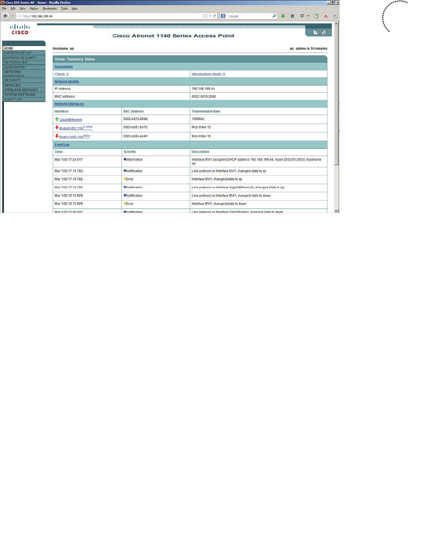
ptg12542968
Chapter 8: Using Autonomous APs 171
■ Hostname
■ Method of IP address assignment
■ For a static address: IP address, subnet mask, default gateway
■ SNMP community
You will also need to set some parameters for the 2.4- and 5-GHz radios. By default,
each radio is configured to operate in the access point mode, so that the AP maintains an
active BSS. You can select one of the following roles instead:
■ Repeater —The AP will associate with another nearby AP automatically, to repeat
or extend that AP’s cell coverage. The Ethernet port will be disabled.
■ Root Bridge —The AP uses its Ethernet port to connect to bridge the wired network
to a remote wireless bridge over a point-to-point or point-to-multipoint link. No
wireless clients will be allowed to associate.
■ Non-Root Bridge —The AP will act as a remote wireless bridge and will connect to a
root bridge AP over a wireless link.
■ Workgroup Bridge —The AP will use one radio to associate with a nearby Cisco
access point, as if it is a wireless client. The other radio interface is disabled. The AP
bridges between its radio and its Ethernet port. You can use an AP in workgroup
bridge (WGB) mode to provide wireless client capability to wired-only devices.
■ Universal Workgroup Bridge —The AP will act as a workgroup bridge to associate
with Cisco and non-Cisco access points.
■ Scanner —The AP will use its radio to scan channels and collect data
Key
Topic
Figure 8-5 Autonomous AP Summary Page.
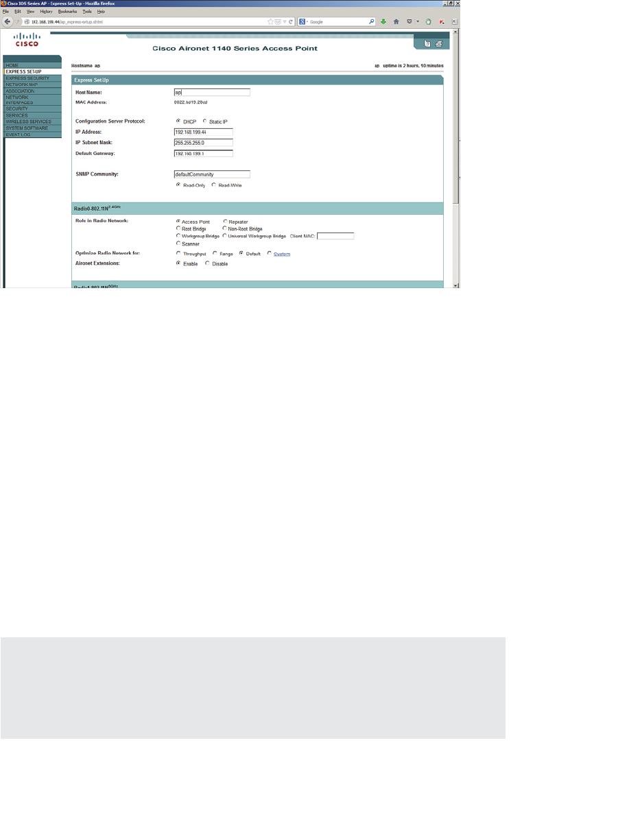
ptg12542968
172 CCNA Wireless 640-722 Official Cert Guide
Click Apply for the settings to take effect
In the Optimize Radio Network For section, you can select how the AP will optimize
its cell for wireless clients. By default, the AP will offer data rates that can provide good
range and throughput. You can select Throughput to leverage higher data rates at the
expense of cell range, Range to require the lowest data rate for maximum cell range, or
Custom to set your own radio parameters.
Aironet Extensions are Cisco proprietary information elements that Cisco APs can use to
interact with Cisco-compatible wireless clients. For example, an AP can provide informa-
tion about its current client load so that potential clients can choose the least busy AP.
Aironet extensions are enabled by default.
You can use the Express Security tab to define an initial SSID. Be aware that the SSID
will be available on both 2.4- and 5-GHz radios. If the AP is connected to a switch with
an 802.1Q trunk link, you can bind the SSID to a VLAN number. You can also define
a wireless security method for the SSID. Figure 8-7 shows the Express Security page. If
you intend to define multiple SSIDs and VLANs, you will have to drill down into some
of the other tabs on the web page.
Tip Although the CCNA Wireless exam is limited to the “express” configuration tabs on
an autonomous AP, you will need to be proficient with many more complex features on
lightweight APs as part of a larger, unified wireless network. Don’t worry; lightweight APs
(LAPs) and unified networks are covered in detail throughout the remainder of the book.
Figure 8-6 Express Setup Configuration Page.
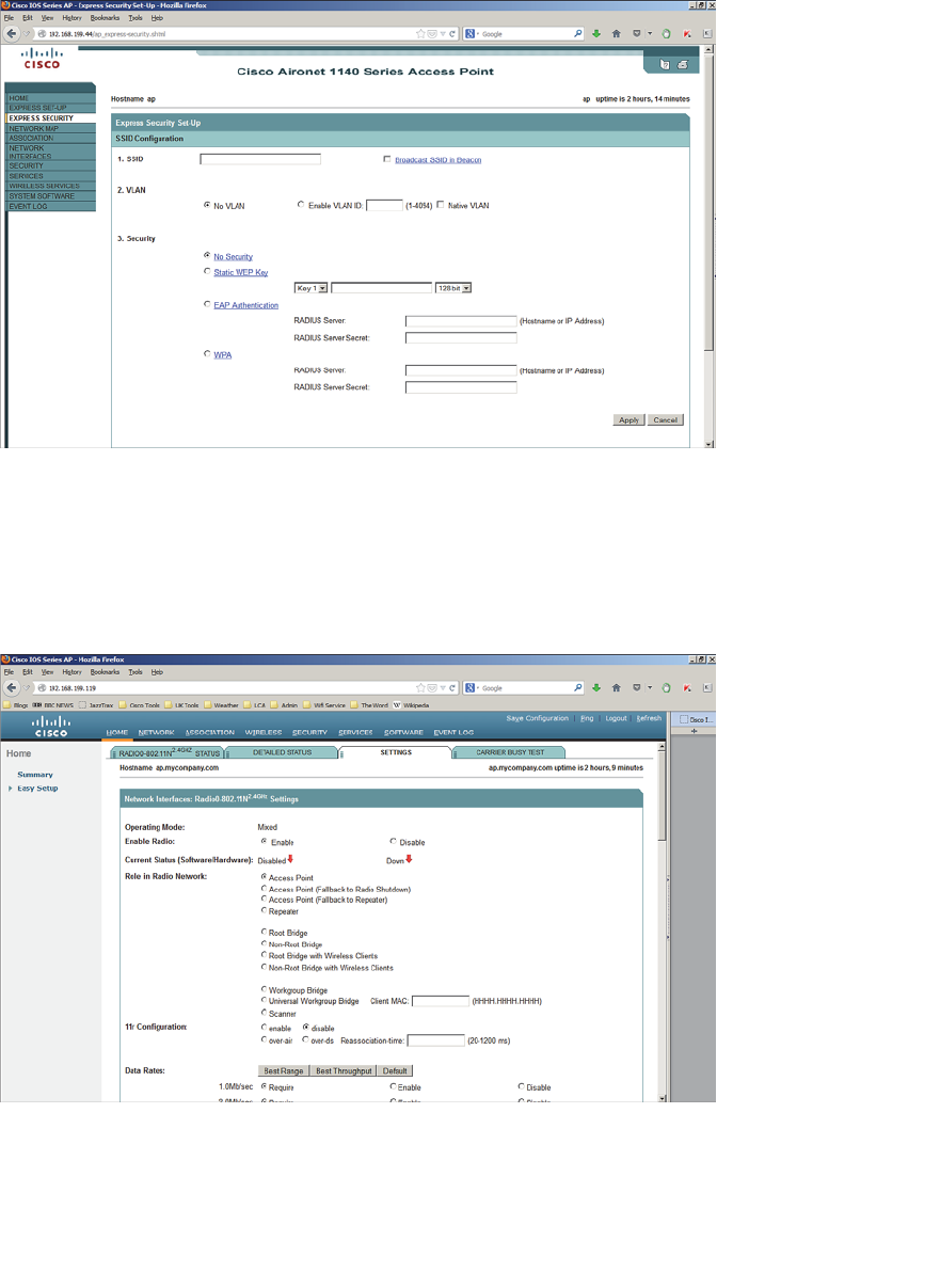
ptg12542968
Chapter 8: Using Autonomous APs 173
Figure 8-7 Express Security Configuration Page.
At this point of the configuration, you do not necessarily have a functional AP because
the radios are still disabled. To enable a radio, navigate to the AP’s home page and select
Radio0-802.11N 2.4GHz or Radio1-802.11N 5GHz in the Network Interfaces section.
Click the Settings tab to open it, and then for Enable Radio click the Enable button, as
shown in Figure 8-8 .
Figure 8-8 Enabling an Autonomous AP Radio.

ptg12542968
174 CCNA Wireless 640-722 Official Cert Guide
Converting an Autonomous AP
Autonomous APs can be useful in remote sites, small offices, or homes where central-
ized management is not necessary or practical. In larger environments, a centralized or
unified approach is more common. Sometimes you might face a hybrid scenario, where
some legacy autonomous APs still exist in a centrally managed network. In that case, you
might need to either replace the AP hardware or convert its software image so that it can
join the wireless controllers that manage the network. In fact, Cisco expects a CCNA
Wireless engineer to know how to convert an autonomous AP to a “lightweight” version
that can join a controller.
To convert an AP, you can use one of the following methods, which are described in the
subsequent sections:
■ Use the Cisco Prime Infrastructure application; all wireless controllers and
lightweight APs can be monitored and managed from this one application. The
autonomous AP must first be managed, then it can be converted. Cisco Prime
Infrastructure is covered in Part V, “Managing Wireless LANs with WCS,” but using
it to convert autonomous APs is not covered on the CCNA Wireless exam.
■ Use the Autonomous to Lightweight Mode Upgrade tool, which you can download
from Cisco.com.
■ Use the archive command from the autonomous AP’s CLI.
Using the Autonomous to Lightweight Mode Upgrade Tool
You can use the Autonomous to Lightweight Mode Upgrade tool to upgrade the IOS
image so that an AP is converted from autonomous to lightweight mode. The tool only
works with Cisco Aironet 1100, 1130, 1200, 1240, and 1310 models; all other models
require a manual upgrade using the archive command.
First, download the upgrade tool from Cisco.com. Be aware that the upgrade tool is
known by several different names. You might also see it called the Cisco Aironet AP
to LWAPP Upgrade tool. To find the software, navigate to Support > Download >
Wireless Software > Access Points , and then select a specific AP model. Once the
upgrade tool is downloaded, install it on a Windows PC.
You will also need to download a lightweight recovery software image for the AP
model. After downloading the upgrade tool, click the Lightweight AP IOS Software
link. The recovery image filename usually includes rcv (as in the word recover ) in the
filename, as in c1140-rcvk9w8-tar.152-2.JB.tar. The recovery image is a small bootstrap
version of lightweight code that allows the AP to boot up and find a wireless controller.
From there, the AP will automatically download a full version of lightweight code from
the controller that it will use long term.
The upgrade tool looks in a text file to find a list of autonomous APs to upgrade.
Therefore, you must prepare the text file ahead of time. Use a text editor such as
Notepad to make a list of APs, one per line, with the following format:
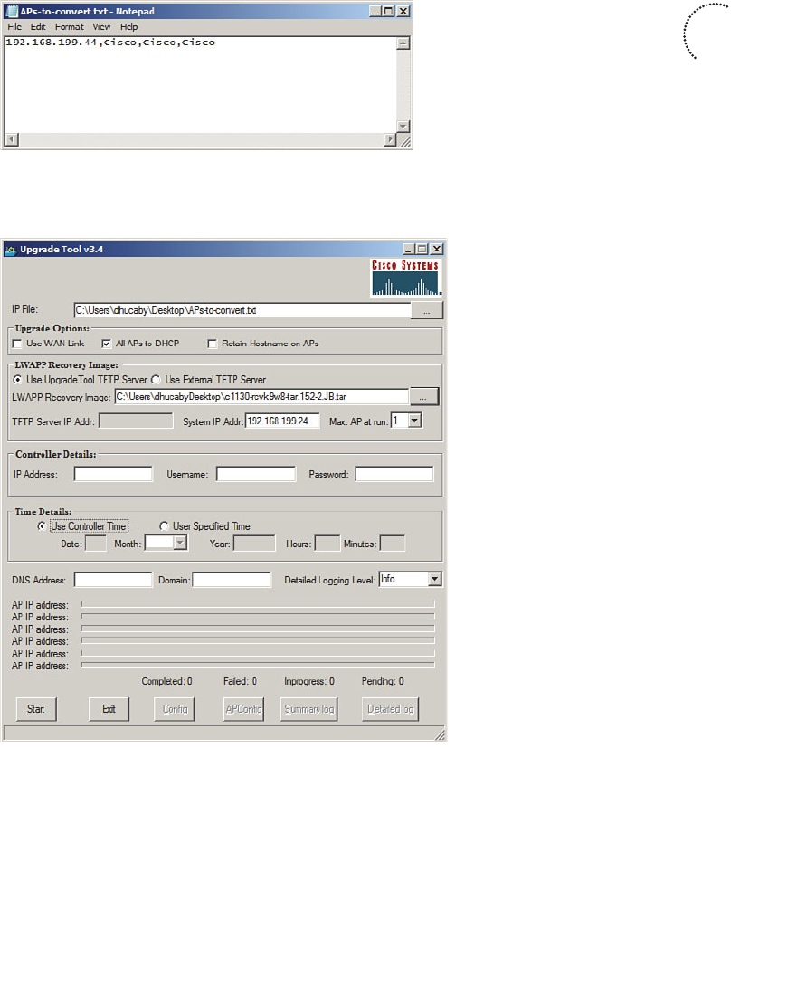
ptg12542968
Chapter 8: Using Autonomous APs 175
ap-ip-address , telnet-username , telnet-Password , enable-password
Figure 8-9 shows a text file created in Notepad with a single entry for an autonomous
AP with the default settings.
Figure 8-9 Text File Containing One Autonomous AP for Upgrade.
Figure 8-10 shows the upgrade tool.
Figure 8-10 The Cisco Autonomous to Lightweight Mode AP Upgrade Tool.
Use the following steps to upgrade an autonomous AP to lightweight mode:
Step 1. Open the Upgrade tool. If the tool complains that it is unable to start the
Cisco TFTP server, exit the application. Right-click over the Upgrade tool’s
icon and select Run as Administrator . This will enable the tool to run its own
TFTP server for downloading an image file to the AP.
Key
Topic

ptg12542968
176 CCNA Wireless 640-722 Official Cert Guide
Step 2. In the IP File field, click the ... button and browse to find the file containing
the list of AP IP addresses. Click Open .
Step 3. Select the appropriate functions under Upgrade Options. Are the APs being
upgraded over a slow WAN link? Should the AP be converted to use DHCP
after the upgrade? Should the APs keep their existing hostname after the
upgrade?
Step 4. In the LWAPP Recovery Image section, choose whether the TFTP server
is internal (integrated into the Upgrade tool) or external. Then select the
LWAPP recovery image that will be downloaded to the AP. Choose how
many APs can upgrade at once in the Max AP at Run field.
Step 5. The Controller Details section is optional; fill in a controller’s IP address,
username, and password, if you want to preconfigure the AP with a specific
controller to use. Otherwise, the AP will go through a discovery process to
find a controller.
Step 6. In the Time Details section, select the method the AP will use to set its clock.
The AP can set its clock according to the controller or a date and time that
you specify.
Step 7. If resolving by DNS, enter the DNS address and domain name. Optionally,
change the logging level if you want to see more verbose information.
Step 8. Click the Start button to begin the process.
The upgrade process verifies each parameter you have entered and errors out if incon-
sistencies are noted. After the conversion, the AP reboots. After the reboot, the AP
behaves like any lightweight AP and tries to find a controller.
Note During the upgrade process on an older AP, a self-signed certificate is gener-
ated if the AP doesn’t have a Cisco signed certificate. If you specify a controller in the
Upgrade tool, the certificate will be imported into the controller. Otherwise, the Upgrade
tool generates a text file that contains the certificate information. You can import that
file into the controller manually.
Converting an Autonomous AP Manually
You can use the CLI to upgrade the IOS image on an autonomous AP and convert it to
lightweight mode. You will also need a TFTP server along with the appropriate light-
weight code image. The process is simple—save the AP’s configuration, then use the fol-
lowing command:
archive download-sw /overwrite /force-reload { tftp:|ftp:}//location/
image-name

ptg12542968
Chapter 8: Using Autonomous APs 177
The lightweight image will be downloaded such that it overwrites the current autono-
mous IOS image, then the AP will reload and run the new image. Example 8-4 demon-
strates the conversion process. The TFTP server is located at 192.168.199.24, and the
new lightweight image is named c1140-k9w8-tar.152-2.JB.tar.
Tip Cisco AP image filenames can be difficult to identify. If a filename contains k9w8,
as in Example 8-4 , it is a lightweight image. If it contains k9w7, it is an autonomous
image.
Example 8-4 Manually Converting an Autonomous AP
ap# archive download-sw /overwrite /reload tftp://192.168.199.24/c1140-
k9w8-tar.152-2.JB.tar
examining image...
Loading c1140-k9w8-tar.152-2.JB.tar from 192.168.199.24 (via BVI1): !
extracting info (282 bytes)
Image info:
Version Suffix: k9w8-.152-2.JB
Image Name: c1140-k9w8-mx.152-2.JB
Version Directory: c1140-k9w8-mx.152-2.JB
Ios Image Size: 9421312
Total Image Size: 9615872
Image Feature: WIRELESS LAN|LWAPP
Image Family: C1140
Wireless Switch Management Version: 7.4.1.37
Extracting files...
c1140-k9w8-mx.152-2.JB/ (directory) 0 (bytes)O
c1140-k9w8-mx.152-2.JB/html/ (directory) 0 (bytes)
[output omitted for clarity]
extracting info.ver (282 bytes)
[OK - 9615360 bytes]
Deleting current version: flash:/c1140-k9w7-mx.124-25d.JA1...done.
New software image installed in flash:/c1140-k9w8-mx.152-2.JB
Configuring system to use new image...done.
Requested system reload
archive download: takes 107 seconds
Key
Topic

ptg12542968
178 CCNA Wireless 640-722 Official Cert Guide
Exam Preparation Tasks
As mentioned in the section, “How to Use This Book,” in the Introduction, you have a
couple of choices for exam preparation: the exercises here, Chapter 22 , “Final Review,”
and the exam simulation questions on the CD-ROM.
Review All Key Topics
Review the most important topics in this chapter, noted with the Key Topic icon in the
outer margin of the page. Table 8-2 lists a reference of these key topics and the page
numbers on which each is found.
Table 8-2 Key Topics for Chapter 8
Key Topic Element Description Page Number
Figure 8-2 Bridging multiple SSIDs to VLANs 167
Figure 8-5 Autonomous AP web interface 171
Figure 8-10 Autonomous AP Upgrade tool 175
Example 8-3 Manually converting an autonomous AP 177
Define Key Terms
Define the following key terms from this chapter and check your answers in the
glossary:
autonomous AP, IP Setup Utility (IPSU), Autonomous to Lightweight Mode
Upgrade tool
Key
Topic

ptg12542968
This page intentionally left blank

ptg12542968
This chapter covers the following topics:
■ A Distributed Architecture —This section discusses
a wireless network formed by autonomous access
points.
■ A Centralized Architecture —This section describes
a wireless network built from lightweight access
points and a centralized wireless LAN controller.
■ CUWN Building Blocks —This section covers the
devices that are necessary to build a Cisco Unified
Wireless Network.
This chapter covers the following exam topics:
■ Identify the components of the Cisco Unified
Wireless Network architecture (Split MAC,
LWAPP, stand-alone AP vs controller-based AP,
specific hardware examples)
■ Describe the modes of controller-based AP deploy-
ment (local, monitor, HREAP, sniffer, rogue detec-
tor, bridge, OEAP, and SE-Connect)

ptg12542968
In Chapter 8 , “Using Autonomous APs,” you learned about autonomous access points
(APs) and their distributed nature. The Cisco Unified Wireless Network (CUWN) takes
the opposite approach by keeping the radios distributed but collapsing wireless services
into the core of the switched network. In this chapter, you will learn more about the
centralized or unified wireless architecture and how you can leverage its strengths to
solve some fundamental problems.
“Do I Know This Already?” Quiz
The “Do I Know This Already?” quiz allows you to assess whether you should read this
entire chapter thoroughly or jump to the “Exam Preparation Tasks” section. If you are
in doubt about your answers to these questions or your own assessment of your knowl-
edge of the topics, read the entire chapter. Table 9-1 lists the major headings in this
chapter and their corresponding “Do I Know This Already?” quiz questions. You can
find the answers in Appendix A , “Answers to the ‘Do I Know This Already?’ Quizzes.”
Table 9-1 “Do I Know This Already?” Section-to-Question Mapping
Foundation Topics Section Questions
A Distributed Architecture 1–2
A Centralized Architecture 3–8
CUWN Building Blocks 9–10
Caution The goal of self-assessment is to gauge your mastery of the topics in this chap-
ter. If you do not know the answer to a question or are only partially sure of the answer,
you should mark that question as wrong for purposes of the self-assessment. Giving your-
self credit for an answer you correctly guess skews your self-assessment results and might
provide you with a false sense of security.
CHAPTER 9
Understanding the CUWN
Architecture

ptg12542968
182 CCNA Wireless 640-722 Official Cert Guide
1.
Which one of the following term best describes a Cisco wireless access point that
operates in a standalone, independent manner?
a. Autonomous AP
b. Independent AP
c. Lightweight AP
d. Embedded AP
2.
Suppose that an autonomous AP is used to support wireless clients. Which one of
the following paths would traffic usually take when passing from one wireless client
to another?
a. Through the AP only
b.
Through the AP and its controller
c. Through the controller only
d.
None of these answers (Traffic can go directly over the air.)
3.
Suppose that a lightweight AP in default local mode is used to support wireless
clients. Which one of the following paths would traffic usually take when passing
from one wireless client to another?
a. Through the AP only
b.
Through the AP and its controller
c. Through the controller only
d.
None of these answers (Traffic must go directly over the air.)
4.
A lightweight access point is said to participate in which one of the following archi-
tectures?
a. Light-MAC
b. Tunnel-MAC
c. Split-MAC
d. Big-MAC
5.
How does a lightweight access point communicate with a wireless LAN controller?
a. Through an IPsec tunnel
b. Through an CAPWAP tunnel
c. Through a GRE tunnel
d. Directly over Layer 2
6.
Which one of the following types of traffic is sent securely over a CAPWAP tunnel
by default?

ptg12542968
Chapter 9: Understanding the CUWN Architecture 183
a. Control messages
b. Client data
c. DHCP requests
d. 802.11 beacons
7.
Which one of the following is not needed for a lightweight AP in default local
mode to be able to support three SSIDs that are bound to three VLANs?
a.
A trunk link carrying three VLANs
b.
An access link bound to a single VLAN
c.
A WLC connected to three VLANs
d. A CAPWAP tunnel to a WLC
8. A CUWN is built with one WLC and 32 lightweight APs. Which one of the follow-
ing best describes the resulting architecture?
a.
A direct Layer 2 path from the WLC to each of the 32 LAPs, all using the same
IP subnet
b.
A direct Layer 3 path from the WLC to each of the 32 LAPs, all using the same
IP subnet
c.
32 CAPWAP tunnels daisy-chained between the LAPs, one CAPWAP tunnel to
the WLC
d. 32 CAPWAP tunnels—one tunnel from the WLC to each LAP, with no IP sub-
net restrictions
9.
A CUWN network is built with 300 lightweight APs and a 5508 WLC. Suppose
wireless coverage needs to be offered in several more floors within a building,
which will double the number of APs in use. Which of the following strategies
would work? (Choose all that apply.)
a. Add another 5508 WLC.
b.
Replace the 5508 with a WLC that offers a greater AP capacity.
c.
The 5508 will become full, so replace the APs with models that can cover twice
the area.
d.
Do nothing; you can have only one WLC in a network and no other model
offers more APs than the 5508.
10.
Which one of the following AP models should you choose if you expect to see
802.11ac clients in the near future?
a. 1140
b. 1602i
c. 2602i
d. 3602i
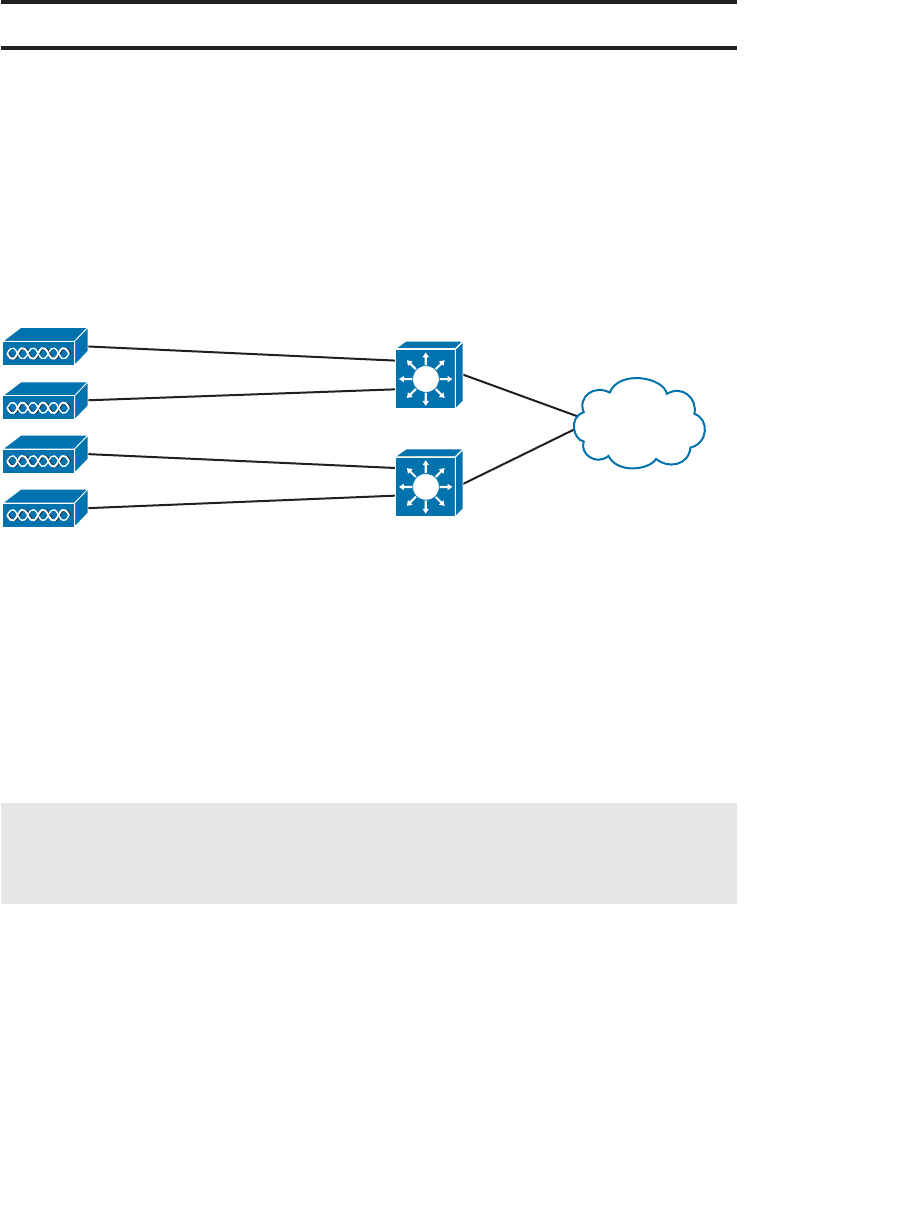
ptg12542968
184 CCNA Wireless 640-722 Official Cert Guide
Foundation Topics
A Distributed Architecture
Autonomous APs are self-contained, each offering one or more fully functional, stand-
alone basic service sets (BSSs). They are also a natural extension of a switched network,
connecting wireless SSIDs to wired VLANs at the access layer. Figure 9-1 shows the
basic architecture; even though only four APs are shown, a typical enterprise network
could consist of hundreds or thousands of APs.
Autonomous
APs Access Layer
Figure 9-1 Wireless Network Architecture with Autonomous APs.
Recall that an autonomous AP needs quite a bit of configuration and management.
To help manage more and more autonomous APs as the wireless network grows, you
could place an AP management device in a central location, as illustrated in Figure 9-2 .
The device could push out code upgrades and configuration changes to the APs in a
bulk fashion, to streamline AP management. With added intelligence, the device could
instruct each AP on which channel and transmit power level to use. It could also collect
information from all of the APs about things such as RF interference, rogue or unexpect-
ed wireless devices that were overheard, and wireless usage statistics.
Note At one time, Cisco offered a central AP management appliance called the
Wireless LAN Solution Engine (WLSE). Its usefulness ended with the dawn of the
CUWN architecture.
What exactly does an autonomous AP need to become a part of the network? Refer
to Figure 9-3 , which focuses on just one AP and its connections. The wireless network
consists of two SSIDs: 100 and 200. These correspond to wired VLANs 100 and 200,
respectively. The VLANs must be trunked from the distribution layer switch to the
access layer, where they are extended further over a trunk link to the AP.
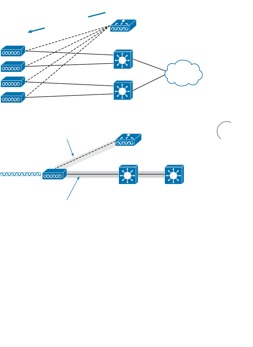
ptg12542968
Chapter 9: Understanding the CUWN Architecture 185
Autonomous
AP
Central AP
Management
SSID 100
SSID 200
Distribution Layer
Access Layer
Trunk Link
Trunk Link
VLAN 10: 10.10.10.1/24
VLAN 100: 192.168.100.1/24
VLAN 200: 192.168.200.1/24
Management:
10.10.10.10
Control Plane
Data Plane
Figure 9-3 The Network Architecture of a Single Autonomous AP.
The AP must be configured with a management IP address (10.10.10.10) so that you and
your central AP management device can remotely manage it. The management address is
not normally part of any of the data VLANs, so a dedicated management VLAN (VLAN
10 in the figure) must be added to the trunk links to reach the AP.
With the central AP management device controlling the AP, notice what happens to the
traffic going to and from the AP. The traffic is divided into two functions:
■ A control plane —Traffic used to control, configure, manage, and monitor the AP
itself
■ A data plane —End-user traffic passing through the AP
Because the control and data plane traffic must reach every autonomous AP, the net-
work configuration and efficiency can become cumbersome as the network scales. For
Autonomous
APs
Central AP
Management
• Code Upgrades
• Configuration
• Transmit Power
• Channel Selection
Figure 9-2 Centrally Managing a Network of Autonomous APs.
Key
Topic
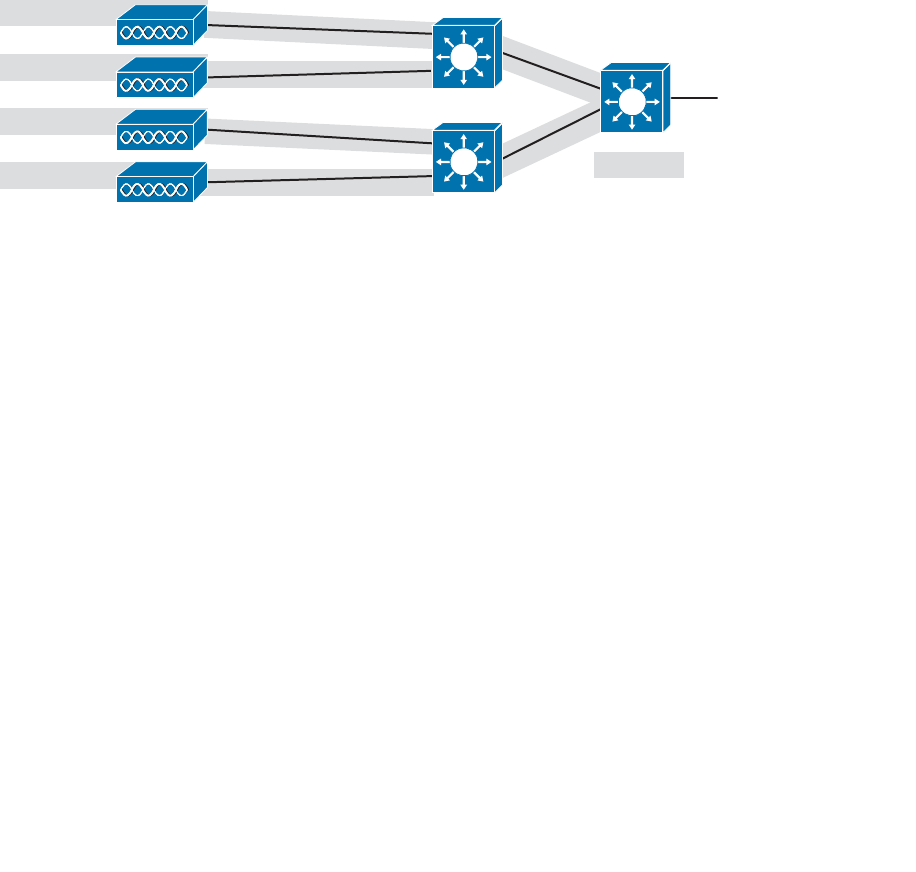
ptg12542968
186 CCNA Wireless 640-722 Official Cert Guide
example, you will likely want to offer the same SSID on many APs so that wireless
clients can associate with that SSID in most any location or while roaming between two
APs. You might also want to extend the corresponding VLAN to each and every AP so
that clients do not have to request a new IP address for each new association.
Because SSIDs and their VLANs must be extended at Layer 2, you should consider how
they are extended throughout the switched network. Figure 9-4 shows an example of
a single VLAN’s extent in the data plane. Working right to left, follow VLAN 100 as it
reaches through the network. VLAN 100 is routed within the distribution layer and must
be carried over trunk links to the access layer switches and then to each autonomous AP.
In effect, VLAN 100 must extend end to end across the whole infrastructure—some-
thing that is considered a bad practice.
Autonomous
APs
Distribution Layer
Access Layer
VLAN 10
VLAN 100
VLAN 200
Trunk Links
Trunk Links
Trunk Links
SSID 100
SSID 200
SSID 100
SSID 200
SSID 100
SSID 200
SSID 100
SSID 200
Figure 9-4 The Extent of VLAN 100 in a Network of Autonomous APs.
That might not sound cumbersome until you have to add a new VLAN and configure
every switch in your network. Even worse, suppose your network has redundant links
between each layer of switches. The Spanning Tree Protocol (STP) running on each
switch becomes a vital ingredient to prevent bridging loops from forming and corrupting
the network. As the wireless network expands, the infrastructure becomes more difficult
to configure correctly and becomes less efficient.
A Centralized Architecture
Because autonomous APs are... well, autonomous, managing their RF operation can be
quite difficult. As a network administrator, you are in charge of selecting and configur-
ing the channel used by each AP and detecting and dealing with any rogue APs that
might be interfering. You must also manage things such as the transmit power level to
make sure that the wireless coverage is sufficient, does not overlap too much, and there
aren’t any coverage holes—even when an AP’s radio fails.
Managing wireless network security can also be difficult. Each autonomous AP handles
its own security policies, with no central point of entry between the wireless and wired
networks. That means there is no convenient place to monitor traffic for things such as
intrusion detection and prevention, quality of service, bandwidth policing, and so on.
The Cisco Unified Wireless Network (CUWN) is a centralized, unified approach that
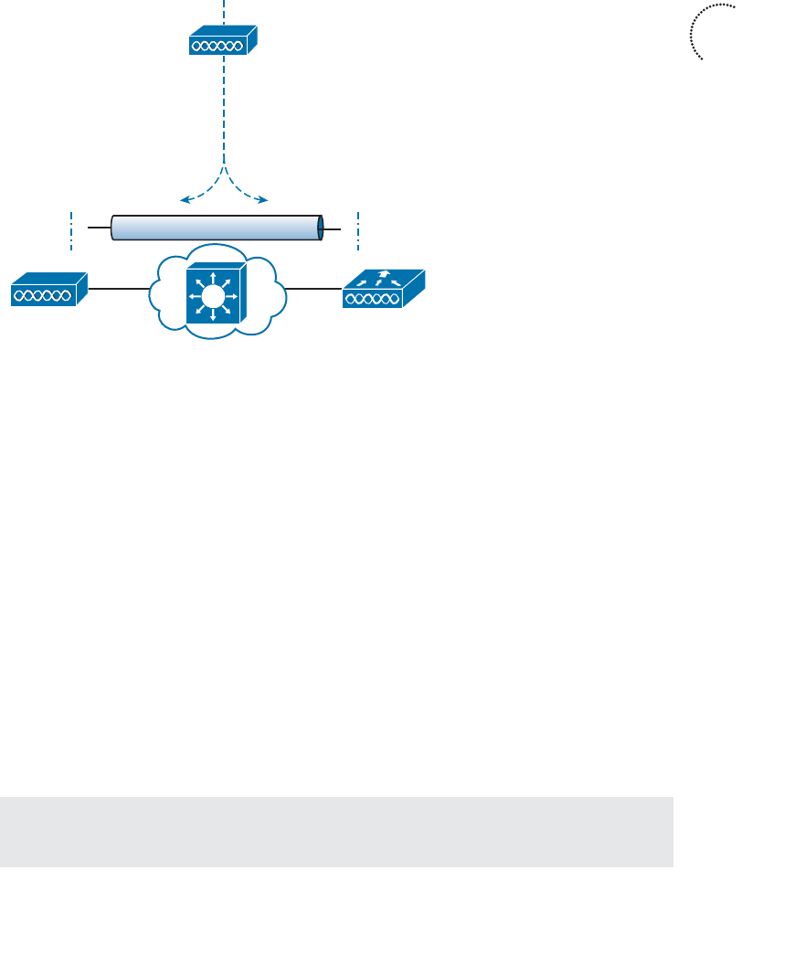
ptg12542968
Chapter 9: Understanding the CUWN Architecture 187
overcomes the shortcomings of distributed autonomous APs. To build such an architec-
ture, many of the functions found within autonomous APs have to be shifted toward
some central location. In Figure 9-5 , most of the activities performed by an autonomous
AP are broken up into two groups—real-time processes on the left and management
processes on the right.
Lightweight AP WLC
Autonomous AP
Real Time Functions
• RF Transmit/Receive
• MAC Management
• Encryption
Management Functions
• RF Management
• Association & Roaming Management
• Client Authentication
• Security Management
• QoS
CAPWAP
Figure 9-5 Autonomous Versus Lightweight Access Point.
The real-time processes involve sending and receiving 802.11 frames, beacons, and probe
messages. 802.11 data encryption is also handled in real-time, on a per-packet basis. The
AP must interact with wireless clients on some low level, known as the media access con-
trol (MAC) layer. These functions must stay with the AP, closest to the clients.
The management functions are not integral to handling frames over the RF channels, but
are things that should be centrally administered. Therefore, those functions are moved
to a centrally located platform away from the AP.
In the CUWN, a lightweight access point (LAP) performs only the real-time 802.11
operation. The LAP gets its name because the code image and the local intelligence are
stripped down or lightweight, compared to the traditional autonomous AP.
The management functions are usually performed on a wireless LAN controller (WLC),
which is common to many LAPs. This is shown in the bottom portion of Figure 9-5 .
Notice that the LAP is left with duties in Layers 1 and 2, where frames are moved into
and out of the RF domain. The LAP becomes totally dependent on the WLC for every
other WLAN function, such as authenticating users, managing security policies, and even
selecting RF channels and output power.
Tip Remember that a lightweight AP cannot normally operate on its own—it is very
dependent upon a WLC somewhere in the network.
Key
Topic
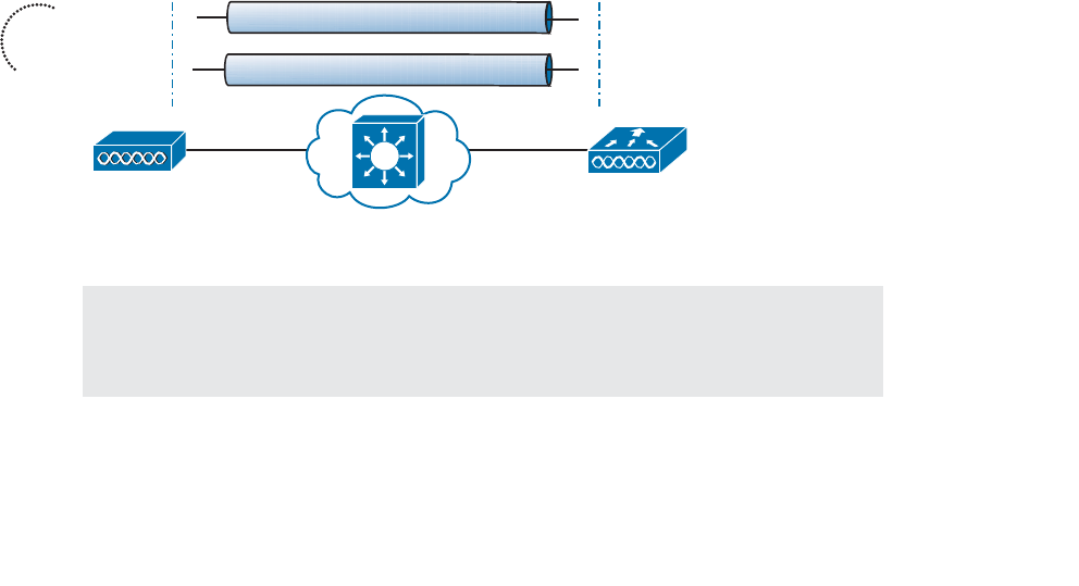
ptg12542968
188 CCNA Wireless 640-722 Official Cert Guide
Split-MAC Architecture
The LAP-WLC division of labor is known as a split-MAC architecture , where the nor-
mal MAC operations are pulled apart into two distinct locations. This occurs for every
LAP in the network; each one must boot and bind itself to a WLC to support wireless
clients. The WLC becomes the central hub that supports a number of LAPs scattered
about in the network.
How does an LAP bind with a WLC to form a complete working access point? The two
devices must use a tunneling protocol between them, to carry 802.11-related messages
and also client data. Remember that the LAP and WLC can be located on the same
VLAN or IP subnet, but they do not have to be. Instead, they can be located on two
entirely different IP subnets in two entirely different locations.
The Control and Provisioning of Wireless Access Points (CAPWAP) tunneling protocol
makes this all possible by encapsulating the data between the LAP and WLC within new
IP packets. The tunneled data can then be switched or routed across the campus net-
work. As Figure 9-6 shows, the CAPWAP relationship actually consists of the following
two tunnels:
■ CAPWAP control messages —Used for exchanges that are used to configure the
LAP and manage its operation. The control messages are authenticated and encrypt-
ed, so that the LAP is securely controlled by only the WLC, then transported using
UDP port 5246 at the controller.
■ CAPWAP data —Used for packets traveling to and from wireless clients that are
associated with the LAP. Data packets are transported using UDP port 5247 at the
controller, but are not encrypted by default. When data encryption is enabled for
an LAP, packets are protected with Datagram Transport Layer Security (DTLS).
CAPWAP Control – UDP 5246
CAPWAP Data – UDP 5247
Lightweight AP WLC
Figure 9-6 Linking an LAP and WLC with CAPWAP.
Tip CAPWAP is defined in RFCs 5415, 5416, 5417, and 5418. CAPWAP is based on
the Lightweight Access Point Protocol (LWAPP), which was a legacy Cisco proprietary
solution.
Key
Topic
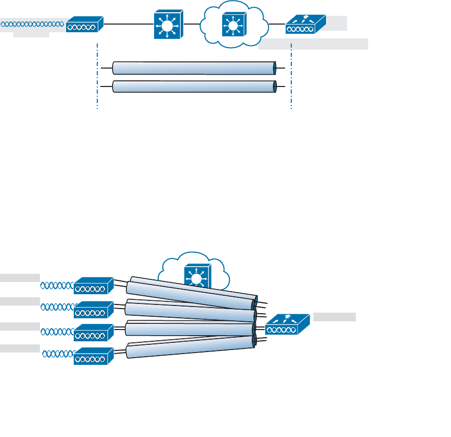
ptg12542968
Chapter 9: Understanding the CUWN Architecture 189
Every LAP and WLC must also authenticate each other with digital certificates. An
X.509 certificate is preinstalled in each device when it is purchased. By using certificates
behind the scenes, every device is properly authenticated before becoming part of the
CUWN. This process helps assure that no rogue LAP or WLC (or devices posing as an
LAP or WLC) can be introduced into the network. The LAP-WLC association is covered
in greater detail in Chapter 11 , “Understanding Controller Discovery.”
The CAPWAP tunneling allows the LAP and WLC to be separated geographically and
logically. It also breaks the dependence on Layer 2 connectivity between them. For
example, Figure 9-7 uses shaded areas to show the extent of VLAN 100. Notice how
VLAN 100 exists at the WLC and in the air as SSID 100, near the wireless clients—but
not in between the LAP and the WLC. Instead, traffic to and from clients associated
with SSID 100 is transported across the network infrastructure encapsulated inside the
CAPWAP data tunnel.
VLAN 100: 192.168.100.1/24
VLAN 200: 192.168.200.1/24
SSID 100
SSID 200
Lightweight AP
10.10.10.10 Access Layer
Access Link
Wireless LAN
Controller
CAPWAP Control
CAPWAP Data
Figure 9-7 The Extent of VLAN 100 in a CUWN.
Also, notice how the LAP is known by only a single IP address 10.10.10.10. Because
the LAP sits on the access layer where its CAPWAP tunnels terminate, it can use one
IP address for management and tunneling. No trunk link is needed because all of the
VLANs it supports are encapsulated and tunneled.
As the wireless network grows, the WLC simply builds more CAPWAP tunnels to reach
more APs. Figure 9-8 depicts a network with four LAPs. Each LAP has a control and a
data tunnel back to the centralized WLC. SSID 100 can exist on every AP, and VLAN
100 can reach every AP through the network of tunnels.
CAPWAP Control/Data
Lightweight APs
Wireless LAN
Controller
SSID 100
SSID 200
SSID 100
SSID 200
SSID 100
SSID 200
SSID 100
SSID 200
CAPWAP Control/Data
VLAN 100
VLAN 200
CAPWAP Control/Data
CAPWAP Control/Data
Figure 9-8 Using CAPWAP Tunnels to Connect LAPs to One Central WLC.

ptg12542968
190 CCNA Wireless 640-722 Official Cert Guide
Once CAPWAP tunnels are built from a WLC to one or more lightweight APs, the WLC
can begin offering a variety of additional functions. Think of all the puzzles and short-
comings that were discussed for the traditional autonomous WLAN architecture as you
read over the following list of WLC activities:
■ Dynamic channel assignment —The WLC can automatically choose and configure
the RF channel used by each LAP, based on other active access points in the area.
■ Transmit power optimization —The WLC can automatically set the transmit power
of each LAP based on the coverage area needed.
■ Self-healing wireless coverage —If an LAP radio dies, the coverage hole can be
“healed” by turning up the transmit power of surrounding LAPs automatically.
■ Flexible client roaming —Clients can roam between LAPs at either Layer 2 or Layer
3 with very fast roaming times.
■ Dynamic client load balancing —If two or more LAPs are positioned to cover the
same geographic area, the WLC can associate clients with the least used LAP. This
distributes the client load across the LAPs.
■ RF Monitoring —The WLC manages each LAP so that it scans channels to monitor
the RF usage. By listening to a channel, the WLC can remotely gather information
about RF interference, noise, signals from neighboring LAPs, and signals from rogue
APs or ad hoc clients.
■ Security management —The WLC can authenticate clients from a central service
and can require wireless clients to obtain an IP address from a trusted DHCP server
before allowing them to associate and access the WLAN.
■ Wireless intrusion protection system —Leveraging its central location, the WLC
can monitor client data to detect and prevent malicious activity.
Traffic Patterns in a CUWN
Recall that autonomous APs bridge traffic between a wireless BSS and a wired VLAN.
To get to and from the wired network, the AP relies on its connection to the distribution
system (DS). LAPs work in a similar fashion, except that the BSS and DS are separated by
some expanse of the network infrastructure; that expanse is connected by the CAPWAP
tunnel.
Consider the network shown in Figure 9-9 . Two wireless clients are associated with the
WLAN that is formed by the LAP and WLC combination. Traffic from Client B to a
host somewhere on the wired network travels through the LAP, through the CAPWAP
data tunnel to the WLC, and then out onto the switched campus network.
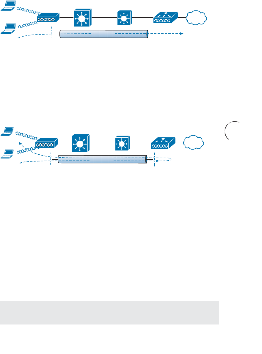
ptg12542968
Chapter 9: Understanding the CUWN Architecture 191
LAP
Access Layer WLC
Distribution Layer
Client A
Client B
CAPWAP
Figure 9-9 CUWN Traffic Patterns Between Wireless and Wired Networks.
Traffic between the two wireless clients, however, takes an interesting path. With an
autonomous AP, the traffic from one client usually passes through the AP to reach the
other client. The CUWN architecture is similar, as shown in Figure 9-10 . The client traf-
fic usually travels through the CAPWAP tunnel and passes through the WLC before
making a return trip back through the tunnel to the other client. There are exceptions,
however. Clients may use DLS to communicate directly, without passing through the AP
and controller; LAPs can also be configured in FlexConnect mode, so that traffic can be
forwarded locally at the AP if needed.
LAP
Access Layer WLC
CAPWAP
Distribution Layer
Client A
Client B
Figure 9-10 CUWN Traffic Pattern Between Wireless Clients.
In a switched campus infrastructure, the CUWN traffic pattern is not a big problem
because the WLC is centrally located and bandwidth is plentiful. Suppose that the net-
work grows to include some remote sites. LAPs are placed at the remote sites, but the
only WLC is located back at the main campus. This scenario forces wireless traffic to
traverse the CAPWAP tunnel between remote and main sites, then perhaps back through
the tunnel to the remote site again. Such a path might not be efficient at all, especially
when the bandwidth to the remote site is limited.
To address the inefficiency, you can leverage the FlexConnect mode on the remote site
LAPs. Remote-site traffic that needs to traverse the CAPWAP data tunnel to reach the
WLC will be transported as usual. However, wireless traffic that is destined for remote
site networks can stay within the remote site; the remote site LAPs are able to locally
switch the traffic without traversing the CAPWAP tunnel. Even if the remote site link
goes down, severing the CAPWAP tunnel completely, FlexConnect allows the LAP
to keep switching traffic locally to maintain wireless connectivity available inside the
remote site.
Tip FlexConnect was previously known as the Hybrid Remote Edge Access Point
(H-REAP) feature.
Key
Topic
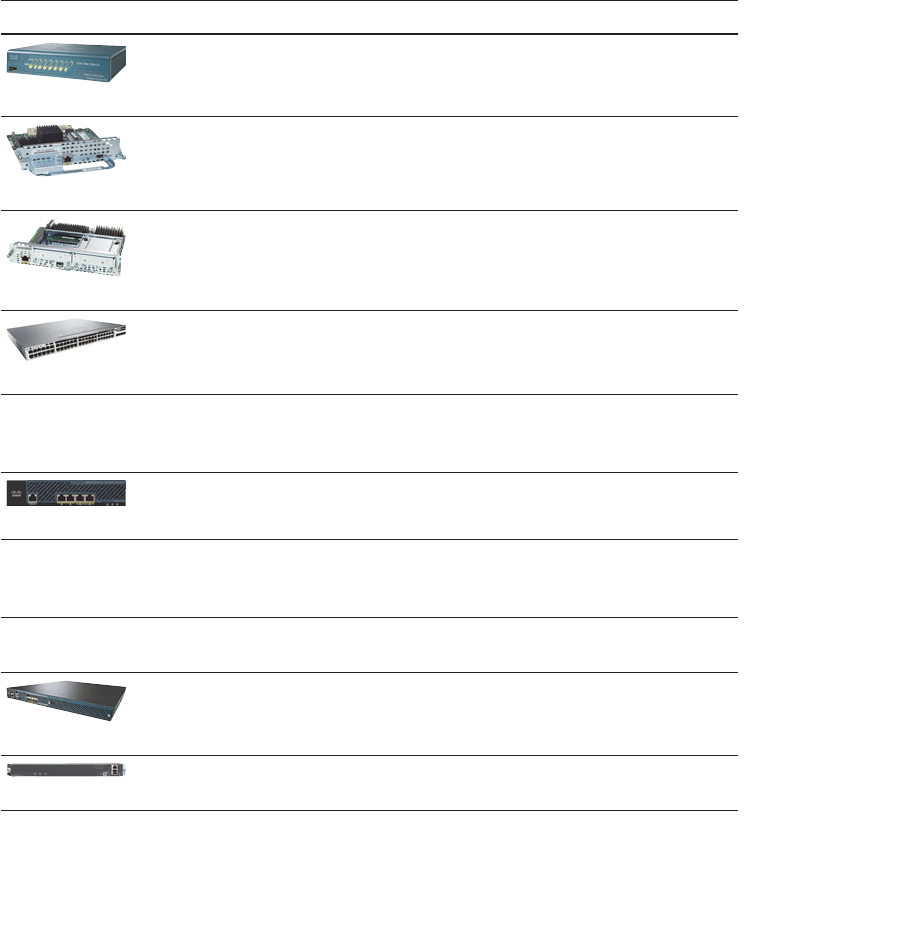
ptg12542968
192 CCNA Wireless 640-722 Official Cert Guide
CUWN Building Blocks
A successful CUWN design involves LAPs, WLCs, and a platform to manage them all.
The following sections describe the Cisco hardware you can use to build a CUWN.
Cisco Wireless LAN Controllers
Cisco WLCs are available in many platforms, differing mainly in the form factor and
the number of managed LAPs. The WLC platforms are listed in Table 9-2 , arranged in
ascending order by the maximum number of LAPs supported.
Table 9-2 Cisco WLC Platforms and Capabilities
Model Form Factor Data Uplink LAPs Supported Application
2100 Series
Appliance* 8x10/100 6, 12, or 25 Small
WLCM
Module (ISR)* Internal Up to 25 Small
SRE ISM
Module (ISR) Internal Up to 10 (ISM-300)
Up to 50
(ISM-710, ISM-910)
Small
Catalyst 3850
Integrated 4x10GigE Up to 50 per switch
stack
Small branch
4400 Series
(image not
available)
Appliance* 2x1GigE (4402)
4x1GigE (4404)
Up to 50 (4402)
Up to 100 (4404)
Small to mid
2504
Appliance 4x1GigE Up to 75 Small
Virtual WLC
(image not
available)
VM Internal Up to 200 Small,
multisite
WiSM (image
not available)
Module
(Catalyst 6500)*
4x1GigE per
WLC
Up to 300
(150 per WLC)
Mid
5508
Appliance 8x1GigE Up to 500 Mid to large
WiSM2
Module
(Catalyst 6500)
2x10GigE Up to 1000 Mid to large

ptg12542968
Chapter 9: Understanding the CUWN Architecture 193
Model Form Factor Data Uplink LAPs Supported Application
5760
Appliance 6x1/10GigE Up to 1000
Up to 6000 per
cluster
Large
Flex 7500
Appliance 2x10GigE Up to 6000
FlexConnect
Very large,
multi-site
8500 Series
Appliance 2x10GigE Up to 6000 Very large,
multi-site
*- Denotes legacy product that is currently end-of-sale or end-of-life
Table 9-2 lists both legacy and current state-of-the-art products, at the time of this
writing. You might see any of these products mentioned on the CCNA Wireless exam.
Because new products are usually introduced before exams are updated, you might have
exam questions that pertain to some of the legacy products. A star in the form factor
column designates a legacy product, or one that has been given end-of-sale (EOS) or
end-of-life (EOL) status.
Use Table 9-2 to become familiar with the entire spectrum of Cisco WLCs—not to
memorize their specifications. Be aware of the relative AP capacity based on the model.
Generally, the number of supported LAPs rises as the model number increases. Products
that support a low number of LAPs are usually meant for small campus sites, while prod-
ucts that support 1000 or 6000 LAPs are flagship models that are meant for very large
enterprises.
Many WLCs are standalone appliances, while a few are special purpose modules that
can be installed in routers (ISR) or Catalyst 6500 chassis. The Wireless Service Module 2
(WiSM2) is unique because it can be integrated into an existing Catalyst 6500 switch. Up
to seven WiSM2 modules can live in a single switch chassis.
You might be surprised to see the Catalyst 3850 switch listed as a WLC. Cisco has
added the WLC functionality to it as an additional software license. The integrated
WLC function can be managed through the CLI or its own web interface. From a wire-
less LAN perspective, the Catalyst 3850 is best suited for a small single-site enterprise
or at remote sites. Even though each switch can support up to 50 APs, the limit does
not increase when switches are stacked. That is not really a problem because it is very
unlikely you would ever encounter more than 50 APs in a single site each limited to a
100-meter twisted-pair cable.
The virtual WLC (vWLC) is an interesting product because it consists of software only,
running under a VMware Hypervisor. You might use it in a small enterprise or in a lab
scenario. Because of its virtual nature, vWLC can coexist with other Cisco wireless man-
agement software on a single VMware platform. The vWLC cannot support any APs in
local mode; all APs must be configured for FlexConnect instead.

ptg12542968
194 CCNA Wireless 640-722 Official Cert Guide
Be aware that you can deploy several WLCs in a network, to handle a growing number
of LAPs. In addition, multiple WLCs offer some redundancy so that LAPs can recover
from a WLC failure. High availability and redundancy are covered in Chapter 11 .
Cisco Lightweight APs
Cisco offers a complete line of LAPs that are designed to connect to a WLC to offer
fully functional wireless service. Table 9-3 lists many of the LAP models, along with their
intended application, antenna gain, and 802.11 radio support. The list of APs might seem
staggering at first, especially when you are studying for the exam.
Try to break the table down into sections and then compare the capabilities between
models. For example, the top portion of the table consists of the 1040, 1140, 1250, and
1260—all legacy models that might be mentioned on the exam, but are not considered
to be forward-looking models. The bottom portion of the table consists of the 1602,
2602, 3602, and 3607—forward-looking models for the small/midsize, small/midsize/
large, and midsize/large enterprise environments, respectively.
Table 9-3 Cisco Lightweight Access Points and Their Capabilities
Model Application CleanAir Antenna
Gain 2.4/
5 GHz
802.11 Radios
1040* Indoor No 4 dBi /
3 dBi
a/g/n 2×2:2
1140* Indoor No 4 dBi /
3 dBi
a/g/n 2×3:2
1250* Rugged No External a/g/n 2×3:2
1260* Rugged No External a/g/n 2×3:2
3502i
3502e
Indoor
Rugged
Yes
Yes
4 dBi /
3 dBi
External
a/g/n
a/g/n
2×3:2
2×3:2
600
OfficeExtend
Indoor No 3.5 dBi /
4 dBi
a/g/n 2×3:2

ptg12542968
Chapter 9: Understanding the CUWN Architecture 195
Model Application CleanAir Antenna
Gain 2.4/
5 GHz
802.11 Radios
1602i
1602e
Indoor
Rugged
Express
Express
4 dBi /
4 dBi
External
a/g/n
a/g/n
3×3:2
3×3:2
2602i
2602e
Indoor
Rugged
Yes
Yes
4 dBi /
4 dBi
External
a/g/n
a/g/n
3×4:3
3×4:3
3602i
3602e
Indoor
Rugged
Yes
Yes
2 dBi /
5 dBi
External
a/g/n/ac
a/g/n/ac
4×4:3
4×4:3
3702i
3702e
Indoor
Rugged
Yes
Yes
4 dBi /
6 dBi
External
a/g/n/ac
a/g/n/ac
4×4:3
4×4:3
*-Denotes legacy product that is currently end-of-sale or end-of-life
The 3602 is unique because it is modular and can provide “future-proof” upgrades. It
can accept an 802.11ac module or a Wireless Security and Spectrum Intelligence (WSSI)
module for added functionality. With the WSSI module, an AP can perform channel
scanning and intrusion protection with dedicated radios, rather than borrowing idle time
from the AP’s own radios between transmissions. The 3702 integrates 802.11ac Wave 1
and provides space for a Wave 2 module.
The 600 OfficeExtend AP is a unique model that is targeted for the remote worker
located in a home office. It can connect directly to a broadband network service and
provide a BSS, while building CAPWAP tunnels back to a centrally located WLC. The
600 encrypts the CAPWAP control tunnel, like other LAP models, but can also encrypt
the CAPWAP data tunnel using DTLS.
CleanAir is a Cisco feature that allows an AP to perform spectrum analysis on the wire-
less channels to detect non-802.11 interference. In cooperation with a WLC, CleanAir
APs can detect and identify sources of interference and make adjustments to avoid
the interference. When the AP and WLC are used in conjunction with Cisco Mobility
Services Engine (MSE) and a CUWN management platform, interferers can even be
located on a map! This enables the CUWN to be self-healing, able to pinpoint and
recover from external problems dynamically. CleanAir is discussed further in Chapter
19 , “Dealing with Wireless Interference.”
Each of the APs listed in Table 9-3 offers 802.11a/b/g/n support. The main difference
between models pertains to multiple-input, multiple-output (MIMO) operation, with a
differing number of radios and spatial streams. Recall from Chapter 2 , “RF Standards,”
that a radio described as 2×3:2 has two transmitters, three receivers, and two spatial
streams. As the number of radios and spatial streams increases, the AP is able to provide

ptg12542968
196 CCNA Wireless 640-722 Official Cert Guide
a greater throughput for its clients. Notice how the number of radios and spatial streams
increase as you move down the table toward higher end models.
Note Table 9-3 lists only the lightweight APs that are used to provide a straightforward
BSS. Cisco also offers the 1500 family of LAPs, which are used to build an outdoor wire-
less mesh network. Mesh networks are outside the scope of this book and the CCNA
Wireless exam.
As you learned in Chapter 8 many Cisco APs can operate in either autonomous or light-
weight mode, depending on which code image is loaded and run. From the WLC, you can
also configure a lightweight AP to operate in one of the following special purpose modes:
■ Local mode —The default lightweight mode that offers one or more functioning
BSSs on a specific channel. During times that it is not transmitting, the LAP will scan
the other channels to measure the noise floor, measure interference, discover rogue
devices, and match against intrusion detection system (IDS) events.
■ Monitor mode —The LAP does not transmit at all, but its receiver is enabled to act
as a dedicated sensor. The LAP checks for IDS events, detects rogue access points,
and determines the position of stations through location-based services (LBS).
■ HREAP mode —Also known as FlexConnect mode, an LAP at a remote site can
locally switch traffic between an SSID and a VLAN if its CAPWAP tunnel to the
WLC is down and if it is configured to do so.
■ Sniffer mode —An LAP dedicates its radios to receiving 802.11 traffic from other
sources, much like a sniffer or packet capture device. The captured traffic is
then forwarded to a PC running network analyzer software such as Wildpackets
OmniPeek or WireShark, where it can be analyzed further.
■ Rogue detector mode —An LAP dedicates its radios to listening for other neigh-
boring APs and clients to determine whether they are rogue devices. Device MAC
addresses heard on the LAP’s wired interface are compared with those heard over
the air. Rogue devices are those that appear on both networks.
■ Bridge —An LAP becomes a dedicated bridge (point to point or point to multipoint)
between two networks. Two LAPs in bridge mode can be used to link two locations
separated by a distance. Multiple LAPs in bridge mode can form an indoor or out-
door mesh network.
■ OEAP —The LAP operates as an OfficeExtend AP, intended for teleworkers in
remote home offices. The LAP connects to the local broadband service and builds
a CAPWAP tunnel to the central WLC. User data can be encrypted over the
CAPWAP data tunnel using DTLS.
■ SE-Connect —The LAP dedicates its radios to spectrum analysis on all wireless
channels. You can remotely connect a PC running software such as the Cisco
Spectrum Expert to the LAP to collect and analyze the spectrum analysis data to
discover sources of interference.

ptg12542968
Chapter 9: Understanding the CUWN Architecture 197
CUWN Management
Managing several WLCs can require a significant effort, due to the number of control-
lers, LAPs, and clients involved. In addition, it is difficult to monitor all of the alarms and
events generated by all of the related equipment present in the network. Fortunately,
Cisco offers a central management platform that is up to the task.
The CUWN management platform began as the Wireless Control System (WCS), then
evolved to become Cisco Prime Network Control System (NCS), and is now known as
Cisco Prime Infrastructure (PI). Unfortunately, the CCNA Wireless Exam 640-722 cov-
ers only WCS and something called Navigator. Do not worry, though: Even though the
product names have changed and many new functions have been added since the WCS
days, the basic CUWN management functions are very much the same. In other words, if
you know something about Cisco PI, you will know something about WCS. The remain-
der of this section presents a running history of the management products, so that you
can put them all into perspective.
WCS was a dedicated appliance that offered a single web-based front end to manage
and monitor all CUWN devices and client activity. From the WCS, you could perform
any WLAN management or configuration task, without having to connect to individual
WLCs or LAPs. You could even streamline configuration tasks by using templates that
could be applied to multiple devices in one pass. WCS also offered RF planning, and
wireless user tracking, troubleshooting, and monitoring.
WCS used building floor plans to display predictive “heatmap” representations of wireless
coverage. It could also be fed information about the building construction to improve its
concept of RF signal propagation. Once this was done, WCS could locate a wireless client
to within a few meters by triangulating the client’s signal as received by multiple LAPs.
WCS could be teamed with the legacy Cisco Wireless Location Appliance to track the
location of thousands of wireless clients. You could even deploy active 802.11 RFID
tags to track objects as they move around in the wireless coverage area.
As a network scaled to become very large, multiple WCS servers might have been need-
ed. The WCS Navigator product provided a single portal to manage up to 20 instances
of WCS and up to 30,000 APs.
When WCS evolved to become NCS, it could be run on a dedicated appliance or as a
VMware image. In addition to wireless device management, NCS added some switch
management functions. It also provided dynamic RF coverage heatmaps, depicting
current conditions on building floor plans. Wireless client location and tracking was
improved by teaming NCS with the Cisco Mobility Services Engine (MSE).
The final evolution from Cisco Prime NCS to Cisco PI streamlined many management pro-
cesses and added much more functionality. For example, PI offers converged management
of both wireless and wired network devices, and more integration with wireless intrusion
prevention services, spectrum analysis, and tracking of users, interferers, and rogue devices.
You can learn more about the management functions that are necessary for the CCNA
Wireless exam in Chapter 18 , “Managing Wireless Networks with WCS.”

ptg12542968
198 CCNA Wireless 640-722 Official Cert Guide
Exam Preparation Tasks
As mentioned in the section, “How to Use This Book,” in the Introduction, you have a
couple of choices for exam preparation: the exercises here, Chapter 22 , “Final Review,”
and the exam simulation questions on the CD-ROM.
Review All Key Topics
Review the most important topics in this chapter, noted with the Key Topic icon in the
outer margin of the page. Table 9-4 lists a reference of these key topics and the page
numbers on which each is found.
Table 9-4 Key Topics for Chapter 9
Key Topic Element Description Page Number
Figure 9-3 Autonomous AP
architecture
185
Figure 9-5 Split-MAC architecture 187
Figure 9-6 CAPWAP operation 188
Figure 9-10 CUWN traffic pattern 191
Key
Topic

ptg12542968
This page intentionally left blank

ptg12542968
This chapter covers the following topics:
■ Connecting the Controller —This section describes
the controller ports and interfaces and explains how
the controller is connected to the network.
■ Running the Initial Setup Wizard —This section
covers how to provide a bootstrap configuration to
a new controller. Both web-based and command-
line interface versions of the initial setup wizard are
explored.
This chapter covers the following exam topics:
■ Configure a WLAN controller and access points
WLC: ports, interfaces, WLANs, NTP, CLI and
Web UI, CLI wizard, and link aggregation group
(LAG) AP: Channel and Power

ptg12542968
Before you can use a Cisco wireless LAN controller, you must connect it to the switched
network. The controller must also link wired networks with wireless ones. You need to
understand how to make the necessary connections, both physical and logical, to build
a functioning Cisco Unified Wireless Network (CUWN). This chapter covers these con-
cepts, in addition to how to enter a minimal initial configuration to get a controller up
on the network where you can manage it more fully.
“Do I Know This Already?” Quiz
The “Do I Know This Already?” quiz allows you to assess whether you should read this
entire chapter thoroughly or jump to the “Exam Preparation Tasks” section. If you are
in doubt about your answers to these questions or your own assessment of your knowl-
edge of the topics, read the entire chapter. Table 10-1 lists the major headings in this
chapter and their corresponding “Do I Know This Already?” quiz questions. You can
find the answers in Appendix A , “Answers to the ‘Do I Know This Already?’ Quizzes.”
Table 10-1 “Do I Know This Already?” Section-to-Question Mapping
Foundation Topics Section Questions
Connecting the Controller 1–7
Running the Initial Setup Wizard 8–10
Caution The goal of self-assessment is to gauge your mastery of the topics in this chap-
ter. If you do not know the answer to a question or are only partially sure of the answer,
you should mark that question as wrong for purposes of the self-assessment. Giving your-
self credit for an answer you correctly guess skews your self-assessment results and might
provide you with a false sense of security.
CHAPTER 10
Initial Controller Configuration

ptg12542968
202 CCNA Wireless 640-722 Official Cert Guide
1.
A wireless controller port is used for which one of the following purposes?
a. Construct CAPWAP tunnel packets
b.
Provide a physical connection to a switch port
c.
Create a logical connection to a WLAN
d. Provide a physical connection to an AP
2. Which one of the following is used for remote out-of-band management of a con-
troller and the initial controller setup?
a. Distribution system port
b. Virtual interface
c. Service port
d. AP-manager interface
3.
A distribution system port is usually configured in which one of the following
modes?
a. 802.1Q trunk
b. Access mode
c. LACP trunk negotiation
d. Recovery mode
4.
Which one of the following correctly describes the single logical link formed by
bundling all of a controller’s distribution system ports together?
a. PHY
b. DSP
c. LAG
d. GEC
5.
A CAPWAP tunnel terminates on which one of the following controller interfaces?
a. Virtual interface
b. Dynamic interface
c. Service port interface
d. AP-manager interface

ptg12542968
Chapter 10: Initial Controller Configuration 203
6.
If an AP-manager interface is not explicitly configured on a port, APs will build
CAPWAP tunnels to which one of the following controller interfaces?
a. Management interface
b. Dynamic interface
c. Virtual interface
d. Service port interface
7.
Which one of the following controller interfaces maps a WLAN to a VLAN?
a. Bridge interface
b. Virtual interface
c. WLAN interface
d. Dynamic interface
8. Suppose that you have just powered up a new controller. If you connect to the con-
troller’s console port, in which one of the following modes will you find the con-
troller?
a. Initial setup mode
b. ROMMON mode
c. Discovery mode
d. Promiscuous mode
9.
You can perform the initial setup of a wireless LAN controller from a web browser.
True or false?
a. True
b. False
10.
To access a controller for its initial setup wizard, to which one of the following
interface addresses should you connect with your web browser?
a. Virtual interface
b. Console port
c. Dynamic interface
d. Service-port interface
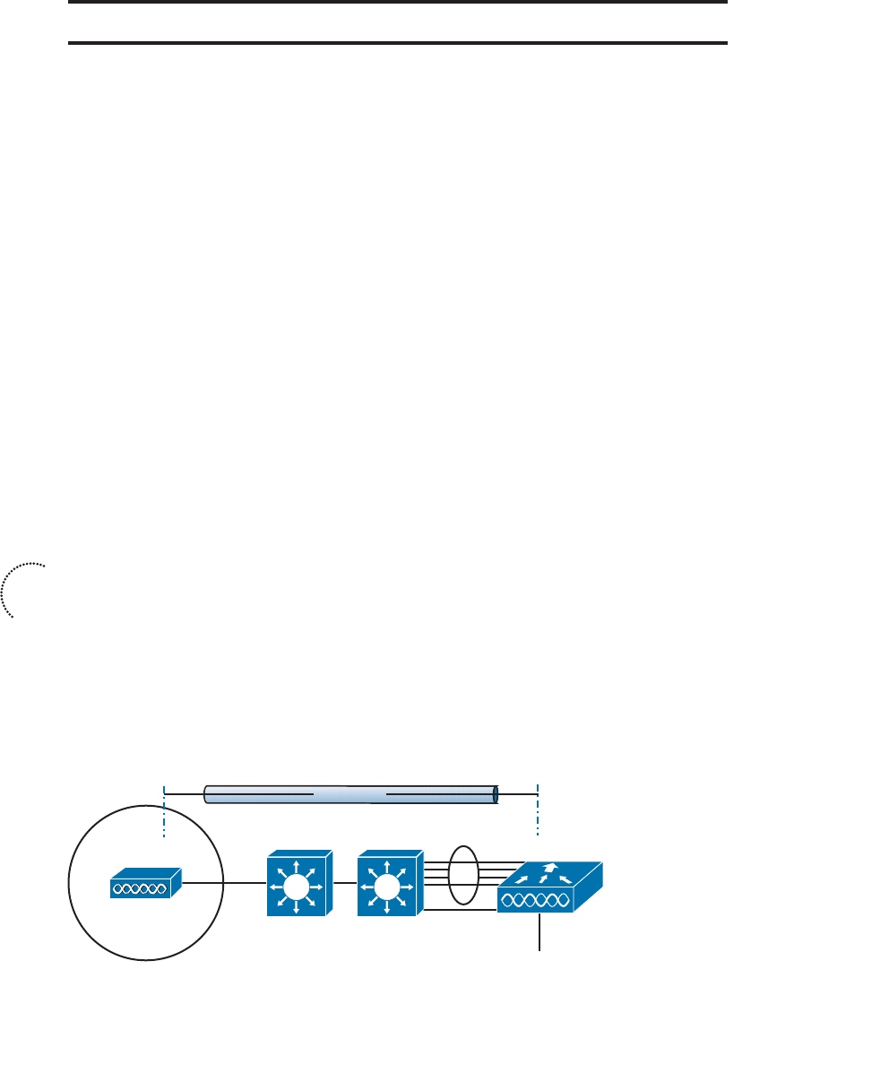
ptg12542968
204 CCNA Wireless 640-722 Official Cert Guide
Foundation Topics
Connecting the Controller
Cisco wireless LAN controllers partner with lightweight access points (LAPs) to provide
connectivity between a switched network and mobile wireless clients. The switched
network infrastructure also transports the packets that make up the Control and
Provisioning of Wireless Access Points (CAPWAP) tunnels between the controllers and
the access points (APs). Your first task to begin using a controller is to connect it to the
network.
From your work with Cisco routers and switches, you probably know that the terms
interface and port are usually interchangeable. For example, switches can come in 24- or
48-port models, and you apply configuration changes to the corresponding interfaces.
Cisco wireless controllers differ a bit; ports and interfaces refer to different concepts.
Controller ports are physical connections made to an external switched network, where-
as interfaces are logical connections made internally within the controller. The following
sections explain each connection type in more detail.
Using Controller Ports
You can connect several different types of controller ports to your network, as shown in
Figure 10-1 and discussed in the following list:
■ Service port —Used for out-of-band management, system recovery, and initial boot
functions; always connects to a switch port in access mode
■ Distribution system port —Used for all normal AP and management traffic; usually
connects to a switch port in 802.1Q trunk mode
■ Console port —Used for out-of-band management, system recovery, and initial
boot functions; asynchronous connection to a terminal emulator (9600 baud, 8 data
bits, 1 stop bit, by default)
■ Redundancy port —Used to connect to a peer controller for redundant operation
AP WLC
Distribution
Ports
Service
Port
Console
LAG
Switched Infrastructure
CAPWAP
Figure 10-1 Cisco Wireless LAN Controller Ports.
Key
Topic

ptg12542968
Chapter 10: Initial Controller Configuration 205
Controllers have a single service port that must be connected to a switched network.
Usually the service port is assigned to a management VLAN so that you can access the
controller with Secure Shell (SSH) or a web browser to perform initial configuration or
for maintenance. Notice that the service port supports only a single VLAN, so the cor-
responding switch port must be configured for access mode only.
Controllers also have multiple distribution system ports that you must connect to the
network. These ports carry most of the data coming to and going from the controller.
For example, the CAPWAP tunnels (control and data) that connect to each of a control-
ler’s APs pass across the distribution system ports. Client data also passes from wireless
LANs to wired VLANs over the ports. In addition, any management traffic using a web
browser, SSH, SNMP, or TFTP normally reaches the controller through the ports.
Because the distribution system ports must carry data that is associated with many dif-
ferent VLANs, VLAN tags and numbers become very important. For that reason, the dis-
tribution system ports always operate in 802.1Q trunking mode. When you connect the
ports to a switch, you should also configure the switch ports for unconditional 802.1Q
trunk mode.
The distribution system ports can operate independently, each one transporting multiple
VLANs to a unique group of internal controller interfaces. For resiliency, you can con-
figure distribution system ports in redundant pairs. One port is primarily used; if it fails,
a backup port is used instead.
To get the most use out of each distribution system port, you can configure all of them
to operate as a single logical group, much like an EtherChannel on a switch. Controller
distribution system ports can be configured as a link aggregation group (LAG) such that
they are bundled together to act as one larger link. In Figure 10-1 , the four distribution
system ports are configured as a LAG. With a LAG configuration, traffic can be load
balanced across the individual ports that make up the LAG. In addition, LAG offers
resiliency; if one individual port fails, traffic will be redirected to the remaining working
ports instead.
Table 10-2 lists common Cisco controller models along with the distribution system and
service ports available. As you might expect, the more APs a controller platform sup-
ports, the greater distribution system port throughput it needs. In contrast, almost every
model uses a 1-Gbps service port because the out-of-band management traffic require-
ments are fairly small.
Table 10-2 Controller Models and Supported Distribution and Service Ports
Controller Model Distribution Ports Service Port
2500 (4) 1 Gbps
5500 (8) 1 Gbps (1) 1 Gbps
5760 (6) 1 or 10 Gbps (1) 1 Gbps
Flex 7500 (2) 10 Gbps (1) 1 Gbps

ptg12542968
206 CCNA Wireless 640-722 Official Cert Guide
Controller Model Distribution Ports Service Port
8500 (2) 10 Gbps (1) 1 Gbps
WiSM2 (2) 10 Gbps (internal) (1) 1 Gbps (internal)
Using Controller Interfaces
Through its distribution system ports, a controller connects to multiple VLANs on the
switched network. Internally, the controller must somehow map those wired VLANs to
equivalent logical wireless networks. For example, suppose that VLAN 10 is set aside for
wireless users in the Engineering division of a company. That VLAN must be connected
to a unique wireless LAN that exists on a controller and its associated APs. The wireless
LAN must then be connected to every client that associates with service set identifier
(SSID) “Engineering”.
Cisco wireless controllers provide the necessary connectivity through internal interfaces.
A controller interface is logical and must be configured with an IP address, subnet mask,
default gateway, and a Dynamic Host Configuration Protocol (DHCP) server. Each inter-
face is then assigned to a physical port and a VLAN ID. You can think of an interface as
a Layer 3 termination on a VLAN.
Cisco controllers support the following interface types, also shown in Figure 10-2 :
■ Management interface —Used for normal management traffic, such as RADIUS
user authentication, wireless LAN controller (WLC)-to-WLC communication, web-
based and SSH sessions, SNMP, NTP, syslog, and so on
■ AP-manager interface —Used to terminate CAPWAP tunnels between the control-
ler and its APs
■ Virtual interface —Used to relay client DHCP requests, client web authentication,
and to support client mobility
■ Service port interface —Bound to the service port and used for out-of-band
management
■ Dynamic interface —Used to connect a VLAN to a WLAN
The management and AP-manager interfaces both face the switched network, where
management users and APs are located. Management traffic will usually consist of proto-
cols like HTTPS, SSH, SNMP, NTP, TFTP, and so on. AP-manager traffic always consists
of CAPWAP packets that carry control and data tunnels to and from the APs.
The two interfaces are listed separately, but the AP-manager interface is optional. By
default, the AP-manager interface is not available for use until it is explicitly config-
ured, so CAPWAP tunnels will be terminated on the Management interface instead.
You can create an AP-manager interface if you would like to keep the management and
CAPWAP traffic separate. However, the two interfaces should always reside on the
same VLAN.
Key
Topic
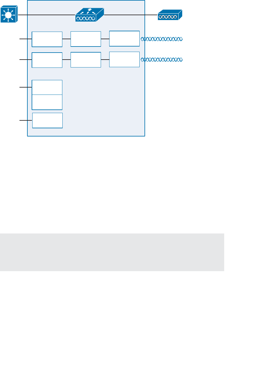
ptg12542968
Chapter 10: Initial Controller Configuration 207
The virtual interface is used only for certain client facing operations. For example, when
a wireless client issues a DHCP request to obtain an IP address, the controller can relay
the request on to a normal DHCP server. From the client’s perspective, the DHCP server
appears to be the controller’s virtual interface address. Clients may see the virtual inter-
face’s address, but that address is never used when the controller communicates with
other devices on the switched network.
Because the virtual interface is used only for some client management functions, you
should configure it with a unique, nonroutable address. For example, you might use
10.1.1.1 because it is within a private address space defined in RFC 1918.
Tip Traditionally, many people have assigned IP address 1.1.1.1 to the virtual inter-
face. Although it is a unique address, it is routable and already in use elsewhere on the
Internet. A better practice is to use an IP address from a private address space that is
unused or reserved, such as 192.0.2.1.
The virtual interface address is also used to support client mobility. For that reason, every
controller that exists in the same mobility group should be configured with a virtual
address that is identical to the others. By using one common virtual address, all the con-
trollers will appear to operate as a cluster as clients roam from controller to controller.
Dynamic interfaces map WLANs to VLANs, making the logical connections between
wireless and wired networks. You will configure one dynamic interface for each wireless
LAN that is offered by the controller’s APs, and then map the interface to the WLAN.
AP
VLAN a WLAN 1 SSID
Dynamic
Interface
VLAN n WLAN n SSID
Dynamic
Interface
VLAN x AP-Manager
Management
Service PortVLAN y
WLC
Switch
Figure 10-2 Cisco Wireless LAN Controller Interfaces.

ptg12542968
208 CCNA Wireless 640-722 Official Cert Guide
Each dynamic interface must also be configured with its own IP address and can act as
a DHCP relay for wireless clients. To filter traffic passing through a dynamic interface,
you can configure an optional access list. Dynamic interface and WLAN configuration
are covered in more detail in Chapter 15 , “Configuring a WLAN.”
Running the Initial Setup Wizard
When you power up a wireless controller for the first time, it comes up with a minimal
default configuration. The distribution system ports are not yet usable, but you can con-
nect to the controller through its console port or through its service port—provided you
have connected the service port to a switch or an Ethernet crossover cable. The service
port can use a default IP address of 192.168.1.1, or it can request an address through
DHCP.
The default configuration has no interfaces or WLANs defined. APs cannot connect to
it until you provide some initial setup information and then configure it further after the
controller reboots into normal operation.
You can use either a web browser or the command-line interface (CLI) to set up a con-
troller for the first time. Both methods are covered in the following sections. Through
the initial setup, you define the minimum parameters for the controller to become
operational—the service port, management interface, virtual interface, WLAN, authenti-
cation server, clock, and so on.
Initial Setup with the Web Interface
After you have connected a controller to the network and have powered it up, you can
use a web browser to enter a basic configuration. The controller prompts you through
the following sequence of steps to configure various parameters as part of an initial
setup wizard:
Step 1. Configure system access. Connect your PC to the same VLAN and subnet
that the controller’s service port uses, and then open a web browser to the
controller’s service port IP address. In Figure 10-3 , the service port uses
192.168.1.1 and the initial setup wizard asks for a system name for the con-
troller, along with an administrative user’s ID and password. By default, the
username is admin and the password is admin . The system name is somewhat
like a hostname and is used to identify the controller to APs and other con-
trollers. Click the Next button to continue.
Step 2. Configure SNMP access.
By default, SNMP Versions 2c and 3 are enabled. Version 3 provides the
most secure access and is recommended, whereas Version 2c is not. Version
1 is disabled because it is not considered to be secure. You can enable or
disable each version as shown in Figure 10-4 . If SNMPv3 is enabled, the con-
troller will remind you to configure an SNMPv3 user once the initial configu-
ration is complete and the controller reboots. Click Next to continue.
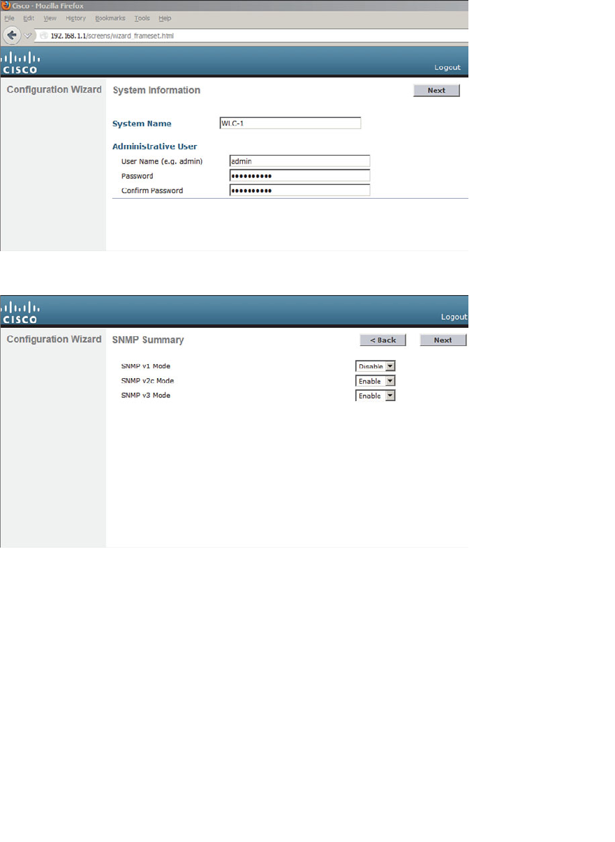
ptg12542968
Chapter 10: Initial Controller Configuration 209
Figure 10-4 Configuring SNMP Access.
Step 3. Configure the service port.
Although the controller’s service port has a default initial IP address (the
one you’re using to run the initial configuration), you can configure it to use
something else in the future. Check the DHCP Protocol box to have the con-
troller request an address through DHCP. Otherwise, you can leave the box
unchecked and enter a static IP address instead. In Figure 10-5 , the service
port is configured to use DHCP. The address and netmask shown will be dis-
regarded. Click Next to continue.
Figure 10-3 Starting the Initial Setup Wizard.
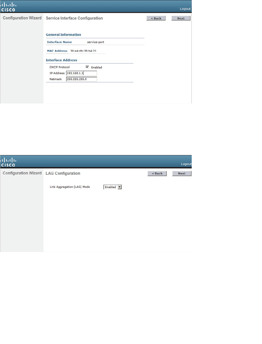
ptg12542968
210 CCNA Wireless 640-722 Official Cert Guide
Figure 10-5 Configuring the Service Port.
Step 4. Configure LAG mode.
By default, all the distribution system ports will be bundled together as a sin-
gle LAG link, as shown in Figure 10-6 . You can disable LAG mode through
the drop-down menu. Click Next to continue.
Figure 10-6 Configuring LAG Mode.
Step 5. Configure the management interface.
By default, a controller uses a single management interface for both man-
agement and CAPWAP traffic. The interface is configured for VLAN 0
(the 802.1Q trunk native VLAN), with no valid IP address. You can set the
VLAN number, IP address, subnet mask, and gateway as shown in Figure
10-7 . In this example, the management interface resides on VLAN 50 at
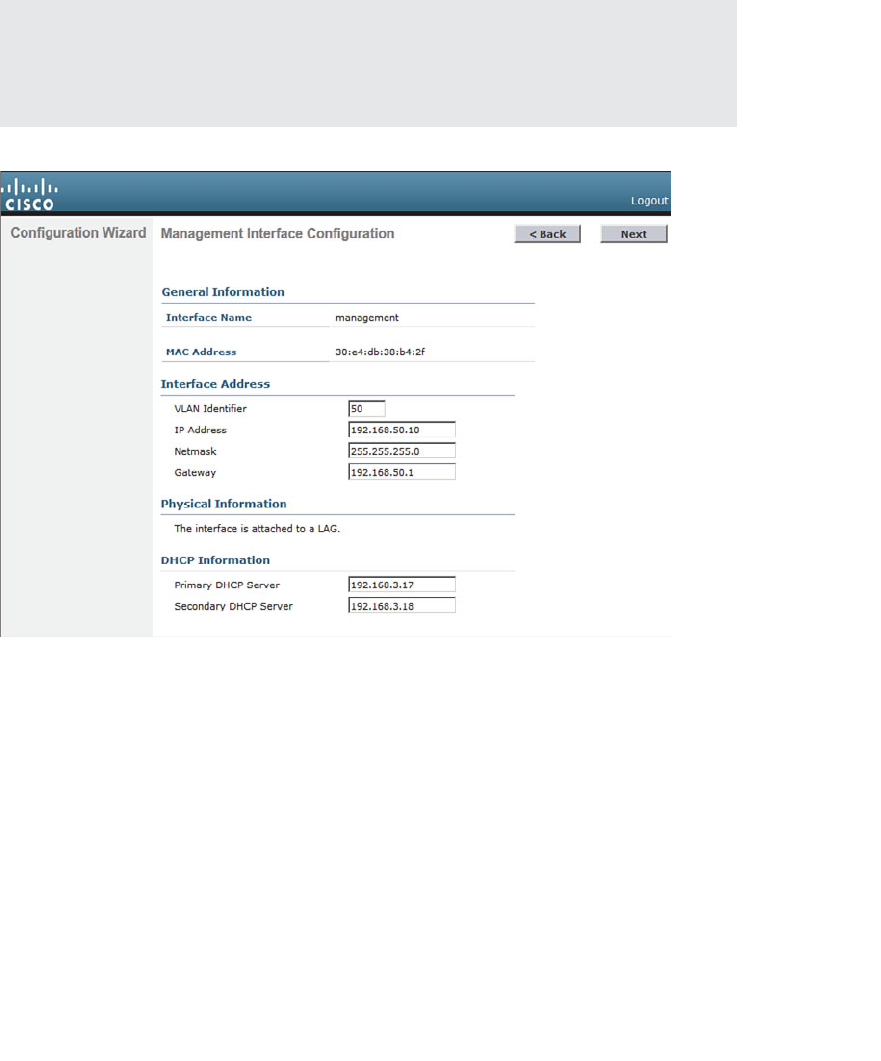
ptg12542968
Chapter 10: Initial Controller Configuration 211
192.168.50.10. You can also configure the primary and secondary DHCP
server addresses that the controller will use if it has to relay any DHCP
requests from wireless clients. Because the management interface does not
touch wireless clients directly, the DHCP server addresses are not necessary.
Click Next to continue.
Tip You might have noticed that the controller’s native VLAN is VLAN 0, whereas
Cisco switches use native VLAN 1 as a default. A controller and a switch may commu-
nicate over the native VLAN because traffic is untagged . Even though the native VLAN
numbers differ, it does not matter because no tag is added at all.
Figure 10-7 Configuring the Management Interface.
Step 6. Configure the RF mobility domain and country code.
A controller must be configured to use the RF parameters that are defined by
the local regulatory body. It also uses a RF mobility domain name to group
like controllers together so that things like AP channel numbers and transmit
power can be centrally managed. By default, the RF mobility domain is set
to default. You can override that value as shown in Figure 10-8 . Although
the selected country code is not shown in the figure, it has defaulted to US.
Click Next to continue.

ptg12542968
212 CCNA Wireless 640-722 Official Cert Guide
Figure 10-8 Configuring the RF Regulatory Domain.
Step 7. Configure the virtual interface.
By default, the virtual interface is configured with address 1.1.1.1. You
should enter a different address, such as the one shown in Figure 10-9 . You
should have an entry for the virtual interface in your DNS server, to stream-
line client web authentication. You can also configure a DNS hostname on
the controller, but that same name should also exist on the DNS server. Click
Next to continue.
Step 8. Configure a WLAN.
During the initial setup, you must define one wireless LAN, as shown in
Figure 10-10 . The profile name is the name of the WLAN within the control-
ler. The WLAN SSID is the SSID string that will be advertised by any APs
that offer the WLAN. You might find it convenient to configure both strings
with the same name, as shown in the figure.
Notice that you only need to enter the name of the WLAN—not a VLAN
number or an interface name. The initial setup process creates a placeholder
for the WLAN. You will complete the WLAN configuration later, when the
controller reboots and becomes fully functional.
After you click Next to continue, you will see a reminder window noting that
the WLAN has been created with the following default wireless security set-
tings: WPA2, AES, and 802.1x authentication. Chapter 14 , “Wireless Security
Fundamentals,” covers these terms in greater detail.
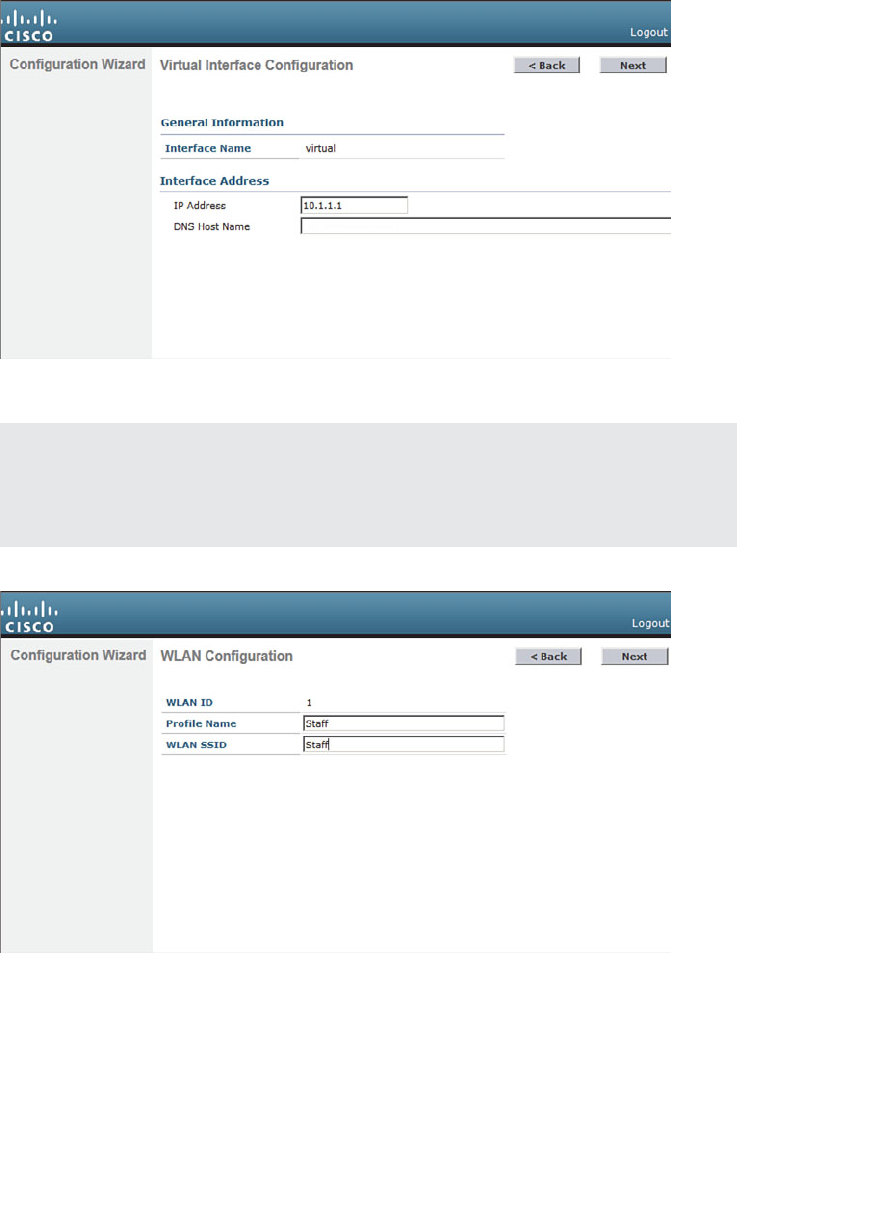
ptg12542968
Chapter 10: Initial Controller Configuration 213
Tip The WLAN Configuration screen also shows a WLAN ID number. As you create
new WLANs, the ID number increments. The WLAN ID is an internal index that is main-
ly used when configuration templates are applied to a controller from an Cisco Prime
Network Control System (NCS) or Cisco Prime Infrastructure (PI) management station.
Figure 10-10 Configuring a WLAN.
Step 9. Configure a RADIUS server.
As an optional step, you can define a RADIUS server that will be used for cli-
ent authentication. You can always click the Skip button to skip this step and
define the server at a later time.
Figure 10-9 Configuring the Virtual Interface.
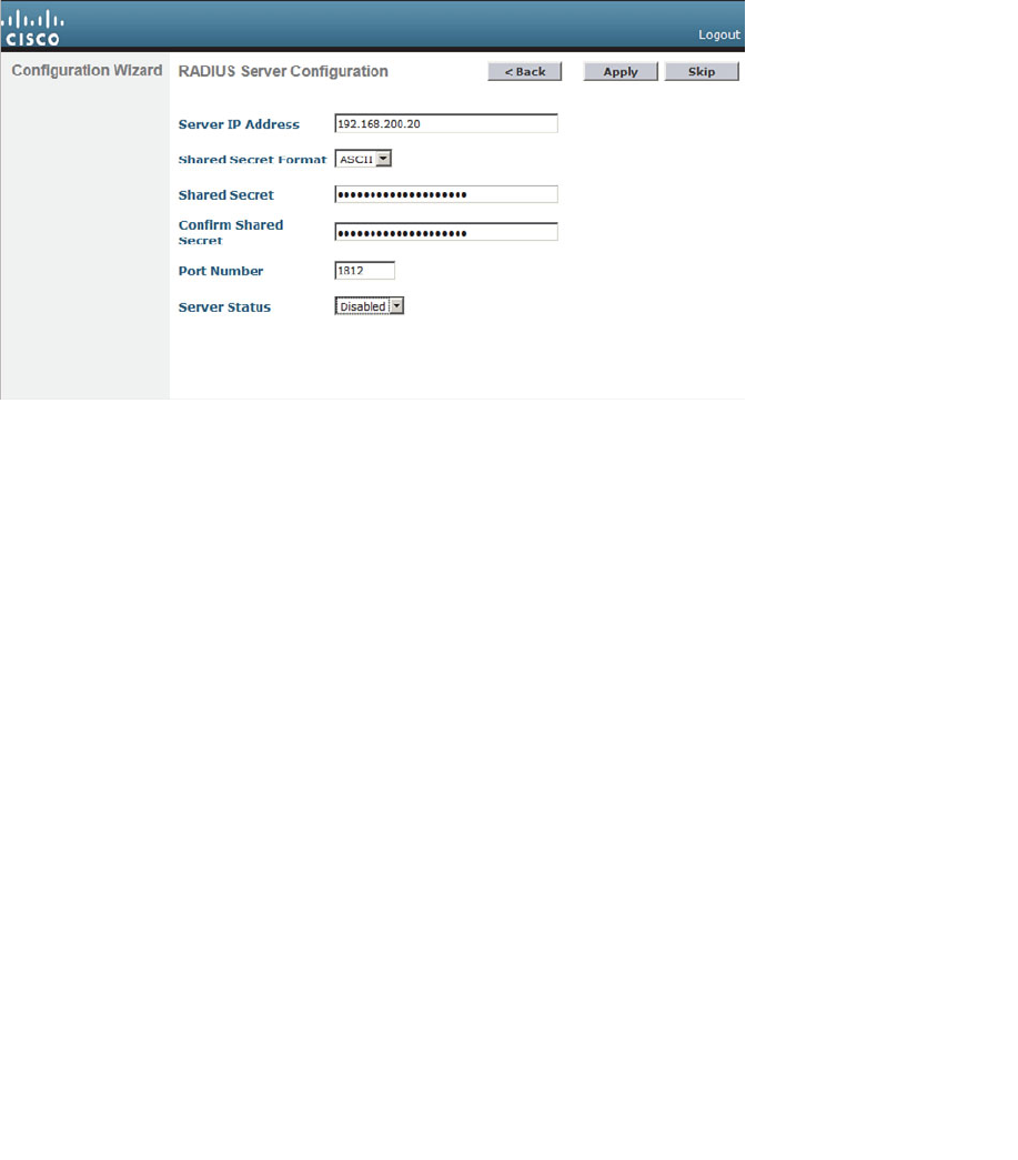
ptg12542968
214 CCNA Wireless 640-722 Official Cert Guide
If you choose to define the server now, enter the RADIUS server’s IP
address, shared secret key, port number, and the server status. Figure 10-11
shows these fields. You use the Server Status field when multiple servers are
defined; the controller will send a request to the next server that is in the
Enabled state in the list. Click Apply to apply the settings and continue to
the next step.
Figure 10-11 Configuring a RADIUS Server.
Step 10. Configure 802.11 support.
By default, a controller enables 802.11a, 802.11b, and 802.11g support glob-
ally for all APs that associate with it. You can override the support settings
by changing the check boxes shown in Figure 10-12 . When the initial setup
is complete and the controller has rebooted into full functionality, you can
fine-tune the 802.11 support settings further.
Also by default, the controller enables Auto-RF, which will automatically
determine the channel and transmit power level for each AP’s radio. You can
always fine-tune the Auto-RF settings globally or on a per-AP basis at a later
time. Click Next to continue.
The Auto-RF functions are also known as Radio Resource Management
(RRM), which is covered in greater detail in Chapter 13 , “Understanding
RRM.”
Step 11. Configure the system clock.
The controller maintains an internal clock. You can set the date, time, and
time zone, as shown in Figure 10-13 . Click Next to continue. After the con-
troller has rebooted and is fully functional, you can configure it to use an
NTP server to synchronize its clock.
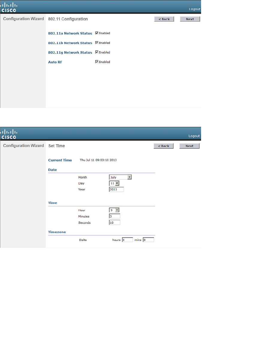
ptg12542968
Chapter 10: Initial Controller Configuration 215
Figure 10-13 Configuring the System Clock.
Step 12. Reboot the controller.
As a last step, to save the initial configuration and reboot the controller, click the Save
and Reboot button (see Figure 10-14 ).
Figure 10-12 Configuring 802.11 Support.

ptg12542968
216 CCNA Wireless 640-722 Official Cert Guide
Figure 10-14 Save and Reboot After Completing the Configuration Wizard.
After the controller has rebooted, it will be fully functional. At that time, you can repo-
sition your PC on the regular wired network and point your web browser toward the
controller’s management interface IP address. You will have to log in using the adminis-
trative user ID and password that you configured in Step 1.
Initial Setup with the CLI
As an alternative to using a web browser for the initial setup, you can connect your PC
to the controller’s asynchronous console port and use the CLI. Your terminal emulator
will need to be configured for 9600 baud, 8 data bits, and 1 stop bit—the same settings
you use to access the console ports on most Cisco routers and switches.
For comparison, the same parameters used in the web-based initial setup are used to
demonstrate the CLI initial setup in Example 10-1 . Notice that some CLI prompts end
with things like [yes][NO]. You can enter either string option shown ( yes or NO ) or you
can press Enter to use the capitalized default value.
Example 10-1 Using the Controller CLI for Initial Setup
Welcome to the Cisco Wizard Configuration Tool
Use the '-' character to backup
Would you like to terminate autoinstall? [yes]:
AUTO-INSTALL: starting now...
System Name [Cisco_38:b4:2f] (31 characters max): WLC-1
Enter Administrative User Name (24 characters max): admin
Enter Administrative Password (3 to 24 characters): **********
Re-enter Administrative Password : **********
Service Interface IP Address Configuration [static][DHCP]: DHCP

ptg12542968
Chapter 10: Initial Controller Configuration 217
Management Interface IP Address: 192.168.50.10
Management Interface Netmask: 255.255.255.0
Management Interface Default Router: 192.168.50.1
Management Interface VLAN Identifier (0 = untagged): 50
Management Interface DHCP Server IP Address: 192.168.3.17
Virtual Gateway IP Address: 10.1.1.1
Mobility/RF Group Name: MyRF
Network Name (SSID): Staff
Configure DHCP Bridging Mode [yes][NO]:
Allow Static IP Addresses [YES][no]:
Configure a RADIUS Server now? [YES][no]:
Enter the RADIUS Server's Address: 192.168.200.20
Enter the RADIUS Server's Port [1812]:
Enter the RADIUS Server's Secret: thisismysharedsecret
Enter Country Code list (enter 'help' for a list of countries) [US]:
Enable 802.11b Network [YES][no]:
Enable 802.11a Network [YES][no]:
Enable 802.11g Network [YES][no]:
Enable Auto-RF [YES][no]:
Configure a NTP server now? [YES][no]:
Enter the NTP server's IP address: 192.168.200.30
Enter a polling interval between 3600 and 604800 secs: 3600
Configuration correct? If yes, system will save it and reset. [yes][NO]:
yes

ptg12542968
218 CCNA Wireless 640-722 Official Cert Guide
Exam Preparation Tasks
As mentioned in the section, “How to Use This Book,” in the Introduction, you have a
couple of choices for exam preparation: the exercises here, Chapter 22 , “Final Review,”
and the exam simulation questions on the CD-ROM.
Review All Key Topics
Review the most important topics in this chapter, noted with the Key Topic icon in the
outer margin of the page. Table 10-3 lists a reference of these key topics and the page
numbers on which each is found.
Table 10-3 Key Topics for Chapter 10
Key Topic Element Description Page Number
List Controller ports 204
List Controller interfaces 206
Define Key Terms
Define the following key terms from this chapter and check your answers in the
glossary:
AP-manager interface, controller interface, controller port, distribution system port,
dynamic interface, link aggregation group (LAG), management interface, service
port, virtual interface
Key
Topic

ptg12542968
This page intentionally left blank

ptg12542968
This chapter covers the following topics:
■ Discovering a Controller —This section explains
how a lightweight access point discovers and joins a
wireless LAN controller.
■ Designing High Availability —This section discusses
what happens when a wireless LAN controller fails
and APs need to find a new home. It also covers
several common approaches to building networks
with redundant controllers.
This chapter covers the following exam topics:
■ Describe controller-based AP discovery and asso-
ciation (DHCP, DNS, Master-Controller, Primary-
Secondary-Tertiary, and n+1 redundancy)

ptg12542968
Cisco lightweight wireless access points need to be paired with a wireless LAN control-
ler (WLC) to function. Each lightweight access point (LAP) must discover and bind itself
with a controller before wireless clients can be supported. This chapter covers the dis-
covery process in detail.
“Do I Know This Already?” Quiz
The “Do I Know This Already?” quiz allows you to assess whether you should read this
entire chapter thoroughly or jump to the “Exam Preparation Tasks” section. If you are
in doubt about your answers to these questions or your own assessment of your knowl-
edge of the topics, read the entire chapter. Table 11-1 lists the major headings in this
chapter and their corresponding “Do I Know This Already?” quiz questions. You can
find the answers in Appendix A , “Answers to the ‘Do I Know This Already?’ Quizzes.”
Table 11-1 “Do I Know This Already?” Section-to-Question Mapping
Foundation Topics Section Questions
Discovering a Controller 1–6
Designing High Availability 7–10
Caution The goal of self-assessment is to gauge your mastery of the topics in this chap-
ter. If you do not know the answer to a question or are only partially sure of the answer,
you should mark that question as wrong for purposes of the self-assessment. Giving your-
self credit for an answer you correctly guess skews your self-assessment results and might
provide you with a false sense of security.
CHAPTER 11
Understanding Controller Discovery

ptg12542968
222 CCNA Wireless 640-722 Official Cert Guide
1.
Which one of the following comes first in a LAP’s state machine, after it boots?
a. Build a CAPWAP tunnel
b. Discover WLCs
c. Download a configuration
d. Join a WLC
2.
If a LAP needs to download a new software image, how does it get the image?
a. From a TFTP server
b. From an FTP server
c. From a WLC
d. You must preconfigure it.
3.
Which of the following are ways that an AP can learn of WLCs that it might join?
(Choose all that apply.)
a. Primed entries
b.
List from a previously joined controller
c. DHCP
d. Subnet broadcast
e. DNS
f. All of these
4.
Which one of the following will an AP try first in order to select a controller to
join?
a. Master controller
b. Least-loaded controller
c. Primed address
d. DHCP option 43
e.
Wait for a controller to send a Join Request
5.
If an AP tries every available method to discover a controller, but fails to do so,
what happens next?
a.
It broadcasts on every possible subnet.
b.
It tries to contact the default controller at 10.0.0.1.
c.
It reboots and starts discovering again.
d.
It uses IP redirect on the local router.

ptg12542968
Chapter 11: Understanding Controller Discovery 223
6. You can configure the priority value on an AP to accomplish which one of the fol-
lowing?
a.
To set the controller it will try to join first
b.
To define which APs will be preferred when joining a controller
c.
To set the SSID that will be advertised first
d.
To identify the least loaded controller to join
7.
Which of the following is the most deterministic strategy you can use to push a spe-
cific AP to join a specific controller?
a. Select the least-loaded controller
b. Use DHCP option 43
c. Configure the master controller
d. Configure the primary controller
8.
By default, which one of the following methods and intervals does an AP use to
detect a failed controller?
a. ICMP, 60 seconds
b. ICMP, 30 seconds
c. CAPWAP keepalive, 60 seconds
d. CAPWAP keepalive, 30 seconds
e. CAPWAP discovery, 30 seconds
9. Suppose that an AP is joined to the WLC that is configured as the primary control-
ler. At a later time, that controller fails and the AP joins its secondary controller.
Once the primary controller is restored to service, which feature would allow the
AP to rejoin it again?
a. CAPWAP Rejoin
b. AP Failover
c. AP Priority
d. AP Fallback
10.
A CUWN architecture consists of two controllers and a number of APs. The APs
are distributed equally across the two controllers. Each AP is configured with one
controller as primary and the other controller as secondary. Based on this informa-
tion, which one of the following redundancy models is being used?
a. No redundancy
b. N+1 redundancy
c. N+N redundancy
d. N+N+1 redundancy

ptg12542968
224 CCNA Wireless 640-722 Official Cert Guide
Foundation Topics
Discovering a Controller
Cisco LAPs are designed to be “touch free,” so that you can simply unbox a new one
and connect it to the wired network, without any need to configure it first. Naturally,
you have to configure the switch port, where the AP connects, with the correct access
VLAN, access mode, and inline power settings. From that point on, the AP can power up
and use a variety of methods to find a viable WLC to join.
AP States
From the time it powers up until it offers a fully functional basic service set (BSS), a LAP
operates in a variety of states. Each of the possible states are well defined in the Control
and Provisioning of Wireless Access Points (CAPWAP) RFC, but are simplified here for
clarity. The AP enters each state in a specific order; the sequence of states is called a
state machine . You should become familiar with the AP state machine so that you can
understand how an AP forms a working relationship with a WLC. If an AP cannot form
that relationship for some reason, your knowledge of the state machine can help you
troubleshoot the problem.
Tip CAPWAP is defined in RFC 5415, and in a few other RFCs. The terms used in the
RFC differ somewhat from the ones used in CUWN and this book. For example, access
controller (AC) refers to a WLC, whereas wireless termination point (WTP) refers to an
AP.
The sequence of the most common states, as shown in Figure 11-1 , is as follows:
1. AP boots:
Once an AP receives power, it boots on a small IOS image so that it
can work through the remaining states and communicate over its network connec-
tion. The AP must also receive an IP address from a Dynamic Host Configuration
Protocol (DHCP) server so that it can communicate over the network.
2. WLC discovery: The AP goes through a series of steps to find one or more control-
lers that it might join. The steps are explained further in the next section.
3. CAPWAP tunnel:
The AP attempts to build a CAPWAP tunnel with one or more
controllers. The tunnel will provide a secure Datagram Transport Layer Security
(DTLS) channel for subsequent AP-WLC control messages. The AP and WLC
authenticate each other through an exchange of digital certificates.
4. WLC join:
The AP selects a WLC from a list of candidates, and then sends a
CAPWAP Join Request message to it. The WLC replies with a CAPWAP Join
Response message. The next section explains how an AP selects a WLC to join.
Key
Topic
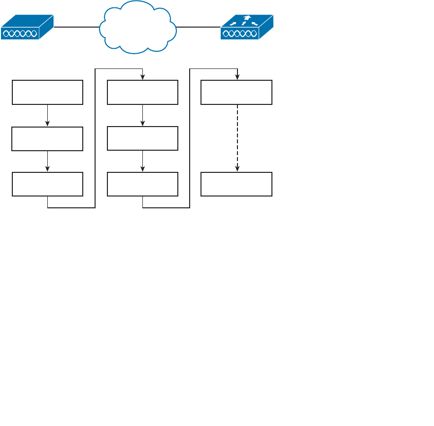
ptg12542968
Chapter 11: Understanding Controller Discovery 225
5. Download image:
The WLC informs the AP of its software release. If the AP’s own
software is a different release, the AP will download a matching image from the
controller and then reboot. If the two are running identical releases, no download is
needed.
6. Download config:
The AP pulls configuration parameters down from the WLC and
can update existing values with those sent from the controller. Settings include RF,
service set identifier (SSID), security, and quality of service (QoS) parameters.
7. Run state:
Once the AP is fully initialized, the WLC places it in the “run” state. The
AP and WLC then begin providing a BSS and begin accepting wireless clients.
8. Reset:
If an AP is reset by the WLC, it tears down existing client associations and
any CAPWAP tunnels to WLCs. The AP then reboots and starts through the entire
state machine again.
WLCLAP
1. AP Boots Up
2. WLC Discovery
3. CAPWAP
Tunnel
4. WLC Join
5. Download
Image
6. Download
Config
7. RUN State
8. Reset
Figure 11-1 The State Machine of a LAP.
Be aware that you cannot control which software image release a LAP runs. Rather,
the WLC that the AP joins determines the release, based on its own software version.
Downloading a new image can take a considerable amount of time, especially if there are
a large number of APs waiting for the same download from one WLC. That might not
matter when a newly installed AP is booting and downloading code, because it does not
yet have any wireless clients to support.
However, if an existing, live AP happens to reboot or join a different controller, clients
can be left hanging with no AP while the image downloads. Some careful planning with
your controllers and their software releases will pay off later by minimizing downtime.
Consider the following scenarios when an AP might need to download a different
release:

ptg12542968
226 CCNA Wireless 640-722 Official Cert Guide
■ The AP joins a WLC, but has a version mismatch.
■ A code upgrade is performed on the WLC itself, requiring all associated APs to
upgrade too.
■ The WLC fails, causing all associated APs to be dropped and join elsewhere.
If there is a chance that an AP could rehome from one WLC to another, you should
make sure that both controllers are running the same code release. Otherwise, the AP
move should happen under controlled circumstances, such as during a maintenance
window. Fortunately, if you have downloaded a new code release to a controller, but
not yet rebooted it to run the new code, you can predownload the new release to the
controller’s APs. The APs will download the new image, but will keep running the previ-
ous release. When it comes time to reboot the controller on the new image, the APs will
already have the new image staged without having to take time to download it. The APs
can reboot on their new image and join the controller after it has booted and become
stable.
Discovering a WLC
A LAP must be very diligent to discover any controllers that it can join—all without any
preconfiguration on your part. To accomplish this feat, several methods of discovery
are used. The goal of discovery is just to build a list of live candidate controllers that are
available, using the following methods:
■ Prior knowledge of WLCs
■ DHCP and DNS information to suggest some controllers
■ Broadcast on the local subnet to solicit controllers
To discover a WLC, an AP sends a unicast CAPWAP Discovery Request to a control-
ler’s IP address or a broadcast to the local subnet. If the controller exists and is working,
it returns a CAPWAP Discovery Response to the AP. The exact sequence of discovery
steps used in Controller Software Release 7.0 is as follows:
Step 1. Broadcast on the local subnet —The AP will broadcast a CAPWAP
Discovery Request on its local wired subnet. Any WLCs that also exist on the
subnet will answer with a CAPWAP Discovery Response.
Tip If the AP and controllers lie on different subnets, you can configure the local router
to relay any broadcast requests on UDP port 5246 to specific controller addresses. Use
the following configuration commands:
router(config)# ip forward-protocol udp 5246
router(config)# interface vlan n
router(config-int)# ip helper-address WLC1-MGMT-ADDR
router(config-int)# ip helper-address WLC2-MGMT-ADDR
Key
Topic

ptg12542968
Chapter 11: Understanding Controller Discovery 227
Step 2. Use locally stored WLCs —An AP can be “primed” with up to three
controllers—a primary, a secondary, and a tertiary. These are stored in
nonvolatile memory so that the AP can remember them after a reboot or
power failure. Otherwise, if an AP has previously joined with a controller, it
should have stored up to 8 out of a list of 32 WLC addresses that it received
from the last controller it joined. The AP will attempt to contact as many
controllers as possible to build a list of candidates.
Step 3. Use DHCP —The DHCP server that supplies the AP with an IP address can
also send DHCP option 43 to suggest a list of WLC addresses.
Step 4. Use DNS —The AP will attempt to resolve the name CISCO-CAPWAP-
CONTROLLER. localdomain with a DNS request. The localdomain string is
the domain name learned from DHCP. If the name resolves to an IP address,
the controller attempts to contact a WLC at that address.
Step 5. Reset and try again —If none of the steps has been successful, the AP resets
itself and starts the discovery process all over again.
Selecting a WLC
Once an AP has finished the discovery process, it should have built a list of live candi-
date controllers. Now it must begin a separate process to select one WLC and attempt
to join it. Joining a WLC involves sending it a CAPWAP Join Request and waiting for it
to return a CAPWAP Join Response. From that point on, the AP and WLC build a DTLS
tunnel to secure their CAPWAP control messages.
The WLC selection process consists of the following three steps:
Step 1. Try primed addresses —If the AP has previously joined a controller and has
been configured or “primed” with a primary, secondary, and tertiary control-
ler, it will try to join those controllers in succession.
Step 2. Try the master controller —If the AP does not know of any candidate con-
troller, it can try to discover one by broadcasting on the local subnet. If a
controller has been configured as a master controller, it can respond to the
AP’s broadcast.
Step 3. Try the least loaded controller —The AP will attempt to join the least loaded
WLC, in an effort to load balance APs across a set of controllers. During the
discovery phase, each controller reports its load—the ratio of the number of
currently joined APs to the total AP capacity. The least loaded WLC is the
one with the lowest ratio. For example, suppose that a 5508 controller has 20
out of a possible 100 APs joined to it, while a 2504 controller has 20 out of a
possible 25 APs. The 5508 would be the least loaded with a ratio of 20/100;
the 2504 is more loaded with 20/25.
If an AP discovers a controller, but gets rejected when it tries to join it, what might be
the reason? Every controller has a set maximum number of APs that it can support. This
is defined by platform or by license. If the controller already has the maximum number
of APs joined to it, it will reject any additional APs.
Key
Topic
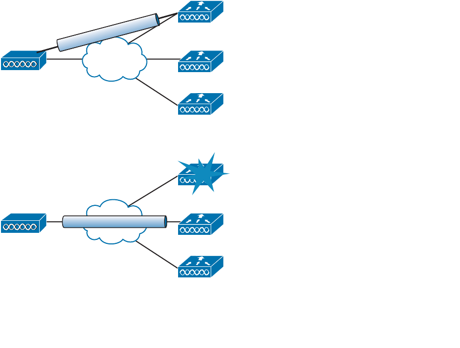
ptg12542968
228 CCNA Wireless 640-722 Official Cert Guide
To provide some flexibility in supporting APs on an oversubscribed controller, where
more APs are trying to join than a license allows, you can configure the APs with a prior-
ity value. All APs begin with a default priority of low. You can change the value to low,
medium, high, or critical. A controller will try to accommodate as many higher-priority
APs as possible. Once a controller is full of APs, it will reject an AP with the lowest pri-
ority to make room for a new one that has a higher priority.
Designing High Availability
Once an AP has discovered, selected, and joined a controller, it must stay joined to that
controller to remain functional. Now consider that a single controller might support
as many as 1000 or even 6000 APs—enough to cover a very large building or an entire
enterprise. If something ever causes the controller to fail, a large number of APs would
also fail. In the worst case, where a single controller carries the enterprise, the entire
wireless network would become unavailable. That might be catastrophic.
Fortunately, Cisco APs can discover multiple controllers—not just the one that it choos-
es to join. Figure 11-2 shows this scenario. If the joined controller becomes unavailable,
the AP can simply select the next least-loaded controller and request to join it, as Figure
11-3 depicts. That sounds simple, but it is not very deterministic.
LAP WLC-B
WLC-A
CAPWAP
WLC-Z
Figure 11-2 An AP Joins One of Several Discovered Controllers.
LAP WLC-B
CAPWAP
WLC-A
WLC-Z
Figure 11-3 An AP Joins a Different Controller After a Failure.

ptg12542968
Chapter 11: Understanding Controller Discovery 229
For example, if a controller full of 1000 APs fails, all 1000 APs must detect the failure,
discover other candidate controllers, and then select the least loaded one to join. During
that time, wireless clients can be left stranded with no connectivity. You might envision
the controller failure as a commercial airline flight that has just been canceled; everyone
that purchased a ticket suddenly joins a mad rush to find another flight out.
The most deterministic approach is to leverage the primary, secondary, and tertiary con-
troller fields that every AP stores. If any of these fields are configured with a controller
name or address, the AP knows which three controllers to try in sequence before resort-
ing to a more generic search.
Tip When an AP boots and builds a list of potential controllers, it can use CAPWAP to
build a tunnel to more than one controller. The AP will join only one controller, which
it uses as the primary unit. By building a tunnel with a second controller ahead of time,
before the primary controller fails, the AP will not have to spend time building a tunnel
to the backup controller before joining it.
As a wireless network grows, you might have several controllers implemented just to
support the number of APs that are required. A good network design should also take
failures and high availability (HA) into consideration. It is not enough just to have multi-
ple controllers in a network. What if they are all in use and full of APs? There would not
be enough room to spare for a large group of additional, displaced APs to join in their
time of need. In the commercial flight analogy, there might be other flights departing the
airport soon after the cancellation. If those flights are already mostly full of passengers,
many people will be left waiting at the gate.
Figure 11-4 illustrates an example network that does not offer enough capacity to fully
survive a controller failure. In the “before” diagram, a group of 400 APs has joined
controller WLC-A, and a group of 300 APs has joined WLC-B. Each controller has a
maximum capacity of 500 APs. As long as both controllers stay up and functional, the
wireless network should work fine. In the “after” diagram, WLC-A has failed. All 400
APs that were previously joined to WLC-A will discover that WLC-B is alive, so they
will all try to join it. WLC-B already has 300 APs, so it has room for only 200 more. That
means 200 APs will be able to join WLC-B and 200 more will be left out in the cold with
no controller to join at all.
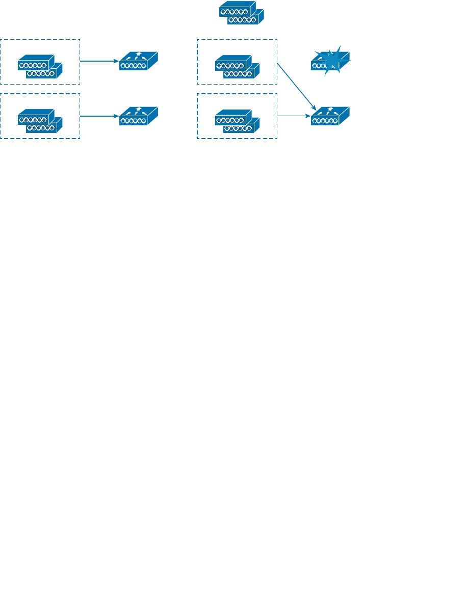
ptg12542968
230 CCNA Wireless 640-722 Official Cert Guide
Before After
WLC-A
200 APs
??
200 APs
300 APs WLC-B
Capacity: 500 APs
Capacity: 500 APs
400 APs
300 APs
WLC-A
Capacity: 500 APs
WLC-B
Capacity: 500 APs
Figure 11-4 The Result of Undersized Controllers During a Failure.
Detecting a Controller Failure
When HA is required, make sure that you design your wireless network to support it
properly. Fortunately, Cisco APs and controllers are built with HA in mind, so you have
several strategies at your disposal. First, it is important to understand how APs detect a
controller failure and what action they take to recover from it.
Once an AP joins a controller, it sends keepalive (also called heartbeat) messages to the
controller over the wired network at regular intervals. By default, keepalives are sent
every 30 seconds. The controller is expected to answer each keepalive as evidence that it
is still alive and working. If a keepalive is not answered, an AP running Software Release
7.0 will escalate the test by sending up to five more keepalive messages at 1-second
intervals. In Release 7.2, four more keepalives are sent at 3-second intervals. If the con-
troller answers, all is well; if it does not answer, the AP presumes that the controller has
failed. The AP then moves quickly to find a successor to join.
Using the default values, an AP can detect a controller failure in as little as 35 seconds.
You can adjust the regular keepalive timer between 1 and 30 seconds and the escalated
or “fast” heartbeat timer between 1 and 10 seconds. By using the minimum values, a fail-
ure can be detected after only 6 seconds.
Normally, an AP will stay joined to a controller until it fails. If the AP has been config-
ured with primary and secondary controller information, it will join the primary control-
ler first. If the primary fails, the AP will try to join the secondary until it fails. Even if the
primary controller is put back into service, the AP will stay with the secondary. You can
change that behavior by enabling the AP Fallback feature—a global controller configura-
tion parameter. If AP Fallback is enabled (the default), an AP can try to rejoin its primary
controller at any time, whether its current controller has failed or not.
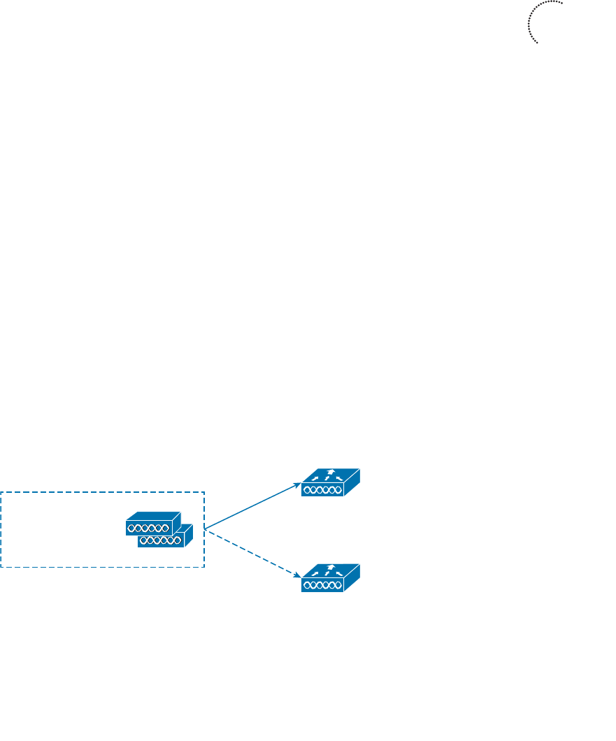
ptg12542968
Chapter 11: Understanding Controller Discovery 231
Building Redundancy
Building a wireless network with one controller and some APs is straightforward, but
it does not address what would happen if the controller fails for some reason. Adding
another controller or two could provide some redundancy, as long as the APs know how
to move from one controller to another when the time comes.
Redundancy is best configured in the most deterministic way possible. The follow-
ing sections explain how you can configure APs with primary, secondary, and tertiary
controller fields to implement various forms of redundancy. As you read through the
sections, keep in mind that redundant controllers should be configured similarly so that
APs can move from one controller to another without having to undergo any major con-
figuration changes.
N+1 Redundancy
The simplest way to introduce HA into a Cisco unified wireless network is to provide an
extra backup controller. This is commonly called N+1 or N:1 redundancy, where N rep-
resents some number of active controllers and 1 denotes the one backup controller.
By having one backup controller, N+1 redundancy can withstand a failure of only one
active controller. As long as the backup controller is sized appropriately, it can accept
all of a failed controller’s APs. However, once an active controller fails and all its APs
rehome to the backup controller, there will be no space to accept any other APs if a sec-
ond controller fails.
Figure 11-5 illustrates N+1 redundancy with a two-controller network for simplicity. The
network could have any number of active controllers, but only one backup controller.
WLC-A is the active controller and carries 100 percent of the network’s APs. WLC-Z is
the backup controller, which normally carries no APs at all. The backup controller sits
idle until an active controller fails.
To configure N+1 redundancy, you configure the primary controller field on all APs
with the name of an active controller (WLC-A, for example). The secondary controller
field is set to the name of the backup controller (WLC-Z).
Primary: WLC-A
Secondary: WLC-Z
Tertiary:
Production WLC
100% AP Capacity
Backup WLC
0% AP Capacity
WLC-A
WLC-Z
Figure 11-5 Configuring N+1 Controller Redundancy.
Key
Topic
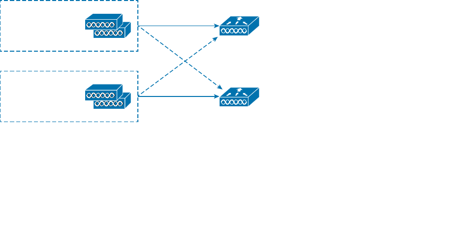
ptg12542968
232 CCNA Wireless 640-722 Official Cert Guide
N+N Redundancy
N+1 design is simple, but it has a couple of shortcomings. First, the backup controller
must sit idle and empty of APs until another controller fails. That might not sound like
a problem, except that the backup unit must be purchased with the same AP capacity as
the active controller it supports. That means the active and backup controllers must be
purchased at the same price. Having a full-price device sit empty and idle might seem
like a poor use of funds.
Second, the backup controller must be configured identically to every other active con-
troller it has to support. The idea is to make a controller failure as seamless as possible so
the APs should not have any noticeable configuration differences when they move from
one controller to another.
The N+N redundancy strategy tries to make better use of the available controllers. N+N
gets its name from grouping controllers in pairs. If you have one active controller, you
would pair it with one other controller; two controllers would be paired with two others,
and so on. You might also see the same strategy called N:N or 1+1.
By grouping controllers in pairs, you can divide the active role across two separate devic-
es. This makes better use of the AP capacity on each controller. As well, the APs and cli-
ents loads will be distributed across separate hardware, while still supporting redundancy
during a failure. N+N redundancy can support failures of more than one controller, but
only if the active controllers are configured in pairs.
Figure 11-6 illustrates the N+N scenario consisting of two controllers, WLC-A and
WLC-B. The APs are divided into two groups—one that joins WLC-A as primary con-
troller and another that joins WLC-B as primary. Notice that the primary and secondary
controllers are reversed between the two groups of APs. To support the full set of APs
during a failure, each controller must not be loaded with more than 50 percent of its AP
capacity.
Primary: WLC-A
Secondary: WLC-B
Tertiary:
Production WLC
50% AP Capacity
Primary: WLC-B
Secondary: WLC-A
Tertiary:
WLC-A
Production WLC
50% AP Capacity
WLC-B
Figure 11-6 Configuring N+N Controller Redundancy.
N+N+1 Redundancy
What if a scenario calls for more resiliency than the N+N plan can provide? You can
simply add one more controller to the mix, as a backup unit. As you might expect, this is
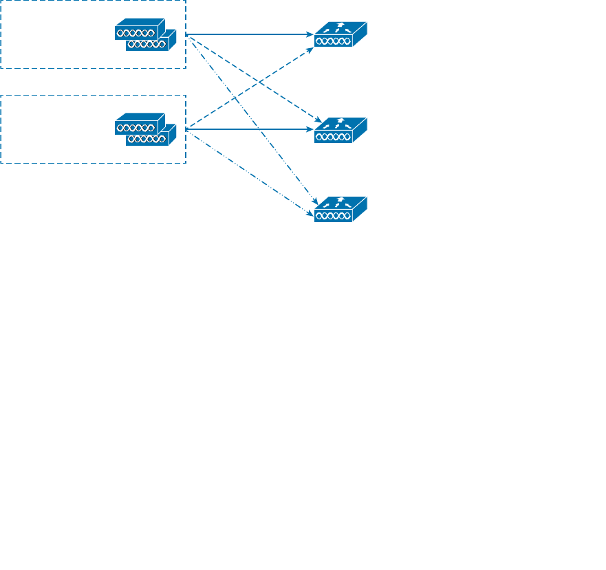
ptg12542968
Chapter 11: Understanding Controller Discovery 233
commonly called N+N+1 redundancy and combines the advantages of the N+N and N+1
strategies.
Two or more active controllers are configured to share the AP and client load, while
reserving some AP capacity for use during a failure. One additional backup controller
is set aside as an additional safety net. Figure 11-7 shows a simple example using three
controllers—two active (WLC-A and WLC-B) and one backup (WLC-Z). Like N+N
redundancy, the two groups of APs are configured with primary and secondary control-
lers that are the reverse of each other. Each group of APs is also configured with a ter-
tiary controller that points to the backup unit.
If one active controller fails, APs that were joined to it will move to the secondary
controller. As long as the two active controllers are not loaded with over 50 percent of
their AP capacity, either one may accept the full number of APs. N+N+1 goes one step
further; if the other active controller happens to fail, the backup controller is available to
carry the load.
Primary: WLC-A
Secondary: WLC-B
Tertiary: WLC-Z
Production WLC
n% AP Capacity
Primary: WLC-B
Secondary: WLC-A
Tertiary: WLC-Z
WLC-A
Production WLC
n% AP Capacity
WLC-B
Backup WLC
0% AP Capacity
WLC-Z
Figure 11-7 Configuring N+N+1 Controller Redundancy.
AP SSO Redundancy
The N+1, N+N, and N+N+1 strategies all address redundancy and fault tolerance, but
each still relies on the basic controller discovery and join processes. In other words, APs
require a certain amount of time to seek out a new controller when they detect that one
has failed.
With Controller Software Release 7.3 or later, Cisco offers AP stateful switchover (SSO)
redundancy, in addition to the other methods. AP SSO groups controllers into HA pairs,
where one controller takes on the active role while the other is in a hot standby mode.
Only the active unit must be purchased with the appropriate license to support the AP
count; the standby unit is purchased with an HA license. The standby unit can be paired
with an active unit of any license size, as its AP licenses are not really used until it takes
on the active role.
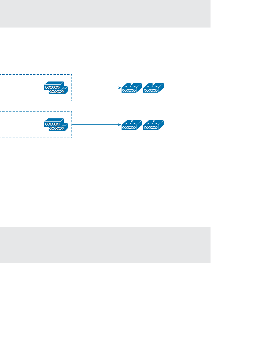
ptg12542968
234 CCNA Wireless 640-722 Official Cert Guide
Tip The 640-722 CCNA Wireless exam covers features found in Controller Software
Release 7.0. AP SSO and client SSO are presented here to provide an overview of more
advanced redundancy mechanisms that are available.
Figure 11-8 depicts AP SSO redundancy. The APs can be configured with only a primary
controller name that references the active unit. Because each active controller has its own
standby controller, there really is no need to configure a secondary or tertiary controller
on the APs unless you need an additional layer of redundancy.
Primary: WLC-A
Secondary:
Tertiary:
Primary: WLC-B
Secondary:
Tertiary:
WLC-A
Active
WLC-A
Standby
WLC-B
Active
WLC-B
Standby
Figure 11-8 Configuring AP SSO Redundancy.
Each AP learns of the HA pair during a CAPWAP discovery phase, then builds a
CAPWAP tunnel to the active controller. The active unit keeps CAPWAP tunnels, AP
states, configurations, and image files all in sync with the hot standby unit. If the active
unit fails, the hot standby unit quickly takes over the active role. The APs do not have to
discover another controller to join; the controllers simply swap roles so the APs can stay
joined to the active controller in the HA pair.
The APs do not even have to rebuild their CAPWAP tunnels after a failure. The tunnels
are synchronized between active and standby, so they are always maintained. The AP
SSO switchover occurs at the controllers—not at the APs.
Tip The active and standby controllers must always run an identical software image.
When one controller is upgraded, its standby peer is also upgraded. That also means
when the active unit is rebooted, the standby unit follows suit. At the time of this writing,
“hitless” in-service software upgrades are not possible.
The hot standby controller monitors the active unit through keepalives that are sent
every 100 ms. If a keepalive is not answered, the standby unit begins to send ICMP echo
requests to the active unit to determine what sort of failure has occurred. For example,
the active unit could have crashed, lost power, or had its network connectivity severed.

ptg12542968
Chapter 11: Understanding Controller Discovery 235
Once standby unit has declared the active unit as failed, it assumes the active role. The
failover may take up to 500 ms, in the case of a crash or power failure, or up to 4 sec-
onds if a network failure has occurred.
AP SSO is designed to keep the failover process transparent from the AP’s perspective.
In fact, the APs know only of the active unit; they are not even aware that the hot stand-
by unit exists. The two controllers share a “mobility” MAC address that initially comes
from the first active unit’s MAC address. From then on, that address is maintained by
whichever unit has the active role at any given time. The controllers also share a virtual
IP address. Keeping both MAC and IP addresses virtual and consistent allows the APs to
stay in contact with the active controller—regardless of which controller currently has
that role.
Even though redundant controllers maintain the state of each AP to minimize any dis-
ruption during a failover, AP SSO does not maintain the state of any clients. If a primary
controller fails, any associated clients will be dropped and will have to reassociate with
their APs (and the secondary controller).
Controller Release 7.5 introduced client SSO to make controller failover seamless to
wireless clients. A primary controller synchronizes the state of each associated client that
is in the RUN state with a secondary controller. If the primary fails, the secondary will
already have the current state information for each client, making the failover process
transparent.
Exam Preparation Tasks
As mentioned in the section, “How to Use This Book,” in the Introduction, you have a
couple of choices for exam preparation: the exercises here, Chapter 22 , “Final Review,”
and the exam simulation questions on the CD-ROM.
Review All Key Topics
Review the most important topics in this chapter, noted with the Key Topic icon in the
outer margin of the page. Table 11-2 lists a reference of these key topics and the page
numbers on which each is found.
Table 11-2 Key Topics for Chapter 11
Key Topic Element Description Page Number
List AP states 224
List Controller discovery methods 226
List Controller selection process 227
Paragraph Controller redundancy methods 231
Key
Topic

ptg12542968
236 CCNA Wireless 640-722 Official Cert Guide
Define Key Terms
Define the following key terms from this chapter and check your answers in the glos-
sary:
AP SSO, CAPWAP Discovery Request, CAPWAP Join Request, client SSO, N+1
redundancy, N+N redundancy, N+N+1 redundancy, primed controller address

ptg12542968
This page intentionally left blank

ptg12542968
This chapter covers the following topics:
■ Roaming with Autonomous APs —This section
reviews the fundamentals of wireless client mobil-
ity between autonomous access points, without the
benefit of a controller.
■ Intracontroller Roaming —This section discusses
wireless client mobility between access points that
are bound to the same controller.
■ Intercontroller Roaming —This section covers wire-
less client mobility between access points that are
bound to different controllers. It also explains how
client mobility can be scaled as a network grows.
This chapter covers the following exam topics:
■ Describe roaming (Layer 2 and Layer 3, intra-con-
troller and inter-controller, and mobility list)

ptg12542968
Wireless client devices are inherently mobile, so you should expect them to move
around. This chapter discusses client mobility from the AP and controller perspectives.
You should have a good understanding of client roaming so that you can design and
configure your wireless network properly as it grows over time.
“Do I Know This Already?” Quiz
The “Do I Know This Already?” quiz allows you to assess whether you should read this
entire chapter thoroughly or jump to the “Exam Preparation Tasks” section. If you are
in doubt about your answers to these questions or your own assessment of your knowl-
edge of the topics, read the entire chapter. Table 12-1 lists the major headings in this
chapter and their corresponding “Do I Know This Already?” quiz questions. You can
find the answers in Appendix A , “Answers to the ‘Do I Know This Already?’ Quizzes.”
Table 12-1 “Do I Know This Already?” Section-to-Question Mapping
Foundation Topics Section Questions
Roaming with Autonomous APs 1–2
Intracontroller Roaming 3–5
Intercontroller Roaming 6–10
Caution The goal of self-assessment is to gauge your mastery of the topics in this chap-
ter. If you do not know the answer to a question or are only partially sure of the answer,
you should mark that question as wrong for purposes of the self-assessment. Giving your-
self credit for an answer you correctly guess skews your self-assessment results and might
provide you with a false sense of security.
CHAPTER 12
Understanding Roaming

ptg12542968
240 CCNA Wireless 640-722 Official Cert Guide
1. When a client moves its association from one autonomous AP to another, it is actu-
ally leaving and joining which one of the following?
a. SSID
b. BSS
c. ESS
d. D S
2.
Which one of the following makes the decision for a device to roam from one AP
to another?
a. The client device
b. The original AP
c. The candidate AP
d. The wireless LAN controller
3.
Ten lightweight APs are joined to a wireless LAN controller. If a client roams from
one of the APs to another, which one of the following correctly describes the
roam?
a. Autonomous roaming
b. Intercontroller roaming
c. Intracontroller roaming
d. Indirect roaming
4. Which one of the following provides the most efficient means for roaming, as mea-
sured by the time to complete the roam?
a. Layer 2 intercontroller roaming
b. Layer 3 intercontroller roaming
c. Intracontroller roaming
d.
All of these answers because each takes an equal amount of time
5.
Which one of the following is used to cache authentication key information to
make roaming more efficient?
a. PGP
b. CCNA
c. CCKM
d. EoIP
6. The term Layer 3 roaming
refers to which one of the following types of client
roam in a CUWN?

ptg12542968
Chapter 12: Understanding Roaming 241
a. Autonomous AP roaming
b. Intracontroller roaming
c. Intercontroller roaming
d. RRM roaming
7.
In a Layer 2 roam, what mechanism is used to tunnel client data between the two
controllers?
a. GRE tunnel
b. EoIP tunnel
c. CAPWAP tunnel
d. None of these answers
8.
When a client roams from one controller to another, it must obtain a new IP address
from a DHCP server. True or false?
a. True
b. False
9.
A client roams from controller A to controller B. If it undergoes a Layer 3 roam,
which one of the following best describes the role of controller A?
a. Foreign controller
b. Host controller
c. Master controller
d. Anchor controller
10.
A network consists of three controllers: A, B, and C. The mobility group lists of
controllers A and B are shown here. Which one of the following answers describes
what will happen when a client tries to roam between controllers A and B?
Controller A
00:00:00:11:11:11 192.168.1.1 group1
00:00:00:22:22:22 192.168.1.2 group2
00:00:00:33:33:33 192.168.1.3 group3
Controller B
00:00:00:22:22:22 192.168.1.2 group2
00:00:00:11:11:11 192.168.1.1 group1
00:00:00:33:33:33 192.168.1.3 group3
a. Roaming is seamless and efficient.
b. Roaming is not possible.
c. Roaming is possible, but CCKM and PKC will not work.
d. Only Layer 3 roaming is possible.

ptg12542968
242 CCNA Wireless 640-722 Official Cert Guide
When a wireless client moves about, the expectations are simple—good, seamless cover-
age wherever the client goes. Clients know how to roam between access points (APs),
but they are ignorant about the wireless network infrastructure. Even in a large network,
roaming should be easy, quick, and not disrupt the client’s service.
Cisco Unified Wireless Networks offer several roaming strategies. From your perspec-
tive as a wireless engineer, roaming configuration is straightforward. The inner workings
can be complex, depending on the size of the wireless network as measured by the num-
ber of APs and controllers. As you work through the sections in this chapter, you will
review roaming fundamentals, then learn more about how the Cisco Unified Wireless
Network (CUWN) handles client roaming and how to configure your controllers to sup-
port it properly.
Foundation Topics
Roaming with Autonomous APs
In Chapter 6 , “Understanding 802.11 Frame Types,” you learned that a wireless client
can move from one basic service set (BSS) to another by roaming between APs. A cli-
ent continuously evaluates the quality of its wireless connection. If the signal quality
degrades, the client begins looking for an AP with a better signal. The process is usually
quick and simple; active scanning reveals candidate APs, and then the client selects one
and tries to reassociate with it.
Figure 12-1 shows a simple scenario with two APs and one client. The client begins with
an association to AP-1. Because the APs are running in autonomous mode, each one
maintains a table of its associated clients. AP-1 has one client; AP-2 has none.
Suppose that the client then begins to move into AP-2’s cell. Somewhere near the cell
boundary, the client decides to roam and reassociate with AP-2. Figure 12-2 shows the
new scenario after the roam occurs. Notice that both APs have updated their list of asso-
ciated clients to reflect Client-1’s move from AP-1 to AP-2. If AP-1 still has any leftover
wireless frames destined for the client after the roam, it forwards them to AP-2 over
the wired infrastructure—simply because that is where the client’s MAC address now
resides.
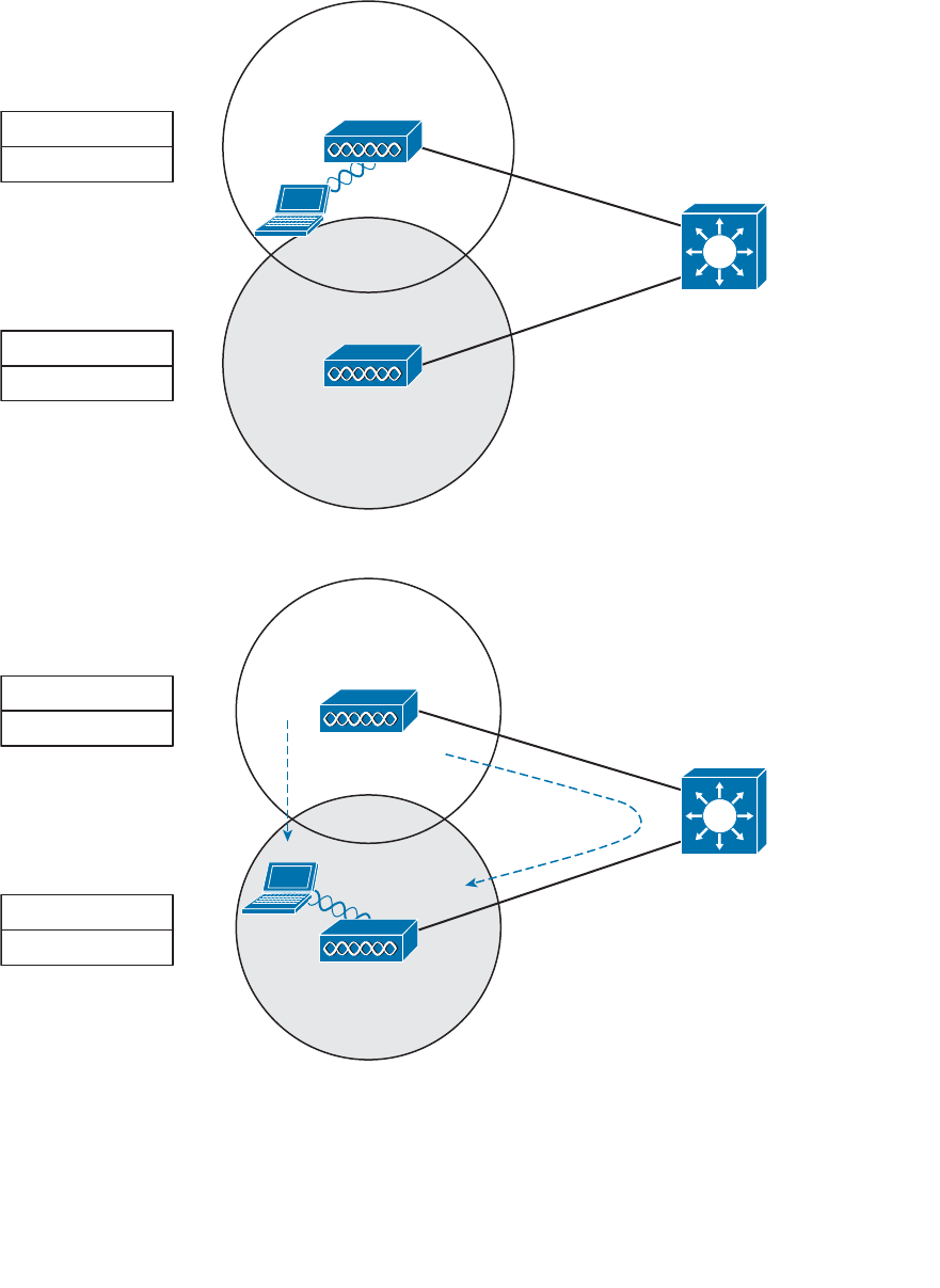
ptg12542968
Chapter 12: Understanding Roaming 243
AP-1
AP-2
Client-1
AP-1 Associations
Client-1
SSID Staff
192.168.100.0/24
SSID Staff
192.168.100.0/24
AP-2 Associations
Client-1’s
Buffered Data
Figure 12-2 After Roaming Between Autonomous APs.
AP-1
AP-2
Client-1
AP-1 Associations
Client-1
SSID Staff
192.168.100.0/24
SSID Staff
192.168.100.0/24
AP-2 Associations
Figure 12-1 Before Roaming Between Autonomous APs.
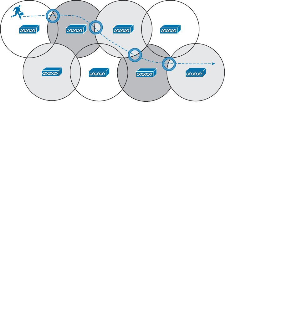
ptg12542968
244 CCNA Wireless 640-722 Official Cert Guide
Naturally, roaming is not limited to only two APs; instead, it occurs between two APs
at any given time. To cover a large area, you will probably install many APs in a pattern
such that their cells overlap. Figure 12-3 shows a typical pattern. When a wireless client
begins to move, it might move along an arbitrary path. Each time the client decides that
the signal from one AP has degraded enough, it attempts to roam to a new, better signal
from a different AP and cell. The exact location of each roam depends on the client’s
roaming algorithm. To illustrate typical roaming activity, each roam in Figure 12-3 is
marked with a dark ring.
Figure 12-3 Successive Roams of a Mobile Client.
Intracontroller Roaming
In a CUWN, lightweight APs are bound to a wireless LAN controller through CAPWAP
tunnels. The roaming process is similar to that of autonomous APs; clients must still reas-
sociate to new APs as they move about. The only real difference is that the controller
handles the roaming process because of the split-MAC architecture.
Figure 12-4 shows a two-AP scenario where both APs connect to a single controller.
Client-1 is associated to AP-1, which has a Control and Provisioning of Wireless Access
Points (CAPWAP) tunnel to controller WLC-1. The controller maintains a client data-
base that contains detailed information about how to reach and support each client. For
simplicity, Figure 12-4 shows the database as a list of its APs, associated clients, and the
wireless LAN (WLAN) being used. The actual database also contains client MAC and IP
addresses, quality of service (QoS) parameters, and other information.
When Client-1 starts moving, it eventually roams to AP-2, as shown in Figure 12-5 . Not
much has changed except that the controller has updated the client association from
AP-1 to AP-2. Because both APs are bound to the same controller, the roam occurs
entirely within the controller. This is known as intra controller roaming.
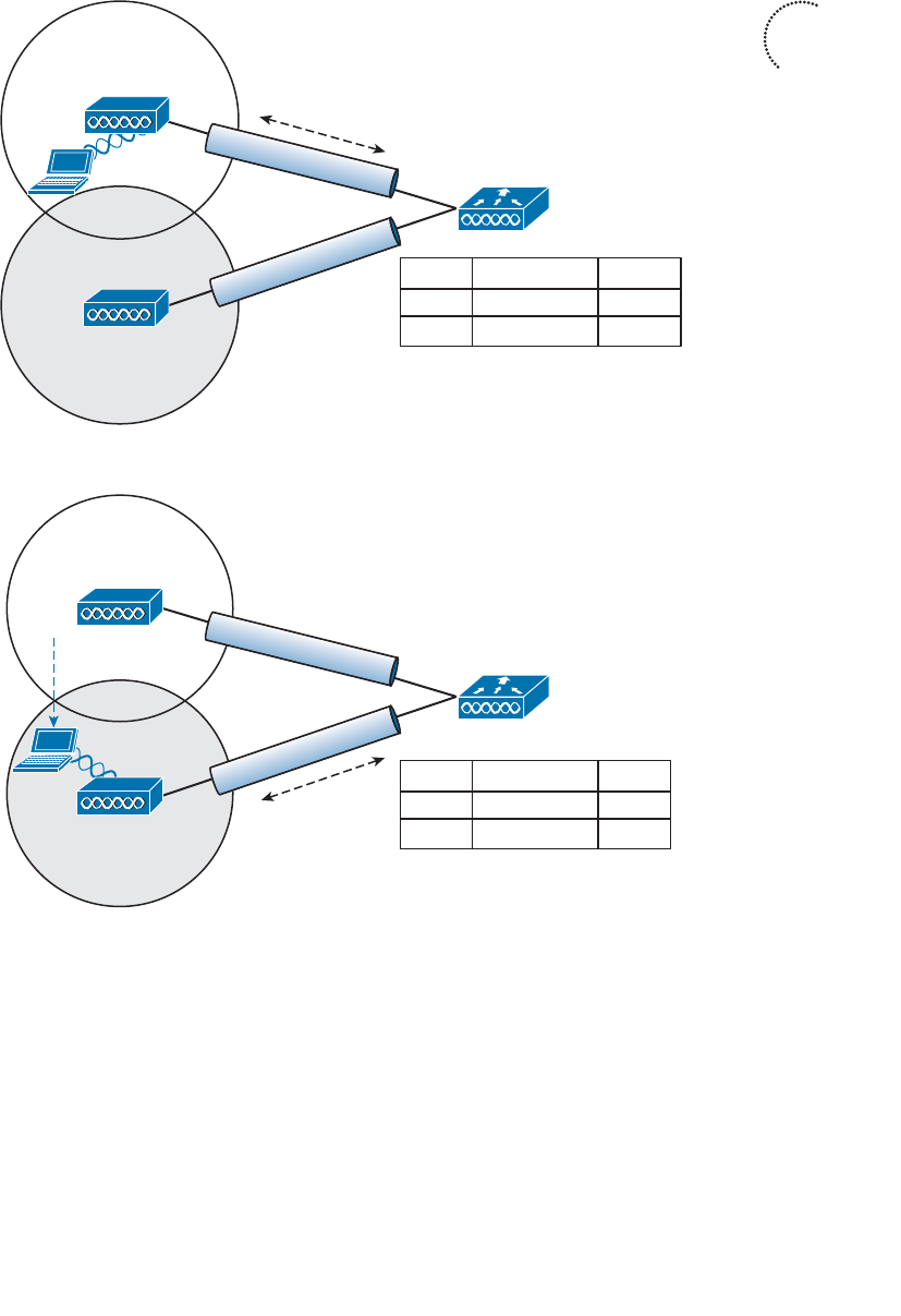
ptg12542968
Chapter 12: Understanding Roaming 245
AP-1
AP-2
AP-2
CAPWAP
CAPWAP
AP-1
Client-1
Client-1
WLC-1
AP Associations WLAN
Staff
SSID Staff
192.168.100.0/24
SSID Staff
192.168.100.0/24
Figure 12-5 A CUWN After an Intracontroller Roam.
If both APs involved in a client roam are bound to the same controller, the roaming pro-
cess is simple and efficient. The controller has to update its client association table so
that it knows which CAPWAP tunnel to use to reach the client. Thanks to the simplicity,
an intracontroller roam takes less than 10 ms to complete—the amount of processing
time needed for the controller to switch the client entry from AP-1 to AP-2. From the
client’s perspective, an intracontroller roam is no different than any other roam. The
client has no knowledge that the two APs are communicating with a controller over
CAPWAP tunnels; it simply decides to roam between two APs based on its own signal
analysis.
AP-1
AP-2
AP-2
CAPWAP
CAPWAP
AP-1
Client-1
Client-1
WLC-1
AP Associations WLAN
Staff
SSID Staff
192.168.100.0/24
SSID Staff
192.168.100.0/24
Figure 12-4 A CUWN Before an Intracontroller Roam.
Key
Topic

ptg12542968
246 CCNA Wireless 640-722 Official Cert Guide
Efficient roaming is especially important when time-critical applications are being used
over the wireless network. For example, wireless phones need a consistent connection so
that the audio stream is not garbled or interrupted. When a roam occurs, there could be
a brief time when the client is not fully associated with either AP. So long as that time is
held to a minimum, the end user probably will not even notice that the roam occurred.
Along with the client reassociation, a couple of other processes can occur:
■ DHCP —The client may be programmed to renew the DHCP lease on its IP address
or to request a new address.
■ Client authentication —The controller might be configured to use an 802.1x meth-
od to authenticate each client on a WLAN.
To achieve efficient roaming, both of these processes should be streamlined as much as
possible. For instance, if a client roams and tries to renew its IP address, it is essentially
cut off from the network until the Dynamic Host Controller Protocol (DHCP) server
responds.
The client authentication process presents the biggest challenge because the dialog
between a controller and a RADIUS server, in addition to the cryptographic keys that
need to be generated and exchanged between the client and an AP or controller, can
take a considerable amount of time to accomplish. Cisco controllers offer three tech-
niques to minimize the time and effort spent on key exchanges during roams:
■ Cisco Centralized Key Management (CCKM) —One controller maintains a data-
base of clients and keys on behalf of its APs and provides them to other controllers
and their APs as needed during client roams. CCKM requires Cisco Compatibility
Extensions (CCX) support from clients.
■ Proactive key caching (PKC) —Each client maintains a list of keys used with prior
AP associations and presents them as it roams. The destination AP must be present
in this list, which is limited to eight AP-key entries. PKC is also known as sticky pair-
wise master key ID caching (SKC).
■ 802.11r —An 802.11 amendment that addresses fast roaming or fast BSS transition;
a client can cache a portion of the authentication server’s key and present that to
future APs as it roams. The client can also maintain its QoS parameters as it roams.
Each of the fast roaming strategies requires help on the part of the wireless client. That
means the client must have a supplicant or driver software that is compatible with fast
roaming and can cache the necessary pieces of the authentication credentials.
Intercontroller Roaming
As a wireless network grows, one controller might not suffice. When two or more con-
trollers support the APs in an enterprise, the APs are distributed across them. As always,
when clients become mobile, they roam from one AP to another—except they could
also be roaming from one controller to another, depending on how neighboring APs are
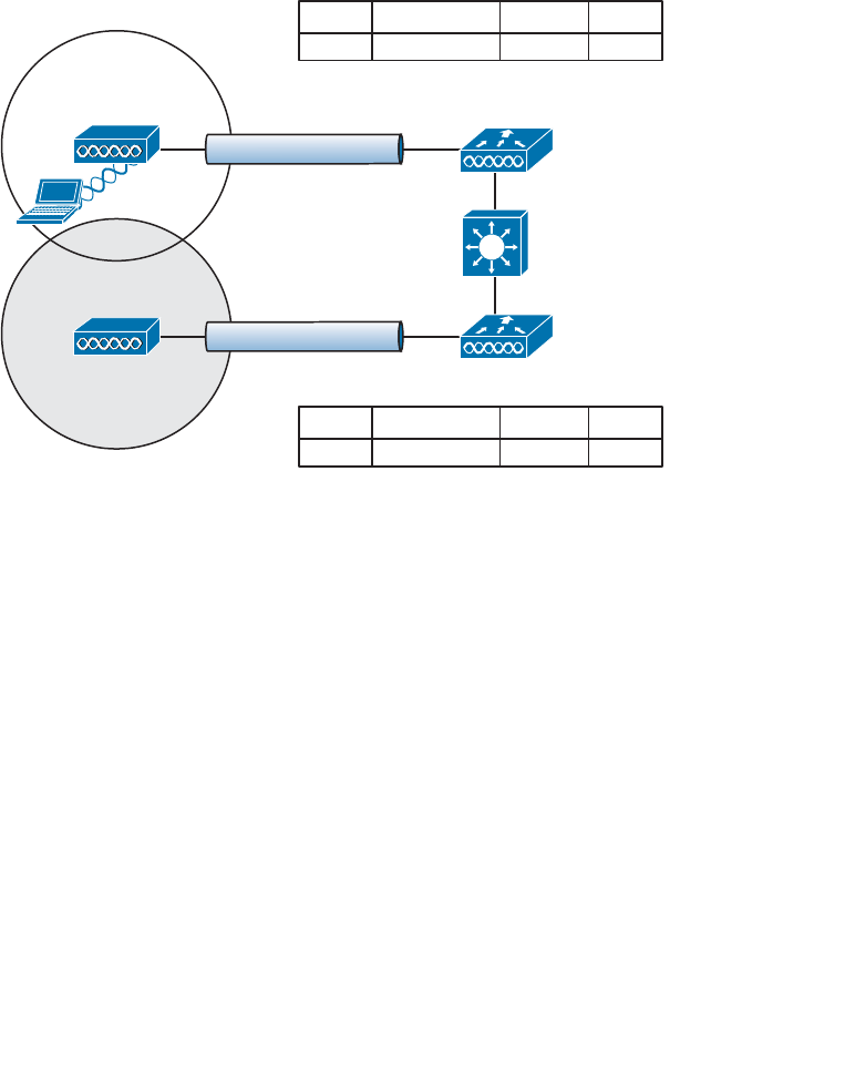
ptg12542968
Chapter 12: Understanding Roaming 247
assigned to the controllers. The following sections cover the two types of intercontroller
roaming that are possible.
Layer 2 Roaming
When a client roams from one AP to another and those APs lie on two different control-
lers, the client makes an intercontroller roam. Figure 12-6 shows a simple scenario prior
to a roam. Controller WLC-1 has one association in its database—that of Client-1 on
AP-1. Figure 12-7 shows the result of the client roaming to AP-2.
AP-2
SSID Staff
192.168.100.0/24
AP-1
Client-1
192.168.100.199
WLC-1
WLC-2
CAPWAP
CAPWAP
VLAN 100
VLAN 100
SSID Staff
192.168.100.0/24
AP-1 Client-1 Staff
AP Associations WLAN
100
VLAN
AP-2
AP Associations WLAN VLAN
Figure 12-6 Before an Intercontroller Roam.
The roam itself is fairly straightforward. When the client decides to roam and reassoci-
ate itself with AP-2, the two controllers must coordinate the move. One subtle detail
involves the client’s IP address. Before the roam, Client-1 is associated with AP-1 and
takes an IP address from the VLAN and subnet that are configured on the WLAN sup-
plied by controller WLC-1. In Figure 12-6 , WLAN Staff is bound to VLAN 100, so the
client uses an address from the 192.168.100.0/24 subnet.
When the client roams to a different AP, it can try to continue using its existing IP
address or work with a DHCP server to either renew or request an address. Figure 12-7
shows the client roaming to AP-2, where WLAN Staff is also bound to the same VLAN
100 and 192.168.100.0/24 subnet. Because the client has roamed between APs but
stayed on the same VLAN and subnet, it has made a Layer 2 intercontroller roam. Layer
2 roams (commonly called local-to-local roams) are nice for two reasons: The client can
keep its same IP address, and the roam is fast (usually less than 20 ms).
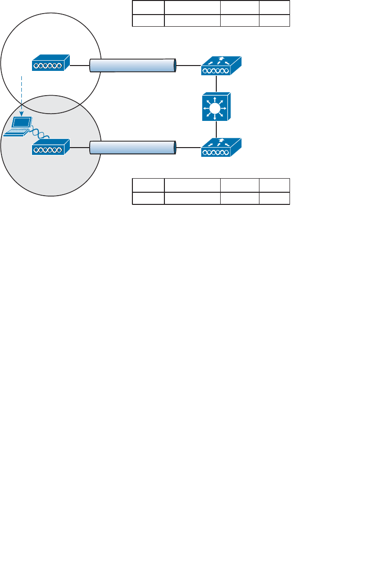
ptg12542968
248 CCNA Wireless 640-722 Official Cert Guide
Layer 3 Roaming
What if a wireless network grows even more, such that the WLAN interfaces on each
controller are assigned to different VLANs and subnets? Breaking a very large WLAN
up into individual subnets seems like a good idea from a scalability viewpoint. However,
when a wireless client roams from one controller to another, it could easily end up on a
different subnet than it started with.
Clients will not usually be able to detect that they have changed subnets. They will be
aware of the AP roam but little else. Only clients that aggressively contact a DHCP serv-
er after each and every roam will continue to work properly. But to make roaming seam-
less and efficient, time-consuming processes such as DHCP should be avoided.
No worries—the CUWN has a clever trick up its sleeve. When a client initiates an inter-
controller roam, the two controllers involved can compare the VLAN numbers that are
assigned to their respective WLAN interfaces. If the VLAN IDs are the same, nothing
special needs to happen; the client undergoes a Layer 2 intercontroller roam and can
continue to use its original IP address on the new controller. If the two VLAN IDs differ,
the controllers arrange a Layer 3 roam (also known as a local-to-foreign roam) that will
allow the client to keep using its IP address.
Figure 12-8 illustrates a simple wireless network containing two APs and two control-
lers. Notice that the two APs offer different IP subnets in their BSSs: 192.168.100.0/24
and 192.168.200.0/24. The client is associated with AP-1 and is using IP address
192.168.100.199. On the surface, it looks like the client will roam into subnet
192.168.200.0/24 if it wanders into AP-2’s cell, and will lose connectivity if it tries to
keep using its same IP address.
AP-1
AP-2
SSID Staff
192.168.100.0/24
SSID Staff
192.168.100.0/24
Client-1
192.168.100.199
WLC-1
CAPWAP
CAPWAP
WLC-2
VLAN 100
VLAN 100
AP-1
Client-1 Staff
AP Associations WLAN
100
VLAN
AP-2
AP Associations WLAN VLAN
Figure 12-7 After an Intercontroller Roam.
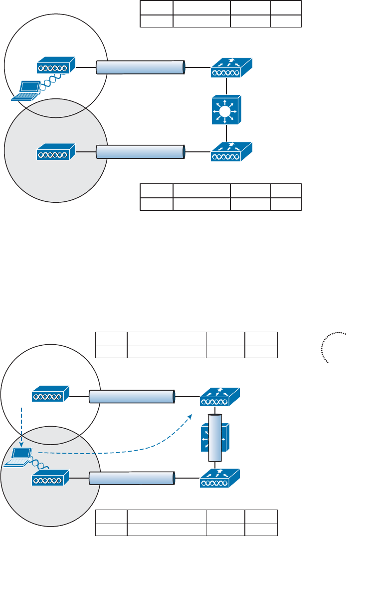
ptg12542968
Chapter 12: Understanding Roaming 249
AP-2
SSID Staff
192.168.200.0/24
AP-1
Client-1
192.168.100.199
WLC-1
CAPWAP
CAPWAP
WLC-2
VLAN 100
VLAN 100
SSID Staff
192.168.100.0/24
AP-1 Client-1 Staff
AP Associations WLAN
100
VLAN
AP-2
AP Associations WLAN VLAN
Figure 12-8 Before a Layer 3 Intercontroller Roam.
A Layer 3 intercontroller roam consists of an extra tunnel that is built between the client’s
original controller and the controller it has roamed to. The tunnel carries data to and from
the client as if it is still associated with the original controller and IP subnet. Figure 12-9
shows the results of a Layer 3 roam. The original controller (WLC-1) is called the anchor
controller , and the controller with the roamed client is called the foreign controller . Think
of the client being anchored to the original controller no matter where it roams later.
When the client roams away from its anchor, it moves into foreign territory.
AP-1
AP-2
SSID Staff
192.168.100.0/24
SSID Staff
192.168.200.0/24
Client-1
192.168.100.199
WLC-1
CAPWAP
CAPWAP
WLC-2
VLAN 100
Anchor Controller
Foreign Controller
VLAN 200
WLC-2 Client-1 (Mobile) Staff
AP Associations WLAN
100
VLAN
AP-2 Client-1 Staff
AP Associations WLAN VLAN
EoIP
Figure 12-9 After a Layer 3 Intercontroller Roam.
Key
Topic
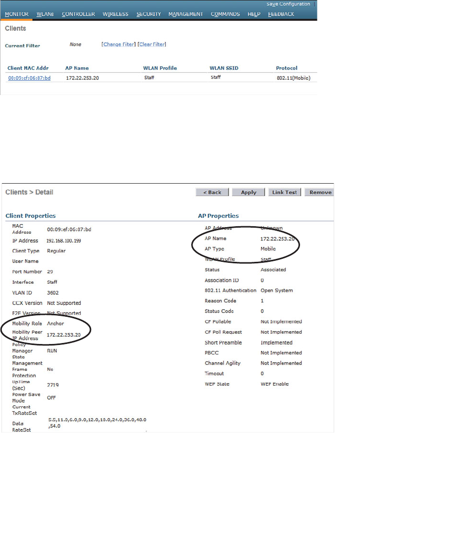
ptg12542968
250 CCNA Wireless 640-722 Official Cert Guide
You can see clients that have undergone a Layer 3 roam by selecting Monitor > Clients
from the controller graphical user interface (GUI). The client from Figures 12-8 and 12-9
is shown in the WLC-1 client list displayed in Figure 12-10 . Notice that the client’s pro-
tocol is shown as 802.11(Mobile); other clients would be listed as 802.11 only.
You can click the client’s MAC address to see more details about its state. In Figure
12-11 , you can see that the controller has mobility role Anchor and that the Layer 3
mobility peer is 172.22.253.20, or WLC-2.
Figure 12-10 Displaying Clients with a Layer 3 Intercontroller Roam.
Figure 12-11 Displaying Client Details on the Anchor Controller.
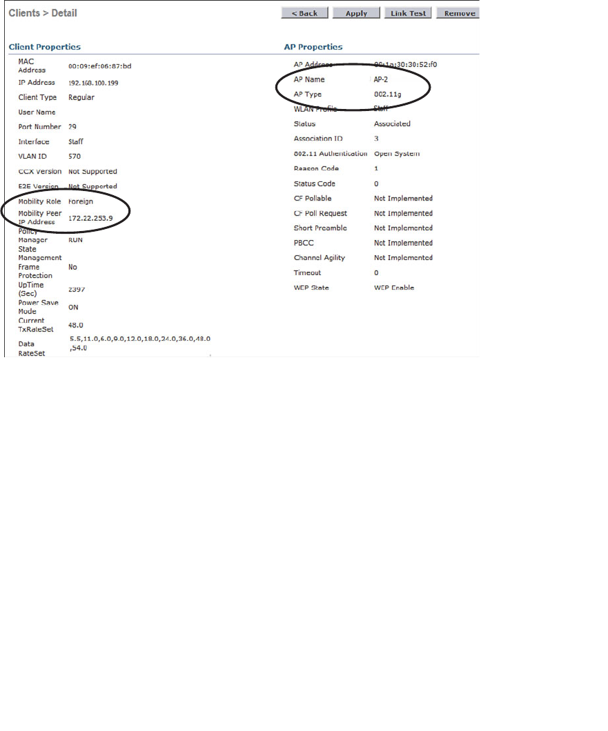
ptg12542968
Chapter 12: Understanding Roaming 251
Due to the Layer 3 roam, the client should have an active association with both the
anchor and foreign controllers. On the foreign controller, you can view the client details
from a different perspective. In Figure 12-12 , the client is shown associated with a for-
eign controller with IP address 172.22.253.9, or WLC-1. On the foreign controller, the
client is associated to an actual AP (AP-2) with a normal AP type.
Cisco controllers have traditionally used Ethernet over IP (EoIP) tunnels between con-
trollers for Layer 3 roaming. Beginning with controller software releases 7.3.112.0, Layer
3 roaming uses a “new mobility” strategy, with CAPWAP tunnels rather than EoIP.
Regardless of the tunnel type, be aware that the controller-to-controller tunnel makes
each Layer 3 roam possible.
You should also know that the tunnel tethers the client to its original anchor control-
ler (and original IP subnet), regardless of its location or how many controllers it roams
through. For example, in Figure 12-13 , the client has roamed from AP-1 to AP-2 to
AP-3, and from WLC-1 to WLC-2 to WLC-3, respectively. Although each controller
offers a different IP subnet for the client to use, the client can keep using its original
192.168.100.199 address. While the client is on AP-2 and WLC-2, a Layer 3 roam tunnel
is built from WLC-2 to anchor controller WLC-1. Then when the client finally lands on
AP-3 and WLC-3, WLC-3 builds a Layer 3 roam tunnel back to anchor controller WLC-1.
Figure 12-12 Displaying Client Details on the Foreign Controller.
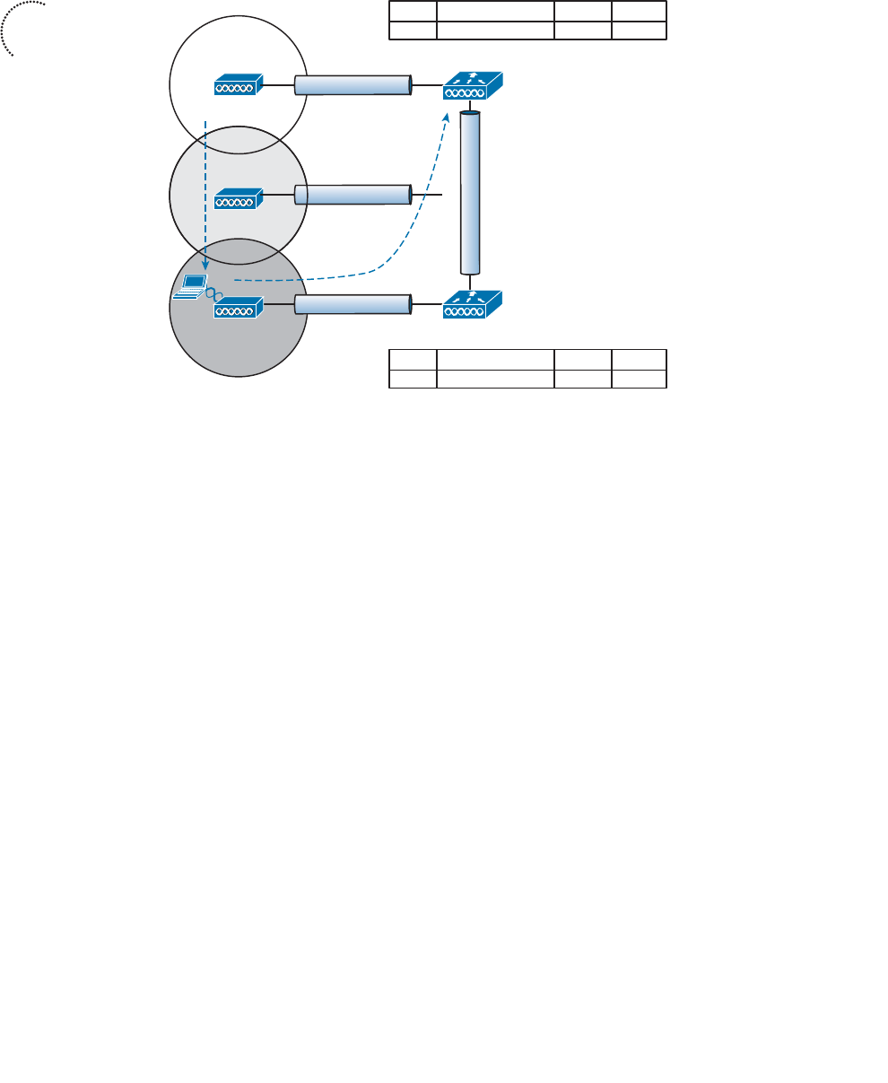
ptg12542968
252 CCNA Wireless 640-722 Official Cert Guide
Anchor and foreign controllers are normally determined automatically. When a client
first associates with an AP and controller, that controller becomes its anchor controller.
When the client roams to a different controller, that controller can take on the for-
eign role. Sometimes you might not want a client’s first controller to be its anchor. For
example, guest users should not be allowed to associate with just any controller in your
network. Instead, you might want guests to be forced onto a specific controller that is
situated behind a firewall or contained in a protected environment. You can configure
one controller to be a static anchor for a WLAN so that other controllers will direct cli-
ents toward it through Layer 3 roaming tunnels. Static anchor controllers are covered in
more detail in Chapter 16 , “Implementing a Wireless Guest Network.”
Using Mobility Groups
Cisco controllers can be organized into mobility groups to facilitate intercontroller
roaming. Mobility groups become important as a wireless network scales and there are
more controllers cooperating to provide coverage over a large area.
If two controllers are configured to belong to the same mobility group, clients can roam
quickly between them. Layer 2 and Layer 3 roaming are both supported, along with
CCKM, PKC, and 802.11r credential caching. If two controllers are assigned to different
mobility groups, clients can still roam between them, but the roam is not very efficient.
Credentials are not cached and shared, so clients must go through a full authentication
during the roam.
Key
Topic
AP-1
AP-2
AP-3
SSID Staff
192.168.100.0/24
SSID Staff
192.168.200.0/24
SSID Staff
192.168.250.0/24
Client-1
192.168.100.199
WLC-1
WLC-3
VLAN 100
CAPWAP
CAPWAP
CAPWAP
VLAN 250
Anchor Controller
Foreign Controller
WLC-3 Client-1 (Mobile) Staff
AP Associations WLAN
100
VLAN
AP-3 Client-1 Staff
AP Associations WLAN VLAN
EoIP
WLC-2
VLAN 200
Figure 12-13 Layer 3 Roaming Across Multiple Controllers.
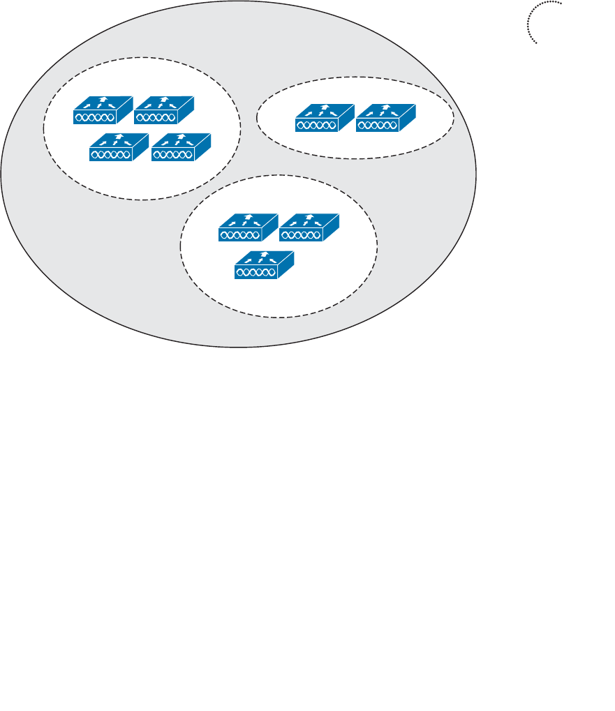
ptg12542968
Chapter 12: Understanding Roaming 253
Mobility groups have an implied hierarchy as shown in Figure 12-14 . Each controller
maintains a mobility list that contains its own MAC address and the MAC addresses of
other controllers. Each controller in the list is also assigned a mobility group name. In
effect, the mobility list gives a controller its view of the outside world; it knows of and
trusts only the other controllers configured in the list. If two controllers are not listed in
each other’s mobility list, they are unknown to each other and clients will not be able to
roam between them. Clients will have to associate and authenticate from scratch.
You can think of this list as a mobility domain. The list can contain up to 72 controllers,
with up to 24 controllers in each mobility group.
You must configure each controller with a mobility group name. Go to Controller >
General and enter the group name in the Default Mobility Domain Name field. In Figure
12-15 , the controller has been assigned to Group1.
Next, populate the controller’s mobility list with other controllers and their mobil-
ity group names. You can see the current list by selecting Controller > Mobility
Management > Mobility Groups , as shown in Figure 12-16 .
s
s
s
WLC-7
WLC-5
WLC-3
WLC-1 WLC-2
WLC-4
WLC-8 WLC-9
WLC-6
Mobility Group “Group1”
Mobility Group “Group2”
Mobility Group “Group3”
Mobility Domain
Figure 12-14 Mobility Group Hierarchy.
Key
Topic
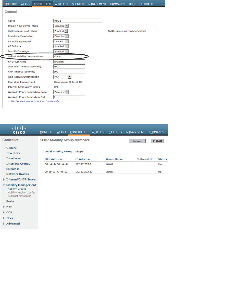
ptg12542968
254 CCNA Wireless 640-722 Official Cert Guide
Figure 12-16 Displaying a Controller’s Mobility Group Member List.
To add a new controller to the list, you can click the New button, and then enter the
controller’s IP address, MAC address, and mobility group name, as shown in Figure
12-17 . Click the Apply button when you finish.
If you have several controllers to add or if you need to make changes to the list, you can
click the Edit All button. This will bring up a page that allows you to edit the list as one
complete text box. You can make simple edits or copy and paste an entire list from your
Figure 12-15 Configuring the Default Mobility Group Name.
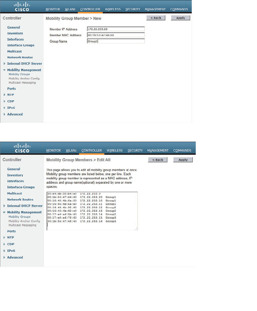
ptg12542968
Chapter 12: Understanding Roaming 255
computer. Figure 12-18 shows a list of controllers that has been input corresponding to
the mobility grouping from Figure 12-14 . Notice that the first controller in the list does
not have an explicit mobility group name. That is because the first controller is the one
that is hosting the list and the web interface. Its mobility group is configured elsewhere
as part of the general controller settings.
Figure 12-17 Adding a New Mobility Group List Entry.
Figure 12-18 Editing the Mobility Group List.

ptg12542968
256 CCNA Wireless 640-722 Official Cert Guide
Exam Preparation Tasks
As mentioned in the section, “How to Use This Book,” in the Introduction, you have a
couple of choices for exam preparation: the exercises here, Chapter 22 , “Final Review,”
and the exam simulation questions on the CD-ROM.
Review All Key Topics
Review the most important topics in this chapter, noted with the Key Topic icon in the
outer margin of the page. Table 12-2 lists a reference of these key topics and the page
numbers on which each is found.
Table 12-2 Key Topics for Chapter 12
Key Topic Element Description Page Number
Figures 12-4 and 12-5 Intracontroller roaming 245
Figure 12-9 Intercontroller roaming 249
Figure 12-13 Intercontroller roaming across a network 252
Figure 12-14 Mobility group hierarchy 253
Define Key Terms
Define the following key terms from this chapter and check your answers in the
glossary:
anchor controller, foreign controller, intercontroller roaming, intracontroller
roaming, Layer 2 roam, Layer 3 roam, mobility group
Key
Topic

ptg12542968
This page intentionally left blank

ptg12542968
This chapter covers the following topics:
■ Configuring 802.11 Support —This section
explains how to configure the data rates in the
2.4- and 5-GHz bands and support for 802.11n high-
throughput functionality.
■ Understanding RRM —This section describes the
algorithms that can monitor and adjust radio
frequency parameters automatically in a wireless
network.
This chapter covers the following exam topics:
■ Describe Radio Resource Management (RRM) fun-
damentals including ED-RRM

ptg12542968
In Chapter 7 , “Planning Coverage with Wireless APs,” you learned how to size access
point (AP) cells appropriately by disabling data rates and changing the transmit power
levels. You also learned how important a proper channel layout is to promote efficient
roaming and minimize co-channel interference. You probably also realized how difficult
these tasks are when you have to tune the radio frequency (RF) parameters manually
across a large number of APs.
In this chapter, you learn about Radio Resource Management (RRM), a flexible and
automatic mechanism that Cisco Wireless LAN controllers can use to make your life
much easier.
“Do I Know This Already?” Quiz
The “Do I Know This Already?” quiz allows you to assess whether you should read this
entire chapter thoroughly or jump to the “Exam Preparation Tasks” section. If you are
in doubt about your answers to these questions or your own assessment of your knowl-
edge of the topics, read the entire chapter. Table 13-1 lists the major headings in this
chapter and their corresponding “Do I Know This Already?” quiz questions. You can
find the answers in Appendix A , “Answers to the ‘Do I Know This Already?’ Quizzes.”
Table 13-1 “Do I Know This Already?” Section-to-Question Mapping
Foundation Topics Section Questions
Configuring 802.11 Support 1–4
Understanding RRM 5–10
Caution The goal of self-assessment is to gauge your mastery of the topics in this chap-
ter. If you do not know the answer to a question or are only partially sure of the answer,
you should mark that question as wrong for purposes of the self-assessment. Giving your-
self credit for an answer you correctly guess skews your self-assessment results and might
provide you with a false sense of security.
CHAPTER 13
Understanding RRM

ptg12542968
260 CCNA Wireless 640-722 Official Cert Guide
1.
Which one of the following correctly describes a mandatory data rate?
a.
The data rate must be used by wireless clients all the time.
b.
The highest data rate used by an AP and its clients.
c.
A data rate that must be supported by a client before it can associate with an
AP.
d.
A data rate required by the IEEE 802.11 standards body.
2.
You can configure only one data rate as mandatory on an AP. True or false?
a. True
b. False
3.
An AP sends 802.11 broadcast management frames at which one of the following
data rates?
a.
The highest mandatory data rate
b.
The lowest mandatory data rate
c.
The lowest supported data rate
d. All supported data rates
4.
Which one of the following is the default state of 802.11n support and the default
channel width on a Cisco wireless LAN controller?
a. Disabled; 20-MHz channels
b. Enabled; 20-MHz channels
c. Enabled; 40-MHz channels
d. Disabled; 40-MHz channels
5.
Which one of the following correctly identifies the scope of the RRM algorithms?
a.
All APs joined to one controller
b.
All APs joined to all controllers
c.
All APs joined to controllers in an RF group
d. All APs of a specific model

ptg12542968
Chapter 13: Understanding RRM 261
6.
An RF group is automatically formed by which one of the following?
a.
All APs that share the same channel
b.
All clients that share the same SSID
c.
Any controllers that can overhear neighbor messages with identical RF group
names sent between their APs
d.
All controllers that can overhear neighbor messages with identical mobility
group names sent between their APs
7.
The TPC algorithm is used for which one of the following purposes?
a.
To adjust the transmission control protocol rate
b.
To detect problems in transmission perimeter coverage
c.
To adjust the transmitting primary channel
d. To adjust the transmit power level
8.
If the DCA algorithm detects that an AP is experiencing interference or excessive
noise, what might it do to mitigate the problem?
a.
Increase the AP’s transmit power level
b.
Decrease the AP’s transmit power level
c.
Change the AP’s channel number
d. Direct the client to a different band
9.
Which one of the following runs the DCA algorithm?
a. RF group leader
b. Master controller
c. Each controller
d. NCS or Cisco Prime Infrastructure
10.
The 2.4-GHz radio in one of several APs in a building has failed. Which one of the
following algorithms should be able to detect the failure?
a. CCA
b. DCA
c. Dead radio detection
d. Coverage hole detection
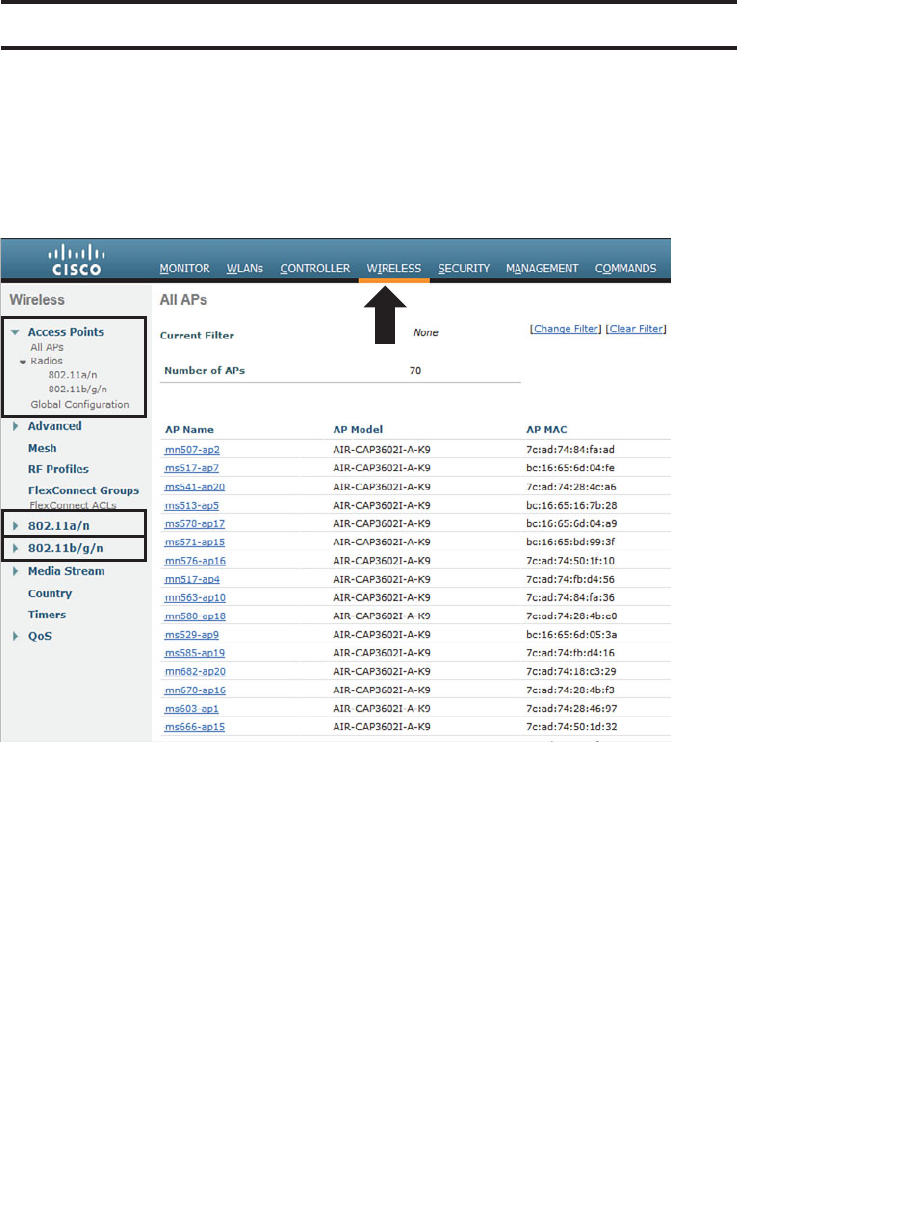
ptg12542968
262 CCNA Wireless 640-722 Official Cert Guide
Foundation Topics
Configuring 802.11 Support
Cisco controllers and most APs can support wireless LANs in both the 2.4- and 5-GHz
bands. By default, both bands are enabled; however, you can view or change a number
of parameters by browsing to the Wireless tab in the controller, shown in Figure 13-1 .
Figure 13-1 The Wireless Tab on a Cisco Controller GUI.
The wireless parameters are organized under a list of links that are found on the left side
of the web page. At the CCNA level, you should be familiar with the following links:
■ Access Points —Used to verify and configure RF things like transmit power level
and channel number on individual APs
■ 802.11a/n —Used to configure global parameters for the 5-GHz band
■ 802.11b/g/n —Used to configure global parameters for the 2.4-GHz band
The initial web page displays a list of all APs that are currently joined to the controller,
as if you had selected Wireless > Access Points > All APs . The remaining configuration
is covered in the sections that follow.
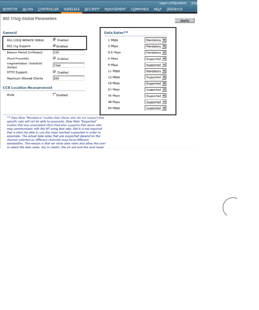
ptg12542968
Chapter 13: Understanding RRM 263
Configuring Data Rates
You can enable or disable the 2.4- or 5-GHz bands by selecting 802.11b/g/n or
802.11a/n , respectively, and then clicking the Network link. Figures 13-2 and 13-3
show the two network configuration pages. Make sure that the 802.11b/g or 802.11a
Network Status check box is checked to enable the 2.4- or 5-GHz radios on all APs.
Figure 13-2 Configuring 2.4-GHz Radios.
On the right side of the network web pages, as shown in Figures 13-2 and 13-3 , you
can configure the individual data rates (and the corresponding modulation and coding
schemes) that are supported on each band. Each data rate can have one of the following
states:
■ Mandatory —A client must be able to use the data rate and Modulation Coding
Scheme (MCS) to associate with an AP.
■ Supported —A client can associate with an AP even if it cannot use the data rate.
■ Disabled —An AP will not use the data rate with any clients.
By default, all data rates are enabled and supported. In the 2.4-GHz band, the 1-, 2-, 5.5-,
and 11-Mbps rates are all marked as mandatory, based on the initial IEEE requirement
that all clients be able to support each possible modulation type defined in 802.1b. In
the 5-GHz band, the 6-, 12-, and 24-Mbps rates are marked as mandatory.
Key
Topic
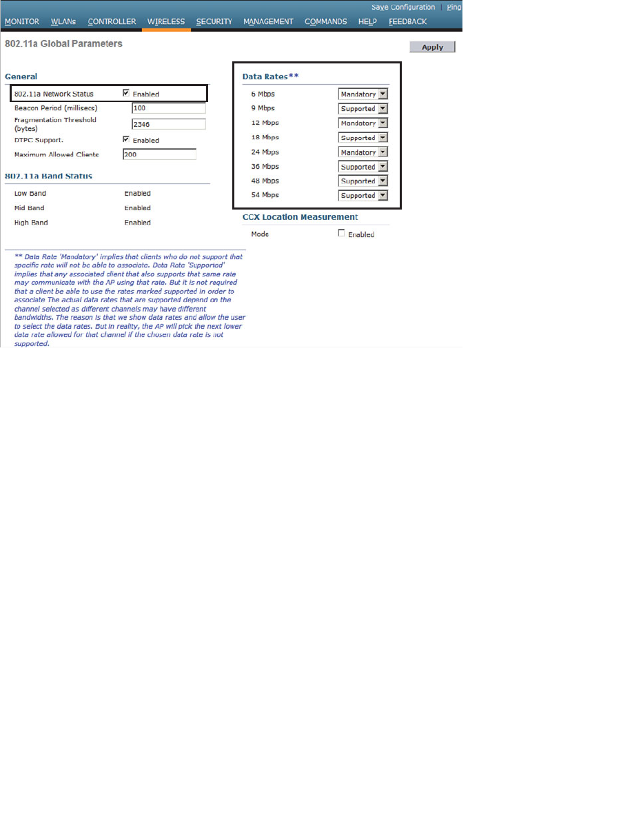
ptg12542968
264 CCNA Wireless 640-722 Official Cert Guide
You can change the state of any data rate by selecting a new state from the drop-down
menu. Remember that you can disable lower data rates to decrease the AP cell size and
make channel use more efficient. Just make sure that your actions do not shrink the cells
too much, leaving holes or gaps in the coverage between APs. Also be sure that all of
your wireless clients can use the same set of mandatory and supported data rates.
Be sure to click the Apply button to make any configuration changes active. Any wire-
less networks that are already in production on the controller might be disrupted while
the new configuration takes effect.
Configuring 802.11n Support
You might have noticed that you can configure plenty of data rates, but 802.11n is never
mentioned on the wireless network configuration pages. That is because 802.11n is con-
sidered to be a rich set of high-throughput enhancements to both 802.11g and 802.11a
and must be configured separately.
By default, 802.11n is enabled. To check or change its state, go to Wireless > 802.11a/n
or 802.11b/g/n > High Throughput (802.11n) . Figure 13-4 shows the 5-GHz 802.11n
configuration page. 802.11n is enabled when the 11n Mode check box is checked. By
default, every possible MCS is enabled and supported.
Figure 13-3 Configuring 5-GHz Radios.
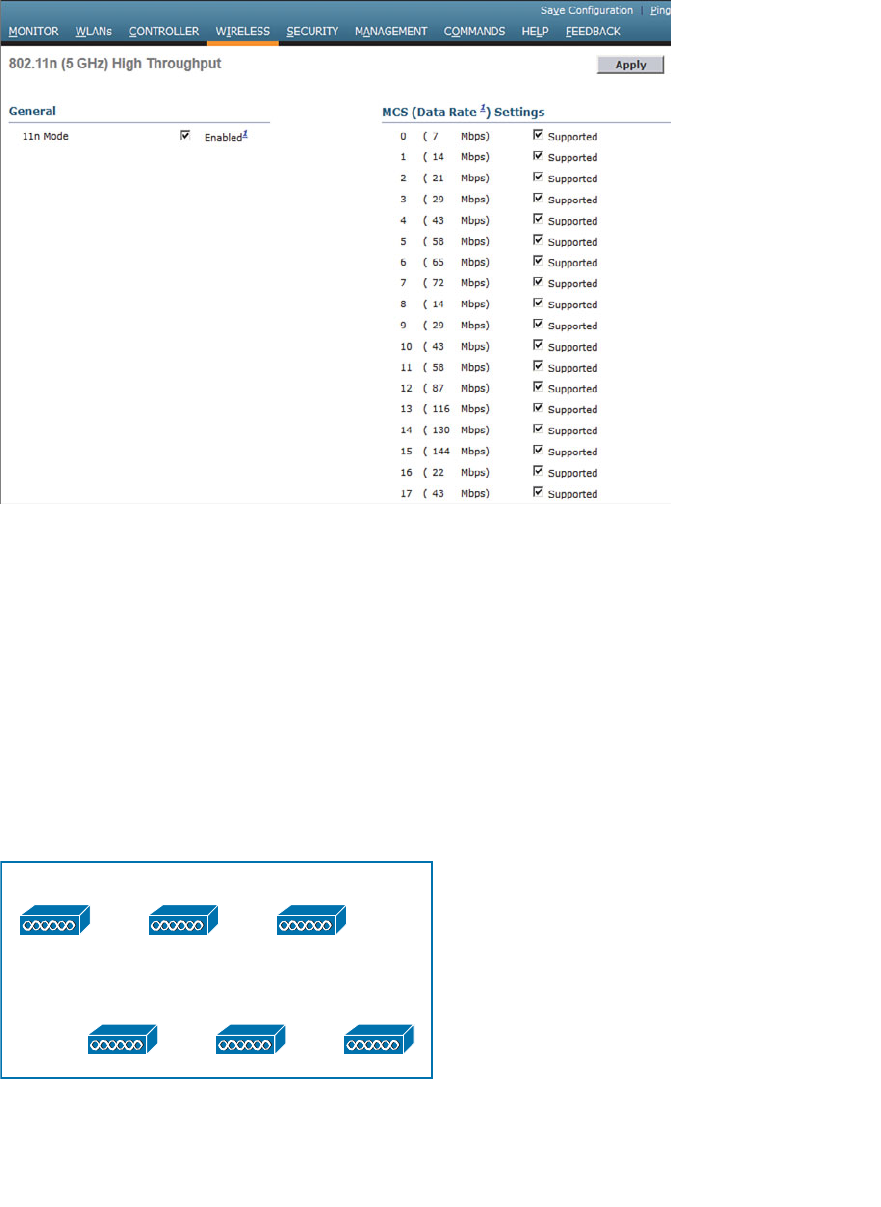
ptg12542968
Chapter 13: Understanding RRM 265
Figure 13-4 Configuring 802.11n Support.
Recall that 802.11n can bond one 20-MHz to an adjacent 20-MHz channel to effectively
double the channel width. By default, the controller will use only a single 20-MHz chan-
nel. You can configure channel bonding as a part of the dynamic channel allocation
(DCA) configuration for the 5-GHz band only, as covered in the following section.
Understanding RRM
Suppose that you need to provide wireless coverage in a rectangular-shaped building.
Using the information you have learned from this book, you decide to use six APs
and locate them such that they form a staggered, regular pattern. The pattern shown in
Figure 13-5 should create optimum conditions for roaming and channel use. (The build-
ing dimensions have not been mentioned, just to keep things simple.)
AP-1 AP-2 AP-3
AP-4 AP-5 AP-6
Figure 13-5 A Hypothetical AP Layout.
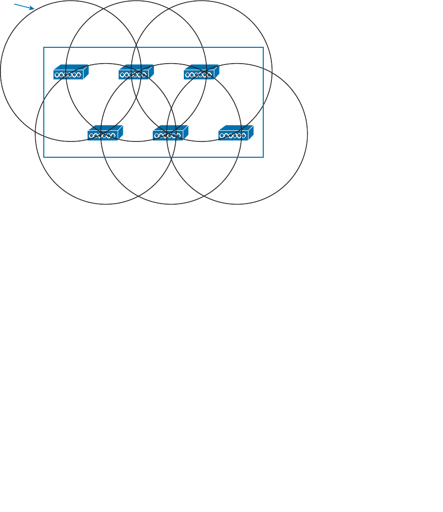
ptg12542968
266 CCNA Wireless 640-722 Official Cert Guide
So far, you have considered the layout pattern and an average cell size, but you still have
to tackle the puzzle of selecting the transmit power level and channel number for each
AP. The transmit power level will affect the final cell size, and the channel assignment
will affect co-channel interference and roaming handoff. At this point, if all the APs are
powered up, they might all end up transmitting at maximum power on the same channel.
Figure 13-6 shows one possible scenario; each of the AP cells overlaps its neighbors by
about 50 percent, and all the APs are fighting to use channel 1!
Ch 1 Ch 1 Ch 1
Ch 1
Tx Level 1
(100 mW) Ch 1 Ch 1
Figure 13-6 Poorly Configured RF Coverage.
Where do you begin to prevent such mayhem? Because the AP locations are already
nailed down, you can figure out the transmit power level that will give the proper cell
overlap. Then you can work your way through the AP layout choosing an alternating
pattern of channel numbers. With six APs, that might not be a daunting task.
Do not forget to repeat the task for both 2.4- and 5-GHz bands.
Also, if you plan on using 802.11n and 40-MHz channel width, do not forget to reserve
the extra channels needed for that. Be aware that only the 5-GHz band is capable of sup-
porting wide channels.
If you happen to notice that an AP fails one day, you could always reconfigure its neigh-
boring APs to increase their transmit power level to expand their cells and cover the
hole.
If you introduce another AP or two in the future, do not forget to revisit the entire con-
figuration again to make room for cells and channels.
Did your life as the wireless LAN administrator just become depressing and tedious?
Cisco Radio Resource Management (RRM) can handle all these tasks regularly and
automatically. RRM consists of several algorithms that can look at a large portion of a

ptg12542968
Chapter 13: Understanding RRM 267
wireless network and work out an optimum transmit power level and channel number for
each AP. If conditions that affect the RF coverage change over time, RRM can detect
that and make the appropriate adjustments.
RF Groups
RRM works by monitoring a number of APs and working out optimal RF settings for
each one. The APs that are included in the RRM algorithms are contained in a single RF
group. An RF group is formed for each band that is supported—one group for 2.4-GHz
AP radios and another for 5-GHz AP radios. By default, an RF group contains all the APs
that are joined to a single controller.
You can also configure a controller to automatically populate its RF group. In that case,
the RF group can expand to include APs from multiple controllers, provided the follow-
ing two conditions are met:
■ The controllers share a common RF group name.
■ At least one AP from one controller can be overheard by an AP on another
controller.
When an RF group touches more than one controller, the controllers form a type of
cluster so that they all participate in any RF adjustments that are needed. Every AP
sends a Neighbor Discovery Packet (NDP) at maximum transmit power and at 60-second
intervals, by default. If two controllers are close enough in proximity for an AP on one
to hear an AP on the other at a received signal strength indicator (RSSI) of –80 dBm or
greater, they are close enough to belong to the same RF group. Up to 20 controllers and
1000 APs can join to form a single RF group.
Figure 13-7 shows a simple scenario with four controllers and four APs, resulting in two
separate RF groups. AP-1 and AP-2 are both joined to controller WLC-1, so they are
members of one RF group by default. AP-3, joined to WLC-2, is located near enough
to AP-1 and AP-2 that neighbor advertisements are overheard. As a result, controller
WLC-2 joins the RF group with WLC-1. However, AP-4, joined to controller WLC-3, is
not close enough to pass the neighbor test. Even though AP-4’s cell intersects the cells of
AP-2 and AP-3, the APs themselves are not within range. Therefore, controller WLC-3
resides in a different RF group by itself.
One controller in each group is elected as an RF group leader, although you can over-
ride that by configuring one controller as a static leader. The leader collects and ana-
lyzes information from all APs in the group about their RF conditions in real time.
You can access the RF group leader configuration information by selecting Wireless >
802.11a/n or 802.11b/g/n > RRM > RF Grouping . In Figure 13-8 , the controller is in
automatic RF group mode and is a member of an RF group along with two other con-
trollers. The RF group leader is controller WLC-1.
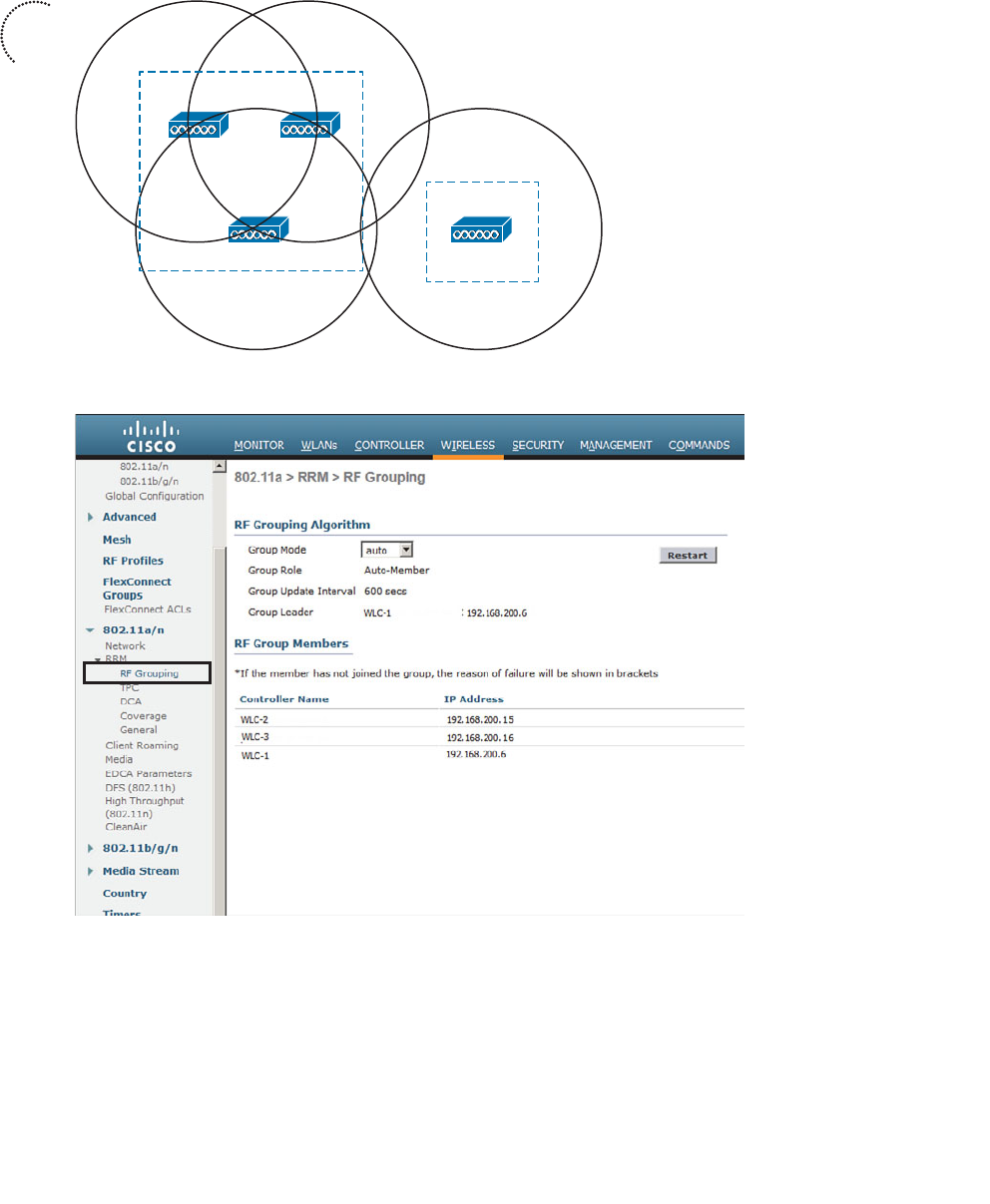
ptg12542968
268 CCNA Wireless 640-722 Official Cert Guide
Figure 13-8 Displaying RF Group Information.
Radio resource monitoring is used to gather and report information from the APs. Each
AP is assigned to transmit and receive on a single channel, so it can easily detect noise
and interference on that channel, as well as the channel utilization. The AP can also keep
a list of clients and other APs that it hears transmitting on that channel.
RF Group
RF Group
AP-1
AP-3 AP-4
(WLC-1)
(WLC-2) (WLC-3)
(WLC-1)
AP-2
Figure 13-7 Automatic RF Group Discovery and Formation.
Key
Topic
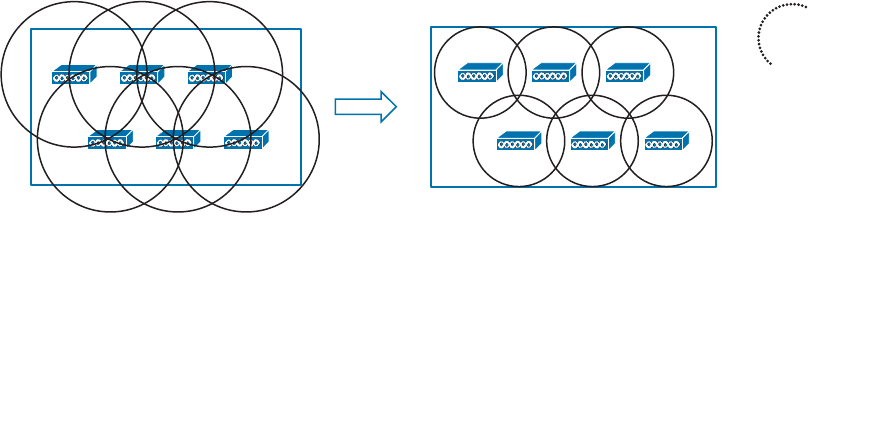
ptg12542968
Chapter 13: Understanding RRM 269
Each AP can also spend a short bit of time (less than 60 ms) tuning its receiver to all of
the other channels that are available. By scanning channels other than the one normally
used, an AP can measure noise and interference all across the band from its own vantage
point. The AP can also detect unexpected transmissions coming from rogue clients and
APs, or devices that are not formally joined to the Cisco Unified Wireless Network
(CUWN).
Based on the radio resource monitoring data, RRM can make the following decisions
about APs in an RF group:
■ Transmit power control (TPC) —RRM can set the transmit power level of each AP.
■ Dynamic channel allocation (DCA) —RRM can select the channel number for each
AP.
■ Coverage hole detection mechanism (CHDM) —Based on information gathered
from client associations, RRM can detect an area with weak RF coverage and
increase an AP’s transmit power level to compensate.
The RRM algorithms are designed to keep the entire wireless network as stable and effi-
cient as possible. The TPC and DCA algorithms run independently because they perform
very different functions. By default, the algorithms are run every 600 seconds (10 min-
utes). If conditions in the RF environment change, such as interference or the addition
or failure of an AP, RRM can discover and react to the changes at the next interval. The
RRM algorithms are discussed in more detail in the following sections.
TPC
The TPC algorithm focuses on one goal: setting each AP’s transmit power level to an
appropriate value so that it offers good coverage for clients while avoiding interfer-
ence with neighboring APs that are using the same channel. Figure 13-9 illustrates this
process. APs that were once transmitting too strongly and overlapping each other’s cells
are adjusted for proper coverage, reducing the cell size more appropriately to support
clients.
Figure 13-9 Basic Concept of the TPC Algorithm.
Controllers have no knowledge of the physical location of each AP. By looking at Figure
13-9 , you can see that the APs are arranged in a nice evenly spaced pattern, but the con-
Key
Topic
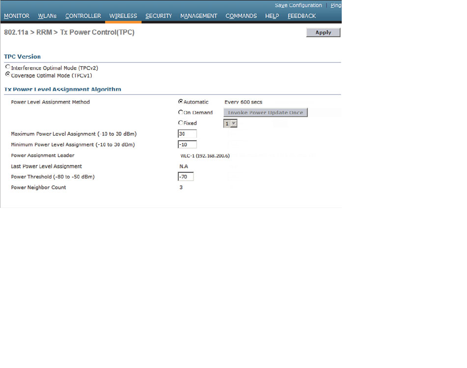
ptg12542968
270 CCNA Wireless 640-722 Official Cert Guide
troller cannot see that. When an AP joins a controller, only the AP’s MAC address, IP
address, and some basic information are advertised to the controller. If the locations of
neighboring APs cannot be known, each AP must resort to using the RSSI of its neigh-
bors as a measure of how closely their cells touch or overlap its own.
During the time each AP scans the channels to listen for RF conditions and other APs, it
forms a list of its neighbors and their RSSI values. Each of those lists is sent to the local
controller and on to the RF group leader where they are used by the TPC algorithm.
TPC works on one AP at a time, one band at a time. If an AP has been heard with an
RSSI above a threshold (–70 dBm by default) by at least three of its neighbors, TPC con-
siders the AP’s cell to be overlapping the cells of its three neighbors too much. The AP’s
transmit power level will be decreased by 3 dB, and then its RSSI will be evaluated again.
This process is repeated at regular intervals until the neighbor that is measuring the third-
strongest RSSI value for the AP no longer measures the RSSI greater than the threshold
Although you probably will not have to make any configuration changes for the TPC
algorithm, it is still useful to understand its settings. TPC runs on the 2.4- and 5-GHz
bands independently. You can see the settings by selecting Wireless > 802.11a/n or
802.11b/g/n > RRM > TPC . Figure 13-10 shows the TPC configuration for the 5-GHz
802.11a band.
Figure 13-10 Adjusting the RRM TPC Algorithm Parameters.
By default, TPC runs automatically every 10 minutes. This is the recommended mode
because any changes in the RF environment can be detected and compensated for with-
out any intervention. As an alternative, you can select On Demand to run the algorithm
once at the next 10-minute interval, and then the resulting transmit power levels will be
frozen until TPC is manually triggered again. If you would rather have the controller set
the transmit power level on all APs to one fixed value, you can select Fixed and choose
the power level from the drop-down menu.

ptg12542968
Chapter 13: Understanding RRM 271
Cisco controllers determine the transmit power level according to an index from 1 to
8, rather than discrete dBm or mW values. A value of 1 corresponds to the maximum
power level that is allowed in the AP’s regulatory domain. You can use Table 13-2
to correlate the power levels used in the 2.4-GHz band in the Americas or European
domains to more familiar real-world values.
Table 13-2 AP Transmit Power Level Numbers, dBm, and mW Values in the 2.4-GHz
Band
Power Level dBm mW
1 20 100
2 17 50
3 14 25
4 11 12.5
5 8 6.25
6 5 3.13
7 2 1.56
8 –1 0.78
With every iteration, the TPC algorithm can continue adjusting the transmit power levels
until no further changes are needed. As a result, some APs might end up higher or lower
than you might want. For example, it is usually best to match the AP transmit power
level with that of the clients. Suppose that some of the clients have a fixed power level
of 25 mW; if TPC ends up reducing some APs to 10 mW, the AP and client power levels
will be mismatched.
To prevent such a condition, you can set minimum and maximum power level boundar-
ies for the TPC algorithm. By default, the minimum level is set to –10 dBm and the maxi-
mum to 30 dBm, as shown in Figure 13-10 .
Whenever you change the TPC parameters in a controller configuration, remember to
make the same changes to all controllers that might be members of the same RF group.
No matter which controller might become the RF group leader, the parameters will be
identical.
Tip What transmit power level does an AP use when it first powers up? A new AP right
out of the box will power up at its maximum power level. After the TPC algorithm has
run and adjusted an AP’s power level, that level is remembered the next time the AP is
power cycled.
Key
Topic
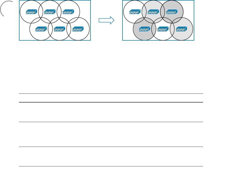
ptg12542968
272 CCNA Wireless 640-722 Official Cert Guide
DCA
Recall from Chapter 7 , “Planning Coverage with Wireless APs,” and Chapter 12 ,
“Understanding Roaming,” that a proper channel assignment is vital for efficient use of
air time and for client mobility. When neighboring APs use the same channel, they can
interfere with each other. Ideally, adjacent APs should use different, non-overlapping
channels. Working out a channel layout for many APs can be a difficult puzzle, but
the DCA algorithm can work out optimum solutions automatically for all APs in an RF
group.
When a new AP first powers up, it uses the first non-overlapping channel in each band—
channel 1 for 2.4 GHz and channel 36 for 5 GHz. Consider a simplistic scenario where
all APs are new and powered up for the first time. You would end up with a building
full of overlapping cells competing for the use of 2.4-GHz channel 1, as shown in simpli-
fied form in Figure 13-11 . The DCA algorithm works to correct this situation by find-
ing a channel that each AP in the RF group can use without overlapping or interfering
with other APs. Like TPC, DCA works out one channel layout in the 2.4-GHz band and
another layout in the 5-GHz band.
Ch 1 Ch 1 Ch 1
Ch 1 Ch 1 Ch 1
Ch 1 Ch 6 Ch 11
Ch 11 Ch 1 Ch 6
Figure 13-11 Basic Concept of the DCA Algorithm.
DCA does not just solve the channel layout puzzle once for all APs. The algorithm runs
every 10 minutes by default, so that it can detect any conditions that might require an
AP’s channel to change. APs in the RF group are monitored for the metrics listed in
Table 13-3 that can influence the channel reassignment decision.
Table 13-3 Metrics Affecting DCA Decisions
Metric Default State Description
RSSI of neighboring APs Always enabled If DCA detects co-channel interference,
it may move an AP to a different
channel.
802.11 interference Enabled If transmissions from APs and devices
that are not part of the wireless network
are detected, DCA may choose to move
an AP to a different channel.
Non-802.11 noise Enabled If excessive noise is present on a
channel, DCA may choose to avoid
using it.
Key
Topic

ptg12542968
Chapter 13: Understanding RRM 273
Metric Default State Description
AP traffic load Disabled If an AP is heavily used, DCA may
not change its channel to keep client
disruption to a minimum.
Persistent interference Disabled If an interference source with a high
duty cycle is detected on a channel,
DCA may choose to avoid using it.
The DCA algorithm tends to look at each AP individually to find the ones with the worst
RF conditions. Changing the channel of even one AP can affect many other APs if there
are not other alternative channels available. Channel layout is a puzzle that may require
several iterations to solve. For this reason, the controller that is the RF group leader will
undergo an RRM startup mode after it is elected. The startup mode consists of ten DCA
iterations at 10-minute intervals, or a total of 100 minutes before the channel layout
reaches a steady state.
The end result of DCA is a channel layout that takes a variety of conditions into
account. The channel layout is not just limited to the two dimensions of a single floor
space in a building; it also extends to three-dimensional space because the RF signals
from one floor can bleed through to another. As long as the APs on different floors
belong to the same RF group, co-channel interference between them should be mini-
mized.
You can display and configure the DCA parameters of either the 2.4- or 5-GHz band by
selecting Wireless > 802.11a/n or 802.11b/g/n > RRM > DCA . Figure 13-12 shows
the 802.11a configuration.
By default, the DCA algorithm runs automatically at 10-minute intervals. You can change
the interval time, select Freeze to run DCA manually on demand, or turn it Off com-
pletely. You can also select the conditions to avoid, which will trigger a channel change
on an AP.
The DCA parameters also include the 802.11n channel width. By default, 20-MHz chan-
nels will be used. If you have enabled 802.11n in the 5-GHz band and want to enable
40-MHz channels, be sure to select 40 MHz as the channel width.
The bottom portion of the web page contains a list of channels that DCA can use as it
assigns channels to APs in the respective band. This list is populated with channel num-
bers by default, but you can edit the list as needed. You can also enable or disable indi-
vidual channel use by using the list of Select check boxes.
The DCA algorithm normally runs on an automatic schedule or manually on demand.
Event-Driven RRM (ED-RRM) takes this a step further; DCA can be triggered based
on RF events that occur in real time. The CleanAir feature, covered in more detail in
Chapter 19 , “Dealing with Wireless Interference,” provides the triggers for ED-RRM. By
default, ED-RRM is disabled. You can enable it with the EDRRM check box at the very
bottom of the web page.
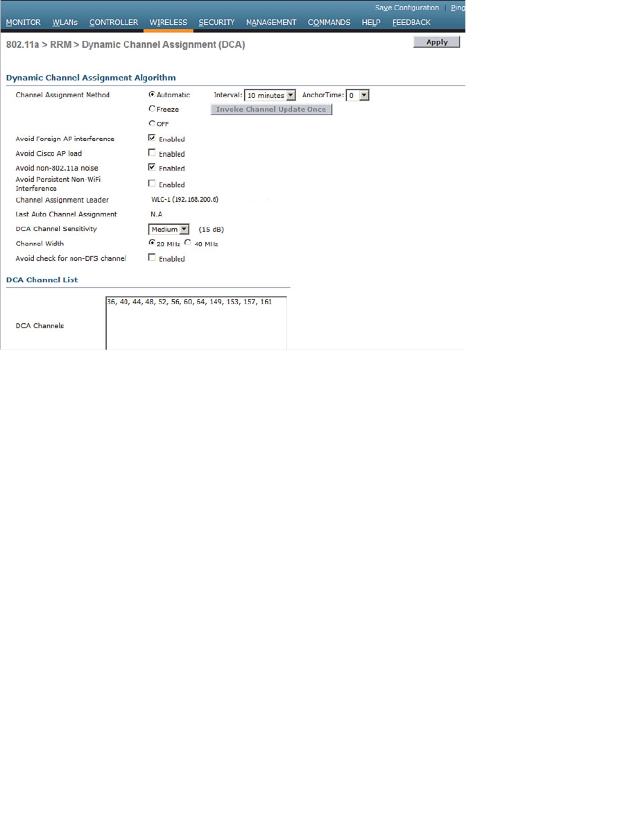
ptg12542968
274 CCNA Wireless 640-722 Official Cert Guide
Coverage Hole Detection
The TPC algorithm normally reduces AP transmit power levels to make cell sizes appro-
priate. Sometimes you might find that your best intentions at providing RF coverage
with a good AP layout still come up short. For example, you might discover that signals
are weak in some small area of a building due to the building construction or surround-
ing obstacles. You might also have an AP radio that happens to fail, causing a larger
coverage hole. How would you discover such a condition? You could make a habit of
surveying the RF coverage often. More likely, your wireless users will discover a weak-
ness or hole in the coverage and complain to you about it.
The Cisco CUWN offers an additional RRM algorithm that can detect coverage holes
and take action to address them. Coverage hole detection mechanism (CHDM) can alert
you to a hole that it has discovered and it can increase an AP’s transmit power level to
compensate for the hole.
Figure 13-12 Adjusting the RRM DCA Algorithm Parameters.

ptg12542968
Chapter 13: Understanding RRM 275
Coverage hole detection is useful in two cases:
■ Extending coverage in a weak area
■ Healing a coverage hole caused by an AP or radio failure
The algorithm does not run at regular intervals like TPC and DCA do. Instead, it moni-
tors the RF conditions of wireless clients and decides when to take action. In effect,
the algorithm leverages your wireless users who are out in the field and tries to notice a
problem before they do.
Every controller maintains a database of associated clients and their RSSI and signal-to-
noise ratio (SNR) values. It might seem logical to think that a low RSSI or SNR would
mean a client is experiencing a hole in coverage. Assuming the client and its AP are using
the same transmit power levels, if the AP is receiving the client at a low level, the client
must also be receiving the AP at a low level. This might not be true at all; the client might
just be exiting the building and getting too far away from the AP. The client might also
have a “sticky” roaming behavior, where it maintains an association with one AP until the
RSSI falls to a very low level before reassociating elsewhere.
Coverage hole detection tries to rule out conditions that are experienced by small num-
bers of clients and signal conditions due to client roaming behavior. A valid coverage
hole is detected when some number of clients, all associated to the same AP, have RSSI
values that fall below a threshold. In addition, the coverage hole condition must exist
longer than a threshold of time without the client roaming to a different AP.
By default, the following conditions must all be met for a coverage hole to be detected:
■ Client RSSI at the AP is at or below –80 dBm.
■ The low RSSI condition must last at least 60 seconds over the past 180 seconds.
■ The condition must affect at least three clients or more than 25 percent of the cli-
ents on a single AP.
Be aware that the coverage hole detection runs on a per-band basis. Unlike TPC and
DCA, which operate on the entire RF group of controllers, coverage hole detection runs
on each controller independently.
You can display and configure the coverage hole detection thresholds by selecting
Wireless > 802.11a/n or 802.11b/g/n > RRM > Coverage . Figure 13-13 shows the
threshold parameters for the 5-GHz 802.11a band.
Key
Topic
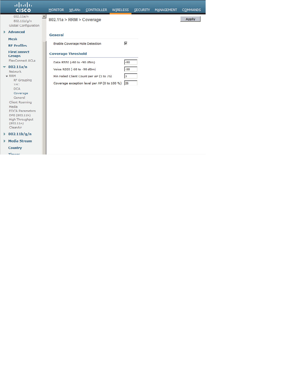
ptg12542968
276 CCNA Wireless 640-722 Official Cert Guide
Figure 13-13 Displaying Coverage Threshold Parameters for the 5-GHz 802.11a Band.
Manual RF Configuration
You might sometimes want to keep RRM from changing the RF conditions in parts of
your wireless network. For instance, you might have client devices that operate at a
fixed transmit power level. Ideally, the AP and client power levels should be identical
or matched. If RRM raises or lowers AP power levels at a later time, then asymmetric
power levels would result.
You can override RRM on a per-AP basis by selecting Wireless > Access Points >
Radios > 802.11a/n or 802.11b/g/n . From the list of APs displayed, choose a specific
AP and select the drop-down menu at the far-right side of the list. From this menu,
select Configure , as shown in Figure 13-14 .
On the AP configuration page, as shown in Figure 13-15 , you can set the channel under
RF Channel Assignment or the transmit power under Tx Power Level Assignment. By
default, the Global radio button is selected for each, which allows the value to be deter-
mined globally within the RF group. You can set a specific channel or power level by
selecting the Custom radio button and then choosing a value from the drop-down list. In
the figure, the AP’s transmit power level has been manually set to 3.
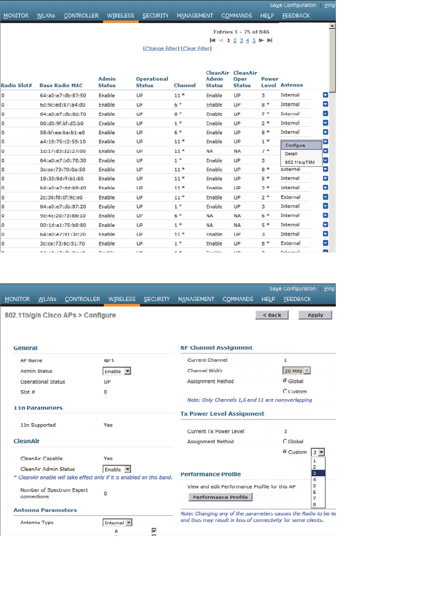
ptg12542968
Chapter 13: Understanding RRM 277
Figure 13-15 Manually Setting the Transmit Power Level of an AP.
Figure 13-14 Selecting an AP for Manual Configuration.
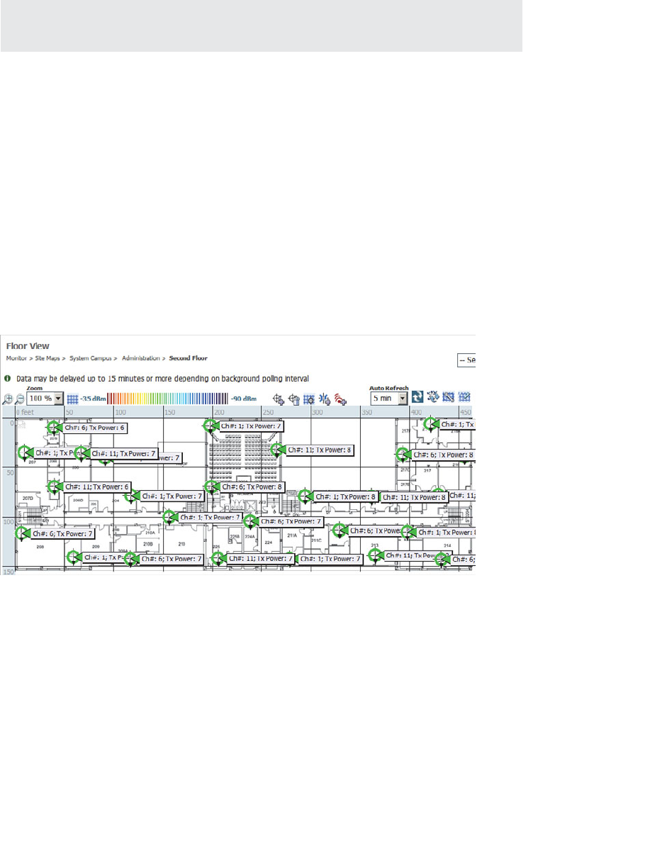
ptg12542968
278 CCNA Wireless 640-722 Official Cert Guide
Tip You should let RRM automatically adjust both channels and transmit power levels
whenever possible.
Verifying RRM Results
The RRM algorithms can either run at regular intervals or on demand. You can dis-
play the channel number and transmit power level that are being used on every AP by
selecting Wireless > Access Points > Radios > 802.11a/n or 802.11b/g/n , as shown
in Figure 13-15 . The controller displays an asterisk next to values that have been set
through RRM. Otherwise, if no asterisk appears, the value has been set manually.
To get a much better feel for the RRM results, you can use the CUWN management
system (Cisco Network Control System [NCS] or Prime Infrastructure [PI], as covered in
Chapters 18 through 20 ) to view APs on a graphical representation of an area. The NCS
map in Figure 13-16 displays each AP’s location on a building floor plan, along with its
channel number and transmit power level. Seeing the physical arrangement of APs and
their cells can help you get a much better idea how the channels are assigned and reused.
Figure 13-16 Displaying RRM Results in Cisco NCS Maps.

ptg12542968
Chapter 13: Understanding RRM 279
Exam Preparation Tasks
As mentioned in the section, “How to Use This Book,” in the Introduction, you have a
couple of choices for exam preparation: the exercises here, Chapter 22 , “Final Review,”
and the exam simulation questions on the CD-ROM.
Review All Key Topics
Review the most important topics in this chapter, noted with the Key Topic icon in the
outer margin of the page. Table 13-4 lists a reference of these key topics and the page
numbers on which each is found.
Table 13-4 Key Topics for Chapter 13
Key Topic Element Description Page Number
List Data rate states 263
Figure 13-7 RF group formation 268
Figure 13-9 TPC operation 269
Table 13-2 AP transmit power level numbers 271
Figure 13-11 DCA operation 272
List Coverage hole detection criteria 275
Define Key Terms
Define the following key terms from this chapter and check your answers in the
glossary:
coverage hole, DCA, mandatory data rate, RRM, RF group, RF group leader,
supported data rate, TPC
Key
Topic
ptg12542968
This chapter covers the following topics:
■ Anatomy of a Secure Connection —This section
provides an overview of the types of information
that should be protected over a wireless connection
and the functions that you can use to provide
protection.
■ Wireless Client Authentication Methods —This
section describes many of the common methods
that you can use to authenticate clients on a wireless
network.
■ Wireless Privacy and Integrity Methods —This
section discusses two methods that you can leverage
to keep data obscured from eavesdroppers and to
discover when data has been tampered with over a
wireless connection.
■ WPA and WPA2 —This section explains two
important industry standards that specify a suite of
security methods for wireless security.
■ Securing Management Frames with MFP —This
section discusses a method that you can use to pre-
vent attacks that use management frames to disrupt
a wireless network.
■ Configuring Wireless Security —This section cov-
ers the configuration steps needed to implement
WPA and WPA2 security on a wireless LAN.
This chapter covers the following exam topics:
■ Describe 802.11 authentication and encryption
methods (Open, Shared, 802.1X, EAP, TKIP, and
AES)
■ Describe the general framework of wireless security
and security components (authentication, encryp-
tion, MFP, and IPS)

ptg12542968
■ Describe and configure authentication methods (Guest, PSK, 802.1X, WPA/WPA2
with EAP-TLS, EAP-FAST, PEAP, and LEAP)
■ Describe and configure encryption methods (WPA/WPA2 with TKIP, and AES)
■ Describe and configure the different sources of authentication (PSK, EAP-local or
-external, and Radius)
As you know by now, wireless networks are complex. Many technologies and protocols
work behind the scenes to give end users a stable, yet mobile, connection to a wired net-
work infrastructure. From the user’s perspective, a wireless connection should seem no
different than a wired connection. A wired connection can give users a sense of security;
data traveling over a wire is probably not going to be overheard by others. A wireless
connection is inherently different; data traveling over the air can be overheard by any-
one within range.
Therefore, securing a wireless network becomes just as important as any other aspect. A
comprehensive approach to wireless security focuses on the following areas:
■ Identifying the endpoints of a wireless connection
■ Identifying the end user
■ Protecting the wireless data from eavesdroppers
■ Protecting the wireless data from tampering
The identification process is performed through various authentication schemes.
Protecting wireless data involves security functions like encryption and frame authenti-
cation.
This chapter covers many of the methods you can use to secure a wireless network.
Be warned—wireless security can be a confusing topic because it is filled with many
acronyms. Some of the acronyms rhyme like words from a children’s book. In fact, this
chapter is a story about WEP, PSK, TKIP, MIC, AES, EAP, EAP-FAST, EAP-TLS, LEAP,
PEAP, WPA, WPA2, CCMP, and on and on it goes. When you finish with this chapter,
though, you will come away with a clear view of what these terms mean and how they all
fit together.
As a CCNA Wireless engineer, you will need to have a basic understanding of the wire-
less security framework and the common methods you can use to build it. You will also
need to know how to configure the most robust methods in a wireless network.
CHAPTER 14
Wireless Security Fundamentals

ptg12542968
282 CCNA Wireless 640-722 Official Cert Guide
“Do I Know This Already?” Quiz
The “Do I Know This Already?” quiz allows you to assess whether you should read this
entire chapter thoroughly or jump to the “Exam Preparation Tasks” section. If you are
in doubt about your answers to these questions or your own assessment of your knowl-
edge of the topics, read the entire chapter. Table 14-1 lists the major headings in this
chapter and their corresponding “Do I Know This Already?” quiz questions. You can
find the answers in Appendix A , “Answers to the ‘Do I Know This Already?’ Quizzes.”
Table 14-1 “Do I Know This Already?” Section-to-Question Mapping
Foundation Topics Section Questions
Anatomy of a Secure Connection 1–2
Wireless Client Authentication Methods 3–7
Wireless Privacy and Integrity Methods 8
WPA and WPA2 9–10
Securing Management Frames with MFP 11
Configuring Wireless Security 12
Caution The goal of self-assessment is to gauge your mastery of the topics in this chap-
ter. If you do not know the answer to a question or are only partially sure of the answer,
you should mark that question as wrong for purposes of the self-assessment. Giving your-
self credit for an answer you correctly guess skews your self-assessment results and might
provide you with a false sense of security.
1.
Which of the following are necessary components of a secure wireless connection?
(Choose all that apply.)
a. Encryption
b. MIC
c. Authentication
d. WIPS
e. All of these answers
2. Which one of the following is used to protect the integrity of data in a wireless
frame?
a. WIPS
b. WEP

ptg12542968
Chapter 14: Wireless Security Fundamentals 283
c. MIC
d. EAP
3.
Which one of the following is a wireless encryption method that has been found to
be vulnerable and is not recommended for use?
a. AES
b. WPA
c. EAP
d. WEP
4.
Which one of the following is used as the 802.11 authentication method when
802.1x is used on a WLAN?
a. Open authentication
b. WEP
c. EAP
d. WPA
5.
A Cisco WLC is configured for 802.1x authentication, using an external RADIUS
server. The controller takes on which one of the following roles?
a. Authentication server
b. Supplicant
c. Authenticator
d. Adjudicator
6. Which one of the following authentication methods uses a certificate to authenti-
cate the AS but not the client?
a. LEAP
b. PEAP
c. EAP-FAST
d. EAP-TLS
7.
Which one of the following authentication methods requires digital certificates on
both the AS and the supplicants?
a. TKIP
b. PEAP
c. WEP
d. EAP-TLS

ptg12542968
284 CCNA Wireless 640-722 Official Cert Guide
8. Which one of the following is currently the most secure data encryption and integ-
rity method for wireless data?
a. WEP
b. TKIP
c. CCMP
d. WPA
9.
WPA2 differs from WPA in which one of the following ways?
a. Allows TKIP
b. Allows CCMP
c. Allows WEP
d. Allows TLS
10.
A pre-shared key is used in which of the following wireless security configurations?
a. WPA personal mode
b. WPA enterprise mode
c. WPA2 personal mode
d. WPA2 enterprise mode
11.
Which of the following is required to implement MFP on a WLAN to protect both
the wireless infrastructure and the client? (Select all that apply.)
a. WPA
b. WPA2
c. CCXv4 or v5
d. CCXv5
e. WEP
12.
Which one of the following options should you select to configure WPA2 personal
on a WLAN?
a. 802.1x
b. PSK
c. TKIP
d. CCMP
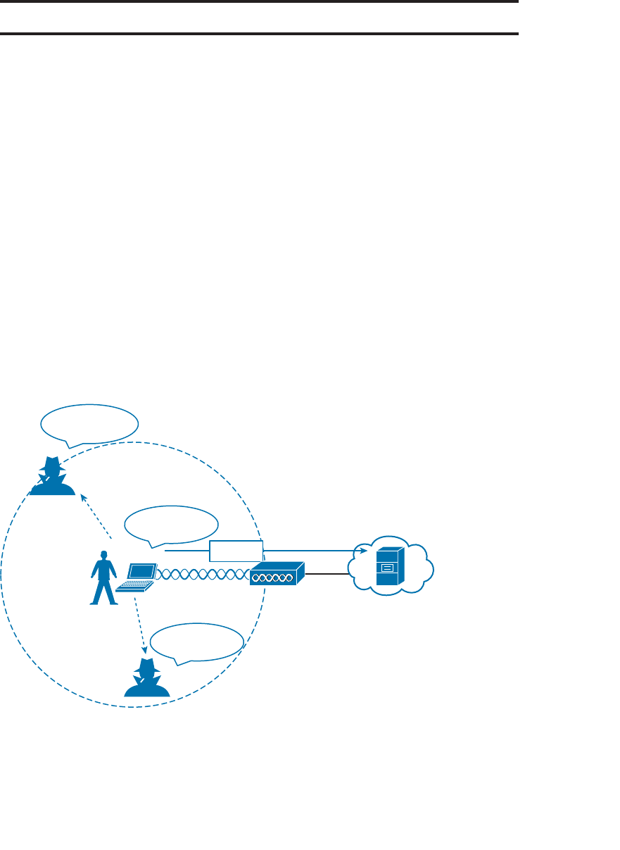
ptg12542968
Chapter 14: Wireless Security Fundamentals 285
Foundation Topics
Anatomy of a Secure Connection
In the previous chapters of this book, you have learned about wireless clients forming
associations with wireless access points (APs) and passing data back and forth across the
air. The main focus has been on the radio frequency (RF) conditions, the modulation
schemes, and the management of airtime that are all necessary to send data from one
place to another successfully.
As long as all clients and APs conform to the 802.11 standard, they can all coexist—even
on the same channel. Not every 802.11 device is friendly and trustworthy, however.
Sometimes it is easy to forget that transmitted frames do not just go directly from the
sender to the receiver, as in a wired or switched connection. Instead, they travel accord-
ing to the transmitter’s antenna pattern, potentially reaching any receiver that is within
range.
Consider the scenario in Figure 14-1 . The wireless client opens a session with some
remote entity and shares a confidential password. Because two untrusted users are also
located within range of the client’s signal, they may also learn the password by capturing
frames that have been sent on the channel. The convenience of wireless communication
also makes it easy for transmissions to be overheard and exploited by malicious users.
AP
Client
His password is
nihao123
My password is
nihao123
His password is
nihao123
nihao123
Figure 14-1 Wireless Transmissions Reaching Unintended Recipients.
If data is sent through open space, how can it be secured so that it stays private and
intact? The 802.11 standard offers a framework of wireless security mechanisms that
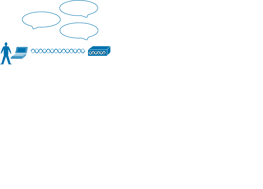
ptg12542968
286 CCNA Wireless 640-722 Official Cert Guide
can be used to add trust, privacy, and integrity to a wireless network. A Cisco Unified
Wireless Network (CUWN) can go even further by detecting and preventing malicious
activity. The following sections give an overview of the wireless security framework.
Each element is described in more detail later in the chapter.
Authentication
In Chapter 6 , “Understanding 802.11 Frame Types,” you learned that wireless clients
must discover a basic service set (BSS) and then request permission to associate with it.
Clients should be authenticated by some means before they can become functioning
members of the wireless LAN. Why?
Suppose that your wireless network connects to corporate resources where confidential
information can be accessed. In that case, only devices known to be trusted and expect-
ed should be given access. Guest users, if they are permitted at all, should be allowed to
join a different guest WLAN where they can access nonconfidential or public resources.
Rogue clients, which are not expected or welcomed, should not be permitted to associ-
ate at all. After all, they are not affiliated with the corporate network and are likely to be
unknown devices that happen to be within range of your network.
To control access, wireless networks can authenticate the client devices before they are
allowed to associate. Potential clients must identify themselves by presenting some form
of credentials to the APs. Figure 14-2 shows the basic client authentication process.
Who are you?
I am Joe User.
Ok.
AP
Figure 14-2 Authenticating a Wireless Client.
Wireless authentication can take many forms. Some methods require only a static text
string that is common across all trusted clients and APs. The text string is stored on
the client device and presented directly to the AP when needed. What might happen
if the device was stolen or lost? Most likely, any user who possessed the device could
still authenticate to the network. Other more stringent authentication methods require
interaction with a corporate user database. In those cases, the end user must enter a valid
username and password—something that would not be known to a thief or an imposter.
If you have ever joined a wireless network, you might have focused on authenticating
your device or yourself, while implicitly trusting the nearest AP. For example, if you
turn on your wireless device and find a wireless network that is available at your work-
place, you probably join it without hesitating. The same is true for wireless networks in

ptg12542968
Chapter 14: Wireless Security Fundamentals 287
an airport, a hotel, a hot spot, or in your home—you expect the AP that is advertising
the SSID to be owned and operated by the entity where you are located. But how can
you be sure?
Normally, the only piece of information you have is the SSID being broadcast or adver-
tised by an AP. If the SSID looks familiar, you will likely choose to join it. Perhaps your
computer is configured to automatically connect to a known SSID so that it associates
without your intervention. Either way, you might unwittingly join the same SSID even if
it was being advertised by an imposter.
Some common attacks focus on a malicious user pretending to be an AP. The fake AP
can send beacons, answer probes, and associate clients just like the real AP it is imper-
sonating. Once a client associates with the fake AP, the attacker can easily intercept all
communication to and from the client from its central position. A fake AP could also
send spoofed management frames to disassociate or deauthenticate legitimate and active
clients, just to disrupt normal network operation.
To prevent this type of man-in-the-middle attack, the client should authenticate the AP
before it associates. Figure 14-3 shows a simple scenario. Even further, any management
frames received by a client should be authenticated too, as proof that they were sent by
a legitimate and expected AP.
Who are you?
I am AP-1.
These are my
management frames.
Ok.
AP-1
Figure 14-3 Authenticating a Wireless AP.
Message Privacy
Suppose that the client in Figure 14-3 must authenticate before joining the wireless net-
work. It might also authenticate the AP and its management frames. The client’s relation-
ship with the AP might become much more trusted, but data passing to and from the
client is still available to eavesdroppers on the same channel.
To protect data privacy on a wireless network, the data should be encrypted for its
journey through free space. This is accomplished by encrypting the data payload in each
wireless frame just prior to being transmitted, then decrypting it as it is received. The
idea is to use an encryption method that the transmitter and receiver share, so the data
can be encrypted and decrypted successfully.
In wireless networks, each WLAN supports only one authentication and encryption
scheme, so all clients must use the same encryption method when they associate. You
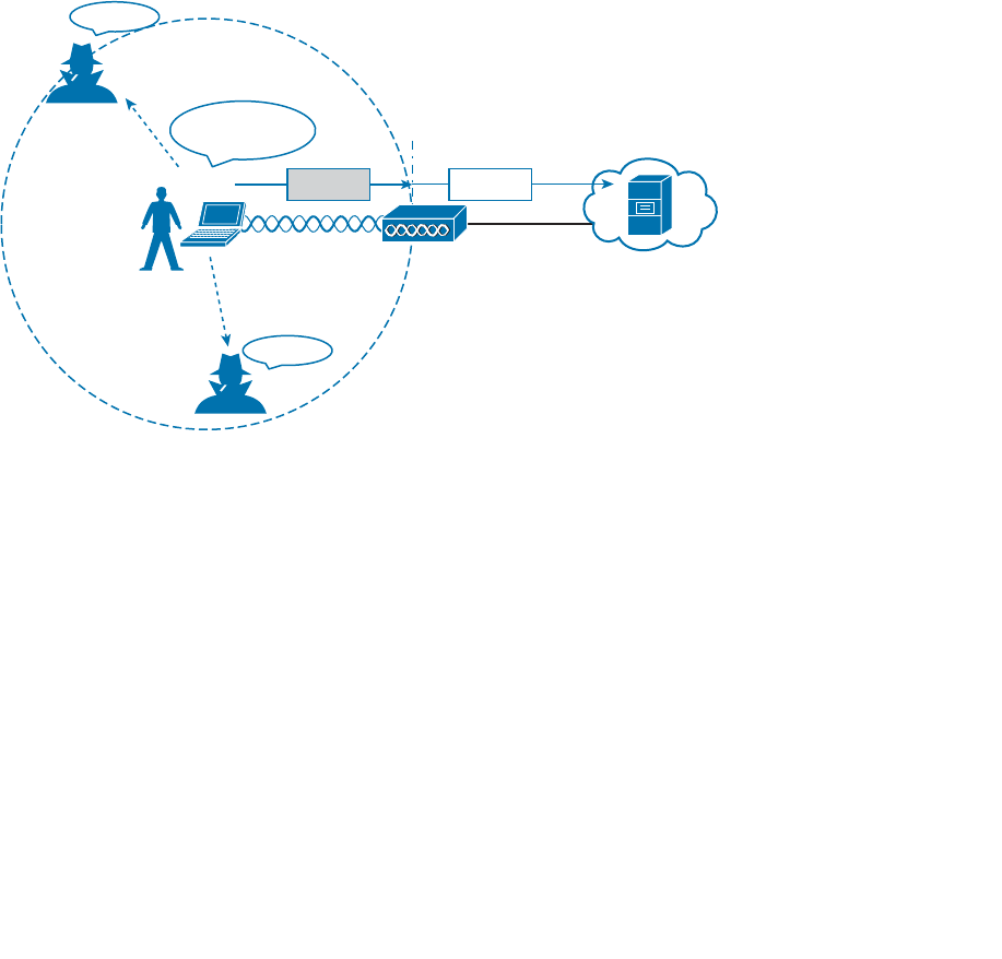
ptg12542968
288 CCNA Wireless 640-722 Official Cert Guide
might think that having one encryption method in common would allow every client to
eavesdrop on every other client. That is not necessarily the case because the AP should
securely negotiate an encryption key to use for each associated client.
Ideally, the AP and a client are the only two devices that have the encryption keys in
common so that they can understand each other’s data. No other device should know
about or be able to use the same keys to eavesdrop and decrypt the data. In Figure 14-4 ,
the client’s confidential password information has been encrypted before being transmit-
ted. The AP can decrypt it successfully before forwarding it onto the wired network, but
other wireless devices cannot.
The AP also maintains a “group key” that it uses when it needs to send encrypted data to
all clients in its cell at one time. Each of the associated clients uses the same group key
to decrypt the data.
AP
Client
My password is
nihao123
??
??
328A29 nihao123
Figure 14-4 Encrypting Wireless Data to Protect Data Privacy.
Message Integrity
Encrypting data obscures it from view while it is traveling over a public or untrusted
network. The intended recipient should be able to decrypt the message and recover the
original contents, but what if someone managed to alter the contents along the way? The
recipient would have a very difficult time discovering that the original data had been
modified.
A message integrity check (MIC) is a security tool that can protect against data tam-
pering. You can think of MIC as a way for the sender to add a secret stamp inside the
encrypted data frame. The stamp is based on the contents of the data bits to be transmit-
ted. Once the recipient decrypts the frame, it can compare the secret stamp to its own
idea of what the stamp should be, based on the data bits that were received. If the two
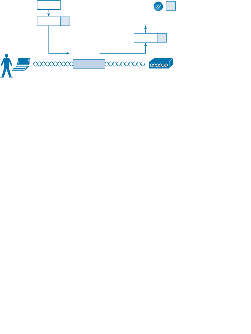
ptg12542968
Chapter 14: Wireless Security Fundamentals 289
stamps are identical, the recipient can safely assume that the data has not been tampered
with. Figure 14-5 shows the MIC process.
AP
Client
nihao123
nihao123
1. Original Data
2. Compute MIC
3. Encrypt Data + MIC 4. Decrypt nihao123 f7
f7
5. Compute MIC
6. Compare MICs
f7
741fcb64901d
f7
f7
Figure 14-5 Checking Message Integrity over a Wireless Network.
Intrusion Protection
Many of the tools in the wireless security framework operate as choreographed steps
between a client and an AP. Because both the client and the AP are active participants in
securing the connection between them, the data they are exchanging can be protected.
In other words, much of the security framework focuses on keeping attackers from join-
ing the wireless network and from tampering with existing associations.
Wireless attacks do not stop there; they can involve malicious activity from a variety
of angles or vectors. A wireless intrusion protection system (wIPS) can monitor wireless
activity and compare that against a database of known signatures or patterns. Cisco APs
can recognize some signatures and inform their controllers. Controllers also have a set
of signatures that can match against data coming from many APs. The Cisco Wireless
Control System (WCS), Cisco Prime Network Control System (NCS), and Cisco Prime
Infrastructure (PI) are wireless management systems that can go even further by recog-
nizing a rich set of signatures, implementing customizable wIPS policies, and integrating
with Cisco Mobility Services Engine (MSE) for granular analysis. Chapter 18 , “Managing
Wireless Networks with WCS,” discusses these management platforms in greater detail.
For the CCNA Wireless exam, you should understand the basics of wireless IPS. Know
that wireless security threats can be grouped into the following categories:
■ Rogue devices
■ Ad hoc networks
■ Client association issues
■ Passive or active attacks
Despite your best efforts to configure and secure every piece of your wireless network,
someone could always bring in his own AP or wireless router and connect it to the wired
network. A rogue AP is one that is not part of your wireless infrastructure but that is

ptg12542968
290 CCNA Wireless 640-722 Official Cert Guide
close enough to be overheard or to cause interference. Any clients that associate with a
rogue AP are known as rogue clients . Cisco controllers can discover both.
Controllers can collect beacon information that is overheard by legitimate APs. Rogue
detection algorithms running on the controllers and WCS/NCS can classify APs as rogue
if they do not appear in the database of APs known to your network. As a wireless
network administrator, you can override the classification and declare an AP as either
friendly or rogue.
When coupled with an MSE, the wIPS can locate rogue APs so that you can go and find
them. The wIPS process can even transmit special probe frames to determine if a rogue
AP is connected to your wired network. This happens if the probe frames are received
by the rogue over the air and then delivered back to the controller through the wired
network.
The wIPS can go one step further and attempt to contain the rogue so that it does not
become a security risk to your own network. Over-the-air rogue containment works
by listening for any wireless clients that associate with a rogue AP. The controller then
sends spoofed deauthentication frames to those clients so that they think the rogue AP
has dropped them.
Based on information gathered by the controllers, wIPS can detect many types of wire-
less network attacks. Attacks can range from completely passive, such as an eavesdrop-
per silently capturing wireless frames, to active ones that attempt to disrupt wireless
service. For example, an attacker might send a flood of association requests to an AP
to overwhelm it with fake potential clients—to the point where the AP can no longer
service real clients. Another type of attack is similar to Cisco’s rogue containment, where
the attacker sends spoofed deauthentication frames to legitimate clients to continually
knock them off the network.
Tip Although you should not need to know the specifics about wIPS and attack sig-
natures, you can investigate further on your own by navigating to Security > Wireless
Protection Policies on a controller and Configure > wIPS Profiles on WCS/NCS.
Wireless Client Authentication Methods
You can use many different methods to authenticate wireless clients as they try to asso-
ciate with the network. The methods have been introduced over time, and have evolved
as security weaknesses have been exposed and wireless hardware has advanced. This sec-
tion covers the most common authentication methods you might encounter.
Open Authentication
In Chapter 6 , you learned about the frames that are used when a client asks to join a
wireless network. The original 802.11 standard offered only two choices to authenticate
a client: open authentication and WEP.
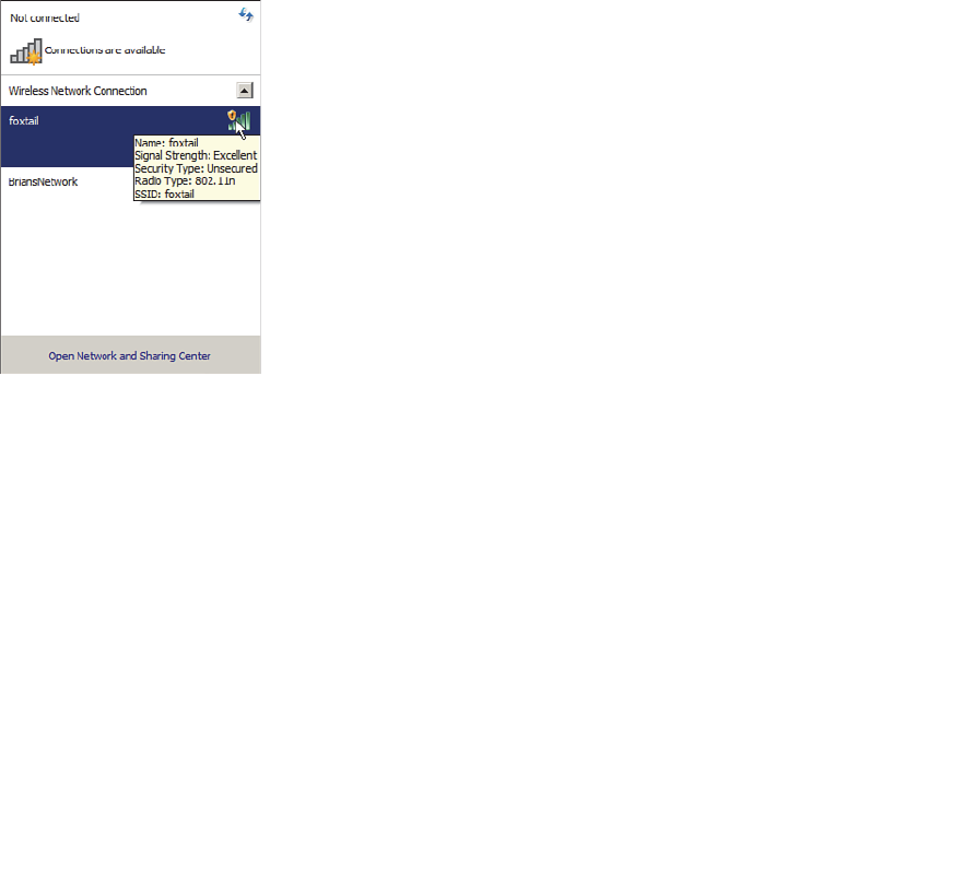
ptg12542968
Chapter 14: Wireless Security Fundamentals 291
Open authentication is true to its name; it offers open access to a WLAN. The only
requirement is that a client must use an 802.11 authentication request before it attempts
to associate with an AP. No other credentials are needed.
When would you want to use open authentication? After all, it does not sound very
secure, because it is not. With no challenge, any client may authenticate to access the
network. This strategy is most often used in public places that offer wireless hot spots.
If any client screening is used at all, it comes in the form of web authentication. A client
can associate right away, but must open a web browser to see and accept the terms for
use and enter basic credentials. From that point, network access is opened up for the
client.
You have probably seen a WLAN with open authentication when you have visited a
public location. Most client operating systems flag such networks to warn you that
your wireless data will not be secured in any way if you join. Figure 14-6 shows an open
WLAN discovered on a Windows-based client. Notice the shield-shaped caution icon
and the security type Unsecured.
Figure 14-6 Discovering a WLAN with Open Authentication.
WEP
As you might expect, open authentication offers nothing that can obscure or encrypt the
data being sent between a client and an AP. As an alternative, the 802.11 standard has
traditionally defined the Wireless Equivalent Privacy (WEP) as a method to make a wire-
less link more like or equivalent to a wired connection.
WEP uses the RC4 cipher algorithm to make every wireless data frame private and hid-
den from eavesdroppers. The same algorithm encrypts data at the sender and decrypts
it at the receiver. The algorithm uses a string of bits as a key, commonly called a WEP
key, to derive other encryption keys—one per wireless frame. As long as the sender and
receiver have an identical key, one can decrypt what the other encrypts.

ptg12542968
292 CCNA Wireless 640-722 Official Cert Guide
You can configure up to four WEP keys to be used on a WLAN, although only one of
them can be active. The key number is included in the wireless frame so that the sender
and receiver can know which one of the four to use.
WEP is known as a shared-key security method. The same key must be shared between
the sender and receiver ahead of time, so that each can derive other mutually agreeable
encryption keys. In fact, every potential client and AP must share the same key ahead of
time so that any client can associate with the AP.
The WEP key can also be used as an optional authentication method as well as an
encryption tool. Unless a client can use the correct WEP key, it cannot associate with an
AP. The AP tests the client’s knowledge of the WEP key by sending it a random chal-
lenge phrase. The client encrypts the challenge phrase with WEP and returns the result
to the AP. The AP can compare the client’s encryption with its own to see whether the
two WEP keys yield identical results.
WEP keys can be either 40 or 104 bits long, represented by a string of 10 or 26 hex
digits. As a rule of thumb, longer keys offer more unique bits for the algorithm, result-
ing in more robust encryption. Except in WEP’s case, that is. Because WEP was defined
in the original 802.11 standard in 1999, every wireless adapter was built with encryp-
tion hardware specific to WEP. In 2001, a number of weaknesses were discovered and
revealed, so work began to find better wireless security methods. By 2004, the 802.11i
amendment was ratified and WEP was officially deprecated. Both WEP encryption and
WEP shared-key authentication are widely considered to be weak methods to secure a
wireless LAN.
You might think such a clear call to move away from a weak or flawed security method
would be easy and quick to achieve. In practice, it has taken many years to move away
from WEP. Why?
Because WEP was implemented in wireless adapter hardware, any better security
schemes had to leverage variations of WEP without the benefit of new cryptographic
hardware. Wireless hardware manufacturers are usually reluctant to commit to build
products until the technology is firmly established in the IEEE 802.11 standard.
Therefore, WEP was an underlying theme for a very long time. In fact, for backward
compatibility, you will still find it supported by clients, APs, and controllers even today.
As you work through the rest of this chapter, notice how wireless security schemes have
evolved and improved, and notice how many of them leverage WEP to some extent.
802.1x/EAP
With only open authentication and WEP available in the original 802.11 standard,
a more secure authentication method was needed. Client authentication generally
involves some sort of challenge, a response, and then a decision to grant access. Behind
the scenes, it can also involve an exchange of session or encryption keys, in addition
to other parameters needed for client access. Each authentication method might have
unique requirements as a unique way to pass information between the client and the AP.
Rather than build additional authentication methods into the 802.11 standard, a more
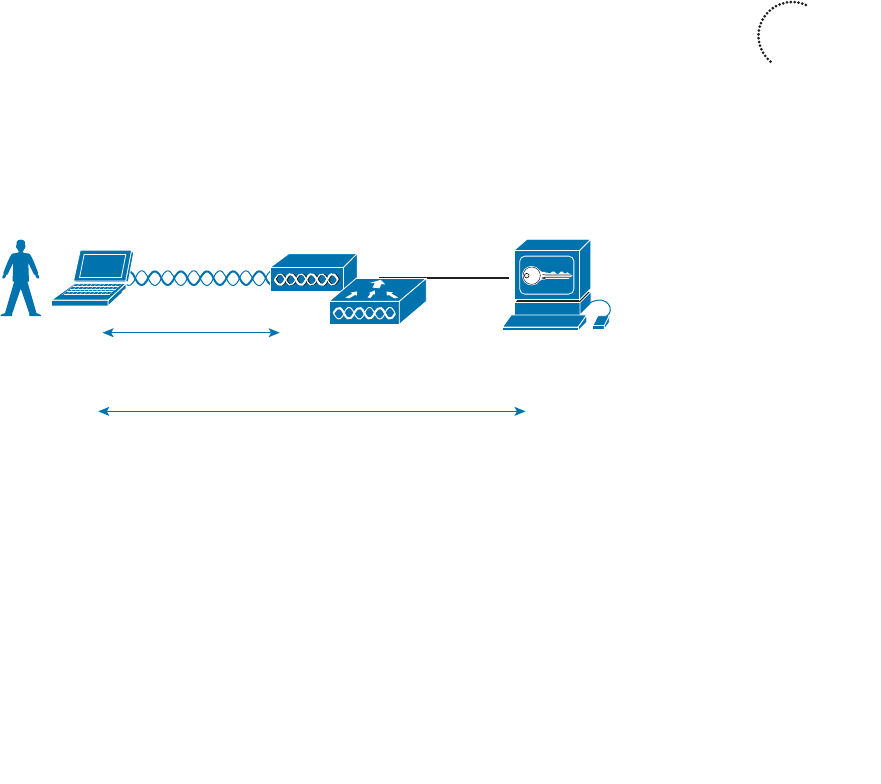
ptg12542968
Chapter 14: Wireless Security Fundamentals 293
flexible and scalable authentication framework, the Extensible Authentication Protocol
(EAP), was chosen. As its name implies, EAP is extensible and does not consist of any
one authentication method. Instead, EAP defines a set of common functions that actual
authentication methods can use to authenticate users. As you read through this section,
notice how many authentication methods have EAP in their names. Each method is
unique and different, but each one follows the EAP framework.
EAP has another interesting quality: It can integrate with the IEEE 802.1x port-based
access control standard. When 802.1x is enabled, it limits access to a network media
until a client authenticates through an EAP method. This means that a wireless client
might be able to associate with an AP, but will not be able to pass data to any other part
of the network until it successfully authenticates.
With open and WEP authentication, wireless clients are authenticated locally at the AP
without further intervention. The scenario changes with 802.1x; the client uses open
authentication to associate with the AP, and then the actual client authentication process
occurs at a dedicated authentication server. Figure 14-7 shows the three-party 802.1x
arrangement that consists of the following entities:
■ Supplicant —The client device that is requesting access
■ Authenticator —The network device that provides access to the network (usually a
wireless LAN controller [WLC])
■ Authentication Server (AS) —The device that takes user or client credentials and
permits or denies network access based on a user database and policies (usually a
RADIUS server)
AP
WLC
Supplicant Authenticator
Authentication
Server (AS)
802.11
Open Authentication
EAP-Based Authentication
Figure 14-7 802.1x Client Authentication Roles.
The controller becomes a middleman in the client authentication process, controlling
user access with 802.1x and communicating with the authentication server using the EAP
framework.
The following sections provide an overview of several common EAP-based authentica-
tion methods.
Key
Topic

ptg12542968
294 CCNA Wireless 640-722 Official Cert Guide
LEAP
As an early attempt to address the weaknesses in WEP, Cisco developed a proprietary
wireless authentication method called Lightweight EAP (LEAP). To authenticate, the cli-
ent must supply username and password credentials. Both the authentication server and
the client exchange challenge messages that are then encrypted and returned. This pro-
vides mutual authentication; as long as the messages can be decrypted successfully, the
client and the AS have essentially authenticated each other.
At the time, WEP-based hardware was still widely used. Therefore, LEAP attempted
to overcome WEP weaknesses by using dynamic WEP keys that changed frequently.
Nevertheless, the method used to encrypt the challenge messages was found to be vul-
nerable, so LEAP has since been deprecated. Even though wireless clients and controllers
still offer LEAP, you should not use it.
E A P - F A S T
Cisco developed a more secure method called EAP Flexible Authentication by Secure
Tunneling (EAP-FAST). Authentication credentials are protected by passing a protected
access credential (PAC) between the AS and the supplicant. The PAC is a form of shared
secret that is generated by the AS and used for mutual authentication.
After the supplicant and AS have authenticated each other, they negotiate a Transport
Layer Security (TLS) tunnel. The end user can then be authenticated through the TLS
tunnel for additional security.
Notice that two separate authentication processes occur in EAP-FAST—one between
the AS and the supplicant and another with the end user. These occur in a nested fash-
ion, as an outer authentication (outside the TLS tunnel) and an inner authentication
(inside the TLS tunnel).
Like other EAP-based methods, a RADIUS server is required. However, the RADIUS
server must also operate as an EAP-FAST server to be able to generate PACs, one per
user. EAP-FAST has a known vulnerability, but is still considered to be secure provided
that rogue APs and supplicants are managed well.
PEAP
Like EAP-FAST, the Protected EAP (PEAP) method uses an inner and outer authentica-
tion; however, the AS presents a digital certificate to authenticate itself with the suppli-
cant in the outer authentication. If the supplicant is satisfied with the identity of the AS,
the two will build a TLS tunnel to be used for the inner client authentication and encryp-
tion key exchange.
The digital certificate of the AS consists of data in a standard format that identifies the
owner and is “signed” or validated by a third party. The third party is known as a cer-
tificate authority (CA) and is known and trusted by both the AS and the supplicants.
The supplicant must also possess the CA certificate just so that it can validate the one
it receives from the AS. The certificate is also used to pass a public key, in plain view,
which can be used to help decrypt messages from the AS.

ptg12542968
Chapter 14: Wireless Security Fundamentals 295
Notice that only the AS has a certificate for PEAP. That means the supplicant can readily
authenticate the AS. The client does not have or use a certificate of its own, so it must
be authenticated within the TLS tunnel using one of the following two methods:
■ MSCHAPv2 —Microsoft Challenge Authentication Protocol
■ GTC —Generic Token Card; a hardware device that generates one-time passwords
for the user or a manually generated password
EAP-TLS
PEAP leverages a digital certificate on the AS as a robust method to authenticate the
RADIUS server. It is easy to obtain and install a certificate on a single server, but the cli-
ents are left to identify themselves through other means. EAP Transport Layer Security
(EAP-TLS) goes one step further by requiring certificates on the AS and on every client
device.
With EAP-TLS, the AS and the supplicant exchange certificates and can authenticate
each other. A TLS tunnel is built afterward so that the client can be authenticated and
encryption key material can be securely exchanged.
EAP-TLS is considered to be the most secure wireless authentication method available;
however, implementing it can sometimes be complex. Along with the AS, each wireless
client must obtain and install a certificate. Manually installing certificates on hundreds
or thousands of clients can be impractical. Instead, you would need to implement a
Public Key Infrastructure (PKI) that could supply certificates securely and efficiently and
revoke them when a client or user should no longer have access to the network. This usu-
ally involves setting up your own CA or building a trust relationship with a third-party
CA that can supply certificates to your clients.
Tip EAP-TLS is practical only if the wireless clients can accept and use digital certifi-
cates. Many wireless devices, such as communicators, medical devices, and RFID tags,
have an underlying operating system that cannot interface with a CA or use certificates.
Wireless Privacy and Integrity Methods
The original 802.11 standard supported only one method to secure wireless data from
eavesdroppers: WEP. As you have learned in this chapter, WEP has been compromised,
deprecated, and can no longer be recommended. What other options are available to
encrypt data and protect its integrity as it travels through free space?
TKIP
During the time when WEP was embedded in wireless client and AP hardware, yet was
known to be vulnerable, the Temporal Key Integrity Protocol (TKIP) was developed.

ptg12542968
296 CCNA Wireless 640-722 Official Cert Guide
TKIP is the product of the 802.11i working group and the Wi-Fi Alliance.
TKIP adds the following security features using legacy hardware and the underlying
WEP encryption:
■ MIC —An efficient algorithm to add a hash value to each frame as a message integ-
rity check to prevent tampering; commonly called Michael” as an informal reference
to MIC.
■ Time stamp —A time stamp is added into the MIC to prevent replay attacks that
attempt to reuse or replay frames that have already been sent
■ Sender’s MAC address —The MIC also includes the sender’s MAC address as evi-
dence of the frame source.
■ TKIP sequence counter —Provides a record of frames sent by a unique MAC
address, to prevent frames from being replayed as an attack.
■ Key mixing algorithm —Computes a unique 128-bit WEP key for each frame.
■ Longer Initialization Vector (IV) —The IV size is doubled from 24 to 48 bits, mak-
ing it virtually impossible to exhaust all WEP keys by brute force calculation.
TKIP became a reasonably secure stopgap security method, buying time until the
802.11i standard could be ratified. Some attacks have been created against TKIP, so it,
too, should be avoided if a better method is available. In fact, TKIP was deprecated in
the 802.11-2012 standard.
CCMP
The Counter/CBC-MAC Protocol (CCMP) is that better method. CCMP consists of two
algorithms:
■ AES counter mode encryption
■ Cipher Block Chaining Message Authentication Code (CBC-MAC) used as a mes-
sage integrity check
The Advanced Encryption Standard (AES) is the current encryption algorithm adopted
by U.S. National Institutes of Standards and Technology (NIST) and the U.S. govern-
ment, and widely used around the world. In other words, AES is open, publicly acces-
sible, and represents the most secure encryption method available today.
Before CCMP can be used to secure a wireless network, the client devices and APs must
support the AES counter mode and CBC-MAC in hardware. CCMP cannot be used on
legacy devices that support only WEP or TKIP. How can you know if a device supports
CCMP? Look for the WPA2 designation, which is described in the following section.

ptg12542968
Chapter 14: Wireless Security Fundamentals 297
WPA and WPA2
This chapter covers a variety of authentication methods and encryption and message
integrity algorithms. When it comes time to configure a WLAN with wireless security,
should you try to select some combination of schemes based on which one is best or
which one is not deprecated? Which authentication methods are compatible with which
encryption algorithms?
The Wi-Fi Alliance has worked out a couple of ways to do that. The IEEE 802.11i stan-
dard defines best practice wireless security methods. While that standard was still being
developed, the Wi-Fi Alliance introduced its Wi-Fi Protected Access (WPA) industry
standard. WPA was based on parts of 802.11i and included 802.1x authentication, TKIP,
and a method for dynamic encryption key management.
Once 802.11i was ratified and published, the Wi-Fi Alliance included it in full in its
WPA Version 2 (WPA2) standard. WPA2 offers the capabilities of WPA, to be back-
ward compatible, while adding the superior CCMP algorithms. Table 14-2 summarizes
the simple differences between WPA and WPA2.
Table 14-2 Comparing WPA and WPA2
WPA WPA2
Authentication Pre-shared key or 802.1x Pre-shared key or 802.1x
Encryption and MIC TKIP TKIP or CCMP
Key management Dynamic key management Dynamic key management
Notice that WPA and WPA2 specify 802.1x, which implies EAP-based authentication,
but they do not require any specific EAP method. Instead, the Wi-Fi Alliance certifies
interoperability with methods like EAP-TLS, PEAP, EAP-TTLS, and EAP-SIM.
The WPA and WPA2 standards also support two authentication modes, based on the
scale of the deployment:
■ Personal mode —A pre-shared key is used to authenticate clients on a WLAN.
■ Enterprise mode —An 802.1x EAP-based authentication method must be used to
authenticate clients.
Tip Personal mode is usually easier to deploy in a small environment or with clients
that are embedded in certain devices. Be aware that every device using the WLAN must
be configured with an identical pre-shared key. If you ever need to update or change the
key, you must touch every device.
Key
Topic

ptg12542968
298 CCNA Wireless 640-722 Official Cert Guide
Securing Management Frames with MFP
Normally, APs send 802.11 management frames on a BSS with no effort to secure the
contents. When clients receive management frames, they assume that the frames were
sent by legitimate APs that control their own BSSs. Malicious users can exploit this
implicit trust by crafting their own spoofed management frames that appear to come
from actual APs.
To mitigate attacks that leverage AP management frames, Cisco developed Management
Frame Protection (MFP), which is available in the following two forms:
■ Infrastructure MFP —To protect the integrity of management frames, APs add
a MIC toward the end of each frame; other neighboring APs also participating in
infrastructure MFP can determine whether overheard management frames have
been tampered with and can alert their controllers.
■ Client MFP —Protects the integrity of management frames through a MIC and
encryption that only associated clients and neighboring APs can understand.
Notice that infrastructure MFP is based on a coordinated effort of APs only.
Participating APs compute and tag management frames with a MIC value and then listen
to detect any evidence of tampering. Wireless clients cannot participate.
Client MFP, in contrast, uses a MIC to protect management frame integrity and adds
end-to-end encryption to protect the privacy of management frame contents. Clients
must be capable of participating too, to decrypt the management frames and validate
the MIC value. Clients using MFP can safely ignore any disassociation, deauthentication,
and WMM quality of service action frames that are broadcast and any unicast frames
that are not signed.
Clients must support CCXv5 and must use WPA2 with either TKIP or CCMP. This
implies that the clients already have a secure relationship with the AP. This same secure
link is used to send trusted management frames. The frames are encrypted in a way that
only the MFP-capable client can understand.
Configuring Wireless Security
Wireless security is fairly straightforward to configure. Each WLAN has its own security
policies. You can configure the security settings when you create a new WLAN or you
can edit the parameters of an existing one. Keep in mind that you should use WPA2
and CCMP as a best practice. You can select personal or enterprise mode based on your
environment and its security policies.
According to the CCNA Wireless exam blueprint, you should know how to configure
WPA and WPA2 with pre-shared keys and 802.1x. You should also know how to con-
figure EAP and RADIUS support on Cisco wireless LAN controllers. These topics are
covered in the following sections.
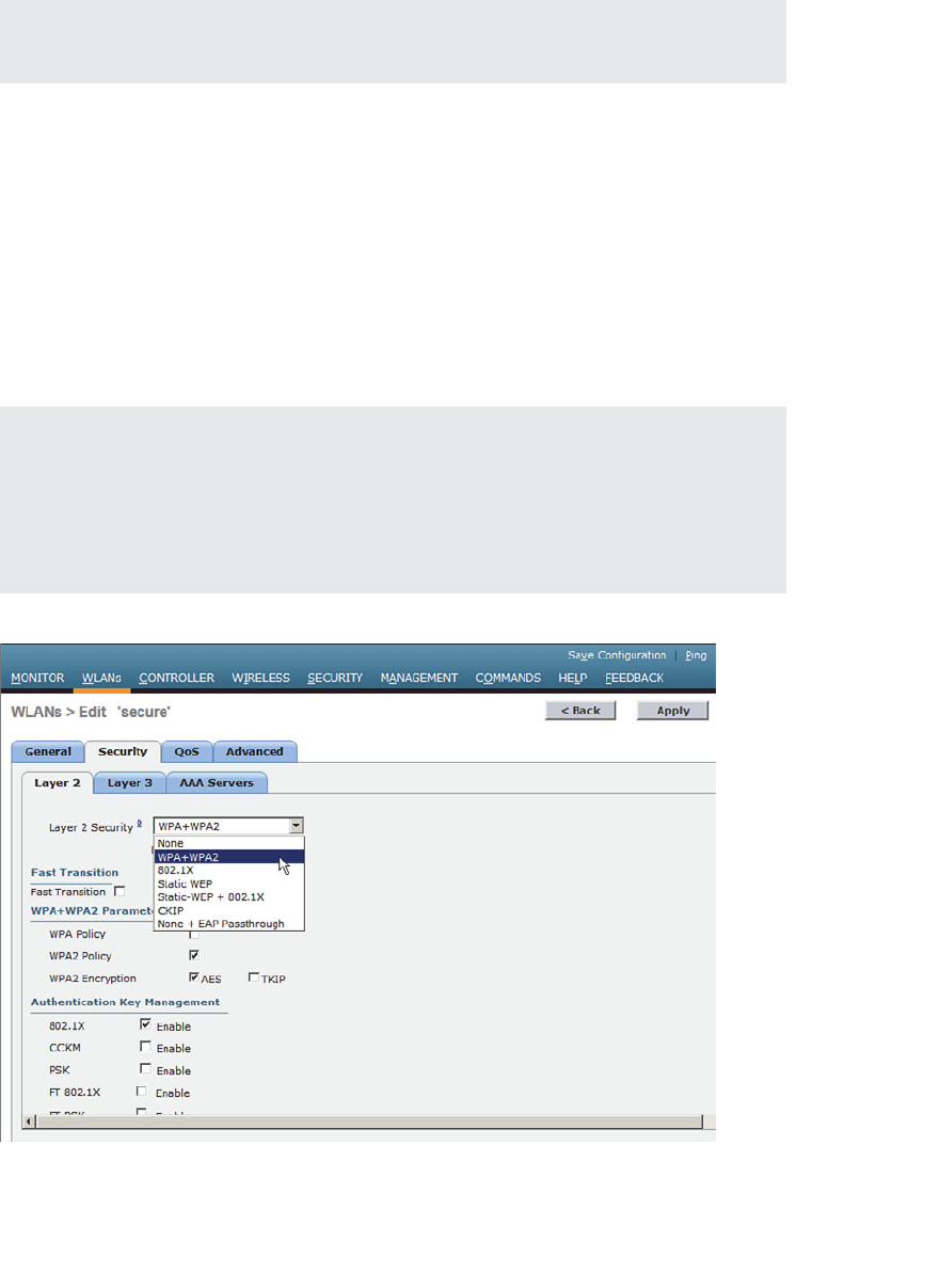
ptg12542968
Chapter 14: Wireless Security Fundamentals 299
Tip Wireless security methods are configured on a per-WLAN basis. The configuration
steps you learn in this chapter will be applied in Chapter 15 , “Configuring a WLAN.”
Configuring WPA or WPA2 Personal
You can configure WPA or WPA2 personal mode and the pre-shared key in one step.
Navigate to WLANs and select Create New or select the WLAN ID of an existing
WLAN to edit. Make sure that the parameters on the General tab are set appropriately.
Next, select the Security > Layer 2 tab. In the Layer 2 Security drop-down menu,
select WPA+WPA2 , as shown in Figure 14-8 for the WLAN named secure. In the
WPA+WPA2 Parameters section of the Layer 2 page, you can enable WPA or WPA2
with the WPA Policy and WPA2 Policy check boxes. In Figure 14-9 , WPA2 has been
selected. Be sure to select AES or TKIP as the WPA2 encryption type.
Tip The controller will allow you to enable both WPA and WPA2 check boxes. You
should do that only if you have legacy clients that require WPA support and are mixed in
with newer WPA2 clients. Be aware that the WLAN will only be as secure as the weakest
security suite you configure on it. Ideally, you should use WPA2 with AES/CCMP and
try to avoid any other hybrid mode. Hybrid modes such as WPA with AES and WPA2
with TKIP can cause compatibility issues; in addition, they will likely be deprecated soon.
Figure 14-8 Selecting the WPA+WPA2 Security Suite for a WLAN.

ptg12542968
300 CCNA Wireless 640-722 Official Cert Guide
Figure 14-9 Selecting WPA or WPA2, Encryption, and Authentication.
For WPA or WPA2 personal mode, select PSK under the Authentication Key
Management settings section. This will use a pre-shared key to authenticate clients on the
WLAN. Be sure to click the Apply button to apply the WLAN changes you have made.
Configuring WPA2 Enterprise Mode
You can use WPA2 enterprise mode to authenticate wireless clients with 802.1x and
EAP through an external RADIUS server located somewhere on the wired network. You
should begin by configuring one or more RADIUS servers on the controller. Navigate
to Security > AAA > RADIUS > Authentication . Click the New button to define a new
server or select the Server Index number to edit an existing server definition.
In Figure 14-10 , a new RADIUS server is being defined. Enter the server’s IP address and
the shared secret key that the controller will use to communicate with the server. Make
sure that the RADIUS port number is correct; if not, you can enter a different port num-
ber. The server status should be Enabled , as selected from the drop-down menu. You
can disable a server to take it out of service if needed. To authenticate wireless clients,
check the box next to Network User . Click the Apply button to apply the new settings.
Next, you will need to enable 802.1x authentication on the WLAN. Navigate to WLANs
and select a new or existing WLAN to edit. Under the Security > Layer 2 tab, select
WPA+WPA2 and make sure that the WPA2 Policy box is checked. Select AES as the
encryption method, and then select 802.1x under the Authentication Key Management
section. Figure 14-11 illustrates the settings that are needed on the WLAN named
MoreSecure.
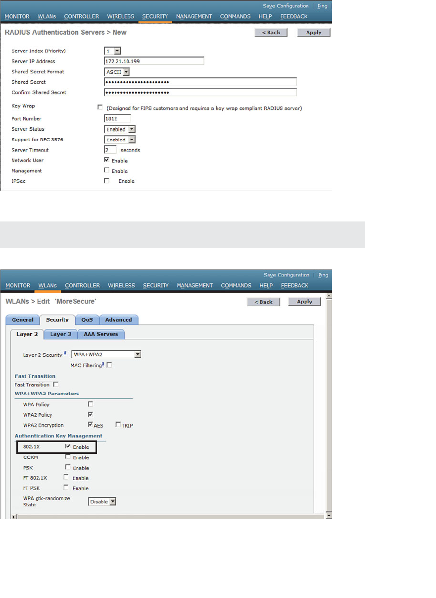
ptg12542968
Chapter 14: Wireless Security Fundamentals 301
Tip The default settings for a new WLAN are WPA2 with AES and 802.1x.
Figure 14-11 Enabling WPA2 Enterprise Mode with 802.1x Authentication.
Figure 14-10 Defining a RADIUS Server for WPA2 Enterprise Authentication.
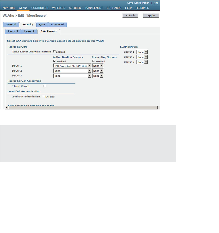
ptg12542968
302 CCNA Wireless 640-722 Official Cert Guide
By default, a controller will use the global list of RADIUS servers in the order you have
defined under Security > AAA > RADIUS > Authentication. You can override that list
on the AAA Servers tab, where you can define which RADIUS servers will be used for
802.1x authentication. You can define up to three RADIUS servers that will be tried in
sequential order, designated as Server 1, Server 2, and Server 3. Choose a predefined
server by clicking the drop-down menu next to one of the server entries. In Figure 14-
12 , the RADIUS server at 172.21.10.176 will be used as Server 1. After you finish select-
ing servers, you can edit other WLAN parameters or click the Apply button to make
your configuration changes operational.
Figure 14-12 Selecting RADIUS Servers to Authenticate Clients in the WLAN.
Tip As you worked through the WPA2 enterprise configuration, did you notice that
you never saw an option to use a specific authentication method like PEAP or EAP-TLS?
The controller only has to know that 802.1x will be in use. The actual authentication
methods are configured on the RADIUS server. The client’s supplicant must also be con-
figured to match what the server is using.
Configuring WPA2 Enterprise with Local EAP
If your environment is relatively small or you do not have a RADIUS server in produc-
tion, you can use an authentication server that is built in to the WLC. This is called local
EAP, which supports LEAP, EAP-FAST, PEAP, and EAP-TLS.
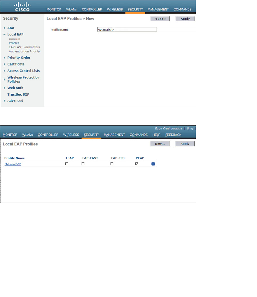
ptg12542968
Chapter 14: Wireless Security Fundamentals 303
First, you will need to define and enable the local EAP service on the controller.
Navigate to Security > Local EAP > Profiles and click the New button. Enter a name for
the local EAP profile, which will be used to define the authentication server methods.
In Figure 14-13 , a new profile called MyLocalEAP has been defined. Click the Apply
button to create the profile. Now you should see the new profile listed, along with the
authentication methods it supports, as shown in Figure 14-14 . From this list, you can
check or uncheck the boxes to enable or disable each method.
Figure 14-13 Defining a Local EAP Profile on a Controller.
Figure 14-14 Displaying Configured Local EAP Profiles.
Select the profile name to edit its parameters. In Figure 14-15 , the profile named
MyLocalEAP has been configured to use PEAP. Click the Apply button to activate your
changes.
Next, you need to configure the WLAN to use the Local EAP server rather than a regu-
lar external RADIUS server. Navigate to WLANs, select the WLAN ID, and then select
the Security > Layer 2 tab and enable WPA2, AES, and 802.1x as before.
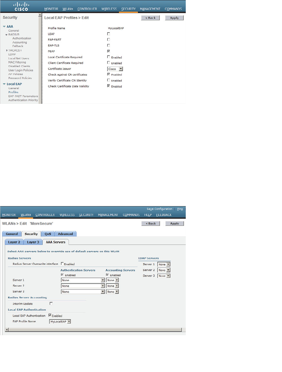
ptg12542968
304 CCNA Wireless 640-722 Official Cert Guide
If you have defined any RADIUS servers in the global list under Security > AAA >
RADIUS > Authentication or any specific RADIUS servers in the WLAN configuration,
the controller will use those first. Local EAP will then be used as a backup method.
To make Local EAP the primary authentication method, you must make sure that no
RADIUS servers are defined on the controller. Select the AAA Servers tab and make
sure that all three RADIUS servers use None from the drop-down menu. In the Local
EAP Authentication section, check the Enabled box to begin using the Local EAP server.
Select the EAP profile name that you have previously configured. In Figure 14-16 , the
Local EAP authentication server is enabled and will use the MyLocalEAP profile, which
was configured for PEAP.
Figure 14-16 Enabling Local EAP Authentication for a WLAN.
Figure 14-15 Configuring a Local EAP Profile to Use PEAP.

ptg12542968
Chapter 14: Wireless Security Fundamentals 305
Because the Local EAP server is local to the controller, you will have to maintain a local
database of users there too. You can create users by navigating to Security > AAA >
Local Net Users .
Exam Preparation Tasks
As mentioned in the section, “How to Use This Book,” in the Introduction, you have a
couple of choices for exam preparation: the exercises here, Chapter 22 , “Final Review,”
and the exam simulation questions on the CD-ROM.
Review All Key Topics
Review the most important topics in this chapter, noted with the Key Topic icon in the
outer margin of the page. Table 14-3 lists a reference of these key topics and the page
numbers on which each is found.
Table 14-3 Key Topics for Chapter 14
Key Topic Element Description Page Number
List 802.1x entities 293
Table 14-2 WPA and WPA2 comparison 297
Define Key Terms
Define the following key terms from this chapter and check your answers in the
glossary:
802.1x, authentication server (AS), authenticator, certificate authority (CA),
Counter/CBC-MAC Protocol (CCMP), EAP Flexible Authentication by Secure
Tunneling (EAP-FAST), EAP-TLS, enterprise mode, Extensible Authentication
Protocol (EAP), Lightweight EAP (LEAP), management frame protection (MFP),
message integrity check (MIC), open authentication, personal mode, protected
access credential (PAC), Protected EAP (PEAP), Public Key Infrastructure (PKI),
RADIUS server, supplicant, Temporal Key Integrity Protocol (TKIP), Wireless
Equivalent Privacy (WEP), wireless intrusion protection system (wIPS), Wi-Fi
Protected Access (WPA), WPA Version 2 (WPA2)
Key
Topic

ptg12542968
This chapter covers the following topics:
WLAN Overview —This section provides a review
of WLAN concepts and rules of thumb for their
use.
Configuring a WLAN —This section covers the
steps necessary to create a WLAN on a Cisco wire-
less LAN controller.
This chapter covers the following exam topics:
■ Configure a WLAN controller and access points
WLC: ports, interfaces, WLANs, NTP, CLI and
Web UI, CLI wizard, and link aggregation group
(LAG) AP: Channel and Power

ptg12542968
A WLC sits somewhere between wireless APs and a wired network. In this chapter, you
learn how to define and tune a wireless LAN to reach devices on each of those net-
works. In addition, based on the concepts you learned in Chapter 14 , “Wireless Security
Fundamentals,” you will be able to configure basic security parameters for the WLAN.
“Do I Know This Already?” Quiz
The “Do I Know This Already?” quiz allows you to assess whether you should read this
entire chapter thoroughly or jump to the “Exam Preparation Tasks” section. If you are
in doubt about your answers to these questions or your own assessment of your knowl-
edge of the topics, read the entire chapter. Table 15-1 lists the major headings in this
chapter and their corresponding “Do I Know This Already?” quiz questions. You can
find the answers in Appendix A , “Answers to the ‘Do I Know This Already?’ Quizzes.”
Table 15-1 “Do I Know This Already?” Section-to-Question Mapping
Foundation Topics Section Questions
WLAN Overview 1–4
Configuring a WLAN 5–6
Caution The goal of self-assessment is to gauge your mastery of the topics in this chap-
ter. If you do not know the answer to a question or are only partially sure of the answer,
you should mark that question as wrong for purposes of the self-assessment. Giving your-
self credit for an answer you correctly guess skews your self-assessment results and might
provide you with a false sense of security.
CHAPTER 15
Configuring a WLAN

ptg12542968
308 CCNA Wireless 640-722 Official Cert Guide
1. Which two of the following things are bound together when a new WLAN is cre-
ated?
a. VLAN
b. AP
c. Controller interface
d. SSID
2.
What is the maximum number of WLANs you can configure on a Cisco wireless
controller?
a. 8
b. 16
c. 512
d. 1024
3. What is the maximum number of WLANs that can be enabled on a Cisco light-
weight AP?
a. 8
b. 16
c. 512
d. 1024
4. Which one of the following is a limiting factor when multiple WLANs are offered
on an AP and its radio channel?
a. The speed of the controller interface
b.
The airtime used for each WLAN’s beacons
c. Co-channel interference between WLANs
d. The number of APs joined to the controller
5.
Which of the following parameters are necessary when creating a new WLAN with
the controller GUI? (Choose all that apply.)
a. SSID
b. VLAN number
c. Interface
d. BSSID
e. IP subnet
6. The WLAN ID number is advertised to wireless clients. True or false?
a. True
b. False
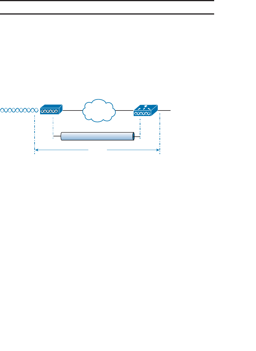
ptg12542968
Chapter 15: Configuring a WLAN 309
Foundation Topics
WLAN Overview
Recall from Chapter 9 , “Understanding the CUWN Architecture,” that a wireless LAN
controller and an access point (AP) work in concert to provide network connectivity to
wireless clients. From a wireless perspective, the AP advertises a service set identifica-
tion (SSID) for the client to join. From a wired perspective, the controller connects to a
VLAN through one of its dynamic interfaces. To complete the path between the SSID
and the VLAN, as illustrated in Figure 15-1 , you must first define a WLAN on the con-
troller.
SSID Engineering Interface Engineering
VLAN 100
WLC-1
CAPWAP
AP-1
WLAN
192.168.100.0/24
Figure 15-1 Connecting Wired and Wireless Networks with a WLAN.
The controller will bind the WLAN to one of its interfaces and then push the WLAN
configuration out to all of its APs by default. From that point on, wireless clients will
be able to learn about the new WLAN and will be able to probe and join the new basic
service set (BSS).
Like VLANs, you can use WLANs to segregate wireless users and their traffic into logi-
cal networks. Users associated with one WLAN cannot cross over into another one
unless their traffic is bridged or routed from one VLAN to another through the wired
network infrastructure.
Before you begin to create new WLANs, it is usually wise to plan your wireless network
first. In a large enterprise, you might have to support a wide variety of wireless devices,
user communities, security policies, and so on. You might be tempted to create a new
WLAN for every occasion, just to keep groups of users isolated from each other or to
support different types of devices. Although that is an appealing strategy, you should be
aware of two limitations:
■ A controller supports a maximum of 512 WLANs, but only 16 of them can be
actively configured on an AP.
■ Advertising each WLAN uses up valuable airtime.
Every AP must broadcast beacon management frames at regular intervals to advertise the
existence of a BSS. Because each WLAN is bound to a BSS, each WLAN must be adver-

ptg12542968
310 CCNA Wireless 640-722 Official Cert Guide
tised with its own beacons. Beacons are normally sent 100 times per second at the lowest
mandatory data rate. The more WLANs you have created, the more beacons you will
need to announce them.
Even further, the lower the mandatory date rate, the more time each beacon will take to
be transmitted. The end result is this: If you create too many WLANs, a channel can be
starved of any usable airtime. Clients will have a hard time transmitting their own data
because the channel is overly busy with beacon transmissions. As a rule of thumb, always
limit the number of WLANs to five or fewer.
Configuring a WLAN
By default, a controller has no configuration and therefore no WLANs. Before you cre-
ate a new WLAN, think about the following parameters it will need to have:
■ SSID
■ Controller interface and VLAN number
■ Type of wireless security needed
Make sure that you have already created the appropriate controller interface to support
the new WLAN. Then you will enter the parameters as you work through the following
sections.
Configuring a RADIUS Server
If your new WLAN will use a security scheme that requires a RADIUS server, you need
to define the server first. Select Security > AAA > RADIUS > Authentication to see
a list of servers that have already been configured, as shown in Figure 15-2 . If multiple
servers are defined, the controller will try them in sequential order. Click New to create
a new server.
Next, enter the server’s IP address, shared secret key, and port number, as shown in
Figure 15-3 . Because the controller already had two other RADIUS servers configured,
the server at 192.168.200.30 will be index number 3. Be sure to set the server status to
Enabled so that the controller can begin using it. At the bottom of the page, you can
select the type of user that will be authenticated with the server. Check Network User
to authenticate wireless clients or Management to authenticate wireless administrators
that will access the controller’s management functions. Click Apply to complete the
server configuration.
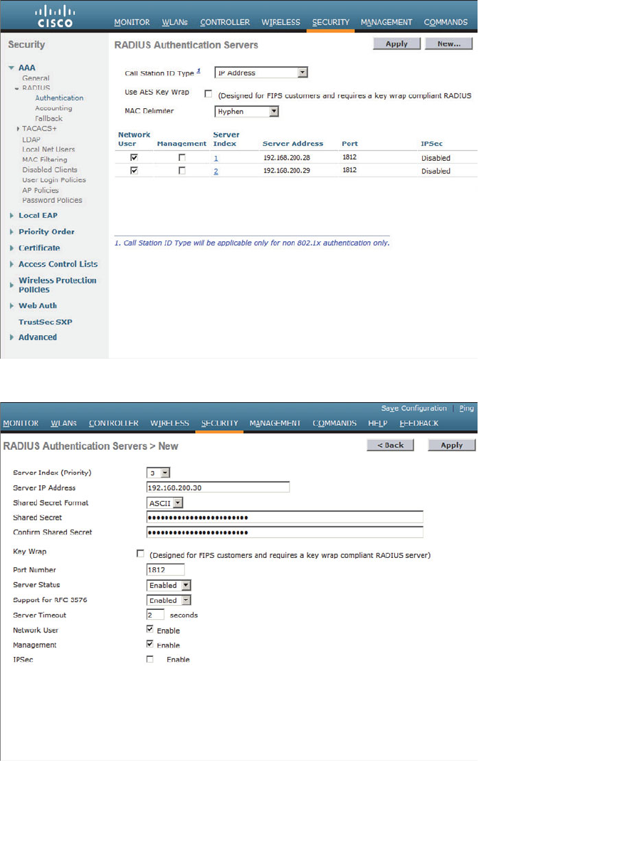
ptg12542968
Chapter 15: Configuring a WLAN 311
Figure 15-2 Displaying the List of RADIUS Authentication Servers.
Figure 15-3 Configuring a New RADIUS Server.
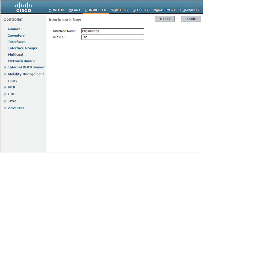
ptg12542968
312 CCNA Wireless 640-722 Official Cert Guide
Creating a Dynamic Interface
In Chapter 10 , “Initial Controller Configuration,” you learned about the different types
of controller interfaces. A dynamic interface is used to connect the controller to a
VLAN on the wired network. When you create a WLAN, you will bind the dynamic
interface (and VLAN) to a wireless network.
To create a new dynamic interface, navigate to Controller > Interfaces . You should see
a list of all the controller interfaces that are currently configured. Click the New button
to define a new interface. Enter a name for the interface and the VLAN number it will
be bound to. In Figure 15-4 , the interface named Engineering is mapped to wired VLAN
100. Click the Apply button.
Figure 15-4 Defining a Dynamic Interface Name and VLAN ID.
Next, enter the IP address, subnet mask, and gateway address for the interface. You
should also define a primary and secondary DHCP server addresses that the control-
ler will use when it relays DHCP requests from clients that are bound to the interface.
Figure 15-5 shows how interface Engineering has been configured with IP address
192.168.100.10. Click the Apply button to complete the interface configuration and
return to the list of interfaces.
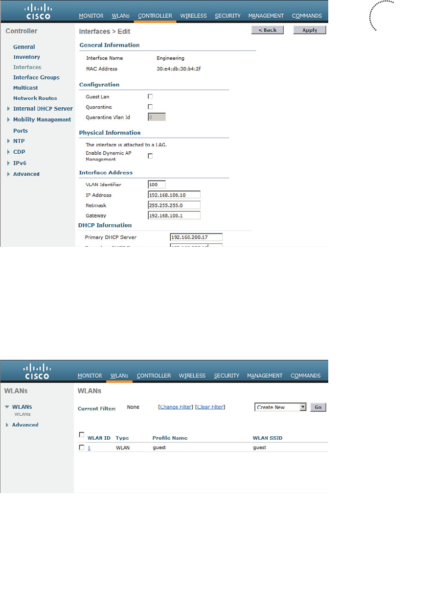
ptg12542968
Chapter 15: Configuring a WLAN 313
Figure 15-5 Editing the Dynamic Interface Parameters.
Creating a New WLAN
You can display a list of the currently defined WLANs by selecting WLANs from
the top menu bar. In Figure 15-6 , the controller has one WLAN called guest already
defined. You can create a new WLAN by selecting Create New from the drop-down
menu and then clicking the Go button.
Figure 15-6 Displaying a List of WLANs.
Key
Topic
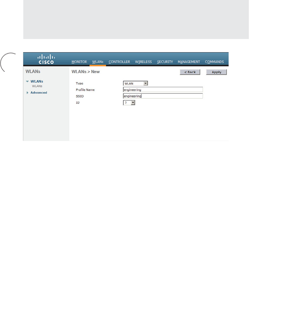
ptg12542968
314 CCNA Wireless 640-722 Official Cert Guide
Next, enter a descriptive name as the profile name and the SSID text string. In Figure
15-7 , the profile name and SSID are identical, just to keep things straightforward. The
ID number is used as an index into the list of WLANs that are defined on the control-
ler. The ID number becomes useful when you use templates on Cisco Network Control
System (NCS) or Prime Infrastructure (PI) to configure WLANs on multiple controllers
at the same time.
Tip WLAN templates are applied to specific WLAN ID numbers on controllers. As a
rule, you should keep the sequence of WLAN names and IDs consistent across multiple
controllers so that any configuration templates you use in the future will be applied to
the correct WLANs.
Figure 15-7 Creating a New WLAN.
Click the Apply button to create the new WLAN. The next page will allow you to edit
four categories of parameters, corresponding to the tabs across the top as shown in
Figure 15-8 . By default, the General tab is selected.
You can control whether the WLAN is enabled or disabled with the Status check box.
Even though the General page shows a specific security policy for the WLAN (the
default WPA2 with 802.1x), you can make changes in a later step through the Security
tab.
Under Radio Policy, select the type of radios that will offer the WLAN. By default, the
WLAN will be offered on all radios that are joined with the controller. You can select
a more specific policy with 802.11a only, 802.11a/g only, 802.11g only, or 802.11b/g
only. For example, if you are creating a new WLAN for devices that have only a 2.4-
GHz radio, it probably does not make sense to advertise the WLAN on both 2.4- and
5-GHz AP radios.
Next, select the controller interface that will be bound to the WLAN. The drop-down
list contains all the interface names that are available. In Figure 15-8 , the new engineering
WLAN will be bound to the Engineering interface.
Key
Topic

ptg12542968
Chapter 15: Configuring a WLAN 315
Finally, use the Broadcast SSID check box to select whether the APs should broadcast
the SSID name in the beacons. Broadcasting SSIDs is usually more convenient for users,
because their devices can learn and display the SSID names automatically. Hiding the
SSID name, by not broadcasting it, does not really provide any worthwhile security.
Instead, it just prevents user devices from discovering an SSID and trying to use it as a
default network.
Configuring WLAN Security
Select the Security tab to configure the security settings. By default, the Layer 2 security
tab is selected. From the Layer 2 Security drop-down menu, select the appropriate secu-
rity scheme to use. Table 15-2 lists the types that are available. You can also check the
MAC Filtering check box to use client MAC addresses as authentication credentials.
Table 15-2 Layer 2 WLAN Security Types
Option Description
None Open authentication
WPA+WPA2 Wi-Fi protected access WPA or WPA2
802.1x EAP authentication with dynamic WEP
Figure 15-8 Configuring the General WLAN Parameters.
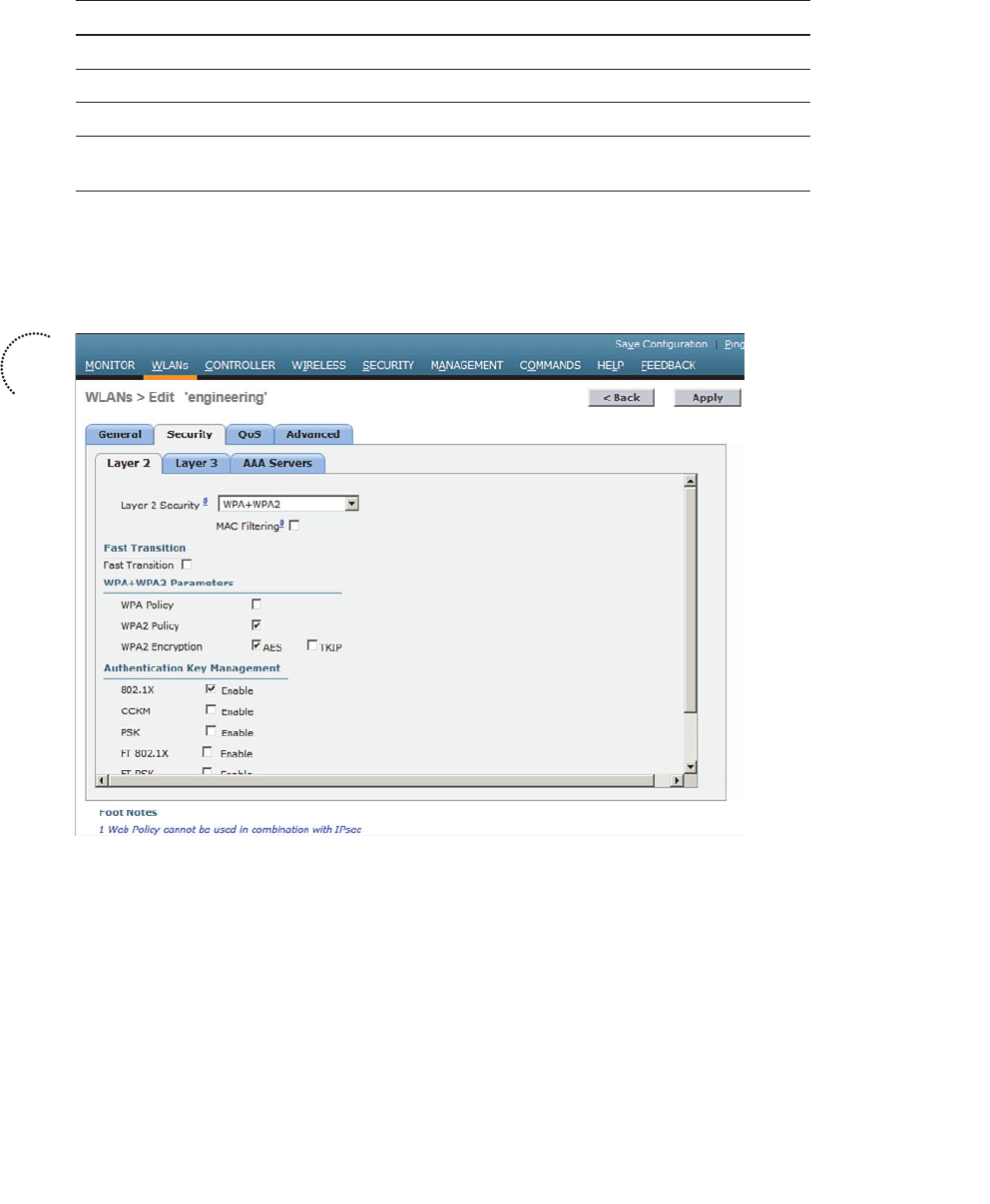
ptg12542968
316 CCNA Wireless 640-722 Official Cert Guide
Option Description
Static WEP WEP key security
Static WEP + 802.1x EAP authentication or static WEP
CKIP Cisco Key Integrity Protocol
None + EAP Passthrough Open authentication with remote EAP
authentication
In Figure 15-9 , WPA+WPA2 security is selected. In the remainder of the page, you can
set parameters that are specific to the security scheme. For example, WPA2 with AES is
used, but WPA and TKIP are not.
Figure 15-9 Configuring Layer 2 WLAN Security.
If you choose a Layer 2 security scheme that requires a RADIUS server, the controller
will use the global list of servers you have defined under Security > AAA > RADIUS >
Authentication . You can override that list by identifying up to three specific RADIUS
servers in the WLAN configuration. Display the AAA Servers tab, then under each
server, you can select a specific server IP address from the drop-down menu of glob-
ally defined servers. Servers 1, 2, and 3 are tried in sequential order until one of them
responds. In Figure 15-10 , Server 1 is being set from a list of servers at 192.168.200.28,
192.168.200.29, and 192.168.200.30.
Key
Topic
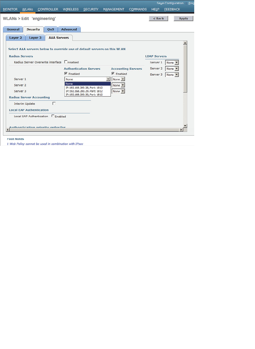
ptg12542968
Chapter 15: Configuring a WLAN 317
Figure 15-10 Selecting RADIUS Servers for WLAN Authentication.
By default, a controller will contact a RADIUS server from its management interface.
You can override this behavior by checking the box next to Radius Server Overwrite
Interface , so that the controller sources RADIUS requests from the dynamic interface
that is associated with the WLAN.
Configuring WLAN QoS
Display the QoS tab to configure quality of service settings for the WLAN, as shown
in Figure 15-11 . By default, the controller will consider all frames in the WLAN to be
normal data, to be handled in a “best effort” manner. You can set the Quality of Service
(QoS) drop-down menu to classify all frames in one of the following ways:
■ Platinum (voice)
■ Gold (video)
■ Silver (best effort)
■ Bronze (background)
You can also set the Wi-Fi Multimedia (WMM) policy and call admission control (CAC)
policies on the QoS page.

ptg12542968
318 CCNA Wireless 640-722 Official Cert Guide
Figure 15-11 Configuring QoS Settings.
Configuring Advanced WLAN Settings
Finally, display the Advanced tab to configure a variety of advanced WLAN settings.
From the page shown in Figure 15-12 , you can enable functions such as coverage hole
detection, peer-to-peer blocking, client exclusion, client load limits, and so on.
Although most of the advanced settings are beyond the scope of the CCNA Wireless
level, you should be aware of a few defaults that might affect your wireless clients.
By default, client sessions with the WLAN are limited to 1800 seconds (30 minutes).
Once that session time expires, a client will be required to reauthenticate. This setting is
controlled by the Enable Session Timeout check box and the Timeout field.
A controller maintains a set of security policies that are used to detect potentially mali-
cious wireless clients. If a client exhibits a certain behavior, the controller can exclude
it from the WLAN for a period of time. By default, all clients are subject to the policies
configured under Security > Wireless Protection Policies > Client Exclusion Policies .
These policies include excessive 802.11 association failures, 802.11 authentication fail-
ures, 802.1x authentication failures, web authentication failures, and IP address theft or
reuse. Offending clients will be automatically excluded or blocked for 60 seconds, as a
deterrent to attacks on the wireless network.
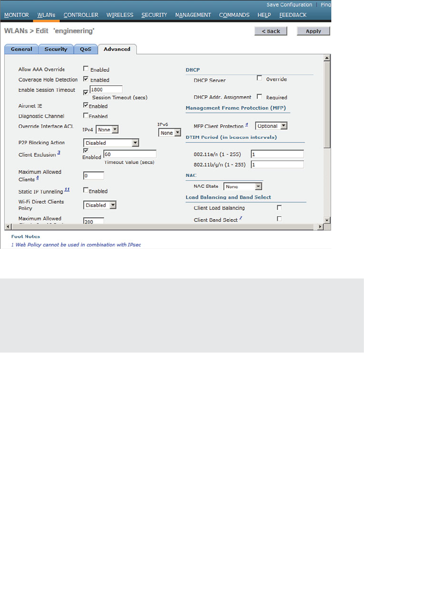
ptg12542968
Chapter 15: Configuring a WLAN 319
Tip Is 60 seconds really enough time to deter an attack coming from a wireless cli-
ent? In the case of a brute-force attack, where passwords are guessed from a dictionary
of possibilities, 60 seconds is enough to disrupt and delay an attacker’s progress. What
might have taken 2 minutes to find a matching password without an exclusion policy
would take 15 years with one.
Finalizing WLAN Configuration
When you are satisfied with the settings in each of the WLAN configuration tabs, click
the Apply button. The WLAN will be created and added to the controller configuration.
In Figure 15-13 , the engineering WLAN has been added as WLAN ID 2 and is enabled
for use.
Figure 15-12 Configuring Advanced WLAN Settings.

ptg12542968
320 CCNA Wireless 640-722 Official Cert Guide
Figure 15-13 Displaying WLANs Configured on a Controller.
Exam Preparation Tasks
As mentioned in the section, “How to Use This Book,” in the Introduction, you have a
couple of choices for exam preparation: the exercises here, Chapter 22 , “Final Review,”
and the exam simulation questions on the CD-ROM.
Review All Key Topics
Review the most important topics in this chapter, noted with the Key Topic icon in the
outer margin of the page. Table 15-3 lists a reference of these key topics and the page
numbers on which each is found.
Table 15-3 Key Topics for Chapter 15
Key Topic Element Description Page Number
Figure 15-5 Creating a dynamic interface 313
Figure 15-7 Creating a WLAN 314
Figure 15-9 Configuring WLAN security 316
Key
Topic

ptg12542968
This page intentionally left blank

ptg12542968
This chapter covers the following topics:
■ Guest Network Overview —This section describes
a guest wireless network and how it can be used to
segregate guests from other users on a network.
■ Configuring a Guest Network —This section covers
the process needed to implement a guest wireless
LAN.
■ Scaling the Guest Network —This section explains
how the guest WLANs on multiple controllers can
be merged and aimed toward a common anchor
point. As a result, guest users can be isolated and
contained with one set of policies.
This chapter covers the following exam topics:
■ Describe and configure authentication methods
(Guest, PSK, 802.1X, WPA/WPA2 with EAP- TLS,
EAP-FAST, PEAP, and LEAP)

ptg12542968
In Chapter 15 , “Configuring a WLAN,” you learned how to define and configure a new
wireless LAN to support a community of clients that have something in common. You
can even configure multiple WLANs to support multiple user communities. In most
cases, the WLAN users are trusted at some level because they are a necessary part of
your enterprise.
What about guest users, who might not be trusted or integral to your business? Guest
users commonly need to access the wireless network as a convenience. This chapter dis-
cusses the steps you can take to configure a guest network as an extension to your wire-
less infrastructure.
“Do I Know This Already?” Quiz
The “Do I Know This Already?” quiz allows you to assess whether you should read this
entire chapter thoroughly or jump to the “Exam Preparation Tasks” section. If you are
in doubt about your answers to these questions or your own assessment of your knowl-
edge of the topics, read the entire chapter. Table 16-1 lists the major headings in this
chapter and their corresponding “Do I Know This Already?” quiz questions. You can
find the answers in Appendix A , “Answers to the ‘Do I Know This Already?’ Quizzes.”
Table 16-1 “Do I Know This Already?” Section-to-Question Mapping
Foundation Topics Section Questions
Guest Network Overview 1–2
Configuring a Guest Network 3
Scaling the Guest Network 4–6
Caution The goal of self-assessment is to gauge your mastery of the topics in this chap-
ter. If you do not know the answer to a question or are only partially sure of the answer,
you should mark that question as wrong for purposes of the self-assessment. Giving your-
self credit for an answer you correctly guess skews your self-assessment results and might
provide you with a false sense of security.
CHAPTER 16
Implementing a Wireless Guest
Network

ptg12542968
324 CCNA Wireless 640-722 Official Cert Guide
1.
Which one of the following should be used to contain visitors and transient users of
a wireless network?
a. WPA2 enterprise
b. Guest WLAN
c. One-time WEP
d. Broadcast SSID
2.
Once a data WLAN and a guest WLAN are configured on a controller and mapped
to two VLANs, the controller can provide connectivity between the two. True or
false?
a. True
b. False
3.
To create a guest WLAN, which one of the following must be configured on a wire-
less controller?
a. A private WLAN
b. A guest mobility group
c. A guest BSS
d. A regular WLAN
4.
By default, all guest WLANs defined on controllers in an enterprise are merged into
one VLAN and subnet. True or false?
a. True
b. False
5.
Which one of the following is necessary to merge guest WLANs from multiple con-
trollers onto a common guest WLAN on a controller?
a. RF group
b. Global WLAN
c. Mobility anchor
d. Master controller
e. NCS templates
6.
You can configure only one controller as a mobility anchor for a guest WLAN. True
or false?
a. True
b. False
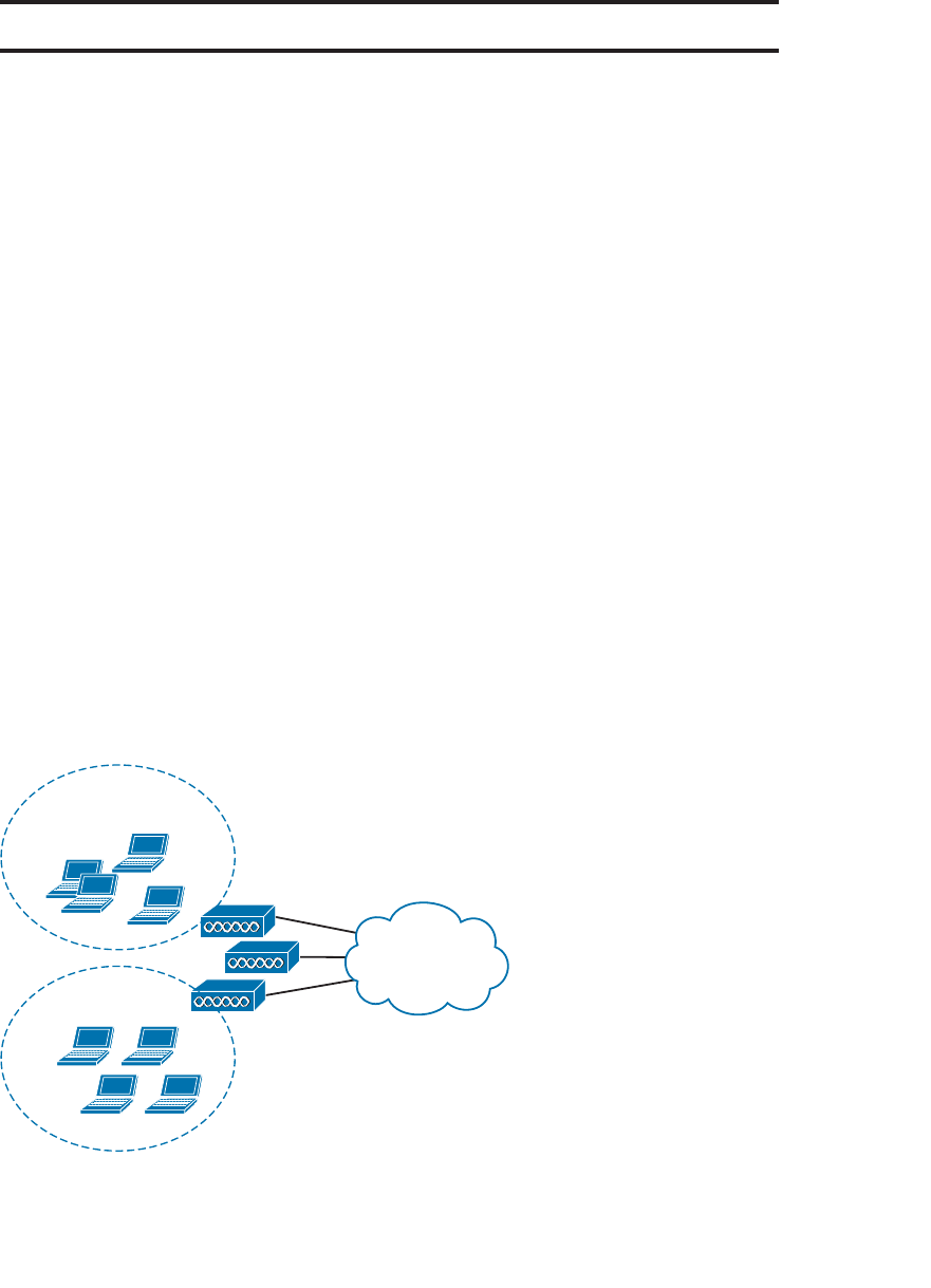
ptg12542968
Chapter 16: Implementing a Wireless Guest Network 325
Foundation Topics
Guest Network Overview
Wireless LANs are usually configured to support specific groups of clients or client
devices. For example, one WLAN might support wireless users in the Engineering
department, even if that department is scattered in several buildings or locations. Other
WLANs might support a sales staff, teachers, students, and so on. These examples seg-
ment wireless users by function or the need to access certain enterprise resources. Each
WLAN might have a different set of security policies from the others.
You might also decide to create WLANs to support different types of wireless devices.
For example, one WLAN could be configured to support all medical devices in a hospi-
tal that can use only Wi-Fi Protected Access Version 2 (WPA2) with a pre-shared key.
A separate WLAN could be created for users with medical devices that support WPA2
Enterprise, with digital certificates. In these cases, WLANs are created according to the
wireless device capabilities.
As a wireless network administrator, you might be asked to provide connectivity for
users who do not fall into any convenient category. Guest users are normally temporary
visitors who need to access a wireless network to make their work and their time onsite
more convenient. Because guests are not regular, trusted employees, you should always
try to offer some basic network access while containing and isolating them from the
trusted portion of your network.
In Figure 16-1 , both guests and engineering staff are able to use the same wireless infra-
structure, while the two user groups are kept isolated from each other. The engineering
users can communicate directly with the company resources. However, the guest users
are commonly placed within a demilitarized zone (DMZ) that has limited access and is
secured by a firewall.
Engineering Clients
Guest Clients
WLAN
Infrastructure
Figure 16-1 Isolating Guest Wireless Users from Other User Groups.
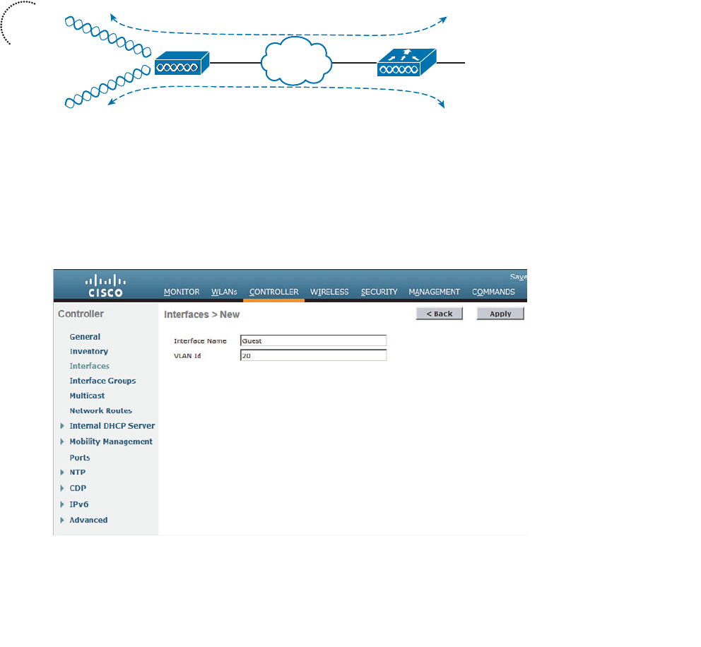
ptg12542968
326 CCNA Wireless 640-722 Official Cert Guide
Configuring a Guest Network
Building a guest wireless network might seem like a complex task; however, it is really no
different from building any other WLAN that is tailored for a user community. The trick
is to provide the appropriate degree of isolation from the rest of the enterprise network.
The guest WLAN can be bound to a guest VLAN that is isolated from other VLANs, as
shown in Figure 16-2 . Before guest users can access any other WLAN or VLAN, a router
or firewall must permit and provide the access. The Guest WLAN advertises service set
identifier (SSID) Guest and is bound to the controller’s Guest interface on VLAN 20. The
same access point (AP) and controller infrastructure has an Engineering WLAN that is
bound to the controller’s Engineering interface on VLAN 100.
SSID Engineering
Interface Engineering
VLAN 100
192.168.100.0/24
WLC-1
AP-1
SSID Guest Interface Guest
VLAN 20
192.168.20.0/24
Trunk Link
Figure 16-2 Isolation Between a Guest and Other WLANs.
To create a guest WLAN, follow these steps:
Step 1. Create a dynamic interface for the guest WLAN. Under Controller >
Interfaces > New , define the dynamic interface, the VLAN ID, and the IP
addressing information. Figures 16-3 and 16-4 show an interface named
Guest configured for VLAN 20 and the 192.168.20.0/24 subnet.
Figure 16-3 Creating a Controller Interface for a Guest WLAN.
Key
Topic
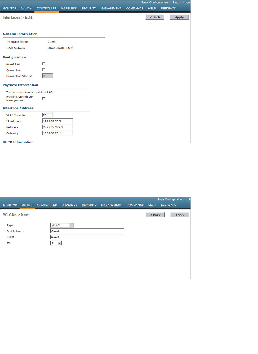
ptg12542968
Chapter 16: Implementing a Wireless Guest Network 327
Figure 16-4 Configuring IP Address Information on the Guest Interface.
Step 2. Create the guest WLAN.
Select WLAN > New to define a new WLAN, and then enter the profile
name and SSID. In Figure 16-5 , the controller has been configured with a sec-
ond WLAN (ID 2) that uses SSID Guest.
Figure 16-5 Creating a Guest WLAN.
Step 3. Bind the guest WLAN to the guest WLAN interface.
On the General tab of the WLAN, select the guest controller interface to
be used. In Figure 16-6 , the Guest WLAN is configured to use the Guest
dynamic interface.
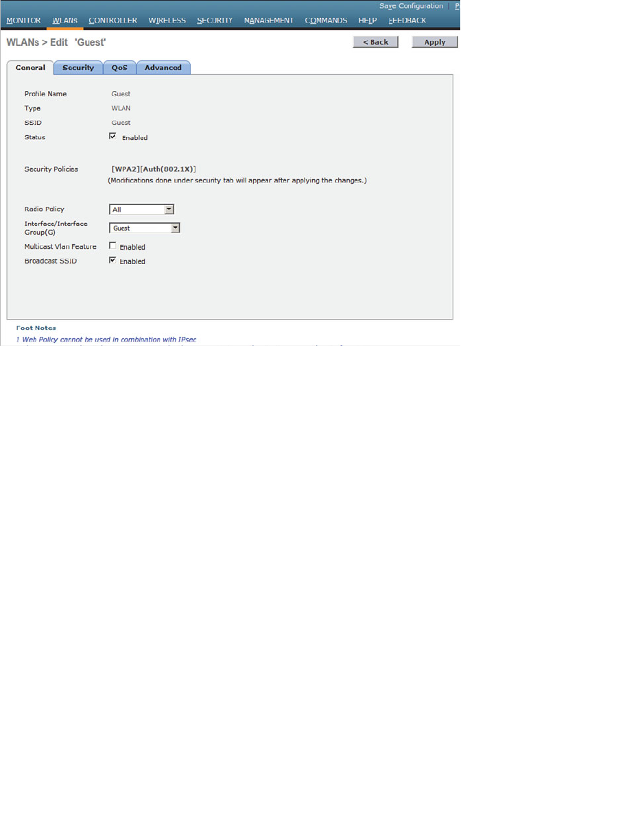
ptg12542968
328 CCNA Wireless 640-722 Official Cert Guide
Figure 16-6 Assigning a Dynamic Interface to the Guest WLAN.
Step 4. Configure wireless security. Guest users are commonly kept isolated from an
enterprise network. Even so, you will have to decide how to secure the guest
WLAN for its users. For example, your security policies might dictate that
guest users must be authenticated before they are granted any access at all.
You might also want to configure a wireless security mechanism to encrypt
and protect each guest user’s traffic from eavesdropping and tampering. On
the Security tab, you can select a Layer 2 security scheme as shown in Figure
16-7 . You can also select the Layer 3 tab to enable web authentication,
where guest users are presented with a login web page before being allowed
to connect to the guest network.
To authenticate guest users, you can use one of the following methods:
■ Create guest users on a RADIUS server, which will be authenticated with 802.1x
■ Create local usernames and passwords on the controller; either a lobby ambassador
or an administrative user on the controller can log into the controller and create
temporary guest user credentials
At the CCNA level, you should know how to configure and implement a guest wireless
network. Guest user authentication is not specified on the exam blueprint.
Be sure to visit the QoS and Advanced tabs to complete the guest WLAN configuration.
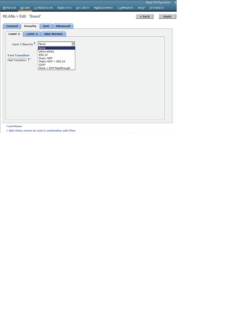
ptg12542968
Chapter 16: Implementing a Wireless Guest Network 329
Scaling the Guest Network
Configuring a guest WLAN on a single controller is straightforward. The guest WLAN
is just like any other WLAN defined on the controller. In larger installations, you might
have more than one controller. In that case, each guest WLAN terminates on its own
controller, making it difficult to isolate all guest clients in a single DMZ or behind a
single firewall.
Recall from Chapter 12 , “Understanding Roaming,” that Cisco WLCs can support Layer
3 roaming by automatically building a tunnel between the first controller a client associ-
ates with and the controller where the client is currently located. In effect, the client is
tunneled from a foreign controller back to the original anchor controller. This same tun-
neling strategy can be leveraged to funnel guest clients from any controller into a mobil-
ity anchor controller where guests share a common IP subnet and security policies.
Where Layer 3 roaming builds controller-to-controller tunnels to follow clients as they
move, mobility anchors are configured ahead of time so that guest clients will be tun-
neled to a predetermined anchor. Figure 16-8 illustrates the concept with three WLCs.
Each WLC is configured with its own guest WLAN, but only WLC-1 is identified as a
mobility anchor. Regardless of which controller a guest user joins, the user will be tun-
neled to the anchor and connected into the guest VLAN. You can also identify several
mobility anchors so that guest users can be distributed across them to balance the load.
Figure 16-7 Configuring Guest WLAN Security.
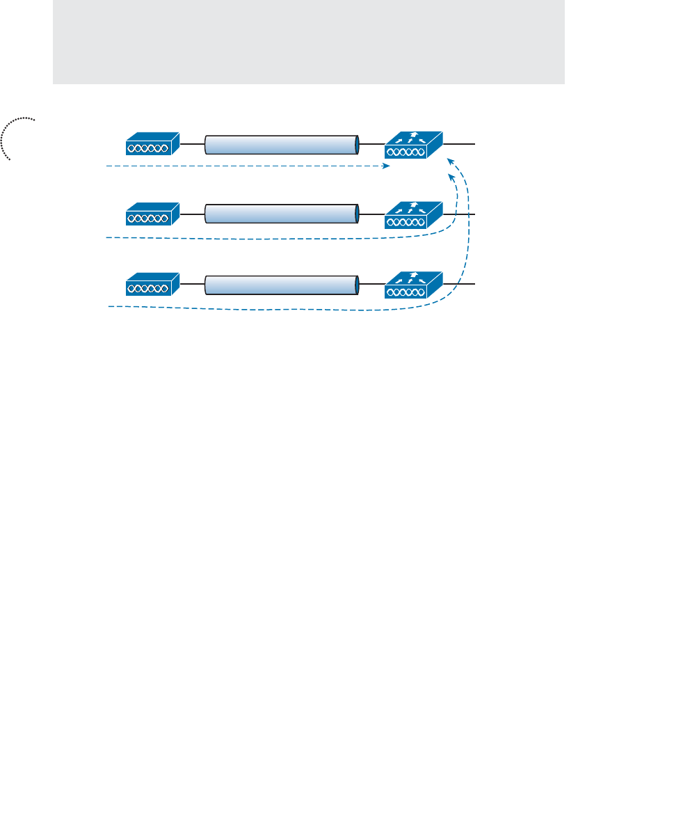
ptg12542968
330 CCNA Wireless 640-722 Official Cert Guide
Tip In many implementations, the controller used as a mobility anchor for a guest
network does not even have any APs joined to it. Instead, it acts as the final destination
for the guest WLANs across an entire enterprise network. Without APs to support, the
anchor controller can devote more resources toward handling guest users.
WLC-2
AP-1
SSID Guest
Interface Guest
VLAN 20
192.168.20.0/24
WLC-1
WLC-3
AP-2
AP-3
SSID Guest
SSID Guest
CAPWAP
CAPWAP
CAPWAP
Figure 16-8 Using Mobility Anchors to Consolidate Guest Wireless Clients.
Configuring mobility anchors is straightforward, provided you configure every control-
ler involved in the guest WLAN consistently and use the following steps:
Step 1. Create a guest WLAN on each controller. The guest WLAN should be config-
ured identically across all of the controllers so that each one can build a tun-
nel to the anchor. The foreign and anchor controller guest WLANs can have
different outgoing interfaces, RADIUS servers, and pre-shared keys. Because
the guest WLAN on each controller is tunneled to the anchor controller, the
outgoing interface does not really matter. For this reason, the management
interface is commonly used. The guest WLAN on the anchor controller,
however, must use the actual dynamic interface name for the guest DMZ net-
work.
Step 2. Form a mobility group relationship.
All the controllers involved must be configured to use the same mobility
group before the anchor relationships can be built. Each of the controllers
must be listed in the anchor controller’s mobility group list, and vice versa.
Step 3. Identify the anchor on each controller. Be aware that even the anchor con-
troller must be configured with an anchor controller (itself) so that it will
accept tunnels from other controllers. Configure the anchor controller first
by selecting the WLANs tab to display the list of WLANs. At the far-right
end of the guest WLAN entry, right-click the blue triangle, and then select
Mobility Anchors from the drop-down menu, as shown in Figure 16-9 .
Key
Topic
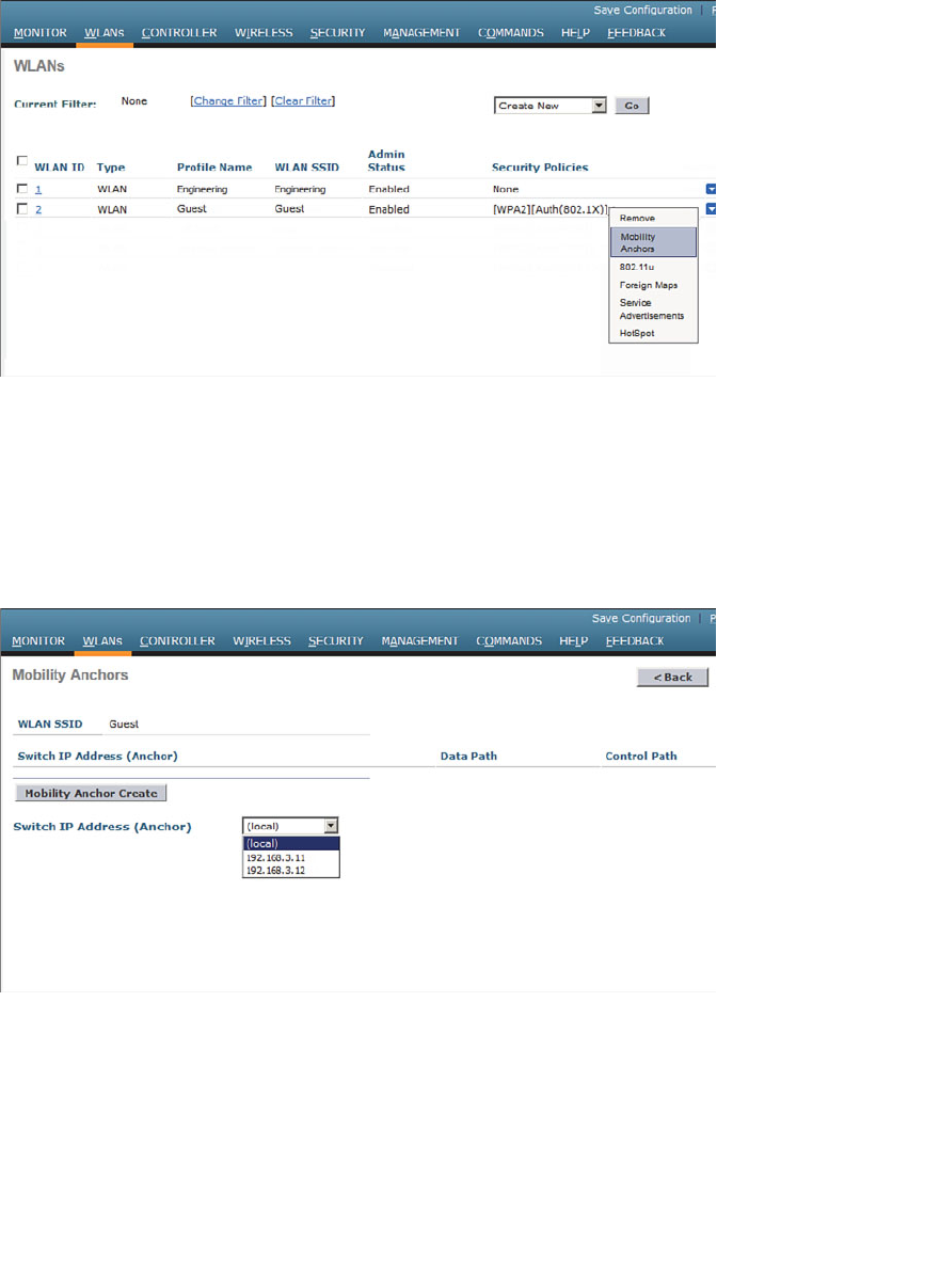
ptg12542968
Chapter 16: Implementing a Wireless Guest Network 331
Figure 16-9 Configuring a Mobility Anchor on a Guest WLAN.
From the Switch IP Address (Anchor) drop-down menu, select the anchor controller
from the list of controllers that are members of the mobility group. The local entry that
is displayed in the list of switch IP addresses represents the controller you are configur-
ing. Select the local entry and click the Mobility Anchor Create button. In Figure 16-10 ,
the local switch that is being configured will serve as the mobility anchor for the guest
WLAN.
Figure 16-10 Enabling a Controller as the Mobility Anchor.
Next, move to a different controller and repeat the process. On that controller, you will
select the IP address of the anchor controller and click the Mobility Anchor Create but-
ton. In Figure 16-11 , the controller at 192.168.3.10 has been identified as the mobility
anchor. Once the two controllers know about their new relationship, they will display
the status of their EoIP tunnel. The figure shows the control and data paths as Up.
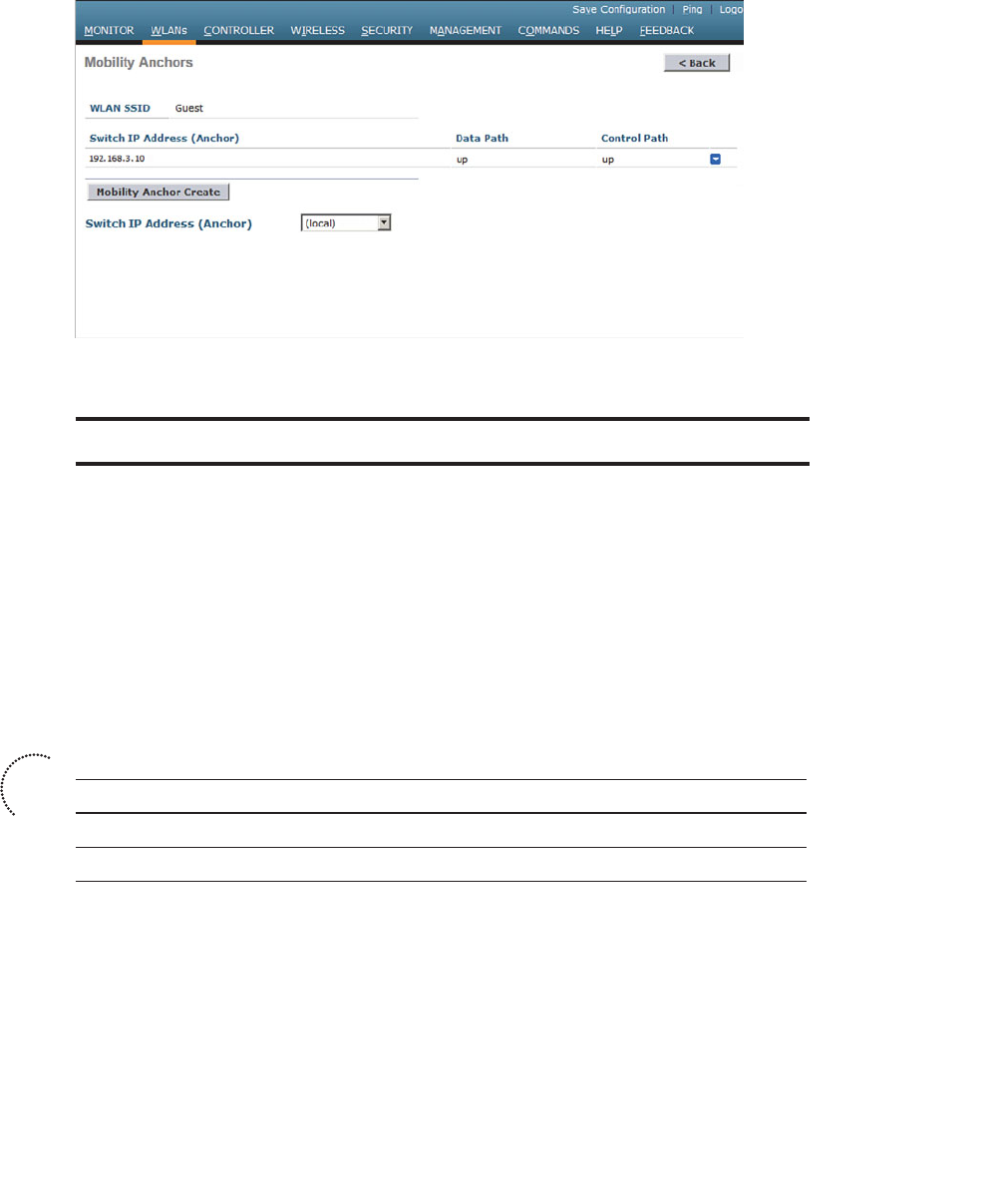
ptg12542968
332 CCNA Wireless 640-722 Official Cert Guide
Figure 16-11 Identifying the Mobility Anchor on Another Controller.
Exam Preparation Tasks
As mentioned in the section, “How to Use This Book,” in the Introduction, you have a
couple of choices for exam preparation: the exercises here, Chapter 22 , “Final Review,”
and the exam simulation questions on the CD-ROM.
Review All Key Topics
Review the most important topics in this chapter, noted with the Key Topic icon in the
outer margin of the page. Table 16-2 lists a reference of these key topics and the page
numbers on which each is found.
Table 16-2 Key Topics for Chapter 16
Key Topic Element Description Page Number
Figure 16-2 WLAN isolation 326
Figure 16-8 Scaling the guest WLAN 330
Define Key Terms
Define the following key terms from this chapter and check your answers in the
glossary:
guest WLAN, mobility anchor
Key
Topic

ptg12542968
This page intentionally left blank

ptg12542968
This chapter covers the following topics:
■ Configuring Common Wireless Clients —This sec-
tion provides an overview of several common clients
and how they are configured.
■ Cisco Compatible Extensions (CCX) —This section
describes the CCX program and how it is used to
certify compatibility with sets of Cisco features and
extensions.
This chapter covers the following exam topics:
■ Describe client WLAN configuration requirements,
such as Service Set Identifier (SSID), security selec-
tion, and authentication
■ Identify basic configuration of common wire-
less supplicants (Macintosh, Intel Wireless Pro,
Windows, iOS, and Android)
■ Describe basic AnyConnect 3.0 or above wireless
configuration parameters
■ Identify capabilities available in CCX versions 1
through 5

ptg12542968
A Cisco Unified Wireless Network (CUWN) consists of wireless LAN controllers, light-
weight access points, and wireless client devices. Even though the majority of this book
is devoted to the controllers and access points (APs), the CCNA Wireless exam also
includes client configuration. Why? When you build and support a wireless network,
you often need to help your users configure and troubleshoot their devices so that they
can use your network.
Wireless networks suffer from the bring-your-own-devices (BYOD) syndrome, where
users often carry all sorts of wireless devices with them. Each device might use a differ-
ent operating system, different wireless adapter hardware, and have different capabili-
ties. This chapter covers the most common types of wireless clients.
“Do I Know This Already?” Quiz
The “Do I Know This Already?” quiz allows you to assess whether you should read this
entire chapter thoroughly or jump to the “Exam Preparation Tasks” section. If you are
in doubt about your answers to these questions or your own assessment of your knowl-
edge of the topics, read the entire chapter. Table 17-1 lists the major headings in this
chapter and their corresponding “Do I Know This Already?” quiz questions. You can
find the answers in Appendix A , “Answers to the ‘Do I Know This Already?’ Quizzes.”
Table 17-1 “Do I Know This Already?” Section-to-Question Mapping
Foundation Topics Section Questions
Configuring Common Wireless Clients 1–3
Cisco Compatible Extensions (CCX) 4–10
Caution The goal of self-assessment is to gauge your mastery of the topics in this chap-
ter. If you do not know the answer to a question or are only partially sure of the answer,
you should mark that question as wrong for purposes of the self-assessment. Giving your-
self credit for an answer you correctly guess skews your self-assessment results and might
provide you with a false sense of security.
CHAPTER 17
Understanding Wireless Clients

ptg12542968
336 CCNA Wireless 640-722 Official Cert Guide
1.
On a Windows machine that has an Intel wireless adapter, wireless connections can
be managed from both Windows Network and Sharing Center and the Intel PROSet
Utility application. True or false?
a. True
b. False
2.
Which one of the following modules must be installed with the Cisco AnyConnect
client?
a. VPN
b. DART
c. Posture
d. Web Security
3.
Which one of the following is used to configure and push policies to AnyConnect
clients?
a. Cisco WLC
b. Web browser
c. RADIUS server
d. ASDM
4.
CCX is used to certify which one of the following?
a.
Interoperability between wireless hardware manufacturers
b.
Compatibility with Cisco wireless features
c. RF coverage
d. Wireless networking professionals
5.
To date, how many versions of CCX have been defined?
a. 1
b. 4
c. 5
d. 1 0
6.
Someone has purchased a new 802.11 wireless device to use in an enterprise that has
a Cisco Unified Wireless Network. After reading through the device specifications,
you realize that it is not certified for any CCX version at all. Which one of the fol-
lowing most correctly describes the outcome?

ptg12542968
Chapter 17: Understanding Wireless Clients 337
a.
The device will not work on the network.
b.
The device will likely work fine.
c.
The device must support at least one CCX version to associate with the net-
work.
d.
The device is compatible with all CCX versions because CCX is part of the
802.11 standard.
7.
A wireless device is certified for CCXv1. Which one of the following is a correct
statement?
a.
The device is compatible with all Cisco features.
b.
The device is compatible with WPA.
c.
The device can support MFP.
d. The device is compatible with 802.11.
8. WPA2 with 802.1x and AES is supported in which one of the following CCX ver-
sions?
a. CCXv1
b. CCXv2
c. CCXv3
d. CCXv4
e. CCXv5
9.
Which one of the following is a CCX Lite module?
a. CCXv1
b. Voice
c. Crypto
d. Video
10.
A device is certified as CCX Lite. Which one of the following modules is manda-
tory for that certification?
a. CCXv5
b. Foundation
c. Mobility
d. Survey
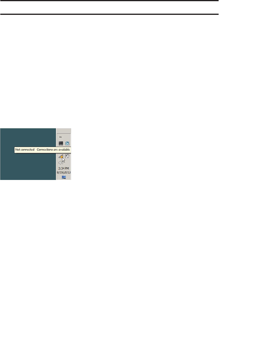
ptg12542968
338 CCNA Wireless 640-722 Official Cert Guide
Foundation Topics
Configuring Common Wireless Clients
As you work through this chapter, keep in mind that the CCNA Wireless exam blueprint
uses words like describe and identify in exam topics that involve client capabilities and
configuration. Therefore, you will find an overview of several common clients in the sec-
tions that follow.
Windows 7 and 8
Microsoft Windows 7 and 8 include a stock wireless client that offers basic connectivity
options. To access the wireless client, display the taskbar and look for the wireless icon
that shows a sequence of bars indicating signal strength. The current network status dis-
plays when you hover the cursor over the icon, as shown in Figure 17-1 .
Figure 17-1 Displaying Windows Network Status.
You can click the wireless network icon to see a list of service set identifiers (SSIDs), as
shown in Figure 17-2 . By default, a Windows PC does not have a prepopulated list of
SSIDs to use. To scan for available SSIDs, it will transmit probe requests with a null or
empty SSID name, expecting nearby APs to respond. You can manually initiate a scan by
clicking on the circulating arrows symbol in the upper-right corner of the wireless net-
work status window. To connect to one of the listed networks, click its name and then
click the Connect button that appears.
You can manually populate a list of wireless networks or edit their properties by click-
ing the Open Network and Sharing Center link and then selecting the Manage Wireless
Networks . Figure 17-3 shows an example list of wireless networks. Windows will try to
find and connect to a network using the ordered sequence in the list. You can change
the order by selecting a network and using the Move Up and Move Down links to move
it to a new position in the list.
To add a new network to the list, click the Add link. As shown in Figure 17-4 , you can
enter the network name (SSID) and security and encryption types. You can also specify
whether the PC should automatically connect to the network each time the SSID is
detected, even if the SSID is not broadcast in any beacon frames.
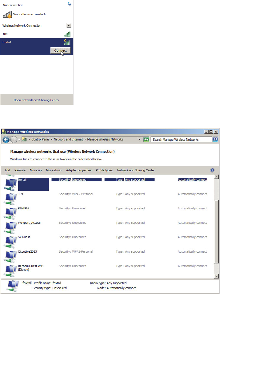
ptg12542968
Chapter 17: Understanding Wireless Clients 339
Figure 17-3 Displaying a List of Wireless Networks.
Figure 17-2 Selecting a Wireless Network to Use.
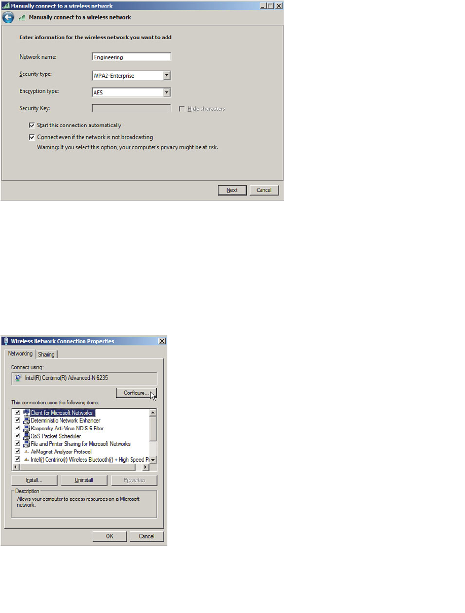
ptg12542968
340 CCNA Wireless 640-722 Official Cert Guide
Figure 17-4 Manually Configuring a New Wireless Network.
The built-in Windows wireless client does not offer many specific configuration options;
however, you might find more options by configuring the wireless adapter. From the
Network and Sharing Center, select Change Adapter Settings to display a list of installed
adapters. Right-click a wireless adapter and select Properties to display the adapter prop-
erties and a list of installed protocols, as shown in Figure 17-5 . Click the Configure button
to bring up a window of adapter driver properties. Finally, display the Advanced tab to
display a list of parameters and values, as shown in Figure 17-6 . The list of parameters var-
ies from one adapter to another, depending on what settings the manufacturer offers.
Figure 17-5 Configuring Wireless Adapter Properties.
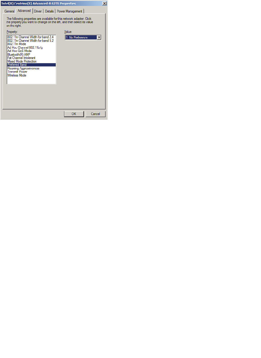
ptg12542968
Chapter 17: Understanding Wireless Clients 341
Figure 17-6 Configuring Advanced Wireless Adapter Settings.
Intel PROSet
If you have an Intel wireless adapter installed, you can download and install the Intel
PROSet driver to access additional features that are not offered by the native Windows
driver. For example, the Windows driver does not support Lightweight Extensible
Authentication Protocol (LEAP), EAP Flexible Authentication by Secure Tunneling
(EAP-FAST), or Cisco Compatible Extensions (CCX), but the Intel PROSet driver does.
The Intel PROSet driver integrates Intel-specific features directly into the wireless net-
work and wireless adapter configurations that you can access through the Windows
Network and Sharing Center.
You can configure additional wireless security features by navigating to Manage
Wireless Networks and then editing the properties of a wireless network. On the
Security tab, you can select the security type, encryption type, and authentication meth-
od. In Figure 17-7 , 802.1x security has been selected. Notice that the Intel PROSet driv-
er has added authentication methods Cisco:LEAP, Cisco:PEAP, and Cisco:EAP-FAST.
To enable the CCX on the Intel adapter, display the Connection tab and check the
box next to Enable Intel Connection Settings , as shown in Figure 17-8 . Then click the
Configure button, select Cisco Options, and then check the box next to Enable Radio
Measurement .
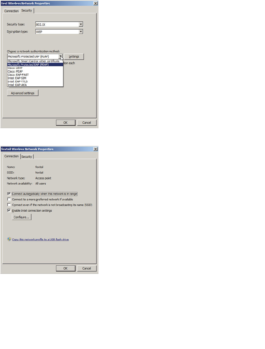
ptg12542968
342 CCNA Wireless 640-722 Official Cert Guide
Figure 17-7 Configuring Intel PROSet Wireless Security Settings.
Figure 17-8 Enabling Intel PROSet Wireless Adapter Connection Settings.
Intel also offers a PROSet utility application that you can download along with the
PROSet driver. The PROSet utility is an alternate way to manage wireless networks and
configure the adapter settings. An Intel wireless adapter can be managed by only one
method—either by Windows or by the Intel PROSet utility.
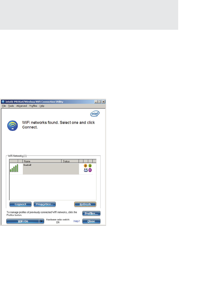
ptg12542968
Chapter 17: Understanding Wireless Clients 343
Tip Even though you can choose to manage an Intel adapter through one of two meth-
ods, it is better to install the PROSet driver and manage the adapter through the native
Windows network configuration tools. In contrast, the Intel PROSet utility application
uses a third-party configuration utility and is not available for all Windows versions.
If you do choose to install the PROSet utility, you can access it through its taskbar icon,
which looks like a radio frequency (RF) wave. If Windows is currently managing the
adapter, you can click the Enable WiFi Control button to switch to PROSet manage-
ment.
Like the native Windows driver, the PROSet utility tries to use any preconfigured wire-
less profiles in sequential order. If no profiles have been defined, it scans for available
networks. In Figure 17-9 , PROSet has discovered one SSID and is waiting for confirma-
tion to connect to it. To do that, you can select the network name and click the Connect
button.
Figure 17-9 Discovering a Network in the Intel PROSet Utility.
You can also configure a list of network profiles by clicking the Profiles button. As you
build a list, you can change the order that the profiles are tried by selecting one and
using the up and down arrows on the right side of the window to raise or lower the pro-
file in the list.
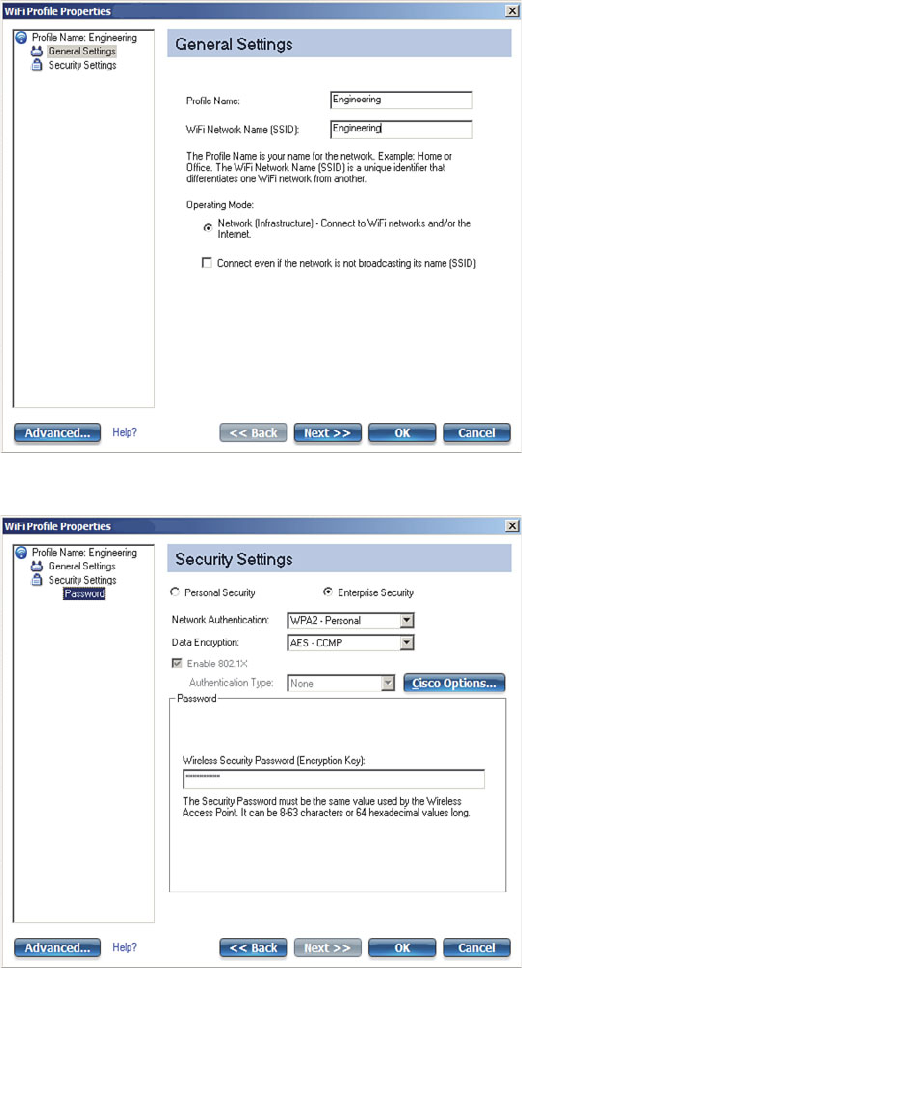
ptg12542968
344 CCNA Wireless 640-722 Official Cert Guide
To add a new profile, click the Add button. You can configure general settings and secu-
rity parameters as shown in Figures 17-10 and 17-11 , respectively. Click the OK button
to save the profile.
Figure 17-10 Configuring General Parameters for a New PROSet Profile.
Figure 17-11 Configuring Security Parameters for a New PROSet Profile.
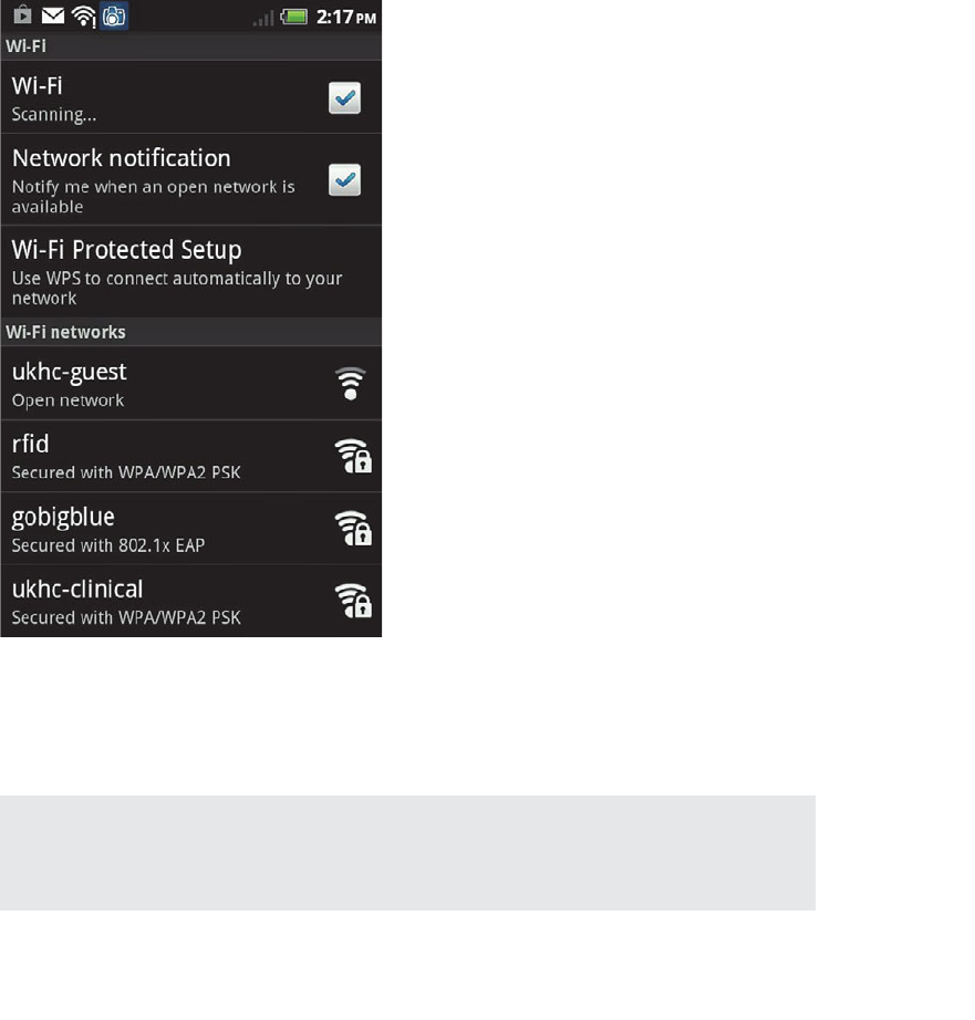
ptg12542968
Chapter 17: Understanding Wireless Clients 345
Android
Devices based on the Android operating system use a built-in driver and utility to man-
age connections to wireless networks. Android devices can discover a list of available
networks and can manage manually configured networks too.
First, you should enable the wireless adapter by selecting Settings > Wireless &
Networks and then checking the Wi-Fi check box. Select Wi-Fi Settings to manage indi-
vidual wireless connections from the list, as shown in Figure 17-12 . The list shows the
SSIDs of networks that have been discovered, in addition to those that are locally con-
figured. After a network has been learned and connected at least once, the device will
automatically try to use it again in the future.
Figure 17-12 Displaying a List of Wireless Networks on an Android Device.
You can manually add a new network by clicking the Add Wi-Fi Network link at the
bottom of the network list. Enter the SSID and security parameters as shown in Figure
17-13 , and then click the Save button.
Tip After a network has been learned, you cannot edit its properties. Instead, you can
select the network name and click the Forget button to remove the network from the list.
From there, the network can be rediscovered or reconfigured manually.
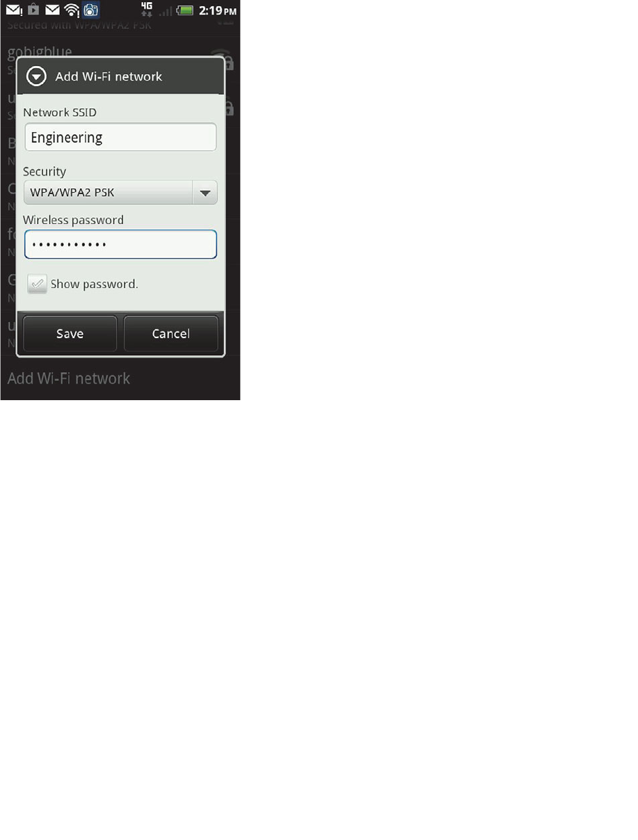
ptg12542968
346 CCNA Wireless 640-722 Official Cert Guide
Figure 17-13 Adding a Wireless Network on an Android Device.
Apple OS X
Apple devices use a built-in wireless adapter and a configuration utility to manage net-
works that are discovered and manually defined. To access the configuration utility,
select System Preferences , and then select Network . Figure 17-14 shows an example,
with all available network types listed down the left side. From this window, you can
enable or disable the wireless adapter. You can also select Wi-Fi and then click the
Advanced button to display and edit the network connection configurations.
The advanced settings window, as shown in Figure 17-15 , has seven tabs across the top.
The Wi-Fi tab contains a list of preferred networks—SSIDs that have already been con-
figured. The network will be tried in sequential order; you can change the order by drag-
ging networks up or down in the list.
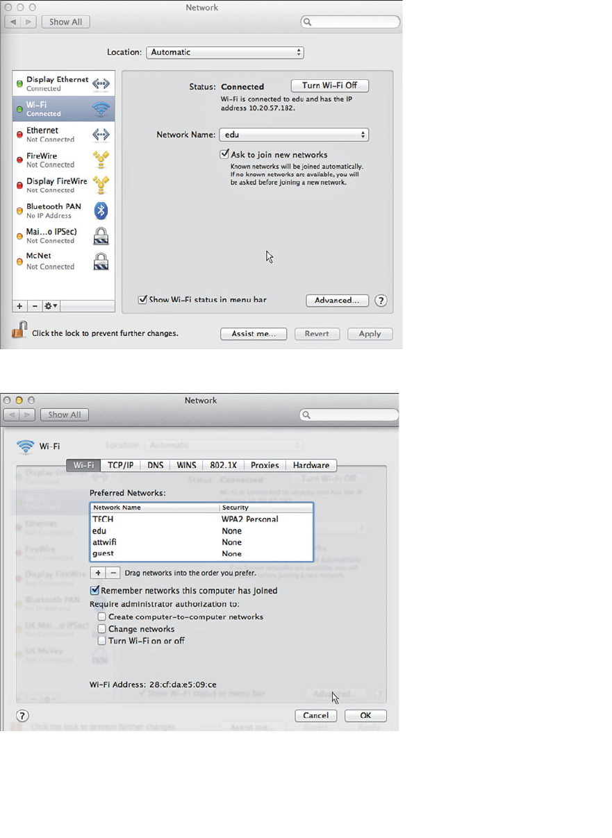
ptg12542968
Chapter 17: Understanding Wireless Clients 347
Figure 17-15 Displaying a List of Preferred Wireless Networks.
Figure 17-14 Accessing Apple Network Properties.
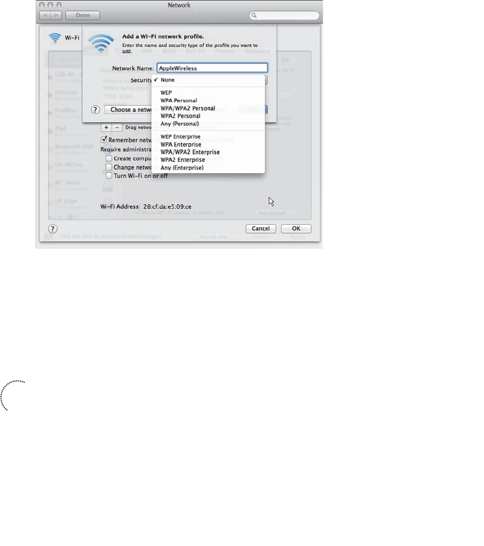
ptg12542968
348 CCNA Wireless 640-722 Official Cert Guide
You can create a new wireless network by clicking the + (plus sign) button. As shown in
Figure 17-16 , you can enter an SSID and security parameters for the new network pro-
file.
Figure 17-16 Creating a New Wireless Network Profile.
Cisco AnyConnect
The Cisco AnyConnect Secure Mobility Client is a robust, modular security client that
integrates a variety of functions into a single software application. The AnyConnect
client runs on Windows, OS X, Linux, Apple iOS, and Google Android devices.
AnyConnect can be installed in a modular fashion too, as shown in Figure 17-17 .
The modules include the following:
■ VPN —Virtual private network connections to a security gateway
■ Diagnostic and Reporting Tool (DART) —Connection status and troubleshooting
information
■ Network Access Manager (NAM) —Control over secure connection methods and
user authentication
■ Posture Assessment —Verifies that antivirus, personal firewall, and service pack
software are installed prior to building a connection
■ Telemetry —Feeds information back into a web filtering infrastructure
Key
Topic
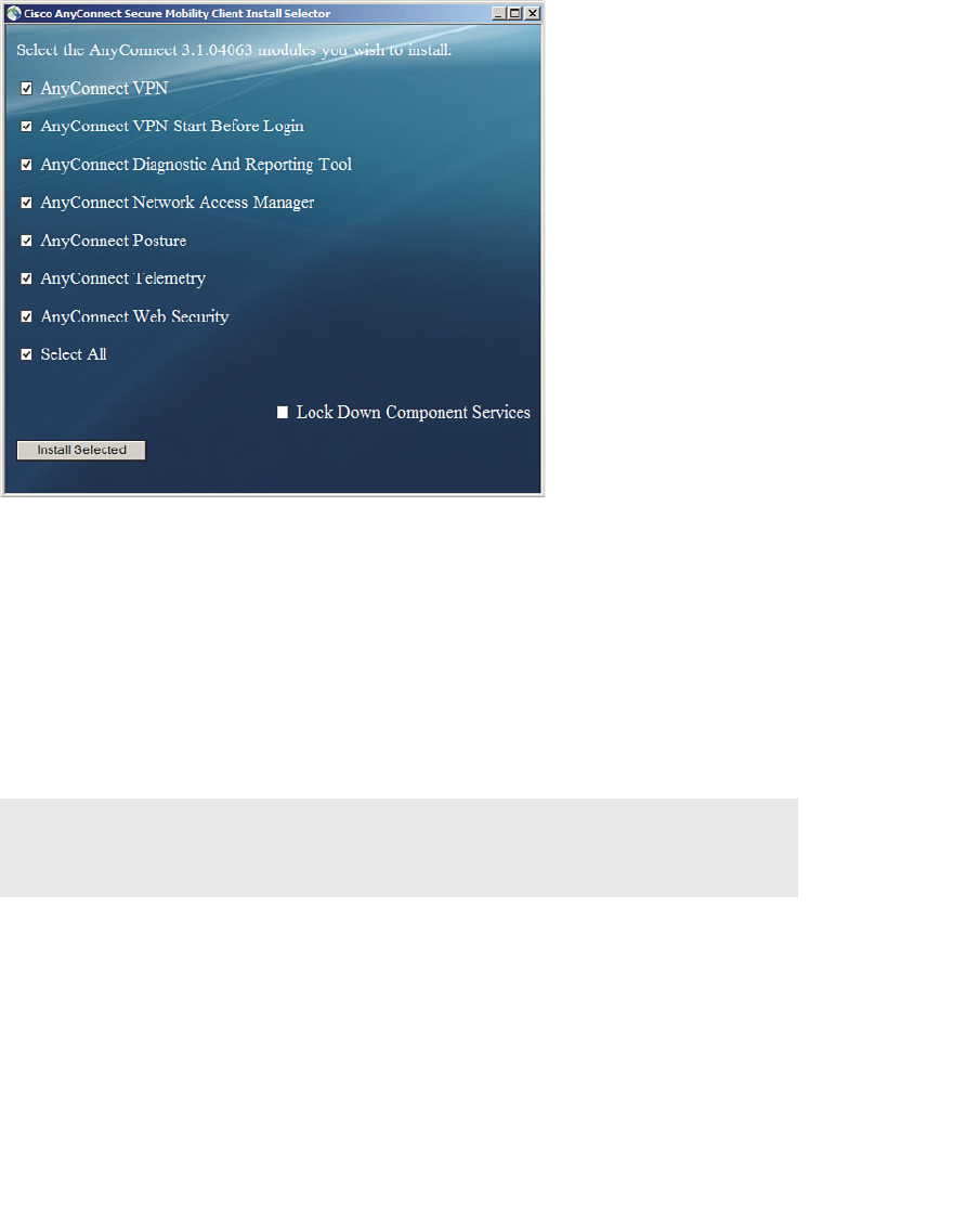
ptg12542968
Chapter 17: Understanding Wireless Clients 349
■ Web Security —Security policies enforced according to Cisco Web Security
policies
Notice that wireless was not mentioned in any of the AnyConnect module descriptions.
That is because AnyConnect collects a suite of security functions into a single client
software, regardless of the connection type. AnyConnect does provide integrated man-
agement of wireless connections, overriding that of any wireless client software that is
installed on the client device. By controlling wireless connections, AnyConnect can also
enforce any security policies that might affect the wireless security parameters an end
user might try to use.
Tip To use AnyConnect to manage wireless connections, you must install the VPN and
NAM modules.
AnyConnect policies can be created on a Cisco Adaptive Security Appliance (ASA)
through its Adaptive Security Device Manager (ASDM) management front end and then
pushed out to AnyConnect clients. The main AnyConnect client interface consists of
VPN, network, and web security functions, as shown in Figure 17-18 . The network func-
tion is the only one relevant to the CCNA Wireless exam.
Figure 17-17 Installing Cisco AnyConnect Secure Mobility Client Modules.
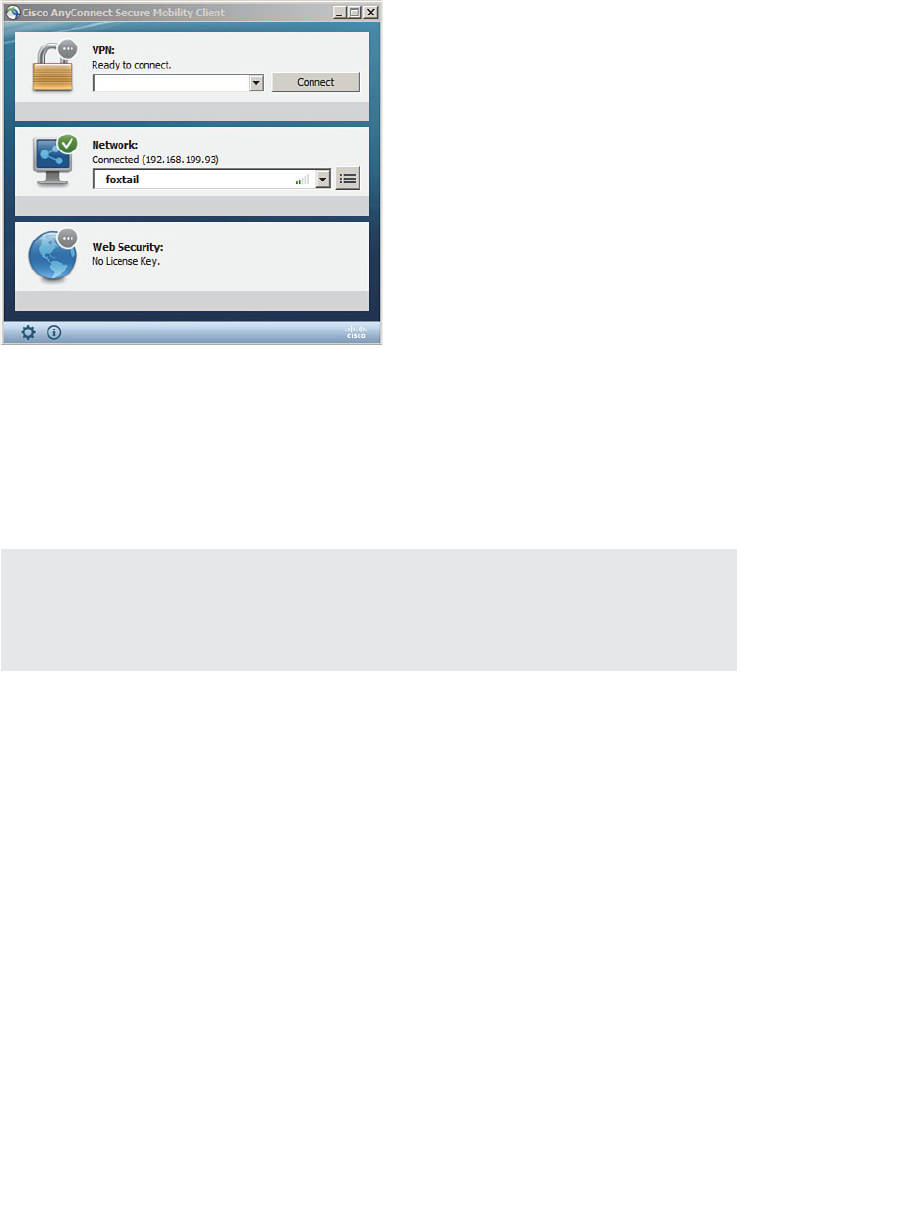
ptg12542968
350 CCNA Wireless 640-722 Official Cert Guide
Figure 17-18 Controlling the Cisco AnyConnect Secure Mobility Client.
You can create and edit network profiles by selecting the properties button to the right
of the Network Status section. Under the Networks > Configuration tab shown in Figure
17-19 , the list of wireless networks is displayed. You can change the order of the net-
works by selecting one and using the up and down arrows to change its position in the
list.
Tip Be aware that your ability to create and edit parameters is limited by the policies
that are used to push the AnyConnect client and its profile to your local machine. For
example, the AnyConnect administrator may have restricted your ability to create new
connections only to wireless networks that use open authentication and pre-shared keys.
To create a new wireless network profile, click the Add button. Enter the SSID, wireless
security parameters, and the 802.1x mode, as shown in Figure 17-20 .
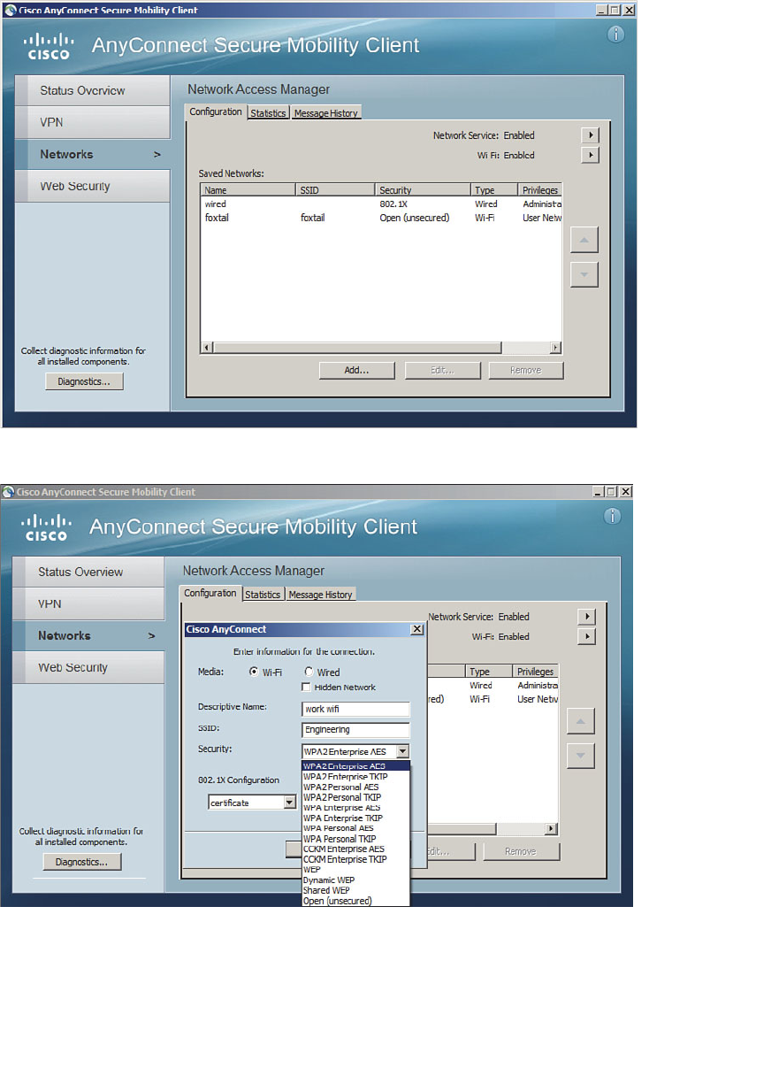
ptg12542968
Chapter 17: Understanding Wireless Clients 351
Figure 17-20 Configuring a New Wireless Network in AnyConnect.
Figure 17-19 Managing Wireless Network Connections in AnyConnect.

ptg12542968
352 CCNA Wireless 640-722 Official Cert Guide
Cisco Compatible Extensions
The wireless clients described in the previous sections are fairly straightforward; the cli-
ent has a wireless network adapter and controls the SSID and wireless security that are
used to associate with an AP. Beyond that, the AP can make a safe assumption that the
client complies with the 802.11 standard and supports certain data rates, but it knows
little else about the client and its capabilities.
For example, without thorough testing, how do you know whether a wireless client
and its driver software release support Wi-Fi Protected Access Version 2 (WPA2) with
EAP Transport Layer Security (EAP-TLS) or some other security scheme? How do you
know whether a client can optimally transport audio and video over wireless? Suppose
that your enterprise just purchased several hundred wireless communication or medi-
cal devices. How can you be certain which wireless functions and security features the
devices support?
To remove some of the unknowns, Cisco created the Cisco Compatible Extensions
(CCX) program. Cisco defines a set of features as part of a specific CCX version.
Wireless device manufacturers can implement the features in their devices and then sub-
mit their devices for testing and validation. If a device passes the interoperability tests, it
receives a “Cisco Certified Compatibility” designation.
The CCX program really has two goals:
■ Take advantage of Cisco enhancements and innovations above what is defined in
the 802.11 standard
■ Verify that a client supports each enhancement correctly
Over time, Cisco has developed CCX in phases or versions. To date, there are five ver-
sions, each building on its predecessor with an increasing set of features. Table 17-2 lists
some of the 70 features, along with the CCX versions that support them. Notice how
the more traditional and general features such as 802.11 are supported in all versions,
essentially over a long period of time as WLAN technology has evolved. Features avail-
able only in v4 and v5 tend to be interactive, where the client works with the wireless
infrastructure to report information about itself.
For example, management frame protection (MFP) addresses an inherent weakness in
the management frames that an AP transmits. When a client receives a management
frame, it implicitly trusts that the frame came from an AP and that the frame contents
have not been tampered with. To secure management frames, both the AP and the cli-
ent must participate to encrypt and authenticate each frame. Only CCXv5 clients are
equipped to use frames protected with MFP.

ptg12542968
Chapter 17: Understanding Wireless Clients 353
Table 17-2 Feature Support in CCX Versions 1–5
Feature v1 v2 v3 v4 v5
IEEE 802.11 (general support for the
standard as a whole)
X X X X X
Wi-Fi compliance X X X X X
IEEE 802.1s X X X X X
Windows Hardware Quality Labs
(WHQL)
X X X X X
WPA X X X X
AP-assisted client roaming X X X X
RF scanning and reporting X X X X
AP-specified client maximum transmit
power
X X X X
Wi-Fi Multimedia (WMM) X X X
Call admission control (CAC) X X
Client keepalive X X
Client link test X X
Unscheduled automatic power save
delivery (U-APSD)
X X
Client location reporting X X
Performance reporting X
Diagnostic channel X
Roaming and real-time diagnostics X
Management frame protection (MFP) X
Tip What if a device is not certified for any CCX version? Chances are that it will work
just fine on a Cisco wireless infrastructure. CCX certifies extended features that are spe-
cific to Cisco networks—not features that are needed for basic wireless operation.
Each CCX version contains more complex and interactive features than the version
before it, but the features are organized more by the version number than by function.
Some devices that are designed for a specific application, such as a wireless phone or a
locator tag, do not have a need to support the entire list of features in a CCX version.
To simplify the compatibility process for these devices, Cisco introduced the CCX Lite
designation.
Key
Topic

ptg12542968
354 CCNA Wireless 640-722 Official Cert Guide
CCX Lite is organized into four basic categories or modules, according to device
function:
■ Foundation —The core set of features that are common to most general purpose
devices
■ Voice —Features specific to voice communication devices, such as WMM, CAC,
expedited bandwidth request, and voice metrics
■ Location —Features specific to near real-time location reporting, usually used with
RFID tags
■ Management —Features specific to client management, such as link test, diagnostic
channel, client reporting, and roaming and real-time diagnostics
A device must be compliant with the Foundation module to achieve CCX Lite certifica-
tion. The other modules are optional for application specific devices.
For the CCNA Wireless exam, be familiar with the CCX basics and know the CCX Lite
modules. You should also have a good understanding of wireless security features and
which CCX version supports them. For example, Cisco Centralized Key Management
(CCKM) is used to make client authentication much more efficient during roaming.
You should know which CCX version should be used to support a given authentication
method. Study Table 17-3 , which lists the wireless security and authentication schemes
along with the CCX versions.
Table 17-3 Wireless Security Support in CCX Versions 1–5
Feature v1 v2 v3 v4 v5
IEEE 802.1x X X X X X
LEAP X X X X X
PEAP-GTC (PEAP with EAP-GTC) X X X X
EAP-FAST X X X
PEAP-MSCHAP (PEAP with EAP-
MSCHAPv2)
X X
EAP-TLS X X
WPA — 802.1x + WPA TKIP X X X X
with LEAP X X X X
with PEAP-GTC X X X X
Key
Topic

ptg12542968
Chapter 17: Understanding Wireless Clients 355
Feature v1 v2 v3 v4 v5
with EAP-FAST X X X
with PEAP-MSCHAP X X
with EAP-TLS X X
WPA2 — 802.1x + AES (802.11i) X X X
with LEAP X X X
with PEAP-GTC X X X
with EAP-FAST X X X
with PEAP-MSCHAP X X
with EAP-TLS X X
Management frame protection (MFP) X
Table 17-3 might seem daunting, especially if you have to remember which CCX ver-
sions correspond to one of the many security features listed. Notice that the table can
be broken down into four main divisions: 802.1x, WPA, WPA2, and MFP. Within each
division, the same set of LEAP, PEAP-GTC, EAP-FAST, PEAP-MSCHAP, and EAP-TLS
schemes are repeated. Therefore, you might benefit from memorizing the following
rules of thumb:
■ 802.1x is covered in all versions.
■ WPA and its schemes were all introduced in CCXv2.
■ WPA2 and its schemes were all introduced in CCXv3.
Except:
■ EAP-FAST introduced in CCXv3
■ PEAP-MSCHAP and EAP-TLS introduced in CCXv4
■ MFP was introduced in CCXv5.
For example, without looking at the table, which CCX versions support WPA2 with
EAP-TLS? From the third rule, you know that WPA2 is supported in Versions 3 and
later, except that EAP-TLS is Version 4 and later. Therefore, your answer should be
CCXv4 and CCXv5.

ptg12542968
356 CCNA Wireless 640-722 Official Cert Guide
Exam Preparation Tasks
As mentioned in the section, “How to Use This Book,” in the Introduction, you have a
couple of choices for exam preparation: the exercises here, Chapter 22 , “Final Review,”
and the exam simulation questions on the CD-ROM.
Review All Key Topics
Review the most important topics in this chapter, noted with the Key Topic icon in the
outer margin of the page. Table 17-4 lists a reference of these key topics and the page
numbers on which each is found.
Table 17-4 Key Topics for Chapter 17
Key Topic Element Description Page Number
List Cisco AnyConnect modules 348
Table 17-2 CCX versions 353
List CCX Lite modules 354
Define Key Terms
Define the following key terms from this chapter and check your answers in the
glossary:
Cisco Compatibility Extensions (CCX), CCX Lite
Key
Topic

ptg12542968
This page intentionally left blank

ptg12542968
This chapter covers the following topics:
■ WCS Overview —This section provides a summary
of Cisco Wireless Control System, its licensing, and
its web-based management interface.
■ Using WCS to Configure Devices —This section
explains how you can use the WCS to add and con-
figure wireless LAN controllers.
■ Using WCS Maps —This section explains WCS
maps and how they are used to provide a graphical
representation of a wireless network in a physical
space.
■ Generating Reports —This section covers the pro-
cess of creating and running a report to gather his-
torical data from WCS.
This chapter covers the following exam topics:
■ Identify key functions of Cisco Wireless Control
System (WCS) and Navigator (versions and
licensing)
■ Navigate WCS interface
■ Configure controllers and access points (APs) (using
the Configuration tab, not templates)
■ Use preconfigured maps in the WCS (adding/relo-
cating/removing access points, turn on/off heat
maps, view client location, and view CleanAir zones
of influence)
■ Use the WCS monitor tab and alarm summary to
verify the WLAN operations
■ Generate standard WCS reports (inventory,
CleanAir, client-related, AP-related, and utilization)

ptg12542968
A Cisco Unified Wireless Network (CUWN) is based on a centralized architecture.
Multiple APs all connect to the same controller for their connectivity. You can con-
figure, monitor, and manage the APs through the controller. As a network scales, man-
agement tasks can become tedious because you have to visit more than one controller
to apply the same configuration changes or to monitor wireless events. The Wireless
Control System (WCS) provides a central platform for managing multiple controllers and
their access points (APs).
This chapter is a brief overview of WCS, how you can configure controllers and APs
with it, and how you can use it to monitor a variety of things in your network.
“Do I Know This Already?” Quiz
The “Do I Know This Already?” quiz allows you to assess whether you should read this
entire chapter thoroughly or jump to the “Exam Preparation Tasks” section. If you are
in doubt about your answers to these questions or your own assessment of your knowl-
edge of the topics, read the entire chapter. Table 18-1 lists the major headings in this
chapter and their corresponding “Do I Know This Already?” quiz questions. You can
find the answers in Appendix A , “Answers to the ‘Do I Know This Already?’ Quizzes.”
Table 18-1 “Do I Know This Already?” Section-to-Question Mapping
Foundation Topics Section Questions
WCS Overview 1–6
Using WCS to Configure Devices 7
Using WCS Maps 8–9
Generating Reports 10
Caution The goal of self-assessment is to gauge your mastery of the topics in this chap-
ter. If you do not know the answer to a question or are only partially sure of the answer,
you should mark that question as wrong for purposes of the self-assessment. Giving your-
self credit for an answer you correctly guess skews your self-assessment results and might
provide you with a false sense of security.
CHAPTER 18
Managing Wireless Networks with
WCS

ptg12542968
360 CCNA Wireless 640-722 Official Cert Guide
1.
What are three benefits of using Cisco WCS?
a. Wireless planning
b. Wireless management
c. Wireless troubleshooting
d. Wireless site surveys
2.
Which two of the following are benefits of purchasing the WCS Plus license?
a.
Closest AP client location on demand
b. High-availability operation
c. Wireless LAN controller management
d. MSE integration for client location
3.
What is the maximum number of APs that a single-server WCS license will support?
a. 100
b. 500
c. 1000
d. 50,000
4.
WCS Navigator is meant for which one of the following functions?
a.
Use location-based information to plot a route through the network
b.
A tool to assist with orienting AP antennas
c.
Management of multiple WCS instances
d. Management of multiple controllers
5. In the alarm summary dashboard, what is represented by the orange triangle point-
ing downward?
a.
Helpful cautions about RF parameters
b. Minor alarms from controllers
c. Major alarms from controllers
d. A summary of all alarm types

ptg12542968
Chapter 18: Managing Wireless Networks with WCS 361
6.
If a WCS alarm goes unacknowledged, what will happen to it?
a.
Nothing; the alarm will be active forever until it is acknowledged.
b.
After 15 days, the alarm will be automatically acknowledged.
c.
After 1 hour, the alarm will be automatically acknowledged.
d.
After 1 day, the AP that is the source of the alarm will be disabled.
7.
To add a controller to WCS, which one of the following menus should you use?
a. Configure > Add
b. Configure > Controllers
c.
Administration > Controllers > Add
d. Management > Controllers
8.
Which one of the following WCS menu options enables you to find a list of maps?
a. Monitor > Maps
b. Configure > Maps
c. View > Maps
d. Management > Maps
9.
WCS maps are organized into which one of the following hierarchies?
a.
Campus > building > floor
b.
Enterprise > department > building
c.
Building > floor > room
d. Domain > building > floor
10. Suppose that you want to see information about all the APs on your wireless net-
work. Which one of the following reports should you choose to generate?
a. Inventory > APs
b. Network Summary > APs
c. Device > Inventory
d. Device > Controllers

ptg12542968
362 CCNA Wireless 640-722 Official Cert Guide
Foundation Topics
WCS Overview
The Cisco WCS is a browser-based software application that offers the capability to
manage multiple controller deployments through a single interface. Benefits of WCS
include the following:
■ Wireless planning tools for access point (AP) placement and radio frequency (RF)
parameters
■ Controller and AP deployment through configuration templates
■ Monitoring of controllers, APs, and wireless client devices
■ Troubleshooting through alerts, events, wireless interference analysis, and a built-in
client troubleshooting tool
■ Extensive set of reports that can be automated or run on-demand
Note You might be aware that Cisco WCS is no longer a supported product.
Nevertheless, WCS is still covered on the IUWNE 640-722 exam. WCS has undergone
an evolution, becoming Cisco Prime Network Control System (NCS) and then becoming
Cisco Prime Infrastructure (PI). Prime Infrastructure can manage both wireless and wired
networks and has much greater functionality than WCS. It can work with Cisco Mobility
Services Engines (MSE) to locate clients, leverage Cisco CleanAir, and provide improved
wireless intrusion prevention system (wIPS) functionality.
WCS is a service that is installed on a 32-bit Windows 2003 SP1+ or Red Hat Linux
server. It is available in two forms: WCS Base and WCS Plus. Both forms can manage
multiple controllers and APs, and can monitor wireless clients, but they differ according
to the functions listed in Table 18-2 .
Table 18-2 Comparison Between WCS Base and WCS Plus
WCS Base WCS Plus
Clients can be coarsely located,
in relation to the nearest AP.
Clients can be located in a context-based fashion by
triangulating between three nearest APs, for a high degree
of accuracy.
WCS can operate as a high-availability pair.
WCS can leverage MSE for client tracking, wIPS.
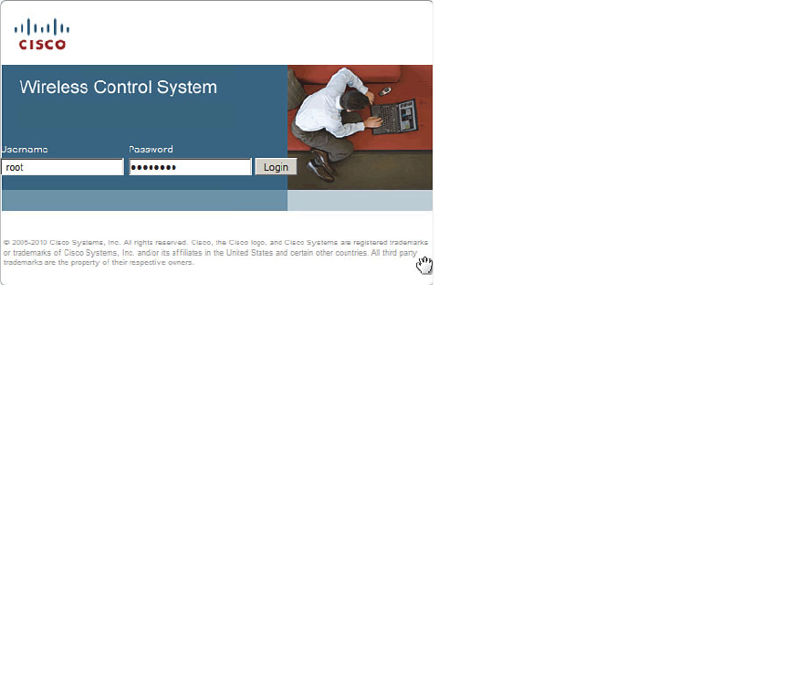
ptg12542968
Chapter 18: Managing Wireless Networks with WCS 363
WCS is also licensed according to scale and the number of APs that will be supported.
You can purchase WCS as a single-server license for installations that can support up to
50, 100, or 500 APs. For larger networks, WCS is available as an enterprise license that
can support one or more server instances and up to 50,000 APs. The enterprise license is
available only in the Plus form.
In large enterprise settings, you might need more than one instance of WCS to man-
age a vast number of controllers and APs. The enterprise license allows you to install
multiple WCS servers, but you still have to visit each WCS individually. To scale even
further, you could leverage the Cisco WCS Navigator. Navigator provides a single WCS-
like interface that can aggregate and manage up to 20 distinct WCS servers. You can
purchase Navigator as a separate product or take advantage of one free license that is
included in a WCS enterprise license.
Once WCS is installed, you can connect to it with a secure web browser session pointed
to the IP address of the WCS server. Installing and initially configuring WCS is beyond
the scope of the CCNA Wireless exam. You can log in with username root and the
initial password, as shown in Figure 18-1 , or with another username that has been subse-
quently configured.
Figure 18-1 WCS Login Screen.
Once you log in to WCS, you see a home page like the one shown in Figure 18-2 . The
home page is organized into several sections or areas:
■ Alarm Summary dashboard —A narrow strip of alarm counters across the top left
of the page
■ Main navigation menu —Monitor, Reports, Configure, Services, Administration,
Tools, and Help drop-down menus
■ WCS Home area —Client, Security, Mesh, CleanAir, and ContextAware tabs
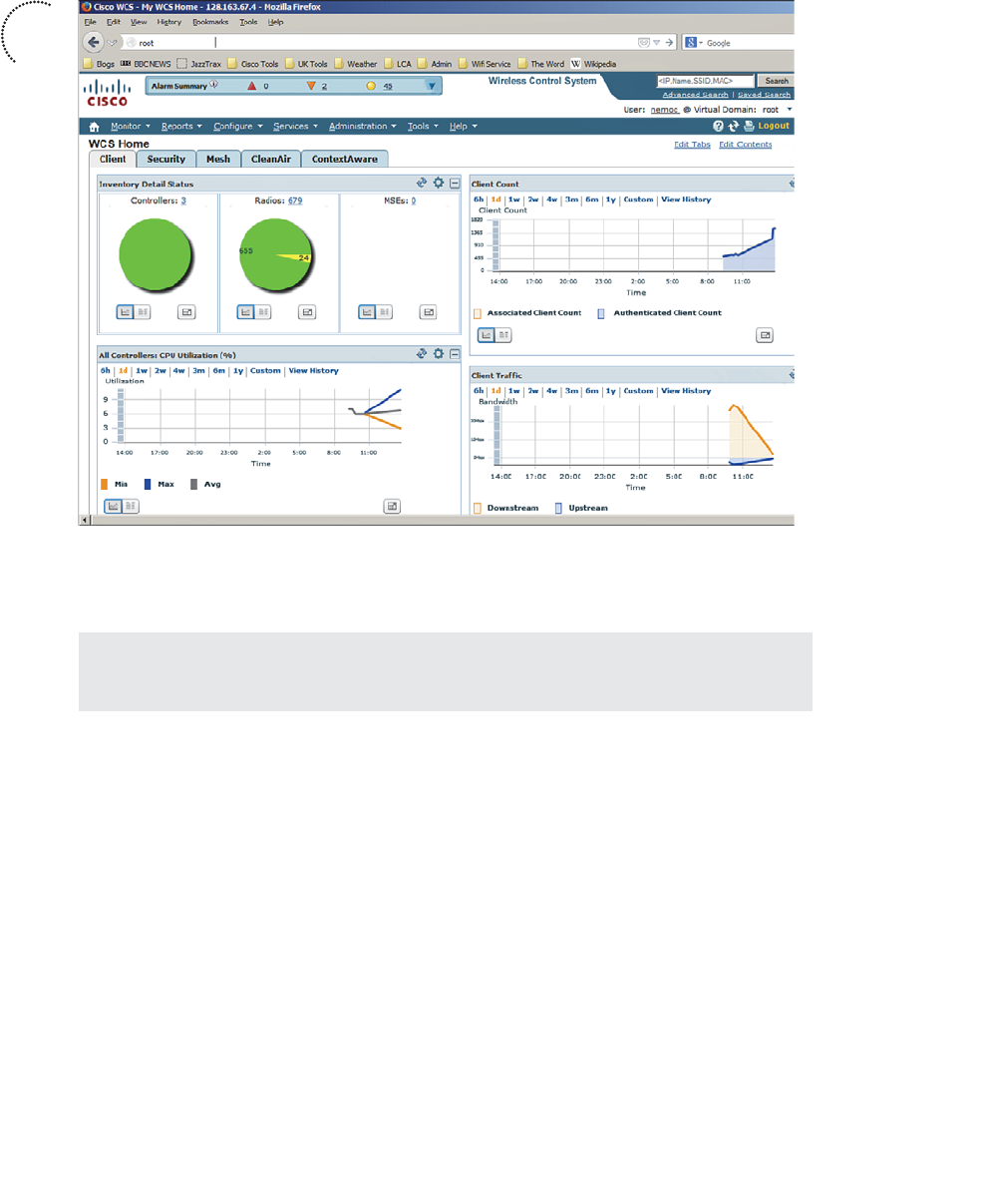
ptg12542968
364 CCNA Wireless 640-722 Official Cert Guide
Figure 18-2 WCS Home Page.
Each area is described further in the following sections.
Tip You can return to the WCS home page at any time by clicking the small house-
shaped icon located in the upper-left corner of the WCS navigation menu.
Alarm Summary Dashboard
As WCS receives alarms from controllers and other wireless management devices, it cat-
egorizes them by severity level and displays a summary count. There are three severity
levels, as follows:
■ Critical —Denoted by a red upward triangular arrow
■ Major —Denoted by an orange downward triangular arrow
■ Minor —Denoted by a yellow circle
If the severity level count is nonzero, you can click the number to display a list of the
specific alarms. Figure 18-3 shows a typical list of minor severity alarms. Notice that
each alarm has a check box in the far-left column. WCS will remember each alarm it
receives for a default period of 15 days or until someone takes some action on it. You
Key
Topic
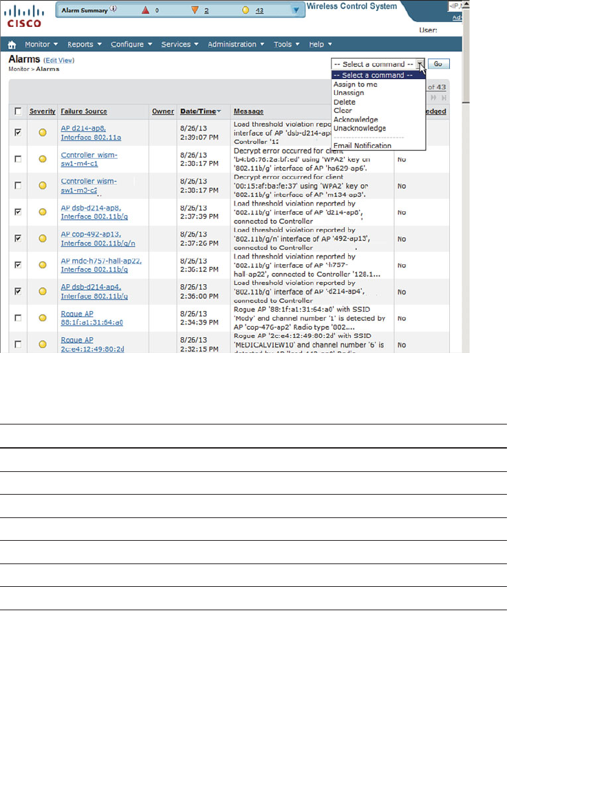
ptg12542968
Chapter 18: Managing Wireless Networks with WCS 365
can check the box next to one or more alarms and then select the drop-down menu at
the upper right of the alarm list to select an action to take. Table 18-3 lists the actions.
Figure 18-3 A Typical List of Alarms.
Table 18-3 Alarm Actions
Action Description
Assign to Me The alarm will remain in your own alarm list.
Unassign Take the alarm out of your alarm list.
Delete Make WCS forget about the alarm.
Clear Remove the alarm from the list, but WCS will keep a record of it.
Acknowledge The alarm has been checked and can be removed from the list.
Unacknowledge The alarm should be added back to the list.
Email Notification Select alarm types to be emailed.
You can also click one of the links that is listed under the Failure Source column in
the alarm list. This will display all the information available about the specific alarm, as
shown in Figure 18-4 . WCS can maintain any annotation text you or other users add
about the alarm as an audit trail or history of the problem. To add an annotation, click
the New Annotation button on the right side of the page.
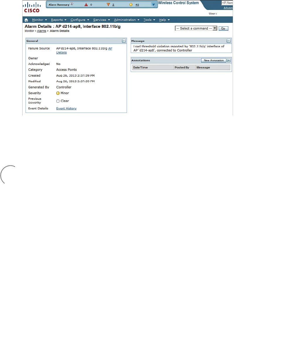
ptg12542968
366 CCNA Wireless 640-722 Official Cert Guide
Figure 18-4 Displaying Details About a Specific Alarm.
Main Navigation Area
You can use the main navigation area to perform many functions. The area is organized
as a bar of the following drop-down menus:
■ Monitor —Display current information from building maps, controllers, access
points, clients, RFID tags, and RF spectrum data. You can also display helpful infor-
mation about Radio Resource Management (RRM) events, alarms, and other events
that have occurred.
■ Reports —Define, schedule, and display reports on various aspects of the wireless
network.
■ Configure —Make configuration changes to controllers, APs, spectrum expert
devices; define and edit configuration templates to be applied to wireless devices.
■ Services —Integrate WCS with external location-based services and applications.
■ Administration —Configure administrative aspects of WCS.
■ Tools —Perform voice and controller configuration audits, attach information to a
Cisco TAC service request, and more.
■ Help —Display helpful information and learn more about WCS topics.
WCS Home Area
The home area is organized as a set of tabs that you can select to display charts and
graphs about categories of wireless activity. By default, the home area consists of the
following tabs:
Key
Topic
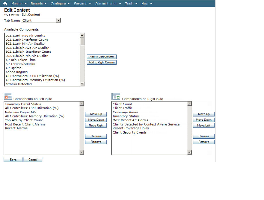
ptg12542968
Chapter 18: Managing Wireless Networks with WCS 367
■ Client —Displays an inventory count of controllers, radios, and MSEs; a client
count; and utilization and traffic histories. The Client tab is displayed by default on
the home page.
■ Security —Displays summaries of threats and attacks that have been detected, in
addition to alarms about rogue APs and other security events.
■ Mesh —Displays statistics that might indicate problems with indoor and outdoor
wireless mesh networks.
■ CleanAir —Displays air-quality and interference information gleaned from APs that
are capable of measuring RF spectrum use.
■ ContextAware —Displays information about various elements and devices that have
been identified and tracked by MSEs.
The home area can be customized for each WCS user. You can edit the list of tabs by
clicking the Edit Tabs link at the upper right of the WCS page. You can also tailor the
tab contents by clicking the Edit Content link. Select the appropriate tab from the Tab
Name drop-down menu, as shown in Figure 18-5 . Then you can select one of the many
information components you want to see and click either the Add to Left Column or
Add to Right Column button to choose which side of the tab page should be used. You
can change the position of each component by using the two component lists at the bot-
tom of the page.
Figure 18-5 Editing the WCS Home Page Area Tabs and Contents.
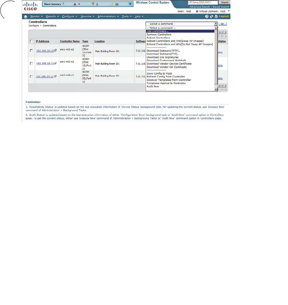
ptg12542968
368 CCNA Wireless 640-722 Official Cert Guide
Using WCS to Configure Devices
Before WCS can manage any controllers, you must add them into the WCS configura-
tion. Select Configure > Controllers to display a list of currently managed controllers.
To add a new one, select Add Controllers from the drop-down menu and click the Go
button, as shown in Figure 18-6 .
Figure 18-6 Adding a New Controller to WCS.
Next, enter the controller’s IP address, along with its Simple Network Management
Protocol (SNMP) and Secure Shell (SSH) credentials, and then click OK . The SNMP cre-
dentials can have read-only access to view the WLC, but must be read-write for WCS to
make configuration changes on the WLC. SSH and Telnet are not necessary except for
migrating autonomous APs to lightweight mode. Figure 18-7 shows a new controller at
192.168.10.13 being added to the WCS database. If the SNMP credentials are correct,
WCS will pull the controller’s configuration, along with the full list of APs joined to it,
into the WCS database.
After you have populated WCS with a list of controllers, you can use it to config-
ure controller and AP parameters from one central location. To make a configuration
change, you can select Configure > Controllers and then select the IP address link of
the target controller. Next, WCS displays a configuration page that is similar to that of
the controller itself. The far-left column represents a list of controller functions. Each
entry is actually a drop-down list of parameters. In Figure 18-8 , the 802.11b/g/n > RRM
> DCA parameters are being configured. The idea is to mimic an actual controller’s con-
figuration before pushing the configuration out to it.
Key
Topic
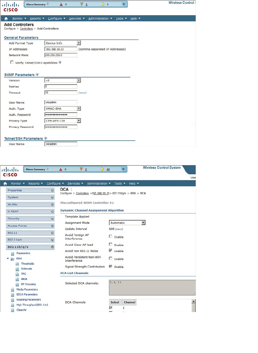
ptg12542968
Chapter 18: Managing Wireless Networks with WCS 369
Figure 18-8 Configuring Controller Parameters Through WCS.
Figure 18-7 Configuring Controller Access Information.

ptg12542968
370 CCNA Wireless 640-722 Official Cert Guide
When you click the Save button at the bottom of the configuration page, the configura-
tion changes are pushed out to the controller.
WCS also offers a flexible and scalable solution for configuring multiple controllers
and APs. You can define configuration templates that can be applied to specific devices
automatically. For example, you can define a template that gets pushed to a newly
installed controller so that it gets configured similarly to other controllers already in pro-
duction. You might also want to change RF settings on a long list of APs. WCS makes a
tedious and time-consuming chore into an organized, efficient, and repeatable task.
You can configure WCS templates by selecting Configure > Controller Template
Launch Pad . WCS templates are not covered on the CCNA Wireless exam.
Using WCS Maps
As you work with wireless controllers and APs, you might find yourself getting lost in
the names and numbers without having a visual concept of things like AP location and
RF coverage in an area. Fortunately, WCS can help! WCS can provide a graphical rep-
resentation of a wireless network, complete with maps, physical locations, predictive
RF coverage, and interactive data displays. In other words, WCS will help you see your
wireless network as it really is—APs and clients distributed throughout a building or out-
door area.
WCS can use an image file (PNG, JPG, or GIF formats) as the background behind objects
and data that it displays. For example, you can upload the floor plan of a building into
WCS and have the APs and clients that are located on that floor shown in relation to
their actual locations.
WCS maps are organized in a tree-like structure. A campus contains one or more build-
ings or outdoor areas. Each building can contain one or more floor maps. By default,
maps are placed into a system campus. You can define your own campuses and your
own buildings as you add maps into WCS.
Tip The CCNA Wireless exam blueprint focuses on manipulating and using preconfig-
ured maps. You will not have to worry about how to create and organize the maps—just
how to work with the APs and the parameters needed to display various wireless data.
Displaying Maps
You can access the WCS maps by selecting Monitor > Maps . The list in the far-left
column contains the map tree structure; the rest of the page contains a single flat list of
every campus, building, and floor map. In Figure 18-9 , WCS already has one building
preconfigured with maps for five floors. You can see from the AP and radio counts that
only the fourth-floor map shows APs. The other floors have maps, but no APs have been
added or located on them yet.
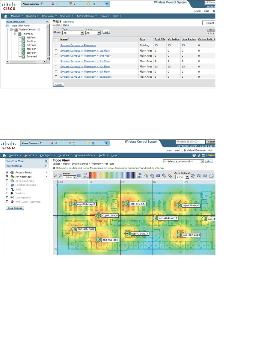
ptg12542968
Chapter 18: Managing Wireless Networks with WCS 371
Figure 18-9 A Typical List of Maps Displayed in Monitor > Maps.
You can click a map name in the list to display it, as shown in Figure 18-10 . The map
consists of the background image, usually a building floor plan or a drawing of an out-
door area, overlaid with AP icons and data. For example, the AP icons in the figure are
shown in their current locations with labels that display the AP names.
Figure 18-10 A WCS Map Showing AP Locations.
By default, a map is shown with dynamic information. WCS computes the RF signal
strength for each AP and displays the results as a colored heatmap. The colors represent
the signal strength that might be received in each location on the map. The color scale
is shown above the heatmap. Red represents a strong signal (–35 dBm), progressing
through orange, yellow, green, and then blues and purples at the weak end of the scale
(–90 dBm).
The heatmap that WCS computes is based on many of the RF principles you learned
about in Chapter 3 , “RF Signals in the Real World.” Based on each map location, WCS
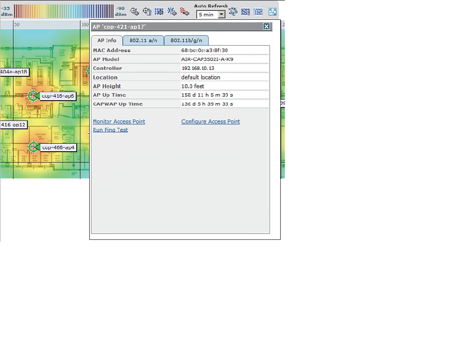
ptg12542968
372 CCNA Wireless 640-722 Official Cert Guide
can compute the free-space loss based on the distance from each of the APs. What
about things like absorption, where the walls of a building attenuate or reduce RF signal
strength? At a minimum, a WCS map contains only the AP icons positioned over a floor
plan background image. You might be able to see objects like walls, doors, and eleva-
tors on the map, but WCS is not able to interpret the drawing at all. Instead, if you want
WCS to know about obstacles and compute their influence, you can use the map editor
tool to define the physical objects and their dBm attenuation values. The more informa-
tion you put into a map, the more accurate WCS can be when it produces the RF heat-
map.
WCS also updates the AP icons based on current conditions. A green icon represents
an AP radio that is working properly, with no faults or alarms. A yellow icon represents
an AP radio with a minor alarm, while a red icon indicates a major alarm. Icons can also
blink, indicating that one of the AP’s profile thresholds (load, interference, noise, or cov-
erage hole) has been exceeded. By default, WCS updates a map every 5 minutes.
While a map is displayed, you can hover the cursor over an icon to display more infor-
mation about it. For example, Figure 18-11 shows a small window that popped up to
display information about the AP named cop-421-ap17. From this window, you can find
the AP’s MAC address, model number, and the IP address of the controller it has joined.
You can select the 802.11a/n or 802.11b/g/n tab to display information about that spe-
cific radio, including channel number and transmit power level.
Figure 18-11 Displaying Information About an AP on a Map.
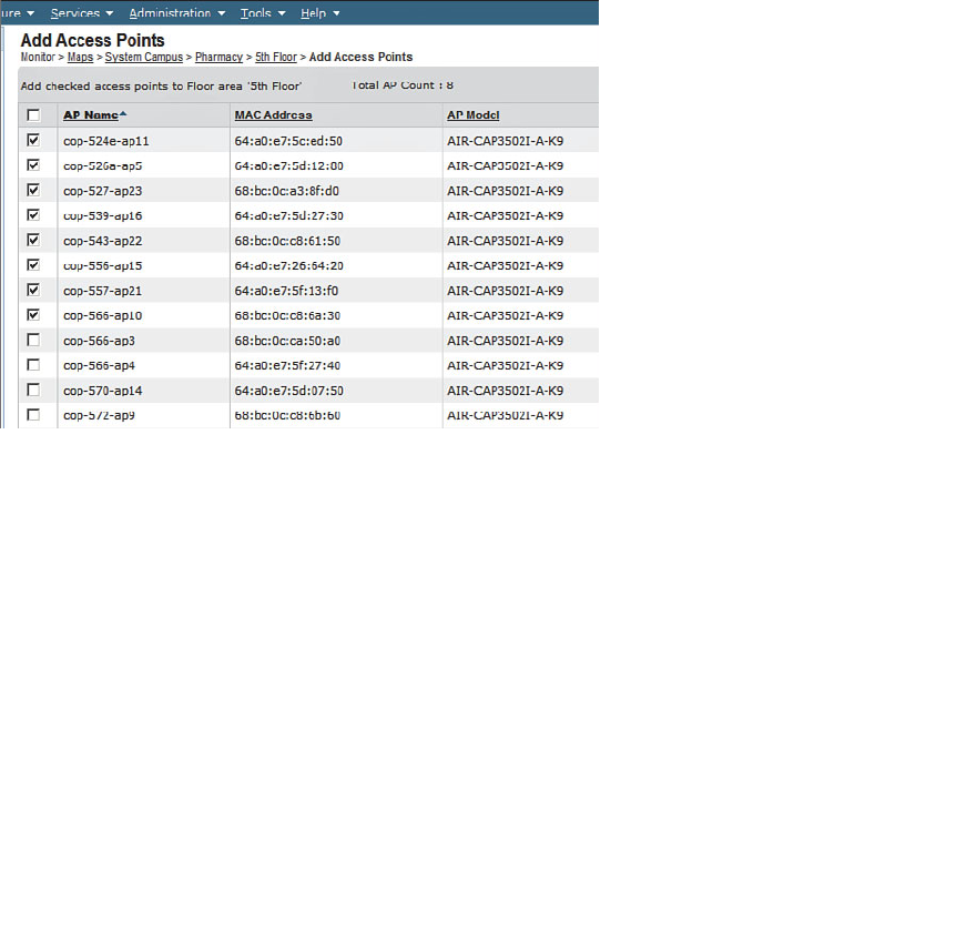
ptg12542968
Chapter 18: Managing Wireless Networks with WCS 373
Manipulating APs on Maps
Once a map has been created for a building floor or outdoor area, you will need to pop-
ulate it with AP icons. Sometimes you might also need to move AP icons to reflect their
location more accurately or delete icons if the corresponding APs have been removed.
To place APs on a map, first display the map. Next, you will need to select the APs that
will be placed on the map. The APs must already exist, be joined to a controller, and be
known to WCS. From the drop-down menu in the upper-right corner of the map floor
view page, select Add Access Points , and then click the Go button.
On the Add Access Points page, WCS will display a list of all of the APs it knows. You
will have to search through the pages of the list to find and select the APs you want to
add to the map. You can sort the list by AP name to make the search easier. After you
have checked the box next to each AP, as shown in Figure 18-12 , click the OK button at
the bottom of the page.
Figure 18-12 Selecting APs to Add to a WCS Map.
Next, you will have to position each AP in its appropriate location on the map. WCS
displays the map and lines the selected APs up along the top edge. Usually the AP icons
start out so close together that their names are obscured. You may have to move them
elsewhere on the map just to space them out and see their names.
To move an AP icon, just click it and drag it to the desired location. In Figure 18-13 , AP
cop-524e-ap11 is being moved from its default position at the upper-left corner. All of
the AP icons will remain dark while the AP being moved will be blue. When you select
an AP to move, WCS will also display the AP’s name, position on the map, mounting
height, and antenna orientation. During this process, you can always make further adjust-
ments and relocate APs as needed. Click the Save button to save the map and AP
locations.
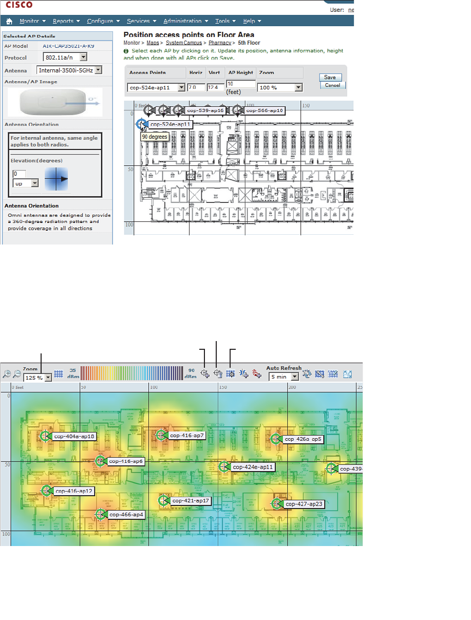
ptg12542968
374 CCNA Wireless 640-722 Official Cert Guide
Figure 18-13 Locating APs on a WCS Map.
You can make further changes to a map whenever it is displayed. There are several small
editing icons along the top of the map, as shown in Figure 18-14 . Use the zoom factor to
resize the map so that you can view it at an appropriate size. You can click the respective
icon to add, remove, and reposition APs in the map.
Zoom Map Add APs Reposition APs
Remove APs
Figure 18-14 Icons Used to Zoom a Map and Edit AP Locations.
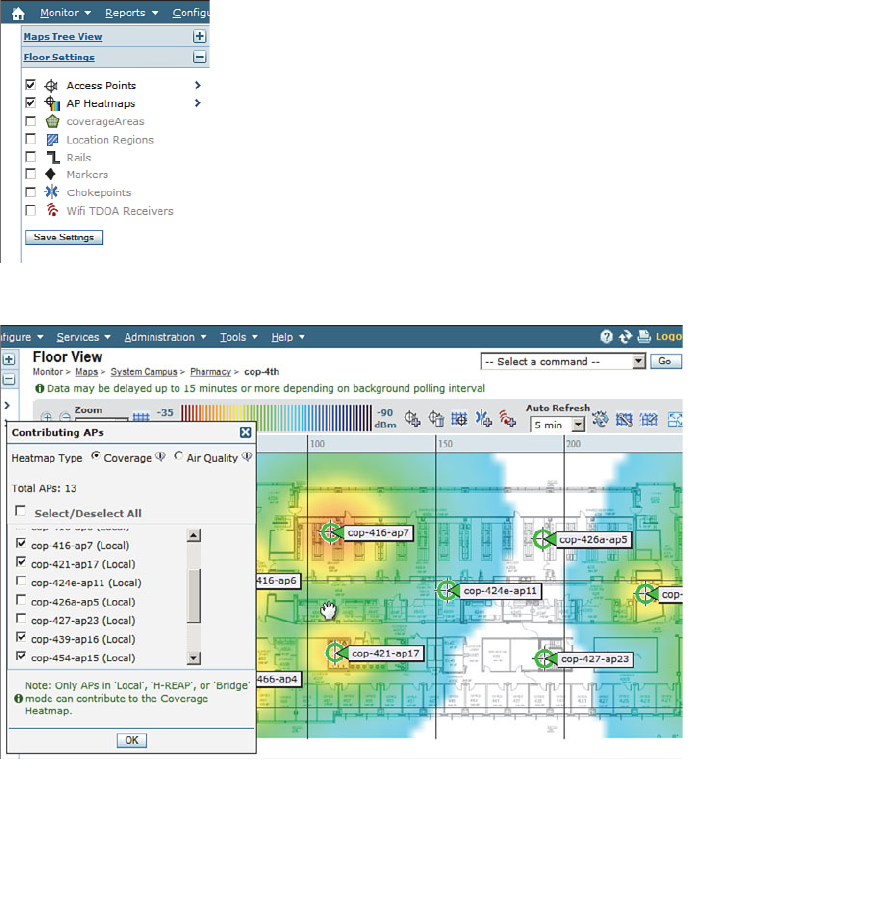
ptg12542968
Chapter 18: Managing Wireless Networks with WCS 375
Viewing Information on Maps
After the APs are placed and their locations are saved, WCS recomputes the RF cover-
age and displays the results as a heatmap. By default, the heatmap is always displayed on
the map and updated every 5 minutes. You can control the heatmap display with the AP
Heatmaps check box found in the Floor Settings portion of the maps page, to the left of
the map display, as shown in Figure 18-15 .
You can also control which APs contribute to the heatmap computation. For example, you
might want to see what might happen if an AP was removed. Select the right arrow next to
AP Heatmaps to display a list of contributing APs that are located on the map. Then select
or deselect specific APs and observe the effect on the heatmap. In Figure 18-16 , three APs
have been deselected, resulting in a white area of no signal in the heatmap.
Figure 18-15 Enabling Heatmap Display.
Figure 18-16 Controlling AP Contributions to the Heatmap Display.
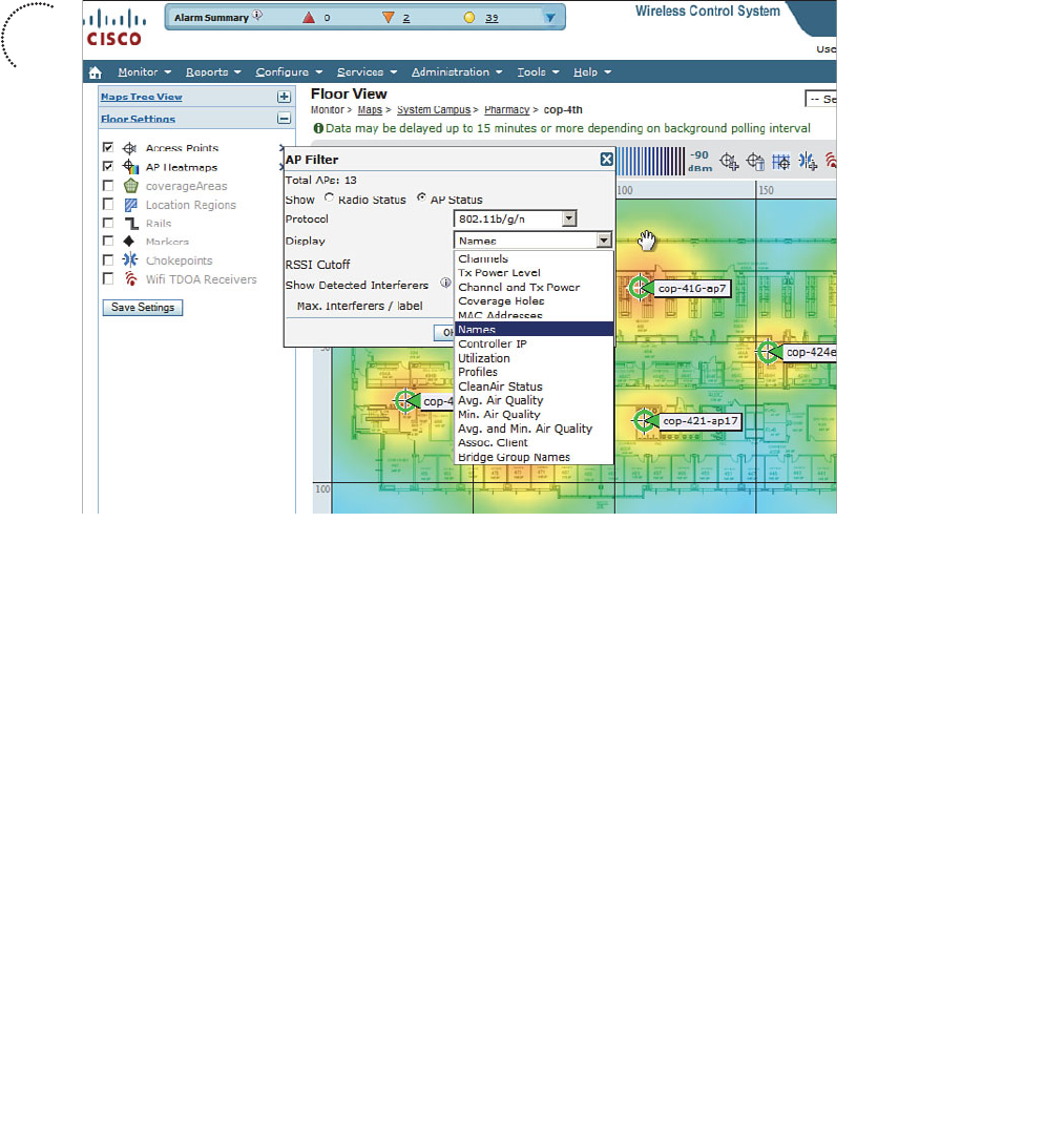
ptg12542968
376 CCNA Wireless 640-722 Official Cert Guide
By default, WCS maps display AP icons and their names. You can select many other AP
labels instead, including AP MAC addresses, transmit power levels, channel numbers,
controller IP address, utilization, associated clients, and so on. Figure 18-17 shows the
complete list of AP label choices.
Figure 18-17 Selecting AP Icon Labels in a WCS Map.
WCS maps can also display client locations. This is a useful function that can help you
pinpoint a client’s whereabouts within the network. If you have an MSE integrated with
WCS, clients will be located and displayed on the maps automatically. You can still
display a client’s location even without an MSE. Select Monitor > Clients and filter for
the client’s MAC address or other information. Once the list of clients is displayed, click
the link that represents the client’s name to display detailed information about it. Select
Recent Map in the drop-down list and click the Go button to display the map where the
client was last known to be located. WCS will display the floor view map with an icon
showing the client’s location and MAC address, as demonstrated in Figure 18-18 .
WCS can also display interference sources that have been detected by CleanAir capable
APs. Select the right arrow to the right of Access Points in the Floor Settings options list,
and then check the Show Detected Interferers box. By default, up to two interferers
will be shown in each AP label. Figure 18-19 shows an example map with some interfer-
ence sources identified.
Key
Topic
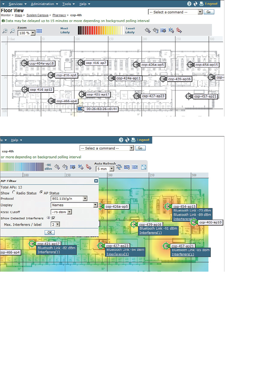
ptg12542968
Chapter 18: Managing Wireless Networks with WCS 377
Figure 18-19 Displaying Interference Sources in a WCS Map.
Generating Reports
WCS maintains a robust database of all the data it collects about the wireless network.
It can also generate a wide variety of reports based on the information in the database.
You can access the reporting functions by selecting Reports > Report Launch Pad , as
shown in Figure 18-20 .
Figure 18-18 Locating a Client with WCS.
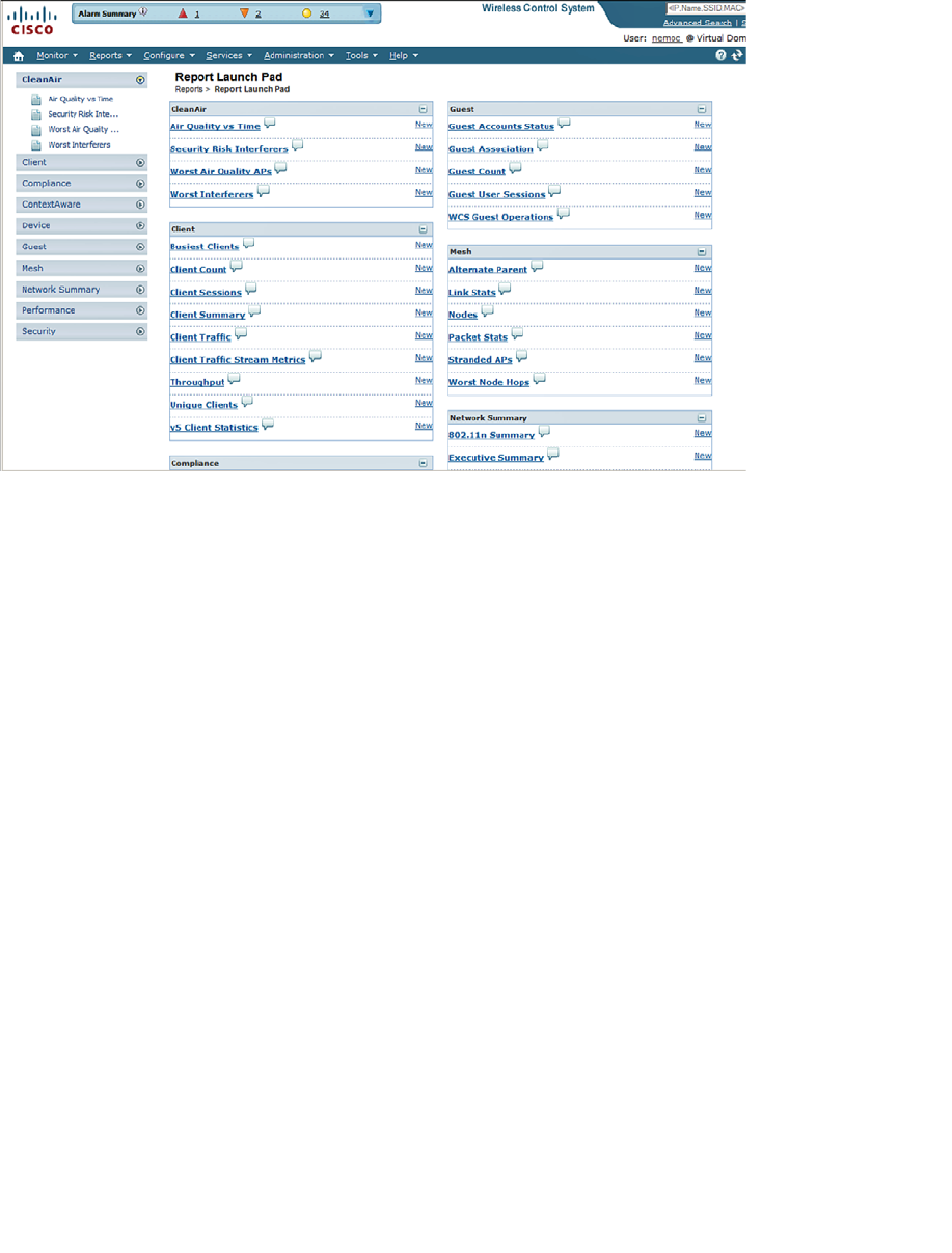
ptg12542968
378 CCNA Wireless 640-722 Official Cert Guide
Figure 18-20 Accessing the WCS Report Launch Pad.
The report launch pad provides a single page that contains every possible report. The
reports are organized into the following categories:
■ CleanAir —Air-quality reports based on CleanAir RF spectrum data
■ Client —Statistics about client populations, loads, and activity
■ Compliance —Audit-based information
■ ContextAware —Client and device location
■ Device —AP status and usage
■ Guest —Guest network activity
■ Mesh —Indoor and outdoor mesh network performance
■ Network Summary —Executive summary, 802.11n summary
■ Performance —802.11 statistics, RF coverage, voice activity, and statistics
■ Security —Wireless intrusion protection system and rogue AP detection
For the CCNA Wireless exam, you should be familiar with generating standard, built-in
reports for network inventory, CleanAir, client information, AP information, and net-
work utilization.
From the report launch pad, select the type of report you want. For example, Figure 18-
21 shows how a Device > Inventory report has been selected. You might see a list of pre-
configured or saved reports. You can select the check box next to one of those or click
the New button to create a new report.
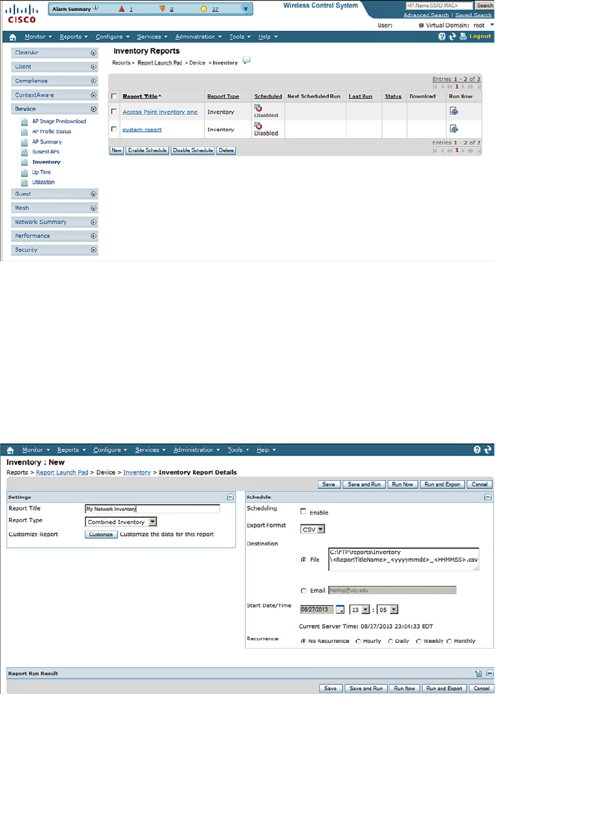
ptg12542968
Chapter 18: Managing Wireless Networks with WCS 379
Figure 18-21 Selecting a Report to Run.
When you create a new report, you can give it a title and select a specific type of report
from a prepopulated list. In Figure 18-22 , an inventory report is being configured as
a Combined Inventory type, which will give information about both APs and control-
lers. You can also specify when the report should be run—either on a scheduled basis
or right now. If you click the Run Now button, the report will run immediately and be
displayed within WCS. If you enable scheduling instead, most likely you will not access
WCS to view the report when it is run. Therefore, you can choose to have the report
automatically saved in a file on the WCS server or sent in an email.
Figure 18-22 Setting the Schedule for a Report to Run.
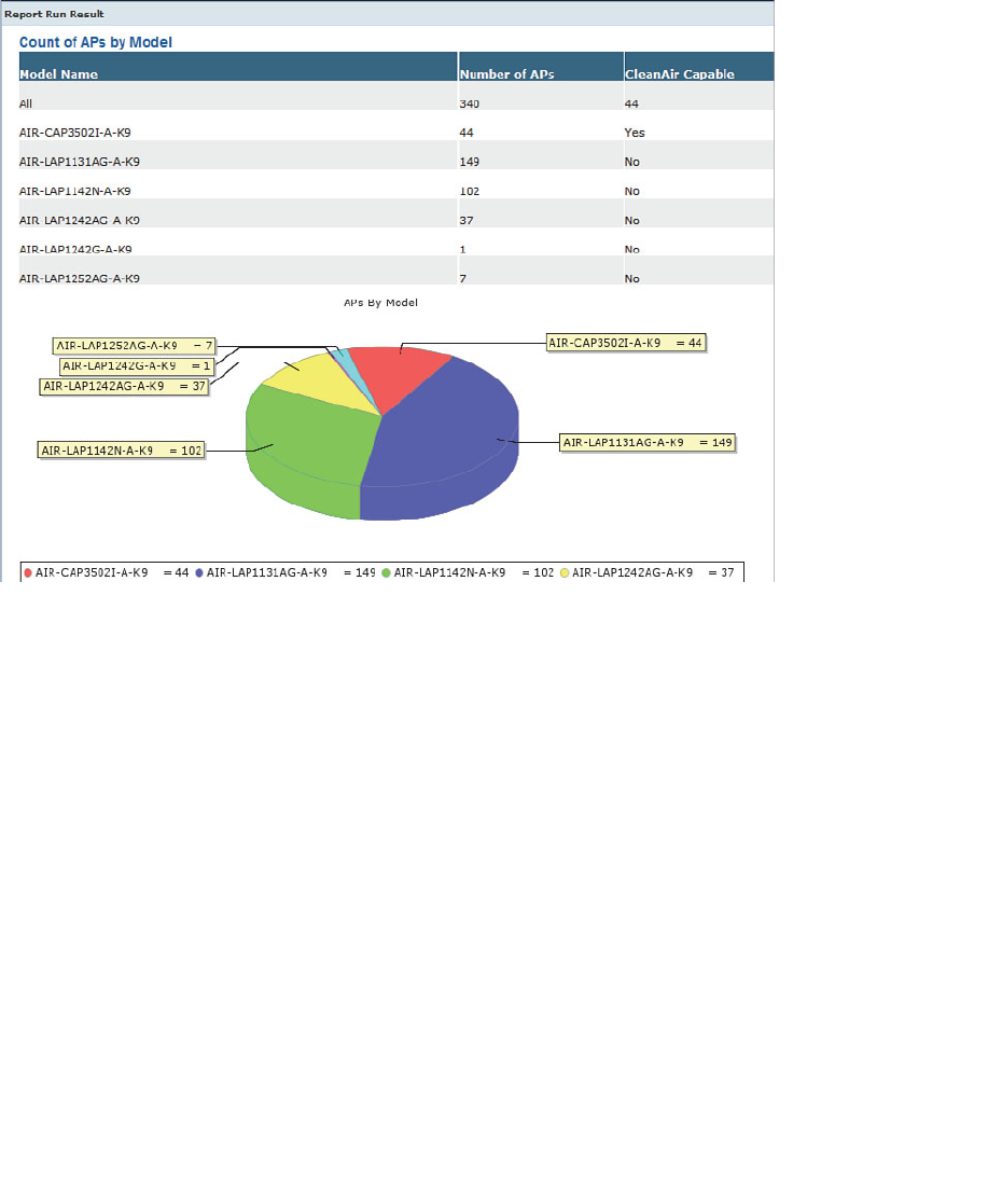
ptg12542968
380 CCNA Wireless 640-722 Official Cert Guide
Figure 18-23 shows an example of the results of an inventory report. The breakdown of
AP model numbers is represented in a table and a pie chart. The actual report is much
longer than that shown.
Figure 18-23 An Example Inventory Report.

ptg12542968
Chapter 18: Managing Wireless Networks with WCS 381
Exam Preparation Tasks
As mentioned in the section, “How to Use This Book,” in the Introduction, you have a
couple of choices for exam preparation: the exercises here, Chapter 22 , “Final Review,”
and the exam simulation questions on the CD-ROM.
Review All Key Topics
Review the most important topics in this chapter, noted with the Key Topic icon in the
outer margin of the page. Table 18-4 lists a reference of these key topics and the page
numbers on which each is found.
Table 18-4 Key Topics for Chapter 18
Key Topic
Element
Description Page Number
Figure 18-2 WCS home page organization 364
List Major functions in the WCS navigation area 366
Figure 18-6 Adding a controller to WCS 368
Figure 18-17 Displaying AP information in maps 376
Key
Topic

ptg12542968
This chapter covers the following topics:
■ Understanding Types of Interference— This sec-
tion describes common technologies and devices
that can cause wireless interference.
■ Using Cisco CleanAir to Manage Interference—
This section covers CleanAir operation and explains
how you can configure it to deal with interference
automatically and efficiently.
This chapter covers the following exam topics:
■ Describe the impact of various wireless technologies
(Bluetooth, WiMAX, ZigBee, and cordless phones)

ptg12542968
With careful design and planning, 802.11 devices can operate as a fully functional wire-
less network. However, many readily available products do not use the 802.11 standard.
When 802.11 and non-802.11 devices come together, the two can interfere with each
other. Wireless interference can make WLAN performance sluggish or completely unus-
able. This chapter covers some common types of devices that can cause interference and
the Cisco CleanAir features that can detect and react to the interference sources.
“Do I Know This Already?” Quiz
The “Do I Know This Already?” quiz allows you to assess whether you should read this
entire chapter thoroughly or jump to the “Exam Preparation Tasks” section. If you are
in doubt about your answers to these questions or your own assessment of your knowl-
edge of the topics, read the entire chapter. Table 19-1 lists the major headings in this
chapter and their corresponding “Do I Know This Already?” quiz questions. You can
find the answers in Appendix A , “Answers to the ‘Do I Know This Already?’ Quizzes.”
Table 19-1 “Do I Know This Already?” Section-to-Question Mapping
Foundation Topics Section Questions
Understanding Types of Interference 1–6
Using Cisco CleanAir to Manage Interference 7–10
Caution The goal of self-assessment is to gauge your mastery of the topics in this chap-
ter. If you do not know the answer to a question or are only partially sure of the answer,
you should mark that question as wrong for purposes of the self-assessment. Giving your-
self credit for an answer you correctly guess skews your self-assessment results and might
provide you with a false sense of security.
CHAPTER 19
Dealing with Wireless Interference

ptg12542968
384 CCNA Wireless 640-722 Official Cert Guide
1.
DECT cordless phone devices in the United States use which one of the following
designations to differentiate from European DECT devices?
a. DECT 1.0
b. DECT 2.4
c. DECT 5.8
d. DECT 6.0
2.
Bluetooth is designed to cover which one of the following areas?
a. Metropolitan
b. Personal area
c. Wide area
d. Local area
3.
Bluetooth operates in which one of the following frequency bands?
a. 900 MHz
b. 2.4 GHz
c. 5 GHz
d. 11 GHz
4.
ZigBee is used for which two of the following common applications?
a. Building automation
b. GPS location
c. Energy management
d. RFID device location
5.
ZigBee belongs to which one of the following family of standards?
a. IEEE 802.11
b. IEEE 802.3
c. IEEE 802.15.4
d. IEEE 802.16
6.
The IEEE 802.16 standard defines which one of the following technologies?
a. Token Ring
b. ZigBee

ptg12542968
Chapter 19: Dealing with Wireless Interference 385
c. Bluetooth
d. WiMAX
7.
CleanAir adds which one of the following capabilities to a Cisco lightweight AP?
a. Wireless mesh
b. Rogue filtration
c. Spectral multiplexing
d. Spectrum analysis
8.
Cisco CleanAir analyzes which one of the following types of RF signals?
a. Non-802.11
b. 802.11
c. 802.11b
d. CAPWAP
9.
By default, is Cisco CleanAir enabled or disabled on a controller?
a. Enabled
b. Disabled
10.
Suppose that an AP has detected an interference source and reported it with RSSI
–58, duty cycle 1 percent, and severity 4. Which one of the following statements is
most correct?
a.
The interfering source is very severe.
b.
The interfering source is constantly transmitting.
c.
The interfering source is too weak to be detected.
d. The interfering source is not severe.
11.
When an interference source is detected and classified, the controller assigns which
one of the following to uniquely identify the same source across several reporting
APs?
a. BSSID
b. Cluster ID
c. ISSID
d. Actual MAC address

ptg12542968
386 CCNA Wireless 640-722 Official Cert Guide
Understanding Types of Interference
Recall from Chapter 3 , “RF Signals in the Real World,” that APs can interfere with each
other. If two APs are configured to use the same channel and are in close proximity to
each other, co-channel interference results. If the APs are set to use adjacent or overlap-
ping channels, adjacent channel interference occurs.
While those types of interference can certainly be destructive, they involve devices that
are based on the 802.11 standard. For example, each access point (AP) transmits on a
specific channel (possibly the wrong one!), uses a standardized channel width, and always
transmits frames in the 802.11 format. As well, each AP should also follow the 802.11
rules for clear channel assessment (CCA) to maintain some etiquette to share the airtime.
Rogue APs can be a significant and pesky source of interference because they usually
belong to someone else. In other words, someone outside your organization is free to
bring up their own APs on channels of their choosing. As long as signals from their APs
can be received within your own AP cells, you might have to deal with the interference.
To mitigate the problem, you must do one of the following:
■ Find the rogue AP and its owner, and then convince the owner to remove the AP or
change its channel.
■ Move your own AP to a different channel, which may cause other nearby APs to be
moved too.
When 802.11 devices interfere with each other, the result is usually poor performance
due to frame retransmissions, errors, and the lack of available airtime. In other words,
the 802.11 data can still be detected but not always correctly received. In contrast, non-
802.11 devices do not have to obey any of the familiar 802.11 rules. When a non-802.11
device transmits, the result is completely incompatible with 802.11. APs and 802.11 cli-
ents will view the signal as unintelligible and regard it as noise.
The following sections provide an overview of some common non-802.11 devices that
can interfere with a WLAN. As you work through this chapter, keep the following two
terms in mind:
■ Interference: 802.11 signals that come from sources other than expected APs
■ Noise: Signals or radio frequency (RF) energy that do not come from 802.11 sources
Bluetooth
Bluetooth is a technology used to form a personal-area network (PAN), in an effort
to unify telephony and computing devices. Today, Bluetooth can be found integrated
into cell phones, PDAs, laptops, desktops, printers, headsets, cameras, and video game
consoles. Bluetooth has low power consumption, making it a good choice for mobile,
battery-powered devices.
Key
Topic

ptg12542968
Chapter 19: Dealing with Wireless Interference 387
Bluetooth began as Versions 1.0 and 1.0b, developed by the Bluetooth Special Interest
Group (SIG). For a time, several Bluetooth versions were incorporated into the IEEE
802.15.1 standard, but that standard is no longer maintained. The Bluetooth SIG contin-
ued to develop its own standard, currently published as core Version 4.
Tip You can find the Bluetooth SIG at http://www.bluetooth.org .
Bluetooth devices are grouped into three classes according to their radiated power.
Classes 1 and 2 are the most common and use a maximum transmit power level of 1 and
2.5 mW, respectively. Because Bluetooth operates as a PAN, class 1 and 2 devices use
a relatively low transmit power level and have a range of only 35 feet. Less common,
“industrial” Bluetooth class 3 devices can operate at up to 100 mW.
Up to eight devices can be paired or linked into a PAN, with one device taking a master
role and the others operating as slaves. Devices operate in the 2.4-GHz ISM band, but
are not compatible with the 802.11 standard. Bluetooth uses a frequency hopping spread
spectrum (FHSS) technique, with devices moving through a predefined sequence of 79
channels with a bandwidth of 1 MHz each.
Bluetooth transmitters could potentially interfere with the majority of the 2.4-GHz
band because their channels overlap with the three non-overlapping 802.11 channels.
Bluetooth devices can interfere at a close range because of their low transmit power. If
there are many Bluetooth devices in an 802.11 cell, they can create a saturation effect
that tends to starve wireless LAN devices for airtime. Be aware that people commonly
carry Bluetooth phones, headsets, and computer peripherals right into your WLAN. You
might have a difficult time finding them and convincing their owners to leave them out-
side your wireless network.
ZigBee
ZigBee is wireless LAN technology that is based around relatively low power consump-
tion and low data rates (20 to 250 Kbps). As a result, it offers reliable communication.
ZigBee is commonly used for energy management and home and building automation
applications.
ZigBee is defined in the IEEE 802.15.4 standard. It allocates the 2.4-GHz ISM band into
16 channels of 5 MHz each. Even though ZigBee uses the same band as 802.11 devices,
it has a low duty cycle and does not utilize a channel much of the time. As well, ZigBee
devices normally use a low transmit power level, which minimizes interference, but can
ramp up to a maximum of 60 mW when necessary.
Tip You can find the ZigBee Alliance at http://www.zigbee.org .

ptg12542968
388 CCNA Wireless 640-722 Official Cert Guide
Cordless Phones
Cordless phones use several wireless technologies to connect remote handsets to a cen-
tral base station. Phones that are advertised to use the 2.4- and 5.8-GHz bands do just
that—and can cause significant interference with nearby WLANs. Cordless phones can
use one channel at a time, but can also change channels dynamically. As well, transmit
power levels can rise up to 250 mW, overpowering an AP at maximum power.
The Digital Enhanced Cordless Telecommunications (DECT) standard was developed
by ETSI and uses the upper portion of the 1.8 GHz band in Europe, Asia, Australia, and
South America. In the United States, cordless phones are based on DECT 6.0, which uses
the 1.9-GHz band.
Because DECT and DECT 6.0 phones do not use the 2.4-GHz ISM band, they should
not interfere with 802.11 WLANs. However, some similar “DECT-like” phones may
operate in the 2.4- and 5.8-GHz bands and interfere.
Microwave Ovens
You might not think of a microwave oven as a communication device. After all, micro-
wave ovens are designed to cook food—not to transmit data. To heat food, liquids, and
make popcorn, a microwave oven transmits RF energy into a sealed cavity. The energy is
meant to stay inside the oven where it can penetrate food items.
In practice, the RF shielding around microwave oven doors is not ideal, causing some
amount of energy to leak out into the surrounding area. Like many other consumer
devices, microwave ovens are free to use the 2.4-GHz ISM band. In fact, most micro-
waves produce a signal that spreads over a large portion of the band. The signal is simply
crudely transmitted energy that does not need to follow any standard or frame format.
Microwaves are commonly rated to generate around 700 W of power inside the oven.
Leaked energy often interferes with nearby APs and 802.11 devices.
To mitigate interference coming from microwave ovens, you can move the oven farther
away from WLAN coverage areas. Even better, suggest that the oven be swapped out for
a commercial model that has higher-quality RF shielding around the oven and its door.
WiMAX
Worldwide Interoperability for Microwave Access (WiMAX) is a wireless technology
designed to provide “last mile” broadband access to consumers within a geographic area.
WiMAX does not require line of sight with a base station, so it can offer connectivity to
many fixed and mobile users within a 3 to 10-km radius.
WiMAX is defined by the WiMAX Forum and published as the IEEE 802.16 standard.
Although WiMAX, with its central base station and a shared wireless medium, sounds
similar to 802.11 WLANs, the two are incompatible. WiMAX operates in several bands

ptg12542968
Chapter 19: Dealing with Wireless Interference 389
between 2 and 11 GHz and from 10 to 66 GHz. Depending on the frequency being
used, WiMAX can possibly interfere with 802.11 devices, but such interference is highly
unlikely. No widely deployed solutions use the ISM bands; the systems that are adver-
tised for ISM are not supported by any major WiMAX players.
Tip You can find the WiMAX Forum at http://www.wimaxforum.org .
Other Devices
You may encounter other types of non-802.11 devices in and around a WLAN. The fol-
lowing devices can cause varying degrees of interference:
■ Canopy: A fixed wireless broadband technology developed by Motorola for
Internet service providers; uses the 900-MHz, 2.4-GHz, 5.2-GHz, 5.4-GHz, and 5.7-
GHz bands.
■ Continuous transmitter: A device that transmits a continuous, generic waveform
that causes steady interference.
■ Jammer: A device that is designed to disrupt radio signals so that channels or bands
become completely unusable.
■ SuperAG: A proprietary set of extensions developed by Atheros to make Wi-Fi
transmissions more efficient. SuperG (802.11g) and SuperAG (both 802.11a and
802.11g) define schemes to compress frames, send bursts of frames, and bond chan-
nels for improved throughput. However, they are incompatible with the 802.11
standard and can cause interference.
■ Video camera: Wireless security cameras that transmit on the 900-MHz, 2.4-GHz,
and 5.8-GHz bands with analog or non-802.11 signals.
■ WiFi invalid channel: Wireless devices that use a nonstandard channel or one that
is slightly offset from the familiar channel numbers and center frequencies in the
2.4- and 5-GHz bands. These devices are proprietary and can be difficult to detect
because they sit on unexpected frequencies. They can overlap normal 802.11 chan-
nels and cause interference.
■ WiFi inverted: Devices that invert the components of an RF signal from what is
normally expected. The inverted signals appear as noise to 802.11 devices. However,
two inverted devices can correctly receive and use each other’s signal and operate as
an undetectable wireless bridge.
■ Xbox: A video game console developed by Microsoft. Its wireless controller uses a
frequency-hopping technique that can interfere with 802.11 devices in the 2.4-GHz
band.
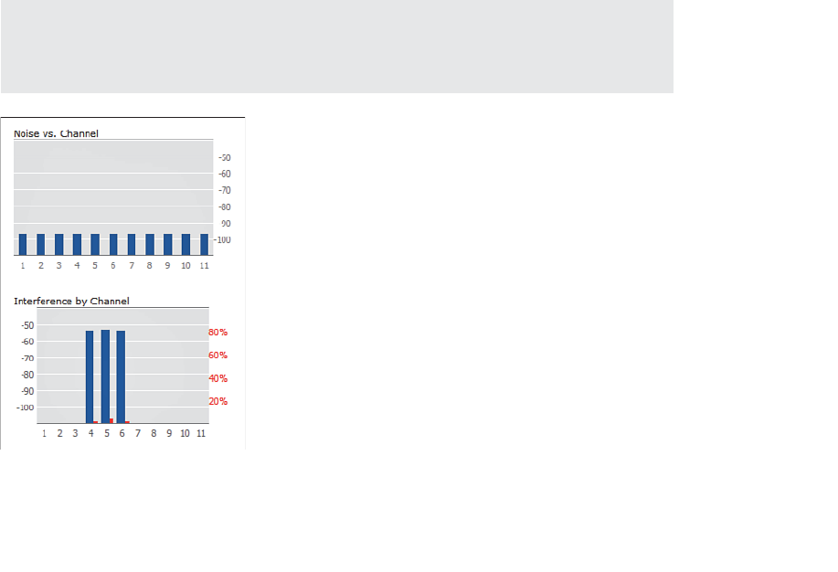
ptg12542968
390 CCNA Wireless 640-722 Official Cert Guide
Using Cisco CleanAir to Manage Interference
As you have learned in this book, WLANs use the same unlicensed bands as many other
technologies and devices. If the RF conditions in your environment are superb, such that
your 802.11 APs and clients can enjoy clear channels with low noise and no interference,
users will be happy and your job will become easier. However, it is all too easy for some-
one to power up a rogue AP or a non-802.11 device that begins to interfere with your
network.
If some portion of your wireless network begins to have degraded performance, wire-
less interference might be occurring there. How should you approach such a problem?
First, you should figure out what type of device is generating the interference. Then you
should attempt to locate the device so that you can negotiate with its owner to have it
disabled. If that is not possible, you should move your AP onto a different channel that
is clear from interference.
Any Cisco lightweight AP can measure both noise and interference as it scans the chan-
nels in a band, as part of the RRM process. Figure 19-1 shows an example of the infor-
mation gathered from the 2.4-GHz radio of an AP. The noise level appears to be very
low and acceptable on every channel. The Interference by Channel graph displays the
received strength of an interference source in dBm on the left vertical axis (dark blue)
and the duty cycle of the interference in percent on the right vertical axis (red). Figure
19-1 shows fairly strong interference on channels 4 through 6, but at a very low duty
cycle. Although that is good information to have, can you tell what sort of thing is caus-
ing the interference?
Tip You can display the results by selecting
Monitor > Access Points > Radios >
802.11a/n or 802.11b/g/n . Find an AP of interest in the list, and then scroll over to the
right side of the page. Click the blue drop-down menu and select Details .
Figure 19-1 Basic Channel Quality Information Gathered by an AP.
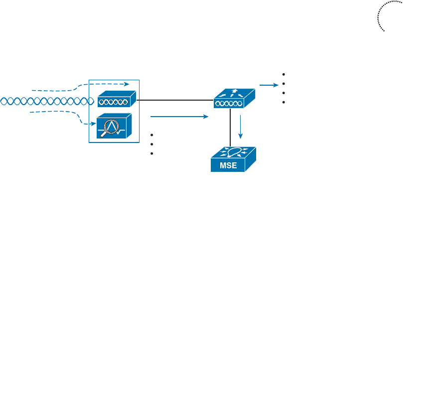
ptg12542968
Chapter 19: Dealing with Wireless Interference 391
To accurately detect and identify interference, you should use a spectrum analyzer,
which sweeps through a range of frequencies and displays the signal strength it receives
on each one. Spectrum analyzers can display this information in many forms so that it is
easier to see patterns in the RF activity. Rather than rely on your own ability to recog-
nize interference patterns, many spectrum analyzers offer their own intelligence. They
can recognize and identify specific types of devices that are causing interference based
on patterns and signatures in the spectrum data.
Now imagine carrying a spectrum analyzer throughout an entire WLAN to look for wire-
less interference. You never know where interference might crop up or how long it will
last. What if you could have a spectrum analyzer permanently located at each AP?
Cisco CleanAir does just that; APs, such as the 3500 and 3600 models, have spectrum
analysis capability built built right in to the radio hardware. While a CleanAir AP is busy
operating its normal basic service sets (BSSs) on a channel, it can also monitor RF energy
on that channel, analyze the data, and report specific information about any interfering
devices—all without interrupting normal WLAN operation.
Anything that the AP receives and recognizes as an 802.11 frame is processed normally
by the split MAC architecture. Other signals that cannot be demodulated according to
any known modulation and coding scheme must be coming from a non-802.11 source.
That signal information is processed by the spectrum analysis hardware in the AP, as
shown in Figure 19-2 .
802.11 Signal
AP w/CleanAir
Non-802.11 Signal
WLC
Interferer Report
RSSI
Duty Cycle
Severity
Correlate and Locate
Interferers
Reports
Traps
Location
Mitigation
Figure 19-2 Overview of CleanAir Operation.
The spectrum information from every AP is sent up to the corresponding wireless LAN
controller (WLC), where it can be collected and processed. If an interference source is
received by more than one AP, the controller can usually correlate the data and realize
that a single source is involved and not several different ones. WLCs can also pass inter-
ference reports to an MSE to determine an interference source’s location and display it
on a WCS/NCS map. With CleanAir, interference can be automatically detected, identi-
fied, and the source located—which should make your job easier!
Beyond that, a Cisco Unified Wireless Network (CUWN) can even react to wireless
interference automatically. Recall that the Radio Resource Management (RRM) process
is responsible for working out a channel reuse plan and assigning APs to use specific
channels in a band—all on a periodic basis. Event-driven RRM can react to interference
immediately, without waiting for the next scheduled RRM iteration, so that an AP can
be moved to a different channel to escape the interference.
Key
Topic
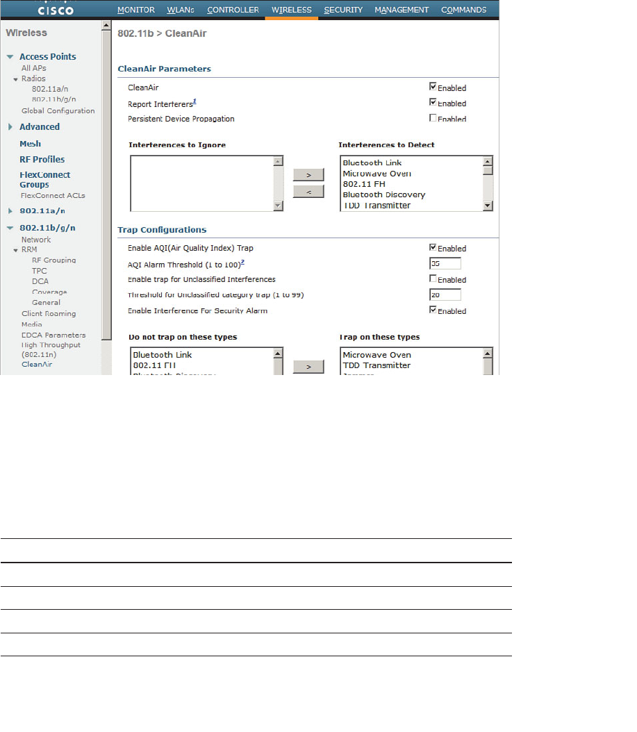
ptg12542968
392 CCNA Wireless 640-722 Official Cert Guide
Enabling CleanAir
CleanAir operates on each band independently. You can enable or disable it globally for
all APs on a controller by selecting Wireless > 802.11a/n or 802.11b/g/n > CleanAir
and using the CleanAir check box, as shown in Figure 19-3 . By default, CleanAir is dis-
abled globally on a controller.
Figure 19-3 Enabling CleanAir Globally on a Controller.
By default, APs will report the interference types listed in Table 19-2 to their respec-
tive controller. You can change this behavior by selecting a type and moving it to the
Interferences to Ignore or Interferences to Detect list. You can also select which types
will generate an SNMP trap from the controller when they are detected. Otherwise, any
types not selected will not be reported.
Table 19-2 CleanAir Interference Types and Their Default Actions
Interference Type Report Trap
802.11 FH (frequency hopping) X
802.15.4 (ZigBee) X
Bluetooth discovery X
Bluetooth link X

ptg12542968
Chapter 19: Dealing with Wireless Interference 393
Interference Type Report Trap
Canopy X
Continuous Transmitter X X
DECT-like phone X
Jammer X X
Microwave oven X X
SuperAG X
TDD transmitter X X
Video camera X X
WiFi invalid channel X X
WiFi inverted X X
WiMax fixed X X
WiMax mobile X X
Xbox X
Tip An AP must be configured for either local or monitor mode before it can generate
CleanAir interference reports. Reporting is not possible in the Spectrum Only Monitor
Mode (SOMM).
As interference sources are detected and classified according to interference type, the
AP also measures the RSSI and the duty cycle of the interferer. The duty cycle is the
percentage of time the source is transmitting on the channel, which indicates its persis-
tence or how much of the airtime the interferer is consuming. The AP combines the RSSI
and duty cycle into a severity index value. Severity ranges from 0 (not severe) to 100
(very severe). Interference with a high severity rating can render a channel unusable.
Interference detection reports sent to a controller include the AP name, interference
type, affected channel, timestamp, severity, duty cycle, and RSSI. The controller then
tries to determine whether the same interference source is involved in reports coming
from multiple APs. If so, the source is uniquely identified by assigning it a cluster ID. A
cluster ID is actually a pseudo-MAC address that represents the non-802.11 device with
a familiar wireless identifier.
You can display a list of interference detection reports on a controller by selecting
Monitor > CleanAir > 802.11a/n or 802.11b/g/n > Interference Devices . Figure 19-4
shows an example list.
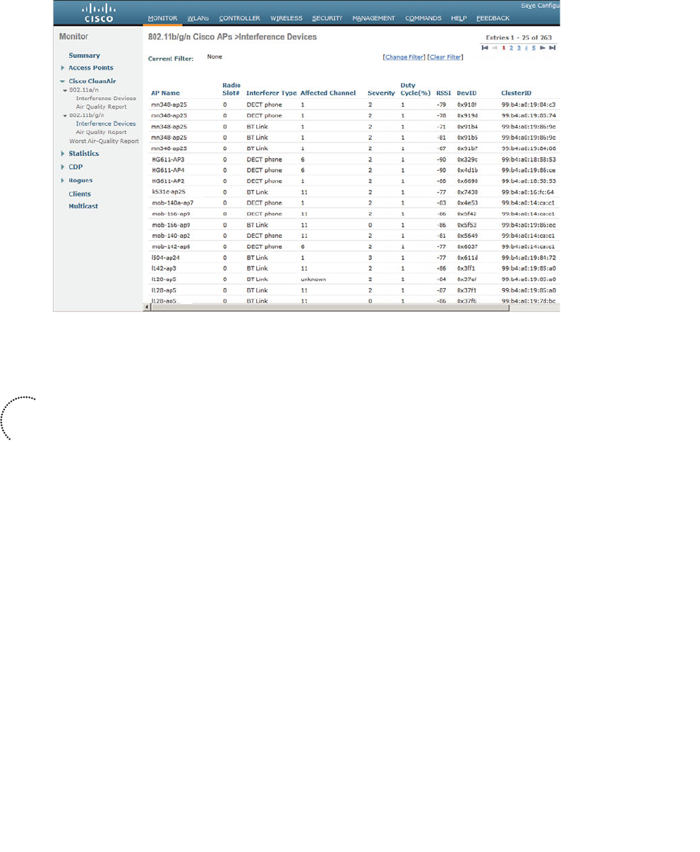
ptg12542968
394 CCNA Wireless 640-722 Official Cert Guide
Figure 19-4 Example List of Interference Device Reports.
Air-Quality Index
As APs and controllers work together to generate a list of interference reports, the list
can grow quite long. For example, the controller from Figure 19-4 has a list of 263
reports from the 2.4 GHz 802.11b/g/n band alone. To get a feel for the RF conditions
on any one channel and AP, you would have to read through the list of reports manually
and guess the cumulative effect that various interferers were having.
Cisco WLCs can do a better analysis by calculating an air-quality index (AQI) for each
AP and its channels. The AQI indicates WiFi health within an AP’s cell, as indicated by a
scale from 0 (unusable) to 100 (perfect). You can display the air quality metrics for every
AP on a controller by selecting Monitor > CleanAir > 802.11a/n or 802.11b/g/n >
CleanAir > Air Quality Report , as shown in Figure 19-5 . You can see a summary of the
AP with the worst air-quality rating in each band by selecting Worst Air-Quality Report .
Air-quality ratings are updated dynamically. Each AP measures RF conditions once a
second and then calculates an air quality value every 15 seconds and a summary every 30
seconds. By default, these values are reported to the AP’s controller every 15 minutes.
You can also view an AP’s CleanAir activity more frequently through the rapid update
mode. To access this mode, use Monitor > Access Points > 802.11a/n or 802.11b/g/n
to display a list of APs. Choose an AP, and then select CleanAir from the blue triangular
drop-down menu on the right side of the list. In rapid update mode, the controller auto-
matically refreshes the page every 30 seconds with updated CleanAir data.
Key
Topic
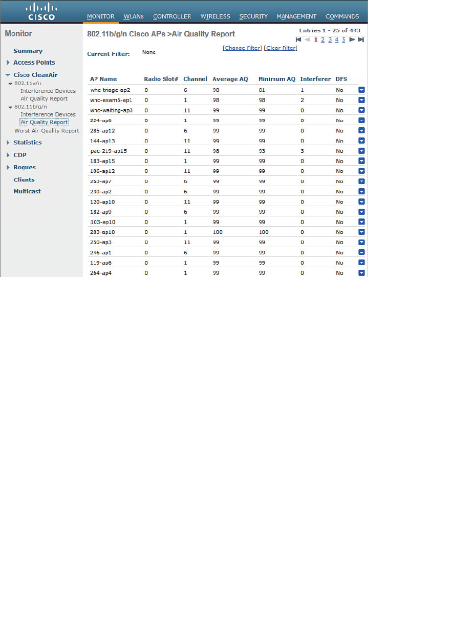
ptg12542968
Chapter 19: Dealing with Wireless Interference 395
Rapid update mode also shows more detailed CleanAir information from an AP. In
Figure 19-6 , the AP has detected interference from a microwave oven. The air quality is
shown as a bar graph. Normally only the one channel used by an AP is shown; if the AP
is in monitor mode, all channels are shown. The same page also shows channel utilization
and interference power measured by the AP.
Controllers display air quality on a per-AP (and channel) basis, and this information
is aggregated further by Wireless Control System/Network Control System/Prime
Infrastructure (WCS/NCS/PI). Air quality is summarized for the entire set of controllers
that are managed in the enterprise.
Figure 19-5 Displaying Air-Quality Indices for all APs on a Controller.
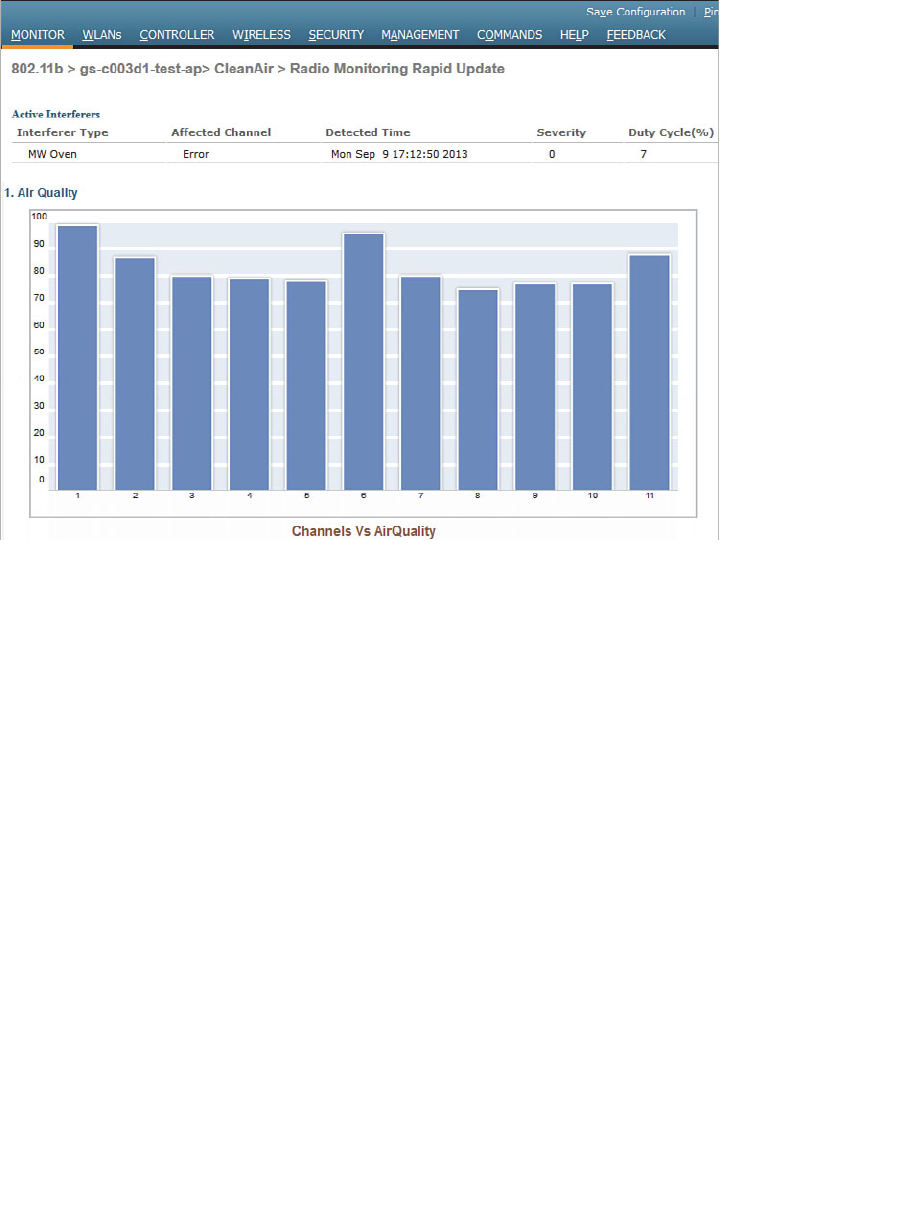
ptg12542968
396 CCNA Wireless 640-722 Official Cert Guide
Using Event-Driven RRM
By default, APs and controllers work together to detect, classify, and report wireless
interference from non-802.11 devices. CleanAir and RRM can work together so that
controllers actually take some action on interference events at the regular RRM inter-
vals. By default, RRM runs the DCA algorithm every 10 minutes, but you can increase
the interval up to 24 hours. If non-802.11 interference occurs near an AP, the controller
must wait until the next dynamic channel allocation (DCA) interval before it can move
the AP away from the unusable channel.
When Event-Driven RRM (ED-RRM) is enabled, the normal periodic RRM DCA process
is triggered immediately in response to interference reported by an AP. ED-RRM must
be enabled and then triggered based on an AQI threshold. You can set the threshold to
Low (AQI 35), Medium (AQI 50), or High (AQI 60).
First, enable ED-RRM globally on a controller. ED-RRM uses the DCA function to
change an AP’s channel and work out any other channel allocation changes that might
be needed. Therefore, navigate to the DCA configuration by selecting Wireless >
802.11a/n or 802.11b/g/n > RRM > DCA . Scroll to the bottom of the page to the
Event Driven RRM section, as shown in Figure 19-7 . Once you check the EDRRM box,
you will be able to select a Sensitivity Threshold from the drop-down list. By default,
the threshold is set to Medium . You can select Low, Medium, High, or Custom.
Figure 19-6 Displaying Detailed CleanAir Data in Rapid Update Mode.
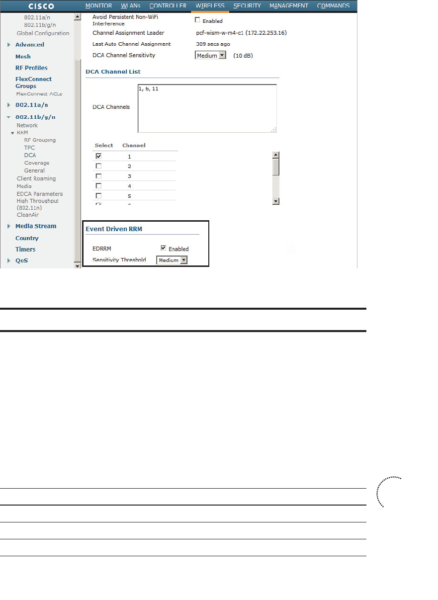
ptg12542968
Chapter 19: Dealing with Wireless Interference 397
Figure 19-7 Enabling ED-RRM.
Exam Preparation Tasks
As mentioned in the section “How to Use This Book” in the Introduction, you have a
couple of choices for exam preparation: the exercises here, Chapter 22 , “Final Review,”
and the exam simulation questions on the CD-ROM.
Review All Key Topics
Review the most important topics in this chapter, noted with the Key Topic icon in the
outer margin of the page. Table 19-3 lists a reference of these key topics and the page
numbers on which each is found.
Table 19-3 Key Topics for Chapter 19
Key Topic Element Description Page Number
List Interference and noise 386
Paragraph CleanAir operation 391
Paragraph Air-quality index 394
Key
Topic

ptg12542968
398 CCNA Wireless 640-722 Official Cert Guide
Define Key Terms
Define the following key terms from this chapter and check your answers in the glos-
sary:
air-quality index (AQI), Cisco CleanAir, cluster ID, Event-Driven RRM (ED-RRM),
duty cycle, interference, noise, pseudo-MAC address, rogue AP, spectrum analyzer

ptg12542968
This page intentionally left blank

ptg12542968
This chapter covers the following topics:
■ Troubleshooting Client Connectivity —This section
covers some strategies and methods you can use
when faced with wireless clients that report prob-
lems connecting to the network.
■ Troubleshooting AP Connectivity —This section
describes some troubleshooting steps you can use
to figure out why an access point is not connecting
or operating properly.
This chapter covers the following exam topics:
■ Verify basic wireless network operation
■ Identify and use basic WLAN troubleshooting tools
(WLC show debug and logging) for client to AP
connectivity, AP to controller connectivity
■ Use the WCS client troubleshooting tool

ptg12542968
As a CCNA Wireless engineer, you will be expected to perform some basic trouble-
shooting work when wireless problems arise. The CCNA Wireless exam blueprint focus-
es on some troubleshooting tools that are available on Cisco Wireless LAN Controllers
(WLCs) and the Cisco Wireless Control System (WCS). This chapter helps you get some
perspective on wireless problems, develop a troubleshooting strategy, and become com-
fortable using the tools at your disposal.
“Do I Know This Already?” Quiz
The “Do I Know This Already?” quiz allows you to assess whether you should read this
entire chapter thoroughly or jump to the “Exam Preparation Tasks” section. If you are
in doubt about your answers to these questions or your own assessment of your knowl-
edge of the topics, read the entire chapter. Table 20-1 lists the major headings in this
chapter and their corresponding “Do I Know This Already?” quiz questions. You can
find the answers in Appendix A , “Answers to the ‘Do I Know This Already?’ Quizzes.”
Table 20-1 “Do I Know This Already?” Section-to-Question Mapping
Foundation Topics Section Questions
Troubleshooting Client Connectivity 1–8
Troubleshooting AP Connectivity 9–10
Caution The goal of self-assessment is to gauge your mastery of the topics in this chap-
ter. If you do not know the answer to a question or are only partially sure of the answer,
you should mark that question as wrong for purposes of the self-assessment. Giving your-
self credit for an answer you correctly guess skews your self-assessment results and might
provide you with a false sense of security.
CHAPTER 20
Troubleshooting WLAN Connectivity

ptg12542968
402 CCNA Wireless 640-722 Official Cert Guide
1.
To get a WLC to display information about a specific wireless client, you go to the
Monitor > Clients page. Which one of the following pieces of information should
you input to obtain the best troubleshooting data?
a. Client’s IP address
b. SSID
c. Client’s MAC address
d. AP name
2.
From the Monitor > Clients page of a controller, you can see the entire list of active
clients. Which of the following represent parameters you can use to further filter
the client list? (Select all that apply.)
a. AP name
b. AP address
c. WLAN profile name
d. SSID
e. Client MAC address
f. Client state
3.
Suppose that you search for a wireless client on a controller and notice that it is
associated. Which one of the following parameters would confirm that the client
has completed the association process with the controller and is ready to pass data?
a. Client’s IP address
b.
AP name and IP address
c. Associated AP status
d. RUN policy manager state
4. Which two of the following are ways you can force a client off the wireless net-
work temporarily so that it has to reassociate?
a.
Add the client to the Shunned Clients list
b.
Add the client to the Disabled Clients list
c. Select Remove
from the client details drop-down menu
d.
Select Disassociate from the client details page
e. Select Deauthenticate from the client details page

ptg12542968
Chapter 20: Troubleshooting WLAN Connectivity 403
5.
If a client is shown to be in the 8021X_REQD state, even though the end user tried
to join the wireless network several minutes ago, which one of the following best
describes the client’s current condition?
a.
The client does not support any of the 802.11 amendments.
b.
The client failed to authenticate itself properly.
c.
Spanning Tree Protocol is blocking the AP’s uplink.
d.
The client failed to receive an IP address.
6.
To troubleshoot a client’s connection to the wireless network, you decide to use
a Link Test from the controller. The client is a Windows-based machine, uses an
adapter that supports 802.11n, is configured to support all possible data rates, and
supports CCXv1. Which one of the following link tests will the controller perform
with the client?
a. CCXv1 test frames
b. ICMP echo packets
c. Round-trip time (RTT) measurements
d. RSSI measurements at client and AP
7.
Which of the following are required on the client’s wireless adapter before a CCX
link test can be performed on a controller? (Select all that apply.)
a. CCXv1
b. CCXv2
c. CCXv4
d. CCXv5
e. Support for any CCX version
8.
To gather detailed troubleshooting information in real time about client MAC
address 40:20:30:10:20:30, which one of the following controller CLI commands
should you use?
a. show mac-address 40:20:30:10:20:30
b. test client 40:20:30:10:20:30
c. trace client 40:20:30:10:20:30
d. debug client 40:20:30:10:20:30

ptg12542968
404 CCNA Wireless 640-722 Official Cert Guide
9.
Suppose that you have a large wireless network with several controllers, many APs,
a RADIUS server, a syslog server, and a WCS server. A user has reported connec-
tivity problems in a specific building location, but gave no details about the AP or
controller he tried to join. Which one of the following represents the most efficient
troubleshooting method you can use to find information about the client?
a.
Go to the client’s location and use your own computer to associate with the
network, then find out which AP and controller you are using
b.
Search for the client’s MAC address on each controller
c.
Search for the client’s MAC address on WCS
d.
Search for the client’s MAC address on the RADIUS server
10.
Suppose that you have just received news that no users can connect with a newly
installed lightweight AP. You decide to examine the switch configuration where the
AP is connected, knowing that it needs to be bound to VLAN 11. Which one of the
following switch interface configurations is correct?
a. switchport
switchport mode access
no shutdown
b. switchport
switchport trunk allowed vlan 1-11
switchport trunk encapsulation dot1q
switchport mode trunk
c. switchport
switchport access vlan 11
switchport mode access
spanning-tree portfast
shutdown
d. switchport
switchport access vlan 11
switchport mode access
no shutdown
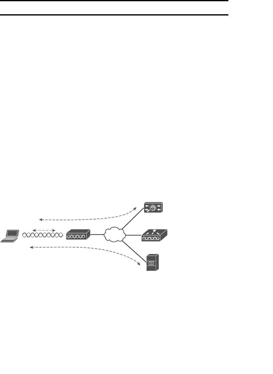
ptg12542968
Chapter 20: Troubleshooting WLAN Connectivity 405
Foundation Topics
Troubleshooting Client Connectivity
When one or more network users report that they are having problems, your first course
of action should be to gather more information. Begin with a broad perspective and then
try to ask pointed questions that will narrow the scope of possible causes. You do not
want to panic or waste time chasing irrelevant things. Instead, ask questions and try to
notice patterns or similarities in the answers you receive.
For example, if you get reports from many people in the same area, perhaps an access
point (AP) is misconfigured or malfunctioning. Reports from many areas or from a single
service set identifier (SSID) may indicate problems with a controller. However, if you
receive a report of only one wireless user having problems, it might not make sense to
spend time troubleshooting a controller, where many users are supported. Instead, you
should focus on that one user’s client device and its interaction with an AP.
As you prepare to troubleshoot a single wireless client, think about all of the things a
client needs to join and use the network. Figure 20-1 illustrates the following conditions
that must be met for a successful association:
■ Client is within RF range of an AP, asks to associate.
■ Client requests and receives an IP address.
■ Client authenticates.
Client LAP WLC
DHCP
AAA
IP Address
802.1X
BSS
Figure 20-1 Conditions for a Successful Association.
Try to gather information from the end user to see what the client is experiencing. “I
cannot connect” or “The WiFi is down” might actually mean that the user’s device can-
not associate, cannot get an IP address, or cannot authenticate. A closer inspection of
the device might reveal more clues.
Can the client associate at all? Most client operating systems display an icon that shows
whether a wireless adapter is connected or disconnected. If the client is not associated,
compare its wireless profile settings with the WLAN configuration on the controller.

ptg12542968
406 CCNA Wireless 640-722 Official Cert Guide
The controller and the client must have identical settings for the following parameters:
■ 2.4- or 5-GHz band
■ Data rates and Modulation Coding Scheme (MCS)
■ SSID string
■ Wireless security
■ Encryption method
Navigate to WLANs, select the WLAN that the client is trying to use, and then review
the settings on the General, Security, QoS, and Advanced tabs. See whether the client is
configured appropriately.
If the client still cannot associate, be aware that it may be listed in the controller as a
disabled client. A client can be added to the disabled list manually, usually as a result of
violating a local security policy, or automatically when the client’s activity matches one
of the controller’s wireless protection policy signatures. Navigate to Security > Disabled
Clients and look for the client’s MAC address in the list. If the list is long, you can also
search for the MAC address on that page.
If the client is able to associate, verify that it has an IP address. Does the client have an
IP address from a subnet on the correct WLAN? If it does not show an address, check
the Dynamic Host Configuration Protocol (DHCP) server to make sure that the respec-
tive DHCP scope is not already full. Remember that the controller acts as a DHCP relay,
accepting the client’s DHCP request and forwarding it on to the server. If an address is
offered in return, the controller relays that back to the client.
Tip Because the controller relays the DHCP offer, it will substitute its own virtual inter-
face address as the DHCP server’s. Do not be surprised to see the controller virtual gate-
way IP address, such as 1.1.1.1, or an address that differs from the actual server, when
you display the DHCP information on the client.
Troubleshooting Clients from the Controller
As a wireless client probes and attempts to associate with an AP, it is essentially com-
municating with the controller. You can access a wealth of troubleshooting information
from the controller, as long as you know the client’s MAC address.
You can view a client’s current status by navigating to Monitor > Clients . The controller
will display every client that is associated to any of its APs. To find a specific client in
the long list of clients, click the Change Filter link. You can then filter the list based on
MAC address, AP name, WLAN profile or SSID, client status, client radio type, or work-
group bridge (WGB) mode. In Figure 20-2 , the list will be filtered to display only client
MAC address 00:01:36:19:12:4a.
Key
Topic
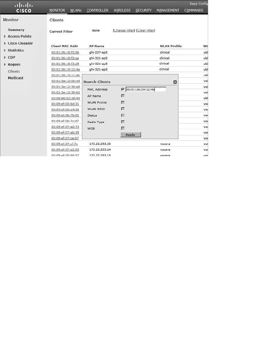
ptg12542968
Chapter 20: Troubleshooting WLAN Connectivity 407
Figure 20-2 Displaying and Filtering Client Status Information.
Click the client MAC address link to display all the known detailed information about
the client. The page begins with client properties, as shown in Figure 20-3 , which lists
useful parameters such as the client’s IP address, the AP name and type, and the AP’s
MAC address.
Scrolling further down, you will find a section of information about the client’s current
operating state, as demonstrated in Figure 20-4 . From this information, you can learn
that the client supports CCXv4. The client’s mobility role is Local, which means it has a
normal association to the local controller. If the mobility role is shown as Anchor, the
client has undergone a Layer 3 roam to another controller with the mobility peer IP
address listed. Toward the bottom of the page, you can see the list of data rates the cli-
ent supports, in addition to its current transmit data rate (TxRateSet) of 18 Mbps.
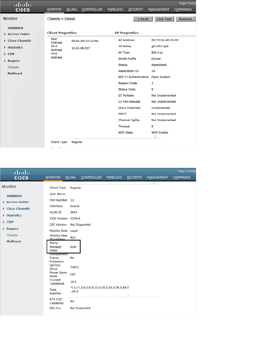
ptg12542968
408 CCNA Wireless 640-722 Official Cert Guide
Figure 20-3 Displaying Detailed Information About a Client.
Figure 20-4 Displaying Client Operating State Information.

ptg12542968
Chapter 20: Troubleshooting WLAN Connectivity 409
Perhaps the most important information about the client is listed as the policy manager
state, which is highlighted in Figure 20-4 . Before a controller will permit a client to fully
associate with a basic service set (BSS), the client must progress through a sequence of
states. Each state refers to a policy that the client must meet before moving on to the
next state. Table 20-2 lists and describes the client policy states.
Table 20-2 Possible WLC Client States
State Description
START Client activity has just begun.
AUTHCHECK Client must pass Layer 2 authentication policy.
8021X_REQD Client must pass 802.1x authentication.
L2AUTHCOMPLETE Layer 2 policy is complete; Layer 3 policies can begin.
WEP_REQD Client must authenticate with Wireless Equivalent Privacy (WEP).
DHCP_REQD WLC is waiting to learn the client’s IP address.
WEBAUTH_REQD Client must pass web authentication.
RUN Client has passed Layer 2 and Layer 3 policies, successfully
associated, and can pass traffic.
A probing client always begins in the START state and then moves into Layer 2 policy
states and Layer 3 policy states. For example, if the client is attempting to associate with
a WLAN that is configured for some form of 802.1x authentication, the client must pass
through the 8021X_REQD state. If it successfully authenticates, it can move further
down the list of states.
Ultimately, each client should end up in the RUN state, where it has fully associated
with the BSS and is permitted to pass traffic over the WLAN. If you find a client that is
consistently shown in a state other than RUN, the client must be having a problem pass-
ing the policy of that state.
For example, a client that is stuck in 8021X_REQD is likely having trouble authenticat-
ing successfully. That could be because the client is sending an incorrect key, has an
invalid certificate, or because the RADIUS server is down.
A client stuck in DHCP_REQD is having trouble obtaining an IP address. The control-
ler monitors the DHCP request of each client, as well as the DHCP offer returned to
each client. If an offer is not seen, the client is stuck waiting. (One exception is a client
that is using a static IP address, without the need for DHCP. So long as the WLAN is
configured to not require DHCP, the controller will move the client on through the
DHCP_REQD state.)
Toward the bottom of the client details page, you will find a list of client statistics, such
as those shown in Figure 20-5 . The controller maintains counters for the number of
bytes and packets sent and received by the client. You can also see the received signal
Key
Topic
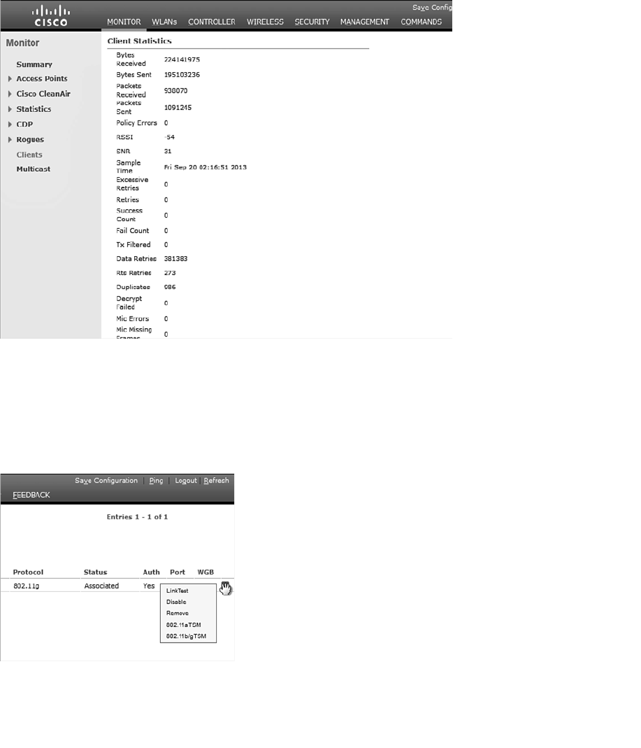
ptg12542968
410 CCNA Wireless 640-722 Official Cert Guide
strength indicator (RSSI) value of the client and the signal-to-noise ratio (SNR) value, as
measured by the AP. This can give you a good idea about how well the client’s signal is
being received. The data retries, request to send (RTS) retries, and duplicates counters
help indicate congested conditions on the AP’s channel. More congestion generally
results in more retries, where frames must be re-sent.
Figure 20-5 Displaying Client Statistics.
You can also select the blue drop-down menu at the right end of the client entry to man-
age the client’s association, as shown in Figure 20-6 . Selecting Remove will deauthen-
ticate the client and force it off the network, so that it will attempt to associate again.
Selecting Disable will add the client’s MAC address to the list of disabled clients and
will force the client off the network.
Figure 20-6 Managing a Client Association.
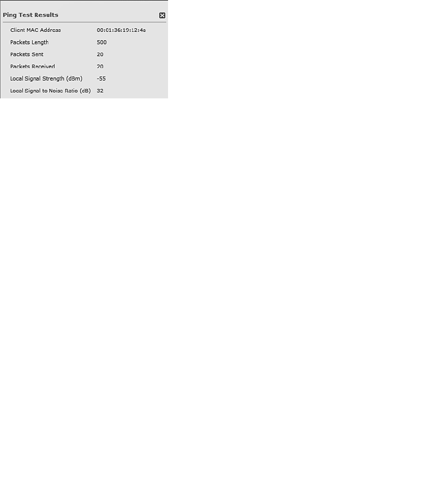
ptg12542968
Chapter 20: Troubleshooting WLAN Connectivity 411
Performing a Link Test
You can select Link Test to perform a short test to gauge the RF conditions between
the controller and the client. If the client does not support Cisco Compatible Extensions
Version 4 (CCXv4) or CCXv5, the controller will run a ping test consisting of 20 500-
byte Internet Control Message Protocol (ICMP) echo packets sent to the client’s IP
address. The client should reply to each of the ping packets if the wireless link is good
and if the client supports ping traffic. The controller also records the RSSI of the client
device and the SNR and reports the test results as shown in Figure 20-7 .
Figure 20-7 Results of a Ping Test to a Client Device.
Notice that the ping test reports only a single RSSI value. Even though a wireless link is
bidirectional and involves two devices, the AP and the client, the controller can report
only on the RSSI of the signal it receives from the client. Naturally, the client can (and
probably does) measure the RSSI of the AP’s signal that it receives, but it cannot share
that information with the controller using ping packets.
If you perform a link test on a client that does support CCXv4 or CCXv5, the controller
can gather much more information about the conditions at both ends of the link. In that
case, the link test uses CCX messages rather than pings. A client with the more advanced
CCX versions can return its own signal quality data to the controller.
Figure 20-8 shows an example of a link test with a CCXv4 client. The controller displays
the round-trip time of the CCX exchange, the RSSI and SNR as measured at the client
and the controller, and frame retries. The last two sets of data show the data rate used
by the AP and the client (that is, 54 Mbps) and the MCS index and frame count in both
directions.
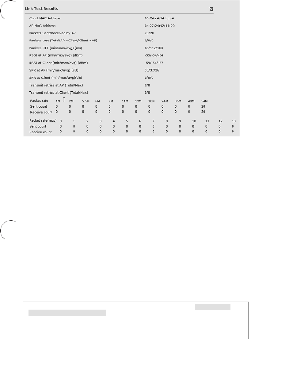
ptg12542968
412 CCNA Wireless 640-722 Official Cert Guide
Figure 20-8 Results of a Link Test to a CCXv4 or CCXv5 Client Device.
Debugging a Client
Sometimes you might encounter a client that is having trouble connecting, but nothing
seems to be obviously wrong. For example, a controller might show that the client is
stuck in the 8021X_REQD or DHCP_REQD state, but you are not able to figure out
why. Perhaps the client does not even get that far along in its attempts to associate. If
you know which AP and controller the client is attempting to associate with, you can
gather useful debugging information.
From the controller command-line interface (CLI), enter the command debug client
client-mac-address . Be sure to configure your terminal emulator session to log or save
all of the output that scrolls by so that you can go back and review it closely. Example
20-1 lists the output produced by the debug client 60:67:20:9a:9e:fa command, as the
client attempts to join the wireless network. The debug command can provide extensive
information about processes running in the AP and the WLC while the client authenti-
cates. Much of the command output is cryptic, but you can pick out important events in
the life of the client as it interacts with the controller. Only the important lines of output
have been extracted and listed in Example 20-1 .
Example 20-1 Output From the debug client 60:67:20:9a:9e:fa Command
*apfMsConnTask_4: Sep 21 02:45:11.456: 60:67:20:9a:9e:fa Association
received from mobile on AP
20:3a:07:6f:5e:f0
*apfMsConnTask_4: Sep 21 02:45:11.457: 60:67:20:9a:9e:fa 0.0.0.0 START (0)
Initializing policy
Key
Topic
Key
Topic

ptg12542968
Chapter 20: Troubleshooting WLAN Connectivity 413
*apfMsConnTask_4: Sep 21 02:45:11.457: 60:67:20:9a:9e:fa 0.0.0.0 START (0)
Change state to AUTHCHECK
(2) last state AUTHCHECK (2)
*apfMsConnTask_4: Sep 21 02:45:11.457: 60:67:20:9a:9e:fa 0.0.0.0 AUTHCHECK
(2) Change state to
8021X_REQD (3) last state 8021X_REQD (3)
*apfMsConnTask_4: Sep 21 02:45:11.457: 60:67:20:9a:9e:fa 0.0.0.0 8021X_REQD
(3) DHCP required on AP
20:3a:07:6f:5e:f0 vapId 5 apVapId 5for this client
*apfMsConnTask_4: Sep 21 02:45:11.458: 60:67:20:9a:9e:fa apfPemAddUser2
(apf_policy.c:270) Changing
state for mobile 60:67:20:9a:9e:fa on AP
20:3a:07:6f:5e:f0 from Idle to Associated
*apfMsConnTask_4: Sep 21 02:45:11.458: 60:67:20:9a:9e:fa Sending Assoc
Response to station on BSSID
20:3a:07:6f:5e:f0 (status 0) ApVapId 5 Slot 0
*apfMsConnTask_4: Sep 21 02:45:11.458: 60:67:20:9a:9e:fa apfProcessAssocReq
(apf_80211.c:6309)
Changing state for mobile 60:67:20:9a:9e:fa on AP
20:3a:07:6f:5e:f0 from Associated to Associated
*dot1xMsgTask: Sep 21 02:45:11.459: 60:67:20:9a:9e:fa dot1x - moving mobile
60:67:20:9a:9e:fa into
Connecting state
*dot1xMsgTask: Sep 21 02:45:11.459: 60:67:20:9a:9e:fa Sending EAP-Request/
Identity to mobile
60:67:20:9a:9e:fa (EAP Id 1)
*Dot1x_NW_MsgTask_2: Sep 21 02:45:11.469: 60:67:20:9a:9e:fa Received EAPOL
EAPPKT from mobile
60:67:20:9a:9e:fa
*Dot1x_NW_MsgTask_2: Sep 21 02:45:11.469: 60:67:20:9a:9e:fa EAP State
update from Connecting to
Authenticating for mobile 60:67:20:9a:9e:fa
*Dot1x_NW_MsgTask_2: Sep 21 02:45:11.469: 60:67:20:9a:9e:fa dot1x - moving
mobile 60:67:20:9a:9e:fa
into Authenticating state
*Dot1x_NW_MsgTask_2: Sep 21 02:45:11.477: 60:67:20:9a:9e:fa Processing
Access-Challenge for mobile
60:67:20:9a:9e:fa
*Dot1x_NW_MsgTask_2: Sep 21 02:45:11.477: 60:67:20:9a:9e:fa Entering Back-
end Auth Req state (id=2) for
mobile 60:67:20:9a:9e:fa
*Dot1x_NW_MsgTask_2: Sep 21 02:45:11.477: 60:67:20:9a:9e:fa Sending EAP
Request from AAA
to mobile
60:67:20:9a:9e:fa (EAP Id 2)
*Dot1x_NW_MsgTask_2: Sep 21 02:45:11.552: 60:67:20:9a:9e:fa Received EAPOL
EAPPKT from mobile
60:67:20:9a:9e:fa
*Dot1x_NW_MsgTask_2: Sep 21 02:45:11.552: 60:67:20:9a:9e:fa Received EAP
Response from mobile
60:67:20:9a:9e:fa (EAP Id 10, EAP Type 13)

ptg12542968
414 CCNA Wireless 640-722 Official Cert Guide
*Dot1x_NW_MsgTask_2: Sep 21 02:45:11.554: 60:67:20:9a:9e:fa Processing
Access-Accept for
mobile 60:67:20:9a:9e:fa
*Dot1x_NW_MsgTask_2: Sep 21 02:45:11.554: 60:67:20:9a:9e:fa Username entry
(host/IMKYCD212L13.mydomain.com) created for mobile, length = 253
*Dot1x_NW_MsgTask_2: Sep 21 02:45:11.554: 60:67:20:9a:9e:fa Username entry
(host/IMKYCD212L13.mydomain.com) created in mscb for mobile, length = 253
*Dot1x_NW_MsgTask_2: Sep 21 02:45:11.556: 60:67:20:9a:9e:fa Sending EAP-
Success to mobile
60:67:20:9a:9e:fa (EAP Id 10)
*Dot1x_NW_MsgTask_2: Sep 21 02:45:11.556: 60:67:20:9a:9e:fa Received Auth
Success while in
Authenticating state for mobile 60:67:20:9a:9e:fa
*Dot1x_NW_MsgTask_2: Sep 21 02:45:11.556: 60:67:20:9a:9e:fa dot1x - moving
mobile 60:67:20:9a:9e:fa
into Authenticated state
*Dot1x_NW_MsgTask_2: Sep 21
02:45:11.565: 60:67:20:9a:9e:fa 0.0.0.0 8021X_
REQD (3) Change state to
L2AUTHCOMPLETE (4) last state L2AUTHCOMPLETE (4)
*Dot1x_NW_MsgTask_2: Sep 21 02:45:11.568: 60:67:20:9a:9e:fa 0.0.0.0 L2AUTH-
COMPLETE (4)
DHCP required on AP 20:3a:07:6f:5e:f0 vapId 5 apVapId 5for this client
*Dot1x_NW_MsgTask_2: Sep 21 02:45:11.568: 60:67:20:9a:9e:fa 0.0.0.0 L2AUTH-
COMPLETE (4)
Change state to DHCP_REQD (7) last state DHCP_REQD (7)
type = Airespace AP - Learn IP address
on AP 20:3a:07:6f:5e:f0, slot 0, interface = 13, QOS = 0
IPv4 ACL ID = 255, IP
*Dot1x_NW_MsgTask_2: Sep 21 02:45:11.568: 60:67:20:9a:9e:fa 0.0.0.0 DHCP_
REQD (7) Fast Path rule
(contd...) 802.1P = 0, DSCP = 0, TokenID = 15206 Local Bridging Vlan =
3606, Local Bridging intf id =
13
*Dot1x_NW_MsgTask_2: Sep 21 02:45:11.568: 60:67:20:9a:9e:fa 0.0.0.0 DHCP_
REQD (7) Successfully plumbed
mobile rule (IPv4 ACL ID 255, IPv6 ACL ID 255)
*apfReceiveTask: Sep 21 02:45:14.484: 60:67:20:9a:9e:fa 0.0.0.0 DHCP_REQD
(7) State Update from
Mobility-Incomplete to Mobility-Complete, mobility role=Local, client
state=APF_MS_STATE_ASSOCIATED
*apfReceiveTask: Sep 21 02:45:14.484: 60:67:20:9a:9e:fa 0.0.0.0 DHCP_REQD
(7) Successfully plumbed
mobile rule (IPv4 ACL ID 255, IPv6 ACL ID 255)
*apfReceiveTask: Sep 21 02:45:14.484: 60:67:20:9a:9e:fa 172.22.121.128
DHCP_REQD (7) Change state to
RUN (20) last state RUN (20)
*apfReceiveTask: Sep 21 02:45:14.484: 60:67:20:9a:9e:fa 172.22.121.128 RUN
(20) Reached PLUMBFASTPATH:
from line 5842
*apfReceiveT: Sep 21 02:45:14.484: 60:67:20:9a:9e:fa 172.22.121.128 RUN

ptg12542968
Chapter 20: Troubleshooting WLAN Connectivity 415
(20) Replacing Fast Path rule
type = Airespace AP Client
on AP 20:3a:07:6f:5e:f0, slot 0, interface = 13, QOS = 0
IPv4 ACL ID = 255, IPv6 ACL
*apfReceiveTask: Sep 21 02:45:14.485: 60:67:20:9a:9e:fa Assigning Address
172.22.121.128 to mobile
*apfReceiveTask: Sep 21 02:45:14.485: 60:67:20:9a:9e:fa Successfully
installed IP address
172.22.121.128 for station
*pemReceiveTask: Sep 21 02:45:14.486: 60:67:20:9a:9e:fa Sending a gratu-
itous ARP for 172.22.121.128,
VLAN Id 3606
The debug client command can also prove useful when you are troubleshooting roaming
issues, as a client moves from one AP to another on the same controller or between two
controllers. In the latter case, you can use debug client on multiple controllers, collect
the output from each CLI session, and find the point where the client leaves one AP and
reassociates with another.
Troubleshooting Clients from WCS/NCS
Most of the troubleshooting tools described in this chapter must be used from a con-
troller. What if your network is large and consists of many controllers? You might
have a hard time figuring out which controller a client is trying to join so that you can
gather information about it. Instead, you can simply move further upstream and trouble-
shoot the client from the Wireless Control System/Network Control System/Prime
Infrastructure (WCS/NCS/PI), at the point where all of the controllers are centrally man-
aged.
You can search for a single wireless client in the entire database of active clients.
Enter all or a part of the client’s MAC address into the search box in the upper-right
corner and click the right arrow to begin the search. In Figure 20-9 , MAC address
00:09:ef:11:2e:e3 has been entered. When the search is complete, you are prompted
with the results, as shown in Figure 20-10 . Select the entry in the Monitor tab that you
want to display.
The search results will be displayed in a Clients and Users page, as shown in Figure 20-
11 . Selecting the radio button of the desired entry will display much more information
about it lower on the page, beginning with the client attributes shown in Figure 20-12 .
From this information, you can verify things such as the client’s IP address, vendor, and
power save mode, in addition to details about the AP where the client is joined and the
security parameters in use.
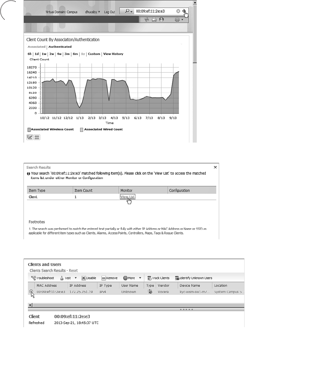
ptg12542968
416 CCNA Wireless 640-722 Official Cert Guide
Figure 20-11 Selecting a Client to Display in Detail.
Key
Topic
Figure 20-9 Searching for a Client MAC Address.
Figure 20-10 Selecting Results to View.

ptg12542968
Chapter 20: Troubleshooting WLAN Connectivity 417
You might notice one thing that is missing from all of the client information presented:
the client’s RSSI value. In the previous section, you learned that a controller can display a
current RSSI that it learned from the AP. WCS and NCS are positioned further upstream
to collect client statistics from all controllers and all APs. They also maintain a database
that contains a history of the client activity.
For example, the client details page also contains an association history in two different
scrolling lists, as shown in Figure 20-13 . The first list contains the APs and controllers
the client was associated with most recently, along with a time stamp and the duration of
each association. If the controllers were able to determine a reason for the client chang-
ing its association, that reason is displayed too.
The second association history list forms a continuous timeline of the client’s path
through the wireless network. Each time stamp marks an association change or a roam
and identifies the APs that the client was associated with before and after the roam. If
you piece this information together, you can trace the path that the client took as it
moved throughout its journey. Sometimes you can figure out locations where the RF
coverage might be lacking. For instance, you might see that the client left the network
near a stairwell in the basement, only to reappear somewhere on the fourth floor.
Further down on the client details page, you will find graphs that represent a history of
the client’s RSSI values and the SNR, as shown in Figure 20-14 .
Figure 20-12 Displaying Client Attributes (Continued Screen from Figure 20-11 ).
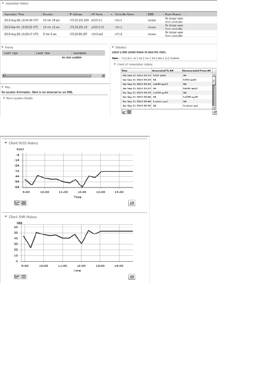
ptg12542968
418 CCNA Wireless 640-722 Official Cert Guide
Figure 20-14 Displaying a Client’s RSSI and SNR History.
You can also use WCS/NCS to perform some interactive troubleshooting on a client.
Select the client’s radio button and then click the Troubleshoot button at the top of the
page (refer to Figure 20-11 ). WCS/NCS will collect debug client information from the
controller and will display the results in a graphical format, breaking the client associa-
tion process down into the following steps:
Figure 20-13 Displaying a Client’s Association History.
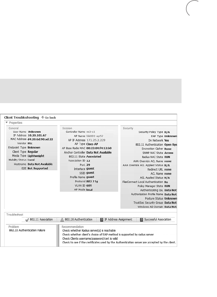
ptg12542968
Chapter 20: Troubleshooting WLAN Connectivity 419
■ 802.11 association
■ 802.1x authentication
■ IP address assignment
■ Successful association
WCS/NCS will also interpret the results and display suggested actions, all on the cli-
ent details page. In Figure 20-15 , the client d4:20:6d:90:ad:22 has failed to authenti-
cate to the WLAN. Notice that the 802.11 association step has a check mark, whereas
802.1x authentication has a caution triangle. The problem is shown to be “802.1x
Authentication Failure,” and you are given a series of parameters to check as part of
your troubleshooting efforts.
Tip If WCS/NCS does not show any obvious problems after you click the
Troubleshoot button, you can scroll to the bottom of the page and click the Check
Again button. The troubleshooting information will refresh with new results.
Figure 20-15 Troubleshooting a Client from WCS/NCS.
Key
Topic
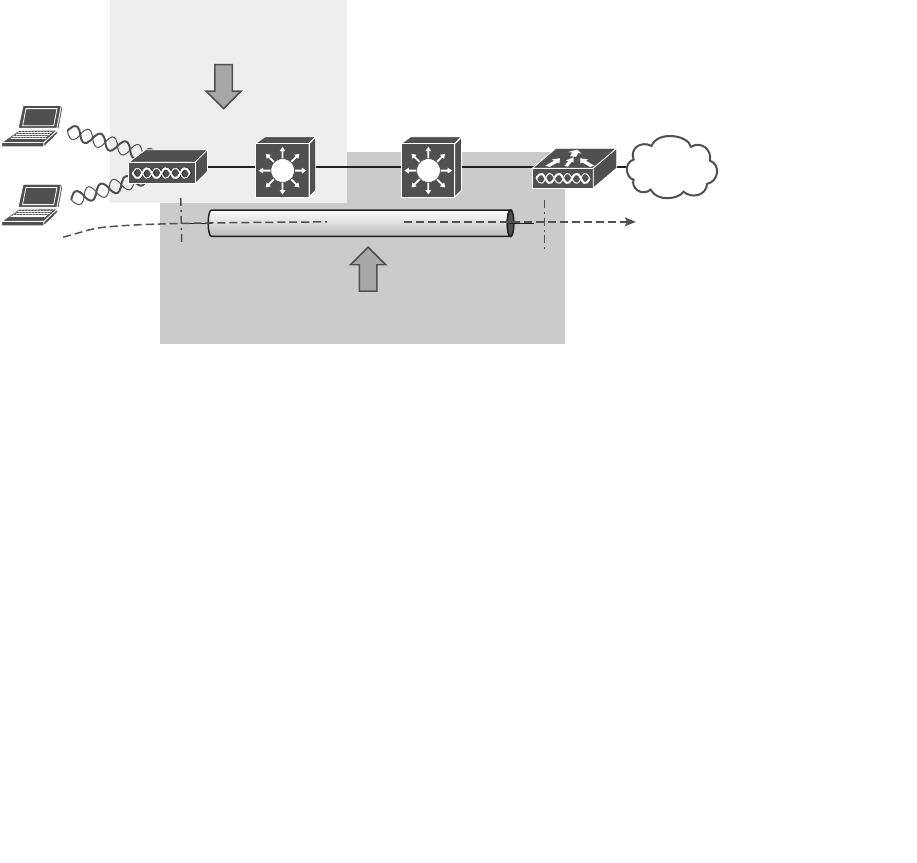
ptg12542968
420 CCNA Wireless 640-722 Official Cert Guide
Troubleshooting AP Connectivity
In cases where you get reports from multiple users who are all having problems in the
same general area, you might need to focus your efforts on an AP. The problem could
be as simple as a defective radio, where no clients are receiving a signal. In that case, you
might have to go onsite to confirm that the transmitter is not working correctly.
Otherwise, the split-MAC architecture creates several different points where you can
troubleshoot. Recall the Cisco Unified Wireless Network (CUWN) structure illustrated
in Figure 20-16 . To successfully operate the lightweight AP and provide a working BSS,
the following two things must work correctly:
■ The LAP must have connectivity to its access layer switch.
■ The LAP must have connectivity to its WLC.
LAP Access Layer WLCDistribution Layer
Client A
Client B
Verify AP Connectivity
to Network
Verify AP Connectivity
to WLC
CAPWAP
Figure 20-16 Verifying AP Connectivity in a CUWN.
Verifying AP-to-WLC Connectivity
First, verify the connectivity between an AP and a controller. Usually you will do this
when a new AP is installed, to make sure it is able to discover and join a controller
before clients arrive and try to use the wireless network. You can also do this at any time
as a quick check of the AP’s health.
The easiest approach is to simply look for the AP in the list of live APs that have joined
the controller. If you know which controller the AP should join, open a management
session to it. Navigate to Wireless > All APs > Change Filter , and then enter the AP’s
MAC address or some portion of its name. In Figure 20-17 , the controller is being
searched for an AP with d208 in its name. Fortunately, the search reveals a live AP that
is joined to the controller, as shown in Figure 20-18 . You can click the AP name link to
display more information about the AP and to configure its parameters. From the details
listed on the General tab, as shown in Figure 20-19 , you can also verify the IP address
that the AP is using.
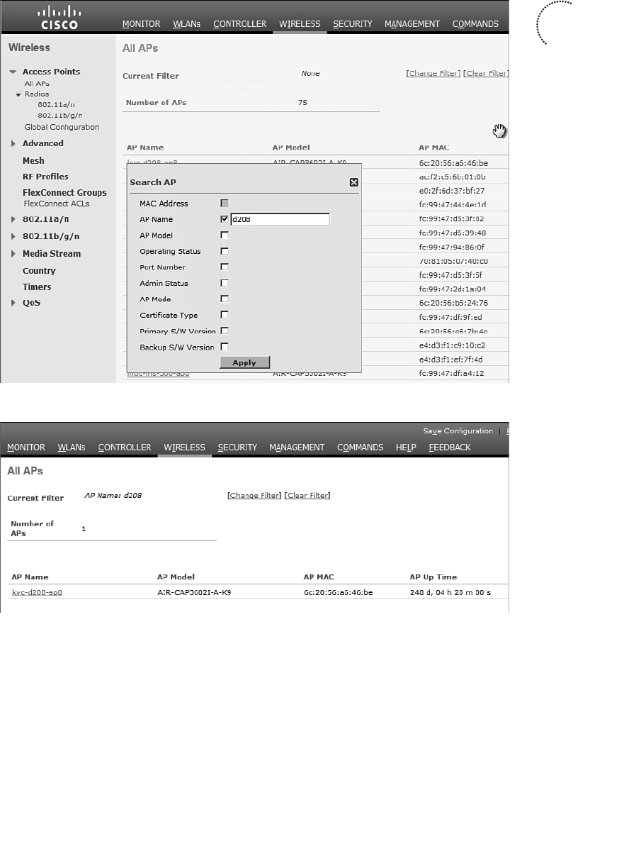
ptg12542968
Chapter 20: Troubleshooting WLAN Connectivity 421
Figure 20-17 Searching a Controller for an AP.
Figure 20-18 Reviewing the Search Results.
As long as the controller shows the AP with an appropriate IP address, you can assume
that there is a working Control and Provisioning of Wireless Access Points (CAPWAP)
tunnel between the two. If clients are reporting problems with one SSID that they have
in common, you should review the WLAN configuration on the controller to make sure
it is bound to the correct controller interface and to the correct VLAN.
If your network is large and you have many controllers, you might not know which one
the AP has joined. You can look from a more broad perspective by searching for the AP
on WCS, NCS, or PI.
Key
Topic
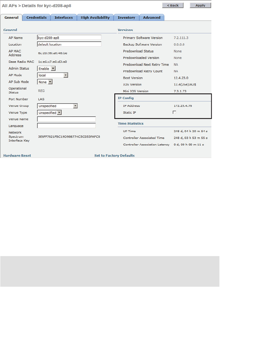
ptg12542968
422 CCNA Wireless 640-722 Official Cert Guide
Verifying AP-to-Network Connectivity
If you do not find the AP joined to a controller, you will have to move your focus fur-
ther away from the controller and onto the AP and its wired connection.
Does the AP have an IP address? Without the help of a controller, you might have to
connect to the AP console and watch the logging information scroll by as the AP tries to
boot, get an address, and find a controller to join. You can also query the DHCP server
to see whether the AP has an active address lease. If it is not able to get an address from
a DHCP server, check the address scope on the server to ensure that the address space is
not exhausted.
Tip To connect to the CLI of an AP, you need to enter some credentials. By default, log
in with username Cisco and password Cisco. The default enable secret password is also
Cisco.
If the AP is having trouble joining a controller, verify that the switch port configuration
where the AP is connected. A lightweight AP needs only a single VLAN to support the
CAPWAP tunnel. All WLANs are transported over the tunnel without the need for sepa-
rate VLANs. In contrast, an autonomous AP has no CAPWAP tunnel, so it needs a trunk
Figure 20-19 Verifying the AP’s IP Address.

ptg12542968
Chapter 20: Troubleshooting WLAN Connectivity 423
link that can carry individual WLANs over VLANs. The switch port configuration should
look like one of those shown in Table 20-3 .
Table 20-3 Switch Port Configuration to Support an AP
Lightweight AP
(Access Link)
Autonomous AP
(Trunk Link)
interface gigabitethernet1/0/1
switchport
switchport access vlan 100
switchport mode access
spanning–tree portfast
no shutdown
interface gigabitethernet1/0/1
switchport
switchport trunk allowed vlan 100,101,102,103
switchport trunk native vlan 100
switchport trunk encapsulation dot1q
switchport mode trunk
no shutdown
Finally, recall that a lightweight AP tries a variety of methods to discover viable control-
lers to join. Most likely, the DHCP server has been configured to send DHCP option 43
with lease offers to APs. Option 43 is a string of hex digits that contain the IP addresses
of one or more controllers. The DHCP server might not have option 43 configured at all,
or it could have a typo or error in the hex string.
Sometimes you might connect an AP and wait a very long time for it to join a control-
ler, only to find that it does not. First, check the controller licensing to make sure that
there are enough available licenses for the AP. If you still cannot figure out what the AP
is doing, you can connect directly to its console port and watch the logging information
scroll by as the AP attempts to discover controllers.
The console output listed in Example 20-2 shows that the AP is not able to obtain
an IP address so it can join the wired network. In Example 20-3 , the AP picked up
a list of three candidate controller IP addresses (192.168.90.22, 192.168.90.23, and
192.168.90.16) from the DHCP server. However, the AP then tries to initiate a DTLS
tunnel (part of CAPWAP) to a controller known as m7-c1 at address 172.22.253.17, and
successfully joins it. Perhaps this AP was previously configured with a primary controller
address elsewhere before it was installed on the network. Therefore, it used an unex-
pected controller address.
Example 20-2 AP Console Output Showing an IP Address Problem
*Mar 1 00:13:33.515: %CDP_PD-4-POWER_OK: Full power - INJECTOR_DETECTED_PD
inline power source
*Mar 1 00:13:34.537: %LINK-3-UPDOWN: Interface Dot11Radio1, changed state
to up
*Mar 1 00:13:35.537: %LINEPROTO-5-UPDOWN: Line protocol on Interface
Dot11Radio1, changed state to up

ptg12542968
424 CCNA Wireless 640-722 Official Cert Guide
*Mar 1 00:13:35.563: %LINK-3-UPDOWN: Interface Dot11Radio0, changed state
to up
*Mar 1 00:13:36.563: %LINEPROTO-5-UPDOWN: Line protocol on Interface
Dot11Radio0, changed state to up
*Mar 1 00:13:57.962: %CAPWAP-3-ERRORLOG: Not sending discovery request AP
does not have an Ip !!
*Mar 1 00:14:17.962: %CAPWAP-3-ERRORLOG: Not sending discovery request AP
does not have an Ip !!
Example 20-3 Verifying Candidate Controller Addresses from the AP Console
*Mar 1 00:16:18.971: %CAPWAP-5-DHCP_OPTION_43: Controller address
192.168.90.22 obtained through DHCP
*Mar 1 00:16:18.971: %CAPWAP-5-DHCP_OPTION_43: Controller address
192.168.90.23 obtained through DHCP
*Mar 1 00:16:18.971: %CAPWAP-5-DHCP_OPTION_43: Controller address
192.168.90.16 obtained through DHCP
*Mar 1 00:16:19.012: %CAPWAP-3-ERRORLOG: Could Not resolve CISCO-CAPWAP-
CONTROLLER
*Mar 1 00:16:29.020: %CAPWAP-3-ERRORLOG: Selected MWAR m7-c1'(index 0).
*Mar 1 00:16:29.020: %CAPWAP-3-ERRORLOG: Go join a capwap controller
*Sep 12 14:16:04.000: %CAPWAP-5-DTLSREQSEND: DTLS connection request sent
peer_ip: 172.22.253.17 peer_port: 5246
*Sep 12 14:16:04.791: %CAPWAP-5-DTLSREQSUCC: DTLS connection created suc-
cessfully peer_ip: 172.22.253.17 peer_port: 5246
*Sep 12 14:16:04.792: %CAPWAP-5-SENDJOIN: sending Join Request to
172.22.253.17
*Sep 12 14:16:05.069: %LINK-3-UPDOWN: Interface Dot11Radio0, changed state
to down
*Sep 12 14:16:05.108: %LINK-5-CHANGED: Interface Dot11Radio0, changed state
to reset
*Sep 12 14:16:05.117:
%CAPWAP-5-JOINEDCONTROLLER: AP has joined controller
m7-c1

ptg12542968
Chapter 20: Troubleshooting WLAN Connectivity 425
Exam Preparation Tasks
As mentioned in the section, “How to Use This Book,” in the Introduction, you have a
couple of choices for exam preparation: the exercises here, Chapter 22 , “Final Review,”
and the exam simulation questions on the CD-ROM.
Review All Key Topics
Review the most important topics in this chapter, noted with the Key Topic icon in the
outer margin of the page. Table 20-4 lists a reference of these key topics and the page
numbers on which each is found.
Table 20-4 Key Topics for Chapter 20
Key Topic Element Description Page Number
Paragraph Monitoring a client 406
Table 20-2 Possible WLC client states 409
Figure 20-8 Performing a CCX link test 412
Paragraph Displaying client debug information 412
Figure 20-9 Searching for a client in WCS/NCS 416
List WCS/NCS client troubleshooting stages 419
Figure 20-17 Verifying AP operation from WCS/NCS 421
Key
Topic

ptg12542968
This chapter covers the following topics:
■ Accessing WLC and AP Management Interfaces —
This section describes the methods you can use to
interact with a controller and its access points for
configuration and monitoring.
■ Maintaining WLC Code Images —This section
explains how you can verify a controller’s code
image and how you can upgrade it.
■ Maintaining WLC Configurations —This section
discusses the controller configuration and how to
save it and back it up.
■ Working with WLC Logs —This section covers
controller activity logs and how you can display and
record them.
This chapter covers the following exam topics:
■ Transfer logs, configuration files, and O/S images to
and from the WLC via the GUI
■ Differentiate and use WLC and AP (autonomous
and LAP) management access methods (console
port, CLI, telnet, ssh, http, https, and wired vs wire-
less management)

ptg12542968
Like Cisco routers, switches, and other networking devices, wireless LAN controllers
maintain configuration files, run operating system images, and generate logs. As a CCNA
Wireless engineer, you will likely be involved in maintaining controllers on a network
and dealing with the information and files they use. This chapter explains how you can
interface with controllers and APs so that you can upload and download their files.
“Do I Know This Already?” Quiz
The “Do I Know This Already?” quiz allows you to assess whether you should read this
entire chapter thoroughly or jump to the “Exam Preparation Tasks” section. If you are
in doubt about your answers to these questions or your own assessment of your knowl-
edge of the topics, read the entire chapter. Table 21-1 lists the major headings in this
chapter and their corresponding “Do I Know This Already?” quiz questions. You can
find the answers in Appendix A , “Answers to the ‘Do I Know This Already?’ Quizzes.”
Table 21-1 “Do I Know This Already?” Section-to-Question Mapping
Foundation Topics Section Questions
Accessing WLC and AP Management Interfaces 1–2
Maintaining WLC Code Images 3–6
Maintaining WLC Configurations 7–8
Working with WLC Logs 9–10
Caution The goal of self-assessment is to gauge your mastery of the topics in this chap-
ter. If you do not know the answer to a question or are only partially sure of the answer,
you should mark that question as wrong for purposes of the self-assessment. Giving your-
self credit for an answer you correctly guess skews your self-assessment results and might
provide you with a false sense of security.
CHAPTER 21
Maintaining Controllers

ptg12542968
428 CCNA Wireless 640-722 Official Cert Guide
1.
By default, which of the following are methods you can use to access a wireless
LAN controller? (Choose all that apply.)
a. Telnet
b. SSH
c. HTTP
d. HTTPS
e. Console port
2.
After a lightweight AP in its default configuration joins a controller, you can use
SSH to connect to it. True or false?
a. True
b. False
3.
A controller maintains how many code image files?
a. 1
b. 2
c. 3
d. Unlimited
4.
Which two of the following file transfer methods can be used to move a controller
code image file onto a controller?
a. TFTP
b. RCP
c. SSH
d. FTP
e. XMODEM
f. HTTP
5.
Suppose that you need to transfer a code image file from a TFTP server on your PC
to a controller. Which of the following file copy directions should you choose?
a. Download
b. Upload
c.
None of these answers because a controller automatically gets its image from
WCS/NCS/PI
d.
None of these answers are correct because it is not possible to transfer an
image file via TFTP

ptg12542968
Chapter 21: Maintaining Controllers 429
6.
After copying a new code image file to a controller, how should you copy the same
code release to the lightweight APs?
a. Use Commands > Download to APs .
b.
Connect to each AP and copy the file there.
c.
Put the address of a TFTP server in the DHCP options field.
d.
Do nothing; each AP will get the new image as it rejoins the controller.
7.
Suppose that you use a web browser to access a controller and make a configuration
change. You make sure to click the Apply button. A short time later, the control-
ler loses power and then reboots. Which two of the following answers correctly
describes the result?
a.
The Apply button saved the change permanently.
b.
The Apply button made the change active, but didn’t save it across the reboot.
c.
You would need to click the Save Configuration link to save the change per-
manently.
d.
To save the change permanently, you would need to use the copy run start
command from the CLI.
8.
To save a copy of a controller’s configuration, which of the following methods
could you use?
a. Commands > Upload File
b. Commands > Download File
c. The copy config tftp CLI command
d. The show running-config CLI command
9.
Which one of the following controller logs contains information about things that a
controller has monitored or detected on the wireless network?
a. Message log
b. Trap log
c. Event log
d. CleanAir log
10. Which one of the following protocols is needed to send entries from the trap log to
a collection station as they occur?
a. TFTP
b. CAPWAP
c. SNMP
d. SMTP
e. NTP
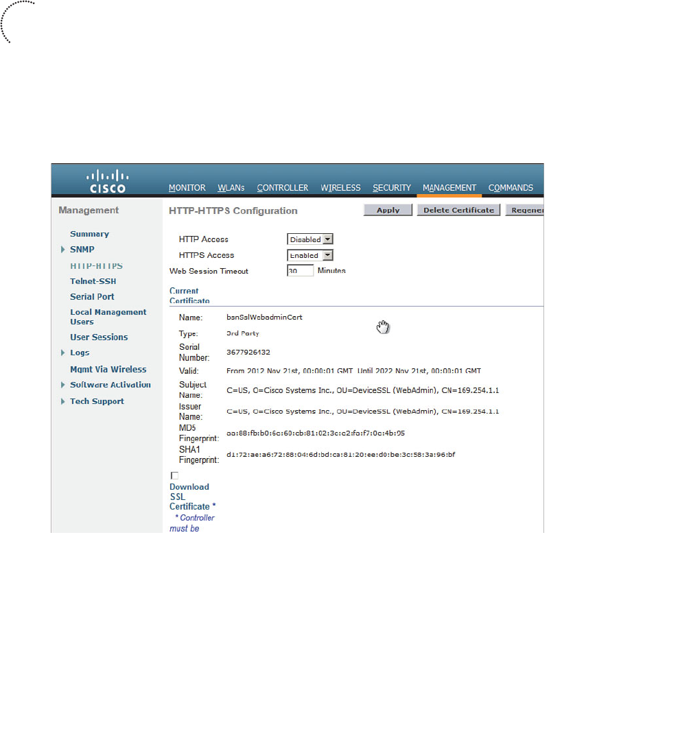
ptg12542968
430 CCNA Wireless 640-722 Official Cert Guide
Accessing WLC and AP Management Interfaces
To interact with and manage a wireless controller, you need a way to connect to it. Cisco
Wireless LAN Controllers (WLCs) offer the following access methods:
■ Command-line interface CLI —You can initiate a CLI session by connecting direct-
ly to the console port (asynchronous serial) or by opening a Telnet or Secure Shell
(SSH) session to the controller’s management interface IP address.
■ Graphical-user interface (GUI) —You can use a web browser to open a session to
the controller’s management interface IP address.
Normally, you will manage a WLC through an HTTPS session with a web browser. HTTP
is disabled by default. You can configure these settings from Management > HTTP-
HTTPS , as shown in Figure 21-1 .
Figure 21-1 Configuring GUI Access to a Controller.
You might need to use the CLI for the initial bootstrap configuration, until a new WLC
is configured with a management IP address and you can access the web-based GUI. The
CLI is also useful when you are troubleshooting problems with wireless clients or col-
lecting important output for Cisco TAC.
The CLI is based on an operating system called AireOS, which is very different from
Cisco IOS. Although the AireOS commands are different from IOS, there are a few
Key
Topic
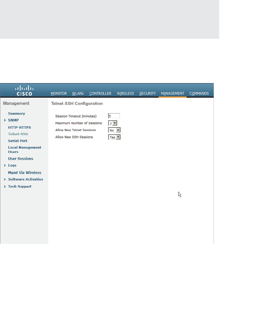
ptg12542968
Chapter 21: Maintaining Controllers 431
similarities. For example, you can use the show and debug commands along with a wide
variety of keywords to gather specific information. You can type a question mark (?) to
see a list of possible keywords you can use to complete a command. The Tab key can be
used to complete a keyword you have started to type. Each configuration change must
be made with the config command followed by keywords.
Tip The CCNA Wireless exam covers controllers that are based on AireOS. Cisco has
also introduced a line of “converged access” controllers that are based on the familiar
IOS. At the time of this writing, converged access controllers include the 5760 WLC and
the Catalyst 3850 switch.
The CLI is accessible through the console port, Telnet, and SSH. By default, Telnet
access is disabled and SSH access is enabled. You can configure these settings from
Management > Telnet-SSH , as shown in Figure 21-2 . It is usually a best practice to keep
Telnet disabled because keystrokes are sent in clear text, without any encryption.
Figure 21-2 Configuring Telnet and SSH Access to a Controller.
You can initiate management sessions to a controller from anywhere on the network,
as long as your IP address can be routed to the controller’s management IP address.
However, by default, a controller will not permit Telnet, SSH, HTTP, and HTTPS
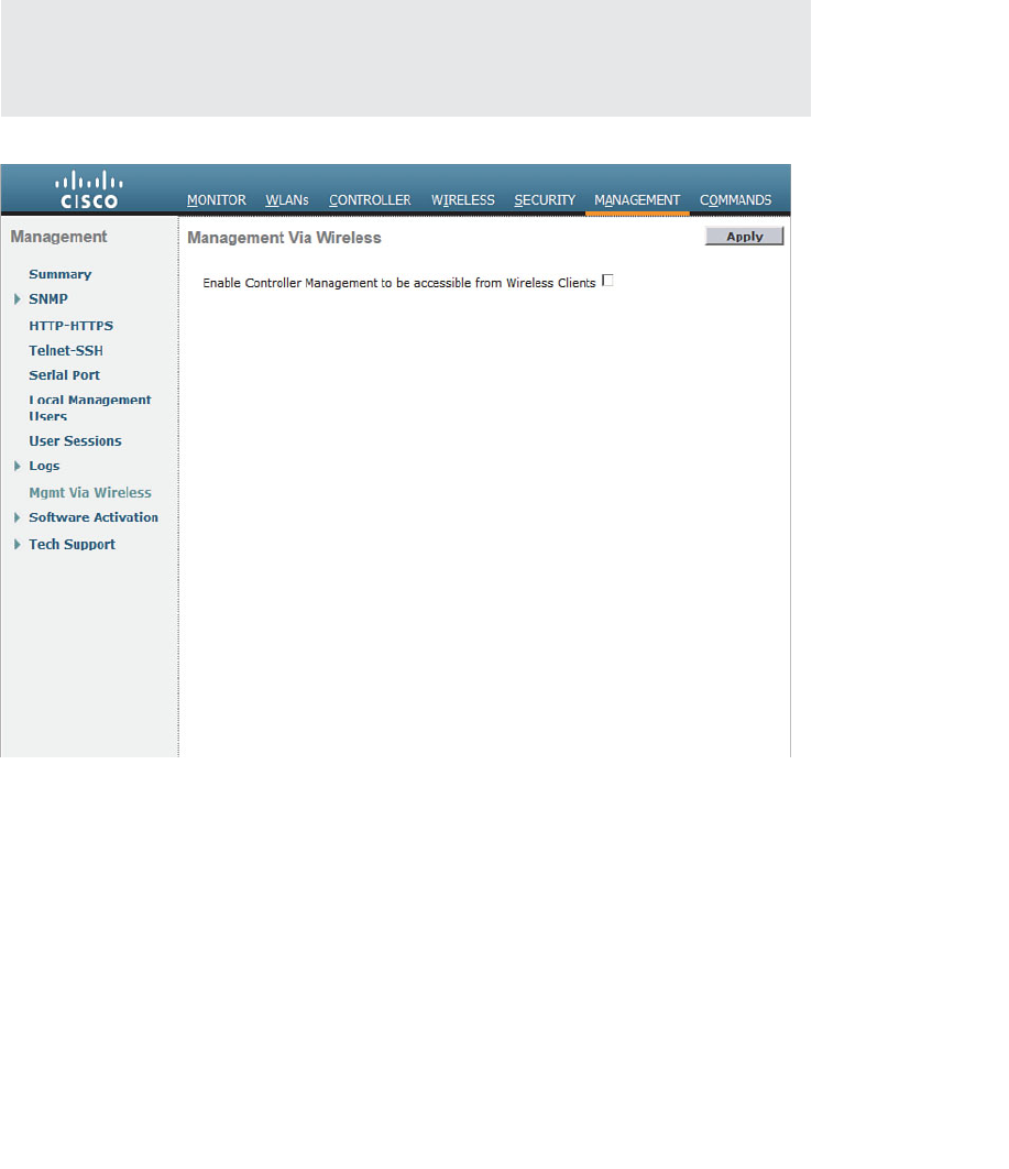
ptg12542968
432 CCNA Wireless 640-722 Official Cert Guide
connections from any of its own wireless network subnets. If you need to connect to
the controller from a WLAN, you can enable access through Management > Mgmt via
Wireless , as shown in Figure 21-3 . Be sure to check the box and click Apply . Even when
management via wireless is enabled, the controller will not allow any type of file uploads
or downloads.
Tip If you try to access a controller through a web browser from a wireless network,
you might find that the web login page is not available. In that case, you should check to
see that the management via wireless setting is enabled.
Figure 21-3 Enabling Management Access from a Wireless LAN.
Accessing APs
You can manage a Cisco autonomous AP’s GUI with a web browser or through a CLI
session with Telnet, or SSH, if you know the AP’s IP address. You can also connect to it
through its console port.
Lightweight APs (LAPs) differ somewhat. Once an LAP boots and joins a controller, all
of its functions are configured, managed, and monitored by the controller. Each AP runs
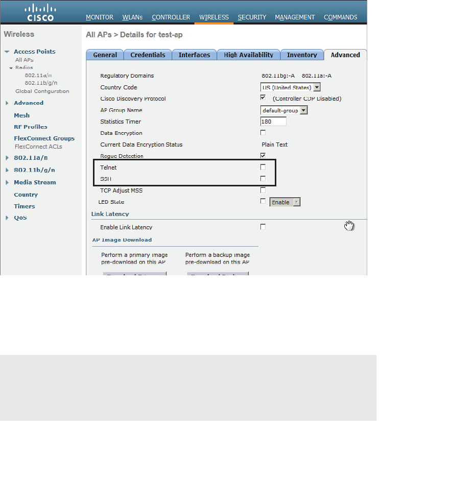
ptg12542968
Chapter 21: Maintaining Controllers 433
a special version of the IOS software, so it is possible to open a CLI management session
for troubleshooting purposes.
By default, LAPs do not permit management Telnet or SSH connections. If you need
to connect directly to an AP to troubleshoot problems, you can enable Telnet and
SSH access from Wireless > Access Points > All APs . Select an AP from the list, and
then select Config from the drop-down menu at the far-right side of the page. On the
Advanced tab, you can use the Telnet and SSH check boxes to control management
access, as shown in Figure 21-4 .
Figure 21-4 Controlling Telnet and SSH Access on a Lightweight AP.
You can also connect to the AP’s console port and use the CLI to troubleshoot con-
nection problems. For example, you can watch useful information displayed as the AP
boots and attempts to discover controllers and enable its radios.
Tip To access the CLI on autonomous or LAPs through their console ports, Telnet, or
SSH, you can use the default credentials of username Cisco, password Cisco, and enable
password Cisco. To help prevent unauthorized access, you should change the default cre-
dentials and restrict remote access to your APs.

ptg12542968
434 CCNA Wireless 640-722 Official Cert Guide
Maintaining WLC Code Images
Like any other network device, a controller requires a code image to operate.
Periodically, you might want to upgrade the code image to a new release so that you can
take advantage of bug fixes and new features. Less often, you might have to downgrade
the code image to return to a more stable version.
A controller maintains two separate code images—a primary image and a backup image.
When a controller boots, it runs the primary image by default. That means you can
download a new image file into the backup position on the controller while it is running,
with no interruption of service. To run the new image, you must reboot the controller.
You can display the two code image versions by navigating to Commands > Config
Boot , as shown in Figure 21-5 . You can select the image that will be run after the next
reboot with the Config Boot Image drop-down menu.
Figure 21-5 Displaying Controller Code Images.
To download a new code image, go to Commands > Download File . The controller
can download from a TFTP or an FTP server. Select the code file type, then enter the
file server’s IP address, file path, and code image filename, as shown in Figure 21-6 .
For an FTP download, enter the credentials required by the FTP server. Then, click the
Download button to start the file transfer.
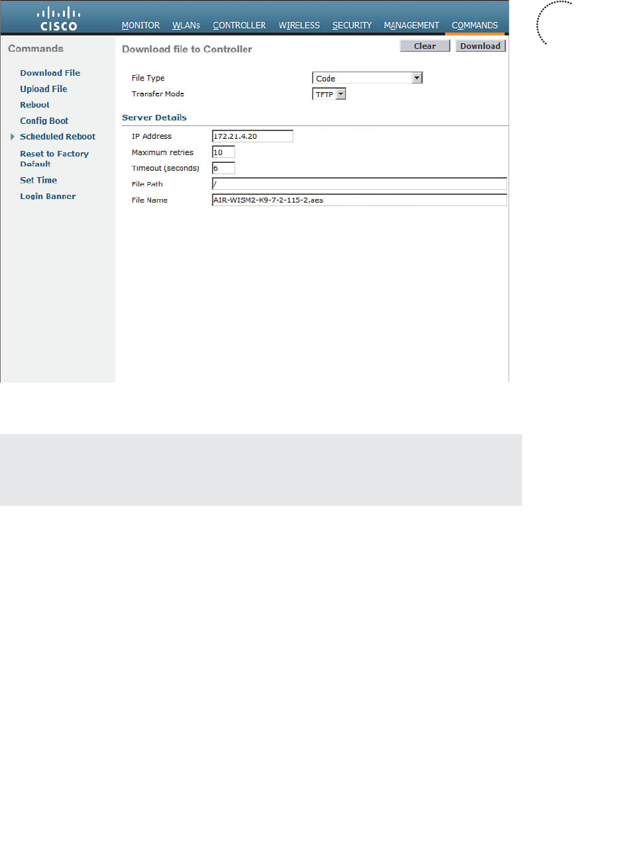
ptg12542968
Chapter 21: Maintaining Controllers 435
Figure 21-6 Preparing to Download a Code Image.
Tip The file transfer terminology might be a bit different from what you are used to
seeing. The terms download and upload refer to the controller’s perspective, as if it acts
like a client. You always download to the controller and upload from it.
WLC image files are usually named according to the hardware platform and the release
number, and ends with an .aes suffix, as in AIR-WISM2-K9-7-2-115-2.aes. During
the download, the WLC periodically updates the web page to display the following
sequence of status messages. (This process can take several minutes.)
1. TFTP code transfer starting.
2. TFTP receive complete...extracting components.
3. Executing backup script.
4.
Writing new RTOS to flash disk.
5.
Writing new FP to flash disk.
6.
Writing new APIB to flash disk.
7. Executing install_apib script.
Key
Topic
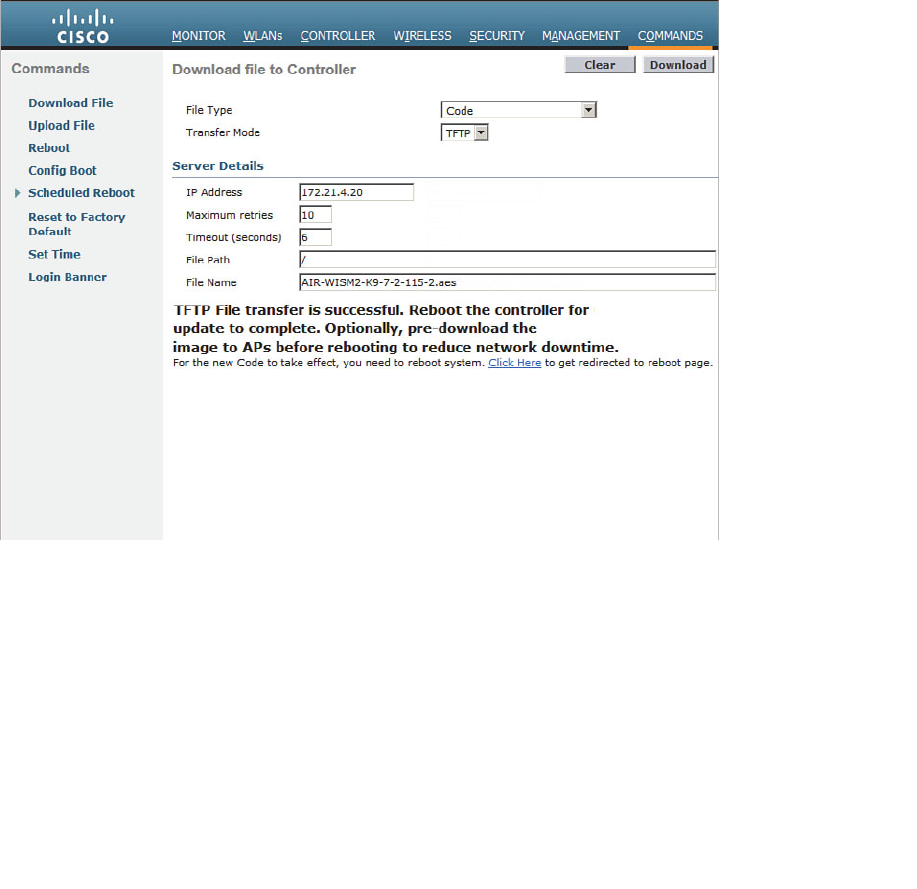
ptg12542968
436 CCNA Wireless 640-722 Official Cert Guide
8. Executing fini script.
9. TFTP File transfer is successful.
At this point, the new image is ready to be used. You must reboot the controller to run
the new image, according to the status message shown in Figure 21-7 . Be aware that
rebooting the controller will interrupt wireless service. All the APs joined to the control-
ler will lose contact with it and will rehome to a secondary controller (if one is config-
ured) or begin the controller discovery process to find a new home.
You can get ready to reboot the controller by selecting the Click Here link at the bot-
tom of the download status or by navigating to Commands > Reboot , as shown in
Figure 21-8 . You can save the current controller configuration and reboot immediately
by clicking the Save and Reboot button.
Figure 21-7 After an Image Download, the Controller Is Ready to Reboot.
After you install a new controller image file, should you install the same code release on
the lightweight APs? Recall that the controller manages all aspects of the APs, including
their code images. When a LAP joins a controller, it compares its own code release with
that of the controller. If the images differ, the AP will download a matching image from
the controller automatically. Therefore, after the controller reboots and begins to run a
new image, each AP will download the same release as it rejoins the controller.

ptg12542968
Chapter 21: Maintaining Controllers 437
As you might imagine, the code upgrade process can impose an extensive outage on a
wireless network. The controller must be rebooted so that it can begin running the new
image. After that, each AP must go offline to download the new image, reboot, and
begin running the new image. To lessen the impact to wireless users, controller releases
7.2 and later can push a new code image to the APs before the controller or the APs
need to reboot. This prepares the APs ahead of time so that they can reboot in parallel
with the controller and can begin running the new code image much sooner.
Maintaining WLC Configurations
As you use the web-based controller GUI to make configuration changes, you need to
click the Apply button to make the changes active. This is similar to configuring a router
or switch, where changes take effect immediately and are updated in the running con-
figuration, but are not saved to the startup configuration. As long as the controller stays
up, your changes will stay active. If the controller reboots or loses power, your changes
will be lost.
A controller also has nonvolatile storage for its configuration, much like flash memory.
You can save the configuration by clicking the Save Configuration link at the upper
right of any controller web page, as shown in Figure 21-9 .
Figure 21-8 Triggering a Controller Reboot.
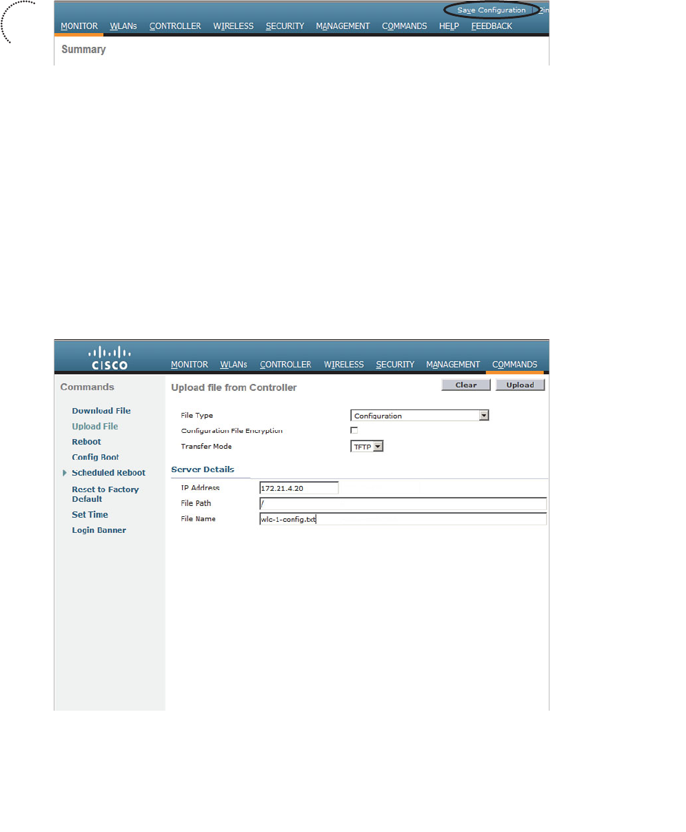
ptg12542968
438 CCNA Wireless 640-722 Official Cert Guide
Figure 21-9 Saving the Controller Configuration.
It is important to save the controller configuration to flash memory so that any configu-
ration changes are retained. Beyond that, you should think about saving the configura-
tion to a location away from the controller itself. If the controller hardware ever fails
and you receive a replacement, you will need a way to access the configuration so you
can import it into the new unit.
From the controller GUI, navigate to Commands > Upload File and select
Configuration from the file type drop-down menu. Select either TFTP or FTP and enter
the IP address, file path, and the target filename, as shown in Figure 21-10 . The control-
ler configuration will be transferred and saved in clear text, showing the CLI commands
that are used to build the entire configuration. You can check the Configuration File
Encryption check box and enter an encryption key string to encrypt the configuration
file so that it cannot be read easily. The file contents will be decrypted when they are
transferred back onto a WLC.
Figure 21-10 Uploading the Controller Configuration to a PC.
Key
Topic

ptg12542968
Chapter 21: Maintaining Controllers 439
You can display the configuration file from a CLI session by entering the command
show run-config commands. Before you enter the command, configure your terminal
emulator application to save the session output to a file. When you display the configu-
ration file contents, the output will automatically be saved on your PC.
Tip By default, a CLI session will pause the output after every 22 lines of text and
prompt you for a keystroke to continue. You can disable the paging action by entering
the config paging disable command before displaying large amounts of output.
After you have an offline copy of the configuration file, you can download the contents
to a controller. This process is just the opposite of uploading the configuration to your
PC, select Commands > Download File , select file type Configuration , and enter the
TFTP or FTP server parameters and filename.
Tip The show run-config command, with no additional keywords, displays the entire
controller configuration, complete with all RF and AP configuration parameters. The out-
put can be enormous if the controller has a large number of APs associated with it. The
show run-config output is normally collected for Cisco TAC or for input into the Cisco
WLC Config Analyzer tool.
Working with WLC Logs
While a controller is busy managing connections with APs, handling client traffic, and
monitoring wireless activity, it also keeps a record of events that occur. You can view
the controller logs to see more information about important events or share the contents
with Cisco TAC when you have a service request open.
A controller maintains three types of logs, as listed in Table 21-2 . You can display the
log contents in a CLI session with the command shown.
Table 21-2 Controller Logs
Log Name CLI Command Description
Message log show msglog System messages and errors
Trap log show traplog Alarms generated by the controller
Event log show eventlog Internal events from controller activity
The trap log is probably the most useful to wireless network administrators. Traps are
messages that are recorded and reported in real time, as events occur. Traps are nor-
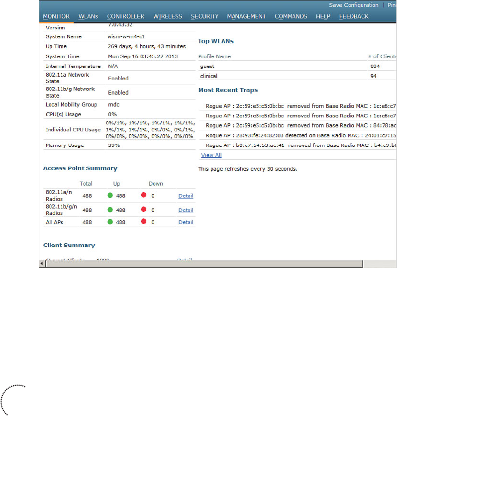
ptg12542968
440 CCNA Wireless 640-722 Official Cert Guide
mally sent via SNMP to a management station such as Wireless Control System (WCS),
Network Control System (NCS), or Prime Infrastructure (PI). Common traps include
reports of rogue APs that have been detected; APs with excessive client loads, interfer-
ence, or noise; coverage holes that have been detected; CleanAir events; and so on.
You can view the trap log from the Monitor > Summary page. Look for the Most
Recent Traps section, as shown in Figure 21-11 . You can select the View All link to see
the 256 most recent log entries that have been buffered.
Figure 21-11 Viewing the Trap Log.
In addition to buffering the log entries, a controller can send each message as an SNMP
trap to one or more trap receivers. The trap receivers are usually some type of manage-
ment platform that collects traps from a variety of devices and keeps a long term record
that can be used as an audit trail. From Management > SNMP > General , enter text
strings that define a name for the controller, its location, and contact information. You
can also configure the SNMP version that will be used. In Figure 21-12 , the controller
will use SNMPv3 and a username and security method to send traps.
Next, define a trap receiver from Management > SNMP > Trap Receivers , as shown in
Figure 21-13 . If the controller has been added into WCS, NCS, or PI, the management
station will be added as a trap receiver automatically. You can add a new receiver by
clicking on the New button, then entering the receiver’s name and IP address, and then
selecting Enable or Disable from the drop-down menu.
Key
Topic
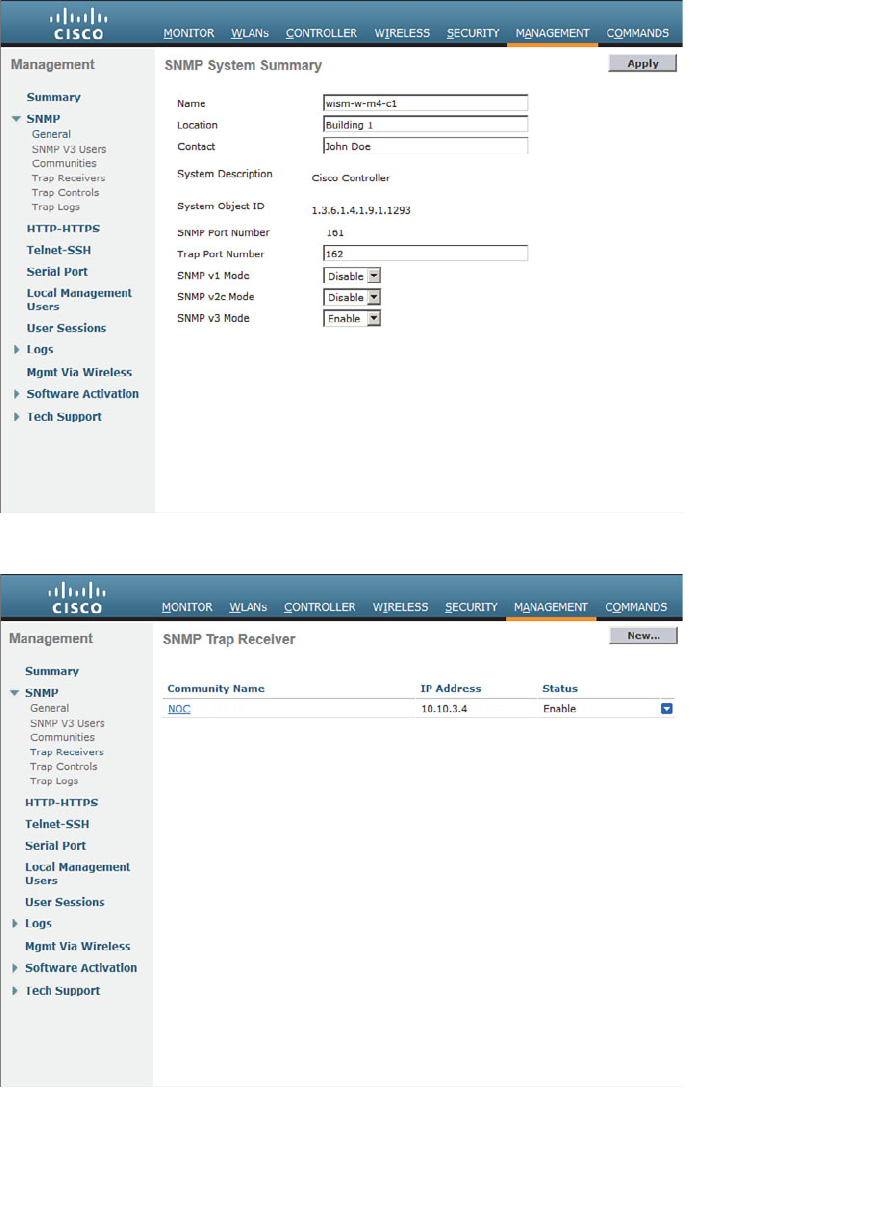
ptg12542968
Chapter 21: Maintaining Controllers 441
Figure 21-12 Configuring General SNMP Parameters.
Figure 21-13 Configuring SNMP Trap Receivers.
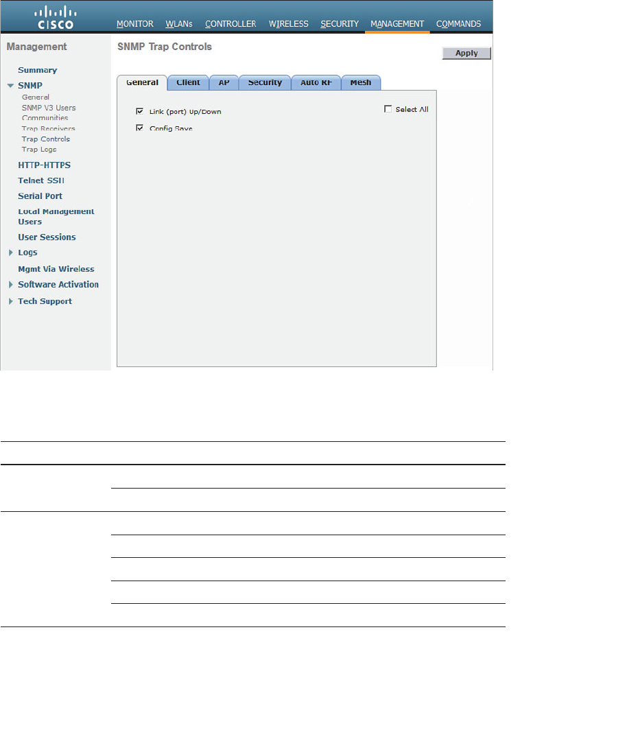
ptg12542968
442 CCNA Wireless 640-722 Official Cert Guide
Finally, you can configure the trap types that are forwarded to the trap receivers. From
the Management > SNMP > Trap Controls page, you can enable or disable individual
trap types. The types are organized under a series of tabs, as shown in Figure 21-14 . The
trap types from each tab are listed in Table 21-3 for your reference.
Figure 21-14 IDS and IPS Operational Differences.
Table 21-3 Controller Trap Types
Tab Trap Type Enabled
General Link (port) Up/Down X
Config Save X
Client 802.11 Association
802.11 Disassociation
802.11 Deauthentication
802.11 Failed Authentication
802.11 Failed Association

ptg12542968
Chapter 21: Maintaining Controllers 443
Tab Trap Type Enabled
AP AP Register X
AP Interface Up/Down X
AP Authorization X
Security User Authentication X
RADIUS Servers Not Responding X
WEP/WPA Decrypt Error X
IDS Signature Attack X
Rogue AP X
SNMP Authentication X
Multiple Users X
Strong Password X
Auto RF Load Profile X
Noise Profile X
Interference Profile X
Coverage Profile X
Channel Update X
Tx Power Update X
Mesh Child Excluded Parent X
Parent Change X
Authfailure Mesh X
Child Moved X
Excessive Parent Change X
Excessive Children X
Poor SNR X
Console Login X
Excessive Association X
Default Bridge Group Name X
Excessive Hop Count
Secondary Backhaul Change

ptg12542968
444 CCNA Wireless 640-722 Official Cert Guide
Exam Preparation Tasks
As mentioned in the section, “How to Use This Book,” in the Introduction, you have a
couple of choices for exam preparation: the exercises here, Chapter 22 , “Final Review,”
and the exam simulation questions on the CD-ROM.
Review All Key Topics
Review the most important topics in this chapter, noted with the Key Topic icon in the
outer margin of the page. Table 21-4 lists a reference of these key topics and the page
numbers on which each is found.
Table 21-4 Key Topics for Chapter 21
Key Topic Element Description Page Number
List WLC management sessions 430
Figure 21-6 Downloading a WLC code image 435
Figure 21-9 Saving the controller configuration 438
Paragraph Defining a trap receiver 440
Key
Topic

ptg12542968
This page intentionally left blank

ptg12542968
This chapter covers the following topics:
■ Advice About the Exam Event —This section
provides an overview of the exam structure and
the types of questions you will encounter. It also
discusses some strategies for managing your time
during the exam, reviewing before the exam, and
preparing yourself to sit through the exam.
■ Final Thoughts —This brief section provides some
concluding bits of encouragement about your exam
results.

ptg12542968
Congratulations! You made it through the book, and now it is time to finish getting
ready for the exam. This chapter helps you get ready to take and pass the exam. You
should know the content and topics. Now you need to think about what will happen
during the exam and what you need to do prepare your mind for it. At this point, you
should be focused on getting yourself ready to pass.
Advice About the Exam Event
Now that you have finished the bulk of this book, you could just register for your Cisco
CCNA Wireless exam, show up, and take the exam. However, if you spend a little time
thinking about the exam event itself and learning more about the user interface of the
real Cisco exams and the environment at the Vue testing centers, you will be better pre-
pared—particularly if this is your first Cisco exam.
Learn the Question Types Using the Cisco Certification Exam Tutorial
During the time leading up to your exam, think more about the different types of exam
questions and have a plan for how to approach them. One of the best ways to learn
about the exam questions is to use the Cisco Certification Exam Tutorial.
To find the Cisco Certification Exam Tutorial, go to http://www.cisco.com and search
for “exam tutorial.” The tutorial sits inside a web page with a Flash presentation of the
exam user interface. Each type of exam question is presented, along with a real-time
demonstration of the actions you might take when answering the question. You can also
click the Try Me button to reset the question and practice interacting and answering the
question yourself.
CHAPTER 22
Final Review
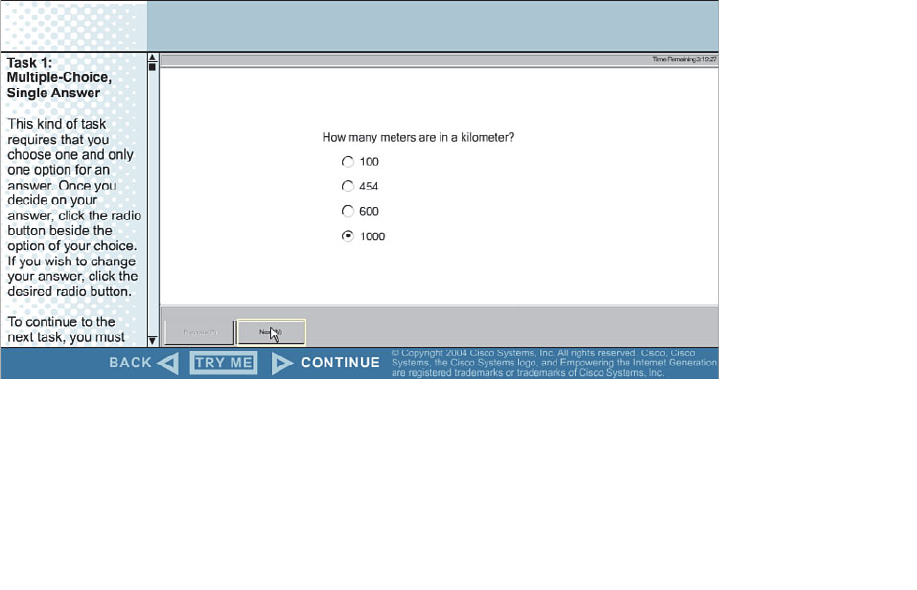
ptg12542968
448 CCNA Wireless 640-722 Official Cert Guide
You can expect to find the following types of questions on the exam. (The example
questions depicted in Figures 22-1 through 22-7 serve only to demonstrate the exam
question formats; they have nothing to do with the actual CCNA Wireless exam
content.)
■ Multiple choice, single answer —The question has several possible answers, but
only one correct one. Figure 22-1 shows an example.
■ Multiple choice, multiple answer —The question has several possible answers, with
a given number of correct ones.
Figure 22-2
shows an example.
■ Drag and drop —The question has a series of items that you must drag and drop
into boxes that represent the correct category, correct sequence, and so on. Figure
22-3 shows an example.
■ Fill in the blank —The question has one or more blank answers that you must fill in.
Figure 22-4 shows an example.
■ Simulation —The question includes a description and a network diagram. You can
click a network device and interact with it through a simulated command-line inter-
face (CLI) session. Figure 22-5 shows an example.
■ Testlet —The question includes a detailed scenario and a set of questions that you
must select and answer. Figure 22-6 shows an example.
■ Simlet —The question includes a scenario and a set of questions that you must
answer based on your interaction with a simulated network device.
Figure
22-7
shows an example.
Figure 22-1 An Example Multiple-Choice, Single-Answer Exam Question.
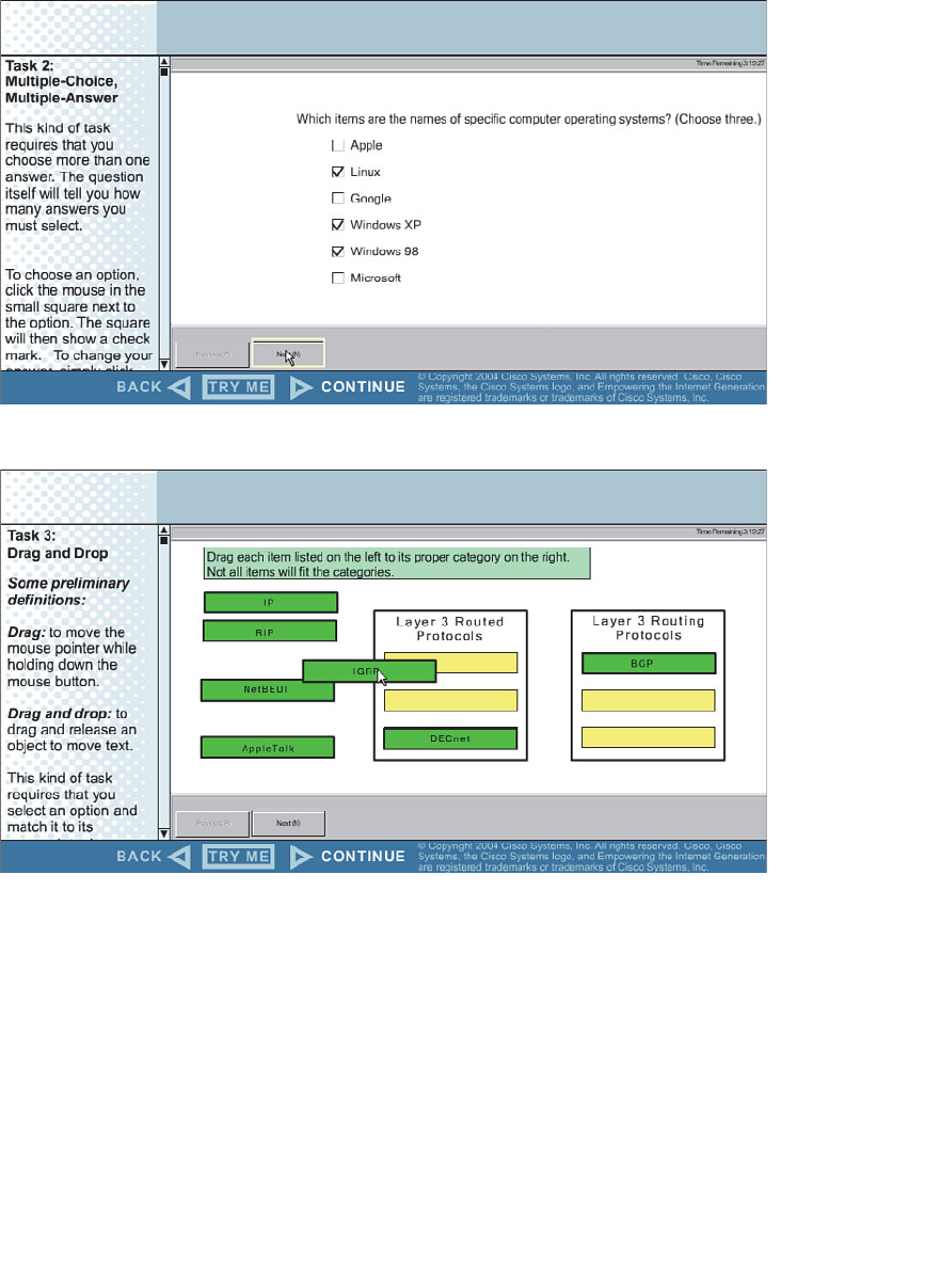
ptg12542968
Chapter 22: Final Review 449
Figure 22-2 An Example Multiple-Choice, Multiple-Answer Exam Question.
Figure 22-3 An Example Drag-and-Drop Exam Question.

ptg12542968
450 CCNA Wireless 640-722 Official Cert Guide
Figure 22-4 An Example Fill-in-the-Blank Exam Question.
Figure 22-5 An Example Simulation Exam Question.
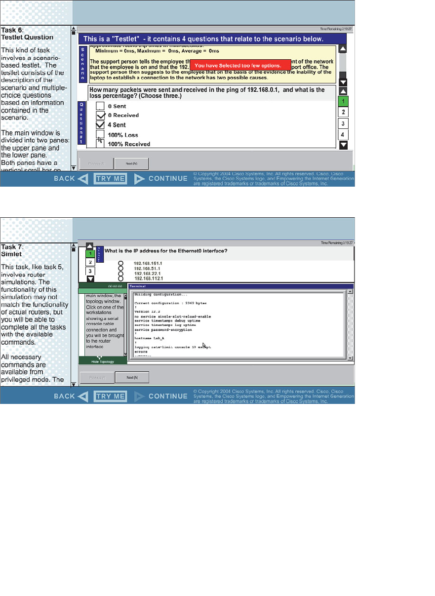
ptg12542968
Chapter 22: Final Review 451
Figure 22-6 An Example Testlet Exam Question.
Figure 22-7 An Example Simlet Exam Question.
You should find the multiple-choice questions fairly straightforward because they have
only one correct answer. Read through the possible answers carefully so that you can
eliminate the obviously incorrect ones. You might find that some answers appear to be
similar or are not easy to dismiss. Look for subtle differences and any key words that
relate to concepts you have learned.
Multiple-choice questions that require multiple answers sometimes prove more difficult.
Fortunately, the questions always state the number of correct answers you should enter.
Pay close attention to that number, and then use the answer check boxes to select and
narrow down your final answers.

ptg12542968
452 CCNA Wireless 640-722 Official Cert Guide
Drag-and-drop questions present you with a list of objects that you must drag and drop
into the correct locations in a blank list. Sometimes you will need to sort the objects into
two different lists. Sometimes you will need to select only the objects that match a cate-
gory and then place them in sequential order. Pay close attention to the stated goals and
the order that you should put the answers in. If you need to change any of your answers,
just drag them back to their starting positions and try again.
The simulation and simlet question formats usually involve network devices such as rout-
ers, switches, and firewalls that have a CLI to interact with. Most likely, you will not find
such questions on the CCNA Wireless exam. Even though Cisco Wireless LAN control-
lers and access points (APs) have a CLI that you can access, you are not really expected
to until you move to more advanced certifications.
Testlet questions include a short set of questions to answer. The questions are listed on
the right side of the exam, usually numbered in sequence. Read through the scenario
description, and then select one of multiple-choice questions to answer. Do not forget
to move through the other multiple-choice questions and answer them all before moving
on to the next exam question.
You might encounter a testlet question that simulates the Cisco Wireless LAN
Controller (WLC) graphical user interface (GUI). Know how to navigate the controller to
find important information like the IP address of an interface, which interface is bound
to a WLAN, client information based on a MAC address, and so on.
Think About Your Time Budget
On exam day, keep an eye on your progress as you move through the questions. Budget
your time so that you have enough to make your way through all the exam questions.
You might find yourself struggling between two feelings:
■ I’m going too slowly! —If your pace is too slow, you might not have enough time to
answer all the questions. You might also find that you are spending what seems like
an eternity on one pesky question when you should be moving on to others.
■ I’m going too fast! —If your pace is too fast, you will get through all the questions,
but you might be rushing without being thorough. Remember that you need to read
both the questions and the answers completely so that you fully understand them.
During the exam, you need to be able to somehow know whether you are moving quick-
ly enough to answer all the questions, while not rushing. The exam user interface shows
some useful information—a countdown timer and a question counter. The question
counter shows the question number you are currently answering and the total number of
questions on your exam.
Unfortunately, treating each question equally does not give you an accurate time esti-
mate. For example, if your exam allows 90 minutes and your exam has 45 questions, you
have an average of 2 minutes per question. Suppose that 40 minutes have elapsed and
you have answered 20 questions. At 2 minutes per question, it seems like you would be
right on schedule. However, several factors make that kind of estimate difficult to run
before the exam.

ptg12542968
Chapter 22: Final Review 453
First, Cisco does not tell us beforehand the exact number of questions for each exam.
For example, Cisco.com lists the CCNA Wireless 640-722 exam as having from 75 to
85 questions in 90 minutes. You will not know exactly how many questions are on your
exam until you go through the initial screens that lead up to the point where you click
Start Exam and the exam actually begins. As a worst case, 85 questions in 90 minutes
works out to an average of slightly over a minute per question.
Next, some questions clearly take a lot more time to answer than others. These are com-
monly called “time-burner” questions. Consider the following comparison:
■ Normal-time questions —Multiple-choice and drag-and-drop questions, approxi-
mately 1 minute each
■ Time burners —Sim, simlet, and testlet questions, approximately 6 to 8 minutes
each
Cisco does not tell us why you might get 85 questions and someone else taking the same
exam might get 75 questions. It seems reasonable to think that the person with 75 ques-
tions might have a few more of the time burners, making the two exams even out.
Even though testlet and simlet questions contain several individual multiple-choice ques-
tions (each graded and scored independently), the exam software counts each testlet and
simlet question as one question in the question counter. For example, if a testlet ques-
tion has four embedded multiple-choice questions, the exam software’s question counter
will show it counting as one exam question.
During the exam, as you encounter each question, resist the temptation to skim through
it. Try to deliberately read it from start to finish so that you do not skip over any impor-
tant words or information. For example, a question might ask “which one is not; if you
skip over the word not , you will likely get the answers wrong.
Scenario descriptions can be lengthy, especially when they set the stage for a complex
problem. Be aware that the text will be located in a scrolling window that might be hard
to read or navigate because of the cramped screen real estate. Network diagrams can be
equally cumbersome because they have to show many icons, links, addresses, and other
information in a small space.
Other Pre-Exam Suggestions
Here are just a few more suggestions for things to think about before exam day arrives.
First, consider the following strategies for reviewing the exam content:
■ Go back through the “Do I Know This Already?” quizzes at the beginning of each
chapter.
■ Open this book to the table of contents page. Read down through the entries until
you find a topic that seems foreign or does not come to mind right away. Spend
time reviewing the corresponding chapter or section to refresh your memory.
■ Use the practice questions on the accompanying CD. You might not find every type
of exam question there, but you should get a thorough sample of the exam content.

ptg12542968
454 CCNA Wireless 640-722 Official Cert Guide
If you get a practice question in the multiple-choice, single-answer format, think
about what might happen if you see that same question on the real exam in another
format.
■ Keep a running list of topics, acronyms, or concepts that you feel you do not under-
stand completely or are taking too much time remembering. Go back and review the
things on your list.
■ Join in the discussions on the Cisco Learning Network. Try to answer questions
asked by other learners. The process of answering, even if you keep your answer to
yourself, makes you think much harder about the topic. When someone posts an
answer with which you disagree, think about why and talk about it online. This is a
great way to both learn more and build confidence.
Next, think about the things you might need to do right before your exam time:
■ Get some earplugs. Testing centers often have some, but if you do not want to
chance it, come prepared. The testing center is usually a room inside the space of a
company that does something else as well. There could be people talking in nearby
rooms, in addition to other office noises. Earplugs can help. Headphones and elec-
tronic devices are not permitted.
■ The testing center usually provides a white-erase card and a marker, but does not
allow you to bring in any notes. Some people like to spend the first minute of the
exam writing down some notes on the white-erase card for reference. For example,
you might want to write out a table of mW-to-dBm value conversions. If you plan
to do that, practice making those notes ahead of time. Before each practice exam,
transcribe those lists, just like you expect to do at the real exam.
■ Plan your travel to the testing center with enough time so that you will not be rush-
ing to make it there by your scheduled exam time.
■ If you tend to be nervous before exams, practice your favorite relaxation tech-
niques for a few minutes before each practice exam, just to be ready to use them.
■ Rest the night before the exam, rather than staying up late to study. Clarity of
thought is more important than learning one extra fact, especially because the exam
requires so much analysis and thinking.
■ You can bring personal effects into the building and testing company’s space, but
not into the actual room in which you take the exam. So, take as little extra stuff
with you as possible. If you have a safe place to leave briefcases, purses, electron-
ics, and so on, leave them there. However, the testing center should have a place to
store your things as well. Simply put, the less you bring, the less you have to worry
about storing.
■ Find a restroom before going into the testing center. If you cannot find one, of
course you can use one in the testing center. The testing personnel will direct you
and give you time before your exam starts.
■ Do not drink a large quantity of liquid before your exam begins. Once the exam has
started, the timer will not stop while you go to the restroom.

ptg12542968
Chapter 22: Final Review 455
Final Thoughts
Congratulations for working your way this far through this book. Nothing about Cisco
certification exams is easy, but they are well worth your time and hard work. At the end
of the exam, you will receive your final score and news of your passing or failing. If you
pass, congratulate yourself and breathe a sigh of relief at not having to study more.
If you fail, remind yourself that you are not a failure. It is never a disgraceful thing to
fail a Cisco exam, as long as you decide to try it again. Anybody who has ever taken a
Cisco exam knows that to be true; just ask the people who have attempted the CCIE
lab exam. As soon as you can after learning that you failed, take a few minutes to write
down as many exam questions as you can remember. Note which questions left you
uneasy. Next, schedule to take the same exam again. Allow a few days so that you can
study the topics that gave you trouble. The exam score should also break down the
entire exam into major topics, each with its respective score. Do not be discouraged
about starting over with your studies; the majority of it is already behind you. Just spend
time brushing up on the “low spots” where you lack knowledge or confidence. Go for it
and do your best!

ptg12542968

ptg12542968
Chapter 1
1. C. The IEEE 802.11 standard focuses on wireless LAN definitions, methods, and
operation. It is made up of many pieces, as described in
Chapter 2
, “RF Standards.”
Sometimes you might see IEEE 802.11x, which refers to the many subparts of
802.11. Be aware of the subtle difference between that and 802.1x, which defines
port-based network access control.
2. B, E. Wireless LANs use the 2.4-GHz and 5-GHz bands. Be careful to notice the
difference between megahertz (MHz) and gigahertz (GHz). Also remember that 5.5
Mbps and 11 Mbps are some of the common data rates used in wireless LANs, but
those are not involved when you need to identify the frequency band.
3.
A. When the two power levels are the same, the result is 0 dB. As long as you
remember the first handy 0 dB fact, you will find exam questions like this easy. If
not, you will need to remember that dB = 10log
10 (100 mW / 100 mW) = 10log 10
(1)
= 0 dB.
4.
C. At first glance, 17 mW and 34 mW might seem like odd numbers to work with.
Notice that if you double 17, you get 34. The second handy dB fact says that dou-
bling a power level will increase the dB value by 3.
5.
D. Start with transmitter A’s level of 1 mW and try to figure out some simple opera-
tions that can be used to get to transmitter B’s level of 100 mW. Remember the
handy dB facts, which use multiplication by 2 and 10. In this case, 1 mW × 10 = 10
mW × 10 = 100 mW. Each multiplication by 10 adds 10 dB, so the end result is 10
+ 10 = 20 dB. Notice that transmitter B is being compared to A (the reference level),
which is 1 mW. You could also state the end result in dB-milliwatt (dBm).
6.
C. This question involves a reduction
in the power level, so the dB value must be
negative. Try to find a simple way to start with 100 and get to 40 by multiplying or
dividing by 2 or 10. In this case, 100 / 10 = 10; 10 × 2 = 20; 20 × 2 = 40. Dividing by
10 reduced the dB value by 10 dB; then multiplying by 2 increased the total by +3
dB; multiplying again by 2 increased the total by +3 more dB. In other words, dB =
–10 + 3 + 3 = –4 dB.
7.
B. Remember that the EIRP involves radiated power, and that is calculated using
only the transmitter components. The EIRP is the sum of the transmitter power level
(+20 dBm), the cable loss (–2 dB), and the antenna gain (+5 dBi). Therefore, the EIRP
is +23 dBm.
APPENDIX A
Answers to “Do I Know This
Already?” Quizzes

ptg12542968
458 CCNA Wireless 640-722 Official Cert Guide
8.
D. A high SNR is best, where the received signal strength is more elevated above the
noise floor. A 30-dBm SNR separates the signal from the noise more than a 10-dBm
SNR does. Likewise, a higher RSSI value means that the signal strength alone is
higher. The RSSI scale ranges from 0 (highest) to –100 (lowest).
9.
C. DSSS supports 1, 2, 5.5, and 11 Mbps data rates through different combina-
tions of coding and modulation schemes. FHSS is locked to 1 or 2 Mbps. With the
exception of 6 and 9 Mbps, only OFDM supports the highest data rates of all the
modulation types.
10. C, B, A, D.
The correct order is C, B, A, D or DBPSK (2 possible phase changes),
DQPSK (4 possible phase changes), 16-QAM (16 possible phase/amplitude changes),
64-QAM (64 possible phase/amplitude changes).
11. B, C. Both 16-QAM and 64-QAM alter the amplitude and phase of a signal.
12. C. OFDM uses 48 subcarriers in a single 20-MHz-wide channel, allowing it to trans-
mit data bits in parallel. DSSS uses a single 22-MHz channel with only one main car-
rier signal.
Chapter 2
1. C. The ITU-R allocated the ISM bands for global use.
2. B. The U-NII-1 band is the first of four 5-GHz bands set aside for wireless LAN use.
3. D. The EIRP is always limited to +36 dBm in the 2.4-GHz band, except in the case
of point-to-point links.
4. D.
5.
C. Only channels 1, 6, and 11 are nonoverlapping. The 2.4-GHz channels are spaced
5 MHz apart, whereas the DSSS channel width is 22 MHz.
6.
D. The first U-NII-1 channel is labeled channel 36.
7.
C, D, F. IEEE 802.11g and 802.11b deal with the 2.4-GHz band. IEEE 802.11a is
strictly for 5 GHz, and 802.11n includes both 2.4 and 5 GHz. The IEEE 802.11-2012
standard has all of these amendments rolled up into one document.
8. C, D. Both 802.11g and 802.11a define OFDM use, even though the two standards
use different bands.
9. A.
10.
B. The device has two transmitters and three receivers. The number of spatial
streams supported would be added after the 2×3 designation.
11.
C. 802.11n is limited to aggregating two 20 MHz channels for a total width of 40
MHz.
12.
A. Devices using 802.11n can use multiple radio chains and multiple spatial streams..
13.
D. Only the Wi-Fi Alliance tests and certifies wireless products according to indus-
try standards.

ptg12542968
Appendix A: Answers to “Do I Know This Already?” Quizzes 459
Chapter 3
1. C. Because both transmitters are using the same channel, the interference is
described as co-channel.
2.
E. Cisco recommends a separation of at least 19 dBm, so +20 dBm is the only cor-
rect answer.
3.
B. The two channels being used are adjacent, so their signals overlap by some
degree. The resulting interference is called adjacent channel interference.
4.
D. In the 2.4-GHz band, channels 1, 6, and 11 are the only ones that are spaced far
enough apart (five channel numbers) that they do not overlap.
5. A. Energy traveling in an electromagnetic wave spreads in three dimensions, weak-
ening the signal strength over a distance.
6.
B. The 802.11b and g devices operate at 2.4 GHz, which is less affected by free
space loss than the 802.11a device, at 5 GHz.
7.
D. By switching to a less-complex modulation scheme, more of the data stream can
be repeated to overcome worsening RF conditions. This can be done automatically
through DRS.
8. B. As a signal is reflected, a new copy travels in a different direction. Each copy of
the signal takes a different path to reach the receiver; thus, the name multipath .
9.
D. As a signal passes through a wall, the building material absorbs some of the RF
energy, reducing the signal strength by some amount.
10.
B. The first Fresnel zone is an elliptical area along the length of a signal path that
should be kept free of obstructions. When an object extends into a significant por-
tion of the Fresnel zone, the signal can be diffracted and distorted.
Chapter 4
1. B, D. The - and H plane plots are used to show a side view and a top-down view,
respectively, with the antenna in the center of the plots.
2.
B. The H plane is also known as the azimuth plane because measurements are taken
at every azimuth angle around the base of the antenna.
3.
D. The beamwidth is the angle measured between the two points on a radiation pat-
tern plot that are 3 dB below the maximum.
4.
D. A wave’s orientation with respect to the horizon is known as the polarization.
5.
B. Cisco antennas are designed to use vertical polarization. Because the dipole
antenna is mounted correctly (pointing straight up or down), the wave will be verti-
cally polarized.
6.
B. A parabolic dish antenna has the greatest gain because it focuses the RF energy
into a tight beam.

ptg12542968
460 CCNA Wireless 640-722 Official Cert Guide
7.
A, E. An omnidirectional antenna is usually used to cover a large area. Therefore, it
has a large beamwidth. Because it covers a large area, its gain is usually small.
8.
C. Integrated antennas are omnidirectional.
9.
B. Orienting a dipole so that its cylinder points toward a receiver will probably
cause the received signal to become weaker. That is because the donut shaped radia-
tion pattern to rotate away from the receiver. The radiation pattern is weakest along
the length of the antenna.
10.
C. Lightning arrestors cannot protect against direct lightning strikes on an antenna.
Chapter 5
1. A, B. WPANs and WLANs can both use the unlicensed 2.4-GHz ISM band.
2. B. WLANs require half-duplex operation because all stations must contend for use
of a channel to transmit frames.
3.
C. An AP offers a basic service set (BSS).
4.
B. The AP at the heart of a BSS or cell identifies itself (and the BSS) with a basic ser-
vice set identifier (BSSID). It also uses an SSID to identify the wireless network, but
that is not unique to the AP or BSS. Finally, the radio MAC address is used as the
basis for the BSSID value, but the value can be altered to form the BSSID for each
SSID that the AP supports.
5.
D. In a BSS, the 802.11 standard requires all traffic to pass through an AP. The only
exception is the 802.11z amendment, which permits an AP to coordinate direct
client-to-client traffic without passing through the AP.
6. A, D.
True: “The DS connects two BSSs to form an ESS”—The distribution system connects
two basic service sets (APs) to form an extended service set.
False: “The BSA of a BSS looks like a MAC address”—The basic service area of a BSS is
its coverage area or cell, which has nothing to do with a MAC address.
False: “The SSID of a STA must be unique within the ESS”—The service set identifier
can be common across one or many BSSs in an ESS.
True: “The BSSID is unique for each SSID in a BSS”—An AP in a BSS uses its radio MAC
address as the basis for its BSSIDs, but each SSID has a unique BSSID value.
7.
E. Roaming implies that the building has some wireless APs that are interconnected.
Therefore, the client must first associate with a BSS. The BSS must connect to a
switched infrastructure through a DS. The DS must extend to at least one more AP
through an ESS. Finally, the same SSID has to be defined on every AP in the ESS.
8.
D. An independent basic service set is also called an ad hoc network.
9.
B. A workgroup bridge acts as a wireless client, but bridges traffic to and from a
wired device connected to it.

ptg12542968
Appendix A: Answers to “Do I Know This Already?” Quizzes 461
10.
B. In a mesh network, each mesh AP builds a standalone BSS. The APs relay client
traffic to each other over wireless backhaul links, rather than wired Ethernet. A
wireless LAN controller is necessary.
Chapter 6
1. D. An 802.11 frame contains four different address fields.
2. B. Frames are marked as going to the DS or from the DS.
3. D. The Address1 field always contains the RA.
4. A. 802.11 devices can participate in the distributed coordination function (DCF).
5. C. A wireless client uses the network allocation vector (NAV) to predict the
number of timeslots required for the channel to become free so that a frame can be
transmitted.
6.
D. Frames are separated by the distributed interframe space (DIFS).
7.
B. A probe request frame is sent to ask any listening APs to identify themselves.
8.
B. A wireless device must send an ACK frame, one of the 802.11 control frames,
back to the source of each unicast frame that is received.
9.
A, B. A client can join a BSS as long as it has at least one mandatory rate in common
with the AP but it must be able to support all of the AP’s mandatory rates.
10. A. In a passive scan, a client simply listens to any beacons that are transmitted by
nearby APs. In contrast, probes are sent by the client to discover APs in an active
scan.
11.
D. A client must first be authenticated to the BSS, then it can request to be associ-
ated.
12.
C. As long as the client can move from one BSS to another without losing a signal or
getting disassociated or deauthenticated, it can probe for a new AP and send a reas-
sociation frame to reassociate itself with the existing SSID.
Chapter 7
1. B, C, D. The transmit power directly affects the range of the AP’s signal. The sup-
ported modulation and coding schemes can affect the range because the simpler
schemes can tolerate a lower SNR and a weaker signal, implying a greater range.
The more complex schemes offer better data rates, but need a better signal quality
within a shorter range. The supported data rates also affect the range because they
directly affect the modulation and coding schemes that are used.
2.
B. If you have already tested the AP’s signal and determined that it reaches every
location in the lobby area, the problem is not that the AP’s transmit power is insuf-
ficient. Instead, the problem is occurring because the small client devices must be
using a transmit power that is lower than that of the AP. In other words, the client

ptg12542968
462 CCNA Wireless 640-722 Official Cert Guide
signals are not strong enough to reach the AP, so the two have asymmetric power
levels. The solution is to increase the client’s transmit power level to be identical to
the AP’s.
3.
D. The 1-Mbps data rate is already disabled, which limits the cell size to some
extent. You can reduce it further by disabling the 2-Mbps data rate.
4. C. If the problem is occurring some distance away from the replacement AP, the
replacement AP must be working correctly within its immediate area. If the replace-
ment had a 1-dBm transmit power, it could not be causing any interference at a
great distance away. The problem is likely because the lowest data rates have been
enabled. The lower rates effective extend the replacement AP’s cell size into the
cells of other APs farther away. If the channels are identical, the replacement could
be causing co-channel interference in other cells, degrading client performance and
roaming.
5.
C. Roaming is entirely up to the client. The client runs a roaming algorithm that
compares current conditions to a threshold. When the signal quality or other factors
drop below the threshold, the client tries to roam.
6.
D. Whereas an association request is used to join a BSS, a reassociation request is
used to move from one BSS to another within the same ESS.
7.
B. Roaming algorithms are not standardized at all. Instead, each manufacturer might
have its own interpretation of an algorithm. Wireless clients can scan a set of avail-
able channels when they anticipate roaming, to look for a new AP. Cisco APs and
controllers can also prime a Cisco compatible client (CCX Versions 3 and later) with
a list of viable APs ahead of time, so that the client can save time without having to
scan channels.
8.
B. To promote clean roaming, neighboring APs should use different, nonoverlap-
ping channels. In addition, APs should be located such that their coverage overlaps
each other by some amount, usually 15 percent to 20 percent.
9.
C. Adjacent APs should always use different, nonoverlapping channels.
10.
A, C. The fourth-floor APs will not interfere with the main office AP on channel
6. However, the other third-floor APs and the second-floor AP all use channel 6.
Those signals could penetrate the floor and interfere with the main office AP, caus-
ing roaming issues.
Chapter 8
1. C. A trunk link is needed to carry multiple SSIDs to multiple VLANs.
2. C. An autonomous AP is a standalone AP; it offers a BSS and connects to a DS, all
without the need for a centralized controller.
3.
A. A console port is available for configuration and management.
4.
D. The wired Ethernet port MAC address is always listed on the sticker. To find the
radio MAC address, you would have to connect to the AP’s console, use Telnet or

ptg12542968
Appendix A: Answers to “Do I Know This Already?” Quizzes 463
SSH to connect to it, or access it through its web interface. Be aware that both 2.4-
and 5-GHz radios use one common base MAC address.
5.
A, B. An autonomous AP tries to use DHCP by default, but you can configure a
static address if necessary.
6.
A, B, C, D. You can use all of the given methods to obtain the AP’s IP address.
7.
B, C. The radios are disabled and no SSIDs are configured. This prevents the AP
from becoming active until you have properly configured it.
8. A. When you configure an SSID, you can decide which radio should support it.
9. C. The upgrade tool downloads a lightweight code image, which you must obtain
from Cisco. A TFTP server is necessary, but you can use the one that is integrated
into the upgrade tool.
10.
C. You should use the archive download-sw
command, which also specifies the
TFTP server address and filename.
Chapter 9
1. A. An autonomous AP can operate independently, without the need for a central-
ized wireless LAN controller.
2.
A. Client-to-client traffic usually passes through an autonomous AP, although cli-
ents can use DLS to communicate directly after coordinating with the AP.
3.
B. An LAP transports client traffic through a tunnel back to a wireless LAN con-
troller. Therefore, client-to-client traffic usually passes through both the AP, the
controller, and back through the AP. If DLS is used, two wireless clients can com-
municate directly without passing through the AP and controller, but only after the
communication has been coordinated with the AP.
4.
C. On a lightweight AP, the MAC function is divided between the AP hardware and
the WLC. Therefore, the architecture is known as split-MAC.
5.
B. An LAP builds a CAPWAP tunnel with a WLC.
6.
A. Only the CAPWAP control tunnel is secured by default. Client data passes over
the CAPWAP data tunnel, but is optionally encrypted. DHCP requests are client
data and are not encrypted by default. Finally, 802.11 beacons are sent over the air
from an LAP, so they are not encrypted or transported by CAPWAP.
7.
A. A trunk link carrying three VLANs is not needed at all. A lightweight AP in
local mode needs only an access link with a single VLAN; everything else is carried
over the CAPWAP tunnel to a WLC. The WLC will need to be connected to three
VLANs so that it can work with the LAP to bind them to the three SSIDs.
8.
D. Because the network is built with a WLC and LAPs, CAPWAP tunnels are
required. One CAPWAP tunnel connects each LAP to the WLC, for a total of 32
tunnels. CAPWAP encapsulates wireless traffic inside an additional IP header, so
the tunnel packets are routable across a Layer 3 network. That means the LAPs and

ptg12542968
464 CCNA Wireless 640-722 Official Cert Guide
WLC can reside on any IP subnet as long as the subnets are reachable. There are no
restrictions for the LAPs and WLC to live on the same Layer 2 VLAN or Layer 3 IP
subnet.
9.
A, B. You can have multiple WLCs in a CUWN, so you could add a second 5508 or
replace the existing one with a more robust model. You should not try to expand
the coverage of each AP, rather than expand the capacity of the WLC.
10.
D. The 3602 offers future-proof capability to add an 802.11ac module. The 3702
AP has 802.11ac Wave 1 capability integrated; an optional 802.11ac Wave 2 mod-
ule will become available in the future.
Chapter 10
1. B. Controller ports are physical connections to the switched network infrastructure.
2. C. The service port is used for out-of-band management.
3. A. The distribution system ports are usually configured as unconditional 802.1Q
trunks.
4.
C. Controllers use a link aggregation group (LAG) to bundle the ports together.
5.
D. CAPWAP tunnels always terminate on the AP-manager interface. All the APs dis-
cover the controller by that interface and its IP address.
6.
A. The management interface can terminate CAPWAP tunnels if no AP-manager
interface exists.
7.
D. A dynamic interface makes a logical connection between a WLAN and a VLAN,
all internal to the controller.
8. A. The controller will begin its initial setup to build a bootstrap configuration.
9. A. You can connect to either the controller console port or use a web browser to
run through the initial setup procedure. The console will use CLI only, while the ser-
vice port is used for a web interface.
10.
D. You should connect to the service-port interface’s IP address. You cannot use
a web browser with the console port. Neither the virtual interface nor a dynamic
interface can be used because it will not be configured until you complete the initial
setup wizard.
Chapter 11
1. B. An AP will discover all possible WLCs before attempting to build a CAPWAP
tunnel or join a controller.
2.
C. After an AP boots, it compares its own software image to that of the controller it
has joined. If the images differ, the AP downloads a new image from the controller.
3.
F. An AP can learn controller addresses from all of the listed methods.

ptg12542968
Appendix A: Answers to “Do I Know This Already?” Quizzes 465
4.
C. An AP will try the three primed addresses (primary, secondary, and tertiary) first
before any other method.
5.
C. If an AP cannot find a viable controller, it reboots and tries the discovery process
all over again.
6.
B. The AP priority determines which APs can join a controller when the controller
fills with APs. Higher-priority APs will be allowed to join and displace lower-priori-
ty APs.
7.
D. If the primary controller responds to an AP’s discovery methods, the AP will
always try to join it first, ahead of any other controller. Configuring an AP with a
primary controller is the most specific method because it points the AP to a pre-
determined controller. Other methods are possible, but they can yield ambiguous
results that could send an AP to one of several possible controllers.
8. D. APs use CAPWAP keepalive messages that are sent to the controller every 30
seconds.
9.
D. The AP Fallback feature allows APs to fall back or revert to a primary controller
at any time.
10.
C. N+N redundancy is being used because there are two active controllers and no
standby or backup controllers.
Chapter 12
1. B. The client must associate with a BSS offered by an AP.
2. A. The client device is in complete control over the roaming decision, based on its
own roaming algorithm. It uses active scanning and probing to discover other candi-
date APs that it might roam to.
3.
C. Because a single controller is involved, the roam occurs in an intracontroller fash-
ion. Even though the client thinks it is associating with APs, the associations actually
occur at the controller, thanks to the split-MAC architecture.
4. C. Intracontroller roaming is the most efficient because the reassociation and client
authentication occur within a single controller.
5.
C. Cisco Centralized Key Management (CCKM) is used to cache key information
between a client and an AP. The cached information is then used as a quick check
when a client roams to a different AP.
6.
C. Intercontroller roaming supports Layer 3 roaming when a client moves from one
controller to another and when the client’s IP subnet changes between controllers.
7. D. In a Layer 2 roam, the client’s IP subnet does not change as it moves between
controllers. Therefore, there is no need to tunnel the client data between the con-
trollers; instead, the client simply gets handed off to the new controller.

ptg12542968
466 CCNA Wireless 640-722 Official Cert Guide
8.
B. A client can always choose to renew or obtain an IP address, but it does not have
to. The client can continue to use its same IP address during either Layer 2 or Layer
3 roams.
9.
D. The anchor controller, where the client starts, maintains the client’s state and
builds a tunnel to the foreign controller, where the client has now roamed.
10.
C. Controllers A and B are listed in each other’s mobility list, so they are known
to each other. However, they are configured with different mobility group names.
Clients may roam between the two controllers, but CCKM and PKC information
will not be exchanged.
Chapter 13
1. C. A data rate marked as mandatory by an AP must be supported by any client that
intends to associate with the AP.
2.
B. You can configure one or more data rates as mandatory. In fact, the 1-, 2-, 5.5-,
and 11-Mbps data rates in the 2.4-GHz band are set as mandatory by default.
3.
B. Broadcast management frames are sent at the lowest mandatory data rate. Unicast
management frames can be sent at any optimal supported or mandatory data rate.
4.
B. 802.11n support is enabled by default. Only 20-MHz channels will be used until
40 MHz channels are enabled.
5. C. RRM monitors and adjusts all APs in a single RF group. The RF group may con-
tain one or more controllers.
6.
C. By default, all APs joined to a controller belong to one common RF group. The
group can be extended to any other controller that has APs within range by con-
figuring that controller with the same RF group name. To build an RF group, APs
send neighbor messages so that they can be discovered. If one controller’s APs hear
neighbor messages sent from another controller’s APs, and the RF group names
match, the RF group is extended to include both controllers.
7.
D. The transmit power control (TPC) algorithm adjusts the power level used by each
AP in an RF group.
8.
C. The goal of DCA is to maintain an efficient channel layout and avoid interference
and noise. Therefore, DCA might choose to move the AP to a different channel.
9.
A. TPC and DCA are RRM algorithms that run on a per-RF group basis. Therefore,
the RF group leader runs the algorithms.
10.
D. A failed radio will probably cause a hole or weakness in the RF coverage around
the AP. Coverage hole detection can detect the failure based on the weak signal cli-
ents in that area are experiencing. The algorithm can also boost the transmit power
level in neighboring APs to help heal the coverage hole.

ptg12542968
Appendix A: Answers to “Do I Know This Already?” Quizzes 467
Chapter 14
1. E. A secure wireless connection between a client and an AP should have all of the
listed security components.
2.
C. The message integrity check (MIC) is used to protect data against tampering.
3.
D. Wireless Equivalent Privacy (WEP) is a wireless encryption method that has been
found to be vulnerable and is not recommended for use.
4.
A. Open authentication is used so that the client can associate with the AP and can
then authenticate through 802.1x and EAP.
5.
C. A controller becomes an authenticator in the 802.1x process.
6.
B. PEAP uses a server certificate, but clients authenticate using more traditional
means without a certificate.
7. D. EAP-TLS requires digital certificates on both the AS and the supplicants.
8. C. CCMP is currently the most secure data encryption and integrity method for
wireless data.
9.
B. WPA2 requires CCMP, whereas WPA does not.
10.
A, C. Pre-shared keys can be used in WPA personal and WPA2 personal modes.
Enterprise mode requires 802.1x authentication.
11.
B, D. MFP requires a secure connection between an AP and a CCXv5 client.
Therefore, WPA2 and CCXv5 are needed.
12.
B. WPA2 personal requires a pre-shared key (PSK). The same key must be config-
ured on the WLAN, which gets propagated to all APs that are joined to the control-
ler, in addition to every client that might associate with the WLAN.
Chapter 15
1. C, D. A WLAN binds an SSID to a controller interface, so that the controller can
link the wired and wireless networks. Although the WLAN ultimately reaches a
wired VLAN, it does so only through a controller interface. It is the interface that is
configured with a VLAN number.
2.
C. You can configure a maximum of 512 WLANs on a controller. However, a maxi-
mum of only 16 of them can be configured on an AP.
3. B. Each AP supports a maximum of 16 WLANs. Even so, you should always try to
limit the number of WLANs to five or fewer.
4.
B. The BSS for each WLAN must be advertised, requiring airtime for beacons. A
growing number of WLANs results in a growing number of beacons needed, which
results in a diminishing amount of airtime left available for data frames.

ptg12542968
468 CCNA Wireless 640-722 Official Cert Guide
5.
A, C. The SSID and controller interface are the only parameters from the list that
are necessary. The VLAN number is not because it is supplied when a controller
interface is configured.
6.
B. The WLAN ID is used internally as an index into the list of WLANs on a control-
ler. Therefore, it is not made visible to any clients.
Chapter 16
1. B. A guest WLAN is normally used to provide limited network access to guest cli-
ents, while keeping them isolated from the rest of the network.
2.
B. By itself, the controller cannot route packets between WLANs; any connectivity
must be provided by an external router or firewall.
3.
D. A guest WLAN is no different from a data or regular WLAN. The only differ-
ences are the type of user authentication and the external means to keep the guest
VLAN isolated from the other networks.
4. B. A guest WLAN on one controller is completely separate from the guest WLAN
defined on another controller. The guest WLANs can be bound to a common
VLAN so that they share a common IP subnet, but the WLANs are not merged or
joined by default.
5.
C. Guest WLANs can be merged toward a common controller if each of the con-
trollers identifies the same controller as a mobility anchor.
6. B. You can configure more than one mobility anchor for a guest WLAN. Guest cli-
ents will be load balanced across the anchor controllers.
Chapter 17
1. B. Wireless connections can be managed by either Windows or Intel PROSet, but
not both.
2.
A. The VPN module must be installed.
3.
D. You can use a Cisco ASA and its ASDM software to push policies to
AnyConnect clients.
4.
B. CCX certifies compatibility with a set of Cisco innovations and features.
5.
C. CCX has five versions.
6.
B. Even though the device has no CCX certification at all, it will most likely work
fine on the network. CCX measures compatibility with Cisco features, not with the
802.11 standard.
7. D. CCXv1 is the oldest version and has few compatible features. One of the fea-
tures is the initial 802.11 standard.
8.
C. WPA2 with 802.1x was introduced in CCXv3 and so is supported in it and later
versions.

ptg12542968
Appendix A: Answers to “Do I Know This Already?” Quizzes 469
9.
B. CCX Lite includes the Foundation, Voice, Location, and Management modules.
10.
B. The Foundation module is mandatory because it contains the core set of compat-
ible features.
Chapter 18
1. A, B, C. WCS can be used to plan, manage, and troubleshoot wireless networks.
2. B, D.
3. B. A single-server license will support up to 500 APs; an enterprise license supports
up to 50,000 APs.
4.
C. WCS Navigator can manage up to 20 WCS instances in a single management
interface.
5.
C. Selecting the number beside the orange triangle will display a list of major alarms
that have been received from controllers.
6.
B. Unacknowledged alarms are automatically acknowledged after 15 days.
7.
B. To add a controller to WCS, select Configure > Controllers .
8. A. To access the maps, select Monitor > Maps
. WCS maps are normally used to
monitor conditions in the wireless network.
9. A. WCS maps are organized according to campus > building > floor.
10. C. An inventory of controller and AP devices can be found under the Device report
type.
Chapter 19
1. D. DECT 6.0 refers to U.S. devices.
2. B. Bluetooth forms a personal-area network (PAN) and has a short range.
3. B. Bluetooth operates in the 2.4-GHz band and can affect 802.11b/g/n devices.
4. A, C. ZigBee is used for building automation and for energy management.
5. C. ZigBee belongs to the IEEE 802.15.4 family of standards.
6. D. The IEEE 802.16 standard defines WiMAX.
7. D. CleanAir adds spectrum analysis capabilities to a Cisco lightweight AP.
8. A. CleanAir analyzes non-802.11 signals to detect and classify devices that interfere
with 802.11 AP cells.
9.
B. By default, Cisco CleanAir is disabled on a controller.
10.
D. Because CleanAir has assigned a severity value of 4, the interference is likely not
severe. The severity scale runs from 0 (not severe) to 100 (very severe).

ptg12542968
470 CCNA Wireless 640-722 Official Cert Guide
11.
B. A unique cluster ID is assigned to each uniquely identified interferer. The cluster
ID is also known as a pseudo-MAC address. Non-802.11 devices do not use regular
MAC addresses, so a virtual MAC address is created and used as a label.
Chapter 20
1. C. By entering the client’s MAC address, the controller can display information
about it straightaway. The other answers might also lead to useful information, but
only after you spend more time sifting through the data.
2. A, C, D, E.
3.
D. From the controller’s perspective, a client must go through a sequence of state
changes before it can be fully associated and joined to the network. Only when a
client is in the RUN state is it fully operational.
4. C. Removing a client causes the controller to deauthenticate it so that it is removed
from the network temporarily. The client is free to probe, associate, and return to
the network again.
5. B. The client must have failed to authenticate with the 802.1x method that is con-
figured on the WLAN. Perhaps a RADIUS server is down, the client is sending an
incorrect username or password, or the client’s digital certificate is invalid.
6. B. Because the client supports only CCXv1, the controller uses ping tests with ICMP
packets. The controller can record RSSI measurements of the client’s signal, but the
lack of robust CCX support prevents the client from relaying its own RSSI measure-
ments of the AP’s signal.
7.
C, D. The client must support CCXv4 or CCXv5 before it can accept the CCX link
test frames and return information about its own radio to the controller.
8. D.
9.
C. You should leverage WCS and its central location in the wireless network.
Assuming that every controller is configured to send SNMP traps to WCS, you
should be able to find useful information about the client with just a single search
through the WCS database.
10.
D. Answer A is incorrect because the access VLAN number is left to the default
(VLAN 1). Answer B is incorrect, even though a lightweight AP can use a trunk link,
as long as the trunk is configured with the AP’s VLAN number as the 802.1Q native
VLAN. The configuration allows VLAN 11 over the trunk, but will use the default
native VLAN 1 because it does not define a specific native VLAN number. Answer
C is incorrect because the switch interface is left in the shutdown state. Answer D is
correct because it provides VLAN 11 to the AP
over an access mode link.

ptg12542968
Appendix A: Answers to “Do I Know This Already?” Quizzes 471
Chapter 21
1. B, D, E. By default, SSH and HTTPS are permitted. You can always connect to a
controller’s console port when necessary.
2.
B. Telnet and SSH are not permitted by default.
3.
B. A controller can store a primary and a backup code image. One file can be run
until the controller is rebooted.
4.
A, D. TFTP and FTP are the only two methods supported.
5.
A. File transfers are always named from the viewpoint of the controller, as if the
controller is a client getting a file from a remote server. In this case, the code image
file should be downloaded to the controller.
6. D. Lightweight APs will compare their own code image releases to that of the
controller they intend to join. If the controller has a different release, the APs will
download the matching release from the controller automatically.
7.
B, C. The Apply button made the change active, but didn’t save it across the reboot,
and you would need to click the Save Configuration link to save the change perma-
nently.
8. A, D. To save a copy of a controller’s configuration, you can use the show running-
config CLI command.
9.
B. The trap log contains wireless events that have been detected.
10. C. Traps are sent via SNMP.

ptg12542968

ptg12542968
Table B-1 lists the possible modulation and coding methods used for direct sequence
spread spectrum (DSSS) and orthogonal frequency-division multiplexing (OFDM) for
802.11b/g and 802.11a wireless LANs.
Table B-1 DSSS and OFDM Data Rates Used for 802.11b/g and 802.11a
Modulation and Coding DSSS Data Rate (Mbps) OFDM Data Rate (Mbps)
DBPSK 1
DQPSK 2
CCK 5.5
OFDM BPSK 1/2 6
OFDM BPSK 3/4 9
CCK 11
OFDM QPSK 1/2 12
OFDM QPSK 3/4 18
OFDM 16-QAM 1/2 24
OFDM 16-QAM 3/4 36
OFDM 64-QAM 2/3 48
OFDM 64-QAM 3/4 54
Table B-2 lists the possible modulation coding schemes (MCS) used in 802.11n wireless
LANs. The resulting data rates also vary according to the number of spatial streams in
use (1 to 4), the guard interval (800 or 400 ns), and the channel width (20 or 40 MHz).
APPENDIX B
Modulation and Coding Schemes

ptg12542968
474 CCNA Wireless 640-722 Official Cert Guide
Table B-2 Modulation and Coding Schemes and Data Rates Used for 802.11n
MCS Index
Spatial Streams
Modulation and
Coding
Data Rate (Mbps)
Guard Interval = 800 ns Guard Interval = 400 ns
20-MHz
Channel
40-MHz
Channel
20-MHz
Channel
40-MHz
Channel
0 1 BPSK 1/2 6.5 13.5 7.2 15
1 1 QPSK 1/2 13 27 14.4 30
2 1 QPSK 3/4 19.5 40.5 21.7 45
3 1 16-QAM 1/2 26 54 28.9 60
4 1 16-QAM 3/4 39 81 43.3 90
5 1 64-QAM 2/3 52 108 57.8 120
6 1 64-QAM 3/4 58.5 121.5 65 135
7 1 64-QAM 5/6 65 135 72.2 150
8 1 BPSK 1/2 13 27 14.4 30
9 2 QPSK 1/2 26 54 28.9 60
10 2 QPSK 3/4 39 81 43.3 90
11 2 16-QAM 1/2 52 108 57.8 120
12 2 16-QAM 3/4 78 162 86.7 180
13 2 64-QAM 2/3 104 216 115.6 240
14 2 64-QAM 3/4 117 243 130.3 270
15 2 64-QAM 5/6 130 270 144.4 300
16 3 BPSK 1/2 19.5 40.5 21.7 45
17 3 QPSK 1/2 39 81 43.3 90
18 3 QPSK 3/4 58.5 121.5 65 135
19 3 16-QAM 1/2 78 162 86.7 180
20 3 16-QAM 3/4 117 243 130 270
21 3 64-QAM 2/3 156 324 173.3 360
22 3 64-QAM 3/4 175.5 364.5 195 405
23 3 64-QAM 5/6 195 405 216.7 450
24 4 BPSK 1/2 26 54 28.9 60
25 4 QPSK 1/2 52 108 57.8 120
26 4 QPSK 3/4 78 162 86.7 180

ptg12542968
Appendix B: Modulation and Coding Schemes 475
MCS Index
Spatial Streams
Modulation and
Coding
Data Rate (Mbps)
Guard Interval = 800 ns Guard Interval = 400 ns
20-MHz
Channel
40-MHz
Channel
20-MHz
Channel
40-MHz
Channel
27 4 16-QAM 1/2 104 216 115.6 240
28 4 16-QAM 3/4 156 324 173.3 360
29 4 64-QAM 2/3 208 432 231.1 480
30 4 64-QAM 3/4 234 486 260 540
31 4 64-QAM 5/6 260 540 288.9 600
Table B-3 lists the possible MCS used in 802.11ac wireless LANs. The resulting data rates
also vary according to the number of spatial streams in use (1 to 4), the guard interval
(800 or 400 ns), and the channel width (20, 40, 80, or 160 MHz).
Table B-3 Modulation and Coding Schemes and Data Rates Used for 802.11ac
MCS Index
Spatial Streams
Modulation and
Coding
Data Rate (Mbps)
Guard Interval = 800 ns Guard Interval = 400 ns
20-MHz
Channel
40-MHz
Channel
80-MHz
Channel
160-
MHz
Channel
20-MHz
Channel
40-MHz
Channel
80-MHz
Channel
160-
MHz
Channel
0 1 BPSK
1/2
6.5 13.5 29.3 58.5 7.2 15 32.5 65
1 1 QPSK
1/2
13 27 58.5 117 14.4 30 65 130
2 1 QPSK
3/4
19.5 40.5 87.8 175.5 21.7 45 97.5 195
3 1 16-
QAM
1/2
26 54 117 234 28.9 60 130 260
4 1 16-
QAM
3/4
39 81 175.5 351 43.3 90 195 390
5 1 64-
QAM
2/3
52 108 234 468 57.8 120 260 520

ptg12542968
476 CCNA Wireless 640-722 Official Cert Guide
MCS Index
Spatial Streams
Modulation and
Coding
Data Rate (Mbps)
Guard Interval = 800 ns Guard Interval = 400 ns
20-MHz
Channel
40-MHz
Channel
80-MHz
Channel
160-
MHz
Channel
20-MHz
Channel
40-MHz
Channel
80-MHz
Channel
160-
MHz
Channel
6 1 64-
QAM
3/4
58.5 121.5 263.3 526.5 65 135 292.5 585
7 1 64-
QAM
5/6
65 135 292.5 585 72.2 150 325 650
8 1 256-
QAM
3/4
78 162 351 702 86.7 180 390 780
9 1 256-
QAM
5/6
— 180 390 780 — 200 433.3 866.7
0 2 BPSK
1/2
13 27 58.6 117 14.4 30 65 130
1 2 QPSK
1/2
26 54 117 234 28.8 60 130 260
2 2 QPSK
3/4
39 81 175.6 351 43.4 90 195 390
3 2 1 6 -
QAM
1/2
52 108 234 468 57.8 120 260 520
4 2 1 6 -
QAM
3/4
78 162 351 702 86.6 180 390 780
5 2 6 4 -
QAM
2/3
104 216 468 936 115.6 240 520 1040
6 2 6 4 -
QAM
3/4
117 243 526.6 1053 130 270 585 1170
7 2 6 4 -
QAM
5/6
130 270 585 1170 144.4 300 650 1300
8 2 256-
QAM
3/4
156 324 702 1404 173.4 360 780 1560

ptg12542968
Appendix B: Modulation and Coding Schemes 477
MCS Index
Spatial Streams
Modulation and
Coding
Data Rate (Mbps)
Guard Interval = 800 ns Guard Interval = 400 ns
20-MHz
Channel
40-MHz
Channel
80-MHz
Channel
160-
MHz
Channel
20-MHz
Channel
40-MHz
Channel
80-MHz
Channel
160-
MHz
Channel
9 2 256-
QAM
5/6
— 360 780 1560 — 400 866.7 1733.4
0 3 BPSK
1/2
19.5 40.5 87.9 175.5 21.6 45 97.5 195
1 3 QPSK
1/2
39 81 175.5 351 43.2 90 195 390
2 3 QPSK
3/4
58.5 121.5 263.4 526.5 65.1 135 292.5 585
3 3 1 6 -
QAM
1/2
78 162 351 702 86.7 180 390 780
4 3 1 6 -
QAM
3/4
117 243 526.5 1053 129.9 270 585 1170
5 3 6 4 -
QAM
2/3
156 324 702 1404 173.4 360 780 1560
6 3 6 4 -
QAM
3/4
175.5 364.5 789.9 1579.5 195 405 877.5 1755
7 3 6 4 -
QAM
5/6
195 405 877.5 1755 216.6 450 975 1950
8 3 256-
QAM
3/4
234 486 1053 2106 260.1 540 1170 2340
9 3 256-
QAM
5/6
— 540 1170 2340 — 600 1299.9 2600.1
0 4 BPSK
1/2
26 54 117.2 234 28.8 60 130 260
1 4 QPSK
1/2
52 108 234 468 57.6 120 260 520

ptg12542968
478 CCNA Wireless 640-722 Official Cert Guide
MCS Index
Spatial Streams
Modulation and
Coding
Data Rate (Mbps)
Guard Interval = 800 ns Guard Interval = 400 ns
20-MHz
Channel
40-MHz
Channel
80-MHz
Channel
160-
MHz
Channel
20-MHz
Channel
40-MHz
Channel
80-MHz
Channel
160-
MHz
Channel
2 4 QPSK
3/4
78 162 351.2 702 86.8 180 390 780
3 4 1 6 -
QAM
1/2
104 216 468 936 115.6 240 520 1040
4 4 1 6 -
QAM
3/4
156 324 702 1404 173.2 360 780 1560
5 4 6 4 -
QAM
2/3
208 432 936 1872 231.2 480 1040 2080
6 4 6 4 -
QAM
3/4
234 486 1053.2 2106 260 540 1170 2340
7 4 6 4 -
QAM
5/6
260 540 1170 2340 288.8 600 1300 2600
8 4 256-
QAM
3/4
312 648 1404 2808 346.8 720 1560 3120
9 4 256-
QAM
5/6
— 720 1560 3120 — 800 1733.2 3466.8

ptg12542968
This page intentionally left blank

ptg12542968

ptg12542968
802.1x An IEEE standard that defines port-based access control for wired and wireless
networks
absorption The effect of an RF signal meeting a material that absorbs or attenuates the sig-
nal strength by some amount
access point (AP) A device that provides wireless service for clients within its coverage area
or cell
active scanning A method used by wireless clients to actively scan for available APs by
sending probe request frames
ad hoc network See independent basic service set (IBSS)
air-quality index (AQI) A scale from 0 to 100 that indicates how usable an 802.11 channel
is, based on the number and intensity of interfering sources
amplifier An active device that adds gain to an RF signal
amplitude The height from the top peak to the bottom peak of a signal’s waveform; also
known as the peak-to-peak amplitude
anchor controller The original controller a client was associated with before a Layer 3
intercontroller roam occurs. An anchor controller can also be used for tunneling clients on a
guest WLAN or with a static anchor. Traffic is tunneled from the client’s current controller
(the foreign controller) back to the anchor.
AP SSO High availability offered by controllers running software release 7.3 or later and
configured as failover pairs. One controller is active and supports the AP and client load, and
the other controller is a hot standby. Stateful information about APs is synchronized between
the active and standby units for an efficient failover.
AP-manager interface A logical link that can be configured to terminate CAPWAP tunnels
from lightweight APs
association The process by which a wireless device becomes a functioning member of a
BSS
Key Terms Glossary

ptg12542968
482 CCNA Wireless 640-722 Official Cert Guide
asymmetric power problem The scenario where the AP and a client use differing transmit
power levels such that the messages sent by device 1 are received and understood by device
2, but the replies from device 2 are too weak to be understood by device 1.
attenuator A passive device that introduces additional loss to an RF signal
authentication server (AS) An 802.1x entity that authenticates users or clients based on
their credentials, as matched against a user database. In a wireless network, a RADIUS server
is an AS.
authenticator An 802.1x entity that exists as a network device that provides access to the
network. In a wireless network, a WLC acts as an authenticator.
autonomous AP A wireless AP operating in a standalone mode, such that it can provide a
fully functional BSS and connect to the DS
Autonomous to Lightweight Mode Upgrade Tool A Cisco software tool that is used to
upgrade or convert an autonomous AP to a lightweight AP
backoff timer The random amount of time a wireless client must wait before attempting to
transmit a frame
band A contiguous range of frequencies
bandwidth The range of frequencies used by a single channel or a single RF signal
Barker 11 code An 11-bit sequence of encoded bits that represent a single data bit
basic service set (BSS) Wireless service provided by an AP to one or more associated cli-
ents
basic service set identifier (BSSID) A unique MAC address that is used to identify the AP
that is providing a BSS
beamwidth A measure of the angle of a radiation pattern in both the E and H planes, where
the signal strength is 3 dB below the maximum value
block acknowledgment A feature used in 802.11n that permits a burst of data frames to be
followed by a single acknowledgment message, improving throughput
BSS basic rate A data rate that is required to be supported between an AP and a wireless
client
CAPWAP Discovery Request A message sent by a lightweight AP to discover one or more
wireless LAN controllers. Any controllers that receive the request should return a CAPWAP
Discovery Response message to the AP.
CAPWAP Join Request A message sent by a lightweight AP to a specific WLC indicat-
ing the AP’s desire to join or associate with the controller. If the AP is accepted, the WLC
returns a CAPWAP Join Response message.

ptg12542968
Key Terms Glossary 483
carrier signal The basic, steady RF signal that is used to carry other useful information
CCX Lite A CCX certification program that is organized in modules, according to specific
applications for wireless devices
cell The area of wireless coverage provided by an AP; also known as the basic service area
certificate authority (CA) A trusted entity that generates and signs digital certificates
channel An arbitrary index that points to a specific frequency within a band
channel aggregation An 802.11n feature that allows two 20-MHz OFDM channels to be
aggregated or bonded into a single 40-MHz channel
channel reuse The pattern of APs and their channels, arranged such that neighboring APs
never use the same channels
chip A bit produced by a coder
Cisco CleanAir Wireless technology used to detect, classify, report, and react to non-
802.11 interference
Cisco Compatibility Extensions (CCX) A wireless device certification that verifies compat-
ibility with a set of Cisco developed features. CCX is defined in five versions.
clear channel assessment (CCA) The process a wireless devices uses to determine whether
a channel is clear and available to use
client SSO High availability offered by controllers running Software Release 7.5 or later
and configured as failover pairs. Stateful information about clients associated with the pri-
mary controller is synchronized to the secondary standby unit for a transparent failover.
cluster ID A unique identifier that a WLC assigns to a non-802.11 device found to be inter-
fering with an AP. See also pseudo-MAC address .
co-channel interference RF signal interference caused by two or more transmitters using
the same frequency or channel
coder A function that converts data bits into multiple encoded bits before transmission, to
provide resilience against noise and interference
collision avoidance The technique used by 802.11 devices to proactively avoid collisions
on a channel
Complementary Code Keying (CCK) An encoding method that takes either 4 or 8 data
bits at a time to create a 6-bit or 8-bit symbol, respectively. The symbols are fed into DQPSK
to modulate the carrier signal.
contention window The total amount of time a wireless client waits before transmitting a
frame

ptg12542968
484 CCNA Wireless 640-722 Official Cert Guide
controller interface A logical connection that a wireless controller uses internally
controller port A physical connection to an external switched network
Counter/CBC-MAC Protocol (CCMP) A wireless security scheme based on 802.11i that
uses AES counter mode for encryption and CBC-MAC for data integrity
coverage hole An area that is left without good RF coverage. A coverage hole can be
caused by a radio failure or a weak signal in an area.
dBd The gain of an antenna, measured in dB, as compared to a simple dipole antenna
dBi The gain of an antenna, measured in dB, as compared to an isotropic reference antenna
dBm The power level of a signal measured in dB, as compared to a reference signal power
of 1 milliwatt
DCA Dynamic channel allocation; an RRM algorithm that monitors APs in an RF group and
adjusts their channel assignment based on poor RF conditions
decibel (dB) A logarithmic function that compares one absolute measurement to another
delivery traffic indication message (DTIM) A beacon sent at regular intervals that indicates
whether buffered broadcast and multicast frames will be sent for clients that have been in a
power save mode
demodulation The receiver’s process of interpreting changes in the carrier signal to recover
the original information being sent
differential binary phase shift keying (DBPSK) A modulation method that takes 1 bit of
encoded data and changes the phase of the carrier signal in one of two ways
differential quadrature phase shift keying (DQPSK) A modulation method that takes 2
bits of encoded data and changes the phase of the carrier signal in one of four ways
diffraction The effect of an RF signal approaching an opaque object, causing the electro-
magnetic waves to bend around the object
dipole An omnidirectional antenna composed of two wire segments
direct sequence spread spectrum (DSSS) A wireless LAN method where a transmitter uses
a single fixed, wide channel to send data
directional antenna A type of antenna that propagates an RF signal in a narrow range of
directions
distributed coordination function (DCF) The method used by each wireless device to
coordinate the use of a wireless channel
distribution system (DS) The wired Ethernet that connects to an AP and transports traffic
between a wired and wireless network

ptg12542968
Key Terms Glossary 485
distribution system port A physical interface that connects a wireless controller to a
switched network and carries both AP and management traffic
duty cycle A measure of the percentage of time a device transmits on a given frequency
dynamic interface An internal logical link that connects a VLAN to a WLAN. Traffic pass-
ing through a dynamic interface also passes through a VLAN on a distribution system port.
dynamic rate shifting A mechanism used by an 802.11 device to change the modulation
coding scheme (MCS) according to dynamic RF signal conditions
EAP Flexible Authentication by Secure Tunneling (EAP-FAST) A Cisco authentication
method that is based on EAP and uses a PAC as a credential for outer authentication and a
TLS tunnel for inner authentication
EAP-TLS An authentication method that uses digital certificates on both the server and the
supplicant for mutual authentication. A TLS tunnel is used during client authentication and
key exchanges.
effective isotropic radiated power (EIRP) The resulting signal power level, measured in
dBm, of the combination of a transmitter, cable, and an antenna, as measured at the antenna
enterprise mode 802.1x EAP-based authentication requirement for WPA or WPA2
E plane The “elevation” plane passing through an antenna that shows a side view of the
radiation pattern
Event-Driven RRM (ED-RRM) Using Cisco CleanAir to trigger the RRM DCA process
automatically, as interference is detected
extended service set (ESS) Multiple APs that are connected by a common switched infra-
structure
Extensible Authentication Protocol (EAP) A standardized authentication framework that is
used by a variety of authentication methods
foreign controller The current controller a client is associated with after a Layer 3 intercon-
troller roam occurs. Traffic is tunneled from the foreign controller back to an anchor control-
ler so that the client retains connectivity to its original VLAN and subnet.
free-space path loss The degradation of an RF signal’s strength as it travels through free
space
frequency The number of times a signal makes one complete up and down cycle in 1
second.
frequency hopping spread spectrum (FHSS) A wireless LAN method where a transmitter
“hops” between frequencies all across a band

ptg12542968
486 CCNA Wireless 640-722 Official Cert Guide
Fresnel zone The elliptical shaped space between a transmitter and receiver that must be
kept clear of objects, else the RF signal will be degraded
gain A measure of how effectively an antenna can focus RF energy in a certain direction
guard interval (GI) The amount of time required between OFDM symbols to prevent inter-
symbol interference. In 802.11n, the guard interval can be reduced from 800 ns to 400 ns.
guest WLAN A wireless LAN that is specially created to support guest clients
hertz (Hz) A unit of frequency equaling one cycle per second
high throughput (HT) The techniques defined in 802.11n and used to scale performance to
a maximum of 600 Mbps
H plane The “azimuth” plane passing through an antenna that shows a top-down view of the
radiation pattern
in phase The condition when the cycles of two identical signals are in sync with each other
independent basic service set (IBSS) An impromptu wireless network formed between two
or more devices without an AP or a BSS; also known as an ad hoc network
infrastructure mode The operating mode of an AP that is providing a BSS for wireless
clients
integrated antenna A very small omnidirectional antenna that is set inside a device’s outer
case
intercontroller roaming Client roaming that occurs between two APs that are joined to two
different controllers
interference Signals coming from 802.11 devices other than expected or known APs
interframe space The amount of time the 802.11 standard defines to separate adjacent
frames on a channel
intersymbol interference (ISI) Data corruption caused by OFDM symbols arriving too
close together at a receiver, usually caused by signals that take different paths from transmit-
ter to receiver
intracontroller roaming Client roaming that occurs between two APs joined to the same
controller
IP Setup Utility (IPSU) A Cisco software tool that can be used to find an autonomous AP’s
IP address or to set its IP address and SSID
isotropic antenna An ideal, theoretical antenna that radiates RF equally in every direction
Layer 2 roam An intercontroller roam where the WLANs of the two controllers are config-
ured for the same Layer 2 VLAN ID; also known as a local-to-local roam.

ptg12542968
Key Terms Glossary 487
Layer 3 roam An intercontroller roam where the WLANs of the two controllers are config-
ured for different VLAN IDs; also known as a local-to-foreign roam. To support the roaming
client, a tunnel is built between the controllers so that client data can pass between the cli-
ent’s current controller and its original controller.
lightning arrestor A device used to protect a transmitter or receiver from large transient
voltages that might be induced by lightning around an antenna
Lightweight EAP (LEAP) A legacy Cisco proprietary wireless security method
link aggregation group (LAG) A grouping or bundling of multiple physical links into a
single logical link
link budget The cumulative sum of gains and losses measured in dB over the complete RF
signal path; a transmitter’s power level must overcome the link budget so that the signal can
reach a receiver effectively
management frame protection (MFP) A method developed by Cisco to protect wireless
clients and APs from attacks involving spoofed management frames
management interface A logical link that is used for normal management traffic. If an
AP-manager interface is not configured, the management interface also terminates CAPWAP
tunnels from APs.
mandatory data rate An 802.11 data rate that must be supported by a client before it can
associate with an AP
maximal-ratio combining (MRC) An 802.11n technique that takes multiple copies of a sig-
nal, received over multiple antennas, and combines them to reconstruct the original signal.
mesh network A network of APs used to cover a large area without the need for wired
Ethernet cabling; client traffic is bridged from AP to AP over a backhaul network
message integrity check (MIC) A cryptographic value computed from the contents of a
data frame and used to detect tampering.
mobility anchor A wireless LAN controller that acts as the anchor or home base for remote
wireless clients that are joined to a different controller
mobility group A logical grouping of controllers that facilitates efficient client roaming and
mobility
modulation The transmitter’s process of altering the carrier signal according to some other
information source
monopole A very short omnidirectional antenna composed of a single wire segment set
over a metal ground plane
multipath Reflected copies of an RF signal arrive at a receiver after taking different paths
through free space

ptg12542968
488 CCNA Wireless 640-722 Official Cert Guide
N+1 redundancy High availability offered by N number of active controllers plus one idle
standby controller.
N+N redundancy High availability offered by N number of active controllers. The AP load
is distributed across the active controllers, so no additional backup controller is used.
N+N+1 redundancy High availability offered by N number of active controllers plus one
idle standby controller.
narrowband RF signals that use a very narrow range of frequencies
neighboring channel interference RF signal interference caused by two or more transmit-
ters using channels that are different, but do not completely overlap
network allocation vector (NAV) An internal timer maintained by each wireless device that
measures the number of timeslots before a transmission may be attempted
noise Signals or RF energy that do not come from 802.11 sources
noise floor The average power level of noise measured at a specific frequency
omnidirectional antenna A type of antenna that propagates an RF signal in a broad range
of directions in order to cover a large area
open authentication An 802.11 authentication method that requires clients to associate
with an AP without providing any credentials at all
open system authentication A simple method used to verify that a wireless device uses
802.11 before it is permitted to join a BSS
orthogonal frequency-division multiplexing (OFDM) A data transmission method that
sends data bits in parallel over multiple frequencies within a single 20 MHz wide channel.
Each frequency represents a single subcarrier.
out of phase The condition when the cycles of one signal are shifted in time in relation to
another signal
parabolic dish antenna A highly directional antenna that uses a passive dish shaped like a
parabola to focus an RF signal into a tight beam
passive scanning A method used to scan for available APs by listening to their beacon
frames
patch antenna A directional antenna that has a planar surface and is usually mounted on a
wall or column
personal mode Pre-shared key authentication as applied to WPA or WPA2
phase A measure of shift in time relative to the start of a cycle; ranges between 0 and 360
degrees

ptg12542968
Key Terms Glossary 489
physical carrier sense To determine whether a channel is available, a device simply listens
to any signals that might be present.
point-to-point bridge An AP configured to bridge a wired network to a companion bridge
at the far end of a line of sight path
polar plot A round graph that is divided into 360 degrees around an antenna and into con-
centric circles that represent decreasing dB values. The antenna is always placed at the center
of the plot.
polarization The orientation (horizontal, vertical, circular, and so on) of a propagating wave
with respect to the ground
primed controller address The name or IP address of a controller that is configured in
advance on an AP
protected access credential (PAC) Special-purpose data that is used as an authentication
credential in EAP-FAST
Protected EAP (PEAP) An authentication method that uses a certificate on the AS for
outer authentication and a TLS tunnel for inner authentication. Clients can provide their cre-
dentials through either MS-CHAPv2 or GTC.
protection mechanism A method of supporting backward compatibility between an
advanced and a legacy wireless standard, such as 802.11g and 802.11b, respectively. For
example, each 802.11g OFDM transmission is flagged with RTS/CTS messages sent in the
lower-rate DSSS format.
pseudo-MAC address A virtual MAC address that a controller assigns to each uniquely
identified non-802.11 interferer so that it can be reported and displayed. See also cluster ID .
Public Key Infrastructure (PKI) An enterprise-wide system that generates and revokes digi-
tal certificates for client authentication
quadrature amplitude modulation (QAM) A modulation method that combines QPSK
phase shifting with multiple amplitude levels to produce a greater number of unique changes
to the carrier signal. The number preceding the QAM name designates how many carrier sig-
nal changes are possible.
radiation pattern A plot that shows the relative signal strength in dBm at every angle
around an antenna
radio frequency (RF) The portion of the frequency spectrum between 3 kHz and 300 GHz
RADIUS server An authentication server used with 802.1x to authenticate wireless clients
reassociation The process by which a wireless client changes its association from one BSS
to another as it moves

ptg12542968
490 CCNA Wireless 640-722 Official Cert Guide
received signal strength indicator (RSSI) The measure of signal strength (in dBm) as seen
by the receiver. RSSI is normally negative (0 to –100) because the received signal is always a
degraded form of the original signal that was sent.
reflection The effect of an RF signal meeting a dense, reflective material, such that it is sent
in a different direction
refraction The effect of an RF signal meeting the boundary between two different materi-
als, causing its trajectory to change slightly
repeater A device that repeats or retransmits signals it receives, effectively expanding the
wireless coverage area
RF group A logical grouping of wireless LAN controllers that operates as a single RF
domain. RRM algorithms run on a per-RF group basis.
RF group leader A controller that is elected to handle all of the RRM algorithms for the
entire RF group
roaming The process a wireless client uses to move from one AP to another as it changes
location
rogue AP A wireless AP that operates outside local administrative control
RRM Radio Resource Management; a set of algorithms that are used to maintain a stable
and optimum wireless network even in a changing RF environment
scattering The effect of an RF signal meeting a rough or uneven surface, causing it to be
reflected or scattered in many different directions
sensitivity level The RSSI threshold (in dBm) that divides unintelligible RF signals from use-
ful ones
service port A physical nontrunking interface that connects a wireless controller to a
switched network and carries only out-of-band management traffic
service set identifier (SSID) A text string that is used to identify a wireless network
shared key authentication A method used to authenticate a wireless device with a BSS by
using a shared WEP key
signal-to-noise ratio (SNR) A measure of received signal quality, calculated as the differ-
ence between the signal’s RSSI and the noise floor. A higher SNR is preferred.
spatial multiplexing Distributing streams of data across multiple radio chains with spatial
diversity
spatial stream An independent stream of data that is sent over a radio chain through free
space. One spatial stream is separate from others due to the unique path it travels through
space.

ptg12542968
Key Terms Glossary 491
spectrum analyzer A device that sweeps through a range of frequencies and displays signals
that it receives. The signal data can be processed and displayed in a variety of ways to assist
in the analysis.
spread spectrum RF signals that spread the information being sent over a wide range of
frequencies
station (STA) An 802.11 client device that is associated with a BSS
supplicant An 802.1x entity that exists as software on a client device and serves to request
network access
supported data rate An 802.11 data rate that can be supported by a client when it associ-
ates with an AP
symbol A complete group of encoded chips that represent a data bit
Temporal Key Integrity Protocol (TKIP) A wireless security scheme developed before
802.11i that provides a MIC for data integrity, a dynamic method for per-frame WEP
encryption keys, and a 48-bit initialization vector. The MIC also includes a time stamp and
the sender’s MAC address.
TPC Transmit power control; an RRM algorithm that adjusts the transmit power level of
APs to minimize cell overlap and interference
traffic indication map (TIM) A list of the association IDs of wireless clients who are in a
power save mode but have frames buffered. The TIM is included in beacon frames sent by an
AP.
transmit beamforming (TxBF) An 802.11n method to transmit a signal over multiple anten-
nas, each having the signal phase carefully crafted, so that the multiple copies are all in phase
at a targeted receiver
unscheduled automatic power save deliver (U-APSD) The method defined in 802.11e and
WMM that allows a wireless client to enter power save mode and then have buffered frames
delivered whenever the client is ready to receive them
virtual carrier sense The method by which a wireless device calculates that a channel is
available, based on frame duration information that is used to set the NAV
virtual interface A logical link used to support wireless clients with things like DHCP relay
and web authentication
wavelength The physical distance that a wave travels over one complete cycle
Wi-Fi Protected Access (WPA) A Wi-Fi Alliance standard that requires pre-shared key or
802.1x authentication, TKIP, and dynamic encryption key management; based on portions of
802.11i before its ratification

ptg12542968
492 CCNA Wireless 640-722 Official Cert Guide
Wireless Equivalent Privacy (WEP) An 802.11 authentication and encryption method that
requires clients and APs to use a common WEP key
wireless intrusion protection system (wIPS) A system that monitors wireless activity to
detect malicious behavior according to a set of signatures or patterns
Wireless Multimedia (WMM) A Wi-Fi Alliance interoperability certification that covers
quality of service (QoS) and enhanced power save delivery methods
workgroup bridge (WGB) An AP that is configured to bridge between a wired device and a
wireless network. The WGB acts as a wireless client.
WPA Version 2 (WPA2) A Wi-Fi Alliance standard that requires pre-shared key or 802.1x
authentication, TKIP or CCMP, and dynamic encryption key management; based on the
complete 802.11i standard after its ratification
Yagi antenna A directional antenna made up of several parallel wire segments that tend to
amplify an RF signal to each other

ptg12542968
This page intentionally left blank

ptg12542968
Symbols & Numerics
λ (lambda), 14
1-Mbps data rate, 28 - 29
2.4 GHz ISM band, 47 - 49
2-Mbps data rate (DSSS), 29
5.5-Mbps data rate (DSSS), 30
5-GHz frequency bands, 12
5-GHz U-NII bands, 49 - 51
11-Mbps data rate (DSSS), 30
802.11-1997 standard, 52
802.11a standard, 54 - 55
802.11ac amendment, 62
802.11b standard, 52 - 53
802.11g standard, 52 - 54
802.11n standard, 55 - 56
channel aggregation, 57 - 58
Cisco controller support,
configuring, 264
MAC layer efficiency, 59 - 60
MRC, 61
spatial multiplexing, 58 - 59
TxBF, 60 - 61
802.1x standard, 292 - 293
A
absolute power measurement, 16
absorption, 78
accessing
AP management interface, 432 - 433
wireless media, 130 - 134
WLC management interface,
430 - 432
accessories, adding to antennas,
101 - 102
ACK frames, 136
active scans, 137
adding
APs to ESS, 153 - 161
roaming process, 155 - 157
controllers to WCS configuration,
368 - 369
addressing, 802.11 frames, 128 - 130
advanced settings, configuring on
WLANs, 318 - 319
AES (Advanced Encryption
Standard), 296
Alarm Summary dashboard (WCS),
364 - 365
alternating channel pattern, 159 - 160
amendments (IEEE), 47
802.11ac, 62
amplifiers, 101
amplitude, 15
Android wireless clients, configuring,
345
answers to self-assessment quizzes
chapter 1, 456 - 458
chapter 2, 458
Index

ptg12542968
chapter 3, 459
chapter 4, 459 - 460
chapter 5, 460 - 461
chapter 6, 461
chapter 7, 461 - 462
chapter 8, 462 - 463
chapter 9, 463 - 464
chapter 10, 464
chapter 11, 464 - 465
chapter 12, 465 - 466
chapter 13, 466
chapter 14, 467
chapter 15, 467 - 468
chapter 16, 468
chapter 17, 468 - 469
chapter 18, 469
chapter 19, 469 - 470
chapter 20, 470
chapter 21, 471
antennas, 20 - 21
adding accessories, 101 - 102
amplifiers, 101
attenuators, 102
beamwidth, 92
dipole, 22
directional antennas, 96 - 100
dish antennas, 99 - 100
patch antennas, 96 - 98
Yagi-Uda antennas, 98 - 99
EIRP, measuring, 21 - 22
gain, 91
lightning arrestors, 102
omnidirectional antennas, 94 - 96
dipole antennas, 94
integrated omnidirectional
antennas, 96
monopole antennas, 94
polarization, 92 - 93
radiation patterns, 88 - 91
AP SSO redundancy, 233 - 235
Apple OS X wireless clients,
configuring, 345
APs (access points), 110 - 111
adding to an ESS, 153 - 161
roaming process, 155 - 157
authentication, 287
autonomous APs
centralized architecture,
186 - 187
configuring, 167 - 173
converting to lightweight
mode, 174 - 177
distributed architecture,
184 - 186
management functions, 187
real-time processes, 187
roaming, 242 - 244
BSS, join process, 137 - 140
CAPWAP, 188 - 190

ptg12542968
496 APs (access points)
association request frames, 135
associations, 111 , 405 - 406
attenuators, 102
authentication, 286 - 287
802.1x, 292 - 293
EAP, 292 - 293
EAP-FAST, 294
EAP-TLS, 295
enterprise mode authentication (WPA/
WPA2), configuring, 300 - 302
LEAP, 294
local EAP, configuring, 302 - 305
open authentication, 290 - 291
PEAP, 294 - 295
personal mode authentication (WPA),
297
personal mode authentication (WPA),
configuring, 299 - 300
supported schemes in CCX versions,
355 - 354
WEP, 291 - 292
autonomous APs, 166 - 167
centralized architecture, 186 - 187
configuring, 167 - 173 , 170 - 173
converting to lightweight mode,
174 - 177
Autonomous to Lightweight
Mode Upgrade tool, 174 - 176
manual conversion, 176 - 177
distributed architecture, 184 - 186
management functions, 187
real-time processes, 187
roaming, 242 - 244
Autonomous to Lightweight Mode
Upgrade tool, 174 - 176
azimuth plane, 90
cell size, tuning, 150 - 153
with data rates, 152 - 153
with transmit power, 150 - 151
connectivity, troubleshooting, 420 - 424
AP-to-network connectivity,
verifying, 422 -423
AP-to-WLC connectivity,
verifying, 420 - 421
data rates, 136
IP address, identifying, 168 - 170
LAPs, 187
image downloads, 225 - 226
split-MAC architecture, 188 - 190
state machine, 224
WLC, discovering, 226 - 227
WLC, selecting, 227 - 228
management interface, accessing,
432 - 433
manipulating on maps, 373 - 374
multiple SSID support, 113 - 114
placement of, 157 - 161
ports, 167 - 168
repeater mode, 116
roaming process, intercontroller
roaming, 246 - 255
rogue APs, 290 , 386
RRM
CHDM, 274 - 275
DCA, 272
ED-RRM, 272
manual RFconfiguration,
276 - 278
RF groups, 267 - 269
TPC, 269 - 271
AQI (air quality index), displaying, 394 -
395

ptg12542968
Cisco Aironet Antennas and Accessories Reference Guide 497
B
bands of frequency, 11
channels, 12 - 13
licensed bands, 42
2.4 GHz ISM band, 47 - 49
U-NII, 42
unlicensed bands, 42
bandwidth, 12
base-10 logarithm function, 17
beacons, 134
beamwidth, 92
benefits of Cisco WCS, 362
bidirectional communication, 109
Block ACK frames, 136
Bluetooth as source of interference,
386 - 387
BPSK (binary phase shift keying), 32
BSA (basic service area), 111
BSS (basic service set), 110 - 111
DS, 112 - 114
multiple SSID support on APs,
113 - 114
join process, 137 - 140
leaving, 139 - 140
moving between, 140 - 142
BSSID (basic service set identifier), 111
building blocks of CUWN, 192 - 194
Cisco LAPs, 194 - 196
Cisco WLC, 192 - 194
BVI (bridged-virtual interface),
displaying P address, 169 - 170
C
calculating free space path loss, 73 - 74
Canopy as source of interference, 389
CAPWAP (Control and Provisioning of
Wireless Access Points), 188 - 190
RFC 5415, 224
carrier sense, 131
carrier signals, 24
CCA (clear channel assessment), 131
CCK (Complementary Code Keying),
27 , 30
CCKM (Cisco Centralized Key
Management), 246
CCMP (Counter/CBC-MAC Protocol),
296
CCX (Cisco Compatible Extensions),
352 - 354
feature support, 352 - 353
goals of, 352
supported authentication schemes,
355 - 354
CCX Lite, 354
cells
layout, 157 - 161
size of, tuning
with data rates, 152 - 153
with transmit power, 150 - 151
centralized architecture, 186 - 187
channel aggregation, 57 - 58
channel separation, 12
channels, 12 - 13
in 2.4 GHz ISM band, 47 - 49
alternating pattern, 159 - 160
AP placement, 157 - 161
DCA, 272
non-overlapping, 49
subchannels, 31
CHDM (coverage hole detection
mechanism), 269 , 274 - 275
Cisco Aironet Antennas and
Accessories Reference Guide, 93

ptg12542968
498 Cisco AnyConnect Secure Mobility Client, configuring
Cisco AnyConnect Secure Mobility
Client, configuring, 348 - 350
Cisco Certification Exam Tutorial, 446 -
452
Cisco CleanAir, 392 - 396 . See also
AQI, 394 - 395
ED-RRM, 396
enabling, 392
Cisco LAPs (lightweight access points),
194 - 196
Cisco WLC (Wireless LAN Controller),
192 - 194
CLI
initial WLC configuration, 216 - 217
LAP management interface, accessing,
432 - 433
WLC management interface, accessing,
430 - 432
client MFP, 298
co-channel interference, 70 - 71
code images
displaying, 434
downloading, 434 - 436
coding, 27
collisions, 131 , 132 - 134
DCF, 134
interframe space periods, 132 - 133
commands, show run-config, 439
comparing
802.3 and 802.11 frames, 126 - 128
power levels, 17 - 19
wired and wireless networks, 7
configuration files
displaying, 439
saving, 437 - 438
uploading to PC, 438
configuring
autonomous APs, 167 - 173 , 170 - 173
IP address, identifying, 168 - 170
controllers
802.11n support, 264
data rates, 263 - 264
with WCS, 368 - 370
wireless clients
Android, 345
Apple OS X, 345
Cisco AnyConnect Secure
Mobility Client, 348 - 350
Intel PROSet, 341 - 344
Windows 7/8, 338 - 340
WLANs, 310 - 312 , 315 - 319
advanced settings, 318 - 319
dynamic interface, 312
QoS, 317
RADIUS server, 310
security, 315 - 317
WLC
with CLI, 216 - 217
with web browser, 208 - 216
WPA/WPA2
enterprise mode authentication,
300 - 302
personal mode authentication,
299 - 300
connecting WLC to switched network
using controller interfaces, 205 - 208
using controller ports, 204 - 206
connectivity
AP connectivity, 420 - 424
AP-to-network connectivity,
verifying, 422 -423
AP-to-WLC connectivity,
verifying, 420 - 421

ptg12542968
cycles 499
wireless clients, troubleshooting,
405 - 419
associations, 405 - 406
from controller, 41 - 410
link tests, performing, 411
from WCS/NCS, 44 - 45
conserving power on wireless devices,
142 - 144
control plane, 185
controllers
802.11n support, configuring, 264
adding to WCS configuration,
368 - 369
AQI, displaying, 394 - 395
code images
displaying, 434
downloading, 434 - 436
configuration files
displaying, 439
saving, 437 - 438
uploading to PC, 438
configuring
with CLI, 216 - 217
with WCS, 368 - 370
with web browser, 208 - 216
connecting WLC to switched network
using controller interfaces,
205 - 208
using controller ports, 204 - 206
data rates, configuring, 263 - 264
discovering, 228 - 229
failure, detecting, 230
high availability
AP SSO redundancy, 233 - 235
N+1 redundancy, 231
N+N redundancy, 232
N+N+1 redundancy, 232 - 233
redundancy, 231
hot standby controller, 234
intercontroller roaming, 246 - 255
Layer 2 roaming, 247
mobility groups, 252 - 255
intracontroller roaming, 244 - 246
rebooting, 436 - 437
trap logs, 439 - 443
sending to trap receivers, 440 -
443
viewing, 440
wireless client connectivity,
troubleshooting, 41 - 410
WLC, discovering, 226 - 227
converting autonomous APs to
lightweight mode, 174 - 177
Autonomous to Lightweight Mode
Upgrade tool, 174 - 176
manual conversion, 176 - 177
cordless phones as source of
interference, 388
creating
guest networks, 326 - 328
WCS reports, 377 - 380
WLANs, 313 - 315
CSMA (carrier sense multiple access),
131
CUWN (Cisco Unified Wireless
Network), 180
building blocks, 192 - 194
Cisco LAPs, 194 - 196
Cisco WLC, 192 - 194
LAPs, 187
split-MAC architecture, 188 - 190
managing, 197
traffic patterns, 190 - 191
cycles, 10

ptg12542968
500 data frames
D
data frames, 136
data plane, 185
data rates
802.11-1997 standard, 52
802.11a standard, 54
802.11b standard, 52 - 53
802.11g standard, 53
for APs, 136
for controllers, configuring, 263 - 264
effect on AP cell size, 152 - 153
dB (decibel), 17 - 19
dBm (decibel-milliwatt), 22
DBPSK (differential binary phase shift
keying), 28 - 29
DCA (dynamic channel allocation), 269 ,
272
DCF (distributed coordination
function), 130 , 134
debugging wireless clients, 44 - 415
designing
AP cells, 157 - 161
high availability, 228 - 235
AP SSO redundancy, 233 - 235
controller failure, detecting, 230
N+N redundancy, 232
N+N+1 redundancy, 232 - 233
redundancy, 231
detecting
controller failure, 230
sources of interference, 390 - 391
diffraction, 80
DIFS (distributed interframe space),
132
dipole antennas, 22 , 94
directional antennas, 96 - 100
dish antennas, 99 - 100
patch antennas, 96 - 98
Yagi-Uda antennas, 98 - 99
disabled data rates, 136
discovering
controllers, 228 - 229
WLC, 226 - 227
dish antennas, 99 - 100
displaying
alarm details (WCS), 364 - 365
AQI, 394 - 395
configuration files, 439
maps (WCS), 370 - 372
RRM results in NCS maps, 278
dissociation frames, 135
distributed architecture, 184 - 186
DMZ (demilitarized zone), 325
"Do I Know This Already?" quizzes.
See
self-assessment quizzes
downloading controller code images,
434 - 436
DQPSK (differential quadrature phase
shift keying), 29
DRS (dynamic rate shifting), 75
DS (distribution system), 112 - 114
multiple SSID support, 113 - 114
DSSS (direct-sequence spread
spectrum), 26 , 27 - 28
11-Mbps data rate, 30
1-Mbps data rate, 28 - 29
2-Mbps data rate, 29
5.5-Mbps data rate, 30
DTIM (delivery traffic indication
message), 143
duration field, 802.11 frames, 131
dynamic interface, configuring for
WLANs, 312

ptg12542968
Fresnel zones 501
E
EAP (Extensible Authentication
Protocol), 292 - 293
EAP-FAST (EAP Flexible
Authentication by Secure Tunneling),
294
EAP-TLS (EAP Transport Layer
Security), 295
ED-RRM (Event-Driven RRM), 272
using with Cisco CleanAir, 396
EIFS (extended interframe space), 132
EIRP (effective isotropic radiated
power)
FCC requirements, 43 - 44
measuring, 21 - 22
electromagnetic waves in wireless
networks, 9
elevation plane, 90
enabling Cisco CleanAir, 392
encoding, Barker 11 code, 28
encryption, AES, 296
enterprise mode authentication (WPA/
WPA2), configuring, 300 - 302
ERP (Extended Rate PHY), 53
ESS (extended service set), 114 - 115
APs, adding, 153 - 161
ETSI (European Telecommunication
Standards Institute), 44 - 45
Express Setup configuration,
autonomous APs, 170 - 173
F
FCC (Federal Communications
Commission), 42 - 44
EIRP, 43 - 44
transmitter requirements, 44
U-NII, 5-GHz bands, 49 - 51
feature support for CCX program,
352 - 353
FHSS (frequency-hopping spread
spectrum), 26 - 27
finalizing WLAN configuration, 319
frames (802.11), 126 - 130
addressing, 128 - 130
collision avoidance, 132 - 134
comparing with 802.3 frames, 126 - 128
data frames, 136
duration field, 131
management frames, 134 - 135
securing with MFP, 298
NAV timer, 131 - 132
free space path loss, 72 - 76
calculating, 73 - 74
mitigating, 74 - 76
frequency, 10 - 13
5-GHz frequency bands, 12
amplitude, 15
bands, 11
bands of frequency
channels, 12 - 13
U-NII, 42
cycles, 10
Hz, 10
microwave frequency, 11
phase, 14
RF, 11 - 13
absolute power measurement, 16
signal strength, 15 - 17
signal bandwidth, 12
watts, 15
wavelength, measuring, 14 - 15
Fresnel zones, 80 - 82

ptg12542968
502 gain
G
gain, 20 - 21 , 91
generating WCS reports, 377 - 380
goals of CCX program, 352
GTC (Generic Token Card), 295
guest networks, 325
configuring, 326 - 328
scaling, 329 - 331
H
H plane, 90
half-duplex transmission, 110
heatmaps (WCS), 370 - 372
high availability, 228 - 235
AP SSO redundancy, 233 - 235
controller failure, detecting, 230
N+1 redundancy, 231
N+N redundancy, 232
N+N+1 redundancy, 232 - 233
redundancy, 231
history of CUWN management
products, 197
home area (WCS), 366 - 367
home page (WCS), 363
Alarm Summary dashboard, 364 - 365
home area, 366 - 367
main navigation area, 366
hot standby controller, 234
Hz (hertz), 10
I
IBSS (independent basic service set),
115 - 116
identifying
IP address of APs, 168 - 170
sources of interference, 390 - 391
IEEE (Institute of Electric and
Electronic Engineers), 45 - 47
amendments, 47
study groups, 47
task groups, 47
working groups, 46
IEEE 802.11 standard, 47 - 62
2.4 GHz ISM band, 47 - 49
5-GHz U-NII bands, 49 - 51
802.11-1997 standard, 52
802.11a standard, 54 - 55
802.11ac amendment, 62
802.11b standard, 52 - 53
802.11g standard, 52 - 54
802.11n standard, 55 - 56
channel aggregation, 57 - 58
MAC layer efficiency, 59 - 60
modulation, 61
MRC, 61
spatial multiplexing, 58 - 59
TxBF, 60 - 61
CSMA, 131
frames, 126 - 130
addressing, 128 - 130
collision avoidance, 132 - 134
comparing with 802.3 frames,
126 - 128
data frames, 136
duration field, 131
management frames, 134 - 135
NAV timer, 131 - 132
interframe space periods, 132 - 133
IEEE 802.3 standard, 7
image downloads for LAP, 225 - 226

ptg12542968
lightning arrestors 503
infrastructure MFP, 298
initial WLC configuration
using CLI, 216 - 217
using web browser, 208 - 216
integrated omnidirectional antennas, 96
integrity
MIC, 288 - 289
TKIP, 295 - 296
Intel PROSet wireless client,
configuring, 341 - 344
intercontroller roaming, 246 - 255
Layer 2 roaming, 247
Layer 3 roaming, 248 - 252
mobility groups, 252 - 255
interfaces, connecting WLC to switched
network, 205 - 208
interference, 386 - 389
co-channel interference, 70 - 71
neighboring channel interference,
71 - 72
non-802.11 interference, 72
rogue APs, 386
sources of, 389
Bluetooth, 386 - 387
cordless phones, 388
locating, 390 - 391
microwave ovens, 388
WiMAX, 388 - 389
ZigBee, 387
interframe space periods, 132 - 133
interleaving, 27
intracontroller roaming, 244 - 246
intrusion protection, 289 - 290
IP address of APs, identifying,
168 - 170
ISM (industrial, scientific, and medical
applications), 2.4 GHz band, 47 - 49
isotropic antennas
EIRP, measuring, 21 - 22
radiation patterns, 88 - 91
ITU-R (International
Telecommunication Union
Radiocommunication Sector), 41 - 42
IV (Initialization Vector), 296
J-K
jammers as source of interference, 389
join process (BSS), 137 - 140
keepalives, detecting controller failure,
230
key exchanges during roams, 246
L
LAPs (lightweight access points), 187
Cisco LAPs, 194 - 196
image downloads, 225 - 226
management interface, accessing, 432 -
433
split-MAC architecture, 188 - 190
state machine, 224
WLC
discovering, 226 - 227
selecting, 227 - 228
Layer 2 roaming, 247
Layer 3 roaming, 248 - 252
leader configuration (RF groups), 268
LEAP (Lightweight EAP), 294
leaving a BSS, 139 - 140
licensed bands, 42
2.4 GHz ISM band, 47 - 49
licensing, WCS, 363
lightning arrestors, 102

ptg12542968
504 lightweight mode
lightweight mode
conversion from autonomous APs,
174 - 177
lightweight mode, conversion from
autonomous APs
Autonomous to Lightweight Mode
Upgrade tool, 174 - 176
manual conversion, 176 - 177
limitations
of 802.11g, 54
of wired networks, 7
line-of-sight transmission, Fresnel
zones, 80 - 82
link budget, 22
link tests, performing, 411
local EAP, configuring, 302 - 305
locating sources of interference,
390 - 391
log files, 439
logarithms, 16
login screen, WCS, 363
loss in signal strength, measuring,
19 - 20
M
MAC layer efficiency, 59 - 60
magnetic waves in wireless networks, 8
main navigation area (WCS), 366
management frames (802.11), 134 - 135
securing with MFP, 298
management functions of autonomous
APs, 187
management interface
for APs, accessing, 432 - 433
for WLC, accessing, 430 - 432
managing CUWN, 197
mandatory data rates, 136
manipulating APs on maps, 373 - 374
manual RF configuration (RRM),
276 - 278
maps (WCS), 370
APs, manipulating, 373 - 374
displaying, 370 - 372
viewing information, 375 - 376
MCS (modulation and coding scheme),
136
measuring
EIRP, 21 - 22
loss in signal strength, 19 - 20
power
absolute power measurement,
16 - 17
dB, 17 - 19
QAM, 32
wavelength, 14 - 15
media, accessing wireless media,
130 - 134
mesh networks, 119
message privacy, 287 - 288
MFP (Management Frame Protection),
298
MIC (message integrity check),
288 - 289
microwave frequency, 11
microwave ovens as source of
interference, 388
MIMO (multiple-input, multiple-output)
systems, 56
mitigating free space path loss, 74 - 76
mobility anchors, creating for guest
networks, 330 - 331
mobility groups, 252 - 255
modulation, 25 - 26 ,
802.11n standard, 61
DBPSK, 28 - 29

ptg12542968
preparing for exam 505
DQPSK, 29
monopole antennas, 94
moving between a BSS (clients),
140 - 142
MRC (maximal-ratio combining), 61
MSCHAPv2 (Microsoft Challenge
Authentication Protocol), 295
multi-floor buildings, cell layout,
159 - 161
N
N+1 redundancy, 231
N+N redundancy, 232
N+N+1 redundancy, 232 - 233
narrowband transmissions, 26
NAV (network allocation vector) timer,
131 - 132
NCS (Cisco Prime Network Control
System), 197
displaying RRM results, 278
wireless client connectivity,
troubleshooting, 44 - 45
neighboring channel interference,
71 - 72
net loss in signal strength, measuring,
19 - 20
noise, 386
non-802.11 interference, 72
non-overlapping channels, 49
DCA, 272
O
OFDM (orthogonal frequency-division
multiplexing), 26 , 31 - 32
omnidirectional antennas, 94 - 96
dipole antennas, 94
integrated omnidirectional antennas, 96
monopole antennas, 94
open authentication, 290 - 291
outdoor bridges, 118
overlapping channels, DCA, 272
P
PAC (protected access credential), 294
parabolic dish antennas, 99 - 100
passive scans, 137
patch antennas, 96 - 98
PEAP (Protected EAP), 294 - 295
performing link tests, 411
personal mode authentication (WPA),
297
configuring, 299 - 300
phase, 14
physical carrier sense, 131
ping tests, performing, 411
PKC (proactive key caching), 246
polarization, 92 - 93
ports
on APs, 167 - 168
connecting WLC to switched network,
204 - 206
power
absolute power measurement, 16
dB, 17 - 19
link budget, 22
at receiving end, 23 - 24
TPC, 269 - 271
power conservation on wireless clients,
142 - 144
preparing for exam, 453 - 454
Cisco Certification Exam Tutorial,
446 - 452
time management, 452 - 453

ptg12542968
506 privacy
privacy
CCMP, 296
message privacy, 287 - 288
WEP, 291 - 292
probes, 135
Project 802, 46
protected mode transmission (802.11g),
53 - 54
protecting message privacy, 287 - 288
PS-Poll frames, 136
Q
QAM (quadrature amplitude
modulation), 32
QoS (Quality of Service), configuring
on WLANs, 317
QPSK (quadrature phase shift keying),
3 2
R
radiation patterns, 88 - 91
radio chains, 56
RADIUS server, configuring for
WLANs, 310
RC4 cipher algorithm, 291
real-time processes of autonomous
APs, 187
reassociation frames, 135
rebooting controllers, 436 - 437
receivers
loss of signal strength, measuring,
19 - 20
power levels, 23 - 24
redundancy
AP SSO redundancy, 233 - 235
N+1 redundancy, 231
N+N redundancy, 232
N+N+1 redundancy, 232 - 233
reflection, 76 - 77
refraction, 79
regions in ITU-R, 41
regulatory bodies, 41 - 45
ETSI, 44 - 45
FCC, 42 - 44
EIRP, 43 - 44
transmitter requirements, 44
ITU-R, 41 - 42
repeater mode, 116
reports (WCS), generating, 377 - 380
RF (radio frequency), 11 - 13
absolute power measurement, 16
absorption, 78
amplitude, 15
antennas, 20 - 21
EIRP, measuring, 21 - 22
bands of frequency, 2.4 GHz ISM
band, 47 - 49
carrier signals, 24
channel aggregation, 57 - 58
diffraction, 80
free space path loss, 72 - 76
calculating, 73 - 74
mitigating, 74 - 76
Fresnel zones, 80 - 82
interference, 386 - 389
Bluetooth as source of, 386 - 387
cordless phones as source of, 388
microwave ovens as source of,
388
rogue APs, 386
WiMAX as source of, 388 - 389
ZigBee as source of, 387
MAC layer efficiency, 59 - 60

ptg12542968
security 507
modulation, 25 - 26
DBPSK, 28 - 29
DQPSK, 29
narrowband transmissions, 26
non-overlapping channels, 49
phase, 14
receiver power levels, 23 - 24
reflection, 76 - 77
refraction, 79
scattering, 78 - 79
signal strength, 15 - 17
spatial multiplexing, 58 - 59
spread spectrum
DSSS, 27 - 28
FHSS, 26 - 27
watts, 15
RF groups, 267 - 269
RFC 5415, 224
RIFS (reduced interframe space), 132
roaming process, 155 - 157
with autonomous APs, 242 - 244
intercontroller roaming, 246 - 255
Layer 2 roaming, 247
Layer 3 roaming, 248 - 252
mobility groups, 252 - 255
intracontroller roaming, 244 - 246
key exchanges, 246
rogue APs, 290 , 386
rogue clients, 290
rope analogy of wireless networks, 8
RP-TNC (reverse-polarity threaded
Neill-Concelman) connectors, 43
RRM (Radio Resource Management),
265 - 278
CHDM, 274 - 275
DCA, 272
ED-RRM, 272
manual RF configuration, 276 - 278
results, displaying in NCS maps, 278
RF groups, 267 - 269
TPC, 269 - 271
RSSI (received signal strength indicator)
scale, 23 - 24
RTS/CTS frames, 136
S
saving controller configuration files,
437 - 438
scanning for APs, 137
scattering, 78 - 79
scrambling, 27
security
authentication, 286 - 287
802.1x, 292 - 293
EAP, 292 - 293
EAP-FAST, 294
EAP-TLS, 295
LEAP, 294
open authentication, 290 - 291
PEAP, 294 - 295
personal mode authentication
(WPA), 297
supported schemes in CCX
versions, 354 - 355
WEP, 291 - 292
CCMP, 296
integrity
MIC, 288 - 289
TKIP, 295 - 296
intrusion protection, 289 - 290
message privacy, 287 - 288
MFP, 298
MIC, 288 - 289

ptg12542968
508 security
shared-key security, 292
WLAN, configuring, 315 - 317
WPA, 297
enterprise mode authentication,
configuring, 300 - 302
personal mode authentication,
configuring, 299 - 300
WPA2, 297
enterprise mode authentication,
configuring, 300 - 302
personal mode authentication,
configuring, 299 - 300
selecting WLC, 227 - 228
self-assessment quizzes
answers
chapter 1, 456 - 458
chapter 2, 458
chapter 3, 459
chapter 4, 459 - 460
chapter 5, 460 - 461
chapter 6, 461
chapter 7, 461 - 462
chapter 8, 462 - 463
chapter 9, 463 - 464
chapter 10, 464
chapter 11, 464 - 465
chapter 12, 465 - 466
chapter 13, 466
chapter 14, 467
chapter 15, 467 - 468
chapter 16, 468
chapter 17, 468 - 469
chapter 18, 469
chapter 19, 469 - 470
chapter 20, 470
chapter 21, 471
chapter 1, 2 - 6
chapter 2, 36 - 40
chapter 3, 66 - 69
chapter 4, 84 - 87
chapter 5, 104 - 107
chapter 6, 122 - 125
chapter 7, 146 - 149
chapter 8, 162 - 165
chapter 9, 180 - 183
chapter 10, 200 - 203
chapter 11, 220 - 223
chapter 12, 238 - 242
chapter 13, 258 - 261
chapter 14, 282 - 284
chapter 15, 306 - 308
chapter 16, 322 - 324
chapter 17, 334 - 337
chapter 18, 358 - 361
chapter 19, 382 - 385
chapter 20, 400 - 404
chapter 21, 426 - 429
sending messages to trap receivers,
440 - 443
shared-key security, 292
show run-config command, 439
SIFS (short interframe space), 132
signal bandwidth, 12
signal strength (RF), 15 - 17
free space path loss, 72 - 76
calculating, 73 - 74
mitigating, 74 - 76
link budget, 22
loss in, measuring, 19 - 20
RSSI, 23 - 24
watts, 15
SISO (single-in, single-out) systems, 56

ptg12542968
transmitters 509
SNMP, sending messages to trap
receivers, 440 - 443
SNR (signal-to-noise ratio), 75
sources of interference, 389
Bluetooth, 386 - 387
cordless phones, 388
microwave ovens, 388
WiMAX, 388 - 389
spatial multiplexing, 58 - 59
spectral mask, 13
split-MAC architecture, 188 - 190
spread spectrum, 26
DSSS, 27 - 28
11-Mbps data rate, 30
1-Mbps data rate, 28 - 29
2-Mbps data rate, 29
5.5-Mbps data rate, 30
FHSS, 26 - 27
OFDM, 31 - 32
SSID (service set identifier), 111
bridging to VLANs, 166 - 167
state machine, 224
STP (Spanning Tree Protocol), 186
study groups, 47
subchannels, 31
SuperAG as source of interference, 389
supplicants, 293
supported data rates (APs), 136
T
task groups, 47
telecommunications regulatory bodies,
41
three-dimensional channel layout,
159 - 161
TIM (traffic indication map), 143
time management, preparing for exam,
452 - 453
timing schemes, 132 - 133
TKIP (Temporal Key Integrity
Protocol), 295 - 296
TLS (Transport Layer Security), 294
EAP-TLS, 295
TNC (threaded Neill-Concelman)
connectors, 43
topologies for wireless networks,
109 - 119
BSS, 110 - 111
DS, 112 - 114
ESS, 114 - 115
IBSS, 115 - 116
mesh network, 119
outdoor bridge, 118
repeater mode, 116
WGB, 117 - 118
TPC (transmit power control), 269 - 271
traffic patterns in CUWN, 190 - 191
translational bridging, 112
transmitters
absolute power measurement, 16 - 17
antennas, 20 - 21
adding accessories, 101 - 102
amplifiers, 101
attenuators, 102
beamwidth, 92
directional antennas, 96 - 100
EIRP, measuring, 21 - 22
gain, 91
lightning arrestors, 102
omnidirectional, 94 - 96
polarization, 92 - 93
radiation patterns, 88 - 91
ETSI requirements, 45

ptg12542968
510 transmitters
FCC requirements, 44
interference
co-channel interference, 70 - 71
neighboring channel interference,
71 - 72
non-802.11 interference, 72
loss in signal strength, measuring,
19 - 20
narrowband transmissions, 26
power level, effect on AP cell size, 150 -
151
trap logs, 439 - 443
sending to trap receivers, 440 - 443
viewing, 440
troubleshooting
AP connectivity, 420 - 424
AP-to-network connectivity,
verifying, 422 -423
AP-to-WLC connectivity,
verifying, 420 - 421
wireless client connectivity, 405 - 419
associations, 405 - 406
from controller, 41 - 410
link tests, performing, 411
from WCS/NCS, 44 - 45
tuning cell size of APs, 150 - 153
with data rates, 152 - 153
with transmit power, 150 - 151
two-dimensional channel layout,
157 - 160
TxBF (transmit beam forming), 60 - 61
U
U-APSD (unscheduled automatic power
delivery), 144
unidirectional communication, 109
U-NII (Unlicensed National Information
Infrastructure), 42
5-GHz bands, 49 - 51
unlicensed bands, 42
uploading configuration files to PC, 438
uWGB (universal workgroup bridge),
118
V
verifying
AP-to-network connectivity, 422 -423
AP-to-WLC connectivity, 420 - 421
video cameras as source of
interference, 389
viewing
map information, 375 - 376
trap logs, 440
virtual carrier sense, 131
VLANs, bridging to SSIDs, 166 - 167
W
W (watts), 15
wave propagation, 8 - 9
cycles, 10
frequency, 10 - 13
benefits of, 362
wavelength, measuring, 14 - 15
WCS (Wireless Control System), 197 .
See also
NCS (Cisco Prime Network
Control System)
controllers
adding, 368 - 369
configuring, 368 - 370
home page, 363
Alarm Summary dashboard,
364 - 365
home area, 366 - 367

ptg12542968
wireless networks 511
main navigation area, 366
licensing, 363
login screen, 363
maps, 370
APs, manipulating, 373 - 374
displaying, 370 - 372
viewing information, 375 - 376
reports, generating, 377 - 380
wireless client connectivity,
troubleshooting, 44 - 45
web browser, initial WLC
configuration, 208 - 216
websites
ETSI, 44
FCC, 42
IEEE, 45
ITU-R, 41
Wi-Fi Alliance, 63
WEP (Wired Equivalent Privacy), 135 ,
291 - 292
WGB (workgroup bridge), 117 - 118
Wi-Fi Alliance, WPA, 297
WiGig (Wireless Gigabit Alliance), 62
WiMAX as source of interference,
388 - 389
Windows 8, wireless client
configuration, 338 - 340
wIPS (wireless intrusion protection
system), 289 - 290
wired networks
comparing with wireless, 7
DS, 112 - 114
limitations of, 7
wireless clients
Android, configuring, 345
Apple OS X, configuring, 345
authentication, 286 - 287
open authentication, 290 - 291
WEP, 291 - 292
CCX, 352 - 354
feature support, 352 - 353
goals of, 352
CCX Lite, 354
Cisco AnyConnect Secure Mobility
Client, configuring, 348 - 350
connectivity
associations, 405 - 406
troubleshooting, 405 - 419
conserving power, 142 - 144
debugging, 44 - 415
Intel PROSet, configuring, 341 - 344
joining a BSS, 139 - 140
leaving a BSS, 139 - 140
moving between a BSS, 140 - 142
rogue clients, 290
scanning for APs, 137
Windows 7/8, configuring, 338 - 340
wireless networks
APs, repeater mode, 116
collision avoidance, 132 - 134
comparing with wired, 7
distributed architecture, 184 - 186
electromagnetic waves, 9
frequency, 10 - 13
5-GHz frequency bands, 12
bands of frequency, 11
channels, 12 - 13
Hz, 10
phase, 14
RF, 11 - 13
signal bandwidth, 12
rope analogy, 8
topologies, 109 - 119

ptg12542968
512 wireless networks
BSS, 110 - 111
ESS, 114 - 115
IBSS, 115 - 116
mesh network, 119
outdoor bridge, 118
WGB, 117 - 118
wave propagation, 8 - 9
cycles, 10
wireless LANs, 108
WLANs, 108
WMANs, 108
WPANs, 108
WWANs, 109
WiSM2 (Wireless Service Module 2),
192
WLANs (wireless local-area networks),
108 , 309 - 310
advanced settings, configuring,
318 - 319
channel layout, 157 - 161
configuring, 310 - 312 , 315 - 319
creating, 313 - 315
dynamic interface, configuring, 312
QoS, configuring, 317
RADIUS server, configuring, 310
security, configuring, 315 - 317
WLC (wireless LAN controller), 190
configuration files
displaying, 439
saving, 437 - 438
uploading to PC, 438
configuring
with CLI, 216 - 217
with web browser, 208 - 216
connecting to switched network,
204 - 217
using controller interfaces,
205 - 208
using controller ports, 204 - 206
as CUWN building block, 192 - 194
discovering, 226 - 227
management interface, accessing,
430 - 432
selecting, 227 - 228
trap logs, 439 - 443
WMANs (wireless metropolitan-area
networks), 108
WMM (Wireless Multimedia), 144
working groups, 46
WPA (Wi-Fi Protected Access), 297
personal mode authentication,
configuring, 299 - 300
WPA2 (Wi-Fi Protected Access version
2), 297
local EAP, configuring, 302 - 305
personal mode authentication,
configuring, 299 - 300
WPANs (wireless personal-area
networks), 108
WWANs (wireless wide-area networks),
109
X-Y-Z
Xbox as source of interference, 389
Yagi-Uda antennas, 98 - 99
zero gain antennas, 91
ZigBee as source of interference, 387
