PG 1 OPERATORS MANUAL Cover Sheet CD7 8000 CD7000 CD 7 8
User Manual: CD7000
Open the PDF directly: View PDF ![]() .
.
Page Count: 59

CD-7
CD-8
Operators
Manual
Power Technology Southeast, Inc.
634 State Road 44 Leesburg, FL 34748-8103
♦ (352) 365-2777 ♦ Fax (352) 787-5545 ♦
3/2007
MANCD7

FORWARD
You are now the proud owner of a Power Technology Generator powered by a Kubota engine.
This engine is a product of Kubota’s quality engineering and manufacturing. The engine is made
with fine materials and manufactured under the strictest quality control standards and will assure you long
satisfactory service. To obtain the best use of your engine, please read this manual carefully. It will help you
become familiar with the operation of the engine and contains many helpful hints regarding engine
maintenance. Continuing improvements and advancements in product design may have caused changes to
your engine, which are not included in this manual.
Please contact Power Technology’s Customer Service Department for latest information on your Kubota
engine or for the number of your local Kubota dealer.
TO OUR CUSTOMERS
Thank you for your purchase of a Power Technology Generator. The information contained in this
manual applies to CD-7 and CD-8 generators. In the event you experience a problem with your generator
please contact the sales dealer, one of our authorized service centers or Power Technology’s Customer
Service Department directly at 1-800-760-0027 from 8:00 a.m. to 5:00 p.m. EST. Please have
the generator model and serial numbers available when you call. This will help expedite service and parts
to you. Parts may be obtained directly through Power Technology and shipped the same day if ordered by
3:00 p.m. EST.
Generator Model Number____________________________________________
Generator Serial Number_____________________________________________
POWER TECHNOLOGY SOUTHEAST, INC.
634 STATE RD. 44
LEESBURG, FL. 34748-8103
(352) 365-2777
FAX (352) 787-5545
www.PowerTech-Gen.com

Limited Warranty on Power Tech Generators
Power Technology Southeast, Inc. warrants to you, the original purchaser, that each product of our manufacture is free from defects in materials, and workmanship. That
each generator will deliver its rated output as indicated on The Power Technology Nameplate, if properly installed, serviced, and operated under normal conditions in
accordance with Power Technology’s instructions.
THE WARRANTY COVERAGE TERMS:
2 years from date of purchase, or 3000 hours whichever comes first, or 36 months from the date of manufacture. Parts, and labor, including diagnostic labor, removal, and
reinstallation are covered for the first 12 months from date in service or 1000 hours whichever comes first.
Parts and labor are covered only on the following generator and engine parts for 2 years or 3000 hours whichever comes first. Generator Parts: Main Rotor and Main
Stator. Engine Parts: Cylinder Block, cylinder head, crankshaft, camshaft, cylinder head gears, connecting rods, flywheel and flywheel housing, intake and exhaust manifold
(only if flexible connection is used).
3) Stand-by Units are covered for a period of 1 year from date of installation, or 1000 hours, or 24 months from the date of manufacture whichever comes first.
4) Replacement Parts are warranted: 30 days. (Excluding the following: voltage regulators, fuses, controllers, capacitors, brushes, and switches)
________________________________________________________________________________________________________________________________
WHAT POWER TECHNOLOGY WILL DO:
Power Tech will at our option, repair or replace any part covered by this warranty which becomes defective, malfunctions or otherwise fails to conform to this warranty
under normal use and service during the term of this warranty.
WHAT YOU MUST DO TO OBTAIN WARRANTY SERVICE:
In order to obtain warranty repairs you must deliver the product, together with proof of purchase to an authorized Power Tech service facility. In the case of repairs
pertaining to the engine only, you must use an authorized dealer or distributor of that make of engine, to be covered under their warranty. Engines used in the manufacture
of Power Tech products are warranted solely by the engine manufacturer.
PRIOR APPROVAL IS REQUIRED FOR ANY WARRANTY SERVICE
Failure to obtain authorization prior to the repair being performed will result in the claim being denied.
All claims must be submitted within 30 days of the repair. Along with the following: a copy of the original repair order, Power Tech authorization number, Power Tech
serial number, and operation hours shown on the genset mounted hour meter.
THIS WARRANTY DOES NOT COVER THE FOLLOWING:
A. Normal wear items, including but not limited to: turbo-chargers, fuel injector (s), starter, alternator, and electronic components, as well as normal engine and/or generator
wear. A1. Travel time and fuel charges to and from the repair facility or travel time and fuel charges for mobile service. (Except stationary units with a maximum of 2-hours
travel time.) B. Defects, malfunctions or failure resulting from accidents, abuse, misuse, improper servicing, improper installation, improper storage, and lack of
performance of required maintenance service. C. Products which have been subjected to alteration, modification, neglect or unauthorized repairs. D. Troubleshooting,
routine service, tune-ups, replacement of filters, belts, coolant, lubricants, hoses, clamps, exhaust system components, fuel system components, gaskets and/or seals. E.
Electrical items damaged by welding or jump-starting. F. Damage caused by water ingestion or electrolysis. G. Damage caused by ingestion of substances other than clean
filtered air, fuel, or intake water. H. Damage caused by faulty repairs performed by a repair facility not authorized in writing by Power Tech. I. Damage caused by operation
with improper fuel or at speeds, loads, conditions, modifications, or installation contrary to published specifications or recommendations. J. Original installation charges and
startup costs. K. Removal and re-installation charges of more than 1-hour labor for outside units, 2-hours for compartment mounted units, and 3-hours for below deck
marine units. Customer is responsible for additional labor/charges due to difficult access, removal or installation. L. Starting batteries and labor or charges related to battery
service. M. Loss of revenue or the rental of equipment due to down time. N. Generator repairs made within the warranty period other than by an authorized Power Tech
service dealer without prior written approval from Power Tech warranty department. O. Damage caused by negligent maintenance such as but not limited to: Failure to
provide the specified type and quantity of lubricating oil, cooling air flow, and proper coolant mixture and level. Failure to provide adequate air intake/or maintenance of the
air intake system. Failure to provide scheduled maintenance as prescribed in supplied manuals. P. Engine fluids such as fuel, oil or coolant/antifreeze. Q. Shop supplies such
as adhesives, cleaning agents, rags, paint, or other miscellaneous supplies. R. Use of other than factory supplied or approved repair parts or procedures. Replacement of a
failed Power Tech component with a non-Power Tech component voids the Power Tech warranty on that component and any and all failures related to that component. S.
Fuel injection pumps repaired by anyone other than the factory authorized dealer or distributor of that engine. T. Expenses incurred investigating performance complaints
unless defective Power Tech materials or workmanship are discovered. U. Generator sets used in rental applications. V. Cleaning, service, or repair of generator sets the
have not been kept free of dirt, debris, or other items that prevent the unit from being able to operate properly. W. Any generator set not application approved. X. Loss of
excitation due to prolonged storage. Y. Any damage attributed to low battery monitoring or automatic generator starting systems. Z. Optional accessories are warranted
solely by the manufacturer of that item including but not limited to the following item: Block heaters, oil pan heaters, electric cooling fans, air-bag isolators, compartment
heaters, fuel tanks, trailers, battery chargers, battery monitors.
To obtain warranty service: For your nearest Power Tech authorized service center, on the World Wide Web at: http://www.powertech-gen.com/parts_service.php
Call 1-352-365-2777 or write to Power Tech Warranty Department, P.O. Box 490133 Leesburg, FL 34749 USA.
Power Tech must be notified in writing within five (5) business days of any product failure.
General Conditions:
This Warranty is the sole property of the original owner /user.
A transfer of ownership shall terminate this Warranty.
This Warranty is only valid within the contiguous United States and Canada.
Warranty coverage is available outside the U.S. and Canada; please speak to a factory representative for those details.
This Warranty does not cover any products or parts not purchased from Power Technology.
Power Technology reserves the right to make design improvements and model changes without any obligation to change units or parts previously manufactured.
Warranty registration card must be completed and mailed to Power Tech at the above address to validate the Warranty.
This is the only express warranty on Power Tech products
No person, agent, or dealer is authorized to give any Warranties on behalf of Power Technology Southeast, Inc., and not to assume for Power Technology Southeast,
Inc. any other liability in connection with any of its products unless made in writing and signed by an officer of Power Technology Southeast, Inc.
LIMITATIONS ON OUR RESPONSIBILITY WITH RESPECT TO PRODUCTS PURCHASED AND USED FOR PERSONAL, FAMILY OR HOUSEHOLD USE:
Our responsibility is to repair or replace defective parts as stated above. We will not be responsible for any other expenses, losses or inconvenience which you may
Sustain as a result of the purchase, use, malfunction or defective condition of our products. ANY IMPLIED WARRANTIES, INCLUDING WARRANTIES OF
MERCHANTABILITY OR FITNESS FOR A PARTICULAR PURPOSE SHALL BE LIMITED IN DURATION TO THE PERIOD SET FORTH ABOVE.
Some states do not allow limitations on how long an implied Warranty lasts or the exclusion or limitation of incidental or consequential damages, so the above
Limitations or exclusions may not apply to you. This Warranty gives you specific legal rights and you may have other rights which vary from state to state.
This Warranty is in lieu of all other Warranties, expressed or implied and of any other obligations or liability on our part.
Our responsibility for any and all losses and IN NO EVENT WILL WE BE LIABLE FOR LOSS OF USE, LOSS OF PROFITS, INCONVIENCE, COMMERCIAL LOSS
OR OTHER INCIDENTIAL OR CONSEQUENTIAL DAMAGES WHATSOEVER.
Power Technology S.E., Inc.
P.O. Box 490133 Leesburg, FL 34749 USA.
Z code 04/20/2010

TABLE of CONTENTS
SECTION 1: “SAFETY”
SAFE OPERATION 1-4
SECTION 2: “ENGINE”
PRE-OPERATION CHECK 1
OPERATING THE ENGINE 2
ENGINE SPECIFICATIONS 3
ENGINE MAINTENANCE SERVICE SCHEDULE 4
ENGINE OIL MAINTENANCE 5
ENGINE COOLANT MAINTENANCE 6
OPERATING HOURS AND SERVICE LOG 7
ENGINE TROUBLESHOOTING GUIDES 8-10
SECTION 3: “GENERATOR END”
PRINCIPLES OF OPERATION 1-2
“S” TYPE GENERATOR ASSEMBLY __ ___________________ 3
GENERATOR END TROUBLESHOOTING GUIDES 4-6
WIRING SCHEMATICS 7-8
SECTION 4: “INSTALLATION”
SAFETY PRECAUTIONS 1-2
GENERATOR INSTALLATION ______________________________ 3-6
SYSTEMS CONNECTION 7-9
ELECTRICAL CONNECTIONS 10-12
ENGINE CONTROLS_______________________________________________ 13-14
WIRING SCHEMATICS
SECTION 5: “POWER CONTROL MODULE”
POWER CONTROL MODULE (PCM) and DISPLAY (PCMD) _____________ 1-3
TROUBLESHOOTING GUIDES ______________________________________ 4-10
12 VOLT DC POWER CONTROL MODULE WIRING SCHEMATIC _______ 11

SECTION 1
“SAFETY”
SAFE OPERATION 1-4
Observe Safety Instructions
Wear Safety Clothing
Check Before Operating the Engine
Keep Area Around the Engine Clean
Safe Handling of Fuel and Lubricants
Exhaust Gases and Fire Prevention
Escaping Fluids
Cautions Against Burns and Battery Explosion
Keep Hands and Body Away From Rotating Parts
Anti-Freeze and Disposal of Fluids
Conducting Safety Checks and Maintenance
This symbol, the industry’s “Safety Alert Symbol”, is used throughout this manual and
on labels attached the machine itself. It warns of the potential for personal injury. It is
essential that you carefully read the instructions and safety regulations before you attempt
to assemble or use this unit.
WARNING: Indicates a potentially hazardous situation, which
may possibly result in serious injury or possible death.
CAUTION: Indicates a potentially hazardous situation, which
may possibly result in minor injury.
IMPORTANT: Indicates that equipment or property damage may result
if instructions are not followed.
NOTE: Indicates helpful information.
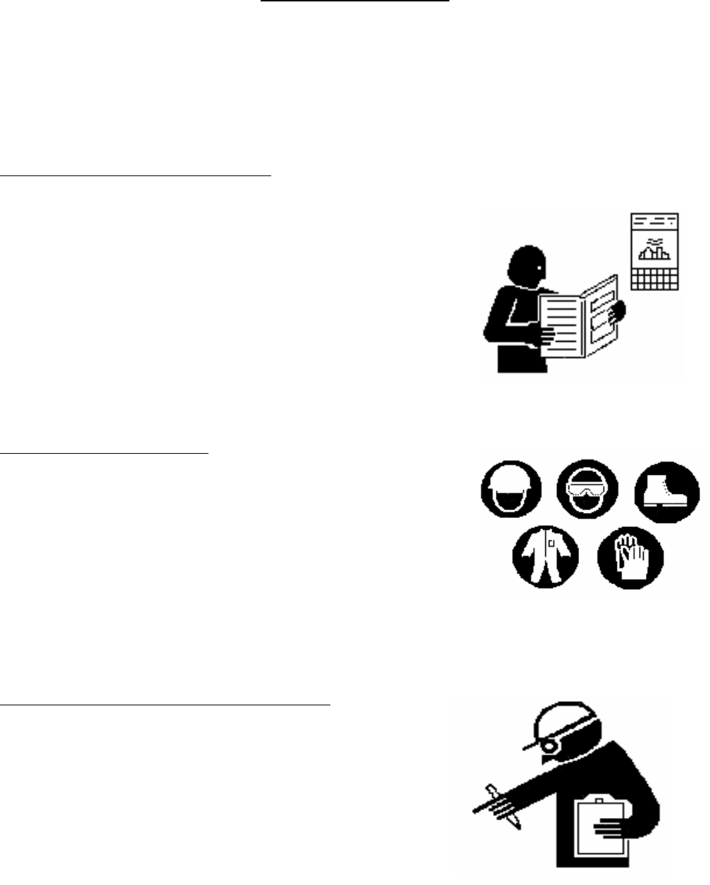
SAFE OPERATION
Cautious operation is your best insurance against an accident. Read and understand this section carefully
before operating the engine. All operators, no matter how knowledgeable they may be, should read this
and other related manuals before operating the engine or any equipment attached to it. It is the owner’s
responsibility to instruct all operators in safe operation. Be sure to observe the following for safe
operation.
OBSERVE SAFETY INSTRUCTIONS
• Read, understand and follow this “OPERATORS MANUAL”
and “LABELS ON THE ENGINE” before starting and operating
the engine.
• Learn how to operate and work safely. Know your equipment
and its limitations. Always keep the engine in good condition.
• Before allowing other people to use your engine, explain how
to operate and have them read this manual before operation.
• DO NOT modify the engine. UNAUTHORIZED
MODIFICATIONS to the engine may impair the function
and/or safety and affect engine life.
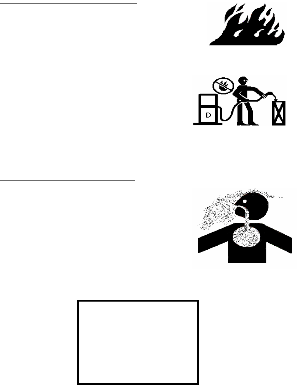
WEAR SAFETY CLOTHING
• DO NOT wear loose, torn or bulky clothing around machinery.
Entanglement in rotating parts, controls or projections may cause
personal injury.
• Use additional safety items, e.g. hardhat, eye protection,
gloves, etc., as appropriate or required.
• DO NOT operate machinery or equipment while under the
influence of alcohol, medication, or other drugs, or
while fatigued.
• DO NOT wear radio or music headphones while operating engine.
CHECK BEFORE OPERATING THE ENGINE
• If the engine is malfunctioning DO NOT operate until repairs
are made.
• Be sure all guards and shields are in place before operating
the engine. Replace any that are damaged or missing.
• Check to see that the area around the engine is clear of foreign
objects before starting.
• Always keep the engine at least 3 feet (1 meter) away from
buildings or other facilities.
• DO NOT allow children or livestock to approach the machine
while in operation.
• DO NOT start the engine by shorting across starter terminals.
1
KEEP AREA AROUND THE ENGINE CLEAN
• Be sure to stop the engine before cleaning.
• Keep the engine clean and free of accumulated dirt, grease and trash.
• DO NOT stop the engine without idling; Temperatures around
the engine rises suddenly. Keep the engine idling for about 5
minutes before stopping.
SAFE HANDLING OF FUEL AND LUBRICANTS
• Always stop the engine before refueling or lubricating.
• DO NOT smoke or allow flames or sparks in your working
area. Fuel is extremely flammable and explosive. Never store
flammable liquids in the engine compartment.
• Refuel at a well-ventilated and open place. If fuel or lubricants
spill, clean up immediately and properly dispose of.
• DO NOT mix gasoline or alcohol with diesel fuel. The mixture
can cause a fire.
EXHAUST GASES AND FIRE PREVENTION
• Engine exhaust fumes can be very harmful if allowed to
accumulate. Be sure to run the engine in a well-ventilated area
where there are no people or livestock near by.
• The exhaust gas from the muffler is very hot. To prevent a fire,
do not expose dry grass, oil or any other combustible materials
to exhaust gas. Keep the engine and mufflers clean all the time.
• To avoid a fire, be alert for leaks of flammables from hoses and
lines. Be sure to check for leaks from hoses and pipes, such as
fuel and hydraulic by following the maintenance check list.
• To avoid a fire, do not short across power cables and wires.
Check to see that all power cables and wires are in good
condition. Keep all power connections clean. Bare wire or
frayed insulation can cause a dangerous electrical shock and
personal injury.
2
CALIFORNIA
Proposition 65 Warning
Diesel Engine Exhaust and some
of it’s constituents are known by the
State of California
to cause
Cancer, Birth Defects and Other
Reproductive harm.
ESCAPING FLUIDS
• Relieve all pressure in the air, oil and cooling systems
before any lines, fittings or related items are removed or
disconnected.
• Be alert for possible pressure release when disconnecting any device
from a system that is pressurized. DO NOT check for
pressure leaks with your hands. High-pressure oil or fuel can
cause personal injury.
• Escaping hydraulic fluid under pressure has sufficient force to
penetrate skin causing serious personal injury.
• Fluid escaping from pinholes may be invisible. Use a piece of
cardboard or wood to search for suspected leaks: do not use
hands and body. Use safety goggles or other eye protection
when checking for leaks.
• If injured by escaping fluid, see a medical doctor immediately.
This fluid can produce gangrene or severe allergic reaction.
CAUTIONS AGAINST BURNS AND BATTERY EXPLOSION
• To avoid burns, be alert for hot components during operation and
just after the engine has been shut off. Such as the muffler, muffler
cover, radiator, piping, engine body, coolants, engine oil, etc.
• DO NOT remove the radiator cap while the engine is running or
immediately after stopping. Wait approximately ten minutes for the
radiator to cool before removing the cap.
• Be sure the radiator drain valve / petcock and hose clamps are
tighten. Check radiator pressure cap and oil fill cap before operating
the engine.
• The battery presents an explosive hazard. When the battery is
being activated, hydrogen and oxygen gases are extremely explosive.
• Keep sparks and open flames away from the battery, especially
during charging. DO NOT strike a match near the battery.
• DO NOT check a batteries charge by placing a metal object across
the terminals. Use a voltmeter or hydrometer.
• DO NOT charge a battery if frozen, it may possibly explode. Frozen
batteries must be warm up to at least 61°F (16°C) before charging.
KEEP HANDS AND BODY AWAY FROM ROTATING PARTS
• Keep your hands and body away from all rotating parts, such
as cooling fan, v-belts, pulleys and flywheel. Contact with these
rotating parts can cause serious personal injury.
• Be sure to stop the engine before adjusting belt tension or checking
the cooling fan.
• DO NOT run the engine without safety guards installed. Be sure the
safety guards are properly aligned and securely fastened before operating
the engine.
3
ANTI-FREEZE AND DISPOSAL OF FLUIDS
• Anti-freeze contains toxic chemicals. Wear rubber gloves when
handling anti-freeze. In case of contact with skin, wash immediately
to avoid personal injury.
• DO NOT mix different types of Anti-freeze. The mixture can
produce a chemical reaction resulting in the formation of harmful
substances. Only use anti-freeze that is recommended and approved
by Caterpillar.
• Be mindful of the environment. Before draining any fluids, be
prepared to dispose of them in a manner consistent with
environmental protection regulations in your location.
• When draining fluids from the engine, use appropriate containers to
hold the different fluids, do not mix fuel, oil or coolant together.
• Dispose of spent filter cartridges and batteries properly.
• DO NOT pollute the soil, or any water source. Never pour fluids
down a drain.
CONDUCTING SAFETY CHECKS AND MAINTENANCE
• When performing safety checks or engine service, be sure the engine is level
and well supported. Use approved stands designed for this type of service.
DO NOT service an engine that is only supported by a lift jack or hoist.
• Detach the battery from the engine before conducting service. Put a
“DO NOT OPERATE!” tag in the key switch to avoid accidental starting.
• To avoid sparks from an accidental short circuit always disconnect
the 12V DC power at the battery.
• Be sure to stop the engine and remove the key when conducting
daily and periodic maintenance, servicing and cleaning.
• Check or conduct maintenance after the engine, radiator, muffler, or
muffler cover has cooled off completely.
• Always use the appropriate tools and jig-fixture when performing any
service work. Be sure to understand and follow the instructions included
with these tools.
• Use ONLY correct engine barring techniques for manually rotating
the engine. DO NOT attempt to rotate the engine by pulling or prying
on the cooling fan and V-belt. Serious personal injury or damage to the
cooling fan may occur.
• Replace fuel hoses and hose clamps every 2 years or earlier whether they
are damaged or not. They are made of rubber and are aged gradually.
• When service is performed with two or more people present, take care
to perform all work safely. Be aware of their location especially when
starting the engine.
• Keep a first aid kit and fire extinguisher handy at all times.
4

SECTION 2
“ENGINE”
PRE-OPERATION CHECK 1
Engine Break-in Period
Daily Check
OPERATING THE ENGINE 2
Engine Starting Controls
Starting the Engine
Check Engine After Starting
Stopping the Engine
ENGINE SPECIFICATIONS 3
Kubota Models D905-B and D1105-B
Service Parts
ENGINE MAINTENANCE SERVICE SCHEDULE 4
ENGINE OIL MAINTENANCE 5
Checking Engine Oil Level
Lubricating Oil Specifications
Engine Refill Capacities
Lubricating Oil Viscosity Recommendations
ENGINE COOLANT MAINTENANCE 6
Coolant Recommendations
Ethylene Glycol / Propylene Glycol
Checking Radiator Coolant Level
Coolant Service Life
Checking Reservoir Tank Coolant Level
Cleaning Radiator Core
OPERATING HOURS AND SERVICE LOG 7
ENGINE TROUBLESHOOTING GUIDES 8-10
Engine Starts but Won’t Run
Engine Runs Rough or Slow
Engine Will Not Start

PRE-OPERATION CHECK
ENGINE BREAK-IN PERIOD
During the engine break-in period, observe the following recommendations:
1. Change the engine oil and oil filter cartridge after the first 50 hours of operation.
(See “ENGINE OIL” in ENGINE MAINTENANCE SERVICE SCHEDULE).
2. In ambient temperature above 32°F (0°C) approximately 3-5 minutes without a load is sufficient
for engine warm up. Allow additional warm up time when temperatures are below 32°F (0°C)
before placing an operating load on the engine.
DAILY CHECK
To prevent future engine problems from occurring, it is important to know and keep track of the engines
condition. Below are items to be Inspected and Checked on a daily basis.
CAUTION:
To avoid personal injury:
• Be sure all safety shields and guards are attached to the engine when operating.
• To prevent a fire hazard, keep foreign materials, fuel and oil away from the battery, wiring, muffler
and engine. Check and clear them daily. Be aware of the muffler and exhaust gas heat underneath the
engine compartment, this heat may ignite grass or other flammable materials.
• Follow all safety precautions as outlined in the “SAFE OPERATION” section.
1. For accurate readings the engine should be on level ground when checking engine fluids.
2. Check fluids before starting the engine. (Cold Engine)
• Lubrication System: Check Engine oil level
Check for Engine oil leaks
• Cooling System: Check coolant level and condition
Check for coolant leaks
Check for proper installation of the radiator cap
• Fuel System: Check for sufficient quantity of fuel
Check for fuel leaks
3. Check engine after starting. (Warm Engine)
• Proper Operation: Check for easy engine start
Check for fluid leaks
Check for abnormal engine noises
Check for abnormal exhaust gas
1

OPERATING THE ENGINE
ENGINE STARTING CONTROLS
1) Generator Main Switch must be in the ON position.
2) Hold Start/Stop Switch for 1 second and release.
3) Glow Plugs will preheat for 8 seconds. LED flashes slowly.
4) Preheating will cease during engine cranking cycle. LED continues flashing.
5) Engine begins an 8 seconds crank cycle, After 4 seconds of cranking the PT-ECU-63 will check
for an AC signal from the generator. If an AC signal is verified the engine will start and the LED
will remain ON during the normal run operation. If the AC signal is not verified the PT-ECU-63
will terminate the cranking cycle and LED will flash a fault code.
6) Starter disengages immediately after engine run is verified.
7) PT-ECU-63 deactivates the Low Oil Pressure and High Water Temperature Switches for 6
seconds, this will assure oil pressure build-up time. If oil pressure does not build-up the engine will
immediately shut down and go into a fault mode. Likewise for a high temperature situation.
8) If engine will not start on the first attempt the PT-ECU-63 will initiate the start cycle 2 more times
before going into a fault mode. Glow Plugs will preheat for 8 seconds per attempt. Engine will
crank for 8 seconds per attempt.
9) To shut down the engine under normal operations, hold the Start/Stop Switch for 1 second and
release.
10) If a fault occurs turn Generator Main Switch OFF and then ON to reset PT-ECU-63.
CHECKING ENGINE AFTER STARTING
1) Allow the engine to warm up 3 to 5 minutes before applying a load. In colder climates allow a few
extra minutes longer.
2) Perform a visual inspection of all areas of the engine and generator.
3) Listen for any abnormal noises.
4) Check for any abnormal exhaust gases.
STOPPING THE ENGINE
It is recommended to disconnect or reduce the power load from the generator before shutting down the
engine. Then follow the steps outlined above for normal shut down.
NOTE: The PT-ECU-63 is designed to operate on 12V DC power. In a low battery situation the
PT-ECU-63 may not initiate the normal cranking cycle. To start the generator you can press and
hold the Start/Stop Switch for approximately 10 seconds or until the engine starts. Once the
engine starts the PT-ECU-63 will resume normal operations. If this situation re-occurs, charge or
replace the battery.
IMPORTANT: Damage to the Starter Motor, Starter Solenoid, Run Solenoid or any generator component
due to excessive or prolonged starting attempts attributed to an external Low Battery Control Monitoring
or Auto-Start System will not be covered by the Power Technology Southeast, Inc. Limited Warranty.
2

ENGINE SPECIFICATIONS
SERVICE PARTS
Power Technology Part #
Filters:
Oil ----------------------------------------------------------------------------------- 01FO05S
Fuel ---------------------------------------------------------------------------------- 08FF081
Air with Metal Canister----------------------------------------------------------- 04FA080
Air with Plastic Canister---------------------------------------------------------- 04FA2E1
Belt: ------------------------------------------------------------------------------------------ 03BF7305
Radiator Hoses:
Upper ------------------------------------------------------------------------------- 03HS7CDU
Lower ------------------------------------------------------------------------------- 03HSCDL
3
MODEL Kubota D905-B Kubota D1105-B
Continuous Output 10.5HP @ 1800 rpm 13.6 HP @ 1800 rpm
Cubic Capacity 54.8 in³ (.898L) 68.5 in³ (1.12L)
Bore and Stroke 2.83” x 2.90”
(72 x 73.6mm)
3.07” x 3.09”
(78.0 x 78.4mm)
Cylinder Arrangement 3 In-Line 3 In-Line
Firing Order 1-2-3 1-2-3
Compression Ratio 22:1 22:1
Engine Oil Capacity 4.0 qts. (3.78L) 4.0 qts. (3.78L)
Coolant Capacity 5qts. (4.7L) 6qts. (5.7L)
Fuel and Type Diesel No. 2-D
4 Cycle
Diesel No. 2-D
4 Cycle
Minimum Fuel Consumption See Specification Chart See Specification Chart

Engine Maintenance Service Schedule
Maintenance
Service Item *See
Note
Daily
Min.
Every
25 Hours
Every 100
Hours
Every 250
Hours
Every 500
Hours
Every
1000
Hours
Remarks
Engine Oil Level
Deterioration &
Leakage
X
Engine Oil
Change * X
Or Once
a Year
Oil Filter
Change X
Or Once
a Year
Coolant Level X
Coolant Leakage X
Coolant Change X Or Once a Year
Fuel Level X As Necessary
Fuel Leakage X
Fuel Filter Re-
placement X Or Once a Year
Air Filter Re-
placement ** X Or Once a Year
Damaged Worn
Or Loose Belts X
Or Every Two
Years
Replace Fuel
Hoses X Or Every Two
Years
Check Radiator
Hoses & Clamps
X
Once a Year
Abnormal Engine
Noise X
Abnormal
Generator Noise X
Muffler Condition
X
Exhaust Gas
Condition X
* Engine oil and filter must be changed after the first 50 hours of operation. Then every 100
hours or once a year whichever comes first.
** Air filter replacement interval will vary depending on operating conditions. Adverse conditions may
require frequent service.
NOTE: Under normal operation items such as Belts, Hoses and Filters are not covered by Power
Technology Southeast, Inc. Limited Warranty.
4
ENGINE OIL MAINTENANCE
Ambient Temperature Oil Viscosity
Above 25°C (77°F)
SAE 10W-30
SAE 30 or
SAE 10W-40
0 to 25°C (32° to 77°F)
SAE 10W-30
SAE 20 or
SAE10W-40
Below 0°C (32°F)
SAE 10W-30
SAE 10W or
SAE 10W-40
5
CHECKING ENGINE OIL LEVEL
( Y ) “ADD” mark. ( X ) “FULL” mark.
1. Maintain the engine oil level between “ADD”
mark and “FULL” mark on oil level gauge.
Do not fill crankcase above “FULL” mark.
2. Remove the oil filler cap and add oil, if
necessary. Clean the oil filler cap. Install the oil
filler cap.
The refill capacities for the engine crankcase
Reflect the approximate capacity of the
crankcase or sump plus a standard oil filter.
Auxiliary oil filter systems will require
additional oil.
KUBOTA D905-B & D1105-B ENGINE
REFILL CAPACITIES
Crankcase Oil Sump 4.0 Qts. (3.78L)
and Filter
LUBRICATING OIL VISCOSITY
RECOMMENDATIONS
The minimum ambient temperature during cold
engine start-up and the maximum ambient
temperature during engine operation determine the
proper SAE viscosity grade of oil.
Refer to the Engine Oil Viscosity Table below
(Minimum Temperature) in order to determine the
required oil viscosity for starting an engine in cold
conditions.
Refer to the Engine Oil Viscosity Table below
(Maximum Temperature) in order to select the oil
viscosity for engine operation at the highest ambient
temperature that is anticipated.
LUBRICATING OIL
SPECIFICATION
Use only good quality
lubricating oil, which meets
or exceeds of the following
Specification
API-CD
or
Higher
ENGINE COOLANT MAINTENANCE
6
COOLANT SERVICE LIFE
Coolant Type Service Life
Commercial Heavy-Duty
Coolant/Antifreeze that 3000 Service Hours
Meets “ASTM D5345” or Two Years
Commercial Heavy-Duty
Coolant/Antifreeze that 3000 Service Hours
Meets “ASTM D4985” or One Year
NOTE: Do not use a commercial
coolant/antifreeze that only meets the ASTM
D3306 or D4656 specification. This type of
coolant/antifreeze is made for light duty
automotive applications.
CHECKING RESERVOIR TANK
COOLANT LEVEL
(At a Minimum of 25 Hours of Operation)
Ensure that the coolant level of the radiator
reservoir tank is between the upper limit (FULL)
and the lower limit (LOW) on the side of the
reservoir tank.
CLEANING RADIATOR CORE
Visually inspect the core for any obstructions such
as dirt or debris. Use running water to clean
particles from between fins.
IMPORTANT: Never use hard objects to clean
radiator core, damage to core could result.
COOLANT RECOMMENDATIONS
For optimum performance, Power Technology
recommends a 1:1 mixture of water / glycol.
NOTE: Use a mixture that will provide
protection against the lowest ambient
temperature.
NOTE: 100 percent pure glycol will freeze at a
temperature of –23°C (-9°F).
Most conventional heavy-duty coolant /
antifreezes use Ethylene Glycol. Propylene
Glycol may also be used in a 1:1 mixture with
water. Ethylene and Propylene Glycol provide
similar protection against freezing and boiling.
See the tables below.
ETHYLENE GLYCOL
Freeze Boil
Concentration Protection Protection
50 Percent -36°C (-33°F) 106°C (223°F)
60 Percent -51°C (-60°F) 111°C (232°F)
PROPYLENE GLYCOL
Freeze Boil
Concentration Protection Protection
50 Percent -29°C (-20°F) 106°C (223°F)
NOTE: Do not use Propylene Glycol in
concentrations that exceed 50 percent glycol
because of Propylene Glycol’s reduced heat
transfer capability. Use Ethylene Glycol in
conditions that require additional protection
against boiling or freezing.
CHECKING RADIATOR COOLANT LEVEL
Remove the radiator cap after the engine has
completely cooled and check to see that
coolant reaches the supply port.
1. Fill to the bottom of the fill neck and
check after every 25 hours of operation.

OPERATING HOURS and SERVICE LOG
THIS SERVICE LOG IS PROVIDED TO HELP YOU KEEP AN ACCUMULATIVE RECORD OF OPERATION HOURS ON YOUR GENERATOR
SET AND THE DATES REQUIRED SERVICES WERE PERFORMED. ENTER TIME TO THE NEAREST HOUR.
OPERATING HOURS SERVICE RECORD
DATE HRs. RUN CUMLATIVE DATE SERVICES
7
Engine Runs OK
Has Power NO Power
Has Power NO Power
Engine runs OK NO Power
ENGINE STARTS
BUT WON’T RUN
Unplug Remote
Start-Stop from
Control Box
Problem with
Remote Connection.
Contact
Equipment Manufacture
r
Jump across
Oil Pressure Switch
with Jumper Wire
(2 pole)
Check Power
to Hold Circuit
of Run Solenoi
d
Check
Oil Pressure
With Gauge
Replace
Oil Pressure Switch
Defective Solenoid
REPLACE
Plug Remote
Back IN
Remote OK Problem with Remote
Check
Safety Shutdown
System
Remove Wire From
Water Temperature Switch
Replace Water
Temperature
Switch
Check Shutdown
Relay
Check Wirin
g
Oil Pressure Switch
Single Pole
Disconnect Wire to Test
If “OK”
Replace
Switch
BLUE
GRAY/WHITE
BLACK
9
ENGINE RUNS
ROUGH or SLOW
NO Visible Exhaust Smoke Excessive Exhaust Smoke
Insufficient
Fuel to Engine
Check
Fuel Level
Replace
Fuel Filter
Air IN
Fuel
System
Check
Fuel
PUMP
Excessive Oil Level
Dirty Air Filter
Engine Overheated
Engine Over Loaded
Clogged Muffler
Over Fueling Injector
HIGH ALTITUDE
Engine Cold
Incomplete
Combustion
Over-fueling
Injector
Glow Plug
Not Activating
Check
With 12 volt DC
Test Light
Check
Safety Shutdowns
And
Fuel Solenoid
YES NO
10
ENGINE WILL NOT
START
Engine Cranks Engine Does NOT
Crank
Engine
Cranks SLOW
NO
Exhaust
Smoke
Smoke
From
Exhaust
Check Fuel
Solenoid
NO
Power While
Cranking
Defective
Solenoid
No Power
From
Starter Terminal
Check
Fuel
Supply
Check
Fuel
Pump
Air IN
Fuel
System
Check
Glow
Plugs
Check
Glow Plug
Relay
Main Switch Battery
Dead
Turn
Switch
“ON” Start
Switch
Starter
Relay
Starter
Motor
Oil Viscosity
TOO HEAVY
LOW
Battery
Voltage
Check
Terminal
Ends
Check Spark
Arrestor
Muffler for
Clogging

SECTION 3
“GENERATOR END”
PRINCIPLES OF OPERATION 1-2
Rotating Field Assembly (Rotor)
Core Assembly
Field Coil
Voltage Connection
Electronic Voltage Regulation
Exciter Field Coil Voltage Source
Balance
Bearing
Stator Assembly
7-8KW EXCITER TYPE “C” GENERATOR ASSEMBLY 3
GENERATOR END TROUBLESHOOTING GUIDES 4-6
Zero or Low Voltage
Voltage Test
12-Volt Battery Test
Overload Condition
WIRING SCHEMATICS 7-8
120 Volt Connection “C” Series Exciter Type
120 / 240 Volt Connection “C” Series Exciter Type

GENERATOR ASSEMBLY INFORMATION
EXCITER TYPE GENERATOR
The exciter pole pieces contain residual magnetism, which sets up lines of force across the air
gap to the exciter armature. When the exciter begins to rotate a voltage is induced and current flow is
initiated in the exciter armature AC windings. This voltage is fed to the rotating rectifier assembly,
rectified and fed to the alternator field, which sets up lines of force across the air gap to the alternator
stator windings and to the output circuit.
A static voltage regulator is connected to the generator output. The regulator will rectify part of
the output voltage to provide a DC voltage to the exciter field coils. This will increase the density of the
lines of force in the exciter, increasing the voltage induced into the exciter armature windings, and
therefore, to the rotating rectifiers. The rotating rectifier output will be increased which will increase the
alternator field strength and generator output will build up its rated voltage. Adjustment of the generator
output to the rated voltage level is accomplished by controlling the current fed to the exciter field coils.
Regulation is automatic with the static type voltage regulator. An additional voltage adjustment range is
provided if desired by turning the Voltage Adjust Rheostat.
ELECTRONIC VOLTAGE REGULATION
Electronic Voltage Regulator (EVR) also referred to, as an Automatic Voltage Regulator (AVR)
is a very reliable device, which uses solid-state electronics to maintain voltage accuracy at ±2% of the
regulated voltage. The Voltage Regulator is designed to automatically regulate and maintain the
generated AC voltage through out the load range that is from no load to full load.
VOLTAGE CONNECTION
The generator may be connected at the terminal board to deliver 120/240 volts to a 3 wire
grounded neutral system, or 120-volts only to a 2 wire distribution system. If any equipment requires
240-volts, then the 120/240-volt connection must be used. If all equipment requires 120-volts then
the 120-volt connection is preferred, even if two lines leave the same switch box. The two lines at
the inputs to the switch box are both connected to the un-grounded 120-volt lines from the generator.
The 120-volt connection enables the Electronic Voltage Regulator (EVR) to hold the voltage very
close to the 115 or 120 volts, as initially adjusted, regardless of the power distribution amount the
different distribution lines. The 120-volt connection is recommended if the entire electrical load
requires only 115 or 120 volts.
Although the 120/240-volt connection may also be used when all loads requires only 110 volts, it
should be pointed out that this connection, the 240-volts, is regulated and the lightly loaded phase, or
line, will deliver a high line to neutral voltage and the heavily loaded phase will deliver a low line to
neutral voltage. The heavily loaded line may have such a low voltage that air conditioning will have
more difficulty in starting, and long starting lines may overload generator and trip circuit breakers
EXCITER FIELD COIL VOLTAGE SOURCE
Field coil DC voltage is obtained by rectifying the voltage from the phase to neutral line of the
generator output, or either appropriate terminal to provide the needed voltage reference.
The rectifier bridge is an internal part of the static regulator. The static regulator senses a change
in the generator output and automatically regulates current flow in the exciter field coil circuit to
increase or decrease the exciter field strength. An adjustable rheostat sized to be compatible with
the regulator is used to provide adjustment of the regulator sensing circuit.
1

ROTATING FIELD ASSEMBLY (ROTOR)
The rotating field assembly consists basically of four members: 1) the shaft assembly, 2) the
core assembly, 3) the field coil damper windings, and 4) balance lugs to provide a high degree of static
and dynamic balance.
CORE ASSEMBLY
The core assembly consists of a quantity of thin steel plates compressed and fastened together to
form a single laminated assembly. The field windings are wound around this assembly.
FIELD COIL
Field coils of heavily insulated wire are “wet” wound directly onto the poles. Field coil leads are
brought out to the rectifier assembly for connection to the source of DC excitation voltage.
BALANCE
The rotor assembly is precision balanced to a high degree of static and dynamic balance.
Although the balance will remain dynamically stable at speeds in excess of the design frequencies, the
prime mover should be adequately governed to prevent excessive over speed. High centrifugal forces
created by excessive over speed may damage the rotor windings and field coils.
BEARING
The generator rotor assembly is suspended on a shielded factory lubricated ball bearing. A visual
inspection of the bearing is recommended at typical service intervals. If signs of abnormal wear
or leakage are observed, the bearing should be replaced. Never use liquids of any kind to clean the
generator end and bearing.
STATOR ASSEMBLY
The stator assembly consists of laminations of steel mounted in a rolled steel frame. Random
wound stator coils are fitted into the insulated slots.
2
DESCRIPTION PART NUMBER
7KW 8KW
1. BEARING PLATE 02BR-CR 02BR-CR
2. END BELL 02H7810 02H7810
3.EXCITER STATOR 02STA7EXC 02STA8EXC
4. MAIN STATOR 02STAMNCD7 02STAMNCD8
5. BELL HOUSING ** 02BHCD7 02BHCD7
6. ROTOR BEARING 02BRG6206 02BRG6206
7. DIODE PLATE 02PLD8CD 02PLD8CD
8. EXCITER ROTOR 02RTR7EXC 02RTR8EXC
9. MAIN ROTOR 02RTRMN7EXC 02RTRMN8EXC
10. END BELL ASSEMBLY 02EB7 02EB8
11. MAIN ROTOR ASSEMBLY 02RTR7EXC-ASSY 02RTR8EXC-ASSY
12. END PLATE ASSEMBLY 02EP7 02EP8
GENERATOR ASSEMBLY 02GEN7EXCCD 02GENCD8E
VOLTAGE REGULATOR 06REG24 06REG24
** NOTE: Item #5 BELL HOUSING is not part of the Generator End assembly.
7
-
8
K
W
EX
C
ITER TYPE “
C
”
G
E
N
ERAT
O
R A
SS
EMBLY
3
BAD OK ON OFF
OK
BAD
OK
4
ZERO OR LOW
VOLTAGE
Check Gen Fuse Check Main
Breaker is “ON”
Replace
Fuse Turn “ON”
Breaker
Main Coil
Output to
Breaker
OK
BAD
Check Ohm’s on
Exciter Leads
12 V Battery Test
Replace Exciter
Wiring To
Panel
Defective
Breaker
Replace
Voltage Regulator
5
VOLTAGE TEST
Zero
or
Low Voltage
High
Voltage
Overload Output
Voltage OK
Replace
AVR
Check Load Distribution
One Voltage Line
may be
Higher than the other
Check AMP
Draw
From equipment
Check
Main Breaker
On GenSet
Check
Gen End
12 VOLT
BATTERY TEST
One Coil
Low Voltage
Both Coils
Low Voltage
Sensing Voltage
Low or None
Replace
AVR
Check
Connections
Check Engine
RPM 1800
Replace Stator
Replace
Stator
Replace
Stator
BAD OK
BAD OK
6
OVERLOAD
CONDITION
Disconnect
AVR
Engine Problem Check
Stator Coil
Resistance
See Engine
Troubleshooting
Replace Stator Replace AVR
And Test
Check AMP Draw
Check Load Distribution
Conduct
12-Volt Battery Test
RESISTANCE CHART
KW 7 8 MARKS COLOR
MAIN STATOR 0.5 0.5 U1-V1 or U2-V2 B-B
MAIN ROTOR 1.9 1.9 *** ---
EXCITER STATOR 83.5 86.9 F1-F2 R-W
EXCITER ROTOR 0.31 0.31 *** ---
AUX. WINDING 2.5 2.5 AW Y-Y
BATT. CHARGE 0.2 0.2 CH W W-W
SENSING WINDING 0.2 0.2 *** BLUE / BROWN
NOTE: THESE READINGS WILL VARY DEPENDING ON AMBIENT TEMPERATURE
POWER TECHNOLOGY SOUTHEAST, INC.
634 STATE ROAD 44
LEESBURG, FL 34748-8103
(352) 365-2777 FAX (352) 787-5545
AC ELECTRICAL CIRCUIT FOR 7 –8 KW “C” GENERATORS 120 VOLTS LINE TO NEUTRAL
GENERATOR OUTPUT LEADS
OPTIONAL 12V CHARGING
TO 12V REGULATOR
2 POLE CIRCUIT BREAKER
30 AMP for 7 KW
35 AMP for 8 KW
7
#12
JUMPER
WIRE
RESISTANCE CHART
KW 7 8 MARKS COLOR
MAIN STATOR 0.5 0.5 U1-V1 or U2-V2 B-B
MAIN ROTOR 1.9 1.9 *** ---
EXCITER STATOR 83.5 86.9 F1-F2 R-W
EXCITER ROTOR 0.31 0.31 *** ---
AUX. WINDING 2.5 2.5 AW Y-Y
BATT. CHARGE 0.2 0.2 CH W W-W
SENSING WINDING 0.2 0.2 *** BLUE / BROWN
NOTE: THESE READINGS WILL VARY DEPENDING ON AMBIENT TEMPERATURE
POWER TECHNOLOGY SOUTHEAST, INC.
634 STATE ROAD 44
LEESBURG, FL 34748-8103
(352) 365-2777 FAX (352) 787-5545
AC ELECTRICAL CIRCUIT FOR 7 –8 KW “C” GENERATORS 120 VOLTS LINE TO NEUTRAL 240 VOLTS LINE TO LINE
GENERATOR OUTPUT LEADS
OPTIONAL 12V CHARGING
TO 12V REGULATOR
2 POLE CIRCUIT BREAKER
30 AMP for 7 KW
35 AMP for 8 KW
8

SECTION 4
“INSTALLATION”
SAFETY PRECAUTIONS 1-2
Hot Piping
Dangerous Fuels
Explosive Battery Gases
Electrocution
Moving Parts
High Voltage
Explosion
Hot Coolant
Lethal Exhaust Gas
Excessive Noise
Electrical Shock
Backfire
Flash Fire
Fire Hazard
Marine Application
Unit Starts Without Notice
Loose Components
GENERATOR INSTALLATION in RECREATIONAL VEHICLES 3-6
Introduction
Marine Application
General Information
Specification Charts
Fuel Consumption in Gallons per Hour
Installation Factors
Generator Compartment Size
Compartment Frame
Air Requirements
Air Requirements Cont’d
SYSTEMS CONNECTION 7-9
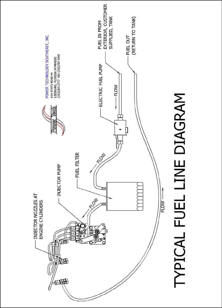
Fuel System
Exhaust System
Fuel Line Diagram
ELECTRICAL CONNECTIONS 10-12
Electrical Wiring
AC Load Lead Connections
Motor Loads
Kilowatt De-Rating
Electrical Loads
Appliance Loads
Extension Cords
ENGINE CONTROLS______________________________________________________ 13-14
PT-ECU-63 Engine Control Module
12 Volt DC Charging
WIRING SCHEMATICS
12 Volt DC Engine Control, PT-ECU-63
12 Volt DC Engine Control for CD-7 and CD-8 Models

SAFTEY PRECAUTIONS
A generator set can be potentially dangerous if not properly maintained and operated. The best Safe
Guard against a dangerous situation is education, good judgment and common sense. For safe trouble free
operation of your generator set some general precautions are listed below. Be sure to read, understand and
follow these precautions. Please call Power Technology Southeast, Inc. with any concerns you may have with
your generator set.
1) HOT PIPING: An engine and exhaust system may get extremely hot while running. Do not work on a
generator set until it has sufficiently cooled.
2) DANGEROUS FUELS: Use extreme caution when handling, storing and using fuels. All fuels are highly
explosive in a vaporous state. Store fuel in a well ventilated area away from spark producing
equipment. Keep fuels and all chemicals out of the reach of children. Never add fuel to the
tank while the engine is running. Spilled fuel may ignite on contact with hot parts or from
ignition spark. Always keep fuel lines and connections tight and in good condition. Don’t
replace flexible fuel lines with rigid lines. If you notice any fuel leakage, fuel accumulation
or electrical sparks, DO NOT OPERATE THE GENERATOR SET.
3) EXPLOSIVE BATTERY GASES: The gases generated by a battery being charged are highly explosive.
Do not smoke or permit any flames or sparks to occur near a battery at any time, especially
when it is being charged. Avoid contact between terminals with tools to prevent sparks and
possible burns. Always remove wristwatch, rings, or other jewelry before handling a battery.
Any compartment containing batteries should be well ventilated to prevent the accumulation
of explosive gases. To avoid sparks never disturb the battery charging connections while the
battery is being charged. Always turn off the battery charger before disconnecting terminal
clips.
4) ELECTROCUTION: Failure to install a generator set with an electrical system consistent with governing
regulations and standards is UNLAWFUL and may cause ELECTROCUTION of vehicle
occupants. Your generator set must not be used to “Back Feed” by connecting it to a building
or outdoor electrical circuit. Back feeding can cause serious injury or death to utility
personnel working to repair a power outage and may also seriously injure persons in your
vehicle. Unauthorized connections are unlawful in some states and/or localities. A transfer
switch must be installed to prevent interconnection of the generator set power and outside
power.
5) MOVING PARTS: Keep hands, feet, and clothing away from belts and related pulleys when unit is running.
Replace guards, covers, and screens before operating the generator set. Serious personal
injury may occur from contact with moving parts.
6) HIGH VOLTAGE: Remember the function of a generator set is to produce electricity. Wherever electricity
is present there is a potential danger of electrocution. Apply the same precautions to the
vehicles electrical appliances as you would for any home appliance. Keep away from
electrical circuits and wiring while the generator set is running. Have electrical service
performed only by qualified electricians. Be sure any unauthorized person; especially
children are denied access to the generator set. Keep the compartment door securely latched
or locked at all times. Be sure the generator is properly grounded. Never touch electrical
leads or appliances with wet hands, or when standing on wet ground.
1
7) EXPLOSION: Never connect the negative (-) battery cable to the positive (+) connection terminal of the
starter solenoid, or test the battery by shorting terminals together. This could ignite fuel
vapors or cause the battery to explode. To disconnect the battery remove the negative battery
cable first and reconnect it last. Do not modify the fuel tank or propulsion engine fuel system.
Your vehicle must be equipped with a fuel pick-up arrangement as described in the Fuel
System section of this manual. Fuel tank and installation must conform to applicable
regulations.
8) HOT COOLANT: Allow engine to cool and release pressure from the cooling system before opening the
radiator pressure cap. To release the pressure, cover the radiator cap with a thick cloth then
turn it slowly counterclockwise to the first stop. After the pressure is released and the engine
has cooled, remove the cap.
9) LETHAL EXHAUST GAS: When installing an exhaust system position the tail pipe end so that the
discharged gases may not be drawn into the vehicle interior through windows, doors, air
conditioners, etc. The engine powering your generator set discharges deadly carbon
monoxide as part of the exhaust gas when running. It is essential that the exhaust system be
leak proof and routinely inspected.
10) EXCESSIVE NOISE: Never operate the generator set without an adequate muffler or with a faulty exhaust
system. Exposure to excessive noise can lead to a hearing impairment.
11) ELECTRICAL SHOCK: A battery can cause electrical burns and shocks. Use reasonable care when
working near the battery to avoid electrical connections by contacting the battery terminals
with tools. Remove wristwatch, rings and all jewelry when working on the generator set.
12) BACKFIRE: A sudden backfire can cause serious burns. Do not operate your generator set without its air
cleaner / flame arrestor in place.
13) FLASH FIRE: A sudden flash fire can cause serious burns. To avoid the possibility of a flash fire do not
smoke or permit a flame or spark to occur near the carburetor, fuel lines, fuel filter, fuel
pump or other potential source of spilled fuel or vapors.
14) FIRE HAZARD: Be careful when parking your vehicle to prevent grass fires from being started by hot
exhaust gases or exhaust system. Keep away from hot engine and generator parts to avoid
burning yourself. Keep the generator set and compartment clean and free of debris, especially
combustible materials. Never store fuel, oil or rags in the generator compartment.
15) MARINE APPLICATION: RV generator sets do not comply with United States Coast Guard (USCG)
requirements. They must not be used for marine applications. Use only generator sets
specified for marine use in a marine application. USCG regulation 33CFR183 requires a
generator set to be ignition protected for use in a gasoline-fueled environment.
16) UNIT STARTS WITHOUT NOTICE: To prevent accidental starting on the units with remote start / stop
switch, always disconnect the battery by removing the negative (-) terminal first and then the
positive (+). Always disconnect the unit this manner before working on the generator or any
equipment connected to it.
17) LOOSE COMPONENTS: Periodically check for and tighten any fasteners that may have become loose
from vibration or road shock. Serious damage may possibly occur if components become
dislodged or misaligned.
2

GENERATOR INSTALLATION
in RECREATIONAL VEHICLES
INTRODUCTION
Use this section as a guide when installing a generator set in a recreational vehicle, and then refer
to the appropriate operation section for specific instructions. The installation of a RV generator set shall
comply with current standards of ANSI / RVIA EGS-1, NFPA 1192 / ANSI A 119.2, ANSI / NFPA 70,
NFPA 551 and applicable articles of the National Electrical Code. Generator set installations must also
comply with state and local requirements.
MARINE APPLICATION
RV generator sets do not comply with United States Coast Guard (USCG) requirements and
must not be used for marine applications. Use only generator sets specified for marine use in marine
installations. USCG regulation 33CFR183 requires a generator set to be “ignition protected” when used
in a gasoline fueled environment.
GENERAL INFORMATION
This information section covers the RV generator set models listed below. To determine which
model is involved, check the model number found on the Power Technology nameplate attached to the
frame of the generator being installed. Follow all instructions to ensure proper installation and operation.
Each generator set features a Kubota diesel engine, rotating-field alternating current generator,
and a relay controller. The generator is directly connected to the engine for permanent alignment. Each
controller includes a Start / Stop switch for test operating the set at the controller. Also included is an On
/Off switch to reset the controller or lockout any remote switch to prevent starting while service is being
performed. The controller may be equipped with a switch to operate the mechanism used to move the
generator out of the coach for servicing. (Supplied by the coach manufacture). After the set is attached
to the frame of the vehicle, all that is usually required to make it operational is the following.
1. Attaching the exhaust system.
2. Add proper amount of radiator coolant.
3. Add oil to crankcase, to the dipstick FULL mark.
4. Connect fuel lines, remote switch, load leads and battery terminals.
(Consult the Specification Charts on the Following Pages for Requirements)
3
MODEL CD-7 CD-8
GENERATOR DIMENSIONS L x W x H 33.5” x 24.5” x 18.3” 35.5” x 24.5” x 19”
WEIGHT 390 lbs. 420 lbs.
ENGINE Kubota D905-B or D1105-B Kubota D1105-B
RPMs 1800 1800
KW RATING 7 8
AC VOLTAGE 120 or 120 / 240 120 or 120 / 240
AMPERAGE 58 / 29 66 / 33
Hz 60 60
PHASE 1 1
GENERATOR COMPARTMENT
FREE AIR OPENING
277
Square Inches
277
Square Inches
SPECIFICATION CHARTS
FUEL CONNECTION ¼” NPT
FUEL RECOMMENDATION DIESEL FUEL No.1-D or No.2-D ASTM / D975
BATTERY VOLTAGE 12 VOLTS DC
BATTERY CRANKING AMPS 420
BATTERY COLD CRANKING AMPS 590 MINIMUM
BATTERY GROUND NEGATIVE
FUEL CONSUMPTION IN GALLONS PER HOUR
LOAD PERCENTAGE 7KW 8KW
25% .16 GPH .25 GPH
50% .32 GPH .38 GPH
75% .51 GPH .60 GPH
100% .64 GPH .72 GPH
INSTALLATION FACTORS
Each generator set is received as a unit except for the optional exhaust system components,
which are shipped loose for assembly after the set is installed in the vehicle. When preplanning the
installation, the following factors must be considered.
1. COMPARTMENT SIZE: Will there be sufficient room around the set to maintain
the minimum clearance of one inch?
2. AIR REQUIREMENTS: Are the compartment air inlets and outlets sized to allow
adequate circulation of air for cooling and combustion?
3. COMPARTMENT FLOOR: Is the compartment floor strong enough to support the
weight of the generator set?
4. COOLING SYSTEM: Is the cooling system large enough to adequately cool the
generator set? **
5. FUEL SYSTEM: Is the fuel system properly designed to prevent fuel
starvation of either the main engine or generator engine?
6. EXHAUST SYSTEM: Will the exhaust system meet all safety requirements
after installation?
7. ELECTRICAL CONNECTIONS: Will all systems, (battery, load and remote switch)
be compatible with the vehicles system?
** NOTE: When using a radiator not supplied by Power Technology consult your radiator
manufacturer to ensure that heat rejection values are met.
4

GENERATOR COMPARTMENT SIZE
In planning the size of the generator compartment or bay allow for the minimum clearance
necessary to adequately cool the generator set. The thickness of insulation and sound deadening material
used to line the compartment must be taken into consideration when planning this clearance. To
maintain minimum clearance it may be necessary to enlarge the compartment. The generator set must be
securely fastened to avoid unwanted movement from vibration and road shock. If the unit is equipped
with a mounting tray the tray is usually supported on the ends by angle iron and has a full door for
service access. Be sure to use all mounting holes in the tray to secure the tray to the vehicle support
structure. Units not equipped with mounting tray are secured by attaching Genset mounts (two in front,
two in rear) directly to the vehicle frame. Skid mounted units can either be affixed to a tray for tray
mounting or attached directly to the vehicle frame. The generator is easily removed from the coach if a
carriage with rollers is incorporated into the support structure. When designing the compartment allow
sufficient access for routine maintenance and for removal when major service is required. Also keep in
mind that the compartment door must have air intake opening having a free area equal to or greater than
that specified under the “Air Requirements” section of this manual. Make sure that the compartment is
vapor tight and completely sealed off from the inside of the vehicle to prevent exhaust or other items
from entering the vehicle. Avoid road splash and the possibility of igniting combustible materials
beneath the coach by enclosing all unnecessary free space beneath the generator compartment.
Line the compartment with a good sound deadening material. The material selected must be
fireproof or highly fire resistant. An available type of 3-layer foam material is very efficient for
absorbing sound. This type of material is easily cut to size with scissors and can be quickly installed
using special fire resistant adhesive which bonds the material to almost any clean dry surface. Other
materials such as fiberglass insulation with heat barrier have also been used successfully in mobile
installations.
NOTE: Since a Genset is flexibly mounted the minimum clearance of one inch (2 inches at the radiator
end) will assure that the sides of the compartment and the set will not rub while the set is in operation or
while the vehicle is in transit.
COMPARTMENT FRAMING
The generator must be bolted to a metal frame, which is either bolted or welded to the frame of
the vehicle. This frame must be designed to withstand a minimum force of 5Gs in any direction. The
frame must support the entire base plate around the outer perimeter and center section. Additional
framing may be required if excessive vibration occurs.
AIR REQUIREMENTS
Each engine is equipped with a high water temperature shutdown switch, which will
automatically shut down the set if the operating temperature climbs too high. To prevent the generator
set from shutting down make sure the compartment openings are large enough to allow adequate
circulation of cooling air. The minimum free air opening in the compartment door is 400 sq. in. or 2580
sq. cm. Remember that louvers, screens and protective grills will restrict airflow. A relatively open mesh
screen will restrict airflow as much as 45%. The intake opening must be increased to compensate for
such restrictions.
NOTE: Ambient temperature is defined as the generators normal operating temperature within its
mounting area. In an RV application this area is referred to as a compartment or bay.
5
AIR REQUIREMENTS CONT’D
* Thermostat Rating: Lower Temperature – Old Style
Higher Temperature – New Style
* Combustion Air Temperature: The output of the engine will decrease about 1% for
every 10°F of air temperature above 77°F or 25°C.
IMPORTANT: Insulation and Sound Absorbing Material used inside of the generator compartment
Must Not reduce the specified airspace clearances or restrict the airflow around the generator. Such
reduction in airspace may lead to an overheating situation and reduced generator performance. Also be
sure the air inlet and outlet openings meet the specified requirements. Allow clearance inside the
generator compartment for easy access when routine maintenance is required.
WARNING: The generator compartment Must Be sealed to prevent hazardous fumes and vapors from
entering the vehicles other compartments and interior spaces. Plugging holes and sealing all seams will
greatly reduce this hazard.
WARNING: Drip Proofing! When installing a generator, the area directly beneath the generator end of
the unit must incorporate a non-flammable barrier. This barrier needs to be made of sufficient material
able to withstand and prevent molten metal, burning insulation, flaming or sparking particles from
contacting any flammable materials at the bottom of the compartment.
6
7KW 8KW
ENGINE SPEED IN RPM 1800 1800
OUTPUT IN HORSEPOWER 10.5 13.6
ENGINE INLET WATER TEMP. N/A N/A
THERMOSTAT RATING* 160°F – 180°F 160°F - 180°F
THERMOSTAT FULL OPEN 203°F 203°F
ENGINE OUTLET WATER TEMP.MAX. 230°F 230°F
HIGH TEMP. SHUTDOWN SWITCH 230°F 230°F
HEAT REJECTION – BTU / MIN. 673 885
HEAT REJECTION – BTU / HR. 40,397 53,135
AIR FLOW – CU. FT. / MIN. 1296 1471
ENGINE OIL TEMP. MAX. 268°F 268°F
COMBUSTION AIR TEMP. * N/A N/A

SYSTEMS CONNECTION
FUEL SYSTEM
The diesel fuel system for the generator set must be designed to operate independently from the vehicles
main engine if both engines are to be operated at the same time. The best way to do this is to have separate fuel
tanks, but this is usually impractical because of space restrictions. In most installations both engines operate
from a common fuel tank with separate pick-up tubes for each engine, not a Tee fitting arrangement. This
prevents either or both engines from being starved for fuel. The generator set fuel pick-up tube is generally
shorter than the vehicles; therefore fuel may not be available to the generator when fuel supply is low. This will
prevent the generator from depleting the fuel supply needed by the main engine.
NOTE: Using a simple Tee fitting to supply both engines from a common fuel line is not recommended. This
practice may possible cause a fuel starvation situation to either or both engines. Also, if excessive pressure were
to build up in the main supply line it could possible cause a failure of the generators fuel lines or connectors and
a hazardous fuel leak may occur.
Care must be taken when routing the fuel line from the main tank to the generator set. Keep the fuel line
as short as possible while maintaining adequate clearance from the exhaust system. Fuel lines must be run along
the frame side rails or coach under carriage. Never run fuel lines inside of the coach. Securely fasten the fuel
lines with hardware that is recommended for the type of fuel line used. The fuel lines should enter the generator
compartment at a point nearest to the generators fuel line connection fittings. Allow for a minimum of 8inches
of flexible fuel line to make the connection. Use proper size fuel line to accommodate the fuel flow needed.
Steel fuel line or high quality fuel hose is recommended, either one should have a minimum of ¼” ID and
strong enough to withstand road and climatic conditions.
EXHAUST SYSTEM
Exhaust system components will vary from one installation to another; therefore a muffler and tailpipe
may not always be furnished with the Genset. However, it is imperative to install a muffler and tailpipe to
reduce exhaust noise and direct exhaust gases beyond the vehicles perimeter and away from the normal head-on
air stream. Install a tail pipe with as few bends as possible to prevent excessive backpressure. A properly
installed exhaust system must be vapor tight, quiet and completely safe for the vehicle, its occupants and
surroundings. Installation of an approved Spark Arrestor is required.
The exhaust system components must be approved and properly installed to meet the codes and
regulations required by Federal and State agencies. Exhaust Mufflers and Spark Arrestors supplied by Power
Technology meet code and standard requirements set forth by the USDA Forest Service.
Laws pertaining to application and maintenance of a Spark Arrestor may vary depending on your
location and State regulations. Federal laws apply on Federal lands. If a generator is used in a forest, on brush or
grass covered unimproved land it must be equipped with a Spark Arrestor. It is the responsibility of the vehicle
owner or operator to install and maintain the entire exhaust system in good working condition.
CAUTION: Any person (s) who installs an unapproved Muffler, Spark Arrestor or other exhaust system
component, and/or modifies an exhaust system or component that may result in a hazardous condition is liable
for damages, injuries or warranty expense caused by such unapproved installation and/or modification.
7

EXHAUST SYSTEM
IMPORTANT SAFETY TIPS:
When exhaust system components are not furnished by Power Technology as part of the Genset, the
installer is responsible for meeting the following requirements.
1) Only use exhaust system components, which do not restrict exhaust flow. A restricted exhaust
system will create excessive backpressure and may cause poor engine performance and possible
engine damage.
2) Muffler shall be fabricated of aluminized steel or other corrosion resistant material and be of a
welded or crimp construction. A USDA Forest Service approved spark arrestor must be part of the
integral design of the muffler or provided as a separate add-on item.
3) Maintain a minimum of 3 inches (76mm) between the exhaust system components and any
surrounding combustible materials. If the minimum clearance cannot be maintained, an insulating
shield must be installed to prevent the combustible material from exceeding temperatures of 117°F
(65°C) above ambient temperature.
4) Extend the exhaust system a minimum of 1 inch (25mm) beyond the vehicles perimeter. Never
terminate the exhaust system underneath the vehicle.
5) Terminate the exhaust system in a direction, which prevents the exhaust gases from being drawn
back into the generator compartment and re-circulated.
6) If the exhaust system in located in an area which may become susceptible to road damage from
curbs, speed bumps, or other road obstacles a protective device such as a skid bar or plate should be
installed.
7) To prevent excessive movement and vibration of the exhaust system, install hangers and clamps
designed for use in exhaust systems.
8) Never join or tee the generator exhaust system and the vehicle exhaust system together. Doing so
may cause excessive back pressure on the generator engine, also condensation from one engine can
damage the other engine.
WARNING: LETHAL EXHAUST GAS! When installing the exhaust system position the tail pipe end so that
discharged exhaust gases are not drawn into the vehicle interior through windows, doors, air conditioners, etc.
During operation an engine discharges deadly carbon monoxide with its exhaust. Carbon monoxide is
particularly dangerous since it is odorless, tasteless, and non-irritating. It can cause death if inhaled for even a
short period of time. Be especially careful if operating the generator set when parked under calm, windless
conditions. Gases may accumulate in these conditions. Park your vehicle so that the exhaust discharges
downwind. Always be aware of others in your vicinity. Make sure that your exhaust discharges away from other
vehicles and buildings.
CAUTION: Make sure the exhaust system components are positioned well away from drain openings beneath
the generator set. Also, be sure not to block access to the oil drain plug.
8
9

ELECTRICAL CONNECTIONS
ELECTRICAL WIRING
All wiring must be applicable with local electrical codes. A qualified licensed electrician must
perform all electrical wiring connections. Ground Fault (GFCI) breakers must be installed to protect all
vehicle branch circuits. All switches and controls must be securely mounted to prevent damage and
accidental opening or closing from vibration, road shock and vehicle motion.
Battery, load leads and the remote switch panel connections are necessary for completing the
installation. Make final connections to the battery only after all other connections have been made, as this
will prevent unintentional starting. Some specific details on each connection are stated in the following
paragraphs. Refer to the wiring diagram for specific details. All wiring to the generator set shall be securely
supported or harnessed to prevent abrasion. Additional support is required to prevent exposure to the exhaust
system and any possible leakage of fuel, oil, or grease. At least 2 inches of clearance must be maintained
between electrical wiring and hot exhaust parts. Wiring must not be located directly below or close to the
fuel system, oil fill and drain locations. If the coach is equipped with a mechanism for removing the
generator set from the compartment such as a mounting base or slide rack, be certain all wiring is long
enough to allow for free movement of the generator for servicing.
A separate 12-volt battery is recommended for the generator set. With a separate battery, cables
should be kept short in length thus eliminating problems with excessive voltage drop. See the Table below
for cable size (AWG) to length requirements.
NOTE: A heavy gauge #4 ground strap must be connected between the ground lug on the generator set and
the frame of the vehicle. All wiring connections made at the time of installation should be readily accessible
for periodic inspection and servicing.
DISTANCE BETWEEN
GENERATOR SET AND
BATTERY
CABLE SIZE (AWG) REQUIREMENTS
AT VARIOUS TEMPERATURES
0°F (-18°C) 32°F (0°C) 75°F (24°C)
40’ (12.2M) 00 0 1
30’ (9.2M) 0 1 2
25’ (7.6M) 1 2 4
20’ (6.1M) 2 2 6
15’ (4.6M) 2 4 6
10’ (3.0M) 4 6 8
5’ (1.5M) 6 6 8
2.5’ (0.8M) 8 8 8
AC LOAD LEAD CONNECTIONS
Some generator sets have four color-coded leads. The Black leads (L1 & L3) are hot. The White or
Gray lead (L2) is neutral and the Green lead is ground. The load leads can be routed directly from the
junction box to the vehicle AC circuit or transfer switch connection. All installations require that the load
leads be routed through flexible conduit from the generator end bracket to the junction box location. The
load lead junction box must be accessible for servicing and inspection.
AC load lead (L2) White or Gray is always the neutral lead on PTS generator sets. Make sure the
neutral of the AC circuit in the vehicle is connected to the (L2) White or Gray lead. If equipment ground type
plugs and receptacles (3 prong) are used in the vehicle, the green wire must be connected to the chassis
ground. On vehicles, which also have provisions for using an outside AC, power source, the neutral lead as
well as the Black (L1 & L3) hot leads must be completely isolated from the generator set when power is
switched to the outside source.
10

MOTOR LOADS
When figuring generator set capacity requirements for installation involving motor loads, do not
overlook the high current demanded by the motor during start-up. The “In-Rush” of starting current may
be 2 to 5 times higher than that required when the motor reaches normal operating speed. Reserve
capacity must be allowed for in rush demands plus other loads, which could be on the line as the motor
starts.
Air conditioning units are the most common type of motor loads for a generator set in a
recreational vehicle. The starting characteristics of the different makes of air conditioners vary greatly.
For example, a particular 12,000 BTU unit may have lower starting requirements than a 10,000 BTU
unit of another make. When only one unit is involved there is usually no starting problem provided of
course the lighting and appliance load is not too high when unit is started.
The trend seems to be toward larger capacity air conditioners and the use of more than one unit in larger
vehicles. Simultaneously starting two large units can present a problem if the capacity is marginal.
Because of the variation in starting characteristics of the different makes of air conditioners, no definite
statement can be made in this publication regarding multiple-motor starting capabilities.
Delayed starting or use of “easy starting” devices on air conditioner units should be considered
whenever simultaneous starting of more than one motor is involved. The starting and running
requirements of some motor loads common to mobile applications are listed in the table below. Use this
as a guide when selecting generator set capacity requirements involving motor loads. Also note the
Kilowatt De-rating factor for generator set capabilities regarding air conditioners. Capabilities will vary
according to “Kilowatt De-rating”.
BASED ON CODE “G” ELECTRIC MOTOR ELECTRIC MOTOR
HORSEPOWER STARTING WATTS RUNNING WATTS
½ 2000 1100
1 3800 1800
2 6000 2800
3 8000 4000
4 11000 5500
5 13000 6500
KILOWATT DE-RATING
All units are rated at 1.0 power factor. The Kilowatts of the generator set will decrease 3.5% per
1,000 feet (305m) above 500 feet (152m) above sea level. De-rate 1% for every 10 °F (5.5°C) above
68°F.
ELECTRICAL LOADS
While the electrical load of the vehicle should have been calculated prior to purchase of the generator
set, you may want to recheck the load before installing the set to make sure the capacity is ample to meet
the demands without possible overloading.
The lighting load is usually easiest to calculate in most cases, simply add the wattage of each
lamp to be operated off the generator set. Note that in many applications, not all of the lights or lamps
are in the generator sets AC circuit. Some are DC powered by the 12-volt battery in the vehicle. Make
sure the total includes only lights actually on the generator sets AC circuit. The lighting load is usually
not to heavy in mobile installations however it must be accurately calculated to prevent overloading. For
example, if all lights are on at the same time and the air conditioner or other motor equipment starts up,
this may possibly cause an overload situation.
11

APPLIANCE LOADS
Generator sets in recreational vehicles are often used to supply AC voltage for appliances. With
the exception of a resistance-type load such as a water heater, requirements for appliances are usually
low. However, such loads must not be overlooked when calculating the total wattage requirements. To
avoid an overload situation, reserve capacity should also be calculated for unanticipated appliance loads.
The average power requirements for some common electrical appliances are listed below as a guide.
DETERMINING ALTERNATOR LOAD REQUIREMENTS
CHECK √ APPLIANCE WATTS REQUIRED
VCR 70
LIGHT BULB 100
RADIO 100
TELEVISION 100
STEREO 100
FRY PAN 150
HOME COMPUTER 150
VACUUM CLEANER 250
ATTIC FAN 1/4 HP 400
SUMP PUMP 1/3 HP 500
REFRIGERATOR 500
FURNACE FAN 1/3 HP 600
FREEZER 800
JET WATER PUMP ¾ HP 900
ELECTRIC STOVE ELEMENT 1000
SUBMERSIBLE WATER PUMP 1 HP 1000
TOASTER 1000
COFFEE MAKER 1200
DISHWASHER 1200
HAIR DRYER 1200
MICROWAVE OVEN 1500
SUBMERSIBLE WATER PUMP 2 HP 1600
WATER HEATER 3000
OVEN 4500
TOTAL WATTS CHECKED
EXTENSION CORDS
An extension cord is normally used to provide electrical power from the generator set to a remote
location. The extension cord size (AWG#) and length must be adequate to safely maintain the amperage
requirements. A proper size extension cord will help minimize the voltage drop between the generator
set and remote location.
AMPS LOAD IN WATTS CORD LENGTH
120 VOLTS 240 VOLTS AWG#10 AWG#12 AWG#14
5 600 1200 500 FT 300 FT 200 FT
10 1200 2400 250 FT 150 FT 100 FT
20 2400 4800 125 FT 75 FT 50 FT
30 3600 7200 60 FT 35 FT 25 FT
40 4800 9600 30 FT 15 FT 10 FT
50 6000 12000 15 FT ----- -----
12
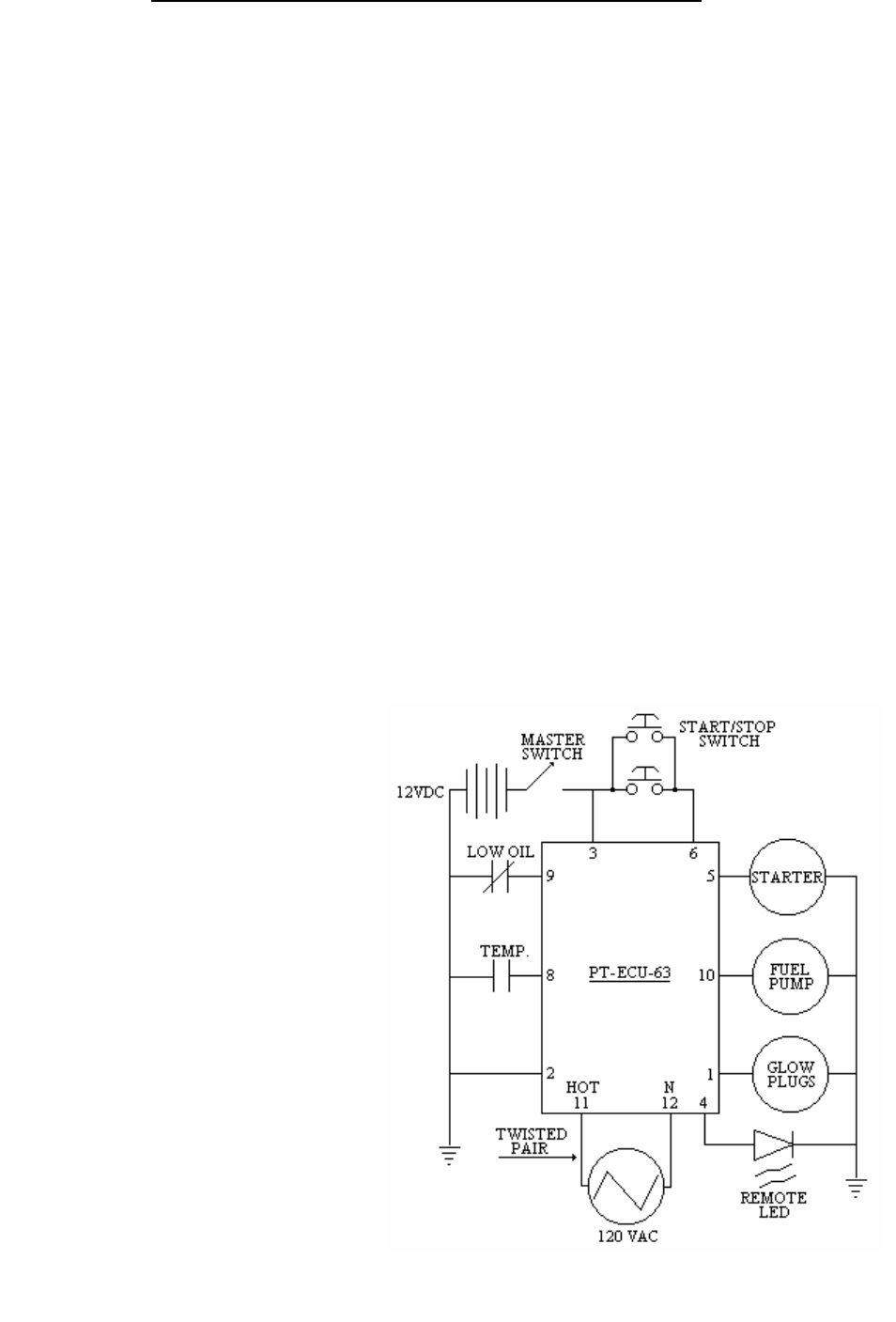
PT-ECU-63 ENGINE CONTROL MODULE
1) Generator Main Switch must be in the ON position.
2) Hold Start/Stop Switch for 1 second and release.
3) Glow Plugs will preheat for 8 seconds. LED flashes slowly.
4) Preheating will cease during engine cranking cycle. LED continues flashing.
5) Engine begins an 8 seconds crank cycle, After 4 seconds of cranking the PT-ECU-63 will check
for an AC signal from the generator. If AC signal is verified the engine will start and the LED
will remain ON during the normal run operation. If the AC signal is not verified the PT-ECU-63
will terminate the cranking cycle and LED will flash a fault code.
6) Starter disengages immediately after engine run is verified.
7) PT-ECU-63 deactivates the Low Oil Pressure and High Water Temperature Switches for 6
seconds, this will assure oil pressure build-up time. If oil pressure does not build-up the engine
will immediately shut down and go into a fault mode. Likewise for a high temperature situation.
8) If engine will not start on the first attempt the PT-ECU-63 will initiate the start cycle 2 more
times before going into a fault mode. Glow Plugs will preheat for 8 seconds per attempt. Engine
will crank for 8 seconds per attempt.
9) To shut down the engine under normal operations, hold the Start/Stop Switch for 1 second and
release.
10) If a fault occurs turn Generator Main Switch OFF and then ON to reset PT-ECU-63.
Fault Codes: LED Flashes
Failure to start 1
Engine High Water Temperature 2
Low Oil Pressure 3
No AC Signal 4
Low Coolant Level (Option) 5
NOTE: The PT-ECU-63 is designed
to operate on 12V DC power. In a low
battery situation the PT-ECU-63 may
not initiate the normal cranking cycle.
To start the generator you can press
and hold the Start/Stop Switch for
approximately 10 seconds or until the
engine starts. Once the engine starts
the PT-ECU-63 will resume normal
operations. If this situation reoccurs,
charge or replace the battery.
13
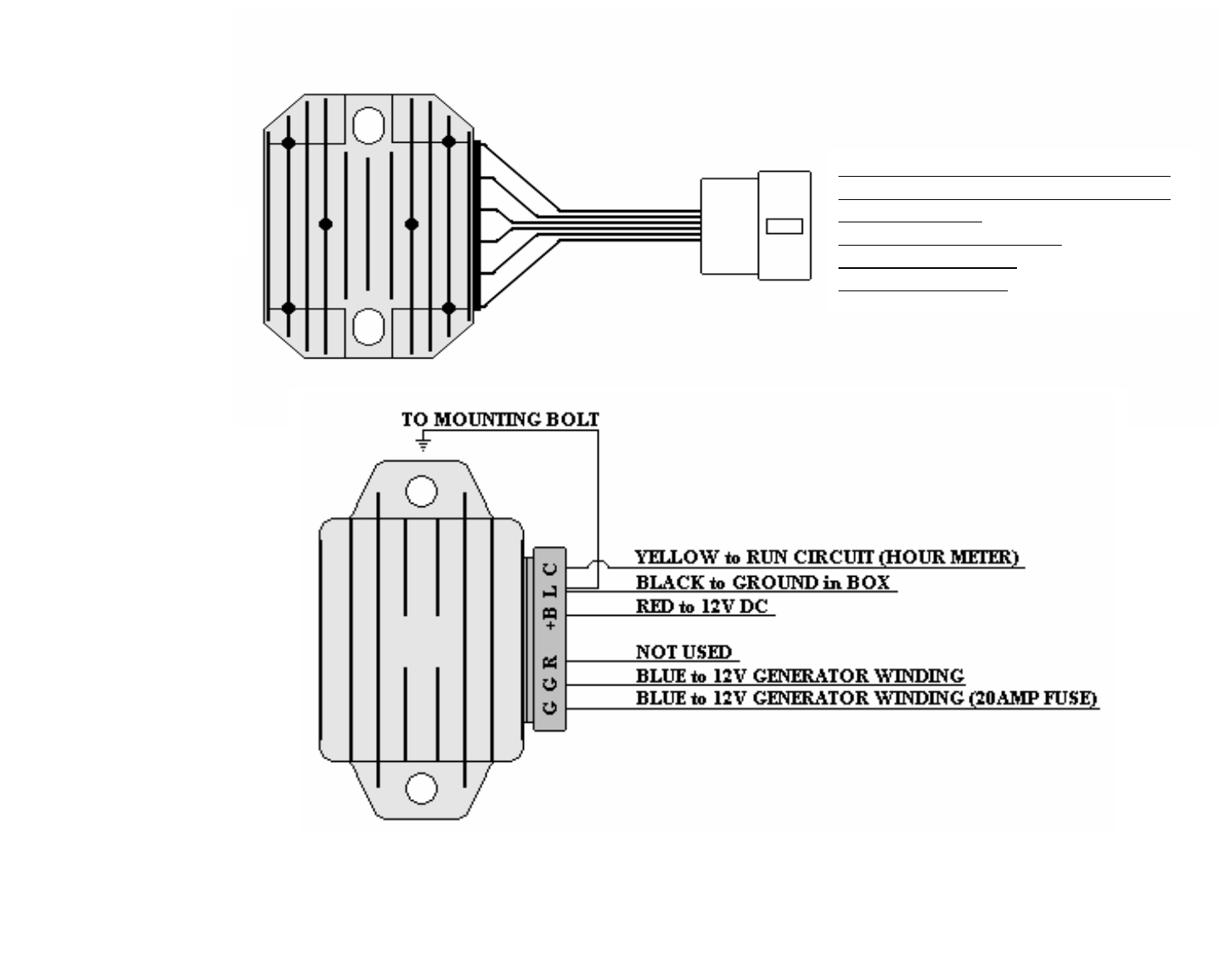
12 VOLT DC CHARGING
BLUE to 12V GENERATOR WINDING
BLUE to 12V GENERATOR WINDING
RED to +12V DC
YELLOW to RUN RELAY
BLACK to GROUND
GREEN NOT USED
06REG12DC
06REG12DCAT
14
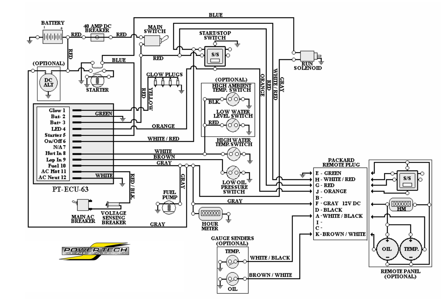
12V DC ENGINE CONTROL
PT-ECU-63
POWER TECHNOLOGY SOUTHEAST, INC.
634 STATE ROAD 44
LEESBURG, FL 34748-8103
(352) 365-2777 FAX (352) 787-5545
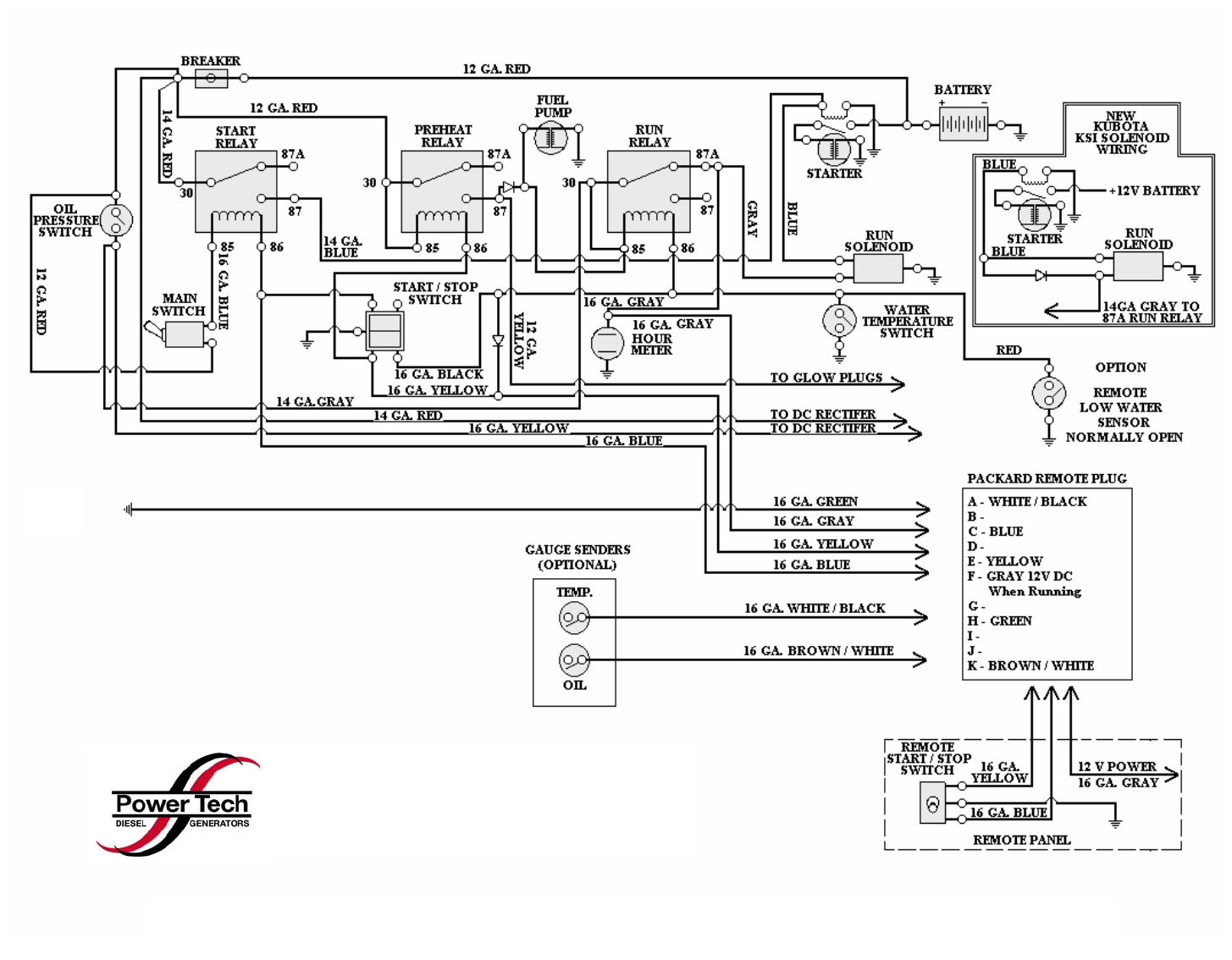
12 VOLT DC ENGINE CONTROL for CD-7 & CD-8
POWER TECHNOLOGY SOUTHEAST, INC.
634 STATE ROAD 44
LEESBURG, FL 34748-8103
(352) 365-2777 FAX (352) 787-5545

SECTION 5
“POWER CONTROL MODULE”
FEATURE SUMMARY _________________________________________________ 1
Internal Ambient Temperature Sensor
Oil Pressure Sensor / Switch Input
Coolant Sensor / Switch Input
Auxiliary (Generic) Shutdown Switch Input
DC Power Supply Voltage Measurement
AC Output Voltage Measurement
AC Output Current Measurement
AC Output Frequency Measurement
Warm Start
One-Touch Remote Start Trigger
Blink Code Fault Reporting
Event Recording
Load Profiling
AGS
Ignition Sensing
OPERATING BEHAVIOR _______________________________________________ 2
Starting
Stopping
Power Cycle/Reset
Idle State
Pre-Heat State
Cranking State
Running State
Fault State
AUTOMATIC GENERATOR START (AGS) ________________________________ 3
SAFETY MONITORING and SHUTDOWN
LED SEQUENCES
TROUBLESHOOTING GUIDES __________________________________________ 4-10
Engine Starts but Won’t Run
Engine Starts but Won’t Run (Continued)
Engine Will Not Start
Engine Runs Rough or Slow
Zero or Low Voltage
Voltage Test
Overload Condition
12 VOLT DC POWER CONTROL MODULE WIRING SCHEMATIC ___________ 11
Power Controller Module
(PCM)
And Display
(PCMD)

Feature Summary
The PowerTech PCM controls all of the start and run processes and characteristics of any PowerTech
generator. The features of the application are:
Internal Ambient Temperature Sensor
Provides an on-board temperature sensor.
Oil Pressure Sensor / Switch Input
Allows input from an external oil pressure sensor or switch. Will shut down the generator if
sufficient pressure is not detected after a start-up period.
Coolant Sensor / Switch Input
Allows input from an external coolant temperature sensor or switch. Will shut down the generator if
extreme temperature is detected.
Auxiliary (Generic) Shutdown Switch Input
Allows input from any external active low (ground) switch. An active state of this switch will shut
down the generator immediately.
DC Power Supply Voltage Measurement
Measures the voltage level of the DC power supply. The DC voltage is monitored for a minimum
and will shutdown the Generator if it falls below a threshold (configuration parameter). This is also reported
on the PCM.
AC Output Voltage Measurement
Measures the voltage level of the AC output. This information is monitored to detect limit
conditions. It also is reported on the PCM. Over and Under Voltage conditions are reported.
AC Output Current Measurement
Measures the current level of the AC output. The data is reported on the PCM and is used for
current, wattage, and load measurement.
AC Output Frequency Measurement
Measures the frequency level of the AC output. This info is monitored to detect a valid start as well
as limit conditions. It also is reported on the PCM. Over and Under Frequency conditions are reported.
Warm Start
Adjusts the Pre-Heat glow plug activation time according to the coolant temperature.
One-Touch Remote Start Trigger
In addition to control via PCM, the unit will respond to an active high digital input. The unit can be
configured to either start or stop in response to activation of a momentary switch or a toggle switch.
Blink Code Fault Reporting
Simple diagnostic data is available through blink codes on a dedicated active high output. The PCM
state as well as fault codes are displayed.
Event Recording
A portion of non-volatile memory is dedicated to recording diagnostic and other events. If a clock is
available on the network, the time and date of the event is included. Events include diagnostic messages,
starts, stops, and configuration changes. Total event capacity is roughly 2,000 events.
Load Profiling
The unit records the total amount of time the generator spends in each of several load intervals.
The information is recorded each time the generator stops, showing the usage profile for that specific cycle.
AGS
Automatic Generator Starting for low battery voltage. Programmable at the factory
voltage threshold and run time. Unit can sense genset battery voltage or any other battery voltage as
required. Enabled or disabled by an external switch.
Ignition Sensing
Will shutdown genset or prevents genset from starting if DC voltage is applied from any
external source. (Example: vehicle ignition, shore power sensor, or transfer switch, etc…)
1

Operating Behavior
Starting
The generator starts in response to the “START” button being depressed for 1 second. The PCM
goes into the Pre-Heat State, followed by the Cranking State, then finally, the Running State. The
PCM attempts to start the generator a specific number of times (configuration parameter) before
declaring a Fault. The shutdown inputs are checked before the start is attempted. If any of these
inputs are active, the start process is aborted.
See the following sections for more detailed information about each state.
Stopping
The generator stops in response to the “START” button being depressed for 1 second. All relays
are returned to their reset condition (OFF). Inputs to the PCM are not actively monitored, except
the Start/Stop Button. The LED is turned off. The PCM enters the Idle State.
Power Cycle/Reset
If the power to the PCM is cycled, it will immediately shut down all relay outputs, stopping the
generator. The unit will start with all fault and status flags reset. There may be a pause of
several seconds before all the configuration information is processed and the unit is ready to
accept input.
Idle State
The Idle State is the initial state of the PCM after a Power Cycle/Reset. The PCM returns to this
state after a Stop Command. The LED is not lit.
Pre-Heat State
The Pre-Heat State is necessary to energize the Glow Plugs for the Cranking State. The Fuel
Pump is active. The duration of this state is determined by using the coolant temperature
according to the formula:
< 23 ºF cranking time = 15 seconds
23 ºF – 50 ºF cranking time = 8 seconds
> 50 ºF cranking time = 5 seconds
The LED blinks.
Cranking State
The Cranking State attempts to start the generator combustion. The starter and fuel pump are
active. Successful sustaining combustion is determined by measuring the AC Line 1 output
frequency. The LED blinks.
Running State
After an initial “ignore” time (configuration parameter), inputs are monitored for out-of-bounds
limits and, if needed, a shutdown command is issued. The LED is lit.
Fault State
The Fault State is entered if an input reaches an out-of-bounds limit. The generator is
immediately stopped. A Power Cycle/Reset is required to exit the Fault state. The LED blinks the
Fault Code(s) (see next section).
2
Automatic Generator Start (AGS)
The Automatic Generator Start (AGS) allows the generator to start based upon the battery level.
The trigger voltage is configurable via a configuration parameter. The entire feature can be
enabled/disabled by a configuration parameter. The AGS feature is currently disabled, by default.
Safety Monitoring And Shutdown
The PCM monitors inputs for safety limitations which might damage the generator. If any input is
outside of the safe operating range, the generator is immediately shutdown and the PCM enters
the FAULT state. The PCM remains in the FAULT state until a power cycle or reset occurs. The
shutdown reason is displayed by blinking the LED.
The thresholds used in determining faults are set by configuration parameters.
These inputs are only monitored when the generator is in the RUNNING state. Before starting the
generator, the following inputs are checked to see whether a start should be attempted: High
Coolant Temperature, Auxiliary switch, Ignition Sense, DC Voltage and High Ambient
Temperatures.
These inputs are averaged over 0.6 seconds to help eliminate noise and settling issues. This
averaging helps to eliminate falsely signaled shutdowns.
Shutdown Reasons
Fault Reason Fault Code Description
Failure to Start 1 The generator was not able to start.
High Coolant
Temperature
2 The generator coolant temperature has reached a
high threshold.
Low Oil Pressure 3 The generator oil pressure has reached a critically
low pressure.
High Ambient (Air)
Temperature
4 The PCM measures an ambient air temperature
above a specific threshold.
NOTE: Temperature inside the Control Box.
AC Fault 5 A Fault with the AC was detected.
DC Fault 6 A Fault with the DC (Battery) was detected.
Auxiliary Input Active 7 The Auxiliary input is active.
Sensor Malfunction 8 One of the sensors has malfunctioned..
Ignition Sense 9 Ignition Sense is active.
The fault codes are displayed on the LED by blinking a number of times equal to the fault code,
then going dark for two seconds. Multiple fault codes are displayed in the order that they have
occurred. This cycle repeats until the fault is cleared by a power cycle, reset or via RV-C.
LED Sequences
The LED on the Start Button is used to communicate the state of the generator in addition to any
fault conditions. The PCM states are different from the Fault Codes in that the states are
displayed continuously (i.e. no two second pause).
PCM State
PCM State LED Notes
Idle State off
Pre-Heat Blink (25% duty cycle)
Cranking State Blink (50% duty cycle)
Running State on
Fault State <various> See “Shutdown Reasons”
Section
3
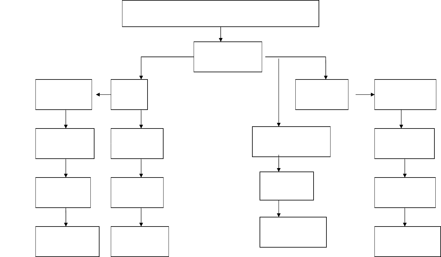
CODE 2 or 8
Replace Defective
Parts as Needed
Check Wiring
From Sensor to
Terminal 13 on PCM
If “OK”
Check Sensor
4
CODE 1 or 6
ENGINE TROUBLE SHOOTING
ENGINE STARTS BUT WON’T RUN
Check Flash Code
Indicator at
PCMD
Engine High
Water Temp.
Fill System
With 50/50 Mix
Check Coolant
Level/Condition
Check Radiator
Air Flow / Belts
Clean Core
Tighten / Replace
Belts
Failure
To Start
Check Fuel
Filter/Supply
Check Battery
Voltage
Check Circuit
To Actuator
If “OK” Check
Fuel System
If “OK” Replace
Actuator
Bleed Air
From System
Check Fuel
Pump / Circuit
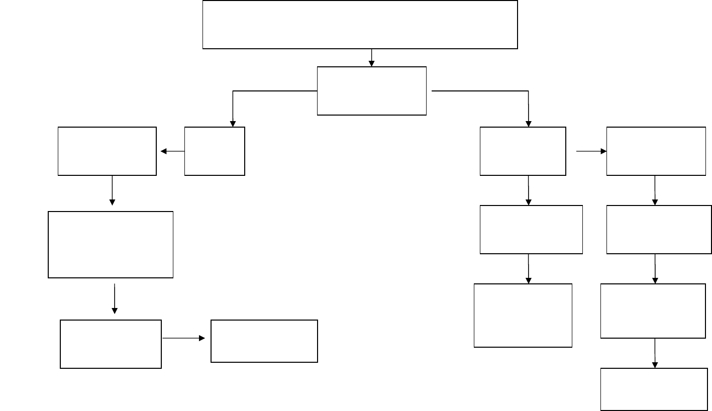
If “OK”
Check Wiring
From Sensor to
Terminal 12 on PCM
If “OK” Check
Oil Pres. Sensor
Replace Defective
Parts as Needed
CODE 5 CODE 3 or 8
ENGINE STARTS BUT WON’T RUN
CONTINUED
ENGINE TROUBLE SHOOTING
Check Flash Code
Indicator at
PCMD
No AC Signal
If “Tripped”
Check Generator
Check Main AC
And Voltage
at Breakers
Low Oil
Pressure
Check Oil
Level/Condition
Check Terminal
Connections at
2&3 on PCM
Check Generator
Wiring
Replace Defective
Parts as Needed
If AC Signal
Present Replace
PCM
5
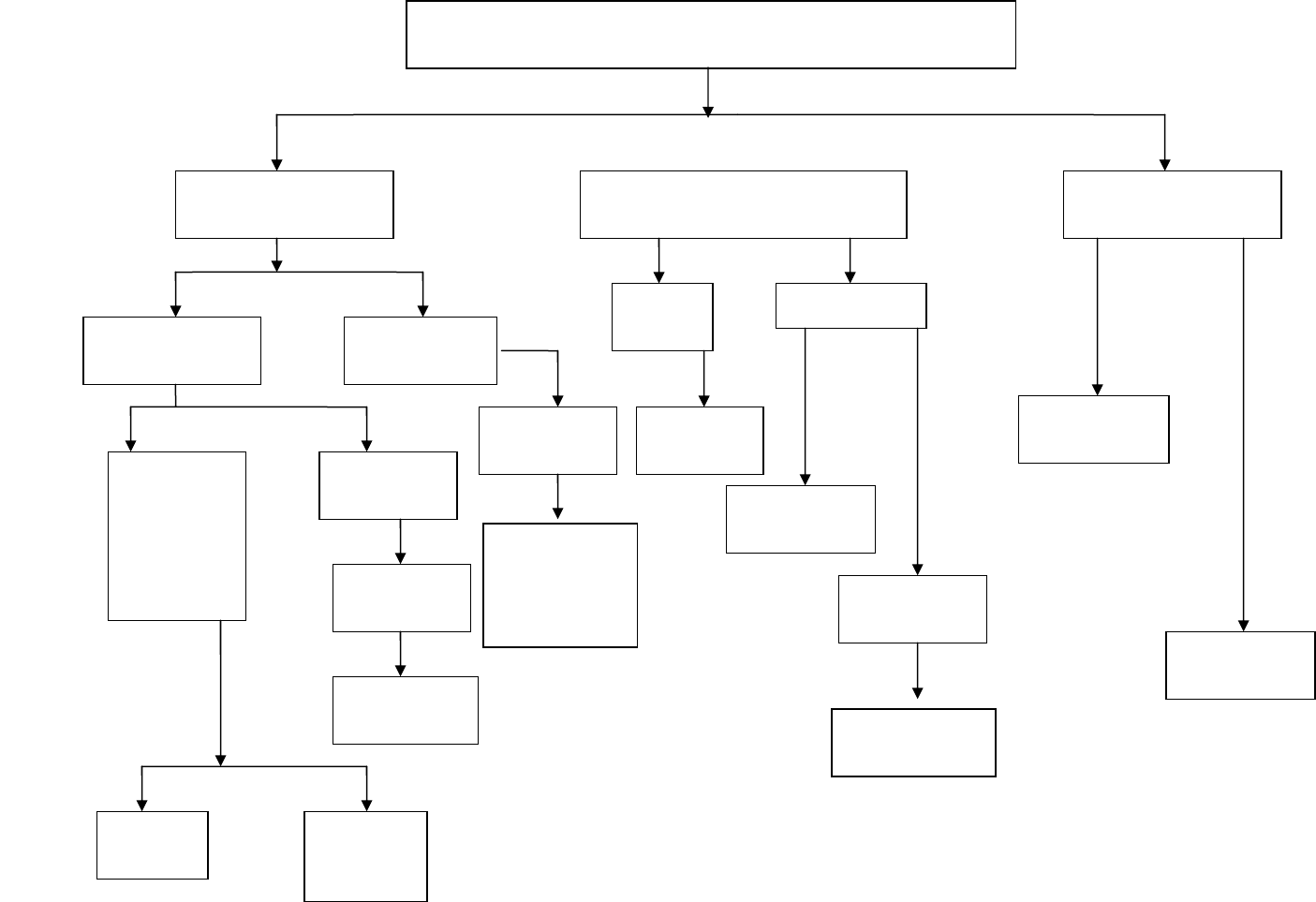
ENGINE WILL NOT START
ENGINE DOES NOT CRANK ENGINE CRANKS ENGINE CRANKS
SLOW
No Exhaust
Smoke
Smoke From
Exhaust
Check Fuel
Solenoid
NO Power
While
Cranking
Check Fuel
Supply
Check Fuel
Pump
Air in
Fuel System
Replace
Solenoid
YES NO
No Power
From
PCMD
Check
Glow Plugs
Check Spark
Arrestor
Muffler for
Clogging
Oil Viscosity
Too Heavy
Main Switch Battery
Dead
Check
Terminals
Turn Switch
On
Start Switch
Starter Motor
Low Battery
Voltage
6
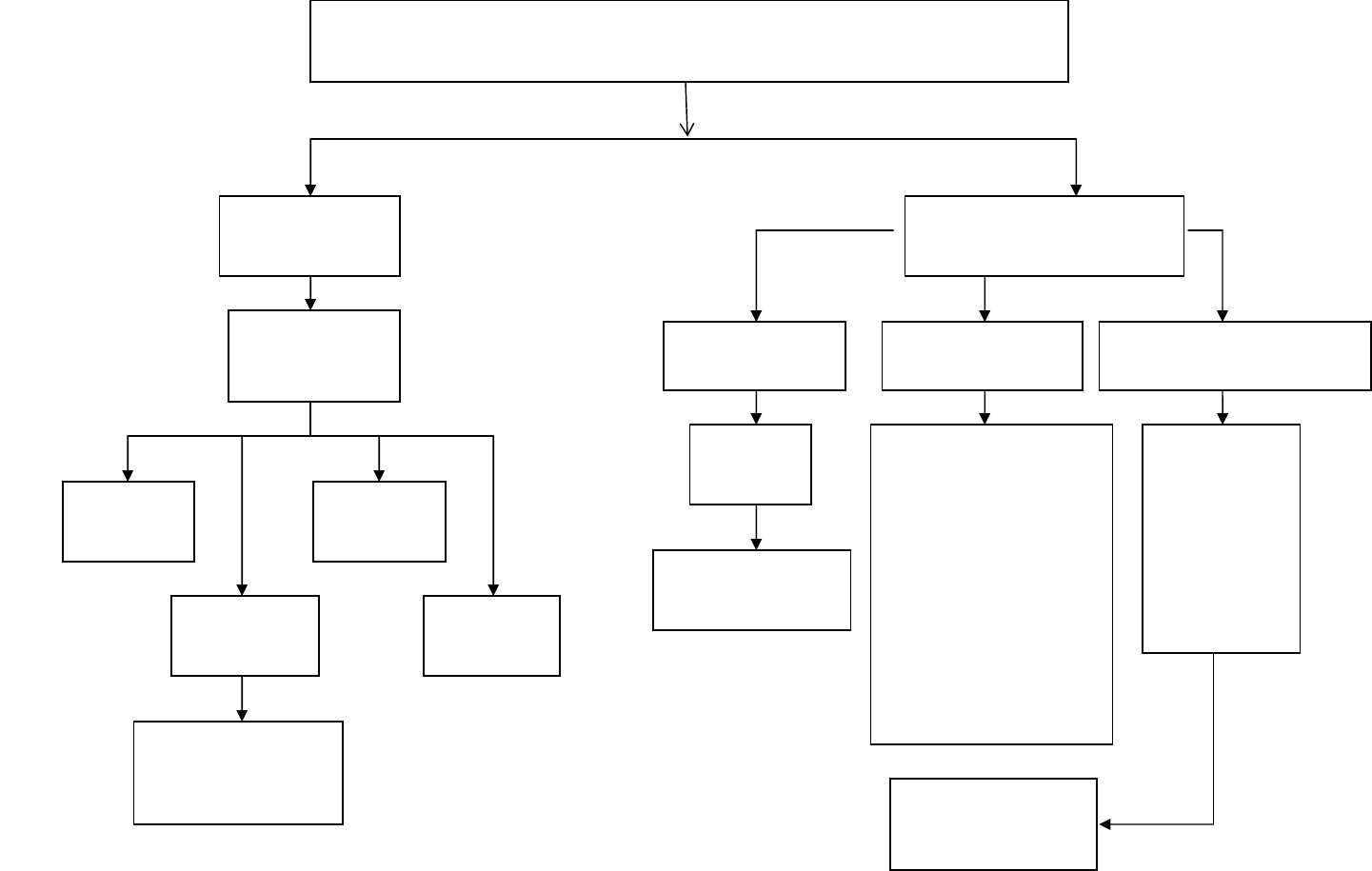
Engine Cold
Incomplete
Combustion
Over Fueling
Injector
Excessive
Oil Level
BLUE SMOKE
Replace
Fuel Filter
Check
Fuel Level
Air in
Fuel System
Check Safety
Shutdowns
And Fuel Solenoid
Insufficient
Fuel to Engine
No Visible
Exhaust Smoke
Check
Fuel Pump
7
ENGINE RUNS ROUGH OR SLOW
Excessive Exhaust Smoke
BLACK SMOKE
Dirty Air Filter
Engine Overheated
Engine Overloaded
Clogged Muffler
Over Fueling Injector
High Altitude
GREY/WHITE SMOKE
Glow Plug Circuit
Not Operating
Excessive
Oil Consumption
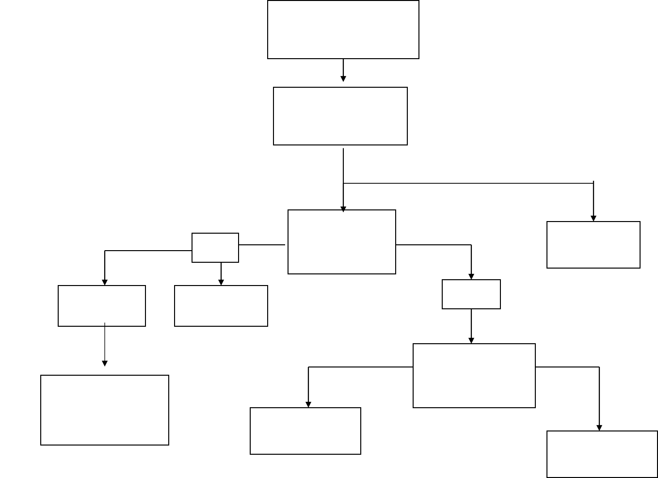
Check Main
Breakers are
“
ON
”
ON
8
Check Brushes
if
Applicable
ZERO or LOW
VOLTAGE
Main Coil
Output to
Breakers
Turn “ON”
Breaker / s
OK
BAD
Wiring To
Panel
Defective
Breaker / s
Check Ohm’s
On Main
Stator Leads
Replace
Stator Check Rotor
Ohm’s
OFF
OKBAD
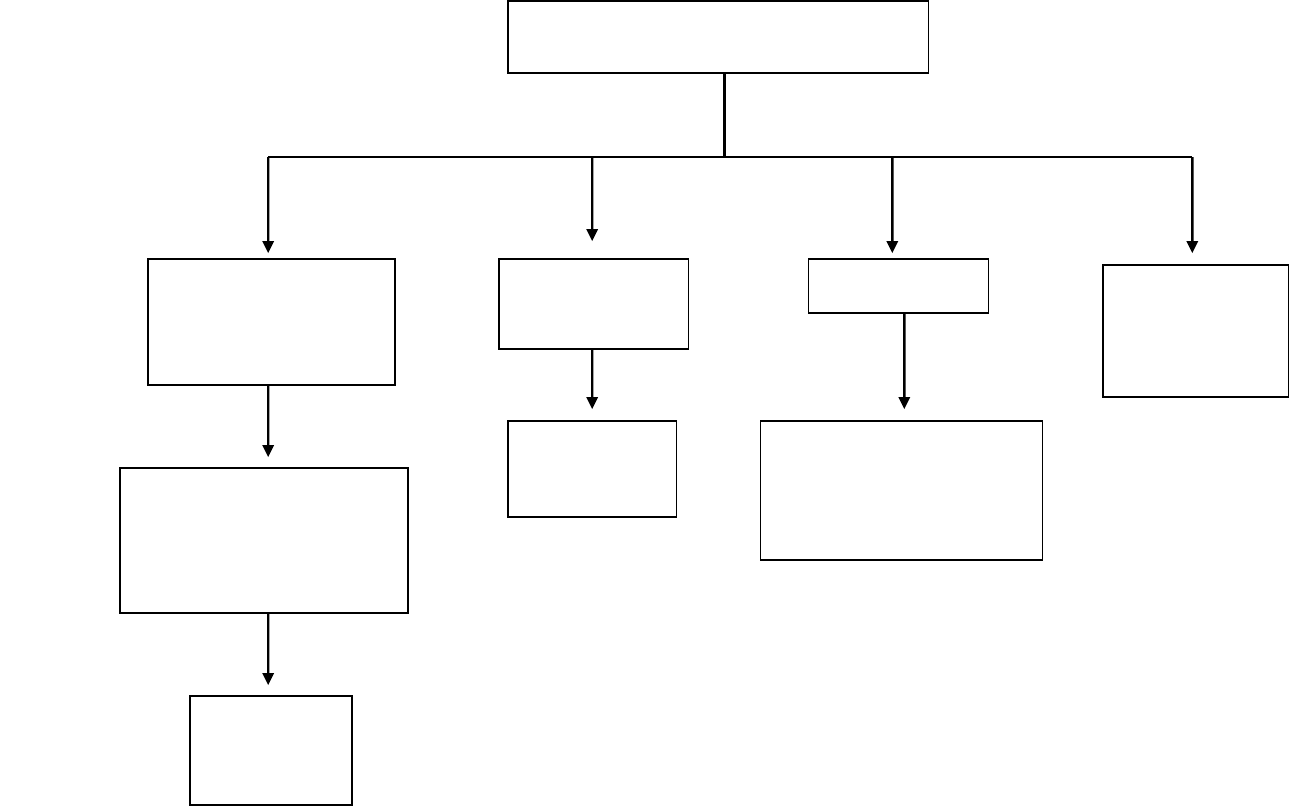
9
VOLTAGE TEST
Zero
or
Low Volta
g
e
High
Voltage
Overload Output
Voltage
OK
Check
Main Breaker / s
On Generator
Check
Regulator
Check AMP
Draw
From equipment
Check
Gen End
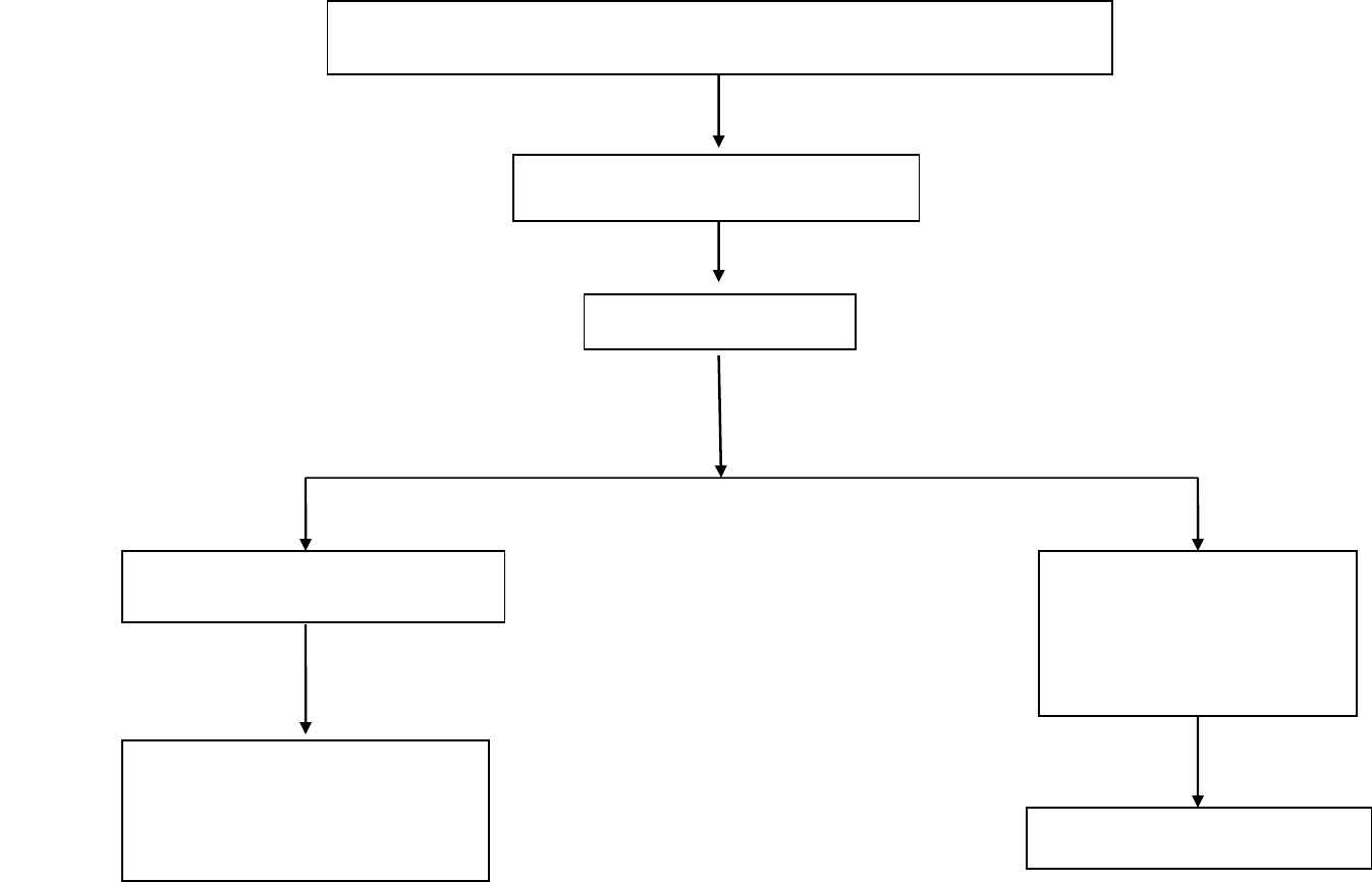
OVERLOAD CONDITION
Check AMP Draw
C
heck Load
10
Engine Problem
See Engine
Troubleshooting
Check
Stator Coil
Resistance
Re
p
lace Stator
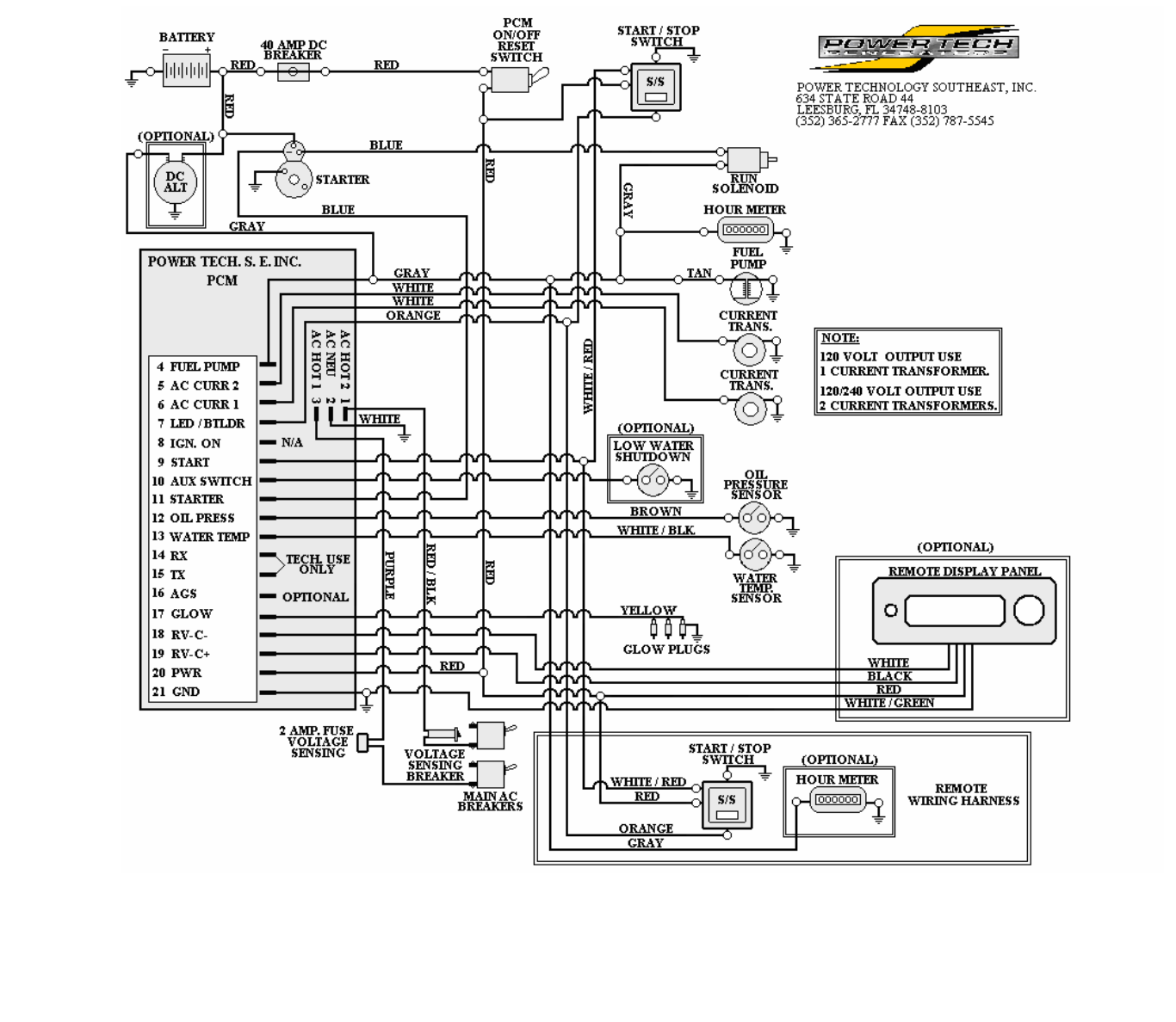
KUBOTA
12Volt DC POWER CONTROL MODULE
WIRING SCHEMATIC
11
