Advanced HVAC Systems For Improving The Indoor Environmental Quality And Energy Performance Of California K 12 Schools Capistrano Ceiling Fan CEC 500 2007 006
User Manual: Capistrano Indoor Ceiling Fan
Open the PDF directly: View PDF ![]() .
.
Page Count: 80
- 1.0 Introduction
- 1.1. Background and Overview
- 1.2. The Project Team
- 1.3. Report Organization
- 2.0 Thermal Displacement Ventilation in Schools (Project 2)
- 2.1. Introduction
- 2.2. Project Objectives
- 2.3. Project Approach
- 2.3.1. Coordination with ongoing related PIER natural ventilation and DV research (Task 2.1)
- 2.3.2. CFD analysis of thermal comfort and ventilation effectiveness (Task 2.2)
- 2.3.3. CFD validation with full-scale mockup (Task 2.3)
- 2.3.4. Barriers study (Task 2.4)
- 2.3.5. System design options (Task 2.5)
- 2.3.6. Construct demonstration classroom (Task 2.6)
- 2.3.7. Monitor performance of demonstration classrooms (Task 2.7)
- 2.3.8. Product development (Task 2.8)
- 2.3.9. Fact sheets and guidelines (Task 2.9)
- 2.3.10. Information dissemination (Task 2.10)
- 2.3.11. Technology transfer activities (Task 2.11)
- 2.3.12. Production readiness plan (Task 2.12)
- 2.4. Project Outcomes
- 2.5. Conclusions and Recommendations
- 3.0 Effectiveness of UVC Technology for Improving School Performance (Project 3)
- 4.0 Program Market Connection (Project 4)
- 5.0 References
- 6.0 Glossary
- 7.0 Appendices

Arnold Schwarzenegger
Governor
ADVANCED HVAC SYSTEMS FOR
IMPROVING THE INDOOR ENVIRONMENTAL
QUALITY AND ENERGY PERFORMANCE OF
CALIFORNIA K–12 SCHOOLS
PIER FINAL PROJECT REPORT
Prepared For:
California Energy Commission
Public Interest Energy Research Program
Prepared By:
Architectural Energy Corporation
January 2007
CEC-500-2007-006
Prepared By:
Donald Frey, Principal in Charge
Vernon Smith, Program Director
Boulder, Colorado
Contract No. 500-03-003
Prepared For:
California Energy Commission
Public Interest Energy Research (PIER) Program
Brad Meister
Contract Manager
Ann Peterson
PIER Buildings End-Use Energy Efficiency Team
Leader
Nancy Jenkins
PIER Energy Efficiency Research Office Manager
Martha Krebs, Ph.D.
Deputy Director
ENERGY RESEARCH AND DEVELOPMENT
DIVISION
B. B. Blevins
Executive Director
DISCLAIMER
This report was prepared as the result of work sponsored by the
California Energy Commission. It does not necessarily represent
the views of the Energy Commission, its employees or the State
of California. The Energy Commission, the State of California, its
employees, contractors and subcontractors make no warrant,
express or implied, and assume no legal liability for the
information in this report; nor does any party represent that the
uses of this information will not infringe upon privately owned
rights. This report has not been approved or disapproved by the
California Energy Commission nor has the California Energy
Commission passed upon the accuracy or adequacy of the
information in this report.

Acknowledgments
The products and outcomes presented in this report are a result of funding provided by the
California Energy Commission’s Public Interest Energy Research (PIER) Program on behalf of
the citizens of California. Architectural Energy Corporation (AEC) would like to acknowledge
the support and contributions of the following individuals and organizations in the successful
completion of this research program.
Program and Contract Management: Brad Meister and Ann Peterson, California Energy
Commission; Donald Frey and Vernon Smith, AEC.
Project Team: Charles Eley and John Arent, AEC; Morton Blatt, Energy Utilization Consultant;
Roger Wright and Stacia Okura, RLW Analytics, Inc.
Project Partners: Andrey Livchak, Halton Company; John Murphy and Gary Leupke, Trane
Company; Richard Lord, Carrier Corporation; Alan Colombo and Ron Warfield, Dry Creek
Joint Elementary School District (Coyote Ridge); Tom Rayburn and Joe Dixon, Capistrano
Unified School District (Kinoshita); Thomas Duval, Capital Engineering Consultants, Inc.; Chip
Fox, Ed Becker, and Abdullah Ahmed, San Diego Gas & Electric Company.
Program Advisory Committee (PAC): Gregg Ander, Southern California Edison; Michael Apte,
Lawrence Berkeley National Laboratory; Dave Bisbee, Sacramento Municipal Utility District;
Bill Boyce, SMUD; Richard Conrad, California Department of General Services; Joe Dixon,
Capistrano Unified School District; Rod Dow, Gordon Chong & Partners; Ken Gillespie, Pacific
Gas and Electric Company; Deborah Gold, Cal/OSHA; Randall Higa, Southern California Gas
Company; Peggy Jenkins, Air Resources Board; Terry Logee, U. S. Department of Energy; Andy
McPherson, Nacht & Lewis Architects; Ken Mozek, York International; Lowell Shields, Capital
Engineering Consultants, Inc.; Bob Thompson, U. S. EPA Headquarters; Dean Tompkins,
University of Wisconsin; Jed Waldman, California Department of Health Services; and John
Zinner, Zinner Consultants.
Additional Support: Tianzhen Hong, Jerry Moechnig, David Goldman, Camren Cordell, and
Judie Porter, AEC; Erik Ring, Tom Lunneberg, and Steven Long, CTG Energetics; market
researchers from SDV-ACCI.
Special Acknowledgements: Matching fund support from San Diego Gas and Electric Company
is appreciated and enhanced the results of the Thermal Displacement Ventilation project. The
support of school district personnel from Coyote Ridge and Kinoshita Elementary Schools is
greatly appreciated for the displacement ventilation project.
Match funding support from San Diego Gas and Electric Company and Sacramento Municipal
Utility District contributed greatly the Ultraviolet Light for Coil and Drain Pan Disinfection
project. The donation of equipment and installation services and support by the two
manufacturers for the ultraviolet light in the “C” band (UVC) study are appreciated. The
cooperation and support provided by school district personnel involved in the UVC study
contributed greatly.
i
Finally, the Indoor Environmental Quality Program team would like to thank the ratepayers of
California for the continued support of the PIER Program.
Please cite this report as follows:
Frey, Donald and Vernon Smith. 2006. Advanced HVAC Systems For Improving the Indoor
Environmental Quality and Energy Performance Of California K–12 Schools. Architectural Energy
Corporation for the California Energy Commission, PIER Building End-Use Energy Efficiency
Program. CEC-500-2007-006.
ii

Preface
The Public Interest Energy Research (PIER) Program supports public interest energy research
and development that will help improve the quality of life in California by bringing
environmentally safe, affordable, and reliable energy services and products to the marketplace.
The PIER Program, managed by the California Energy Commission (Energy Commission),
conducts public interest research, development, and demonstration (RD&D) projects to benefit
the electricity and natural gas ratepayers in California.
The PIER program strives to conduct the most promising public interest energy research by
partnering with RD&D entities, including individuals, businesses, utilities, and public or
private research institutions.
PIER funding efforts are focused on the following RD&D program areas:
Buildings End-Use Energy Efficiency •
•
•
•
•
•
•
Energy-Related Environmental Research
Energy Systems Integration
Environmentally Preferred Advanced Generation
Industrial/Agricultural/Water End-Use Energy Efficiency
Renewable Energy Technologies
Transportation
Advanced HVAC Systems For Improving the Indoor Environmental Quality and Energy Performance
Of California K–12 Schools is the final report for the Indoor Environmental Quality K–12 project,
(contract number 500-03-303), conducted by Architectural Energy Corporation. The information
from this project contributes to PIER’s Building End-Use Energy Efficiency program.
For more information about the PIER Program, please visit the Energy Commission’s website at
www.energy.ca.gov/pier/ or contact the Energy Commission at (916) 654-5164.
iii
iv
Table of Contents
Preface................................................................................................................................................ iii
Abstract ............................................................................................................................................... ix
Executive Summary........................................................................................................................... 1
1.0 Introduction.......................................................................................................................... 7
1.1. Background and Overview........................................................................................... 7
1.2. The Project Team............................................................................................................ 7
1.3. Report Organization ...................................................................................................... 8
2.0 Thermal Displacement Ventilation in Schools (Project 2) ............................................. 9
2.1. Introduction ....................................................................................................................9
2.2. Project Objectives ........................................................................................................... 9
2.3. Project Approach............................................................................................................ 10
2.3.1. Coordination with ongoing related PIER natural ventilation and DV research
(Task 2.1) .................................................................................................................... 10
2.3.2. CFD analysis of thermal comfort and ventilation effectiveness (Task 2.2)....... 10
2.3.3. CFD validation with full-scale mockup (Task 2.3)............................................... 12
2.3.4. Barriers study (Task 2.4) .......................................................................................... 12
2.3.5. System design options (Task 2.5)............................................................................ 13
2.3.6. Construct demonstration classroom (Task 2.6) .................................................... 14
2.3.7. Monitor performance of demonstration classrooms (Task 2.7).......................... 15
2.3.8. Product development (Task 2.8)............................................................................. 16
2.3.9. Fact sheets and guidelines (Task 2.9) ..................................................................... 17
2.3.10. Information dissemination (Task 2.10) .................................................................. 17
2.3.11. Technology transfer activities (Task 2.11) ............................................................. 18
2.3.12. Production readiness plan (Task 2.12) ................................................................... 18
2.4. Project Outcomes............................................................................................................ 18
2.5. Conclusions and Recommendations ........................................................................... 25
2.5.1. Conclusions................................................................................................................ 25
2.5.2. Commercialization potential................................................................................... 26
2.5.3. Recommendations..................................................................................................... 27
2.5.4. Benefits to California ................................................................................................ 29
3.0 Effectiveness of UVC Technology for Improving School Performance (Project 3).... 31
3.1. Introduction ....................................................................................................................31
3.2. Project Objectives ........................................................................................................... 32
3.3. Project Approach............................................................................................................ 32
v
3.4. Primary Data Collection................................................................................................ 36
3.4.1. Manufacturer Interviews and Literature Review................................................. 36
3.4.2. Microbial data............................................................................................................ 37
3.4.3. Engineering data ....................................................................................................... 37
3.4.4. Teacher and Classroom Surveys............................................................................. 37
3.4.5. Attendance Data........................................................................................................ 37
3.5. Project Outcomes............................................................................................................ 37
3.6. Conclusions and Recommendations ........................................................................... 40
3.6.1. Conclusions................................................................................................................ 40
3.6.2. Commercialization Potential................................................................................... 41
3.6.3. Recommendations..................................................................................................... 42
3.6.4. Benefits to California ................................................................................................ 47
4.0 Program Market Connection (Project 4)........................................................................... 49
4.1. Introduction ....................................................................................................................49
4.2. Project Objectives ........................................................................................................... 49
4.3. Project Approach............................................................................................................ 49
4.3.1. Project Administration ............................................................................................. 50
4.3.2. Program-Wide Market Connection System .......................................................... 50
4.3.3. Program Technology Transfer Plan........................................................................ 50
4.3.4. Indoor Air Quality Codes Assessments................................................................. 50
4.4. Project Outcomes............................................................................................................ 50
4.5. Conclusions and Recommendations ........................................................................... 55
4.5.1. Conclusions................................................................................................................ 55
4.5.2. Commercialization Potential................................................................................... 57
4.5.3. Recommendations..................................................................................................... 57
4.5.4. Benefits to California ................................................................................................ 58
5.0 References............................................................................................................................. 59
6.0 Glossary ................................................................................................................................ 61
7.0 Appendices........................................................................................................................... 65
vi
List of Figures
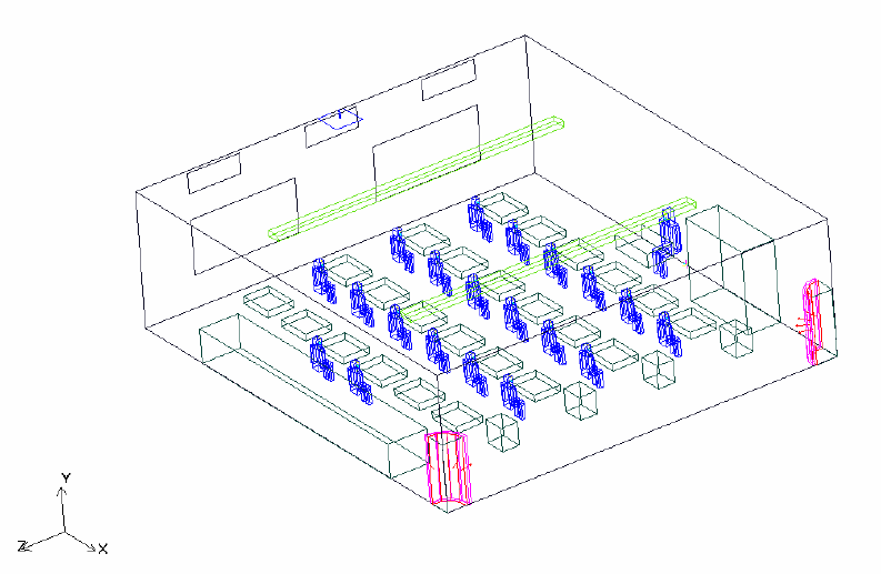
.....................................................................................11 Figure 1. 3-D layout of CFD classroom model
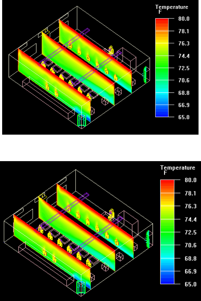
............................................................................20 Figure 2. CFD modeling – base case – vertical slice
...........................................................20 Figure 3. CFD modeling – DV case 9 ft ceiling – vertical slice
Figure 4. The CO2 concentration in the occupied zone of the DV classroom is consistently lower
than the concentration at the return, a sign of good ventilation effectiveness........................ 24
Figure 5. Relative humidity, September 15, 2005. While the RH in the DV classroom is slightly
higher than the RH in control classroom, it remains within acceptable limits. ......................24
......................................................................................32 Figure 6. Example UVC disinfection systems
Figure 7. Example of a rooftop air conditioning unit in UVC study (top), schematic of a typical
unit (middle), and example of a wall-mounted air conditioning unit in UVC study (bottom)
............................................................................................................................................................35
List of Tables
..............................................................................13 Table 1. DV interviews: participant stratifications
.........................................................23 Table 2. HVAC electricity comparison, Kinoshita Elementary
................................................................................................................33 Table 3. UVC systems studied
..................................56 Table 4. Information/actions needed to overcome selected market barriers
..............................................................................................................65 Table 5. Summary attachments
vii
viii
Abstract
The three projects described in this report were designed to evaluate advanced equipment for
cooling, heating, and ventilating California’s K–12 schools that improve indoor air quality, save
energy, reduce peak demand, and reduce pollution. The program investigated the ability of
thermal displacement ventilation technology to increase economizer use, improve ventilation
effectiveness, reduce fan energy use, enhance pollutant removal, and reduce noise. The study
also examined the potential of ultraviolet light in the “C” spectrum to improve coil cleanliness,
enhance equipment service life, remove microorganisms, and reduce odor. In addition, the
program conducted market connection activities to improve the market focus of the
technologies and thereby increase the public benefits.
The results this program indicated that displacement ventilation can enable 10 to 40 percent
energy savings in California K–12 schools, depending on climate. The primary data for the
ultraviolet project showed substantial surface disinfection, but no statistically significant
reduction in heating, ventilation, and air conditioning coil energy use or absentee rates. Market
connection efforts were successfully conducted by developing access to existing information
dissemination channels through e-mail efforts, telephone conversations, articles and
publications, and presentations and meetings with influential market participants and
organizations.
Keywords: Displacement ventilation, DV, heating, ventilation, and air conditioning, ultraviolet
light, UVC, K–12 schools, energy savings, indoor environmental quality, IEQ
ix
x

Executive Summary
Introduction
Schools use more than 3 percent of California’s electricity each year, and
27 percent of that electricity powers heating, cooling, and ventilation. The
way that schools are ventilated and the quantity of the ventilation used
directly affects the quality of the school environment, which has
implications for student health and overall learning performance. This
program addresses three of the four indoor environmental quality (IEQ)
target areas identified by the California Energy Commission (Energy Commission).
Purpose
The goal of the Advanced HVAC Systems For Improving Indoor Environmental Quality and Energy
Performance Of California K–12 Schools Program (IEQ–K12) was to develop and demonstrate
advanced heating, ventilation, and air conditioning (HVAC) equipment for school classrooms.
Such equipment would improve indoor environmental quality, save energy, reduce peak
demand, and, ultimately, reduce pollution for the citizens of California.
Meeting this goal yields the following benefits:
The next generation of California K–12 classrooms will be more comfortable, energy
efficient, and healthier because of the improvements mandated by Proposition 47 (State
of California 2002) and local bond funding.
•
•
•
•
•
•
•
Teachers will have more control over the IEQ and thermal comfort of their classrooms.
Students and teachers will be sick less often and more comfortable, and thus perform
better.
School districts will spend less money on energy and so are able to spend proportionally
more on books, computers and other equipment, and teachers’ salaries.
The IEQ–K12 Projects
The IEQ–K12 program, headed by Donald Frey and Vernon Smith of Architectural Energy
Corporation (AEC), included the following projects:
Thermal Displacement Ventilation (DV) in Schools (Project 2), led by Charles Eley and
John Arent of AEC
Effectiveness of UVC [ultraviolet light in the “C” band, 200-280 nanometers] Technology
for Improving School Performance (Project 3), led by Roger Wright and Stacia Okura of
RLW Analytics, Inc.
Program Market Connection (Project 4), led by Morton Blatt of Morton H. Blatt, Energy
Utilization Consultancy
Each of these three projects had different objectives, approaches and results. These elements are
summarized by project below.
1

Thermal Displacement Ventilation in Schools (Project 2)
Poor environments in schools adversely affect the health, performance, and attendance of
students. Many existing school air conditioning systems using conventional mixed ventilation
systems fail to provide the indoor air quality, appropriate acoustic environment, and comfort
level that produces optimal student and teacher performance. DV is a cost-effective means of
providing an optimal environment by delivering a cool air supply directly to the occupants of
the space. The air is enters the room at about 65°F (18.3°C)—approximately 10 degrees warmer
than with a conventional air conditioning system. The fresh air, supplied near the floor at a very
low velocity, falls towards the floor and spreads across the room until it encounters heat
sources. Then this air slowly rises as it picks up heat from occupants and equipment. The
warmed air also picks up contaminants as it rises towards the ceiling, where it is exhausted
from the space. This vertical airflow pattern near each occupant, often referred to as a thermal
plume, decreases the likelihood that germs will spread between occupants. This air distribution
system provides for effective ventilation, since the fresh supply air is delivered directly to each
occupant. All this can be provided at an initial cost comparable to that of many less effective
conventional mixed-ventilation systems that rely on creating fully mixed air in the room.
The overall goal of this project was to gain wide acceptance of DV in both newly constructed
and renovated K–12 schools.
DV Project Outcomes
Key information products developed for this project are listed in the Attachments section of this
report and may be found at
www.archenergy.com/ieq-k12/thermal_displacement/thermal_displace.htm.
Specifically, the following outcomes were achieved:
Coordination with related Public Interest Energy Research (PIER) natural ventilation
and DV research yielded new information and showed that computational fluid
dynamics (CFD) simulation and testing can validate existing or mandate new DV design
guidelines for best thermal comfort and air quality. The CFD analyses of different DV
classroom configurations showed specific conclusions:
•
•
o Nine foot (ft) ceilings are sufficient if not optimal.
o Two diffusers providing 65°F supply air are sufficient.
o Double-pane windows substantially diminished the need for perimeter heat.
o Lights contribute less heat than equipment or occupants.
o Comfort levels vary with proximity to diffusers.
o DV lowers CO2 levels and “age” of air in a space.
The Barriers Study identified cost and the lack of demonstration classrooms as key
hurdles to acceptance. Even though most respondents identified the energy and indoor
air quality (IAQ) benefits, most erroneously thought DV had a higher initial cost than
conventional systems.
2
Three DV system design options for California K–12 classrooms were evaluated for cost-
effectiveness and performance. Single-classroom rooftop units won as the most probable
near-term solution for widespread implementation.
•
•
•
•
•
•
•
•
•
•
•
•
•
•
•
Two demonstration DV systems were installed, commissioned, and monitored in two
classrooms. Results of the DV demonstration showed that DV can provide up to 20
percent energy savings and improve IAQ and acoustic comfort while providing
acceptable humidity levels.
Technical documents and marketing collateral were developed presenting the results of
this project and technology transfer activities were conducted. Papers and articles on DV
design have been presented or published in professional venues throughout the DV
development period from 2002 to present.
Conclusions and Recommendations
Project 2 resulted in the following conclusions:
DV provides good thermal comfort for classrooms with normal ceiling heights (9 ft).
A supply of 1100 cubic feet per minute (cfm) of 65°F air is sufficient for most classrooms
in California climates.
The use of a tuned variable air volume (VAV) control strategy will optimize energy
savings.
DV can be achieved today using a variety of HVAC system designs.
DV provides many compelling benefits, including energy savings.
Recommendations from Project 2 include the following:
Adopt load calculation procedures for Title 24 Standards.
Offset cost premiums with incentives for high performance designs.
Increase education and numbers of demonstrations for wider acceptance and
implementation of DV in California schools.
Make DV technology available as off-the-shelf equipment.
Improve design options for heating with displacement diffusers to further increase
efficiency.
Initiate additional design research into potential DV use in other space types such as
libraries, gymnasiums, and auditoriums.
Continue IAQ research, such as in particle motion studies.
Effectiveness of UVC Technology for Improving School
Performance (Project 3)
This project attempted to quantify the impact of ultraviolet
irradiation in the “C” band (UVC) of evaporator coils for
disinfection and IEQ of California K–12 schools. UV is a line-
of-sight technology; when produced by a lamp it can only
provide effective disinfection on components with exposure
to direct or reflected ultraviolet radiation.
3

The goal of the study was to determine if UVC is effective in reducing mold and mildew in
HVAC systems, improving IEQ, and saving energy.
This study was originally funded as a purely analytical study that would quantify the benefits
of the UVC disinfection systems using existing data. A recommendation endorsed by the Project
Advisory Committee (PAC) and the Energy Commission changed the direction of the project
from an analytical model to a field study.
Outcomes
Key information products developed for this project are listed in the Attachments section of this
report and may be found at
www.archenergy.com/ieq-k12/uvc_technology/uvc_technology.htm.
Specifically, the following outcomes were noted:
Microbial analysis showed the reduction of growth on the evaporator coils, as expected.
Total fungal and bacterial colonies were reduced by 65–100 percent with the use of UVC.
•
•
•
•
•
•
•
•
•
•
•
Airflow and efficiency analyses showed a positive trend. More tests are needed to
ascertain statistical significance.
Attendance data analysis was inconclusive. More attendance data collection is needed
along with a larger sample size of UVC field tests.
Teacher and classroom surveys indicated positive feedback on some issues of health and
attendance. More research, larger sample populations, and longer test periods are
needed to draw more scientifically valid conclusions.
Some of the HVAC housings created challenges for proper installation. The success of
the technology is also dependent on the quality of the installation, which can also
depend upon the available unit configuration.
Additional adverse environmental factors were determined, including standing water,
dirty rooftops, toxic substances in the classroom, and dirty floors.
Conclusions and Recommendations
The research team could not conclusively determine if there were statistically valid
improvements in some areas. These include air flow and efficiency of the air
conditioning units with UVC disinfection systems.
UVC technology effectively reduced surface microbial levels on cooling coils. This
finding is not in question.
The potential impact of this technology on IEQ in California schools is in question. It will
be proportional to the pervasiveness of microbial growth on cooling coils and the
relationship between surface microbial growth and IEQ.
The success of the technology is dependent upon the quality of the installation. Review
and inspection of installation will help assure quality.
The primary recommendation is to increase sample sizes and allow for repetition of
sampling within the study. The limitations can be overcome with additional funding to
allow a research team to develop a comprehensive study methodology.
4

Both laboratory and field work are required to adequately answer research questions. A
discussion of questions and opportunities is provided in the main body of this report.
•
•
•
Labeling and testing procedures must be standardized. Currently, each manufacturer
uses only its own discretion on printed information in marketing material.
Existing measures and processes could predictably contribute to improved HVAC
system performance and IEQ. The main factors that can contribute to improved IEQ are
good ventilation and filtration, which also depend upon proper inspection and
maintenance.
Market Connection (Project 4)
The Market Connection Project was concerned with disseminating the results of the two
previously defined technology projects, DV and UVC, each designed to improve energy use
and indoor air quality in K–12 schools in California. The goal of this project was to improve the
market focus of the entire program’s activities, thereby increasing the ultimate viability and
public benefit of the resulting technology products. The information products are designed to
overcome market barriers, influence market participants, and produce desired market effects.
Outcomes
Key information products developed for the Market Connection project are listed in the
Attachments section of this report and may be found at
www.archenergy.com/ieq-k12/market_connection/market_connection_reports.htm.
Specifically, the project achieved the following outcomes:
Input was gained from influential market participants and the PAC. This helps ensure
that the needs of these influential market participants are met through their involvement
and that their feedback is utilized.
•
•
•
•
•
•
•
A Technology Transfer Plan was prepared and expert guidance provided. Market
barriers at all levels of implementation from finance to infrastructure can thus be more
easily overcome.
Key organizations have been identified. Useful organizations were identified and
tabulated according to their missions, publications, and meetings.
Fact sheets addressing issues of both DV and UVC were developed. The fact sheets were
distributed at various presentations and conferences.
Journal articles have been and continue to be published. Information on these articles for
Engineering Systems is provided in the Project 4 section of this report.
Presentations, forums, and training sessions were conducted. Among these are venues at
American Society of Heating, Ventilating, and Air Conditioning Engineers (ASHRAE)
meetings 2004–2006; the annual CASH conference; and the American Council for an
Energy Efficient Economy (ACEEE).
Guidelines for the Collaborative for High Performance Schools (CHPS) Best Practices
Manual were developed and training material was created. Training material for both
DV and UVC technologies was utilized.
5
Educational Specifications (EdSpecs) were produced. Model EdSpecs for siting and
construction were prepared; reference information is provided under Project 4 and in
the Attachments section of this report.
•
•
•
•
•
•
•
•
•
Application guidelines were developed. Separate guidelines for DV and UVC were
provided to meet school and equipment provider needs.
Key meetings were conducted and numerous communication activities occurred. These
included information exchanges with Carrier and Commissions Codes and Standards
personnel.
Code Action Plans and White Papers were developed and outreach efforts begun. The
focus was on identifying and assessing issues, influences, and needs that affect
implementation of DV and UVC technology in the schools.
Conclusions and Recommendations
Key market barriers for the DV and UVC technologies must be addressed.
Continued action is needed to address codes and standard issues that impede the
specification and installation of DV and UVC.
Results are encouraging but inconclusive. Additional testing is recommended.
Extending market connection activities for future PIER programs beyond the study
period for these technical projects should be considered.
Statewide energy impacts should be revisited after data from field tests is analyzed.
Benefits to California
Project 1: Administration
Project 1 comprised all and only administrative tasks, is not detailed in this final report, and has
no associated energy impacts.
Project 2: Thermal DV in Schools
The results of this project indicate that DV technology may reduce classroom cooling energy use
from 10 to 40 percent depending upon the climate. Non-energy benefits include improved
ventilation effectiveness and acoustics, which are both compelling findings.
Project 3: Effectiveness of UVC Technology for Improving School Performance
Statewide energy impacts from this technology could not be calculated due to small sample size
and inconclusive results. The UVC impact on system airflow, though not statistically significant
for this study, produced a positive trend, 1 to 2 percent improvement. The study also concluded
that the UVC technology is effective in reducing microbial growth on air conditioning cooling
coils, a non-energy benefit.
Project 4: Program Market Connection
Statewide energy impacts are not directly applicable to the market connection activities under
the PIER Indoor Air Quality (IEQ) program.
6
1.0 Introduction
1.1. Background and Overview
The goal of the Advanced HVAC Systems for Improving Indoor Environmental Quality and Energy
Performance of California K–12 Schools Program (IEQ-K12) was to evaluate advanced equipment
for heating ventilating, and cooling school classrooms, with an emphasis on the latter two. This
equipment improves indoor environmental quality, saves energy, reduces peak demand, and,
ultimately, reduces pollution for the citizens of California. Schools use more than 3% of
California’s electricity each year, and 27% of that electricity powers heating, cooling, and
ventilation. The way in which schools are ventilated and the quality of the ventilation directly
affects the quality of the school environment, which has implications for student health and
overall learning performance. This program addresses three of the four IEQ target areas
identified by the Commission:
The next generation of California K–12 classrooms, resulting from Proposition 47 (State
of California 2002) and local bond funding, are more comfortable and energy efficient, as
well as healthier.
•
•
•
•
•
•
•
Teachers have better control over the IEQ and thermal comfort of their classrooms.
Students and teachers are sick less often, are more comfortable, and perform better.
School districts spend less on energy and so are able to spend proportionately more of
their budgets on books, computers, and salaries.
Under the projects in this program, the project team worked with major manufacturers to
investigate innovative systems that potentially have energy and IEQ advantages over
conventional systems, to demonstrate the energy performance and cost advantages of these
systems, and to develop and distribute design tools and related information to decision makers
and school design professionals.
The IEQ-K12 program consisted of two technical projects and a market connection project.
(Information about Project 1, Program Administration, led by Donald Frey and Vernon Smith of
AEC, is not included in this report.) The three projects are as follows:
Thermal DV in Schools (Project 2), led by Charles Eley and John Arent of AEC
Effectiveness of UVC [ultraviolet light in the “C” band] Technology for Improving
School Performance (Project 3), led by Roger Wright and Stacia Okura of RLW Analytics,
Inc.
Program Market Connection (Project 4), led by Morton Blatt of Morton H. Blatt Energy
Utilization Consulting
1.2. The Project Team
The IEQ-K12 program was overseen by Program Manager Vernon Smith and Principal-in-
Charge Donald Frey, both of AEC. Vernon Smith provided administrative, financial, and
technical guidance to the project team.
Thermal Displacement Ventilation (DV) in Schools (Project 2) was led by Charles Eley and John
Arent of AEC. John Arent provided the technical expertise and was responsible for the field
demonstrations at the two school districts.
7
Effectiveness of UVC Technology for Improving School Performance (Project 3) was led by
Roger Wright and Stacia Okura of RLW Analytics, Inc. Stacia Okura provided the technical
expertise and was responsible for the field demonstrations at the school districts.
Program Market Connection (Project 4) was led by Morton Blatt of Morton H. Blatt Energy
Utilization Consulting. Morton Blatt provided his expertise regarding market and code issues
related to the two technologies.
The PAC representatives, named in the Acknowledgements section of this report, offered
invaluable input and helped guide the project team on numerous issues.
School district personnel provided access and feedback for the field demonstrations at Coyote
Ridge Elementary School in Roseville, northern California, and Kinoshita Elementary School in
San Juan Capistrano, southern California.
Representatives from heating, ventilation, and air conditioning (HVAC) and UVC
manufacturers supplied information about the technologies along with equipment and support.
California Energy Commission staff reviewed and provided input into the research at critical
points throughout the IEQ Program.
1.3. Report Organization
Under each project in this study, researchers investigated, or advanced the understanding of an
area of concern related to, the IEQ of K–12 classrooms. Project 1 focused on the administrative
tasks of orchestrating monthly reports, deliverables, and invoices and is not discussed in this
report. Accordingly, this report is organized into three distinct sections, one for each of the
remaining projects 2, 3, and. These sections discuss the objectives, outcomes, conclusions, and
recommendations for each project.
8
2.0 Thermal Displacement Ventilation in Schools (Project 2)
2.1. Introduction
Poor environments in schools influence the health, performance, and attendance of students.
Many existing school space conditioning systems that use conventional mixed ventilation
systems fail to provide the indoor air quality, acoustic acceptability, and comfort that can
produce optimal student and teacher performance. DV is a cost-effective means of providing an
optimal indoor environment by delivering cool supply air directly to the occupants in a space.
The air is enters the room at about 65°F (18.3°C), about 10 degrees warmer than with a
conventional air conditioning system. The fresh air, supplied near the floor at a very low
velocity, falls towards the floor, and spreads across the room until it comes into contact with
heat sources. The supply air slowly rises as it picks up heat from occupants and equipment. The
warmed air picks up particulates as it rises towards the ceiling, where it is exhausted from the
space. This vertical airflow pattern near each occupant is often referred to as a thermal plume;
this thermal plume makes it less likely that germs will spread between occupants. This air
distribution system provides for effective ventilation, since the fresh supply air is delivered
directly to each occupant. All this can be provided at an initial cost comparable to that of less
effective conventional mixed-ventilation systems that rely upon creating fully mixed air in the
room to achieve their ends.
The overall goal of this DV project was to gain wide acceptance of DV in both newly-
constructed and renovated K–12 schools. Specifically, the project team worked toward four
goals:
Create a DV HVAC system that uses less energy; that is, only 50% of the fan energy and
33% of the cooling energy of conventional HVAC systems.
•
•
•
•
•
•
•
Achieve a target 20% market penetration in the new construction and
retrofit/renovation market for schools.
Reduce the peak demand for electrical energy in California by 224 megawatts (MW) at
the 20% level of market penetration.
Reduce annual energy consumption in California by 380 gigawatt-hours (GWh) at the
20% level of market penetration.
2.2. Project Objectives
The objectives for Project 2 follow:
Coordinate with other natural ventilation and under-floor air distribution Public Interest
Energy Research (PIER) research projects to inform the DV project regarding relevant
recent research results
Develop definitive guidelines based on computational fluid dynamics (CFD) analyses of
eight classroom configurations for the quantity and conditions of air that must be
delivered in order to maintain thermal comfort in a variety of classroom configurations
Validate the CFD results with a full-scale mockup of one classroom designed so that it
could be reconfigured to allow study of various thermal conditions
9
Contact approximately 40 individuals involved in the design, construction, and
operation of California schools in order to gain an understanding of concerns about
implementing DV in new schools and in major modernizations
•
•
•
•
•
•
•
•
•
•
Develop at least two detailed engineering solutions for applying DV in K–12 California
classrooms including specific equipment specifications, system schematics, control
sequences, and other information
Construct two demonstration DV classrooms, one in northern California and one in
southern California
Monitor the performance of the demonstration classrooms for a period of at least 6
months
Work with manufacturers to develop new products that meet DV-related marketplace
needs
Develop a series of fact sheets for school decision makers and an engineering guide for
design professionals and work with the Collaborative for High Performance Schools
(CHPS) representatives to integrate these materials into the CHPS Best Practices Manual
for 2006
Develop a one-day training curriculum on DV for design professionals and present the
training program to technical audiences in a variety of California locations
Prepare and submit for publication at least two articles on the application of DV in
California schools in professional trade journals or technical conference proceedings
2.3. Project Approach
Key tasks and approaches by the project team are summarized below.
2.3.1. Coordination with ongoing related PIER natural ventilation and DV research
(Task 2.1)
The objective of this task was to review, coordinate, and leverage the content of work under this
project with two other Commission-sponsored research projects.
The two projects and the objectives of the review were to:
Review research, conducted at University of California (UC) San Diego and at Lawrence
Berkeley National Laboratory (LBNL), on natural ventilation modeling and algorithms
developed for EnergyPlus (PIER Contract Number 400-99-012, Element 4, Task 2.8)
Review current under-floor air distribution research by UC Berkeley, UC San Diego,
LBNL, and York International (PIER Contract Number 500-01-035)
Other work under this task included a literature search on other DV research.
2.3.2. CFD analysis of thermal comfort and ventilation effectiveness (Task 2.2)
The project team first built a CFD model of a typical California classroom, designed to comply
with the current or proposed California energy efficiency standards and validated this model
through full-scale testing (see Figure 1). The team then studied variations from the baseline case
to understand how the design parameters (such as air flow) would change with variables in
ceiling height, internal heat gains, and building envelope loads.
10
For the baseline case classroom, a series of CFD simulations were performed to determine the
supply rate of 65°F (18.3°C) air needed to maintain acceptable thermal conditions. A supply air
temperature (SAT) of 65°F was selected based on prior applications of DV in other locations.
Warmer air provides inadequate cooling, and colder air carries a greater risk of causing cold
feet for those sitting near the diffusers.
Through parametric CFD simulations, air volume was gradually increased in order to achieve
satisfactory thermal conditions; that is, until the average temperature at the top of the occupied
zone (60 inches [in]above the floor) was no greater than 75°F (74+1°F) (23.8°C) and the
temperature difference from the top to the bottom of the occupied zone was no greater than
5.4°F (12° C)—the recommendations of American Society of Heating, Ventilating, and Air
Conditioning Engineers (ASHRAE) Standard 55.
For the other simulation cases, the volume of air was scaled up or down from the baseline case
with thermal loads. The same diffuser area was used in all cases.
The project team determined the volume of air, the delivery velocity, the number and
configuration of delivery points, and the temperature and humidity needed to maintain thermal
comfort and IEQ for a variety of K–12 classrooms. The researchers examined the thermal needs
of typical California classrooms and related these to air temperature and volume requirements
for DV systems. This study resulted in recommended supply-air temperature and air volume
levels for the various classrooms analyzed by the team. Three-dimensional visualization
techniques were used to illustrate temperature, air quality, and movement. Under the direction
of the Architectural Energy Corporation (AEC), Halton Company performed the CFD
simulation studies for this project.
Figure 1. 3-D layout of CFD classroom model
11
2.3.3. CFD validation with full-scale mockup (Task 2.3)
The objective of this task was to validate the results of the CFD analysis using a full-scale
mockup of a classroom at a key industry partner’s laboratory. A CFD model was developed as a
classroom representative of current California classrooms meeting Title 24 standards. The CFD
simulation of the classroom provided detailed information on the temperature distribution and
air velocities in the room. A comparison of predicted air temperatures and air velocities with
CFD simulation predictions served to validate the CFD model. Once the model is validated,
parametric CFD runs can be performed to determine supply-air requirements for different
cooling load conditions.
A full-scale mockup of one-half of a typical classroom (32 ft x 16 ft x 10 ft height) was
constructed at the Halton test facility. The heat load in the classroom consisted of overhead
fluorescent lighting, 2 computers, 10 60-watt (W) light bulbs inside of steel cylinders to
represent students, and 3 heat tapes used to simulate solar radiation, conduction, and lighting
loads.
Air temperature and air velocity measurements were made at six different heights for each of
eight locations in the test room. The space temperatures and air velocities measured at various
locations in the room were collected using eight thermal anemometers (air velocity detectors).
These devices have a velocity accuracy of 3.94 feet per minute (fpm) (0.02 meters per second
[m/s]) ± 1% of reading within 1–200 fpm (0.05–1 m/s), a temperature accuracy that is ± 0.4° F
(0.2°C). Supply-air flow was measured using a laminar flow element (LFE) with an accuracy of
± 0.7% of the reading. Two cases were validated and both demonstrated good agreement
between the CFD simulations and the measurements. This allows researchers to conclude that
the CFD software package (Airpak 2.1.10 from Fluent Inc.) can be used as a reliable tool to
simulate thermal DV systems for a classroom environment.
2.3.4. Barriers study (Task 2.4)
The objective of this task was to perform a market research study to identify both the perceived
and encountered barriers that restrict the implementation of DV systems in the design of new
and retrofitted K–12 classrooms. Perceived and real barriers were identified through an in-
depth study that included structured interviews among leading designers, engineers,
manufacturers, decision makers, and users.
In-depth interviews—30- to 45-minute detailed telephone interviews—were held with 35
professionals in the field (see Table 1). The focus was on general knowledge, attitudes (past,
present, and future), experience, and perceived or actual problems with thermal DV in
classrooms. A mix of closed and open-ended questions was used. On occasion, some
participants were asked subsequent questions via e-mail and telephone for clarification. All
interviews were recorded for further reference.
All participants in this study had previous experience working with schools and school
districts. Those participating in the in-depth interviews derived more than 60% (and usually
more than 70%) of their business from service to schools. The participants’ experience also
reflected a variety of school and school project sizes that ranged from 15 to more than 75
classrooms.
12

The interview script was designed to uncover and determine participants’ level of knowledge of
and attitudes about of DV as compared to HVAC systems currently in use in California schools.
To gain the most useful insights, respondents were stratified across the following
responsibilities and experience levels. Market researchers working for SDV/ACCI contributed
significantly to this market barriers study.
Table 1. DV interviews: participant stratifications
With TDV Without TDV
Segment Experience Experience
6 3
A. HVAC Mechanical Engineers
3 3
B. School Architects / Designers
3
C. School District Facilities
3
D. Maintenance and Operations
personnel
1 3
E. Construction/Contractors
2 2
F. Manufacturers
2
G. Division of the State Architect
Plan Examiners
4
H. Users (Teachers)
Total 12 23
2.3.5. System design options (Task 2.5)
To fulfill this task, the project team evaluated and developed practical and cost-effective
engineering solutions for supplying neutral DV air to K–12 classrooms. Conventional HVAC
designs and equipment used for typical schools are not well configured for DV, which requires
higher air delivery temperatures and different load assumptions than conventional HVAC
solutions with overhead air delivery. This task involved developing load calculations for a
representative classroom building in each of two California climates in order to determine
required system cooling capacity.
The approach for this task was first to gather leading design engineers and architects for K–12
schools at a design charette to develop conceptual design options and discuss practical design
considerations. Results from the charrette were applied to detailed design solutions developed
for the project. AEC worked with CTG Energetics to develop three design solutions, using
available HVAC technology and the standard design of a typical modern classroom building in
a California coastal climate. Researchers then evaluated the options considering energy savings,
comfort, and simplicity.
An eight-classroom building was chosen as a prototype building, meeting Title 24 prescriptive
requirements, to determine typical loads. EnergyPro was used to determine design cooling
13
loads, assuming year-round operation in an 8:00 am–5:00 pm operating schedule. For the
southern California coastal climate of Capistrano in climate zone 6, the classroom has a design
cooling load of 28,400 British thermal units per hour (Btu/h), comprising a 22,800 Btu/h
sensible load and a 5600 Btu/h latent load. Adding the combined sensible and latent ventilation
load from 600 cubic feet per minute (cfm) of outside air, at design conditions of 85°F (29.4°C)
dry bulb and 67°F (19.4°C) wet bulb, the total system cooling load is 40,300 Btu/h (3.3 tons). A
similar load analysis for a Sacramento building, meeting current Title 24 prescriptive envelope
requirements, shows a design room cooling load of 28,600 Btu/h and a system cooling load of
40,900 Btu/h (3.4 tons). Thus, while the sensible cooling load is significantly higher for the
Sacramento classroom, the total (sensible plus latent) system cooling load is only marginally
higher.
DV systems require different load calculation procedures than conventional systems. A
procedure must account for the portion of heat gains that affect the occupied portion of the
space in order to determine required airflow. The return air temperature can then be
determined in order to calculate the required system capacity. The required DV system capacity
depends greatly on the supply air temperature (SAT) when leaving the cooling coil. Systems
that can provide 65°F (18.3°C) supply air without reheat will have a much lower cooling
requirement, since the latent load is reduced or eliminated. For the representative Capistrano
classroom building, a 3-ton nominal cooling capacity per classroom was chosen, as this is the
smallest available size that provides the required sensible cooling capacity.
The final step of this task was to address detailed design considerations that are unique to DV.
The unique design considerations addressed were diffuser selection and layout, load calculation
procedures and energy modeling, and HVAC control sequences. Several existing load
calculation procedures, documented in prior research, were reviewed for applicability to DV
applications in classrooms. Energy modeling procedures using both DOE-2 and EnergyPlus
were evaluated through simulation studies of typical California classrooms built to Title 24
standards. Control strategies were developed by first working with HVAC manufacturing
partners and refined by practical results of the two demonstration projects. The detailed design
results were packaged in the Displacement Ventilation Design Guide developed under of this
project (referenced in the Attachments section of this report).
2.3.6. Construct demonstration classroom (Task 2.6)
This task was designed to demonstrate the viability of DV in two classrooms, one in northern
California and one in southern California. Researchers developed a list of selection criteria.
School district representatives were contacted to gather data and qualitative information and to
identify candidate classrooms. Finally, a list of specific sites was recommended and presented
to district representatives. The sites selected had to meet the following key criteria:
The classroom should have a minimum ceiling height of 9 ft to allow for adequate
stratification. (A ceiling height of 12 ft is desirable, if possible).
•
•
•
•
The building envelope should meet the Title 24 standards.
Internal heat gains should be minimized to control the cooling load of the classroom.
If HVAC equipment is mounted on the roof, space will be required to drop the ducts so
air can be delivered near the floor.
14
The classroom should have the ability to conveniently locate the diffusers near the floor
and to provide for exhaust near the ceiling.
•
•
•
For existing classrooms, the classroom must be easily retrofitted and not have excessive
envelope loads.
The interior floor surface should be chosen to promote indoor air quality. (One criticism
of distribution systems that deliver supply-air at floor level, such as DV, is that
pollutants residing at floor levels may be brought up to the students’ breathing space
from rising air plumes.)
Schools meeting the CHPS selection criteria and that meet the conditions above will have many
of the desirable characteristics for DV.
Two schools were selected, and DV systems installed and commissioned. Instrumentation was
installed inside the classrooms and connected to a data collection system, and the data was
transferred to a computer sitting outside the classroom. Researchers installed the monitoring
equipment at each site, performed short-term monitoring of IAQ, and verified equipment
operation and upload data.
For the first demonstration, AEC worked with the Trane Company to design an HVAC system
specifically to meet DV requirements. The most important design requirement was tight control
of the supply-air temperature. The design selected used a heat pump with a refrigerant-water
heat exchanger that could provide chilled water for cooling and heated water for heating. The
system also included a custom outdoor air handler, with an economizer and variable-speed
drive for VAV control. The system was integrated with the school’s existing Alerton controls
network for diagnostics and analysis.
The first construction project came in well over budget, leaving very little budget for the second
demonstration. The factors contributing to the high costs were system complexity, the
requirement for a new electrical panel, and a significant cost for custom Alerton controls for
programming and graphics. For this reason, AEC held a Critical Project Review meeting with
the California Energy Commission to revise plans for the second demonstration. The
Commission desired a packaged equipment solution for DV that was not yet available from
manufacturers. This accelerated the product development tasks of the project: to design and
develop a new packaged rooftop product for DV that could be used in the Capistrano
demonstration. AEC obtained match funding from San Diego Gas & Electric’s Emerging
Technologies Program to help fund the installation and monitoring costs for the second
demonstration.
2.3.7. Monitor performance of demonstration classrooms (Task 2.7)
For this task, the project team collected detailed data for approximately nine months on the
temperature and IEQ conditions of the demonstration classrooms at the two school campuses.
For each DV classroom, a similar classroom using a conventional overhead air mixing system
for climate control was also instrumented and monitored as the control for the test.
There were two key components: monitoring of the equipment operation via the system
controller, and monitoring thermal comfort and indoor air quality inside the classroom. The
primary objectives were to:
15
Determine if the DV system provides thermal comfort and IEQ as well as or better than
an overhead ventilation system
•
• Confirm what supply-air volume is required to cool the space
Prior research indicates that fewer cfm are required to cool the space with DV systems, even
though the air is supplied at a higher temperature. One objective of the study was to determine
whether or not this claim is true. The Halton CFD analysis predicted a slightly higher supply-air
flow than a conventional mixing system would provide.
Measurements were taken of temperature, relative humidity, and carbon dioxide. Data on
supply- and return-air temperature and supply-air flow (determined from fan speed) were
collected via the system controller and building energy management system and reviewed
periodically. Temperature measurements, taken at four different heights for each of three
locations in each classroom, were used to evaluate thermal comfort. Temperature levels at
different heights were compared to verify that stratification levels comply with ASHRAE 55-
2004 requirements.
In addition, the team assessed the IAQ and energy use of the DV system. To evaluate IAQ,
carbon dioxide sensors were installed in the occupied zone, at the exhaust sites of each
classroom, and outside. The CO2 sensors had an accuracy of ± 30 parts per million (ppm) + 2%
of the reading. These measurements were used to evaluate ventilation effectiveness. ASHRAE
62.1-2004 states that DV systems have higher ventilation effectiveness, indicating a higher
outside air ventilation rate in the breathing zone than with mixing systems. This is the principal
documented IAQ benefit of DV systems. Since natural ventilation sources will also affect IAQ,
door status was monitored with magnetic contact switches. Data on HVAC electricity use was
recorded to compare the heating and cooling energy used by the DV classroom to that of the
conventional classroom. HVAC electricity use was monitored with WattNode pulse counters
and Magnelab 5A current transducers.
Data was collected at one-minute intervals and routinely uploaded for review. The data was
reviewed to detect any sensor malfunctions or collection issues. Teachers, students, and
maintenance personnel were contacted to verify that the system was operating correctly and
that thermal comfort was being maintained.
Match funding from San Diego Gas & Electric enabled the research team to proceed with the
monitoring activities and data analyses for the southern California Capistrano Kinoshita
Elementary School site. Although the primary expected energy benefit of DV was electricity
savings, HVAC heating energy was also monitored at Kinoshita with gas meters.
2.3.8. Product development (Task 2.8)
The objective of this task was to develop new products for DV systems in classrooms. Although
chillers with hydronic coils may be configured for DV applications, packaged direct-expansion
(DX) equipment is generally not capable of producing neutral air from 100% outside air (OA)
conditions.
New product requirements have been identified as a result of the market barriers study, the DV
design charette, work on system design options, and preliminary results of the first
demonstration classroom. New technologies for capacity modulation may be applied to new
16
products for DV. These products are described in more detail in the Commercialization
Potential section of the report for this project.
The outline specifications for the packaged DX unit for displacement ventilation were provided
to multiple manufacturers. The second demonstration at Kinoshita was delayed in order to
allow time for the development of a custom unit meeting these requirements.
2.3.9. Fact sheets and guidelines (Task 2.9)
Under this task, the project team developed promotional materials that highlight the benefits of
DV in classroom applications for school district personnel and an engineering guide for design
professionals and contractors. The fact sheets and guidelines developed in this task summarize
the findings of the previous tasks. The information is packaged for effective distribution to
industry and distributed to groups that make school-related decisions. The collateral was
developed jointly under this task and under the Program Market Connection (Project 4)
activities. Several of the documents are referenced in the Attachment section of this report.
2.3.10. Information dissemination (Task 2.10)
The objective of this task was to introduce the informational products to the target audiences of
school districts, school architects, engineers, construction managers, and contractors. In
California, a large share of school HVAC system design is carried out by a handful of
mechanical engineering firms. The project team worked with various organizations to unveil
the tools that emerged from this project and to help designers become more comfortable with
the DV concept.
Each school district has a set of Educational Specifications (EdSpecs) that describe, often in
detail, typical design and system concepts to be considered for each school facility. The EdSpecs
often restrict the type of HVAC system that is permitted and specify requirements for controls,
design temperatures, and other aspects. The project team developed model EdSpec language
focusing on DV for HVAC systems.
Another major focus of this task was to develop training material to be delivered at the state
energy centers. Training sessions were delivered at the Sacramento Municipal Utility District
(SMUD) facility and at the Southern California Edison (SCE) Customer Technologies
Application Center (CTAC). The seminars included an overview of the technology, a discussion
of architectural design issues and air delivery options, guidelines for diffuser specifications,
load calculation and energy modeling procedures, and performance monitoring results.
Due in part to scheduling difficulties, some of the planned seminars were not provided. In lieu
of additional seminars, AEC provided several outreach activities to school designers. These
included a design charette for the Los Angeles Unified School District (LAUSD) in May 2005, an
ASHRAE presentation at the 2005 Winter Meeting, a CASH presentation in February 2006, and
several publications.
Again, the work under this task was completed in parallel with the Program Market Connection
(Project 4) activities. More detailed information about information dissemination may be found
in the Program Market Connection section of this report.
17

2.3.11. Technology transfer activities (Task 2.11)
Under this task, the project team helped researchers under Project 4 develop a plan for key
decision makers that presents the experimental results, knowledge gained, and lessons learned
during the DV study. The plan provided a time-phased tabulation and description of
documents to be published and distributed to disseminate the results and increase the market
penetration of the DV technology being studied. The plan addressed market barriers that often
impede the adoption of new technologies and analyzed the roles of influential market
participants in the funding, specification, installation, and operation of the technology. Potential
advantages and disadvantages were tabulated. Information dissemination channels were
outlined for each set of market participants, including publications, periodicals, web sites, and
upcoming meetings.
The general approach to the development of the technology transfer deliverables for the
different dissemination channels was to provide varying levels of technical materials. One level
included materials of general interest such as fact sheets that have been distributed to a broad
set of market participants. Another category of deliverables were those produced specifically
for a group of market participants, such as detailed design guidelines for engineers and
architects. Other materials included technical papers, journal articles, and tailored
presentations.
Again, the work under this task was completed in parallel with the Program Market Connection
(Project 4) activities. More detailed information about the technology transfer activities may be
found in the Program Market Connection section of this report.
2.3.12. Production readiness plan (Task 2.12)
For this task, the researchers provided the project results to the manufacturing partner and
other interested organizations such as CHPS to further develop the design specifications and
equipment tested under this project. The research team will continue to promote the results of
this project and provide market and technical information on request.
2.4. Project Outcomes
A summary of the project outcomes follows. Key information products developed for this
project are listed in the Attachments section of this report and may be found at
www.archenergy.com/ieq-k12/thermal_displacement/thermal_displace.htm.
Coordination with related PIER natural ventilation and DV research yielded information
of interest.
•
Researchers reviewed a thermal plume model based on UC San Diego research designed
to help professionals understand the fundamental driving forces of displacement flow.
This analytical plume model predicts the airflow of a single thermal plume for a given
supply velocity and heat gain. The model is applicable when thermal plumes generated
by internal heat gains are the driving force of the flow. For well-insulated classrooms,
internal heat gains from occupants make a large contribution to the cooling load.
Experiment results from the DV mockup tests can be compared with predictions from
this model.
18
EnergyPlus offers a more accurate estimate of DV than other energy simulation
programs such as DOE-2. The CFD simulation data and mockup test data from the PIER
DV project can be used to validate the EnergyPlus model. The CFD and mockup tests
provide a more accurate estimate of the temperature profile for design cooling
conditions. The CFD and mockup tests are used primarily to estimate an appropriate
size for the system. The value of EnergyPlus is in estimating annual energy costs of the
DV system. EnergyPlus can estimate the annual savings in cooling costs of a DV system
over a conventional system. Modeling rules for DV can be incorporated into the Title 24
performance compliance procedure so that users receive proper credit for use of DV
systems.
Researchers also reviewed PIER research on under floor air distribution (UFAD) systems
to determine its applicability to DV. It was determined that due to differences between
the test setup and load patterns for the UFAD and DV systems, the UFAD test data
cannot be applied to DV in classrooms.
Existing design guidelines published by ASHRAE and the European Federation of
Heating and Air-Conditioning Associations offer procedures for designing DV systems
for thermal comfort and air quality. The CFD simulation results and mockup test results
can validate the applicability of these guidelines to California classrooms or serve as the
basis for new design guidelines.
CFD simulation results and field test data obtained in later phases of this project showed
that while a pattern of thermal stratification is maintained, it is lower than that predicted
by the ASHRAE model. The results of this research suggest that the model introduced in
the Energy Design Resources Simulation Guidebook provides a fair estimate of the
performance of DV systems in classrooms.
The CFD analyses of different classroom configurations provided the following
outcomes:
•
In all cases, sufficient cooling and thermal comfort can be provided through two
displacement diffusers, providing 65°F (18.3°C) supply air. A supply-air flow rate of
1000 cfm to 1500 cfm of 65°F air is sufficient for most classroom cooling conditions.
A 9-ft ceiling is sufficient for thermal DV. Benefits of stratification are seen with higher
(12-ft) ceilings; as a result, less air is required to maintain the same room set-point for the
same design cooling loads.
For all cases, marginal comfort is maintained at locations close to the diffusers. The
temperatures at floor level are cool (67–68°F or 19.4–20°C) and the temperature
stratification slightly exceeds ASHRAE 55 recommendations. Adding additional
diffusers would improve comfort at locations near the corners of the room. Seated
students should be situated at a distance of at least 4 ft from the corner diffusers to stay
comfortable.
As expected, lighting loads contribute less heat to the occupied zone than occupant or
equipment loads.
19
DV shows improvements in ventilation effectiveness, as evidenced by lower CO2 levels
and a lower mean age of air in the occupied zone.
For classrooms with double-pane windows, perimeter heat is not required for coastal
and valley California climates. Perimeter heat is required in mountain climates where
the winter design dry-bulb is 10°F (-12°C) or less. Perimeter heat losses through the slab
cause the most comfort issues during heating conditions.
Figure 2. CFD modeling – base case – vertical slice
Figure 3. CFD modeling – DV ase 9 ft ceiling – vertical slice
c
20
Figures 2 and 3 show vertical temperature profiles at different locations in the space. At
• onstration
an do
t
• tem design options for California K–12 classrooms were evaluated for cost
entral boiler with individual
ackaged rooftop unit serving multiple classrooms, with
rt-
ed
e, thermal comfort, practicality, and first
a height of 4 in above the floor, there is a temperature gradient between the interior of
the space (near the diffusers) and exterior of the space. However, at head level of seated
students (40 in) the temperature is uniform throughout the space.
The market barriers study identified initial cost and the lack of dem
classrooms as key hurdles to acceptance.
The study showed that many respondents thought DV to have a higher first cost th
conventional systems. Most participants readily identified the energy and IAQ benefits.
Other groups not experienced with DV were less convinced of the benefits. Also, all
outside air systems may not make sense in some climates; respondents in southern
California in particular were concerned about using all outside air. Many thought tha
incentive programs could offset the perceived higher first cost and greater risk if using
DV systems.
Three DV-sys
effectiveness and performance.
Three general schematic design solutions were evaluated for DV in classroom
applications, using available HVAC technology and the standard design of a typical
modern classroom building in a California coastal climate.
The first option is to use a packaged air-cooled chiller and c
fan coil units for each classroom. With typical classroom buildings, the air handlers
would likely have to be mounted on the roof. This option provides the greatest degree of
supply-air temperature control with high system efficiency and good thermal comfort at
part-load conditions. However, this option has the highest actual first cost for
equipment and installation.
The second option is a VAV p
VAV terminal units for each classroom. This option provides fan energy savings at pa
load conditions and requires relatively low maintenance. A single 25-ton unit allows for
multiple stages of cooling, providing good energy efficiency at part-load conditions.
However, this option requires more sophisticated controls and, while less expensive
than an air-cooled chiller, is more expensive than single-zone packaged units.
The third option is a separate 3-ton packaged gas-electric rooftop unit for each
classroom. This option has a substantially lower first cost than either a single packag
VAV rooftop or a central chiller. A unit with two-stage cooling, multiple speed fan, and
two-stage gas heat is the best currently available unit in terms of energy efficiency and
supply-air temperature control at part-load conditions. This system would require some
control modifications to ensure that the discharge air temperature meets DV system
requirements. However, this option is likely to have higher operating costs and
maintenance costs than the other two options.
Based upon a comparison of energy performanc
cost, researchers felt that option 3, individual-package rooftop units serving each
classroom, is the most practical application for near-term implementation in California
classrooms.
21
•
ne in northern and one in southern California:
t
strict
site
t
designed for the retrofit of a
d allows for a reduction in cooling output to
, calibration of controls,
ent
•
Two demonstration DV systems were installed, commissioned, and monitored in two
classrooms; o
For northern California, Coyote Ridge Elementary in the Dry Creek Joint School Distric
of Roseville, Sacramento County, was selected. This school has a high open ceiling in the
center of the classrooms with a skylight and a 9 ft ceiling around the perimeter of the
classroom. Eight new classrooms were completed in June 2004. The Coyote Ridge
classrooms are served by individually packaged HVAC rooftop units.
For southern California, Kinoshita Elementary in the Capistrano Unified School Di
of San Juan Capistrano, Orange County was selected. The school is on a
approximately 2 miles inland in southern Orange County, with a temperate climate. The
school has 6’x 6’ skylights in the center of each classroom. The perimeter of the
classroom has a suspended ceiling at a height of 9 ft. The large 14 ft x 14 ft skylight well
provides additional space for temperature stratification. The Kinoshita classrooms are
served by individually packaged HVAC rooftop units.
The research team collaborated with the manufacturer on the two installations. The firs
system at Coyote Ridge Elementary was a custom system
single existing classroom. The air handler unit was modified to adapt to the existing roof
curb for the packaged unit. The system was specifically designed for tight control of the
supply-air temperature. The system was installed for a single classroom, and was tested
and commissioned prior to monitoring.
The DV system for the second installation at Kinoshita Elementary features Copeland
Digital ScrollTM compressor technology an
as low as 10% of full capacity. This virtually eliminates the on-off cycling that commonly
occurs with small packaged systems. The unit also incorporates a variable-speed drive
for the supply fan in order to provide fan energy savings at part-load conditions. This
unit was developed as a prototype for a future product.
Commissioning activities were provided by the project team and started during the
construction phase. Activities included equipment startup
testing, adjusting and balancing, and functional testing. The commissioning activities for
the demonstration classrooms focused on ensuring the proper function of the equipm
after installation and on proper operation during the school year.
Results of the DV demonstration classrooms showed that significant energy savings are
possible.
HVAC electricity use was monitored at the control classroom and the DV classroom at
Kinoshita during the fall 2005 and spring 2006 semesters. Initially, energy monitoring
results did not show a reduction in HVAC electricity use in the DV classroom. However,
an investigation of the data showed that the DV classroom was being maintained at a
cooler average temperature. Moreover, the HVAC system’s economizer settings were
not optimally set for DV. After configuration changes were made to the DV unit, the
energy monitoring results showed energy savings of 20% over the length of the
monitored time periods (see Table 2).
22

Table 2. HVAC electricity comparison, Kinoshita Elementary
Period Control Unit kilowatt-hours DV Unit kWh
(kWh)
School Days (not Total Daily Average Total Daily Average
including
weekends/holidays)
8/22/05–9/30/05 392.0 kWh 19.6 kWh/day 448.0 kWh 22.4 kWh/day
10/31/05–12/14/05 330.8 kWh 10.7 kWh/day 197.9 kWh 6.4 kWh/day
2/23/06–4/18/06 128.4 kWh 2.9 kWh/day* 239.0 kWh 5.4 kWh/day
4/19/06–5/23/06 611.3 kWh 17.0 kWh/day 266.9 kWh 7.41 kWh/day
Entire Monitoring
Period
1462.5 kWh 1151.8 kWh
* During this period the supply fan was often set to” auto” during school hours. Supply fans are typically
required to be “on” during occupied hours.
It also is important to note that a direct comparison of the monitoring results of the two
Kinoshita Elementary classrooms was made difficult because the teacher in the control
classroom often set the fan to “auto” rather than the “on” position. This setting caused
the fan to operate only intermittently between February and April 2006, resulting in
lower electricity use in the control classroom but at the expense of the IAQ. Typically,
supply fans are required to be set to “on” during occupied hours. .
The DV demonstration also shows that teachers are less likely to turn off HVAC fans
due to noise, which positively affects both comfort and air quality. This is an important
finding.
The DV design allows the cooling capacity to vary continuously to meet the space load.
As a result, the supply-air temperature is controlled closely to the set point. This allows
for good space temperature control with the DV system.
The primary IAQ benefit of the DV system is improved ventilation effectiveness. In the
DV classroom, the CO2 concentration is consistently lower in the occupied zone than in
the return (see Figure 4). As a result, the outside air is delivered more effectively to the
occupants. This result was consistently shown in monitored data from both northern
and southern sites. It should be noted that this benefit prevails only when cool-to-
neutral air is supplied to the classroom.
With the use of a higher supply-air temperature, some engineers have been concerned
that DV may not provide sufficient dehumidification in some cases. The results from this
demonstration indicate that the relative humidity is maintained to acceptable levels in
the DV classroom (see Figure 5). While the conventional unit provides additional
23
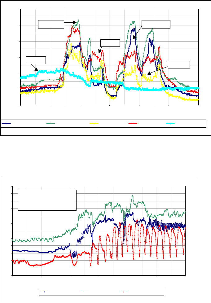
dehumidification, DV classrooms showed improved IAQ and acoustics with acceptable
humidity levels.
Another noticeable benefit of DV is an improvement in acoustic comfort. Spot
surements of back a typ 44 decibels for
the DV classroom (with the fan at maximum speed) and 48–50 decibels for the control
a result ers are less ff fan.
mea ground noise levels showed ical rage of 40–
classroom. As , teach likely to turn o the DV
300
900
400
500
6: 14:00 16:00 18:00
ppm
600
700
800
00 8:00 10:00 12:00
CTRL-CO2-OCC CTRL-CO2-RET DV-CO2-OCC DV-CO2-RET AMBIENT-CO2
CTRL-RET
A
mbient
CTRL-OCC
DV-RET
DV-OCC
4. The COFigure n
2 concentration in the occupied zone of the DV classroom is consistently lower tha
the concentration at the return, a sign of good ventilation effectiveness.
42
44
46
48
50
52
54
56
58
60
62
64
66
6:00 8:00 10:00 12:00 14:00 16:00 18:00
DV-RH-OCC % DV-RH-RET % CTRL-RH-OCC %
D op line
D middle line
C
Figure
V-RH RET% t
V-RH OCC%
TRL-RH-OCC% bottom line
5. Relative humidity, September 15, 2005. While the RH in the DV classroom is slightly higher
than the RH in control classroom, it remains within acceptable limits.
24
Teacher feedback has been positive in the DV classroom. The teachers in both the DV
and the conventional classrooms were given surveys on the acoustics, indoor air quality,
• eloped that present
the results of this project.
Fact sheets, guidelines, case studies, presentations, and technical articles were
developed. The information has been distributed as part of the CHPS program to the
CASH, the Energy Design Resources Program, ASHRAE, and other groups that make
school-related decisions. The project team developed model EdSpec language, which
focuses on DV for HVAC systems. A detailed DV Design Guide has been developed that
provides practical design information to engineers and architects.
The collateral was developed jointly under this task and under the Program Market
Connection (Project 4) activities. Several of the documents are referenced in the
Attachment section of this report.
Technology transfer activities were conducted, including the following:
• Presentations given at the DV School design charette, ASHRAE meeting, CASH
conference and CASH representatives, American Council for an Energy Efficient
Economy (ACEEE) 2004 and 2006 Summer Study
• Article published in Engineered Systems magazine (April 2006)
Again, the work under this task was completed in parallel with the Program Market
Connection (Project 4) activities. More detailed information about information
dissemination may be found in the Program Market Connection section of this report.
The research team will continue to promote the results of this project and provide
market and technical information upon request.
2.5. Conclusions and Recommendations
2.5.1. Conclusions
• The demonstration classrooms confirmed that DV provides good thermal comfort for
classrooms with normal ceiling heights (9 ft).
The DV system did not create problems with cold drafts at floor level. The system
provides a consistent thermal stratification in the space and good ventilation
effectiveness. The effects of occupant activity and the opening of doors and windows
did limit the amount of (desirable) stratification achieved in practice.
• The DV system provides a remarkable improvement in acoustics.
•A supply of 1100 cfm of 65 F air is sufficient for most classrooms in California climates.
conditions can be met by a DV system without increases in system cooling capacity or
and thermal comfort they experienced in their classrooms. The teachers in the
displacement ventilation classrooms gave the DV system higher marks for both
acoustics and thermal comfort compared with the conventional classrooms.
Various technical documents and marketing collateral have been dev
• Training sessions held at SMUD and CTAC
°
Both the CFD simulation results and monitored data show that design cooling
25
airflow. While simulation studies indicate that up to 20% more supply air is needed w
DV, a system supply-air flow rate of 1100 cfm is less than what is typically supplied to
California classrooms in actual practice.
The use of a tuned VAV control strategy will optimize energy savings.
ith
•
The expected energy savings potential for this demonstration were not realized during
nce. With VAV systems, in which air volume is the primary
o space
nd
•
re compatible with
current DV system design requirements. The principal design requirement is a steady
to
vide
le classroom. Further development of additional
d opportunities
•
excellent thermal comfort for
compelling reason to use
ncludes variable-
savings.
2.5.2.
New pr
design char
demon d to
new products for DV. These products are described below.
ge air temperature control and capacity
use in California K–12 classrooms. This
-volume units.
cooling modes.
land
the initial phase of the project. Control setting modifications and tuning dramatically
improved system performa
means of space temperature control, compressor operation is not directly tied t
temperature (and cooling requirements). Under such a VAV control strategy, tuning a
verification are critical to ensuring system performance.
DV can be achieved today using a variety of HVAC system designs.
Large, off-the-shelf HVAC units that have multiple cooling stages a
supply of 65°F air. The customized HVAC unit used at Kinoshita Elementary proved
be effective in meeting the design requirements, and is unique in its ability to pro
single-zone, VAV control for a sing
innovative HVAC design options for DV will most likely afford increase
for energy savings.
DV provides many compelling benefits.
DV has shown to provide effective ventilation and
California classrooms. Acoustic benefits alone are a sufficiently
when the HVAC system i
DV. Energy savings are significant, especially
speed drive and VAV control for fan energy
Commercialization potential
oduct requirements have been identified as a result of the market barriers study, the DV
ette work on system design options, and preliminary results of the first
stration classroom study. New technologies for capacity modulation may be applie
• Packaged DX unit with improved dischar
modulation
The results of the design charette made clear the need for a new packaged DX rooftop
unit, by far the most common HVAC system in
new product would be designed to provide the relatively constant 65°F supply air
required for thermal DV, over a range of outdoor temperatures and part-load
conditions. Existing packaged products of capacities of 5 tons or lower do not have the
capacity to provide 65°F supply air under varying outdoor conditions and load
conditions. Additionally, packaged rooftop units are typically constant
The product should have capacity modulation in both heating and
Variable capacity compressors have great potential to provide a much tighter supply-air
temperature control and energy savings during part-load conditions. The Cope
Digital Scroll™ compressor has a capacity modulation down to 10%, and has been used
26
in air-conditioning systems in Korea. One possible product solution is to incorporate a
variable-capacity scroll compressor in a gas-electric rooftop or a heat pump
configuration. The prototype unit installed for the Kinoshita demonstration verified the
ent ventilation
midity control,
•
the casework. Displacement
f the typical 6 in,
y
d
• r heating
ibution
10–15°F (-12 to -9°C) or less.
Therefore, the diffusion performance of displacement diffusers in heating mode is an
imp
ixed
displacement diffusers for heating
can cause short-circuiting of the supply air if the warmer supply air moves toward the
ote
the diffuser is used for heating, thereby improving diffuser performance.
2.5.3.
•
ards and
tent
potential for this product. The technology is a good match for displacem
and offers benefits of improved space temperature control, improved hu
and high efficiency.
Diffuser integrated with teaching wall
Another idea that arose from the design charette is a diffuser that could be integrated
into the casework. The diffusers could be integrated into the side of the teaching wall, or
a long, linear slot diffuser could be positioned underneath
diffuser manufacturers do not currently offer a diffuser that would work under a
casement. Perhaps the cabinet base becomes 8 in or 10 in tall instead o
providing space for low velocity air distribution. At the design charette, participants
commented on the desire for more architectural options for diffusers. As DV technolog
gains acceptance, more options should become available. A long, low diffuser has the
advantage of delivering air directly to low heights, and it takes up less wall space that
would otherwise be used by the teacher. Potentially, the casework and diffusers coul
be installed by the same contractor, with a mechanical contractor simply making the
duct connections.
Variable aperture displacement diffuser fo
Low-velocity diffusers are well suited for cooling with DV. However, the air distr
is less effective in heating mode. Previous studies caution the use of low-velocity
diffusers for heating. For California classrooms, perimeter heating is only required in
mountain climates where the winter design dry-bulb is
ortant design consideration.
In heating, the goal of the air delivery system is to achieve a thermally well-m
airspace. The idea with this product is to vary the opening area of the diffuser in heating
mode to increase the air velocity. Using low-velocity
return grille before it diffuses throughout the space. A higher air velocity will prom
mixing when
Recommendations
Adopt load calculation procedure for Title 24 Standards.
To provide an accurate estimate of energy use of DV systems, the Title 24 Stand
Alternate Calculation Method (ACM) must be revised to include a procedure for
modeling DV systems. A procedure has been recommended for modeling the
stratification and predicting the supply-air flow requirements for DV systems. While
this procedure would require an independent review, the model outputs are consis
with CFD simulation results and field data from this study. Additional monitored data
from other DV installations would most likely strengthen the case for inclusion of the
model.
27
•
s carry a
cedures that can provide an accurate estimate of energy savings
•
n the
g
o
tes.
• DV technology must become available as off-the-shelf equipment.
nce HVAC system options for
d
t. A
lutions for displacement ventilation.
•
this concern by developing products that increase
e availability of these
•
e
.
ace types. While CFD is a good design tool, it will increase project soft costs and
Incentives for high performance designs will help offset cost premiums.
While DV has the potential to be competitive with traditional systems, it doe
slight cost premium because the HVAC designs for displacement ventilation require
more sophisticated control strategies. Programs such as Southern California Gas and
Electric’s Savings By Design could offer incentives. However, load calculation and
energy modeling pro
must be adopted.
More demonstrations and education are needed.
Gaining acceptance for DV in California schools will require more examples of
successful applications and a significant education campaign. The research from this
project suggests that familiarity with DV is low among all professionals involved i
classroom design process. While many of the architects and engineers without DV
experience were familiar with the theory of DV and its benefits, most had little workin
knowledge of it and questioned the specifics of how the system might be implemented.
The education of engineers represents the crucial front line of acceptance. Architects,
contractors, construction managers, maintenance personnel, and facilities managers als
are looking for more than just information on material costs and specifications. They are
looking for experiences and success stories of DV used in similar situations and clima
A significant desire and need exists for low-maintena
California K–12 classrooms. Although other HVAC system designs can be readily
designed to meet DV requirements, school districts strongly prefer to use package
rooftop units for each classroom. The DV prototype unit developed for the Kinoshita
demonstration is unique in its ability to meet requirements for DV in a packaged uni
sustained educational outreach to market participants is recommended to further the
development of packaged unit so
Improved design options are needed for heating with displacement diffusers.
It is well known that low-velocity displacement diffusers are not designed for heating.
Although adequate comfort in the heating season was maintained in the two
demonstration classrooms, the air distribution pattern was not ideal. The supply of very
warm air at a very low velocity through displacement diffusers will cause some of the
warm supply air to rise to the ceiling before it reaches the occupants. European
manufacturers have addressed
discharge air velocity to improve heating performance. Th
products in the United States market would make DV a more compelling solution in
applications with greater heating needs.
Additional design guidance is needed for other space types.
This PIER project showed that DV design is relatively straightforward for simple spac
types such as classrooms. DV has also been successfully used in libraries and
gymnasiums. However, the design of DV for spaces with higher ceilings is not as simple
Many design professionals recommend the use of CFD analysis when using DV for
these sp
28
could be a deterrent to the widespread application of DV. Additional research is needed
n
•
ave questioned whether or not the air patterns from DV would cause
o the breathing zone. Particle count
al field
2.5.4.
The res
10–40%
effectiv
to determine thermal stratification patterns and optimal diffuser layouts for school
gymnasiums, libraries, and auditoriums without the use of time-consuming simulatio
studies.
Additional IAQ research is needed.
This project focused on the air quality benefit of improved ventilation effectiveness.
Some researchers h
particles to be drawn upwards from carpet and int
studies were not feasible within the monitoring budget of this project. Addition
studies would clarify whether respirable particle counts are higher or lower in the
breathing zone.
Benefits to California
ults of this project indicate that DV technology may reduce classroom cooling energy use
depending on the climate. Non-energy-cost benefits include improved ventilation
eness and improved acoustic quality, which are both compelling findings.
29
30
3.0 Effectiveness of UVC Technology for Improving School Performance (Project 3)
3.1. Introduction
This project quantified the impact of ultraviolet irradiation in the “C” band on evaporator coil
disinfection and IEQ of California K–12 schools. The goal of the study was to determine if UVC
is effective in reducing mold and mildew in HVAC systems, improving IEQ, and saving energy.
UV is a line-of-sight technology; when produced by a lamp it can only provide effective
disinfection on components with direct or reflected exposure to ultraviolet irradiation. For this
study, the project team, RLW Analytics, focused on surface disinfection systems that
manufacturers claim kill mold and bacteria growing on cooling coil, drain pan, and other
surfaces in the supply-air stream. The UVC lamps in these systems are mounted in the HVAC
system supply duct, usually right above the evaporator coil. Because microbial colonies act as
insulating agents, removing the microbial buildup should result in increased air flow and
energy efficiency of the HVAC unit. In addition, the removal of these microbes can improve the
IEQ by eliminating the cause of potential contamination of the air passing by the dirty coils and
drain pan.
In the past 12 years, some manufacturers have begun to produce UVC systems designed
specifically for HVAC systems. Manufacturers have re-engineered their main line of UVC
products to work in HVAC systems because the non-HVAC-specific lamps suffered drastic
output losses, specifically a loss in “killing power” when exposed to cold or moving air.
According to some manufacturers, not all of the products on the market have these adjustments.
Since the application of UVC disinfection technology in HVAC systems is relatively new, there
are currently no codes or performance standards for the industry, making product comparisons
difficult. The International Ultraviolet Association is currently working to establish
performance standards. ASHRAE is forming a standards committee to address this issue as
well. Output levels at specific temperatures and safety features for each disinfection system
should be tested by an independent laboratory and clearly stated in the marketing material to
allow for comparisons between products. Equally important is the total application of UVC
lamps within the geometry of the system. The number of lamps and the spacing between rows
of lamps is critical to the actual distribution of UVC energy over a given surface.
The UVC disinfection system consists of an assembly whose primary components serve similar
functions to those of a standard fluorescent fixture. This includes the UVC lamp, lamp socket,
ballast, associated wiring, and enclosure. Mercury vapor is the gas used in the lamps, which
produces UVC irradiation. Inert gases are used to illuminate the lamps. UVC bulbs are made of
quartz or soda barium glass, which transmits UVC, rather than common “soft” glass, used in
fluorescent lamps, which largely absorbs UVC. The mounting arrangements vary depending on
the configuration and physical constraints of the equipment upon which it is installed, and have
been designed with flexibility in mind in order to be adaptable to a variety of field conditions.
The enclosures, ballasts, and related components can be installed internally in or externally on
the equipment that it serves. Some examples of typical UVC disinfection systems are pictured in
Figure 6.
31
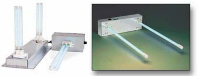
Figure 6. Example UVC disinfection systems
Within the HVAC industry, UVC technology is applied to packaged, unitary, and built-up (site
constructed) air-conditioning equipment, on both direct-expansion and chilled-water cooling
systems. The irradiation process can be applied to the cooling coil, condensate pan, AC unit
internal surfaces, and air distribution systems.
fection
sult
air
il.
• Quantify any changes in average daily attendance (ADA) as a result of the decrease in
K–12 schools and to obtain utility billing and attendance data from these schools in
order to determine if there were any significant decreases in kWh usage and increases in ADA
when comparing the pre- and post-UVC periods. As a result of some initial research into the
As mentioned previously, this study investigated the use of UVC to provide surface disin
of the cooling coil and condensate drain pan. The reduction in buildup on the coils could re
in an increased system capacity by increasing air flow across the coils and improving coil-to-
heat transfer, resulting in energy savings due to the resulting increase in efficiency. A recent
study showed that the reduced air flows that result from coil fouling cause typical efficiency
and capacity degradations of less than 5%. However, the losses can be much greater for
marginal systems or in extreme conditions. (Seigel) The disinfection systems also may reduce
fungal-related odors and alleviate air quality concerns in the indoor environment, and also
reduce the need for costly chemical or pressure washing treatments of the cooling co
3.2. Project Objectives
The primary purposes of the study were as follows:
• Understand whether or not UVC surface disinfection systems reduce the energy
consumption of AC units and, if so, to quantify the reduction
the microbial levels after the UVC disinfection systems are installed
• Understand whether or not UVC surface disinfection systems reduce the microbial
growth on air-conditioning (AC) cooling coil surfaces and, if so, to quantify the amount,
which might be used to explain improvements in IEQ and, potentially, ADA
3.3. Project Approach
This study was originally funded as a purely analytical study that would quantify the benefits
of the UVC disinfection systems using existing data. Through the course of the project, several
factors changed the direction of the project from an analytical model to a field study. The team
originally planned to work with a single manufacturer to identify the existing UVC systems in
California
32

number of installed systems in California K–12 schools, it was determined that there were not
sufficient numbers of systems installed in classrooms where students were in the rooms for the
majority of the school day, providing inadequate data to complete the ADA analysis.
The researchers recommended that a comparative field study be performed in place of the
analytical study in order to provide some research into the field effectiveness of the UVC
disinfection systems. With concurrence from the PAC members and the Energy Commission,
the research team reassessed the study budget and goals and transformed the project into a field
study. While the field study was designed to provide exploratory research into measuring UVC
efficiency and ADA changes, th not sufficient to provide the large sample sizes,
comprehensive testing, and customized instrumentation needed to provide more robust and
definitive results.
s,
s were included in this study. Both
lled
nditioning units just one or two lamps provide effective
icrobial growth
The UV
Rooftop conventional permanent
school t
after th
market led on an exterior
wall of loy
conven
coil pro this study
. The UVC systems that were chosen for this study can be
e budget was
At the outset of this project, the research team spoke with 12 manufacturers of UVC disinfection
systems for HVAC systems to discuss current UVC products and technologies, market barrier
product availability, customer demand, markets served, and available research.
Two manufacturers of UVC disinfection system
manufacturers produce surface- and air-treatment disinfection systems. The two manufacturers
donated equipment, technical support, and installation services to the study. The research team
is appreciative of their generosity and support. This study was designed to be a technology,
rather than a product, assessment. Therefore, no manufacturer names are disclosed. The
disinfection systems are analyzed separately in this report and will be referred to as system,
treatment, or group ‘A’ and ‘B’ in subsequent sections.
The disinfection systems were installed downstream of and adjacent to the cooling coil and
provided irradiation to both surfaces, except for a few units in which the systems were insta
upstream due to downstream internal space limitations. This approach is widely employed by
installers because on small air co
coverage of the surfaces that are most likely to have m
C technology was applied to both packaged rooftop and wall-mounted AC units.
units are the most common type of air conditioning units for
buildings. The wall-mounted style is often referred to as a “Bard” (heat pump style) uni
e manufacturer that originally developed the configuration and currently dominates the
for California portable classroom HVAC units. These units are instal
portable classrooms. Both types of cooling systems, rooftop and wall-mounted, emp
tional direct expansion/refrigerant vapor compression systems with a direct expansion
viding the cooling in the air stream. All UVC disinfection systems provided in
were standard production units
generally characterized as shown in Table 3. Figure 7 shows example installations.
Table 3. UVC systems studied
Units Treatment A Treatment B
One Lamp Units 30 Watts 36 Watts
Two Lamp Units 30 and 20 Watts 21 Watts
33
The two lamp fixtures were typically used in units with space constraints. The smaller wattage
lamps were typically used for drain pan irradiation.
34
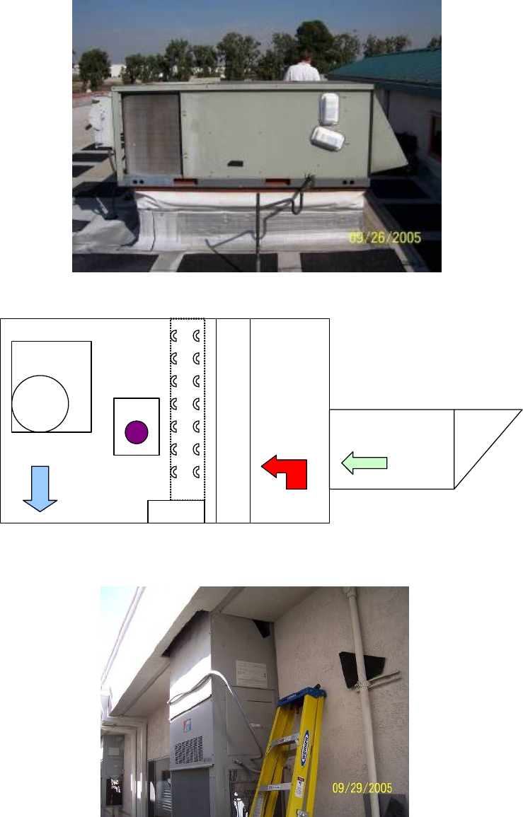
Economizer
F
I
L
T
E
R
S
E
V
A
P
C
O
I
L
Fan Box
and
Motor
UV
Supply
Outside
Air
Return
PAN
Figure 7. Example of a rooftop air conditioning unit in UVC study (top), schematic of a typical unit
(middle), and example of a wall-mounted air conditioning unit in UVC study (bottom)
35
The most common installation approach was to mount the UVC ballast and wiring externally
on the casing of the cooling equipment with only the lamp or tube penetrating into the system
while the power supply remains external. All disinfection systems used in this study were rated
for outside installations and, with one exception, were mounted on either the side or the top of
the AC units. The UVC disinfection systems can be wired either so that they are in operation
continuously or only when the AC is on. The UVC disinfection systems in this study were
powered on continuously, so they were in operation regardless of a call for cooling.
The team investigated the study goals by performing a side-by-side comparison of two
treatment groups receiving UVC disinfection systems to a control group receiving no UVC
treatment. Measurements were taken before and after turning on the UVC disinfection systems
in order to compare changes in AC efficiency, microbial contamination, and ADA between the
treatment and control groups. The study period commenced in August 2005 and lasted
approximately six weeks.
A total of 54 AC units at nine schools within thr
included in the study. Of the 54 AC units, 36 received UVC treatments. A total of 18 AC units
were included in each of the three study groups, one control group, and treatment groups A
and B. Identical AC units serving similar grade-level classrooms comprised each of the three
study groups. Both packaged rooftop and wall-mount-type units were included in the study.
The study goal was to determine the impact of DV technology on typical AC systems in
California schools; therefore, the study did not specifically target fouled coils. However, the
team did exclude units that were less than four years old to ensure that newer coils were not in
the study.
The three districts that were included in the study were located in cooling climates and had
year-round school schedules. Districts with year-round schedules were targeted in order to
ensure that the units in the study were running throughout the summer with the exception of
two-to three-week breaks between sessions. The level of coil fouling was approximately that
expected during a normal cooling season. Elementary grade levels were selected to ensure that
students were in the same classrooms all day for full school days to enable adequate pre- and
post-ADA analysis.
3.4. Primary Data Collection
The research team performed a variety of primary data collection tasks consisting of survey,
microbial, and engineering information. There were five primary sources for data gathered and
analyzed for this study, which are categorized and described as follows:
3.4.1. Manufacturer Interviews and Literature Review
The research team began the study by contacting the major manufacturers across the country in
order to better understand current UVC disinfection products and technologies, market
barriers, product availability, customer demand, markets served, and existing research. This
background research was used to inform the selection of the surface disinfection technology to
be included
ee school districts across California were
in the study, and to provide background information about the technology.
36

3.4.2. Microbial data
sed
A.
by
he state of various other malfunction indicators. Incorrect
y. The
f
tion of
the units. The units underwent the same set of measurements as were taken during
er
s were also surveyed during the pre-installation site visits. They provided
ut the thermostat controls, the ventilation in the rooms,
ny fteen of the teachers participated in a follow-up survey to
uring the
r this
project are listed in the Attachments section of this report and may be found at
www.archenergy.com/ieq-k12/uvc_technology/uvc_technology.htm
The research team collected microbial samples from the surface of cooling coils prior to and
after the installation of the UVC disinfection systems. A single swab sample was taken from the
cooling coil fin edge and fin face from each AC unit over one square inch using an absorption
spear. The on-site team followed the sample handling techniques as directed by the
microbiology lab that performed the testing. These surface samples were analyzed for
culturable fungi and bacteria. The laboratory provided the research team with estimates of the
number of colony-forming units (CFUs) per area sampled per coil. These lab results were u
to analyze the reduction in CFUs on treated units relative to the control group units. This
analysis was performed in order to determine improvements in IEQ and, potentially, AD
3.4.3. Engineering data
The research team collected data to support the evaluation of in-situ air conditioner efficiency.
The team first qualified each unit to ensure that the units were in proper working order
measuring operating pressures and temperatures and determining diagnosis-level refrigerant
charge, air flow, coil condition, and t
condenser fan speed, or incorrect evaporator fan speed, and were excluded from the stud
selected units were then subjected to extensive measurements to evaluate system efficiency.
Careful measurements were taken using high-quality calibrated instruments during steady-
state operation of the system in order to evaluate the field-operating efficiency and capacity o
the systems. These measurements quantified pressure drop across the evaporator coil, cooling
capacity, and efficiency readings. On/off event motor loggers were installed for the dura
the study period in order to quantify run-time of the units in cooling mode (fan plus
compressor). At the end of the study, field staff returned to retest the operating efficiency and
capacity of
the first visit. The resulting data were used to quantify UVC-related impacts on energy
efficiency.
3.4.4. Teacher and Classroom Surveys
To supplement the analysis of the changes in biological contamination on the cooling coil, oth
field observations were collected that are typically used in the assessment of indoor air quality.
The observations account for the condition of the area or building in question. The teachers in
the studied classroom
information to the research team abo
and a other IEQ observations. Fi
determine what, if any, changes they noticed as a result of the UVC disinfection systems.
3.4.5. Attendance Data
Average daily attendance data were collected from each school district for each classroom in the
study. Attention was paid to ensure that the same students were in the classrooms d
study period. The study period began approximately three weeks after the beginning of the
school year. Any changes in ADA were analyzed and summarized.
3.5. Project Outcomes
A summary of the UVC project outcomes follows. Key information products developed fo
.
37
• Microbial analysis showed the reduction of growth on the evaporator coils, as expected.
s
t
of the
obial
t statistically significant for this study,
–2% improvement. This suggests that further laboratory
.
end
t
rage daily attendance data were collected from each school district for each
clas aid to ensure that the same students were in the
the air cools quicker; in a matter of seconds it gets cold in
of the teachers
rrelation between the units and attendance. In fact, many
eachers in one
ttendance.” However,
Microbial samples were taken from the surface of the cooling coils for each of the unit
prior to and after the installation of the UVC disinfection systems. The samples were
taken on the leading coil fin edge and fin face using sterile swabs. Each sample was sen
to a microbiology lab for quantitative fungal and bacterial testing. The results
microbial analysis indicate that the two treatments notably reduce levels of micr
growth on the evaporator coils. Total fungal and gram-positive bacteria reductions were
65–100% of colony forming units.
• Air flow and efficiency analyses showed a positive trend.
The UVC impact on system air flow, though no
produced a positive trend, 1
tests or field tests over a longer period may produce more statistically significant results
There were no statistically significant impacts on efficiency and no distinguishable tr
such as the trend identified in the air flow analysis other than a mild positive trend as
noted. In future research, true energy impacts must be studied in terms of a systems air
flow and efficiency degradation over time and the impact of disinfection systems on
preventing this decline. As previously mentioned, one study showed that air flow
restrictions that result from coil fouling can cause typical efficiency and capacity
degradations of less than 5%; however, the degradations can be much greater for
marginally functional systems or extreme conditions. Fouled coils were not targeted for
inclusion in this study and were in fact systematically excluded from this study, and the
on-site team did not observe much fouling of the coils; therefore, it is not surprising tha
air flow and efficiency impacts were inconclusive.
• Attendance data results were inconclusive.
Ave
sroom in the study. Attention was p
classrooms during the study period. The study period began approximately three weeks
after the beginning of the school year. After analyzing data, researcher did not find a
strong correlation between the reduction of microbial growth and student attendance.
More attendance data is needed along with a larger sample size of UVC field tests in
order to draw conclusions that are more scientific.
• Teacher and classroom surveys indicated positive feedback for some issues.
In the survey, 13 of the 15 teachers stated that the room did cool more quickly. One
teacher stated, “It feels like
here.” In addition, 13 respondents (87%) said that the room seemed to be less stuffy.
• Concerning attendance, the responses were not as clear.
When asked, 47%of respondents said attendance had improved; 33% said it had not
improved; and 20% said they did not know if there was a change. None
were able to confirm a co
teachers had new groups of students by the time the post-installation surveys were
administered, which made it difficult to see changes in student health. T
district said they were in the middle of a “district-wide push on a
38
in comparing the responses from teachers in the UVC group to those in the control
group, researchers found that the teachers in UVC-treated rooms reported an
improvement in attendance (5 out of 7) while those in the control group stated that thei
attendance had not improved (4 out of 6).
Sixty percent of the teachers asked about the prevalence of air quality issues stated th
there were fewer air-quality-related illnesses than before the study period began. One
teacher made the statement “Students who have air quality related illnesses seem to be
less affected by them,” while anoth
r
at
er said “There are fewer kids with asthma than in last
ere was no improvement.
and 1
r of
ed,
• ges for proper installation.
it of
re
e
this study, the technicians were
he
in
n
adiating the condensate pan;
the opposite side of the pan
n
•
year’s class.” Twenty-seven percent of teachers said that th
Thirteen percent of the teachers said they could not tell any difference in the amount or
severity of air-quality illness. When asked if illnesses had decreased, there was an even
split of yes and no responses. Seven teachers said yes, seven said no, and one responded
don’t know. The majority of the yes responses came from UVC teachers, while only one
teacher in the control group noted a decrease in illness. The majority of the control
group teachers did not find a decrease in illnesses.
The responses to questions about using the AC less and opening doors and windows
more often than in the two months prior to the study period were split: 7 yes, 7 no,
don’t know. The responses were evenly split among UVC and control groups. Fou
the teachers commented that it was district policy to keep doors and windows clos
possibly to conserve energy. None of the teachers reported any new staining or mold
growth. One teacher stated she had smelled moldy smells in the past but that they were
gone now. She was in the UVC test group, but the information can only be treated as
anecdotal due to the small sample size.
Some of the HVAC housings created challen
The effectiveness of UVC can be limited by the AC unit configurations. In pursu
economy, rooftop and wall-mounted units employ very compact designs. It is common
to find the evaporator fan housing within 2 in of the cooling coil on one side and the
same distance for the air filter on the other side. For example, fan housings may obscu
access to coils. These types of configurations result in less-than-ideal lamp locations. Th
greatest irradiation area per lamp is afforded when the lamps are installed
perpendicular to the coil fins. In some instances for
forced to install the lamps parallel to the coil fins, a less advantageous position for
irradiation. The success of the technology is also dependent on the quality of t
installation. Installers often rely on their own judgment to compensate for challenges
the field. The field staff for this project made some observations of installations
performed in space-constrained systems. For example, an inspection of one installatio
shows that the lamp was installed with the intention of irr
however, it was placed on the upstream side of the coil on
due to space constraints. In another instance, the lamp lens was in contact with the fa
housing, which may contribute to premature lamp failure. Review of installers’
approaches and inspection of their work are useful in assuring quality installation.
Environmental issues were found.
39
The research team made a number of environmental observations at the schools wh
performing engineering measurements. These observations indicate that there
additional areas where attention could be paid to potential sources of IEQ problems and
energy-saving opportunities in California K
ile
are
–12 schools such as dirty rooftop surfaces,
3.6.
3.6.1.
•
for the six-week study was a small
• he
id provide notable findings.
ial
• on
•
standing water near classroom and outdoor air intake areas, cleaning supplies in
classrooms, and lack of door mats at the entry to each classroom that may contribute to
the level of contaminants transferred to interior floors.
Conclusions and Recommendations
Conclusions
The research team could not conclusively determine if there were any improvements in
air flow or efficiency of the air conditioning units with UVC disinfection systems.
With the small sample size, large error bounds, and study limitations discussed earlier,
the analysis did not determine with statistical significance that the technology
significantly affected airflow or efficiency. The trend
increase in air flow in units with either of the two manufacturers’ disinfection systems
and inconclusive impacts on efficiency. True energy impacts must be studied not only as
an improvement in efficiency or air flow, but in terms of the degradation of a system’s
air flow and efficiency over time and the disinfection system’s impact on slowing the
decline of unit performance. Coils that are fouled may be the best application for this
technology, in order to produce greater energy savings through coil disinfection.
The microbial sampling, which was undertaken primarily to explain the results from t
energy analysis and the ADA analysis, d
The study did find that the UVC technology is effective in reducing surface microb
levels on cooling coils. The research team did not find high concentrations of fungi or
bacteria on the cooling coils in the study. This could be due to the fact that California’s
climate is relatively dry compared to the rest of the country, which equates to a smaller
latent load. Since microbial activity is correlated with the amount of moisture present,
the more humid the climate, the more applicable this technology. Additionally, this
technology is probably more applicable in regions with high annual cooling hours or in
more inland climate zones where the potential for mold growth may be greater.
This study concludes that UVC technology is effective in reducing microbial growth
air conditioning cooling coils.
However, the impact of this technology on IEQ in California schools would be directly
proportional to the pervasiveness of microbial growth on cooling coils and the
relationship between surface microbial growth and IEQ. The presence and magnitude of
microbial activity on the population of existing classroom cooling coils is
uncharacterized at present. The UVC technology may be best suited for application in
AC units in classrooms with pre-existing or substantial microbial growth, or classrooms
with IEQ problems.
The success of the technology is dependent on the quality of the installation.
40
Installers often rely on their own judgment to compensate for challenges in the field.
Review of installers’ approaches and inspection of their work are useful in assuring
quality installation.
Commercialization Potential
ers purchase the UVC disinfection systems to improve indoor air quality. The
cturers contacted at the beginning of this study agree th
3.6.2.
Custom
manufa at very few buildings in the
country have UVC disinfection systems installed in their HVAC systems. Most thought the
, with more installations occurring in the South
the e these regions are characterized by longer cooling seasons and high
reacted
A fund
people
technol
dissem
to unde
lessene
overcom
Many m
nearly ach
the mo
painful
cause cataracts. Regardless of th
this stu
human
units, p
when s
It is im
familia
In addi
equipm
consen it wiring, air filter materials, and fan drive belts are
subject
require
require
Until th ser should
careful ,
installa
can pro and references for local contractors familiar with the technology. It
was the r was
invaluable in the proper and safe application of the UVC disinfection systems. For market
commercialization, manufacturers must continue to address these issues and provide customer
support.
percentage of buildings with UVC was below 5%
and on East Coast sinc
humidity. Most installations currently occur in retrofit applications when the end users have
to mold and moisture problems.
amental barrier to the adoption of UVC for AC systems is that potentially interested
are not aware of the benefits of the technology. Many have misconceptions that UVC
ogy will produce ozone or will damage eyesight. More information needs to be
inated that states the benefits of the technology in simple terms that are easy for people
rstand. Consumers need to be shown the cost payback of the technology in terms of
d chemical cleaning costs and possible energy savings. Once the information barrier is
e, the sale is relatively easy.
anufacturers claim that the lamps have low penetrating ability and that UVC light is
completely absorbed by the outer, dead layer of skin. They say that the light can re
st superficial layer of the eye, if exposed, where overexposure can cause reddening and
but temporary irritation, but claim it cannot penetrate to the lens of the eye and cannot
e effects, the UVC disinfection systems that were included in
dy were all safely enclosed within the HVAC systems and were not in direct view of
s. As a further safety option, door safety interlocks can be wired into the circuitry of AC
reventing accidental exposure to UVC light by interrupting power to the UVC lamp
pecific access doors and or panels are opened.
portant for any individual who installs and maintains these systems to be completely
r with any hazards posed, and potential damage that can be caused by, UVC radiation.
tion to human safety, there are other issues that could potentially arise from the
ent components and wiring being directly exposed to UVC radiation. There is no clear
sus on whether such items as un
to deterioration due to UVC exposure. Originally, Underwriters Laboratory (UL)
d that lamp wiring be shielded with metal, but they have since removed that
ment.
ere are federal standards for the industry that address this issue, the end u
ly read and understand the manufacturer’s installation and safety data prior to selection
tion, and maintenance of these disinfection systems. In many instances, manufacturers
vide information on
research team’s experience that the technical support from each manufacture
41
3.6.3.
The pri g
within t this PIER project, researchers have documented the limitations in
dy, the number of microbial samples taken, the
microbial disinfection effectiveness near to and
that
ist the standards committee in setting regulations as to
ng
oved that requirement. Teflon, used to
aterial.
ing to some manufacturers, not all of the UVC for HVAC products on the market
have been adjusted properly to work inside the units. At such low temperatures, the
e
ss.
Recommendations
mary recommendation is to increase sample sizes and allow for repetition of samplin
the study. Throughou
terms of the numbers of AC units in the stu
engineering data that were logged, etc. The limitations can be overcome with additional
funding (estimated by researchers to be in the $2 million range). This funding would allow a
research team to develop a comprehensive study methodology that allows for primary data
collection in order to directly answer all possible research questions. Both laboratory and field
work are required to answer these research questions.
Some of the outstanding research questions and study opportunities are as follows:
• What is the irradiation efficacy and
distant from UVC lamps?
An important factor to study is the irradiation efficacy directly under, and at specified
distances from, the UVC lamp. A number of research studies have been written
describe output measurement procedures and some suggest required documentation of
the process (Sagges and Robinson 2005). A common metric measurement such as
microwatts per square centimeter, at specified distances, should be addressed by a
standard. This would also ass
how much distance can be placed between the lamps when installed to provide
sufficiently effective irradiation. To test the overall efficacy factor, microbial samples
would have to be taken at prespecified distances from the lamp, with ideally at least five
samples being taken at each distance on each coil.
• Does the UVC irradiation cause deterioration of non-metal HVAC equipment?
There is no clear consensus on whether or not such items as unit wiring, air filter
materials, packaged unit case insulation, and fan drive belts are subject to deterioration
due to UVC exposure. Originally, Underwriters Laboratory required that system wiri
be shielded with metal, but they have since rem
shield outdoor wiring, is resistant to all bandwidths of UV and so is a possible defense
for wiring exposed to UVC. An independent laboratory needs to perform tests to
determine what type of materials and parts should be shielded and with what m
A standard should be established to address this issue.
• Are the UVC disinfection systems designed to work properly in the cooling
environment?
Accord
lamps may not be performing optimally once installed in the HVAC systems since som
lamps are tested at room temperature. Laboratory testing under HVAC conditions of all
of the products being offered on the market is needed to confirm or disprove this
assertion. Laboratory testing is also needed to test output in general. As mentioned
above, a number of research studies have been written that describe output
measurement procedures and some suggested required documentation of the proce
42
• What would the recommended repetition of cooling-coil surface sample quantities and
om
have
g
ch
e upstream and downstream sides of
s the
icrobial activity on cooling coils, it would be best to collect
•
t
procedures for all products on the
•
•
rrow
to
locations reveal?
The microbial reduction findings would be optimized with a robust sampling plan.
When looking at any particular cooling coil, the degree of microbial growth varies fr
spot to spot. If one were to inspect multiple locations on a coil, some areas would
more colonies, others fewer. In order to characterize the entire coil, additional samplin
points for each coil are necessary to calculate an average level of contamination for ea
coil. It is now recommended that a minimum of five samples be taken per coil (i.e., five
repetitions per sample). It is also logical to ask th
the coil experienced different microbial growth. For instance, the coil fin edge on the
upstream side would see impingement of debris and airborne spores, wherea
downstream side would see a greater accumulation of condensate. To gain a
comprehensive picture of m
up to 10 samples on both the upstream and downstream sides of the cooling coil for
culturable and non-culturable fungi and bacteria.
Can UVC be used effectively as a preventative measure to inactivate destructive bio-
agents?
UVC might be effectively used for cleaning building ventilation air in order to preven
contamination by chemical agents that would otherwise be used for this purpose. The
Environmental Protection Agency (EPA) and the Research Triangle Institute are
currently investigating this research question through the EPA’s Technology Testing
and Evaluation Program. This study is currently outlining the laboratory test parameters
that could be used to develop standardized testing
market.
What is the probable UVC output degradation over time?
The UVC products currently on the market are rated for varying hours of useful life. In
order to test the life of the products, a study should be performed over a 12-month
period. This will allow for at least three testing intervals within the year. Those
treatments that degrade over time will have less disinfection effectiveness at the end of
the study. Such a study might also show a reduction in more resilient strands of mold in
a longer test period. In addition, a school attendance analysis would be strengthened by
having at least one year of pre- and post-data.
What is the ability of UVC to penetrate into the cooling coil fins?
There are currently no thorough research studies on how long it takes UVC to penetrate
into the coil fins. This is the subject of one proposed research project request being
prepared by ASHRAE TG 2.UVAS. It is widely accepted that a one-to-two month study
period will show high levels of microbial reduction on the irradiated surfaces. However,
tests should be performed to determine the optimal length of time needed for the UVC
irradiation to penetrate deep into the coil. UV levels can be quite low deep in the na
spots between fins. As the fins clear, more UVC is able to get in and reflect deeper in
the coil. A minimum depth to test would be a depth similar to that reached by the
research team with the swab sampling technique.
43
•
r in conditioned space?
gal
r
. Latent load should be correlated
seasons. The presence of mold in the building structure, along with elevated
chers. A study could address the effects of wiping
n the classroom, AC air
•
ould include those for fungi and a
•
rable
entilation air supply into classrooms
could affect and improve academic performance. The U.S. General Accounting Office in
What might be the relative contribution of AC system, classroom, and outdoor
contaminants to ai
Many sources contribute to the air quality characteristics in the HVAC system air
stream. Some of the more significant factors are the seasonal and incidental conditions
that affect the airborne count of mold spores, quantity of outdoor (ventilation) air being
brought in to the conditioned space, seasonal weather conditions that affect the latent
load on the system, AC unit air filter efficiency, air filter bypass conditions, and
classroom contaminants. It is important to understand the source of contamination to
determine the most appropriate mitigation method.
When trying to determine what types of microbial sampling to perform, the research
team realized that a study is needed to quantify the correlation between surface fun
colonies and air stream spore counts. In addition, this study should quantify the
relationship between outdoor contamination and seasonal weather conditions on indoo
air quality in order to control for these effects using filtration or other methods. The
season affects the amount of latent load on the AC
with effects on system performance and the amount of fungal proliferation during
different
levels of volatile organic compounds (VOCs), formaldehyde, and many other
contaminants may compromise the indoor air quality. Supplies customarily provided
for children’s activities in classrooms (paints, markers, glues, paper, and clay) as well as
the activities themselves (cutting, filing, scraping of wood) can also have an impact. In
addition, classroom occupants, particularly students, introduce contaminants from their
home environments and through exposure to other students and the outdoors at lunch
and recess. Children living in less desirable environments may introduce agents outside
the control of school districts and tea
off shoes on floor mats and of washing hands before enteri g
stream testing for culturable bacteria, and other practices to detect and prevent
contaminants from entering the classroom via its occupants.
Detection in particular might entail the following considerations:
There are many potential locations for airborne microbial tests such as on air duct
surfaces; in the AC air stream (upstream and downstream from the cooling coil); and
elsewhere in the outdoor, return, and classroom air. To bring greater clarity to the
influence of these many factors, desirable tests w
spore trap analysis.
Microbiological testing of classroom air could use interval data for endotoxins, microbial
antigenic proteins, culturable bacteria and fungi, volatile organic compounds,
formaldehyde, carbon dioxide and monoxide, and other particulates.
What is the quantifiable amount of outdoor air being supplied to classrooms and what
are its true effects on indoor air quality?
It is a widely supported conjecture that there is an important relationship between the
amount of ventilation air and the concentration of airborne contaminants, or measu
IEQ. Numerous studies imply that an increase in v
44
1995 conducted a study that found that nearly one third of all schools surveyed
unsatisfactory ventilation in the classrooms
reported
. That same survey indicated that nearly two
es in an
mode, and also heating mode.
•
•
fered,
disinfection that higher
o provide reliable
on
er.
UVC te
microb coils. However, while awaiting the future widespread deployment
of UVC
IEQ wi
• efficiency
d
ufacturers have available filters in the typical
•
thirds of the U.S. student population receives its education in buildings that, due to
deterioration of the facility, warrant major repairs or renovations.
Additionally, there is energy savings potential when utilizing outdoor air for space
cooling needs, referred to as the economizer cycle. Minimum or enhanced levels of
ventilation air can also be introduced independent of the heating or cooling mod
HVAC system. Special attention should be placed on portable classrooms, where units
may not be providing outside air when not in cooling
Particular focus and analysis of the effects of insufficient versus minimum or enhanced
levels of ventilation air would be fortuitous.
What are the best sampling techniques to determine UVC-related impacts?
A six-month planning period would enable the research team to determine the most
appropriate sampling techniques and tools to use for surface and air samples. As
mentioned previously, there is no broad consensus on appropriate air sampling
techniques for this type of study. Therefore, thorough secondary research and in-depth
discussions with a team made up of IAQ experts, researchers, and UVC disinfection
system manufacturers must take place before any air sampling is attempted. To allow
for comparison between air sampling results, a set of standard testing protocols could
also be developed based on future research.
Standardize labeling and testing procedures.
One critical factor that would assist with the widespread adoption of UVC disinfection
systems for HVAC systems is the development of standardized labeling and testing
procedures for the products on the market. Currently, there are no such standards; each
manufacturer uses its own discretion on selecting the type of information offered on
marketing material. There are no standardized industry tests for the products of
allowing too much room for products that do not provide the
quality products do. Consumers currently rely on manufacturers t
information about their products. It would be a great improvement if the informati
came from a standardized laboratory facility that could verify the manufacturers’ claims
and allow for comparisons between suppliers, eliminating uncertainty for the consum
chnology can and will contribute more to IEQ in California schools by reducing
ial growth on cooling
technology, much can be done in the way of proper maintenance now to ensure better
th existing equipment, including the following:
Increase air filter efficiency: The use of air filters that have a minimum
reporting value (MERV) rating of 8 or greater would provide a significant improvement
in the prevention of the passage of airborne allergens including pollen, mold spores, an
coarser particulate matter. Numerous man
1-in and 2-in depths.
Increase air filter replacement frequency: Appropriate change-out frequency will
prevent excessive dirt loading of air filters and the resulting degradation of air flow and
45
performance. It is apparent that increased frequency of replacement would benefit
numerous units.
Check for air filter bypass: Filter bypass is due primarily to poor construction of the f
rack assembly, which allows wide tolerances between the filter and
• ilter
its mating surface.
e
it
•
ents to achieve the minimum requirements
62.
•
e
l
•
ashing.
• taminants and particulates are
lly
•
ent in performance.
• r over-
•
s, especially in monetarily constrained school districts. The new
This, along with substandard installation of replacement filters, results in appreciabl
debris buildup on the evaporator coil and therefore a decrease in air flow and AC un
efficiency. Correcting bypass conditions through appropriate alterations to filter racks,
as well as stipulating better filter replacement methods, would produce beneficial results
to AC performance and IEQ.
Verify/increase ventilation air: This involves the retrofitting to code of existing outdoor
air dampers, controls, and associated compon
for ventilation air as noted in the California Energy Code and ASHRAE standard
Improve areas near air intakes: Areas near packaged HVAC units where outside air
supplies are drawn are often overlooked in routine maintenance. These area within th
classroom and outdoor activity areas commonly receive little attention from schoo
district maintenance crews. To improve IEQ, condensation, rainwater, and other liquids
should drain away from the air intake side of a unit. Routine cleaning crews should
report visibly poor conditions to maintenance, and roofs should be regularly inspected
for evidence of mold, mildew, standing water, etc.
Mitigate contaminants introduced by occupants: Many contaminants could be reduced
by the introduction of door mats and hand w
Encourage use of door mats: Many indoor con
transported from outdoors via shoes. Dirt, mold, plant matter, pesticides, and lead are
routinely brought into the classroom on the soles of shoes. Track-off mats are essentia
long door mats and provide a very effective and passive means of extracting debris from
shoes. Use of the mats at the exterior entry to each classroom or classroom building
would be beneficial.
Encourage hand washing: Many contaminants introduced into the classroom by
students and teachers are transported via their hands. Interaction with other students,
the outdoors, and home environments could lead to the introduction of microbial
species into the classroom. The use of this strategy, hand washing, along with track-off
mats limits potential sources of IEQ problems to those under the control of school
districts.
• Clean coils: Some of the evaporator coils had slight-to-heavy accumulations of
particulate debris. In many instances, a one-time vacuuming or washing of evaporator
and condenser coils effected a notable improvem
Test and adjust refrigerant charge: It is common to find AC units that are under- o
charged with refrigerant. Correcting this condition often brings about a notable
reduction in energy costs and premature equipment failure and improves performance.
Retire the oldest units: It is common for units to remain in service well beyond typical
replacement time limit
Department of Energy Air Conditioning Standard (Department of Energy) sets the
minimum efficiency of small units (<5.5 ton cooling capacity) to seasonal energy
46
efficiency ratio (SEER) 13, and prices should drop as these become base models for
manufacturers. Replacing units more than 20 years old with these new SEER 13-certified
• t
gines and other equipment. Implementing a program to
• ,
3.6.4.
The UV y significant for this study, produced
a positi
longer ts. Statewide energy impacts from
this tec e results.
This stu
conditi
would
relation
microbial activity on the population of existing classroom cooling coils is uncharacterized at
present s with
pre-exi
units could result in significant energy savings, and falling prices would yield shorter
payback periods.
Reduce diesel exhaust emissions: Diesel exhaust is a prevalent source of air pollution a
many school sites and is often produced by school buses and traffic on major nearby
roadways. When inspecting used air filters at several different school sites, there was
evidence of this problem. The presence of black particulate matter on the filters indicates
pollution from combustion en
reduce diesel exhaust emissions can have a positive impact on air quality and the
incidence of asthma and other respiratory issues. Similar pollution sources in the
school’s proximity, such as airports and manufacturing facilities, should be mitigated to
ensure optimal IEQ.
Clean cool roofs: White, cool roofs are meant to reflect solar radiation from roof surfaces
thereby reducing heat transfer during the warmer months. The research team observed
many cool roofs that had a buildup of dirt and debris, resulting in a darker roof and
thereby reducing reflection benefits.
Benefits to California
C impact on system air flow, though not statisticall
ve trend, a 1–2% improvement. This suggests that further laboratory or field tests over a
time period may produce statistically significant resul
hnology could not be ascertained due to the small sample size and inconclusiv
dy concludes that the UVC technology is effective in reducing microbial growth on air
oning cooling coils. However, the impact of this technology on IEQ in California schools
be proportional to the pervasiveness of microbial growth on cooling coils and the
ship between surface microbial growth and IEQ. The presence and magnitude of
. The UVC technology may be best suited for application in AC units in classroom
sting microbial growth or IAQ problems.
47
48
4.0 Program Market Connection (Project 4)
4.1. Introduction
The market connection project was concerned with disseminating the results of two technology
projects designed to improve energy use and indoor air quality in K–12 schools in California.
One of the technology projects examined the use of DV for delivering fresh air more effectively
to students and teachers; the other tested UVC for cleaning air-handling units and improving
their cooling performance.
The goal of this project was to improve the market focus of the program’s activities, thereby
increasing the ultimate viability and public benefits of the technology products resulting from
the program. Specifically, the market connections effort was intended to result in the
production of a number of information products designed to overcome market barriers,
influence market participants, and produce desired market effects.
4.2. Project Objectives
The objectives of this project follow:
• Involve influential market participants at all stages of program planning and execution
to make sure that the design, conduct, and documentation of the program achieves
results with maximum market penetration and benefits. This level of involvement
ensures that the needs of influential market participants are met.
• Draw on the expertise of the PAC market participants and other important players, as
well as use existing information channels, meetings, and publications, to ensure that
information about the project’s technology enhancements is disseminated to those who
can influence school facility construction and operations.
• Provide specific expert guidance to the program, and project participants as well as
technology developers on technology transfer approaches, formats, and content
requirements needed to meet infrastructure and design specifier needs in order to
maximize market success.
• Disseminate consistent and appropriate information in effective forms of
communication to relevant market actors and consumers to enable understanding and
further acceptance of all program products. These materials should be designed to
convince those concerned that the new technologies work; that the risks of adopting
these technologies are minimal; and that the corresponding energy and cost savings,
along with environmental benefits, are considerable.
• Understand the basis for codes and standards that affect the adoption of the proposed
technology enhancements, identify individuals who could influence the acceptance of
desired changes in codes and standards, and identify the results needed to affect the
changes.
4.3. Project Approach
The project was executed by completing key activities and creating products within four main
task areas: Project Administration, Program Wide Market Connection System, Program
Technology Transfer, and Indoor Air Quality Codes Assessment. Key aspects of these main
tasks are summarized below.
49

4.3.1. Project Administration
The objective of this task was to verify that satisfactory progress was made toward achieving
arket Connection System
ecute the Technology Transfer Plan by developing and
ximize the benefits of this PIER research and the
in K–12 schools in California. The following
produc
•
•
•
•
•
•
•
4.3.4.
The ob
facilitat
change be
used by
4.4.
A summ
market
at www
the market connections objectives of this program. This task provided the format for continuous
updates between IEQ team members and involvement with the PAC members. The task
consisted of these elements: a program kick-off meeting, bi-weekly phone calls, monthly
progress reports, Program Advisory Committee meetings, and a Project Final Report.
4.3.2. Program-Wide M
The objectives of this task were to develop a plan to identify market barriers impeding the
market penetration of DV and UVC technologies in California schools and to determine what
actions and products are needed to overcome those barriers. This task consisted of preparing a
Technology Transfer Plan.
4.3.3. Program Technology Transfer Plan
The objective of this task was to ex
delivering the products needed to ma
appropriate use of DV and UVC technologies
ts were developed as part of this task:
Promotional fact sheets and brochures
Articles in trade publications and engineering journals
Presentations and forums for DV and UVC
CHPS training session information and materials for incorporation into CHPS Best
Practices Manual
EdSpec Models for DV and UVC applications
Communication conduits for disseminating information
Applications guides for off-the-shelf DV and UVC equipment for schools
Indoor Air Quality Codes Assessments
jective of this task was to identify codes and standards that might need to be modified to
e adoption of project results, define information needs that must be supplied to affect
s to applicable codes and standards, and present that information in a format that can
codes and standards- and guideline-setting bodies.
Project Outcomes
ary of the project outcomes follows. Key information products developed for the
connection project are listed in the Attachments section of this report and may be found
.archenergy.com/ieq-k12/market_connection/market_connection_reports.htm.
Input was
• solicited and gained from influential market participants and the PAC.
ipants were involved at all stages of the IEQ Program planning
a
is also
eir influence was utilized.
Influential market partic
and execution to assure that the projects were designed, conducted and documented in
manner that achieved results that maximized market penetration and benefits. Th
assured that the needs of these influential market participants were met through their
involvement and that th
50
Four meetings were conducted with the PAC participants during the program. Input
A d with the objective of overcoming
ance was provided on the approaches, format, and content
req e and specifier needs to maximize market
ial
ion
rovide a single-package, direct-expansion HVAC
t. In addition, influential parties suggested
classroom demonstration in
es.
•
viding outreach and technology information dissemination for
tions dealing with schools were
sions, key publications and periodicals,
nizations as well as some of
les:
o te, e-newsletter
Savings By Design: Case studies and design briefs as part of the Energy Design
raining sessions at utility energy centers
rce
o
was gained and integrated into the projects. A highlight of the meetings was a walk-
through tour of the DV technology installations at Coyote Ridge Elementary School in
Roseville, California, and Kinoshita Elementary School in San Juan Capistrano,
California.
• A Technology Transfer Plan was prepared and expert guidance was provided.
etailed Technology Transfer Plan was prepared
market barriers affecting market participants involved in specification, financing,
installation, operation, maintenance, and use of DV and UVC technologies in K–12
schools in California (Blatt 2004).
Specific expert guid
uirements needed to meet infrastructur
success. This information consisted of cost assessments and benchmarks for the two
technologies, technical assessments of coil fouling, and an assessment of the potent
benefits of UVC for coil cleaning. Market connection and market potential informat
from a manufacturer’s point of view was gained in the course of influencing a
participating HVAC manufacturer to p
unit that met the needs of the DV projec
obtaining additional cooling test data for the Capistrano
order to provide a more compelling case for code chang
Key organizations were identified.
Organizations pro
specific market participants as well as organiza
identified and tabulated according to their mis
and key meetings. The following list comprises these orga
the products and meetings that served as information dissemination vehic
Alliance to Save Energy: Green Schools Upda
o California’s CASH: Annual conference in February
o DesignShare: The International Forum for Innovative Schools, e-newsletter
o Healthy Schools Network: Guidebooks
o
Resources Program; t
o Sustainable Buildings Industry Council: High Performance Schools Buildings Resou
and Strategy Guide, workshops
CHPS: Best practices manuals, training sessions
o United States Green Building Council: Standards for government buildings
o Whole Building Design: Whole Building Design Guide
51
•
rs
The DV fact sheet contained information on and answers to the following frequently
avings By Design?
How does it fit into sustainable building practices?
ailable?
C technology for coil
•
ted with secondary research on field
tems,
sys et Light for Coil
Ap or Displacement” (Engineered Systems 2006B).
m the editor of Engineered Systems
n.
• ted.
Presentations were conducted throughout the course of the Program for the purposes of
informing market participants, eliciting involvement from influential participants, and
Fact sheets were developed.
Fact sheets were produced for both DV and UVC to address issues and market barrie
impeding the acceptance of these technologies in California. The fact sheets were
distributed at various presentations and conferences.
asked questions:
o What are the system benefits?
o How does this technology fit in with Leadership in Energy and Environmental
Design (LEED™), CHPS, and S
o How can the technology increase neighborhood property values?
o What are the building requirements?
o What is the applicability to retrofit situations and relocatables?
o What kinds of HVAC systems can be used?
o What are the best ways to handle heating, humidity, field experience, and cost?
The UVC fact sheet provided information on and answers to the following frequently
asked questions:
o What are the technology benefits?
o
What are the types of systems av
o
o What about sizing and operation?
o What are the safety issues?
o What has been the field experience so far?
o What is the probable cost?
o What are the variables affecting the cost-effectiveness of UV
cleaning?
Journal articles have been published.
Material from the fact sheets was supplemen
experience with the DV and UVC technologies to produce articles for Engineered Sys
a magazine focused on “practical applications for innovative HVACR mechanical
tems engineers.” The article in the March 2006 issue, “Ultraviol
Cleaning in Schools,” (Engineered Systems 2006A) was followed by an article in the
ril 2006 issue, “The Right Place f
Electronic versions of these articles were obtained fro
and distributed to a wide audience, as delineated in the Technology Transfer Pla
Presentations, forums, and training sessions were conduc
52
using participant involvement to both shape the results of and disseminate the
of these informational events:
aheim in January 2004. These included a presentation to the
Energy Standard for Buildings Except
.
004)
eded to better
VC technology.
experience with DV
AE
icient Economy Summer Study Conference on
he Asilomar Conference Center in Pacific Grove,
CASH conference held in February 2006
were prepared and given. The CASH DV
urface disinfection (Okura 2006) presentation
m web site.
energy centers. These presentations were
n Sacramento on April 27, 2006, and at the SCE
d
rainee in utilizing these materials as training tools for a training session or
•
ria,
he
nd
, air
lines for UVC
operation and maintenance issues, commissioning, and references. These guidelines
information about the technical projects.
Technical presentations, forums, and training sessions occurred at several venues.
Several ASHRAE and other venues typified the range
o Informal presentations were made to ASHRAE technical committees at the Winter
meeting in An
mechanical subcommittee of ASHRAE 90.1:
Low-Rise Residential Buildings
o Forums were held at the ASHRAE Chicago (January 2004) and Nashville (June 2
meetings on issues relating to work that needed to be done in order to apply UVC
systems to commercial buildings and on research and programs ne
inform the HVAC community about U
o Seminars were held at the ASHRAE meeting in Chicago on field
and UVC technologies.
o Forums also occurred at the ASHRAE Denver (June 2005) meeting and the ASHR
Quebec meeting (June 2006).
o A presentation on Computational Fluid Dynamic Modeling was made at the
American Council for an Energy Eff
Buildings (held in August 2004 at t
California).
o The proposal prepared for a session at the
in Sacramento was accepted; presentations
presentation (Eley 2006) and UVC s
may be found on the Progra
o Training presentations were made at utility
made at the SMUD facility i
Customer Training and Assistance Center in Irwindale on May 2, 2006. The DV an
UVC presentations were appended with explanatory notes that could be used by a
trainer or t
for self-study.
Guidelines for CHPS Best Practices Manual were developed.
The CHPS organization has developed a series of best practices manuals for Planning
(Volume I) and Design Guidelines (Volume II), as well as four other volumes on crite
maintenance and operations, commissioning, and relocatable schools. The results of t
research conducted under this IEQ Program were used to update the DV guidelines a
to create new guidelines for UVC. The revised-draft guidelines for DV (Collaborative for
High Performance Schools A) contain updated information on applicability, codes and
standards, cost effectiveness, advantages, disadvantages, design tools, design details
distribution requirements, and references. The new draft guide
(Collaborative for High Performance Schools B) contains recommendations, description,
variations and options, applicability, applicable codes, integrated design implications,
cost effectiveness, attributes, benefits, disadvantages, design tools, design information,
53
have been transmitted to CHPS personnel and will be used as starting points for
technologies in the next version of Volume
these
II of the CHPS Best Practices Manual.
•
arch
• Educational Specifications were produced.
env
200 ber
nee C options to be considered in the facility planning; and the
con requirements; acoustic requirements; HVAC System
ma
issu
•
Gu
spe ld
mee formation to help them select appropriate
tech ) and
Ap
200
• Key meetings were conducted and numerous
ation personnel at a
e
as
CHPS training material was created.
Training material for both DV and UVC technologies was created and will be used by
CHPS representatives to provide future training to various audiences including
itects, school and utility representatives, and consulting engineers.
Educational Specifications, often known as EdSpecs, are used as guidelines for the siting
and construction of school facilities to provide comfortable, healthy, productive learning
ironments. Model EdSpecs were prepared for UVC (Blatt 2006A) and for DV (Blatt
6B) were reviewed by Tom Rayburn of Capistrano Unified School District. A num
of examples are provided in each model EdSpec. For example, for the model DV EdSpec,
the examples ranged between a simple statement of facility objectives; building HVAC
ds; suggestions for HVA
most detailed specifications. This last example, the most detailed specifications,
sisted of an overview of facility
requirements; and climate-related issues. Similarly, for the UVC system, the most
detailed specifications provided information on climate and environmental issues,
intenance and operational issues, HVAC/UVC system requirements, and safety
es.
Application guidelines were developed.
idelines were developed to assist school facility decision makers, equipment
cifiers, and manufacturers in assessing whether DV and UVC for coil cleaning cou
t their needs, and to provide them with in
system configurations and components. Separate guidelines are provided for each
nology: Application Guidelines for Off-the-Shelf DV Equipment (Blatt 2006C
plications Guidelines for Ultraviolet Lighting Equipment for Coil Cleaning (Blatt
6D).
communication activities occurred.
A presentation on market issues was given to Carrier Corpor
meeting of the California Energy Commission on August 13, 2004. The meeting was
designed to provide Carrier with an overview of PIER research that might be of interest
with a specific focus on DV.
A presentation on Title 24 Issues was prepared for delivery to California Energy
Commission Codes and Standards personnel and was transmitted to them along with a
detailed e-mail message in fall 2004. The presentation dealt with the benefits of UVC; th
limitations of Title 24 in assuming system performance in the as-built condition; and the
actions needed to address field degradation with consideration to issues such
inspection, commissioning, retro-commissioning, and performance measurement. DV
benefits were outlined and the need for handling the differences in mixed-ventilation
systems and DV were described along with modeling suggestions on how to best
facilitate these changes.
54
•
ment with the activities of ASHRAE, an
ram results.
ransfer Plan and Code Action Plans, as
can
• ction Plans and White Papers were developed and outreach efforts begun.
developed. They provided assessments of the
nformation regarding the issues impeding the acceptance of these technologies
,
4.5.
4.5.1.
•
rs
nted
Other communication activities consisted in part of “word of mouth” efforts to involve
influential market participants.
One focus of these efforts was involve
organization influential in reaching specifiers, users, and manufacturers, to organize
forums that encourage discussion of the attributes of DV and UVC and the issues
surrounding each technology’s use. Efforts were fruitful: ASHRAE forums and
presentations were approved that afforded dissemination of Market Prog
In the course of developing the Technology T
well as gathering general information on market connections activities needed to
encourage the adoption of these and other new technologies in schools, numerous
telephone conversations and e-mail exchanges occurred. These connections with
individuals who are involved in maintaining information channels with influential
market participants and with code- and guideline-setting bodies has helped to ascertain
the issues involved in handling DV and UVC technologies for such codes and
guidelines. The results of these contacts and communications were incorporated into the
Technology Transfer Plan and Code Action Plan.
Existing information channels, meetings, and publications were utilized to deliver
accurate and timely information regarding DV and UVC technologies to those who
influence school facility construction and operations.
Code A
Code action plans and white papers were
codes and standards issues affecting the adoption of DV and UVC technologies,
identified individuals and organizations that could influence the acceptance of desired
changes in codes and standards, and identified the changes needed to properly account
for the attributes of DV and UVC systems in schools.
This information, which included the secondary research on DV and UVC benefits and
the results obtained from this IEQ Program, were included in the Code Action White
Papers. I
has already been disseminated to influential code-, standard-, and guideline-setting
bodies in the course of developing these plans and white papers. Some actions have
already been taken to include the recommended changes in existing codes, standards
and guidelines, in part as a result of these interactions. The Code Action White Papers
have been transmitted to numerous interested individuals and organizations.
Conclusions and Recommendations
Conclusions
Key market barriers for DV and UVC technologies must be addressed.
Influential market participants and their market roles have been identified. Barriers that
inhibit market penetration of new technologies for each of these market participants
have been determined and actions needed to overcome these barriers described. Barrie
such as performance uncertainties, hidden costs, and product availability were
identified. These barriers must be properly addressed through incentives, docume
55
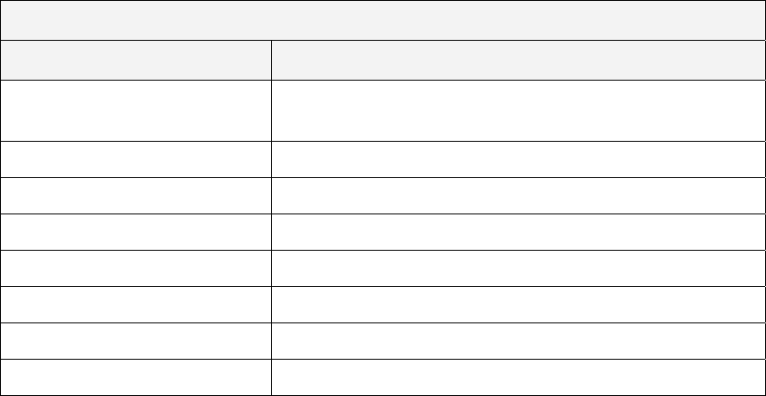
case studies, guidelines, and other actions needed for both technologies to succeed.
Table 4 below summarizes these barriers along with the action recommended for
addressing the each issue.
Table 4. Information/actions needed to overcome selected market barriers
Information/Actions Needed to Overcome Selected Market Barriers
Market Barrier Information/Action Needed
C
e
osts of identifying efficient
quipment
Product directory showing characteristics and performance
P erformance uncertainties Case studies documenting performance with testimonials
Acquisition costs Guidelines for specifying and purchasing
Financing Benefits information, sources of funding
Hidden costs Installation, operation, and maintenance guidelines
High purchase price Rebates or other financial incentives
Codes and standards Documented performance
Product availability Publicity and other actions in this table
•
around the differences between
o be
rgy
, and
Savings By Design programs.
With UVC s dard is needed to assure that acceptable
VC system design (sizing), installation, field performance,
se goals in
Continued action is needed to address codes and standard issues that impede the
specification and installation of DV and UVC systems.
The main codes and standards issues with DV revolve
conventional mixed-ventilation systems and stratified DV systems. These differences
occur in the areas of room air flow patterns, sizing, room air temperature distribution,
ventilation effectiveness, thermal loads and indoor pollutants, supply-air quantity and
temperature, control strategies, and economizer operation. Existing standards need t
modified to assure that DV is handled fairly. These standards are principally the Ene
Code provisions (Part 6) of the State of California Building Code (Title 24) and the
ASHRAE 90.1 standards. Other corollary programs, based in part on the California
Energy Code (Title 24, Part 6) and ASHRAE standards, are the CHPS, LEED™®
ystems, a comprehensive UVC stan
practice is defined for U
maintenance, lamp replacement, and safety. An emerging effort with the
mind is being led by the International Ultraviolet Association. Title 24, ASHRAE, CHPS,
LEED™®, and Savings by Design standards and programs need to be modified to assure
that efficiency improvements associated with the use of UVC lamps are incorporated.
The general problem with receiving credit for UVC systems is that building codes and
standards and the corollary programs based on these standards assume that the coils are
56
clean and do not account for the degradation in performance that naturally occurs ov
time.
Results are encouraging but
er
• inconclusive.
The ves
indoor air quality in K
savings d gs due to
increased economizer use and some savings due to reduced cooling loads. Energy
savings of 10–40% are expected, depending on the climate.
s for UVC technology in coil cleaning showed substantial surface disinfection
icant reducti
findi ,
onsidered surp on system
n is better understood.
4.5.2. rcialization Poten
Specific com under the
respective sections for Project 2 and P
Market connection efforts for these tw ntinue with influential market
participants and organizations for the nsistent and relevant
formation needs to be delivered in effective media forms to relevant market actors,
nd-standards governing bodies in order to enable understanding and
cceptance of the new DV and UVC products. Market barriers and issues of concern must be
overcom
technol
4.5.3.
•
t
of air-handling units and UVC light systems should be
.
•
results of the IEQ Program indicate that DV reduces energy use and impro
–12 schools in California. The primary data for DV showed
uring the month of November 2005 of ≥ 39% with most of the savin
The result
but no statistically signif
rates. These preliminary
on in HVAC coil energy use or student absentee
ngs, while different from what was originally expected
should not be c rising once the influence of coil fouling
performance degradatio
Comme tial
mercialization information for the DV and UVC technologies is provided
roject 3 of this report.
o technologies need to co
California K–12 schools market. Co
in
consumers, and codes-a
a
e by promoting understanding and by continuing research activities for both
ogies.
Recommendations
Additional testing is recommended.
With DV systems, more data is needed from the Capistrano test classroom in order to
corroborate the findings that the system provides cooling energy savings and indoor air
quality improvement. If possible, additional data should be obtained in order to perform
validation of the “load partitioning” being considered by Title 24 personnel as a means
for enabling the use of programs such as DOE-2.1 or DOE-2.2 to model displacemen
systems. If this data and corresponding correlations were made available, the case for
implementing code changes to accommodate the use of these technologies would be
stronger. A much larger sample
evaluated, with some of these test UVC units placed in situations that would include
moist, microbial-rich conditions that encourage coil fouling and loss of performance
Market connection activities for future PIER programs should be extended beyond the
period of performance for the technical projects.
This action would enable the more effective distribution and dissemination of the
research results to key market participants, and to be able to adequately follow up
questions and requests with answers, additional information, published articles, as well
57
as with presentations in meetings and other venues critical to reaching and influencing
key market participants.
• ed after data from field tests is analyzed.
oth
ws
4.5.4.
Statew ct
4) activ
Statewide energy impacts should be revisit
It is recommended that the estimates of energy impact and market penetration for b
the DV and the UVC technologies be revisited after better data is available on
performance improvements. Market penetration estimates can be made based on life-
cycle cost calculations, payback periods, and market research (that includes intervie
with key infrastructure participants).
Benefits to California
ide energy impacts are not directly applicable to the Program Market Connection (Proje
ities conducted under the PIER IEQ program.
58
5.0
Blatt, M d HVAC Systems for Improving Indoor Environmental
Quality
California Energy Commission, February 13, 20
1, 2004
Blatt, M
in Calif
Energy
g Indoor Environmental Quality and Energy Performance in
Blatt, Morton H., 2006C. “Improving Indoor Environmental Quality and Energy Performance in
California K-12 Schools,” Application Guidelines for Off-the-Shelf Displacement Equipment, for the
California Energy Commission, May 24, 2006.
Blatt, Morton H. 2006D. “Improving Indoor Environmental Quality and Energy Performance in
California K-12 Schools,” Application Guidelines for Ultraviolet Lighting Equipment for Coil
Cleaning, for the California Energy Commission, May 19, 2006.
Collaborative for High Performance Schools. 2006. Best Practices Manual. Available at
http://www.chps.net/index.htm. Accessed April 29, 2006.
Collaborative for High Performance Schools A. “GuidelineTC2: DV System,” Draft for the Next
Version of the CHPS Best Practices Manual, Volume II, Design
Collaborative for High Performance Schools B. “GuidelineTC26: Ultraviolet Lights for Coil
Cleaning,” Draft for the Next Version of the CHPS Best Practices Manual, Volume II, Design.
Department of Energy. DOE Air Conditioning Standard, effective on all units manufactured
after January 23, 2006.
Eley, Charles and Arent, John. 2006. “DV: Design and Application,” SMUD Presentation, April
27, 2006.
Sagges and Robinson, 2005. p. 21, IUVA News, Volume 7, No. 3, p. 21.
Siegel, et al., Lawrence Berkeley National Laboratory
State of California. 2002. Kindergarten-University Public Education Facilities Bond Act of 2002.
Summary available at http://www.smartvoter.org/2002/11/05/ca/state/prop/47/. Accessed
April 28, 2006.
Engineered Systems. 2006A. “Ultraviolet Light for Coil Cleaning in Schools,” Engineered
Systems, March 2006, pp. 50–60, 95.
Engineered Systems. 2006B. “The Right Place for Displacement,” Engineered Systems, April 2006,
pp. 56–62.
References
orton H. 2004. “Advance
and Energy Performance in California K-12 Schools,” Technology Transfer Plan, for the
04 with revised deliverables dates on December
orton H., 2006A. “Improving Indoor Environmental Quality and Energy Performance
ornia K-12 Schools”, EdSpec Model for Ultraviolet Lights for Coil Cleaning, for the California
Commission, May 16, 2006.
Blatt, Morton H., 2006B. “Improvin
California K-12 Schools”, EdSpec Model for DV HVACE Applications, for the California Energy
Commission, May 16, 2006.
59
Okura, Stacia. 2006. “An Introduction to UVC Surface Disinfection and Evaluation of its Use in
California K-12 Air Conditioning Systems,” SMUD Presentation, April 27, 2006.
60
6.0 Glossary
Specific terms and acronyms used throughout this report are defined as follows.
Acronym Definition
AC air conditioning
ACEEE American Council for an Energy Efficient Economy
ACM alternate calculation method
AEC Architectural Energy Corporation
ADA average daily attendance
ASHRAE American Society of Heating, Ventilating, and Air Conditioning Engineers
Bioaerosols Airborne products that include microorganisms, their fragments and spores,
metabolic gases, and other toxins and waste products
Btu British thermal unit
CASBO California Association of School Business Officials
CASH Coalition of Adequate School Housing
CFD computational fluid dynamics
cfm cubic feet per minute
CFU Colony-forming unit
CHPS Collaborative for High Performance Schools
CSBA California School Board Association
CTAC Customer Technologies Application Center
DOE-2 An hourly building energy simulation software package
DV displacement ventilation
DX Direct expansion (refers to the thermodynamic process where the refrigerant
in an air-conditioning or heat pump system expands directly in the cooling
coil or evaporator). Technology is commonly used in packaged and split
system equipment.
EdSpec Educational Specification (the document that sets forth the requirements that
design professionals must follow when they design new schools or
modernize existing schools)
EnergyPlus A subhourly building energy simulation software package
EPA U.S. Environmental Protection Agency
61
Acronym Definition
f
ur
C on, and air-conditioning
school
LEED™ Leadership in Energy and Environmental Design™
MEV minimum efficiency reporting value
Modernization A set of extensive improvements to an existing school that often includes air
usly only heated. The scope of a
include new lighting systems, controls, and
d through DV systems, which is at a temperature
imum humidity of about 60%.
visory Committee)
earch
RD&D
SAT re
SDG&E mpany
t foot
GWh gigawatt-ho
HVA Heating, ventilati
IAQ Indoor air quality
IEQ Indoor environmental quality
in inch
K–12 Kindergarten through high
kWh kilowatt-hour
LBNL Lawrence Berkeley National Laboratory
conditioning for spaces that were previo
modernization project may also
finishes, among others.
MW megawatt
Neutral air Conditioned air delivere
between about 63°F and 68°F and with a max
OA outside air
PAC Program Advisory Committee (or Project Ad
PG&E Pacifica Gas and Electric Company
PIER Public Interest Energy Res
ppm parts per million
research, development and demonstration
supply air temperatu
SCE Southern California Edison Company
San Diego Gas and Electric Co
SEER seasonal energy efficiency ratio
SMUD Sacramento Municipal Utility District
62
Acronym Definition
UC ersity of California
distribution
” band
C ile organic compound
Univ
UFAD under-floor air
UL Underwriters Laboratory
UVC ultraviolet in the “C
VAV variable air volume
VO Volat
W watt
63
64

7.0 Appendices
his section lists the appendices to the final report of the Advanced HVAC Systems for Improving
al Quality and Energy Performance of California K–12 Schools Program, Contract
Number 500-03-003, conducted by Architectural Energy Corporation (AEC).
The final report and these appendices are intended to provide a complete record of the
program’s objectives, methods, findings, and accomplishments. Architects, school designers
and specifiers, contractors, school district owners and operators, manufacturers, researchers,
and the energy efficiency community should find the report and the attachments highly
applicable to their interests. Table 5 summarizes information about each attachment, including
the Energy Commission’s publication number, the title of the report or the type of publication,
and a short description. To obtain copies of these a or other reports produced within this
contract, or for more information on the PIER Program, please visit
www.energy.ca.gov/pier/buildings
T
Indoor Environment
or contact the Energy Commission’s Publications Unit at
(916) 654-5200. All research products are also available through AEC at
www.archenergy.com/ieq-k12/.
Table 5. Summary attachments
Publication Number Title Short Description
CEC-500-2003-XXXA Thermal Displacement
Ventilation (DV) in Schools
Final Report
Final report provided
overview of project results
CEC-500-2003-XXXB Thermal Displacement
Ventilation (DV) in Schools
Research Report
Research report detailing
technical results
CEC-500-2003-XXXC Thermal Displacement
Ventilation (DV) Design
Guide
Design guide for design teams
and school facility personnel
CEC-500-2003-XXXD Effectiveness Of UVC
Technology For Improving
School Performance Final
Report
Final report provided
overview of project results
CEC-500-2003-XXXE Program Market Connection
Final Report
Final report provided
overview of project results
CEC-500-2003-XXXF DV and UVC Fact Sheets Promotional material
CEC-500-2003-XXXG DV and UVC Training
Presentations
Promotional material
CEC-500-2003-XXXH EdSpec Models for DV HVAC
Applications and UVC
Applications
Sample Inputs for Educational
Specifications
65

CEC-500-2003-XXX Application Guides for Application Guidelines
Compatible Off-the-Shelf
Equipment for Use in DV and
UVC Applications in Schools
CEC-500-2003-XXX Code Action White Papers
and Brochures for DV and
UVC Technologies
Code action documents
66
