CEM3000 Service Manual
Philips Car Stereo System cem220 CEM3000 service manual
User Manual: CEM3000 service manual
Open the PDF directly: View PDF ![]() .
.
Page Count: 15
Version 1.0
CEM3000/00/55/98
3141 785 35330
Car audio system
Published by LX 1027 Service Audio Subject to modification
© Copyright 2010 Philips Consumer Electronics B.V. Eindhoven, The Netherlands
All rights reserved. No part of this publication may be reproduced, stored in a retrieval
system or transmitted, in any form or by any means, electronic, mechanical, photocopying,
or otherwise without the prior permission of Philips.
CONTENTS
�
Technical specification ..................................................................1-2
Version variation ...........................................................................1-2
Service measurement setup..........................................................1-3
Service aids .................................................................................1-4
Instructions on CD playability ................................................2-1..2-2
Block diagram................................................................................3-1
Wiring diagram...............................................................................4-1
Disassembly diagram............ ........................................................5-1
Main board
Circuit diagram .........................................................................6-1
Layout diagram ..................................................................6-2..6-3
Servo board
Circuit diagram .........................................................................7-1
Layout diagram .........................................................................7-2
Exploded view diagram .................................................................8-1

Display
• Type: High contrast LCD, 32K color illuminations
(11 characters)
• Key illumination: White
Audio Playback
• Playback Media: CD, CD-R, CD-RW, MP3-CD,
WMA, WMA-CD
• Compression format: MP3, WMA
• Disc Playback Modes: Fast Forward/Backward,
Introscan, Next/Previous Album Search, Next/
Previous Track Search
• MP3 bit rates: 32-320kbps and variable bit rate
• ID3 Tag support: Song title, artist, album
• USB Direct Modes: Fast Backward/Fast Forward,
Play/Pause, Previous/Next, Repeat, Shuffle
Tuner/Reception/Transmission
• Tuner Bands: AM, FM Stereo
• Auto digital tuning
• No. of preset stations: 18(FM), 12(AM)
• Tuner Enhancements: Auto search and store
• RDS: Station Name, Station Information, Radio
Text, Program Type, News, News & Traffic, RDS
Clock Set
Sound
• Output power (MAX): 50Wx4 channels
• Output power (RMS): 24Wx4 channels (4 ohms,
10% T.H.D.)
• Equalizer: 3-bands
• Equalizer settings: Classic, Jazz, Pop, Rock, Flat,
Optimal, Techno, User defined
• Sound Enhancement: Dynamic Bass Boost, MAX
Sound
Connectivity
• USB: USB 2.0 Host
• MP3-Link: For portable MP3 music playback
• Sub-woofer preamp output: With gain control
• Preamp output: 2 pairs RCA(L/R)
Security/Anti-thief
• Front panel: Detachable
• Display blackout: 10/20 sec selectable
Accessories
• Remote control: Slim remote with battery
• Quick start guide: English, Traditional Chinese,
Brazillian, Portuguese, Spanish
• User Manual: Brazilian Portuguese, Spanish
Power
• Power supply: 12V DC
Dimensions
• Product dimensions (W x H x D):
188 x 58 x 190 mm
• Chassis: 1 Din
•
TECHNICAL SPECIFICATION
1 - 2
Type /Versions:
Features
Board in used:
CEM3000
Service policy
SERVO BOARD
MAIN BOARD
* TIPS : C -- Component Lever Repair.
M -- Module Lever Repair
-- Used
/05 /00 /55 89/16/85/
Feature diffrence
RDS
VOLTAGE SELECTOR
ECO STANDBY - DARK
C/M
C/M
Type /Versions:
CEM3000
/05 /12 /55 89/16/85/
VERSION VARIATION
C/M
C/M
C/M
C/M
1-3
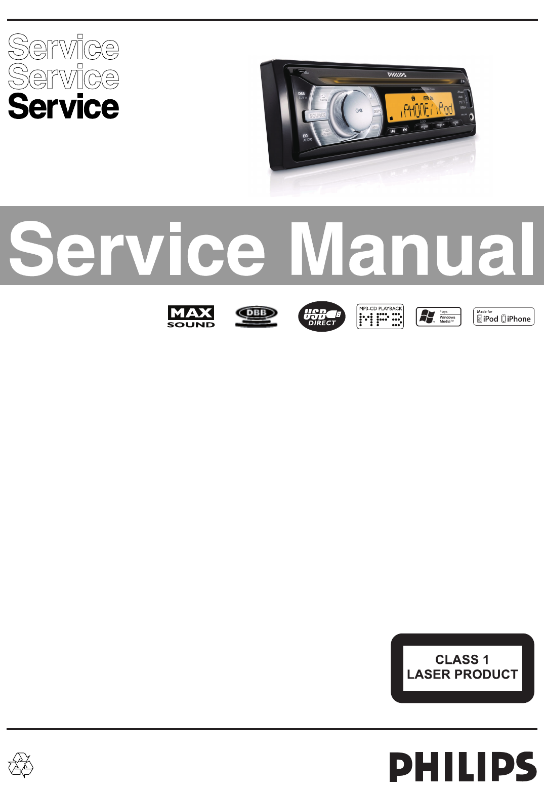
LF Generator
e.g. PM5110
Recorder
Use Universal Test Cassette CrO2 SBC419 4822 397 30069
LEVEL METER
e.g. Sennheiser UPM550
with FF-filter
S/N and distortion met
e
e.g. Sound Technology ST170
L
R
DUT
or Universal Test Cassette Fe SBC420 4822 397 30071
LEVEL METER
e.g. Sennheiser UPM550
with FF
-
filter
S/N and distortion meter
e.g. Sound Technology ST1700B
L
R
DUT
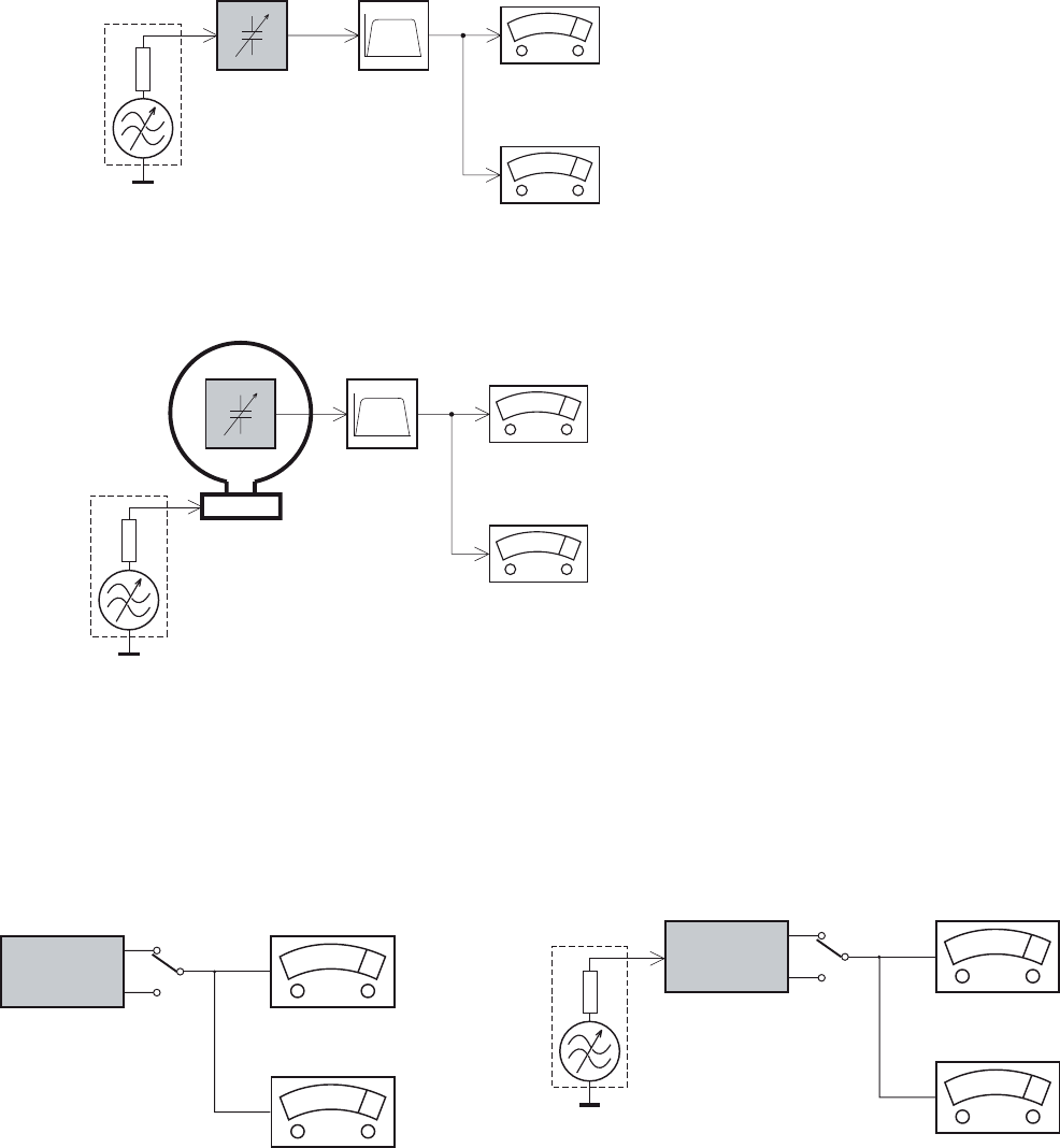
CD
Use Audio Signal Disc
(replaces test disc 3)
SBC429 4822 397 30184
Bandpass
250Hz-15kHz
e.g. 7122 707 48001
LF Voltmeter
e.g. PM2534
DUT
S/N and distortion meter
e.g. Sound Technology ST1700B
Frame aerial
e.g. 7122 707 89001
Tuner AM (MW,LW)
To avoid atmospheric interference all AM-measurements have to be carried out in a Faraday´s cage.
Use a bandpass filter (or at least a high pass filter with 250Hz) to eliminate hum (50Hz, 100Hz).
RF Generator
e.g. PM5326
Ri=50:
Bandpass
250Hz-15kHz
e.g. 7122 707 48001
LF Voltmeter
e.g. PM2534
DUT
RF Generator
e.g. PM5326
S/N and distortion meter
e.g. Sound Technology ST1700B
Use a bandpass filter to eliminate hum (50Hz, 100Hz) and disturbance from the pilottone (19kHz, 38kHz).
Ri=50:
Tuner FM
MEASUREMENT SETUP
1-4
SERVICE AIDS
GB WARNING
All ICs and many other semi-conductors are
susceptible to electrostatic discharges (ESD).
Careless handling during repair can reduce life
drastically.
When repairing, make sure that you are
connected with the same potential as the mass
of the set via a wrist wrap with resistance.
Keep components and tools also at this
potential.
ESD
CLASS 1
LASER PRODUCT
GB
Safety regulations require that the set be restored to its original
condition and that parts which are identical with those specified,
be used
Safety components are marked by the symbol !.
Lead free
Set remains closed!
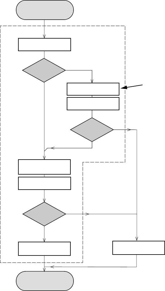
N
Y
Play a CD
for at least 10 minutes
Y
playability
ok ?
N
playability
ok ?
add Info for customer
"SET OK"
check playability
N
Y
playability
ok ?
check playability
check playability
return set
Customer complaint
"CD related problem"
"fast" lens cleaning
1
2
3For flap loaders (= access to CD drive possible)
cleaning method 4 is recommended
INSTRUCTIONS ON CD PLAYABILITY
2 - 1
Exchange CDM
1-4For description - see following pages
1
PLAYABILITY CHECK
For sets which are compatible with CD-RW discs
use CD-RW Printed Audio Disc ....................7104 099 96611
TR 3 (Fingerprint)
TR 8 (600µ Black dot) maximum at 01:00
• playback of these two tracks without audible disturbance
playing time for: Fingerprint 10seconds
Black dot from 00:50 to 01:10
• jump forward/backward (search) within a reasonable time
For all other sets
use CD-DA SBC 444A..................................4822 397 30245
TR 14 (600µ Black dot) maximum at 01:15
TR 19 (Fingerprint)
TR 10 (1000µ wedge)
• playback of all these tracks without audible disturbance
playing time for: 1000µ wedge 10seconds
Fingerprint 10seconds
Black dot from 01:05 to 01:25
• jump forward/backward (search) within a reasonable time
2
CUSTOMER INFORMATION
It is proposed to add an addendum sheet to the set which
informs the customer that the set has been checked
carefully - but no fault was found.
The problem was obviously caused by a scratched, dirty or
copy-protected CD. In case problems remain, the customer
is requested to contact the workshop directly.
The lens cleaning (method 3) should be mentioned in the
addendum sheet.
The final wording in national language as well as the printing
is under responsibility of the Regional Service Organizations.
4
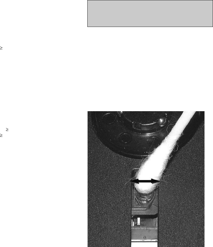
LIQUID LENS CLEANING
Because the material of the lens is synthetic and coated
with a special anti-reflectivity layer, cleaning must be done
with a non-aggressive cleaning fluid. It is advised to use
“Cleaning Solvent
The actuator is a very precise mechanical component and
may not be damaged in order to guarantee its full function.
Clean the lens gently (don’t press too hard) with a soft and
clean cotton bud moistened with the special lens cleaner.
The direction of cleaning must be in the way as indicated in
the picture below.
Before touching the lens it is advised to clean the
surface of the lens by blowing clean air over it.
This to avoid that little particles make scratches on
the lens.
INSTRUCTIONS ON CD PLAYABILITY
2 - 2
3 - 1 3 - 1
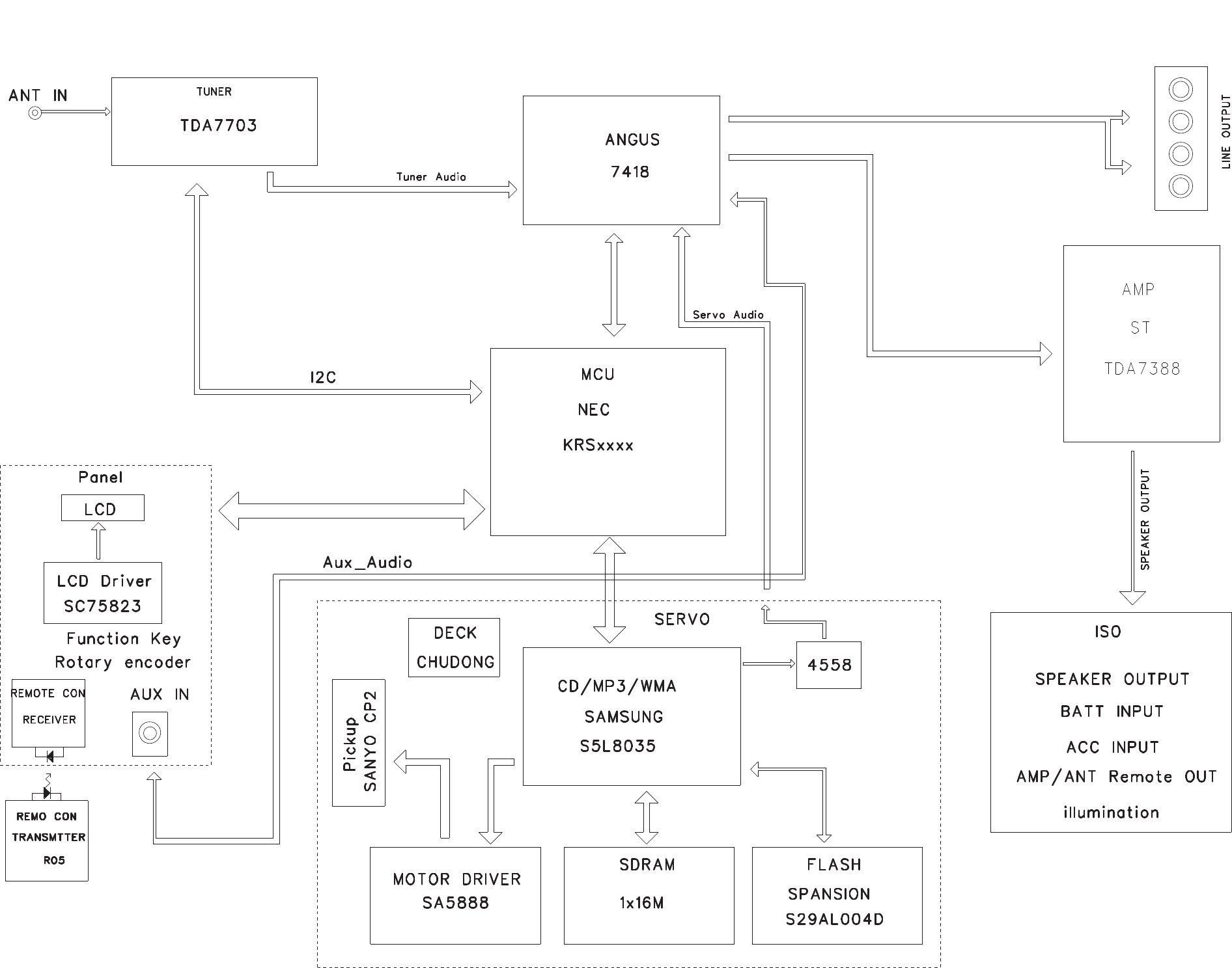
SET BLOCK DIAGRAM
4 - 1 4 - 1
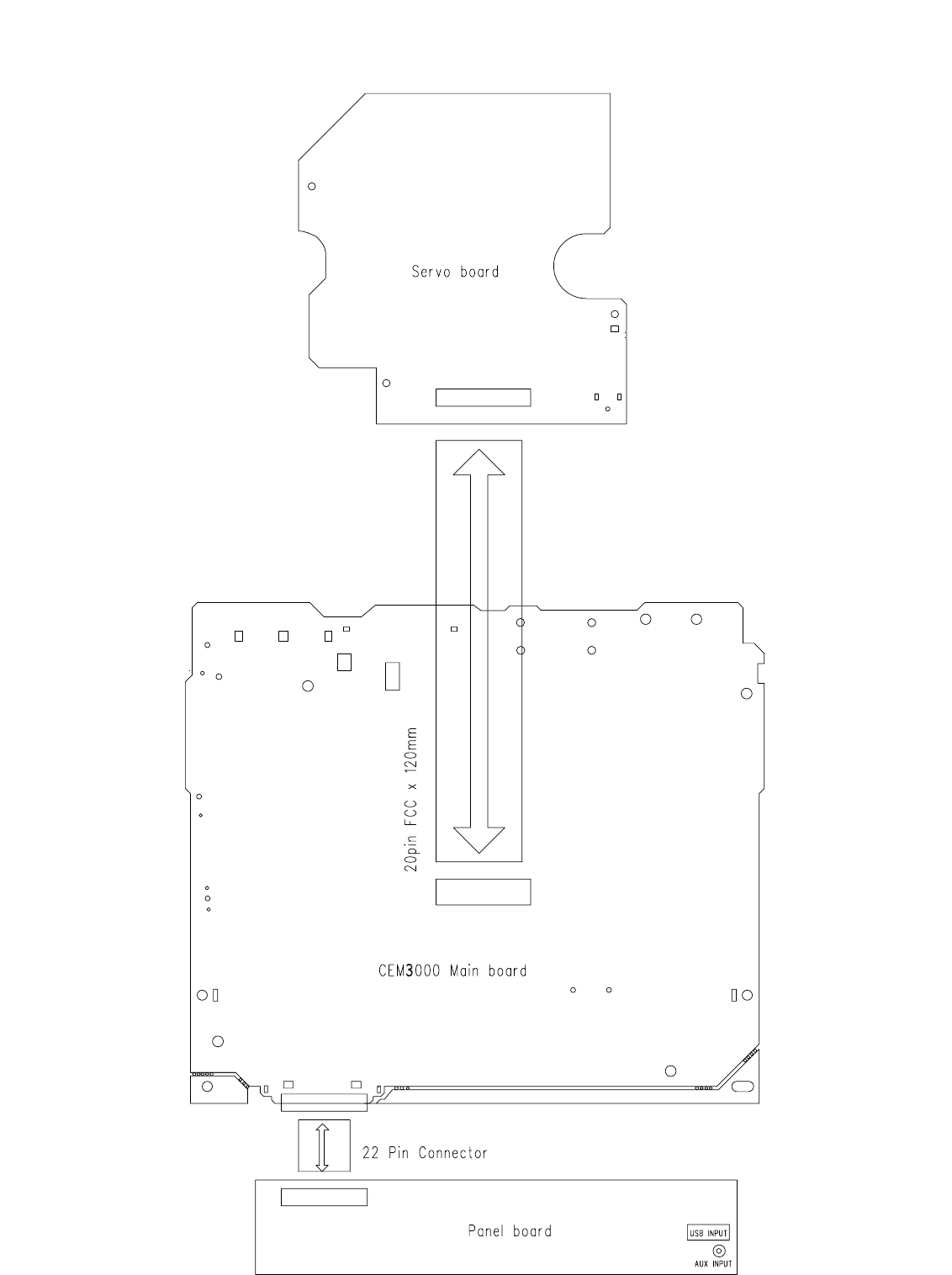
SET WIRING DIAGRAM
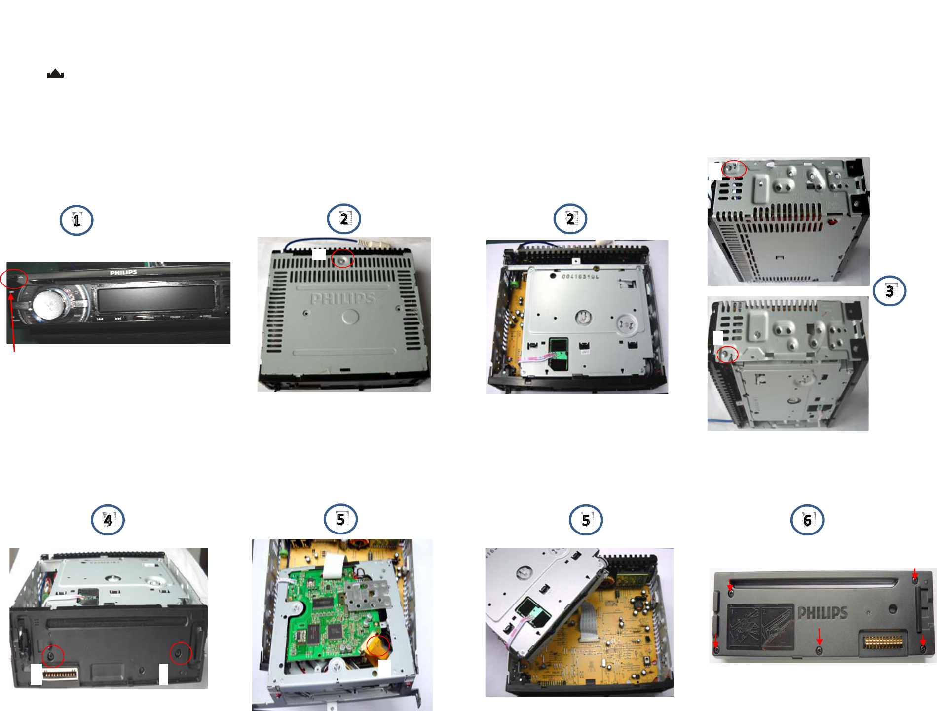
1)PRESS " " TO OPEN THE PANEL, THEN DISENGAGE IT FROM THE CHASSIS
2)REMOVE SCERW "A" AS INDICATED TO DISCHARGE THE TOP LID
3)REMOVE SCREW "B" & "C" AS INDICATESD
4)REMOVE SCREW "D" & "E" AS INDICATED
5)PUT OUT FLAT CABLE FROM DECK AS "F" INDICATED
6)REMOVE 5 SCREWS AS INDICTED TO LOSSEN THE FRONT PANEL
A
B
C
D E F
BUTTON
SET DISASSEMBLY DIAGRAM
5 - 1 5 - 1
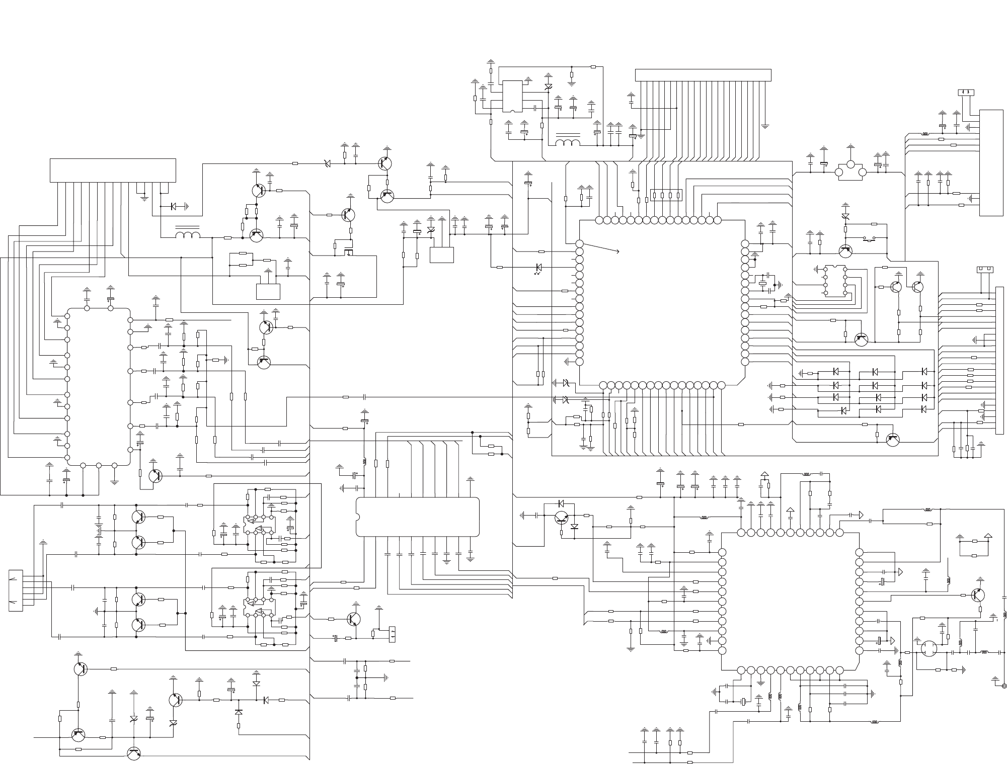
6 - 16 - 1
CIRCUIT DIAGRAM - MAIN BOARD
R123
1K
R112
2K2
R114
2K2
C37
4U7
C95 4U7
C115 4U7
C94 4U7
C93 4U7
C78 4U7
C410 4U7
C85
474
C61
474
C88
474
C67
474
R99
1K
R107
1K
C708
102
C57
102
C82
102
C92
104
R117
100K
R109
100K
R91
100K
R98
100K
R88
47K
C5
104
Q33
9014C
Q25
A1273
R168
22K
R255
4K7
C107
1UF
R144
10K
R89
1K
R118
1K
RR
FR
RL
FL
Q10
9014
EC9
NC
C89 4U7
F/R-
F/L+
F/R+
F/L-
R/R+
R/R-
R/L+
R/L-
F LIME L
F LINE R
R LINE R
R LINE L
R1
2K2
R183
100 1/2W
RR
RL
FR
FL
R55
22K
R66 47k
R149 22K
R69
10
EC106
100UF EC19
100uF
R3
220
R146 22K
R67 47k
R2
220
R85 22K
R29
22K
Q14
9014C
Q15
9014C
R36
10K
R37 10K
12
3
4
5 6 7 8
U6 4558
R81 22K
R54
22K
R60 47k
R64 22K
R58 10
EC20
47UF
EC18
100uF
R45
180
R63 22K
R61 47k
R50
180
R65 22K
R14
22K
Q13
9014C
Q12
9014C
R44
10K
R35
10K
1
2
3
4
5 6 7 8
U7 4558
R68
22K
FL
FR
RR
MUTE_1
L1 EI-14
D1
5401
EC24
100UF
S GND
R101
4k7
C73
104
BATT+
EC31
47UF
EC22
2200UF
OPTIONAL
POWER_IN2
5V_POW_IN1
OUT1
OUT2
OUT3
BEEP/IN3
MP3_CLK
CPU5V
C91 4U7
C103
NC
R75
2K2
R74 2K2
R71 2K2
R73
2K2
R192
4K7
R191
4K7
C5V
Q27 9015S
R102
NC
MUTE1
R11
4K7
R159 10K
R188
10K
Q32
9015S
ZD5
3V3
RESET
C129
104
XT4
7.2MHz
C113
27P
C112 27P
R104
330K
R113
220K
R110
220K
R95
220K
R90
220K
MP3_DI
R84
10K
Q23
9014C
R160
2K2
CPU5V
RESET
R142 100R
CPU5V
SCL
SDA
R120
1M
CD ON
CPU5V
CPU5V
R193
NC
MP3_REQ_O
Q28
9014S
R140
47K
R141
4K7
ZD4
4V7
SDA
SCL
BT_TX
BT_RX
C16
4U7
C18
4U7
C15
4U7
C17
4U7
SW101
RES SW
R194
NC
C98
1UF
C36
4U7
C35
104
R62
4K7
R18
220
R86
10K
C86
4U7
C38
4U7
RL
R189
10K
R185
10K
C118
102
C117
102
C122
104
C140
4U7
C139
4U7
C39
4U7
R158
47K
R139
4K7
R157
10K
R100
4K7
AUX/L
AUX/R
EC28
1UF
ZD3
6V8
Q30
9014
R179 1K
R152
10K
R153
10k
R174 1K
R92 100
R132 100
R10 100
R51 1K
REMOTE
C5V
+9V
ENCODER
CPU5V
AUX_L
VCC
F_INH
F_DATA
OUT3
OUT2
OUT1
CPU UPGRADE SOCKET
BT_TX
CPU5V
BT_RX
VPP
R28
5K6
2COLOR
SENSI_IN
KEY1
KEY2
R206
1M
CDP_RST
C77 4U7
D8
AREA2
D15
N.C
D20
NC
D16
DIS AUX
D7
EN RDS
D18
EN 2COLOR
D11
AREA 1
D14
DIS SW
D23
EN SUB-W
C47
474
C110
474
RDS_INT
EC30
47UF
CD_R
CD_L
C90
102
AUX R
AUX L
RA_SDA
RA_SCL
R216
47K
MP3_DO
ACC_DET
C83 4U7
R211
3K9
CPU5V
SENSIO
S5V
EC33
47UF
1
2
3
45
6
7
8GND
X IN
+5V
NC
VPP
TX
RX
RES
UP01
RESET
4
8
7
1
9
6
23
24
21
10
14
11
13
12
15
16
17
18
19
20
5
22
3
2
U3
TDA7381/84/86/88
R186
X
BT_MUTE
R234 10K
L3
15nH
EC2
47UF
EC1
47UF
EC36
47UF
IN
GND
OUT
U4
LM2950
ZD7
30V
FEEDF
IPOD_POW
R203
220K
EC21
220UF
C74 104
R78
4K7
CPU5V
Q8
9014S
R228
1K
R42
10K
R12
3K3
R17
3K3
C7
272
C9
272
RA_RST
RDS_INT
RA_SDA
R175
0
RA_SCL
R57
20K
R53
20K
RA-L
RA-R
RA-R
RA-L
RN1
4K7
F_CLK
F_DATA
F_CE
SENSIO
VOL_LED
MUTE
L2
100uH/2A
BATT+
EC4
100UF
POWER_IN2
5V_POW_IN1
EC11
10UF
EC12
10UF
R223
10K
R222
10K
R221
10K
R220 10K
EC42
NC 电池
USBPO
RA_RST
R103
NC
gnd
out in
U13
LA7809
R127 4K7
R26
NC
R207
220k
R82
1K
REMOTE
R169
4K7
C21
104
CPU5V
C111
104
R136
2K2
EC3
220UF
R190
1K
R170
1K
BEEP/IN3
C136
104
R24
1K
R93
1K
R122
1K
R491K
IN
GND
OUT
U11
78L15
ANT
ANT
1
2
3
4
5
6
7
8
9
10
11
TCAGC-FM
FLI
RF-GND
FM-MIXIN
FM-MXDEC
RF-VCC
AM-TC
FM-MPINDRV
PINDDEC
PINDIN
GND-LNA
VDD-1V2
12 13 14 15 16 17 18 19 20 21 22
LNADEC
LNAIN
LNAOUT2
LNAIN2
LNAOUT
LNADEC2
AMMIXIN
VREF165
VREFDEC
GND-DIG
VCC-DIG
33
32
31
30
29
28
27
26
25
24
23
GND-1V2
VCC-DAC
RDSINT
RSIN
VDD-1V2
SCL
SDA
VDD-3V3
REG-1V2
1V2
34
353637
38
39
40
414243
44
OSCIN
OSCOUT
L-OUT
R-OUT
GND-DAC
G-IFDAC
VCC-IFDAC
VCC-PLL
GND-PLL
VCC-VCO
GND-VCO
U2
TDA7303
C1 472
C13 47P
C14
30P
C28 2.2UF
L5
1UH
RA_5V
L6
2.7uH
C29
470P
JP1
0R
L7
2.7uH
C30
103
C33
104
C40
120P
R39
100R
R34
1K
C31
1UF
C42
103
L8
33uH
C45
104
C43
330P
R38
1K
C48
1UF
C49
1UF C50
2U2
R40
22R
C52
474
R43
10R
C105
103
C54
1UF
L11
BLM
C55
103
R46
4R7
C59
104 C56
2U2
R224
0
R27
0
C60
20P
C62
20P
XT1
37.05MHz
FB3
BLM
FB2
BLM
C64
4U7
C63 4U7
L14
1UH
R48
4R7
R47
4R7
C65 104
C69 104
C66 104
RA_5V
L9
BLM
C6
102
C8
102
C25
2U2
EC6 1UF
R212
0
R213
0
EC32 2U2
C5V
EC5
47UF
RA_5V
C70
104
C71
104
C76
104
R9
4K7
R6
1R
D26
NC
D27
N.C
D25
AREA 3
DIMMER
DIMMER
R148
4K7
VPP
LAMP_POW
F_INH
2COLOER
BT_LED
C121
22P
C12
102
R205
470K
C124
102
USB/SD_DET
CPU5V
CPU5V
CPU5V
ENCODER
Q40 9015S
R197
330K
R195
47K
ENCODER
FEEDR
1
2
3
4
5
6
7
8
9
10
11
12
13
14
15
16
17
18
19
20
21
22
23
24
CN9
CON24-2.0
MIC+
MIC-
CN1
2p-2.0mm-R
MP3_REQ_1
CD ON
USB_DP
USB_DN
USB/SD_DET
C5V
FEEDR
MP3_REQ_O
FEEDF
R131 100
R130 100
R129 100
R128 100
MP3_DO
MP3_DI
MP3_CLK
CDP_RST
SENSI_IN
S5V
R116 1K
R105 1K
CD_R
CD_L
+9V
R115
12K R108
12K
C87
152
C84
152
1
2
3
4
5
6
7
8
9
10
11
12
13
14
15
16
17
18
19
20
21
22
CN5
CON22-2.0P
AUX_R
KEY1
KEY2
F_CLK
LAMP_VCC
BT_LED
S5V
VOL_LED
USB_5V
USB_DN
USB_DP
F_CE
R80
0R
JP2
0
R19
220
R77
220
R13
47K
C53
1UF
R15
2K2
D2
4148
D4
4148
Q1
9014S
R16
100R
R22
4K7
R21
4K7
C10
100
1
2
3
4
5
6
7
8
9
10
11
12
13
14
15
CON2
ISOCON
ACC_IN
AUTO_AINT
ILLUME_IN
C137
104
SE3L 1
SE3R 2
SE2L 3
SE2R 4
SE1L 5
SE1R 6
DIEL 7
DIFFG 8
DIFFR 9
CREF 10
GND
11
SUB-W_OUT
12
OUT_RF
13
OUT_RR
14
OUT_RL
15
OUT_LF
16
MUTE
17
SCL
18
SDA
19
VDD
20
U5 TDA7418
+9V
SUB_OUT
BEEP
VCC
1
2
3
4
5
6
CON10
AV-4P
C32
104
BT_R
BT_L
AUX_R
AUX_L
MUTE
CON
CON6
SUB-WOOFER
MUTE
MUTE1
MIC+ 1
MIC- 2
GND 3
+5V 4
TX 5
RX 6
Mute 7
L-OUT 8
A-GND 9
R-OUT 10
BT1
BT-70
BT-L
BT_R
BT_MUTE
BT_TX
BT_RX
FB1
FB1
C5V
CON4
NC
L12
1R
C2
104
C5V
USB_5V
EC15
100UF
R227
4K7
USBPO
VCC R7
1 1/2W
C41
104
EC44
100UF
VCC
R155
2.2 1/2W
R156
RESETTABLE FUSE
R196
NC
C100
104
C120
104
EC39
100UF
C119
104
R5 100 1/2W
C109
104
R161
1K
Q35
9015 R167
4K7
SYS5V
C123
102
R202
22K
R201
1K
ACC_DET
D12
4148
ILLUME-IN
D24
4148
ZD6
6V8
Q2
882
Q38
9014C
Q37
9015
Q36
9014C
R176
2K2
LAMP-POW
R177
1K
R178
22K
+9V
R199
220
R187
NC
LAMP_VCC
DIMMER
L10
220nH
L4
220nH
C24
15P
C4 30P
OIRT/30P
C01
30P
R04
4K7
R05
5K6
C02
103
R01
68K
R02
270K
R03
47R
Q4
SK254
R20
100
L01
2.7uH
C03
103
Q5
9014S
R07
470
R8
2K2
Q9
SI2301BDS
POWER_IN2
C79
10UF
C80
10UF
SUB_OUT
C116
102
C127
102
C114
102
C108
102
EC46
47UF
EC29
47UF
C19
104
C34
104
C44
104
EC14
47UF
EC13
47UF
VCC
R208
220K
R204
220K
R97
2K2
R96
2k2
1
2
3
4
5
6
7
8
9
10
11
12
13
14
15
16
17 18 19 20 21 22 23 24 25 26 27 28 29 30 31 32
33
34
35
36
37
38
39
40
41
42
43
44
45
46
47
48
4950515253
55
56
5758596162
63
64 60 54
IN2/POWER
IN1/5V_POW
DIO OUT1
DIO OUT2
DIO OUT3
RESET
NC
UP
FLDM0
X-IN
X-OUT
REGC
GND
GND
VDD
VDD
RA_SDA
RA_SCL
VOL_SCL
VOL_CLK
FRONTINH
FDATA
FCLK
FRONTCE
FLASH
NC
NC
RDS_CLK
LAMP_POW
NC
RA_RES
FEEDR
NC
NC
BT_MUTE
MUTE
NC
ACC_DET
USB_POW
CD-ON
BT_TXD
BT_RXD
VDD
AGND
KEYADI2
KEYADI1
DANCE
USB/SD_DET
2COLOR
ENCODER
CDP_SW
SENSIO
CDPRES
MP3_CLK
MP3_DI
MP3_DO
FEEDF
BEEP/IN3
MP3_REQ
MP3_REQ1
NC
33Pin:REMOCONIN
BT_LED
NC
U1
CEM3000
ZD2
5V6
ZD1 5V6
R217
22K
C104
104
R218
47K
LED11
LEDN
R124
NC
R125
NC
C125
NC
C124
NC
C68
4U7
D17
IN4148
R154
4K7
L01
2.7uH
R8
1K R25
3K3
C128
4U7
R72
2.2R 1/2W
EC23
100UF
L26
10K
L28
10K
L27
10K
L25
10K
R236
49.9k
R237
43.2k
R238
49.9k
R235
75k
R240
1k
Q39
9015S
R239
10k
C5V
IPOD_POW
MCU:64Pin
Q40
9014S
R241
10K
C11
103
R56
10K
R70
45.3K
D130
NC
R79
20K
R52
4K7
5V_POW_IN1
1
2
3
4 5
6
7
8
BOOT
IN
OUT
GND FB
COMP
EN
SS
U8
RT8284N
C126
103
C99 104
C130
332
R59 47K
EC17
100UF
EC7
100UF
Q41
9014S
R242
10K
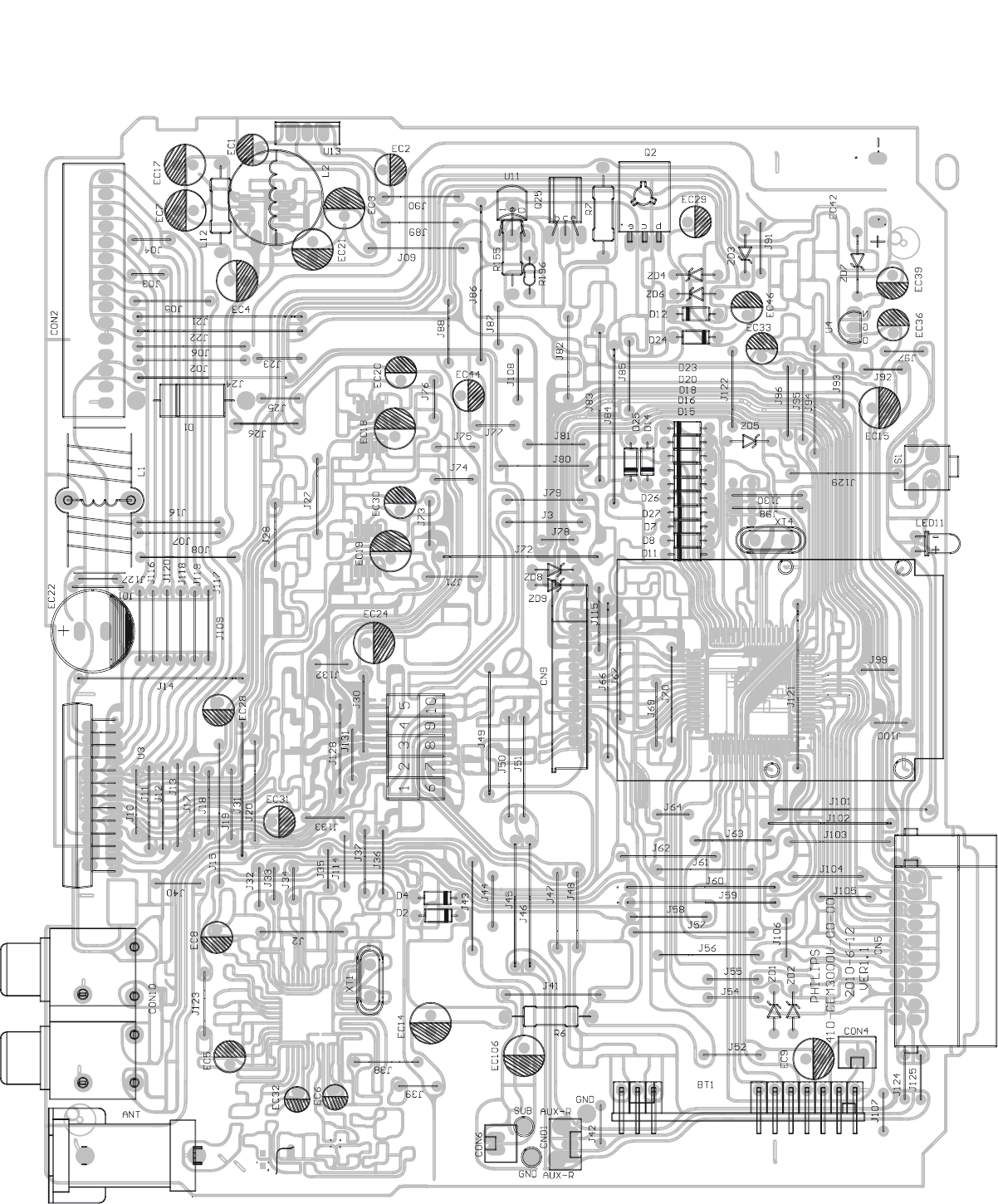
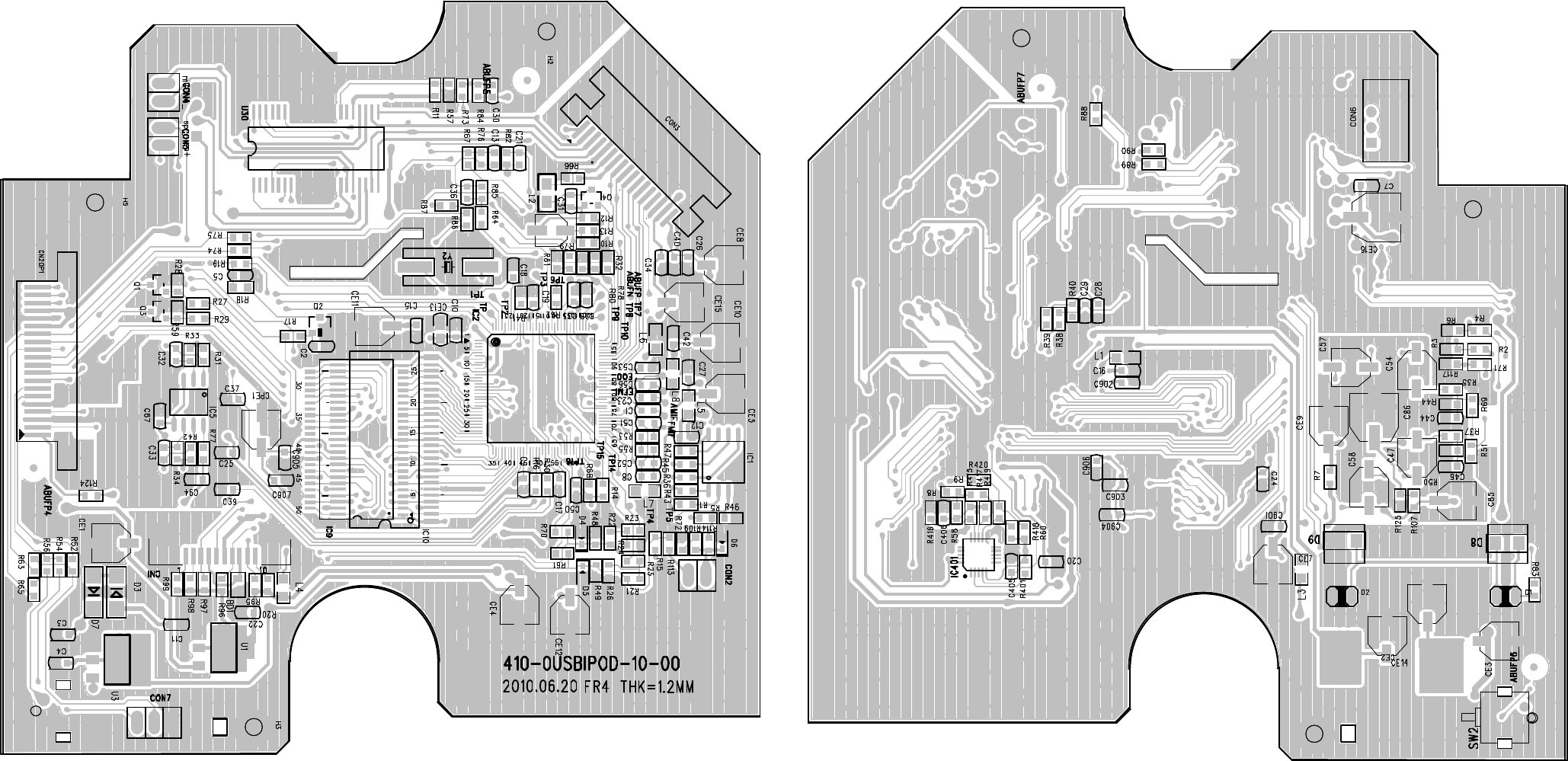
6 - 26 - 2
LAYOUT DIAGRAM - MAIN BOARD
COMPONENT SIDE
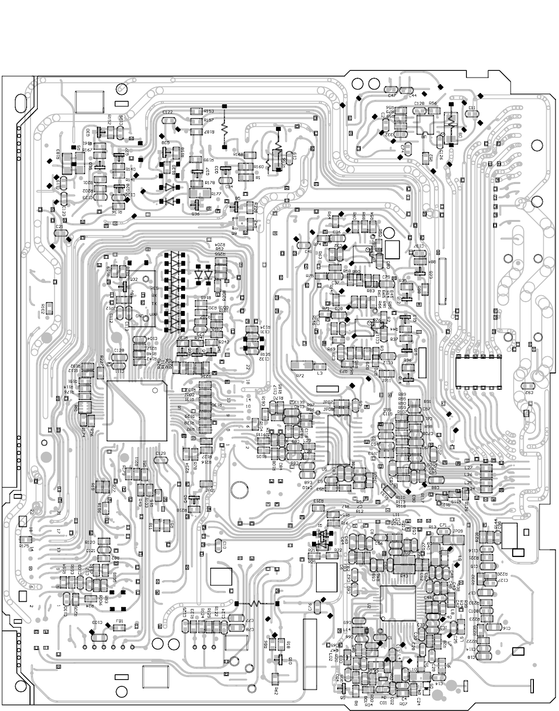
6 - 3
6 - 3
LAYOUT DIAGRAM - MAIN BOARD
COPPER SIDE
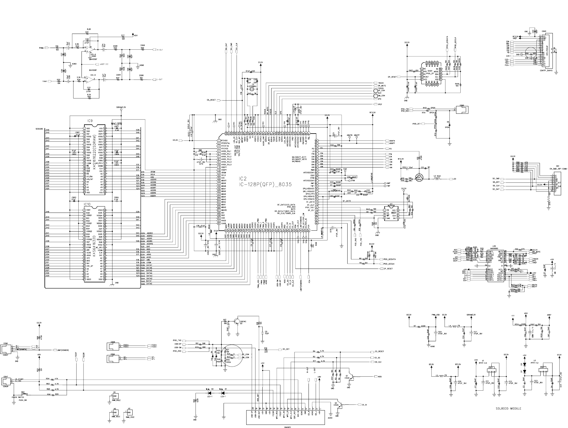
7 - 1 7 - 1
CIRCUIT DIAGRAM - SERVO BOARD
LAYOUT DIAGRAM - SERVO BOARD
7 - 27 - 2
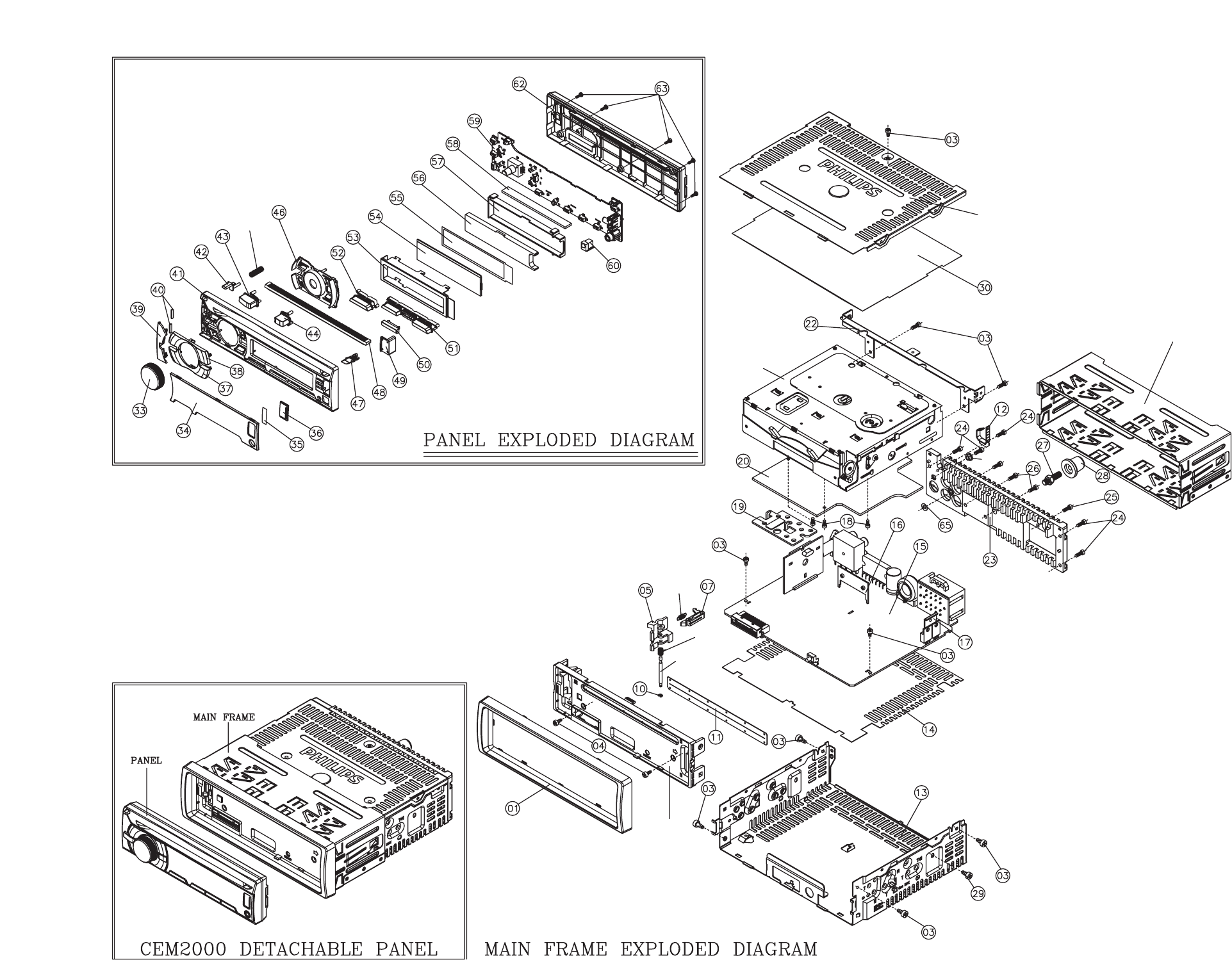
8 - 1 8 - 1
6501
6502
6503
6504
6505
6506
CD01
PL01
PL02
EXPLODED VIEW DIAGRAM
