VASC Release Guide CESL Windows
User Manual:
Open the PDF directly: View PDF ![]() .
.
Page Count: 64

Continua Enabling Software Library (CESL)
“CESL 5.0 Release Guide”
Windows Source, SDK, and Binary Release Instructions
Revision 4.0 (for CESL 5.0.2)
April 28, 2015
Copyright © 2015 Continua Health Alliance ® All Rights Reserved
This document may be distributed under the Continua license agreement.

ii
Revision History
Author
Revision
Comments
Date
Ben Reinhold
4.0
Updated for 5.0 – Gold Release [Binary, Source and SDK]
4/28/2015
Ben Reinhold
3.1
Updated for 2.0 – [Beta] Release 1 [Binary, Source and SDK]
4/10/2012
Ben Reinhold
3.0
Updated for 2.0 – [Alpha] Release 1 [Binary, Source and SDK]
2/3/2012
Lisa Colbroth
2.5
Updated to add setting of PersonID
8/26/2011
John LaMontagne
2.4
Maintenance Release #3
- Added Known Issue regarding ZigBee internal timeouts
- Updated Frontline Sniffer instructions and added files to
the Binary installer
- Numerous bug fixes to CESL code
- 35 test projects updated to create unique build logs
- WAN API and Programmer’s Guide documentation have
been added to the CESL SDK distribution
8/12/2011
John LaMontagne
2.3
Updated Release Information for Maintenance Release 2
5/6/2011
Stollmann
2.2
Updated Bluetooth Transport section for use with new
Evaluation Kit version and alternatively for use with a
Bluetooth USB dongle
4/25/2011
John LaMontagne
2.1
Official CESL 1.5.0 Release
4/12/2011
John LaMontagne
2.0
Updated for rc5.2 Release
Restructured this guide for better flow
3/21/2011
John LaMontagne
1.9
Added information for Release Candidate release
Corrected Paths of ZigBee Firmware Update
2/7/2011
John LaMontagne
1.8
Update of CESL Build – Warning removed for Debug build
Added information on manual configuration of ZigBee in the
CESL GUI Manager
Update of Bugs and Known Issues
12/30/2010
Barry Reinhold
1.7
Added Information about ZigBee and TRACElib
11/29/2010
John LaMontagne
1.6
Added Information about configuring a WAN receiver
Updated Open Issues list with Open Source bugs
11/19/2010
John LaMontagne
1.5
Updated WAN information and small changes for release
11/16/2010
Adam Elnagger
1.4
Updated WAN documentation in section 4.1.4
10/20/2010
John LaMontagne
1.3
Updated functionality in section 1.3
Added Code Changes and Known Issues to Section 1
Added Information about changes between CESL 1.0 and
CESL 1.5
Added instructions for creating CESL Unit Tests
9/17/2010
John LaMontagne
1.2
CESL 1.5 – [Beta] Release 2 [Source and SDK]
- Updated Bluetooth to new Stollmann Hardware
- Updated Source Modules for New Projects
- Added XDM Information
- Updated WAN Instructions
8/27/2010

iii
John LaMontagne
1.1
CESL 1.5 – [Beta] Release 1 [Source and SDK]
- Added WAN Instructions
- Added 1.5 Device Specializations
- Added Regression Test Suite and Instructions
7/8/2010
John LaMontagne
1.0
Alpha-1 Release of CESL 1.5 Source and Binary
4/23/2010
John LaMontagne
0.8
5th Official Release – Release Candidate 2 [RC2]
Addition of Frontline sniffer
Creation of an additional SDK installer
Moved Binary Installer instructions to separate User’s Guide
6/8/2009
John LaMontagne
0.7
4th Official Release – Release Candidate 1 [RC1]
Name change from VASC to CESL
1/13/2009
John LaMontagne
0.6
3rd Official Release – Beta
12/4/2008
John LaMontagne
0.5
Removed Linux Instructions
11/28/2008
Nathan Holstein
0.4
Linux Notes
10/21/2008
John LaMontagne
0.3
2nd Official Release – Beta
10/19/2008
John LaMontagne
0.2
Initial Release – Beta
9/4/2008
John LaMontagne
0.1
Initial Draft of document for Snapshot Release
7/24/2008

iv
Table of Contents
1 Release Information ..................................................................................... 1
1.1 Summary .................................................................................................... 1
1.2 System and Software Requirements .......................................................... 1
1.3 Functionality of Release Components ........................................................ 2
1.4 Bug Fixes Applied ....................................................................................... 3
1.5 Updates from CESL 4.0 ............................................................................... 3
1.6 Known Issues ............................................................................................. 3
2 Documentation ............................................................................................ 5
2.1 Example Documentation – CESL Reference Designs ................................... 5
2.2 CESL Requirements/Design Documentation ............................................... 6
2.3 API Documentation .................................................................................... 6
2.4 Programmer’s Guides ................................................................................ 7
2.5 Support Documents ................................................................................... 7
3 CESL 5.0 Core Distribution ............................................................................ 8
3.1 CESL Source Code ....................................................................................... 8
3.2 CESL Software Development Kit [SDK] Distribution .................................. 12
3.3 CESL Binary Distribution ........................................................................... 13
4 ZigBee Distribution ..................................................................................... 14
4.1 The FreescaleZigbeeShim Visual Studio Solution ...................................... 14
4.2 Freescale Embedded ................................................................................ 14
5 WAN Distribution ....................................................................................... 15
5.1 WAN Information ..................................................................................... 15
5.2 Building the WAN Bridge from Source ..................................................... 16
5.3 Running the Bridge within Eclipse ............................................................ 18
5.4 Using a Runnable WAN .jar file ................................................................ 18
5.5 Setting up a WAN Receiver ...................................................................... 19
6 XDM Sender Functionality .......................................................................... 21
7 Test Distribution ......................................................................................... 22
7.1 CESL Regression Testing ........................................................................... 22
7.2 Unit Tests ................................................................................................. 23

v
8 Running CESL Prototype Applications ......................................................... 25
8.1 Manager GUI Application ......................................................................... 25
8.2 Agent Applications ................................................................................... 28
8.3 Using TCP Transport ................................................................................. 32
8.4 Using USB Transport ................................................................................ 33
8.5 Using Bluetooth Transport ....................................................................... 39
8.6 Using ZigBee Transport ............................................................................ 44
8.7 Using Bluetooth(LE) Transport ................................................................. 49
Appendix A - CESL Trace Facility ........................................................................ 55
8.8 Proper Usage of CESL Trace facility .......................................................... 55
8.9 TRACELIB_THREAD ................................................................................... 55
8.10 Information Level ................................................................................. 55
8.11 Code Categories ................................................................................... 55
8.12 Conditions ............................................................................................ 55
8.13 Application Specific Additions .............................................................. 56
9 Appendix B – CESL 5.0 Enhancements ......................................................... 57
10 Appendix C - Frontline Test System ....................................................... 57
10.1 Frontline Analyzer – Quick Start Guide ................................................. 57
10.2 Additional Instructions ......................................................................... 57

1
1 Release Information
1.1 Summary
Release Title: CESL 5.0
Date: April 28, 2015
Release Version: 4.0
Release Status: Gold
Files: CESL-Source-Distribution-5.0.2.zip
[Source Distribution, contains ZigBee, Bluetooth, and Bluetooth LE transport source]
CESL-SDK-5.0.2.zip [Binary and Header File Distribution]
CESL-binary-5.0.2.zip [Binary Only Distribution]
CESL-wan-source-5.0.2.zip [WAN Source Distribution – Java]
1.2 System and Software Requirements
1.2.1 Platforms
The CESL system is engineered to run on Windows 32- and 64-bit platforms.
1.2.2 Third-Party Software
Visual Studio 2008 - This source distribution is shipped with Visual Studio 2008 compatible solution and
project files.
PThreads is required for use with this software. All required libraries are provided.
Qt is required for use with the Continua Manager GUI. Qt files are included in this source distribution to
build the Continua Manager GUI project. (Qt header files are not included with the SDK distribution.) The
necessary dynamic libraries must be located with the Manager GUI application in the \lib directory of
the source distribution or \bin directory for the SDK. If the executable is run from a different location, the
necessary Qt .dlls must be moved or copied.
CPPUNIT is required for running unit tests and is provided with this release.
libusb-Win32 – this is used by the LNI USB Manager Driver Shim to communicate with the USB device and is
provided with this release.
Frontline IEEE Protocol Analyzer (IEEE 11073+ Analyzer) – IEEE 11073+ Analyzer is a PC-based, IEEE 11073
20601 protocol analyzer that works with any CESL application (TCP, USB, and Bluetooth Transports). It
produces a much more detailed decomposition of the 20601 APDUs than provided by the CESL AL APDU
dump facility. The analysis of packets is also done in real time. This release of CESL includes the necessary
files with the source release, and automatically installs these files with the Binary and SDK release.
JAVA – Java Runtime Environment is required to run the WAN Bridge Java application
Eclipse – Build environment required to build using the WAN Bridge Java source distribution
IAR – IDE for use with Freescale ZigBee ARM based hardware. This is needed only if you are building the
embedded images that are used with the Freescale ZigBee USB dongles.
BeeKit – A software package from Freescale that is used creating embedded images for Freescale ZigBee
hardware.
Xerces This package provides support for the handling of xml documents and is used primarily in the XHR
interface.

2
1.3 Functionality of Release Components
Agent functionality
Basic Functionality
1. Adherence Monitor
Standard Configuration – Fixed Scan Report
Standard Configuration – Fixed Scan Report with Feedback
Standard Configuration – Variable Scan Report
Standard Configuration – Variable Scan Report with Feedback
Extended Configuration – ConfigID=0x7204, Fixed Scan Report
o The extended configuration is based on the Fixed Feedback standard configuration with
ConfigID=0x1C21 and has the same objects
o The status reporter object was modified to add the optional attribute Context-Key
2. Blood Pressure Monitor
3. Base Offset Time [Weighing Scale Agent to show functionality of Base Offset Time]
4. Cardiovascular Fitness and Activity Monitor
5. Glucose Meter
6. Independent Living Activity Hub
7. Insulin Pump
Standard Configuration
Extended Configuration - ConfigID=0x76CO, Fixed scan report – The extended configuration is
based on the standard configuration with the following objects added:
o Absolute Basal Rate
o Total Daily Dose
8. Peak Flow Meter
Standard Configuration
Extended Configuration - ConfigID=0x4021, Fixed scan report – The extended configuration is
based on the standard configuration with the following exceptions:
o Simple Numeric Object was modified to add the Unit-Label-String attribute
o FEV6 object was added
9. Pulse Oximeter
10. Strength and Fitness Equipment
11. Thermometer
12. Weighing Scale
Episodic Scanner – Scanner functionality added to a separate Pulse Oximeter Agent
Periodic Scanner – Scanner functionality added to a separate Pulse Oximeter Agent
PM-Store – Functionality added to a separate Glucose Meter Agent
‘One to Many’ functionality added to a separate Pulse Oximeter Agent which supports PM Store.
Manager Functionality – Manager Reference Design supports:
All Agent functionality referenced above
NOTE: The Manager only supports GetSegmentInfo for all segments. It is not designed to take a time
input and support other GetSegmentInfo APIs. However, the CESL libraries do support this.
WAN connection
XDM (Enable sending email)

3
1.4 Bug Fixes Applied
The following fixes have been applied since the previous release:
Resolved issue associated with legacy pairing: Will enable measurement transfer between Nonin Pulse
Ox and the CESL GUI.
1.5 Updates from CESL 4.0
The BTLE Thermometer GUI has been expanded to become a multifunction reference agent. This device is
now called BTLEAgentGUI, and includes weight scale and BCA configurations.
The SABTE reference agent has been added as a separate CESL project. This directory can be populated and
released independently of the CESL distribution.
Included BTLE support for included services. Previously CESL only used BTLE primary service. This was
needed to enable the BCA as an included service for the weight scale.
Included support for the UDS (User Data Service). This support is displayed in the BTLEAgentGUI and the
manager GUI
Updated nomenclature codes, mostly to include the new SABTE specialization.
Included support for the battery service
1.6 Known Issues
Agent initiated active connections can cause an issue when the user attempts to use the connect button to
associate with a Bluetooth HDP device. The CESL manager and the agent will both attempt to initiate the
connection which will cause the attempt to timeout. A user must use the “Pair” button when associating
with an active BT device. (bug 86)
An erroneous conversion is performed when transferring BTLE Agent GUI BCA measurements to the CESL
GUI. The height measurement is off by a factor of 10. IE: If the user sends a value of 70, the CESL GUI
measurement pane will show 700. (bug 88)
SABTE reconnect fails to propagate up to the application. This issue is intermittent and might be associated
specifically with the AT4 test suite. Unable to reproduce reliably. (bug 70)
WAN – SAML 2.0 Issue
By Design Guidelines, WAN is to use SAML 2.0 Token Validation.
SAML 2.0 token validation doesn’t fully exist in open source, making it challenging to integrate into CESL and
test for in the Test Tool. – Desired approach – Do not verify SAML 2.0 tokens in the test tool.
Because token validation does not fully exist, partial implementation of the SAML 2.0 has been completed
through the implementation of a patch. Operation is as follows:
o WAN Sender requests a Token to STS Service (provides a SAML 2.0 token)
o WAN Sender sends token to WAN Receiver
o WAN Receiver accepts the token but does not validate it.
o Communication can be established and verification of PCD-01 can be performed for WAN Senders
and WAN Receivers.
o SAML 2.0 Token can be used for authentication purposes only and it cannot be used to sign the
message
Because the SAML2.0 functionality is not fully implemented, but a patch was created to provide a testing
solution, the following disclaimer is included with this Release of WAN code:
a. The supplied code does not perform the primary SAML 2.0 purpose which is a trustworthy security
function
b. It is not an endorsed version of the AXIS2/Rampart code and cannot be used for non-Continua
purposes

4
c. It is not an endorsed version of the AXIS2/Rampart code and therefore is not known or supported by
that community
d. It is to be used as-is or as a pattern only for Continua testing purposes until such time as
AXIS2/Rampart is updated and works fully
NOTE: More information is provided within the WAN Programmers Guide available within the WAN Source
Distribution.
WAN – Open Source Projects – The following are issues with Open Source projects that affect WAN
operation
o Rampart: Supports SAML2.0 token issuance, but not validation.
o Sandesha: Does not automatically handle sequence termination.
o Sandesha: Several issues with ACK and fault handling.
o OHT ATNA: Several issues with BSD syslog implementation.
WAN Receiver – If WAN testing is desired, each vendor should establish a WAN receiver. Instructions for
this are available in Section 5.5 of this Release Guide.

5
2 Documentation
2.1 Example Documentation – CESL Reference Designs
The source release distribution includes 30 Reference Designs:
28 Agents
o Adherence Monitor ( Standard Configuration – Fixed )
o Adherence Monitor ( Standard Configuration – Fixed FB )
o Adherence Monitor ( Standard Configuration – Variable )
o Adherence Monitor ( Standard Configuration – Variable FB )
o Adherence Monitor ( Extended Configuration)
o Blood Pressure Monitor
o Base Offset Time (BOT)
o Cardiovascular Monitor
o Glucose Meter
o Glucose Meter [BTLE command line]
o Heart Rate Monitor [BTLE command line]
o Independent Living Activity Hub
o Insulin Pump (Standard Configuration)
o Insulin Pump (Extended Configuration)
o One-to-Many Set-Time (Pulse Oximeter supporting Set-Time and Multiple connection capability)
o One-to-Many PMStore(Pulse Oximeter with PM-Store and Multiple connection capability)
o Peak Flow Monitor (Standard Configuration)
o Peak Flow Monitor (Extended Configuration)
o PM-Store (Glucose Meter with PM-Store)
o Pulse Oximeter
o Episodic Scanner (Pulse Oximeter with Episodic Scanner)
o Periodic Scanner (Pulse Oximeter with Periodic Scanner)
o Sleep Apnea Agent (GUI implementation)
o Strength and Fitness Equipment
o Thermometer
o Thermometer [BTLE command line]
o Weighing Scale
o BTLEAgentGUI (Contains Weight Scale, BCA and Thermometer)
2 Managers
o ContinuaManagerGUI
o BTLE Transcoder Manager (console test application)
Many of these are heavily commented to provide instruction on creating Agents and Managers. To become
familiar with the source code, reviewing these is an excellent first step.
For an overall view of the process for creating an Agent, refer to AgentRefDesign.cpp located in
the \refdesign\src directory of the CESL distribution.
For details on creating objects and attributes for Agents, refer to the specific Agent Specializations located
in the \refdesign\AgentSpecializations\src directory of the CESL distribution
For information on Manager creation, refer to VASCManagerExample.cpp located in the
\refdesign\VASCManager\src directory of the CESL distribution.

6
2.2 CESL Requirements/Design Documentation
The following Specification Documents are available with this release:
Object Layer [Metric_Data_Architecture.pdf]
Transport Layer [Transport_Layer_Architecture_and_Software_Design.pdf]
HRN Module Specification [CESL_XHR_Interface_Architecture_and_Design.pdf - plus 3 images] – This is a
separate directory located in the documents directory.
The Requirements/Design Documents are located in the \docs directory of the source distribution and in the
C:\Program Files\CESL_SDK\doc directory and Start Menu with the SDK Installer.
2.3 API Documentation
2.3.1 CESL API Documentation
The API documentation provides a reference for implementers and is used when building devices or
applications. The API documentation is generated using the Doxygen tool and supplemented by the developers.
This is a tool which documents the external API's of a system from developer written comments embedded in
the code base. This type of documentation is easiest to keep up to date since it can be generated from the most
recent code base.
The API Documentation created by Doxygen is available as a zip file (API_Documentation.zip) in the \docs
directory of the source distribution and in C:\Program Files\CESL_SDK\doc\ directory for the SDK.
Unzip the ‘API_Documentation.zip’ file and click on index.html within the API_Documentation
Directory.
2.3.2 WAN API Documentation – Using Javadoc
WAN API documentation has been generated and is part of the WAN source distribution.
NOTE: The WAN API Documentation is also available with the CESL SDK distribution as a zip file
(javadoc.zip) and can be found at:
C:\Program Files\CESL_SDK\doc
Unzip the ‘javadoc.zip’ and follow steps 2 and 3 below.
1. Open the ‘org.ca.cesl.wan.documentation’ folder in the ‘wan’ distribution
2. Three html documents have been generated with Javadoc and are available in the ‘javadoc’ directory
a. encoding
b. hl7
c. transport
3. To access these documents, open the appropriate directory and click on ‘index.html’
Creating Javadoc output
NOTE: To create Javadoc output, the Java JDK is necessary and must be installed
Generation of Javadoc is very straightforward through Eclipse
1. Open Eclipse and load the WAN project.
2. Right click on the .api project you wish to create a javadoc [ex. org.ca.cesl.wan.encoding.api] and select
export from the right-click menu.
3. Open the Java category, select javadoc and click next.
4. The next screen will ask you to "Select types for javadoc generation". Select the projects to generate
javadoc (packages that end with .api) by checking the box.

7
5. Next select the member visibility to generate javadoc for (‘Protected’ gives coverage of features
available to developers).
6. Select the destination to dump the javadoc (Under the "Use standard doclet" radio button), and click
finish.
2.4 Programmer’s Guides
2.4.1 CESL Programmer’s Guide
A Programmer’s Guide for the CESL source code has been created and is available in the \docs directory of
the CESL source distribution and in the C:\Program Files\CESL_SDK\doc directory and Start Menu
with the SDK Installer. Section 10 of the guide describes the new application APIs provided in CESL 5.0.
2.4.2 WAN Programmer’s Guide
A WAN Programmer’s Guide is located within the WAN source distribution.
Open the ‘org.ca.cesl.wan.documentation’ folder in the ‘wan’ distribution.
The Programmer’s Guide (WAN-JavaProgrammersGuide-20100804.pdf) is available in the ‘users guide’ directory.
NOTE: The WAN Programmer’s Guide is also available in the C:\Program Files\CESL_SDK\doc
directory and Start Menu with the SDK Installer.
2.5 Support Documents
2.5.1 Release Guide
A Windows-oriented Release Guide (this guide) is provided with this distribution. Several guides for specific
agent applications have also been developed and will be located in the included “docs” directory.
2.5.2 Training Presentation
A Slide Presentation from the October 2008 October Plugfest has been provided for CESL Training. This is called
VASC Training Boston 2008.pdf and is located in the \docs directory of the source distribution and in the
C:\Program Files\CESL_SDK\doc directory and Start Menu with the SDK Installer.
2.5.3 AgentGui
A new GUI interface has been developed for the CESL 20601 agents. This interface provides a visual
representation for the various flags that can be set for the CESL reference agents. The GUI is provided as an
executable file that must be placed in the same directory as the CESL reference agents. The AgentGui is not
supported code and can only be used “as-is”.
2.5.4 Third-Party Guides
S3 USB - S3 Original User Guide for hardware configuration is found in the
\shims\s3\medusb_rel1.2_20080704\doc\user_guide directory. This User Guide is
located in the C:\Program Files\CESL_SDK\doc directory with the SDK Installer.
Stollmann Bluetooth – Bluetooth documentation is available with the CD that comes with the Bluetooth
hardware.
Freescale ZigBee – ZigBee hardware configuration documentation is available in the CESL source
distribution within the ZigBee Freescale shim directory (FreescaleZigBeeShim\doc)

8
3 CESL 5.0 Core Distribution
The CESL 5.0 is distributed in three forms: Source, SDK and Binary. The Binary distribution is primarily used as a
demonstration of CESL Agents and Manager and does not include documentation, source files or libraries.
3.1 CESL Source Code
The CESL Source distribution is provided as a zipped file.
Unzip the source distribution. This will unzip to a directory called Cesl-Source-Distribution-5.0.2. This directory will
contain 4 sub-directories: BTShim_Stollmann, SS1BTLEShim, FreescaleZigbeeShim, and Cesl. The following
instructions involve the Cesl directory.
3.1.1 Installing Required Libraries
When building the Source distribution, all binaries (Manager and all Agents) are copied from the Visual Studio
build via \Debug directory (or \Release, depending on the build) to the \lib directory. All dlls have
been pre-loaded into this directory for proper operation and demonstration of the binaries.
NOTE: If it is desired to start instances of the binaries (for Debug purposes) through Visual Studio, all necessary
libraries may not be available within the created \Debug directory. There are two solutions for this:
1. Position libraries (shown below) by copying them from in the \lib directory to the system directory,
or to the \Debug directory.
2. In Visual Studio, set the Working Directory for each Agent and Manager to the \lib directory.
The following dlls need to be either in the System directory or in the directory from which the binary is
executed. These dlls are available in the \lib directory.
1. libusb0.dll
2. msvcrtd.dll
3. pthreadsVC2d.dll
4. rs232api.dll [for Bluetooth operation]
5. BTLI_dll.dll [for Bluetooth trace using the Frontline Test System application]
6. ieee11073VirtualSniffer.dll [for USB and TCP trace using the Frontline Test System application]
7. SS1BTDBG.dll [for BTLE operation]
8. SS1BTGAT.dll [for BTLE operation]
9. SS1BTPS.dll [for BTLE operation]
The following dlls are required for the operation of the ContinuaManagerGUI. These can be found in the \lib
directory. If the ContinuaManagerGUI is to be run from the \Debug or \Release directories for testing
purposes, these libraries need to be copied.
1. QtCore4.dll
2. QtCored4.dll
3. QtGui4.dll
4. QtGuid4.dll
5. QtNetwork4.dll
6. QtNetworkd4.dll
3.1.2 Release Solution
1. Open Visual Studio 2008
2. Open the vasc_release.sln located in the unzipped source directory of the distribution.
This release of the CESL Source Code Repository is a Win32-based Microsoft Visual Studio 2008 Solution. There

9
are 50 individual projects which comprise the solution (vasc_release.sln). When building the solution, output is
copied to the \lib directory (both debug and release versions for .lib files).
NOTE: The SABTE agent is saved as a separate repository located at D:\git_repo\QAScripts\CESL\Cesl-Source-
Distribution-5.0.2\Cesl\SABTE. If a user wishes to build this repository they must either add the SABTE agent
manually to the release solution or build it from the SabteDemo solution.
Project Name
Description
Output
AdherenceMonitorAgentExtended
Adherence Monitor
[Reference Agent Device]
[Extended Configuration]
AdherenceMonitorAgentExtended.exe
AdherenceMonitorAgentFixed
Adherence Monitor
[Reference Agent Device]
[Standard Configuration]
[ConfigId = 0x1c20]
AdherenceMonitorAgentFixed.exe
AdherenceMonitorAgentFixedFB
Adherence Monitor
[Reference Agent Device]
[Standard Configuration]
[ConfigId = 0x1c21]
AdherenceMonitorAgentFixedFB.exe
AdherenceMonitorAgentVariable
Adherence Monitor
[Reference Agent Device]
[Standard Configuration]
[ConfigId = 0x1c22]
AdherenceMonitorAgentVariable.exe
AdherenceMonitorAgentVariableFB
Adherence Monitor
[Reference Agent Device]
[Standard Configuration]
[ConfigId = 0x1c23]
AdherenceMonitorAgentVariableFB.exe
AgentSpecializations
20 Agents
AgentSpecializations.lib
AgentSpecializationsd.lib
ASN1
Encapsulates the C Structures and
Supporting Code generated by the
ASN1C Compiler.
ASN1.lib
ASN1d.lib
Association
Implementation of the Association
Layer
Association.lib
Associationd.lib
BloodPressureMonitorAgent
Blood Pressure Monitor
[Reference Agent Device]
BloodPressureMonitorAgent.exe
BotAgent
WeighScaleAgent
using Base Offset Time (BOT)
BotAgent.exe
BTLEAgentGUI
GUI interface supporting BTLE
weight scale, BCA and
thermometer agents
BTLEAgentGUI.exe
BTLE Transcoder Manager
Reference console manager
working with BTLE for debugging.
Prints details of the BTLE exchange
processes.
BTLETranscoderManager.exe

10
CardiovascularMonitorAgent
Cardiovascular Fitness and
Activity Monitor
[Reference Agent Device]
CardiovascularMonitorAgent.exe
ContinuaManagerExample
Underlying code for Manager GUI
ContinuaManagerExample.lib
ContinuaManagerExampled.lib
ContinuaManagerGUI
Reference Manager Device
ContinuaManagerGUI.exe
GlucoseMeterAgent
Glucose Meter
[Reference Agent Device]
GlucoseMeterAgent.exe
IndependentLivingHubAgent
Independent Living Activity Hub
[Reference Agent Device]
IndependentLivingHubAgent.exe
InsulinPumpAgent
Insulin Pump
[Reference Agent Device]
[Standard Configuration]
InsulinPumpAgent.exe
InsulinPumpAgentExtended
Insulin Pump
[Reference Agent Device]
[Extended Configuration]
InsulinPumpAgentExtended.exe
MessageModule
Contains classes for abstraction of
the various Apdu types defined by
20601. Also provides a simplified
API for creating, serializing, and
de-serializing messages
MessageModule.lib
MessageModuled.lib
ObjectLayer
Implementation of the Object
Layer. Implements Abstractions of
the DIM, MDS, Agent, Objects, and
Attributes. Also contains a
“Message Factory” which is
designed to greatly simplify
message manipulation
ObjectLayer.lib
ObjectLayerd.lib
OneToManyPMStore
‘One to Many’ Pulse Oximeter
Agent with PM Store
[Reference Agent Device]
OneToManyPMStore.exe
OneToManySetTime
‘One to Many’ Pulse Oximeter
Agent with Set Time support
[Reference Agent Device]
OneToManySetTime.exe
PeakFlowMonitorAgent
Peak Flow Monitor
[Reference Agent Device]
[Standard Configuration]
PeakFlowMonitorAgent.exe
PeakFlowMonitorAgentExtended
Peak Flow Monitor
[Reference Agent Device]
[Extended Configuration]
PeakFlowMonitorAgentExtended.exe
PMStoreAgent
Glucose Meter with PM-Store
[Reference Agent Device]
GlucoseMeterAgentWithPMStore.exe
PosixWin32
Provides limited POSIX
compatibility when running under
a Windows environment
PosixWin32.lib
PosixWin32d.lib
PulseOximeterAgent
Pulse Oximeter
[Reference Agent Device]
PulseOximeterAgent.exe
PulseOximeterAgentWithPeriScanner
Pulse Oximeter with Periodic
Scanner
[Reference Agent Device]
PulseOximeterAgentWithPeriScanner.exe

11
PulseOximeterAgentWithScanner
Pulse Oximeter with Episodic
Scanner
[Reference Agent Device]
PulseOximeterAgentWithScanner.exe
ServiceLayer
Implementation of the Service
Layer as defined in [REFERENCE].
Handles service registration and
defines prototypes for Apdu
Dispatch.
ServiceLayer.lib
ServiceLayerd.lib
StrengthFitnessEquipmentAgent
Strength & Fitness Equipment
[Reference Agent Device]
StrengthFitnessEquipmentAgent.exe
TcpAgentShim
Shim used for TCP connection with
the Agent
TcpAgentShim.dll
TcpManagerShim
Shim used for TCP connection with
the Manager
TcpManagerShim.dll
ThermometerAgent
Thermometer
[Reference Agent Device]
ThermometerAgent.exe
Thermometer Agent (BTLE)
Thermometer Agent using BTLE
[Reference Agent Device]
ThermometerAgentBtle.exe
ThermometerAgentExample
Underlying Code for
ThermometherAgentGUI
ThermometerAgentExample.lib
ThermometerAgentExampled.lib
TIL
Implementation of the Transport
Interface Layer. Provides the
device/application with an easy to
manage set of calls that provide a
clear API for interacting with the
Transport Layer from any level in
the Application.
TIL.lib
TILd.lib
TRACElib
Supports trace messages in the
shims
TRACElib.dll
TransportAPI
Application that wraps the
functionality of the lower level
transport libraries in C++
TransportAPI.lib
TransportAPId.lib
usb_agent
Agent Side USB Transport Shim
provided by S3.
usb_agent.dll
usb_manager
Manager Side USB Transport Shim
provided by S3
usb_manager.dll
vascbtshim
Shim used for Bluetooth
connection with the Manager
vascBtShim.dll
VASCTrace
Provides debugging trace facilities
VASCTrace.lib
VASCTraced.lib
WanDemoBridge
Continua Manager GUI connection
to the WAN Bridge
[Demonstration library]
WanDemoBridge.lib
WanDemoBridged.lib
WeighScaleAgent
Weighing Scale
[Reference Agent Device]
WeighScaleAgent.exe
XDMSender
Implementation of email sender of
XDM output
XDMSender.lib
XHRInterface
Interface for exporting 20601 data
to CDA XML
XHRInterface.lib
XHRInterfaced.lib
12
3.1.3 Additional Project
Two additional projects are available within the source distribution but must be added to the solution before
building.
Project Name
Description
Output
SABTE
Sleep Apnea and
Breathing Therapy
Equipment GUI [Reference
Agent Device]
WinSabteAgent.exe
VascDevUnitTestCmdLine
Unit Test Application run
on the Command Line
VascDevUnitTestCmdLine.exe
unit_test.log
3.1.4 Building from Source
Build vasc_release.sln
The solution may be built with either Release or Debug configuration. If unit tests are to be run, the
solution must be built in Debug configuration.
3.1.5 Known Build Warnings
3.1.5.1 Debug Configuration Build
ContinuaManagerGUI – 1 Warning – vc90.pdb file not found. This has no impact on the project output.
3.1.5.2 Release Configuration Build
No Warnings detected
3.2 CESL Software Development Kit [SDK] Distribution
3.2.1 Installation
An SDK installer for Windows is provided as part of the CESL Release
The application installs as “CESL Software Development Kit.” This can be uninstalled through the
Windows Add or Remove Programs.
3.2.2 Directory Structure
The program installs in C:\Program Files\CESL_SDK [default directory]
Four directories are installed
o bin – contains Agent and Manager applications, Shims, driver directories, and required
third party dynamic libraries plus other executables.
o doc – contains documents for reference and development
o include – contains source header files
o lib – contains all debug libraries
The Start Menu will have the following under Programs | CESL SDK
Continua Manager GUI application
Agent Folder – Contains shortcuts to the Agent applications. These may be filed under sub-
directories.
NOTE: Agent applications run from the Start Menu can only be executed using TCP Loopback.
For all other Agent transport options, the Agents must be run from Command Line with
appropriate options configured.

13
Documentation Folder – Access to pertinent documents
3.3 CESL Binary Distribution
A CESL Binary Distribution is provided as a demonstration of the CESL code using the Agent and Manager
Reference Device applications. This distribution does not include any source code, static libraries, header files or
documentation.
Additionally, this Binary Distribution can be used to provide for interoperability testing.
The Agent and Manager reference applications are identical to those available in the CESL SDK and the
applications as built within the CESL Source Code.
3.3.1 Binary Installer
A Binary installer for Windows is provided as a separate zip file.
Unzip the distribution. There are 2 files included in the distribution.
Click on setup.exe to install the application. The application installs as “CESL Reference Design
Applications.” This can be uninstalled through the Windows Add or Remove Programs.
3.3.2 Directory Structure
The program installs in C:\Program Files\CESL_Binary [default directory]
Four directories are installed
o bin – contains Agent and Manager applications, Shims, and required third party dynamic
libraries plus other executables.
o usb – contains driver files for USB
o btle – contains driver files for Bluetooth Low Energy
The Start Menu will have the following under Programs | CESL Example Applications
Continua Manager GUI application
Agent Folder – Contains shortcuts to the Agent applications. These may be filed under
subdirectories.
NOTE: Agent applications run from the Start Menu can only be executed using TCP Loopback.
For all other Agent transport options, the Agents must be run from Command Line with
appropriate options configured.
14
4 ZigBee Distribution
As CESL matures it is anticipated that there will be additional shims from 3rd party providers. In order to better
support these third party developers, the CESL core is being distributed independently from new shims. ZigBee is
the first “new” shim to be distributed in this more independent form. The ZigBee software comes in its own zip
archive and will unpack to two directories, a directory called FreescaleZigBeeShim, and a directory called
FreescaleEmbedded.
If the ZigBee shim is to be built from source:
1. The CESL Source (vasc_release.sln) must be built first before building the ZigBee shim. Because of matched
static libraries, both CESL Source and ZigBee shim must be built in the same configuration (either debug or
release).
2. It needs to sit in the same directory as the CESL tree. That is, both the CESL and FreescaleZigBeeShim
directories must share a common root. The Visual Studio project files use relative references to find CESL
libraries and expects to find CESL at $(SolutionDir)..\CESL.
4.1 The FreescaleZigbeeShim Visual Studio Solution
The Freescale ZigBee Shim is built using Visual Studio 2008. Within the solution select either the CESL_DEBUG or
the CESL_RELEASE configurations to build the shim. The following projects are contained within the solution:
Project Name
Description
Output
ZigBeeShim
This is the project which builds the ZigBee shim for use with CESL
ZigBeeShim.dll
ZHCDriver
This is a validation project that builds a simple test tool that can be
used to exercise components of the ZigBee shim.
It is not a supported project and is provided as is.
ZHCDriver.exe
ZHClib
The ZigBee HealthCare library
ZHClib.obj
FS_ZBAlib
The Freescale adaptor layer that provides support for ZHC using
Freescale’s ZigBee Test Controller (ZTC) serial protocol
FS_ZBAlib.obj
FSSerialPortLib
The Serial Port libraries that interfaces to the Windows Host
FSSerialPortLib.obj
SerialCmdTool
This is a validation project the exercises the serial port interface.
It is not supported as part of the ZigBee release and is provided as is.
SerialCmdTool.exe
NOTE: The included FreescaleZigBeeShim.sln is configured to only build the ZigBeeShim and FS_ZBAlib projects.
If the other projects are desired to be built, they must be selected in the Configuration Manager.
4.2 Freescale Embedded
The Freescale embedded code when unpacked has three directories.
1. ARM – This directory represents the architecture of the software that is being produced (ARM, HSC08)
2. FlashImages – This directory contains the pre-built images for flashing the Agent and Manager dongles
3. LampreyModifiedFiles – This directory contains the modifications that have been made to Freescale
BeeStack software

15
5 WAN Distribution
The WAN project is included as a separate distribution from the CESL source distribution. This project is written in
Java and uses the “Eclipse” application for building this project.
5.1 WAN Information
Information regarding this project is detailed in the WAN source distribution. There are numerous documents
provided for this project (see Sections 2.3.2 and 2.4.2. The following additional information is provided.
5.1.1 Transport
The number of specifications referenced by the Continua WAN can be daunting. The design guidelines dictate
the use of Web Services over HTTP as a base transport using TLS to secure the connection and SAML2.0 tokens
through WS-Security in order to authenticate the connection. With full security in place, it becomes impossible
to observe a simple WAN transaction as it occurs over the network. Even with TLS disabled and only using SAML
authentication tokens it is easy to get lost in the sea of XML data that is the token request, issuance, and
presentation in addition to the core WAN transaction. In order to facilitate debugging and to help satiate
curiosity as to what is going on under the hood, the WAN senders and receivers are broken into different
categories according to the subset of WAN interface functionality that they actually implement. There are four
classifications of servers included in the distribution:
Vanilla is the basic WAN Server
Sandesha implements WS-ReliableMessaging
Rampart implements WS-Security using the SAML2.0 token
Full implements both WS-Reliable Messaging AND WS-Security
Using these servers it is possible to observe the simple core WAN transaction, the WAN transaction with
reliability guarantees, the WAN transaction with user authentication, and the fully protected WAN transaction
as specified in the Continua Guidelines.
The transport packages of the WAN distribution contain the pertinent WAN client and server code, and Javadoc
is accordingly found in the org.ca.cesl.wan.documentation subproject under the transport folder.
Important WS-Security files, namely the policy.xml and sts_policy.xml policy files for the secured WAN receiver
and SAML token issuer are found in the org.ca.cesl.wan.transport.client.axiom.rampart
project under the org.ca.cesl.wan.transport.client.axiom.rampart package. These two files
are also found injected into the services.xml Web Service deployment descriptor file for the full server found in
the org.ca.cesl.wan.transport.server.full project. In the interest of validating minimal
interoperability the policy.xml file requires only that a SAML2.0 token be presented to the WAN receiver, no
signature or other validation of the message is required.
5.1.2 Java WAN Bridge
The CESL WAN interface exists as a separate Java process from the CESL Continua manager. In order to receive
observations from the manager to transmit over the WAN interface, a "bridge" is required from the C++ CESL
manager to the Java WAN code. Communications over this bridge are performed using the HTTP protocol to
communicate with a simple Servlet which executes the WAN logic. Users who are familiar with the OSGi
framework may deploy the servlet into an OSGi environment. This method of execution is not currently a typical
use case and is not supported. The servlet may also be run by deploying it into a local web server. To accomplish
this, a simple Jetty web server is included with the distribution. The main Java method to launch the server is
found in the org.ca.cesl.wan.bridge.ceslcpp.internal.launcher subproject in the
org.ca.cesl.wan.bridge.ceslcpp package. The StandaloneJettyLauncher class starts a small Jetty
server and deploys the WAN bridge servlet. The default behavior of the application is to bind locally to port 9001

16
to listen for messages from the CESL manager, and to export WAN observations to the WAN receiver located at
http://continua.bxihealth.com:8080/axis2/services/DeviceObservationConsumer_
Service. These default values may be changed by providing application arguments either through the Eclipse
IDE or through the command line interface. The format and order of the parameters can be printed by providing
any set of arguments to the application. Due to the unusual and inefficient architecture of the WAN bridge
transmitting XML observations over HTTP, this code is provided for demonstration purposes only and not to be
considered production-capable code. Unusual attributes transmitted by agents may not work.
5.1.3 Policy Documents – Client and Server
Documentation is provided regarding the web service security policy used.
5.1.3.1 Client Policy
For the four Client transport services used in the WAN distribution (vanilla, sandesha, rampart, and
full), each project includes a policy.xml. These can be found in the WAN source distribution at:
org.ca.cesl.wan.transport.client.axiom.<service>\src\org\ca\cesl\
wan\transport\client\axiom\<service>
where <service> refers to one of the transport services listed above.
5.1.3.2 Server Policy
For the four Server transport services used in the WAN distribution (vanilla, sandesha, rampart, and
full), each project includes a services.xml. These can be found in the WAN source distribution at:
org.ca.cesl.wan.transport.server.<service>\resources
where <service> refers to one of the transport services listed above.
5.2 Building the WAN Bridge from Source
WAN Bridge code is provided as a Java distribution. To build the WAN Bridge from the source code, the
application Eclipse is required.
Unzip the CESL WAN Source distribution
NOTE: Because path names are long, it is recommended the unzipped source distribution be placed in a
location to minimize additional path name lengths (as close to C:\ as possible).
5.2.1 Obtain the Eclipse build environment
1. Eclipse is provided under a Public License and can be obtained at:
http://www.eclipse.org/downloads/
2. Select to download Eclipse IDE for Java EE Developers
5.2.2 Import WAN project into eclipse to build
1. Open Eclipse.exe (This application is provided as an executable and does not install you your system)
2. In the top menu, select File | Import…
a. In the Import window, expand General and select ‘Existing Projects into Workspace’
b. Click ‘Next’
c. In the field ‘Select root directory:’ browse and select the ‘wan’ folder you unzipped in 1. Above
d. Click ‘Finish’
3. On the Welcome screen, select ‘Workbench’ in the upper right.
4. Right click the project org.ca.cesl.wan.bridge.ceslcpp and select properties
a. In the Properties window
i. Select Run/ Debug settings
ii. Click on the button New…

17
iii. Select Java Application and click ‘OK’ (this will open the ‘Edit Configuration’ window)
b. Give the configuration a memorable name (wan bridge or something similar)
c. Specify the main class
i. Click ‘Search’ next to the Main class: window
ii. Select “StandaloneJettyLauncher – org.ca.cesl.wan.bridge.ceslcpp.internal.launcher”
iii. Click ‘OK’
iv. Click ‘Apply'
d. Select the Arguments tab in the ‘Edit Configuration’ window
i. In VM Arguments (2nd window) put: (the dash [-] is necessary)
-Dwanclient.axisbase=<location of org.apache.axis2\repository directory in your wan
distribution>
NOTE: Variables in this document are expressed in the form of <description> and are meant to
be replaced by their actual value.
For example, the above turns into:
-Dwanclient.axisbase=/usr/home/ae/gitrepository/wan/org.apache.axis2/repository
or,
-Dwanclient.axisbase=C:\CESL\wan\org.apache.axis2\repository
NOTE: If desired, program arguments (top window, not VM Arguments window!) for the default
wan server can be changed. Follow the format of:
<local port to listen on> <wan hostname> <wan host port> <wan webservice name>
ex: 8080 wan.lnihealth.com 20601 axis2/services/DeviceObservationConsumer_Service
or: 9001 23.21.82.221 8443 axis2/services/HealthVault (note no http(s)://)
ii. Click Apply then OK to close the ‘Edit Configuration’ window
e. Click OK to close the Properties window.
5. In the Eclipse main menu, select Window | Preferences
a. In the left frame expand Java
b. Expand Compiler
c. Select Errors/Warnings
d. In the Errors/Warnings window, expand Deprecated and Restricted API
e. On “Forbidden reference (access rules):” select ‘Warning’
f. Click Apply
g. Select Yes for the full rebuild
h. Click OK
6. Check for build errors in the org.ca.cesl.wan.bridge.ceslcpp project. Build errors are indicated by a red x
on the folder icon next to the project name.
NOTE: Other errors may be reflected in the ‘Markers’ window. These can be disregarded as long as
there are no errors in the org.ca.cesl.wan.bridge.ceslcpp project.
7. If there are build errors with this project caused by Eclipse not unable to find the javax.servlet package,
then install the Eclipse web development tools:
a. Go to main menu “Help”
b. Select “Install New Software”
c. Under work with select “Galileo - http://download.eclipse.org/releases/galileo”
d. Make sure “Hide items that are already installed is checked
e. Under the selection window select “Web, XML, and Java EE Development”
f. Click next to install the Web, XML, and Java EE tools.

18
5.3 Running the Bridge within Eclipse
1. Right click the project org.ca.cesl.wan.bridge.ceslcpp
a. Select Run As | Java Application
b. Select “StandaloneJettyLauncher - …” as the main class if the runner requests it. Click ‘OK’
c. The Console window of the Eclipse application will identify the bridge is running.
2. Within the Manager GUI, select:
Edit | WAN Bridge | Change WAN Bridge Address/Port
3. Change the address/port to http://localhost:9001/wanbridge [default]
4. The Manager GUI will now send Agent data to this WAN Bridge. Output will be observed within Eclipse.
5. A final line with AA shows that the measurements were successfully passed to the WAN receiver
(Application Accept). Other possible responses would be:
AE – Application Error
AR – Application Reject
NOTE: To observe the data received by the WAN Bridge from the GUI Manager, it is necessary to change the
Output Flags to allow this data to be shown in the Output window of the GUI Manager.
1. In the Manager GUI menu, select Edit | Output Flags
2. In the ‘Code Group Flags’ tab, make sure the VD_WAN_BRIDGE box is checked. To only see the WAN
Bridge output, uncheck all other boxes to keep the Output window from being cluttered.
Data received by the WAN Bridge will be displayed in the GUI Manager Output window while data is sent from
the Agent to the Manager, and the Manager sends this data to the WAN Bridge.
Once the Agent is stopped, the WAN Bridge will format a PCD-01 message to send to the WAN Receiver. This
will also be shown in the Manager Output window.
5.4 Using a Runnable WAN .jar file
A separate WAN sender executable can be created and then configured for use with the GUI Manager.
5.4.1 Creating the .jar file
The ANT script ‘build-runnable-jar.xml’ can be used to generate the WanBridge.jar. The script can be run in Eclipse by
right clicking on the script file in the package explorer and selecting ‘Run as / Ant Build’. The built jar is placed in the
org.ca.cesl.wan.bridge.binary directory. However, there are four different client options one can build the jar for and the
ANT script and the source code in the WanBridgeServlet.java file have to be modified in order to be consistent.
1. In the file WanBridgeServlet.java lines 218 and 221 need to be changed depending the client model used. Line 218
needs to have the parameter set to ‘true’ for the secure clients (that turns on TLS) and line 221 needs to call the desired
client model (one of the WanServiceClientAxiom* classes).
2. In the line 110 of the ANT script, the correct WanServiceClientAxiom* class files need to be pointed to.
3. Open the MANIFEST.MF file in eclipse and be sure that the correct org.ca.cesl.wan.transport.client.axiom.* package is
included.
4. In the axis2.xml file (not the one in the /res directory) has the correct modules included. They are lines that appear as
follows:
<module ref="addressing"/>
<module ref="rampart"/>

19
<module ref="rahas"/>
<module ref="sandesha2"/>
The rampart and rahas modules are needed for security and the sandesha2 module is needed for reliable messaging.
The addressing module is needed for all clients. You are free to edit the ANT script to change the name of the resulting
jar to whatever you want.
In order to create a runnable .jar file using Eclipse:
1. Right click the project org.ca.cesl.wan.bridge.ceslcpp and select Export
2. Expand Java and select ‘Runnable JAR file’. Click ‘Next’
3. Under Launch configuration: select to run the configuration created earlier.
4. Provide a destination file name in the Export destination: frame.
5. Select “Package required libraries into generated JAR”.
6. Click ‘Finish’
7. There may be compiler warnings. These will not affect the operation of the .jar file
One still has to configure the supporting axis2.xml, MANIFEST.MF, and WanBridgeServlet.java files for the client being
used.
5.4.2 Running the .jar file
To run the java WAN Bridge executable, either the Java Runtime Environment (JRE) or Java Development Kit
(JDK) must be installed on the system.
To acquire the JRE:
1. Go to http://www.java.com/en/download
2. Click the red ‘Free Java Download’ button and click ‘Save File’
3. Once the file has been downloaded, click on the ‘jxpinstall.exe’ icon to install
Running the WAN Bridge:
1. Open a command window
2. Enter the following with the appropriate destinations
3. Be sure that the the trivial login service is also deployed when using secure communications. It is
accessed by the clients prior to the STS service (which obtains the SAML token).
java -jar -Dwanclient.axisbase=<location of org.apache.axis2 in wan repository> <location of exported bridge jar file>
NOTE: When running a built WAN Bridge generated from eclipse, this bridge listens on port 9001. Therefore, it is
required to change the port number in Edit | WAN Bridge | Change WAN Bridge Address/Port
to 9001.
5.5 Setting up a WAN Receiver
NOTE: A capable server administrator, familiar with their web application server, is assumed.
5.5.1 Building the WAN Receiver
Build the WAN source
Run the buildAARFile.xml ant script of the full server project. This will generate an AAR file which is
suitable for deployment into an axis2 service repository.

20
The WAN receiver code is known to work with Axis2 1.5.1. Axis2 1.5.2 should also work, but this has not been
tested. Before starting the service ensure that the rampart and sandesha modules included with the WAN
distribution are deployed in the modules directory of your axis2 service, and that the rampart and sandesha .jar
files are copied over to your axis2/WEB-INF/lib directory. It is important that you copy over the rampart
and wss4j .jar files in order to keep the patched SAML 2.0 support. You can ensure that your WAN receiver has
been deployed by visiting your http://<YOUR HOST NAME HERE>/axis2/services/listServices page
and ensuring that the DeviceObservationConsumer_Service service has been deployed without any errors. Also
remember to properly configure your server for use of TLS.
5.5.2 Modifying Sender Settings
Once the receiver is in place, you are ready to modify your sender settings. Under the
org.ca.cesl.wan.transport.client.axiom.tests package you will find the AbstractTransportTest
class. Modify the SERVICE_IP member to point at your server hostname and the SERVICE_PORT member to
target the port your server accepts connections on. Save the AbstractTransportTest class and execute the
TransportTestFull class under the org.ca.cesl.wan.transport.client.axiom.full.tests package to
make sure that your WAN receiver is properly functioning. Once the test passes, you are now ready to modify
the CESL WAN bridge. Open the StandaloneJettyLauncher class under the
org.ca.cesl.wan.bridge.ceslcpp.internal.launcher package, and modify the serviceIp and
servicePort members with the same values used for the full client test. Save, and run the
StandaloneJettyLauncher class.
You now have a fully functional CESL WAN bridge pointing at your WAN receiver.

21
6 XDM Sender Functionality
XDM functionality has been added to this distribution of CESL.
The XDM module takes, as input, a serialized PHR from the existing CESL code, compresses it, and delivers it to
the electronic email system in a Microsoft Windows platform. This module is developed in accordance to the
IHE’s XDM specification.
To activate this functionality in the Continua Manager GUI, check the box in
Edit | Enable Sending Email
NOTE: This option is grayed out until after activating transports (‘Start Transport’ button is clicked).
When an Agent ends its transmission and disconnects from the Manager, an Email shell will be generated with
the XDMDocumentSet.zip attachment. The email can then be addressed to be sent.
The XDMDocumentSet.zip includes a README.TXT file, an INDEX.HTM file and a directory of two .xml files.
Unzip the file
Click on INDEX.HTM
In the browser, click on ‘PHMR’ – This will display the transmitted data from the Agent.
NOTE: If an email message is generated but the attached file is not a .zip file, please refer to Section 1.8.4
Other Issues.

22
7 Test Distribution
The test distribution is made up of numerous parts. For CESL 5.0, no regression test of CESL 1.5 enhancements has
yet been provided. Unit tests are provided within the CESL source distribution and the WAN source distribution.

23
7.1 Unit Tests
Unit tests are provided for testing from the Source distribution.
NOTE: Unit tests are not available with the CESL SDK installer.
7.1.1 CESL
7.1.1.1 Source
There are 7 separate files that execute 115 separate unit tests. These files are located in the
\utests\src directory.
UNIT_TEST_ALL_ATTRIBUTE_VERIFY
UNIT_TEST_ATTRIB
UNIT_TEST_ATTRIB_2
UNIT_TEST_MDS
UNIT_TEST_MESSAGE
UNIT_TEST_MESSAGE_MODULE
UNIT_TEST_PM_STORE
7.1.1.2 Building and Running Unit Tests
To run Unit Tests from the Command Line an additional project must be added to the build in Visual
Studio 2008. Unit tests are only supported under Windows.
1. Add the project VascDevUnitTestCmdLine.vcproj to the vasc_release.sln found
in the \thirdparty\VascDevUnitTest\VascDevUnitTestCmdLine directory.
2. Build the solution in ‘Debug’ mode
NOTE: There are a total of 29 warnings produced during a build.
28 Warnings come from a linking issue with vc90.pdb
– These have no effect on testing
1 Warning is generated from VascDevUnitTestCmdLine.cpp
– This has no effect on testing
3. The Unit Tests are run from the executable VascDevUnitTestCmdLine.exe copied from the
\Debug directory to the \lib directory of the source distribution.
a. Open a Command Prompt window
b. Navigate to the \lib directory of the source distribution.
c. Type VascDevUnitTestCmdLine.exe > unit_test.log 2>&1 in the command
window and press <enter>.
4. A log of the test results (unit_test.log) will be created in the \lib directory.
7.1.1.3 Creating New Unit Tests
Unit Tests use the CppUnit for unit testing. This application is available at:
http://sourceforge.net/projects/cppunit/
The Visual Studio project called VascDevUnitTestCmdLine.vcproj located in the
/thirdparty/VascDevUnitTest/VascDevUnitTestCmdLine directory is used for Unit
Test development.
Two template files are provided for Unit Test Development. The file UNIT_TEST_HEADER_TEMPLATE.h
is provided in the /utests/include directory, and the file UNIT_TEST_CODE_TEMPLATE.cpp is
provided in the /utests/src directory. Other developed Unit Tests can be referenced within these
directories as well.

24
7.1.2 WAN Java Unit Tests (JUnit)
Unit tests for the WAN source release can be run through the Eclipse application. Load the WAN project into the
workspace as detailed above.
Within the Eclipse Project Explorer, there are 6 unit testing projects. These are the projects ending in:
.tests
.testing
Running JUnit Tests
1. Expand one of the projects for testing
2. Within the project, expand the src folder and sub-folders and look for source files following the convention
similar to:
All {something} tests
3. Right click the test source file and select "run as" -> "Junit Test"
4. You will receive console output. A JUnit summary is available under the JUnit tab.
NOTE: Some test for the WAN require the location of the axis2 folder.
Should errors arise they should be resolvable by setting the -Dwanclient.axisbase vm argument as specified in
the release instructions.

25
8 Running CESL Prototype Applications
TCP, USB and Bluetooth functionality is currently provided for all Agents and the Manager. The Manager runs from
a GUI application. All agents are run from a Command Window.
NOTE: All Shims required for the operation of the Manager and the Agents are placed with the executables in the
\lib directory for the Source distribution and the \bin directory for the SDK installer. Because the TIL
attempts to load all dlls in the ‘shim directory’ the many non-shim dlls will generate errors in the TRACE log.
In the future it is planned to place all the shims in a separate directory.
NOTE: For proper functioning of the Manager and Agent applications, libusb0.dll is provided. This dll must
either reside within the same directory as the executables or can be placed in the system folder.
8.1 Manager GUI Application
8.1.1 Configuring Manager GUI dlls
Six Qt dlls are required for proper operation of the ContinuaManagerGUI (QtCore4.dll, QtCored4.dll, QtGui4.dll,
QtGuid4.dll, QtNetwork4.dll, QtNetworkd4.dll). These have been preloaded in the \lib directory for the
Source distribution and the \bin directory for the SDK installer.
If the GUI application is executed outside of these directories, the Qt dlls must be moved to follow Windows
default paths for the application to locate these libraries.
8.1.2 Manager GUI Functionality
Menu
o File – Only provides the option to Exit the application
o Edit
Transport Settings – Permits selection of USB, TCP, Bluetooth, ZigBee and Bluetooth(LE)
transport and configuration.
ZigBee Connect – Provides the option for manual ZigBee connection
WAN Bridge – Configuration options for the WAN Bridge
(NOTE: These options are unavailable until after ‘Start Transport’ is clicked)
Enable Delivery to WAN Bridge – Default is checked to enable a connection from the
Manager GUI to the WAN Bridge for transport of Agent Device data
Change WAN Bridge Address/Port – Provides the option to have the GUI Manager look
to a different address or port for the WAN Bridge
Output Flags – Option to set flags to generate output logs to the Output window. Two groups
exist: Code Group Flags and Printing Flags.
APDU Log Directory – Permits the selection of location for the apdu_dump.txt file to be placed.
Enable/Disable Writing Measurements to File – Creates a file of Object measurements from the
Agent
(NOTE: Unavailable until after ‘Start Transport’ is clicked)
Enable Sending Email (XDM) – Creates an XDM zip attachment to an email for sending
(NOTE: Unavailable until after ‘Start Transport’ is clicked)
Accept All Connections – Default is checked to accept connections without prompt. If
unchecked, the Manager GUI will prompt for connection.
Advanced – Additional dialog boxes for configuration
Confirmation Timeout – Provides the opportunity to change the timeout for Event

26
Reports [used normally for ZigBee transport]
ZigBee Connect – Provides the ability to bypass usual Discover/Connect process to
connect directly to a known ZigBee device.
TCP Connect – Provides the ability to bypass usual Discover/Connect process to connect
directly to a known TCP device.
o Help – Provides an About dialog box for information about this version of the GUI.
Manager State – Identifies the state of the Manager GUI –Disconnected; Connected; Unassociated;
Disassociating; Operating; Waiting Configuration
Device tab – Tab is located on the right edge of the GUI
o Select Shim Directory – Allows for the opportunity to select a Shim directory for the Manager. On start,
the path defaults to the directory of the Manager GUI. For this release, all Shims are located in this
directory. A Browse button is provided to select a different directory.
o Start Transport button – Once the transports are configured, this button will enable transports
o Device List frame – This frame displays information on the devices connected to the Manager.
Discovered devices will be displayed by Name, Transport Type, Device Specialization, and Address.
Buttons at the bottom of the frame allow for:
Discover – Used with Bluetooth and ZigBee to discover Medical devices
Connect/Disconnect– Connect allows for the manual connection to Bluetooth devices –
Disconnect will shut down transport to the Agent without expecting a response from the Agent
Unassociate – Sends a message to the Agent to quit. The Manager expects a response from the
Agent and will change the Manager state to Unassociated
Abort – Aborts the connection to the Agent
o Device Information frame – Once connected, information about the device is displayed
o Data frame – Displays data received from the connected Agent
Device Information Model tab – Tab is located on the right edge of the GUI
The Device Information tab provides access to various frame displays for specific DIM objects. Not all
Agents have capability for these objects. Two specific Agents have been created with PM-Store and Scanner
objects.
o DIM – Objects frame – Displays Device Information Model objects for the Agent. By clicking on each
object, either information will be displayed stating the object is not supported, or other frames will open
permitting access to these objects.
o Segment frame – If a PM-Store is selected in the DIM-Objects frame, a Segment frame will open with 2
windows. The segment type will be displayed at the top
Type – Designates the Object type selected in the DIM-Objects frame
The left window will display recognized segments with the Agent, showing the Segment Name,
Instance # and Operating State. Two buttons are located at the bottom of the window to either
get the data from the segment, or to clear the segment from the Agent.
Segment Data window – If a Segment is selected and if the “Get Segment Data” button is
selected, all segment data will be displayed in this frame. A context menu is available to Copy,
Clear or Select All.
o If a Scanner object is selected in the DIM-Objects frame, 2 boxes and an Enable/Disable Scanning button
will be displayed to the right. The boxes identify the Type of Object and State of the object [Enabled or
Disabled]. The Enable/Disable button will allow for data to be displayed in the Data frame of the Device

27
tab. Note that the SABTE RTSAs will not be displayed in the GUI until the user manually enables the
scanner here.
Output frame – Displays debug information from the CESL Trace Facility. To change the output, select the
options available in the Edit | Output Flags menu. A context menu is available to Copy, Clear, or Select All.
Transport [Enabled/Disabled] – Five icons which will light to indicate enabled transports

28
8.2 Agent Applications
NOTE: All Agent applications are placed in the following directories:
the \lib directory for the Source distribution
the \bin directory for the SDK and Binary installers
8.2.1 Basic Agent Functionality
Reference Design Agents are pre-configured for TCP transport over a loopback interface (127.0.0.1) and will run
with the Reference Design Manager on a single system. For other TCP operations using 2 systems, and/or for
other Transport options (USB and Bluetooth), the Agents must either be executed from the Command Line using
command line switches, or from the creation of pre-configured shortcuts.
To run the Agent applications with other transport or configuration options, the following are provided:
Generic Options
o --transport [tcp | usb | bluetooth | zigbee]
This specifies the Transport to use. One of these must be set.
The default value is tcp.
o --count NUMBER
NUMBER specifies the number of event reports to send.
If this value is -1 or if this switch is not used, then event reports will be generated until the
program is manually halted.
o --shim_dir PATH
Designate a path to the Shim directory. PATH is either a relative or absolute path
o --timeout NUMBER
NUMBER specifies the number of seconds to wait for a successful connection after transport
initialization.
Default is 30 for USB and TCP, and -1 (wait forever) for Bluetooth.
o --context_key NUMBER
NUMBER specifies the context key. Used only with the Medication Monitor Agent to specify the
context key of the agent.
o --personId NUMBER
NUMBER specifies the PersonId .
ScanReports will be updated to send this PersonId.
Used with the GlucoseMeter Agent with PMStore to assign this PersonId value and an additional
PersonId values to the PM-Seg-Person-Id attribute on the segments of the PMStore Object.
The default value is unknown-person-id (0xFFFF).
o --confirmTimeout NUMBER
NUMBER is specified in milliseconds. Indicates the time to wait for the RORS Confirmation
Response. Defaults to 30000 for ZigBee and 3000 for all other transports.
o --help
Provides a listing of all command line options
TCP Specific Options
o --ip_address ADDRESS
ADDRESS is standard dot notation.
This defaults to 127.0.0.1 [loopback]
o --tcp_port PORT

29
The PORT value defaults to 6024
USB Specific Options – There are no specific USB options.
Bluetooth Specific Options [for use with the Stollmann card]
o --com_port COMPORT
COMPORT must be set to the COM port connected to the Stollmann device [e.g. COM2].
This defaults to COM0.
o --bt_pin PIN#
The shared key used for Bluetooth authentication. Default is 0000
o --connbt #
Active or passive bluetooth connection. Once paired the agent will connect to the manager if
this parameter is set to 1. If set to 0, the user must enable the connection from the manager..
Default is 1 (active connect).
ZigBee Specific Options
o --com_port COMPORT
COMPORT must be set to the COM port that windows assigned to the ZigBee USB adapter.
Defaults to COM0
o --baudrate NUMBER
Defaults to 38400 – Valid values are: 9600, 14400, 19200, 38400, 57600 and 115200.
o --zbif NUMBER
NUMBER is a small integer that identifies the interface (and associated configuration
information) that the software will use. Defaults to 0
o --srcep NUMBER
The srcep is the ZigBee defined end point on the local node that is the source of messages. The
source end point value is compiled into the Freescale ZigBee USB adaptor and is 8. This value
should be used unless the embedded software has been changed on the local ZigBee interface.
Defaults to 0x08
o --connect
This command line option tells the agent to initiate a connection by sending a ZigBee Connect
Status Notification message with the value of RECONNECT_REQUEST. Defaults to false
o --mac NUMBER
Indicates an application initiated connection, using the 64-bit IEEE address. Defaults to 0
o --nwk NUMBER
This is the 16 bit network address target address. This value is used when the agent attempts to
setup a connection. Defaults to 0x0000
o --channel NUMBER
NUMBER represents a valid ZigBee channel on which the software will operate. Defaults to 14
o --PANID NUMBER
This is the PANID that the agent will attempt to join. Defaults to 0xFFFF (Join any PAN, when
ePAN is 0)
o --epanid NUMBER
This is the extended PANID that the agent is to operate on. When epanid is set and PANID is
0xFFFF the agent will attempt to join any PAN that matches the epanid provided. Defaults to 0
o --dstep NUMBER

30
The destination end point is the ZigBee end point address the software will use in attempting to
setup a connection (11073 Tunnel). Defaults to 8
To run any of the Agent applications using these options either click on the executable, or open a command
window and navigate to the \lib directory. Enter the Agent executable followed by appropriate options. For
TCP communication to a Manager on another system within the same network, an example input would be:
ThermometerAgent.exe --transport tcp --ip_address 192.168.0.45 --count 30
NOTE: A shortcut can be created with the Target path in “Properties” edited with the appropriate options.
8.2.2 Added Agent Functionality
Three Agent applications have been modified to include additional functionality. These Agents are started as all
others with the additional functionality managed from the Manager GUI.
8.2.2.1 PM-Store
The Glucose Meter Agent example has been modified to include the PM-Store Object. The new example is
GlucoseMeterAgentWithPMStore.exe whose project name is PMStoreAgent. Previously, when this Agent was
started, the Agent command window continuously displayed generated data and cycled through stages of
having the PM store enabled and disabled. This behavior is no longer true. First it is illegal by the glucose
specialization to do so when a PM store is present. Second it is an unrealistic use case. Most PM Store agents
are designed to record measurements offline and then, at the user’s convenience, upload the measurements to
some AHD. The GlucoseMeterAgentWithPMStore.exe is now designed to follow this behavior. When started it
is initialized with one segment containing 10 observations. If person ids are optionally requested via the
command line, a second segment is added also containing 10 measurements. In that case both segments are
given person id attributes where the first segment has the person id of the command line and the second
segment has (person id + 1). The agent has been also written to support clearing these segments either by
instance list (which the ContinuaGUIManager uses) or by ‘clear all’. However, once cleared, the segments will
remain empty and the user must re-start the agent to re-load the segments.
To observe the stored data within the Segment(s):
1. Click on the Device Information Model tab (right side of the GUI)
2. In the DIM-Objects frame, select the PM-Store object. The Segment frame will open.
3. Select a segment in the Segment window
4. Click “Get Segment Data” – Data is displayed in the right window.
NOTE: This data may be copied or cleared using the available context menu.
5. Once the segment is no longer needed, click the “Clear Segment” button. This will clear the segment
from the Segment window. Attempting to get data from the segment will now fail.
6. Stop the Agent using normal operation.
NOTE: When running this Agent over USB Transport, if Disconnect is selected on the Manager GUI, the
Manager will disconnect but the Agent will not shut down. REASON: A USB device does not receive disconnect
signals from a USB host without a physical disconnect (pulling the plug). The USB device does not know the
manager has disconnected until it tries to communicate with it. Since this agent never sends data to the
manager (but only responds to requests to obtain data from the manager) it will continue to run. The Agent
must be stopped manually.
NOTE: If the GlucoseMeterAgentWithPMStore.exe is started with the –personId option on the command line,
two segments will be created on the PMStore Object. The first segment will use the personId value indicated in
the command line. The second segment will use a different personId value. Each segment will be filled with 10
measurements. The Manager GUI’s segment window will show two segments available.

31
8.2.2.2 Scanners
Two Pulse Oximeter Agents have been modified to include the Episodic and Periodic Scanner Object
(PulseOximeterAgentWithScanner.exe and PulseOximeterAgentWithPeriScanner.exe). Once these Agents are
started, debug information will be displayed in the Agent command window. However, no data will initially be
displayed in the Manager GUI. To begin data transfer, the Scanner must be enabled.
1. Click on the Device Information Model tab (right side of the GUI)
2. In the DIM-Objects frame, select the Scanner object [either Episodic or Periodic].
3. Click “Enable Scanning” to begin the scanner. Data will be displayed on the Device tab data frame.
NOTE: For the Periodic Scanner, data display is delayed up to 12 seconds
4. To stop scanning, click “Disable Scanning”.
5. Stop the Agent using normal operation.
NOTE: When running these Agents over USB Transport, if Disconnect is selected on the Manager GUI while the
scanners are disabled, the Manager will disconnect but the Agent will not shut down. REASON: A USB device
does not receive disconnect signals from a USB host without a physical disconnect (pulling the plug). The USB
device does not know the manager has disconnected until it tries to communicate with it. In this case the Agent
is not sending values to the Manager and therefore is not aware of the state of the Manager. The Agent must
be stopped manually.

32
8.3 Using TCP Transport
NOTE: For proper TCP discovery, the Manager application must be started before the Agents. Once the Manager
application is started, it is not required to re-start the Manager each time a new Agent is started.
NOTE: TCP communication requires the use of the TcpManagerShim.dll for operation of the Manager and
TcpAgentShim.dll for operation of the Agent. These shims are located in the directory with the Agent and
Manager executables. If the applications are started in a different directory, the shims must be moved to that
directory for proper TCP operation.
8.3.1 Running the CESL Manager Application (Continua Manager GUI)
1. Click on ContinuaManagerGUI.exe. This can found either in the \lib directory for the Source
distribution or in the \bin directory for the SDK and Binary installer. Additionally, a shortcut in the Start
menu may be used with the SDK and Binary installer. The Manager GUI will open.
2. From the Edit | Transport Settings menu, configure the Manager output, if desired.
3. Set the appropriate Shim path
NOTE: The Shim path should default to the directory where the executable resides. Selecting a different
path would only be necessary if the Shims do not reside in the same directory as the application.
4. Click “Start Transport.” The TCP icon will color (brown) and state “Transport: Enabled”
NOTE: Other transports may be enabled. This depends on the different Shims detected by the Manager.
5. At this point, the Manager will wait for input from the Agent
8.3.2 Running the Agent Application
1. Using Windows Explorer, navigate to the \lib directory to access the Agent executables.
2. Execute any Agent by clicking on any of the executables (for loopback connection). The agent will open a
command window to display connection information. Additionally, a shortcut in the Start menu may be
used with the SDK installer.
NOTE: For other TCP configuration options, run the Agent from the Command Line using TCP options, or
configure a shortcut.
3. If the Menu | Edit option is selected (default) for “Accept All Connections”, the Agent will be connected and
data will flow to the Manager.
If the connections are done manually, then when the Agent is discovered, the Manager displays a dialog box
asking for connection. Click ‘Yes’. The Agent device will time-out in 30 seconds if connection is not made.
4. The Agent will generate random values. These values are displayed in the Manager GUI.
NOTE: Most Agents are configured to run indefinitely. However, a few Agents are configured to send only
one measurement before closing. This can be changed by adding the --count switch and a desired
value.
5. The Agent will continue to send values unless the --count switch is used. To stop the operation, close
the Agent Command Window, or select ‘Disconnect,’ ‘Unassociate’, or ‘Abort’ on the Manager GUI.
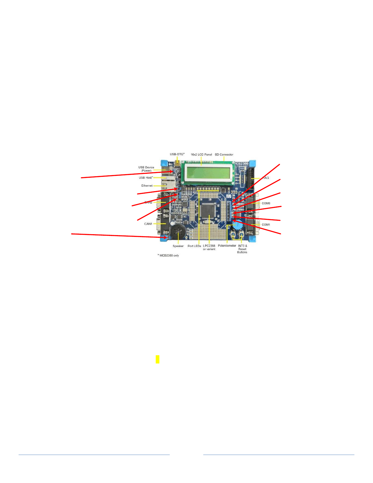
33
8.4 Using USB Transport
USB prototype functionality is provided through the Keil Evaluation Board. The evaluation board is connected to
a system using TCP to replicate the Agent. USB connection is made to a system for Manager communication.
8.4.1 Configure the USB Hardware
Instructions to set up the environment for USB device emulation are provided here.
NOTE: For additional information, refer to “medusb_user_guide.pdf” provided by S3 and located in the
\shims\s3\medusb_rel1.2_20080704\doc\user_guide directory of the source distribution and in
C:\Program Files\doc directory of the SDK.
8.4.1.1 Evaluation Board – Jumper Settings and Processor Revision
There are circuit board differences between Version 3.1 (shown in the User’s Guide and used by S3) and
Version 4 (used by LNI) requiring different jumper settings. LNI uses the MCB2300 Version 4 board with
an LPC2378 processor. Both Version 3.1 and Version 4 are compatible.
Jumper Settings for S3 Configuration
[Version 4 Evaluation Board]
J7 [VBUS] – Closed
J12 [D+] – 3-pin – Position toward speaker
J4 [D-] – 3-pin – Position toward speaker
J5 [UMODE] – 3-pin – Position toward LCD
J3 [AOUT] - Either
J11 [LED] – Closed
J10 [ISP] – Closed
J13 [ETM] – Either
J9 [RST] – Closed
J8 [INTO] – Closed
J6 [ADO.O] - Either
NOTE: There are 2 USB connections on this board, both in the top left corner of this diagram. Do not use
the USB-OTG [on-the-go] connector next to the LCD display. Only use the USB Device connector, which
uses a USB A to USB B cable.
NOTE: the USB Module SW runs only on processor revisions “A” and “B”. The processor revision is
printed on the chip. LNI Version 4 Evaluation Boards use revision B and the chip notation is as follows
(revision highlighted):
LPC2378FBD144
SH3954.1 13
ZSD0747BY
8.4.1.2 System Configuration
The Evaluation Board and the Agent PC act as the total Agent solution. The Evaluation Board is connected
by USB to the Manager PC, which is stand-alone as the Manager. There are 2 configurations possible.
1. Single PC [Using Laptop or desktop]
2. Dual PCs [ex: Desktop as the Agent PC and Laptop as the Manager PC]
NOTE: There are two systems to set up: Agent and Manager – The Agent should be set up first followed
by configuring of the manager.
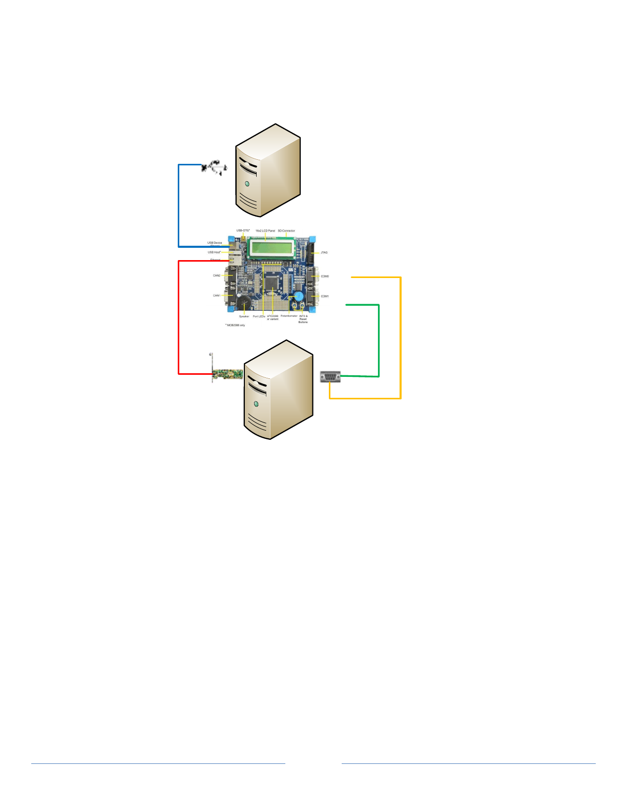
34
8.4.1.3 Hardware Elements
Two PCs are normally used to implement Agent and Manager functionality
NOTE: These two machines can be physically realized in one PC
USB
Manager PC
Agent PC
NIC COMx
COM0
COM1
Ethernet RJ45 Cable from the Agent PC to the Evaluation Board
NOTE: This should be a cross-over cable if the PC card is not 1Gb capable
Dedicated network interface card on the Agent PC – It can be 10/100Mb or 10/100Mb/1Gb
USB 2.0 PC interface on the Manager PC
USB Cable Type A-B for use between the Manager PC and the Evaluation Board
NOTE: This USB connection provides power to the Evaluation Board
RS232 Serial Connection – NOTE: These are optional connections
NOTE: Both ports do not need to be connected simultaneously.
Therefore, only one cable would be required.
o Flashing (COM0) interface [Only needed if module flashing is required] – See Section 8.4.1.4
o Console (COM1) interface [Only needed if Console Interface is desired]
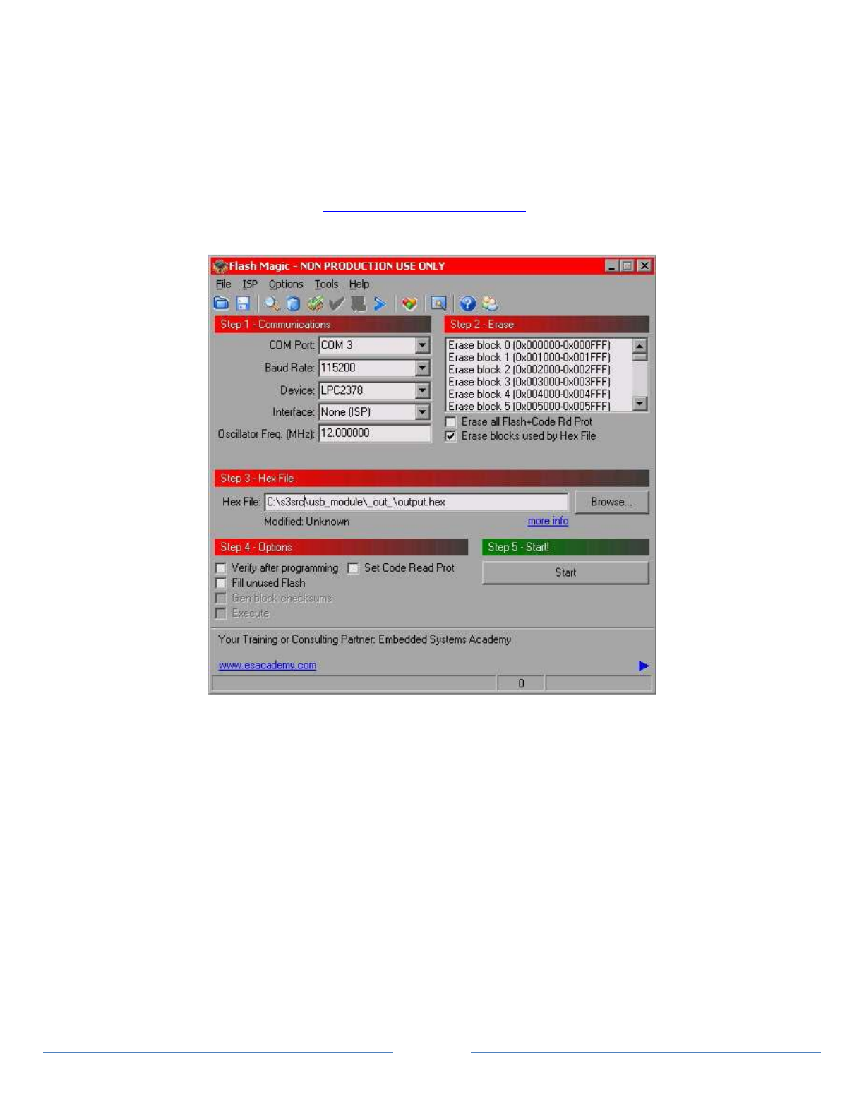
35
8.4.1.4 Flashing
When the Evaluation Board is initially connected (powered up) the LCD will display “MCB2380”.
In order to flash compiled image into the USB Module microcontroller, use the FlashMagic utility.
FlashMagic is a tool used for USB Module flashing. It is a license-free application.
Setup file: “FlashMagic.exe”
Installation remarks: Use installer defaults
Webpage: http://www.flashmagictool.com
The figure below shows the FlashMagic utility panel.
To do flashing, all parameters should be set as on the picture. Using “Browse” button, select the
“output.hex” file.
For the Source distribution, the output.hex file is located in the
\shims\s3\medusb_rel1.2_20080704\bin directory
For the SDK Installer, the output.hex file is located in the
C:\Program Files\CESL_SDK\bin\usb directory.
NOTE: The “COM Port” can be different depending on RS232 PC interface connected to the flashing
socket.
NOTE: Checking the “Erase all Flash+Code Rd Prot” will restore the default IP address. The default
address is 192.168.0.100.
Once the board has been flashed, the LCD will display “USB PHDC Module!” followed by an IP address.
Flashing is needed only on initial configuration. Once flashed, this procedure does not need to be
repeated.
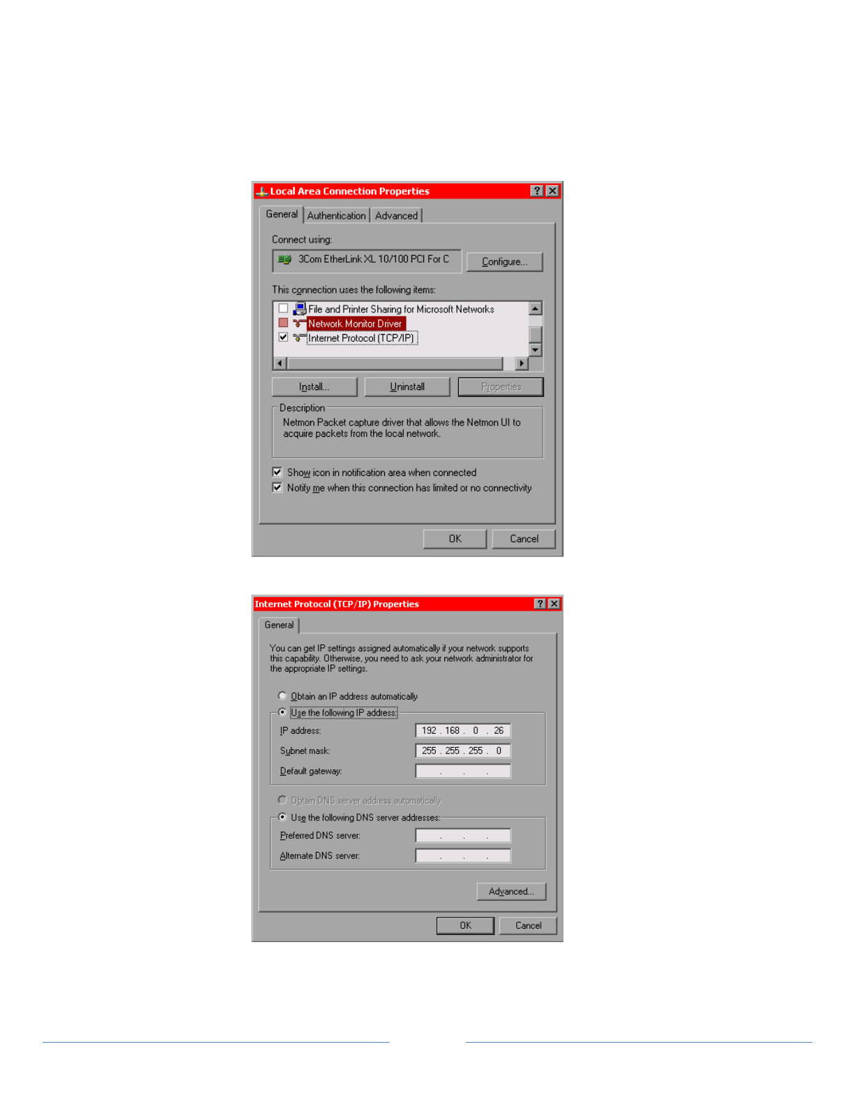
36
8.4.1.5 TCP Network Interface between Agent PC and the Evaluation Board
By default, the USB Module has IP address 192.168.0.100. Therefore, the network card dedicated for
use with the Keil board module must have an IP address of the same network; that is 192.168.0.X where
X can be any number from 1-254 excluding the IP address of the module. It is also recommended, but
not necessary, to disable the remaining supported protocols except for “Internet Protocol (TCP/IP)”.
Leave that one checked. The pictures below show the network interface configuration example.
Figure 4-1 Network Interface protocols configuration
Figure 4-2 TCP/IP configuration

37
8.4.2 Installing the LNI USB Driver
The most direct way to install the USB Driver is to start one of the USB Reference Agents provided with this
distribution. Note that Windows 8 does not allow the installation of unsigned device drivers.
1. Open a Command Window
2. Navigate to the Agent executables in the appropriate directory.
3. On the command line, execute ThermometerAgent.exe --transport usb
4. After a few seconds, Windows should flicker a notification “New USB Hardware Found”- This will bring
up the “Found New Hardware Wizard” window. Additionally, the Thermometer Agent will close.
a. Select “No, not this time” – Click “Next”
b. Select “Install from a list of specific location…” – Click “Next”
c. Use “Browse” to select the location within the source distribution
“\shims\s3\medusb_rel1.2_20080704\src\usb_manager\driver\libusb-win32-1.2.2.0\bin”
d. Click “Next” – The system should copy the necessary file and install the new USB Module device.
NOTE: For the SDK Installer, the necessary library is located in the
C:\Program Files\CESL_SDK\bin\usb directory.
8.4.3 Running the application with USB Communication
This section outlines how to run the Continua Manager GUI with any Agent over a USB connection.
NOTE: USB communication requires the use of the usb_agent.dll for operation of the Agent and
usb_manager.dll for operation of the Manager. These shims are located in the directory with the
Agent and Manager executables. If the applications are started in a different directory, the shims must
be moved to that directory for proper USB operation.
8.4.3.1 Running the Continua Manager Application
1. Click on ContinuaManagerGUI.exe. This can found either in the \lib directory for the Source
distribution or in the \bin directory for the SDK installer. Additionally, a shortcut in the Start menu
may be used with the SDK installer. The Manager GUI will open.
2. From the Settings menu, configure the Manager output, if desired.
3. Set the appropriate Shim path
NOTE: The Shim path should default to the directory where the executable resides. Selecting a
different path would only be necessary if the Shims do not reside in the same directory as the
application.
4. Click “Start Transport.” The USB icon will color (green) and state “Transport: Enabled”
NOTE: Other transports may be enabled. This depends on the different Shims detected by the
Manager.
5. At this point, the Manager will wait for input from the Agent
8.4.3.2 Running the Agent Application
NOTE: If properly configured, the Evaluation Board will display “USB Configured.” when activated by any
Agent Application.
1. Open a Command Window and navigate to the appropriate directory with the Agent executables.

38
2. Starting the Agent
a. Enter the appropriate executable (any of the Agents) on the Command Line with the
appropriate USB transport switch. A configured shortcut can also be created.
ThermometerAgent.exe --transport usb --count 30
b. The Agent will open a command window to display connection information.
3. When discovered, the Manager displays a dialog box asking for connection. Click ‘Yes’
NOTE: The Agent device will time-out in 30 seconds if connection is not made.
4. The Agent will generate random values. These values are displayed in the Manager GUI.
5. The Agent will continue to send values unless the --count switch is used. To stop the operation,
close the Agent Command Window, or select ‘Disconnect,’ ‘Unassociate’, or ‘Abort’ on the Manager
GUI.
NOTE: When running the Scanner Agents over USB Transport, if Disconnect is selected on the Manager
GUI, the Manager will disconnect but the Agent will not shut down. It will continue generating
values. The reason for this is that the Agent is not sending values to the Manager and therefore
is not aware of the state of the Manager. The Agent must be stopped manually.
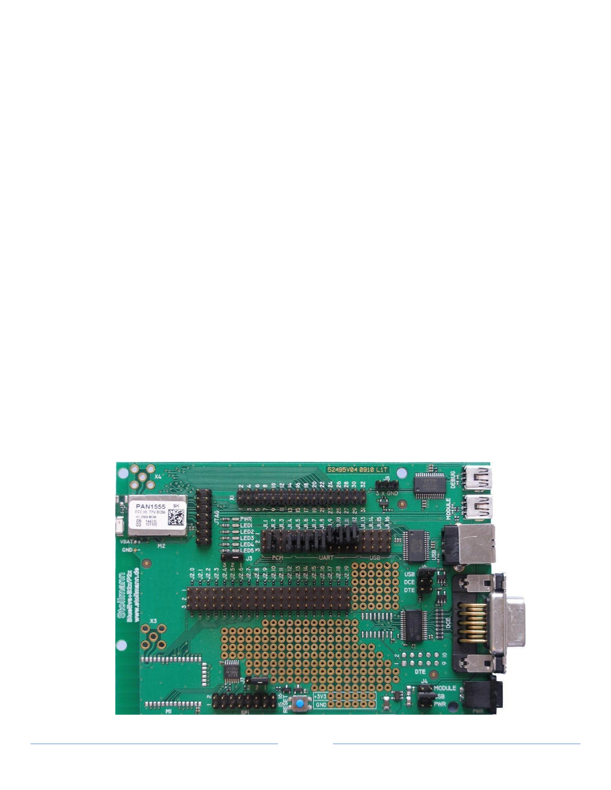
39
8.5 Using Bluetooth Transport
Bluetooth prototype functionality is provided through either the:
Stollmann BlueDev+P25/G2/HDP kit
Stollmann BlueHDP+USB dongle.
Both connect to a system to replicate the Agent or the Manager.
8.5.1 Configure for Bluetooth Operation
Some of the following information is taken from the Stollmann Evaluation Kit CD that came with the Stollmann
Evaluation Kit. Original Stollmann documentation is available on the CD.
8.5.1.1 System Requirements
Either one PC with Windows installed and two free USB ports
or
Two PCs with Windows installed, one free USB port on each
8.5.1.2 Hardware Configuration of Stollmann BlueDev+P25/G2/HDP Kit
The BlueEva+P25/G2 module jumper settings are as follows. The boards are preconfigured to the USB
mode and jumper positions should not need to be changed. If more information is required on the
evaluation board, refer to BlueEva+P25-G2_User_Guide_r03.pdf on the Stollmann CD.
o Use positions 1 & 2 for jumpers:
J1.9, J1.10, J1.11 and J1.12
J3
J7
o Use positions 2 & 3 for jumpers:
J1.2, J1.4, J1.5, J1.6, J1.7 and J1.8
o Use positions USB for jumpers:
J4 (board power selection – preset to power from USB interface)
J6 (board serial interface selection – preset to USB to serial bridge connected to USB)
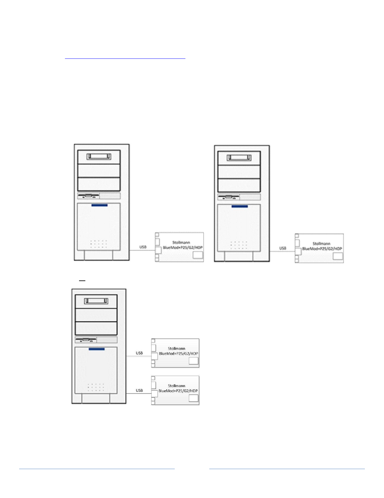
40
Connect each Stollmann BlueEva+P25/G2 module to a USB port on a PC and install the FTDI VCP USB to
UART driver (included on the BlueEva+P25/G2 CD or download at
http://www.ftdichip.com/Drivers/VCP.htm).
NOTE: Power is supplied by USB connection. Jumper J4 is used to select the power for the card.
Position USB is used for USB connection power. Position PWR is used for power supply power.
The board is preset to position USB (for USB connection power).
NOTE: Use the USB port on the Evaluation Board. Jumper J6 is used to select the USB port. Position USB
is for the USB port and this is preset.
You may use two separate PCs with one USB port each or one PC with two USB ports:
or
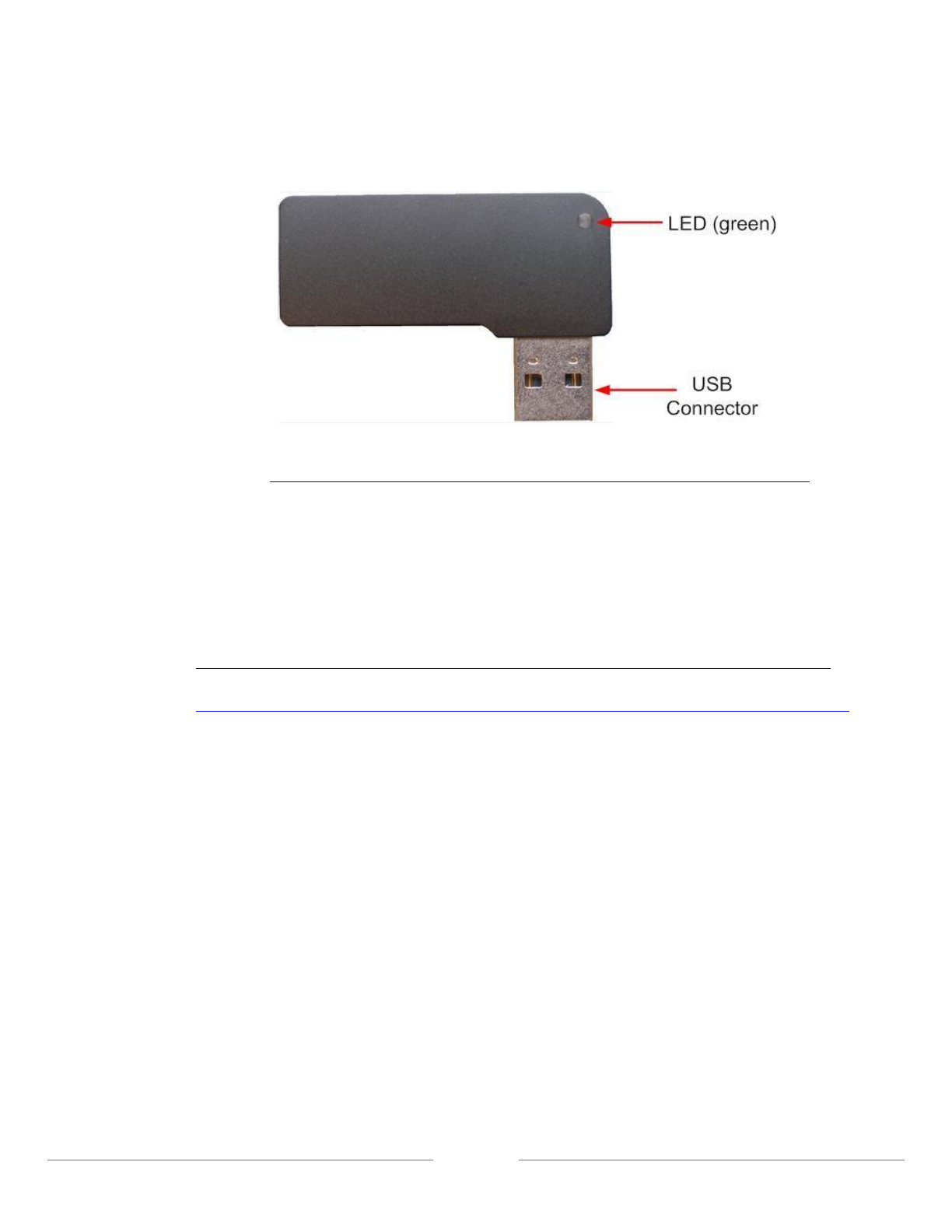
41
8.5.1.3 Hardware Configuration of Stollmann BlueHDP+USB Dongle
The BlueHDP+USB dongle does not allow any hardware configuration. The power is supplied via the USB
connector.
The green LED indicates that the BlueHDP+USB is powered correctly from the USB port of the host
system. There is no other functionality of the LED.
Connect the BlueHDP+USB to a PC USB port and install the Silabs USB to UART Bridge driver (can be
downloaded at http://www.silabs.com/products/mcu/pages/usbtouartbridgevcpdrivers.aspx).
During the driver installation a new COM port will be added to your system. Please use the Windows
Device Manager to identify the corresponding COM port number.
8.5.1.4 Firmware Updates
Stollmann E+V GmbH provides their most recent firmware update on their web site. This update is
provided as a self-extracting file and is available at the following URLs:
Stollmann BlueDev+P25/G2/HDP Kit:
http://www.stollmann.de/en/support/downloads/bluetooth-adapter/bluemod-p2xg2.html
Stollmann BlueHDP+USB Dongle:
http://www.stollmann.de/en/support/free-downloads/bluetooth-adapters/bluehdp-usb.html
1. Start the .exe
2. Select the COM port of the development board or the USB dongle and press the “Update”
button
3. Reset the board when prompted by pressing the blue reset button on the board as shown in the
picture above (note that the software prompt says ‘restart’ but what is meant is to reset). This
operation is not necessary for updating the USB dongle firmware.
4. Wait for the Firmware Update to complete.
5. When the update is complete, repress the reset button.
8.5.2 Running the application with Bluetooth Communication
The Manager has a discovery option that will discover the Agent when the user is prepared. Therefore, it does
not matter whether the Agent or the Manager is started first for Bluetooth operation.
NOTE: Bluetooth communication requires the use of the Bluetooth Shim (vascBtShim.dll) and an RS232
library (rs232api.dll). These shims are located in the directory with the Agent and Manager
executables. If the applications are started in a different directory, the shims must be moved to that
directory for proper Bluetooth operation.

42
8.5.2.1 Running the Continua Manager Application
1. Click on ContinuaManagerGUI.exe. This can found either in the \lib directory for the
Source distribution or in the \bin directory for the SDK installer. Additionally, a shortcut in the
Start menu may be used with the SDK installer. The Manager GUI will open.
2. From the Settings menu, configure the Manager output, if desired.
3. Set the appropriate Shim path
NOTE: The Shim path should default to the directory where the executable resides. Selecting a
different path would only be necessary if the Shims do not reside in the same directory as the
application.
4. In the menu bar, select Settings | Setup Transports
Check the box “Enable BlueTooth Transport” if it is not already checked.
In the COM Port entry box, select the communications port to be used with your configuration
(e.g. COM1)
Click OK
5. Click “Start Transport.” After a short delay, the Bluetooth icon will color (blue) and state “Transport:
Enabled”
NOTE: Other transports may be enabled. This depends on the different Shims detected by the
Manager.
6. Start the Agent (see below) - Once an Agent is started, click on the “Discover” button in the
Manager. This should discover all Bluetooth devices. It may take between 20 and 30 seconds for
Discover to occur.
NOTE: For proper Device Specialization to be displayed in the Manager, ‘Discover’ must be clicked to
discover a new Agent.
7. Select the appropriate Agent device in the window and click “Connect.” The Agent will connect and
begin to pass data.
NOTE: On the first connection attempt with any Agent, the Manager will attempt to Pair with the
Agent. A dialog box will be displayed (‘Bluetooth Security’) requesting a PIN number
For use with the Stollmann BlueEva card, enter 0000 as the default [or the appropriate
number set as a command line option on the Agent (bt_pin)]. Once this value is set, pairing
will not be reattempted regardless of the Agent selected. To reactivate the pairing process, the
Agent Bluetooth evaluation card must have the firmware flashed (see Section 8.5.1.4)
For other medical device agents, enter the appropriate PIN when prompted
NOTE: Firmware version 1.404 or higher uses SSP “just works” by default when connecting to a
Bluetooth 2.1 device. In this scenario no PIN exchange is required.

43
8.5.2.2 Running the Reference Agent Applications
1. Open a Command Window and navigate to the appropriate directory with the Agent executables.
2. Starting the Agent
a. Enter the appropriate executable (any of the Agents) on the Command Line with the
appropriate Bluetooth transport switch. A configured shortcut can also be created.
ThermometerAgent.exe --transport bluetooth --com_port COM3 --count 30
b. The Agent will open a command window to display connection information.
3. The Agent will then pause (after ”Waiting for the transport to connect…”) for connection to the CESL
Manager. If the agent is set to active connect (default) the agent will pause after seeing a message
(“Waiting for an AHD to pair …”). If the agent is paired and is set to active connect (default) and the
AHD is running, the agent will connect to the AHD and start transferring data.
4. Once the CESL Manager discovers and connects to the Agent, the Agent will display the words,
“Accepting connection to device ‘ ‘ “.
The Agent will generate random values. These values are displayed in the CESL Manager GUI.
The Agent will continue to send values unless the --count switch is used. To stop the
operation, close the Agent Command Window, or select ‘Disconnect,’ ‘Unassociate’, or ‘Abort’
on the Manager GUI.
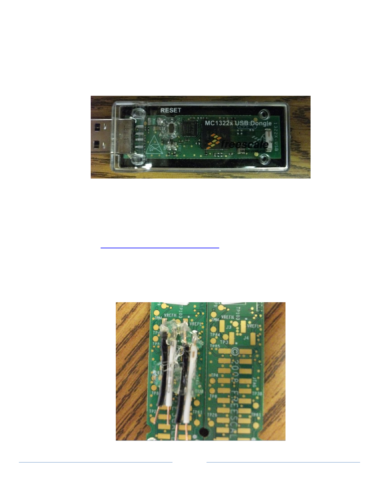
44
8.6 Using ZigBee Transport
The ZigBee transport provides support for devices that comply with the ZigBee Health Care profile as documented
in ZigBee Health Care Profile 1.0 from the ZigBee Alliance (ZigBee Document 075360r15). The ZigBee transport is
discussed from a user’s perspective and covers flashing the software onto a Freescale USB dongle, and using the
transport with the GUI Manager and the reference agent applications.
8.6.1 Freescale ZigBee USB Hardware
The CESL ZigBee shim operates in conjunction with the Freescale ZigBee USB Dongle (MC 1322x USB) pictured
below:
The module, if not already preflashed, must be flashed with the embedded image that comes with the CESL
distribution before it can operate with CESL code. The flashing process involves erasing the existing image and
then programming the 1322x with the new image.
8.6.1.1 Driver
The ZigBee USB dongle uses an FTDI USB/Serial driver which is part of current Windows distributions
and will load automatically when the dongle is inserted. If your system does not have the driver it may
be found at http://www.ftdichip.com/Drivers/VCP.htm.
8.6.1.2 Programming
NOTE: Before the MC 1322x can be flashed with a new image the exiting image must be erased. The
process of erasing the existing image involves shorting two sets of connectors. This can be done
using professional setups, or it can be done by soldering a “header” onto the 1322x as shown in
the diagram below:
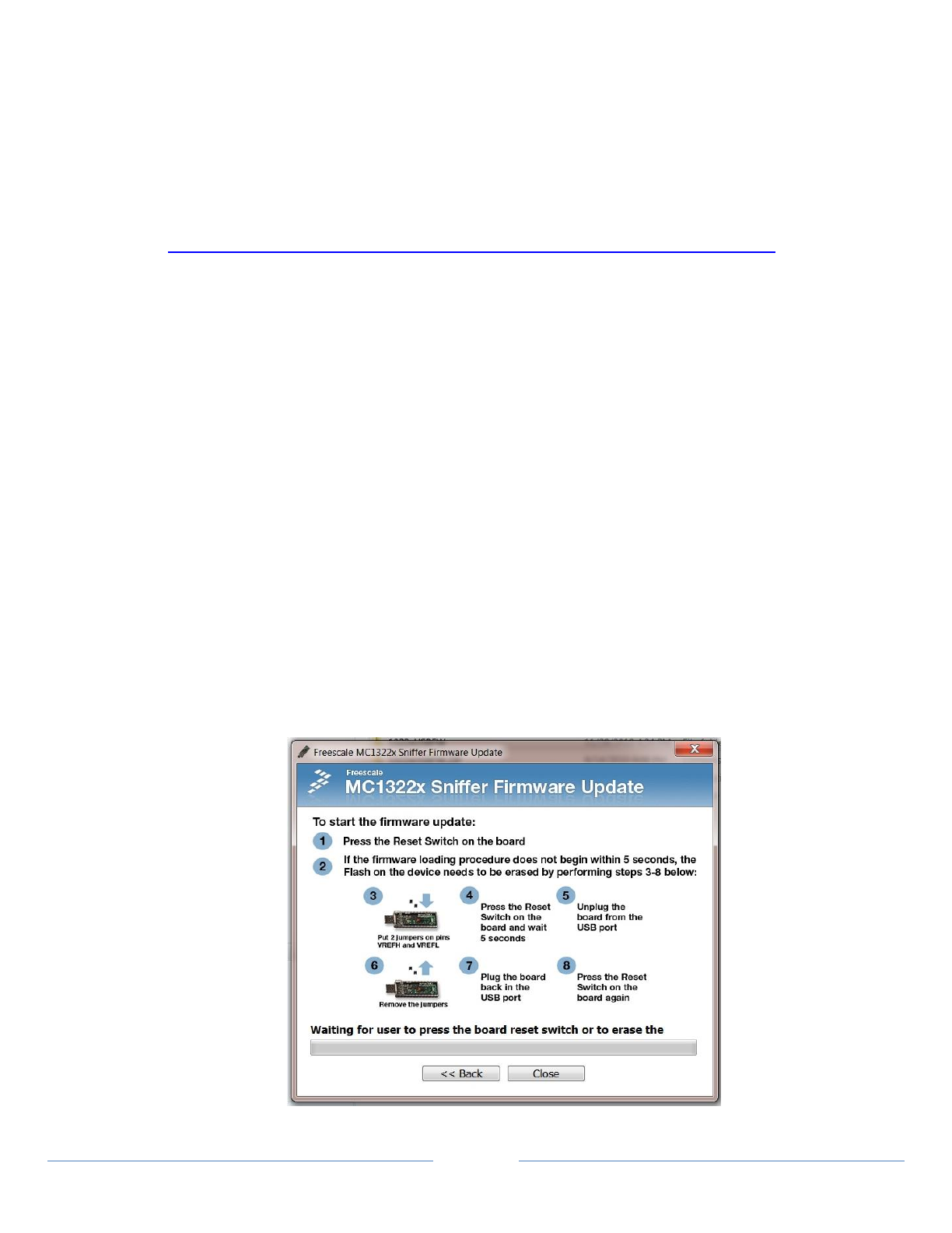
45
NOTE: The solder points are two sets of rectangular blocks designated by J3 on the left (for jumper one)
and J4 on the right (for jumper two).
Once the header is soldered in place the leads of the header can be shorted together using a standard
header pin jumper. In the picture shown above the blacks leads are to be shorted to the white leads.
Both sets of leads have to be jumpered together while the erasing process takes place (see instructions
below)
The USB dongle is programmed using the MC1322x Sniffer Firmware Update tool available at
http://www.freescale.com/webapp/sps/site/prod_summary.jsp?code=1322x_Dev_Kits.
1. Start the MC1322X Sniffer Firmware Update software
2. Step 1 - Select ‘Browse…” and navigate to the appropriate firmware image within the CESL-
zigbeeShim-1.5 distribution (\FreescaleEmbedded\FlashImages\ARM):
NOTE: This release includes firmware version
a. MC13224 Dongle
i. Agent (secure or insecure) - \MC13224\USBDongle\Agent
ii. Manager (insecure only) - \MC13224\USBDongle\Manager
b. MC13226 Dongle
i. Agent (secure or insecure) - \MC13226\USBDongle\Agent
ii. Manager (secure or insecure) - \MC13226\USBDongle\Manager
3. Step 2 - Set the MAC address to the value found on the plastic shell of your USB dongle.
4. Step 3 -
a. Insert the dongle into the USB port. The application should detect the USB dongle and
display its corresponding COM port.
b. Select the radio button for “Use USB COM port connection”
5. Click ‘Update Firmware’ and the following image should come up:
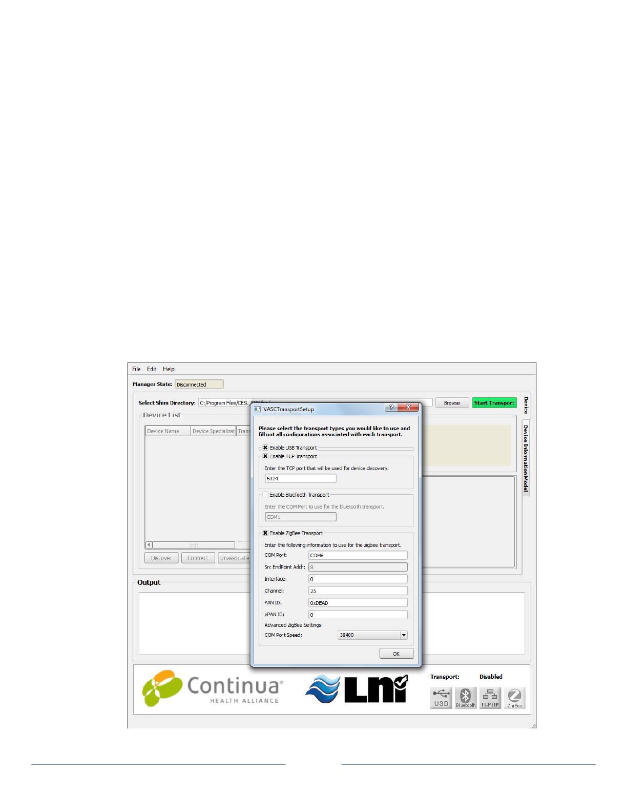
46
Follow the instructions on the screen. When the memory is sucessfully erased the application will start
to program the 1322X.
6. When the application completes the programming on the 1322x exit the application, remove
the dongle and label it with appropriate identification to know what image it is running.
NOTE: To run the CESL agents against the CESL Manager you will need to have two USB ZigBee dongles,
one programmed with the agent image and one programmed with the Manager image. Due to memory
limitations on the USB dongle the Manager image can only be a ZigBee Coordinator. It cannot operate
on a PAN when another node is playing the role of coordinator.
8.6.2 Running the Application with ZigBee
The CESL ZigBee transport software is designed to operate under the consumer scenario as specified for ZigBee
Health Care. However, the CESL Manager and applications are expected to be used primarily in development
environments and have been tailored to work more effectively for this environment. This is most notable in that
the CESL GUI Manager, when acting as a PAN coordinator, allows end devices to join the network at any time.
Future users are anticipated to operate the transport using hosted software environments that have application
interfaces running on development platforms and the applications provide command line interfaces to allow
connections to be established based on known network parameters such as 16 bit network address and known
endpoint address.
8.6.2.1 Using the CESL GUI Manager with ZigBee
The CESL GUI Manager operates with ZigBee in a manner similar to Bluetooth. Start the GUI Manager
and select Edit | Transport Settings. This brings up the Transport settings window:
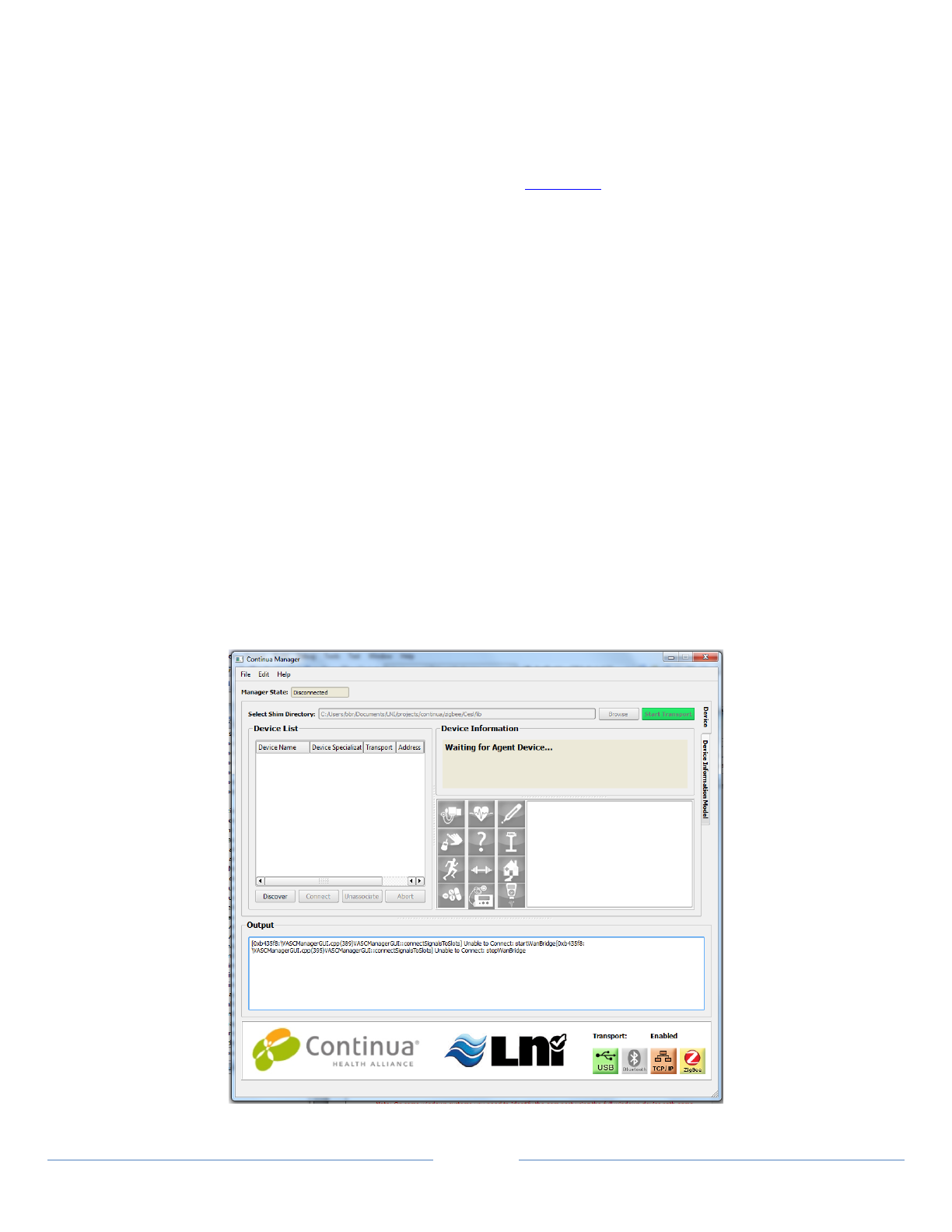
47
From this window the user selects the operating parameters that will be used when forming the PAN.
COM Port: This value must match the com number (i.e. COM4) associated with the USB dongle as
reported in Windows Device Manager.
NOTE: If the COM number associated with the USB dongle is above COM9 then you must enter the
full windows device path name (such as \\.\COM14).
Src EndPoint Addr: This value is statically set by the Manager application.
Interface: This value should be set to 0.
Channel: This value may be any number between 1 and 25. The agent channel must match the Manager
channel. Multiple ZigBee networks in close proximity relying upon the same channel will cause
interference.
PAN ID: Leave PAN ID at the default value, 0xDEAD.
ePAN ID: Agent and Manager ePAN ID must be set to the same value.
COM Port Speed: Com Port speed may need to be modified to allow the ZigBee shim to function with
different device images. If an image is built at a particular speed the shim Com Port Speed must be
set to an equal value.
Once the transport setting have been selected, click OK to close the VASCTransportSetup window and
return to the main window. Click on the “Start Transport” button on the top right corner of the GUI. The
Manager will form a new PAN based on the parameters provide. This will be indicated by the ZigBee
transport icon transitioning from a gray shade to a highlighted color as shown in the image below. The
CESL Manager will delay five second after forming the network to allow devices to exchange initial
information. This delay is normal and will take place whenever the CESL Manager forms a network.
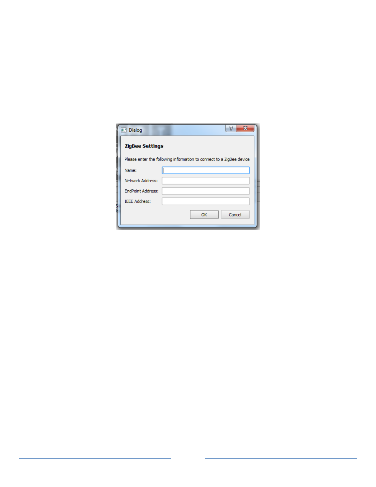
48
ZigBee Health Care devices can be discovered by the Manager application by clicking on the Discover
button. After a short delay the discovered devices will be displayed in a scroll list. The Manager can
initiate a connection by selecting the device of interest from the list and then clicking on Connect.
NOTE: If Bluetooth is also enabled, two discovery cycles are implemented. Bluetooth is
accomplished first followed by ZigBee. If there are multiple devices preseent, the discovery
process may take a while.
NOTE: If normal discovery is not possible, a device can be manually added to the list of available
devices by clicking selecting Edit | ZigBee Connect from the top menu. ZigBee
addressing parameters can be provided in the ZigBee Settings window for the device of
interest.
Name: Any value is permissable. It is for display purposes only within the Manager GUI.
Network Address: This address is dynamically assigned.
This address may be identified with a sniffer or other display mechanism
If unknown, enter 0xffff and specify the IEEE Address below
EndPoint Address:
If this is a CESL Manager or CESL Agent, the value is 8
If not, then specifying 0xff will cause a search for the first available Health Care endpoint
IEEE Address: This is the MAC address printed on the dongle
8.6.2.2 Using the Reference Agents with ZigBee
All of the supported CESL reference agents run with the ZigBee transport. Transport operation and
addressing are set through the use of command line parameters. Assuming that a Manager has formed a
PAN, the following command line is a common way by which one of the reference agents can join the
network, allowing the Manager to discover it and connect to it.
ThermometerAgent --transport zigbee --zbif 0 --com_port com5 --channel 25
To have the agent initiate the connection the additional command line parameter –connect is given
along with a set of values that will allow the connection to be made.
ThermometerAgent --transport zigbee --zbif 0 --com_port com5 --channel 25
--connect --nwk 0 --dstep 8

49
8.6.2.3 ZigBee Considerations
ZigBee is, by design, a local, low-power, and small data flow protocol. ZigBee networks can be (theoretically)
extended indefinitely the local range by ZigBee ‘routers’. The internal timeouts and retry requirements specified
by the ZigBee standard are inconsistent with the timeouts specified by the IEEE 11073-20601 standard. APDUs
do not have to be very large (by IEEE 11073-20601 considerations) before the three-second timeout is reached.
In a clean (radio) environment, APDUs exceeding about 700 bytes are going to take longer than three seconds to
reach the peer. The CESL library does provide a method where the IEEE 11073-20601 timeout can be set to an
arbitrary value.
8.7 Using Bluetooth(LE) Transport
Bluetooth(LE) prototype functionality is provided through one of the following:
Texas Instruments Stellaris Board (requires BTVEN.dll)
CSR casira pods.
CSR 8510 USB dongle
Any of these devices may be connected to a system to replicate the Agent or the Manager.
8.7.1 Configure for Bluetooth(LE) Operation
Some of the following information is taken from the Stollmann Evaluation Kit CD that came with the Stellaris
Evaluation Kit. Original Stellaris documentation is available on the CD.
8.7.1.1 System Requirements
One PC with Windows installed and two free USB ports (or COM ports)
Or
Two PCs with Windows installed, one free USB port (or COM port) on each
8.7.1.2 Hardware Configuration of Stellaris Development Kit
Some of the following information is taken from the Stellaris CD that came with the Stellaris Evaluation Kit.
Original Stellaris documentation is available on the CD. When using the Stellaris board the BTVEN.dll MUST be
present in the runtime directory.
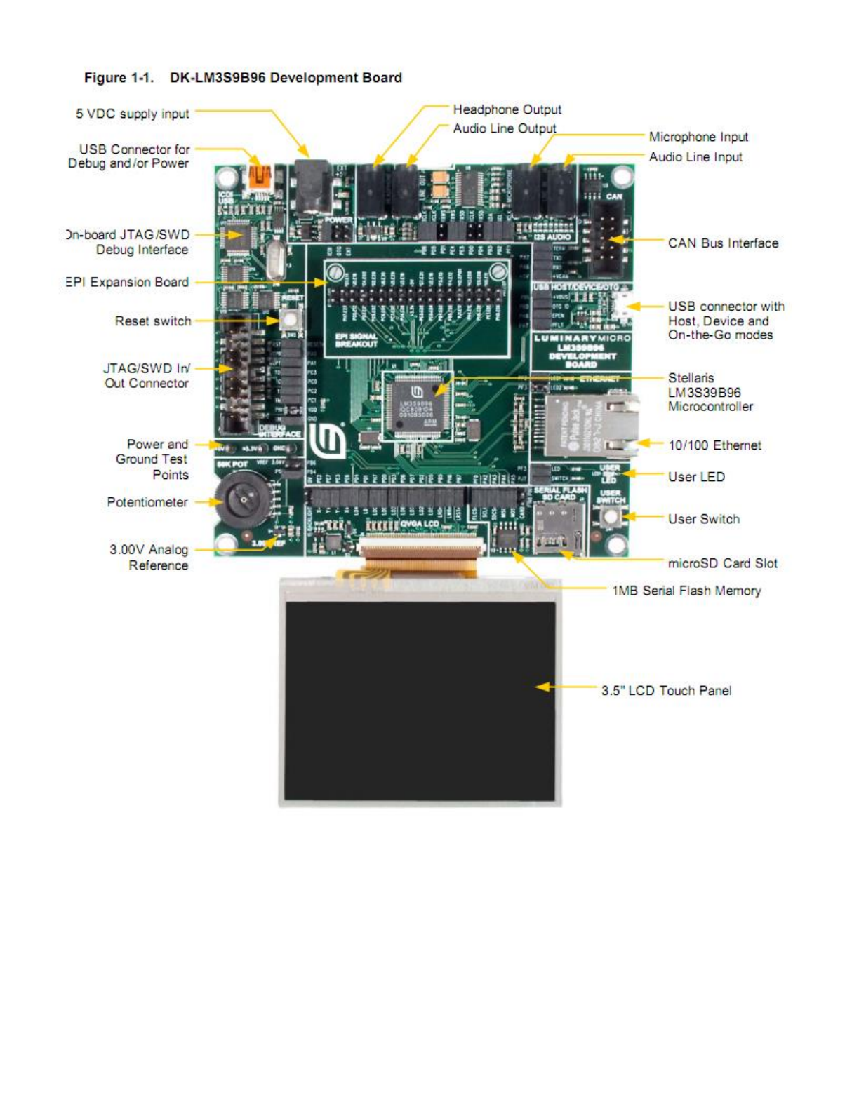
50
Connect each Stellaris module to a COM port on a PC
NOTE: Power is supplied separately and must be plugged in before board will be funtional
NOTE: When using the Stellaris board the SS1BTVEN.dll MUST be present in the working directory.
Suggested configuration is two separate PCs with one COM port each:
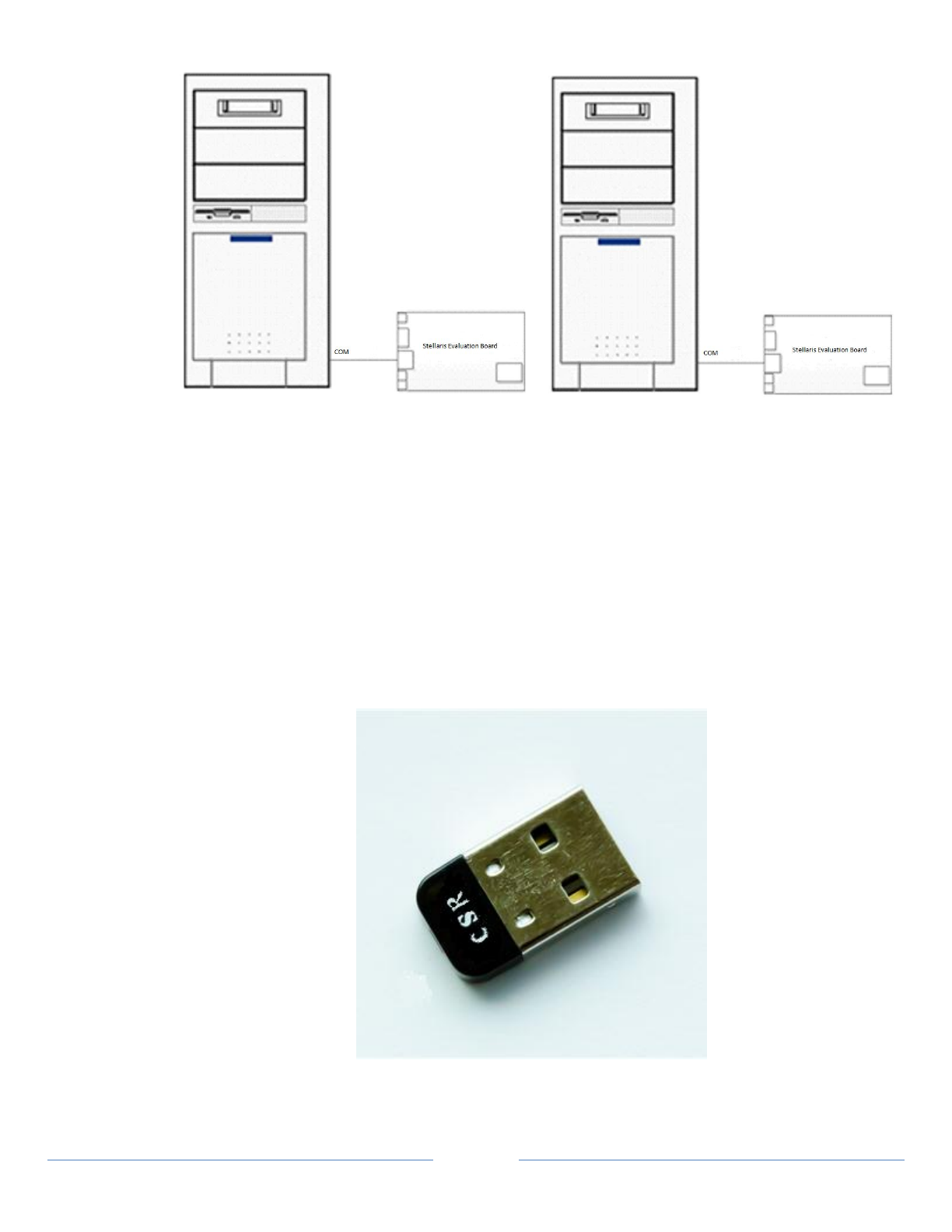
51
Figure 1-2: Suggested configuration
8.7.1.3 Using Casira Evaluation Pods
The CSR Casira Evaluation Pods are not expected to be needed for the preliminary evaluation of
Bluetooth LE.
8.7.1.4 Using the CSR 8510 USB Dongle
If the embedded blue LED is lit the dongle is active.

52
8.7.2 Running the application with Bluetooth Communication
The Manager has a discovery option that will discover the Agent when the user is prepared. Therefore, it does
not matter whether the Agent or the Manager is started first for Bluetooth operation.
NOTE: Bluetooth(LE) communication requires the use of the Bluetooth(LE) Shim (BTLEShim.dll) and a
number of supplementary BT libraries (SS1BTDBG.dll, SS1BTGAT.dll, and SS1BTPS.dll).
These shims are located in the directory with the Agent and Manager executables. If the applications are
started in a different directory, the shims must be moved to that directory for proper Bluetooth
operation.
8.7.2.1 Installing BTLE Drivers
1. Insert the CSR shim (pictured above) into an available USB port. Start the Device Manager. By
default Windows should install a driver labeled Generic Bluetooth Device.
2. Right click on this icon and click ‘Update Diver- This will bring up the “Update Driver Software
Wizard” window.
3. A 'Found New Hardware' bubble will appear.
4. Select the 'Install from a list or specific location (Advanced)' option and then click 'Next'.
5. Choose the 'Don't search. I will choose the driver to install' option.
6. Select 'Have Disk' and click 'Browse'.
7. Navigate to the folder which contains the Bluetooth(LE) Driver.
For source distributions the driver is located at [DistributionDir]\SS1BTLEShim\SS1\Windows
For binary distributions the driver is located at [InstallDir]\CESL_Binary\btle
For SDK distributions the driver is located at [InstallDir]\CESL SDK\bin\btle
8. Select the .inf file.
For 32-Bit systems, select the folder “x86”
For 64-Bit systems, select the folder “ia64”
9. Click 'Next' and follow the installation directions.
10. To verify the driver is loaded correctly, go to Device Manager
11. Displayed should show “Bluetooth HCI USB Driver“ with a nested index of “Bluetooth HCI USB
Driver (CSR)” (Pictured Below).
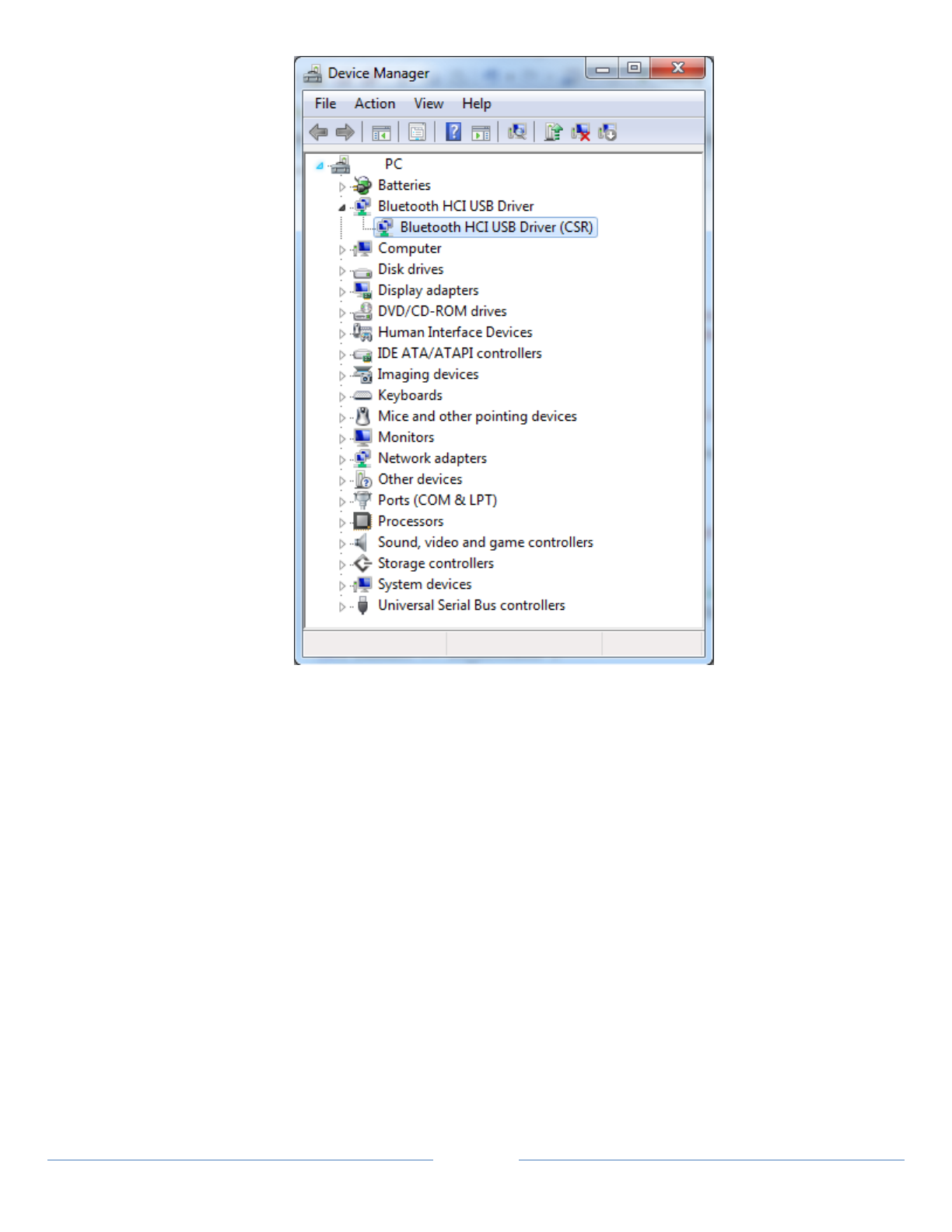
53
8.7.2.2 Running the Continua Manager Application
1. Click on ContinuaManagerGUI.exe. This can found either in the \lib directory for the
Source distribution or in the \bin directory for the SDK installer. Additionally, a shortcut in the
Start menu may be used with the SDK installer. The Manager GUI will open.
2. From the Settings menu, configure the Manager output, if desired.
3. Set the appropriate Shim path
NOTE: The Shim path should default to the directory where the executable resides. Selecting a
different path would only be necessary if the Shims do not reside in the same directory as the
application.
4. In the menu bar, select Settings | Setup Transports
Check the box “Enable BlueTooth LE Transport” if it is not already checked.
Verify that the interface being used is USB (for the CSR dongle) or COM (for the Stellaris)
If you choose to use the Stellaris board you must enter the COM_PORT associated with the
device (e.g. COM1)
Click OK

54
5. Click “Start Transport.” After a short delay, the 4.0 Bluetooth icon will color (blue) and state
“Transport: Enabled”
NOTE: Other transports may be enabled. This depends on the different Shims detected by the
Manager.
6. Start the Bluetooth LE Thermometer Agent (see below) or other BTLE agent - Once an Agent is
started, take/send a measurement. The agent MUST have a measurement to send in order to issue
advertisements and be discoverable. Then click on the “Discover” button in the Manager. This
should discover all Bluetooth(LE) devices. The discovery is instantaneous as the discovery function
returns a list of devices that that have sent advertisements. If no advertisements have been received
the discovery will return empty.
7. Select the appropriate Agent device in the window and click “Connect.” The Agent should connect
and begin to pass data. However a connection will only be established if the agent issues a
subsequent advertisement after the user’s connection attempt. The duration and frequency of
advertisements is application-dependent and can be up to 30 seconds between events. If the agent
has stopped advertising no connection will be established. The user will often be required to
perform some task or take another measurement to make the agent start advertising.
8. !! NOTE !! If the agent is stopped and then restarted the Continua GUI manager will need to be
restarted in order to reconnect to the agent.
NOTE: Bluetooth LE uses SSP “just works” protocol by default when connecting to a Bluetooth 2.1
device. In this scenario no PIN exchange is required.

55
Appendix A - CESL Trace Facility
CESL is written such that the code can be traced when needed. A tracing facility is built on a macro that is
precompiled into the code. It allows for flexible logging based on user needs.
8.8 Proper Usage of CESL Trace facility
The CESL trace facility is designed to allow a wide range of debugging output to be generated from a program
without the need for external tools. For the system to be effective, however, the CESL code base must use the
VD_symbols in a consistent manner. VD_Symbols come in pairs, and are typically logically ORd together, as in
VD_APP|VD_ERROR. One set of symbols defines code layers or categories. The other group of symbols is the
condition of interest. CESL code categories and conditions are defined in \include\tracelib.h.
8.9 TRACELIB_THREAD
Detailed trace output can impact the operation of time sensitive callback functions within the CESL codebase. If
protocol timeouts appear when tracing is used the display of trace output can be pushed to a different thread of
execution by defining the preprocessor symbol TRACELIB_THREAD in the tracelib project.
8.10 Information Level
The amount of information associated with a given line of trace output can be modulated using the information
display bits as specified below:
VD_SIMPLE – Display the source file name, the line number, and the function name
VD_CLOCK – Display the time at which the trace line was generated
VD_THREAD – Display the thread ID of the thread that called the trace routine
VD_FULL – Display all available information
8.11 Code Categories
When code is written it is associated with logical groupings. The number of groupings can be changed by adding
new code categories to vasc.h. At the time of writing the list of code groups is:
VD_APP /* Application code */
VD_OBJECT /* Object layer code */
VD_SERVICE /* Service layer code */
VD_ASSOCIATION /* Association layer code */
VD_TIL /* Transport layer */
VD_SHIM /* SHIM code */
VD_TAPI /* Transport API code */
VD_PM_STORE /* PM Store code */
VD_MSG /* Message module code */
VD_LOC_MASK /* Bits used for code regions */
VD_EVERYWHERE /* All locations */
VD_NONE /* nowhere – turn off trace output */
8.12 Conditions
In addition to code location, the TRACE facility also uses a condition indicator. The condition indicator indicates
what class of message we are working with – error, warning, APDU trace, code trace…
VD_PROMPT – user prompting
VD_ERROR - Code detected error that will generally result is failure
VD_WARN - An unexpected conditon
VD_TRACE – A degree of output that includes entry to major routines
VD_TRACE – A more detailed level of trace output
VD_EVEN – Some event that is deemed significant, such as a conneciton event.

56
VD_APD – Tracks the flow of APDUs in the system.
VD_APDU_DUMP – Dumps the contents of APDUs
VD_LOC – Traces information associated with locking and signaling
VD_CM – Used to track commands issued to hardware devices, typically in shims
VD_RS – Used to track responses from hardware devices, typically in shims
VD_IN – Used to track unsolicted device messages, typically used in shims
VD_NOTABLE (VD_PROMPT|VD_ERROR|VD_EVENT|VD_WARN)
VD_ACTIVITY (VD_PROMPT|VD_ERROR|VD_EVENT|VD_WARN|VD_APDU)
VD_FLOW (VD_PROMPT|VD_ERROR|VD_EVENT|VD_WARN|VD_CMD|VD_RSP|VD_IND)
VD_DEBUG1 (VD_PROMPT|VD_ERROR|VD_EVENT|VD_WARN|VD_APDU|VD_TRACE1)
VD_DEBUG2 (VD_PROMPT|VD_ERROR|VD_EVENT|VD_WARN|VD_APDU|VD_TRACE1|VD_TRACE2)
8.13 Application Specific Additions
VD_WAN_BRIDGE /* Output from the WAN Bridge Java Process */
VD_MGR /* Manager Code */
VD_MGR_GUI /* Manager GUI Code */

57
9 Appendix B – CESL 5.0 Enhancements
The following should be updated to identify the major changes that have been implemented in this CESL 2.0
release.
10 Appendix C - Frontline Test System
Frontline Test Equipment, Inc. has developed a free sniffer tool that automatically works will any application based
upon the CESL API. The tool provides the same type of functionality as the APDU dump facility in the CESL API but
with much more extensive deciphering as well as interactive capabilities.
This CESL distribution has been enhanced to provide functionality with this sniffer to enable CESL users to decode
and debug IEEE 11073-20601 level protocols that are run over CESL (for TCP, USB and Bluetooth transports).
10.1 Frontline Analyzer – Quick Start Guide
The use of the Frontline Analyzer is straight forward. Additional information is provided in Section 11.2.
1. Install either the CESL Binary or the CESL SDK – All required files will be automatically installed
2. Download and install the Analyzer (http://www.fte.com/support/IEEE11073-download.aspx)
3. Start the Analyzer – Begin a capture (click the Red Ball)
NOTE: The Analyzer must be started before the CESL Manager or CESL Agents are started
4. Start the CESL Manager and configure for the specific transport (TCP, USB, Bluetooth)
5. Start a Reference Agent, or a Continua Certified Agent
10.2 Additional Instructions
10.2.1 Frontline Analyzer Application
NOTE: The analyzer is not provided with this distribution.
The analyzer is available for free to Continua Alliance members.
1. Download the application from: http://www.fte.com/support/IEEE11073-download.aspx
This analyzer supports operation on Windows XP (32-bit) and Windows 7 (32- & 64-bit) platforms.
The analyzer does not support Linux.
2. Install the application (selecting ‘Live Product’ during installation). The following actions will occur:
a. A Program Files directory Frontline Test System II is created.
b. A directory within the Public User Documents directory is created:
Frontline Test Equipment
Ex: Windows 7 – (C:\Users\Public\Documents\Frontline Test Equipment)
This directory will contain output from the operation of this tool.
Additionally, installing the CESL Frontline Files (see below) will place the required files in the
following new directories:
My Decoders

58
My Methods\Release
NOTE: These directories will be created even if the CESL Frontline Files are installed before the
analyzer is installed.
10.2.2 Installation of CESL Frontline Files
Functionality has been added to CESL distributions for use with the Frontline analyzer.
For TCP and USB sniffing:
ieee11073Sniffer.dll
IEEE11073VirtualSniffing.Personality
For Bluetooth sniffing:
BTLI_dll.dll
ltp_11.dll
LTP.dec
LTPVirtualSniffing.Personality
10.2.2.1 Source Distribution
The necessary libraries, Personality Files and installation programs to work with the CESL code are provided with
the CESL Source distribution but need to be manually installed. The necessary installers are located in the
source distribution directory \thirdparty\frontline.
Proper installation of the above files is accomplished by the use of the two executables:
CopyToFTS4PHD.exe – used for TCP and USB file installation
CopyToFTS4BT.exe – used for Bluetooth file installation
NOTE: A batch file called DoCopyToFTS4BT.bat is provided to accomplish this complete task and set the
appropriate installation parameters.
To install the necessary files for operation of the Frontline Analyzer, run DoCopyToFTS4BT.bat. This will:
1. Place the following files in the directory My Decoders
LTPVirtualSniffing.Personality
IEEE11073VirtualSniffing.Personality
LTP.dec
2. Place the following file in the directory My Methods\Release
ltp.dll
Two library files are pre-loaded in the \lib directory of the source distribution:
ieee11073Sniffer.dll (for TCP and USB)
BTLI_dll.dll (for Bluetooth)
When the Manager GUI is built, the executable is also placed in this directory.
NOTE: If the Manager GUI is started in a different directory, these two files must be copied to that directory.
10.2.2.2 Binary and SDK Installation
The needed libraries for the Binary and SDK installers are installed when installing CESL. The installers
run the following to install the files to the proper directories:

59
CopyToFTS4PHD.exe
CopyToFTS4BT.exe
NOTE: If it is necessary to reinstall these files manually, run DoCopyToFTS4BT.bat from within the
appropriate installed directory:
Program Files\CESL_Binary\bin\Frontline
Program Files\CESL_SDK\bin\Frontline
The library files ieee11073Sniffer.dll (for TCP and USB) and BTLI_dll.dll (for
Bluetooth) are available in the following directories depending on the installer:
Binary Installer - Program Files\CESL_Binary\bin directory
SDK Installer - Program Files\CESL_SDK\bin directory
NOTE: If the Manager GUI is started in a different directory, these two files must be copied to that
directory.
10.2.3 Using the Frontline Test System
NOTE: The Analyzer must be started before the CESL Manager or CESL Agents are started.
The Analyzer establishes the shared memory. When CESL comes up, it checks exactly once to see if that
memory is there. If it isn’t, CESL proceeds without it and never checks again.
1. From the Start Menu | All Programs, select:
Frontline IEEE 11073+ Analyzer <version number>| Frontline IEEE 11073+ Analyzer
a. Two windows will open – A small Analyzer window and Frame Display (View | Frame Display)
b. Click on the ‘Start Capture’ [red ball] icon to begin a trace.
2. Start the Manager Application and continue with the transport specific instructions in this guide.
The Frame Display will display the captured APDUs.
(The window can be manually viewed by selecting View | Frame Display from the main menu of the small
Analyzer window.)
The APDU sequence will be displayed in the top frame.
Click on one of the APDUs. The APDU is expanded in a tree to the left and to the right the data are shown in
three formats.
Saved Captures can be reviewed at a later time using the Capture File Viewer
Start Menu | All Programs |Frontline IEEE 11073+ Analyzer <version number>| Capture File Viewer
