CF 74ECBAXBM SPG
CF-74ECBAXBM to the manual f56f224b-13ac-4270-955e-336bdfcc22e7
User Manual: CF-74ECBAXBM
Open the PDF directly: View PDF ![]() .
.
Page Count: 50
ORDER NO. CPD0611204C1
Personal Computer
CF-74ECBAXBM
© 2006 Matsushita Electric Industrial Co., Ltd. All rights reserved.
Unauthorized copying and distribution is a violation of law.
1

LASER SAFETY INFORMATION
For U.S.A.
Class 1 LASER-Product
This product is certified to comply with DHHS Rules 21 CFR Subchapter J.
This product complies with European Standard EN60825 (or IEC Publication 825)
For all areas
This equipment is classified as a class 1 level LASER product and there is no hazardous LASER radiation.
Caution:
(1) Use of controls or adjustments or performance of procedures other than those specified herein may result in
hazardous radiation exposure.
(2) The drive is designed to be incorporated into a computer-based system or unit which has an enclosing cover.
It should never be used as a stand alone drive.
Danger:
The serviceman should not remove the cover of drive unit and should not service because the drive unit is a non-
serviceable part.
Please check DANGER label on PD-drive unit.
• Unplug the AC power cord to the equipment before opening the top cover of the drive.
• When the power switch it on, do not place your eyes close to the front panel door to look into the interior of the unit.
LASER Specification
Class 1 level LASER Product
Wave Length: DVD 658±8 nm
CD 775~815 nm
Laser safety information is appropriate only when drive with laser is installed.
2
3
4
CONTENTS
1. Specifications ··················································································································1-1
2. Names and Functions of Parts ······················································································2-1
3. Block Diagram ···············································································································3-1
4. Diagnosis Procedure ·····································································································4-1
5. Power-On Self Test (Boot Check) ·················································································5-1
6. List of Error Codes <Only when the port replicator is connected> ································6-1
7. Self Diagnosis Test ········································································································7-1
8. Wiring Connection Diagram ··························································································8-1
9. Disassembly/Reassembly ·····························································································9-1
10. Exploded View ···········································································································10-1
11. Replacement Parts List ·····························································································11-1
Getting StartedUseful InformationTroubleshootingAppendix
1 Specifications
This page provides the specifications for the basic model CF-74ECBAXBM / CF-74FCBAZBM / CF-74FCBCZBM / CF-
74ECBCXBM / CF-74ECBADBM. The model number is different according to the unit configuration.
zTo check the model number:
Check the bottom of the computer or the box the computer came in at the time of purchase.
zTo check CPU speed, memory size and the hard disk drive (HDD) size:
Run the Setup Utility (Î Reference Manual “Setup Utility”) and select [Information] menu.
[CPU Speed]: CPU speed, [System Memory]: Memory size, [Hard Disk]: Hard disk drive size
Main Specifications
Model No. CF-74ECBAXBM / CF-74FCBAZBM / CF-74FCBCZBM / CF-74ECBCXBM / CF-74ECBADBM
CPU Intel® Core™ Duo Processor T2500 (2.0 GHz, 2 MB*1 L2 cache, 667 MHz FSB)
Chipset Intel® 945GM
Memory*1 512 MB (2560 MB Max.)
Video Memory*1*2 UMA (128 MB Max.)
Hard Disk Drive*3 80 GB
CD/DVD Drive DVD-ROM & CD-R/RW Drive
Data
Transfer
Rate*4
Reading*5 DVD-ROM: 8X (Max.), CD-ROM: 24X (Max.)
Writing*6 CD-R: 4X/10X/7-16X/10-24X
CD-RW: 4X
High-Speed CD-RW: 4X/10X
Ultra-Speed CD-RW: 10X/10-24X
Sup-
ported
Discs/For-
mat*3
Reading DVD-ROM (4.7 GB, 8.5 GB, 9.4 GB, 17 GB), DVD-Video, DVD-R (1.4 GB, 3.95 GB, 4.7 GB),
DVD-R DL (8.5 GB), DVD-RW*7 (1.4 GB, 2.8 GB, 4.7 GB, 9.4 GB), DVD-RAM*8 (1.4 GB, 2.8
GB, 2.6 GB, 5.2 GB, 4.7 GB, 9.4 GB), +R (4.7 GB), +R DL (8.5 GB), +RW (4.7 GB), CD-Audio,
CD-ROM, CD-R, Photo CD, Video CD, CD-RW, CD TEXT, CD-EXTRA
Writing CD-R, CD-RW, High-Speed CD-RW, Ultra-Speed CD-RW
Display Method 13.3 type (TFT) with Touchscreen
Internal LCD*9 65,536/16,777,216 colors (800 × 600 dots/1024 × 768 dots)
External Display*10 65,536/16,777,216 colors (800 × 600 dots/1024 × 768 dots/1280 × 1024 dots/1600 × 1200
dots/2048 × 1536 dots)
Wireless LAN*11 Î Next Page Wireless LAN
Bluetooth*12 Version 2.0+EDR
LAN IEEE 802.3 10Base-T, IEEE 802.3u 100Base-TX, IEEE 802.3ab 1000Base-T
Modem Data: 56 kbps (V.92) FAX: 14.4 kbps
Sound WAVE and MIDI playback, Stereo speaker, Intel® High Definition Audio subsystem support
Security Chip TPM (TCG V1.2 compliant)*13
Card Slot PC Card Type I or Type II x 1 (3.3 V: 400 mA, 5 V: 400 mA)
ExpressCard ExpressCard/34 or ExpressCard/54 x 1
SD Memory Card*14 x 1, Data transfer rate = 8 MB per second*15
Smart Card*16 x 1
RAM Module Slot 200-pin, 1.8 V, SO-DIMM, DDR2 SDRAM, PC2-4200 Compliant
Interface USB port (4-pin, USB 2.0) x 2, Serial Port (Dsub 9-pin male), Modem port (RJ-11), LAN port
(RJ-45), External display port (Mini Dsub 15-pin female), Expansion Bus Connector (Dedicated
65-pin female), Microphone Jack (Miniature jack, 3.5 DIA, Stereo), Headphone Jack (Miniature
jack, 3.5 DIA, Impedance 32 Ω, Output Power 4 mW × 2)
Keyboard / Pointing Device 87 keys / Touch Pad / Touchscreen (Anti-Reflection, Stylus (included) touch capable)
Power Supply AC adaptor or Battery pack
AC Adaptor*17 Input: 100 V to 240 V AC, 50 Hz/60 Hz, Output: 15.6 V DC, 8.0 A
CF-74MK2_X_E_OI_XA.book 28 ページ 2006年9月11日 月曜日 午前9時18分
1-1
Getting StartedUseful InformationTroubleshootingAppendix
*1 1MB = 1,048,576 bytes
*2 A segment of the main memory is allotted automatically
depending on the computer’s operating status. The size of
the Video Memory cannot be set by the user.
*3 1GB = 1,000,000,000 bytes. Your operating system or some
application software will report as fewer GB.
*4 The data transfer rate of DVD per 1X speed is 1,350 KB/s.
The data transfer rate of CD per 1X speed is 150 KB/s.
*5 If an unbalanced disc (e.g., the balance has been displaced
from the center) is inserted, the speed may become slower if
there are large vibrations while the disc is rotating.
*6
Depending on the disc, the writing speed may become slower.
*7 Does not support DVD-RW Ver.1.0.
*8 DVD-RAM: Only non-cartridge type or removable cartridge
type can be used.
*9
A 16,777,216 color display is achieved by using the dithering function.
*10 Maximum resolution depends on the specifications of the
external display.
*11 Only for model with wireless LAN
*12 Only for model with Bluetooth
*13 For information on TPM, click [start] - [Run] and input
“c:\util\drivers\tpm\README.pdf”, and refer to the Installation
Manual of “Trusted Platform Module (TPM)”.
*14 Operation has been tested and confirmed using Panasonic
SD Memory Cards with a capacity of up to 2 GB.
The transfer rate using the SD Memory Card slot on this com-
puter is 8 MB per second. (This is a theoretical value, and dif-
fers from actual speeds.)
The transfer rate is 8 MB per second even if you use an SD
Memory Card that supports high-speed transfer rates.
Operation on other SD equipment is not guaranteed.
This computer is not compatible with MultiMediaCards or
SDHC Memory Cards. Do not insert these kinds of cards.
*15 Theoretical value and not the actual speed. The transfer rate
does not become higher even if you use a card that supports
the higher transfer rate.
*16 Only for model with Smart Card slot
*17 The AC adaptor is compatible with power sources up to
240 V AC adaptor. The computer is supplied with a 125 V AC
compatible AC cord.
*18 Varies depending on the usage conditions.
*19 Measured with the LAN Power-saving function’s Auto-off set-
ting set to 1 minute.
*20 Measured using BatteryMark™ Version 4.0.1 (LCD bright-
ness: Maximum - Minimum)
*21
Measured using MobileMark™ 2002 (LCD brightness: 60
cd/m
2
)
*22
Approx. 1.0
W
when the battery pack is fully charged (or not being
charged) and the computer is OFF.
Approx. 2.0
W
when the Wake up from LAN has been enabled.
*23 Rated power consumption
*24 You need to install to use the feature.
*25 The Product Recovery DVD-ROM is required.
*26 These are speeds specified in IEEE802.11a+b+g standards.
Actual speeds may differ.
Battery Pack Li-ion 11.1 V, 7.8 Ah
Operating Time*18*19 Approx. 6 hours to 9 hours*20 (Approx. 8 hours*21)
Charging
Time*18 Power on Approx. 4.5 hours
Clock Battery Coin type lithium battery 3.0 V
Power Consumption*22 Approx. 40 W*23/ Approx. 100 W (Maximum when recharging in the ON state)
Physical Dimensions (W × H × D)
(including the carrying handle) 303.5 mm × 43.6 - 60.1 mm × 293.3 mm {12.0" × 1.7 - 2.4" × 11.6"}
Weight
(including the carrying handle) Approx. 2.7 kg {Approx. 6.0 lb.}
Operation Environment Temperature: 5 °C to 35 °C {41 °F to 95 °F}
Humidity: 30% to 80% RH (No condensation)
Storage Environment Temperature: -20 °C to 60 °C {-4 °F to 140 °F}
Humidity: 30% to 90% RH (No condensation)
Operating System Microsoft® Windows® XP Professional Service Pack 2 with Advanced Security Technologies
(NTFS File System)
Utility Programs DMI Viewer, Microsoft® Windows® Media Player 10, Adobe Reader, PC Information Viewer, SD
Utility, Icon Enlarger, Loupe Utility, WinDVD™ 5 (OEM Version), B’s Recorder GOLD8 BASIC,
B’s CLiP 6, Intel® Matrix Storage Manager, Intel® PROSet/Wireless Software*11, Bluetooth™
Stack for Windows® by TOSHIBA*12, Wireless Switch Utility, Hotkey Settings, Battery Recali-
bration, LAN Power-Saving Utility, Infineon TPM Professional Package*24
Setup Utility, Hard Disk Backup Utility*25, Hard Disk Data Erase Utility*25
Main Specifications
Wireless LAN <Only for model with wireless LAN>
Intel PRO / Wireless 3945 ABG (802.11 a + b + g) PCI Ex. 1/4
Data Transfer Rates*26 IEEE802.11a: 54/48/36/24/18/12/9/6 Mbps (automatically switched)
IEEE802.11b: 11/5.5/2/1 Mbps (automatically switched)
IEEE802.11g: 54/48/36/24/18/12/9/6 Mbps (automatically switched)
Standards Supported IEEE802.11a/IEEE802.11b/IEEE802.11g
Transmission method OFDM system, DSSS system
Wireless Channels Used IEEE802.11a: Channels 36/40/44/48/52/56/60/64/149/153/157/161/165
IEEE802.11b/IEEE802.11g: Channels 1 to 11
RF Frequency Band IEEE802.11a: 5.18-5.32 GHz, 5.745-5.825 GHz
IEEE802.11b/IEEE802.11g: 2.412-2.462 GHz
1-2
2-1
Getting StartedUseful InformationTroubleshootingAppendix
2 Names and Functions of Parts
CAUTION
zDo not put a metallic object or magnetic media close to the speakers.
A :Speaker
Î Reference Manual “Key Combinations”
B :USB port
Î Reference Manual “USB Devices”
C :Stylus holder
D :Multimedia pocket
Î Reference Manual “Multimedia Pocket”
E : Hard disk drive
Î Reference Manual “Hard Disk Drive”
F : Carrying handle
G :Wireless LAN antenna
<Only for model with wireless LAN>
Î Reference Manual “Wireless LAN”
H :LCD
Î Reference Manual “Touchscreen”
I : LED indicator
: Caps lock
: Numeric key (NumLk)
: Scroll lock (ScrLk)
: Multimedia pocket device status or the second
battery status
Î Reference Manual “Multimedia Pocket”
“Battery Power”
: Hard disk drive status
: Power status
(Off: Power off/Hibernation, Green: Power on, Blink-
ing green: Standby, Blinking green rapidly: Cannot
power on or resume due to low temperature.)
: Battery status
Î Reference Manual “Battery Power”
J : Power button
K :Function key
Î Reference Manual “Key Combinations”
L : Bluetooth antenna
<Only for model with Bluetooth>
Î Reference Manual “Bluetooth”
M :Keyboard
N :Touch pad
O :Microphone jack
You can use a stereo condenser microphone. Con-
necting other type of microphone may interrupt audio
input or may cause a malfunction.
P :Headphone jack
You can connect headphones or amplified speakers.
When they are connected, audio from the internal
speakers is not heard.
Q :Wireless switch
Î Reference Manual “Wireless LAN” “Bluetooth”
“Wireless Switch Utility”
B
D
E
F
C
A
G
H
J
K
L
A
I
M
N
O
P
Q
I
CF-74MK2_X_E_OI_XA.book 9 ページ 2006年9月11日 月曜日 午前9時18分
CAUTION
zDo not block the ventilation hole with a thick cloth etc. Select a position with good ventilation.
A :ExpressCard slot
Î Reference Manual “PC Card / ExpressCard”
B :PC Card slot
Î Reference Manual “PC Card / ExpressCard”
C :Smart Card slot
<Only for model with Smart Card slot>
Î Reference Manual “Smart Card”
D :USB port
Î Reference Manual “USB Devices”
E : SD Memory Card slot
Î Reference Manual “SD Memory Card”
F : Expansion bus connector
Î Reference Manual “Mini Port Replicator”
G :SD Memory Card indicator
(Blinking: During access or a password is requested)
Î
Reference Manual “SD Memory Card”
H :Ventilation hole
I : Stylus holder
J : DC-IN jack
K :LAN port
Î Reference Manual “LAN”
L : Modem port
Î Reference Manual “Modem”
M :Serial port
N :External display port
Î Reference Manual “External Display”
O :Security lock
A Kensington cable can be connected.
For further information, read the manual that comes
with the cable.
P :Battery pack
Q :Battery latch
R :Multimedia pocket release button
Î Reference Manual “Multimedia Pocket”
S :Hard disk drive latch
Î Reference Manual “Hard Disk Drive”
T : RAM module slot
Î Reference Manual “RAM Module”
EX PC
Right side
Rear side Bottom
CF-74MK2_X_E_OI_XA.book 10 ページ 2006年9月11日 月曜日 午前9時18分
2-2
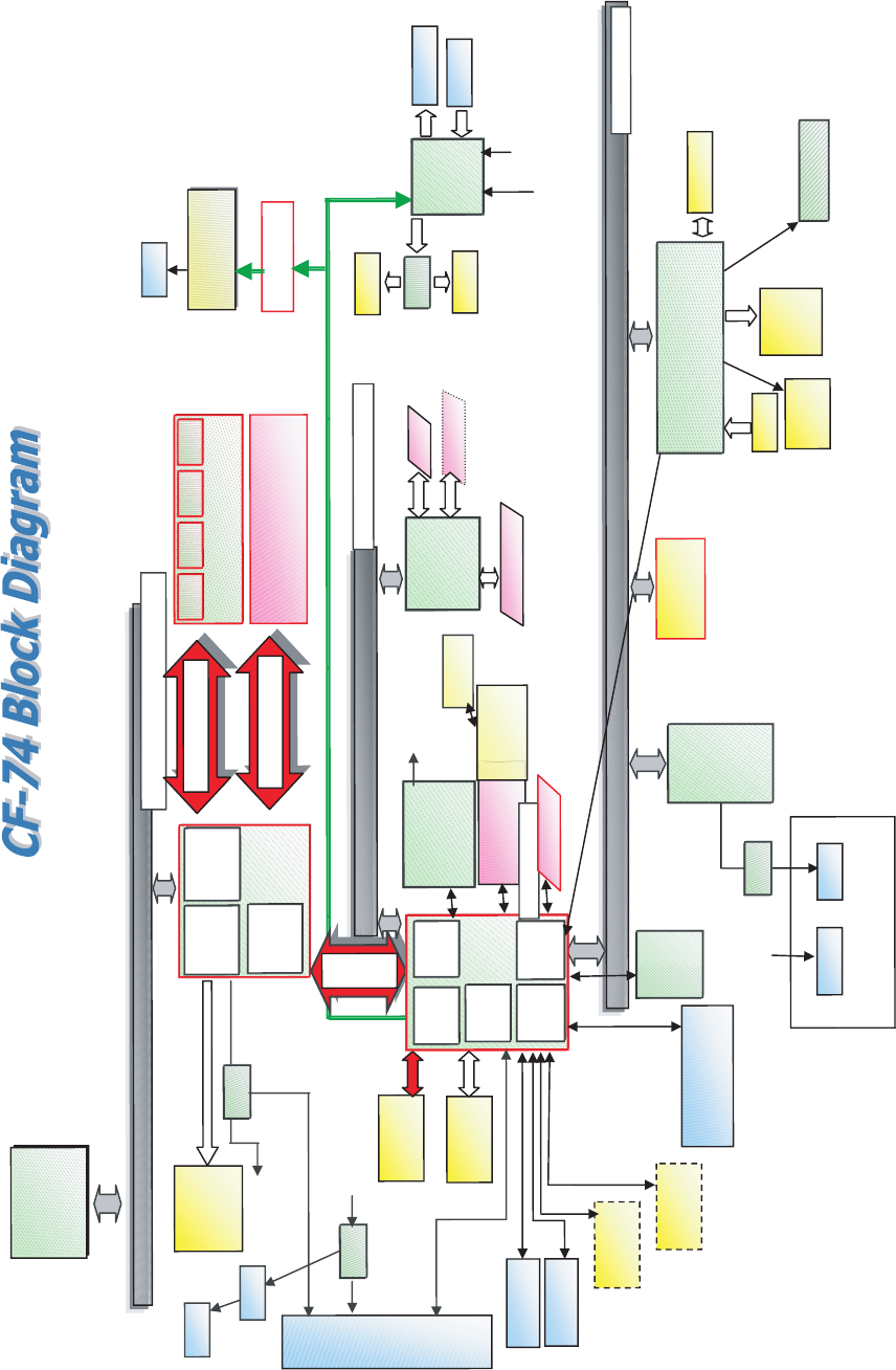
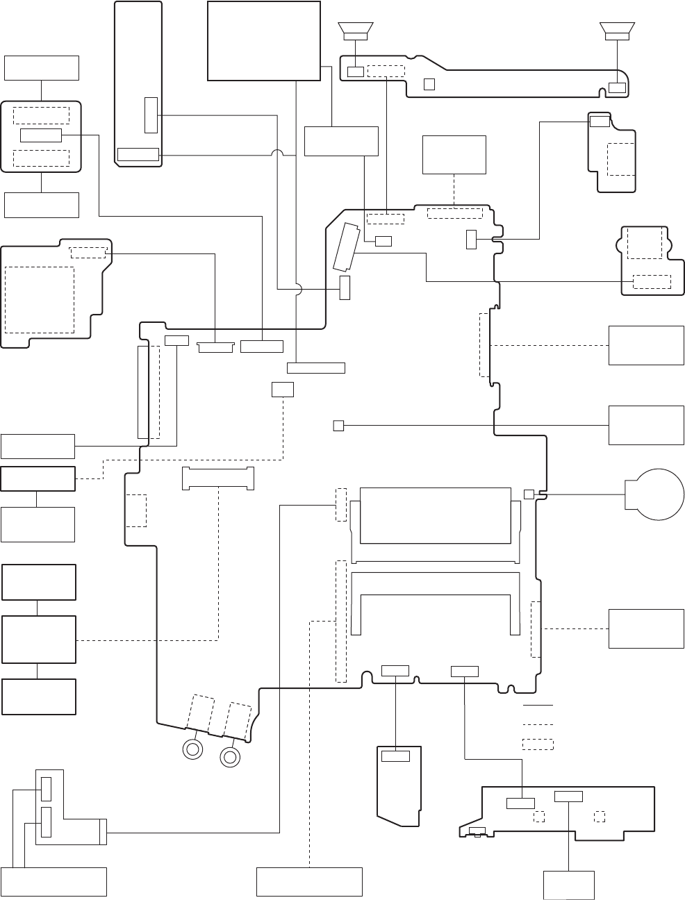
3 Block Diagram
BIOS
SPI 8Mbit
25LF080 Super I/O
PC87381
Winbond
Processor side Bus 64bit 667MHz
EC/KBC
(M306KA)
Li-Ion
Battery
Pack
LPC Bus
3.3V
32bit PCI Bus 33MHz
3.3V
1.05V AGTL+
SATA HDD
USB 2.0 x2
Calistoga G
Calistoga G
(1.05)
INTEL
Host PCI
Bridge
DRAM
Interface
SO-DIMM Extension Memory
DDR2 SDRAM
LCD
LCD
13.3
13.3
” XGA
XGA
18bit
18bit
CRT
Ext. MIC
AMP
PCMCIA
R5C811A/812A
MiniCard Wireless LAN
Golan 11ABG
Data Modem
Agere or Conexant
Serial
Int. KB
Touch Pad
Headphone
RJ11
Internal
Graphics
Sound
STAC9200
PCI
Bridge
ICH7-M
ICH7-M
1.05V
INTEL
IDE
Interface
USB 2.0
Interface
LPC
Bridge
HDA
Interface
DMI x2
2lane
64bit BUS 1.8V 667MHz
RJ45
antenna
USB 2.0 x2
TYPE II
MDC1.5 I/F
Smart Card
Ethernet GBe
Ethernet GBe
Yukon Ultra
Marvell
USB
Battey Charger
PM Signals
HD Audio
LED
BKLT
Buffer
64bit BUS 1.8V 667MHz
SD Card
Touch screen
Wide Range Wireless
SATA
PATA
DVD-Combo
PATA
PCI Express Bus
Express Card
ODD
Beep
TPM 1.2
Module
Finger Print
LVDS 1ch
Analog 0.7Vpp
Speaker
PR
SW
GBE
SW
GBE
Trans
Bluetooth
CRT
CRT
I/O Board
int
int
l
e
e
SO-DIMM Main Memory
DDR2 SDRAM
Speaker
3-1
4
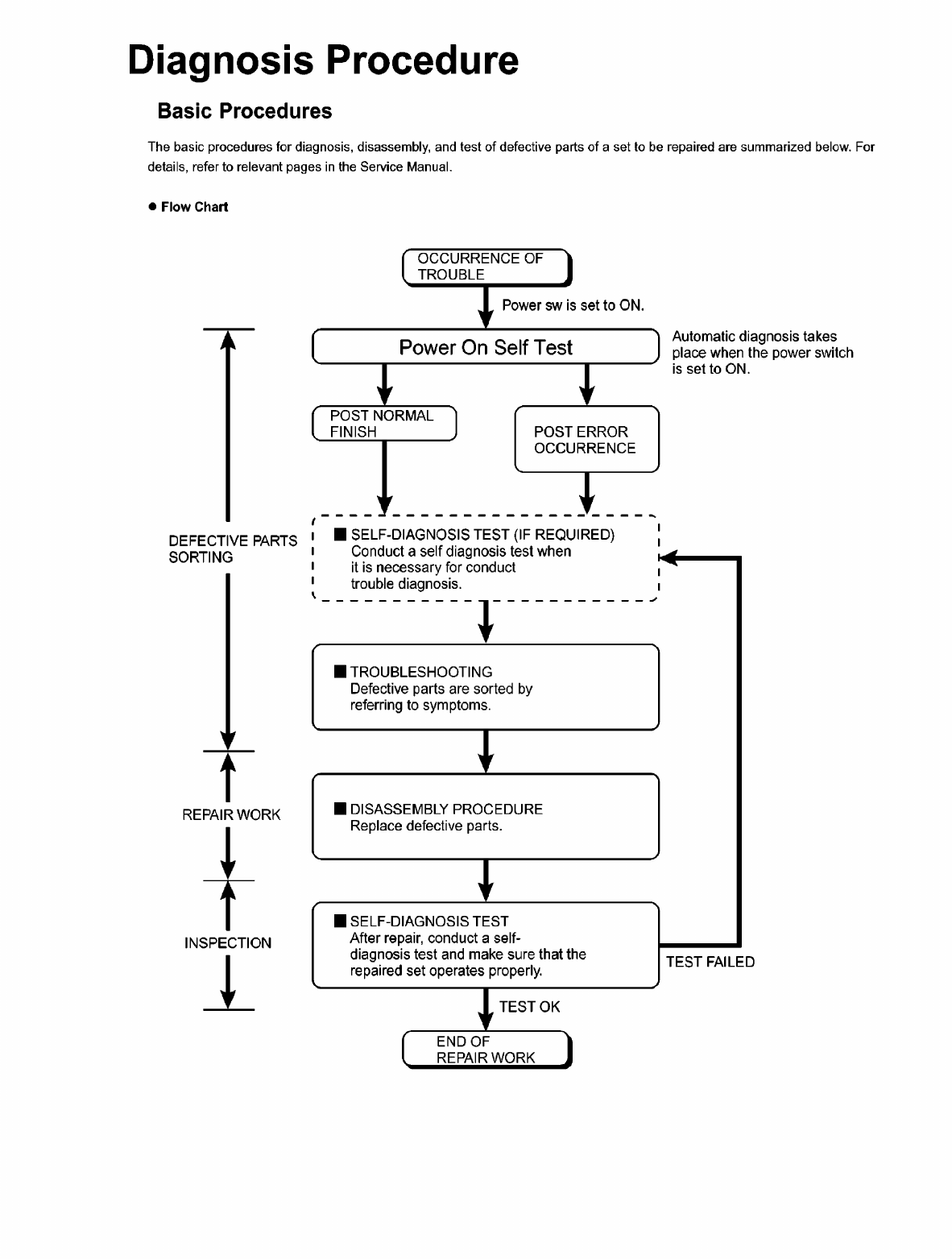
4.1.
4-1
4.2. Troubleshooting
Please take note of the following two points with regard to troubleshooting:
1. Know-how of diagnosis upon occurrence of heavy troubles, e.g. ‘Set cannot be turned ON’, ‘Set fails to start’, ‘No display on
screen’, etc.
2. Explanation of each trouble, mainly symptom of trouble in operation.
● Flow Chart
NG
NO
YES
NO
YES
NG
NO
YES NG
OK
OK
NO
YES
NG
OK
NG
OK
NO
YES
OK
OK
NG
START
START
Pay attention to the following points when in pursuit of the cause of a troubleshooting.
1. Peripheral apparatus connected with the set should all be removed before operation check.
2. Make sure that cables, boards, etc. are not coming off, and recheck the contact condition.
Set cannot be supplied with current.
Power lamp fails to light up.
AC
Adaptor/Battery
Output voltage Replace AC Adaptor/Battery
Return set-up utility setpoint to the state of ‘delivery from factory’.
Make sure of contact of K/B connector in use.
Replace keyboard or main board.
Replace DVD drive.
Replace main board.
Reinstall HDD.
Replace main board.
Power lamp
check
Check contact condition of power input terminal. Replace if
defective.
Check Power SW. Replace if defective.
Inverter board Replace inverter board.
Check inverter cable continuity. Replace if defective
Replace LCD back light.
BIOS operation
checkReplace main board (Check fuse at power source).
LCD unit
check Replace LCD unit.
Result of
POST
Refer to POST
error code table. Replace main board.
Main board
check Replace main board
HDD access
Check HDD cable connection and continuity.
Replace if defective.
Replace HDD & Reinstall.
Replace main board.
Set-up utility
starting Replace main board.
Trouble
symptoms on some
of DVD or CD
Check if there are any flaws on DVD or CD
media. Since flaws may appear on specific
media, DVD or CD media can be defective.
START
END
Dark display on screen.
Screen fails to display.
Failure in starting
Not displayed properly on screen.
Some or all keys cannot be input.
DVD/CD CALL not practicable.
Starts but operates unstably.
Heavy trouble e.g.,
‘Set cannot be turned
ON’, ‘Set fails to start’,
‘No display on
screen’, etc.
Each kind of
trouble in
operation.
*Clean DVD-ROM drive with an applicator.
LCD back
light lighting
4-2
5 Power-On Self Test (Boot Check)
Outline of POST
The set has a boot check function called POST (Power-On Self Test) in it. The condition of the main body is diagnosed by checking
beep sound or error code.
z Start .............Test begins automatically when power switch is set to ON.
z Normal finish .....After memory checking, a beep sound is issued once and the set is placed into automatic stop.
Note: If no error occurs, nothing is displayed. (No display of OK, etc.)
Error Diagnosis by Checking Beep Signal Sound
The beep sound is as follows:
= long sound (about 0.4 sec.), = short sound (about 0.2 sec.), Length between sounds is about 0.1 sec.
z Table of errors classified by beep sounds
(1 (long sound) -2-3-4)
(Length of bar shows length of sound.)
Diagnosis Beep signal sound Error message
1(long sound)-2 BIOS ROM error
BIOS ROM error
RAM error
Keyboard controller error
RAM error
RAM error
RAM error
1-2-2-3
1-3-1-1
1-3-1-3
1-3-4-1
1-3-4-3
1-4-1-1
BIOS ROM error2-1-2-3
Occurrence of unexpected offering2-2-3-1
Main board
(Note) A beep sound is also issued in case of other I/O trouble.
5-1
6 List of Error Codes
<Only when the port replicator is connected>
The following is a list of the messages that BIOS can display. Most of them occur during
POST. Some of them display information about a hardware device, e.g., the amount of memory
installed. Others may indicate a problem with a device, such as the way it has been configured.
Following the list are explanations of the messages and remedies for reported problems.
If your system displays one of except the messages marked below with an asterisk (*), write
down the message and contact Panasonic Technical Support. If your system fails after you
make changes in the Setup menus, reset the computer, enter Setup and install Setup defaults
or correct the error.
0200 Failure Fixed Disk
Fixed disk in not working or not configured properly. Check to see if fixed disk is attached
properly. Run Setup. Find out if the fixed-disk type is correctly identified.
0210 Stuck key
Stuck key on keyboard.
0211 Keyboard error
Keyboard not working.
0212 Keyboard Controller Failed
Keyboard controller failed test. May require replacing keyboard controller.
0213 Keyboard locked - Unlock key switch
Unlock the system to proceed.
0230 System RAM Failed at offset : nnnn
System RAM failed at offset nnnn of in the 64k block at which the error was detected.
0231 Shadow RAM Failed at offset : nnnn
Shadow RAM failed at offset nnnn of the 64k block at which the error was detected.
0232 Extended RAM Failed at offset : nnnn
Extended memory not working or not configured properly at offset nnnn.
0250 System battery is dead - Replace and run SETUP
The CMOS clock battery indicator shows the battery is dead. Replace the battery and run Setup
to reconfigure the system.
*0251 System CMOS checksum bad - Default configuration used
System CMOS has been corrupted or modified incorrectly, perhaps by an application program
that changes data stored in CMOS. The BIOS installed Default SETUP Values. If you do not
want these values, enter Setup and enter your own values. If the error persists, check the system
battery or contact Panasonic Technical Support.
0260 System timer error
The timer test failed. Requires repair of system board.
0270 Real time clock error
Real-time clock fails BIOS test. May require board repair.
*0280 Previous boot incomplete - Default configuration used
Previous POST did not complete successfully. POST loads default values and offers to run
Setup. If the failure was caused by incorrect values and they are not corrected, the next boot
will likely fail. On systems with control of wait states, improper Setup settings can also termi-
nate POST and cause this error on the next boot. Run Setup and verify that the wait-state
configuration is correct. This error is cleared the next time the system is booted.
0281 Memory Size found by POST differed from EISA CMOS
Memory size found by POST differed from EISA CMOS.
6-1
Troubleshooting
02D0 System cache error - Cache disabled
Contact Panasonic Technical Support.
02F0: CPU ID:
CPU socket number for Multi-Processor error.
02F4: EISA CMOS not writable
ServerBIOS2 test error: Cannot write to EISA CMOS.
02F5: DMA Test Failed
ServerBIOS2 test error: Cannot write to extended DMA (Direct Memory Access) registers.
02F6: Software NMI Failed
ServerBIOS2 test error: Cannot generate software NMI (Non-Maskable Interrupt).
02F7: Fail - Safe Timer NMI Failed
ServerBIOS2 test error: Fail-Safe Timer takes too long.
device address Conflict
Address conflict for specified device.
Allocation Error for: device
Run ISA or EISA Configuration Utility to resolve resource conflict for the specified device.
Failing Bits : nnnn
The hex number nnnn is a map of the bits at the RAM address which failed the memory test.
Each 1 (one) in the map indicates a failed bit. See error 230,231 or 232 for offset address of the
failure in System, Extended or Shadow memory.
Invalid System Configuration Data
Problem with NVRAM (CMOS) data.
I/O device IRQ conflict
I/O device IRQ conflict error.
Operating System not found
Operating system cannot be located on either drive A: or drive C:. Enter Setup and see if fixed
disk and drive A: are properly identified.
Parity Check 1 nnnn
Parity error found in the system bus. BIOS attempts to locate the address and display it on the
screen. If it cannot locate the address, it displays ????. Parity is a method for checking errors
in binary data. A parity error indicates that some data has been corrupted.
Parity Check 2 nnnn
Parity error found in the I/O bus. BIOS attempts to locate the address and display it on the
screen. If it cannot locate the address, it displays ????.
Press <F1> to resume, <F2> to Setup
Displayed after any recoverable error message. Press <F1> to start the boot process or <F2> to
enter a Setup and change the settings. Write down and follow the information shown on the
screen.
6-2
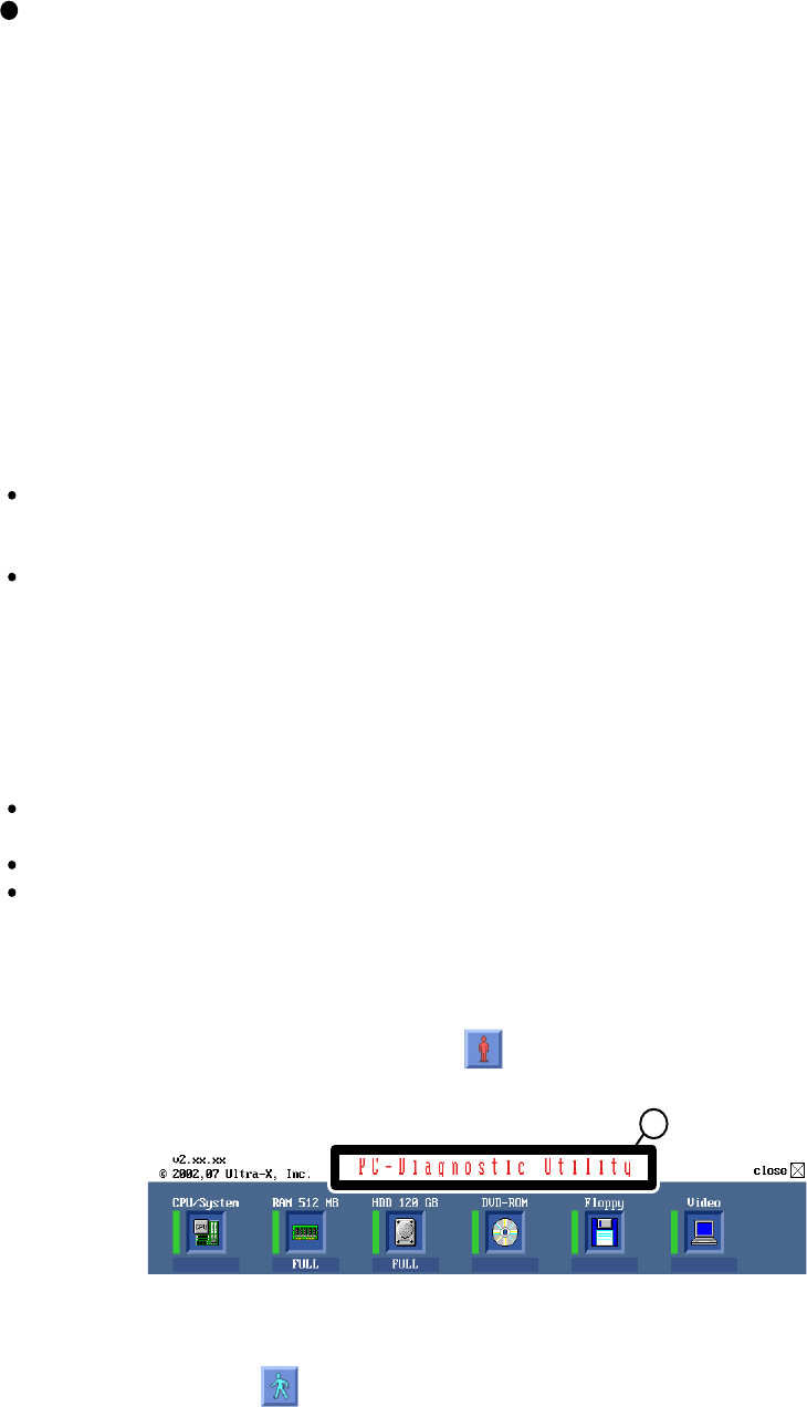
7Self Diagnosis Test
As for the self-diagnosis test(PC-Diagnostic utility) to use this model, a standard test and the
enhancing test by the module of the main body building in are possible.
The power supply of the computer is turned on.
" F2 " is pushed on the screen of "Panasonic" while " press <F2 to enter Setup> " is displayed.
The setup utility starts and then takes notes of the content of the BIOS setup of present set.
" F9 " is pushed, " Yes" is selected on the screen of " Is the default value loaded? ", and " Enter"
is pushed.
" F10 " is pushed.
" Yes" is selected on the screen of the setup confirmation, and " Enter" is pushed.
The computer starts automatically.
1.
2.
3.
4.
5.
6.
7.
1.
2.
Notes
1-1. Setting of content of setup
1. Beginning of self-diagnosis test
If the device which can be set is set to "Invalidity" by "Advanced" or "Security" menu, becomes an
error by "PC-Diagnostic utility".
(It is judged that the device which can be set to "Invalidity" by "Main" menu such as "Flat pad" is
normal if the controller operates normally though sets to "Invalidity" by the setup. )
In the model with built-in DVD of the USB connection, even if DVD is normal, becomes an error if
legacy USB is set to "Invalidity"
Attention
Attention
"Ctrl" + "F7" is pushed while the "Panasonic" start screen is displayed after the computer is started.
The test of all devices begins automatically by "PC-Diagnostic utility"’s starting.
It is a test which the customer who bought PC can execute. (As for HDD, the enhancing test is also
possible.)
A flat pad does not work for a while after starting "PC-Diagnostic utility".
The movement of a flat pad might become abnormal If after RAM begins from the CPU/System
test, a flat pad will be operated in about 30 seconds. In that case,restarts pushing"Alt" + "Ctrl" +
"Del" key. Or, please start "PC-Diagnostic utility" again after doing the power supply switch in the
slide, and turning off the power supply.
1-2. When you execute an automatic test
1.
2.
Please let me discontinue diagnosing clicking to end an automatic test.
Please click on the character of "D" "PC-Diagnostic utility" on the screen while pushing both of right
"Shift" and left "Shift" keys.
All devices which can select the enhancing test make the setting of the enhancing test possible.
The district device is made"FULL" display (enhancing test).
The test begins clicking .
1-3. When you execute the enhancing test
3.
4.
5.
D
*Please refer to item 4 for the error result of each test and the division of the breakdown part.
To skip BIOS password
Use <Ctrl>+<F10> key to skip BIOS password or authentication of fingerprint.
This key is only for entering DIAG mode. Not available to boot the computer.
If customer set "HDD Lock", the DIAG program cannot perform HDD test.
*This key is for service purpose only. Do not disclose this information to unrelated others.
7-1
-Only the device which can be inspected on the entire screen is displayed.
-The item does not appear when the device of wireless LAN etc. is not physically connected.
-The movement of the item must use an arrow key or a flat pad.
-As for the device under the diagnosis, blue and yellow are alternately displayed at the left of the icon.
- The diagnosis result of the device greens at the left of the icon when it is normal, and becomes red when
abnormal.
-Please click while diagnosing when being stop on the way by the time the test of all devices ends.
-Please click when you restart "PC-Diagnostic utility".
*Each device is tested from the beginning, and it is not possible to restart on the way.
-When the test of all devices ends, the test result is displayed under the right of the screen.
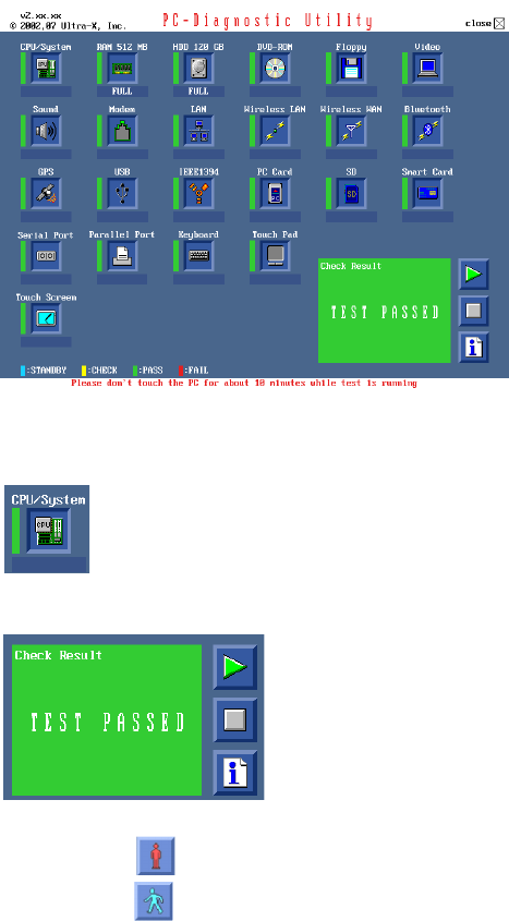
2. Operation of PC-Diagnostic Utility
7-2
1.
2.
3.
4.
5.
Turned on the computer.
"F2" is pushed on the screen while "Press<F2>to enter Setup" is displayed of "Panasonic".
Push "F10", and on the screen of "Is the change in the setting preserved and do end?"and then "Yes"
is selected, and "Enter" is pushed.
The computer reactivates automatically.
The end option is chosen by the start menu, and the power supply of the computer is turned off.
Ex.The standard when the standard <all device> is tested becomes 1+2+3=6 minutes.
There is greatly a difference from RAM test when the memory is increased according to the perform-
ance of the memory occasionally.
Moreover, when the main body of PC under the test is a high temperature, it occasionally takes time.
There is greatly a difference from HDD according to the performance of the drive occasionally.
2-3. The content of the setup is returned to the setting of the user
Standard at test time
All devices other than RAM and HDD
RAM standard test
HDD standard test
HDD enhancing test (60GB)
about 1 minute
1 - 2 minutes
2 - 3 minutes
about 40 minutes
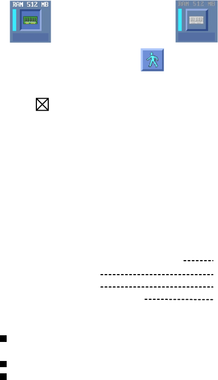
-To test only a specific device, "Test" and "Do not test" of each device can be selected.
-The device which can select the enhancing test changes in order of "The standard is tested" and "Do not
test" whenever the device icon is clicked.
2-1. Selection of tested device
When of "Close" on the right of the screen is clicked, the computer reactivates automatically. Or, the
power supply switch is done in the slide and the power supply is turned off.
2-2. "PC-Diagnostic utility" End method
Please begin testing clicking if the selection of the tested device ends.
Start the standard test Do not test
7-3
7.1. Test Item and Division of trouble
CPU /
SYSTEM
Test item Stanard
Enhancing
Content of standard test Content of enhancing test
Place with possibili-
ty of breakdown
CPU is shifted to protected mode, and
"Violation of the paging", "Operation of
the violation of a privileged instruc-
tion", and DMA, INT, TIMER, and the
RTC operation are confirmed.
CPU /
Main board
RAM All memory space is tested in a spe-
cial memory access pattern based on
"R.S.T . technology".
Memory / Main-
board
HDD The record area frequently accessed
with Microsoft Windows XP to test in
about two minutes regardless of
points of HDD is emphatically tested.
All record area is tested. HDD /
Mainboard /
Cable /
Connector
MODEM It is confirmed not to find abnormality
in the AC97 modem controller.
MODEM/ Main-
board
Wireless
LAN
It is confirmed not to find abnormality
in the Wireless LAN modem controller. Wireless LAN
board /
Connector /
Mainboard
It is confirmed not to find ab-
normality in the wiring be-
tween the USB controller and
the connector by confirming
the connection of the USB
equipment connected with the
USB connector.
Sound
USB It is confirmed not to find abnormality
in the USB controller.
Mainboard /
Connector
It is confirmed not to find ab-
normality in the wiring be-
tween the controller and the
connector by connecting to
HUB with LAN cable.
LAN It is confirmed not to find abnormality
in the LAN controller.
Mainboard /
Connector
PC Card It is confirmed not to find abnormality
in the CardBus controller.
Mainboard
*5
*1
*2
*3
SD It is confirmed not to find abnormality
in the SD controller.
Mainboard
The key is actually input, and
the operation is displayed on
the screen.
Keyboard It is confirmed not to find abnormality
in keyboard controller’s keyboard inter-
face.
Mainboard /
Keyboard
*4
*6
The operation is actually dis-
played on the screen by oper-
ating the touch pad.
Touch Pad Whether keyboard controller’s mouse
interface operates normally is con-
firmed.
The drive is normally reset, and it is
accessible is confirmed.
Mainboard /
Touch Pad
It is confirmed to be able to
read media normally.
DVD-ROM Mainboard /
Touch Pad
7-4
Test Item
Standard Enhanced
Content of Standard Test Content of Extend Test
The place with possibility of
breakdown
Touch Screen
It is confirmed not to find
abnormality in the USB
connection of Touch Screen.
This test cannot find
abnormality of Touch Screen.
Perform Touch Screen
functionality practically.
Operator has to judge
PASS/FAIL with test result.
Main board/
Touch Screen
Bluetooth
It is confirmed not to find
abnormality in the connection
of Main board and Bluetooth
module.
Bluetooth cable
Wireless WAN
It is confirmed not to find
abnormality in the connection
of Main board and Wireless
WAN module.
WWAN cable
Floppy
It is confirmed not to find
abnormality in the legacy FD
drive.
This test cannot find
abnormality of mechanical
breakdown. (e.g.. Head, Motor)
FD Drive/
Main board (Super I/O)/
FDD cable
FDD connector
Video
It is confirmed not to find
abnormality in access to
VRAM with VESA.
The PC which uses main
memory as VRAM may fail with
main memory failure.
Main board
(Chipset, Graphic
Controller)/
Memory
GPS
It is confirmed not to find
abnormality in the connection
of Main board and GPS
GPS cable
IEEE1394
It is confirmed not to find
abnormality in the IEEE1394
controller.
Main board
(IEEE#394 Controller)
Express Card
It is confirmed not to find
abnormality in the wiring
between Chipset and Express
Card.
Main board (Chipset)/
Express Card Connector
Smart Card
It is confirmed not to find
abnormality in the Smart Card
controller.
Main board
(Smart Card Controller)
Serial Port *7
It is confirmed not to find
abnormality of Super I/O
UART function.
This test cannot find lack of
wiring between Super I/O and
Serial Connector.
It is confirmed not to find
abnormality in the wiring
between Super I/O and Serial
Connector.
This test cannot find failure of
cable characteristic and device
problems.
Main board (Super I/O)/
Serial Connector
Parallel Port *8
It is confirmed not to find
abnormality of Super I/O
parallel function.
This test cannot find lack of
wiring between Super I/O and
Parallel Connector.
It is confirmed not to find
abnormality in the wiring
between Super I/O and
Parallel Connector.
This test cannot find failure of
cable characteristic and device
problems.
Main board (Super I/O)/
Parallel Connector
*8 Please set a Special Loop Back Connector Tool at parallel connector for Enhanced Test.
(This Connector Tools is same as the one used before.)
*7 Please set a Special Loop Back Connector Tool at serial connector for Enhanced Test.
(This Connector Tool is same as the one used before.)
*1 Please connect the USB device with the port (USB connector) which wants to test before the tests.
Please connect LAN port with LAN HUB with LAN cable before the tests.
The operator actually inputs the key, and the operator judges PASS/FAIL of the test.
The operator actually operates the mouse, and the operator judges PASS/FAIL of the test.
It is not abnormal though the sound is emitted from the speaker while testing.
Please set DVD/CD media in the drive before the tests.
*2
*3
*4
When the test result is PASS, trouble is thought by not hearing of the sound under the test from
the speaker and the headphone by the wiring of the audio output system.
*5
*6
7-5
8 Wiring Connection Diagram
CN1001
CN1701
CN1201
CN1203
CN1202
CN1401
CN1402
JK1501
CN1501
DC-IN PCB
USB PCB
CN1702
CN1003 CN1002
SW1001
POWER SW
LED PCB
SD PCB
I O PCB
TS PCB
LCD
CN1602
CN1603
Connector by Cable
Direct connection by Connectors
Parts on Bottom Side
HDD PACK
LITHIUM
BATTERY
FAN MOTOR
DVD-ROM
DRIVE
DC-IN
USB
BATTERY
PACK
SPEAKER (R) SPEAKER (L)
FLAT
PAD
KEYBOARD
KBD FPC
PCMCIA SLOT
LAN JACK
MODEM
JACK
MODEM
ANTENNA
PCB R
WIRELESS
MODULE
ANTENNA
PCB L
Microphone
Headphone
PORT
REPLICATOR
USB DIMM MEMORY CARD
VGA
SERIAL
INVERTER
CN18
CN21
CN28
CN802
CN6 CN7 CN24
CN19
CN12
CN5
CN15
CN4
CN2
CN3
CN26
CN16
CN17 CN801
CN14
CN25
CN8
CN13
CN23
JK2 JK1
MAIN PCB
PAD SW PCB
SW1301
CN1301
CN1302
SW1303
SW1304
CN27
CN1
FINGER SENSOR
PCB
8-1
9-1
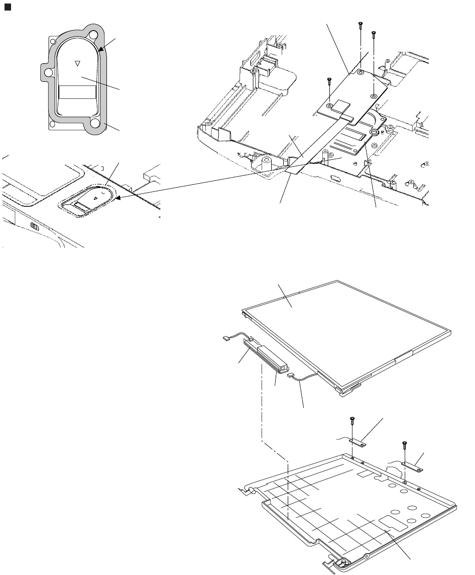
9 Disassembly/Reassembly
Note:
Power off the computer. Do not shut down to the Suspend or hibernation mode.
Do not add peripherals while the computer is in the Suspend or hibernation mode; abnormal operation may result.
9.1. Disassembly Instructions
9.1.1. Preparation
Before disassembling, be sure to make the following prepara-
tions.
• Shut down Windows and turn off the power.
• Disconnect the AC adaptor.
• Remove the optional DIMM memory card and PCMCIA card
if they are connected.
• Remove other devices if they are connected.
Attention:
• Please execute writing BIOS ID when you exchange the
Main Board.
• You cannot reuse the Conductive Clothes and the heat dissi-
pating parts such as Sheet and Rubber. Use new parts.
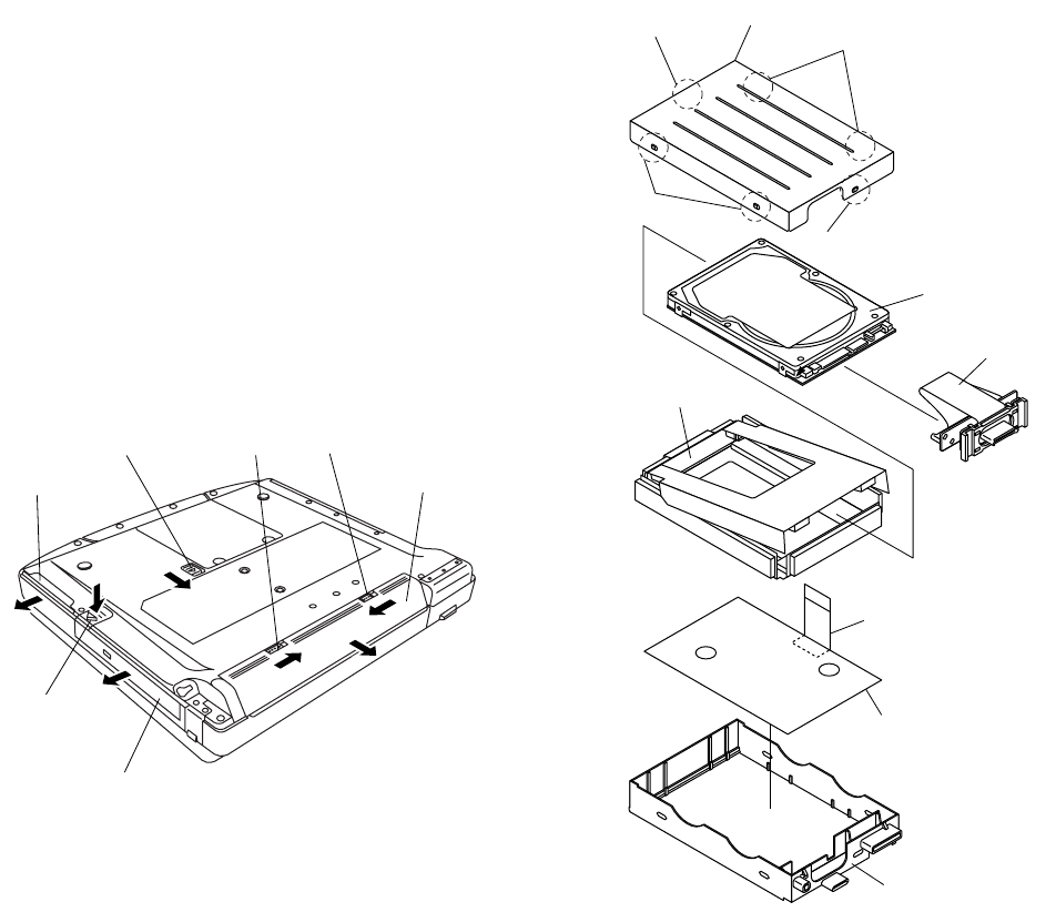
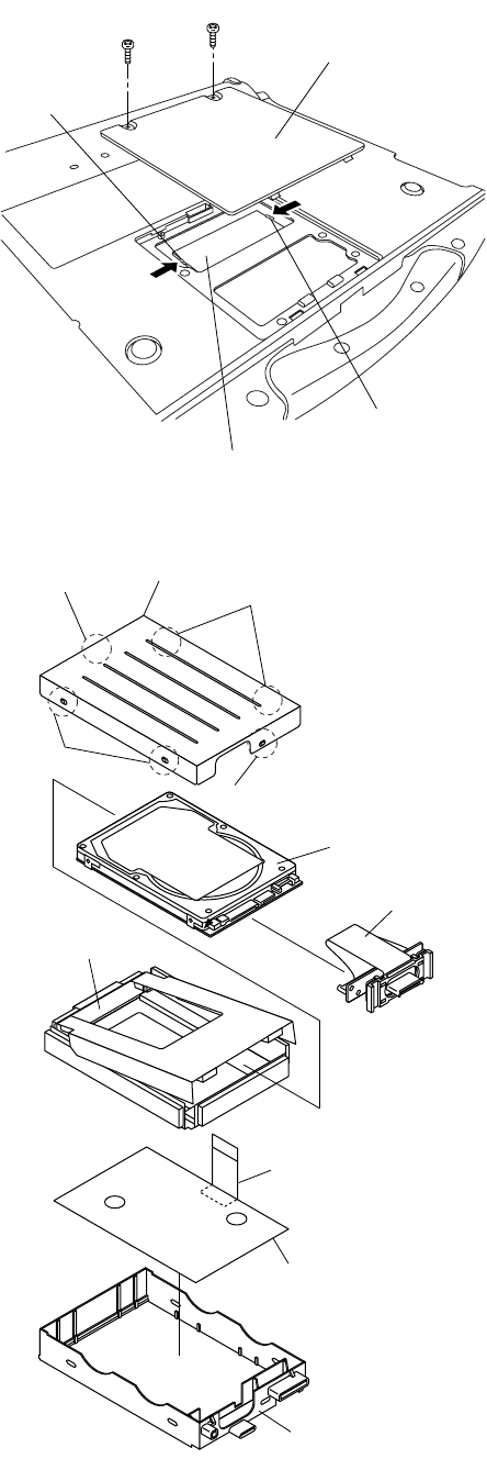
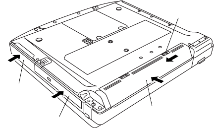
9.1.2. Removing the Battery Pack, the
HDD Unit and the DVD-ROM Drive
Unit
Battery Pack
1. Slide the Latch 1 to unlock. (1)
2. Slide the Latch 2 (2), and then without releasing it, slide
and remove the Battery Pack. (3)
HDD Unit
1. Slide the HDD Latch Knob (4), and then without releasing
it, slide and remove the HDD Unit. (5)
DVD-ROM Drive Unit
1. Push the MP Latch (6), and then without releasing it, slide
the DVD-ROM Drive Unit. (7)
9.1.3. Removing the HDD
1. Remove the six Hooks, and remove the HDD Case
Upper.
2. Remove the HDD Damper.
3. Disconnect the HDD from the HDD FPC.
4. Remove the HDD Conductive Sheet and HDD Earth
Plate.
HDD Latch Knob
HDD Unit
MP Latch
DVD-ROM Drive Unit
Latch 2
1
23
4
5
6
7
Latch 1
Battery Pack
Hook
Hook
Hook
Hook
HDD Case Upper
HDD Conductive Sheet
HDD Earth Plate
HDD FPC
HDD Damper
HDD Case
HDD
9-2
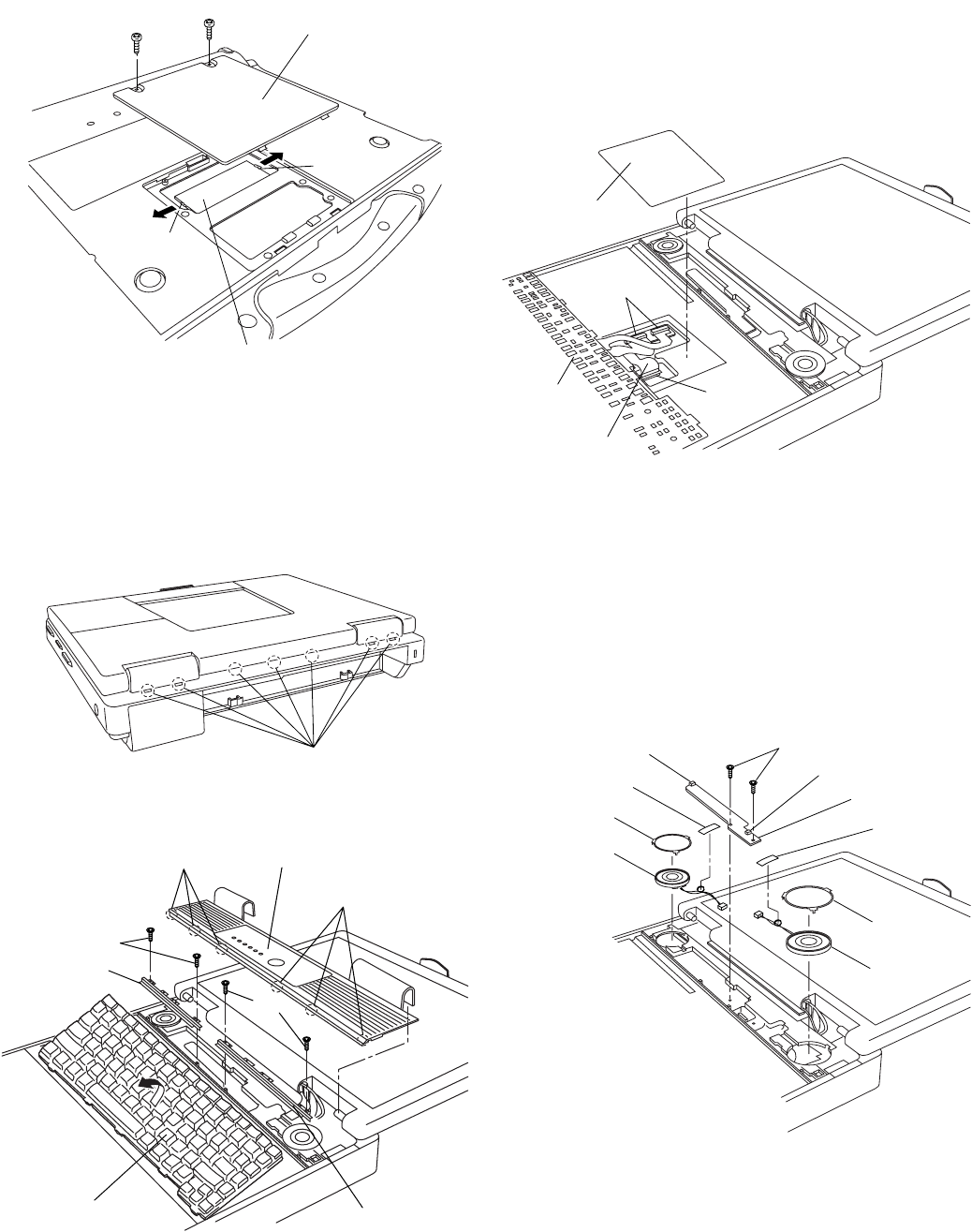
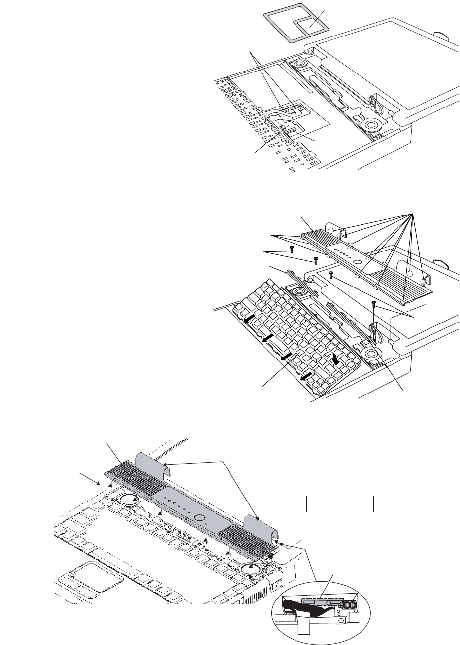
9.1.4. Removing the DIMM Memory Card
1. Remove the two Screws <N1>, and remove the DIMM
Cover.
2. Open the right and left Hooks of the DIMM Memory Card
outward, and remove the DIMM Memory Card.
Screws <N1>: XSB2+3FNL
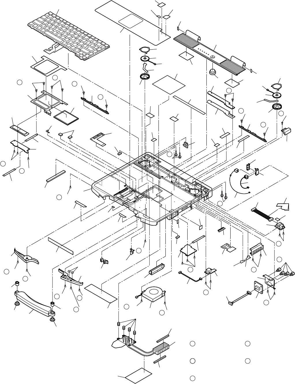
9.1.5. Removing the Keyboard
1. Release the seven Hooks fixing the rear side of the Cen-
ter Cover.
2. Lift the upper part of the Center Cover and draw it back-
ward, release the six Hooks fixing the front side of the
Center Cover, and then remove the Center Cover.
3. Remove the four Screws <N9> and the KBD Angle L and
R.
4. Lift the upper part of the Keyboard and draw it backward,
and then turn the Keyboard over forward.
5. Remove the KBD WP Sheet.
6. Disconnect the two KBD Cables from the two Connectors
(KBD FPC).
7. Remove the Keyboard.
8. Disconnect the Cable from the Connector (CN25).
9. Remove the KBD FPC,
Screws <N9>: DFHE5025XA
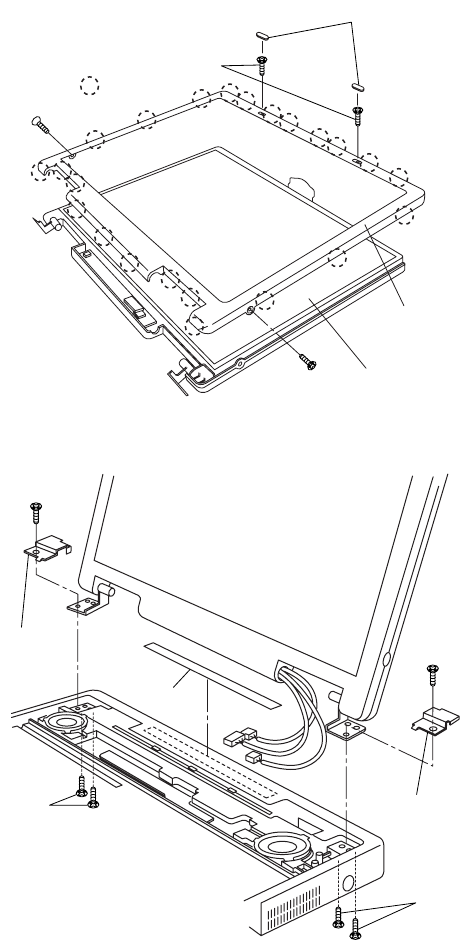
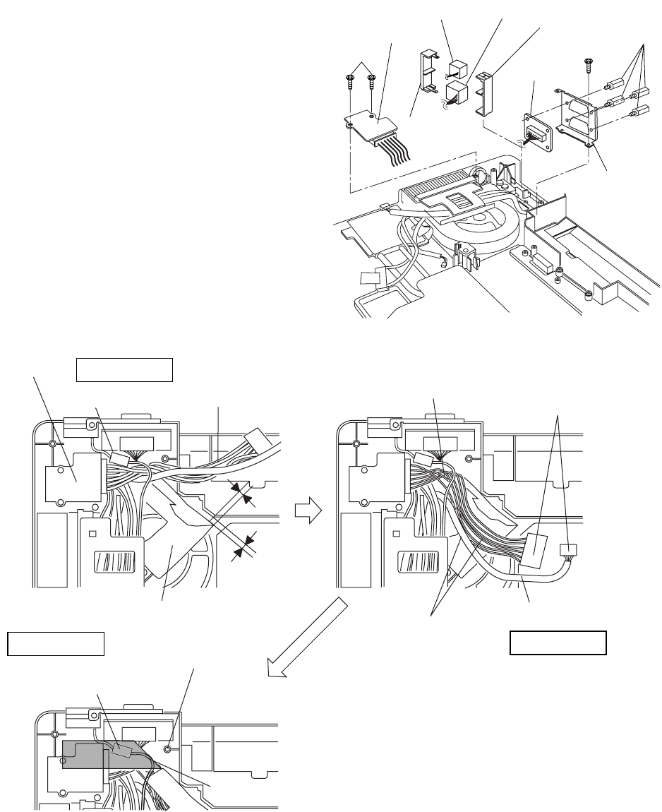
9.1.6. Removing the Speaker and the LED
PCB
1. Remove the two Speaker Holders.
2. Remove the two tapes, and disconnect the two Speaker
Cables from the two Connectors (CN1002, CN1003)
3. Remove the Speaker L and R.
4. Remove the two Screws <N9>, and Remove the LED
PCB.
Screws <N9>: DFHE5025XA
<N1> <N1>
Hook
Hook
DIMM Cover
DIMM Memory Card
Hooks
Center Cover
Hooks
Hooks
<N9>
<N9>
KBD Angle L
KBD Angle R
Keyboard
Connectors
KBD FPC
Connector
(CN25)
KBD WP Sheet
Keyboard
Speaker
Holder
Speaker
Holder
CN1002
Tape
Tape
CN1003
<N9>
LED PCB
Speaker L
Speaker R
9-3
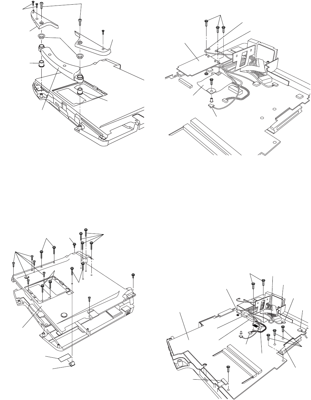
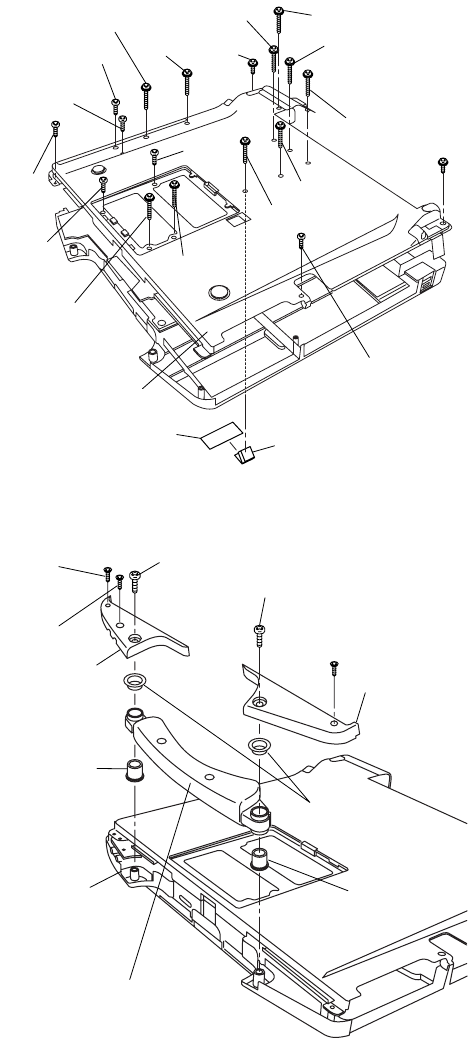
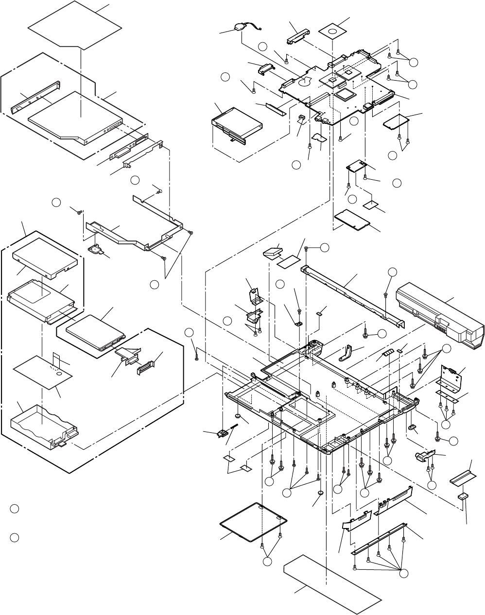
9.1.7. Removing the Handle Ass'y
1. Remove the two Screws <N2>.
2. Remove the three Screws <N4>, and remove the Handle
Cover L and R.
3. Remove the two Sleeves A, Handle Ass'y and two
Sleeves B.
Screws <N2>: DRHM4+10FKS
Screws <N4>: DRSB2+6FKL
9.1.8. Removing the Bottom Case
1. Remove the six Screws <N5>.
2. Remove the ten Screws <N7>.
3. Remove the two Screws <N8>.
4. Open the Lid Rubbers and remove the Bottom Cover.
5. Remove the Sheet and Gasket.
Screws <N5>: DXSB2+6FNL
Screws <N7>: DXYN2+J16FNL
Screws <N8>: DXYN2+J8FNL
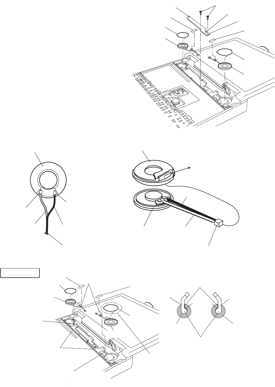
9.1.9. Removing the Wireless Module and
MDC Module
1. Remove the two Antenna Cables from the two Connec-
tors.
• Antenna Cable (Black): MAIN Connector
• Antenna Cable (Gray): AUX Connector
2. Remove the two Screws <N9>.
3. Remove the Wireless Module.
4. Remove the two Screws <N9>.
5. Disconnect the Modem Cable from the Connector.
6. Remove the MDC Module.
Screws <N9>: DFHE5025XA
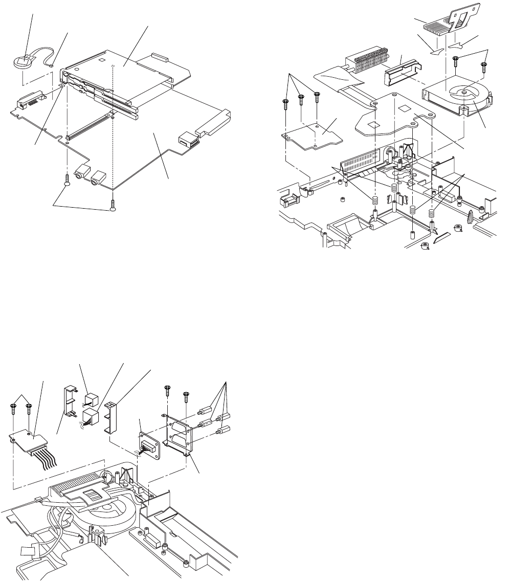
9.1.10. Removing the Main PCB
Handle Cover R Handle Cover L
Handle Ass’y
Sleeves B
Sleeves A
Sleeves A
<N4>
<N4>
<N2>
<N7>
<N7>
<N7>
<N8>
<N8>
<N5>
<N5>
Bottom Cover
Sheet
Gasket
<N7>
Antenna Cable (Black)
Antenna Cable (Gray)
<N9>
<N9>
MDC Module
Wireless Module
Modem Cable
CN6
CN7
CN24
CN19
CN28
CN21
CN802
CN18
CN15
CN26
<N9>
<N9>
Main PCB
MP Guide
9-4
Note:
After replacing the Main Board, rewrite the BIOS ID.
1. Disconnect the ten Cables from the ten Connectors (CN6,
CN7, CN24, CN19, CN28, CN21, CN802, CN18, CN15,
CN25).
2. Remove the six Screws <N9>.
3. Remove the Main PCB.
4. Remove the MP Guide.
Screws <N9>: DFHE5025XA
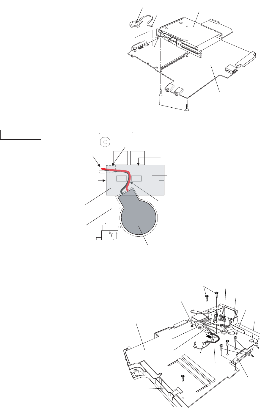
9.1.11. Removing the PC Card Ejector and
Lithium Battery
1. Remove the two Screws <N9>.
2. Remove the PC Card Ejector.
3. Disconnect the Cable from the Connector (CN14).
4. Remove the Lithium Battery.
Screws <N9>: DFHE5025XA
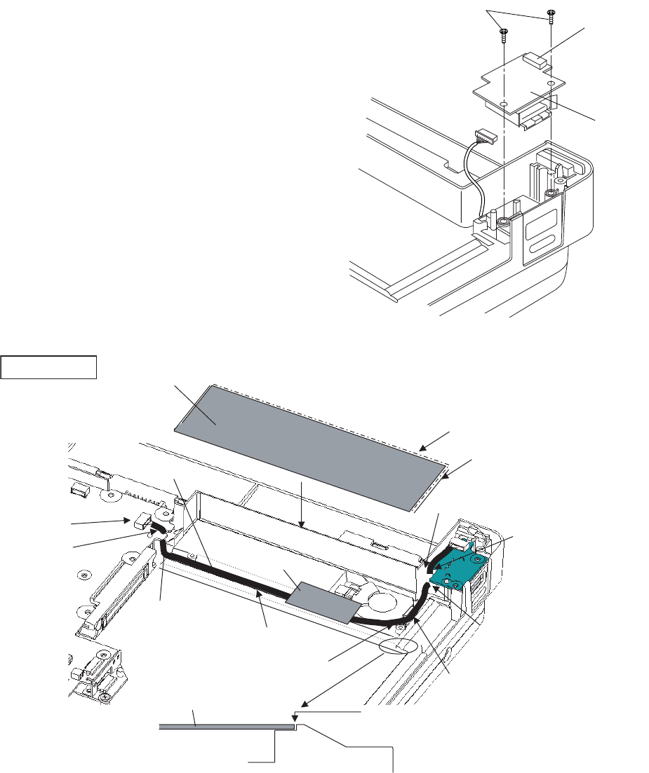
9.1.12. Removing the DC-IN PCB and I/O
PCB
1. Remove the two Screws <N9>.
2. Remove the DC-IN PCB.
3. Remove the two Screws <N9>.
4. Remove the four Screws <N19>, and then the I/O PCB
from the I/O Plate.
5. Remove the Modem Cable and LAN Cable from the
MODELAN Holders.
Screws <N9>: DFHE5025XA
Screws <N19>: DFHE5035ZB
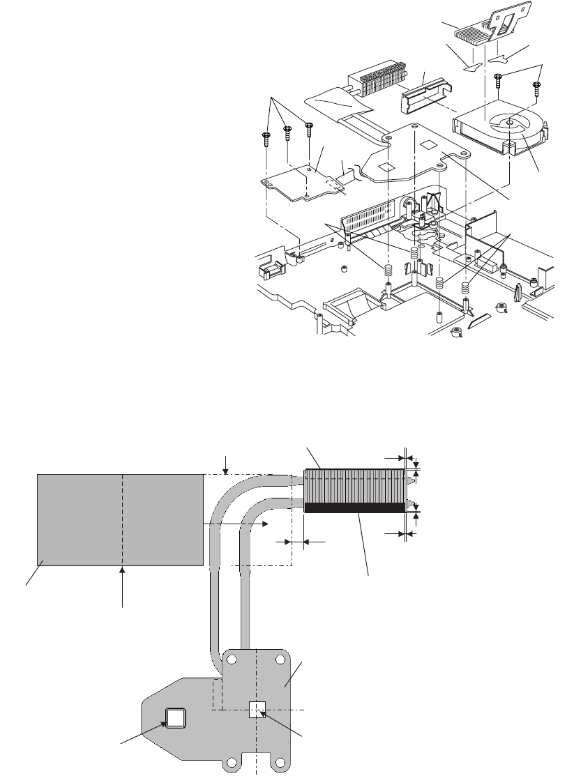
9.1.13. Removing the FAN Motor and SD
PCB
1. Remove the Cable Holder.
2. Remove the two Screws <N5>.
3. Remove the FAN Motor.
4. Remove the Heat Sink, Fan Duct, and the four Heat Sink
Springs.
5. Remove the three Screws <N9>.
6. Remove the SD PCB.
Screws <N5>: DXSB2+6FNL
Screws <N9>: DFHE5025XA
<N9>
PC Card Ejector
Lithium Battery
(to CN14)
CN14
Main PCB
<N9> <N9>
DC-IN PCB
MODELAN-2
Holder
LAN Cable MODELAN
Holder
Modem Cable
I/O Plate
I/O PCB
<N19>
<N9>
Cable Holder
<N5>
FAN Motor
Heat Sink
Fan Duct
Fan Tape1 Fan Tape2
Heat Sink
Spring Heat Sink
Spring
<N9>
SD PCB
9-5
9.1.14. Removing the USB PCB
1. Disconnect the Cable from the Connector (CN1701).
2. Remove the two Screws <N9>.
3. Remove the USB PCB.
Screws <N9>: DFHE5025XA
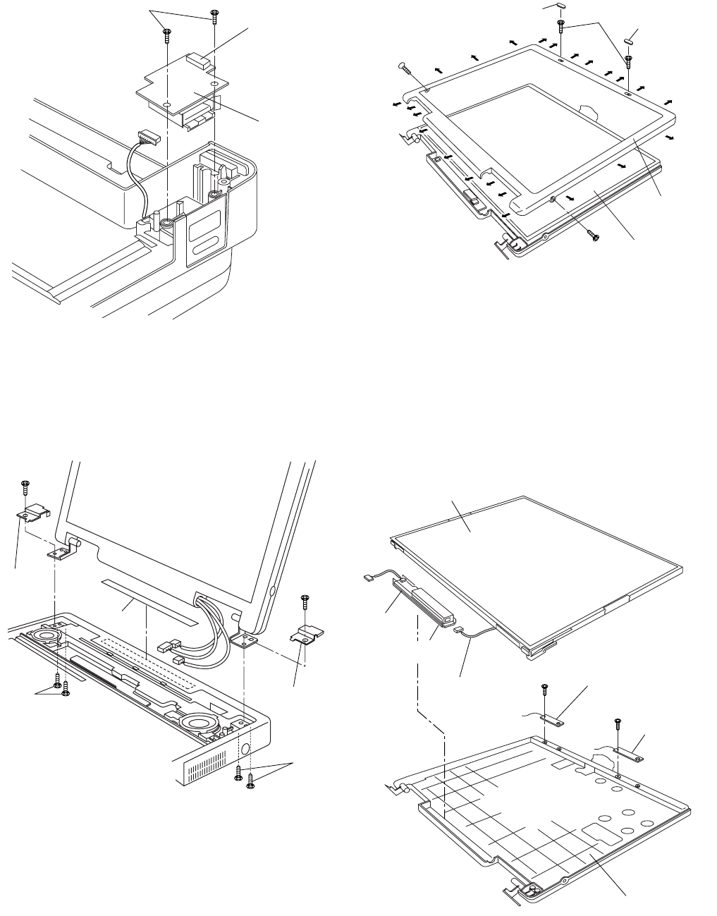
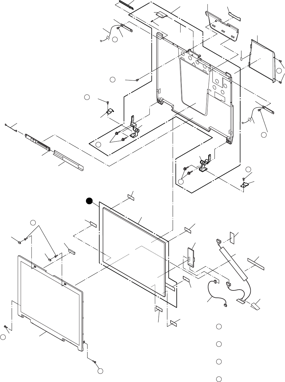
9.1.15. Removing the Display unit
1. Remove the four Screws <N6> from the computer bottom
side.
2. Remove the two Screws <N6> from the computer upper
side.
3. Remove the Display Unit.
4. Remove the Hinge Screw Cover L and R.
5. Remove the Gasket.
Screws. <N6>: DXSB3+6FNL
9.1.16. Removing the LCD Front Cabinet
1. Remove the two LCD Leg Rubbers, and then the two
Screws <N16>.
2. Remove the two Screws <N15>.
3. Release the 23 Hooks joining the LCD Front and Rear
Cabinet on the LCD Front Cabinet outward. (See the Fig-
ure),
4. Remove the LCD Front Cabinet.
Screws <N15>: DRHM0075ZA
Screws <N16>: DXQT2+G4FCL
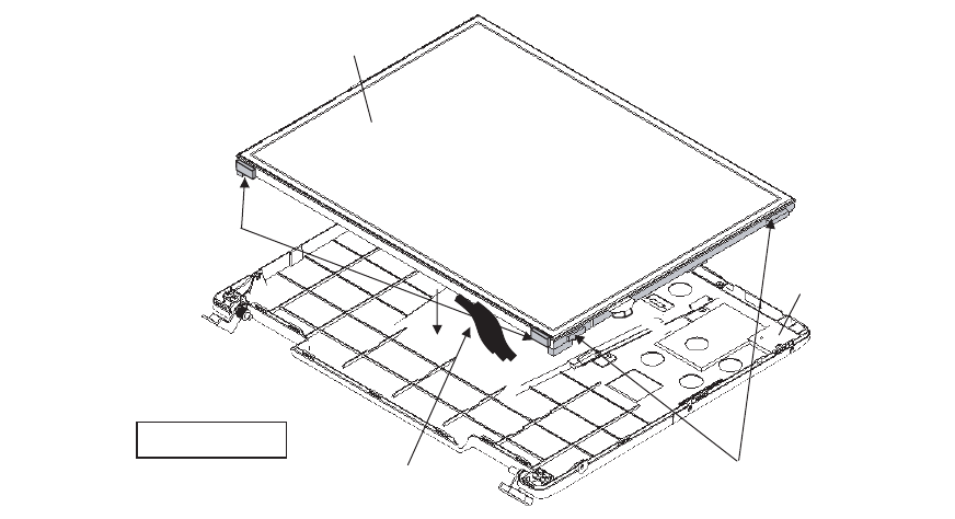
9.1.17. Removing the LCD and the Inverter
<N9>
USB PCB
CN1701
<N6>
<N6>
<N6>
<N6>
Display Unit
Gasket
Hinge
Screw
Cover L
Hinge
Screw
Cover R
<N16>
<N15>
<N15>
LCD Leg
Rubber
LCD Front
Cabinet
LCD Unit
LCD Leg Rubber
LCD/INV. Cable
Inverter
Inverter Case
LCD Unit
<N18>
<N18>
LCD Rear Cabinet
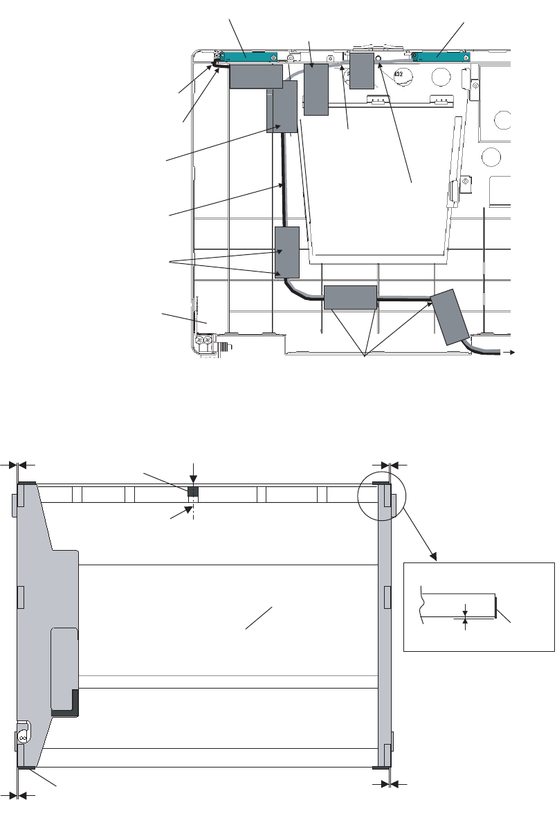
W-LAN PCB L
W-LAN PCB R
9-6
1. Disconnect the LCD/INV. Cable from the Connector on
the Inverter.
2. Remove the LCD Unit.
3. Remove the Inverter with the Inverter Case.
4. Remove the two Screws <N18>, and then the W-LAN
PCB L and R.
Screws <N18>: XQN17+BJ6FJ
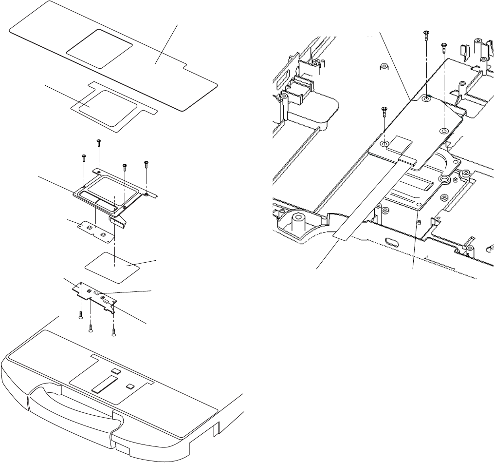
9.1.18. Removing the Touch PAD and PAD
PCB
1. Remove the Palm Rest Sheet.
2. Remove the four Screws <N20>, and then PAD Base
Ass'y.
3. Disconnect the two Cables from the two Connectors
(CN1301, CN1302).
4. Remove the three Screws <N14>.
5. Remove the PAD Button WP Rubber and PAD SW PCB.
6. Remove the Touch PAD.
Screws <N14>: DRHM0106ZA
Screws <N20>: DXQT2+G4FCL
9.1.19. Removing the Finger PCB
Preparation
Perform the steps up to removing of the Main PCB.
1. Remove the three Screws. <N9>
2. Remove the Finger PCB and Finger Sensor Base.
Screws <N9>: DFHE5025XA
Palm Rest Sheet
Pad WP Sheet A
PAD Base Ass’y
PAD Button
WP Rubber
Touch PAD
PAD SW PCB
<N20>
<N20>
<N20>
<N20>
CN1302
CN1301
<N14>
<N14>
<N14>
<N9>
Finger PCB
Finger Sensor Base
FP FFC Cable
<N9>
<N9>
9-7
9.2. Reassembly Instructions
9.2.1. Attention when CF-74 series is repaired
• Please execute writing BIOS ID when you exchange the Main Board.
• You cannot reuse the Conductive Clothes and the heat dissipating parts such as Sheet and Rubber. Use new parts.
9.2.2. Setting the Finger PCB
1. Fix the Finger PCB and the Finger Sensor Base to the computer using the 3 Screws <N9>.
2. Connect the FP FFC Cable to the Connector (CN27) on the Main PCB.
Screws <N9>: DFHE5025XA
9.2.3. Setting the LCD Unit and the
Inverter
1. Fix the W-LAN PCB L and R to the LCD Rear Cabinet
using the two Screws <N18>.
2. Attach the Inverter with the Inverter Case to the LCD Rear
Cabinet.
3. Set the LCD Unit to the LCD Rear Cabinet.
4. Connect the LCD/INV. Cable to the Connector on the
Inverter.
Screws <N18>: XQN17+BJ6FJ
<N9>
Finger P.C.B.
Finger Sensor Base
FP FFC Cable
(to Connector CN27)
Preparing and setting the Finger Sensor Base
Press the surrounding part strongly enough.
Fit the frame of the PALMREST SHEET.
(Avoid running over.)
Avoid catching of
the FP FFC Cable.
Attach the
(all circumferences) to avoid
running over the rib of Finger
Sensor Base.
(Clearance: 0 to 1 mm)
FS Waterproof
Sheet 2
Finger Sensor Base
<N9>
<N9>
LCD/INV. Cable
Inverter
Inverter
Case
LCD Unit
<N18>
<N18>
LCD Rear Cabinet
W-LAN PCB L
W-LAN PCB R
9-8
Q Arranging the W-LAN L and R Cable
Q Attaching the LCD Damper C and LCD Damper D
1. Attach the four LCD Damper C to the upper part and lower part of the LCD Unit.
2. Attach the LCD Damper D to the upper center of the LCD Unit.
W-LAN Antenna L PCB W-LAN Antenna R PCB
LCD Rear Cabnet
Attach the Tape to hold the Cable.
Pass the Cable
through the notch
and lead it downward.
Pass the Cable between
the boss and rib.
Pass the Cable through the notch
and lead it downward.
Lead the Cable along the surface.
A
ttach the Tape to each of the Cables.
(Avoid overlapping.)
Avoid overlapping of the Cables
(all the way).
Pass the Cable through the notch.
(Avoid running over the ribs.)
Pass the Cable through the notch.
(Avoid running over the ribs.)
A: Match the LCD Damper C by LCD edge 0~2mm
A
A
A
LCD Damper D
LCD Unit
LCD Display Side
LCD Rear Side
0~1mm
LCD Damper C
Match the LCD Damper D to the center
of the LCD Unit.
LCD Damper C
0~1mm
9-9
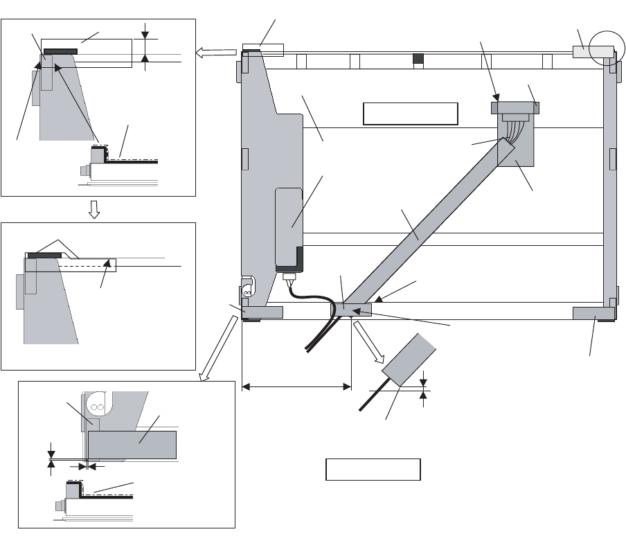
Q Arranging the LCD/TS Cable
1. Connect the LCD/TS Cable (LCD) to the Connector on the LCD Unit.
2. Connect the LCD/TS Cable (TS) to the Connector (CN603) on the TS PCB.
Cushion
A: Match the Cloth by Cushion edge 0~1mm
AA
Cloth
Cloth
TS PCB
LCD Unit
Cloth
Cloth
Cloth
Cloth
Cushion
Match the end of
the Cloth to the end
of the Cushion.
Cloth
B
B: Attaching the Cloth
3~5mm
95~100mm 0~2mm
B
LCD/TS Cable EMI Sheet
Tape
Match the end of the Tape to the end of the EMI Sheet.
Attach the Cloth along
the surface of
the Cushion.
Fold it back and attach to the side surface.
Ensure the Cloth is surely
attached to the metal
chassises on both of the
side and top.
(The Cloth should catch
the metal chassieses only.
It must not catch the TAB.)
Attach the Cloth
along the surface
of the Cushion.
Before attaching the EMI Sheet,
attach the Tape.
Turn them halfway.
*Avoid too much tension
on the Cables.
Ensure it does not come out
of the metal part.
Use the Cable covered
with the Conductive Cloth only.
Ensure the corner of the Cloth
does not come out of the LCD's edge.
Corner of the Cloth
Safety Working
Safety Working
Cover the
Connector
Terminals
using the Tape.
9-10
Q Arranging the TP Power Cable and Attaching the TP/LCD Sheet
Q Setting the Inverter and Arranging the Inverter Cable
1. Insert the Inverter to the Inverter Case, and connect the Inverter Cable to the Connector on the Inverter.
2. Fix the Connector of the Inverter Cable using the Tape.
0~2mm
0~2mm
0~1mm
TP Power Cable
Cable Sheet
Tape
Sheet
Match the end of the Sheet
to the end of the Connecter.
Ensure the Tape does not cover the Connecter port.
Connect the Connector.
Pass the Cables over
the Conductive Cloth.
Fold it back and attach
to the side suface.
Corner of the Conductive Cloth.
No protrusion.
B
A
Arrange the Cable A and B
coming out of the Connector
part in the same length.
Ensure the Tape and Cable Sheet
do not come out of the metal part.
Safety Working
Safety Working
Safety Working
Safety Working
Safety Working
Inverter
Inverter
Case
Inverter Cable
Inverter Case
Match the end of
the Inverter Case
to the end.
Attach the Inverter on
the two-sided tapes.
Match the end of the Inverter
to the mark.
Pass the Cable between the LCD and the Inverter Case.
Ensure the portion with
the Black Tape stays on
the outlet.
Ensure the Cables do not
come over the "a" line.
(Otherwise they push up
the front surface.)
"a" line
1. Avoid any kink, twist or stress on the components.
2. Do not reuse the Inverter once you removed it
from the Inverter Case.
Tape
0~1mm Fold it back and fix it.
Pass the Cables through the notch.
Fit the surplus length
under the LCD.
Safety Working
Safety Working
Safety Working
Tape
9-11
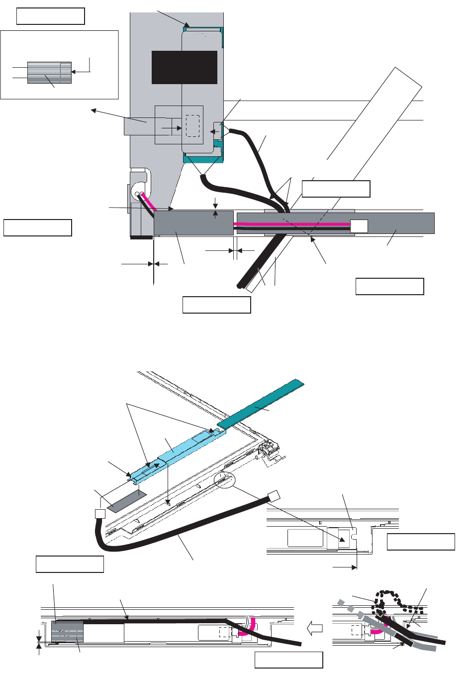
Q Cautions for Setting the LCD Unit
LCD Unit
LCD Rear Cabinet
Ensure the Cushion does not run
over the rib of the LCD Rear Cabinet.
(Same on the upper side.)
Safety Working
Pull and hold the Cables, and set the LCD.
(Avoid them from being caught inside the LCD unit.)
Ensure the Cushion does not run over the rib
of the LCD Rear Cabinet.
(Same on the other side.)
9-12
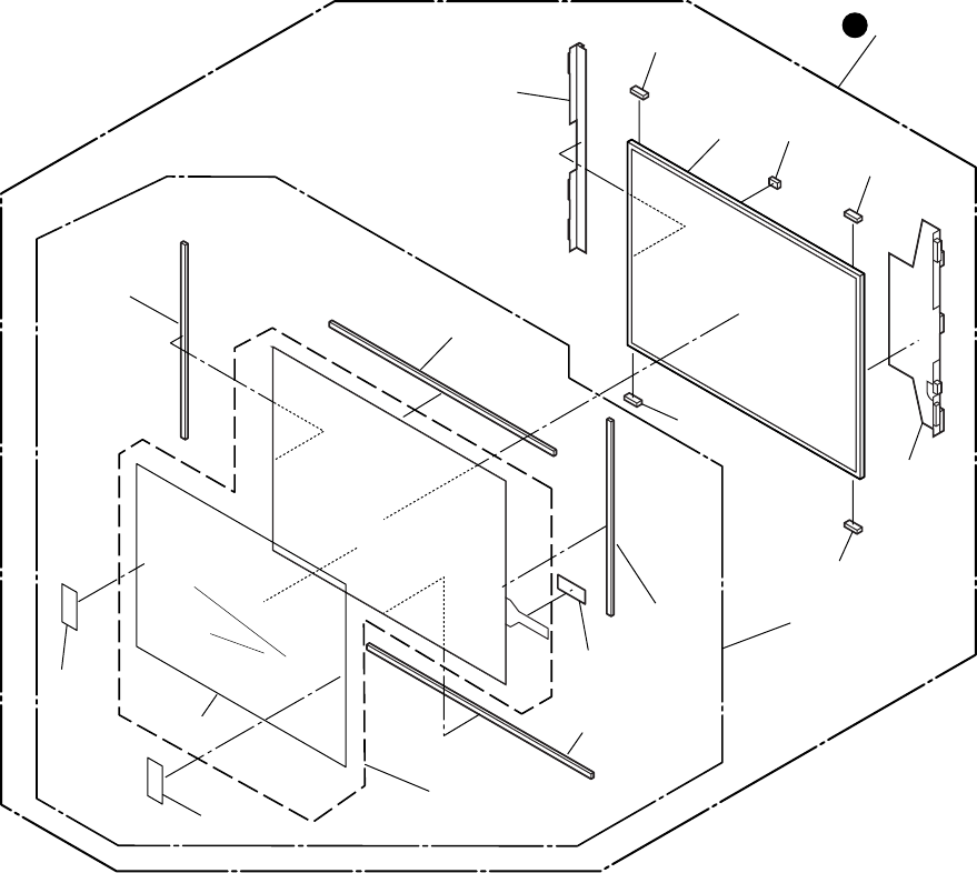
9.2.4. Setting the LCD Front Cabinet
1. Set the LCD Front Cabinet to the LCD Rear Cabinet.
2. Fix the LCD Front Cabinet using the two Screws<N15>.
3. Fix the LCD Front Cabinet using the two Screws<N16>,
and attach the two LCD Leg Rubbers.
Screws <N15>: DRHM0075ZA
Screws <N16>: DXQT2+G4FCL
Q Fixing of the LCD Front Cabinet
Ensure all the 23 Hooks are securely set in.
9.2.5. Setting the Display unit
1. Attach the Gasket.
2. Set the Hinge Screw Cover L and R to the Hinge L and R.
3. Pass the Cables coming out of the LCD Unit into the com-
puter.
4. Fix the Display Unit using the two Screws<N6> from the
computer upper side.
5. Fix the Display Unit using the four Screws<N6> from the
computer bottom side.
Screws. <N6>: DXSB3+6FNL
<N16>
<N15>
<N15>
LCD Leg Rubber
LCD Front
Cabinet
LCD Unit
: Hooks
<N6>
<N6>
<N6>
<N6>
Display Unit
Gasket
Hinge
Screw
Cover L
Hinge
Screw
Cover R
9-13
9.2.6. Setting the USB PCB
1. Fix the USB PCB to the computer using the two
Screws<N9>.
2. Connect the USB Cable to the Connector (CN1701).
Screws <N9>: DFHE5025XA
Q Arranging the USB Cable
<N9>
USB PCB
CN1701
MP Slide Sheet
MP Slide Sheet
USB Cable
Attach the MP Slid Sheet to prevent the Cable from coming off.
A
Fitting edge
Pass the Cable through
the notch and lead it downward.
Fit the surplus length of
the Cable into this side.
Tape
Connect
the Connector.
Pass it through
the notch.
Ensure the Cable does not
come out of the board edge
so that the Cable does not
touch the MP Drive.
Pass it through
the notch.
Avoid runnning over the boss.
Pass it through the rib.
Ensure the "A" end does not come on the level.
Safety Working
Fit the Cable between the pins.
9-14
9.2.7. Setting the SD PCB, Heat Sink and FAN Motor
1. Connect the SD FFC to the Connector (CN1401).
2. Fix the SD PCB to the computer using the three
Screws<N9>.
3. Set the Heat Sink, Fan Duct and the four Heat Sink
Springs.
4. Fix the FAN Motor to the computer using the two
Screws<N5>.
5. Attach the Fan Tape 1 and 2 on the FAN Motor, and fix
the Cable Holder on them.
Screws <N5>: DXSB2+6FNL
Screws <N9>: DFHE5025XA
Q Applying Grease on the Heat Sink
1. Apply grease on two points of the Heat Sink.
2. Attach the Pipe Sheet on the Heat Pipe.
Cable Holder
<N5>
FAN Motor
Heat Sink
Fan Duct
Fan Tape1 Fan Tape2
Heat Sink
Spring Heat Sink
Spring
<N9>
SD PCB
CN1401
SD FFC
Grease is applied.
Fan Dust Sheet
Fan Dust Sheet
0~1mm
G751(10mmX10mmXt0.3)
Grease is applied.
G751(10mmX10mmXt0.3)
0~1mm
0~1mm
0~1mm
5~10mm
Pipe Sheet
Heat Sink
(Attach the Fan Duct Sheet
to the back side.)
Match the end of the Pipe Sheet.
(0 ~ -2mm)
Fold on the center line
and attach it.
9-15
9.2.8. Setting the DC-IN PCB and I/O PCB
1. Fit the Modem Cable and LAN Cable between the MOD-
ELAN Holders, and set them on to the computer.
2. Fix the I/O PCB to the I/O Plate using the four
Screws<N19>.
3. Fix the I/O PCB with I/O Plate to the computer using the
two Screws<N9>.
4. Fix the DC-IN PCB to the computer using the two
Screws<N9>.
Screws <N9>: DFHE5025XA
Screws <N19>: DFHE5035ZB
Q Arranging the DC-IN Cable
<N9> <N9>
DC-IN PCB
MODELAN-2
Holder
LAN Cable MODELAN
Holder
Modem Cable
I/O Plate
I/O PCB
<N19>
DC-IN PCB
Set the Core of the Modem
over the DC-IN Cable.
DC-IN Cable
FAN Cable Sheet
0~3mm
0~3mm
Connect the Connector
Attach the Cable avoiding
overlapping
(DC-IN Cable and INV Cable).
Set the INV Cable under
the DC IN Cable.
Safety Working
Turn the DC-IN Cable halfway
(counterclockwise)
Safety Working
INV. Cable
Avoid runnning over the boss.
(Otherwise the Cable will be caught
at the Bottom Cabnet.)
Fix the Core using the Tape.
Safety Working
Fold back the end of Tape.
9-16
9.2.9. Setting the PC Card Ejector and Lithium Battery
1. Attach the Lithium Battery to the Main PCB.
2. Pass the Lead Wire of the Lithium Battery through the
groove of the Main PCB, and connect it to the Connector
(CN14) on the back side.
3. Fix the PC Card Ejector to the Main PCB using the two
Screws<N9>.
Screws <N9>: DFHE5025XA
Q Arranging the Lithium Battery
9.2.10. Setting the Main PCB
Note:
After replacing the Main Board, rewrite the BIOS ID.
1. Set the MP Guide to the Main PCB.
2. Set the Main PCB to the computer.
3. Fix the Main PCB using the six Screws<N9>.
4. Connect the ten Cables to the corresponding Connecters
(CN6, CN7, CN24, CN19, CN28, CN21, CN802, CN18,
CN15, CN25).
Screws <N9>: DFHE5025XA
<N9>
PC Card Ejector
Lithium Battery
(to CN14)
CN14
Main PCB
Pass the Cable through the groove of the Main PCB.
Safety Working
Tap e
Main PCB
Lithium Battery
Match the end of the Tape.
(0 to 1 mm)
Match the end of the Tape.
(0 to 1 mm)
Connect to the Connector (CN14) on the back side.
Fix the Cable using the Tape.
Pass the Cable between the parts.
(Avoid running over the parts.)
CN6
CN7
CN24
CN19
CN28
CN21
CN802
CN18
CN15
CN26
<N9>
<N9>
Main PCB
MP Guide
9-17
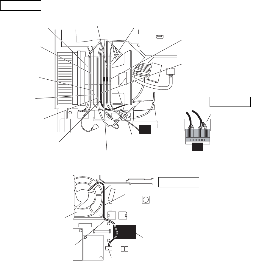
Q Arranging the Cables to the Cable Holder and their Wiring Order
• Pull the surplus length of the Cable coming from the LCD side to inside of the unit.
(If the surplus length comes outside, it will be caught by the center cover during setting.)
• Fit the Cables to the corresponding grooves of the Cable Holder.
• Ensure the Cables in the Cable Holder are wired in the correct order.
Q Arranging the FAN Cable
No.1: LAN Cable
No.2:
Black Antenna
Cable
No.3:
Gray Antenna
Cable
No.4: Empty
No.5: I/O Cable
No.6: LCD Cable
No.7: LCD Cable with the tube
No.8: TP Power Cable No.9: Modem Cable
Cable Holder
Cover the Cables
using the Tape.
Fold the Tape in half
and attach it to the Cables.
Safety Working
Fit the portion using the Tape
in the notch.
Fit the Black Tube to the end
of the rib.
Be sure to wire the Cables in the correct order.
Safety Working
FAN Motor
Tape
Main PCB
Connector (CN28)
FAN Cable
Lead the FAN Cable into the space next to the Board.
Fix the FAN Cable.
Connect the FAN Cable.
Safety Working
9-18
9.2.11. Setting the Wireless Module and MDC Module
1. Connect the Modem Cable to the Connector, and fix the
MDC Module to the Main PCB using the two
Screws<N9>.
2. Connect the Wireless Module to the Connector of the
Main PCB, and fix it using the two Screws<N9>.
3. Connect the two Antenna Cables to the two Connectors
on the Wireless Module.
• Antenna Cable (Black): MAIN Connector
• Antenna Cable (Gray): AUX Connector
Screws <N9>: DFHE5025XA
Q Arranging the Modem Cable
Antenna Cable (Black)
Antenna Cable (Gray)
<N9>
<N9>
MDC Module
Wireless Module
Modem Cable
10–3mm
Safety Working
MDC Module
Modem Cable
<Preparation for assembly of the MDC Module>
Ensure the Kapton Tape is
overlapping the Shrink Tube
by 1 mm or more.
Fix the Connector
using the Tape.
Fold back and attach to the back side
of the MDC Module.
Arranging the Modem Cable
<Bad example>
Kapton Tape
Ensure the Cable does not run over the Screw.
Ensure the Cable does not come over the end
of the MDC Module.
Safety Working
Ensure both of the inlet and outlet
of the Cable are within the frame.
Avoid any stress on
the outlet of the Cable.
Pass the Cable over
the CCC mark.
Coming over the end of the Screw.
Coming over the end
of the Screw.
<Good example>
Coming outside of the frame.
Safety Working
9-19
9.2.12. Setting the Bottom Case
1. Attach the Gasket and Sheet.
2. Set the Bottom Case.
3. Fix the Bottom Case using the ten Screws<N7>. No1 to
No10
4. Fix the Bottom Case using the six Screws<N5>. No11 to
No16
5. Fix the Bottom Case using the two Screws<N8>. No17,
No18
6. Close the Lid Covers.
Note:
Tighten the Screws in the numbered order (No1 to No18).
Screws <N5>: DXSB2+6FNL
Screws <N7>: DXYN2+J16FNL
Screws <N8>: DXYN2+J8FNL
9.2.13. Setting the Handle Ass'y
1. Set the two Sleeves A, the Handle Ass'y and the two
Sleeves B.
2. Fix the Handle Cover L and R using the two Screws<N2>.
No1, No2
3. Fix the Handle Cover L and R using the three
Screws<N4>. No3 to No5
Note:
Tighten the Screws in the numbered order (No1 to No5).
Screws <N2>: DRHM4+10FKS
Screws <N4>: DRSB2+6FKL
<N7>:No10
<N7>:No1
<N8>
:No18
<N8>
:No17
<N5>:No16
<N5>:No11
Bottom Cover
<N7>:No2
<N7>:No6
<N7>:No7
<N7>:No3
<N7>:No4
<N7>:No8
<N7>:No5
<N7>
:No9
<N5>
:No15
<N5>
:No13
<N5>:No12
<N5>
:No14
Sheet Gasket
Handle Cover R Handle Cover L
Handle Ass’y
Sleeves B
Sleeves A
Sleeves A
<N4>
:No4
<N4>:No3
<N2>:No1
Top Case
<N2>:No2
<N4>
:No5
9-20
9.2.14. Setting the Speaker and the LED PCB
1. Fix the LED PCB using the two Screws<N9>.
2. Set the Speaker L and R to the computer.
3. Connect the Speaker Cable L and R to the two Connec-
tors (CN1002, CN1003) on the LED PCB.
4. Fix the Speaker Cable L and R using the Tape.
5. Fix the Speaker L and R using the Speaker Holder.
Note:
Ensure the three Hooks of the Speaker Holder are securely
set in the computer.
Screws <N9>: DFHE5025XA
Q Soldering the Speaker Cable and Setting the Speaker Rubber
Q Cautions for Setting the Speaker
Speaker
Holder
Speaker
Holder
CN1002
Tape
Tape
CN1003
<N9>
LED PCB
Speaker L
Speaker R
Speaker Speaker Rubber
Speaker
Speaker Cable
White Line
Red Line
White Line Red Line
Speaker Cable
Soldering
Soldering
Speaker
Holder
Tape
Speaker L
Speaker
Holder
Tape
Speaker R
Pass the Speaker Cables
through the notch.
(Avoid running over.)
Set as the loop of the Speaker Cable
is on the upper side.
Ensure the Cable does not
touch the Steel Plate.
Pass the Speaker Cables through the notch.
(Avoid running over.)
Safety Working
SP Conductive
Cloth R
SP Conductive
Cloth L
Speaker L Speaker R
Securely attach the SP Conductive Cloth
to the round frame of the Speaker.
Fit to the stand wall.
Fit to
the corner.
Ensure the Hooks are
securely set in. (3 points)
9-21
9.2.15. Setting the Keyboard
1. Connect the KBD FPC Cable to the Connector (CN25) of
the Main PCB.
2. Connect the two Cables of the Keyboard to the two Con-
nectors on the KBD FPC.
3. Remove the Release Paper of the KBD WP Sheet, and
attach the KBD WP Sheet to the computer as it covers
the Cable of the Keyboard.
Note:
Press strongly enough until the color of the contact of
two-sided tape is changed.
4. Insert the front Hooks of the Keyboard and the FPC to the
computer, and set the Keyboard to the computer.
5. Fix the KBD Angle L and R using the four Screws<N9>.
6. Hook the six front Hooks of the Center Cover to the KBD
Angle L and R.
7. Hook the seven rear Hooks of the Center Cover to the
computer, and press the Center Cover to be securely set
in.
Screws <N9>: DFHE5025XA
Q Cautions for Setting the Center Cover
Connectors
KBD FPC
Connector
(CN25)
KBD WP Sheet
Center Cover Hooks
Hooks
<N9>
<N9>
KBD Angle L
KBD Angle R
Keyboard
Center Cover
Hook with the front hooks.
(six points)
Note:
Do not allow any gaps when
aligning the front hooks.
Push in the claws on the rear side of the dome.
(two each on the left and right)
Push until they are snapped on.
When setting the Center Cover,
fit the Lead Wire in the unit and
avoid it from being caught inside
the dome.
Ensure the Cable does not
run in this area.
Safety Working
9-22
9.2.16. Setting the DIMM Memory Card and DIMM Cover
1. Set the DIMM Memory Card to the Main PCB.
2. Fix the DIMM Cover using the two Screws<N1>.
Screws <N1>: XSB2+3FNL
9.2.17. Setting the HDD
1. Attach the HDD Earth Plate and HDD Conductive Sheet.
2. Connect the HDD to the HDD FPC.
3. Attach the HDD Dumper.
4. Fix the six Hooks, and attach the HDD Case.
<N1> <N1>
Hook
Hook
DIMM Cover
DIMM Memory Card
Hook
Hook
Hook
Hook
HDD Case Upper
HDD Conductive Sheet
HDD Earth Plate
HDD FPC
HDD Damper
HDD Case
HDD
9-23
9.2.18. Setting the Battery Pack, the HDD Unit and the DVD-ROM Drive Unit
1. Set the DVD-ROM Driver Unit.
2. Set the HDD Pack.
3. Set the Battery Pack.
4. Slide the Latch 1 to the locked position.
HDD Unit
DVD-ROM Drive Unit
1
Latch 1
Battery Pack
CF-74ECBAXBM
10 Exploded View
K76
K41
K40
K62
K67
K77
K68
K61
K61
K75
K74
K63
K63
K66
K80
K81
K65
K64
K82
E28
E28
E27
E8
K83
K79
K73
K70
E29
E7
K98
N5
E33
K1
K9
K39
K39
K45
K48
E2
K51
N19
E32
K37 K38
K10
E5
E35 K31
E36
E4
K5
K33
K43
K44
K43
K44 K29
K6
K28
N2 N4
K27
N2
N4
E3
K35
E19
E37
K30
K21
N9
K19
K50
E30
K25
K42
E31
K50
E30
K24
K42
E31
K206
N6
K23
K206
K71
K71
K78
K69
K78
K72
K60
K58
K59
K47
Screw tightening torque
0.1 ± 0.01 N.m
(1.0 ± 0.1 kgf.cm)
0.2 ± 0.02 N.m
(2.0 ± 0.2 kgf.cm)
0.4 ± 0.02 N.m
(4.0 ± 0.2 kgf.cm)
1.2 ± 0.1 N.m
(12.0 ± 1.0 kgf.cm)
0.8 ± 0.1 N.m
(8.0 ± 1.0 kgf.cm)
B
D
C
C
F
A
D
B
D
B
B
N9
B
N9
B
N9
B
N13
B
N9
B
C
N9
B
B
N5
B
N9
B
N9
B
N9
B
N12
A
F
F
N9
B
N20
B
N20
B
N9
B
N14
A
N14
A
E12
E34
N6
N10
B
K46
K1000
K32
10-1
CF-74ECBAXBM
EN11
EN11
E
B
K10
K56
E20-1
K53
E20
A2
K54
E21
N7
K86
K91
K91
K84
K96
K57
BN5 BN5 BN7
BN7
BN7
BN9
BN8
BN8
B
N9
BN9
B
N5
BN9
BN3
BN1
K55
Screw tightening torque
0.2 ± 0.02 N.m
(2.0 ± 0.2 kgf.cm)
0.13 ± 0.01 N.m
(1.3 ± 0.1 kgf.cm)
B
E
K15
K12
K20
K94
K93
K88
K90
K2
N9
B
K18
K11
K95
K87
K89
K95
K85
K13
K14
K97
N9
N9
K8
K34
K36
K49
K17 K52
K101
N9
N9
E10
N9
E11
E1
E38
E13
E9
BN9
BN9
BN9
BN9
BN9
K92
B
B
B
B
B
E17-4
E18
E17-7
E17-6
E17-2
E17-1
E17-5
E17-3
E17
K1001 K1002
10-2
CF-74ECBAXBM
Screw tightening torque
0.1 ± 0.01 N.m
(1.0 ± 0.1 kgf.cm)
0.2 ± 0.02 N.m
(2.0 ± 0.2 kgf.cm)
0.8 ± 0.1 N.m
(8.0 ± 1.0 kgf.cm)
0.375 ± 0.025 N.m
(3.75 ± 0.25 kgf.cm)
K205
K210-6
K211
K210-2
K212
K26
K16
K210-1
K210
a
K204
K204
K208
E26
K202
E25
K201
K206
E14
E14-1
K210-3
K3
K4
K210-4
AN18
BN16
GN15
GN15
AN17
FN6
FN6
E15
E15-1
A
B
N18
N9
FK210-5
FK210-5
A
B
K207
K207
K207
K209
K203
K22
E23
E6
E24
K207
K207
F
G
E22
10-3
CF-74ECBAXBM
E22-6-6
E22-6-3
E22-1
E22-2
E22-3
E22-4
E22-4
E22-4
E22-4
E22-5
E22
E22-6-2
E22-6-4
E22-6-4
E22-6
E22-6-1-1
E22-6-1
E22-6-5
E22-6-5
a
10-4
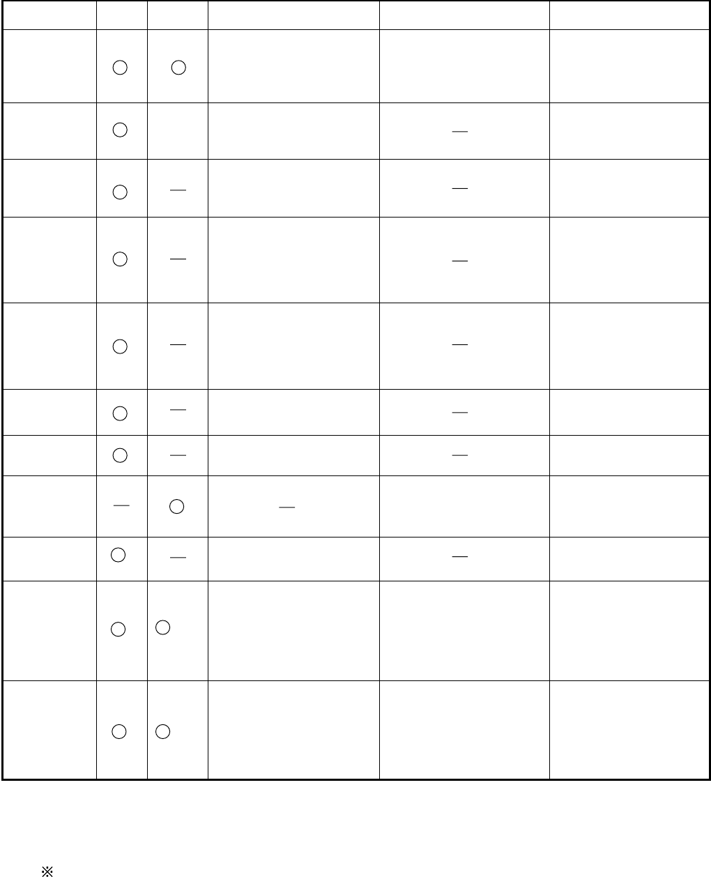
11 Replacement Parts List Comparison Table
Note : Important Safety Notice
Components identified by mark have special characteristics important for safety.
When replacing any of these components, use only manufacturer's specified parts.
CF-74ECBAXBM
REF. NO and AREA PART NO. DESCRIPTION Q'TY
CF-74CCBAXBM CF-74ECBAXBM
Main Block Unit
E1 DL3U11518AAA DL3U11518ABA PCB, MAIN RTL 1
E2 DL3U21518AAA DL3U21518ABA PCB, IO RTL 1
E3 DL3U31518AAA DL3U31518ABA PCB, LED RTL 1
E4 DL3U41518AAA DL3U41518ABA PCB, USB RTL 1
E5 DL3U51518AAA DL3U51518ABA PCB, DC-IN RTL 1
E6 DL3U61518AAA DL3U61518ABA PCB, TS RTL 1
E17 DFWV99A0107 DFWV99A0115 HDD MOUNTING KIT 1
E17-6 ------ DFHE1027ZA HDD CONDUCTIVE SHEET B 0->1
E17-7 ------ DFMC0872ZA HDD EARTH PLATE 0->1
E22-6-1 DL3DV0179AAA DL3DV0179BAA TS PREPARATION UNIT 1
Mechanical Parts
K18 DFHM0386ZA-0 DFHM0386ZB-0 IO COVER PLATE 1
K20 DFHM0390ZA-0 DFHM0390ZB-0 PC COVER PLATE 1
K99 DFHG1599ZA ------ LCD DUMPER A 1->0
K100 DFHR3D53ZB ------ SLIDE SHEET 1->0
K206 DFMX0778ZA DFMX0778ZA SHEET 4
K1000 ------ DFHE1024ZA GASKET-81TS10-2.5-145 0->1
K1001 ------ DFHE1026ZA GASKET-81TL15-14-10 0->1
K1002 ------ DFHR7518ZA SHEET 0->1
Accessories
A1 S CF-AA1683AM1 CF-AA1683AM3 AC ADAPTOR 1
A3 S DFQX5582YA DFQX5582XA MANUAL 1
!
11-1
