CG100 Data Sheet CG100datasheet
User Manual: CG100
Open the PDF directly: View PDF ![]() .
.
Page Count: 2
TECHNICAL DATA SHEET
Single phase, ungrounded WYE, ungrounded DELTA and less common voltage configurations also
available; other motor control configurations available. Contact factory, local Current Technology rep-
resentative or authorized distributor for details.
To determine complete ControlGuard catalog number, identify manufacturer and type of motor
control center; select prefix from PREFIX column in Selection Table 1; then add suffix from SUF-
FIX column in Selection Table 2. Example: General Electric 8000 Series; CG100-GE84GC-480-3D
STANDARD MODEL NUMBERS
SELECTION TABLE 1 — MCC MFG/MCC TYPE
TYPICAL CLAMPING VOLTAGE DATA
Voltage Protection A3 B3 B3/C1 C3
mode Ringwave Ringwave Comb.Wave Comb.Wave
L-N 200 260 360 470
L-G 340 365 355 530
N-G 240 280 350 510
L-L 360 475 675 800
L-N 460 580 825 950
L-G 800 740 765 930
N-G 500 535 775 1000
L-L 795 1000 1545 1710
120 / 208
277 / 480
MECHANICAL SPECIFICATIONS
STANDARD FEATURES
Protection Minimum tested impulses
mode per mode
Line-to-Neutral > 4,000
Line-to-Ground > 4,000
Neutral-to-Ground > 4,000
Line-to-Line > 4,000
REPETITIVE SURGE CURRENT CAPACITY
Protection Single pulse surge
mode current capacity per mode
Line-to-Neutral > 100,000 A
Line-to-Ground > 100,000 A
Neutral-to-Ground > 100,000 A
Line-to-Line > 100,000 A
Per Phase > 200,000 A
SINGLE PULSE SURGE CURRENT CAPACITY
Multiple unit Frequency Single unit
installation installation
51 dB 100 KHz 34 dB
94 dB 1 MHz 51 dB
114 dB 10 MHz 54 dB
120 dB 100 MHz 48 dB
EMI/RFI NOISE REJECTION VALUES
Voltage MCOV Voltage MCOV
120V 150V 347V 420V
240V 275V 480V 640V
277V 320V 600V 840V
MAXIMUM CONTINUOUS OPERATING VOLTAGE (MCOV)
In compliance with NEMA LS 1-1992, paragraphs 2.2.7, 2.2.9 and 3.9, Current Technology suppression
filter systems are single pulse surge current tested in all modes at currents up to 150% of the product
design rating by an industry-recognized independent test laboratory. Single pulse surge current
capacities of 200,000 amps or less are established by single-unit testing of all components within each
mode. Due to present industry test equipment limitations, single pulse surge current capacities over
200,000 amps are established via testing of individual components or sub-assemblies within a mode.
All Current Technology suppression filter systems EMI-RFI noise or attenuation rejection values are in
compliance with test and evaluation procedures outlined in NEMA LS 1-1992, paragraphs 2.2.11 and 3.11.
All Current Technology suppression filter systems maximum continuous operating voltages are in com-
pliance with test and evaluation procedures outlined in NEMA LS 1-1992, paragraphs 2.2.6 and 3.6.
Per ANSI/IEEE C62.41-1991 and ANSI/IEEE C62.45-1992, all Current Technology suppression filter sys-
tems are repetitive surge current capacity tested in every mode utilizing a 1.2 X 50 µsec 20KV open
circuit voltage, 8 X 20 µsec 10 KA short circuit current Category C3 bi-wave at one minute intervals
without suffering either performance degradation or more than 10% deviation of clamping voltage at
a specified surge current.
Connection method Parallel
Enclosure type/mount
NEMA size 1/MCC housing mount
Temperature operating range -40˚C to 60˚C
Humidity operating range 5% - 95% non-condensing
Dimensions Varies depending on motor control center manufacturer
Weight 50 lbs.
Options Include Double form “C” dry contacts (-FCC) and DTS-2 Diagnostic
Test Set (-DTS)
Suppression filter seamless technology™
technology
Internal construction All suppression filter components are bolted to corrosion-
resistant tin-plated copper bus bar
Fused Disconnect Integral UL listed safety interlocked fused disconnect
switch to enhance safety, reduce installation cost, improve
performance, optimize reliability and permit system test-
ing without interruption of facility power. Coordinated
UL listed 200KAIC field replaceable Class J fuses for
added convenience and safety.
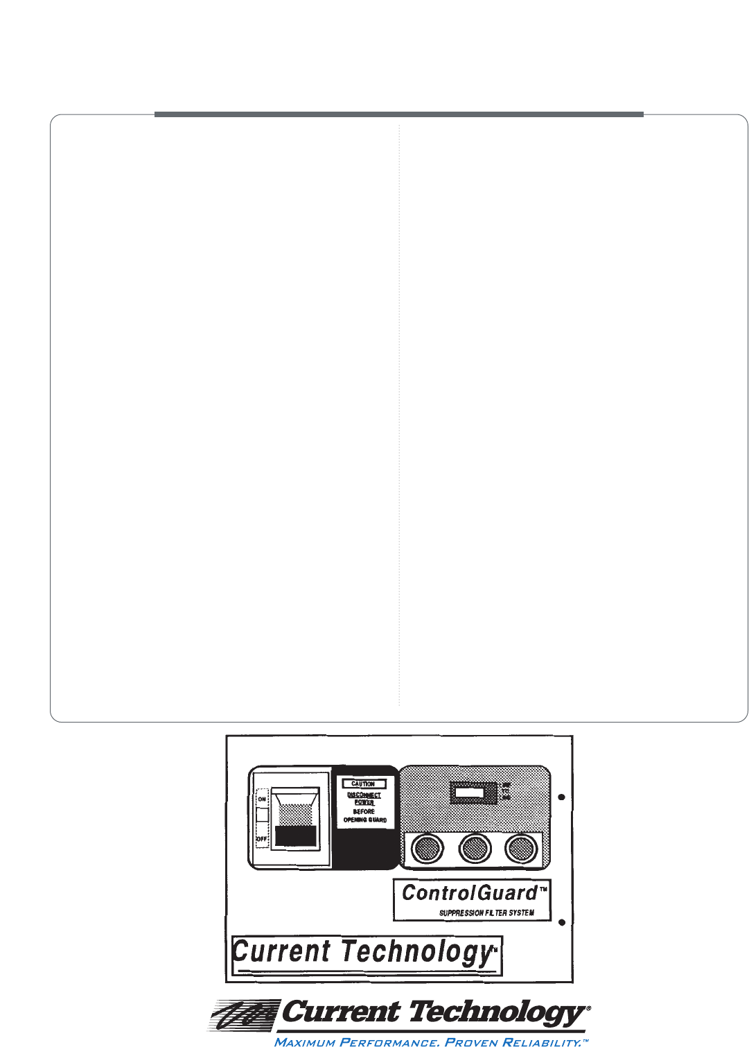
Status indicators Pilot light status indicators indicate suppression and
overcurrent status
Display Event Counters Provides ongoing tabulation of damaging or upsetting
transients
Test point Diagnostic ten mode test point allows easy DTS-2
Diagnostic Test Set connection
Standards UL 1449-Second Edition, UL 1283, CSA, NEMA LS 1
Warranty Five Years
SUPPRESSION FILTER SYSTEM
Compatible with all Current Technology MasterPLAN
®
facility-wide suppression filter system products
PROTECTION FOR MOTOR
CONTROL CENTER-FED LOADS
Manufacturer/Type Cat. # PREFIX Description
Allen Bradley CG100-ABC4GS- 3 phase 4 wire w/ground bus stab
• Centerline CG100-ABC3GS- 3 phase 3 wire w/ground bus stab
Cutler-Hammer CG100-CHU4GC- 3 phase 4 wire w/ground bus contact
• Unitrol CG100-CHU3GC- 3 phase 3 wire w/ground bus contact
General Electric CG100-GE84GS- 3 phase 4 wire w/ground bus stab
• 8000 Series CG100-GE84GC- 3 phase 4 wire w/ground bus contact
CG100-GE83GS- 3 phase 3 wire w/ground bus stab
CG100-GE83GC- 3 phase 3 wire w/ground bus contact
Square D CG100-SQD54GS- 3 phase 4 wire w/ground bus stab
• Model 5 CG100-SQD53GS- 3 phase 3 wire w/ground bus stab
• Model 6
Siemens/ITE CG100-ITE94GC- 3 phase 4 wire w/ground bus contact
• Model 90 CG100-ITE93GC- 3 phase 3 wire w/ground bus contact
• Model 95
Cutler-Hammer/ CG100-W2A4GC- 3 phase 4 wire w/ground bus contact
Westinghouse CG100-W2A3GC- 3 phase 3 wire w/ground bus contact
• Series 2100
SELECTION TABLE 2 — VOLTAGE/CONFIGURATION
Cat. # SUFFIX Voltage Configuration Cat. # SUFFIX Voltage Configuration
WYE DELTA
120/208-3GY 120/208 Grounded Wye 240-3D 240 Delta
277/480-3GY 277/480 Grounded Wye 480-3D 480 Delta
347/600-3GY 347/600 Grounded Wye 575-3D 575 Delta
120/240-3GHD 120/240 Grounded Neutral 600-3D 600 Delta
High Leg Delta
All Current Technology suppression filter systems clamping voltages are in compliance with test and
evaluation procedures established in NEMA LS 1-1992, paragraphs 2.21.0 and 3.10. Values indicate typi-
cal clamping voltage data for models with integral fused disconnect.
1. Voltage/System Verification
Prior to product installation, verify that the voltage rating of
the intended electrical service matches the voltage rating of
the unit to be installed. Verify that ControlGuard™type and
configuration are the same as the motor control center intend-
ed for ControlGuard installation. Warning: serious injury or
damage may result from installing a product with an
improper voltage rating, incorrect type or configuration.
Contact Current Technology if voltage rating, type and configu-
ration are not identical. For WYE connected systems, verify
neutral-ground bond on secondary side of upstream distribu-
tion or service entrance transformer. Warranty void if
ControlGuard is connected to incorrect system configuration
or if neutral-ground bond is not present in WYE configured
systems.
2. Installation Location
Install ControlGuard into motor control center per manufac-
turer’s instructions.
3. Mounting
ControlGuard mounts into a standard NEMA 1 sized motor
control center space. Follow manufacturer’s instructions for
bucket installation. ControlGuard will not feed any loads.
4. Electrical Connections
Before installing ControlGuard, measure voltage Line-to-Line,
Line-to-Neutral, Line-to-Ground and Neutral-to-Ground to
ensure that it does not exceed ±10% of the nominal rated volt-
age for the unit. Contact factory if these tolerances are exceed-
ed. For some applications, a neutral conductor must be tapped
from motor control center neutral bus or neutral conductor
and connected to the neutral lug on the suppression filter sys-
tem depending on motor control center voltage configuration.
Caution: B phase must be the high leg for high leg DELTA
configured products installed on high leg DELTA systems.
Contact factory for other voltage configurations not listed on
ControlGuard technical data sheet.
5. Display Event Counters
ControlGuard comes equipped with dual display event
counter(s) that measure the number of Line-to-Neutral and
Line-to-Ground transients occurring in WYE configurations.
For DELTA systems, a single counter measures Line-to-Line
transients. To reset counters, remove connector on the back of
each counter and short pins 1 and 3.
6. Remote Monitor Contacts Option
ControlGuard models are available with two sets of form “C”
remote monitor dry contacts that may be connected to building
management systems or remote annunciation alarm panels. To
wire contacts, locate the output terminals mounted on the dry
contact circuit board. Each set of contacts may be wired inde-
pendently. Each set of form “C” contacts includes common (C),
normally open (NO) and normally closed (NC) contacts. For
normally open operation under energized conditions, connect
the normally open terminal and common terminal to the moni-
toring input. For normally closed operation during energized
conditions, connect the normally closed terminal and common
terminal to the monitoring input. Upon loss of power to any or
all phases, contacts will change to alarm state.
7. Final Instructions
If all voltages are in tolerance, apply power to ControlGuard by
engaging the fused disconnect switch on front cover of unit.
Illumination of status indicator lights indicates proper function.
8. Diagnostic Testing
In the unlikely event of unit’s overcurrent protection opening,
unit should be tested with a DTS-2 Diagnostic Test Set to verify
operational integrity. To test, locate test point and disconnect
from wiring harness. Follow DTS-2 Diagnostic Test Set instruc-
tions. If the test results are within factory specified tolerances,
replace or reset overcurrent protection. IF TEST RESULTS
ARE NOT WITHIN FACTORY SPECIFIED TOLERANCES,
DO NOT REPLACE OR RESET OVERCURRENT PROTEC-
TION PRIOR TO CONTACTING CURRENT TECHNOLOGY’S
“24X7” TECHNICAL SERVICE HOTLINE AT 1-888-200-
6400. Reconnect test point to wiring harness upon completion
of testing and prior to re-energizing.
CONTROLGUARD™ INSTALLATION INSTRUCTIONS
3001 W. Story Road, Irving, TX 75038 • 1-800-238-5000 • 972-252-7705 fax
www.currenttechnology.com
© 1996 Current Technology, Inc. All rights reserved. DT-9821-CGD-25M
