CIX MA PRGM3 VH IPT2000 FYI
User Manual: IPT2000
Open the PDF directly: View PDF ![]() .
.
Page Count: 110 [warning: Documents this large are best viewed by clicking the View PDF Link!]
- Title Page
- Contents
- My Phone Manager™ 1
- My Phone Manager Server PC Hardware/Software Requirements
- Minimum Hardware Platform
- Minimum Software Platform
- System Configuration
- Installation
- User Levels
- Configure My Phone Manager
- Run My Phone Manager
- My Phone Manager Main Screen
- Program Menu
- Voice Mail Settings
- FeatureFlex
- Telephone System
- Super1 Options
- About
- Log Out
- FeatureFlex™ 2
- Set up FeatureFlex
- Access FeatureFlex
- Sorting the Screen
- Add FeatureFlex Application to Phone
- Delete FeatureFlex Application from Phone
- Remove FeatureFlex Application
- Editing FeatureFlex Applications
- Alarm Clock
- Call Monitor
- Return Call
- One Number Access
- Screen Call
- Hot Desk
- Simultaneous Ring
- Personal Call Handler
- Operation
- Ordering Information
- PCH On/Off
- FeatureFlex Application Interactions
- InfoManager™ 3
- PC Software Requirements
- Add/Edit Company
- Add/Edit Department
- Add/Edit Employee
- Change Parameters
- Configure Calendar Properties
- Stock Quote
- Weather
- Company News
- Calendar
- View Calendar
- Application Cycle
- Configure Settings
- Properties
- Stock Quote
- Configure Company News
- Weather
- eMonitor/Alarm Notification 4
- Alarm Notification Setup and Programming
- Alarm Notification
- System Alarm Control
- Trap IP Setup
- Strata CIX Network eMonitor
- eMonitor PC/Server Requirements
- Prior to Installation
- Uniform Call Distribution 5
- Call Distribution
- Login/Logout
- Initial Greeting
- Queuing
- Overflow
- UCD Group Setup
- Programming
- Capacity
- How UCD Operates
- Interaction with Other Features
- Call Forward, System Call Forward
- Do Not Disturb
- Dialed Number Identification Service
- Station Hunting
- Offhook Call Announce (OCA), Handset Offhook Call Announce
- Private Networking
- Multiple Calling
- Door Phone
- Class of Service
- Lost Call Treatment
- Intercept
- Phantom DN
- Music on Hold
- Traffic Measurement and Reporting 6
- Feature Initialization
- TM Output Statistics
- Capacities
- Measurement Categories and Items
- Traffic Measurement Reports
- Traffic Intensity Calculation
- Analog Trunk
- ISDN Trunk Traffic Intensity
- All Trunk Traffic Intensity
- Abandoned Calls
- Hourly Traffic Reports (Program 921)
- Traffic Measure
- I/O Device Setup
- Specified Traffic Reports (Program 922)

TOSHIBA Telecommunication Systems Division
September 2009
Strata CIX™
Programming Manual
Volume 3
Application Implementation
Title Page
®
Publication Information
Toshiba America Information Systems, Inc.
Telecommunication Systems Division
Publication Information
Toshiba America Information Systems, Inc., Telecommunication Systems Division, reserves the right,
without prior notice, to revise this information publication for any reason, including, but not limited to,
utilization of new advances in the state of technical arts or to simply change the design of this document.
Further, Toshiba America Information Systems, Inc., Telecommunication Systems Division, also reserves
the right, without prior notice, to make such changes in equipment design or components as engineering or
manufacturing methods may warrant.
CIX-MA -PRGM3-VH
Version H, September 2009
Our mission is to publish accurate, complete and user accessible documentation. At the time of printing the
information in this document was as accurate and current as was reasonably possible. However, in the
time required to print and distribute this manual additions, corrections or other changes may have been
made. To view the latest version of this or other documents please refer to the Toshiba FYI web site.
Toshiba America Information Systems shall not be liable for any commercial losses, loss of revenues or
profits, loss of goodwill, inconvenience, or exemplary, special, incidental, indirect or consequential
damages whatsoever, or claims of third parties, regardless of the form of any claim that may result from the
use of this document.
THE SPECIFICATIONS AND INFORMATION PROVIDED HEREIN ARE FOR INFORMATIONAL
PURPOSES ONLY AND ARE NOT A WARRANTY OF ACTUAL PERFORMANCE, WHETHER
EXPRESSED OR IMPLIED. THE SPECIFICATIONS AND INFORMATION ARE SUBJECT TO CHANGE
WITHOUT NOTICE. ACTUAL PERFORMANCE MAY VARY BASED ON INDIVIDUAL
CONFIGURATIONS, USE OF COLLATERAL EQUIPMENT, OR OTHER FACTORS.
© Copyright 2008-2009
This document is copyrighted by Toshiba America Information Systems, Inc. with all rights reserved. Under
the copyright laws, this document cannot be reproduced in any form or by any means—graphic, electronic,
or mechanical, including recording, taping, photocopying, without prior written permission of Toshiba. No
patent liability is assumed, however, with respect to the use of the information contained herein.
Trademarks
Strata, SmartMedia, SD (Secure Digital) and CIX are registered trademarks of Toshiba Corporation.
Stratagy, eManager, FeatureFlex, My Phone Manager, and InfoManager are registered trademarks of
Toshiba America Information Systems, Inc.
Windows and Microsoft are registered trademarks of Microsoft.
Trend Micro and PC-cillin are registered trademarks of Trend Micro Inc.
Norton Anti-Virus is a registered trademark of Symantec Corp.
McAfee and Virusscan are registered trademarks of McAfee, Inc.
DESI is a registered trademark of Desi Telephone Labels, Inc.
Trademarks, registered trademarks, and service marks are the property of their respective owners.

T
WARRANTIES FOR NON-TOSHIBA BRANDED THIRD
PARTY PRODUCTS
A valuable element of Toshiba’s product strategy is to offer our customers a complete product portfolio. To
provide this value to our customers at the most optimal prices, we offer both Toshiba-branded and third-
party manufactured products that support our Toshiba Strata CIX product portfolio. Similar to other
resellers of software, hardware and peripherals, these third-party manufactured products carry warranties
independent of our Toshiba limited warranty provided with our Toshiba-branded products. Customers
should note that third-party manufacturer warranties vary from product to product and are covered by the
warranties provided through the original manufacturer and passed on intact to the purchaser by Toshiba.
Customers should consult their product documentation for third-party warranty information specific to third-
party products. More information may also be available in some cases from the manufacturer’s public
website.
While Toshiba offers a wide selection of software, hardware and peripheral products, we do not specifically
test or guarantee that the third-party products we offer work under every configuration with any or all of the
various models of the Toshiba Strata CIX. Toshiba does not endorse, warrant nor assume any liability in
connection with such third party products or services. If you have questions about compatibility, we
recommend and encourage you to contact the third-party software, hardware and peripheral product
manufacturer directly.
This page is intentionally left blank

Strata CIX Application Implementation Vol 3 09/09 1
Contents
Chapter 1 – My Phone Manager™
My Phone Manager Server PC Hardware/Software Requirements.....................................1-2
Minimum Hardware Platform.......................................................................................... 1-2
Minimum Software Platform........................................................................................... 1-2
System Configuration........................................................................................................... 1-2
Installation............................................................................................................................ 1-3
User Levels.......................................................................................................................... 1-3
Configure My Phone Manager............................................................................................. 1-3
Run My Phone Manager...................................................................................................... 1-6
My Phone Manager Main Screen ........................................................................................ 1-7
Program Menu ..................................................................................................................... 1-7
Voice Mail Settings.........................................................................................................1-8
FeatureFlex....................................................................................................................1-8
Telephone System ......................................................................................................... 1-8
Super1 Options .............................................................................................................. 1-9
About.................................................................................................................................... 1-9
Log Out ................................................................................................................................ 1-9
Chapter 2 – FeatureFlex™
Set up FeatureFlex ..............................................................................................................2-1
Access FeatureFlex .............................................................................................................2-5
Sorting the Screen ......................................................................................................... 2-5
Add FeatureFlex Application to Phone ................................................................................ 2-6
Delete FeatureFlex Application from Phone ........................................................................ 2-6
Remove FeatureFlex Application......................................................................................... 2-7
Editing FeatureFlex Applications ......................................................................................... 2-8
Alarm Clock....................................................................................................................2-8
Call Monitor....................................................................................................................2-9
Return Call ...................................................................................................................2-10
One Number Access.................................................................................................... 2-11
Screen Call................................................................................................................... 2-12
Hot Desk ......................................................................................................................2-13
Simultaneous Ring....................................................................................................... 2-16
Personal Call Handler .................................................................................................. 2-19
Operation ..................................................................................................................... 2-25
Ordering Information ....................................................................................................2-25
PCH On/Off..................................................................................................................2-26
FeatureFlex Application Interactions.................................................................................. 2-30

Contents
Chapter 3 – InfoManager™
2Strata CIX Application Implementation Vol 3 09/09
Chapter 3 – InfoManager™
PC Software Requirements .................................................................................................3-1
Add/Edit Company ......................................................................................................... 3-5
Add/Edit Department...................................................................................................... 3-5
Add/Edit Employee......................................................................................................... 3-6
Change Parameters....................................................................................................... 3-6
Configure Calendar Properties....................................................................................... 3-7
Stock Quote ......................................................................................................................... 3-9
Weather ............................................................................................................................... 3-9
Company News....................................................................................................................3-9
Calendar ............................................................................................................................ 3-10
View Calendar............................................................................................................. 3-11
Application Cycle ...............................................................................................................3-11
Configure Settings .............................................................................................................3-12
Properties.....................................................................................................................3-12
Stock Quote ................................................................................................................. 3-13
Configure Company News ...........................................................................................3-14
Weather........................................................................................................................3-15
Chapter 4 – eMonitor/Alarm Notification
Alarm Notification Setup and Programming......................................................................... 4-3
Alarm Notification........................................................................................................... 4-3
System Alarm Control .................................................................................................... 4-3
Trap IP Setup................................................................................................................. 4-3
Strata CIX Network eMonitor ...............................................................................................4-4
eMonitor PC/Server Requirements ................................................................................ 4-4
Prior to Installation ......................................................................................................... 4-5
Chapter 5 – Uniform Call Distribution
Call Distribution.................................................................................................................... 5-1
Login/Logout ........................................................................................................................ 5-2
Initial Greeting...................................................................................................................... 5-2
Queuing ............................................................................................................................... 5-2
Overflow............................................................................................................................... 5-2
UCD Group Setup................................................................................................................ 5-3
Programming ....................................................................................................................... 5-3
Capacity............................................................................................................................... 5-5
How UCD Operates ............................................................................................................. 5-5
Interaction with Other Features............................................................................................ 5-6
Call Forward, System Call Forward ............................................................................... 5-6
Do Not Disturb................................................................................................................ 5-6
Dialed Number Identification Service............................................................................. 5-6
Station Hunting............................................................................................................... 5-6
Offhook Call Announce (OCA), Handset Offhook Call Announce..................................5-6
Private Networking.........................................................................................................5-6
Multiple Calling...............................................................................................................5-6
Door Phone.................................................................................................................... 5-6
Class of Service .............................................................................................................5-6
Lost Call Treatment........................................................................................................ 5-6

Contents
Chapter 6 – Traffic Measurement and Reporting
Strata CIX Application Implementation Vol 3 09/09 3
Intercept ......................................................................................................................... 5-7
Phantom DN................................................................................................................... 5-7
Music on Hold ................................................................................................................ 5-7
Chapter 6 – Traffic Measurement and Reporting
Feature Initialization....................................................................................................... 6-1
TM Output Statistics ............................................................................................................ 6-2
Capacities ............................................................................................................................ 6-2
Measurement Categories and Items.................................................................................... 6-3
Traffic Measurement Reports ..............................................................................................6-5
Traffic Intensity Calculation.................................................................................................. 6-7
Analog Trunk ................................................................................................................. 6-7
ISDN Trunk Traffic Intensity........................................................................................... 6-8
All Trunk Traffic Intensity................................................................................................ 6-8
Abandoned Calls............................................................................................................ 6-8
Hourly Traffic Reports (Program 921).................................................................................. 6-8
Traffic Measure.................................................................................................................... 6-8
I/O Device Setup.................................................................................................................. 6-9
Specified Traffic Reports (Program 922) ............................................................................. 6-9
This page is intentionally left blank
Strata CIX Application Implementation Vol 3 09/09 v
Introduction
This guide has been customized for your use and describes how to use the independent CIX
programs with the Stratagy ES Media Application Server.
Organization
This Program Administrator Manual includes one or more of the following topics.
•Chapter 1 – My Phone Manager™ covers the My Phone Manager program. The program is a
Microsoft® Windows®-based telephone administration system for use by individual phone
users. It allows the administrator to manage their communication devices through a Web
Browser from even remote locations.
•Chapter 2 – FeatureFlex™ describes the new FeatureFlex program that serves as an
application development tool that enables the customer to develop custom applications easily
and quickly.
•Chapter 3 – InfoManager™ provides applications (e.g., company news, stock quotes,
weather, calendar) that can be used with display versions of the IP5000- and IPT2000-Series
telephones or a PC with a web browser. The user can view them using the telephone’s LCD or
a network PC.
•Chapter 5 – Uniform Call Distribution provides ACD-like service based on the simplified
Distributed Hunt feature.
•Chapter 4 – eMonitor/Alarm Notification sends a notification of a system alarm condition.
The notification can be sent over a network connection to an eMonitor system, other
application, and, optionally, to a feature button on a telephone. This chapter also includes the
instructions for using the Strata CIX Network eMonitor.
•Chapter 6 – Traffic Measurement and Reporting includes the description of the feature,
Initialization, Output Statistics, Capacities, Reports, and other details.
Conventions
Conventions Description
Note Elaborates specific items or references other information. Within
some tables, general notes apply to the entire table and numbered
notes apply to specific items.
Important! Calls attention to important instructions or information.
CAUTION! Advises you that hardware, software applications, or data could be
damaged if the instructions are not followed closely.
Courier Shows a computer keyboard entry or screen display.
Introduction
Related Documents/Media
vi Strata CIX Application Implementation Vol 3 09/09
Related Documents/Media
Note Some documents listed here may appear in different versions on the CD-ROM, FYI, or in
print. To find the most current version, check the version/date in the Publication
Information on the back of the document’s title page.
You can find additional detailed information about Stratagy in the following companion documents:
•Strata CIX General Description
•Strata CIX Installation and Maintenance Manual
•Strata CIX Programming Manual (Volume 1)
•Strata CIX Programming Manual (Volume 2) Stratagy ES Voice Mail Application
•Strata CIX Application and Documentation Library CD-ROM
For authorized users, Internet site FYI (http://fyi.tsd.toshiba.com) contains all current Stratagy ES
documentation and enables you to view, print, and download current publications.
Arial Bold Represents tokens. For example: M( ).
“Type” Indicates entry of a string of text.
“Press” Indicates entry of a single key. For example: Type prog then
press Enter.
Plus (+)
Shows a multiple PC keyboard or phone button entry. Entries
without spaces between them show a simultaneous entry.
Example: Esc + Enter. Entries with spaces between them show
a sequential entry. Example: # + 5.
Tilde (~) Means “through.” Example: 350~640 Hz frequency range.
Denotes a procedure.
Denotes the step in a one-step procedure.
See Figure 10
Grey words within the printed text denote cross-references. In the
electronic version of this document (Strata CIX Library
CD-ROM or FYI Internet download), cross-references appear in
blue hypertext.
Conventions Description

Strata CIX Application Implementation Vol 3 09/09 1-1
My Phone Manager™ 1
This chapter serves as a companion document to the My Phone Manager User Guide. It is written
for the Administrator who will be installing, configuring and administering the program. All feature
descriptions and how to use the features are in the user guide.
My Phone Manager™ is a Microsoft® Windows®-based telephone administration system for use
by individual phone users. It allows the administrator to manage their communication devices
through a Web Browser from even remote locations.
The Client PC must have a network connection and Microsoft® Internet Explorer 6.00 or above. The
user connects to My Phone Manager with the browser in the same manner as connecting to any
Website.
Note At this time My Phone Manager only supports Windows IE. Other browsers are not
supported.
The number of concurrent users who can use the program depends on the server platform on which
the program is installed. Windows 2000 Professional and Windows XP Professional are limited to
10 connections per server—MAS or PC. The Windows 2000 server can have up to 256
simultaneous users.
Note For a complete wording of the Microsoft License Agreement, see the End-User License
Agreement (EULA) document in the Windows program. To view the EULA document, click
Start > Run. In the pop-up box, type EULA.txt and click OK.
When the maximum number of users are logged on to the program, the next user who attempts to
log on will see the message “Error Message: HTTP 403.9 – Access Forbidden: Too many users are
connected.”
My Phone Manager is a service provided for the following users:
•Telephone users both in the office and/or from a remote location who can use the Web Browser
and Internet connection to customize settings for his/her phone and voice mailbox, including
setting Call Forward and Do Not Disturb.
•Supervisor who has access clearance to configuring features such as System Speed Dial,
Advisory Message and Account Codes.
My Phone Manager™
My Phone Manager Server PC Hardware/Software Requirements
1-2 Strata CIX Application Implementation Vol 3 09/09
My Phone Manager Server PC Hardware/Software
Requirements
Minimum Hardware Platform
•Intel® Pentium 400 MHz or faster
•512MB RAM
•1.6GB free space on the hard disk
•SVGA card and monitor
•CD-ROM drive
•Network Interface Card (NIC) connects to URL
Minimum Software Platform
•Windows® 2000 Pro/XP Pro
Note XP Home Edition is not supported.
•Internet Explorer version 6.00 or higher
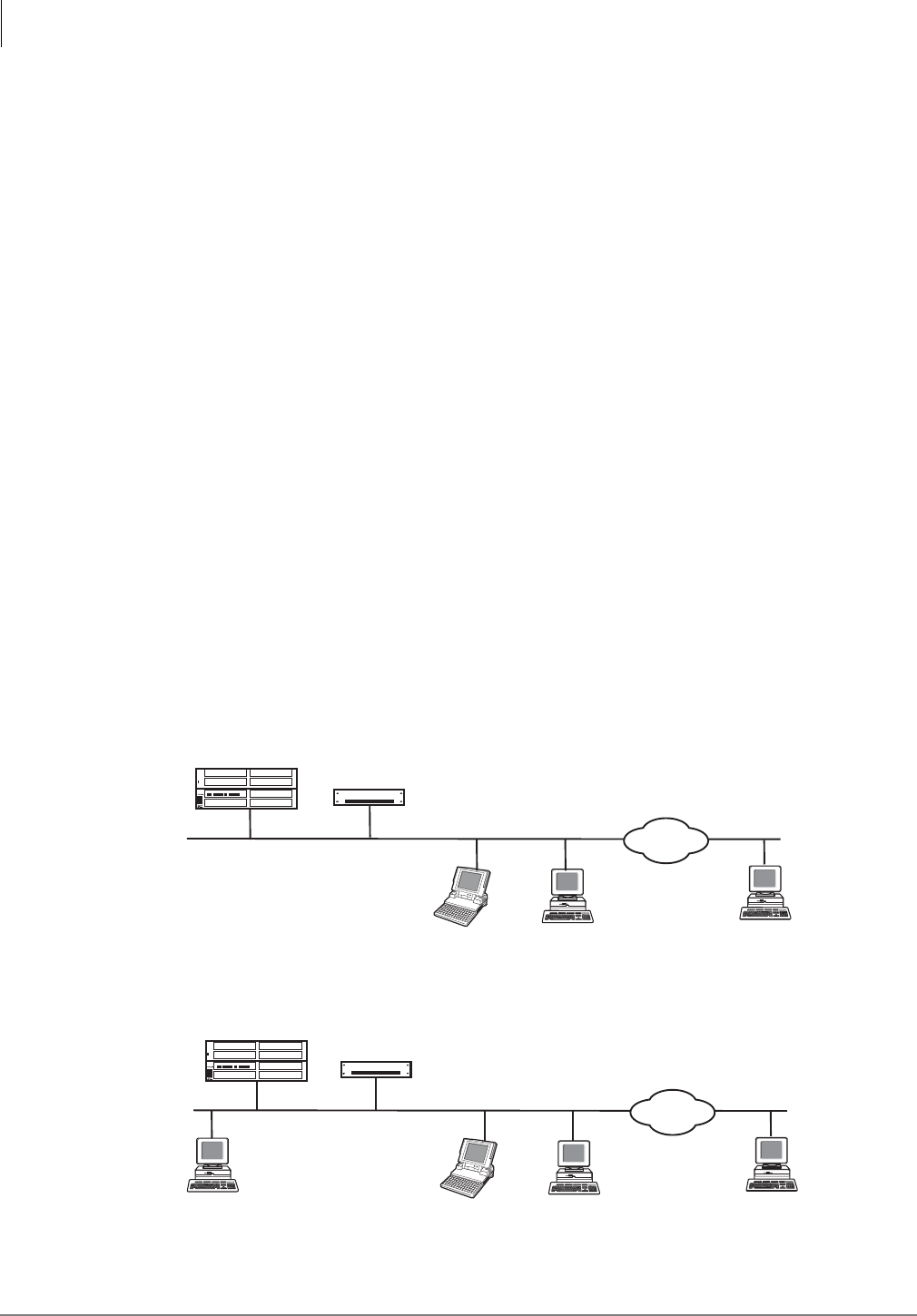
System Configuration
There are two basic hardware configurations for My Phone Manager (see Figure 1-1 below).
Configuration 1 has My Phone Manager and eManager™ software installed on the MAS with Client
PCs able to access it over the Internet. Configuration 2 has a PC server on the network that has My
Phone Manager software installed on it.
Figure 1-1 My Phone Manager System Configurations
Client PC
VPN/
Internet
Strata CIX
MAS
Client PC Client PC
(with eManager and
My Phone Manager)
Client PC
VPN/
Internet
Strata CIX MAS
Client PC Client PC
(with eManager)
My Phone Manager
Server
7663
Configuration 1
Configuration 2

My Phone Manager™
Installation
Strata CIX Application Implementation Vol 3 09/09 1-3
Installation
Note You need to uninstall any existing My Phone Manager software before starting this
procedure.
1. Insert the CD-ROM into the CD-ROM drive. The Installation screen displays.
2. Click Install My Phone Manager and the installation begins.
3. Follow the installation instructions on the screen.
4. Click Finish when the installation is complete. The system reboots.
Notes
lThe installer automatically creates the Default Web Site virtual directory
“MyPhoneManager.”
lThe installer automatically registers all necessary components.
User Levels
There are three levels—normal, Super1 and Super2. The levels are assigned in the My Phone
Manager Level field in the Station > Station Assignments screen of Network eManager.
Note The Super1 user is not the System Administrator of the program. The Super1 user is
someone located in the company who can be assigned to take care of day-to-day
operations such as system speed dial and account codes, etc.
The Normal level allows the user to view all menu options except Account Code and DISA Code.
In addition, there are two screens where additional fields are only available to the Super1 user.
The Super1 level allows the user to view all menu options including the Account Code and DISA
Code. The Super1 user also has access to additional fields on the following screens enabling the
editing of those screens—Advisory Message and System Speed Dial screens.
Configure My Phone Manager
Step 1: Configure Users
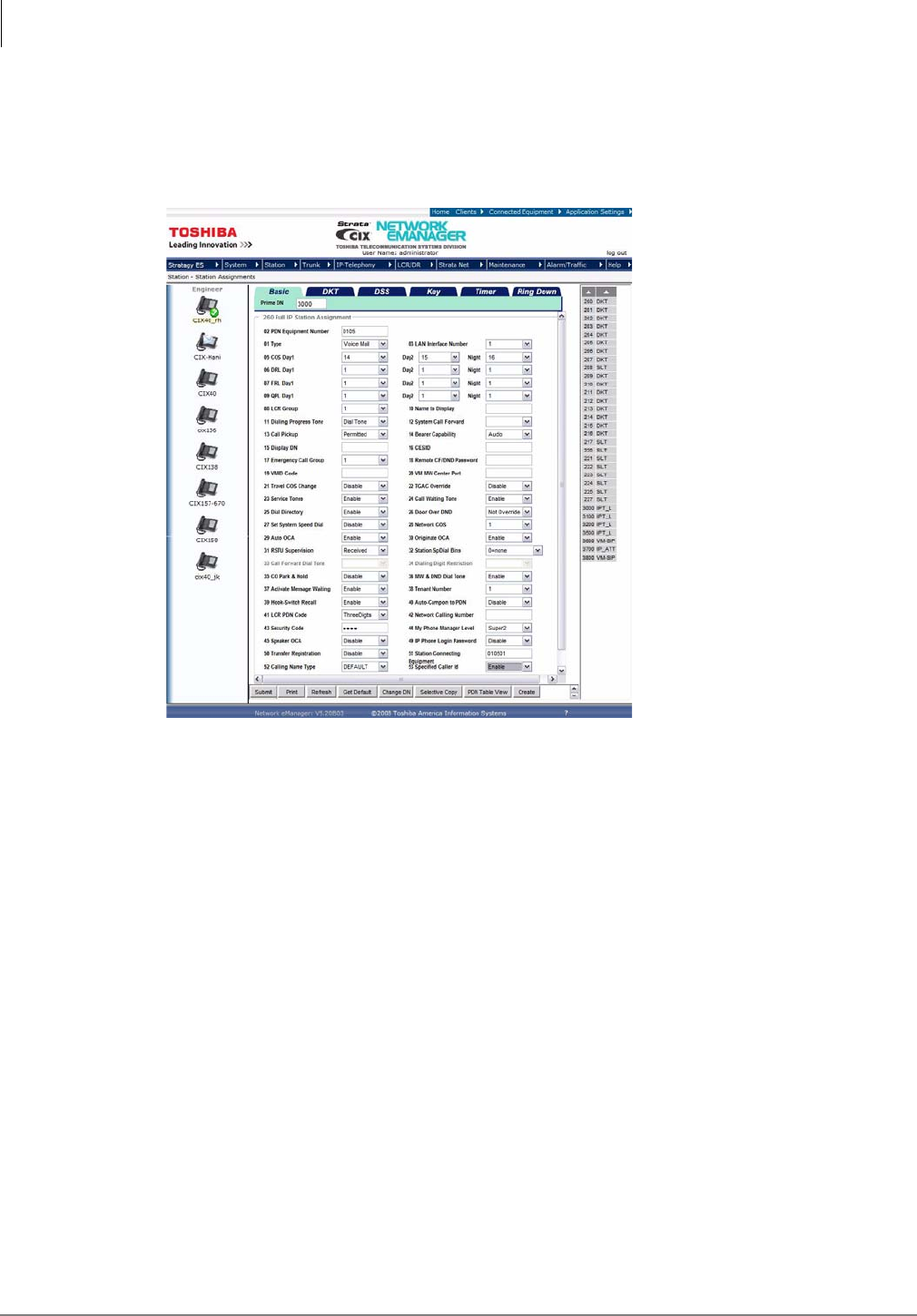
1. In Network eManager, click Station > Station Assignments. The Assignments screen displays.
2. Choose the DN from the list at the right side of the screen and click Refresh. The screen that
displays is Program 200 Station Data for DKTs or SLTs, or Program 260 Full IP Station
Assignment for IP-VM or IPTs.
My Phone Manager™
Configure My Phone Manager
1-4 Strata CIX Application Implementation Vol 3 09/09
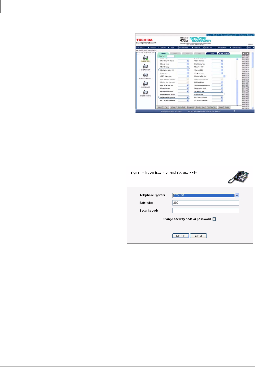
3. Set the following parameters (sample
screen shown at right):
•Set System Speed Dial – Set to
Enable (allows the Super1 user to
make changes to the system speed
dial through My Phone Manager or
the phone).
•My Phone Manager Level – Choose
one: Normal, Super1, Super2.
•Security Code – Set to CIX security
code.
Note This security code is what the
client uses to log into the CIX. If
you use your telephone security
code, you can only manage the
CIX phone system. Users who
want to manage both their phone system and voice mail must use their voice mail security
code to log in.
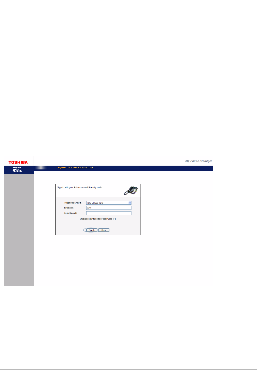
Step 2: Log In as Administrator
1. Start the Internet Explorer.
2. Type http://<PC Name>/
MyPhoneManager (example: http:/
/NETWORK/MyPhoneManager)
and press <Enter>. The Login
screen displays (shown right).
3. In the Telephone System field,
select your system from the drop-
down menu.
4. In the Extension field, type in
Administrator.
5. In the Security code field, type in
“password.”
6. Click Sign In.
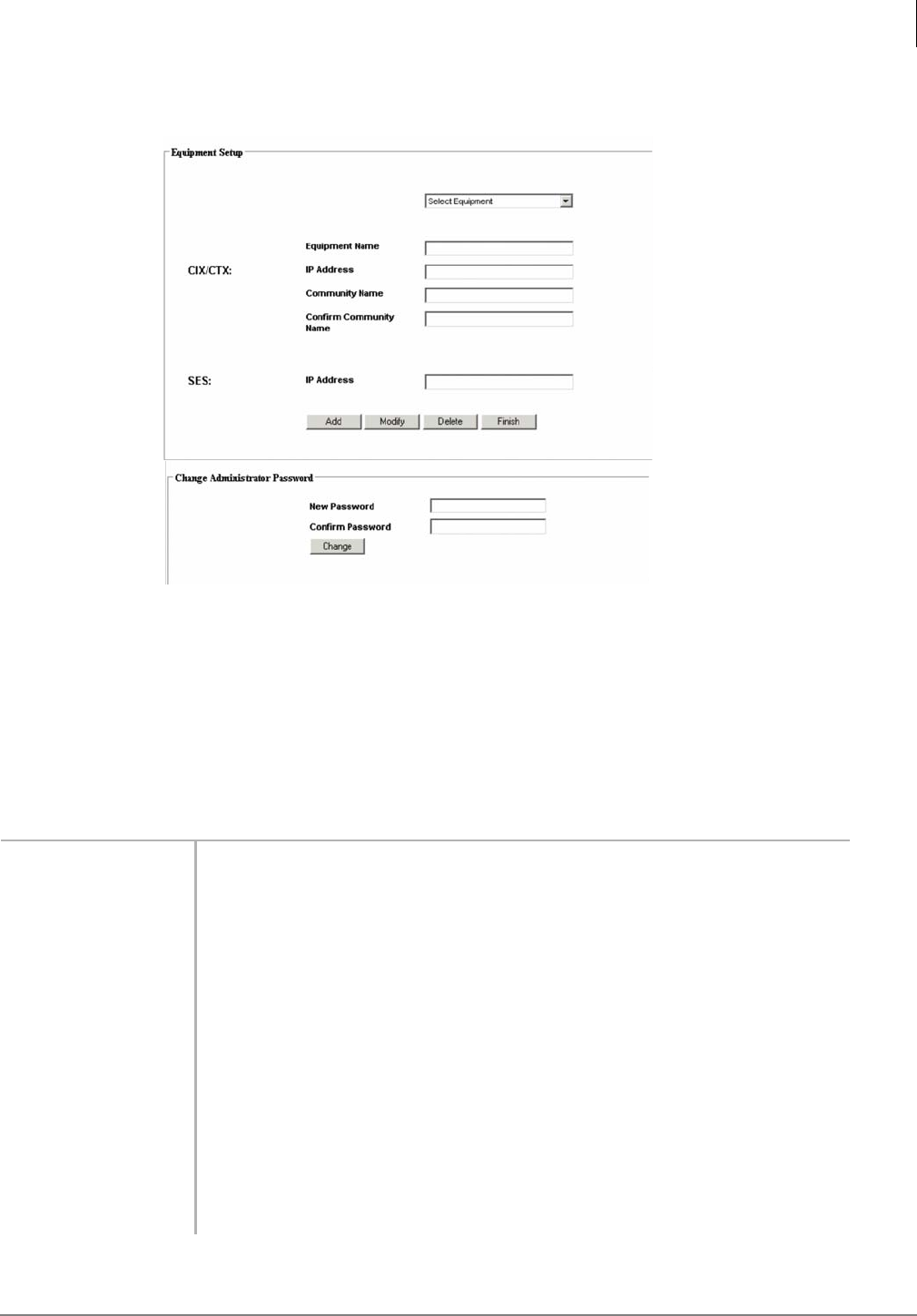
Step 3: Change Administrator Password
1. The Change Administrator Password screen displays below the Equipment Setup screen.
2. Type in the new password and confirm it. Click Change.
Step 4: Equipment Setup
The Equipment Setup screen is for adding, modifying or deleting equipment. If you enter the
information for both the CIX and SES as one piece of equipment, the menu you view will be a
blended menu of both CIX and Stratagy options (see “Program Menu” on page 7).
If you want the option of viewing only CIX programming or only Stratagy ES programming, you
need to make and save a separate entry for each piece of Equipment in this screen. For
example: For CIX only, leave the IP Address for the SES blank and for Stratagy only, leave the
CIX fields blank.
The defined equipment is saved in a file and stored on the server.
My Phone Manager™
Configure My Phone Manager
Strata CIX Application Implementation Vol 3 09/09 1-5
Note This file is not combined with the equipment entered on the Equipment Editor screen from
the Network eManager Profile.
1. Select a Telephone System from the Equipment drop-down menu. If the desired equipment
name is not found, type in a name in the Equipment Name field and click Add.
Note To delete an Equipment name, select it from the drop-down menu and click Delete.
2. In the Equipment section, fill in the appropriate fields based on the descriptions shown in Table
1 below.
3. Click Finish.
Table 1 Equipment Editor Screen Fields
FIELD DESCRIPTION
Equipment Name Name designating the equipment. For example: CIX999.
Possible values:alphanumeric characters
CIX
IP Address Enter the IP Address of the CIX system. For example: 192.168.254.253.
Format: xxx.xxx.xxx.xxx
Community Name Enter the Community password.
Possible values:Alpha characters
Default: communityName
Confirm
Community Name Re-enter the Community password.
SES
IP Address Enter the IP Address of the Media Server. For example: 192.168.254.252.
Format: xxx.xxx.xxx.xxx
My Phone Manager™
Run My Phone Manager
1-6 Strata CIX Application Implementation Vol 3 09/09
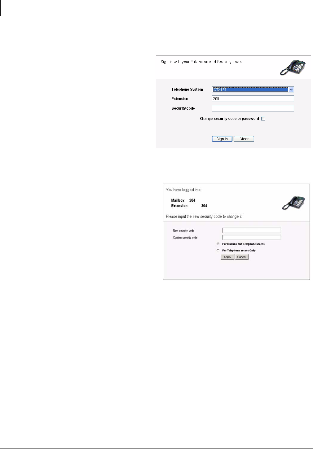
Run My Phone Manager
1. Start the Internet Explorer.
2. Type http://<PC Name>/
MyPhoneManager (example: http:/
/NETWORK/MyPhoneManager)
and press <Enter>. The Login
screen displays (shown right).
3. In the Telephone System field,
select your system from the drop-
down menu.
4. Type in your Extension and
Security code.
5. (Optional) Check Change Security
Code or Password.
Note This security code is for the
individual user of the program.
6. Click Sign In.
7. If you checked Change Security
Code, a dialog box displays (shown
right). You are requested to enter the
new password and confirm it. If the
security code is to access only the
phone, check the radio button For
Telephone access Only. Otherwise,
check For Mailbox and Telephone
access. Click Apply.
Important! If using voice mail,
changing the security code
on this screen
automatically changes the
password/security code of
your voice mail and vice
versa.
8. The My Phone Manager main screen displays.
My Phone Manager™
My Phone Manager Main Screen
Strata CIX Application Implementation Vol 3 09/09 1-7
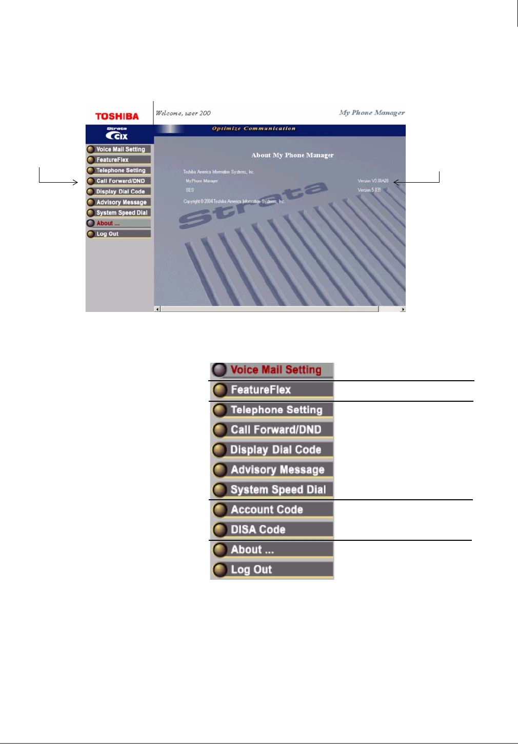
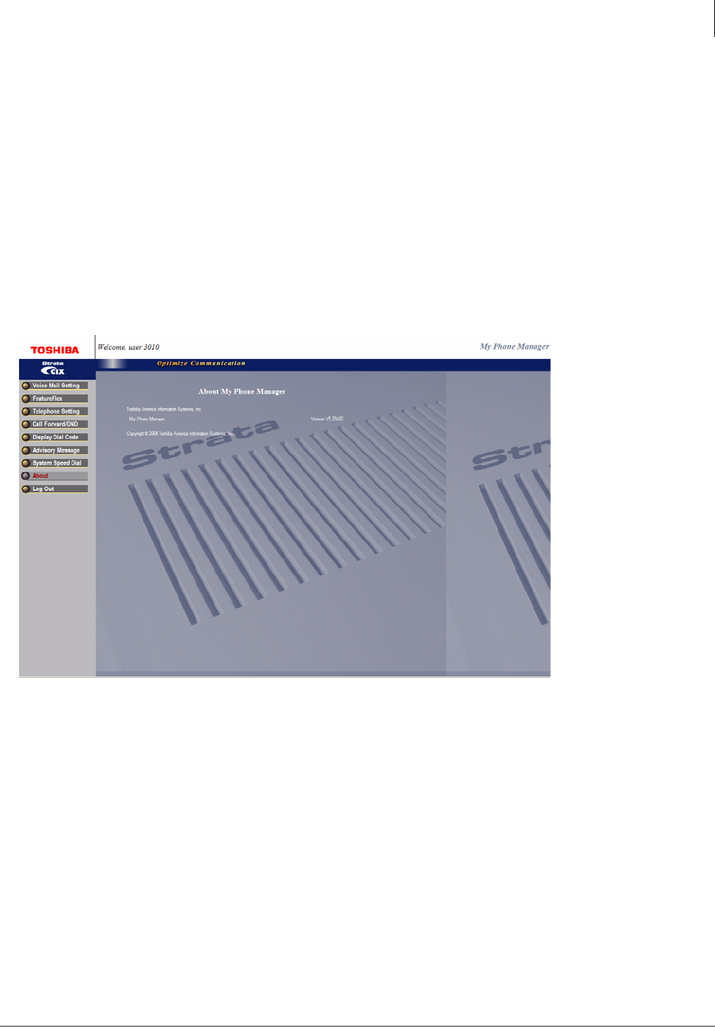
My Phone Manager Main Screen
After you log in to My Phone Manager, the main screen displays (shown below). Verify the
information on this screen. It contains the System type and Software version.
Program Menu
The Program Menu is the primary
tool used to navigate through My
Phone Manager. Click a selection to
open the options available.
The Program menu consists of
three possible configurations—only
CIX options, only Stratagy ES
options or a blend of both.
What you see depends upon:
•the equipment you are
connected to using the Sign In
screen, Telephone System field
•or, the extension and security
code that was used at log in.
The figure to the right shows a
blended menu.
Note See My Phone Manager
User Guide for a complete description of these features and how to use them.
Program Menu Software
Versions
Voice Mail Options
Telephone System Options
Super1 Options
Standard Options
FeatureFlex Options
My Phone Manager™
Program Menu
1-8 Strata CIX Application Implementation Vol 3 09/09
Voice Mail Settings
The user can access the Media Server to customize their mailbox settings. The features are:
•Mailbox settings
•Name and Greetings
•Message Notification
•Distribution Lists
•One Number Access (must be enabled by System Administrator in the CIX Network eManager)
FeatureFlex
The user can access FeatureFlex to customize the features. See Chapter 2 – FeatureFlex™.
Telephone System
The user can access the Telephone system to personalize telephone settings, retrieve information
and remotely activate/deactivate phone features. The following are the phone features:
•Telephone Setting
•Basic Settings
•Key Programming
•Speed Dial Setting
•Advanced Settings
•DKT Phone Settings
•Call Forward/DND
•DND Activating
•Call Forward Setting
•Display Dial Code (for display only)
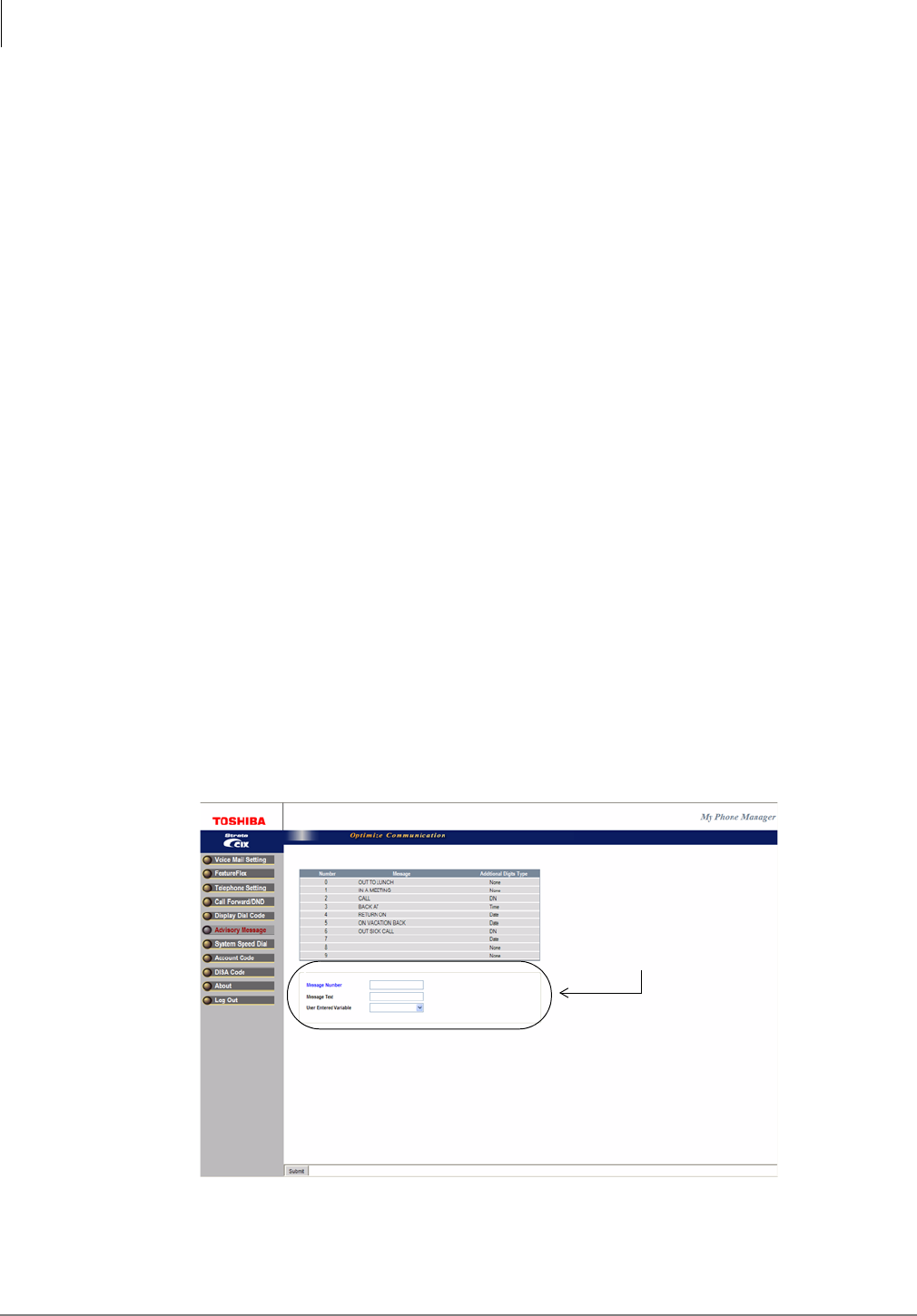
•Advisory Message (user can only display, Supers1/2 can display and edit).
Figure 1-1 Advisory Message Screen
Displays only
on Supers1/2
screen
My Phone Manager™
About
Strata CIX Application Implementation Vol 3 09/09 1-9
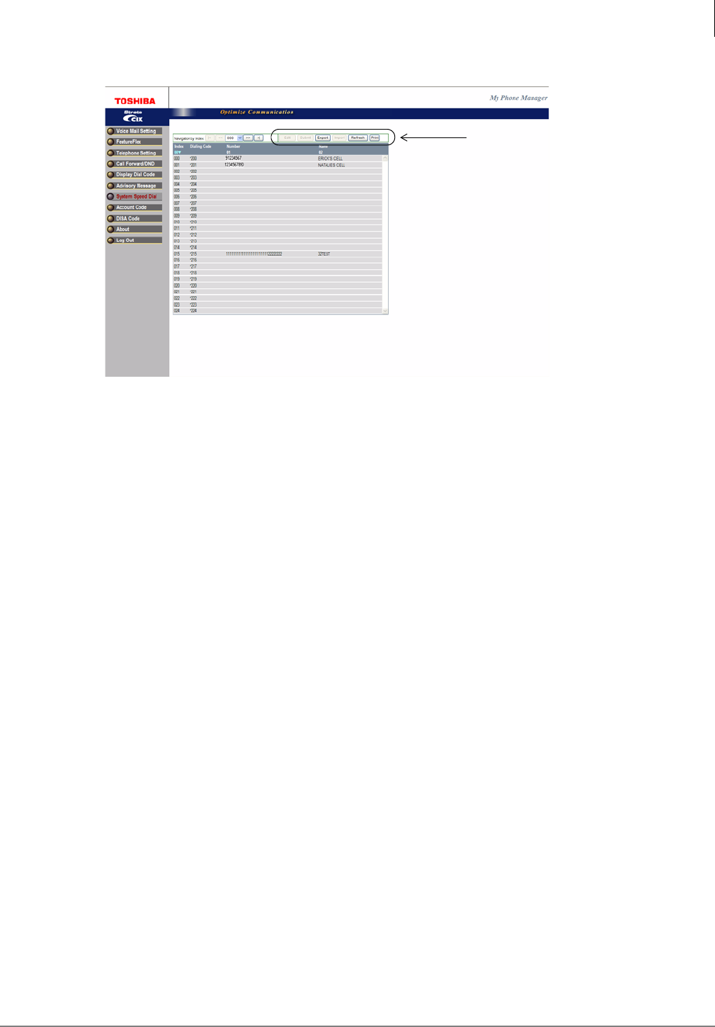
•System Speed Dial (shown below) — user can only display, Supers1/2 can display and edit
Figure 1-2 System Speed Dial Screen
Super1 Options
•DISA Code (access limited to Supers1/2 user)
•Account Code (access limited to Super1/2 user)
About
Click on About and the Main Screen displays (shown on page 7).
Log Out
Click on Log Out and the Login screen displays (shown on page 6).
Supers1/2
capability
This page is intentionally left blank
Strata CIX Application Implementation Vol 3 09/09 2-1
FeatureFlex™ 2
FeatureFlex™ is a new application development tool that enables the customer to develop custom
applications easily and quickly.
In order to use FeatureFlex applications, the feature must first be assigned to the extension. The
assignment is done using the Options screen in the eManager program (see Chapter 2 in the Strata
CIX Programming Manual). eManager provides the user with friendly, easy-to-learn, and easy-to-
use user interfaces to install/uninstall customer-developed FeatureFlex applications. Then, using
either eManager or the My Phone Manager program, the feature is configured for the individual
phone.
Set up FeatureFlex
Step 1: Configure the Stratagy ES System
Configure the Stratagy ES system for CIX/CTX Proprietary Integration per Chapter 10 of the
Strata CIX Voice Programming Manual Volume 2.
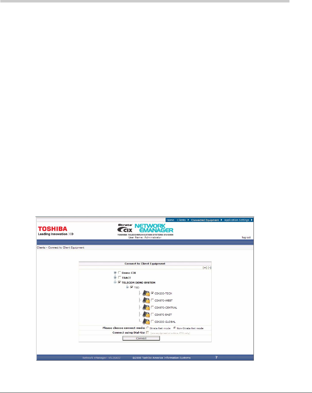
Step 2: Use Network eManager to Configure FeatureFlex
1. Log in to Network eManager. Click the Connect to Equipment icon and, in the next screen
(shown below), select the system(s) to configure FeatureFlex applications and click Connect.
FeatureFlex™
Set up FeatureFlex
2-2 Strata CIX Application Implementation Vol 3 09/09
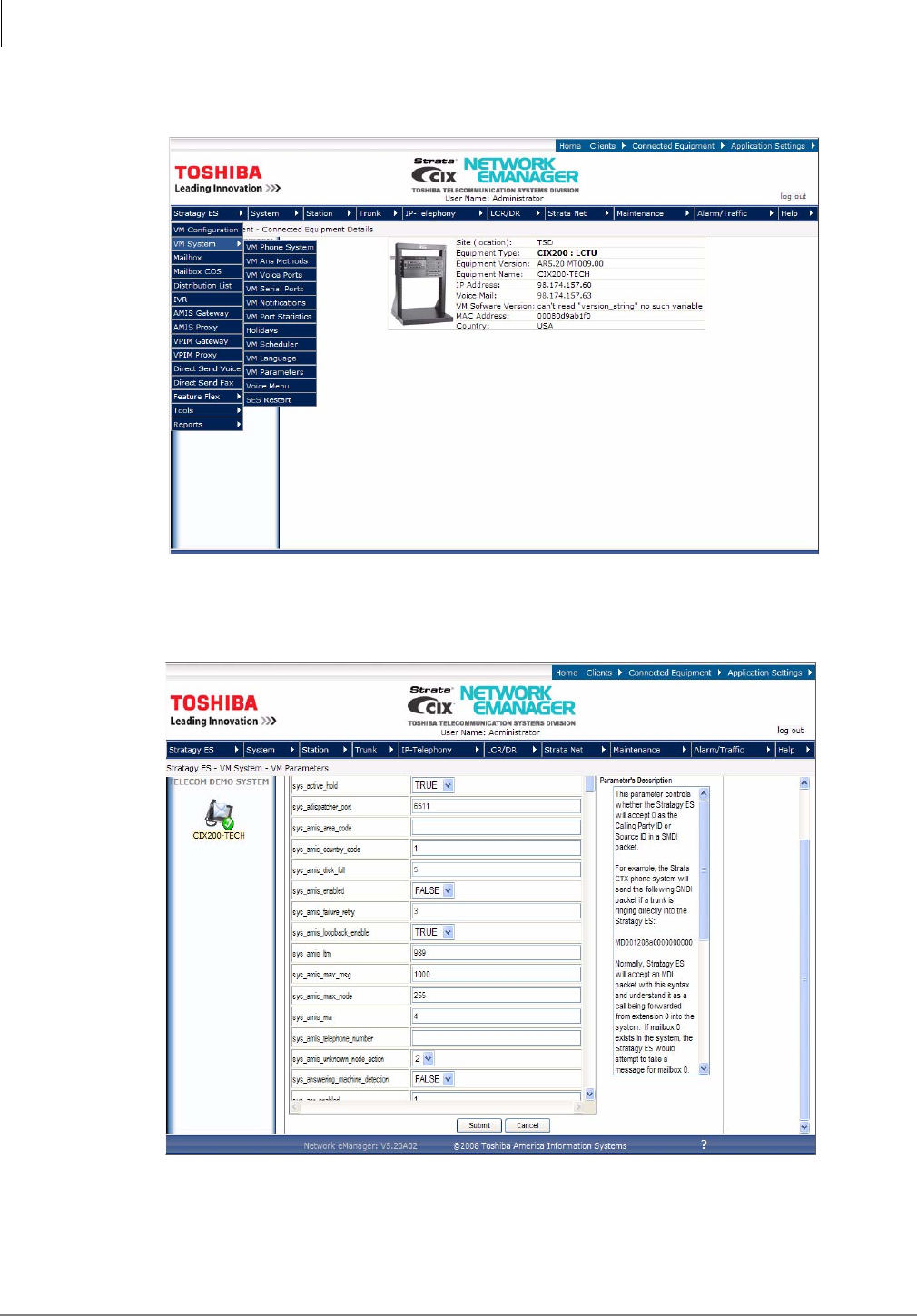
2. Put the cursor over Stratagy ES in the toolbar to expand the menu and select VM System > VM
Parameters. This expansion menu is shown here.
3. Scroll down to the sys_voicemail_pilot_number parameter (at the bottom of the screen) and
assign the voice mail pilot number.
4. Set this value to the pilot number of the voice mail hunt group.
5. Click Submit.
6. Restart Stratagy ES.
FeatureFlex™
Set up FeatureFlex
Strata CIX Application Implementation Vol 3 09/09 2-3
Step 3: License Requirement
1. A FeatureFlex license for CIX (LIC-CIX-FF) must be purchased.
2. Follow the procedures in MAS Licensing of the Strata CIX Voice Programming Manual
Volume 2.
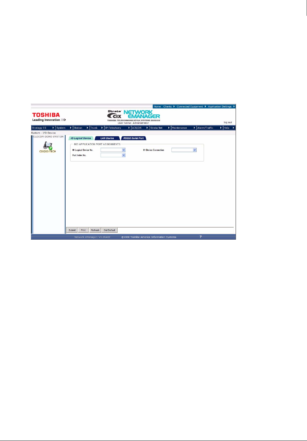
Step 4: Program Strata CIX for Adaptability
1. Using Network eManager, click System > I/O Device. Program 803 I/O Device screen displays
(shown below).
2. Click the IO Logical Device tab. This screen is used to assign SMDR and SMDI to logical
device and BSIS port numbers.
First set the screen to:
•00 Logical Device No. – 208 CTI #8.
•Device Port No. – set device to 11.
•FB01Device Connection – LAN.
FeatureFlex™
Set up FeatureFlex
2-4 Strata CIX Application Implementation Vol 3 09/09
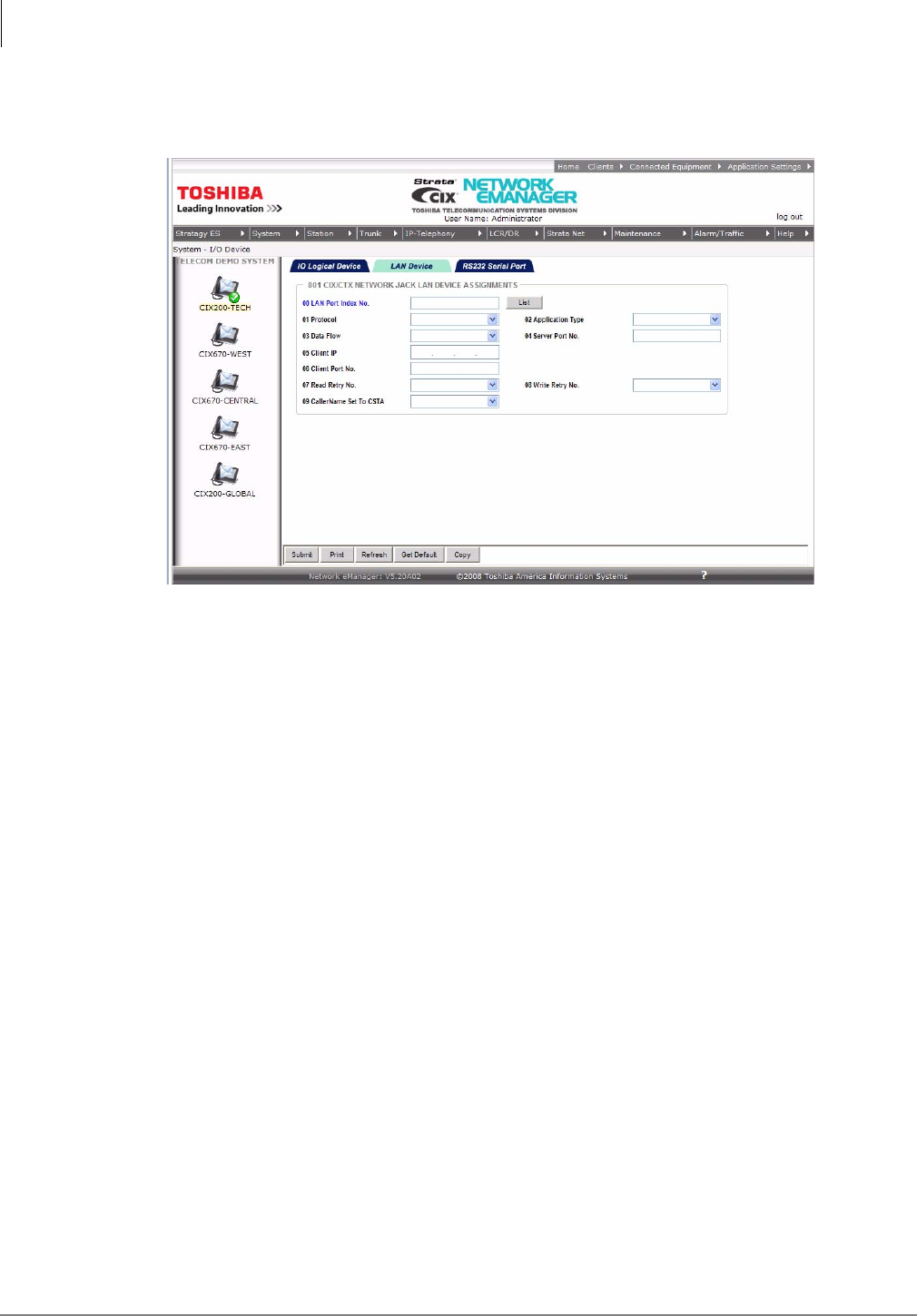
3. Click the LAN Device tab to show Program 801, CIX/CTX NETWORK JACK LAN DEVICE
ASSIGNMENT. This screen assigns LAN parameters for the PC applications connected to the
LCTU Network Jack through a LAN or Hub.
First set screen to:
•00 Set LAN Port No. to the port number set in Program 803 for 208CTI#8.
•01 Protocol = TCP
•02 PC Operation Type = Server
•03 Data Flow = Asynchronization
•04 Server Port Number = 1117
FeatureFlex™
Access FeatureFlex
Strata CIX Application Implementation Vol 3 09/09 2-5
Access FeatureFlex
Important! You must be connected to the Media Application Server (MAS) in order to see the
FeatureFlex menu option.
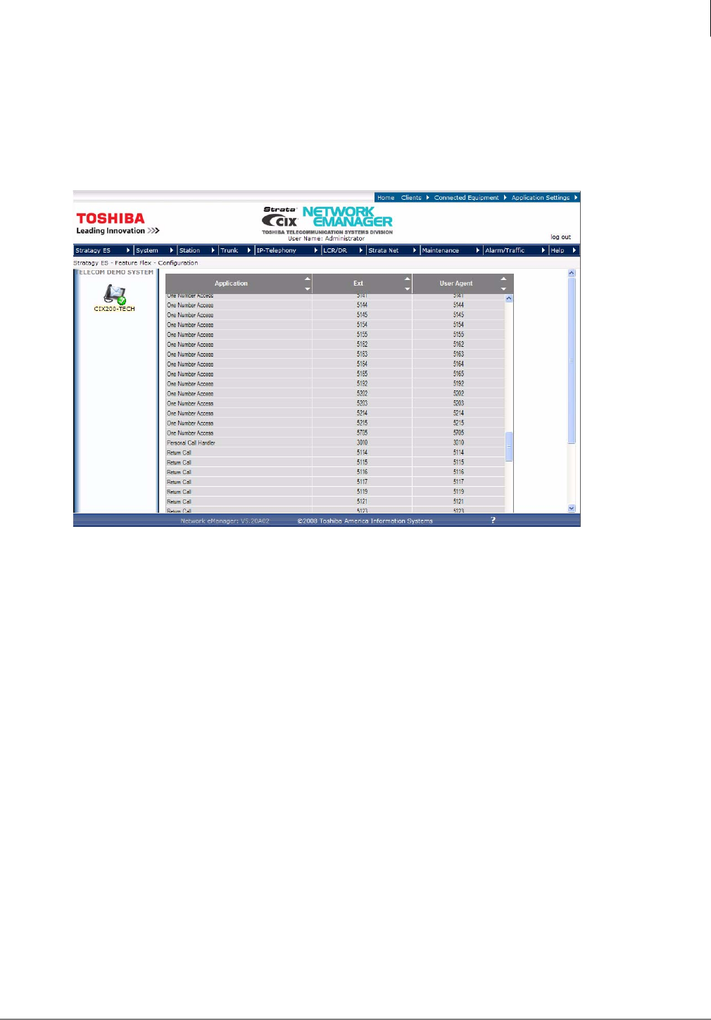
1. In Network eManager, go to Stratagy ES > FeatureFlex > Configuration
2. The FeatureFlex Configuration screen displays (shown below).
The first time you access this screen it is blank. As you assign features to phones the assigned
features display on this screen.
From this screen, you can see the list of existing Application(s), Extension and User Agent to
which each is assigned. Placing the cursor on an application displays a one-line description of
the feature.
Sorting the Screen
Click on an up arrow () in the field and the column is sorted in ascending order
...or click on a down arrow ()in the field and the column is sorted in descending order.
FeatureFlex™
Add FeatureFlex Application to Phone
2-6 Strata CIX Application Implementation Vol 3 09/09
Add FeatureFlex Application to Phone
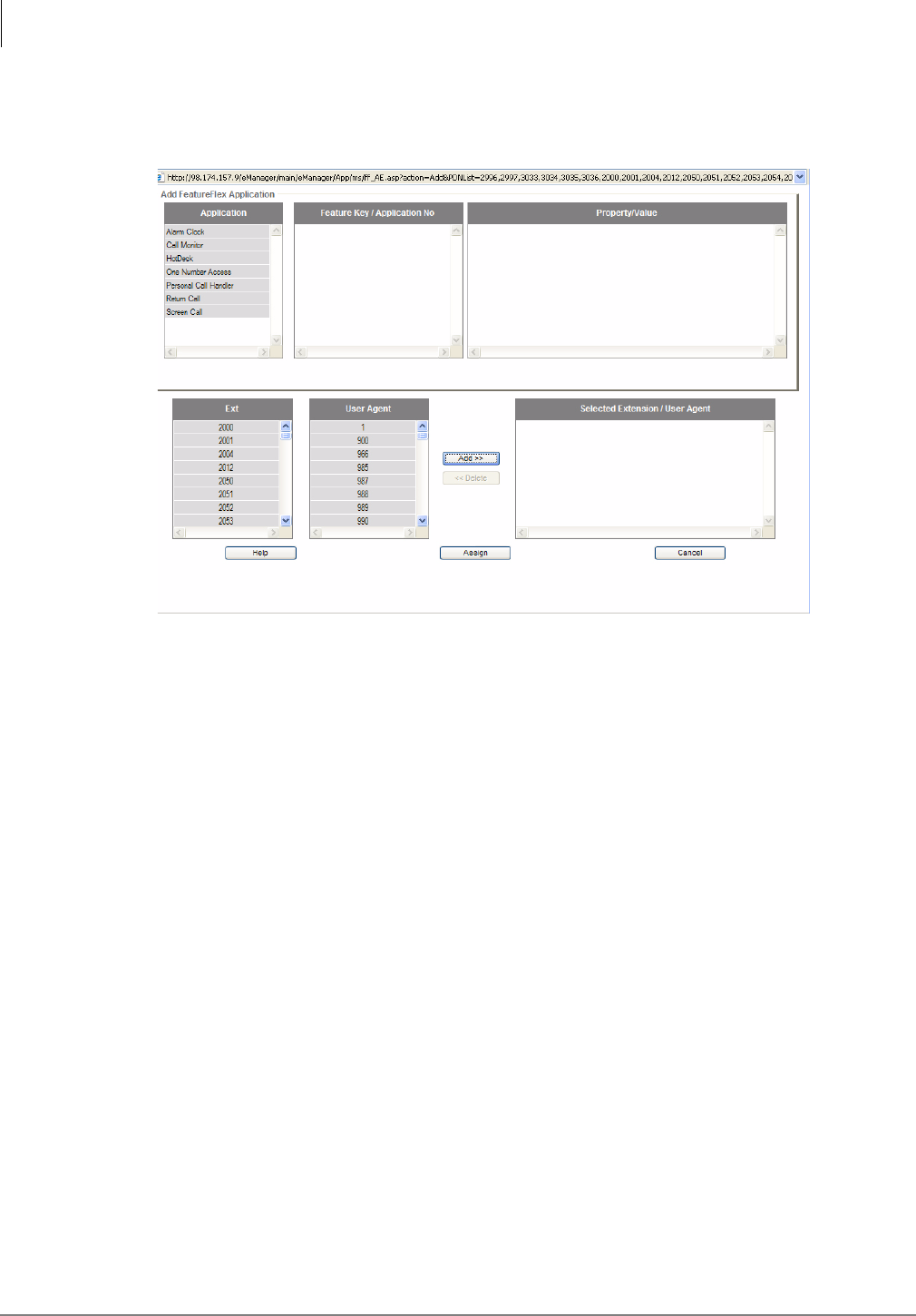
1. From the FeatureFlex Configuration screen, click Add. The Add FeatureFlex Application screen
displays (shown below).
2. Highlight the Application, Ext., and User Agent you want to assign to a phone. Highlighting an
application also displays the description. Depending upon the chosen feature, additional pop-
up boxes display. Fill in the requested information.
3. Click Add. The FeatureFlex screen display shows the Application and the Selected Extension/
User Agent highlighted. For the same Application, choose other Extensions/User Agents and
click Add, making a list of the Extensions/User Agents for a particular Application.
4. After adding Applications and Extension/User Agents, click Assign. The FeatureFlex screen
shows the assignment results. Click on Print to print the list, or click on Close to go back to the
FeatureFlex Configuration screen.
Additional information regarding individual FeatureFlex applications parameters are shown in the
Edit FeatureFlex Application section.
Delete FeatureFlex Application from Phone
Note This function only deletes the feature from the extension. It is not the same as the Remove
FeatureFlex Application described later.
1. Highlight the feature on the FeatureFlex Configuration screen and click Delete. A pop-up box
displays requesting you confirm the deletion.
2. Click OK. The feature is deleted from the screen.
FeatureFlex™
Remove FeatureFlex Application
Strata CIX Application Implementation Vol 3 09/09 2-7
Remove FeatureFlex Application
This function removes the feature from the system. To delete a feature from an individual phone,
use the Delete feature instead.
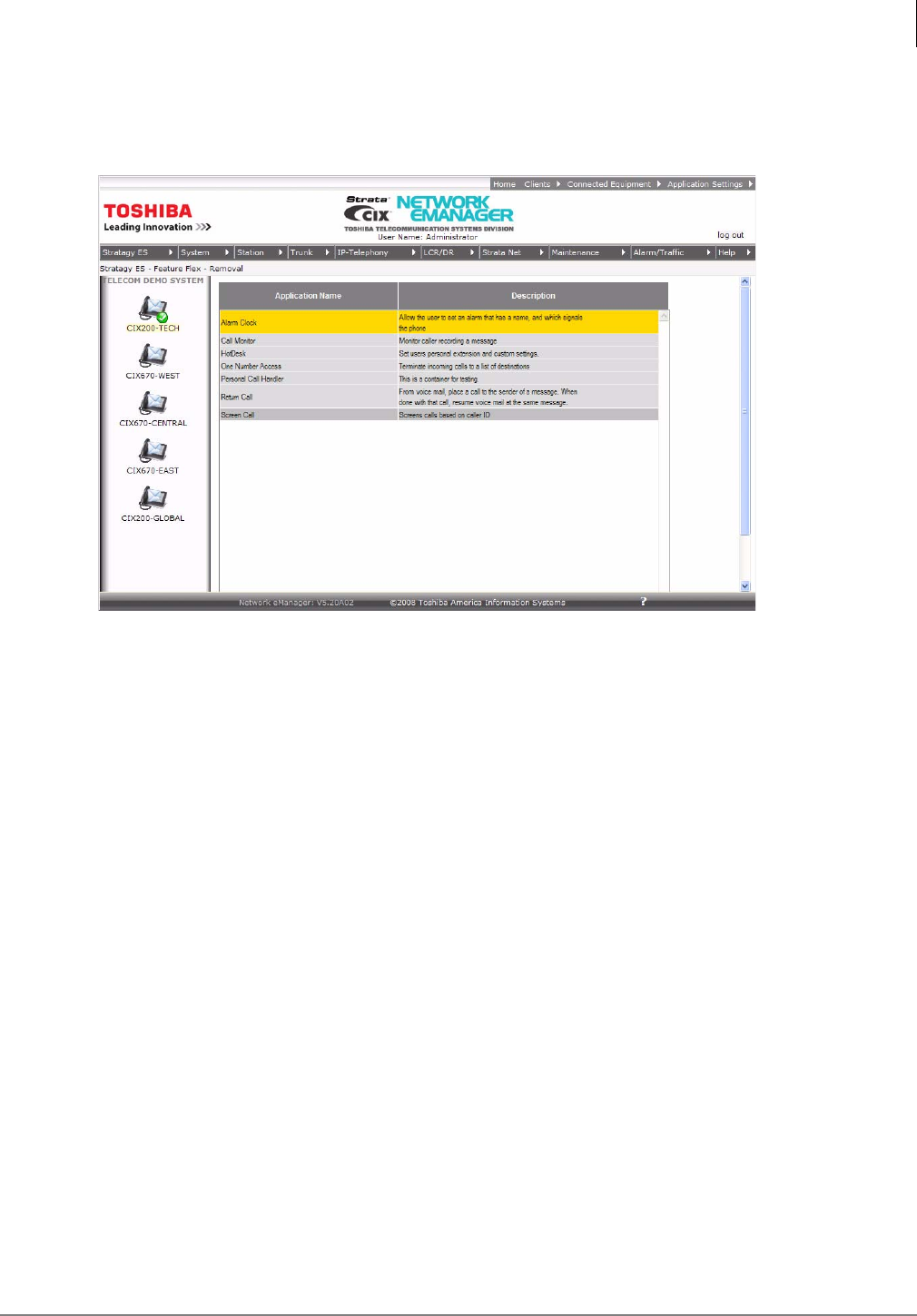
1. From Network eManager, click Stratagy ES > FeatureFlex > Removal. The Remove
FeatureFlex screen displays (shown above).
2. Highlight a feature in the box and click Remove. A pop-up box asks you to confirm the removal.
3. Click OK. The feature is removed.
Important! When an Administrator removes a feature, no phones can use that feature if they
already subscribed to it, and no phones can have that feature added to their
configurations. Once removed, a feature can only be reinstated by restoring the files
that compose the feature.
FeatureFlex™
Editing FeatureFlex Applications
2-8 Strata CIX Application Implementation Vol 3 09/09
Editing FeatureFlex Applications
FeatureFlex comes with preconfigured applications that can be customized by using the Edit
operation. The following applications and their parameters are edited individually or system-wide
as follows:
Note The user can also customize most of these parameters using My Phone Manager.
From the FeatureFlex Configuration screen, highlight the application to customize and click
Edit.
Alarm Clock
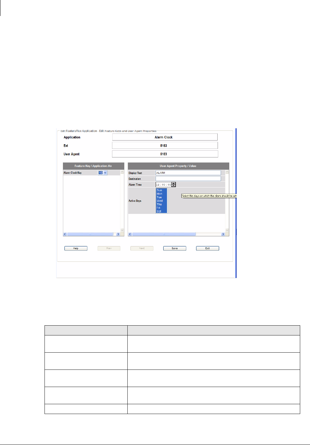
1. Highlight the particular Alarm Clock, Ext., and User Agent line(s) you want to change. Click
Edit. The current settings for the feature, Ext., and User Agent are displayed (shown below).
2. Clicking Save saves the changes and brings up the next selection; clicking Next deletes the
changes and brings up the next selection. If there are no other selections, clicking Save saves
the changes and takes you back to the FeatureFlex Configuration screen.
Field Definitions
Field Description
Alarm Code Key Maps to an application location in the Key Map configurations.
Can only be done in this screen.
Display Text What displays on the LCD when the alarm clock feature is
alarming the station (up to 24 characters long).
Destination These are the digits the system will dial at the alarm time. If
no digits are entered, no call will be made.
Alarm Time Enter the time for the alarm. Time is set in 12 or 24 hour
format.
Active Days The days the alarm clock feature is active.
FeatureFlex™
Editing FeatureFlex Applications
Strata CIX Application Implementation Vol 3 09/09 2-9
Call Monitor
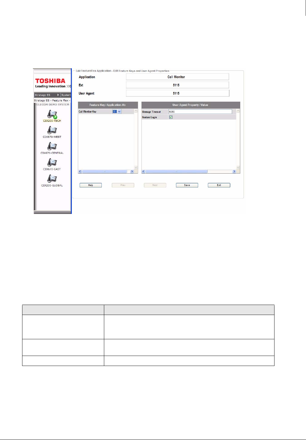
Note This feature must be enabled/disabled from the end-user’s station device.
1. Highlight Call Monitor > Extension > User Agent. Click Edit. The edit screen for Call Monitor
displays (shown below).
To reassign the Call Monitor Key
1. Turn off Call Monitoring on the phone.
2. Change the definition of the old key (either to 000 or to a new function).
3. Change the definition of the new key to Application Starting, with the proper application
number. This may be done via #9876 on the phone, via Network eManager, or via My Phone
Manager.
4. Press the new key to re-enable Call Monitoring on the phone.
Field Definitions
Field Description
Call Monitor Key Select the Feature Key Name/Application No. from the drop-
down menu. This will map to an application location in Key
Map configurations. This can only be done in this screen.
Message Timeout Number of milliseconds that Call Monitor shows messages
before reverting to the normal phone display
Restore Login
FeatureFlex™
Editing FeatureFlex Applications
2-10 Strata CIX Application Implementation Vol 3 09/09
Return Call
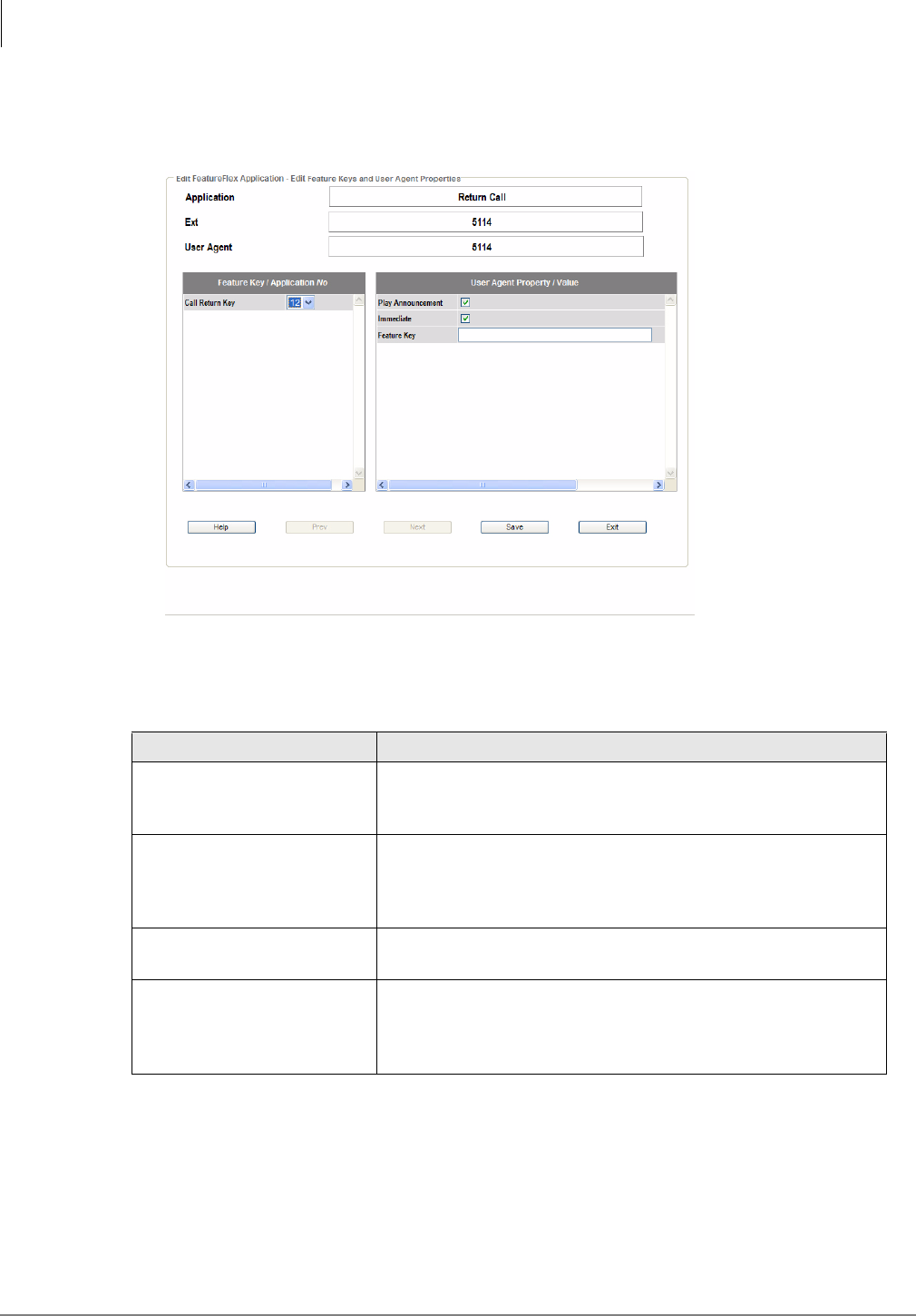
1. Highlight Return Call > Extension > User Agent. Click Edit. The edit Return Call feature
displays (shown below).
Note When using Return Call in a 10-digit dialing area the CIX may need to have LCR
Programming to remove digit 1.
Field Definitions
Field Description
Call Return Key Select the Feature Key Name/Application No. from the drop-
down menu. This will map to an application location in Key
Map configurations. This can only be done in this screen.
Immediate
If checked, as soon as the reply call finishes (either end
hangs up), the Return Call immediately connects to voice
mail. If not checked, the user must press the feature key to
return to voice mail.
Play Announcement Controls whether the system plays the prompt that states “I’ll
retain your place in your mailbox if you wish to return.”
Feature Key Can be left blank, especially if Return Call Immediate is
checked. If the user wants to press a key to return to voice
mail, this parameter should be set to the “physical” key
location that is being used.
FeatureFlex™
Editing FeatureFlex Applications
Strata CIX Application Implementation Vol 3 09/09 2-11
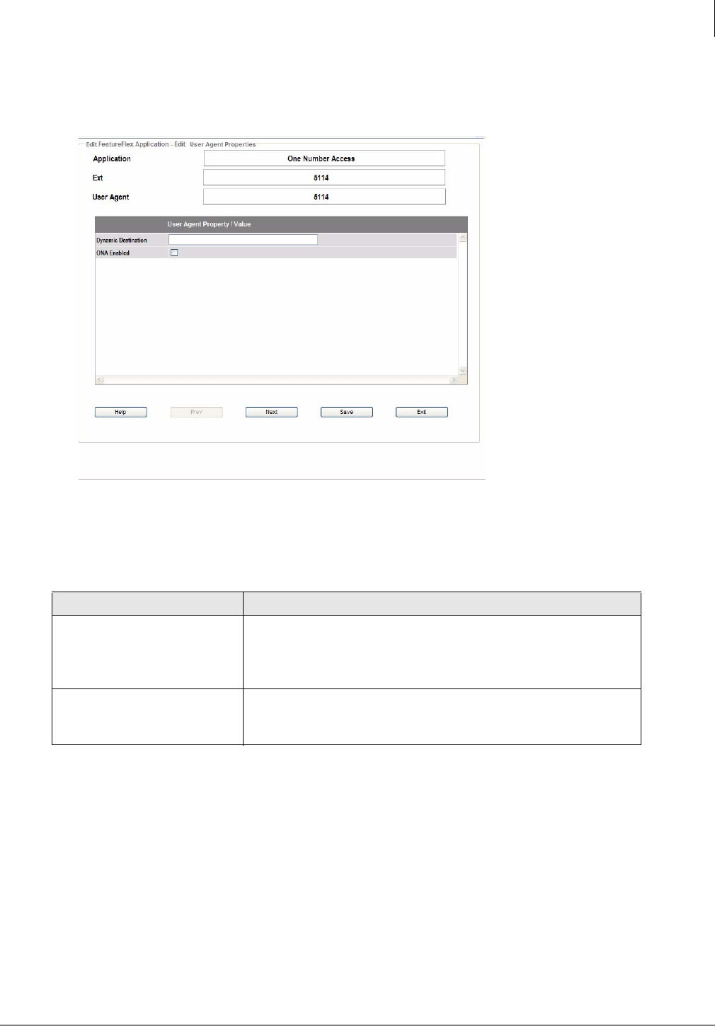
One Number Access
1. Highlight One Number Access > Extension > User Agent. Click Edit. The edit One Number
Access feature displays (shown below).
2. Do not edit the User Agent Property/Values. You must edit these properties using the My
Phone Manager program. See My Phone Manager User Guide for instructions.
3. Click OK.
Field Definitions
Note Secondary Destination Number can be any destination including a cell phone, extension
in another node. When a PSTN number is used, do not add long distance prefix (1) or
LCR access code.
Field Description
Dynamic Destination
This value is a place holder for the Dynamic Destination which
will be determined by the locations input for the directory list.
The Dynamic Destination is the location where a call is
successfully answered, if programmed to do so
ONA Enabled If this box is unchecked, One Number Access will be disabled,
but the routing list will be retained. The feature can be turned
back on by checking this box.
FeatureFlex™
Editing FeatureFlex Applications
2-12 Strata CIX Application Implementation Vol 3 09/09
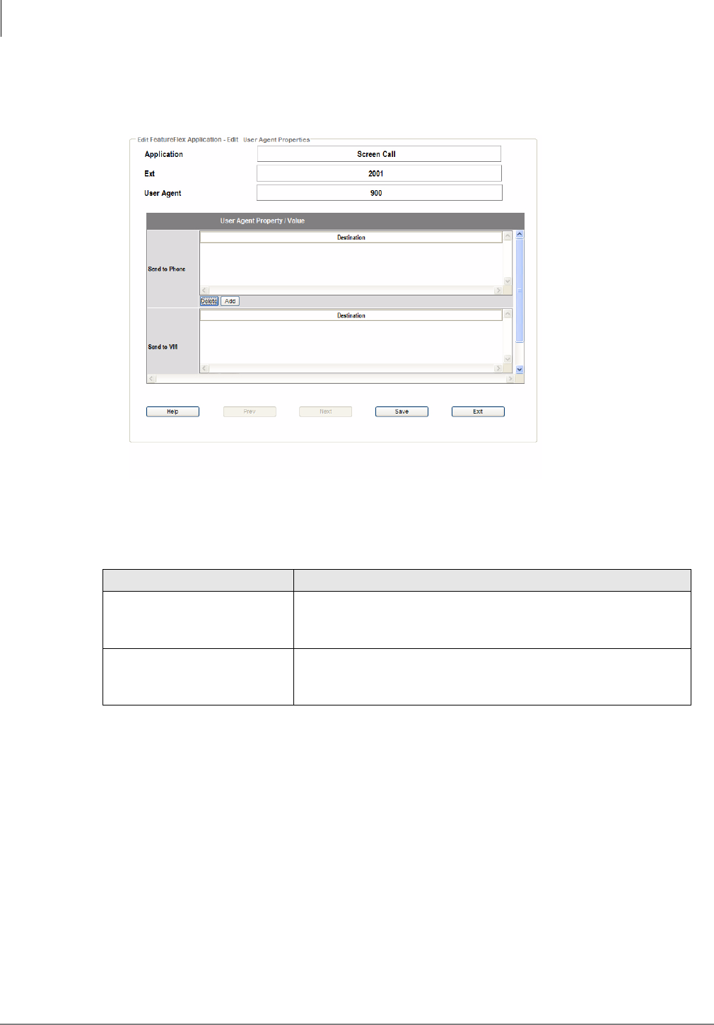
Screen Call
1. Highlight Screen Call > Extension > User Agent. Click Edit. The edit Screen Call feature
displays (shown below).
2. You may edit the fields in this screen using either Net eManager or My Phone Manager. See
My Phone Manager User Guide for instructions.
Field Definitions
Field Description
Send to Phone The number(s) (PDN or outside caller ID) the user would like
to ring directly at his/her phone. Space-delimited list of
extensions and caller IDs. Do not add punctuation.
Send to VM The number(s) (DN or outside caller ID) the user would like to
go directly to Voice Mail (never rings phone). Space-delimited
list of extensions and caller IDs. Do not add punctuation.
FeatureFlex™
Editing FeatureFlex Applications
Strata CIX Application Implementation Vol 3 09/09 2-13
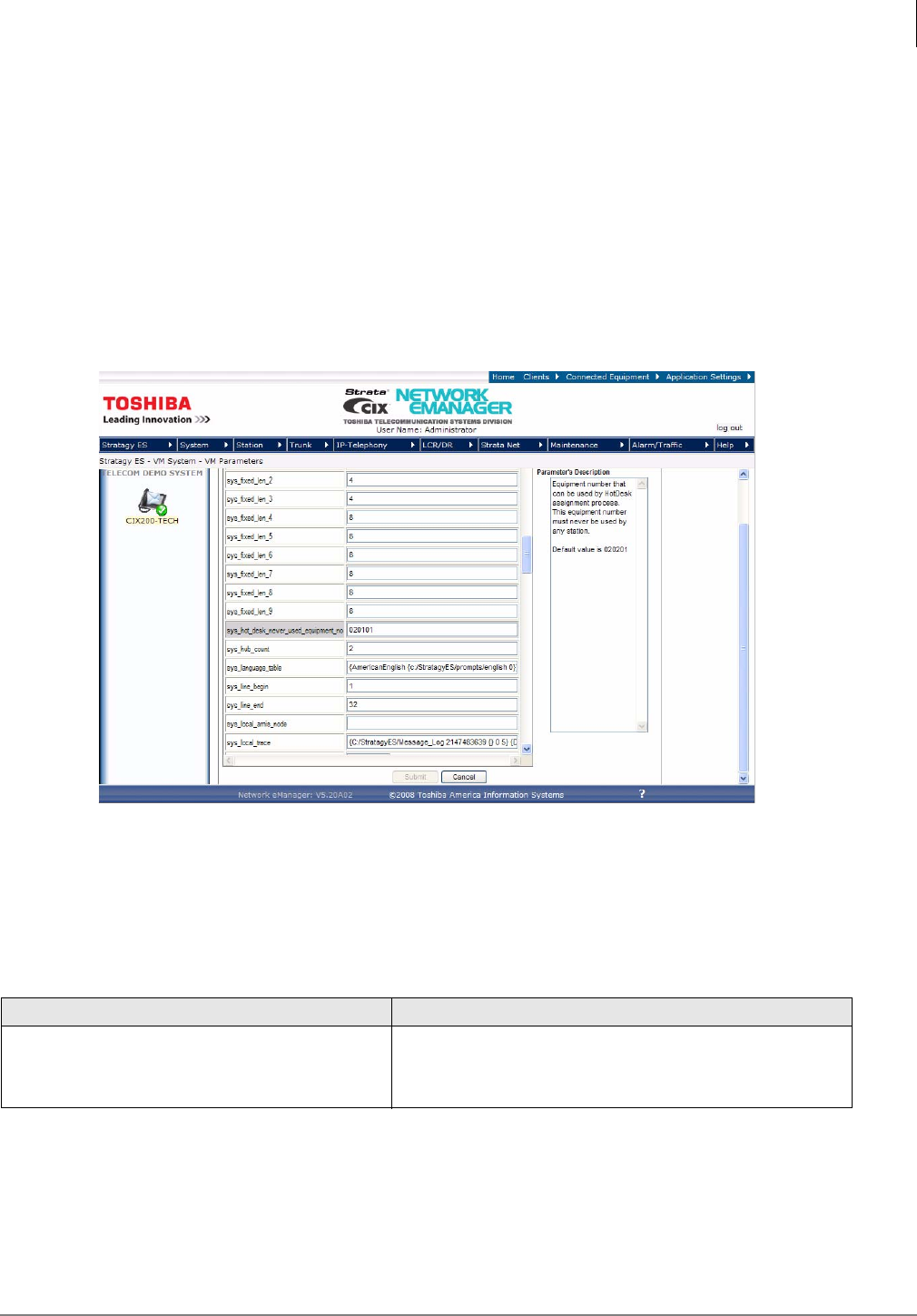
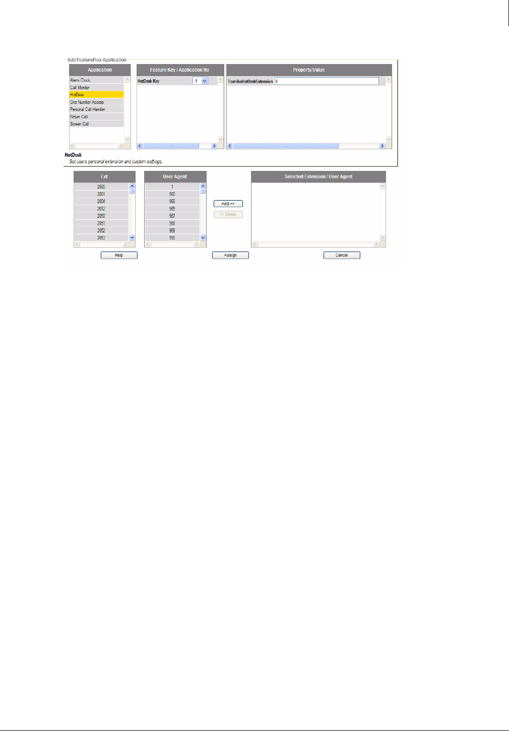
Hot Desk
To setup a Hot Desk environment, you must apply this FeatureFlex application to a pool of IP/
DKT stations that can be used by users. These stations do not have actual phones associated
with them. You can also create voice mail boxes for each Hot Desk station. In order to swap
extensions a valid equipment number that will never be used for a real extension is required.
Important! The number of licenses required is non-Hot Desk phones plus Hot Desk phones.
Reserve an Equipment Number to be used for Swapping
The Equipment Number does not need to be associated with any hardware.
1. Using Network eManager, click Stratagy ES > VM System > VM Parameters. The Voice Mail
Parameters screen displays (shown below).
2. Enter the appropriate value according to the Field Definition in the table below.
3. Click Submit.
Field Definitions
Set up the Pilot number
You must set up the Pilot number for numerical access of Hot Desk assignment.
Field Description
sys_hot_desk_never_used_equipment_no
Enter the Port number, Cabinet and Slot. This
equipment number must never be used by any station.
Default: 020201
FeatureFlex™
Editing FeatureFlex Applications
2-14 Strata CIX Application Implementation Vol 3 09/09
1. Using Network eManager, Station > Pilot DN.
2. Click Submit.
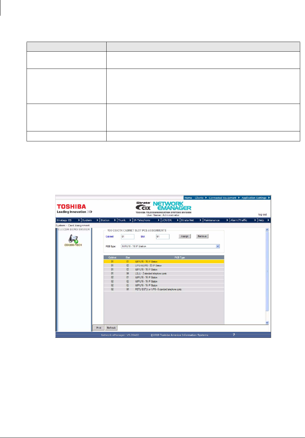
Create Hot Desk Stations
Hot Desk stations do not need to be associated with any hardware.
1. Click System > Card Assignment. Assign the Equipment Numbers (cards to slots).
Note While no physical hardware is used for Hot Desk stations, valid equipment numbers are
required.
2. Create stations that can be used for Hot Desk extensions. Click Station > Station Assignments.
Enter the PDN Equipment number, then Create button to enter a range of stations. Example:
4001-4007. Click OK.
3. Create mail boxes. Click Stratagy ES > Mailbox. Click the Create UA button and enter the
range and COS. Click OK.
4. Assign the Hot Desk application to each Hot desk station-mailbox pair. Go to Stratagy ES >
Feature Flex > Configuration. Click Add. The Add FeatureFlex Application displays.
Field Description
Pilot DN Pilot DNs have no physical appearance, they are true virtual numbers,
usually used in CTI and Voice Mail applications.
01 Alternate Destination
Calls to the Pilot DN are routed to the Alternate Destination if the Pilot
DN is not available (example: ACD After Shift). If Dialing Digits is
selected, enter the appropriate DN in the Alternate DN assignment.
Possible values: No Data (default), Dialing Digits or Night Bell
Alternate DN
If Dialing Digits is selected as the Alternate Destination, enter the PDN,
PhDN or Hunt Group pilot number to which the call should be routed.
Possible values: Up to 32 ASCII characters (default = no value)
02 Voice Mail ID For Hot Desk Application, enter 966.
FeatureFlex™
Editing FeatureFlex Applications
Strata CIX Application Implementation Vol 3 09/09 2-15
5. Highlight Hot Desk in the Application box.
6. Select the Feature Key Name/Application No. from the drop-down menu. This will map to an
application location in Key Map configurations. This can only be done in this screen.
7. Leave ToshibaHotDeskExtension field blank. This field is used by the system to swap and store
the Hot desk telephone’s extension.
8. Highlight the Ext and User Agent and click Add.
9. Click Assign to save your edits.
To create a One Touch button for Hot Desk Assignment on the phone, use Station > Station
Assignments, Key tab.
Note Hot Desk users cannot use an Add on Module or DSS console even if it is configured on
the phone. Also, if a Hot Desk user is configured to have more buttons than the Hot Desk
phone, the user will only have the number of buttons on the Hot Desk phone. For
example, if the Hot Desk phone is 10-button and the user has a 20-button phone, the user
will only have the first 10-buttons. The other the 10 buttons will not be available on the Hot
Desk phone.
User Information – From the Telephone
To log into the Hot Desk phone
1. Dial the Pilot number from PDN on the phone (get this number from the System Administrator).
2. The phone prompts you to enter the new extension number.
3. Press # (Example: Enter 2504#)
4. The system prompts, “You entered 2504, if this is correct, press 1.” You are now logged in.
To return the Hot Desk phone or to log out
1. Dial the Pilot number from PDN on the phone.
2. Press * to cancel the assignment, OR
1. Press the feature access button assigned for Hot Desk.
2. Press * to cancel the assignment.
FeatureFlex™
Editing FeatureFlex Applications
2-16 Strata CIX Application Implementation Vol 3 09/09
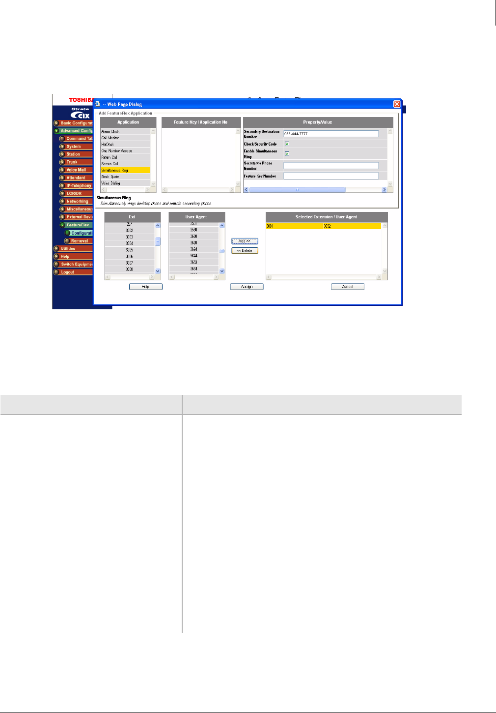
Simultaneous Ring
Simultaneous Ring is a FeatureFlex application that rings two telephones when a call comes into
the system. One telephone must be the user’s desktop phone while the other can be any telephone.
The user can take the call from either of the ringing telephones. If the user’s desktop phone is busy,
the call will not ring the alternate destination - it is forwarded directly to voice mail. If neither phone
answers the call, the call is forwarded to voice mail.
Note The Simultaneous Ring application requires two voice mail ports to ring two destinations.
Therefore, if there are many Simultaneous Ring users in the system, or the call volume for
the Simultaneous Ring users is high, additional voice mail ports are required. In general,
four additional voice mail ports may be required for a 10-user system; ten voice mail ports
may be required for a 100-user system. When a voice mail port is not available, the call
may ring either the desktop phone or the destination phone, or the call may be routed to
the user's voice mail box immediately.
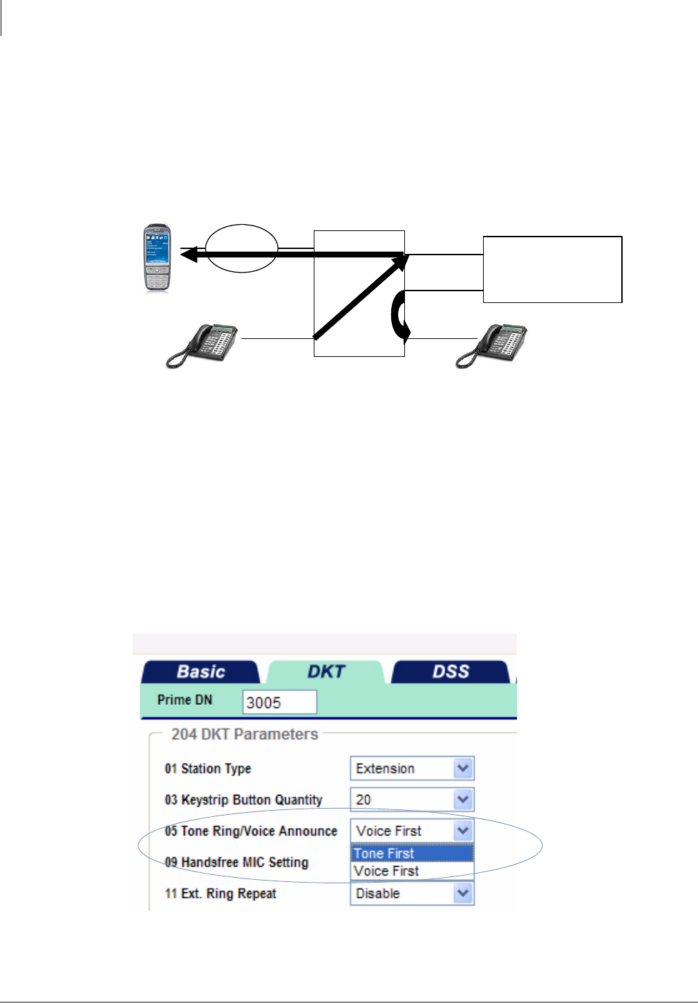
To set up Simultaneous Ring
Make sure Tone First is selected, see steps below.
1. Using Network eManager, click Station > Station Assignments and enter the DN.
2. Click the DKT tab.
3. Select Tone first in 05 Tone Ring/Voice Announce parameter.
Strata CIX MAS
Caller
Simultaneous Ring
user desktop phone
FeatureFlex
Simultaneous
Ring
User cell
phone PSTN
FeatureFlex™
Editing FeatureFlex Applications
Strata CIX Application Implementation Vol 3 09/09 2-17
To customize Simultaneous Ring
1. Highlight Simultaneous Ring > Extension > User Agent. Click Edit. The Edit Simultaneous Ring
feature displays
2. You may edit the fields in this screen or use the My Phone Manager program. See My Phone
Manager User Guide for instructions.
3. Click OK to save your edits.
Field Definitions
Note Secondary Destination Number can be any destination including a cell phone, extension
in another node. When a PSTN number is used, do not add long distance prefix (1) or
LCR access code.
Field Description
Secondary Destination Number Other phone will ring simultaneously when the desktop rings.
Check Security Code If this box is checked, the user must enter a Mailbox password
before line gets connected.
Enable Simultaneous Ring If this box is checked Simultaneous Ring is enabled.
Secretary’s Phone Number Enter the secretary’s phone number
Feature Key Number The feature key of secretary’s phone; if the Simultaneous Ring
is enabled, this LED will be turned on.
VoiceMail Erasing String If Simultaneous ring application calls the cell phones as the
secondary phone, the call may be immediately connected to
voice mail. In this case, application prompt may be recorded
as the voice mail. To avoid leaving an unnecessary voice
message, please specify the digit string to delete the voice
mail. “,” can be used for the pause.
If it is blank, it is automatically configured for AT&T (#311).

FeatureFlex™
Editing FeatureFlex Applications
2-18 Strata CIX Application Implementation Vol 3 09/09
User Information – From the Telephone
If a caller calls your extension, both telephones ring.
To accept the call, either
•Press 1 (if there is no security code enabled), or
•Enter the security code (if this is enabled).
Simultaneous Ring – Using My Phone Manager
You can also use My Phone Manager to set up to set up the secondary destination.
Follow these steps:
1. Log in to My Phone Manager.
2. Click FeatureFlex from the left panel.
3. Click Simultaneous Ring, or click Edit.
4. In the Secondary destination field, enter the cell phone, home number, or station that you want
to ring simultaneously with the desk telephone.
5. Click OK.
FeatureFlex™
Editing FeatureFlex Applications
Strata CIX Application Implementation Vol 3 09/09 2-19
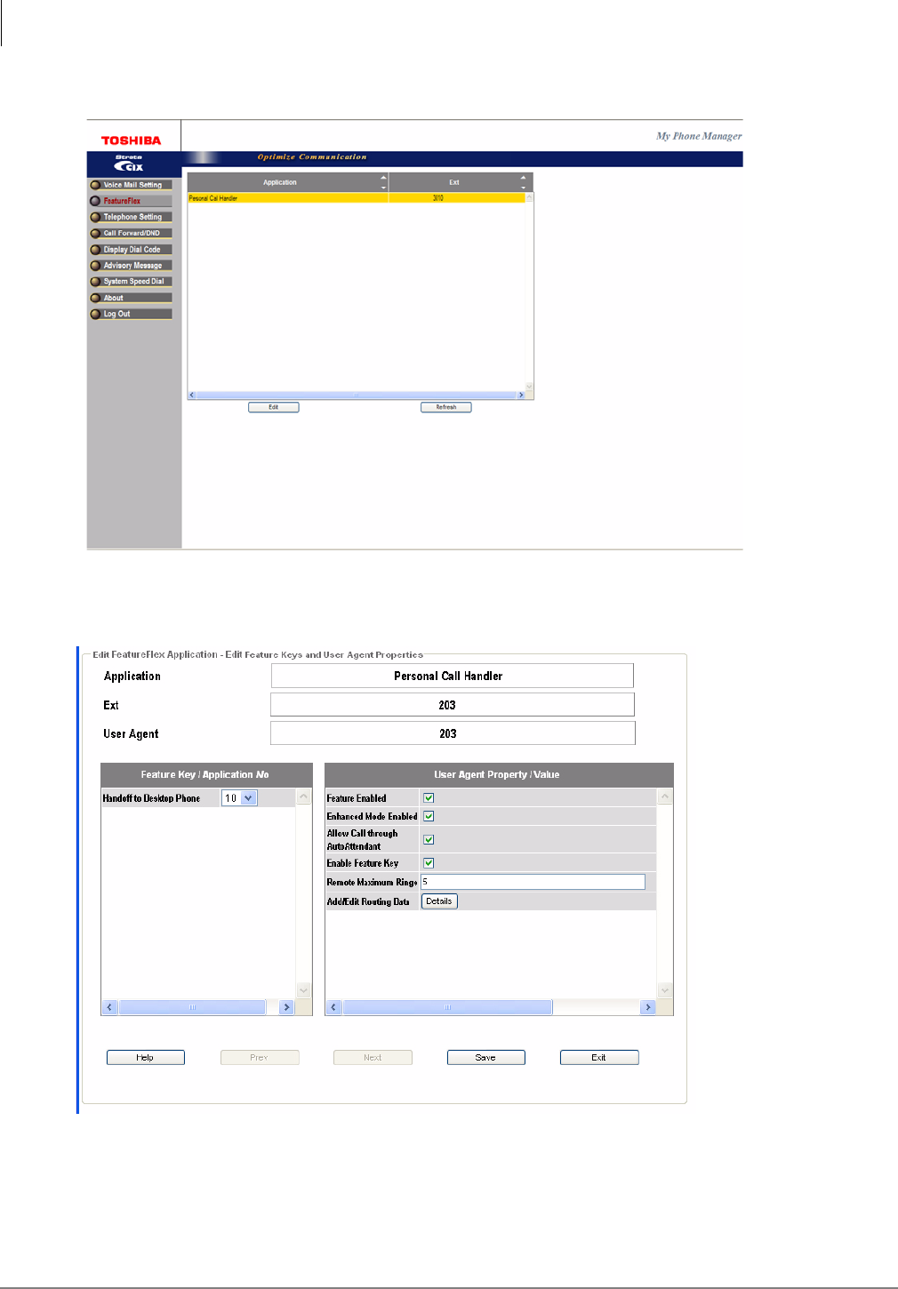
Personal Call Handler
The Personal Call Handler (PCH) application combines multiple call handling options and allows
the user to create rules to handle calls so that the user can choose the best way to handle the call
based on the schedule and the caller ID. PCH is based on a table-driven rule. The user can
configure the rule table from Toshiba’s web-based MyPhone Manager.
When the call comes into the system, the Personal Call handler Application checks the table for call
conditions such as the day/time/caller ID. If the conditions are met, the associated action is
executed.
Note Personal Call Handler requires MAS or Micro MAS-H. When Enhanced mode is selected,
it requires 32 voice mail ports for 30 users.
To set up Personal Call Handler, follow these steps:
1. Select FeatureFlex tab.
FeatureFlex™
Editing FeatureFlex Applications
2-20 Strata CIX Application Implementation Vol 3 09/09
2. Select EDIT
3. For Handoff to Desktop Telephone see the following Field Definition Table. For Add/Edit
Routing Data, select Detail and go to Step 5.
FeatureFlex™
Editing FeatureFlex Applications
Strata CIX Application Implementation Vol 3 09/09 2-21
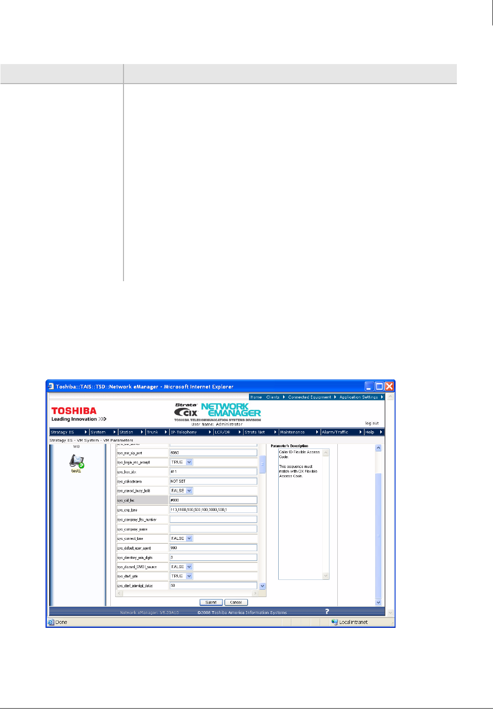
Field Definitions
4. For Caller ID feature, use Network eManager and go to Stratagy ES > VM System > VM
Parameters. As shown below, enter the Feature Access Code (sys_cid_fac) to enable caller ID
pass-through. The default feature access code is #888, which can be changed in the
Numbering Plan configuration in Network eManager. When the caller ID is not required or
cannot be used, remove the Feature Access Code and leave the field blank. The change is in
effect after Stratagy ES is restarted.
Field Description
Feature Enabled Enables Personal Call Handler for this extension.
Enhanced Mode
Enabled Enables the enhanced mode operation so that the user can transfer the call
from the cell phone or other phone.
Allow Call through
AutoAttendant Apply Personal Call Handler to calls transferred from the AutoAttendant
application.
NoteUncheck this only if you assign a Token Programming to the mailbox.
Enable Feature Key Enables handoff to desktop telephone capability. Requires Enhanced Mode
Enabled (default is unchecked).
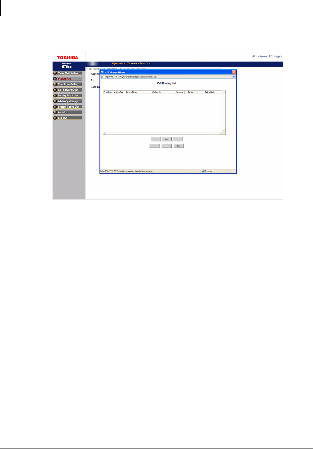
Add/Edit Routing Data Clicking this button causes the Call Routing List screen to display as shown
in the following figure.
Handoff to Desktop
Phone Assigns a Feature Button to invoke the handoff operation. Requires Enable
Feature Key to be checked.
FeatureFlex™
Editing FeatureFlex Applications
2-22 Strata CIX Application Implementation Vol 3 09/09
5. For Add/Edit Routing Data, select Add.
FeatureFlex™
Editing FeatureFlex Applications
Strata CIX Application Implementation Vol 3 09/09 2-23
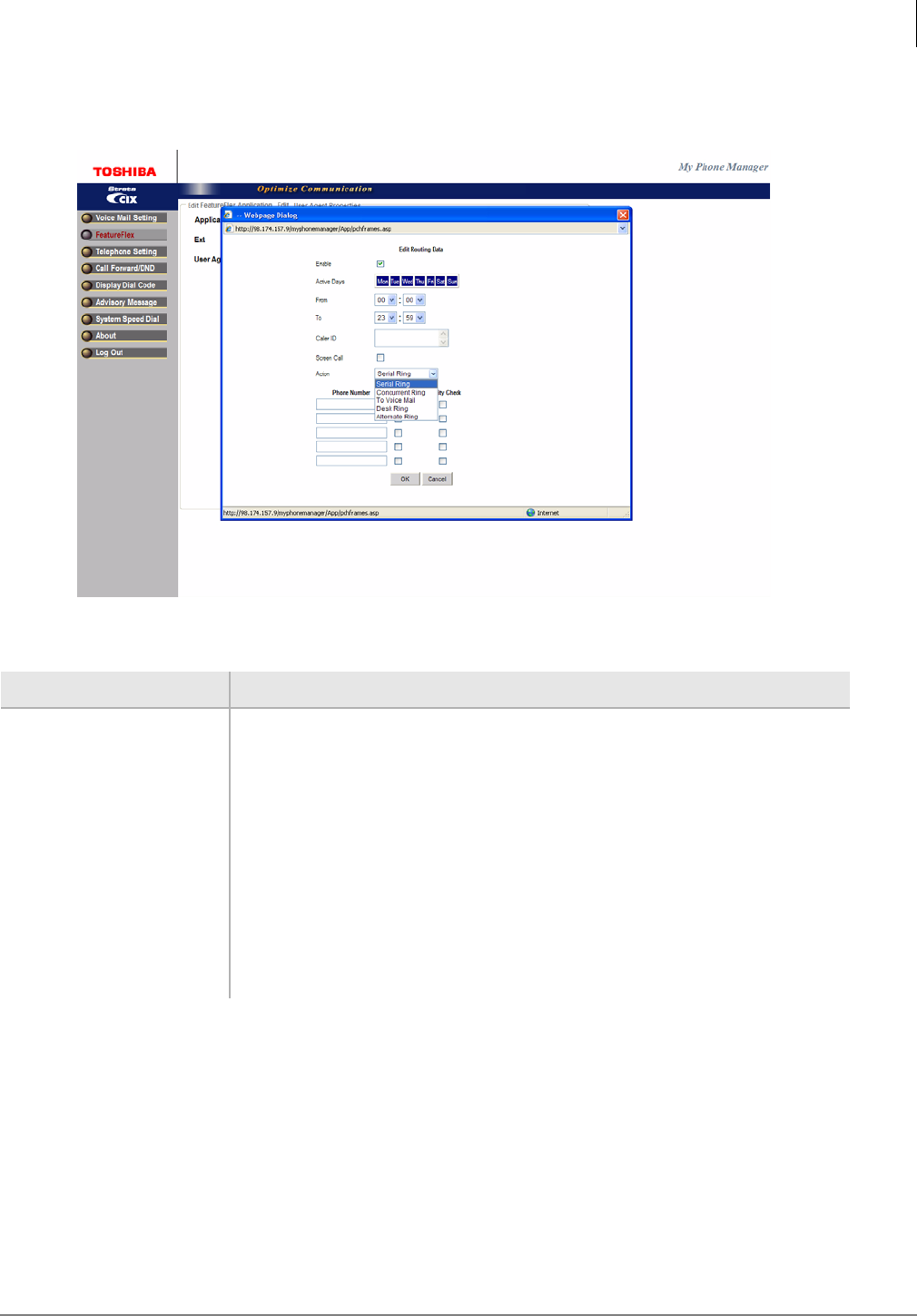
6. Configure the Routing Data, then Click OK and Save.
Field Definitions
Field Description
Enable Must be checked to activate Routing Data entries
Active Days Days for scheduling
From/To From what time, to what time, the schedule will take effect.
Caller ID Caller ID or station number that PCH monitors. For all calls, use (*)
Action Serial Ring – Ring a serial hunt for four destinations.
Concurrent Ring – Calls simultaneously ring the desk phone and a second
destination.
To Voice Mail – Direct to VM mailbox.
Desk Ring – Calls ring direct to deskphone.
Alternate Ring – Calls directly transferred to the destination
FeatureFlex™
Editing FeatureFlex Applications
2-24 Strata CIX Application Implementation Vol 3 09/09
7. To enable sending the caller ID of the original caller to the cell phone or desktop telephone, all
voice mail ports need to be configured to enable the Specified Caller ID feature in the IP
Station Assignment.
Select Enable from the dropdown menu for FK53, Specified Caller ID.
FeatureFlex™
Editing FeatureFlex Applications
Strata CIX Application Implementation Vol 3 09/09 2-25
Operation
1. When you answer the phone from your desktop extension, the call will be connected
immediately if you do not enable the call screen. If you enable the call screen, you will need to
accept or reject the call.
2. When you answer the call from your cell phone (or home phone), you will need to accept or
reject the call. The prompt will start when you speak (e.g., “Hello”). Press 1 to accept the call or
press 2 to reject the call.
3. After you answer the call from the cell phone (or home phone), you may press “**” (star star) to
access the menu.
You can then press 1 to check your voice mail, 2 to make a consultation call, or 9 to go back to the
caller. If you select 2, you can hang up to complete the transfer. When the consultation party
answers the call, you can hang up to transfer the call or press “**” to access the menu so that you
can go back to the caller.
Note FeatureFlex application is not compatible with ACD or Net Phone. Do not use them at the
same time.
Ordering Information
The part number for the Personal Call Handler application license is LICMAS-FF-PCH (one per
system). LIC-CIX-FF (Strata CIX license for FeatureFlex) is required to run Personal Call Handler.
[or mailbox]
[VM Security Code]
FeatureFlex™
Editing FeatureFlex Applications
2-26 Strata CIX Application Implementation Vol 3 09/09
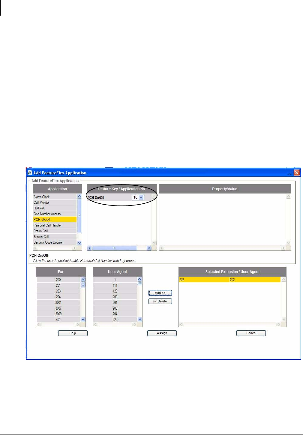
PCH On/Off
The PCH On/Off is automatically installed when Personal Call Handler (PCH) is installed. Add the
PCH On/Off button when you want to be able to use a button to enable or disable the Personal Call
Handler on that phone.This application displays when the Add button is pressed in the FeatureFlex
Configuration view as shown below.
The PCH ON/Off button is added to the mailbox/station pair just as any other FeatureFlex
application is added.
License
The PCH On/Off FeatureFlex application uses the Personal Call Handler license, therefore no new
license is required.
To add the PCH On/Off button to a station/mailbox
1. In the FeatureFlex configuration view, set the “Feature Key/Application No” to be the button on
the telephone that will be used to enable or disable the PCH. The number 10 is used in the
screen shown below.
FeatureFlex™
Editing FeatureFlex Applications
Strata CIX Application Implementation Vol 3 09/09 2-27
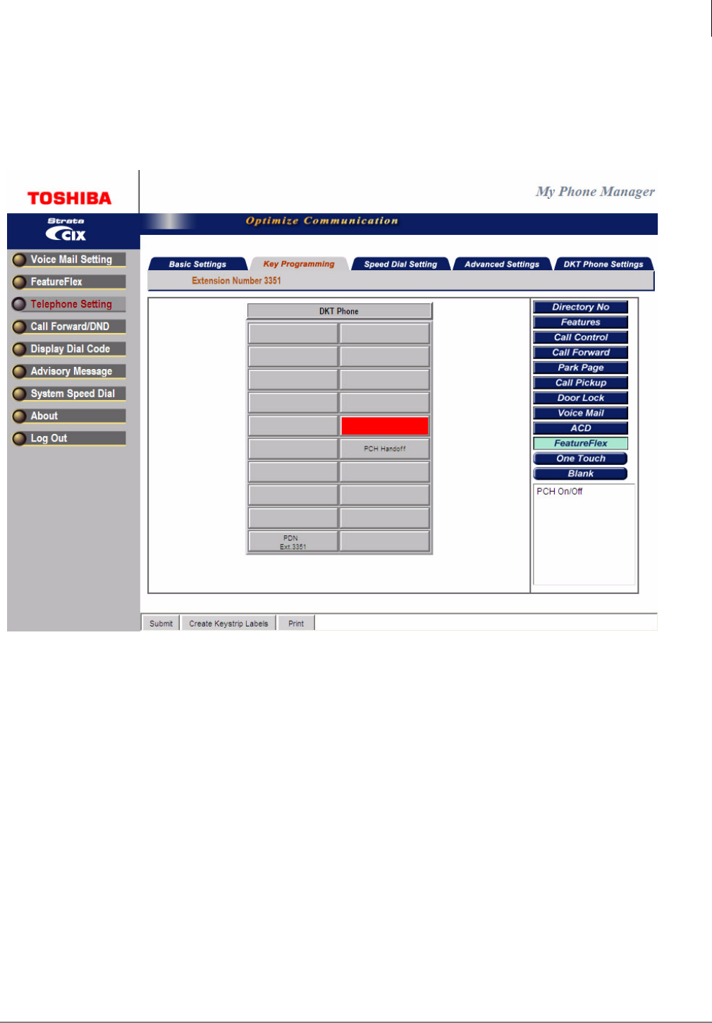
2. After PCH On/Off has been added, go to Station assignments (shown below) for the station
selected and set the PCH On/Off button to the assigned Application No.
Note This is done so that when the PCH enabled station is called for the first time the LED for
the control button will turn green indicating that is the button that can be used to Disable
and then Enable the PCH feature on that station.
Now that the On/Off button has been configured, the button can be used to disable Personal Call
Handler if it has been enabled and visa versa. When the button is first assigned, it does not synch
the status automatically. Press the button a few times to make sure that the enable/disable status
matches.
If eManager or MyPhoneManager is used to enable or disable PCH, then the On/Off button on the
telephone will change its state based on the action performed in the application. This means, if PCH
is enabled, the LED turns green and if it is disabled, the LED turns off.
FeatureFlex™
Editing FeatureFlex Applications
2-28 Strata CIX Application Implementation Vol 3 09/09
Installing PCH On/Off
Both PCH and PCH On/Off FeatureFlex application is installed together. Do not configure the PCH
On/Off button if it is not needed.
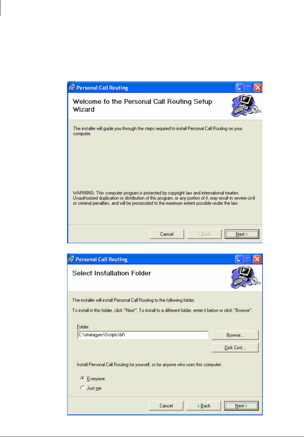
1. Double click on the self extracting installer PersonalCallHandler1.0.11.exe and the following
screens display.
2. Click Next
3. Click the Browse button to choose a different folder or click Next to accept the default.
FeatureFlex™
Editing FeatureFlex Applications
Strata CIX Application Implementation Vol 3 09/09 2-29
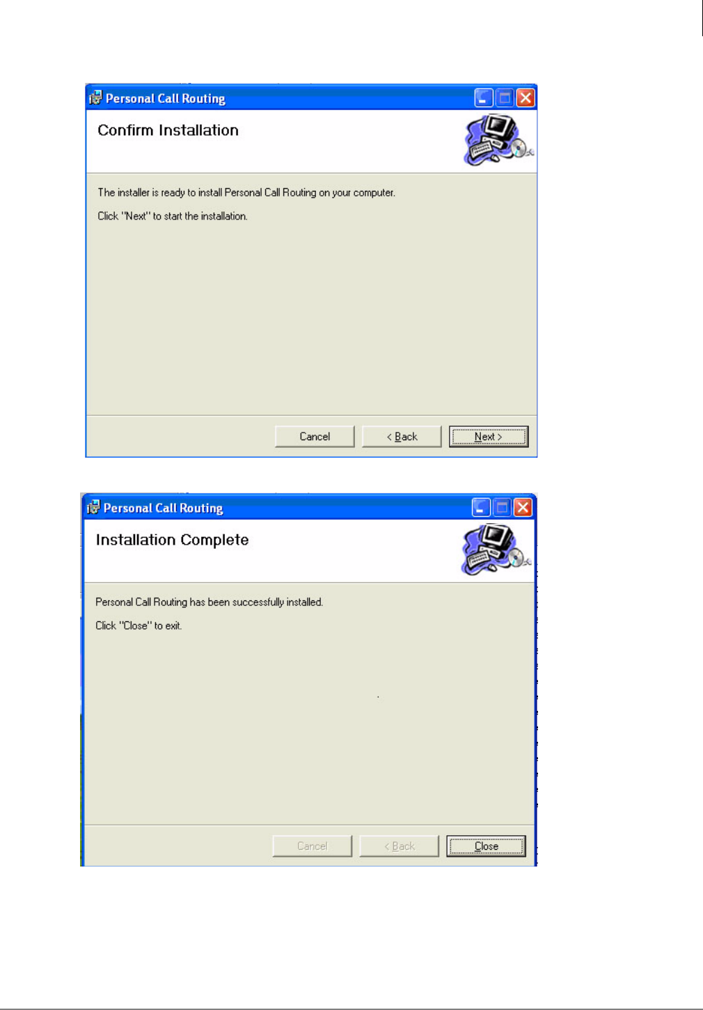
4. The Confirmation screen displays, click Next.
5. Click Close when the Installation Complete screen displays.

FeatureFlex™
FeatureFlex Application Interactions
2-30 Strata CIX Application Implementation Vol 3 09/09
FeatureFlex Application Interactions
The following table shows how the FeatureFlex Applications interact with other FeatureFlex
Applications and some CIX features. FeatureFlex applications that use the button on the digital or
IP telephones are not compatible with the Shift button on 5000-series phones. Do not use the Shift
button if any of these FeatureFlex applications are assigned to the phone.
Notes:
1. Screen Call, One Number Access (ONA is a Strata CIX feature), Simultaneous Ring, and
Personal Call Handler should not be assigned to the same telephone. If a telephone has ONA
registered, and one of its destinations has Screen Call registered, when a call is routed by ONA
to that destination the call simply rings the telephone instead of screening it.
2. If the caller has another call on hold, Screen Call and ONA will not operate. The caller is sent to
voice mail. Simultaneous Ring and PCH can work when the call is a consultation call as long as
enough voice mail ports are available.
3. The monitoring call can be transferred by putting it on hold at one telephone and then retrieving
it from a secondary appearance at another phone. When this happens, the monitoring function
cannot be controlled by the telephone that retrieved the call. The only action available is to
hang up.
4. If a call is forwarded to a telephone that has Screen Call, ONA, Simultaneous Ring, or PCH
turned on, and that telephone is itself forwarded to another phone, the FeatureFlex feature will
not turn on.
5. If a Hot Desk (Strata CIX feature) user does not login to a telephone, all calls will be routed to
the user’s voice mailbox regardless of Call Forwarding setting.
Alarm
Clock
Screen
Call
Call
Return
Call
Monitor
(Note 7)
One
Number
Access
Hot
Desk
Simultaneous
Ring
(Note 7)
Personal Call
Handler
(Note 7)
Security
Code
Update
Alarm Clock OK OK OK OK OK OK OK OK
Screen Call OK OK OK Note 1 OK Note 1 Note 1 OK
Call Return OK OK OK OK OK OK OK OK
Call Monitor
(Note 7)
OK OK OK OK OK OK OK OK
One Number
Access
OK Note 1 OK OK OK Note 1 Note 1 OK
Hot Desk OK OK OK OK OK OK OK OK
Simultaneous
Ring
OK Note 1 OK OK Note 1 OK Note 1 OK
Personal Call
Handler (Note 7)
OK Note 1 OK OK Note 1 OK Note 1 OK
Security Code
Update
OK OK OK OK OK OK OK OK
Phantom DN No FeatureFlex feature can be assigned to a Phantom DN. OK
Conference/
Transfer
OK Note 2 OK Note 2 OK OK OK OK
Multiple
Appearances
OK OK OK Note 3 OK OK OK OK OK
All Call
Forwarding
OK Note 4 OK OK Note 4 Note 5 Note 4 Note 4 OK
Busy Forwarding OK Note 4 OK OK Note 4 OK Note 4 Note 4 OK
Auto Attendant OK Note 6 Note 6 Note 6 Note 6 OK Note 6 OK OK
ACD/NetPhone/
RCC
OK Note 8 OK OK Note 8 OK Note 8 Note 8 OK

FeatureFlex™
FeatureFlex Application Interactions
Strata CIX Application Implementation Vol 3 09/09 2-31
6. If a call is transferred from Auto Attendant, Screen Call, ONA, or Simultaneous Ring is not
executed. However, Personal Call Handler does work for a call transferred from Auto
Attendant.
7. MAS or MicroMAS-H is required. MicroMAS-D is not supported.
8. When Screen Call, ONA, Simultaneous Ring or Personal Call Handler is activated, NetPhone
or Office Communicator with Remote Call Control (RCC) will not operate correctly. Those
applications should not be turned on to phones used by ACD agents.
This page is intentionally left blank

Strata CIX Application Implementation Vol 3 09/09 3-1
InfoManager™ 3
These applications can be used with IP5000- and IPT2000-Series display telephones or a PC with
a web browser. Call control can be with any phone connected to the CIX. You can both configure
and view them using the telephone’s LCD or a network PC. See the Strata CIX Telephone User
Guides for instructions on using this program with the phone.
PC Software Requirements
The following software must be resident on the Server PC:
•Windows® 2000 or Windows XP Pro (capable of networking)
The following browsers on the client PC are supported:
•Windows Internet Explorer 6.0 or higher, Firefox 1.0 or higher, Netscape 7.2 or higher,
Opera 7.54 or higher.
Note Windows NT is not supported.
Step 1: Install Software
This installation procedure describes how to install application and supporting software via the
installation CD-ROM.
Important! It is important that you install the software in the order presented on the menu. Click
only once on each selection. If you double-click, you will run two parallel installations
of the same component with unpredictable results.
Prior to starting this procedure, close and stop all applications (e.g., SES, ACD, MSDE) running
on the server/Media Application Server (MAS).
Step 1A: Install Third Party Software
1. Insert the Installation CD-ROM. An installation menu displays.
2. Under Third Party Software, select the first option—Install .NET Framework 1.1. Follow the
installation instructions using the default values.
3. Select the second option—Install Java 2 SDK 1.4.2 option. Follow the installation instructions
using the default values.
4. Select the third option—Install MSDE 2000 Desktop Engine. Follow the installation instructions
using all the default values. When installation is complete the install shield closes automatically.
You can now continue.
Note When installing the MSDE 2000 Desktop Engine, MSDE is creating a specific instance of
the program for the InfoManager application. This installation is required even if you have
previous versions of MSDE on the server (e.g., if MSDE is installed for eManager).
5. Select the fourth option—Install SQL Server 2000 JDBC Driver. Follow the installation
instructions using all the default values.
6. Select the fifth option—Tomcat5.027. Follow the installation instructions using all the default
values.
InfoManager™
PC Software Requirements
3-2 Strata CIX Application Implementation Vol 3 09/09
Step 1B: Install InfoManager Software
1. From the Installation Menu, select Install InfoManager Application option.
2. Follow the instructions on the install screens. When the installation reaches 100%, the installer
runs an InfoManager setup application. Do not close or exit the installation wizard at this time. It
will close automatically upon completion of the InfoManager setup.
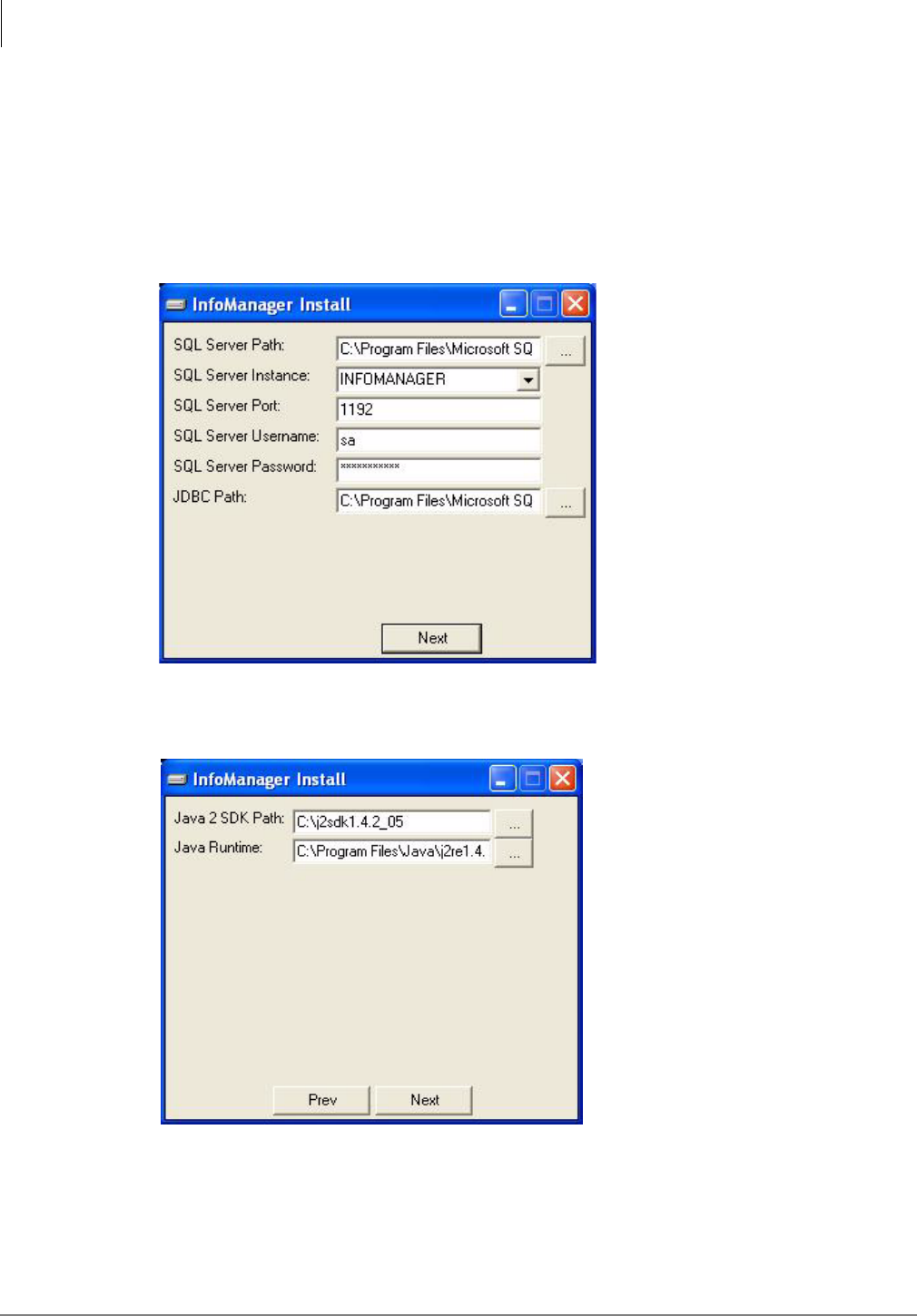
3. The first screen displays the path/username/password for the MSDE software and is a
verification of the MSDE default settings (shown at right). Click Next.
4. The next screen displays (shown at right) the Java 2 SDK default settings.Click Next.
InfoManager™
PC Software Requirements
Strata CIX Application Implementation Vol 3 09/09 3-3
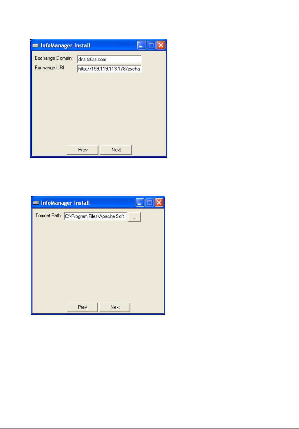
5. Enter the Microsoft Exchange Domain and URI (shown right) and click Next.
Note If you do not know these parameters, you may leave them blank and enter them later. See
“Configure Calendar Properties” on page 7 for instructions.
6. The screen displays the Tomcat installation directory (shown right). Click next.
7. When the installation is complete, the install program runs the InfoManager application and
displays the database screen (see Figure 3-2). You can choose to program the settings and
parameters at this time (follow Step 2) or select Exit to complete the Installation Wizard.
InfoManager™
PC Software Requirements
3-4 Strata CIX Application Implementation Vol 3 09/09
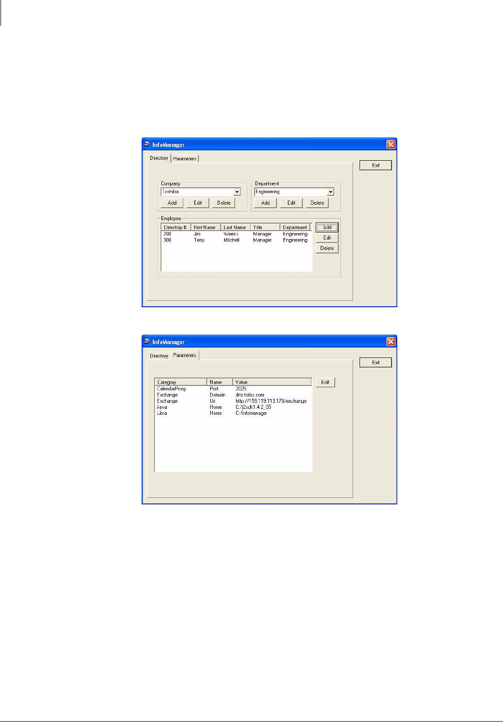
Step 2: Create/Edit Databases
These screens display automatically at the completion of the install program .or you can access
these screens locally from the server by clicking Start > Programs > Terminal_App > Terminal
Configuration.
The InfoManager screens display (shown below) the Company, Department and Employee
information.
Figure 3-1 Directory Tab Screen (with sample data)
Figure 3-2 Parameters Tab Screen (with sample data)
InfoManager™
PC Software Requirements
Strata CIX Application Implementation Vol 3 09/09 3-5
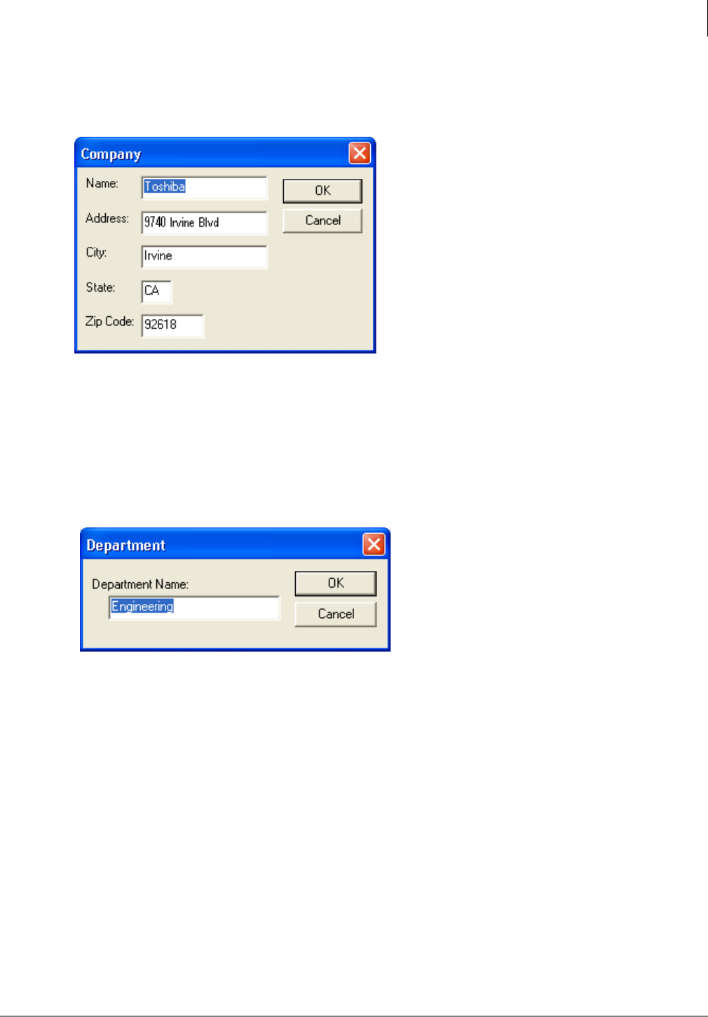
Add/Edit Company
1. From the Directory Tab Screen (see Figure 3-1 on page 4), click Add in the Company section of
the screen. The Company screen displays (shown right).
2. Type the company information into the fields and click OK to save the information and exit the
screen.
Add/Edit Department
1. From the Directory Tab screen, click Add in the Department section of the screen. The
Department screen displays (shown right).
2. Type in a department name and click OK. To add more departments, continue to click Add. This
information will be important when you add the employees’ information in the next step.
InfoManager™
PC Software Requirements
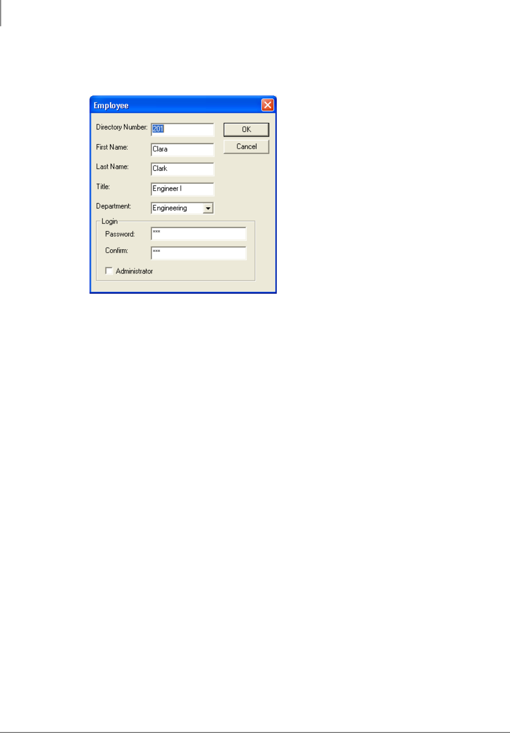
3-6 Strata CIX Application Implementation Vol 3 09/09
Add/Edit Employee
1. From the Directory Tab screen, click Add in the Employee section of the screen. The Employee
screen displays (shown right).
2. Type in the Password and confirm it and if the employee is to be an Administrator you need to
check the box.
Note The Administrator is the only person who can add, change or delete the Company News
and Weather Stations portion of the program.
3. Click OK.
4. When you have finished adding information to the InfoManager screen, click Exit.
Change Parameters
1. From the InfoManager screen (see Figure 3-2 on page 4), select the Parameters tab.
2. Highlight the parameter you wish to edit and click Edit.
3. Edit the Name and/or Value fields. Click Save.
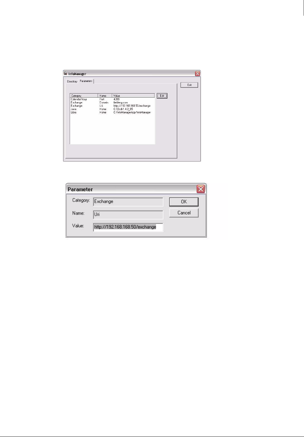
InfoManager™
PC Software Requirements
Strata CIX Application Implementation Vol 3 09/09 3-7
Configure Calendar Properties
To configure the Calendar Properties if you chose to skip the configuration during the installation:
1. Run the InfoManagerApp_Config utility from the Start >All Program menu.
2. Click on the Parameters tab and you should see the following.
3. Click on the Exchange URI category and click Edit as shown on the picture below.
4. Edit and input the information on the Value field that corresponds with your Exchange server in
the following format: http://<ip address of Exchange Server>/exchange
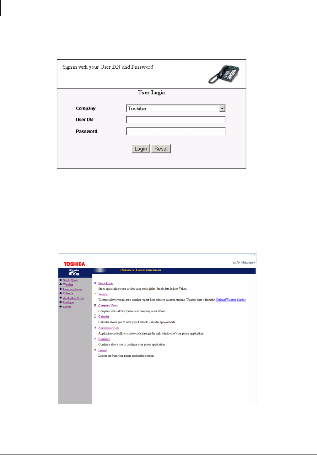
InfoManager™
PC Software Requirements
3-8 Strata CIX Application Implementation Vol 3 09/09
Step 3: Log on to InfoManager Program
1. Start the Internet Explorer.
2. Type http://<Server name>:8080/infomanager and press Enter. The Login screen displays
(shown right).
3. Select the company name from the drop-down list.
4. Type the User Name in the User Name field. Press Tab.
5. Type the password in the Password field.
6. Click Login. The Main menu displays. The following options are available—Directory, Call
Status, Find Me Follow Me, Stock Quote, Weather, Company News, Calendar, Application
Cycle, Configure and Logout.
7. Select one of the options by clicking on it.
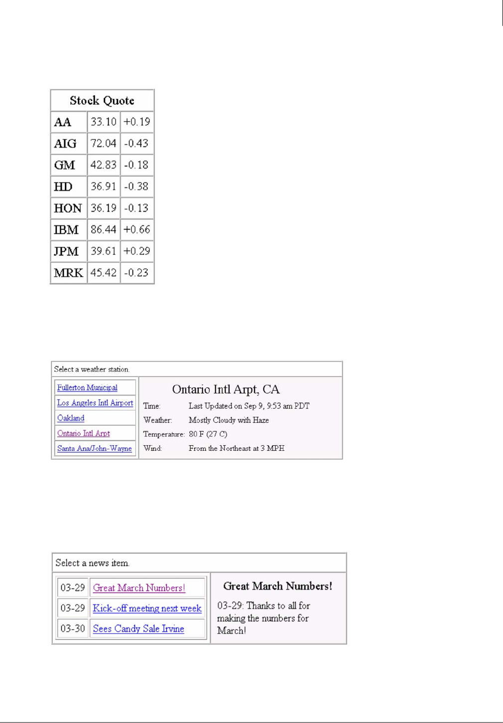
InfoManager™
Stock Quote
Strata CIX Application Implementation Vol 3 09/09 3-9
Stock Quote
The Stock Quote application allows you to view selected stock prices.
You can add as many stocks as you want.
Weather
The Weather application allows you to get a weather report from selected weather stations.
The weather stations are added or removed by the administrator.
To display the weather at a specific location, click the weather station on the left of the screen.
Company News
The Company News application allows your company to display company news items that would
be of interest to you.
By clicking on the headline on the left, additional information is displayed about the story.
You can add as many news stories as you want.
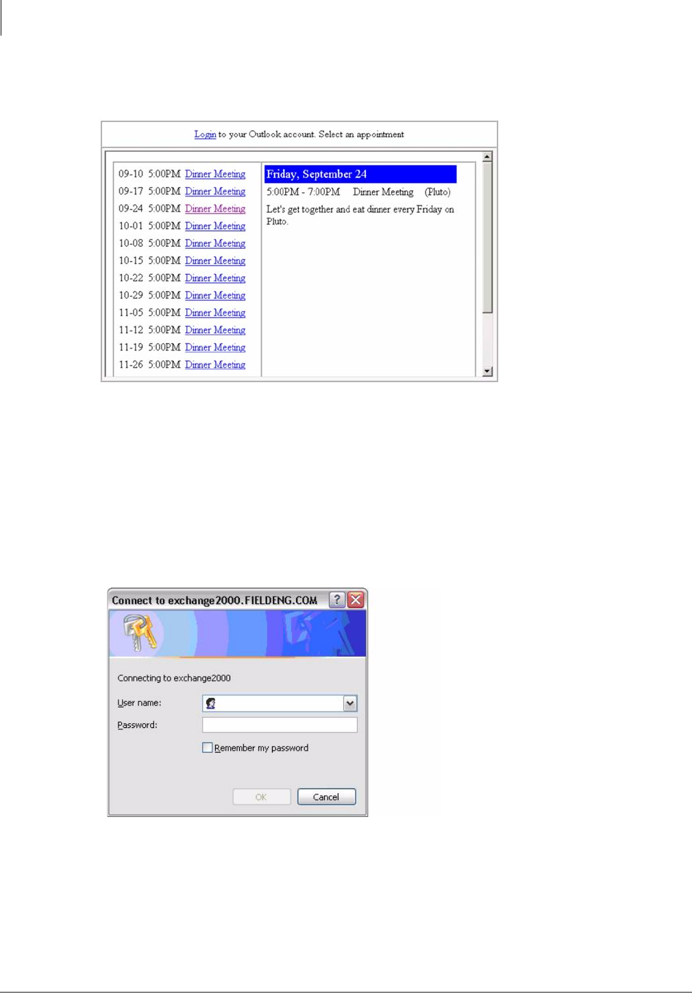
InfoManager™
Calendar
3-10 Strata CIX Application Implementation Vol 3 09/09
Calendar
The Calendar application allows you to view your Outlook Calendar appointments.
Note Changes to the entries on the calendar must be made in Microsoft® Outlook.
The Calendar function on the InfoManager works using Outlook Web Access. The login assumes
that there is no firewall server between the InfoManager PC and the Exchange Server. Some
companies require a primary login authentication prior to the Outlook Web Access authentication.
Perform this simple test to make sure that the MAS can access the Exchange Server via Outlook
Web Access.
1. From Internet Explorer, type the following address on the address field:
http://<exchange ip_address>/exchange
2. If successful, you will get a screen similar to the one on the right.
3. If you receive an error, then the MAS or PC where the InfoManager is installed is being blocked
from accessing the Exchange Server.
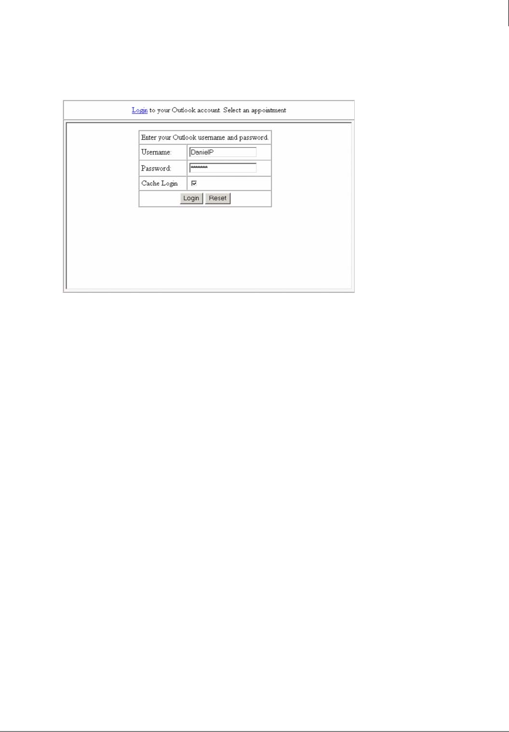
InfoManager™
Application Cycle
Strata CIX Application Implementation Vol 3 09/09 3-11
View Calendar
1. From the main menu on the left, click Calendar. The Login screen for Outlook displays (shown
at right).
2. Type in the information for the fields and click Login. The screen shown above displays.
Note If you check Cache Login, the Username and Password appear automatically at the next
login.
3. Click on a calendar entry and it displays in the right-hand pane.
Application Cycle
This feature allows you to automatically cycle through the displays.
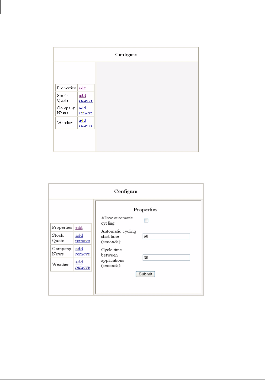
InfoManager™
Configure Settings
3-12 Strata CIX Application Implementation Vol 3 09/09
Configure Settings
From the main menu on the left, click configure. The Configure screen displays (shown right).
Properties
1. Click edit under Properties. The Properties screen displays (shown right).
2. Fill in the fields and click Submit.
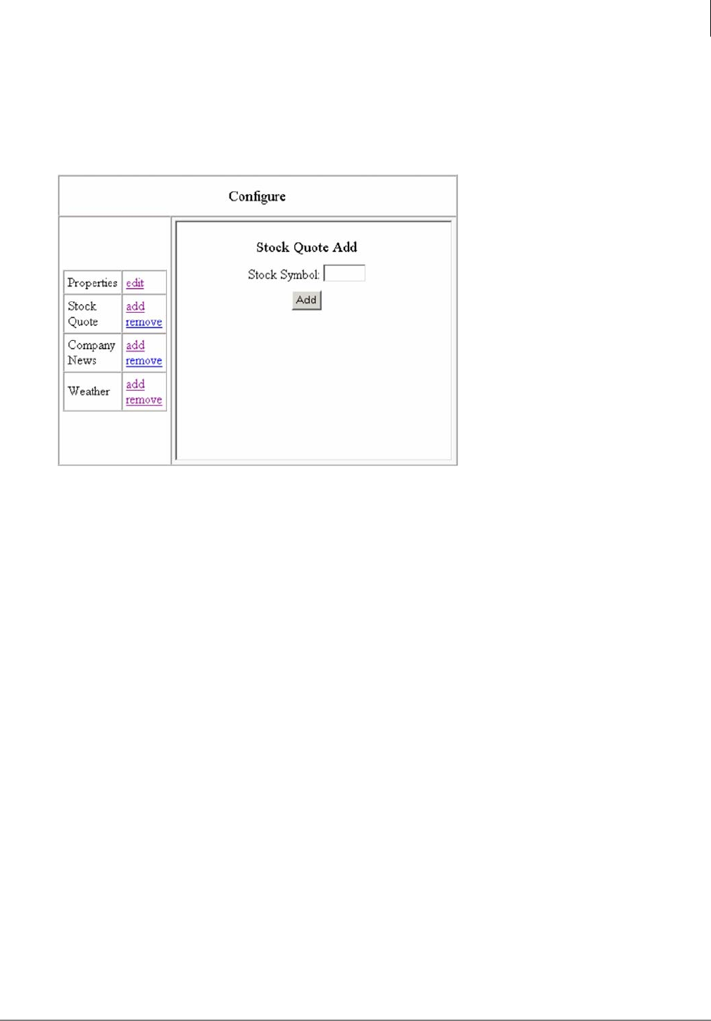
InfoManager™
Configure Settings
Strata CIX Application Implementation Vol 3 09/09 3-13
Stock Quote
Add Stock to Display
1. From the main menu on the left, click Configure. The Configure screen displays.
2. Click Add under Stock Quote. Type in the stock symbol (can be 2, 3, or 4 letters).
Note If the symbol you enter is not valid, the display will show it with 000 in the price column.
You need to remove the incorrect symbol and add in the correct one.
3. Click Add.
Remove Stock from Display
1. From the main menu on the left, click configure. The Configure screen displays.
2. Click Remove under Stock Quote. From the drop-down menu, select the stock symbol you
want to remove and click Remove. The stock is removed from your display.
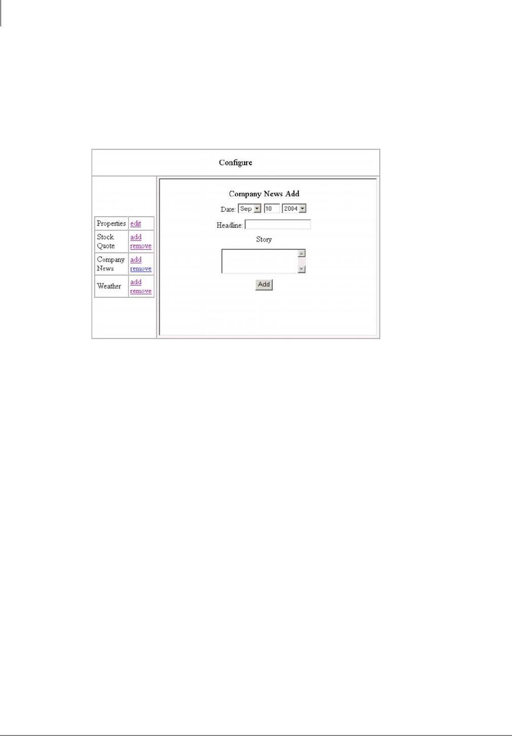
InfoManager™
Configure Settings
3-14 Strata CIX Application Implementation Vol 3 09/09
Configure Company News
Add Company News Story to Display
1. From the main menu on the left, click Configure. The Configure screen displays.
2. Click Add under Company News. Set the date (current date displays automatically) using the
drop-down menus. If you want to change the day of the month, place your cursor in the field
and type over the current date.
3. Type in a headline (can be up to 60 alphanumeric characters long).
4. Type in the story.
5. Click Add.
Remove Company News Story from Display
1. From the main menu on the left, click configure. The Configure screen displays.
2. Click Remove under Company News. From the drop-down menu, select the news headline/
story you want to remove and click Remove. The story is removed from your display.
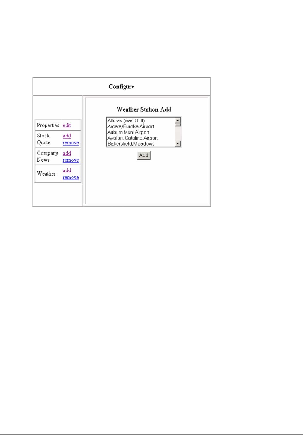
InfoManager™
Configure Settings
Strata CIX Application Implementation Vol 3 09/09 3-15
Weather
Add Weather Station to Display
1. From the main menu on the left, click Configure. The Configure screen displays.
2. Click Add under Weather. From the drop-down menu, select the state you want and click Find.
A list of weather stations in alphabetical order appear in a drop-down box.
3. Highlight the weather station you want and click Add. The weather station is added to your
display.
Remove Weather Station from Display
1. From the main menu on the left, click configure. The Configure screen displays.
2. Click Remove under Weather. From the drop-down menu, select the weather station you want
to remove and click Remove. The weather station is removed from your display.
This page is intentionally left blank
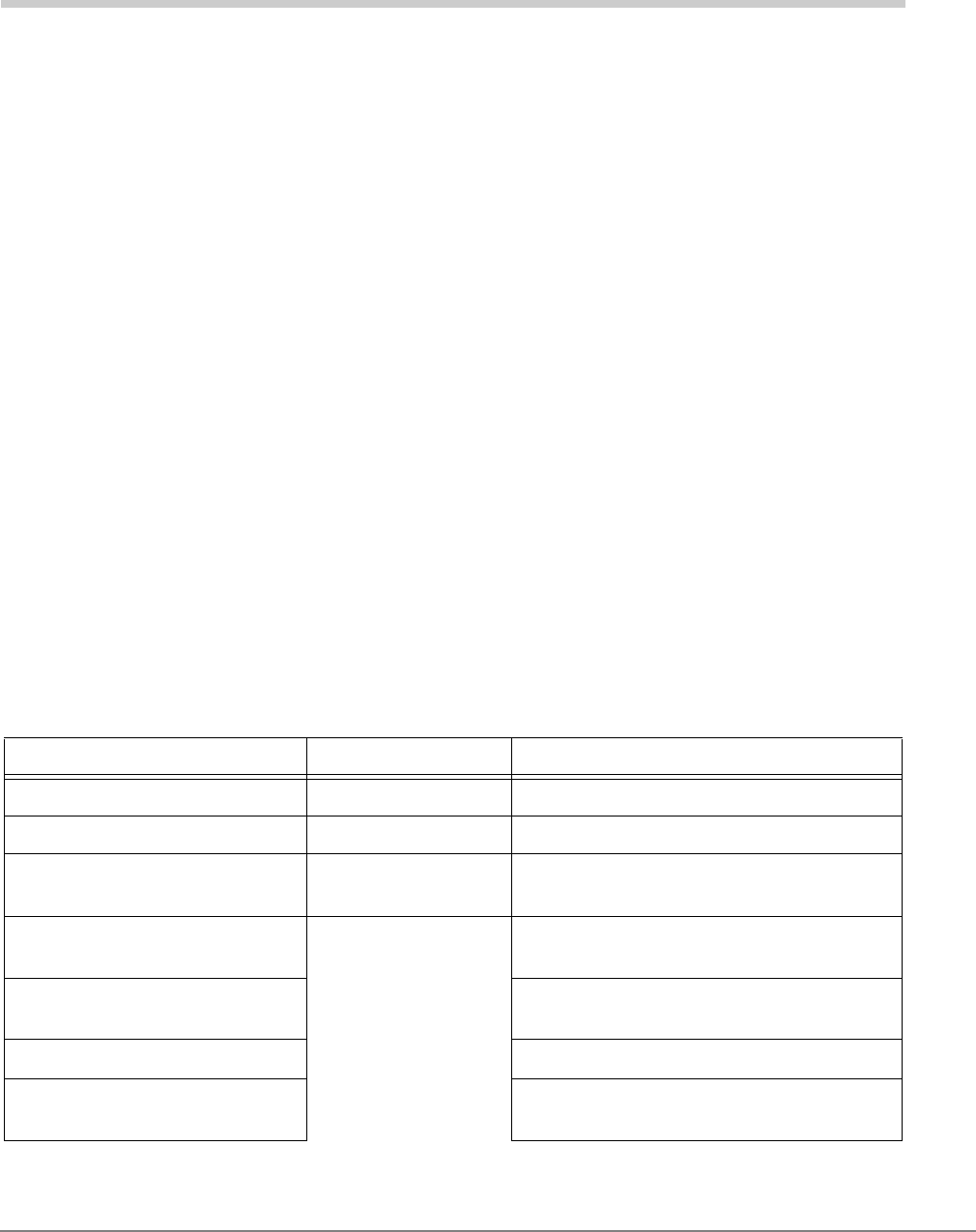
Strata CIX Application Implementation Vol 3 09/09 4-1
eMonitor/Alarm Notification 4
Alarm Notification (AN) sends a notification of a system alarm condition. The notification can be sent
over a network connection to an eMonitor system, other application and, optionally, to a feature
button on a telephone.
eMonitor configuration capacity:
•Each CIX system can send alarm trap messages to up to 11 eMonitor servers.
•Each eMonitor server can monitor an unlimited number of CIX systems.
•Each eMonitor server can send email alerts to an unlimited number of mail boxes.
•Each eMonitor can send emails to unique email addresses for each CIX system.
The alarm notification is SNMP Trap data that can be sent to as many as 11 different IP addresses.
Up to eight stations can have a button programmed as an Alarm Indicator. There are three
categories of alarms: ISDN, T1, and System Resources.
This section provides a description of Alarm types the Strata CIX system sends to eMonitor and
describes how Network eManager is used to set up the CIX system to send alarm notifications to
the eMonitor application.
There are two types of SNMP messages sent to the external, eMonitor, PC or Server.
•Alarm Notification when an error condition occurs.
•Alarm Summary Condition Summary, containing the alarm buffer status, is sent every 10
minutes whether an alarm has occurred or not. This summary includes the Alarm Buffer status.
The table below shows the alarms that can be monitored by the Alarm Notification feature. The list
is shown by alarm type.
ISDN T1 System Resources
ISDN Loss of signal (PRI) T1 Yellow Alarm Expansion Cabinet Power Failure
ISDN Frame Sync Failure (PRI) T1 Blue Alarm Cooling Fan Failure (CIX200 only)
ISDN AIS (PRI T1 Frame Sync
Failure IPU Card Data Set Problem
(LIPU or BIPU-M DSP)
ISDN-U Maintenance Mode
(BRI) SMDR Memory Buffer Full
ISDN-U EOC Maintenance
Mode (BRI) CTI Link Down (Attendant Console, ACD,
External Stratagy System)
ISDN-U ACT (BRI) SMDR Link Down (LAN / RS232c)
ISDN-U AIB (BRI) SMDI Link Down (LAN only -
The SMDI RS232c port is not monitored)
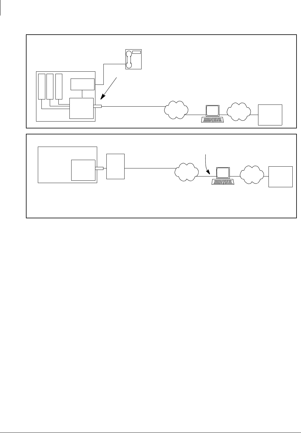
eMonitor/Alarm Notification
4-2 Strata CIX Application Implementation Vol 3 09/09
Alarm Notification is sent on a card slot basis, not per port. This helps reduce network loading. Use
the Port Make Busy program to determine individual port status (Utilities/Maintenance/Cabinet).
Expansion Cabinet power supply alarms are reported as System Resource (Slot 0x00, x = cabinet
number) alarms. SMDR Memory Buffer Full, CTI Link Down, SMDR Link Down and SMDI Link
Down are reported as System Resource (Slot 0100) in Cabinet 1.
When an alarm condition occurs the CIX processor records the error code in the alarm buffer. The
processor will send a command to light Alarm Indicators on stations and send the SNMP Trap data
to as many as 11 IP addresses. The trap data can be read by eMonitor or another alarm monitor
software application.
The Alarm Notification SNMP Trap Data messages are sent from the CIX processor to eMonitor
using UDP port 162. To allow eMonitor to send SNMP messages to the CIX processor, port 161 on
the NAT router must be port forwarded to the CIX IP address. Any firewall between the CIX and the
external console will need this port enabled.
When the CIX detects an alarm condition, the Alarm buffer sends the notification. When the alarm
condition has been cleared for several seconds the CIX will send an alarm clear message to
eMonitor, and turn off the alarm notification LED on stations.
Note On T1 and PRI alarms only, if the Clear Alarm Buffer Command is invoked (Utilities/
Operations/System Alarm), the system will not issue another alarm notification even if the
T1 or PRI alarm condition persists. Only a new T1 or PRI alarm condition will cause
another alarm notification.
Strata CIX
T1
Fan
ISDN
Alarm
Buffer
Alarm Notification
Indicator (Button)
LAN
SNMP Trap Data
CIX Processor Network Jack
BDKU
eMonitor
LAN
WAN
Recommended Configuration
SMTP
Server
Install eMonitor and the Strata CIX
system on the same LAN.
* If the CIX is behind a NAT router eMonitor will be able to monitor (receive) CIX alarms but,
will not be able to send alarm programming to the CIX unless the NAT router performs Port
forwarding to the CIX IP address.
Strata CIX
Alarm
Buffer
NAT*
WAN
SNMP Trap Data eMonitor
SMTP
Server
LAN
WAN
Public IP Address
Configuration with NAT

eMonitor/Alarm Notification
Alarm Notification Setup and Programming
Strata CIX Application Implementation Vol 3 09/09 4-3
Alarm Notification Setup and Programming
Alarm Notification
1. In Network eManager go to Alarm/Traffic > Alarm Setup > Alarm Slot.
Across the top of the screen is a Tab for each CIX cabinet in the system.
2. Enable or Disable the cards and system resources to be monitored by the Alarm Manager
feature. If a card or resource is not enabled, the Alarm Notification feature will not report errors
concerning that card or resource.
Note Currently only T1, PRI, and IP Telephone interface cards send alarms. System resources
alarms include SMDI (LAN), SMDR, Expansion cabinet power supplies, CIX200 fan, and
the CTI link (Attendant and Console ACD, External VM). CTI Link Alarms occur when a
CTI device loses communication with the CIX. CTI alarms clear when communications are
restored between the CIX and CTI device.
System Alarm Control
1. In Network eManager go to Alarm/Traffic > Alarm Setup > System Alarm.
2. The Clear Alarm Buffer (Prog. 919, FB01) is default Idle. To manually clear the buffer set to
Invoke and Submit. If you invoke the clear buffer command, the system will not re-send a
persisting T1 or PRI alarm condition. When an alarm condition is clear for several seconds, the
system will clear the buffer.
3. Set the Alarm Buffer Status (Prog. 919, FB02) to Enable for Alarm Notifications to be sent to
eMonitor. Set to Disable to shut off alarm notification output. When this feature is enabled the
Strata CIX system will send the contents of the alarm buffer to the eMonitor servers as an
Alarm Summary every 10 minutes. The Alarm Summary is a list of alarms stored in the Strata
CIX alarm buffer.
4. Enter the System ID (Prog. 919). This is the ‘name’ of this CIX system or Group of Strata Net
systems. The System ID can be up to eight alpha/numeric characters. This is the name sent
from the CIX to eMonitor with the Alarm Trap message.
Trap IP Setup
1. In Network eManager go to Alarm/Traffic > Alarm Setup > IP Trap Destination .
2. Enter the IP Address of the external console (eMonitor or other application)
3. Enter the Community Name. This is the Community Name for the external console (eMonitor,
other applications).The name must be alphanumeric string and must not contain any spaces.
Note The Community Name for eMonitor is not a password. Any name can be used. It is
recommended that the Community Name identifies the location of the eMonitor, or where
the alarms will be sent.

eMonitor/Alarm Notification
Strata CIX Network eMonitor
4-4 Strata CIX Application Implementation Vol 3 09/09
Strata CIX Network eMonitor
CAUTION! Remove eMonitor from your system using the Windows Add/Remove Software
function before installing a new version eMonitor.
It is recommended you go through the Toshiba eMonitor training module prior to installing and using
eMonitor V1.08. To access the training module, perform the following steps:
1. Log into Toshiba University, Technical College.
2. Select the Course Catalog
3. Select A3: CIX-Elective Courses
4. Select 1012 - (a1) CIX 4.0, Begin the course.
5. eMonitor training is found in the Strata CIX R4.0 (Online) module,
Chapter 3 (Alarm Notification) and Chapter 4 (eMonitor Operation).
eMonitor PC/Server Requirements
Hardware Requirements
•Intel Pentium 1Ghz or faster
•512 MB of main memory
•200 MB available disk space in the hard disk
•SVGA card and monitor
•CDROM drive
•Network Interface card
System Software Requirements
More detailed information about loading these components can found in the Network eManager
installation procedures.
•Windows Vista Business Edition or WindowsXP Professional (SP 1 or higher)
•Although not required for proper functioning of the CIX Network eMonitor application, it is
highly recommended that the system be updated with the latest security patches and
updates before using CIX Network eMonitor. This will maintain up-to-date protection level of
the operating system, which is specifically recommended for systems hosting Web
applications such as CIX Network eMonitor.
To get the latest updates you can go to: http://www.microsoft.com/security/
select “Windows Update” from the index.
•IIS and SNMP Service must be installed:
•These features are part of Windows but may not have been installed when the Windows
Operating System (OS) was installed. To insure correct OS configuration go to the Add
Remove Program control. Click on Add/Remove Components. Makes sure that the Internet
Information Services (IIS) and Management and Monitoring Tools are checked. Click OK
and follow the instruction. You may need the Windows Vista or Win XP installation CD.
•Microsoft .NET Framework V1.1 / V2.0
•The CIX Network eMonitor installer will check to see if these two components are missing. If
they are, the installer will install them onto the target computer.
Important! Microsoft .NET Service Pack 1 (SP1) must be installed before running eMonitor.
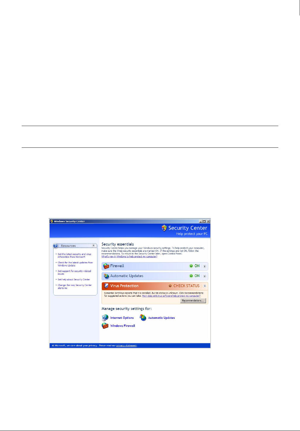
eMonitor/Alarm Notification
Strata CIX Network eMonitor
Strata CIX Application Implementation Vol 3 09/09 4-5
•IE Browser V6.0 -This component version is a required by CIX Network eMonitor.
•If this version is not loaded the CIX Network eMonitor installer detects this missing
component version and prompts for installation.
•CIX Network eMonitor Profile Database:
•The CIX Network eMonitor User’s Profile database creation & initialization is only required
for the CIX Network eMonitor first installation. When this program runs, the existing
database (if there is an existing database) is reset to default.
•This CIX Network eMonitor Profile database installation is automatically called by the
installer and is available from the release CD under Database Installation folder.
Prior to Installation
CAUTION! Remove any eMonitor applications from your system using the Windows Add/
Remove Software function before installing a new version eMonitor.
1. To insure correct OS configuration, go to the Add/ Remove Program control. Click Add/Remove
Windows Components. Make sure that the Internet Information Services (IIS) is listed. Go to
Management and Monitoring Tools and click Details. The Simple Network Management
Protocol and WMI SNMP Provider should be listed.
2. (Optional) If you are using Windows SP2, you need to perform the following steps:
•From the desktop, click the Firewall icon at the bottom of your screen: The following screen
displays.
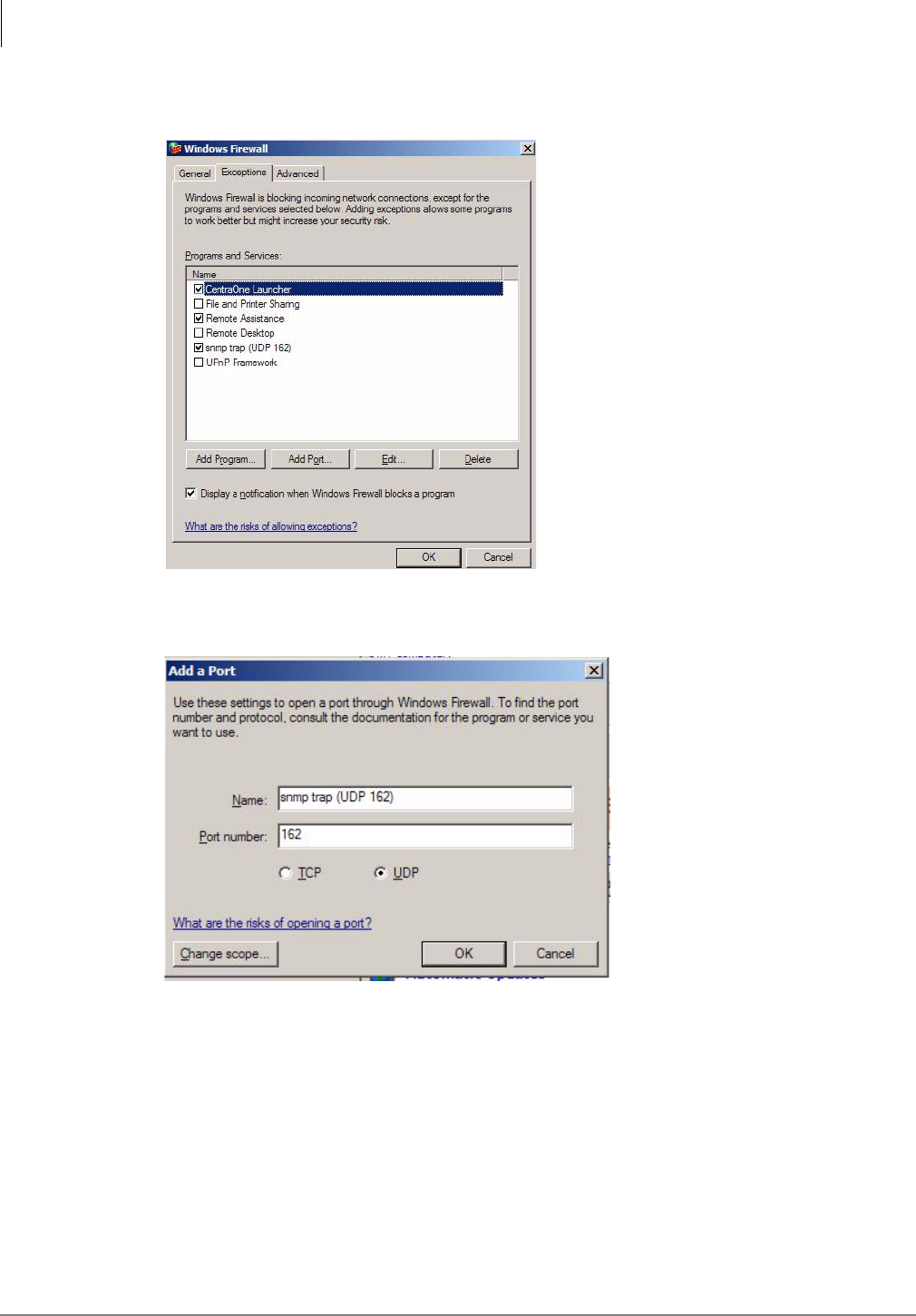
eMonitor/Alarm Notification
Strata CIX Network eMonitor
4-6 Strata CIX Application Implementation Vol 3 09/09
• Click Windows Firewall. The Windows Firewall screen displays. Click the Exceptions tab.
The following screen displays:
•Click Add Port. The following screen displays (shown below).
•In the Name field, type in “snmp trap (UDP 162)”. In the Port Number field, type in 162.
Select UDP and click OK.
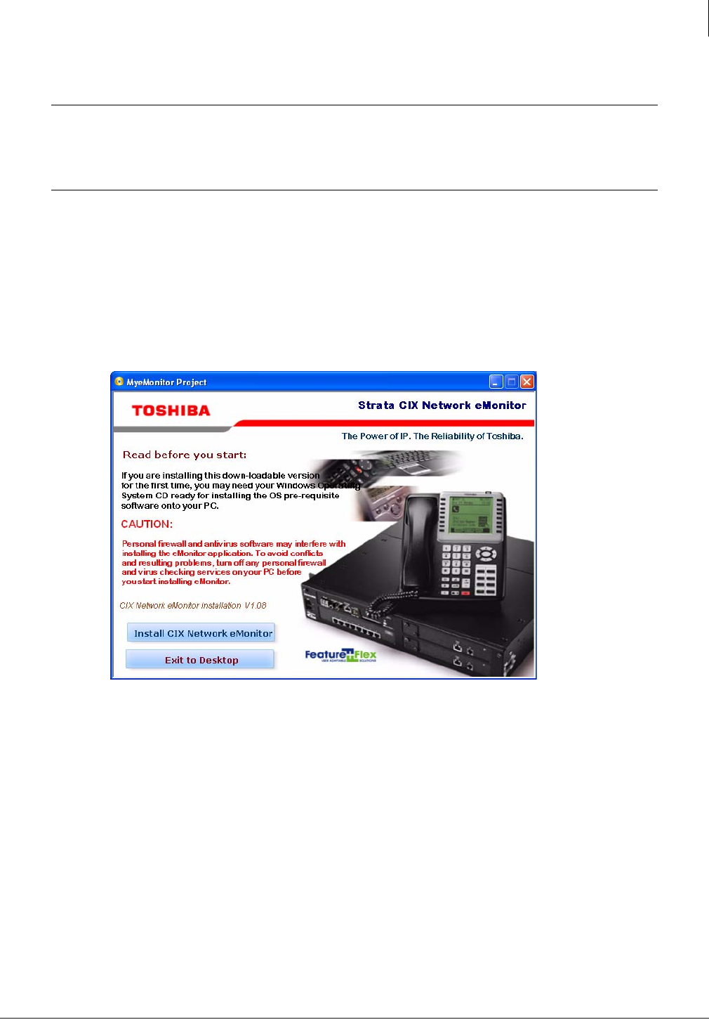
eMonitor/Alarm Notification
Strata CIX Network eMonitor
Strata CIX Application Implementation Vol 3 09/09 4-7
Step 4: Install CIX Network eMonitor on PC
CAUTION! Remove any eMonitor software from your system using the Windows Add/
Remove Software function before installing eMonitor.
All firewalls and anti-virus programs must be stopped.
eMonitor can be installed from a CD-ROM or as a download from the Toshiba FYI web site.
Download eMonitor Software
The basic steps for downloading then, installing eMonitor are listed below:
1. Login to Toshiba’s FYI web site.
2. Navigate to the Software (Strata Sys) > CIX Applications & Utilities section. Select SAVE
(not run) and download the eMonitor application software.
3. Open the folder the files were uncompressed into. Double click the Autorun file.
4. The installation program checks the supporting OS:
•The installer terminates the installation process if the target machine OS is not supported.
•Installer checks for Internet Explorer Browser V6.0 and prompts for installation if not found.
•Installer checks for missing components such as Internet Information Services (IIS) and
Maintenance and Monitoring Tools (MMT) and prompts for installation if not found.
•Installer checks for missing components such as .NET Framework V1.1 and V2.0. If a
component is missing the installer will exit to a screen indicating what is missing. A link to
the source of the missing component will be provided. Note: the program can not check for
SP1.
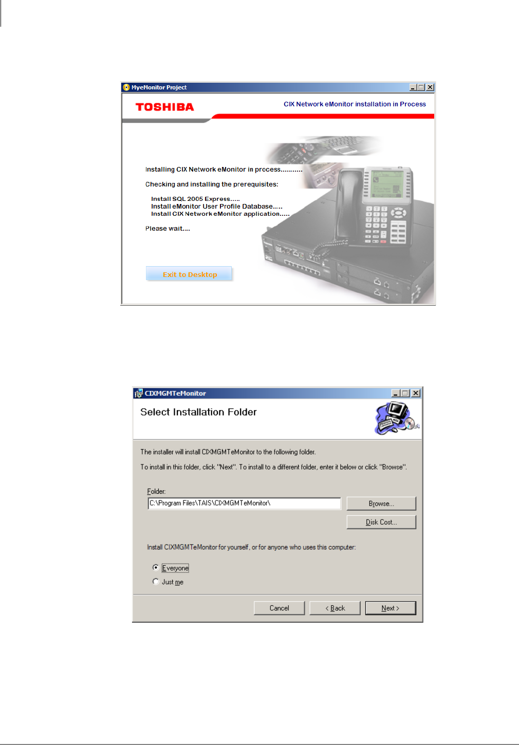
eMonitor/Alarm Notification
Strata CIX Network eMonitor
4-8 Strata CIX Application Implementation Vol 3 09/09
If any of the require software is not found, the installation will stop, and you will be prompted to load
the required items.
If all of the required software is detected, the system will perform some data setup then start the
Installation Wizard.
5. The Install Wizard dialog box will open. Click on Next.
6. When prompted select install for Everybody then click on Next.
7. In the Confirm Install dialog box click on Next.
The system will install the CIX System Manager.
8. When the Install Complete dialog appears click on Close.
9. The Setup Wizard will start, click on Next.
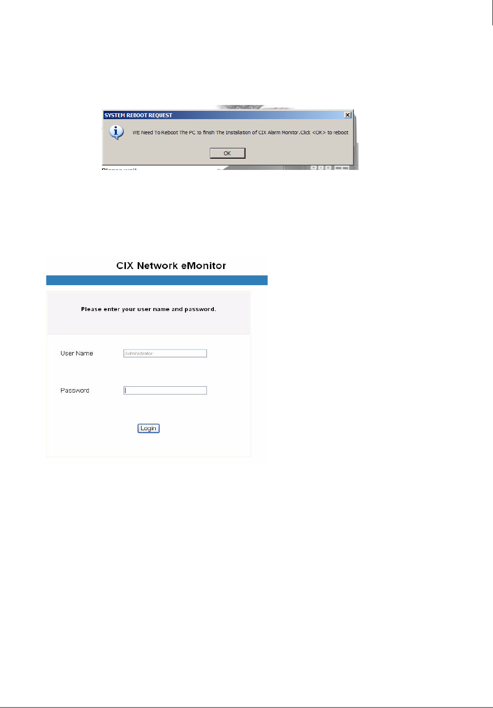
eMonitor/Alarm Notification
Strata CIX Network eMonitor
Strata CIX Application Implementation Vol 3 09/09 4-9
10.In the Select Installation Address dialog do not change anything, click on Next.
The system will begin the Network eMonitor installation
11.In the Installation Complete dialog box click on Close.
12.In the Reboot dialog box click on OK to reboot the system.
13.After the system reboots the installation is complete.
Step 5: Log In as Administrator
1. Start the Internet Explorer.
2. Type http://localhost/cixalarmmonitor and press <Enter>. The Login screen displays
(shown right).
3. In the User Name field, type in Administrator.
4. In the Password field, type in the word password.
5. Click on Login.
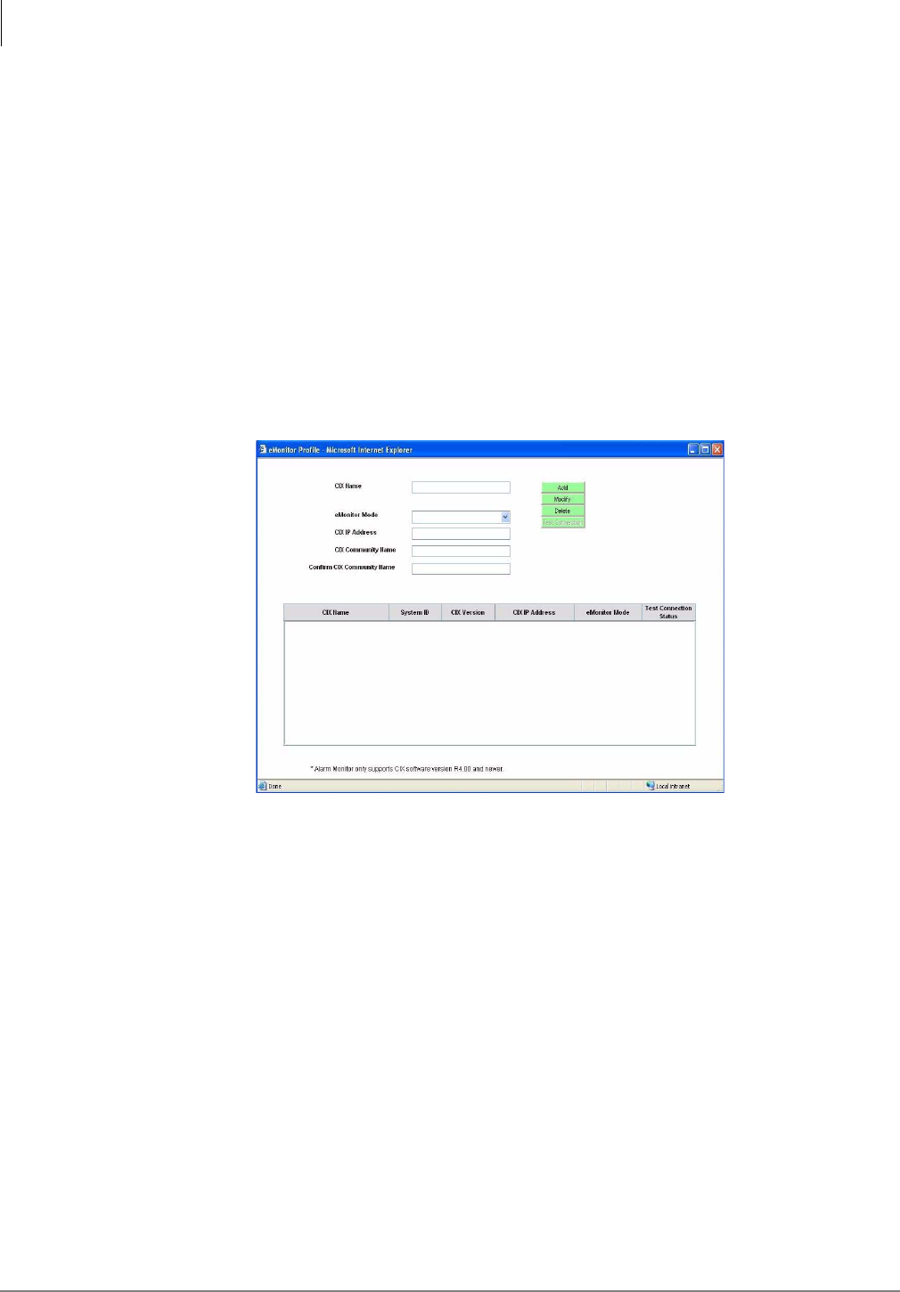
eMonitor/Alarm Notification
Strata CIX Network eMonitor
4-10 Strata CIX Application Implementation Vol 3 09/09
Step 6: Change User Password
1. Click on the Change User Password button on the top of the screen. The Change User
Password screen displays.
2. Type in the old password.
3. Type in the new password and confirm it. Click OK.
Step 7: Set up CIX eMonitor Profile
eMonitor Profile Screen
To monitor a particular CIX system, the CIX IP address and community name must be entered from
this screen.
The CIX System Setup screen is for adding, modifying or deleting a CIX system.The defined
equipment is saved in a file and stored on the server.
1. Select a Telephone System from the CIX equipment list displayed on the screen. If the desired
equipment name is not found, type in a name in the CIX Name field and click Add.
Note To delete a CIX name, highlight it on the list and click Delete.
2. Fill in the rest of the fields based on the descriptions shown in Table 5 below.
3. Click Test Connection to make sure the connection is active.

eMonitor/Alarm Notification
Strata CIX Network eMonitor
Strata CIX Application Implementation Vol 3 09/09 4-11
Buttons
•Add – Create CIX Equipment and store in Profile Database.
•Modify – Modify CIX Equipment from Profile Database.
•Delete – Remove CIX Equipment from Profile Database.
•Test Connection – Get connection results by using IP Address and Community Name.
Table 4 Equipment Setup Screen Fields
FIELD DESCRIPTION
CIX Name Name designating the equipment. For example: CIX670. This name appears in
each alarm and in the email notification of the alarms.
Possible values:alphanumeric characters
Note The System ID is programmed in the CIX database Alarm Control setup
(Prog. 919), it is not entered from the eMonitor Profiles setup. The
System Name is entered in the eMonitor Profiles setup. The System ID
and System Name do not need to be the same.
eMonitor Mode Provides information on connections.
Command monitor is for equipment that resides in a Local Area Network (LAN)
environment with the IP address accessible to the eMonitor server. It provides
the following information on the equipment:
listen trap, collects extended alarm, clears CIX alarm buffer, test connection,
setup alarm notification, alarm viewer and system detail page.
Monitor Only is for equipment that resides behind a firewall or Network Address
Translator (NAT) in which the IP address is not published or accessible by the
eMonitor server. It provides the following information: Listen Trap, Alarm viewer.
In Monitor Only mode, the system can only listen but can not send commands.
If you select Monitor only mode, the following fields are grayed out:
Community Name, Confirm Community Name, Test Connection. The following
is not displayed: System Label, Test Connection Status.
Possible values:command monitor, monitor only
Default: Command monitor mode
CIX IP Address Enter the IP Address of the CIX system. For example: 192.168.254.253.
Format: xxx.xxx.xxx.xxx
CIX Community
Name Enter the CIX Community password.
Possible values:Alpha characters
Default: communityName
Confirm CIX
Community Name Re-enter the CIX Community password.
Test Connection
Status Results from performing Test Connection using the CIX IP Address and CIX
Community Name. This Test Connection is similar to a “ping” test except it also
checks the community name. If the connection failed, you would see a pop-up
box and it would tell you why the connection could not be made.
Note Test Connection will not function if the eMonitor server is behind a NAT
router.
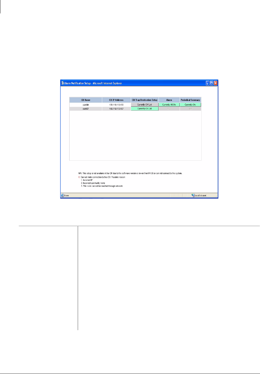
eMonitor/Alarm Notification
Strata CIX Network eMonitor
4-12 Strata CIX Application Implementation Vol 3 09/09
Step 8: Set up vbAlarm Notification
Alarm Notification Setup Screen
This screen sends commands to add/remove alarm traps and enables/disables alarm notification.
Note If the CIX is behind a NAT router and eMonitor is not on the same LAN as CIX, eMonitor
cannot administer CIX Alarm programs. eMonitor can only monitor (receive) Alarm data
from the CIX.
Table 4 Alarm Notification Setup Screen Fields
FIELD DESCRIPTION
CIX Name Display only. Name of CIX stored in the eMonitor Database.
Note Equipment marked as Monitor only mode does not display here.
CIX IP Address Display only. IP Address of the CIX system. For example: 192.168.254.253.
CIX Trap Destination
Setup Currently On/Off List – Indicates the eMonitor is on the target CIX Trap
Destination list or not. Current On List means that eMonitor’s IP is registered
in target CIX Trap Destination List. Currently Off means that eMonitor’s IP is
not in the target CIX Trap Destination List. If the eMonitor is not on the list, the
CIX alarm will not be displayed on this screen.
If this field displays an “X,” it means there is a problem in connecting to the
target CIX.
Alarm Currently All On/Off – Turns On/Off the Alarm Notification of a CIX.
Periodical Summary Currently On/Off – Turns On/Off the Current Alarm Summary Notification of a
CIX.
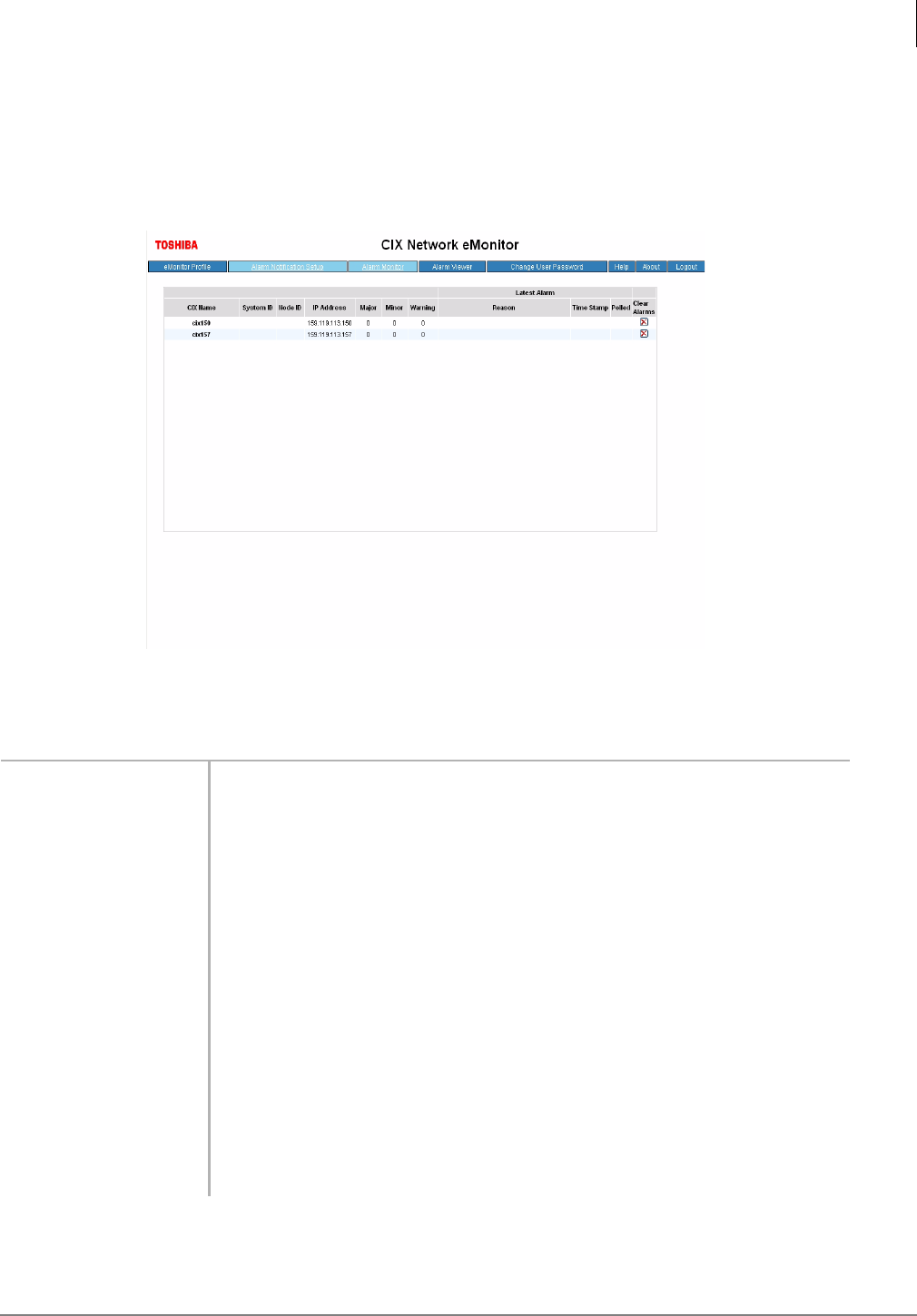
eMonitor/Alarm Notification
Strata CIX Network eMonitor
Strata CIX Application Implementation Vol 3 09/09 4-13
Step 9: Monitor Alarms
Alarm Monitor Screen
This screen displays an alarm list based on the equipment in the Profile Database.
Note The same alarm only counts once.,
Table 4 Alarm Monitor Screen Fields
FIELD DESCRIPTION
CIX Name From Equipment Table of Profile Database (eMonitor database)
System ID From Event Log. Stored in CIX database Program 919 (Alarm Setup).
Node ID From Event Log
IP Address From Event Log (CIX IP address).
Major Displays Major Alarms in Red. All ports fail on a card.
Minor Displays Minor Alarms in Orange. Some of the ports fail on the card.
Warning Displays Warnings in Yellow. All other alarms except major and minor
Latest Alarm
Reason From Event Log
Time Stamp From Event Log.
Polled If Yes, it indicates the time stamp is when the component gets the Extended
Alarm from CIX. If No, the time stamp is from the Raw Alarm Event.
Clear Alarm Clears CIX Alarm buffer. If the CIX equipment is set to Monitor only mode in
the eMonitor Profile screen, this feature is disabled. CIX Program 919.
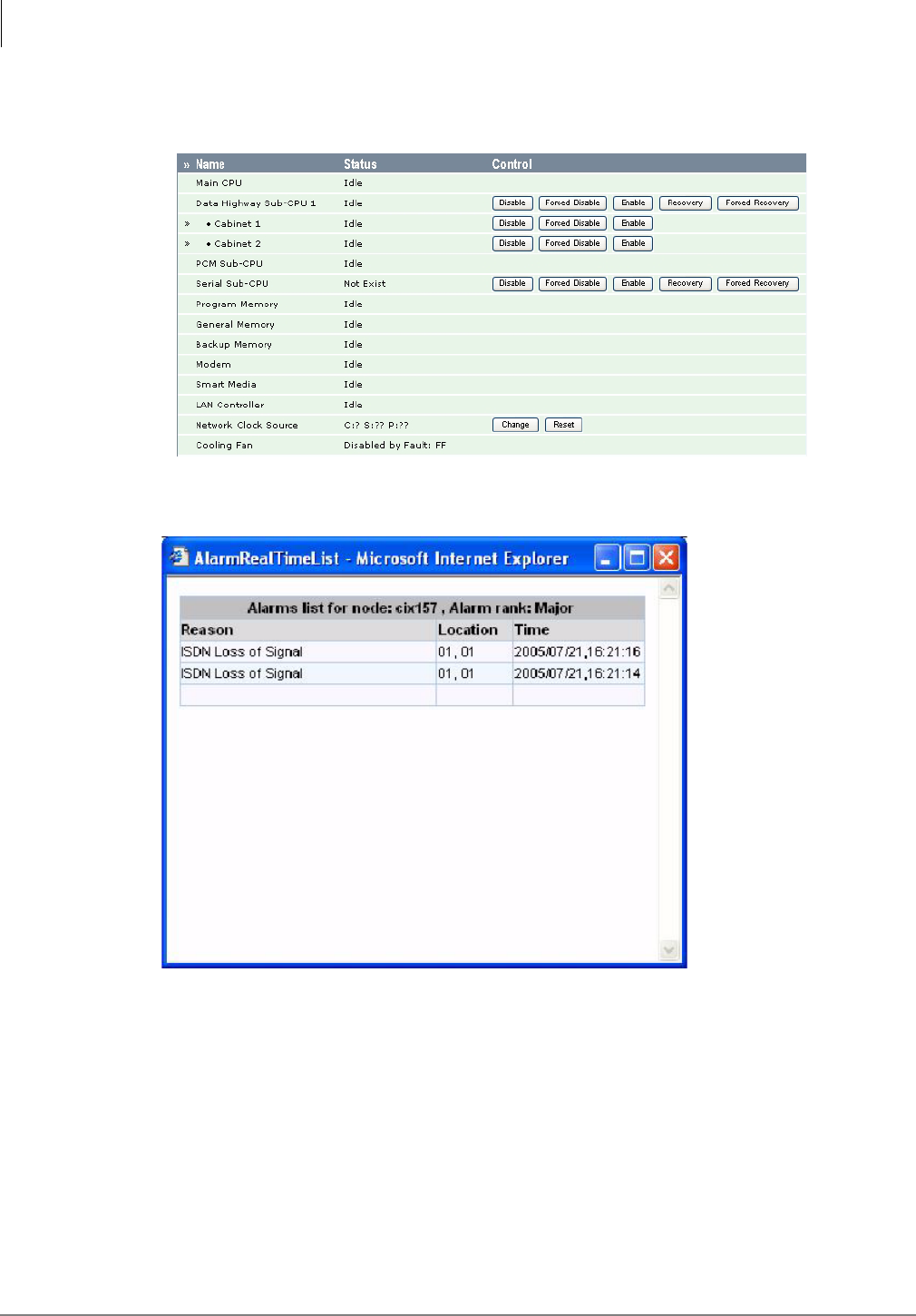
eMonitor/Alarm Notification
Strata CIX Network eMonitor
4-14 Strata CIX Application Implementation Vol 3 09/09
If you double-click on a listing for a Command/Monitor mode CIX, a pop-up window displays (shown
below) with detail cabinet and slot error information. Administer’s CIX Program 920.
If you click in the Major, Minor or Warning fields for an alarm, a table displays (shown right) listing
details of that category of alarms.
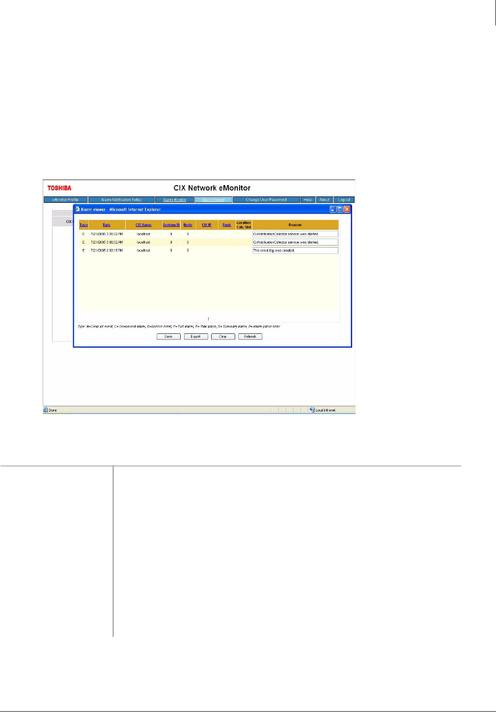
eMonitor/Alarm Notification
Strata CIX Network eMonitor
Strata CIX Application Implementation Vol 3 09/09 4-15
Step 10: View and Maintain Alarms
Alarm Viewer (Browser and Maintenance) Screen
Using this screen you can:
•Save the current event log as a backup file using the Save button.
•Export the current event log file as a tab delimiter text file using the Export button.
•Delete all the alarm information from the current event log file using the Clear button.
•Collect the most updated alarm information from the current event log file using the Refresh
button.
Table 4 Alarm Viewer Screen Fields
FIELD DESCRIPTION
Type Alarm Type: A = Clear all event, C = component alarm, E = service event, F =
full alarm, R = raw alarm, S = summary alarm, P = alarm parse error.
Date From Event Log Date/Time
CIX Name From Equipment Table of Profile Database
System ID From the CIX System ID set in Program 919 (Alarm Setup)
Node From Equipment Table of Profile Database
CIX IP IP Address
Rank Major, Minor or Warning
Location (cab/slot) Location of alarm.
Reason From Network eManager Component page.

eMonitor/Alarm Notification
Strata CIX Network eMonitor
4-16 Strata CIX Application Implementation Vol 3 09/09
Step 11: Email Notification
Email Notification Description
The email notification feature allows eMonitor to automatically send email alarm notifications to
designated mail boxes. The email notifications can be sent to multiple mail boxes and can be sent,
or not sent, depending on the CIX Alarm type. This can be setup independently for each CIX
monitored by eMonitor.
Notification Service
This component is designed and configured to run as a service; it starts when the eMonitor is
started and it uses the built in system account to login.
The notification service performs the following activity:
•At startup, the notification service subscribes to the CIX Monitoring Log event log to receive
notifications when an alarm is stored in the event log.
•During the startup phase it parses the existing event log entries and determines if new events
have been added since the last time the service was running. If there are any new alarms the
notification mechanism is triggered. For history alarm notification all alarms that will be sent to
one email address will be grouped and sent in one email regardless of the Alarm notification
threshold value.
•A threshold timer is provided so that when a repeated alarm is generated within the threshold
time the this alarm is ignored.
•When a new alarm is added to the event log, the eMonitor notifies the registered email users.
The service will try to collect several generated alarms and send them in a one email format
rather than separate email for each alarm. The service monitors the following types of alarms:
Major, Minor, Warning, and Summary.
•When an email is sent, the service considers the alarm processed. No further action will be
taken, even if the alarm is still active.
•When an email is sent, the notification service does not know if the email delivery was
successful. If the email delivery fails, the “from email address” receives a message indicating
that the email delivery has failed.
This service includes information about each alarm generated. The format is shown in the table
below.
The following alarm(s) have been detected:
CIX Name IP Address Node ID Alarm reason Severity Position Date/Time
Lab 143 159.119.127.143 1 CTI Link Down Minor 010000 1/29/2007-10:03
AM
Lab 143 159.119.127.143 1 ISDN Loss of Signal Major 010100 1/29/2007-10:03
AM

eMonitor/Alarm Notification
Strata CIX Network eMonitor
Strata CIX Application Implementation Vol 3 09/09 4-17
Summary Monitoring
The Strata CIX system has a buffer that stores alarms as they are generated. The contents of the
alarm buffer can be automatically sent to the eMonitor as a Summary report, at 10 minute intervals,
by enabling the Alarm Buffer Status parameter in the CIX.
To enable sending alarm buffer data to eMonitor use Network eManager. Connect to the Strata CIX
system using Network eManager, go to the System Alarm Control screen and enable Alarm Buffer
Status (Program 919, FB 02). The eMonitor must then be configured to monitor the summary
alarms from that Strata CIX system.
When the CIX Alarm Buffer Status is enabled and the eMonitor is configured to perform summary
alarm monitoring (per email address), summary alarms from the CIX will be sent to eMonitor every
10 minutes.
Important! If the eMonitor does not receive a Summary report within two cycles (approximately
20 minutes) a notification alarm is sent to the configured email address. This
notification indicates that the CIX system or some part or the IP network connecting
the CIX system to the eMonitor is down. This notification will be sent once. The
format of the email is as follows:
When the Strata CIX system resumes sending summary alarms, eMonitor will generate a
notification email as shown below:
eMonitor Summary Monitoring Failure
eMonitor did not receive the periodic summary alarm from the following equipment:
CIX Name IP Address
Lab 143 159.119.127.143
eMonitor Summary Monitoring
The following equipment in back online:
CIX Name IP Address
Lab 143 159.119.127.143
eMonitor/Alarm Notification
Strata CIX Network eMonitor
4-18 Strata CIX Application Implementation Vol 3 09/09
Email Configuration
Use the email configuration screen to perform the following:
•View existing configured email addresses.
•Add a new email address,
•For each email address the user can select:
–ALL or
–A particular CIX system
•The user can select the notification alarm level:
–Major, Minor, Warning or Summary Monitoring
•Delete an existing email address.
•Set a threshold value (in minutes) for the service so that repeated same alarms within this time
value are ignored.
•Setup the “from email address” and “subject line” to used when sending an email
•Set a text template to be used in the email body
Email Configuration Menu
Click “Email Notification Setup” in the menu as shown below.
Email Notification Setup Page
Alarm Notification Threshold: The time the service waits before sending an email after an alarm
has occurred, this value is in minutes. This is to prevent sending multiple notifications for the same
error condition. The default value is 0.
Alarm Processing History Threshold: When the service starts, it will look for alarms that occurred
this far back in the past and have them processed for notification. This value is in minutes, 0 means
do not look for past alarms. The default value is 0.
From Email Address: The “From” email address can be any real email or fictitious address. A
fictitious email address must be in a legitimate email address format (example:
eMonitor@CIX.com). If a fictitious address is used the email box that receives the alarm notification
will not be able to reply to alarm message email.
Email Subject: The text entered in this field is the subject line of the alarm notification email, any
text can be entered. The default value is “CIX Network eMonitor Alarm Notification”.
Email Body: The text entered in this field is what appears in the body of the email message when
the alarm notification email sent, any text can be entered.
SMTP Server: Enter the Name or IP address of the mail server used to relay eMonitor alarm
notification email messages. This server must accessible to the eMonitor server and it must be
running SMTP service.
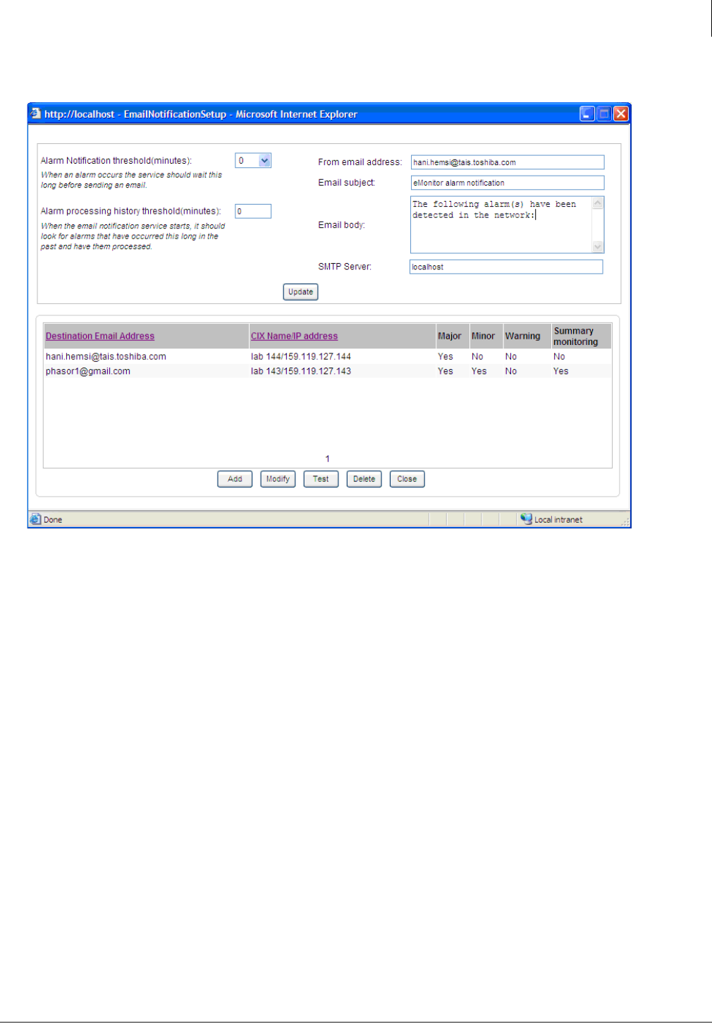
eMonitor/Alarm Notification
Strata CIX Network eMonitor
Strata CIX Application Implementation Vol 3 09/09 4-19
Update: Use the Update button to save the entered data.
The email configuration page also allows the user to perform the following:
Add: Used to add a new Destination email address for each CIX listed on the screen, for each
Destination email address the user can select:
•ALL to select all CIX systems listed on the screen, or
•A particular CIX system.
The user must select at least one CIX system and one alarm level; Major, Minor, Warning or
Summary Monitoring. Refer to Destination Email Address Setup on page 5-20.
Note Only Strata CIX systems setup in the eMonitor Profile will display on this screen. Systems
can only be added from the “eMonitor Profile,” not from this screen.
Modify: Used to modify an existing item, select an email address from the list and click modify.
Refer to Destination Email Address Setup on page 5-20.
Test: Initiates the email test mode; in this mode the first alarm received from the CIX system will be
forwarded to the destination email address. When an alarm is forwarded the email test is reset. It
will take an unknown amount of time for this test to occur, it depends on CIX activity and whether
the eMonitor server can be reached by the CIX system. Do not run this test if it is not practical to
wait for an Alarm Summary report. An alarm summary is sent at 10 minute intervals.
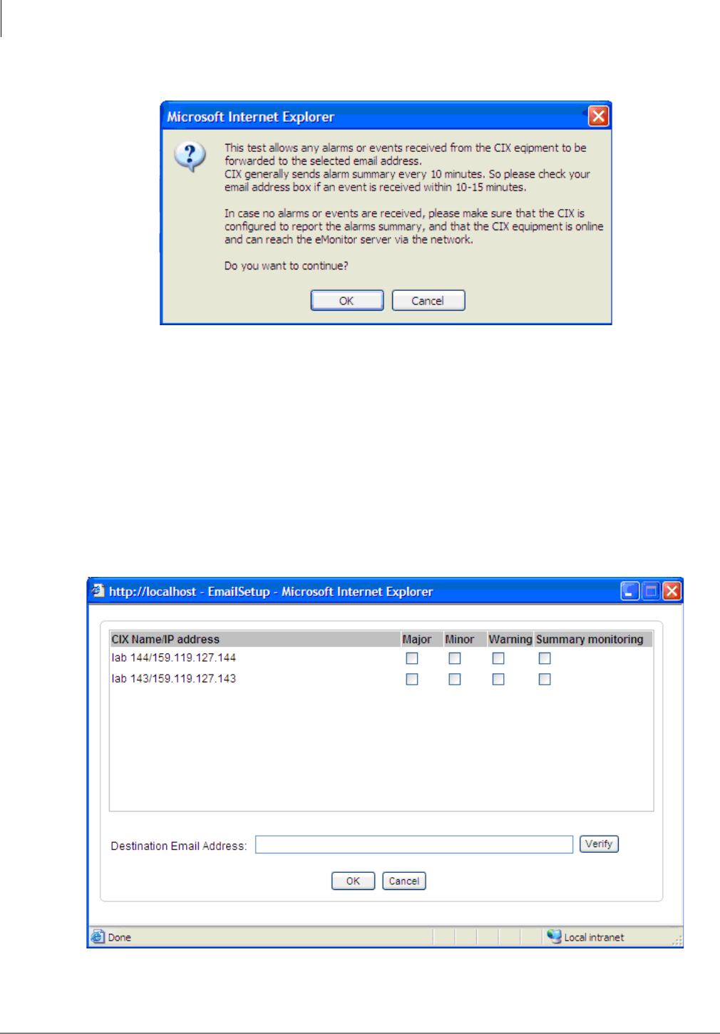
eMonitor/Alarm Notification
Strata CIX Network eMonitor
4-20 Strata CIX Application Implementation Vol 3 09/09
When the Test Button is clicked the following message is given the user.
Note Unless the CIX is sending alarms this test will be not be effective because it relies on
eMonitor receiving an actual Alarm or Alarm Summary from a CIX system during the test
period.
Delete: Used to delete an email address entry from the list.
Close: Closes the window.
Destination Email Address Setup
When the user clicks on either the Add or Modify buttons the following screen appears.
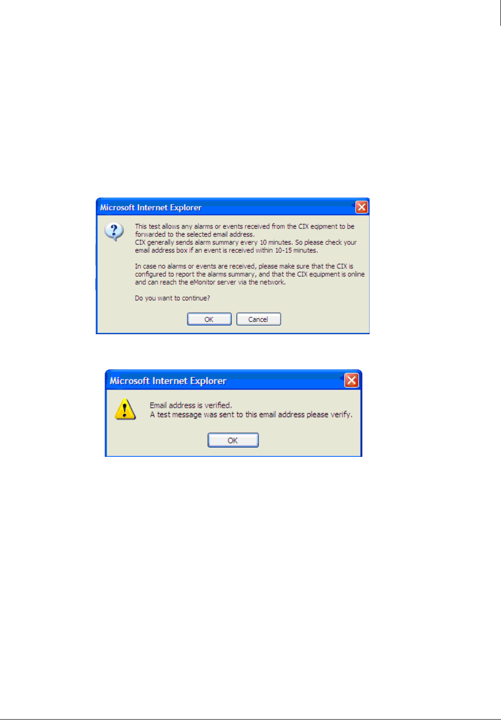
eMonitor/Alarm Notification
Strata CIX Network eMonitor
Strata CIX Application Implementation Vol 3 09/09 4-21
The CIX Name and the IP address of the Strata CIX systems setup in the eMonitor profile will be
present on one screen. Click to highlight a CIX system then, click to check-mark the type of alarms
that will cause notification email to be sent. The eMonitor server will send notification email to the
destination email address when those alarms occur.
Enter the destination email address to which the alarm notification should be sent and click OK.
To send notifications for the selected system to multiple addresses, enter another Destination Email
address and click on OK. Continue until all email Destinations are setup.
The verify button is used to verify that the SMPT email server is valid and reachable, it does not
guarantee that the email account is valid or can receive messages. If the address can be reached
a test email is sent to that address for the user to check. The following message is given the user
when this button is clicked.
The following message is given if the email SMTP server responds to the sent email.
Important! Important Note: This screen DOES NOT mean that the email was received by the
destination mail box, it only indicates that an email was accepted by the SMTP mail
server and was sent to the destination mail box. Please check the destination mail
in-box to verify that the verification message was received.
This page is intentionally left blank
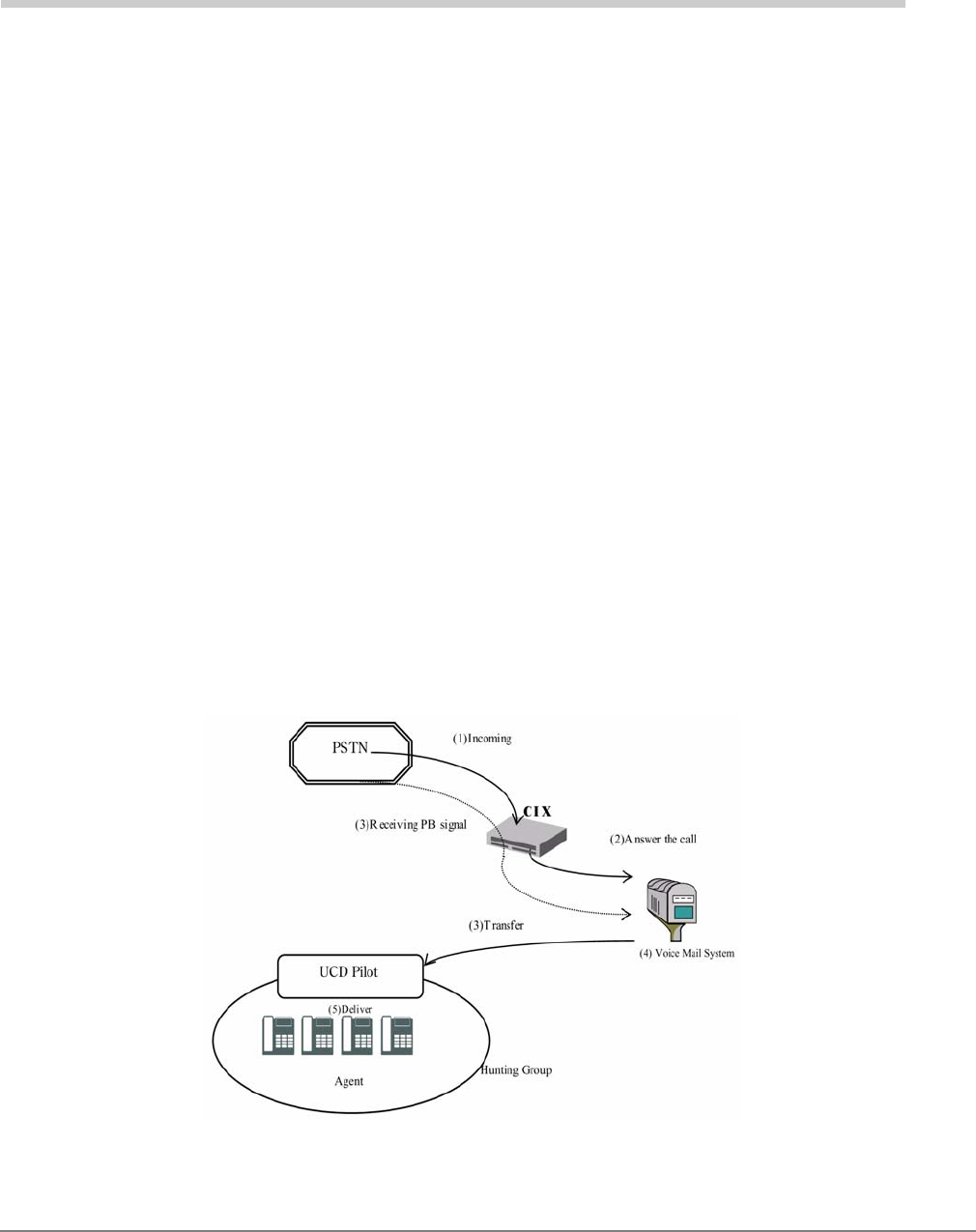
Strata CIX Application Implementation Vol 3 09/09 5-1
Uniform Call Distribution 5
Uniform Call Distribution (UCD) provides ACD-like service based on the simplified Distributed Hunt
feature. Incoming calls are answered by Voice Mail as the Auto Attendant function or they can be
directly routed to the UCD (Distributed Hunt) Pilot number. The caller will dial the UCD Pilot station
in response to a prompt. The call will go to the next agent or, if all agents are busy, the call will camp-
on to the Distributed Hunt pilot and ring-back tone or Music-on-Hold (MOH) will be sent.
Call Distribution
This feature distributes incoming calls to available agents. Agents must be logged into the group to
receive UCD calls. The following illustration shows the typical call flow for this service.
1. Agent logs into the UCD group.
2. CIX receives a call from PSTN or extension.
3. The call is routed to voice mail which provides the initial greeting using the auto attendant
service.
4. The voice mail can be configured to prompt callers to enter the destination number or to route
the call to the pre-determined destination.
5. The voice mail transfers the call to the UCD pilot group.
6. According to the hunting rule (distribute), the call is delivered to an idle agent who logs in to this
hunting group.
If no agent is available in the hunting group, the call is queued to the UCD pilot group. The caller
may hear the Music on Hold (MOH) or Ring Back Tone (RBT) depending on the configuration. If the
call cannot be answered within the preconfigured time, the call is routed to an overflow destination.
Uniform Call Distribution
Login/Logout
5-2 Strata CIX Application Implementation Vol 3 09/09
Login/Logout
Login/Logout is controlled by the Login key assigned to the agent phone (see the Strata CIX
Programming Manual Vol.1, for details).
The Login/Logout feature is applied to the call which terminates to UCD pilot only. Therefore, the
call can directly terminate to agent Prime or Phantom PDN even if the agent is in Logout state. Also,
Login/Logout can be activated by an access code. The default numbering plan is shown below
(Prog. 102).
Initial Greeting
Calls can be directly routed to the UCD pilot via DID number or DIT ringing assignments. In this
case, the caller hears the ring back tone and MOH while waiting.
If an initial greeting is necessary, it is recommended to use the Auto Attendant feature of the voice
mail system. It can be configured to prompt callers to enter the destination UCD pilot or to route all
calls to a pre-programmed destination (see the Strata CIX Programming Manual Vol. 2 for details).
Queuing
If no agents are available (e.g., all agents are in the busy state), a call is queued to the UCD pilot.
It will be delivered to the agent when the agent becomes available. While it is queued, the caller
hears MOH which is assigned to the UCD pilot (see Program 209 in the Strata CIX Programming
Manual Vol. 1).
Overflow
In the following case, calls are routed to the overflow destination configured by the DH Pilot System
Call Forward NA destination and UCD Pilot Overflow Timer.
1. If UCD Pilot Overflow timer is expired while the call is queued to UCD pilot, the call is forwarded
to the Call forward destination which is assigned to the Pilot DN in System Call Forward-No
Answer.
2. If all agents in the group are in a logout, DND or Make Busy state, the call is forwarded to a Call
forward destination that is assigned to the Pilot DN in System Call Forward-DND. Also, if
overflow destination is not assigned or is invalid, a call stays in the queue.
Note Ring-No-Answer overflow for each agent can be established by setting Call Forward-No-
Answer (CFNA) on the UCD DN button. The agent’s UCD button will ring for the time set
in the CFNA timer, then hunt to the next available agent. The CFNA destination must be
set to the next agent in the UCD group rotation. If another destination is assigned it will be
ignored, the call will forward to the next agent in the UCD hunt group.
Login key LED Login State on Agent
On steady Login
Off Logout
Access Code Feature
#6061 Login - from Agent Station
#6062 Logout - from Agent Station
#6161 + DN + # Login - Agent Station (DN) from another station
#6162 + DN + # Logout – Agent Station (DN) from another station
where DN = the Directory number of the agent station

Uniform Call Distribution
UCD Group Setup
Strata CIX Application Implementation Vol 3 09/09 5-3
UCD Group Setup
UCD Groups are Distributed Hunt Groups with UCD feature parameters enabled.
Programming
UCD Group Parameters (Prog 209)
From Network eManager click Station > Hunt Group > Group
• 01 Hunt Method – Distributed
• 02 Pilot Number – any non-conflicting up to 5 digits
• 04 Number To Display – any number
• 05 Pilot Number SCFwd – select the System Call Forward template number that contains the
Queue Overflow destination assignments. (see Network eManager > System > Sys Call
Forward [Prog 500/504] )
• 06 Multiple DN Hunt – Disable
• 07 DHG Auto Camp-on – Enable
• 08 UCD Enable/Disable – Enable
• 09 UCD MOH Source – select the music source that should play to callers in queue.
• 10 UCD Overflow Timer – The time calls should remain in queue before overflowing to the SCF
No-Answer overflow destination.
• 11 UCD RBT Timer – the time a caller in queue should hear Ring Back Tone before being
switched to the UCD MOH source.
UCD Group Members (Prog 218)
From Network eManager, click Station > Hunt Group > Member
• Select the PhDN or PDN buttons that should be included in the UCD group.
UCD Queue Overflow
UCD calls that are in queue will overflow to the System Call Forward (SCF) destinations set in the
SCF template assigned to the UCD group.
1. The time the call remains in queue before it overflows is set in UCD Overflow Timer. (Prog 209-
10)
2. An SCF pattern is assigned to each UCD Group in Pilot Number SCFwd. (Prog. 209-05).
Assign a pattern with the SCF No-Answer destination set to a telephone or Voice Mail box that
should answer calls that overflow from the queue. And, SCF DND destination set to the UCD
Queue overflow destination, a station that should handle calls when all agents are logged out.
•When all agents are busy the call will be directed to the SCF No Answer destination.
•When all Agents are logged out calls will be directed immediately to the SCF DND
destination
Note If station Call Forward No-Answer is not registered on the agent station (PDN or PhDN), a
call to an agent station will continue to ring until answered or the caller hangs up.

Uniform Call Distribution
Programming
5-4 Strata CIX Application Implementation Vol 3 09/09
Set SCF assignments (Prog 500/504)
From Network eManager, click System > Sys Call Forward
• Select the SCF template that is assigned to the UCD group in Prog. 209-05
• Enter the No Answer destination – overflow when all agents busy
• Enter the DND destination – overflow for when agents logged out
Note The SCF No Answer timer (PRG 104-08) does not apply to UCD Queue overflow. The
UCD OverFlow Time in Prg 209-10 determines how long calls stay in queue before
overflowing to the SCF destinations.
Enable UCD in Station Class Of Service (Prog 103)
Assign the UCD feature to a COS.
From Network eManager, click System > Class of Service.
• 45 UCD Local Login - (default = ENABLE)
• 46 UCD Remote Login (default = DISABLE)
Assign Class Of Service to the Agent Station (Prog 200)
Assign the COS defined above to an agent station.
From Network eManager, click Station > Station Assignments.
• 04 Class of Service - (= the COS defined above)
Assign Agent Login/Logout and UCD Agent Call Button. (Prog 205, 213, and 215)
•UCD Call Button — The UCD Call button can be a Phantom DN (PhDN) or Primary DN (PDN).
On stations that are used for both UCD calls and other calls, it is recommended that a PhDN
button be used for the UCD button. This allows the non-UCD calls to be forwarded to the PDN’s
Voice Mail or an other station.
Note A PhDN or a PDN button is not a UCD button until it is programmed as a member of a
UCD Hunt Group with Progr. 209 and Prog. 218.
From Network eManager, click Station > Station Assignments > [DN] Key > ACD/UCD.
•Select UCD Agent Log in/out key.
Program 102 Flexible Numbering Plan Assignment
From Network eManager, click System > Flexible Access Code.
• Flexible number of login from local node (default access code = #6061)
• Flexible number of logout from local node (default access code = #6062)
• Flexible number of login to Agent Station from another station (default access code = #6161)
• Flexible number of logout of Agent Station from another station (default access code = #6162)
Note The default access code can be changed.

Uniform Call Distribution
Capacity
Strata CIX Application Implementation Vol 3 09/09 5-5
Capacity
• Total waiting calls in the system – The number of calls waiting in the queue times the number of
agents in the system must be less than 128. For example, there are two UCD groups and group
#1 has 10 agents and group #2 has 15 agents. Group #1 can have only 3 calls queued (10x3 =
30) when group #2 already has 6 calls in the queue (15x6 = 90). A total of 120.
• UCD groups in the system:
CIX100 – 90
CIX200 – 200
CIX670 (small) – 200
CIX670 – 640
• Number of agents:
CIX100 – 72
CIX200 – 160
CIX670 (small) – 160
CIX670 – 560
How UCD Operates
1. Calls routed directly to UCD pilot, are distributed to an available agent. If no agents are
available, the caller hears RBT, and after the UCD Response Timer expires, the caller hears
MOH.
2. If the overflow destination is busy when the call overflows, it is camped onto the overflow
destination.
3. Ring transfer timer is not applied to a UCD call. Therefore, after the voice mail transfers the call
to a UCD group, ring transfer recall is not executed when the call is queued.
4. Once the call is delivered to the agent, it is not redistributed to another agent or forwarded to
the call forward destination.
5. If the agent logs out while the call is ringing, the call continues to ring the agent.
6. When the last agent logs out while on a call, the already queued calls stay in the queue and do
not overflow.
7. The second destination of System Call Forward can not be used as the overflow destination.

Uniform Call Distribution
Interaction with Other Features
5-6 Strata CIX Application Implementation Vol 3 09/09
Interaction with Other Features
Call Forward, System Call Forward
UCD calls do not forward per the station’s call forward assignments. Calls routed directly to the
agent’s station, not through the UCD pilot, will forward when Call Forward or System Call Forward
is set.
Do Not Disturb
If DND is activated while the call is ringing the agent, the ringing is stopped. However, queuing or
overflow is not executed. If DND is activated on the overflow destination, the call does not overflow.
Dialed Number Identification Service
If the overflow destination is voice mail and the overflowed call is a DNIS call and associated with
VM-ID, VM-ID assigned to DNIS is sent to the voice mail.
Station Hunting
The overflow destination can be a station hunting pilot or member. The system selects an idle
station from the Station Hunting group and terminates a call. If no idle station is found in the station
hunting group, the system camps on the call according to the station hunting specifications.
Offhook Call Announce (OCA), Handset Offhook Call Announce
Even if automatic OCA is set at the originator terminal and the overflow destination is set to allow
OCA, the overflowed call does not use OCA.
Private Networking
The overflow destination can be a station in another node. However, if the overflow destination is
an UCD pilot in another node and all agents are in logout, DND or Make Busy state, the call does
not overflow and stays in the queue.
Multiple Calling
If a UCD pilot is a member of a Multiple Calling Group (MCG), the call does not terminate at the
UCD agent. If all members in a MCG are UCD pilots, the caller hears ROT.
Door Phone
If a door phone call comes to UCD, it terminates to an UCD agent according to the hunting rule even
if the agent is not logged in.
Class of Service
Call is queued to UCD, even if caller’s Class of Service does not allow the camp on.
Lost Call Treatment
If a Lost call comes to UCD, it terminates to an UCD agent according to the hunting rule even if the
agent is not logged in.

Uniform Call Distribution
Interaction with Other Features
Strata CIX Application Implementation Vol 3 09/09 5-7
Intercept
If UCD is assigned as the intercept position, the call terminates to UCD agent according to the
hunting rule even if the agent is not logged in.
Phantom DN
If the phantom DN is assigned to the UCD group, Login/Logout and DND are controlled by the
owner of the phantom DN. When the owner logs in, the call can be terminated at phantom DN. If
this DN appears on multiple phones, it will ring all phones. However, if no owner is assigned to the
phantom DN, the call cannot be terminated at the phantom DN.
Music on Hold
If a UCD call is camped on to the overflow destination, the caller hears MOH programmed for the
overflow destination. When a UCD call is in the UCD queue, the caller hears MOH programmed for
the CCO group.
This page is intentionally left blank

Strata CIX Application Implementation Vol 3 07/09 6-1
Traffic Measurement and Reporting 6
The Traffic Measurement (TM) feature provides a method of recording the traffic in a Strata CIX
system and a method of reporting the system traffic statistics to a system administrator. System
traffic statistics are mandatory for the system administrator to both monitor the effectiveness of the
system and determine whether the system is over dimensioned, under dimensioned, or has
improper traffic balance.
The TM function can measure and report the following categories of measurement objects:
•Incoming Line Groups (ILG) - Up to 64 groups
•Outgoing Line Groups (OLG) - Up to 64 groups
•DID numbers (DID) - Up to 130 numbers
•DTMF Receivers (DTMF)
•Conference Trunk Circuits (Conf)
•Each report will also contain a System Total summary
Feature Initialization
The system administrator sets Traffic Measurements and Reporting using Network eManager to
execute system commands. The following items are specified:
•Time Zones – Start and Stop Times
•Measurement Objects – Line Groups, Stations, System Resources
•Reporting Specification –
•Unit of traffic intensity – Erlang or CCS
In time zones setting, the system administrator sets starting time (from 0 to 23 o’clock) and end time
(from 1 to 24 o’clock). For example, if system administrator specifies 9 as start time and 16 as end
time, the system begins measurement at 09:00:00 and finish at 16:59:59. The system provides up
to three time zones, but overlapping time zones is not allowed. A time zone across two days is not
allowed, either. Time zones are defined per attribute (Working Day / Non-Working Day / Holiday) in
Programs 106, 112 and 113 (Network eManager: Advanced Configuration > System > Day Night
Service). System administrator must specify one tenant number for Traffic Measurement and
Reporting feature.; Program 921 (Network eManager: Advanced Configuration > System > IO
Device)
In the measurement objects setting, the system administrator defines “activate” or “deactivate” as
the measurement object per group (e.g. ILG1, ILG2, OLG2, OLG3).
TM output is set to LAN port or serial I/O port. When the CIX has a SM or SD card inserted the
statistics are also output to a folder named “TRAFFIC” in it. When the SD/SM card in present the
TM will be sent to the output port and the TRAFFIC folder on the SSD/SM card. When the traffic
folder on the SD/SM card is full the next TM file will over-write the oldest file in the folder.
In unit of traffic intensity setting, the system administrator selects “Erlang” of “CCS” as unit of traffic
intensity in reporting. Refer to Traffic Intensity Calculation on page 6-7.

Traffic Measurement and Reporting
TM Output Statistics
6-2 Strata CIX Application Implementation Vol 3 07/09
TM Output Statistics
The TM information collected is sent from the report buffer each hour. It is compiled into the output
format, then output to specified output port, and the SD/SM card if installed. Reports are sent to the
I/O or LAN port and the SD/SM card at the same time. Naming rules of output files are the same as
CIX/CTX event trace files:
MMDDHHNN.trf
MM: Month (Japanese style, 01-12)
DD: Day (01-31)
HH: Hour (01-23)
NN: Sequence Number*
*Sequence Number indicates the file number created in same hour.
For example: 10211600.trf is the file containing traffic information from 16:00 p.m. to 17:00 p.m. on
October 21.
Once the report output is completed, the statistics in the report buffer is cleared. However, if it isn’t
completed for some reason, that buffer isn’t cleared.
System administrator can request to re-output statistics report with a programming command that
includes the start and end times.
Statistics under measurement at the time a report is requested cannot be outputted. The report is
only available after the end time. For example; the traffic measurement data for 10 to 11 is not
available until after 11.
TM data is recorded each hour. A Traffic Report is requested using Network eManager to enter the
programming parameters to specify the report Start date and time, and the end date and time. The
traffic report is output to file named traffic.trf on the SD/SM card. If a traffic.trf file already exists on
the card the new file will over-write it.
Note The Traffic Measurement is system based. The measurement cannot be set to report per
tenant.
Capacities
The system provides up to three time zones. Each time zone must be a minimum of one hour to a
maximum of 24 hours. Overlapping of time zones is not allowed. A time zone across two days is
not allowed.
The system supports up to 64 OLGs and 64 ILGs for measurement.
The system supports up to 130 DID numbers for measurement (per 1 system).
When measuring under the following conditions, CIX can accumulate the statistics for 1 week in the
buffer.
•Programming about this feature is not changed.
•CIX time setting is not changed.
•Switching to summer / normal time is not occured.
•CIX is not restarted.
•CIX is not turned off.

Traffic Measurement and Reporting
Measurement Categories and Items
Strata CIX Application Implementation Vol 3 07/09 6-3
Measurement Categories and Items
In each report the requested categories will be measured, The report will show all of the following
items in each category.
Category Items Description
OLG (Analog CO) Station to Trunk Calls Number of calls by stations to OLG trunks attempted
Counts each attempt to access a trunk in the OLG.
Trunk to Trunk Calls Number of calls by an ILG trunk to OLG trunks attempted
Counts each attempt by an ILG trunk to access an OLG
trunk.
All Trunks Busy Number of calls to an OLG trunk attempted when all trunks
were busy.
Counts each attempt to access an OLG when all trunk
were busy.
Call CCS Refer to the Traffic Intensity Calculation
OLG (ISDN CO) Station to Trunk Calls Number of calls by stations to OLG trunks attempted
Each attempt to access a trunk in the OLG is counted.
Trunk to Trunk Calls Number of calls by an ILG trunk to OLG trunks attempted
Counts each attempt by an ILG trunk to access a trunk in
the OLG.
All Trunks Busy Number of calls to an OLG trunk attempted when all trunks
were busy.
Each attempt unable to access a trunk in the OLG when all
trunks were busy is counted.
Destination Busy Number of call attempted that receive “Destination Busy”.
Counts each attempt that encounters “Destination Busy”
after “Setup” is sent.
Call CCS Refer to the Traffic Intensity Calculation
OLG (Strata Net) Same as ISDN (CO)
ILG (Analog CO) Incoming Calls Number of incoming call attempts
Each attempt call in on a trunk is counted.
DID No. nnnn Number of incoming calls per DID number.
Call CCS Refer to the Traffic Intensity Calculation
Abandoned Calls Counts each abandoned call.
Each call on an incoming trunk that is not answered.
(Sheet 1 of 2)

Traffic Measurement and Reporting
Measurement Categories and Items
6-4 Strata CIX Application Implementation Vol 3 07/09
ILG (ISDN CO) Incoming Calls Same as ILG (CO)
DID No. nnnn Same as ILG (CO)
Call CCS Refer to the Traffic Intensity Calculation
Abandoned Calls Same as ILG (CO)
ILG (Strata Net) Incoming calls Same as ILG (CO)
Call CCS Refer to the Traffic Intensity Calculation
DTMF Receiver Use attempts Number of times the system attempts to use a DTMF
Receiver.
All Receivers Busy Counts each unsuccessful attempt to use a DTMF
Receiver because all receivers were busy.
Conference Use attempts Number of channels the system attempts to connect to the
conference circuit.
Counted each time the system uses a conference circuit.
All Circuits Busy Counts each unsuccessful attempt to conference because
all conference circuits were busy.
System Total Station to Trunk Calls Total number of station to OLG calls.
Trunk to Trunk Calls Total number of trunk to OLG calls
Abandoned Calls Total number of incoming calls that ‘hung up’ prior to
answer.
Incoming Calls Total number of incoming call attempts on trunks.
All Trunk Busy Total number of outgoing calls attempted which
experience All Trunks Busy.
Call CCS Refer to the Traffic Intensity Calculation
Category Items Description (continued)
(Sheet 2 of 2)

Traffic Measurement and Reporting
Traffic Measurement Reports
Strata CIX Application Implementation Vol 3 07/09 6-5
Traffic Measurement Reports
When Traffic Measurement is setup the system will output a report, example shown below, for each
hour of the requested measurement period. The example shown below is a printout of the
08011300.trf file.
AUG 01 2008 NODE:11
Measurement Period 1300 1400
Outgoing Line Group 1 1001
Group Size 15
Station -Trunk Calls 9
Trunk - Trunk Calls 0
All Trunk Busy 0
Destination Busy 5
Call CCS 27.0
Measurement Period 1300 1400
Outgoing Line Group 2 1002
Group Size 8
Station -Trunk Calls 19
Trunk - Trunk Calls 0
All Trunk Busy 0
Destination Busy -
Call CCS 67.8
Measurement Period 1300 1400
Outgoing Line Group 3 1003
Group Size 0
Station -Trunk Calls 0
Trunk - Trunk Calls 0
All Trunk Busy 0
Destination Busy -
Call CCS 0.0
Measurement Period 1300 1400
Outgoing Line Group 8 1008
Group Size 8
Station -Trunk Calls 0
Trunk - Trunk Calls 0
All Trunk Busy 0
Destination Busy 0
Call CCS 0.0
Measurement Period 1300 1400
Incoming Line Group 1 2001
Group Size 15
Incoming Calls 22
DID NO.0851 3
DID NO.2600 0
DID NO.3279 5
DID NO.3400 0
Call CCS 27.0
Abandoned Calls 1
Statistics from 1300 to 1359
1:00 pm to 2:00 pm) on August 1, 2008
OLG 1 has 15 trunks
Nine Station to Trunk calls were made
during this hour. Five of those calls
were to busy numbers.
Total traffic on this trunk group was
27 CCS
Start time 1:00 p.m.
End time 2:00 (1:59)p.m.
Internal Code
0000 = System Total
1xxx = Outgoing Line Group xxx
2xxx = Incoming Line Group xxx
3000 = DTMF receivers
4000 = Conference Circuits
ILG 1 has 15 trunks
22 Trunk to Station calls were made
during this hour.
Total traffic on this trunk group was
27 CCS
Three of those calls went to DID
station 0851. Five of the calls went
to DID station 3279
There was one caller that hung up
before the call was answered.

Traffic Measurement and Reporting
Traffic Measurement Reports
6-6 Strata CIX Application Implementation Vol 3 07/09
Measurement Period 1300 1400
Incoming Line Group 2 2002
Group Size 8
Incoming Calls 10
Call CCS 67.8
Abandoned Calls 0
Measurement Period 1300 1400
Incoming Line Group 3 2003
Group Size 0
Incoming Calls 0
Call CCS 0.0
Abandoned Calls 0
Measurement Period 1300 1400
Incoming Line Group 8 2008
Group Size 8
Incoming Calls 0
Call CCS 0.0
Abandoned Calls 0
Measurement Period 1300 1400
Incoming Line Group 32 2032
Group Size 0
Incoming Calls 0
Call CCS 0.0
Abandoned Calls 0
Measurement Period 1300 1400
SYSTEM TOTAL 0000
Group Size 62
Station - Trunk Calls 28
Trunk - Trunk Calls 0
Abandoned Calls 1
Incoming Calls 32
All Trunk Busy 0
Call CCS 189.6
The system has 62 trunks
28 Station to Trunk calls were made
during this hour.
Total traffic on this system was
189.6 CCS
There were no Trunk to Trunk calls
There was one abandoned call
There were 32 incoming calls
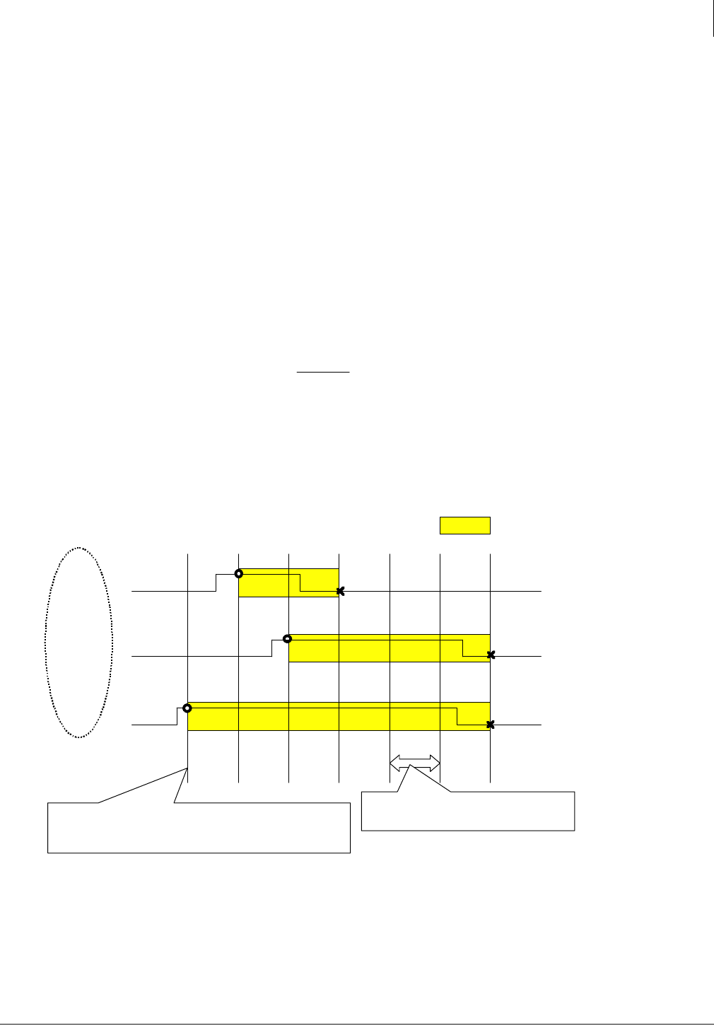
Traffic Measurement and Reporting
Traffic Intensity Calculation
Strata CIX Application Implementation Vol 3 07/09 6-7
Traffic Intensity Calculation
Analog Trunk
Traffic Intensity is calculated based on how long each trunk is in use during the measurement hour.
The time a trunk circuit is in use is called hold time. Holding time is measured per trunk. Holding
time T_hold (seconds) is calculated as below;
T_off (seconds) is the time when the trunk is available. T_on (seconds) is the time when the trunk
is in use. “Trunk is in use” indicates the condition that the trunk is not free (i.e. talking, terminating,
originating, and so on).
Traffic intensity A is calculated as shown below;
The relation of Erlang to CCS is 1 Erlang = 36 CCS. The system administrator can choose Erlang
or CCS as unit of Traffic intensity.
The system checks each circuit every 30 seconds for in-use or available status. As shown in the
figure below, if a becomes busy after a system check it is not counted as busy, for traffic
measurement, until the next system check.
Figure 6-1 Holding time
onoffhold TTT −=
][
100 CCS
T
Ahold
=
Trunk 1 ON
OFF
Trunk 2 ON
OFF
Trunk 3 ON
OFF
Each collect period is 30 sec.
CTX software collect each trunk/trunk Gr
idle/busy information.
: Holding Time
21030 60 90 120 150 180 Sec.
OLG1
Each collection period is 30 sec-
onds
CIX software collects busy/idle status of each
trunk in each trunk group at the beginning of
each period.

Traffic Measurement and Reporting
Hourly Traffic Reports (Program 921)
6-8 Strata CIX Application Implementation Vol 3 07/09
For example, if three calls seize trunks 1, 2, and 3 belonging to OLG1 during a measured hour,
traffic intensity A [CCS] carried by the OLG1 is calculated as below;
A: traffic intensity[CCS] T_hold: holding time
ISDN Trunk Traffic Intensity
Traffic intensity carried by the ISDN trunk group is calculated in the same way of analog trunk group
except the holding time calculation.
All Trunk Traffic Intensity
Traffic intensity reported is calculated with the holding time of all trunks.
Abandoned Calls
An abandoned call is usually an incoming trunk call that the caller hangs up before it is answered.
Incoming calls on a Strata Net trunk are never counted as abandoned. When a call from Node A to
Node B via Strata Net is attempted, Node B will count the attempt as an incoming trunk call. If the
call is abandoned it will not be included in the abandoned call count.
A call on an incoming CO line to Node A, routed to a station in Node B, that is abandoned will be
recorded as an abandoned call only in Node A.
Hourly Traffic Reports (Program 921)
TM, when ON, sends data each hour. The data is stored in the SD/SM card on the processor in a
TRAFFIC folder or it can be sent to an external device via LAN or RS-232. Each file is named:
MMDDHHNN.trf.
MM = Month (01 - 12)
DD = Day (01 - 31)
HH = Hour (01 - 24)
NN = Sequence Number
Traffic Measure
1. In Network eManager go to Alarm/Traffic > Traffic Measure > Control Setup.
2. In the Traffic Tab
•01 Traffic Measurement On/Off - Select Enable to run traffic measurement.
•02 Send TM Data to SM/SD Card - Set to Enable to send data to the SM/SD card (TRAFFIC
folder) and, if setup in I/O Device configuration, to an external device (RS232c or LAN). Set
to Disable to send data only to the external device. The external device must be set (refer to
the I/O Device configuration below).
•03 Select Tenant to Measure - This selects the System Day/Night Table to be used for the
Work Day and Non-Work Day and Holiday definitions. This does not select TM by tenant.
•04 to 12 Set the Time Zone (report hours) in each category.
•Select the appropriate tab at the top of the page for 13 Traffic Measurement Unit (CCS or
Erlang),
Select the other tabs to setup Incoming Line Group, Outgoing Line Groups, DID
Numbers, DID Intercept, DTMF/Conf., and Hunt Groups.
][6.3
100
18012060
100 CCS
T
Ahold =
++
==

Traffic Measurement and Reporting
I/O Device Setup
Strata CIX Application Implementation Vol 3 07/09 6-9
I/O Device Setup
For TM output to an external device, set the I/O Device.
1. In Network eManager go to System > I/O Device. (Program 803 APPLICATION PORT
ASSIGNMENTS)
2. In 00 Logical Device No. - Select 600-traffic Report.
In 01 Device Connection - Select LAN or RS232.
3. If set to LAN go to Step 5. If set to RS232c go to Step 6.
4. Select an unused Port Index No. If the TM output will be to an RS232 port choose an index
number in the range 1 ~ 4.
5. Select the LAN Device tab (Program 801 CIX/CTX NETWORK JACK LAN DEVICE
ASSIGNMENTS):
00 LAN Port Index No. - Click on List and select the Index Number chosen in Step 3.
01 Protocol - TCP
02 Application Type - Client
03 Data Flow - Asynchronization
04 Server Port No. - 0 (default)
05 Client IP - IP address of the Traffic Measurement application or application PC
06 Client TCP Port No. - 5050
07 Read Retry No. - 1 (default)
08 Write Retry No. - 1 (default)
Go to Step 7.
6. Click on the RS232 Serial Port tab. (Program 804 BSIS RS-232 SERIAL PORT SET UP)
00 BSIS port (1 ~ 4) - assigned in Step 3.
01 Port Speed - Baud rate of the TM device
02 Port Parity - TM device parity
03 Data Bits - TM device data bits
04 Flow Control - Flow
05 Wait Timer - Number of seconds to wait for connection to TM device (0 ~ 255) (0 =
permanent)
7. Setup is complete. Click on Submit.
Specified Traffic Reports (Program 922)
Traffic Reports are a summary of the Traffic Report Generator (Program 922). Traffic Reports are
stored as a file named TRAFFIC.TRF, written to the SD/SM card. The SD/SM card must be inserted
in the processor car before executing this program. The SD/SM card can store one Traffic Report.
If a report is on the SD/SM card when another report is started, the new report will overwrite the old
report. The TRAFFIC.trf file will be mixed in with the YYMMDDHHNN.trf files.
1. In Network eManager go to Alarm/Traffic > Traffic Measure > Traffic Report.
2. 01 Start Traffic Report - Start - start a report. Cancel - stop a report that is running.
3. 02 First Date in Traffic Report - The first day of TM data to be included in the report. Traffic
Report Start Time - The First hour of the first day of TM data to be included in the report.
4. 03 Last Date in Traffic Report - The last day of TM data to be included in the report. Traffic
Report Stop Time - The last hour of the first day of TM data to be included in the report.
5. 04 Traffic Report Status - No entry. This is a status display.
This is the last page of the document.
