CIX_MAS_Install Strata CIX200 CIX MAS Install 090619
User Manual: Strata CIX200
Open the PDF directly: View PDF ![]() .
.
Page Count: 62
- Title Page
- Contents
- Media Application Server Installation 1
- Input Power
- 2U MAS Physical Specifications
- 2U MAS Physical Installation
- 2U MAS Release 3
- Description
- Hardware Specifications
- Part Numbers
- R3 MAS Installation Instructions
- PCI Board Installation Instructions
- Front Panel Detail
- Dual Redundant Power Supplies Installation
- Power Supply Hot Swap
- Micro MAS
- Introduction
- Micro MAS
- MicroMAS Installation
- Install Fax-modem Board Software - All MAS Systems
- Network Connection - All MAS Systems
- Software
- Media Application Server Configuration Requirements
- MAS Licensing
- Change MAS Static IP Address (Optional)
- MAS Recovery
- MAS Software Backup
- MAS Modem Installation (Optional)

TOSHIBA Telecommunication Systems Division
Strata CIX
Media Application Server
Installation and Maintenance Manual
(MAS Release 3)
Title Page
June 2009
Publication Information
Toshiba America Information Systems, Inc.
Telecommunication Systems Division
Publication Information
Toshiba America Information Systems, Inc., Telecommunication Systems Division, reserves the right,
without prior notice, to revise this information publication for any reason, including, but not limited to,
utilization of new advances in the state of technical arts or to simply change the design of this document.
Further, Toshiba America Information Systems, Inc., Telecommunication Systems Division, also reserves
the right, without prior notice, to make such changes in equipment design or components as engineering or
manufacturing methods may warrant.
CIX-MAS-INSTALL-VA-E
Version 1, June, 2009
Our mission to publish accurate, complete and user accessible documentation. At the time of printing the
information in this document was as accurate and current as was reasonably possible. However, in the
time required to print and distribute this manual additions, corrections or other changes may have been
made. To view the latest version of this or other documents please refer to the Toshiba FYI web site.
Toshiba America Information Systems shall not be liable for any commercial losses, loss of revenues or
profits, loss of goodwill, inconvenience, or exemplary, special, incidental, indirect or consequential
damages whatsoever, or claims of third parties, regardless of the form of any claim that may result from the
use of this document.
THE SPECIFICATIONS AND INFORMATION PROVIDED HEREIN ARE FOR INFORMATIONAL
PURPOSES ONLY AND ARE NOT A WARRANTY OF ACTUAL PERFORMANCE, WHETHER
EXPRESSED OR IMPLIED. THE SPECIFICATIONS AND INFORMATION ARE SUBJECT TO CHANGE
WITHOUT NOTICE. ACTUAL PERFORMANCE MAY VARY BASED ON INDIVIDUAL
CONFIGURATIONS, USE OF COLLATERAL EQUIPMENT, OR OTHER FACTORS.
© Copyright 2009
This document is copyrighted by Toshiba America Information Systems, Inc. with all rights reserved. Under
the copyright laws, this document cannot be reproduced in any any form or by any means—graphic,
electronic, or mechanical, including recording, taping, photocopying, without prior written permission of
Toshiba. No patent liability is assumed, however, with respect to the use of the information contained
herein.
Trademarks
Toshiba, CIX, CTX, VCS, eManager, SoftIPT, Strata, Strata Net, Stratagy, Net Phone, SmartMedia, and SD
(Secure Digital) are trademarks of Toshiba Corporation or Toshiba America Information Systems, Inc.
Windows, Outlook, and Microsoft are registered trademarks of Microsoft.
Trend Micro and PC-cillin are registered trademarks of Trend Micro Inc.
Norton Anti-Virus is a registered trademark of Symantec Corp.
McAfee and Virusscan are registered trademarks of McAfee, Inc.
Intel is a registered trademark of Intel Corporation
Trademarks, registered trademarks, and service marks are the property of their respective owners.

Strata CIX MAS General End User Information
FCC Requirements
Means of Connection: The Federal Communications Commission (FCC) has established rules which
permit the Strata CIX system to be connected directly to the telephone network. Connection points are
provided by the telephone company—connections for this type of customer-provided equipment will not be
provided on coin lines. Connections to party lines are subject to state tariffs.
Incidence of Harm: If the system is malfunctioning, it may also be disrupting the telephone network. The
system should be disconnected until the problem can be determined and repaired. If this is not done, the
telephone company may temporarily disconnect service. If possible, they will notify you in advance, but, if
advance notice is not practical, you will be notified as soon as possible. You will be informed of your right to
file a complaint with the FCC.
Service or Repair: For service or repair, contact your local Toshiba telecommunications distributor. To
obtain the nearest Toshiba telecommunications distributor in your area, log onto www.toshiba.com/taistsd/
pages/support_dealerlocator.html or call (800) 222-5805 and ask for a Toshiba Telecom Dealer.
Telephone Network Compatibility: The telephone company may make changes in its facilities, equipment,
operations, and procedures. If such changes affect the compatibility or use of the Strata CIX100, CIX200,
CIX670 or CIX1200 system, the telephone company will notify you in advance to give you an opportunity to
maintain uninterrupted service.
Radio Frequency Interference
Warning: This equipment generates, uses, and can radiate radio frequency energy and if not installed and
used in accordance with the manufacturer’s instruction manual, may cause interference to radio
communications. It has been tested and found to comply with the limits for a Class A computing device
pursuant to Subpart J of Part 15 of FCC Rules, which are designed to provide reasonable protection
against such interference when operated in a commercial environment. Operation of this equipment in a
residential area is likely to cause interference, in which case, the user, at his/her own expense, will be
required to take whatever measures may be required to correct the interference.
Underwriters Laboratory
This system is listed with Underwriters Laboratory (UL). Secondary protection is required, on any
wiring from any telephone that exits the building or is subject to lightning or other electrical
surges, and on DID, OPS, and Tie lines. (Additional information is provided in this manual.)
Important Notice — Music-On-Hold
In accordance with U.S. Copyright Law, a license may be required from the American Society of
Composers, Authors and Publishers, or other similar organization, if radio or TV broadcasts are
transmitted through the music-on-hold feature of this telecommunication system. Toshiba America
Information Systems, Inc., strongly recommends not using radio or television broadcasts and hereby
disclaims any liability arising out of the failure to obtain such a license.
CP01, Issue 8, Part I Section 14.1
Notice: The Industry Canada label identifies certified equipment. This certification means that the
equipment meets certain telecommunications network protective, operational and safety requirements as
prescribed in the appropriate Terminal Equipment Technical Requirements document(s). The Department
does not guarantee the Equipment will operate to the user’s satisfaction.
Before installing this equipment, users should ensure that it is permissible to be connected to the facilities
of the local telecommunications company. The equipment must also be installed using an acceptable
method of connection. The customer should be aware that compliance with the above conditions may not
prevent degradation of service in some situations.
UL
®
Repairs to certified equipment should be coordinated by a representative designated by the supplier. Any
repairs or alterations made by the user to this equipment, or equipment malfunctions, may give the
telecommunications company cause to request the user to disconnect the equipment.
Users should ensure for their own protection that the electrical ground connections of the power utility,
telephone lines and internal metallic water pipe system, if present, are connected together. This precaution
may be particularly important in rural areas.
CAUTION! Users should not attempt to make such connections themselves, but should
contact the appropriate electric inspection authority, or electrician, as appropriate.
CP01, Issue 8, Part I Section 14.2
Ringer Equivalence Notice: The Ringer Equivalence Number (REN) assigned to each terminal device
provides an indication of the maximum number of terminals allowed to be connected to a telephone
interface. The terminal on an interface may consist of any combination of devices subject only to the
requirement that the sum of the Ringer Equivalence Numbers of all the Devices does not exceed 5.
Hearing Aid Compatibility Notice: The FCC has established rules that require all installed business
telephones be hearing aid compatibile. This rule applies to all telephones regardless of the date of
manufacture or installation. There are severe financial penalties which may be levied on the end-user for
non-compliance.
Regulatory Information
Area United States Canada
Safety UL 60950-1 1st Edition CSA-C22.2 No. 60950-1-03 1st Edition
Network FCC CFR 47 Part 68
TIA/EIA/IS-968 IC CS-03
EMC FCC CFR 47 Part 15 ICES003:2004

TOSHIBA AMERICA INFORMATION SYSTEMS, INC. (“TAIS”)
Telecommunication Systems Division License Agreement
IMPORTANT: THIS LICENSE AGREEMENT (“AGREEMENT”) IS A LEGAL AGREEMENT BETWEEN YOU (“YOU”) AND TAIS. CAREFULLY READ THIS LICENSE AGREEMENT. USE OF ANY
SOFTWARE OR ANY RELATED INFORMATION (COLLECTIVELY, “SOFTWARE”) INSTALLED ON OR SHIPPED WITH A TAIS DIGITAL SOLUTIONS PRODUCT OR OTHERWISE MADE AVAILABLE TO
YOU BY TAIS IN WHATEVER FORM OR MEDIA, WILL CONSTITUTE YOUR ACCEPTANCE OF THESE TERMS, UNLESS SEPARATE TERMS ARE PROVIDED BY THE SOFTWARE SUPPLIER. IF
YOU DO NOT AGREE WITH THE TERMS OF THIS LICENSE AGREEMENT, DO NOT INSTALL, COPY OR USE THE SOFTWARE AND PROMPTLY RETURN IT TO THE LOCATION FROM WHICH YOU
OBTAINED IT IN ACCORDANCE WITH APPLICABLE RETURN POLICIES. EXCEPT AS OTHERWISE AUTHORIZED IN WRITING BY TAIS, THIS SOFTWARE IS LICENSED FOR DISTRIBUTION
THROUGH TAIS AUTHORIZED CHANNELS ONLY TO END-USERS PURSUANT TO THIS LICENSE AGREEMENT.
1. License Grant. The Software is not sold; it is licensed upon payment of applicable charges. TAIS grants to you a personal, non-transferable and non-exclusive right to use the copy of the Software
provided under this License Agreement. You agree you will not copy the Software except as necessary to use it on one TAIS system at a time at one location. Modifying, translating, renting, copying,
distributing, printing, sublicensing, transferring or assigning all or part of the Software, or any rights granted hereunder, to any other persons and removing any proprietary notices, labels or marks from the
Software is strictly prohibited except as permitted by applicable law; you agree violation of such restrictions will cause irreparable harm to TAIS and provide grounds for injunctive relief, without notice,
against you or any other person in possession of the Software. You and any other person whose possession of the software violates this License Agreement shall promptly surrender possession of the
Software to TAIS, upon demand. Furthermore, you hereby agree not to create derivative works based on the Software. TAIS reserves the right to terminate this license and to immediately repossess the
software in the event that you or any other person violates this License Agreement. Execution of the Software for any additional capabilities require a valid run-time license.
2. Intellectual Property. You acknowledge that no title to the intellectual property in the Software is transferred to you. You further acknowledge that title and full ownership rights to the Software will remain
the exclusive property of TAIS and/or its suppliers, and you will not acquire any rights to the Software, except the license expressly set forth above. You will not remove or change any proprietary notices
contained in or on the Software. The Software is protected under US patent, copyright, trade secret, and/or other proprietary laws, as well as international treaties. Any transfer, use, or copying of the
software in violation of the License Agreement constitutes copyright infringement. You are hereby on notice that any transfer, use, or copying of the Software in violation of this License Agreement constitutes
a willful infringement of copyright.
3. No Reverse Engineering. You agree that you will not attempt, and if you employ employees or engage contractors, you will use your best efforts to prevent your employees and contractors from
attempting to reverse compile, reverse engineer, modify, translate or disassemble the Software in whole or in part. Any failure to comply with the above or any other terms and conditions contained herein
will result in the automatic termination of this license and the reversion of the rights granted hereunder back to TAIS.
4. Limited Warranty. THE SOFTWARE IS PROVIDED “AS IS” WITHOUT WARRANTY OF ANY KIND. TO THE MAXIMUM EXTENT PERMITTED BY APPLICABLE LAW, TAIS AND ITS SUPPLIERS
DISCLAIM ALL WARRANTIES WITH REGARD TO THE SOFTWARE, EITHER EXPRESS OR IMPLIED, INCLUDING, BUT NOT LIMITED TO, THE WARRANTY OF NON-INFRINGEMENT OF THIRD
PARTY RIGHTS, THE WARRANTY OF YEAR 2000 COMPLIANCE, AND THE IMPLIED WARRANTIES OF MERCHANTABILITY AND FITNESS FOR A PARTICULAR PURPOSE. THE ENTIRE RISK AS
TO THE QUALITY AND PERFORMANCE OF THE SOFTWARE IS WITH YOU. NEITHER TAIS NOR ITS SUPPLIERS WARRANT THAT THE FUNCTIONS CONTAINED IN THE SOFTWARE WILL MEET
YOUR REQUIREMENTS OR THAT THE OPERATION OF THE SOFTWARE WILL BE UNINTERRUPTED OR ERROR-FREE. HOWEVER, TAIS WARRANTS THAT ANY MEDIA ON WHICH THE
SOFTWARE IS FURNISHED IS FREE FROM DEFECTS IN MATERIAL AND WORKMANSHIP UNDER NORMAL USE FOR A PERIOD OF NINETY (90) DAYS FROM THE DATE OF DELIVERY TO
YOU.
5. Limitation Of Liability. TAIS’ ENTIRE LIABILITY AND YOUR SOLE AND EXCLUSIVE REMEDY UNDER THIS LICENSE AGREEMENT SHALL BE AT TAIS’ OPTION REPLACEMENT OF THE MEDIA OR
REFUND OF THE PRICE PAID. TO THE MAXIMUM EXTENT PERMITTED BY APPLICABLE LAW, IN NO EVENT SHALL TAIS OR ITS SUPPLIERS BE LIABLE TO YOU FOR ANY CONSEQUENTIAL,
SPECIAL, INCIDENTAL OR INDIRECT DAMAGES FOR PERSONAL INJURY, LOSS OF BUSINESS PROFITS, BUSINESS INTERRUPTION, LOSS OF BUSINESS INFORMATION/DATA, OR ANY
OTHER PECUNIARY LOSS OF ANY KIND ARISING OUT OF THE USE OR INABILITY TO USE THE SOFTWARE, EVEN IF TAIS OR ITS SUPPLIER HAS BEEN ADVISED OF THE POSSIBILITY OF
SUCH DAMAGES. IN NO EVENT SHALL TAIS OR ITS SUPPLIERS BE LIABLE FOR ANY CLAIM BY A THIRD PARTY.
6. State/Jurisdiction Laws. SOME STATES/JURISDICTIONS DO NOT ALLOW THE EXCLUSION OF IMPLIED WARRANTIES OR LIMITATIONS ON HOW LONG AN IMPLIED WARRANTY MAY LAST, OR
THE EXCLUSION OR LIMITATION OF INCIDENTAL OR CONSEQUENTIAL DAMAGES, SO SUCH LIMITATIONS OR EXCLUSIONS MAY NOT APPLY TO YOU. THIS LIMITED WARRANTY GIVES YOU
SPECIFIC RIGHTS AND YOU MAY ALSO HAVE OTHER RIGHTS WHICH VARY FROM STATE/JURISDICTION TO STATE/JURISDICTION.
7. Export Laws. This License Agreement involves products and/or technical data that may be controlled under the United States Export Administration Regulations and may be subject to the approval of the
United States Department of Commerce prior to export. Any export, directly or indirectly, in contravention of the United States Export Administration Regulations, or any other applicable law, regulation or
order, is prohibited.
8. Governing Law. This License Agreement will be governed by the laws of the State of California, United States of America, excluding its conflict of law provisions.
9. United States Government Restricted Rights. The Software is provided with Restricted Rights. The Software and other materials provided hereunder constitute Commercial Computer Software and
Software Documentation and Technical Data related to Commercial Items. Consistent with F.A.R. 12.211 and 12.212 they are licensed to the U.S. Government under, and the U.S. Government’s rights
therein are restricted pursuant to, the vendor’s commercial license.
10. Severability. If any provision of this License Agreement shall be held to be invalid, illegal or unenforceable, the validity, legality and enforceability of the remaining provisions hereof shall not in any way
be affected or impaired.
11. No Waiver. No waiver of any breach of any provision of this License Agreement shall constitute a waiver of any prior, concurrent or subsequent breach of the same or any other provisions hereof, and no
waiver shall be effective unless made in writing and signed by an authorized representative of the waiving party.
12. Supplier Software. The Software may include certain software provided by TAIS suppliers. In such event, you agree that such supplier may be designated by TAIS as a third party beneficiary of TAIS with
rights to enforce the Agreement with respect to supplier’s software.
YOU ACKNOWLEDGE THAT YOU HAVE READ THIS LICENSE AGREEMENT AND THAT YOU UNDERSTAND ITS PROVISIONS. YOU AGREE TO BE BOUND BY ITS TERMS AND CONDITIONS. YOU
FURTHER AGREE THAT THIS LICENSE AGREEMENT CONTAINS THE COMPLETE AND EXCLUSIVE AGREEMENT BETWEEN YOU AND TAIS AND SUPERSEDES ANY PROPOSAL OR PRIOR
AGREEMENT, ORAL OR WRITTEN, OR ANY OTHER COMMUNICATION RELATING TO THE SUBJECT MATTER OF THIS LICENSE AGREEMENT.
Toshiba America Information Systems, Inc.
Telecommunication Systems Division
9740 Irvine Boulevard
Irvine, California 92618-1697
United States of America
DSD 020905
5932

T
Toshiba America Information Systems, Inc.
Telecommunication Systems Division
End-User Limited Warranty
Toshiba America Information Systems, Inc., (“TAIS”) warrants that this telephone equipment manufactured by
Toshiba (except for fuses, lamps, and other consumables) will, upon delivery by TAIS or an authorized TAIS
dealer to a retail customer in new condition, be free from defects in material and workmanship for twenty-four (24)
months after delivery, except as otherwise provided by TAIS in the TAIS warranty accompanying the products or
posted on TAIS’s website. Products which are not manufactured by Toshiba but are purchased from Toshiba, will
be subject to the warranty provisions provided by the equipment manufacturer, unless TAIS notifies the end-user
of any additional warranty provisions in writing.
This warranty is void (a) if the equipment is used under other than normal use and maintenance conditions, (b) if
the equipment is modified or altered, unless the modification or alteration is expressly authorized by TAIS, (c) if
the equipment is subject to abuse, neglect, lightning, electrical fault, or accident, (d) if the equipment is repaired
by someone other than TAIS or an authorized TAIS dealer, (e) if the equipment’s serial number is defaced or miss-
ing, or (f) if the equipment is installed or used in combination or in assembly with products not supplied by TAIS
and which are not compatible or are of inferior quality, design, or performance.
The sole obligation of TAIS or Toshiba Corporation under this warranty, or under any other legal obligation with
respect to the equipment, is the repair or replacement of such defective or missing parts as are causing the malfunc-
tion by TAIS or its authorized dealer with new or refurbished parts (at their option). If TAIS or one of its autho-
rized dealers does not replace or repair such parts, the retail customer’s sole remedy will be a refund of the price
charged by TAIS to its dealers for such parts as are proven to be defective, and which are returned to TAIS through
one of its authorized dealers within the warranty period and no later than thirty (30) days after such malfunction,
whichever first occurs.
Under no circumstances will the retail customer or any user or dealer or other person be entitled to any direct,
special, indirect, consequential, or exemplary damages, for breach of contract, tort, or otherwise. Under no circum-
stances will any such person be entitled to any sum greater than the purchase price paid for the item of equipment
that is malfunctioning.
To obtain service under this warranty, the retail customer must bring the malfunction of the machine to the atten-
tion of one of TAIS’ authorized dealers within the applicable warranty period and no later than thirty (30) days
after such malfunction, whichever first occurs. Failure to bring the malfunction to the attention of an authorized
TAIS dealer within the prescribed time results in the customer being not entitled to warranty service.
THERE ARE NO OTHER WARRANTIES FROM EITHER TOSHIBA AMERICA INFORMATION SYSTEMS,
INC., OR TOSHIBA CORPORATION WHICH EXTEND BEYOND THE FACE OF THIS WARRANTY. ALL
OTHER WARRANTIES, EXPRESS OR IMPLIED, INCLUDING THE WARRANTIES OF MERCHANTABILITY,
FITNESS FOR A PARTICULAR PURPOSE, AND FITNESS FOR USE, ARE EXCLUDED.
No TAIS dealer and no person other than an officer of TAIS may extend or modify this warranty. No such modifi-
cation or extension is effective unless it is in writing and signed by the Vice President and General Manager, Tele-
communication Systems Division.
WARRANTIES FOR NON-TOSHIBA BRANDED THIRD
PARTY PRODUCTS
A valuable element of Toshiba’s product strategy is to offer our customers a complete product portfolio. To
provide this value to our customers at the most optimal prices, we offer both Toshiba-branded and third-
party manufactured products that support our Toshiba Strata CIX product portfolio. Similar to other
resellers of software, hardware and peripherals, these third-party manufactured products carry warranties
independent of our Toshiba limited warranty provided with our Toshiba-branded products. Customers
should note that third-party manufacturer warranties vary from product to product and are covered by the
warranties provided through the original manufacturer and passed on intact to the purchaser by Toshiba.
Customers should consult their product documentation for third-party warranty information specific to third-
party products. More information may also be available in some cases from the manufacturer’s public
website.
While Toshiba offers a wide selection of software, hardware and peripheral products, we do not specifically
test or guarantee that the third-party products we offer work under every configuration with any or all of the
various models of the Toshiba Strata CIX. Toshiba does not endorse, warrant nor assume any liability in
connection with such third party products or services. If you have questions about compatibility, we
recommend and encourage you to contact the third-party software, hardware and peripheral product
manufacturer directly.
This page is intentionally left blank.

STRATA CIX INSTALLATION AND MAINTENANCE 04/09 i
Contents
Chapter 1 – Media Application Server Installation
Input Power ........................................................................................................................................1-1
Power Failure Backup .................................................................................................................1-1
Grounding ....................................................................................................................................1-1
Connection ..................................................................................................................................1-1
2U MAS Physical Specifications ........................................................................................................1-2
2U MAS Physical Installation .............................................................................................................1-2
Two Post Rack Mount .................................................................................................................1-2
Four Post Rack Mount (Recommended) .....................................................................................1-3
Assemble the MAS ......................................................................................................................1-4
2U MAS Cabinet Mount ...............................................................................................................1-4
Fax Modem Board Installation .....................................................................................................1-6
2U MAS Release 3 .............................................................................................................................1-7
Description .........................................................................................................................................1-7
Hardware Specifications ....................................................................................................................1-8
Part Numbers .....................................................................................................................................1-8
R3 MAS Installation Instructions ........................................................................................................1-9
PCI Board Installation Instructions .....................................................................................................1-9
Front Panel Detail ............................................................................................................................1-10
Dual Redundant Power Supplies Installation ...................................................................................1-10
Prepare the Dual Redundant Power Supplies (DRPS) chassis ................................................1-11
Power Supply Hot Swap ..................................................................................................................1-12
Micro MAS ........................................................................................................................................1-13
Introduction ......................................................................................................................................1-13
System Status LED Indicators ...................................................................................................1-13
Micro MAS ........................................................................................................................................1-14
Hardware Specifications ............................................................................................................1-14
MicroMAS Installation ......................................................................................................................1-14
Install Fax-modem Board Software - All MAS Systems ...................................................................1-19
Installing Fax Modem Boards using the Control Panel ..............................................................1-21
Windows XP Firewall Settings ...................................................................................................1-29
Network Connection - All MAS Systems ..........................................................................................1-30
Software ...........................................................................................................................................1-30
Windows XP Firewall Settings ...................................................................................................1-30
Media Application Server Configuration Requirements ...................................................................1-31
Approved Third Party Application Software ...............................................................................1-31
Maximum MAS Configurations ..................................................................................................1-32
MAS Licensing .................................................................................................................................1-36
Access Main MAS Licensing Screen .........................................................................................1-36
Upload Licenses ........................................................................................................................1-37
Issue Licenses ...........................................................................................................................1-37
Activate Licenses .......................................................................................................................1-37
Delete Licenses .........................................................................................................................1-37

Contents
ii STRATA CIX INSTALLATION AND MAINTENANCE 04/09
View Licenses ............................................................................................................................1-38
View Current Licenses ...............................................................................................................1-38
Logout of eManager ..................................................................................................................1-38
Change MAS Static IP Address (Optional) ......................................................................................1-38
SES Voice Mail and ACD Setup ................................................................................................1-39
MAS Recovery .................................................................................................................................1-39
Post Recovery Procedure ..........................................................................................................1-42
MAS Software Backup .....................................................................................................................1-42
MAS Modem Installation (Optional) .................................................................................................1-44
Dial-up the MAS Modem ...........................................................................................................1-50

Strata CIX MAS Installation 06/09 1-1
Media Application Server Installation 1
The MAS is a multi-function server that connects through a Network Switch to the Strata CIX
System IP LAN connection.
The MAS operating system is Windows® XP. The system is shipped with Service Pack 2 (SP2)
installed.
The MAS is offered in two physical forms:
•Micro MAS - A desktop PC style cabinet
•2U MAS - A 2U high, rackmount
Input Power
The MAS requires an input power source of 120 VAC, 50 or 60 Hz, 5.67 amps (max). The MAS is
supplied with a standard 15 Amp power cord with a standard three-prong 120VAC that plugs into
an AC power outlet. The MAS requires a dedicated, properly grounded circuit.
Power Failure Backup
Customer-supplied commercially available UPS systems should be used for power failure backup.
Grounding
The MAS does not need any additional grounding provided the AC outlet is properly grounded.
Connection
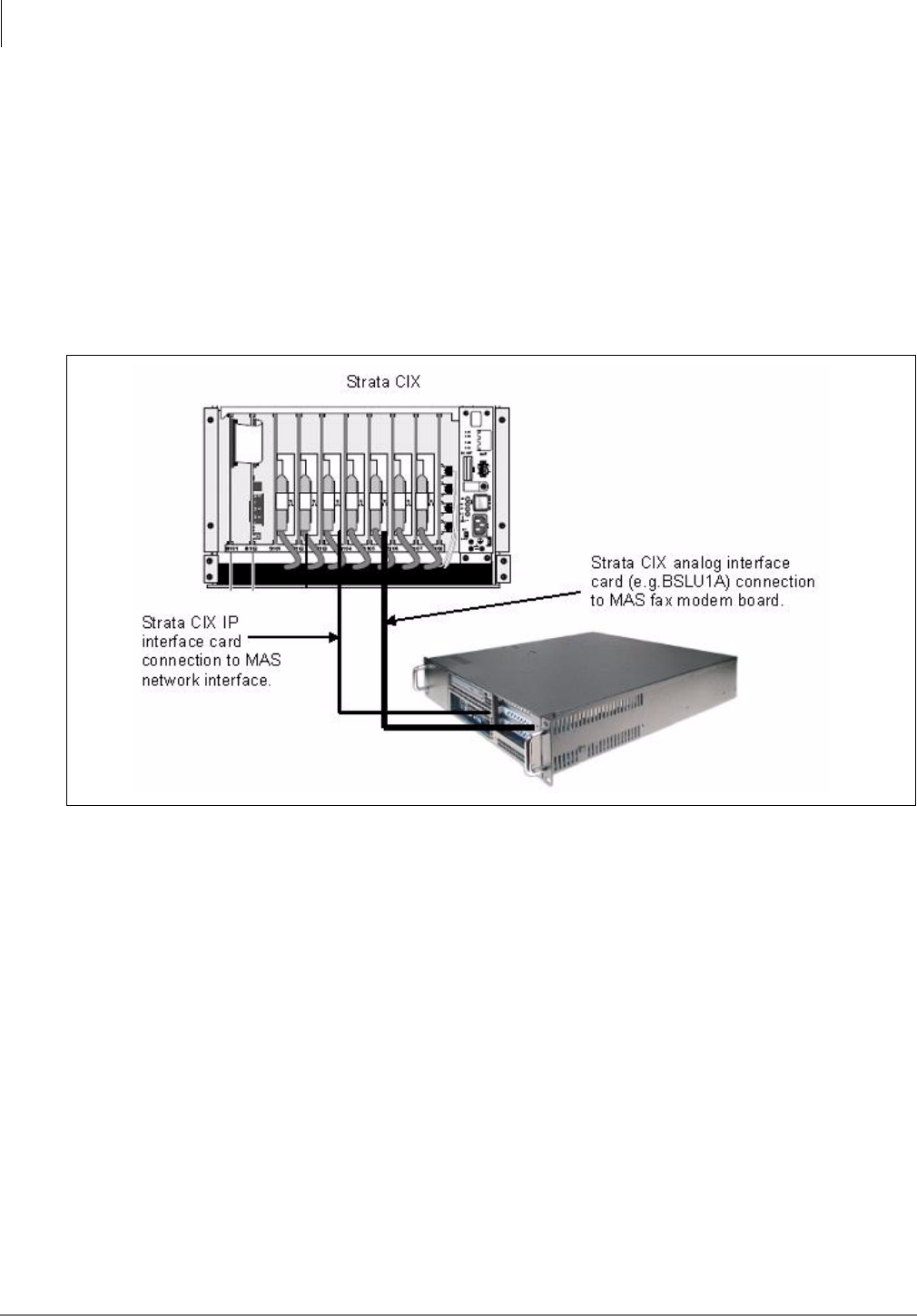
The MAS connects to the CIX using a single IP connection through a Network Switch or Router. All
of the feature communications and Voice Mail speech paths are carried by this one connection.
The monitor, keyboard and mouse are customer supplied options. The MAS can be accessed via
the network by using the Windows® XP Remote Desktop feature.
Figure 1 - 1 MAS Connection Block Diagram
CIX
MAS
Network Switch
*Monitor
*Key Board
*Mouse
LAN
*Optional
Media Application Server Installation
2U MAS Physical Specifications
1-2 STRATA CIX MAS INSTALLATION 06/09
2U MAS Physical Specifications
This 2U MAS platform includes the following features and options;
• Intel Pentium® 4, 2.3 gigahertz CPU
• 512 MB memory
• Internal PCI slots – Two full PCI slots for installation of fax modem boards
• Front cable connections
• RoHS Compliant (Restricted use of Hazardous Substances Directive)
Supports Toshiba’s mandate of environmental responsibility.
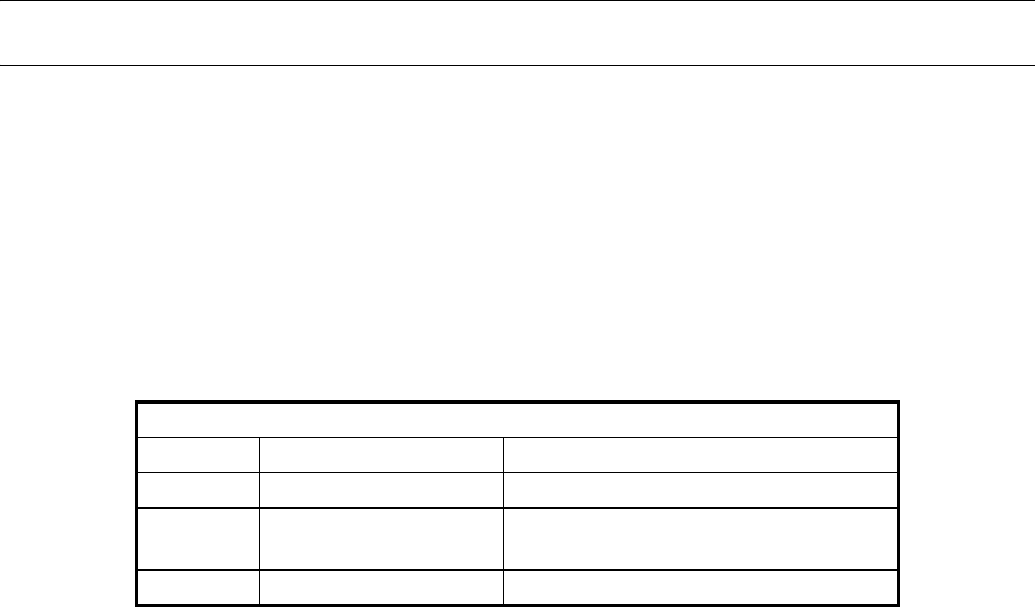
Basic 2U MAS Specifications
2U MAS Physical Installation
The MAS can be mounted in a two post rack or it can be mounted on sliding rails in a four post
rack.
Two Post Rack Mount
Use four screws to secure the MAS in a standard 19 inch rack. The rack and other equipment must
not block the air-flow at the back and front of the MAS. The rail kit is not intended for use in a two
post rack.
Dimensions of Cabinet
Height: 3.5 inches (86 mm)
Width: 17 inches (430 mm) with bracket: 19 inches (483 mm)
Depth: 18 inches (457.5 mm)
Cabinet Weight Approximately 30 lbs. (13.6 kg)
Installation Type Rack-mountable only. Cannot be floor or wall mounted.
Media Application Server Installation
2U MAS Physical Installation
Strata CIX MAS Installation 06/09 1-3
Four Post Rack Mount (Recommended)
The MAS can be mounted in a standard 19 inch four post rack or server cabinet. The rack and other
equipment must not block the air-flow at the back and front of the MAS.
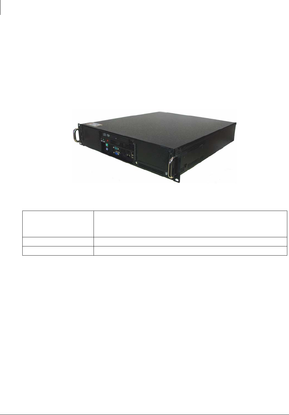
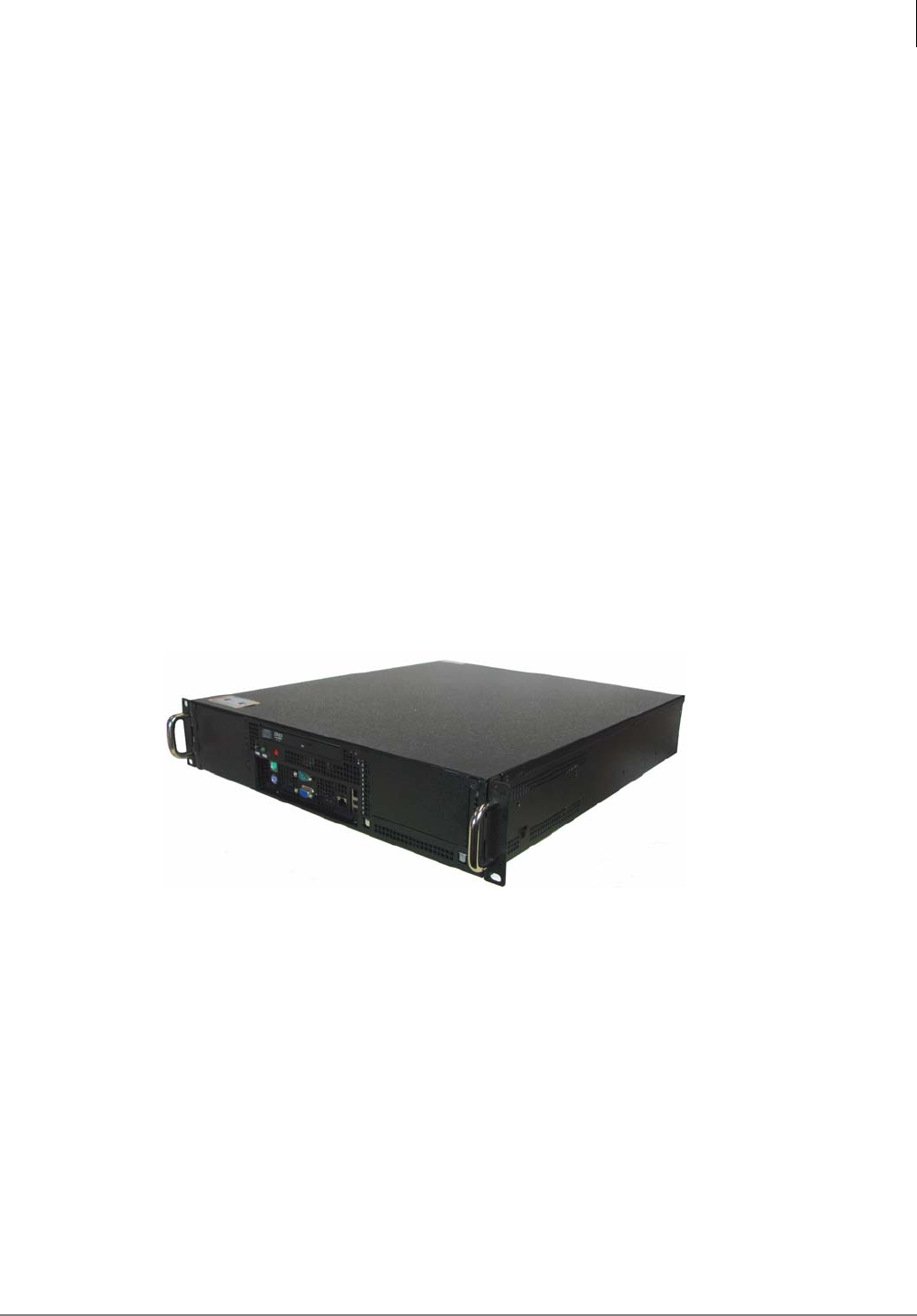
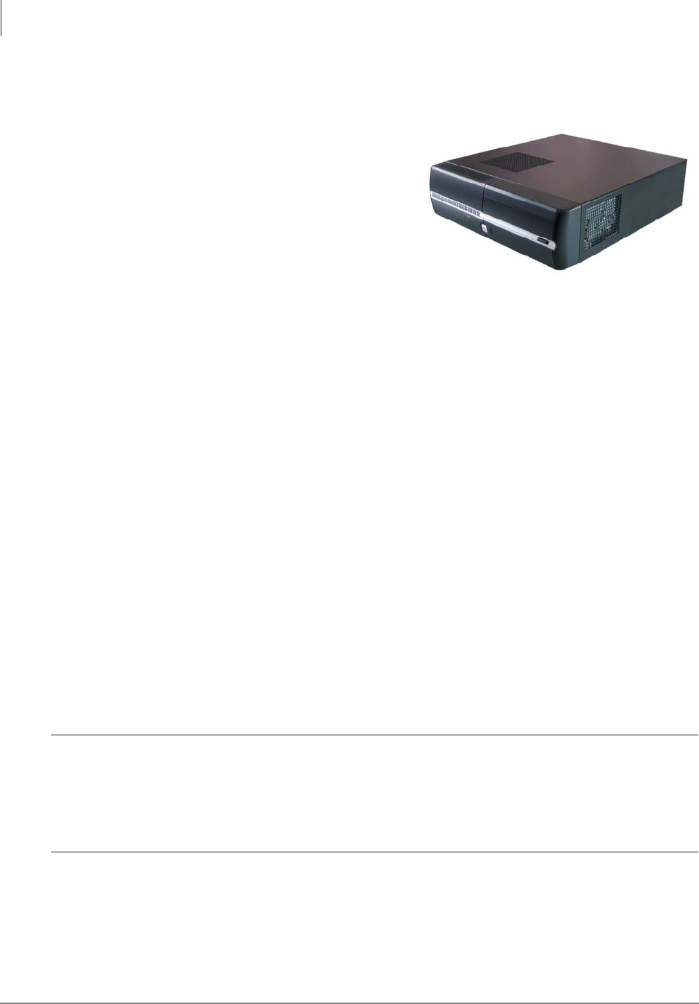
Figure 1 - 2 MAS Front View
Figure 1 - 3 MAS Connector Detail
Figure 1 - 4 MAS Rear Panel
0002-MAS
Two full length PCI card slots
CD ROM Drive
for FAX/Modem cards.
USB Ports
Keyboard Connector
Mouse Connector
Monitor Output Serial Port
1 Gb LAN
10/100 Mb LAN
Connector
I
I
O
<
C
AC Input Power Switch
Reset
Switch
Power
AC Power
Connector
Switch
Media Application Server Installation
2U MAS Physical Installation
1-4 STRATA CIX MAS INSTALLATION 06/09
Assemble the MAS
Fax Modem Board Installation
The 2U MAS supports up to two fax modem boards per system for a maximum of 16 fax modem
ports. If you are installing a fax modem board refer to “Fax Modem Board Installation” on page 6.
2U MAS Cabinet Mount
The 2U MAS can be fixed in a two pole rack or mounted on sliders in a four pole cabinet.
Two Post Rackmount
The MAS is attached to a two post rack using four screws through the brackets on the front of the
cabinet.
Four Post Rackmount
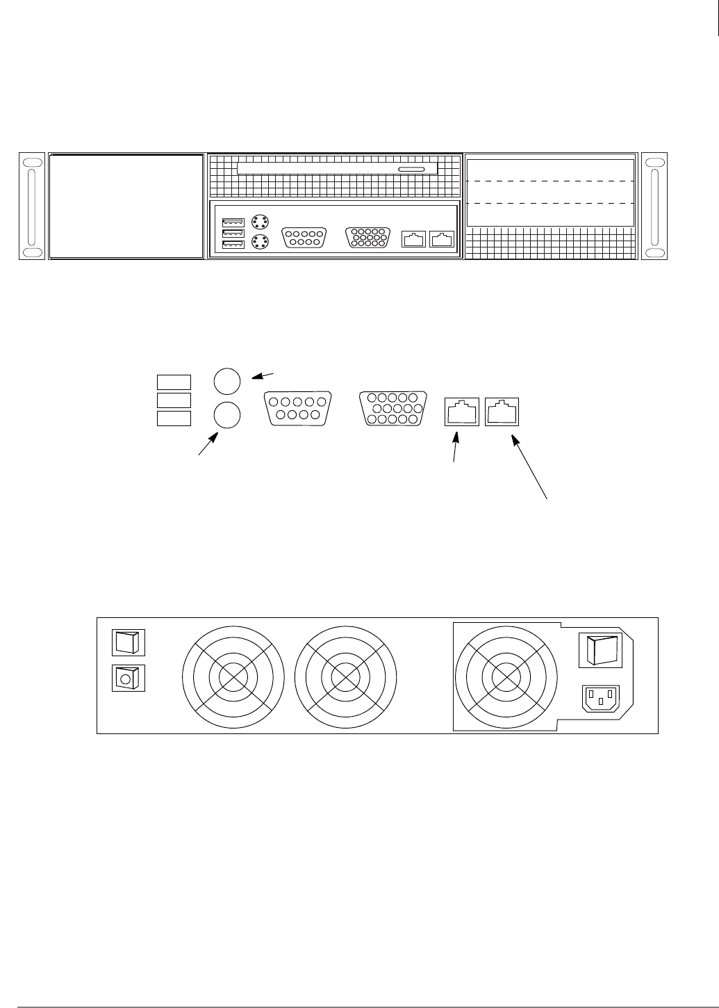
1. Secure the inner rails to the MAS chassis as shown in Figure 1 - 5.
Figure 1 - 5 MAS with Rail Attached
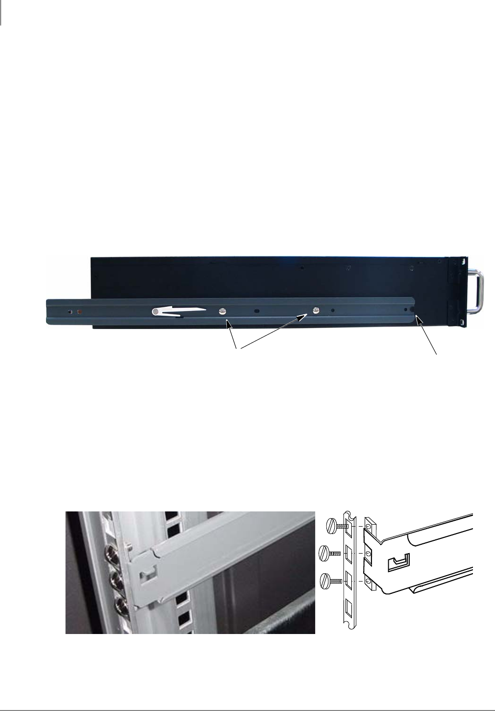
2. Attach the outer rails to the front posts of the rack. Refer to Figure 1 - 6 and Figure 1 - 7.
•If the post has non-threaded holes use the M5 screws and M5 nut plates. The nut plate
must go behind the post. The rail flange goes between the nut plate and the post.
•If the post has threaded M5 holes use the M4 screws and M4 nut plates. The screws will not
engage the threads in the post. The nut plate must go behind the post. The rail flange goes
between the nut plate and the post.
Figure 1 - 6 Outer Rail Attachments
0006-MAS
Use the M4x4 (small) screws provided Notch in the rail
to attach the inner rail to the MAS chassis engages chassis tab.
Front Post Rack Post
Nut Plate
Outer Rail
Media Application Server Installation
2U MAS Physical Installation
Strata CIX MAS Installation 06/09 1-5
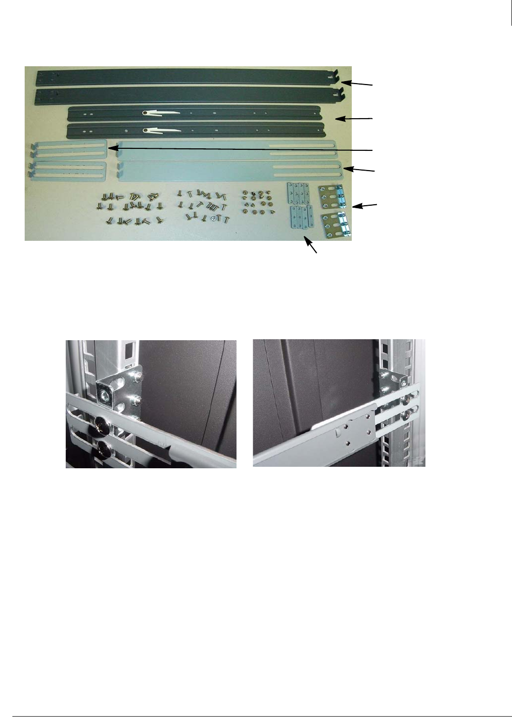
Figure 1 - 7 Rail Kit
3. Attach the rails to the rear posts of the rack. Use the five or 15 inch extensions as needed. If
needed use the L-brackets to attach the extension to the rear post. Refer to Figure 1 - 7 and
Figure 1 - 8.
Figure 1 - 8 L-Bracket to Attach Extension to Rear Post
4. Slide the MAS rails into the rails attached to the rack. Ensure that both side locks “click” into
place.
Note The cooling air flow through the MAS is front to back. Ensure that the front and rear grills
are not obstructed.
5. Connect IP cable from the 1 Gbit connector to the Network Switch. Refer to Figure 1 - 3. This
is the only IP connection to the MAS. Do not use the 10/100 Mbit connector.
6. Connect AC power cord. Refer to Figure 1 - 4.
Outer Rails
Inner Rails
Five inch Extension
15 inch Extension
L Brackets
M4 and M5 Nut Plates
Rear Post using Extension and L-Bracket
Media Application Server Installation
2U MAS Physical Installation
1-6 STRATA CIX MAS INSTALLATION 06/09
Fax Modem Board Installation
There are three fax modem boards available. Their Toshiba part numbers and capacities are:
•SYS-FAXMODEM-1 – 1 port modem board
•SYS-FAXMODEM-4 – 4 port modem board
•SYS-FAXMODEM-8 – 8 port modem board
The following is required to enable fax features on the MAS:
•Minimum of one MultiTech fax modem board
•Corroborating analog interface board (e.g. BSLU1A) in the host Strata CIX telephone system.
1. Power OFF the MAS.
2. Install the MultiTech Fax board(s).
Notes
•For the majority of the 2U MAS systems, the CD-ROM assembly will need to be removed in
order to access the screws that secure the factory installed blank slot covers.
For some units that had a secondary retaining bracket which secured the blank slot covers;
simply remove the secondary retaining bracket to remove the blank slot covers.
•For the 1U MAS the plastic slot guide on the end of the MultiTech board must be removed.
3. Refer to “Install Fax-modem Board Software - All MAS Systems” on page 1-19.
Media Application Server Installation
2U MAS Release 3
Strata CIX MAS Installation 06/09 1-7
2U MAS Release 3
This is the third generation Media Application Server (MAS). This 2U rack mountable chassis
incorporates Dual Core Central Processing Unit (CPU) technology from Intel®. Also available are an
optional dual redundant power supply and RAID1 or RAID5 hard drive redundancy.
Description
This R3 MAS platform (Part number MAS-2U-XPPRO-R3) includes the following features and options;
• Intel Pentium® Dual Core 1.8 gigahertz CPU
• Dual core technology provides optimal performance with less power.
• Intel Server Motherboard (Snow Hill) – Intel 3210 chip set
• Windows® XP Professional (standard) – Windows 2003 Server (Optional)
• Front panel - Hard drive activity LED
• Front panel - Reset button – CPU reset
• Internal PCI slots – Two full PCI slots for installation of fax modem boards.
• Optional SATA RAID 1 or SAS RAID 5 hard drive redundancy.
• Optional Dual Redundant Power Supplies
• RoHS Compliant (Restricted use of Hazardous Substances Directive)
Supports Toshiba’s mandate of environmental responsibility.
Media Application Server Installation
Hardware Specifications
1-8 STRATA CIX MAS INSTALLATION 06/09
Hardware Specifications
Part Numbers
For this new platform there are six new part numbers from which to choose.
Hardware Specification
CPU Pentium Dual Core, 1.8 Gigahertz
Memory 1 GB (Maximum 4 GB)
Memory Slots 4 DIMM (DDR2 667/800 MHz)
Hard Drive 80 GB Serial ATA
SATA DVD Drive Serial ATA Combo Drive CD, CD/RW, DVD-ROM
PCI Slots 2 Full length (Note: RAID 5 chassis support one PCI slot.)
USB 2 Ports – Front side connection
Serial I/O 1 Port – Front side connection
Chassis 2U rack mount chassis
Dimensions (HxWxD) 3.47" x 17.32" x 20" (8.814 cm x 44 cm x 50.8 cm)
Environment Operating temperature: 32° ~ 122° F (0° ~ 50° C)
Humidity: 5% ~ 95% non-condensing
Fans 2 fixed rear fans, 1 hard drive chamber fan
Power Supply 350 Watts
Part Numbers Description
MAS-2U-XPPRO-R3 2U MAS with Windows XP Professional, one 80GB SATA hard drive,
Dialogic HMP 3.0, 1 gigabyte RAM
MAS-2U-R3-RAID1 2U MAS with Windows XP Professional, two 80GB SATA hard drives
(RAID 1 redundancy), Dialogic HMP 3.0, 1 gigabyte RAM
MAS-2U-R3-RAID5 2U MAS with Windows XP Professional, three 73GB SAS hard drives
(RAID 5 redundancy), Dialogic HMP 3.0, 1 gigabyte RAM
MAS-2USVR2K3-R3* 2U MAS with Windows 2003 Server, one 80GB SATA hard drive, Dialogic
HMP 3.0, 1 gigabyte RAM
MAS-2USR3-RAID1* 2U MAS with Windows Server 2003, two 80GB SATA hard drives (RAID 1
redundancy), factory equipped with Dialogic HMP 3.0, 1 gigabyte RAM
MAS-2USR3-RAID5* 2U MAS with Windows Server 2003, three 73GB SAS hard drives (RAID
5 redundancy), Dialogic HMP 3.0, 1 gigabyte RAM
MAS-R3-REDUN-PS Optional dual redundant power supply
*MAS units equipped with Windows Server 2003 are special order items. Please allow three to four
business weeks for delivery.
Media Application Server Installation
R3 MAS Installation Instructions
Strata CIX MAS Installation 06/09 1-9
R3 MAS Installation Instructions
The R3 platform uses the same programming instructions as the previous 2U MAS system. It also
shares the same side rail mounting instructions to install the system in a 19-inch rack. Refer to “2U
MAS Cabinet Mount” on page 1-4.
There are some minor differences with the front panel connections as well as the instructions for
installing optional PCI cards in the system.
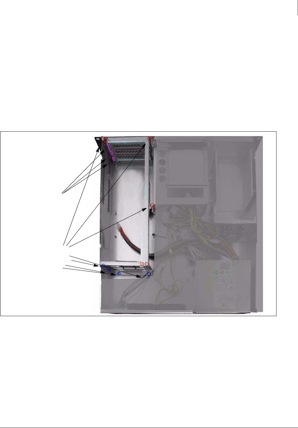
PCI Board Installation Instructions
To install PCI boards into the 2 MAS system please follow these instructions;
1. Remove the top cover of the 2U MAS. Retaining screws can be found on the top front of the
cover and on the side of the chassis.
2. Locate and remove the seven retaining screws, as indicated below.
3. Carefully remove the card cage from the system.
4. Remove the blank panels for the card slot(s) that will be populated with PCI boards.
5. Install the PCI boards as required. Make sure that they are properly seated in their respective
board connectors.
Card cage
Blank panel screws (4)
screws (7)
Media Application Server Installation
Front Panel Detail
1-10 STRATA CIX MAS INSTALLATION 06/09
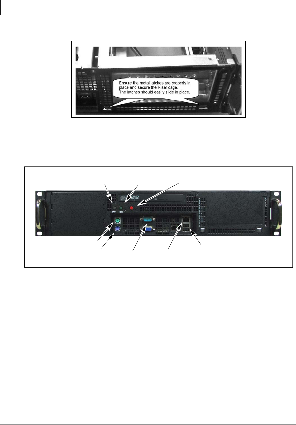
6. Reassemble card cage by reversing steps 1 through 3. Ensure that the locating tabs on the
card cage slide into place at the bottom, front of the chassis.
Front Panel Detail
The AC Power cord connects on the rear panel of the MAS. All other connections are on the front
panel.
Dual Redundant Power Supplies Installation
Use the following procedure to remove the standard power supply and install the optional dual,
redundant power supply assembly.
1. Shut down the system. When the system has completely shut down, the fans have stopped,
remove the AC power cord from the back of the MAS chassis.
2. Remove the top cover of the 2U MAS. Retaining screws can be found on the top front of the
cover and on the side of the chassis.
3. Access the bottom of the cabinet. Remove two power supply bracket screws. The screws are
approximately six inches (15.5 cm) from the rear edge of the cabinet and about 5.75 inches
(12.25 cm) apart.
4. Carefully cut the cable ties securing the power supply cables to the bottom of the cabinet.
5. Remove the PCI card cage from the chassis.
6. Remove the DVD drive assembly. The cables are long enough to set the DVD drive out of the
way. It is necessary to remove the drive to access the power connection to the motherboard.
Power Hard Disk Drive CPU Reset Button
Mouse connector
Keyboard connector Monitor 1 GB LAN connector USB Connectors
Activity
Media Application Server Installation
Dual Redundant Power Supplies Installation
Strata CIX MAS Installation 06/09 1-11
7. Remove the four screws securing the power supply to the back of the cabinet.
8. Disconnect the power supply cables.
9. Disconnect the power cable from the DVD cable.
10. Remove the power supply from the cabinet. The power supply and AC power cord are no
longer needed.
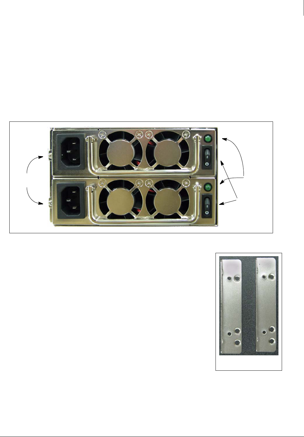
Prepare the Dual Redundant Power Supplies (DRPS) chassis
The 2U chassis brackets must be attached to the DRPS chassis before it is installed.
1. Remove the retaining screw from both power supply units.
2. Use the folding handle to remove both power supply units.
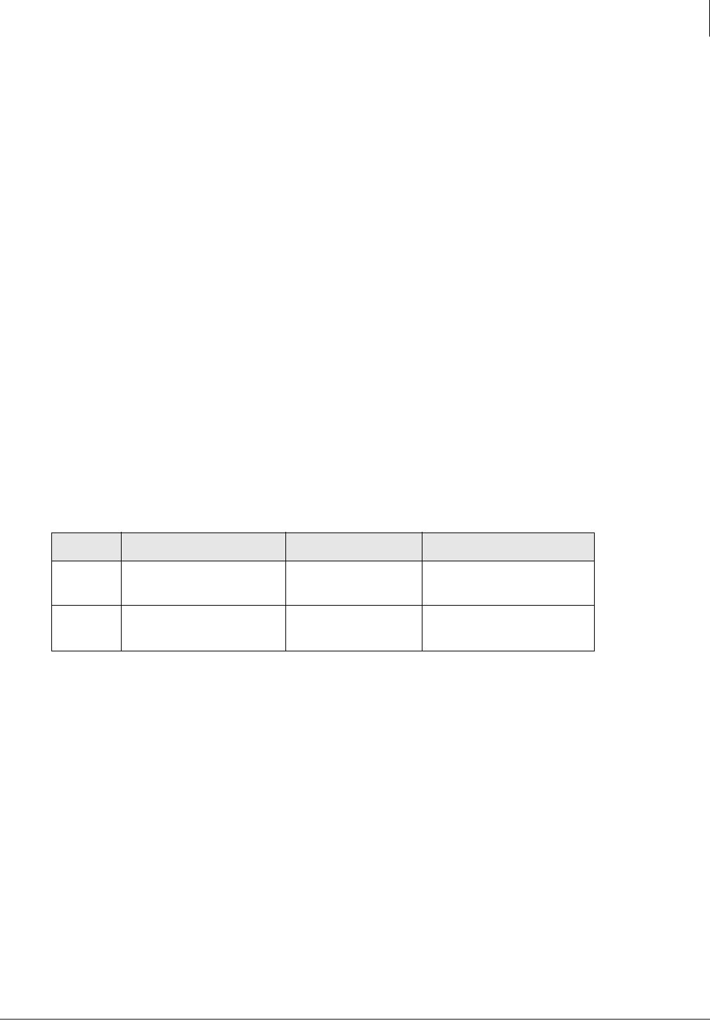
3. Attach the cabinet mounting brackets to the DRPS chassis.
The left (as viewed from the rear) bracket attached with two of the
included flat head screws through counter-sunk holes into threaded
holes in the power supply chassis.
The right bracket uses two screws through holes in the power
supply chassis into threaded holes in the bracket, The two power
supply units must be out of the chassis to access these holes.
4. Set the DRPS chassis in the MAS cabinet. The four threaded holes,
two on each bracket, must align with the holes in the cabinet. Notice
the DRPS chassis extends approximately 0.375 inch out of the
back edge of the cabinet. Do not install the screws at this time.
5. Plug the power supply cables into the motherboard connectors.
6. Replace the PCI card cage then, replace the DVD drive assembly.
7. Plug the power supply cables into the hard disk drive(s). Then, plug in the DVD power cable.
8. Use the four screws from the standard power supply the secure the DRPS chassis in the
cabinet. Dress the power cables, as much as possible, away from the RAID hard drive cage
fan.
Retaining
Screws
Power
Power
Switches
Indicators
DRPS Chassis
Brackets

Media Application Server Installation
Power Supply Hot Swap
1-12 STRATA CIX MAS INSTALLATION 06/09
9. Some of the unused cables can be placed between the DRPS chassis and the side of the
MAS cabinet. The LED attached to one of the DRPS cables is a power supply status indicator.
When both power supply units are functioning the indicator is green. When one of the power
supply units fails the indicator in red. This can be left inside the cabinet. Optionally, it can be
secured with a cable tie such that it is visible through the front panel of the MAS.
10. Bundle the power cables and use new cable ties through the anchor points on the bottom of
the cabinet.
CAUTION! Ensure that all of the power supply cables are routed and secured so that
none will rub against any sharp edges. Be sure that none of the cables are
trapped or pinched under any of the brackets.
11. Install the four screws to secure the DRPS chassis to the MAS back panel.
12. Replace the MAS cabinet top.
13. Plug both AC power cords into the dual power supply units Then, plug the power cords into a
dedicated outlet.
14. Set the switches to the “ON” or “1” position.
15. Press and release the power switch on the rear of the MAS cabinet. Verify that the cabinet and
power supply fan are running while the system reboots.
Power Supply Hot Swap
The two power supply units in the DRPS chassis share the MAS power load. In the event that one
of the power supply units fail the other power supply unit will supply all of the power. The failing
unit can be replaced with the system power on, without interrupting service.
When one of the DRPS units fails an audible alarm is generated and the status indicator led (Refer
to Step 9 in the installation procedure) will turn red. The green power indicator next to the power
switch on the back of the power supply unit will go dark on the failing unit. Use the following
procedure to replace a failing power supply unit.
1. Set the power switch on the malfunctioning power supply unit to off. Unplug the AC power cord
from the failed unit.
2. Remove the retaining screw next to the AC power connector.
WARNING! The power supply unit cover may be as hot as 120° to 140° F (40° ~ 50° C). It may be
necessary to wear gloves while replacing the power supply.
3. Use the handle to pull the power supply out of the chassis.
4. Set the power switch on the replacement power supply to off.
5. Plug the replacement power supply into the chassis and replace the retaining screw.
6. Plug the AC power cord into the replacement power supply unit.
7. Set the replacement power supply switch to on. The power indicator next to the switch will light
and the audible alarm will quite.
Media Application Server Installation
Micro MAS
Strata CIX MAS Installation 06/09 1-13
Micro MAS
This section gives the initial steps to set up Toshiba’s entry level Media Application Server (MAS)
called MicroMAS. Please read the entire contents of this section before beginning installation.
Introduction
MicroMAS platform includes:
•Motherboard with a 2.93 Ghz Intel® Celeron D processor
•2 half-length Peripheral Component Interconnect (PCI) slots
•80GB Serial ATA hard disk drive
•CD-R\RW drive
•512MB Random Access Memory (RAM)
•10/100BaseT Ethernet Connection
•PS/2 keyboard
•PS/2 mouse
•Windows XP Professional
•2 Serial ports
•2 Universal Serial Bus (USB) 2.0 connectors (front and rear)
•Footstand
System Status LED Indicators
These LEDs display the current status of critical elements and parameters within the unit
LED Description No Light Light
Power System Power No Power Blue Light — System is
operational.
HDD Hard Drive Activity No Activity Amber Light — Hard
drive is active.
Media Application Server Installation
Micro MAS
1-14 STRATA CIX MAS INSTALLATION 06/09
Micro MAS
The Strata MicroMAS is an entry-level server that
offers all of the features of the 2U MAS platform
but with a much smaller footprint.
The new Strata MicroMAS (shown right) is a very
cost-effective Media Application Server that
targets the small to medium CIX customers. The
MicroMAS uses the same platform as the Strata
ACD CT2 and the Stratagy ES8 but with greater
processing power to handle the multiple
applications of the MAS.
Hardware Specifications
The MicroMAS platform includes the following:
•Intel™ Celeron™ D processor and motherboard using the Intel 950 chipset
•2 half-length Peripheral Component Interconnect (PCI) slots
•80GB Serial ATA hard disk drive
•CD-R\RW drive
•512MB Random Access Memory (RAM)
•10/100 Base-T Ethernet Connection
•PS/2 keyboard
•PS/2 mouse
•Windows® XP Professional
•2 Serial ports
•2 Universal Serial Bus (USB) 2.0 connectors (front and rear)
•Footstand
MicroMAS Installation
Step 1: Before You Start
CAUTION! Always handle this system with care. Avoid dropping or jarring the unit by
keeping the system in a secure position on a flat surface.
Electrostatic discharge can damage or destroy the components in the server.
During this entire procedure, use an anti-static wrist strap to discharge any
static electricity you may be carrying.
1. Check the packing list on the side of the carton to make sure that you have received all the
items.
2. Make sure that you have a Phillips screwdriver.

Media Application Server Installation
MicroMAS Installation
Strata CIX MAS Installation 06/09 1-15
Step 2. Network Connection
The MicroMAS requires a static IP Address. The MicroMAS and the Strata CIX (xCTU processor
card) should be the same network segment.
Since MicroMAS-H has a VoIP connection to the MIPU/LIPU, then the supporting MIPU/LIPU must
have an IP address that can be successfully pinged by the MicroMAS.
A MIPU/LIPU card’s IP Address must be accessible by all IP devices (IP Telephones (IPT),
MicroMAS). If IPT stations are going to be placed on the public internet or Strata Net IP will be run
on the public network without a Virtual Private Network (VPN), the MIPU/LIPU should have a public
IP address. The MicroMAS and CIX must be physically installed first. Connect up the MicroMAS.
Insert the IP circuit cards into the CIX cabinets. Connect the IP cables. When all of the cables are
connected proceed to the next step of setup.
Step 3. Verify PC Operation
Notes
•Steps 2~5 are required only if you have purchased a Voice board. They are not required for
ACD, etc.
•This step verifies the unit is operational before installing voice boards.
1. Set the Voltage Selector Switch, located on the back panel, to an input power source of either
115VAC default or 220VAC (50-60 Hz), depending upon the available input power.
2. Plug-in the power cable to the rear of the unit and to the UPS.
3. Connect the monitor, keyboard and mouse. See Figure 1 - 11 on Page 17 for the monitor,
keyboard and mouse connections on the MicroMAS.
4. Power up the unit. If the Windows® XP logon screen does not display, check the connections.
At this point the installation is partitioned.
•If you are installing a MicroMAS-D, that uses Dialogic analog port voice boards for
connectivity to the CIX or installing a Fax modem card, proceed to the next step.
•If you are installing a MicroMAS-H, that uses HMP for IP connectivity to a CIX MIPU/LIPU
card, proceed to step 13.
Step 4. Remove Cover
1. Once the unit is operational, shut down Windows, turn the power off and remove the power
cable.
2. Remove the two screws from the upper left and right corners of the back of the server. Pull the
cover off using the build-in handle.
Step 5. Unpack Voice / Fax-modem Boards
Remove the Dialogic voice (Dialogic part number D4PCIUF/S) and/or MultiTech System Fax-
modem (MultiTech part number MT5634ZPX-PCI) board(s) to be installed in this system from
the shipping boxes.
Note MicroMAS only supports half-length PCI boards.
Media Application Server Installation
MicroMAS Installation
1-16 STRATA CIX MAS INSTALLATION 06/09
Step 6. Install Voice/Fax
Board(s)
The 1U MAS system supports one fax
modem board per system for a maximum of
8 fax modem ports.
1. Loosen the riser retaining bar by pulling
on the release tab and lifting the Bar to
unlock it (shown right).
2. Remove the PCI riser screw, then
remove the PCI riser by pulling the riser
upwards with the green strap.
3. Insert the edge connector of the first
board into the PCI 1 slot (see Figure 1 -
10). Apply pressure only to the top edge
of the board, and gently rock the board
back and forth to seat the edge
connector into the slot.
4. Insert the second board into the PCI 2 slot.
Note A Dialogic Voice board can be installed in the PCI 1 (top) slot with no modification. To
install a fax-Modem card into the PCI 1 card slot the green strap must first be removed
from the riser. The fax-modem card can be installed in the PCI 2 slot without modification.
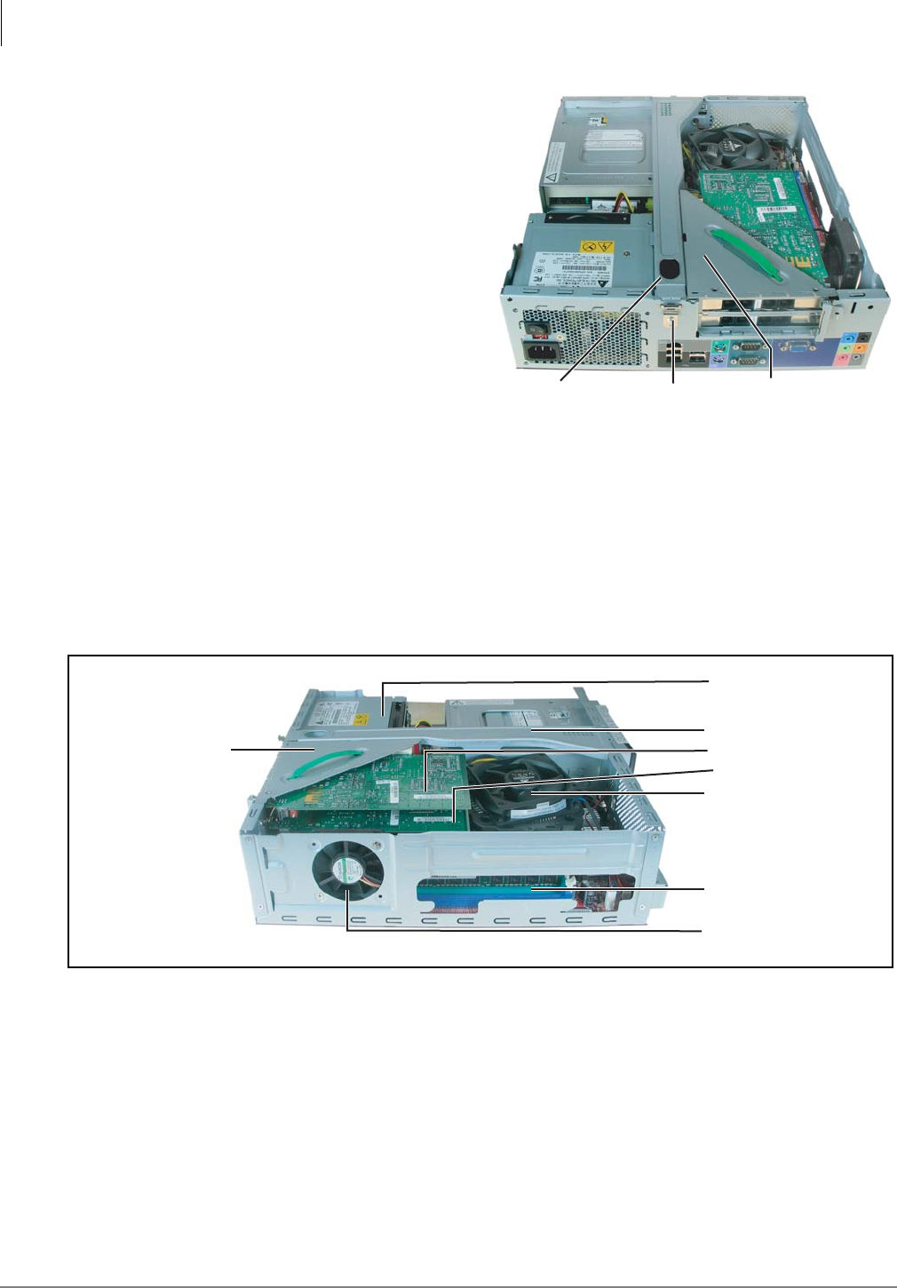
Figure 1 - 10 MicroMAS Internal View 2
Step 7. Reinstall Riser
1. Reinstall the PCI riser in the chassis. Align the PCI slot and press down to secure the PCI riser
assembly.
2. Insert the riser retaining bar and press gently to lock into place.
3. Secure the riser to the chassis by screwing in the screw taken out in Step 6.Install Voice/Fax
Board(s).
Release Tab Riser
Retaining Bar 001-MM
Figure 1 - 9 MicroMAS Internal View 1
002-MM
Power Supply
PCI Riser
CPU Fan
Retaining Bar
Chassis Fan
RAM Slot
PCI 1 Card
PCI 2 Card
Media Application Server Installation
MicroMAS Installation
Strata CIX MAS Installation 06/09 1-17
Step 8. Check Hardware Connections
Check to insure that all other boards and cables are properly seated.
Step 9. Complete MicroMAS Hardware Setup
1. Replace the cover and tighten the two thumbscrews.
2. Connect the following items (see Figure 1 - 11 on page 17 for
connections):
•Keyboard
•Monitor
•Mouse
The hardware portion of this installation is now complete.
Step 10. (Optional) Install Footstand
Set the unit on the footstand (shown at right).
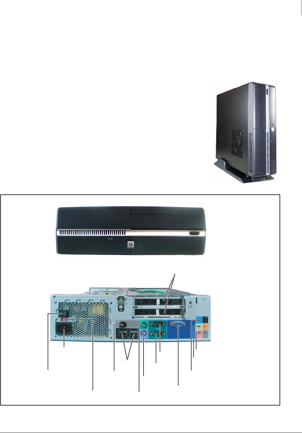
Figure 1 - 11 MicroMAS Front and Back Panels
AC Power Cord
Connectore
220V and 110V Switch
Main Power
Switch
USB
RJ45 LAN
Connection
Mouse
Keyboard
Com 2
Com 1
VGA Connector
PCI Card Slots
Line-in (Blue)
Line-out (Green)
Mic-in (Pink)
003-MM
Front Panel
Rear Panel

Media Application Server Installation
MicroMAS Installation
1-18 STRATA CIX MAS INSTALLATION 06/09
Step 11. Power Up the PC
1. Plug-in the power cable to the rear of the unit and to the UPS.
2. Power up the unit using the Power Switch on the front control panel. If the Windows XP logon
screen does not display, check the connections detailed in Steps 3 and Steps 3.
If the Windows Found New Hardware Wizard starts follow “Install Fax-modem Board
Software - All MAS Systems” on page 1-19 or “Configure Voice Board Software” on
page 1-28 as appropriate. If no PCI cards are installed skip forward to “Configure Software”
on page 1-29.
Media Application Server Installation
Install Fax-modem Board Software - All MAS Systems
Strata CIX MAS Installation 06/09 1-19
Install Fax-modem Board Software - All MAS
Systems
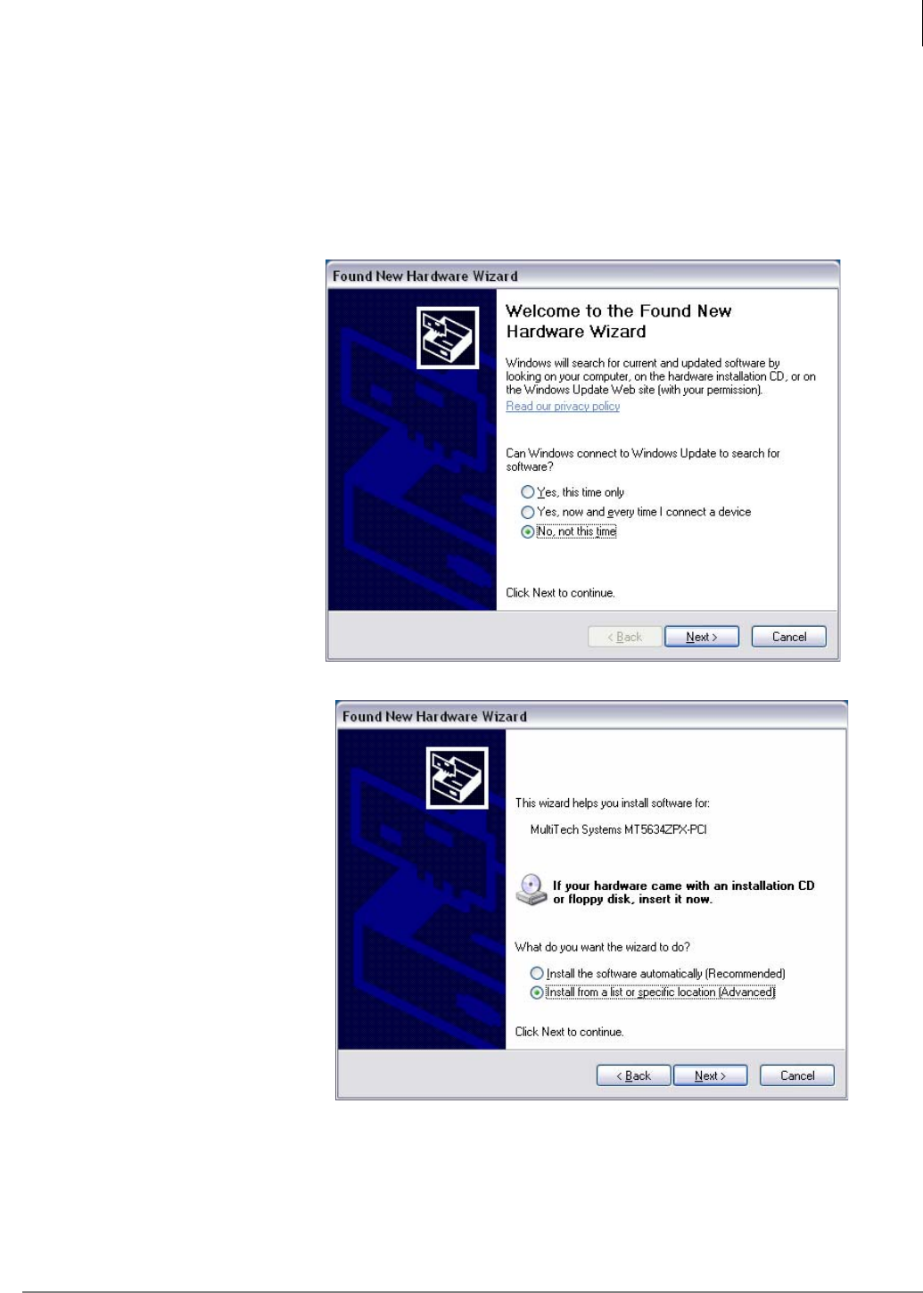
When the MAS is powered-up after the installation of a MultiTech modem board the Windows
Found New Hardware Wizard should start. Follow this procedure to complete the installation
wizard.
1. The first dialog box will
ask if it can connect to
Windows update to
search for software.
Select "No, not at this
time" then, click on
Next.
2. Insert the MultiTech
Driver CD now.
Note: If the "Auto
Run" installation
menu appears click
“EXIT” to close it.
In the Found New
Hardware Wizard
window select Install
from a list or
specific location
[Advanced].
Click on Next.
Media Application Server Installation
Install Fax-modem Board Software - All MAS Systems
1-20 STRATA CIX MAS INSTALLATION 06/09
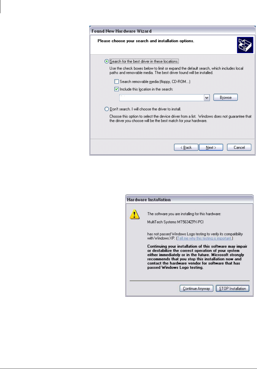
3. Selectt Search
for the best
driver in these
locations.
Uncheck the
Search
removable
media [floppy,
CD-ROM…]
button.
Check the
Include this
location in the
search box.
For a one port
fax modem
board enter D:\
For a multi-port
fax modem
board, use the Browse button to select; D:\Drivers\Win2K-XP-2003.
Ensure that the Don’t search radio button is not selected. Click on Next.
A dialog box will appear asking you to wait while the installation wizard finds the files.
4. When the Hardware Installation
warning appears, click on
Continue Anyway.
D:\Drivers\Win2K-XP-2003
Media Application Server Installation
Install Fax-modem Board Software - All MAS Systems
Strata CIX MAS Installation 06/09 1-21
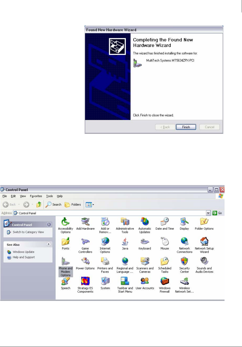
5. Click Finish to complete
installation of one fax-
modem card.
If another modem is
detected a Hardward
Installation dialog box
will open. Select
Continue Anayway.
Each modem port must
be installed. The system
treats each port as a
separate device.
Repeat the above steps
for each modem port.
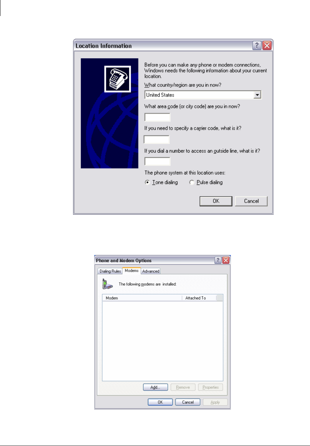
Installing Fax Modem Boards using the Control Panel
1. Click Start > Control Panel.
2. Click on “Phone and Modem Options” icon (shown below).
3. Enter the "Area code" for the installation (This is not used by SES. Windows requires this
entry).
4. Leave the other fields blank and click "OK".
Media Application Server Installation
Install Fax-modem Board Software - All MAS Systems
1-22 STRATA CIX MAS INSTALLATION 06/09
5. Click on the "Modems" tab.
6. Enter the "Area code" (this is not used by Stratagy but Windows requires this entry).
7. Leave the other fields blank, then click "OK"
8. In the Phone and Modems Options screen, click on the Modems tab. You should see the
MultiTech modems installed and assigned to COM 3 and COM 4.
9. Highlight one of the modems and click on "Add"
Media Application Server Installation
Install Fax-modem Board Software - All MAS Systems
Strata CIX MAS Installation 06/09 1-23
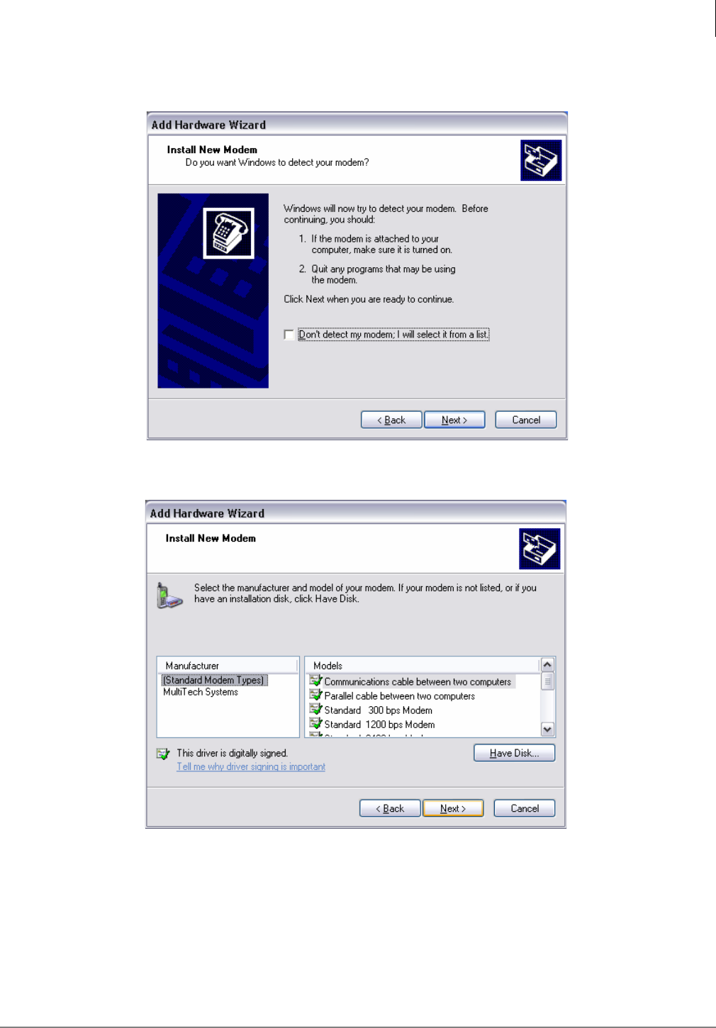
10. The New “Hardware Wizard appears"
11. Select the check box "Don't detect my modem; I will select it from a list.
12. Select MuliTech Systems
13. Click "Next"
Media Application Server Installation
Install Fax-modem Board Software - All MAS Systems
1-24 STRATA CIX MAS INSTALLATION 06/09
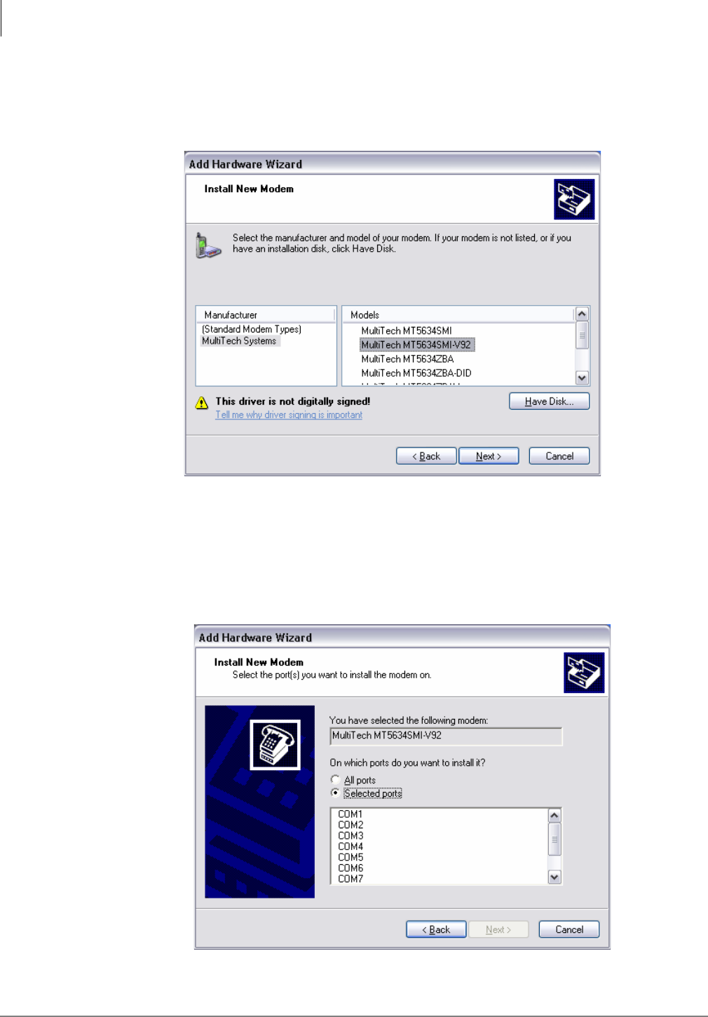
14. Select:
•For the 4 port fax modem board, select - MT5634SMI-V92
•For the 8 port fax modem board, select - MT5634SMI-V92
15. Click “Next”
Windows displays a list of available COM ports.
The MultiTech board (s) start at COM3
Note System software will always interpret the existing COM ports on the MAS motherboard as
COM1 and COM2. Therefore, the addition of the fax modem boards begin at COM3.
Media Application Server Installation
Install Fax-modem Board Software - All MAS Systems
Strata CIX MAS Installation 06/09 1-25
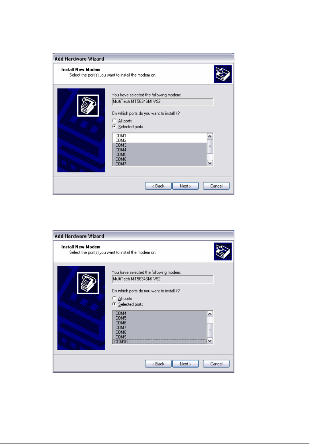
16. Click on COM3 continuing to the highest port number. For example 8 Modem ports will display
as COM3 ~ COM10.
17. Click until all the MultiTech COM ports are highlighted.
18. Click "Next".
Media Application Server Installation
Install Fax-modem Board Software - All MAS Systems
1-26 STRATA CIX MAS INSTALLATION 06/09
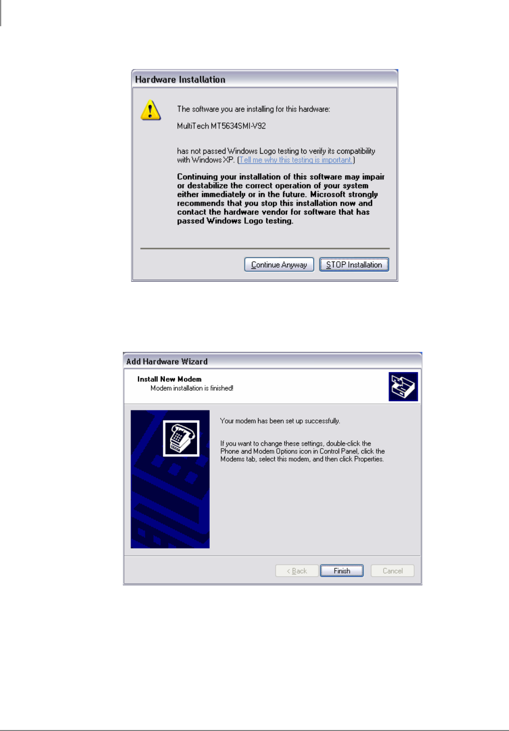
The Windows "compatibility" dialog warning appears.
19. Click "Continue Anyway"
Repeat for each MultiTech COM port when prompted.
When completed the following dialog box appears:
20. 39. Click "Finish" to close the "Add Hardware Wizard"
The installed COM port / MultTech Modems appear in the list.
21. 40. Click "OK" to close the "Phone and Modem Options"
Media Application Server Installation
Install Fax-modem Board Software - All MAS Systems
Strata CIX MAS Installation 06/09 1-27
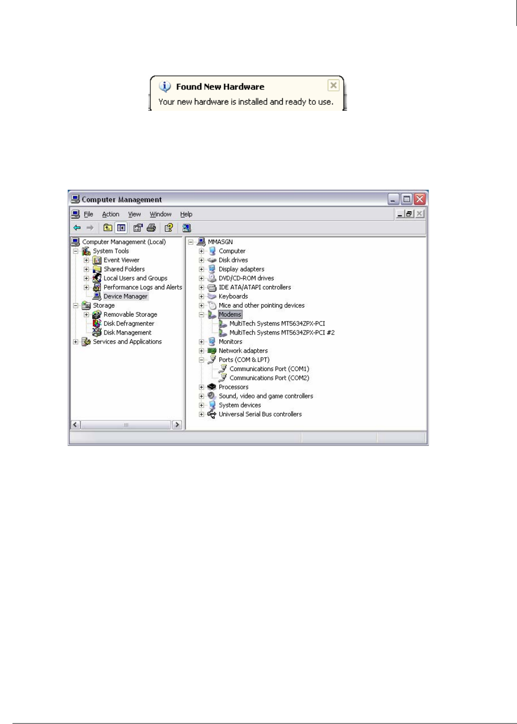
When all of the modems have been installed the Found New Hardware box will display briefly in
the lower right corner of the task bar.
22. When properly installed, the modems will appear in the system Device Manager. To view the
Device Manager right click on the My Computer icon, then click on Manage. Click on Device
Manager then expand the Modems tab.The MultiTech single port Modems will appear in the
list as shown below.
Step 12. Configure Stratagy using Network eManager
When the fax-modem card has been installed, the Stratagy software must be configured for the
modem to function.
1. Login to eManager, connect to the system.
2. Select Stratagy ES> VM System > VM Serial ports.
3. For the COM port(s) the modem card(s) occupy, click on the drop arrow in the Assign As
column and select FAX. The example below shows a system with two modems.
4. Enter the PDN of the single line port in the Telephone System or Resource Name: field for
each modem installed. The modem and the PDN must match this entry.
5. You must restart the Stratagy VM system for the changes to take effect.
6. Assign the Voice Mail to a COS that has DND enabled.
Note Changes will not take effect until after the SES service has been restarted. This can be
accomplished by selecting Utilities > Operations > SES Restart menu option, or by
Media Application Server Installation
Install Fax-modem Board Software - All MAS Systems
1-28 STRATA CIX MAS INSTALLATION 06/09
accessing the MAS system’s desktop using Remote Desktop and using the StartStratagy
control service utility.
Step 13. Configure Voice Board Software
Depending on the Stratagy ES’s hardware configuration, you may need one or all of the following
procedures to fully configure all of the voice boards that you have installed. To set up and configure
the software for the voice boards, you must run the Dialogic Configuration Manager (DCM).
Procedures for the following voice boards are available in this section:
•D/4PCIUF (Fax), D/41PCIUS (Automatic Speech Recognition)
Configure Voice Boards
Windows XP and the Dialogic Software
automatically detect Dialogic’s PCI boards.
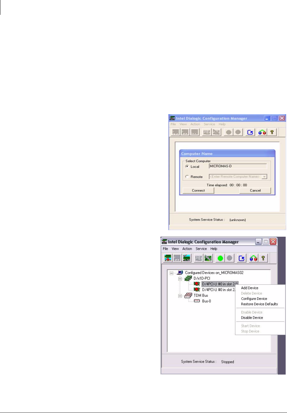
1. From Windows, click Start > Programs >
Dialogic System Software > Dialogic
Configuration Manager - DCM. The DCM
Main screen displays (sample shown right).
Click Connect.
2. Right-click on the installed board and
select Configure Device. The Configure
Device screen for the board displays.
Media Application Server Installation
Install Fax-modem Board Software - All MAS Systems
Strata CIX MAS Installation 06/09 1-29
3. To change the firmware setting, select the Misc Tab and highlight FirmwareFile.
4. From the drop-down menu in the
Value field, select
d4u.fwl for the D/4PCIUF board or
d4ucsp.fwl for the D/4PCIUS board
(shown right).
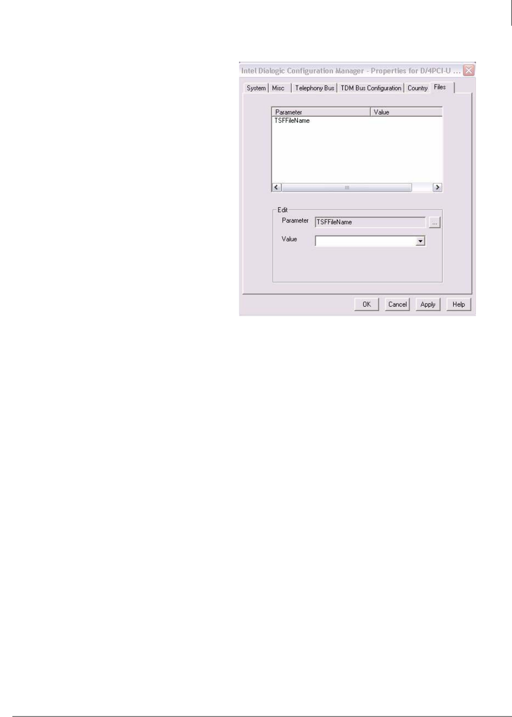
5. To set the Tone Set File, highlight
TSFFileSupport and from the Value
field, select Yes.
6. Select the Files tab, highlight
TSFFileName and in the Values field
type or browse to
C:\StratagyES\Bin\DK.tsf.
7. Click Apply.
8. Click OK. The DCM screen displays.
9. Repeat steps 2~4 for the second
board if applicable.
10. Exit out of the DCM and reboot the
system.
Step 14. Configure Software
The MicroMAS is shipped with the application software loaded. Product and service licenses are
downloaded from FYI. Refer to the Toshiba Strata CIX Programming Manual (Vol. 2).
The pre-loaded software should never need to be loaded. In the event this becomes necessary the
MicroMAS recovery CD-ROM set, included with the server should be used.
Installation of any software not approved by Toshiba voids the warranty. Refer to “Approved Third
Party Application Software” on page 1-31.
Windows XP Firewall Settings
The MicroMAS runs on the Windows XP Professional operating system. Windows XP includes an
Internet Connection Firewall (ICF). When installing the MicroMAS, consider the configuration of the
network and how the MicroMAS will be accessed. Changes to the ICF may be required.
Considerations include:
•Will the MicroMAS be accessed using remote desktop or will a keyboard, monitor and mouse
connected to the MicroMAS be the only direct access?
•Will the MicroMAS be addressable via the internet?

Media Application Server Installation
Network Connection - All MAS Systems
1-30 STRATA CIX MAS INSTALLATION 06/09
Network Connection - All MAS Systems
The MAS requires a static IP Address. The MAS and the CIX processor card (xCTU) should be in
the same network segment. The MIPU/LIPU address must be assigned so that it can be pinged by
the MAS.
The MIPU/LIPU card IP Address must be accessible by all IP devices (IPT, MAS). If IPT stations
are going to be placed on the public internet, or Strata Net IP will be run on the public network
without a VPN the MIPU/LIPU should have a public IP address.
The MAS and CIX must be physically installed first. Mount the MAS in the rack. Insert the circuit
cards into the CIX cabinets. Connect the IP cables. When all of the cables are connected power up
the system and proceed to the MAS Software Setup.
Software
The MAS is shipped with the application software loaded. Product and service licenses will be
downloaded from FYI.
Refer to the Toshiba CIX Programming Manual Vol. 1.
The pre-loaded software should never need to be loaded. In the event this becomes necessary the
MAS recovery CD-ROM set, included with the server will be used.
Important! Installation of any software not approved by Toshiba will void the warranty.
Refer to “Approved Third Party Application Software” on page 1-31.
Windows XP Firewall Settings
The MAS runs on the Windows XP Professional operating system. Windows XP includes an
Internet Connection Firewall (ICF). When installing the MAS consider the configuration of the
network and how the MAS will be accessed. Changes to the ICF may be required. Considerations
include:
•Will the MAS be accessed using remote desktop or will and keyboard, monitor and mouse
connected to the MAS be the only direct access?
•Will the MAS be addressable via the internet?
Media Application Server Installation
Media Application Server Configuration Requirements
Strata CIX MAS Installation 06/09 1-31
Media Application Server Configuration
Requirements
The MAS is a platform for running real-time IP based multimedia applications. It must process
each IP packet of a multimedia stream, each voice packet, within a fixed amount of time, generally
20 ms. It is imperative that the amount of processing required of the MAS in the worst case not
exceed its capacity in terms of processor speed, cache size, or memory size.
To ensure that the capacity of the MAS is not exceeded, two steps must be taken.
•The number of real-time voice channels processed on the MAS must be limited. When licenses
are generated FYI will check what is currently licensed on the MAS, what is being added, and
check to see that the maximum is not being exceeded. This information is also programmed
into CIX Quote.
•No other applications or windows components should be loaded onto the MAS. Many
applications can, all by themselves, exceed the ability of the MAS to meet its 20 ms response
time requirement, other applications working together can also exceed it.
This document contains information about specific applications and configurations. As the product
and market evolve, we will update this document. Please check back on FYI occasionally for the
latest version of this bulletin.
Approved Third Party Application Software
The Toshiba MAS is a purpose built system. Do not install any software not authorized by Toshiba.
The table below shows the only third party application software that should be installed on the
MAS.
Important! Installing any other applications will void the warranty, and tech support
will not provide any support until the MAS has been brought back to a
reliable configuration.
Table 1 - 1 Third Party Application Software
Application Configuration Notes
PC-cillin™ Internal Security 2005 Should not be run in batch mode when running any
other applications.
Symantec’s Norton Anti-Virus™ 2005 Script blocking option must be un-checked.
McAfee® Virusscan® 2005 Ver. 9.0 Script blocking option must be un-checked.
Zoom Modem Driver Zoom™/Modem V.92 USB Mini refer to “MAS
Modem Installation (Optional)” on page 1-44.
Trend Micro and PC-cillin are registered trademarks of Trend Micro Inc.
Norton Anti-Virus is a registered trademark of Symantec Corp.
McAfee and Virusscan are registered trademarks of McAfee, Inc.

Media Application Server Installation
Media Application Server Configuration Requirements
1-32 STRATA CIX MAS INSTALLATION 06/09
Maximum MAS Configurations
The tables below show the available part numbers for the features that can be licensed to run on
the MAS, and the maximum number of each that can be supported. However, we recommend
checking all configurations through CIX Quote.
The tables below have three columns showing maximum configurations, the first shows the
constraints on a MAS configured with both SES and ACD. The second column shows the
constraints on a system that is configured with only VoiceMail. The third column shows the
constraints of a system that is only configured with ACD.
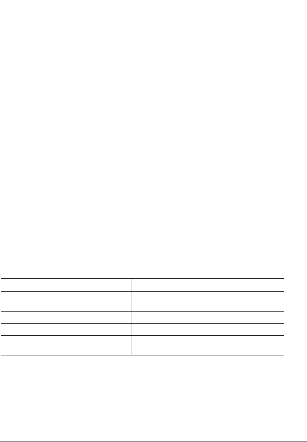
Table 1 - 2 Toshiba SES and Feature Flex - Maximum Number of Licenses Shown
Feature License SES and
ACD
Voice Mail
Only ACD
Only
Alarm Clock Enable LICMAS-FF-ACLK 1 1 0
Auto Speech Recognition Auto Attendant. LICMASFGASRAA,
LICMASUPASRAA-2 880
Call Monitor Enable LICMAS-FF-CMON 1 1 0
Call Return Enable LICMAS-FF-CRET 1 1 0
Call Screen Enable LICMAS-FF-CSCR 1 1 0
Hot Desk LICMAS-FF-HDSK 1 1 0
Four Port Upgrade for Stratagy ES on MAS
Note: Four ports per license. LICMAS4PORTUPG 4 5 0
One Seat Unified Messaging Upgrade.
LICMAS-FG-UM,
LICMASUM10SEATS,
LICMASUM25SEATS,
LICMASUM50SEATS,
LICMASUMUNLIMT
Unlimited Unlimited 0
One Number Access Enable LICMAS-FF-ONUM 1 1 0
Text-To-Speech Feature Group. LICMASFGTTSETI 4 8 0
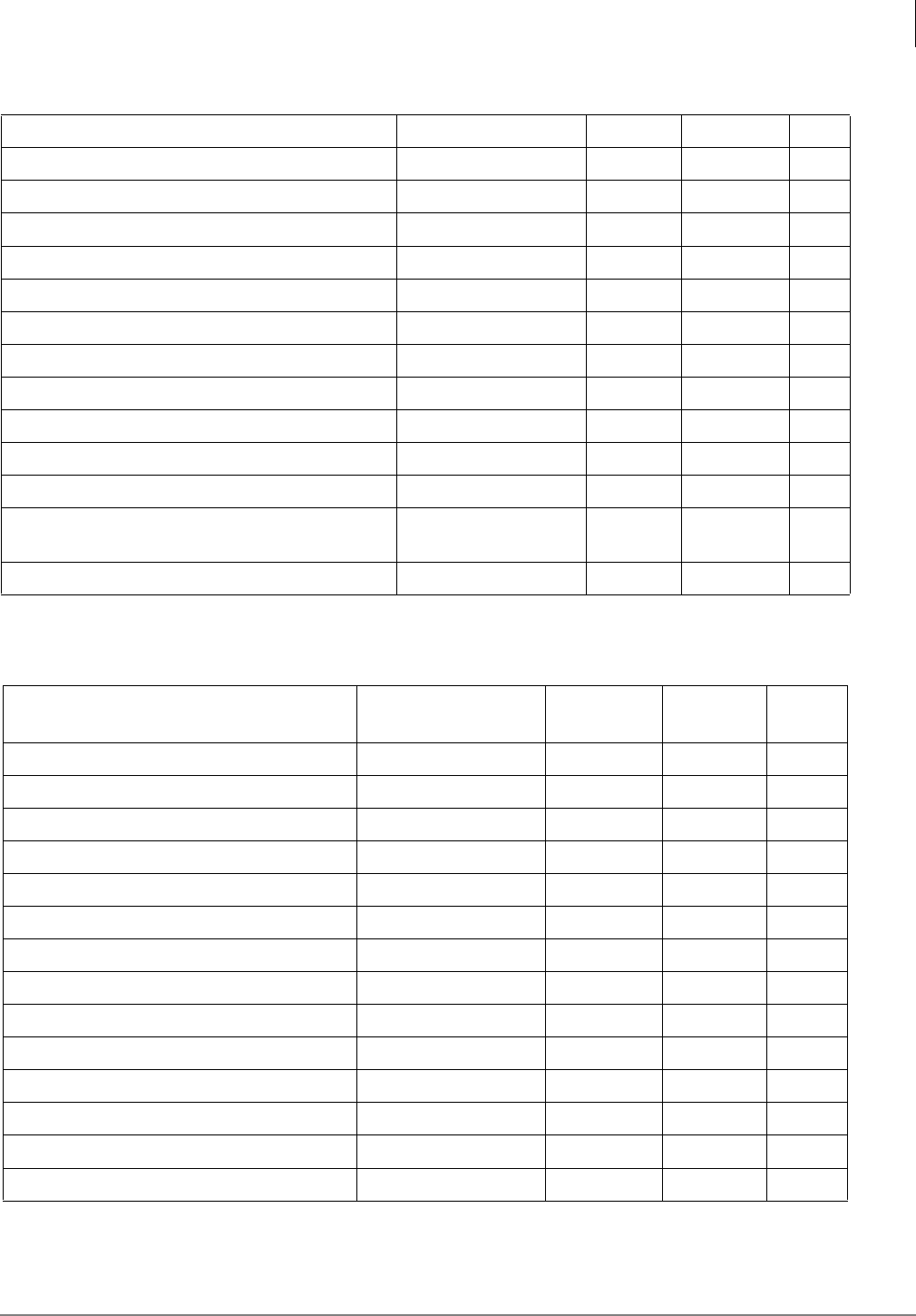
Table 1 - 3 ACD - Maximum Number of Licenses Shown
Feature License SES and
ACD
Voice Mail
Only ACD
Only
ACD Application License LICMAS-APPLSW 1 0 1
Single Basic Agent License LICMAS-BAADDL1 350 350 350
Single Agent Upgrade License LICMAS-UPGREN1 360 360 360
Single Wnhanced Agent License LICMAS-ENADDL1 350 350 350
Advanced Partner Program ACD Demo SW - B LICMAS-ACDBR 1 0 0
Advanced Partner Program ACD Demo SW - H LICMAS-ACDHQ 1 0 0
OAISYS Call Router License for Strata ACD LICMAS-CALLRUTR 1 0 1
Media Application Server Installation
Media Application Server Configuration Requirements
Strata CIX MAS Installation 06/09 1-33
OAISYS Chat Text Messaging License LICMAS-CHATSEAT 360 0 360
OAISYS Diamond out-of-plan upgrade for MAS LICMAS-SUP-OUT 999 0 999
OAISYS Diamond support for MAS LICMAS-SUP-OAI 999 0 999
OAISYS IVR Option with Database Assistan LICMAS-ACDIVR 1 0 1
OAISYS NetPhone and chat license for MAS LICMAS-NETSEAT 360 0 360
OAISYS NetPhone server and client LICMAS-NETPH 1 0 1
Strata ACD Basic ACD 20 agent add-on LICMAS-BASADD20 17 0 17
Strata ACD Enhanced ACD 20 agent add-on LICMAS-ENADD20 17 0 17
Strata ACD MAS license (10 basic agent) LICMAS-ACDBA10 2 0 2
Strata ACD MAS license (20 basic agent) LICMAS-ACDBA20 1 0 1
Strata ACD MAS license (20 enhanced agent) LICMAS-ACDEN20 1 0 1
Strata ACD upgrade to enhanced for MAS LICMAS-UPGENHD 1 0 1
Strata ACD upgrade to enhanced for MAS LICMAS-
UPGADD20 17 0 17
VA port license with HMP license LICMAS-ACDVA 15 0 31
Table 1 - 4 Insight - Maximum Number of Licenses Shown
Feature License SES and
ACD
Voice
Mail Only ACD
Only
Insight Plus Agent LICMAS-INSPAG1 360 0 360
Insight App Pack LICMAS-INSPA10 1 0 1
Insight Basic Agent LICMAS-INSBAG1 350 0 350
Insight Agent Upgrade LICMAS-INSPUP1 350 0 350
Additional Supervisor license for Insight LICMAS-INSITSUB 99 0 99
Insight upgrade to Plus for Strata ACD LICMAS-INSITUPG 1 0 1
Insight license for MAS LICMAS-INSIGHT 1 0 1
inView client license for fifty users LICMAS-INVIEW50 8 0 8
inView client license for five users LICMAS-INVIEW5 72 0 72
inView client license for forty users LICMAS-INVIEW40 9 0 9
inView client license for one user LICMAS-INVIEW1 360 0 360
inView client license for ten users LICMAS-INVIEW10 36 0 36
inView client license for thirty users LICMAS-INVIEW30 12 0 12
inView client license for twenty users LICMAS-INVIEW20 18 0 18
Table 1 - 3 ACD - Maximum Number of Licenses Shown (continued)

Media Application Server Installation
Media Application Server Configuration Requirements
1-34 STRATA CIX MAS INSTALLATION 06/09
Table 1 - 5 Taske - Maximum Number of Licenses Shown
Feature License SES and
ACD
Voice
Mail Only ACD
Only
Contact - Base Renewal for MAS LICMAS-TASCONB 999 0 999
Contact - Per Agent for MS LICMAS-TASCONA 999 0 999
Contact - Per Month for MAS LICMAS-TASCONM 999 0 999
Contact - Per Site for MAS LICMAS-TASCONS 999 0 999
Contact - Re-enlist Site for MAS LICMAS-TASCONR 999 0 999
TASKE Blue Pumpkin Integration for MAS LICMAS-TASBPINT 1 0 1
TASKE COREMEDIA INTEG LICMAS-TASCOREM 1 0 1
TASKE Contact Agent for MAS LICMAS-TASAGENT 360 0 360
TASKE Contact Base System for MAS LICMAS-TASBASE 1 0 1
TASKE Contact Blue Pumpkin Director LICMAS-TASBPWF 1 0 1
TASKE Contact Conversion (Change
PBX) for MAS LICMAS-TASCONV 1 0 1
TASKE Contact Desktop Sign for MAS LICMAS-TASSIGN 360 0 360
TASKE Conversion w/o Historical Data LICMAS-TASTRAN 1 0 1
TASKE Demo System (10 agents, 1
supervisor) LICMAS-TASKE-
DEMO 101
TASKE Enterprise Client Software for
MAS LICMAS-TASENTER 1 0 1
TASKE IEX Integration LICMAS-TASIEXWF 1 0 1
TASKE Left Bank WFM Integration LICMAS-TASLBWF 1 0 1
TASKE Supervisor Client, 1 license for
MAS LICMAS-TASSUP1 99 0 99
TASKE Supervisor Client, 3 licenses for
MAS LICMAS-TASAUP3 33 0 33
TASKE Supervisor Client, 5 licenses for
MAS LICMAS-TASSUP5 20 0 20
TASKE Supervisor Client, 10 licenses for
MAS LICMAS-TASSUP10 10 0 10
myTaskeReporter Supervisor LICMAS-TASMTSUP 100 0 100
myTaskeReporter Maintenance LICMAS-TASSUPMT 999 0 999

Media Application Server Installation
Media Application Server Configuration Requirements
Strata CIX MAS Installation 06/09 1-35
Maximum MAS Ports
One MAS can support up to 32 voice channels. One MAS can support up to 32 channels of Voice
Mail OR up to 32 channels of ACD Voice Announcements.
When voice mail and voice announce are both on one MAS it can support up to 16 channels of
Voice Mail, AND up to 16 Voice Announce ports.
If you want more than 16 ports of voice mail AND some ACD ports (or more than 16 voice
announce AND some voice mail ports), you will then use one MAS for the voice mail ports and
another for the voice announce ports. For example; 20 voice mail ports and 10 ACD ports will
require two MASs.
Table 1 - 6 Toshiba VCS - Maximum Number of Licenses Shown
Feature License Max.
Quanity Max.
Server Max.
User
VCS 90 Day Trial License LIC-VCSTRIAL 1 1 512
VCS Starter LIC-VCSBASIC5 1 1 5
VCS User License LIC-VCSUSER1,
LIC-VCSUSER10,
LIC-VCSUSER20
Mix and
Match 0507
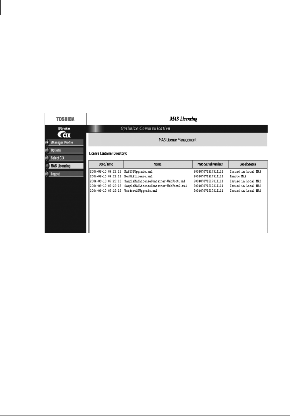
Media Application Server Installation
MAS Licensing
1-36 STRATA CIX MAS INSTALLATION 06/09
MAS Licensing
For information about CIX Licensing see Chapter 10 in the Strata CIX Programming Manual
Volume 1 for Licensing.
This option enables you to manage, issue and activate MAS licenses in the eManager™ server
host. It is required that administrators should be able to manage licenses for all applications in the
MAS.
Access Main MAS Licensing Screen
Before connecting to the system login using the keyboard connected to the MAS. In the
Manager Menu, click MAS Licensing. The screen below displays.
The upper part of the screen is a list of MAS License Container files stored in the eManager
server in the <eManager>\Licenses folder. The example above shows a system with licensing
already activated. The first time the license container directory is viewed it will be empty. The
following columns are shown:
•Generation Time – date and time assigned by the FYI application when it creates the
container file.
•File Name – specified by the administrator when the container file was created in eManager
using the Upload button.
•MAS Serial Number – defined in the header of the container file.
•Local Status
•Local MAS – The MAC address in this container file is the same as the local MAS host
MAC address (where the eManager server is running).
•Issued in Local MAS – Same as “Local MAS” but the licenses in this container have
been issued already. eManager stores a log of the issued container files.
•Remote MAS – The MAC address in this container file is different than the local MAS
host MAC address (where the eManager server is running). This file could be viewed,
uploaded to other MAS, but it cannot be issued in the local MAS host.
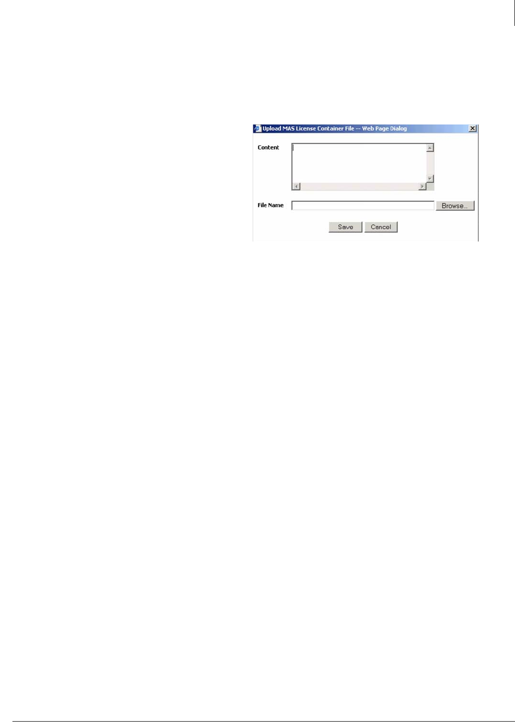
Media Application Server Installation
MAS Licensing
Strata CIX MAS Installation 06/09 1-37
Upload Licenses
Note The Upload button is enabled if no file is selected, otherwise disabled.
The MAS License Container File is an XML file generated by the FYI application. The file can be
downloaded from FYI or the file can be e-mailed from FYI.
1. From the MAS Licensing screen, click
Upload. The Upload MAS License
Container File screen displays (shown
right).
2. If the file is stored in the local client PC,
click Browse. Select the Container file.
The file’s contents and file name are
copied into the fields of the Upload
screen
...or go to FYI and open the MAS License
Container File in a text file such as
Notepad. Copy and paste the displayed file in the Content portion of the Upload MAS license
screen shown here. The File Name field is blank.
Note If you chose to fill in the File Name before you copied/pasted the file, the file name
remains in the field after pasting the file.
3. If the file name was filled in automatically, change the file name so that it is unique to the file. If
you copy/pasted the file into this screen, you need to enter a unique file name.
Note File names must conform with the Windows filenames and conventions. If the file you
uploaded does not have an .xml extension, you must add it before saving the file.
4. Click Save.
Issue Licenses
Note The file you selected must be “Local” to use this feature. Any file with a status of Remote
MAS must be issued from the controlling server.
From the MAS Licensing screen, select a file and click Issue Licenses. eManager separates
the selected container file, extracts each license for the different applications and services and
delivers the licenses. This process can take several minutes depending upon the number of
applications installed.
A pop-up dialog box will show the status of the issue command as successful or failed.
Activate Licenses
To activate the licenses, be sure the license file is not highlighted, click Activate Licenses. A
warning box displays telling you that the MAS operating system will be shut down and
rebooted. The MAS attempts to shut down and reboot immediately.
Important! During the activation process, the MAS cannot be processing calls. Any
current connection being processed by the MAS is disconnected. In order
not to disrupt daily activity in your customer’s business, you can choose to
do the activation process unattended during the evening/early morning
hours by scheduling the procedure using the Windows scheduling
process.
Delete Licenses
Note You can delete more than one file at a time by highlighting the files.
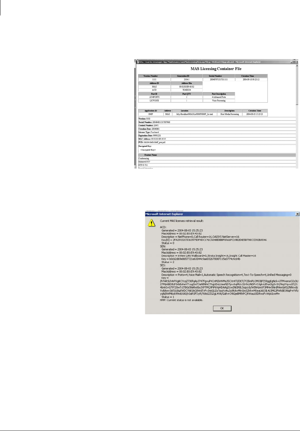
Media Application Server Installation
Change MAS Static IP Address (Optional)
1-38 STRATA CIX MAS INSTALLATION 06/09
1. From the MAS Licensing screen, highlight a Container file(s).
2. Click Delete. A pop-up box displays and you are asked to confirm your deletion.
3. Click OK.
View Licenses
Note The View button is
enabled when one file is
highlighted, disabled
when none or more than
one is highlighted.
1. From the MAS Licensing
screen, highlight a Container
file.
2. Click View. The MAS
Licensing Container File
displays (sample shown
below).
View Current Licenses
1. From the MAS Licensing screen, make sure that none of the listings in the License Container
Directory is highlighted.
Note To remove a highlight, press Ctrl and click the highlighted item.
2. Click View Current Licenses.
eManager checks the status of
the license activation through
each application’s licensing
interface and displays the results
(sample shown right).
3. When finished, click OK.
Status Values Shown on Screen
•0 – New license was issued, but
not activated yet.
•1 – The license activation during
the startup procedure was
successful.
•2 – The license activation during
the startup procedure failed.
Logout of eManager
From the eManager Menu, click Logout to exit eManager.
Change MAS Static IP Address (Optional)
This procedure is used to change the MAS static IP Address from the default setting. The MAS
must be mounted in the rack, the power cord plugged in and the IP cable installed between the
MAS and the IP switch (LAN).

Media Application Server Installation
MAS Recovery
Strata CIX MAS Installation 06/09 1-39
Note This procedure requires a monitor, keyboard and mouse connected directly to the MAS.
Refer to “MAS Rear Panel” on page 1-3.
1. At the MAS desktop select Start > Control Panel > Network and Internet connection. Click on
Network Connection.
2. Right Click on Local Area Connection for Intel® PRO/1000 CT Network. Then select
Properties.
3. Highlight Internet Protocol (TCP/IP) then click on the Properties button.
4. Select; Use the following IP address then enter the following:
•IP Address: (default = 192.168.254.252)
•Subnet Mask: (default = 192.255.255.0)
•Default Gateway: <default is blank>
5. Click on the OK button.
SES Voice Mail and ACD Setup
When the MAS reboots login to eManager. Refer to the CIX Programming Manual Volume One for
setting up user accounts. Then refer to the SES and ACD manuals to program the applications as
appropriate.
MAS Recovery
In the event that MAS suffers a catastrophic failure the following procedures will restore the MAS
to the configuration it was in when shipped. If possible backup the data, configuration and license
files before starting. At the conclusion of these steps return to the MAS Software Setup section of
this chapter.
Important! The MAS Recovery procedure MUST be followed completely. Do not stop
until the procedure is complete.
Step 1: Restore Using the Recovery CD Set
1. Ensure that the LAN cable from the 1Gbps connector on the MAS is NOT connected. Refer to
“MAS Rear Panel” on page 1-3.
Important! Ensure that the MAS does NOT have internet access at this time.
2. Connect power cable to your MAS server and power up the server.
3. Power up the MAS by depressing the power switch on the rear panel switch. Refer to “MAS
Rear Panel” on page 1-3.
4. Insert the Recovery CD number one into the CD-ROM Drive.
(Note: DO NOT remove this CD until instructed to insert another CD-ROM.)
5. Restart the MAS by pressing the Reset Button the rear panel. Refer to “MAS Rear Panel” on
page 1-3. The computer will boot from the CD into the recovery environment.
Note Until the recovery is complete the mouse will not function.
6. A dialog box will appear asking: Do you want to recover? Press the Y key on the keyboard to
answer yes. A Caution dialog box stating that All data on the hard drive will be lost. Press the
Y key on the keyboard.
The Clearing Hard Disk Drive box will appear. Then the Toshiba - Symantec status screen will
appear.
7. The screen prompt: Please insert the CD in order to continue the process. Remove CD one,
insert CD two then press ENTER.

Media Application Server Installation
MAS Recovery
1-40 STRATA CIX MAS INSTALLATION 06/09
8. When the screen prompts: Please insert the CD in order to continue the process. Remove CD
two, insert CD three then press ENTER.
9. At the end of the process the following will display. Recovery of Pre-installed Software is
completed. Please remove the CD-ROM or floppy disk. Press any key and restart the system.
10. Remove the CD-ROM from the drive then, press any key on the keyboard. The MAS will
restart.
Step 2. Setup for Windows Mini-Setup Wizards
1. In the Welcome to the Windows XP Setup screen, click on Next.
2. In License Agreement screen, check the I accept the agreement box then click Next
3. In Regional and Language option, leave everything default, then click Next.
4. In the Personalize Your Software screen enter admin as the name and your company name
then click Next
5. Enter the 25 characters Product Key which can be found on the label on the top cover of the
MAS chassis.
6. For computer name enter: STRATAMAS01
For password enter password
(Note that the name and password are case-sensitive.)
then click Next.
7. Adjust appropriate date, time and time zone, then click Next. Set Auto adjust for Daylight
Savings Time if appropriate for this area.
8. Click Typical settings, then click Next.
9. Select No and enter WORKGROUP if the MAS is not in any specific domain.
Note Note contact your network administrator for more information.
10. Click on Finish when done.
The MAS will restart as soon as the Windows Mini-setup is finished.
Step 3. Activate Microsoft Windows license
1. Plug the LAN cable into the MAS 1 Gbit connector, refer to Figure 1 - 3 on Page 1-3. At this
time internet access is required, or you may choose to license the MAS via a telephone
conversation.
2. On the Windows Taskbar, double click on the Activation Key appearing in the System Tray
window.
3. Select Yes activate over the internet now or Yes I want to telephone a Customer Service
Representative.
4. Follow the prompts or instructions to activate the license.
5. When the registration completed, proceed to the next section.
Note At this point the MAS is in the “as shipped” condition. Data file, configuration files and
license files must be restored.
Step 4. Setup Network Connections
1. Log on to the MAS; click on Valued Customer and enter password as the password.
2. From the main menu select Start > Control Panel > Network and Internet Connection then
click on Network Connection.

Media Application Server Installation
MAS Recovery
Strata CIX MAS Installation 06/09 1-41
3. Right click on the Local Area Connection for the Intel® PRO/1000 CT Network, and select
Properties.
4. Highlight Internet Protocol (TCP/IP) and click the Properties button.
5. Select Use the following IP address and enter the following:
a. IP Address: 192.168.254.252 (static address)
b. Subnet Mask: 255.255.255.0
c. Default Gateway: Blank
6. Click on OK.
Step 5. Set Up Firewall
7. Click the Advance tab at the top of the window, check mark; Protect my computer and network
by limiting or …from the internet.
8. Click on the Settings… button.
9. Select following protocols:
a. CIX SMDI. Click Edit to enter STRATAMAS01 in the Name or IP address field. Click
on OK.
b. CTX SMDI. Click Edit to enter STRATAMAS01 in the Name or IP address field.
Click on OK.
c. Ensure that ALL of the protocols in the list are set to STRATAMAS01.
10. Click on OK.
11. Click on Close to finish.
12. Close the control panel window.
Step 6. Set Up Valued Customer Auto-Login
13. From the main Menu select Start > Run …> enter: control userpasswords2
and then press Enter.
14. In the Users for this computer list, scroll down to select Valued Customer.
15. Uncheck the Users must enter a user name and password to use this computer box.
16. Click Apply.
17. In the Automatically Log On window, type password as the Password and Confirmed
Password text boxes, and then click the OK button.
18. Click OK to finish the user accounts settings.
Note Note that when restarting the MAS again, the system will not prompt the user to logon the
local machine any more.
Step 7. Enabling Remote Desktop in Windows XP
Professional
1. Click Start, right-click My Computer, and then click Properties.
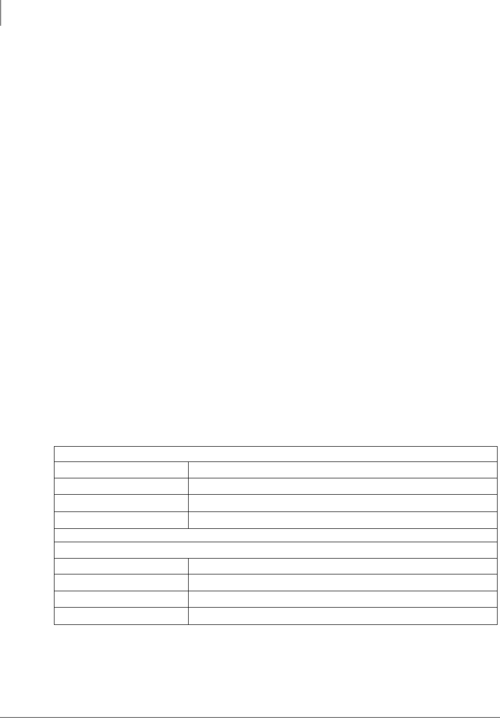
Media Application Server Installation
MAS Software Backup
1-42 STRATA CIX MAS INSTALLATION 06/09
2. In the System Properties sheet, click the Remote tab.
3. Select the Allow users to connect remotely to this computer check box.
4. Select the Select Remote Users… check box.
5. Click Add button.
6. Click Advanced button.
7. Click Find Now button.
8. Highlight Valued Customer name, then click OK.
9. Click OK three times to save all the settings.
END OF RECOVERY PROCEDURE
Post Recovery Procedure
The MAS is now in its as shipped condition. Go to “MAS Licensing” on page 1-36.
To setup the SES and ACD refer to their manuals.
MAS Software Backup
The files shown in the following lists should be backed up on a regular basis. The backup files can
be stored on a network disk drive or another network device.
Stratagy ES (Voice Mail Backup)
Refer to the Stratagy ES Installation and Maintenance manual for backup instructions.
ACD
The files listed in Table 1 - 7 should be backed-up. Refer to the ACD documentation for detailed
information.
Files that get saved when doing an upgrade/maintenance
Here is the list and location of the files that should backed up when doing an upgrade.
Table 1 - 7 ACD INI and Report Data
INI FILES
NAME USE
MISGEN.INI configurator
MISREPTR.INI report template
MISW.INI real time display
REPORT DATA
FILE NAME
MASTER.PDB
ELOGx \ ELOGyyyy.PDB
MEMOx \ MEMOyyyy

Media Application Server Installation
MAS Software Backup
Strata CIX MAS Installation 06/09 1-43
In the CTS folder there will be a folder for each of the software pieces you have installed, (i.e. Net
Server, V_Assist32, Call Router, etc.)
Search each of the folders and copy the following file extensions to the respective folders on the
backup drive via the network:
•.mdb, .aci, .dat and .acs (example: netserver.mdb) (not every folder will have every one of
these file extensions in it)
•If using Park n Page, backup the directory that has all the .txt files used to call users of the
locate me application. cts\v_assist32
•The entire prompts & scripts folders
•The Voice Assistant port information and Database Assistant information is stored in the
registry. Export the Computer Telephony Solutions registry key from:
hkey_local_machine\software\computer telephony solutions. From the Registry menu,
choose export registry file.
•If you have Voice Assistant version 3 or below: va32.dat located in cts\v_assist32 folder
•If you have TASKE: toolbox.cde located in taske8\sitedata\local folder all the .pbx files
located in taske8\sitedata\local\smdr folder OR the entire local folder
•If the customer is printing reports from the server: templates (.tpl) files located in the
document_settings/user/applic777ation_data/taske/prefs/local
•If using Wall Sign, backup the entire SignData folder
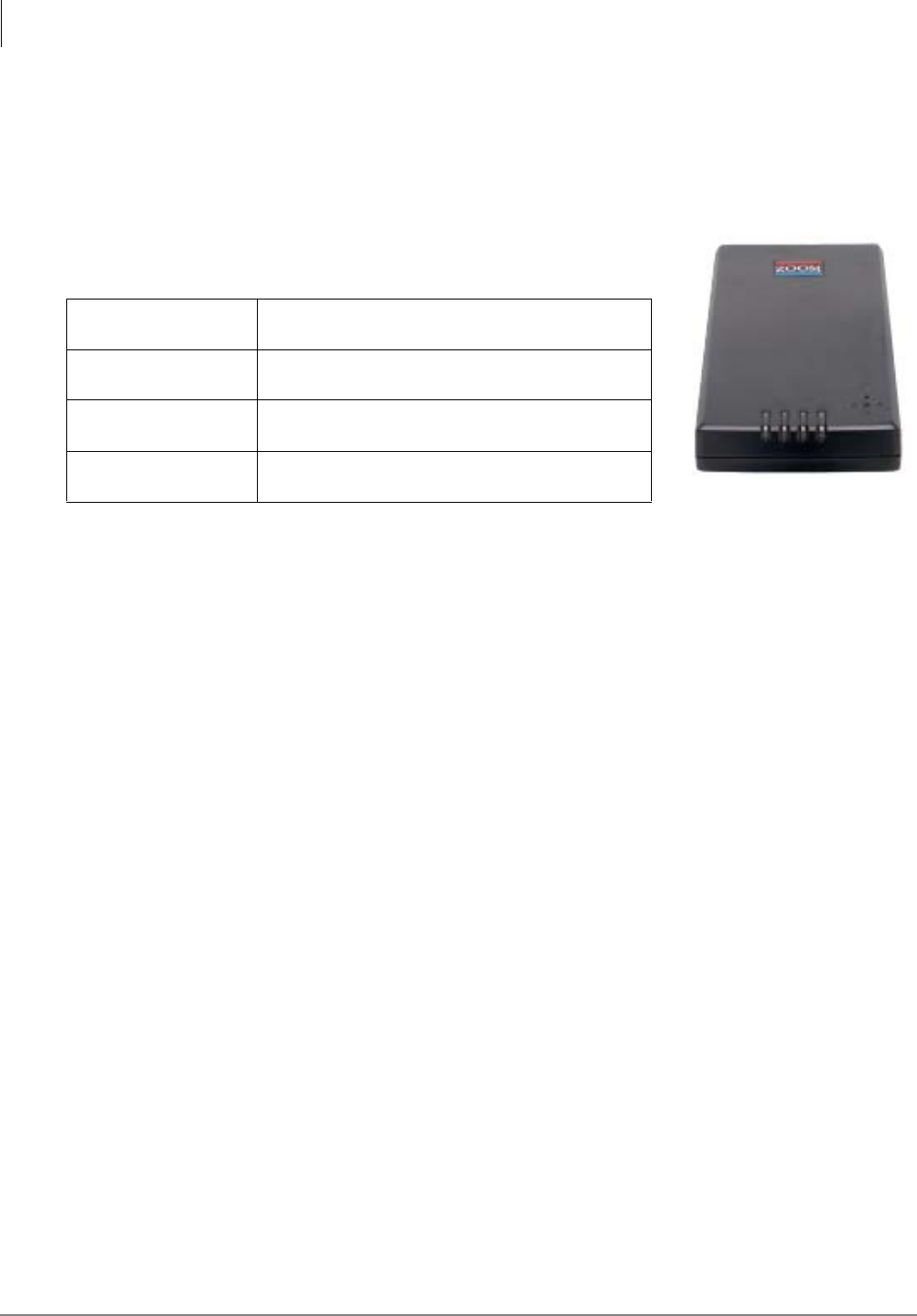
Media Application Server Installation
MAS Modem Installation (Optional)
1-44 STRATA CIX MAS INSTALLATION 06/09
MAS Modem Installation (Optional)
The MAS can be accessed from a remote location via the network by using the Windows® XP
Remote Desktop feature. The MAS can also be accessed via a dial-up connection after the
installation of the Zoom 3090 USB V.92 Modem (Toshiba part number SYS-USB-MODEM).
The Zoom™/Modem V.92 USB Mini is a compact external modem
for Windows computers.
Zoom is a registered trademark of Zoom Telephonics, Inc.
Important! Do not connect the modem to the USB until after the modem driver
software has been installed on the MAS.
Step 1: Install Modem Driver Software on the MAS
Install the USB modem driver software before connecting the modem to the USB port on the MAS.
1. Insert the Zoom driver software CD-ROM into the MAS CD drive. The CD will auto-run.
2. Select Install Modem Drivers.
3. Select USB Drivers.
Physical Size 2.75 in. x 5.0 in. x 0.87 in.
(7.0 cm x 12.7 cm x 2.21 cm)
Power USB port powered
no batteries or AC adapters are required
Interface Cables Modem to MAS: USB cable (included)
Modem to phone circuit: RJ-11 (NOT included)
Regulatory Approvals FCC Parts 15B and 68
UL, C-UL, CE
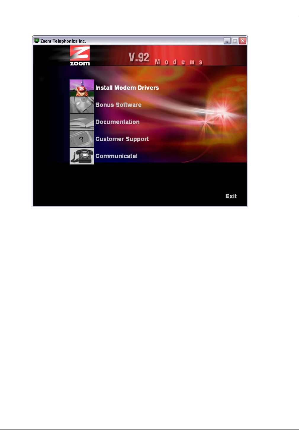
Media Application Server Installation
MAS Modem Installation (Optional)
Strata CIX MAS Installation 06/09 1-45
4. Say no to all of the other software components when prompted.
5. Reboot when prompted.
Step 2. Install Hardware and Configure Windows on the MAS
1. Plug in the USB cable between the modem and the MAS. When the Found New Hardware
wizard appears, click Next. Windows will install the modem.
2. Add the Incoming Connection to Windows. Click Start>My Network Places. Click “View
Network Connections” and then click “Create a new connection”.
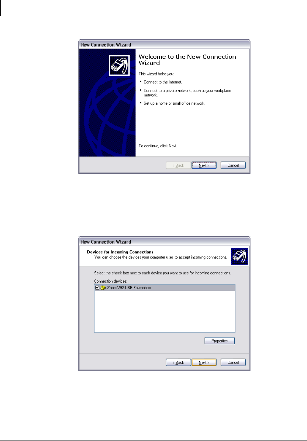
Media Application Server Installation
MAS Modem Installation (Optional)
1-46 STRATA CIX MAS INSTALLATION 06/09
3. When the New Comnnection Welcome box opens click on Next.
4. In the Network Connection Type dialog box click to select Set up an advanced connection.
5. Click on Next.
6. In the Advanced Connection Options click to select Accept incoming connections, then click
on Next.
7. In the Devices for Incoming Connections dialog box check-mark Zoom V92USB Faxmodem,
then click on Next.
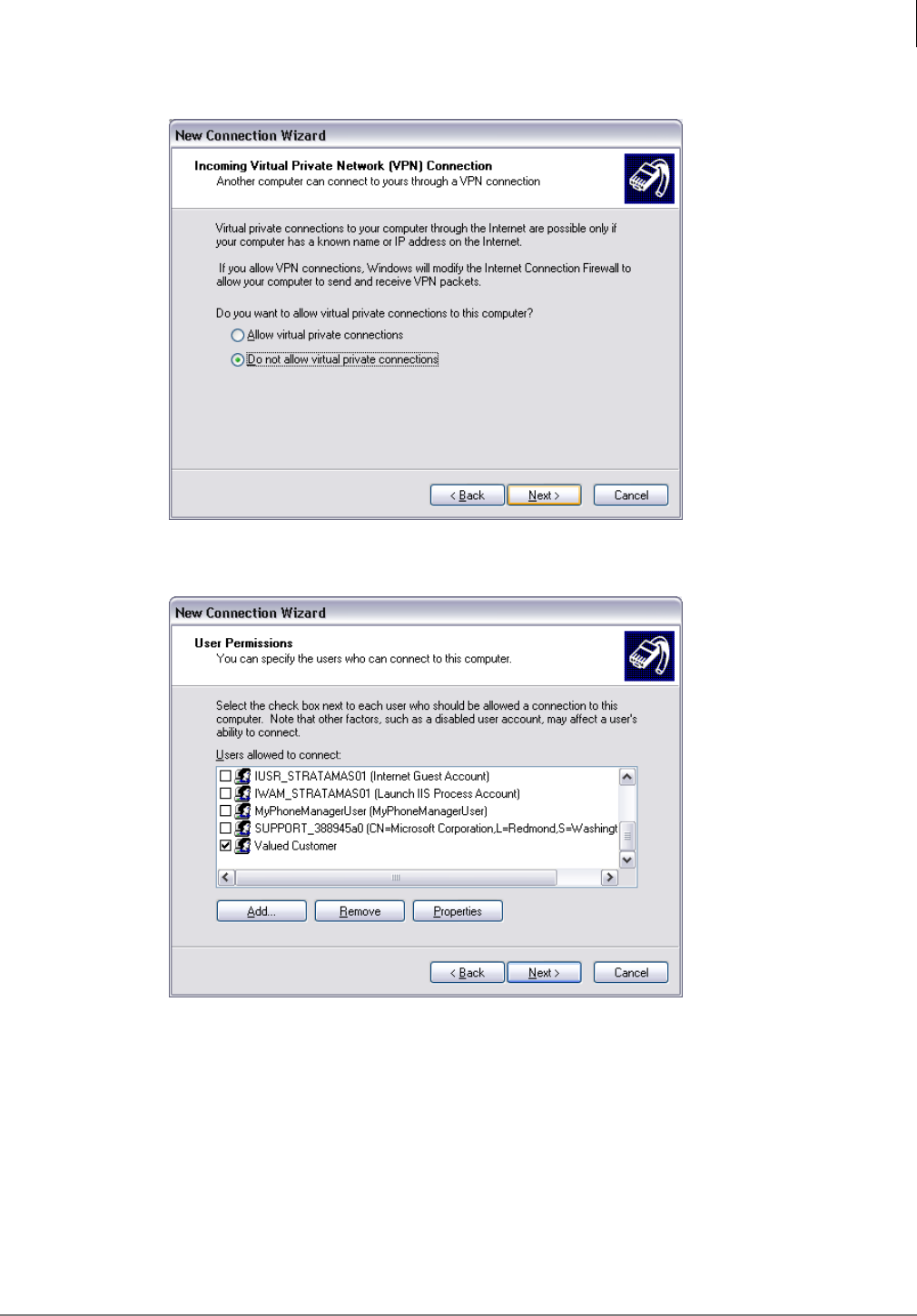
Media Application Server Installation
MAS Modem Installation (Optional)
Strata CIX MAS Installation 06/09 1-47
8. Select Do not allow virtual private connections, then click on Next.
9. Select only Valued Customer in the User Permissions list.
10. In the Networking Software dialog box accept the default selections, click on Next.
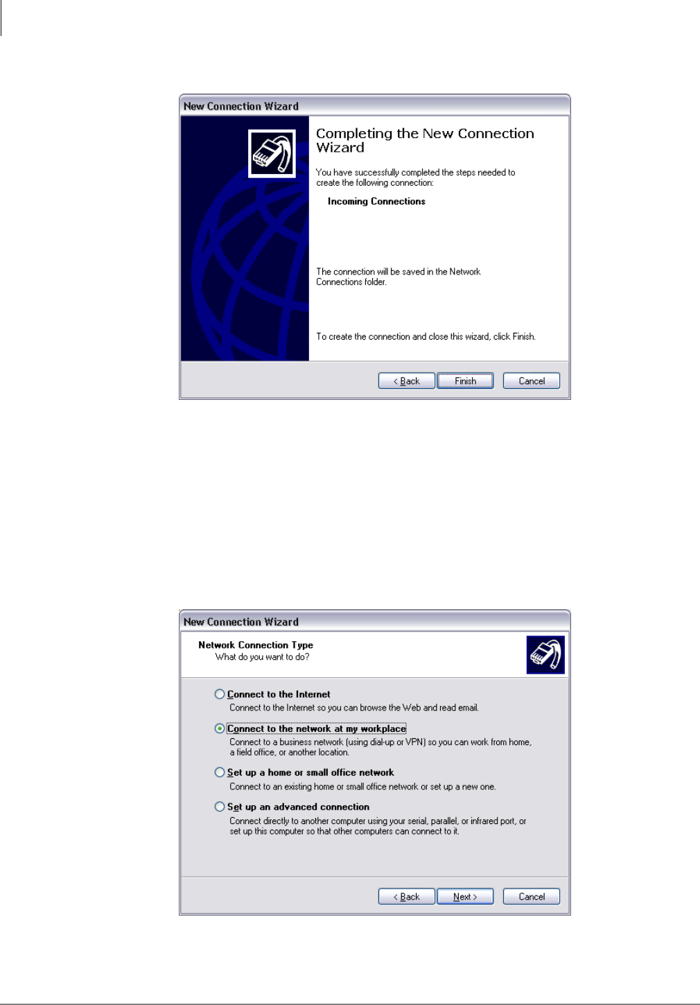
Media Application Server Installation
MAS Modem Installation (Optional)
1-48 STRATA CIX MAS INSTALLATION 06/09
11. In the Completing dialog box click on Finish.
12. The MAS setup is complete. The remaining steps are performed at the computer that will be
used to dial into the MAS.
Step 3. Client Configuration
Create the dialup connection on the computer that will be used to dial into the MAS
1. Get to the Network Connections / Add Network Connection dialog box. Typically this is through
the Settings / Control Panel from the Start menu.
2. Select Connect to the network at my workplace, then click on Next.
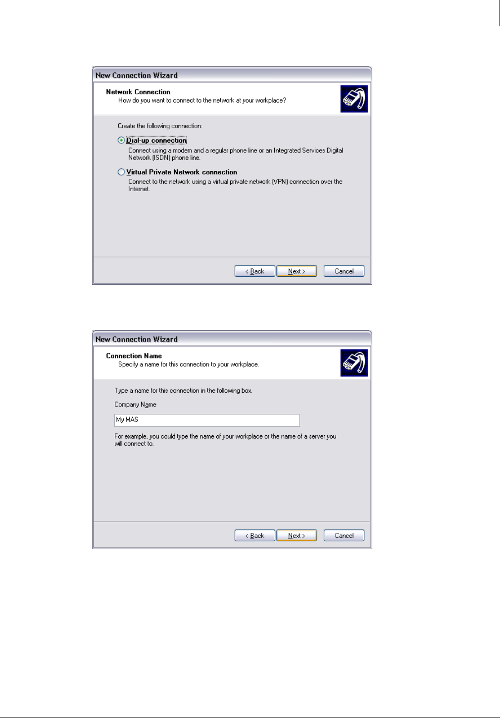
Media Application Server Installation
MAS Modem Installation (Optional)
Strata CIX MAS Installation 06/09 1-49
3. Select Dial-up connection as the Network Connection type.
4. Type a name in the Company Name field. Use a name that identifies the system or location.
My MAS, shown below, is an example.
5. Enter the telephone number of the telephone line connected to the modem. Enter the modem
number in the same format that a station user would dial the same number. Enter trunk access
codes, toll prefix and/or area code as required.
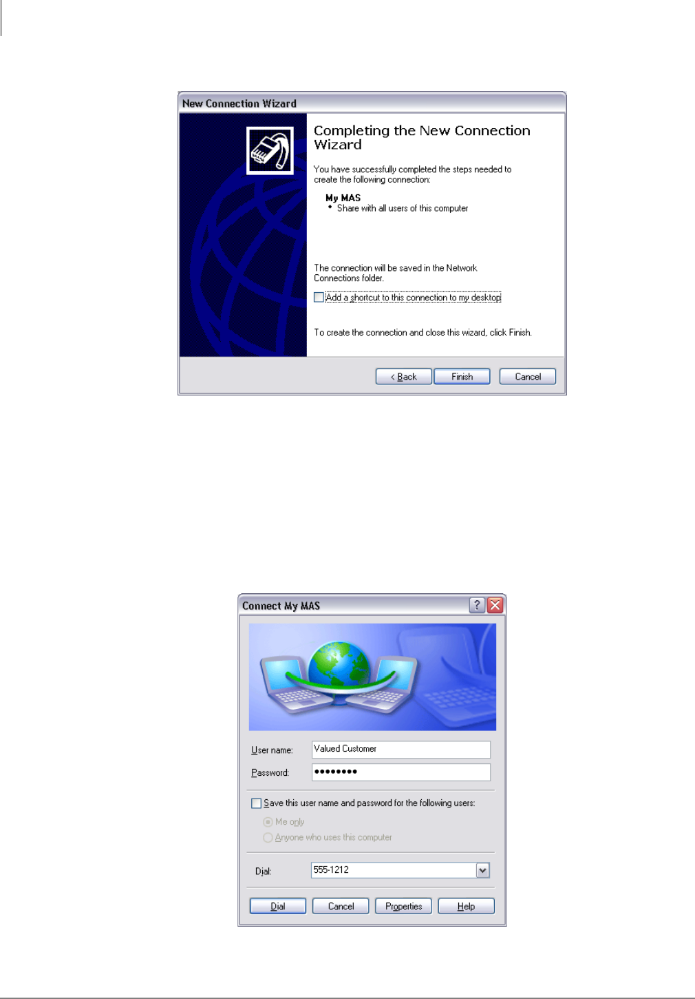
Media Application Server Installation
MAS Modem Installation (Optional)
1-50 STRATA CIX MAS INSTALLATION 06/09
6. Click on Finish.
Dial-up the MAS Modem
1. From the remote location computer open the Network Connection.
2. In the Connect dialog box enter Valued Customer as the User Name. Enter the password, then
click on the Dial button.
This is the last page of the document.
