Product Detail Manual CL
User Manual: CL
Open the PDF directly: View PDF ![]() .
.
Page Count: 16

CL-1
CLUTCH
C TRANSMISSION/TRANSAXLE
CONTENTS
D
E
F
G
H
I
J
K
L
M
SECTION CL A
B
CL
Revision: June 2006 2007 Versa
PRECAUTIONS .......................................................... 2
Precautions for Supplemental Restraint System
(SRS) “AIR BAG” and “SEAT BELT PRE-TEN-
SIONER” .................................................................. 2
Service Notice or Precautions .................................. 2
PREPARATION ........................................................... 3
Special Service Tools ............................................... 3
Commercial Service Tools ........................................ 3
NOISE, VIBRATION AND HARSHNESS (NVH)
TROUBLESHOOTING ................................................ 4
NVH Troubleshooting Chart ..................................... 4
CLUTCH PEDAL ........................................................ 5
On-vehicle Inspection and Adjustment ..................... 5
Removal and Installation .......................................... 7
COMPONENTS .................................................... 7
REMOVAL ............................................................. 7
INSPECTION AFTER REMOVAL ......................... 7
INSTALLATION ..................................................... 7
CLUTCH FLUID .......................................................... 8
Air Bleeding Procedure ............................................ 8
CLUTCH MASTER CYLINDER .................................. 9
Removal and Installation .......................................... 9
REMOVAL ............................................................. 9
INSTALLATION ..................................................... 9
CSC (CONCENTRIC SLAVE CYLINDER) ................ 11
Removal and Installation ........................................ 11
REMOVAL ........................................................... 11
INSTALLATION ................................................... 11
CLUTCH PIPING ....................................................... 12
Removal and Installation ........................................ 12
REMOVAL ........................................................... 12
INSTALLATION ................................................... 12
CLUTCH DISC, CLUTCH COVER AND FLYWHEEL ... 13
Removal and Installation ........................................ 13
COMPONENTS ................................................... 13
REMOVAL ........................................................... 13
INSPECTION AND ADJUSTMENT AFTER
REMOVAL ........................................................... 13
INSTALLATION ................................................... 14
SERVICE DATA AND SPECIFICATIONS (SDS) ...... 16
Clutch Control System ............................................ 16
Clutch Pedal ........................................................... 16
Clutch Disc ............................................................. 16
Clutch Cover ........................................................... 16

CL-2
PRECAUTIONS
Revision: June 2006 2007 Versa
PRECAUTIONS PFP:00001
Precautions for Supplemental Restraint System (SRS) “AIR BAG” and “SEAT
BELT PRE-TENSIONER” ECS00GVW
The Supplemental Restraint System such as “AIR BAG” and “SEAT BELT PRE-TENSIONER”, used along
with a front seat belt, helps to reduce the risk or severity of injury to the driver and front passenger for certain
types of collision. This system includes seat belt switch inputs and dual stage front air bag modules. The SRS
system uses the seat belt switches to determine the front air bag deployment, and may only deploy one front
air bag, depending on the severity of a collision and whether the front occupants are belted or unbelted.
Information necessary to service the system safely is included in the SRS and SB section of this Service Man-
ual.
WARNING:
●To avoid rendering the SRS inoperative, which could increase the risk of personal injury or death
in the event of a collision which would result in air bag inflation, all maintenance must be per-
formed by an authorized NISSAN/INFINITI dealer.
●Improper maintenance, including incorrect removal and installation of the SRS, can lead to per-
sonal injury caused by unintentional activation of the system. For removal of Spiral Cable and Air
Bag Module, see the SRS section.
●Do not use electrical test equipment on any circuit related to the SRS unless instructed to in this
Service Manual. SRS wiring harnesses can be identified by yellow and/or orange harnesses or
harness connectors.
Service Notice or Precautions ECS00FST
●Use recommended brake fluid when adding fluid to the clutch reservoir tank. Refer to MA-11,
"RECOMMENDED FLUIDS AND LUBRICANTS".
●Never reuse fluid drained from clutch system.
●Be careful not to splash brake fluid on painted areas.
●Use new brake fluid to clean or wash all parts of master cylinder and operating cylinder.
●Never use mineral oils such as gasoline or kerosene. It will ruin the rubber parts of the hydraulic
system.
●If transaxle assembly is removed from the vehicle, always replace CSC (Concentric slave cylin-
der). Return CSC to original position to remove transaxle assembly. Dust on clutch disc sliding
parts may damage CSC seal and may cause clutch fluid leakage.
●Do not disassemble clutch master cylinder and CSC.
WARNING:
After cleaning clutch disc, clean it with a dust collector. Do not use compressed air.
PREPARATION
CL-3
D
E
F
G
H
I
J
K
L
M
A
B
CL
Revision: June 2006 2007 Versa
PREPARATION PFP:00002
Special Service Tools ECS00FSU
The actual shapes of Kent-Moore tools may differ from those of special service tools illustrated here.
Commercial Service Tools ECS00G57
Tool number
(Kent-Moore No.)
Tool name
Description
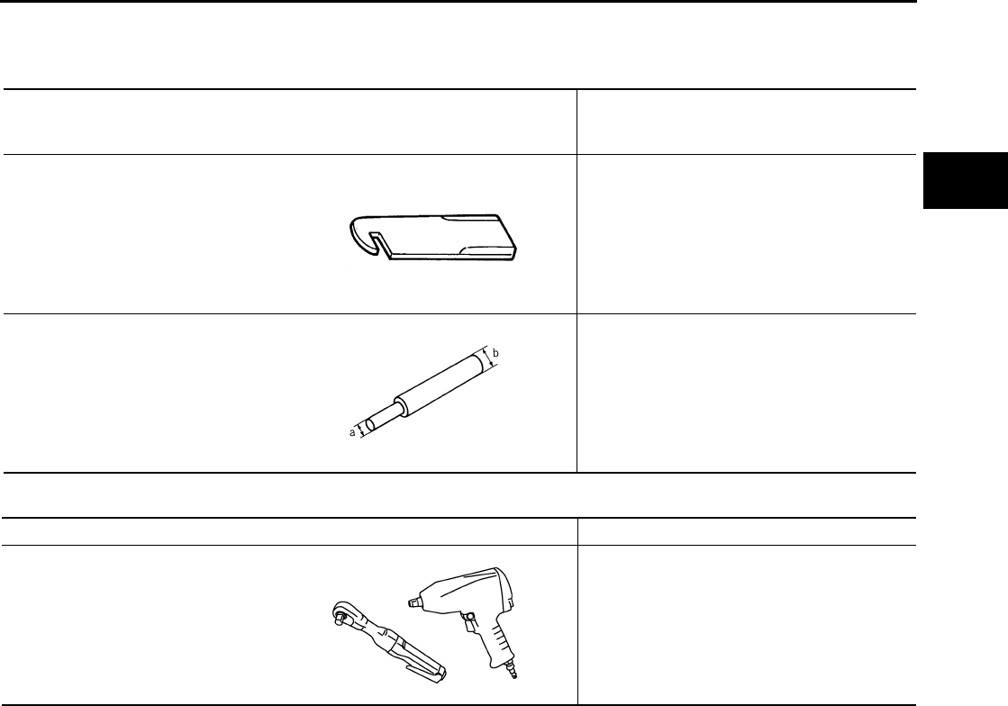
ST20050240
(—)
Diaphragm spring adjusting wrench
Adjusting unevenness of diaphragm spring of
clutch cover
KV30101000
(—)
Clutch aligning bar
Installing clutch cover and clutch disc
a: 15.9 mm (0.626 in) dia.
b: 19.8 mm (0.780 in) dia.
ZZA0508D
ZZA1178D
Tool name Description
Power tool Loosening bolts and nuts
PBIC0190E

CL-4
NOISE, VIBRATION AND HARSHNESS (NVH) TROUBLESHOOTING
Revision: June 2006 2007 Versa
NOISE, VIBRATION AND HARSHNESS (NVH) TROUBLESHOOTING PFP:00003
NVH Troubleshooting Chart ECS00FSV
Use the chart below to help you find the cause of the symptom. The numbers indicate the order of the inspec-
tion. If necessary, repair or replace these parts.
Reference page
CL-5
CL-8
EM-73
CL-11
CL-13
EM-103
SUSPECTED PARTS (Possible cause)
CLUTCH PEDAL (Inspection and adjustment)
CLUTCH LINE (Air in line)
ENGINE MOUNTING (Loose)
CSC (Concentric slave cylinder) (Worn, dirty or damaged)
CLUTCH DISC (Out of true)
CLUTCH DISC (Runout is excessive)
CLUTCH DISC (Lining broken)
CLUTCH DISC (Dirty or burned)
CLUTCH DISC (Oily)
CLUTCH DISC (Worn out)
CLUTCH DISC (Hardened)
CLUTCH DISC (Lack of spline grease)
DIAPHRAGM SPRING (Damaged)
DIAPHRAGM SPRING (Out of tip alignment)
PRESSURE PLATE (Distortion)
FLYWHEEL (Distortion)
Symptom
Clutch grabs/chatters 1 2 2 2 2 2
Clutch pedal spongy 1
Clutch noisy 1
Clutch slips 1 2 2 3 4 5
Clutch does not disengage 1 2 5 5 5 5 5 5 6 6 7
CLUTCH PEDAL
CL-5
D
E
F
G
H
I
J
K
L
M
A
B
CL
Revision: June 2006 2007 Versa
CLUTCH PEDAL PFP:46540
On-vehicle Inspection and Adjustment ECS00GVX
1. Check to see if the master cylinder rod end floats freely. It
should not be bound by the clutch pedal.
a. If the rod end is not free, check that the ASCD switch is not
applying pressure to the clutch pedal causing the rod end to
bind. To adjust, disconnect the ASCD switch electrical connector
and turn the ASCD switch.
b. Connect the ASCD switch electrical connector.
c. Verify that the master cylinder rod end floats freely. It should not
be bound by the clutch pedal.
d. If the rod end is still not free, remove the rod end and check for
deformation or damage. Leave the rod end removed for step 2.
2. Check the clutch pedal stroke for free range of movement.
a. With the master cylinder rod end removed, manually move the pedal up and down to determine if it moves
freely.
b. If any sticking is noted, replace the clutch pedal assembly. Re-verify that the master cylinder rod end floats
freely.
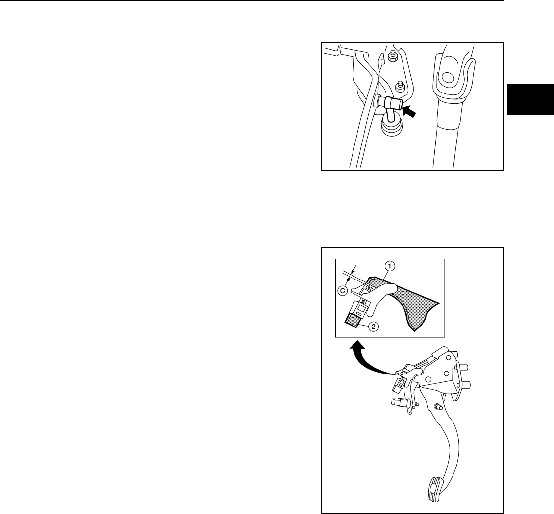
3. Adjust clutch interlock switch (1) position so that clearance
between clutch pedal (2) and thread end of clutch interlock
switch (1), with clutch pedal fully depressed, is within specifica-
tion (C).
Clearance C : 0.74 - 1.96 mm (0.0291 - 0.0772 in)
PCIB1491E
WCIA0594E
CL-6
CLUTCH PEDAL
Revision: June 2006 2007 Versa
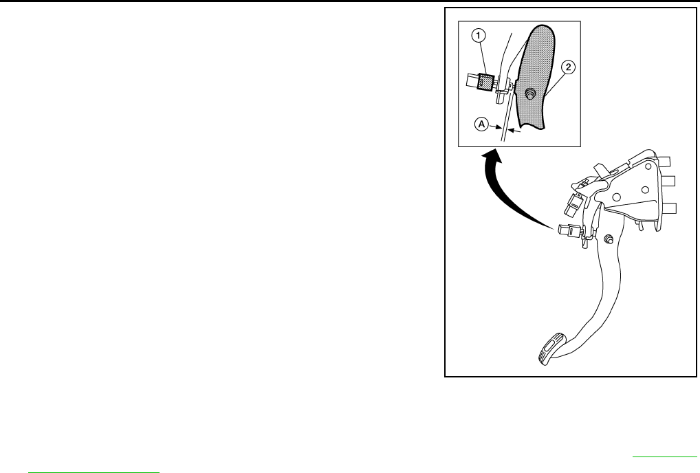
4. Adjust ASCD clutch switch (1) position so that clearance
between clutch pedal (2) and thread end of ASCD clutch switch
(1), with clutch pedal fully released, is within specification (A).
5. Check the clutch hydraulic system components (clutch master cylinder, clutch operating cylinder, clutch
withdrawal lever and clutch release bearing) for sticking or binding.
a. If any sticking or binding is noted, repair or replace the related parts as necessary.
b. If any hydraulic system repair was necessary, bleed the clutch hydraulic system. Refer to CL-8, "Air
Bleeding Procedure" .
NOTE:
Do not use a vacuum assist or any other type of power bleeder on this system. Use of a vacuum assist or
power bleeder will not purge all of the air from the system.
Clearance A : 0.74 - 1.96 mm (0.0291 - 0.0772 in)
WCIA0595E
CLUTCH PEDAL
CL-7
D
E
F
G
H
I
J
K
L
M
A
B
CL
Revision: June 2006 2007 Versa
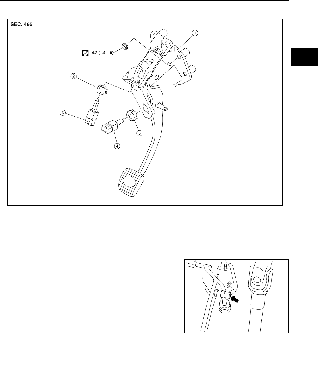
Removal and Installation ECS00FSX
COMPONENTS
REMOVAL
1. Remove instrument lower finisher. Refer to IP-11, "Removal and Installation" .
2. Disconnect clutch interlock switch and ASCD clutch switch harness connectors.
3. Remove clutch switch harness clamp from clutch pedal assembly.
4. Disconnect master cylinder rod end from clutch pedal lever.
5. Remove clutch pedal assembly nuts, and then remove clutch
pedal assembly.
INSPECTION AFTER REMOVAL
Check clutch pedal for bend, damage or a cracked weld. If bend, damage or a cracked weld is found, replace
clutch pedal assembly.
INSTALLATION
Installation is in the reverse order of removal.
●After installing the clutch switches, adjust the switch positions. Refer to CL-5, "On-vehicle Inspection and
Adjustment" .
1. Clutch pedal assembly 2. Lock nut 3. Clutch interlock switch
4. ASCD clutch switch 5. Lock nut
WCIA0596E
PCIB1491E
CL-8
CLUTCH FLUID
Revision: June 2006 2007 Versa
CLUTCH FLUID PFP:00017
Air Bleeding Procedure ECS00FSY
NOTE:
Do not use a vacuum assist or any other type of power bleeder on this system. Use of a vacuum assist or
power bleeder will not purge all the air from the system.
CAUTION:
●Carefully monitor fluid level in reservoir tank during bleeding operation.
●Keep painted surface of body and other parts free of clutch fluid. If it spills, wipe up immediately
and wash the affected area with water.
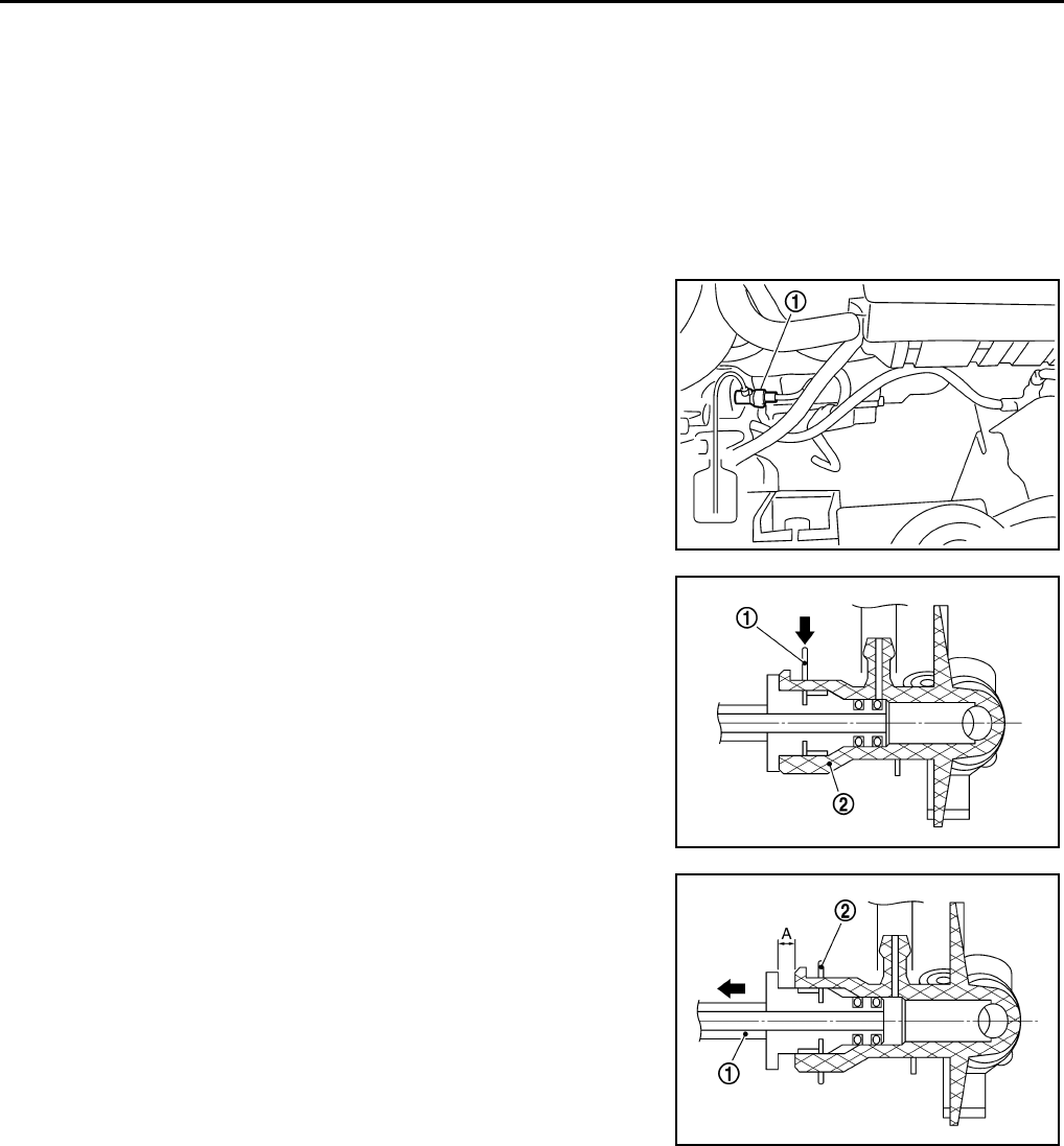
●First bleed the air from the operating cylinder air bleed
valve (1) and then from the bleed connector air bleed valve.
1. Connect a transparent vinyl tube and container to the air bleeder
valve on the clutch operating cylinder.
2. Fill reservoir tank with new clutch fluid.
3. Depress and release the clutch pedal slowly and fully 15 times
at an interval of 2 to 3 seconds.
4. With pedal depressed, continue the bleeding procedure.
5. Push the lock pin (1) of the bleeding connector (2) into the
locked position.
CAUTION:
Hold it to prevent releasing clutch tube from bleeding con-
nector (2) when fluid pressure is applied in the tube.
6. Slide clutch tube (1) in the direction of the arrow as shown, then
bleed the air from the tube.
7. Return clutch tube (1) and lock pin (2) to their original positions.
8. Release clutch pedal and wait for 5 seconds.
9. Repeat steps 2 to 8 until no bubbles are observed in the clutch
fluid.
PCIB1494E
PCIB1495E
Dimension A : 5 mm (0.20 in)
PCIB1496E
CLUTCH MASTER CYLINDER
CL-9
D
E
F
G
H
I
J
K
L
M
A
B
CL
Revision: June 2006 2007 Versa
CLUTCH MASTER CYLINDER PFP:30610
Removal and Installation ECS00FSZ
REMOVAL
1. Use one of the following methods to remove hose from master cylinder.
●Drain clutch fluid from reservoir tank and remove hose.
●Remove hose from master cylinder. Immediately plug hose and reservoir tank to prevent clutch fluid
from dripping.
CAUTION:
Keep painted surface of the body and other parts free of clutch fluid. If it spills, wipe up immedi-
ately and wash the affected area with water.
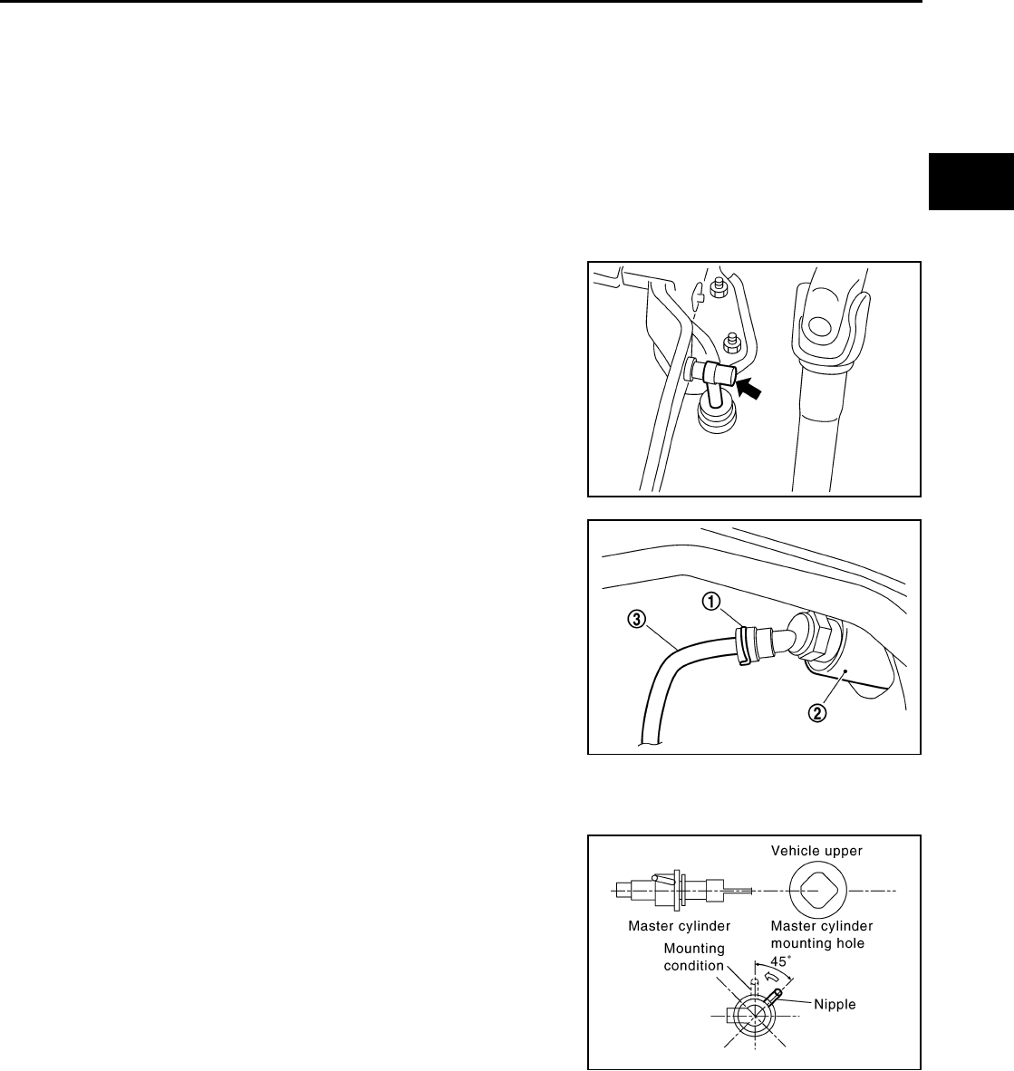
2. Remove master cylinder rod end from clutch pedal assembly.
3. Remove lock pin (1) from connector of master cylinder (2) and
separate clutch tube (3).
4. Rotate master cylinder clockwise by 45° and remove from the vehicle.
INSTALLATION
1. Tilt master cylinder clockwise by 45° and insert it in the mounting
hole. Rotate counterclockwise to secure it. At this time, nipple is
in the up position.
2. Install master cylinder rod end to clutch pedal.
PCIB1491E
PCIB1497E
SCIA1286E
CL-10
CLUTCH MASTER CYLINDER
Revision: June 2006 2007 Versa
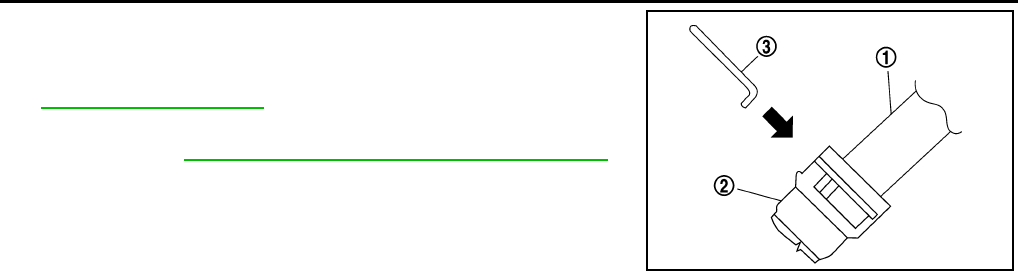
3. Install clutch tube (1) fully into connector of master cylinder (2).
4. Install lock pin (3) fully into connector of master cylinder (2).
5. Fill with new clutch fluid and bleed air from the system. Refer to
CL-8, "CLUTCH FLUID" .
6. After completing this procedure, inspect and adjust the clutch
pedal. Refer to CL-5, "On-vehicle Inspection and Adjustment" .
PCIB1500E
CSC (CONCENTRIC SLAVE CYLINDER)
CL-11
D
E
F
G
H
I
J
K
L
M
A
B
CL
Revision: June 2006 2007 Versa
CSC (CONCENTRIC SLAVE CYLINDER) PFP:30500
Removal and Installation ECS00FT0
CAUTION:
●If transaxle assembly is removed from the vehicle, always replace CSC (Concentric slave cylin-
der). Return CSC insert to original position to remove transaxle assembly. Dust on clutch disc
sliding parts may damage CSC seal and may cause clutch fluid leakage.
●Keep painted surface of the body and other parts free of clutch fluid. If it spills, wipe up immedi-
ately and wash the affected area with water.
REMOVAL
1. Remove transaxle assembly. Refer to MT-15, "Removal and Installation" .
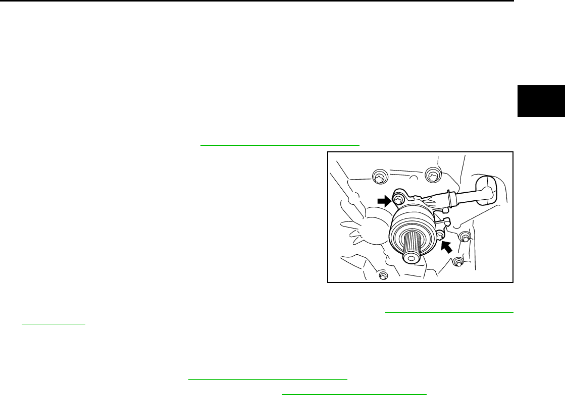
2. Remove CSC bolts and the CSC from clutch housing.
INSTALLATION
1. Install CSC to clutch housing and then tighten bolts to specification. Refer to MT-17, "Case and Housing
Components" .
CAUTION:
●Do not reuse CSC.
●Do not insert and operate CSC because piston and stopper of CSC components may fall off.
2. Install transaxle assembly. Refer to MT-15, "Removal and Installation" .
3. Bleed the air from the clutch hydraulic system. Refer to CL-8, "Air Bleeding Procedure" .
PCIB1498E
CL-12
CLUTCH PIPING
Revision: June 2006 2007 Versa
CLUTCH PIPING PFP:30650
Removal and Installation ECS00FT1
Carefully observe the following steps during clutch tube removal and installation.
CAUTION:
Keep painted surface of the body and other parts free of clutch fluid. If it spills, wipe up immediately
and wash the affected area with water.
REMOVAL
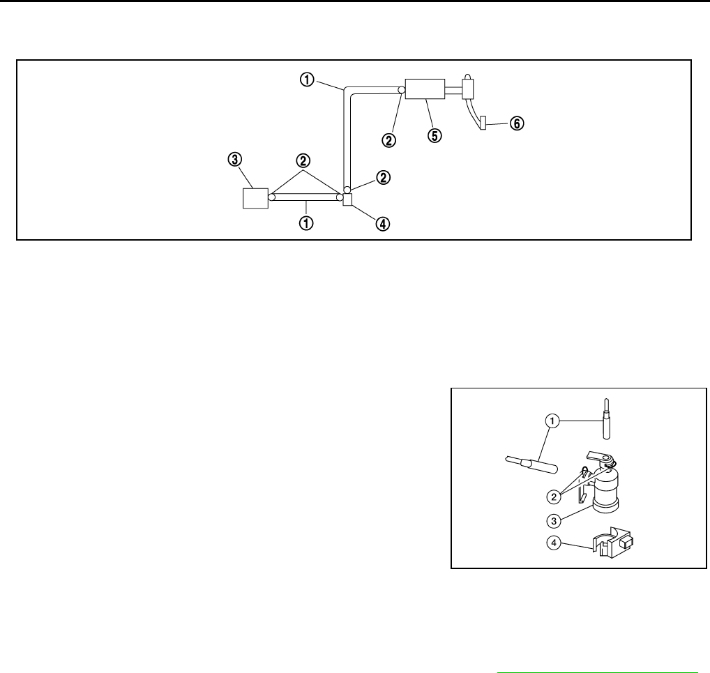
1. Remove lock pin (2) from clutch damper (3).
2. Remove clutch tube (1) from clutch damper (3).
3. Remove clutch damper (3) from bracket (4).
INSTALLATION
Installation is in the reverse order of removal.
●Make sure that all tubes are fully installed into connectors.
●Make sure that all connector lock pins are fully installed.
●After installation, bleed the air from the clutch hydraulic system. Refer to CL-8, "Air Bleeding Procedure" .
1. Clutch tube 2. Lock pin 3. CSC
4. Clutch damper 5. Master cylinder 6. Clutch pedal
PCIB1499E
WCIA0597E
CLUTCH DISC, CLUTCH COVER AND FLYWHEEL
CL-13
D
E
F
G
H
I
J
K
L
M
A
B
CL
Revision: June 2006 2007 Versa
CLUTCH DISC, CLUTCH COVER AND FLYWHEEL PFP:30100
Removal and Installation ECS00FT2
COMPONENTS
CAUTION:
●If transaxle assembly is removed from the vehicle, always replace CSC (Concentric slave cylin-
der). Return CSC insert to original position to remove transaxle assembly. Dust on clutch disc
sliding parts may damage CSC seal and may cause clutch fluid leakage.
●Be careful not to apply any grease to the clutch disc facing, pressure plate surface and flywheel
surface.
REMOVAL
1. Remove transaxle assembly from the vehicle. Refer to MT-15, "Removal and Installation" .
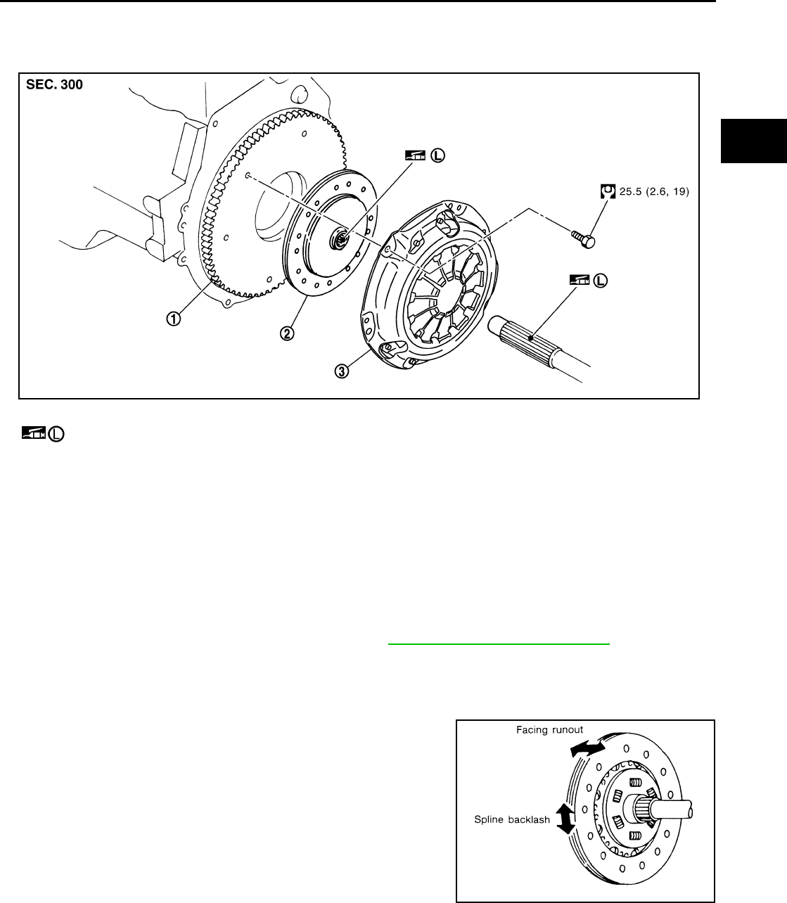
2. Loosen clutch cover bolts evenly. Then remove clutch cover and clutch disc.
INSPECTION AND ADJUSTMENT AFTER REMOVAL
Clutch Disc
●Check clutch disc for backlash of spline and runout of facing.
●Check clutch disc for burns, discoloration or oil or grease leak-
age. Replace if necessary.
●Measure backlash to clutch disc spline and input shaft spline at
the circumference of clutch disc. If outside the specification,
replace clutch disc.
1. Flywheel 2. Clutch disc *1, *2 3. Clutch cover
Apply lithium-based grease including molybdenum disulphide.
*1. Do not clean in solvent. *2. When installing, be careful that grease applied to input shaft does not adhere to
clutch disc.
WCIA0637E
Maximum backlash of spline
(at outer edge of disc) : 1.0 mm (0.039 in)
Distance of runout check point
(from hub center) : 215 mm (8.46 in)
Maximum allowable spline backlash : 1.0 mm (0.039 in)
SCL221
CL-14
CLUTCH DISC, CLUTCH COVER AND FLYWHEEL
Revision: June 2006 2007 Versa
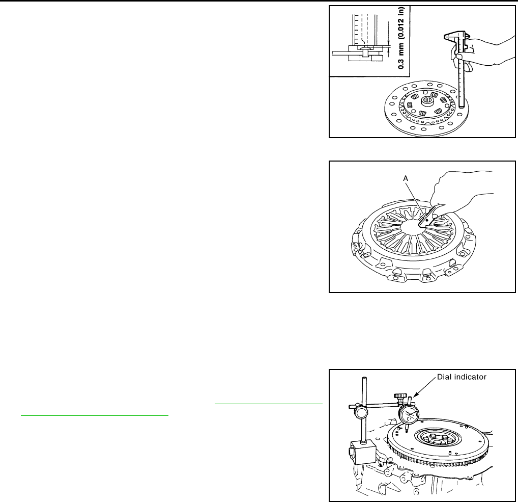
●Use a suitable tool to measure the depth to clutch disc facing
rivet heads. If it exceeds the allowable wear limit, replace clutch
disc.
Clutch Cover
Check clutch cover installed on vehicle for unevenness of diaphragm
spring toe height.
●If out of limit, adjust the height using Tool (A).
●Check clutch cover thrust ring for wear or breakage. If wear or
breakage is found, replace clutch cover assembly.
NOTE:
●Worn thrust ring will generate a beating noise when tapped at
the rivet with a suitable tool.
●Broken thrust ring will make a clinking sound when cover is shaken up and down.
●If a trace of burn or discoloration is found on the clutch cover pressure plate to clutch disc contact surface,
repair the surface with sandpaper. If surface is damaged or distorted, replace the assembly.
Flywheel Runout
●Check contact surface of flywheel for slight burns or discolora-
tion. Repair flywheel with emery paper.
●Check the flywheel runout. Refer to EM-103, "FLYWHEEL
DEFLECTION (M/T MODELS)" .
CAUTION:
Measure flywheel outer face (not on knock pin and clutch cover
mounting hole).
INSTALLATION
1. Clean clutch disc and input shaft splines to remove grease and dust caused by abrasion.
2. Apply recommended grease to clutch disc and input shaft splines.
CAUTION:
Be sure to apply grease to the points specified. Otherwise, noise, poor disengagement, or damage
to the clutch may result. Excessive grease may cause slip or shudder. If it adheres to CSC seal, it
will cause clutch fluid leakage. Wipe off excess grease.
3. Install clutch disc using tool.
4. Install clutch cover. Pre-tighten clutch cover bolts.
Wear limit of facing
surface to rivet head : 0.3 mm (0.012 in)
SCL229
Uneven limit : 0.7 mm (0.028 in) or less
Tool number A : ST20050240 ( — )
PCIB1502E
PBIC2646E
Tool number : KV30101000 ( — )


CL-16
SERVICE DATA AND SPECIFICATIONS (SDS)
Revision: June 2006 2007 Versa
SERVICE DATA AND SPECIFICATIONS (SDS) PFP:00030
Clutch Control System ECS00FT3
Clutch Pedal ECS00FT4
Clutch Disc ECS00FT5
Clutch Cover ECS00FT6
Type of clutch control Hydraulic
Clearance ″A″ between clutch pedal and ASCD switch threaded
end while clutch pedal is fully released. 0.74 - 1.96 mm (0.0291 - 0.0772 in)
Clearance ″C″ between clutch pedal and clutch interlock switch
threaded end while clutch pedal is fully depressed. 0.74 - 1.96 mm (0.0291 - 0.0772 in)
Model 225
Facing size (outer dia. × inner dia. × thickness) 225 mm × 160 mm × 3.2 mm (8.86 in × 6.30 in × 0.126 in)
Thickness of disc assembly with load 7.2 - 7.6 mm (0.283 - 0.299 in) with 5,394 N (550 kg, 1,213 lb)
Runout limit/diameter of the area to be measured 1.0 mm (0.039 in) / 215 mm (8.46 in) dia.
Maximum spline backlash (at outer edge of disc) 1.0 mm (0.039 in)
Wear limit of facing surface to rivet head 0.3 mm (0.012 in)
Set-load 5,394 N (550 kg, 1,213 lb)
Diaphragm spring lever height 20 - 22 mm (0.79 - 0.87 in)
Uneven limit diaphragm spring toe height 0.7 mm (0.028 in) or less
