BMC Atrium Configuration Management Database 7.6.04 Data Ing Guide CMDB7.6.04
176785_CMDB7.6.04_DataingGuide
User Manual:
Open the PDF directly: View PDF ![]() .
.
Page Count: 92
- Contents
- Preface
- Computer system modeling
- Logical identity of BMC_ComputerSystem
- Computer system modeling
- Software inventory and patch modeling
- Router modeling
- Virtual system modeling
- Logical identity of BMC_System and BMC_ComputerSystem (for virtual systems)
- Logical identity of BMC_VirtualSystemEnabler
- Logical identity of BMC_VirtualSystemSettingData
- Logical identity of BMC_ResourcePool for virtual systems
- Logical identity of BMC_ResourceAllocationSettingData for virtual systems
- Deprecated classes for virtual systems
- Relationships used for virtual systems
- Operating system modeling
- Hardware component modeling
- Access point modeling
- Network interface and address modeling
- Software and hardware cluster modeling
- Application modeling
- Software server modeling
- Storage entity modeling
- Network topology modeling
- Summary of changes to the Common Data Model
- Index

www.bmc.com
BMC Atrium CMDB 7.6.04
Data Modeling Guide
January 2011

If you have comments or suggestions about this documentation, contact Information Development by email at
doc_feedback@bmc.com.
Contacting BMC Software
You can access the BMC Software website at http://www.bmc.com. From this website, you can obtain information
about the company, its products, corporate offices, special events, and career opportunities.
United States and Canada
Address BMC SOFTWARE INC
2101 CITYWEST BLVD
HOUSTON TX 77042-2827
USA
Telephone 713 918 8800 or
800 841 2031
Fax 713 918 8000
Outside United States and Canada
Telephone (01) 713 918 8800 Fax (01) 713 918 8000
© Copyright 2006–2007, 2009–2011 BMC Software, Inc.
BMC, BMC Software, and the BMC Software logo are the exclusive properties of BMC Software, Inc., are registered with the U.S. Patent
and Trademark Office, and may be registered or pending registration in other countries. All other BMC trademarks, service marks, and
logos may be registered or pending registration in the U.S. or in other countries. All other trademarks or registered trademarks are the
property of their respective owners.
AIX and IBM are registered trademarks of International Business Machines Corporation.
Oracle and Java are registered trademarks of Oracle and/or its affiliates. Other names may be trademarks of their respective owners.
UNIX is the registered trademark of The Open Group in the US and other countries.
SAP is the trademark or registered trademark of SAP AG in Germany and in several other countries.
The information included in this documentation is the proprietary and confidential information of BMC Software, Inc., its affiliates, or
licensors. Your use of this information is subject to the terms and conditions of the applicable End User License agreement for the product
and to the proprietary and restricted rights notices included in the product documentation.
Restricted rights legend
U.S. Government Restricted Rights to Computer Software. UNPUBLISHED -- RIGHTS RESERVED UNDER THE COPYRIGHT LAWS OF
THE UNITED STATES. Use, duplication, or disclosure of any data and computer software by the U.S. Government is subject to
restrictions, as applicable, set forth in FAR Section 52.227-14, DFARS 252.227-7013, DFARS 252.227-7014, DFARS 252.227-7015, and
DFARS 252.227-7025, as amended from time to time. Contractor/Manufacturer is BMC Software, Inc., 2101 CityWest Blvd., Houston, TX
77042-2827, USA. Any contract notices should be sent to this address.

Customer Support
You can obtain technical support by using the Support page on the BMC Software website or by contacting Customer
Support by telephone or email. To expedite your inquiry, please see “Before Contacting BMC Software.”
Support Website
You can obtain technical support from BMC Software 24 hours a day, 7 days a week at
http://www.bmc.com/support. From this website, you can:
■Read overviews about support services and programs that BMC Software offers.
■Find the most current information about BMC Software products.
■Search a database for problems similar to yours and possible solutions.
■Order or download product documentation.
■Report a problem or ask a question.
■Subscribe to receive email notices when new product versions are released.
■Find worldwide BMC Software support center locations and contact information, including email addresses, fax
numbers, and telephone numbers.
Support by telephone or email
In the United States and Canada, if you need technical support and do not have access to the Web, call 800 537 1813 or
send an email message to customer_support@bmc.com. (In the Subject line, enter
SupID:<yourSupportContractID>, such as SupID:12345.) Outside the United States and Canada, contact your local
support center for assistance.
Before contacting BMC Software
Have the following information available so that Customer Support can begin working on your issue immediately:
■Product information
—Product name
— Product version (release number)
— License number and password (trial or permanent)
■Operating system and environment information
—Machine type
— Operating system type, version, and service pack
— System hardware configuration
— Serial numbers
— Related software (database, application, and communication) including type, version, and service pack or
maintenance level
■Sequence of events leading to the problem
■Commands and options that you used
■Messages received (and the time and date that you received them)
— Product error messages
— Messages from the operating system, such as file system full
— Messages from related software

License key and password information
If you have a question about your license key or password, contact Customer Support through one of the following
methods:
■E-mail customer_support@bmc.com. (In the Subject line, enter SupID:<yourSupportContractID>,
such as SupID:12345.)
■In the United States and Canada, call 800 537 1813. Outside the United States and Canada, contact your local support
center for assistance.
■Submit a new issue at http://www.bmc.com/support.

Contents 5
Contents
Preface 9
Audience . . . . . . . . . . . . . . . . . . . . . . . . . . . . . . . . . . . . . . . . . . . . . . . . . . . . . . . . . . . . . . . . 10
Conventions used in this guide . . . . . . . . . . . . . . . . . . . . . . . . . . . . . . . . . . . . . . . . . . . . . 10
Terminology . . . . . . . . . . . . . . . . . . . . . . . . . . . . . . . . . . . . . . . . . . . . . . . . . . . . . . . . . . 10
Diagrams. . . . . . . . . . . . . . . . . . . . . . . . . . . . . . . . . . . . . . . . . . . . . . . . . . . . . . . . . . . . . 11
Relationships represented in illustrative model diagrams . . . . . . . . . . . . . . . . . . . 11
BMC Atrium Core documentation . . . . . . . . . . . . . . . . . . . . . . . . . . . . . . . . . . . . . . . . . . 13
Chapter 1 Computer system modeling 17
Logical identity of BMC_ComputerSystem . . . . . . . . . . . . . . . . . . . . . . . . . . . . . . . . . . . 18
Key attributes of BMC_ComputerSystem . . . . . . . . . . . . . . . . . . . . . . . . . . . . . . . . . 19
Additional attributes for BMC_ComputerSystem . . . . . . . . . . . . . . . . . . . . . . . . . . 20
Computer system modeling . . . . . . . . . . . . . . . . . . . . . . . . . . . . . . . . . . . . . . . . . . . . . . . . 21
Software inventory and patch modeling . . . . . . . . . . . . . . . . . . . . . . . . . . . . . . . . . . . . . 22
Logical identity of BMC_ComputerSystem (for products or patches) . . . . . . . . . 23
Additional attributes of BMC_ComputerSystem (for products or patches). . . . . 23
Router modeling. . . . . . . . . . . . . . . . . . . . . . . . . . . . . . . . . . . . . . . . . . . . . . . . . . . . . . . . . . 24
Virtual system modeling. . . . . . . . . . . . . . . . . . . . . . . . . . . . . . . . . . . . . . . . . . . . . . . . . . . 25
Logical identity of BMC_System and BMC_ComputerSystem (for virtual
systems) . . . . . . . . . . . . . . . . . . . . . . . . . . . . . . . . . . . . . . . . . . . . . . . . . . . . . . . . . . . 26
Logical identity of BMC_VirtualSystemEnabler. . . . . . . . . . . . . . . . . . . . . . . . . . . . 27
Logical identity of BMC_VirtualSystemSettingData . . . . . . . . . . . . . . . . . . . . . . . . 27
Logical identity of BMC_ResourcePool for virtual systems . . . . . . . . . . . . . . . . . . 30
Logical identity of BMC_ResourceAllocationSettingData for virtual systems . . 31
Deprecated classes for virtual systems. . . . . . . . . . . . . . . . . . . . . . . . . . . . . . . . . . . . 32
Relationships used for virtual systems. . . . . . . . . . . . . . . . . . . . . . . . . . . . . . . . . . . . 33
Operating system modeling . . . . . . . . . . . . . . . . . . . . . . . . . . . . . . . . . . . . . . . . . . . . . . . . 33
Logical identity of BMC_OperatingSystem. . . . . . . . . . . . . . . . . . . . . . . . . . . . . . . . 34
Additional attributes for BMC_OperatingSystem . . . . . . . . . . . . . . . . . . . . . . . . . . 34
Hardware component modeling . . . . . . . . . . . . . . . . . . . . . . . . . . . . . . . . . . . . . . . . . . . . 34
Logical identity of BMC_HardwareSystemComponent . . . . . . . . . . . . . . . . . . . . . 35
Additional attributes for BMC_HardwareSystemComponent. . . . . . . . . . . . . . . . 35
Access point modeling . . . . . . . . . . . . . . . . . . . . . . . . . . . . . . . . . . . . . . . . . . . . . . . . . . . . 36
Logical identity of BMC_IPEndpoint . . . . . . . . . . . . . . . . . . . . . . . . . . . . . . . . . . . . . 36
Additional attributes for BMC_IPEndpoint . . . . . . . . . . . . . . . . . . . . . . . . . . . . . . . 37
Logical identity of BMC_LANEndpoint . . . . . . . . . . . . . . . . . . . . . . . . . . . . . . . . . . 37
Additional attributes of BMC_LANEndpoint. . . . . . . . . . . . . . . . . . . . . . . . . . . . . . 38
Access point binding. . . . . . . . . . . . . . . . . . . . . . . . . . . . . . . . . . . . . . . . . . . . . . . . . . . 38

6 Data Modeling Guide
Network interface and address modeling . . . . . . . . . . . . . . . . . . . . . . . . . . . . . . . . . . . . 38
Logical identity of BMC_NetworkPort. . . . . . . . . . . . . . . . . . . . . . . . . . . . . . . . . . . . 39
Additional attributes for BMC_NetworkPort . . . . . . . . . . . . . . . . . . . . . . . . . . . . . . 39
Software and hardware cluster modeling. . . . . . . . . . . . . . . . . . . . . . . . . . . . . . . . . . . . . 41
Chapter 2 Application modeling 43
Application characteristics . . . . . . . . . . . . . . . . . . . . . . . . . . . . . . . . . . . . . . . . . . . . . . . . . 44
Application infrastructure and hosting environment. . . . . . . . . . . . . . . . . . . . . . . . . . . 47
Applications running on application servers or application systems . . . . . . . . . . 47
Applications running on computer systems . . . . . . . . . . . . . . . . . . . . . . . . . . . . . . . 48
Relationships for applications . . . . . . . . . . . . . . . . . . . . . . . . . . . . . . . . . . . . . . . . . . . . . . 48
Business applications and services . . . . . . . . . . . . . . . . . . . . . . . . . . . . . . . . . . . . . . . . . . 49
Chapter 3 Software server modeling 51
Software server characteristics . . . . . . . . . . . . . . . . . . . . . . . . . . . . . . . . . . . . . . . . . . . . . . 52
Logical identity of BMC_SoftwareServer . . . . . . . . . . . . . . . . . . . . . . . . . . . . . . . . . . . . . 52
Additional attributes for BMC_SoftwareServer . . . . . . . . . . . . . . . . . . . . . . . . . . . . 53
Relationships for software servers. . . . . . . . . . . . . . . . . . . . . . . . . . . . . . . . . . . . . . . . 53
Database server modeling . . . . . . . . . . . . . . . . . . . . . . . . . . . . . . . . . . . . . . . . . . . . . . . . . . 54
Database modeling . . . . . . . . . . . . . . . . . . . . . . . . . . . . . . . . . . . . . . . . . . . . . . . . . . . . 55
Oracle Listener modeling . . . . . . . . . . . . . . . . . . . . . . . . . . . . . . . . . . . . . . . . . . . . . . . 56
Relationships for database servers and databases. . . . . . . . . . . . . . . . . . . . . . . . . . . . . . 57
Database storage entity modeling . . . . . . . . . . . . . . . . . . . . . . . . . . . . . . . . . . . . . . . . . . . 58
Logical identity of BMC_DataBaseStorage . . . . . . . . . . . . . . . . . . . . . . . . . . . . . . . . 58
Additional attributes for BMC_DataBaseStorage . . . . . . . . . . . . . . . . . . . . . . . . . . . 58
Chapter 4 Storage entity modeling 59
Characteristics of storage entities and devices. . . . . . . . . . . . . . . . . . . . . . . . . . . . . . . . . 60
Modeling a tape drive . . . . . . . . . . . . . . . . . . . . . . . . . . . . . . . . . . . . . . . . . . . . . . . . . . . . . 60
Logical identity of BMC_TapeDrive . . . . . . . . . . . . . . . . . . . . . . . . . . . . . . . . . . . . . . 60
Additional attributes for BMC_TapeDrive . . . . . . . . . . . . . . . . . . . . . . . . . . . . . . . . 60
Tape drive instance . . . . . . . . . . . . . . . . . . . . . . . . . . . . . . . . . . . . . . . . . . . . . . . . . . . . 61
Modeling a DASD . . . . . . . . . . . . . . . . . . . . . . . . . . . . . . . . . . . . . . . . . . . . . . . . . . . . . . . . 61
Logical identity of BMC_DiskDrive . . . . . . . . . . . . . . . . . . . . . . . . . . . . . . . . . . . . . . 61
Additional attributes for BMC_DiskDrive . . . . . . . . . . . . . . . . . . . . . . . . . . . . . . . . . 61
DASD instance . . . . . . . . . . . . . . . . . . . . . . . . . . . . . . . . . . . . . . . . . . . . . . . . . . . . . . . . 62
Modeling a Virtual disk. . . . . . . . . . . . . . . . . . . . . . . . . . . . . . . . . . . . . . . . . . . . . . . . . . . . 62
Logical identity of BMC_LogicalDisk (virtual disk). . . . . . . . . . . . . . . . . . . . . . . . . 63
Additional attributes of BMC_LogicalDisk . . . . . . . . . . . . . . . . . . . . . . . . . . . . . . . . 63
Modeling virtual disk allocated to a virtual machine. . . . . . . . . . . . . . . . . . . . . . . . 63
Modeling logical disk allocated to a virtual machine from a resource pool . . . . . 64
Modeling a NAS device. . . . . . . . . . . . . . . . . . . . . . . . . . . . . . . . . . . . . . . . . . . . . . . . . . . . 65
Modeling a remote mounted file system . . . . . . . . . . . . . . . . . . . . . . . . . . . . . . . . . . 66
Modeling raw storage . . . . . . . . . . . . . . . . . . . . . . . . . . . . . . . . . . . . . . . . . . . . . . . . . . . . . 67
Logical identity of BMC_StorageVolume (raw storage volume) . . . . . . . . . . . . . . 67
Additional attributes of BMC_StorageVolume . . . . . . . . . . . . . . . . . . . . . . . . . . . . . 67

Contents 7
Modeling storage volume allocated to a virtual machine . . . . . . . . . . . . . . . . . . . . 68
Modeling storage volume allocated to a virtual machine from a resource pool . 68
Relationships for storage systems. . . . . . . . . . . . . . . . . . . . . . . . . . . . . . . . . . . . . . . . 69
Chapter 5 Network topology modeling 71
Network topology characteristics . . . . . . . . . . . . . . . . . . . . . . . . . . . . . . . . . . . . . . . . . . . 72
L3 topology and IP connectivity modeling . . . . . . . . . . . . . . . . . . . . . . . . . . . . . . . . . . . 72
Logical identity of BMC_IPConnectivitySubnet. . . . . . . . . . . . . . . . . . . . . . . . . . . . 73
Additional attributes for BMC_IPConnectivitySubnet . . . . . . . . . . . . . . . . . . . . . . 73
Relationships for components on a subnet . . . . . . . . . . . . . . . . . . . . . . . . . . . . . . . . 73
L2 topology and physical connectivity modeling . . . . . . . . . . . . . . . . . . . . . . . . . . . . . . 73
Logical identity of BMC_ConnectivitySegment . . . . . . . . . . . . . . . . . . . . . . . . . . . . 74
Additional attributes for BMC_ConnectivitySegment. . . . . . . . . . . . . . . . . . . . . . . 75
Relationships for network interfaces . . . . . . . . . . . . . . . . . . . . . . . . . . . . . . . . . . . . . 75
Network topology and LAN and WAN network modeling . . . . . . . . . . . . . . . . . . . . . 75
Logical identity of BMC_LAN. . . . . . . . . . . . . . . . . . . . . . . . . . . . . . . . . . . . . . . . . . . 77
Logical identity of BMC_WAN . . . . . . . . . . . . . . . . . . . . . . . . . . . . . . . . . . . . . . . . . . 77
Appendix A Summary of changes to the Common Data Model 79
Changes to the BMC Atrium CMDB 7.5.00 Common Data Model . . . . . . . . . . . . . . . 80
Changes to the BMC Atrium CMDB 7.6.00 Common Data Model . . . . . . . . . . . . . . . 81
Attributes that have been moved . . . . . . . . . . . . . . . . . . . . . . . . . . . . . . . . . . . . . . . . 81
Attributes that have been hidden . . . . . . . . . . . . . . . . . . . . . . . . . . . . . . . . . . . . . . . . 81
Changes to the BMC Atrium CMDB 7.6.03 Common Data Model . . . . . . . . . . . . . . . 82
Classes that have been deprecated . . . . . . . . . . . . . . . . . . . . . . . . . . . . . . . . . . . . . . . 82
Changes to the BMC Atrium CMDB 7.6.04 Common Data Model . . . . . . . . . . . . . . . 83
Classes and attributes that are deprecated . . . . . . . . . . . . . . . . . . . . . . . . . . . . . . . . 84
Index 85
8 Data Modeling Guide

Preface 9
Preface
The BMC Atrium CMDB 7.6.04 Data Modeling Guide describes how to model
business entities in BMC Atrium CMDB 7.6.04. The guide uses the Common Data
Model (CDM) and extensions to that model, and explores recommended practices
for using new entities effectively.
The BMC Atrium Configuration Management Database (CMDB) enables you to
store and manage information about products and services that are in your
environment. The BMC Atrium CMDB uses the term class to describe a
configuration item (CI) or relationship classification. Each CI is partially classified
using some common attributes that describe the base class (BMC_BaseElement).
Specific details about each class of CI are described by attributes of subclasses of
BMC_BaseElement. Relationships are also modeled as a base relationship class
(BMC_BaseRelationship) with subclasses for different types of relationships.
As a provider of BMC Atrium CMDB data, BMC Atrium Discovery products can
discover large amounts of configuration data for use by data consumers. BMC
Atrium Discovery products are natural enablers for the creation of service models
because they can discover many of the components, or CIs, that ultimately make
up the service models. These components include:
Computer systems (including servers, routers, physical and virtual systems,
and operating systems)
Applications
Software servers (including specialized elements such as SAP®, Sun, Siebel, and
mainframe infrastructure components)
Databases
Business process definitions
Network elements

10 Data Modeling Guide
BMC Atrium CMDB 7.6.04
Audience
This guide is intended for configuration managers, application administrators,
asset analysts, and related IT professionals.
Conventions used in this guide
This guide illustrates how to use the classes that BMC provides for the BMC
Atrium CMDB to model a particular business entity, focusing on how you use the
entire model rather than on general information about a class or attribute.
Although descriptions of classes and attributes are provided to give you context
when determining how to model CIs, detailed information such as syntax and the
type of attribute is not specified. For that level of information, see the BMC Atrium
CMDB 7.6.04 Data Model Help.
This guide applies the following conventions to explain BMC Atrium CMDB
concepts in both textual and graphical formats.
Terminology
In many cases you will be modeling an entity using classes from the CDM, but you
might also model part of that same entity using an extension to the CDM. For
models that require extensions to the CDM, the term data model is used. This guide
is organized so that the entities are introduced first in each section, including the
recommended practice for that implementation. Any classes and attributes that
can be included in the deployment of these business entities in an IT infrastructure
are described in an architectural diagram. Where appropriate, recommendations
are provided for setting specific attributes for a given class.
Attributes are defined as either key or additional. Key attributes are those that BMC
recommends that you populate for a given class to model a specific CI. Additional
attributes are optional attributes that you can populate to further classify a CI or
relationship.
Differentiating Name and ShortDescription attributes
A common misconception is that the caption for the CI on user interfaces and
reports is represented by the Name attribute, when it is actually the
ShortDescription attribute. In diagrams in this guide, the names that appear are
not from the Name attribute, they are the ShortDescription attribute (which is
usually just a user interface caption). Also, in modeling recommendations,
ShortDescription is the more user-friendly label, and should always be
provided and set with a value that makes sense to an end user.

Preface 11
Conventions used in this guide
Diagrams
Illustrative model diagrams help explain the concepts and modeling
recommendations in this guide, and also show how you might model an entity in
a real-world business environment. In these diagrams, CIs are represented by
single-line boxes that contain attributes of the class or its parent class. Where
applicable, key attributes are shown in the box that depicts a specific class and, in
some cases, include the recommended value of those attributes.
NOTE
Illustrative diagrams are just examples, and might not reflect every possible class,
attribute, or relationship that you would use for modeling all types of the
represented object.
Relationships represented in illustrative model diagrams
In the diagrams, boxes illustrate how CIs in your environment should be mapped
to the CDM, or how to extend the CDM to create your own data model. Lines are
used to represent the type and direction of the relationship.
NOTE
Relationships in the diagrams in this guide are illustrated using Unified Modeling
Language (UML) standards. The UML notation may not be consistent with the
BMC Atrium CMDB 7.6.04 user interfaces (UI). Some of this discrepancy is due to
the absence of a direct UML equivalent to the relationships represented, and some
of it is the lack of alignment between the CDM, the UI, and UML standards.
Although discrepancies may exist between the UML standards and the BMC
Atrium CMDB UI, changes in the UI for future releases of BMC Atrium CMDB will
enable the UI to more closely align with UML. In this guide, the conventions
applied to the diagrams enable you to easily distinguish which relationship is used
in a modeling scenario, regardless of how you might view them in the product.
For example, one major difference between UML standards and the BMC Atrium
CMDB UI is that, in the UI, an arrow is always used to represent the source and
destination of the relationship, whereas in UML, it is not. Therefore, in this guide,
the diagrams more closely align with UML so that you can understand the
semantic of the modeling scenario in the context of the corresponding best-practice
modeling recommendations.
Although UML does not standardize colors in its rendering of relationships, they
are used in the diagrams to help you easily distinguish at a glance which
relationship type is recommended to model an example business object.
Additionally, the source and destination of each relationship are represented by
the letters S and D, respectively. The following section illustrates examples of each
relationship type.
12 Data Modeling Guide
BMC Atrium CMDB 7.6.04
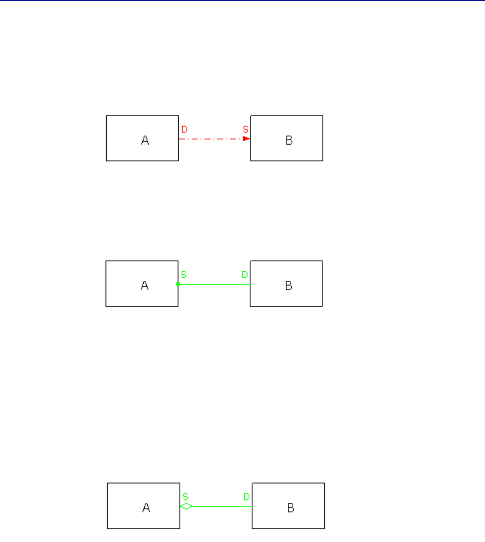
Examples of dependency relationships (arrow)
Dependency relationships are represented by dashed red lines, and contain an
arrow to show the direction of the relationship. In a BMC_Dependency relationship,
the arrow starts at A, the dependent (Destination), and ends at B, the antecedent
(Source) of the relationship. Entity A is dependent on Entity B.
Example of a collection relationship (circle)
A BMC_MemberOfCollection relationship is represented by green lines with circle
tips, as illustrated in the following diagram:
A is the collection class (Source), and B is the member class (Destination). The circle
represents a collection relationship, where the collection class uses properties of
the member class.
Example of a component relationship (diamond)
In a component relationship, the source CI is a group that has a component or part;
its destination. Entity A is a group (Source) that has a component B (Destination).
In diagrams, component relationships are represented by green lines with
diamond tips.

Preface 13
BMC Atrium Core documentation
Cardinality in relationships
Every relationship class has a cardinality that defines how many instances of the
source class can be related to each instance of the destination class and vice versa.
Where cardinality is specified in the diagrams, it is shown at the ends of the
relationship lines as one of the following types:
1:1 (one to one)
1:* (one to many)
*:1 (many to one)
*:* (many to many)
Weak relationships
Where a weak relationship exists between two instances, that relationship is
indicated by the letter W in the illustrative model diagrams. If the relationship is a
weak relationship, its destination member, called the weak member, cannot exist
without its source member, called the strong member. A weak relationship creates
a logical composite object consisting of both member CIs.
BMC Atrium Core documentation
This section describes the complete set of BMC Atrium CMDB documentation,
including manuals, help systems, videos, and so on.
Unless otherwise noted, documentation is available free of charge on the BMC
Atrium CMDB documentation media (DVD or Electronic Product Download
bundle) and on the BMC Customer Support site, at http://www.bmc.com/
support.
To find this documentation on the BMC Customer Support site, choose Product
Documentation > Supported Product A-Z List > BMC Atrium CMDB Enterprise
Manager >7.6.04
Title Description Audience
Atrium Integrator 7.6.04
User's Guide
Information about defining source and target
connections, creating jobs and transformations,
editing and monitoring jobs, and other Atrium
Integrator concepts.
Users who are responsible
for setting up data transfer
integrations between
external data stores and
BMC Atrium CMDB.
BMC Atrium CMDB 7.6.04
Administrator's Guide
Information about setting permissions, configuring
federation, modifying the data model, configuring
an impact model, and other administrative tasks in
BMC Atrium Configuration Management Database
(BMC Atrium CMDB).
Configuration managers,
application administrators,
and asset analysts.
BMC Atrium CMDB 7.6.04
Common Data Model
Diagram
Hierarchical diagram of all classes in the Common
Data Model (CDM), including unique attributes and
applicable relationships.
Configuration managers,
application administrators,
and asset analysts.

14 Data Modeling Guide
BMC Atrium CMDB 7.6.04
BMC Atrium CMDB
7.6.04 Data Model Help
Description and details of superclasses, subclasses,
attributes, and relationship classes for each class.
Contains only information about the CDM at first,
but you can update it to include information about
data model extensions that you install.
Note: This Help is provided in HTML and is available
on the BMC Atrium CMDB media. It is not
available on the BMC Customer Support site.
Configuration managers,
application administrators,
and asset analysts.
BMC Atrium CMDB 7.6.04
Data Modeling Guide
Best practices for using the classes that BMC
provides for BMC Atrium CMDB (both the CDM
and extensions) to model complex business entities,
focusing on the use of multiple related CIs to model
an entity rather than on general information about a
class or attribute.
Configuration managers,
application administrators,
and asset analysts.
BMC Atrium CMDB
7.6.04 Javadoc Help
Information about Oracle Java classes, methods, and
variables that integrate with BMC Atrium CMDB.
Note: This Help is provided in HTML and is available
on the BMC Atrium CMDB media. It is not
available on the BMC Customer Support site.
Application programmers.
BMC Atrium CMDB 7.6.04
Normalization and
Reconciliation Guide
Information about normalizing data in BMC Atrium
CMDB and reconciling CIs from different data
providers into a single production dataset.
Configuration managers,
application administrators,
and asset analysts.
BMC Atrium CMDB
7.6.04 Online Help
Help for using and configuring BMC Atrium CMDB,
including Atrium Integrator, BMC Atrium Product
Catalog, Reconciliation Engine, Normalization
Engine, and so on.
Note: This Help is provided in HTML and is available
through the Help links in the BMC Atrium CMDB
user interface. It is not available on the BMC
Customer Support site.
Configuration managers,
application administrators,
asset analysts, and users
that work with CIs and need
to understand the
relationships that exist
within BMC Atrium CMDB.
BMC Atrium CMDB 7.6.04
User's Guide
Information about using BMC Atrium CMDB,
including searching for and comparing CIs and
relationships, relating CIs, viewing history, running
impact simulations, and viewing federated data.
Users that work with CIs
and need to understand the
relationships that exist
within BMC Atrium CMDB.
BMC Atrium Core: Taking
Your Data Into Production
End to End
End-to-end high-level steps for bringing data into
BMC Atrium CMDB from a third-party source and
making it available in your production dataset.
Note: This Flash video is available on the BMC
Atrium CMDB media. It is not available on the
BMC Customer Support site.
Configuration managers,
application administrators,
and asset analysts.
Title Description Audience

Preface 15
BMC Atrium Core documentation
BMC Atrium Core 7.6.04
Compatibility Matrix
Information about the BMC Atrium CMDB
configurations that are expected to work together
based on design, testing, or general understanding
of the interaction between products.
Note: Download the BMC Atrium Core 7.6.04
Compatibility Matrix from the BMC Customer
Support site at http://www.bmc.com/
support/reg/remedy-compatibility-
tables.html?c=n.
Configuration managers,
application administrators,
and asset analysts.
BMC Atrium Core 7.6.04
Concepts and Planning
Guide
Information about CMDB concepts and high-level
steps for planning and implementing BMC Atrium
CMDB.
Anyone who wants to learn
about and understand BMC
Atrium CMDB products,
CMDBs in general, and the
functionality of BMC
Atrium CMDB in particular.
IT leaders, configuration
managers, application
administrators, and asset
analysts are some who will
benefit from this
information.
BMC Atrium Core 7.6.04
Developer’s Reference Guide
Information about creating API programs using C
API functions and data structures.
Application administrators
and programmers.
BMC Atrium Core 7.6.04
Installation Guide
Information about installing, upgrading, and
uninstalling BMC Atrium Core features.
Application administrators.
BMC Atrium Core 7.6.04
Master Index
Combined index of all guides. Everyone.
BMC Atrium Core 7.6.04
Product Catalog and DML
Guide
Information about configuring the Product Catalog
and DML, adding products, and creating aliases for
products, manufacturers, and categorizations.
System administrators, IT
managers, network
managers, and other
qualified personnel who are
familiar with their
computing and networking
environment.
BMC Atrium Core 7.6.04
Release Notes
Information about new features, known issues, and
other late-breaking topics.
Everyone.
BMC Atrium Core 7.6.04
Troubleshooting Guide
Information about resolving issues with BMC
Atrium CMDB components, including API, filter,
and console error messages and their solutions.
Application administrators,
programmers, and BMC
Support personnel.
BMC Atrium Core 7.6.04
Web Services Help
Information about using BMC Atrium Core Web
Services, including how to publish and find
interfaces in the Web Services Registry, set versions,
disambiguate web services, configure security
policies and encryption, and use BMC Atrium Core
Web Services data structures and operations.
Note: This Help is provided in HTML and is available
on the BMC Atrium CMDB media. It is not
available on the BMC Customer Support site.
Application administrators
and programmers.
Title Description Audience

16 Data Modeling Guide
BMC Atrium CMDB 7.6.04
BMC Atrium Integration
Engine 7.6.04 ADK
Developer's Guide
Information about how to build adapters that can
transfer information between an external data store
and either BMC Remedy AR System forms or BMC
Atrium CMDB.
Developers who have a
basic understanding of BMC
Atrium Integration Engine
and want to build adapters
that can exchange data
between two data sources.
BMC Atrium Integration
Engine 7.6.04 Online Help
Help for using and configuring BMC Atrium
Integration Engine.
Note: This Help is provided in HTML and is available
through the Help links in the BMC Atrium
Integration Engine user interface. It is not
available on the BMC Customer Support site.
Users who are responsible
for setting up data transfer
integrations between
external data stores and
either BMC Atrium CMDB
or BMC Remedy
AR System.
BMC Atrium Integration
Engine 7.6.04 User's Guide
Information about creating data exchanges and data
mappings, defining rules and queries, activating
event-driven data exchanges, defining connection
settings, and other BMC Atrium Integration Engine
concepts.
Users who are responsible
for setting up data transfer
integrations between
external data stores and
either BMC Atrium CMDB
or BMC Remedy
AR System.
Mapping Your Data to
BMC Atrium CMDB 7.6.04
Classes
Spreadsheet that maps common IT objects to the
appropriate class, whether part of the CDM or an
extension. This spreadsheet also includes
information about further categorizing instances
using key attributes, and best practices for creating
normalized relationships.
Configuration managers,
application administrators,
and asset analysts.
Title Description Audience

Chapter 1 Computer system modeling 17
Chapter
1Computer system modeling
This section describes how to use the CDM to model computer systems (servers,
workstations, and network nodes such as routers, switches, and hubs). It details
the classes, relationships, and attributes used to model computer systems,
operating systems, hardware components, software inventory and patches, access
points, and network interfaces.
For information on modeling applications, including modeling runtime versus
installed aspects of applications, see Chapter 2, “Application modeling.”.
The following topics are provided:
Logical identity of BMC_ComputerSystem (page 18)
Computer system modeling (page 21)
Software inventory and patch modeling (page 22)
Router modeling (page 24)
Virtual system modeling (page 25)
Operating system modeling (page 33)
Hardware component modeling (page 34)
Access point modeling (page 36)
Network interface and address modeling (page 38)
Software and hardware cluster modeling (page 41)

18 Data Modeling Guide
BMC Atrium CMDB 7.6.04
Logical identity of BMC_ComputerSystem
BMC_ComputerSystem is a class that stores CIs relating to collections of managed
system elements. This is the primary class that you use to model the computers in
your organization. You can use the attributes in this class to identify the purpose
of each computer CI in your organization.
For example, the class contains several attributes that represent any network-
addressable system, such as a server, a workstation, or a network device (router,
switch, hub, load balancer, firewall, and so forth), as well as mainframes, printers,
and virtual systems. Table 1-1 shows the key attributes that identify an instance of
BMC_ComputerSystem.
Table 1-1: Key attributes for BMC_ComputerSystem
Attribute Usage
Name,
NameFormat
Identifies a computer system. The Name attribute should be a unique
instance identifier that may not be Human Readable. Because multiple
valid naming conventions may exist and can be used according to
specific contexts, set the NameFormat attribute with a value
indicating the heuristic used to generate the Name value. For example,
in some cases, an instance of BMC_ComputerSystem will be
identified by an external DNS name (a name configured in a DNS
server). In other cases, a static IP address will be used. The naming
conventions for NameFormat are:
IP—a valid IP address (decimal bytes delimited with dots).
DNS—a fully qualified host name, formatted as a HostName and a
DomainName delimited with dots (the DomainName can also be
made of multiple components delimited with dots).
TOKEN—Name holds a value defined by the TokenId (see
“Additional attributes for BMC_ComputerSystem” on page 20 for
more information on the TokenId).
Domain Identifies the domain name of the computer, as known by the end
points.
HostName Specifies the local name of the computer, as known by the end points.
This value must be set according to BMC nationalization guidelines
that specifies the algorithms and methods required to obtain the
correct values.
SerialNumber Specifies the serial number of the computer.

Chapter 1 Computer system modeling 19
Logical identity of BMC_ComputerSystem
Key attributes of BMC_ComputerSystem
Table 1-2 show the attributes that further describe the role of an instance of
BMC_ComputerSystem.
Table 1-2: The role of an instance of BMC_ComputerSystem (Sheet 1 of 2)
Attribute Usage
CapabilityList Defines the main functions that the computer can perform.
This is a character attribute in which you can enter any value
listed in the description. You can enter more than one of these
values; however, make sure that multiple values are delimited
by commas. A computer system can be dedicated to a single
function, such as printing, routing, or switching packets, or it
can perform several functions. Typically, the
PrimaryCapability attribute is set to the first value specified
in CapabilityList.
The following list illustrates the functions and values to assign
to a CapabilityList attribute depending on the function of
the computer.
Not Dedicated—0
Unknown—1
Other—2
Storage—3
Router—4
Switch—5
Layer 3 Switch—6
Central Office Switch—7
Hub—8
Access Server—9
Firewall—10
Print—11
I/O—12
Web Caching—13
Server—14
Management —15
Block Server —16
File Server —17
Mobile User Device —18
Repeater—19
Bridge/Extender—20
Gateway —21
LoadBalancer—22
Mainframe—23
SANSwitch—24
SANHub—25
SANBridge—26
SANRouter—27
SANDirector—28
RAIDStorageDevice—29
Virtual Tape Library—30
JBOD—31
Workstation—32
StorageSubsystem—33
Storage Virtualizer—34
Media Library—35
ExtenderNode—36
NAS Head—37
Self-contained NAS—38
UPS—39
IP Phone—40
Management Controller—41
Chassis Manager—42
Host-based RAID controller—
43
Storage Device Enclosure—44
Desktop—45
Laptop—46
Virtual Library System—47
Blade System—48
Blade Server—49

20 Data Modeling Guide
BMC Atrium CMDB 7.6.04
For example, a server with active firewall capabilities could have the values 14
(Server) or 10 (Firewall) for CapabilityList. PrimaryCapability would be set
to Server if this is the main function of the system. However, a switch device would
have CapabilityList = 5 (Switch) and PrimaryCapability = 5.
Additional attributes for BMC_ComputerSystem
Table 1-3 describes the attributes that provide additional information about an
instance of BMC_ComputerSystem.
For more information about specific attributes, see the BMC Atrium CMDB 7.6.04
Common Data Model Help.
PrimaryCapability Describes the main function that the computer performs.
By convention, PrimaryCapability is the first item in the
CapabilityList attribute.
ShortDescription Specifies a short description for the instance when the value of
the Name attribute is encoded. ShortDescription should
always be provided and set with a value that makes sense to an
end user.
Table 1-2: The role of an instance of BMC_ComputerSystem (Sheet 2 of 2)
Attribute Usage
Table 1-3: Additional information for BMC_ComputerSystem
Attribute Description
Description The functions that the computer system can perform.
DHCPUse Specifies whether the system is configured to use DHCP:
Enabled = configured to use DHCP
Disabled = not configured to use DHCP
ManufacturerName The company that manufactured the computer.
Model The model of the computer.
OwnerContact The contact information that specifies how the primary
system owner can be reached (such as phone number or email
address).
OwnerName The name of the primary system owner.
TokenId A unique identifier populated by BMC Discovery products
and used by the Reconciliation Engine (of the BMC Atrium
CMDB) to identify instances.
TotalPhysicalMemory The total physical memory, in kilobytes.
Chapter 1 Computer system modeling 21
Computer system modeling
Computer system modeling
Computer systems are parent objects that may be represented as an aggregation of
component parts (such as operating systems, hardware, software inventory, or
network addresses) that are child instances related to the BMC_ComputerSystem
instance.
Systems provide computing capabilities and aggregate one or more of the these
elements: file systems, operating systems, processors, and memory (including
volatile and nonvolatile storage). Therefore, additional information about a
computer system might not be part of a BMC_ComputerSystem instance but be
available from instances of other classes connected to the BMC_ComputerSystem
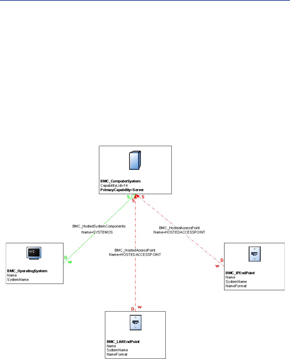
instance through relationships. For example, Figure 1-1 represents a model for a
server, a network-addressable computer system.
Figure 1-1: Illustrative model of a server
Servers, workstations, network devices (such as routers, switches, hubs, load
balancers, or firewalls) are all instances of BMC_ComputerSystem, the class
representing all network addressable systems. BMC_ComputerSystem represents
an entity made up of component parts that operate as a functional whole.

22 Data Modeling Guide
BMC Atrium CMDB 7.6.04
The PrimaryCapability attribute is crucial to identifying whether a specific
instance is a server, a router, or something else. BMC Atrium CMDB planners
might use the PrimaryCapability attribute to define a vendor-specific switch
used in their network, making it easy to import this data from a vendor’s
environment as an industry-standard item in their BMC Atrium CMDB.
Software inventory and patch modeling
Software inventory represents the products and patches that are installed on a
computer. BMC_Product represents instances of installed products, whereas
BMC_Patch represents instances of patches (operating system patches and product
patches). Figure 1-2 illustrates an example model of a server with two installed
products.
Figure 1-2: Illustrative model of a software inventory containing two installed products
Figure 1-3 illustrates an example model of a server with one installed patch.
Figure 1-3: Illustrative model of a software inventory with a patch

Chapter 1 Computer system modeling 23
Software inventory and patch modeling
You might not want to model patches in your BMC Atrium CMDB in all cases. For
example, you might store patches for servers in the BMC Atrium CMDB, but it
might not be necessary to do so for desktops and routers.
Both BMC_Product and BMC_Patch are subclasses of BMC_Software and
BMC_SystemComponent. You should associate each instance of a product or of a
patch to the parent instance of BMC_ComputerSystem by the
BMC_HostedSystemComponents relationship. When modeling software inventory,
be aware that the BMC_Product class captures only installed products or
applications, not runtime aspects.
For more information about modeling runtime applications and using instances of
BMC_Product for application modeling, see Chapter 2, “Application modeling.”.
Logical identity of BMC_ComputerSystem (for products or patches)
Like any child instance of BMC_ComputerSystem, a product or a patch is identified
by the Name attribute in conjunction with the SystemName attribute that represents
the name of the computer instance. Thus, the Name attribute represents the local
name of the CI in the context of the computer that is hosting it, as described in
Table 1-4.
Additional attributes of BMC_ComputerSystem (for products or
patches)
Table 1-5 describes attributes that provide additional information about products
and patches.
Table 1-4: Key attributes for BMC_ComputerSystem
Attribute Usage
Name Identifies the child instance in the context of the parent instance of
BMC_ComputerSystem.
SystemName Specifies the name of the computer instance. This must be the same as the
parent instance of the BMC_ComputerSystem Name attribute. This
attribute is automatically populated from the related CI when a weak
relationship is created between the computer system and the product or
patch.
Table 1-5: Additional information about products and patches
Attribute Description
Description The description for the component.
ManufacturerName The company that manufactured the component.
SerialNumber The serial number of the component.
ShortDescription A caption for the component.
PatchNumber The version number of the patch.
VersionNumber The version number of the component.
24 Data Modeling Guide
BMC Atrium CMDB 7.6.04
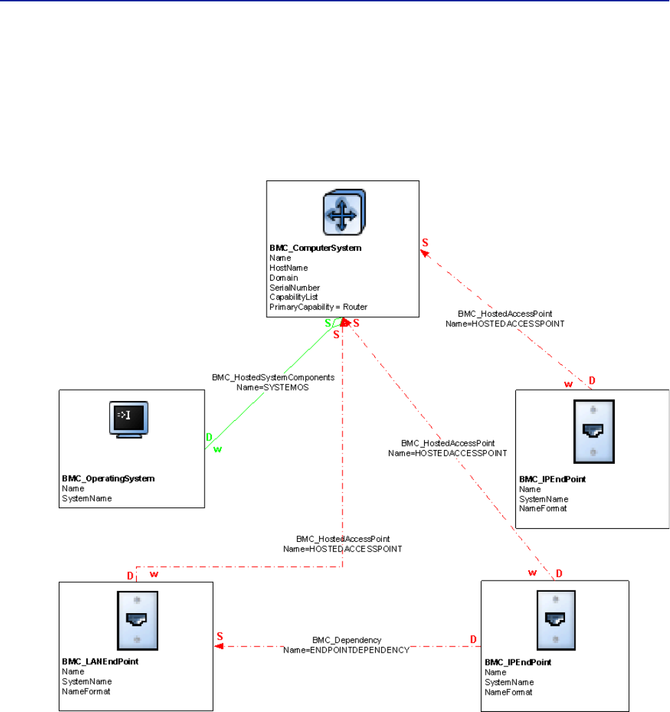
Router modeling
Routers are modeled using the BMC_ComputerSystem class by setting the
PrimaryCapability attribute to Router. Figure 1-4 illustrates an example model
of a network router.
Figure 1-4: Illustrative model of a router
In the model, two BMC_IPEndpoint classes are used to represent the interfaces to
the router.
Chapter 1 Computer system modeling 25
Virtual system modeling
Virtual system modeling
Virtual systems represent one or more virtual machines that are hosted by a
physical computer. A virtual system has the same relationships to subcomponents
and applications that a physical system does. In other words, a virtual system has
an operating system (such as Windows or UNIX®), network addresses, and
software. The major difference is that these subcomponents, although captured as
regular CIs, are all virtual. Additionally, virtual systems can have BMC_Genealogy
relationships that define relationships between a parent virtual system and its
child virtual systems. For example, If you have a virtual system named win2k-vm1
and a clone of that system named win2k-vm2, the win2k-vm1 system is the parent
and the win2k-vm2 system is the child.
When modeling virtualization in your environment, represent the virtual
computer system using the BMC_ComputerSystem class, and the virtualization
software (such as Hypervisor or virtualization software), using the
BMC_VirtualSystemEnabler class.
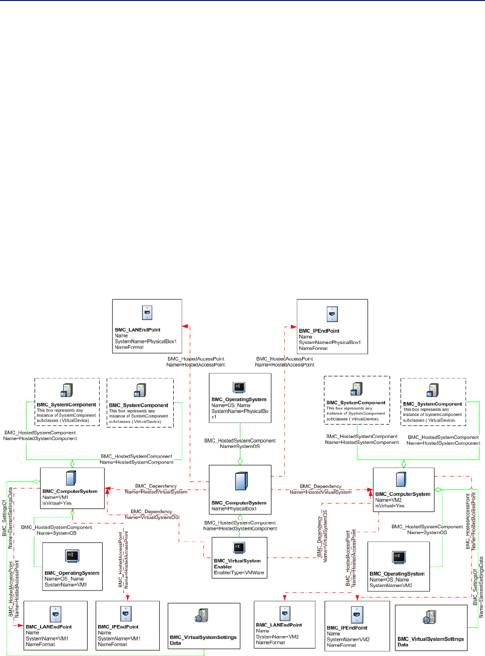
An example of a virtual system model is illustrated in Figure 1-5.
Figure 1-5: Illustrative model of a virtual system without resource pools and settings

26 Data Modeling Guide
BMC Atrium CMDB 7.6.04
Figure 1-5 illustrates multiple virtual systems (virtual machines, or VMs), the
physical computer system that hosts them, and the virtualization operating
system, which is hosted on the physical system and runs the VMs. The diagram is
simplified and does not contain resource pools.
Logical identity of BMC_System and BMC_ComputerSystem (for
virtual systems)
You model virtual systems as instances of BMC_ComputerSystem, a subclass of
BMC_System. You should follow the same naming rules as for an instance of
BMC_ComputerSystem class. For more information about this class, see “Logical
identity of BMC_ComputerSystem” on page 18.
The key attributes for defining virtual systems are VirtualSystemType (for the
BMC_ComputerSystem class) and isVirtual (for the BMC_System and
BMC_SystemComponent classes and their subclasses). Both attributes are described
in Table 1-6.
NOTE
In BMC Atrium CMDB 7.6.00, the isVirtual attribute was moved from the
BMC_ComputerSystem class to the BMC_System and BMC_SystemComponent
classes. This move expands the virtualization scope beyond computer systems,
enabling you to model potential future virtualizable entities, such as applications.
Because BMC_ComputerSystem is a subclass of the BMC_System class, the
isVirtual attribute is still available in the BMC_ComputerSystem class.
To ensure correct reconciliation with data created by BMC Software products, use
NULL instead of No for the isVirtual attribute to represent an instance that is not
virtual.
Table 1-6: Key attributes for defining virtual systems
Attribute Usage
VirtualSystemType Identifies the type of virtual machine. Values are Other (0),
Unknown (1), PR/SM (2), z/VM (3), VMWare (4), Xen (10),
Hyper-V (15), Sun Solaris™ Container (20), VPar (25), NPar (30)
and LPar (35).
isVirtual Specifies whether the instance is virtual or physical. Values are
NULL, No (0), or Yes (1). If you know that it is a virtual machine,
use Yes. If you know that it is a physical machine, use No. If you
are unsure, use NULL.

Chapter 1 Computer system modeling 27
Virtual system modeling
Logical identity of BMC_VirtualSystemEnabler
The BMC_VirtualSystemEnabler class stores information about software that
enables a collection of virtual computer systems to run on a single physical
computer system (for example, VMware). This class is used to capture the
virtualization OS, such as operating systems that run virtual machines (including
VMware images, Solaris zones, IBM® AIX® logical partitions, HP-UX virtual
partitions, and so forth).
The BMC_VirtualSystemEnabler class is associated to the parent computer
system instance by the BMC_HostedSystemComponents relationship. As a subclass
of BMC_ComputerSystem, any instance (representing a new business CI) of the
BMC_VirtualSystemEnabler class is identified, at minimum, by the Name and
SystemName attributes.
The key attribute for BMC_VirtualSystemEnabler is EnablerType, described in
Table 1-7.
For a complete list of attributes for the BMC_VirtualSystemEnabler class, see the
BMC Atrium CMDB 7.6.04 Data Model Help.
Logical identity of BMC_VirtualSystemSettingData
The BMC_VirtualSystemSettingData class (derived from BMC_Settings)
provides additional granularity about a virtual system’s settings through a set of
virtualization-specific properties.
Key attributes for defining the virtual aspects using the
BMC_VirtualSystemSettingData class are described in Table 1-8.
Table 1-7: Key attributes for EnablerType
Attribute Usage
EnablerType Specifies the virtualization software or OS. The possible values
are Other (0, the default), Unknown (1), PR/SM (2), z/VM (3),
VMWare Server (4), Solaris Resource Manager (5), LPar (6),
VPar (7), HP nPartitions (20), Integrity VM (25), Microsoft
Hyper-V (30), VMWare ESX Server (35), VMWare Workstation
(40), Xen Hypervisor (45), and LDOM Hypervisor (50).
Table 1-8: Key attributes for BMC_VirtualSystemSettingData (Sheet 1 of 2)
Attribute Usage
VirtualSystemState Specifies the state of the virtual machine. Values are Other (0),
Unknown (1), Active (10), InActive (15), Suspended (20), and
Disabled (25).
VirtualSystemType Specifies a type of virtual system.
Values are Other (0),Unknown (1), LPAR (2), VM/VM Guest
(3), VMware (4),Xen (20), LDOM (25), Solaris Container (30),
HP nPartitions (35), VPar (40), and Microsoft Hyper-V (45).
ActualProvisionDat
e
The date and time that a specific VM was provisioned. This
attribute is important for enabling successful reporting on BMC
Dashboards.

28 Data Modeling Guide
BMC Atrium CMDB 7.6.04
Figure 1-6 displays an organization that has a virtual system environment, where
a Solaris server is divided into two domains (LDOM1 and LDOM2), which are
further divided into containers (Container1 and Container2).
ProposedDecommissi
onDate
The date and time that the VM will be removed from the
environment. One of the biggest problems causing virtual
system sprawl is that organizations do not decommission VMs
and track the information. This attribute helps to drive
workflow actions such as:
Notifying users that their VM is about to be decommissioned
and enabling them to extend the time before that occurs.
Automatically creating change requests to begin the
decommissioning process.
Automatically starting a job in BMC BladeLogic, BMC
Atrium Orchestrator, and other consuming applications to
decommission the VM.
ActualDecommission
Date
The date of the actual decommission. There can be an extension
to that date to enable you to report or track a VM.
You can also compare differences between the decommission
date and actual decommission date, or block future updates to
the extension date.
Table 1-8: Key attributes for BMC_VirtualSystemSettingData (Sheet 2 of 2)
Attribute Usage
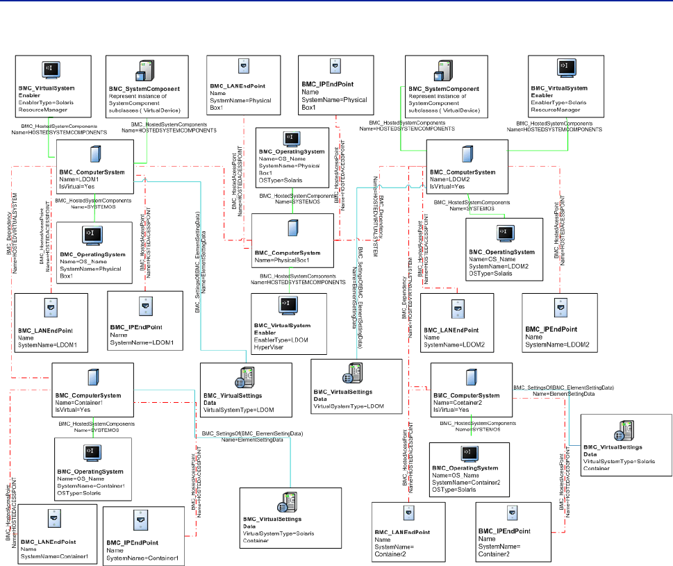
Chapter 1 Computer system modeling 29
Virtual system modeling
Figure 1-6: Logical domain virtual systems with settings and containers
Best Practice
The recommended best practice for modeling this scenario would be:
For the virtualization environment, use BMC_ComputerSystem, where the
isVirtual attribute is set to Yes. The parent system, which is either virtual or
physical has to be related to the virtual system with a BMC_Dependency
relationship where the attribute Name has a value of HostedVirtualSystem. To
model the virtualization technology, BMC_VirtualsystemEnabler is related to
the host system with the appropriate EnablerType attribute is set to the correct
type of software (for example, LDOM Hypervisor) and relationships are set to
BMC_ComputerSystem (the physical computer).
For containers, create a relationship to BMC_VirtualsystemEnabler (Solaris
Resource Manager) and relationships to the domain (or physical computer,
depending on the configuration), and operating system.

30 Data Modeling Guide
BMC Atrium CMDB 7.6.04
Logical identity of BMC_ResourcePool for virtual systems
The BMC_ResourcePool class serves as a logical entity (with associated controls)
provided by the host system to allocate and assign resources. A resource pool may
be used to allocate resources of a specific type. Hierarchies of resource pools may
be created to provide administrative control over allocations. In cases where
resources are subdivided, multiple resource pools may exist.
Key attributes for defining resource pools using the BMC_ResourcePool class are
described in Table 1-9.
Table 1-9: Key attributes for BMC_ResourcePool
Attribute Usage
Primordial Specifies how the ResourcePool is used in the activity of
resource management. If set to true, this attribute indicates that
the ResourcePool is a base from which resources are drawn and
returned in the activity of resource management. It also
indicates that this ResourcePool shall not be created or deleted
by consumers of this model. However, other actions (whether
they are modeled or not), may affect the characteristics or size of
primordial ResourcePools. If set to false (the default), this
attribute indicates that the ResourcePool serves as a concrete
Resource Pool, meaning that is subject to resource allocation
services functions.
This distinction is important, because higher-level
ResourcePools may be assembled using the Component or
ElementAllocatedFromPool associations. Although the higher-
level abstractions can be created and deleted, the most basic,
hardware-based ResourcePools (such as primordial pools)
cannot. Instead, they are physically realized as part of the
system, or are actually managed by some other system and
imported as if they were physically realized.
ResourceType Specifies the type of resource that the resource pool may
allocate. Values are Other (0), Computer System (2), Processor
(3), Memory (4), IDE Controller (5), Parallel SCSI HBA (6), FC
HBA (7), iSCSI HBA (8), IB HCA (9), Ethernet Adapter (10),
Other Network Adapter (11), I/O Slot (12), I/O Device (13),
Floppy Drive (14), CD Drive (15), DVD drive (16), Disk Drive
(17), Tape Drive (18), Storage Extent (19), Other storage device
(20), Serial port (21), Parallel port (22), USB Controller (23),
Graphics controller (24), IEEE 1394 Controller (25), Partitionable
Unit (26), Base Partitionable Unit (27), Power (28), Cooling
Capacity (29), Ethernet Switch Port (30), Logical Disk (31),
Storage Volume (32), Ethernet Connection (33).

Chapter 1 Computer system modeling 31
Virtual system modeling
In systems that support over-commitment, pools represent the reservable capacity,
not an upper bound or limit on the maximum amount that can be allocated.
Admission control during power-on may detect and prevent systems from
powering due to resource exhaustion. For example, over-commitment on a
resource pool with ResourceType set to Memory would require that sufficient
space be available in a backing store that might be managed through a storage
resource pool. Figure 1-7 on page 34 illustrates an example virtual system model
including resource pools.
Logical identity of BMC_ResourceAllocationSettingData for virtual
systems
The BMC_ResourceAllocationSettingData class (derived from BMC_Settings)
represents settings that specifically relate to an allocated resource.
Use BMC_VirtualSystemSettingData and
BMC_ResourceAllocationSettingData to represent virtual system settings, and
BMC_ResourcePool to model resource pools. Figure 1-7 illustrates an example
virtual system model including settings
The key attribute for defining settings using the
BMC_ResourceAllocationSettingData class is ResourceType, described in
Table 1-10.
Table 1-10: Key attribute for ResourceAllocationSettingData
Attribute Usage
ResourceType Specifies the type of resource that this allocation setting
represents. Values are Other (0), Computer System (2),
Processor (3), Memory (4), IDE Controller (5), Parallel SCSI HBA
(6), FC HBA (7), iSCSI HBA (8), IB HCA (9), Ethernet Adapter
(10), Other Network Adapter (11), I/O Slot (12), I/O Device (13),
Floppy Drive (14), CD Drive (15), DVD drive (16), Disk Drive
(17), Tape Drive (18), Storage Extent (19), Other storage device
(20), Serial port (21), Parallel port (22), USB Controller (23),
Graphics controller (24), IEEE 1394 Controller (25), Partitionable
Unit (26), Base Partitionable Unit (27), Power (28), Cooling
Capacity (29), Ethernet Switch Port (30).

32 Data Modeling Guide
BMC Atrium CMDB 7.6.04
Figure 1-7: Model of a virtual system with one resource pool and resource allocation
Using Figure 1-7 as an example, a physical box is related to BMC_ResourcePool by
BMC_Component where the Name attribute is set to HostedResourcePool. Use the
relationship class BMC_MemberOfCollection, where the Name attribute is set
toisMemberofPool to allocate resources and resource pools. You can use the
relationship class BMC_Dependency, where the Name attribute is set to
ElementAllocatedFromPool to allocate resources and resource pools. You can
also use the relationship class BMC_Dependency, where the Name attribute is set to
ResourceAllocationFromPool to allocate resources and resource pools.
Deprecated classes for virtual systems
The following classes were deprecated in BMC Atrium CMDB 7.5.00, and are no
longer used for modeling virtualized environments:
BMC_VirtualSystem (including all subclasses)
BMC_VMWare
BMC_VMWareVirtualSystem

Chapter 1 Computer system modeling 33
Operating system modeling
BMC_UnixVirtualSystem
BMC_MFVirtualSystem
BMC_MFVirtualSystemEnabler
BMC_LPAR
Relationships used for virtual systems
Table 1-11 describes the relationships for virtual systems.
Operating system modeling
An operating system is software or firmware that controls the operation of a
computer and directs the processing of programs. This section describes how to
model Windows and UNIX operating systems.
To model a Windows or UNIX operating system, create an instance of the
BMC_OperatingSystem class. Associate the instance to the parent
BMC_ComputerSystem instance by a BMC_HostedSystemComponents relationship.
NOTE
This class is not reserved for servers and workstations only but is used to capture
any type of operating system, such as the IOS for a Cisco network switch or router.
Table 1-11: Relationships used for virtual systems
Relationship Relationship class Value of Name attribute
Managed elements and
setting data
BMC_SettingsOf ELEMENTSETTINGDATA
Allocated resource and
resource pool
BMC_MemberOfCollection ISMEMBEROFPOOL
Resource allocated from a
pool
BMC_Dependency ELEMENTALLOCATEDFROMPOOL

34 Data Modeling Guide
BMC Atrium CMDB 7.6.04
Logical identity of BMC_OperatingSystem
As with any related component of BMC_ComputerSystem, an operating system is
identified by the Name attribute in conjunction with the SystemName attribute that
represents the name of the parent instance of the computer. Therefore, the Name
attribute represents the local name of the operating system CI in the context of the
computer that is hosting it, as described in Table 1-13.
Additional attributes for BMC_OperatingSystem
Table 1-14 describes additional attributes of BMC_OperatingSystem.
Hardware component modeling
The hardware components that make up a computer system are captured by
subclasses of BMC_HardwareSystemComponent. Generally, one subclass represents
one type of hardware component. Examples of hardware components include:
Disk drive—Machine that reads data from and writes data to a disk.
Disk partition—Logical allocation of space on a disk drive.
Monitor—Video device attached to computer systems that displays computer
operations.
Keyboard—Set of typewriter-like keys that enables you to enter data into a
computer.
Memory—Stores information about internal storage areas in a computer.
Table 1-12: Key attributes for BMC_OperatingSystem
Attribute Usage
Name Identifies the name of the child instance in the context of the parent
instance of BMC_ComputerSystem.
If multiple operating systems are installed on the same computer, Name
must be structured so that the multiple instances have different names.
SystemName Specifies the name of the system. This must be the same as the parent
instance of the BMC_ComputerSystem Name attribute. This attribute is
automatically populated from the related CI when a weak relationship
is created between the operating system and a computer system.
Table 1-13: Additional attributes of BMC_OperatingSystem
Attribute Usage
Description The description for the operating system.
ManufacturerName The company that manufactured the operating system.
SerialNumber The serial number of the operating system.
ShortDescription A caption for the operating system.
VersionNumber The version number of the operating system.

Chapter 1 Computer system modeling 35
Hardware component modeling
Processor—Device that interprets a machine instructions in a computer.
Network port—Interfaces that connect network drives to computer systems.
For example, you might identify a specific processor as an instance of
BMC_HardwareSystemComponent. Each instance representing a hardware
component is associated to the parent BMC_ComputerSystem instance by the
BMC_HostedSystemComponents relationship.
Logical identity of BMC_HardwareSystemComponent
Like any child instance of BMC_ComputerSystem, a hardware component is
identified by the Name attribute in conjunction with the SystemName attribute that
represents the name of the parent computer instance. Therefore, the Name attribute
represents the local name of the hardware CI in the context of the computer that is
hosting it, as described in Table 1-15.
Additional attributes for BMC_HardwareSystemComponent
Table 1-16 describes additional attributes of BMC_HardwareSystemComponent.
Because each hardware component contains attributes specific to its type, see the
BMC Atrium CMDB 7.6.04 Data Model Help for a complete list of
BMC_HardwareSystemComponent types and attributes to ensure you can
accurately and completely represent your specific hardware CIs.
Table 1-14: Key attributes for BMC_HardwareSystemComponent
Attribute Usage
Name Identifies the child instance in the context of the parent instance of
BMC_ComputerSystem.
SystemName Specifies the name of the system. This must be the same as the parent
instance of BMC_ComputerSystem Name attribute. This attribute is
automatically populated from the related CI when a weak relationship is
created between the computer system and the operating system.
Table 1-15: Additional attributes of BMC_HardwareSystemComponent
Attribute Description
Description The description for the component.
ManufacturerName The company that manufactured the component.
SerialNumber The serial number of the component.
ShortDescription A caption for the component.
VersionNumber The version number of the component.

36 Data Modeling Guide
BMC Atrium CMDB 7.6.04
Access point modeling
A computer provides functions for other entities to use. Access points represent
those available functions. Each access point represents the configuration of access
to a function or the ability to invoke a service and is modeled by the
BMC_AccessPoint class. This characteristic is further defined by
BMC_ProtocolEndpoint, the only direct subclass of BMC_AccessPoint. Among
other types of access points, a network address such as an IP address, MAC
address, or IPX address, is captured as a subclass of BMC_AccessPoint.
Instances of the BMC_AccessPoint class are related to a computer system through
a BMC_HostedAccessPoint dependency relationship. Access points exist within
the context of a computer system, and are associated to their parent instance of the
system through the BMC_HostedAccessPoint dependency relationship.
For example, Figure 1-4 on page 25 illustrates an example of a computer system’s
relationship to an IP endpoint, in the context of modeling a router.
Logical identity of BMC_IPEndpoint
An IP address is modeled as an instance of BMC_IPEndpoint. Like any child
instance of BMC_ComputerSystem, an instance of BMC_IPEndpoint is identified by
the Name attribute in conjunction with the SystemName attribute that represents the
name of the parent instance of the computer. Therefore, the Name attribute
represents the local name of the CI in the context of the computer that is hosting it,
as described in Table 1-17.
Table 1-16: Key attributes for BMC_IPEndpoint
Attribute Usage
Name Identifies the child instance in the context of the parent instance of the
BMC_ComputerSystem. Name must be an IPv4 or IPv6 address, and
must be formatted as decimal numbers delimited by a period, with no
leading zeros.
NameFormat Sets the heuristic used to generate the Name value. This value must be set
to IP.
SystemName Specifies the name of the system. This must be the same as the parent
instance of the BMC_ComputerSystem Name attribute. This attribute is
automatically populated from the related CI when a weak relationship is
created between the computer system and the operating system.

Chapter 1 Computer system modeling 37
Access point modeling
Additional attributes for BMC_IPEndpoint
Table 1-18 describes additional attributes of BMC_IPEndpoint.
Logical identity of BMC_LANEndpoint
A MAC address is modeled as an instance of BMC_LANEndpoint. Like any child
instance of BMC_ComputerSystem, a MAC address is identified by the Name
attribute in conjunction with the SystemName attribute that represents the name of
the parent instance of the computer. Therefore, the Name attribute represents the
local name of the CI in the context of the computer that is hosting it, as described
in Table 1-19.
Table 1-17: Additional attributes of BMC_IPEndpoint
Attribute Description
Address The IP address. This value must be compliant with
AddressType.
AddressType The enumeration that defines the type of address. This value
must be set to either 0 (Unknown), 1 (IPv4), or 2 (IPv6).
DNSName The system name based on its DNS name. The DNS name
corresponds to the IP address; therefore, when you want to
search a system by DNS name, you should look up the
IPEndpoint CIs, and then the parent computer.
ProtocolType The enumeration that categorizes and classifies instances of this
class.
ShortDescription A caption of the IP address.
SubnetMask The IP address subnet mask.
ManagementAddress The selection that defines if the IP address is a management
address such as a Discovered Address or an SNMP address.
Table 1-18: Key attributes for BMC_LANEndpoint
Attribute Usage
Name Identifies the MAC address. The value must be an address suffixed by an
index. The index uniquely identifies a MAC address for situations where
multiple identical MAC addresses are configured within the same
system.
The index is generally the index of the MAC address entry in the SNMP
MIB.
NameFormat Specifies the heuristic used to generate the Name value. This value must
be set to MACAddress:Index.
SystemName Specifies the name of the system. This must be the same as the parent
instance of the BMC_ComputerSystem Name attribute. This attribute is
automatically populated from the related CI when a weak relationship is
created between the computer system and the operating system.

38 Data Modeling Guide
BMC Atrium CMDB 7.6.04
Additional attributes of BMC_LANEndpoint
Table 1-20 describes additional attributes of BMC_LANEndpoint.
Access point binding
Some access points use the services provided through another access point. You
can use access point binding to establish a layering of two protocols, with the
upper layer represented by the dependent and the lower layer represented by the
antecedent.
This binding is modeled in the CDM by the BMC_Dependency relationship with the
Name attribute set to BindsTo.
Network interface and address modeling
Network interfaces are captured by instances of BMC_NetworkPort. Although
model extensions might define subclasses (like a FiberChannel port), the class
that you should use for network interfaces is BMC_NetworkPort. Like other
hardware components, each instance of a network port is associated to the parent
instance of the BMC_ComputerSystem by the BMC_HostedSystemComponents
relationship.
Network addresses are captured by BMC Discovery products as access points
(inherited from BMC_AccessPoint) and therefore must always be associated to
their parent instance of the computer through the BMC_HostedAccessPoint
relationship. Also, a network address can have a relationship to the network
interface for which it is configured. This relationship is modeled by a
BMC_Dependency relationship in which the network interface is the antecedent
(source) and the network address is the dependent (destination).
For more information on modeling network addresses, including an illustration of
the relationships used in the model, see Chapter 5, “Network topology modeling.”.
Table 1-19: Additional attributes of BMC_LANEndpoint
Attribute Description
Address The MAC address.
ProtocolType The enumeration that categorizes and classifies instances of this
class, such as for 14 (for Ethernet).
ShortDescription A caption of the MAC address.

Chapter 1 Computer system modeling 39
Network interface and address modeling
Logical identity of BMC_NetworkPort
Like any child instance of BMC_ComputerSystem, a network port is identified by
the Name attribute in conjunction with the SystemName attribute that represents the
name of the parent instance of the computer. Therefore, the Name attribute
represents the local name of the CI in the context of the computer that is hosting it,
as described in Table 1-21.
Additional attributes for BMC_NetworkPort
Table 1-22 describes additional attributes of BMC_NetworkPort.
Table 1-20: Key attributes for BMC_NetworkPort
Attribute Usage
Name Identifies the network address. This must be an address suffixed by
an index. The index uniquely identifies a MAC address for situations
where multiple identical MAC addresses are configured within the
same system.
The index is generally the index of the MAC address entry in the
SNMP MIB.
NameFormat Specifies the heuristic used to generate the Name value. For instance,
in many cases, network interfaces are best discovered and identified
using SNMP information.
PhysicalIndex Specifies the index, which must be a valid SNMP index relative to the
SNMP IF Table of the computer.
SystemName Identifies the name of the system. This must be the same as the parent
instance of the BMC_ComputerSystem Name attribute. This
attribute is automatically populated from the related CI when a weak
relationship is created between the computer system and the
operating system.
Table 1-21: Additional attributes for BMC_NetworkPort (Sheet 1 of 2)
Attribute Description
AutoSense The Boolean value that indicates whether the port can
automatically determine the speed or other communications
characteristics of the connected network media.
Description The description for the component.
FullDuplex The Boolean value that indicates whether the port is
operating in full duplex mode (carrying signals in both
directions).
LinkTechnology The enumeration of the types of link technologies, with
values such as Unknown, Other, Ethernet, IB, FC, FDDI,
ATM, Token Ring, Frame Relay, Infrared, BlueTooth, or
Wireless LAN.
ManufacturerName The company that manufactured the component.
MaxSpeed The maximum bandwidth of the port in bits/second.
NetworkAddresses The list of strings specifying the network addresses for the
port.

40 Data Modeling Guide
BMC Atrium CMDB 7.6.04
PermanentAddress The network address hard-coded into the port. This address
can be changed by a firmware upgrade or software
reconfiguration. If it is changed, update this field. If no hard-
coded address exists for the network port, leave this attribute
blank.
PhysicalDescription The physical description or location for the port, such as
slot3/port4.
PortType The enumeration of the types of ports, with values such as
Ethernet, FDDI, Token Ring, WAN, or Unknown.
ShortDescription A caption for the component.
SerialNumber The serial number of the component.
SpeedConfigured The maximum bandwidth of the port in bits/second.
Table 1-21: Additional attributes for BMC_NetworkPort (Sheet 2 of 2)
Attribute Description

Chapter 1 Computer system modeling 41
Software and hardware cluster modeling
Software and hardware cluster modeling
Use the BMC_Cluster class to classify or update groups of software or hardware.
Clusters are modeled using the BMC_Cluster class, which stores information
about the cluster in relation to the BMC_System component.
Clusters help increase the performance of resources by storing groups of two or
more computer systems or applications so that they operate together as a
functional whole. Using clusters helps to improve and maintain the reliability,
serviceability, and availability of your operating-system environment.
For example, an accounting department might create a cluster and link it with
relationships to specific computer systems to obtain a complete picture of their
business environment and assess the performance of computers individually and
collectively.

42 Data Modeling Guide
BMC Atrium CMDB 7.6.04

Chapter 2 Application modeling 43
Chapter
2Application modeling
This section describes how to model software business entities, including
applications, software servers, databases, and middleware.
The following topics are provided:
Application characteristics (page 44)
Application infrastructure and hosting environment (page 47)
Relationships for applications (page 48)
Business applications and services (page 49)

44 Data Modeling Guide
BMC Atrium CMDB 7.6.04
Application characteristics
Applications have characteristics that help you determine how to best use the
CDM in your modeling strategy. Table 2-1 maps the characteristics of an
application to the type of class you would use to model that application. Note that
not all objects and relationships are required to model certain types of applications.
For example, patch information may not be required in the case of software license
management.
Figure 2-1 on page 47 illustrates how the installed, runtime, and service aspects of
an application relate to each other.
Table 2-1: Mapping application characteristics to a class
Characteristic Description Class
Runtime aspect Running instances of
applications and software
servers
BMC_SoftwareServer
BMC_Application
BMC_ApplicationInfrastructure
Installation aspect Identifies the product that is
installed, its version, and
any patch
BMC_Product
Service aspect Business applications. (For
business applications
supporting a particular
function such as payroll and
trading, use the
BMC_BusinessService
class.)
BMC_Application
BMC_BusinessService
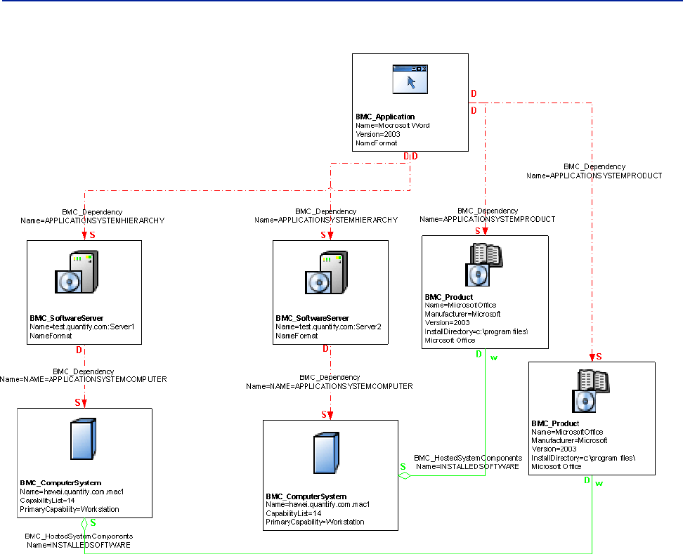
Chapter 2 Application modeling 45
Application characteristics
Figure 2-1: Illustrative representation of multiple application aspects
The BMC_SoftwareServer class represents the deployed, runtime aspects of
applications; in other words, the instances of software actually running on a server.
You instantiate this class to capture long-lived, server-type applications in your
environment. When modeling applications, you must remember this distinction.
To model static, installed components such as Microsoft Excel or Microsoft Word,
create a BMC_Product instance.
You can also use the BMC_Product class to model noncommercial products, such
as in-house software. One application can be installed once, yet have multiple
instances running. For example, you can create a BMC_Product instance to
represent the installed version of WebServer and create several
BMC_SoftwareServer instances to represent actual instances of WebServer, one
listening on port 80, another on port 8000, and a third on port 8080.
As another example, you would model Weblogic first by instantiating the
BMC_Product class (to indicate where it is installed, the number of licenses,
product name, and version). To add the runtime aspect, you would instantiate a
BMC_SoftwareServer class.
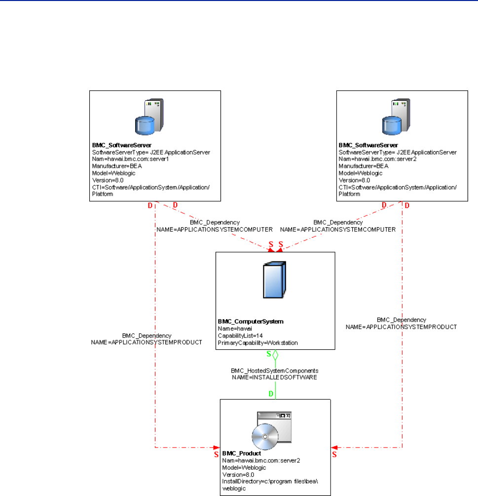
46 Data Modeling Guide
BMC Atrium CMDB 7.6.04
Figure 2-2 illustrates an example of this model, where two instances of a Weblogic
application server (server1 and server2) are actually instances of the same installed
product.
Figure 2-2: Illustrative model of a Weblogic application
Accounting for the runtime aspect of the application in this context is very
important for understanding the impact of an application on a business service.
You must consider capturing Weblogic patches (using the BMC_Patch class),
because the patch will then be connected to the service through the installed
product, runtime, applications and, ultimately, the service and its relationships.
Consequently, an IT administrator responsible for updating patches on Weblogic
would understand how the change relates to the business that Weblogic supports.
For complete descriptions of the classes described in this section for modeling
applications, including examples of usage, see the BMC Atrium CMDB 7.6.04 Data
Model Help. For more information about using the BMC_Product class to model
components, see“Software inventory and patch modeling” on page 22.
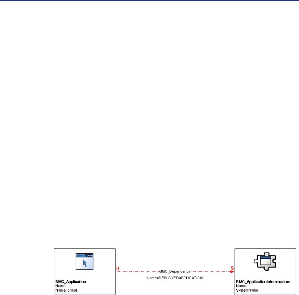
Chapter 2 Application modeling 47
Application infrastructure and hosting environment
Application infrastructure and hosting
environment
The BMC_Application class stores information about standalone applications,
applications deployed on servers (such as SAP), and applications deployed on
distributed systems (such as SAP).
The BMC_ApplicationInfrastructure class stores information about the
framework that supports applications in a distributed or composite system. This
class represents the platform to model your applications. For example, you would
model SAP® as an instance of BMC_ApplicationInfrastructure. After an
application is deployed in that platform, it can run on any application server in the
SAP environment. An application can be hosted by different types of
environments: an application server or application system, or a physical or virtual
system.
Applications running on application servers or application systems
To model applications to run directly on top of an application server or application
system, relate an instance of the BMC_Application class to a hosting
BMC_ApplicationInfrastructure instance. In this model, the application has
only one relationship: a dependency on the application infrastructure hosting the
application. This dependency is modeled by a BMC_Dependency relationship, as
illustrated in Figure 2-3. When using the relationship, set the Name value to
DEPLOYEDAPPLICATION.
Figure 2-3: Illustrative model of applications running on application systems
An application infrastructure cannot have any direct relationship to computers.
Only applications and software servers have relationships to computers.
This model can also be applied to an application or set of applications that support
or collaborate to provide a particular business function. For example, an Oracle®
application infrastructure supports two applications, TimeCard and HR personal
data, both stored in the BMC_Application class. The two classes relate to each
other through the BMC_Dependency relationship, meaning that both the TimeCard
and HR personal data applications are dependent on the supporting Oracle
application infrastructure. To decompose the system into its functional
components, relate an instance of this class to its component BMC_SoftwareServer
instance with the BMC_Dependency class.
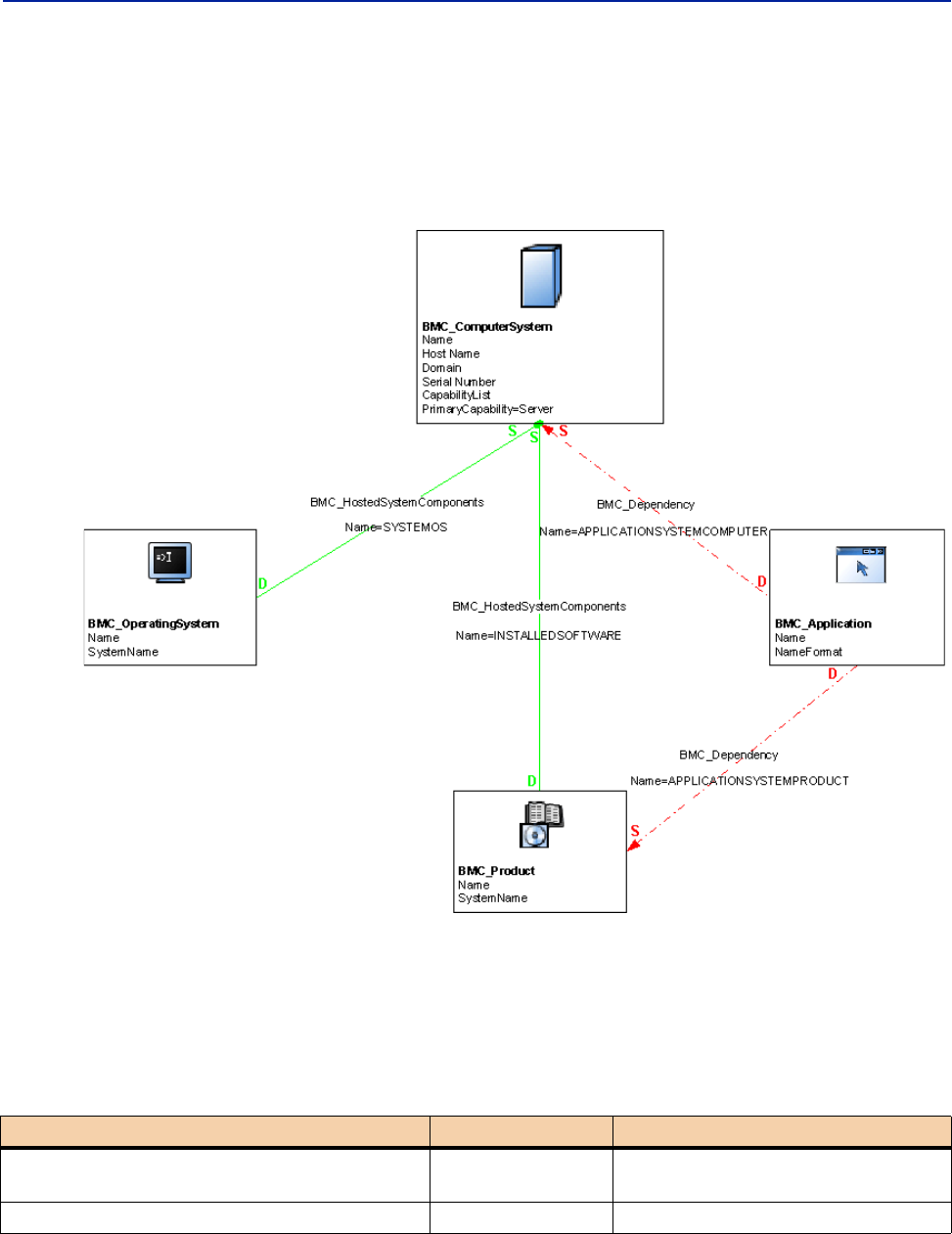
48 Data Modeling Guide
BMC Atrium CMDB 7.6.04
Applications running on computer systems
To model applications to run on computer systems (physical or virtual), relate an
instance of the BMC_Application class to a hosting physical or virtual
BMC_ComputerSystem instance. Figure 2-4 illustrates this model.
Figure 2-4: Illustrative model of applications running on computer systems
Relationships for applications
The relationships for modeling applications are described in Table 2-2.
Table 2-2: Relationships for modeling applications
Relationship Relationship class Value of Name attribute
Application infrastructure hosting the
application.
BMC_Dependency DEPLOYEDAPPLICATION
System hosting the application (mandatory). BMC_Dependency APPLICATIONSYSTEMCOMPUTER
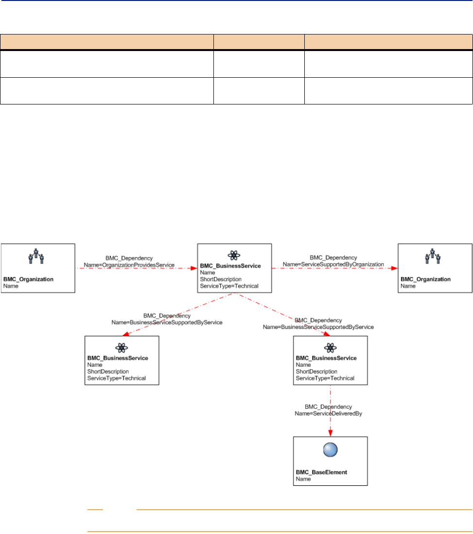
Chapter 2 Application modeling 49
Business applications and services
Business applications and services
To model the business aspect of applications, use the BMC_BusinessService class.
Business applications support a particular business function (such as payroll or
trading) and are, generally, made up of a set of applications, servers, and databases
that collaborate to provide a particular service.
Figure 2-5: Illustrative model of business services
NOTE
In this model, the BMC_BaseElement Name is typically an application or database.
Operating system running the application
(optional).
BMC_Dependency APPLICATIONSYSTEMOS
Product representing the installed software of
which this application is an instance (optional).
BMC_Dependency APPLICATIONSYSTEMPRODUCT
Table 2-2: Relationships for modeling applications (Continued)
Relationship Relationship class Value of Name attribute

50 Data Modeling Guide
BMC Atrium CMDB 7.6.04

Chapter 3 Software server modeling 51
Chapter
3Software server modeling
This section describes how to model software servers, such as database servers,
web servers, DNS servers, mainframe servers, and directory servers.
The following topics are provided:
Software server characteristics (page 52)
Logical identity of BMC_SoftwareServer (page 52)
Database server modeling (page 54)
Relationships for database servers and databases (page 57)
Database storage entity modeling (page 58)
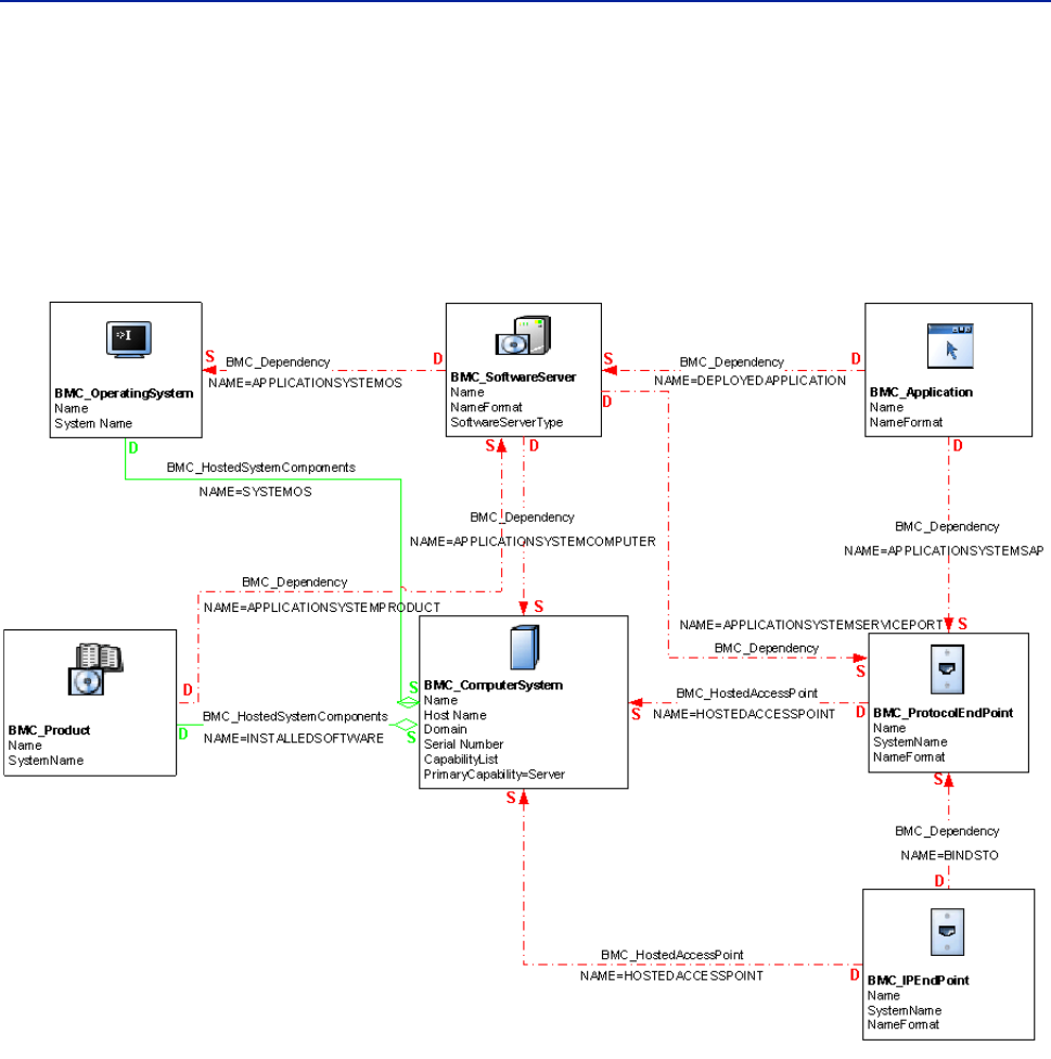
52 Data Modeling Guide
BMC Atrium CMDB 7.6.04
Software server characteristics
A software server is a system that provides services to client applications and other
servers, runs on top of a physical or virtual system, and is modeled using the
BMC_SoftwareServer class. Figure 3-1 illustrates a software server model.
Figure 3-1: Illustrative model of software servers
Logical identity of BMC_SoftwareServer
The BMC_SoftwareServer class stores information about a server that provides a
single service to client applications or other systems. Database servers, web
servers, DNS servers, mainframe servers, and directory servers can be represented
by this class.
Table 3-1 details the key attributes used in the BMC_SoftwareServer class. When
modeling software servers, you identify the unique server type by specifying its
name in the SoftwareServerType attribute.

Chapter 3 Software server modeling 53
Logical identity of BMC_SoftwareServer
For example, for database servers, set the SoftwareServerType attribute to
DatabaseServer.
Additional attributes for BMC_SoftwareServer
Table 3-2 describes additional attributes for BMC_SoftwareServer.
Relationships for software servers
Table 3-3 describes the relationships for software servers.
Table 3-1: Key attributes for BMC_SoftwareServer
Attribute Usage
Name Identifies the name of the software server.
NameFormat Sets the heuristic used to generate the Name value. Set this
attribute to name the installation directory of the server.
SoftwareServerType Specifies the type of software server (for example,
DatabaseServer).
Table 3-2: Additional attributes for BMC_SoftwareServer
Attribute Description
ShortDescription A caption of the software server.
TokenId The unique identifier populated by BMC Discovery products and
used by the Reconciliation Engine (of BMC Atrium CMDB) to
identify instances.
Table 3-3: Relationships for software servers
Relationship Relationship class Value of Name attribute
Computer system hosting
the software server
(mandatory).
BMC_Dependency APPLICATIONSYSTEMCOMPUTER
Communication endpoint
(one relationship per
endpoint) that the
software server is
listening on.
BMC_Dependency APPLICATIONSYSTEMSERVICEENDP
OINT
Operating system
running the application.
This dependency is
actually on the OS that is
running the server (as
opposed to the
computer).
BMC_Dependency APPLICATIONSYSTEMOS
Installed software of
which this software
server is an instance
(optional).
BMC_Dependency APPLICATIONSYSTEMPRODUCT
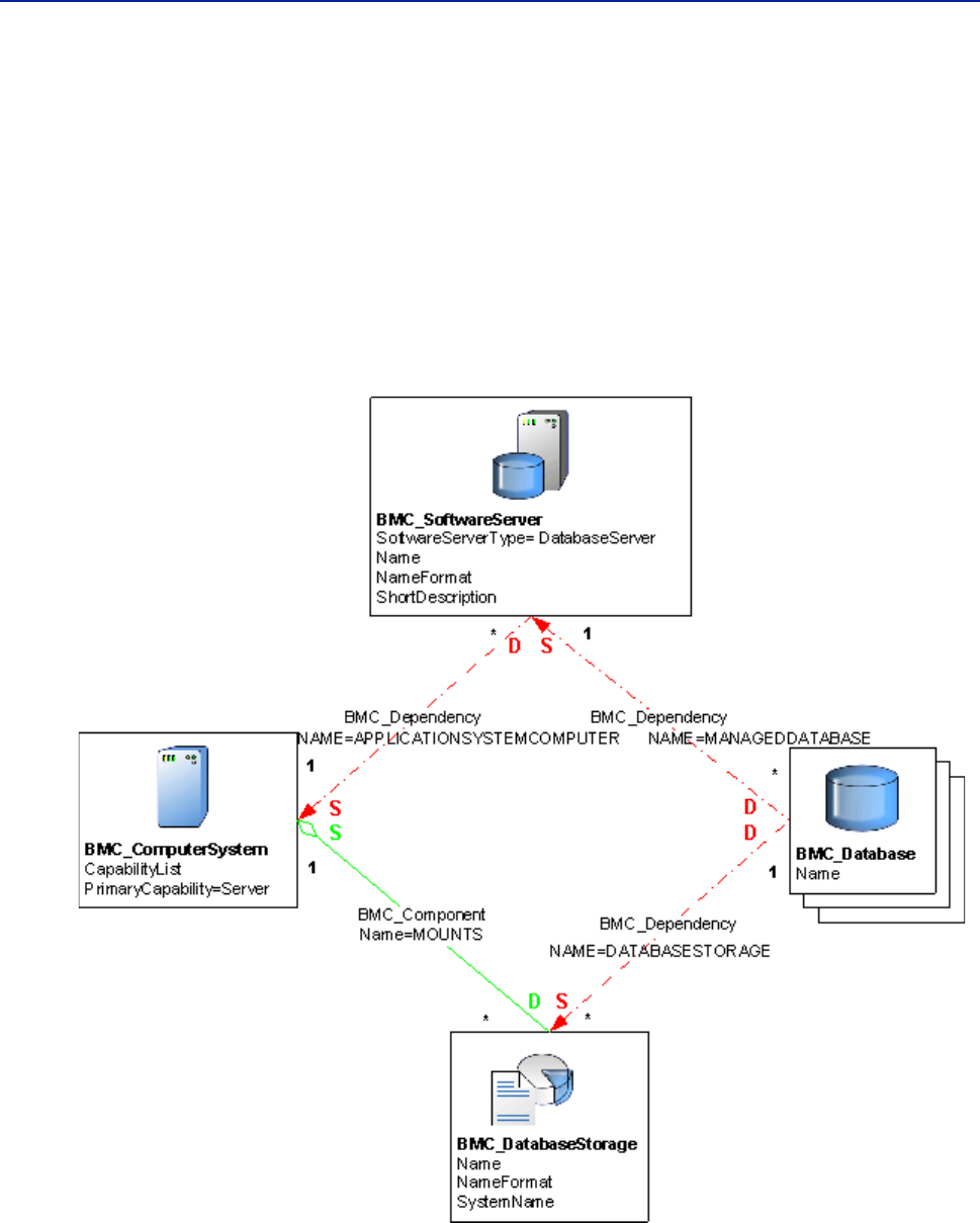
54 Data Modeling Guide
BMC Atrium CMDB 7.6.04
Database server modeling
A database server is a form of software server that, like all software servers, must
be uniquely named in the context of the CDM. A database server is modeled as an
instance of the BMC_SoftwareServer class (derived from the
BMC_ApplicationSystem class) and is identified by its Name attribute.
The key attribute for this class is SoftwareServerType, which must be set to
DatabaseServer.
Figure 3-2 illustrates how to model a database server.
Figure 3-2: Illustrative model of a database server environment

Chapter 3 Software server modeling 55
Database server modeling
Database modeling
A database is a collection of interrelated data that is treated as a unit and that is
organized into one or more schemas. Databases are dependent on software servers
and, therefore, are dependent on database servers.
Logical identity of BMC_DataBase
A database is modeled as an instance of the BMC_DataBase class (derived from the
BMC_LogicalEntity class) and is identified by its Name attribute.
Table 3-4 describes the description and syntax for the Name and NameFormat
attributes used in the BMC_DataBase class.
The BMC_DataBase class defines the properties that are common across database
models and vendor implementations for the database entity that is represented by
the unit of interrelated data. Create an instance of this class for each managed
database. You can use this class to specify the software that belongs to the
database, perform system-wide database management operations (such as
stopping all the databases that were created by the system for maintenance
purposes), or view runtime statistics for the database.
To represent database storage areas, use the BMC_DataBaseStorage class. The key
to a BMC_DataBase instance in an enterprise environment is its Name attribute. For
more information about database storage, see “Database storage entity modeling”
on page 58.
Table 3-4: Key attributes for BMC_DataBase
Attribute Usage
Name Identifies the database.
NameFormat As multiple valid naming conventions can be used in specific contexts,
the NameFormat attribute must be set with a value indicating the
heuristic used to generate the Name value. For example, in some cases,
a computer system will be identified by an external DNS Name (a
name configured in a DNS Server). In other cases, a static IP Address
will be used. In any case, the values for NameFormat should be:
HostName.IP: The name must be a valid IP Address, decimal bytes
delimited with dots ('.')
HostName.DNS: The name must a fully qualified host name, a host
name and a domain name delimited with dots (the domain name can
also consist of multiple components delimited with dots).

56 Data Modeling Guide
BMC Atrium CMDB 7.6.04
Additional attributes for BMC_DataBase
Although databases are primarily defined by the Name attribute, Table 3-5 provide
additional information about an instance of BMC_DataBase:
Oracle Listener modeling
The Oracle Listener manages network communications for one or more database
instances. An Oracle Listener is modeled as an instance of the
BMC_SoftwareServer class (derived from BMC_ApplicationSystem) and is
identified by both its Name attribute (set to Oracle Listener) and
SoftwareServerType attribute (set to Other).
Table 3-6 details the attributes used to model Oracle Listeners.
Table 3-5: Additional information for BMC_DataBase
Attribute Description
ShortDescription A short description of the database.
TokenId A unique identifier populated by BMC Discovery products and
used by the Reconciliation Engine (of BMC Atrium CMDB) to
identify instances.
Table 3-6: Attributes used to model Oracle Listeners
Attribute Usage
Name Identifies the Oracle Listener.
NameFormat Defines the heuristic used to generate the Name value.
SoftwareServerType Defines the type of server. This value must be set to Other.
ShortDescription A caption of the database.
TokenId Specifies the unique identifier populated by BMC Discovery
products and used by the Reconciliation Engine to identify
instances.

Chapter 3 Software server modeling 57
Relationships for database servers and databases
Relationships for database servers and
databases
The BMC_Dependency class is a generic association used to establish dependency
relationships between instances in the BMC Atrium CMDB. This association
allows you to establish dependency relationships between endpoints, including
the roles of the endpoints.
Table 3-7 describes the relationships for database servers and databases.
Table 3-7: Relationships for database servers and databases
Relationship Relationship class Value of Name attribute
Computer system (source)
and database server
(destination)
BMC_Dependency APPLICATIONSYSTEMCOMPUTER
Computer system (source)
and Oracle Listener
(destination)
BMC_Dependency APPLICATIONSYSTEMCOMPUTER
Oracle Listener (source)
and database server
(destination)
BMC_Dependency DEPENDENCY
Installed software of
which this software server
is an instance (optional).
BMC_Dependency APPLICATIONSYSTEMPRODUCT
Database server (source)
and database (destination)
BMC_Dependency MANAGEDDATABASE
Computer system (source)
and the file system
(destination)
BMC_HostedSystemComponents HOSTEDSYSTEMCOMPONENT
Database storage (source)
and database (destination)
BMC_Component DATABASEDATASTORAGE

58 Data Modeling Guide
BMC Atrium CMDB 7.6.04
Database storage entity modeling
Database storage entities are an extension of file system CIs in a database
environment and are modeled using the BMC_DataBaseStorage class.
Logical identity of BMC_DataBaseStorage
The BMC_DataBaseStorage class stores information about a collection of logical
storage areas that hold and retain data. You model a database storage CI as an
instance of the BMC_DataBaseStorage class (derived from the BMC_FileSystem
class) and identify the instance by its Name and SystemName attributes. The
BMC_DataBaseStorage class extends a file system CI and uses its inherited
associations to represent the internal structure of the database.
Table 3-8 details the attributes used to model database storage CIs.
Additional attributes for BMC_DataBaseStorage
Table 3-9 describes attributes that provide additional information about an
instance of BMC_DataBaseStorage.
Table 3-8: Key attributes for model database storage CIs
Attribute Usage
Name Identifies the storage area (tablespace) name.
NameFormat Specifies the heuristic used to generate the Name value. Set it with the
storage name used to generate the Name value.
SystemName Specifies the name of the parent BMC_Database CI. This attribute is
automatically populated from the related CI when a weak relationship is
created between the computer system and the operating system.
Table 3-9: Additional information for BMC_DataBaseStorage
Attribute Description
IsSystemArea The owner of the storage area.
ShortDescription A caption of the database.
TokenId A unique identifier populated by BMC Discovery products and
used by the Reconciliation Engine to identify instances

Chapter 4 Storage entity modeling 59
Chapter
4Storage entity modeling
This section details how to model storage entities and their relationship to the
computer systems that will utilize the services provided.
The following topics are provided:
Characteristics of storage entities and devices (page 60)
Modeling a tape drive (page 60)
Modeling a DASD (page 61)
Modeling a Virtual disk (page 62)
Modeling a NAS device (page 65)
Modeling raw storage (page 67)

60 Data Modeling Guide
BMC Atrium CMDB 7.6.04
Characteristics of storage entities and devices
Storage entities and devices that you want to model in your environment might
include tape drives, disk drives, virtual disks, network-attached storage (NAS),
and pool of storage subsystems.
Modeling a tape drive
A tape drive is modeled as an instance of BMC_TapeDrive (derived from
BMC_Media).
Logical identity of BMC_TapeDrive
Table 5-1 describes key attributes of a tape drive.
Additional attributes for BMC_TapeDrive
Table 5-2 describes additional attributes of a tape drive.
Table 4-1: Key attributes of a tape drive
Attribute Usage
Name Identifies the instance. The unique name is not necessarily human-
readable.
NameFormat Specifies the heuristic used to generate the Name value.
SystemName Specifies the name of the system in which the component resides. This
attribute is automatically populated from the related CI when a weak
relationship is created between the computer system and the tape drive.
Table 4-2: Additional attributes of a tape drive
Attribute Description
Description The description of the instance.
ManufacturerName The name of the vendor.
MediaType
(not inherited)
The type of media. Its value is always Removable Media.
Model The tape drive model.
ShortDescription A caption of the instance.

Chapter 4 Storage entity modeling 61
Modeling a DASD
Tape drive instance
Table 5-3 illustrates an example instance.
Modeling a DASD
A direct access storage device (DASD) is modeled as an instance of
BMC_DiskDrive (derived from BMC_Media).
Logical identity of BMC_DiskDrive
Table 5-4 describes key attributes of a DASD.
Additional attributes for BMC_DiskDrive
Table 5-5 describes additional attributes of a DASD.
Table 4-3: Example of a tape drive instance
Attribute Value
Description 003590.B1A.IBM.13.000000044832.0080
ManufacturerName IBM
MediaType Removable Media
Model 3590-1
Name 003590.B1A.IBM.13.000000044832.0080
NameFormat Mainframe
ShortDescription 003590.B1A.IBM.13.000000044832.0080
SystemName 003590.B1A.IBM.13.000000044832
Table 4-4: Key attributes of DASD
Attribute Usage
Name Identifies the instance of the disk drive. Use this attribute to specify the
unique name of the instance; not necessarily human-readable.
NameFormat Specifies the heuristic used to generate the Name value.
SystemName Specifies the name of the system in which the component resides. This
attribute is automatically populated from the related CI when a weak
relationship is created between the computer system and the tape drive.
Table 4-5: Additional attributes of DASD
Attribute Description
Description The description of the instance.
ManufacturerName The name of the mainframe vendor.
MediaType
(inherited from
BMC_Media)
The type of media. Its value is always Fixed Hard Disk.

62 Data Modeling Guide
BMC Atrium CMDB 7.6.04
DASD instance
Table 5-6 illustrates an example of an DASD instance.
Modeling a Virtual disk
A virtual disk refers to storage allocated to a virtual machine for use by the
operating system. The file system is laid on the provided virtual disk. Virtual disks
are created from a physical hard drive or allocated from NAS/SAN infrastructure.
A virtual disk is modeled as an instance of BMC_LogicalDisk.
Model The DASD model.
SerialNumber The manufacturer-allocated number used to identify the instance.
ShortDescription A caption of the instance.
Table 4-5: Additional attributes of DASD (Continued)
Attribute Description
Table 4-6: Attributes of a DASD instance
Attribute Value
Name 002105.000.IBM.13.000000025559.0B46
NameFormat Mainframe
SystemName 002105.000.IBM.13.000000025559
Description 002105.000.IBM.13.000000025559.0B46
ManufacturerName IBM
MediaType Fixed Hard Disk
Model 3390
SerialNumber ADR071
ShortDescription ADR071

Chapter 4 Storage entity modeling 63
Modeling a Virtual disk
Logical identity of BMC_LogicalDisk (virtual disk)
Table 4-7 describes key attributes of a virtual disk.
Additional attributes of BMC_LogicalDisk
Table 4-8 describes additional attributes of a virtual disk.
Modeling virtual disk allocated to a virtual machine
Model the virtual disk allocated to a virtual machine (VM) using the
BMC_LogicalDisk class and create an association to the virtual machine using the
SYSTEMDEVICE relationship. Figure 4-1 on page 64 illustrates a simple scenario
where a virtual disk is allocated to a VM and a file system is installed on it.
Table 4-7: Key attributes of a virtual disk
Attribute Usage
Name Identifies the logical disk with respect to the virtual machine to which the
disk is allocated. The following list provides examples of the values that
the Name attribute might contain, depending on the operating system:
Windows—the name of the drive, for example, E:\
UNIX—the access path, for example, '/dev/...'
NameFormat Specifies the heuristic used to generate the Name value. When this
attribute is set to 'OS Device Name', the Name attribute is populated with
a uniquely identifiable device name.
SystemName Name of the computer system to which the logical device belongs.
Table 4-8: Additional attributes of a virtual disk
Attribute Description
BlockSize Size of the blocks (in bytes) that form the given storage extent.
If the block size is variable, make sure that you specify the
maximum block size in bytes. If the block size is unknown,
specify a value of 1.
NumberOfBlocks Total number of logical contiguous blocks that form the given
storage extent. You can calculate the total size of the storage
extent by multiplying the BlockSize by the value of the
NumberOfBlocks attribute. If the BlockSize is 1, this property is
the total size of the Extent.
AvailableCapacity Indicates the total amount of free space (in bytes) that is
available on the given storage extent. If the free space is
unknown, specify a value of 0.
ConnectionType The storage protocol used to communicate with the storage
controller, for example, SCSI, iSCSI, FCoE, and Infiniband.
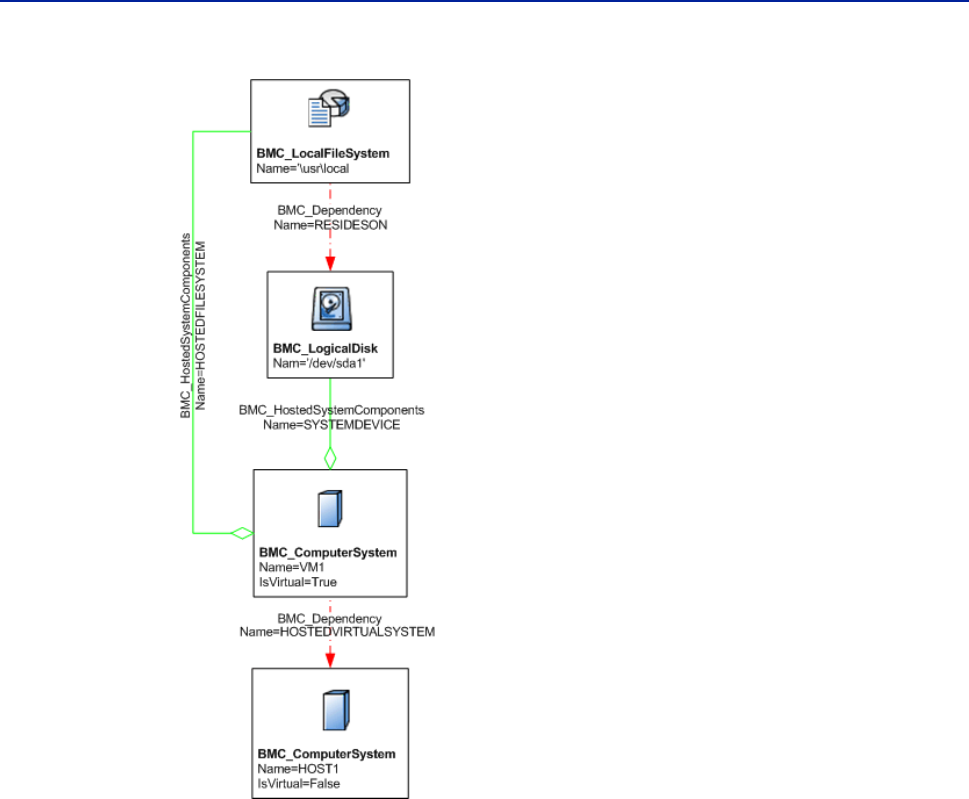
64 Data Modeling Guide
BMC Atrium CMDB 7.6.04
Figure 4-1: Modeling virtual disk allocated to virtual machine
Modeling logical disk allocated to a virtual machine from a resource
pool
You can model storage resources that are allocated from the storage resource pool
using the BMC_ResourcePool class. This class has attributes to store the capacity
and utilization properties of the storage resources. The resource pool should be
related to the storage system that hosts it using HOSTEDRESOURCEPOOL
relationship.
You might have one or more virtual disks in your environment that are created
from a storage system and are allocated to virtual machines. You model such
virtual disks by using the BMC_LogicalDisk class. You can associate this class to
the hosted virtual machine by using the SYSTEMDEVICE relationship. You will
also need to associate the logical disk to the resource pool where it comes from by
using the ELEMENTALLOCATEDFROMPOOL relationship.
You should model the file system laid by the virtual computer system on the
logical disk by using the BMC_LocalFileSystem class. You associate this class to the
logical disk by using the RESIDESON relationship. Associate the
BMC_ComputerSystem class by using the HOSTEDFILESYSTEM relationship.
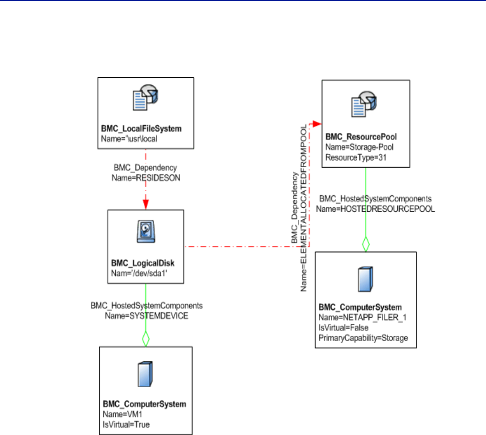
Chapter 4 Storage entity modeling 65
Modeling a NAS device
Figure 4-2 illustrates an example of a logical disk that is allocated from a resource
pool and is hosted on a storage system.
Figure 4-2: Modeling a logical disk
Modeling a NAS device
This section describes how to model simple and complex NAS devices.
Modeling a simple NAS device
To model a NAS device in a simple scenario, represent the NAS device using the
BMC_ComputerSystem class. Set the PrimaryCapability attribute of the class to
Storage. Figure 4-3 on page 66 illustrates how to model a simple NAS device.
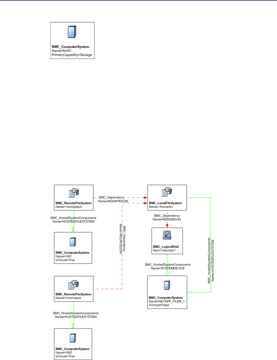
66 Data Modeling Guide
BMC Atrium CMDB 7.6.04
Figure 4-3: Modeling NAS device—simple
Modeling a remote mounted file system
When a virtual machine mounts a file system from a network-attached storage
(NAS) device, model the file system by using the BMC_RemoteFileSystem class.
You model the file system on the NAS device by using the BMC_LocalFileSystem
class. You relate the remote file system to the local file system by using the
MOUNTEDON relationship. Associate the remote file system with the computer
system by using the HOSTEDFILESYSTEM relationship.
You can model various logical storage components in the NAS device by using the
BMC_LogicalDisk class and the BMC_ResourcePool class. Figure 4-4 on page 66
illustrates an example where a virtual machine accesses a NAS device and uses the
NAS to mount a file system from it.
Figure 4-4: Modeling a remote mounted file system

Chapter 4 Storage entity modeling 67
Modeling raw storage
Modeling raw storage
A raw storage volume might be directly mapped to a physical or virtual machine,
provided a storage volume manager is present, from the host computer over the
network, from SAN infrastructure, or a physical machine.
The virtualization platform, in order to access such volumes over the network,
uses protocols such as iSCSI or Fiber Channel. Raw storage volume is modeled as
an instance of BMC_storageVolume.
Logical identity of BMC_StorageVolume (raw storage volume)
Table 4-9 describes key attributes of a raw storage volume.
Additional attributes of BMC_StorageVolume
Table 4-10 describes additional attributes of a raw storage volume.
Table 4-9: Key attributes of a raw storage volume
Attribute Usage
Name Identifies the storage volume allocated to a virtual machine. A unique
device identifier that is returned from the storage system is populated in
this attribute.
NameFormat Specifies the heuristic used to generate the Name value.
SystemName Name of the computer system on which the storage volume is hosted.
Table 4-10: Additional attributes of a virtual disk
Attribute Description
LUNID A logical unit number (LUN) is the identifier of a device, which
is being addressed by the SCSI protocol or similar protocols,
such as Fiber Channel and iSCSI.
BlockSize Size of the blocks (in bytes) that form the given storage extent.
If the block size is variable, make sure that you specify the
maximum block size in bytes. If the block size is unknown,
specify a value of 1.
NumberOfBlocks Total number of logical contiguous blocks that form the given
storage extent. You can calculate the total size of the storage
extent by multiplying BlockSize by the value of the
NumberOfBlocks attribute. If the BlockSize is 1, this property is
the total size of the Extent.
AvailableCapacity Indicates the total amount of free space (in bytes) that is
available on the given storage extent. If the free space is
unknown, specify a value of 0.
ConnectionType The storage protocol used to communicate with the storage
controller, for example, SCSI, iSCSI, FCoE, and Infiniband.
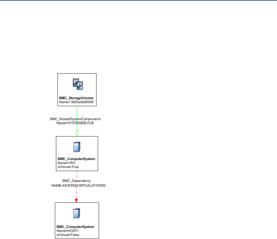
68 Data Modeling Guide
BMC Atrium CMDB 7.6.04
Modeling storage volume allocated to a virtual machine
You can model storage volume allocations to virtual machines using the
BMC_StorageVolume class and associate it to the containing computer using the
SYSTEMDEVICE relationship. Figure 4-5 on page 68 illustrates a simple scenario
where a storage volume is used in a virtual machine.
Figure 4-5: Modeling storage volume allocated to virtual machine
Modeling storage volume allocated to a virtual machine from a
resource pool
Model virtual machine, storage resource pool, and the storage system, as described
in Modeling logical disk allocated to a virtual machine from a resource pool
(page 64).
You should model the raw device that is mapped directly to a virtual machine by
using the BMC_StorageVolume class. You associate this class to the resource pool
by using the ELEMENTALLOCATEDFROM relationship and the
BMC_ComputerSystem class that represents the virtual system by using the
SYSTEMDEVICE relationship.
Figure 4-6 on page 69 illustrates an example of allocating a storage volume to a
virtual machine from a storage system.
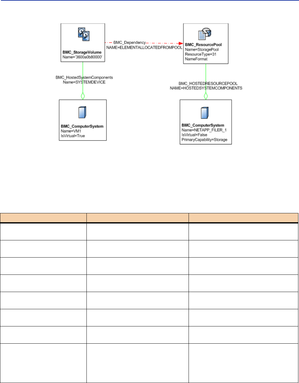
Chapter 4 Storage entity modeling 69
Modeling raw storage
Figure 4-6: Modeling a raw storage volume
Relationships for storage systems
Table 4-11 describes the relationships used for storage systems. Use the value
listed in the table to specify the name for a relationship between any two storage
classes.
Table 4-11: Relationships for storage systems
Relationship Relationship class Value of Name attribute
Storage subsystem and an
operating system
BMC_Dependency STORAGESUBSYSTEMOS
Storage subsystem and a
DASD
BMC_HostedSystemComponents STORAGESUBSYSTEMDASD
Storage subsystem and a tape
drive
BMC_HostedSystemComponents STORAGESUBSYSTEMTAPE
File system hosted on a
physical or virtual machine
BMC_HostedSystemComponents HOSTEDFILESYSTEM
A logical disk allocated to a
virtual machine
BMC_HostedSystemComponents SYSTEMDEVICE
A file system residing on a
logical disk
BMC_Dependency RESIDESON
A storage volume allocated to
a virtual machine
BMC_HostedSystemComponents SYSTEMDEVICE
Relationship between a
remote mounted file system
such as NFS and the file
system where it actually
resides.
BMC_Dependency MOUNTEDON

70 Data Modeling Guide
BMC Atrium CMDB 7.6.04

Chapter 5 Network topology modeling 71
Chapter
5Network topology modeling
This section details how to model network topology, including components on a
subnet, network interfaces, and LAN and WAN networks.
The following topics are provided:
Network topology characteristics (page 72)
L3 topology and IP connectivity modeling (page 72)
L2 topology and physical connectivity modeling (page 73)
Network topology and LAN and WAN network modeling (page 75)
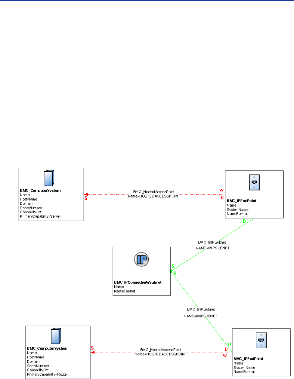
72 Data Modeling Guide
BMC Atrium CMDB 7.6.04
Network topology characteristics
Topologies are based on the BMC_ConnectivityCollection class, which are
collections of BMC_ProtocolEndpoint (communication points from which data
may be sent or received) of the same type and which can communicate with each
other. Logical groupings of these connectivity collections enable users to define the
scope of LAN and WAN networks.
L3 topology and IP connectivity modeling
A BMC_IPConnectivitySubnet instance represents a group of related
BMC_IPEndpoint instances that can communicate with each other as members of
a subnet and describes the characteristics of the subnet.
Figure 6-1 illustrates a server and a router that belong to the same subnet.
Figure 5-1: Illustrative model of components on a subnet

Chapter 5 Network topology modeling 73
L2 topology and physical connectivity modeling
Logical identity of BMC_IPConnectivitySubnet
Table 6-1 describes key attributes of BMC_IPConnectivitySubnet.
L
Additional attributes for BMC_IPConnectivitySubnet
Table 6-2 describes attributes that provide additional information about
BMC_IPConnectivitySubnet.
Relationships for components on a subnet
BMC_IPEndpoint instances are associated to the BMC_IPConnectivitySubnet to
which they belong through the BMC_InIPSubnet relationship.
L2 topology and physical connectivity
modeling
A BMC_ConnectivitySegment instance represents a group of related instances of
BMC_LANEndpoint of a particular type (such as Ethernet, token ring, or fiber
channel) that can intercommunicate without the assistance of bridging or routing
services. They are sometimes referred to as members of the same collision domain.
The class describes the characteristics of the group, or segment.
Table 5-1: Key attributes for BMC_IPConnectivitySubnet
Attribute Usage
Name Identifies the IP address of the entire subnet, formatted according to the
appropriate convention as defined in the AddressType attribute. When
AddressType is 1 (IPV4), the Name must be built by concatenating the
SubnetNumber and SubnetMask separated by a /.
NameFormat Specify the heuristic used to generate the Name value, which must be set
to IP.
Table 5-2: Additional attributes for BMC_IPConnectivitySubnet
Attribute Description
AddressType An enumeration that describes the format of the Name and
SubnetNumber properties in IPConnectivitySubnet:
0—Unknown
1—IPv4
2—IPv6
PrefixLength A prefix length for IPv6 addresses in the IP subnet (AddressType
property is 2).
SubnetMask The mask for the starting address of the IPv6 IP subnet (AddressType
is 1).
SubnetNumber The IP address of the entire subnet; must be equal to the Name attribute.

74 Data Modeling Guide
BMC Atrium CMDB 7.6.04
Figure 6-2 illustrates a server and a switch, with the server having one NIC directly
connected to a network interface of the switch.
Figure 5-2: Illustrative model of a network interface
Logical identity of BMC_ConnectivitySegment
Table 6-3 describes key attributes of BMC_ConnectivitySegment.
Table 5-3: Key attributes of BMC_ConnectivitySegment
Attribute Usage
Name Identifies the connectivity segment, which uses the following information
and generates a hash code as resulting value:
The list of physical addresses that belong to the segment.
The name of the LAN instance to which the segment belongs.
NameFormat Specifies the heuristic used to generate the Name value, which must be set
to OID.

Chapter 5 Network topology modeling 75
Network topology and LAN and WAN network modeling
Additional attributes for BMC_ConnectivitySegment
Table 6-4 describes attributes that provide additional information about
BMC_ConnectivitySegment.
Relationships for network interfaces
Instances of BMC_LANEndpoint are associated to the BMC_ConnectivitySegment
to which they belong through the BMC_InSegment relationship.
Network topology and LAN and WAN network
modeling
LAN and WAN networks do not have a well-known identifier, such as an IP
address or mask for an IP subnet. These networks are characterized by the list of
machines that can intercommunicate at the physical level without crossing the
boundaries of gateways. This description includes the infrastructure network
devices (switches, hubs) that enable these machines to communicate. In the CDM,
LANs and WANs are captured by entities that aggregate that list of IP subnets.
Table 5-4: Additional attributes for BMC_ConnectivitySegment
Attribute Description
ConnectivityType An enumeration that describes the type of technology used:
0—Unknown
1—Other
2—Ethernet
3—Token Ring
4—FDDI
5—Fiber Channel
Count The current number of endpoints connected to this segment.
When this value equals 2 it indicates a direct connection between
the two network ports interconnected by means of the segment.
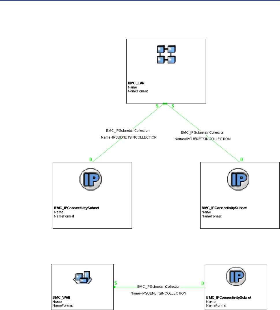
76 Data Modeling Guide
BMC Atrium CMDB 7.6.04
Figure 6-3 illustrates a LAN that aggregates IP subnets.
Figure 5-3: Illustrative model of a LAN
Figure 6-4 illustrates an example of a WAN that aggregates IP subnets.
Figure 5-4: Illustrative model of a WAN

Chapter 5 Network topology modeling 77
Network topology and LAN and WAN network modeling
Logical identity of BMC_LAN
You can model a virtual LAN by using the BMC_LAN class and setting its
IsVirtual attribute to True. Table 6-5 describes key attributes of BMC_LAN.
Logical identity of BMC_WAN
Table 6-6 describes key attributes of a BMC_WAN.
Table 5-5: Key attributes of BMC_LAN
Attribute Usage
Name Identifies the LAN, computed from the list of IP subnets that make up the
LAN. The name for the LAN is the lexicographically lower value of the
names of IP subnets.
NameFormat Specifies the heuristic used to generate the Name value, which must be set
to OID.
Table 5-6: Key attributes of BMC_WAN
Attribute Usage
Name Identifies the WAN, computed from the list of IP subnets that make up the
WAN. The name for the WAN is the lexicographically lower value of the
names of IP subnets.
NameFormat Specifies the heuristic used to generate the Name value, which must be set
to OID.
WANType Specifies the enumeration that describes the type of technology used:
0—Unknown
1—Other
2—ATM
3—Frame relay

78 Data Modeling Guide
BMC Atrium CMDB 7.6.04

Appendix A Summary of changes to the Common Data Model 79
Appendix
ASummary of changes to the
Common Data Model
This section lists all the change to the Common Data Model in the 7.6.00 release.
The following topics are provided:
Changes to the BMC Atrium CMDB 7.5.00 Common Data Model (page 80)
Changes to the BMC Atrium CMDB 7.6.00 Common Data Model (page 81)
Changes to the BMC Atrium CMDB 7.6.03 Common Data Model (page 82)
Changes to the BMC Atrium CMDB 7.6.04 Common Data Model (page 83)

80 Data Modeling Guide
BMC Atrium CMDB 7.6.04
Changes to the BMC Atrium CMDB 7.5.00
Common Data Model
The following CI classes were added to the CDM in BMC Atrium CMDB 7.5.00:
The following relationship classes were added to the CDM in BMC Atrium CMDB
7.5.00:
Table A-1: New CI classes in BMC Atrium CMDB 7.5.00
CI class Description
BMC_Offering stores information about service offerings that are part of a
high-level service
BMC_ServiceLevelTar
get
stores information about Service Level Targets (SLTs)
BMC_Contract acts as a container object made up of line items that establish
a specific agreement between a provider and a customer
BMC_ContractLine stores contract line items that establish specific agreements
between the provider and the customer
BMC_Transaction specifies a single transaction initiated by an end user or
system
BMC_ResourcePool serves as a logical entity (with associated controls) provided
by the host system to allocate and assign resources
BMC_ResourceAllocat
ionSettingData
represents settings that specifically relate to an allocated
resource that is outside the scope of the CIM class (which is
typically used to represent the resource itself)
BMC_VirtualSystemSe
ttingData
defines the virtual aspects of a virtual system through a set of
virtualization-specific properties
BMC_Settings represents additional attributes of a given CI that are not part
of the CI type definition
Table A-2: New relationship classes in BMC Atrium CMDB 7.5.00
Relationship class Description
BMC_Impact represents a generic association used to establish impact
relationships between objects
BMC_SettingsOf represents the association between ManagedElements and
applicable setting data
BMC_ServiceRealizedBy
Offering
defines the relationship between the business service and
the offering
BMC_OfferingMeasuredB
y
defines the relationship between the offering and the
Service Level Target
BMC_ContractComponent defines the relationship between the contract and the
contract line item

Appendix A Summary of changes to the Common Data Model 81
Changes to the BMC Atrium CMDB 7.6.00 Common Data Model
The BMC_VirtualSystem class was removed. The VirtualSystemType attribute
from the removed class was added to BMC_ComputerSystem. The TotalMemory
attribute was deleted. Your virtual system information should be stored in
BMC_ComputerSystem.
Changes to the BMC Atrium CMDB 7.6.00
Common Data Model
The following classes and attributes have been added in BMC Atrium CMDB
7.6.00.
Attributes that have been moved
In BMC Atrium CMDB 7.6.00, the isVirtual attribute was moved from the
BMC_ComputerSystem class to the BMC_System and BMC_SystemComponent
classes. This move expands the virtualization scope beyond computer systems,
enabling you to model potential future virtualizable entities, such as applications.
Because BMC_ComputerSystem is a subclass of the BMC_System class, the
isVirtual attribute is still available in the BMC_ComputerSystem class.
Attributes that have been hidden
The Dimensions attribute in the BMC_ComputerSystem class is hidden in the
Console view but can be seen in the Class Manager.
Table A-3: New classes and attributes in BMC Atrium CMDB 7.6.00
New Class Existing class New attributes
BMC_Geneology Not applicable No attributes
Not applicable BMC_VirtualSystemSettingData ActualDecommissionDate,
ActualProvisionDate,
ProposedDecommissionDate

82 Data Modeling Guide
BMC Atrium CMDB 7.6.04
Changes to the BMC Atrium CMDB 7.6.03
Common Data Model
The following classes and attributes have been added in BMC Atrium CMDB
7.6.03.
Classes that have been deprecated
The BMC_Impact relationship class is deprecated and is mapped to the
BMC_BaseRelationship class. The HasImpact attribute of the
BMC_BaseRelationship class is set to “Yes” and the Name attribute is set to
“ImpactOnly”.
Table A-4: New classes and attributes in BMC Atrium CMDB 7.6.03
New class Existing class New attributes
BMC_MFCouplingFacility Not applicable CFRMName, CFRMSiteName,
NodeDescriptor, Storage
BMC_StorageSubsystem Not applicable No attributes added
Not applicable BMC_BaseElement ADDMIntegrationId,
MarketVersion,
NormalizationStatus,
ReconciliationMergeStatus
Not applicable BMC_ComputerSystem IsUnqualified
Not applicable BMC_IPEndpoint IsUnqualified
Not applicable BMC_ApplicationSystem MFJobName, MFServerId
Not applicable BMC_BaseRelationship ImpactSourceId,
ImpactDestinationId,
NormalizationStatus,
ReconciliationMergeStatus
Not applicable BMC_HostesAccessPoint IsUnqualified
BMC_MFCouplingFacility Not applicable CFRMName, CFRMSiteName,
NodeDescriptor, Storage

Appendix A Summary of changes to the Common Data Model 83
Changes to the BMC Atrium CMDB 7.6.04 Common Data Model
Changes to the BMC Atrium CMDB 7.6.04
Common Data Model
The following classes and attributes are added in BMC Atrium CMDB 7.6.04.
Table A-5: New classes and attributes in BMC Atrium CMDB 7.6.04(Sheet 1 of 2)
New class Existing class New attributes
Not applicable BMC_BaseElement ReconciliationIdType,
LastUpdatedDatasetId
Not applicable BMC_BaseRelationship ReconciliationIdType,
LastUpdatedDatasetId
Not applicable BMC_Offering IsLocked, WarrantyLevel
Not applicable BMC_ServiceLevelTarge
t
SLTClassification
Not applicable BMC_Document DocumentPurpose,
ExecutionDate,
TerminationDate
Not applicable BMC_BusinessService ServiceLifeCycle
Not applicable BMC_ContractLine Quantity, PerPricePeriod,
PriceAmount, PriceUOM,
ServiceRequestId
Not applicable BMC_FileSystem FileSystemSize,
AvailableSpace,
FileSystemType, BlockSize
Not applicable BMC_Collection IsVirtual
Not applicable BMC_ResourcePool HighWaterMark,
LowWaterMark,
MaxConsumableResource,
MinConsumableResource
BMC_ServiceOffering Not applicable IsDefault
BMC_RequestableOffering Not applicable IsAddOn, DeliveryRO
BMC_ServiceOfferingInstance ActualDecommissionDate,
ProposedDecommissionDate
, ProvisionDate
BMC_Option ChoiceSelectionMode,
FulfillmentDetails,
OptionType
BMC_OptionChoice Sequence, IsDefault
BMC_FinancialElement PerTimePeriod, UOM
BMC_Cost CostAmount,
CostDeliveredFlag

84 Data Modeling Guide
BMC Atrium CMDB 7.6.04
Classes and attributes that are deprecated
The OfferingType attribute of the BMC_Offering class is deprecated. Use the
BMC_ServiceOffering or the BMC_RequestableOffering derived classes instead
of the BMC_Offering class to store OfferingType information for a service.
BMC_Price IsLocked,
MaximumQuantity,
MinimumQuantity,
PriceAmount,
PriceLifeCycle,
PriceQuantity
BMC_StorageExtent Not applicable BlockSize, NumberOfBlocks,
AvailableCapacity,
ConnectionType
BMC_LogicalDisk Not applicable No attributes added
BMC_StorageVolume Not applicable LUNID
BMC_Tag Not applicable IsCategory, CategoryName
Not applicable BMC_Offering IsLocked, WarrantyLevel
Table A-5: New classes and attributes in BMC Atrium CMDB 7.6.04(Sheet 2 of 2)
New class Existing class New attributes

Index 85
A B C D E F G H I J K L M N O P Q R S T U V W X Y Z
Index
A
access points
binding 38
modeling 36
additional attributes 10
addresses
modeling IP 36
modeling MAC 37
modeling network 38
application servers, modeling applications on 47
application systems
modeling applications on 47
applications
hosting environment 47
infrastructure 47
modeling business aspects 49
relationships 48
running on application servers 47
running on application systems 47
running on computer systems 48
arrows, dependency relationships and 12
attributes
about 9
additional 10
key 10
Name versus ShortDescription 10
attributes, hidden 81
attributes, moved 81
audience for this guide 10
B
base classes
about 9
BMC_BaseElement 9
BMC_BaseRelationship 9
relationship 9
binding, access point 38
BMC Atrium CMDB 9
BMC Atrium Core documentation 13
BMC Discovery products 9
BMC Software, contacting 2
BMC_AccessPoint class 36, 38
BMC_Application class 44, 47
BMC_ApplicationInfrastructure class 44, 47
BMC_ApplicationSystem class 54, 56
BMC_BaseElement class 9
BMC_BaseRelationship class 9
BMC_Cluster class 41
BMC_Component relationship 12
BMC_ComputerSystem class
about 18, 23
additional attributes 20, 23
key attributes 19
patches 23
products 23
virtual systems 26
BMC_ConnectivitySegment class
about 74
additional attributes 75
BMC_DataBase class
about 55
additional attributes 56
BMC_DataBaseStorage class
about 58
additional attributes 58
BMC_Dependency relationship 12
BMC_DiskDrive class
about 61
additional attributes 61
BMC_FileSystem class 58
BMC_Genealogy class 25
BMC_HardwareSystemComponent class
about 35
additional attributes 35
BMC_IPConnectivitySubnet class
about 72, 73
additional attributes 73
BMC_IPEndpoint class
about 36
additional attributes 37
BMC_LAN class 77
86 Data Modeling Guide
A B C D E F G H I J K L M N O P Q R S T U V W X Y Z
BMC_LANEndpoint class
about 37
additional attributes 38
BMC_LogicalDisk class
about 63
additional attributes 63
BMC_LogicalEntity class 55
BMC_LPAR class 33
BMC_Media class 60, 61
BMC_MemberOfCollection relationship 12
BMC_MFVirtualSystem class 33
BMC_MFVirtualSystemEnabler class 33
BMC_NetworkPort class
about 39
additional attributes 39
BMC_OperatingSystem class
about 34
additional attributes 34
BMC_Patch class 22, 46
BMC_ProtocolEndpoint class 36, 72
BMC_ResourceAllocationSettingData class 31
BMC_ResourcePool class 30
BMC_SoftwareServer class
about 52
additional attributes 53
database servers 54
Oracle Listeners 56
software servers 52
BMC_StorageVolume
about 67
BMC_StorageVolume class
about 67
additional attributes 67
BMC_TapeDrive class
about 60, 63
additional attributes 60
BMC_VirtualSystem class 32
BMC_VirtualSystemEnabler class
about 27
BMC_VirtualSystemSettingData class 27
BMC_VMWare class 32
BMC_WAN class 77
business
aspects of applications, modeling 49
C
cardinality, relationship class 13
CDM. See Common Data Model
circles, collection relationships and 12
class
BMC_StorageVolume 67
class, deprecated 82, 84
class, terminology 9
classes
base 9
BMC_AccessPoint 36, 38
BMC_Application 44, 47
BMC_ApplicationInfrastructure 44, 47
BMC_ApplicationSystem 54, 56
BMC_BaseElement 9
BMC_BaseRelationship 9
BMC_Cluster 41
BMC_Component 12
BMC_ComputerSystem 18, 23
BMC_ConnectivitySegment 74
BMC_DataBase 55
BMC_DataBaseStorage 58
BMC_Dependency 12
BMC_DiskDrive 61
BMC_FileSystem 58
BMC_HardwareSystemComponent 35
BMC_IPConnectivitySubnet 72, 73
BMC_IPEndpoint 36
BMC_LAN 77
BMC_LANEndpoint 37
BMC_LogicalDisk 63
BMC_LogicalEntity 55
BMC_LPAR 33
BMC_Media 60, 61
BMC_MemberOfCollection 12
BMC_MFVirtualSystem 33
BMC_MFVirtualSystemEnabler 33
BMC_NetworkPort 39
BMC_OperatingSystem 34
BMC_Patch 22, 46
BMC_ProtocolEndpoint 36, 72
BMC_ResourceAllocationSettingData 31
BMC_ResourcePool 30
BMC_SoftwareServer 52
BMC_StorageVolume 67
BMC_TapeDrive 60, 63
BMC_VirtualSystem 32
BMC_VirtualSystemEnabler 27
BMC_VirtualSystemSettingData 27
BMC_VMWare 32
BMC_WAN 77
cardinality of relationship 13
deprecated virtual system 32
FiberChannel 38
subclasses 9
clusters, modeling software and hardware 41
CMDB. See BMC Atrium CMDB
collection relationships, example 12
Index 87
A B C D E F G H I J K L M N O P Q R S T U V W X Y Z
component relationships, example 12
components
hardware examples 34
modeling hardware 34
service model 9
subnet relationships 73
computer systems
applications running on 48
modeling 21
connectivity
modeling IP 72
modeling physical 73
conventions of this guide 10
customer support 3
D
DASD
example instance 62
modeling 61
data models 10
database servers
modeling 54
relationships 57
databases
modeling 55
relationships 57
dependency relationships, examples 12
deprecated
virtual system classes 32
deprecated class 82, 84
diagrams
about 11
representing relationships in 11
diamonds, component relationships and 12
discovery products 9
disk drives 34
disk partitions 34
documentation, related 13
drives, disk 34
E
environments
application hosting 47
examples
DASD instance 62
server 21
tape drive instance 61
F
FiberChannel class 38
framework, application 47
G
guide
conventions 10
terminology 10
H
hardware
component examples 34
modeling clusters 41
modeling components 34
Hidden attributes 81
hosting environments, application 47
I
illustrative models
about 11
server 21
infrastructures, application 47
interfaces
modeling network 38
relationships for network 75
inventories
modeling software 22
IP addresses, modeling 36
IP connectivity, modeling 72
K
key attributes 10
keyboards 34
L
L2 topology, modeling 73
L3 topology, modeling 72
LANs
modeling 72, 75
logical disk, virtual machine 64
88 Data Modeling Guide
A B C D E F G H I J K L M N O P Q R S T U V W X Y Z
M
MAC addresses, modeling 37
machines, virtual 25
memory 34
modeling
access points 36
application business aspects 49
business services 49
computer systems 21
DASD 61
database servers 54
database storage 58
databases 55
hardware clusters 41
hardware components 34
IP addresses 36
IP connectivity 72
L2 topology 73
L3 topology 72
LANs 72, 75
logical disk, virtual machine 64
MAC addresses 37
NAS 65
network addresses 38
network interfaces 38
network topology 72, 75
operating systems 33
Oracle Listeners 56
patches 22
physical connectivity 73
raw storage 67
routers 24
services, business 49
simple NAS 65
software clusters 41
software inventory 22
software servers 52
storage entities and devices 60
tape drives 60
virtual disk 62
virtual systems 25
WANs 72, 75
modeling storage volume allocated to virtual
machine 68
modeling virtual disk allocated to virtual machine 63
modeling, remote mounted file system 66
modeling, storage volume, virtual machine 68
models. See data models; illustrative models; service
models
monitors 34
Moved attributes 81
N
Name versus ShortDescription 10
NAS
modeling 65
networks
interface relationships 75
modeling addresses 38
modeling interfaces 38
modeling LANs 75
modeling topologies 72, 75
modeling WANs 75
ports 35
O
operating systems, modeling 33
Oracle Listeners, modeling 56
P
partitions, disk 34
patches
modeling 22
physical connectivity, modeling 73
ports, network 35
processors 35
product support 3
products
modeling 22
R
raw storage
modeling 67
related documentation 13
relationships
application 48
base class 9
BMC_Component 12
BMC_Dependency 12
BMC_MemberOfCollection 12
cardinality 13
database 57
database server 57
examples of collection 12
examples of component 12
examples of dependency 12
network interface 75
representing in illustrative models 11
software servers 53
Index 89
A B C D E F G H I J K L M N O P Q R S T U V W X Y Z
relationships (continued)
storage system 69
subnet component 73
virtual system 33
weak 13
remote mounted file system, modeling 66
routers
modeling 24
S
servers
illustrative model 21
modeling database 54
modeling software 52
software, relationships 53
service models, components of 9
services
modeling business 49
ShortDescription versus Name 10
simple NAS
modeling 65
software
modeling clusters 41
modeling inventory 22
software servers
modeling 52
relationships 53
storage
modeling database 58
modeling entities and devices 60
system relationships 69
storage volume allocated to virtual machine,
modeling 68
storage volume, virtual machine 68
subclasses 9
subnet components
relationships 73
support, customer 3
systems. See application systems; computer systems;
operating systems; virtual systems
T
tape drives
example instance 61
technical support 3
terminology in this guide 10
topologies
modeling L2 73
modeling L3 72
modeling network 72, 75
U
Unified Modeling Language (UML) 11
V
virtual disk
modeling 62
virtual disk allocated to virtual machine,
modeling 63
virtual machine, logical disk 64
virtual machines 25
virtual systems
deprecated classes 32
modeling 25
relationships 33
W
WANs
modeling 72, 75
weak relationships 13

*176785*
