Tshootlabmanual CNAP Lab Manual En TSHOOT SLM V60
User Manual: manual pdf -FilePursuit
Open the PDF directly: View PDF ![]() .
.
Page Count: 310 [warning: Documents this large are best viewed by clicking the View PDF Link!]
CCNPv6 TSHOOT
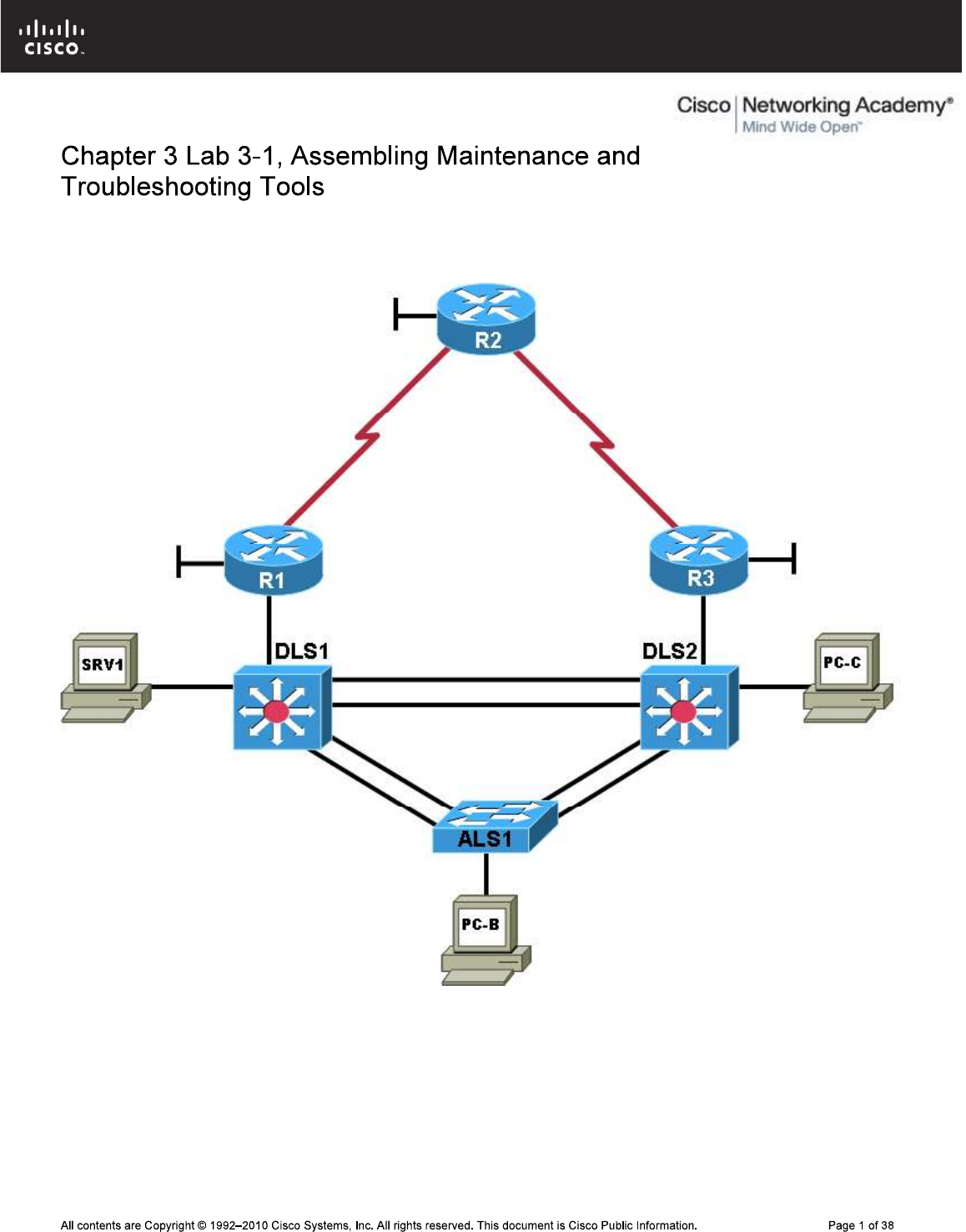
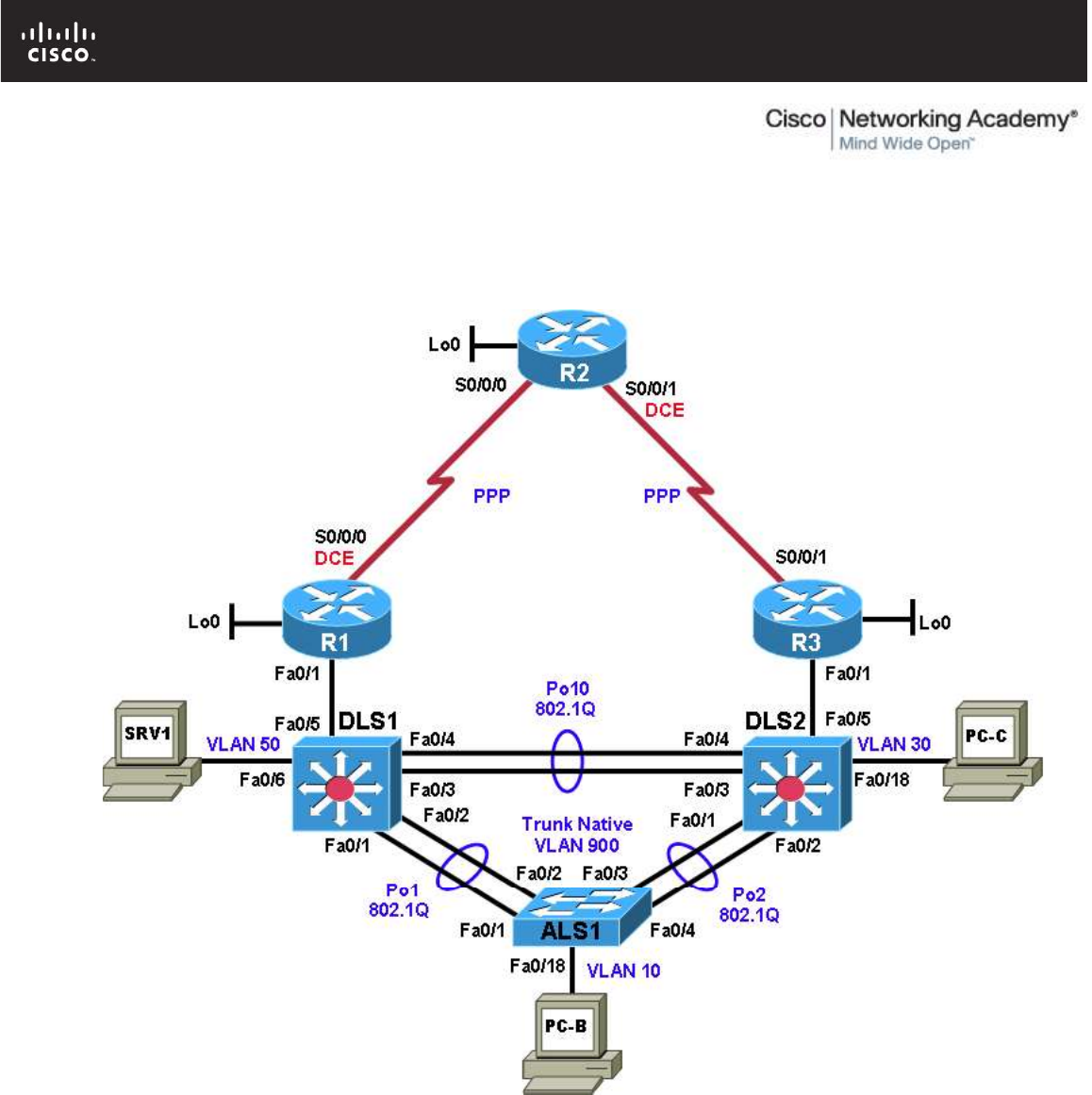
Physical Topology
CCNPv6 TSHOOT
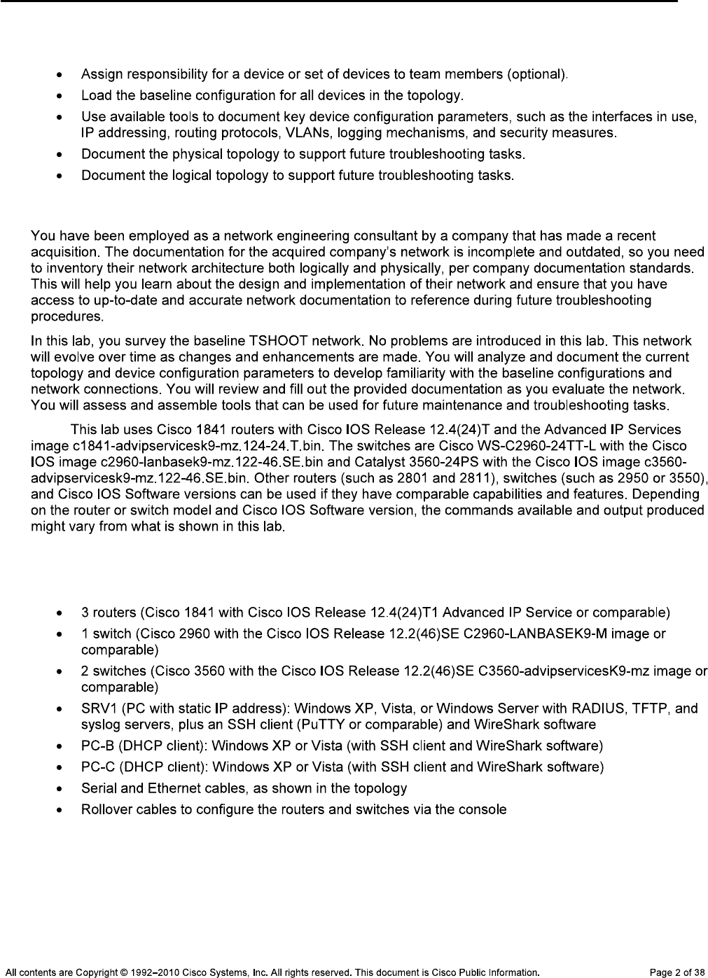
Objectives
Background
Note:
Required Resources
CCNPv6 TSHOOT
Task 1: Assign Responsibility for Each Device (optional)
Step 1: Review the lab topology together with your team members.
Step 2: Assign responsibility for each device to a team member.
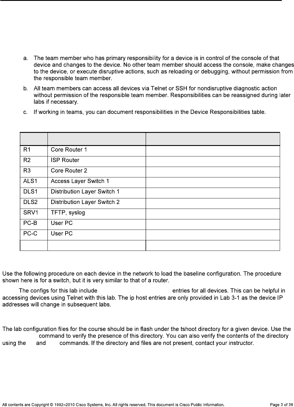
Device Responsibilities Table
Device Description Responsible Team Member
Task 2: Load the Baseline Device Configuration Files
Note: ip host name ip-addr
Step 1: Verify the existence and location of the lab configuration files.
show flash
cd dir
CCNPv6 TSHOOT
Note: show flash
cd dir
ALS1#show flash:
Directory of flash:/
3 -rwx 916 Mar 1 1993 00:00:29 +00:00 vlan.dat
619 -rwx 6582 Mar 1 1993 00:10:09 +00:00 config.text
6 drwx 192 Oct 9 2009 13:00:50 +00:00 c2960-lanbasek9-mz.122-46.SE.bin
622 drwx 128 Oct 9 2009 13:03:05 +00:00 tshoot
ALS1#cd tshoot
ALS1#dir
Directory of flash:/tshoot/
623 -rwx 6582 Oct 9 2009 13:03:05 +00:00 Lab31-ALS1-Base-Cfg.txt
624 -rwx 6578 Oct 9 2009 12:32:48 +00:00 Lab41-ALS1-TT-A-Cfg.txt
<output omitted>
Alternatively, you can see the contents of the directory by specifying its name
using the dir command. For example:
ALS1#dir flash:/tshoot
Directory of flash:/tshoot/
5 -rwx 6515 Oct 9 2009 14:39:42 +00:00 Lab31-ALS1-Base-Cfg.txt
Note: show flash
show flash
R1#show flash:
-#- --length-- -----date/time------ path
1 38266988 Sep 24 2009 17:47:14 c1841-advipservicesk9-mz.124-24.T1.bin
2 0 Oct 09 2009 12:32:06 tshoot
3 2288 Oct 09 2009 12:32:48 tshoot/Lab31-R1-Base-Cfg.txt
<output omitted>
Step 2: Erase the startup config from NVRAM.
ALS1#erase startup-config
Erasing the nvram filesystem will remove all configuration files! Continue?
[confirm]
[OK]
Erase of nvram: complete
Step 3: Delete the VLAN database from flash (switches only).
ALS1#delete vlan.dat
Delete flash:vlan.dat? [confirm]

CCNPv6 TSHOOT
Step 4: Reload the device, but do not save the system configuration if prompted.
ALS1#reload
System configuration has been modified. Save? [yes/no]: no
Proceed with reload? [confirm]
*Oct 1 00:29:28.704: %SYS-5-RELOAD: Reload requested by console. Reload
Reason: Reload command.
Step 5: When the device restarts, do not enter the initial configuration dialog, but terminate
autoinstall if prompted.
Press RETURN to get started!
--- System Configuration Dialog ---
Would you like to enter the initial configuration dialog? [yes/no]: no
Would you like to terminate autoinstall? [yes]: Enter
Step 6: Copy the specified lab device configuration file from flash to the running config.
Switch>enable
Switch#copy flash:/tshoot/Lab31-ALS1-Base-Cfg.txt running-config
Destination filename [running-config]? Enter
ALS1#
Note:
Step 7: Copy the running config to the startup config.
Note: not
ALS1#copy running-config startup-config
Building configuration...
[OK]
Note: admin
adminpa55 enable ciscoenpa55
Step 8: Repeat Steps 1 through 7 for the other devices in the network.
Step 9: Configure the PCs.
CCNPv6 TSHOOT
Step 10: Test basic network connectivity between devices.
Note:
Task 3: Analyze and Document the Physical Lab Topology
Note:
Step 1: Review the physical topology diagram on page 1 of the lab.
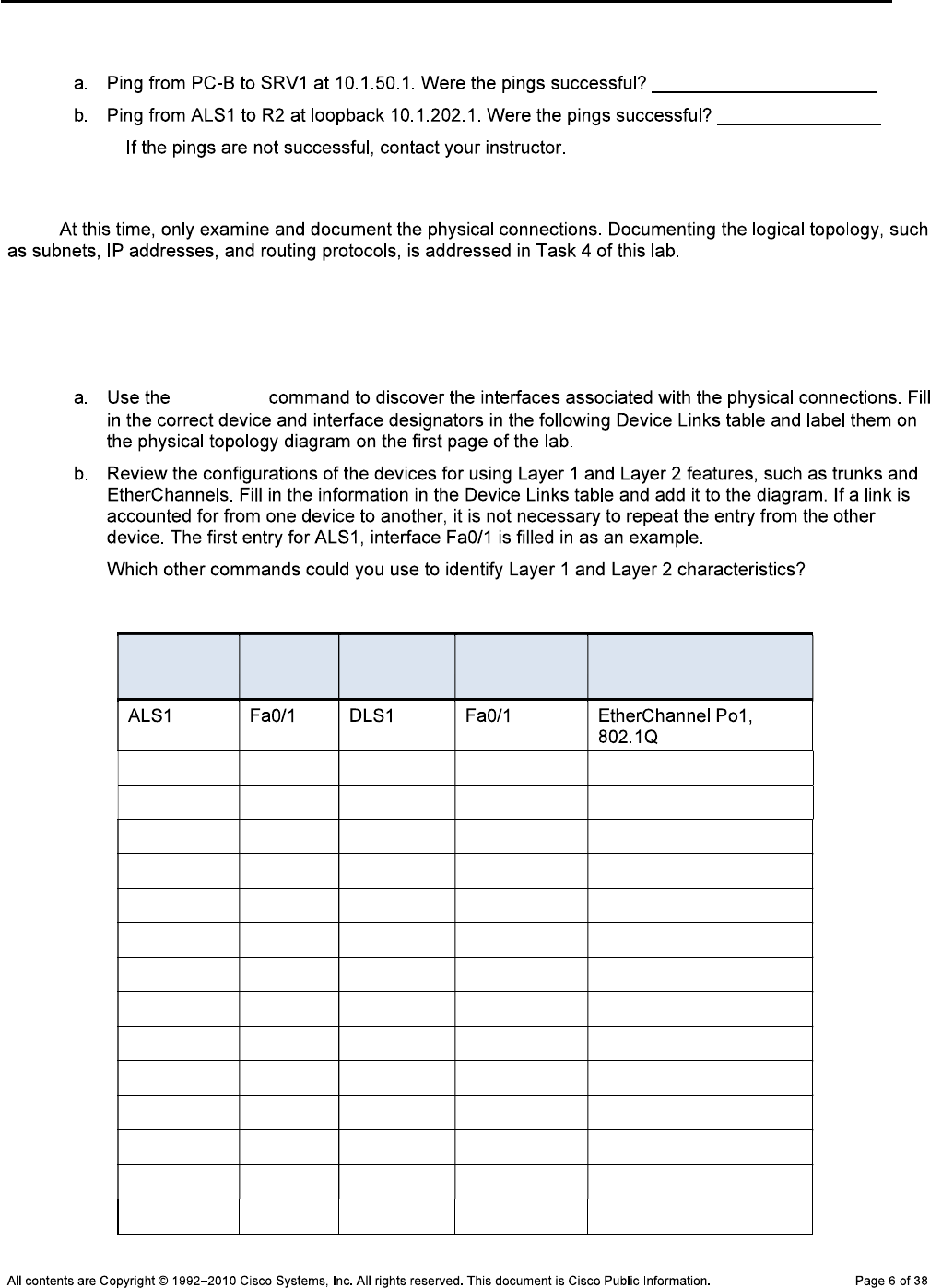
Step 2: Use Cisco Discovery Protocol and show commands to verify the Layer 1 and Layer 2
connections of the lab topology.
show cdp
Device Links Table
From Device Interface To Device Interface Layer 1 and 2 Features
and Protocols Used
CCNPv6 TSHOOT
From Device Interface To Device Interface Layer 1 and 2 Features
and Protocols Used
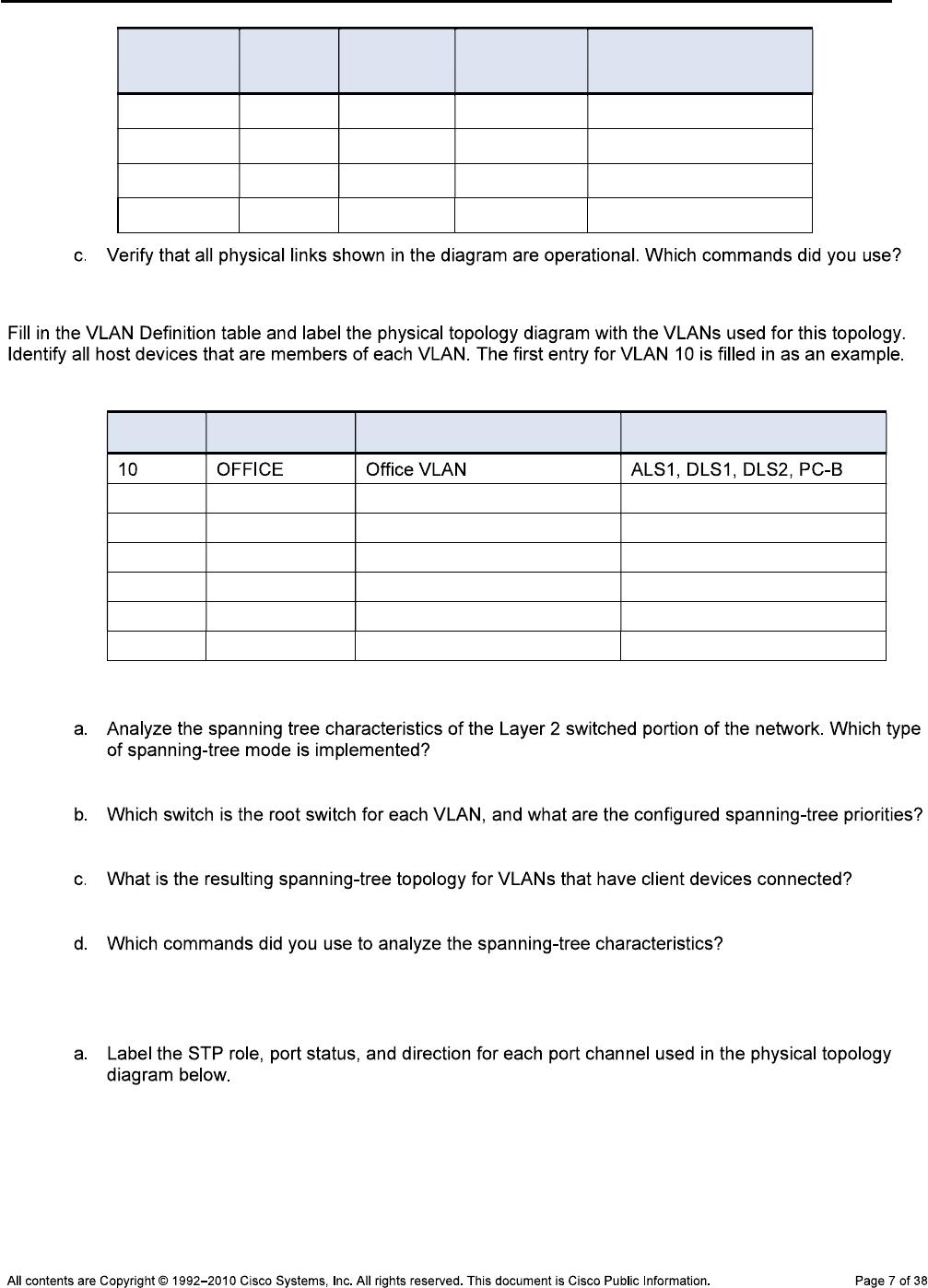
Step 3: Map the VLANs used in the lab to the devices in the diagram.
VLAN Definition Table
VLAN # Name Description VLAN Members
Step 4: Analyze spanning tree for the Layer 2 switched domain.
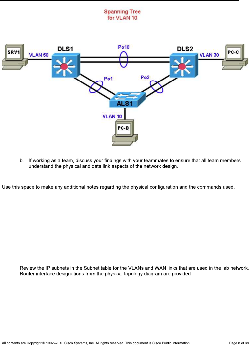
Step 5: Diagram the spanning tree for VLAN 10.
CCNPv6 TSHOOT
Student Notes
_______________________________________________________________________________
_______________________________________________________________________________
_______________________________________________________________________________
_______________________________________________________________________________
_______________________________________________________________________________
Task 4: Analyze and Document the Logical Lab Topology
Step 1: Review the logical lab diagram and the subnets.

CCNPv6 TSHOOT
CCNPv6 TSHOOT
Subnet Table
Description Subnet Prefix Devices
VLANs
WAN Links
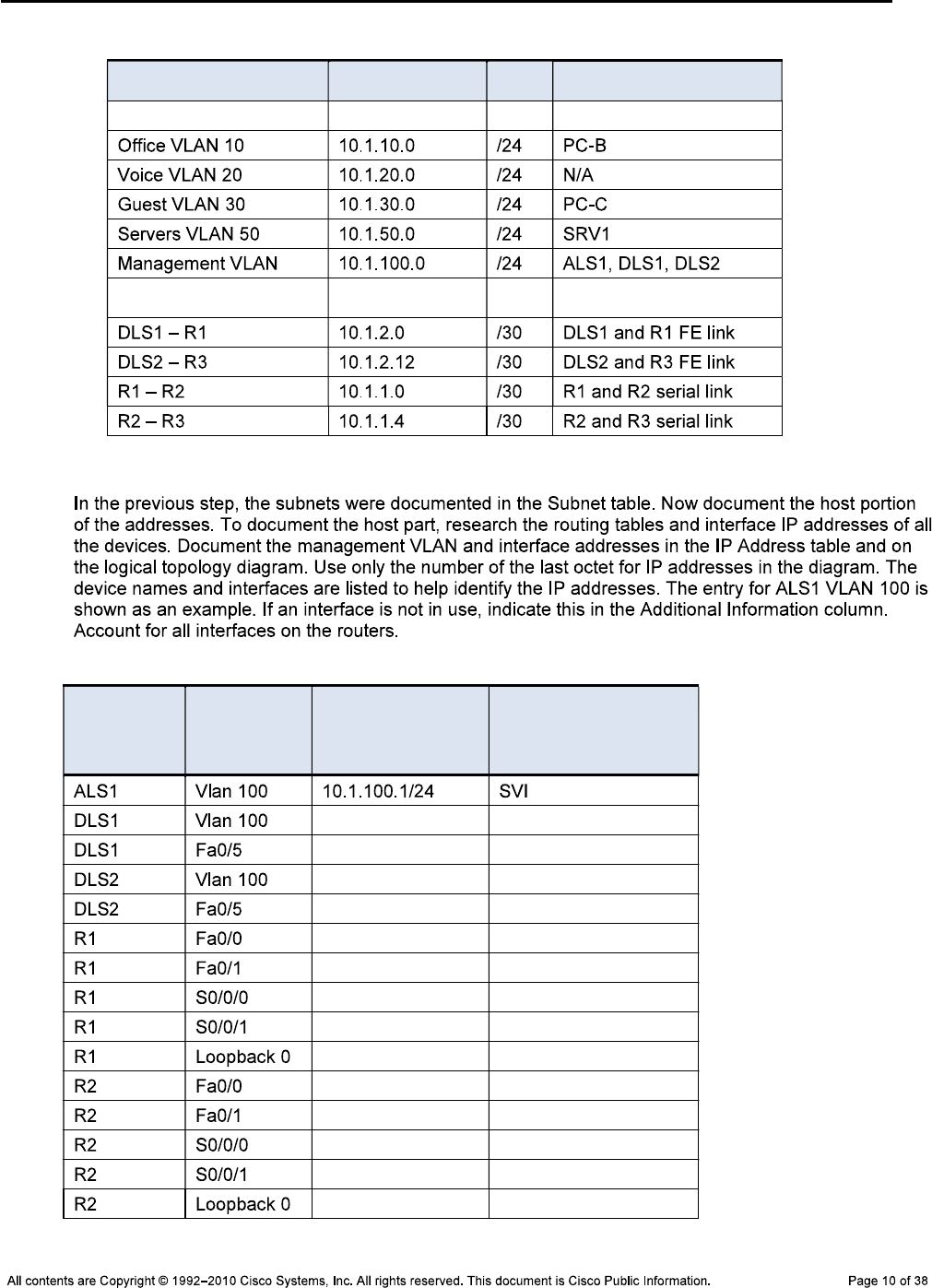
Step 2: Map the subnet scheme to the logical diagram.
IP Address Table
Device
Name
Abbreviation Interface
Network Address
and Prefix Additional Information
CCNPv6 TSHOOT
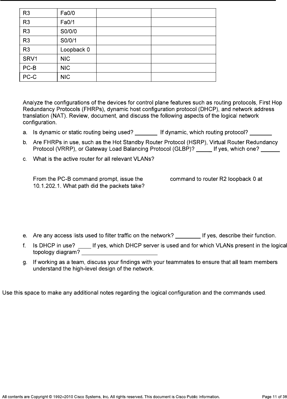
Step 3: Analyze and document control plane logical configuration features.
d. tracert
Notes
_______________________________________________________________________________
_______________________________________________________________________________
_______________________________________________________________________________
_______________________________________________________________________________
_______________________________________________________________________________
_______________________________________________________________________________
CCNPv6 TSHOOT
Task 5: Identify Troubleshooting and Maintenance Tools
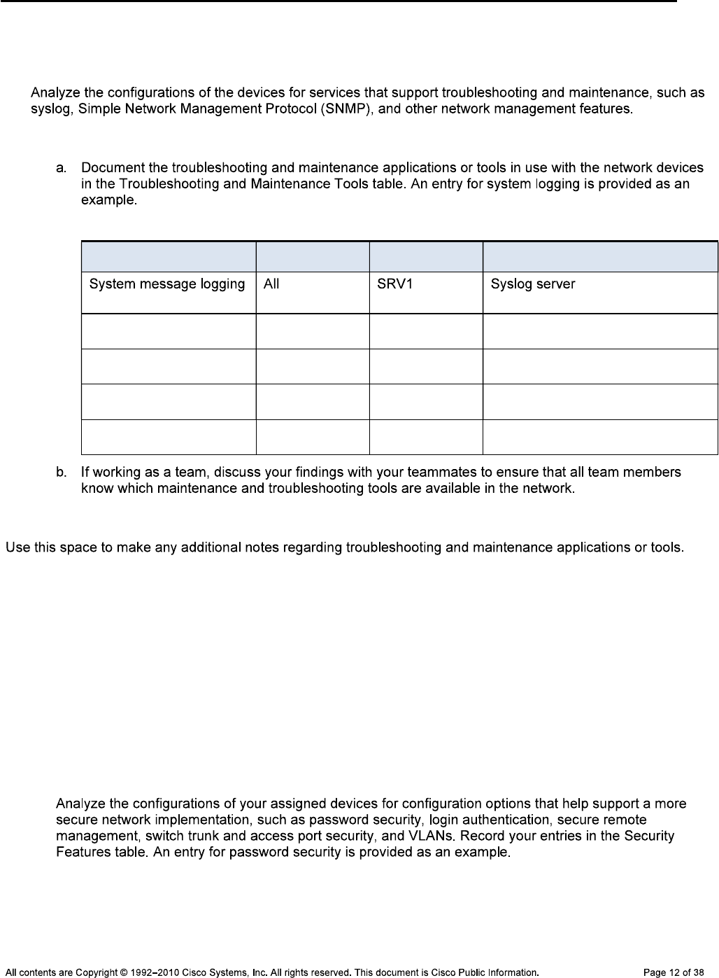
Step 1: Analyze device configurations for troubleshooting and maintenance features.
Step 2: Document the troubleshooting and maintenance features.
Troubleshooting and Maintenance Tools Table
Configured Feature Devices Target Server Target Tool or Application
Notes
_______________________________________________________________________________
_______________________________________________________________________________
_______________________________________________________________________________
_______________________________________________________________________________
_______________________________________________________________________________
_______________________________________________________________________________
Task 6: Identify the Security Measures Implemented
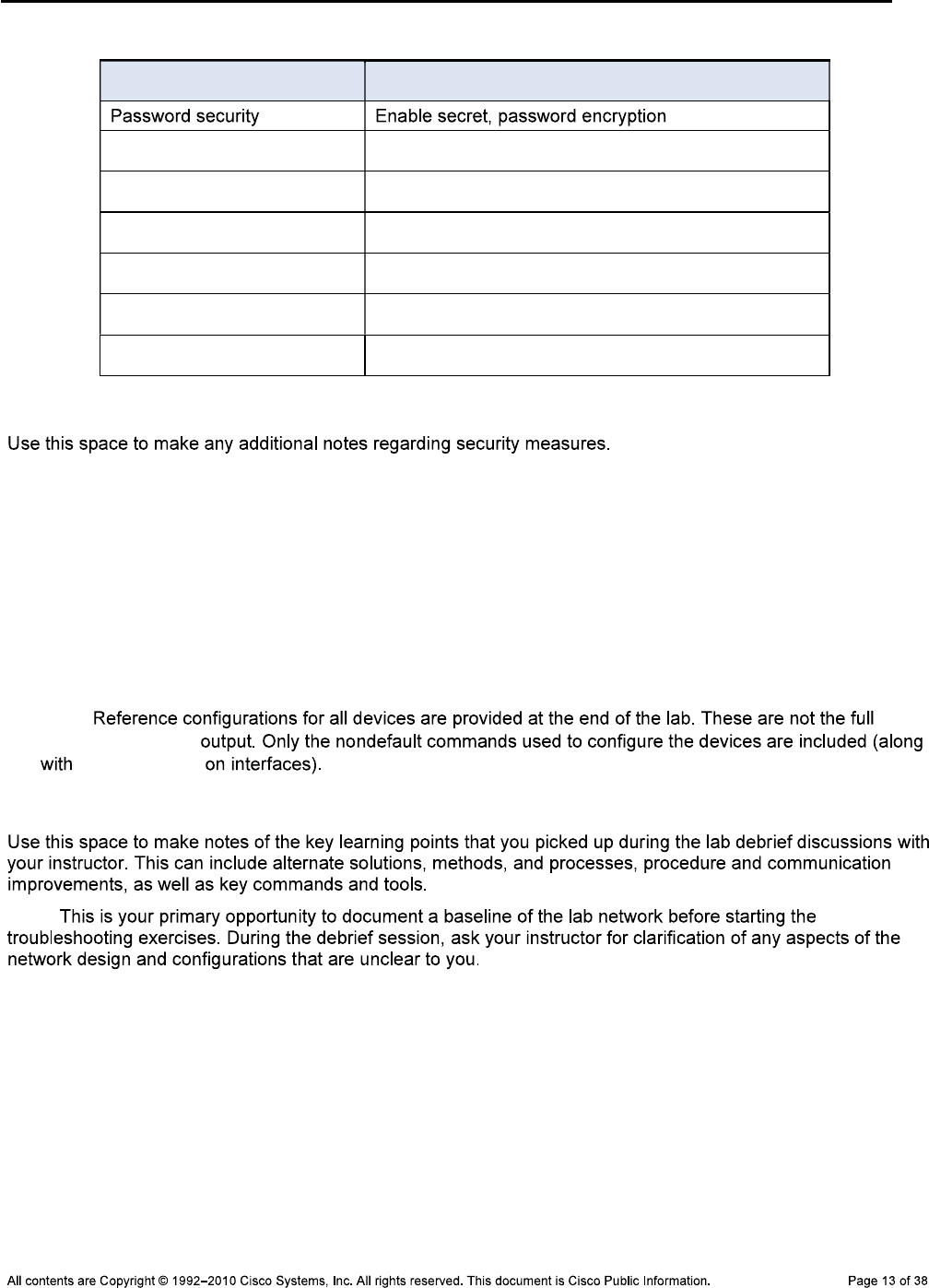
Step 1: Analyze device configurations for security-related features.
CCNPv6 TSHOOT
Security Features Table
Security Feature Configured Implementation Method or Commands
Notes
_______________________________________________________________________________
_______________________________________________________________________________
_______________________________________________________________________________
_______________________________________________________________________________
_______________________________________________________________________________
_______________________________________________________________________________
Note: show
running-config
no shutdown
Lab Debrief Notes
Note:
_______________________________________________________________________________
_______________________________________________________________________________
_______________________________________________________________________________
_______________________________________________________________________________
_______________________________________________________________________________
_______________________________________________________________________________
_______________________________________________________________________________
CCNPv6 TSHOOT
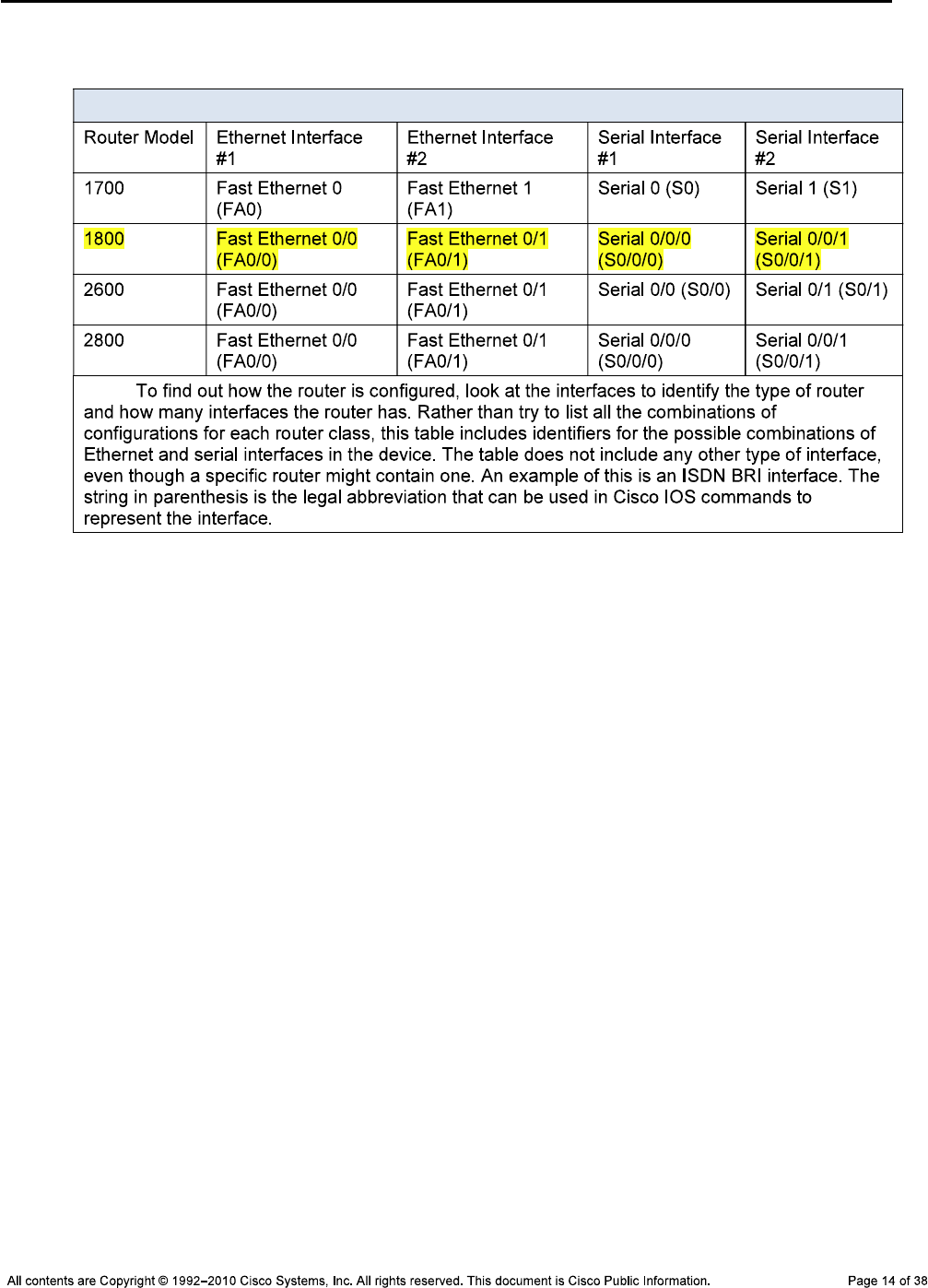
Router Interface Summary Table
Router Interface Summary
Note:
Device Configurations
Switch ALS1
!Lab 3-1 Switch ALS1 Baseline Config
!
hostname ALS1
!
service timestamps debug datetime msec
service timestamps log datetime msec
service password-encryption
!
logging buffered 16384
enable secret ciscoenpa55
!
username admin secret adminpa55
!
banner motd $*** Lab 3-1 Switch ALS1 Baseline Config ***$
!
no ip domain lookup
!
aaa new-model
aaa authentication login default local
aaa authentication login CONSOLE none
aaa authorization exec default local
!
system mtu routing 1500
!
vtp domain TSHOOT
vtp mode transparent
!
ip subnet-zero
ip domain-name tshoot.net

CCNPv6 TSHOOT
ip host R1 10.1.2.2 10.1.1.1 10.1.201.1
ip host R2 10.1.1.2 10.1.1.6 10.1.202.1
ip host R3 10.1.1.5 10.1.2.14 10.1.203.1
ip host ALS1 10.1.100.1
ip host DLS1 10.1.100.252 10.1.2.1
ip host DLS2 10.1.100.253 10.1.2.13
!
crypto key zeroize rsa
crypto key generate rsa general-keys modulus 1024
!
archive
log config
logging size 50
notify syslog
hidekeys
path tftp://10.1.50.1/$h-archive-config
write-memory
file prompt quiet
spanning-tree mode rapid-pvst
spanning-tree portfast default
!
interface Vlan1
no ip address
shutdown
!
vlan 10
name OFFICE
!
vlan 20
name VOICE
!
vlan 30
name GUEST
!
vlan 100
name MGMT
!
vlan 900
name NATIVE
!
vlan 999
name UNUSED
!
ip telnet source-interface Vlan100
ip ssh source-interface Vlan100
!
interface Port-channel1
description Channel to DLS1
no shutdown
!
interface Port-channel2
description Channel to DLS2
no shutdown
!
interface FastEthernet0/1
description Channel to DLS1
switchport trunk native vlan 900

CCNPv6 TSHOOT
switchport trunk allowed vlan 10,20,30,100
switchport mode trunk
switchport nonegotiate
channel-group 1 mode on
no shutdown
!
interface FastEthernet0/2
description Channel to DLS1
switchport trunk native vlan 900
switchport trunk allowed vlan 10,20,30,100
switchport mode trunk
switchport nonegotiate
channel-group 1 mode on
no shutdown
!
interface FastEthernet0/3
description Channel to DLS2
switchport trunk native vlan 900
switchport trunk allowed vlan 10,20,30,100
switchport mode trunk
switchport nonegotiate
channel-group 2 mode on
no shutdown
!
interface FastEthernet0/4
description Channel to DLS2
switchport trunk native vlan 900
switchport trunk allowed vlan 10,20,30,100
switchport mode trunk
switchport nonegotiate
channel-group 2 mode on
no shutdown
!
interface FastEthernet0/5
description Unused
switchport access vlan 999
switchport mode access
switchport nonegotiate
shutdown
!
interface FastEthernet0/6
description Unused
switchport access vlan 999
switchport mode access
switchport nonegotiate
shutdown
interface FastEthernet0/7
description Unused
switchport access vlan 999
switchport mode access
switchport nonegotiate
shutdown
!
interface FastEthernet0/8
description Unused
switchport access vlan 999
switchport mode access

CCNPv6 TSHOOT
switchport nonegotiate
shutdown
!
interface FastEthernet0/9
description Unused
switchport access vlan 999
switchport mode access
switchport nonegotiate
shutdown
!
interface FastEthernet0/10
description Unused
switchport access vlan 999
switchport mode access
switchport nonegotiate
shutdown
!
interface FastEthernet0/11
description Unused
switchport access vlan 999
switchport mode access
switchport nonegotiate
shutdown
!
interface FastEthernet0/12
description Unused
switchport access vlan 999
switchport mode access
switchport nonegotiate
shutdown
!
interface FastEthernet0/13
description Unused
switchport access vlan 999
switchport mode access
switchport nonegotiate
shutdown
!
interface FastEthernet0/14
description Unused
switchport access vlan 999
switchport mode access
switchport nonegotiate
shutdown
!
interface FastEthernet0/15
description Unused
switchport access vlan 999
switchport mode access
switchport nonegotiate
shutdown
!
interface FastEthernet0/16
description Unused
switchport access vlan 999
switchport mode access
switchport nonegotiate
shutdown

CCNPv6 TSHOOT
!
interface FastEthernet0/17
description Unused
switchport access vlan 999
switchport mode access
switchport nonegotiate
shutdown
!
interface FastEthernet0/18
description To PC-B
switchport access vlan 10
switchport mode access
switchport voice vlan 20
spanning-tree portfast
switchport port-security
switchport port-security maximum 2
switchport port-security violation shutdown
switchport port-security mac-address sticky
no shut
!
interface FastEthernet0/19
description Unused
switchport access vlan 999
switchport mode access
switchport nonegotiate
shutdown
!
interface FastEthernet0/20
description Unused
switchport access vlan 999
switchport mode access
switchport nonegotiate
shutdown
!
interface FastEthernet0/21
description Unused
switchport access vlan 999
switchport mode access
switchport nonegotiate
shutdown
!
interface FastEthernet0/22
description Unused
switchport access vlan 999
switchport mode access
switchport nonegotiate
shutdown
!
interface FastEthernet0/23
description Unused
switchport access vlan 999
switchport mode access
switchport nonegotiate
shutdown
!
interface FastEthernet0/24
description Unused
switchport access vlan 999

CCNPv6 TSHOOT
switchport mode access
switchport nonegotiate
shutdown
!
interface gigabitethernet0/1
description Unused
switchport access vlan 999
switchport mode access
switchport nonegotiate
shutdown
!
interface gigabitethernet0/2
description Unused
switchport access vlan 999
switchport mode access
switchport nonegotiate
shutdown
!
interface Vlan100
ip address 10.1.100.1 255.255.255.0
no shutdown
!
ip default-gateway 10.1.100.254
!
ip http server
ip http secure-server
!
logging source-interface Vlan100
logging 10.1.50.1
!
snmp-server community cisco RO
snmp-server community san-fran RW
snmp-server trap-source Vlan100
snmp-server location TSHOOT Lab Facility
snmp-server contact support@tshoot.net
snmp-server host 10.1.50.1 version 2c cisco
snmp-server enable traps vtp
snmp-server enable traps vlancreate
snmp-server enable traps vlandelete
snmp-server enable traps port-security
snmp-server enable traps vlan-membership
!
line con 0
exec-timeout 60 0
login authentication CONSOLE
logging synchronous
line vty 0 4
exec-timeout 60 0
transport input telnet ssh
line vty 5 15
no transport input
!
ntp source Vlan100
ntp server 10.1.202.1
end

CCNPv6 TSHOOT
Switch DLS1
!Lab 3-1 Switch DLS1 Baseline Config
!
hostname DLS1
!
service timestamps debug datetime msec
service timestamps log datetime msec
service password-encryption
!
logging buffered 16384
enable secret ciscoenpa55
!
username admin secret adminpa55
banner motd $*** Lab 3-1 Switch DLS1 Baseline Config ***$
!
no ip domain lookup
!
aaa new-model
aaa authentication login default local
aaa authentication login CONSOLE none
aaa authorization exec default local
!
system mtu routing 1500
!
vtp domain TSHOOT
vtp mode transparent
!
ip subnet-zero
ip routing
!
ip domain-name tshoot.net
ip host R1 10.1.2.2 10.1.1.1 10.1.201.1
ip host R2 10.1.1.2 10.1.1.6 10.1.202.1
ip host R3 10.1.1.5 10.1.2.14 10.1.203.1
ip host ALS1 10.1.100.1
ip host DLS1 10.1.100.252 10.1.2.1
ip host DLS2 10.1.100.253 10.1.2.13
!
ip dhcp excluded-address 10.1.10.252 10.1.10.254
ip dhcp excluded-address 10.1.20.252 10.1.20.254
ip dhcp excluded-address 10.1.30.252 10.1.30.254
!
ip dhcp pool OFFICE
network 10.1.10.0 255.255.255.0
default-router 10.1.10.254
domain-name tshoot.net
!
ip dhcp pool VOICE
network 10.1.20.0 255.255.255.0
default-router 10.1.20.254
domain-name tshoot.net
!
ip dhcp pool GUEST
network 10.1.30.0 255.255.255.0
default-router 10.1.30.254
domain-name tshoot.net

CCNPv6 TSHOOT
!
crypto key zeroize rsa
crypto key generate rsa general-keys modulus 1024
!
errdisable recovery cause bpduguard
!
archive
log config
logging size 50
notify syslog
hidekeys
path tftp://10.1.50.1/$h-archive-config
write-memory
file prompt quiet
!
spanning-tree mode rapid-pvst
!
spanning-tree vlan 10,30,100 priority 24576
spanning-tree vlan 20,50 priority 28672
!
vlan 10
name OFFICE
!
vlan 20
name VOICE
!
vlan 30
name GUEST
!
vlan 50
name SERVERS
!
vlan 100
name MGMT
!
vlan 900
name NATIVE
!
vlan 999
name UNUSED
!
ip telnet source-interface Vlan100
ip ssh source-interface Vlan100
!
interface Port-channel1
description Channel to ALS1
no shut
!
interface Port-channel10
description Channel to DLS2
no shut
!
interface FastEthernet0/1
description Channel to ALS1
switchport trunk encapsulation dot1q
switchport trunk native vlan 900
switchport trunk allowed vlan 10,20,30,100
switchport mode trunk

CCNPv6 TSHOOT
switchport nonegotiate
channel-group 1 mode on
no shut
!
interface FastEthernet0/2
description Channel to ALS1
switchport trunk encapsulation dot1q
switchport trunk native vlan 900
switchport trunk allowed vlan 10,20,30,100
switchport mode trunk
switchport nonegotiate
channel-group 1 mode on
no shut
!
interface FastEthernet0/3
description Channel to DLS2
switchport trunk encapsulation dot1q
switchport trunk native vlan 900
switchport trunk allowed vlan 10,20,30,50,100
switchport mode trunk
switchport nonegotiate
channel-group 10 mode on
no shut
!
interface FastEthernet0/4
description Channel to DLS2
switchport trunk encapsulation dot1q
switchport trunk native vlan 900
switchport trunk allowed vlan 10,20,30,50,100
switchport mode trunk
switchport nonegotiate
channel-group 10 mode on
no shut
!
interface FastEthernet0/5
description FE to R1
no switchport
ip address 10.1.2.1 255.255.255.252
speed 100
duplex full
spanning-tree bpduguard enable
no shut
!
interface FastEthernet0/6
description FE to SRV1
switchport access vlan 50
switchport mode access
switchport nonegotiate
spanning-tree portfast
no shut
!
interface FastEthernet0/7
description Unused
switchport access vlan 999
switchport mode access
switchport nonegotiate
shutdown
!

CCNPv6 TSHOOT
interface FastEthernet0/8
description Unused
switchport access vlan 999
switchport mode access
switchport nonegotiate
shutdown
!
interface FastEthernet0/9
description Unused
switchport access vlan 999
switchport mode access
switchport nonegotiate
shutdown
!
interface FastEthernet0/10
description Unused
switchport access vlan 999
switchport mode access
switchport nonegotiate
shutdown
!
interface FastEthernet0/11
description Unused
switchport access vlan 999
switchport mode access
switchport nonegotiate
shutdown
!
interface FastEthernet0/12
description Unused
switchport access vlan 999
switchport mode access
switchport nonegotiate
shutdown
!
interface FastEthernet0/13
description Unused
switchport access vlan 999
switchport mode access
switchport nonegotiate
shutdown
!
interface FastEthernet0/14
description Unused
switchport access vlan 999
switchport mode access
switchport nonegotiate
shutdown
!
interface FastEthernet0/15
description Unused
switchport access vlan 999
switchport mode access
switchport nonegotiate
shutdown
!
interface FastEthernet0/16
description Unused

CCNPv6 TSHOOT
switchport access vlan 999
switchport mode access
switchport nonegotiate
shutdown
!
interface FastEthernet0/17
description Unused
switchport access vlan 999
switchport mode access
switchport nonegotiate
shutdown
!
interface FastEthernet0/18
description Unused
switchport access vlan 999
switchport mode access
switchport nonegotiate
shutdown
!
interface FastEthernet0/19
description Unused
switchport access vlan 999
switchport mode access
switchport nonegotiate
shutdown
!
interface FastEthernet0/20
description Unused
switchport access vlan 999
switchport mode access
switchport nonegotiate
shutdown
!
interface FastEthernet0/21
description Unused
switchport access vlan 999
switchport mode access
switchport nonegotiate
shutdown
!
interface FastEthernet0/22
description Unused
switchport access vlan 999
switchport mode access
switchport nonegotiate
shutdown
!
interface FastEthernet0/23
description Unused
switchport access vlan 999
switchport mode access
switchport nonegotiate
shutdown
!
interface FastEthernet0/24
description Unused
switchport access vlan 999
switchport mode access

CCNPv6 TSHOOT
switchport nonegotiate
shutdown
!
interface gigabitethernet0/1
description Unused
switchport access vlan 999
switchport mode access
switchport nonegotiate
shutdown
!
interface gigabitethernet0/2
description Unused
switchport access vlan 999
switchport mode access
switchport nonegotiate
shutdown
!
interface Vlan1
no ip address
shutdown
interface Vlan10
ip address 10.1.10.252 255.255.255.0
standby 10 ip 10.1.10.254
standby 10 priority 110
standby 10 preempt
!
interface Vlan20
ip address 10.1.20.252 255.255.255.0
standby 20 ip 10.1.20.254
standby 20 preempt
!
interface Vlan30
ip address 10.1.30.252 255.255.255.0
standby 30 ip 10.1.30.254
standby 30 priority 110
standby 30 preempt
!
interface Vlan50
ip address 10.1.50.252 255.255.255.0
standby 50 ip 10.1.50.254
standby 50 preempt
!
interface Vlan100
ip address 10.1.100.252 255.255.255.0
standby 100 ip 10.1.100.254
standby 100 priority 110
standby 100 preempt
!
router eigrp 1
passive-interface default
no passive-interface Fa0/5
no auto-summary
network 10.1.0.0 0.0.255.255
!
ip classless
ip http server
ip http secure-server

CCNPv6 TSHOOT
!
logging source-interface Vlan100
logging 10.1.50.1
!
snmp-server community cisco RO
snmp-server community san-fran RW
snmp-server trap-source Vlan100
snmp-server location TSHOOT Lab Facility
snmp-server contact support@tshoot.net
snmp-server host 10.1.50.1 version 2c cisco
snmp-server enable traps eigrp
snmp-server enable traps vtp
snmp-server enable traps vlancreate
snmp-server enable traps vlandelete
snmp-server enable traps port-security
snmp-server enable traps config
snmp-server enable traps hsrp
snmp-server enable traps vlan-membership
snmp-server enable traps errdisable
!
line con 0
exec-timeout 60 0
login authentication CONSOLE
logging synchronous
line vty 0 4
exec-timeout 60 0
transport input telnet ssh
line vty 5 15
no transport input
!
ntp source Vlan100
ntp server 10.1.202.1
end
Switch DLS2
!Lab 3-1 Switch DLS2 Baseline Config
!
hostname DLS2
!
service timestamps debug datetime msec
service timestamps log datetime
service password-encryption
!
logging buffered 16384
enable secret ciscoenpa55
!
username admin secret adminpa55
!
banner motd $*** Lab 3-1 Switch DLS2 Baseline Config ***$
!
no ip domain lookup
!
aaa new-model
aaa authentication login default local
aaa authentication login CONSOLE none
aaa authorization exec default local
!

CCNPv6 TSHOOT
system mtu routing 1500
!
vtp domain TSHOOT
vtp mode transparent
!
ip subnet-zero
ip routing
ip domain-name tshoot.net
ip host R1 10.1.2.2 10.1.1.1 10.1.201.1
ip host R2 10.1.1.2 10.1.1.6 10.1.202.1
ip host R3 10.1.1.5 10.1.2.14 10.1.203.1
ip host ALS1 10.1.100.1
ip host DLS1 10.1.100.252 10.1.2.1
ip host DLS2 10.1.100.253 10.1.2.13
!
crypto key zeroize rsa
crypto key generate rsa general-keys modulus 1024
!
errdisable recovery cause bpduguard
!
archive
log config
logging size 50
notify syslog
hidekeys
path tftp://10.1.50.1/$h-archive-config
write-memory
file prompt quiet
!
spanning-tree mode rapid-pvst
!
spanning-tree vlan 10,30,100 priority 28672
spanning-tree vlan 20,50 priority 24576
vlan 10
name OFFICE
!
vlan 20
name VOICE
!
vlan 30
name GUEST
!
vlan 50
name SERVERS
!
vlan 100
name MGMT
!
vlan 900
name NATIVE
!
vlan 999
name UNUSED
!
ip telnet source-interface Vlan100
ip ssh source-interface Vlan100
!

CCNPv6 TSHOOT
interface Port-channel2
description Channel to ALS1
no shut
interface Port-channel10
description Channel to DLS1
no shut
!
interface FastEthernet0/1
description Channel to ALS1
switchport trunk encapsulation dot1q
switchport trunk native vlan 900
switchport trunk allowed vlan 10,20,30,100
switchport mode trunk
switchport nonegotiate
channel-group 2 mode on
no shut
!
interface FastEthernet0/2
description Channel to ALS1
switchport trunk encapsulation dot1q
switchport trunk native vlan 900
switchport trunk allowed vlan 10,20,30,100
switchport mode trunk
switchport nonegotiate
channel-group 2 mode on
no shut
!
interface FastEthernet0/3
description Channel to DLS1
switchport trunk encapsulation dot1q
switchport trunk native vlan 900
switchport trunk allowed vlan 10,20,30,50,100
switchport mode trunk
switchport nonegotiate
channel-group 10 mode on
no shut
!
interface FastEthernet0/4
description Channel to DLS1
switchport trunk encapsulation dot1q
switchport trunk native vlan 900
switchport trunk allowed vlan 10,20,30,50,100
switchport mode trunk
switchport nonegotiate
channel-group 10 mode on
no shut
!
interface FastEthernet0/5
description FE to R3
no switchport
ip address 10.1.2.13 255.255.255.252
speed 100
duplex full
spanning-tree bpduguard enable
no shut
!
interface FastEthernet0/6

CCNPv6 TSHOOT
description Unused
switchport access vlan 999
switchport mode access
switchport nonegotiate
shutdown
!
interface FastEthernet0/7
description Unused
switchport access vlan 999
switchport mode access
switchport nonegotiate
shutdown
!
interface FastEthernet0/8
description Unused
switchport access vlan 999
switchport mode access
switchport nonegotiate
shutdown
!
interface FastEthernet0/9
description Unused
switchport access vlan 999
switchport mode access
switchport nonegotiate
shutdown
!
interface FastEthernet0/10
description Unused
switchport access vlan 999
switchport mode access
switchport nonegotiate
shutdown
!
interface FastEthernet0/11
description Unused
switchport access vlan 999
switchport mode access
switchport nonegotiate
shutdown
!
interface FastEthernet0/12
description Unused
switchport access vlan 999
switchport mode access
switchport nonegotiate
shutdown
!
interface FastEthernet0/13
description Unused
switchport access vlan 999
switchport mode access
switchport nonegotiate
shutdown
!
interface FastEthernet0/14
description Unused
switchport access vlan 999

CCNPv6 TSHOOT
switchport mode access
switchport nonegotiate
shutdown
!
interface FastEthernet0/15
description Unused
switchport access vlan 999
switchport mode access
switchport nonegotiate
shutdown
!
interface FastEthernet0/16
description Unused
switchport access vlan 999
switchport mode access
switchport nonegotiate
shutdown
!
interface FastEthernet0/17
description Unused
switchport access vlan 999
switchport mode access
switchport nonegotiate
shutdown
!
interface FastEthernet0/18
description FE to PC-C
switchport access vlan 30
switchport mode access
switchport nonegotiate
spanning-tree portfast
no shutdown
!
interface FastEthernet0/19
description Unused
switchport access vlan 999
switchport mode access
switchport nonegotiate
shutdown
!
interface FastEthernet0/20
description Unused
switchport access vlan 999
switchport mode access
switchport nonegotiate
shutdown
!
interface FastEthernet0/21
description Unused
switchport access vlan 999
switchport mode access
switchport nonegotiate
shutdown
!
interface FastEthernet0/22
description Unused
switchport access vlan 999
switchport mode access

CCNPv6 TSHOOT
switchport nonegotiate
shutdown
!
interface FastEthernet0/23
description Unused
switchport access vlan 999
switchport mode access
switchport nonegotiate
shutdown
!
interface FastEthernet0/24
description Unused
switchport access vlan 999
switchport mode access
switchport nonegotiate
shutdown
!
interface GigabitEthernet0/1
description Unused
switchport access vlan 999
switchport mode access
switchport nonegotiate
shutdown
!
interface GigabitEthernet0/2
description Unused
switchport access vlan 999
switchport mode access
switchport nonegotiate
shutdown
!
interface Vlan1
no ip address
shutdown
!
interface Vlan10
ip address 10.1.10.253 255.255.255.0
standby 10 ip 10.1.10.254
standby 10 preempt
!
interface Vlan20
ip address 10.1.20.253 255.255.255.0
standby 20 ip 10.1.20.254
standby 20 priority 110
standby 20 preempt
!
interface Vlan30
ip address 10.1.30.253 255.255.255.0
standby 30 ip 10.1.30.254
standby 30 preempt
!
interface Vlan50
ip address 10.1.50.253 255.255.255.0
standby 50 ip 10.1.50.254
standby 50 priority 110
standby 50 preempt
!
interface Vlan100

CCNPv6 TSHOOT
ip address 10.1.100.253 255.255.255.0
standby 100 ip 10.1.100.254
standby 100 preempt
!
!
router eigrp 1
passive-interface default
no passive-interface Fa0/5
no auto-summary
network 10.1.0.0 0.0.255.255
!
ip classless
ip http server
ip http secure-server
!
!
logging source-interface Vlan100
logging 10.1.50.1
!
snmp-server community cisco RO
snmp-server community san-fran RW
snmp-server trap-source Vlan100
snmp-server location TSHOOT Lab Facility
snmp-server contact support@tshoot.net
snmp-server enable traps eigrp
snmp-server enable traps vtp
snmp-server enable traps vlancreate
snmp-server enable traps vlandelete
snmp-server enable traps port-security
snmp-server enable traps hsrp
snmp-server enable traps vlan-membership
snmp-server enable traps errdisable
snmp-server host 10.1.50.1 version 2c cisco
!
line con 0
exec-timeout 60 0
login authentication CONSOLE
logging synchronous
line vty 0 4
exec-timeout 60 0
transport input telnet ssh
line vty 5 15
no transport input
!
ntp source Vlan100
ntp server 10.1.202.1
end
Router R1
!Lab 3-1 Router R1 Baseline Config
!
hostname R1
!
service timestamps debug datetime msec
service timestamps log datetime msec
service password-encryption
!

CCNPv6 TSHOOT
logging buffered 16384 debugging
enable secret ciscoenpa55
!
username admin secret adminpa55
!
banner motd $*** Lab 3-1 Router R1 Baseline Config ***$
!
no ip domain lookup
!
aaa new-model
aaa authentication login default local
aaa authentication login CONSOLE none
aaa authorization exec default local
!
ip domain name tshoot.net
ip host R1 10.1.2.2 10.1.1.1 10.1.201.1
ip host R2 10.1.1.2 10.1.1.6 10.1.202.1
ip host R3 10.1.1.5 10.1.2.14 10.1.203.1
ip host ALS1 10.1.100.1
ip host DLS1 10.1.100.252 10.1.2.1
ip host DLS2 10.1.100.253 10.1.2.13
!
crypto key zeroize rsa
crypto key generate rsa general-keys modulus 1024
!
file prompt quiet
archive
log config
logging size 50
notify syslog
hidekeys
path tftp://10.1.50.1/$h-archive-config
write-memory
!
ip telnet source-interface Loopback0
ip ssh source-interface Loopback0
!
interface Loopback0
ip address 10.1.201.1 255.255.255.255
!
interface FastEthernet0/0
no ip address
shutdown
!
interface FastEthernet0/1
description FE to DLS1
ip address 10.1.2.2 255.255.255.252
ip flow ingress
speed 100
full-duplex
no shutdown
!
interface Serial0/0/0
description WAN link to R2 - 128k leased line
ip address 10.1.1.1 255.255.255.252
ip flow ingress
encapsulation ppp
clock rate 128000

CCNPv6 TSHOOT
no shutdown
!
interface Serial0/0/1
description WAN link to R3 (not used)
no ip address
shutdown
!
router eigrp 1
passive-interface default
no passive-interface FastEthernet0/1
no passive-interface Serial0/0/0
network 10.1.1.0 0.0.0.3
network 10.1.2.0 0.0.0.3
network 10.1.201.1 0.0.0.0
no auto-summary
!
ip http server
no ip http secure-server
!
ip flow-export source Loopback0
ip flow-export version 5
ip flow-export destination 10.1.50.1 9996
!
logging source-interface Loopback0
logging 10.1.50.1
!
snmp-server community cisco RO
snmp-server community san-fran RW
snmp-server trap-source Loopback0
snmp-server location TSHOOT Lab Facility
snmp-server contact support@tshoot.net
snmp-server enable traps eigrp
snmp-server enable traps flash insertion removal
snmp-server enable traps config
snmp-server enable traps cpu threshold
snmp-server host 10.1.50.1 version 2c cisco
!
line con 0
exec-timeout 60 0
login authentication CONSOLE
logging synchronous
line vty 0 4
exec-timeout 60 0
transport input telnet ssh
!
ntp source Loopback0
ntp update-calendar
ntp server 10.1.202.1
end
Router R2
!Lab 3-1 Router R2 Baseline Config
!
service timestamps debug datetime msec
service timestamps log datetime msec
service password-encryption
!

CCNPv6 TSHOOT
Hostname R2
!
logging buffered 16384 debugging
enable secret ciscoenpa55
!
username admin secret adminpa55
!
banner motd $*** Lab 3-1 Router R2 Baseline Config ***$
!
no ip domain lookup
ip host R1 10.1.2.2 10.1.1.1 10.1.201.1
ip host R2 10.1.1.2 10.1.1.6 10.1.202.1
ip host R3 10.1.1.5 10.1.2.14 10.1.203.1
ip host ALS1 10.1.100.1
ip host DLS1 10.1.100.252 10.1.2.1
ip host DLS2 10.1.100.253 10.1.2.13
!
aaa new-model
aaa authentication login default local
aaa authentication login CONSOLE none
aaa authorization exec default local
!
ip domain name tshoot.net
!
crypto key zeroize rsa
crypto key generate rsa general-keys modulus 1024
!
file prompt quiet
archive
log config
logging size 50
notify syslog
hidekeys
path tftp://10.1.50.1/$h-archive-config
write-memory
!
!
ip telnet source-interface Loopback0
ip ssh source-interface Loopback0
!
interface Loopback0
ip address 10.1.202.1 255.255.255.255
!
interface FastEthernet0/0
no ip address
shutdown
!
interface FastEthernet0/1
description optional connection for PC-C w/ static address
no ip addr
shutdown
!
interface Serial0/0/0
description WAN link to R1 - 128k leased line
ip address 10.1.1.2 255.255.255.252
encapsulation ppp
no shutdown

CCNPv6 TSHOOT
!
interface Serial0/0/1
description WAN link to R3 - 128k leased line
ip address 10.1.1.6 255.255.255.252
clock rate 128000
encapsulation ppp
no shutdown
!
router eigrp 1
passive-interface default
no passive-interface Serial0/0/0
no passive-interface Serial0/0/1
network 10.1.1.0 0.0.0.3
network 10.1.1.4 0.0.0.3
network 10.1.202.1 0.0.0.0
no auto-summary
!
ip http server
no ip http secure-server
!
logging source-interface Loopback0
logging 10.1.50.1
snmp-server community cisco RO
snmp-server community san-fran RW
snmp-server trap-source Loopback0
snmp-server location TSHOOT Lab Facility
snmp-server contact support@tshoot.net
snmp-server enable traps eigrp
snmp-server enable traps flash insertion removal
snmp-server enable traps config
snmp-server enable traps cpu threshold
snmp-server host 10.1.50.1 version 2c cisco
!
line con 0
exec-timeout 60 0
login authentication CONSOLE
logging synchronous
line vty 0 4
exec-timeout 60 0
transport input telnet ssh
!
ntp master 3
end
Router R3
!Lab 3-1 Router R3 Baseline Config
!
service timestamps debug datetime msec
service timestamps log datetime msec
service password-encryption
!
hostname R3
!
!
logging buffered 16384 debugging
enable secret ciscoenpa55
!

CCNPv6 TSHOOT
username admin secret adminpa55
!
banner motd $*** Lab 3-1 Router R3 Baseline Config ***$
!
aaa new-model
aaa authentication login default local
aaa authentication login CONSOLE none
aaa authorization exec default local
!
no ip domain lookup
ip domain-name tshoot.net
ip host R1 10.1.2.2 10.1.1.1 10.1.201.1
ip host R2 10.1.1.2 10.1.1.6 10.1.202.1
ip host R3 10.1.1.5 10.1.2.14 10.1.203.1
ip host ALS1 10.1.100.1
ip host DLS1 10.1.100.252 10.1.2.1
ip host DLS2 10.1.100.253 10.1.2.13
!
crypto key zeroize rsa
crypto key generate rsa general-keys modulus 1024
!
file prompt quiet
archive
log config
logging size 50
notify syslog
hidekeys
path tftp://10.1.50.1/$h-archive-config
write-memory
!
ip telnet source-interface Loopback0
ip ssh source-interface Loopback0
!
interface Loopback0
ip address 10.1.203.1 255.255.255.255
!
interface FastEthernet0/0
no ip address
shutdown
interface FastEthernet0/1
description FE to DLS2
ip address 10.1.2.14 255.255.255.252
ip flow ingress
speed 100
full-duplex
no shutdown
!
interface Serial0/0/0
description WAN link to R1 - (Not used)
no ip address
clock rate 128000
encapsulation ppp
shutdown
!
interface Serial0/0/1
description WAN link to R2 - 128k leased line
ip address 10.1.1.5 255.255.255.252

CCNPv6 TSHOOT
ip flow ingress
encapsulation ppp
no shutdown
!
router eigrp 1
passive-interface default
no passive-interface FastEthernet0/1
no passive-interface Serial0/0/1
network 10.1.1.4 0.0.0.3
network 10.1.2.12 0.0.0.3
network 10.1.203.1 0.0.0.0
no auto-summary
!
ip http server
no ip http secure-server
!
ip flow-export source Loopback0
ip flow-export version 5
ip flow-export destination 10.1.50.1 9996
!
logging source-interface Loopback0
logging 10.1.50.1
!
snmp-server community cisco RO
snmp-server community san-fran RW
snmp-server trap-source Loopback0
snmp-server location TSHOOT Lab Facility
snmp-server contact support@tshoot.net
snmp-server enable traps eigrp
snmp-server enable traps flash insertion removal
snmp-server enable traps config
snmp-server enable traps cpu threshold
snmp-server host 10.1.50.1 version 2c cisco
!
line con 0
exec-timeout 60 0
login authentication CONSOLE
logging synchronous
line vty 0 4
exec-timeout 60 0
transport input telnet ssh
!
ntp source Loopback0
ntp update-calendar
ntp server 10.1.202.1
end
All contents are Copyright © 1992–2010 Cisco Systems, Inc. All rights reserved. This document is Cisco Public Information. Page 1 of 24
CCNPv6 TSHOOT
Chapter 4 Lab 4-1, Layer 2 Connectivity and Spanning Tree
Physical Topology
All contents are Copyright © 1992–2010 Cisco Systems, Inc. All rights reserved. This document is Cisco Public Information. Page 2 of 24
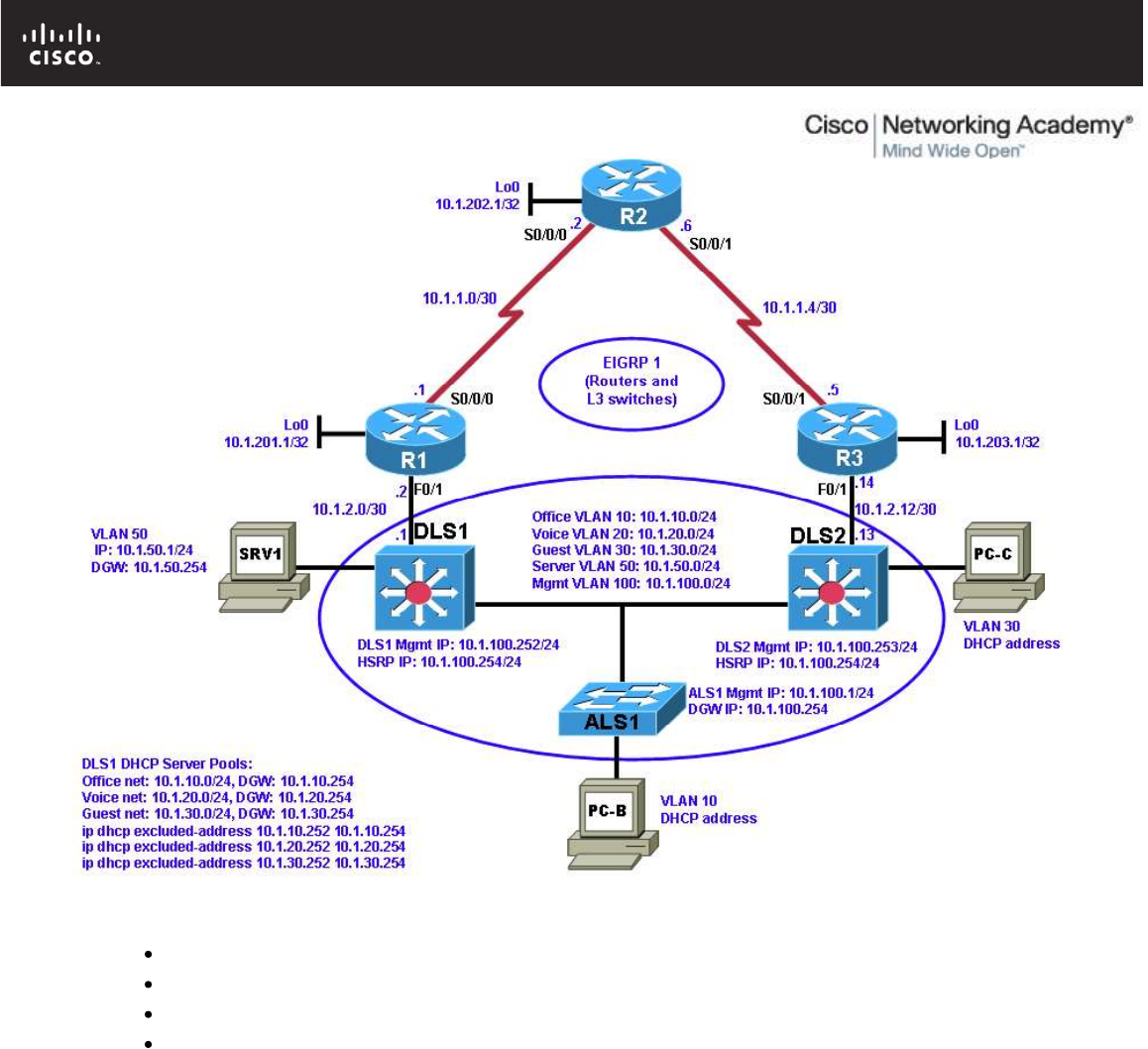
Logical Topology
Objectives
Load the device configuration files for each trouble ticket.
Diagnose and resolve Layer 2 connectivity problems.
Diagnose and resolve spanning-tree problems.
Document the troubleshooting progress, configuration changes, and problem resolution.
Background
User computers, servers, and printers all connect to the access layer of the hierarchical model. With hundreds
or thousands of hosts attached, access devices such as Layer 2 switches are a common source of
networking issues. Physical and data-link problems at the access layer can include hardware, cabling, VLAN
assignment, spanning tree, trunking protocol, or port security issues.
In this lab, you will troubleshoot various Layer 2 problems. For each task or trouble ticket, the scenario and
symptoms are described. While troubleshooting, you will discover the cause of the problem, correct it, and
then document the process and results.
Physical and Logical Topology Diagrams
The physical and logical topologies, including interface designations and IP addresses, are provided to assist
the troubleshooting effort.

CCNPv6 TSHOOT
All contents are Copyright © 1992–2010 Cisco Systems, Inc. All rights reserved. This document is Cisco Public Information. Page 3 of 24
Lab Structure
This lab is divided into two main sections.
Section 1—Trouble Tickets and Troubleshooting Logs
This section includes multiple tasks. Each task is associated with a trouble ticket (TT) and introduces one or
more errors on one or more devices. If time is a consideration, each task or trouble ticket can be performed
independently.
Section 2—Troubleshooting Reference Information
This section provides general Layer 2 troubleshooting information that can be applied to any of the trouble
tickets in this lab. Sample troubleshooting flows are provided, along with examples of useful commands and
output. If time permits, it is recommended that you read through Section 2 prior to starting on the trouble
tickets.
Note: This lab uses Cisco 1841 routers with Cisco IOS Release 12.4(24)T1 and the advanced IP image
c1841-advipservicesk9-mz.124-24.T1.bin. The switches are Cisco WS-C2960-24TT-L with the Cisco IOS
image c2960-lanbasek9-mz.122-46.SE.bin and Catalyst 3560-24PS with the Cisco IOS image c3560-
advipservicesk9-mz.122-46.SE.bin. Other routers (such as 2801 and 2811), switches (such as 2950 or 3550),
and Cisco IOS Software versions can be used if they have comparable capabilities and features. Depending
on the router or switch model and Cisco IOS Software version, the commands available and output produced
might vary from what is shown in this lab.
Note: Any changes made to the baseline configurations or topology (other than errors introduced) are noted
in the trouble ticket so that you are aware of them prior to beginning the troubleshooting process.
Required Resources
3 routers (Cisco 1841 with Cisco IOS Release 12.4(24)T1 Advanced IP Service or comparable)
1 switch (Cisco 2960 with the Cisco IOS Release 12.2(46)SE C2960-LANBASEK9-M image or
comparable)
2 switches (Cisco 3560 with the Cisco IOS Release 12.2(46)SE C3560-advipservicesK9-mz image or
comparable)
SRV1 (Windows PC with a static IP address) with TFTP and syslog servers, plus an SSH client
(PuTTY or comparable) and WireShark software
PC-B (Windows PC—DHCP client) with PuTTY and WireShark software
PC-C (Windows PC—DHCP client) with PuTTY and WireShark software
Serial and Ethernet cables
CCNPv6 TSHOOT
All contents are Copyright © 1992–2010 Cisco Systems, Inc. All rights reserved. This document is Cisco Public Information. Page 4 of 24
Section 1—Trouble Tickets and Troubleshooting Logs
Task 1: Trouble Ticket Lab 4-1 TT-A
Step 1: Review trouble ticket Lab 4-1 TT-A.
Late yesterday afternoon, access switch ALS1 failed, and you discovered that the power supply was not working.
A junior colleague was tasked with replacing ALS1 with a comparable switch.
When you arrived this morning, you asked him how things went. He told you that he had stayed late trying to
reconfigure ALS1, but was not entirely successful. Users on VLAN 10 have started to complain that they cannot
get access to the network server SRV1, and you are unable to use Telnet to connect to ALS1 from SRV1. In
addition, syslog messages from ALS1 are not being received on SRV1.
Your task is to diagnose the issues and restore switch ALS1 as a fully functional access switch on the network.
Step 2: Load the device trouble ticket configuration files for TT-A.
Using the procedure described in Lab 3-1, verify that the lab configuration files are present in flash. Load the
configuration files indicated in the Device Configuration File table.
Note: The following device access methods are in effect after loading the configuration files:
Console access requires no username or password.
Telnet and SSH require username admin and password adminpa55.
The enable password is ciscoenpa55.
Device Configuration File Table
Device Name File to Load Notes
ALS1 Lab41-ALS1-TT-A-Cfg.txt
DLS1 Lab41-DLS1-TT-A-Cfg.txt
DLS2 Lab41-DLS2-TT-A-Cfg.txt
R1 Lab41-R1-TT-A-Cfg.txt
R2 Lab41-R2-TT-A-Cfg.txt
R3 Lab41-R3-TT-A-Cfg.txt
SRV1 N/A Static IP: 10.1.50.1
Default gateway: 10.1.50.254
PC-B N/A DHCP (release and renew after loading device
configurations)
PC-C N/A DHCP (release and renew after loading device
configurations)
Step 3: Configure SRV1 and start the syslog and TFTP servers.
Ensure that SRV1 has static IP address 10.1.50.1 and default gateway 10.1.50.254.
Start the syslog server on SRV1, which is the syslog server for the entire network. When the network is properly
configured, all devices send syslog messages to SRV1.
Start the TFTP server on SRV1, which is the archive server for the entire network. When the network is properly
configured, all devices send archives of their running configurations to this server whenever the running config is

CCNPv6 TSHOOT
All contents are Copyright © 1992–2010 Cisco Systems, Inc. All rights reserved. This document is Cisco Public Information. Page 5 of 24
copied to the startup config. Ensure that the default TFTP directory on SRV1 is set to the directory where you
want to store the archives.
Step 4: Release and renew the DHCP leases on PC-B and PC-C.
Ensure that PC-B and PC-C are configured as DHCP clients.
After loading all TT-A device configuration files, issue the ipconfig /release and ipconfig /renew commands on
PC-B and PC-C.
Note: Problems introduced into the network by the trouble ticket might prevent one or both of these PCs from
acquiring an IP address. Do not assign either PC a static address.
Step 5: Outline the troubleshooting approach and validation steps.
Use this space to identify your troubleshooting approach and the key steps to verify that the problem is resolved.
Troubleshooting approaches to select from include the follow-the-path, spot-the-differences, bottom-up, top-down,
divide-and-conquer, shoot-from-the-hip, and move-the-problem methods.
Note: In addition to a specific approach, you can use the generic troubleshooting process described in the
course, which can be found at the beginning of Section 2 of this lab.
_______________________________________________________________________________
_______________________________________________________________________________
_______________________________________________________________________________
_______________________________________________________________________________
_______________________________________________________________________________
_______________________________________________________________________________
Step 6: Record the troubleshooting process and configuration changes.
Note: Section 2 of this lab includes sample troubleshooting flows, useful commands, and examples of output.
Use this log to document your actions and results during the troubleshooting process. List the commands you
used to gather information and, as you progress, record your thoughts as to what you think the problem might be
and what actions you will take to correct the problems.
Device Actions and Results
CCNPv6 TSHOOT
All contents are Copyright © 1992–2010 Cisco Systems, Inc. All rights reserved. This document is Cisco Public Information. Page 6 of 24
Device Actions and Results
Step 7: Document trouble ticket debrief notes.
Use this space to make notes of the key learning points that you picked up during the discussion of this trouble
ticket with your instructor. The notes can include problems encountered, solutions applied, useful commands
employed, alternate solutions, methods, and processes, and procedure and communication improvements.
_______________________________________________________________________________
_______________________________________________________________________________
_______________________________________________________________________________
_______________________________________________________________________________
_______________________________________________________________________________
_______________________________________________________________________________
_______________________________________________________________________________

CCNPv6 TSHOOT
All contents are Copyright © 1992–2010 Cisco Systems, Inc. All rights reserved. This document is Cisco Public Information. Page 7 of 24
Task 2: Trouble Ticket Lab 4-1 TT-B
Step 1: Review trouble ticket Lab 4-1 TT-B.
After an equipment failure, a network technician was asked to configure bundled Ethernet links between the ALS1
access switch and the two distribution layer switches in the network (DLS1 and DLS2). Shortly after the changes
were made, users on ALS1 were unable to access the Internet (simulated by Lo0 on R2). You have been asked
to look into the problem and have determined that you are able to ping the Internet from SRV1.
Your task is to diagnose the issues, allow hosts on ALS1 to connect to the Internet via DLS1 or DLS2, and verify
that the switching environment redundant paths are functional.
Note: To simulate an Internet connection, you can ping the R2 Lo0 address at 10.1.202.1. Alternately, you can
use the PC browser to connect to 10.1.202.1. You will then be prompted for a login to the router management
GUI by R2. Enter the username admin and enable password ciscoenpa55.
Step 2: Load the device trouble ticket configuration files for TT-B.
Using the procedure described in Lab 3-1, verify that the lab configuration files are present in flash. Load the
configuration files indicated in the Device Configuration File table.
Note: See Task 1, Step 2 for device access methods, usernames, and passwords after the configuration files
have been loaded.
Device Configuration File Table
Device Name File to Load Notes
ALS1 Lab41-ALS1-TT-B-Cfg.txt
DLS1 Lab41-DLS1-TT-B-Cfg.txt
DLS2 Lab41-DLS2-TT-B-Cfg.txt
R1 Lab41-R1-TT-B-Cfg.txt
R2 Lab41-R2-TT-B-Cfg.txt
R3 Lab41-R3-TT-B-Cfg.txt
SRV1 N/A Static IP: 10.1.50.1
Default gateway: 10.1.50.254
PC-B N/A DHCP (release and renew after loading device
configurations)
PC-C N/A DHCP (release and renew after loading device
configurations)
Step 3: Configure SRV1 and start the syslog and TFTP servers as described in Task 1.
Step 4: Reboot PC-B and PC-C or release and renew the DHCP lease as described in Task 1.
Step 5: Outline the troubleshooting approach and validation steps.
Use this space to identify your troubleshooting approach and the key steps to verify that the problem is resolved. .
Troubleshooting approaches to select from include the follow-the-path, spot-the-differences, bottom-up, top-down,
divide-and-conquer, shoot-from-the-hip, and move-the-problem methods.

CCNPv6 TSHOOT
All contents are Copyright © 1992–2010 Cisco Systems, Inc. All rights reserved. This document is Cisco Public Information. Page 8 of 24
Note: In addition to a specific approach, you can use the generic troubleshooting process described at the
beginning of Section 2 of this lab.
_______________________________________________________________________________
_______________________________________________________________________________
_______________________________________________________________________________
_______________________________________________________________________________
_______________________________________________________________________________
Step 6: Record the troubleshooting process and configuration changes.
Note: Section 2 of this lab includes sample troubleshooting flows, useful commands, and examples of output.
Use this log to document your actions and results during the troubleshooting process. List the commands you
used to gather information. As you progress, record what you think the problem might be and what actions you
will take to correct the problem.
Device Actions and Results
CCNPv6 TSHOOT
All contents are Copyright © 1992–2010 Cisco Systems, Inc. All rights reserved. This document is Cisco Public Information. Page 9 of 24
Device Actions and Results
Step 7: Document trouble ticket debrief notes.
Use this space to make notes of the key learning points that you picked up during the discussion of this trouble
ticket with your instructor. The notes can include problems encountered, solutions applied, useful commands
employed, alternate solutions, methods and processes, and procedure and communication improvements.
_______________________________________________________________________________
_______________________________________________________________________________
_______________________________________________________________________________
_______________________________________________________________________________
_______________________________________________________________________________
_______________________________________________________________________________
_______________________________________________________________________________
Task 3: Trouble Ticket Lab 4-1 TT-C
Step 1: Review trouble ticket Lab 4-1 TT-C.
This morning, the help desk received a call from an external consultant that needed access to the SRV1 guest
account (simulated by ping). Her PC, PC-C, was plugged into one of the outlets that is patched to the guest VLAN
on switch DLS2. However, she has not been able to get an IP address and cannot get onto the network.
Your task is to diagnose and solve this problem, making sure that the consultant gets access to SRV1.
Step 2: Load the device trouble ticket configuration files for TT-C.
Using the procedure described in Lab 3-1, verify that the lab configuration files are present in flash. Load the
configuration files indicated in the Device Configuration File table.
Note: See Task 1, Step 2 for device access methods, usernames, and passwords after you have loaded the
configuration files.
Device Configuration File Table
Device Name File to Load Notes
ALS1 Lab41-ALS1-TT-C-Cfg.txt
DLS1 Lab41-DLS1-TT-C-Cfg.txt
DLS2 Lab41-DLS2-TT-C-Cfg.txt
R1 Lab41-R1-TT-C-Cfg.txt
R2 Lab41-R2-TT-C-Cfg.txt
R3 Lab41-R3-TT-C-Cfg.txt
SRV1 N/A Static IP: 10.1.50.1

CCNPv6 TSHOOT
All contents are Copyright © 1992–2010 Cisco Systems, Inc. All rights reserved. This document is Cisco Public Information. Page 10 of 24
Default gateway: 10.1.50.254
PC-B N/A DHCP (release and renew after loading the device
configurations)
PC-C N/A DHCP (release and renew after loading the device
configurations)
Step 3: Configure SRV1 and start the syslog and TFTP servers, as described in Task 1.
Step 4: Reboot PC-B and PC-C or release and renew the DHCP lease, as described in Task 1.
Step 5: Outline the troubleshooting approach and validation steps.
Use this space to identify your troubleshooting approach and the key steps to verify that the problem is resolved. .
Troubleshooting approaches to select from include the follow-the-path, spot-the-differences, bottom-up, top-down,
divide-and-conquer, shoot-from-the-hip, and move-the-problem methods.
Note: In addition to a specific approach, you can use the generic troubleshooting process described at the
beginning of Section 2 of this lab.
_______________________________________________________________________________
_______________________________________________________________________________
_______________________________________________________________________________
_______________________________________________________________________________
_______________________________________________________________________________
_______________________________________________________________________________
Step 6: Record the troubleshooting process and configuration changes.
Note: Section 2 of this lab includes sample troubleshooting flows, useful commands, and examples of output.
Use this log to document your actions and results during the troubleshooting process. List the commands you
used to gather information. As you progress, record your thoughts as to what you think the problem might be and
which actions you take to correct the problem.
Device Actions and Results
CCNPv6 TSHOOT
All contents are Copyright © 1992–2010 Cisco Systems, Inc. All rights reserved. This document is Cisco Public Information. Page 11 of 24
Device Actions and Results
Step 7: Document trouble ticket debrief notes.
Use this space to make notes of the key learning points that you picked up during the discussion of this trouble
ticket with your instructor. The notes can include problems encountered, solutions applied, useful commands
employed, alternate solutions and methods, and procedure and communication improvements.
_______________________________________________________________________________
_______________________________________________________________________________
_______________________________________________________________________________
_______________________________________________________________________________
_______________________________________________________________________________
_______________________________________________________________________________
_______________________________________________________________________________

CCNPv6 TSHOOT
All contents are Copyright © 1992–2010 Cisco Systems, Inc. All rights reserved. This document is Cisco Public Information. Page 12 of 24
Section 2—Troubleshooting Reference Information
General Troubleshooting Process
As a general guideline, you can use the following general troubleshooting process described in the course:
1. Define the problem (symptoms).
2. Gather information.
3. Analyze the information.
4. Propose a hypothesis (possible cause).
5. Test the hypothesis.
6. Eliminate or accept the hypothesis.
7. Solve the problem.
8. Document the problem.
Command Summary
The table lists useful commands for this lab. The sample output is shown on following pages.
Command Key Information Displayed
clear arp-cache Clears ARP entries and resets aging.
show arp Displays the IP address, MAC address, and interface.
show interfaces status Displays link status, speed, duplex, trunk or VLAN
membership, and interface descriptions.
show cdp neighbors (detail) Displays device ID and type and confirms that a link is
operational at the data link layer in both directions,
including the sending and receiving ports. The detail
option gives the remote device IP address.
show spanning-tree vlan vlan# Displays all essential parameters that affect the topology,
such as root port, designated ports, port state, and port
type, as well as the spanning-tree mode implemented.
show spanning-tree
inconsistentports
Displays a more detailed description of the type of port
inconsistency and what might be causing it.
show spanning-tree summary Displays the spanning-tree mode and the VLANs for which
this switch is the root bridge. VLANs are listed along with
the number of ports in various STP states.
show mac address-table address
mac-addr
Displays the MAC address and interface entry in the table
for the specified host.
show mac-address-table interface
intf-id
Displays all MAC addresses that were learned on the
specified port.
show vlan brief Displays an overview of all existing VLANs and the ports
CCNPv6 TSHOOT
All contents are Copyright © 1992–2010 Cisco Systems, Inc. All rights reserved. This document is Cisco Public Information. Page 13 of 24
within them. Trunk ports are not listed.
show vlan id vlan# Displays whether the VLAN exists and, if so, which ports
are assigned to it. Includes trunk ports on which the VLAN
is allowed.
show interfaces type/# Displays interface status, IP address/prefix, load, duplex,
speed and packet statistics and errors.
show interfaces trunk Displays all trunk ports, the operational status, trunk
encapsulation, and native VLAN, as well as the list of
allowed VLANs, active VLANs, and the VLANs in Spanning
Tree Forwarding state for the trunk.
show interfaces type/#
switchport
Checks all VLAN-related parameters for a specific interface
(access ports and trunk ports).
show etherchannel summary Displays port channels, the member ports, and flags
indicating status.
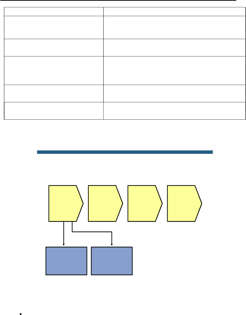
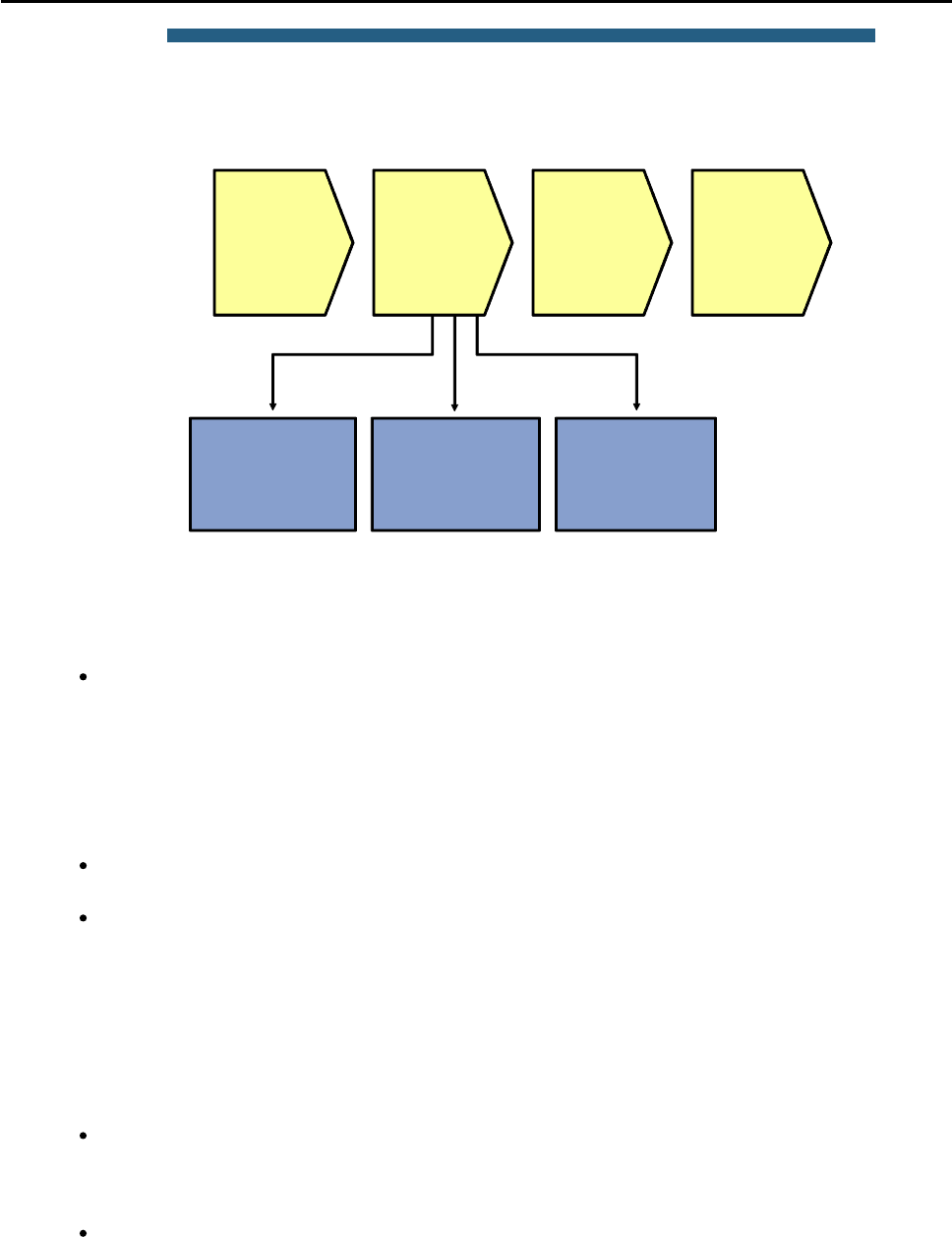
Lab 4-1 Sample Troubleshooting Flows
The figure illustrates an example of a method that you could follow to diagnose and resolve Layer 2 problems.
© 2009 Cisco Systems, Inc. All rights reserved. TSHOOT v1.0—15
Sample Layer 2 Troubleshooting Flow
Verify through
connection testing
(ping) and ARP
cache checks
Determine
and verify L2
path
between
devices
Track frames
and device
MAC
addresses
along L2
path
Investigate
links where
path seems
broken
Analyze packet
captures
No L3
connectivity
between
adjacent
devices
Usually, you start troubleshooting the Layer 2 connectivity between devices because you have discovered that
there is no Layer 3 connectivity between two adjacent Layer 2 hosts, such as two hosts in the same VLAN or a
host and its default gateway. The following are typical symptoms that could lead you to start examining Layer 2
connectivity:
Failing pings between adjacent devices. (This can also be caused by a host-based firewall that is
blocking pings.)

CCNPv6 TSHOOT
All contents are Copyright © 1992–2010 Cisco Systems, Inc. All rights reserved. This document is Cisco Public Information. Page 14 of 24
Address Resolution Protocol (ARP) failures. After clearing the ARP cache and triggering a connection
attempt (for instance, by using ping), ARP entries show up as incomplete or are missing.
Packets are not being received, which is shown by using a packet sniffer on the receiving host.
Confirm or Deny Layer 3 Connectivity
DLS1#ping 10.1.2.2
Type escape sequence to abort.
Sending 5, 100-byte ICMP Echos to 10.1.2.2, timeout is 2 seconds:
.....
Success rate is 0 percent (0/5)
DLS1#clear arp-cache
DLS1#show arp
Protocol Address Age (min) Hardware Addr Type Interface
Internet 10.1.10.1 0 0007.e963.ce53 ARPA Vlan10
Internet 10.1.2.1 - 0017.5a5b.b442 ARPA FastEthernet0/5
Internet 10.1.50.1 0 0007.e963.ce53 ARPA Vlan50
Internet 10.1.100.1 0 001b.0c6d.8f41 ARPA Vlan100
Internet 10.1.100.254 - 0000.0c07.ac64 ARPA Vlan100
Internet 10.1.100.253 0 0017.5a53.a3c1 ARPA Vlan100
Internet 10.1.100.252 - 0017.5a5b.b441 ARPA Vlan100
Internet 10.1.50.252 - 0017.5a5b.b446 ARPA Vlan50
Internet 10.1.50.254 - 0000.0c07.ac32 ARPA Vlan50
Internet 10.1.20.252 - 0017.5a5b.b444 ARPA Vlan20
Internet 10.1.30.252 - 0017.5a5b.b445 ARPA Vlan30
Internet 10.1.10.252 - 0017.5a5b.b443 ARPA Vlan10
The most relevant fields in the output are the IP address, hardware address, and interface fields, because these
give you the essential information that you are usually looking for when you issue the show arp command.
The age field is also relevant. By default, ARP entries are cached for four hours. To make sure that you are
looking at current information, you can use the clear arp-cache command to flush existing entries from the
cache.
If there is a “-” in the age field instead of a number, this entry is local to the switch. These entries represent locally
configured IP and MAC addresses, and the switch will respond to ARP requests for these entries.
CCNPv6 TSHOOT
All contents are Copyright © 1992–2010 Cisco Systems, Inc. All rights reserved. This document is Cisco Public Information. Page 15 of 24
© 2009 Cisco Systems, Inc. All rights reserved. TSHOOT v1.0—17
Sample Layer 2 Troubleshooting Flow
No L3
connectivity
between
adjacent
devices
Determine
expected L2 path
based on
documentation and
baselines
Determine
and verify L2
path
between
devices
Verify port status
and CDP to
determine
operational L2 links
Analyze spanning
tree to determine
L2 path
Track frames
and device
MAC
addresses
along L2
path
Investigate
links where
path seems
broken
If you have determined that the problem is most likely a Layer 2 or Layer 1 problem, you want to reduce the scope
of the potential failures. You can diagnose Layer 2 problems with the following common troubleshooting method:
Determine the Layer 2 path. Based on documentation, baselines, and knowledge of your network in
general, the first step is to determine the path that you would expect frames to follow between the
affected hosts. Determining the expected traffic path beforehand helps you in two ways: It gives you a
starting point for gathering information about what is actually happening on the network, and it makes
it easier to spot abnormal behavior. The second step in determining the Layer 2 path is to follow the
expected path and verify that the links on the expected path are actually up and forwarding traffic. If
the actual traffic path is different from your expected path, this step might give you clues about the
particular links or protocols that are failing and the cause of these failures.
Track the flow of traffic across the Layer 2 path. By following the expected Layer 2 path and verifying
that frames actually flow along that path, you can likely find the spot where the connectivity is failing.
When you have found the spot where the connectivity is failing, examine the link or links where the
path is broken. Now you can apply targeted troubleshooting commands to find the root cause of the
problem. Even if you cannot find the underlying cause of the problem yourself, by reducing the scope
of the problem, you have a better-defined problem that can be escalated to the next level of support.
Although there are many different approaches to troubleshooting Layer 2 problems, the elements mentioned
above will most likely be part of any methodical approach. These elements are not necessarily executed in the
presented order. Determining the expected path and verifying the actual path often go hand-in-hand.
To determine the traffic path between the affected hosts, you can combine knowledge from the following sources:
Documentation and baselines: Documentation that was written during design and implementation
usually contains information about the intended traffic paths between the hosts. If the documentation
does not provide this information, you can usually reconstruct the expected flow of traffic by analyzing
network diagrams and configurations.
Link status across the path: A very straightforward check after you have determined the expected
path of the traffic is to verify that all ports and links in the path are operational.

CCNPv6 TSHOOT
All contents are Copyright © 1992–2010 Cisco Systems, Inc. All rights reserved. This document is Cisco Public Information. Page 16 of 24
Spanning-tree topology: In Layer 2 networks that have a level of redundancy built into the topology,
analyze the operation of Spanning Tree Protocol (STP) to determine which of the available links will
be used.
Verify Link Status
DLS1#show interfaces status
Port Name Status Vlan Duplex Speed Type
Fa0/1 Channel to ALS1 connected trunk a-full a-100 10/100BaseTX
Fa0/2 Channel to ALS1 connected trunk a-full a-100 10/100BaseTX
Fa0/3 Channel to DLS2 connected trunk a-full a-100 10/100BaseTX
Fa0/4 Channel to DLS2 connected trunk a-full a-100 10/100BaseTX
Fa0/5 FE to R1 notconnect routed full 100 10/100BaseTX
Fa0/6 FE to SRV1 connected 50 a-full a-100 10/100BaseTX
Fa0/7 Unused disabled 999 auto auto 10/100BaseTX
<output omitted>
Fa0/24 Unused disabled 999 auto auto 10/100BaseTX
Gi0/1 Unused disabled 999 auto auto Not Present
Gi0/2 Unused disabled 999 auto auto Not Present
Po1 Channel to ALS1 connected trunk a-full a-100
Po10 Channel to DLS2 connected trunk a-full a-100
To determine link status on switches, the show interfaces status command is useful because it gives a
brief overview of all the interfaces on the switch as well as contains important elements, such as link status,
speed, duplex, trunk or VLAN membership, and interface descriptions. If the link is up, the Status field shows
“connected.” If it is down up, “notconnect” is in the Status field. If the link has been administratively shut down, the
status is “disabled.”
DLS1#show cdp neighbors
Capability Codes: R - Router, T - Trans Bridge, B - Source Route Bridge
S - Switch, H - Host, I - IGMP, r - Repeater, P - Phone
Device ID Local Intrfce Holdtme Capability Platform Port ID
R1.tshoot.net Fas 0/5 151 R S I 1841 Fas 0/1
ALS1.tshoot.net Fas 0/2 153 S I WS-C2960- Fas 0/2
ALS1.tshoot.net Fas 0/1 153 S I WS-C2960- Fas 0/1
DLS2.tshoot.net Fas 0/4 172 R S I WS-C3560- Fas 0/4
DLS2.tshoot.net Fas 0/3 172 R S I WS-C3560- Fas 0/3
If the Cisco Discovery Protocol is enabled between the switches and routers, you can use the show cdp
neighbor command to confirm that a link is operational at the data link layer in both directions. Also, it is
essential in uncovering cabling problems because it records both the sending and receiving ports, as can be seen
in the output above.
Analyze Spanning Tree
ALS1#show spanning-tree vlan 10
VLAN0010
Spanning tree enabled protocol rstp
Root ID Priority 24586
Address 0017.5a5b.b400
Cost 12
Port 56 (Port-channel1)
Hello Time 2 sec Max Age 20 sec Forward Delay 15 sec
Bridge ID Priority 32778 (priority 32768 sys-id-ext 10)
Address 001b.0c6d.8f00

CCNPv6 TSHOOT
All contents are Copyright © 1992–2010 Cisco Systems, Inc. All rights reserved. This document is Cisco Public Information. Page 17 of 24
Hello Time 2 sec Max Age 20 sec Forward Delay 15 sec
Aging Time 300
Interface Role Sts Cost Prio.Nbr Type
------------------- ---- --- --------- -------- --------------------------------
Fa0/18 Desg FWD 19 128.18 P2p Edge
Po1 Root FWD 12 128.56 P2p
Po2 Altn BLK 12 128.64 P2p
To analyze the spanning-tree topology and the consequences that STP has for the Layer 2 path, the show
spanning-tree vlan vlan-id command is a good starting point. It lists all essential parameters that affect
the topology, such as the root port, designated ports, port state, and port type.
Typical values for the port status field are BLK (blocking) and FWD (forwarding). You might also see LIS or LTN
(listening), and LRN (learning) while STP is converging.
The states LBK (loopback), DWN (down), or BKN (broken) typically indicate problems. If the value is BKN, the
Type field indicates what is causing the broken status. Possible values are ROOT_Inc, LOOP_Inc, PVID_Inc,
TYPE_Inc, or PVST_Inc. To get a more detailed description of the type of inconsistency and what might be
causing it, you can examine the output of the show spanning-tree inconsistentports command.
Interface Type and information includes:
P2p or Shr to indicate the link type (typically based on duplex status – P2p is full-duplex and Shr is
half-duplex or shared Ethernet).
Edge for edge (PortFast) ports.
Bound for boundary ports when this switch is running 802.1s (MST) and the other switch is running a
different spanning-tree variety. The output also indicates which other type of STP was detected on
the port.
Peer for peer ports when this switch is running Per VLAN Spanning Tree Plus (PVST+) or Per VLAN
Rapid Spanning Tree Plus (PVRST+) and the other switch is running a different standard variety of
STP (802.1D or 802.1s MST).

CCNPv6 TSHOOT
All contents are Copyright © 1992–2010 Cisco Systems, Inc. All rights reserved. This document is Cisco Public Information. Page 18 of 24
© 2009 Cisco Systems, Inc. All rights reserved. TSHOOT v1.0—21
Sample Layer 2 Troubleshooting Flow
No L3
connectivity
between
adjacent
devices
Analyze traffic
statistics and
counters
Determine
and verify L2
path
between
devices
Analyze MAC
address tables
Analyze packet
captures
Investigate
links where
path seems
broken
Track frames
and device
MAC
addresses
along L2
path
After you have determined the Layer 2 path between the two affected hosts, you can start tracking the traffic
between the hosts as it is being switched along the path. The most direct approach to tracking the traffic is to
capture packets at set points along the path by using a packet sniffer. Tracking packets in real time is a fairly
intensive procedure, and technical limitations might restrict the links where traffic captures could be collected.
However, it is the most definitive proof that traffic is or is not flowing along specific paths and links. A less labor-
intensive method is to track the flow of traffic by analyzing MAC address tables or traffic statistics. These methods
are less direct, because you are not looking at the actual traffic itself but at traces left by the passing of frames.
In a network that has not yet gone into production, packet statistics can help you see where traffic is flowing. On
live networks, the test traffic that you are generating will be lost against the background of the live traffic patterns
in most cases. However, if the switches that you are using have the capability to track packet statistics for access
lists, you might be able to write an access list that matches the specific traffic that you are interested in and isolate
the traffic statistics for that type of traffic.
A method of tracing traffic that can be used under all circumstances is analyzing the process of MAC address
learning along the Layer 2 path. When a switch receives a frame on a particular port and for a particular VLAN, it
records the source MAC address of that frame together with the port and VLAN in the MAC address table.
Therefore, if the MAC address of the source host is recorded in a switch but not on the next switch in the path, it
indicates a communication problem between these switches for the VLAN concerned, and the link between these
switches should be examined.
Analyze MAC Address Tables
DLS1#show mac address-table
Mac Address Table
-------------------------------------------
Vlan Mac Address Type Ports
---- ----------- -------- -----
<Output omitted>
50 0000.0c07.ac32 STATIC CPU
50 0007.e963.ce53 DYNAMIC Fa0/6
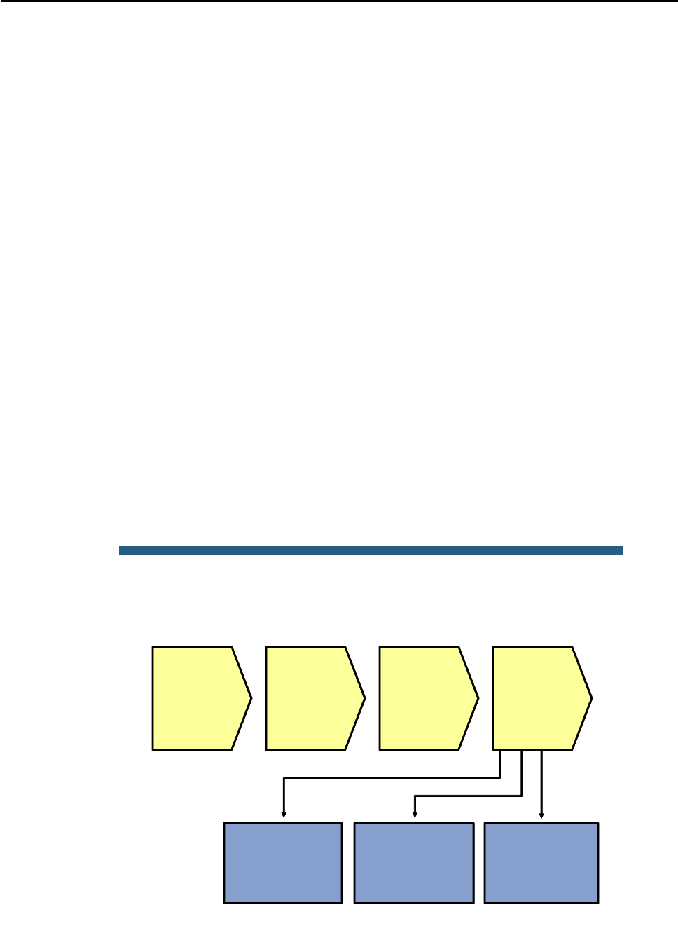
CCNPv6 TSHOOT
All contents are Copyright © 1992–2010 Cisco Systems, Inc. All rights reserved. This document is Cisco Public Information. Page 19 of 24
50 0017.5a53.a385 DYNAMIC Po10
50 0017.5a53.a3c6 DYNAMIC Po10
10 0000.0c07.ac0a DYNAMIC Po10
10 000b.db04.a5cd DYNAMIC Po1
20 0000.0c07.ac14 DYNAMIC Po10
20 0017.5a53.a385 DYNAMIC Po10
30 0000.0c07.ac1e DYNAMIC Po10
100 0000.0c07.ac64 STATIC CPU
100 0017.5a53.a3c1 DYNAMIC Po10
100 001b.0c6d.8f41 DYNAMIC Po1
Total Mac Addresses for this criterion: 32
DLS1#show mac address-table address 0000.0c07.ac0a
Mac Address Table
-------------------------------------------
Vlan Mac Address Type Ports
---- ----------- -------- -----
10 0000.0c07.ac0a DYNAMIC Po10
Total Mac Addresses for this criterion: 1
You can use the show mac-address-table command to check the content of the MAC address table.
Because this table usually contains hundreds to thousands of entries, you can narrow the results to find what you
are looking for by using command options.
If you are looking for the MAC address of a specific host, use the show mac-address-table address mac-
address option.
Another useful option is show mac-address-table interface intf-id, which shows which MAC
addresses were learned on a specific port.
© 2009 Cisco Systems, Inc. All rights reserved. TSHOOT v1.0—23
Sample Layer 2 Troubleshooting Flow
No L3
connectivity
between
adjacent
devices
Investigate and
verify VLAN
existence
Determine
and verify L2
path
between
devices
Investigate and
verify trunk and
access port
operation
Investigate and
verify
Etherchannel
operation
Track frames
and device
MAC
addresses
along L2
path
Investigate
links where
path seems
broken

CCNPv6 TSHOOT
All contents are Copyright © 1992–2010 Cisco Systems, Inc. All rights reserved. This document is Cisco Public Information. Page 20 of 24
After you have found the spot in the Layer 2 path where one switch is learning the source MAC address and the
next switch is not, examine the link between those two switches carefully.
When trying to determine what could cause the MAC address not to be learned on the next switch, consider the
following questions:
Does the VLAN exist on the next switch?
Is there an operational trunk between the two switches?
Is the VLAN allowed on the trunk between the switches?
If an EtherChannel is between the switches, is the EtherChannel fully operational?
Verify VLAN Existence
ALS1#show vlan brief
VLAN Name Status Ports
---- ------------------------ --------- -------------------------------
1 default active
10 OFFICE active Fa0/18
20 VOICE active Fa0/18
30 GUEST active
100 MGMT active
900 NATIVE active
999 UNUSED active Fa0/5, Fa0/6, Fa0/7, Fa0/8
Fa0/9, Fa0/10, Fa0/11, Fa0/12
Fa0/13, Fa0/14, Fa0/15, Fa0/16
Fa0/17, Fa0/19, Fa0/20, Fa0/21
Fa0/22, Fa0/23, Fa0/24, Gi0/1
Gi0/2
1002 fddi-default act/unsup
1003 token-ring-default act/unsup
1004 fddinet-default act/unsup
1005 trnet-default act/unsup
To get a quick overview of all existing VLANs, use the show vlan brief command. However, this command
does not list the trunk ports. For instance, in the sample output above, trunk ports F0/1, F0/2, F0/3, and F0/4 are
not listed. FastEthernet 0/18 is listed as the only port in VLANs 10 and 20.
ALS1#show vlan id 10
VLAN Name Status Ports
---- -------------------------------- --------- -------------------------------
10 OFFICE active Fa0/18, Po1, Po2
VLAN Type SAID MTU Parent RingNo BridgeNo Stp BrdgMode Trans1 Trans2
---- ----- ---------- ----- ------ ------ -------- ---- -------- ------ ------
10 enet 100010 1500 - - - - - 0 0
To verify the existence of a particular VLAN on a switch, use the show vlan id vlan-id command. This
command shows you whether the VLAN exists and which ports are assigned to it. This command includes trunk
ports that the VLAN is allowed on. For the same VLAN 10 that was referenced in the previous output, you now
see interface port channel 1 and port channel 2 listed as ports that are associated with VLAN 10.
Verify Trunk Operation
ALS1#show interfaces trunk

CCNPv6 TSHOOT
All contents are Copyright © 1992–2010 Cisco Systems, Inc. All rights reserved. This document is Cisco Public Information. Page 21 of 24
Port Mode Encapsulation Status Native vlan
Po1 on 802.1q trunking 900
Po2 on 802.1q trunking 900
Port Vlans allowed on trunk
Po1 10,20,30,100
Po2 10,20,30,100
Port Vlans allowed and active in management domain
Po1 10,20,30,100
Po2 10,20,30,100
Port Vlans in spanning tree forwarding state and not pruned
Po1 10,30,100
Po2 20
The easiest way to get an overview of trunk operation is by using the show interface trunk command. Not
only does it list trunk status, trunk encapsulation, and the native VLAN, but it also lists the allowed VLANs, active
VLANs, and VLANs in Spanning Tree Forwarding state for the trunk. The last list can be very helpful in
determining whether frames for a particular VLAN will be forwarded on a trunk.
For instance, in the example, you can see that both interface port channel 1 and port channel 2 allow VLANs 10,
20, 30, and 100, but VLANs 10, 30, and 100 are forwarded on port channel 1, while VLAN 20 is forwarded on port
channel 2.
Verify VLAN Port Status
ALS1#show interfaces fastEthernet 0/18 switchport
Name: Fa0/18
Switchport: Enabled
Administrative Mode: static access
Operational Mode: static access
Administrative Trunking Encapsulation: dot1q
Operational Trunking Encapsulation: native
Negotiation of Trunking: Off
Access Mode VLAN: 10 (OFFICE)
Trunking Native Mode VLAN: 1 (default)
Administrative Native VLAN tagging: enabled
Voice VLAN: 20 (VOICE)
Administrative private-vlan host-association: none
Administrative private-vlan mapping: none
Administrative private-vlan trunk native VLAN: none
Administrative private-vlan trunk Native VLAN tagging: enabled
Administrative private-vlan trunk encapsulation: dot1q
Administrative private-vlan trunk normal VLANs: none
Administrative private-vlan trunk associations: none
Administrative private-vlan trunk mappings: none
<Output Omitted>
To check all VLAN-related parameters for a specific interface, use the show interface intf-id
switchport command. This command applies to access ports as well as trunk ports. For instance, in the
example output, the port is configured as a static access port in VLAN 10, and VLAN 20 is assigned to the port as
a voice VLAN.
Verify EtherChannel Operation

CCNPv6 TSHOOT
All contents are Copyright © 1992–2010 Cisco Systems, Inc. All rights reserved. This document is Cisco Public Information. Page 22 of 24
ALS1#show etherchannel summary
Flags: D - down P - bundled in port-channel
I - stand-alone s - suspended
H - Hot-standby (LACP only)
R - Layer3 S - Layer2
U - in use f - failed to allocate aggregator
M - not in use, minimum links not met
u - unsuitable for bundling
w - waiting to be aggregated
d - default port
Number of channel-groups in use: 2
Number of aggregators: 2
Group Port-channel Protocol Ports
------+-------------+-----------+---------------------------------------
1 Po1(SU) - Fa0/1(P) Fa0/2(P)
2 Po2(SU) - Fa0/3(P) Fa0/4(P)
When an EtherChannel is configured between the switches and you suspect that EtherChannel operation could
be causing the communication failure between the switches, you can verify this by using the show
etherchannel summary command. Although the command output is fairly self-explanatory, the typical things
to look for is the lowercase “s” flag, which indicates that a physical interface is suspended because of
incompatibility with the other ports in the channel or the uppercase “D” flag, which indicates that an interface
(physical or port channel) is down.

CCNPv6 TSHOOT
All contents are Copyright © 1992–2010 Cisco Systems, Inc. All rights reserved. This document is Cisco Public Information. Page 23 of 24
Reflection Questions
1. Which lab trouble tickets did you have the most difficulty with?
__________________________________________________________________________________________
__________________________________________________________________________________________
__________________________________________________________________________________________
2. Would you change anything about the process that you used now that you see the resolution of the problem?
__________________________________________________________________________________________
__________________________________________________________________________________________
__________________________________________________________________________________________
3. Which commands did you find most useful in diagnosing Layer 1 and Layer 2 issues? Add these to your
toolbox for future use. Which commands did you find least useful?
__________________________________________________________________________________________
__________________________________________________________________________________________
__________________________________________________________________________________________

CCNPv6 TSHOOT
All contents are Copyright © 1992–2010 Cisco Systems, Inc. All rights reserved. This document is Cisco Public Information. Page 24 of 24
Lab 4-1: References
If you need more information on the commands and their options, refer to the following references:
Command References for Cisco Catalyst LAN Switches
Go to http://www.cisco.com/en/US/products/hw/switches/index.html. Then select Campus LAN and the
product family that you are working with. The Command References are under the “Reference Guides”
section.
Virtual LANs and VLAN Trunking Protocol Troubleshooting Tech Notes
www.cisco.com/en/US/tech/tk389/tk689/tsd_technology_support_troubleshooting_technotes_list.html
Spanning Tree Protocol Troubleshooting Tech Notes
www.cisco.com/en/US/tech/tk389/tk621/tsd_technology_support_troubleshooting_technotes_list.html
EtherChannel Troubleshooting Tech Notes
www.cisco.com/en/US/tech/tk389/tk213/tsd_technology_support_troubleshooting_technotes_list.html
Router Interface Summary Table
Router Interface Summary
Router Model Ethernet Interface
#1
Ethernet Interface
#2
Serial Interface
#1
Serial Interface
#2
1700 Fast Ethernet 0
(FA0)
Fast Ethernet 1
(FA1)
Serial 0 (S0) Serial 1 (S1)
1800 Fast Ethernet 0/0
(FA0/0)
Fast Ethernet 0/1
(FA0/1)
Serial 0/0/0
(S0/0/0)
Serial 0/0/1
(S0/0/1)
2600 Fast Ethernet 0/0
(FA0/0)
Fast Ethernet 0/1
(FA0/1)
Serial 0/0 (S0/0) Serial 0/1 (S0/1)
2800 Fast Ethernet 0/0
(FA0/0)
Fast Ethernet 0/1
(FA0/1)
Serial 0/0/0
(S0/0/0)
Serial 0/0/1
(S0/0/1)
Note: To find out how the router is configured, look at the interfaces to identify the type of router
and how many interfaces the router has. Rather than try to list all the combinations of
configurations for each router class, this table includes identifiers for the possible combinations of
Ethernet and serial interfaces in the device. The table does not include any other type of interface,
even though a specific router might contain one. An example of this is an ISDN BRI interface. The
string in parenthesis is the legal abbreviation that can be used in Cisco IOS commands to
represent the interface.
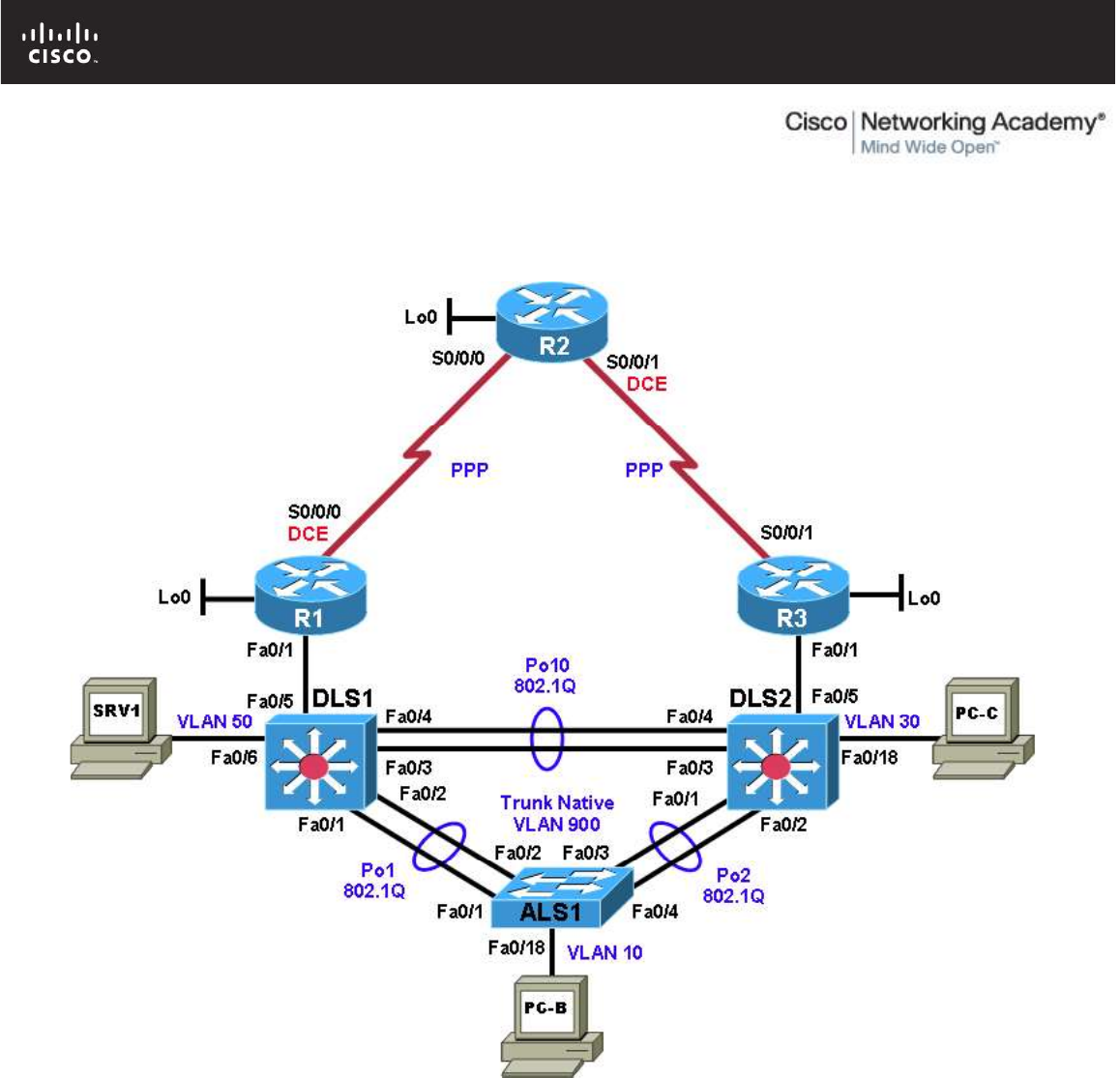
All contents are Copyright © 1992–2010 Cisco Systems, Inc. All rights reserved. This document is Cisco Public Information. Page 1 of 26
CCNPv6 TSHOOT
Chapter 4 Lab 4-2, Layer 3 Switching and First-Hop Redundancy
Physical Topology

CCNPv6 TSHOOT
All contents are Copyright © 1992–2010 Cisco Systems, Inc. All rights reserved. This document is Cisco Public Information. Page 2 of 26
Logical Topology
Objectives
Load the trouble ticket device configuration files for each trouble ticket.
Diagnose and resolve problems related to switch virtual interfaces and multilayer switching.
Diagnose and resolve problems related to First Hop Redundancy Protocols.
Document troubleshooting progress, configuration changes, and problem resolution.
Background
Multilayer (Layer 3) switches have the capability to act as switches and routers when using switch virtual
interfaces (SVIs), routed interfaces, and routing protocols. Layer 3 switches allow you to create SVIs or logical
interfaces that represent a VLAN. They can also support routed physical interfaces. These versatile switches
are frequently used as part of the LAN switch fabric and can be configured with a First Hop Redundancy
Protocol (FHRP). Two or more Layer 3 switches (or routers) can provide redundant paths to the network edge
for local hosts. A host is configured with a virtual default gateway address. If one of the gateways goes down,
the other can take over for the client without the client’s knowledge. Examples of FHRPs discussed in this
course are Hot Standby Router Protocol (HSRP), Virtual Router Redundancy Protocol (VRRP), and Gateway
Load Balancing Protocol (GLBP).
In this lab, you will troubleshoot problems related to Layer 3 switching and FHRPs, such as HSRP, including
HSRP authentication. For each task or trouble ticket, the scenario and problem symptom is described. While

CCNPv6 TSHOOT
All contents are Copyright © 1992–2010 Cisco Systems, Inc. All rights reserved. This document is Cisco Public Information. Page 3 of 26
troubleshooting, you will discover the cause of the problem, correct it, and then document the process and
results.
Physical and Logical Topology Diagrams
The physical and logical topologies, including interface designations and IP addresses, are provided to assist
the troubleshooting effort.
Lab Structure
This lab is divided into two main sections.
Section 1—Trouble Tickets and Troubleshooting Logs
This section includes multiple tasks. Each task is associated with a trouble ticket (TT) and introduces one or
more errors on one or more devices. If time is a consideration, each task or trouble ticket can be performed
independently.
Section 2—Troubleshooting Reference Information
This section provides general Layer 2 troubleshooting information that can be applied to any trouble ticket in
this lab. Sample troubleshooting flows are provided, along with examples of useful commands and output. If
time permits, it is recommended that you read through Section 2 prior to starting on the trouble tickets.
This lab uses Cisco 1841 routers with Cisco IOS Release 12.4(24)T1 and the advanced IP image c1841-
advipservicesk9-mz.124-24.T1.bin. The switches are Cisco WS-C2960-24TT-L with the Cisco IOS image
c2960-lanbasek9-mz.122-46.SE.bin and Catalyst 3560-24PS with the Cisco IOS image c3560-
advipservicesk9-mz.122-46.SE.bin. Other routers (such as 2801 and 2811), switches (such as 2950 or 3550),
and Cisco IOS Software versions can be used if they have comparable capabilities and features. Depending
on the router or switch model and Cisco IOS Software version, the commands available and output produced
might vary from what is shown in this lab.
Note: Any changes made to the baseline configurations or topology (other than errors introduced) are noted
in the trouble ticket so that you are aware of them prior to beginning the troubleshooting process.
Required Resources
3 routers (Cisco 1841 with Cisco IOS Release 12.4(24)T1 Advanced IP Service or comparable)
1 switch (Cisco 2960 with the Cisco IOS Release 12.2(46)SE C2960-LANBASEK9-M image or
comparable)
2 switches (Cisco 3560 with the Cisco IOS Release 12.2(46)SE C3560-advipservicesK9-mz image or
comparable)
SRV1 (Windows PC with a static IP address) with TFTP and syslog servers plus an SSH client
(PuTTY or comparable) and WireShark software.
PC-B (Windows PC—DHCP client) with PuTTY and WireShark software available
PC-C (Windows PC—DHCP client) with PuTTY and WireShark software available
Serial and Ethernet cables
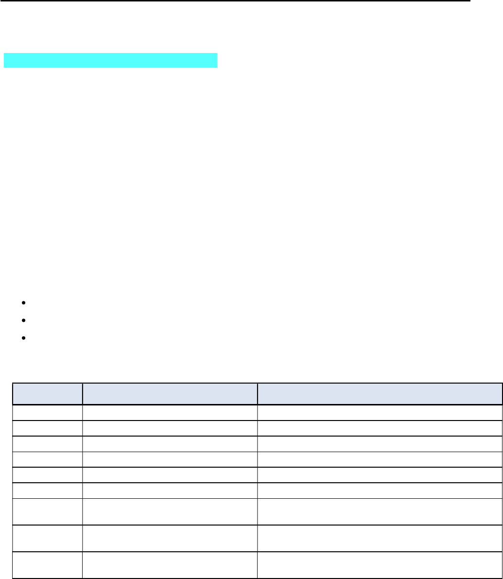
CCNPv6 TSHOOT
All contents are Copyright © 1992–2010 Cisco Systems, Inc. All rights reserved. This document is Cisco Public Information. Page 4 of 26
Section 1—Trouble Tickets and Troubleshooting Logs
Task 1: Trouble Ticket Lab 4-2 TT-A
Step 1: Review trouble ticket Lab 4-2 TT-A.
Upon arriving at the office this morning, you find the following ticket in the system:
Switch ALS1 has been showing CRC errors on a group of eight ports for several days. It was suspected that
hardware was the cause. During yesterday evening’s maintenance window, the switch was replaced with a similar
switch from the lab. After this replacement, clients could connect, and no errors were shown on the ports.
However, making a backup of the ALS1 configuration to server SRV1 did not work, and no syslog messages from
ALS1 are being received by SRV1. The switch is not reachable via Telnet or SSH from server SRV1. There was
no time for further research yesterday so, because there is no impact to users, it was decided to leave the switch
and pick up this issue the next day.
Your task is to diagnose the issue and restore connectivity between switch ALS1 and server SRV1. After
resolving the problem, make a backup of the configuration to server SRV1.
Step 2: Load the device trouble ticket configuration files for TT-A.
Using the procedure described in Lab 3-1, verify that the lab configuration files are present in flash. Load the
proper configuration files indicated in the Device Configuration File table.
Note: The following device access methods are in effect after loading the configuration files:
Console access requires no username or password.
Telnet and SSH require the username admin and password adminpa55.
The enable password is ciscoenpa55.
Device Configuration File Table
Device Name File to Load Notes
ALS1 Lab42-ALS1-TT-A-Cfg.txt
DLS1 Lab42-DLS1-TT-A-Cfg.txt
DLS2 Lab42-DLS2-TT-A-Cfg.txt
R1 Lab42-R1-TT-A-Cfg.txt
R2 Lab42-R2-TT-A-Cfg.txt
R3 Lab42-R3-TT-A-Cfg.txt
SRV1 N/A Static IP: 10.1.50.1
Default gateway: 10.1.50.254
PC-B N/A DHCP (release and renew after loading device
configurations)
PC-C N/A DHCP (release and renew after loading device
configurations)

CCNPv6 TSHOOT
All contents are Copyright © 1992–2010 Cisco Systems, Inc. All rights reserved. This document is Cisco Public Information. Page 5 of 26
Step 3: Configure SRV1 and start the syslog and TFTP servers.
a. Ensure that SRV1 has the static IP address 10.1.50.1 and default gateway 10.1.50.254.
b. Start the syslog server on SRV1, which is the syslog server for the entire network. When the network
is properly configured, all devices send syslog messages to SRV1.
c. Start the TFTP server on SRV1, which is the archive server for the entire network. When the network
is properly configured, all devices send archives of their running configurations to this server
whenever the running config is copied to the startup config. Ensure that the default TFTP directory on
SRV1 is set to the directory where you want to store the archives.
Step 4: Release and renew the DHCP leases on PC-B and PC-C.
a. Ensure that PC-B and PC-C are configured as DHCP clients.
b. After loading all TT-A device configuration files, issue the ipconfig /release and ipconfig /renew
commands on PC-B and PC-C. You might need to repeat this process after the TT problems have
been resolved.
Note: Problems introduced into the network by the trouble ticket might prevent one or both of the PCs
from acquiring an IP address. Do not assign either PC a static address.
Step 5: Outline the troubleshooting approach and validation steps.
Use this space to identify the troubleshooting approach that you plan to take and the key steps involved to verify
that the problem is resolved. Troubleshooting approaches to select from include the follow-the-path, spot-the-
differences, bottom-up, top-down, divide-and-conquer, shoot-from-the-hip, and move-the-problem methods.
Note: In addition to a specific approach, you can use the generic troubleshooting process described at the
beginning of Section 2 of this lab.
_______________________________________________________________________________
_______________________________________________________________________________
_______________________________________________________________________________
_______________________________________________________________________________
_______________________________________________________________________________
_______________________________________________________________________________
Step 6: Record the troubleshooting process and configuration changes.
Note: Section 2 of this lab includes sample troubleshooting flows, useful commands, and examples of output.
Use this log to document your actions and results during the troubleshooting process. List the commands you
used to gather information. As you progress, record your thoughts as to what you think the problem might be and
which actions you take to correct the problem.

CCNPv6 TSHOOT
All contents are Copyright © 1992–2010 Cisco Systems, Inc. All rights reserved. This document is Cisco Public Information. Page 6 of 26
Device Actions and Results
Step 7: Document trouble ticket debrief notes.
Use this space to make notes of the key learning points that you picked up during the discussion of this trouble
ticket with your instructor. The notes can include problems encountered, solutions applied, useful commands
employed, alternate solutions, methods and processes, and procedure and communication improvements.
_______________________________________________________________________________
_______________________________________________________________________________
_______________________________________________________________________________
_______________________________________________________________________________
_______________________________________________________________________________
_______________________________________________________________________________
_______________________________________________________________________________
CCNPv6 TSHOOT
All contents are Copyright © 1992–2010 Cisco Systems, Inc. All rights reserved. This document is Cisco Public Information. Page 7 of 26
Task 2: Trouble Ticket Lab 4-2 TT-B
Step 1: Review trouble ticket Lab 4-2 TT-B.
During last Friday’s maintenance window, a series of failover tests at headquarters and the branch offices were
executed. It was discovered during a reboot of switch DLS1 that connectivity between clients in OFFICE VLAN 10
and the Internet was lost. After router DLS1 came back online, the clients regained connectivity. This was not the
expected behavior, because the network provides gateway first-hop redundancy for clients in the OFFICE VLAN
to ensure correct failover during outages.
If one of the HSRP switches fails, the hosts on the OFFICE VLAN should still be able to access the Internet (by
pinging R2 Lo0 10.1.202.1 during the outage).
Step 2: Load the device trouble ticket configuration files for TT-B.
Using the procedure described in Lab 3-1, verify that the lab configuration files are present in flash. Load the
proper configuration files indicated in the Device Configuration File table.
Note: See Task 1, Step 2 for device access methods, usernames, and passwords after the configuration files
have been loaded.
Note: You can test the simulated Internet access by opening a browser and entering the IP address of the R2 Lo0
interface 10.1.202.1. You will be prompted for a username and password. You can gain access to the router GUI
management interface by entering username admin and the enable password ciscoenpa55.
Device Configuration File Table
Device Name File to Load Notes
ALS1 Lab42-ALS1-TT-B-Cfg.txt
DLS1 Lab42-DLS1-TT-B-Cfg.txt
DLS2 Lab42-DLS2-TT-B-Cfg.txt
R1 Lab42-R1-TT-B-Cfg.txt
R2 Lab42-R2-TT-B-Cfg.txt
R3 Lab42-R3-TT-B-Cfg.txt
SRV1 N/A Static IP: 10.1.50.1
Default gateway: 10.1.50.254
PC-B N/A DHCP (release and renew after loading device
configurations)
PC-C N/A DHCP (release and renew after loading device
configurations)
Step 3: Configure SRV1 and start the syslog and TFTP servers, as described in Task 1.
Step 4: Release and renew the DHCP leases on PC-B and PC-C, as described in Task 1.
Step 5: Outline the troubleshooting approach and validation steps.
Use this space to identify the troubleshooting approach that you plan to take and the key steps involved to verify
that the problem is resolved. Troubleshooting approaches to select from include the follow-the-path, spot-the-
differences, bottom-up, top-down, divide-and-conquer, shoot-from-the-hip, and move-the-problem methods.

CCNPv6 TSHOOT
All contents are Copyright © 1992–2010 Cisco Systems, Inc. All rights reserved. This document is Cisco Public Information. Page 8 of 26
Note: In addition to a specific approach, you can use the generic troubleshooting process described at the
beginning of Section 2 of this lab.
_______________________________________________________________________________
_______________________________________________________________________________
_______________________________________________________________________________
_______________________________________________________________________________
_______________________________________________________________________________
Step 6: Record the troubleshooting process and configuration changes.
Note: Section 2 of this lab includes sample troubleshooting flows, useful commands, and examples of output.
Use this log to document your actions and results during the troubleshooting process. List the commands you
used to gather information. As you progress, record your thoughts as to what you think the problem might be and
which actions you take to correct the problem.
Device Actions and Results
CCNPv6 TSHOOT
All contents are Copyright © 1992–2010 Cisco Systems, Inc. All rights reserved. This document is Cisco Public Information. Page 9 of 26
Step 7: Document trouble ticket debrief notes.
Use this space to make notes of the key learning points that you picked up during the discussion of this trouble
ticket with your instructor. The notes can include problems encountered, solutions applied, and useful commands
employed. It can also include alternate solutions, methods, and procedures and communication improvements.
_______________________________________________________________________________
_______________________________________________________________________________
_______________________________________________________________________________
_______________________________________________________________________________
_______________________________________________________________________________
_______________________________________________________________________________
_______________________________________________________________________________
Task 3: Trouble Ticket Lab 4-2 TT-C
Step 1: Review trouble ticket Lab 4-2 TT-C.
Your company has decided to use Message Digest 5 (MD5)-based authentication between the HSRP routers. A
colleague of yours was asked to test the authentication using VLAN 100 MGMT (to avoid impact on end users)
between DLS1 and DLS2. He started to configure the test late this afternoon but then left on vacation. Your task
is to review and verify the implementation of HSRP authentication in VLAN 100 and fix any issues that remain.
Step 2: Load the device trouble ticket configuration files for TT-C.
Using the procedure described in Lab 3-1, verify that the lab configuration files are present in flash. Load the
configuration files indicated in the Device Configuration File table.
Note: See Task 1, Step 2 for device access methods, usernames, and passwords after you have loaded the
configuration files.
Device Configuration File Table
Device Name File to Load Notes
ALS1 Lab42-ALS1-TT-C-Cfg.txt
DLS1 Lab42-DLS1-TT-C-Cfg.txt
DLS2 Lab42-DLS2-TT-C-Cfg.txt
R1 Lab42-R1-TT-C-Cfg.txt
R2 Lab42-R2-TT-C-Cfg.txt
R3 Lab42-R3-TT-C-Cfg.txt
SRV1 N/A Static IP: 10.1.50.1
Default gateway: 10.1.50.254
PC-B N/A DHCP
PC-C N/A DHCP

CCNPv6 TSHOOT
All contents are Copyright © 1992–2010 Cisco Systems, Inc. All rights reserved. This document is Cisco Public Information. Page 10 of 26
Step 3: Configure SRV1 and start the syslog and TFTP servers, as described in Task 1.
Step 4: Release and renew the DHCP leases on PC-B and PC-C, as described in Task 1.
Step 5: Outline the troubleshooting approach and validation steps.
Use this space to identify the troubleshooting approach you plan to take and the key steps to verify that the
problem is resolved. Troubleshooting approaches to select from include the follow-the-path, spot-the-differences,
bottom-up, top-down, divide-and-conquer, shoot-from-the-hip, and move-the-problem methods.
Note: In addition to a specific approach, you can use the generic troubleshooting process described at the
beginning of Section 2 of this lab.
_______________________________________________________________________________
_______________________________________________________________________________
_______________________________________________________________________________
_______________________________________________________________________________
_______________________________________________________________________________
_______________________________________________________________________________
Step 6: Record the troubleshooting process and configuration changes.
Note: Section 2 of this lab includes sample troubleshooting flows, useful commands, and examples of output.
Use this log to document your actions and results during the troubleshooting process. List the commands you
used to gather information. As you progress, record your thoughts as to what you think the problem might be and
which actions you take to correct the problem.
Note: You might need to issue the ipconfig /release and ipconfig /renew commands on DHCP clients after the
network device problems are resolved.
Device Actions and Results
CCNPv6 TSHOOT
All contents are Copyright © 1992–2010 Cisco Systems, Inc. All rights reserved. This document is Cisco Public Information. Page 11 of 26
Device Actions and Results
Step 7: Document trouble ticket debrief notes.
Use this space to make notes of the key learning points that you picked up during the discussion of this trouble
ticket with your instructor. The notes can include the problems encountered, solutions applied, and useful
commands employed. It could also include alternate solutions, methods, and procedures and communication
improvements.
_______________________________________________________________________________
_______________________________________________________________________________
_______________________________________________________________________________
_______________________________________________________________________________
_______________________________________________________________________________
_______________________________________________________________________________
_______________________________________________________________________________

CCNPv6 TSHOOT
All contents are Copyright © 1992–2010 Cisco Systems, Inc. All rights reserved. This document is Cisco Public Information. Page 12 of 26
Section 2—Troubleshooting Reference Information
General Troubleshooting Process
As a general guideline, you can use the following general troubleshooting process described in the course:
1. Define the problem (symptoms).
2. Gather information.
3. Analyze the information.
4. Propose a hypothesis (possible cause).
5. Test the hypothesis.
6. Eliminate or accept the hypothesis.
7. Solve the problem.
8. Document the problem.
Commands Summary
The table lists useful commands. The sample output is shown on the following pages.
Command Key Information Displayed
show spanning-tree vlan vlan#
Displays all essential parameters that affect the topology, such
as the root port, designated ports, port state, and port type, as
well as the spanning-tree mode being implemented.
show vlan brief Displays a quick overview of all existing VLANs and the ports
within them. Trunk ports are not listed.
show vlan id vlan#
Displays whether the VLAN exists and which ports are
assigned to it. Includes the trunk ports on which the VLAN is
allowed.
show interfaces vlan vlan# Displays the SVI status, IP address, and statistics.
show ip route ip-addr Displays the routing table information for a particular destination
address.
show ip arp ip-addr Displays the ARP table information for an IP address, including
age, hardware address, and interface.
show interfaces type/# |include
bia Displays the MAC address of an interface on one output line.
show ip cef ip-addr detail Displays the next hop and interface used for a particular
destination address from the Cisco Express Forwarding table.
show adjacency int-type/# detail Displays the information contained in the adjacency table for a
next-hop IP address or interface.
show platform forward
Displays the hardware ternary content addressable memory
(TCAM) information and exact forwarding behavior for a Layer
2 or Layer 3 switched frame.
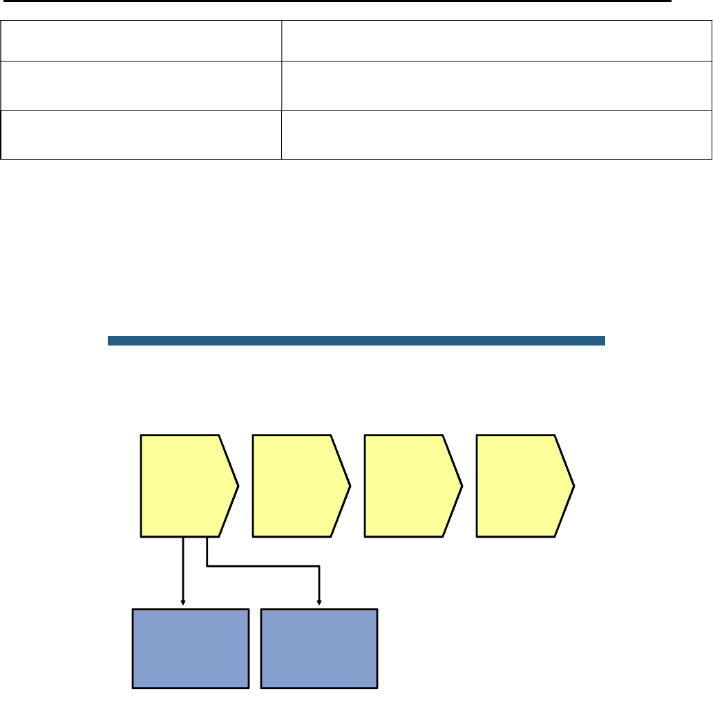
CCNPv6 TSHOOT
All contents are Copyright © 1992–2010 Cisco Systems, Inc. All rights reserved. This document is Cisco Public Information. Page 13 of 26
Note:
Specific to the Catalyst 3560 and 3750 series of
switches.
show standby vlan vlan# brief Verify active and standby roles and IP addresses for a
particular VLAN for HSRP routers.
debug standby packets Displays real-time messages exchanged between HSRP
routers.
Lab 4-2 Sample Troubleshooting Flows
Troubleshooting Multilayer Switching
The figure illustrates an example of a method that you could follow to diagnose and resolve problems related to
multilayer switching.
© 2009 Cisco Systems, Inc. All rights reserved. TSHOOT v1.0—29
Sample Multilayer Switching
Troubleshooting Flow
Verify Layer 3 path
using traceroute
and ping
Verify
ingress
Layer 3
interface
Check
control plane
data
structures
Check
packet
switching
data
structures
Analyze sniffer
traces
Locate failing
Layer 3 hop
What is multilayer switching? In essence, a multilayer switch is a switch that is capable of switching Ethernet
frames based on information in the Layer 2 and Layer 3 headers. Troubleshooting Layer 2 switching was covered
in the previous lab exercise. This troubleshooting flow focuses on troubleshooting the process of switching
Ethernet frames based on Layer 3 information.
Under which kind of circumstances do you start troubleshooting the multilayer switching process?
Troubleshooting multilayer switching is just one of the steps in the bigger picture of troubleshooting network
connectivity along a Layer 3 path. After you have determined—by using tools like traceroute or ping or through
analysis of packet captures—that a particular hop in the Layer 3 path seems to be the point where packets start to
get dropped and that hop is a multilayer switch, or when you are troubleshooting performance problems and you
want to find the exact physical links on which packets travel, then start tracing and verifying the Layer 3
forwarding behavior of the multilayer switch that you suspect to be the cause of the problem.

CCNPv6 TSHOOT
All contents are Copyright © 1992–2010 Cisco Systems, Inc. All rights reserved. This document is Cisco Public Information. Page 14 of 26
© 2009 Cisco Systems, Inc. All rights reserved. TSHOOT v1.0—30
Sample Multilayer Switching
Troubleshooting Flow
Check
control plane
data
structures
Check
packet
switching
data
structures
Locate failing
Layer 3 hop
Verify interface
status of the SVI or
routed port
Verify VLAN
existence in case
the ingress
interface is an SVI
Verify spanning
tree state in case
the ingress
interface is an SVI
Verify
ingress
Layer 3
interface
Layer 3 packet switching generally consists of three major steps:
1. Receive the packet on a Layer 3 interface. This interface can either be a routed port or an SVI.
2. Perform a lookup in the hardware packet-switching data structures. Multilayer switches store packet-
forwarding information in special TCAM data structures. The information contained in these data
structures is compiled from the Cisco Express Forwarding data structures in the main memory of the
route processor. These data structures are, in turn, derived from control plane tables, such as the routing
table and the ARP cache.
3. Rewrite the frame and switch it to the outbound interface based on the information found in the TCAM.
Consequently, a straightforward approach to troubleshooting a Layer3 switching problem is to verify the
components that are involved in this process. First, verify the ingress Layer 3 interface, then the control plane
data structures and, subsequently, the packet-forwarding data structures. (Alternatively, you can perform these
steps in the reverse order.)
If the ingress interface is a routed port, the first step in this process is simple because the Layer 3 and Layer 2
ports are identical. Verifying the physical interface status and the configured IP address and subnet mask for that
interface is sufficient to determine the status of the Layer 3 ingress interface. However, if the ingress interface is
an SVI, its status is not directly related to any particular physical interface.
Verify SVI Status (Missing VLAN)
DLS1#show vlan id 100
VLAN id 100 not found in current VLAN database
DLS1#show interfaces vlan 100
Vlan100 is down, line protocol is down
Hardware is EtherSVI, address is 0017.5a5b.b441 (bia 0017.5a5b.b441)
Internet address is 10.1.100.252/24
<Output Omitted>

CCNPv6 TSHOOT
All contents are Copyright © 1992–2010 Cisco Systems, Inc. All rights reserved. This document is Cisco Public Information. Page 15 of 26
A VLAN interface or SVI is up if there is at least one interface in the spanning-tree forwarding state for that VLAN.
This implies that if an SVI is down, you should verify VLAN existence, VLAN port assignments, and the spanning-
tree state for the SVI.
In the output above, you can see that a missing VLAN results in a VLAN interface that is in state “down, line
protocol is down.”
Verify SVI Status (VLAN with No Port Assigned)
DLS1#show vlan id 100
VLAN Name Status Ports
---- -------------------------------- --------- -------------------------------
100 MGMT active
VLAN Type SAID MTU Parent RingNo BridgeNo Stp BrdgMode Trans1 Trans2
---- ----- ---------- ----- ------ ------ -------- ---- -------- ------ ------
100 enet 100100 1500 - - - - - 0 0
DLS1#show interfaces vlan 100
Vlan100 is up, line protocol is down
Hardware is EtherSVI, address is 0017.5a5b.b441 (bia 0017.5a5b.b441)
Internet address is 10.1.100.252/24
<Output Omitted>
When the VLAN exists but no ports are assigned to that VLAN, the status of the SVI changes to “up, line protocol
is down.”
Verify SVI Status (VLAN with No Port in Spanning-Tree Forwarding State)
DLS1#show spanning-tree vlan 100
<Output Omitted>
Interface Role Sts Cost Prio.Nbr Type
------------------- ---- --- --------- -------- --------------------------------
Po1 Desg LRN 12 128.56 P2p
Po10 Desg LRN 12 128.128 P2p
DLS1#show interfaces vlan 100
Vlan100 is up, line protocol is down
Hardware is EtherSVI, address is 0017.5a5b.b441 (bia 0017.5a5b.b441)
Internet address is 10.1.100.252/24
<Output Omitted>
Finally, if ports are assigned to the VLAN and at least one of these physical ports (trunk or access port) is up, one
more condition needs to be met: The spanning-tree state for at least one of the ports needs to be forwarding.
Under normal circumstances, if there is at least one interface assigned to a VLAN, an interface is in spanning-tree
forwarding state. Either the switch is the root for the VLAN and all the ports assigned to the VLAN are designated
ports and therefore forwarding, or the switch is not the root and it has a root port that is in forwarding state.
As a result, when you are troubleshooting a multilayer switching problem and you find that the ingress interface is
an SVI and it is down, there is an underlying Layer 2 problem for that VLAN and you need to initiate a Layer 2
troubleshooting process.
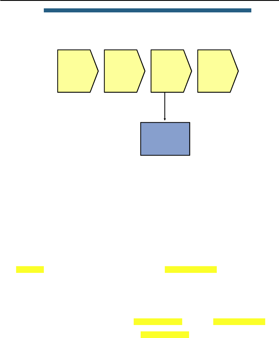
CCNPv6 TSHOOT
All contents are Copyright © 1992–2010 Cisco Systems, Inc. All rights reserved. This document is Cisco Public Information. Page 16 of 26
© 2009 Cisco Systems, Inc. All rights reserved. TSHOOT v1.0—34
Sample Multilayer Switching
Troubleshooting Flow
Check
control plane
data
structures
Check
packet
switching
data
structures
Locate failing
Layer 3 hop
Verify
ingress
Layer 3
interface
Verify routing table
and ARP cache
Verify the Routing Table and ARP Cache
The next step in this process is to verify that the control plane information that is necessary to forward the packets
is present. The two control plane data structures that are relevant to multilayer switching are the routing table and
the ARP cache.
In this sample troubleshooting flow, the multilayer switching data structures for an Internet Control Message
Protocol (ICMP) echo request traveling from source IP address 10.1.50.1 to destination IP address 10.1.202.1 is
verified by using various show commands.
DLS1#show ip route 10.1.202.1
Routing entry for 10.1.202.1/32
Known via "eigrp 1", distance 90, metric 2300416, type internal
Redistributing via eigrp 1
Last update from 10.1.2.2 on FastEthernet0/5, 02:41:16 ago
Routing Descriptor Blocks:
* 10.1.2.2, from 10.1.2.2, 02:41:16 ago, via FastEthernet0/5
Route metric is 2300416, traffic share count is 1
Total delay is 25100 microseconds, minimum bandwidth is 1544 Kbit
Reliability 255/255, minimum MTU 1500 bytes
Loading 1/255, Hops 2
DLS1#show ip arp 10.1.2.2
Protocol Address Age (min) Hardware Addr Type Interface
Internet 10.1.2.2 162 001b.530d.60b1 ARPA FastEthernet0/5
DLS1#show interfaces FastEthernet 0/5 | include bia
Hardware is Fast Ethernet, address is 0017.5a5b.b442 (bia 0017.5a5b.b442)
In the output, you can see that a route is found in the routing table for the destination IP address 10.1.202.1, and
the next hop and outbound interface for packets with that destination are listed.
If the routing table does not contain an entry (specific prefix or default route) for the destination, the problem is not
a packet-switching problem but a routing problem, and you should initiate a process to troubleshoot the routing
operation on the control plane.
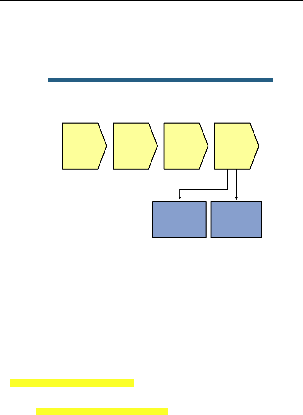
CCNPv6 TSHOOT
All contents are Copyright © 1992–2010 Cisco Systems, Inc. All rights reserved. This document is Cisco Public Information. Page 17 of 26
The ARP cache provides the destination MAC address for the next hop. If an ARP entry for the destination is
missing or listed as incomplete, either the next hop listed in the route is not valid, or there is a Layer 2 problem
between the multilayer switch and the next hop. In both cases, the problem is not really a multilayer switching
problem, and you should investigate the routing operation on the control plane and the Layer 2 connectivity to the
next hop first.
The final element that the router needs to rewrite a frame and switch it out is the source MAC address of the
frame, which corresponds to the MAC address of the outbound Layer 3 interface.
© 2009 Cisco Systems, Inc. All rights reserved. TSHOOT v1.0—36
Verify CEF FIB and
adjacency table
Verify TCAM
forwarding
information
Sample Multilayer Switching
Troubleshooting Flow
Check
control plane
data
structures
Check
packet
switching
data
structures
Locate failing
Layer 3 hop
Verify
ingress
Layer 3
interface
When the control plane data structures have been verified, the next step in the multilayer switching
troubleshooting process is to verify the data structures in software and hardware that are used to forward packets.
All recent Layer 3 switches use the Cisco Express Forwarding technology as the foundation for the multilayer
switching process. The switches combine the information from the control plane data structure, such as the
routing table and the ARP cache, into two different data structures: the Forwarding Information Base (FIB) and the
adjacency table. These two data structures are stored in the main memory of the route processor. They are only
used to forward packets that are not handled in hardware.
However, based on the information in the FIB and adjacency table, the hardware TCAM is populated, and the
resulting TCAM information is what is eventually used to forward frames in hardware.
To verify the correct operation of the multilayer switching process, first verify that the control plane information is
accurately reflected in the software FIB and adjacency table. Next, verify that the information from the FIB and
adjacency table is correctly compiled into the TCAM.
Verify the FIB and Adjacency Table
DLS2#show ip cef 10.1.202.1
10.1.202.1/32
nexthop 10.1.2.14 FastEthernet0/5
DLS2#show adjacency fastEthernet 0/5 detail
Protocol Interface Address
IP FastEthernet0/5 10.1.2.14(19)
0 packets, 0 bytes

CCNPv6 TSHOOT
All contents are Copyright © 1992–2010 Cisco Systems, Inc. All rights reserved. This document is Cisco Public Information. Page 18 of 26
epoch 0
sourced in sev-epoch 0
Encap length 14
001B530D6029 00175A53A3C2 0800
L2 destination address byte offset 0
L2 destination address byte length 6
Link-type after encap: ip
ARP
The show ip cef command can be used in a similar way as the show ip route command. When you specify
a destination IP address as an option to the command, it lists the entry in the Cisco Express Forwarding FIB that
matches that IP address. It also shows the next-hop IP address and egress interface, which serve as a pointer to
the adjacency table.
The show adjacency command can be used to display the information contained in the adjacency table. The
next-hop IP address or interface can be specified to select specific adjacencies. Adding the detail keyword to
the command shows the frame rewrite information for packets that are switched through that adjacency. The
frame rewrite information lists the complete Ethernet header. For the example in the output, this consists of the
destination MAC address 001B.530D.6029 (which is the same MAC address that was listed as the MAC address
of next hop 10.1.2.14 in the ARP cache), followed by the source MAC address 0017.5A53.A3C2 (which equals
the MAC address of the egress interface F0/5), and finally, the Ethertype 0x0800 (which indicates that the
protocol contained in the Ethernet frame is IP version 4).
The information displayed in these show commands should accurately reflect the information in the routing table
and ARP cache.
Verify the Hardware TCAM Information
DLS2#show platform forward fa0/3 vlan 50 0017.5a5b.b405 0017.5a53.a385 ip 10.1.50.1
10.1.202.1 icmp 8 0
Ingress:
Global Port Number: 129, lpn: 4 Asic Number: 0
Source Vlan Id: Real 50, Mapped 5. L2EncapType 0, L3EncapType 0
<Output Omitted>
Egress: Asic 0, switch 1
CPU queues: 7 14.
Source Vlan Id: Real 50, Mapped 5. L2EncapType 0, L3EncapType 0
portMap 0x1000, non-SPAN portMap 0x1000
<Output Omitted>
Port Vlan SrcMac DstMac Cos Dscpv
Fa0/5 1006 0017.5a53.a385 0017.5a53.a3c2
Note: The show platform forward command shown in the above output is specific to the Catalyst 3560 and
3750 series of switches. Consult the documentation for the platform that you are working with to find similar
commands to examine the content of the hardware forwarding data structures for the platform.
The show platform forward command consults the hardware TCAM information and displays the exact
forwarding behavior for a Layer 2 or Layer 3 switched frame.
This command displays the exact forwarding behavior for a packet, taking into account all features that affect
packet forwarding, including Cisco Express Forwarding load balancing, EtherChannel load balancing, and packet
filtering using access control lists. Therefore, you must specify the exact content of all the relevant fields in the
header of the packet.
In the example command output above, the following fields are specified:

CCNPv6 TSHOOT
All contents are Copyright © 1992–2010 Cisco Systems, Inc. All rights reserved. This document is Cisco Public Information. Page 19 of 26
Ingress interface: In the example interface, FastEthernet 0/3 is specified as the ingress interface for
the packet.
Ingress VLAN: It is not necessary to specify this parameter if the port is an access port. For trunk
ports, you must specify the VLAN that the frame is tagged with when it enters the ingress interface.
VLAN 50 is specified as the ingress VLAN.
Source MAC address: The source MAC address of the frame when it enters the switch needs to be
specified. In the example, the address is 0017.5A5B.B405. This is the MAC address of the egress
interface of the previous hop (DLS1 Fa0/3 MAC).
Destination MAC address: The destination MAC address of the frame when it enters the switch
needs to be specified. In the example, the address is 0017.5A53.A385 (DLS2 Fa0/3 MAC). For a
Layer 3 switched packet, this address is the MAC address of the ingress Layer 3 interface (routed
port or SVI).
Protocol: This is not necessary for Layer 2 switched frames. For Layer 3 switching, the Layer 3
protocol that is used and the major fields in that protocol’s header must be specified. In the example,
IP is listed as the protocol.
Source IP address: When IP is specified as the Layer 3 protocol, the source IP address of the
packet must be specified. In the example, it is 10.1.50.1.
Destination IP address: When IP is specified as the Layer 3 protocol, the destination IP address of
the packet must be specified. In the example, it is 10.1.202.1.
IP protocol:When IP is specified as the Layer 3 protocol, the protocol in the IP header, for example,
TCP, UDP, or ICMP, must be specified. In the example, ICMP is specified because the example
represents an ICMP echo request packet.
ICMP type and code:When ICMP is specified as the protocol, the ICMP type and code values must
be specified. When TCP or UDP is specified as the protocol, additional header fields that are
appropriate for those protocols, such as source and destination port numbers, must be specified. In
the example, ICMP type 8 and code 0 are specified to represent an echo request packet.
This command is very powerful because it shows you exactly how frames will be forwarded based on all features
that affect forwarding behavior, such as load balancing, EtherChannel, and access control lists. Also, if a frame is
dropped instead of forwarded, the command lists the reason why the frame is dropped.
What should you do if somewhere in this chain of verifying the control plane, you find an inconsistency between
the software and hardware packet-forwarding data structures?
The process of building the FIB and adjacency table from the routing table and ARP cache, and subsequently
populating the TCAM based on the FIB and adjacency table, is internal to the Cisco IOS software and not
configurable. Whenever you find an instance where the information in these data structures is not consistent,
open a case with the Cisco Technical Assistance Center (provided that you have a valid support contract for your
device) to investigate and resolve the issue. As a workaround, you can try to clear the control plane data
structures, such as the routing table and the ARP cache, for the particular entries that you are troubleshooting.
This triggers both the control plane and the packet-forwarding data structures to be repopulated for those entries
and, in certain cases, this might resolve the inconsistencies. However, this is only a workaround, not a real
solution, because it only addresses the symptoms of the problem and not the underlying cause.
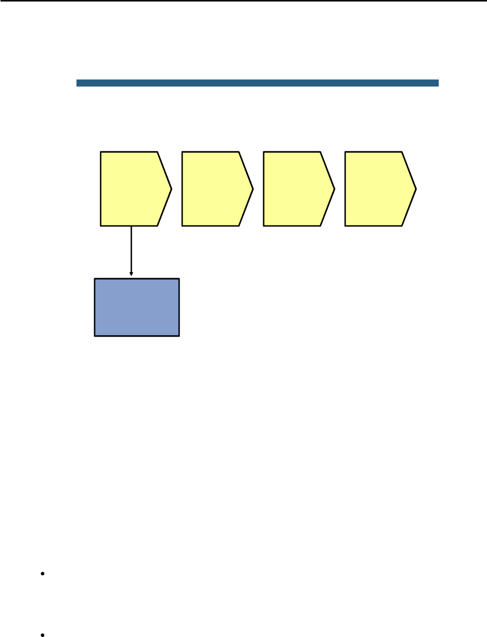
CCNPv6 TSHOOT
All contents are Copyright © 1992–2010 Cisco Systems, Inc. All rights reserved. This document is Cisco Public Information. Page 20 of 26
Troubleshooting First Hop Redundancy Protocols
The figure illustrates an example of a method that you could follow to diagnose and resolve problems related to
FHRPs, such as HSRP, VRRP, and GLBP.
© 2009 Cisco Systems, Inc. All rights reserved. TSHOOT v1.0—39
If failover testing is
possible, ping
virtual and real IP
addresses during
failover
Sample First Hop Redundancy
Troubleshooting Flow
Determine if
FHRP
addresses
are used by
hosts
Investigate
FHRP
router-to-
router
communi-
cation
Investigate
FHRP role
selection
Determine if
outages are
caused by
FHRP or
other
protocols
The most common reason to start troubleshooting FHRP behavior is because during an outage or a test, network
connectivity is lost for longer than expected when a redundant device or link is temporarily disabled. In
redundantly configured IP networks, a number of different protocols usually need to reconverge to recover from a
failure. The FHRP that is used is just one of the protocols that could be the cause of the loss of connectivity.
Other protocols that need to converge as well—and could be the cause of the problem—are routing protocols and
Spanning Tree Protocol (STP).
So how do you determine if the FHRP is the problem?
If you have the opportunity to execute failover tests (for instance, during a scheduled maintenance window), a
good way to determine if the problem is caused by the FHRP or by another protocol is by sending multiple
continuous pings from a client that is using the virtual router as its default gateway. Ping to the virtual and real IP
addresses of the routers that participate in the FHRP, and ping to an IP address of a host that is one or more
router hops removed from the client. Observe and compare the behavior of the pings while you force a failover by
disabling a device or a link.
Based on the observed differences between the ping responses, you can draw conclusions about the likelihood
that the problem is related to the FHRP or to any other protocols that are involved in the convergence. Here are a
few examples:
If you observe that the pings to the real IP address of the redundant router and the virtual IP address
of the FHRP both fail at the same time and resume at the same time when you disable the primary
router, assume that the problem is not related to the FHRP (because the FHRP does not affect the
pings to the real IP address). The most likely cause in this scenario is the Layer 2 convergence for
the VLAN, so you should start a Layer 2 troubleshooting procedure.
If you observe that the pings to the real IP address of the redundant router do not suffer any packet
loss, but pings to the virtual IP address fail, this strongly suggests that there is a problem with the
FHRP.
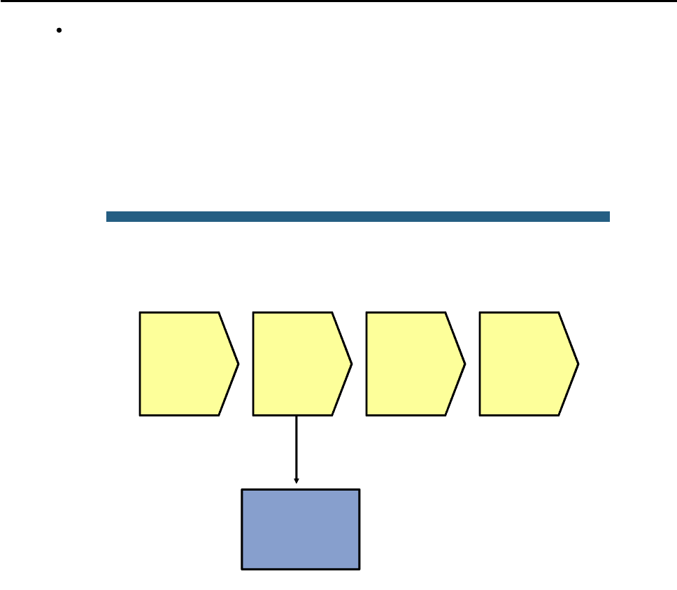
CCNPv6 TSHOOT
All contents are Copyright © 1992–2010 Cisco Systems, Inc. All rights reserved. This document is Cisco Public Information. Page 21 of 26
If you observe that the pings to the real IP address of the redundant router and to the virtual IP
address do not suffer packet loss, but the ping to the host further out in the network fails, this might
indicate an issue with the routing protocol. Alternatively, it could indicate that the client is using the
primary router address as its default gateway rather than the virtual IP address.
There are too many possible scenarios, combinations of ping results, and conclusions to list, but important clues
can be gained in any scenario by comparing the differences between several pings during a failover.
If you have to troubleshoot without the opportunity to force failover for testing purposes, you might need to
assume that the FHRP is the cause of the problem and carefully verify its implementation and operation, even if
you cannot determine beforehand if this might be the cause of the problem.
© 2009 Cisco Systems, Inc. All rights reserved. TSHOOT v1.0—40
Verify default
gateway
configuration and
ARP cache on the
host
Sample First Hop Redundancy
Troubleshooting Flow
Determine if
FHRP
addresses
are used by
hosts
Investigate
FHRP
router-to-
router
communi-
cation
Investigate
FHRP role
selection
Determine if
outages are
caused by
FHRP or
other
protocols
Before starting to troubleshoot the FHRP itself, verify if the client is correctly using the virtual IP address and MAC
address of the FHRP as its default gateway. This involves verifying the default gateway configuration (whether
statically configured or learned via DHCP) and the ARP cache on the client to verify that both the virtual IP
address and the virtual MAC address on the client match the expected values for the FHRP that is in use.
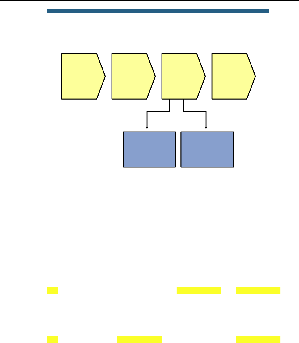
CCNPv6 TSHOOT
All contents are Copyright © 1992–2010 Cisco Systems, Inc. All rights reserved. This document is Cisco Public Information. Page 22 of 26
© 2009 Cisco Systems, Inc. All rights reserved. TSHOOT v1.0—41
Verify Layer 3
connectivity
between routers
Verify reception of
FHRP messages
Sample First Hop Redundancy
Troubleshooting Flow
Determine if
FHRP
addresses
are used by
hosts
Investigate
FHRP
router-to-
router
communi-
cation
Investigate
FHRP role
selection
Determine if
outages are
caused by
FHRP or
other
protocols
Many problems with FHRPs are caused by underlying problems in the Layer 3 connectivity between the routers.
Therefore, a good next-step in the troubleshooting process is to verify that there is Layer 3 connectivity between
all routers that are participating in the FHRP. Ping from each of the participating routers to the IP addresses of the
other participating routers. If one of these pings fail, start a troubleshooting process to diagnose and resolve the
Layer 3 connectivity issues between the routers before further investigating the FHRP.
When you have confirmed that there is Layer 3 connectivity between the participating routers in general, you must
verify the proper transmission and reception of FHRP packets. To limit potential disruption, always use show
commands to gather information before using debug commands.
Verify Reception of FHRP Messages
DLS1#show standby vlan 100 brief
P indicates configured to preempt.
|
Interface Grp Pri P State Active Standby Virtual IP
Vl100 100 110 P Active local 10.1.100.253 10.1.100.254
DLS2#show standby vlan 100 brief
P indicates configured to preempt.
|
Interface Grp Pri P State Active Standby Virtual IP
Vl100 100 100 P Standby 10.1.100.252 local 10.1.100.254
This example shows how to confirm proper transmission and reception of HSRP messages. For GLBP or VRRP,
the procedure is similar, although the command output is slightly different.
To confirm the proper reception of HSRP messages on all routers in the group, verify that all routers list an active
and a standby router and that these roles are listed in a consistent way across all the routers. The show
standby brief command is concise and still shows the most relevant information. As you can see in the
example, switch DLS2 lists the IP address of switch DLS1 as the active router. As the standby router, it lists
“local” to indicate that it considers itself to be the standby router. On switch DLS1, the situation is the opposite:
The address of switch DLS2 is listed as the standby address, while the active router is listed as local. While you
are verifying these roles, this is also a good opportunity to confirm that both the standby group number and the

CCNPv6 TSHOOT
All contents are Copyright © 1992–2010 Cisco Systems, Inc. All rights reserved. This document is Cisco Public Information. Page 23 of 26
virtual IP address are configured in a consistent manner. Misconfiguration of these parameters is a common
cause of HSRP problems.
DLS1#debug standby packets
DLS1#show logging | include Grp 100
Oct 26 15:29:00.049: HSRP: Vl100 Grp 100 Hello in 10.1.100.253 Standby pri 100
vIP 10.1.100.254
Oct 26 15:29:01.659: HSRP: Vl100 Grp 100 Hello out 10.1.100.252 Active pri 110
vIP 10.1.100.254
Note: If you used Telnet, you cannot see the debug messages without using the terminal monitor command.
If you find inconsistencies in the output of the show standby brief commands, such as a missing standby
router on one of the routers or multiple routers claiming the active or standby role for a group, this strongly
suggests that there is a problem with the reception or interpretation of the HSRP messages on the routers. A
debug command can now be used to investigate the transmission and reception of HSRP messages to gather
more clues about the failure.
Before enabling a debug, first verify that the CPU of the device is not running at such high levels that adding the
load of a debug would risk overloading the CPU. Secondly, it is always good to have a fallback plan to stop the
debug when it unexpectedly starts to affect the performance of the device. For instance, you could open a second
connection to the device and before you enable the debug in your primary session, type the undebug all
command in the secondary session, but do not confirm it by pressing the Enter key yet. Another fallback scenario
is to schedule a timed reload within a short time by using the reload in command. If you lose your connection to
the device as a result of your debug, you can be assured that it will reload shortly and you will be able to
reconnect to it. And finally, you should always refer to your organization’s policies before executing any
commands on a device that put the operation of the network at risk.
The debug standby packets command displays all HSRP packets sent or received by the device. This can
quickly generate a lot of output, especially if you have configured many different HSRP groups or if you have
tuned the hello timer to be shorter than the default value of three seconds. To make it easier to select the packets
that you are interested in, you could use the technique shown in the example above. Instead of logging the debug
output to the console or virtual terminal session, you can capture the output in a buffer in the device’s RAM and
then display the buffer’s content by using the show logging command. The output of the command can then be
filtered by using a regular expression to select the HSRP group that you are interested in.
In the example above, the output reveals that hellos are sent by this router and received from the other router.
Just like the show commands in the previous output examples, execute the debug command on both routers to
spot possible differences in behavior between the devices.
Do not forget to disable the debug by using the no debug command after you have gathered the information that
you were interested in.
If these debugs reveal that HSRP protocol packets are not properly received on any router, check if access lists
are blocking the packets. Given that you have already verified the Layer 3 connectivity between the devices, this
problem should be on a higher layer.
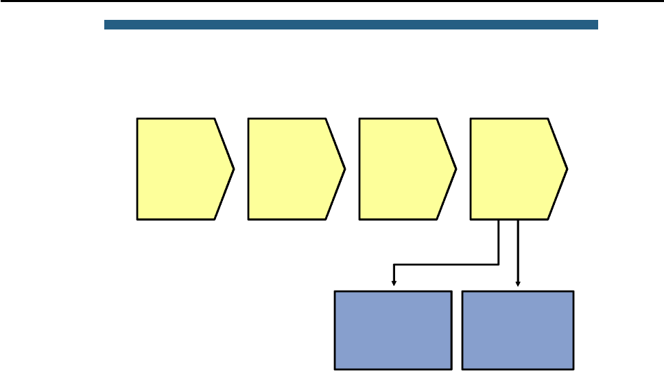
CCNPv6 TSHOOT
All contents are Copyright © 1992–2010 Cisco Systems, Inc. All rights reserved. This document is Cisco Public Information. Page 24 of 26
© 2009 Cisco Systems, Inc. All rights reserved. TSHOOT v1.0—44
Verify
authentication
Verify priorities,
preemption and
tracking
Sample First Hop Redundancy
Troubleshooting Flow
Determine if
FHRP
addresses
are used by
hosts
Investigate
FHRP
router-to-
router
communi-
cation
Investigate
FHRP role
selection
Determine if
outages are
caused by
FHRP or
other
protocols
After you have established that FHRP messages are sent and received properly on all routers and still the FHRP
does not perform as expected, the problem must be related to the role selection and transferring roles between
routers during failover. You might need to verify two potential problem areas.
If the FHRP is using authentication and there is a mismatch between the authentication parameters, the devices
will not accept each other’s messages as valid when they are received. A typical symptom is that more than one
router considers itself to be the active router for a group.
For all FHRPs, role selection is influenced by two parameters: priority and preemption. Tracking objects such as
interfaces and routes can further alter these priorities. If an unexpected router is selected for the primary role at
any point in the process, carefully analyze the priorities configured on the different devices and how they are
affected by potential tracking options. However, to properly determine how properties behave during a failover,
you must be able to force a failover, which means that you might need to postpone this type of testing until a
regularly scheduled maintenance interval.

CCNPv6 TSHOOT
All contents are Copyright © 1992–2010 Cisco Systems, Inc. All rights reserved. This document is Cisco Public Information. Page 25 of 26
Reflection Questions
1. Which lab trouble tickets did you have the most difficulty with?
__________________________________________________________________________________________
__________________________________________________________________________________________
__________________________________________________________________________________________
2. For the trouble tickets that you had difficulty with, would you change anything about the process that you used
now that you see the resolution of the problem?
__________________________________________________________________________________________
__________________________________________________________________________________________
__________________________________________________________________________________________
3. Which commands did you find most useful in diagnosing Layer 3 and HSRP issues? Add these to your toolbox
for future use. Which commands did you find least useful?
__________________________________________________________________________________________
__________________________________________________________________________________________
__________________________________________________________________________________________

CCNPv6 TSHOOT
All contents are Copyright © 1992–2010 Cisco Systems, Inc. All rights reserved. This document is Cisco Public Information. Page 26 of 26
References
If you need more information on the commands and their options, see the following references:
Command References for Cisco Catalyst LAN Switches
Go to http://www.cisco.com/en/US/products/hw/switches/index.html. Then select product category
(Campus LAN) and the model you are working with (for example 3560-E). The Command References for
various IOS releases are under the “Reference Guides” section.
Virtual LANs and VLAN Trunking Protocol Troubleshooting Tech Notes
www.cisco.com/en/US/tech/tk389/tk689/tsd_technology_support_troubleshooting_technotes_list.html
Layer 3 Switching and Forwarding Troubleshooting Tech Notes
www.cisco.com/en/US/tech/tk389/tk815/tsd_technology_support_troubleshooting_technotes_list.html
Router Interface Summary Table
Router Interface Summary
Router Model Ethernet Interface
#1
Ethernet Interface
#2
Serial Interface
#1
Serial Interface
#2
1700 Fast Ethernet 0
(FA0)
Fast Ethernet 1
(FA1)
Serial 0 (S0) Serial 1 (S1)
1800 Fast Ethernet 0/0
(FA0/0)
Fast Ethernet 0/1
(FA0/1)
Serial 0/0/0
(S0/0/0)
Serial 0/0/1
(S0/0/1)
2600 Fast Ethernet 0/0
(FA0/0)
Fast Ethernet 0/1
(FA0/1)
Serial 0/0 (S0/0) Serial 0/1 (S0/1)
2800 Fast Ethernet 0/0
(FA0/0)
Fast Ethernet 0/1
(FA0/1)
Serial 0/0/0
(S0/0/0)
Serial 0/0/1
(S0/0/1)
Note: To find out how the router is configured, look at the interfaces to identify the type of router
and how many interfaces the router has. Rather than try to list all the combinations of
configurations for each router class, this table includes identifiers for the possible combinations of
Ethernet and serial interfaces in the device. The table does not include any other type of interface,
even though a specific router might contain one. An example of this is an ISDN BRI interface. The
string in parenthesis is the legal abbreviation that can be used in Cisco IOS commands to
represent the interface.

CCNPv6 TSHOOT
Physical Topology

CCNPv6 TSHOOT
Logical Topology
Objectives
Background
CCNPv6 TSHOOT
Physical and Logical Topology Diagrams
Lab Structure
Section 1—Trouble Tickets and Troubleshooting Logs
Section 2—Troubleshooting Reference Information
Note:
Required Resources
CCNPv6 TSHOOT
Section 1—Trouble Tickets and Troubleshooting Logs
Task 1: Trouble Ticket Lab 5-1 TT-A
Step 1: Review trouble ticket Lab 5-1 TT-A.
Step 2: Load the device trouble ticket configuration files for TT-A.
Note:
admin adminpa55
ciscoenpa55
Device Configuration File Table
Device Name File to Load Notes
ALS1
DLS1
DLS2
R1
R2
R3
SRV1
PC-B
PC-C

CCNPv6 TSHOOT
Step 3: Configure the CCTV server IP address.
Note:
Step 4: Release and renew the DHCP lease on PC-B.
ipconfig /release ipconfig /renew
Step 5: Outline the troubleshooting approach and validation steps.
Note:
_______________________________________________________________________________
_______________________________________________________________________________
_______________________________________________________________________________
_______________________________________________________________________________
_______________________________________________________________________________
Step 6: Record the troubleshooting process and configuration changes.
Note:
Device Actions and Results
CCNPv6 TSHOOT
Device Actions and Results
Step 7: Document trouble ticket debrief notes.
_______________________________________________________________________________
_______________________________________________________________________________
_______________________________________________________________________________
_______________________________________________________________________________
_______________________________________________________________________________
_______________________________________________________________________________
_______________________________________________________________________________
Task 2: Trouble Ticket Lab 5-1 TT-B
Step 1: Review trouble ticket Lab 5-1 TT-B.
Step 2: Load the device trouble ticket configuration files for TT-B.
Note:
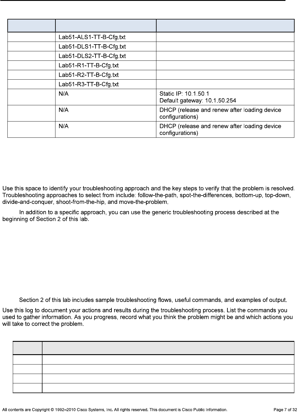
CCNPv6 TSHOOT
Device Configuration File Table
Device Name File to Load Notes
ALS1
DLS1
DLS2
R1
R2
R3
SRV1
PC-B
PC-C
Step 3: Configure SRV1 and start the syslog and TFTP servers, as described in Task 1.
Step 4: Release and renew the DHCP leases on PC-B and PC-C, as described in Task 1.
Step 5: Outline the troubleshooting approach and validation steps.
Note:
_______________________________________________________________________________
_______________________________________________________________________________
_______________________________________________________________________________
_______________________________________________________________________________
_______________________________________________________________________________
Step 6: Record the troubleshooting process and configuration changes.
Note:
Device Actions and Results
CCNPv6 TSHOOT
Device Actions and Results
Step 7: Document trouble ticket debrief notes.
_______________________________________________________________________________
_______________________________________________________________________________
_______________________________________________________________________________
_______________________________________________________________________________
_______________________________________________________________________________
_______________________________________________________________________________
_______________________________________________________________________________
Task 3: Trouble Ticket Lab 5-1 TT-C
Step 1: Review trouble ticket Lab 5-1 TT-C.
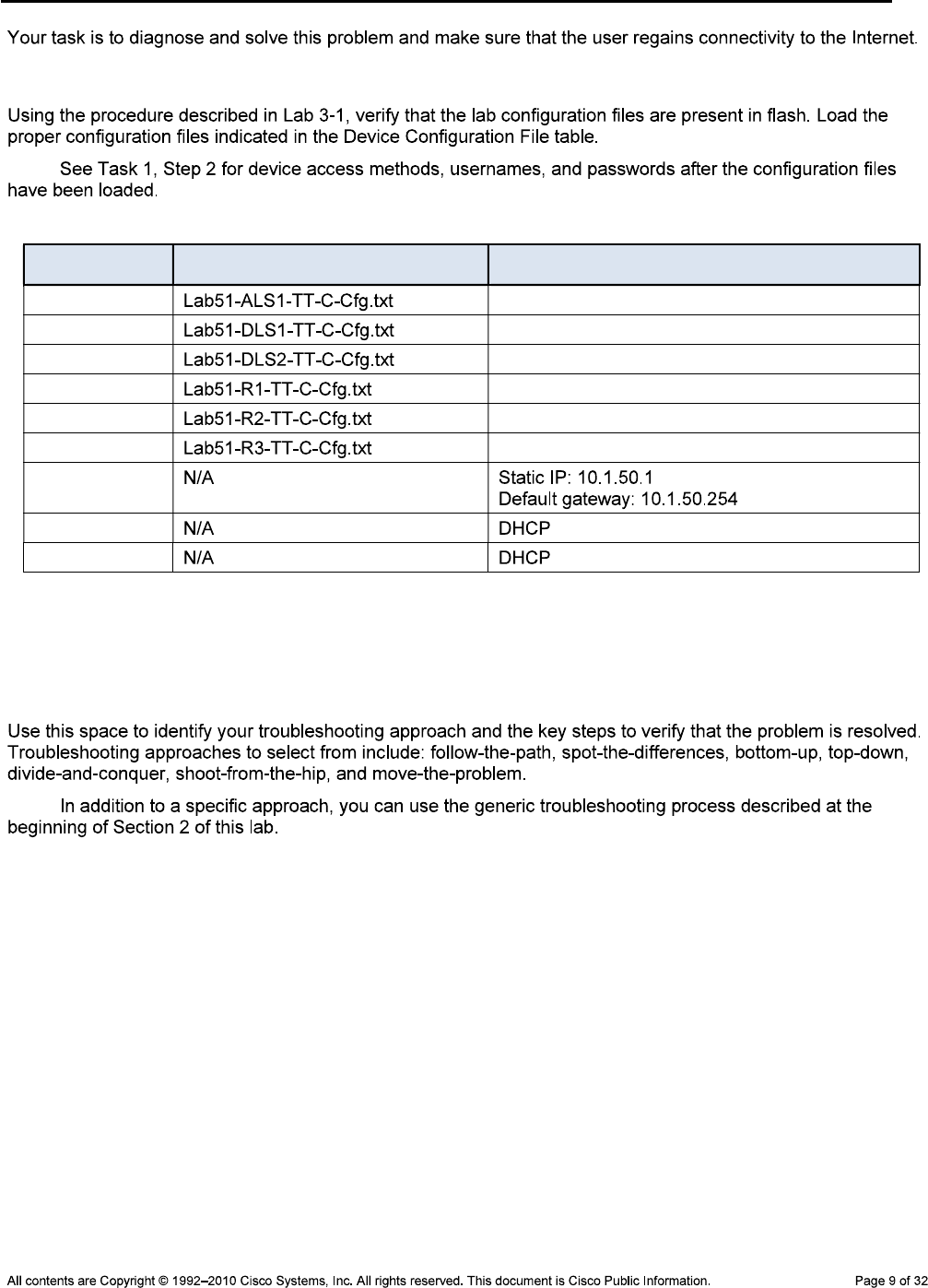
CCNPv6 TSHOOT
Step 2: Load the device trouble ticket configuration files for TT-C.
Note:
Device Configuration File Table
Device Name File to Load Notes
ALS1
DLS1
DLS2
R1
R2
R3
SRV1
PC-B
PC-C
Step 3: Configure SRV1 and start the syslog and TFTP servers, as described in Task 1.
Step 4: Release and renew the DHCP leases on PC-B and PC-C, as described in Task 1.
Step 5: Outline the troubleshooting approach and validation steps.
Note:
_______________________________________________________________________________
_______________________________________________________________________________
_______________________________________________________________________________
_______________________________________________________________________________
_______________________________________________________________________________
_______________________________________________________________________________

CCNPv6 TSHOOT
Step 6: Record the troubleshooting process and configuration changes.
Note:
Device Actions and Results
Step 7: Document trouble ticket debrief notes.
_______________________________________________________________________________
_______________________________________________________________________________
_______________________________________________________________________________
_______________________________________________________________________________
_______________________________________________________________________________
_______________________________________________________________________________
_______________________________________________________________________________

CCNPv6 TSHOOT
Task 4: Trouble Ticket Lab 5-1 TT-D
Step 1: Review trouble ticket Lab 5-1 TT-D.
Step 2: Load the device trouble ticket configuration files for TT-D.
Note:
Device Configuration File Table
Device Name File to Load Notes
ALS1
DLS1
DLS2
R1
R2
R3
SRV1
PC-B
PC-C
Step 3: Configure SRV1 and start the syslog and TFTP servers, as described in Task 1.
Step 4: Release and renew the DHCP leases on PC-B and PC-C, as described in Task 1.
Step 5: Outline the troubleshooting approach and validation steps.
CCNPv6 TSHOOT
Note:
_______________________________________________________________________________
_______________________________________________________________________________
_______________________________________________________________________________
_______________________________________________________________________________
_______________________________________________________________________________
_______________________________________________________________________________
Step 6: Record the troubleshooting process and configuration changes.
Note:
Device Actions and Results
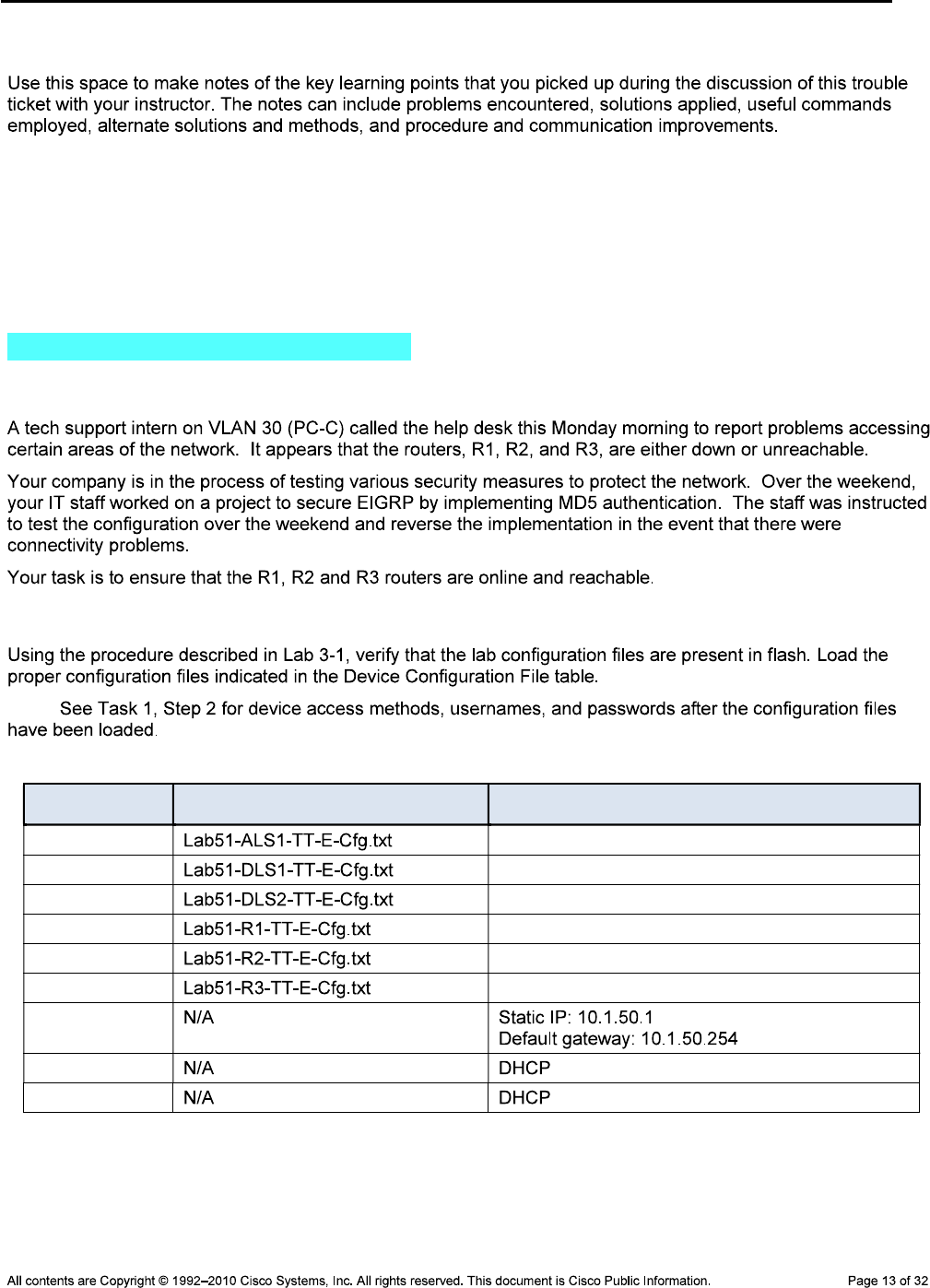
CCNPv6 TSHOOT
Step 7: Document trouble ticket debrief notes.
_______________________________________________________________________________
_______________________________________________________________________________
_______________________________________________________________________________
_______________________________________________________________________________
_______________________________________________________________________________
Task 5: Trouble Ticket Lab 5-1 TT-E
Step 1: Review trouble ticket Lab 5-1 TT-E.
Step 2: Load the device trouble ticket configuration files for TT-E.
Note:
Device Configuration File Table
Device Name File to Load Notes
ALS1
DLS1
DLS2
R1
R2
R3
SRV1
PC-B
PC-C
CCNPv6 TSHOOT
Step 3: Configure SRV1 and start the syslog and TFTP servers, as described in Task 1.
Step 4: Release and renew the DHCP leases on PC-B and PC-C, as described in Task 1.
Step 5: Outline the troubleshooting approach and validation steps.
Note:
_______________________________________________________________________________
_______________________________________________________________________________
_______________________________________________________________________________
_______________________________________________________________________________
_______________________________________________________________________________
_______________________________________________________________________________
Step 6: Record the troubleshooting process and configuration changes.
Note:
Device Actions and Results

CCNPv6 TSHOOT
Step 7: Document trouble ticket debrief notes.
_______________________________________________________________________________
_______________________________________________________________________________
_______________________________________________________________________________
_______________________________________________________________________________
_______________________________________________________________________________
_______________________________________________________________________________
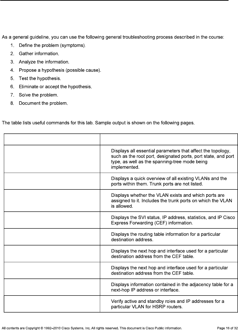
CCNPv6 TSHOOT
Section 2 – Troubleshooting Reference Information
General Troubleshooting Process
Command Summary
Command Key Information Displayed
show spanning-tree vlan vlan#
show vlan brief
show vlan id vlan#
show ip interface vlan vlan#
show ip route ip-addr
show ip cef ip-addr detail
show ip cef exact-route src-ip-
addr dest-ip-addr
show adjacency int-type/# detail
show standby vlan vlan# brief
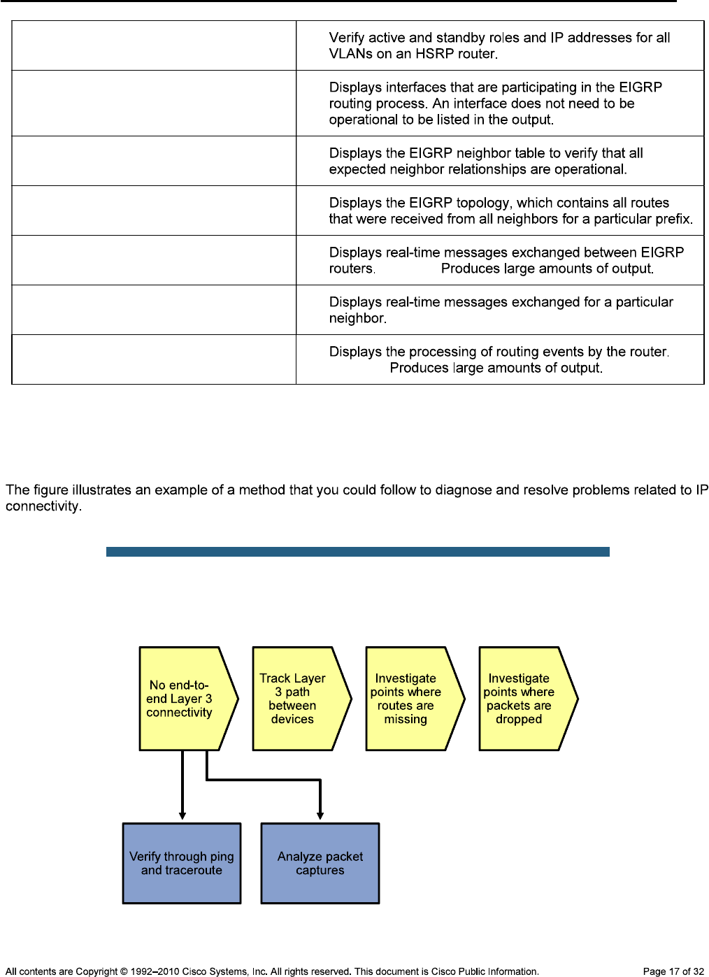
CCNPv6 TSHOOT
show standby brief
show ip eigrp interfaces
show ip eigrp neighbors
show ip eigrp topology ip-addr
net-mask
debug eigrp packets Caution:
debug ip eigrp as# neighbor ip-addr
debug ip eigrp Caution:
Lab 5-1 Sample Troubleshooting Flows
Troubleshooting IP Connectivity
Sample Layer 3 Troubleshooting Flow
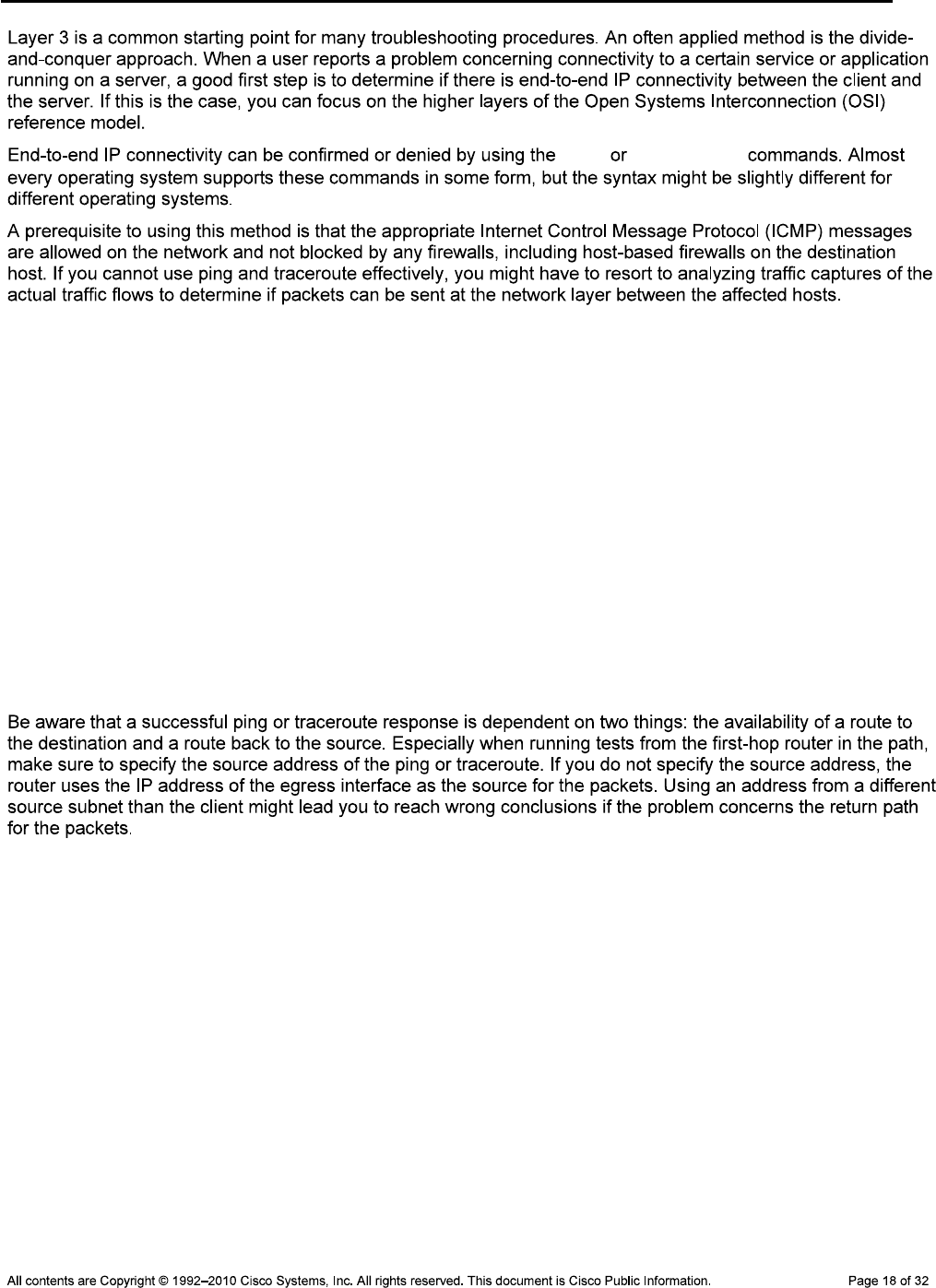
CCNPv6 TSHOOT
ping traceroute
Using the Correct Source Address
R2#ping 10.1.50.1 source Lo0
Type escape sequence to abort.
Sending 5, 100-byte ICMP Echos to 10.1.50.1, timeout is 2 seconds:
Packet sent with a source address of 10.1.202.1
!!!!!
Success rate is 100 percent (5/5), round-trip min/avg/max = 16/20/32 ms
R2#traceroute 10.1.50.1 source Lo0
Type escape sequence to abort.
Tracing the route to 10.1.50.1
1 10.1.1.1 16 msec 16 msec 8 msec
2 10.1.2.1 8 msec 16 msec 12 msec
3 10.1.50.1 12 msec 12 msec 8 msec
CCNPv6 TSHOOT
Sample Layer 3 Troubleshooting Flow
CCNPv6 TSHOOT
Verify the Routing Table
R2#show ip route 10.1.10.1
Routing entry for 10.1.10.0/24
Known via "eigrp 1", distance 90, metric 2172672, type internal
Redistributing via eigrp 1
Last update from 10.1.1.5 on Serial0/0/1, 02:05:21 ago
Routing Descriptor Blocks:
10.1.1.5, from 10.1.1.5, 02:05:21 ago, via Serial0/0/1
Route metric is 2172672, traffic share count is 1
Total delay is 20110 microseconds, minimum bandwidth is 1544 Kbit
Reliability 255/255, minimum MTU 1500 bytes
Loading 1/255, Hops 2
* 10.1.1.1, from 10.1.1.1, 02:05:21 ago, via Serial0/0/0
Route metric is 2172672, traffic share count is 1
Total delay is 20110 microseconds, minimum bandwidth is 1544 Kbit
Reliability 255/255, minimum MTU 1500 bytes
Loading 1/255, Hops 2
show ip
route ip-address
show ip route
0.0.0.0 0.0.0.0
Verify the Cisco Express Forwarding Information Base
R2#show ip cef 10.1.10.1
10.1.10.0/24
nexthop 10.1.1.1 Serial0/0/0
nexthop 10.1.1.5 Serial0/0/1
show ip cef
ip-address show ip route
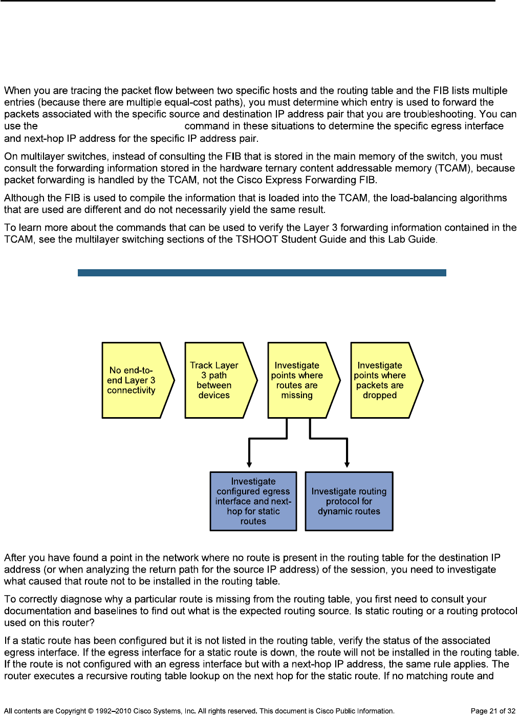
CCNPv6 TSHOOT
DLS1#show ip cef exact-route 10.1.10.1 10.1.202.1
10.1.10.1 -> 10.1.202.1 => IP adj out of FastEthernet0/5, addr 10.1.2.2
R2#show ip cef exact-route 10.1.202.1 10.1.50.1
10.1.202.1 -> 10.1.50.1 => IP adj out of Serial0/0/0
show ip cef exact-route
Sample Layer 3 Troubleshooting Flow
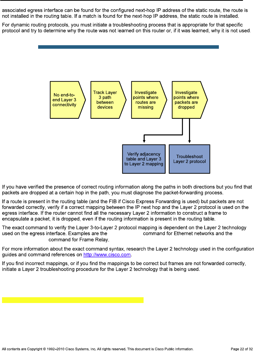
CCNPv6 TSHOOT
Sample Layer 3 Troubleshooting Flow
show ip arp show
frame-relay map
Verify the Adjacency Table
DLS1#show adjacency fa0/5 detail
Protocol Interface Address
IP FastEthernet0/5 10.1.2.2(15)
0 packets, 0 bytes
epoch 0
sourced in sev-epoch 0
Encap length 14
001B530D60B100175A5BB4420800
L2 destination address byte offset 0
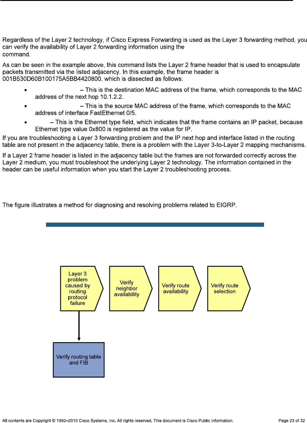
CCNPv6 TSHOOT
L2 destination address byte length 6
Link-type after encap: ip
ARP
show adjacency int-type/# detail
001B530D60B1
00175A5BB442
0800
Troubleshooting EIGRP
Sample EIGRP Troubleshooting Flow
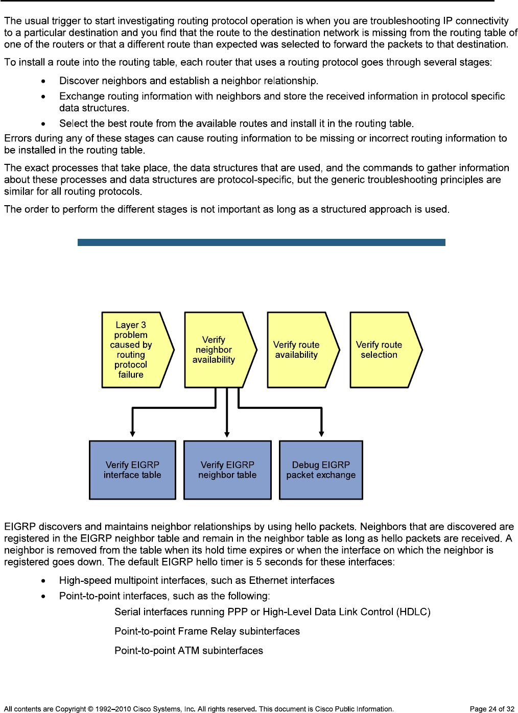
CCNPv6 TSHOOT
Sample EIGRP Troubleshooting Flow
—
—
—
CCNPv6 TSHOOT
Verify the EIGRP Interfaces
R1#show ip eigrp interfaces
IP-EIGRP interfaces for process 1
Xmit Queue Mean Pacing Time Multicast Pending
Interface Peers Un/Reliable SRTT Un/Reliable Flow Timer Routes
Se0/0/0 1 0/0 19 0/15 99 0
Fa0/1 1 0/0 8 0/1 50 0
router eigrp
show ip eigrp interfaces
show interfaces show interface status, show ip interfaces
brief
show ip eigrp interfaces
network passive-interface router eigrp
Verify the EIGRP Neighbor Table
R1#show ip eigrp neighbors
IP-EIGRP neighbors for process 1
H Address Interface Hold Uptime SRTT RTO Q Seq
(sec) (ms) Cnt Num
0 10.1.2.1 Fa0/1 13 04:50:36 8 200 0 12
1 10.1.1.2 Se0/0/0 10 04:07:52 19 200 0 36
show ip eigrp neighbors
Nov 2 06:25:01 EST: %LINEPROTO-5-UPDOWN: Line protocol on Interface
FastEthernet0/1, changed state to down
Nov 2 06:25:02 EST: %LINK-3-UPDOWN: Interface FastEthernet0/1, changed state to
down
Nov 2 06:25:02 EST: %DUAL-5-NBRCHANGE: EIGRP-IPv4:(1) 1: Neighbor 10.1.2.1
(FastEthernet0/1) is down: interface down
Nov 2 06:25:14 EST: %DUAL-5-NBRCHANGE: EIGRP-IPv4:(1) 1: Neighbor 10.1.2.1
(FastEthernet0/1) is up: new adjacency
Nov 2 06:25:16 EST: %LINK-3-UPDOWN: Interface FastEthernet0/1, changed state to up
Nov 2 06:25:17 EST: %LINEPROTO-5-UPDOWN: Line protocol on Interface
FastEthernet0/1, changed state to up

CCNPv6 TSHOOT
Debug EIGRP Packet Exchange
debug eigrp packets
debug ip eigrp as-number
show logging
R1#configure terminal
Enter configuration commands, one per line. End with CNTL/Z.
R1(config)#no logging console
R1(config)#logging buffered 16384
R1(config)#^Z
R1#debug eigrp packets
EIGRP Packets debugging is on
(UPDATE, REQUEST, QUERY, REPLY, HELLO, IPXSAP, PROBE, ACK, STUB, SIAQUERY,
SIAREPLY)
R1#debug ip eigrp 1 neighbor 10.1.2.1
IP Neighbor target enabled on AS 1 for 10.1.2.1
IP-EIGRP Neighbor Target Events debugging is on
R1#clear logging
Clear logging buffer [confirm]
R1#show logging
Syslog logging: enabled (1 messages dropped, 108 messages rate-limited,
0 flushes, 0 overruns, xml disabled, filtering disabled)
Console logging: disabled
Monitor logging: level debugging, 0 messages logged, xml disabled,
filtering disabled
Buffer logging: level debugging, 13924 messages logged, xml disabled,
filtering disabled
Logging Exception size (4096 bytes)
Count and timestamp logging messages: disabled
No active filter modules.
Trap logging: level informational, 242 message lines logged
Logging to 10.1.50.1(global) (udp port 514, audit disabled, link up), 242
message lines logged, xml disabled,
filtering disabled
Log Buffer (16384 bytes):
Nov 2 07:40:38.177 PDT: EIGRP: Received HELLO on FastEthernet0/1 nbr 10.1.2.1
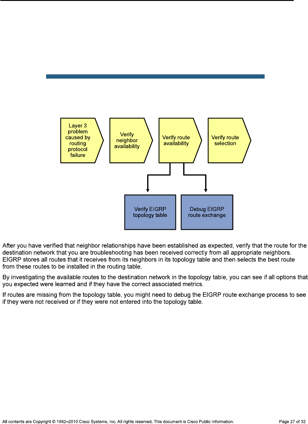
CCNPv6 TSHOOT
Nov 2 07:40:38.177 PDT: AS 1, Flags 0x0, Seq 0/0 idbQ 0/0 iidbQ un/rely 0/0 peerQ
un/rely 0/0
Nov 2 07:40:42.517 PDT: EIGRP: Received HELLO on FastEthernet0/1 nbr 10.1.2.1
Nov 2 07:40:42.517 PDT: AS 1, Flags 0x0, Seq 0/0 idbQ 0/0 iidbQ un/rely 0/0 peerQ
un/rely 0/0
Nov 2 07:40:47.237 PDT: EIGRP: Received HELLO on FastEthernet0/1 nbr 10.1.2.1
Nov 2 07:40:47.237 PDT: AS 1, Flags 0x0, Seq 0/0 idbQ 0/0 iidbQ un/rely 0/0 peerQ
un/rely 0/0
Sample EIGRP Troubleshooting Flow
Verify the EIGRP Topology Table
R2#show ip eigrp topology 10.1.50.0 255.255.255.0
IP-EIGRP (AS 1): Topology entry for 10.1.50.0/24
State is Passive, Query origin flag is 1, 2 Successor(s), FD is 2172672
Routing Descriptor Blocks:
10.1.1.1 (Serial0/0/0), from 10.1.1.1, Send flag is 0x0
Composite metric is (2172672/28416), Route is Internal
Vector metric:
Minimum bandwidth is 1544 Kbit
Total delay is 20110 microseconds
Reliability is 255/255
Load is 1/255
Minimum MTU is 1500
CCNPv6 TSHOOT
Hop count is 2
10.1.1.5 (Serial0/0/1), from 10.1.1.5, Send flag is 0x0
Composite metric is (2172672/28416), Route is Internal
Vector metric:
Minimum bandwidth is 1544 Kbit
Total delay is 20110 microseconds
Reliability is 255/255
Load is 1/255
Minimum MTU is 1500
Hop count is 2
Successors
Feasible successors
Possible successors
R2#show ip eigrp topology 10.1.50.0 255.255.255.0
IP-EIGRP (AS 1): Topology entry for 10.1.50.0/24
State is Passive, Query origin flag is 1, 2 Successor(s), FD is 2172672
Routing Descriptor Blocks:
10.1.1.1 (Serial0/0/0), from 10.1.1.1, Send flag is 0x0
Composite metric is (2172672/28416), Route is Internal
Vector metric:
Minimum bandwidth is 1544 Kbit
Total delay is 20110 microseconds
Reliability is 255/255
Load is 1/255
Minimum MTU is 1500
Hop count is 2
10.1.1.5 (Serial0/0/0), from 10.1.1.5, Send flag is 0x0
Composite metric is (2172672/28416), Route is Internal
Vector metric:
Minimum bandwidth is 1544 Kbit

CCNPv6 TSHOOT
Total delay is 20110 microseconds
Reliability is 255/255
Load is 1/255
Minimum MTU is 1500
Hop count is 2
Verify the EIGRP Topology Table
R2#debug ip eigrp
IP-EIGRP Route Events debugging is on
R2#debug ip eigrp 1 neighbor 10.1.1.1
IP Neighbor target enabled on AS 1 for 10.1.1.1
IP-EIGRP Neighbor Target Events debugging is on
R2#clear ip eigrp neighbors 10.1.1.1
R2#
Nov 2 17:18:50.945: %DUAL-5-NBRCHANGE: IP-EIGRP(0) 1: Neighbor 10.1.1.2 (Serial
0/0/0) is down: Interface Goodbye received
Nov 2 17:18:55.085: %DUAL-5-NBRCHANGE: IP-EIGRP(0) 1: Neighbor 10.1.1.2 (Serial
0/0/0) is up: new adjacency
debug ip eigrp
debug eigrp packets
Sample EIGRP Troubleshooting Flow

CCNPv6 TSHOOT
CCNPv6 TSHOOT
Reflection Questions
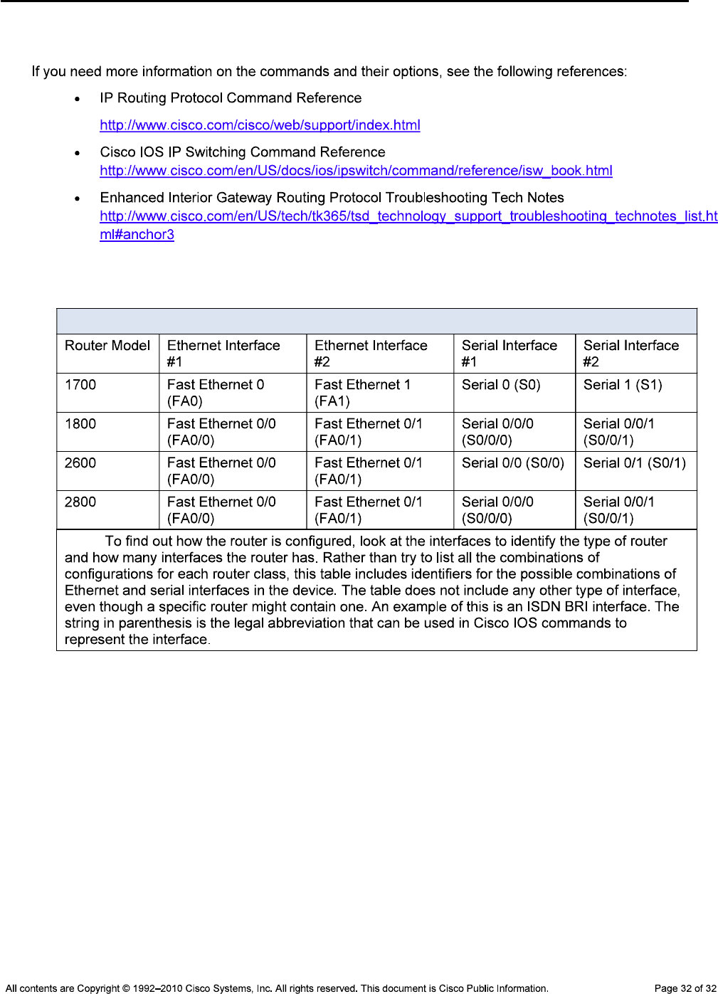
CCNPv6 TSHOOT
References
Router Interface Summary Table
Router Interface Summary
Note:
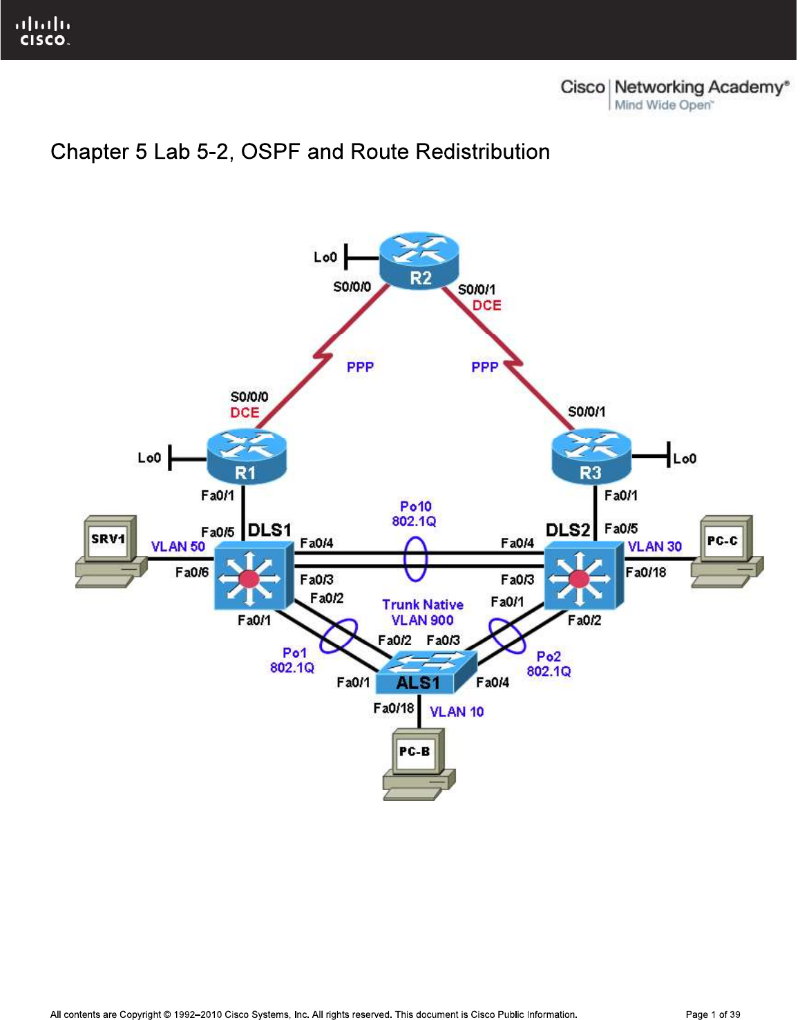
CCNPv6 TSHOOT
Physical Topology (Baseline)
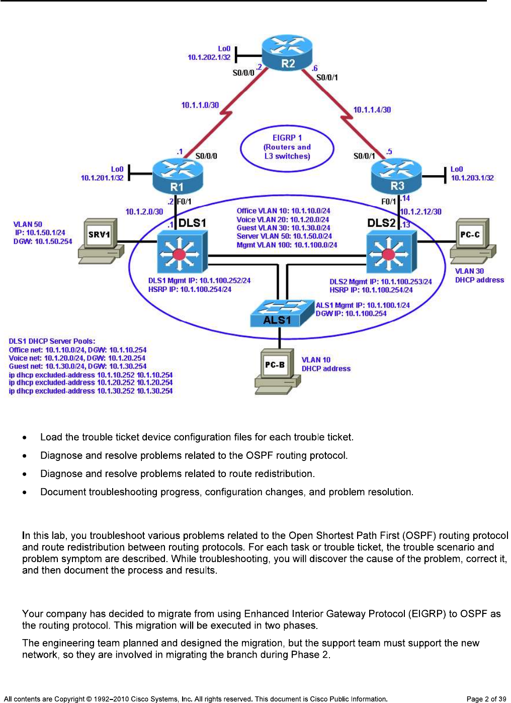
CCNPv6 TSHOOT
Logical Topology (Baseline)
Objectives
Background
Migrating from EIGRP to OSPF
CCNPv6 TSHOOT
Phase 1
Phase 2
OSPF Network Design
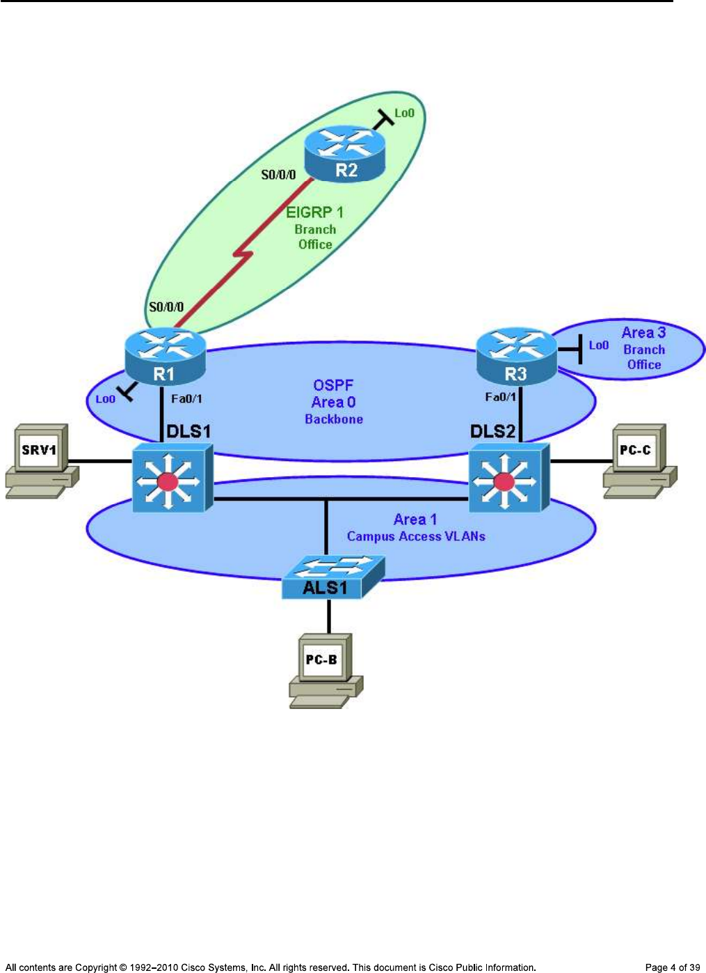
CCNPv6 TSHOOT
Phase 1 OSPF Network Design
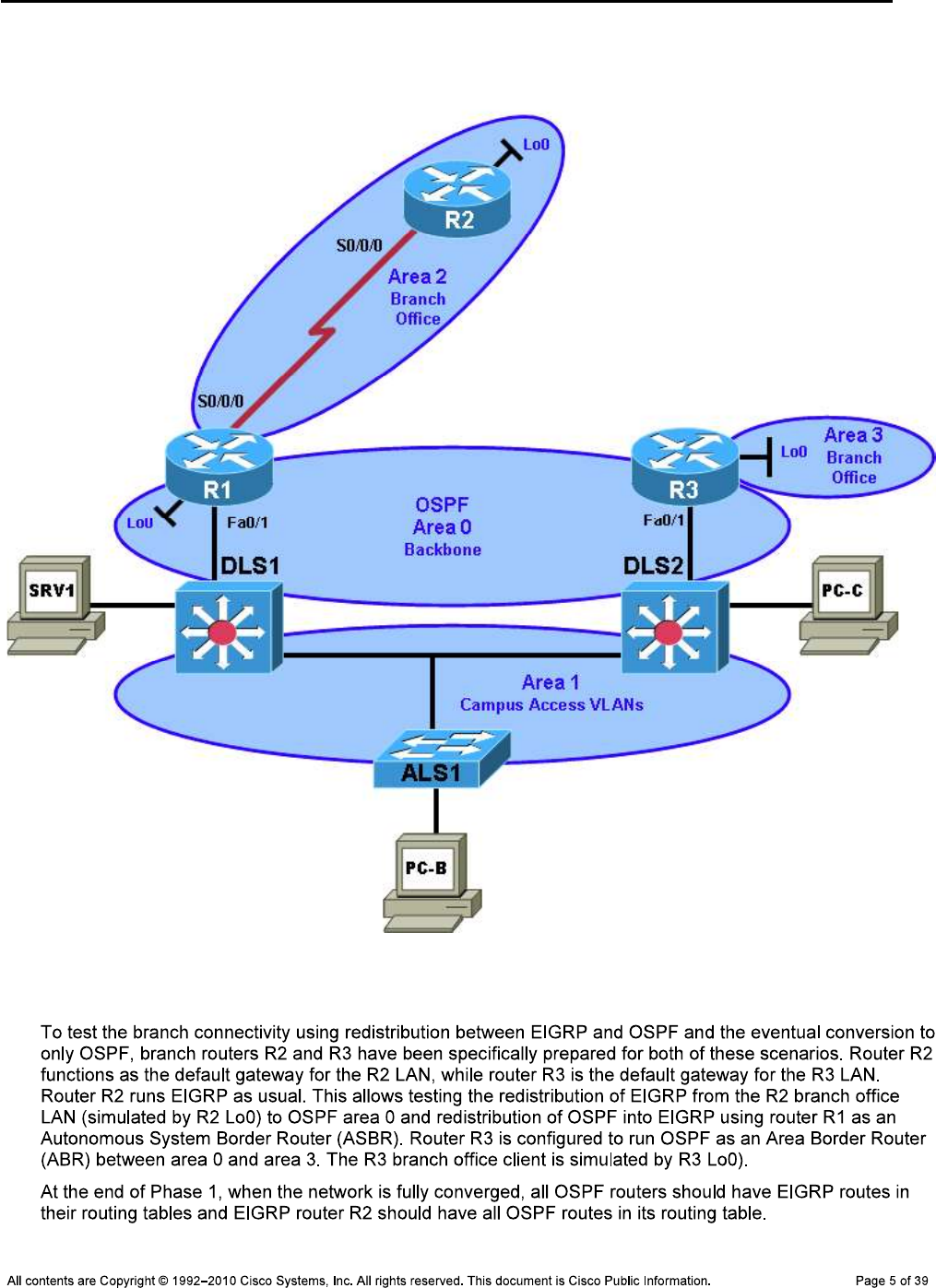
CCNPv6 TSHOOT
Phase 2 OSPF Network Design
Test Plan
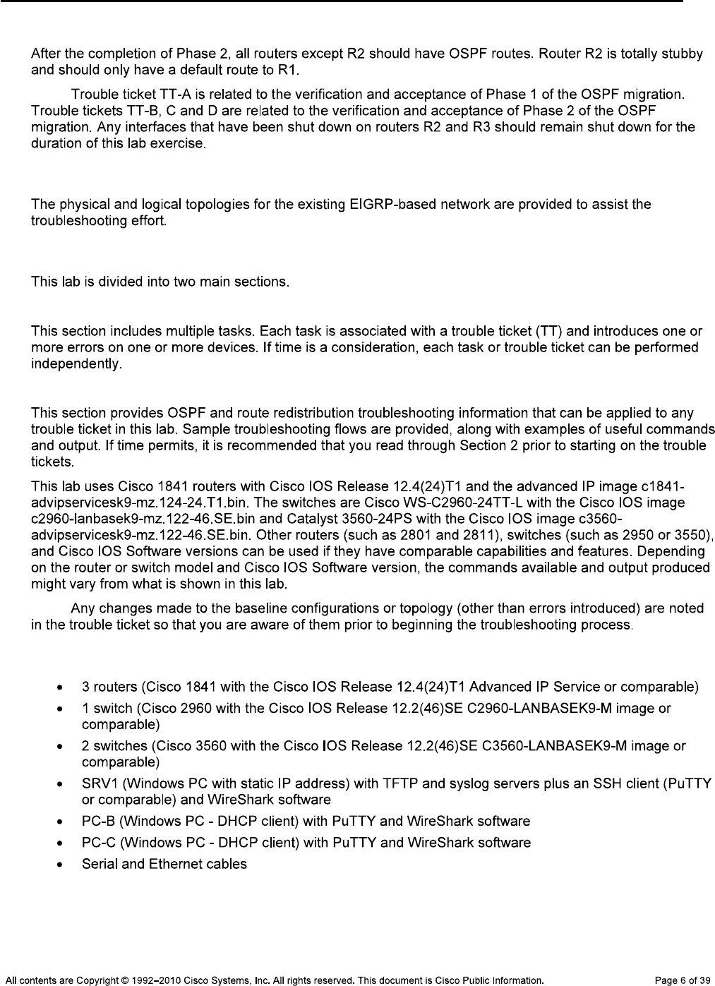
CCNPv6 TSHOOT
Note:
Physical and Logical Topology Diagrams
Lab Structure
Section 1—Trouble Tickets and Troubleshooting Logs
Section 2—Troubleshooting Reference Information
Note:
Required Resources
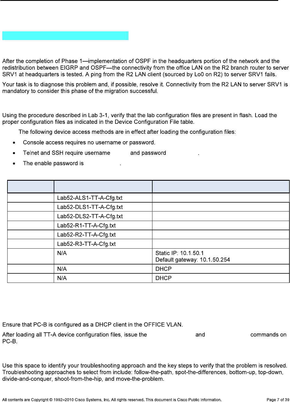
CCNPv6 TSHOOT
Section 1—Trouble Tickets and Troubleshooting Logs
Task 1: Trouble Ticket Lab 5-2 TT-A
Step 1: Review trouble ticket Lab 5-2 TT-A.
Step 2: Load the device trouble ticket configuration files for TT-A.
Note:
admin adminpa55
ciscoenpa55
Device Configuration File Table
Device Name File to Load Notes
ALS1
DLS1
DLS2
R1
R2
R3
SRV1
PC-B
PC-C
Step 3: Configure SRV1 and start the syslog and TFTP servers.
Step 4: Release and renew the DHCP lease on PC-B.
ipconfig /release ipconfig /renew
Step 5: Outline the troubleshooting approach and validation steps.
CCNPv6 TSHOOT
Note:
_______________________________________________________________________________
_______________________________________________________________________________
_______________________________________________________________________________
_______________________________________________________________________________
_______________________________________________________________________________
_______________________________________________________________________________
Step 6: Record the troubleshooting process and configuration changes.
Note:
Device Actions and Results
CCNPv6 TSHOOT
Step 7: Document trouble ticket debrief notes.
_______________________________________________________________________________
_______________________________________________________________________________
_______________________________________________________________________________
_______________________________________________________________________________
_______________________________________________________________________________
_______________________________________________________________________________
_______________________________________________________________________________
Task 2: Trouble Ticket Lab 5-2 TT-B
Step 1: Review trouble ticket Lab 5-2 TT-B.
Note:
Step 2: Load the device trouble ticket configuration files for TT-B.
Note:
Device Configuration File Table
Device Name File to Load Notes
ALS1
DLS1
DLS2
R1
R2
R3
SRV1
PC-B
PC-C
CCNPv6 TSHOOT
Step 3: Configure SRV1 and start the syslog and TFTP servers.
Step 4: Release and renew the DHCP leases on PC-B and PC-C, as described in Task 1.
Step 5: Outline the troubleshooting approach and validation steps.
Note:
_______________________________________________________________________________
_______________________________________________________________________________
_______________________________________________________________________________
_______________________________________________________________________________
_______________________________________________________________________________
Step 6: Record the troubleshooting process and configuration changes.
Note:
Device Actions and Results
CCNPv6 TSHOOT
Device Actions and Results
Step 7: Document trouble ticket debrief notes.
_______________________________________________________________________________
_______________________________________________________________________________
_______________________________________________________________________________
_______________________________________________________________________________
_______________________________________________________________________________
_______________________________________________________________________________
_______________________________________________________________________________
Task 3: Trouble Ticket Lab 5-2 TT-C
Step 1: Review trouble ticket Lab 5-2 TT-C.
Step 2: Load the device trouble ticket configuration files for TT-C.
Note:
Device Configuration File Table
Device Name File to Load Notes
ALS1
DLS1
DLS2
R1
R2

CCNPv6 TSHOOT
R3
SRV1
PC-B
PC-C
Step 3: Configure SRV1 and start the syslog and TFTP servers, as described in Task 1.
Step 4: Release and renew the DHCP leases on PC-B and PC-C, as described in Task 1.
Step 5: Outline the troubleshooting approach and validation steps.
Note:
_______________________________________________________________________________
_______________________________________________________________________________
_______________________________________________________________________________
_______________________________________________________________________________
_______________________________________________________________________________
_______________________________________________________________________________
Step 6: Record the troubleshooting process and configuration changes.
Note:
Device Actions and Results
CCNPv6 TSHOOT
Device Actions and Results
Step 7: Document trouble ticket debrief notes.
_______________________________________________________________________________
_______________________________________________________________________________
_______________________________________________________________________________
_______________________________________________________________________________
_______________________________________________________________________________
_______________________________________________________________________________
_______________________________________________________________________________
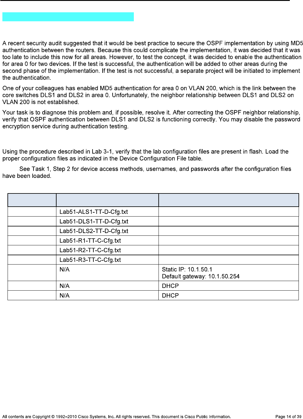
CCNPv6 TSHOOT
Task 4: Trouble Ticket Lab 5-2 TT-D
Step 1: Review trouble ticket Lab 5-2 TT-D.
Step 2: Load the device trouble ticket configuration files for TT-D.
Note:
Device Configuration File Table
Device Name File to Load Notes
ALS1
DLS1
DLS2
R1
R2
R3
SRV1
PC-B
PC-C
Step 3: Configure SRV1 and start the syslog and TFTP servers, as described in Task 1.
Step 4: Release and renew the DHCP leases on PC-B and PC-C, as described in Task 1.
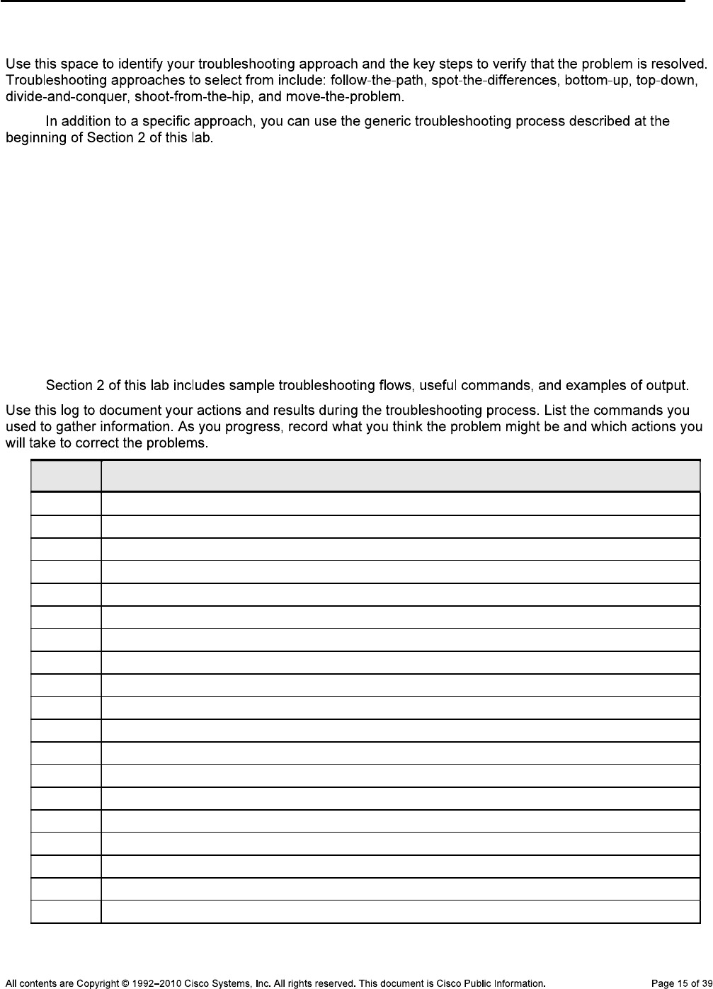
CCNPv6 TSHOOT
Step 5: Outline the troubleshooting approach and validation steps.
Note:
_______________________________________________________________________________
_______________________________________________________________________________
_______________________________________________________________________________
_______________________________________________________________________________
_______________________________________________________________________________
_______________________________________________________________________________
Step 6: Record the troubleshooting process and configuration changes.
Note:
Device Actions and Results

CCNPv6 TSHOOT
Step 7: Document trouble ticket debrief notes.
_______________________________________________________________________________
_______________________________________________________________________________
_______________________________________________________________________________
_______________________________________________________________________________
_______________________________________________________________________________
_______________________________________________________________________________
_______________________________________________________________________________
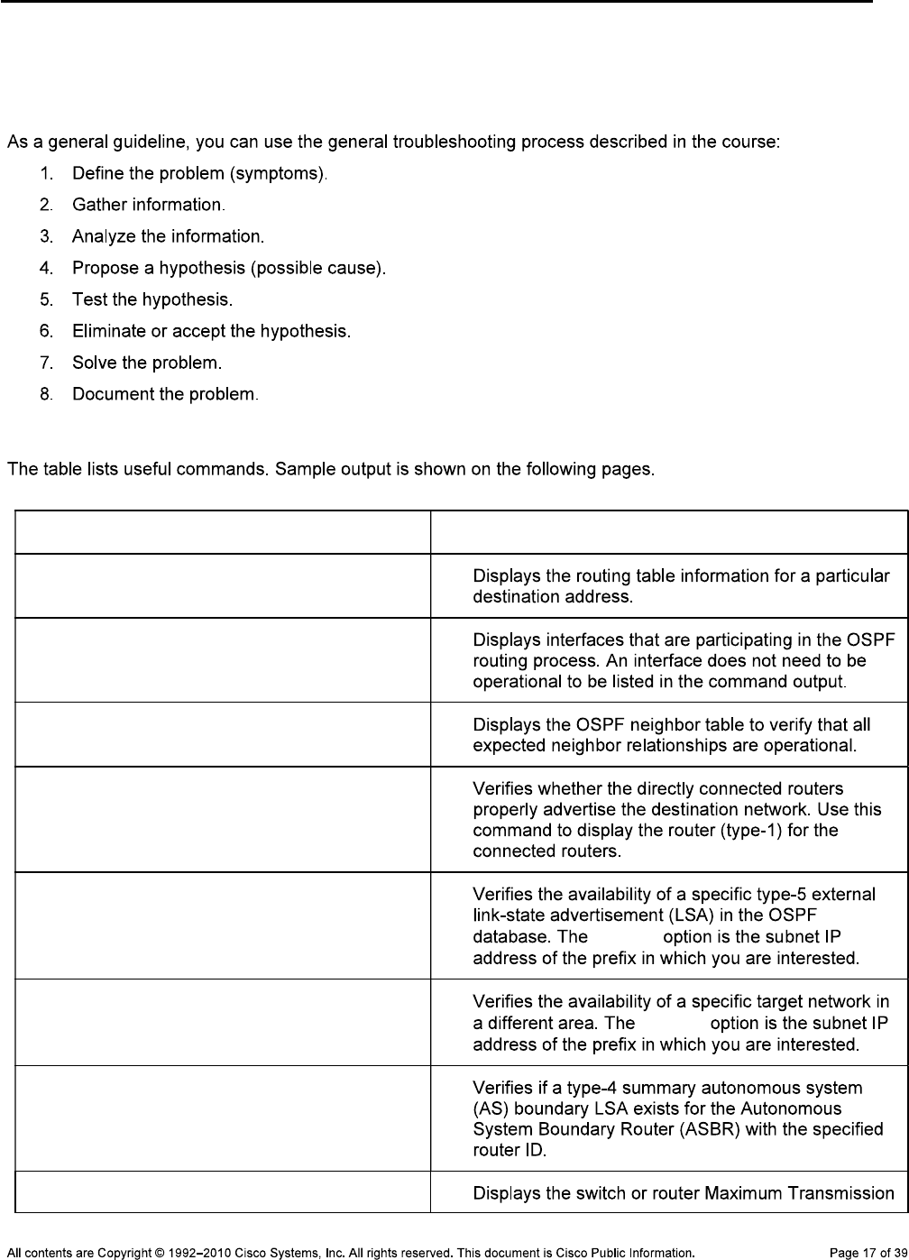
CCNPv6 TSHOOT
Section 2—Troubleshooting Reference Information
General Troubleshooting Process
Commands Summary
Command Key Information Displayed
show ip route ip-addr
show ip ospf interface type/#
show ip ospf interface brief
show ip ospf neighbor
show ip ospf database router router-
id
show ip ospf database external
subnet subnet
show ip ospf database summary subnet subnet
show ip ospf database asbr-summary
router-id
show system mtu
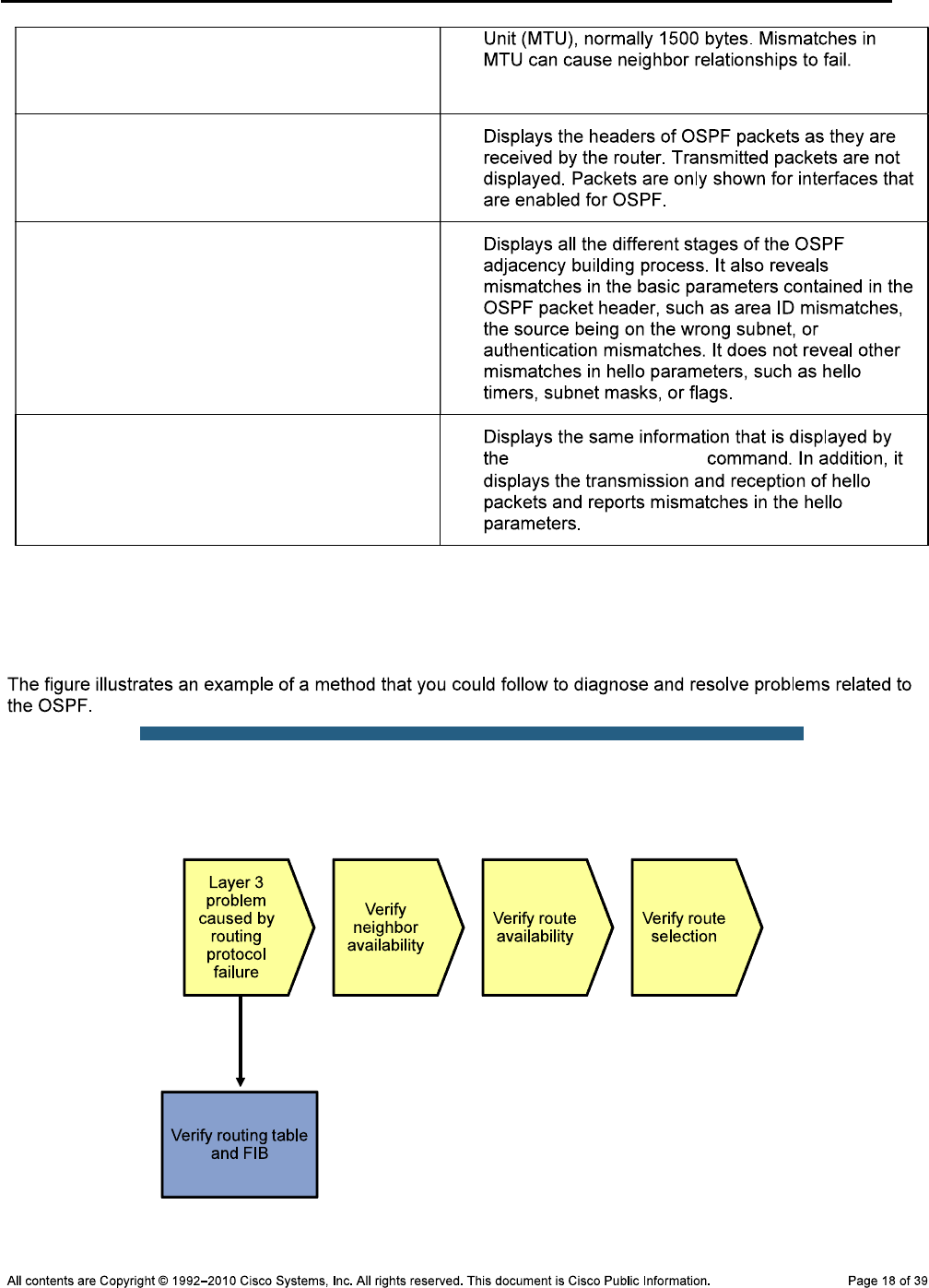
CCNPv6 TSHOOT
debug ip ospf packet
debug ip ospf adj
debug ip ospf events
debug ip ospf adj
Lab 5-2: Sample Troubleshooting Flows
Troubleshooting the OSPF Routing Protocol
Sample OSPF Troubleshooting Flow
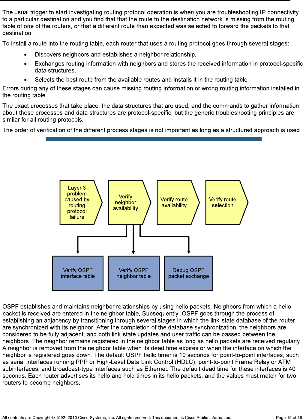
CCNPv6 TSHOOT
Sample OSPF Troubleshooting Flow
Verify OSPF Interfaces
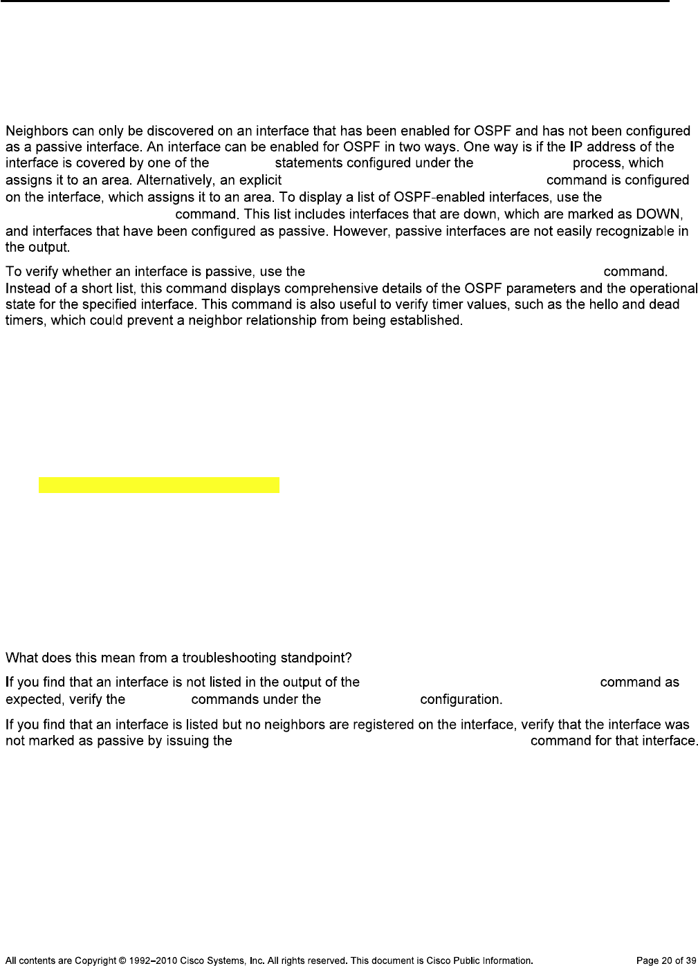
CCNPv6 TSHOOT
R1#show ip ospf interface brief
Interface PID area IP Address/Mask Cost State Nbrs F/C
Lo0 1 0 10.1.201.1/32 1 P2P 0/0
Fa0/1 1 0 10.1.2.2/30 1 DR 1/1
Se0/0/0 1 2 10.1.1.1/30 64 P2P 1/1
network router ospf
ip ospf process-id area area-id
show ip
ospf interface brief
show ip ospf interface interface-id
R1#show ip ospf interface fastEthernet 0/1
FastEthernet0/1 is up, line protocol is up
Internet Address 10.1.2.2/30, area 0
Process ID 1, Router ID 10.1.201.1, Network Type BROADCAST, Cost: 1
Transmit Delay is 1 sec, State DR, Priority 1
Designated Router (ID) 10.1.201.1, Interface address 10.1.2.2
No backup designated router on this network
Timer intervals configured, hello 10, dead 40, Wait 40, Retransmit 5
oob-resync timeout 40
No Hellos (Passive interface)
Supports Link-local Signaling (LLS)
Cisco NSF helper support enabled
IETF NSF helper support enabled
Index 1/2, flood queue length 0
Next 0x0(0)/0x0(0)
Last flood scan length is 0, maximum is 0
Last flood scan time is 0 msec, maximum is 0 msec
Neighbor Count is 0, Adjacent neighbor count is 0
Suppress hello for 0 neighbor(s)
show ip ospf interface brief
network router ospf
show ip ospf interface interface-id
Verify the OSPF Neighbor Table
R1#show ip ospf neighbor
Neighbor ID Pri State dead Time Address Interface
10.1.211.1 1 FULL/DR 00:00:31 10.1.2.1 FastEthernet0/1
10.1.202.1 0 FULL/ - 00:00:38 10.1.1.2 Serial0/0/0
DLS1>show ip ospf neighbor
Neighbor ID Pri State dead Time Address Interface
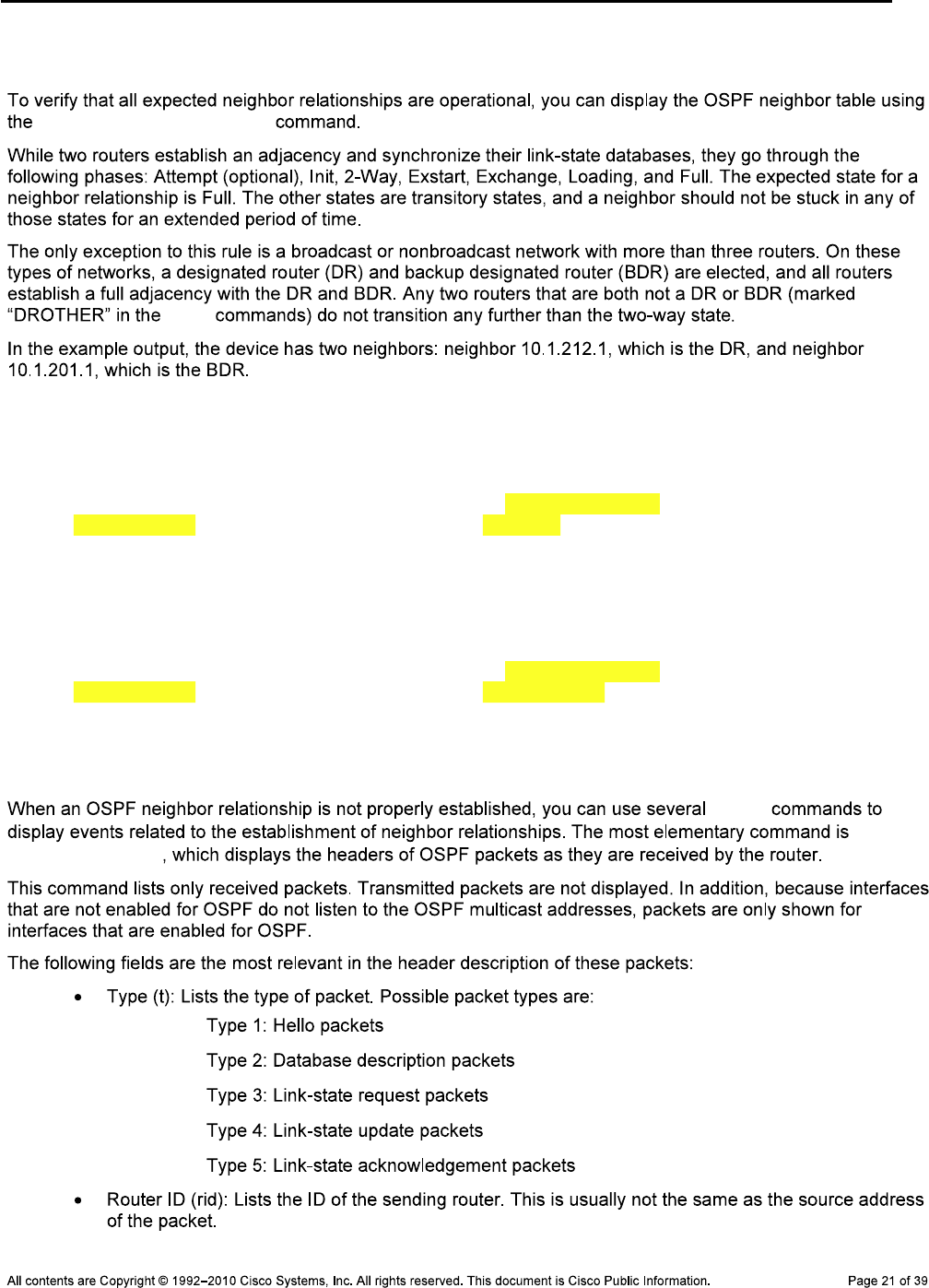
CCNPv6 TSHOOT
10.1.212.1 1 FULL/DR 00:00:35 10.1.200.253 Vlan200
10.1.201.1 1 FULL/BDR 00:00:39 10.1.2.2 FastEthernet0/5
show ip ospf neighbor
show
Debug OSPF Packet Exchange
DLS1#debug ip ospf packet
OSPF packet debugging is on
DLS1#
Nov 5 15:54:32.574: OSPF: rcv. v:2 t:1 l:48 rid:10.1.212.1
aid:0.0.0.0 chk:8B98 aut:0 auk: from Vlan200
Nov 5 15:54:38.917: OSPF: rcv. v:2 t:1 l:48 rid:10.1.201.1
aid:0.0.0.0 chk:2394 aut:0 auk: from FastEthernet0/5
R1#debug ip ospf packet
Nov 5 15:57:21.503: OSPF: rcv. v:2 t:1 l:48 rid:10.1.211.1
aid:0.0.0.0 chk:2394 aut:0 auk: from FastEthernet0/1
Nov 5 15:57:22.443: OSPF: rcv. v:2 t:1 l:48 rid:10.1.202.1
aid:0.0.0.2 chk:4497 aut:0 auk: from Serial0/0/0
In this highlighted sample output for R1, router ID 10.1.202.1 is in area 2
(aid:0.0.0.2) and the hello was received on interface Serial 0/0/0.
debug
debug
ip ospf packet
—
—
—
—
—
CCNPv6 TSHOOT
—
—
—
Note: debug ip ospf packet
Debug OSPF Adjacencies
DLS1#debug ip ospf adj
OSPF adjacency events debugging is on
DLS1(config)#interface fa0/5
DLS1(config-if)#shut
Nov 5 16:04:10.619: OSPF: Interface FastEthernet0/5 going Down
Nov 5 16:04:10.619: OSPF: 10.1.211.1 address 10.1.2.1 on FastEthernet0/5 is dea
d, state DOWN
Nov 5 16:04:10.619: OSPF: Neighbor change Event on interface FastEthernet0/5
Nov 5 16:04:10.619: OSPF: DR/BDR election on FastEthernet0/5
Nov 5 16:04:10.619: OSPF: Elect BDR 10.1.201.1
Nov 5 16:04:10.619: OSPF: Elect DR 10.1.201.1
Nov 5 16:04:10.619: OSPF: Elect BDR 10.1.201.1
Nov 5 16:04:10.619: OSPF: Elect DR 10.1.201.1
Nov 5 16:04:10.619
DLS1(config-if)#: DR: 10.1.201.1 (Id) BDR: 10.1.201.1 (Id)
Nov 5 16:04:10.619: OSPF: Flush network LSA immediately
Nov 5 16:04:10.619: OSPF: Remember old DR 10.1.211.1 (id)
Nov 5 16:04:10.619: OSPF: 10.1.201.1 address 10.1.2.2 on FastEthernet0/5 is dea
d, state DOWN
Nov 5 16:04:10.619: %OSPF-5-ADJCHG: Process 1, Nbr 10.1.201.1 on FastEthernet0/
5 from FULL to DOWN, Neighbor Down: Interface down or detached
Nov 5 16:04:10.619: OSPF: Neighbor change Event on interface FastEthernet0/5
Nov 5 16:04:10.619: OSPF: DR/BDR election on FastEthernet0/5
Nov 5 16:04:10.619: OSPF: Elect BDR 0.0.0.0
Nov 5 16:04:10.619: OSPF: Elect DR 0.0.0.0
Nov 5 16:04:10.619: DR: none BDR: none
Nov 5 16:04:10.619: OSPF: Remember old DR 10.1.201.1 (id)
Nov 5 16:04:10.619: OSPF: [change notify] will poll [cnt 11] interface status f
or FastEthernet0/5

CCNPv6 TSHOOT
Nov 5 16:04:11.122: OSPF: We are not DR to build Net Lsa for interface FastEthe
rnet0/5
Nov 5 16:04:11.122: OSPF: Build network LSA for FastEthernet0/5, router ID 10.1
.211.1
Nov 5 16:04:11.122: OSPF: Build router LSA for area 0, router ID 10.1.211.1, se
q 0x80000012, process 1
Nov 5 16:04:12.599: %LINK-5-CHANGED: Interface FastEthernet0/5, changed state t
o administratively down
Nov 5 16:04:13.606: %LINEPROTO-5-UPDOWN: Line protocol on Interface FastEtherne
t0/5, changed state to down
Nov 5 16:04:20.628: OSPF: will poll [count 10] interface status for FastEtherne
t0/5
Nov 5 16:04:30.636: OSPF: will poll [count 9] interface status for FastEthernet
0/5
Nov 5 16:04:40.821: OSPF: will poll [count 8] interface status for FastEthernet
0/5
Nov 5 16:04:50.830: OSPF: will poll [count 7] interface status for FastEthernet
0/5
Nov 5 16:05:00.838: OSPF: will poll [count 6] interface status for FastEthernet
0/5
Nov 5 16:05:10.839: OSPF: will poll [count 5] interface status for FastEthernet
0/5
Nov 5 16:05:20.847: OSPF: will poll [count 4] interface status for FastEthernet
0/5
Nov 5 16:05:30.856: OSPF: will poll [count 3] interface status for FastEthernet
0/5
Nov 5 16:05:40.865: OSPF: will poll [count 2] interface status for FastEthernet
0/5
Nov 5 16:05:50.865: OSPF: will poll [count 1] interface status for FastEthernet
0/5
DLS1(config)#interface fa0/5
DLS1(config-if)#no shut
Nov 5 16:05:59.800: %LINK-3-UPDOWN: Interface FastEthernet0/5, changed state to
up
Nov 5 16:05:59.800: OSPF: Interface FastEthernet0/5 going Up
Nov 5 16:05:59.800: OSPF: [change notify] will poll [cnt 11] interface status f
or FastEthernet0/5
Nov 5 16:06:00.303: OSPF: Build router LSA for area 0, router ID 10.1.211.1, se
q 0x80000013, process 1
Nov 5 16:06:00.807: %LINEPROTO-5-UPDOWN: Line protocol on Interface FastEtherne
t0/5, changed state to up
Nov 5 16:06:09.800: OSPF: will poll [count 10] interface status for FastEtherne
t0/5
Nov 5 16:06:09.800: OSPF: 2 Way Communication to 10.1.201.1 on FastEthernet0/5,
state 2WAY
Nov 5 16:06:19.809: OSPF: will poll [count 9] interface status for FastEthernet
0/5
Nov 5 16:06:29.809: OSPF: will poll [count 8] interface status for FastEthernet
0/5
Nov 5 16:06:39.809: OSPF: end of Wait on interface FastEthernet0/5
Nov 5 16:06:39.809: OSPF: DR/BDR election on FastEthernet0/5
Nov 5 16:06:39.809: OSPF: Elect BDR 10.1.211.1
Nov 5 16:06:39.809: OSPF: Elect DR 10.1.211.1
Nov 5 16:06:39.809: OSPF: Elect BDR 10.1.201.1
Nov 5 16:06:39.809: OSPF: Elect DR 10.1.211.1
Nov 5 16:06:39.809: DR: 10.1.211.1 (Id) BDR: 10.1.201.1 (Id)
CCNPv6 TSHOOT
Nov 5 16:06:39.809: OSPF: Send DBD to 10.1.201.1 on FastEthernet0/5 seq 0x192E
opt 0x52 flag 0x7 len 32
Nov 5 16:06:39.818: OSPF: will poll [count 7] interface status for FastEthernet
0/5
Nov 5 16:06:40.313: OSPF: No full nbrs to build Net Lsa for interface FastEther
net0/5
Nov 5 16:06:42.209: OSPF: Rcv DBD from 10.1.201.1 on FastEthernet0/5 seq 0x8AC
opt 0x52 flag 0x7 len 32 mtu 1500 state EXSTART
Nov 5 16:06:42.209: OSPF: First DBD and we are not SLAVE
Nov 5 16:06:44.818: OSPF: Send DBD to 10.1.201.1 on FastEthernet0/5 seq 0x192E
opt 0x52 flag 0x7 len 32
Nov 5 16:06:44.818: OSPF: Retransmitting DBD to 10.1.201.1 on FastEthernet0/5 [
1]
Nov 5 16:06:44.818: OSPF: Rcv DBD from 10.1.201.1 on FastEthernet0/5 seq 0x192E
opt 0x52 flag 0x2 len 432 mtu 1500 state EXSTART
Nov 5 16:06:44.818: OSPF: NBR Negotiation Done. We are the MASTER
Nov 5 16:06:44.818: OSPF: Send DBD to 10.1.201.1 on FastEthernet0/5 seq 0x192F
opt 0x52 flag 0x3 len 412
Nov 5 16:06:44.818: OSPF: Rcv DBD from 10.1.201.1 on FastEthernet0/5 seq 0x192F
opt 0x52 flag 0x0 len 32 mtu 1500 state EXCHANGE
Nov 5 16:06:44.818: OSPF: Send DBD to 10.1.201.1 on FastEthernet0/5 seq 0x1930
opt 0x52 flag 0x1 len 32
Nov 5 16:06:44.818: OSPF: Send LS REQ to 10.1.201.1 length 24 LSA count 2
Nov 5 16:06:44.826: OSPF: Rcv LS REQ from 10.1.201.1 on FastEthernet0/5 length
36 LSA count 1
Nov 5 16:06:44.826: OSPF: Send UPD to 10.1.2.2 on FastEthernet0/5 length 64 LSA
count 1
Nov 5 16:06:44.826: OSPF: Rcv DBD from 10.1.201.1 on FastEthernet0/5 seq 0x1930
opt 0x52 flag 0x0 len 32 mtu 1500 state EXCHANGE
Nov 5 16:06:44.826: OSPF: Exchange Done with 10.1.201.1 on FastEthernet0/5
Nov 5 16:06:44.826: OSPF: Rcv LS UPD from 10.1.201.1 on FastEthernet0/5 length
108 LSA count 2
Nov 5 16:06:44.826: OSPF: No full nbrs to build Net Lsa for interface FastEther
net0/5
Nov 5 16:06:44.826: OSPF: Build network LSA for FastEthernet0/5, router ID 10.1
.211.1
Nov 5 16:06:44.826: OSPF: Synchronized with 10.1.201.1 on FastEthernet0/5, stat
e FULL
Nov 5 16:06:44.826: %OSPF-5-ADJCHG: Process 1, Nbr 10.1.201.1 on FastEthernet0/
5 from LOADING to FULL, Loading Done
debug ip ospf adj
Debug OSPF Events
DLS2#debug ip ospf events
*Nov 5 03:03:11.043: OSPF: Send hello to 224.0.0.5 area 0 on FastEthernet0/5 fr
om 10.1.2.13
DLS2#
*Nov 5 03:03:13.551: OSPF: Send hello to 224.0.0.5 area 0 on Vlan200 from 10.1.
200.253
CCNPv6 TSHOOT
*Nov 5 03:03:13.845: OSPF: Rcv hello from 10.1.211.1 area 0 from Vlan200 10.1.2
00.252
*Nov 5 03:03:13.845: OSPF: End of hello processing
DLS2#
*Nov 5 03:03:16.051: OSPF: Send hello to 224.0.0.5 area 0 on FastEthernet0/5 fr
om 10.1.2.13
*Nov 5 03:03:16.286: OSPF: Rcv hello from 10.1.203.1 area 0 from FastEthernet0/
5 10.1.2.14
*Nov 5 03:03:16.286: OSPF: Mismatched hello parameters from 10.1.2.14
*Nov 5 03:03:16.286: OSPF: dead R 40 C 15, hello R 10 C 5 Mask R 255.255.255.2
52 C 255.255.255.252
DLS2#
DLS2#undebug all
All possible debugging has been turned off
DLS2#
*Nov 5 03:03:28: %OSPF-5-ADJCHG: Process 1, Nbr 10.1.203.1 on FastEthernet0/5 f
rom FULL to DOWN, Neighbor Down: dead timer expired
debug
debug ip ospf events debug ip
ospf adj
debug ip ospf
packet debug ip ospf adj
debug ip ospf adj
debug ip ospf event

CCNPv6 TSHOOT
Sample OSPF Troubleshooting Flow
Verify the OSPF Link-State Database for Intra-Area Routes
DLS2#show ip ospf database router 10.1.212.1
OSPF Router with ID (10.1.212.1) (Process ID 1)
Router Link States (area 0)
LS age: 60
Options: (No TOS-capability, DC)
LS Type: Router Links
Link State ID: 10.1.212.1
Advertising Router: 10.1.212.1
LS Seq Number: 80000012
Checksum: 0x592C
Length: 60
area Border Router
Number of Links: 3
Link connected to: a Stub Network
(Link ID) Network/subnet number: 10.1.212.1
(Link Data) Network Mask: 255.255.255.255
Number of TOS metrics: 0
TOS 0 Metrics: 1
Link connected to: a Transit Network
(Link ID) Designated Router address: 10.1.2.13
(Link Data) Router Interface address: 10.1.2.13

CCNPv6 TSHOOT
Number of TOS metrics: 0
TOS 0 Metrics: 1
show ip ospf database router router-id
show
DLS1#show ip ospf database network 10.1.2.13
OSPF Router with ID (10.1.211.1) (Process ID 1)
Net Link States (area 0)
Routing Bit Set on this LSA
LS age: 695
Options: (No TOS-capability, DC)
LS Type: Network Links
Link State ID: 10.1.2.13 (address of Designated Router)
Advertising Router: 10.1.212.1
LS Seq Number: 80000004
Checksum: 0xDBAA
Length: 32
Network Mask: /30
Attached Router: 10.1.212.1
Attached Router: 10.1.203.1
show ip ospf database network designated-
router
Verify the OSPF Link-State Database for Inter-Area Routes
DLS1>show ip ospf database summary 10.1.203.1
OSPF Router with ID (10.1.211.1) (Process ID 1)
Summary Net Link States (area 0)
LS age: 577
Options: (No TOS-capability, DC, Upward)

CCNPv6 TSHOOT
LS Type: Summary Links(Network)
Link State ID: 10.1.203.1 (summary Network Number)
Advertising Router: 10.1.203.1
LS Seq Number: 8000000B
Checksum: 0x2A58
Length: 28
Network Mask: /32
TOS: 0 Metric: 1
show ip ospf
database summary subnet subnet
Verify the OSPF Link-State Database for External Routes
DLS1#show ip ospf database external 10.1.1.0
OSPF Router with ID (10.1.211.1) (Process ID 1)
Type-5 AS External Link States
Routing Bit Set on this LSA
LS age: 1196
Options: (No TOS-capability, DC)
LS Type: AS External Link
Link State ID: 10.1.1.0 (External Network Number )
Advertising Router: 10.1.201.1
LS Seq Number: 80000006
Checksum: 0x6804
Length: 36
Network Mask: /30
Metric Type: 2 (Larger than any link state path)
TOS: 0
Metric: 100
Forward Address: 0.0.0.0
External Route Tag: 0
show ip ospf
database external subnet subnet

CCNPv6 TSHOOT
DLS1#show ip ospf database router 10.1.201.1
OSPF Router with ID (10.1.211.1) (Process ID 1)
Router Link States (area 0)
Routing Bit Set on this LSA
LS age: 391
Options: (No TOS-capability, DC)
LS Type: Router Links
Link State ID: 10.1.201.1
Advertising Router: 10.1.201.1
LS Seq Number: 8000000E
Checksum: 0x1163
Length: 48
AS Boundary Router
Number of Links: 2
<Output omitted>
DLS1#show ip ospf database asbr-summary 10.1.201.1
OSPF Router with ID (10.1.211.1) (Process ID 1)
Summary ASB Link States (area 1)
LS age: 723
Options: (No TOS-capability, DC, Upward)
LS Type: Summary Links(AS Boundary Router)
Link State ID: 10.1.201.1 (AS Boundary Router address)
Advertising Router: 10.1.211.1
LS Seq Number: 8000000D
Checksum: 0xF583
Length: 28
Network Mask: /0
TOS: 0 Metric: 1
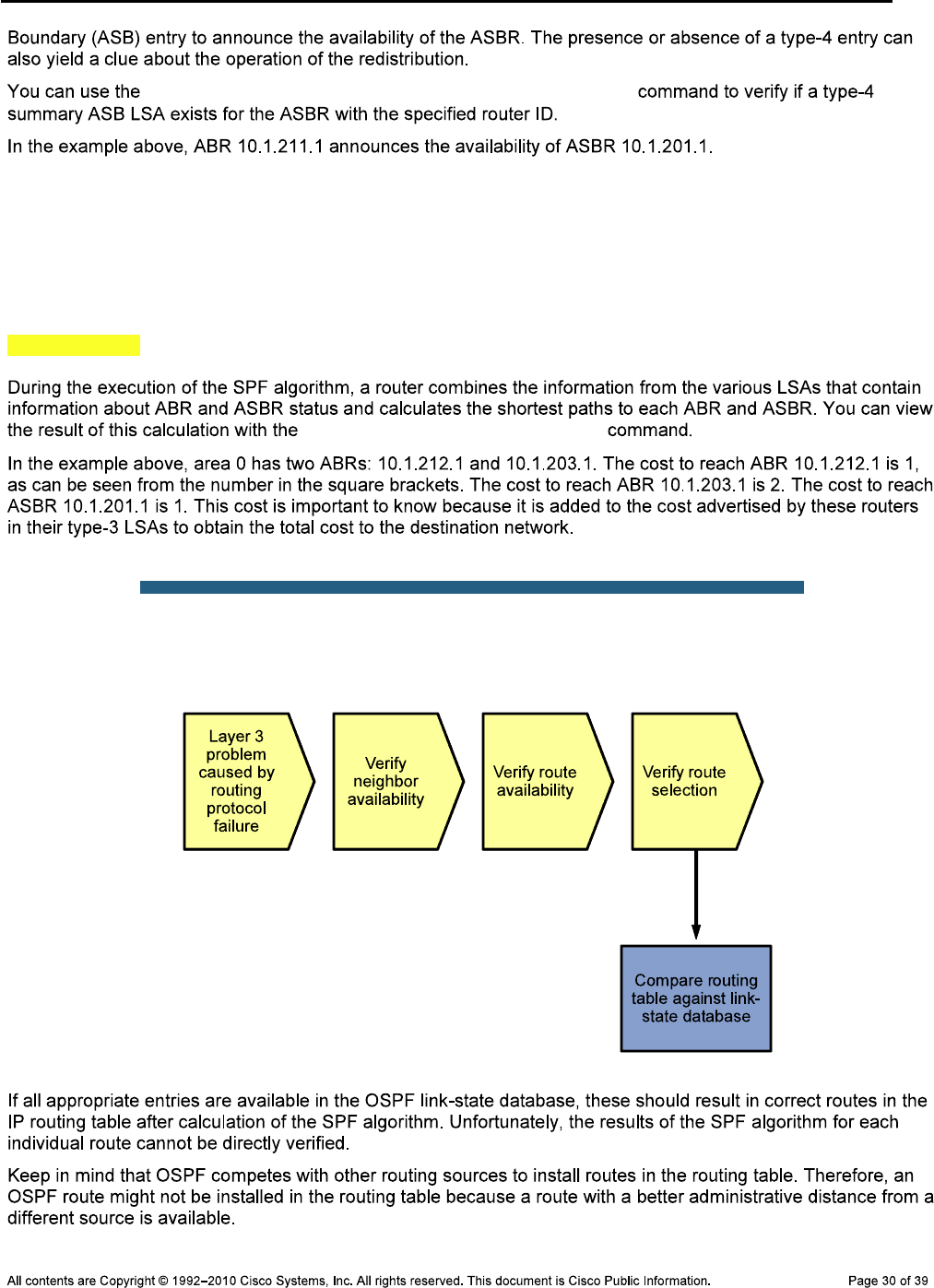
CCNPv6 TSHOOT
show ip ospf database asbr-summary router-id
DLS1#show ip ospf border-routers
OSPF Process 1 internal Routing Table
Codes: i - Intra-area route, I - Inter-area route
i 10.1.212.1 [1] via 10.1.200.253, Vlan200, ABR, area 0, SPF 5
i 10.1.201.1 [1] via 10.1.2.2, FastEthernet0/5, ASBR, area 0, SPF 5
i 10.1.203.1 [2] via 10.1.200.253, Vlan200, ABR, area 0, SPF 5
show ip ospf border-routers
Sample OSPF Troubleshooting Flow
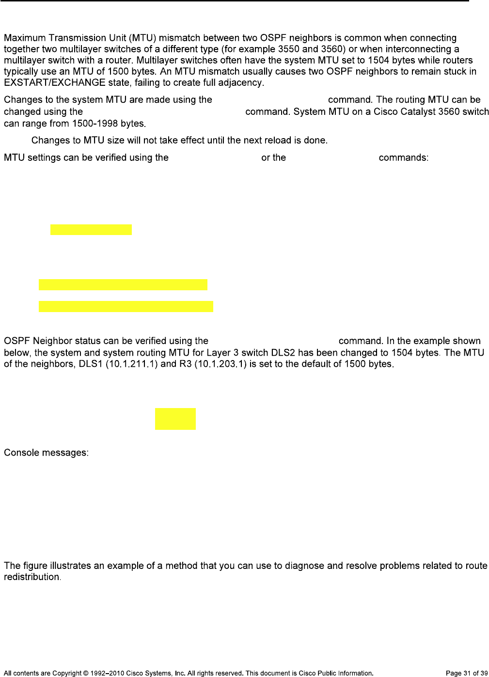
CCNPv6 TSHOOT
Verify the MTU between OSPF Neighbors
system mtu mtu-size
system mtu routing mtu-size
Note:
show interfaces show system mtu
DLS2#show interfaces fastEthernet 0/5
FastEthernet0/5 is up, line protocol is up (connected)
Hardware is Fast Ethernet, address is 0017.5a53.a3c2 (bia 0017.5a53.a3c2)
Description: FE to R3
Internet address is 10.1.2.13/30
MTU 1500 bytes, BW 100000 Kbit, DLY 100 usec,
reliability 255/255, txload 1/255, rxload 1/255
DLS2#show system mtu
System MTU size is 1500 bytes
System Jumbo MTU size is 1500 bytes
Routing MTU size is 1500 bytes
show ip ospf neighbor
DLS2#show ip ospf neighbor
Neighbor ID Pri State Dead Time Address Interface
10.1.211.1 1 EXSTART/BDR 00:00:38 10.1.200.252 Vlan200
10.1.203.1 1 EXSTART/BDR 00:00:37 10.1.2.14 FastEthernet0/5
DLS2#
%OSPF-5-ADJCHG: Process 1, Nbr 10.1.203.1 on FastEthernet0/5 from DOWN to
DOWN, Neighbor Down: Ignore timer expired
DLS2#
%OSPF-5-ADJCHG: Process 1, Nbr 10.1.211.1 on Vlan200 from EXSTART to DOWN,
Neighbor Down: Too many retransmissions
Troubleshooting Route Redistribution
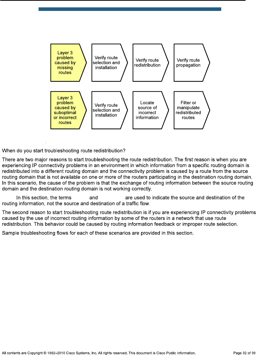
CCNPv6 TSHOOT
Sample Route Redistribution
Troubleshooting Flow
Note: source destination
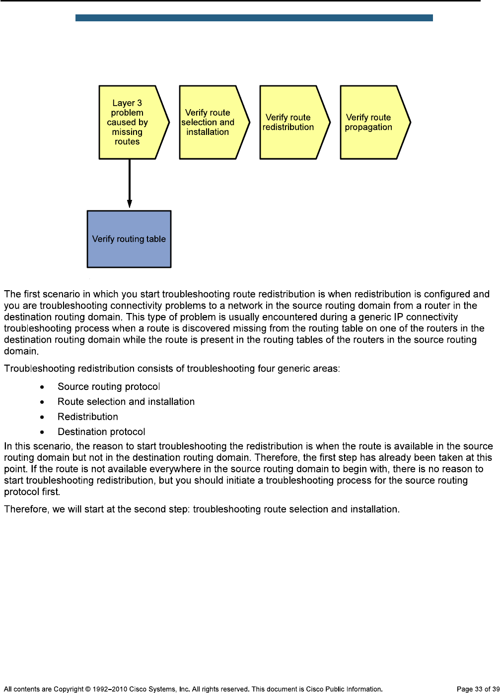
CCNPv6 TSHOOT
Sample Route Redistribution
Troubleshooting Flow
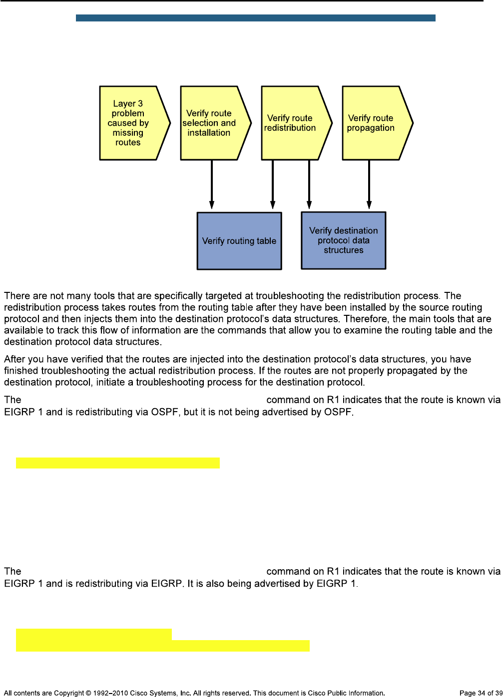
CCNPv6 TSHOOT
Sample Route Redistribution
Troubleshooting Flow
show ip route 10.1.202.1 255.255.255.255
R1#show ip route 10.1.202.1 255.255.255.255
Routing entry for 10.1.202.1/32
Known via "eigrp 1", distance 90, metric 2297856, type internal
Redistributing via eigrp 1, ospf 1
Last update from 10.1.1.2 on Serial0/0/0, 07:02:16 ago
Routing Descriptor Blocks:
* 10.1.1.2, from 10.1.1.2, 07:02:16 ago, via Serial0/0/0
Route metric is 2297856, traffic share count is 1
Total delay is 25000 microseconds, minimum bandwidth is 1544 Kbit
Reliability 255/255, minimum MTU 1500 bytes
Loading 1/255, Hops 1
show ip route 10.1.203.1 255.255.255.255
R1#show ip route 10.1.203.1 255.255.255.255
Routing entry for 10.1.203.1/32
Known via "ospf 1", distance 110, metric 4, type inter area
Redistributing via eigrp 1
Advertised by eigrp 1 metric 1544 2000 255 1 1500
Last update from 10.1.2.1 on FastEthernet0/1, 07:13:32 ago
Routing Descriptor Blocks:

CCNPv6 TSHOOT
* 10.1.2.1, from 10.1.203.1, 07:13:32 ago, via FastEthernet0/1
Route metric is 4, traffic share count is 1
show ip route network mask
Sample Route Redistribution
Troubleshooting Flow
show ip route traceroute
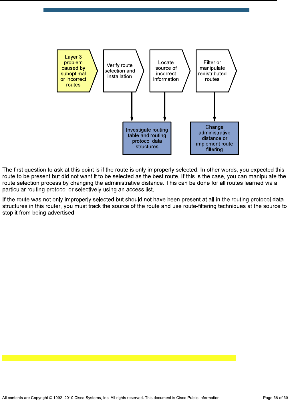
CCNPv6 TSHOOT
Sample Route Redistribution
Troubleshooting Flow
Verify the Routing Table
R1#show ip route
Codes: C - connected, S - static, R - RIP, M - mobile, B - BGP
D - EIGRP, EX - EIGRP external, O - OSPF, IA - OSPF inter area
N1 - OSPF NSSA external type 1, N2 - OSPF NSSA external type 2
E1 - OSPF external type 1, E2 - OSPF external type 2
i - IS-IS, su - IS-IS summary, L1 - IS-IS level-1, L2 - IS-IS level-2
ia - IS-IS inter area, * - candidate default, U - per-user static route
o - ODR, P - periodic downloaded static route
Gateway of last resort is not set
10.0.0.0/8 is variably subnetted, 15 subnets, 3 masks
O IA 10.1.10.0/24 [110/2] via 10.1.2.1, 07:43:07, FastEthernet0/1
O 10.1.2.12/30 [110/3] via 10.1.2.1, 07:42:57, FastEthernet0/1
C 10.1.1.2/32 is directly connected, Serial0/0/0
C 10.1.2.0/30 is directly connected, FastEthernet0/1
C 10.1.1.0/30 is directly connected, Serial0/0/0
O IA 10.1.30.0/24 [110/2] via 10.1.2.1, 07:43:07, FastEthernet0/1
O IA 10.1.20.0/24 [110/2] via 10.1.2.1, 07:43:07, FastEthernet0/1
O IA 10.1.50.0/24 [110/2] via 10.1.2.1, 07:43:07, FastEthernet0/1
O IA 10.1.100.0/24 [110/2] via 10.1.2.1, 07:43:07, FastEthernet0/1
D 10.1.202.1/32 [90/2297856] via 10.1.1.2, 07:43:48, Serial0/0/0
O IA 10.1.203.1/32 [110/4] via 10.1.2.1, 07:42:57, FastEthernet0/1
C 10.1.201.1/32 is directly connected, Loopback0
CCNPv6 TSHOOT
O 10.1.200.0/24 [110/2] via 10.1.2.1, 07:43:00, FastEthernet0/1
O 10.1.211.1/32 [110/2] via 10.1.2.1, 07:43:10, FastEthernet0/1
O 10.1.212.1/32 [110/3] via 10.1.2.1, 07:43:00, FastEthernet0/1
R1#show ip route 10.1.50.0 255.255.255.0
Routing entry for 10.1.50.0/24
Known via "ospf 1", distance 110, metric 2, type inter area
Redistributing via eigrp 1
Advertised by eigrp 1 metric 1544 2000 255 1 1500
Last update from 10.1.2.1 on FastEthernet0/1, 07:42:07 ago
Routing Descriptor Blocks:
* 10.1.2.1, from 10.1.211.1, 07:42:07 ago, via FastEthernet0/1
Route metric is 2, traffic share count is 1
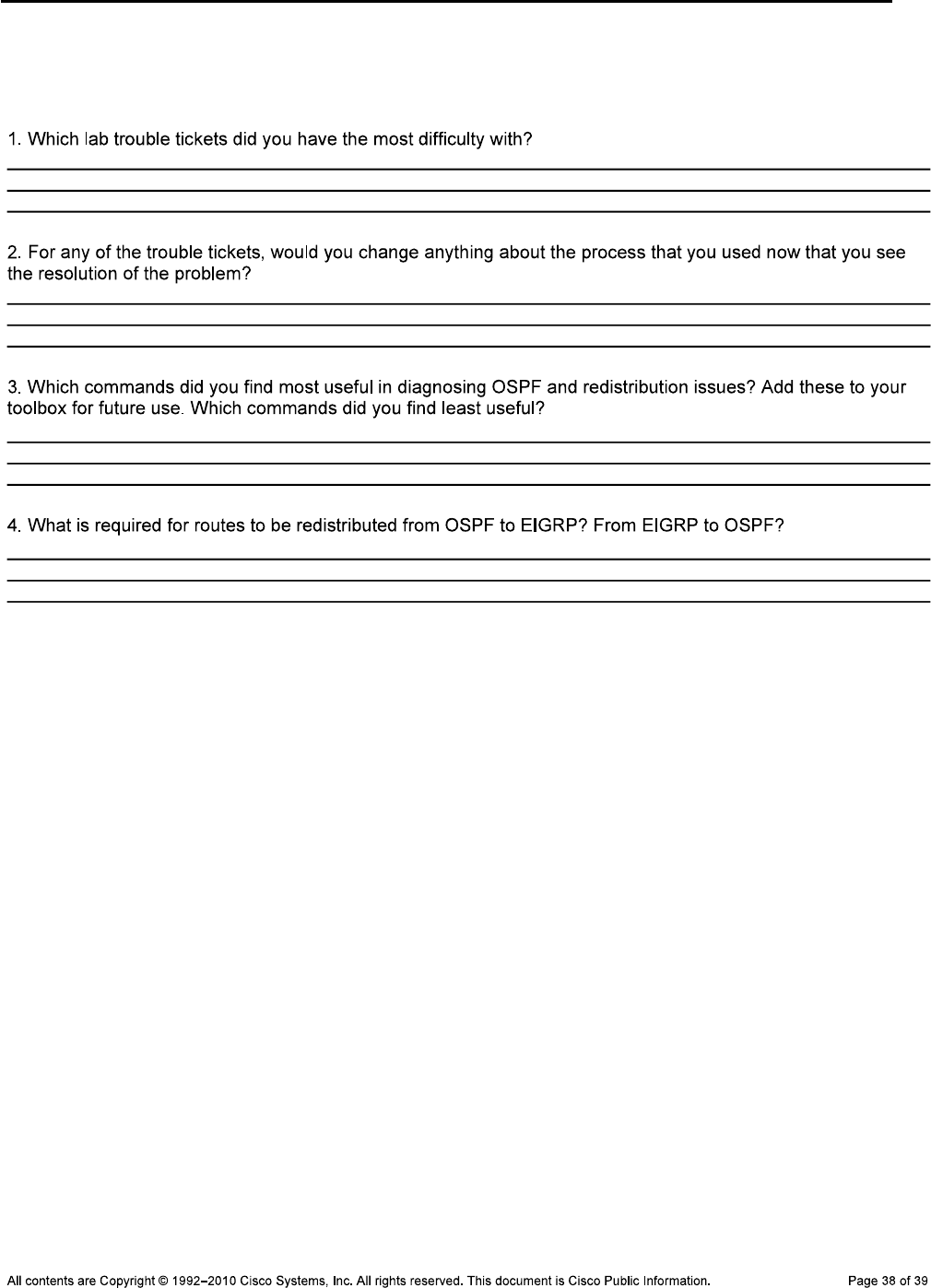
CCNPv6 TSHOOT
Reflection Questions
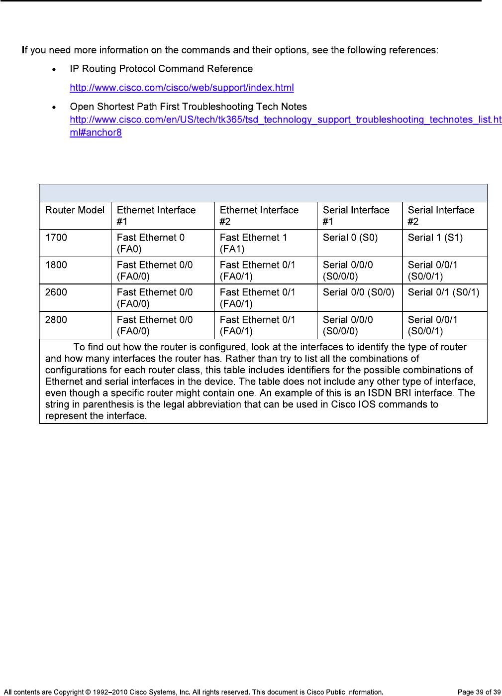
CCNPv6 TSHOOT
References
Router Interface Summary Table
Router Interface Summary
Note:
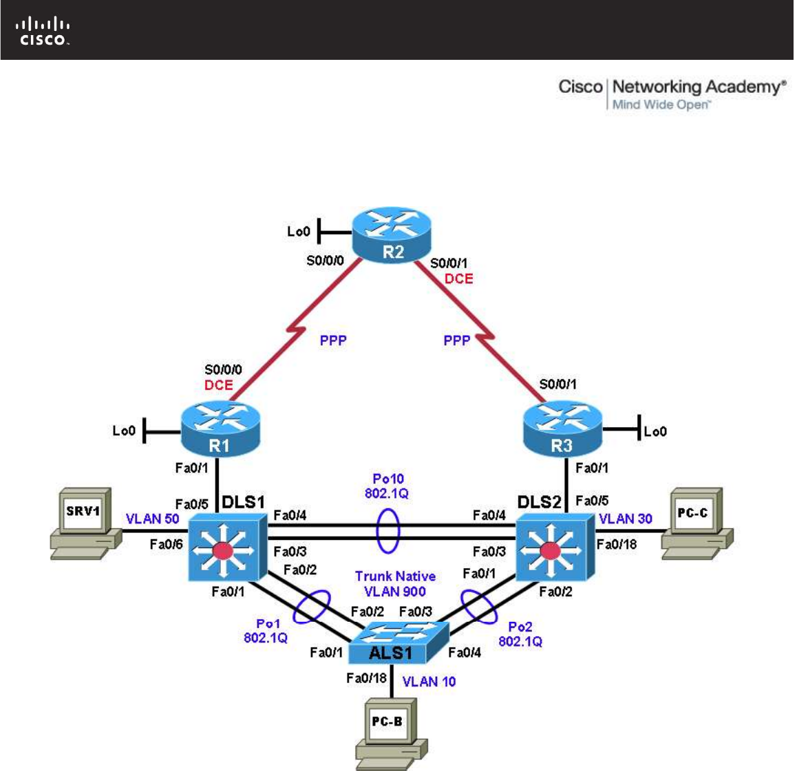
All contents are Copyright © 1992–2010 Cisco Systems, Inc. All rights reserved. This document is Cisco Public Information. Page 1 of 27
CCNPv6 TSHOOT
Chapter 5 Lab 5-3, BGP
Physical Topology (Baseline)

CCNPv6 TSHOOT
All contents are Copyright © 1992–2010 Cisco Systems, Inc. All rights reserved. This document is Cisco Public Information. Page 2 of 27
Logical Topology (Baseline)
Objectives
Load the trouble ticket device configuration files for each trouble ticket.
Diagnose and resolve problems related to the BGP exterior routing protocol.
Document troubleshooting progress, configuration changes, and problem resolution.
Background
Border Gateway Protocol (BGP) is the most widely used exterior routing protocol on the Internet. It is the de
facto standard for route (prefix) exchange between the autonomous systems (AS) of Internet service
providers (ISPs). BGP can also be used between a customer network and one or more ISPs. In this lab, you
will troubleshoot various problems related to BGP. For each task or trouble ticket, the trouble scenario and
problem symptom are described. While troubleshooting, you will discover the cause of the problem, correct it,
and then document the process and results.
Implementing BGP
Your company has decided to implement several new Internet-based services. The current web services that
the company offers are hosted at an external data center. It has been decided to build an in-house data
center from which the new services will be hosted. The servers that are currently externally hosted will also be
moved to the new data center.
Your company currently has a single ISP for Internet access. You have obtained a registered AS number
(65501) and address block 172.30.1.0/27, which will be used for the new services. After consulting with the

CCNPv6 TSHOOT
All contents are Copyright © 1992–2010 Cisco Systems, Inc. All rights reserved. This document is Cisco Public Information. Page 3 of 27
ISP, it has been decided to use BGP between the network edge router R1 and the ISP (R2). Upon successful
completion of the BGP implementation, your company is considering adding another ISP for redundancy, but
not as part of the current project.
Your support team has been working closely together with the engineering team to prepare the
implementation. You have received confirmation from the ISP that they have prepared their router for the
BGP implementation.
Router R1 will advertise the 172.30.1.0/27 IP address block to the ISP (R2). No other prefixes are allowed to
be advertised. This ensures that only the assigned network address block will be received by the ISP. ISPs
typically place filters on their edge routers to prevent customers from accidently announcing routes that do not
belong to them.
The ISP router will send a default route to router R1 via BGP. The default route will be redistributed into
Enhanced Interior Gateway Routing Protocol (EIGRP) by router R1. No other routes will be redistributed.
It is Friday evening, and the engineering team has just configured router R1 for BGP. To facilitate testing, a
new hosted services VLAN and the corresponding subnet 172.30.1.0/27 will be created. All other devices,
which have IP addresses in the 10.1.0.0/16 range, are using Network Address Translation (NAT), and their
Internet access should not be affected by the BGP configuration.
You are on standby to assist in troubleshooting and testing the solution.
Implementation Plan
The implementation plan is in two phases.
Phase 1
During Phase 1, the link between edge router R1 and the existing ISP will be upgraded to a T1 leased line
and converted to BGP. The remainder of the network will continue to use EIGRP. The 10.1.1.0/30 addressing
on the R1-to-R2 serial WAN link will be changed to a public address (209.165.200.224/30) provided by the
ISP. NAT will be used to translate the 10.1.0.0/16 internal private addresses to public address
209.165.200.225 using Port Address Translation (PAT). The loopback 0 address on R1 is also changed to
192.168.1.1.
An external BGP peering will be established between router R1 and the ISP (R2). The ISP will advertise a
default route to R1 via BGP. On router R1, redistribution of the default route will be configured between BGP
and EIGRP to ensure connectivity between headquarters and the ISP.
Phase 2
During Phase 2, the hosted services VLAN 130 named HSVCS and the corresponding subnet 172.30.1.0/27
will be created on switch DLS1. A test server for the hosted services subnet will be installed, simulated by
switch virtual interface (SVI) VLAN 130 172.30.1.1/27 on DLS1. A static route will be provided from R1 to
DLS1 VLAN 130. Some services will be migrated to the new IP address block before moving them to the
newly built datacenter.
BGP Network Design
The BGP design is outlined in the following figure. BGP AS 65501 is the company’s newly acquired AS
number. The ISP AS is 65502.

CCNPv6 TSHOOT
All contents are Copyright © 1992–2010 Cisco Systems, Inc. All rights reserved. This document is Cisco Public Information. Page 4 of 27
Test Plan
In Phase 1, edge router R1 must become a BGP peer with the ISP, and the internal office clients must be
able to access the Internet through the ISP. In Phase 2, the Internet clients must be able to access the hosted
services network.
Note: Trouble ticket A is related to the verification and acceptance of BGP Phase 1. Trouble tickets B and C
are related to the second phase of BGP conversion. Any interfaces that have been shut down on routers R2
and R3 should remain shut down for the duration of this lab exercise.
Physical and Logical Topology Diagrams
The physical and logical topologies for the existing EIGRP-based network are provided in this lab to assist the
troubleshooting effort.

CCNPv6 TSHOOT
All contents are Copyright © 1992–2010 Cisco Systems, Inc. All rights reserved. This document is Cisco Public Information. Page 5 of 27
Lab Structure
This lab is divided into two main sections.
Section 1—Trouble Tickets and Troubleshooting Logs
This section includes multiple tasks. Each task is associated with a trouble ticket (TT) and introduces one or
more errors on one or more devices. If time is a consideration, each task or trouble ticket can be performed
independently.
Section 2—Troubleshooting Reference Information
This section provides general BGP troubleshooting information that can be applied to any trouble ticket in this
lab. Sample troubleshooting flows are provided, along with examples of useful commands and output. If time
permits, it is recommended that you read Section 2 prior to starting on the trouble tickets.
Note: This lab uses Cisco 1841 routers with Cisco IOS Release 12.4(24)T1 and the advanced IP image
c1841-advipservicesk9-mz.124-24.T1.bin. The switches are Cisco WS-C2960-24TT-L with the Cisco IOS
image c2960-lanbasek9-mz.122-46.SE.bin and Catalyst 3560-24PS with the Cisco IOS image c3560-
advipservicesk9-mz.122-46.SE.bin. Other routers (such as 2801 and 2811), switches (such as 2950 or 3550),
and Cisco IOS Software versions can be used if they have comparable capabilities and features. Depending
on the router or switch model and Cisco IOS Software version, the commands available and output produced
might vary from what is shown in this lab.
Required Resources
3 routers (Cisco 1841 with Cisco IOS Release 12.4(24)T1 Advanced IP Service or comparable)
1 switch (Cisco 2960 with the Cisco IOS Release 12.2(46)SE C2960-LANBASEK9-M image or
comparable)
2 switches (Cisco 3560 with the Cisco IOS Release 12.2(46)SE C3560-LANBASEK9-M image or
comparable)
SRV1 (Windows PC with a static IP address) with TFTP and syslog servers, plus an SSH client
(PuTTY or comparable) and WireShark software
PC-B (Windows PC—DHCP client) with PuTTY and WireShark software
PC-C (Windows PC—DHCP client) with PuTTY and WireShark software
Serial and Ethernet cables
CCNPv6 TSHOOT
All contents are Copyright © 1992–2010 Cisco Systems, Inc. All rights reserved. This document is Cisco Public Information. Page 6 of 27
Section 1—Trouble Tickets and Troubleshooting Logs
Task 1: Trouble Ticket Lab 5-3 TT-A
Step 1: Review trouble ticket Lab 5-3 TT-A.
After your colleague finished configuring BGP on edge router R1, you tested connectivity from PC-B in VLAN
10 to the ISP router to verify the configuration and peering between R1 and R2. This test failed. When you
asked your colleague, he said he did not actually test the configuration from a client PC on the internal
network. He suspected there was a problem with the ISP and contacted them to find out if there was an issue
at their end. They stated that everything was correctly configured on router R2.
Your task is to diagnose the problem and verify that BGP is properly configured to enable BGP peering
between router R1 and the ISP.
Step 2: Load the device trouble ticket configuration files for TT-A.
Using the procedure described in Lab 3-1, verify that the lab configuration files are present in flash and load
the proper configuration files as indicated in the Device Configuration File table.
Note: The following device access methods are in effect after loading the configuration files:
Console access requires no username or password.
Telnet and SSH require username admin and password adminpa55.
The enable password is ciscoenpa55.
Device Configuration File Table
Device Name File to Load Notes
ALS1 Lab53-ALS1-TT-A-Cfg.txt
DLS1 Lab53-DLS1-TT-A-Cfg.txt
DLS2 Lab53-DLS2-TT-A-Cfg.txt
R1 Lab53-R1-TT-A-Cfg.txt
R2 Lab53-R2-TT-A-Cfg.txt
R3 Lab53-R3-TT-A-Cfg.txt
SRV1 N/A Static IP: 10.1.50.1
Default gateway: 10.1.50.254
PC-B N/A DHCP
PC-C N/A DHCP
Step 3: Configure SRV1 and start the syslog and TFTP servers.
Step 4: Release and renew the DHCP lease on PC-B.
a. Ensure that PC-B is configured as a DHCP client in the OFFICE VLAN.
b. After loading all TT-A device configuration files, issue the ipconfig /release and ipconfig /renew
commands on PC-B.

CCNPv6 TSHOOT
All contents are Copyright © 1992–2010 Cisco Systems, Inc. All rights reserved. This document is Cisco Public Information. Page 7 of 27
Step 5: Outline the troubleshooting approach and validation steps.
Use this space to identify your troubleshooting approach and the key steps to verify that the problem is
resolved. Troubleshooting approaches to select from include the follow-the-path, spot-the-differences, bottom-
up, top-down, divide-and-conquer, shoot-from-the-hip, and move-the-problem methods.
Note: In addition to a specific approach, you can use the generic troubleshooting process described at the
beginning of Section 2 of this lab.
_______________________________________________________________________________
_______________________________________________________________________________
_______________________________________________________________________________
_______________________________________________________________________________
_______________________________________________________________________________
_______________________________________________________________________________
Step 6: Record the troubleshooting process and configuration changes.
Note: Section 2 of this lab includes sample troubleshooting flows, useful commands, and examples of output.
Use this log to document your actions and results during the troubleshooting process. List the commands you
used to gather information. As you progress, record what you think the problem might be and which actions
you will take to correct the problem.
Device Actions and Results

CCNPv6 TSHOOT
All contents are Copyright © 1992–2010 Cisco Systems, Inc. All rights reserved. This document is Cisco Public Information. Page 8 of 27
Step 7: Document trouble ticket debrief notes.
Use this space to make notes of the key learning points that you picked up during the discussion of this
trouble ticket with your instructor. The notes can include problems encountered, solutions applied, useful
commands employed, alternate solutions and methods, and procedure and communication improvements.
_______________________________________________________________________________
_______________________________________________________________________________
_______________________________________________________________________________
_______________________________________________________________________________
_______________________________________________________________________________
_______________________________________________________________________________
_______________________________________________________________________________
Task 2: Trouble Ticket Lab 5-3 TT-B
Step 1: Review trouble ticket Lab 5-3 TT-B.
The next step after the peering has been established is to test the new hosted services subnet, which has
been created using VLAN 130. This subnet uses the 172.30.1.0/27 IP address block that was assigned to
your company by the ISP. The subnet has been configured, and a test server has been installed (simulated
by DLS1 SVI VLAN 130 - 172.30.1.1). Internet clients must be able to access the subnet from ISP router R2
(simulated by Lo0 192.168.2.1). Other hosts in the EIGRP 10.1.0.0/16 domain do not require access to the
hosted services subnet.
Your task is to verify VLAN configuration and routing functionality. Also, verify that traffic from the Internet can
be sent to the hosted network test server in VLAN 130 via R1 and that the return traffic can be received via
ISP router R2.
Step 2: Load the device trouble ticket configuration files for TT-B.
Using the procedure described in Lab 3-1, verify that the lab configuration files are present in flash. Load the
configuration files as indicated in the Device Configuration File table.
Note: See Task 1, Step 2 for device access methods, usernames, and passwords after the configuration files
have been loaded.
Device Configuration File Table
Device Name File to Load Notes
ALS1 Lab53-ALS1-TT-B-Cfg.txt
DLS1 Lab53-DLS1-TT-B-Cfg.txt
DLS2 Lab53-DLS2-TT-B-Cfg.txt
R1 Lab53-R1-TT-B-Cfg.txt
R2 Lab53-R2-TT-B-Cfg.txt
R3 Lab53-R3-TT-B-Cfg.txt
SRV1 N/A Static IP: 10.1.50.1
Default gateway: 10.1.50.254
PC-B N/A DHCP
PC-C N/A DHCP

CCNPv6 TSHOOT
All contents are Copyright © 1992–2010 Cisco Systems, Inc. All rights reserved. This document is Cisco Public Information. Page 9 of 27
Step 3: Configure SRV1 and start the syslog and TFTP servers.
Step 4: Release and renew the DHCP leases on PC-B and PC-C, as described in Task 1.
Step 5: Outline the troubleshooting approach and validation steps.
Use this space to identify your troubleshooting approach and the key steps to verify that the problem is
resolved. Troubleshooting approaches to select from include the follow-the-path, spot-the-differences, bottom-
up, top-down, divide-and-conquer, shoot-from-the-hip, and move-the-problem methods.
Note: In addition to a specific approach, you can use the generic troubleshooting process described at the
beginning of Section 2 of this lab.
_______________________________________________________________________________
_______________________________________________________________________________
_______________________________________________________________________________
_______________________________________________________________________________
_______________________________________________________________________________
Step 6: Record the troubleshooting process and configuration changes.
Note: Section 2 of this lab includes sample troubleshooting flows, useful commands, and examples of output.
Use this log to document your actions and results during the troubleshooting process. List the commands you
used to gather information. As you progress, record what you think the problem might be and which actions
you will take to correct the problem.
Device Actions and Results

CCNPv6 TSHOOT
All contents are Copyright © 1992–2010 Cisco Systems, Inc. All rights reserved. This document is Cisco Public Information. Page 10 of 27
Step 7: Document trouble ticket debrief notes.
Use this space to make notes of the key learning points that you picked up during the discussion of this
trouble ticket with your instructor. The notes can include problems encountered, solutions applied, useful
commands employed, alternate solutions and methods, and procedure and communication improvements.
_______________________________________________________________________________
_______________________________________________________________________________
_______________________________________________________________________________
_______________________________________________________________________________
_______________________________________________________________________________
_______________________________________________________________________________
_______________________________________________________________________________
Task 3: Trouble Ticket Lab 5-3 TT-C
Step 1: Review trouble ticket Lab 5-3 TT-C.
Your ISP uses prefix lists to ensure that customers do not announce routes that have not been officially
assigned to them. This is critical for an ISP because if two customers were to accidently announce the same
route as their own, it would create problems for both customers and the ISP. After you corrected the static
route and BGP route injection issues on R1, one of your colleagues was working with the hosted services test
network and made some changes. Now he can no longer ping from the hosted network test server (DLS1
VLAN 130) to the ISP. The ISP is also not receiving the advertisement for the hosted services subnet. Your
task is to diagnose this problem and resolve it.
Step 2: Load the device trouble ticket configuration files for TT-C.
Using the procedure described in Lab 3-1, verify that the lab configuration files are present in flash. Load the
proper configuration files as indicated in the Device Configuration File table.
Note: See Task 1, Step 2 for device access methods, usernames, and passwords after the configuration files
have been loaded.

CCNPv6 TSHOOT
All contents are Copyright © 1992–2010 Cisco Systems, Inc. All rights reserved. This document is Cisco Public Information. Page 11 of 27
Device Configuration File Table
Device Name File to Load Notes
ALS1 Lab53-ALS1-TT-C-Cfg.txt
DLS1 Lab53-DLS1-TT-C-Cfg.txt
DLS2 Lab53-DLS2-TT-C-Cfg.txt
R1 Lab53-R1-TT-C-Cfg.txt
R2 Lab53-R2-TT-C-Cfg.txt
R3 Lab53-R3-TT-C-Cfg.txt
SRV1 N/A Static IP: 10.1.50.1
Default gateway: 10.1.50.254
PC-B N/A DHCP
PC-C N/A DHCP
Step 3: Configure SRV1 and start the syslog and TFTP servers, as described in Task 1.
Step 4: Release and renew the DHCP leases on PC-B and PC-C, as described in Task 1.
Step 5: Outline the troubleshooting approach and validation steps.
Use this space to identify your troubleshooting approach and the key steps to verify that the problem is
resolved. Troubleshooting approaches to select from include the follow-the-path, spot-the-differences, bottom-
up, top-down, divide-and-conquer, shoot-from-the-hip, and move-the-problem methods.
Note: In addition to a specific approach, you can use the generic troubleshooting process described at the
beginning of Section 2 of this lab.
_______________________________________________________________________________
_______________________________________________________________________________
_______________________________________________________________________________
_______________________________________________________________________________
_______________________________________________________________________________
_______________________________________________________________________________
Step 6: Record the troubleshooting process and configuration changes.
Note: Section 2 of this lab includes sample troubleshooting flows, useful commands, and examples of output.
Use this log to document your actions and results during the troubleshooting process. List the commands you
used to gather information. As you progress, record what you think the problem might be and which actions
you will take to correct the problem.
Device Actions and Results
CCNPv6 TSHOOT
All contents are Copyright © 1992–2010 Cisco Systems, Inc. All rights reserved. This document is Cisco Public Information. Page 12 of 27
Device Actions and Results
Step 7: Document trouble ticket debrief notes.
Use this space to make notes of the key learning points that you picked up during the discussion of this
trouble ticket with your instructor. The notes can include problems encountered, solutions applied, useful
commands employed, alternate solutions and methods, and procedure and communication improvements.
_______________________________________________________________________________
_______________________________________________________________________________
_______________________________________________________________________________
_______________________________________________________________________________
_______________________________________________________________________________
_______________________________________________________________________________
_______________________________________________________________________________

CCNPv6 TSHOOT
All contents are Copyright © 1992–2010 Cisco Systems, Inc. All rights reserved. This document is Cisco Public Information. Page 13 of 27
Section 2—Troubleshooting Reference Information
General Troubleshooting Process
As a general guideline, you can use the following general troubleshooting process described in the course.
1. Define the problem (symptoms).
2. Gather information.
3. Analyze the information.
4. Propose a hypothesis (possible cause).
5. Test the hypothesis.
6. Eliminate or accept the hypothesis.
7. Solve the problem.
8. Document the problem.
Command Summary
The table lists useful commands. Sample output is shown on the following pages.
Command Key Information Displayed
show ip route
or
show ip route ip-addr
Displays the entire routing table or information for a
particular destination address.
show ip bgp
Displays local and learned network entries in the
BGP table with next hop, metric, local preference,
weight, and AS path.
show ip bgp summary
Displays a summary of the BGP neighbor table. This
command lists important BGP parameters, such as
the AS number and router ID, statistics about the
memory consumption of the various BGP data
structures, and a brief overview of the configured
neighbors and their state.
show ip bgp neighbors
or
show ip bgp neighbor ip-address
Displays parameters and extensive statistics about
the peering session for all neighbors or for a
particular neighbor address.
show ip bgp network mask
Displays the contents of the BGP table for a specific
prefix. The information is organized in the following
manner: The entry for each available path in the
table starts with the AS path attribute of the path,
using the word “Local” to represent the empty AS
path string.
debug ip tcp transactions
Displays TCP connection activity between peers.
Can be used to investigate whether the TCP session
is refused, established, and subsequently torn down
again, or no response is received at all from the
neighbor.
debug ip bgp Displays the successive state transitions during the
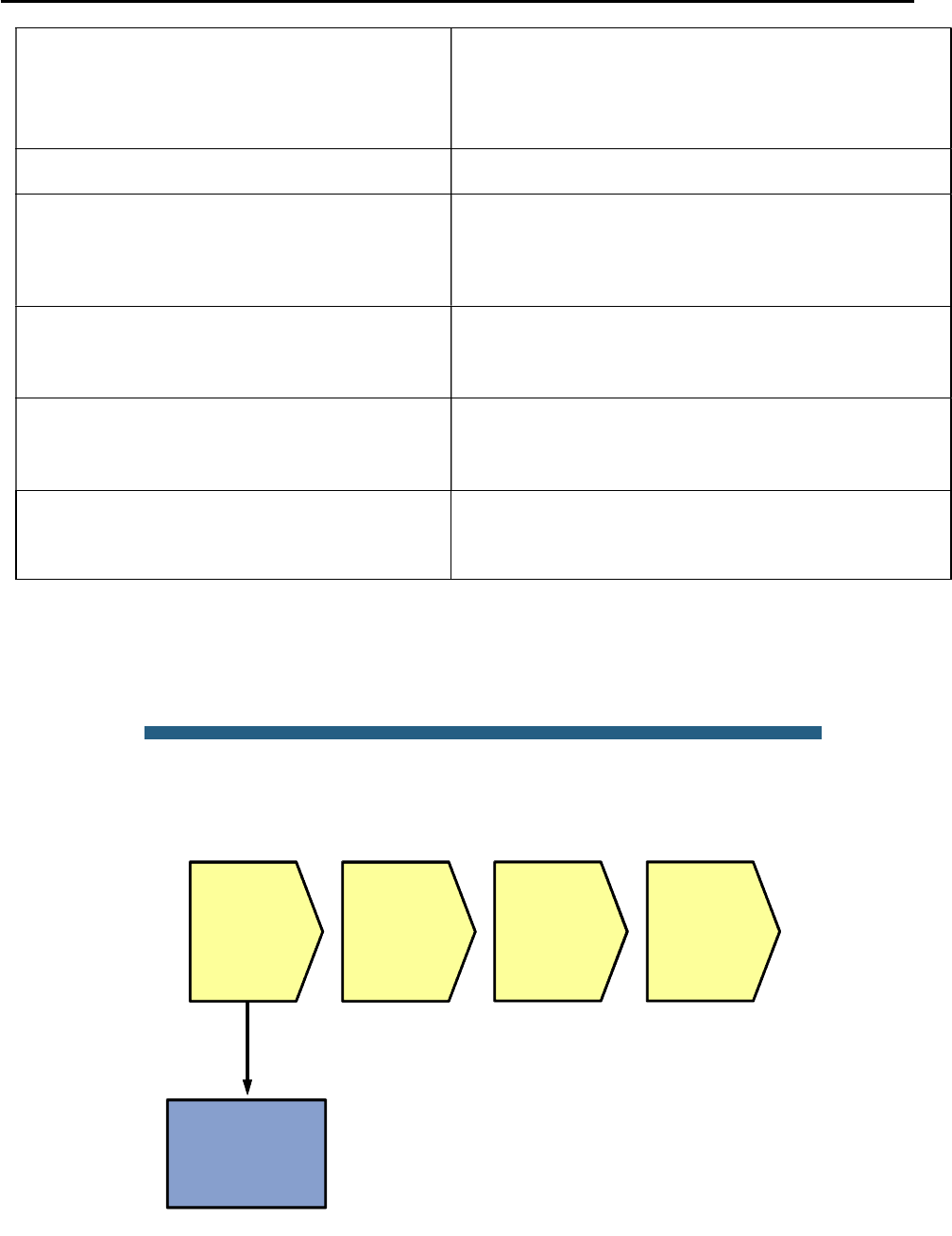
CCNPv6 TSHOOT
All contents are Copyright © 1992–2010 Cisco Systems, Inc. All rights reserved. This document is Cisco Public Information. Page 14 of 27
establishment of the BGP peering. If one of the peers
decides to close the session because of a parameter
problem, such as a mismatched AS number or an
invalid router ID, the debug also displays information
about the cause.
clear ip bgp * Clears the contents of the BGP table.
show ip bgp network mask longer
prefixes
Displays more specific prefixes present in the BGP
table (including the prefix itself) that are contained in
the prefix specified by the network and mask
options.
show ip bgp neighbor ip-address
routes
Displays all routes in the BGP table that were
received from the neighbor specified by the ip-
address option.
show ip bgp neighbor ip-address
advertised-routes
Displays all routes in the BGP table that will be
advertised to the neighbor specified by the ip-
address option.
show ip bgp regexp regular-
expression
Displays all routes from the BGP table that have an
AS path string that is matched by the specified
regular expression.
Lab 5-3: Sample Troubleshooting Flows
The figure illustrates an example of a method that you could follow to diagnose and resolve problems related to
BGP.
© 2009 Cisco Systems, Inc. All rights reserved. TSHOOT v1.0—93
Sample BGP Troubleshooting Flow
Verify routing table
and FIB
Verify
neighbor
availability
Verify route
availability
Verify route
selection
Layer 3
problem
caused by
routing
protocol
failure
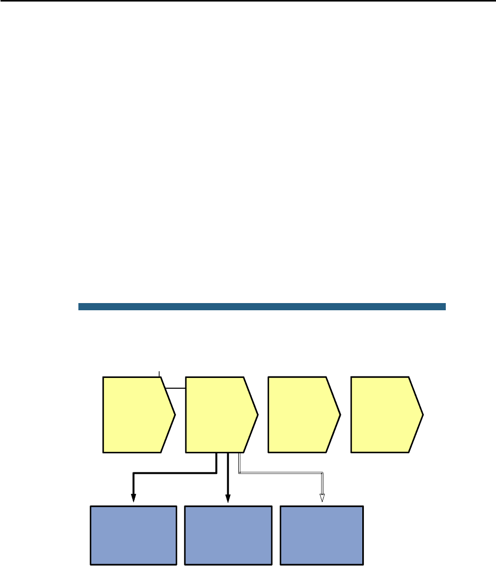
CCNPv6 TSHOOT
All contents are Copyright © 1992–2010 Cisco Systems, Inc. All rights reserved. This document is Cisco Public Information. Page 15 of 27
The typical trigger to start investigating BGP operation is when you are using BGP as an exterior gateway
protocol to connect to other autonomous systems and you are troubleshooting IP connectivity to a destination in a
different AS. Some reasons to start investigating BGP are if a route to the destination network is missing from the
routing table of one of the routers, a different route than expected was selected to forward the packets to that
destination, or return traffic from the other AS is not making it back to the source.
Troubleshooting problems with missing return traffic usually requires coordination with those responsible for the
routing in the destination AS and possibly even intermediate autonomous systems. The only thing you can verify
from within your own AS is if your routing information is correctly passed to the neighbor AS. Propagation of your
routes beyond your direct peers cannot be verified without access to routers in other autonomous systems.
Therefore, this flow focuses mainly on troubleshooting traffic to a destination network in a different AS. However,
commands that are helpful in troubleshooting route advertisement to a different AS are also highlighted, if
appropriate.
To install a route into the routing table, each router that uses BGP goes through several stages:
1. Establish neighbor relationships with its configured neighbors.
2. Exchange routing information with neighbors and store the received information in the BGP table.
3. Select the best route from the available routes and install it in the routing table.
Errors during any of these stages can cause routing information to be missed or incorrect routing information to
be installed in the routing table.
The order in which the different stages are verified is not important, as long as a structured approach is used.
© 2009 Cisco Systems, Inc. All rights reserved. TSHOOT v1.0—94
Sample BGP Troubleshooting Flow
Verify
neighbor
availability
Verify route
availability
Verify route
selection
Layer 3
problem
caused by
routing
protocol
failure
Verify BGP
neighbor table
Verify IP and TCP
connectivity
Debug BGP
neighbor
establishment
BGP does not discover neighbors. Neighbor relationships are established based on an explicit configuration on
both routers that participate in the peering session.
BGP uses TCP as a transport protocol. Establishing a peering relationship always starts with the establishment of
a TCP session on port 179 between the configured neighbor IP addresses. By default, both neighbors attempt to
initiate the TCP session to the configured IP address of the neighbor. When a router receives an incoming
session request, it compares the source IP address of the session to its list of configured neighbors. It only
accepts the session if the source IP address matches one of the IP addresses of its configured neighbors.
Therefore, it is important that a router always sources the BGP packets that it sends to a specific neighbor from

CCNPv6 TSHOOT
All contents are Copyright © 1992–2010 Cisco Systems, Inc. All rights reserved. This document is Cisco Public Information. Page 16 of 27
the IP address that has been configured as the neighbor IP address on the peer router. For neighbors that are
directly connected on an interface, the correct source address is automatically used. For neighbors that are not
directly connected, the appropriate source IP address for the session to a neighbor might need to be selected with
the neighbor ip-address update-source interface-id command.
Verify the BGP Neighbor Table
R1#show ip bgp
BGP table version is 2, local router ID is 192.168.1.1
Status codes: s suppressed, d damped, h history, * valid, > best, i - internal,
r RIB-failure, S Stale
Origin codes: i - IGP, e - EGP, ? - incomplete
Network Next Hop Metric LocPrf Weight Path
*> 0.0.0.0 192.168.2.1 0 0 65502 i
R1#show ip bgp summary
BGP router identifier 192.168.1.1, local AS number 65501
BGP table version is 3, main routing table version 3
2 network entries using 264 bytes of memory
2 path entries using 104 bytes of memory
3/2 BGP path/bestpath attribute entries using 504 bytes of memory
1 BGP AS-PATH entries using 24 bytes of memory
0 BGP route-map cache entries using 0 bytes of memory
0 BGP filter-list cache entries using 0 bytes of memory
Bitfield cache entries: current 1 (at peak 1) using 32 bytes of memory
BGP using 928 total bytes of memory
BGP activity 2/0 prefixes, 2/0 paths, scan interval 60 secs
Neighbor V AS MsgRcvd MsgSent TblVer InQ OutQ Up/Down State/PfxRcd
192.168.2.1 4 65502 36 36 3 0 0 00:33:01 1
To verify that all expected neighbor relationships are operational, you can display a summary of the BGP
neighbor table using the show ip bgp summary command. This command lists important BGP parameters,
such as the AS number and router ID, statistics about the memory consumption of the various BGP data
structures, and a brief overview of the configured neighbors and their state.
For each neighbor, the configured IP address and AS of the neighbor are listed. The Up/Down column lists the
time that has elapsed since the last state change. For a neighbor that is currently up, it lists the time elapsed
since the session was established. For a neighbor that is down, it lists the time elapsed since the session was
lost.
The most important column to verify the operational state of the neighbor is State/PfxRcd. This column can
display the following values:
Idle – Indicates that there is no session with the peer, and the router is not currently attempting to
establish a session with the peer. The router is ready to accept incoming sessions.
Idle (Admin) – Indicates that the session has been administratively shut down with the neighbor
ip-address shutdown command.
Active – The router is actively trying to open a TCP session with the neighbor. If it does not succeed
in establishing the session, the router toggles between the Idle and Active states
Open Sent – An Open message has been sent to the neighboring router containing the router ID, AS
number, BGP version, hold timer, and capabilities.
Open Confirm – An Open message from the neighbor has been received, the parameters in the
message have been processed and accepted, and a hello message has been sent to acknowledge
the acceptance of the neighbor’s Open message.

CCNPv6 TSHOOT
All contents are Copyright © 1992–2010 Cisco Systems, Inc. All rights reserved. This document is Cisco Public Information. Page 17 of 27
Number of received prefixes – After an acknowledgment from the neighbor confirming the reception
of this router’s Open message, the state of the session moves to the Established state. At this point,
the State/PfxRcd column does not list the state. It shows the number of prefixes that have been
received from that neighbor and installed in the BGP table. The desired result is to see a number
listed in this column, because that indicates that the session with the peer has been successfully
established.
The Open Sent and Open Confirm states are transitory states. When the state for a neighbor toggles between
Active and Idle, this indicates that the router is not successful in establishing a session with the neighbor.
You can use the show ip bgp neighbor ip-address command to display additional parameters and
extensive statistics about the peering session. For more information about these parameters and statistics, see
the BGP command references on www.cisco.com.
Verify IP and TCP Connectivity
R1#debug ip tcp transactions
TCP special event debugging is on
R1#conf t
Enter configuration commands, one per line. End with CNTL/Z.
R1(config)#no router bgp 65501
R1(config)#
*Nov 16 17:21:35.102: %BGP-5-ADJCHANGE: neighbor 192.168.2.1 Down BGP protocol i
nitialization
R1(config)#
*Nov 16 17:21:35.102: TCP0: state was ESTAB -> FINWAIT1 [179 -> 192.168.2.1(1188
9)]
*Nov 16 17:21:35.102: TCP0: sending FIN
*Nov 16 17:21:35.126: Released port 179 in Transport Port Agent for TCP IP type
0 delay 240000
*Nov 16 17:21:35.126: TCP0: state was LISTEN -> CLOSED [179 -> 192.168.2.1(0)]
*Nov 16 17:21:35.126: TCB 0x66EE8F34 destroyed
*Nov 16 17:21:35.138: TCP0: state was FINWAIT1 -> FINWAIT2 [179 -> 192.168.2.1(1
1889)]
*Nov 16 17:21:35.138: TCP0: FIN processed
*Nov 16 17:21:35.138: TCP0: state was FINWAIT2 -> TIMEWAIT [179 -> 192.168.2.1(1
1889)]
R1(config)#
*Nov 16 17:21:50.286: Reserved port 0 in Transport Port Agent for TCP IP type 0
*Nov 16 17:21:50.286: TCP: sending RST, seq 0, ack 2752306274
*Nov 16 17:21:50.286: TCP: sent RST to 192.168.2.1:41738 from 192.168.1.1:179
*Nov 16 17:21:50.290: Released port 0 in Transport Port Agent for TCP IP type 0
delay 240000
*Nov 16 17:21:50.290: TCP0: state was LISTEN -> CLOSED [0 -> UNKNOWN(0)]
*Nov 16 17:21:50.290: TCB 0x66F17E40 destroyed
R1(config)#
*Nov 16 17:21:55.006: Reserved port 0 in Transport Port Agent for TCP IP type 0
*Nov 16 17:21:55.006: TCP: sending RST, seq 0, ack 3974493125
*Nov 16 17:21:55.006: TCP: sent RST to 192.168.2.1:47416 from 192.168.1.1:179
*Nov 16 17:21:55.006: Released port 0 in Transport Port Agent for TCP IP type 0
delay 240000
R1(config)#router bgp 65501
R1(config-router)#no synchronization
R1(config-router)#bgp log-neighbor-changes
R1(config-router)#neighbor 192.168.2.1 remote-as 65502
R1(config-router)#neighbor 192.168.2.1 ebgp-multihop 2

CCNPv6 TSHOOT
All contents are Copyright © 1992–2010 Cisco Systems, Inc. All rights reserved. This document is Cisco Public Information. Page 18 of 27
R1(config-router)#neighbor 192.168.2.1 update-source Loopback0
*Nov 16 17:28:46.549: TCB65950C34 created
*Nov 16 17:28:46.549: TCB65950C34 setting property TCP_PMTU (38) 66A7C214
*Nov 16 17:28:46.549: TCB65950C34 setting property TCP_TOS (11) 66A7C220
*Nov 16 17:28:46.549: TCB65950C34 setting property TCP_VRFTABLEID (20) 66F233F8
*Nov 16 17:28:46.549: TCB65950C34 setting property TCP_IN_TTL (29) 66A7C200
*Nov 16 17:28:46.553: TCB65950C34 setting property TCP_OUT_TTL (30) 66A7C200
*Nov 16 17:28:46.553: TCB65950C34 setting property TCP_OUT_TTL (30) 66F2359A
*Nov 16 17:28:46.553: TCB65950C34 bound to UNKNOWN.179
*Nov 16 17:28:46.553: TCB65950C34 setting property TCP_ACCESS_CHECK (5) 60B47108
*Nov 16 17:28:46.553: TCB65950C34 setting property TCP_MD5KEY (4) 0
*Nov 16 17:28:46.553: Reserved port 179 in Transport Port Agent for TCP IP type
0
*Nov 16 17:28:46.553: TCB65950C34 listening with queue 1
*Nov 16 17:28:46.585: TCB65950C34 setting property TCP_IN_TTL (29) 66A7C278
*Nov 16 17:28:46.585: TCB65950C34 setting property TCP_OUT_TTL (30) 66A7C278
*Nov 16 17:28:46.585: TCB65950C34 setting property TCP_OUT_TTL (30) 66F2359A
R1(config-router)#
*Nov 16 17:28:50.581: TCB67096718 created
*Nov 16 17:28:50.581: TCB67096718 setting property TCP_VRFTABLEID (20) 66F233F8
*Nov 16 17:28:50.581: TCB67096718 setting property TCP_MD5KEY (4) 0
*Nov 16 17:28:50.581: TCB67096718 setting property TCP_ACK_RATE (32) 66F1B4D4
*Nov 16 17:28:50.581: TCB67096718 setting property TCP_TOS (11) 66F1B4C0
*Nov 16 17:28:50.581: TCB67096718 setting property TCP_PMTU (38) 66F1B48C
*Nov 16 17:28:50.581: TCB67096718 setting property TCP_IN_TTL (29) 66F1B478
*Nov 16 17:28:50.581: TCB67096718 setting property TCP_OUT_TTL (30) 66F1B478
*Nov 16 17:28:50.581: TCB67096718 setting property TCP_OUT_TTL (30) 66F2359A
*Nov 16 17:28:50.581: TCP: Random local port generated 30517, network 1
*Nov 16 17:28:50.581: TCB67096718 bound to 192.168.1.1.30517
*Nov 16 17:28:50.581: TCB67096718 setting property TCP_RTRANSTMO (31) 66F1B4D8
*Nov 16 17:28:50.581: Reserved port 30517 in Transport Port Agent for TCP IP typ
e 1
*Nov 16 17:28:50.581: TCP: sending SYN, seq 3632881552, ack 0
*Nov 16 17:28:50.581: TCP0: Connection to 192.168.2.1:179, advertising MSS 536
*Nov 16 17:28:50.585: TCP0: state was CLOSED -> SYNSENT [30517 -> 192.168.2.1(17
9)]
*Nov 16 17:28:50.593: TCP0: state was SYNSENT -> ESTAB [30517 -> 192.168.2.1(179
)]
*Nov 16 17:28:50.593: TCP: tcb 67096718 connection to 192.168.2.1:179, peer MSS
536, MSS is 536
*Nov 16 17:28:50.593: TCB67096718 connected to 192.168.2.1.179
*Nov 16 17:28:50.593: TCB67096718 setting property TCP_NO_DELAY (0) 66F1B4D8
*Nov 16 17:28:50.593: TCB67096718 setting property TCP_RTRANSTMO (31) 66F1B4D8
*Nov 16 17:28:50.621: %BGP-5-ADJCHANGE: neighbor 192.168.2.1 Up
R1(config-router)#
*Nov 16 17:28:50.821: TCP0: ACK timeout timer expired
R1(config-router)#do u all
All possible debugging has been turned off
If a session to one of the neighbors is not established correctly, you can take several steps to diagnose the issue.
The first step is to test IP connectivity to the IP address of the neighbor by using the ping command. Make sure
that you specify the same source interface that is used as the source interface for the BGP session. If the ping
fails, initiate a troubleshooting process to first restore IP connectivity to the neighbor.
If the ping is successful, the next step is to determine whether the TCP session with the neighbor is established
and successively torn down again, or if the TCP session is never established.

CCNPv6 TSHOOT
All contents are Copyright © 1992–2010 Cisco Systems, Inc. All rights reserved. This document is Cisco Public Information. Page 19 of 27
You can use the debug ip tcp transactions command to investigate whether the TCP session is refused
(indicated by the reception of a TCP RST), established and subsequently torn down again (indicated by the
normal TCP initiation and termination handshakes), or no response is received at all from the neighbor.
In the example output above, you can see that the TCP session to IP address 192.168.2.1 and TCP port 179 is
refused by the peer, as indicated by the reception of the TCP RST from the peer. Clues like these can help
eliminate possible problem causes. For instance, in this particular example, the output rules out an access list as
the cause of the problem, because a TCP RST has been successfully received from the neighbor in response to
the transmitted TCP SYN. In general, the fact that the peer refuses the session indicates that it does not
recognize the session as coming from one of its configured neighbors. Possible causes are a missing neighbor
statement or a mismatch between the configured IP address on the neighbor and the source IP address used by
this router. Note that the source IP address and TCP port of the session are also displayed in the output of the
debug as “bound to 192.168.1.1.30517.” You must work together with the party that manages the peer router to
determine the exact cause of the problem.
Debug BGP Neighbor Establishment
R1#debug ip bgp
BGP debugging is on for address family: IPv4 Unicast
R1#conf t
Enter configuration commands, one per line. End with CNTL/Z.
R1(config)#interface s0/0/0
R1(config-if)#shutdown
R1(config-if)#
*Nov 16 17:38:51.181: %LINK-5-CHANGED: Interface Serial0/0/0, changed state to a
dministratively down
*Nov 16 17:38:52.181: %LINEPROTO-5-UPDOWN: Line protocol on Interface Serial0/0/
0, changed state to down
R1(config-if)#do clear ip bgp 192.168.2.1
R1(config-if)#
*Nov 16 17:40:21.093: BGPNSF state: 192.168.2.1 went from nsf_not_active to nsf_
not_active
*Nov 16 17:40:21.093: BGP: 192.168.2.1 went from Established to Idle
*Nov 16 17:40:21.093: %BGP-5-ADJCHANGE: neighbor 192.168.2.1 Down User reset
R1(config-if)#
*Nov 16 17:40:21.093: BGP: 192.168.2.1 closing
R1(config-if)#
*Nov 16 17:40:22.973: BGP: 192.168.2.1 went from Idle to Active
*Nov 16 17:40:22.973: BGP: 192.168.2.1 active open failed - route to peer is inv
alid, open active delayed 26762ms (35000ms max, 60% jitter)
R1(config-if)#interface s0/0/0
R1(config-if)#no shutdown
R1(config-if)#
*Nov 16 17:40:51.041: %LINK-3-UPDOWN: Interface Serial0/0/0, changed state to up
R1(config-if)#
*Nov 16 17:40:52.045: %LINEPROTO-5-UPDOWN: Line protocol on Interface Serial0/0/
0, changed state to up
R1(config-if)#
*Nov 16 17:41:11.365: BGP: 192.168.2.1 open active, local address 192.168.1.1
*Nov 16 17:41:11.373: BGP: 192.168.2.1 read request no-op
*Nov 16 17:41:11.377: BGP: 192.168.2.1 went from Active to OpenSent
*Nov 16 17:41:11.377: BGP: 192.168.2.1 sending OPEN, version 4, my as: 65501, ho
ldtime 180 seconds
*Nov 16 17:41:11.377: BGP: 192.168.2.1 send message type 1, length (incl. header

CCNPv6 TSHOOT
All contents are Copyright © 1992–2010 Cisco Systems, Inc. All rights reserved. This document is Cisco Public Information. Page 20 of 27
) 53
*Nov 16 17:41:11.397: BGP: 192.168.2.1 rcv message type 1, length (excl. header)
34
*Nov 16 17:41:11.397: BGP: 192.168.2.1 rcv OPEN, version 4, holdtime 180 seconds
*Nov 16 17:41:11.397: BGP: 192.168.2.1 rcv OPEN w/ OPTION parameter len: 24
*Nov 16 17:41:11.397: BGP: 192.168.2.1 rcvd OPEN w/ optional parameter type 2 (C
apability) len 6
*Nov 16 17:41:11.397: BGP: 192.168.2.1 OPEN has CAPABILITY code: 1, length 4
*Nov 16 17:41:11.397: BGP: 192.168.2.1 OPEN has MP_EXT CAP for afi/safi: 1/1
*Nov 16 17:41:11.397: BGP: 192.168.2.1 rcvd OPEN w/ optional parameter type 2 (C
apability) len 2
*Nov 16 17:41:11.397: BGP: 192.168.2.1 OPEN has CAPABILITY code: 128, length 0
*Nov 16 17:41:11.397: BGP: 192.168.2.1 OPEN has ROUTE-REFRESH capability(old) fo
r all address-families
*Nov 16 17:41:11.397: BGP: 192.168.2.1 rcvd OPEN w/ optional parameter type 2 (C
apability) len 2
*Nov 16 17:41:11.397: BGP: 192.168.2.1 OPEN has CAPABILITY code: 2, length 0
*Nov 16 17:41:11.397: BGP: 192.168.2.1 OPEN has ROUTE-REFRESH capability(new) fo
r all address-families
*Nov 16 17:41:11.397: BGP: 192.168.2.1 rcvd OPEN w/ optional parameter type 2 (C
apability) len 6
*Nov 16 17:41:11.397: BGP: 192.168.2.1 OPEN has CAPABILITY code: 65, length 4
*Nov 16 17:41:11.397: BGP: 192.168.2.1 OPEN has 4-byte ASN CAP for: 65502
BGP: 192.168.2.1 rcvd OPEN w/ remote AS 65502, 4-byte remote AS 65502
*Nov 16 17:41:11.401: BGP: 192.168.2.1 went from OpenSent to OpenConfirm
*Nov 16 17:41:11.405: BGP: 192.168.2.1 went from OpenConfirm to Established
*Nov 16 17:41:11.405: %BGP-5-ADJCHANGE: neighbor 192.168.2.1 Up
R1(config-if)#
*Nov 16 17:41:11.433: BGP_Router: unhandled major event code 128, minor 0
R1(config-if)#do u all
All possible debugging has been turned off
If the TCP session is successfully established but consecutively torn down again, the likely cause is that one of
the BGP peers is rejecting one of the parameters in the received Open message from the peer. The debug ip
bgp command displays the successive state transitions during the establishment of the BGP peering. If one of the
peers decides to close the session because of a parameter problem, such as a mismatched AS number or invalid
router ID, the debug output displays information about the exact cause.

CCNPv6 TSHOOT
All contents are Copyright © 1992–2010 Cisco Systems, Inc. All rights reserved. This document is Cisco Public Information. Page 21 of 27
© 2009 Cisco Systems, Inc. All rights reserved. TSHOOT v1.0—98
Verify BGP table Debug BGP route
exchange
Sample BGP Troubleshooting Flow
Verify
neighbor
availability
Verify route
availability
Verify route
selection
Layer 3
problem
caused by
routing
protocol
failure
After you have verified that neighbor relationships have been established as expected, verify that the route for the
destination network that you are troubleshooting has been received correctly from all appropriate neighbors. BGP
stores all routes that it receives from its neighbors in the BGP table and then selects the best route for each prefix
to be installed in the routing table and advertised to other neighbors.
By investigating all available paths to the destination network in the BGP table, you can see if all the paths you
expected to find are available. If multiple paths to the same prefix are listed, you can see which one was selected.
In addition, you can see all the associated BGP attributes for the route, which can be useful to verify the path
selection process and the results of the possible attribute manipulation by route maps that are used.
If routes are missing from the BGP table, you might need to debug the BGP route exchange process to see if they
were not received or not entered into the BGP table.
Debug BGP Neighbor Establishment
R1#show ip bgp 0.0.0.0 0.0.0.0
BGP routing table entry for 0.0.0.0/0, version 4
Paths: (1 available, best #1, table Default-IP-Routing-Table)
Not advertised to any peer
65502
192.168.2.1 from 192.168.2.1 (192.168.2.1)
Origin IGP, metric 0, localpref 100, valid, external, best
In the output above, the prefix is 0.0.0.0/0, the AS path is 65502, and the next hop is 192.168.2.1.
R1#show ip bgp 172.30.1.0 255.255.255.224
BGP routing table entry for 172.30.1.0/27, version 5
Paths: (1 available, best #1, table Default-IP-Routing-Table)
Flag: 0x820
Advertised to update-groups:
1
Local
10.1.2.1 from 0.0.0.0 (192.168.1.1)
Origin IGP, metric 0, localpref 100, weight 32768, valid, sourced, local,

CCNPv6 TSHOOT
All contents are Copyright © 1992–2010 Cisco Systems, Inc. All rights reserved. This document is Cisco Public Information. Page 22 of 27
R2>sh ip bgp 172.30.1.0/27
BGP routing table entry for 172.30.1.0/27, version 5
Paths: (1 available, best #1, table Default-IP-Routing-Table)
Flag: 0x820
Not advertised to any peer
65501
192.168.1.1 from 192.168.1.1 (192.168.1.1)
Origin IGP, metric 0, localpref 100, valid, external, best
The BGP table contains all routes that were received from all neighbors and were not denied by an incoming
access list, prefix list, or route map. In the output for R2 above, the prefix is 172.30.1.0/27, the AS path is 65501
to the network, and the next hop is 192.168.1.1.
When you issue the show ip bgp network mask command to display the content of the BGP table for a
specific prefix, the information is organized in the following manner. The entry for each available path in the table
starts with the AS path attribute of the path (using the word “Local” to represent the empty AS path string). On the
following lines, the other BGP attributes of the route, such as the next hop, origin code, and local preference, are
listed. In addition, other information associated with the route is displayed. For example, the route is marked as
internal if it was received from a BGP neighbor in the same AS. It is marked as external if it was received from a
neighbor in a different AS. The path that was selected as the best path by the BGP path selection algorithm is
marked as “best.”
Note: The following section uses some sample output not produced from the equipment in this lab to demonstrate
how to interpret the output of this command. This output is interspersed with comments that explain the important
fields and their interpretation.
IRO1#show ip bgp 172.34.224.0 255.255.224.0
BGP routing table entry for 172.34.224.0/19, version 98
Paths: (2 available, best #1, table Default-IP-Routing-Table)
Two paths are available to reach prefix 172.34.224.0/19. The first path listed has been selected as the best path.
Advertised to update-groups:
2
The best path is advertised to all neighbors in update group 2. Use the show ip bgp update-group
command to view the neighbors that are members of a specific update group.
65525 65486
The first path has 65525 65486 as its AS path attribute, which indicates that the route has originated in AS 65486
and then passed to AS 65525, which subsequently passed it to this AS.
192.168.224.254 from 192.168.224.254 (192.168.100.1)
The BGP next hop for this route is 192.168.224.254. The route was received from neighbor 192.168.224.254. The
router ID of that neighbor is 192.168.100.1.
Origin IGP, localpref 100, valid, external, best
The origin attribute for this route is IGP, and the local preference attribute has a value of 100. This route is a valid
route received from an external BGP peer, and it has been selected as the best path.
64566 65486
The second path has 64566 65486 as its AS path attribute, which indicates that the route has originated in AS
65486 and then passed to AS 64566, which subsequently passed it to this AS.

CCNPv6 TSHOOT
All contents are Copyright © 1992–2010 Cisco Systems, Inc. All rights reserved. This document is Cisco Public Information. Page 23 of 27
172.24.244.86 (metric 30720) from 10.1.220.4 (10.1.220.4)
The BGP next hop for this route is 172.24.244.86, and the IGP metric to reach this next-hop IP address is 30720
(which is the EIGRP metric listed in the routing table to reach 172.24.244.86). The route was received from
neighbor 10.1.220.4, and the router ID of that neighbor is also 10.1.220.4.
Origin IGP, metric 0, localpref 100, valid, internal
The origin attribute for this route is IGP, the multi-exit discriminator (MED) attribute has a value of 0, and the local
preference attribute has a value of 100. The route is a valid route received from an internal BGP peer.
For troubleshooting purposes, the AS path, next hop, and best path indicator are the most important fields in the
output of this command. For a full description of all possible fields, see the BGP command references on
www.cisco.com.
Instead of viewing a specific entry in the BGP table, it can also be useful to select a set of routes from the BGP
table based on certain criteria. The Cisco IOS BGP command toolkit includes the following options to select
specific routes from the BGP table:
show ip bgp network mask longer-prefixes – Lists more specific prefixes present in the
BGP table (including the prefix itself) that are contained in the network and mask options.
show ip bgp neighbor ip-address routes – Lists all routes in the BGP table that were
received from the neighbor specified by the ip-address option.
show ip bgp neighbor ip-address advertised-routes – Lists all routes in the BGP table
that will be advertised to the neighbor specified by the ip-address option.
show ip bgp regexp regular-expression – Selects all routes from the BGP table that have
an AS path string that is matched by the specified regular expression.
For more information about how to match specific AS paths using regular expressions, see the “Understanding
Regular Expressions” section in the Cisco IOS Configuration Fundamentals Configuration Guide at
http://www.cisco.com/en/US/docs/ios/fundamentals/configuration/guide/cf_cli-
basics_ps6350_TSD_Products_Configuration_Guide_Chapter.html#wp1002051
Debug BGP Route Exchange
R1#debug ip bgp update
BGP updates debugging is on for address family: IPv4 Unicast
R1#clear ip bgp *
R1#
*Nov 16 18:14:11.508: %BGP-5-ADJCHANGE: neighbor 192.168.2.1 Down User reset
R1#
*Nov 16 18:14:13.844: %BGP-5-ADJCHANGE: neighbor 192.168.2.1 Up
R1#
*Nov 16 18:14:13.860: BGP(0): 192.168.2.1 rcvd UPDATE w/ attr: nexthop 192.168.2
.1, origin i, metric 0, merged path 65502, AS_PATH
*Nov 16 18:14:13.860: BGP(0): 192.168.2.1 rcvd 0.0.0.0/0
*Nov 16 18:14:14.832: BGP(0): Revise route installing 1 of 1 routes for 0.0.0.0/
0 -> 192.168.2.1(main) to main IP table
R1#
*Nov 16 18:14:47.264: BGP(0): nettable_walker 172.30.1.0/27 route sourced locall
y
*Nov 16 18:14:47.268: BGP(0): 192.168.2.1 send UPDATE (format) 172.30.1.0/27, ne
xt 192.168.1.1, metric 0
If you find expected route entries to be missing from the BGP table, or you doubt whether the router is sending
specific routes to a neighbor, consider using the debug ip bgp updates command to display the processing

CCNPv6 TSHOOT
All contents are Copyright © 1992–2010 Cisco Systems, Inc. All rights reserved. This document is Cisco Public Information. Page 24 of 27
of BGP updates by the router. However, this command can generate a large number of messages, especially if
your BGP table carries many routes. Consequently, it has a high risk of disrupting the router’s operation. In
production networks, you should take extreme care when using this command, and you should use command
options to limit the output to the prefixes and neighbor that you are troubleshooting.
Note: The following section uses sample output not produced from the equipment in this lab to demonstrate how
to limit the output of the debug ip bgp updates command by specifying a neighbor and using an access list
to select only certain prefixes.
The commands are interspersed with comments that explain the procedure and output.
IRO1#configure terminal
Enter configuration commands, one per line. End with CNTL/Z.
IRO1(config)#access-list 37 permit 172.17.76.0 0.0.3.255
IRO1(config)#^Z
IRO1#
An access list with number 37 is created. When used to filter BGP routes, this access list matches any prefix in
the 172.17.76.0–172.17.79.0 IP range.
IRO1#debug ip bgp 192.168.224.254 updates 37
BGP updates debugging is on for access list 37 for neighbor
192.168.224.254 for address family: IPv4 Unicast
The debug is enabled for neighbor 192.168.224.254 and access list 37. Only update messages transmitted to or
received from neighbor 192.168.224.254 that are permitted by access list 37 will be displayed.
IRO1#clear ip bgp 192.168.224.254 soft
A “soft” clear of BGP neighbor 192.168.224.254 is issued. As opposed to a “hard” clear, a soft clear does not tear
down and restart the session completely. It just forces the routes between this router and the neighbor to be
retransmitted.
IRO1#
Apr 29 06:36:57.549 PDT: BGP(0): 192.168.224.254 send UPDATE (format)
172.17.76.0/22, next 192.168.224.241, metric 0, path Local
An update about prefix 172.17.76.0/22 is transmitted to neighbor 192.168.224.254. Note that both the neighbor
and the prefix match the imposed restrictions.
Apr 29 06:36:57.553 PDT: BGP(0): 192.168.224.254 rcv UPDATE w/ attr:
nexthop 192.168.224.254, origin i, originator 0.0.0.0, path 65525 64568,
community , extended community
Apr 29 06:36:57.553 PDT: BGP(0): 192.168.224.254 rcv UPDATE about
172.17.76.0/22 -- DENIED due to: AS-PATH contains our own AS;
An update about prefix 172.17.76.0/22 is received but denied, because the AS path attribute contains this router’s
autonomous system (AS 64568).
Many more updates were sent between this router and its neighbor, but only updates that match the imposed
restrictions were displayed, limiting the impact of the command.

CCNPv6 TSHOOT
All contents are Copyright © 1992–2010 Cisco Systems, Inc. All rights reserved. This document is Cisco Public Information. Page 25 of 27
© 2009 Cisco Systems, Inc. All rights reserved. TSHOOT v1.0—101
Sample BGP Troubleshooting Flow
Verify
neighbor
availability
Verify route
availability
Verify route
selection
Layer 3
problem
caused by
routing
protocol
failure
Compare routing
table and BGP
table
If you find that a route is available in the BGP table but not in the routing table, there are two possible
explanations. Either BGP has not been able to select any of the paths as the best path, or it has selected a best
path, but a competing route from a different source with a better administrative distance is present and has been
installed in the routing table.
If none of the paths has been selected as the best path, this will be clearly visible in the BGP table, and clues
about the cause of the best path selection failure can be gathered from the BGP table. For example, if none of the
paths has a next hop that can be resolved in the IP routing table, “Inaccessible” is displayed instead of the IGP
metric to reach the next hop. If the BGP synchronization rule is causing a route not to be installed in the routing
table, “not synchronized” is displayed behind the route.
If a best path has been selected for the prefix but not installed in the routing table due to the presence of a
competing route with a better administrative presence, the route is marked as a “RIB-failure” in the BGP table. To
list all BGP routes that have not been installed in the routing table due to a RIB failure, use the show ip bgp
rib-failure command.

CCNPv6 TSHOOT
All contents are Copyright © 1992–2010 Cisco Systems, Inc. All rights reserved. This document is Cisco Public Information. Page 26 of 27
Reflection Questions
1. Which lab trouble tickets did you have the most difficulty with?
__________________________________________________________________________________________
__________________________________________________________________________________________
__________________________________________________________________________________________
2. Would you change anything about the process that you used for any of the trouble tickets now that you see the
resolution of the problem?
__________________________________________________________________________________________
__________________________________________________________________________________________
__________________________________________________________________________________________
3. Which commands did you find most useful in diagnosing BGP issues? Add these to your toolbox for future use.
Which commands did you find least useful?
__________________________________________________________________________________________
__________________________________________________________________________________________
__________________________________________________________________________________________
CCNPv6 TSHOOT
All contents are Copyright © 1992–2010 Cisco Systems, Inc. All rights reserved. This document is Cisco Public Information. Page 27 of 27
References
If you need more information on the commands and their options, see the following references:
IP Routing Protocol Command Reference
http://www.cisco.com/en/US/docs/ios/iproute/command/reference/irp_book.html
Border Gateway Protocol Troubleshooting Tech Notes
http://www.cisco.com/en/US/tech/tk365/tsd_technology_support_troubleshooting_technotes_list.html
#anchor1
Router Interface Summary Table
Router Interface Summary
Router Model Ethernet Interface
#1
Ethernet Interface
#2
Serial Interface
#1
Serial Interface
#2
1700 Fast Ethernet 0
(FA0)
Fast Ethernet 1
(FA1)
Serial 0 (S0) Serial 1 (S1)
1800 Fast Ethernet 0/0
(FA0/0)
Fast Ethernet 0/1
(FA0/1)
Serial 0/0/0
(S0/0/0)
Serial 0/0/1
(S0/0/1)
2600 Fast Ethernet 0/0
(FA0/0)
Fast Ethernet 0/1
(FA0/1)
Serial 0/0 (S0/0) Serial 0/1 (S0/1)
2800 Fast Ethernet 0/0
(FA0/0)
Fast Ethernet 0/1
(FA0/1)
Serial 0/0/0
(S0/0/0)
Serial 0/0/1
(S0/0/1)
Note: To find out how the router is configured, look at the interfaces to identify the type of router
and how many interfaces the router has. Rather than try to list all the combinations of
configurations for each router class, this table includes identifiers for the possible combinations of
Ethernet and serial interfaces in the device. The table does not include any other type of interface,
even though a specific router might contain one. An example of this is an ISDN BRI interface. The
string in parenthesis is the legal abbreviation that can be used in Cisco IOS commands to
represent the interface.

CCNPv6 TSHOOT
Physical Topology (Baseline)
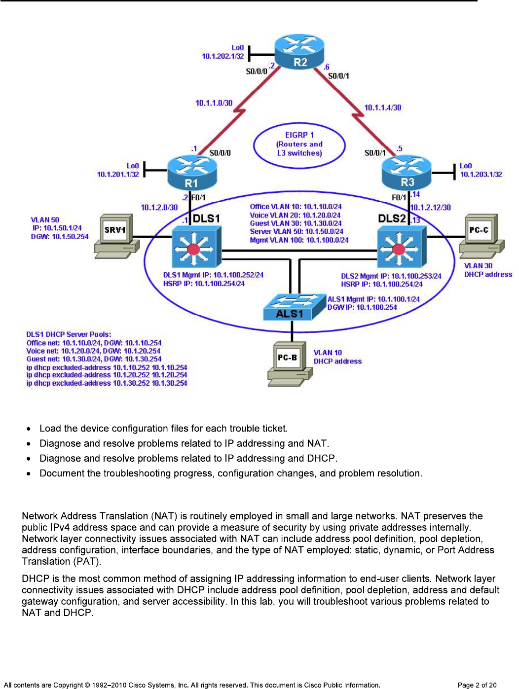
CCNPv6 TSHOOT
Logical Topology (Baseline)
Objectives
Background
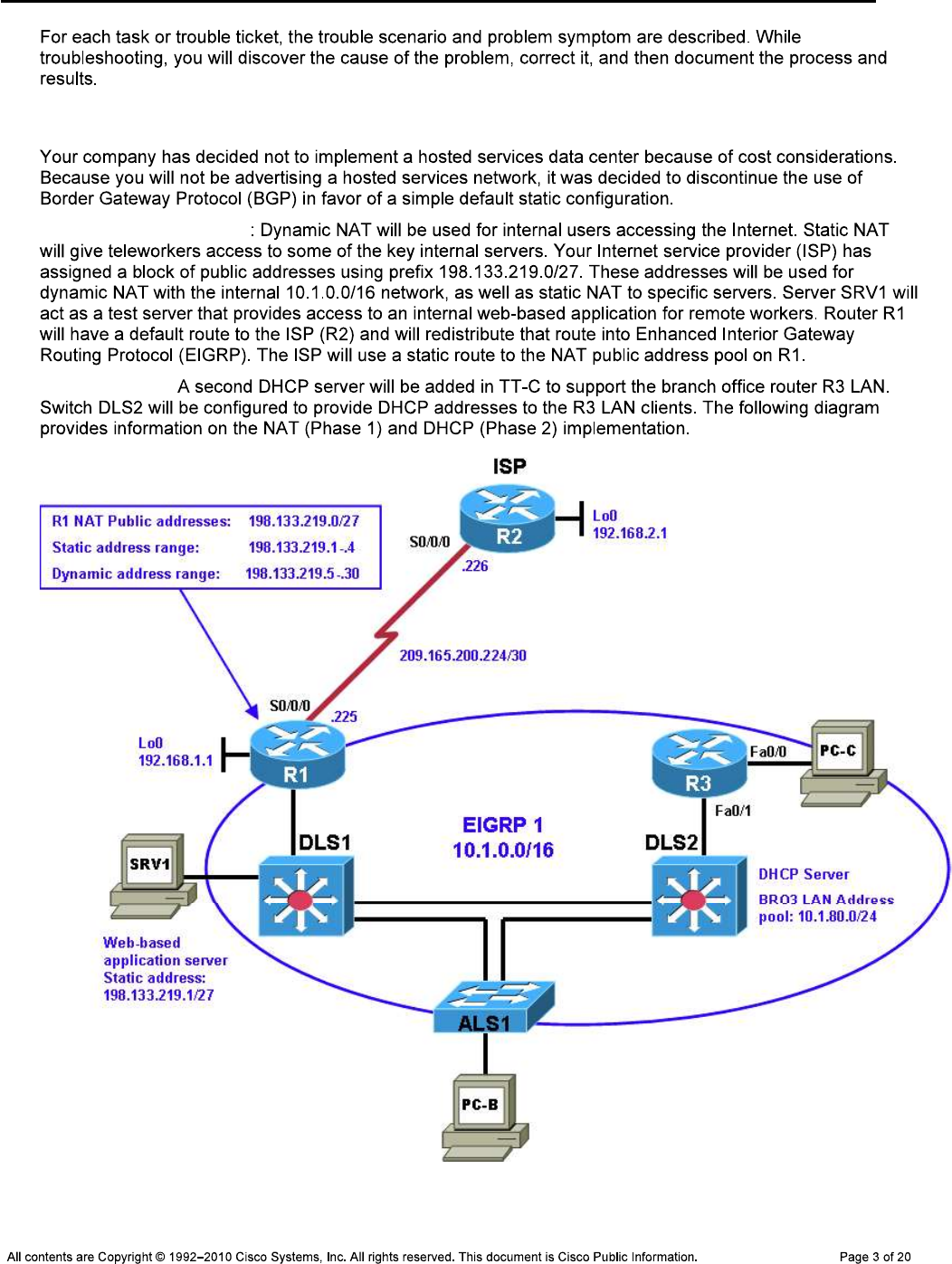
CCNPv6 TSHOOT
NAT and DHCP Configuration
Phase 1 (TT-A and TT-B)
Phase 2 (TT-C):
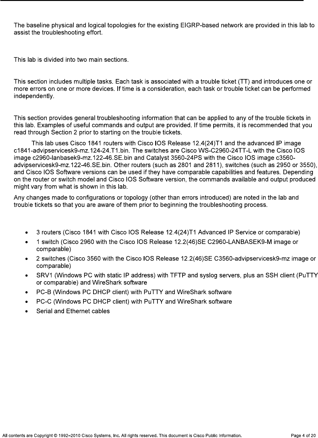
CCNPv6 TSHOOT
Physical and Logical Topology Diagrams
Lab Structure
Section 1—Trouble Tickets and Troubleshooting Logs
Section 2—Troubleshooting Reference Information
Note:
Required Resources
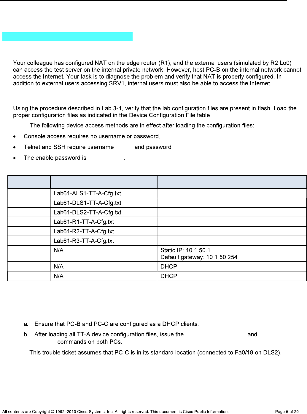
CCNPv6 TSHOOT
Section 1—Trouble Tickets and Troubleshooting Logs
Task 1: Trouble Ticket Lab 6-1 TT-A
Step 1: Review trouble ticket Lab 6-1 TT-A.
Step 2: Load the device trouble ticket configuration files for TT-A.
Note:
admin adminpa55
ciscoenpa55
Device Configuration File Table
Device Name File to Load Notes
ALS1
DLS1
DLS2
R1
R2
R3
SRV1
PC-B
PC-C
Step 3: Configure SRV1 and start the syslog and TFTP servers.
Step 4: Release and renew the DHCP leases.
ipconfig /release ipconfig
/renew
Note

CCNPv6 TSHOOT
Step 5: Outline the troubleshooting approach and validation steps.
Note:
_______________________________________________________________________________
_______________________________________________________________________________
_______________________________________________________________________________
_______________________________________________________________________________
_______________________________________________________________________________
_______________________________________________________________________________
Step 6: Record the troubleshooting process and configuration changes.
Note:
Device Actions and Results
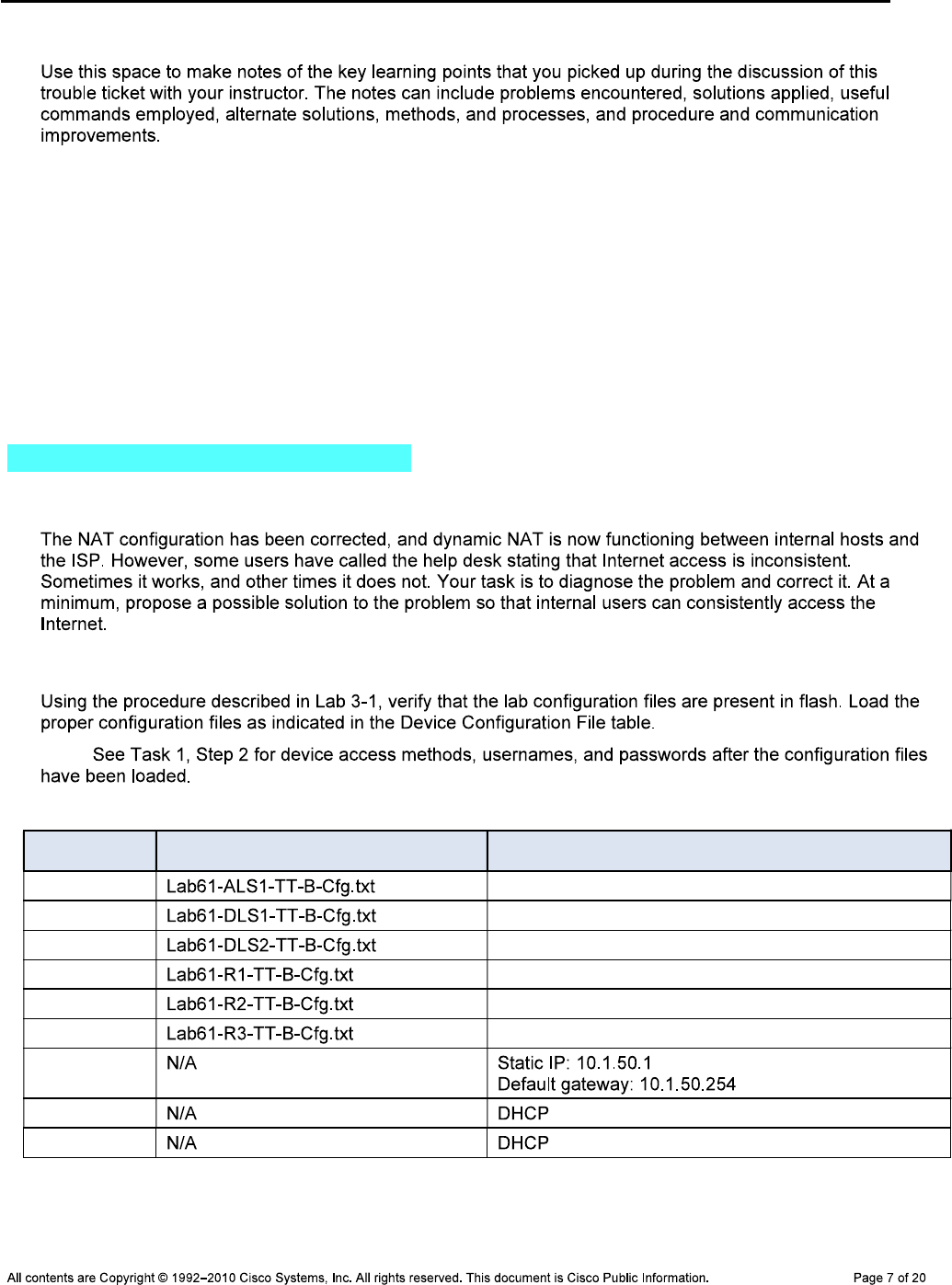
CCNPv6 TSHOOT
Step 7: Document trouble ticket debrief notes.
_______________________________________________________________________________
_______________________________________________________________________________
_______________________________________________________________________________
_______________________________________________________________________________
_______________________________________________________________________________
_______________________________________________________________________________
_______________________________________________________________________________
Task 2: Trouble Ticket Lab 6-1 TT-B
Step 1: Review trouble ticket Lab 6-1 TT-B.
Step 2: Load the device trouble ticket configuration files for TT-B.
Note:
Device Configuration File Table
Device Name File to Load Notes
ALS1
DLS1
DLS2
R1
R2
R3
SRV1
PC-B
PC-C
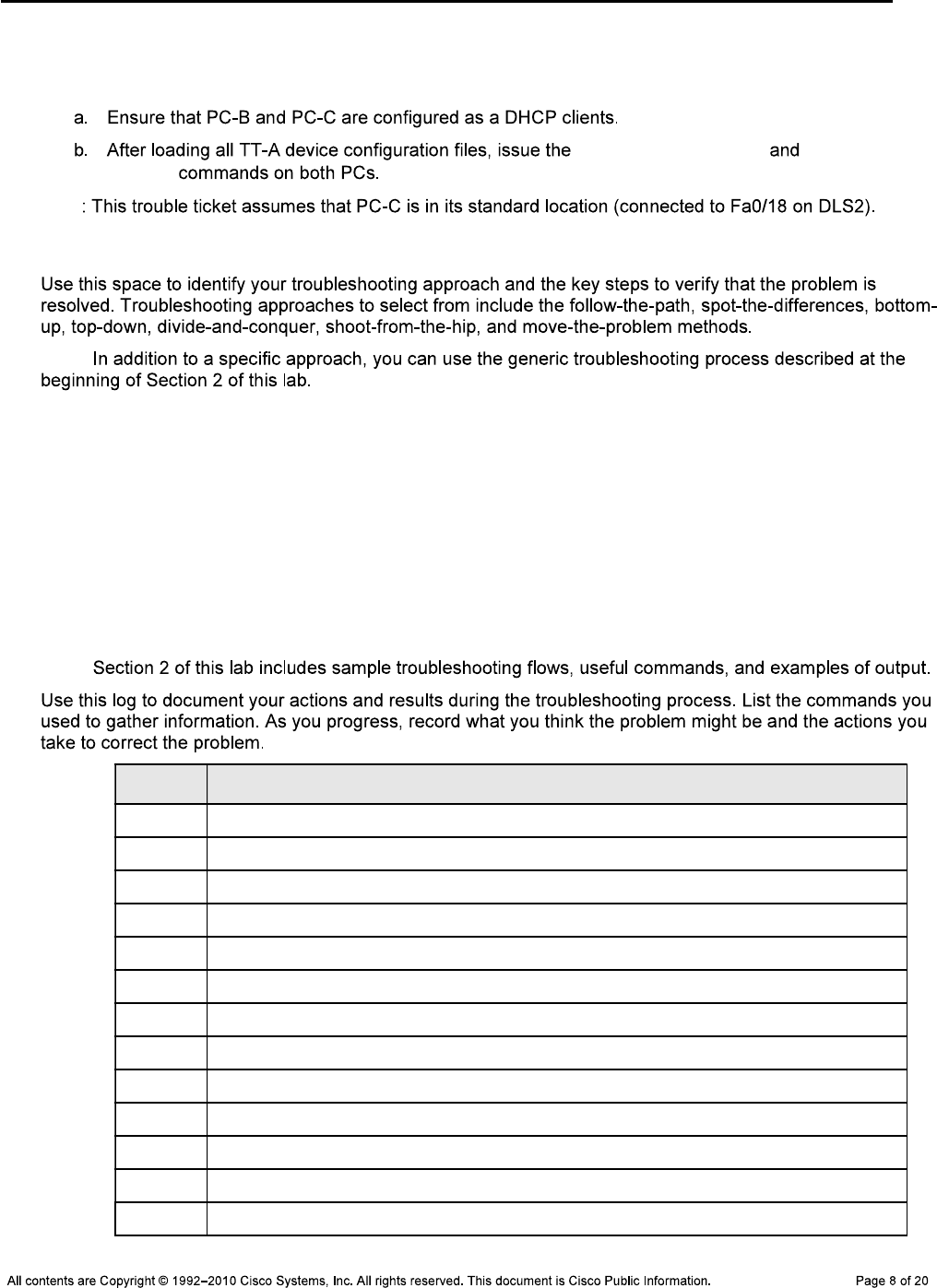
CCNPv6 TSHOOT
Step 3: Configure SRV1 and start the syslog and TFTP servers.
Step 4: Release and renew the DHCP leases.
ipconfig /release ipconfig
/renew
Note
Step 5: Outline the troubleshooting approach and validation steps.
Note:
_______________________________________________________________________________
_______________________________________________________________________________
_______________________________________________________________________________
_______________________________________________________________________________
_______________________________________________________________________________
_______________________________________________________________________________
Step 6: Record the troubleshooting process and configuration changes.
Note:
Device Actions and Results
CCNPv6 TSHOOT
Device Actions and Results
Step 7: Document trouble ticket debrief notes.
_______________________________________________________________________________
_______________________________________________________________________________
_______________________________________________________________________________
_______________________________________________________________________________
_______________________________________________________________________________
_______________________________________________________________________________
_______________________________________________________________________________
Task 3: Trouble Ticket Lab 6-1 TT-C
Step 1: Review trouble ticket Lab 6-1 TT-C.
Step 2: Load the device trouble ticket configuration files for TT-C.
Note:

CCNPv6 TSHOOT
Device Configuration File Table
Device Name File to Load Notes
ALS1
DLS1
DLS2
R1
R2
R3
SRV1
PC-B
PC-C
Step 3: Configure SRV1 and start the syslog and TFTP servers.
Step 4: Release and renew the DHCP lease on PC-C.
ipconfig /release ipconfig
/renew
Step 5: Outline the troubleshooting approach and validation steps.
Note:
_______________________________________________________________________________
_______________________________________________________________________________
_______________________________________________________________________________
_______________________________________________________________________________
_______________________________________________________________________________

CCNPv6 TSHOOT
Step 6: Record the troubleshooting process and configuration changes.
Note:
Device Actions and Results

CCNPv6 TSHOOT
Step 7: Document trouble ticket debrief notes.
_______________________________________________________________________________
_______________________________________________________________________________
_______________________________________________________________________________
_______________________________________________________________________________
_______________________________________________________________________________
_______________________________________________________________________________
_______________________________________________________________________________
CCNPv6 TSHOOT
Section 2 Troubleshooting Reference Information
General Troubleshooting Process
Command Summary
Command Key Information Displayed
show ip nat statistics
show ip nat translations
debug ip icmp
debug ip nat
clear ip nat translations *
clear ip nat statistics *
show ip dhcp server statistics
show ip dhcp pool
show ip dhcp conflicts
show ip dhcp binding

CCNPv6 TSHOOT
debug dhcp detail
debug ip dhcp server events
clear ip dhcp server statistics
clear ip dhcp conflict *
show ip sockets
Sample Troubleshooting Output
NAT-related Commands
R1#show ip nat translations
Pro Inside global Inside local Outside local Outside global
icmp 198.133.219.7:512 10.1.10.1:512 192.168.2.1:512 192.168.2.1:512
--- 198.133.219.7 10.1.10.1 --- ---
--- 198.133.219.1 10.1.50.1 --- ---
udp 198.133.219.6:123 10.1.100.1:123 192.168.2.1:123 192.168.2.1:123
tcp 198.133.219.6:38711 10.1.100.1:38711 192.168.2.1:23 192.168.2.1:23
--- 198.133.219.6 10.1.100.1 --- ---
udp 198.133.219.4:123 10.1.100.252:123 192.168.2.1:123 192.168.2.1:123
--- 198.133.219.4 10.1.100.252 --- ---
tcp 198.133.219.3:1121 10.1.10.1:1121 192.168.2.1:80 192.168.2.1:80
--- 198.133.219.3 10.1.10.1 --- ---
udp 198.133.219.5:123 10.1.100.253:123 192.168.2.1:123 192.168.2.1:123
--- 198.133.219.5 10.1.100.253 --- ---
R1#show ip nat statistics
Total active translations: 7 (1 static, 6 dynamic; 2 extended)
Peak translations: 9, occurred 00:45:03 ago
Outside interfaces:
Serial0/0/0
Inside interfaces:
FastEthernet0/1
Hits: 2442 Misses: 0
CEF Translated packets: 2439, CEF Punted packets: 11
Expired translations: 15
Dynamic mappings:
-- Inside Source
[Id: 8] access-list 1 pool public-addrs refcount 6
pool public-addrs: netmask 255.255.255.248
start 198.133.219.3 end 198.133.219.6
type generic, total addresses 4, allocated 4 (100%), misses 8
Appl doors: 0
Normal doors: 0
Queued Packets: 0

CCNPv6 TSHOOT
R1#debug ip nat
IP NAT debugging is on
R1#terminal monitor
R1#
Nov 18 16:52:09.304: NAT*: s=10.1.10.1->198.133.219.6, d=192.168.2.1 [108]
Nov 18 16:52:09.316: NAT*: s=192.168.2.1, d=198.133.219.6->10.1.10.1 [108]
Nov 18 16:52:10.300: NAT*: s=10.1.10.1->198.133.219.6, d=192.168.2.1 [109]
Nov 18 16:52:10.308: NAT*: s=192.168.2.1, d=198.133.219.6->10.1.10.1 [109]
Nov 18 16:52:11.300: NAT*: s=10.1.10.1->198.133.219.6, d=192.168.2.1 [110]
Nov 18 16:52:11.308: NAT*: s=192.168.2.1, d=198.133.219.6->10.1.10.1 [110]
Nov 18 16:52:12.300: NAT*: s=10.1.10.1->198.133.219.6, d=192.168.2.1 [111]
Nov 18 16:52:12.312: NAT*: s=192.168.2.1, d=198.133.219.6->10.1.10.1 [111]
Nov 18 16:52:59.356: NAT*: s=10.1.100.252->198.133.219.4, d=192.168.2.1 [0]
Nov 18 16:52:59.368: NAT*: s=192.168.2.1, d=198.133.219.4->10.1.100.252 [0]
Nov 18 16:53:12.772: NAT: expiring 198.133.219.6 (10.1.10.1) icmp 512 (512)
Nov 18 16:53:47.140: NAT*: s=10.1.100.1->198.133.219.5, d=192.168.2.1 [0]
Nov 18 16:53:47.152: NAT*: s=192.168.2.1, d=198.133.219.5->10.1.100.1 [0]
Nov 18 16:53:53.992: NAT*: s=10.1.100.253->198.133.219.3, d=192.168.2.1 [0]
Nov 18 16:53:54.004: NAT*: s=192.168.2.1, d=198.133.219.3->10.1.100.253 [0]
terminal monitor
R1#debug ip nat
IP NAT debugging is on
R1#
Nov 18 19:31:36.112: NAT: translation failed (A), dropping packet s=10.1.10.1 d=
192.168.2.1
Nov 18 19:31:37.108: NAT: translation failed (A), dropping packet s=10.1.10.1 d=
192.168.2.1
R1#
Nov 18 19:31:38.112: NAT: translation failed (A), dropping packet s=10.1.10.1 d=
192.168.2.1
R1#
Nov 18 19:31:39.112: NAT: translation failed (A), dropping packet s=10.1.10.1 d=
192.168.2.1
R1#debug ip icmp
ICMP packet debugging is on
Nov 18 19:50:50.879: ICMP: dst (192.168.2.1) host unreachable sent to 10.1.10.1
Nov 18 19:50:51.875: ICMP: dst (192.168.2.1) host unreachable sent to 10.1.10.1
R1#
Nov 18 19:50:52.879: ICMP: dst (192.168.2.1) host unreachable sent to 10.1.10.1
R1#
Nov 18 19:50:53.879: ICMP: dst (192.168.2.1) host unreachable sent to 10.1.10.1
debug ip icmp
CCNPv6 TSHOOT
R2#debug ip icmp
Nov 18 18:29:31.381: ICMP: echo reply sent, src 192.168.2.1, dst 10.1.10.1
Nov 18 18:29:36.737: ICMP: echo reply sent, src 192.168.2.1, dst 10.1.10.1
Nov 18 18:29:41.745: ICMP: echo reply sent, src 192.168.2.1, dst 10.1.10.1
Nov 18 18:29:46.753: ICMP: echo reply sent, src 192.168.2.1, dst 10.1.10.1
DHCP-Related Commands
DLS2#show ip dhcp server statistics
Memory usage 15668
Address pools 1
Database agents 0
Automatic bindings 1
Manual bindings 0
Expired bindings 0
Malformed messages 0
Secure arp entries 0
Renew messages 2
Message Received
BOOTREQUEST 0
DHCPDISCOVER 4
DHCPREQUEST 4
DHCPDECLINE 0
DHCPRELEASE 1
DHCPINFORM 0
Message Sent
BOOTREPLY 0
DHCPOFFER 2
DHCPACK 4
DHCPNAK 0
DLS2#show ip dhcp pool
Pool BRO3 :
Utilization mark (high/low) : 100 / 0
Subnet size (first/next) : 0 / 0
Total addresses : 254
Leased addresses : 1
Excluded addresses : 3
Pending event : none
1 subnet is currently in the pool :
Current index IP address range Leased/Excluded/Total
10.1.80.1 10.1.80.1 - 10.1.80.254 1 / 3 / 254
DLS2#show ip dhcp conflict
IP address Detection method Detection time VRF
10.1.80.1 Gratuitous ARP Nov 20 2009 06:09 PM

CCNPv6 TSHOOT
clear ip dhcp
conflict *
DLS2#show ip dhcp binding
Bindings from all pools not associated with VRF:
IP address Client-ID/ Lease expiration Type
Hardware address/
User name
10.1.80.2 0100.0bdb.04a5.cd Nov 21 2009 02:50 PM Automatic
DLS2#debug ip dhcp server events
DHCP server event debugging is on.
DLS2#
Nov 20 15:20:31.653: DHCPD: Sending notification of TERMINATION:
Nov 20 15:20:31.653: DHCPD: address 10.1.80.2 mask 255.255.255.0
Nov 20 15:20:31.653: DHCPD: reason flags: RELEASE
Nov 20 15:20:31.653: DHCPD: htype 1 chaddr 000b.db04.a5cd
Nov 20 15:20:31.653: DHCPD: lease time remaining (secs) = 86356
Nov 20 15:20:31.653: DHCPD: interface = FastEthernet0/5
Nov 20 15:20:31.653: DHCPD: returned 10.1.80.2 to address pool BRO3.
DLS2#
Nov 20 15:20:46.226: DHCPD: Sending notification of DISCOVER:
Nov 20 15:20:46.226: DHCPD: htype 1 chaddr 000b.db04.a5cd
Nov 20 15:20:46.226: DHCPD: giaddr = 10.1.80.1
Nov 20 15:20:46.226: DHCPD: interface = FastEthernet0/5
Nov 20 15:20:46.226: DHCPD: class id 4d53465420352e30
Nov 20 15:20:46.226: DHCPD: Sending notification of DISCOVER:
Nov 20 15:20:46.226: DHCPD: htype 1 chaddr 000b.db04.a5cd
Nov 20 15:20:46.226: DHCPD: giaddr = 10.1.80.1
Nov 20 15:20:46.226: DHCPD: interface = FastEthernet0/5
Nov 20 15:20:46.226: DHCPD: class id 4d53465420352e30
Nov 20 15:20:48.239: DHCPD: client requests 10.1.80.2.
Nov 20 15:20:48.239: DHCPD: Adding binding to radix tree (10.1.80.2)
Nov 20 15:20:48.239: DHCPD: Adding binding to hash tree
Nov 20 15:20:48.239: DHCPD: assigned IP address 10.1.80.2 to client
0100.0bdb.04a5.cd. (471 0)
Nov 20 15:20:48.239: DHCPD: Sending notification of ASSIGNMENT:
Nov 20 15:20:48.239: DHCPD: address 10.1.80.2 mask 255.255.255.0
Nov 20 15:20:48.239: DHCPD: htype 1 chaddr 000b.db04.a5cd
Nov 20 15:20:48.239: DHCPD: lease time remaining (secs) = 86400
Nov 20 15:20:48.239: DHCPD: interface = FastEthernet0/5
Nov 20 15:21:49.307: DHCPD: checking for expired leases.
ipconfig
/release ipconfig /renew
R3#debug ip udp
UDP packet debugging is on
R3#conf t
Enter configuration commands, one per line. End with CNTL/Z.
CCNPv6 TSHOOT
R3(config)#int f0/0
R3(config-if)#no ip helper-address 10.1.2.13
R3(config-if)#
*Nov 20 15:53:29.606: UDP: rcvd src=0.0.0.0(68), dst=255.255.255.255(67), length
=308
*Nov 20 15:53:32.606: UDP: rcvd src=0.0.0.0(68), dst=255.255.255.255(67), length
=308
*Nov 20 15:53:41.610: UDP: rcvd src=0.0.0.0(68), dst=255.255.255.255(67), length
=308
*Nov 20 15:53:57.614: UDP: rcvd src=0.0.0.0(68), dst=255.255.255.255(67), length
=308
R3#
R3(config)#int f0/0
R3(config-if)#ip helper-address 10.1.2.13
R3(config-if)#
*Nov 20 15:54:19.547: Reserved port 67 in Transport Port Agent for UDP IP type 1
*Nov 20 15:54:34.035: UDP: rcvd src=0.0.0.0(68), dst=255.255.255.255(67), length
=308
*Nov 20 15:54:34.035: UDP: sent src=10.1.80.1(67), dst=10.1.2.13(67), length=308
*Nov 20 15:54:36.043: UDP: rcvd src=10.1.2.13(67), dst=10.1.80.1(67), length=308
*Nov 20 15:54:36.047: UDP: sent src=0.0.0.0(67), dst=255.255.255.255(68), length
=308
*Nov 20 15:54:36.047: UDP: rcvd src=0.0.0.0(68), dst=255.255.255.255(67), length
=324
*Nov 20 15:54:36.047: UDP: sent src=10.1.80.1(67), dst=10.1.2.13(67), length=324
*Nov 20 15:54:36.051: UDP: rcvd src=10.1.2.13(67), dst=10.1.80.1(67), length=308
*Nov 20 15:54:36.051: UDP: sent src=0.0.0.0(67), dst=255.255.255.255(68), length
=308
DLS2#show ip sockets
Proto Remote Port Local Port In Out Stat TTY OutputIF
17 --listen-- 10.1.200.253 1985 0 0 1001 0
17 10.1.50.1 162 10.1.100.253 62682 0 0 0 0
17 --listen-- 10.1.200.253 1975 0 0 11 0
17 10.1.80.1 67 10.1.200.253 67 0 0 2211 0
17 0.0.0.0 0 10.1.200.253 2228 0 0 211 0
17 --listen-- 10.1.200.253 161 0 0 1 0
17 --listen-- 10.1.200.253 162 0 0 11 0
17 --listen-- 10.1.200.253 55485 0 0 1 0
17 --listen-- --any-- 161 0 0 20001 0
17 --listen-- --any-- 162 0 0 20011 0
17 --listen-- --any-- 61812 0 0 20001 0
17 --listen-- 10.1.200.253 123 0 0 1 0
17 10.1.50.1 514 10.1.100.253 58346 0 0 400201 0
CCNPv6 TSHOOT
Reflection Questions
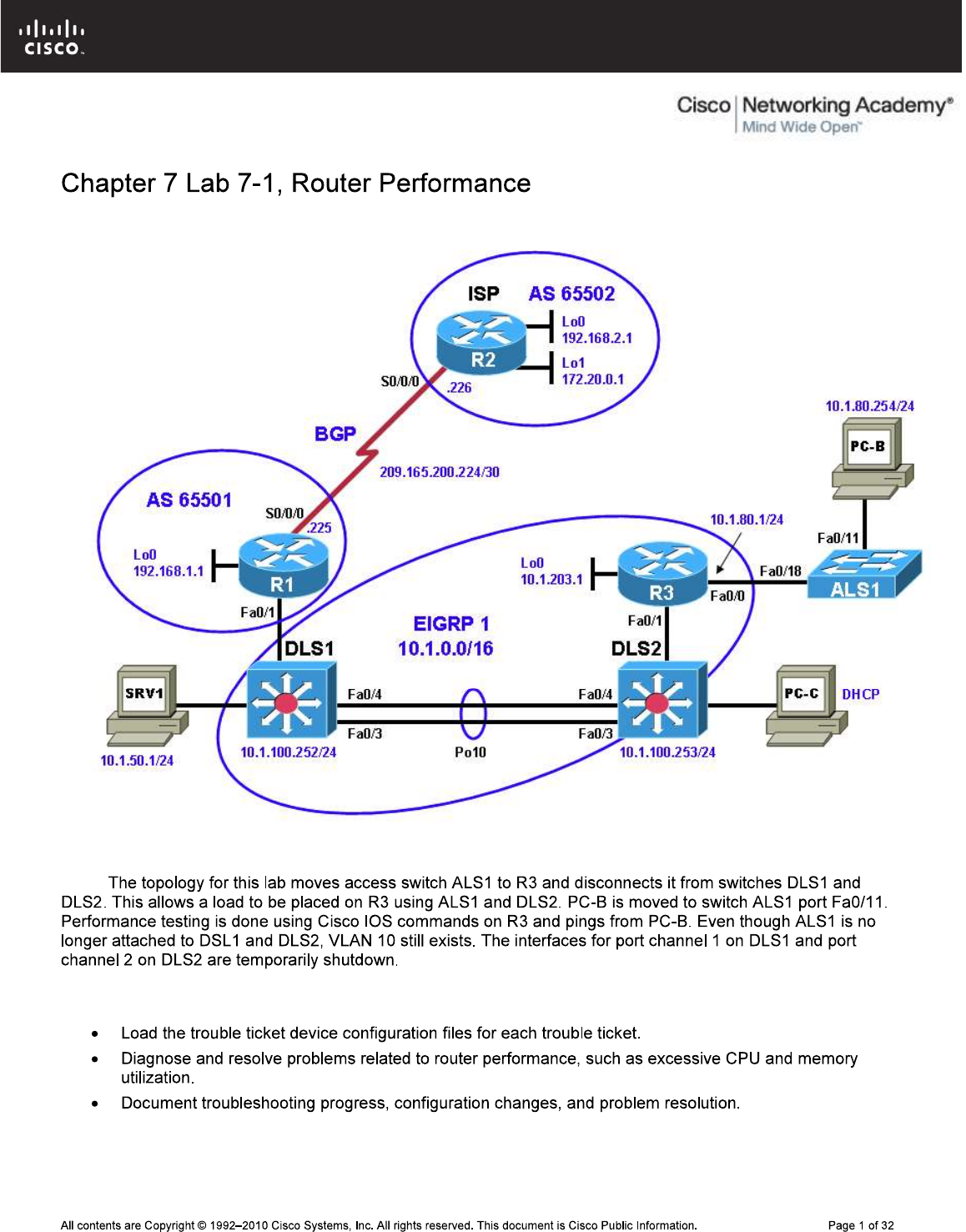
CCNPv6 TSHOOT
Lab Topology
Note:
Objectives
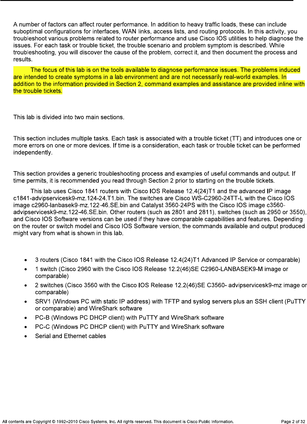
CCNPv6 TSHOOT
Background
Note:
Lab Structure
Section 1—Trouble Tickets and Troubleshooting Logs
Section 2—Troubleshooting Reference Information
Note:
Required Resources

CCNPv6 TSHOOT
Section 1—Trouble Tickets and Troubleshooting Logs
Task 1: Trouble Ticket Lab 7-1 TT-A
ttcp
Note:
ping ttcp
ping
Step 1: Review trouble ticket Lab 7-1 TT-A.
Step 2: Load the device trouble ticket configuration files for TT-A.
Note:
admin adminpa55
ciscoenpa55
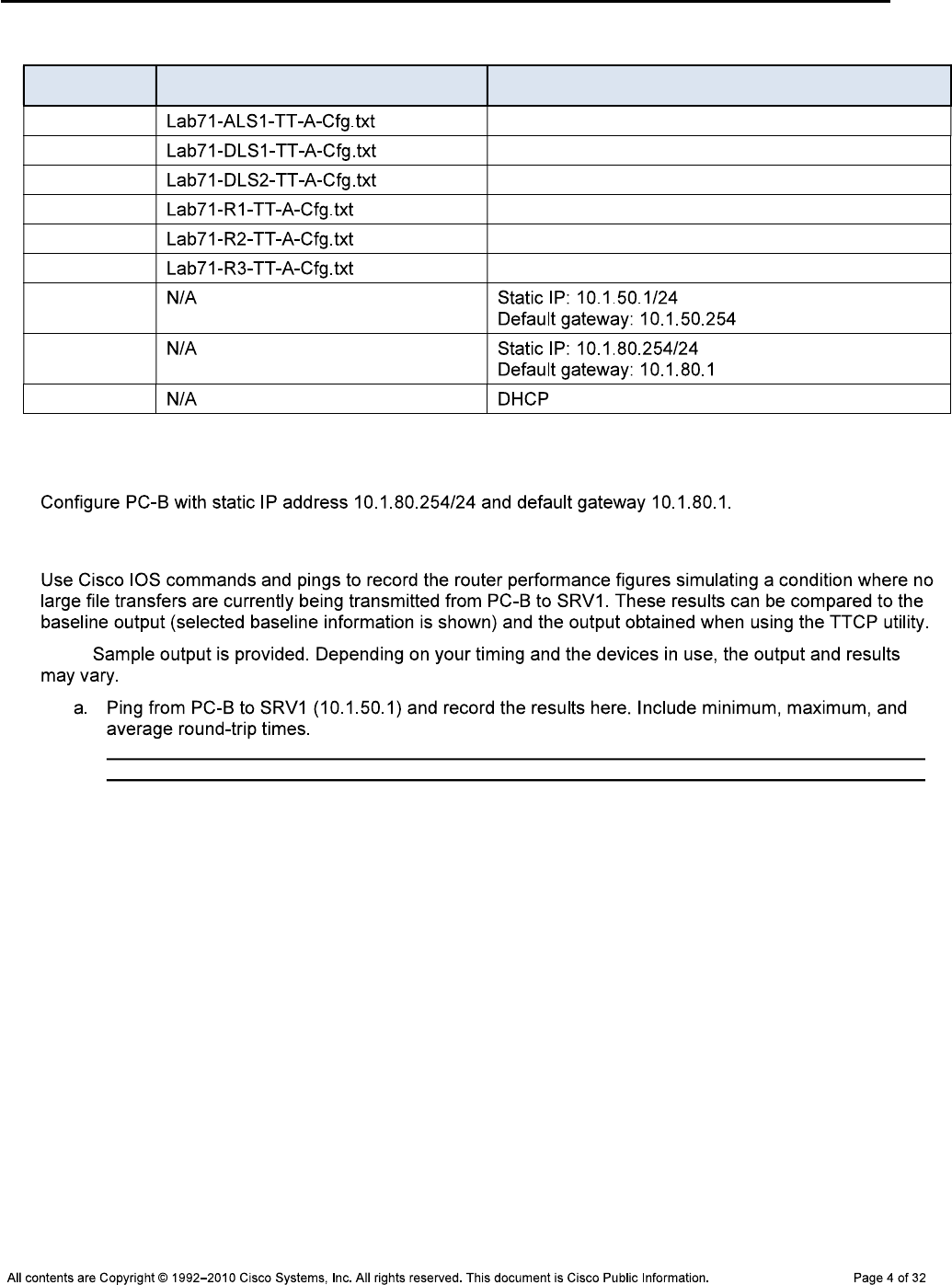
CCNPv6 TSHOOT
Device Configuration File Table
Device Name File to Load Notes
ALS1
DLS1
DLS2
R1
R2
R3
SRV1
PC-B
PC-C
Step 3: Configure PC-B.
Step 4: Test R3 performance without the TTCP load generator.
Note:
C:\>ping 10.1.50.1
Pinging 10.1.50.1 with 32 bytes of data:
Reply from 10.1.50.1: bytes=32 time=3ms TTL=64
Reply from 10.1.50.1: bytes=32 time=1ms TTL=64
Reply from 10.1.50.1: bytes=32 time=1ms TTL=64
Reply from 10.1.50.1: bytes=32 time=1ms TTL=64
Ping statistics for 10.1.50.1:
Packets: Sent = 4, Received = 4, Lost = 0 (0% loss),
Approximate round trip times in milli-seconds:
Minimum = 1ms, Maximum = 3ms, Average = 1ms
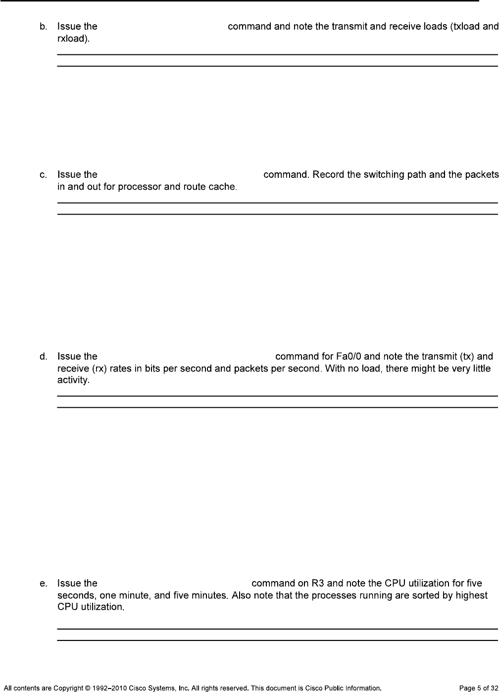
CCNPv6 TSHOOT
show interfaces fa0/0
R3#show interfaces fa0/0
FastEthernet0/0 is up, line protocol is up
Hardware is Gt96k FE, address is 001b.530d.6028 (bia 001b.530d.6028)
Internet address is 10.1.80.1/24
MTU 1500 bytes, BW 100000 Kbit/sec, DLY 100 usec,
reliability 255/255, txload 1/255, rxload 1/255
show interfaces fa0/0 stats
R3#show interfaces fa0/0 stats
FastEthernet0/0
Switching path Pkts In Chars In Pkts Out Chars Out
Processor 50 16309 176 18457
Route cache 1 159 0 0
Total 51 16468 176 18457
Total 116557 66924378 115034 6384079
show interfaces fa0/0 summary
R3#show interfaces fa0/0 summary
*: interface is up
IHQ: pkts in input hold queue IQD: pkts dropped from input queue
OHQ: pkts in output hold queue OQD: pkts dropped from output queue
RXBS: rx rate (bits/sec) RXPS: rx rate (pkts/sec)
TXBS: tx rate (bits/sec) TXPS: tx rate (pkts/sec)
TRTL: throttle count
Interface IHQ IQD OHQ OQD RXBS RXPS TXBS TXPS TRTL
------------------------------------------------------------------------
* FastEthernet0/0 0 0 0 0 0 1 0 0 0
show processes cpu sorted
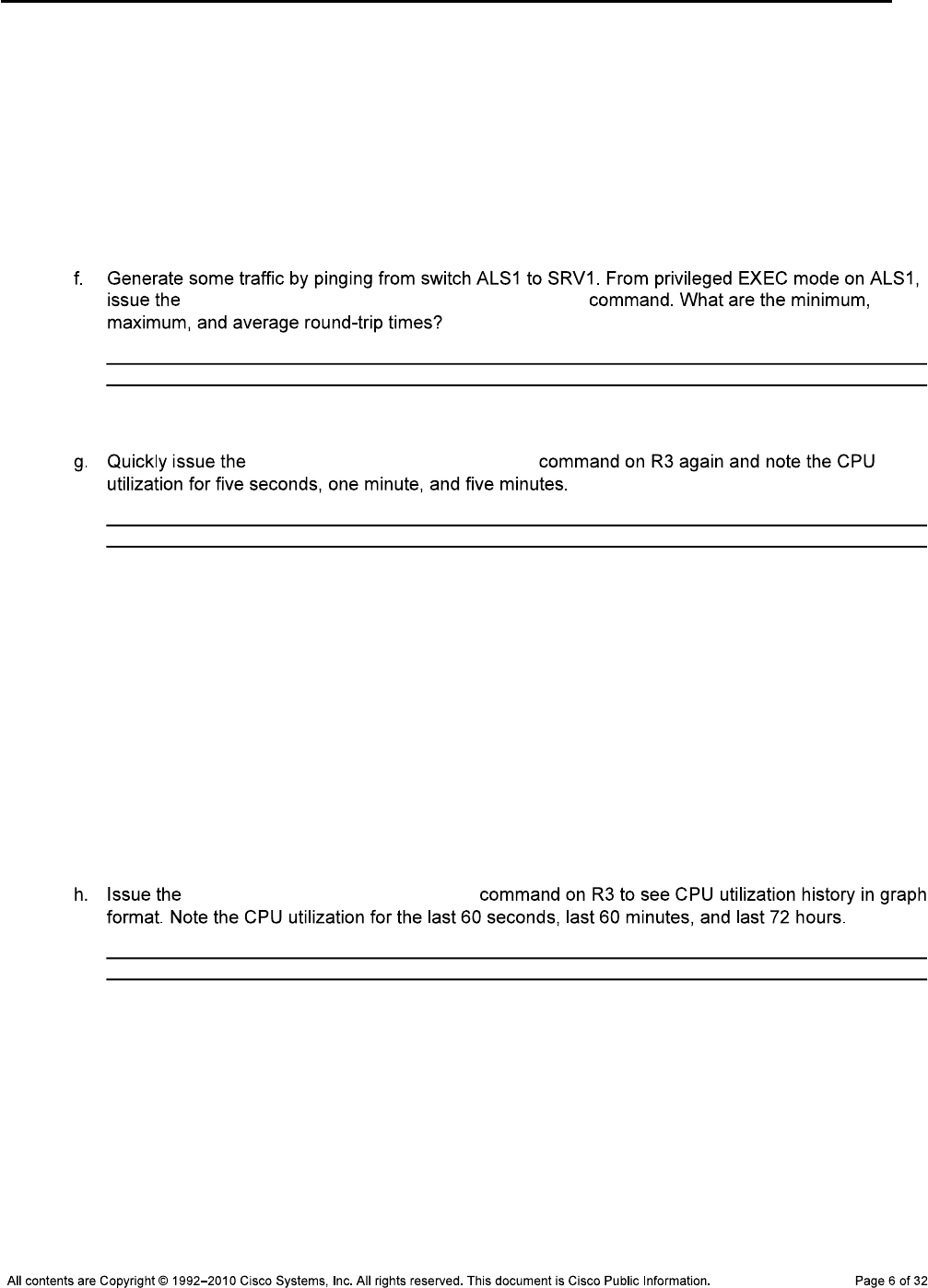
CCNPv6 TSHOOT
R3#show processes cpu sorted
CPU utilization for five seconds: 0%/0%; one minute: 0%; five minutes: 0%
PID Runtime(ms) Invoked uSecs 5Sec 1Min 5Min TTY Process
153 4 1366369 0 0.15% 0.12% 0.10% 0 HQF Shaper Backg
2 0 7658 0 0.07% 0.02% 0.02% 0 Load Meter
5 4 3 1333 0.00% 0.00% 0.00% 0 Pool Manager
<output omitted>
ping 10.1.50.1 repeat 1000 size 1000
Success rate is 100 percent (1000/1000), round-trip min/avg/max = 1/4/9 ms
show processes cpu sorted
R3#show processes cpu sorted
CPU utilization for five seconds: 17%/5%; one minute: 3%; five minutes: 1%
PID Runtime(ms) Invoked uSecs 5Sec 1Min 5Min TTY Process
91 2308 4797 481 11.19% 2.10% 0.52% 0 IP Input
3 13308 2477 5372 0.87% 0.18% 0.05% 0 Exec
124 12 265 45 0.15% 0.03% 0.00% 0 TCP Timer
153 20 93423 0 0.15% 0.12% 0.10% 0 HQF Shaper Backg
265 1280 11572 110 0.07% 0.01% 0.00% 0 IP-EIGRP: HELLO
<output omitted>
show processes cpu history
R3#show processes cpu history
R3 06:04:05 PM Monday Nov 30 2009 UTC
1 11111 11111
100
90
80
70

CCNPv6 TSHOOT
60
50
40
30
20
10
0....5....1....1....2....2....3....3....4....4....5....5....6
0 5 0 5 0 5 0 5 0 5 0
CPU% per second (last 60 seconds)
5 1 1 1 9
511911111111119119413111111111111112111111211111111111829111
100 *
90 *
80 *
70 *
60 * *
50 * *
40 * *
30 * *
20 * * * * #
10 * * * * * #
0....5....1....1....2....2....3....3....4....4....5....5....6
0 5 0 5 0 5 0 5 0 5 0
CPU% per minute (last 60 minutes)
* = maximum CPU% # = average CPU%
9
9
100 *
90 *
80 *
70 *
60 *
50 *
40 *
30 *
20 *
10 *
0....5....1....1....2....2....3....3....4....4....5....5....6....6....7..
0 5 0 5 0 5 0 5 0 5 0 5 0
CPU% per hour (last 72 hours)
* = maximum CPU% # = average CPU%
Step 5: Generate loads on R3 using the TTCP utility.
ttcp
Note: ttcp

CCNPv6 TSHOOT
ttcp
DLS2#ttcp
transmit or receive [receive]:
receive packets asynchronously [n]:
perform tcp half close [n]:
receive buflen [32768]:
bufalign [16384]:
bufoffset [0]:
port [5001]:
sinkmode [y]:
rcvwndsize [32768]:
ack frequency [0]:
delayed ACK [y]:
show tcp information at end [n]:
ttcp-r: buflen=32768, align=16384/0, port=5001
rcvwndsize=32768, delayedack=yes tcp
ALS1#ttcp
transmit or receive [receive]: transmit
Target IP address: 10.1.100.253
calculate checksum during buffer write [y]:
perform tcp half close [n]:
send buflen [32768]:
send nbuf [2048]:
bufalign [16384]:
bufoffset [0]:
port [5001]:
sinkmode [y]:
buffering on writes [y]:
show tcp information at end [n]:
ttcp-t: buflen=32768, nbuf=2048, align=16384/0, port=5001 tcp ->
10.1.100.253
ttcp-t: connect
ttcp-t: 67108864 bytes in 106812 ms (106.812 real seconds) (~613 kB/s) +++
ttcp-t: 2048 I/O calls
ttcp-t: 0 sleeps (0 ms total) (0 ms average)
ttcp-r: accept from 10.1.80.251
ttcp-r: 67108864 bytes in 106837 ms (106.837 real seconds) (~613 kB/s) +++
ttcp-r: 43182 I/O calls
ttcp-r: 0 sleeps (0 ms total) (0 ms average)

CCNPv6 TSHOOT
Note:
Caution:
Step 6: Test R3 with load applied.
Note:
send buflen
C:\>ping 10.1.50.1
Pinging 10.1.50.1 with 32 bytes of data:
Reply from 10.1.50.1: bytes=32 time=39ms TTL=64
Reply from 10.1.50.1: bytes=32 time=38ms TTL=64
Reply from 10.1.50.1: bytes=32 time=38ms TTL=64
Reply from 10.1.50.1: bytes=32 time=38ms TTL=64
Ping statistics for 10.1.50.1:
Packets: Sent = 4, Received = 4, Lost = 0 (0% loss),
Approximate round trip times in milli-seconds:
Minimum = 38ms, Maximum = 39ms, Average = 38ms
interface fa0/0
load-interval 30
show interfaces fa0/0
R3#show interfaces fa0/0
FastEthernet0/0 is up, line protocol is up
Hardware is Gt96k FE, address is 001b.530d.6028 (bia 001b.530d.6028)
Internet address is 10.1.80.1/24
MTU 1500 bytes, BW 100000 Kbit/sec, DLY 100 usec,
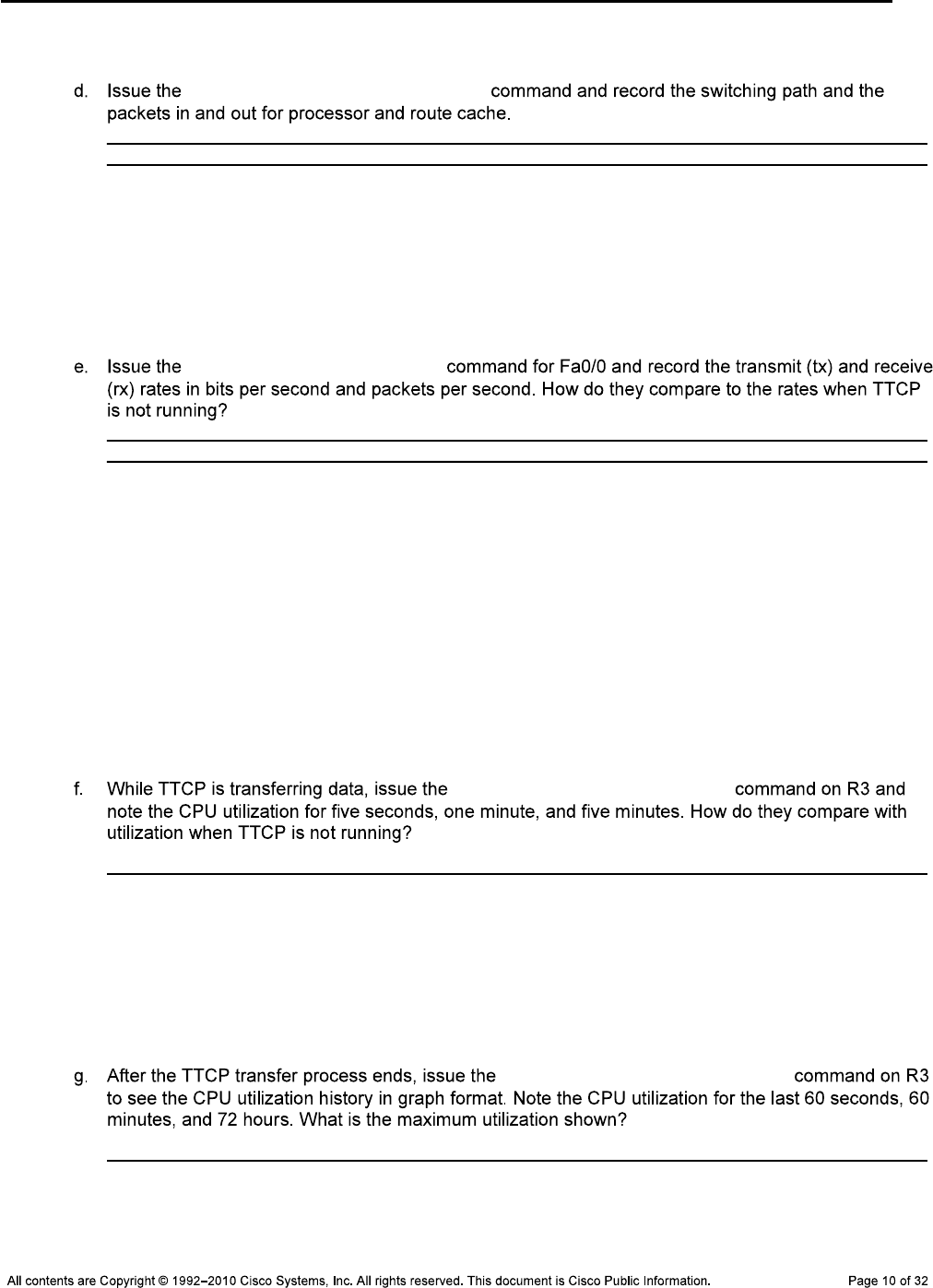
CCNPv6 TSHOOT
reliability 255/255, txload 0/255, rxload 4/255
show interfaces fa0/0 stats
R3#show interfaces f0/0 stats
FastEthernet0/0
Switching path Pkts In Chars In Pkts Out Chars Out
Processor 134289 77529720 129782 10884700
Route cache 1 159 0 0
Total 134290 77529879 129782 10884700
show interfaces summary
R3#show interfaces f0/0 summary
*: interface is up
IHQ: pkts in input hold queue IQD: pkts dropped from input queue
OHQ: pkts in output hold queue OQD: pkts dropped from output queue
RXBS: rx rate (bits/sec) RXPS: rx rate (pkts/sec)
TXBS: tx rate (bits/sec) TXPS: tx rate (pkts/sec)
TRTL: throttle count
Interface IHQ IQD OHQ OQD RXBS RXPS TXBS TXPS TRTL
------------------------------------------------------------------------
* FastEthernet0/0 0 0 0 0 969000 204 94000 201 0
show processes cpu sorted
R3#show processes cpu sorted
CPU utilization for five seconds: 99%/29%; one minute: 77%; five minutes: 26%
PID Runtime(ms) Invoked uSecs 5Sec 1Min 5Min TTY Process
91 201824 20441 9873 69.50% 54.19% 18.26% 0 IP Input
<output omitted>
show processes cpu history

CCNPv6 TSHOOT
R3#show processes cpu history
R3 07:54:09 PM Monday Nov 30 2009 UTC
999988888
99999999922222 11111
100 ****
90 *********
80 *********
70 *********
60 *********
50 *********
40 *********
30 *********
20 *********
10 *********
0....5....1....1....2....2....3....3....4....4....5....5....6
0 5 0 5 0 5 0 5 0 5 0
CPU% per second (last 60 seconds)
992 3
111111119981111121111111211111111112111111211111113111111111
100 *#
90 *#
80 ##
70 ##
60 ##
50 ##
40 ##
30 ##* *
20 ##* *
10 ##* *
0....5....1....1....2....2....3....3....4....4....5....5....6
0 5 0 5 0 5 0 5 0 5 0
CPU% per minute (last 60 minutes)
* = maximum CPU% # = average CPU%
99
99
100 **
90 **
80 **
70 **
60 **
50 **
40 **
30 **
20 **
10 **
0....5....1....1....2....2....3....3....4....4....5....5....6....6....7..
0 5 0 5 0 5 0 5 0 5 0 5 0
CPU% per hour (last 72 hours)
* = maximum CPU% # = average CPU%
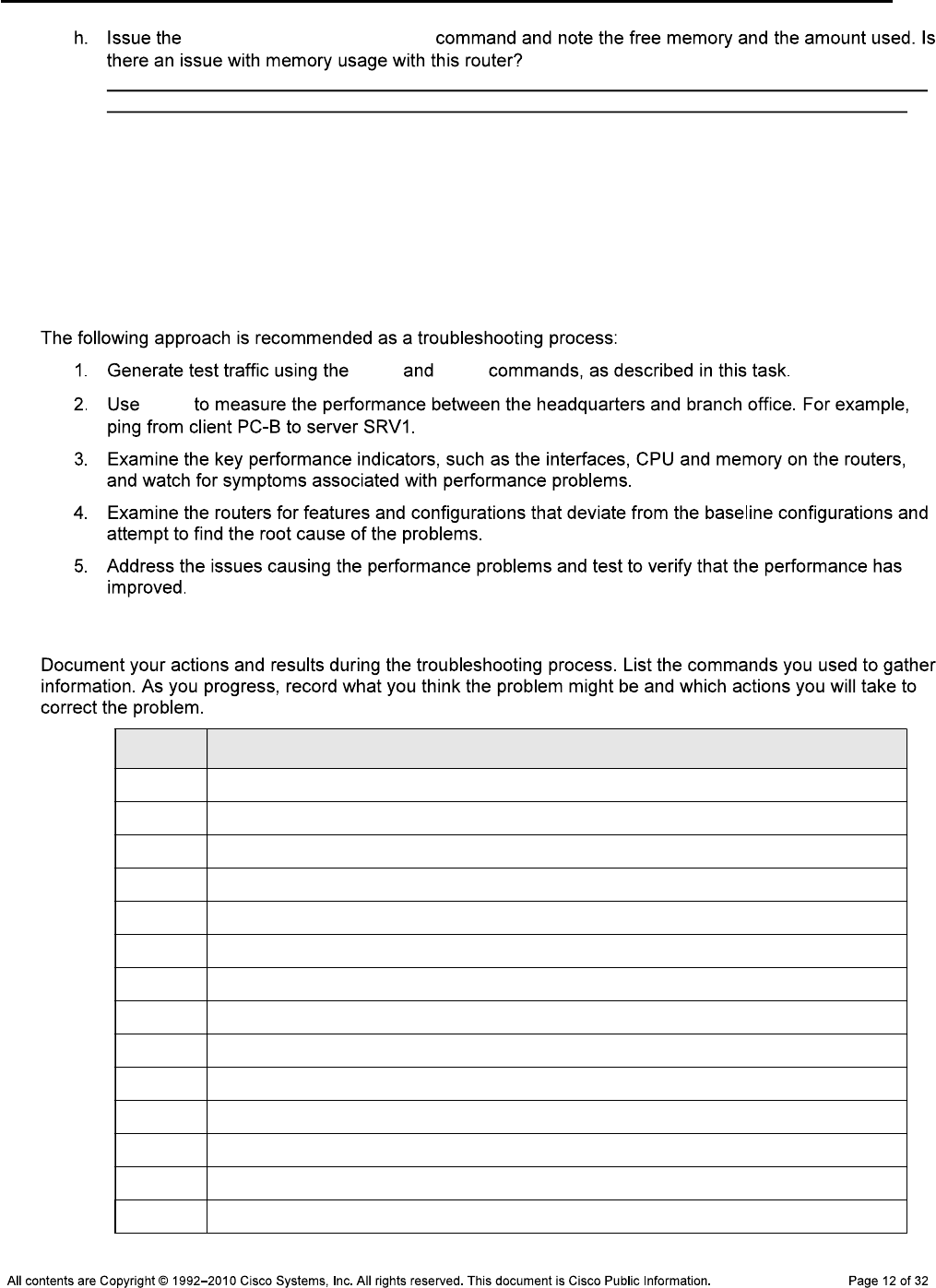
CCNPv6 TSHOOT
show memory statistics
R3#show memory statistics
Head Total(b) Used(b) Free(b) Lowest(b) Largest(b)
Processor 64E822C0 101178688 24016328 77162360 75584536 75588172
I/O EAF00000 17825792 5421744 12404048 12363136 1238780
Step 7: Outline the troubleshooting approach and validation steps.
ping ttcp
ping
Step 8: Record the troubleshooting process and configuration changes.
Device Actions and Results
CCNPv6 TSHOOT
Device Actions and Results
Step 9: Document trouble ticket debrief notes.
_______________________________________________________________________________
_______________________________________________________________________________
_______________________________________________________________________________
_______________________________________________________________________________
_______________________________________________________________________________
_______________________________________________________________________________
_______________________________________________________________________________
Task 2: Trouble Ticket Lab 7-1 TT-B
Step 1: Review trouble ticket Lab 7-1 TT-B.
Step 2: Load the device trouble ticket configuration files for TT-B.
Note:

CCNPv6 TSHOOT
Device Configuration File Table
Device Name File to Load Notes
ALS1
DLS1
DLS2
R1
R2
R3
SRV1
PC-B
PC-C
Step 3: Test R3 performance without the TTCP load generator.
C:\>ping 172.20.0.1
Pinging 172.20.0.1 with 32 bytes of data:
Reply from 172.20.0.1 : bytes=32 time=11ms TTL=64
Reply from 172.20.0.1 : bytes=32 time=10ms TTL=64
Reply from 172.20.0.1 : bytes=32 time=10ms TTL=64
Reply from 172.20.0.1 : bytes=32 time=10ms TTL=64
Ping statistics for 172.20.0.1 :
Packets: Sent = 4, Received = 4, Lost = 0 (0% loss),
Approximate round trip times in milli-seconds:
Minimum = 10ms, Maximum = 11ms, Average = 10ms
show interfaces fa0/0
R3#show interfaces fa0/0
FastEthernet0/0 is up, line protocol is up
Hardware is Gt96k FE, address is 001b.530d.6028 (bia 001b.530d.6028)
Internet address is 10.1.80.1/24
MTU 1500 bytes, BW 100000 Kbit/sec, DLY 100 usec,
reliability 255/255, txload 1/255, rxload 1/255
<output omitted>

CCNPv6 TSHOOT
show interfaces fa0/0 stats
R3#show interfaces fa0/0 stats
FastEthernet0/0
Switching path Pkts In Chars In Pkts Out Chars Out
Processor 831 356623 4075 408723
Route cache 381399 221941950 375270 20282949
Total 382230 222298573 379345 20691672
show processes cpu sorted
R3#show processes cpu sorted
CPU utilization for five seconds: 0%/0%; one minute: 0%; five minutes: 0%
ping 172.20.0.1 repeat 100 size 1000
show processes cpu sorted
R3#show processes cpu sorted
CPU utilization for five seconds: 11%/11%; one minute: 6%; five minutes: 2%
<output omitted>
show processes cpu history
R3#show processes cpu history
R3 04:08:25 PM Tuesday Dec 1 2009 UTC
11111 11111
100
90
80
70
60
50
40

CCNPv6 TSHOOT
30
20
10
0....5....1....1....2....2....3....3....4....4....5....5....6
0 5 0 5 0 5 0 5 0 5 0
CPU% per second (last 60 seconds)
5
211121111111111111111111211111111111111111111111311151111111
100
90
80
70
60 *
50 *
40 *
30 *
20 *
10 *
0....5....1....1....2....2....3....3....4....4....5....5....6
0 5 0 5 0 5 0 5 0 5 0
CPU% per minute (last 60 minutes)
* = maximum CPU% # = average CPU%
344351
251910
100
90
80
70
60
50 * *
40 ****
30 *****
20 *****
10 ******
0....5....1....1....2....2....3....3....4....4....5....5....6....6....7..
0 5 0 5 0 5 0 5 0 5 0 5 0
CPU% per hour (last 72 hours)
* = maximum CPU% # = average CPU%
show processes memory sorted
R3#show processes memory sorted
Processor Pool Total: 101178688 Used: 24024572 Free: 77154116
I/O Pool Total: 17825792 Used: 5421728 Free: 12404064
PID TTY Allocated Freed Holding Getbufs Retbufs Process
0 0 64042304 36231984 23552016 0 0 *Init*
55 0 659620 1328 640292 0 0 USB Startup
1 0 474960 0 482164 0 0 Chunk Manager
CCNPv6 TSHOOT
219 0 469096 18304 436816 0 0 VLAN Manager
25 0 260308 0 270512 99792 0 EEM ED Syslog
170 0 218420 504 215916 0 0 Crypto HW
Proc
221 0 196192 0 203396 0 0 EEM Server
183 0 114340 532 123012 0 0 Crypto WUI
167 0 76476 252 83428 0 0 HTTP Process
show memory statistics
Note:
Baseline
R3#show memory statistics
Head Total(b) Used(b) Free(b) Lowest(b) Largest(b)
Processor 64E822C0 101178688 24016328 77162360 75584536 75588172
I/O EAF00000 17825792 5421744 12404048 12363136 1238780
After TT Issues Are Introduced
R3#show memory statistics
Head Total(b) Used(b) Free(b) Lowest(b) Largest(b)
Processor 64E822C0 101178688 24085092 77093596 75584536 75579176
I/O EAF00000 17825792 5421744 12404048 12363136 1238780
Step 4: Generate loads on R3 using the TTCP utility.
DLS2#ttcp
transmit or receive [receive]:
receive packets asynchronously [n]:
perform tcp half close [n]:
receive buflen [32768]:
bufalign [16384]:
bufoffset [0]:
port [5001]:
sinkmode [y]:
rcvwndsize [32768]:
CCNPv6 TSHOOT
ack frequency [0]:
delayed ACK [y]:
show tcp information at end [n]:
ttcp-r: buflen=32768, align=16384/0, port=5001
rcvwndsize=32768, delayedack=yes tcp
ALS1#ttcp
transmit or receive [receive]: transmit
Target IP address: 10.1.100.253
calculate checksum during buffer write [y]:
perform tcp half close [n]:
send buflen [32768]:
send nbuf [2048]:
bufalign [16384]:
bufoffset [0]:
port [5001]:
sinkmode [y]:
buffering on writes [y]:
show tcp information at end [n]:
ttcp-t: buflen=32768, nbuf=2048, align=16384/0, port=5001 tcp ->
10.1.100.253
ttcp-t: connect
ttcp-t: 67108864 bytes in 68434 ms (68.434 real seconds) (~957 kB/s)
+++
ttcp-t: 2048 I/O calls
ttcp-t: 0 sleeps (0 ms total) (0 ms average)
Note:
Step 5: Test R3 with load applied.
Note:
C:\>ping 172.20.0.1
Pinging 172.20.0.1 with 32 bytes of data:
Reply from 172.20.0.1 : bytes=32 time=12ms TTL=64
Reply from 172.20.0.1 : bytes=32 time=11ms TTL=64
CCNPv6 TSHOOT
Reply from 172.20.0.1 : bytes=32 time=11ms TTL=64
Reply from 172.20.0.1 : bytes=32 time=11ms TTL=64
Ping statistics for 172.20.0.1 :
Packets: Sent = 4, Received = 4, Lost = 0 (0% loss),
Approximate round trip times in milli-seconds:
Minimum = 11ms, Maximum = 12ms, Average = 11ms
show processes cpu sorted
R3#show processes cpu sorted
CPU utilization for five seconds: 10%/9%; one minute: 2%; five minutes: 1%
PID Runtime(ms) Invoked uSecs 5Sec 1Min 5Min TTY Process
<output omitted>
show processes cpu history
R3#show processes cpu history
R3 05:46:25 PM Tuesday Dec 1 2009 UTC
<Output omitted>
4 11
111111111111111111111111111111911111111110111111111111111111
100
90
80
70
60
50 *
40 *
30 *
20 *
10 * *#
0....5....1....1....2....2....3....3....4....4....5....5....6
0 5 0 5 0 5 0 5 0 5 0
CPU% per minute (last 60 minutes)
* = maximum CPU% # = average CPU%
35344351
15251910
100
90
80
70
60 *
50 * * *
40 * ****
30 *******

CCNPv6 TSHOOT
20 *******
10 ********
0....5....1....1....2....2....3....3....4....4....5....5....6....6....7..
0 5 0 5 0 5 0 5 0 5 0 5 0
CPU% per hour (last 72 hours)
* = maximum CPU% # = average CPU%
show processes cpu sorted
show memory statistics
Note:
Baseline
R3#show memory statistics
Head Total(b) Used(b) Free(b) Lowest(b) Largest(b)
Processor 64E822C0 101178688 24016328 77162360 75584536 75588172
I/O EAF00000 17825792 5421744 12404048 12363136 1238780
After TT Issues Are Introduced
R3#show memory statistics
Head Total(b) Used(b) Free(b) Lowest(b) Largest(b)
Processor 64E822C0 101178688 24085092 77093596 75584536 75579176
I/O EAF00000 17825792 5421744 12404048 12363136 1238780
While Running TTCP
R3#show memory statistics
Head Total(b) Used(b) Free(b) Lowest(b) Largest(b)
Processor 64E822C0 101178688 24092388 77086300 75584536 75579176
I/O EAF00000 17825792 5424292 12401500 12363136 1238780
Step 6: Outline the troubleshooting approach and validation steps.
ping ttcp
ping
CCNPv6 TSHOOT
Step 7: Record the troubleshooting process and configuration changes.
Device Actions and Results

CCNPv6 TSHOOT
Step 8: Document trouble ticket debrief notes.
_______________________________________________________________________________
_______________________________________________________________________________
_______________________________________________________________________________
_______________________________________________________________________________
_______________________________________________________________________________
_______________________________________________________________________________
_______________________________________________________________________________
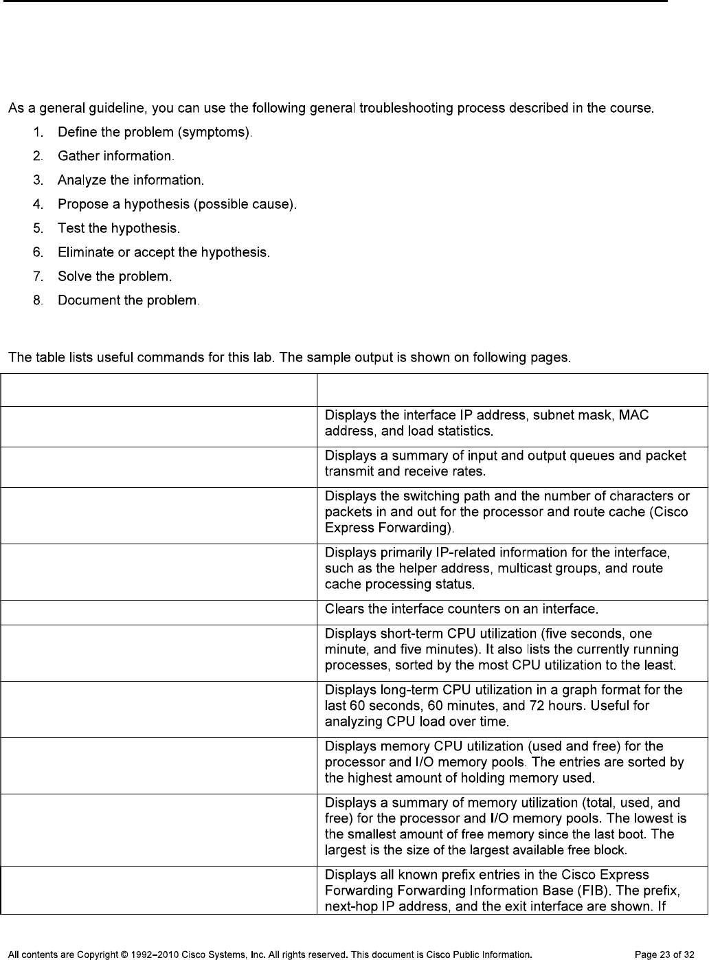
CCNPv6 TSHOOT
Section 2—Troubleshooting Reference Information
General Troubleshooting Process
Command Summary
Command Key Information Displayed
show interfaces type/#
show interfaces type/# summary
show interfaces type/# stats
show ip interface type/#
clear counters type/#
show processes cpu sorted
show processes cpu history
show processes memory sorted
show memory statistics
show ip cef
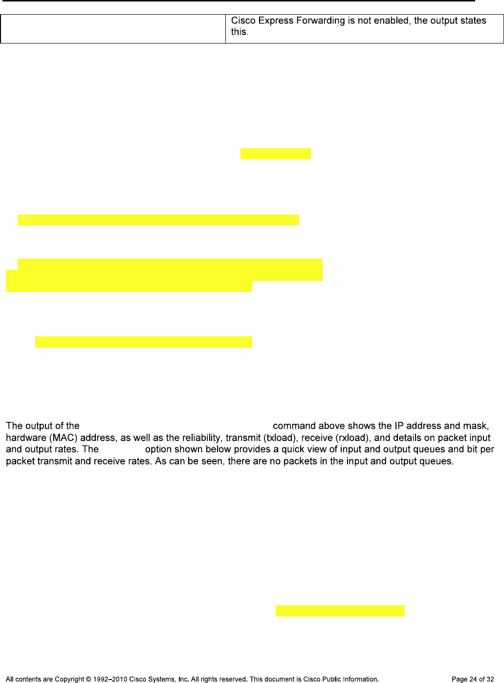
CCNPv6 TSHOOT
Display Interface Load, Statistics, and Forwarding Information
R3#show interfaces fastethernet 0/0
FastEthernet0/0 is up, line protocol is up
Hardware is Gt96k FE, address is 001b.530d.6028 (bia 001b.530d.6028)
Internet address is 10.1.80.1/24
MTU 1500 bytes, BW 100000 Kbit/sec, DLY 100 usec,
reliability 255/255, txload 1/255, rxload 2/255
Encapsulation ARPA, loopback not set
Keepalive set (10 sec)
Full-duplex, 100Mb/s, 100BaseTX/FX
ARP type: ARPA, ARP Timeout 04:00:00
Last input 00:00:00, output 00:00:00, output hang never
Last clearing of "show interface" counters never
Input queue: 0/75/0/0 (size/max/drops/flushes); Total output drops: 0
Queueing strategy: fifo
Output queue: 0/40 (size/max)
5 minute input rate 913000 bits/sec, 179 packets/sec
5 minute output rate 62000 bits/sec, 175 packets/sec
381659 packets input, 222009886 bytes
Received 257 broadcasts, 0 runts, 0 giants, 0 throttles
0 input errors, 0 CRC, 0 frame, 0 overrun, 0 ignored
0 watchdog
0 input packets with dribble condition detected
377267 packets output, 20429223 bytes, 0 underruns
0 output errors, 0 collisions, 3 interface resets
0 unknown protocol drops
0 babbles, 0 late collision, 0 deferred
0 lost carrier, 0 no carrier
0 output buffer failures, 0 output buffers swapped out
show interfaces fastethernet 0/0
summary
R3#show interfaces fa0/0 summary
*: interface is up
IHQ: pkts in input hold queue IQD: pkts dropped from input queue
OHQ: pkts in output hold queue OQD: pkts dropped from output queue
RXBS: rx rate (bits/sec) RXPS: rx rate (pkts/sec)
TXBS: tx rate (bits/sec) TXPS: tx rate (pkts/sec)
TRTL: throttle count
Interface IHQ IQD OHQ OQD RXBS RXPS TXBS TXPS TRTL
------------------------------------------------------------------------
* FastEthernet0/0 0 0 0 0 969000 204 94000 201 0
R3#show interfaces fa0/0 stats
FastEthernet0/0
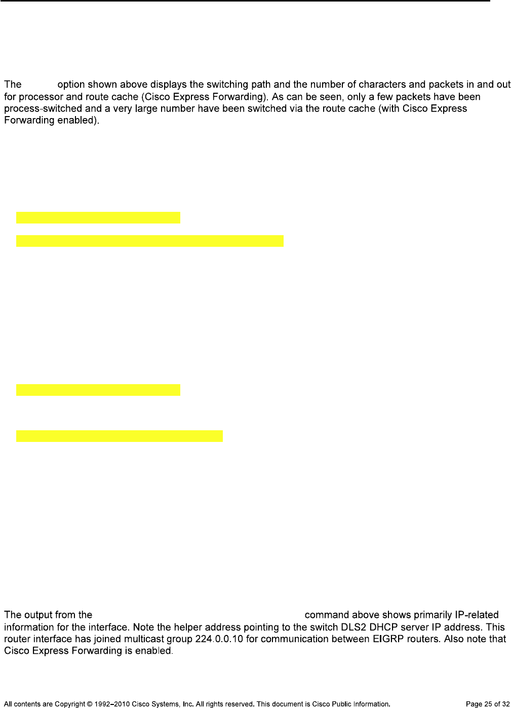
CCNPv6 TSHOOT
Switching path Pkts In Chars In Pkts Out Chars Out
Processor 831 356623 4075 408723
Route cache 381399 221941950 375270 20282949
Total 382230 222298573 379345 20691672
stats
R3#show ip interface fastethernet 0/0
FastEthernet0/0 is up, line protocol is up
Internet address is 10.1.80.1/24
Broadcast address is 255.255.255.255
Address determined by non-volatile memory
MTU is 1500 bytes
Helper address is 10.1.2.13
Directed broadcast forwarding is disabled
Multicast reserved groups joined: 224.0.0.10
Outgoing access list is not set
Inbound access list is not set
Proxy ARP is enabled
Local Proxy ARP is disabled
Security level is default
Split horizon is enabled
ICMP redirects are always sent
ICMP unreachables are always sent
ICMP mask replies are never sent
IP fast switching is enabled
IP fast switching on the same interface is disabled
IP Flow switching is disabled
IP CEF switching is enabled
IP CEF switching turbo vector
IP multicast fast switching is enabled
IP multicast distributed fast switching is disabled
IP route-cache flags are Fast, CEF
Router Discovery is disabled
IP output packet accounting is disabled
IP access violation accounting is disabled
TCP/IP header compression is disabled
RTP/IP header compression is disabled
Policy routing is disabled
Network address translation is disabled
BGP Policy Mapping is disabled
Input features: Ingress-NetFlow, MCI Check
Output features: Post-Ingress-NetFlow
WCCP Redirect outbound is disabled
WCCP Redirect inbound is disabled
WCCP Redirect exclude is disabled
show ip interface fastethernet 0/0
R1#show ip cef
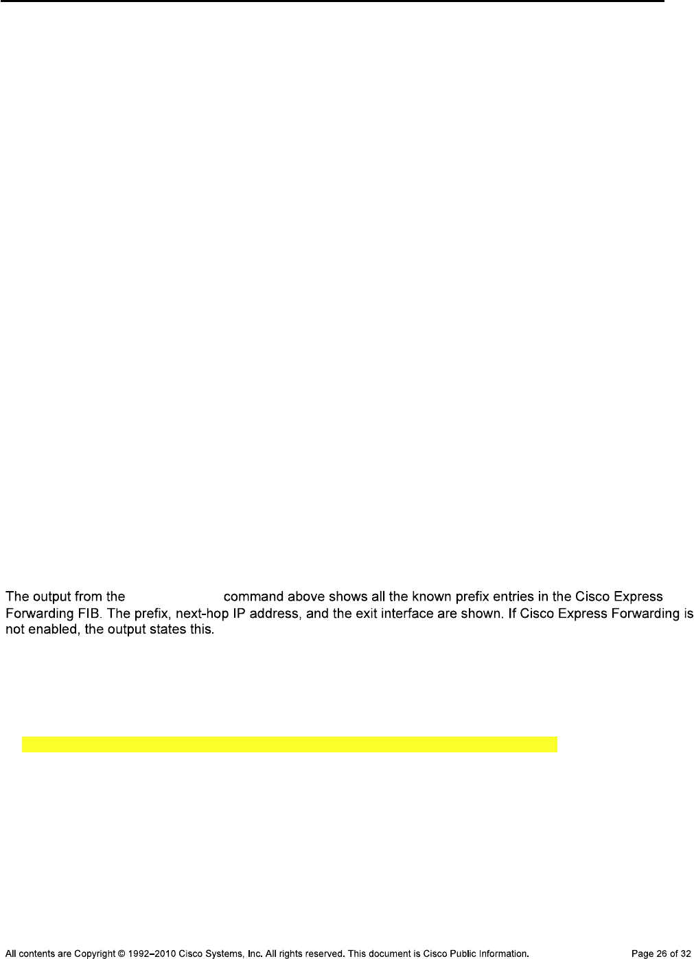
CCNPv6 TSHOOT
Prefix Next Hop Interface
0.0.0.0/0 209.165.200.226 Serial0/0/0
0.0.0.0/8 drop
0.0.0.0/32 receive
10.1.2.0/30 attached FastEthernet0/1
10.1.2.0/32 receive FastEthernet0/1
10.1.2.1/32 attached FastEthernet0/1
10.1.2.2/32 receive FastEthernet0/1
10.1.2.3/32 receive FastEthernet0/1
10.1.2.12/30 10.1.2.1 FastEthernet0/1
10.1.10.0/24 10.1.2.1 FastEthernet0/1
10.1.20.0/24 10.1.2.1 FastEthernet0/1
10.1.30.0/24 10.1.2.1 FastEthernet0/1
10.1.50.0/24 10.1.2.1 FastEthernet0/1
10.1.80.0/24 10.1.2.1 FastEthernet0/1
10.1.100.0/24 10.1.2.1 FastEthernet0/1
10.1.200.0/24 10.1.2.1 FastEthernet0/1
10.1.203.1/32 10.1.2.1 FastEthernet0/1
127.0.0.0/8 drop
172.20.0.0/21 209.165.200.226 Serial0/0/0
192.168.1.0/24 attached Loopback0
192.168.1.0/32 receive Loopback0
Prefix Next Hop Interface
192.168.1.1/32 receive Loopback0
192.168.1.255/32 receive Loopback0
192.168.2.1/32 209.165.200.226 Serial0/0/0
209.165.200.224/30 attached Serial0/0/0
209.165.200.224/32 receive Serial0/0/0
209.165.200.225/32 receive Serial0/0/0
209.165.200.226/32 attached Serial0/0/0
209.165.200.227/32 receive Serial0/0/0
224.0.0.0/4 drop
224.0.0.0/24 receive
240.0.0.0/4 drop
255.255.255.255/32 receive
show ip cef
Display CPU Load and Process Statistics
R3#show processes cpu sorted
CPU utilization for five seconds: 17%/5%; one minute: 3%; five minutes: 1%
PID Runtime(ms) Invoked uSecs 5Sec 1Min 5Min TTY Process
91 2308 4797 481 11.19% 2.10% 0.52% 0 IP Input
3 13308 2477 5372 0.87% 0.18% 0.05% 0 Exec
124 12 265 45 0.15% 0.03% 0.00% 0 TCP Timer
153 20 93423 0 0.15% 0.12% 0.10% 0 HQF Shaper Backg
265 1280 11572 110 0.07% 0.01% 0.00% 0 IP-EIGRP: HELLO
<output omitted>

CCNPv6 TSHOOT
show processes cpu sorted
R3#show processes cpu history
R3 07:54:09 PM Monday Nov 30 2009 UTC
999988888
99999999922222 11111
100 ****
90 *********
80 *********
70 *********
60 *********
50 *********
40 *********
30 *********
20 *********
10 *********
0....5....1....1....2....2....3....3....4....4....5....5....6
0 5 0 5 0 5 0 5 0 5 0
CPU% per second (last 60 seconds)
992 3
111111119981111121111111211111111112111111211111113111111111
100 *#
90 *#
80 ##
70 ##
60 ##
50 ##
40 ##
30 ##* *
20 ##* *
10 ##* *
0....5....1....1....2....2....3....3....4....4....5....5....6
0 5 0 5 0 5 0 5 0 5 0
CPU% per minute (last 60 minutes)
* = maximum CPU% # = average CPU%
99
99
100 **
90 **
80 **
70 **
60 **
50 **
40 **
30 **
20 **
10 **
0....5....1....1....2....2....3....3....4....4....5....5....6....6....7..
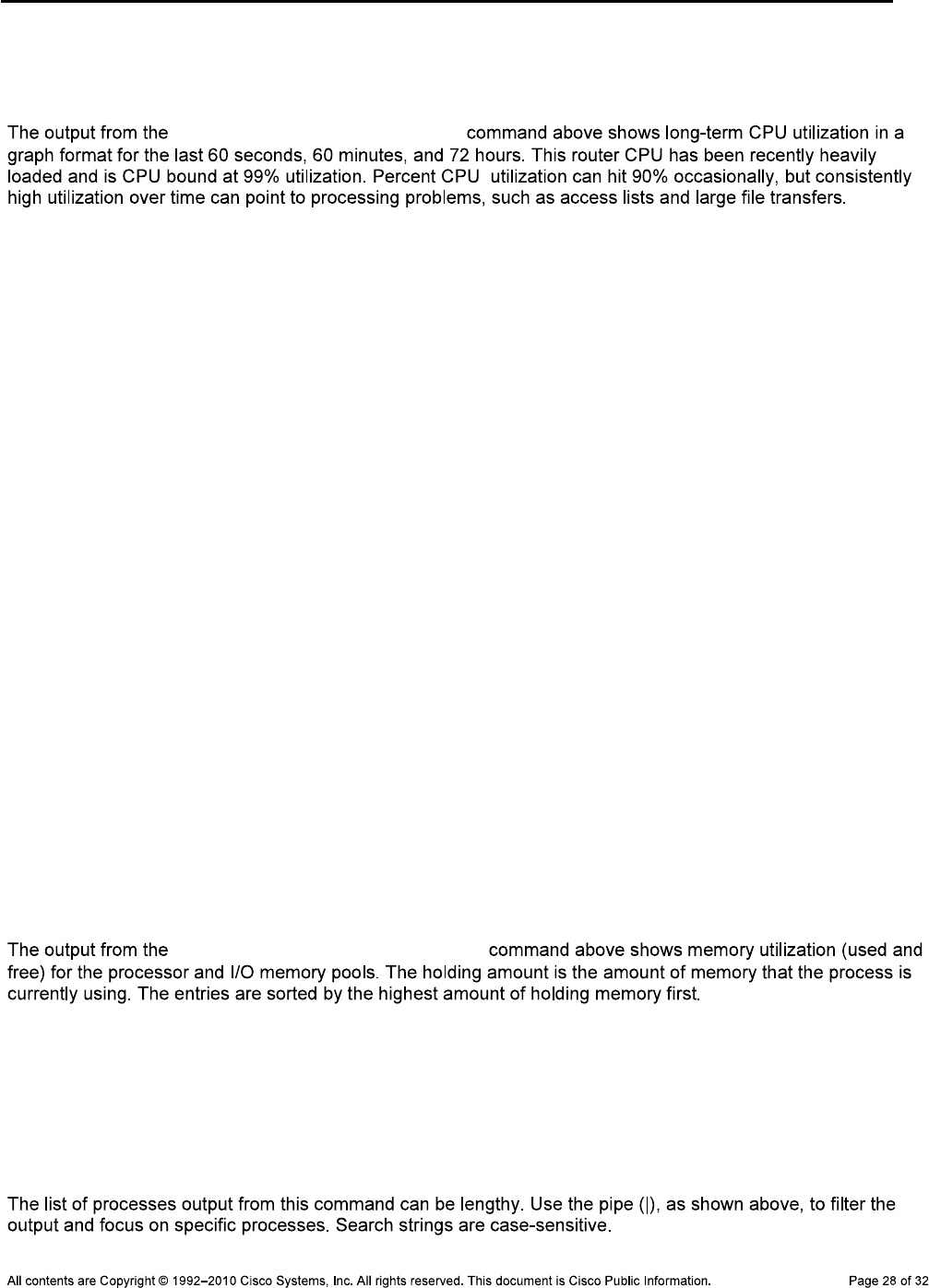
CCNPv6 TSHOOT
0 5 0 5 0 5 0 5 0 5 0 5 0
CPU% per hour (last 72 hours)
* = maximum CPU% # = average CPU%
show processes cpu history
Display Memory Usage and Process Statistics
R3#show processes memory sorted
Processor Pool Total: 101226944 Used: 24015448 Free: 77211496
I/O Pool Total: 17825792 Used: 5446544 Free: 12379248
PID TTY Allocated Freed Holding Getbufs Retbufs Process
0 0 62860036 36235836 23615956 0 0 *Init*
55 0 659528 1328 640200 0 0 USB Startup
1 0 466000 0 473204 0 0 Chunk Manager
219 0 469124 18304 436776 0 0 VLAN Manager
0 0 0 0 420380 0 0 *MallocLite*
25 0 260308 0 270512 99792 0 EEM ED Syslog
170 0 218420 504 215916 0 0 Crypto HW Proc
221 0 196192 0 203396 0 0 EEM Server
183 0 114384 528 123060 0 0 Crypto WUI
167 0 76544 252 83496 0 0 HTTP Process
40 0 66536 153420 73340 0 0 IF-MGR control p
3 0 7352228 7237092 66908 0 0 Exec
<output omitted>
show processes memory sorted
R3#show processes memory sorted | include EIGRP
265 0 1676448 7910464 24464 0 0 IP-EIGRP: PDM
264 0 0 0 18200 0 0 IP-EIGRP Router
266 0 19720032 13337320 7116 0 0 IP-EIGRP: HELLO

CCNPv6 TSHOOT
R3#show memory statistics
Head Total(b) Used(b) Free(b) Lowest(b) Largest(b)
Processor 64E76640 101226944 23964420 77262524 76880040 76910312
I/O EAF00000 17825792 5421732 12404060 12376432 1240031
show memory statistics
CCNPv6 TSHOOT
Reflection Questions
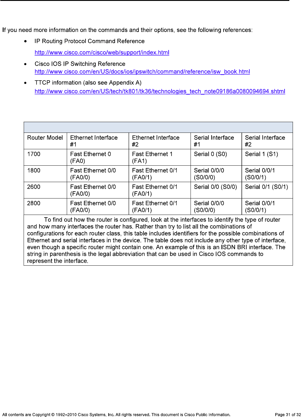
CCNPv6 TSHOOT
References
Router Interface Summary Table
Router Interface Summary
Note:
CCNPv6 TSHOOT
Appendix A—Using a Windows PC as a TTCP End Device
C:\Cisco\TTCP>ttcpw -r -s ttcp-r: buflen=8192, nbuf=2048, align=16364/0,
port=5001 tcp ttcp-r: socket
DLS2#ttcp
transmit or receive [receive]: transmit
Target IP address: 10.1.80.254
calculate checksum during buffer write [y]:
perform tcp half close [n]:
send buflen [32768]:
send nbuf [2048]:
bufalign [16384]:
bufoffset [0]:
port [5001]:
sinkmode [y]:
buffering on writes [y]:
show tcp information at end [n]:
ttcp-t: buflen=32768, nbuf=2048, align=16384/0, port=5001 tcp ->
10.1.80.254
ttcp-t: connect
ttcp-t: 67108864 bytes in 47622 ms (47.622 real seconds) (~1375 kB/s) +++
ttcp-t: 2048 I/O calls
ttcp-t: 0 sleeps (0 ms total) (0 ms average)
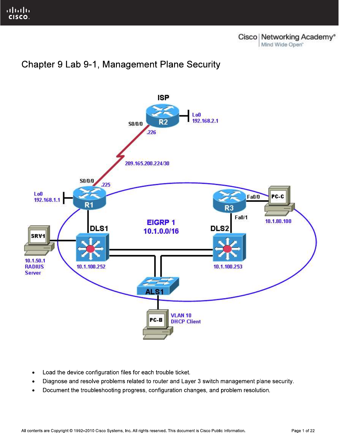
CCNPv6 TSHOOT
Lab Topology
Objectives
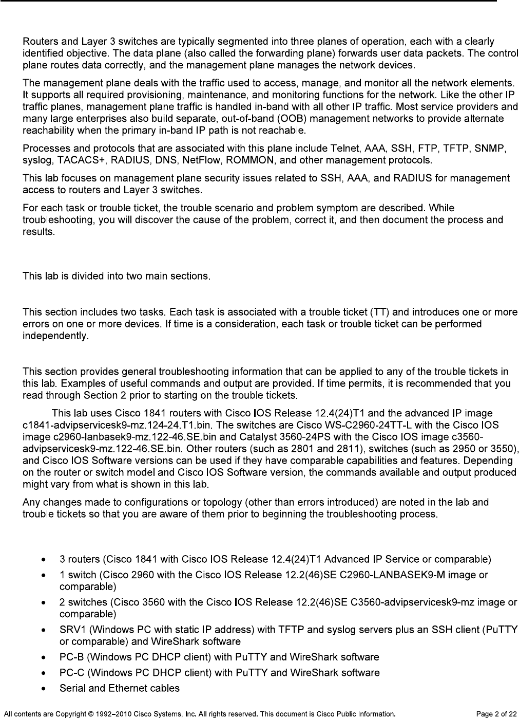
CCNPv6 TSHOOT
Background
Lab Structure
Section 1—Trouble Tickets and Troubleshooting Logs
Section 2—Troubleshooting Reference Information
Note:
Required Resources
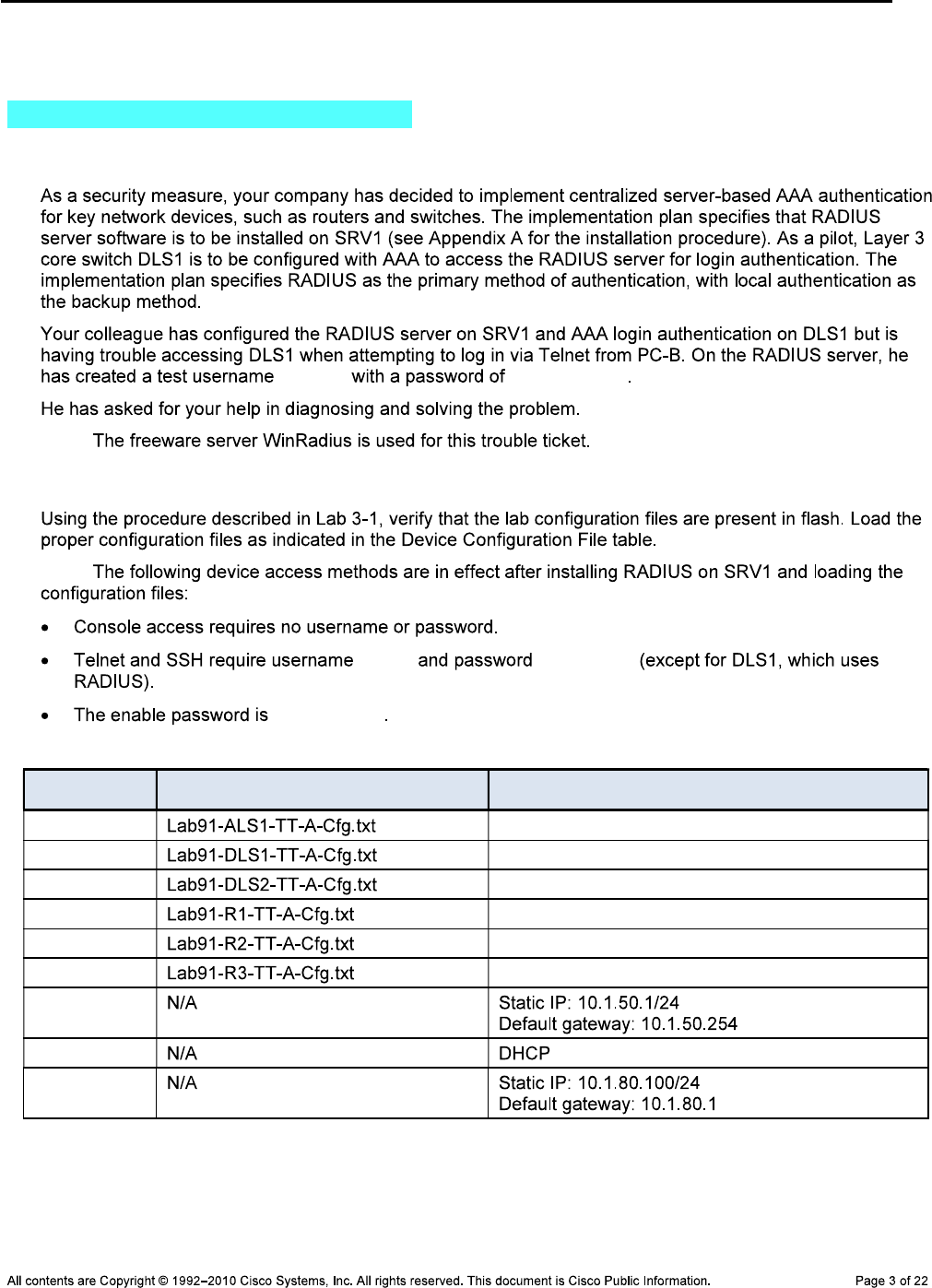
CCNPv6 TSHOOT
Section 1—Trouble Tickets and Troubleshooting Logs
Task 1: Trouble Ticket Lab 9-1 TT-A
Step 1: Review trouble ticket Lab 9-1 TT-A.
raduser RadUserpass
Note:
Step 2: Load the device trouble ticket configuration files for TT-A.
Note:
admin adminpa55
ciscoenpa55
Device Configuration File Table
Device Name File to Load Notes
ALS1
DLS1
DLS2
R1
R2
R3
SRV1
PC-B
PC-C
CCNPv6 TSHOOT
Step 3: Configure SRV1 and start the RADIUS server.
Operation > Add User raduser
RadUserpass. OK
Note:
Log > Clear
Note: raduser
Step 4: Release and renew the DHCP lease on PC-B.
ipconfig /release ipconfig
/renew
Step 5: Outline the troubleshooting approach and validation steps.
Note:
_______________________________________________________________________________
_______________________________________________________________________________
_______________________________________________________________________________
_______________________________________________________________________________
_______________________________________________________________________________
_______________________________________________________________________________
Step 6: Record the troubleshooting process and configuration changes.
Note:
CCNPv6 TSHOOT
Device Actions and Results
Step 7: Document trouble ticket debrief notes.
_______________________________________________________________________________
_______________________________________________________________________________
_______________________________________________________________________________
_______________________________________________________________________________
_______________________________________________________________________________
_______________________________________________________________________________
_______________________________________________________________________________
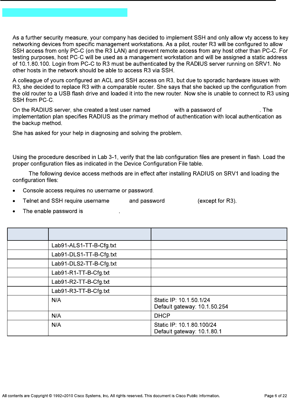
CCNPv6 TSHOOT
Task 2: Trouble Ticket Lab 9-1 TT-B
Step 1: Review trouble ticket Lab 9-1 TT-B.
raduser RadUserpass
Step 2: Load the device trouble ticket configuration files for TT-B.
Note:
admin adminpa55
ciscoenpa55
Device Configuration File Table
Device Name File to Load Notes
ALS1
DLS1
DLS2
R1
R2
R3
SRV1
PC-B
PC-C
CCNPv6 TSHOOT
Step 3: Configure SRV1 and start the RADIUS server.
Operation > Add User raduser
RadUserpass OK
Note:
Log > Clear
Note: raduser
Step 4: Configure a static IP address on PC-C.
Step 5: Outline the troubleshooting approach and validation steps.
Note:
_______________________________________________________________________________
_______________________________________________________________________________
_______________________________________________________________________________
_______________________________________________________________________________
_______________________________________________________________________________
_______________________________________________________________________________
Step 6: Record the troubleshooting process and configuration changes.
Note:
Device Actions and Results
CCNPv6 TSHOOT
Device Actions and Results
Step 7: Document trouble ticket debrief notes.
_______________________________________________________________________________
_______________________________________________________________________________
_______________________________________________________________________________
_______________________________________________________________________________
_______________________________________________________________________________
_______________________________________________________________________________
_______________________________________________________________________________

CCNPv6 TSHOOT
Section 2—Troubleshooting Reference Information
General Troubleshooting Process
Command Summary
Command Key Information Displayed
show line vty 0
show users
show radius server-group all
show radius statistics
debug radius authentication
show aaa servers
show aaa method-lists all
debug aaa authentication
debug aaa authorization
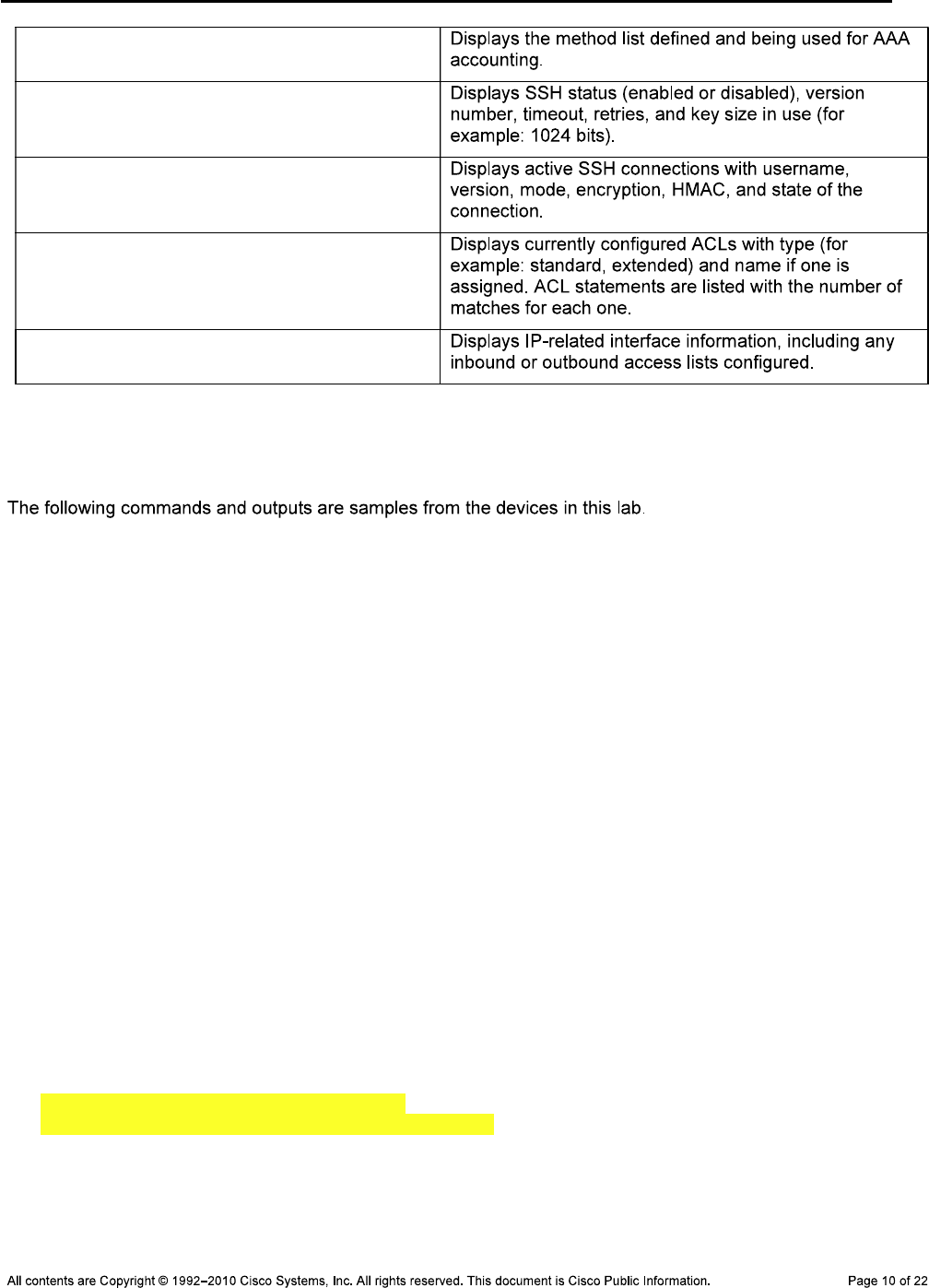
CCNPv6 TSHOOT
debug aaa accounting
show ip ssh
show ssh
sh access-lists
show ip interface fa0/0
Sample Troubleshooting Output
VTY Line-related Commands
DLS1#show line vty 0
Tty Typ Tx/Rx A Modem Roty AccO AccI Uses Noise Overruns Int
1 VTY - - - - - 4 0 0/0 -
Line 1, Location: "", Type: ""
Length: 24 lines, Width: 80 columns
Baud rate (TX/RX) is 9600/9600
Status: Ready, No Exit Banner
Capabilities: none
Modem state: Ready
Special Chars: Escape Hold Stop Start Disconnect Activation
^^x none - - none
Timeouts: Idle EXEC Idle Session Modem Answer Session Dispatch
01:00:00 never none not set
Idle Session Disconnect Warning
never
Login-sequence User Response
00:00:30
Autoselect Initial Wait
not set
Modem type is unknown.
Session limit is not set.
Time since activation: never
Editing is enabled.
History is enabled, history size is 20.
DNS resolution in show commands is enabled
Full user help is disabled
Allowed input transports are ssh.
Allowed output transports are telnet ssh.
Preferred transport is telnet.
No output characters are padded
No special data dispatching characters
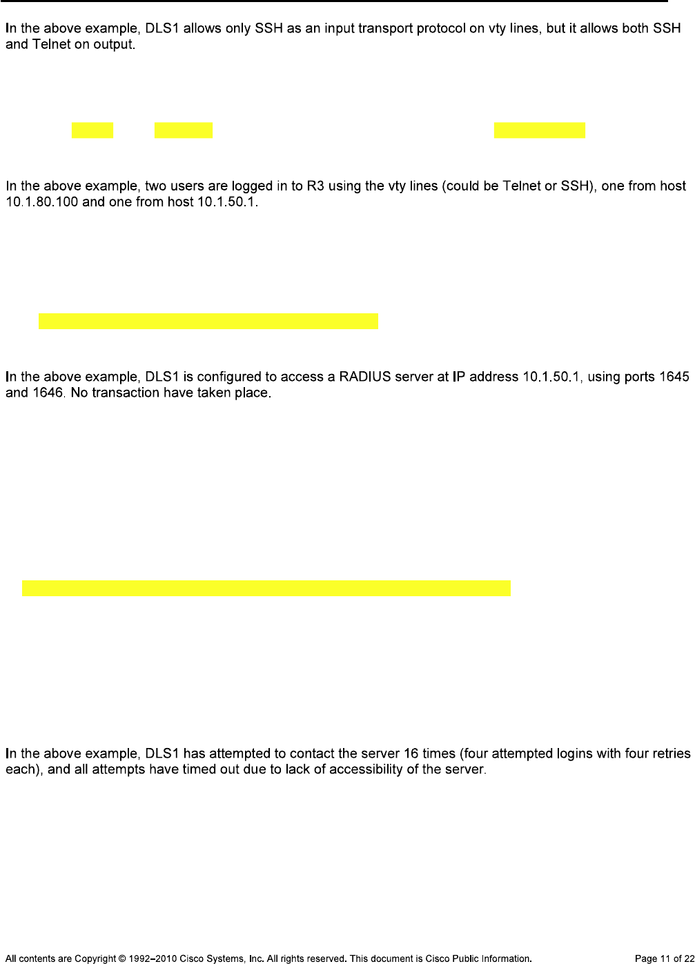
CCNPv6 TSHOOT
R3#show users
Line User Host(s) Idle Location
* 0 con 0 idle 00:00:00
194 vty 0 raduser idle 00:22:52 10.1.80.100
195 vty 1 admin idle 00:00:22 10.1.50.1
RADIUS-related Commands
DLS1#show radius server-group all
Sever group radius
Sharecount = 1 sg_unconfigured = FALSE
Type = standard Memlocks = 1
Server(10.1.50.1:1645,1646) Transactions:
Authen: Not Available Author:Not Available Acct:Not Available
DLS1#show radius statistics
Auth. Acct. Both
Maximum inQ length: NA NA 1
Maximum waitQ length: NA NA 1
Maximum doneQ length: NA NA 1
Total responses seen: 0 0 0
Packets with responses: 0 0 0
Packets without responses: 4 0 4
Average response delay(ms): 0 0 0
Maximum response delay(ms): 0 0 0
Number of Radius timeouts: 16 0 16
Duplicate ID detects: 0 0 0
Buffer Allocation Failures: 0 0 0
Maximum Buffer Size (bytes): 82 0 82
Source Port Range: (2 ports only)
1645 - 1646
Last used Source Port/Identifier:
1645/4
1646/0
DLS1#debug radius authentication
Radius protocol debugging is on
Radius protocol brief debugging is off
Radius protocol verbose debugging is off
Radius packet hex dump debugging is off
Radius packet protocol debugging is on
Radius packet retransmission debugging is off
Radius server fail-over debugging is off
Radius elog debugging is off
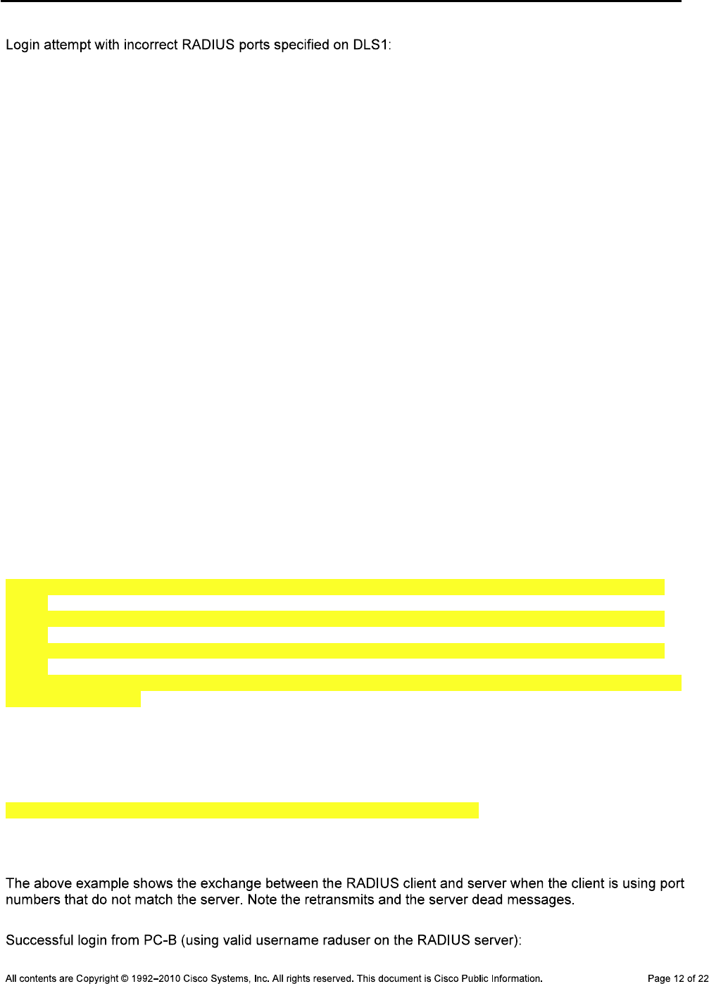
CCNPv6 TSHOOT
DLS1#
Dec 4 16:06:50.142: RADIUS/ENCODE(00000005): ask "Username: "
DLS1#
Dec 4 16:06:59.430: RADIUS/ENCODE(00000005): ask "Password: "
DLS1#
Dec 4 16:07:05.487: RADIUS/ENCODE(00000005):Orig. component type = EXEC
Dec 4 16:07:05.487: RADIUS: AAA Unsupported Attr: interface [170] 4
Dec 4 16:07:05.487: RADIUS: 74 74 [ tt]
Dec 4 16:07:05.487: RADIUS/ENCODE(00000005): dropping service type, "radius-server
attribute 6 on-for-login-auth" is off
Dec 4 16:07:05.487: RADIUS(00000005): Config NAS IP: 0.0.0.0
Dec 4 16:07:05.487: RADIUS/ENCODE(00000005): acct_session_id: 5
Dec 4 16:07:05.487: RADIUS(00000005): sending
Dec 4 16:07:05.487: RADIUS/ENCODE: Best Local IP-Address 10.1.50.252 for Radius
-Server 10.1.50.1
Dec 4 16:07:05.487: RADIUS(00000005): Send Access-Request to 10.1.50.1:1645 id
1645/5, len 82
Dec 4 16:07:05.487: RADIUS: authenticator B5 DF D2 00 81 8A C0 08 - 5E 68 DA A
9 59 01 7A 00
Dec 4 16:07:05.487: RADIUS: User-Name [1] 9 "raduser"
Dec 4 16:07:05.487: RADIUS: User-Password [2] 18 *
Dec 4 16:07:05.487: RADIUS: NAS-Port [5] 6 1
DLS1#
Dec 4 16:07:05.487: RADIUS: NAS-Port-Id [87] 6 "tty1"
Dec 4 16:07:05.487: RADIUS: NAS-Port-Type [61] 6 Virtual
[5]
Dec 4 16:07:05.487: RADIUS: Calling-Station-Id [31] 11 "10.1.10.1"
Dec 4 16:07:05.487: RADIUS: NAS-IP-Address [4] 6 10.1.50.252
DLS1#
Dec 4 16:07:10.370: RADIUS: Retransmit to (10.1.50.1:1645,1646) for id 1645/5
DLS1#
Dec 4 16:07:15.269: RADIUS: Retransmit to (10.1.50.1:1645,1646) for id 1645/5
DLS1#
Dec 4 16:07:20.403: RADIUS: Retransmit to (10.1.50.1:1645,1646) for id 1645/5
DLS1#
Dec 4 16:07:25.370: %RADIUS-4-RADIUS_DEAD: RADIUS server 10.1.50.1:1645,1646 is
not responding.
Dec 4 16:07:25.370: %RADIUS-4-RADIUS_ALIVE: RADIUS server 10.1.50.1:1645,1646 h
as returned.
DLS1#
Dec 4 16:07:25.370: RADIUS: No response from (10.1.50.1:1645,1646) for id 1645/
5
Dec 4 16:07:25.370: RADIUS/DECODE: parse response no app start; FAIL
Dec 4 16:07:25.370: RADIUS/DECODE: parse response; FAIL
DLS1#
Dec 4 16:07:27.375: RADIUS/ENCODE(00000005): ask "Username: "
CCNPv6 TSHOOT
DLS1(config)#
Dec 6 17:04:47.577: RADIUS/ENCODE(0000000F): ask "Username: "
DLS1(config)#
Dec 6 17:04:55.715: RADIUS/ENCODE(0000000F): ask "Password: "
DLS1(config)#
Dec 6 17:05:05.439: RADIUS/ENCODE(0000000F):Orig. component type = EXEC
Dec 6 17:05:05.439: RADIUS: AAA Unsupported Attr: interface [170] 4
Dec 6 17:05:05.439: RADIUS: 74 74 [ tt]
Dec 6 17:05:05.439: RADIUS/ENCODE(0000000F): dropping service type, "radius-ser
ver attribute 6 on-for-login-auth" is off
Dec 6 17:05:05.439: RADIUS(0000000F): Config NAS IP: 0.0.0.0
Dec 6 17:05:05.439: RADIUS/ENCODE(0000000F): acct_session_id: 15
Dec 6 17:05:05.439: RADIUS(0000000F): se
DLS1(config)#nding
Dec 6 17:05:05.439: RADIUS/ENCODE: Best Local IP-Address 10.1.50.252 for Radius
-Server 10.1.50.1
Dec 6 17:05:05.439: RADIUS(0000000F): Send Access-Request to 10.1.50.1:1812 id
1645/12, len 82
Dec 6 17:05:05.439: RADIUS: authenticator 7E D1 DF 37 75 69 EC 91 - 42 FC 2E 7
8 D7 9B 5B 3B
Dec 6 17:05:05.439: RADIUS: User-Name [1] 9 "raduser"
Dec 6 17:05:05.439: RADIUS: User-Password [2] 18 *
Dec 6 17:05:05.439: RADIUS: NAS-Port [5] 6 1
DLS1(config)#
Dec 6 17:05:05.439: RADIUS: NAS-Port-Id [87] 6 "tty1"
Dec 6 17:05:05.439: RADIUS: NAS-Port-Type [61] 6 Virtual
[5]
Dec 6 17:05:05.439: RADIUS: Calling-Station-Id [31] 11 "10.1.10.1"
Dec 6 17:05:05.439: RADIUS: NAS-IP-Address [4] 6 10.1.50.252
Dec 6 17:05:05.447: RADIUS: Received from id 1645/12 10.1.50.1:1812, Access-Acc
ept, len 26
Dec 6 17:05:05.447: RADIUS: authenticator 75 81 E4 CD 45 1D F6 14 - 5D 1F AD F
4 D4 83 D
DLS1(config)#5 FE
Dec 6 17:05:05.447: RADIUS: Session-Timeout [27] 6 9999999
Dec 6 17:05:05.447: RADIUS(0000000F): Received from id 1645/12
DLS1(config)#
Dec 6 17:10:00.346: RADIUS/ENCODE(00000010): ask "Username: "
DLS1(config)#
Dec 6 17:10:06.722: RADIUS/ENCODE(00000010): ask "Password: "
DLS1(config)#
Dec 6 17:10:16.580: RADIUS/ENCODE(00000010):Orig. component type = EXEC
Dec 6 17:10:16.580: RADIUS: AAA Unsupported Attr: interface [170] 4
Dec 6 17:10:16.580: RADIUS: 74 74 [ tt]
Dec 6 17:10:16.580: RADIUS/ENCODE(00000010): dropping service type, "radius-ser
ver attribute 6 on-for-login-auth" is off
CCNPv6 TSHOOT
Dec 6 17:10:16.580: RADIUS(00000010): Config NAS IP: 0.0.0.0
Dec 6 17:10:16.580: RADIUS/ENCODE(00000010): acct_session_id: 16
Dec 6 17:10:16.580: RADIUS(00000010): se
DLS1(config)#nding
Dec 6 17:10:16.580: RADIUS/ENCODE: Best Local IP-Address 10.1.50.252 for Radius
-Server 10.1.50.1
Dec 6 17:10:16.580: RADIUS(00000010): Send Access-Request to 10.1.50.1:1812 id
1645/13, len 82
Dec 6 17:10:16.580: RADIUS: authenticator 17 3A 1D 34 81 4C F1 6F - 89 62 05 1
3 14 8F 33 4B
Dec 6 17:10:16.580: RADIUS: User-Name [1] 9 "baduser"
Dec 6 17:10:16.580: RADIUS: User-Password [2] 18 *
Dec 6 17:10:16.580: RADIUS: NAS-Port [5] 6 1
Dec 6 17:10:16.580: RADIUS: NAS-Port-Id [87] 6 "tty1"
Dec 6 17:10:16.580: RADIUS: NAS-Port-Type [61] 6 Virtual
[5]
Dec 6 17:10:16.580: RADIUS: Calling-Station-Id [31] 11 "10.1.10.1"
Dec 6 17:10:16.580: RADIUS: NAS-IP-Address [4] 6 10.1.50.252
Dec 6 17:10:16.588: RADIUS: Received from id 1645/13 10.1.50.1:1812, Access-Rej
ect, len 20
Dec 6 17:10:16.588: RADIUS: authenticator 81 34 66 76 58 03 AF 9B - CF D5 93 F
2 C6 13 6
DLS1(config)#7 7D
Dec 6 17:10:16.588: RADIUS(00000010): Received from id 1645/13
Dec 6 17:10:18.593: RADIUS/ENCODE(00000010): ask "Username: "
AAA-related Commands
DLS1#show aaa servers
RADIUS: id 2, priority 1, host 10.1.50.1, auth-port 1645, acct-port 1646
State: current UP, duration 13752s, previous duration 0s
Dead: total time 0s, count 0
Quarantined: No
Authen: request 8, timeouts 8
Response: unexpected 0, server error 0, incorrect 0, time 0ms
Transaction: success 0, failure 2
<output omitted>
R3#show aaa servers
RADIUS: id 1, priority 1, host 10.1.50.1, auth-port 1812, acct-port 1813
State: current UP, duration 23188s, previous duration 0s
CCNPv6 TSHOOT
Dead: total time 0s, count 0
Quarantined: No
Authen: request 0, timeouts 0, failover 0, retransmission 0
Response: accept 0, reject 0, challenge 0
Response: unexpected 0, server error 0, incorrect 0, time 0ms
Transaction: success 2, failure 0
Throttled: transaction 0, timeout 0, failure 0
Author: request 0, timeouts 0, failover 0, retransmission 0
Response: accept 0, reject 0, challenge 0
Response: unexpected 0, server error 0, incorrect 0, time 0ms
Transaction: success 0, failure 0
Throttled: transaction 0, timeout 0, failure 0
Account: request 0, timeouts 0, failover 0, retransmission 0
Request: start 0, interim 0, stop 0
Response: start 0, interim 0, stop 0
Response: unexpected 0, server error 0, incorrect 0, time 0ms
Transaction: success 0, failure 0
Throttled: transaction 0, timeout 0, failure 0
R3#show aaa method-lists all
authen queue=AAA_ML_AUTHEN_LOGIN
name=default valid=TRUE id=0 :state=ALIVE : LOCAL
name=CONSOLE valid=TRUE id=2B000001 :state=ALIVE : NONE
name=VTY_LINES valid=TRUE id=87000002 :state=ALIVE : SERVER_GROUP radius LOCAL
authen queue=AAA_ML_AUTHEN_ENABLE
authen queue=AAA_ML_AUTHEN_PPP
authen queue=AAA_ML_AUTHEN_SGBP
authen queue=AAA_ML_AUTHEN_ARAP
authen queue=AAA_ML_AUTHEN_DOT1X
authen queue=AAA_ML_AUTHEN_EAPOUDP
authen queue=AAA_ML_AUTHEN_8021X
permanent lists
name=Permanent Enable None valid=TRUE id=0 :state=ALIVE : ENABLE NONE
name=Permanent Enable valid=TRUE id=0 :state=ALIVE : ENABLE
name=Permanent None valid=TRUE id=0 :state=ALIVE : NONE
name=Permanent Local valid=TRUE id=0 :state=ALIVE : LOCAL
author queue=AAA_ML_AUTHOR_SHELL
name=VTY_LINES valid=TRUE id=61000003 :state=ALIVE : SERVER_GROUP radius LOCAL
<output omitted>
DLS1#debug aaa authentication
AAA Authentication debugging is on
DLS1#
Dec 7 15:48:21.869: AAA/BIND(0000000C): Bind i/f
Dec 7 15:48:21.869: AAA/AUTHEN/LOGIN (0000000C): Pick method list 'TELNET_LINES
'

CCNPv6 TSHOOT
DLS1#debug aaa authorization
AAA Authorization debugging is on
DLS1#
Dec 7 16:06:34.836: AAA/AUTHOR (0xD): Pick method list 'default' - FAIL
Dec 7 16:06:34.844: AAA/AUTHOR/EXEC(0000000D): Authorization FAILED
SSH-related Commands
R3#show ip ssh
SSH Enabled - version 1.99
Authentication timeout: 120 secs; Authentication retries: 3
Minimum expected Diffie Hellman key size : 1024 bits
R3#show ip ssh
SSH Disabled - version 1.99
%Please create RSA keys (of at least 768 bits size) to enable SSH v2.
Authentication timeout: 120 secs; Authentication retries: 3
Minimum expected Diffie Hellman key size : 1024 bits
R3#show ssh
Connection Version Mode Encryption Hmac State Username
0 2.0 IN aes256-cbc hmac-sha1 Session started raduser
0 2.0 OUT aes256-cbc hmac-sha1 Session started raduser
1 2.0 IN aes256-cbc hmac-sha1 Session started admin
1 2.0 OUT aes256-cbc hmac-sha1 Session started admin
%No SSHv1 server connections running.
ACL-related Commands
R3#show access-lists
Standard IP access list 1
10 permit 10.1.80.100 (77 matches)
R3#show ip interface fa0/0
FastEthernet0/0 is up, line protocol is up
Internet address is 10.1.80.1/24
Broadcast address is 255.255.255.255
Address determined by non-volatile memory
MTU is 1500 bytes
Helper address is not set
Directed broadcast forwarding is disabled
Multicast reserved groups joined: 224.0.0.10
Outgoing access list is not set
CCNPv6 TSHOOT
Inbound access list is 1
Proxy ARP is enabled
Local Proxy ARP is disabled
Security level is default
Split horizon is enabled
ICMP redirects are always sent
ICMP unreachables are always sent
ICMP mask replies are never sent
IP fast switching is enabled
IP fast switching on the same interface is disabled
IP Flow switching is disabled
IP CEF switching is enabled
IP CEF switching turbo vector
<output omitted>
Reflection Questions
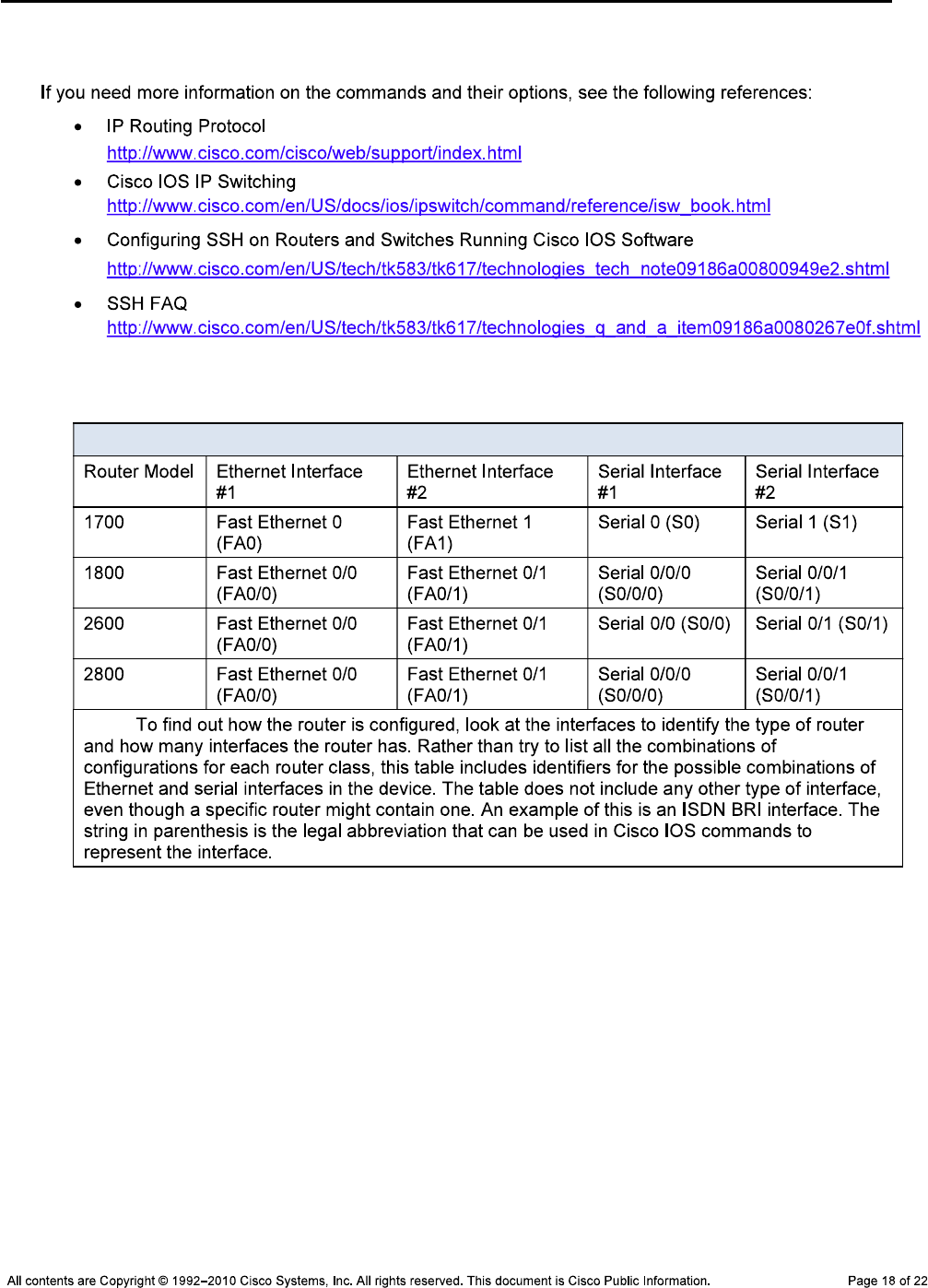
CCNPv6 TSHOOT
References
Router Interface Summary Table
Router Interface Summary
Note:

CCNPv6 TSHOOT
Appendix A—WinRadius Server Installation
Note:
Step 1: Download the WinRadius software.
Note:
Step 2: Install the WinRadius software.
winradius
Step 3: Configure the WinRadius server database.
Please go to “Settings/Database and create the ODBC for your RADIUS
database.
Launch ODBC failed.
Settings > Database
Configure ODBC automatically OK
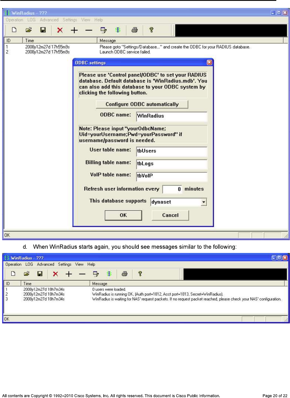
CCNPv6 TSHOOT

CCNPv6 TSHOOT
Step 4: Configure users and passwords on the WinRadius server.
Note:
Operation > Add User.
raduser RadUserpass.
Note: raduser RadUser
OK
Step 5: Clear the log display.
Log > Clear
Step 6: Test the new user added using the WinRadius test utility.
raduser RadUserpass
Note:
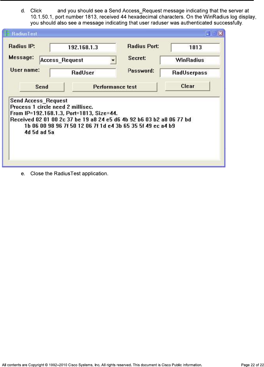
CCNPv6 TSHOOT
Send
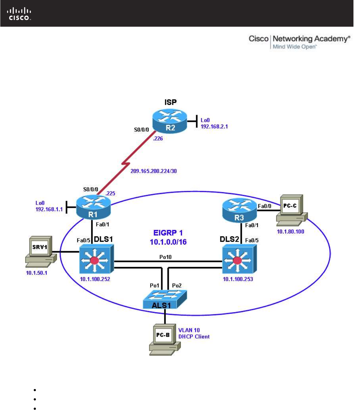
All contents are Copyright © 1992–2010 Cisco Systems, Inc. All rights reserved. This document is Cisco Public Information. Page 1 of 17
CCNPv6 TSHOOT
Chapter 9 Lab 9-2, Control Plane Security
Lab Topology
Objectives
Load the device configuration files for each trouble ticket.
Diagnose and resolve problems related to router and switch control plane security.
Document the troubleshooting progress, configuration changes, and problem resolution.

CCNPv6 TSHOOT
All contents are Copyright © 1992–2010 Cisco Systems, Inc. All rights reserved. This document is Cisco Public Information. Page 2 of 17
Background
Routers and Layer 3 switches are typically segmented into three planes of operation, each with a clearly
identified objective. The data plane (also called the forwarding plane) forwards user data packets. The control
plane routes data correctly, and the management plane manages the network devices.
The control plane is typically associated with packets generated by the network elements themselves. End
users typically do not interact with the control plane. Examples of Layer 3 control plane protocols and related
security functions include neighbor authentication for routing protocols and HSRP. Examples of security-
related Layer 2 control plane protocols include root guard, BPDU guard, DHCP snooping, Dynamic ARP
Inspection, IP source guard, and the use of special VLANs for trunks and unused ports.
This lab focuses on control plane security issues related to DHCP snooping and EIGRP authentication for
routers and Layer 3 switches.
For each task or trouble ticket, the trouble scenario and problem symptom is described. While
troubleshooting, you will discover the cause of the problem, correct it, and then document the process and
results.
Lab Structure
This lab is divided into two main sections.
Section 1—Trouble Tickets and Troubleshooting Logs
This section includes two tasks. Each task is associated with a trouble ticket (TT) and introduces one or more
errors on one or more devices. If time is a consideration, each task or trouble ticket can be performed
independently.
Section 2—Troubleshooting Reference Information
This section provides general troubleshooting information that can be applied to any of the trouble tickets in
this lab. Examples of useful commands and output are provided. If time permits, it is recommended that you
read through Section 2 prior to starting on the trouble tickets.
Note: This lab uses Cisco 1841 routers with Cisco IOS Release 12.4(24)T1 and the advanced IP image
c1841-advipservicesk9-mz.124-24.T1.bin. The switches are Cisco WS-C2960-24TT-L with the Cisco IOS
image c2960-lanbasek9-mz.122-46.SE.bin and Catalyst 3560-24PS with the Cisco IOS image c3560-
advipservicesk9-mz.122-46.SE.bin. Other routers (such as 2801 and 2811), switches (such as 2950 or 3550),
and Cisco IOS Software versions can be used if they have comparable capabilities and features. Depending
on the router or switch model and Cisco IOS Software version, the commands available and output produced
might vary from what is shown in this lab.
Any changes made to configurations or topology (other than errors introduced) are noted in the lab and
trouble tickets so that you are aware of them prior to beginning the troubleshooting process.
Required Resources
3 routers (Cisco 1841 with Cisco IOS Release 12.4(24)T1 Advanced IP Service or comparable)
1 switch (Cisco 2960 with the Cisco IOS Release 12.2(46)SE C2960-LANBASEK9-M image or
comparable)
2 switches (Cisco 3560 with the Cisco IOS Release 12.2(46)SE C3560-advipservicesk9-mz image or
comparable)
SRV1 (Windows PC with static IP address) with TFTP and syslog servers plus an SSH client (PuTTY
or comparable) and WireShark software
PC-B (Windows PC DHCP client) with PuTTY and WireShark software
PC-C (Windows PC DHCP client) with PuTTY and WireShark software
Serial and Ethernet cables
CCNPv6 TSHOOT
All contents are Copyright © 1992–2010 Cisco Systems, Inc. All rights reserved. This document is Cisco Public Information. Page 3 of 17
Section 1—Trouble Tickets and Troubleshooting Logs
Task 1: Trouble Ticket Lab 9-2 TT-A
Step 1: Review trouble ticket Lab 9-2 TT-A.
As a security measure, your company has decided to implement DHCP snooping on access switches to
prevent DHCP spoofing by unauthorized DHCP servers. For the pilot, the implementation plan specifies that
the user VLAN 10 (OFFICE VLAN) on ASL1 be configured for DHCP snooping, and DHCP client PC-B be
used as a test station. The test plan requires that the redundant switch topology failover allows VLAN 10
users to obtain an IP address from the DHCP server (DLS1) if one of the trunk links from ALS1 to DLS1 or
DLS2 goes down.
Your colleague has configured DHCP snooping on ASL1, but now PC-B cannot access SRV1 or the Internet.
He has asked for your help in diagnosing and solving the problem.
Step 2: Load the device trouble ticket configuration files for TT-A.
Using the procedure described in Lab 3-1, verify that the lab configuration files are present in flash. Load the
proper configuration files as indicated in the Device Configuration File table.
Note: The following device access methods are in effect after loading the configuration files:
Console access requires no username or password.
Telnet and SSH require username admin and password adminpa55.
The enable password is ciscoenpa55.
Device Configuration File Table
Device Name File to Load Notes
ALS1 Lab92-ALS1-TT-A-Cfg.txt
DLS1 Lab92-DLS1-TT-A-Cfg.txt
DLS2 Lab92-DLS2-TT-A-Cfg.txt
R1 Lab92-R1-TT-A-Cfg.txt
R2 Lab92-R2-TT-A-Cfg.txt
R3 Lab92-R3-TT-A-Cfg.txt
SRV1 N/A Static IP: 10.1.50.1
Default gateway: 10.1.50.254
PC-B N/A DHCP
PC-C N/A Static IP: 10.1.80.100
Default gateway: 10.1.80.1
Step 3: Configure SRV1.
a. Configure SRV1 with static IP address 10.1.50.1/24 and default gateway 10.1.50.254.
Step 4: Release and renew the DHCP lease on PC-B.
a. Ensure that PC-B is configured as a DHCP client in the OFFICE VLAN.
b. After loading all TT-A device configuration files, issue the ipconfig /release and ipconfig
/renew commands on PC-B.

CCNPv6 TSHOOT
All contents are Copyright © 1992–2010 Cisco Systems, Inc. All rights reserved. This document is Cisco Public Information. Page 4 of 17
Step 5: Outline the troubleshooting approach and validation steps.
Use this space to identify your troubleshooting approach and the key steps to verify that the problem is
resolved. Troubleshooting approaches to select from include the follow-the-path, spot-the-differences, bottom-
up, top-down, divide-and-conquer, shoot-from-the-hip, and move-the-problem methods.
Note: In addition to a specific approach, you can use the generic troubleshooting process described at the
beginning of Section 2 of this lab.
_______________________________________________________________________________
_______________________________________________________________________________
_______________________________________________________________________________
_______________________________________________________________________________
_______________________________________________________________________________
_______________________________________________________________________________
Step 6: Record the troubleshooting process and configuration changes.
Note: Section 2 of this lab includes useful commands and examples of output.
Use this log to document your actions and results during the troubleshooting process. List the commands you
used to gather information. As you progress, record what you think the problem might be and the actions you
take to correct the problem.
Device Actions and Results
CCNPv6 TSHOOT
All contents are Copyright © 1992–2010 Cisco Systems, Inc. All rights reserved. This document is Cisco Public Information. Page 5 of 17
Step 7: Document trouble ticket debrief notes.
Use this space to make notes of the key learning points that you picked up during the discussion of this
trouble ticket with your instructor. The notes can include problems encountered, solutions applied, useful
commands employed, alternate solutions, methods, and processes, and procedure and communication
improvements.
_______________________________________________________________________________
_______________________________________________________________________________
_______________________________________________________________________________
_______________________________________________________________________________
_______________________________________________________________________________
_______________________________________________________________________________
_______________________________________________________________________________
Task 2: Trouble Ticket Lab 9-2 TT-B
Step 1: Review trouble ticket Lab 9-2 TT-B.
As another control plane security measure, your company has decided to implement MD5 authentication
between EIGRP routers and Layer 3 switches. As a pilot, a colleague of yours configured MD5 authentication
on Layer 3 switch DLS2 and router R3. Now branch office users on the R3 LAN (PC-C) cannot access SRV1
or the Internet. He has asked for your help in diagnosing and solving the problem.
Step 2: Load the device trouble ticket configuration files for TT-B.
Using the procedure described in Lab 3-1, verify that the lab configuration files are present in flash. Load the
proper configuration files as indicated in the Device Configuration File table.
Note: The following device access methods are in effect after loading the configuration files:
Console access requires no username or password.
Telnet and SSH require username admin and password adminpa55.
The enable password is ciscoenpa55.
Device Configuration File Table
Device Name File to Load Notes
ALS1 Lab92-ALS1-TT-B-Cfg.txt
DLS1 Lab92-DLS1-TT-B-Cfg.txt
DLS2 Lab92-DLS2-TT-B-Cfg.txt
R1 Lab92-R1-TT-B-Cfg.txt
R2 Lab92-R2-TT-B-Cfg.txt
R3 Lab92-R3-TT-B-Cfg.txt
SRV1 N/A Static IP: 10.1.50.1
Default gateway: 10.1.50.254
PC-B N/A DHCP
PC-C N/A Static IP: 10.1.80.100
Default gateway: 10.1.80.1

CCNPv6 TSHOOT
All contents are Copyright © 1992–2010 Cisco Systems, Inc. All rights reserved. This document is Cisco Public Information. Page 6 of 17
Step 3: Configure SRV1.
Configure SRV1 with static IP address 10.1.50.1/24 and default gateway 10.1.50.254.
Step 4: Configure a static IP address on PC-C.
Configure PC-C with static IP address 10.1.80.100, subnet mask 255.255.255.0, and default gateway
10.1.80.1.
Step 5: Outline the troubleshooting approach and validation steps.
Use this space to identify your troubleshooting approach and the key steps to verify that the problem is
resolved. Troubleshooting approaches to select from include the follow-the-path, spot-the-differences, bottom-
up, top-down, divide-and-conquer, shoot-from-the-hip, and move-the-problem methods.
Note: In addition to a specific approach, you can use the generic troubleshooting process described at the
beginning of Section 2 of this lab.
_______________________________________________________________________________
_______________________________________________________________________________
_______________________________________________________________________________
_______________________________________________________________________________
_______________________________________________________________________________
_______________________________________________________________________________
Step 6: Record the troubleshooting process and configuration changes.
Note: Section 2 of this lab includes useful commands and examples of output.
Use this log to document your actions and results during the troubleshooting process. List the commands you
used to gather information. As you progress, record what you think the problem might be and the actions you
take to correct the problem.
Device Actions and Results
CCNPv6 TSHOOT
All contents are Copyright © 1992–2010 Cisco Systems, Inc. All rights reserved. This document is Cisco Public Information. Page 7 of 17
Device Actions and Results
Step 7: Document trouble ticket debrief notes.
Use this space to make notes of the key learning points that you picked up during the discussion of this
trouble ticket with your instructor. The notes can include problems encountered, solutions applied, useful
commands employed, alternate solutions, methods, and processes, and procedure and communication
improvements.
_______________________________________________________________________________
_______________________________________________________________________________
_______________________________________________________________________________
_______________________________________________________________________________
_______________________________________________________________________________
_______________________________________________________________________________
_______________________________________________________________________________

CCNPv6 TSHOOT
All contents are Copyright © 1992–2010 Cisco Systems, Inc. All rights reserved. This document is Cisco Public Information. Page 8 of 17
Section 2 Troubleshooting Reference Information
General Troubleshooting Process
As a general guideline, you can use the following general troubleshooting process described in the course.
1. Define the problem (symptoms).
2. Gather information.
3. Analyze the information.
4. Propose a hypothesis (possible cause).
5. Test the hypothesis.
6. Eliminate or accept the hypothesis.
7. Solve the problem.
8. Document the problem.
Command Summary
The table lists useful commands for this lab. The sample output is shown on following pages.
Command Key Information Displayed
show ip dhcp snooping
Displays snooping status (enabled or not) and, if
enabled, on which VLANs. Also shows which interfaces
are trusted.
debug ip dhcp snooping packet Displays real-time information on DHCP snooping activity
and the client/server exchange.
debug ip dhcp server packet Displays real-time information on DHCP on the
client/server exchange from the server perspective.
show ip eigrp neighbors Displays the IP address of EIGRP neighbors and the
interface on which they were learned.
sh ip eigrp interfaces Displays all interfaces participating in EIGRP for each AS
and the number of peers associated with each interface.
show ip eigrp interfaces detail
Displays all interfaces participating in EIGRP for each AS
along with the number of peers, hello interval, and the
type of authentication (if configured).
debug eigrp packets
Displays real-time information on types of EIGRP
packets exchange, which include authentication
information.

CCNPv6 TSHOOT
All contents are Copyright © 1992–2010 Cisco Systems, Inc. All rights reserved. This document is Cisco Public Information. Page 9 of 17
Sample Troubleshooting Output
DHCP Snooping-related Commands
The following commands and outputs are provided as samples from the devices in this lab.
ALS1#show ip dhcp snooping
Switch DHCP snooping is enabled
DHCP snooping is configured on following VLANs:
10
DHCP snooping is operational on following VLANs:
10
DHCP snooping is configured on the following L3 Interfaces:
Insertion of option 82 is enabled
circuit-id format: vlan-mod-port
remote-id format: MAC
Option 82 on untrusted port is not allowed
Verification of hwaddr field is enabled
Verification of giaddr field is enabled
DHCP snooping trust/rate is configured on the following Interfaces:
Interface Trusted Rate limit (pps)
------------------------ ------- ----------------
FastEthernet0/1 yes unlimited
FastEthernet0/2 yes unlimited
FastEthernet0/3 yes unlimited
FastEthernet0/4 yes unlimited
Port-channel1 yes unlimited
Port-channel2 yes unlimited
In the above example, DHCP snooping is operational on ALS1 VLAN 10, and Fa0/1 through Fa0/4 (port channels
Po1 and Po2) are trusted.
DLS1#show ip dhcp snooping
Switch DHCP snooping is disabled
DHCP snooping is configured on following VLANs:
none
DHCP snooping is operational on following VLANs:
none
DHCP snooping is configured on the following L3 Interfaces:
Insertion of option 82 is enabled
circuit-id format: vlan-mod-port
remote-id format: MAC
Option 82 on untrusted port is not allowed
Verification of hwaddr field is enabled
Verification of giaddr field is enabled
DHCP snooping trust/rate is configured on the following Interfaces:
Interface Trusted Rate limit (pps)
------------------------ ------- ----------------
In the above example, Option 82 on untrusted port is not allowed, and no interfaces are trusted.

CCNPv6 TSHOOT
All contents are Copyright © 1992–2010 Cisco Systems, Inc. All rights reserved. This document is Cisco Public Information. Page 10 of 17
ALS1#debug ip dhcp snooping packet
DHCP Snooping Packet debugging is on
ALS1#
*Mar 1 09:04:48.215: DHCPSNOOP(hlfm_set_if_input): Setting if_input to Fa0/18 f
or pak. Was not set
*Mar 1 09:04:48.215: DHCPSNOOP(hlfm_set_if_input): Clearing if_input for pak.
Was Fa0/18
*Mar 1 09:04:48.215: DHCPSNOOP(hlfm_set_if_input): Setting if_input to Fa0/18 f
or pak. Was not set
*Mar 1 09:04:48.215: DHCP_SNOOPING: received new DHCP packet from input interfa
ce (FastEthernet0/18)
*Mar 1 09:04:48.215: DHCP_SNOOPING: process new DHCP packet, message type: DHCP
DISCOVER, input interface: Fa0/18, MAC da: ffff.ffff.ffff, MAC sa: 000b.db04.a5cd,
IP da: 255.255.255.255
, IP sa: 0.0.0.0, DHCP ciaddr: 0.0.0.0, DHCP yiaddr: 0.0.0.0, DHCP siaddr: 0.0.0
.0, DHCP giaddr: 0.0.0.0, DHCP chaddr: 000b.db04.a5cd
*Mar 1 09:04:48.215: DHCP_SNOOPING: add relay information option.
*Mar 1 09:04:48.215: DHCP_SNOOPING_SW: Encoding opt82 CID in vlan-mod-port form
at
*Mar 1 09:04:48.215: DHCP_SNOOPING_SW: Encoding opt82 RID in MAC address format
*Mar 1 09:04:48.215: DHCP_SNOOPING: binary dump of relay info option, length: 20
data:
0x52 0x12 0x1 0x6 0x0 0x4 0x0 0xA 0x1 0x12 0x2 0x8 0x0 0x6 0x0 0x1B 0xC 0x6D 0x8
F 0x0
*Mar 1 09:04:48.215: DHCP_SNOOPING_SW: bridge packet get invalid mat entry: FFF
F.FFFF.FFFF, packet is flooded to ingress VLAN: (10)
ALS1#
In the above example, a DHCP DISCOVER message with option 82 and GIADDR of 0.0.0.0 was sent to DLS1
but, because DLS1 does not trust this relay information a reply was not received from the DLS1 DHCP server.
ALS1#debug ip dhcp snooping packet
DHCP Snooping Packet debugging is on
ALS1#
*Mar 1 09:10:36.904: DHCPSNOOP(hlfm_set_if_input): Setting if_input to Fa0/18 f
or pak. Was not set
*Mar 1 09:10:36.904: DHCPSNOOP(hlfm_set_if_input): Clearing if_input for pak.
Was Fa0/18
*Mar 1 09:10:36.904: DHCPSNOOP(hlfm_set_if_input): Setting if_input to Fa0/18 f
or pak. Was not set
*Mar 1 09:10:36.904: DHCP_SNOOPING: received new DHCP packet from input interfa
ce (FastEthernet0/18)
*Mar 1 09:10:36.904: DHCP_SNOOPING: process new DHCP packet, message type: DHCP
DISCOVER, input interface: Fa0/18, MAC da: ffff.ffff.ffff, MAC sa: 000b.db04.a5cd,
IP da: 255.255.255.255
, IP sa: 0.0.0.0, DHCP ciaddr: 0.0.0.0, DHCP yiaddr: 0.0.0.0, DHCP siaddr: 0.0.0
.0, DHCP giaddr: 0.0.0.0, DHCP chaddr: 000b.db04.a5cd
*Mar 1 09:10:36.904: DHCP_SNOOPING: add relay information option.
*Mar 1 09:10:36.904: DHCP_SNOOPING_SW: Encoding opt82 CID in vlan-mod-port form
at
*Mar 1 09:10:36.904: DHCP_SNOOPING_SW: Encoding opt82 RID in MAC address format
*Mar 1 09:10:36.904: DHCP_SNOOPING: binary dump of relay info option, length: 20
data:
0x52 0x12 0x1 0x6 0x0 0x4 0x0 0xA 0x1 0x12 0x2 0x8 0x0 0x6 0x0 0x1B 0xC 0x6D 0x8

CCNPv6 TSHOOT
All contents are Copyright © 1992–2010 Cisco Systems, Inc. All rights reserved. This document is Cisco Public Information. Page 11 of 17
F 0x0
*Mar 1 09:10:36.904: DHCP_SNOOPING_SW: bridge packet get invalid mat entry: FFF
F.FFFF.FFFF, packet is flooded to ingress VLAN: (10)
*Mar 1 09:10:36.912: DHCPSNOOP(hlfm_set_if_input): Setting if_input to Po1 for
pak. Was not set
*Mar 1 09:10:36.912: DHCPSNOOP(hlfm_set_if_input): Clearing if_input for pak.
Was Po1
*Mar 1 09:10:36.912: DHCPSNOOP(hlfm_set_if_input): Setting if_input to Po1 for
pak. Was not set
*Mar 1 09:10:36.912: DHCP_SNOOPING: received new DHCP packet from input interfa
ce (Port-channel1)
*Mar 1 09:10:36.912: DHCP_SNOOPING: process new DHCP packet, message type: DHCP
OFFER, input interface: Po1, MAC da: ffff.ffff.ffff, MAC sa: 0017.5a5b.b443, IP
da: 255.255.255.255, IP sa: 10.1.10.252, DHCP ciaddr: 0.0.0.0, DHCP yiaddr: 10.1
.10.1, DHCP siaddr: 0.0.0.0, DHCP giaddr: 0.0.0.0, DHCP chaddr: 000b.db04.a5cd
*Mar 1 09:10:36.912: DHCP_SNOOPING: binary dump of option 82, length:
ALS1#20 data:
0x52 0x12 0x1 0x6 0x0 0x4 0x0 0xA 0x1 0x12 0x2 0x8 0x0 0x6 0x0 0x1B 0xC 0x6D 0x8
F 0x0
*Mar 1 09:10:36.912: DHCP_SNOOPING: binary dump of extracted circuit id, length
: 8 data:
0x1 0x6 0x0 0x4 0x0 0xA 0x1 0x12
*Mar 1 09:10:36.912: DHCP_SNOOPING: binary dump of extracted remote id, length:
10 data:
0x2 0x8 0x0 0x6 0x0 0x1B 0xC 0x6D 0x8F 0x0
*Mar 1 09:10:36.912: DHCP_SNOOPING_SW: opt82 data indicates local packet
*Mar 1 09:10:36.912: DHCP_SNOOPING: remove relay information option.
*Mar
ALS1# 1 09:10:36.912: DHCP_SNOOPING: direct forward dhcp reply to output port: F
astEthernet0/18.
*Mar 1 09:10:36.912: DHCPSNOOP(hlfm_set_if_input): Setting if_input to Fa0/18 f
or pak. Was not set
*Mar 1 09:10:36.912: DHCPSNOOP(hlfm_set_if_input): Clearing if_input for pak.
Was Fa0/18
*Mar 1 09:10:36.912: DHCPSNOOP(hlfm_set_if_input): Setting if_input to Fa0/18 f
or pak. Was not set
*Mar 1 09:10:36.912: DHCP_SNOOPING: received new DHCP packet from input interfa
ce (FastEthernet0/18)
*Mar 1 09:10:36.91
ALS1#2: DHCP_SNOOPING: process new DHCP packet, message type: DHCPREQUEST, input
interface: Fa0/18, MAC da: ffff.ffff.ffff, MAC sa: 000b.db04.a5cd, IP da: 255.2
55.255.255, IP sa: 0.0.0.0, DHCP ciaddr: 0.0.0.0, DHCP yiaddr: 0.0.0.0, DHCP sia
ddr: 0.0.0.0, DHCP giaddr: 0.0.0.0, DHCP chaddr: 000b.db04.a5cd
*Mar 1 09:10:36.912: DHCP_SNOOPING: add relay information option.
*Mar 1 09:10:36.912: DHCP_SNOOPING_SW: Encoding opt82 CID in vlan-mod-port form
at
*Mar 1 09:10:36.912: DHCP_SNOOPING_SW: Encoding opt82 RID
ALS1#in MAC address format
*Mar 1 09:10:36.912: DHCP_SNOOPING: binary dump of relay info option, length: 2
0 data:
0x52 0x12 0x1 0x6 0x0 0x4 0x0 0xA 0x1 0x12 0x2 0x8 0x0 0x6 0x0 0x1B 0xC 0x6D 0x8
F 0x0
*Mar 1 09:10:36.921: DHCP_SNOOPING_SW: bridge packet get invalid mat entry: FFF
F.FFFF.FFFF, packet is flooded to ingress VLAN: (10)
*Mar 1 09:10:36.921: DHCPSNOOP(hlfm_set_if_input): Setting if_input to Po1 for
pak. Was not set
*Mar 1 09:10:36.921: DHCPSNOOP(hlfm_set_if_input): Clearing if_input for pak.
ALS1# Was Po1

CCNPv6 TSHOOT
All contents are Copyright © 1992–2010 Cisco Systems, Inc. All rights reserved. This document is Cisco Public Information. Page 12 of 17
*Mar 1 09:10:36.921: DHCPSNOOP(hlfm_set_if_input): Setting if_input to Po1 for
pak. Was not set
*Mar 1 09:10:36.921: DHCP_SNOOPING: received new DHCP packet from input interfa
ce (Port-channel1)
*Mar 1 09:10:36.921: DHCP_SNOOPING: process new DHCP packet, message type: DHCP
ACK, input interface: Po1, MAC da: ffff.ffff.ffff, MAC sa: 0017.5a5b.b443, IP da
: 255.255.255.255, IP sa: 10.1.10.252, DHCP ciaddr: 0.0.0.0, DHCP yiaddr: 10.1.1
0.1, DHCP siaddr: 0.0.0.0, DHCP giaddr: 0.0.0.0, DHCP chaddr:
ALS1# 000b.db04.a5cd
*Mar 1 09:10:36.921: DHCP_SNOOPING: binary dump of option 82, length: 20 data:
0x52 0x12 0x1 0x6 0x0 0x4 0x0 0xA 0x1 0x12 0x2 0x8 0x0 0x6 0x0 0x1B 0xC 0x6D 0x8
F 0x0
*Mar 1 09:10:36.921: DHCP_SNOOPING: binary dump of extracted circuit id, length
: 8 data:
0x1 0x6 0x0 0x4 0x0 0xA 0x1 0x12
*Mar 1 09:10:36.921: DHCP_SNOOPING: binary dump of extracted remote id, length:
10 data:
0x2 0x8 0x0 0x6 0x0 0x1B 0xC 0x6D 0x8F 0x0
*Mar 1 09:10:36.921: DHCP_SNOOPING_SW: opt82 data indicates lo
ALS1#cal packet
*Mar 1 09:10:36.921: DHCP_SNOOPING_SW: opt82 data indicates local packet
*Mar 1 09:10:36.921: DHCP_SNOOPING: remove relay information option.
*Mar 1 09:10:36.921: DHCP_SNOOPING: direct forward dhcp reply to output port: F
astEthernet0/18.
ALS1#u all
All possible debugging has been turned off
ALS1#
In the above example, the ip dhcp relay information trust-all command was issued on DLS1. The
DHCP DISCOVER message received on ALS1 interface Fa0/18 (from PC-B) and was forwarded to DLS1 to
complete the DHCP exchange between PC-B and DLS1.
DLS1#debug ip dhcp server packet
DHCP server packet debugging is on.
Dec 11 14:14:25.024: DHCPD: Reload workspace interface Vlan10 tableid 0.
Dec 11 14:14:25.024: DHCPD: tableid for 10.1.10.252 on Vlan10 is 0
Dec 11 14:14:25.024: DHCPD: client's VPN is .
Dec 11 14:14:25.024: DHCPD: inconsistent relay information.
Dec 11 14:14:25.024: DHCPD: relay information option exists, but giaddr is zero
In the above example, with dhcp relay information from ALS1 and a GIADDR of 0.0.0.0, the relay information is
inconsistent and DLS1 rejects the DHCP DISCOVER message from PC-B.
DLS1#debug ip dhcp server packet
DHCP server packet debugging is on.
Dec 11 14:28:13.118: DHCPD: Reload workspace interface Vlan10 tableid 0.
Dec 11 14:28:13.118: DHCPD: tableid for 10.1.10.252 on Vlan10 is 0
Dec 11 14:28:13.118: DHCPD: client's VPN is .
Dec 11 14:28:13.118: DHCPD: DHCPRELEASE message received from client 0100.0bdb.0
4a5.cd (10.1.10.1).
Dec 11 14:28:15.542: DHCPD: Reload workspace interface Vlan10 tableid 0.
Dec 11 14:28:15.542: DHCPD: tableid for 10.1.10.252 on Vlan10 is 0
Dec 11 14:28:15.542: DHCPD: client's VPN is .
Dec 11 14:28:15.542: DHCPD: using received relay info.
Dec 11 14:28:15.542: DHCPD: DHCPDISCOVER received from client 0100.0bdb.04a5.cd
on interface Vlan10.

CCNPv6 TSHOOT
All contents are Copyright © 1992–2010 Cisco Systems, Inc. All rights reserved. This document is Cisco Public Information. Page 13 of 17
Dec 11 14:28:15.542: DHCPD: using received relay info.
Dec 11 14:28:17.556: DHCPD: Sending DHCPOFFER to client 0100.0bdb.04a5.cd (10.1.
10.1).
Dec 11 14:28:17.556: DHCPD: Check for IPe on Vlan10
Dec 11 14:28:17.556: DHCPD: creating ARP entry (10.1.10.1, 000b.db04.a5cd).
Dec 11 14:28:17.556: DHCPD: unicasting BOOTREPLY to client 000b.db04.a5cd (10.1.
10.1).
Dec 11 14:28:17.556: DHCPD: Reload workspace interface Vlan10 tableid 0.
Dec 11 14:28:17.556: DHCPD: tableid for 10.1.10.252 on Vlan10 is 0
Dec 11 14:28:17.556: DHCPD: client's VPN is .
Dec 11 14:28:17.556: DHCPD: DHCPREQUEST received from client 0100.0bdb.04a5.cd.
Dec 11 14:28:17.556: DHCPD: Sending DHCPACK to client 0100.0bdb.04a5.cd (10.1.10
.1).
Dec 11 14:28:17.556: DHCPD: Check for IPe on Vlan10
Dec 11 14:28:17.556: DHCPD: creating ARP entry (10.1.10.1, 000b.db04.a5cd).
Dec 11 14:28:17.556: DHCPD: unicasting BOOTREPLY to client 000b.db04.a5cd (10.1.
10.1).
In the above example, with the ip dhcp relay information trust-all command issued on DLS1, the
entire DHCP conversation between PC-B and the DLS1 server takes place, and PC-B is provided with an IP
address.
EIGRP Authentication-related Commands
DLS2#show ip eigrp neighbors
EIGRP-IPv4:(1) neighbors for process 1
H Address Interface Hold Uptime SRTT RTO Q Seq
(sec) (ms) Cnt Num
1 10.1.2.14 Fa0/5 13 00:20:59 1 200 0 29
0 10.1.200.252 Vl200 14 05:31:25 2 200 0 45
In the above example, DLS2 has two EIGRP neighbors, R3 (10.1.2.14) via Fa0/5 and DLS1 (10.1.200.252) via
VLAN 200.
DLS2#show ip eigrp interfaces
EIGRP-IPv4:(1) interfaces for process 1
Xmit Queue Mean Pacing Time Multicast Pending
Interface Peers Un/Reliable SRTT Un/Reliable Flow Timer Routes
Vl200 1 0/0 2 0/1 50 0
Fa0/5 1 0/0 1 0/1 50 0
In the above example, DLS2 has two interfaces participating in the EIGRP process, VLAN 200 and Fa0/5. Both
interfaces have a peer attached.
DLS2#show ip eigrp interfaces detail
EIGRP-IPv4:(1) interfaces for process 1
Xmit Queue Mean Pacing Time Multicast Pending
Interface Peers Un/Reliable SRTT Un/Reliable Flow Timer Routes
Vl200 1 0/0 1 0/1 50 0
Hello interval is 5 sec
Next xmit serial <none>
Un/reliable mcasts: 0/18 Un/reliable ucasts: 22/9
Mcast exceptions: 1 CR packets: 1 ACKs suppressed: 1

CCNPv6 TSHOOT
All contents are Copyright © 1992–2010 Cisco Systems, Inc. All rights reserved. This document is Cisco Public Information. Page 14 of 17
Retransmissions sent: 1 Out-of-sequence rcvd: 0
Topology-ids on interface - 0
Authentication mode is not set
Fa0/5 0 0/0 0 0/1 50 0
Hello interval is 5 sec
Next xmit serial <none>
Un/reliable mcasts: 0/18 Un/reliable ucasts: 9/25
Mcast exceptions: 2 CR packets: 2 ACKs suppressed: 3
Retransmissions sent: 6 Out-of-sequence rcvd: 1
Topology-ids on interface - 0
Authentication mode is md5, key-chain is "EIGRPCHAIN"
In the above example, no authentication is configured on DLS2 interface VLAN 200. MD5 authentication is
configured on interface Fa0/5 using key chain EIGRPCHAIN.
DLS2#debug eigrp packets
EIGRP Packets debugging is on
(UPDATE, REQUEST, QUERY, REPLY, HELLO, IPXSAP, PROBE, ACK, STUB, SIAQUERY,
SIAREPLY)
DLS2#
Dec 14 18:21:51.626: EIGRP: Sending HELLO on FastEthernet0/5
Dec 15 18:21:51.626: AS 1, Flags 0x0, Seq 0/0 interfaceQ 0/0 iidbQ un/rely 0/0
Dec 15 18:21:51.895: EIGRP: FastEthernet0/5: ignored packet from 10.1.2.14, opcode
= 5 (missing authentication)
Dec 15 18:21:52.255: EIGRP: Sending HELLO on Vlan200
Dec 15 18:21:52.255: AS 1, Flags 0x0, Seq 0/0 interfaceQ 0/0 iidbQ un/rely 0/0
Dec 15 18:21:54.495: EIGRP: Received HELLO on Vlan200 nbr 10.1.200.252
Dec 15 18:21:54.495: AS 1, Flags 0x0, Seq 0/0 interfaceQ 0/0 iidbQ un/rely 0/0
peerQ un/rely 0/0
DLS2#debug eigrp packets
EIGRP Packets debugging is on
(UPDATE, REQUEST, QUERY, REPLY, HELLO, IPXSAP, PROBE, ACK, STUB, SIAQUERY,
SIAREPLY)
Dec 15 18:28:38.442: EIGRP: Sending UPDATE on FastEthernet0/5 tid 0
Dec 15 18:28:38.442: AS 1, Flags 0x2, Seq 21/0 interfaceQ 2/0 iidbQ un/rely 0/
0 serno 1-10
Dec 15 18:28:38.442: EIGRP: received packet with MD5 authentication, key id = 1
Dec 15 18:28:38.442: EIGRP: Received HELLO on FastEthernet0/5 nbr 10.1.2.14
In the first debug example above, authentication is configured on DLS2 Fa0/5. However, it is not configured on R3
Fa0/1, and DLS2 ignores packets from R3. No authentication is required on VLAN 200, so DLS2 is able to send
and receive hello messages with DLS1.
In the second debug example above, authentication is now configured on R3 Fa0/1, and DLS2 accepts hello
packets from R3.
R3#show ip route
Codes: C - connected, S - static, R - RIP, M - mobile, B - BGP
D - EIGRP, EX - EIGRP external, O - OSPF, IA - OSPF inter area
N1 - OSPF NSSA external type 1, N2 - OSPF NSSA external type 2
E1 - OSPF external type 1, E2 - OSPF external type 2
i - IS-IS, su - IS-IS summary, L1 - IS-IS level-1, L2 - IS-IS level-2

CCNPv6 TSHOOT
All contents are Copyright © 1992–2010 Cisco Systems, Inc. All rights reserved. This document is Cisco Public Information. Page 15 of 17
ia - IS-IS inter area, * - candidate default, U - per-user static
route
o - ODR, P - periodic downloaded static route
Gateway of last resort is 10.1.2.13 to network 0.0.0.0
10.0.0.0/8 is variably subnetted, 9 subnets, 3 masks
D 10.1.10.0/24 [90/28416] via 10.1.2.13, 00:01:43, FastEthernet0/1
C 10.1.2.12/30 is directly connected, FastEthernet0/1
D 10.1.2.0/30 [90/30976] via 10.1.2.13, 00:01:43, FastEthernet0/1
D 10.1.30.0/24 [90/28416] via 10.1.2.13, 00:01:43, FastEthernet0/1
D 10.1.20.0/24 [90/28416] via 10.1.2.13, 00:01:43, FastEthernet0/1
D 10.1.50.0/24 [90/28416] via 10.1.2.13, 00:01:43, FastEthernet0/1
D 10.1.100.0/24 [90/28416] via 10.1.2.13, 00:01:43, FastEthernet0/1
C 10.1.203.1/32 is directly connected, Loopback0
D 10.1.200.0/24 [90/28416] via 10.1.2.13, 00:01:43, FastEthernet0/1
D 192.168.1.0/24 [90/158976] via 10.1.2.13, 00:01:43, FastEthernet0/1
D*EX 0.0.0.0/0 [170/2175232] via 10.1.2.13, 00:01:43, FastEthernet0/1
In the above example, all expected routes are present in the R3 routing table. This does not prove that
authentication is occurring. However, it does indicate that either authentication is configured correctly for both
adjacent interfaces, or it is not configured at all for both adjacent interfaces.

CCNPv6 TSHOOT
All contents are Copyright © 1992–2010 Cisco Systems, Inc. All rights reserved. This document is Cisco Public Information. Page 16 of 17
Reflection Questions
1. Which lab trouble tickets did you have the most difficulty with?
__________________________________________________________________________________________
__________________________________________________________________________________________
__________________________________________________________________________________________
2. Would you change anything about the process that you used for any of the trouble tickets now that you see the
resolution of the problem?
__________________________________________________________________________________________
__________________________________________________________________________________________
__________________________________________________________________________________________
3. Which commands did you find most useful in diagnosing management plane security issues? Add these to your
toolbox for future use. Which commands did you find least useful?
__________________________________________________________________________________________
__________________________________________________________________________________________
__________________________________________________________________________________________

CCNPv6 TSHOOT
All contents are Copyright © 1992–2010 Cisco Systems, Inc. All rights reserved. This document is Cisco Public Information. Page 17 of 17
References
If you need more information on the commands and their options, see the following references
IP Routing Protocol
http://www.cisco.com/cisco/web/support/index.html
Cisco IOS IP Switching
http://www.cisco.com/en/US/docs/ios/ipswitch/command/reference/isw_book.html
Configuring DHCP Features on a Cisco 2960 Switch
http://www.cisco.com/en/US/docs/switches/lan/catalyst2960/software/release/12.2_37_se/configuration/guide/
swdhcp82.html
Configuring EIGRP Message Authentication
http://www.cisco.com/en/US/tech/tk365/technologies_configuration_example09186a00807f5a63.shtml
Router Interface Summary Table
Router Interface Summary
Router Model Ethernet Interface
#1
Ethernet Interface
#2
Serial Interface
#1
Serial Interface
#2
1700 Fast Ethernet 0
(FA0)
Fast Ethernet 1
(FA1)
Serial 0 (S0) Serial 1 (S1)
1800 Fast Ethernet 0/0
(FA0/0)
Fast Ethernet 0/1
(FA0/1)
Serial 0/0/0
(S0/0/0)
Serial 0/0/1
(S0/0/1)
2600 Fast Ethernet 0/0
(FA0/0)
Fast Ethernet 0/1
(FA0/1)
Serial 0/0 (S0/0) Serial 0/1 (S0/1)
2800 Fast Ethernet 0/0
(FA0/0)
Fast Ethernet 0/1
(FA0/1)
Serial 0/0/0
(S0/0/0)
Serial 0/0/1
(S0/0/1)
Note: To find out how the router is configured, look at the interfaces to identify the type of router
and how many interfaces the router has. Rather than try to list all the combinations of
configurations for each router class, this table includes identifiers for the possible combinations of
Ethernet and serial interfaces in the device. The table does not include any other type of interface,
even though a specific router might contain one. An example of this is an ISDN BRI interface. The
string in parenthesis is the legal abbreviation that can be used in Cisco IOS commands to
represent the interface.

All contents are Copyright © 1992–2010 Cisco Systems, Inc. All rights reserved. This document is Cisco Public Information. Page 1 of 16
CCNPv6 TSHOOT
Chapter 9 Lab 9-3, Data Plane Security
Lab Topology
Objectives
Load the device configuration files for each trouble ticket.
Diagnose and resolve problems related to router and switch data plane security.
Document the troubleshooting progress, configuration changes, and problem resolution.

CCNPv6 TSHOOT
All contents are Copyright © 1992–2010 Cisco Systems, Inc. All rights reserved. This document is Cisco Public Information. Page 2 of 16
Background
Routers and Layer 3 switches are typically segmented into three planes of operation, each with a clearly
identified objective. The data plane (also called the forwarding plane) forwards user data packets. The control
plane routes data correctly. The management plane provides administrative access to network devices.
The data plane encompasses all “customer” application traffic. Customer traffic refers to traffic generated by
hosts, clients, servers, and applications that are intended to use the network for the purpose of transport only.
Data plane traffic should never have destination IP addresses that belong to any networking devices (routers
or switches). Instead, data plane traffic should be sourced from and destined to other devices, such as PCs
and servers, that are supported by the network. The primary job of the router or Layer 3 switch is to forward
these packets downstream as quickly as possible. Routers and switches can inspect and filter traffic as part of
the implementation of a security policy.
Examples of security features implemented on the data plane include ACLs, NAT, firewalls, IPS, switch port
security, VLAN ACLs (VACLs), IP Source Guard, private VLANs, Storm Control, and VPNs.
This lab focuses on data plane security issues related to Cisco IOS stateful firewalls and VLAN ACLs for
routers and Layer 3 switches.
For each task or trouble ticket, the trouble scenario and problem symptom are described. While
troubleshooting, you will discover the cause of the problem, correct it, and then document the process and
results.
Lab Structure
This lab is divided into two main sections.
Section 1—Trouble Tickets and Troubleshooting Logs
This section includes two tasks. Each task is associated with a trouble ticket (TT) and introduces one or more
errors on one or more devices. If time is a consideration, each task or trouble ticket can be performed
independently.
Section 2—Troubleshooting Reference Information
This section provides general troubleshooting information that can be applied to any of the trouble tickets in
this lab. Examples of useful commands and output are provided. If time permits, it is recommended that you
read through Section 2 prior to starting on the trouble tickets.
Note: This lab uses Cisco 1841 routers with Cisco IOS Release 12.4(24)T1 and the advanced IP image
c1841-advipservicesk9-mz.124-24.T1.bin. The switches are Cisco WS-C2960-24TT-L with the Cisco IOS
image c2960-lanbasek9-mz.122-46.SE.bin and Catalyst 3560-24PS with the Cisco IOS image c3560-
advipservicesk9-mz.122-46.SE.bin. Other routers (such as 2801 and 2811), switches (such as 2950 or 3550),
and Cisco IOS Software versions can be used if they have comparable capabilities and features. Depending
on the router or switch model and Cisco IOS Software version, the commands available and output produced
might vary from what is shown in this lab.
Any changes made to configurations or topology (other than errors introduced) are noted in the lab and
trouble tickets so that you are aware of them prior to beginning the troubleshooting process.
Required Resources
3 routers (Cisco 1841 with Cisco IOS Release 12.4(24)T1 Advanced IP Service or comparable)
1 switch (Cisco 2960 with the Cisco IOS Release 12.2(46)SE C2960-LANBASEK9-M image or
comparable)
2 switches (Cisco 3560 with the Cisco IOS Release 12.2(46)SE C3560-LANBASEK9-M image or
comparable)
SRV1 (Windows PC with static IP address) with TFTP and syslog servers plus an SSH client (PuTTY
or comparable) and WireShark software
PC-B (Windows PC DHCP client) with PuTTY and WireShark software

CCNPv6 TSHOOT
All contents are Copyright © 1992–2010 Cisco Systems, Inc. All rights reserved. This document is Cisco Public Information. Page 3 of 16
PC-C (Windows PC DHCP client) with PuTTY and WireShark software
Serial and Ethernet cables

CCNPv6 TSHOOT
All contents are Copyright © 1992–2010 Cisco Systems, Inc. All rights reserved. This document is Cisco Public Information. Page 4 of 16
Section 1—Trouble Tickets and Troubleshooting Logs
Task 1: Trouble Ticket Lab 9-3 TT-A
Step 1: Review trouble ticket Lab 9-3 TT-A.
As a security measure, your company has decided to implement stateful packet inspection using a Cisco IOS
firewall on edge router R1. The firewall will allow traffic from external hosts only if it is a response to a
legitimate request from an internal host. The only exception is that Internet access to the internal SRV1 web-
based application will be allowed. Internal users should be able to access the Internet (simulated by Lo1 on
R2) using various protocols, such as ICMP, FTP, Telnet, DNS, and HTTP. The firewall implementation must
work in conjunction with the dynamic NAT currently being employed on R1. In addition, internal network
devices must be able to obtain the correct time from the ISP (R2).
You colleague has configured the firewall and the necessary access lists on R1. However, users on the office
VLAN cannot access Internet websites, and remote users on the Internet cannot access the web-based
application on SRV1. Your colleague has asked for your help in diagnosing and solving the problem.
Step 2: Load the device trouble ticket configuration files for TT-A.
Using the procedure described in Lab 3-1, verify that the lab configuration files are present in flash. Load the
proper configuration files as indicated in the Device Configuration File table.
Note: The following device access methods are in effect after loading the configuration files:
Console access requires no username or password.
Telnet and SSH require username admin and password adminpa55.
The enable password is ciscoenpa55.
Device Configuration File Table
Device Name File to Load Notes
ALS1 Lab93-ALS1-TT-A-Cfg.txt
DLS1 Lab93-DLS1-TT-A-Cfg.txt
DLS2 Lab93-DLS2-TT-A-Cfg.txt
R1 Lab93-R1-TT-A-Cfg.txt
R2 Lab93-R2-TT-A-Cfg.txt
R3 Lab93-R3-TT-A-Cfg.txt
SRV1 N/A Static IP: 10.1.50.1
Default gateway: 10.1.50.254
PC-B N/A DHCP
PC-C N/A DHCP
Step 3: Configure SRV1.
Configure SRV1 with static IP address 10.1.50.1/24 and default gateway 10.1.50.254.
Step 4: Release and renew the DHCP lease on PC-B.
a. Ensure that PC-B is configured as a DHCP client in the OFFICE VLAN.
b. After loading all TT-A device configuration files, issue the ipconfig /release and ipconfig
/renew commands on PC-B.

CCNPv6 TSHOOT
All contents are Copyright © 1992–2010 Cisco Systems, Inc. All rights reserved. This document is Cisco Public Information. Page 5 of 16
Step 5: Outline the troubleshooting approach and validation steps.
Use this space to identify your troubleshooting approach and the key steps to verify that the problem is
resolved. Troubleshooting approaches to select from include the follow-the-path, spot-the-differences, bottom-
up, top-down, divide-and-conquer, shoot-from-the-hip, and move-the-problem methods.
Note: In addition to a specific approach, you can use the generic troubleshooting process described at the
beginning of Section 2 of this lab.
_______________________________________________________________________________
_______________________________________________________________________________
_______________________________________________________________________________
_______________________________________________________________________________
_______________________________________________________________________________
_______________________________________________________________________________
Step 6: Record the troubleshooting process and configuration changes.
Note: Section 2 of this lab includes useful commands and examples of output.
Use this log to document your actions and results during the troubleshooting process. List the commands you
used to gather information. As you progress, record what you think the problem might be and the actions you
take to correct the problem.
Device Actions and Results

CCNPv6 TSHOOT
All contents are Copyright © 1992–2010 Cisco Systems, Inc. All rights reserved. This document is Cisco Public Information. Page 6 of 16
Device Actions and Results
Step 7: Document trouble ticket debrief notes.
Use this space to make notes of the key learning points that you picked up during the discussion of this
trouble ticket with the instructor. The notes can include problems encountered, solutions applied, useful
commands employed, alternate solutions, methods, and processes, and procedure and communication
improvements.
_______________________________________________________________________________
_______________________________________________________________________________
_______________________________________________________________________________
_______________________________________________________________________________
_______________________________________________________________________________
_______________________________________________________________________________
_______________________________________________________________________________
Task 2: Trouble Ticket Lab 9-3 TT-B
Step 1: Review trouble ticket Lab 9-3 TT-B.
In a continuing effort to improve network data plane security, your company has decided to limit access for
users on the guest VLAN 30 subnet (10.1.30.0/24). Guest VLAN users should not have access to any Office
VLAN 10 or Server VLAN 50 resources. In addition, it will be necessary to prevent guests from pinging
internal network switches. Although they will not have access to internal resources, guest users must be able
to access the Internet from VLAN 30. Guest user PCs are DHCP clients (simulated by PC-C) that connect to
the network from Layer 3 core switch DLS2 and obtain their IP addresses from DLS1.
Your colleague has configured a VLAN access control list (VACL) on DLS2 to limit guest access. After the
VACL implementation, guests are prevented from accessing Office VLAN and Server VLAN resources, as
expected. However, guest users are unable to access the Internet (simulated by R2 Lo1). Your colleague has
asked for your help in diagnosing and solving the problem.
Step 2: Load the device trouble ticket configuration files for TT-B.
Using the procedure described in Lab 3-1, verify that the lab configuration files are present in flash. Load the
proper configuration files as indicated in the Device Configuration File table.
Note: The following device access methods are in effect after loading the configuration files:
Console access requires no username or password.
Telnet and SSH require username admin and password adminpa55.
The enable password is ciscoenpa55.

CCNPv6 TSHOOT
All contents are Copyright © 1992–2010 Cisco Systems, Inc. All rights reserved. This document is Cisco Public Information. Page 7 of 16
Device Configuration File Table
Device Name File to Load Notes
ALS1 Lab93-ALS1-TT-B-Cfg.txt
DLS1 Lab93-DLS1-TT-B-Cfg.txt
DLS2 Lab93-DLS2-TT-B-Cfg.txt
R1 Lab93-R1-TT-B-Cfg.txt
R2 Lab93-R2-TT-B-Cfg.txt
R3 Lab93-R3-TT-B-Cfg.txt
SRV1 N/A Static IP: 10.1.50.1
Default gateway: 10.1.50.254
PC-B N/A DHCP
PC-C N/A DHCP
Step 3: Configure SRV1.
Configure SRV1 with static IP address 10.1.50.1/24 and default gateway 10.1.50.254.
Step 4: Release and renew the DHCP lease on PC-C.
After loading all TT-B device configuration files, issue the ipconfig /release and ipconfig
/renew commands on PC-C.
Step 5: Outline the troubleshooting approach and validation steps.
Use this space to identify your troubleshooting approach and the key steps to verify that the problem is
resolved. Troubleshooting approaches to select from include the follow-the-path, spot-the-differences, bottom-
up, top-down, divide-and-conquer, shoot-from-the-hip, and move-the-problem methods.
Note: In addition to a specific approach, you can use the generic troubleshooting process described at the
beginning of Section 2 of this lab.
_______________________________________________________________________________
_______________________________________________________________________________
_______________________________________________________________________________
_______________________________________________________________________________
_______________________________________________________________________________
_______________________________________________________________________________
Step 6: Record the troubleshooting process and configuration changes.
Note: Section 2 of this lab includes useful commands and examples of output.
Use this log to document your actions and results during the troubleshooting process. List the commands you
used to gather information. As you progress, record what you think the problem might be and the actions you
take to correct the problem.

CCNPv6 TSHOOT
All contents are Copyright © 1992–2010 Cisco Systems, Inc. All rights reserved. This document is Cisco Public Information. Page 8 of 16
Device Actions and Results
Step 7: Document trouble ticket debrief notes.
Use this space to make notes of the key learning points that you picked up during the discussion of this
trouble ticket with the instructor. The notes can include problems encountered, solutions applied, useful
commands employed, alternate solutions, methods, and processes, and procedure and communication
improvements.
_______________________________________________________________________________
_______________________________________________________________________________
_______________________________________________________________________________
_______________________________________________________________________________
_______________________________________________________________________________
_______________________________________________________________________________
_______________________________________________________________________________

CCNPv6 TSHOOT
All contents are Copyright © 1992–2010 Cisco Systems, Inc. All rights reserved. This document is Cisco Public Information. Page 9 of 16
Section 2 Troubleshooting Reference Information
General Troubleshooting Process
As a general guideline, you can use the following general troubleshooting process described in the course.
1. Define the problem (symptoms).
2. Gather information.
3. Analyze the information.
4. Propose a hypothesis (possible cause).
5. Test the hypothesis.
6. Eliminate or accept the hypothesis.
7. Solve the problem.
8. Document the problem.
Command Summary
The table lists useful commands for this lab. The sample output is shown on following pages.
Command Key Information Displayed
show ip inspect sessions
Displays established sessions with the source IP address and
port number, protocol name, and destination IP address and
port number.
show ip inspect config
Displays inspection rule configuration information, including
rule name, session parameters, and protocols being
inspected.
show ip inspect interfaces
Displays interfaces configured for inspection and
inbound/outbound inspection rules, if set, and
inbound/outbound access lists, if applied. Also displays
protocols being inspected.
show access-lists ACL#/name
Displays all ACLs configured on a device, including the ACL
number and name, the type of ACL (standard or extended),
the statements in each ACL, and the number of matches
accumulated for each statement.
show vlan access-map
Displays the name of any configured VLAN access maps,
including the match clauses in each. An implied deny all
match clause is in effect at the end of the access map.
show vlan filter Displays the name of any configured VLAN access maps and
the VLANs for which they are filtering traffic.
show clock Displays the time and date kept by the device internal clock.
show ntp associations Displays the configured NTP server IP address, reference
clock in use, stratum level, and sync status.
show ntp status
Displays the clock synchronization status, stratum level, and
reference clock IP address. Also shows the number of
seconds since the last update was received from the
reference clock.

CCNPv6 TSHOOT
All contents are Copyright © 1992–2010 Cisco Systems, Inc. All rights reserved. This document is Cisco Public Information. Page 10 of 16
Sample Troubleshooting Output
The following commands and outputs are provided as samples from the devices in this lab.
Cisco IOS Stateful Firewall-related Commands
R1#show ip inspect sessions
Established Sessions
Session 657D5B98 (10.1.10.1:8)=>(172.20.0.1:0) icmp SIS_OPEN
Session 657D5608 (10.1.10.1:1041)=>(172.20.0.1:23) telnet SIS_OPEN
In the example above, PC-B (10.1.10.1) has established two sessions to R2 Lo1 through the firewall, one for ping
(ICMP) and one for Telnet.
R1#show ip inspect config
Session audit trail is disabled
Session alert is enabled
one-minute (sampling period) thresholds are [unlimited : unlimited] connections
max-incomplete sessions thresholds are [unlimited : unlimited]
max-incomplete tcp connections per host is unlimited. Block-time 0 minute.
tcp synwait-time is 30 sec -- tcp finwait-time is 5 sec
tcp idle-time is 3600 sec -- udp idle-time is 30 sec
tcp reassembly queue length 16; timeout 5 sec; memory-limit 1024 kilo bytes
dns-timeout is 5 sec
Inspection Rule Configuration
Inspection name FW-inspect
ftp alert is on audit-trail is off timeout 3600
http alert is on audit-trail is off timeout 3600
smtp max-data 20000000 alert is on audit-trail is off timeout 3600
tftp alert is on audit-trail is off timeout 30
dns alert is on audit-trail is off timeout 30
icmp alert is on audit-trail is off timeout 10
telnet alert is on audit-trail is off timeout 3600
http alert is on audit-trail is off timeout 3600
ntp alert is on audit-trail is off timeout 30
In the example above, a stateful firewall rule named FW-inspect has been configured that inspects FTP, HTTP,
SMTP, TFTP, DNS, ICMP, HTTP, NTP, and Telnet traffic.
R1#show ip inspect interfaces
Interface Configuration
Interface Serial0/0/0
Inbound inspection rule is not set
Outgoing inspection rule is FW-inspect
ftp alert is on audit-trail is off timeout 3600
http alert is on audit-trail is off timeout 3600
smtp max-data 20000000 alert is on audit-trail is off timeout 3600
tftp alert is on audit-trail is off timeout 30
dns alert is on audit-trail is off timeout 30
icmp alert is on audit-trail is off timeout 10
telnet alert is on audit-trail is off timeout 3600
Inbound access list is FW-ACL
Outgoing access list is not set
In the example above, an outgoing inspection rule named FW-inspect has been configured on S0/0/0, and an
access list FW-ACL is applied inbound on S0/0/0.

CCNPv6 TSHOOT
All contents are Copyright © 1992–2010 Cisco Systems, Inc. All rights reserved. This document is Cisco Public Information. Page 11 of 16
The example below shows the use of the Cisco IOS help function to display a partial listing of the protocols that
can be inspected.
R1(config)#ip inspect name FW-inspect ?
802-11-iapp IEEE 802.11 WLANs WG IAPP
ace-svr ACE Server/Propagation
appfw Application Firewall
appleqtc Apple QuickTime
bgp Border Gateway Protocol
biff Bliff mail notification
bittorrent bittorrent
bootpc Bootstrap Protocol Client
bootps Bootstrap Protocol Server
cddbp CD Database Protocol
cifs CIFS
cisco-fna Cisco FNATIVE
cisco-net-mgmt cisco-net-mgmt
cisco-svcs cisco license/perf/GDP/X.25/ident svcs
cisco-sys Cisco SYSMAINT
cisco-tdp Cisco TDP
cisco-tna Cisco TNATIVE
citrix Citrix IMA/ADMIN/RTMP
citriximaclient Citrix IMA Client
clp Cisco Line Protocol
creativepartnr Creative Partnr
creativeserver Creative Server
cuseeme CUSeeMe Protocol
daytime Daytime (RFC 867)
dbase dBASE Unix
dbcontrol_agent Oracle dbControl Agent po
ddns-v3 Dynamic DNS Version 3
dhcp-failover DHCP Failover
directconnect Direct Connect Version 2.0
discard Discard port
dns Domain Name Server
dnsix DNSIX Securit Attribute Token Map
echo Echo port
edonkey eDonkey
entrust-svc-hdlr Entrust KM/Admin Service Handler
entrust-svcs Entrust sps/aaas/aams
esmtp Extended SMTP
exec Remote Process Execution
fasttrack FastTrack Traffic - KaZaA, Morpheus, Gro
fcip-port FCIP
finger Finger
fragment IP fragment inspection
ftp File Transfer Protocol
ftps FTP over TLS/SSL
gdoi GDOI
giop Oracle GIOP/SSL
gnutella Gnutella Version2 Traffic - BearShare, S
gopher Gopher
gtpv0 GPRS Tunneling Protocol Version 0
gtpv1 GPRS Tunneling Protocol Version 1
h323 H.323 Protocol (e.g, MS NetMeeting, Intel Video Phone)
h323-annexe H.323 Protocol AnnexE (e.g, MS NetMeetin
h323-nxg H.323 Protocol AnnexG
hp-alarm-mgr HP Performance data alarm manager

CCNPv6 TSHOOT
All contents are Copyright © 1992–2010 Cisco Systems, Inc. All rights reserved. This document is Cisco Public Information. Page 12 of 16
hp-collector HP Performance data collector
hp-managed-node HP Performance data managed node
hsrp Hot Standby Router Protocol
http HTTP Protocol
https Secure Hypertext Transfer Protocol
ica ica (Citrix)
icabrowser icabrowser (Citrix)
icmp ICMP Protocol
<output omitted>
ACL-related Commands
R1#show access-lists
Standard IP access list 1
10 permit 10.1.0.0, wildcard bits 0.0.255.255 (18 matches)
Extended IP access list FW-ACL
10 deny ip any any (29 matches)
In the above example, two ACLs are configured on R1: a standard numbered ACL that identities internal NAT
hosts, and an extended named ACL that blocks all traffic for a given direction (inbound or outbound). Statements
in both are accumulating matches.
R1#show access-lists FW-ACL
Extended IP access list FW-ACL
10 permit icmp any host 198.133.219.1 (13 matches)
20 permit tcp any host 198.133.219.1 eq www
30 permit udp host 192.168.2.1 host 192.168.1.1 eq ntp
40 deny ip any any log (299 matches)
In the above example, a specific named ACL is displayed. Note the log option on the deny ip any any
statement. The use of this option produces logged message output on the console and syslog server, similar to
that shown below. In this example, an NTP packet (port 123) from R2 to R1 is being denied.
Dec 19 20:23:29.691: %SEC-6-IPACCESSLOGP: list FW-ACL denied udp 192.168.2.1(123) -
> 192.168.1.1(123), 1 packet
VACL-related Commands
DLS2#show vlan access-map
Vlan access-map "BLOCK-GUEST" 10
Match clauses:
ip address: GUEST-ACCESS-CTRL
Action:
drop
Vlan access-map "BLOCK-GUEST" 20
Match clauses:
Action:
Forward
In the above example, access map BLOCK-GUEST has been configured with two match clauses. The first drops
all traffic that matches the IP addresses specified in named ACL GUEST-ACCESS-CTRL. The second forwards
all traffic that does not match the IP addresses specified in named ACL GUEST-ACCESS-CTRL. An implied
deny all match clause is in effect at the end of the access map.

CCNPv6 TSHOOT
All contents are Copyright © 1992–2010 Cisco Systems, Inc. All rights reserved. This document is Cisco Public Information. Page 13 of 16
DLS2#show vlan filter
VLAN Map BLOCK-GUEST is filtering VLANs:
30
In the above example, access map BLOCK-GUEST has been applied to VLAN 30 and is filtering traffic.
NAT-related Commands
R1#show ip nat translations
Pro Inside global Inside local Outside local Outside global
icmp 198.133.219.20:512 10.1.10.1:512 172.20.0.1:512 172.20.0.1:512
tcp 198.133.219.20:1043 10.1.10.1:1043 172.20.0.1:23 172.20.0.1:23
tcp 198.133.219.20:1046 10.1.10.1:1046 172.20.0.1:80 172.20.0.1:80
--- 198.133.219.1 10.1.50.1 --- ---
udp 198.133.219.17:123 10.1.100.1:123 192.168.2.1:123 192.168.2.1:123
udp 198.133.219.18:123 10.1.100.252:123 192.168.2.1:123 192.168.2.1:123
udp 198.133.219.16:123 10.1.100.253:123 192.168.2.1:123 192.168.2.1:123
In the above example, PC-B (inside local 10.1.10.1) has initiated a ping (ICMP port 512), a Telnet session (TCP
port 23), and a browser (HTTP) session (TCP port 80) to the external R2 Lo1 IP address 172.20.0.1. In addition,
several internal devices have initiated NTP requests (UDP port 123) to NTP server R2 (192.168.2.1). Server
SRV1 with IP address 10.1.50.1 has a NAT static mapping to public address 198.133.219.1.
NTP-related Commands
R2#show clock
*19:19:48.350 UTC Wed Dec 21 2009
R1#show ntp associations
address ref clock st when poll reach delay offset disp
~192.168.2.1 .INIT. 16 2258 256 0 0.000 0.000 15937.
* sys.peer, # selected, + candidate, - outlyer, x falseticker, ~ configured
R1#show ntp associations
address ref clock st when poll reach delay offset disp
*~192.168.2.1 127.127.1.1 3 3 64 377 0.000 -0.393 3.038
* sys.peer, # selected, + candidate, - outlyer, x falseticker, ~ configured
In the first example above, R1 is configured to contact the NTP server R2 at 192.168.2.1, but the reference clock
is in the INIT state, and R1 has not peered with R2. In the second example, R1 has peered with the NTP server
R2 at 192.168.2.1, and the reference clock is now R1’s internal clock (127.127.1.1).
R1#show ntp status
Clock is unsynchronized, stratum 16, no reference clock
nominal freq is 250.0000 Hz, actual freq is 250.0002 Hz, precision is 2**24
reference time is CED4F227.B352D730 (18:08:39.700 UTC Thu Dec 17 2009)
clock offset is 0.0000 msec, root delay is 0.00 msec
root dispersion is 0.02 msec, peer dispersion is 0.00 msec
loopfilter state is 'CTRL' (Normal Controlled Loop), drift is -0.000000961 s/s
system poll interval is 64, last update was 2278 sec ago.

CCNPv6 TSHOOT
All contents are Copyright © 1992–2010 Cisco Systems, Inc. All rights reserved. This document is Cisco Public Information. Page 14 of 16
R1#show ntp status
Clock is synchronized, stratum 4, reference is 192.168.2.1
nominal freq is 250.0000 Hz, actual freq is 250.0002 Hz, precision is 2**24
reference time is CED63F93.9C972B04 (17:51:15.611 UTC Fri Dec 18 2009)
clock offset is -0.0003 msec, root delay is 0.01 msec
root dispersion is 0.00 msec, peer dispersion is 0.00 msec
loopfilter state is 'CTRL' (Normal Controlled Loop), drift is -0.000000977 s/s
system poll interval is 64, last update was 20 sec ago.
In the first example above, the R1 clock is unsynchronized, and there is no reference clock. The stratum level
defaults to 16 (the highest) when no NTP server is reachable. The last update occurred before the firewall was
applied and blocked NTP. In the second example, the R1 clock is synchronized, and the reference clock is R2
192.168.2.1. The stratum level is now 4. The last update occurred very recently after the firewall was adjusted to
allow NTP.

CCNPv6 TSHOOT
All contents are Copyright © 1992–2010 Cisco Systems, Inc. All rights reserved. This document is Cisco Public Information. Page 15 of 16
Reflection Questions
1. Which lab trouble tickets did you have the most difficulty with?
__________________________________________________________________________________________
__________________________________________________________________________________________
__________________________________________________________________________________________
2. Would you change anything about the process that you used for any of the trouble tickets now that you see the
resolution of the problem?
__________________________________________________________________________________________
__________________________________________________________________________________________
__________________________________________________________________________________________
3. Which commands did you find most useful in diagnosing data plane security issues? Add these to your toolbox
for future use. Which commands did you find least useful?
__________________________________________________________________________________________
__________________________________________________________________________________________
__________________________________________________________________________________________
CCNPv6 TSHOOT
All contents are Copyright © 1992–2010 Cisco Systems, Inc. All rights reserved. This document is Cisco Public Information. Page 16 of 16
References
If you need more information on the commands and their options, see the following references:
IP Routing Protocol
http://www.cisco.com/cisco/web/support/index.html
Cisco IOS IP Switching
http://www.cisco.com/en/US/docs/ios/ipswitch/command/reference/isw_book.html
Configuring Cisco IOS Firewall with NAT
http://www.cisco.com/en/US/products/sw/secursw/ps1018/products_configuration_example09186a00800944
5f.shtml
Configuring VLAN ACLs (VACLs)
http://www.cisco.com/en/US/docs/routers/7600/ios/12.2SXF/configuration/guide/vacl.html#wp1039754
Router Interface Summary Table
Router Interface Summary
Router Model Ethernet Interface
#1
Ethernet Interface
#2
Serial Interface
#1
Serial Interface
#2
1700 Fast Ethernet 0
(FA0)
Fast Ethernet 1
(FA1)
Serial 0 (S0) Serial 1 (S1)
1800 Fast Ethernet 0/0
(FA0/0)
Fast Ethernet 0/1
(FA0/1)
Serial 0/0/0
(S0/0/0)
Serial 0/0/1
(S0/0/1)
2600 Fast Ethernet 0/0
(FA0/0)
Fast Ethernet 0/1
(FA0/1)
Serial 0/0 (S0/0) Serial 0/1 (S0/1)
2800 Fast Ethernet 0/0
(FA0/0)
Fast Ethernet 0/1
(FA0/1)
Serial 0/0/0
(S0/0/0)
Serial 0/0/1
(S0/0/1)
Note: To find out how the router is configured, look at the interfaces to identify the type of router
and how many interfaces the router has. There is no way to effectively list all the combinations of
configurations for each router class. This table includes identifiers for the possible combinations of
Ethernet and Serial interfaces in the device. The table does not include any other type of interface,
even though a specific router may contain one. An example of this might be an ISDN BRI interface.
The string in parenthesis is the legal abbreviation that can be used in Cisco IOS commands to
represent the interface.
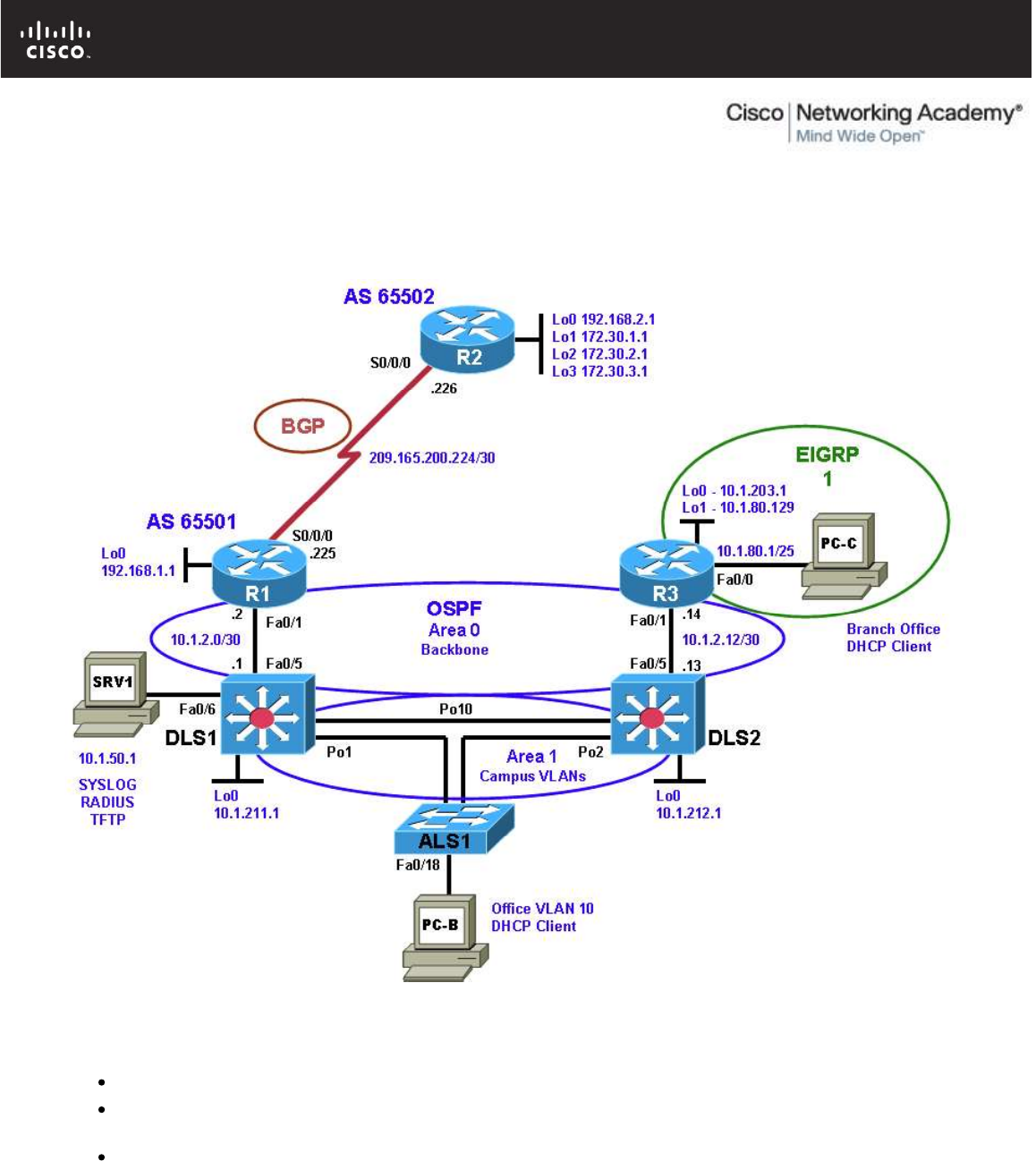
All contents are Copyright © 1992–2010 Cisco Systems, Inc. All rights reserved. This document is Cisco Public Information. Page 1 of 17
CCNPv6 TSHOOT
Chapter 10 Lab 10-1, Troubleshooting Complex Environments
Lab Topology
Objectives
Load the device configuration files for each trouble ticket.
Diagnose and resolve problems related to features, protocols, or technology that could be encountered in
a complex, integrated enterprise network.
Document the troubleshooting progress, configuration changes, and problem resolution.

CCNPv6 TSHOOT
All contents are Copyright © 1992–2010 Cisco Systems, Inc. All rights reserved. This document is Cisco Public Information. Page 2 of 17
Background
This lab covers a range of problems and requires that you make use of the troubleshooting skills acquired
throughout this course to resolve the routing and switching problems introduced. These trouble tickets are
based on scenarios from previous labs. This lab focuses on routing and switching connectivity issues related
to EtherChannel, STP, OSPF, EIGRP, and ACLs.
For each task or trouble ticket, the trouble scenario and problem symptom are described. While
troubleshooting, you will discover the cause of the problem, correct it, and then document the process and
results.
Trouble Tickets and Troubleshooting Logs
This lab includes four tasks. Each task is associated with a trouble ticket (TT) and introduces one or more
errors on one or more devices. If time is a consideration, each task or trouble ticket can be performed
independently.
Troubleshooting Reference Information
A generic troubleshooting flow is provided for analysis. Suggested commands are provided for each trouble
ticket. Refer to previous labs for specific troubleshooting flows, examples of additional commands and
command output.
Note: This lab uses Cisco 1841 routers with Cisco IOS Release 12.4(24)T1 and the advanced IP image
c1841-advipservicesk9-mz.124-24.T1.bin. The switches are Cisco WS-C2960-24TT-L with the Cisco IOS
image c2960-lanbasek9-mz.122-46.SE.bin and Catalyst 3560-24PS with the Cisco IOS image c3560-
advipservicesk9-mz.122-46.SE.bin. Other routers (such as 2801 and 2811), switches (such as 2950 or 3550),
and Cisco IOS Software versions can be used if they have comparable capabilities and features. Depending
on the router or switch model and Cisco IOS Software version, the commands available and output produced
might vary from what is shown in this lab.
Required Resources
3 routers (Cisco 1841 with Cisco IOS Release 12.4(24)T1 Advanced IP Service or comparable)
1 switch (Cisco 2960 with the Cisco IOS Release 12.2(46)SE C2960-LANBASEK9-M image or
comparable)
2 switches (Cisco 3560 with the Cisco IOS Release 12.2(46)SE C3560-advipservicesk9-mz image or
comparable)
SRV1 (Windows PC with static IP address) with TFTP and syslog servers plus an SSH client (PuTTY
or comparable) and WireShark software
PC-B (Windows PC DHCP client) with PuTTY and WireShark software
PC-C (Windows PC DHCP client) with PuTTY and WireShark software
Serial and Ethernet cables
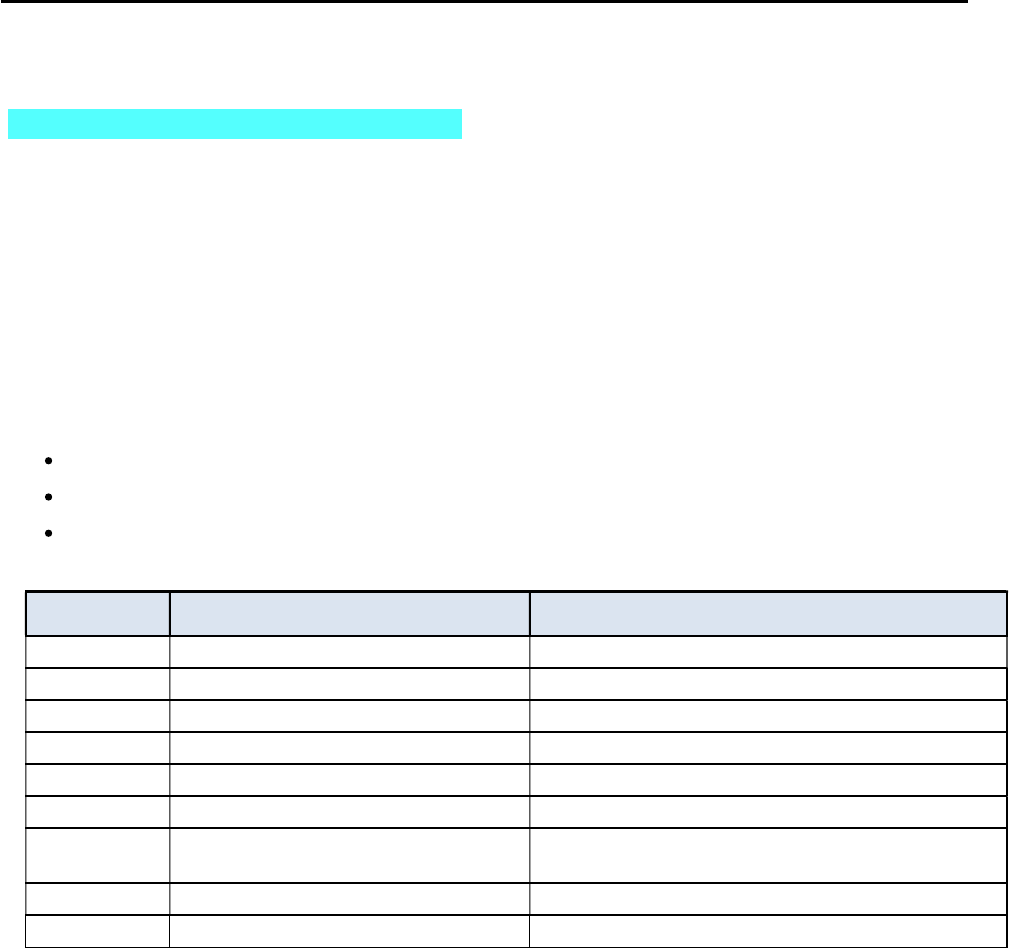
CCNPv6 TSHOOT
All contents are Copyright © 1992–2010 Cisco Systems, Inc. All rights reserved. This document is Cisco Public Information. Page 3 of 17
Section 1—Trouble Tickets and Troubleshooting Logs
Task 1: Trouble Ticket Lab 10-1 TT-A
Step 1: Review trouble ticket Lab 10-1 TT-A.
One of your colleagues mentioned that he had established a Telnet connection to switch ALS1 from PC-B
and tested connectivity to server SRV1 via ping but was not successful. All switches in the network have a
management address assigned, so he should be able to ping any device in the network. He asked for your
help in determining the cause and resolving the issue.
Step 2: Load the device trouble ticket configuration files for TT-A.
Using the procedure described in Lab 3-1, verify that the lab configuration files are present in flash. Load the
proper configuration files as indicated in the Device Configuration File table.
Note: The following device access methods are in effect after loading the configuration files:
Console access requires no username or password.
Telnet and SSH require username admin and password adminpa55.
The enable password is ciscoenpa55.
Device Configuration File Table
Device Name File to Load Notes
ALS1 Lab101-ALS1-TT-A-Cfg.txt
DLS1 Lab101-DLS1-TT-A-Cfg.txt
DLS2 Lab101-DLS2-TT-A-Cfg.txt
R1 Lab101-R1-TT-A-Cfg.txt
R2 Lab101-R2-TT-A-Cfg.txt
R3 Lab101-R3-TT-A-Cfg.txt
SRV1 N/A Static IP: 10.1.50.1
Default gateway: 10.1.50.254
PC-B N/A DHCP
PC-C N/A DHCP
Step 3: Configure SRV1 and start the syslog and TFTP servers.
a. Configure SRV1 with the static IP address 10.1.50.1/24 and default gateway 10.1.50.254.
b. Start the syslog server on SRV1 to monitor console messages from multiple devices.
c. Start the TFTP server on SRV1 to record device configuration changes.
Step 4: Release and renew the DHCP lease on PC-B and PC-C.
a. Ensure that PC-B is configured as a DHCP client in the OFFICE VLAN.
b. Ensure that PC-C is configured as a DHCP client in the R3 branch office LAN.
c. After loading all TT-A device configuration files, issue the ipconfig /release and ipconfig
/renew commands on PC-B and PC-C.

CCNPv6 TSHOOT
All contents are Copyright © 1992–2010 Cisco Systems, Inc. All rights reserved. This document is Cisco Public Information. Page 4 of 17
Step 5: Outline the troubleshooting approach and validation steps.
Use this space to identify your troubleshooting approach and the key steps to verify that the problem is
resolved. Troubleshooting approaches to select from include the follow-the-path, spot-the-differences, bottom-
up, top-down, divide-and-conquer, shoot-from-the-hip, and move-the-problem methods.
Note: In addition to a specific approach, you can use the generic troubleshooting process described at the
beginning of Section 2 of this lab.
_______________________________________________________________________________
_______________________________________________________________________________
_______________________________________________________________________________
_______________________________________________________________________________
_______________________________________________________________________________
_______________________________________________________________________________
Step 6: Record the troubleshooting process and configuration changes.
Use this log to document your actions and results during the troubleshooting process. List the commands you
used to gather information. As you progress, record what you think the problem might be and the actions you
take to correct the problem.
Note: Refer to the table of commands following this log, which might be helpful in troubleshooting this
problem. You can also refer to Lab 4-1 for sample troubleshooting flows and additional commands.
Device Actions and Results

CCNPv6 TSHOOT
All contents are Copyright © 1992–2010 Cisco Systems, Inc. All rights reserved. This document is Cisco Public Information. Page 5 of 17
Command Key Information Displayed
show interfaces status Displays link status, speed, duplex, trunk or VLAN
membership, and interface descriptions.
show cdp neighbors [detail]
Displays detailed information about a neighbor (or neighbors)
including network address, enabled protocols, hold time, and
software version.
show spanning-tree vlan vlan#
Displays all essential parameters that affect the topology, such
as root port, designated ports, port state, and port type, as well
as the spanning-tree mode implemented.
show spanning-tree summary
Displays the spanning-tree mode and the VLANs for which this
switch is the root bridge. VLANs are listed along with the
number of ports in various STP states.
show vlan brief Displays an overview of all existing VLANs and the ports within
them. Trunk ports are not listed.
show vlan id vlan#
Displays whether the VLAN exists and which ports are
assigned to it. Includes which trunk ports that the VLAN is
allowed on.
show interfaces trunk
Displays all trunk ports, the operational status, trunk
encapsulation, and native VLAN, as well as the list of allowed
VLANs, active VLANs, and the VLANs in Spanning Tree
Forwarding state for the trunk.
show interfaces type/#
switchport
Checks all VLAN-related parameters for a specific interface
(access ports and trunk ports).
show etherchannel summary Displays port channels, member ports, and flags indicating
status.
Step 7: Document trouble ticket debrief notes.
Use this space to make notes of the key learning points that you picked up during the discussion of this
trouble ticket with the instructor. The notes can include problems encountered, solutions applied, useful
commands employed, alternate solutions, methods, and processes, and procedure and communication
improvements.
_______________________________________________________________________________
_______________________________________________________________________________
_______________________________________________________________________________
_______________________________________________________________________________
_______________________________________________________________________________
_______________________________________________________________________________
_______________________________________________________________________________

CCNPv6 TSHOOT
All contents are Copyright © 1992–2010 Cisco Systems, Inc. All rights reserved. This document is Cisco Public Information. Page 6 of 17
Task 2: Trouble Ticket Lab 10-1 TT-B
Step 1: Review trouble ticket Lab 10-1 TT-B.
Many users on the network are experiencing problems when accessing the Internet. An office user who uses
client PC-B reports that he cannot browse to a website at IP address 172.30.3.1 (simulated by R2 Lo3).
Your task is to restore connectivity from client PC-B to the Internet and ensure that the user can connect to
172.30.3.1 using ping or a web browser.
Step 2: Load the device trouble ticket configuration files for TT-B.
Using the procedure described in Lab 3-1, verify that the lab configuration files are present in flash. Load the
proper configuration files as indicated in the Device Configuration File table.
Note: The following device access methods are in effect after loading the configuration files:
Console access requires no username or password.
Telnet and SSH require username admin and password adminpa55.
The enable password is ciscoenpa55.
Device Configuration File Table
Device Name File to Load Notes
ALS1 Lab101-ALS1-TT-B-Cfg.txt
DLS1 Lab101-DLS1-TT-B-Cfg.txt
DLS2 Lab101-DLS2-TT-B-Cfg.txt
R1 Lab101-R1-TT-B-Cfg.txt
R2 Lab101-R2-TT-B-Cfg.txt
R3 Lab101-R3-TT-B-Cfg.txt
SRV1 N/A Static IP: 10.1.50.1
Default gateway: 10.1.50.254
PC-B N/A DHCP
PC-C N/A DHCP
Step 3: Configure SRV1 and start the syslog and TFTP servers.
a. Configure SRV1 with the static IP address 10.1.50.1/24 and default gateway 10.1.50.254.
b. Start the syslog server on SRV1 to monitor console messages from multiple devices.
c. Start the TFTP server on SRV1 to record device configuration changes.
Step 4: Release and renew the DHCP lease on PC-B and PC-C.
a. Ensure that PC-B is configured as a DHCP client in the OFFICE VLAN.
b. Ensure that PC-C is configured as a DHCP client in the R3 branch office LAN.
c. After loading all TT-B device configuration files, issue the ipconfig /release and ipconfig
/renew commands on PC-B and PC-C.

CCNPv6 TSHOOT
All contents are Copyright © 1992–2010 Cisco Systems, Inc. All rights reserved. This document is Cisco Public Information. Page 7 of 17
Step 5: Outline the troubleshooting approach and validation steps.
Use this space to identify your troubleshooting approach and the key steps to verify that the problem is
resolved. Troubleshooting approaches to select from include the follow-the-path, spot-the-differences, bottom-
up, top-down, divide-and-conquer, shoot-from-the-hip, and move-the-problem methods.
Note: In addition to a specific approach, you can use the generic troubleshooting process described at the
beginning of Section 2 of this lab.
_______________________________________________________________________________
_______________________________________________________________________________
_______________________________________________________________________________
_______________________________________________________________________________
_______________________________________________________________________________
_______________________________________________________________________________
Step 6: Record the troubleshooting process and configuration changes.
Use this log to document your actions and results during the troubleshooting process. List the commands you
used to gather information. As you progress, record what you think the problem might be and the actions you
take to correct the problem.
Note: In addition to the commands listed for TT-A, the table of commands following this log might be helpful
in troubleshooting this problem. You can also refer to Labs 5-2 and 5-3 for sample troubleshooting flows and
additional commands.
Device Actions and Results

CCNPv6 TSHOOT
All contents are Copyright © 1992–2010 Cisco Systems, Inc. All rights reserved. This document is Cisco Public Information. Page 8 of 17
Command Key Information Displayed
show ip route
or
show ip route ip-addr
Displays the entire routing table or information for a
particular destination address.
show ip ospf interface brief
Displays interfaces that are participating in the OSPF
routing process. An interface does not need to be
operational to be listed in the command output.
show ip ospf neighbor Displays the OSPF neighbor table to verify that all
expected neighbor relationships are operational.
show ip bgp
Displays local and learned network entries in the BGP
table with next hop, metric, local preference, weight, and
AS path.
show ip bgp summary
Displays a summary of the BGP neighbor table. Lists
important BGP parameters, such as the AS number and
router ID, statistics about the memory consumption of the
various BGP data structures, and a brief overview of the
configured neighbors and their state.
show ip bgp neighbors Displays parameters and extensive statistics about the
peering session for all BGP neighbors.
show ip ospf database Verifies the link types and link IDs for all areas in which
this device participates.
Step 7: Document trouble ticket debrief notes.
Use this space to make notes of the key learning points that you picked up during the discussion of this
trouble ticket with the instructor. The notes can include problems encountered, solutions applied, useful
commands employed, alternate solutions, methods, and processes, and procedure and communication
improvements.
_______________________________________________________________________________
_______________________________________________________________________________
_______________________________________________________________________________
_______________________________________________________________________________
_______________________________________________________________________________
_______________________________________________________________________________
_______________________________________________________________________________
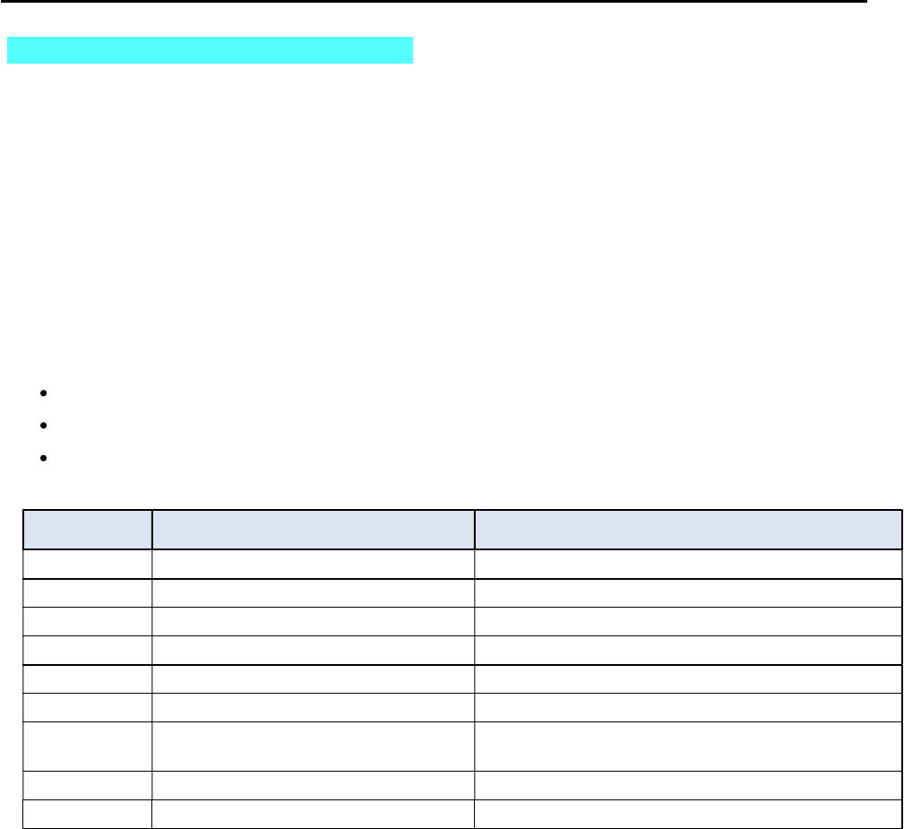
CCNPv6 TSHOOT
All contents are Copyright © 1992–2010 Cisco Systems, Inc. All rights reserved. This document is Cisco Public Information. Page 9 of 17
Task 3: Trouble Ticket Lab 10-1 TT-C
Step 1: Review trouble ticket Lab 10-1 TT-C.
The user of PC-C on the branch office network called the help desk and reported that she is unable to access
SRV1 or the Internet. Your task is to restore connectivity from client PC-C to SRV1 and the Internet and
ensure that the user can connect to 172.30.3.1 using ping or a web browser. The branch office administrator
did some preliminary testing and reported that he cannot ping or use Telnet to DLS2 or any other network
devices from R3. The capability to ping other devices from remote router R3 is a connectivity requirement for
the network.
Step 2: Load the device trouble ticket configuration files for TT-C.
Using the procedure described in Lab 3-1, verify that the lab configuration files are present in flash. Load the
proper configuration files as indicated in the Device Configuration File table.
Note: The following device access methods are in effect after loading the configuration files:
Console access requires no username or password.
Telnet and SSH require username admin and password adminpa55.
The enable password is ciscoenpa55.
Device Configuration File Table
Device Name File to Load Notes
ALS1 Lab101-ALS1-TT-C-Cfg.txt
DLS1 Lab101-DLS1-TT-C-Cfg.txt
DLS2 Lab101-DLS2-TT-C-Cfg.txt
R1 Lab101-R1-TT-C-Cfg.txt
R2 Lab101-R2-TT-C-Cfg.txt
R3 Lab101-R3-TT-C-Cfg.txt
SRV1 N/A Static IP: 10.1.50.1
Default gateway: 10.1.50.254
PC-B N/A DHCP
PC-C N/A DHCP
Step 3: Configure SRV1 and start the syslog and TFTP servers.
a. Configure SRV1 with the static IP address 10.1.50.1/24 and default gateway 10.1.50.254.
b. Start the syslog server on SRV1 to monitor console messages from multiple devices.
c. Start the TFTP server on SRV1 to record device configuration changes.
Step 4: Release and renew the DHCP lease on PC-B and PC-C.
a. Ensure that PC-B is configured as a DHCP client in the OFFICE VLAN.
b. Ensure that PC-C is configured as a DHCP client in the R3 branch office LAN.
c. After loading all TT-C device configuration files, issue the ipconfig /release and ipconfig
/renew commands on PC-B and PC-C.

CCNPv6 TSHOOT
All contents are Copyright © 1992–2010 Cisco Systems, Inc. All rights reserved. This document is Cisco Public Information. Page 10 of 17
Step 5: Outline the troubleshooting approach and validation steps.
Use this space to identify your troubleshooting approach and the key steps to verify that the problem is
resolved. Troubleshooting approaches to select from include follow-the-path, spot-the-differences, bottom-up,
top-down, divide-and-conquer, shoot-from-the-hip, and move-the-problem methods.
Note: In addition to a specific approach, you can use the generic troubleshooting process described at the
beginning of Section 2 of this lab.
_______________________________________________________________________________
_______________________________________________________________________________
_______________________________________________________________________________
_______________________________________________________________________________
_______________________________________________________________________________
_______________________________________________________________________________
Step 6: Record the troubleshooting process and configuration changes.
Use this log to document your actions and results during the troubleshooting process. List the commands that
you used to gather information. As you progress, record what you think the problem might be and the actions
you take to correct the problem.
Note: In addition to the commands listed for TT-A and TT-B, the table of commands following this log might
help you troubleshoot this problem. You can also refer to Lab 5-1 and the Chapter 9 labs for sample
troubleshooting flows and additional commands.
Device Actions and Results

CCNPv6 TSHOOT
All contents are Copyright © 1992–2010 Cisco Systems, Inc. All rights reserved. This document is Cisco Public Information. Page 11 of 17
Command Key Information Displayed
show ip cef ip-addr detail Displays the next hop and interface used for a particular
destination address from the CEF table.
show standby brief Verifies active and standby roles and IP addresses for all
VLANs on an HSRP router.
show ip eigrp interfaces
Displays interfaces that are participating in the EIGRP routing
process. An interface does not need to be operational to be
listed in the output.
show ip eigrp neighbors Displays the EIGRP neighbor table to verify that all expected
neighbor relationships are operational.
show access-lists ACL#/name
Displays all ACLs configured on a device, including the ACL
number and name, the type (standard or extended), the
statements, and the number of matches accumulated for each
statement.
show ntp status
Displays the clock synchronization status, stratum level, and
reference clock IP address. Also shows the number of seconds
since the last update was received from the reference clock.
Step 7: Document trouble ticket debrief notes.
Use this space to make notes of the key learning points that you picked up during the discussion of this
trouble ticket with the instructor. The notes can include problems encountered, solutions applied, useful
commands employed, alternate solutions, methods, and processes, and procedure and communication
improvements.
_______________________________________________________________________________
_______________________________________________________________________________
_______________________________________________________________________________
_______________________________________________________________________________
_______________________________________________________________________________
_______________________________________________________________________________
_______________________________________________________________________________
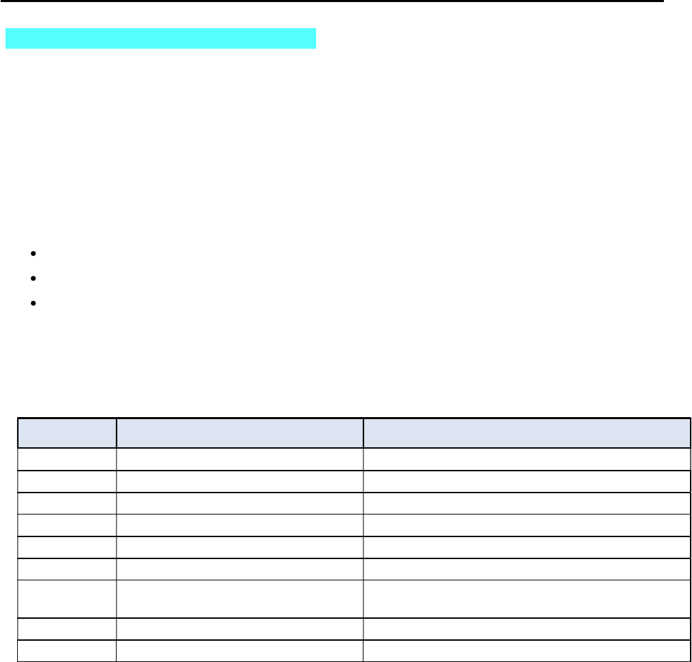
CCNPv6 TSHOOT
All contents are Copyright © 1992–2010 Cisco Systems, Inc. All rights reserved. This document is Cisco Public Information. Page 12 of 17
Task 4: Trouble Ticket Lab 10-1 TT-D
Step 1: Review trouble ticket Lab 10-1 TT-D.
The user of PC-C on the branch office network called the help desk again and reported that she is unable to
access SRV1 or the Internet and she is pretty upset. You must restore access to these resources for this
user.
Step 2: Load the device trouble ticket configuration files for TT-D.
Using the procedure described in Lab 3-1, verify that the lab configuration files are present in flash. Load the
proper configuration files as indicated in the Device Configuration File table.
Note: The following device access methods are in effect after loading the configuration files:
Console access requires no username or password.
Telnet and SSH require username admin and password adminpa55.
The enable password is ciscoenpa55.
Step 3: Restart router R3 after the TT-D file is loaded.
After loading the TT-D file into the running config for router R3 and then copying it to the startup config, use
the reload command to restart the router.
Device Configuration File Table
Device Name File to Load Notes
ALS1 Lab101-ALS1-TT-D-Cfg.txt
DLS1 Lab101-DLS1-TT-D-Cfg.txt
DLS2 Lab101-DLS2-TT-D-Cfg.txt
R1 Lab101-R1-TT-D-Cfg.txt
R2 Lab101-R2-TT-D-Cfg.txt
R3 Lab101-R3-TT-D-Cfg.txt
SRV1 N/A Static IP: 10.1.50.1
Default gateway: 10.1.50.254
PC-B N/A DHCP
PC-C N/A DHCP
Step 4: Configure SRV1 and start the syslog and TFTP servers.
a. Configure SRV1 with the static IP address 10.1.50.1/24 and default gateway 10.1.50.254.
b. Start the syslog server on SRV1 to monitor console messages from multiple devices.
c. Start the TFTP server on SRV1 to record device configuration changes.
Step 5: Release and renew the DHCP lease on PC-B and PC-C.
a. Ensure that PC-B is configured as a DHCP client in the OFFICE VLAN.
b. Ensure that PC-C is configured as a DHCP client in the R3 branch office LAN.
c. After loading all TT-D device configuration files, issue the ipconfig /release and ipconfig
/renew commands on PC-B and PC-C.

CCNPv6 TSHOOT
All contents are Copyright © 1992–2010 Cisco Systems, Inc. All rights reserved. This document is Cisco Public Information. Page 13 of 17
Step 6: Outline the troubleshooting approach and validation steps.
Use this space to identify your troubleshooting approach and the key steps to verify that the problem is
resolved. Troubleshooting approaches to select from include the follow-the-path, spot-the-differences, bottom-
up, top-down, divide-and-conquer, shoot-from-the-hip, and move-the-problem methods.
Note: In addition to a specific approach, you can use the generic troubleshooting process described at the
beginning of Section 2 of this lab.
_______________________________________________________________________________
_______________________________________________________________________________
_______________________________________________________________________________
_______________________________________________________________________________
_______________________________________________________________________________
_______________________________________________________________________________
Step 7: Record the troubleshooting process and configuration changes.
Use this log to document your actions and results during the troubleshooting process. List the commands that
you used to gather information. As you progress, record what you think the problem might be and the actions
you take to correct the problem.
Note: The table of commands following this log might help you troubleshoot this problem.
Device Actions and Results

CCNPv6 TSHOOT
All contents are Copyright © 1992–2010 Cisco Systems, Inc. All rights reserved. This document is Cisco Public Information. Page 14 of 17
Command Key Information Displayed
show version Displays the device hardware and software status.
dir flash: Displays the files and directories in flash memory.
Step 7: Document trouble ticket debrief notes.
Use this space to make notes of the key learning points that you picked up during the discussion of this
trouble ticket with the instructor. The notes can include problems encountered, solutions applied, useful
commands employed, alternate solutions, methods, and processes, and procedure and communication
improvements.
_______________________________________________________________________________
_______________________________________________________________________________
_______________________________________________________________________________
_______________________________________________________________________________
_______________________________________________________________________________
_______________________________________________________________________________
_______________________________________________________________________________

CCNPv6 TSHOOT
All contents are Copyright © 1992–2010 Cisco Systems, Inc. All rights reserved. This document is Cisco Public Information. Page 15 of 17
Section 2 Troubleshooting Reference Information
This lab covers all the technologies that were practiced in the previous labs. Therefore, no specific additional
troubleshooting flows are provided for this lab. Refer to the Sample Troubleshooting Flows sections in previous
labs for examples of procedures for specific technologies.
General Troubleshooting Process
As a general guideline, you can use the following general troubleshooting process described in the course.
1. Define the problem (symptoms).
2. Gather information.
3. Analyze the information.
4. Propose a hypothesis (possible cause).
5. Test the hypothesis.
6. Eliminate or accept the hypothesis.
7. Solve the problem.
8. Document the problem.

CCNPv6 TSHOOT
All contents are Copyright © 1992–2010 Cisco Systems, Inc. All rights reserved. This document is Cisco Public Information. Page 16 of 17
Reflection Questions
1. Which lab trouble tickets did you have the most difficulty with?
__________________________________________________________________________________________
__________________________________________________________________________________________
__________________________________________________________________________________________
2. Would you change anything about the process that you used for any of the trouble tickets now that you see the
resolution of the problem?
__________________________________________________________________________________________
__________________________________________________________________________________________
__________________________________________________________________________________________
3. Which commands did you find most useful in diagnosing issues?
__________________________________________________________________________________________
__________________________________________________________________________________________
__________________________________________________________________________________________
CCNPv6 TSHOOT
All contents are Copyright © 1992–2010 Cisco Systems, Inc. All rights reserved. This document is Cisco Public Information. Page 17 of 17
Router Interface Summary Table
Router Interface Summary
Router Model Ethernet Interface
#1
Ethernet Interface
#2
Serial Interface
#1
Serial Interface
#2
1700 Fast Ethernet 0
(FA0)
Fast Ethernet 1
(FA1)
Serial 0 (S0) Serial 1 (S1)
1800 Fast Ethernet 0/0
(FA0/0)
Fast Ethernet 0/1
(FA0/1)
Serial 0/0/0
(S0/0/0)
Serial 0/0/1
(S0/0/1)
2600 Fast Ethernet 0/0
(FA0/0)
Fast Ethernet 0/1
(FA0/1)
Serial 0/0 (S0/0) Serial 0/1 (S0/1)
2800 Fast Ethernet 0/0
(FA0/0)
Fast Ethernet 0/1
(FA0/1)
Serial 0/0/0
(S0/0/0)
Serial 0/0/1
(S0/0/1)
Note: To find out how the router is configured, look at the interfaces to identify the type of router
and how many interfaces the router has. There is no way to effectively list all the combinations of
configurations for each router class. This table includes identifiers for the possible combinations of
Ethernet and Serial interfaces in the device. The table does not include any other type of interface,
even though a specific router may contain one. An example of this might be an ISDN BRI interface.
The string in parenthesis is the legal abbreviation that can be used in Cisco IOS commands to
represent the interface.
