CS1G/H CPU__H Programmable Controllers Operation Manual CS1GHMnaul
User Manual: CS1GHMnaul
Open the PDF directly: View PDF ![]() .
.
Page Count: 818 [warning: Documents this large are best viewed by clicking the View PDF Link!]
- SYSMAC CS Series CS1G/H-CPU__H Programmable Controllers
- About this Manual:
- PRECAUTIONS
- SECTION 1 Introduction
- 1-1 Overview
- 1-2 CS-series Features
- 1-3 CS1-H CPU Unit Features
- 1-3-1 High-speed Performance
- 1-3-2 High-speed Structured Programming
- 1-3-3 Function Block (FB)
- 1-3-4 More Instructions for Specific Applications
- 1-3-5 Battery-free Operation with Flash Memory
- 1-3-6 Better Compatibility with Other SYSMAC PLCs
- 1-3-7 Refreshing Timer/Counter PVs in Binary
- 1-3-8 Features of CS1-H CPU Units Ver. 3.0
- 1-3-9 Changes to CS-series Operating Specifications
- 1-3-10 Features of CS1-H CPU Units Ver. 2.0
- 1-4 CS1-H CPU Unit Ver. 4.0 Upgrades
- 1-5 CS1-H CPU Unit Ver. 3.0 Upgrades
- 1-5-1 Function Blocks (FB)
- 1-5-2 Serial Gateway (Converting FINS to CompoWay/F Via Serial Port)
- 1-5-3 Comment Memory (in Internal Flash Memory)
- 1-5-4 Simple Backup Data Expanded
- 1-5-5 Free Running Timer
- 1-5-6 New Special Instructions and Functions
- 1-5-7 Increased Points for SYSMAC BUS Remote I/O Communications
- 1-6 CS1-H CPU Unit Ver. 2.0 Upgrades
- 1-6-1 Downloading and Uploading Individual Tasks
- 1-6-2 Improved Read Protection Using Passwords
- 1-6-3 Write Protection from FINS Commands Sent to CPU Units via Networks
- 1-6-4 Online Network Connections without I/O Tables
- 1-6-5 Communications through a Maximum of 8 Network Levels
- 1-6-6 Connecting Online to PLCs via NS-series PTs
- 1-6-7 Setting First Slot Words
- 1-6-8 Automatic Transfers at Power ON without a Parameter File
- 1-6-9 Operation Start/End Times
- 1-6-10 New Application Instructions
- 1-7 CS-series Function Tables
- 1-8 CS1-H Functions Arranged by Purpose
- 1-9 Comparison of CS-series PLCs and C200HX/HG/HE Operation
- 1-10 Checking the Package
- SECTION 2 Specifications and System Configuration
- SECTION 3 Nomenclature, Functions, and Dimensions
- SECTION 4 Operating Procedures
- SECTION 5 Installation and Wiring
- SECTION 6 DIP Switch Settings
- SECTION 7 PLC Setup
- SECTION 8 I/O Allocations
- SECTION 9 Memory Areas
- 9-1 Introduction
- 9-2 I/O Memory Areas
- 9-3 Precautions in Using C200H Special I/O Units
- 9-4 CIO Area
- 9-5 C200H DeviceNet Area
- 9-6 CS-series DeviceNet Area
- 9-7 PLC Link Area
- 9-8 Data Link Area
- 9-9 CPU Bus Unit Area
- 9-10 Inner Board Area
- 9-11 Special I/O Unit Area
- 9-12 SYSMAC BUS Area
- 9-13 I/O Terminal Area
- 9-14 Work Area
- 9-15 Holding Area
- 9-16 Auxiliary Area
- 9-17 TR (Temporary Relay) Area
- 9-18 Timer Area
- 9-19 Counter Area
- 9-20 Data Memory (DM) Area
- 9-21 Extended Data Memory (EM) Area
- 9-22 Index Registers
- 9-23 Data Registers
- 9-24 Task Flags
- 9-25 Condition Flags
- 9-26 Clock Pulses
- 9-27 Parameter Areas
- SECTION 10 CPU Unit Operation and the Cycle Time
- 10-1 CPU Unit Operation
- 10-2 CPU Unit Operating Modes
- 10-3 Power OFF Operation
- 10-4 Computing the Cycle Time
- 10-5 Instruction Execution Times and Number of Steps
- 10-5-1 Sequence Input Instructions
- 10-5-2 Sequence Output Instructions
- 10-5-3 Sequence Control Instructions
- 10-5-4 Timer and Counter Instructions
- 10-5-5 Comparison Instructions
- 10-5-6 Data Movement Instructions
- 10-5-7 Data Shift Instructions
- 10-5-8 Increment/Decrement Instructions
- 10-5-9 Symbol Math Instructions
- 10-5-10 Conversion Instructions
- 10-5-11 Logic Instructions
- 10-5-12 Special Math Instructions
- 10-5-13 Floating-point Math Instructions
- 10-5-14 Double-precision Floating-point Instructions
- 10-5-15 Table Data Processing Instructions
- 10-5-16 Data Control Instructions
- 10-5-17 Subroutine Instructions
- 10-5-18 Interrupt Control Instructions
- 10-5-19 Step Instructions
- 10-5-20 Basic I/O Unit Instructions
- 10-5-21 Serial Communications Instructions
- 10-5-22 Network Instructions
- 10-5-23 File Memory Instructions
- 10-5-24 Display Instructions
- 10-5-25 Clock Instructions
- 10-5-26 Debugging Instructions
- 10-5-27 Failure Diagnosis Instructions
- 10-5-28 Other Instructions
- 10-5-29 Block Programming Instructions
- 10-5-30 Text String Processing Instructions
- 10-5-31 Task Control Instructions
- 10-5-32 Model Conversion Instructions (Unit Ver. 3.0 or Later Only)
- 10-5-33 Special Function Block Instructions (Unit Ver. 3.0 or Later Only)
- 10-5-34 Function Block Instance Execution Time (CPU Units with Unit Version 3.0 or Later)
- SECTION 11 Troubleshooting
- 11-1 Error Log
- 11-2 Error Processing
- 11-2-1 Error Categories
- 11-2-2 Error Information
- 11-2-3 Error Codes and Error Flags
- 11-2-4 Error Processing Flowchart
- 11-2-5 Error Messages
- 11-2-6 Power Supply Check
- 11-2-7 Memory Error Check
- 11-2-8 Program Error Check
- 11-2-9 Cycle Time Too Long Error Check
- 11-2-10 PLC Setup Setting Error Check
- 11-2-11 Battery Error Check
- 11-2-12 Environmental Conditions Check
- 11-2-13 I/O Check
- 11-3 Troubleshooting Racks and Units
- SECTION 12 Inspection and Maintenance
- Appendix A Specifications of Basic I/O Units and High-density I/O Units
- Appendix B Auxiliary Area
- Appendix C Memory Map of PLC Memory Addresses
- Appendix D PLC Setup Coding Sheets for Programming Console
- Appendix E Connecting to the RS-232C Port on the CPU Unit
- Appendix F Restrictions in Using C200H Special I/O Units
- Appendix G CJ1W-CIF11 RS-422A Converter
- Index
- Revision History

OPERATION MANUAL
Cat. No. W339-E1-17
SYSMAC CS Series
CS1G/H-CPU@@H
Programmable Controllers
SYSMAC CS Series
CS1G/H-CPU@@H
Programmable Controllers
Operation Manual
Revised March 2012
iv
v
Notice:
OMRON products are manufactured for use according to proper procedures
by a qualified operator and only for the purposes described in this manual.
The following conventions are used to indicate and classify precautions in this
manual. Always heed the information provided with them. Failure to heed pre-
cautions can result in injury to people or damage to property.
!DANGER Indicates an imminently hazardous situation which, if not avoided, will result in death or
serious injury. Additionally, there may be severe property damage.
!WARNING Indicates a potentially hazardous situation which, if not avoided, could result in death or
serious injury. Additionally, there may be severe property damage.
!Caution Indicates a potentially hazardous situation which, if not avoided, may result in minor or
moderate injury, or property damage.
OMRON Product References
All OMRON products are capitalized in this manual. The word “Unit” is also
capitalized when it refers to an OMRON product, regardless of whether or not
it appears in the proper name of the product.
The abbreviation “Ch,” which appears in some displays and on some OMRON
products, often means “word” and is abbreviated “Wd” in documentation in
this sense.
The abbreviation “PLC” means Programmable Controller. “PC” is used, how-
ever, in some Programming Device displays to mean Programmable Control-
ler.
Visual Aids
The following headings appear in the left column of the manual to help you
locate different types of information.
Note Indicates information of particular interest for efficient and convenient opera-
tion of the product.
1,2,3... 1. Indicates lists of one sort or another, such as procedures, checklists, etc.
OMRON, 1999
All rights reserved. No part of this publication may be reproduced, stored in a retrieval system, or transmitted, in any form, o
r
by any means, mechanical, electronic, photocopying, recording, or otherwise, without the prior written permission o
f
OMRON.
No patent liability is assumed with respect to the use of the information contained herein. Moreover, because OMRON is con-
stantly striving to improve its high-quality products, the information contained in this manual is subject to change without
notice. Every precaution has been taken in the preparation of this manual. Nevertheless, OMRON assumes no responsibility
for errors or omissions. Neither is any liability assumed for damages resulting from the use of the information contained in
this publication.
vi
Unit Versions of CS/CJ-series CPU Units
Unit Versions A “unit version” has been introduced to manage CPU Units in the CS/CJ
Series according to differences in functionality accompanying Unit upgrades.
This applies to the CS1-H, CJ1-H, CJ1M, and CS1D CPU Units.
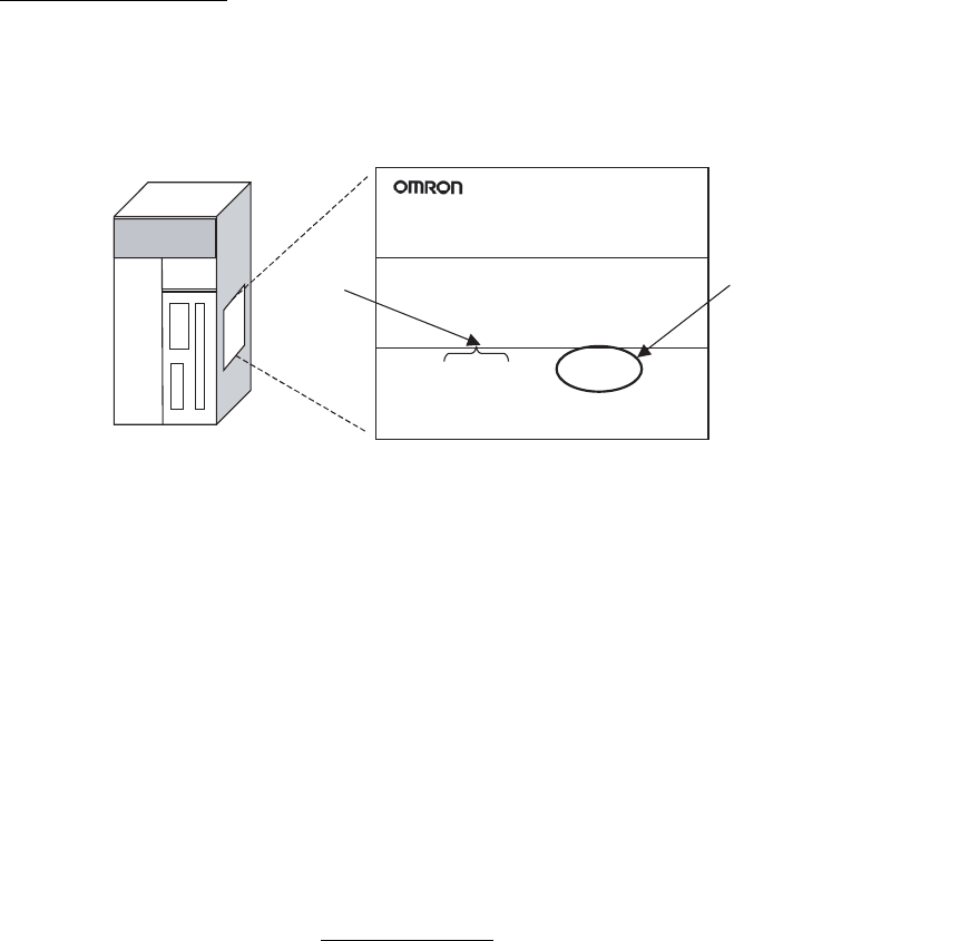
Notation of Unit Versions
on Products
The unit version is given to the right of the lot number on the nameplate of the
products for which unit versions are being managed, as shown below.
• CS1-H, CJ1-H, and CJ1M CPU Units manufactured on or before Novem-
ber 4, 2003 do not have a unit version given on the CPU Unit (i.e., the
location for the unit version shown above is blank).
• The unit version of the CS1-H, CJ1-H, and CJ1M CPU Units, as well as
the CS1D CPU Units for Single-CPU Systems, begins at version 2.0.
• The unit version of the CS1D CPU Units for Duplex-CPU Systems, begins
at version 1.1.
• CPU Units for which a unit version is not given are called Pre-Ver. @.@
CPU Units, such as Pre-Ver. 2.0 CPU Units and Pre-Ver. 1.1 CPU Units.
Confirming Unit Versions
with Support Software
CX-Programmer version 4.0 can be used to confirm the unit version using one
of the following two methods.
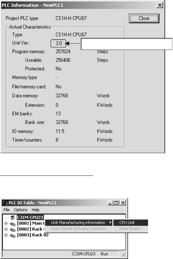
•Using the PLC Information
• Using the Unit Manufacturing Information (This method can be used for
Special I/O Units and CPU Bus Units as well.)
Note CX-Programmer version 3.3 or lower cannot be used to confirm unit versions.
PLC Information
• If you know the device type and CPU type, select them in the Change
PLC Dialog Box, go online, and select PLC - Edit - Information from the
menus.
• If you don't know the device type and CPU type, but are connected
directly to the CPU Unit on a serial line, select PLC - Auto Online to go
online, and then select PLC - Edit - Information from the menus.
In either case, the following PLC Information Dialog Box will be displayed.
CS1H-CPU67H
CPU UNIT
Lot No. 040715 0000 Ver.3.0
OMRON Corporation MADE IN JAPAN
CS/CJ-series CPU Unit Product nameplate
Lot No. Unit version
Example for Unit version 3.0
vii
Use the above display to confirm the unit version of the CPU Unit.
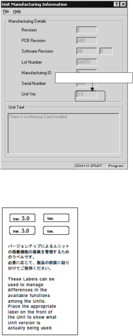
Unit Manufacturing Information
In the IO Table Window, right-click and select Unit Manufacturing informa-
tion - CPU Unit.
The following Unit Manufacturing information Dialog Box will be displayed.
Unit version
viii
Use the above display to confirm the unit version of the CPU Unit connected
online.
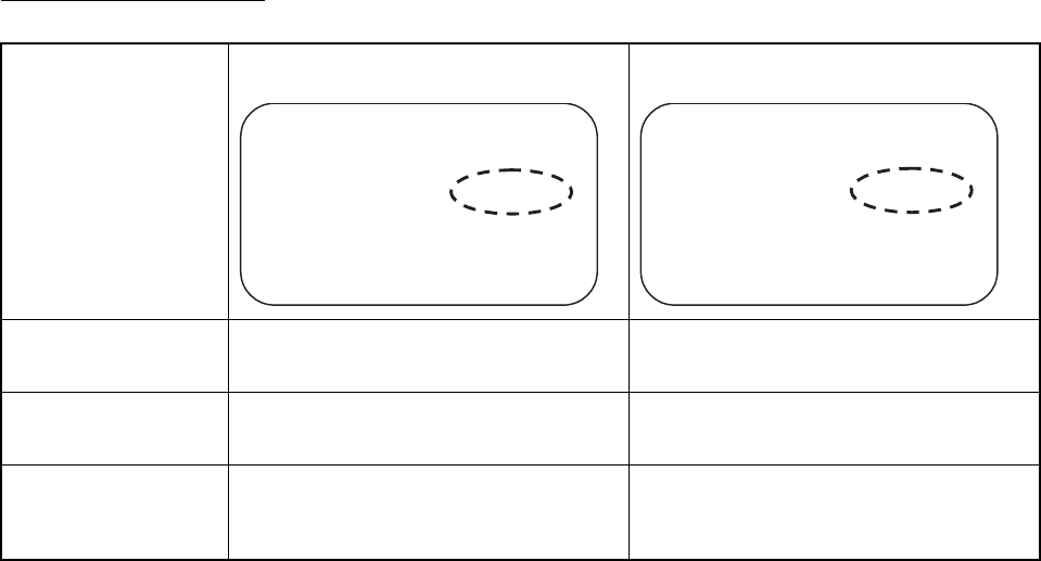
Using the Unit Version
Labels
The following unit version labels are provided with the CPU Unit.
These labels can be attached to the front of previous CPU Units to differenti-
ate between CPU Units of different unit versions.
Unit version
ix
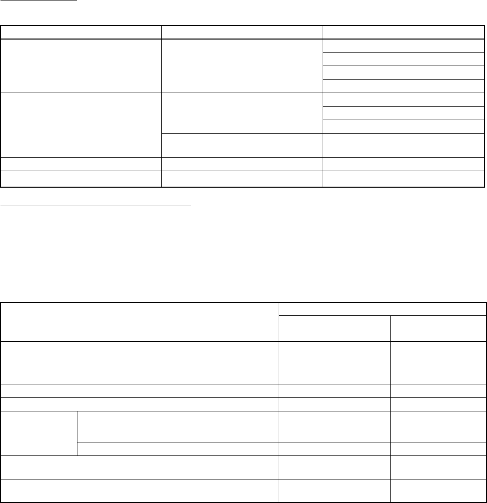
Unit Version Notation In this manual, the unit version of a CPU Unit is given as shown in the follow-
ing table.
Product nameplate
Meaning
CPU Units on which no unit version is
given
Units on which a version is given
(Ver. @.@)
Designating individual
CPU Units (e.g., the
CS1H-CPU67H)
Pre-Ver. 2.0 CS1-H CPU Units CS1H-CPU67H CPU Unit Ver. @.@
Designating groups of
CPU Units (e.g., the
CS1-H CPU Units)
Pre-Ver. 2.0 CS1-H CPU Units CS1-H CPU Units Ver. @.@
Designating an entire
series of CPU Units
(e.g., the CS-series CPU
Units)
Pre-Ver. 2.0 CS-series CPU Units CS-series CPU Units Ver. @.@
Lot No. XXXXXX XXXX
OMRON Corporation MADE IN JAPAN
Lot No. XXXXXX XXXX
Ver. @
@
.@
x
Unit Versions
CS Series
Function Support by Unit Version
• Functions Supported for Unit Version 4.0 or Later
CX-Programmer 7.0 or higher must be used to enable using the functions
added for unit version 4.0.
CX-Programmer version 7.2 can be used to enable using additional functions.
CS1-H CPU Units
User programs that contain functions supported only by CPU Units with unit
version 4.0 or later cannot be used on CS/CJ-series CPU Units with unit ver-
sion 3.0 or earlier. An error message will be displayed if an attempt is made to
download programs containing unit version 4.0 functions to a CPU Unit with a
unit version of 3.0 or earlier, and the download will not be possible.
If an object program file (.OBJ) using these functions is transferred to a CPU
Unit with a unit version of 3.0 or earlier, a program error will occur when oper-
ation is started or when the unit version 4.0 function is executed, and CPU
Unit operation will stop.
Units Models Unit version
CS1-H CPU Units CS1@-CPU@@H Unit version 4.0
Unit version 3.0
Unit version 2.0
Pre-Ver. 2.0
CS1D CPU Units Duplex-CPU Systems
CS1D-CPU@@H
Unit version 1.2
Unit version 1.1
Pre-Ver. 1.1
Single-CPU Systems
CS1D-CPU@@S
Unit version 2.0
CS1 CPU Units CS1@-CPU@@ No unit version.
CS1 Version-1 CPU Units CS1@-CPU@@-V1 No unit version.
Function CS1@-CPU@@H
Unit version 4.0 or
later
Other unit versions
Online editing of function blocks
Note This function cannot be used for simulations on the CX-
Simulator.
OK ---
Input-output variables in function blocks OK ---
Text strings in function blocks OK ---
New application
instructions
Number-Text String Conversion Instructions:
NUM4, NUM8, NUM16, STR4, STR8, and STR16
OK ---
TEXT FILE WRITE (TWRIT) OK ---
The ST language can be used in task programs. OK with CX-Programmer
version 7.2 or higher
---
The SFC language can be used in task programs. OK with CX-Programmer
version 7.2 or higher
---

xi
• Functions Supported for Unit Version 3.0 or Later
CX-Programmer 5.0 or higher must be used to enable using the functions
added for unit version 3.0.
CS1-H CPU Units
User programs that contain functions supported only by CPU Units with unit
version 3.0 or later cannot be used on CS/CJ-series CPU Units with unit ver-
sion 2.0 or earlier. An error message will be displayed if an attempt is made to
download programs containing unit version 3.0 functions to a CPU Unit with a
unit version of 2.0 or earlier, and the download will not be possible.
If an object program file (.OBJ) using these functions is transferred to a CPU
Unit with a unit version of 2.0 or earlier, a program error will occur when oper-
ation is started or when the unit version 3.0 function is executed, and CPU
Unit operation will stop.
Function CS1@-CPU@@H
Unit version 3.0 or
later
Other unit versions
Function blocks OK ---
Serial Gateway (converting FINS commands to CompoWay/F
commands at the built-in serial port)
OK ---
Comment memory (in internal flash memory) OK ---
Expanded simple backup data OK ---
New application
instructions
TXDU(256), RXDU(255) (support no-protocol
communications with Serial Communications
Units with unit version 1.2 or later)
OK ---
Model conversion instructions: XFERC(565),
DISTC(566), COLLC(567), MOVBC(568),
BCNTC(621)
OK ---
Special function block instructions: GETID(286) OK ---
Additional
instruction func-
tions
TXD(235) and RXD(236) instructions (support no-
protocol communications with Serial Communica-
tions Boards with unit version 1.2 or later)
OK ---

xii
• Functions Supported for Unit Version 2.0 or Later
CX-Programmer 4.0 or higher must be used to enable using the functions
added for unit version 2.0.
CS1-H CPU Units
User programs that contain functions supported only by CPU Units with unit
version 2.0 or later cannot be used on CS/CJ-series Pre-Ver. 2.0 CPU Units.
An error message will be displayed if an attempt is made to download pro-
grams containing unit version s.0 functions to a Pre-Ver. 2.0 CPU Unit, and
the download will not be possible.
If an object program file (.OBJ) using these functions is transferred to a Pre-
Ver. 2.0 CPU Unit, a program error will occur when operation is started or
when the unit version 2.0 function is executed, and CPU Unit operation will
stop.
Function CS1-H CPU Units
(CS1@-CPU@@H)
Unit version 2.0 or
later
Other unit versions
Downloading and Uploading Individual Tasks OK ---
Improved Read Protection Using Passwords OK ---
Write Protection from FINS Commands Sent to CPU Units
via Networks
OK ---
Online Network Connections without I/O Tables OK ---
Communications through a Maximum of 8 Network Levels OK ---
Connecting Online to PLCs via NS-series PTs OK OK from lot number 030201
Setting First Slot Words OK for up to 64 groups OK for up to 8 groups
Automatic Transfers at Power ON without a Parameter File OK ---
Automatic Detection of I/O Allocation Method for Automatic
Transfer at Power ON
--- ---
Operation Start/End Times OK ---
New Application
Instructions
MILH, MILR, MILC OK ---
=DT, <>DT, <DT, <=DT, >DT, >=DT OK ---
BCMP2 OK ---
GRY OK OK from lot number 030201
TPO OK ---
DSW, TKY, HKY, MTR, 7SEG OK ---
EXPLT, EGATR, ESATR, ECHRD,
ECHWR
OK ---
Reading/Writing CPU Bus Units with
IORD/IOWR
OK OK from lot number 030418
PRV2 --- ---
xiii
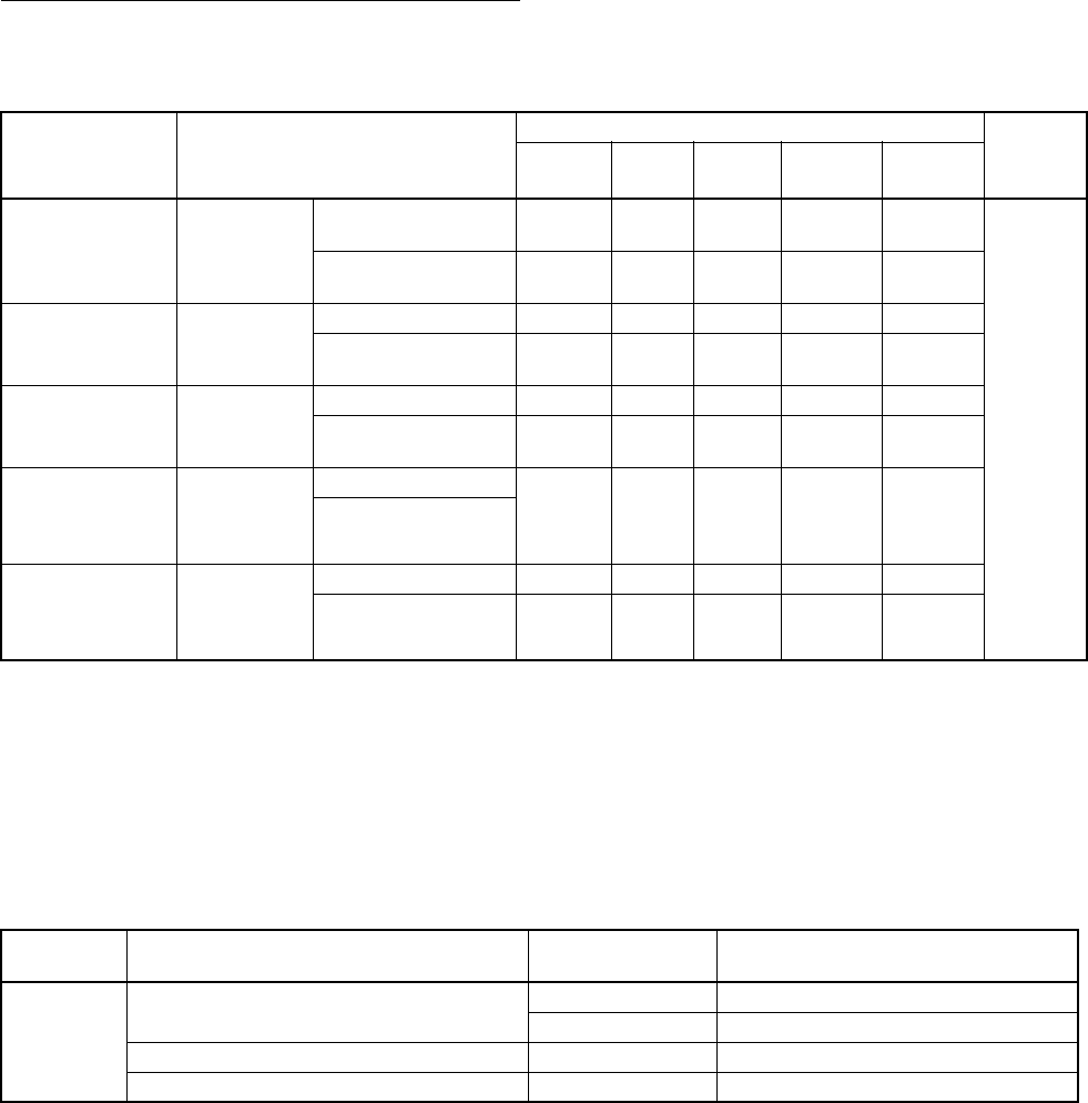
Unit Versions and Programming Devices
The following tables show the relationship between unit versions and CX-Pro-
grammer versions.
Unit Versions and Programming Devices
Note 1. As shown above, there is no need to upgrade to CX-Programmer version
as long as the functions added for unit versions are not used.
2. CX-Programmer version 7.0 or higher is required to use the upgraded
functions for CS/CJ-series CPU Units with unit version 4.0. CX-Program-
mer version 7.2 can be used to enable using additional functions.
Device Type Setting The unit version does not affect the setting made for the device type on the
CX-Programmer. Select the device type as shown in the following table
regardless of the unit version of the CPU Unit.
CPU Unit Functions CX-Programmer Program-
ming
Console
Ver. 3.3
or lower
Ver. 4.0 Ver. 5.0
Ver. 6.0
Ver. 7.0
or higher
Ver. 7.2
or higher
CS/CJ-series unit
Ver. 4.0
Functions
added for unit
version 4.0
Using new functions --- --- --- OK (See
note 2.)
OK (See
note 2.)
No
restric-
tions
Not using new func-
tions
OK OK OK OK OK
CS/CJ-series unit
Ver. 3.0
Functions
added for unit
version 3.0
Using new functions --- --- OK OK OK
Not using new func-
tions
OK OK OK OK OK
CS/CJ-series unit
Ver. 2.0
Functions
added for unit
version 2.0
Using new functions --- OK OK OK OK
Not using new func-
tions
OK OK OK OK OK
CS1D CPU Units
for Single-CPU
Systems, unit Ver.
2.0
Functions
added for unit
version 2.0
Using new functions --- OK OK OK OK
Not using new func-
tions
CS1D CPU Units
for Duplex-CPU
Systems, unit
Ver.1.
Functions
added for unit
version 1.1
Using function blocks --- OK OK OK OK
Not using function
blocks
OK OK OK OK OK
Series CPU Unit group CPU Unit model Device type setting on
CX-Programmer Ver. 4.0 or higher
CS Series CS1-H CPU Units CS1G-CPU@@H CS1G-H
CS1H-CPU@@H CS1H-H
CS1D CPU Units for Duplex-CPU Systems CS1D-CPU@@H CS1D-H (or CS1H-H)
CS1D CPU Units for Single-CPU Systems CS1D-CPU@@S CS1D-S
xiv
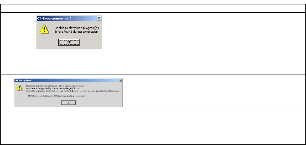
Troubleshooting Problems with Unit Versions on the CX-Programmer
Problem Cause Solution
After the above message is displayed, a compiling
error will be displayed on the Compile Tab Page in the
Output Window.
An attempt was made to down-
load a program containing
instructions supported only by
later unit versions or a CPU Unit
to a previous unit version.
Check the program or change
to a CPU Unit with a later unit
version.
An attempt was to download a
PLC Setup containing settings
supported only by later unit ver-
sions or a CPU Unit to a previous
unit version.
Check the settings in the PLC
Setup or change to a CPU Unit
with a later unit version.
“????” is displayed in a program transferred from the
PLC to the CX-Programmer.
An attempt was made to upload a
program containing instructions
supported only by higher versions
of CX-Programmer to a lower ver-
sion.
New instructions cannot be
uploaded to lower versions of
CX-Programmer. Use a higher
version of CX-Programmer.
xv
TABLE OF CONTENTS
PRECAUTIONS . . . . . . . . . . . . . . . . . . . . . . . . . . . . . . . . . . . xxvii
1 Intended Audience . . . . . . . . . . . . . . . . . . . . . . . . . . . . . . . . . . . . . . . . . . . . . . . . . . . . . . . . xxviii
2 General Precautions . . . . . . . . . . . . . . . . . . . . . . . . . . . . . . . . . . . . . . . . . . . . . . . . . . . . . . . xxviii
3 Safety Precautions. . . . . . . . . . . . . . . . . . . . . . . . . . . . . . . . . . . . . . . . . . . . . . . . . . . . . . . . . xxviii
4 Operating Environment Precautions . . . . . . . . . . . . . . . . . . . . . . . . . . . . . . . . . . . . . . . . . . . xxx
5 Application Precautions . . . . . . . . . . . . . . . . . . . . . . . . . . . . . . . . . . . . . . . . . . . . . . . . . . . . xxxi
6 Conformance to EC Directives . . . . . . . . . . . . . . . . . . . . . . . . . . . . . . . . . . . . . . . . . . . . . . . xxxvi
SECTION 1
Introduction . . . . . . . . . . . . . . . . . . . . . . . . . . . . . . . . . . . . . . 1
1-1 Overview . . . . . . . . . . . . . . . . . . . . . . . . . . . . . . . . . . . . . . . . . . . . . . . . . . . . . . . . . . . . . . . . 2
1-2 CS-series Features. . . . . . . . . . . . . . . . . . . . . . . . . . . . . . . . . . . . . . . . . . . . . . . . . . . . . . . . . 3
1-3 CS1-H CPU Unit Features . . . . . . . . . . . . . . . . . . . . . . . . . . . . . . . . . . . . . . . . . . . . . . . . . . 13
1-4 CS1-H CPU Unit Ver. 4.0 Upgrades . . . . . . . . . . . . . . . . . . . . . . . . . . . . . . . . . . . . . . . . . . . 22
1-5 CS1-H CPU Unit Ver. 3.0 Upgrades . . . . . . . . . . . . . . . . . . . . . . . . . . . . . . . . . . . . . . . . . . . 23
1-6 CS1-H CPU Unit Ver. 2.0 Upgrades . . . . . . . . . . . . . . . . . . . . . . . . . . . . . . . . . . . . . . . . . . . 30
1-7 CS-series Function Tables. . . . . . . . . . . . . . . . . . . . . . . . . . . . . . . . . . . . . . . . . . . . . . . . . . .52
1-8 CS1-H Functions Arranged by Purpose . . . . . . . . . . . . . . . . . . . . . . . . . . . . . . . . . . . . . . . . 60
1-9 Comparison of CS-series PLCs and C200HX/HG/HE Operation . . . . . . . . . . . . . . . . . . . . 62
1-10 Checking the Package . . . . . . . . . . . . . . . . . . . . . . . . . . . . . . . . . . . . . . . . . . . . . . . . . . . . . . 68
SECTION 2
Specifications and System Configuration. . . . . . . . . . . . . . . 69
2-1 Specifications . . . . . . . . . . . . . . . . . . . . . . . . . . . . . . . . . . . . . . . . . . . . . . . . . . . . . . . . . . . . 70
2-2 CPU Unit Components . . . . . . . . . . . . . . . . . . . . . . . . . . . . . . . . . . . . . . . . . . . . . . . . . . . . .81
2-3 Basic System Configuration . . . . . . . . . . . . . . . . . . . . . . . . . . . . . . . . . . . . . . . . . . . . . . . . . 87
2-4 Units . . . . . . . . . . . . . . . . . . . . . . . . . . . . . . . . . . . . . . . . . . . . . . . . . . . . . . . . . . . . . . . . . . . 105
2-5 Expanded System Configuration. . . . . . . . . . . . . . . . . . . . . . . . . . . . . . . . . . . . . . . . . . . . . . 119
2-6 Unit Current Consumption . . . . . . . . . . . . . . . . . . . . . . . . . . . . . . . . . . . . . . . . . . . . . . . . . . 137
2-7 CPU Bus Unit Setting Area Capacity . . . . . . . . . . . . . . . . . . . . . . . . . . . . . . . . . . . . . . . . . . 148
2-8 I/O Table Settings . . . . . . . . . . . . . . . . . . . . . . . . . . . . . . . . . . . . . . . . . . . . . . . . . . . . . . . . . 149
SECTION 3
Nomenclature, Functions, and Dimensions . . . . . . . . . . . . . 155
3-1 CPU Units . . . . . . . . . . . . . . . . . . . . . . . . . . . . . . . . . . . . . . . . . . . . . . . . . . . . . . . . . . . . . . . 156
3-2 File Memory . . . . . . . . . . . . . . . . . . . . . . . . . . . . . . . . . . . . . . . . . . . . . . . . . . . . . . . . . . . . . 163
3-3 Programming Devices . . . . . . . . . . . . . . . . . . . . . . . . . . . . . . . . . . . . . . . . . . . . . . . . . . . . . .172
3-4 Power Supply Units. . . . . . . . . . . . . . . . . . . . . . . . . . . . . . . . . . . . . . . . . . . . . . . . . . . . . . . . 183
3-5 Backplanes . . . . . . . . . . . . . . . . . . . . . . . . . . . . . . . . . . . . . . . . . . . . . . . . . . . . . . . . . . . . . . 197
3-6 Basic I/O Units . . . . . . . . . . . . . . . . . . . . . . . . . . . . . . . . . . . . . . . . . . . . . . . . . . . . . . . . . . . 207
3-7 C200H High-density I/O Units (Special I/O Units) . . . . . . . . . . . . . . . . . . . . . . . . . . . . . . . 225
3-8 B7A Interface Units . . . . . . . . . . . . . . . . . . . . . . . . . . . . . . . . . . . . . . . . . . . . . . . . . . . . . . . 231
3-9 Analog Timer Units. . . . . . . . . . . . . . . . . . . . . . . . . . . . . . . . . . . . . . . . . . . . . . . . . . . . . . . . 256
xvi
TABLE OF CONTENTS
SECTION 4
Operating Procedures . . . . . . . . . . . . . . . . . . . . . . . . . . . . . . 261
4-1 Introduction. . . . . . . . . . . . . . . . . . . . . . . . . . . . . . . . . . . . . . . . . . . . . . . . . . . . . . . . . . . . . . 262
4-2 Examples. . . . . . . . . . . . . . . . . . . . . . . . . . . . . . . . . . . . . . . . . . . . . . . . . . . . . . . . . . . . . . . . 264
SECTION 5
Installation and Wiring . . . . . . . . . . . . . . . . . . . . . . . . . . . . . 277
5-1 Fail-safe Circuits . . . . . . . . . . . . . . . . . . . . . . . . . . . . . . . . . . . . . . . . . . . . . . . . . . . . . . . . . . 278
5-2 Installation. . . . . . . . . . . . . . . . . . . . . . . . . . . . . . . . . . . . . . . . . . . . . . . . . . . . . . . . . . . . . . . 280
5-3 Wiring . . . . . . . . . . . . . . . . . . . . . . . . . . . . . . . . . . . . . . . . . . . . . . . . . . . . . . . . . . . . . . . . . . 299
SECTION 6
DIP Switch Settings . . . . . . . . . . . . . . . . . . . . . . . . . . . . . . . . 325
6-1 DIP Switch Settings . . . . . . . . . . . . . . . . . . . . . . . . . . . . . . . . . . . . . . . . . . . . . . . . . . . . . . . 326
SECTION 7
PLC Setup . . . . . . . . . . . . . . . . . . . . . . . . . . . . . . . . . . . . . . . . 329
7-1 PLC Setup . . . . . . . . . . . . . . . . . . . . . . . . . . . . . . . . . . . . . . . . . . . . . . . . . . . . . . . . . . . . . . . 330
7-2 Explanations of PLC Setup Settings . . . . . . . . . . . . . . . . . . . . . . . . . . . . . . . . . . . . . . . . . . . 357
SECTION 8
I/O Allocations . . . . . . . . . . . . . . . . . . . . . . . . . . . . . . . . . . . . 369
8-1 I/O Allocations . . . . . . . . . . . . . . . . . . . . . . . . . . . . . . . . . . . . . . . . . . . . . . . . . . . . . . . . . . . 370
8-2 I/O Allocation Methods . . . . . . . . . . . . . . . . . . . . . . . . . . . . . . . . . . . . . . . . . . . . . . . . . . . .375
8-3 Allocating First Words to Racks . . . . . . . . . . . . . . . . . . . . . . . . . . . . . . . . . . . . . . . . . . . . . . 382
8-4 Allocating First Words to Slots . . . . . . . . . . . . . . . . . . . . . . . . . . . . . . . . . . . . . . . . . . . . . . . 385
8-5 Detailed Information on I/O Table Creation Errors . . . . . . . . . . . . . . . . . . . . . . . . . . . . . . . 388
8-6 Data Exchange with CPU Bus Units. . . . . . . . . . . . . . . . . . . . . . . . . . . . . . . . . . . . . . . . . . . 388
SECTION 9
Memory Areas . . . . . . . . . . . . . . . . . . . . . . . . . . . . . . . . . . . . 393
9-1 Introduction. . . . . . . . . . . . . . . . . . . . . . . . . . . . . . . . . . . . . . . . . . . . . . . . . . . . . . . . . . . . . . 394
9-2 I/O Memory Areas . . . . . . . . . . . . . . . . . . . . . . . . . . . . . . . . . . . . . . . . . . . . . . . . . . . . . . . . 395
9-3 Precautions in Using C200H Special I/O Units . . . . . . . . . . . . . . . . . . . . . . . . . . . . . . . . . . 404
9-4 CIO Area . . . . . . . . . . . . . . . . . . . . . . . . . . . . . . . . . . . . . . . . . . . . . . . . . . . . . . . . . . . . . . . . 405
9-5 C200H DeviceNet Area . . . . . . . . . . . . . . . . . . . . . . . . . . . . . . . . . . . . . . . . . . . . . . . . . . . . 411
9-6 CS-series DeviceNet Area. . . . . . . . . . . . . . . . . . . . . . . . . . . . . . . . . . . . . . . . . . . . . . . . . . .412
9-7 PLC Link Area . . . . . . . . . . . . . . . . . . . . . . . . . . . . . . . . . . . . . . . . . . . . . . . . . . . . . . . . . . . 414
9-8 Data Link Area . . . . . . . . . . . . . . . . . . . . . . . . . . . . . . . . . . . . . . . . . . . . . . . . . . . . . . . . . . . 416
9-9 CPU Bus Unit Area. . . . . . . . . . . . . . . . . . . . . . . . . . . . . . . . . . . . . . . . . . . . . . . . . . . . . . . . 417
9-10 Inner Board Area. . . . . . . . . . . . . . . . . . . . . . . . . . . . . . . . . . . . . . . . . . . . . . . . . . . . . . . . . . 418
9-11 Special I/O Unit Area . . . . . . . . . . . . . . . . . . . . . . . . . . . . . . . . . . . . . . . . . . . . . . . . . . . . . . 419
9-12 SYSMAC BUS Area. . . . . . . . . . . . . . . . . . . . . . . . . . . . . . . . . . . . . . . . . . . . . . . . . . . . . . .421
9-13 I/O Terminal Area . . . . . . . . . . . . . . . . . . . . . . . . . . . . . . . . . . . . . . . . . . . . . . . . . . . . . . . . . 422
9-14 Work Area . . . . . . . . . . . . . . . . . . . . . . . . . . . . . . . . . . . . . . . . . . . . . . . . . . . . . . . . . . . . . . . 423
xvii
TABLE OF CONTENTS
9-15 Holding Area. . . . . . . . . . . . . . . . . . . . . . . . . . . . . . . . . . . . . . . . . . . . . . . . . . . . . . . . . . . . . 424
9-16 Auxiliary Area. . . . . . . . . . . . . . . . . . . . . . . . . . . . . . . . . . . . . . . . . . . . . . . . . . . . . . . . . . . . 425
9-17 TR (Temporary Relay) Area . . . . . . . . . . . . . . . . . . . . . . . . . . . . . . . . . . . . . . . . . . . . . . . . . 448
9-18 Timer Area . . . . . . . . . . . . . . . . . . . . . . . . . . . . . . . . . . . . . . . . . . . . . . . . . . . . . . . . . . . . . . 449
9-19 Counter Area. . . . . . . . . . . . . . . . . . . . . . . . . . . . . . . . . . . . . . . . . . . . . . . . . . . . . . . . . . . . . 450
9-20 Data Memory (DM) Area . . . . . . . . . . . . . . . . . . . . . . . . . . . . . . . . . . . . . . . . . . . . . . . . . . . 451
9-21 Extended Data Memory (EM) Area . . . . . . . . . . . . . . . . . . . . . . . . . . . . . . . . . . . . . . . . . . . 453
9-22 Index Registers . . . . . . . . . . . . . . . . . . . . . . . . . . . . . . . . . . . . . . . . . . . . . . . . . . . . . . . . . . . 455
9-23 Data Registers . . . . . . . . . . . . . . . . . . . . . . . . . . . . . . . . . . . . . . . . . . . . . . . . . . . . . . . . . . . . 461
9-24 Task Flags . . . . . . . . . . . . . . . . . . . . . . . . . . . . . . . . . . . . . . . . . . . . . . . . . . . . . . . . . . . . . . . 463
9-25 Condition Flags . . . . . . . . . . . . . . . . . . . . . . . . . . . . . . . . . . . . . . . . . . . . . . . . . . . . . . . . . . . 463
9-26 Clock Pulses . . . . . . . . . . . . . . . . . . . . . . . . . . . . . . . . . . . . . . . . . . . . . . . . . . . . . . . . . . . . . 466
9-27 Parameter Areas . . . . . . . . . . . . . . . . . . . . . . . . . . . . . . . . . . . . . . . . . . . . . . . . . . . . . . . . . . 467
SECTION 10
CPU Unit Operation and the Cycle Time. . . . . . . . . . . . . . . 471
10-1 CPU Unit Operation . . . . . . . . . . . . . . . . . . . . . . . . . . . . . . . . . . . . . . . . . . . . . . . . . . . . . . . 473
10-2 CPU Unit Operating Modes . . . . . . . . . . . . . . . . . . . . . . . . . . . . . . . . . . . . . . . . . . . . . . . . . 478
10-3 Power OFF Operation . . . . . . . . . . . . . . . . . . . . . . . . . . . . . . . . . . . . . . . . . . . . . . . . . . . . . . 480
10-4 Computing the Cycle Time . . . . . . . . . . . . . . . . . . . . . . . . . . . . . . . . . . . . . . . . . . . . . . . . . . 485
10-5 Instruction Execution Times and Number of Steps . . . . . . . . . . . . . . . . . . . . . . . . . . . . . . . 503
SECTION 11
Troubleshooting . . . . . . . . . . . . . . . . . . . . . . . . . . . . . . . . . . . 529
11-1 Error Log. . . . . . . . . . . . . . . . . . . . . . . . . . . . . . . . . . . . . . . . . . . . . . . . . . . . . . . . . . . . . . . . 530
11-2 Error Processing . . . . . . . . . . . . . . . . . . . . . . . . . . . . . . . . . . . . . . . . . . . . . . . . . . . . . . . . . . 531
11-3 Troubleshooting Racks and Units . . . . . . . . . . . . . . . . . . . . . . . . . . . . . . . . . . . . . . . . . . . . . 553
SECTION 12
Inspection and Maintenance . . . . . . . . . . . . . . . . . . . . . . . . . 557
12-1 Inspections . . . . . . . . . . . . . . . . . . . . . . . . . . . . . . . . . . . . . . . . . . . . . . . . . . . . . . . . . . . . . . 558
12-2 Replacing User-serviceable Parts . . . . . . . . . . . . . . . . . . . . . . . . . . . . . . . . . . . . . . . . . . . . . 560
Appendices
A Specifications of Basic I/O Units and High-density I/O Units . . . . . . . . . . . . . . . . . . . . . . 569
B Auxiliary Area . . . . . . . . . . . . . . . . . . . . . . . . . . . . . . . . . . . . . . . . . . . . . . . . . . . . . . . . . . . 691
C Memory Map of PLC Memory Addresses . . . . . . . . . . . . . . . . . . . . . . . . . . . . . . . . . . . . . . 727
D PLC Setup Coding Sheets for Programming Console . . . . . . . . . . . . . . . . . . . . . . . . . . . . . 729
E Connecting to the RS-232C Port on the CPU Unit . . . . . . . . . . . . . . . . . . . . . . . . . . . . . . . 741
F Restrictions in Using C200H Special I/O Units . . . . . . . . . . . . . . . . . . . . . . . . . . . . . . . . . . 749
G CJ1W-CIF11 RS-422A Converter . . . . . . . . . . . . . . . . . . . . . . . . . . . . . . . . . . . . . . . . . . . . 755
Index . . . . . . . . . . . . . . . . . . . . . . . . . . . . . . . . . . . . . . . . . . . . 761
Revision History . . . . . . . . . . . . . . . . . . . . . . . . . . . . . . . . . . . 771
xviii
xix
About this Manual:
This manual describes the installation and operation of the CS-series Programmable Controllers
(PLCs) and includes the sections described on the following page. The CS Series and CJ Series are
subdivided as shown in the following figure.
Please read this manual and all related manuals listed in the following table and be sure you under-
stand information provided before attempting to install or use CS1G/H-CPU@@H CPU Units in a PLC
System.
Name Cat. No. Contents
SYSMAC CS Series
CS1G/H-CPU@@H, CS1G/H-CPU@@-EV1
Programmable Controllers Operation Manual
W339 Provides an outlines of and describes the
design, installation, maintenance, and other
basic operations for the CS-series PLCs. (This
manual)
SYSMAC CS/CJ/NSJ Series
CS1G/H-CPU@@-EV1, CS1G/H-CPU@@H, CS1D-CPU@@H,
CS1D-CPU@@S, CJ1H-CPU@@H-R, CJ1G-CPU@@, CJ1M-
CPU@@, CJ1G-CPU@@P, C J 1 G / H - C P U @@H
Programmable Controllers Programming Manual
W394 This manual describes programming and
other methods to use the functions of the CS/
CJ-series PLCs.
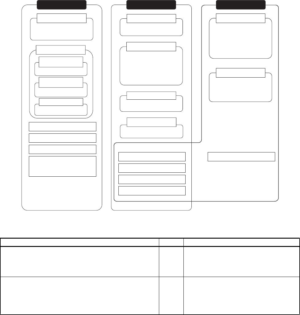
CS1H-CPU@@H
CS1G-CPU@@H
CS1-H CPU Units
CS Series
CS1D CPU Units
CS1D CPU Units for
Duplex Systems
CS1D-CPU@@H
CS1D CPU Units for
Simplex Systems
CS1D-CPU@@S
CS1D Process-control CPU Units
CS1D-CPU@@P
CS-series Basic I/O Units
CS-series Special I/O Units
CS-series CPU Bus Units
CS-series Power Supply Units
Note: A special Power Supply Unit
must be used for CS1D CPU
Units.
CJ-series Power Supply Units
CJ-series CPU Bus Units
CJ-series Special I/O Units
CJ-series Basic I/O Units
CJ1G-CPU@@
CJ1 CPU Units
CJ1M CPU Units
CJ1M-CPU@@
CJ1H-CPU@@H-R
CJ1H-CPU@@H
CJ1G-CPU@@H
CJ1G -CPU@@P
(Loop-control CPU Units)
CJ1-H CPU Units
CJ Series
CJ2H-CPU@@-@@@
CJ2 CPU Units
NSJ Series
NSJ Controllers
NSJ-series Expansion Units
NSJ Controllers
NSJ5-TQ@@(B)-G5D
NSJ5-SQ@@(B)-G5D
NSJ8-TV@@(B)-G5D
NSJ10-TV@@(B)-G5D
NSJ12-TS@@(B)-G5D
NSJ5-TQ@@(B)-M3D
NSJ5-SQ@@(B)-M3D
NSJ8-TV@@(B)-M3D

xx
SYSMAC CS/CJ/NSJ Series
CJ2H-CPU6@-EIP, CJ2H-CPU6@, CJ2M-CPU@@,
CS1G/H-CPU@@H, CS1G/H-CPU@@-EV1, CS1D-CPU@@H,
CS1D-CPU@@S, CJ1H-CPU@@H-R, CJ1G/H-CPU@@H,
CJ1G-CPU@@P, CJ1M-CPU@@, CJ1G-CPU@@,
NSJ@-@@@@(B)-G5D, NSJ@-@@@@(B)-M3D
Programmable Controllers Instructions Reference Manual
W474 Provides detailed descriptions of the instruc-
tions. When programming, use this manual
together with the manuals for your CPU Unit.
SYSMAC CS/CJ/NSJ Series
CQM1H-PRO01-E, C200H-PRO27-E, CQM1-PRO01-E
Programming Consoles Operation Manual
W341 Provides information on how to program and
operate CS/CJ-series PLCs using a Program-
ming Console.
SYSMAC CS/CJ/NSJ Series
CS1G/H-CPU@@-EV1, CS1G/H-CPU@@H,
CS1D-CPU@@H, CS1D-CPU@@S, CJ1H-CPU@@H-R,
CJ1G-CPU@@, CJ1M-CPU@@, CJ1G-CPU@@P,
CJ1G/H-CPU@@H, CJ2H-CPU6@-EIP, CJ2H-CPU6@,
CJ2M-CPU@@, CS1W-SCU@@-V1, CS1W-SCB@@-V1,
CJ1W-SCU@@-V1, CP1H-X@@@@-@, CP1H-XA@@@@-@,
CP1H-Y@@@@-@, CP1L-M/L@@@-@, CP1E-E@@D@-@,
CP1E-N@@D@-@, NSJ@-@@@@(B)-G5D,
NSJ@-@@@@(B)-M3D
Communications Commands Reference Manual
W342 Describes the C-series (Host Link) and FINS
communications commands used with CS/CJ-
series PLCs.
SYSMAC CS Series
CS1D-CPU@@H CPU Units
CS1D-CPU@@S CPU Units
CS1D-DPL01/02D Duplex Unit
CS1D-PA/PD@@@ Power Supply Unit
Duplex System Operation Manual
W405 Provides an outline of and describes the
design, installation, maintenance, and other
basic operations for a Duplex System based
on CS1D CPU Units.
CXONE-AL@@C-V4/AL@@D-V4
CX-Programmer Operation Manual
W446 Provides information on how to use the CX-
Programmer for all functionality except for
function blocks.
CXONE-AL@@C-V4/CXONE-AL@@D-V4
CX-Programmer Operation Manual
Function Blocks/Structured Text
W447 Explains how to use the CX-Programmer soft-
ware’s function block and structured text func-
tions. For explanations of other shared CX-
Programmer functions, refer to the CX-Pro-
grammer Operation Manual (W446).
SYSMAC CS/CJ Series
CS1W-SCB@@-V1, CS1W-SCU@@-V1, CJ1W-SCU@@-V1,
CJ1W-SCU@2
Serial Communications Boards/Units Operation Manual
W336 Describes the use of Serial Communications
Unit and Boards to perform serial communica-
tions with external devices, including the
usage of
standard system protocols for OMRON prod-
ucts.
CXONE-AL@@C-V4/AL@@D-V4
CX-Protocol Operation Manual
W344 Describes the use of the CX-Protocol to cre-
ate protocol macros as communications
sequences to communicate with external
devices.
CXONE-AL@@C-V4/AL@@D-V4
CX-Integrator Operation Manual
W464 Describes operating procedures for the CX-
Integrator Network Configuration Tool for CS-,
CJ-, CP-, and NSJ-series Controllers.
CXONE-AL@@C-V4/AL@@D-V4, CXONE-LT@@C-V4
CX-One Setup Manual
W463 Installation and overview of CX-One FA
Integrated Tool Package.
Name Cat. No. Contents

xxi
This manual contains the following sections.
Section 1 introduces the special features and functions of the CS-series PLCs and describes the dif-
ferences between these PLCs and other PLCs.
Section 2 provides tables of standard models, Unit specifications, system configurations, and a com-
parison between different Units.
Section 3 provides the names of components and their functions for various Units. The Unit dimen-
sions are also provided.
Section 4 outlines the steps required to assemble and operate a CS-series PLC system.
Section 5 describes how to install a PLC System, including mounting the various Units and wiring the
System. Be sure to follow the instructions carefully. Improper installation can cause the PLC to mal-
function, resulting in very dangerous situations.
Section 6 describes the settings of the DIP switch and how they affect operation.
Section 7 describes the settings in the PLC Setup and how they are used to control CPU Unit opera-
tion.
Section 8 describes I/O allocations to Basic I/O Units, Special I/O Units, and CPU Bus Units, and data
exchange with Units.
Section 9 describes the structure and functions of the I/O Memory Areas and Parameter Areas.
Section 10 describes the internal operation of the CPU Unit and the cycle used to perform internal
processing.
Section 11 provides information on hardware and software errors that occur during PLC operation.
Section 12 provides inspection and maintenance information.
The Appendices provide Unit specifications, current/power consumptions, Auxiliary Area words and
bits, a comparison of CS-series and previous PLCs, internal I/O addresses, and PLC Setup settings.
!WARNING Failure to read and understand the information provided in this manual may result in per-
sonal injury or death, damage to the product, or product failure. Please read each section
in its entirety and be sure you understand the information provided in the section and
related sections before attempting any of the procedures or operations given.
xxii

xxiii
Read and Understand this Manual
Please read and understand this manual before using the product. Please consult your OMRON
representative if you have any questions or comments.
Warranty and Limitations of Liability
WARRANTY
OMRON's exclusive warranty is that the products are free from defects in materials and workmanship for a
period of one year (or other period if specified) from date of sale by OMRON.
OMRON MAKES NO WARRANTY OR REPRESENTATION, EXPRESS OR IMPLIED, REGARDING NON-
INFRINGEMENT, MERCHANTABILITY, OR FITNESS FOR PARTICULAR PURPOSE OF THE
PRODUCTS. ANY BUYER OR USER ACKNOWLEDGES THAT THE BUYER OR USER ALONE HAS
DETERMINED THAT THE PRODUCTS WILL SUITABLY MEET THE REQUIREMENTS OF THEIR
INTENDED USE. OMRON DISCLAIMS ALL OTHER WARRANTIES, EXPRESS OR IMPLIED.
LIMITATIONS OF LIABILITY
OMRON SHALL NOT BE RESPONSIBLE FOR SPECIAL, INDIRECT, OR CONSEQUENTIAL DAMAGES,
LOSS OF PROFITS OR COMMERCIAL LOSS IN ANY WAY CONNECTED WITH THE PRODUCTS,
WHETHER SUCH CLAIM IS BASED ON CONTRACT, WARRANTY, NEGLIGENCE, OR STRICT
LIABILITY.
In no event shall the responsibility of OMRON for any act exceed the individual price of the product on which
liability is asserted.
IN NO EVENT SHALL OMRON BE RESPONSIBLE FOR WARRANTY, REPAIR, OR OTHER CLAIMS
REGARDING THE PRODUCTS UNLESS OMRON'S ANALYSIS CONFIRMS THAT THE PRODUCTS
WERE PROPERLY HANDLED, STORED, INSTALLED, AND MAINTAINED AND NOT SUBJECT TO
CONTAMINATION, ABUSE, MISUSE, OR INAPPROPRIATE MODIFICATION OR REPAIR.

xxiv
Application Considerations
SUITABILITY FOR USE
OMRON shall not be responsible for conformity with any standards, codes, or regulations that apply to the
combination of products in the customer's application or use of the products.
At the customer's request, OMRON will provide applicable third party certification documents identifying
ratings and limitations of use that apply to the products. This information by itself is not sufficient for a
complete determination of the suitability of the products in combination with the end product, machine,
system, or other application or use.
The following are some examples of applications for which particular attention must be given. This is not
intended to be an exhaustive list of all possible uses of the products, nor is it intended to imply that the uses
listed may be suitable for the products:
• Outdoor use, uses involving potential chemical contamination or electrical interference, or conditions or
uses not described in this manual.
• Nuclear energy control systems, combustion systems, railroad systems, aviation systems, medical
equipment, amusement machines, vehicles, safety equipment, and installations subject to separate
industry or government regulations.
• Systems, machines, and equipment that could present a risk to life or property.
Please know and observe all prohibitions of use applicable to the products.
NEVER USE THE PRODUCTS FOR AN APPLICATION INVOLVING SERIOUS RISK TO LIFE OR
PROPERTY WITHOUT ENSURING THAT THE SYSTEM AS A WHOLE HAS BEEN DESIGNED TO
ADDRESS THE RISKS, AND THAT THE OMRON PRODUCTS ARE PROPERLY RATED AND INSTALLED
FOR THE INTENDED USE WITHIN THE OVERALL EQUIPMENT OR SYSTEM.
PROGRAMMABLE PRODUCTS
OMRON shall not be responsible for the user's programming of a programmable product, or any
consequence thereof.

xxv
Disclaimers
CHANGE IN SPECIFICATIONS
Product specifications and accessories may be changed at any time based on improvements and other
reasons.
It is our practice to change model numbers when published ratings or features are changed, or when
significant construction changes are made. However, some specifications of the products may be changed
without any notice. When in doubt, special model numbers may be assigned to fix or establish key
specifications for your application on your request. Please consult with your OMRON representative at any
time to confirm actual specifications of purchased products.
DIMENSIONS AND WEIGHTS
Dimensions and weights are nominal and are not to be used for manufacturing purposes, even when
tolerances are shown.
PERFORMANCE DATA
Performance data given in this manual is provided as a guide for the user in determining suitability and does
not constitute a warranty. It may represent the result of OMRON's test conditions, and the users must
correlate it to actual application requirements. Actual performance is subject to the OMRON Warranty and
Limitations of Liability.
ERRORS AND OMISSIONS
The information in this manual has been carefully checked and is believed to be accurate; however, no
responsibility is assumed for clerical, typographical, or proofreading errors, or omissions.
xxvi
xxvii
PRECAUTIONS
This section provides general precautions for using the CS-series Programmable Controllers (PLCs) and related devices.
The information contained in this section is important for the safe and reliable application of Programmable
Controllers. You must read this section and understand the information contained before attempting to set up or
operate a PLC system.
1 Intended Audience . . . . . . . . . . . . . . . . . . . . . . . . . . . . . . . . . . . . . . . . . . . . . xxviii
2 General Precautions . . . . . . . . . . . . . . . . . . . . . . . . . . . . . . . . . . . . . . . . . . . . xxviii
3 Safety Precautions. . . . . . . . . . . . . . . . . . . . . . . . . . . . . . . . . . . . . . . . . . . . . . xxviii
4 Operating Environment Precautions . . . . . . . . . . . . . . . . . . . . . . . . . . . . . . . . xxx
5 Application Precautions . . . . . . . . . . . . . . . . . . . . . . . . . . . . . . . . . . . . . . . . . xxxi
6 Conformance to EC Directives . . . . . . . . . . . . . . . . . . . . . . . . . . . . . . . . . . . . xxxvi
6-1 Applicable Directives . . . . . . . . . . . . . . . . . . . . . . . . . . . . . . . . . . . . xxxvi
6-2 Concepts . . . . . . . . . . . . . . . . . . . . . . . . . . . . . . . . . . . . . . . . . . . . . . xxxvi
6-3 Conformance to EC Directives . . . . . . . . . . . . . . . . . . . . . . . . . . . . . xxxvi
6-4 Relay Output Noise Reduction Methods . . . . . . . . . . . . . . . . . . . . . xxxvi

xxviii
Intended Audience 1
1 Intended Audience
This manual is intended for the following personnel, who must also have
knowledge of electrical systems (an electrical engineer or the equivalent).
• Personnel in charge of installing FA systems.
• Personnel in charge of designing FA systems.
• Personnel in charge of managing FA systems and facilities.
2 General Precautions
The user must operate the product according to the performance specifica-
tions described in the operation manuals.
Before using the product under conditions which are not described in the
manual or applying the product to nuclear control systems, railroad systems,
aviation systems, vehicles, combustion systems, medical equipment, amuse-
ment machines, safety equipment, and other systems, machines, and equip-
ment that may have a serious influence on lives and property if used
improperly, consult your OMRON representative.
Make sure that the ratings and performance characteristics of the product are
sufficient for the systems, machines, and equipment, and be sure to provide
the systems, machines, and equipment with double safety mechanisms.
This manual provides information for programming and operating the Unit. Be
sure to read this manual before attempting to use the Unit and keep this man-
ual close at hand for reference during operation.
!WARNING It is extremely important that a PLC and all PLC Units be used for the speci-
fied purpose and under the specified conditions, especially in applications that
can directly or indirectly affect human life. You must consult with your OMRON
representative before applying a PLC System to the above-mentioned appli-
cations.
3 Safety Precautions
!WARNING The CPU Unit refreshes I/O even when the program is stopped (i.e., even in
PROGRAM mode). Confirm safety thoroughly in advance before changing the
status of any part of memory allocated to I/O Units, Special I/O Units, or CPU
Bus Units. Any changes to the data allocated to any Unit may result in unex-
pected operation of the loads connected to the Unit. Any of the following oper-
ation may result in changes to memory status.
• Transferring I/O memory data to the CPU Unit from a Programming
Device.
• Changing present values in memory from a Programming Device.
• Force-setting/-resetting bits from a Programming Device.
• Transferring I/O memory files from a Memory Card or EM file memory to
the CPU Unit.
• Transferring I/O memory from a host computer or from another PLC on a
network.
!WARNING Do not attempt to take any Unit apart while the power is being supplied. Doing
so may result in electric shock.

xxix
Safety Precautions 3
!WARNING Do not touch any of the terminals or terminal blocks while the power is being
supplied. Doing so may result in electric shock.
!WARNING Do not attempt to disassemble, repair, or modify any Units. Any attempt to do
so may result in malfunction, fire, or electric shock.
!WARNING Do not touch the Power Supply Unit while power is being supplied or immedi-
ately after power has been turned OFF. Doing so may result in electric shock.
!WARNING Provide safety measures in external circuits (i.e., not in the Programmable
Controller), including the following items, to ensure safety in the system if an
abnormality occurs due to malfunction of the PLC or another external factor
affecting the PLC operation. Not doing so may result in serious accidents.
• Emergency stop circuits, interlock circuits, limit circuits, and similar safety
measures must be provided in external control circuits.
• The PLC will turn OFF all outputs when its self-diagnosis function detects
any error or when a severe failure alarm (FALS) instruction is executed.
Unexpected operation, however, may still occur for errors in the I/O con-
trol section, errors in I/O memory, and other errors that cannot be
detected by the self-diagnosis function. As a countermeasure for all such
errors, external safety measures must be provided to ensure safety in the
system.
• The PLC outputs may remain ON or OFF due to deposition or burning of
the output relays or destruction of the output transistors. As a counter-
measure for such problems, external safety measures must be provided
to ensure safety in the system.
• When the 24-V DC output (service power supply to the PLC) is over-
loaded or short-circuited, the voltage may drop and result in the outputs
being turned OFF. As a countermeasure for such problems, external
safety measures must be provided to ensure safety in the system.
!Caution Confirm safety before transferring data files stored in the file memory (Mem-
ory Card or EM file memory) to the I/O area (CIO) of the CPU Unit using a
peripheral tool. Otherwise, the devices connected to the output unit may mal-
function regardless of the operation mode of the CPU Unit.
!Caution Fail-safe measures must be taken by the customer to ensure safety in the
event of incorrect, missing, or abnormal signals caused by broken signal lines,
momentary power interruptions, or other causes. Serious accidents may
result from abnormal operation if proper measures are not provided.
!Caution Execute online edit only after confirming that no adverse effects will be
caused by extending the cycle time. Otherwise, the input signals may not be
readable.

xxx
Operating Environment Precautions 4
!Caution A CS1-H/CJ1-H/CJ1M/CS1D CPU Unit automatically back up the user pro-
gram and parameter data to flash memory when these are written to the CPU
Unit. I/O memory (including the DM, EM, and HR Areas), however, is not writ-
ten to flash memory. The DM, EM, and HR Areas can be held during power
interruptions with a battery. If there is a battery error, the contents of these
areas may not be accurate after a power interruption. If the contents of the
DM, EM, and HR Areas are used to control external outputs, prevent inappro-
priate outputs from being made whenever the Battery Error Flag (A40204) is
ON. Areas such as the DM, EM, and HR Areas, the contents of which can be
held during power interrupts, is backed up by a battery. If a battery error
occurs, the contents of the areas that are set to be held may not be accurate
even though a memory error will not occur to stop operation. If necessary for
the safety of the system, take appropriate measures in the ladder program
whenever the Battery Error Flag (A40204) turns ON, such as resetting the
data in these areas.
!Caution Confirm safety at the destination node before transferring a program to
another node or changing contents of the I/O memory area. Doing either of
these without confirming safety may result in injury.
!Caution Tighten the screws on the terminal block of the AC Power Supply Unit to the
torque specified in the operation manual. The loose screws may result in
burning or malfunction.
!Caution Be careful when connecting personal computers or other peripheral devices
to a PLC to which is mounted a non-insulated Unit (CS1W-CLK1@(-V1),
CS1W-CLK5@(-V1), or CS1W-ETN01) connected to an external power sup-
ply. A short-circuit will be created if the 24 V side of the external power supply
is grounded and the 0 V side of the peripheral device is grounded. When con-
necting a peripheral device to this type of PLC, either ground the 0 V side of
the external power supply or do not ground the external power supply at all.
4 Operating Environment Precautions
!Caution Do not operate the control system in the following locations:
• Locations subject to direct sunlight.
• Locations subject to temperatures or humidity outside the range specified
in the specifications.
• Locations subject to condensation as the result of severe changes in tem-
perature.
• Locations subject to corrosive or flammable gases.
• Locations subject to dust (especially iron dust) or salts.
• Locations subject to exposure to water, oil, or chemicals.
• Locations subject to shock or vibration.
!Caution Take appropriate and sufficient countermeasures when installing systems in
the following locations:
• Locations subject to static electricity or other forms of noise.
• Locations subject to strong electromagnetic fields.
• Locations subject to possible exposure to radioactivity.

xxxi
Application Precautions 5
• Locations close to power supplies.
!Caution The operating environment of the PLC System can have a large effect on the
longevity and reliability of the system. Improper operating environments can
lead to malfunction, failure, and other unforeseeable problems with the PLC
System. Be sure that the operating environment is within the specified condi-
tions at installation and remains within the specified conditions during the life
of the system.
5 Application Precautions
Observe the following precautions when using the PLC System.
• You must use the CX-Programmer (programming software that runs on
Windows) if you need to program more than one task. A Programming
Console can be used to program only one cyclic task plus interrupt tasks.
A Programming Console can, however, be used to edit multitask pro-
grams originally created with the CX-Programmer.
• There are restrictions in the areas and addresses that can be accessed in
I/O memory of the CS-series CPU Units when using the C200H Special
I/O Units in combination with the following functions. (Refer to Appendix F
Restrictions in Using C200H Special I/O Units for details.)
• There are restrictions in data transfer with the CPU Unit when pro-
gramming transfers inside an ASCII Unit using the PLC READ, PLC
WRITE, and similar commands.
• There are restrictions in data transfer with the CPU Unit for allocated
bits and DM area specifications (areas and addresses for source and
destination specifications).
• The DeviceNet output area for a C200HW-DRM21-V1 DeviceNet Mas-
ter Unit (CIO 0050 to CIO 0099) overlaps with the I/O bit area (CIO
0000 to CIO 0319). Do not use automatic allocations for I/O in any sys-
tem where allocations to the DeviceNet system will overlap with allo-
cations to I/O Units. Instead, use a Programming Device or the CX-
Programmer to manually allocate I/O for the DeviceNet devices, being
sure that the same words and bits are not allocated more than once,
and transfer the resulting I/O table to the CPU Unit. If DeviceNet com-
munications are attempted when the same bits are allocated to both
DeviceNet devices and I/O Units (which can occur even if automatic al-
location is used), the DeviceNet devices and I/O Units may both exhibit
faulty operation.
• Special bits and flags for PLC Link Units (CIO 0247 to CIO 0250) over-
lap with the I/O bit area (CIO 0000 to CIO 0319). Do not use automatic
allocations for I/O in any system where allocations to the I/O Units will
overlap with allocations to I/O Units. Instead, use a Programming De-
vice or the CX-Programmer to manually allocate I/O to I/O Units, being
sure that the special bits and flags for PLC Link Units are not used, and
transfer the resulting I/O table to the CPU Unit. If operation is attempt-
ed when the special bits and flags for PLC Link Units are also allocated
to I/O Units (which can occur even if automatic allocation is used), the
PLC Link Units and I/O Units may both exhibit faulty operation.
!WARNING Always heed these precautions. Failure to abide by the following precautions
could lead to serious or possibly fatal injury.

xxxii
Application Precautions 5
• Always connect to a ground of 100 Ω or less when installing the Units. Not
connecting to a ground of 100 Ω or less may result in electric shock.
• A ground of 100 Ω or less must be installed when shorting the GR and LG
terminals on the Power Supply Unit.
• Always turn OFF the power supply to the PLC before attempting any of
the following. Not turning OFF the power supply may result in malfunction
or electric shock.
• Mounting or dismounting Power Supply Units, I/O Units, CPU Units, In-
ner Boards, or any other Units.
• Assembling the Units.
• Setting DIP switches or rotary switches.
• Connecting cables or wiring the system.
• Connecting or disconnecting the connectors.
!Caution Failure to abide by the following precautions could lead to faulty operation of
the PLC or the system, or could damage the PLC or PLC Units. Always heed
these precautions.
• The user program and parameter area data in CS1-H CPU Units is
backed up in the built-in flash memory. The BKUP indicator will light on
the front of the CPU Unit when the backup operation is in progress. Do
not turn OFF the power supply to the CPU Unit when the BKUP indicator
is lit. The data will not be backed up if power is turned OFF.
• If, when using a CS1-H CPU Unit, the PLC Setup is set to specify using
the mode set on the Programming Console and a Programming Console
is not connected, the CPU Unit will start in RUN mode. This is the default
setting in the PLC Setup.
• When creating an AUTOEXEC.IOM file from a Programming Device (a
Programming Console or the CX-Programmer) to automatically transfer
data at startup, set the first write address to D20000 and be sure that the
size of data written does not exceed the size of the DM Area. When the
data file is read from the Memory Card at startup, data will be written in
the CPU Unit starting at D20000 even if another address was set when
the AUTOEXEC.IOM file was created. Also, if the DM Area is exceeded
(which is possible when the CX-Programmer is used), the remaining data
will be written to the EM Area. Refer to information on file operations in
the CS/CJ Series Programming Manual for details.
• Always turn ON power to the PLC before turning ON power to the control
system. If the PLC power supply is turned ON after the control power sup-
ply, temporary errors may result in control system signals because the
output terminals on DC Output Units and other Units will momentarily turn
ON when power is turned ON to the PLC.
• Fail-safe measures must be taken by the customer to ensure safety in the
event that outputs from Output Units remain ON as a result of internal cir-
cuit failures, which can occur in relays, transistors, and other elements.
• Fail-safe measures must be taken by the customer to ensure safety in the
event of incorrect, missing, or abnormal signals caused by broken signal
lines, momentary power interruptions, or other causes.
• Interlock circuits, limit circuits, and similar safety measures in external cir-
cuits (i.e., not in the Programmable Controller) must be provided by the
customer.

xxxiii
Application Precautions 5
• Do not turn OFF the power supply to the PLC when data is being trans-
ferred. In particular, do not turn OFF the power supply when reading or
writing a Memory Card. Also, do not remove the Memory Card when the
BUSY indicator is lit. To remove a Memory Card, first press the memory
card power supply switch and then wait for the BUSY indicator to go out
before removing the Memory Card.
• If the I/O Hold Bit is turned ON, the outputs from the PLC will not be
turned OFF and will maintain their previous status when the PLC is
switched from RUN or MONITOR mode to PROGRAM mode. Make sure
that the external loads will not produce dangerous conditions when this
occurs. (When operation stops for a fatal error, including those produced
with the FALS(007) instruction, all outputs from Output Unit will be turned
OFF and only the internal output status will be maintained.)
• The contents of the DM, EM, and HR Areas in the CPU Unit are backed
up by a Battery. If the Battery voltage drops, this data may be lost. Provide
countermeasures in the program using the Battery Error Flag (A40204) to
re-initialize data or take other actions if the Battery voltage drops.
• When supplying power at 200 to 240 V AC, always remove the metal
jumper from the voltage selector terminals on the Power Supply Unit
(except for Power Supply Units with wide-range specifications). The prod-
uct will be destroyed and must be replaced if 200 to 240 V AC is supplied
while the metal jumper is attached. Refer to 5-3 Wiring for details.
• Always use the power supply voltages specified in the operation manuals.
An incorrect voltage may result in malfunction or burning.
• Do not apply a force greater than 100 N on the terminal block when tight-
ening the terminals.
• Take appropriate measures to ensure that the specified power with the
rated voltage and frequency is supplied. Be particularly careful in places
where the power supply is unstable. An incorrect power supply may result
in malfunction.
• Install external breakers and take other safety measures against short-cir-
cuiting in external wiring. Insufficient safety measures against short-cir-
cuiting may result in burning.
• Install Units as far as possible away from devices that generate strong,
high-frequency noise.
• Do not apply voltages to the Input Units in excess of the rated input volt-
age. Excess voltages may result in burning.
• Do not apply voltages or connect loads to the Output Units in excess of
the maximum switching capacity. Excess voltage or loads may result in
burning.
• Separate the line ground terminal (LG) from the functional ground termi-
nal (GR) on the Power Supply Unit before performing withstand voltage
tests or insulation resistance tests. Not doing so may result in burning.
• Change the applied voltage gradually using the adjuster on the Tester. If
full dielectric strength voltage is applied or turned OFF using the switch on
the Tester, the generated impulse voltage may damage the Power Supply
Unit.
• Install the Units properly as specified in the operation manuals. Improper
installation of the Units may result in malfunction.
• Be sure that all the Backplane mounting screws, terminal block screws,
and cable connector screws are tightened to the torque specified in the
relevant manuals. Incorrect tightening torque may result in malfunction.

xxxiv
Application Precautions 5
• Leave the label attached to the Unit when wiring. Removing the label may
result in malfunction if foreign matter enters the Unit.
• Remove the label after the completion of wiring to ensure proper heat dis-
sipation. Leaving the label attached may result in malfunction.
• Use crimp terminals for wiring. Do not connect bare stranded wires
directly to terminals. Connection of bare stranded wires may result in
burning.
• Wire all connections correctly.
• Do not drop the product or subject it to excessive vibration or shock.
• Double-check all wiring and switch settings before turning ON the power
supply. Incorrect wiring may result in burning.
• Mount Units only after checking terminal blocks and connectors com-
pletely.
• Be sure that the terminal blocks, Memory Units, expansion cables, and
other items with locking devices are properly locked into place. Improper
locking may result in malfunction.
• Check switch settings, the contents of the DM Area, and other prepara-
tions before starting operation. Starting operation without the proper set-
tings or data may result in an unexpected operation.
• Check the user program for proper execution before actually running it on
the Unit. Not checking the program may result in an unexpected opera-
tion.
• Confirm that no adverse effect will occur in the system before attempting
any of the following. Not doing so may result in an unexpected operation.
• Changing the operating mode of the PLC (including the setting of the
startup operating mode).
• Force-setting/force-resetting any bit in memory.
• Changing the present value of any word or any set value in memory.
• Resume operation only after transferring to the new CPU Unit the con-
tents of the DM Area, HR Area, and other data required for resuming
operation. Not doing so may result in an unexpected operation.
• Do not pull on the cables or bend the cables beyond their natural limit.
Doing either of these may break the cables.
• Do not place objects on top of the cables or other wiring lines. Doing so
may break the cables.
• Do not use commercially available RS-232C personal computer cables.
Always use the special cables listed in this manual or make cables
according to manual specifications. Using commercially available cables
may damage the external devices or CPU Unit.
• Never connect pin 6 (5-V power supply) on the RS-232C port on the CPU
Unit to any device other than an NT-AL001, CJ1W-CIF11 Link Adapter, or
NV3W-M@20L Programmable Terminal. The external device or the CPU
Unit may be damaged.
• When replacing parts, be sure to confirm that the rating of a new part is
correct. Not doing so may result in malfunction or burning.
• Before touching a Unit, be sure to first touch a grounded metallic object in
order to discharge any static build-up. Not doing so may result in malfunc-
tion or damage.
• When transporting or storing circuit boards, cover them in antistatic mate-
rial to protect them from static electricity and maintain the proper storage
temperature.

xxxv
Application Precautions 5
• Do not touch circuit boards or the components mounted to them with your
bare hands. There are sharp leads and other parts on the boards that
may cause injury if handled improperly.
• Do not short the battery terminals or charge, disassemble, heat, or incin-
erate the battery. Do not subject the battery to strong shocks. Doing any
of these may result in leakage, rupture, heat generation, or ignition of the
battery. Dispose of any battery that has been dropped on the floor or oth-
erwise subjected to excessive shock. Batteries that have been subjected
to shock may leak if they are used.
• UL standards required that batteries be replaced only by experienced
technicians. Do not allow unqualified persons to replace batteries.
• Dispose of the product and batteries according to local ordinances as
they apply.
Have qualified specialists properly dispose of used batteries as industrial
waste.
• Unexpected operation may result if inappropriate data link tables or
parameters are set. Even if appropriate data link tables and parameters
have been set, confirm that the controlled system will not be adversely
affected before starting or stopping data links.
• CPU Bus Units will be restarted when routing tables are transferred from
a Programming Device to the CPU Unit. Restarting these Units is required
to read and enable the new routing tables. Confirm that the system will
not be adversely affected before allowing the CPU Bus Units to be reset.
• When wiring crossovers between terminals, the total current for both ter-
minals will flow in the line. Check the current capacities of all wires before
wiring crossovers.
• The following precautions apply to Power Supply Units with Replacement
Notification.
• When the LED display on the front of the Power Supply Unit starts to
alternately display “0.0” and “A02” or the alarm output automatically
turns OFF, replace the Power Supply Unit within 6 months.
• Separate the alarm output cables from power lines and high-voltage
lines.
• Do not apply a voltage or connect a load to the alarm output that ex-
ceeds the rated voltage or load.
• Maintain an ambient storage temperature of −20 to 30°C and humidity
of 25% to 70% when storing the product for longer than 3 months to
keep the replacement notification function in optimum working condi-
tion.
• Always use the standard installation method. A nonstandard installa-
tion will decrease heat dissipation, delay the replacement notification
signal, and may degrade or damage the internal elements.
• Design the system so that the power supply capacity of the Power Supply
Unit is not exceeded.
• Do not touch the terminals on the Power Supply Unit immediately after
turning OFF the power supply. Electric shock may occur due to the resid-
ual voltage.

xxxvi
Conformance to EC Directives 6
6 Conformance to EC Directives
6-1 Applicable Directives
•EMC Directives
• Low Voltage Directive
6-2 Concepts
EMC Directives
OMRON devices that comply with EC Directives also conform to the related
EMC standards so that they can be more easily built into other devices or the
overall machine. The actual products have been checked for conformity to
EMC standards (see the following note). Whether the products conform to the
standards in the system used by the customer, however, must be checked by
the customer.
EMC-related performance of the OMRON devices that comply with EC Direc-
tives will vary depending on the configuration, wiring, and other conditions of
the equipment or control panel on which the OMRON devices are installed.
The customer must, therefore, perform the final check to confirm that devices
and the overall machine conform to EMC standards.
Note Applicable EMC (Electromagnetic Compatibility) standards are as follows:
EMS (Electromagnetic Susceptibility): EN61131-2 or EN61000-6-2
EMI (Electromagnetic Interference): EN61000-6-4
(Radiated emission: 10-m regulations)
Low Voltage Directive
Always ensure that devices operating at voltages of 50 to 1,000 V AC and 75
to 1,500 V DC meet the required safety standards for the PLC (EN61131-2).
6-3 Conformance to EC Directives
The CS-series PLCs comply with EC Directives. To ensure that the machine
or device in which the CS-series PLC is used complies with EC Directives, the
PLC must be installed as follows:
1,2,3... 1. The CS-series PLC must be installed within a control panel.
2. You must use reinforced insulation or double insulation for the DC power
supplies used for the communications power supply and I/O power sup-
plies.
3. CS-series PLCs complying with EC Directives also conform to the Com-
mon Emission Standard (EN61000-6-4). Radiated emission characteris-
tics (10-m regulations) may vary depending on the configuration of the
control panel used, other devices connected to the control panel, wiring,
and other conditions. You must therefore confirm that the overall machine
or equipment complies with EC Directives.
6-4 Relay Output Noise Reduction Methods
The CS-series PLCs conforms to the Common Emission Standards
(EN61000-6-4) of the EMC Directives. However, noise generated by relay out-
put switching may not satisfy these Standards. In such a case, a noise filter
must be connected to the load side or other appropriate countermeasures
must be provided external to the PLC.
Countermeasures taken to satisfy the standards vary depending on the
devices on the load side, wiring, configuration of machines, etc. Following are
examples of countermeasures for reducing the generated noise.
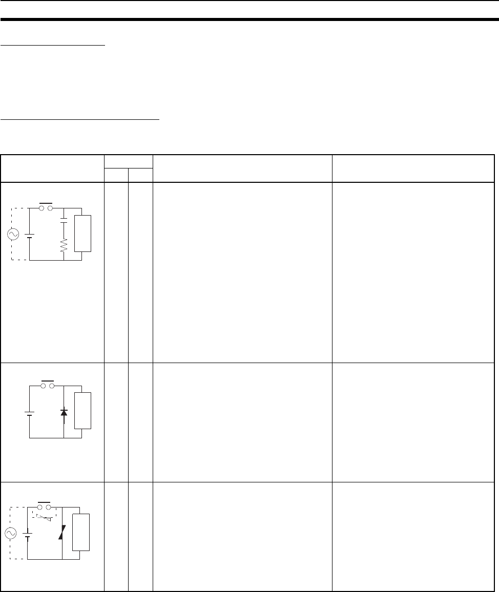
xxxvii
Conformance to EC Directives 6
Countermeasures (Refer to EN61000-6-4 for more details.)
Countermeasures are not required if the frequency of load switching for the
whole system with the PLC included is less than 5 times per minute.
Countermeasures are required if the frequency of load switching for the whole
system with the PLC included is more than 5 times per minute.
Countermeasure Examples
When switching an inductive load, connect an surge protector, diodes, etc., in
parallel with the load or contact as shown below.
Circuit Current Characteristic Required element
AC DC
Yes Yes If the load is a relay or solenoid, there is a
time lag between the moment the circuit is
opened and the moment the load is reset.
If the supply voltage is 24 or 48 V, insert
the surge protector in parallel with the
load. If the supply voltage is 100 to 200 V,
insert the surge protector between the
contacts.
The capacitance of the capacitor must
be 1 to 0.5 µF per contact current of
1 A and resistance of the resistor must
be 0.5 to 1 Ω per contact voltage of
1 V. These values, however, vary with
the load and the characteristics of the
relay. Decide these values from exper-
iments, and take into consideration
that the capacitance suppresses
spark discharge when the contacts
are separated and the resistance lim-
its the current that flows into the load
when the circuit is closed again.
The dielectric strength of the capacitor
must be 200 to 300 V. If the circuit is
an AC circuit, use a capacitor with no
polarity.
No Yes The diode connected in parallel with the
load changes energy accumulated by the
coil into a current, which then flows into
the coil so that the current will be con-
verted into Joule heat by the resistance of
the inductive load.
This time lag, between the moment the cir-
cuit is opened and the moment the load is
reset, caused by this method is longer
than that caused by the CR method.
The reversed dielectric strength value
of the diode must be at least 10 times
as large as the circuit voltage value.
The forward current of the diode must
be the same as or larger than the load
current.
The reversed dielectric strength value
of the diode may be two to three times
larger than the supply voltage if the
surge protector is applied to electronic
circuits with low circuit voltages.
Yes Yes The varistor method prevents the imposi-
tion of high voltage between the contacts
by using the constant voltage characteris-
tic of the varistor. There is time lag
between the moment the circuit is opened
and the moment the load is reset.
If the supply voltage is 24 or 48 V, insert
the varistor in parallel with the load. If the
supply voltage is 100 to 200 V, insert the
varistor between the contacts.
---
CR method
Power
supply
Inductive
load
Diode method
Power
supply
Inductive
load
Varistor method
Power
supply
Inductive
load
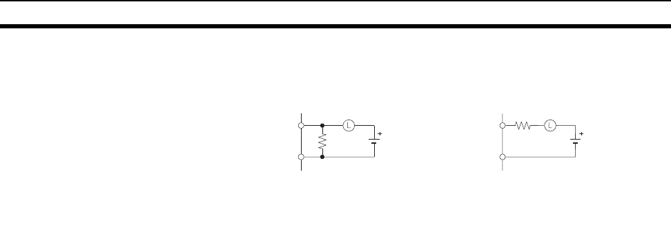
xxxviii
Conformance to EC Directives 6
When switching a load with a high inrush current such as an incandescent
lamp, suppress the inrush current as shown below.
OUT
COM
R
OUT
COM
R
Countermeasure 1 Countermeasure 2
Providing a limiting resistor
Providing a dark current of approx.
one-third of the rated value through
an incandescent lamp
1
SECTION 1
Introduction
This section introduces the special features and functions of the CS-series PLCs and describes the differences between these
PLCs and other PLCs.
1-1 Overview . . . . . . . . . . . . . . . . . . . . . . . . . . . . . . . . . . . . . . . . . . . . . . . . . . . . . . . . . . 2
1-2 CS-series Features. . . . . . . . . . . . . . . . . . . . . . . . . . . . . . . . . . . . . . . . . . . . . . . . . . . 3
1-2-1 Features. . . . . . . . . . . . . . . . . . . . . . . . . . . . . . . . . . . . . . . . . . . . . . . . . . . . 3
1-2-2 Versatile Functions . . . . . . . . . . . . . . . . . . . . . . . . . . . . . . . . . . . . . . . . . . . 8
1-3 CS1-H CPU Unit Features . . . . . . . . . . . . . . . . . . . . . . . . . . . . . . . . . . . . . . . . . . . . 13
1-3-1 High-speed Performance . . . . . . . . . . . . . . . . . . . . . . . . . . . . . . . . . . . . . . 13
1-3-2 High-speed Structured Programming . . . . . . . . . . . . . . . . . . . . . . . . . . . . . 14
1-3-3 Function Block (FB) . . . . . . . . . . . . . . . . . . . . . . . . . . . . . . . . . . . . . . . . . . 14
1-3-4 More Instructions for Specific Applications. . . . . . . . . . . . . . . . . . . . . . . . 15
1-3-5 Battery-free Operation with Flash Memory . . . . . . . . . . . . . . . . . . . . . . . . 16
1-3-6 Better Compatibility with Other SYSMAC PLCs . . . . . . . . . . . . . . . . . . . 16
1-3-7 Refreshing Timer/Counter PVs in Binary . . . . . . . . . . . . . . . . . . . . . . . . . 16
1-3-8 Features of CS1-H CPU Units Ver. 3.0. . . . . . . . . . . . . . . . . . . . . . . . . . . . 16
1-3-9 Changes to CS-series Operating Specifications . . . . . . . . . . . . . . . . . . . . . 17
1-3-10 Features of CS1-H CPU Units Ver. 2.0. . . . . . . . . . . . . . . . . . . . . . . . . . . . 18
1-4 CS1-H CPU Unit Ver. 4.0 Upgrades . . . . . . . . . . . . . . . . . . . . . . . . . . . . . . . . . . . . . 22
1-4-1 Online Editing of Function Blocks . . . . . . . . . . . . . . . . . . . . . . . . . . . . . . . 22
1-4-2 Input-Output Variables in Function Blocks . . . . . . . . . . . . . . . . . . . . . . . . 22
1-4-3 Text String Support in Function Blocks . . . . . . . . . . . . . . . . . . . . . . . . . . . 22
1-5 CS1-H CPU Unit Ver. 3.0 Upgrades . . . . . . . . . . . . . . . . . . . . . . . . . . . . . . . . . . . . . 23
1-5-1 Function Blocks (FB) . . . . . . . . . . . . . . . . . . . . . . . . . . . . . . . . . . . . . . . . . 24
1-5-2 Serial Gateway (Converting FINS to CompoWay/F Via Serial Port). . . . . 25
1-5-3 Comment Memory (in Internal Flash Memory) . . . . . . . . . . . . . . . . . . . . . 26
1-5-4 Simple Backup Data Expanded . . . . . . . . . . . . . . . . . . . . . . . . . . . . . . . . . 26
1-5-5 Free Running Timer . . . . . . . . . . . . . . . . . . . . . . . . . . . . . . . . . . . . . . . . . . 27
1-5-6 New Special Instructions and Functions. . . . . . . . . . . . . . . . . . . . . . . . . . . 28
1-5-7 Increased Points for SYSMAC BUS Remote I/O Communications . . . . . 28
1-6 CS1-H CPU Unit Ver. 2.0 Upgrades . . . . . . . . . . . . . . . . . . . . . . . . . . . . . . . . . . . . . 30
1-6-1 Downloading and Uploading Individual Tasks. . . . . . . . . . . . . . . . . . . . . . 30
1-6-2 Improved Read Protection Using Passwords . . . . . . . . . . . . . . . . . . . . . . . 31
1-6-3 Write Protection from FINS Commands Sent to CPU Units via Networks 36
1-6-4 Online Network Connections without I/O Tables. . . . . . . . . . . . . . . . . . . . 41
1-6-5 Communications through a Maximum of 8 Network Levels . . . . . . . . . . . 43
1-6-6 Connecting Online to PLCs via NS-series PTs . . . . . . . . . . . . . . . . . . . . . 46
1-6-7 Setting First Slot Words . . . . . . . . . . . . . . . . . . . . . . . . . . . . . . . . . . . . . . . 47
1-6-8 Automatic Transfers at Power ON without a Parameter File . . . . . . . . . . . 49
1-6-9 Operation Start/End Times . . . . . . . . . . . . . . . . . . . . . . . . . . . . . . . . . . . . . 51
1-6-10 New Application Instructions . . . . . . . . . . . . . . . . . . . . . . . . . . . . . . . . . . . 51
1-7 CS-series Function Tables. . . . . . . . . . . . . . . . . . . . . . . . . . . . . . . . . . . . . . . . . . . . . 52
1-7-1 Functions Arranged by Purpose . . . . . . . . . . . . . . . . . . . . . . . . . . . . . . . . . 52
1-7-2 Communications Functions (Serial/Network) . . . . . . . . . . . . . . . . . . . . . . 58
1-8 CS1-H Functions Arranged by Purpose . . . . . . . . . . . . . . . . . . . . . . . . . . . . . . . . . . 60
1-9 Comparison of CS-series PLCs and C200HX/HG/HE Operation . . . . . . . . . . . . . . 62
1-10 Checking the Package . . . . . . . . . . . . . . . . . . . . . . . . . . . . . . . . . . . . . . . . . . . . . . . . 68
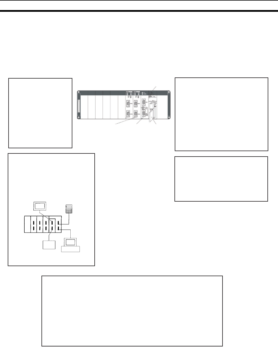
2
Overview Section 1-1
1-1 Overview
The CS-series PLCs are medium-sized Programmable Controllers that pro-
vide improved programming efficiency by dividing the program into tasks. The
CS-series PLCs also feature faster processing, higher capacities, multiple
ports supporting protocol macros, improved seamless communications
across three network levels, and much more, enabling them to flexibly handle
advanced information capabilities as core FA controllers.
CS-series PLC CPU Unit Structured Programming
The program is divided into tasks.
Symbols can be used in programming.
The overall performance of the system is
improved by executing only the required
tasks.
Modification and debugging are simplified.
The program arrangement can be changed.
Step control and block programming
instructions can be used.
Comments can be added to make the
program easier to understand.
Improvements in Basic
Performance
Faster instruction execution
and peripheral servicing
Larger memory capacity
Faster data exchange
between Units and I/O
memory access
Instruction operands can
be specified binary or BCD
Programs from earlier PLCs
are compatible
Memory
Card
Serial
Communications
Board
Serial
Communications
Unit
Protocol Macro Function Serves
Multiple Ports
Up to 34 ports can be connected (Serial
Communications Boards + Serial
Communications Units).
Different Protocol Macros can be
allocated to each port.
Programmable
Terminal or
other device
Programming
Console
Personal
computer
General-
purpose
I/O device
Remote Programming, Monitoring
and Seamless Links between
Networks
FINS commands allow communications
between nodes in different networks.
Remote programming and monitoring
can be performed.
Full Complement of Versatile Functions
Memory Card and file processing functions
Simplify programs with specialized instructions such as the table data and text
string processing instructions
Troubleshooting functions
Data tracing function
Minimum (fixed) cycle time function
I/O refreshing method selection
PLC Setup functions
Use Windows tools to create multiple environments in a single personal computer.

3
CS-series Features Section 1-2
1-2 CS-series Features
1-2-1 Features
Improvements in Basic Performance
The CS-series PLCs provide higher speed, greater capacity, and more func-
tions in a package as compact as the C200H PLCs.
Faster Cycle Times For the CS1-H CPU Units, instruction processing times have been reduced to
0.02 µs min. for basic instructions, to 0.06 µs min. for special instructions, and
to 0.8 µs min. for floating-point calculations. The time required for overseeing
(overhead), I/O refreshing, and peripheral servicing has also been reduced
dramatically.
Extra Capacity for High
Value-added Programs
With capacity for 250,000 program steps, up to 448,000 words of Data Mem-
ory, and up to 5,120 I/O points, there is plenty of memory for complex pro-
grams, intricate interfaces, communications, and data processing.
Binary Operand Settings
Increase Setting Ranges
In earlier PLCs, most instruction operands had to be specified in BCD (0 to
9,999), but in the CS-series PLCs they can be specified in binary (0 to FFFF
hexadecimal or 0 to 65,535 decimal). As an example, the BLOCK TRANSFER
instruction can now transfer data from up to 65,535 words rather than 9,999
words. Also the maximum DM address that can be indirectly addressed is
now D32767 rather than the maximum DM address of D09999 in
C200HX/HG/HE PLCs.
Program Compatibility Programs from earlier OMRON PLCs (such as the C200H, C200HS,
C200HX/HG/HE, and CV Series) can be imported into the CS-series PLCs.
CS-series and C200H
Units Supported
High-density CS-series Units, such as the 96-point I/O Units and 8-point Ana-
log I/O Units (4 inputs and 4 outputs) can be used together with the wide vari-
ety of C200H Units (about 90 models) can be used in a CS-series PLC.
CS-series Long-distance
Expansion Racks
I/O Control Units and I/O Interface Units can be used to create systems con-
taining CS-series Long-distance Expansion Racks. Up to two series of Long-
distance Expansion Racks can be connected, each measuring up to 50 m, for
a total coverage of 100 m. CS-series Long-distance Expansion Racks can be
used to create high-speed, low-cost distribution systems without using Com-
munications Units.
Structured Programming
Division of the Program
into Tasks
When the program is divided into tasks that handle separate functions, control
systems, or processes, several programmers can develop these separate
tasks simultaneously.
There can be up to 32 normal (cyclic) tasks and 256 interrupt tasks. There are
four types of interrupts: the Power OFF Interrupt, Scheduled Interrupts, I/O
Interrupts, and External Interrupts (interrupts from Special I/O Units or CPU
Bus Units).
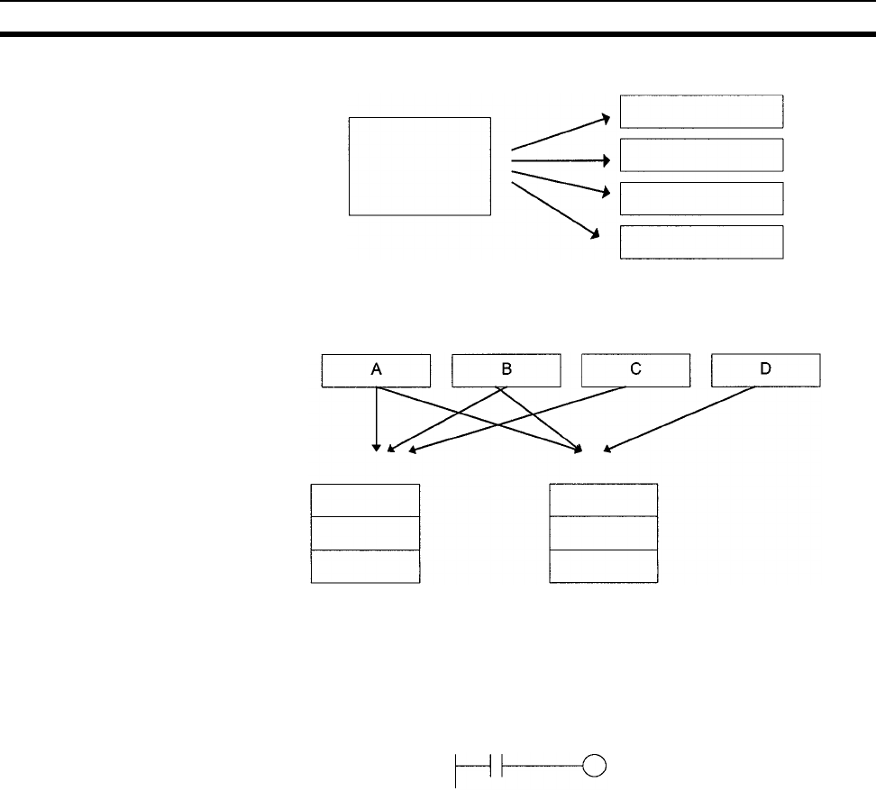
4
CS-series Features Section 1-2
When a new program is being created, standard programs can be combined
as tasks to create an entire program.
Using Symbols Arbitrary symbols (names up to 32 characters) that are independent of I/O ter-
minal allocations can be used in programming. Standard programs created
with symbols are more general and easier to reuse as tasks in different pro-
grams.
Global and Local Symbols
Supported
I/O names are handled as symbols which can be defined as global symbols,
which apply to all of the programs in all tasks, or as local symbols, which apply
to just the local task.
When the symbols are defined, you can choose to have the local symbols
allocated to addresses automatically.
Improve Overall System
Response Performance
The response performance of the system can be improved by dividing the
program into a system-management task and tasks used for control and exe-
cuting only those control tasks that need to be executed.
Simplify Program Modification
• Debugging is more efficient when the job of modifying and debugging the
tasks can be divided among several individuals.
• Program maintenance is easier because only the tasks affected by
changes have to be modified when there are changes (such as changes
in specifications).
• Several consecutive program lines can be modified with online editing.
• The amount the cycle time is extended during online editing has been
reduced.
Earlier program
Task
Task
Task
Task
Standard programs
Program ABC Program ABD
Task 1 (A)
Task 2 (B)
Task 3 (C)
Task 1 (A)
Task 2 (B)
Task 3 (D)
Symbols specified for bit address:
SW1 VALVE
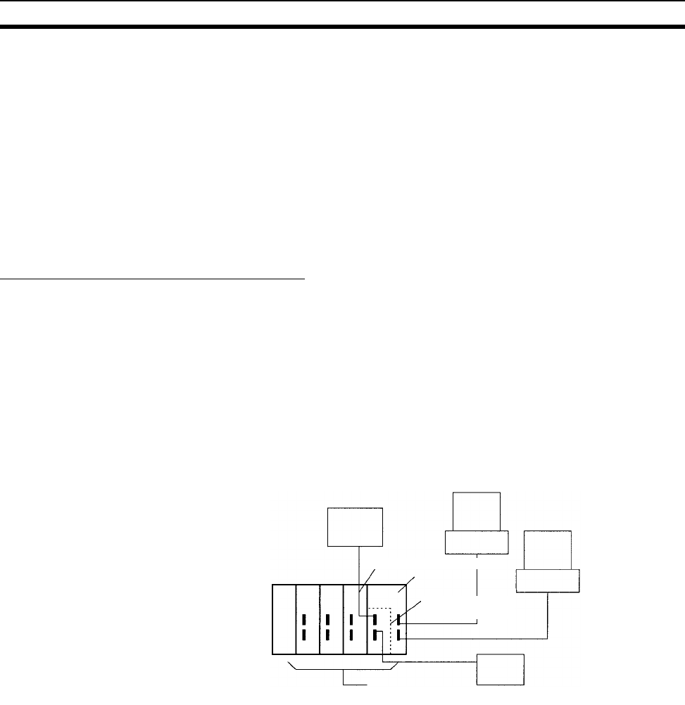
5
CS-series Features Section 1-2
Change Program
Arrangement Easily
When separate tasks have been programmed for different production models,
the task control instructions can be used to switch the program quickly from
production of one model to another.
Step Control and Block
Programming
The step control and block programming instructions can be used to control
repetitive processes that are difficult to program with ladder programming
alone.
Comments Several types of comments can be added to the program to make it easier to
understand, including Rung comments, and I/O comments.
Section Function The section function can be used to make the program easier to visualize
(CX-Programmer version 2.0 or higher).
Port-specific Protocol Macro Function
Create Protocol Functions
for All Ports
The protocol macro function can be used to create versatile communications
functions for any of the PLC’s communications ports. The communications
functions can have host link, NT Link, or protocol macro configurations and
can be directed to RS-232C and RS-422/485 ports on any of the Units.
1,2,3... 1. One Serial Communications Board can be mounted in the CPU Unit. (A
Serial Communications Board has two serial communications ports.)
2. Up to 16 Serial Communications Units can be connected to a CPU Unit.
(Each Serial Communications Unit has two serial communications ports.)
In total, up to 36 ports can be used.
Standard Serial
Communications with
External Devices
Messages can be transferred to and from standard serial devices with the pro-
tocol macro function (according to preset parameter settings). The protocol
macro function supports processing options such as retries, timeout monitor-
ing, and error checks.
Symbols that read and write data to the CPU Unit can be included in the com-
munications frames, so data can be exchanged with the CPU Unit very easily.
OMRON components (such as Temperature Controllers, ID System Devices,
Bar Code Readers, and Modems) can be connected to a Serial Communica-
tions Board or Serial Communications Unit with the standard system protocol.
It is also possible to change the settings if necessary.
Note The Serial Communications Board or Serial Communications Unit must be
purchased separately to take advantage of this function.
PT
Programming Device
Host Computer
Serial Communications Unit
CPU Unit
Serial Commu-
nications Board
Up to 36 ports
are possible
External device
with serial port
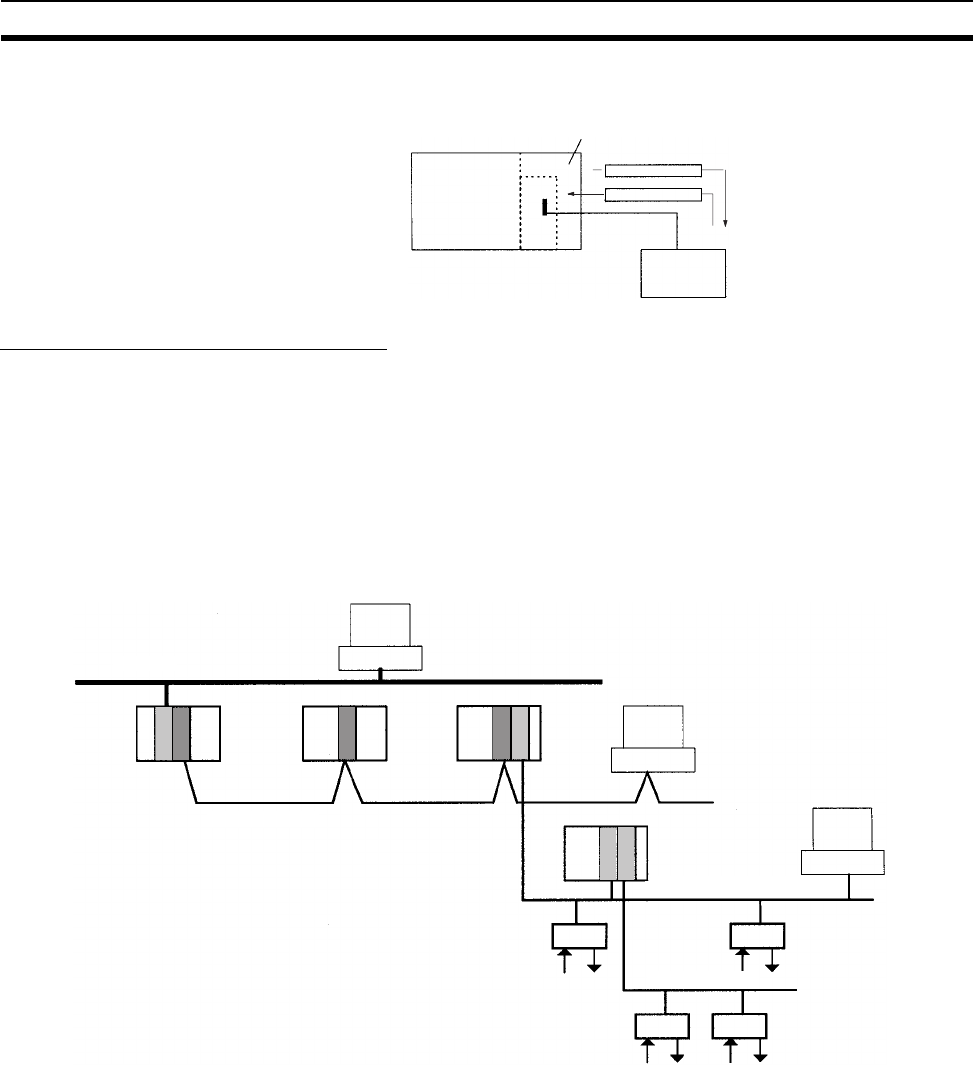
6
CS-series Features Section 1-2
Multilevel Network Configurations
Different network levels can be connected as shown in the following diagram.
The multilevel configuration provides more flexibility in networking from the
manufacturing site to production management. In particular, the DeviceNet
network makes it very easy to connect devices from other manufacturers.
OA Network: Ethernet
FA Network: Controller Link
DeviceNet*: DeviceNet
High-speed ON/OFF bus: CompoBus/S
Note *Units that conform to JEMANET standards are also available.
Transmit or receive data
with just one instruction.
External device
Ethernet
Controller Link
CompoBus/S
DeviceNet
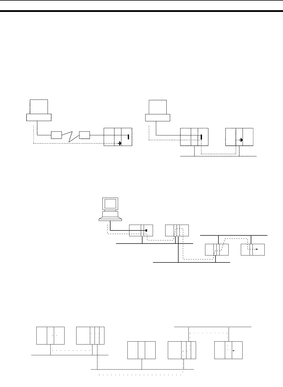
7
CS-series Features Section 1-2
Remote Monitoring and Programming
1,2,3... 1. The host link function can operate through a modem, which allows moni-
toring of a distant PLC’s operation, data transfers, or even online editing of
a distant PLC’s program by phone.
2. PLCs in a network can be programmed and monitored through the Host
Link.
3. It is possible to communicate through 3 network levels even with different
types of networks.
Communications Across 3
Network Levels
Remote programming/monitoring of a PLC on a network up to 3 levels away
(including the local network) for the same or different types of networks is pos-
sible through Host Link.
Note With CS/CJ-series CPU Units Ver. 2.0 or later, remote programming/monitor-
ing is possible up to 8 levels away. Refer to 1-6-2 Improved Read Protection
Using Passwords for details.
Message transfer between PLCs on a network 3 levels away (including the
local network) for the same or different types of networks.
High-speed
Communications with PTs
NT Link communications between an NS-series or NT31/NT631-V2 PT and a
CS-series PLC are possible at high speed.
Remote programming/monitoring
of a distant PLC
Remote programming/monitoring of a
PLC on the network through Host Link
Controller Link Network
Modem Modem
Network 3
Network 2
Network 1
Network 1
Network 3
Network 2
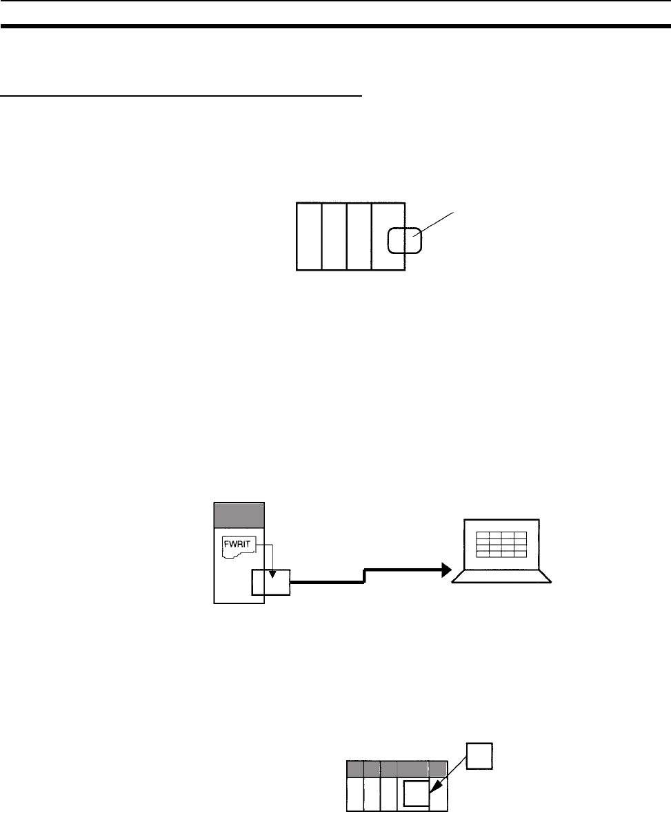
8
CS-series Features Section 1-2
1-2-2 Versatile Functions
Memory Card and File Management Functions
Transfer Data to and from
Memory Cards
Data area data, program data, and PLC Setup data can be saved as files on a
Memory Card (compact flash memory). Data can be read and written from
Programming Devices, instructions in the user program, or host computers.
(From the program, only I/O memory can be read and written and it must be
read or written as a file.)
Convert EM Area Banks to
File Memory
Part of the EM Area can be converted to file memory to provide file manage-
ment capabilities without a Memory Card and with much faster access time
than a Memory Card. (I/O comments can also be stored.)
Automatic File Transfer at
Start-up
The PLC can be set up to transfer the program and/or PLC Setup files from
the Memory Card when the PLC is turned ON. With this function, the Memory
Card provides a flash-ROM transfer. This function can also be used to store
and change PLC configurations quickly and easily.
I/O Memory Files in CSV
and Text Format
It is now possible to save production results and other data (hexadecimal)
from the CPU Unit I/O memory in a Memory Card in CSV or text format. The
data can then be read and edited using personal computer spreadsheet soft-
ware by means of a Memory Card Adapter.
File Operations (Deleting,
Creating Directories, etc.)
from Ladder Programs
It is possible to format files, delete, copy, change file names, create new direc-
tories, and perform similar operations on a Memory Card from the ladder pro-
gram during PLC operation.
Program Replacement
During Operation
It is now possible to replace the entire user program in the CPU Unit from the
Memory Card during operation. In this way, it is possible to switch PLC opera-
tion without stopping the PLC.
Easy Backups It is now possible to back up all data (user programs, parameters, and I/O
memory) to the Memory Card by pressing the Memory Card power supply
switch. In this way, if a malfunction arises, it is possible to back up all data in
the CPU Unit at the time without using a Programming Device.
I/O Memory, program,
and parameter areas
stored as files.
I/O memory data stored
in CSV or text format
Via Memory Card Adapter
Spreadsheet software
Memory Card
PLC operation .OBJ
Replacement
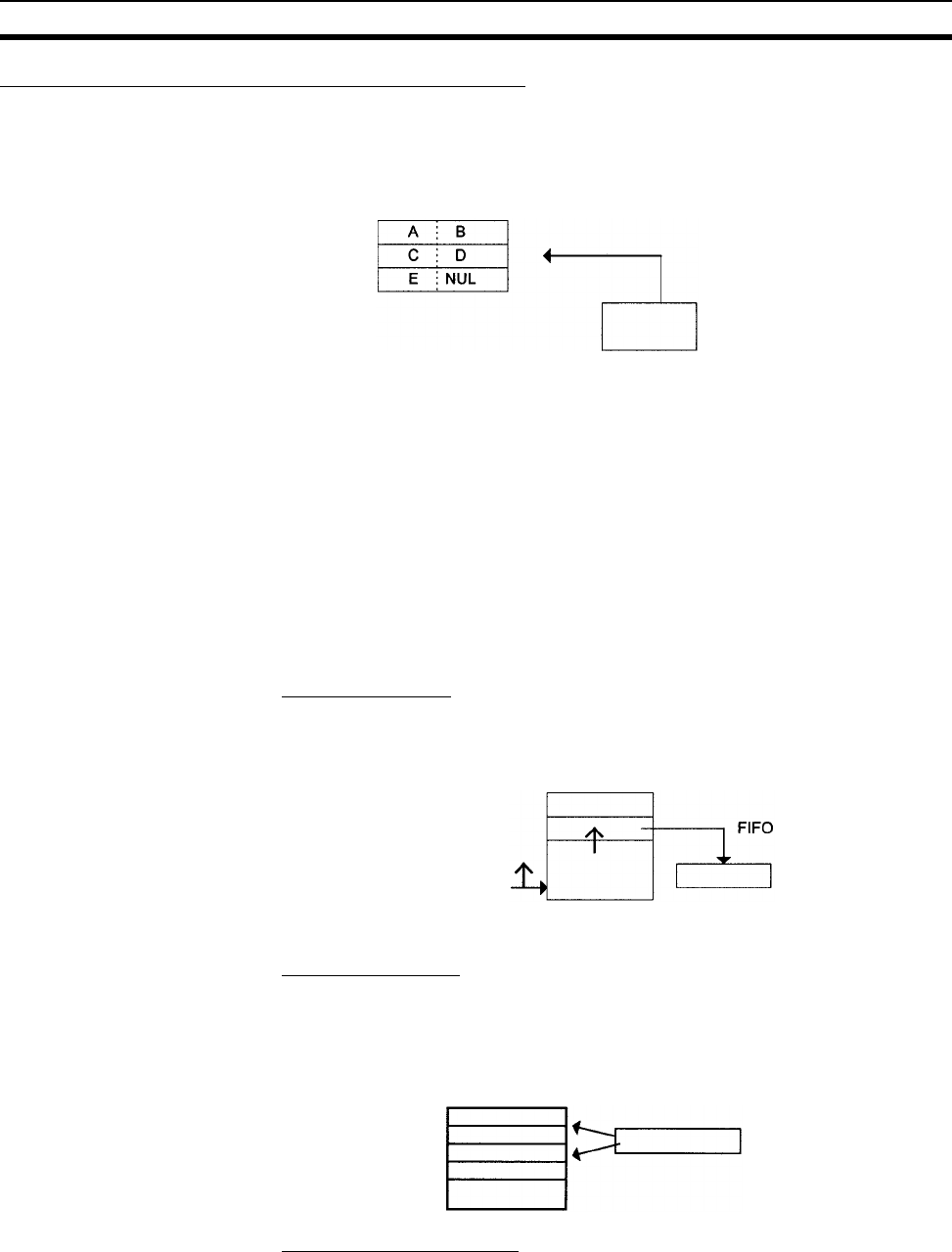
9
CS-series Features Section 1-2
Specialized Instructions Simplify Programming
Text String Instructions The text string instructions allow text processing to be performed easily from
the ladder program. These instructions simplify the processing required when
creating messages for transmission or processing messages received from
external devices with the protocol macro function.
Loop Instructions The FOR(512), NEXT(513), and BREAK(514) instructions provide a very
powerful programming tool that takes up little program capacity.
Index Registers Sixteen Index Registers are provided for use as pointers in instructions. An
Index Register can be used to indirectly address any word in I/O memory. The
CS-series PLCs also support the auto-increment, auto-decrement, and offset
functions.
The Index Registers can be a powerful tool for repetitive processing (loops)
when combined with the auto-increment, auto-decrement, and offset func-
tions. Index Registers can also be useful for table processing operations such
as changing the order of characters in text strings.
Table Data Processing Instructions
Stack Instructions
A region of I/O memory can be defined as a stack region. Words in the stack
are specified by a stack pointer for easy FIFO (first-in first-out) or LIFO (last-in
first-out) data processing.
Table Processing
Range Instructions
These instructions operate on a specified range of words to find the maximum
value or minimum value, search for a particular value, calculate the sum or
FCS, or swap the contents of the leftmost and rightmost bytes in the words.
Record-table Instructions
Record-table instructions operate on specially defined data tables. The record
table must be defined in advance with DIM(631), which declares the number
of words in a record and the number of records in the table. Up to 16 record
tables can be defined.
Processing of text string
data
External device with
standard serial port
Stack region
Pointer
Range specified
in the instruction
Data
Search, find maximum,
find minimum, etc.
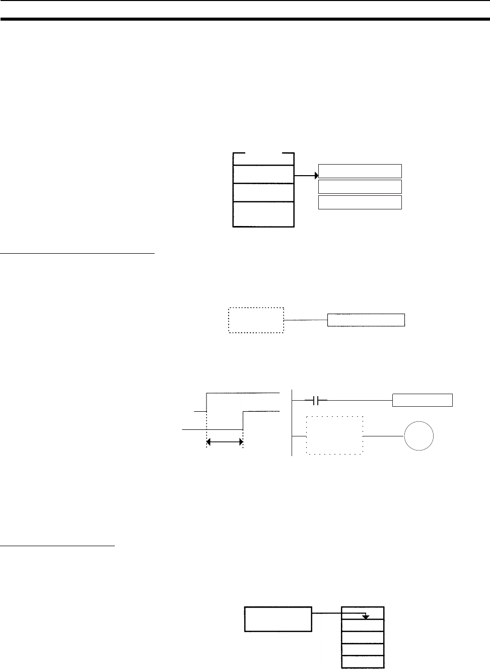
10
CS-series Features Section 1-2
Record tables are useful when data is organized in records. As an example, if
temperatures, pressures, or other set values for various models have been
combined into a table, the record-table format makes it easy to store and read
the set values for each model.
The SETR(635) can be used to store the first address of the desired record in
an Index Register. Index Registers can then be used to simplify complicated
processes such as changing the order of records in the record table, search-
ing for data, or comparing data.
Troubleshooting Functions
Failure Diagnosis:
FAL(006) and FALS(007)
The FAL(006) and FALS(007) can be used to generate a non-fatal or fatal
error when the user-defined conditions are met. Records of these errors are
stored in the error log just like system-generated errors.
Failure Point Detection:
FPD(269)
Diagnoses a failure in an instruction block by monitoring the time between
execution of FPD(269) and execution of a diagnostic output and finding which
input is preventing an output from being turned ON.
Error Log Functions The error log contains the error code and time of occurrence for the most
recent 20 errors (user-defined or system-generated errors).
Maintenance Functions The CS-series PLCs record information useful for maintenance, such as the
number of power interruptions and the total PLC ON time.
Data Trace Function
The content of the specified word or bit in I/O memory can be stored in trace
memory by one of the following methods: scheduled sampling, cyclic sam-
pling, or sampling at execution of TRSM(045).
Ta b l e
Record 2
Record 3
Record 2
Set values for model A
Temperature setting
Time setting
Pressure setting
User-defined
error condition FAL(006) or FALS(007) error
Input preventing
diagnostic output
from going ON
FPD
Trace memory
Specified address
in I/O memory
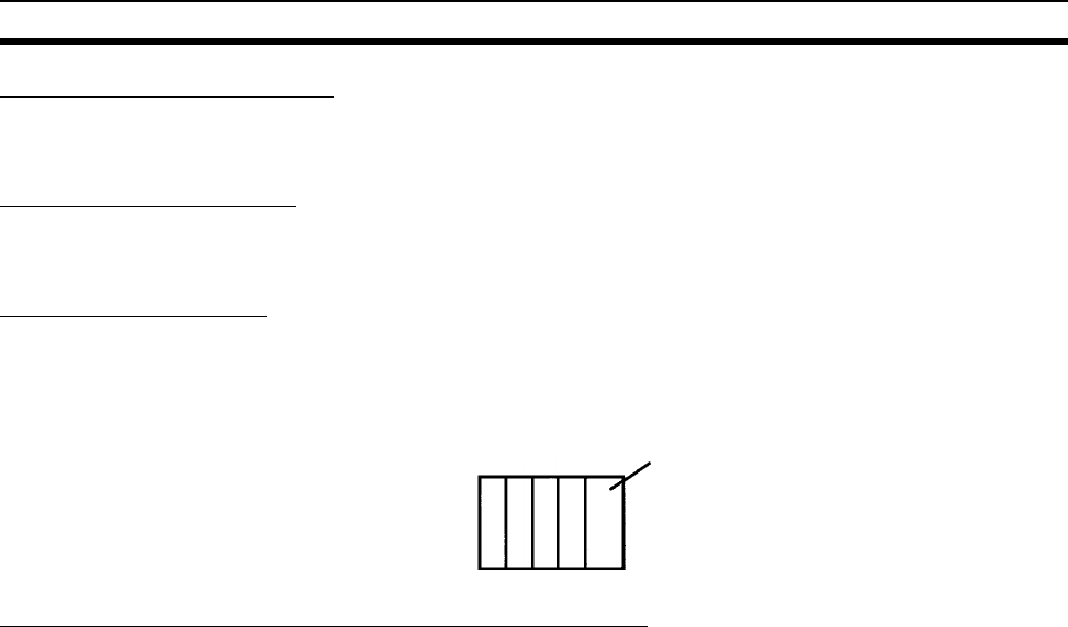
11
CS-series Features Section 1-2
Fixed Cycle Time Function
A fixed (minimum) cycle time can be set to minimize variations in I/O response
times.
I/O Refreshing Methods
I/O refreshing can be performed cyclically and immediately by programming
the immediate-refreshing variation of the instruction.
PLC Setup Functions
PLC operation can be customized with PLC Setup settings, such as the maxi-
mum cycle time setting (watch cycle time) and the instruction error operation
setting, which determines whether instruction processing errors and access
errors are treated as non-fatal or fatal errors.
Binary Refreshing of Timer/Counter Instruction PVs
Present values of timer/counter instructions can now be refreshed in binary, in
addition to the existing BCD capability. (Binary refreshing, however, can be
specified with only CX-Programmer Ver. 3.0 and higher.) This allows the
timer/counter setting time to be expanded to a range of 0 to 65535 (from the
existing 0 to 9,999). Also, results calculated by other instructions can be used
as is for timer/counter set values.
The PLC's initial settings can be
customized with the PLC Setup.
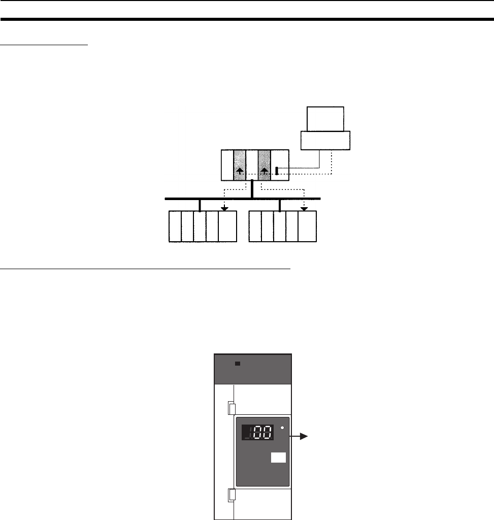
12
CS-series Features Section 1-2
Windows Tools
The single-port multiple-access (SPMA) function can be used to program and
monitor other CPU Bus Units on the same bus (CPU Rack or Expansion
racks) or other CPU Units on the same network from a serial port on the CPU
Unit or a Serial Communications Board.
Power Supply Units with Replacement Notification
The C200HW-PA204C Power Supply Units with Replacement Notification pro-
vide six display levels using a 7-segment display on the front panel of the Unit
to indicate the remaining service life of the Power Supply Unit. An alarm out-
put also notifies when the estimated remaining service life drops to 6 months
or shorter. This function enables Power Supply Unit replacement before the
power supply reaches the end of its service life resulting in a system failure.
Controller Link
Several CPU Bus Units on the same
bus or other CPU Units on the same
network can be accessed from a
single port.
CX-Programmer
POWER
PA204C
POWER
Years
C200HW-PA204C
TEST
C200HW-PA204C Power Supply
Unit with Replacement Notification
Alarm output turns OFF
when remaining service
life is 6 months.

13
CS1-H CPU Unit Features Section 1-3
1-3 CS1-H CPU Unit Features
1-3-1 High-speed Performance
Ultra High-speed Cycle
Time
The CS1-H CPU Units provide a cycle time that is three to four times faster
than that of the previous CPU Units.
For example, a program consisting of 38 Ksteps of only basic instructions with
128 inputs and 128 outputs executes in 1 ms; a program consisting of 20
Ksteps of basic and special instructions in a 1:1 ratio with 128 inputs and 128
outputs executes in 1 ms; and a program consisting of 8 Ksteps of basic and
special instructions in a 1:2 ratio with 64 inputs and 64 outputs executes in 0.5
ms.
The following factors give the CS1-H CPU Units their high speed.
1,2,3... 1. Instruction execution times: Only about 1/2 the time required for basic in-
structions, and only about 1/3 the time required for special instructions.
2. Better bus performance: Data transfers between the CPU Unit and Special
I/O or Communications Units is about twice as fast, providing greater over-
all system performance.
3. Instruction execution is performed in parallel with peripheral servicing.
4. Other factors, including background execution of text string processing and
table data processing instructions.
Faster Execution of
Common Instructions
Extensive research on PLC applications was used to identify the 20 most
commonly used instructions of the more than 400 supported instructions (see
below), and execution speed for these instructions was increased by 10 to 20
times previous performance.
CPS (SIGNED BINARY COMPARE)
JMP (JUMP)
CPSL (DOUBLE SIGNED BINARY COMPARE)
CJP (CONDITIONAL JUMP)
XFER (BLOCK TRANSFER)
BCNT (BIT COUNTER)
MOVB (MOVE BIT)
MLPX (DATA DECODER)
MOVD (MOVE DIGITS)
BCD (BINARY-TO-BCD)
BSET (BLOCK SET)
SBS/RET (SUBROUTINE CALL/RETURN)
Transfer Speed between
CPU Unit and CPU Bus
Units Doubled
The speed of transferring data between the CPU Unit and CPU Bus Units has
been doubled to increase overall system performance.
Parallel Processing of
Instructions and
Peripheral Servicing
A special mode is supported that enables parallel processing of instruction
execution and peripheral device servicing to support the following types of
application.
• Extensive data exchange with a host not restricted by the program capac-
ity in the CS1-H CPU Unit
• Consistently timed data exchange with SCADA software
• Eliminating the effects on cycle time of future system expansion or
increases in communications

14
CS1-H CPU Unit Features Section 1-3
Less Cycle Time
Fluctuation for Data
Processing
Table data processing and text string processing, which often require time,
can be separated over several cycles to minimize fluctuations in the cycle time
and achieve stable I/O response.
Better Data Link and
Remote I/O Refreshing
CPU Bus Unit refresh response has been increased both by reductions in the
cycle time itself and by the addition of an immediate I/O refresh instruction for
CPU Bus Units (DLNK(226)). This instruction will refresh data links,
DeviceNet remote I/O, protocol macros, and other special data for CPU Bus
Units.
The response of a CS1-H CPU Unit is approximately 2.4 times that of a CS1
CPU Unit. And, for a cycle time of approximately 100 ms or higher, the
increase in the data link response is comparable to that for the cycle time.
Immediate Refreshing for
CPU Bus Units
Although previously, I/O refreshing for CPU Bus Units was possible only after
program executions, a CPU BUS I/O REFRESH instruction (DLNK(226)) has
been added to enable immediate I/O refreshing for CPU Bus Units. Data links,
DeviceNet remote I/O, an other unique CPU Bus Unit refreshing can be
refreshed along with words allocated to the CPU Bus Unit in the CIO and DM
Areas whenever DLNK(226) is executed. This is particularly effective for
longer cycle times (e.g., 100 ms or longer). (Data exchange for data links,
DeviceNet remote I/O, and other network communications are also affected
by the communications cycle time, i.e., DLNK(226) refreshes data only
between the CPU Bus Units and the CPU Unit, not the data on the individual
networks.)
1-3-2 High-speed Structured Programming
To further aid standardized programming, program structuring functions have
been improved, as has program execution speed.
More Cyclic Tasks Tasks provide better efficiency by enabling programs to be separated by func-
tion or for development by different engineers. The CS1-H CPU Units support
up to 288 cyclic tasks, an incredible increase over the previous maximum of
32 tasks.
Common Processing from
Multiple Tasks
Global subroutines that can be called by any task are now supported. These
can be used for common processing from more than one task, for greater
standardization.
Faster Subroutine
Instructions
Subroutine instruction are executed approximately 70 times faster to enable
greater program modularization without having to be concerned about
increasing the cycle time.
Shared Index and Data
Registers between Tasks
Although separate index and data registers can still be used in each task, they
have been joined by shared index and data registers that can be used
between tasks to reduce the time required to switch between tasks.
1-3-3 Function Block (FB)
When using a CPU Unit with unit version 3.0 or later, standard processes can
be encapsulated as easily reusable function blocks as long as those pro-
cesses only exchange I/O data externally. The function blocks can be written
in ladder language or ST (structured text) language. Mathematical processing
that is difficult to write in ladder language can be written easily in the ST lan-
guage.
OMRON function blocks can be written in ladder language or ST (structured
text) language, and conform to IEC 61131-3 standards (JIS B3503). The func-
tion blocks provide functions for more efficient design and debugging of the
user equipment, as well as easier maintenance.

15
CS1-H CPU Unit Features Section 1-3
Smart FB Library The Smart FB Library is a set of function blocks that improve interoperability
between OMRON PLC Units and FA components. Since it isn't necessary to
create a ladder program to use basic Unit and FA component functions, the
user can concentrate on more important work, such as determining how to
make the most of device functions.
Online Editing of FB
Definitions
FB definitions can be changed during operation, so FB definitions can be
edited quickly during debugging. In addition, FBs can be used with confidence
even in equipment that must operate 24 hours/day. (Requires CPU Unit unit
version 4.0 or later and CX-Programmer version 7.0 or higher.)
Nesting Not only can programs be created with nested OMRON FBs, it is possible to
make easy-to-understand, stress-free operations by switching displays under
preset conditions and displaying structures in a directory-tree format.
(Requires CX-Programmer version 6.0 or higher.)
Protecting FB Definitions It is possible to prevent unauthorized manipulation, editing, or misappropria-
tion of the program by setting passwords for the function block definitions allo-
cated in the project file and protecting the definitions based on their purpose.
(Requires CX-Programmer version 6.1 or higher.)
Offline Debugging with
the Simulator
The Simulator enables checking the PLC program's operation on the desktop,
so program quality can be improved and verified early on. Both the ladder and
ST programming can be executed in the computer application.
Variable Support for
String Operations (CPU
Units with Unit Version 4.0
or Later)
The functions that perform string data operations in ST language not only
support string variables, they also strengthen the functions used to communi-
cate with string data I/O. This feature simplifies the creation of programs that
send and receive communications commands. (Requires CPU Unit unit ver-
sion 4.0 or later and CX-Programmer version 7.0 or higher.)
FB Generation Function Existing PLC programming can be reused by easily converting it to FBs.
(Requires CX-Programmer version 7.0 or higher.)
1-3-4 More Instructions for Specific Applications
Very specific control can be easily programmed for a much wider range of
applications with the many new special instructions added to the CS1-H CPU
Units.
High-speed Positioning
for XY Tables
Double-precision floating-point calculations are supported for the CS1-H CPU
Units to provide even better precision for position control operations.
Convert between Floating
Point and Text String Data
To display floating-point data on PTs, the CS1-H CPU Units provide conver-
sion instructions from floating-point data to text strings (ASCII). Conversion
between ASCII and floating-point data is also possible so that ASCII data from
serial communications with measurement devices can be used in calcula-
tions.
Accurate Line
Approximations
Unsigned 16-bit binary/BCD data, signed 16/32-bit binary data, or single-pre-
cision floating-point data can be used for line data, enabling precise (high data
resolution) conversions, such as from a level meter (mm) to tank capacity (l)
based on the shape of the tank.
Realtime Workpiece Data
Management
When loading and unloading workpieces from conveyor lines, stack instruc-
tions can be used to manage workpiece information in realtime in table for-
mat.

16
CS1-H CPU Unit Features Section 1-3
PID Autotuning Autotuning is now supported for PID constants with the PID CONTROL
instruction. The limit cycle method is used to ensure rapid autotuning. Very
effective for multiloop PID control.
System Debugging
through Error Simulation
A specified error status can be created with the FAL/FALS instructions. This
can be used effectively when depending systems. For example, errors can be
simulated to produce corresponding displays on a PT to confirm that the cor-
rect messages are being displayed.
Program Simplification
with More Specific Basic
Instructions
Programs that use a high quantity of basic instructions can be simplified
though the use of differentiated forms of the LD NOT, AND NOT and OR NOT
instructions, and through the use of OUT, SET, and RSET instructions that
can manipulate individual bits in the DM or EM Area.
Delayed Power OFF
Processing for Specified
Program Areas
The DI and EI instructions can be used to disable interrupts during specific
portions of the program, for example, to prevent the power OFF interrupt from
being executed until a specific instruction has been executed.
1-3-5 Battery-free Operation with Flash Memory
Any user program or parameter area data transferred to the CPU Unit is auto-
matically backed up in flash memory in the CPU Unit to enable battery-free
operation without using a Memory Card.
Note Refer to information on flash memory in the CS/CJ Series Programming Man-
ual (W394) for precautions on this function.
1-3-6 Better Compatibility with Other SYSMAC PLCs
C200HE/HG/HX PLCs The AREA RANGE COMPARE (ZCP) and DOUBLE AREA RANGE COM-
PARE (ZCPl) instructions from the C200HE/HG/HX PLCs are supported. This
makes it easier to use C200HE/HG/HX programs in CS-series CPU Units.
CVM1/CV-series PLCs The CONVERT ADDRESS FROM CV instruction allows real I/O memory
addresses for the CVM1/CV-series PLCs to be converted to addresses for the
CS-series PLCs, enabling programs with CVM1/CV-series addresses to be
quickly converted for use with a CS-series CPU Unit.
1-3-7 Refreshing Timer/Counter PVs in Binary
In addition to BCD, binary can also be set as the PV refresh method for
timer/counter instructions. (This setting is possible, however, only with version
3.0 or higher versions of the CX-Programmer.) This means that the settable
time range for timer/counter instructions is increased from 0 to 9999 to 0 to
65,535. It also means that the results of calculations made with other instruc-
tions can be used without conversion.
1-3-8 Features of CS1-H CPU Units Ver. 3.0
Encapsulate Programming into Function Blocks Using Ladder Programming or Structured Text
When using CX-Programmer Ver. 5.0 or higher, function blocks can be used
to encapsulate standard processing that is often reused and for which only I/O
data is output externally as the user interface. Function blocks can be written
using ladder programming or structured text. Structured text is particularly
effective for easily including arithmetic processing that is difficult to write in
ladder programming.

17
CS1-H CPU Unit Features Section 1-3
Incorporate CompoWay/F-compatible OMRON Components into FINS Network Via Serial Gateway
Using the Serial Gateway mode for the CPU Unit’s serial port enables flexible
access to CompoWay/F-compatible OMRON components from devices on
the network (e.g., PTs, PLC CPU Units, personal computers)
Store Comment/Section Data in CPU Unit’s Flash Memory
The CX-Programmer can be used to save I/O comments and other com-
ment/section data in the comment memory contained in the CPU Unit’s flash
memory.
Back Up Comment and Section Data
Comment/section data in comment memory can be backed up using the sim-
ple backup function.
Use No-protocol Communications at Multiple Ports
No-protocol communications can be performed via the serial ports of Serial
Communications Boards/Units with unit version 1.2 or later. This enables no-
protocol communications at multiple ports.
Free Running Timer Calculates Intervals without Requiring Timer Instructions
The system timers used after the power is turned ON are contained in Auxil-
iary Area words A000 and A001.
A000 is set to 0000 hex when the power is turned ON and this value is auto-
matically incremented by 1 every 10 ms. The value returns to 0000 hex after
reaching FFFF hex (655,350 ms), and then continues to be incremented in a
ring operation.
A001 is set to 0000 hex when the power is turned ON and automatically incre-
mented by 1 every 100 ms. The value returns to 0000 hex after reaching
FFFF hex (655,350 ms), and then continues to be incremented in a ring oper-
ation.
Example:The interval can be counted between processing A and processing
B without requiring timer instructions. This is achieved by calculating
the difference between the value in A000 for processing A and the
value in A000 for processing B. The interval is counted in 10 ms
units. With unit version 4.0 or later, the free running time is stored in
A002 in 1-s increments.
Reuse Ladder Programs Created Using C-series CPU Units
C-series ladder programs can be easily reused through the newly supported
model conversion instructions (XFERC(565), DISTC(566), COLLC(567),
MOVBC(568), and BCNTC(621)).
1-3-9 Changes to CS-series Operating Specifications
Increased Points for SYSMAC BUS Remote I/O Communications
The maximum number of points for SYSMAC BUS remote I/O communica-
tions in the operating specifications has been expanded from 800 points (50
words) to 1,280 points (80 words). This change applies to all CS-series CPU
Units and Units using SYSMAC BUS remote I/O communications, including
previously manufactured Units. For details, refer to 1-5-7 Increased Points for
SYSMAC BUS Remote I/O Communications.

18
CS1-H CPU Unit Features Section 1-3
1-3-10 Features of CS1-H CPU Units Ver. 2.0
Easier System Development by Teams
Download/Upload Tasks Individually with CX-Programmer Version 4.0 or Higher
The CX-Programmer (version 4.0 or higher) can be used to upload or down-
load only the required tasks. This enables the member of a development team
to work separately and then upload/download tasks after debugging them,
helping to eliminate the need for unification work by a manager as well as mis-
takes that can easily occur in such work.
Many Protection Functions
Improved Read Protection Using Passwords with CX-Programmer Version 4.0 or Higher
■Read Protection for Specific Tasks
Passwords can be set to read-protect individual groups of tasks. This enables
creating black boxes in the program.
■Enabling/Disabling Creating File Memory Program Files
When read protection is set, an optional setting allows you to enable or dis-
able creating program backup files (.OBJ). This setting can be used to prevent
programs from being disclosed.
■Program Write Protection
The user program can be protected without using the DIP switch setting. This
helps prohibit unauthorized or accidental program changes.
Protection for CPU Units from FINS Write Commands Sent via Networks
Write operations to a CPU Unit using FINS commands across networks can
be enabled for specific nodes and disabled for all other nodes. This can be
used to enable monitoring data via networks while eliminating the possibility
of accidental mistakes caused by careless writing operations.
Easier Network Connections and More-advanced Seamless Network Communications
Online Connections via Networks without I/O Tables
By using the CS1W-ETN21 Ethernet Unit, online connection is possible to any
PLC in the local network from a Programming Device, such as the CX-Pro-
grammer, as soon as the network is connected by using automatic I/O alloca-
tion at startup. It’s not necessary to create the I/O tables to enable connection.
This eliminates the need to use a serial connection to create I/O tables before
the CX-Programmer can be connected via Ethernet. Only an Ethernet con-
nection is required to go online and create I/O tables.
Work Across Up to Eight Networks with CX-Net in CX-Programmer Version 4.0 or Higher
FINS commands can be sent across up to 8 network levels (including the local
network). This enables a wider range of communications between devices on
Ethernet and Controller Link Networks.
FINS commands can only be sent across up to 8 network levels when the
destination is a CPU Unit. FINS commands can be sent to other destinations
up to 3 network levels away.
Online Connections to PLCs via NS-series PTs
Downloading, uploading, and monitoring of ladder programs or other data is
possible to a PLC connected serially to an NS-series PT from the CX-Pro-
grammer connected to the NS-series PT by Ethernet.

19
CS1-H CPU Unit Features Section 1-3
Easier Implementation of Explicit Messages with Explicit Message Instructions
Special Explicit Message Instructions are now supported to simplify using
explicit messages. (Previously, CMND(490) had to be used to send a FINS
command of 2801 hex to enable sending explicit messages.) The new instruc-
tions include the following: EXPLICIT MESSAGE SEND (EXPLT(720)),
EXPLICIT GET ATTRIBUTE (EGATR(721)), EXPLICIT SET ATTRIBUTE
(ESATR(722)), EXPLICIT WORD READ (ECHRD(723)), and EXPLICIT
WORD WRITE (ECHWR(724)). Of these, EXPLICIT WORD READ
(ECHRD(723)) and EXPLICIT WORD WRITE (ECHWR(724)) enable easily
reading and writing data in CPU Units on networks with the same type of
notation as used for SEND(290) and RECV(298). (Not supported by the
C200HX(-Z)/HG(-Z)/HE(-Z) and CV-series PLCs.)
Greater Flexibility in I/O Allocations
First Word Address Settings for Slots (Using CX-Programmer Version 3.1 or Higher)
When editing I/O tables for CS1-H CPU Units, the first word address can be
set for up to 64 slots. This can be used, for example, to create fixed starting
addresses for Input Units and Output Unit to separate I/O allocations from the
program and increase the efficiency of program maintenance.
Automatic Power-ON Transfers without a Parameter File (.STD)
The user program can be automatically transferred to the CPU Unit at power
ON without a parameter file (.STD) if the name of the program file (.OBJ) is
changed to REPLACE on the CX-Programmer and the file is stored on a
Memory Card. This can be used, for example, to enable transferring a pro-
gram to a CPU Unit by creating the program offline and sending it as an email
attachment, without a local Programming Device.
More Application Instruction with CX-Programmer Version 4.0 or Higher
Multiple Interlock Instructions (MILH(517), MILR(518), and MILC(519)) for Nested Interlocks
These instruction enable easy creation of nested interlocks. For example, cre-
ate one interlock to control the entire program (e.g., for an emergency stop)
and then nest other interlocks for separate portions of the program (e.g., con-
veyor operation, alarms, etc.).
TIME-PROPORTIONAL OUTPUT (TPO(685)) Instruction for Time-proportional Operation with
Temperature Controllers or Variable-duty Lighting/Power Control
This instruction is used in combination with PID instructions to create a time-
proportional output based on the manipulated variable output by the PID
instruction. This enables easily connecting an SSR to a Transistor Output Unit
to achieve time-proportional operation of a Temperature Controller. Variable-
duty pulse outputs can also be created for lighting or power control.
Symbol Time Comparison Instructions for Easy Calendar Timers
Two times/dates can be compared to continue operation to the next instruction
in the ladder program rung when the results of comparison is true. Opposed
to normal comparison instructions, comparisons are by byte and the bytes
that are compared in the time/date data can be controlled. This enables com-
paring built-in clock data with set times/dates to easily create a calendar timer,
for example, on the hour (when the minutes is 0) or on a specific date each
year).

20
CS1-H CPU Unit Features Section 1-3
GRAY CODE CONVERSION (GRY(474)) for Easy Conversion of Parallel Inputs from Absolute Encoders
to Binary, BCD, or Angle Data
This instruction converts Gray binary codes to binary, BCD, or angle data.
This enables easily handling position or angle data input as parallel signals
(2n) from an Absolute Encoder with a Gray code output using a DC Input Unit.
EXPANDED BLOCK COMPARE (BCMP2(502)) for Comparison Judgements for Up to 256 Ranges
(Upper/Lower Limits) with One Instruction
This instruction determines if a value is within any of up to 256 ranges defined
by upper and lower limits. When used with the GRAY CODE CONVERSION
(GRY(474)) instruction, the same operation as a cam switch can be achieved
by determining if an angle input from an Absolute Encoder is in a comparison
table.
Easier Processing of I/O Devices with Special I/O Instructions
Previously many instructions were required to read or write data for external
input devices such as digital switches and 7-segment displays connected to
Basic I/O Units. Now, I/O processing for these devices can be achieved with a
single instruction. These are sometimes call Combination Instructions.
These instructions are the same as those supported by the C200HX/HG/HE
and CQM1H PLCs, with the exception that more than one of each of these
instructions can be executed in a single user program.
TEN KEY INPUT (TKY(211))
Sequentially reads numbers input from a ten-key connected to an Input Unit.
HEXADECIMAL KEY INPUT (HKY(212))
Sequentially reads numbers input from a hexadecimal keypad connected to
an Input Unit and an Output Unit for a maximum of 8 digits.
DIGITAL SWITCH INPUT (DSW(213))
Reads numbers input from a digital switch or thumbwheel switch connected to
an Input Unit and an Output Unit. Either 4 or 8 digits are read.
MATRIX INPUT (MTR(210))
Sequentially reads 64 input points input from a 8 × 8 matrix connected to an
Input Unit and an Output Unit.
7-SEGMENT DISPLAY OUTPUT (7SEG(214))
Converts 4-digit or 8-digit values to data for a 7-segment display and outputs
the result.
Read/Write CPU Bus Unit Memory Areas with IORD(222)/IOWR(223)
Although INTELLIGENT I/O READ (IORD(222)) and INTELLIGENT I/O
WRITE (IOWR(223)) could previously be used only for Special I/O Units,
these instructions can now be used to read and write data for CPU Bus Units.
Operation Start/End Times
The times that operation is started and ended are automatically stored in
memory in the Auxiliary Area (A515 to A517). This enables easier manage-
ment of the operating times of the PLC System.
21
CS1-H CPU Unit Features Section 1-3
Power Supply Units with Replacement Notification
The C200HW-PA204C Power Supply Units with Replacement Notification pro-
vide six display levels using a 7-segment display on the front panel of the Unit
to indicate the remaining service life of the Power Supply Unit. An alarm out-
put also notifies when the estimated remaining service life drops to 6 months
or shorter. This function enables Power Supply Unit replacement before the
power supply reaches the end of its service life resulting in a system failure.
POWER
PA204C
POWER
Years
C200HW-PA204C
TEST
C200HW-PA204C Power Supply
Unit with Replacement Notification
Alarm output turns OFF
when remaining service
life is 6 months.
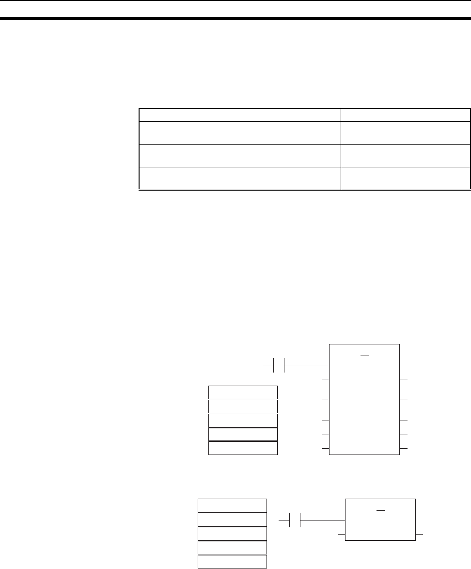
22
CS1-H CPU Unit Ver. 4.0 Upgrades Section 1-4
1-4 CS1-H CPU Unit Ver. 4.0 Upgrades
This section summarizes the upgrades made for CS1-H CPU Units with unit
version 4.0. CX-Programmer version 7.0 or higher must be used to enable
using the following functions.
Functional Upgrades for Unit Version 4.0
1-4-1 Online Editing of Function Blocks
Unit Version 3.0 or Earlier Function block definitions could not be changed during operation.
Unit Version 4.0 or Later Function block definitions can be changed during operation. This allows func-
tion block definitions to be quickly corrected during debugging. It also allows
function blocks to be used more easily in systems that operate 24 hours a day.
1-4-2 Input-Output Variables in Function Blocks
Unit Version 3.0 or Earlier The data size of parameters that could be passed to and from function blocks
was limited to four words maximum. It was thus necessary to separate ele-
ments with large data sizes, such as data tables.
Unit Version 4.0 or Later Input-output variables can be used to passed large quantities of data, such as
table data.
1-4-3 Text String Support in Function Blocks
Unit Version 3.0 or Earlier To program text string processing for communications commands and display
data in ladder diagrams, it was necessary to know the ladder string instruc-
tions and ASCII codes. Also, several instructions had to be combined to con-
verted from numbers to text strings or text strings to numbers.
Function Section
Online Editing of Function Blocks 1-4-1 Online Editing of Function
Blocks
Input-Output Variables in Function Blocks 1-4-2 Input-Output Variables in
Function Blocks
Text String Support in Function Blocks 1-4-3 Text String Support in
Function Blocks
Pattern A
Pattern B
Pattern C
Pattern D
Pattern E
D100
D101
D102
D103
D104
D100
D101
D102
D103
D104
FB
(INT) (INT)
Para1i Para1o
(INT) (INT)
Para2i Para2o
(INT) (INT)
Para3i Para3o
(INT) (INT)
Para4i Para4o
(INT) (INT)
Para5i Para5o
D100
D101
D102
D103
D104
Pattern A
Pattern B
Pattern C
Pattern D
Pattern E
D100
D101
D102
D103
D104
D100
FB
(INT)[]
Para1 --- Para1 D10
0
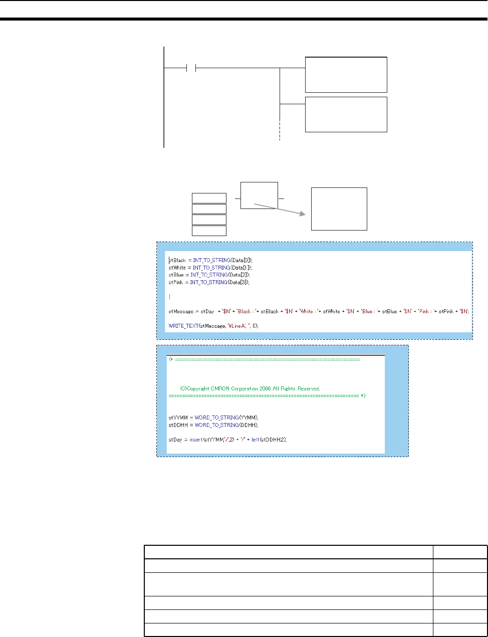
23
CS1-H CPU Unit Ver. 3.0 Upgrades Section 1-5
Unit Version 4.0 or Later Text strings can be used in ST programming to easily create text string pro-
cessing programs.
1-5 CS1-H CPU Unit Ver. 3.0 Upgrades
The following table shows the functional upgrades for CS1-H CPU Unit
Ver. 3.0.
Functional Upgrades for CS1-H CPU Unit Ver. 3.0
MOV
#426C
stBlack[0]
MOV
#6163
stBlack[1]
" Bl" is #426C in ASCII.
" ac" is #6163 in ASCII.
06/05/28
Black: 9
White: 18
Blue: 7
Pink: 30
Black
White
Blue
Pink
9
18
7
30
Production
log file
created.
File name
LineA.txt
FB to Create Date Text
FB to Create Production Log File
(* Convert black quantity to string *)
(* Convert white quantity to string *)
(* Convert blue quantity to string *)
(* Convert pink quantity to string *)
(* Get date text *)
(* Create production log LineA.txt *)
GetDate(stDay)
Name: Generate Date Text
Function: To create text data for yy/mm/dd
(* Create yymm text *)
(* Create ddhh text *)
(* Insert / between yy and mm; extract only dd and combine *)
Function Section
Function blocks (when using CX-Programmer Ver. 5.0 or higher) 1-5-1
Serial Gateway (converting FINS commands to CompoWay/F com-
mands at the built-in serial port)
1-5-2
Comment memory (in internal flash memory) 1-5-3
Expanded simple backup data 1-5-4
Free running timer (system timer after power is turned ON) 1-5-5

24
CS1-H CPU Unit Ver. 3.0 Upgrades Section 1-5
Changes to Operating Specifications
1-5-1 Function Blocks (FB)
Pre-Ver. 2.0 Earlier Units did not support function blocks (FB).
Unit Ver. 3.0 or Later Function blocks (FB) conforming to IEC 61131-3 are supported. Use of func-
tion blocks is determined by the user.
Note IEC 61131-3 is an international standard for programmable logic
controllers (PLC) established by the International Electro-technical
Commission (IEC). This standard is divided into seven parts, of
which Part 3 Programming Languages (IEC 61131-3) provides reg-
ulations for programming PLCs.
Function blocks can be created with CX-Programmer Ver. 5.0 or higher by the
user and pasted into normal programs. The standard function blocks provided
by OMRON in the OMRON FB Library can also be pasted into normal pro-
grams. Function blocks enable standard processing to be simply inserted into
a program as a single unit. Function blocks provide the following features.
• Function block algorithms can be written using ladder programming or
structured text (see note).
Note Structured text is a high level textual language designed for industrial
control (primarily PLCs) stipulated in IEC 61131-3. The structured
text supported by CX-Programmer Ver. 5.0 conforms to IEC 61131-1.
• A single function block that has been created can be stored in a library for
easy reuse of standard processing.
• Programs that contain function blocks (ladder programming or structured
text), can also be uploaded or downloaded in the same way as normal
programs that do not contain function blocks. Tasks that include function
blocks, however, cannot be downloaded in task units (although they can
be uploaded).
• Array (one-dimensional) variables are supported, making it easier to han-
dle data specific to an application.
New instructions
added
TXDU(256) and RXDU(255) instructions (sup-
port no-protocol communications with Serial
Communications Units with unit version 1.2 or
later)
1-5-6
Model conversion instructions: XFERC(565),
DISTC(566), COLLC(567), MOVBC(568), and
BCNTC(621)
Special function block instruction: GETID(286)
Additional instruc-
tion functions
TXD(236) and RXD(235) instructions (support
no-protocol communications with Serial Com-
munications Boards with unit version 1.2 or
later)
Function Section
Maximum number of points expanded for SYSMAC BUS remote I/O
communications
1-5-7
Function Section
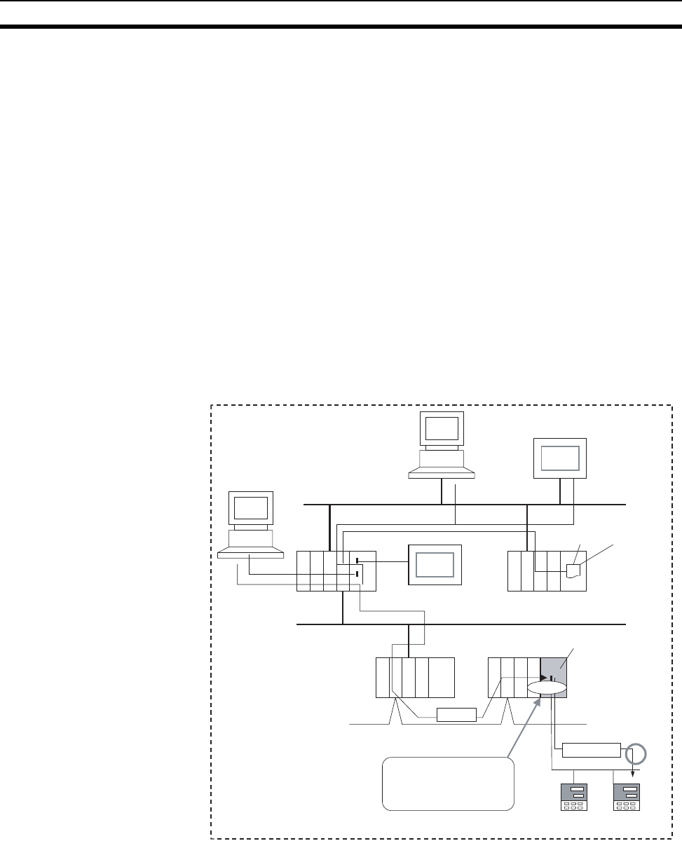
25
CS1-H CPU Unit Ver. 3.0 Upgrades Section 1-5
1-5-2 Serial Gateway (Converting FINS to CompoWay/F Via Serial Port)
Pre-Ver. 2.0 Temperature Controllers, Digital Panel Meters, and other CompoWay/F-com-
patible OMRON Components previously could be accessed by sending user-
specified CompoWay/F commands from the PLC. This required, however, the
use of a Serial Communications Board/Unit protocol macro, execution of the
PMCR(260) instruction in the ladder program of the CPU Unit on the same
PLC, and implementation of the standard system protocol (CompoWay/F
Master). The use of protocol macros prevented access across networks.
Note Specific data could be shared without communications instructions if
user-specified CompoWay/F commands were not required, however,
by using the CJ1W-CIF21 Basic Communications Unit.
Unit Ver. 3.0 or Later FINS commands (CompoWay/F commands encapsulated in FINS frames)
received by the CPU Unit at the built-in serial port (RS-232C port or peripheral
port) are converted automatically into CompoWay/F command frames and
transmitted on the serial line. This enables access to CompoWay/F-compati-
ble OMRON components that are connected to the CPU Unit’s built-in serial
port via either an NS-series Programmable Terminal (PT) or by using the
CMND(490) instruction.
FINS
CompoWay/F
FINS System
Network
Serial
Serial
Network
CMND(490)
Network
Serial
CS/CJ-series CPU Unit with
unit version 3.0 or later
Protocol
conversion
CompoWay/F-compatible
components can be ac-
cessed via the network from
personal computers, PTs,
or PLCs.
CompoWay/F-compatible
components
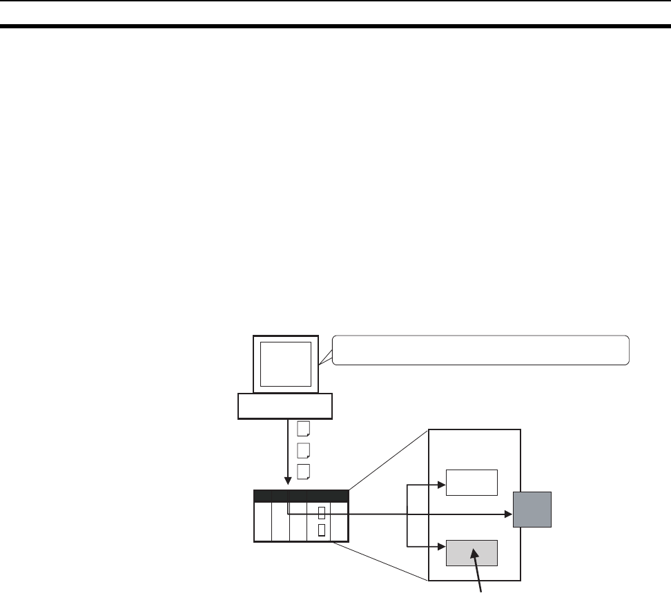
26
CS1-H CPU Unit Ver. 3.0 Upgrades Section 1-5
1-5-3 Comment Memory (in Internal Flash Memory)
Pre-Ver. 2.0 Comment data and section data could not be stored in the actual PLC when a
project was downloaded from the CX-Programmer to the CPU Unit unless
both a Memory Card and EM file memory were available.
Unit Ver. 3.0 or Later A comment memory is provided within the CPU Unit’s internal flash memory.
Therefore, the following comment/section data can be stored in and read from
comment memory even if neither Memory Card nor EM file memory are avail-
able.
• Symbol table files (including CX-Programmer symbol names and I/O
comments)
• Comment files (CX-Programmer rung comments and other comments)
• Program index files (CX-Programmer section names, section comments,
and program comments)
When downloading projects using the CX-Programmer Ver. 5.0, either of the
following storage locations can be selected as the transfer destination for
comment data and section data.
•Memory Card
• EM file memory
• Comment memory (in CPU Unit’s internal flash memory)
Note When using CX-Programmer Ver. 4.0 or earlier, this data is stored in either the
Memory Card or EM file memory, whichever is available. If neither the Mem-
ory Card nor EM file memory is available, the comment/section data cannot
be stored in comment memory.
1-5-4 Simple Backup Data Expanded
Pre-Ver. 2.0 The simple backup function could not be used to back up comment data or
section data.
Unit Ver. 3.0 or Later The following files stored in comment memory can be backed up to a Memory
Card when a simple backup operation is executed, or the files can be restored
to comment memory from the Memory Card.
• Symbol table files (including CX-Programmer symbol names and I/O
comments)
CX-Programmer Ver. 5.0 or later
Project
Transfer Symbol table file
Comment file
Program index file
CPU Unit
Memory Card
EM file memory
Comment/section data can be stored in this area.
Comment/section data can be stored in the actual PLC
when downloading projects.
Comment
memory
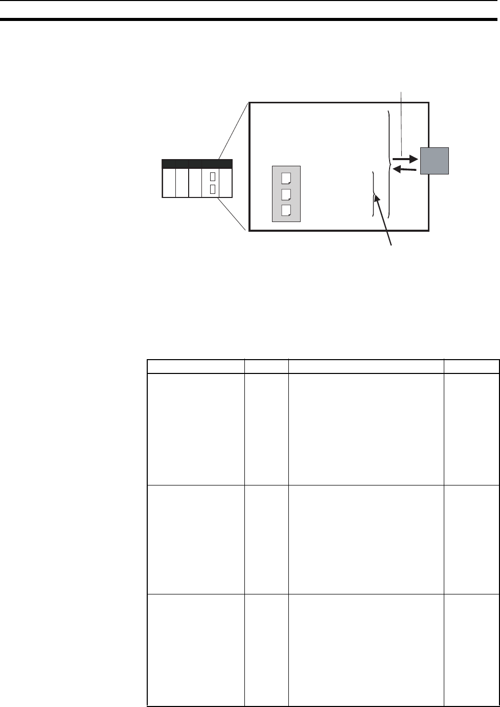
27
CS1-H CPU Unit Ver. 3.0 Upgrades Section 1-5
• Comment files (CX-Programmer rung comments and other comments)
• Program index files (CX-Programmer section names, section comments,
and program comments)
This enables backup/restoration of all data in the CPU Unit including I/O com-
ments if an error occurs or when adding a CPU Unit with the same specifica-
tions without requiring a Programming Device.
1-5-5 Free Running Timer
he system timers used after the power is turned ON are contained in the fol-
lowing Auxiliary Area words.
CPU Unit
Simple backup executing
Memory Card
CS/CJ Series
• User program
• Parameters
• I/O memory
Symbol table file
(In comment memory)
Comment file
Program index file
These files can also be backed up using simple backup.
Name Address Function Access
10-ms Incrementing
Free Running Timer
A000 This word contains the system timer
used after the power is turned ON.
0000 hex is set when the power is
turned ON and this value is automat-
ically incremented by 1 every 10 ms.
The value returns to 0000 hex after
reaching FFFF hex (655,350 ms),
and then continues to be automati-
cally incremented by 1 every 10 ms.
(Unit version 3.0 or later)
Read-only
100-ms Incrementing
Free Running Timer
A001 This word contains the system timer
used after the power is turned ON.
0000 hex is set when the power is
turned ON and this value is automat-
ically incremented by 1 every 100
ms. The value returns to 0000 hex
after reaching FFFF hex (6,553,500
ms), and then continues to be auto-
matically incremented by 1 every
100 ms.(Unit version 3.0 or later)
Read-only
1-s Incrementing Free
Running Timer
A002 This word contains the system timer
used after the power is turned ON.
0000 hex is set when the power is
turned ON and this value is automat-
ically incremented by 1 every sec-
ond. The value returns to 0000 hex
after reaching FFFF hex (65,535 s),
and then continues to be automati-
cally incremented by 1 every second.
(Unit version 4.0 or later)
Read-only

28
CS1-H CPU Unit Ver. 3.0 Upgrades Section 1-5
Note The timer will continue to be incremented when the operating mode is
switched to RUN mode.
Example: The interval can be counted between processing A and processing
B without requiring timer instructions. This is achieved by calculat-
ing the difference between the value in A000 for processing A and
the value in A000 for processing B. The interval is counted in 10 ms
units.
CPU Units with unit version 4.0 and later also have a 1-s timer in
A002, which is incremented by 1 every 1 s.
1-5-6 New Special Instructions and Functions
The following new instructions and instruction functions have been added. For
details, refer to the CS/CJ Series Instructions Reference Manual (W474).
These new instructions are supported by the CX-Programmer Ver. 5.0 or
higher only.
• Serial Communications Instructions:
Supporting no-protocol communications with Serial Communications
Units with unit version 1.2 or later:
TXDU(256): TRANSMIT VIA SERIAL COMMUNICATIONS UNIT
RXDU(255): RECEIVE VIA SERIAL COMMUNICATIONS UNIT
Supporting no-protocol communications with Serial Communications
Boards with unit version 1.2 or later:
TXD(236): TRANSMIT
RXD(235): RECEIVE
• Model Conversion Instructions:
When using CX-Programmer Ver. 5.0 or higher to convert a C-series lad-
der program for use in a CS/CJ-series CPU Unit, the C-series
XFER(070), DIST(080), COLL(081), MOVB(082), and BCNT(067)
instructions will be automatically converted to the following instructions.
The operands do not require editing.
XFERC(565) BLOCK TRANSFER
DISTC(566) SINGLE WORD DISTRIBUTE
COLLC(567) DATA COLLECT
MOVBC(568) MOVE BIT
BCNTC(621) BIT COUNTER
1-5-7 Increased Points for SYSMAC BUS Remote I/O Communications
Earlier Specifications The maximum number of SYSMAC BUS remote I/O points per CPU Unit was
800 points (50 words), which were allocated in the SYSMAC BUS Area
(CIO 3000 to CIO 3049).
Updated Specifications The maximum number of SYSMAC BUS remote I/O points per CPU Unit has
been increased to 1,280 points (80 words), which are allocated in the SYS-
MAC BUS Area (CIO 3000 to CIO 3079).
This expansion in the number of points is not related to any upgrade of the
Units (CPU Units or SYSMAC BUS Remote I/O Communications Units).
Therefore, the increase in maximum number of points applies to all CS-series
CPU Units, including those that have already been shipped.
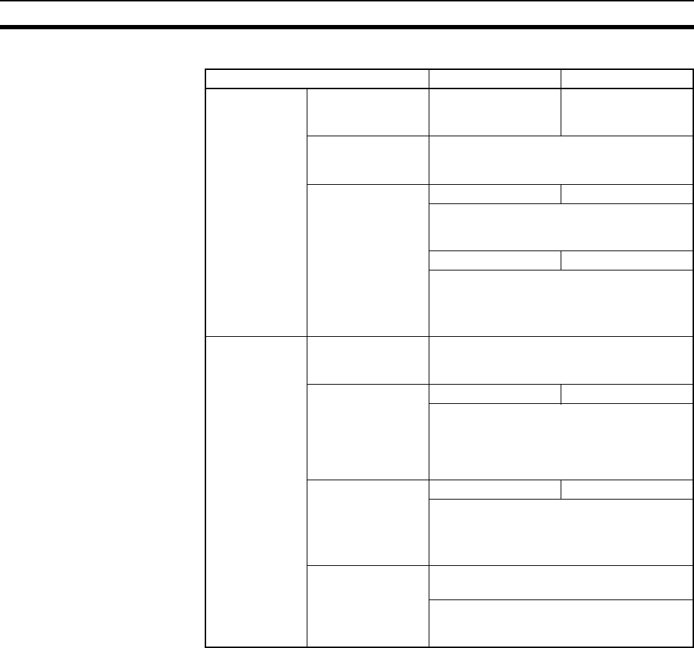
29
CS1-H CPU Unit Ver. 3.0 Upgrades Section 1-5
Refer to the following table for details.
Item Before Now
Maximum num-
ber of points per
CPU Unit (total
optical/wired
points)
SYSMAC Bus
remote I/O relay
area
800 points
(50 words)
1,280 points
(80 words)
Number of Remote
I/O Master Units
(RM)
2 Units
Number of C500
Remote I/O Slave
Units (RT) (i.e.,
Slave Racks))
2 Units 4 Units
C500 Remote I/O Slave Unit (RT) allocated
words for 2 unit numbers
Up to 20 words in total per Slave Rack.
5 Units 8 Units
Slave Rack: Any location, fixed word alloca-
tions
C200H Special I/O Unit can be connected.
Up to 10 words in total per Slave Rack.
Maximum
points per
Remote I/O
Master Unit
(RM) (Total opti-
cal/wired points)
SYSMAC BUS
Remote I/O Relay
Points
512 points (32 words)
Maximum number
of C500 Remote I/O
Slave Units (i.e.,
Slave Racks)
2 Units 4 Units
C500 Remote I/O Slave Unit (RT) allocated
words for 2 unit numbers
Up to 20 words in total per Slave Rack.
Remote I/O Slave Unit’s (RT) unit number
cannot be used more than once.
Maximum number
of C200H Remote
I/O Slave Units (RT)
(i.e., Slave Racks)
5 Units 8 Units
Slave Rack: Any location, fixed word alloca-
tions
C200H Special I/O Unit can be connected.
Up to 10 words in total per Slave Rack.
Maximum number
of Remote I/O
Slaves (Slave Units,
I/O Link Units,
Remote I/O Units)
Optical: 64 Units (Repeater required if num-
ber exceeds 32).
Wired: Remote Interfaces, Remote Termi-
nals: 32 Units total
Remote Units: 16 Units.
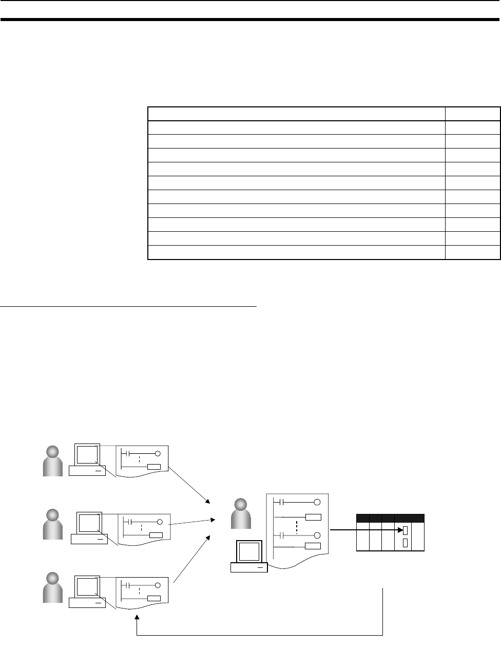
30
CS1-H CPU Unit Ver. 2.0 Upgrades Section 1-6
1-6 CS1-H CPU Unit Ver. 2.0 Upgrades
The following table shows the functional upgrades for CS1-H CPU Unit
Ver. 2.0.
Functional Upgrades for CS1-H CPU Unit Ver. 2.0
1-6-1 Downloading and Uploading Individual Tasks
Previous CPU Units (Pre-Ver. 2.0 CPU Units)
With the pre-Ver. 2.0 CPU Units, individual program tasks could not be down-
loaded from the CX-Programmer. It was only possible to download the entire
user program.
For example, if several programmers were developing the program, the
project manager had to unify each program after debugging and then down-
load the entire user program. Furthermore, the entire user program had to be
downloaded even if just a few changes were made.
Note It was possible to upload individual program tasks with CS/CJ-series PLCs.
Function Reference
Downloading and Uploading Individual Tasks 1-6-1
Improved Read Protection Using Passwords 1-6-2
Write Protection from FINS Commands Sent to CPU Units via Networks 1-6-3
Online Network Connections without I/O Tables 1-6-4
Communications through a Maximum of 8 Network Levels 1-6-5
Connecting Online to PLCs via NS-series PTs 1-6-6
Setting First Slot Words 1-6-7
Automatic Transfers at Power ON without a Parameter File 1-6-8
Operation Start/End Times 1-6-9
New Application Instructions 1-6-10
CX-Programmer
CX-Programmer
CX-Programmer
Developer A
Developer C
Developer B
Manager
Unification
Entire user program
Download
CS/CJ Series
Individual tasks can be uploaded.
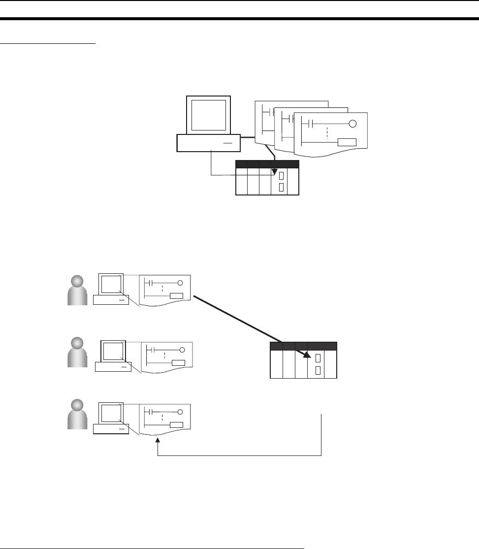
31
CS1-H CPU Unit Ver. 2.0 Upgrades Section 1-6
CPU Unit Ver. 2.0
Overview With CPU Unit Ver. 2.0 or later CPU Units, individual program tasks can be
uploaded and downloaded from the CX-Programmer.
Usage When several programmers are developing a program, it isn't necessary for a
project manager to unify the data because just the debugged tasks can be
downloaded/uploaded. Also, transferring individual tasks can help avoid mis-
takes.
Restrictions to Function
Block Use
Individual tasks cannot be downloaded for programs containing function
blocks (unit version 3.0 or later only) (uploading is possible).
1-6-2 Improved Read Protection Using Passwords
Read Protection for Individual Tasks Using Passwords
Previous CPU Units (Pre-
Ver. 2.0 CPU Units)
With the pre-Ver. 2.0 CS/CJ-series CPU Units, it was possible to read-protect
the entire PLC with a password (referred to as “UM read protection” below),
but it was not possible to protect individual tasks.
UM read protection prevented anyone from displaying, editing, or uploading
the entire user program from CX-Programmer without inputting the correct
password.
CPU Unit Ver. 2.0 or Later
and CX-Programmer
Ver. 4.0 or Higher
Overview
With the CPU Unit Ver. 2.0 or later CPU Units, it is possible to read-protect
individual program tasks (referred to as “task read protection” below) or the
entire PLC. same password controls access to all of the read-protected tasks.
END
CX-Programmer
END
END
Individual tasks (programs)
Download individual tasks (programs).
CS/CJ-series
CPU Unit Ver.2.0 or later
CX-Programmer
CX-Programmer
CX-Programmer
Developer A
Developer C
Developer B
Edited
Unchanged
Unchanged
Download individual tasks.
Just the edited tasks can be downloaded.
CS/CJ-series
CPU Unit Ver.2.0 or later
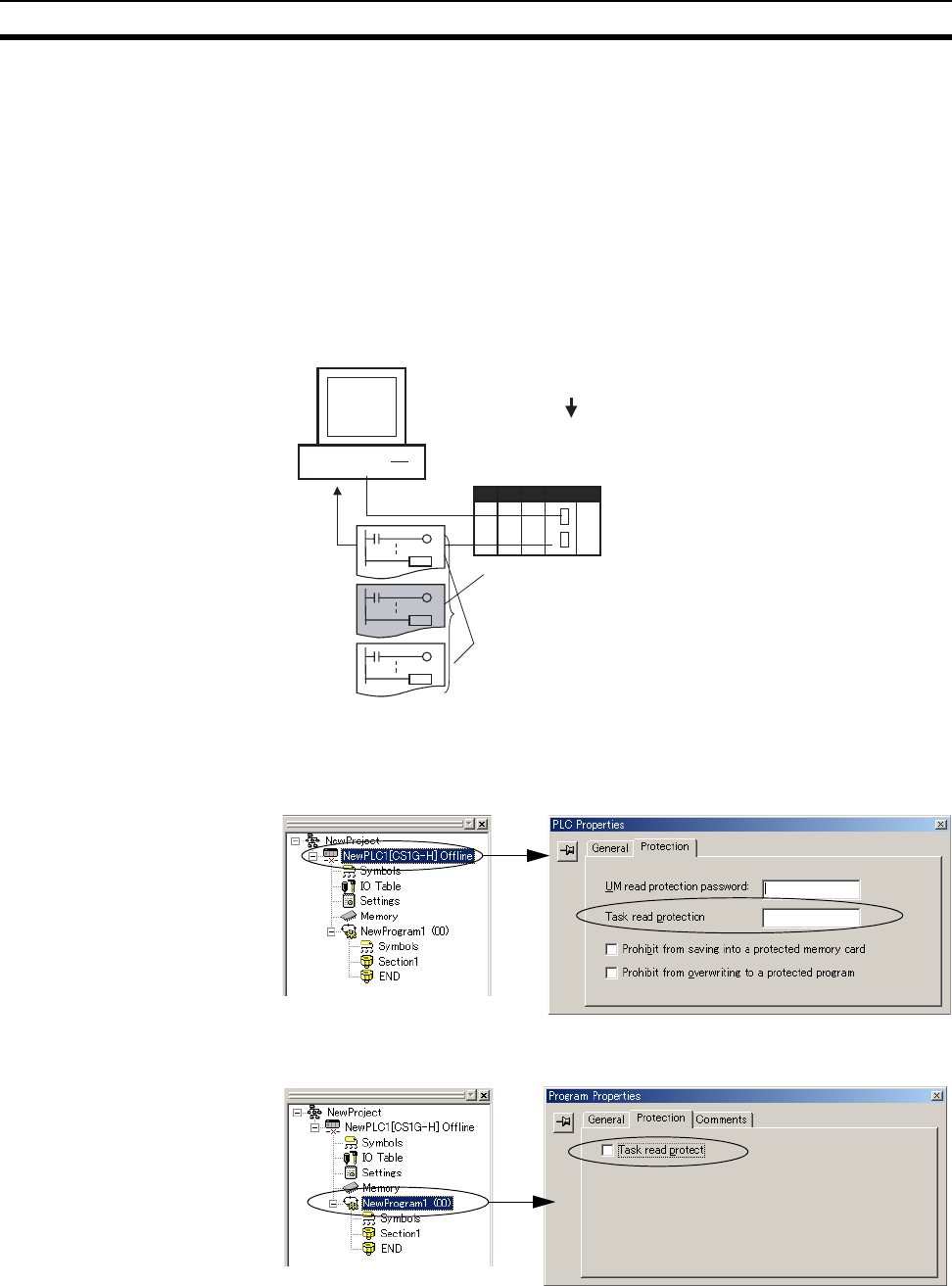
32
CS1-H CPU Unit Ver. 2.0 Upgrades Section 1-6
Task read protection prevents anyone from displaying, editing, or uploading
the read-protected set of tasks from CX-Programmer without inputting the cor-
rect password. In this case, the entire program can be uploaded, but the read-
protected tasks cannot be displayed or edited without inputting the correct
password. Tasks that are not read-protected can be displayed, edited, or mod-
ified with online editing.
Note Task read protection cannot be set if UM read protection is already set. How-
ever, it is possible to set UM read protection after task read protection has
been set.
Operating Procedure
1,2,3... 1. Display the Protection Tab of the PLC Properties Window and register a
password in the Task read protection Box.
2. Select the tasks that will be password-protected and select the Ta s k r e a d
protect Option in the Program Properties Ta b.
3. Connect online and execute either step a or b below.
a) Transferring the Program and Setting Password Protection:
Select PLC - Transfer - To PLC to transfer the program. The tasks reg-
istered in step 2 will be password-protected.
END
CX-Programmer
END
END
Password?
Set a password for particular tasks in the project directory.
Those tasks cannot be displayed without inputting the password.
CS/CJ-series CPU Unit Ver.2.0 or later
The entire user program can be uploaded, but password-
protected tasks will not be displayed until the password is input.
The other tasks can be displayed/edited and are also accessible
through online editing.
Right-click.
Properties
Right-click.
Properties
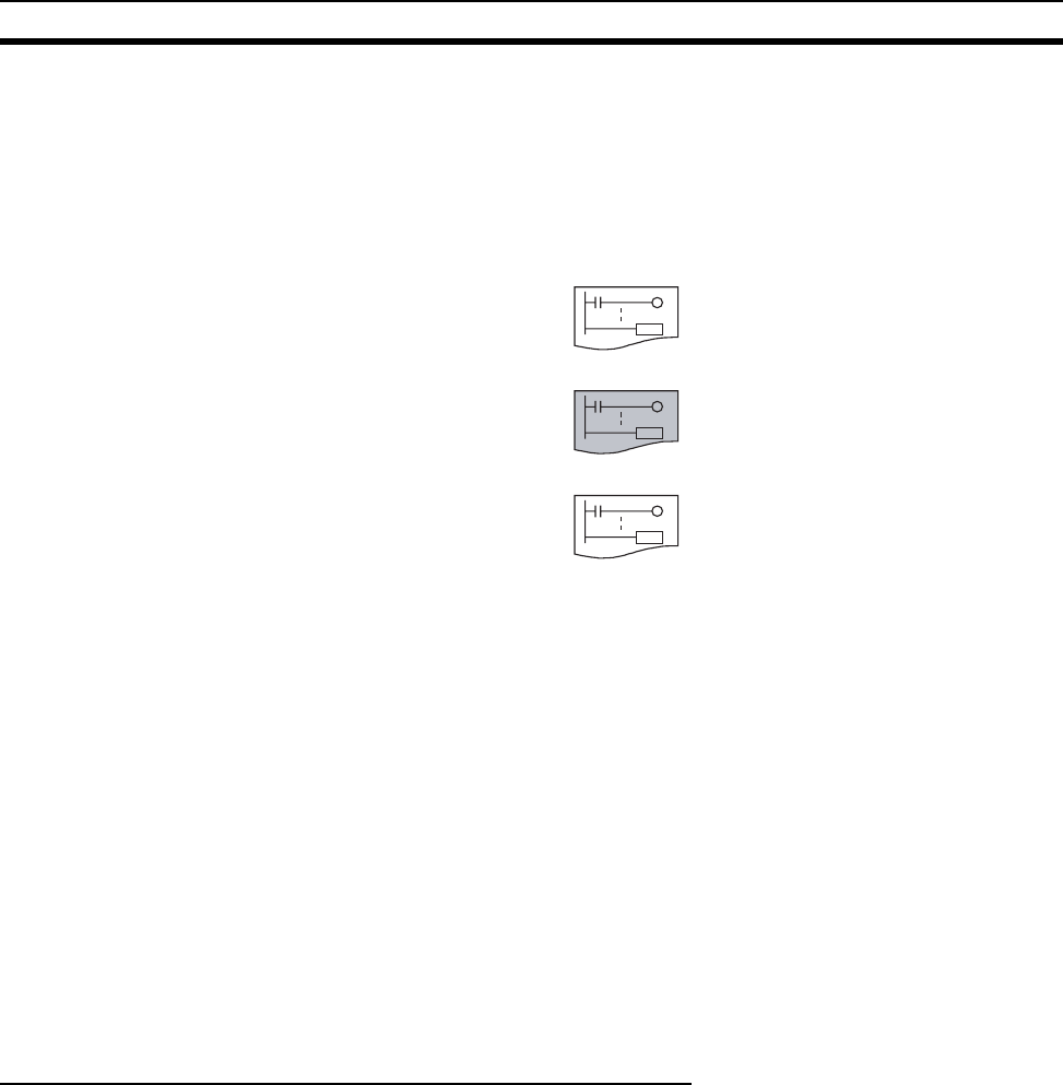
33
CS1-H CPU Unit Ver. 2.0 Upgrades Section 1-6
b) Setting Password Protection without Transferring the Program:
Select PLC - Protection - Set Password and click the OK button. The
tasks registered in step 2 will be password-protected.
Usage
Apply read protection to tasks when you want to convert those tasks (pro-
grams) to “black box” programs.
Note 1. If CX-Programmer Ver. 3.2 or an earlier version is used to read a task with
task read protection applied, an error will occur and the task will not be
read. Likewise, if a Programming Console or the PT Ladder Monitor func-
tion is used to read a password protected task, an error will occur and the
task will not be read.
2. The entire program can be transferred to another CPU Unit even if individ-
ual tasks in the program are read-protected. It is also possible to connect
online and create a program file (.OBJ file) with file memory operations. In
both cases, the task read protection remains effective for the password-
protected tasks.
3. When the CX-Programmer is used to compare a user program in the com-
puter's memory with a user program in the CPU Unit, password-protected
tasks will be compared too.
Restrictions on Function
Block Use
For programs containing function blocks (unit version 3.0 or later only), func-
tion block definitions can be read even if the entire program or tasks are read-
protected.
Enabling/Disabling Creating File Memory Program Files
Previous CPU Units (Pre-
Ver. 2.0 CPU Units)
With the pre-Ver. 2.0 CS/CJ-series CPU Units, it was possible use file mem-
ory operations to transfer a program file (.OBJ file) to a Memory Card even if
the program was protected with UM read protection. (Consequently, illegal
copies could be made.)
CPU Unit Ver. 2.0 or Later
and CX-Programmer
Ver. 4.0 or Higher
Overview
When the entire program or individual tasks in a CPU Unit Ver. 2.0 or later are
read-protected from the CX-Programmer, an option can be set to enable or
disable the creation/backup of.OBJ program files. It will not be possible to cre-
ate program files (.OBJ files) with file memory operations if the cre-
ation/backup of program files is prohibited with this setting. (This setting
prohibits both online transfers to a Memory Card/EM file memory as well as
offline storage of PLC data that was uploaded to the CX-Programmer.)
Disabling the creation of file memory program files can help prevent illegal
copying of the user program.
END
END
END
Tas k 0
Tas k 1
Tas k 2
Password applied.
Task converted to "black box."
Accessable
Not accessable
Accessable
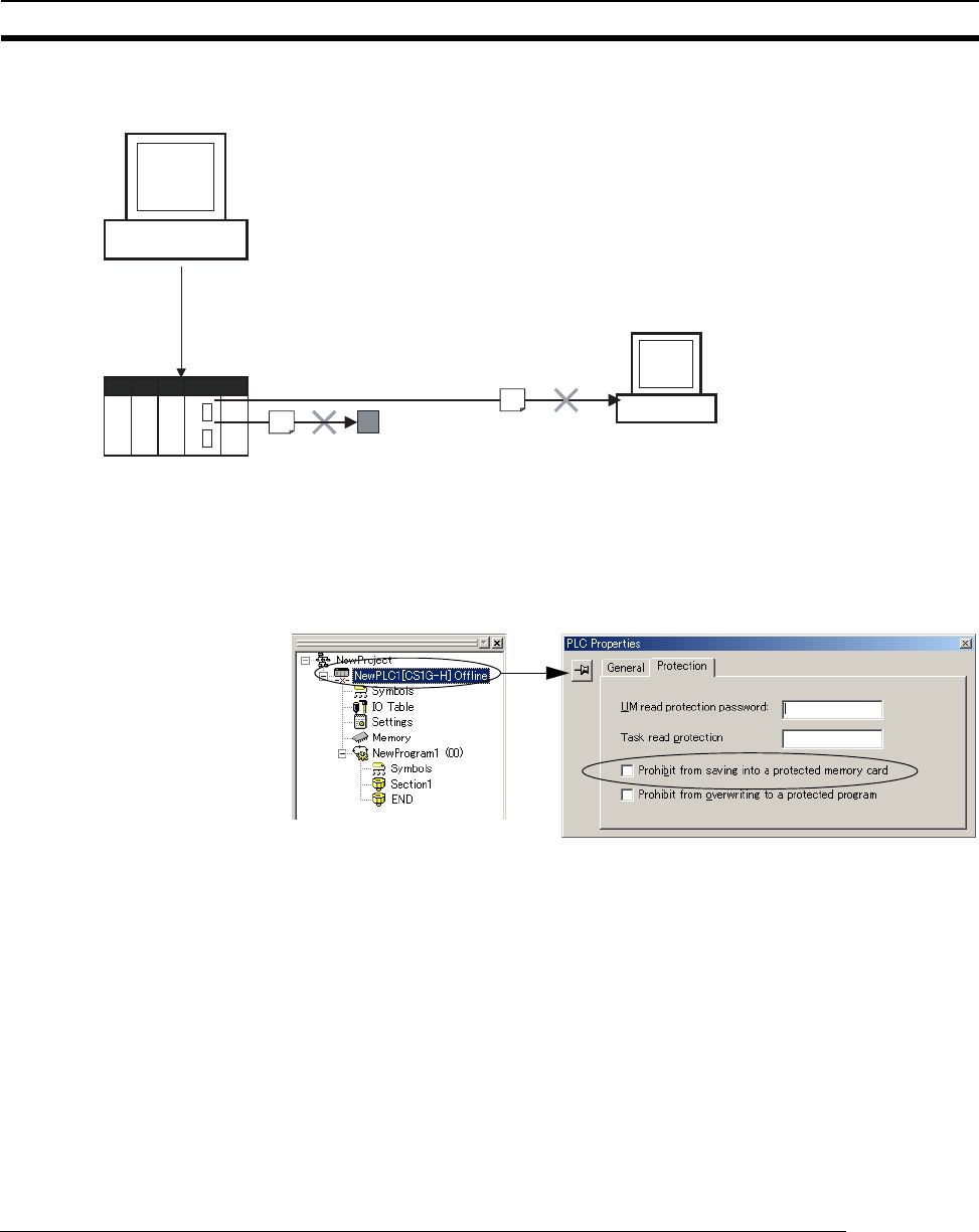
34
CS1-H CPU Unit Ver. 2.0 Upgrades Section 1-6
Operating Procedure
1,2,3... 1. When registering a password in the UM read protection password Box or
Task read protection Box, select the Prohibit from saving into a protected
memory card Option.
2. Either select PLC - Transfer - To PLC to transfer the program or select
PLC - Protection - Set Password and click the OK button.
Usage
This option can be used to prevent the program from being transferred out of
the PLC using the password.
Note 1. The simple backup operation can still be performed when the creation of
program files is prohibited, but the backup program file (BACKUP.OBJ) will
not be created.
2. The program can be copied when program read protection is not enabled.
3. The setting to enable/disable creating file memory program files will not
take effect unless the program is transferred to the CPU Unit. Always trans-
fer the program after changing this setting.
Enabling/Disabling Write Protection for Individual Tasks Using Passwords
Previous CPU Units
(Pre-Ver. 2.0 CPU Units)
With the pre-Ver. 2.0 CS/CJ-series CPU Units, the CPU Unit's user program
memory (UM) can be write-protected by turning ON pin 1 of the CPU Unit's
DIP switch. In this case, it is possible to overwrite the user program memory
by turning OFF pin 1.
CX-Programmer
CX-Programmer
Password?
When a password is being registered for the entire user program or
selected tasks, the creation of backup program files (.OBJ files) can be
enabled/disabled with an option setting.
Online creation of backup program files
(.OBJ files) prohibited by option setting.
CPU Unit
Backup program files (.OBJ files) cannot be
created with file memory operations.
Uploading of all PLC
data is prohibited.
Properties
Right-click.
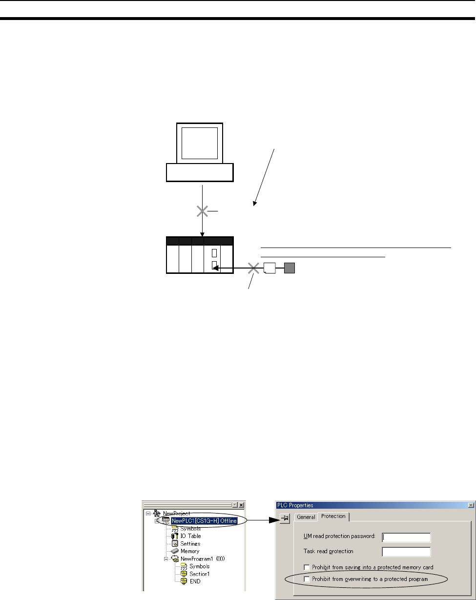
35
CS1-H CPU Unit Ver. 2.0 Upgrades Section 1-6
CPU Unit Ver. 2.0 or Later
and CX-Programmer
Ver. 4.0 or Higher
With the CPU Unit Ver. 2.0 and later CPU Units, the CPU Unit's UM area can
be write protected by turning ON pin 1 of the CPU Unit's DIP switch. The pro-
gram (or selected tasks) can also be write-protected if the write protection
option is selected from the CX-Programmer when a password is being regis-
tered for the entire program or those selected tasks. The write protection set-
ting can prevent unauthorized or accidental overwriting of the program.
Note 1. If the selected tasks or program are write-protected by selecting this option
when registering a password, only the tasks (program) that are password-
protected will be protected from overwriting. It will still be possible to over-
write other tasks or programs with operations such as online editing and
task downloading.
2. All tasks (programs) can be overwritten when program read protection is
not enabled.
3. The setting to enable/disable creating file memory program files will not
take effect unless the program is transferred to the CPU Unit. Always trans-
fer the program after changing this setting.
Operating Procedure
1,2,3... 1. When registering a password in the UM read protection password Box or
Task read protection Box, select the Prohibit from overwriting to a protect-
ed program Option.
2. Either select PLC - Transfer - To PLC to transfer the program or select
PLC - Protection - Set Password and click the OK button.
CX-Programmer
Password?
When a password is being registered for the entire user
program or selected tasks, program write-protection can be
enabled/disabled with an option setting.
The user program cannot be overwritten.
CPU Unit
Overwriting can be prohibited with password protection,
regardless of the DIP switch setting.
Memory Card
The user program cannot be overwritten.
Properties
Right-click.

36
CS1-H CPU Unit Ver. 2.0 Upgrades Section 1-6
Auxiliary Area Flags and Bits related to Password Protection
1-6-3 Write Protection from FINS Commands Sent to CPU Units via
Networks
Previous CPU Units (Pre-Ver. 2.0 CPU Units)
With the pre-Ver. 2.0 CS/CJ-series CPU Units, there was no way to prohibit
write operations and other editing operations sent to the PLC's CPU Unit as
FINS commands through a network such as Ethernet, i.e., connections other
than direct serial connections.
CPU Unit Ver. 2.0 or Later
Summary With the CPU Unit Ver. 2.0 and later CS/CJ-series CPU Units, it is possible to
prohibit write operations and other editing operations sent to the PLC's CPU
Unit as FINS commands through a network (including write operations from
CX-Programmer, CX-Protocol, CX-Process, and other applications using Fin-
sGateway). Read processes are not prohibited.
FINS write protection can disable write processes such as downloading the
user program, PLC Setup, or I/O memory, changing the operating mode, and
performing online editing.
It is possible to exclude selected nodes from write protection so that data can
be written from those nodes.
An event log in the CPU Unit automatically records all write processes sent
through the network and that log can be read with a FINS command.
Name Bit
address
Description
UM Read Protection
Flag
A09900 Indicates whether or not the PLC (the entire user
program) is read-protected.
0: UM read protection is not set.
1: UM read protection is set.
Task Read Protec-
tion Flag
A09901 Indicates whether or not selected program tasks
are read-protected.
0: Task read protection is not set.
1: Task read protection is set.
Program Write
Protection for Read
Protection
A09902 Indicates whether or not the write protection
option has been selected to prevent overwriting
of password-protected tasks or programs.
0: Overwriting allowed
1: Overwriting prohibited (write-protected)
Enable/Disable Bit
for Program Backup
A09903 Indicates whether or not a backup program file
(.OBJ file) can be created when UM read protec-
tion or task read protection is set.
0: Creation of backup program file allowed
1: Creation of backup program file prohibited
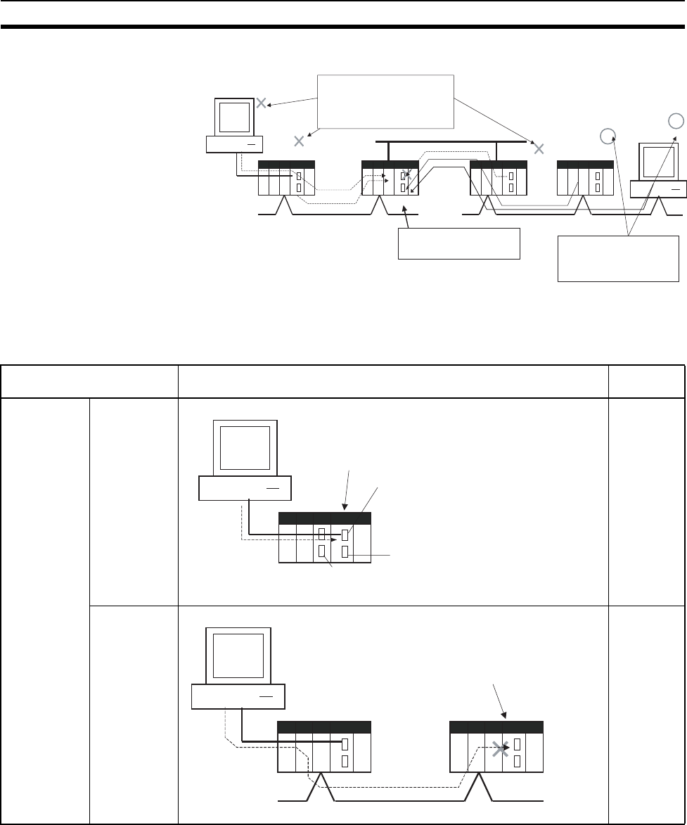
37
CS1-H CPU Unit Ver. 2.0 Upgrades Section 1-6
Example:
Note This function prohibits writing by FINS commands only, so it has no effect on
write operations by functions other than FINS commands, such as data links.
Example Write Protection Patterns
Computer #1
PLC #1
Network
Write operations by FINS com-
mands are prohibited from some
nodes in the network (in this exam-
ple, computer #1, PLC #1, and
PLC #2).
Network
PLC #2
Write access to this PLC
is enabled/disabled.
Network
PLC #3
Computer #2
Write operations by FINS com-
mands are not prohibited from
selected nodes in the network
(in this example, computer #2
and PLC #3).
Connection pattern Diagram (example) Write
protection
From a
computer
through a
direct serial
connection
Direct
connection to
PLC
Cannot be
applied.
Gateway
connection
(Serial-to-net-
work) to PLC
Can be
applied.
PLC
Computer
Write-protection not effective
Peripheral port
RS-232C port
Serial connection
(Peripheral bus or
host link) RS-232C port or 422A/485 port
on a Communications Board/Unit
Computer
PLC #1 PLC #2
Serial connection
(Peripheral bus
or host link)
Network
The CPU Unit in PLC #2
can be write-protected.
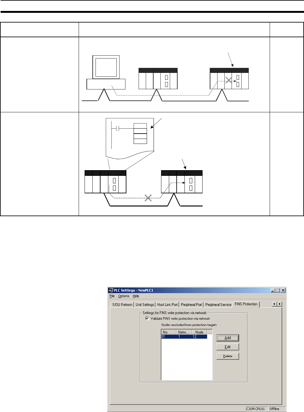
38
CS1-H CPU Unit Ver. 2.0 Upgrades Section 1-6
Operation With the CX-Programmer, open the PLC Setup's FINS Protection Tab a n d
select the Use FINS Write Protection Option. When this option is selected, it
will not be possible to execute write operations for that CPU Unit with FINS
commands sent through a network. To permit write operations from particular
nodes, enter network addresses and node addresses for the node under Pro-
tection Releasing Addresses. (Up to 32 nodes can be excluded from FINS
Write Protection).
From a computer through a
direct network connection
Can be
applied.
From another PLC in the
network
Can be
applied.
Connection pattern Diagram (example) Write
protection
Computer
PLC #1 PLC #2
Network
The CPU Unit in PLC #2
can be write-protected.
CMND
PLC #1 PLC #2
If the CMND instruction is used to send
a FINS command (requesting a write
operation) to the CPU Unit of PLC #2,
the operation is not performed.
The CPU Unit in PLC #2
can be write-protected.
Network

39
CS1-H CPU Unit Ver. 2.0 Upgrades Section 1-6
PLC Setup
Usage The system can be configured so that a PLC can be written only from autho-
rized nodes in the network. (For example, use this function when the system's
control/monitoring computer is the only node allowed to write to a Controller
within a piece of equipment.)
By limiting the number of nodes that can write to the PLC, it is possible to pre-
vent system problems caused by unintentional overwrites during data moni-
toring.
Item Address in
Programming
Console
Description Settings Default setting
Use FINS Write
Protection
Word 448, bit 15 Sets whether the CPU Unit is
write-protected from FINS com-
mands sent through the network.
(Does not prohibit FINS com-
mands sent through a direct serial
connection).
0: Write protection
disabled
1: Write protection
enabled
0: Write protection
disabled
Nodes Excluded
from Write Protec-
tion (Protection
Releasing
Addresses)
Words 449 to
480
This area lists the nodes in the
network that are not restricted by
FINS write protection. Up to 32
nodes can be specified.
Note These settings are effective
only when FINS write
protection is enabled.
Bits 08 to
15
Network address:
Network address of the FINS
command source
00 to 7F hex
Bits 00 to
07
Node address:
Node address of the FINS
command source
01 to FE hex, or FF
hex
(FF hex: node
address unspecified)
Number of Nodes
Excluded from FINS
Write Protection
(Do not set this
value. It is automati-
cally calculated by
the CX-Program-
mer.)
Word 448, bits
00 to 07
Contains the number of nodes that
are not subject to the FINS write
protection.
If 0 is specified (no nodes
excluded from write protection),
FINS write commands are prohib-
ited from all nodes other than the
local node.
Note This setting is effective only
when FINS write protection
is enabled.
0 to 32
(00 to 20 hex)
(A value of 0 indi-
cates that all nodes
are subject to write
protection.)
0
(All nodes subject to
write protection.)
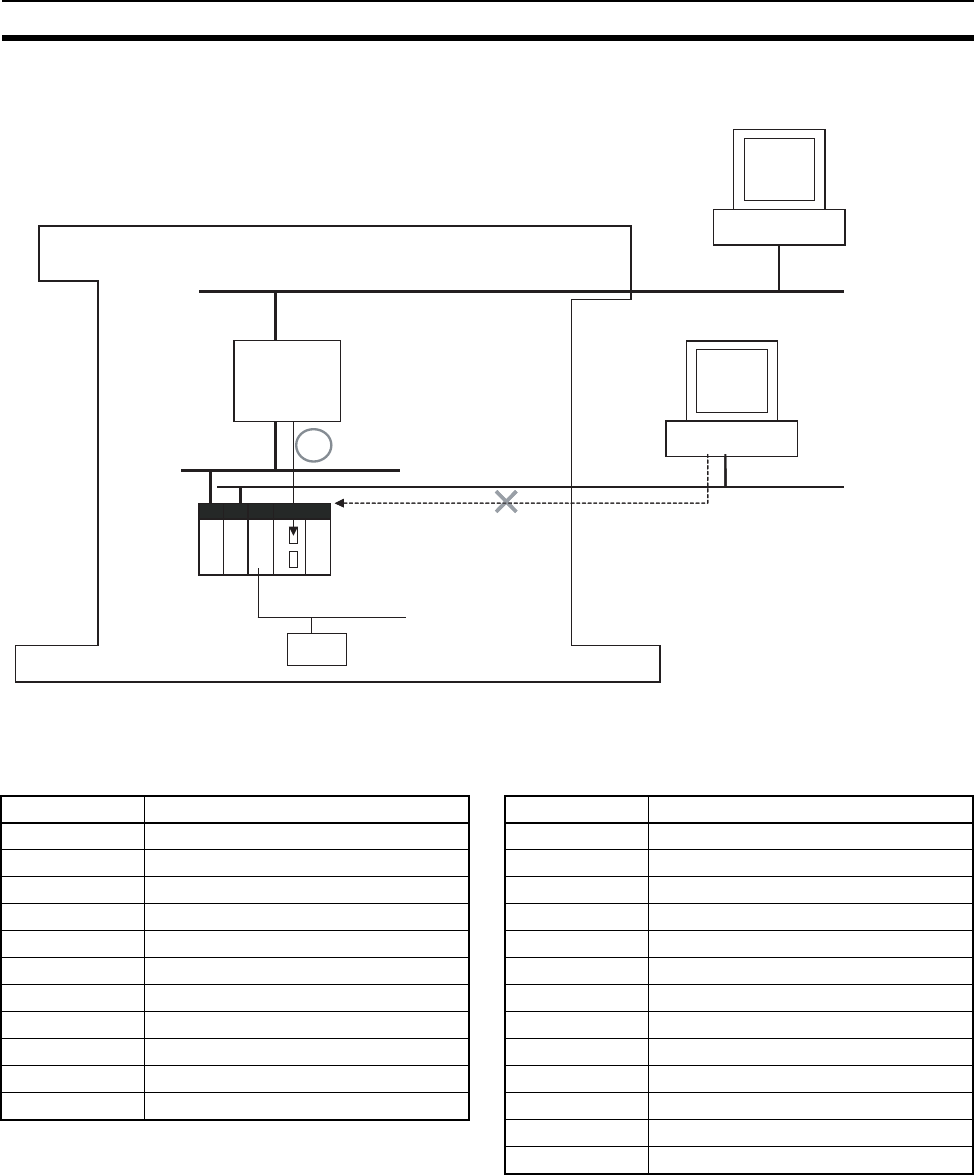
40
CS1-H CPU Unit Ver. 2.0 Upgrades Section 1-6
Operations Restricted by
Network FINS Write
Protection
FINS Write Commands
The following FINS commands are restricted by FINS write protection when
sent to the CPU Unit through the network.
CS/CJ-series PLC
Equipment
Network
Controller
Allowed to
write/con-
trol PLC
Network
Network
System control/monitoring computer
Allowed to
write/control
Monitoring computer
Not allowed to
write/control
Code Command name Code Command name
0102 hex MEMORY AREA WRITE 2101 hex ERROR CLEAR
0103 hex MEMORY AREA FILL 2103 hex ERROR LOG POINTER CLEAR
0105 hex MEMORY AREA TRANSFER 2203 hex SINGLE FILE WRITE
0202 hex PARAMETER AREA WRITE 2204 hex FILE MEMORY FORMAT
0203 hex PARAMETER AREA FILL (CLEAR) 2205 hex FILE DELETE
0307 hex PROGRAM AREA WRITE 2207 hex FILE COPY
0308 hex PROGRAM AREA CLEAR 2208 hex FILE NAME CHANGE
0401 hex RUN 220A hex MEMORY AREA-FILE TRANSFER
0402 hex STOP 220B hex PARAMETER AREA-FILE TRANSFER
0702 hex CLOCK WRITE 220C hex PROGRAM AREA-FILE TRANSFER
0C01 hex ACCESS RIGHT ACQUIRE 2215 hex CREATE/DELETE DIRECTORY
2301 hex FORCED SET/RESET
2302 hex FORCED SET/RESET CANCEL

41
CS1-H CPU Unit Ver. 2.0 Upgrades Section 1-6
Operations from CX-Programmer (including CX-Net) through the Network
The following CX-Programmer (including CX-Net) operations are restricted by
FINS write protection when performed on the CPU Unit through the network.
Note 1. FINS write protection does not prevent CX-Programmer operations from a
computer connected through a direct serial connection.
2. FINS write protection does not prevent the following file memory write
operations.
• Automatic transfer from the Memory Card at startup
• Simple backup function (including backup operations to selected
Units/Boards)
• Writing files with the FWRIT (WRITE DATA FILE) instruction
Operations from Other Support Software
FINS write protection also prevents the following operations performed
through the network by the CX-Protocol and CX-Process.
• Changing the CPU Unit's operating mode, writing memory areas,
transferring PLC Setup settings, transferring the I/O table, forced
set/reset, and clearing the CPU Unit's error log
Operations from Applications That Use FinsGateway
FINS write protection prevents all write operations addressed to the CPU Unit
from applications that use FinsGateway, such as PLC Reporter and Compo-
let.
1-6-4 Online Network Connections without I/O Tables
Previous CPU Units (Pre-Ver. 2.0 CPU Units)
With the pre-Ver. 2.0 CPU Units, it was not possible to make an online con-
nection to other PLCs in the network from CX-Programmer unless the I/O
tables had been created (even if the network connections were completed)
because the Network Communications Unit itself was not recognized from the
CPU Unit. Consequently, it was necessary to connect a Programming Device
(CX-Programmer or a Programming Console) to each PLC through a serial
connection and create and I/O tables in each PLC in order to make online
connections through the network.
Operations not
allowed through the
network when FINS
write protection is
enabled.
• Changing the Operating Mode
• Transferring the ladder program to the CPU Unit
• Transferring parameter area data (PLC Setup, I/O table, and
CPU Bus Unit Setup) to the CPU Unit
• Transferring memory area data (I/O memory data) to the
CPU Unit
• Transferring the variable table, comments, or program index
to the CPU Unit
• Forced Set/Reset
• Changing timer/counter set values
• Online editing
• Writing file memory
• Clearing the error log
• Setting the clock
• Releasing the access right
• Transferring the routing table
• Transferring the data link table
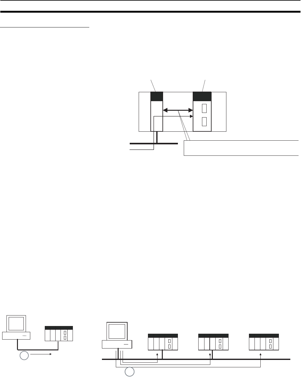
42
CS1-H CPU Unit Ver. 2.0 Upgrades Section 1-6
CPU Unit Ver. 2.0 or Later
Summary With the CPU Unit Ver. 2.0 and later CS/CJ-series CPU Units, the CPU Unit
can recognize a CPU Bus Unit (such as a Network Communications Unit, see
note) even if the I/O tables have not been created and there is no registered
I/O tables.
Note Network Communications Units include Ethernet Units, Controller Link Units,
SYSMAC Link Units, and DeviceNet Units.
Usage If the nodes are connected to the network, this function allows a computer-
based Programming Device (such as the CX-Programmer) to connect online
to PLCs in the network even if the I/O tables have not been created. Since a
network connection is established with the PLCs, setup operations can be
performed such as creating the I/O tables (or editing and transferring I/O
tables), transferring the user program, transferring the PLC Setup, and trans-
ferring the CPU Bus Unit Setup.
This function is particularly useful when connecting the CX-Programmer via
Ethernet (using a CS1W-ETN21), because the I/O tables can be created
through Ethernet so a serial cable isn't required and it isn't necessary to
spend extra time establishing a serial connection.
Details
• Applicable Units: All CS/CJ-series CPU Bus Units
• Applicable computer-based Programming Devices: CX-Programmer and
CX-Protocol only
• Applicable functions: Online connections from CX-Programmer and CX-
Protocol, and online functions of the applicable CPU Units and CPU Bus
Units
CPU Bus Unit
(including Network Communications Units) CS/CJ-series CPU Unit Ver.2.0 or later
Network
Online connection
can be made.
CPU Bus Units (including Network Communications Units)
can be recognized before an I/O table is created.
CX-Programmer
Ethernet
Ethernet
CX-Programmer
1:1 Computer-to-PLC connection 1:N Computer-to-PLC connection
Even without an I/O table, it is
possible to make an online con-
nection, create the I/O table,
transfer the program, and per-
form other operations.
CS/CJ-
series
CPU Unit
Ver.2.0
CS/CJ-
series
CPU Unit
Ver.2.0
CS/CJ-
series
CPU Unit
Ver.2.0
I/O table not registered I/O table not registered I/O table not registered
Even without an I/O table, it is possible to make an online
connection, create the I/O table, transfer the program, and
perform other operations.
CS/CJ-
series
CPU Unit
Ver.2.0
I/O table not
registered

43
CS1-H CPU Unit Ver. 2.0 Upgrades Section 1-6
Note 1. A non-fatal I/O verification error will occur if a CPU Bus Unit (including a
Network Communications Unit) is used without creating I/O tables.
2. With a CPU Unit Ver. 2.0 or later CS1-H CPU Unit, CPU Bus Units can be
used even if the I/O tables have not been created, but the purpose of this
function is making an online connection through the network with a com-
puter-based Programming Device (such as the CX-Programmer).
The I/O tables are used to identify the mounted Units and allocate I/O, so
always create the I/O tables before operating the PLC.
3. Data can be exchanged between the CPU Unit and CPU Bus Units even if
the I/O tables have not been created, but do not perform any online func-
tions other than establishing an online connection with a computer-based
Programming Device (such as the CX-Programmer).
4. When a CS1W-ETN21 or CJ1W-ETN21 Ethernet Unit is being used, the
Ethernet Unit's IP address is automatically set to the default value of
192.168.250.xx, where xx is the FINS node address. After connecting the
ethernet cable between the CX-Programmer and PLC (without making a
direct serial connection and creating the I/O tables), manually set the com-
puter's IP address (Example: 192.168.250.55) in the Windows Local Area
Connection Properties. An online connection can be established just by
setting the Ethernet Unit's IP address (192.168.250.xx) and node in the
CX-Programmer.
Note When connecting the computer directly to the Ethernet Unit, use an
Ethernet crossover cable.
1-6-5 Communications through a Maximum of 8 Network Levels
Previous CPU Units (Pre-Ver. 2.0 CPU Units)
With the pre-Ver. 2.0 CPU Units, it was possible to communicate through 3
network levels max. (see note), including the local network. It was not possible
to communicate through 4 or more levels.
Note 1. This functionality is enabled only after setting routing tables with the CX-
Net in CX-Programmer version 4.0 or higher.
2. A Gateway to the network via serial communications was not counted as a
level.
FINS command
source
OR
Serial
connection
Network 1
This connection is not counted as a network level.
Level count = 1
Network 2
Level count = 2
Network 3
FINS command
destination
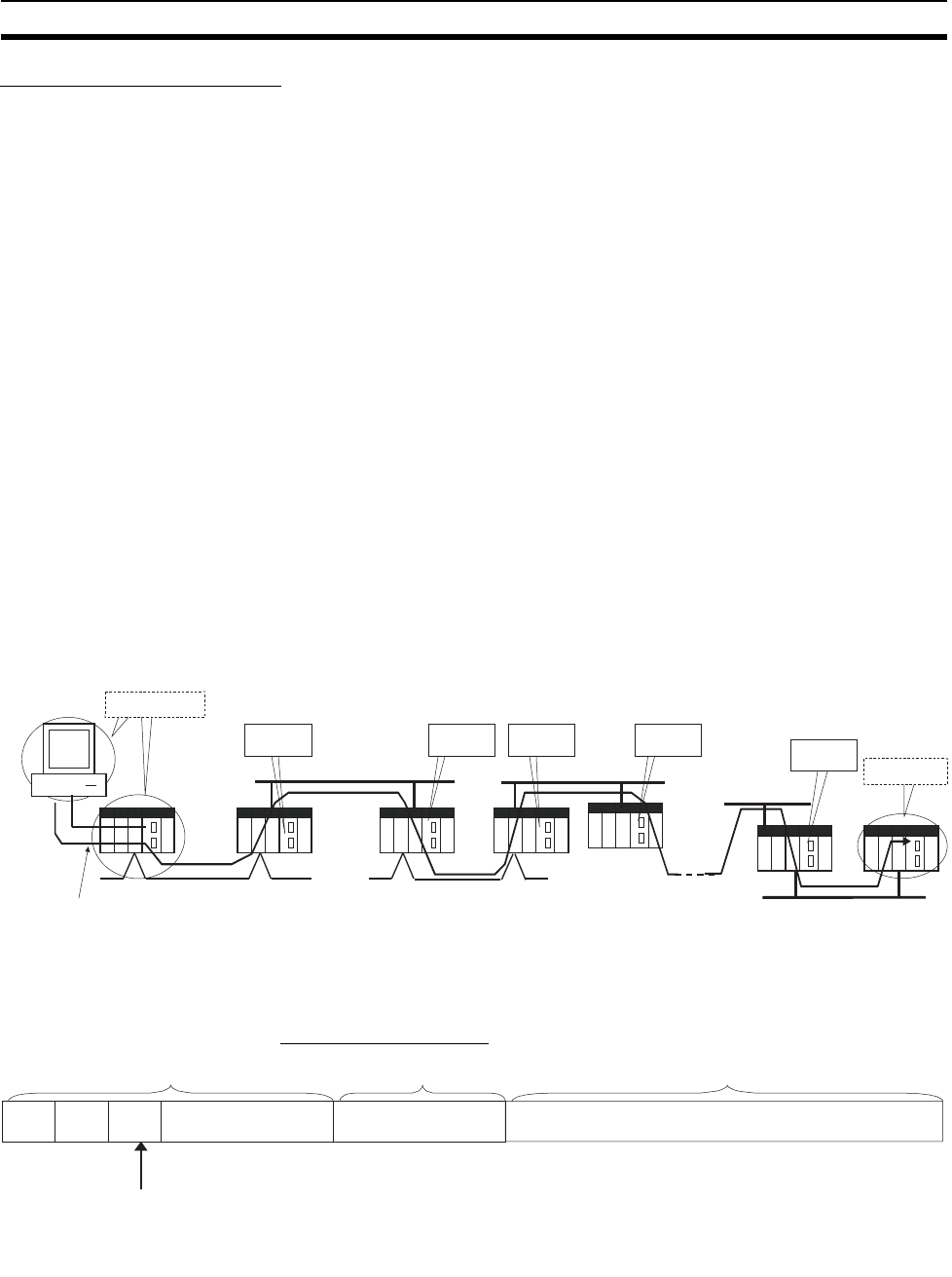
44
CS1-H CPU Unit Ver. 2.0 Upgrades Section 1-6
CPU Unit Ver. 2.0 or Later
Summary With the CPU Unit Ver. 2.0 or later CS/CJ-series CPU Units, it is possible to
communicate through 8 network levels max. (see note), including the local
network.
Note 1. FINS commands can only be sent across up to 8 network levels, however,
when the destination is a CPU Unit. FINS commands can be sent to other
destinations up to 3 network levels away.
2. CX-Net in CX-Programmer version 4.0 or higher must be used to set rout-
ing tables to enable communicating through 8 network levels.
3. A Gateway to the network via serial communications was not counted as a
level.
Compatible Networks
Only the following 2 kinds of networks can be used when communicating
through a maximum of 8 networks. The network levels can be combined in
any order.
• Controller Link
• Ethernet
Note Communications are restricted to a maximum of 8 networks through
DeviceNet and SYSMAC Link networks.
Configuration of Compatible Models
All of the CPU Units must be CPU Unit Ver. 2.0 or later CS/CJ-series CPU
Units. Also, the Gateway Counter Setting must be made with the CX-Net.
Internal Structure The Gateway Counter (GCT) is in the FINS header of the FINS com-
mand/response frame. This counter value is decremented (−1) each time a
network level is crossed.
FINS Command Frame
FINS command
source
OR
Serial
connection
This connection is not counted as a network level.
Network 1
Network 2
Level
count = 1
Level
count = 4
Level
count = 3
Level
count = 2
Network 4
Network 3
Network 8
Network 7
Level
count = 7 FINS command
destination
ICF RSV GCT
FINS header Command code Text
GCT (Gateway counter: Number of allowed bridge passages)
The standard setting is 02 hex when sending, but this value can be
user-set up to 07 hex.
The count is decremented by one each time a network level is passed.
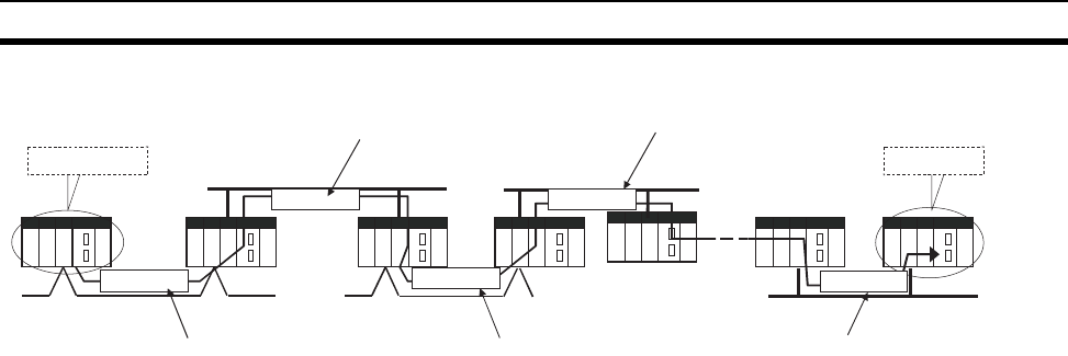
45
CS1-H CPU Unit Ver. 2.0 Upgrades Section 1-6
Example:
Operating Procedure Set the maximum number of network levels that can be crossed by setting the
Gateway Counter Setting to 2 or 7. The gateway counter setting can be
changed in the routing table settings of the CX-Net in the CX-Programmer
Ver.4.0 or higher.
Note 1. The gateway counter is the maximum number of levels that can be
crossed, i.e., the maximum number of junctions.
With earlier CPU Units (Pre-Ver. 2.0 CPU Units), up to 3 network levels
were allowed, so the gateway counter was set to 2.
With the CPU Unit Ver. 2.0 and later CS/CJ-series CPU Units, up to 8
network levels are allowed, so the maximum gateway counter setting is 7.
2. With CS/CJ-series CPU Units Ver. 2.0 or later, communications are possi-
ble for up to 8 network levels simply by setting the normal routing tables.
No other operations are required.
3. When using communications only for up to 3 network levels, the CS/CJ-se-
ries CPU Units Ver. 2.0 or later can be used together with other CPU Units.
When using communications only for up to 4 to 8 network levels, use only
CS/CJ-series CPU Units Ver. 2.0 or later. Other CPU Units cannot be used.
(Routing error (error codes 0501 to 0504 hex) may occurs in one of the
relaying PLCs, preventing a FINS response from being returned.
4. With CS/CJ-series CPU Units with unit version 2.0 or later, the Gateway
Counter (GCT: Number of allowed bridges passed) for FINS command/
response frames is the value decremented from 07 hex (variable). (In ear-
lier versions, the value was decremented from 02 hex.)
With unit version 3.0 or later, the default GCT for FINS command/response
frames is the value decremented from 02 hex. CX-Net can be select to
used 07 hex as the value from which to decrement.
5. Do not use the Gateway Counter (GCT: Number of allowed bridge passag-
es) enclosed in the FINS header of the FINS command/response frame in
verification checks performed by user applications in host computers. The
GCT in the FINS header is used by the system, and a verification error may
occur if it is used to perform verification checks in user applications, partic-
ularly when using CS/CJ-series CPU Units with unit version 2.0 or later.
FINS command
source
FINS command
Network 1
Network 2
Network 3
FINS command
At this point, the gateway counter = 7 hex
At this point, the gateway counter = 6 hex
FINS command
FINS command
Network 4
At this point, the gateway counter = 5 hex
At this point, the gateway counter = 4 hex
FINS command
At this point, the gateway counter = 0 hex
Network 8
FINS command
destination
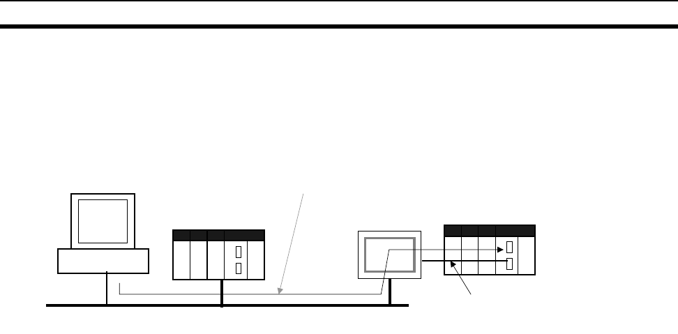
46
CS1-H CPU Unit Ver. 2.0 Upgrades Section 1-6
1-6-6 Connecting Online to PLCs via NS-series PTs
Summary The CX-Programmer can be connected online to a PLC connected via a serial
line to an NS-series PT that is connected to the CX-Programmer via Ethernet
(see note 2). This enables uploading, downloading, and monitoring the ladder
program and other data.
Note 1. The NS-series PT must be version 3.0 or higher and the CX-Programmer
must be version 3.1 or higher.
2. Connection is not possible through an NS-series PT connected serially to
the CX-Programmer.
Connection Method In CX-Programmer, open the Change PLC Window and set the Network Type
to Ethernet. Click the Settings Button and set the IP address of the NS-series
PT on the Driver Tab Page. Also make the following settings on the Network
Tab Page.
• FINS Source Address
Set the local network address of the NS-series PT for the Network (exam-
ple network address: 1).
• FINS Destination Address
Network: Set the address to 111 if the PLC is connected to serial port A
on the NS-series PT and to 112 if it is connected to serial port B.
Node: Always set to 1
• Frame Length: 1,000 (See note.)
• Response Timeout: 2
Note Do not set the frame length higher than 1,000. If any higher value is used, the
program transfer will fail and a memory error will occur.
CX-Programmer
(Example IP address: 192.168.0.1)
Ethernet (See note 1.)
(Example network address: 1)
CS/CJ-series
CPU Unit Ver. 2.0
Connect online to PLC #1 to enable
programming, monitoring, and other operations.
NS-series PT
(Example IP address:
192.168.0.22)
1:N NT Link
(Example network address: 111)
PLC #1
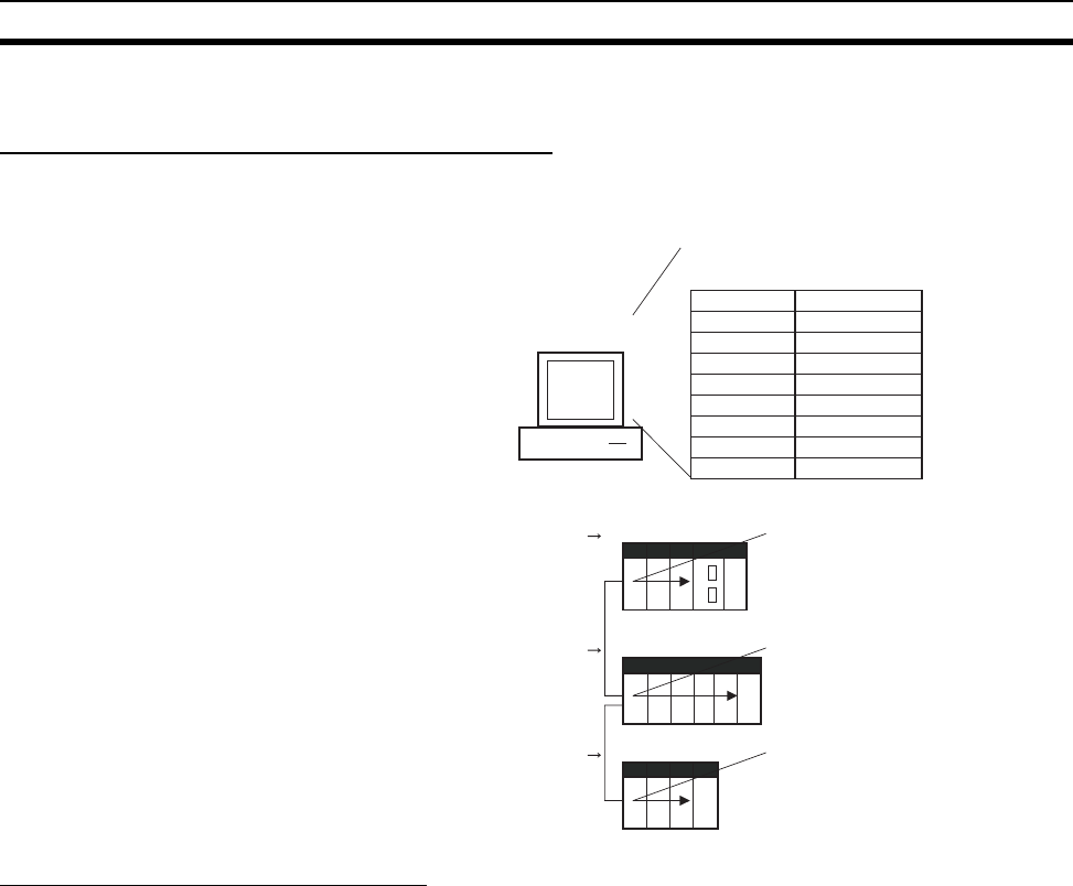
47
CS1-H CPU Unit Ver. 2.0 Upgrades Section 1-6
1-6-7 Setting First Slot Words
Previous CPU Units (Pre-Ver. 2.0 CPU Units)
With CX-Programmer Ver. 3.0 or earlier, only the first addresses on Racks
could be set. The first address for a slot could not be set.
CX-Programmer Ver. 3.1 or Higher
Summary Starting with CX-Programmer Ver. 3.1, the first addresses for slots can be set
when editing the I/O tables for CS/CJ-series CPU Units (CS1-H, CJ1-H, and
CJ1M). The first address can be set for up to eight slots. (See note.)
Note This function is supported only for CS1-H/CJ1-H CPU Units manufactured on
June 1, 2002 or later (lot number 020601@@@@ or later). It is supported for all
CJ1M CPU Units regardless of lot number. It is not supported for CS1D CPU
Units.
0 1 2
01 234
01 2
CX-Programmer
Ver. 3.0 or earlier
First addresses on Racks
Rack No.
CPU Rack
Rack 1
Rack 2
Rack 3
Rack 4
Rack 5
Rack 6
Rack 7
First address
100
0
200
Example:
CPU Rack slot
Rack 1 slot
Rack 2 slot
CIO 0100
CIO 0000
CIO 0200
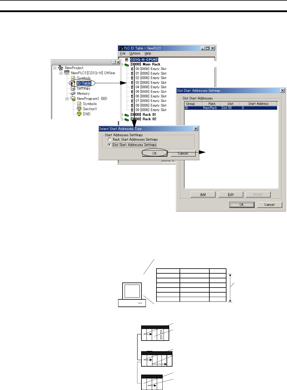
48
CS1-H CPU Unit Ver. 2.0 Upgrades Section 1-6
Operating Procedure Select Option - Rack/Slot Start Addresses in the PLC IO Table - Traffic Con-
troller Window. This command will enable setting both the first Rack
addresses and the first slot addresses.
This function can be used, for example to allocate fixed addresses to Input
Units and Output Units. (With CQM1H PLCs, input bits are from IR 000 to
IR 015 and output bits are from IR 100 to IR 115. First slot addresses can be
set when replacing CQM1H PLCs with CS/CJ-series PLCs to reduce conver-
sion work.)
Note The first address settings for Racks and slots can be uploaded/downloaded
from/to the CPU Unit.
Select Option - Rack/Slot Start. Addresses.
Double-click
100
0
102
1
105
5
012
01 2
01 2
34
CX-Programmer
Ver. 3.2 or higher
Rack No.
CPU Rack
CPU Rack
Rack 1
Rack 1
Rack 2
Rack 2
Slot No.
Slot No. 00
Slot No. 02
Slot No. 00
Slot No. 02
Slot No. 00
Slot No. 01
Example:
CPU Rack slot
Rack 1 slot
Rack 2 slot
CIO 0005
CIO 0105
CIO 0001
CIO 0102
CIO 0000
CIO 0100
Up to 8 settings
can be made.
First slot addresses
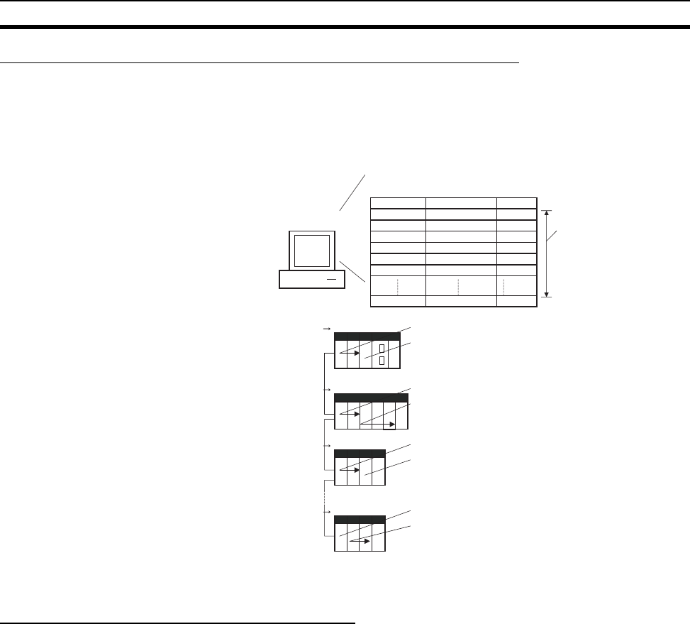
49
CS1-H CPU Unit Ver. 2.0 Upgrades Section 1-6
CPU Unit Ver. 2.0 or Later and CX-Programmer Ver. 4.0 or Higher
Summary When using CX-Programmer Ver.4.0 or higher with CPU Unit Ver. 2.0 or later,
the first address can be set for up to 64 slots.
Note This function is supported only for CS1-H, CJ1-H, and CJ1M CPU Units
Ver. 2.0 or later. It is not supported for CS1D CPU Units.
1-6-8 Automatic Transfers at Power ON without a Parameter File
Previous CPU Units (Pre-Ver. 2.0 CPU Units)
Previously with the CS/CJ-series CPU Units, both the program file for auto-
matic transfer at power ON (AUTOEXEC.OBJ) and the parameter file for auto-
matic transfer at power ON (AUTOEXEC.STD) had to be stored on the
Memory Card to enable automatic transfers to the CPU Unit at power ON.
Also, the parameter file for automatic transfer at power ON (AUTOEXEC.STD)
could not be created without the actual PLC (regardless of whether it was
made in online operations from the CX-Programmer or a Programming Con-
sole or by using the easy backup operation).
100
0
102
1
105
5
50
012
01 2
01 2
34
01 2
CX-Programmer
Ver. 4.0 or higher
Rack No.
CPU Rack
CPU Rack
Rack 1
Rack 1
Rack 2
Rack 2
Rack 7
Slot No.
Slot No. 00
Slot No. 02
Slot No. 00
Slot No. 02
Slot No. 00
Slot No. 01
Slot No. 01
Example:
CPU Rack slot
Rack 1 slot
Rack 2 slot
CIO 0005
CIO 0105
CIO 0001
CIO 0102
CIO 0000
CIO 0100
Up to 64 settings
can be made.
Rack 7 slot
CIO 0050
CIO 0155
CPU Unit Ver. 2.0
or later
First slot addresses

50
CS1-H CPU Unit Ver. 2.0 Upgrades Section 1-6
Even if a program file (.OBJ) was created offline without the actual PLC and
then sent to a remote PLC as an email attachment, the program file could not
be transferred to the CPU Unit without a Programming Device.
CPU Unit Ver. 2.0 or Later
Summary With CS/CJ-series CPU Unit Ver. 2.0, the user program can be automatically
transferred to the CPU Unit at power ON without a parameter file (.STD) if the
name of the program file (.OBJ) is changed to REPLACE.OBJ on the CX-Pro-
grammer and the file is stored on a Memory Card. If data files are included
with the program file using this function, the following data file names are
used: REPLACE.IOM, REPLCDM.IOM, REPLCE@.IOM.
Note 1. If the Memory Card contains a REPLACE.OBJ file, any parameter file on
the Memory Card will not be transferred.
2. If the Memory Card contains both a REPLACE.OBJ file and a AUTOEX-
EC.OBJ file, neither will be transferred.
Note With CX-Programmer Ver. 3.0 or higher, a program file (.OBJ) can be created
offline and saved on a computer storage media. Select Transfer - To File
from the PLC Menu. This enable creating a program file offline without a PLC
so that the name can be changed to enable sending the program file.
Personal
computer
Mail
Mail
Internet
Program file (.OBJ) sent
as mail attachment.
CPU Unit
Local site (no Programming Device)
Program cannot be transferred
(see note).
Program file
(AUTOEXEC.OBJ)
Note: Transfer is not possible because
there is no parameter file
(AUTOEXEC.STD).
Personal
computer
Mail
Mail
Internet
Program file created on CX-
Programmer (see note), file name
changed to REPLACE.OJB, and
file sent as mail attachment.
CPU Unit
Remote site (no Programming Device)
Program can be transferred
(see note).
REPLACE.OBJ
Note: Transfer is possible even
without a parameter file
(AUTOEXEC.STD).

51
CS1-H CPU Unit Ver. 2.0 Upgrades Section 1-6
1-6-9 Operation Start/End Times
Previous CPU Units (Pre-Ver. 2.0 CPU Units)
The time that operation started and the time operation ended were not stored
in the CPU Unit.
CPU Unit Ver. 2.0 or Later
The times that operation started and ended are automatically stored in the
Auxiliary Area.
• The time that operation started as a result of changing the operating
mode to RUN or MONITOR mode is stored in A515 to A517 of the Auxil-
iary Area. The year, month, day, hour, minutes, and seconds are stored.
• The time that operation stopped as a result of changing the operating
mode to PROGRAM mode or due to a fatal error is stored in A518 to
A520 of the Auxiliary Area. The year, month, day, hour, minutes, and sec-
onds are stored.
This information simplifies managing PLC System operating times.
1-6-10 New Application Instructions
The following instructions have been added. Refer to the Instructions Refer-
ence Manual (W474) for details.
• Multiple Interlock Instructions:
MULTI-INTERLOCK DIFFERENTIATION HOLD (MILH(517)), MULTI-
INTERLOCK DIFFERENTIATION RELEASE (MILR(518)), and MULTI-
INTERLOCK CLEAR (MILC(519))
• TIME-PROPORTIONAL OUTPUT (TPO(685))
• GRAY CODE CONVERSION (GRY(474))
• Combination Instructions:
TEN KEY INPUT (TKY(211)), HEXADECIMAL KEY INPUT (HKY(212)),
DIGITAL SWITCH INPUT (DSW(213)), MATRIX INPUT (MTR(210)), and
7-SEGMENT DISPLAY OUTPUT (7SEG(214))
• Time Comparison Instructions: =DT, <>DT, <DT, <=DT, >DT, >=DT
• Explicit Message Instructions:
EXPLICIT MESSAGE SEND (EXPLT(720)), EXPLICIT GET ATTRIBUTE
(EGATR(721)), EXPLICIT SET ATTRIBUTE (ESATR(722)), EXPLICIT
WORD READ (ECHRD(723)), and EXPLICIT WORD WRITE
(ECHWR(724))
• EXPANDED BLOCK COMPARE (BCMP2(502)) (This instruction, previ-
ously supported by only the CJ1M PLCs, is now supported by the CS1-H
and CJ1-H.)
• INTELLIGENT I/O READ (IORD(222)) and INTELLIGENT I/O WRITE
(IOWR(223)) (These instructions could previously be used only for Spe-
cial I/O Units, but they can now be used to read and write data for CPU
Bus Units.)
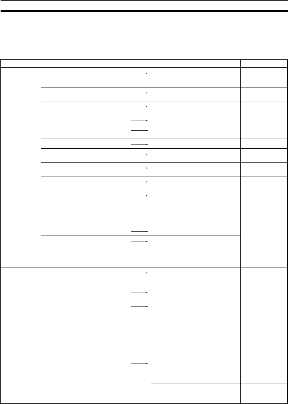
52
CS-series Function Tables Section 1-7
1-7 CS-series Function Tables
The following tables list functions for the CS-series CPU Units.
1-7-1 Functions Arranged by Purpose
Purpose Function Reference
Studying Basic
Operations and
the System
Studying the system configuration SECTION 2 Spec-
ifications and Sys-
tem Configuration
Studying I/O allocations SECTION 8 I/O
Allocations
Finding the installation dimensions 5-2-4 Mounting
Dimensions
Finding the installation method 5-2 Installation
Setting the DIP switch 3-1-2 Compo-
nents
Setting the PLC Setup 7-1 PLC Setup
Using special flags in the Auxiliary
Area
Appendix B Auxil-
iary Area
Studying the cycle time 10-4-2 Cycle Time
Overview
Troubleshooting 11-2-4 Error Pro-
cessing Flowchart
Improving
Program
Structure
Standardizing programs as modules. Program with tasks to divide the pro-
gram, use function blocks (FBs),
specify symbols, and define local
and global symbols.
Use ST (Structured Text) language.
Programming
Manual (W394)
Developing a program with several
programmers working in parallel.
Making the program easier to under-
stand.
Creating step programs. Use the step instructions. Instructions Refer-
ence Manual
(W474)
Using BASIC-like mnemonic instruc-
tions to program processes that are
difficult to enter in the ladder dia-
gram format (such as conditional
branches and loops).
Use the block programming instruc-
tions.
Use ST (Structured Text) language.
Simplifying the
Program
Creating looped program sections. Use FOR(512) and NEXT(513) or
JMP(004) and JME(005).
Instructions Refer-
ence Manual
(W474)
Indirectly addressing DM words. All words in the DM and EM Areas
can be indirectly addressed.
Programming
Manual (W394)
Simplifying the program by switching
to PLC memory address specifica-
tion.
Use Index Registers as pointers to
indirectly address data area
addresses.
The Index Registers are very useful
in combination with loops, increment
instructions, and table data process-
ing instructions. The auto-increment,
auto-decrement, and offset func-
tions are also supported.
Consolidating instruction blocks with
the same pattern but different
addresses into a single instruction
block.
Use function blocks (FBs). CX-Programmer
Operation Man-
ual Function
Blocks (W438)
Use MCRO(099). Instructions Refer-
ence Manual
(W474)
53
CS-series Function Tables Section 1-7
Managing the
Cycle Time
Reducing the cycle time. • Use tasks to put parts of the pro-
gram that don’t need to be exe-
cuted into “standby” status.
• Use JMP(004) and JME(005) to
jump parts of the task that don’t
need to be executed.
• Convert parts of the task to sub-
routines if they are executed only
under particular conditions.
• Disable a Unit’s Special I/O Unit
refreshing in the PLC Setup if it
isn’t necessary to exchange data
with that Special I/O Unit every
cycle.
• Set sharing index and data regis-
ters by all tasks if index and data
registers are not being used.
Programming
Manual (W394)
Setting a fixed (minimum) cycle time.
• Variations in I/O response times
can be eliminated by suppressing
processing variations.
Set a minimum cycle time in the PLC
Setup.
Setting a maximum cycle time.
(Generating an error for a cycle time
exceeding the maximum.)
Set a maximum cycle time (watch
cycle time) in the PLC Setup. If the
cycle time exceeds this value, the
Cycle Time Too Long Flag (A40108)
will be turned ON and PLC operation
will be stopped.
7-1 PLC Setup
Reducing the I/O response time for
particular I/O points.
Use an I/O interrupt task, immediate
refreshing, or IORF(097).
Programming
Manual (W394)
Receiving input pulses shorter than
the cycle time.
Use a quick-response input on a
Unit with High-speed Inputs or a
High-density I/O Unit (a Special I/O
Unit).
3-6-3 Units with
High-speed Inputs
and 3-7 C200H
High-density I/O
Units (Special I/O
Units)
Finding the I/O refresh times for
Units
10-4-2 Cycle Time
Overview
Studying the I/O response times 10-4-6 I/O
Response Time
Finding the increase in cycle time
caused by online editing
10-4-5 Online
Editing Cycle
Time Extension
Purpose Function Reference
54
CS-series Function Tables Section 1-7
Using Interrupt
Tasks
Monitoring operating status at regu-
lar intervals
• Monitoring operating status at reg-
ular intervals.
Use a scheduled interrupt task. Programming
Manual (W394)
Performing interrupt processing
when an input goes ON.
• Executing processing immediately
with an input.
Use an I/O interrupt task.
Issuing an interrupt to the CPU
when data is received through serial
communications.
Use a Serial Communications Board
and external interrupt task or an
ASCII Unit.
Executing an emergency interrupt
program when the power supply
fails.
Use a power OFF interrupt task.
Enable the power OFF interrupt task
in the PLC Setup.
Studying the interrupt response time 10-4-7 Interrupt
Response Times
Finding the priority of interrupt tasks Programming
Manual (W394)
Data Process-
ing
Operating a FIFO or LIFO stack. Use the stack instructions
(FIFO(633) and LIFO(634)).
Instructions Refer-
ence Manual
(W474)
Performing basic operations on
tables made up of 1-word records.
Use range instructions such as
MAX(182), MIN(183), and
SRCH(181).
Performing complex operations on
tables made up of 1-word records.
Use Index Registers as pointers in
special instructions.
Performing operations on tables
made up of records longer than 1
word.
(For example, the temperature, pres-
sure, and other manufacturing set-
tings for different models of a
product could be stored in separate
records.)
Use Index Registers and the record-
table instructions (DIM, GETR, etc.)
Programming
Manual (W394)
System
Configuration
Monitoring several different kinds of
devices through the RS-232C port.
Multiple serial ports can be installed
with Serial Communications Units
(protocol macro) and ASCII Units.
2-3 Basic System
Configuration
Changing protocol during operation
(from a modem connection to host
link, for example).
Use STUP(237), the CHANGE
SERIAL PORT SETUP instruction.
Instructions Refer-
ence Manual
(W474)
Purpose Function Reference
55
CS-series Function Tables Section 1-7
Connecting
Programming
Devices
Connecting a Programming Con-
sole.
Connect to the peripheral port with
pin 4 of the CPU Unit’s DIP switch
OFF.
3-3-2 Program-
ming Consoles
Connecting a Programming Device
(e.g., the CX-Programmer).
Connect to the peripheral port with
pin 4 of the CPU Unit’s DIP switch
OFF or with pin 4 ON and the net-
work type of the CX-Programmer set
to the peripheral bus.
Connect to the RS-232C port with
pin 5 of the CPU Unit’s DIP switch
ON or with pin 5 OFF and the net-
work type of the CX-Programmer set
to the peripheral bus.
3-3-3 CX-Pro-
grammer
Connecting a host computer. Connect to the RS-232C port or
peripheral port. (Set the communi-
cations mode to “host link” in the
PLC Setup.)
2-5 Expanded
System Configu-
ration
Connecting a PT. Connect to the RS-232C port or
peripheral port. (Set the communi-
cations mode to “NT Link” in the
PLC Setup.)
Set the PT communications settings
for a 1:N NT Link.
Connecting a standard serial device
to the CPU Unit (no-protocol mode).
Connect to the RS-232C port.
(Set the communications mode to
“no-protocol” in the PLC Setup.)
Controlling Out-
puts
Turning OFF all outputs on basic
Output Units and High-density Out-
put Units (a type of Special I/O Unit).
Turn ON the Output OFF Bit
(A50015).
Programming
Manual (W394)
Maintaining the status of all outputs
on Output Units when PLC operation
stops (hot start).
Turn ON the IOM Hold BIt (A50012).
Controlling
I/O Memory
Maintaining the previous contents of
all I/O Memory at the start of PLC
operation (hot start).
Turn ON the IOM Hold BIt (A50012). Programming
Manual (W394)
Maintaining the previous contents of
all I/O Memory when the PLC is
turned on.
Turn ON the IOM Hold BIt (A50012)
and set the PLC Setup to maintain
the status of the IOM Hold Bit at
start-up.
(IOM Hold Bit Status at Startup)
Purpose Function Reference
56
CS-series Function Tables Section 1-7
File Memory Automatically transferring the pro-
gram, I/O Memory, and PLC Setup
from the Memory Card when the
PLC is turned on.
• Easily replacing the program
onsite.
• Operating without a battery.
Enable the “automatic transfer at
start-up” function by turning ON pin
2 of the CPU Unit’s DIP switch and
create an AUTOEXEC file.
Programming
Manual (W394)
Creating a library of programs for dif-
ferent program arrangements.
Memory Card functions (Program
Files)
Creating a library of parameter set-
tings for various PLC Racks and
models.
Memory Card functions (Parameter
Files)
Creating a library of data files with
settings for various PLC Racks, and
CPU Bus Units.
Memory Card functions (Data Files)
Storing I/O Comment data within the
Memory Card.
Memory Card functions
(Symbol Table Files)
Storing operating data (trend and
quality data) within the CPU Unit
during program execution.
EM File Memory Functions and the
FREAD(700)/FWRIT(701) instruc-
tions
Replacing the program without
stopping operation.
Memory Card functions (Program
Replacement during PLC Operation)
Reading and writing I/O memory
data with a spreadsheet.
Read/write data files using instruc-
tions in CSV or text format.
Creating data that can be read with
a text editor.
Use the WRITE TEXT FILE instruc-
tion (TWRIT(704)).
Text string
processing
Performing string processing at the
PLC which was performed at the
host computer previously and reduc-
ing the program load at the host
computer (operations such as read,
insert, search, replace, and
exchange).
• Easily replacing the program
onsite
• Operating without a battery
Combine the Host Link function with
the text string processing instruc-
tions.
Instructions Refer-
ence Manual
(W474)
Performing string processing opera-
tions such as rearranging text
strings.
Replacing the program without stop-
ping operation.
Use the string comparison instruc-
tions and index registers.
Receiving data from external
devices (such as bar code readers)
through serial communications, stor-
ing the data in DM, and reading just
the required string when it is
needed.
Use the WRITE TEXT FILE instruc-
tion (TWRIT(704)).
Combine the protocol macro func-
tion with the text string processing
instructions.
Purpose Function Reference
57
CS-series Function Tables Section 1-7
Maintenance
and Debugging
Changing the program while it is
being executed.
Use the online editing function from
a Programming Device.
(Several instruction blocks can be
changed with CX-Programmer.)
Programming
Manual (W394)
Sampling I/O Memory data.
• Periodic sampling
• Sampling once each cycle
• Sampling at specified times
Data trace at regular intervals
Data trace at the end of each cycle
Data trace each time that
TRSM(045) is executed
Confirming there are no errors in
instruction execution.
Set the PLC Setup to specify the
desired operating mode at start-up.
(Startup Mode)
Recording the time that power was
turned on, the last time that power
was interrupted, the number of
power interruptions, and the total
PLC on time.
Read the Auxiliary Area words
containing power supply information.
Startup Time: A510 and A511
Power Interruption Time: A512 and
A513
Number of Power Interruptions:
A514
Replacing the program without stop-
ping operation.
Reading the time/date when the
user program was changed.
Reading the time/date when the
parameter area was changed.
Set the PLC Setup so that instruc-
tion errors are treated as fatal errors.
(Instruction Error Operation)
Programming/monitoring the PLC
remotely.
• Programming or monitoring a PLC
on the network through Host Link.
• Programming or monitoring a PLC
through modems.
Host Link → Network Gateway
function
Host Link through modems
2-5 Expanded
System Configu-
ration
Programming/monitoring PLCs in
other networks
Communicate with PLCs up to 2
network levels away through
Controller Link or Ethernet.
Error Process-
ing and Trou-
bleshooting
Generating a non-fatal or fatal error
for user-defined conditions.
• Non-fatal errors (Operation contin-
ues.)
• Fatal errors (PLC operation stops.)
• Not recording user-defined alarms
and errors in the error log.
FAILURE ALARM: FAL(006)
SEVERE FAILURE ALARM:
FALS(007)
Set the PLC Setup so that user-
defined FAL errors are not recorded
in the error log.
Programming
Manual (W394)
Analyzing time and logic in execu-
tion of an instruction block.
FAILURE POINT DETECTION:
FPD(269)
Recording the time/date of errors
and error details.
Reading recorded error details.
Use the error log function. Up to 20
error records can be stored.
Other
Functions
Allocating words in the I/O Area by
specifying the first word allocated to
Rack.
Set the first word allocated to Rack
by registering the I/O table from the
CX-Programmer. (Words must be
allocated to Racks in the order that
the Racks are connected.)
Programming
Manual (W394)
Purpose Function Reference
58
CS-series Function Tables Section 1-7
1-7-2 Communications Functions (Serial/Network)
Reducing input chattering and the
effects of noise.
Specify the input response times for
Basic I/O Units in the PLC Setup.
(Basic I/O Unit Input Response
Time)
Allocating words in the I/O Area
freely by specifying the word allo-
cated to a slot.
Set the first word allocated to a slot
by registering the I/O tables from the
CX-Programmer.
8-4 Allocating
First Words to
Slots
Purpose Protocol: Required Equipment Reference
Monitoring from
the Host Com-
puter
RS-232C or RS-422/485 Host Link:
Port in the CPU Unit, Serial Commu-
nications Board, or Serial Communi-
cations Unit
2-5-2 Sys-
tems
Host Link communications from the
PLC
Enclose a FINS command with a
Host Link header and terminator and
issue it from the PLC as a network
communications instruction.
Network communications through
RS-232C or RS-422/485
Controller Link and Ethernet commu-
nications are possible through the
Host Link. (Enclose a FINS command
with a Host Link header and termina-
tor and issue it from the PLC as a net-
work communications instruction.)
Network Control system Controller Link:
Controller Link Unit or Controller Link
Board
2-5-3 Com-
munications
Network Sys-
tem
Information sys-
tem
Ethernet: Ethernet Unit
Connecting to a
Standard Serial
Device
Creating a custom, user-defined pro-
tocol
Protocol written in BASIC: ASCII Unit 2-5-2 Sys-
tems
Creating a simple protocol Protocol Macro:
Serial Communications Board or
Serial Communications Unit
High-speed data exchange
No protocol No protocol:
CPU Unit’s RS-232C port, ASCII Unit,
or Protocol Macro
Communicating
with a PT
Direct access NT Link:
Port in the CPU Unit, Serial Commu-
nications Board, or Serial Communi-
cations Unit
Data Link
between PLCs
High capacity or free word allocation Controller Link: Controller Link Unit 2-5-3 Com-
munications
Network Sys-
tem
Low capacity and fixed word alloca-
tion
PLC Link: PLC Link Unit
Data Link between PLC and computer Controller Link:
Controller Link Unit or Controller Link
Board
Message
communications
between PLCs
Normal or high capacity Controller Link: Controller Link Unit
Information system Ethernet: Ethernet Unit
Purpose Function Reference

59
CS-series Function Tables Section 1-7
Message
communications
between PLC
and computer
Control system Controller Link:
Controller Link Unit or Controller Link
Board
2-5-3 Com-
munications
Network Sys-
tem
Information system Ethernet: Ethernet Unit
Remote I/O
between PLC
and Slaves
High-density I/O DeviceNet:
DeviceNet Master Unit and required
Slave Units
Free word allocation
Multi-vendor capability
Analog I/O capability
Multi-level architecture
High-speed Remote I/O CompoBus/S:
CompoBus/S Master Unit and
required Slave Units
Remote I/O Slave Rack connection SYSMAC BUS Wired Remote I/O:
SYSMAC BUS Master Unit and
required Slave Units
2-3 Basic
System Con-
figuration
Purpose Protocol: Required Equipment Reference

60
CS1-H Functions Arranged by Purpose Section 1-8
1-8 CS1-H Functions Arranged by Purpose
Purpose Function
Increas-
ing
speed
Reducing the cycle time and improving
communications responsiveness.
• Fast large-scale data exchange with the
host is needed even though the PLC
program is very large.
• Consistently timed data exchange with
SCADA software is needed.
• Fast message communications and control
are required between distributed PLCs.
• It is necessary to minimize the effects on
the cycle time of future system expansion
or increases in communications.
Use the Parallel Processing Mode with Synchronous Memory
Access or Parallel Processing Mode with Asynchronous Mem-
ory Access.
Using parallel processing enables the following savings.
For example, if the program consists of basic instructions with a
cycle time of approximately 10 ms and one Ethernet Unit is
being used, the cycle time will be reduced to approximately
90% of the time for the normal mode. and the peripheral servic-
ing time will be reduced to approximately 40% of the time for
the normal mode.
When using parallel processing mode, it is
necessary to maintain concurrency
between I/O memory data accessed for
instruction execution and from communica-
tions (for data larger than one word).
Use the Parallel Processing Mode with Synchronous Memory
Access.
When using parallel processing mode, it is
not necessary to maintain concurrency
between I/O memory data accessed for
instruction execution and from communica-
tions (for data larger than one word).
Use the Parallel Processing Mode with Asynchronous Memory
Access.
Giving higher priority to communications
response than the cycle time. (For example,
to give priority to the read/write response of
CPU Unit data from SCADA software for
process control).
The response of peripheral servicing can be adjusted by using
the following modes (listed in order from highest response):
Parallel Processing Mode with Asynchronous Memory Access,
Peripheral Servicing Priority Mode (with a long instruction exe-
cution cycle), Parallel Processing Mode with Synchronous
Memory Access, Normal Mode
Minimizing cycle time fluctuations and main-
taining consistent I/O response even when
extensive table data and text string data is
being processed
Table data processing and text string processing, which often
require time, can be set in the PLC Setup so that they are pro-
cessed in the background. The default is for no background
execution. (For background execution, time slicing is used to
separate processing over several cycles.)
If background execution is used, the effect on the cycle time
can be limited to 4% or less (PLC Setup default setting).
Improving data link response with a long
cycle time (Controller Link or SYSMAC LINK)
The CPU BUS UNIT I/O REFRESH instruction (DLNK(226))
can be used at one or more locations in the ladder program.
This enables refreshing data links for specified Controller Link
or SYSMAC LINK Units, whenever necessary, as well as during
the I/O refresh period. (The actual data that is refreshed
depends on the communications cycle time.)
Improving DeviceNet remote I/O response The CPU BUS UNIT I/O REFRESH instruction (DLNK(226))
can be used in the ladder program. This enables refreshing
remote I/O for DeviceNet Units, whenever necessary, as well
as during the I/O refresh period. (The actual data that is
refreshed depends on the communications cycle time.)
Improving the response of protocol macro
data transfers for Serial Communications
Units
The CPU BUS UNIT I/O REFRESH instruction (DLNK(226))
can be used at one or more locations in the ladder program.
This enables refreshing data transferred for protocol macros
executed by Serial Communications Units, whenever neces-
sary, as well as during the I/O refresh period. (The actual data
that is refreshed depends on the communications cycle time.)
Immediately refreshing status data and other
words allocated to CPU Bus Units in the CIO
Area whenever necessary (including Ether-
net Units, Serial Communications Units,
Controller Link Units, etc.)
The CPU BUS UNIT I/O REFRESH instruction (DLNK(226))
can be used at one or more locations in the ladder program.
This enables refreshing words allocated to CPU Bus Units in
the CIO Area (25 words) whenever necessary, in the same way
that the IORF instruction is used for other Units.

61
CS1-H Functions Arranged by Purpose Section 1-8
Increas-
ing
structure
Using more tasks Define interrupt tasks as cyclic tasks (called “extra cyclic
tasks”).
Reducing the cycle time even with structured
programs using many tasks
Use shared index and data registers.
Using the same index or data registers in dif-
ferent tasks without saving and loading regis-
ter contents
Initializing processing when a task is started Use the Task Start Flags.
Using standard processing shared by more
than one task
Use a global subroutine (GSBN to GRET) in interrupt task
number 0.
User function blocks (FBs).
Standardization and program structure based
on subroutines
Increase speed using subroutine instructions (SBS, SBN, and
RET) and global subroutine instructions (GSBS, GSBN, and
GRET)
Protecting programs so that other people
cannot read them
Read protection for entire program
Task read protection
Function block protection
Special
applica-
tions
Displaying floating-point decimal data on a
PT
Use the FLOATING- POINT TO ASCII instruction (FSTR(448)).
Use function blocks (FBs).
Using text string data from measurement
devices in calculations
Use the ASCII TO FLOATING-POINT instruction (FVAL(449)).
Use function blocks (FBs).
Performing high-precision positioning, e.g.,
for XY tables
Use the Double-precision Floating-point instructions.
Managing information on workpieces flowing
on a conveyer in realtime in table form, e.g.,
when workpieces are added or removed from
the conveyor during processing
Use the stack instructions.
STACK DATA READ, STACK DATA OVERWRITE, STACK DATA
INSERT, and STACK DATA DELETE (Operate on a specified
element in the stack.)
STACK SIZE READ (Counts the number of elements in the
stack.)
Performing high-precision linear approxima-
tions, e.g., converting a level meter reading in
mm to a capacity value in liters according to
the shape of a tank
Use the ARITHMETIC PROCESS instruction (unsigned 16-bit
binary/BCD data, signed 16/32-bit binary data, or single-preci-
sion floating-point data can be used for line data).
Autotuning PID constants (particularly to
automatically tune PID constants and start
the system faster when using multiloop PID)
Use the PID CONTROL WITH AUTO TUNING instruction.
Saving and loading execution results (e.g.,
from comparison instructions) at different
locations in a task or in different tasks
Use the SAVE CONDITION FLAGS (CCS) and LOAD CONDI-
TION FLAGS (CCL) instructions to save the current status of
the Condition Flags or load the previous status.
Using a CVM1/CV-series program containing
real I/O memory addresses in a CS-series
CPU Unit
Use the CONVERT ADDRESS FROM CV (FRMCV) instruc-
tion.
Using I/O memory tables containing
CVM1/CV-series real I/O memory addresses
(e.g., to return the data to a CVM1/CV-series
CPU Unit after processing by the CS-series
CPU Unit).
Use the CONVERT ADDRESS TO CV (TOCV) instruction.
Disabling power interruptions during specific
regions of the program
Create program sections for which power interrupts have been
disabled with the DI and EI instructions (set A530 to A5A5 hex).
Purpose Function

62
Comparison of CS-series PLCs and C200HX/HG/HE Operation Section 1-9
1-9 Comparison of CS-series PLCs and C200HX/HG/HE
Operation
Operation of the CS-series PLCs differs from that of the C200HX/HG/HE
PLCs in several basic points, which are outlined in the following table. Refer to
Appendix A PLC Comparison in the CS/CJ Series Programming Manual
(W394) for differences between the CJ-series, CS-series, C200HX/HG/HE,
CQM1H, and CV-series PLCs.
Debug-
ging and
mainte-
nance
Simulating errors in the CPU Unit when
debugging the system, e.g., to check error
messages displayed on a PT
Use FAL/FALS to simulate fatal and nonfatal system errors.
Backing up CPU Unit data and internal from
other Units, such as DeviceNet Units and
Serial Communications Units/Boards.
Use the simple backup operation, which includes data from
specific Units/Boards.
Finding errors occurring when creating I/O
tables
Reference the I/O Table Error Flags in A261.
Using battery-free operation (ROM operation)
without a Memory Card
Use the automatic program/parameter area backup function to
flash memory in the CPU Unit.
Starting CPU Unit operation without waiting
for Units/Boards with comparatively long
power-ON startup times to complete startup
processing.
Use the startup condition settings (allowing the CPU Unit to
startup immediately in RUN or MONITOR mode even when
startup processing has not been completed for other
Units/Boards).
Purpose Function
Item C200HX/HG/HE PLCs CS-series PLCs
Program
Structure
Single program vs.
multiple tasks
The program is executed as a single
unit each cycle.
Interrupt programs are executed as
subroutines with subroutine num-
bers 00 to 15 (I/O interrupts) and 99
(scheduled interrupt).
Both I/O interrupt (up to 16) and
scheduled interrupt (just 1) pro-
grams are supported.
In CS-series PLCs, the program is divided into
tasks (cyclic tasks) that are executed in order
when they are enabled. Interrupt programs are
also entered as tasks (interrupt tasks).
The operation of a CS-series PLC is the same
as a C200HX/HG/HE PLC when just one cyclic
task (or extra cyclic task) is enabled.
CS-series PLCs support up to 32 cyclic tasks,
32 I/O interrupt tasks, 2 scheduled interrupt
tasks, 1 power OFF interrupt task, and 256
external interrupt tasks.
With the CS1-H CPU Units, up to 255 interrupt
tasks can be defined as cyclic tasks (called
“extra cyclic tasks’). Thus, up to 288 extra cyclic
tasks can be created (including normal cyclic
tasks and extra cyclic tasks).
I/O alloca-
tion
I/O Table Registra-
tion is supported in
CS-series PLCs.
I/O allocation is determined solely
by the slot location of Basic I/O
Units and the unit number settings
on Special I/O Units. IR Area words
are automatically allocated to I/O
Units and Special I/O Units without
performing the I/O Table Registra-
tion operation.
(The I/O Table Registration opera-
tion is used to prevent Units from
being installed in the wrong slots.)
In CS-series PLCs, word allocation doesn’t
depend only on slot position, and it isn’t neces-
sary to allocate words to an empty slot. If a Unit
requires several words, those words can be allo-
cated.
When a CS-series PLC is being used, the I/O
Table Registration operation must be executed.
If it isn’t executed, the CPU Unit won’t recognize
each Basic I/O Unit, Special I/O Unit, and CS-
series CPU Bus Unit that has been installed.

63
Comparison of CS-series PLCs and C200HX/HG/HE Operation Section 1-9
Data Areas CIO
Area
I/O Area IR 000 to IR 029,
IR 300 to IR 309
(Unlike the CS Series, word alloca-
tion is fixed.)
CIO 0000 to CIO 0319 (CIO 0000 to CIO 0999
can be set if the first word on the Rack is set.)
(Unlike the C200HX/HG/HE PLCs, word alloca-
tion is flexible.)
C200H
Group-2
High-den-
sity I/O Unit
and B7A
Interface
Unit Area
IR 030 to IR 049,
IR 330 to IR 341
(These words are allocated to
C200H Group-2 High-density I/O
Units.)
None
(These words are allocated in the I/O Area.)
Special I/O
Unit Area
IR 100 to IR 199,
IR 400 to IR 459
CIO 2000 to CIO 2959
DeviceNet
Area and
SYSMAC
BUS Area
IR 050 to IR 099
IR 350 to IR 399
(Can be used as the DeviceNet
Area or SYSMAC BUS Area, but not
both.)
DeviceNet Area:
CIO 0050 to CIO 0099,
CIO 0350 to CIO 0399
SYSMAC BUS Area:
CIO 3000 to CIO 3079
PLC Link
Words
SR 247 to SR 250 (in SR Area) CIO 0247 to CIO 0250 and A442
Optical I/O
Unit and I/O
Te rm in al
Area
Optical I/O Unit and I/O Terminal
Area: IR 200 to IR 231
I/O Terminal Area:
CIO 3100 to CIO 3131
Work/Inter-
nal I/O Area
Work Areas:
IR 310 to IR 329, IR 342 to IR 349,
and IR 460 to IR 511
Internal I/O Area:
CIO 1200 to CIO 1499
CIO 3800 to CIO 6143
Work Area (WR) None Work Area: W000 to W511
(No new functions will be assigned to this area
in future CPU versions; this area has been set
aside for use as work words and bits.)
Temporary Relay
Area (TR)
TR 00 to TR 07 TR 00 to TR 15
Holding Relay Area
(HR)
HR 00 to HR 99 H 000 to H 511
Special Relay Area
(SR)
Special Relay Area:
SR 236 to SR 255,
SR 256 to SR 299
Auxiliary Area:
A000 to A959
Auxiliary Relay
Area (AR)
Auxiliary Relay Area:
AR 00 to AR 27
Link Relay Area
(LR)
Link Relay Area: LR 00 to LR 63 Link Area: CIO 1000 to CIO 1199
DM Area DM 0000 to DM 6143 (Normal DM):
Words in this range can be read and
written by instructions and Program-
ming Devices, although DM 6000 to
DM 6030 are used for the Error Log
and DM 1000 to DM 2599 are used
by Special I/O Units.
DM 6144 to DM 6655 (Fixed DM):
Words in this range are read-only for
instructions and can be read or writ-
ten by Programming Devices.
DM 6550 to DM 6559 and DM 6600
to DM 6655 are used for the PLC
Setup. The Programming Console
can be used to convert up to 3,000
words from the user program area
(UM) to Fixed DM words (DM 7000
to DM 9999).
D00000 to D32767
D20000 to D29599 are used by Special I/O
Units, D30000 to D31599 are used by CS-series
CPU Bus Units, and D32000 to D32099 are
used by Inner Boards.
The Error Log is stored in A100 to A199 and the
PLC Setup is stored in the Parameter Area (not
a part of I/O Memory).
Item C200HX/HG/HE PLCs CS-series PLCs

64
Comparison of CS-series PLCs and C200HX/HG/HE Operation Section 1-9
Data
Areas,
continued
EM Area EM 0000 to EM 6143
(3 banks max., 16 banks max. for
ZE-version PLCs)
Basically, those EM Area instruc-
tions access the current bank, which
can be changed.
E00000 to E32767
(13 banks max.)
Regular instructions can access data in the cur-
rent bank or any other bank.
Part of the EM Area can be converted for use as
file memory.
Timer Area Timer/Counter Area:
T/C 000 to T/C 511
(Timers and counters share the
same numbers.)
T0000 to T4095
Counter Area C0000 to C4095
(Timer and counter numbers are independent.)
Task Flag Area None TK00 to TK31
Index Registers None IR0 to IR15
Data Registers None DR0 to DR15
Flags and
Clock
Pulses
Arithmetic Flags
(such as ER, EQ,
and CY)
Part of the SR Area Condition Flags:
In the CS Series, these Flags are in a separate
area and are specified by labels rather than
addresses. With the CX-Programmer, these are
specified using global symbols, such as “P_ER”
and “P_EQ.” With a Programming Console, they
are specified using “ER,” “=,” etc.
Clock pulses Part of the SR Area Clock Pulses:
In the CS-series PLCs these pulses are in a
separate area and are specified by labels such
as “P_1s” and “P_0_1s” rather than addresses.
PLC Setup C200HX/HG/HE:
DM Area
CS: Special Area
The PLC Setup is stored in the DM
Area (DM 6550 to DM 6559 and
DM 6600 to DM 6655), so PLC
Setup settings are made directly by
specifying DM addresses.
In the CS Series, the PLC Setup isn’t stored in
the DM Area, but a separate area (the Parame-
ter Area) which isn’t a part of I/O memory. The
PLC Setup is edited with CX-Programmer in a
table format and user-friendly dialogue. Individ-
ual PLC Setup addresses can also be edited
with a Programming Console.
Instruction
variations
Up-differentiation Supported Supported
Including LD NOT, AND NOT, and OR NOT for
CS1-H CPU Units.
Down-differentia-
tion
Supported Supported for LD, AND, OR, RSET, and SET
Including LD NOT, AND NOT, and OR NOT for
CS1-H CPU Units.
Immediate refresh-
ing
Not supported Supported for LD, LD NOT, AND, AND NOT, OR,
OR NOT, OUT, OUT NOT, RSET, SET, KEEP,
DIFU, DIFD, CMP, CPS, and MOV
Up-differentiation
and immediate
refreshing
Not supported Supported for LD, LD NOT, AND, AND NOT, OR,
OR NOT, RSET, SET, and MOV
Down-differentia-
tion and immediate
refreshing
Not supported Supported for LD, LD NOT, AND, AND NOT, OR,
OR NOT, RSET, and SET
Instruction operand data format Basically operands are specified in
BCD. In XFER(070), for example,
the number of words is specified in
BCD (0001 to 9999).
Basically operands are specified in binary. In
XFER(070), for example, the number of words is
specified in binary (0001 to FFFF or 1 to 65,535
decimal).
Specifying operands requiring
multiple words
If an operand requiring multiple
words is specified at the end of an
area so that there are not enough
words left in the area for the oper-
and, the instruction will not be exe-
cuted and the Error Flag will turn
ON.
If an operand requiring multiple words is speci-
fied at the end of an area so that there are not
enough words left in the area for the operand,
the instruction can be executed and the Error
Flag will not turn ON. The program, however, is
checked when transferred from the CX-Pro-
grammer to the CPU Unit and cannot be trans-
ferred with incorrect operand specifications.
Such programs also cannot be read from the
CPU Unit.
Item C200HX/HG/HE PLCs CS-series PLCs

65
Comparison of CS-series PLCs and C200HX/HG/HE Operation Section 1-9
Instructions Sequence Input Up and down-differentiated ver-
sions of LD, AND, and OR are not
supported.
TST and TSTN not supported.
Up and down-differentiated versions of LD, AND,
and OR are supported.
TST and TSTN supported.
Sequence Output SETA and RSTA not supported. SETA and RSTA supported.
With the CS1-H CPU Units, bit addresses can
be specified in the DM and EM areas using
OUT, SET, and RSET.
Sequence Control CJP and CJPN not supported. CJP and CJPN supported.
Timer/Counter TIML, MTIM, TMHH, and CNR not
supported.
TIML, MTIM, TMHH, and CNTR supported.
Comparison Input Comparison Instructions not
supported.
Supported (AREA RANGE COMPARE (ZCP)
and DOUBLE RANGE COMPARE (ZCPL)).
Data Movement MOVL, MVNL, and XCGL not sup-
ported.
MOVL, MVNL, and XCGL supported.
Data Shift NSFL/NSFR, NASL/NASR,
NSLL/NSRL, ASLL/ASRL,
ROLL/RORL, RLNC/RRNC, and
RLNL/RRNL not supported.
NSFL/NSFR, NASL/NASR, NSLL/NSRL,
ASLL/ASRL, ROLL/RORL, RLNC/RRNC, and
RLNL/RRNL supported.
ASFT can be executed in the background for
CS1-H CPU Units.
Increment/Decre-
ment
++, ++L, – –, – –L, ++BL, and – –BL
not supported.
++, ++L, – –, – –L, ++BL, and – –BL supported.
Symbol Math The same in both series.
Conversion SIGN, BINS, BCDS, BISL, and
BDSL not supported.
SIGN, BINS, BCDS, BISL, and BDSL sup-
ported.
Logic ANDL, ORWL, XORL, XNRL, and
COML not supported.
ANDL, ORWL, XORL, XNRL, and COML sup-
ported.
Special Math ROTB not supported. ROTB supported.
SAVE CONDITION FLAGS (CCS) and LOAD
CONDITION FLAGS (CCL) supported by CS1-
H CPU Units.
Floating-point Math Not supported. Supported.
Floating-point math, floating-point to/from ASCII
conversions, and double-precision floating-point
math supported by CS1-H CPU Units.
Table Data Pro-
cessing
SSET, PUSH, LIFO, and FIFO not
supported.
SSET, PUSH, LIFO, and FIFO supported.
Stack insertions/deletions/replacements and
stack counts supported by CS1-H CPU Units.
Background execution of SRCH, SWAP, MAX,
MIN, SUM, and FCS supported by CS1-H CPU
Units.
Data Control SCL2 and SCL3 not supported. SCL2 and SCL3 supported.
PID with autotuning supported by CS1-H CPU
Units.
Subroutines The same in both series. Global subroutines (GSBS, GSBN, and GRET)
supported by CS1-H CPU Units.
Interrupt Control Interrupts controlled using one
instruction (INT).
Interrupts controlled using CLI, MSKS, and
MSKR.
Item C200HX/HG/HE PLCs CS-series PLCs

66
Comparison of CS-series PLCs and C200HX/HG/HE Operation Section 1-9
Instruc-
tions, con-
tinued
Step The same in both series, although the specified control bit must be in the WR Area in
CS-series PLCs.
I/O Units TKY, HKY, DSW, and CMCR
supported.
TKY, HKY, DSW, and CMCR not supported.
CPU BUS UNIT I/O REFRESH (DLNK(226))
supported by CS1-H CPU Units.
Network CMND not supported. CMND supported.
File Memory Not supported. Supported.
Display LMSG (32-character message
display) supported.
MSG (32-character message display) available,
but only 16 characters displayed on a Program-
ming Console.
Clock CADD, CSUB, and DATE not
supported.
CADD, CSUB, and DATE supported.
Debugging The same in both series.
Failure Diagnosis The same in both series. Not storing user-defined FAL errors in the error
log supported by CS1-H CPU Units.
FAL/FALS error simulation supported by CS1-H
CPU Units.
Special XDMR and IEMS supported. SCAN not available
Block Programming Not supported. Supported.
Text String Pro-
cessing
Not supported. Supported.
Background execution supported by CS1-H
CPU Units.
Task Control Not supported. Supported.
I/O Comment storage A Programming Device can be used
to divide the UM Area (user program
memory area) into a program area,
I/O comment area, and Expansion
DM area. I/O comments can be
stored in that I/O comment area.
In the CS-series PLCs, I/O comments can be
stored in Memory Cards or EM file memory as
variable files.
Battery installation A battery is installed in the CPU Unit
when it is shipped from the factory.
A battery is installed in a CS1-H CPU Unit when
it is shipped from the factory, the same as it is
for a C200HX/HG/HE CPU Unit.
Clock function The internal clock is set when the
PLC is shipped from the factory.
The internal clock is set when a CS1-H CPU
Unit is shipped from the factory, the same as it is
for a C200HX/HG/HE CPU Unit.
Memory
Cards and
Memory
Cassettes
I/O Memory All of I/O Memory can be saved to
an EEPROM Memory Cassette by
turning ON a control bit in the SR
Area. A Programming Device (other
than a Programming Console) can
be used to read the data back from
the Memory Cassette.
Any range of I/O Memory can be saved as a file
in a Memory Card (flash ROM) or EM file mem-
ory with a Programming Device (including Pro-
gramming Consoles) or the instruction provided
for this operation. (With all CS1-H CPU Units,
these files can also be saved in CSV or text for-
mat.) A Programming Device or instruction can
be used to read the data from file memory.
These operations can also be performed with
FINS commands.
Item C200HX/HG/HE PLCs CS-series PLCs

67
Comparison of CS-series PLCs and C200HX/HG/HE Operation Section 1-9
Memory
Cards and
Memory
Cassettes
User program The entire program can be saved to
an EEPROM Memory Cassette by
turning ON a control bit in the SR
Area. A Programming Device (other
than a Programming Console) can
be used to read the data back from
the Memory Cassette.
A standard EPROM Writer can be
used to save the entire program to
an EPROM Memory Cassette. A
Programming Device can be used to
read the data back from the Memory
Cassette.
The PLC can be set to automatically
read the entire program from the
Memory Cassette (EEPROM or
EPROM) when the PLC is turned
on.
The entire program can be saved as a file in a
Memory Card (flash ROM) or EM file memory
with a Programming Device (including Program-
ming Consoles) or the instruction provided for
this operation. A Programming Device or
instruction can be used to read the program
back from file memory.
These operations can also be performed with
FINS commands.
The PLC can be set to automatically read the
entire program from the Memory Card when the
PLC is turned on.
With the -EV1 or higher, it is also possible to
read (i.e., replace) the entire user program from
the Memory Card during PLC operation.
Serial com-
munica-
tions
(peripheral
port or RS-
232C ports)
Mode Peripheral
port
Host link, customer (Programming
Console and peripheral bus are
automatically recognized.)
Host Link, peripheral bus, NT Link (1:N), (Pro-
gramming Console is automatically recognized.)
Custom protocols are not possible for the
peripheral port.
RS-232C
port
Host Link, NT Link (1:1), NT Link
(1:N), custom, 1:1 link master, 1:1
link slave
Host Link, peripheral bus, NT Link (1:N), custom
1:1 links and Programming Console are not sup-
ported for the RS-232C port.
Baud
rate
Peripheral
port
2,400/4,800/9,600/19,200 bps 300/600/1,200/2,400/4,800/9,600/
19,200/38,400/57,600/115,200 bps
Baud rates of 38,400/57,600/ 115,200 bps are
not standard for RS-232C. Your computer may
not support these speeds. Use slower baud
rates if necessary.
RS-232C
port
Interrupt control modes There are two interrupt modes in
C200HX/HG/HE PLCs: normal inter-
rupt mode and high-speed interrupt
mode.
Normal Interrupt Mode:
In this mode, the interrupt is not exe-
cuted until the current process (Host
Link servicing, Remote I/O servic-
ing, Special I/O Unit servicing, or
execution of an instruction) is com-
pleted.
High-speed Interrupt Mode:
In this mode, the interrupt stops the
current process (Host Link servic-
ing, Remote I/O servicing, Special
I/O Unit servicing, or execution of an
instruction) and executes the inter-
rupt immediately.
CS-series PLCs operate in high-speed interrupt
mode only. If an interrupt occurs during periph-
eral servicing, I/O refreshing, or execution of an
instruction, that process will be stopped immedi-
ately and the task will be executed instead.
With CS1-H CPU Units, interrupt processing will
also wait for completion of the BLOCK TRANS-
FER (XFER), BLOCK SET (BSET), and BIT
COUNTER (BCNT) instructions.
Item C200HX/HG/HE PLCs CS-series PLCs
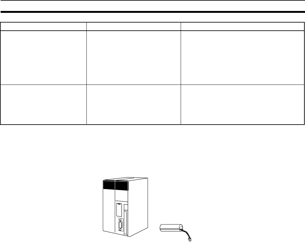
68
Checking the Package Section 1-10
1-10 Checking the Package
Check to be sure that the CPU Unit and Battery Unit are in good shape with-
out any damage.
CS1-H CPU Units
Note The CS1W-BAT01 will already be installed in the CPU Unit.
CPU processing mode Normal Mode only (including
instruction execution followed by I/O
refreshing and peripheral servicing)
Peripheral servicing include servic-
ing the RS-232C port, Host Link,
peripheral bus, and Communica-
tions Units (e.g., Controller Link
Units).
CS1-H CPU Units: Normal Mode, Parallel Pro-
cessing Mode with Asynchronous Memory
Access, Parallel Processing Mode with Synchro-
nous Memory Access, or Peripheral Servicing
Priority Mode (Parallel processing executes
peripheral servicing in parallel with instruction
execution and I/O refreshing.)
Startup mode RUN mode was entered if the Star-
tup Mode was set in the PLC Setup
to 00: Switch Setting on Program-
ming Console and the CPU Unit was
started without a Programming Con-
sole connected.
A CS1-H CPU Unit will start in RUN mode if the
Startup Mode is set in the PLC Setup to PRCH:
Switch Setting on Programming Console
(default setting) and the CPU Unit is started
without a Programming Console connected.
Item C200HX/HG/HE PLCs CS-series PLCs
CPU Unit
69
SECTION 2
Specifications and System Configuration
This section provides tables of standard models, Unit specifications, system configurations, and a comparison between
different Units.
2-1 Specifications . . . . . . . . . . . . . . . . . . . . . . . . . . . . . . . . . . . . . . . . . . . . . . . . . 70
2-1-1 CPU Unit Specifications. . . . . . . . . . . . . . . . . . . . . . . . . . . . . . . . . . 70
2-1-2 General Specifications . . . . . . . . . . . . . . . . . . . . . . . . . . . . . . . . . . . 78
2-2 CPU Unit Components . . . . . . . . . . . . . . . . . . . . . . . . . . . . . . . . . . . . . . . . . . 81
2-2-1 Components . . . . . . . . . . . . . . . . . . . . . . . . . . . . . . . . . . . . . . . . . . . 81
2-2-2 CS-series CPU Unit Capabilities . . . . . . . . . . . . . . . . . . . . . . . . . . . 84
2-2-3 Unit Classifications. . . . . . . . . . . . . . . . . . . . . . . . . . . . . . . . . . . . . . 84
2-2-4 Data Communications . . . . . . . . . . . . . . . . . . . . . . . . . . . . . . . . . . . 85
2-3 Basic System Configuration . . . . . . . . . . . . . . . . . . . . . . . . . . . . . . . . . . . . . . 87
2-3-1 Basic System Configuration . . . . . . . . . . . . . . . . . . . . . . . . . . . . . . . 87
2-3-2 CPU Rack . . . . . . . . . . . . . . . . . . . . . . . . . . . . . . . . . . . . . . . . . . . . . 89
2-3-3 Expansion Racks. . . . . . . . . . . . . . . . . . . . . . . . . . . . . . . . . . . . . . . . 94
2-3-4 SYSMAC BUS Slave Racks. . . . . . . . . . . . . . . . . . . . . . . . . . . . . . . 102
2-4 Units . . . . . . . . . . . . . . . . . . . . . . . . . . . . . . . . . . . . . . . . . . . . . . . . . . . . . . . . 105
2-4-1 Basic I/O Units . . . . . . . . . . . . . . . . . . . . . . . . . . . . . . . . . . . . . . . . . 105
2-4-2 Special I/O Units. . . . . . . . . . . . . . . . . . . . . . . . . . . . . . . . . . . . . . . . 111
2-4-3 CS-series CPU Bus Units . . . . . . . . . . . . . . . . . . . . . . . . . . . . . . . . . 118
2-5 Expanded System Configuration. . . . . . . . . . . . . . . . . . . . . . . . . . . . . . . . . . . 119
2-5-1 Serial Communications System . . . . . . . . . . . . . . . . . . . . . . . . . . . . 119
2-5-2 Systems . . . . . . . . . . . . . . . . . . . . . . . . . . . . . . . . . . . . . . . . . . . . . . . 120
2-5-3 Communications Network System . . . . . . . . . . . . . . . . . . . . . . . . . . 132
2-6 Unit Current Consumption . . . . . . . . . . . . . . . . . . . . . . . . . . . . . . . . . . . . . . . 137
2-6-1 CPU Racks and Expansion Racks . . . . . . . . . . . . . . . . . . . . . . . . . . 137
2-6-2 SYSMAC BUS Remote I/O Slave Racks. . . . . . . . . . . . . . . . . . . . . 138
2-6-3 Example Calculations . . . . . . . . . . . . . . . . . . . . . . . . . . . . . . . . . . . . 138
2-6-4 Current Consumption Tables . . . . . . . . . . . . . . . . . . . . . . . . . . . . . . 140
2-7 CPU Bus Unit Setting Area Capacity . . . . . . . . . . . . . . . . . . . . . . . . . . . . . . . 148
2-7-1 System Setting Allocations to CPU Bus Units . . . . . . . . . . . . . . . . . 148
2-8 I/O Table Settings . . . . . . . . . . . . . . . . . . . . . . . . . . . . . . . . . . . . . . . . . . . . . . 149
2-8-1 CS-series Basic I/O Units . . . . . . . . . . . . . . . . . . . . . . . . . . . . . . . . . 149
2-8-2 CS-series Special I/O Units . . . . . . . . . . . . . . . . . . . . . . . . . . . . . . . 151
2-8-3 C200H Special I/O Units . . . . . . . . . . . . . . . . . . . . . . . . . . . . . . . . . 152
2-8-4 CS-series CPU Bus Units . . . . . . . . . . . . . . . . . . . . . . . . . . . . . . . . . 153
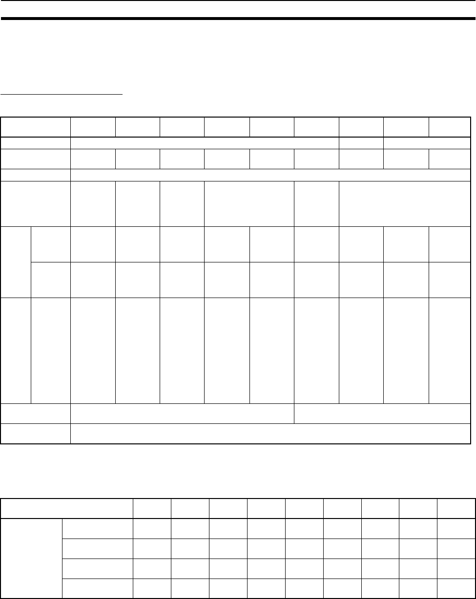
70
Specifications Section 2-1
2-1 Specifications
2-1-1 CPU Unit Specifications
CPU Unit Comparison
CS1-H CPU Units
Note The values displayed in the table are valid when a CPU Unit with unit version
4 or later is combined with CX-Programmer 7.0 or higher.
The following table shows the flash memory capacities for CPU Units with unit version 3.
Earlier CPU Units (unit version 2 or earlier) are not equipped with the function
that stores data such as comment files in flash memory.
CPU CS1H-
CPU67H
CS1H-
CPU66H
CS1H-
CPU65H
CS1H-
CPU64H
CS1H-
CPU63H
CS1G-
CPU45H
CS1G-
CPU44H
CS1G-
CPU43H
CS1G-
CPU42H
I/O bits 5120 1280 960
User program
memory (steps)
250K 120K 60K 30K 20K 60K 30K 20K 10K
Data memory 32K words
Extended data
memory
32K words
x 13 banks
E0_00000
to
EC_32767
32K words
x 7 banks
E0_00000
to
E6_32767
32K words
x 3 banks
E0_00000
to
E2_32767
32K words x 1 bank
E0_00000 to E0_32767
32K words
x 3 banks
E0_00000
to
E2_32767
32K words x 1 bank
E0_00000 to E0_32767
Func-
tion
blocks
Maxi-
mum No.
of defini-
tions
1024 1024 1024 1024 128 1024 1024 128 128
Maxi-
mum No.
of
instances
2048 2048 2048 2048 256 2048 2048 256 256
Flash
mem-
ory
(Unit
ver-
sion
4.0 or
later
(See
note.))
Total
(Kbytes)
for FB
program
memory,
com-
ment
files,
program
index
files, and
symbol
tables
2048 2048 1280 1280 1280 1280 704 704 704
Current
consumption
0.82 A at 5 V DC 0.78 A at 5 V DC
Connector
(provided)
One RS-232C Connector (Plug: XM2A-0901, Hood: XM2S-0911-E) provided with CPU Unit as standard
CPU CS1H-
CPU67H
CS1H-
CPU66H
CS1H-
CPU65H
CS1H-
CPU64H
CS1H-
CPU63H
CS1G-
CPU45H
CS1G-
CPU44H
CS1G-
CPU43H
CS1G-
CPU42H
Flash memory
(unit version 3)
FB program
memory (Kbytes)
1664 1664 1024 512 512 1024 512 512 512
Comment files
(Kbytes)
128 128 64 64 64 64 64 64 64
Program index
files (Kbytes)
128 128 64 64 64 64 64 64 64
Symbol tables
(Kbytes)
128 128 128 64 64 128 64 64 64

71
Specifications Section 2-1
Common Specifications
Item Specification Reference
Control method Stored program ---
I/O control method Cyclic scan and immediate processing are both possible. ---
Programming • Ladder diagrams
• SFC (sequential function charts)
• ST (structured text)
• Mnemonics
---
CPU processing mode CS1-H CPU Units: Normal Mode, Parallel Processing Mode
with Asynchronous Memory Access, Parallel Processing
Mode with Synchronous Memory Access, or Peripheral Ser-
vicing Priority Mode
---
Instruction length 1 to 7 steps per instruction Steps and number of
steps per instruction:
10-5 Instruction Execu-
tion Times and Num-
ber of Steps
Ladder instructions Approx. 400 (3-digit function codes) ---
Execution time CS1-H CPU Units:
Basic instructions: 0.02 µs min.
Special instructions: 0.06 µs min.
Instruction execution
times: 10-5 Instruction
Execution Times and
Number of Steps
Overhead processing time CS1-H CPU Units:
Normal mode: 0.3 ms min.
Parallel processing: 0.2 ms min.
---
Number of Expansion Racks 7 max. (C200H Expansion I/O Racks: 3 max.) Expansion Racks:
2-3-3 Expansion Racks
Number of tasks 288 (cyclic tasks: 32, interrupt tasks: 256)
Note Cyclic tasks are executed each cycle and are con-
trolled with TKON(820) and TKOF(821) instructions.
Note The following 4 types of interrupt tasks are supported.
Power OFF interrupt tasks: 1 max.
Scheduled interrupt tasks: 2 max.
I/O interrupt tasks: 32 max.
External interrupt tasks: 256 max.
Tasks:
Programming Manual
(W394): 1-4 Programs
and Tasks
Programming Manual
(W394): Section 4:
Tasks
Interrupt types Scheduled Interrupts:
Interrupts generated at a time scheduled by the CPU Unit’s
built-in timer.
I/O Interrupts:
Interrupts from Interrupt Input Units.
Power OFF Interrupts:
Interrupts executed when the CPU Unit’s power is turned
OFF.
External I/O Interrupts:
Interrupts from the Special I/O Units, CS-series CPU Bus
Units, or the Inner Board.
Calling subroutines from more
than one task
CS1-H CPU Units: Supported.
Function blocks (CPU Units
with unit version 3.0 or later
only)
Languages in function block definitions: ladder programming,
structured text
CX-Programmer Ver.
7.@ CS/CJ Series
Operation Manual
Function Blocks (W447)

72
Specifications Section 2-1
CIO
(Core
I/O)
Area
I/O Area 5,120: CIO 000000 to CIO 031915 (320 words from CIO
0000 to CIO 0319)
The setting of the first word can be changed from the default
(CIO 0000) so that CIO 0000 to CIO 0999 can be used.
I/O bits are allocated to Basic I/O Units, such as CS-series
Basic I/O Units, C200H Basic I/O Units, and C200H Group-2
High-density I/O Units.
Input and
output
bits:9-4
CIO Area
The CIO
Area can
be used as
work bits if
the bits are
not used
as shown
here.
C200H DeviceNet
Area
1,600 (100 words):
Outputs: CIO 005000 to CIO 009915 (words CIO 0050 to
CIO 0099)
Inputs: CIO 035000 to CIO 039915 (words CIO 0350 to
CIO 0399)
C200H DeviceNet Area bits are allocated to Slaves according
to C200HW-CRW21-V1 DeviceNet Unit remote I/O communi-
cations.
9-5 C200H
DeviceNet
Area
PLC Link Area 80 bits (5 words): CIO 024700 to CIO 025015 (words
CIO 0247 to CIO 0250 and CIO A442)
When a PLC Link Unit is used in a PLC Link, use these bits to
monitor PLC Link errors and the operating status of other
CPU Units in the PLC Link.
9-7 PLC
Link Area
Link Area 3,200 (200 words): CIO 10000 to CIO 119915 (words CIO
1000 to CIO 1199)
Link bits are used for data links and are allocated to Units in
Controller Link Systems and PLC Link Systems.
9-8 Data
Link Area
CPU Bus Unit Area 6,400 (400 words): CIO 150000 to CIO 189915 (words CIO
1500 to CIO 1899)
CS-series CPU Bus Unit bits store the operating status of
CS-series CPU Bus Units.
(25 words per Unit, 16 Units max.)
9-9 CPU
Bus Unit
Area
Special I/O Unit Area 15,360 (960 words): CIO 200000 to CIO 295915 (words CIO
2000 to CIO 2959)
Special I/O Unit bits are allocated to CS-series Special I/O
Units and C200H Special I/O Units. (See Note.)
(10 words per Unit, 96 Units max.)
Note Special I/O Units are I/O Units that belong to a special
group called “Special I/O Units.” Examples: C200H-
ID215/0D215/MD215
9-11 Spe-
cial I/O
Unit Area
Inner Board Area 1,600 (100 words): CIO 190000 to CIO 199915 (words CIO
1900 to CIO 1999)
Inner Board bits are allocated to Inner Boards. (100 I/O
words max.)
9-10 Inner
Board
Area
SYSMAC BUS Area 1,280 (80 words): CIO 300000 to CIO 307915 (words CIO
3000 to CIO 3079)
SYSMAC BUS bits are allocated to Slave Racks connected
to SYSMAC BUS Remote I/O Master Units. (10 words per
Rack, 8 Racks max.)
9-12 SYS-
MAC BUS
Area
I/O Terminal Area 512 (32 words): CIO 310000 to CIO 313115 (words CIO 3100
to CIO 3131)
I/O Terminal bits are allocated to I/O Terminal Units (but not
to Slave Racks) connected to SYSMAC BUS Remote I/O
Master Units. (1 word per Terminal, 32 Terminals max.)
9-13 I/O
Terminal
Area
Item Specification Reference
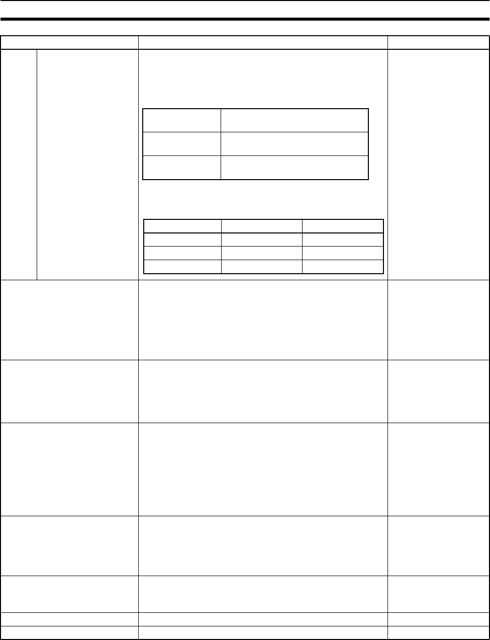
73
Specifications Section 2-1
CIO
(Core
I/O)
Area,
contin-
ued
CS-series DeviceNet
Area
9,600 (600 words): CIO 320000 to CIO 379915 (words
CIO 3200 to CIO 3799)
CS-series DeviceNet Area bits are allocated to Slaves
according to C200HW-CRW21-V1 DeviceNet Unit remote I/O
communications.
The following words are allocated to the CS-Series
DeviceNet Unit functioning as a master when fixed alloca-
tions are used for the CS1W-DRM21 DeviceNet Unit.
9-6 CS-series
DeviceNet Area
Internal I/O Area 4,800 (300 words): CIO 120000 to CIO 149915 (words CIO
1200 to CIO 1499)
37,504 (2,344 words): CIO 380000 to CIO 614315 (words
CIO 3800 to CIO 6143)
These bits in the CIO Area are used as work bits in program-
ming to control program execution. They cannot be used for
external I/O.
---
Work Area 8,192 bits (512 words): W00000 to W51115 (W000 to W511)
Controls the programs only. (I/O from external I/O terminals is
not possible.)
Note When using work bits in programming, use the bits in
the Work Area first before using bits from other areas.
9-14 Work Area
Holding Area 8,192 bits (512 words): H00000 to H51115 (H000 to H511)
Holding bits are used to control the execution of the program,
and maintain their ON/OFF status when the PLC is turned
OFF or the operating mode is changed.
Note The Function Block Holding Area words are allocated
from H512 to H1535. These words can be used only
for the function block instance area (internally allocated
variable area).
9-15 Holding Area
Auxiliary Area Read only: 7,168 bits (448 words): A00000 to A44715 (words
A000 to A447)
Read/write: 8,192 bits (512 words): A44800 to A95915
(words A448 to A959)
Auxiliary bits are allocated specific functions.
9-16 Auxiliary Area
Temporary Area 16 bits (TR0 to TR15)
Temporary bits are used to temporarily store the ON/OFF
execution conditions at program branches.
9-17 TR (Temporary
Relay) Area
Timer Area 4,096: T0000 to T4095 (used for timers only) 9-18 Timer Area
Counter Area 4,096: C0000 to C4095 (used for counters only) 9-19 Counter Area
Item Specification Reference
Fixed allocation 1 Outputs: CIO 3200 to CIO 3263
Inputs: CIO 3300 to CIO 3363
Fixed allocation 2 Outputs: CIO 3400 to CIO 3463
Inputs: CIO 3500 to CIO 3563
Fixed allocation 3 Outputs: CIO 3600 to CIO 3663
Inputs: CIO 3700 to CIO 3763
Setting Master to slave Slave to master
Fixed allocation 1 Outputs: CIO 3370 Inputs: CIO 3270
Fixed allocation 2 Outputs: CIO 3570 Inputs: CIO 3470
Fixed allocation 3 Outputs: CIO 3770 Inputs: CIO 3670

74
Specifications Section 2-1
DM Area 32K words: D00000 to D32767
Used as a general-purpose data area for reading and writing
data in word units (16 bits). Words in the DM Area maintain
their status when the PLC is turned OFF or the operating
mode is changed.
Internal Special I/O Unit DM Area: D20000 to D29599 (100
words × 96 Units)
Used to set parameters for Special I/O Units.
CPU Bus Unit DM Area: D30000 to D31599 (100 words × 16
Units)
Used to set parameters for CPU Bus Units.
Inner Board DM Area: D32000 to D32099
Used to set parameters for Inner Boards.
9-20 Data Memory
(DM) Area
EM Area 32K words per bank, 13 banks max.: E0_00000 to EC_32767
max. (Not available on some CPU Units.)
Used as a general-purpose data area for reading and writing
data in word units (16 bits). Words in the EM Area maintain
their status when the PLC is turned OFF or the operating
mode is changed.
The EM Area is divided into banks, and the addresses can be
set by either of the following methods.
Changing the current bank using the EMBC(281) instruction
and setting addresses for the current bank.
Setting bank numbers and addresses directly.
EM data can be stored in files by specifying the number of
the first bank.
9-21 Extended Data
Memory (EM) Area
Data Registers DR0 to DR15
Store offset values for indirect addressing. One register is 16
bits (1 word).
CS1-H CPU Units: Setting to use data registers either inde-
pendently in each task or to share them between tasks.
9-23 Data Registers
Index Registers IR0 to IR15
Store PLC memory addresses for indirect addressing. One
register is 32 bits (2 words).
CS1-H CPU Units: Setting to use index registers either inde-
pendently in each task or to share them between tasks.
9-22 Index Registers
Task Flag Area 32 (TK0000 to TK0031)
Task Flags are read-only flags that are ON when the corre-
sponding cyclic task is executable and OFF when the corre-
sponding task is not executable or in standby status.
9-24 Task Flags
Trace Memory 40,000 words (trace data: 31 bits, 6 words) Programming Manual
(W394)
File Memory Memory Cards: Compact flash memory cards can be used
(MS-DOS format).
EM file memory: Part of the EM Area can be converted to file
memory (MS-DOS format).
Programming Manual
(W394)
Item Specification Reference

75
Specifications Section 2-1
Function Specifications
Item Specification Reference
Constant cycle time 1 to 32,000 ms (Unit: 1 ms)
When a parallel processing mode is used for a CS1-H CPU
Unit, the cycle time for executing instructions is constant.
Cycle time:10-4 Computing the
Cycle Time
Constant cycle time: Program-
ming Manual (W394)
Cycle time monitoring Possible (Unit stops operating if the cycle is too long): 1 to
40,000 ms (Unit: 10 ms)
When a parallel processing mode is used for a CS1-H CPU
Unit, the instruction execution cycle is monitored. CPU Unit
operation will stop if the peripheral servicing cycle time
exceeds 2 s (fixed).
Cycle time:10-4 Computing the
Cycle Time
Cycle time monitoring: Program-
ming Manual (W394)
I/O refreshing Cyclic refreshing, immediate refreshing, refreshing by
IORF(097).
IORF(097) refreshes I/O bits allocated to Basic I/O Units
and Special I/O Units.
With the CS1-H CPU Units, the CPU BUS UNIT I/O
REFRESH (DLNK(226)) instruction can be used to refresh
bits allocated to CPU Bus Units in the CIO and DM Areas.
I/O refreshing:10-4 Computing
the Cycle Time
I/O refresh methods: Program-
ming Manual (W394)
Timing of special
refreshing for CPU Bus
Units
Data links for Controller Link Units and SYSMAC LINK
Units, remote I/O for DeviceNet Units, and other special
refreshing for CPU Bus Units is performed at the following
times:
CS1-H CPU Units: I/O refresh period and when the CPU
BUS UNIT I/O REFRESH (DLNK(226)) instruction is exe-
cuted
---
I/O memory holding
when changing operat-
ing modes
Depends on the ON/OFF status of the IOM Hold Bit in the
Auxiliary Area.
I/O memory: SECTION 9 Mem-
ory Areas
Programming Manual (W394):
6-6-1 Hot Start/Cold Start Func-
tion
Holding I/O memory: 9-2-3 Data
Area Properties
Load OFF All outputs on Output Units can be turned OFF when the
CPU Unit is operating in RUN, MONITOR, or PROGRAM
mode.
Load OFF:
Programming Manual (W394):
6-7-2 Load OFF Function and 7-
2-3 Online Editing
Input response time
setting
Time constants can be set for inputs from Basic I/O Units.
The time constant can be increased to reduce the influence
of noise and chattering or it can be decreased to detect
shorter pulses on the inputs.
Input response time: 10-4-6 I/O
Response Time
Input response settings:
Programming Manual (W394):
6-11-1 I/O Response Time Set-
tings
Startup mode setting Supported
The startup mode will be as follows if the PLC Setup is set
to use the Programming Console mode (default) and a Pro-
gramming Console is not connected:
CS1-H CPU Units: RUN mode
Startup mode: Programming
Manual (W394)
Flash memory (CS1-H
CPU Units only)
• The user program and parameter area data (e.g., PLC
Setup) are always backed up automatically in flash
memory.
• CPU Units with unit version 3.0 or later only:
When downloading projects from CX-Programmer Ver.
5.0 or higher, symbol table files (including CX-Program-
mer symbol names, I/O comments), comment files (CX-
Programmer rung comments, other comments), and
program index files (CX-Programmer section names,
section comments, or program comments) are stored in
comment memory within the flash memory.
---

76
Specifications Section 2-1
Memory Card functions Automatically reading pro-
grams (autoboot) from the
Memory Card when the
power is turned ON.
Supported Memory Cards and file memory:
3-2 File Memory and Program-
ming Manual (W394) Section 5
File Memory Functions
Automatic file transfer at startup
and file operations using CMND:
Programming Manual (W394)
5-2-3 Using Instruction in User
Program
Program replacement during
PLC operation
Supported Replacing the program with
CMND: Programming Manual
(W394)
Format in which data is
stored in Memory Card
User program: Program file
format
PLC Setup and other
parameters: Data file format
I/O memory: Data file format
(binary format), text format,
or CSV format
Data stored in the Memory Card:
Programming Manual (W394)
5-2-3 Using Instruction in User
Program
Functions for which Memory
Card read/write is supported
User program instructions,
Programming Devices
(including Programming
Consoles), Host Link com-
puters, AR Area control bits,
easy backup operation
Memory Card read/write opera-
tions: Programming Manual
(W394)
Filing Memory Card data and the EM (Extended Data Memory)
Area can be handled as files.
File memory: Programming Man-
ual (W394)
Debugging Control set/reset, differential monitoring, data tracing
(scheduled, each cycle, or when instruction is executed),
storing location generating error when a program error
occurs
Debugging, set/reset, differential
monitoring, data tracing: Pro-
gramming Manual (W394)
Online editing When the CPU Unit is in MONITOR or PROGRAM mode,
multiple program sections (“circuits”) of the user program
can be edited together. This function is not supported for
block programming areas.
(With the CX-Programmer is used, multiple program sec-
tions of the user program can be edited together. When a
Programming Console is used, the program can be edited
in mnemonics only.).
Operating modes: Programming
Manual (W394)
Program protection Overwrite protection: Set using DIP switch.
Copy protection: Password set using Programming Device.
Program protection: Program-
ming Manual (W394)
Error check User-defined errors (i.e., user can define fatal errors and
non-fatal errors)
The FPD(269) instruction can be used to check the execu-
tion time and logic of each programming block.
FAL and FALS instructions can be used with the CS1-H
CPU Units to simulate errors.
Failure diagnosis: Programming
Manual (W394)
Fatal and nonfatal errors: 11-2-4
Error Processing Flowchart
User-defined errors: Program-
ming Manual (W394)
Error log Up to 20 errors are stored in the error log. Information
includes the error code, error details, and the time the error
occurred.
A CS1-H CPU Unit can be set so that user-defined FAL
errors are not stored in the error log.
Error log: Programming Manual
(W394)
Serial communications Built-in peripheral port: Programming Device (including
Programming Console) connections, Host Links, NT Links
Built-in RS-232C port: Programming Device (excluding
Programming Console) connections, Host Links, no-proto-
col communications, NT Links
Serial communications systems:
2-5-1 Serial Communications
System
Serial communications: Program-
ming Manual (W394)
Serial Communications Board (sold separately): Protocol
macros, Host Links, NT Links
Item Specification Reference

77
Specifications Section 2-1
Clock Provided on all models. Accuracy: ± 30 s/mo. at 25°C
(accuracy varies with the temperature)
Note Used to store the time when power is turned ON and
when errors occur.
Clock: Programming Manual
(W394)
Power OFF detection
time
10 to 25 ms (not fixed) Power OFF operation and power
OFF detection time: 10-3 Power
OFF Operation
Power OFF detection
delay time
0 to 10 ms (user-defined, default: 0 ms) Power OFF detection delay time:
Programming Manual (W394)
Memory protection Held Areas: Holding bits, contents of Data Memory and
Extended Data Memory, and status of the counter Comple-
tion Flags and present values.
Note If the IOM Hold Bit in the Auxiliary Area is turned
ON, and the PLC Setup is set to maintain the IOM
Hold Bit status when power to the PLC is turned ON,
the contents of the CIO Area, the Work Area, part of
the Auxiliary Area, timer Completion Flag and PVs,
Index Registers, and the Data Registers will be
saved for up to 20 days.
Memory protection: 9-2-3 Data
Area Properties
Sending commands to
a Host Link computer
FINS commands can be sent to a computer connected via
the Host Link System by executing Network Communica-
tions Instructions from the PLC.
Host Links and non-solicited
communications: 2-5-2 Systems
Remote programming
and monitoring
Host Link communications can be used for remote pro-
gramming and remote monitoring through a Controller Link
System or Ethernet network.
Remote programming and moni-
toring: Programming Manual
(W394)
Controller Link 2-5-3 Communi-
cations Network System
Communicating across
network layers
Remote programming and monitoring using the Support
Software, as well as FINS message communications, can
be conducted across network layers, including other types
of network.
Pre-Ver. 2.0: Three layers
Version 2.0 or later: Eight layers for Controller Link and
Ethernet (see note). Three layers for
DeviceNet and SYSMAC LINK.
Note To construct a network of eight layers, it is necessary
to use the CX-Integrator or CX-Programmer (version
4.0 or higher) to set routing tables.
Host Links and FINS message
service: 2-5-2 Systems
Storing comments in
CPU Unit
I/O comments can be stored as symbol table files in the
Memory Card, EM file memory, or comment memory (see
note).
Note Comment memory is supported for CS/CJ-series
CPU Units with unit version 3.0 or later only.
I/O comments: CX-Programmer
Operation Manual (W446)
Storing comments in CPU Unit:
Programming Manual (W394)
Program check Program checks are performed at the beginning of opera-
tion for items such as no END instruction and instruction
errors.
CX-Programmer can also be used to check programs.
Program check: Programming
Manual (W394)
Control output signals RUN output: The internal contacts will turn ON (close)
while the CPU Unit is operating.
These terminals are provided only on the C200HW-
PA204R and C200HW-PA209R Power Supply Units.
RUN output: Programming Man-
ual (W394)
Battery life Battery Set: CS1W-BAT01 Battery life and replacement
period: 12-2-1 Battery Replace-
ment
Item Specification Reference

78
Specifications Section 2-1
2-1-2 General Specifications
Self-diagnostics CPU errors (watchdog timer), I/O verification errors, I/O
bus errors, memory errors, and battery errors.
CPU, I/O bus, memory, and bat-
tery errors: 11-2-4 Error Process-
ing Flowchart
Other functions Storage of number of times power has been interrupted.
(Stored in A514.)
Number of power interruptions:
10-3 Power OFF Operation
Item Specifications
Power
Supply
Unit
C200HW-
PA20 4
C200HW-
PA204C
C200HW-
PA204R
C200HW-
PA204S
C200HW-
PA209R
C200HW-
PD024
C200HW-
PD025
Supply
voltage
100 to 240 V AC (wide range), 50/60 Hz (See
note 7.)
100 to 120 V AC or
200 to 240 V AC, 50/60 Hz
24 V DC 24 V DC
Operating
voltage
range
85 to 264 V AC 85 to 132 V AC or
170 to 264 V AC
19.2 to 28.8 V
DC
19.2 to 28.8 V
DC
Power
consump-
tion
120 VA max. 100 VA max. 120 VA max. 120 VA max. 180 VA max. 40 W max. 60 W max.
Inrush
current
100 to 120 V AC input: 15 A max. (cold start
at room temperature) for 8 ms max.
200 to 240 V AC input: 30 A max. (cold start
at room temperature) for 8 ms max.
100 to 120 V
AC input: 20
A max. (cold
start at room
temperature)
for 8 ms max.
200 to 240 V
AC input: 30
A max. (cold
start at room
temperature)
for 8 ms max.
30 A max.
100 to 120 V
40 A max.
200 to 240 V
30 A max. 30 A max.
Output
capacity
(See note
6.)
4.6 A, 5 V DC (including the CPU Unit power supply) 9 A, 5 V DC
(including the
CPU Unit
power supply)
4.6 A, 5 V DC
(including the
CPU Unit
power supply)
5.3 A, 5 V DC
(including the
CPU Unit
power supply)
0.625 A,
26 V DC
Total: 30 W
max.
0.625 A,
26 V DC
Total: 30 W
max.
0.625 A,
26 V DC
Total: 30 W
max.
0.625 A,
26 V DC
0.8 A,
24 V DC
Total: 30 W
max.
1.3 A,
26 V DC
Total: 45 W
max.
0.625 A,
26 V DC
Total: 30 W
max.
1.3 A,
26 V DC
Total: 40 W
max.
Output
terminal
(service
supply)
Not provided Not provided Not provided Provided.
At consump-
tion of less
than 0.3 A,
24-V DC sup-
ply will be
+17%/–11%;
at 0.3 A or
greater,
+10%/–11%
(lot 0197 or
later)
Not provided Not provided Not provided
Item Specification Reference

79
Specifications Section 2-1
RUN
output
(See note
2.)
Not provided Not provided Contact con-
figuration:
SPST-NO
Switch
capacity:
250 V AC,
2A (resistive
load)
250 V AC,
0.5 A (induc-
tion load),
24 V DC, 2 A
Not provided Contact con-
figuration:
SPST-NO
Switch capac-
ity: 240 V AC,
2A (resistive
load)
120 V AC,
0.5 A (induc-
tion load)
24 V DC, 2 A
(resistive
load)
24 V DC, 2 A
(induction
load)
Not provided Not provided
Replace-
ment
notifica-
tion
function
Not provided With
Alarm output
(open-collec-
tor output)
30 V DC
max., 50 mA
max.
Not provided Not provided Not provided Not provided Not provided
Insulation
resistance
20 MΩ min.
(at 500 V DC)
between AC
external and
GR terminals
(See note 1.)
20 MΩ min.
(at 500 V DC)
between all
external ter-
minals and
GR terminal,
and between
all alarm out-
put terminals.
20 MΩ min.
(at 250 V DC)
between all
alarm output
terminals and
GR terminal.
20 MΩ min.
(at 500 V DC)
between AC
external and
GR terminals
(See note 1.)
20 MΩ min.
(at 500 V DC)
between AC
external and
GR terminals
(See note 1.)
20 MΩ min.
(at 500 V DC)
between AC
external and
GR terminals
(See note 1.)
20 MΩ min.
(at 500 V DC) between DC
external and GR terminals
(See note 1.)
Dielectric
strength
(See note
5.)
2,300 V AC
50/60 Hz for
1 min
between AC
external and
GR terminals
(See note 1.)
Leakage cur-
rent: 10 mA
max.
2,300 V AC,
50/60 Hz for 1
minute
between all
external ter-
minals and
GR terminal
and between
all alarm out-
put terminals
with a leak-
age current of
10 mA max.
2,300 V AC
50/60 Hz for
1 min
between AC
external and
GR terminals
(See note 1.)
Leakage cur-
rent: 10 mA
max.
2,300 V AC
50/60 Hz for
1 min
between AC
external and
GR terminals
(See note 1.)
Leakage cur-
rent: 10 mA
max.
2,300 V AC
50/60 Hz for
1min
between AC
external and
GR terminals
(See note 1.)
Leakage cur-
rent: 10 mA
max.
1,000 V AC 50/60 Hz for
1 min between DC external
and GR terminals (See note
1.).
Leakage current: 10 mA max.
1,000 V AC, 50/60 Hz for 1 minute between all alarm output terminals and
GR terminal with a leakage current of 10 mA max.
Noise
immunity
2 kV on power supply line (conforming to IEC61000-4-4)
Vibration
resistance 10 to 57 Hz, 0.075-mm amplitude, 57 to 150 Hz, acceleration: 9.8 m/s2 in X, Y, and Z directions for 80
minutes (Time coefficient: 8 minutes ×coefficient factor 10 = total time 80 min.)
CPU Unit mounted to a DIN track: 2 to 55 Hz, 2.94 m/s2 in X, Y, and Z directions for 20 minutes
Shock
resistance 147 m/s2 3 times each in X, Y, and Z directions (according to JIS 0041)
Ambient
operating
tempera-
ture
0 to 55°C
Item Specifications
Power
Supply
Unit
C200HW-
PA20 4
C200HW-
PA204C
C200HW-
PA204R
C200HW-
PA204S
C200HW-
PA209R
C200HW-
PD024
C200HW-
PD025

80
Specifications Section 2-1
Note 1. Disconnect the Power Supply Unit’s LG terminal from the GR terminal
when testing insulation and dielectric strength.
Testing the insulation and dielectric strength with the LG terminal and the
GR terminals connected will damage internal circuits in the CPU Unit.
2. Supported only when mounted to CPU Backplane.
3. The depth is 153 mm for the C200HW-PA209R/PD025 Power Supply Unit,
111 mm for the C200HW-PA204C Power Supply Unit.
4. Maintain an ambient storage temperature of −25 to 30°C and relative hu-
midity of 25% to 70% when storing the C200HW-PA204C for longer than 3
months to keep the replacement notification function in optimum working
condition.
5. Change the applied voltage gradually using the adjuster on the Tester. If
the full dielectric strength voltage is applied or turned OFF using the switch
on the Tester, the generated impulse voltage may damage the Unit.
6. The Power Supply Unit’s internal parts may deteriorate and be damaged if
the power supply output capacity is exceeded for a long time or the outputs
are short-circuited.
7. The power supply voltage for C200HW-PA204 Power Supply Units manu-
factured before March 2010 and C200HW-PA204R Power Supply Units
manufactured before May 2010 is 100 to 120 V AC/200 to 240 V AC
(switched using short bar). For details on the differences between these
Units, refer to Unit Differences by Manufacturing Date (Reference Informa-
tion) on page 189
Ambient
operating
humidity
10% to 90%
(with no con-
densation)
10% to 90%
(without con-
densation)
(See note 4.)
10% to 90%
(with no con-
densation)
10% to 90%
(with no con-
densation)
10% to 90% (with no condensation)
Atmo-
sphere
Must be free from corrosive gases.
Ambient
storage
tempera-
ture
–20 to 75°C
(excluding
battery)
–20 to 75°C
(See note 4.)
–20 to 75°C
(excluding
battery)
–20 to 75°C
(excluding
battery)
–20 to 75°C (excluding battery)
Grounding Less than 100 Ω
Enclosure Mounted in a panel.
Weight All models are each 6 kg max.
CPU Rack
dimen-
sions
(mm)
(See note
3.)
2 slots:198.5 × 157 × 123 (W x H x D)
3 slots: 260 × 130 × 123 (W x H x D)
5 slots: 330 × 130 × 123 (W x H x D)
8 slots: 435 × 130 × 123 (W x H x D)
10 slots:505 × 130 × 123 (W x H x D)
Safety
measures
Conforms to UL, CSA, cULus, cUL, NK, Lloyds, and EC directives.
Item Specifications
Power
Supply
Unit
C200HW-
PA20 4
C200HW-
PA204C
C200HW-
PA204R
C200HW-
PA204S
C200HW-
PA209R
C200HW-
PD024
C200HW-
PD025
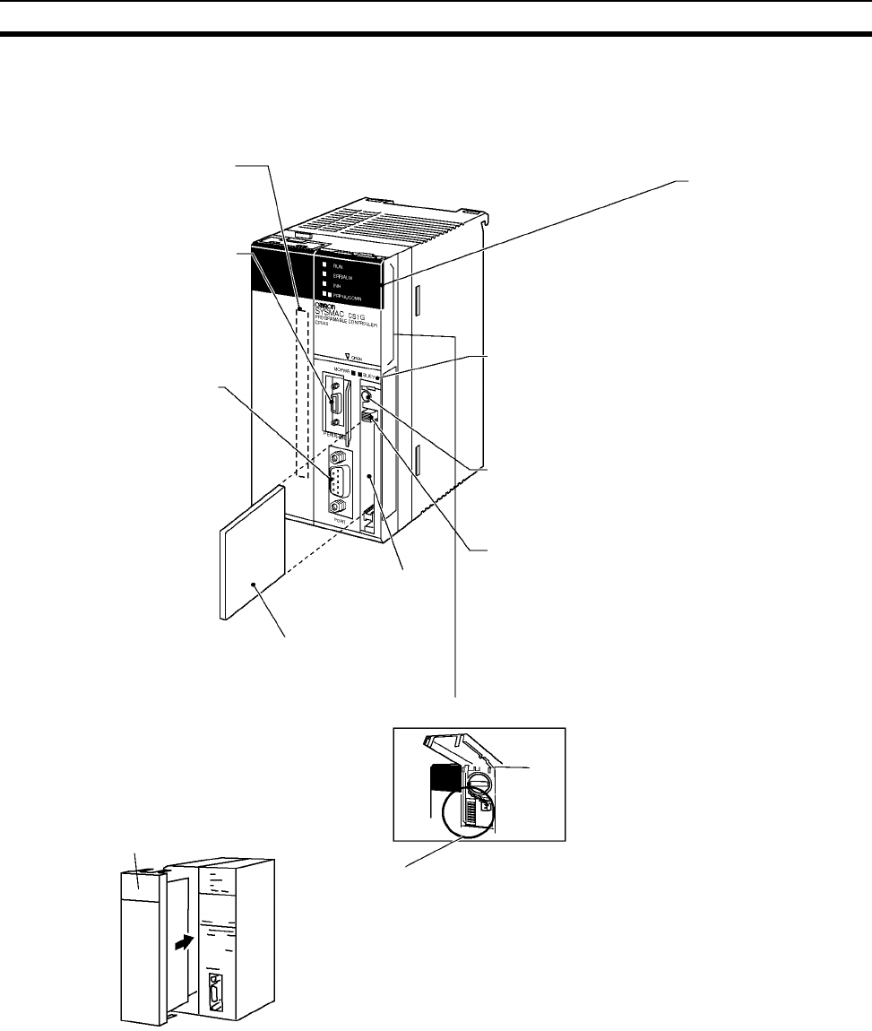
81
CPU Unit Components Section 2-2
2-2 CPU Unit Components
2-2-1 Components
1. Indicators
2. Memory Card indicators
3. Memory Card power supply switch
4. Memory Card eject button
5. DIP switch
6. Memory Card
connector
7. Memory Card
8. Inner Board
connector
compartment
9. Peripheral port
10. RS-232C port
Battery compartment cover lifted
Inner Board
(e.g., Serial Communications Board)
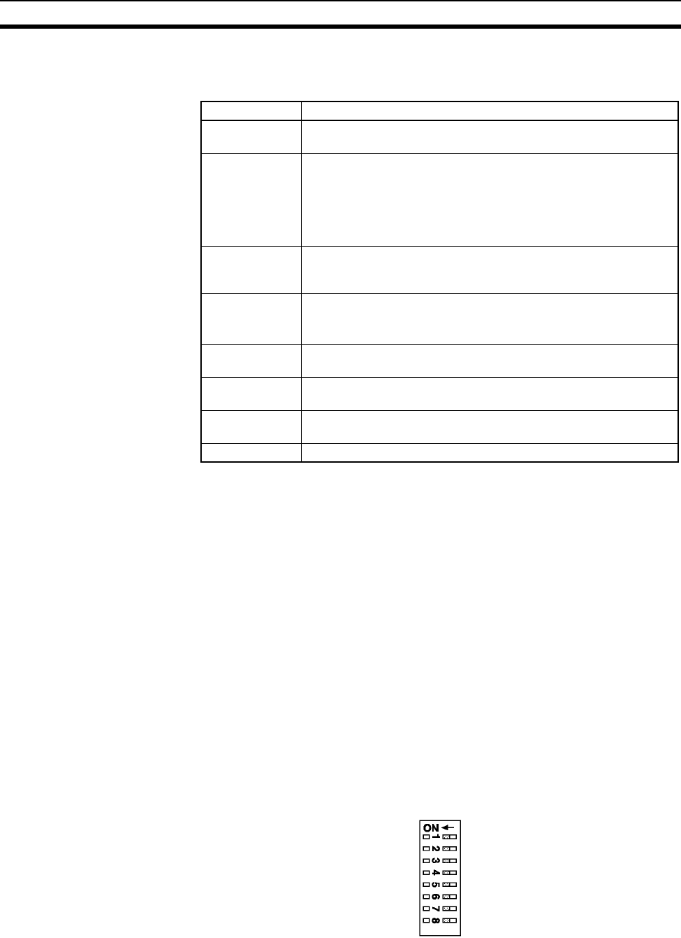
82
CPU Unit Components Section 2-2
1,2,3... 1. Indicators
The following table describes the LED indicators on the front panel of the
CPU Unit.
2. Memory Card Indicators
The MCPWR indicator flashes green when power is being supplied to the
Memory Card and the BUSY indicator flashes orange when the Memory
Card is being accessed.
3. Memory Card Power Supply Switch
Press the Memory Card power supply switch to disconnect power before
removing the Memory Card. Also, press the Memory Card Power Supply
Switch to perform an easy backup operation (i.e., to write to or verify the
Memory Card), or to stop the MCPWR indicator flashing due to a write or
verify malfunction when performing an easy backup to the Memory Card.
4. Memory Card Eject Button
Press the Memory Card eject button to remove the Memory Card from the
CPU Unit before turning the power OFF or to perform an easy backup op-
eration.
5. DIP Switch
A CS-series CPU Unit has an 8-pin DIP switch that is used to set basic op-
erational parameters for the CPU Unit. The DIP switch is located under the
cover of the battery compartment. The DIP switch pin settings are de-
scribed in the following table.
Indicator Meaning
RUN (green) Lights when the PLC is operating normally in MONITOR or RUN
mode.
ERR/ALM (red) Flashes if a non-fatal error occurs that does not stop the CPU Unit.
If a non-fatal error occurs, the CPU Unit will continue operating.
Lights if a fatal error occurs that stops the CPU Unit or if a hard-
ware error occurs. If a fatal or hardware error occurs, the CPU Unit
will stop operating, and the outputs from all Output Units will turn
OFF.
INH (orange) Lights when the Output OFF Bit (A50015) turns ON. If the Output
OFF Bit is turned ON, the outputs from all Output Units will turn
OFF.
BKUP (orange) Lights when data is being backed up from RAM to the flash mem-
ory.
Do not turn OFF the CPU Unit when this indicator is lit.
PRPHL
(orange)
Flashes when the CPU Unit is communicating via the peripheral
port.
COMM (orange) Flashes when the CPU Unit is communicating via the RS-232C
port.
MCPWR
(green)
Flashes when power is being supplied to the Memory Card.
BUSY (orange) Flashes when the Memory Card is being accessed.

83
CPU Unit Components Section 2-2
6. Memory Card Connector
The Memory Card connector connects the Memory Card to the CPU Unit.
7. Memory Card
Memory Cards fit into the slot located on the lower right side of the CPU
Unit. Memory Cards are not provided with the PLC and must be ordered
separately and installed in the CPU Unit.
8. Inner Board Connector Compartment
The Inner Board connector compartment is used to connect Inner Boards
such as the Serial Communications Board.
9. Peripheral Port
The peripheral port is connected to Programming Devices, such as a Pro-
gramming Console or Host Computers. Refer to 3-3 Programming Devices
for details.
10. RS-232C Port
The RS-232C port is connected to Programming Devices (excluding Pro-
gramming Console), Host Computers, general-purpose external devices,
Programmable Terminals, and other devices. Refer to 3-3 Programming
Devices for details.
Pin No. Setting Function
1 ON Writing disabled for user program memory.
OFF Writing enabled for user program memory.
2 ON The user program is automatically transferred and executed when power is turned ON.
OFF The user program is automatically transferred but not executed when power is turned ON.
3 OFF Always OFF.
4 ON Use peripheral port communications parameters set in the PLC Setup.
OFF Auto-detect Programming Console or CX-Programmer communications parameters at the
peripheral port.
5 ON Auto-detect Programming Console or CX-Programmer communications parameters at the RS-
232C port.
OFF Use RS-232C port communications parameters set in the PLC Setup.
6 ON User-defined pin. Turns OFF the User DIP Switch Pin Flag (A39512).
OFF User-defined pin. Turns ON the User DIP Switch Pin Flag (A39512).
7 ON Easy backup by reading/writing to Memory Card.
OFF Easy backup by verifying contents of Memory Card.
8 OFF Always OFF.
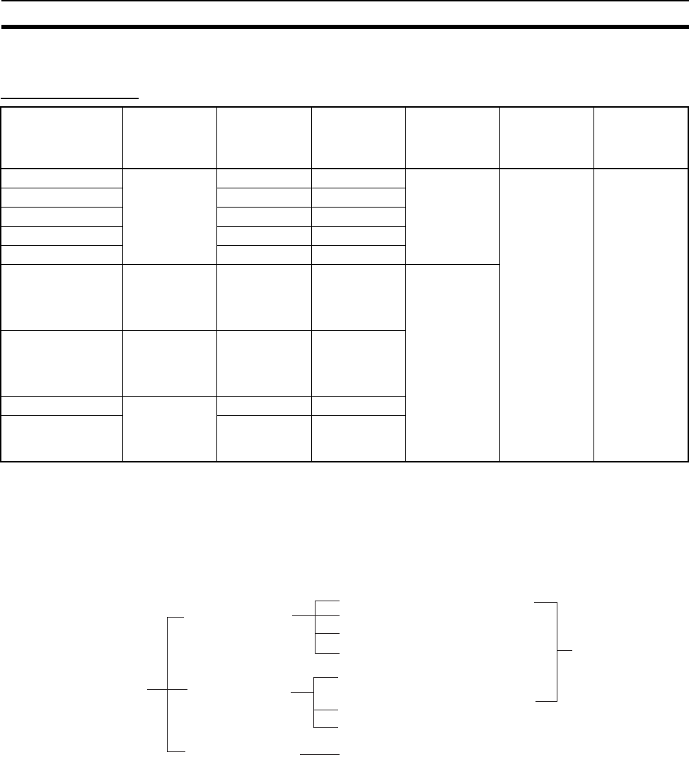
84
CPU Unit Components Section 2-2
2-2-2 CS-series CPU Unit Capabilities
CS1-H CPU Units
Note The available Data Memory capacity is the sum of the Data Memory (DM) and
the Extended Data Memory (EM).
2-2-3 Unit Classifications
CS-series CPU Units can exchange data with Basic I/O Units, Special I/O
Units, and CS-series CPU Bus Units as shown in the following diagram.
Model I/O bits Program
capacity
Data memory
capacity
(See note.)
Ladder
instruction
processing
speed
Internal com-
munications
ports
Optional
products
CS1H-CPU67H 5120 bits
(Up to 7
Expansion
Racks)
250K steps 448K words 0.02 µs Peripheral port
and
RS-232C port.
Memory Cards
Inner Boards
such as Serial
Communica-
tions Boards
CS1H-CPU66H 120K steps 256K words
CS1H-CPU65H 60K steps 128K words
CS1H-CPU64H 30K steps 64K words
CS1H-CPU63H 20K steps 64K words
CS1G-CPU45H 5120 bits
(Up to 7
Expansion
Racks)
60K steps 128K words 0.04 µs
CS1G-CPU44H 1280 bits
(Up to 3
Expansion
Racks)
30K steps 64K words
CS1G-CPU43H 960 bits
(Up to 2
Expansion
Racks)
20K steps 64K words
CS1G-CPU42H 10K steps 64K words
CS-series Units
Basic I/O Units
Special I/O Units
CPU Bus Units
C200H Basic I/O Units
C200H Interrupt Input Units
C200H Group-2 High-density I/O Units
C200H High-density I/O Units
(classified as C200H Special I/O Units)
C200H Special I/O Units
CS-series Special I/O Units
I/O Units
CS-series CPU Bus Units
CS-series Basic I/O Units

85
CPU Unit Components Section 2-2
2-2-4 Data Communications
CPU Unit Data Communications
CPU Unit Connections
Note 1. The maximum number of Units on CPU Racks and Expansion Racks is 80
because there is a maximum of 80 slots.
2. There is a maximum of 80 slots.
3. Some CS-series CPU Bus Units cannot be mounted to a CS-series Expan-
sion Rack.
4. Up to 89 Special I/O Units can be mounted as follows: Up to 79 CS-series
Special I/O Units can be mounted to the CPU Rack and CS-series Expan-
sion Racks and up to 10 C200H Special I/O Units can be mounted to the
Unit Data Exchange during cyclic servicing
(allocations)
Event service data
communications
(IORD/IOWR
instruction)
I/O refreshing using
IORF instruction
CS-series Basic I/O
Units
According to I/O
allocations
(Words are allocated
in order according to
the position the Unit is
mounted.)
I/O refreshing Not provided. Yes
C200H Basic I/O
Units
Ye s
C200H Group-2 High-
density I/O Units
(classified as Basic
I/O Units)
Ye s
CS-series Special I/O
Units
Unit No. allocations Special I/O Unit Area
(CIO): 10 words/Unit
Special I/O Unit Area
(DM): 100 words/Unit
Ye s
(Not available for some
Units.)
Ye s
(Not available for some
Units.)
C200H Special I/O
Units
Ye s
(Not available for some
Units.)
Ye s
(Not available for some
Units.)
CPU Bus Units CS-series CPU Bus
Unit Area (CIO):
5 words/ Unit
CS-series CPU Bus
Unit Area (DM): 100
words/Unit
Not provided. No
Unit Maximum Num-
ber of Units on
CPU Racks and
Expansion
Racks
Racks to which Unit can be mounted
CPU Rack
(See note 5.)
C200H
Expansion
I/O Racks
CS-series
Expansion
Racks
(See note 5.)
SYSMAC BUS
Slave Racks
CS-series Basic I/O
Units
80
(See note 1.)
Ye s N o Ye s N o
C200H Basic I/O
Units
80
(See note 1.)
Ye s Ye s Ye s Ye s
C200H Group-2 High-
density I/O Units
(classified as Basic
I/O Units)
80
(See note 1.)
Ye s Ye s Ye s N o
CS-series Special I/O
Units
80
(See notes 2 and
4.)
Ye s N o Ye s N o
C200H Special I/O
Units
16 Yes Yes Yes Yes (See notes 3
and 4.)
CPU Bus Units 16 Yes No Yes
(See note 3.)
No

86
CPU Unit Components Section 2-2
SYSMAC BUS Slave Racks. The C200H Special I/O Units must be as-
signed unit numbers 0 to 9, and each Remote I/O Master Unit must be
counted as a CS-series Special I/O Unit.
5. C200H Units and Racks cannot be used with CS-series-only CPU Racks
or Expansion Racks.

87
Basic System Configuration Section 2-3
2-3 Basic System Configuration
2-3-1 Basic System Configuration
CPU Rack A CPU Rack consists of a CPU Unit, a Power Supply Unit, a CPU Backplane,
Basic I/O Units, Special I/O Units, and CPU Bus Units. A Serial Communica-
tions Board and Memory Card are optional.
Note 1. The Backplanes required depend on which CPU Racks, Expansion I/O
Racks, and Slave Racks are used.
2. Expansion Racks cannot be connected to a 2-slot CPU Rack.
3. A maximum of four C200HS-INT01 Interrupt Input Units can be connected
to one CPU Unit.
Expansion Racks The Expansion Racks required for the C200H CPU Units and CS-series CPU
Units are different.
• C200H Expansion I/O Racks can be connected to CPU Racks, CS-series
Expansion Racks, or other C200H Expansion I/O Racks.
• CS-series Expansion Racks can be connected to CPU Racks or other
CS-series Expansion Racks. A CS-series Expansion Rack consists of a
Power Supply Unit, a CS-series Expansion Backplane or C200H Expan-
sion I/O Backplane, a Basic I/O Unit, a Special I/O Unit, and a CS-series
CPU Bus Unit.
Note a) CS-series Expansion Racks cannot be connected after C200H
Expansion I/O Racks.
b) CS-series Basic I/O Units, CS-series Special I/O Units and CS-se-
ries CPU Bus Units cannot be mounted to C200H Expansion I/O
Racks.
c) Interrupt Input Units cannot be mounted to CS-series Expansion
Racks or C200H Expansion I/O Racks.
CS-series Long-distance
Expansion Racks
I/O Control Units and I/O Interface Units can be used to create systems con-
taining CS-series Long-distance Expansion Racks. Up to two series of Long-
distance Expansion Racks can be connected, each measuring up to 50 m, for
a total coverage of 100 m.
SYSMAC BUS Slave
Racks
Up to 5 SYSMAC BUS Slave Racks can be connected to one SYSMAC BUS
Remote I/O Master Unit. A maximum of 5 Units, however, can be connected
to one CPU Unit.
A SYSMAC BUS Slave Rack consists of a Remote I/O Slave Unit, a Remote
I/O Slave Rack Backplane, a Basic I/O Unit, and a Special I/O Unit.
Note 1. C200H Group-2 High-density I/O Units, Interrupt Input Units, CS-series
Basic I/O Units, CS-series Special I/O Units and CS-series CPU Bus Units
cannot be mounted to SYSMAC BUS Slave Racks.
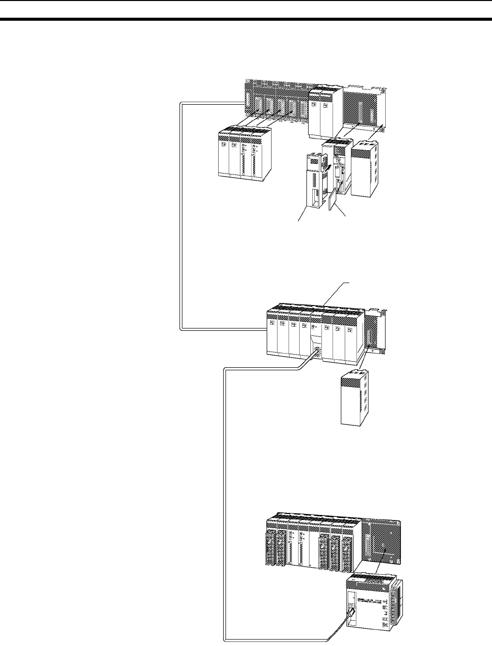
88
Basic System Configuration Section 2-3
2. SYSMAC BUS Slave Racks can be connected to C200H Expansion I/O
Racks using C200H I/O Connecting Cables.
CPU Rack
CPU Backplane
Power Supply Unit
Memory Card
Serial Communications Board
I/O Units
Special I/O Units
CS-series CPU Bus Units
I/O Connecting
Cables
Expansion Rack Remote I/O Master Unit
I/O Backplane
Power Supply Unit
I/O Units
Special I/O Units
CS-series CPU Bus Units
Optical fiber cables
Two-core cables
SYSMAC BUS Slave Rack
Backplane
Remote I/O Slave Unit
I/O Units
Special I/O Units
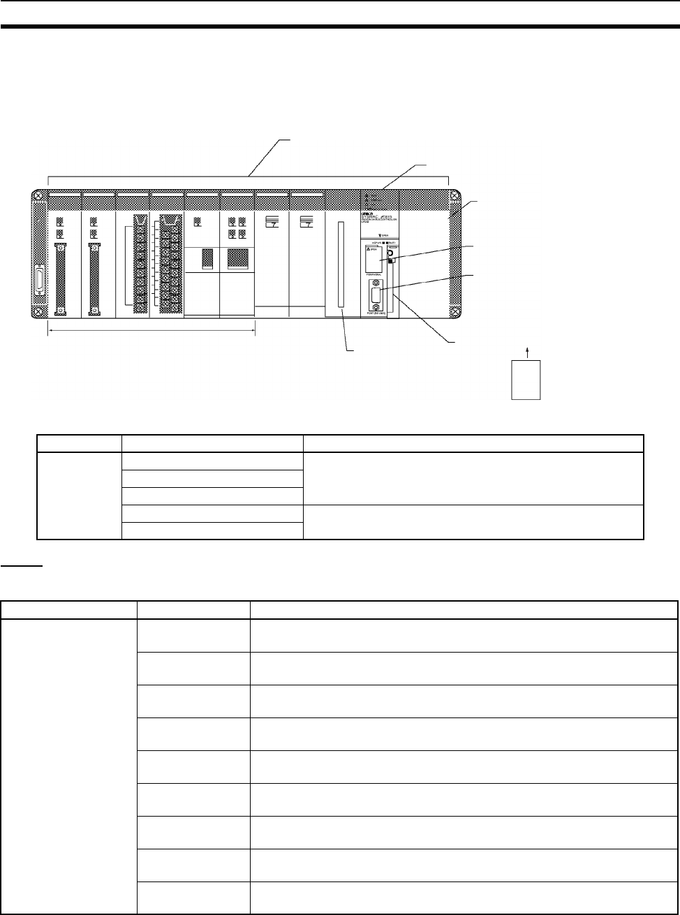
89
Basic System Configuration Section 2-3
2-3-2 CPU Rack
A CS-series CPU Rack consists of a CPU Backplane, a Power Supply Unit,
and various other Units.
Units
CS1-H CPU Units
CPU Backplane (2, 3, 5, 8, or 10 slots)
CPU Unit
Power Supply Unit
Peripheral port
RS-232C port
Inner Board
connector
Memory Card compartment
Memory Card
Other Units
(Depending on the CPU Backplane, 2, 3, 5, 8,
or 10 Units can be mounted)
Name Configuration Remarks
CPU Rack CPU Backplane One of each Unit required for every CPU Rack.
Refer to the following table for details on applicable models.
CPU Unit
Power Supply Unit
Memory Card Install as required.
Refer to the following table for details on applicable models.
Serial Communications Board
Name Model Specifications
CS-series CS1-H CPU
Units
CS1H-CPU67H I/O bits: 5,120, Program capacity: 250K steps
Data Memory: 448K words (DM: 32K words, EM: 32K words × 13 banks)
CS1H-CPU66H I/O bits: 5,120, Program capacity: 120K steps
Data Memory: 256K words (DM: 32K words, EM: 32K words × 7 banks)
CS1H-CPU65H I/O bits: 5,120, Program capacity: 60K steps
Data Memory: 128K words (DM: 32K words, EM: 32K words × 3 banks)
CS1H-CPU64H I/O bits: 5,120, Program capacity: 30K steps
Data Memory: 64K words (DM: 32K words, EM: 32K words × 1 banks)
CS1H-CPU63H I/O bits: 5,120, Program capacity: 20K steps
Data Memory: 32K words (DM: 32K words, EM: 32K words × 1 banks)
CS1H-CPU45H I/O bits: 5,120, Program capacity: 60K steps
Data Memory: 128K words (DM: 32K words, EM: 32K words × 3 banks)
CS1H-CPU44H I/O bits: 1,280, Program capacity: 30K steps
Data Memory: 64K words (DM: 32K words, EM: 32K words × 1 banks)
CS1H-CPU43H I/O bits: 960, Program capacity: 20K steps
Data Memory: 64K words (DM: 32K words, EM: 32K words × 1 banks)
CS1H-CPU42H I/O bits: 960, Program capacity: 10K steps
Data Memory: 64K words (DM: 32K words, EM: 32K words × 1 banks)

90
Basic System Configuration Section 2-3
Note: 1. C200H Units (C200H Basic I/O Units, C200H Group-2 High-density I/O Units, and C200H Special I/O
Units) cannot be used with CS-series-only CPU Backplanes.
2. When using the CX-Programmer with the computer connected via a Programming Device Connecting
Cable for the peripheral port, a Host Link (SYSWAY) software connection is not possible. Use a toolbus
(peripheral bus) connection.
Standard CPU
Backplanes
CS1W-BC023 2 slots (Expansion Racks cannot be connected)
CS1W-BC033 3 slots
CS1W-BC053 5 slots
CS1W-BC083 8 slots
CS1W-BC103 10 slots
CS-series-only CPU
Backplanes
CS1W-BC022 2 slots (See note 1.)
CS1W-BC032 3 slots (See note 1.)
CS1W-BC052 5 slots (See note 1.)
CS1W-BC082 8 slots (See note 1.)
CS1W-BC102 10 slots (See note 1.)
Name Model Specifications
Power Supply Units C200HW-PA204 100 to 240 V AC
Output capacity: 4.6 A at 5 V DC
C200HW-PA204C 100 to 240 V AC (with replacement notification)
Output capacity: 4.6 A at 5 V DC
C200HW-PA204R 100 to 240 V AC (with RUN output)
Output capacity: 4.6 A at 5 V DC
C200HW-PA204S 100 to 120 V AC or 200 to 240 V AC (with 0.8 A 24 V DC service
power supply)
Output capacity: 4.6 A at 5 V DC
C200HW-PA209R 100 to 120 V AC or 200 to 240 V AC (with RUN output)
Output capacity: 9 A at 5 V DC
C200HW-PD024 24 V DC
C200HW-PD025 24 V DC
Memory Cards HMC-EF372 Flash memory, 30 MB
HMC-EF672 Flash memory, 64 MB
HMC-EF183 Flash memory, 128 MB (See note 3.)
HMC-AP001 Memory Card Adapter
Serial Communications
Boards
CS1W-SCB21 2 × RS-232C ports, protocol macro function
CS1W-SCB41 1 × RS-232C port + 1 × RS-422/485 port, protocol macro function
Programming Consoles CQM1H-PRO01-E An English Keyboard Sheet (CS1W-KS001-E) is required.
CQM1-PRO01-E
C200H-PRO27-E
Programming Console
Key Sheet
CS1W-KS001-E For CQM1-PRO01 or C200H-PRO27
Programming Console
Connecting Cables
CS1W-CN114 Connects the CQM1-PRO01-E Programming Console.
(Length: 0.05 m)
CS1W-CN224 Connects the CQM1-PRO27-E Programming Console.
(Length: 2.0 m)
CS1W-CN624 Connects the CQM1-PRO27-E Programming Console.
(Length: 6.0 m)
Programming Device
Connecting Cables
(for peripheral port)
CS1W-CN118 Connects DOS computers, D-Sub 9-pin receptacle (For converting
between RS-232C cable and peripherals) (Length: 0.1 m)
CS1W-CN226 Connects DOS computers, D-Sub 9-pin (Length: 2.0 m)
CS1W-CN626 Connects DOS computers, D-Sub 9-pin (Length: 6.0 m)
Name Model Specifications
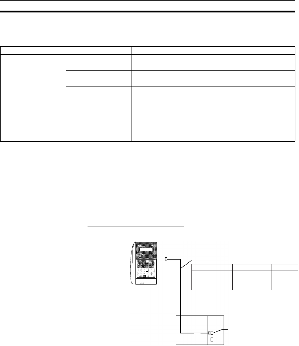
91
Basic System Configuration Section 2-3
3. The HMC-EF183 cannot be used with all CPU Units. Before ordering, refer to Precaution on Applicable
Units on page 164.
Other Units
Note A peripheral bus connection is not possible when connecting the CX-Pro-
grammer via an RS-232C Connecting Cable. Use the Host Link (SYSWAY)
connection.
Connecting Programming Devices
Programming Console When using a Programming Console, connect the Programming Console to
the peripheral port of the CPU Unit and set pin 4 of the DIP switch on the front
panel of the Unit to OFF (automatically uses default communications parame-
ters for the peripheral port).
CQM1H-PRO01-E/CQM1-PRO01-E
The Programming Console can be connected only to the peripheral port.
Name Model Specifications
Programming Device
Connecting Cables (for
RS-232C port)
XW2Z-200S-CV Connects DOS computers
D-Sub 9-pin (Length: 2.0 m), Static-resistant connector used.
XW2Z-500S-CV Connects DOS computers
D-Sub 9-pin (Length: 5.0 m), Static-resistant connector used.
XW2Z-200S-V Connects DOS computers
D-Sub 9-pin (Length: 2.0 m) (See note.)
XW2Z-500S-V Connects DOS computers
D-Sub 9-pin (Length: 5.0 m) (See note.)
USB−Serial Conversion
Cable
CS1W-CIF31 Converts between a USB connector and a D-Sub 9-pin connector.
Cable length: 0.5 m
Battery Set CS1W-BAT01 For CS Series only.
CQM1H-PRO01-E,
CQM1-PRO01-E
Programming
Console
The following cable is included with the
CQM1-PRO01-E Programming Console
Programming Console
CQM1-PRO01-E
CQM1H-PRO01-E
Cable
CS1W-CN114
Not required
(pre-wired).
Length
0.05 m
2 m
Note Set pin 4 of the DIP switch on the
front panel of the CPU Unit to OFF.
Peripheral port
CS1W-KS001-E
English Keyboard
Sheet required.
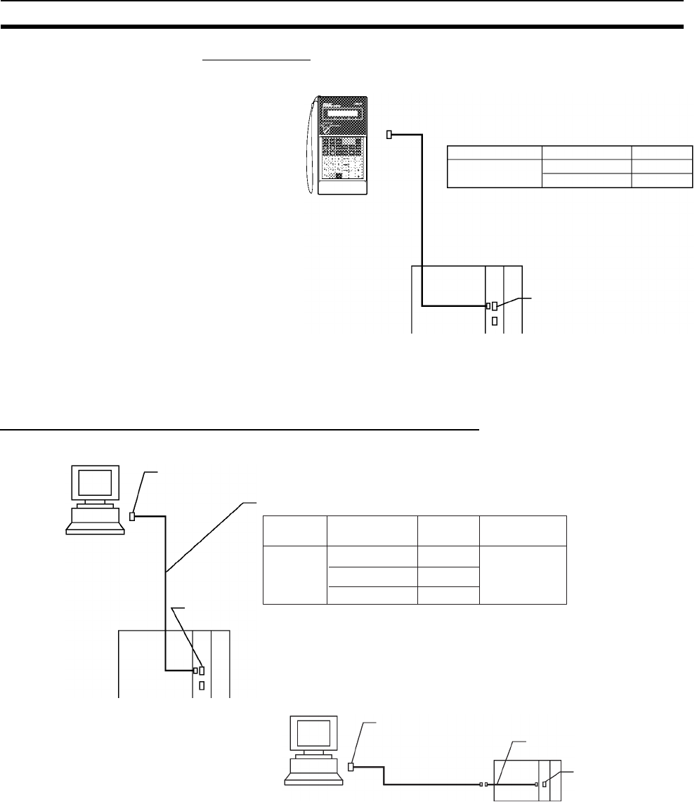
92
Basic System Configuration Section 2-3
C200H-PRO27-E
The Programming Console can be connected only to the peripheral port.
Note When an OMRON Programmable Terminal (PT) is connected to the RS-232C
port and Programming Console functions are being used, do not connect the
Programming Console at the same time.
Connecting Personal Computers Running Support Software
Connecting to Peripheral Port
Note Set pin 4 of the DIP switch on the
front panel of the CPU Unit to OFF.
Peripheral port
Programming Console
CQM1-PRO27-E
Cable Length
CS1W-CN224
CS1W-CN624
2.0 m
6.0 m
CS1W-KS001-E
English Keyboard
Sheet required.
C200H-PRO27-E
Programming
Console
DOS computer
(RS-232C, 9-pin)
RS-232C
Peripheral
port
Connecting Cables for Peripheral Port
Computer Cable Length Computer
connector
DOS CS1W-CN118
CS1W-CN226
CS1W-CN626
Note The CS1W-CN118 Cable is used with an RS-232C
cable to connect to the peripheral port on the CPU
Unit as shown below. The CS1W-CN118 Cable can
not be used with an RS-232C cable whose model
number ends in -V for a peripheral bus connection
and must be used for a Host Link (SYSMAC WAY)
connection.
D-Sub,
9-pin
0.1 m
2.0 m
6.0 m
RS-232C Cable
XW2Z-200S-@@: 2 m
XW2Z-500S-@@: 5 m CS1W-CN118 Cable
Peripheral
port
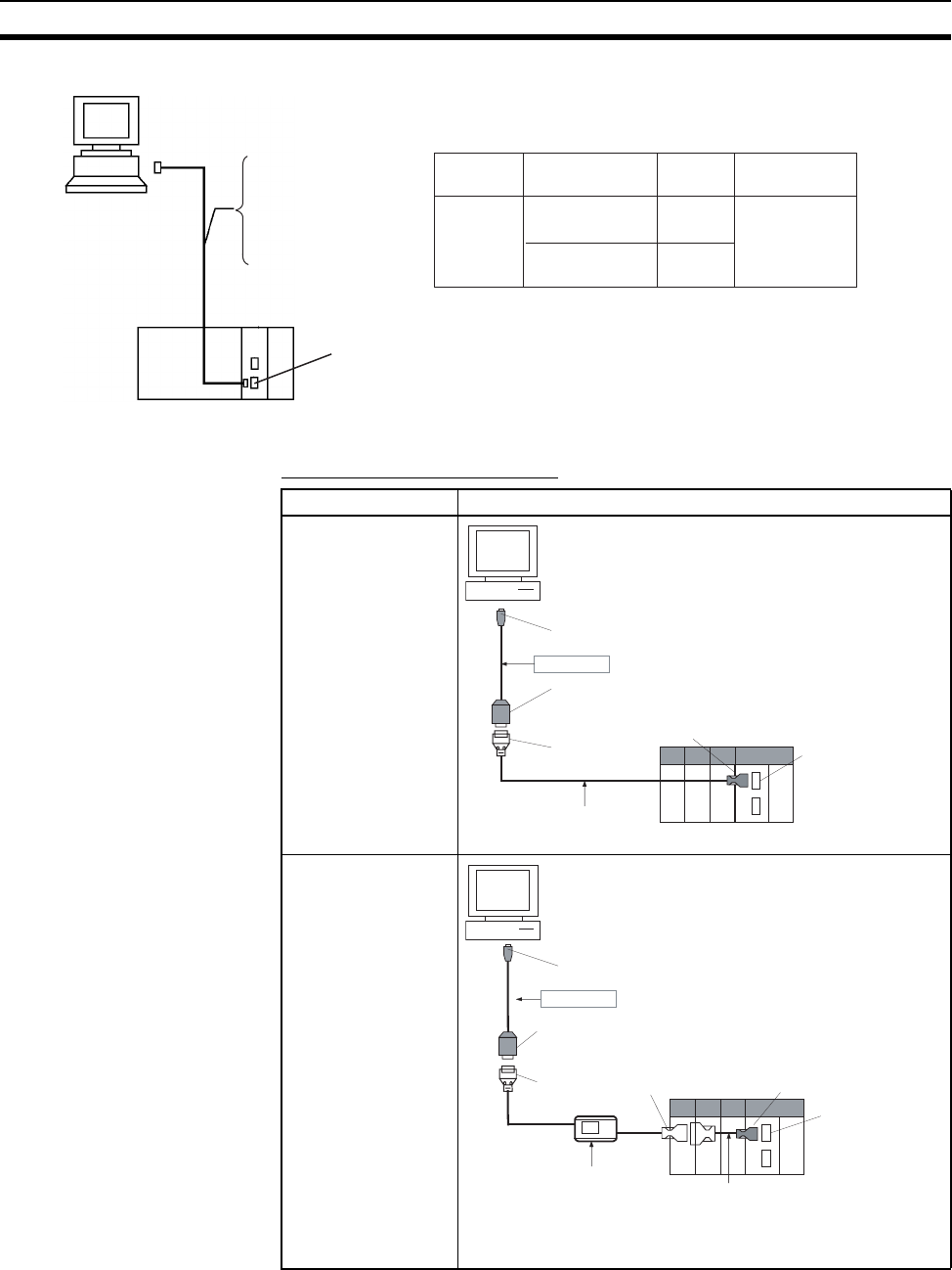
93
Basic System Configuration Section 2-3
Connecting to RS-232C Port
Using Personal Computer’s USB Port (USB-Serial Conversion Cable)
Connecting to Peripheral Port
DOS version
(RS-232C, 9-pin)
RS-232C Cable
XW2Z-200S-CV
or XW2Z-200S-V: 2 m
XW2Z-500S-CV
or XW2Z-500S-V: 5 m
RS-232C port
Connecting Cables for RS-232C Port
Computer Cable Length Computer
connector
DOS XW2Z-200S-CV
or XW2Z-200S-V
XW2Z-500S-CV
or XW2Z-500S-V
D-Sub,
9-pin
2.0 m
5.0 m
Note The XW2Z-200S-CV and XW2Z-500S-CV use static-resist-
ant connectors and can be connected to the peripheral bus
or the Host Link. The XW2Z-200S-V and XW2Z-500S-V,
however, can only be connected to the Host Link, not the
peripheral bus.
Cable Connection diagram
CS1W-CN226/626
CQM1-CIF02
Note Connection supported for Host Link only when using
CS/CJ-series PLCs.
CS1W-CIF31
USB A plug connector (male)
CS/CJ-series PLC
Customizable Counter Unit
CS/CJ-series peripheral connector
D-sub connector
(9-pin, male)
D-sub connector
(9-pin, female)
Recommended cable:
CS1W-CN226/626
Peripheral
port
CS1W-CIF31
CS1W-CN114
USB A plug connector (male)
Peripheral port
CS/CJ-series PLC (See note.)
D-sub connector
(9-pin, male)
D-sub connector
(9-pin, female)
C-series peripheral
connector
CS/CJ-series
peripheral connector
Recommended cable:
CQ1M-CIF02
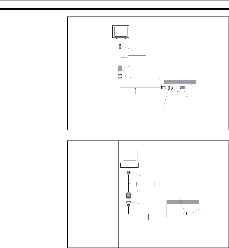
94
Basic System Configuration Section 2-3
Connecting to RS-232C Port
2-3-3 Expansion Racks
To expand the number of Units in the system, other Expansion Racks can be
connected to CPU Racks. The other Expansion Racks that can be connected
to the CPU Racks are Standard CS-series Expansion Racks, CS-series Long-
distance Expansion Racks, CS-series-only Expansion Racks, and C200H
Expansion I/O Racks.
C200H Expansion I/O Racks can be connected after CS-series Expansion
Racks, however, the CS-series Expansion Racks cannot be connected after
C200H Expansion I/O Racks.
C200H Expansion I/O Racks cannot be connected in the same series as CS-
series Long-distance Expansion Racks.
Note 1. Expansion Racks cannot be connected to a 2-slot CPU Rack (Backplane:
CS1W-BC02@).
XW2Z-200S-CV/
500S-CV or
XW2Z-200S-V/
500S-V for RS-232C
Note Connection supported for Host Link only when using
CS/CJ-series PLCs.
Cable Connection diagram
XW2Z-200S-CV/500S-
CV or
XW2Z-200S-V/500S-V
for RS-232C
Note Connection supported for Host Link only when
using CS/CJ-series PLCs.
Cable Connection diagram
CS1W-CIF31
XW2Z-200S-CV/500S-CV
or XW2Z-200S-V/500S-V
(See note.)
CS1W-CN118
USB A plug connector (male)
D-sub connector (9-pin, male)
CS/CJ-series PLC
Customizable Counter Unit
D-sub connector
(9-pin, male)
D-sub connector
(9-pin, female)
D-sub connector
(9-pin, female)
CS/CJ-series
peripheral connector
Peripheral
port
CS1W-CIF31
USB A plug connector (male)
D-sub connector (9-pin, male)
CS/CJ-series PLC
Recommended cable:
XW2Z-200S-CV/500S-CV or
XW2Z-200S-V/500S-V
(
See note.
)
D-sub connector
(9-pin, male)
D-sub connector
(9-pin, female) RS-232C port
D-sub connector
(9-pin, female)

95
Basic System Configuration Section 2-3
2. C200H Units (C200H Basic I/O Units, C200H Group-2 High-density I/O
Units, and C200H Special I/O Units) cannot be used on CS-series-only
CS-series Expansion Backplanes (CS1W-BI@@2).
3. C200H Units cannot be used on the CPU Rack or Expansion Racks if a
CS-series-only CPU Backplane (CS1W-BC@@2) is used. The C200H
Units will not be recognized by the CPU Unit.
4. When using a CS-series-only Expansion Rack (CS1W-BI@@2) with a CPU
Unit with a lot number of 000427 (27 April 2000) or earlier, CS-series Units
and C200H Units cannot be used on any Expansion Racks past the CS-
series-only CPU Expansion Rack. When using a CS-series-only CPU
Backplane (CS1W-BC@@2), CS-series Units and C200H Units cannot be
used on any Expansion Racks.
When using C200H Units and both CS1W-BC@@2 and CS1W-BI@@2
Backplanes are used, use a CPU Unit with a lot number of 000428 (28 April
2000) or later. (When using a CS-series-only CPU Backplane (CS1W-
BC@@2), the restriction described in note 3 above applies, and so C200H
Units cannot be mounted on Expansion Racks even if a CPU Unit with a
lot number of 000428 or later is used.)
Examples of Mixing Backplanes (❍: Mountable, ×: Not mountable)
Refer to Configuration Device List and 2-4 Units on CS-series Units and
C200H Units.
Rack Backplane name Backplane model CS-series
Units
C200H Units
Example 1 CPU Rack CPU Backplane CS1W-BC@@3❍❍
Expansion Racks CS-series Expansion Backplane CS1W-BI@@3❍❍
Expansion Racks C200H Expansion I/O Backplane C200HW-BI@@1-V1 ×❍
Example 2 CPU Rack CPU Backplane CS1W-BC@@3❍❍
Expansion Racks CS-series-only Expansion Back-
plane
CS1W-BI@@2❍ (See note 4.) × (See note 2.)
Expansion Racks CS-series Expansion Backplane CS1W-BI@@3❍ (See note 4.) ❍ (See note 4.)
Example 3 CPU Rack CPU Backplane CS1W-BC@@3❍❍
Expansion Racks CS-series-only Expansion Back-
plane
CS1W-BI@@2❍ (See note 4.) × (See note 2.)
Expansion Racks C200H Expansion I/O Backplane C200HW-BI@@1-V1 ×❍ (See note 4.)
Example 4 CPU Rack CS-series-only CPU Backplane CS1W-BC@@2❍× (See note 3.)
Expansion Racks CS-series-only Expansion Back-
plane
CS1W-BI@@2❍ (See note 4.) × (See notes 2
and 3.)
Expansion Racks CS-series Expansion Backplane CS1W-BI@@3❍ (See note 4.) × (See note 3.)
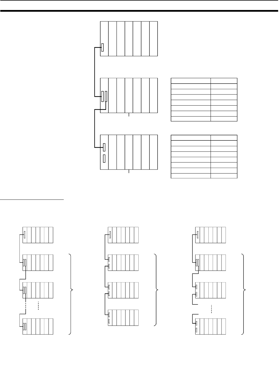
96
Basic System Configuration Section 2-3
Expansion Patterns
The following diagrams show the 4 possible expansion patterns.
CPU Rack
(Other than a 2-slot CPU Rack)
CS-series
I/O Connecting Cable
(30 cm, 70 cm, 2 m, 3 m,
5 m, 10 m, or 12 m)
CS to C200H I/O Connecting
Cables (30 cm, 70 cm, 2 m,
3 m, 5 m, 10 m, or 12 m)
CS I/O Connecting Cables
CS to C200H I/O Connecting Cables
CS-series Expansion Backplane
(3, 5, 8, 10 slots)
C200H Expansion I/O Backplane
(3, 5, 8, 10 slots)
Cable
CS1W-CN313
CS1W-CN713
CS1W-CN223
CS1W-CN323
CS1W-CN523
CS1W-CN133
CS1W-CN133B2
Length
0.3 m
0.7 m
2 m
3 m
5 m
10 m
12 m
Cable
CS1W-CN311
CS1W-CN711
CS1W-CN221
CS1W-CN321
CS1W-CN521
CS1W-CN131
CS1W-CN131B2
Length
0.3 m
0.7 m
2 m
3 m
5 m
10 m
12 m
CPU Unit
Power Supply UnitPower Supply UnitPower Supply Unit
1. CPU Rack connected to CS
Expansion Rack 2. CPU Rack connected to C200H
Expansion I/O Rack 3. CPU Rack connected to CS
Expansion Rack connected to
C200H Expansion I/O Rack
CPU Rack
(Excluding the
2-slot Rack.)
CPU Rack
(Excluding the
2-slot Rack.)
CS I/O
Connecting
Cable
CS I/O
Connecting
Cable
CS Ex-
pansion
Rack
C200H
Expan-
sion I/O
Rack
3 Expansion
Racks max.
7 Expan-
sion Racks
max.
7 Expansion
Racks max. (3
C200H Expansion
I/O Racks max.)
CS Ex-
pansion
Rack
C200H
Expan-
sion I/O
Rack
CS I/O
Connecting
Cable
*
* Power Supply Unit
*
*
*
CS Ex-
pansion
Rack
CS Ex-
pansion
Rack
*
*
*
*
C200H
Expan-
sion I/O
Rack
C200H
Expan-
sion I/O
Rack
*
*
*
*
CS to C200H
I/O Connecting
Cable
CPU Rack
(Excluding the
2-slot Rack.)
CS I/O Con-
necting Cable
C200H I/O Con-
necting Cable
C200H I/O Con-
necting Cable C200H
Expan-
sion I/O
Rack
CPU Unit
CPU Unit
CPU Unit
Note: The above configuration is not possible if a
CS-series-only CPU Backplane is used.
Note: The above configuration is not possible if a
CS-series-only CPU Backplane is used.
When using a CS-series-only CPU
Expansion Rack with a CPU Unit with a lot
number of 000427 (27 April 2000) or earlier,
C200H Units cannot be used past the CS-
series-only CPU Expansion Rack.
CS to C200H
I/O Connecting
Cable
C200H I/O Con-
necting Cable
C200H I/O Con-
necting Cable
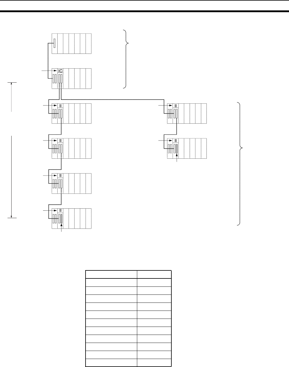
97
Basic System Configuration Section 2-3
Note The following CV-series Expansion I/O Cables are used to connect to the CS-
series Long-distance Expansion Racks (i.e., between the I/O Control Unit and
the first I/O Interface Unit and between I/O Interface Units).
CPU Rack
(Excluding the
2-slot Rack.)
I/O Control
Unit**
* Power Supply Unit
*
*
*
*
*
*
Series A (50 m max.) Series B (50 m max.)
I/O Interface
Unit
I/O Interface
Unit
I/O Interface
Unit
I/O Interface
Unit
I/O Interface
Unit
I/O Interface
Unit
Terminator
Terminator
*
*
The following Units can be mounted: CS1/C200H I/O Units,
CS1/C200H Special I/O Units, and CS1 CPU Bus Units.
CV-series
Expansion
I/O Cables
(See table
below.)
CPU Unit
4. CPU Rack connected to CS-series Long-distance Expansion Racks
CS-series
Connecting
Cable(30 cm/70 cm)
CS-series
Expansion Rack
CS-series Long-distance
Expansion Rack
CS-series Long-distance
Expansion Rack
CS-series Long-distance
Expansion Rack
CS-series Long-distance
Expansion Rack CS-series Long-
distance
Expansion Rack
CS-series Long-
distance
Expansion Rack
The following Units
can be mounted: CS-
series I/O Units, CS-
series Special I/O
Units, and CS-series
CPU Bus Units.
(C200H Units cannot
be mounted.)
**The I/O Control Unit can be mounted to
the CPU Rack or a CS-series Expansion
Rack (Rack No. 1). A CS-series Long-
distance Expan-sion Rack is a CS-series
Expansion Rack con-nected after an I/O
Control Unit.
Model number Length
CV500-CN312 0.3 m
CV500-CN612 0.6 m
CV500-CN122 1 m
CV500-CN222 2 m
CV500-CN322 3 m
CV500-CN522 5 m
CV500-CN132 10 m
CV500-CN232 20 m
CV500-CN332 30 m
CV500-CN432 40 m
CV500-CN532 50 m
98
Basic System Configuration Section 2-3
Note CS-series Expansion Racks must be connected before C200H Expansion I/O
Racks. The following configuration is not allowed.
Maximum Expansion Racks
Note C200H Units (C200H Basic I/O Units, C200H Group-2 High-density I/O Units,
and C200H Special I/O Units) cannot be used with CS-series-only CPU
Racks.
C200H Expansion I/O Rac
k
CS-series Expansion Rack
Not Allowed
Power Supply UnitPower Supply Unit
Expansion pattern Rack Maximum No. of Racks Remarks
CPU Rack with CS-series
Expansion Racks
CS-series Expansion Racks 7 Racks The total cable length must
be 12 m or less.
CPU Rack with CS-series
Expansion Racks and
C200H Expansion I/O Racks
CS-series Expansion Racks
and C200H Expansion I/O
Racks
7 Racks (with 3 C200H
Expansion I/O Racks max.)
CPU Rack with C200H
Expansion I/O Racks
C200H Expansion I/O Racks 3 Racks
CPU Rack with CS-series
Expansion Racks and
CS-series Long-distance
Expansion Racks
CS-series Expansion Racks
and CS-series Long-dis-
tance Expansion Racks
7 Racks (with 1 CS-series
Expansion Rack max.)
The total cable length must
be 0.7 m or less to the last
CS-series Expansion Rack.
The total cable length must
be 50 m or less each for up
to two series of CS-series
Long-distance Expansion
Racks (100 m max. total).
99
Basic System Configuration Section 2-3
Rack Configurations
Configuration Device List
Note Using the C200HW-BI081/BI101
The C200HW-BI081 or C200HW-BI101 can be used, but always use the
C200HW-BI081-V1 or C200HW-BI101-V1 if you are using the C200HW-
PA209R Power Supply.
Rack Configuration Remarks
Standard CS-series Expan-
sion Racks
CS-series Expansion Backplane One of each Unit is required.
Note CS-series Expansion
Racks can be con-
nected to C200H
Expansion I/O Racks,
however, C200H
Expansion I/O Racks
must be connected
after CS-series
Expansion Racks.
Power Supply Unit
CPU Backplane or CS-series
Expansion Backplane
CS I/O Connecting Cables
C200H Expansion I/O
Backplane
CS to C200H I/O Connecting
Cables
CS-series-only Expansion
Racks
CS-series-only Backplane One of each Unit is required.
Note C200H Units and
Racks cannot be used
with CS-series-only
CPU Racks or Expan-
sion Racks.
Power Supply Unit
CPU Backplane or CS-series
Expansion Backplane
CS I/O Connecting Cables
C200H Expansion I/O Racks C200H Expansion I/O Backplane One of each Unit is required.
Power Supply Unit
CS-series Expansion
Backplane
CS to C200H I/O Connecting
Cables
C200H Expansion I/O
Backplane
C200H I/O Connecting
Cables
CS-series Long-distance
Expansion Racks
Mount an I/O Control Unit (CS1W-IC102) to the leftmost slot
on the CPU Rack or the last CS-series Expansion Rack.
Mount an I/O Interface Unit (CS1W-II102) to the leftmost
slot on each Long-distance Expansion Rack.
Attach a Terminator (CV500-TER01) to the last Long-dis-
tance Expansion Rack in each series. Two Terminators are
provided with the I/O Control Unit.
Each I/O Control Unit and
I/O Interface Unit requires
one slot.
These Units are not allo-
cated I/O words.
Use CV-series I/O Connect-
ing Cables.
A CS-series Expansion Rack
cannot be connected to a
CS-series Long-distance
Expansion Rack using a CS
I/O Connecting Cable.
Name Model Specifications Cable Length
Standard CS-series Expan-
sion Backplanes
CS1W-BI033 3 slots Can be used for Long-dis-
tance Expansion Racks.
CS1W-BI053 5 slots
CS1W-BI083 8 slots
CS1W-BI103 10 slots
CS-series-only CS-series
Expansion Backplanes
CS1W-BI032 3 slots Can be used for Long-dis-
tance Expansion Racks.
CS1W-BI052 5 slots
CS1W-BI082 8 slots
CS1W-BI102 10 slots
C200H Expansion I/O
Backplanes
C200HW-BI031 3 slots Cannot be used for Long-dis-
tance Expansion Racks.
C200HW-BI051 5 slots
C200HW-BI081-V1 (See note.) 8 slots
C200HW-BI101-V1 (See note.) 10 slots

100
Basic System Configuration Section 2-3
Note Restrictions in Using CS-series I/O Connecting Cables
When using a CS1W-CN313 or CS1W-CN713 CS-series I/O Connecting
Cable with a CS1-H CPU Unit, always use a Cable manufactured on Septem-
ber 20, 2001 or later. Do not use Cables that do not have manufacturing num-
bers or Cables manufacture earlier than September 20, 2001.
Name Model Specifications Cable Length
Power Supply Units C200HW-PA204 100 to 240 V AC
Output capacity: 4.6 A at 5 V
DC
---
C200HW-PA204C 100 to 240 V AC (with
replacement notification)
Output capacity: 4.6 A at 5 V
DC
C200HW-PA204R 100 to 240 V AC (with RUN
output)
Output capacity: 4.6 A, 5 V
DC
C200HW-PA204S 100 to 120 V AC or 200 to
240 V AC (with 0.8 A 24 V
DC service power supply)
Output capacity: 4.6 A at 5 V
DC
C200HW-PA209R 100 to 120 V AC or 200 to
240 V AC (with RUN output)
Output capacity: 9 A at 5 V
DC
C200HW-PD024 24 V DC
C200HW-PD025 24 V DC
CS I/O Connecting Cables CS1W-CN313 (See note.) Connects CS-series Expan-
sion Backplanes to CPU
Backplanes or other CS-
series Expansion Back-
planes.
0.3 m
CS1W-CN713 (See note.) 0.7 m
CS1W-CN223 2 m
CS1W-CN323 3 m
CS1W-CN523 5 m
CS1W-CN133 10 m
CS1W-CN133B2 12 m
CS to C200H I/O
Connecting Cables
CS1W-CN311 Connects C200H Expansion
I/O Backplanes to CPU
Backplanes or CS-series
Expansion Backplanes.
0.3 m
CS1W-CN711 0.7 m
CS1W-CN221 2 m
CS1W-CN321 3 m
CS1W-CN521 5 m
CS1W-CN131 10 m
CS1W-CN131B2 12 m
C200H I/O Connecting
Cables
C200H-CN311 Connects C200H Expansion
I/O Backplanes to other
C200H Expansion I/O Back-
planes.
0.3 m
C200H-CN711 0.7 m
C200H-CN221 2 m
C200H-CN521 5 m
C200H-CN131 10 m
I/O Control Unit CS1W-IC102 Mounts to the leftmost slot on
the CPU Rack or a CS-series
Expansion Rack to enable
connecting CS-series Long-
distance Expansion Racks.
---
I/O Interface Unit CS1W-II102 Mounts to the leftmost slot on
an CS-series Long-distance
Expansion Rack.
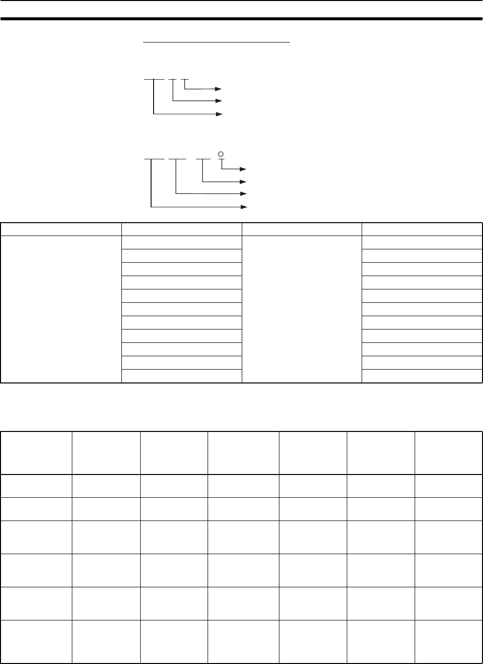
101
Basic System Configuration Section 2-3
Manufacturing Number Legend
Four-digit Numbers
Six-digit Numbers
Connectable Units The following table shows the Units that can be connected to CPU Racks, CS-
series Expansion Racks, and C200H Expansion I/O Racks.
Refer to 2-4 Units for details on the limitations on each particular Unit.
Note 1. The CS1W-INT01 and C200HS-INT01 Interrupt Input Units are Basic I/O
Units, but they can be mounted only to the CPU Rack.
@@@ @
Year (e.g., 1997 = 7, 2001 = 1
Month (January to September = 1 to 9, October to December = X to Z)
Day of month (01 to 31)
@@@ @
Symbol
Day of month (01 to 31)
Month (January to September = 01 to 12)
Year (e.g., 2003 = 03)
@ @
Name Model Specifications Cable Length
CV-series I/O Connecting
Cables
CV500-CN312 Connects CS-series Long-
distance Expansion Racks.
0.3 m
CV500-CN612 0.6 m
CV500-CN122 1 m
CV500-CN222 2 m
CV500-CN322 3 m
CV500-CN522 5 m
CV500-CN132 10 m
CV500-CN232 20 m
CV500-CN332 30 m
CV500-CN432 40 m
CV500-CN532 50 m
Unit CS-series
Basic I/O Units
C200H Basic
I/O Units
C200H Group-2
High-density
I/O Units (Basic
I/O Units)
CS-series
Special
I/O Units
C200H
Special I/O
Units
(See note 2.)
CPU Bus
Units
(See note 3.)
Standard CPU
Rack
Ye s Ye s Ye s Ye s Ye s Ye s
CS-series-only
CPU Rack
Ye s N o N o Ye s N o Ye s
Standard CS-
series Expan-
sion Racks
Ye s Ye s Ye s Ye s Ye s Ye s
C200H
Expansion I/O
Racks
No Yes Yes No Yes No
CS-series-only
Expansion
Racks
Ye s N o N o Ye s N o Ye s
CS-series
Long-distance
Expansion
Racks
Ye s N o N o Ye s N o Ye s
(See note 2.)
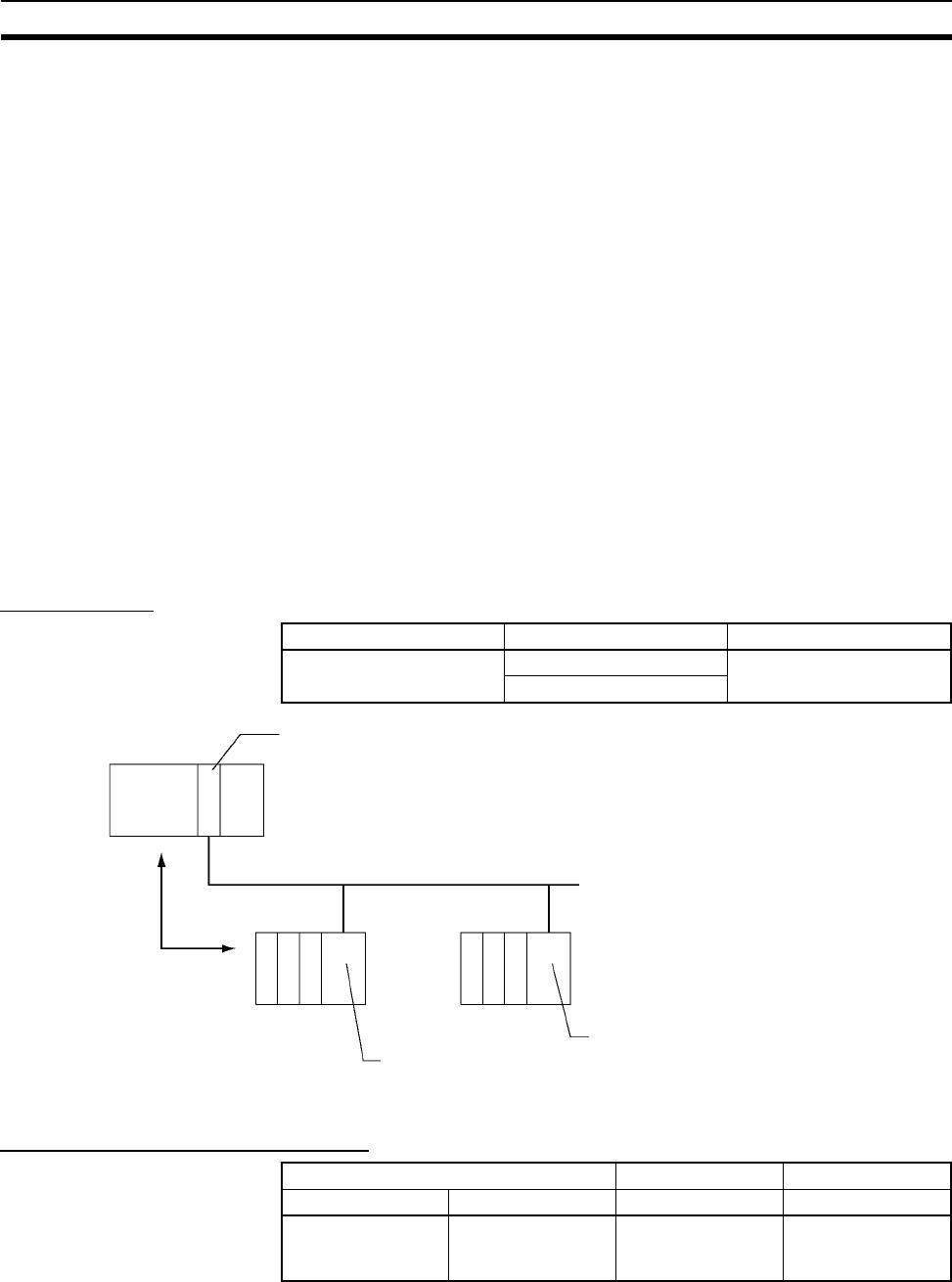
102
Basic System Configuration Section 2-3
2. Although CS-series CPU Bus Units can be mounted to CS-series Long-
distance Expansion Racks, it is not recommended because doing so will
increase the cycle time.
Maximum Number of Units The maximum number of expansion slots is 80, so the maximum number of
Units that can be connected is 80. The total number of each type of Unit is not
limited in the mounting location.
Note 1. CS1W-INT01 and C200HS-INT01 Interrupt Input Units are Basic I/O Units
but can be connected to CPU Racks only (four C200HS-INT01 and two
CS1W-INT01 Units max. per CPU Rack).
2. Up to 16 C200H Special I/O Units can be mounted.
3. Up to 16 CPU Bus Units can be mounted.
2-3-4 SYSMAC BUS Slave Racks
SYSMAC BUS Slave Racks are used to perform basic CS-series remote I/O
communications. The SYSMAC BUS Slave Rack allows comparatively small-
scale (512 bits max.) remote I/O communications using Basic I/O Units and
Special I/O Units. The Slave Racks are connected using two-core cable or
optical fiber cables. Units such as Basic I/O Units and Special I/O Units can
be mounted to some Slave Racks. I/O Terminals can also be connected.
Configuration
Maximum No. of Units and Racks
Rack Configuration Remarks
SYSMAC BUS Slave
Racks
Backplane One of each required per
Rack.
Remote I/O Slave Unit
Per CPU Rack Per Master Unit Per Slave Rack
Master Units Slave Racks Slave Racks Maximum Units
2 Units max. 8 Racks max. 8 Racks max. 10 Units max.
(depending on the
Backplane used)
SYSMAC BUS Remote I/O Master Unit (two-conductor or optical fiber cables)
SYSMAC BUS (two-conductor or optical fiber cables)
Remote I/O
Slave Rack Slave Rack
SYSMAC BUS
Remote I/O Slave
Unit
SYSMAC BUS
Remote I/O Slave
Unit
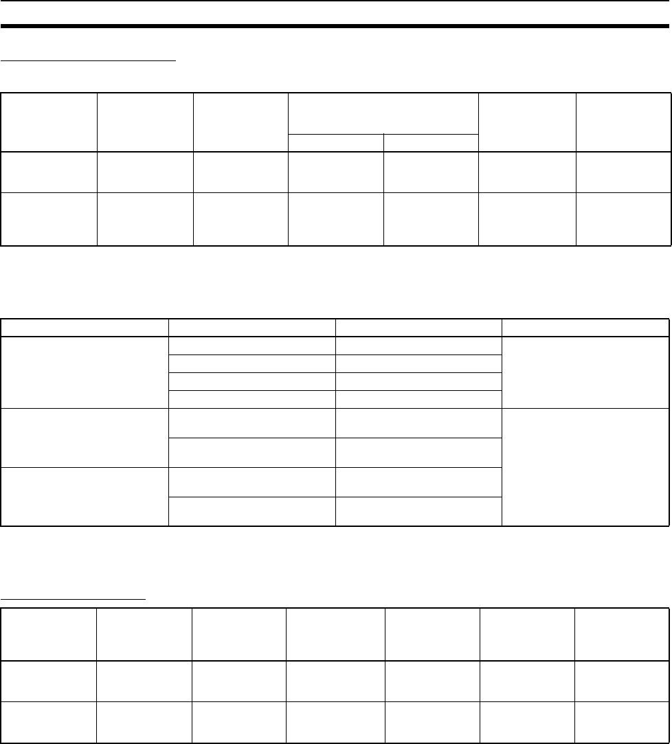
103
Basic System Configuration Section 2-3
Configuration Devices
Master Units
Note PCF: Plastic Clad Optical Fiber Cable
APF: All Plastic Optical Fiber Cable.
Slave Racks
Note Words are allocated to Units on SYSMAC BUS Slave Racks from the
SYSMAC BUS Area and not from the I/O Bit Area.
Connectable Units
Note 1. C200H DeviceNet Master Units (C200HW-DRM21-V1), CompoBus/S
Master Units, PLC Link Units, and SYSMAC BUS Remote I/O Master Units
cannot be connected to Wired Slave Racks.
2. Special I/O Unit words (CIO 2000 to CIO 2959) are allocated to C200H
Special I/O Units according to unit numbers.
3. Up to a total of 10 C200H Special I/O Units can be mounted to all Slave
Racks in a SYSMAC BUS Remote I/O System. Only unit numbers 0 to 9
can be used. The number of C200H Special I/O Units that can be mounted
to any one Slave Rack depends on the specific Units that are used, as
shown in the following table. For the purpose of calculating the maximum
number of Units, Units are classified into four groups, A to D.
Unit Model Maximum Units
per CPU Unit
Maximum Slave Racks and I/O
bits per CPU Unit and Master
Unit
Slave Rack
communica-
tions cables
Transmission
distance (total
extension)
Slave Racks I/O bits
SYSMAC BUS
Wired Remote
I/O Master Units
C200H-RM201 2 Units 8 1,280
(80 words)
Two-core cable 200 m
SYSMAC BUS
Optical Remote
I/O Master Units
C200H-RM001-
PV1
2 Units 8 1,280
(80 words)
Optical fiber
cable (PCF or
APF)
(See note.)
PCF: 200 m
APF: 20 m
Name Model Specifications Remarks
SYSMAC BUS Slave Rack
Backplanes
C200H-BC101-V2 10 Units ---
C200H-BC081-V2 8 Units
C200H-BC051-V2 5 Units
C200H-BC031-V2 3 Units
SYSMAC BUS Wired Remote
I/O Master Units
C200H-RT201 Power supply voltage: 100 to
120 V AC or 200 to 240 V AC
Power Supply Unit is not
required.
C200H-RT202 Power supply voltage:
24 V DC
SYSMAC BUS Optical Remote
I/O Master Units
C200H-RT001-P Power supply voltage: 100 to
120 V AC or 200 to 240 V AC
C200H-RT002-P Power supply voltage:
24 V DC
Unit CS-series
Basic I/O Units
C200H Basic
I/O Units
C200H Group-2
High-density I/O
Units (Basic I/O
Units)
CS-series Spe-
cial I/O Units
C200H Special
I/O Units
CPU Bus Units
SYSMAC BUS
Wired Slave
Racks
No Yes No No Yes
(See note.)
No
SYSMAC BUS
Optical Slave
Racks
No Yes No No Yes
(See note.)
No

104
Basic System Configuration Section 2-3
Note I/O READ/WRITE instructions (IORD/IOWR) cannot be used with C200H
Special I/O Units that are mounted to a Slave Rack.
Group A B C D
Units High-speed Counter Units,
NC111/NC112/NC113/NC213
Position Control Units, ASCII
Units, Analog I/O Units, ID
Sensor Units, Fuzzy Logic Units
High-density I/O Units, Tem-
perature Controller Units,
Heating/Cooling Control
Units, PID Control Units,
Cam Positioner Units
Temperature
Sensor Units,
Voice Units
NC211/NC413
Position Con-
trol Units,
Motion Control
Units
Maximum Units in
each group for
each Slave Rack
4 Units max. 8 Units max. 6 Units max. 2 Units max.
Maximum Units for
all groups for each
Slave Rack
3A + B + 2C + 6D ≤ 12 and A + B + C + D ≤ 8

105
Units Section 2-4
2-4 Units
2-4-1 Basic I/O Units
Input Units
CS-series Basic Input Units
Note 1. The interrupt function can be used only when the Unit is mounted to the
CPU Rack. (The Interrupt Input Unit can be used as a regular I/O Unit on
Expansion Racks.)
2. The C200H-ID001 (8 no-voltage contact inputs, NPN) cannot be used with
CS-series PLCs.
Name Specifications Model Number
of bits
allocated
(CIO 0000
to
CIO 0319)
Mountable Racks Reference
CPU
Rack
C200H
Expan-
sion I/O
Racks
CS-series
Expan-
sion
Racks
CS-series
Long-
distance
Expan-
sion
Racks
SYSMAC
BUS
Slave
Racks
AC Input
Units
100 to 120 V DC,
100 to 120 V AC 16
inputs
CS1W-IA111 16 Yes No Yes Yes No
200 to 240 V AC, 16
inputs
CS1W-IA211 16 Yes No Yes Yes No
DC Input
Units
24 V DC, 16 inputs CS1W-ID211 16 Yes No Yes Yes No
Interrupt
Input
Units
24 V DC, 16 inputs CS1W-INT01 16 Yes No Yes (See
note 1.)
Yes (See
note 1.)
No
High-
speed
Input
Units
24 V DC, 16 inputs CS1W-IDP01 16 Yes No Yes Yes No
DC Input
Units
24 V DC, 32 inputs CS1W-ID231 32 Yes No Yes Yes No
24 V DC, 64 inputs CS1W-ID261 64 Yes No Yes Yes No
24 V DC, 96 inputs CS1W-ID291 96 Yes No Yes Yes No
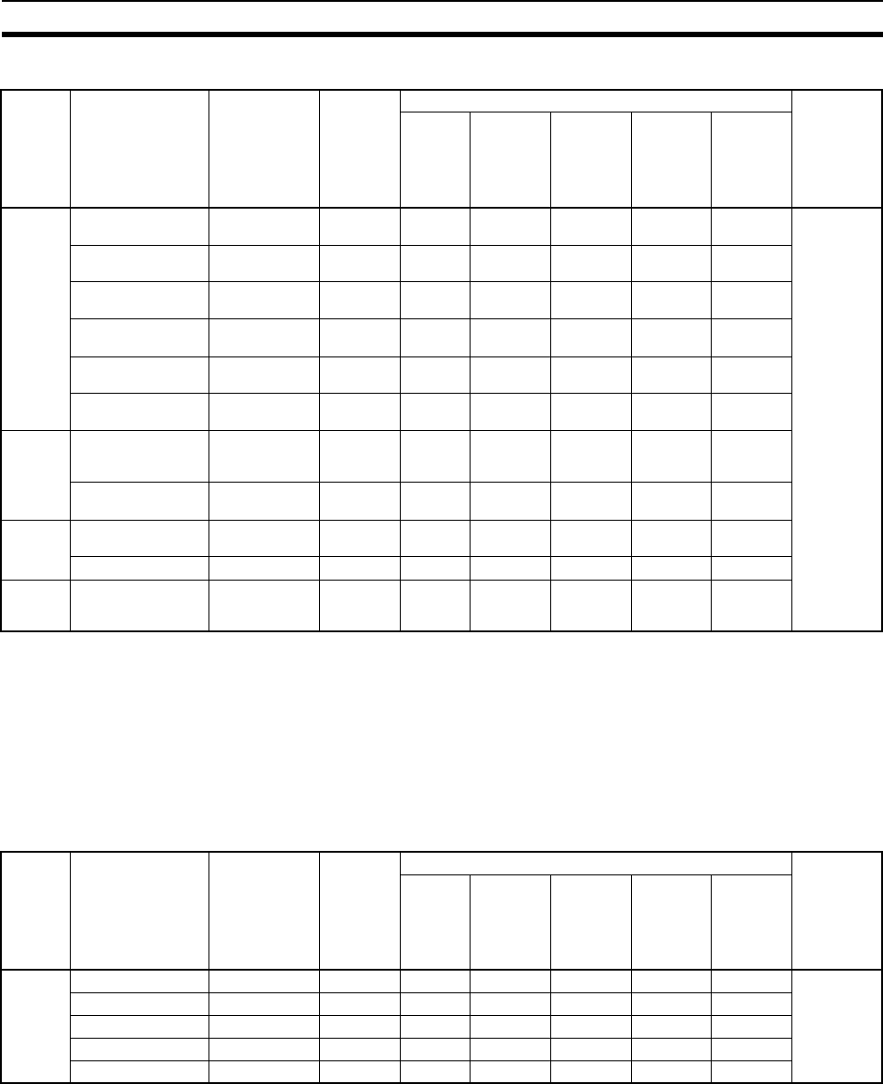
106
Units Section 2-4
C200H Basic Input Units
Note 1. The interrupt function can be used only when the Unit is mounted to the
CPU Rack. (The Interrupt Input Unit can be used as a regular I/O Unit on
Expansion Racks.)
2. The C200H-ID001 (8 no-voltage contact inputs, NPN) cannot be used with
CS-series PLCs.
3. C200H Units and Racks cannot be used with CS-series-only CPU Racks
or Expansion Racks.
C200H High-density Input Units (Group 2)
Note C200H Units and Racks cannot be used with CS-series-only CPU Racks or
Expansion Racks.
Name Specifications Model Number
of bits
allocated
(CIO 0000
to
CIO 0319)
Mountable Racks Reference
CPU
Rack
C200H
Expan-
sion I/O
Racks
CS-series
Expan-
sion
Racks
CS-series
Long-
distance
Expan-
sion
Racks
SYSMAC
BUS
Slave
Racks
AC Input
Units
100 to 120V AC,
8inputs
C200H-IA121 16 Yes Yes Yes No Yes 3-6 Basic
I/O Units
and Appen-
dix A Speci-
fications of
Basic I/O
Units and
High-den-
sity I/O
Units
100 to 120V AC,
16inputs
C200H-IA122 16 Yes Yes Yes No Yes
100 to 120V AC,
16inputs
C200H-IA122V 16 Yes Yes Yes No Yes
200 to 240V AC,
8inputs
C200H-IA221 16 Yes Yes Yes No Yes
200 to 240V AC,
16inputs
C200H-IA222 16 Yes Yes Yes No Yes
200 to 240V AC,
16inputs
C200H-IA222V 16 Yes Yes Yes No Yes
AC/DC
Input
Units
12 to 24
VAC/VDC,
8inputs
C200H-IM211 16 Yes Yes Yes No Yes
24 V AC/V DC,
16inputs
C200H-IM212 16 Yes Yes Yes No Yes
DC Input
Units
12 to 24 V DC,
8inputs
C200H-ID211 16 Yes Yes Yes No Yes
24 V DC, 16 inputs C200H-ID212 16 Yes Yes Yes No Yes
Interrupt
Input
Units
12 to 24 V DC,
8inputs
C200HS-INT01 16 Yes Yes Yes
(See note
1.)
No No
Name Specifications Model Number
of bits
allocated
(CIO 0000
to
CIO 0319)
Mountable Racks Reference
CPU
Rack
C200H
Expan-
sion I/O
Racks
CS-series
Expan-
sion
Racks
CS-series
Long-
distance
Expan-
sion
Racks
SYSMAC
BUS
Slave
Racks
DC Input
Units
24 V DC, 32 inputs C200H-ID216 32 Yes Yes Yes No No
24 V DC, 32 inputs C200H-ID218 32 Yes Yes Yes No No
12 V DC, 64inputs C200H-ID111 64 Yes Yes Yes No No
24 V DC, 64 inputs C200H-ID217 64 Yes Yes Yes No No
24 V DC, 64 inputs C200H-ID219 64 Yes Yes Yes No No

107
Units Section 2-4
Basic Output Units
CS-series Basic Output Units
Name Specifications Model Number
of bits
allocated
(CIO 0000
to
CIO 0319)
Mountable Racks Reference
CPU
Rack
C200H
Expan-
sion I/O
Racks
CS-series
Expan-
sion
Racks
CS-series
Long-
distance
Expan-
sion
Racks
SYSMAC
BUS
Slave
Racks
Relay
Output
Units
250 V AC/
24 V DC, 2 A;
120 V DC, 0.1A;
8 points, indepen-
dent contacts
CS1W-OC201 16 Yes No Yes Yes No 3-6 Basic
I/O Units
and
Appendix
A Specifi-
cations of
Basic I/O
Units and
High-den-
sity I/O
Units
250 V AC/24 V
DC, 2 A; 120 V
DC, 0.1 A;
16 points
CS1W-OC211 16 Yes No Yes Yes No
Tr ia c
Output
Units
250 V AC, 1.2 A,
8outputs, with
fuse burnout
detection circuit
CS1W-OA201 16 Yes No Yes Yes No
250 V AC, 0.5 A,
16 outputs
CS1W-OA211 16 Yes No Yes Yes No
Transis-
tor Out-
put Units
12 to 24 V DC,
0.5 A,
16sinkingoutputs
CS1W-OD211 16 Yes No Yes Yes No
12 to 24 V DC,
0.5 A,
32sinkingoutputs
CS1W-OD231 32 Yes No Yes Yes No
12 to 24 V DC,
0.3 A,
64sinkingoutputs
CS1W-OD261 64 Yes No Yes Yes No
12 to 24 V DC,
0.1 A,
96sinkingoutputs,
with fuse burnout
detection circuit
CS1W-OD291 96 Yes No Yes Yes No
24 V DC, 0.5 A,
16sourcingoutputs,
load short-circuit
protection
CS1W-OD212 16 Yes No Yes Yes No
24 V DC, 0.3 A,
32sourcingoutputs,
load short-circuit
protection
CS1W-OD232 32 Yes No Yes Yes No
24 V DC, 0.3 A,
64sourcingoutputs,
load short-circuit
protection
CS1W-OD262 64 Yes No Yes Yes No
24 V DC, 0.1 A,
96sourcingoutputs,
with fuse burnout
detection circuit
CS1W-OD292 96 Yes No Yes Yes No

108
Units Section 2-4
C200H Basic Output Units
Name Specifications Model Number
of bits
allocated
(CIO 0000
to
CIO 0319)
Mountable Racks Reference
CPU
Rack
C200H
Expan-
sion I/O
Racks
CS-series
Expan-
sion
Racks
CS-series
Long-
distance
Expan-
sion
Racks
SYSMAC
BUS
Slave
Racks
Relay
Output
Units
250V AC/24V DC,
2 A, independent
contacts, 5 outputs
max.
C200H-OC223 16 Yes Yes Yes No Yes
250 V AC/24 V DC,
2 A, independent
contacts, 8 outputs
max.
C200H-OC224 16 Yes Yes Yes No Yes
250 V AC/24 V DC,
2 A, independent
contacts, 8 outputs
max.
C200H-OC224V
(no longer manu-
factured)
16 Yes Yes Yes No Yes
250 V AC/24 V DC,
2 A, independent
contacts, 8 outputs
max.
C200H-OC224N 16 Yes Yes Yes No Yes
250V AC/24V DC,
2 A, 8 outputs max.
C200H-OC221 16 Yes Yes Yes No Yes
250V AC/24V DC,
2 A, 12outputs max.
C200H-OC222 16 Yes Yes Yes No Yes
250 V AC/24V DC,
2A, 12 outputs max.
C200H-OC222V
(no longer manu-
factured)
16 Yes Yes Yes No Yes
250 V AC/24V DC,
2A, 12 outputs max.
C200H-OC222N 16 Yes Yes Yes No Yes
250V AC/24V DC,
2 A, 16 outputs max.
C200H-OC226
(no longer manu-
factured)
16 Yes Yes Yes No Yes
250V AC/24V DC,
2 A, 16 outputs max.
C200H-OC226N 16 Yes Yes Yes No Yes
250V AC/24V DC,
2 A, 16 outputs max.
C200H-OC225 16 Yes Yes Yes No Yes
Tr ia c
Output
Units
250 V AC, 1 A,
8outputs, with fuse
burnout detection
circuit
C200H-OA221
(no longer manu-
factured)
16 Yes Yes Yes No Yes
250 V AC, 1.2 A,
8outputs, with fuse
burnout detection
circuit
C200H-OA223 16 Yes Yes Yes No Yes
250 V AC, 0.3 A,
12outputs
C200H-OA222V 16 Yes Yes Yes No Yes
250 V AC, 0.5 A,
12outputs
C200H-OA224 16 Yes Yes Yes No Yes
Transis-
tor Out-
put
Units,
Sinking
24 V DC, 2.1 A,
8outputs
C200H-OD213 16 Yes Yes Yes No Yes
12 to 48 V DC, 1A,
8 outputs
C200H-OD411 16 Yes Yes Yes No Yes
24 V DC, 0.3 A,
12outputs
C200H-OD211 16 Yes Yes Yes No Yes
24 V DC, 0.3 A,
16outputs
C200H-OD212 16 Yes Yes Yes No Yes

109
Units Section 2-4
Note C200H Units and Racks cannot be used with CS-series-only CPU Racks or
Expansion Racks.
C200H High-density Group-two Output Units
Note C200H Units and Racks cannot be used with CS-series-only CPU Racks or
Expansion Racks.
Transis-
tor Out-
put
Units,
Sourcing
24 V DC, 0.8 A,
8outputs, load short-
circuit protection.
C200H-OD214 16 Yes Yes Yes No Yes
5 to 24 V DC, 0.3 A,
8outputs
C200H-OD216 16 Yes Yes Yes No Yes
5 to 24 V DC, 0.3 A,
12outputs
C200H-OD217 16 Yes Yes Yes No Yes
24 V DC, 1 A,
16outputs, load
short-circuit protec-
tion.
C200H-OD21A 16 Yes Yes Yes No Yes
Name Specifications Model Number
of bits
allocated
(CIO 0000
to
CIO 0319)
Mountable Racks Reference
CPU
Rack
C200H
Expan-
sion I/O
Racks
CS-series
Expan-
sion
Racks
CS-series
Long-dis-
tance
Expan-
sion
Racks
SYSMAC
BUS
Slave
Racks
Transis-
tor Out-
put Units
4.5 V DC/16 mA to
26.4 V/100mA,
32sinking outputs
C200H-OD218 32 Yes Yes Yes No No
4.5 V DC/16 mA to
26.4 V/100mA,
64sinking outputs
C200H-OD219 64 Yes Yes Yes No No
24 V DC, 0.5 A,
32 outputs, sourc-
ing outputs, load
short-circuit pro-
tection
C200H-OD21B 32 Yes Yes Yes No No
Name Specifications Model Number
of bits
allocated
(CIO 0000
to
CIO 0319)
Mountable Racks Reference
CPU
Rack
C200H
Expan-
sion I/O
Racks
CS-series
Expan-
sion
Racks
CS-series
Long-
distance
Expan-
sion
Racks
SYSMAC
BUS
Slave
Racks

110
Units Section 2-4
Mixed I/O Units
CS-series Basic I/O Units
B7A Interface Units
CS-series Basic I/O Units
C200H Basic I/O Units
Name Specifications Model Number
of bits
allocated
(CIO 0000
to
CIO 0319)
Mountable Racks Reference
CPU
Rack
C200H
Expan-
sion I/O
Racks
CS-series
Expan-
sion
Racks
CS-series
Long-
distance
Expan-
sion
Racks
SYSMAC
BUS
Slave
Racks
DC
Input/
Transis-
tor Out-
put Units
24V DC, 32 inputs
12 to 24 V DC,
0.3A, 32 sinking
outputs
CS1W-MD261 64-point
I/O
Ye s N o Ye s Ye s N o 3-6 Basic
I/O Units
and
Appendix
A Specifi-
cations of
Basic I/O
Units and
High-den-
sity I/O
Units
24V DC, 48 inputs
12 to 24 V DC,
0.1A, 48 sinking
outputs, with fuse
burnout detection
circuit
CS1W-MD291 96-point
I/O
Ye s N o Ye s Ye s N o
24V DC, 32 inputs
24 V DC, 0.3A, 32
sourcing outputs,
load short-circuit
protection.
CS1W-MD262 64-point
I/O
Ye s N o Ye s Ye s N o
24V DC, 48 inputs
12 to 24 V DC,
0.1A, 48 sourcing
outputs, with fuse
burnout detection
circuit
CS1W-MD292 96-point
I/O
Ye s N o Ye s Ye s N o
TTL I/O
Units
5V DC, 3.5mA,
32 inputs
5 V DC, 35 mA,
32 outputs
CS1W-MD561 64-point
I/O
Ye s N o Ye s Ye s N o
Name Specifications Model Number
of bits
allocated
(CIO 0000
to
CIO 0319)
Mountable Racks Reference
CPU
Rack
C200H
Expan-
sion I/O
Racks
CS-series
Expan-
sion
Racks
CS-series
Long-
distance
Expan-
sion
Racks
SYSMAC
BUS
Slave
Racks
B7A
Input
Units
32 inputs CS1W-B7A12 32 Yes No Yes Yes No 3-8 B7A
Interface
Units
B7A
Output
Units
32 outputs CS1W-B7A02 32 Yes No Yes Yes No
B7A
Input/
Output
Units
16 inputs/
16 outputs
CS1W-B7A21 32-point
I/O
Ye s N o Ye s Ye s N o
32 inputs/
32 outputs
CS1W-B7A22 64-point
I/O
Ye s N o Ye s Ye s N o
Name Specifications Model Number
of bits
allocated
(CIO 0000
to
CIO 0319)
Mountable Racks Reference
CPU
Rack
C200H
Expan-
sion I/O
Racks
CS-series
Expan-
sion
Racks
CS-series
Long-
distance
Expan-
sion
Racks
SYSMAC
BUS
Slave
Racks
B7A
Input
Units
16 inputs C200H-B7AI1 16 Yes Yes Yes No Yes 3-8 B7A
Interface
Units
B7A
Output
Units
16 outputs C200H-B7AO1 16 Yes Yes Yes No Yes
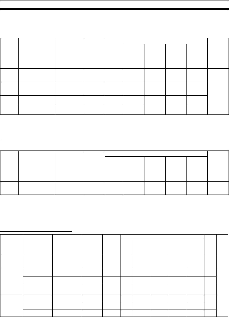
111
Units Section 2-4
Note C200H Units and Racks cannot be used with CS-series-only CPU Racks or
Expansion Racks.
C200H High-density I/O Units (Group 2)
Note C200H Units and Racks cannot be used with CS-series-only CPU Racks or
Expansion Racks.
Analog Timer Unit
C200H Basic Unit
Note C200H Units and Racks cannot be used with CS-series-only CPU Racks or
Expansion Racks.
2-4-2 Special I/O Units
CS-series Special I/O Units
Name Specifications Model Number
of bits
allocated
(CIO 0000
to
CIO 0319)
Mountable Racks Reference
CPU
Rack
C200H
Expan-
sion I/O
Racks
CS-series
Expan-
sion
Racks
CS-series
Long-
distance
Expan-
sion
Racks
SYSMAC
BUS
Slave
Racks
B7A
Input
Units
32 inputs C200H-B7A12 32 Yes Yes Yes No No 3-8 B7A
Interface
Units
B7A
Output
Units
32 outputs C200H-B7A02 32 Yes Yes Yes No No
B7A I/O
Units
16 inputs,
16outputs
C200H-B7A21 32-point
I/O
Ye s Ye s Ye s N o N o
32 inputs,
32outputs
C200H-B7A22 64-point
I/O
Ye s Ye s Ye s N o N o
Name Specifications Model Number
of bits
allocated
(CIO 0000
to
CIO 0319)
Mountable Racks Reference
CPU
Rack
C200H
Expan-
sion I/O
Racks
CS-series
Expan-
sion
Racks
CS-series
Long-
distance
Expan-
sion
Racks
SYSMAC
BUS
Slave
Racks
Analog
Timer
Units
4-point timer C200H-TM001 16 points Yes Yes Yes No Yes 3-9 Analog
Timer
Units
Name Specifications Model Number of
words
allocated
(CIO 2000 to
CIO 2959)
Number of
words
allocated
(D20000 to
D29599)
Mountable Racks Unit
No.
Refer-
ence
CPU
Rack
C200H
Expansion
I/O Racks
CS-series
Expansion
Racks
CS-series
Long-
distance
Expansion
Racks
SYSMAC
BUS Slave
Racks
Analog I/O Unit 4 inputs (4 to 20 mA,
1 to 5 V, etc.)
4 outputs (1 to 5 V,
0 to 10 V, etc.)
CS1W-MAD44 10 words 100 words Yes No Yes Yes No 0 to 95 W345
Analog Input
Unit
4 inputs (4 to 20 mA,
1 to 5 V, etc.)
CS1W-AD041-V1 10 words 100 words Yes No Yes Yes No 0 to 95
8 inputs (4 to 20 mA,
1 to 5 V, etc.)
CS1W-AD081-V1 10 words 100 words Yes No Yes Yes No 0 to 95
16 inputs (4 to 20
mA,
1 to 5 V, etc.)
CS1W-AD161 20 words 200 words Yes No Yes Yes No 0 to 95
(See
note.)
Analog Output
Unit
4 outputs (1 to 5 V,
4 to 20 mA, etc.)
CS1W-DA041 10 words 100 words Yes No Yes Yes No 0 to 95
8 outputs
(1 to 5 V, etc.)
CS1W-DA08V 10 words 100 words Yes No Yes Yes No 0 to 95
8 outputs
(4 to 20 mA)
CS1W-DA08C 10 words 100 words Yes No Yes Yes No 0 to 95

112
Units Section 2-4
Note Allocated two unit numbers.
Isolated Ther-
mocouple Input
Unit
4 inputs (D, E, J, K,
N, R, S, T, or ±80 mV
DC)
CS1W-PTS01-V1 10 words 100 words Yes No Yes Yes No 0 to 95 W368
High-resolution
Isolated Ther-
mocouple Input
Unit
4 inputs (B, E, J, K,
L, N, R, S, T, U,
WRe5-26, PL II, or
mV)
CS1W-PTS11 10 words 100 words Yes No Yes Yes No 0 to 95
Isolated Resis-
tance Ther-
mometer Input
Unit
4 inputs
(Pt100, JPt100)
CS1W-PTS02 10 words 100 words Yes No Yes Yes No 0 to 95
Isolated
Ni508.4Ω
Resistance
Thermometer
Input Unit
4 inputs (Ni508.4Ω) CS1W-PTS03 10 words 100 words Yes No Yes Yes No 0 to 95
High-resolution
Isolated Resis-
tance Ther-
mometer Input
Unit
4 inputs (Pt100,
JPt100, Pt50, or
Ni508.4 Ω)
CS1W-PTS12 10 words 100 words Yes No Yes Yes No 0 to 95
Isolated 2-wire
Transmission
Device Input
Unit
4 inputs (1 to 5 V, 4
to 20 mA) 2-wire
transmission device
power supply built in
CS1W-PTW01 10 words 100 words Yes No Yes Yes No 0 to 95
Isolated DC
Input Unit
4 inputs (1 to 5 V,
4 to 20 mA, etc.)
CS1W-PDC01 10 words 100 words Yes No Yes Yes No 0 to 95
High-resolution
Isolated DC
Input Unit
4 inputs (1 to 5 V,
4 to 20 mA, etc.)
CS1W-PDC11 10 words 100 words Yes No Yes Yes No 0 to 95
Isolated Con-
trol Output Unit
(Analog Output
Unit)
4 outputs (1 to 5 V,
4 to 20 mA)
CS1W-PMV01 10 words 100 words Yes No Yes Yes No 0 to 95
Isolated Con-
trol Output Unit
(Analog Output
Unit, advanced
type)
4 outputs
(−10 to 10 V, −1 to
1 V: 1/16,000 resolu-
tion; 0 to 10 V, 0 to
5 V, 0 to 1 V: 1/8,000
resolution; 0 to 5 V:
1/4,000 resolution)
CS1W-PMV02 10 words 100 words Yes No Yes Yes No 0 to 95
Power Trans-
ducer Input Unit
8 inputs (−1 to 1 mA,
0 to 1 mA)
CS1W-PTR01 10 words 100 words Yes No Yes Yes No 0 to 95
DC Input Unit
(100 mA)
8 inputs (−100 to
100 mV, 0 to
100 mV)
CS1W-PTR02 10 words 100 words Yes No Yes Yes No 0 to 95
Isolated Pulse
Input Unit
4 pulse inputs (0 to
20 kpulses/s, 0 to 20
pulses/s)
CS1W-PPS01 10 words 100 words Yes No Yes Yes No 0 to 95
Name Specifications Model Number of
words
allocated
(CIO 2000 to
CIO 2959)
Number of
words
allocated
(D20000 to
D29599)
Mountable Racks Unit
No.
Refer-
ence
CPU
Rack
C200H
Expansion
I/O Racks
CS-series
Expansion
Racks
CS-series
Long-
distance
Expansion
Racks
SYSMAC
BUS Slave
Racks
Name Specifications Model Number of
words
allocated
(CIO 2000 to
CIO 2959)
Number of
words
allocated
(D20000 to
D29599)
Mountable Racks Unit No. Refer-
ence
CPU
Rack
C200H
Expan-
sion I/O
Racks
CS-series
Expan-
sion
Racks
CS-series
Long-
distance
Expansion
Racks
SYSMAC
BUS
Slave
Racks
Position
Control
Units
Pulse output, 1 axis, 1 to
500 kpulses/s, open-col-
lector output
CS1W-NC113 10 words 100 words Yes No Yes Yes No 0 to 95 W376
Pulse output, 1 axis, 1 to
500 kpulses/s, line-driver
output
CS1W-NC133 10 words 100 words Yes No Yes Yes No 0 to 95
Pulse outputs, 2 axes, 1 to
500 kpulses/s, open-col-
lector outputs
CS1W-NC213 10 words 100 words Yes No Yes Yes No 0 to 95
Pulse outputs, 2 axes, 1 to
500 kpulses/s, line-driver
outputs
CS1W-NC233 10 words 100 words Yes No Yes Yes No 0 to 95
Pulse outputs, 4 axes, 1 to
500 kpulses/s, open-col-
lector outputs
CS1W-NC413 20 words 200 words Yes No Yes Yes No 0 to 95 (See
note 1.)
Pulse output, 4 axes, 1 to
500 kpulses/s, line-driver
outputs
CS1W-NC433 20 words 200 words Yes No Yes Yes No 0 to 95 (See
note 1.)
Motion
Control
Units
Two axes, analog output
for each axis, supports G-
language
CS1W-MC221-V1 30 words None Yes No Yes Yes No 0 to 95 (See
note 2.)
W359
Four axes, analog output
for each axis, supports G-
language
CS1W-MC421-V1 50 words None Yes No Yes Yes No 0 to 95 (See
note 3.)

113
Units Section 2-4
Note 1. Allocated two unit numbers.
2. Allocated three unit numbers.
3. Allocated five unit numbers.
Customiz-
able
Counter
Unit
4 Kwords, 12 contact
inputs, 8 contact outputs
CS1W-HIO01 10 words 100 words
(90 for gen-
eral data
ex-change)
Yes No Yes Yes No 0 to 95 W384
4 Kwords, 12 contact
inputs, 8 contact outputs,
2 pulse inputs, 2 pulse
outputs
CS1W-HCP22 10 words Yes No Yes Yes No 0 to 95
4 Kwords, 12 contact
inputs, 8 contact outputs,
1 pulse input, 1 analog
input, 2 analog outputs
CS1W-HCA12-V1 10 words Yes No Yes Yes No 0 to 95
4 Kwords, 12 contact
inputs, 8 contact outputs,
2 pulse inputs, 2 analog
outputs
CS1W-HCA22 10 words Yes No Yes Yes No 0 to 95
High-
speed
Counter
Unit
Pulse inputs for two axes,
counting rate: 500 kcps
max., line driver compati-
ble
CS1W-CT021 40 words 400 words Yes No Yes Yes No 0 to 95 (Allo-
cated words
for 4 unit
numbers.)
W902
Pulse inputs for four axes,
counting rate: 500 kcps
max., line driver compati-
ble
CS1W-CT041 40 words 400 words Yes No Yes Yes No 0 to 95 (Allo-
cated words
for 4 unit
numbers.)
GP-IB
Interface
Unit
Conforms to IEEE-488-
1978.
CS1W-GPI01 10 words 100 words Yes No Yes Yes No 0 to 95 W410
Compo-
Net Mas-
ter Unit
CompoNet remote I/O CS1W-CRM21 Yes No Yes Yes No W456
Communications
mode No. 0: 128
inputs/128 outputs
for Word Slaves
20 words None 0 to 95 (Allo-
cated words
for 2 unit
numbers.)
Communications
mode No. 1: 256
inputs/256 outputs
for Word Slaves
40 words None 0 to 95 (Allo-
cated words
for 4 unit
numbers.)
Communications
mode No. 2: 512
inputs/512 outputs
for Word Slaves
80 words None 0 to 95 (Allo-
cated words
for 8 unit
numbers.)
Communications
mode No. 3: 256
inputs/256 outputs
for Word Slaves and
128 inputs/128 out-
puts for Bit Slaves
80 words None 0 to 95 (Allo-
cated words
for 8 unit
numbers.)
Communications
mode No. 8: 1,024
inputs/1,024 outputs
for Word Slaves and
256 inputs/256 out-
puts for Bit Slaves
maximum
10 words Depends
on setting
0 to 95 (Allo-
cated words
for 1 unit
numbers.)
Name Specifications Model Number of
words
allocated
(CIO 2000 to
CIO 2959)
Number of
words
allocated
(D20000 to
D29599)
Mountable Racks Unit No. Refer-
ence
CPU
Rack
C200H
Expan-
sion I/O
Racks
CS-series
Expan-
sion
Racks
CS-series
Long-
distance
Expansion
Racks
SYSMAC
BUS
Slave
Racks
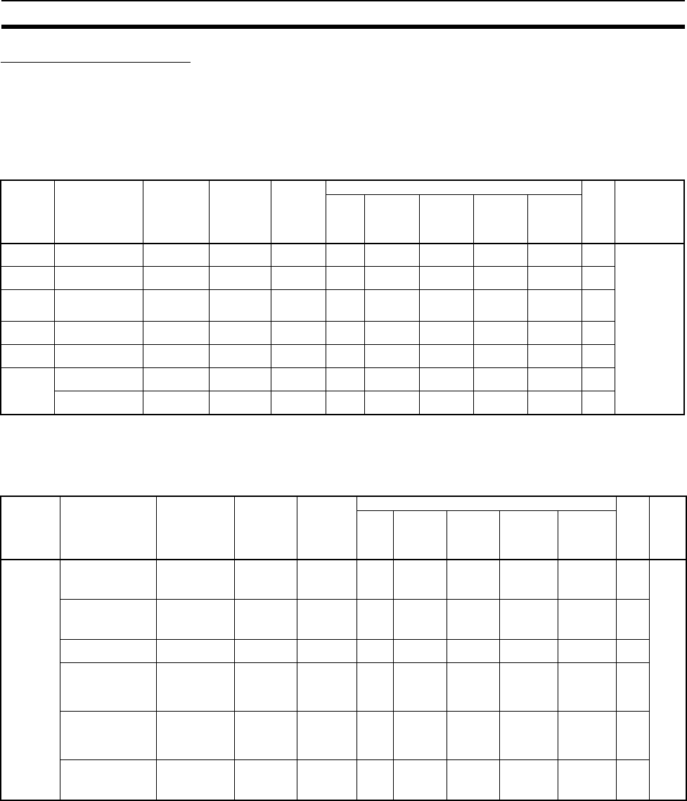
114
Units Section 2-4
C200H Special I/O Units
C200H High-density I/O Units
Note 1. Functionally, these Units are I/O Units, but are categorized as Special I/O
Units.
2. C200H Units and Racks cannot be used with CS-series-only CPU Racks
or Expansion Racks.
C200H Special I/O Units
Note C200H Units and Racks cannot be used with CS-series-only CPU Racks or
Expansion Racks.
Name Specifications Model Number of
words allo-
cated
(CIO 2000 to
CIO 2959)
Number of
words allo-
cated
(D20000 to
D29599)
Mountable Racks Unit
No.
Reference
CPU
Rack
C200H
Expansion
I/O Racks
CS-series
Expansion
Racks
CS-series
Long-dis-
tance
Expansion
Racks
SYSMAC
BUS Slave
Racks
DC Input
Units
24 V DC, 32 inputs C200H-ID215 10 words None Yes Yes Yes No Yes 0 to 9 3-7 C200H
High-density I/O
Units (Special
I/O Units) and
Appendix A
Specifications
of Basic I/O
Units and High-
density I/O
Units
TTL Input
Units
5 V DC, 32 inputs C200H-ID501 10 words None Yes Yes Yes No Yes 0 to 9
Transistor
Output
Units
24 V DC, 32 sinking
outputs
C200H-OD215 10 words None Yes Yes Yes No Yes 0 to 9
TTL Output
Units
5 V DC, 32 sinking
outputs
C200H-OD501 10 words None Yes Yes Yes No Yes 0 to 9
TTL I/O
Units
5 V DC, 16 inputs,
16 sinking outputs
C200H-MD501 10 words None Yes Yes Yes No Yes 0 to 9
DC
Input/Tran-
sistor Out-
put Units
24 V DC, 16 inputs,
16 sinking outputs
C200H-MD215 10 words None Yes Yes Yes No Yes 0 to 9
12 V DC, 16 inputs,
16 sinking outputs
C200H-MD115 10 words None Yes Yes Yes No Yes 0 to 9
Name Specifications Model Number of
words allo-
cated
(CIO 2000 to
CIO 2959)
Number of
words allo-
cated
(D20000 to
D29599)
Mountable Racks Unit
No.
Refer-
ence
CPU
Rack
C200H
Expan-
sion I/O
Racks
CS-series
Expan-
sion Racks
CS-series
Long-dis-
tance
Expansion
Racks
SYSMAC
BUS Slave
Racks
Temperature
Control Units
Thermocouple input,
time-proportioning PID,
or ON/OFF transistor
output
C200H-TC001 10 words None Yes Yes Yes No Yes 0 to 9 W225
Thermocouple input,
time-proportioning PID,
or ON/OFF voltage out-
put
C200H-TC002 10 words None Yes Yes Yes No Yes 0 to 9
Thermocouple input,
PID current output
C200H-TC003 10 words None Yes Yes Yes No Yes 0 to 9
Temperature-resis-
tance thermometer
input, time-proportion-
ing PID, or ON/OFF
transistor output
C200H-TC101 10 words None Yes Yes Yes No Yes 0 to 9
Temperature-resis-
tance thermometer
input, time-proportion-
ing PID, or ON/OFF
voltage output
C200H-TC102 10 words None Yes Yes Yes No Yes 0 to 9
Temperature-resis-
tance thermometer
input, PID current out-
put
C200H-TC103 10 words None Yes Yes Yes No Yes 0 to 9

115
Units Section 2-4
Heat/Cool
Temperature
Control Units
Thermocouple input,
time-proportioning PID,
or ON/OFF transistor
output
C200H-TV001 10 words None Yes Yes Yes No Yes 0 to 9 W240
Thermocouple input,
time-proportioning PID,
or ON/OFF voltage out-
put
C200H-TV002 10 words None Yes Yes Yes No Yes 0 to 9
Thermocouple input,
PID current output
C200H-TV003 10 words None Yes Yes Yes No Yes 0 to 9
Temperature-resis-
tance thermometer
input, time-proportion-
ing PID, or ON/OFF
transistor output
C200H-TV101 10 words None Yes Yes Yes No Yes 0 to 9
Temperature-resis-
tance thermometer
input, time-proportion-
ing PID, or ON/OFF
voltage output
C200H-TV102 10 words None Yes Yes Yes No Yes 0 to 9
Temperature-resis-
tance thermometer
input, PID current out-
put
C200H-TV103 10 words None Yes Yes Yes No Yes 0 to 9
Temperature
Sensor Units
Thermocouple input,
K(CA) or J(IC), select-
able
C200H-TS001 10 words None Yes Yes Yes No Yes 0 to 9 W124
C200H-TS002 10 words None Yes Yes Yes No Yes 0 to 9
Temperature-resis-
tance thermometer,
JPt 100 Ω
C200H-TS101 10 words None Yes Yes Yes No Yes 0 to 9
Temperature-resis-
tance thermometer,
Pt 100 Ω
C200H-TS102 10 words None Yes Yes Yes No Yes 0 to 9
PID Control
Units
Voltage output/current
input, time-proportion-
ing PID, or ON/OFF
transistor output
C200H-PID01 10 words None Yes Yes Yes No Yes 0 to 9 W241
Voltage output/current
input, time-proportion-
ing PID, or ON/OFF
voltage output
C200H-PID02 10 words None Yes Yes Yes No Yes 0 to 9
Voltage output/current
input, PID current out-
put
C200H-PID03 10 words None Yes Yes Yes No Yes 0 to 9
Cam Posi-
tioner Units
48 cam outputs (16
external outputs and 32
internal outputs)
Resolver speed: 20 µs
(5 kHz)
C200H-CP114 10 words 11 words Yes Yes Yes No Yes 0 to 9 W224
ASCII Units 24-Kbyte RAM C200H-ASC02 10 words None Yes Yes Yes No Yes 0 to 9 W165
200-Kbyte RAM, 2 RS-
232C ports
C200H-ASC11 10 words 100 words Yes Yes Yes No Yes 0 to F W306
200-Kbyte RAM, RS-
232C port, RS-422/485
port
C200H-ASC21 10 words 100 words Yes Yes Yes No Yes 0 to F
200-Kbyte RAM, 3 RS-
232C ports
C200H-ASC31 10 words 100 words Yes Yes Yes No Yes 0 to F
Analog Input
Units
4 to 20 mA, 1 to 5/0 to
10 V (selectable), 4
inputs, 1/4,000 resolu-
tion
C200H-AD001 10 words 100 words Yes Yes Yes No Yes 0 to 9 W229
4 to 20 mA, 1 to 5/0 to
10 V/–10 to +10 V
(selectable); 8 inputs;
1/4,000 resolution
C200H-AD002 10 words 100 words Yes Yes Yes No Yes 0 to F
4 to 20 mA, 1 to 5/0 to
10 V/–10 to +10 V
(selectable); 8 inputs;
1/4,000 resolution
C200H-AD003 10 words 100 words Yes Yes Yes No Yes 0 to F W345
Analog Out-
put Units
4 to 20 mA, 1 to 5/0 to
10 V (selectable); 2
outputs; 1/4,000 reso-
lution
C200H-DA001 10 words 100 words Yes Yes Yes No Yes 0 to 9 W229
4 to 20 mA, –10 to
+10 V (selectable),
4outputs
C200H-DA002 10 words None Yes Yes Yes No Yes 0 to F
1 to 5 V, 0 to 10 V, –10
to +10 V (selectable), 8
outputs; 1/4,000 reso-
lution
C200H-DA003 10 words 100 words Yes Yes Yes No Yes 0 to F W325
4 to 20 mA, 8 outputs;
1/4,000 resolution
C200H-DA004 10 words 100 words Yes Yes Yes No Yes 0 to F
Analog I/O
Units
2 inputs (4 to 20 mA,
1 to 5 V, etc.)
2 outputs (4 to 20 mA,
1 to 5 V, etc.)
C200H-MAD01 10 words 100 words Yes Yes Yes No Yes 0 to F
Name Specifications Model Number of
words allo-
cated
(CIO 2000 to
CIO 2959)
Number of
words allo-
cated
(D20000 to
D29599)
Mountable Racks Unit
No.
Refer-
ence
CPU
Rack
C200H
Expan-
sion I/O
Racks
CS-series
Expan-
sion Racks
CS-series
Long-dis-
tance
Expansion
Racks
SYSMAC
BUS Slave
Racks

116
Units Section 2-4
Note 1. The DeviceNet Slaves are allocated up to 1,600 I/O bits (100 words) in the
DeviceNet Area.
2. PLC Link Units are allocated up to 1,024 bits (64 words) in the Link Area.
3. Each Slave Rack connected to a Remote I/O Master Unit is allocated
10 words in the SYSMAC BUS Area.
Each I/O Terminal is allocated 1 word in the I/O Terminal Area.
4. The C200HW-CLK21 Controller Link Unit (C200HX/HG/HE) cannot be
used. Use the CS1W-CLK21(-V1) or CS1W-CLK23 Controller Link Unit
(CS-series CPU Bus Unit). Data links and message services are support-
ed between C200HX/HG/HE and CS-series PLCs.
High-speed
Counter
Units
One-axis pulse input,
counting rate: 50 kcps
max.
C200H-CT001-V1 10 words 100 words Yes Yes Yes No Yes 0 to 9 W141
One-axis pulse input,
counting rate: 75 kcps
max., line driver com-
patible
C200H-CT002 10 words 100 words Yes Yes Yes No Yes 0 to 9
Two-axis pulse input,
counting rate: 75 kcps
max., line driver com-
patible
C200H-CT021 20 words 100 words Yes Yes Yes No Yes 0 to F W311
Motion Con-
trol Units
G-language program-
mable, two-axis analog
outputs
C200H-MC221 20 words 100 words
(Uses first 2
words.)
Yes Yes Yes No Yes 0 to F W315
W314
Position Con-
trol Units
Two axes, pulse output
for each axis, speeds: 1
to 250,000 pps, directly
connects to servomotor
driver
C200H-NC211 20 words 200 words Yes Yes Yes No Yes 0 to 9 W166
One axis, pulse output,
speed: 1 to 99,990 pps
C200H-NC111 10 words 100 words Yes Yes Yes No Yes 0 to 9 W137
One axis, pulse output,
speeds 1 to 250,000
pps, directly connects
to servomotor driver,
line driver compatible
(Z level)
C200H-NC112 10 words 100 words Yes Yes Yes No Yes 0 to 9 W128
One axis, pulse output,
speeds 1 to 500,000
pps, directly connects
to servomotor driver
C200HW-NC113 10 words 100 words Yes Yes Yes No Yes 0 to F W334
Two axes, pulse output
for each axis, speeds 1
to 500,000 pps, directly
connects to servomotor
driver
C200HW-NC213 10 words 100 words Yes Yes Yes No Yes 0 to F
Four axes, pulse output
for each axis, speeds 1
to 500,000 pps, directly
connects to servomotor
driver
C200HW-NC413 20 words 200 words Yes Yes Yes No Yes 0 to F
ID Sensor
Units
Electromagnetic cou-
pling
C200H-IDS01-V1 10 words None Yes Yes Yes No Yes 0 to 9 W153
Microwave type C200H-IDS21 10 words None Yes Yes Yes No Yes 0 to 9
Voice Unit
(See note 6.)
Adaptive differential
pulse-code modulation
C200H-OV001 10 words 100 words Yes Yes Yes No Yes 0 to 9 W172
Fuzzy Logic
Unit
8 inputs, 4 outputs C200H-FZ001 10 words 100 words Yes Yes Yes No Yes 0 to 9 W208
JPCN-1 Unit Settable as master or
slave
C200H-JRM21 10 words 100 words Yes Yes Yes No No 0 to F ---
DeviceNet
Master Units
DeviceNet Remote I/O,
1,600 bits max.
C200HW-DRM21-
V1
(See note 1.) None Yes Yes Yes No No 0 to F W347
C200H I/O
Link Units
DeviceNet Slave, 512
inputs/512 outputs
max.
C200HW-DRT21 10 words None Yes Yes Yes No No 0 to F W347
Compo-
Bus/S Mas-
ter Units
CompoBus/S Remote
I/O, 256 bits max.
C200HW-SRM21-
V1
10 words or
20 words
None Yes Yes Yes No No 0 to F W266
PLC Link
Units
PLC Link, single level:
32 units, multilevel:
16 Units
C200H-LK401 (See note 2.) None Yes Yes Yes No No 0 to 9 W135
SYSMAC
BUS Remote
I/O Master
Units
Wired C200H-RM201 (See note 3.) --- Yes Yes Yes No No 0 to 3 W120
Optical C200H-RM001-
PV1
- - - Ye s Yes Ye s N o N o 0 t o 3 W 1 3 6
Name Specifications Model Number of
words allo-
cated
(CIO 2000 to
CIO 2959)
Number of
words allo-
cated
(D20000 to
D29599)
Mountable Racks Unit
No.
Refer-
ence
CPU
Rack
C200H
Expan-
sion I/O
Racks
CS-series
Expan-
sion Racks
CS-series
Long-dis-
tance
Expansion
Racks
SYSMAC
BUS Slave
Racks

117
Units Section 2-4
5. The C200H-LK@@@-@@ Host Link Unit (C200H, C200HS,
C200HX/HG/HE) cannot be used. Use the CS1W-SCU21 Serial Commu-
nications Unit (CS-series CPU Bus Unit).
6. Observe the following precautions when using the C200H-OV001 Voice
Unit.
• The Voice Unit cannot be used if an OMRON Programmable Terminal
(PT) set for NT Link Mode is connected to the peripheral port or RS-
232C port on the CPU Unit.
• When using both a Voice Unit and an OMRON PT, connect the PT to
a CS1W-SCB@@@ Serial Communications Board or to a CS1W-
SCU@@@ Serial Communications Unit.
• When a Voice Unit is mounted, set to baud rate for the peripheral port
or RS-232C port on the CPU Unit to 9,600 bps or less when commu-
nicating with a computer or other external device.

118
Units Section 2-4
2-4-3 CS-series CPU Bus Units
Note 1. A maximum of eight Units can be mounted.
2. A maximum of four Units can be mounted.
3. A maximum of three Units can be mounted.
4. Some CPU Bus Units are allocated words in the CPU Bus Unit Setting Ar-
ea. The system must be designed so that the number of words allocated
in the CPU Bus Unit Setting Area does not exceed its capacity. Refer to 2-
7 CPU Bus Unit Setting Area Capacity for details.
Name Specifications Model Number
of words
allocated
CIO 1500
to
CIO 1899
Number
of words
allocated
D30000
to
D31599
CPU
Bus
Unit
System
Settings
Mountable Racks Unit
No.
Refer-
ence
CPU
Rack
C200H
Expansion
I/O Racks
CS-series
Expansion
Racks
CS-series
Long-dis-
tance
Expansion
Racks
SYSMAC
BUS Slave
Racks
Controller
Link Units
Wired CS1W-
CLK21-V1,
CS1W-
CLK23
25 words 100 words Used
(data link
tables)
Ye s N o Ye s Yes N o 0 t o F
(See
note
1.)
W309
Optical ring,
H-PCF cable
CS1W-
CLK12-V1,
CS1W-
CLK13
25 words 100 words Used
(data link
tables)
Ye s N o Ye s Ye s N o - - -
Optical ring,
GI cable
CS1W-
CLK52-V1,
CS1W-
CLK53
25 words 100 words Used
(data link
tables)
Ye s N o Ye s Ye s N o
SYSMAC
LINK Units
Coaxial CS1W-
SLK21
25 words 100 words Used
(data link
tables)
Ye s N o Ye s Yes N o 0 t o F
(See
note
2.)
W367
Optical CS1W-
SLK11
25 words 100 words Used
(data link
tables)
Ye s N o Ye s Ye s N o
Serial Com-
munications
Unit
Two RS-232C Ports CS1W-
SCU21-V1
25 words 20 words Not used Yes No Yes Yes No 0 to F W336
Two RS-422A/ 485 Ports CS1W-
SCU31-V1
25 words 20 words Not used Yes No Yes Yes No
Ethernet
Unit
10Base-5 CS1W-
ETN01
25 words 100 words Used Yes No Yes Yes No 0 to F
(See
note
2.)
W343
100Base-TX (Can be used
as 10Base-T.)
CS1W-
ETN21
25 words 100 words Used Yes No Yes Yes No 0 to F
(See
note
2.)
W420
W421
EtherNet/IP
Unit
Tag data links, FINS commu-
nications, CIP message com-
munications, FTP server, etc.
CS1W-
EIP21
25 words 100 words Not used Yes No Yes Yes No 0 to F
(8
Units
max.)
W465
FL-net Unit 100Base-TX cyclic transmis-
sions and message transmis-
sions
CS1W-
FLN22
25 words 100 words Used Yes No Yes Yes No 0 to F
(See
note
2.)
W440
DeviceNet
Unit
DeviceNet remote I/O 2,048
pt, user settings without Con-
figurator
CS1W-
DRM21-V1
25 words 100 words Not used Yes No Yes Yes No 0 to F W380
PROFIBUS-
DP Master
Unit
PROFIBUS-DP remote I/O
7,168 words
CS1W-
PRM21
25 words 100 words Not used Yes No Yes Yes No 0 to F W409
Loop Control
Unit
PID operations: 32 max.
Loop, process operations:
250 max.
CS1W-
LC001
25 words None Not used Yes No No No No 0 to F
(See
note
3.)
W374
W375
Position
Control
Units
supporting
MECHA-
TROLINK-II
communica-
tions
MECHATROLINK-II,
16 axes max.
CS1W-
NCF71
25 words None Not used Yes No Yes Yes No 0 to F W426
High-resolu-
tion Motion
Control Unit
MECHATROLINK II, Real
axes: 30, Virtual axes: 2,
Special motion control lan-
guage
CS1W-
MCH71
25 words 100 words Not used Yes No Yes Yes No 0 to F ---
SYSMAC
SPU Unit
(High-speed
Storage and
Processing
Unit)
One CF card
type I/II slot
(used with
OMRON HMC-
EF@@@ Mem-
ory Card)
One
Ethernet
port
CS1W-
SPU01
Not used Not used Not used Yes No Yes Yes No 0 to F W229
Two
Ethernet
ports
CS1W-
SPU02
Not used Not used Not used
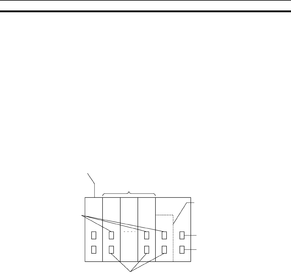
119
Expanded System Configuration Section 2-5
2-5 Expanded System Configuration
2-5-1 Serial Communications System
The CS-series system configuration can be expanded by using the following
serial communications ports.
• CPU Unit built-in ports × 2 (peripheral port and RS-232C port)
• Serial Communications Board ports × 2 (RS-232C or RS-422/485)
• Serial Communications Unit ports × 2 (RS-232C)
• ASCII Unit ports × 2 (RS-232C or RS-422/485)
1,2,3... 1. If the CPU Unit built-in ports, the Serial Communications Board ports, or
Serial Communications Unit ports are used, words can be allocated to var-
ious protocols, such as Host Link and protocol macro.
2. Up to 16 Serial Communications Units and 16 ASCII Units can be connect-
ed to one CPU Unit. The system configuration can then be expanded by
connecting devices with RS-232C or RS-422/485 ports, such as Temper-
ature Sensor Units, Bar Code Readers, ID Systems, personal computers,
Board Computers, Racks, and other companies’ PLCs.
Expanding the system configuration as shown above allows a greater
number of serial communications ports, and greater flexible and simpler
support for different protocols.
3. The Serial Gateway is supported for CPU Units with unit version 3.0 or lat-
er and Serial Communications Boards/Units with unit version 1.2 or later.
• CPU Units with unit version 3.0 or later: Gateway from FINS network to
serial communications (CompoWay/F only) is possible through the
peripheral port and RS-232C port.
• Serial Communications Boards/Units with unit version 1.2 or later: Gate-
way from FINS network to serial network (CompoWay/F, Modbus, or Host
Link) is possible. Using a Gateway to Host Link enables Host Links with
the PLC as master.
ASCII Unit (16 Units max.)
Communications ports 1
Serial Communications Unit (16 Units max.)
CPU Unit
Serial Communications Board
Peripheral port
RS-232C port
Communications ports 2
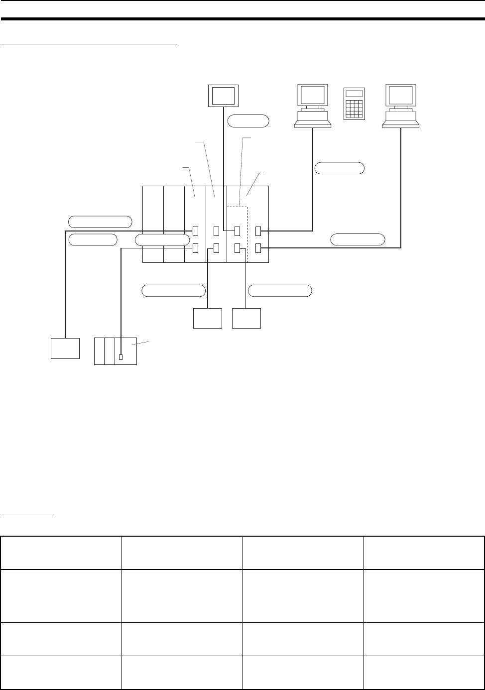
120
Expanded System Configuration Section 2-5
System Configuration Example
Refer to page 127 for a table showing which communications protocols are
supported by each Unit.
2-5-2 Systems
The serial communications port mode (protocol) can be switched in the CPU
Unit’s PLC Setup. Depending on the protocol selected, the following systems
can be configured.
Protocols
The following protocols support serial communications.
NT Link
CPU Unit
RS-232C port
Host computer
Host Link slave
Protocol macroProtocol macro
RS-232C port
RS-232C port
OR
General-purpose external devices
(such as Temperature Sensor
Units, Bar Code Readers)
General-purpose
external devices
(such as other
companies' PLCs)
Peripheral
port
Peripheral Bus
Communications
conditions
automatically
recognized.
Serial Commu-
nications Board
Serial Communications Unit
Programmable
Terminal
CX Programmer Programming
Console
Programming Device
CompoWay Master
Modbus Master Host Link Master
CPU Unit
Host Link slave
CompoWay/F-
compatible device
Modbus-
compatible device
Serial Communications Unit
Ver. 1.2 or later
Protocol Main connection Use Applicable commands,
communications
instructions
Host Link (SYSMAC WAY)
slave
Personal computer
OMRON Programmable
Terminals
Communications between
the Host computer and the
PLC. Commands can be
sent to a computer from the
PLC.
Host Link commands/ FINS
commands. Commands can
be sent to a computer from
the PLC.
No-protocol (customer) com-
munications
General-purpose external
devices
No-protocol communica-
tions with general-purpose
devices.
TXD(236), RXD(235),
TXDU(256), RXDU(255)
NT Links (1: N) OMRON Programmable
Terminals
High-speed communica-
tions with Programmable
Terminals via direct access.
None

121
Expanded System Configuration Section 2-5
Note 1. The peripheral bus mode is used for Programming Devices excluding Pro-
gramming Console. If Programming Console is to be used, set pin 4 of the
DIP switch on the front panel of the Unit to OFF so that the default periph-
eral port communications parameters are used instead of those specified
in the PLC Setup.
2. Serial Communications Unit or Serial Communications Board required.
3. ASCII Unit required.
4. CPU Unit with version 3.0 or later (peripheral port and RS-232C port) and
Serial Communications Board/Unit with unit version 1.2 or later only.
5. Serial Communications Board/Unit with unit version 1.2 or later only.
Host Link System (SYSWAY 1:N Mode) (Slave)
The Host Link System allows the I/O memory of the PLC to be read/written,
and the operating mode to be changed from a Host computer (personal com-
puter or Programmable Terminal) by executing Host Link commands or FINS
commands that are preceded by a header and followed by a terminator. Alter-
natively, FINS commands (preceded by a header and followed by a termina-
Peripheral bus (See note 1.) Programming Devices
CX-Programmer
Communications between
Programming Devices and
the PLC from the computer.
None
Protocol macro (See note 2.) General-purpose external
devices
Sending and receiving mes-
sages (communications
frames) according to the
communications specifica-
tions of external devices.
(SYSMAC-PST is used to
create protocols by setting
various parameters.)
PMCR(260) instruction
General-purpose (BASIC
languages) (See note 3.)
General-purpose external
devices
Free communications with
general-purpose external
devices using BASIC com-
mands.
BASIC program
Serial Gateway OMRON Component
PLC
Converts FINS commands
that are received into Com-
poWay/F, Modbus, or Host
Link protocols, and then
transmits the converted
command to the serial line.
CompoWay/F Master
(See note 4.)
CompoWay/F slave Converts FINS commands
(encapsulated CompoWay/F
commands) received at the
serial port into CompoWay/F
commands.
FINS command
2803 hex received
(including sending FINS
command using
CMND(490))
Modbus Master
(See note 5.)
Modbus slave Converts FINS commands
(encapsulated Modbus com-
mands) received at the serial
port into Modbus commands.
FINS command
2804 hex or 2805 hex
received
(including sending FINS
command using
CMND(490))
Host Link FINS
(SYSWAY) Master
(See note 5.)
Host Link FINS (SYSWAY)
slave (PLC)
Converts FINS commands
into FINS commands encap-
sulated in Host Link
Any FINS command
received except those sent
to serial port
(including sending FINS
command using
CMND(490))
Protocol Main connection Use Applicable commands,
communications
instructions
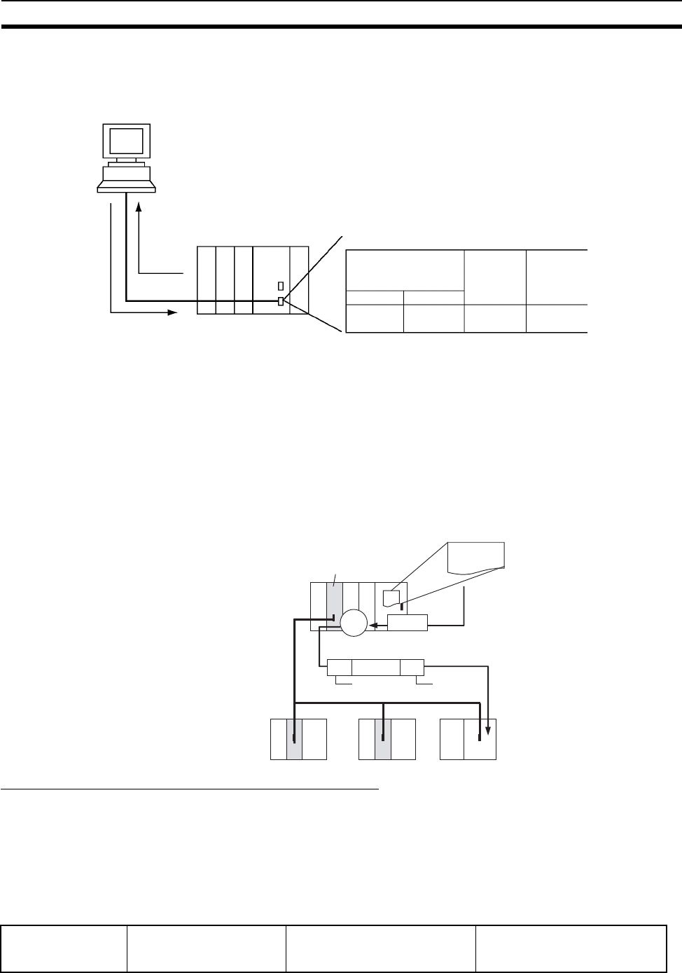
122
Expanded System Configuration Section 2-5
tor) can be sent to a computer connected via the Host Link System by
executing Network Communications Instructions (SEND(090), RECV(098),
and CMND(490)) from the CPU Unit.
Note 1. Set pin 4 of the DIP switch on the front panel of the CPU Unit to ON, and
set the serial communications mode in the PLC Setup to Host Link.
2. Set pin 5 of the DIP switch on the front panel of the CPU Unit to OFF, and
set the serial communications mode in the PLC Setup to Host Link.
3. Host Link master functions can be performed by sending the CMND(490)
instruction via the Serial Gateway when using Serial Communications
Boards/Units with unit version 1.2 or later.
No-protocol (Custom) Communications System
No-protocol communications allow simple data transmissions, such as input-
ting bar code data and outputting printer data using communications port I/O
instructions. The start and completion codes can be set, and RS and CS sig-
nal control is also possible with no-protocol communications.
The following table shows the usage of each communications port I/O
instruction, based on the communications port being used and the direction of
the data transfer (sending or receiving).
Host computer
FINS commands sent via
SEND/RECV/CMND
instructions from the PLC
Host Link com-
mands or FINS
commands
Applicable port
CPU Unit
Peripheral port
Ye s
(See note 1.)
RS-232C port
Serial
Commu-
nications
Board
Serial
Commu-
nications
Unit
Ye s
(See note 2.)
Ye s Ye s
CMND(490)
FINS
FINS
FINS command sent
PLC (Host Link Master)
PLC (Host Link slave)
Serial
Gateway
Serial Communications
Board/Unit
Host Link
header
Host Link
terminator
Communications
port
CPU Unit's built-in
RS-232C port
Serial port on a Serial Communi-
cations Unit (unit version 1.2 or
later)
Serial port on a Serial Communi-
cations Board (unit version 1.2
or later)
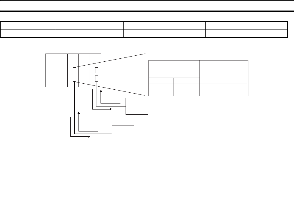
123
Expanded System Configuration Section 2-5
Note 1. Set pin 5 of the DIP switch on the front panel of the CPU Unit to OFF, and
set the serial communications mode in the PLC Setup to no-protocol com-
munications.
2. No-protocol communications are supported for Serial Communications
Units with unit version 1.2 or later only.
NT Link System (1:N Mode)
If the PLC and Programmable Terminal (PT) are connected together using
RS-232C ports, the allocations for the PT’s status control area, status notify
area, objects such as touch switches, indicators, and memory maps can be
allocated in the I/O memory of the PLC. The NT Link System allows the PT to
be controlled by the PLC, and the PT can periodically read data from the sta-
tus control area of the PLC, and perform necessary operations if there are any
changes in the area. The PT can communicate with the PLC by writing data to
the status notify area of the PLC from the PT. The NT Link system allows the
PT status to be controlled and monitored without using PLC ladder programs.
The ratio of PLCs to PTs is 1: n (8 ≥ n ≥ 1).
Set the PT communications settings for a 1:N NT Link. Either one or up to
eight PTs can be connected to each PLC.
Version-1 CPU Units support high-speed NT Links (1:N mode). In this way,
equipment monitoring and settings can be made faster from the PT. The appli-
cable PTs are the NS-series PTs, the NT31(C)-V2 and the NT631(C)-V2.
Send TXD(236) TXDU(256) TXD(236)
Receive RXD(235) RXDU(255) RXD(235)
Applicable port
Peripheral port
No
RS-232C port
Yes
(See note 1.)
CPU Unit
Yes
Serial
Communications
Unit (SCU)
(See note 2.)
CPU SCU
RXD
TXD
RXDU
TXDU
General-purpose
external device
General-purpose
external device
RS-232C
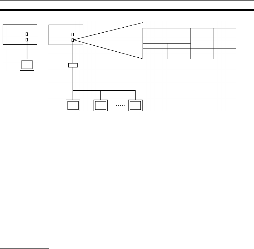
124
Expanded System Configuration Section 2-5
Note 1. The PLC can be connected to any PT port that supports 1:N NT Links. It
cannot be connected to the RS-232C ports on the NT30 or NT30C, be-
cause these ports support only 1:1 NT Links.
2. The NT20S, NT600S, NT30, NT30C, NT620S, NT620C, and NT625C can-
not be used if the CPU Unit’s cycle time is 800 ms or longer (even if only
one of these PTs is connected).
3. The Programming Console functionality of a PT (Expansion Function) can
be used only when the PT is connected to the RS-232C or peripheral port
on the CPU Unit. It cannot be used when connected to an RS-232C or RS-
422A/485 port on a Serial Communications Board or Serial Communica-
tions Unit.
4. When more than one PT is connected to the same PLC, be sure that each
PT is assigned a unique unit number. Malfunctions will occur if the same
unit number is set on more than one PT.
5. The 1:1 and 1:N NT Link protocols are not compatible with each other, i.e.,
they are separate serial communications protocols.
Protocol Macros
The CX-Protocol is used to create data transmission procedures (protocols)
for general-purpose external devices according to the communications speci-
fications (half-duplex or full-duplex, asynchronous) of the general-purpose
external devices. The protocols that have been created are then recorded in a
Serial Communications Board, enabling data to be sent to and received from
the external devices by simply executing the PMCR(260) instruction in the
CPU Unit. Protocols for data communications with OMRON devices, such as
Temperature Controller, Intelligent Signal Processors, Bar Code Readers, and
Modems, are supported as standard protocols. (See note.)
Note The standard protocols are provided with the CX-Protocol, Serial Communi-
cations Boards, and Serial Communications Units.
1:N Mode
RS-232C to RS-422/485
Conversion Adapter
RS-232C
Programmable
Terminal Programmable
Terminal Programmable
Terminal
CPU Unit
Peripheral port
Ye s
(See note 1.)
RS-232C port
Serial
Commu-
nications
Board
Serial
Commu-
nications
Unit
Ye s
(See note 2.)
Ye s Ye s
Applicable port
RS-422A/485
1:N Mode
RS-232C
Programmable
Terminal
Note 1. Turn ON pin 4 on the DIP switch on
the front of the CPU Unit and set the
serial communications mode in the
PLC Setup for an NT Link.
2. Turn OFF pin 5 on the DIP switch on
the front of the CPU Unit and set the
serial communications mode in the
PLC Setup for an NT Link.
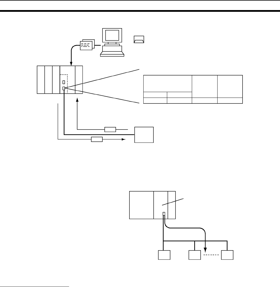
125
Expanded System Configuration Section 2-5
CompoWay/F
(Host Function)
The CS-series CPU Unit can operate as a host to send CompoWay/F com-
mands to OMRON components connected in the system. CompoWay/F com-
mands are executed by using the CompoWay/F send/receive sequences in
the standard protocols of the protocol macro function.
Serial Gateway Mode
When using CPU Units with unit version 3.0 or later (peripheral port and RS-
232C port), the received FINS message is automatically converted into Com-
poWay/F according to the message (see note). When Serial Communications
Boards/Units with unit version 1.2 or later are used, the received FINS mes-
sage is automatically converted into either CompoWay/F, Modbus-RTU, Mod-
bus-ASCII, or Host Link FINS according to the message.
Note CPU Units with unit version 3.0 or later (peripheral port and RS-232C port)
support automatic conversion into CompoWay/F only (automatic conversion
into Modbus-RTU, Modbus-ASCII, and Host Link FINS is not possible).
Protocol CX-Protocol or PSS Support
Software for protocol macro
function
Host computer
Applicable port
Messages
General-purpose external device
Messages
CPU Unit
Peripheral port RS-232C port
Serial
Commu-
nications
Board
Serial
Commu-
nications
Unit
No Yes YesNo
Protocol macro
CompoWay/F command
CompoWay/F
OMRON
device
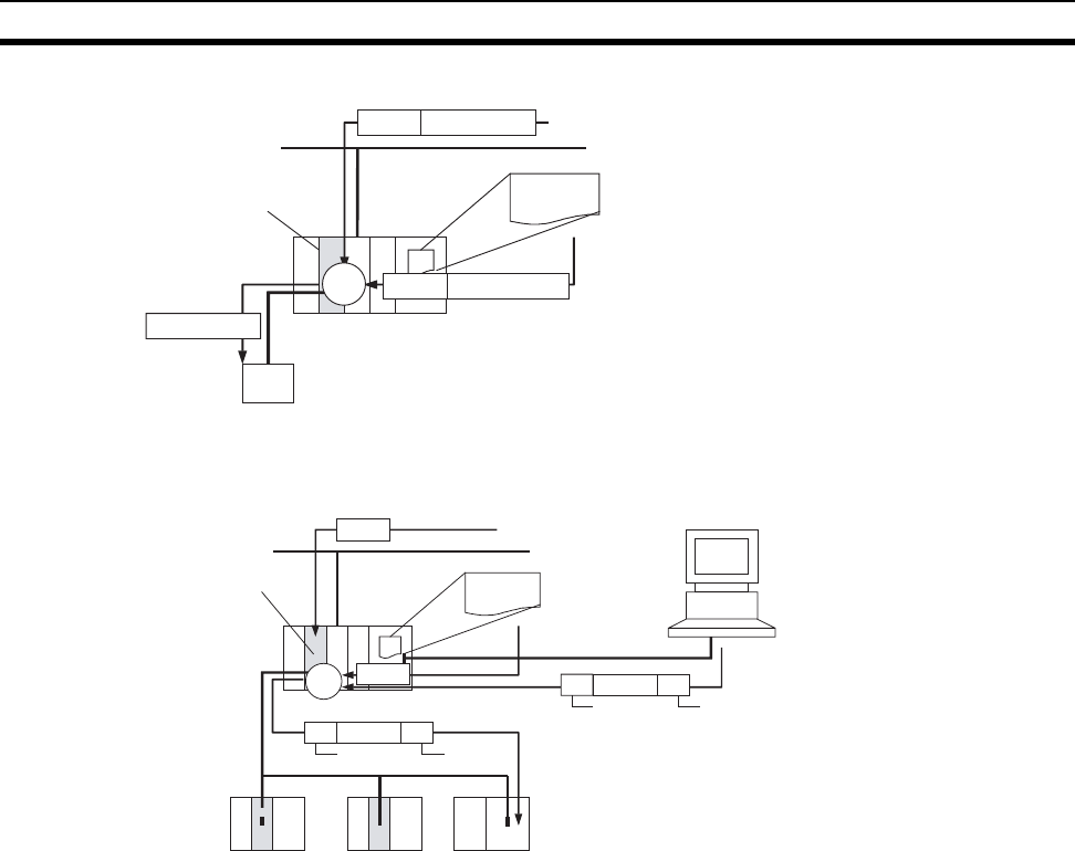
126
Expanded System Configuration Section 2-5
CompoWay/F, Modbus-RTU, Modbus-ASCII
Host Link FINS
CMND(490)
FINS
FINS
CompoWay
(See note.)
CompoWay
(See note.)
CompoWay
(See note.)
Network
FINS command sent
CPU Unit with unit
version 3.0 or later
(peripheral port or RS-
232C port)
Serial Communications
Board/Unit with unit
version 1.2 or later
CompoWay-compatible
OMRON Component, or
Modbus-RTU-compatible
or Modbus-ASCII-
com
p
atible device
Note: Or Modbus-RTU command or Modbus-ASCII command.
These commands cannot be sent to the CPU Unit.
Serial
Gateway
CMND(490)
FINS
FINS
FINS
FINS
Network
PLC (Host Link slave)
PLC (Host Link Master)
Serial Communications
Board/Unit with unit
version 1.2 or later
Note: Not supported
for CPU Units Serial
Gateway
Host Link
header
Host Link
terminator
FINS command
sent
Host Link
header
Host Link
terminator
CX-Programmer or other
Programming Device that
uses CX-Server as the
communications driver
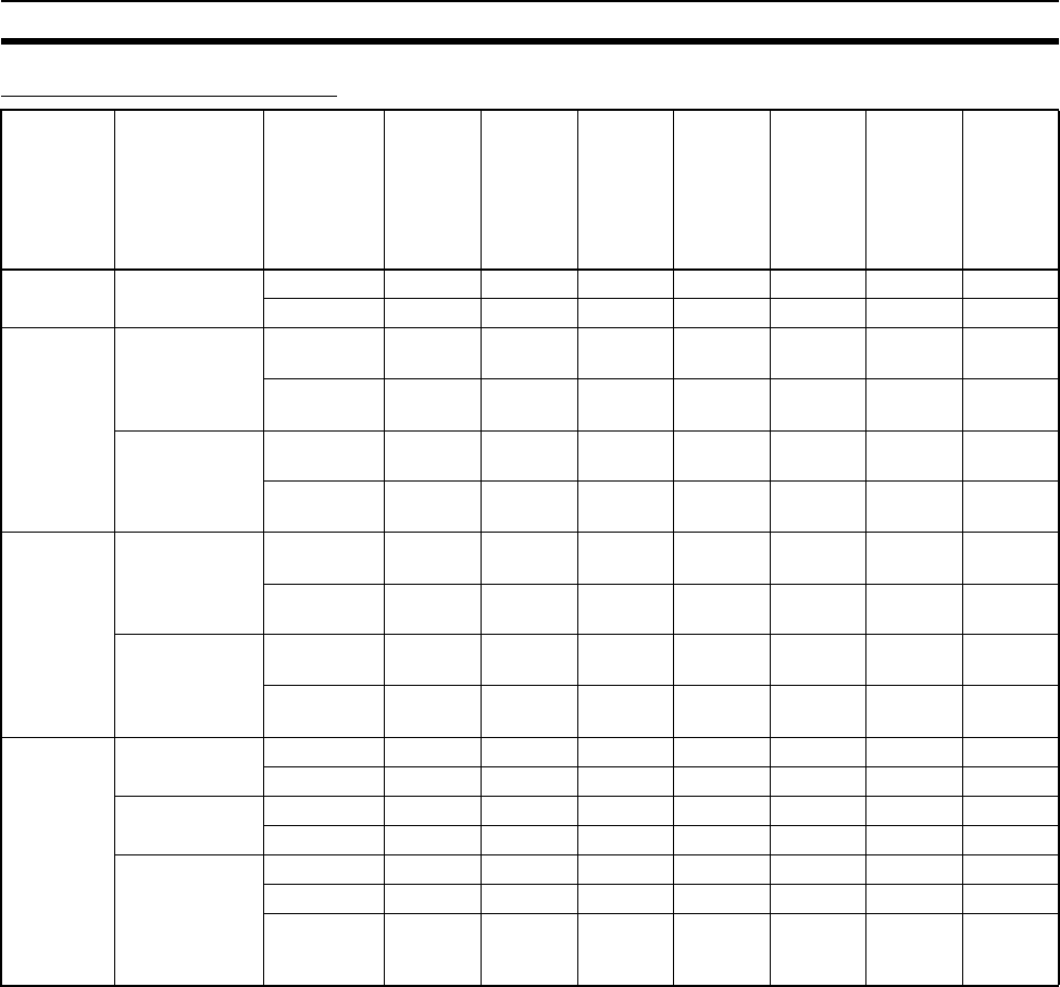
127
Expanded System Configuration Section 2-5
Unit/Protocol Compatibility
Note 1. The peripheral bus mode is used for Programming Devices excluding Pro-
gramming Console. If Programming Console is to be used, set pin 4 of the
DIP switch on the front panel of the Unit to OFF so that the default periph-
eral port communications parameters are used instead of those specified
in the PLC Setup.
2. Supported for CPU Units with unit version 3.0 or later and Serial Commu-
nications Boards/Units with unit version 1.2 or later only. For CPU Units,
however, only automatic CompoWay/F connection is possible.
Unit Model Port Periph-
eral bus
(See
note 1.)
Host
Link
(slave)
No-pro-
tocol
(cus-
tomer)
commu-
nica-
tions
Protocol
macro
NT Link
(1:N
Mode)
General-
purpose
(using
BASIC)
Serial
Gateway
(See
note 2.)
CPU Units CS1G/H-
CPU@@-E
Peripheral Yes Yes --- --- Yes --- Yes
R S - 2 3 2 C Ye s Ye s Ye s - - - Ye s - - - Ye s
Serial
Communi-
cations
Boards
CS1W-SCB21-
V1
RS-232C --- Yes Yes (See
note 2.)
Ye s Ye s - - - Ye s
RS-232C --- Yes Yes (See
note 2.)
Ye s Ye s - - - Ye s
CS1W-SCB41-
V1
RS-232C --- Yes Yes (See
note 2.)
Ye s Ye s - - - Ye s
RS-422/485 --- Yes Yes (See
note 2.)
Ye s Ye s - - - Ye s
Serial
Communi-
cations
Units
CS1W-SCU21-
V1
RS-232C --- Yes Yes (See
note 2.)
Ye s Ye s - - - Ye s
RS-232C --- Yes Yes (See
note 2.)
Ye s Ye s - - - Ye s
CS1W-SCU31-
V1
RS422A/
485
--- Yes Yes (See
note 2.)
Ye s Ye s - - - Ye s
RS422A/
485
--- Yes Yes (See
note 2.)
Ye s Ye s - - - Ye s
ASCII
Units
C200H-ASC11 RS-232C --- --- --- --- --- Yes ---
RS-232C --- --- --- --- --- Yes ---
C200H-ASC21 RS-232C --- --- --- --- --- Yes ---
RS-422/485 --- --- --- --- --- Yes ---
C200H-ASC31 RS-232C --- --- --- --- --- Yes ---
RS-232C --- --- --- --- --- Yes ---
RS-232C
(Terminal
port)
--- --- --- --- --- Yes ---
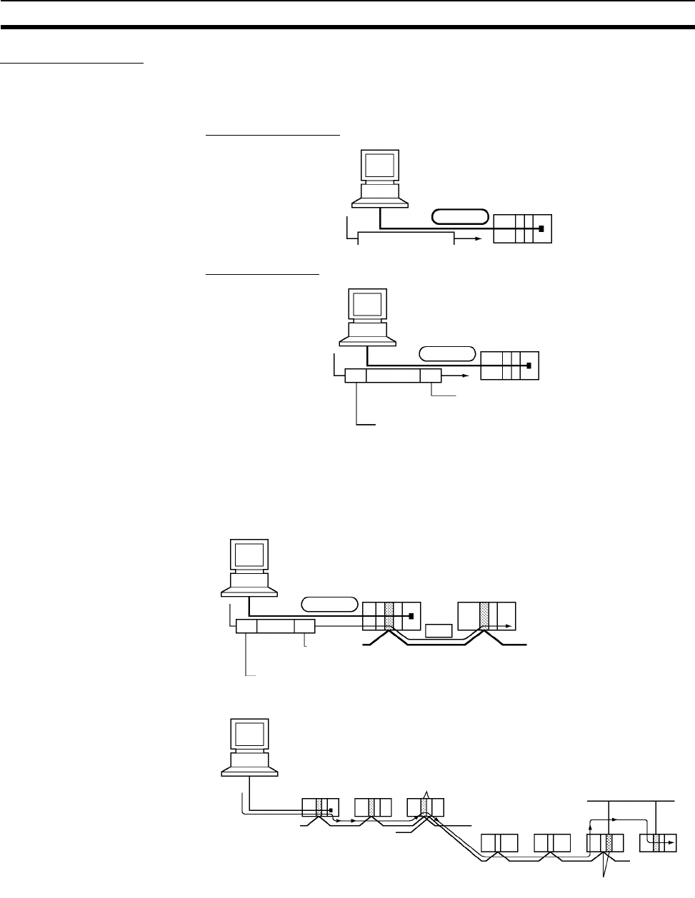
128
Expanded System Configuration Section 2-5
Host Link System
The following system configurations are possible for a Host Link System.
Host Link Slave
C-mode Commands
FINS Commands
In Host Link mode, FINS commands contained between a header and termi-
nator can be sent from the host computer to any PLC on the Network. Com-
munications are possible with PLCs on the same or different types of
interconnected Networks up to two levels away (three levels including the
local level but not including the Host Link connection).
Host Link
Host Link commands
Host Link
Host Link terminator
FINS
Host Link header
Host Link
Host Link
terminator
Host Link header
FINS FINS
Controller Link Network
or Ethernet
Controller Link Network
Host Link Bridge
Controller Link
Network Gateway
Ethernet
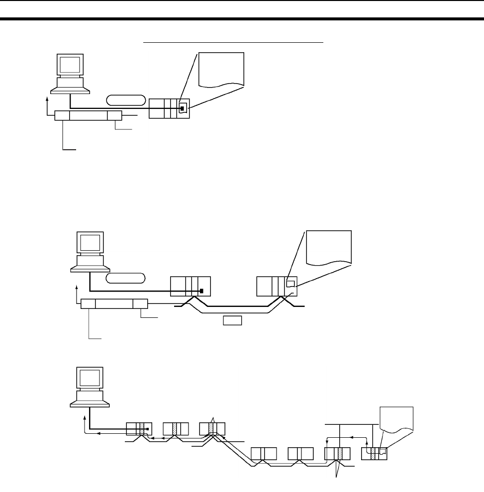
129
Expanded System Configuration Section 2-5
Communications from Host Computer
In Host Link mode, FINS commands contained between a header and termi-
nator can be sent from the host computer to any PLC on the Network. Com-
munications are possible with PLCs on the same or different types of
interconnected Networks up to two levels away (three levels including the
local level but not including the Host Link connection).
Host Link Master Using a Serial Communications Board/Unit with unit version 1.2 or later and
Serial Gateway mode enables received FINS commands to be enclosed in a
Host Link header and terminator and transmitted to the PLC on the serial line
(Host Link slave).
SEND(090)/
RECV(098)
CMND(490)
SEND(090): Sends data to the Host computer.
RECV(098): Receives data from the Host computer.
CMND(490): Executes a specified FINS command.
Host Link
FINS
Host Link header
Host Link terminator
Host Link
FINS
Host Link header
Host Link
terminator
Controller
Link Network
SEND(090)/
RECV(098)
CMND(490)
Host Link Bridge
Controller Link Network
Controller Link Network
Gateway
Ethernet
FINS
SEND(090)/
RECV(098)
CMND(490)
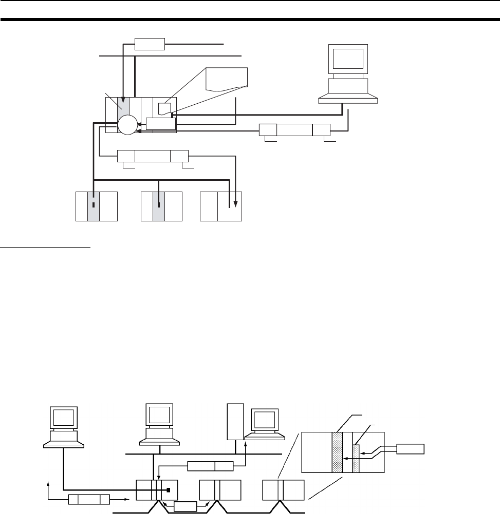
130
Expanded System Configuration Section 2-5
FINS Messages
FINS (Factory Interface Network Service) messages are commands and
responses that are used as a message service in an OMRON Network. FINS
messages enable the user to control operations such as sending and receiv-
ing data and changing operating modes when necessary. The features of
FINS messages are as follows:
Flexible Communications FINS messages are defined in the application layer and do not rely on the
physical layer, data link layer, or other lower-level layers. This enables flexible
communications on the CPU bus and different types of networks. Basically,
communications with Ethernet, SYSMAC NET, SYSMAC LINK, Controller
Link, DeviceNet, or Host Link Networks, and between the CPU Unit and CPU
Bus Units or Inner Boards is possible via the CPU bus.
Note A TCP/IP header must be attached to the FINS command for an Ethernet Net-
work, and a Host Link header must be attached to the FINS command for a
Host Link Network
CMND(490)
FINS
FINS
FINS
FINS
Network
PLC (Host Link slave)
Serial Communications
Board/Unit with unit
version 1.2 or later
Serial
Gateway
PLC (Host Link Master)
Host Link
header
Host Link
terminator
Host Link
header
Host Link
terminator
FINS command
sent
CX-Programmer or other
Programming Device
that uses CX-Server as
the communications
driver
Host Link
FINS
TCP/IP FINS
FINS
Controller Link
Ethernet
CS-series CPU Bus Uni
t
Inner Board
FINS
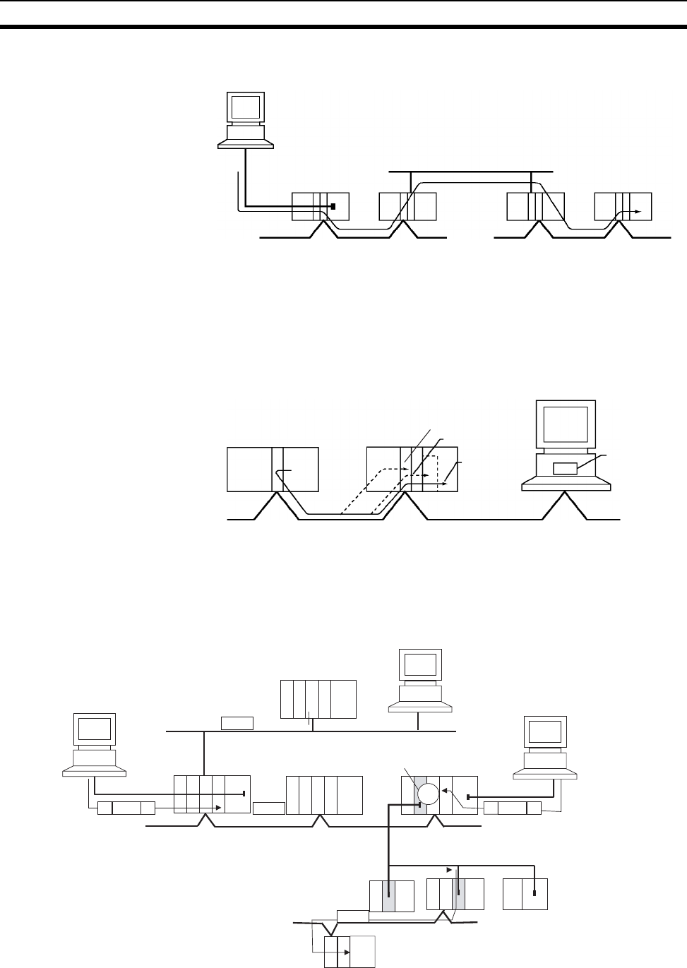
131
Expanded System Configuration Section 2-5
Supports Network Relay Up to three network levels (eight levels for unit version 2.0 or later), including
the local network, can be bypassed to access other Racks.
Note With CS/CJ-series CPU Units Ver. 2.0 or later, remote programming/monitor-
ing is possible up to 8 levels away. Refer to 1-6-5 Communications through a
Maximum of 8 Network Levels for details.
Access to CPU Unit Plus
Other Devices on Racks
The CPU Unit, CS-series CPU Bus Units, personal computers (boards), Inner
Boards, and other devices can be identified and specified using unit
addresses.
Network-to-Serial
Conversion or Network-to-
Serial-to-Network
Conversion
Using a Serial Communications Board/Unit with unit version 1.2 or later and
Serial Gateway mode enables received FINS commands to be automatically
converted into CompoWay/F, Modbus-RTU, Modbus-ASCII, or Host Link FINS
commands according to the FINS message. FINS commands that have been
converted into Host Link FINS commands can also be converted back into
Host Link FINS commands.
Network 1
Network 2
Network 3
CS-series
CPU Bus Unit
Inner Board Personal
computer
board
CPU Unit
FINS FINS
FINS
FINS
FINS
Serial Communications
Unit with unit version 1.2
or later
Network
Serial (Host Link)
PLC
(Host Link slave)
Network
Network
Serial
Gateway
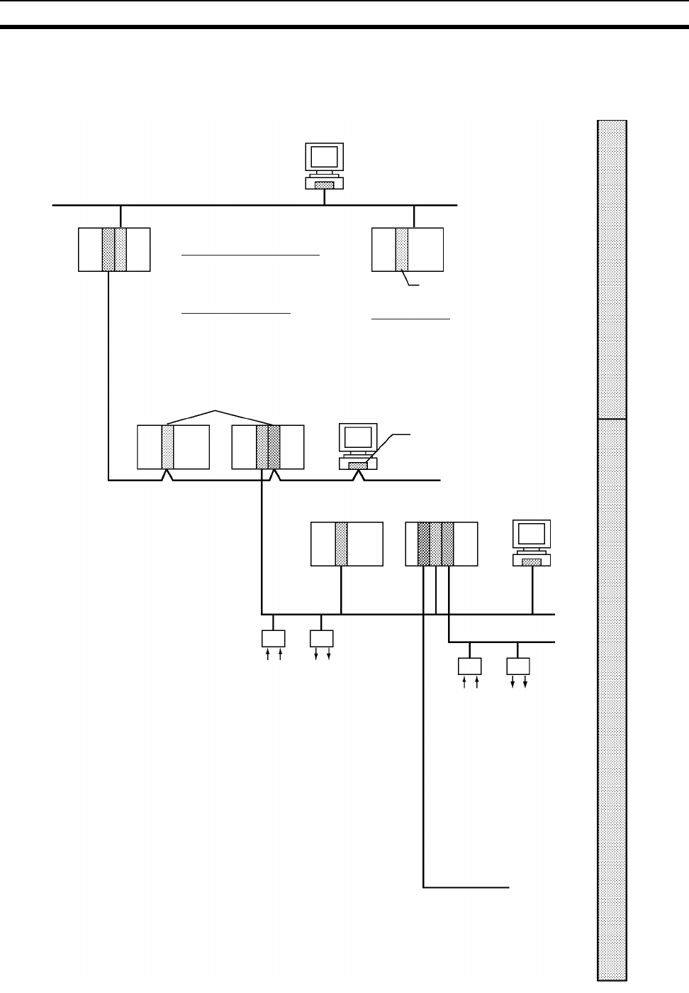
132
Expanded System Configuration Section 2-5
2-5-3 Communications Network System
The following network systems can be configured when using CS-series
Units.
Ethernet
Ethernet Unit
Controller Link Support Board
Controller Link Unit
Controller Link
DeviceNet
CompoBus/S
SYSMAC BUS Remote I/O
Message Communications
Host computer to PLC
PLC to PLC or Host computer
FTP Server Function
Host computer to PLC
Transmission of files to Memory
Card installed in CPU Unit
Socket Service
Sends/receives data using TCP
or UDP protocol
Configurator
High-speed remote I/O
Various connection methods
Superior Master Units
Serial Communications Units
CPU Units
Many Types of Slaves
Remote I/O Terminals, Re-
mote I/O Modules, Sensor
Amp Terminals, Sensor Ter-
minals, Bit Chain Terminals
Multi-vendor network
DeviceNet
Remote I/O message
communications
Remote I/O: Many points,
free allocation
Message communications
between PLCs, DeviceNet
and Explicit messages
Multi-level network
Various connection
methods
Superior Slaves
Remote I/O Terminals,
Remote Adapters, Analog
I/O Terminals, Sensor
Terminals, I/O Link Units,
Temperature Input
Terminals, High-density
I/O Terminals
Simple Network configuration
(twisted-pair cables/ optical
fiber cables)
Data link and message com-
munications
Large-capacity, flexible, and
effective data links
Message communications
and large-capacity data
transmission
Links between PLC and per-
sonal computer
Optical Controller Link Units
provide a bypass function
when a node fails.
Remote I/O via I/O Units
Multiple and optical fiber
cables
Slave Racks, I/O Termi-
nals, I/O Relay Termi-
nals
Information SystemsControl Systems
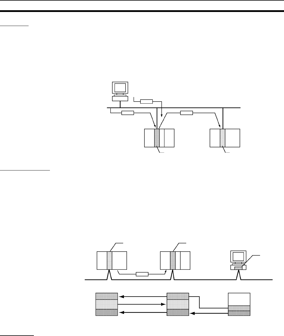
133
Expanded System Configuration Section 2-5
Ethernet
If an Ethernet Unit is connected to the system, FINS messages can be used
to communicate between the Host computer connected to the Ethernet and
the PLC, or between PLCs. By executing FTP commands for the PLC from
the Host computer connected to the Ethernet, the contents of the files on the
Memory Card installed in the CPU Unit can be read or written (transferred).
Data can be sent and received using UDP and TCP protocols. These func-
tions enable a greater compatibility with information networks.
Controller Link
The Controller Link Network is the basic framework of the OMRON PLC FA
Network. Connecting a Controller Link Unit to the network enables data links
between PLCs, so that data can be shared without programming, and FINS
message communications between PLCs, which enable separate control and
data transfer when required. The Controller Link Network connections use
either twisted-pair cables or optical fiber cables. Data links and message com-
munications are also possible between the PLC and personal computer. Data
links enable large-capacity and free allocations. FINS message communica-
tions also allow large-capacity data transfer.
DeviceNet
DeviceNet is a multi-vendor network consisting of multi-bit control and infor-
mation systems and conforms to the Open Field DeviceNet specification.
Connecting a DeviceNet Master Unit to the network enables remote I/O com-
munications between the PLC and the Slaves on the network. Remote I/O
communications enable large-capacity I/O and user-set allocations. Analog
I/O Terminals are used for the Slaves. Message communications are possible
between PLCs and between the PLC and DeviceNet devices manufactured by
other companies.
Host computer
FTP command
FINS FINS
Ethernet Unit Ethernet Unit
Ethernet
Controller Link Unit Controller Link Unit
Control-
ler Link
Support
Board
Messages
Controller Link
Data link
Free
allocation
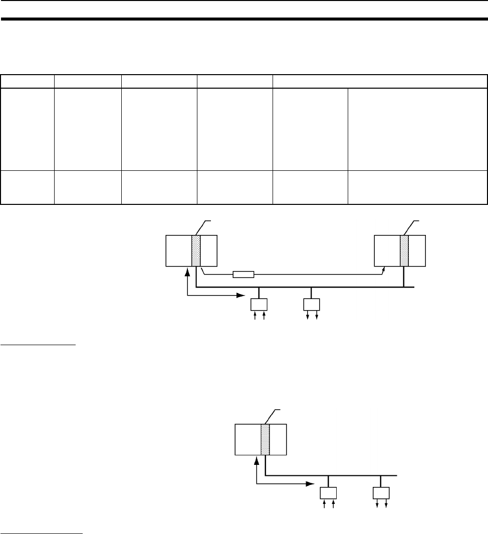
134
Expanded System Configuration Section 2-5
The following Units can be used to connect to a DeviceNet network from a
CS-series PLC. There are differences in functionality, including in the words
that are allocated for fixed allocations.
CompoBus/S
CompoBus/S is a high-speed ON/OFF bus for remote I/O communications.
Connecting a CompoBus/S Master Unit to the network allows remote I/O
communications between the PLC and Slaves. High-speed communications
are performed with 256 points in a cycle time of 1 ms max.
PROFIBUS-DP
PROFIBUS (PROcess FIeldBUS) is an open fieldbus standard for a wide
range of applications in manufacturing, processing, and building automation.
The Standard, EN 50170 (the Euronorm for field communications), to which
PROFIBUS adheres, ensures vendor independence and transparency of
operation. It enables devices from various manufacturers to intercommunicate
without having to make any special interface adaptations.
Name Model Classification Master/slave Fixed allocations for remote I/O master
CS-series
DeviceNet
Unit
CS1W-DRM21 CS-series CPU
Bus Unit
Master and slave In CS-series
DeviceNet Area
One of following three groups
Outputs: CIO 3200 to CIO 3263
Inputs: CIO 3300 to CIO 3363
Outputs: CIO 3400 to CIO 3463
Inputs: CIO 3500 to CIO 3563
Outputs: CIO 3600 to CIO 3663
Inputs: CIO 3700 to CIO 3763
C200H
DeviceNet
Master Unit
C200HW-
DRM21-V2
C200H Special
I/O Unit
Master only In C200H
DeviceNet Area
Outputs: CIO 0050 to CIO 0099
Inputs: CIO 0350 to CIO 0399
DeviceNet
Master Unit
Messages
Remote I/O DeviceNet Slaves
DeviceNet
Master Unit
CompoBus/S Master Unit
CompoBus/S
Remote I/O
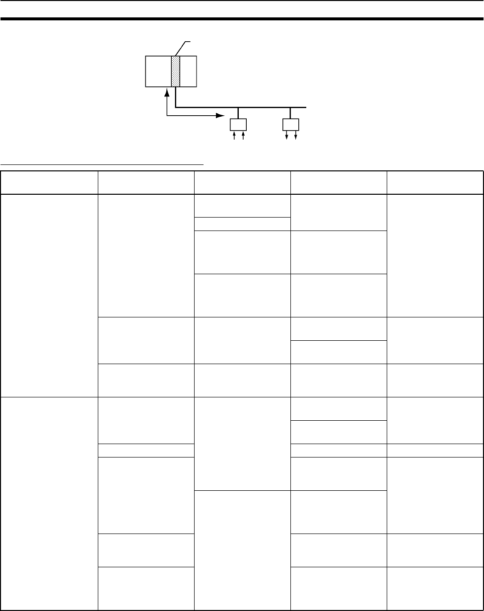
135
Expanded System Configuration Section 2-5
Communications Network Overview
PROFIBUS-DP Master Unit
PROFIBUS-DP
Remote I/O
System Network Function Communications Communications
Device
Information networks Ethernet Between Host com-
puter and PLC.
FINS message
communications
Ethernet Unit
Between PLCs.
Between Host com-
puter and Memory
Card installed in CPU
Unit.
FTP server
Between PLC and
nodes with socket ser-
vice, such as UNIX
computers.
Socket service
Controller Link Between PLC and per-
sonal computer
directly connected to
the Network.
FINS message
communications
Controller Link Sup-
port Board and Con-
troller Link Unit
Data link (offset,
simple settings)
RS-232C →
Controller Link
Between Host Link
computer and PLC on
the Network.
Host Link commands
and gateway.
RS-232C cables and
Controller Link Unit
Control networks Controller Link Between PLCs. FINS message
communications
Controller Link Unit
Data link (offset,
simple settings)
PLC Link Simple data link PLC Link Unit
DeviceNet FINS message
communications in an
open network.
C200H DeviceNet
Master Unit (C200HW-
DRM21-V1) and Con-
figurator
PLC and Network
devices (Slaves).
Large-capacity remote
I/O (fixed or free allo-
cation) in an open net-
work
CompoBus/S High-speed remote I/O
in a network with
OMRON devices only.
CompoBus/S Master
Unit
PROFIBUS-DP Large-capacity remote
I/O (user-set alloca-
tion) in an open net-
work
PROFIBUS-DP Master
Unit and Configurator

136
Expanded System Configuration Section 2-5
Communications Specifications
Network Communications Max.
baud rate
Commu-
nica-
tions
distance
Max. No.
of Units
Commu-
nica-
tions
medium
Data link
capacity
(per net-
work)
Max.
remote
I/O
points
Connect-
able
devices
Mes-
sages
Data
link
Re-
mote
I/O
Ethernet Yes --- --- 10 Mbps 2.5 km/
100 m
--- Coaxial
or
twisted-
pair
--- --- Host com-
puter-to-
PLC, PLC-
to-PLC
100 Mbps 100 m --- Twisted-
pair
--- ---
Controller Link Yes Yes --- 2 Mbps Twisted-
pair
cables:
500 m
(1.5 km
with two
Repeater
Units)
Optical
cables:
20 km/
30km
62
(62 for
Wired
Units
only with
Repeater
Units, 32
without
Repeater
Units)
Special
(twisted-
pair)
cables or
optical
fiber
cables
32,000
words
--- PLC-to-PLC,
personal
computer-to-
PLC
PLC Link --- Yes --- 128 Kbps 500 m 32 RS-
232C,
RS-422,
optical
fiber
cables
64 words ---
DeviceNet Yes --- Yes 500 Kbps
Communi-
cations
cycle:
Approx.
5 ms (128
inputs,
128 out-
puts)
100 m 63 Special
cables
--- 2,048 PLC-to-
Slave
(Slaves:
Remote I/O
Terminals,
Remote
Adapters.
Sensor Ter-
minals,
CQM1 I/O
Link Units,
Analog Out-
put Termi-
nals, Analog
Input Termi-
nals)

137
Unit Current Consumption Section 2-6
2-6 Unit Current Consumption
The amount of current/power that can be supplied to the Units mounted in a
Rack is limited by the capacity of the Rack’s Power Supply Unit. Refer to the
following tables when designing your system so that the total current con-
sumption of the mounted Units does not exceed the maximum current for
each voltage group and the total power consumption does not exceed the
maximum for the Power Supply Unit.
2-6-1 CPU Racks and Expansion Racks
The following table shows the maximum currents and power that can be sup-
plied by Power Supply Units in CPU Racks and Expansion Racks (both CS-
series Expansion Racks and C200H Expansion I/O Racks).
When calculating current/power consumption in a CPU Rack, be sure to
include the power required by the CPU Rack and CPU Unit themselves. Like-
wise, be sure to include the power required by the Expansion Rack itself
When calculating current/power consumption in an Expansion Rack.
CompoBus/S --- --- Yes 750 Kbps
Communi-
cations
cycle:
Approx.
1 ms max.
(128
inputs,
128 out-
puts)
100 m 32 Two-core
wires,
special
flat
cables
--- 256 PLC-to-
Slave
(Slaves:
Remote I/O
Terminals,
Remote I/O
Modules.
Sensor Ter-
minals, Sen-
sor Amp
Terminals,
Bit Chain
Terminals)
PROFIBUS-DP --- --- Yes 12 Mbps
Communi-
cations
cycle:
Approx.
3.5 ms
max. (128
inputs,
128 out-
puts)
100 m 125 Special
cables
--- 7,168
words
PLC-to-
Slave
(Slaves: All
PROFIBUS-
DP slaves)
Network Communications Max.
baud rate
Commu-
nica-
tions
distance
Max. No.
of Units
Commu-
nica-
tions
medium
Data link
capacity
(per net-
work)
Max.
remote
I/O
points
Connect-
able
devices
Mes-
sages
Data
link
Re-
mote
I/O
Power Supply
Unit
Max. Current Consumption Max. Total
Power
Consumption
5-V group
(Internal logic)
26-V group
(Relays)
24-V group
(Service)
C200HW-PA204 4.6 A 0.625 A None 30 W
C200HW-PA204S 4.6 A 0.625 A 0.8 A 30 W
C200HW-PA204R 4.6 A 0.625 A None 30 W
C200HW-PA204C 4.6 A 0.625 A None 30 W
C200HW-PD204 4.6 A 0.625 A None 30 W
C200HW-PA209R 9 A 1.3 A None 45 W
C200HW-PD025 5.3 A 1.3 A None 40 W
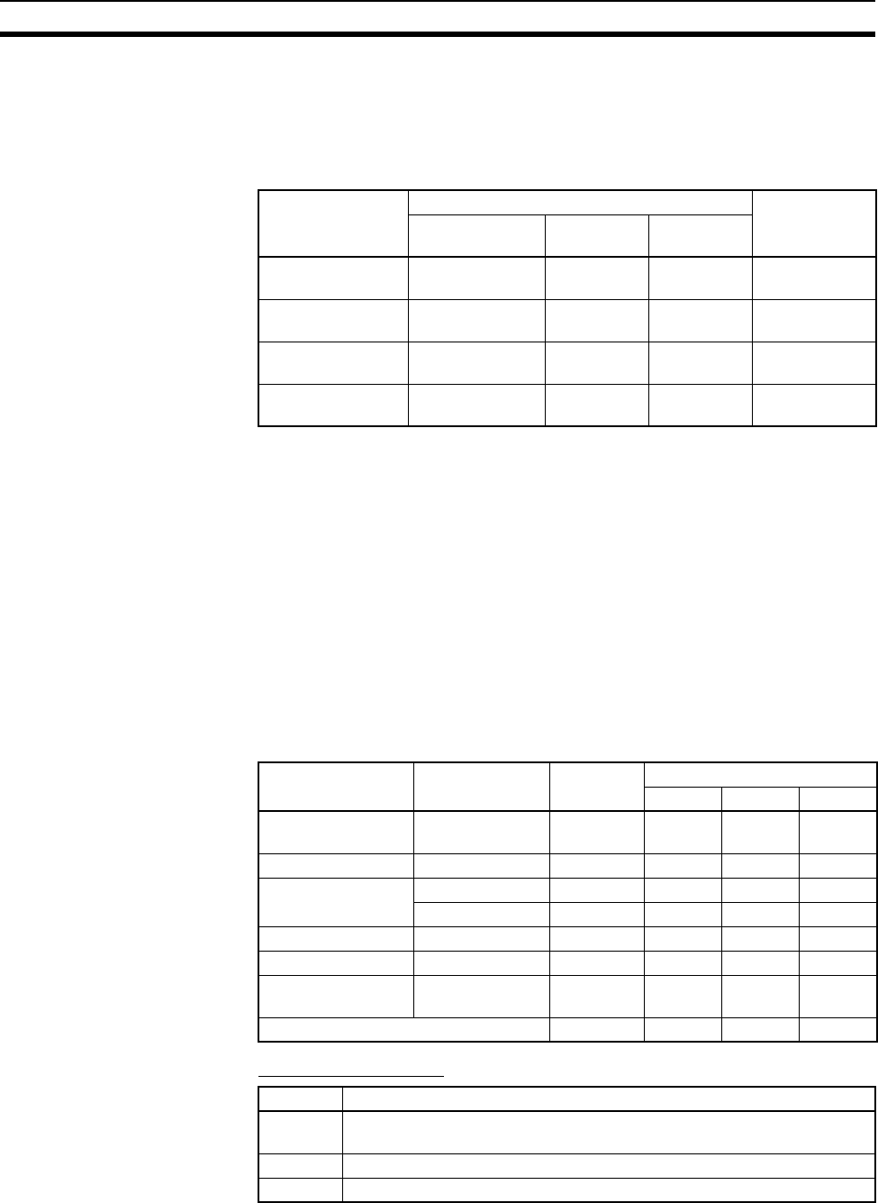
138
Unit Current Consumption Section 2-6
2-6-2 SYSMAC BUS Remote I/O Slave Racks
The following table shows the maximum currents and power that can be sup-
plied by Power Supply Units in SYSMAC BUS Remote I/O Slave Racks. Be
sure to include the power required by the Rack itself When calculating cur-
rent/power consumption.
The current consumed by each voltage group must not exceed the maximum
current shown in the table above.
1,2,3... 1. Current required at 5 V DC by all Units (A) ≤ Max. Current shown in table
2. Current required at 26 V DC by all Units (B) ≤ Max. Current shown in table
3. Current required at 24 V DC by all Units (C) ≤ Max. Current shown in table
Also, the power consumed by all Units must not exceed the maximum shown
in the table above.
A × 5 V DC + B × 26 V DC + C × 24 V DC ≤ Max. Power shown in table
2-6-3 Example Calculations
Example 1 In this example, the following Units are mounted to a CPU Rack with a
C200HW-PA204S Power Supply Unit.
Current Consumption
Slave Unit Max. Current Consumption Max. Total
Power
Consumption
5-V group
(Internal logic)
26-V group
(Relays)
24-V group
(Service)
C200H-RT201
(Wired)
2.7 A 0.625 A 0.8 A 28 W
C200H-RT202
(Wired)
2.7 A 0.625 A None 23 W
C200H-RT001-P
(Optical)
2.7 A 0.625 A 0.8 A 28 W
C200H-RT002-P
(Optical)
2.7 A 0.625 A None 23 W
Unit Model Quantity Voltage group
5 V DC 26 V DC 24 V DC
CPU Backplane
(8 slots)
CS1W-BC083 1 0.11 A --- ---
CPU Unit CS1H-CPU66H 1 0.82 A --- ---
Input Units C200H-ID216 2 0.10 A --- ---
CS1W-ID291 2 0.20 A --- ---
Output Units C200H-OC221 2 0.01 A 0.075 A ---
Special I/O Unit C200HW-NC213 1 0.30 A --- ---
CS-series CPU Bus
Unit
CS1W-CLK21 1 0.33 A --- ---
Service power supply (24 V DC) 0.3 A used --- --- 0.3 A
Group Current consumption
5 V DC 0.11 A + 0.82 A + 0.10 A × 2 + 0.20 A × 2 + 0.01 A × 2 + 0.30 A + 0.33 A
= 2.18 A (≤4.6 A)
26 V DC 0.075 A × 2 = 0.15 A (≤0.625 A)
24 V DC 0.3 A = 0.3 A (≤0.8 A)
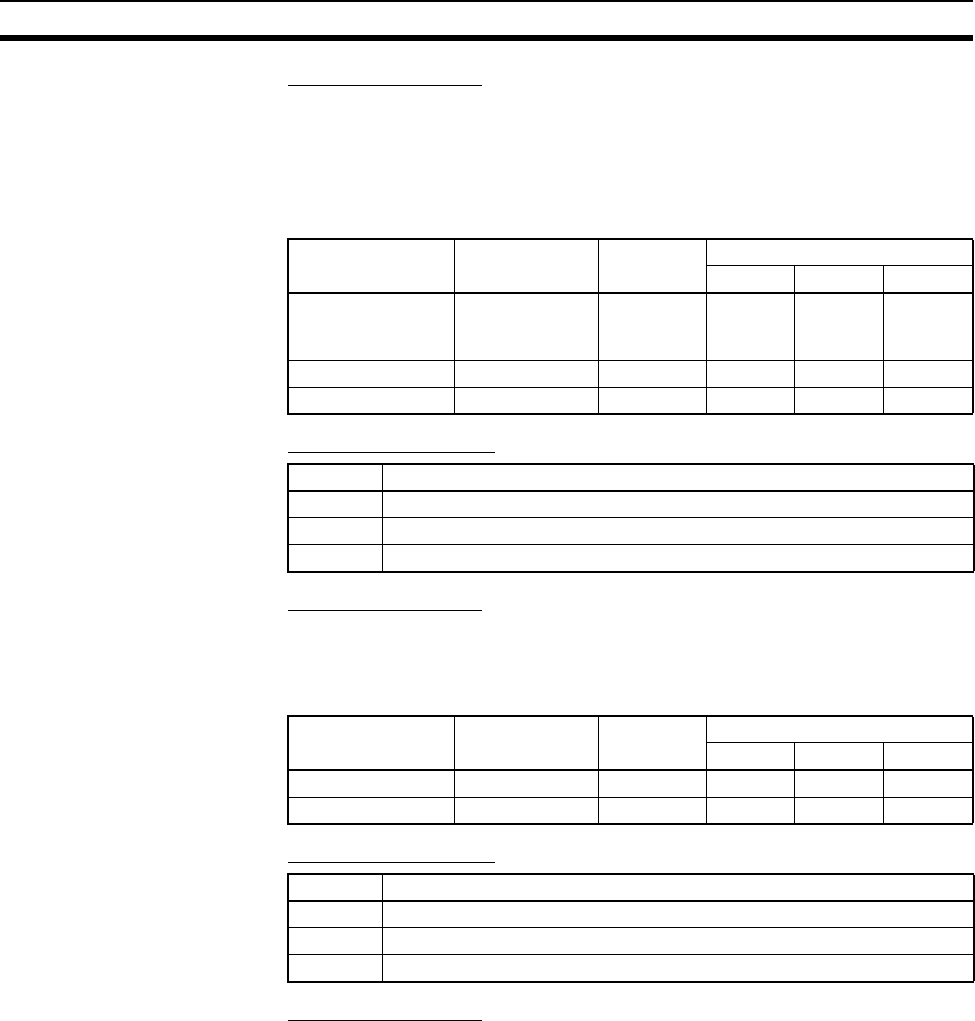
139
Unit Current Consumption Section 2-6
Power Consumption
2.18 A × 5 V + 0.15 A × 26 V + 0.3 A × 24 V
= 10.9 W + 3.9 W + 7.2 W
= 22.0 W (≤30 W)
Example 2 In this example, the following Units are mounted to a CS-series Expansion
Rack with a C200HW-PA209R Power Supply Unit.
Current Consumption
Power Consumption
4.47 A × 5 V = 22.35 W (≤45 W)
Example 3 In this example, the following Units are mounted to a SYSMAC BUS Remote
I/O Slave Rack with a C200H-RT201 Slave Unit.
Current Consumption
Power Consumption
0.64 A × 5 V = 3.2 W (≤28 W)
Unit Model Quantity Voltage group
5 V DC 26 V DC 24 V DC
CS-series Expan-
sion Backplane
(10 slots)
CS1W-BI103 1 0.23 A --- ---
Input Units CS1W-ID291 2 0.20 A --- ---
Output Units CS1W-OD291 8 0.48 A --- ---
Group Current consumption
5 V DC 0.23 A + 0.20 A × 2 + 0.48 A × 8 = 4.47 A (≤9 A)
26 V DC ---
24 V DC ---
Unit Model Quantity Voltage group
5 V DC 26 V DC 24 V DC
Input Units C200H-ID211 2 0.11 A --- ---
Output Units C200H-OD411 3 0.14 A --- ---
Group Current consumption
5 V DC 0.11 A × 2 + 0.14 A × 3 = 0.64 A (≤2.7A)
26 V DC ---
24 V DC ---
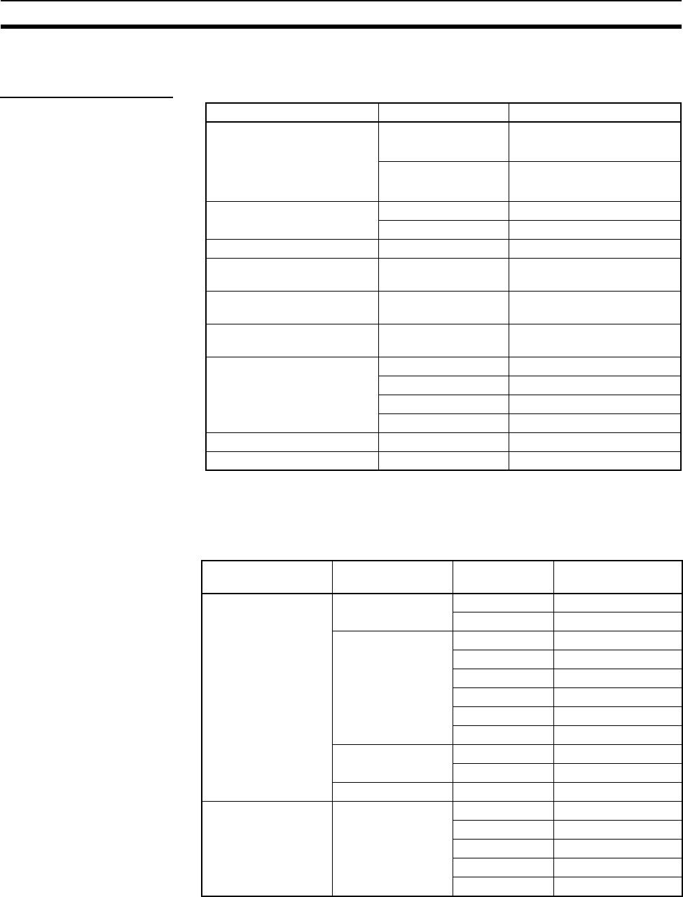
140
Unit Current Consumption Section 2-6
2-6-4 Current Consumption Tables
5-V DC Voltage Group
Note NT-AL001 Link Adapters consume 0.15/Unit when used.
Add 0.04 A for each CJ1W-CIF11 RS-422A Adapter that is used.
Add 0.20 A for each NV3W-M@20L Programmable Terminal that is used.
Basic I/O Unit
Name Model Current consumption (A)
CS1-H CPU Units
(These values include current
consumption by a Program-
ming Console or CX-Pro-
grammer connection.)
CS1H-CPU6@H 0.82 (See note.)
CS1G-CPU4@H 0.78 (See note.)
Serial Communications
Boards
CS1W-SCB21 0.28 (See note.)
CS1W-SCB41 0.37 (See note.)
Standard CPU Backplanes CS1W-BC@@30.11
CS-series-only CPU Back-
planes
CS1W-BC@@20.11
Standard CS-series Expan-
sion Backplanes
CS1W-BI@@30.23
CS-series-only Expansion
Backplanes
CS1W-BI@@20.23
C200H Expansion I/O Back-
planes
C200HW-BI031 0.15
C200HW-BI051 0.15
C200HW-BI081-V1 0.15
C200HW-BI101-V1 0.15
I/O Control Units CS1W-IC102 0.92
I/O Interface Units CS1W-II102 0.23
Category Name Model Current
consumption (A)
C200H Input Units DC Input Units C200H-ID211 0.01
C200H-ID212 0.01
AC Input Units C200H-IA121 0.01
C200H-IA122 0.01
C200H-IA122V 0.01
C200H-IA221 0.01
C200H-IA222 0.01
C200H-IA222V 0.01
AC/DC Input Units C200H-IM211 0.01
C200H-IM212 0.01
Interrupt Input Unit C200HS-INT01 0.02
C200H Group-2 High-
density Input Units
DC Input Units C200H-ID216 0.10
C200H-ID217 0.12
C200H-ID218 0.10
C200H-ID219 0.12
C200H-ID111 0.12

141
Unit Current Consumption Section 2-6
CS-series Basic Input
Units
DC Input Units CS1W-ID211 0.10
CS1W-ID231 0.15
CS1W-ID261 0.15
CS1W-ID291 0.20
AC Input Units CS1W-IA111 0.11
CS1W-IA211 0.11
B7A Input Unit CS1W-B7A12 0.09
Interrupt Input Unit CS1W-INT01 0.10
High-speed Input
Unit
CS1W-IDP01 0.10
C200H Output Units Relay Output Units C200H-OC221 0.01
C200H-OC222 0.01
C200H-OC222V 0.01
C200H-OC222N 0.01
C200H-OC225 0.05
C200H-OC226 0.03
C200H-OC226N 0.03
C200H-OC223 0.01
C200H-OC224 0.01
C200H-OC224V 0.01
C200H-OC224N 0.01
Transistor Output
Units
C200H-OD411 0.14
C200H-OD213 0.14
C200H-OD214 0.14
C200H-OD216 0.01
C200H-OD211 0.16
C200H-OD217 0.01
C200H-OD212 0.18
C200H-OD21A 0.10
B7A Interface Units C200H-B7AO1 0.10
C200H-B7A02 0.18
Triac Output Units C200H-OA221 0.14
C200H-OA223 0.27
C200H-OA222V 0.18
C200H-OA224 0.27
C200H Group-2 High-
density Output Units
Transistor Output
Units
C200H-OD218 0.18
C200H-OD21B 0.18
C200H-OD219 0.27
Category Name Model Current
consumption (A)
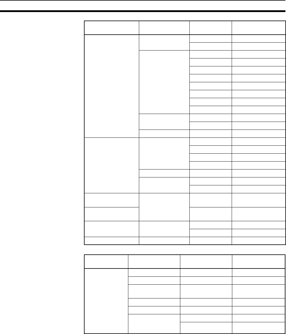
142
Unit Current Consumption Section 2-6
Special I/O Units
CS-series Basic Out-
put Units
Relay Output Units CS1W-OC201 0.10
CS1W-OC211 0.13
Transistor Output
Units
CS1W-OD211 0.17
CS1W-OD212 0.17
CS1W-OD231 0.27
CS1W-OD232 0.27
CS1W-OD261 0.39
CS1W-OD262 0.39
CS1W-OD291 0.48
CS1W-OD292 0.48
Triac Output Units CS1W-OA201 0.23
CS1W-OA211 0.41
B7A Output Unit CS1W-B7A02 0.09
CS-series Basic I/O
Units
DC Input/ Transis-
tor Output Units
CS1W-MD261 0.27
CS1W-MD262 0.27
CS1W-MD291 0.35
CS1W-MD292 0.35
TTL I/O Unit CS1W-MD561 0.27
B7A I/O Units CS1W-B7A21 0.09
CS1W-B7A22 0.09
C200H Basic Output
Unit
B7A Output Unit C200H-B7AO1 0.10
C200H High-density
Output Unit
C200H-B7A02 0.10
C200H High-density
I/O Units
B7A I/O Units C200H-B7A21 0.10
C200H-B7A22 0.10
C200H Basic Unit Analog Timer Unit C200H-TM001 0.06
Category Name Model Current
consumption (A)
Category Name Model Current
consumption (A)
C200H High-
density I/O Units
(Special I/O
Units)
DC Input Unit C200H-ID215 0.13
TTL Input Unit C200H-ID501 0.13
Transistor Output
Unit
C200H-OD215 0.22
TTL Output Unit C200H-OD501 0.22
TTL I/O Unit C200H-MD501 0.18
DC Input/
Transistor Output
Units
C200H-MD215 0.18
C200H-MD115 0.18

143
Unit Current Consumption Section 2-6
C200H Special
I/O Units
Temperature Con-
trol Units
C200H-TC001 0.33
C200H-TC002 0.33
C200H-TC003 0.33
C200H-TC101 0.33
C200H-TC102 0.33
C200H-TC103 0.33
Heat/Cool Tempera-
ture Control Units
C200H-TV001 0.33
C200H-TV002 0.33
C200H-TV003 0.33
C200H-TV101 0.33
C200H-TV102 0.33
C200H-TV103 0.33
Temperature Sen-
sor Units
C200H-TS001 0.45
C200H-TS002 0.45
C200H-TS101 0.45
C200H-TS102 0.45
PID Control Units C200H-PID01 0.33
C200H-PID02 0.33
C200H-PID03 0.33
Cam Positioner Unit C200H-CP114 0.30
ASCII Units C200H-ASC02 0.20
C200H-ASC11 0.25
C200H-ASC31 0.30
Analog Input Units C200H-AD001 0.55
C200H-AD002 0.45
C200H-AD003 0.10
Analog Output Units C200H-DA001 0.65
C200H-DA002 0.60
C200H-DA003 0.10
C200H-DA004 0.10
Category Name Model Current
consumption (A)

144
Unit Current Consumption Section 2-6
C200H Special
I/O Units
Analog I/O Unit C200H-MAD01 0.10
High-speed Counter
Units
C200H-CT001-V1 0.30
C200H-CT002 0.30
C200H-CT021 0.45
Motion Control Unit C200H-MC221 0.65
(0.85 with Teaching
Box)
Position Control
Units
C200H-NC211 0.50
C200H-NC111 0.15
C200H-NC112 0.15
C200HW-NC113 0.30
C200HW-NC213 0.30
C200HW-NC413 0.50
ID Sensor Units C200H-IDS01-V1 0.25
C200H-IDS21 0.25
Voice Unit C200H-OV001 0.30
DeviceNet Master
Unit
C200HW-DRM21-
V1
0.25
CompoBus/S Mas-
ter Unit
C200HW-SRM21-
V1
0.15
PLC Link Unit C200H-LK401 0.35
SYSMAC BUS
Remote I/O Slave
Units
C200H-RM201 0.20
C200H-RM001-PV1 0.20
CS-series Spe-
cial I/O Units
Analog I/O Unit CS1W-MAD44 0.20
Analog Input Units CS1W-AD041-
V1/081-V1
0.13
CS1W-AD161 0.15
Analog Output Units CS1W-
DA041/08V/08C
0.13
Isolated Thermo-
couple Input Unit
CS1W-PTS01-V1 0.15
High-resolution
Isolated Thermo-
couple Input Unit
CS1W-PTS11 0.12
Isolated Resistance
Thermometer Input
Unit
CS1W-PTS02 0.15
Isolated Ni508.4Ω
Resistance Ther-
mometer Input Unit
CS1W-PTS03 0.15
High-resolution
Isolated Resistance
Thermometer Input
Unit
CS1W-PTS12 0.12
Isolated 2-wire
Transmission Device
Input Unit
CS1W-PTW01 0.15
Isolated DC Input
Unit
CS1W-PDC01 0.15
High-resolution Iso-
lated DC Input Unit
CS1W-PDC11 0.12
Isolated Control
Output Unit (Analog
Output Unit)
CS1W-PMV01 0.15
Category Name Model Current
consumption (A)

145
Unit Current Consumption Section 2-6
CS-series Spe-
cial I/O Units
Power Transducer
Input Unit
CS1W-PTR01 0.15
DC Input Unit
(100 mA)
CS1W-PTR02 0.15
Isolated Pulse Input
Unit
CS1W-PPS01 0.20
Motion Control Units CS1W-MC221 0.6 (0.80 when con-
nected to a Teach-
ing Box)
CS1W-MC421 0.7 (1.00 when con-
nected to a Teach-
ing Box)
Position Control
Units
CS1W-NC113 0.25
CS1W-NC133 0.25
CS1W-NC213 0.25
CS1W-NC233 0.25
CS1W-NC413 0.36
CS1W-NC433 0.36
Customizable
Counter Units
CS1W-HIO01-V1 0.60
CS1W-HCP22-V1 0.80
CS1W-HCA12-V1 0.75
CS1W-HCA22-V1 0.75
High-speed Counter
Unit
CS1W-CT021 0.36
CS1W-CT041 0.45
GP-IB Interface Unit CS1W-GPI01 0.33
CompoNet Master
Unit
CS1W-CRM21 0.40
Category Name Model Current
consumption (A)

146
Unit Current Consumption Section 2-6
CS-series CPU Bus Units
Note NT-AL001 Link Adapters consume 0.15/Unit when used.
Add 0.04 A for each CJ1W-CIF11 RS-422A Adapter that is used.
Add 0.20 A for each NV3W-M@20L Programmable Terminal that is used.
Current Consumptions for
26-V Supply
Category Name Model Current
consumption (A)
CS-series CPU Bus
Units
Controller Link
Unit
CS1W-CLK21-V1,
CS1W-CLK23
0.33
CS1W-CLK12-V1,
CS1W-CLK13
0.58
CS1W-CLK52-V1,
CS1W-CLK53
0.65
Serial Communi-
cations Units
CS1W-SCU21-V1 0.30 (See note.)
CS1W-SCU31-V1 0.40
SYSMAC LINK
Unit
CS1W-SLK21 0.48
CS1W-SLK11 0.47
Ethernet Unit CS1W-ETN01 0.40
CS1W-ETN21 0.38
EtherNet/IP Unit CS1W-EIP21 0.41
FL-net Unit CS1W-FLN22 0.38
DeviceNet Unit CS1W-DRM21-V1 0.29
PROFIBUS-DP
Master Unit
CS1W-PRM21 0.40
Position Control
Unit supporting
MECHATROLINK-
II communications
CS1W-NCF71 0.36
Loop Control Unit CS1W-LC001 0.36
High-resolution
Motion Control
Unit
CS1W-MCH71 0.80
SYSMAC SPU
Units (High-speed
Storage and Pro-
cessing Unit)
CS1W-SPU01 0.56
CS1W-SPU02 0.70
Category Name Model Current
consumption (A)
C200H Output Units Relay Contact
Output Unit
C200H-OC221 0.075 for 8 points
when ON simulta-
neously
C200H-OC222
C200H-OC223
C200H-OC224
C200H-OC225
C200H-OC222V/N 0.09 for 8 points
when ON simulta-
neously
C200H-OC226(N)
C200H-OC224V/N
Transistor
Output Units
C200H-OD216 0.075 for 8 points
when ON simulta-
neously
C200H-OD217

147
Unit Current Consumption Section 2-6
C200H Special I/O
Units
Analog Input
Units
C200H-AD003 0.10
Analog Output
Units
C200H-DA003 0.20
C200H-DA004 0.25
Analog I/O Units C200H-MAD01 0.2
ID Sensor Units C200H-IDS01-V1 0.12
C200H-IDS21 0.12
CS-series Basic
Output Units
Relay Output
Units
CS1W-OC201 0.006 per ON
output point
CS1W-OC211 0.006 per ON
output point
CS-series Special I/O
Units
Analog I/O Unit CS1W-MAD44 0.20
Analog Input
Unit
CS1W-AD041/081 0.09
CS1W-AD161 0.06
Analog Output
Unit
CS1W-DA041/08V 0.18
CS1W-DA08C 0.25
Isolated Ther-
mocouple Input
Unit
CS1W-PTS01-V1 0.15
High-resolution
Isolated Ther-
mocouple Input
Unit
CS1W-PTS11 0.08
Isolated Resis-
tance Thermom-
eter Input Unit
CS1W-PTS02 0.15
Isolated Ni508Ω
Resistance
Thermometer
Input Unit
CS1W-PTS03 0.15
High-resolution
Isolated Resis-
tance Thermom-
eter Input Unit
CS1W-PTS12 0.07
Isolated 2-wire
Transmission
Device Input
Unit
CS1W-PTW01 0.16
Isolated DC
Input Unit
CS1W-PDC01 0.15
High-resolution
Isolated DC
Input Unit
CS1W-PDC11 0.12
Isolated Control
Output Unit
(Analog Output
Unit)
CS1W-PMV01 0.16
Power Trans-
ducer Input Unit
CS1W-PTR01 0.08
DC Input Unit
(100 mA)
CS1W-PTR02 0.08
Isolated Pulse
Input Unit
CS1W-PPS01 0.16
Customizable
Counter Unit
CS1W-HCA12-V1 0.15
CS1W-HCA22-V1 0.15
Category Name Model Current
consumption (A)

148
CPU Bus Unit Setting Area Capacity Section 2-7
2-7 CPU Bus Unit Setting Area Capacity
Settings for most CPU Bus Units and Inner Boards are stored in the CPU Bus
Unit Setting Area in the CPU Unit. Refer to 9-27 Parameter Areas for details.
The CPU Bus Units are allocated the required number of works for settings
from this area.
There is a limit to the capacity of the CPU Bus Unit Setting Area of 10,752
bytes (10 Kbytes). The system must be designed so that the number of words
used in the CPU Bus Unit Setting Area by all of the CPU Bus Units and the
Inner Board does not exceed this capacity. If the wrong combination of Units
is used, the capacity will be exceeded and either Units will operate from
default settings only or will not operate at all.
2-7-1 System Setting Allocations to CPU Bus Units
Note Any Unit with a usage of “0” does not use the CPU Bus Unit Setting Area at
all.
Classification Name Model number Allocation
(bytes)
CS-series CPU
Bus Units
Controller Link Unit CS1W-
CLK11/12/21/52(-V1),
CS1W-CLK13/23/53
512
Serial Communica-
tions Unit
CS1W-SCU21/31-V1 0
Ethernet Unit CS1W-ETN01 412
CS1W-ETN21 99.4
FL-net Unit CS1W-FLN22 988
SYSMAC LINK Unit CS1W-SLK21/11 512
DeviceNet Unit CS1W-DRM21-V1 0
Position Control Unit CS1W-NCF71 0
Motion Control Unit CS1W-MCH71 0
Loop Control Unit CS1W-LC001 0
High-resolution
Motion Control Unit
CS1W-MCH71 0
Storage and Process-
ing Unit
CS1W-SPU01/02 0
Inner Boards Serial Communica-
tions Board
CS1W-SCB21/41 0

149
I/O Table Settings Section 2-8
2-8 I/O Table Settings
The following settings are used in the I/O tables on the CX-Programmer.
2-8-1 CS-series Basic I/O Units
Name Model Unit type setting Addresses
per Unit
Input
Words
Output
Words
AC Input Units CS1W-IA111 16pt Unit − 16pt Input --- 1 0
CS1W-IA211 16pt Unit − 16pt Input --- 1 0
CS1W-IA121/221 CS/CJ 8pt Unit − 8pt Input --- 1 0
CS1W-IA122/122V/222/222V 16pt Unit − 16pt Input --- 1 0
AC/DC Input Units C200H-IM211 CS/CJ 8pt Unit − 8pt Input --- 1 0
C200H-IM212 16pt Unit − 16pt Input --- 1 0
DC Input Units CS1W-ID211 16pt Unit − 16pt Input --- 1 0
CS1W-ID231 32pt Unit − 32pt Input --- 2 0
CS1W-ID261 64pt Unit − 64pt Input --- 4 0
CS1W-ID291 96pt Unit − 96pt Input --- 6 0
C200H-ID211 CS/CJ 8pt Unit − 8pt Input --- 1 0
C200H-ID212 16pt Unit − 16pt Input --- 1 0
DC Input Units classi-
fied as C200H Group-2
Units
C200H-ID216/218 32pt Unit − 32pt Input --- 2 0
C200H-ID111/217/219 64pt Unit − 64pt Input --- 4 0
Interrupt Input Units CS1W-INT01 Interrupt Unit (8 Bit) --- 1 0
C200HS-INT01 Interrupt Unit (8 Bit) --- 1 0
High-speed Input Unit CS1W-IDP01 16pt Unit − 16pt Input --- 1 0
Contact Output Units CS1W-OC201 8pt Unit − 8pt Output --- 0 1
CS1W-OC211 16pt Unit − 16pt Output --- 0 1
C200H-OC223 5pt Unit - 5pt Output --- 0 1
C200H-OC221/224/224V/224N 8pt Unit − 8pt Output --- 0 1
C200H-OC222/222V/222N 12pt Unit - 12pt Output --- 0 1
C200H-OC225/226/226N 16pt Unit − 16pt Output --- 0 1
Triac Output Units CS1W-OA201 8pt Unit − 8pt Output --- 0 1
CS1W-OA211 16pt Unit − 16pt Output --- 0 1
CS1W-OA221/223 8pt Unit − 8pt Mixed --- 0 1
CS1W-OA222V/224 12pt Unit − 12pt Output --- 0 1
Transistor Output Units CS1W-OD211/212 16pt Unit − 16pt Output --- 0 1
CS1W-OD231/232 32pt Unit − 32pt Output --- 0 2
CS1W-OD261/262 64pt Unit − 64pt Output --- 0 4
CS1W-OD291/292 96pt Unit − 96pt Mixed --- 0 6
C200H-OD213/214/216/411 8pt Unit − 8pt Mixed --- 0 1
C200H-OD211/217 12pt Unit − 12pt Output --- 0 1
C200H-OD212/21A 16pt Unit − 16pt Output --- 0 1
Transistor Output Units
classified as C200H
Group-2 Units
C200H-OD218/21B 32pt Unit − 32pt Output --- 0 2
C200H-OD219 64pt Unit − 64pt Output --- 0 4
DC Input/Transistor Out-
put Units
CS1W-MD261/262 64pt Unit − 64pt Mixed --- 2 2
CS1W-MD291/292 96pt Unit − 96pt Mixed --- 3 3
TTL I/O Units CS1W-MD561 64pt Unit - 64pt Mixed --- 2 2

150
I/O Table Settings Section 2-8
Note 1. An I/O setting error will occur if Units are not set correctly.
2. An I/O verification error will occur if the number of input or output words is
set incorrectly.
B7A Interface Units
classified as CS-series
Basic I/O Units
CS1W-B7A12 32pt Unit − 32pt Input --- 2 0
CS1W-B7A02 32pt Unit − 32pt Output --- 0 2
CS1W-B7A21 32pt Unit − 32pt Mixed --- 1 1
CS1W-B7A22 64pt Unit − 64pt Mixed --- 2 2
B7A Interface Units C200H-B7AI1 16pt Unit − 16pt Input --- 1 0
C200H-B7AO1 16pt Unit − 16pt Output --- 0 1
B7A Interface Units
classified as C200H
Group-2 Units
C200H-B7A12 32pt Unit − 32pt Input --- 2 0
C200H-B7A02 32pt Unit − 32pt Output --- 0 2
C200H-B7A21 32pt Unit − 32pt Mixed --- 1 1
C200H-B7A22 64pt Unit − 64pt Mixed --- 2 2
Analog Timer Unit C200H-TM001 4 times
Internal bits: 8 inputs and 4
outputs
--- 1
Name Model Unit type setting Addresses
per Unit
Input
Words
Output
Words

151
I/O Table Settings Section 2-8
2-8-2 CS-series Special I/O Units
Note A Special I/O setting error will occur if Units, the number of input, or the num-
ber of output words is set incorrectly.
Name Model Unit type setting Addresses
per Unit
Input
Words
Output
Words
Analog I/O Unit CS1W-MAD44 CS/CJ SIO Unit − Analog Input/Out-
put Unit
155
Analog Input Units CS1W-AD041/081-V1 CS/CJ SIO Unit − Analog Input Unit 1 9 1
CS1W-AD161 CS/CJ SIO Unit − Analog Input Unit 2 17 1
Analog Output Units CS1W-
DA041/08V/08C
CS/CJ SIO Unit − Analog Output
Unit
119
Isolated Thermocouple
Input Unit
CS1W-PTS01-V1 CS/CJ SIO Unit − Process
Input/Output Unit
1100
High-resolution Isolated
Thermocouple Input Unit
CS1W-PTS11 CS/CJ SIO Unit − Process
Input/Output Unit
1100
Isolated Resistance Ther-
mometer Input Unit
CS1W-PTS02 CS/CJ SIO Unit − Process
Input/Output Unit
1100
Isolated Ni508.4Ω Resis-
tance Thermometer Input
Unit
CS1W-PTS03 CS/CJ SIO Unit − Process
Input/Output Unit
1100
High-resolution Isolated
Resistance Thermometer
Input Unit
CS1W-PTS12 CS/CJ SIO Unit − Process
Input/Output Unit
1100
Isolated 2-wire Transmis-
sion Device Input Unit
CS1W-PTW01 CS/CJ SIO Unit − Process
Input/Output Unit
1100
Isolated DC Input Unit CS1W-PDC01 CS/CJ SIO Unit − Process
Input/Output Unit
1100
High-resolution Isolated DC
Input Unit
CS1W-PDC11 CS/CJ SIO Unit − Process
Input/Output Unit
1100
Isolated Control Output Unit
(Analog Output Unit)
CS1W-PTR01 CS/CJ SIO Unit − Process
Input/Output Unit
1100
Power Transducer Input
Unit
CS1W-PTR02 CS/CJ SIO Unit − Process
Input/Output Unit
1100
DC Input Unit (100 mA) CS1W-PMV01 CS/CJ SIO Unit − Process
Input/Output Unit
155
Isolated Pulse Input Unit CS1W-PPS01 CS/CJ SIO Unit − Process
Input/Output Unit
1100
Motion Control Units CS1W-MC221 CS/CJ SIO Unit − Motion Control
Unit
32010
CS1W-MC421 5 32 18
Position Control Units CS1W-NC113/133 CS/CJ SIO Unit − Numerical Con-
trol Unit
132
CS1W-NC213/233 1 6 4
CS1W-NC413/433 2 12 8
Customizable Counter Units CS1W-
HIO01/HCP22/HCA22
CS/CJ SIO Unit − Customizable
Unit
155
High-speed Counter Units CS1W-CT021/041 CS/CJ SIO Unit − High Speed
Counter Unit
42614
GP-IB Interface Unit CS1W-GPI01 CS/CJ SIO Unit − Other SIO Unit 1 5 5
CompoNet Master Unit CS1W-CRM21 CS/CJ SIO Unit
− CompoNet
Master Unit
Communications
mode No. 0
2119
No. 1 4 21 17
No. 2 8 41 33
No. 3 8 45 25
No. 8 1 Vari-
able
Vari-
able

152
I/O Table Settings Section 2-8
2-8-3 C200H Special I/O Units
Name Model Unit type setting Addresses
per Unit
Input
Words
Output
Words
High-density I/O Units C200H-ID501/215 C200H SIOU/C200H ASCII Unit 1 2 0
C200H-OD501/215 (standard
mode)
102
C200H-OD501/215 (dynamic
mode)
108
C200H-MD501/215/115
(standard mode)
111
C200H-MD501/215/115
(dynamic mode)
180
Temperature Control
Units
C200H-
TC001/002/003/101/102/103
C200H SIOU/C200H ASCII Unit 1 7 3
Heating/Cooling Con-
trol Units
C200H-
TV001/002/003/101/102/103
C200H SIOU/C200H ASCII Unit 1 7 3
Temperature Sensor
Units
C200H-TS001/002/101/102 C200H SIOU/C200H ASCII Unit 1 5 1
PID Control Units C200H-PID01/02/03 C200H SIOU/C200H ASCII Unit 1 7 3
Cam Positioner Unit C200H-CP114 C200H SIOU/C200H ASCII Unit 1 8 2
ASCII Units C200H-ASC02 C200H SIOU/C200H ASCII Unit 1 1 3
C200H-ASC11/21/31 1 5 5
Analog Input Units C200H-AD001 C200H SIOU/C200H ASCII Unit 1 5 1
C200H-AD002 1 9 1
C200H-AD003 (normal mode) 1 9 1
C200H-AD003 (adjustment
mode)
128
Analog Output Units C200H-DA001 C200H SIOU/C200H ASCII Unit 1 1 3
C200H-DA002 1 0 4
C200H-DA003/004 (normal
mode)
119
C200H-DA003/004 (adjust-
ment mode)
128
Analog I/O Units C200H-MAD01 (normal
mode)
C200H SIOU/C200H ASCII Unit 1 5 5
C200H-MAD01 (adjustment
mode)
128
High-speed Counter
Units
C200H-CT001-V1/CT002
(mode 1 or 2)
C200H High Speed Counter Unit 1 6 4
C200H-CT001-V1/CT002
(mode 3)
154
C200H-CT001-V1/CT002
(mode 4, 5, or 6)
144
C200H-CT021 1 8 2
Motion Control Units C200H-MC221 C200H Numerical Control Unit 2 12 8
Position Control Units C200H-NC111/112 C200H Numerical Control Unit 1 5 5
C200H-NC211 2 10 10
C200H-NC114 1 3 2
C200HW-NC213 1 6 4
C200HW-NC413 2 12 8
ID Sensor Units C200H-IDS01-V1/IDS21 C200H SIOU/C200H ASCII Unit 1 1 4
Voice Unit C200H-OV001 C200H SIOU/C200H ASCII Unit 1 1 5
Fuzzy Logic Control
Unit
C200H-FZ001 C200H SIOU/C200H ASCII Unit 1 1 4
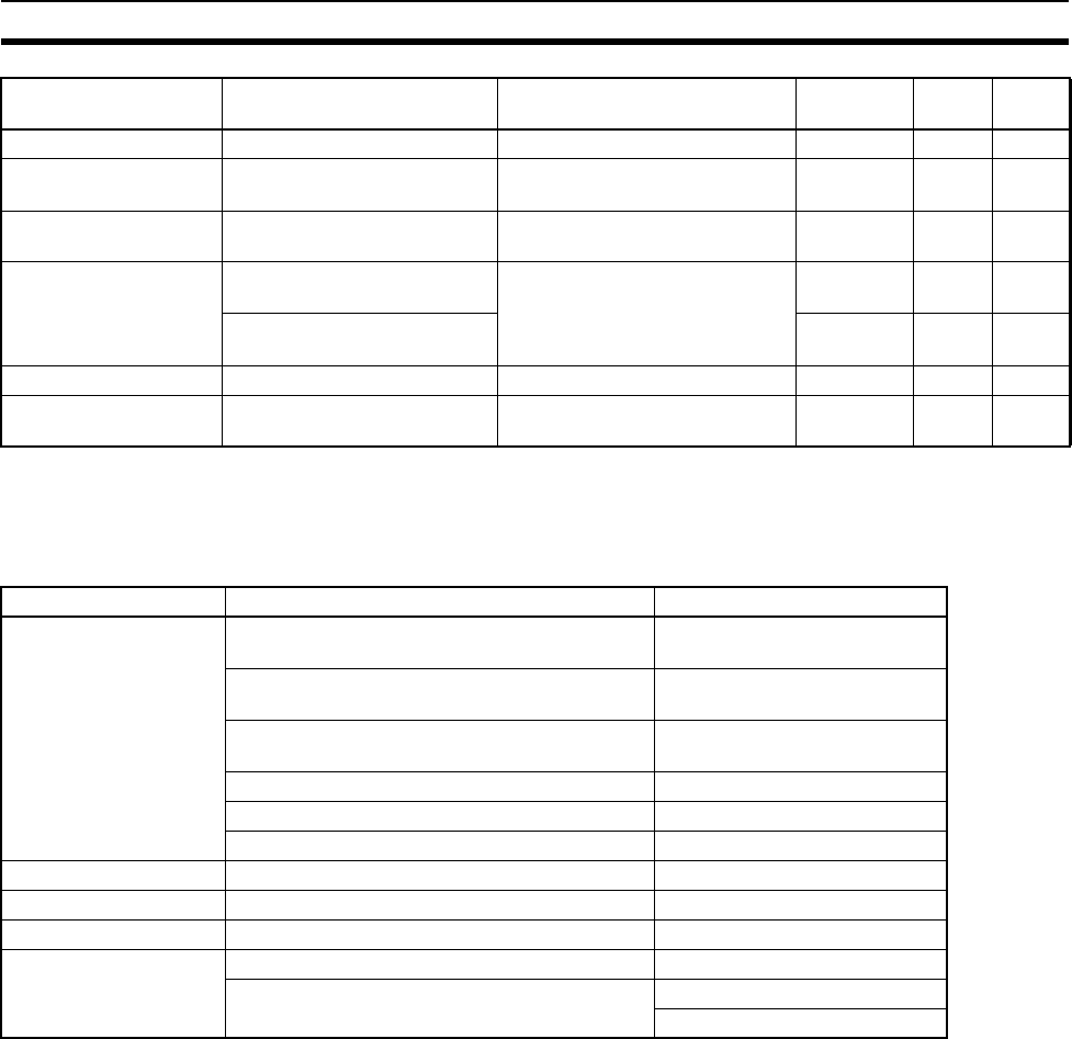
153
I/O Table Settings Section 2-8
Note A Special I/O setting error will occur if Units, the number of input, or the num-
ber of output words is set incorrectly.
2-8-4 CS-series CPU Bus Units
Note The DeviceNet Unit is not support by CX-Programmer version 2.0 or earlier,
and I/O tables containing the DeviceNet Unit cannot be created with these
versions. Create the tables online.
JPCN-1 Unit C200H-JRM21 C200H SIOU/C200H ASCII Unit 1 2 8
C200H DeviceNet Mas-
ter Unit
C200HW-DRM21-V1 C200H SIOU/C200H ASCII Unit 1 9 1
DeviceNet Slave Unit
(C200H I/O Link Unit)
C200HW-DRT21 C200H SIOU/C200H ASCII Unit 1 5 5
CompoBus/S Master
Unit
C200HW-SRM21-V1 (unit
number 1)
C200H SIOU/C200H ASCII Unit 1 6 4
C200HW-SRM21-V1 (unit
number 2)
2128
PLC Link Unit C200H-LK401 PC Link Unit LK401 --- --- ---
SYSMAC BUS Remote
I/O Master Unit
C200H-RM001-PV1/RM201 SYSMAC BUS Master --- --- ---
Unit type setting Name Model
Communications Controller Link Unit CS1W-CLK13/23/53
CS1W-CLK12/21/52(-V1)
Serial Communications Unit CS1W-SCU21-V1
CS1W-SCU31-V1
Ethernet Unit CS1W-ETN01/11/21
CS1D-ETN21D
FL-net Unit CS1W-FLN01/02/12/22
SYSMAC LINK Unit CS1W-SLK11/21
DeviceNet Unit CS1W-DRM21-V1
Position Control Unit Position Control Unit CS1W-NCF71
Motion Controllers Motion Control Unit CS1W-MCH71
Loop Controllers Loop Control Unit CS1W-LC001
General-purpose
Devices
Storage and Processing Unit CS1W-SPU01/02
Open Network Controller CS1W-EIS/EIX-CTS
ITBC-CTS01
Name Model Unit type setting Addresses
per Unit
Input
Words
Output
Words

154
I/O Table Settings Section 2-8
155
SECTION 3
Nomenclature, Functions, and Dimensions
This section provides the names of components and their functions for various Units. The Unit dimensions are also
provided.
3-1 CPU Units . . . . . . . . . . . . . . . . . . . . . . . . . . . . . . . . . . . . . . . . . . . . . . . . . . . . 156
3-1-1 Models . . . . . . . . . . . . . . . . . . . . . . . . . . . . . . . . . . . . . . . . . . . . . . . 156
3-1-2 Components . . . . . . . . . . . . . . . . . . . . . . . . . . . . . . . . . . . . . . . . . . . 156
3-1-3 CPU Unit Memory Block Map. . . . . . . . . . . . . . . . . . . . . . . . . . . . . 159
3-1-4 Dimensions . . . . . . . . . . . . . . . . . . . . . . . . . . . . . . . . . . . . . . . . . . . . 163
3-2 File Memory . . . . . . . . . . . . . . . . . . . . . . . . . . . . . . . . . . . . . . . . . . . . . . . . . . 163
3-2-1 Specifications of Memory Card . . . . . . . . . . . . . . . . . . . . . . . . . . . . 164
3-2-2 Files Handled by CPU Unit . . . . . . . . . . . . . . . . . . . . . . . . . . . . . . . 165
3-2-3 Initializing File Memory. . . . . . . . . . . . . . . . . . . . . . . . . . . . . . . . . . 166
3-2-4 Using File Memory. . . . . . . . . . . . . . . . . . . . . . . . . . . . . . . . . . . . . . 167
3-2-5 Memory Card Dimensions . . . . . . . . . . . . . . . . . . . . . . . . . . . . . . . . 170
3-2-6 Installing and Removing the Memory Card . . . . . . . . . . . . . . . . . . . 170
3-3 Programming Devices . . . . . . . . . . . . . . . . . . . . . . . . . . . . . . . . . . . . . . . . . . . 172
3-3-1 Overview. . . . . . . . . . . . . . . . . . . . . . . . . . . . . . . . . . . . . . . . . . . . . . 172
3-3-2 Programming Consoles. . . . . . . . . . . . . . . . . . . . . . . . . . . . . . . . . . . 174
3-3-3 CX-Programmer . . . . . . . . . . . . . . . . . . . . . . . . . . . . . . . . . . . . . . . . 175
3-3-4 Peripheral Port Specifications. . . . . . . . . . . . . . . . . . . . . . . . . . . . . . 179
3-3-5 RS-232C Port Specifications . . . . . . . . . . . . . . . . . . . . . . . . . . . . . . 180
3-4 Power Supply Units. . . . . . . . . . . . . . . . . . . . . . . . . . . . . . . . . . . . . . . . . . . . . 183
3-4-1 Power Supply Units . . . . . . . . . . . . . . . . . . . . . . . . . . . . . . . . . . . . . 183
3-4-2 Components and Switch Settings . . . . . . . . . . . . . . . . . . . . . . . . . . . 184
3-4-3 Dimensions . . . . . . . . . . . . . . . . . . . . . . . . . . . . . . . . . . . . . . . . . . . . 186
3-4-4 Selecting a Power Supply Unit . . . . . . . . . . . . . . . . . . . . . . . . . . . . . 187
3-4-5 Replacement Notification . . . . . . . . . . . . . . . . . . . . . . . . . . . . . . . . . 190
3-5 Backplanes . . . . . . . . . . . . . . . . . . . . . . . . . . . . . . . . . . . . . . . . . . . . . . . . . . . 197
3-5-1 CPU Backplanes . . . . . . . . . . . . . . . . . . . . . . . . . . . . . . . . . . . . . . . . 197
3-5-2 CS-series Expansion Backplanes . . . . . . . . . . . . . . . . . . . . . . . . . . . 199
3-5-3 C200H Expansion I/O Backplanes . . . . . . . . . . . . . . . . . . . . . . . . . . 201
3-5-4 I/O Control Units, I/O Interface Units, and Terminators . . . . . . . . . 203
3-6 Basic I/O Units . . . . . . . . . . . . . . . . . . . . . . . . . . . . . . . . . . . . . . . . . . . . . . . . 207
3-6-1 C200H and CS-series Basic I/O Units with Terminal Blocks . . . . . 207
3-6-2 Interrupt Input Units . . . . . . . . . . . . . . . . . . . . . . . . . . . . . . . . . . . . . 213
3-6-3 Units with High-speed Inputs . . . . . . . . . . . . . . . . . . . . . . . . . . . . . . 219
3-6-4 CS-series Basic I/O Units with Connectors (32-, 64-, and 96-pt Units) 220
3-6-5 C200H Group-2 High-density I/O Units . . . . . . . . . . . . . . . . . . . . . 223
3-7 C200H High-density I/O Units (Special I/O Units) . . . . . . . . . . . . . . . . . . . . 225
3-8 B7A Interface Units . . . . . . . . . . . . . . . . . . . . . . . . . . . . . . . . . . . . . . . . . . . . 231
3-8-1 CS-series B7A Interface Units (CS-series Basic I/O Units). . . . . . . 231
3-8-2 C200H Basic B7A Interface Units (C200H Basic I/O Units) . . . . . 245
3-8-3 B7A Interface Units (C200H Group-2 High-density I/O Units) . . . 247
3-9 Analog Timer Units. . . . . . . . . . . . . . . . . . . . . . . . . . . . . . . . . . . . . . . . . . . . . 256
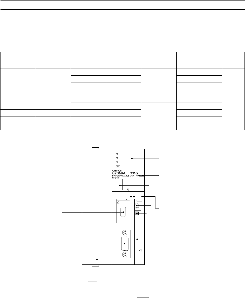
156
CPU Units Section 3-1
3-1 CPU Units
3-1-1 Models
CS1-H CPU Units
3-1-2 Components
I/O points Expansion
Racks
Programming Data Memory
(DM + EM)
LD instruction
processing
time
Model Weight
5,120 7 max. 250K steps 448K words 0.02 µs CS1H-CPU67H 350 g
max.
120K steps 256K words CS1H-CPU66H
60K steps 128K words CS1H-CPU65H
30K steps 64K words CS1H-CPU64H
20K steps 64K words CS1G-CPU63H
60K steps 128K words 0.04 µs CS1G-CPU45H
1,280 3 max. 30K steps 64K words CS1G-CPU44H
960 2 max. 20K steps 64K words CS1G-CPU43H
10K steps 64K words CS1G-CPU42H
1. LED indicators
2. Battery compartment
3. DIP switch (under battery cover)
4. Memory Card indicators
5. Memory Card power supply switch
6. Memory Card eject button
7. Memory Card connector
8. Inner Board connector compartment
10. Peripheral port
9. RS-232C port
OPEN
OPEN
PERIPHERAL
PORT
BUSY
RUN
ERR/ALM
INH
PRPHL/COMM
MCPWR
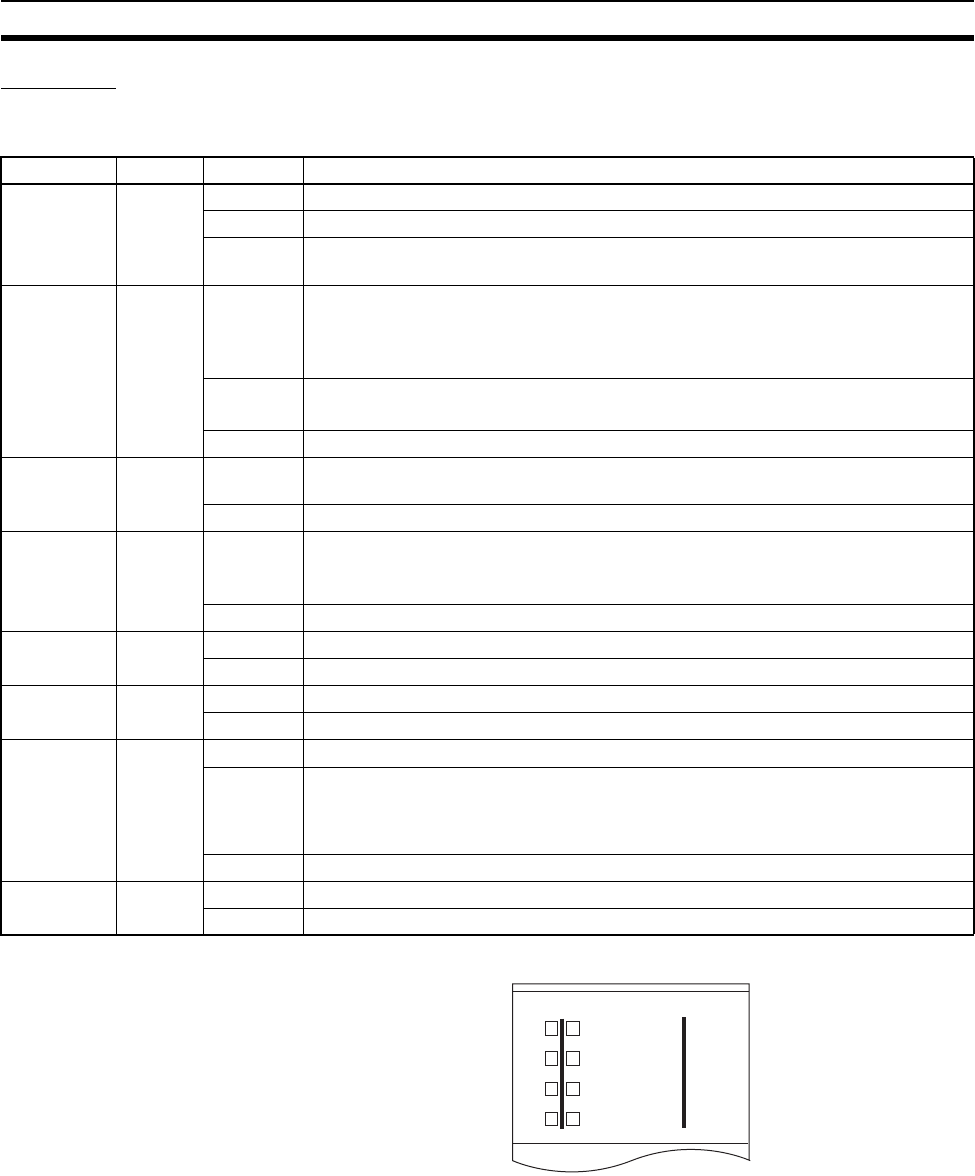
157
CPU Units Section 3-1
Indicators
The following table describes the LED indicators located on the front panel of
the CPU Units.
Indicator Color Status Meaning
RUN Green ON PLC is operating normally in MONITOR or RUN mode.
Flashing System download mode error or DIP switch settings error.
OFF PLC has stopped operating while in PROGRAM mode, or has stopped operating
due to a fatal error, or is downloading data from the system.
ERR/ALM Red ON A fatal error has occurred (including FALS instruction execution), or a hardware
error (watchdog timer error) has occurred.
The CPU Unit will stop operating, and the outputs from all Output Units will turn
OFF.
Flashing A non-fatal error has occurred (including FAL instruction execution)
The CPU Unit will continue operating.
OFF CPU Unit is operating normally.
INH Orange ON Output OFF Bit (A50015) has been turned ON. The outputs from all Output Units
will turn OFF.
OFF Output OFF Bit (A50015) has been turned OFF.
BKUP Orange ON User program and parameter area data is being backed up to flash memory in the
CPU Unit or being restored from flash memory.
Note Do not turn OFF the power supply to the PLC while this indicator is lit.
OFF Data is not being written to flash memory.
PRPHL Orange Flashing CPU Unit is communicating (sending or receiving) via the peripheral port.
OFF CPU Unit is not communicating via the peripheral port.
COMM Orange Flashing CPU Unit is communicating (sending or receiving) via the RS-232C port.
OFF CPU Unit is not communicating via the RS-232C port.
MCPWR Green ON Power is being supplied to the Memory Card.
Flashing Flashes once: Easy backup read, write, or verify normal
Flashes five times: Easy backup write malfunction
Flashes three times: Easy backup write warning
Flashes continuously: Easy backup read or verify malfunction
OFF Power is not being supplied to the Memory Card.
BUSY Orange Flashing Memory Card is being accessed.
OFF Memory Card is not being accessed.
RUN
ERR/ALM
INH
PRPH COMM
BKUP
CS
CS1-H CPU Unit

158
CPU Units Section 3-1
DIP Switch Settings
Note 1. The following data cannot be overwritten when pin 1 is ON:
• All parts of the user program (programs in all tasks)
• All data in the parameter area (such as the PLC Setup and I/O table)
When pin 1 is ON, the user program and parameter area will not be cleared
when the memory clear operation is performed from a Programming De-
vice.
2. The DIP switch is not used to set the display language with CS1-H CPU
Units. The language is selected on the startup display on the Programming
Console.
3. The CPU Unit will not enter any mode except PROGRAM mode after back-
ing up data to a Memory Card using DIP switch pin 7. To enter RUN or
MONITOR mode, turn OFF the power supply, turn OFF pin 7, and then re-
start the PLC. This will enable changing the operating mode as normal.
Pin no. Setting Function Usage Default
1 ON Writing disabled for user program memory.
(See note.)
Used to prevent programs from being acci-
dently overwritten from Programming
Devices (including Programming Console).
OFF
OFF Writing enabled for user program memory.
2 ON The user program is automatically trans-
ferred from the Memory Card when power is
turned ON.
Used to store the programs in the Memory
Card to switch operations, or to automatically
transfer programs at power-up (Memory
Card ROM operation).
Note When pin 7 is ON, easy backup read-
ing from the Memory Card is given pri-
ority, so even if pin 2 is ON, the user
program is not automatically trans-
ferred from the Memory Card when
power is turned ON.
OFF
OFF The user program is not automatically trans-
ferred from the Memory Card when power is
turned ON.
3 OFF Always OFF. (See note.) OFF
4 ON Peripheral port communications parameters
set in the PLC Setup are used.
Turn ON to use the peripheral port for a
device other than Programming Console or
CX-Programmer (Peripheral bus only).
OFF
OFF Peripheral port communications parameters
set using Programming Console or CX-Pro-
grammer (Peripheral bus only) are used.
5 ON RS-232C port communications parameters
set using a CX-Programmer (Peripheral bus
only) are used.
Turn ON to use the RS-232C port for a Pro-
gramming Device.
OFF
OFF RS-232C port communications parameters
set in the PLC Setup are used.
6 ON User-defined pin. Turns OFF the User DIP
Switch Pin Flag (A39512).
Set pin 6 to ON or OFF and use A39512 in
the program to create a user-defined condi-
tion without using an I/O Unit.
OFF
OFF User-defined pin. Turns ON the User DIP
Switch Pin Flag (A39512).
7 ON Writing from the CPU Unit to the Memory
Card.
Press and hold the Memory Card Power
Supply Switch for three seconds.
Note Normally, this pin should be left turned
OFF.
OFF
Restoring from the Memory Card to the CPU
Unit.
To read from the Memory Card to the CPU
Unit, turn ON the PLC power.
This operation is given priority over automatic
transfer (pin 2 is ON) when power is ON.
OFF Verifying contents of Memory Card. Press and hold the Memory Card Power
Supply Switch for three seconds.
8 OFF Always OFF. OFF
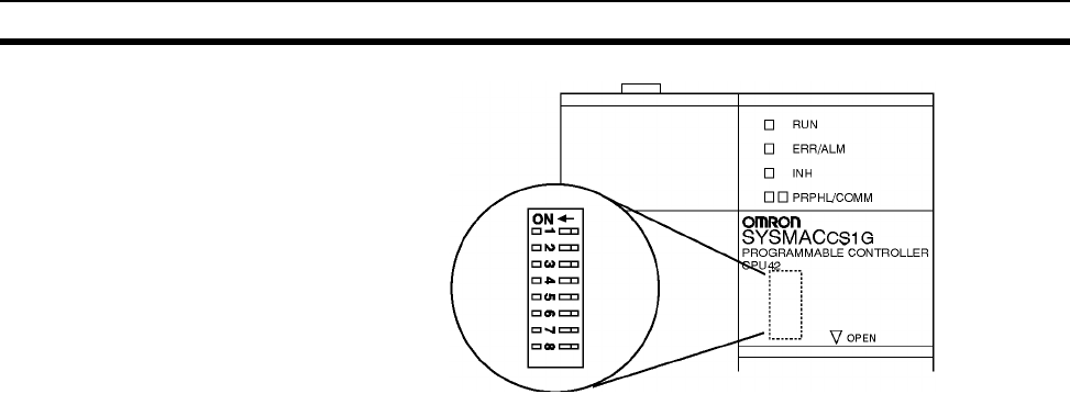
159
CPU Units Section 3-1
3-1-3 CPU Unit Memory Block Map
The memory of CS-series CPU Units is configured in the following blocks.
• I/O Memory: The data areas accessible from the user program
• User Memory: The user program and parameter areas (See Note 1.)
The above memory is backed up using a CS1W-BAT01 Battery. If the battery
voltage is low, the data in these areas will not be stable.
With the CS1-H CPU Units, however, the CPU Unit has a built-in flash mem-
ory to which the user program and parameter area data is backed up when-
ever the user memory is written to, including data transfers and online editing
from a Programming Device (CX-Programmer or Programming Console, data
transfers from a Memory Card, etc. The user program and the parameter area
data will be held when using a CS1-H CPU Unit.
The internal flash memory of CS1-H CPU Units with unit version 3.0 also con-
tains a comment memory and FB program memory area. The comment mem-
ory is used to store symbol table files, comment files, and program index files
(if comment memory is selected as the transfer destination when transferring
projects from a CX-Programmer Ver. 5.0). The FB source memory area is
used to store function block program data.
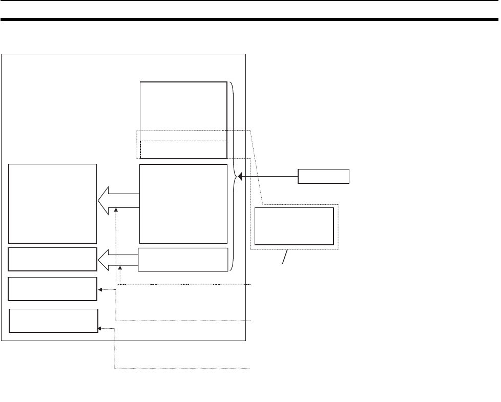
160
CPU Units Section 3-1
Note 1. The Parameter Area stores system information for the CPU Unit, such as
the PLC Setup.
2. Part of the EM (Extended Data Memory) Area can be converted to file
memory to handle data files and program files in RAM memory format,
which has the same format as Memory Cards. File memory in the EM Area
is backed up by a battery.
CPU Unit
Built-in RAM
I/O Memory Area
Battery
Backup
File memory
User program
User program
Parameter Area
Drive 1: EM file memory
(See Note 2.)
Parameter Area
(See Note 1.)
The battery life is 5 years at an
ambient temperature of 25°C.
Drive 0: Memory
Card
(flash memory)
Comment memory area
FB program memory area
Automatically backed up to flash memory whenever a write
operation for the user memory area (user program or parameter
area) is performed from a Programming Device.
Used to store symbol table files, comment files, and program
index files. CPU Units with unit version 3.0 or later, Memory
Card, EM file memory, or comment memory can be selected as
the destination when transferring projects from CX-Programmer
Ver. 5.0.
For CPU Units with unit version 3.0 or later, when transferring
projects containing function blocks from the CX-Programmer,
the function block program information is automatically stored
in the FB
p
ro
g
ram memor
y
area.
Flash Memory
(CS1-H CPU Units only)
Written
automatically
Written
automatically
Written
automatically
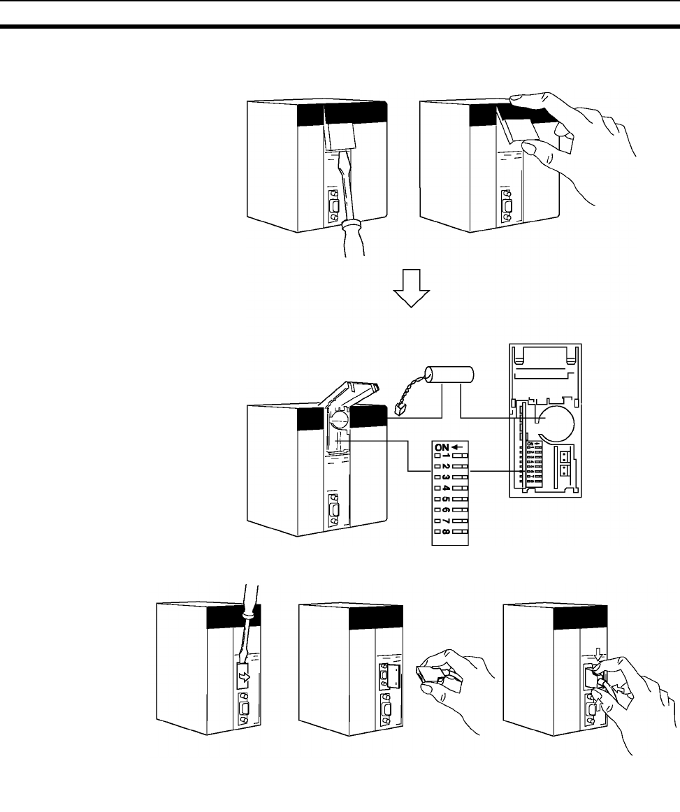
161
CPU Units Section 3-1
Opening the Battery
Compartment Cover
Insert a small flat-blade screwdriver into the opening at the bottom of the bat-
tery compartment cover and lift open the cover.
Opening the Peripheral Port Cover and Connecting Cables
Insert a small flat-blade
screwdriver into the opening
at the bottom of the battery
compartment cover and lift
open the cover.
Battery
DIP switch
Insert a small flat-blade
screwdriver into the
opening at the top of the
p
ort cover and
p
ull o
p
en.
Make sure the connector is
in facing the correct direction. Hold the grips on the side of the
connector and push into the port.
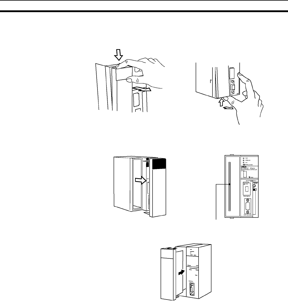
162
CPU Units Section 3-1
Installing Inner Boards
1,2,3... 1. Press in the lever at the top of the Inner Board connector compartment and
pull out.
2. Remove the cover of the Inner Board connector compartment.
3. Insert the Inner Board into the compartment.
Note 1. Always make sure the power is OFF before installing the Inner Board. In-
stalling the Inner Board when the power is ON may cause CPU Unit mal-
function, damage to internal components, and improper communications.
2. Before installing the Inner Board, be sure to touch a grounded metal object
to discharge static electricity from your body.
Press in the lever on the top of the
cover and pull out.
Press in the lever on the bottom of
the cover and pull out.
Inner Board connector
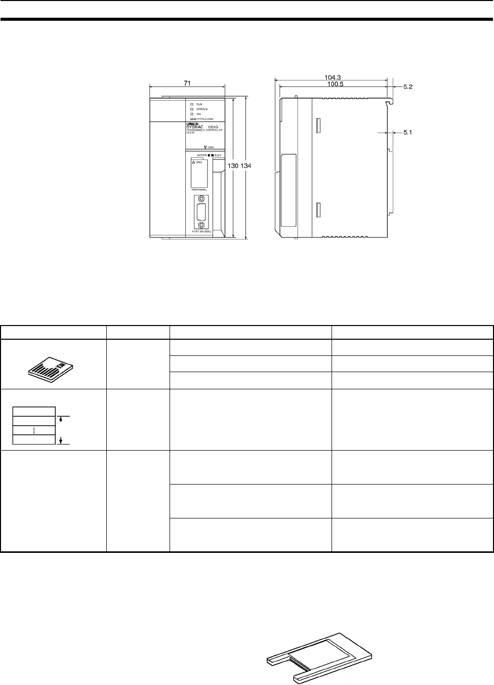
163
File Memory Section 3-2
3-1-4 Dimensions
3-2 File Memory
For CS-series CPU Units, the Memory Card and a specified part of the EM
Area can be used to store files. All user programs, the I/O Memory Area, and
the Parameter Area can be stored as files.
Note 1. A Memory Card can be written up to approximately 100,000 times. (Each
write operation to the Memory Card must be counted regardless of the size
of the write.) Be particularly careful not to exceed the life of the Memory
Card when writing to it from the ladder program.
2. The HMC-AP001 Memory Card Adapter is shown below.
3. The HMC-EF183 cannot be used with all CPU Units. Before ordering, refer
to Precaution on Applicable Units on page 164.
CS1H-CPU@@H, CS1G-CPU@@H
File memory Memory type Memory capacity Model/Contents
Flash mem-
ory
30 Mbytes HMC-EF372
64 Mbytes HMC-EF672
128 Mbytes HMC-EF183 (See note 3.)
RAM The maximum capacity of the CPU
Unit’s EM Area (e.g., the maximum
capacity for a CPU67 is 832 Kbytes)
The specified bank (set in the PLC
Setup) to the last bank of the EM Area
in the I/O Memory.
Comment memory
(CS/CJ-series CPU
Units with unit version
3.0 or later only)
CPU Unit’s
internal flash
memory
Comment files
CPU66H/67H: 128 Kbytes
Other CPU Units: 64 Kbytes
CX-Programmer rung comments and
other comments
Program index files
CPU66H/67H: 128 Kbytes
Other CPU Units: 64 Kbytes
CX-Programmer section names, sec-
tion comments, and program com-
ments
Symbol table files
CPU45H/65H66H/67H: 128 Kbytes
Other CPU Units: 64 Kbytes
CX-Programmer global symbol tables,
local symbol tables, and settings for
automatically allocated areas.
Memory Card
EM file memory
Bank 0
Bank n
Bank C
EM file
memory
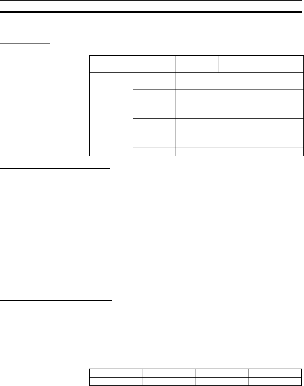
164
File Memory Section 3-2
3-2-1 Specifications of Memory Card
Specifications
Precaution on Applicable Units
The HMC-EF183 Memory Card cannot be used with the following CPU Units
and PTs. Confirm applicability when ordering.
1) CS-series CPU Units
• All CS1G-CPU@@H and CS1H-CPU@@H CPU Units manufactured
before January 9, 2002 (lot number 020108 and earlier)
2) CJ-series CPU Units
• All CJ1G-CPU@@H and CJ1H-CPU@@H CPU Units manufactured before
January 9, 2002 (lot number 020108 and earlier)
• All CJ1G-CPU@@ CPU Units (i.e., those without an H in the model num-
ber suffix: CPU@@H)
3) NS7-series PTs
All NS7-SV0@ PTs manufactured before May 9, 2002 (lot number 0852 and
earlier)
Memory Card Recognition Time
Several seconds is normally required for the CPU Unit to recognize the Mem-
ory Card after it is inserted. The required time depends on the PLC's cycle
time, the Memory Card Capacity, the number of files stored on the Memory
Card, and other factors.
The recognition times given in the following table are guidelines for a CS1H-
CPU@@H CPU Unit with a PLC cycle time of 0.4 ms and all PLC Setup
parameters set to the default values.
Model number HMC-EF183 HMC-EF672 HMC-EF372
Memory Card capacity 128 Mbytes 64 Mbytes 30 Mbytes
Common
specifications
Dimensions 42.8 × 36.4 × 3.3 mm (W × H × T)
Weight 15 g max.
Current
consumption
Approx. 30 mA (when used with PLC)
Environmental
specifications
Same as general specifications of PLC
No. of writes 100,000 (guaranteed value)
Factory
specifications
No. of files
writable to
root directory
511
File system FAT16
Model HMC-EF183 HMC-EF672 HMC-EF372
Recognition time 8 s 5 s 3 s
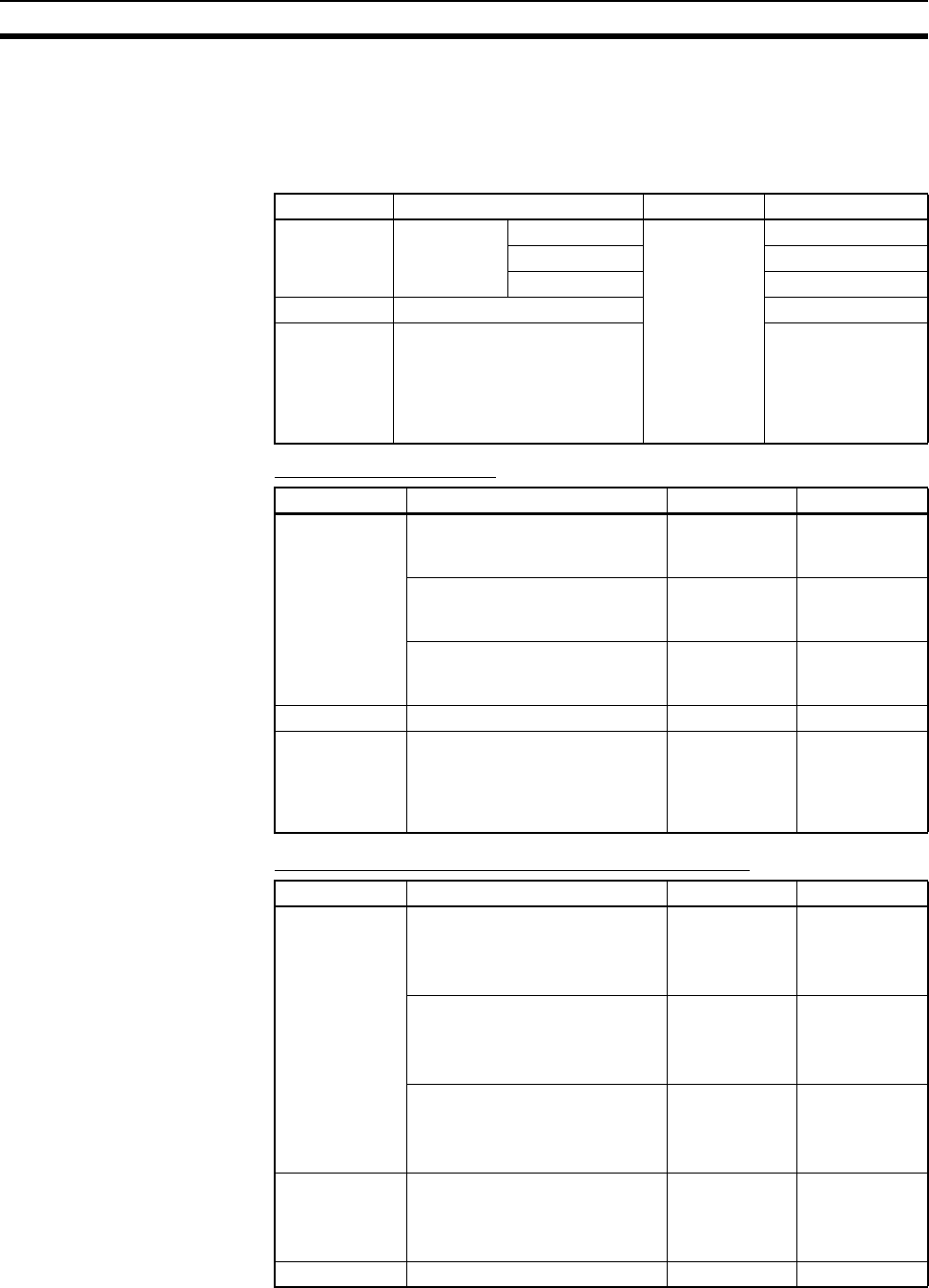
165
File Memory Section 3-2
3-2-2 Files Handled by CPU Unit
Files are ordered and stored in the Memory Card or EM file memory accord-
ing to the file name and the extension attached to it.
General-use Files
Files Transferred
Automatically at Startup
Including Parameter File
Excluding Parameter File (CPU Unit Ver. 2.0 or Later)
File type Contents File name Extension
Data files Specified
range in I/O
memory
Binary ********
(See note 1.)
.IOM
Text . T X T
CSV .CSV
Program file All user programs .OBJ
Parameter file PLC Setup, registered I/O
tables, routing tables, CS-
series CPU Bus Unit settings,
SYSMAC LINK data link tables,
and Controller Link data link
tables
.STD
File type Contents File name Extension
Data files DM area data (stores data for
specified number of words start-
ing from D20000)
AUTOEXEC .IOM
DM area data (stores data for
specified number of words start-
ing from D00000)
ATEXECDM .IOM
EM area for bank No. @ (stores
data for specified number of
words starting from E@_00000)
ATEXECE@.IOM
Program file All user programs AUTOEXEC .OBJ
Parameter file PLC Setup, registered I/O tables,
routing tables, CS-series CPU
Bus Unit settings, SYSMAC
LINK data link tables, and Con-
troller Link data link tables
AUTOEXEC .STD
File type Contents File name Extension
Data files DM area data (stores data for
specified number of words start-
ing from D20000)
REPLACE
(CPU Unit Ver.
2.0 or later
only)
.IOM
DM area data (stores data for
specified number of words start-
ing from D00000)
REPLCDM
(CPU Unit Ver.
2.0 or later
only)
.IOM
EM area for bank No. @ (stores
data for specified number of
words starting from E@_00000)
REPLCE@
(CPU Unit Ver.
2.0 or later
only)
.IOM
Program file All user programs REPLACE
(CPU Unit Ver.
2.0 or later
only)
.OBJ
Parameter file --- Not needed ---
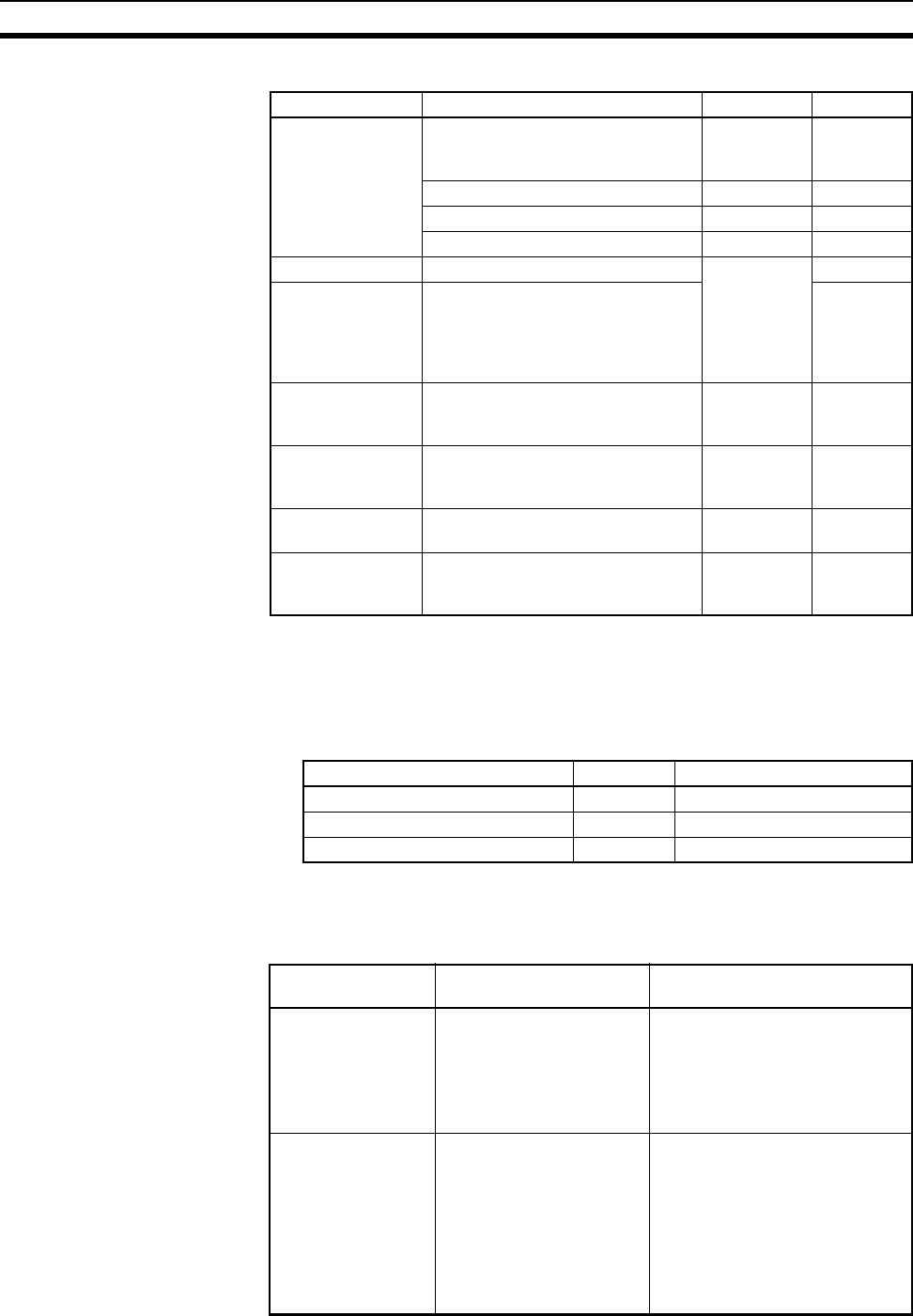
166
File Memory Section 3-2
Easy Backup Files
Note 1. Specify 8 ASCII characters. For a file name with less than 8 characters,
add spaces (20 hex).
2. Always specify the name of files to be transferred automatically at power-
up as AUTOEXEC or ATEXEC@@.
3. The BACKUP@@.PRM files are as follows:
4. Supported for CS/CJ-series CPU Units with unit version 3.0 or later only.
3-2-3 Initializing File Memory
File type Contents File name Extension
Data files Words allocated to Special I/O
Units, CPU Bus Units, and Inner
Boards in the DM area
BACKUP .IOM
CIO area BACKUPIO .IOR
DM area BACKUPDM .IOM
EM area BACKUPE@.IOM
Program files All user programs BACKUP .OBJ
Parameter files PLC Setup, registered I/O tables,
routing tables, CS-series CPU Bus
Unit settings, SYSMAC LINK data
link tables, and Controller Link data
link tables
.STD
Unit/Board backup
files (CS1-H CPU
Units only)
Data from specific Units or Boards BACKUP@@ .PRM
Symbol table files
(See note 4.)
CX-Programmer global symbol
tables, local symbol tables, settings
for automatically allocated areas
BKUPSYM .SYM
Comment files
(See note 4.)
CX-Programmer rung comments
and comments
BKUPCMT .CMT
Program index
files (See note 4.)
CX-Programmer section names,
section comments, and program
comments
BCKUPPRG .IDX
Unit/Board @@ Unit number
CPU Bus Units 10 to 1F 0 to F
Special I/O Units 20 to 6F 0 to 79
Inner Board E1 ---
File memory Initializing procedure Data capacity after
initialization
Memory Card 1. Install Memory Card into
CPU Unit.
2. Initialize the Memory
Card using a Program-
ming Device (including
Programming Console).
Essentially the specific capacity
of the Memory Card
EM file memory 1. Convert the part of the
EM Area from the specified
bank No. to the last bank
No. to file memory in the
PLC Setup.
2. Initialize the EM file
memory using a Program-
ming Device (excluding
Programming Console).
1 bank: Approx. 61 KB
13 banks: Approx. 825 KB
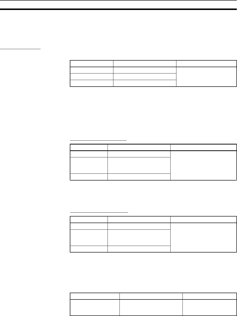
167
File Memory Section 3-2
3-2-4 Using File Memory
Note For details on using file memory, refer to SECTION 5 File Memory of the
CS/CJ Series PLC Programming Manual.
Memory Cards
Reading/Writing Files Using Programming Device
1,2,3... 1. Install the Memory Card into the CPU Unit.
2. Initialize the Memory Card if necessary.
3. Name the file containing the data in the CPU Unit and save the contents in
the Memory Card.
4. Read the file that is saved in the Memory Card to the CPU Unit.
Automatically Transferring Memory Card Files to the CPU Unit at Power-up
Including Parameter File
1,2,3... 1. Install the Memory Card into the CPU Unit.
2. Set pin 2 of the DIP switch to ON.
3. The files are read automatically when the power is turned ON.
Excluding Parameter File
1,2,3... 1. Install the Memory Card into the CPU Unit.
2. Set pin 2 of the DIP switch to ON.
3. Turn ON the power to the PLC. The files will be read automatically when
the power is turned ON.
Reading/Writing I/O Memory Files Using FREAD(700)and FWRIT(701)
1,2,3... 1. Install the Memory Card into the CPU Unit.
2. Initialize the Memory Card using a Programming Device.
File File name and extension Data transfer direction
Program files ∗∗∗∗∗∗∗∗.OBJ Between CPU Unit and Mem-
ory Card,
I/O memory files ∗∗∗∗∗∗∗∗.IOM
Parameter files ∗∗∗∗∗∗∗∗.STD
File File name and extension Data transfer direction
Program file AUTOEXEC.OBJ From Memory Card to CPU Unit
I/O memory files AUTOEXEC.IOM
ATEXECDM.IOM
ATEXECE@.IOM
Parameter file AUTOEXEC.STD
File File name and extension Data transfer direction
Program file REPLACE.OBJ From Memory Card to CPU Unit
I/O memory files REPLACE.IOM
REPLCDM.IOM
REPLCE@.IOM
Parameter file Not needed
File File name and extension Data transfer direction
I/O memory files ∗∗∗∗∗∗∗∗.IOM
∗∗∗∗∗∗∗∗.TXT
∗∗∗∗∗∗∗∗.CSV
Between CPU Unit and
Memory Card
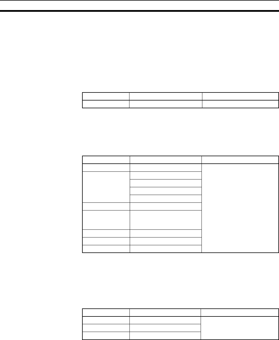
168
File Memory Section 3-2
3. Using the FWRIT(701) instruction, name the file of the specified I/O mem-
ory area, and save to the Memory Card.
4. Using the FREAD(700) instruction, read the I/O memory files from the
Memory Card to the I/O memory in the CPU Unit.
Note When using spreadsheet software to read data that has been written to the
Memory Card in CSV or text format, it is now possible to read the data using
Windows applications by mounting a Memory Card in the personal computer
card slot using a HMC-AP001 Memory Card Adapter.
Reading and Replacing Program Files during Operation
1,2,3... 1. Install a Memory Card into the CPU Unit.
2. Set the following information: Program File Name (A654 to A657) and Pro-
gram Password (A651).
3. Next, from the program, turn ON the Replacement Start Bit (A65015).
Backing Up or Restoring CPU Unit Data or Data for Specific Units and Boards
1,2,3... 1. Install a Memory Card into the CPU Unit.
2. Turn ON pin 7 on the DIP switch.
3. To back up data, press and hold the Memory Card Power Supply Switch
for three seconds. To restore data, turn ON the PLC power.
Transferring Files between
Memory Cards and the
CX-Programmer
The following files can be transferred between a Memory Card and the CX-
Programmer.
1,2,3... 1. Insert a formatted Memory Card into the CPU Unit.
2. Place the CX-Programmer online and use the file transfer operations to
transfer the above files from the personal computer to the PLC or from the
PLC to the personal computer.
File File name and extension Data transfer direction
Program files ∗∗∗∗∗∗∗∗.OBJ Memory Card to CPU Unit
File File name and extension Data transfer direction
Program files BACKUP.OBJ CPU Unit to Memory Card
(when backing up)
Memory Card to CPU Unit
(when restoring)
Data files BACKUP.IOM
BACKUPIO.IOR
BACKUPDM.IOM
BACKUPE@.IOM
Parameter files BACKUP.STD
Unit/Board backup
files (CS1-H CPU
Units only)
BACKUP@@.PRM
Symbol table files BKUPSYM.SYM
Comment files BKUPCMT.CMT
Program index files BKUPPRG.IDX
File File name and extension Data transfer direction
Symbols file SYMBOLS.SYM Between CX-Programmer and
Memory Card
Comment file COMMENTS.CNT
Program index file PROGRAM.IDX
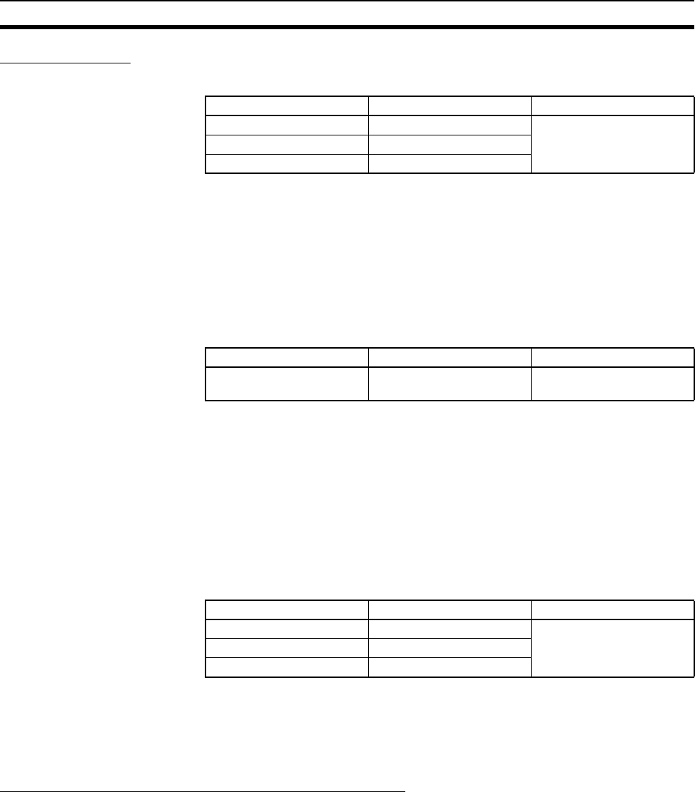
169
File Memory Section 3-2
EM File Memory
Reading/Writing EM File Memory Files Using Programming Device
1,2,3... 1. Convert the part of the EM Area specified by the first bank number into file
memory in the PLC Setup.
2. Initialize the EM file memory using a Programming Device.
3. Name the data in the CPU Unit and save in the EM file memory using the
Programming Device.
4. Read the EM file memory files to the CPU Unit using the Programming De-
vice.
Reading/Writing I/O Memory Files in EM File Memory Using FREAD(700)and FWRIT(701)
1,2,3... 1. Convert the part of the EM Area specified by the first bank number into file
memory in the PLC Setup.
2. Initialize the EM file memory using a Programming Device.
3. Using the FWRIT(701) instruction, name the specified area in I/O memory
with a file name and save in the EM file memory.
4. Using the FREAD(700) instruction, read the I/O memory files from the EM
file memory to the I/O memory in the CPU Unit.
Note The following files can be transferred between EM file memory and the CX-
Programmer.
1,2,3... 1. Format the EM Area in the CPU Units as file memory.
2. Place the CX-Programmer online and use the file transfer operations to
transfer the above files from the personal computer to the PLC or from the
PLC to the personal computer.
Comment Memory (Unit Version 3.0 or Later Only)
The internal flash memory in CS/CJ-series CPU Units with unit version 3.0 or
later contains a comment memory area. The following comment data and sec-
tion data (symbol table files, comment files, and program index files) can be
stored in or read from the comment memory when both the Memory Card and
EM file memory are not available.
Note When using CX-Programmer Ver. 5.0 to download projects, either of the fol-
lowing locations can be selected as the transfer destination for comment data
and section data.
•Memory Card
• EM file memory
File File name and extension Data transfer direction
Program files ∗∗∗∗∗∗∗∗.OBJ Between CPU Unit and EM
file memory
I/O memory files ∗∗∗∗∗∗∗∗.IOM
Parameter files ∗∗∗∗∗∗∗∗.STD
File File name and extension Data transfer direction
I/O memory files ∗∗∗∗∗∗∗∗.IOM Between CPU Unit and EM
file memory
File File name and extension Data transfer direction
Symbols file SYMBOLS.SYM Between CX-Programmer
and EM file memory
Comment file COMMENTS.CNT
Program index file PROGRAM.IDX
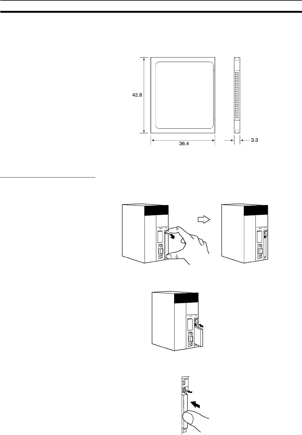
170
File Memory Section 3-2
• Comment memory (in CPU Unit’s internal flash memory)
3-2-5 Memory Card Dimensions
3-2-6 Installing and Removing the Memory Card
Installing the Memory Card
1,2,3... 1. Pull the top end of the Memory Card cover forward and remove from the
Unit.
2. Insert the Memory Card with the label facing to the right. (Insert with the ∆
on the Memory Card label and the on the CPU Unit facing each other.)
3. Push the Memory Card securely into the compartment. If the Memory Card
is inserted correctly, the Memory Card eject button will be pushed out.
∇
Product label
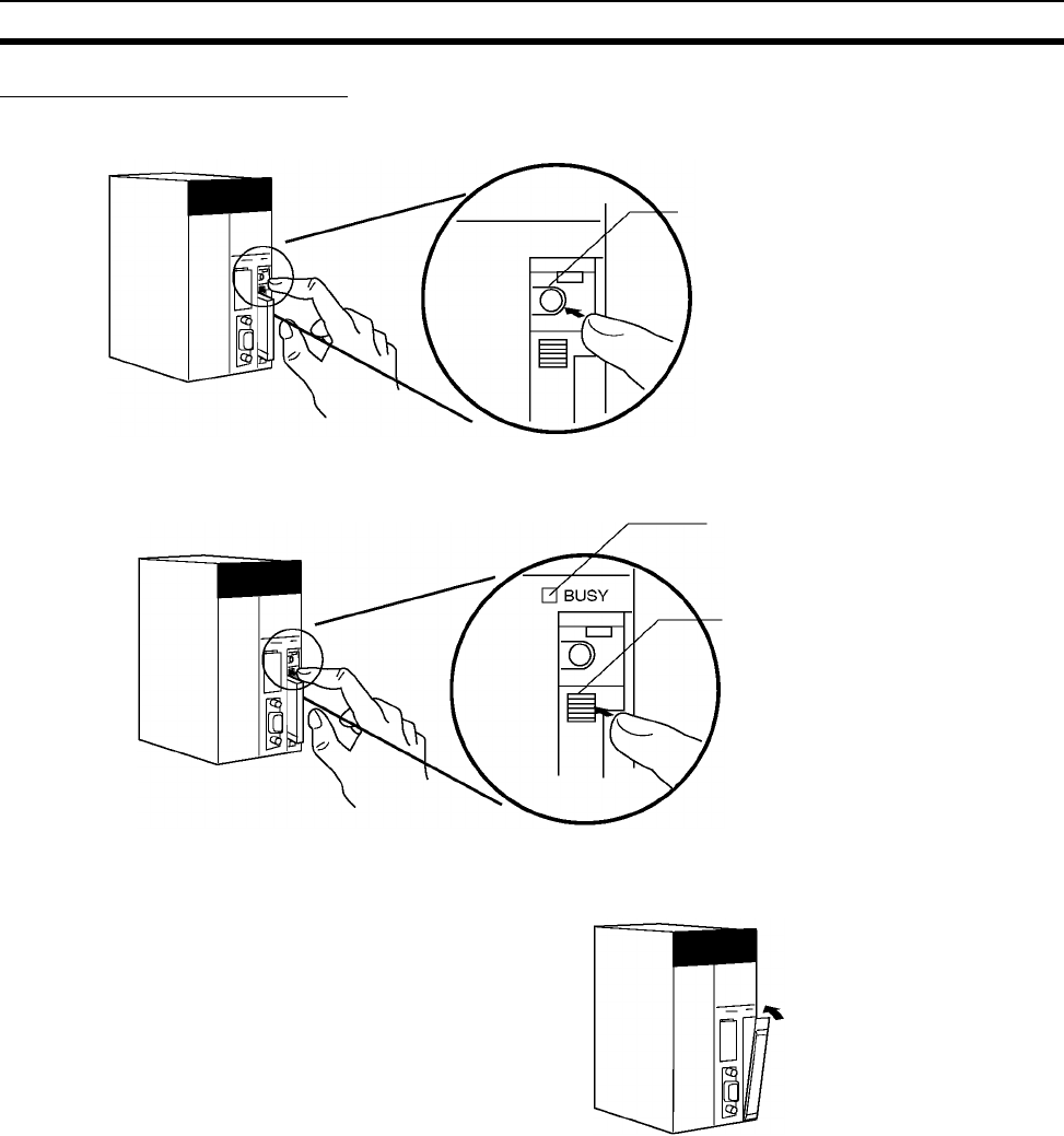
171
File Memory Section 3-2
Removing the Memory Card
1,2,3... 1. Press the Memory Card power supply switch.
2. Press the Memory Card eject button after the BUSY indicator is no longer
lit.
3. The Memory Card will eject from the compartment.
4. Remove the Memory Card cover when a Memory Card is not being used.
Note 1. Never turn OFF the PLC while the CPU is accessing the Memory Card.
2. Never remove the Memory Card while the CPU is accessing the Memory
Card. Press the Memory Card power supply switch and wait for the BUSY
indicator to go OFF before removing the Memory Card. In the worst case,
the Memory Card may become unusable if the PLC is turned OFF or the
Memory Card is removed while the Card is being accessed by the CPU.
3. Never insert the Memory Card facing the wrong way. If the Memory Card
is inserted forcibly, it may become unusable.
Memory Card power supply switch
BUSY indicator
Memory Card eject button
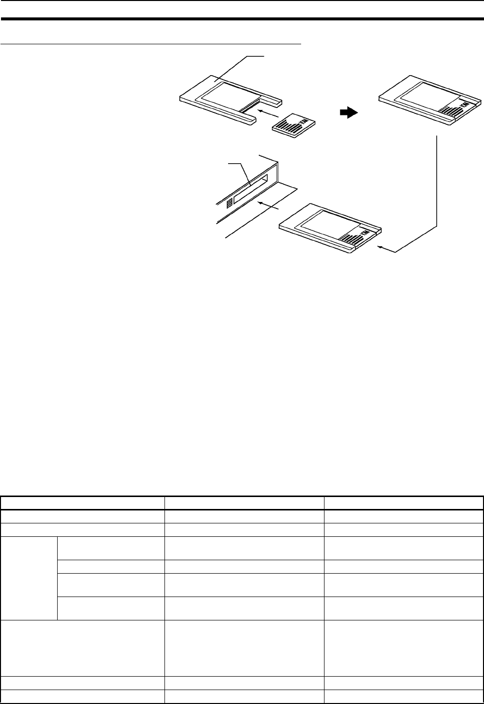
172
Programming Devices Section 3-3
Installing the Memory Card into a Personal Computer
Note 1. When a Memory Card is inserted into a computer using a Memory Card
Adapter, it can be used as a standard storage device, like a floppy disk or
hard disk.
2. When deleting all of the data in a Memory Card or formatting it in any way,
always place it in the CPU Unit and perform the operation from the CX-Pro-
grammer or a Programming Console.
3-3 Programming Devices
3-3-1 Overview
There are 2 types of Programming Devices that can be used: Any of three
models of Hand-held Programming Consoles or the CX-Programmer, which is
operated on a Windows computer. The CX-Programmer is usually used to
write the programs, and a Programming Console is then used to change the
operating modes, edit the programs, and monitor a limited number of points.
The following table provides a comparison between the CX-Programmer func-
tions and the Programming Console functions.
HMC-AP001 Memory Card Adapter
Memory Card
Personal computer PC card slot
Function Programming Console CX-Programmer
Editing and referencing I/O tables Yes Yes
Selecting tasks Yes Yes
Writing
programs
Inputting instructions Writes instructions one at a time using
mnemonics
Writes multiple blocks using mnemon-
ics or ladder programs
Inputting addresses Addresses only Addresses or symbols
I/O comment, rung com-
ment
No Yes
Setting global/local sym-
bols
No Yes (Automatic allocation of local sym-
bols)
Editing programs Inserts instructions and searches for
program addresses
Ye s
(Cutting, pasting, inserting within pro-
grams; searching/exchanging instruc-
tions, addresses, and symbols;
displaying cross-references)
Checking programs No Yes
Monitoring programs Monitors in program address units Monitors multiple blocks

173
Programming Devices Section 3-3
Monitoring I/O memory Simultaneous, 2 points max. Monitors multiple points
Changing I/O memory present values Changes 1 point at a time Yes
Online editing Edits in instruction units Edits multiple adjacent blocks
Debugging Changing timer and
counter settings
Ye s Ye s
Control set/ reset Executes 1 point at a time (or resets all
at once)
Ye s
Differentiation monitoring Yes Yes
Reading cycle time Yes Yes
Data tracing No Yes
Time chart monitoring No Yes
Reading error information Yes (error message display) Yes
Reading error log No Yes
Reading/setting timer information Yes Yes
Reading/setting PLC parameters Yes Yes
Setting CPU Bus Unit parameters No Yes
File mem-
ory opera-
tions
Initializing Memory Card Yes Yes
Initializing EM file mem-
ory
Ye s Ye s
Transferring files between
CPU Unit and file mem-
ory
Ye s Ye s
Remote
program-
ming and
monitoring
Between Host Link and
Network PLC
No Yes
Via modem No Yes
Setting password protection No Yes
Managing files No Manages files by project.
Printing No Yes
Function Programming Console CX-Programmer
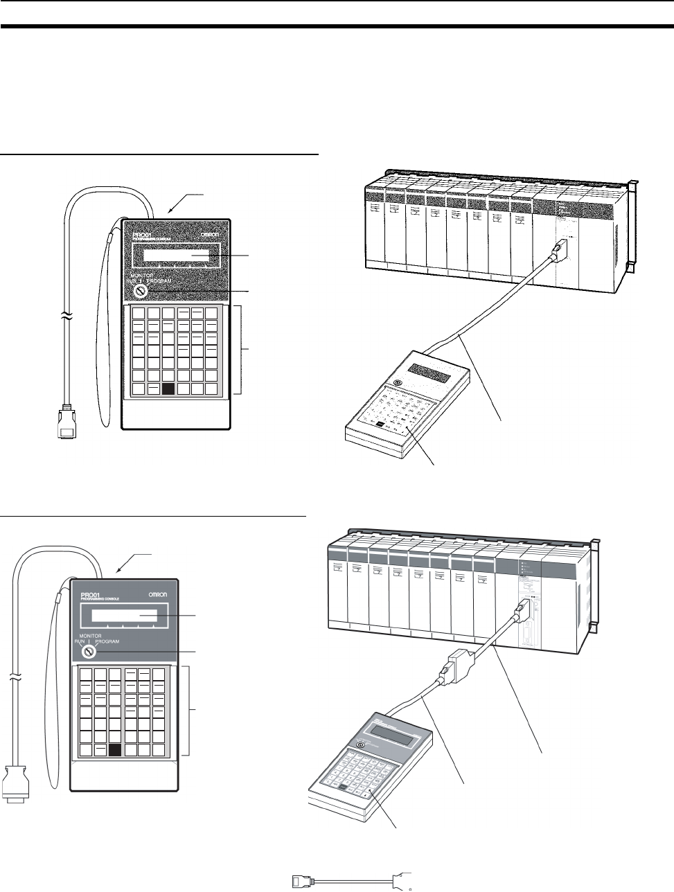
174
Programming Devices Section 3-3
3-3-2 Programming Consoles
There are three Programming Consoles that can be used with the CS-series
CPU Units: The CQM1H-PRO01-E, CQM1-PRO01-E, and C200H-PRO27-E.
These Programming Consoles are shown here.
CQM1H-PRO01-E Programming Console
CQM1-PRO01-E Programming Console
Connection
LCD area
Mode selector switch
Operation keys (Install the
CS1W-KS001-E Key Sheet
(See Note.)
Cable included with CQM1H-PRO01-E
Programming Console
CQM1H-PRO01-E Pro
g
rammin
g
Console
FUN
A
SFT
B
NOT
C
SHIFT
F
*EM
K
WR/LR
. IR+
D
. IR
. −IR
J
TR
DR
E
IR
TN
G
AND
ST
H
OR
TK
I
CNT
AR
L
HR
AA
M
LD
AC
N
OUT
TIM
O
EM
P
DM
CH
Q
*DM
CONT
R
#
7
7
8
8
9
9
*EM_
S
EM_/EXT
CHG
T
CF
U
SRCH
4
4
E
5
5
F
6
6
SET
V
DEL
W
MON
X
1
1
B
2
2
C
3
3
D
RESET
Y
INS
Z
↑
↓
WRITE
VRFY
CLR
TEXT
!
0
0
A
Connection
LCD area
Mode selector switch
Operation keys (Install the
CS1W-KS001-E Key Sheet
(See Note.)
CS1W-CN114 (cable length: 0.05 m)
Cable included with CQM1-PRO01-E
Programming Console
CQM1-PRO01-E Programming Console
Connect the CPU Unit to the Programming Console with the following cables.
CS1W-CN114 (Cable length: 0.05 m)
FUN
A
SFT
B
NOT
C
SHIFT
F
*EM
K
WR/LR
. IR+
D
. IR
. −IR
J
TR
DR
E
IR
TN
G
AND
ST
H
OR
TK
I
CNT
AR
L
HR
AA
M
LD
AC
N
OUT
TIM
O
EM
P
DM
CH
Q
*DM
CONT
R
#
7
7
8
8
9
9
*EM_
S
EM_/EXT
CHG
T
CF
U
SRCH
4
4
E
5
5
F
6
6
SET
V
DEL
W
MON
X
1
1
B
2
2
C
3
3
D
RESET
Y
INS
Z
↑
↓
WRITE
VRFY
CLR
TEXT
!
0
0
A
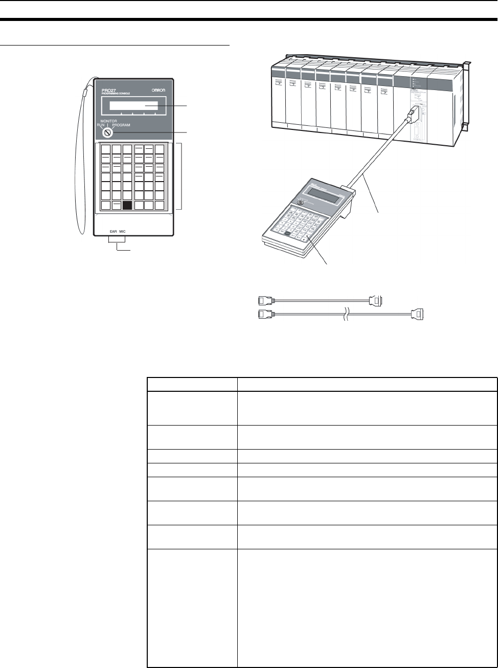
175
Programming Devices Section 3-3
C200H-PRO27-E Programming Console
Note The Key Sheet is not used with CS-series CPU Units.
3-3-3 CX-Programmer
Note Windows 95 cannot be used when connecting via a Controller Link Support
Board (PCI bus) or a SYSMAC LINK Support Board (PCI bus).
Item Details
Applicable PLC CS-series, CJ-series, CP-series, NSJ-series, CV-series,
C200HX/HG/HE (-Z), C200HS, CQM1, CPM1, CPM1A,
SRM1, C1000H/2000H
OS Microsoft Windows 95 (See note.), 98, NT 4.0 (Service Pack
6), 2000, Me, XP
Personal computer DOS version
Connection method CPU Unit’s peripheral port or built-in RS-232C port
Communications
protocol with PLC
Peripheral bus or Host Link
Offline operation Programming, I/O memory editing, creating I/O tables, setting
PLC parameters, printing, program changing
Online operation Transmitting, referencing, monitoring, creating I/O tables, set-
ting PLC parameters
Basic functions 1. Programming: Creates and edits ladder programs and mne-
monic programs for the applicable PLC.
2. Creating and referencing I/O tables.
3. Changing the CPU Unit operating mode.
4. Transferring: Transfers programs, I/O memory data, I/O
tables, PLC Setup, and I/O comments between the personal
computer and the CPU Unit.
5. Program execution monitoring: Monitors I/O status/present
values on ladder displays, I/O status/present values on mne-
monic displays, and present values on I/O memory displays
CS1W-CN224 (Cable length: 2.0 m)
CS1W-CN624 (Cable length: 6.0 m)
Mode selector switch
LCD area
Operation keys (Install
the CS1W-KS001-E
Key Sheet (See Note.)
C200H-PRO27-E
Connect the CPU Unit to the Programming Console with the following cables.
CS1W-CN224 (Cable length: 2.0 m)
CS1W-CN624 (Cable length: 6.0 m)
FUN
A
SFT
B
NOT
C
SHIFT
F
*EM
K
WR/LR
. IR+
D
. IR
. −IR
J
TR
DR
E
IR
TN
G
AND
ST
H
OR
TK
I
CNT
AR
L
HR
AA
M
LD
AC
N
OUT
TIM
O
EM
P
DM
CH
Q
*DM
CONT
R
#
7
7
8
8
9
9
*EM_
S
EM_/EXT
CHG
T
CF
U
SRCH
4
4
E
5
5
F
6
6
SET
V
DEL
W
MON
X
1
1
B
2
2
C
3
3
D
RESET
Y
INS
Z
↑
↓
WRITE
VRFY
CLR
TEXT
!
0
0
A
Cassette jacks
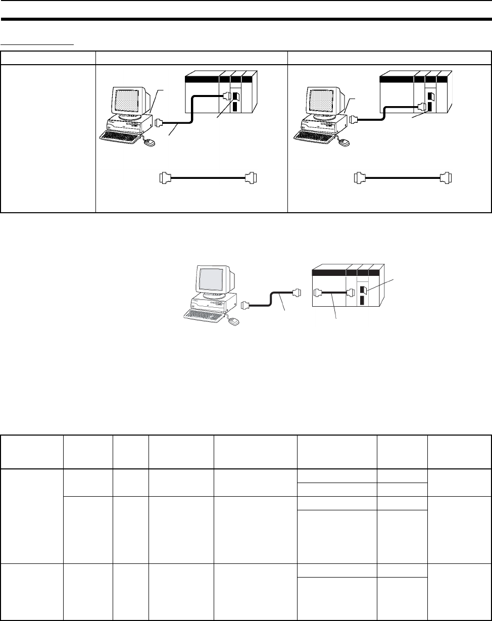
176
Programming Devices Section 3-3
Connections
Note 1. The CS1W-CN118 Cable is used with one of the RS-232C Cables shown
on the right (XW2Z-@@@S-@@) to connect to the peripheral port on the
CPU Unit.
2. If cables with model numbers ending in -V instead of -CV are used to con-
nect the computer running the CX-Programmer to the RS-232C port (in-
cluding when using a CS1W-CN118 Cable), a peripheral bus connection
cannot be used. Use a Host Link (SYSMAC WAY) connection. To connect
to the port using a peripheral bus connection, prepare an RS-232C cable
as described in 3-3-5 RS-232C Port Specifications.
CX-Programmer Connecting Cables
Note 1. Before connecting a connector from the above table to an RS-232C port,
touch a grounded metal object to discharge static electricity from your
body.
The XW2Z-@@@S-CV Cables have been strengthened against static be-
cause they use a static-resistant connector hood (XM2S-0911-E). Even so,
always discharge static electricity before touching the connectors.
Personal computer Peripheral port connection RS-232C port connection
DOS
Peripheral port
10-pin female
CS1W-CN118 (0.1 m) (See note 1
)
CS1W-CN226 (2.0 m)
CS1W-CN616 (6.0 m)
CS1W-CN118
CS1W-CN226
CS1W-CN616 9-pin
female 10-pin
9-pin
male
9-pin
female
9-pin
male
9-pin
female
RS-232C port
9-pin female
9-pin
female
9-pin
male
XW2Z-200S-CV/200S-V (See note 2)
XW2Z-500S-CV/500S-V (See note 2)
XW2Z-200S-
CV/200S-V or
XW2Z-500S-
CV/500S-V
RS-232C Cable
Peripheral port
CS1W-CN118 Cable
Unit Unit port Com-
puter
Computer
port
Serial
communications
mode
Model Length Cable notes
CPU Units Periph-
eral port
DOS D-Sub, 9-pin,
male
Peripheral Bus or
Host Link
CS1W-CN226 2.0 m ---
CS1W-CN626 6.0 m
Built-in
RS-232C
port
D-Sub, 9-
pin,
female
DOS D-Sub, 9-pin,
male
Peripheral Bus or
Host Link
XW2Z-200S-CV 2 m Use a static-
resistant con-
nector.
XW2Z-500S-CV 5 m
Serial Com-
munications
Boards/Units
RS-232C
Port
D-Sub, 9-
pin,
female
DOS D-Sub, 9-pin,
male
Host Link XW2Z-200S-CV 2 m Use a static-
resistant con-
nector.
XW2Z-500S-CV 5 m
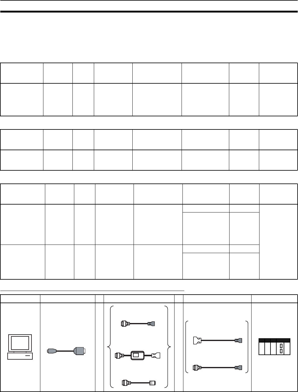
177
Programming Devices Section 3-3
2. Do not use commercially available RS-232C personal computer cables. Al-
ways use the special cables listed in this manual or make cables according
to manual specifications. Using commercially available cables may dam-
age the external devices or CPU Unit.
RS-232C Cables for a Peripheral Port
Using a CQM1-CIF01/02 Cable for a Peripheral Port
Using a RS-232C Cable for a IBM PC/AT or Compatible
Connection Method for USB-Serial Conversion Cable
Unit Unit port Com-
puter
Computer
port
Serial
communications
mode
Model Length Cable notes
CPU Units Built-in
periph-
eral port
DOS D-Sub, 9-pin,
male
Peripheral Bus or
Host Link
CS1W-CN118 +
XW2Z-200S-CV/
500S-CV
0.1 m+
(2 m or
5m)
XW2Z-
@@@S-CV
models use a
static-resis-
tant connector
Unit Unit port Com-
puter
Computer
port
Serial
communications
mode
Model Length Cable notes
CPU Units Built-in
periph-
eral port
DOS D-Sub, 9-pin,
male
Host Link CS1W-CN114 +
CQM1-CIF02
0.05 m +
3.3 m
---
Unit Unit port Com-
puter
Computer
port
Serial
communications
mode
Model Length Cable notes
CPU Units Built-in
RS-232C
port
D-Sub, 9-
pin,
female
DOS D-Sub, 9-pin,
male
Host Link XW2Z-200S-V 2 m ---
XW2Z-500S-V 5 m
Serial Communi-
cations
Boards/Units
RS-232C
port
D-Sub,
9-pin,
female
DOS D-Sub, 9-pin,
male
Host Link XW2Z-200S-V 2 m
XW2Z-500S-V 5 m
Computer CS1W-CIF31 Cable 1 Cable 2 PLC
++
CS1W-CIF31
USB Connecting Cable
OR
OR
CS1W-CN226/626 CS/CJ-series
Peripheral Port Programming
Device Connecting Cable
CQM1H-CIF02 C-series
Peripheral Port Programming
Device Connecting Cable
XW2Z-@@@ RS-232C
Programming Device
Connecting Cable
CS1W-CN114 C-series Peripheral-
CS/CJ-series Peripheral
Conversion Cable
CS1W-CN118 RS-232C-CS/CJ-
series Peripheral Conversion
Cable
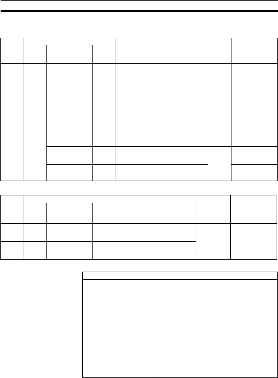
178
Programming Devices Section 3-3
CX-Programmer Connecting Cables
Cables Connecting to CPU Units
Cables Connecting to Serial Communications Boards/Units
Communications Modes when Connecting a CX-Programmer to a CS-series CPU Unit
Note The CX-Programmer can be used for remote programming and monitoring. It
can be used to program and monitor not only the PLC to which it is directly
connected, but also to program and monitor any PLC connected through a
Controller Link or Ethernet network to which the PLC that the CX-Programmer
USB
Con-
necting
Cable
Model
Cable 1 Cable 2 Unit port Serial
communications
mode
(network)
Connec-
tor
Cable model Connec-
tor
Connec-
tor
Cable model Connec-
tor
CS1W-
CIF31
D-sub, 9-
pin
female
CS1W-CN226/626
(length: 2 m/6 m)
CS/CJ-
series
periph-
eral
Not required. CS/CJ-
series
periph-
eral
Peripheral Bus
(Toolbus) or Host
Link (SYSWAY)
CQM1-CIF02
(length: 3.3 m)
C-series
periph-
eral
C-series
periph-
eral
CS1W-CN114
(length: 5 cm)
CS/CJ-
series
periph-
eral
Host Link
(SYSWAY)
XW2Z-200S-V/
500S-V (length: 2 m/
5 m)
D-sub, 9-
pin male
D-sub, 9-
pin
female
CS1W-CN118
(length: 0.1 m)
CS/CJ-
series
periph-
eral
Peripheral Bus
(Toolbus) or Host
Link (SYSWAY)
XW2Z-200S-V/
500S-V (length: 2 m/
5 m)
D-sub, 9-
pin male
D-sub, 9-
pin
female
CS1W-CN118
(length: 0.1 m)
CS/CJ-
series
periph-
eral
Host Link
(SYSWAY)
XW2Z-200S-CV/
500S-CV (length:
2 m/5 m)
RS-232C
D-sub, 9-
pin male
Not required. RS-232C
D-sub, 9-
pin
female
Peripheral Bus
(Toolbus) or Host
Link (SYSWAY)
XW2Z-200S-V/
500S-V (length: 2 m/
5 m)
RS-232C
D-sub, 9-
pin male
Not required. Host Link
(SYSWAY)
USB
Con-
necting
Cable
Model
Cable 1 Cable 2 Unit port Serial
communications
mode
(network)
Con-
nector
Cable model Connector
CS1W-
CIF31
D-sub,
9-pin
female
XW2Z-200S-CV/
500S-CV
(length: 2 m/5 m)
RS-232C
D-sub, 9-pin
male
Not required. RS-232C
D-sub, 9-pin
female
Host Link
(SYSWAY)
CS1W-
CIF31
D-sub,
9-pin
female
XW2Z-200S-V/
500S-V
(length: 2 m/5 m)
RS-232C
D-sub, 9-pin
male
Not required.
Serial communications mode Characteristics
Peripheral Bus High-speed communications are possible. Conse-
quently, connecting via a peripheral bus is recom-
mended when using a CX-Programmer.
Only 1:1 connection is possible.
When using a CS-series CPU Unit, the baud rate of
the communications devices can be automatically
recognized for connection.
Host Link This is a communications protocol with a general-
purpose host computer.
Either 1:1 or 1:N connections are possible.
Host Link communications are slow compared with
the Peripheral Bus communications.
The following connections are possible: Via a
modem or optical fiber adapter, over long distance
using a RS-422A/485, and 1:N.
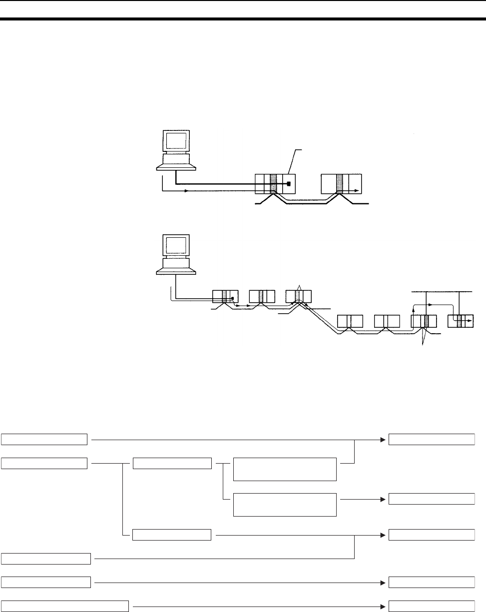
179
Programming Devices Section 3-3
is connected to is a part of. All programming and monitoring functionality for
the directly connected PLC is supported for remote programming and moni-
toring, the PLC can be connected though either the peripheral or an RS-232C
port, and either the peripheral bus or Host Link bus can be used. Remote pro-
gramming is possible for up to three levels of networks (counting the local net-
work but not counting the peripheral bus or Host Link connection between the
CX-Programmer and the local PLC).
3-3-4 Peripheral Port Specifications
Communications Mode Selection Flowchart
CX-Programmer
Peripheral bus
or Host Link
Peripheral port
or RS-232C port
FINS
Controller Link or Ethernet Network
Remote programming
and monitoring
CX-Programmer
Peripheral bus
or Host Link Bridge Ethernet Network
Controller Link Network
Controller Link Network Gateway
OMRON PT
Programming Console 1. Peripheral bus (auto-detect)
5. Serial Gateway
CX-Programmer Peripheral bus connection
2. Peripheral bus
Communicate with the PLC Setup's
communications settings
(peripheral bus).
Host Link connection
Host computer
OMRON component (CompoWay/F)
4. NT Link
3. Host Link
Communicate with the
CX-Programmer's communications
settings (peripheral bus).
Connecting Device (Protocol) Communications Mode
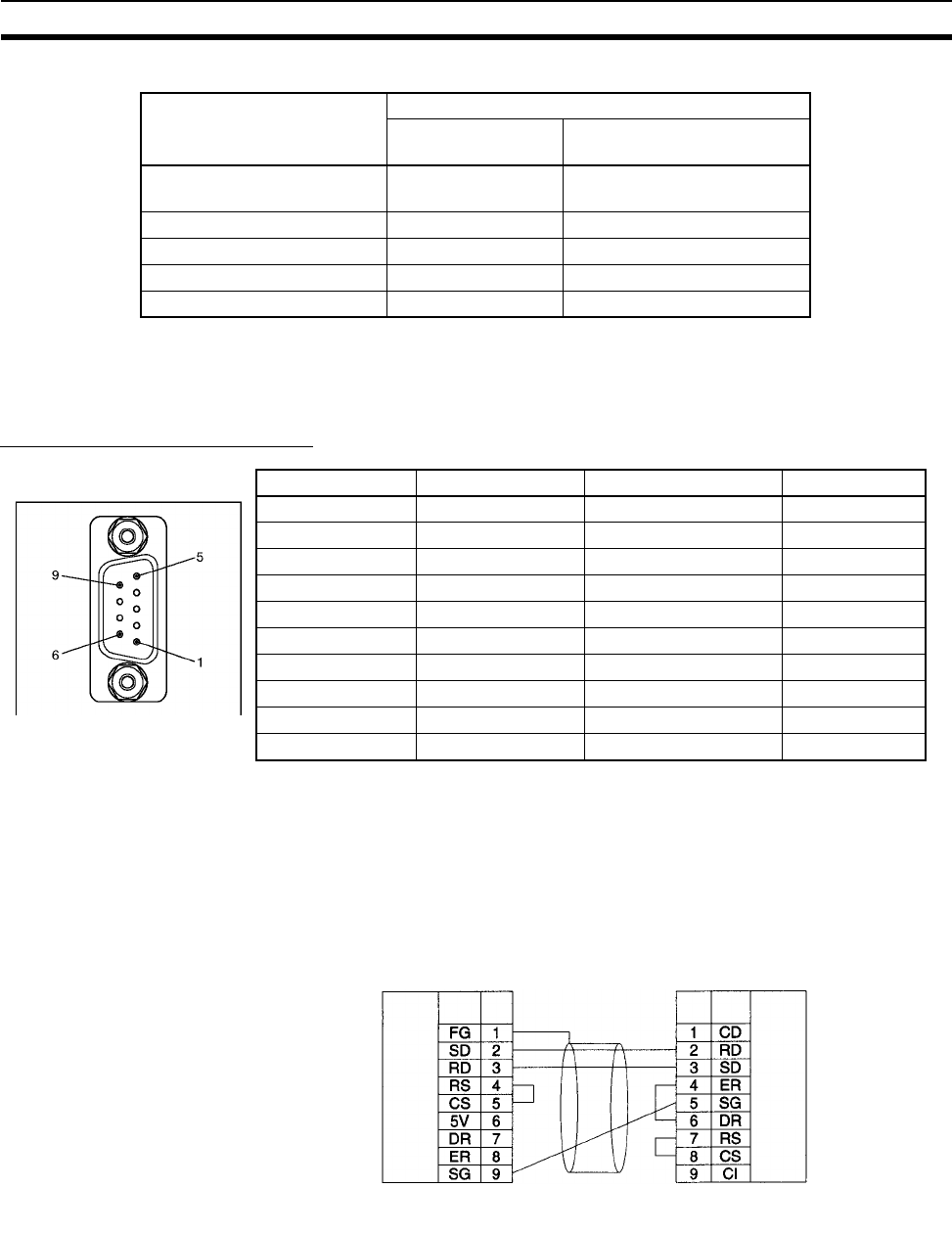
180
Programming Devices Section 3-3
Peripheral Port Communications Settings
Note Set from the CX-Programmer or Programming Console.
3-3-5 RS-232C Port Specifications
Connector Pin Arrangement
Note Do not use the 5-V power from pin 6 of the RS-232C port for anything other
than an NT-AL001, CJ1W-CIF11 Link Adapter, or NV3W-M@20L Programma-
ble Terminal. Using this power supply for any other external device may dam-
age the CPU Unit or the external device.
Connection between CS-series CPU Unit and Personal Computer
The following connections are in Host Link serial communications mode.
Note 1. Refer to Appendix E Connecting to the RS-232C Port on the CPU Unit
when converting between RS-232C and RS-422A/485 for 1:N connec-
tions.
2. Refer to Appendix E Connecting to the RS-232C Port on the CPU Unit
when making your own RS-232C cable.
Connection Communications Settings
Pin 4 of Front-panel
DIP Switch
PLC Setup peripheral port
setting (See note.)
1. Peripheral bus
(auto-detect)
OFF (factory setting) ---
2. Peripheral bus ON Peripheral bus
3. Host Link ON Host Link (default setting)
4. NT Link ON NT Link
5. Serial Gateway ON Serial Gateway
Pin No. Signal Name Direction
1 FG Protection earth ---
2 SD (TXD) Send data Output
3 RD (RXD) Receive data Input
4 RS (RTS) Request to send Output
5 CS (CTS) Clear to send Input
6 5 V Power supply ---
7 DR (DSR) Data set ready Input
8 ER (DTR) Data terminal ready Output
9 SG (0 V) Signal ground ---
Connector hood FG Protection earth ---
Signal Pin
No. Signal Pin
No.
CS-series
CPU Unit Personal computer
Shield
RS-232C
interface RS-232C
interface
D-Sub, 9-pin connector
Male connector on cable D-Sub, 9-pin connector
Female connector on cable
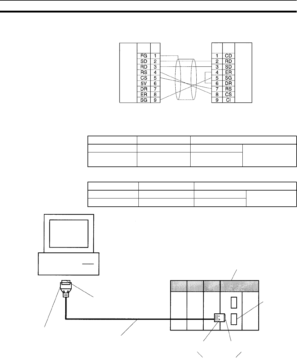
181
Programming Devices Section 3-3
The following connections are in Peripheral Bus serial communications mode.
Applicable Connectors CPU Unit Connector
Personal Computer Connector
Note Use the special cables provided from OMRON for all connections whenever
possible. If cables are produced in-house, be sure they are wired correctly.
External devices and the CPU Unit may be damaged if general purpose (e.g.,
computer to modem) cables are used or if wiring is not correct.
Recommended Cables Fujikura Ltd.: UL2464 AWG28 × 5P IFS-RVV-SB (UL product)
AWG 28 × 5P IFVV-SB (non-UL product)
Signal Pin
No. Signal
Pin
No.
CS-series
CPU Unit Personal computer
RS-232C
interface RS-232C
interface
D-Sub, 9-pin connector
Male connector on cable D-Sub, 9-pin connector
Female connector on cable
Item Model Specifications
Plug XM2A-0901 9-pin male Used together (One
of each provided
with CPU Unit.)
Hood XM2S-0911-E 9-pin, millimeter
screws
Item Model Specifications
Plug XM2D-0901 9-pin female Used together
Hood XM2S-0913 9-pin, inch screws
IBM PC/AT or compatible
(9-pin male connector)
Hood: XM2S-0913
Plug: XM2D-0901 (9-pin female)
Recommended cable
Hood: XM2S-0911-E Plug: XM2A-0901 (9-pin male)
Provided with CPU Unit
CS1-series CPU Unit
RS-232C port
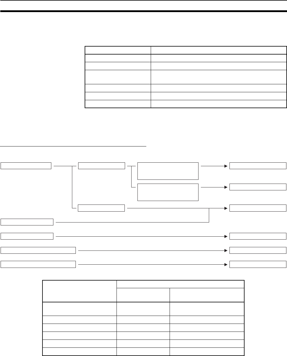
182
Programming Devices Section 3-3
Hitachi Cable, Ltd.: UL2464-SB(MA) 5P × 28AWG (7/0.127) (UL product)
CO-MA-VV-SB 5P × 28AWG (7/0.127) (non-UL product)
RS-232C Port Specifications
Note Baud rates for the RS-232C are specified only up to 19.2 kbps. The CS Series
supports serial communications from 38.4 kbps to 115.2 kbps, but some com-
puters cannot support these speeds. Lower the baud rate if necessary.
Communications Mode Selection Flowchart
RS-232C Port Communications Settings
Note Set from the CX-Programmer or Programming Console.
Item Specification
Communications method Half duplex
Synchronization Start-stop
Baud rate 0.3/0.6/1.2/2.4/4.8/9.6/19.2/38.4/57.6/115.2 kbps
(See note.)
Transmission distance 15 m max.
Interface EIA RS-232C
Protocol Host Link, NT Link, 1:N, No-protocol, or Peripheral Bus
Connection Communications Settings
Pin 5 of Front-panel
DIP Switch
PLC Setup RS-232C port
setting (See note.)
1. Peripheral bus
(auto-detect)
ON ---
2. Peripheral bus OFF (factory setting) Peripheral bus
3. Host Link OFF (factory setting) Host Link (default setting)
4. NT Link OFF (factory setting) NT Link
5. No-protocol OFF (factory setting) No-protocol
6. Serial Gateway OFF (factory setting) Serial Gateway
OMRON PT
1. Peripheral bus (auto-detect)
5. No-protocol
CX-Programmer Peripheral bus connection
2. Peripheral bus
Communicate with the PLC Setup’s
communications settings
(peripheral bus).
Host Link connection
Host computer
General-purpose external serial device
4. NT Link
3. Host Link
Communicate with the
CX-Programmer’s communications
settings (peripheral bus).
Connecting Device (Protocol)
6. Serial Gateway
OMRON component (CompoWay/F)
Communications Mode

183
Power Supply Units Section 3-4
3-4 Power Supply Units
3-4-1 Power Supply Units
Note 1. For C200HW-PA204S, the total also includes the power consumption of
the power supply output terminals.
2. The power supply voltage for C200HW-PA204 Power Supply Units manu-
factured before March 2010 and C200HW-PA204R Power Supply Units
manufactured before May 2010 is 100 to 120 V AC/200 to 240 V AC
(switched using short bar). For details on the differences between these
Units, refer to Unit Differences by Manufacturing Date (Reference Informa-
tion) on page 189.
Model Supply voltage Output capacity Power
output
terminals
RUN
output
Replacement
notification
function
Weight
C200HW-PA204 100 to 240 V AC
(Wide range)
(See note 2.)
5 V DC, 4.6 A,
26 V DC, 0.625 A,
total 30 W
No No Without 500 g max.
C200HW-PA204C No No Display: Sup-
ported Output:
Supported
500 g max.
C200HW-PA204R No Yes Without 500 g max.
C200HW-PA204S 100 to 120 V AC or
200 to 240 V AC
(Select the voltage
using the metal
short bar on the
voltage selector
terminals.)
5 V DC, 4.6 A,
26 V DC, 0.625 A,
total 30 W (See note 1.)
Ye s
24 V DC,
0.8 A
No Without 500 g max.
C200HW-PA209R 5 VDC, 9 A,
26 V DC, 1.3A,
total 45 W
No Yes Without 1,000 g
max.
C200HW-PD024 24 V DC 5 V DC, 4.6 A, 26 V DC,
0.625 A, total 30 W
No No Without 550 g max.
C200HW-PD025 24 V DC 5 V DC, 5.3 A, 26 V DC,
1.3 A, total 40 W
No No Without 630 g max.
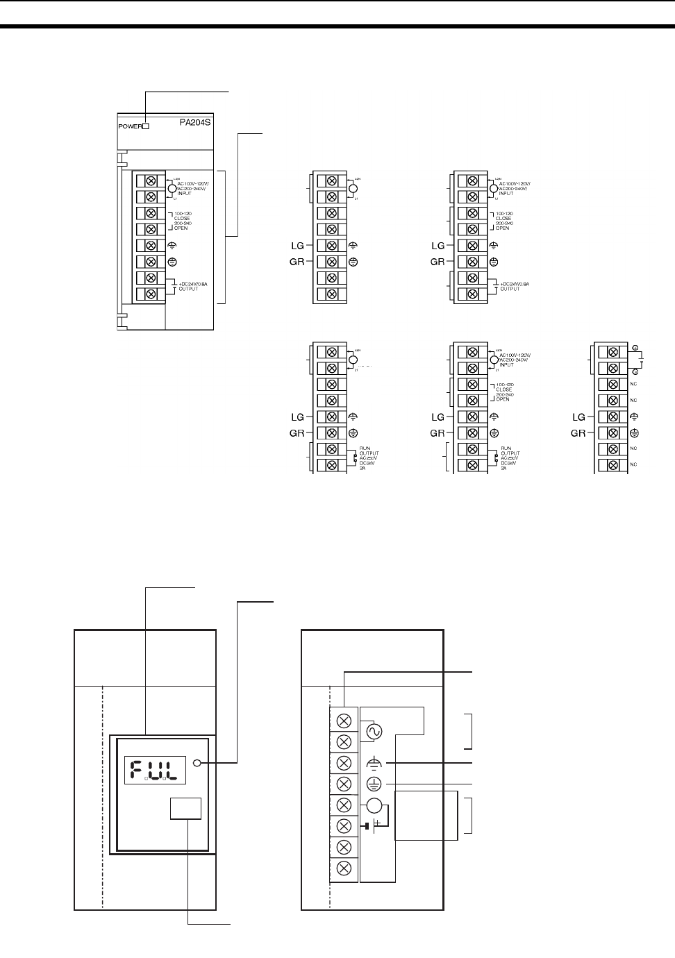
184
Power Supply Units Section 3-4
3-4-2 Components and Switch Settings
Note 100 to 120 V AC: Closed circuit, 200 to 240 V AC: Open circuit
Always open the circuit (remove the metal jumper) before applying a voltage
of 200 to 240 V AC.
POWER indicator
(Lights when 5 V is output
from Power Supply Unit)
External connection terminals
AC input
RUN
output
AC input
AC input
Voltage
selector
24 VDC
power
output
DC input
C200HW-PA204 C200HW-PA204S
C200HW-PA204R C200HW-PA209R C200HW-PD024/025
AC input
Voltage
selector
RESISTIVE
RUN
output
NC
NC
DC24V
AC100-240V
INPUT
NC
NC
NC
NC
AC100-240V
INPUT
(See note.)
(See note.)
C200HW-PA204C
C200HW-PA204C
POW
POW
ER
TEST
TEST
ALARM
OUTPUT
30 VDC, 50 mA
NORMAL: ON
AL ARM : OFF
PA204C
L
−NC
−NC
L1
L2 /N 100 to 240
VAC
IN PUT
PA204C
(Example: C200HW-PA204C)
Replacement notification display
POWER indicator
Lit: 5-V output from Power Supply Unit.
Terminals
external connect
AC input
LG
GR
Alarm output
(replacement notification
output)
TEST switch
The TEST switch can be used to temporarily turn OFF the
alarm output that notifies when replacement is needed.
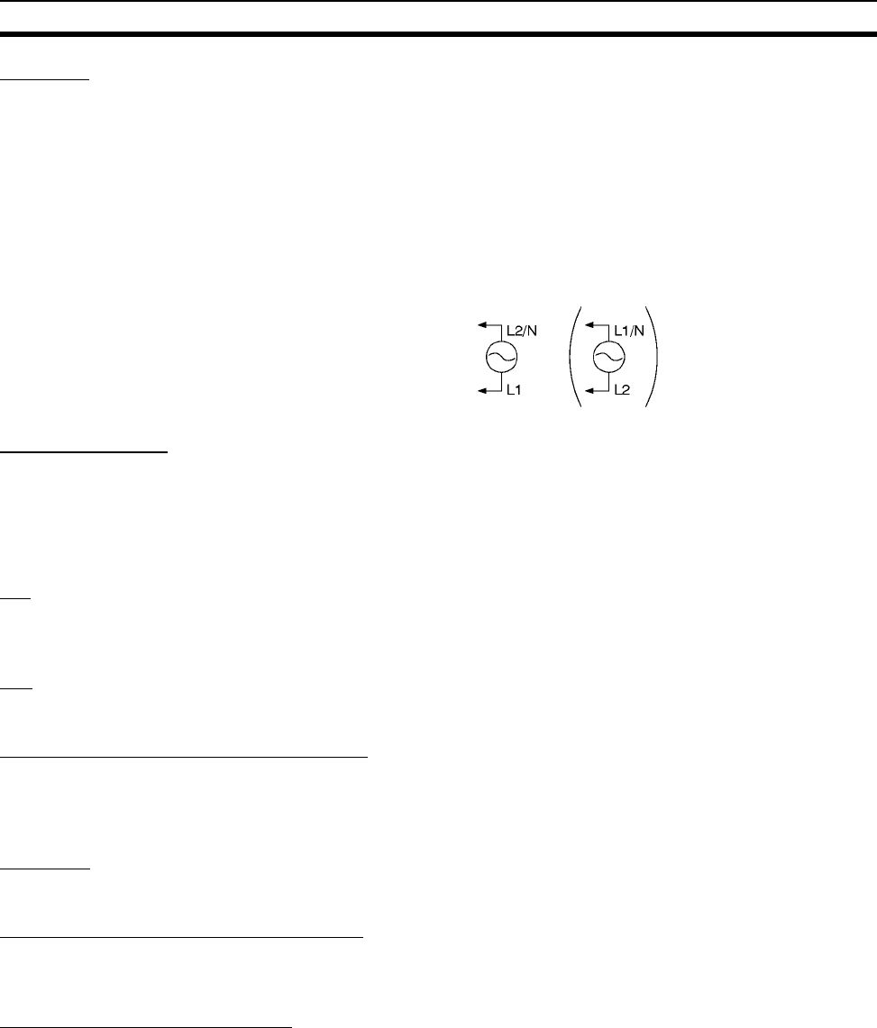
185
Power Supply Units Section 3-4
AC Input
Either a power supply of 100 to 120 V AC or 200 to 240 V AC can be selected.
The C200HW-PA204/PA204R/PA204C supplies 100 to 240 V AC (allowable
voltage fluctuation range: 85 to 264 V AC).
The C200HW-PA204C has a wide-range supply voltage, so voltage selector
terminals are not provided.
Note The L2/N and L1 display on the AC power supply terminal is L1/N and L2 on
some products, however, the function and performance of the terminals are
the same.
Voltage Selector
Before applying a voltage of 100 to 120 V AC, close the circuit using the metal
jumper.
Note Always remove the metal jumper before applying a voltage of 200 to 240 V
AC. Not doing so will damage the Unit.
LG
Ground to a resistance of 100 Ω or less to increase noise resistance and
avoid electric shock.
GR
Ground to a resistance of 100 Ω or less to avoid electric shock.
24-V DC Power Output (PA204 Only)
This terminal outputs a service voltage of 24 V DC. Use this terminal to supply
power to DC Input Units (C200HW-PA204S only). The total current consump-
tion of the 5-V and 24-V outputs must be 30 W max.
DC Input
24-V DC power is supplied from this terminal.
RUN Output (PA204R/PA209R Only)
The internal contact turns ON when the CPU Unit is operating (RUN or MON-
ITOR mode). (The RUN output does not turn ON on Expansion Racks.)
Alarm Output (PA204C Only)
The alarm output is used to notify when Power Supply Unit replacement is
required. The output is normally ON. The output turns OFF when the time
until replacement is 6 months or less.
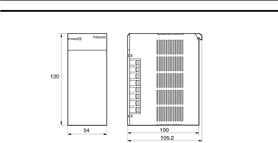
186
Power Supply Units Section 3-4
3-4-3 Dimensions
C200HW-PA204
C200HW-PA204S
C200HW-PA204R
C200HW-PD204
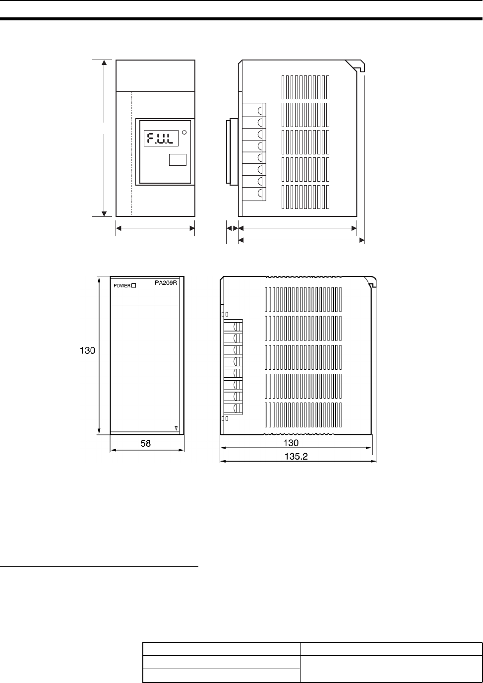
187
Power Supply Units Section 3-4
3-4-4 Selecting a Power Supply Unit
After determining what power supply voltage is required, whether power out-
put terminals and a RUN output are required, and whether replacement notifi-
cation is required, calculate the current and power requirements for each
Rack.
Condition 1: Current Requirements
There are three voltage groups for internal power consumption: 5 V DC,
26 V DC, and 24 V DC.
Current Consumption at 5 V DC (Internal Logic Power Supply)
The following table shows the current that can be supplied to Units (including
the CPU Unit) and Backplanes that use 5-V DC power.
C200HW-PA204C
100
130
54
C200HW-PA204C
C200HW-PA204C
PO
PO
WER
TE
TE
ST
PA204C
105.2
11
C200HW-PA209R
C200HW-PD025
Power Supply Unit Maximum current at 5 V DC
C200HW-PA204/204S/204R/204C 4.6 A
C200HW-PD204
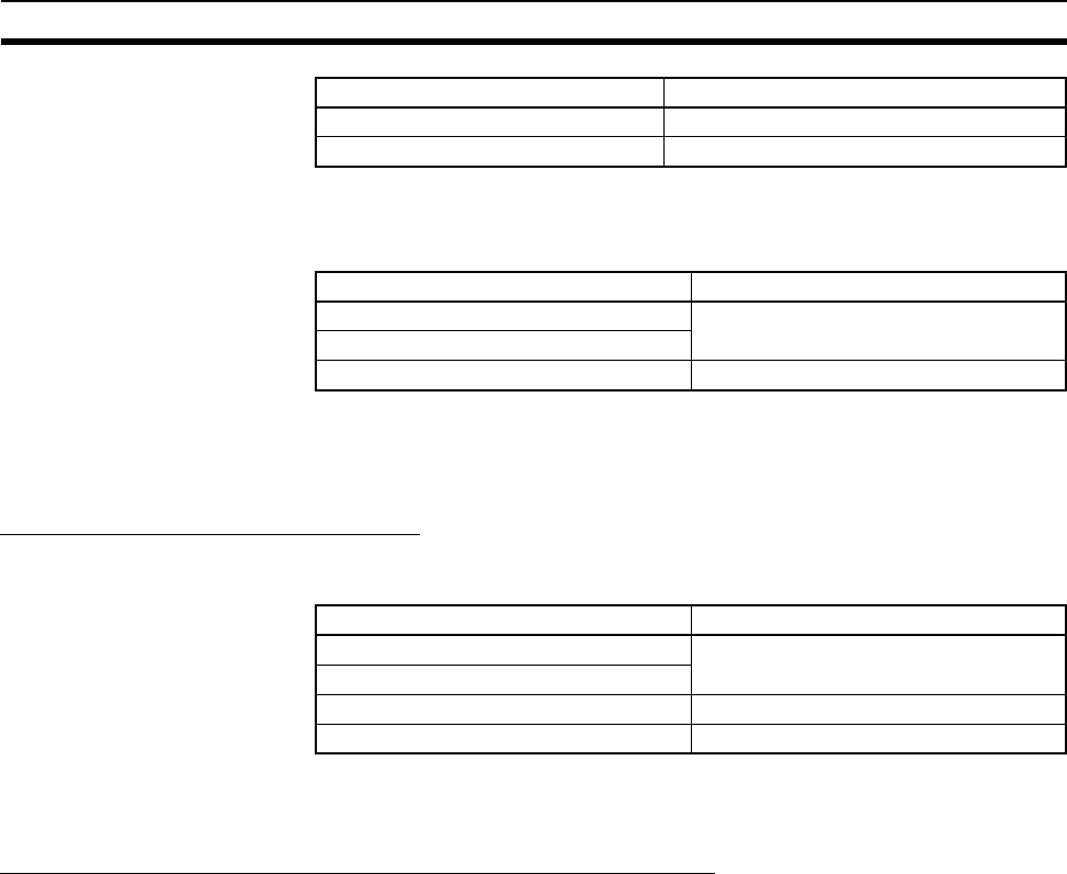
188
Power Supply Units Section 3-4
Current Consumption at 26 V DC (Relay Driving Power Supply)
The following table shows the current that can be supplied to Units that use
26-V DC power.
Current Consumption at 24 V DC (Power Output Terminals)
The C200HW-PA204S Power Supply Unit can supply up to 0.8 A at 24 V DC
through its power output terminals.
Condition 2: Power Requirements
The following table shows the maximum total power that can be supplied at
5 V DC, 26 V DC, and 24 V DC.
Refer to 2-6 Unit Current Consumption for tables showing the current con-
sumed by each particular Unit as well as example calculations.
Precautions when Replacing the C200HW-PA204/PA204R
The following precautions apply when replacing a C200HW-PA204/PA204R.
■Startup Time
The time from when the power is turned ON until the PLC operation starts is
approximately 1 second faster. Make sure that the system will not be
adversely affected by the change in timing.
■Power Failure Detection Voltage
The power failure detection voltage is 85 V max. The PLC will stop operating if
the voltage drops below this voltage level.
Note If the previously used Power Supply Unit was switchable between 100 to 120
V AC and 200 to 240 V AC and 200 to 240 V AC was used, power failures
were detected when the voltage dropped to 170 V or lower and the PLC oper-
ation stopped. With C200HW-PA204 Units manufactured from March 2010
and C200HW-PA204R Units manufactured from May 2010, however, opera-
tion will not stop between 85 V and 170 V. Therefore, make sure that the sys-
tem will not be adversely affected by the change in detection voltage.
C200HW-PA209R 9 A
C200HW-PD025 5.3 A
Power Supply Unit Maximum current at 5 V DC
Power Supply Unit Maximum current at 26 V DC
C200HW-PA204/204S/204R/204C 0.625 A
C200HW-PD204
C200HW-PA209R/PD025 1.3 A
Power Supply Unit Maximum total power output
C200HW-PA204/204S/204R/204C 30 W
C200HW-PD204
C200HW-PA209R 45 W
C200HW-PD025 40 W
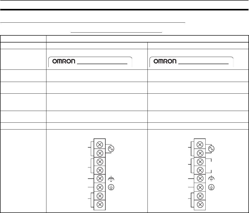
189
Power Supply Units Section 3-4
Unit Differences by Manufacturing Date (Reference Information)
■Differences in C200HW-PA204 Models
Note The time from when the external input (AC power supply) is input until 5 V or
26 V is output.
Model C200HW-PA204
Manufacturing date March 2010 or later Before March 2010
Identification on
nameplate
C200HW-PA204/Wide AC C200HW-PA204
Input
specifications
100 to 240 V AC (wide range) 100 to 120 V AC/200 to 240 V AC
(Switched with short bar.)
Power failure
detection voltage
85 V max. 100 to 120 V AC: 85 V max.
200 to 240 V AC: 170 V max.
Power supply
startup time (See
note.)
200 ms max. 1,500 ms max.
Service power
supply
Not supported. Not supported.
RUN output Not supported. Not supported.
Terminal block
wiring
C200HW-PA204 C200HW-PA204
C200HW-PA204
/
Wide AC C200HW-PA204
GR
LG
NC
L1
L2/N
NC
NC
NC
AC input
Unconnect-
ed terminals
Unconnect-
ed terminals
100 to
240 V AC
INPUT
GR
LG
NC
L1
L2/N
NC
AC input
Unconnect-
ed terminals
Voltage
selector
100 to 120
CLOSE
200 to 240
OPEN
100 to
120 V AC
200 to
240 V AC
INPUT
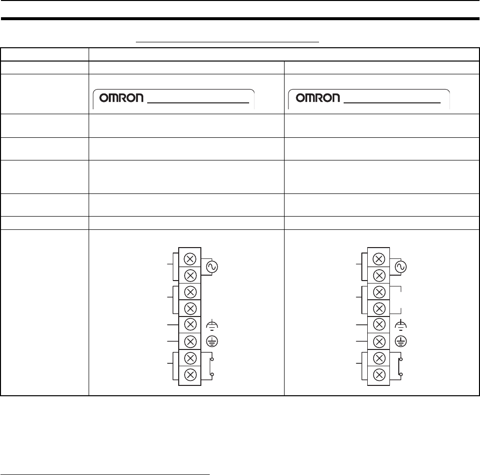
190
Power Supply Units Section 3-4
■Differences in C200HW-PA204R Models
Note The time from when the external input (AC power supply) is input until 5 V or
26 V is output.
3-4-5 Replacement Notification
Principle of Replacement Notification
The Power Supply Unit has a built-in electrolytic capacitor. The electrolytic
capacitor is impregnated with electrolytic solution that starts to penetrate the
sealing rubber from the time of manufacture. As time elapses, the internal
electrolytic solution continues to evaporate, resulting in decreased electro-
static capacity and deterioration in other characteristics. Over time, the char-
acteristic deterioration of the electrolytic capacitor prevents the Power Supply
Unit from being utilized to its full capacity. In particular, the speed at which the
electrolytic capacitor deteriorates fluctuates greatly with the ambient tempera-
ture (generally, a temperature rise of 10°C will double the rate of a reaction, as
stated by Arrhenius' law).
The C200HW-PA204C Power Supply Unit with Replacement Notification mon-
itors the internal temperature of the Power Supply Unit while the power is
turned ON, and calculates the level of deterioration of the electrolytic capaci-
tor from the operating time and internal temperature. The replacement notifi-
cation function displays the approximate time until the Power Supply Unit will
stop functioning at its full capacity due to the characteristic deterioration of the
electrolytic capacitor, based on the calculated level of deterioration. When 6
months are remaining until replacement is required, the alarm output will turn
OFF.
Model C200HW-PA204R
Manufacturing date May 2010 or later Before May 2010
Identification on
nameplate
C200HW-PA204R/Wide AC C200HW-PA204R
Input
specifications
100 to 240 V AC (wide range) 100 to 120 V AC/200 to 240 V AC
(Switched with short bar.)
Power failure
detection voltage
85 V max. 100 to 120 V AC: 85 V max.
200 to 240 V AC: 170 V max.
Power supply
startup time (See
note.)
200 ms max. 1,500 ms max.
Service power
supply
Not supported. Not supported.
RUN output Supported Supported
Terminal block
wiring
C200HW-PA204R C200HW-PA204R
C200HW-PA204R
/
Wide AC C200HW-PA204R
GR
LG
L1
L2/N
RUN
OUTPUT
250 V AC
24 V DC
2A
NC
NC
AC input
Unconnect-
ed terminals
RUN output
100 to
240 V AC
INPUT
GR
LG
L1
L2/N
RUN
OUTPUT
250 V AC
24 V DC
2A
AC input
RUN
output
Voltage
selector
100 to 120
CLOSE
200 to 240
OPEN
100 to
120 V AC
200 to
240 V AC
INPUT
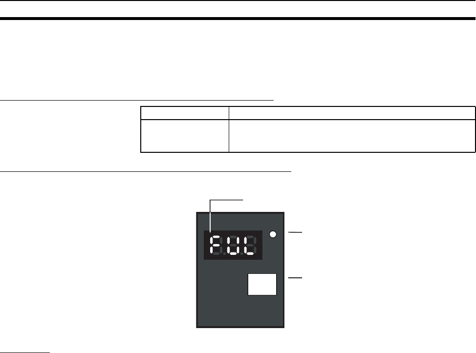
191
Power Supply Units Section 3-4
Note The replacement notification function provides an indication of when the dete-
rioration of the electrolytic capacitor will prevent the power supply functioning
at its full capacity. It does not provide information on failures occurring due to
other causes.
Power Supply Unit with Replacement Notification
Power Supply Unit Replacement Notification Module
C200HW-PA204C
Function
Replacement Notification Function Displays
The replacement notification for the Power Supply Unit is shown using three
7-segment LED displays.
• At time of purchase “FUL” is displayed. The display changes to “HLF” as
the electrolytic capacitor deteriorates (“HLF” may not be displayed,
depending on the operating environment).
• When the time until replacement is required drops below 2 years, the dis-
play will change corresponding to the operating time from “1.5” to “1.0” to
“0.5” to “0.0”/”A02.” When the remaining service life reaches 6 months or
less, the display will alternate between “0.0” and “A02” in 2-second inter-
vals.
Model Specifications
C200HW-PA204C Output capacity: 4.6 A at 5 V DC, 0.625 A at 26 V DC, total of
30 W
With replacement notification
C200HW-PA204C
C200HW-PA204C
PO
PO
WER
TE
TE
ST
ST
Replacement notification display (7-segment, red)
POWER indicator (green)
Alarm output
(replacement notification output)
Test switch
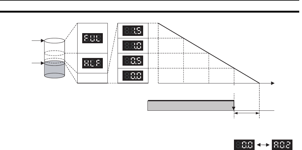
192
Power Supply Units Section 3-4
Note 1. The time remaining until replacement does not include periods when the
power is turned OFF.
2. Until approximately one month of operating time has accumulated, the dis-
play will always be “FUL” and the alarm output will remain ON (conducting)
due to the estimated deterioration speed.
3. The time remaining until replacement will vary the operating and storage
conditions, so periodically check the display.
4. Fluctuation in the time remaining until replacement may result in the alarm
output repeatedly turning ON and OFF.
5. The precision of the replacement notification function will be adversely af-
fected by applications in which the power is frequently turned ON and OFF.
6. Due to the service life of the electronic components, replace the Power
Supply Unit approximately 15 years after purchase, even if the replace-
ment notification display or output has not indicated that replacement is re-
quired.
Alarm Output (Replacement Notification Output)
The output remains ON until the remaining service life drops below 6 months
and then turns OFF.
Note 1. The alarm output will also turn OFF under the following conditions.
• The AC input to the Power Supply Unit is turned OFF.
• An error is detected by the self-diagnostic function.
• The TEST switch is pressed for at least 3 seconds.
2. Example of Using the Alarm Output:
Monitoring Power Supply Replacement Notification in the System (6
Months or Less Until Replacement Is Required)
Capacity at
time of
manufacture
Replacement
required
Electrolytic
capacitor level Replacement notification display
(7-Segment)
Alarm output
(replacement notification output) Output ON
2.0 yr 1.5 yr 1.0 yr 0.5 yr 0 yr
Output
OFF
Remaining
life plan
The output turns OFF when the remaining
life span reaches 6 months, and the
following display is repeatedly alternated.
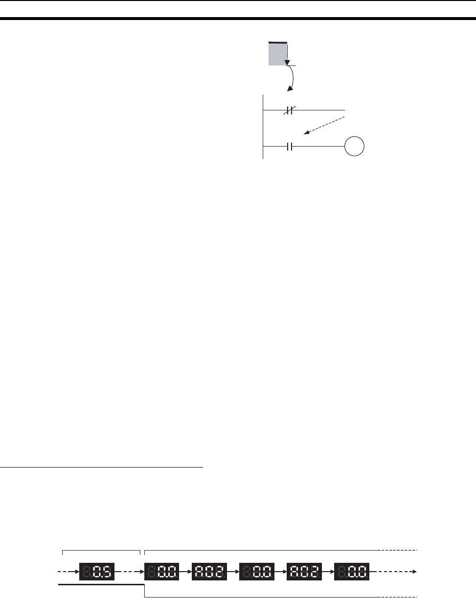
193
Power Supply Units Section 3-4
The Flag is programmed to allow for the delay in the alarm output at system
startup. The Flag does not turn ON when the alarm output is ON (normal
operation). When the alarm output turns OFF (replacement required), the
Flag turns ON, and the replacement notification can be monitored from the
system.
Maintenance Function Using the TEST Switch
• Press the TEST switch for at least 3 seconds to display “A02” and force
the alarm output OFF. Release the switch to return to normal operating
status.
The TEST switch is used initially or periodically to check the connection
status between the alarm output and external devices.
• Press the TEST switch for less than 3 seconds to display the unit version
information for the Power Supply Unit.
Note 1. Replace the Power Supply Unit within 6 months when the display on the
front panel of the Power Supply Unit alternates between 0.0 and A02 or the
alarm output automatically turns OFF.
2. Maintain an ambient storage temperature of −20 to 30°C and humidity of
25% to 70% when storing the product (with the power turned OFF) for
longer than 3 months to keep the replacement notification function in opti-
mum working condition. The replacement time is calculated from when the
power is turned ON only. The precision of the replacement period will de-
cline if the electrolytic capacitor deteriorates during storage.
Display and Alarm Output Operation
Normal Display: Replacement Notification Display
When 6 months or less are remaining until replacement is required, the dis-
play will alternate between “0.0” and “A02” (in 2 second intervals), and the
alarm output will turn OFF.
Operation at Powerup
The following initial display is shown when the power is turned ON, after which
the replacement notification is displayed. The alarm output turns ON approxi-
mately 0.2 seconds after the power is turned ON.
ON
OFF
T000
[ TIM 000 5 s ]
Alarm output
Turns OFF when 6 months remain
s
Alarm output
Internal Flag
Remaining service life:
1 year to 6 months
Remaining service life:
6 months max.
2 s 2 s 2 s 2 s 2 s
Alarm output ON OFF
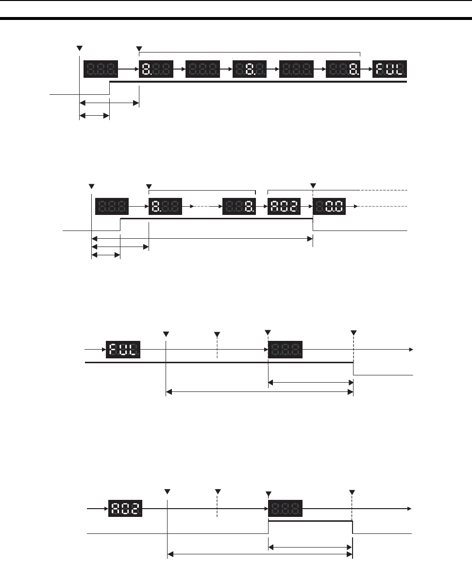
194
Power Supply Units Section 3-4
When replacement is already required, the alarm display will follow the initial
display. The alarm output will turn ON approximately 0.2 seconds after the
power is turned ON, and then turn OFF after approximately 5 seconds.
Operation at Power OFF
When the power is turned OFF, the display will turn OFF after the PLC opera-
tion stops. The alarm output will turn OFF after the display turns OFF.
If replacement is already required, the display will turn OFF after the PLC
operation stops. When the display turns OFF, the alarm output will turn ON
momentarily and then turn OFF again.
Note The values shown are reference values (calculated for a no-load status on the
Power Supply Unit's output).
Operation when TEST Switch Is Pressed
The following operation will be performed when the TEST switch on the
replacement notification function module is pressed. When the switch is
pressed for less than 3 seconds, the unit version will be displayed 3 times at
0.5-second intervals. When the switch is pressed for at least 3 seconds, the
alarm output will momentarily turn OFF, and the alarm display A02 will be
shown. The operation will return to the normal display and output when the
Power ON
Display
Alarm
output OFF
Display start
1 s max.
0.2 s max.
0.3 s
Initial display (approx. 1.1 s)
0.1 s 0.1 s0.3 s 0.3 s
ON
Replacement
required display
Power ON
Display
Alarm
output OFF ON
1 s max.
0.2 s max.
Initial display (approx. 1.1 s)
Display start
Alarm display Alarm output OFF
OFF
5 s max.
Display
Alarm
output
Replacement
notification display
Power
interruption
PLC operation
stopped
ON
Notification display
OFF
Approx. 70 ms
(See note.)
OFF
Alarm output
OFF
100 VAC: Approx. 2 s
200 VAC: Approx. 7 s
(See note.)
Display
Alarm
output
Alarm display
Power
interruption
PLC operation
stopped
OFF
Notification display OFF
+ alarm output ON
ON
OFF
Alarm output
OFF
Approx. 70 ms
(See note.)
100 VAC: Approx. 2 s
200 VAC: Approx. 7 s
(See note.)
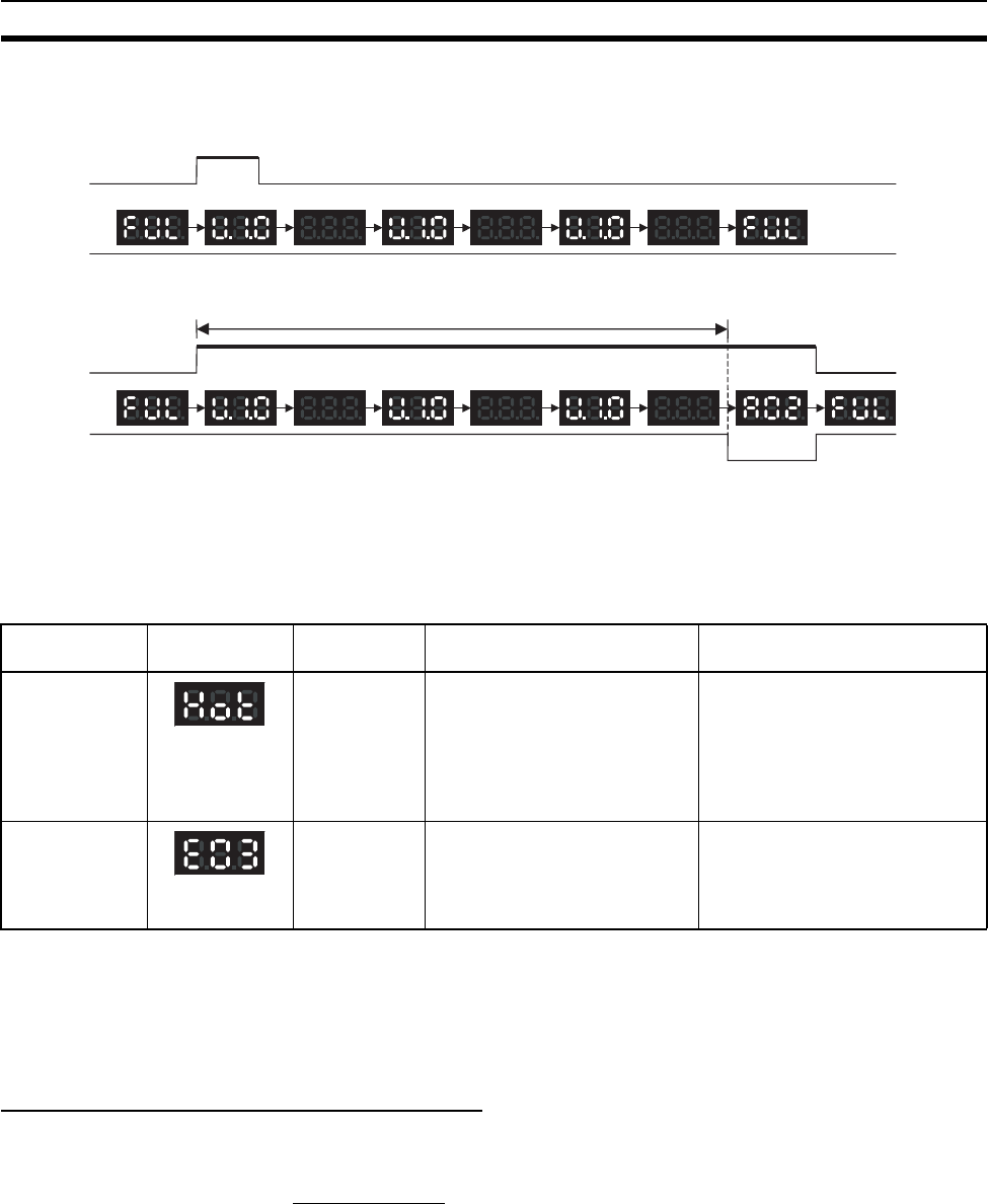
195
Power Supply Units Section 3-4
switch is released. Use the TEST switch to check the connection between the
replacement notification output and devices.
1. Operation when TEST switch is pressed for less than 3 seconds.
2. Operation when TEST switch is pressed for 3 seconds or longer.
Note In standard operating conditions, the Power Supply Unit replacement notifica-
tion function will be activated after between several years to beyond a decade.
For long-term use, be sure to periodically check TEST switch operations, and
make sure that the alarm output is operating normally.
Self-diagnostic Function
Note If the error continues for 3 hours or longer, the replacement notification func-
tion will be disabled. Even if the cause of the overheating is removed, the dis-
play will continue as “Hot,” and the notification output will remain OFF. In this
state, the internal parts may deteriorate even if the PLC operation is normal,
so replace the Power Supply Unit.
Precautions when Replacing Earlier Units
The following precautions apply when replacing a C200HW-PA204/PA204S/
PA204R with a C200HW-PA204C.
Terminal Wiring
• Be sure to wire the ground terminals correctly. Incorrect ground terminal
wiring will adversely affect the Unit's resistance to noise. (For details on
terminal arrangements for each Power Supply Unit, refer to 3-4-2 Compo-
nents and Switch Settings.)
• The C200HW-PA204C is not provided with a service power supply and
RUN output (RUN).
TEST switch ON
0.5 s 0.5 s 0.5 s 0.5 s 0.5 s 0.5 s
Error name Display Alarm output
status
Error details (cause) Recovery method
Unit overheated
error
OFF Internal overheating has
occurred in the Power Supply
Unit as a result of usage under
conditions that exceed the spec-
ified values, insufficient ventila-
tion, or incorrect installation.
(See note.)
Remove the cause of the over-
heating error.
Unit error OFF System error from external
noise or hardware malfunction.
Turn ON the input's power supply
again.If the Unit does not recover,
the error may be caused by a Unit
malfunction. Consult with your
OMRON representative.
TEST switch ON
ONAlarm output
0.5 s 0.5 s 0.5 s 0.5 s 0.5 s 0.5 s
3 s
OFF ON
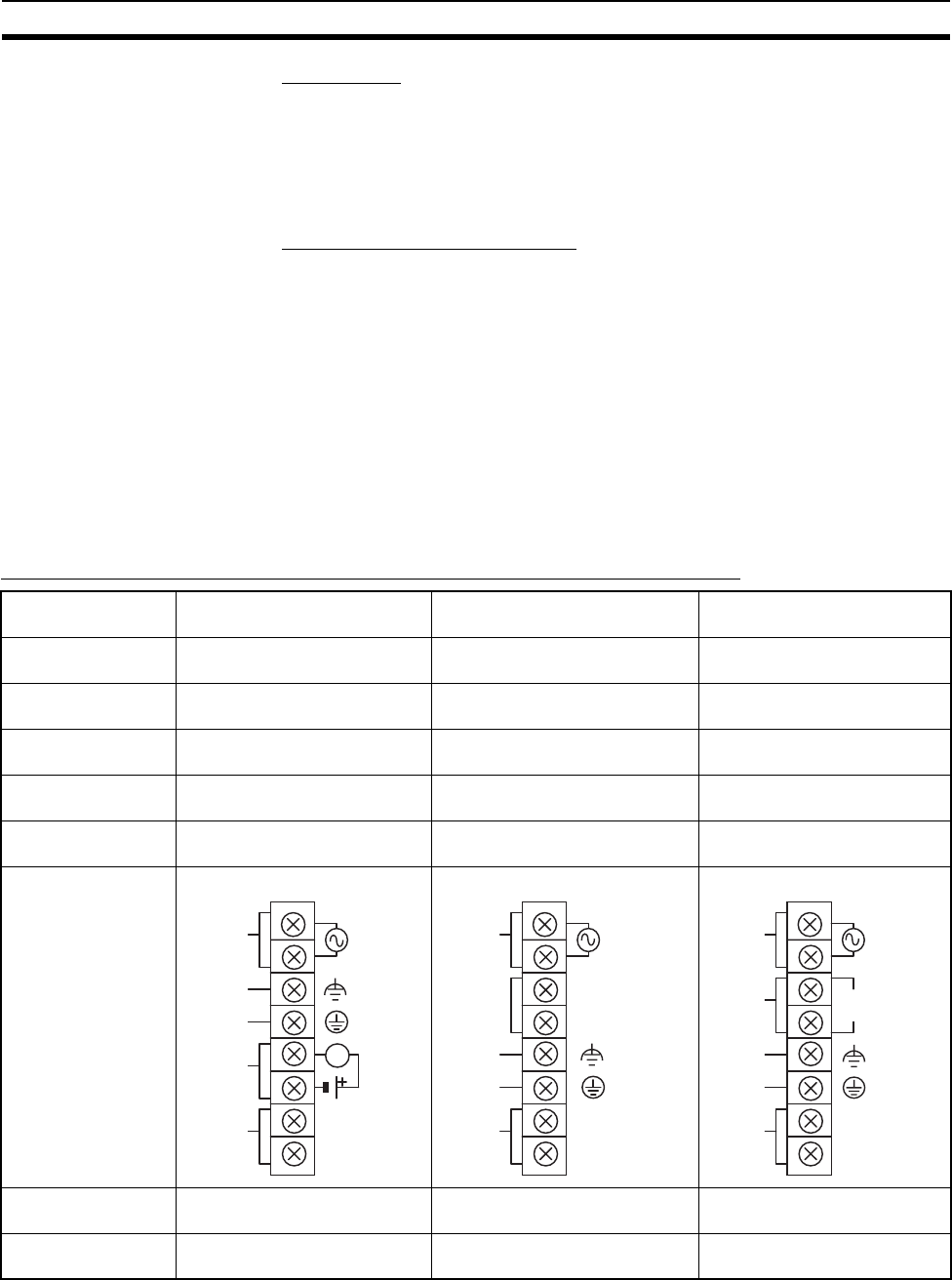
196
Power Supply Units Section 3-4
Startup Time
The startup time of the C200HW-PA204 and C200HW-PA204R depends on
the manufacturing date. Refer to the tables of differences for details.
The time from when the power is turned ON until the PLC operation starts is
approximately 1 second faster. Make sure that the system will not be
adversely affected by the change in timing.
Power Failure Detection Voltage
The power failure detection voltage of the C200HW-PA204 and C200HW-
PA204R depends on the manufacturing date. Refer to the tables of differences
for details.
The power failure detection voltage is 85 V. The PLC will stop operating if the
voltage drops below this voltage level.
Note If the previously used Power Supply Unit was switchable between 100 to 120
V AC and 200 to 240 V AC and 200 to 240 V AC was used, power failures
were detected when the voltage dropped to 170 V or lower and the PLC oper-
ation stopped. With C200HW-PA204C, however, operation will not stop
between 85 V and 170 V. Therefore, make sure that the system will not be
adversely affected by the change in detection voltage.
Comparison between the C200HW-PA204C and the C200HW-PA204
Note The time from when the external input (AC power supply) is input until 5 V or
26 V is output.
Item C200HW-PA204C C200HW-PA204 (Manufactured
March 2010 or later)
C200HW-PA204 (Manufac-
tured before March 2010)
Identification on
nameplate
C200HW-PA204C C200HW-PA204/Wide AC C200HW-PA204
Input specifications 100 to 240 V AC (wide range) 100 to 240 V AC (wide range) 100 to 120 V AC/200 to 240 V
AC (Switched with short bar.)
Power failure detec-
tion voltage
85 V max. 85 V max. 100 to 120 V AC: 85 V max.
200 to 240 V AC: 170 V max.
Power supply startup
time (See note.)
200 ms max. 200 ms max. 1,500 ms max.
RUN output Not supported Not supported (Supported by the
PA204R)
Not supported (Supported by
the PA204R)
Terminal block wiring C200HW-PA204C C200HW-PA204 C200HW-PA204
POWER indicator On replacement notification
module
On hood of Power Supply Unit On hood of Power Supply Unit
Replacement notifi-
cation
Supported (7-segment display
+ transistor outputs)
Not supported Not supported
AC
input
Alarm output
(replacement
notification
output)
Unconnected
terminals
ALARM
OUTPUT
30 V DC,
50 mA
NORMAL: ON
ALARM: OFF
100 to
240 V AC
INPUT
GR
LG
NC
L1
L2/N
L
NC
AC
input
Unconnected
terminals
100 to
240 V AC
INPUT
GR
LG
NC
L1
L2/N
NC
NC
NC
Unconnected
terminals
100 to 120
CLOSE
200 to 240
OPEN
AC input
Voltage
selector
Unconnected
terminals
100 to 120 V AC
200 to 240 V AC
INPUT
GR
LG
NC
L1
L2/N
NC
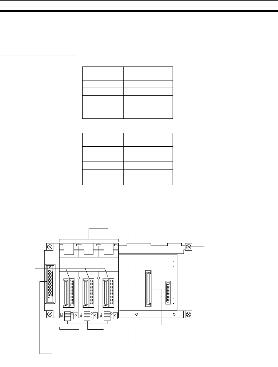
197
Backplanes Section 3-5
3-5 Backplanes
3-5-1 CPU Backplanes
CPU Backplane Models
Standard CS-series CPU Backplanes
CS-series-only CPU Backplanes
Note C200H Units (C200H Basic I/O Units, C200H Group-2 High-density I/O Units,
and C200H Special I/O Units) cannot be used with CS-series-only CPU Back-
planes.
Components and Switch Settings
Note Always cover the connectors that are not being used with Connector Covers
(sold separately) as a measure against dust.
When you attach the CV500-COV01 to a CS-series Backplane (for CS-series
Units only), it will go on easier if you insert the CV500-COV01 on the side with
Number of
slots
Model
2 slots CS1W-BC023
3 slots CS1W-BC033
5 slots CS1W-BC053
8 slots CS1W-BC083
10 slots CS1W-BC103
Number of
slots
Model
2 slots CS1W-BC022
3 slots CS1W-BC032
5 slots CS1W-BC052
8 slots CS1W-BC082
10 slots CS1W-BC102
Unit connectors
Unit mounting slots
(for mounting each Unit)
Backplane mounting screws
(4 M4 screws)
Power Supply Unit connector
CPU Unit connector
Unit lock lever
(Fix each Unit securely. Press down on
the lock lever to remove the Unit)
I/O cable connector
(for connecting a CS-series Expansion Rack
or a C200H Ex
p
ansion I/O Rack
)
See note.
Note Mount an I/O Control Unit (CS1W-IC102)
here to connect a CS-series Long-distance Ex-
pansion Rack next.
(The Backplane is structured so that
it can be insulated from the control
panel when installed.)
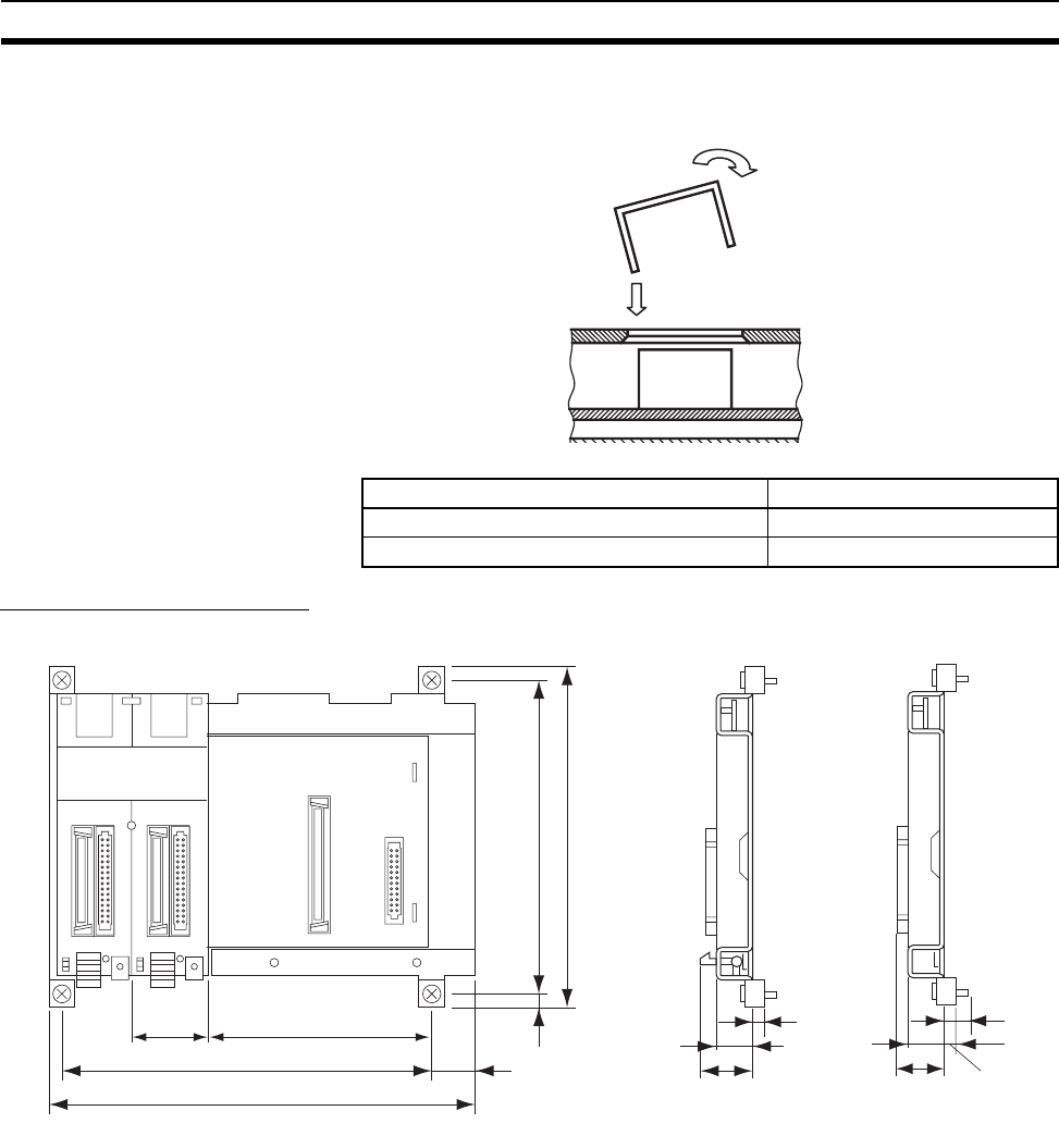
198
Backplanes Section 3-5
the larger gap next to the connector first and then rotate the CV500-COV01
and insert it on the side with the narrower gap.
Dimensions and Weights
CS1W-BC023/022 (2 Slots)
Name Model
C200H Unit Connector Cover C500-COV01
CS-series Special I/O Unit Connector Cover CV500-COV01
B
A
Wei
g
ht: 600
g
max.
5.2
17
23.7
198.5
172.3 20.2
145
157
6
35 105.25
5.9
17
21.9
CS1W-BC023 CS1W-BC022
5.2
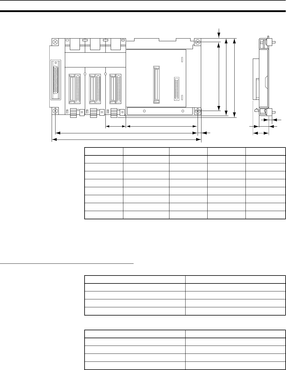
199
Backplanes Section 3-5
CS1W-BC@@@ (3, 5, 8, or 10 Slots)
3-5-2 CS-series Expansion Backplanes
CS-series Expansion Backplanes are used for both CS-series Expansion
Racks and CS-series Long-distance Expansion Racks.
CS-series Expansion Backplane Models
Standard CS-series Expansion Backplane
CS-series-only Expansion Backplane
Note C200H Units (C200H Basic I/O Units, C200H Group-2 High-density I/O Units,
and C200H Special I/O Units) cannot be used with CS-series-only Expansion
Backplanes.
Model Number of slots L (mm) W (mm) Weight (max.)
CS1W-BC033 3 246 260 750 g
CS1W-BC053 5 316 330 900 g
CS1W-BC083 8 421 435 1,200 g
CS1W-BC103 10 491 505 1,400 g
CS1W-BC032 3 246 260 750 g
CS1W-BC052 5 316 330 900 g
CS1W-BC082 8 421 435 1,200 g
CS1W-BC102 10 491 505 1,400 g
W
L6
135 (including protruding parts)
118
132
5.2
17
27
35 124
6
Number of slots Model
3 slots CS1W-BI033
5 slots CS1W-BI053
8 slots CS1W-BI083
10 slots CS1W-BI103
Number of slots Model
3 slots CS1W-BI032
5 slots CS1W-BI052
8 slots CS1W-BI082
10 slots CS1W-BI102
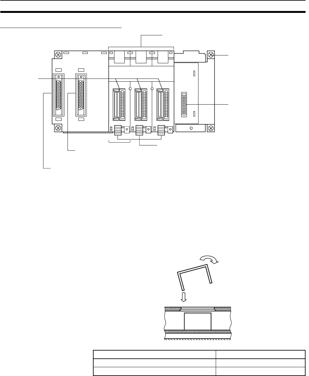
200
Backplanes Section 3-5
Components and Switch Settings
Note Always cover the connectors that are not being used with Connector Covers
(sold separately) as a measure against dust.
When you attach the CV500-COV01 to a CS-series Backplane (for CS-series
Units only), it will go on easier if you insert the CV500-COV01 on the side with
the larger gap next to the connector first and then rotate the CV500-COV01
and insert it on the side with the narrower gap.
Unit connectors
Power Supply Unit connector
I/O cable connector
(for connecting the following Rack)
See note.
Note Mount an I/O Control Unit (CS1W-IC102) here to start con-
necting CS-series Long-distance Expansion Racks next. Mount an
I/O Interface Unit (CS1W -II102) if this Rack is a CS-series Long-dis-
tance Expansion Rack (i.e., the previous Rack is connected
via an I/O Control Unit or an I/O Interface Unit
)
.
Unit mounting slots
(for mounting each Unit)
(The Backplane is structured
so that it can be insulated
from the control panel when
installed.)
I/O cable connector
(for connecting the previous Rack)
Unit lock lever
(Fix each Unit securely. Press down
on the lock lever to remove the Unit)
Backplane mounting screws
(4 M4 screws)
Name Model
C200H Unit Connector Cover C500-COV01
CS-series CPU Bus Unit Connector Cover CV500-COV01
B
A
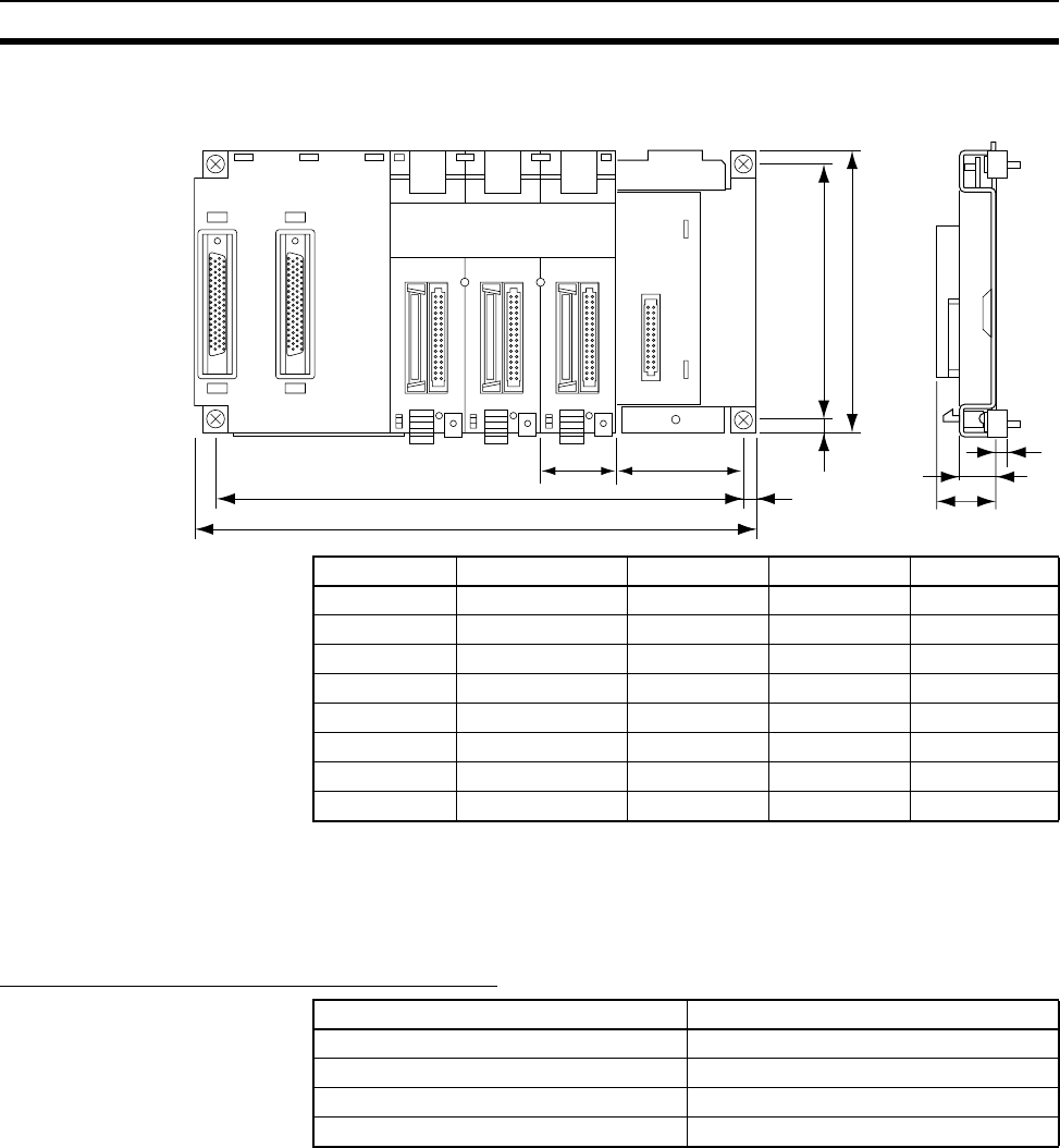
201
Backplanes Section 3-5
Dimensions
3-5-3 C200H Expansion I/O Backplanes
C200H Expansion I/O Racks cannot be connected together with CS-series
Long-distance Expansion Racks.
C200H Expansion I/O Backplane Models
Model Number of slots L (mm) W (mm) Weight (max.)
CS1W-BI033 3 246 260 750 g
CS1W-BI053 5 316 330 900 g
CS1W-BI083 8 421 435 1,200 g
CS1W-BI103 10 491 505 1,400 g
CS1W-BI032 3 246 260 750 g
CS1W-BI052 5 316 330 900 g
CS1W-BI082 8 421 435 1,200 g
CS1W-BI102 10 491 505 1,400 g
W
L6
6118
130
5.2
17
27
35 59.75
CS1W-BI@@@
Number of slots Model
3 slots C200HW-BI031
5 slots C200HW-BI051
8 slots C200HW-BI081-V1
10 slots C200HW-BI101-V1
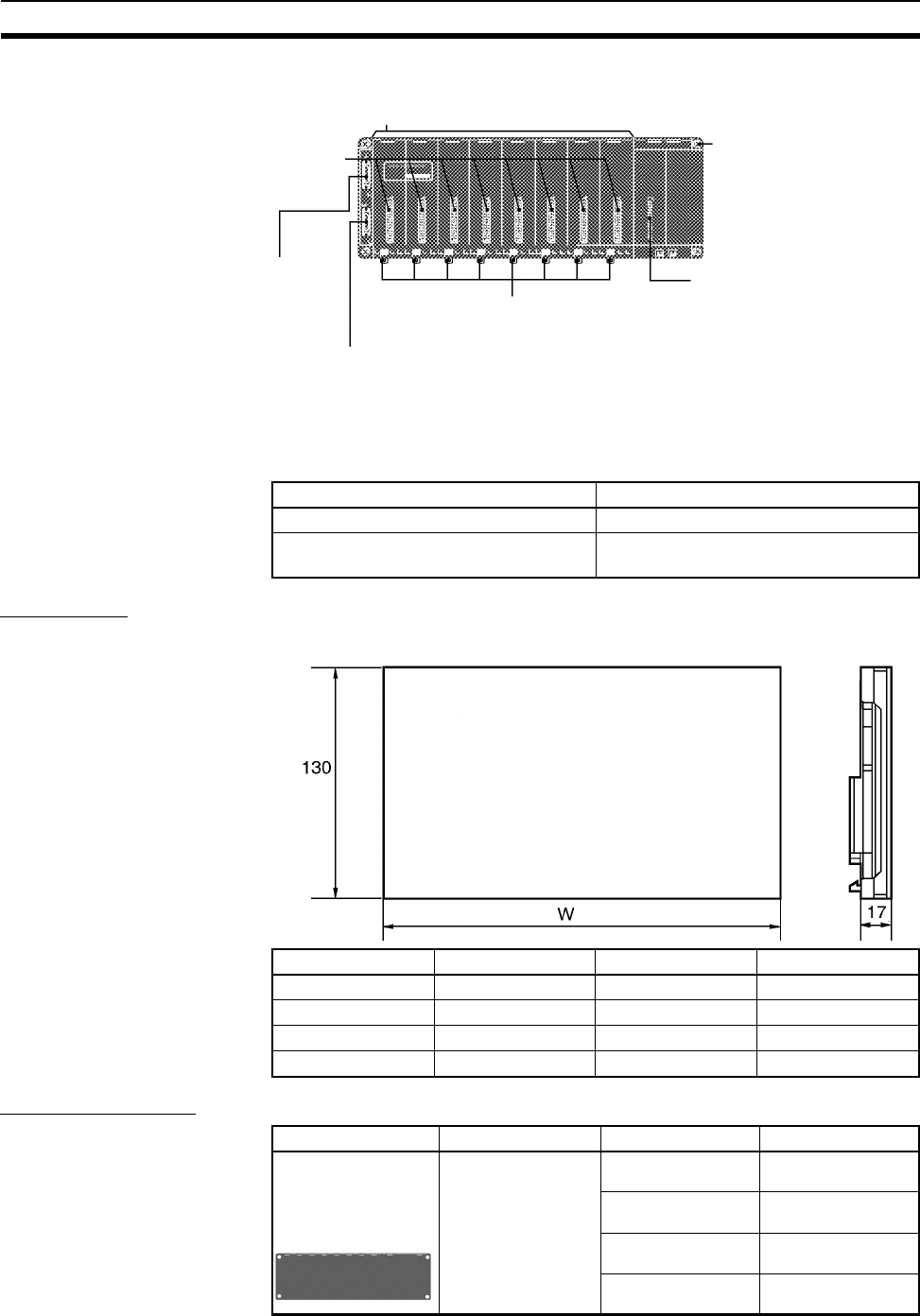
202
Backplanes Section 3-5
Components and Switch Settings
Note Always cover the connectors that are not being used with Connector Covers
(sold separately) as a measure against dust.
Dimensions
Optional Products
Name Model
C200H Unit Connector Cover C500-COV01
CS-series CPU Bus Unit Connector
Cover
CV500-COV01
Unit connectors
Unit mounting slots
(for mounting each Unit)
Backplane mounting screws
(4 M4 screws)
Power Supply Unit connector
Unit lock lever
(Fix each Unit securely. Press down
on the lock lever to remove the Unit)
I/O cable connector
(for connecting the following Rack:
C200H Expansion I/O Rack)
I/O cable connector
(for connecting the previous Rack:
CPU Rack, CS-series Expansion Rack,
or C200H Expansion I/O rack)
Model Number of slots W (mm) Weight (max.)
C200HW-BI031 3 189 500 g
C200HW-BI051 5 259 650 g
C200HW-BI081-V1 8 364 950 g
C200HW-BI101-V1 10 434 1,100 g
C200HW-BI@@@
Product Specifications Number of slots Model
Used to electrically
insulate the C200H
Expansion I/O Rack
from the mounting
surface in the con-
trol panel to
improve noise
resistance.
3 slots C200HW-ATT32
5 slots C200HW-ATT52
8 slots C200HW-ATT82
10 slots C200HW-ATTA2
Backplane
Insulation Plate
(for C200H
Expansion I/O
Backplane)
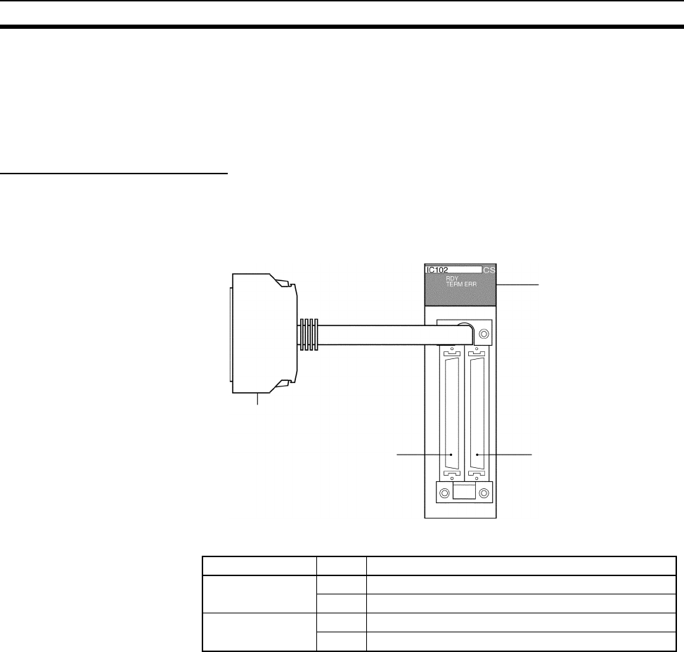
203
Backplanes Section 3-5
3-5-4 I/O Control Units, I/O Interface Units, and Terminators
I/O Control Units and I/O Interface Units are used to create CS-series Long-
distance Expansion Racks. Terminators are connected to the last CS-series
Long-distance Expansion Rack in each series. (Up to two series of CS-series
Long-distance Expansion Racks can be connected.)
CS1W-IC102 I/O Control Unit
An I/O Control Unit is connected to the leftmost slot on the CPU Rack or the
last CS-series Expansion Rack to start connecting CS-series Long-distance
Expansion Racks.
Part Names and Functions
Indicators
Indicators
Connector to Backplane
Connector to I/O Interface
Unit of series A
Connector to I/O Interface
Unit of series B
OUT A OUT B
Indicator Status Meaning
RDY (green) Lit Operating normally.
Not lit Bus error.
TERM ERR (red) Lit Terminator missing.
Not lit Terminator connected.
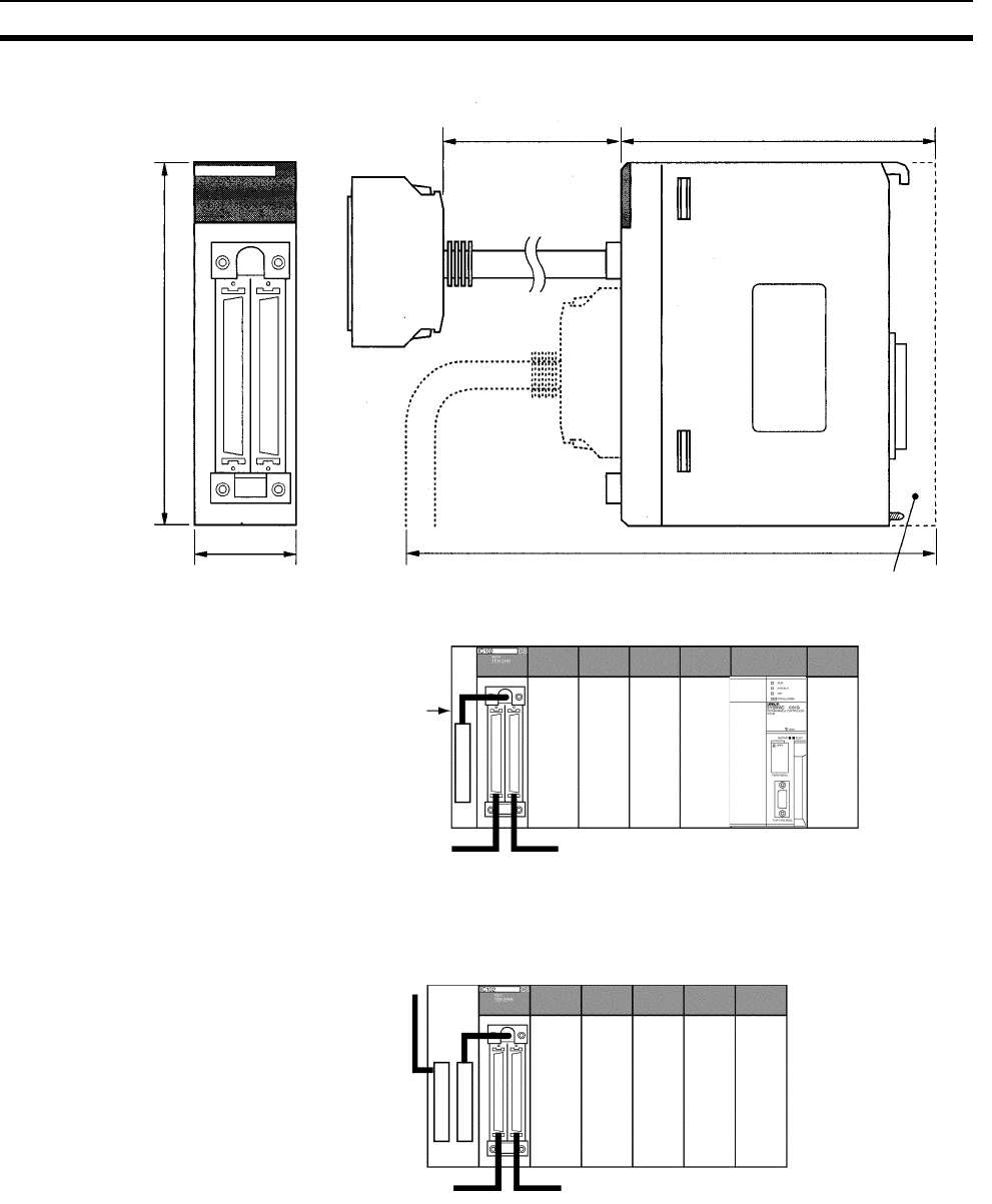
204
Backplanes Section 3-5
Dimensions and Weight
Connection Method on CPU Rack
Note Connect a Terminator (CV500-TER01) to the unused connector when con-
necting only series A or series B.
Connection Method on
CS-series Expansion Rack
Connect the I/O Control Unit to the output I/O cable connector (right side).
Note Connect a Terminator (CV500-TER01) to the unused connector when con-
necting only series A or series B.
Backplane
Weight: 300 g max. (including cable to Backplane)
130
34.5
190 123
OUT A OUT B
236.5
IC102 CS
RDY
TERM ERR
OUT A OUT B
Connect to I/O
cable connector.
Series A Series B
CPU Rac
k
Series A Series B
CS-series Expansion Rac
k
To CPU Rack
or previous CS
series Expan-
sion Rack
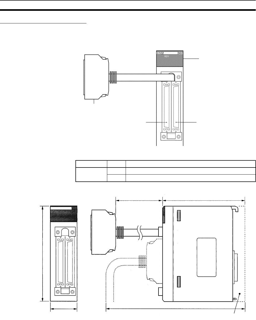
205
Backplanes Section 3-5
CS1W-II102 I/O Interface Unit
Mount an I/O Interface Unit to the leftmost slot on each CS-series Long-dis-
tance Expansion Rack.
Part Names and Functions
Indicator
Dimensions and Weight
Connector to
Backplane
Indicator
IN expansion connector
(to previous Rack) OUT expansion connector
(to following Rack)
IN OUT
Indicator Status Meaning
RDY (green) Lit Operating normally.
Not lit Bus error (bus reset) or system error.
BackplaneWei
g
ht: 300
g
max. (includin
g
connector to Backplane)
130
190 123
34.5
IN OUT
236.5
II102 CS
RDY
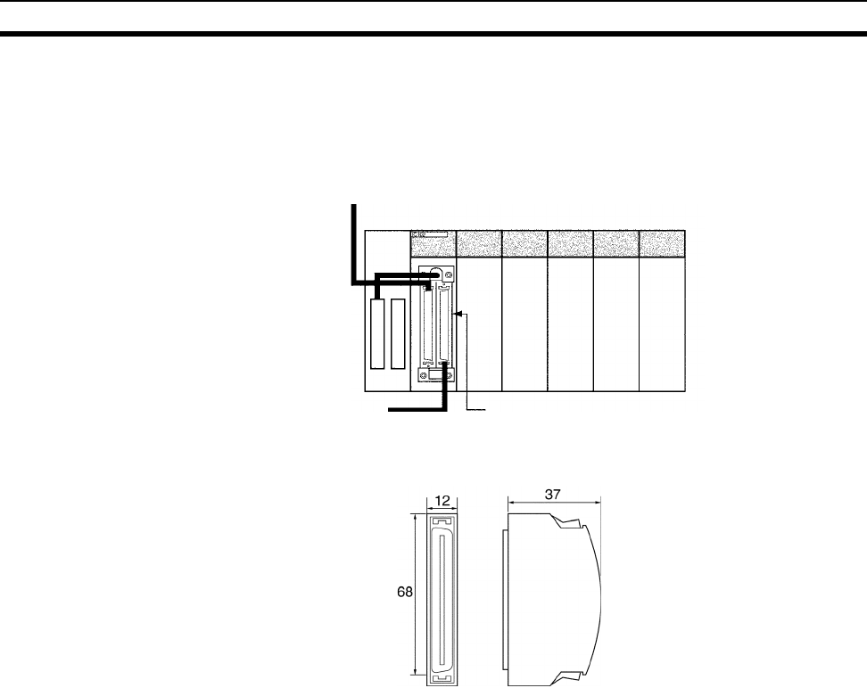
206
Backplanes Section 3-5
Connection Method Connect the I/O Interface Unit to the input I/O cable connector on the Back-
plane (left side). Always connect a Terminator (CV500-TER01) to the connec-
tor for the next Rack when it is not used (i.e., on the last CS-series Long-
distance Expansion Rack in the series).
CV500-TER01 Terminator Two Terminators are provided with an I/O Control Unit
To the previous Rack
(I/O Control Unit or I/O
Interface Unit)
To the next Rack
(I/O Interface Unit)
CS-series Long-distance
Expansion Rack
Connect a Terminator when not used.
Weight: 50 g max.

207
Basic I/O Units Section 3-6
3-6 Basic I/O Units
3-6-1 C200H and CS-series Basic I/O Units with Terminal Blocks
Name Specifications Model External
view/dimensions
reference No.
Basic Input
Units (with
terminal
blocks)
AC Input Units 100 to 120 V AC, 100 to 120 V DC, 16 inputs CS1W-IA111 5
100 to 120 V AC, 8 inputs C200H-IA121 1
100 to 120 V AC, 16 inputs C200H-IA122 3
C200H-IA122V 3
200 to 240 V AC, 8 inputs C200H-IA221 1
200 to 240 V AC, 16 inputs C200H-IA222 3
C200H-IA222V 3
200 to 240 V AC, 16 inputs CS1W-IA211 5
AC/DC Input Units 12 to 24 V AC/V DC, 8 inputs C200H-IM211 1
24 V AC/V DC, 16 inputs C200H-IM212 3
DC Input Units 12 to 24 V DC, 8 inputs C200H-ID211 1
12 to 24 V DC, 16 inputs C200H-ID212 3
24 V DC, 16 inputs CS1W-ID211 5
Interrupt Input
Units
24 V DC, 16 inputs CS1W-INT01 5
12 to 24 V DC, 8 inputs C200HS-INT01 1
High-speed Input
Unit
24 V DC, 16 inputs CS1W-IDP01 5
C200H Out-
put Units (with
terminal
blocks)
Relay Output
Units
2 A at 250 V AC/24 V DC max., 0.1 A at
120 V DC, independent contacts, 8 outputs
CS1W-OC201 5
2 A at 250 V AC/24 V DC max., 0.1 A at
120 V DC, 16 outputs
CS1W-OC211 5
2 A at 250 V AC/24 V DC max., independent
contacts, 5 outputs
C200H-OC223 1
2 A at 250 V AC/24 V DC max., independent
contacts, 8 outputs
C200H-OC224 3
C200H-OC224N 3
C200H-OC224V
(no longer manu-
factured)
3
C200H-OC124N
2 A at 250 V AC/24 V DC max., 8 outputs C200H-OC221 1
2 A at 250 V AC/24 V DC max., 12 outputs C200H-OC222 3
C200H-OC222V
(no longer manu-
factured)
3
C200H-OC222N 3
2 A at 250 V AC/24 V DC max., 16 outputs C200H-OC225 3
C200H-OC226 (no
longer manufac-
tured)
4
C200H-OC226N 4
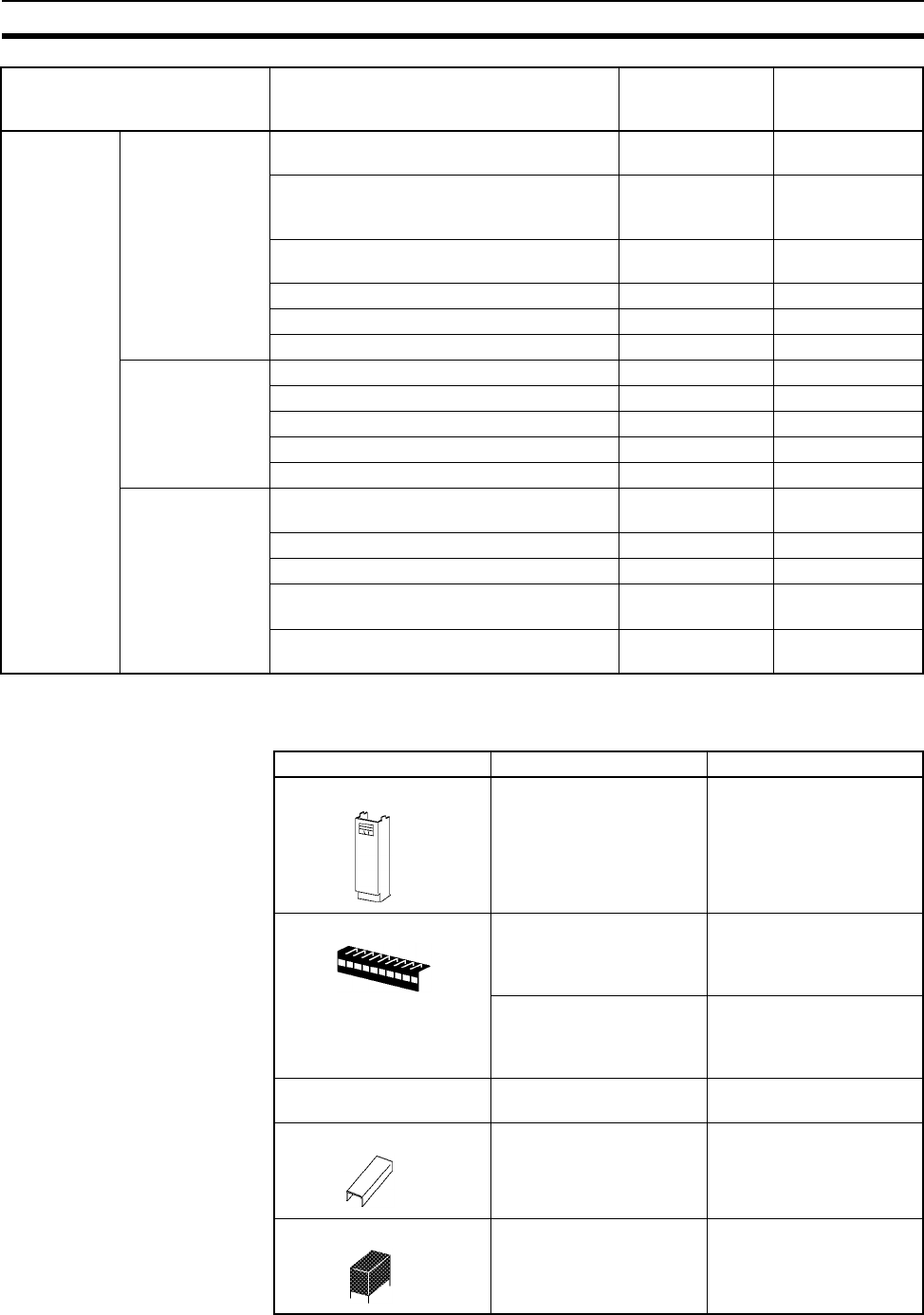
208
Basic I/O Units Section 3-6
Note Immediate refreshing (!) or refreshing using IORF(097) is possible for all
C200H Basic I/O Units.
Optional Products
C200H Out-
put Units (with
terminal
blocks)
Triac Output Units 1.2 A at 250 V AC max., 8 outputs, with fuse
burnout detection circuit
CS1W-OA201 5
1 A at 250 V AC max., 8 outputs, with fuse
burnout detection circuit
C200H-OA221 (no
longer manufac-
tured)
1
1.2 A at 250 V AC max., 8 outputs, with fuse
burnout detection circuit
C200H-OA223 2
0.3 A at 250 V AC max., 12 outputs C200H-OA222V 3
0.5 A at 250 V AC max., 12 outputs C200H-OA224 3
0.5 A at 250 V AC max., 16 outputs CS1W-OA211 5
Transistor Output
Units, Sinking
2.1 A at 24 V DC, 8 outputs C200H-OD213 1
1 A at 12 to 48 V DC, 8 outputs C200H-OD411 1
0.3 A at 24 V DC, 12 outputs C200H-OD211 3
0.3 A at 24 V DC, 16 outputs C200H-OD212 3
0.5 A at 12 to 24 V DC, 16 outputs CS1W-OD211 5
Transistor Output
Units, Sourcing
0.8 A at 24 V DC, load short-circuit protec-
tion, 8 outputs
C200H-OD214 1
0.3 A at 5 to 24 V DC common, 8 outputs C200H-OD216 1
0.3 A at 5 to 24 V DC common, 12 outputs C200H-OD217 3
0.5 A at 24 V DC, load short-circuit protec-
tion, 16 outputs
CS1W-OD212 5
1 A at 24 V DC, load short-circuit protection,
16 outputs
C200H-OD21A 3
Name Specifications Model
Cover for 10-pin terminal
block; 8-point Input/5-point
Output Unit
C200H-COV11
Short protection for 10-pin
terminal block (package of
10 covers); 8 inputs, 8 out-
puts
C200H-COV02
Short protection for 19-pin
terminal block (package of
10 covers); 12 inputs, 12
outputs
C200H-COV03
CS-series Special I/O Unit
Connector Cover
Protective cover for unused
connectors on Backplane
CV500-COV01
Protective cover for unused
connectors on Backplane
C200H-COV01
24 V DC, C200H-OC221/
OC222/OC223/OC224/
OC225
G6B-1174P-FD-US-M
Name Specifications Model External
view/dimensions
reference No.
I/O Unit Cover
Terminal Block Covers
C200H Unit Connector
Cover
Relay
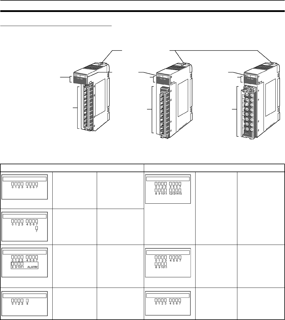
209
Basic I/O Units Section 3-6
Components and Switch Settings
C200H 10-pin/19-pin Terminal Block
10-pin terminal block 19-pin terminal block
8-point Unit C200H-ID211,
C200H-IM211,
C200H-IA121,
C200H-IA221,
C200H-OC221,
C200H-OD216
16-point Unit C200H-ID212,
C200H-IA122,
C200H-IA222,
C200H-IM212,
C200H-IA122V,
C200H-IA222V,
C200H-OD21A,
C200H-OD212,
C200H-OC225,
C200H-OC226N,
C200H-OC226
(illustrated above)
8-point Unit
F indicator (fuse
burnout)
C200H-OD213,
C200H-OD411,
C200H-OA221,
C200H-OA223
(illustrated above)
8-point Unit
ALARM indicator
C200H-OD214 12-point Unit C200H-OC222,
C200H-OC222V,
C200H-OD211,
C200H-OD217,
C200H-OA224,
C200H-OA222V
C200H-OC222N
5-point Unit C200H-OC223 8-point Unit C200H-OC224,
C200H-224V,
C200H-224N
I/O indicator
Terminal block
connector
(10-pin)
10-pin terminal block 19-pin terminal block
I/O indicator I/O indicator
Terminal block
connector
(10-pin)
Terminal block
connector
Model label
Model label
10-pin Terminal Block 10-pin Terminal Block (C200H-OA223) 19-pin Terminal Block
(C200H-OC226 19-pin
Terminal Block)
Unit mounting hooks
Hooked onto Back-
plane to mount Unit.
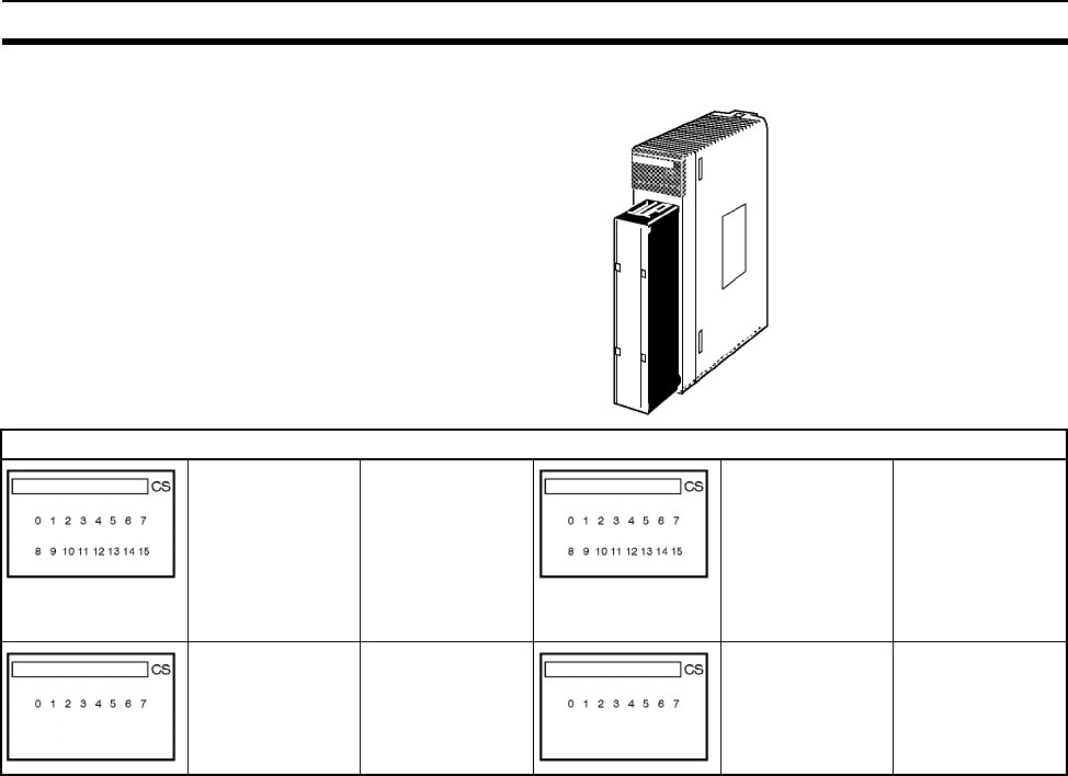
210
Basic I/O Units Section 3-6
CS-series Basic Input Units (20-pin Terminal Block)
20-pin terminal block
16-point Unit CS1W-ID211
INT01
IDP01
OD211
IA111
IA211
OC211
OA211
16-point Units
with ERR indica-
tor (load short-cir-
cuit)
CS1W-OD212
8-point Unit CS1W-OC201 8-point Units
with ERR indica-
tor (fuse burnout)
CS1W-OA201
ERR
ERR
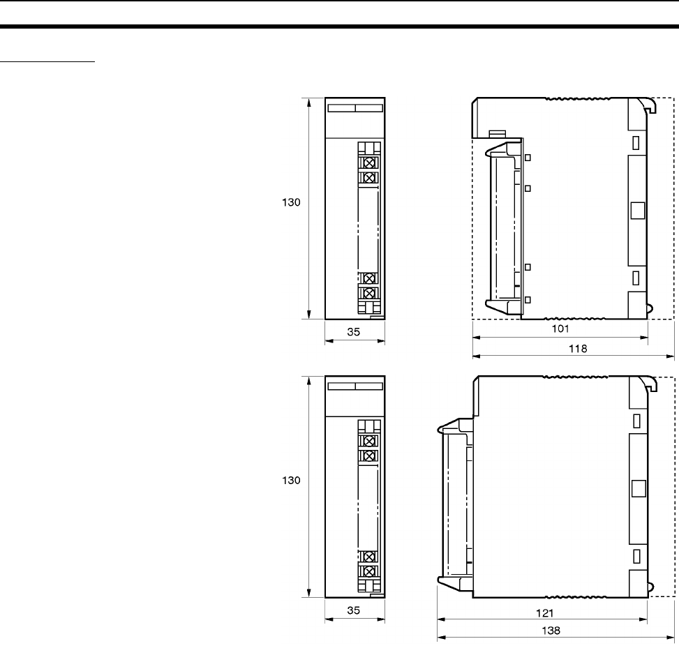
211
Basic I/O Units Section 3-6
Dimensions
C200H Units with 10-pin Terminal Blocks
Note The heights of the Units including the Backplane are 5 mm greater on the
CPU Backplane and CS-series Expansion Backplane (123 and 143 mm).
C200H-IA121
C200H-IA221
C200H-ID211
C200H-IM211
C200H-OA221
C200H-OC221
C200H-OC223
C200H-OD216
C200H-OD213
C200H-OD411
C200H-OD214
C200H-OA223
Backplane
Backplane
(See note.)
(See note.)
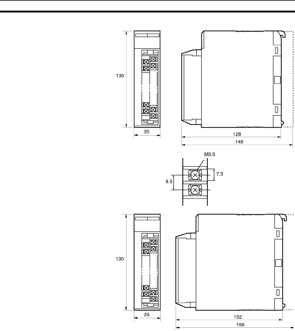
212
Basic I/O Units Section 3-6
Units with 19-pin Terminal Blocks
Note The heights of the Units including the Backplane are 5 mm greater on the
CPU Backplane and CS-series Expansion Backplane (150 and 174 mm).
C200H-IA122
C200H-IA122V
C200H-IA222
C200H-IA222V
C200H-ID212
C200H-IM212
C200H-OA222V
C200H-OA224
C200H-OC222
C200H-OC222V
C200H-OC224
C200H-OC224V
C200H-OC225
C200H-OD211
C200H-OD212
C200H-OD217
C200H-OD21A
C200H-OC222N
C200H-OC224N
Backplane
Terminal Dimensions
(See note.)
C200H-OC226
C200H-OC226N
Backplane
(See note .)
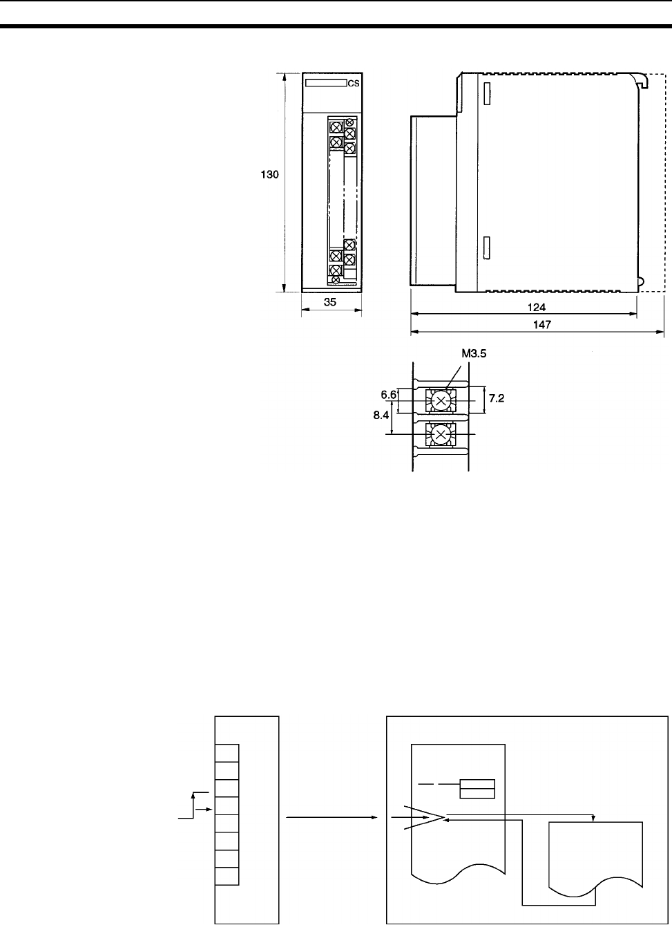
213
Basic I/O Units Section 3-6
CS-series Basic I/O Units (20-pin Terminal Blocks)
3-6-2 Interrupt Input Units
Functions Interrupt Input Units are used to execute interrupt programs on the rising or
falling edge of an input signal (See note.). When the specified interrupt input
turns ON (or OFF), execution of the cyclic program in the CPU Unit is inter-
rupted and an I/O interrupt task (task number 100 to 131) is executed. When
execution of the I/O interrupt task has been completed, the cyclic program is
again executed starting from the instruction after which it was interrupted.
Note Only the CS1W-INT01 can detect falling edges. The interrupt control instruc-
tions, however, can be used to switch between upward and downward differ-
entiation.
Backplane
Terminal Dimensions
CS1W-IA111
CS1W-IA211
CS1W-ID211
CS1W-INT01
CS1W-IDP01
CS1W-OD211
CS1W-OD212
CS1W-OA201
CS1W-OA211
CS1W-OC201
CS1W-OC211
Interrupt Input Unit
Input
(rising or
falling
edge)
Immediate
interrupt
CPU Unit
1 cyclic task
I/O interrupt task is
executed when the in
put turns ON (or OFF).
I/O interrupt task
MSKS(690)
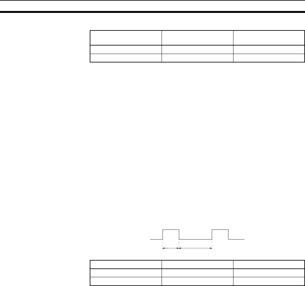
214
Basic I/O Units Section 3-6
Applicable Units Either of the following Interrupt Input Units can be used.
Application Precautions
All Interrupt Input Units must be mounted to the CPU Rack. The interrupt input
function will not be supported if an Interrupt Input Unit is mounted to an
Expansion Rack. If mounted to an Expansion Rack, the Unit can be used as a
normal I/O Unit.
There are limits to the number of Interrupt Input Units that can be mounted.
(See table, above.)
Use only CS-series or only C200H Interrupt Input Units on the same CPU
Rack. The CS-series and C200H Interrupt Input Units cannot be used
together.
Can be used only with CPU Units with model numbers ending in “-V1,” i.e.,
CS1W-CPU4@-V1 or CS1W-CPU6@-V1.
The input response time cannot be changed for the CS1W-INT01, and the
related portions of the Basic I/O Unit input time constants in the PLC Setup,
and the setting status in A220 to A259 will not be valid.
Use CX-Programmer Version 2.0 or higher when using the CS1W-INT01
Interrupt Input Unit. Earlier versions of CX-Programmer do not support this
Unit. (The Programming Consoles, however, can be used for this Unit.)
Input Signal Width Input signals must meet the following conditions.
Model Specifications No. of Units mountable
to CPU Rack
CS1W-INT01 24 V DC 16 inputs 2 max.
C200HS-INT01 24 V DC 8 inputs 4 max.
Unit ON time OFF time
CS1W-INT01 0.1 ms min. 0.5 ms min.
C200HS-INT01 0.2 ms min. 0.5 ms min.
ON OFF
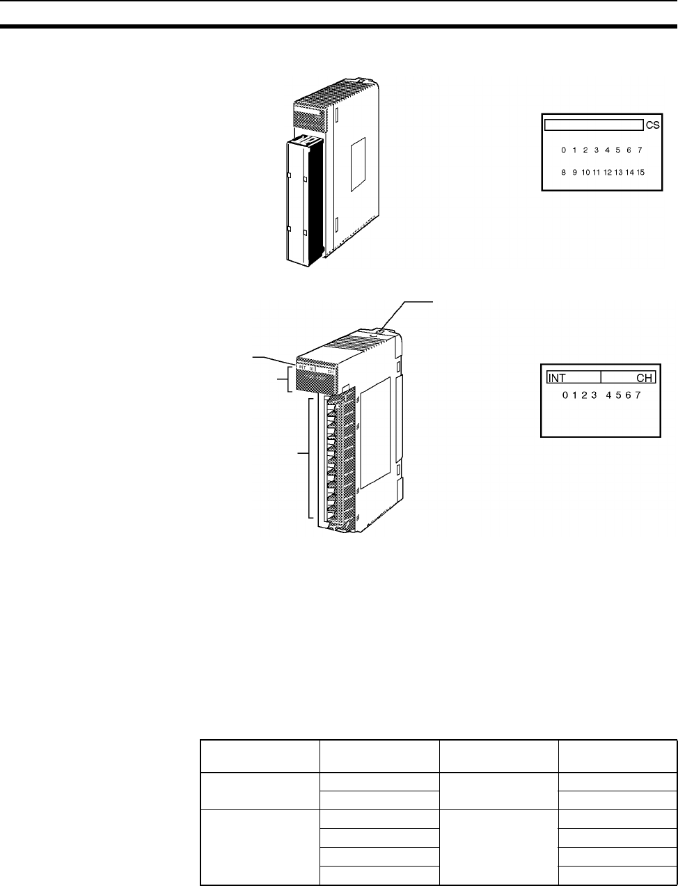
215
Basic I/O Units Section 3-6
Components
Using I/O Interrupts
1,2,3... 1. Mount the Input Interrupt Unit to the CPU Rack and create the I/O tables.
2. Create the I/O task (see note 1).
3. Use the SET INTERRUPT MASK Instruction (MSKS(690)) in the cyclic
program to enable the required interrupt input numbers (see note 1).
4. Turn ON or OFF the inputs on the Interrupt Input Unit for the interrupt input
numbers that have been enabled.
Note 1. The relationship between Interrupt Input Unit numbers, interrupt input
numbers, and I/O interrupt tasks is shown in the following table.
2. The CS1W-INT01 can set to detect either rising or falling edges.
CS1W-INT01
C200HS-INT01
Model label
I/O indicator
10-pin Terminal
Block connector
Unit lock notch
(fit into the Backplane)
Input indicators
01
Input indicators
Model Interrupt Input
Unit number
Interrupt input
number
I/O interrupt task
number
CS1W-INT01 0 0 to 15 100 to 115
1 116 to 131
C200HS-INT01 0 0 to 7 100 to 107
1 108 to 115
2 116 to 123
3 124 to 131
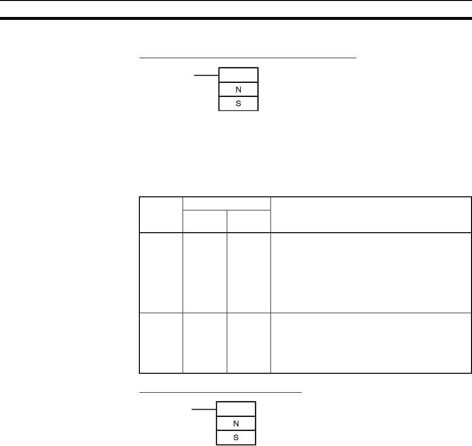
216
Basic I/O Units Section 3-6
MSKS(690) Instruction
Specifying Rising/Falling Edge for CS1W-INT01
The MSKS(690) instruction is used to set rising edge or falling edge detection
for each interrupt input number.
• The value of N will determine which Interrupt Input Unit will perform the
I/O interrupt processing.
• The value of S will determine rising or falling edge detection for each
interrupt input number.
Specifying I/O Interrupt Processing
The MSKS(690) instruction is used to set I/O interrupt processing or sched-
uled interrupt processing.
• The value of N will determine which Interrupt Input Unit will perform the
I/O interrupt processing.
• The value of S will determine which interrupt number will be enabled.
Operand Value Details
CS1W-
INT01
C200HS-
INT01
N 2, 3 --- Interrupt Input Unit Number
Numbers 2 and 3 are assigned to the Units in
order from left to right.
2: Interrupt Input Unit 0 (interrupt task numbers
100 to 115)
3: Interrupt Input Unit 1 (interrupt task numbers
116 to 131)
S 0000 to
FFFF hex
--- Rising/Falling Edge Designation
Bits 00 to 15 correspond to the interrupt input num-
bers (interrupt tasks 100 to 115 or 116 to 131).
0: Rising edge
1: Falling edge
MSKS(690) N: Control data 1 (Interrupt Input Unit No.)
S: Control data 2 (interrupt mask data)
N: Control data 1 (Interrupt Input Unit No.)
S: Control data 2 (interrupt mask data)
MSKS(690)

217
Basic I/O Units Section 3-6
Operand Value Details
CS1W-
INT01
C200HS-
INT01
N 0, 1 0 to 3 Interrupt Input Unit Number
Numbers are assigned to the Units in order from
left to right.
CS1W-INT01 (unit numbers 0 and 1)
0: Interrupt Input Unit 0 (interrupt task numbers
100 to 115)
1: Interrupt Input Unit 1 (interrupt task numbers
116 to 131)
CS1W-INT01 (unit numbers 0 to 3)
0: Interrupt Input Unit 0 (interrupt task numbers
100 to 107)
1: Interrupt Input Unit 1 (interrupt task numbers
108 to 115)
2: Interrupt Input Unit 2 (interrupt task numbers
116 to 123)
3: Interrupt Input Unit 3 (interrupt task numbers
123 to 131)
S 0000 to
FFFF hex
0000 to
00FF hex
Interrupt Mask Data
Bits 00 to 15 for the CS1W-INT01 and the right-
most 8 bits for the C200H-INT01are used for the
Interrupt Input Unit’s interrupt input number.
1: Interrupt masked
(interrupt input disabled)
0: Interrupt valid
(interrupt input enabled)
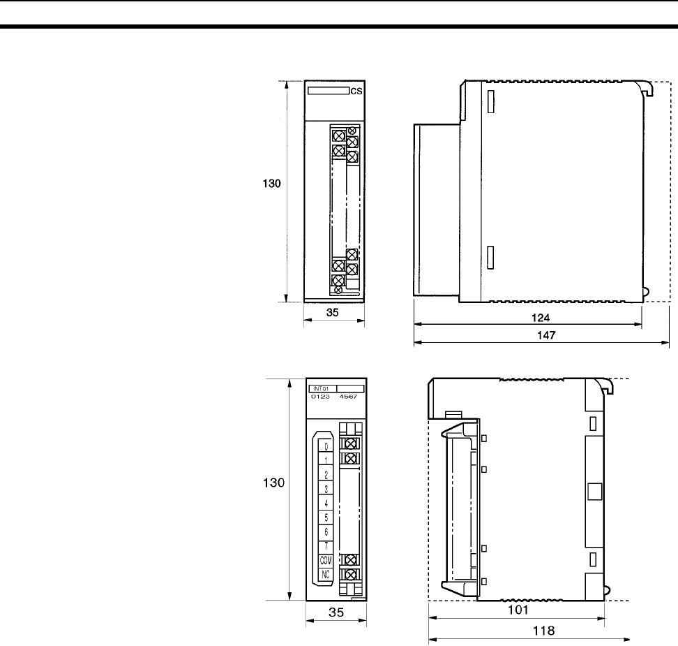
218
Basic I/O Units Section 3-6
Dimensions
Note The height of the Unit including the Backplane is 5 mm greater on the CPU
Backplane and CS-series Expansion Backplane (123 mm).
CS1W-INT01
C200HS-INT01
Backplane
(See note .)
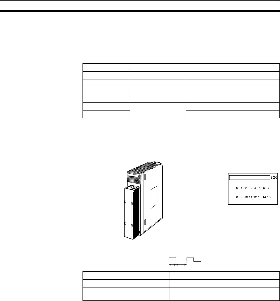
219
Basic I/O Units Section 3-6
3-6-3 Units with High-speed Inputs
Functions The CS1W-IDP01 enables inputting pulse signals that are shorted than the
cycle time of the CPU Unit. C200H High-density I/O Units (Special I/O Units)
also supported high-speed inputs.
I/O Units with High-speed
Inputs
Note Refer to 3-7 C200H High-density I/O Units (Special I/O Units) for details on
C200H High-density I/O Units
Components
Input Signal Width High-speed input signals must meet the following conditions for the ON time.
Dimensions The High-speed Input Unit has the same dimensions as the Interrupt Input
Unit. Refer to page 218.
Model Name Specifications
CS1W-IDP01 High-speed Input Unit 24 V DC, 16 inputs
C200H-ID501 TTL Input Unit 5 V DC, 32 inputs
C200H-ID215 DC Input Unit 24 V DC, 32 inputs
C200H-MD501 TTL I/O Unit 5 V DC,16 inputs/16 outputs
C200H-MD115 DC Input/Transistor
Output Unit
12 V DC,16 inputs/16 outputs
C200H-MD215 24 V DC,16 inputs/16 outputs,
CS1W-IDP01
Input indicators
Model ON time
CS1W-IDP01 0.1 ms min.
C200H-ID501/215
C200H-MD501/215/115
1.0/4.0 ms min. (switchable)
ON OFF

220
Basic I/O Units Section 3-6
3-6-4 CS-series Basic I/O Units with Connectors
(32-, 64-, and 96-pt Units)
CS-series Basic I/O Units are classified as Basic I/O Units.
Models
Name Specifications Model
DC Input Unit 24 V DC, 32 inputs CS1W-ID231
24 V DC, 64 inputs CS1W-ID261
24 V DC, 96 inputs CS1W-ID291
Transistor Output Unit,
Sinking
0.5 A at 12 to 24 V DC, 32 outputs CS1W-OD231
0.3 A at 12 to 24 V DC, 64 outputs CS1W-OD261
0.1 A at 12 to 24 V DC, with fuse burnout
detection circuit, 96 outputs
CS1W-OD291
Transistor Output Unit,
Sourcing
0.5 A at 24 V DC, load short-circuit pro-
tection, 16 outputs
CS1W-OD212
0.5 A at 24 V DC, load short-circuit pro-
tection, 32 outputs
CS1W-OD232
0.3 A at 24 V DC, load short-circuit pro-
tection, 64 outputs
CS1W-OD262
0.1 A at 24 V DC, with fuse burnout
detection circuit, 96 outputs
CS1W-OD292
DC Input/Transistor
Output Unit, Sinking
24 V DC input, 0.3 A output at 12 to
24 V DC, 32 inputs/32 outputs
CS1W-MD261
24 V DC input, 0.1 A output at 12 to 24 V
DC, with fuse burnout detection circuit,
48 inputs/48 outputs
CS1W-MD291
DC Input/Transistor
Output Unit, Sourcing
24 V DC input, 0.3 A output at 24 V DC,
load short-circuit protection, 32
inputs/32 outputs
CS1W-MD262
24 V DC input, 0.1 A output at 24 V DC,
with fuse burnout detection circuit, 48
inputs/48 outputs
CS1W-MD292
TTL I/O Unit 3.5 mA at 5 V DC, 32 inputs
35 mA at 5 V DC, 32 outputs
CS1W-MD561
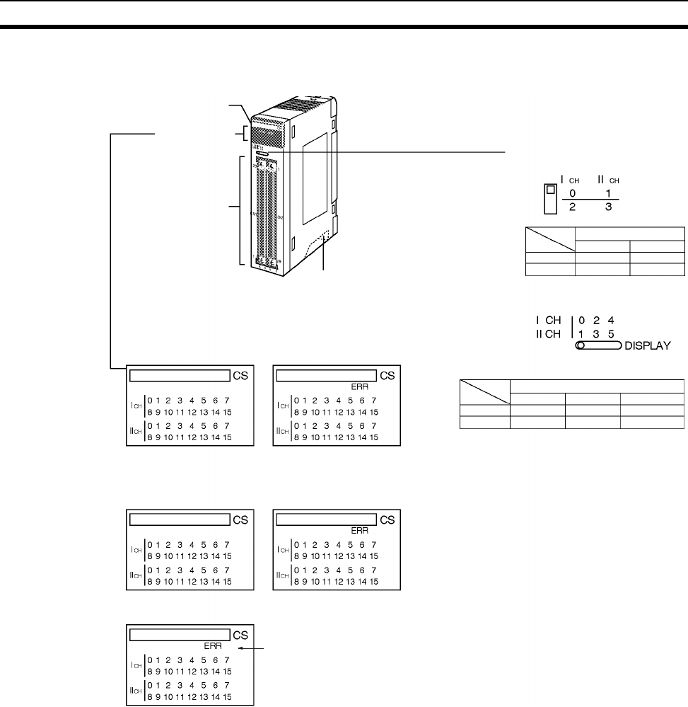
221
Basic I/O Units Section 3-6
Note Immediate refreshing (!) or refreshing using IORF(097) is possible for CS-
series High-density I/O Units.
F (fuse burnt out) indicator
Available on Output Units.
Lights when one or more fuses in the Unit blows.
Lights when external power is OFF.
Model label
I/O indicators
56-pin I/O wiring
connectors 2
Unit mounting hooks
Hooked onto Backplane to
mount Unit.
Unit lock notch
(Attach Unit to Backplane
and fix securely)
Display Switch
for 64-point I/O Units
Display Switch
for 96-point I/O Units
Display switch
Area 1 m m + 2
Area 2 m + 1 m + 3
0, 1 2, 3
Display switch
Display switch (3-level selection)
Area 1 m m + 2 m + 4
Area 2 m + 1 m + 3 m + 5
0, 1 2, 3 4, 5
32-point Units
CS1W-ID231
CS1W-OD231
32-point Units with ERR indicator
(load short-circuit indicator)
CS1W-OD232
CS1W-ID291/OD291/OD292/MD291/MD292
64-point Units
CS1W-ID261
CS1W-OD261
CS1W-MD261
64-point Units with ERR indicator
(load short-circuit indicator)
CS1W-OD262
CS1W-MD262
CS1W-MD561
96-point Units
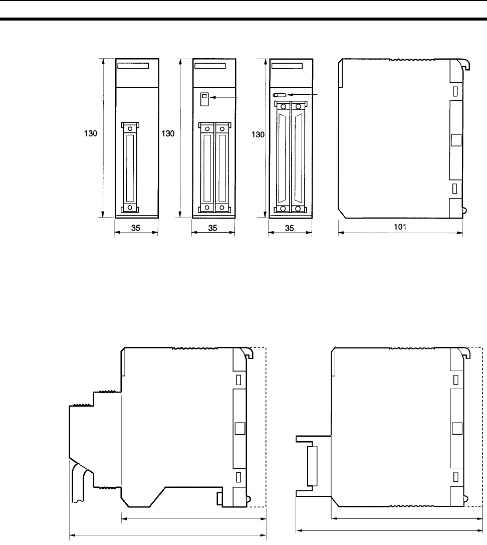
222
Basic I/O Units Section 3-6
Dimensions
Approx. 169 for 32- and 64-pt Units
A
pp
rox. 179 for 96-
p
t Units
Backplane
123
Backplane
123
150
Units with 56-pin
connectors
CS1W-ID291
CS1W-OD291
CS1W-OD292
CS1W-MD291
CS1W-MD292
Units with Two
40-pin connectors
CS1W-ID261
CS1W-0D261
CS1W-OD262
CS1W-MD261
CS1W-MD262
Units with One
40-pin connector
CS1W-ID231
CS1W-0D231
CS1W-0D232
Using Soldered or Crimped Connector
Using Pressure-welded Connector
Connecting Cables:
G79-@@@C-@@@-@@@
XW2Z-@@@
CS1W-MD561
Indicator switch
Indicator switch
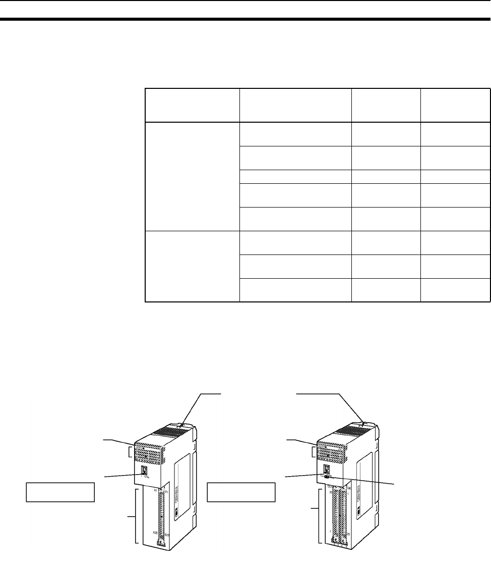
223
Basic I/O Units Section 3-6
3-6-5 C200H Group-2 High-density I/O Units
C200H Group-2 High-density I/O Units are classified as Basic I/O Units.
Models
Note 1. C200H Group-2 High-density I/O Units cannot be mounted to SYSMAC
BUS Slave Racks.
2. Immediate refreshing (!) is not possible for C200H Group-2 High-density
I/O Units, but refreshing using IORF (097) is possible for these Units.
Components and Switch Settings
Note The I/O number setting switch on the front panel of C200H Group-2 High-den-
sity I/O Units is not used for the CS Series, i.e., the I/O number setting will not
affect allocations. Words are allocated to the Units according to their position
on the Rack in the same way as for Basic I/O Units.
Name Specifications Model Appearance/
dimensions
reference No.
DC Input Unit 24 V DC, input current:
4.1 mA typical, 32 inputs
C200H-ID216 1
24 V DC, input current:
6 mA typical, 32 inputs
C200H-ID218 1
12 V DC, 64 inputs C200H-ID111 2
24 V DC, input current:
4.1 mA typical, 64 inputs
C200H-ID217 2
24 V DC, input current:
6 mA typical, 64 inputs
C200H-ID219 2
Transistor Output Unit 16 mA at 4.5 V to 100 mA
at 26.4 V, 32 outputs
C200H-OD218 1
16 mA at 4.5 V to 100 mA
at 26.4 V, 64 outputs
C200H-OD219 2
24 V DC, 0.5 A, sourcing,
32 inputs
C200H-OD21B 1
Model label
I/O indicators
(Cannot be used with
the CS-series)
I/O wiring connector
1. Units with One 40-pin Connector 2. Units with Two 40-pin Connectors
Model label
I/O indicators
(Cannot be used with
the CS-series)
40-pin I/O wiring
connector × 2
Indicator selector switch
(Select whether the I/O
indicator is CN1 or CN2.)
I/O No. setting switch
Unit mounting hooks
Hooked onto Back
plane to mount Unit.
I/O No. setting switch
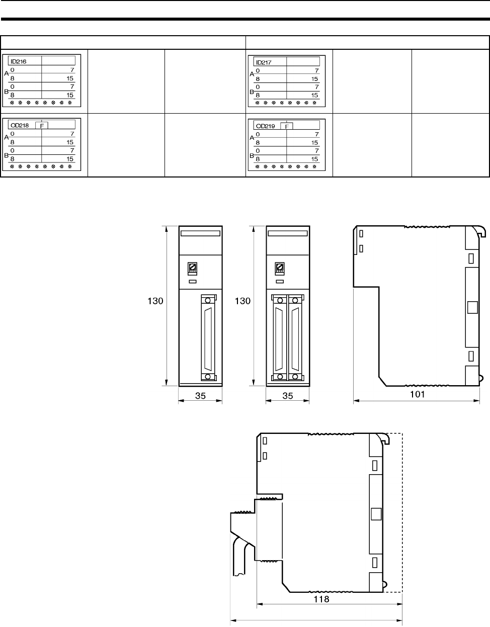
224
Basic I/O Units Section 3-6
Dimensions
Unit Dimensions with Backplane and Connector
Note The height of the Unit including the Backplane is 5 mm greater on the CPU
Backplane and CS-series Expansion Backplane (123 and 148 mm).
Units with One 40-pin Connector Units with Two 40-pin Connectors
32-point Unit C200H-ID216
C200H-ID218
64-point Unit C200H-ID111
C200H-ID217
C200H-ID219
32-point Unit
F (fuse burnt out)
indicator
C200H-OD218 64-point Unit
F (fuse burnt out)
indicator
C200H-OD219
1. Units with 40-pin
Connector
2. Units with Two 40-pin
Connectors
Approx. 143
Backplane
(See note .)
(See note .)
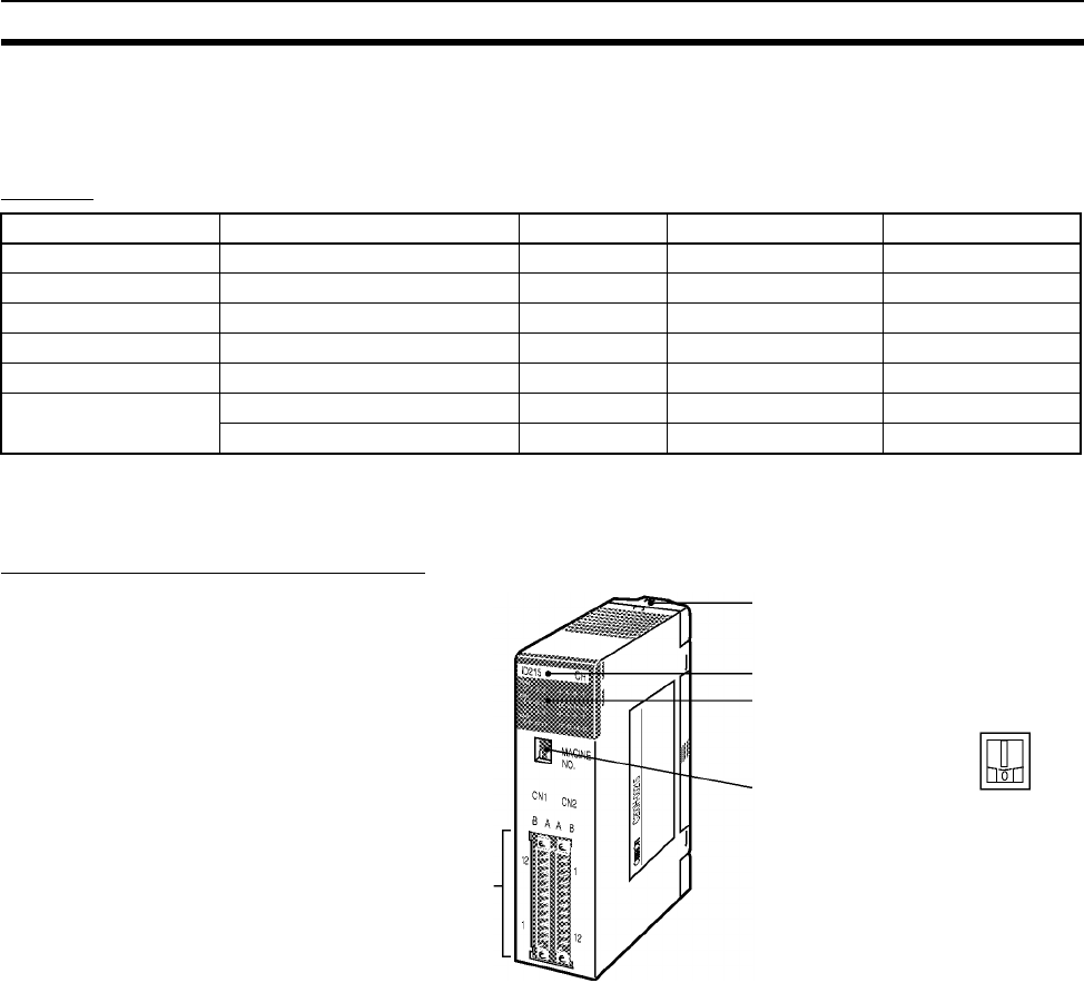
225
C200H High-density I/O Units (Special I/O Units) Section 3-7
3-7 C200H High-density I/O Units (Special I/O Units)
C200H High-density I/O Units are classified as C200H Special I/O Units.
Models
Note Immediate refreshing (!) is not possible for C200H High-density I/O Units, but
refreshing using IORF (097) is possible.
Components and Switch Settings
Note 1. Be sure to turn OFF the power supply to the PLC before setting the unit
number.
2. Set the unit number using a flat-blade screwdriver.
3. Do not stop in the middle of setting the value (between 0 and 9) or the set-
ting will not be complete.
4. Make sure that the groove in the unit number setting switch does not be-
come damaged.
Name Specifications Model Dynamic I/O mode Static I/O mode
TTL Input Unit 5 V DC, 32 inputs C200H-ID501 --- High-speed inputs
DC Input Unit 24 V DC, 32 inputs C200H-ID215 --- High-speed inputs
TTL Output Unit 5 V DC, 32 outputs C200H-OD501 128 outputs ---
Transistor Output Unit 24 V DC, 32 outputs C200H-OD215 128 outputs ---
TTL I/O Unit 5 V DC, 16 inputs/16 outputs C200H-MD501 128 inputs High-speed inputs
DC Input/Transistor
Output Unit
12 V DC, 16 inputs/16 outputs C200H-MD115 128 inputs High-speed inputs
24 V DC, 16 inputs/16 outputs C200H-MD215 128 inputs High-speed inputs
Unit lock notch
Model label
I/O indicators
24-pin I/O wiring
connectors × 2
Unit number setting switch
Set the unit number between 0 and
9. Ten words are allocated per Unit
in the Special I/O Unit Area (words
2000 to 2959) according to the unit
number setting.
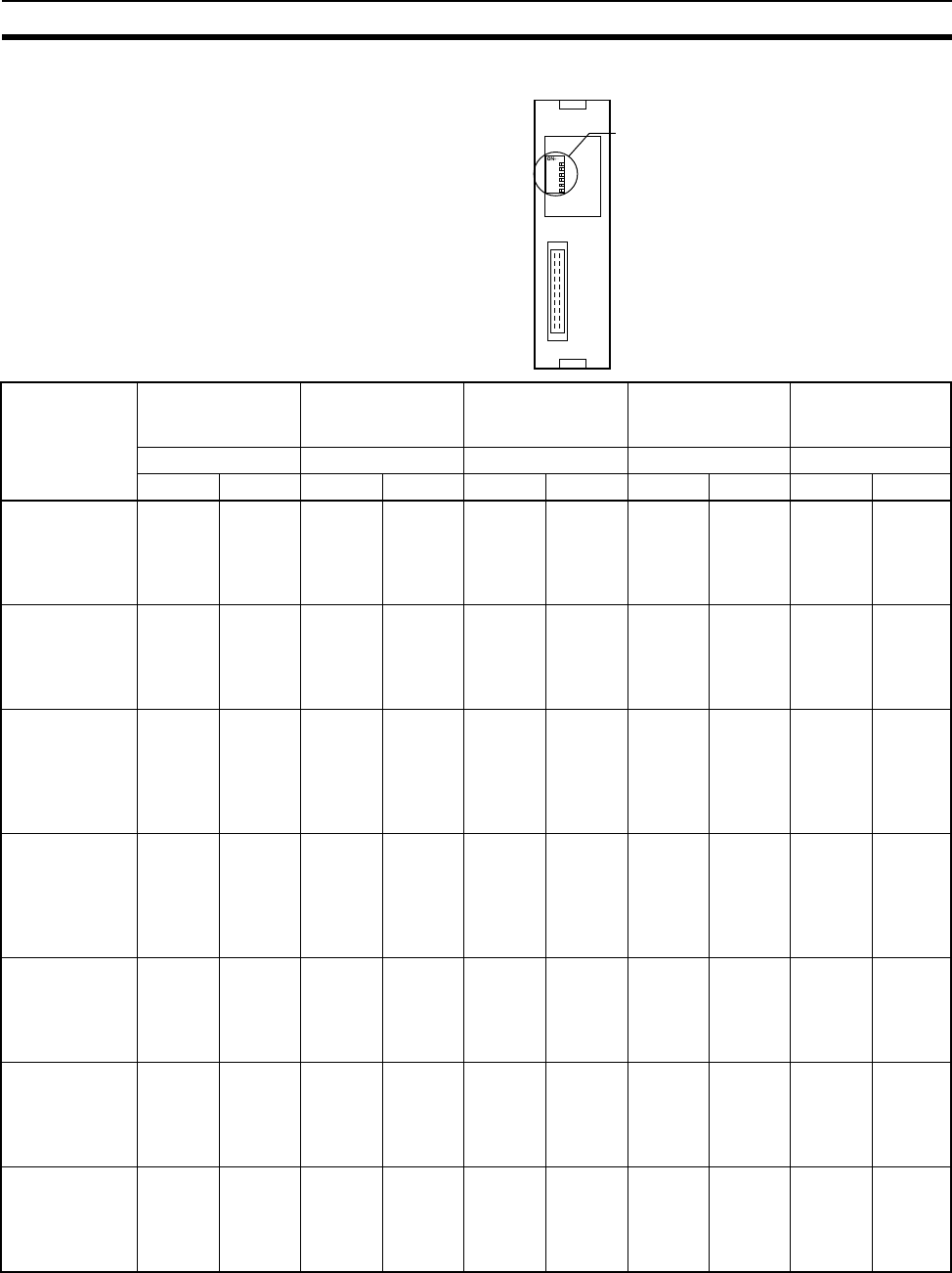
226
C200H High-density I/O Units (Special I/O Units) Section 3-7
Note Negative and positive logic output are only available with 128-point dynamic
output mode.
C200H High-density I/O Units are classified as C200H Special I/O Units and
have the following functions.
123456
DIP switch
Back of Unit
Model RUN mode High-speed
inputs
High-speed input
minimum
response pulse
Normal input
response time
Dynamic data
output logic
SW1 SW2 SW3 SW4 SW5
ON OFF ON OFF ON OFF ON OFF ON OFF
C200H-ID501 --- --- High-
speed
input
function
enabled
Normal
input
4 ms 1 ms --- --- 15 ms
max.
2.5 ms
max.
C200H-ID215 --- --- High-
speed
input
function
enabled
Normal
input
4 ms 1 ms --- --- 15 ms
max.
2.5 ms
max.
C200H-OD501 128
dynamic
outputs
32 static
outputs
--- --- --- --- --- --- Positive
logic
output
(See
note.)
Nega-
tive
logic
output
(See
note.)
C200H-OD215 128
dynamic
outputs
32 static
outputs
--- --- --- --- --- --- Positive
logic
output
(See
note.)
Nega-
tive
logic
output
(See
note.)
C200H-MD501 128
dynamic
inputs
16 static
inputs,
16 static
outputs
High-
speed
input
function
enabled
Normal
input
4 ms 1 ms 15 ms
max.
2.5 ms
max.
--- ---
C200H-MD115 128
dynamic
inputs
16 static
inputs,
16 static
outputs
High-
speed
input
function
enabled
Normal
input
4 ms 1 ms 15 ms
max.
2.5 ms
max.
--- ---
C200H-MD215 128
dynamic
inputs
16 static
inputs,
16 static
outputs
High-
speed
input
function
enabled
Normal
input
4 ms 1 ms 15 ms
max.
2.5 ms
max.
--- ---
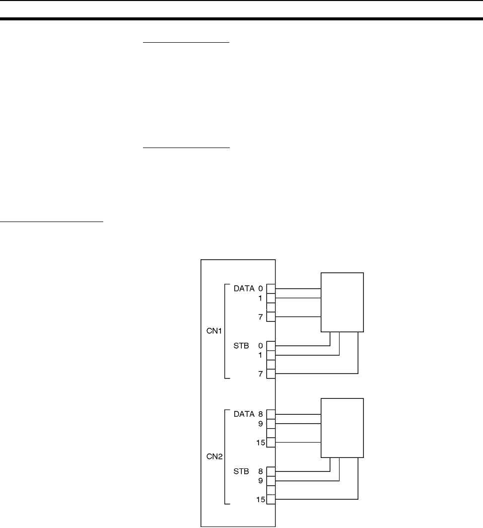
227
C200H High-density I/O Units (Special I/O Units) Section 3-7
Dynamic I/O Mode
The High-density I/O Units (other than the C200H-ID501 and C200H-ID215)
can provide high-density I/O rather than the normal output (static output
mode) and I/O (static I/O mode). High-density I/O (dynamic output and
dynamic input modes: 128 points) is achieved by combining the I/O signals
with a strobe signal output. The High-density I/O Units require less wiring, use
a numeric display device in dynamic output mode with large number capacity,
and use keyboard switches in dynamic input mode.
High-speed Inputs
The High-density I/O Units (other than the C200H-OD501 and C200H-
OD502) also provide high-speed inputs. High-speed inputs are possible with 8
input points. This function enables accurate reading of short pulse inputs from
photomicroswitches and other devices.
Dynamic I/O Mode
Dynamic Output Mode
By combining data signals (DATA 0 to 7 and DATA 8 to 15) with strobe signals
(STB 0 to 7/ STB 8 to 15, 128 bits (8 words) can be output to a numerical dis-
play device as shown in the following diagram.
C200H-OD501/OD215
Data output
Strobe output
Numeric display
Numeric displayData output
Strobe output
:
:
:
:
:
:
:
:
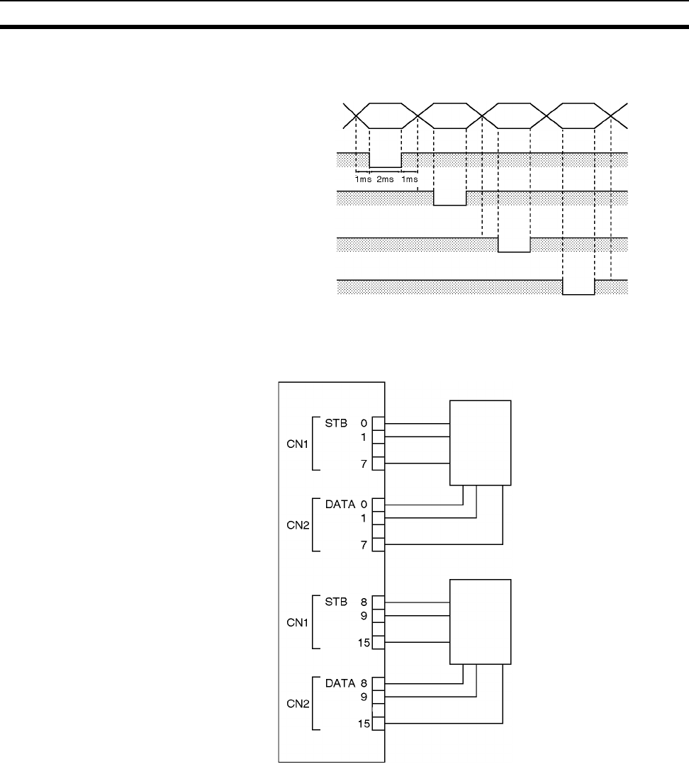
228
C200H High-density I/O Units (Special I/O Units) Section 3-7
Dynamic Input Mode
Using strobe signals STB 0 to 7 as outputs, data signals DATA 0 to 7 as
inputs, strobe signals STB 8 to 15 as outputs, and data signals DATA 8 to 15
as inputs, 128 bits (8 words) can be input from strobe input keyboard switches
or thumbwheel switches as shown in the following diagram.
Data output
DATA 0 to 7
Strobe output
STB 0
Word n
Rightmost
byte
Word n
Leftmost
byte
Word n + 1
Rightmost
byte
Word n + 3
Leftmost
byte
DATA 8 to 15 can also be output as STB 8 to 15 at the same time.
STB 1
STB 2
to
STB 7
C200H-MD501/MD115/MD215
Strobe
output
Data input
Strobe
output
Data input
Keyboard switch,
thumbwheel
switch, etc.
Keyboard switch,
thumbwheel
switch, etc.
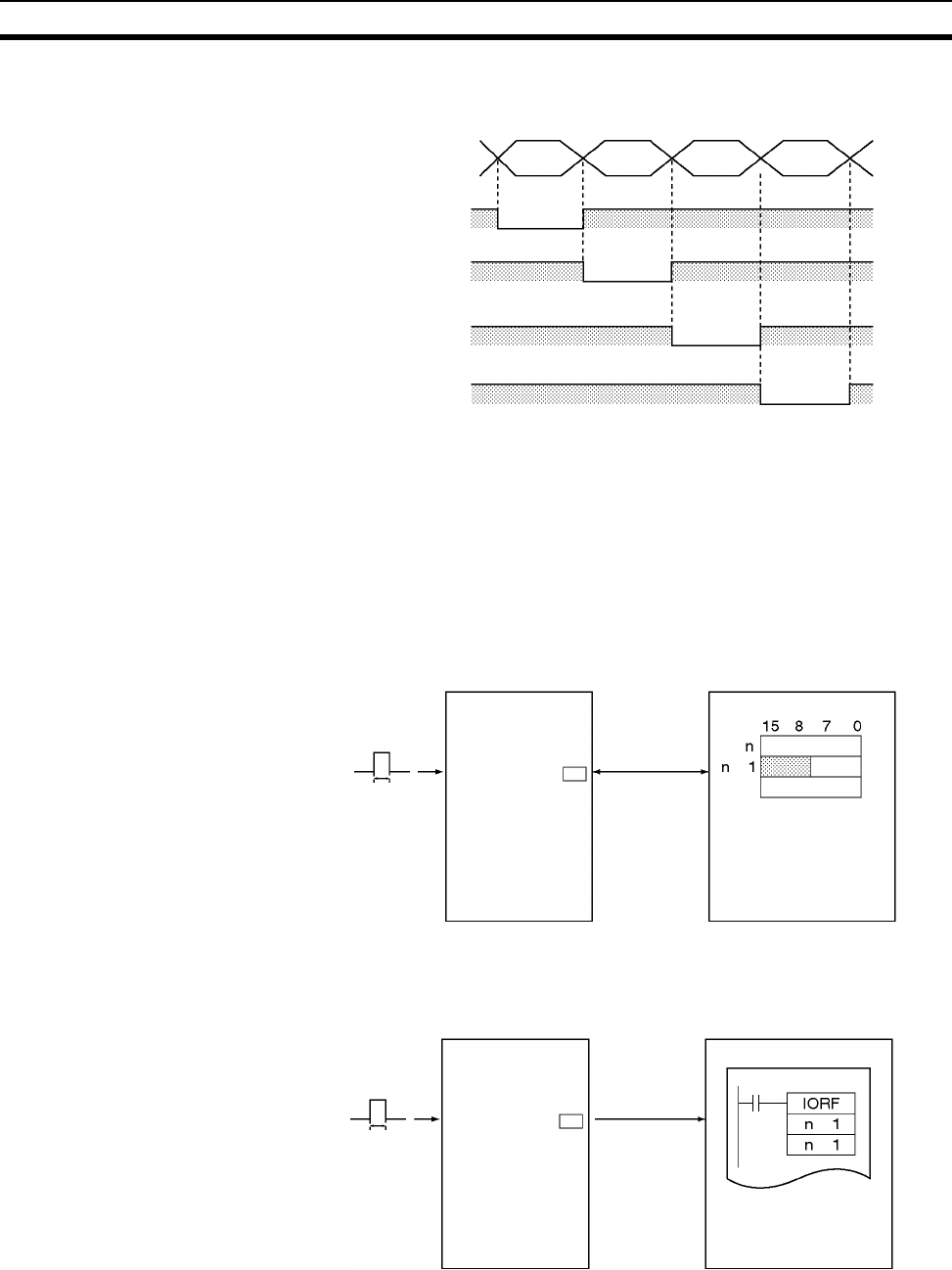
229
C200H High-density I/O Units (Special I/O Units) Section 3-7
High-speed Inputs
The inputs 8 to 15 from the CN2 connector can be used for pulse input. The
minimum pulse width is 1 ms or 4 ms (selectable).
A High-density I/O Unit will recognize a pulse input when the pulse input
occurs (i.e., the inputs turns ON and then OFF again), and the pulse width is
greater than 1 ms or 4 ms (according to the selected minimum pulse width).
The data is refreshed in the Special I/O Unit Area (word n + 1, bits 8 to 15) of
I/O memory during the CPU Unit’s I/O refresh period.
The High-density I/O Unit data in the high-speed input buffer can also be
refreshed during program execution by executing the IORF(097) instruction
for the desired Special I/O Unit.
Data input
DATA 0 to 7
Word n
Rightmost
bytes
Word n
Leftmost
bytes
Word n + 3
Leftmost
bytes
Word n + 1
Rightmost
bytes
DATA 8 to 15 can also be output as STB 8 to 15 at the same time.
Strobe output
STB 0
STB 1
STB 2
to
STB 7
High-density I/O Unit CPU Unit
I/O refresh
High-speed
input buffer
1 ms or 4 ms
+
High-density I/O Unit CPU Unit
I/O refresh
High-speed
input buffer
1 ms or 4 ms
+
+
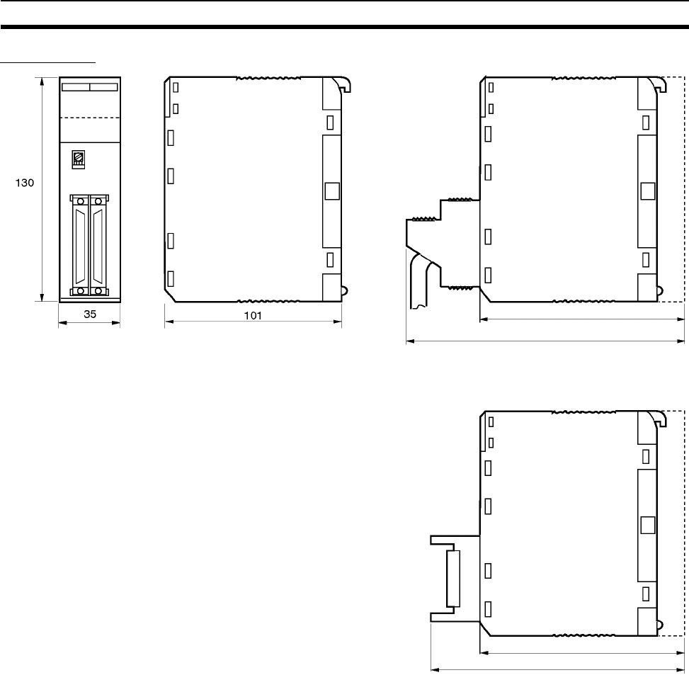
230
C200H High-density I/O Units (Special I/O Units) Section 3-7
Dimensions
Fujitsu connection
cable
G79-@C Connecting Cable
BackplaneBackplane
Approx. 168
123
123
150
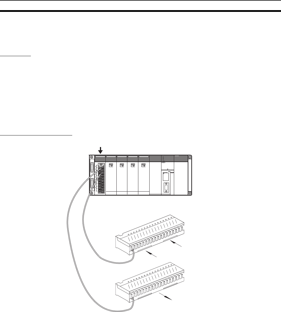
231
B7A Interface Units Section 3-8
3-8 B7A Interface Units
3-8-1 CS-series B7A Interface Units (CS-series Basic I/O Units)
Overview
The B7A is a 1:1 transmission path that does not require a master. A total of
16 signals are transmitted using a two-conductor or three-conductor VCTF
cable (maximum length: 500 m). The CS1W-B7A@@ B7A Interface Unit is a
CS-series Basic I/O Unit that exchanges up to 64 points of I/O data mainly
with B7A Link Terminals using a B7A transmission path.
The B7A Interface Unit and B7A Link Terminal can be used in the same way
as a standard Basic I/O Unit and I/O Terminal without any need to worry about
communications. This characteristic reduces the wiring when using more than
one relatively remote sensor or actuator.
System Configuration
B7A Input Link Terminal
B7A Output Link Terminal
B7 Interface Unit
Switches
Sensors
Lamps or other output devices
Transmission
distance:
500 m max.
CPU
Unit
SYSMAC
CS1G
PROGRAMABLE CONTROLLER
CPU42
OPEN
OPEN
PERIPHERAL
PORT (RS-232C)
BUSY
RUN
ERR/ALM
INH
PRPHL/COMN
MCPWR

232
B7A Interface Units Section 3-8
Models
Note 1. A 10-point B7A Link Terminal cannot be connected to a B7A Interface Unit.
B7A Interface Units can be connected together.
2. Wireless transmissions are possible if B7AP Power Couplers are used on
a B7A transmission path, reducing the wiring required for moving objects
and rotating objects.
B7A Interface Unit Specifications I/O words allocated
to Unit
Connectable B7A Link Terminals
(See note 1.)
CS1W-B7A12 32 inputs
(two B7A ports)
2 input words Inputs: Two 16-point Input Terminals, one
32-point Input Terminal, or one 16-point Input
Te r mi n al
CS1W-B7A02 32 outputs
(two B7A ports)
2 output words Outputs: Two 16-point Output Terminals or
one 32-point Output Terminal or one 16-point
Output Terminal
CS1W-B7A21 16 inputs, 16 outputs
(two B7A ports)
1 input word and
1 output word
Inputs: One 16-point Input Terminal
Outputs: One 16-point Output Terminal
or
One Mixed I/O Terminal
(16 inputs/16 outputs)
CS1W-B7A22 32 inputs, 32 outputs
(four B7A ports)
2 input words and
2 output words
Inputs: Two 16-point Input Terminals or one
32-point Input Terminal
Outputs: Two 16-point Output Terminals or
one 32-point Output Terminal
or
Two Mixed I/O Terminals
(16 inputs/16 outputs)
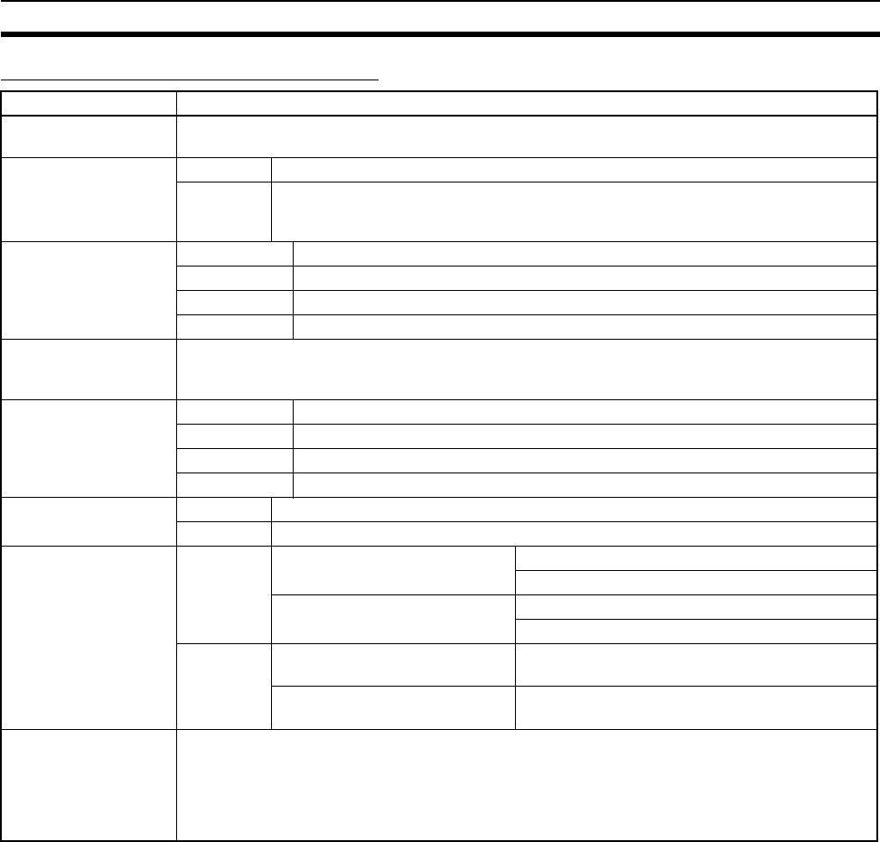
233
B7A Interface Units Section 3-8
B7A Communications Specifications
Note 1. When separate power supplies are used, the B7A Interface Unit and B7A
Link Terminal are supplied by separate external power supplies.
2. When a common power supply is used, the B7A Interface Unit and B7A
Link Terminal are supplied by the same external power supply.
3. Use a SELV power supply with overcurrent protection. A SELV power sup-
ply refers to a power supply with double or reinforced insulation between
input and output and with an output voltage of 30 V rms with a 42.4-V peak
or an output voltage of 60 VDC max. We recommend OMRON S8@@-se-
ries Power Supply Units for the external power supplies.
4. The capacity of the external supply current does not include the capacity
required by the B7A Link Terminal.
5. The minimum input time is the minimum time required by the B7A Interface
Unit to read the input signals from the CPU Unit.
Item Specifications
Transmission
method
One-way time-sharing multiplex transmissions
Transmission delay
(communications
delay on
transmission path)
High-speed 3 ms typical, 5 ms max.
Standard 19.2 ms typical, 31 ms max.
Transmission points CS1W-B7A12 32 inputs (2 ports)
CS1W-B7A02 32 outputs (2 ports)
CS1W-B7A21 16 inputs (1 port), 16 outputs (1 port)
CS1W-B7A22 32 inputs (2 ports), 32 outputs (2 ports)
External power
supply voltage
(See note 3.)
12 to 24 V DC (allowable voltage range: 10.8 to 26.4 V)
External supply
current
(See note 4.)
CS1W-B7A12 20 mA min.
CS1W-B7A02 60 mA min.
CS1W-B7A21 30 mA min.
CS1W-B7A22 60 mA min.
Minimum input time
(See note 5.)
High-speed 16 ms
Standard 2.4 ms
Transmission
distance
High-speed Power supply on one side
(common power supply)
10 m max.
50 m max. (with shielded cable)
Power supply on both sides
(separate power supplies)
10 m max.
100 m max. (with shielded cable)
Standard Power supply on one side
(common power supply)
100 m max.
Power supply on both sides
(separate power supplies)
500 m max.
Cables VCTF, 0.75 mm2, 3 conductors (power supply on one side (common power supply))
VCTF, 0.75 mm2, 2 conductors (power supply on both sides (separate power supplies))
Shielded cable, 0.75 mm2, 3 conductors (power supply on one side (common power supply))
Shielded cable, 0.75 mm2, 2 conductors (power supply on both sides (separate power supplies))
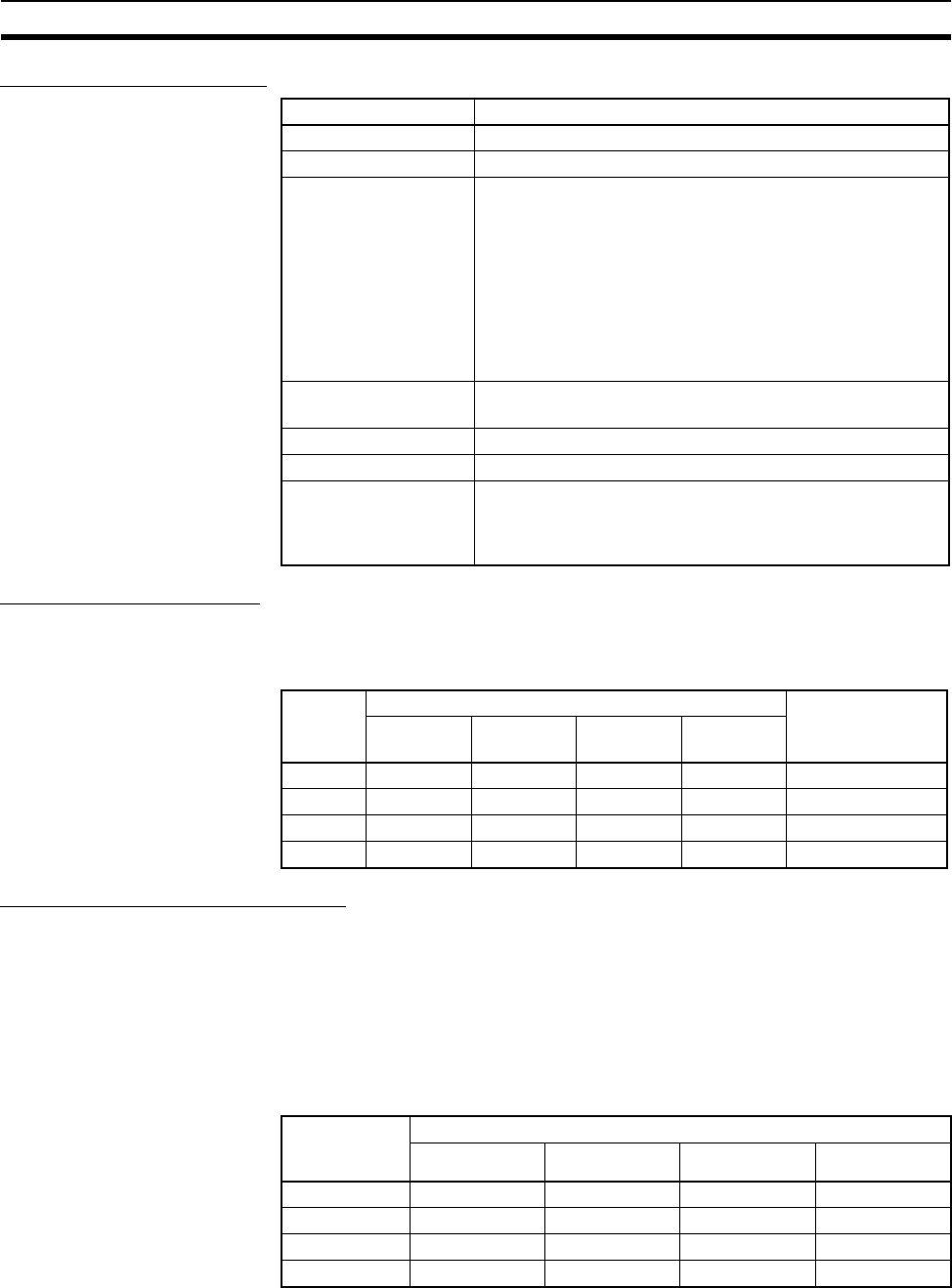
234
B7A Interface Units Section 3-8
Common Specifications
I/O Memory Allocations
The B7A Interface Unit is a Basic I/O Unit. Each Unit is allocated two or four
words in the I/O Area (which starts at CIO 0000). The words are allocated
according to the mounting position of the Unit as shown in the following table.
Transmission Error Processing
Input Ports
The B7A Interface Unit detects transmission errors at the input ports. When a
transmission error is detected at an input port, the corresponding indicator
and Transmission Error Flag turn ON.
■Indicators
When a transmission occurs at an input port, indicators ERR1 to ERR2 on the
front panel will turn ON according to the port where the error occurred.
Item Specifications
Applicable PLCs CS Series
Unit classification CS-series Basic I/O Unit
Transmission delay Standard (19.2 ms typical) or high-speed (3 ms typical),
switchable
(Switchable by using the setting switch on the front panel.
Settings are read when power is turned ON or Unit is
restarted.)
Factory setting: Standard (19.2 ms typical)
Note A transmission error will occur if B7A Link Terminals
with different transmission delay times are con-
nected to each other.
Transmission error
input status processing
Hold status or reset inputs (loads off) (switch settable)
Front panel connection Terminal block
Current consumption 5 V DC: 90 mA max. (supplied from Power Supply Unit)
Weight CS1W-B7A12: 230 g max.
CS1W-B7A02: 230 g max.
CS1W-B7A21: 240 g max.
CS1W-B7A22: 240 g max.
Port Input/output Allocated word
(n: First word
allocated to Unit)
CS1W-
B7A12
CS1W-
B7A02
CS1W-
B7A21
CS1W-
B7A22
1 Input Output Output Output Word n
2 Input Output Input Output Word n+1
3 --- --- --- Input Word n+2
4 --- --- --- Input Word n+3
Port where
error
occurred
LED error indicators
CS1W-B7A12 CS1W-B7A02 CS1W-B7A21 CS1W-B7A22
Port 1 ERR1 --- --- ---
Port 2 ERR2 --- ERR1 ---
Port 3 --- --- --- ERR1
Port 4 --- --- --- ERR2
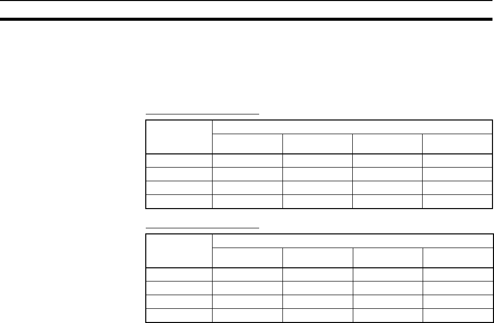
235
B7A Interface Units Section 3-8
■Transmission Error Flag
The corresponding Transmission Error Flag in the first word allocated to the
Unit in the CPU Unit's Auxiliary Area will turn ON for each input port, as
shown in the following table. Words A050 to A080 are allocated to Basic I/O
Unit as information words.
Example: Rack 0, Slot 0
Example: Rack 0, Slot 1
■Transmission Error Input Status Processing
If an error occurs at an input port, the Unit will hold the status of the input bit in
the CPU Unit's I/O memory from immediately before the transmission error
occurred. When transmission returns to normal, the signals that have been
normally received will be input to the input bit.
Output Ports
The B7A Interface Unit does not detect transmission errors at output ports.
Detect output port transmission errors at the B7A Link Terminal that is con-
nected to the B7A Interface Unit.
Port where
error
occurred
Transmission Error Flag
CS1W-B7A12 CS1W-B7A02 CS1W-B7A21 CS1W-B7A22
Port 1 A05000 --- --- ---
Port 2 A05001 --- A05000 ---
Port 3 --- --- --- A05000
Port 4 --- --- --- A05001
Port where
error
occurred
Transmission Error Flag
CS1W-B7A12 CS1W-B7A02 CS1W-B7A21 CS1W-B7A22
Port 1 A05008 --- --- ---
Port 2 A05009 --- A05008 ---
Port 3 --- --- --- A05008
Port 4 --- --- --- A05009
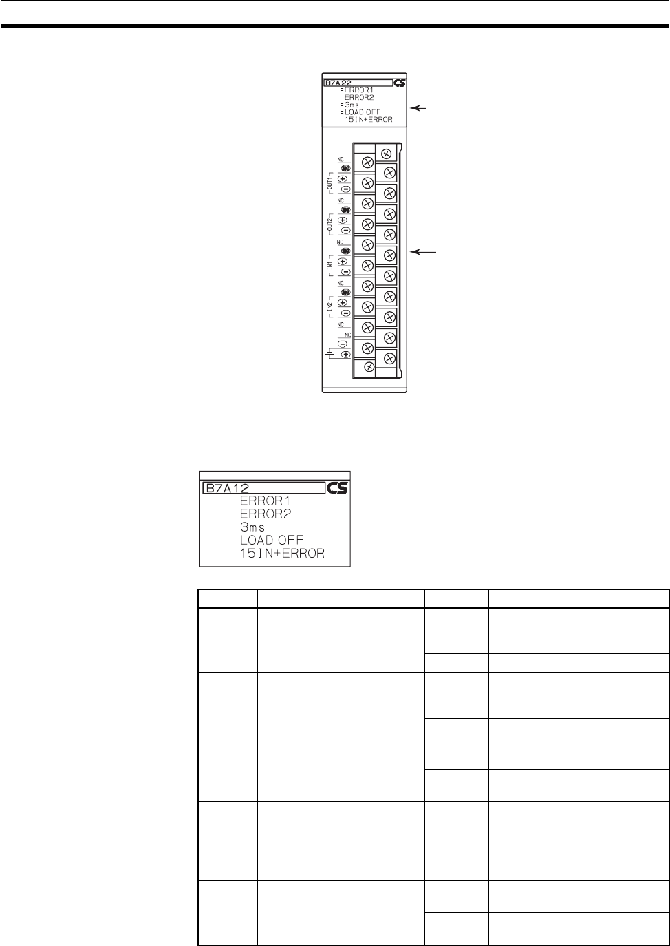
236
B7A Interface Units Section 3-8
Parts and Names
Indicators
■CS1W-B7A12
Indicators
Connection terminals
Display Name Color Status Condition
ERROR1 Port 1 trans-
mission error
Red ON A transmission error has
occurred at port 1 of the B7A
Unit.
OFF The Unit is operating normally.
ERROR2 Port 2 trans-
mission error
Red ON A transmission error has
occurred at port 2 of the B7A
Unit.
OFF The Unit is operating normally.
3 ms Transmission
delay setting
Orange ON The high-speed transmission
delay (3 ms) is set.
OFF The standard transmission
delay (19.2 ms) is set.
LOAD
OFF
Transmission
error input
status process-
ing setting
Orange ON Transmission error input status
processing is set to reset status
(loads OFF).
OFF Transmission error input status
processing is set to hold status.
15IN +
ERR
Input mode
setting
Orange ON The input mode is set to 15
inputs + error input.
OFF The input mode is set to 16
inputs.
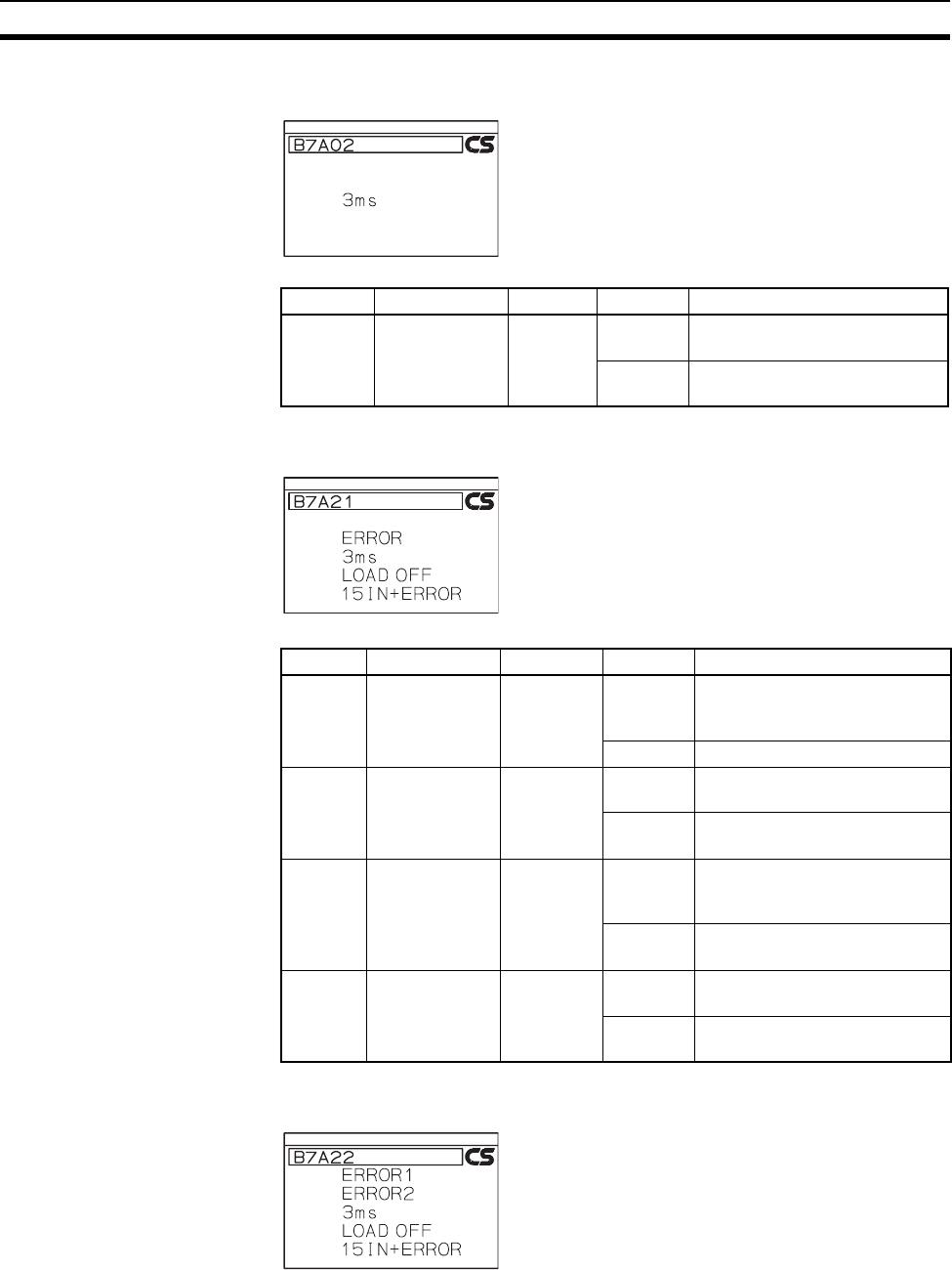
237
B7A Interface Units Section 3-8
■CS1W-B7A02
■CS1W-B7A21
■CS1W-B7A22
Display Name Color Status Condition
3 ms Transmission
delay setting
Orange ON The high-speed transmission
delay (3 ms) is set.
OFF The standard transmission
delay (19.2 ms) is set.
Display Name Color Status Condition
ERROR Port 1 trans-
mission error
Red ON A transmission error has
occurred at port 1 of the B7A
Unit.
OFF The Unit is operating normally.
3 ms Transmission
delay setting
Orange ON The high-speed transmission
delay (3 ms) is set.
OFF The standard transmission
delay (19.2 ms) is set.
LOAD
OFF
Transmission
error input sta-
tus processing
setting
Orange ON Transmission error input status
processing is set to reset status
(loads OFF).
OFF Transmission error input status
processing is set to hold status.
15IN +
ERR
Input mode set-
ting
Orange ON The input mode is set to 15
inputs + error input.
OFF The input mode is set to 16
inputs.
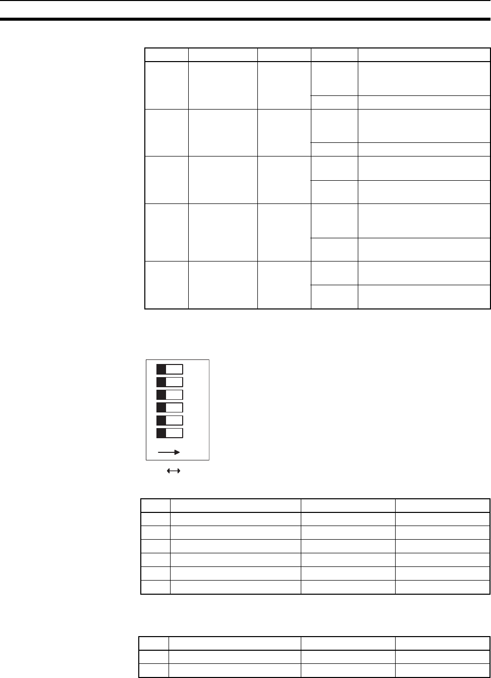
238
B7A Interface Units Section 3-8
Function Setting Switch
Set functionality using the DIP switch on the back of the Unit.
■CS1W-B7A12
Defaults: Pins 4 and 5 are turned ON and all other pins are turned OFF.
■CS1W-B7A02
Defaults: All pins are turned OFF
Display Name Color Status Condition
ERROR1 Port 1 trans-
mission error
Red ON A transmission error has
occurred at port 1 of the B7A
Unit.
OFF The Unit is operating normally.
ERROR2 Port 2 trans-
mission error
Red ON A transmission error has
occurred at port 2 of the B7A
Unit.
OFF The Unit is operating normally.
3 ms Transmission
delay setting
Orange ON The high-speed transmission
delay (3 ms) is set.
OFF The standard transmission
delay (19.2 ms) is set.
LOAD
OFF
Transmission
error input sta-
tus processing
setting
Orange ON Transmission error input status
processing is set to reset status
(loads OFF).
OFF Transmission error input status
processing is set to hold status.
15IN +
ERR
Input mode set-
ting
Orange ON The input mode is set to 15
inputs + error input.
OFF The input mode is set to 16
inputs.
654321
ON
ONOFF
Pin Name OFF ON
1 Transmission delay Standard (19.2 ms) High-speed (3 ms)
2 Transmission error process Hold status Reset Inputs
3 Input mode 16 inputs 15 inputs + error input
4 ERROR 1 indicator enable Disabled Enabled
5 ERROR 2 indicator enable Disabled Enabled
6 Not used. (Leave OFF.) NA NA
Pin Name OFF ON
1 Transmission delay Standard (19.2 ms) High-speed (3 ms)
2 to 6 Not used. (Leave OFF.) NA NA
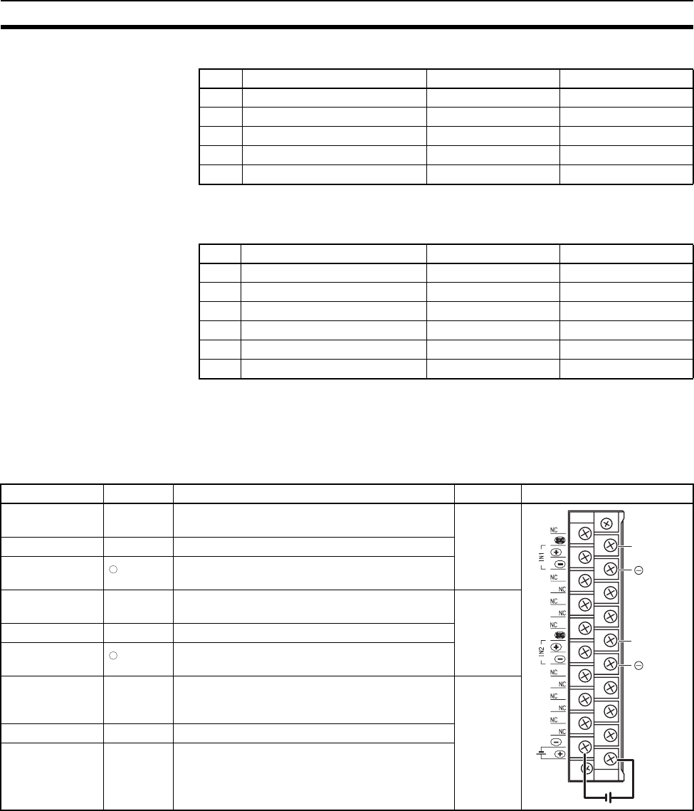
239
B7A Interface Units Section 3-8
■CS1W-B7A21
Defaults: Pin 5 is turned ON and all other pins are turned OFF
■CS1W-B7A22
Defaults: Pins 4 and 5 are turned ON and all other pins are turned OFF
Terminal Names and
Allocations
■CS1W-B7A12
Pin Name OFF ON
1 Transmission delay Standard (19.2 ms) High-speed (3 ms)
2 Transmission error process Hold status Reset Inputs
3 Input mode 16 inputs 15 inputs + error input
5 ERROR indicator enable Disabled Enabled
4, 6 Not used. (Leave OFF.) NA NA
Pin Name OFF ON
1 Transmission delay Standard (19.2 ms) High-speed (3 ms)
2 Transmission error process Hold status Reset Inputs
3 Input mode 16 inputs 15 inputs + error input
4 ERROR 1 indicator enable Disabled Enabled
5 ERROR 2 indicator enable Disabled Enabled
6 Not used. (Leave OFF.) NA NA
Terminal Name Function Word Appearance
B0 SIG IN1 Connect to SIG terminal on Input B7A Link Ter-
minal.
n
A1 +V Connect to + terminal on external power supply.
B1 IN1 Connect to – power supply terminal on Input
B7A Link Terminal.
B4 SIG IN2 Connect to SIG terminal on Input B7A Link Ter-
minal.
n+1
A5 +V Connect to + terminal on external power supply.
B5 IN2 Connect to – power supply terminal on Input
B7A Link Terminal.
A0, A2 to A4, A6
to A8, B2, B3,
B6 to B8
NC Not used. ---
A9 −V Connect to – terminal on external power supply.
B9 +V Connect to + terminal on external power supply.
SIG IN1
SIG IN2
IN1
IN2
−
−
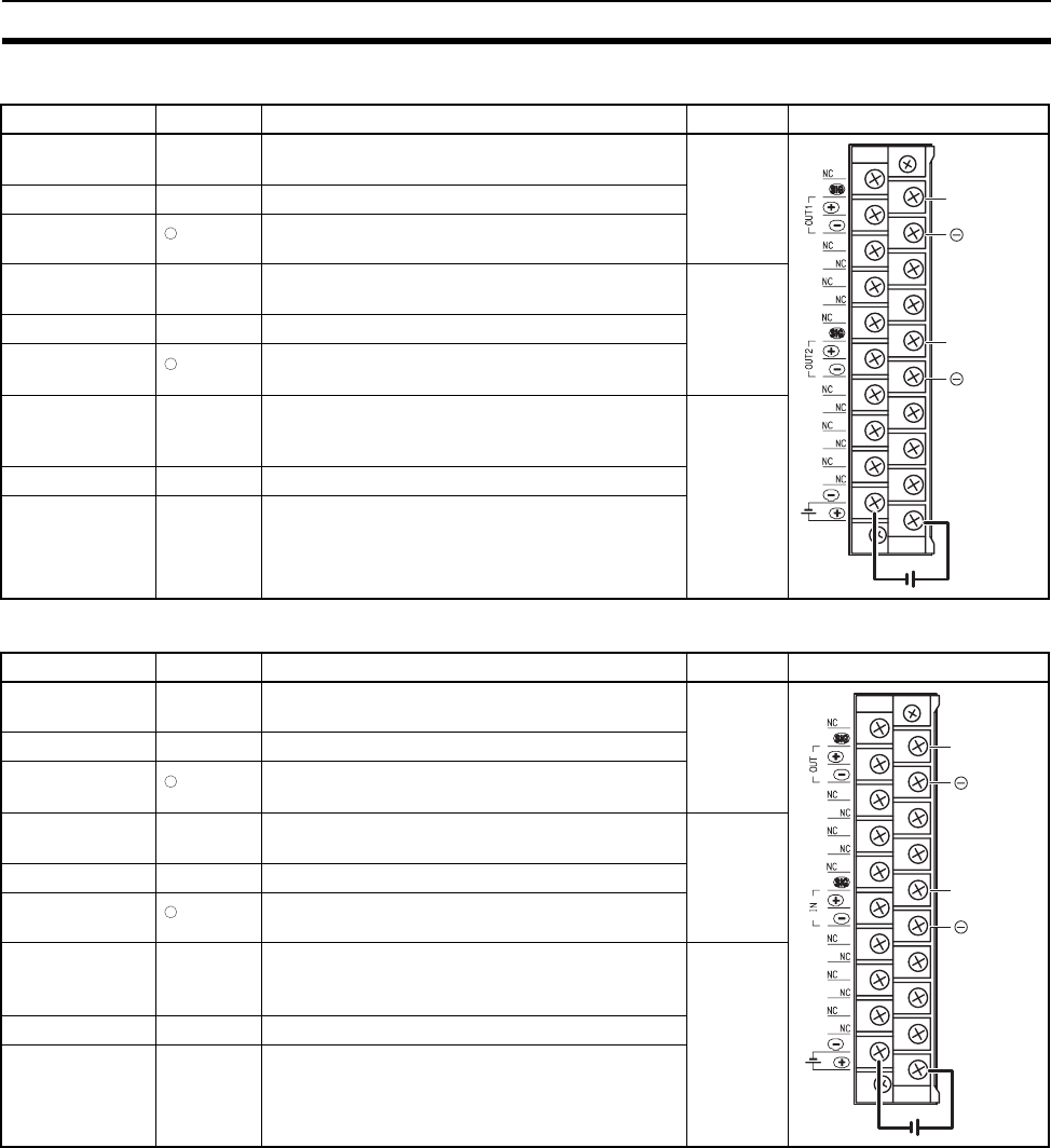
240
B7A Interface Units Section 3-8
■CS1W-B7A02
■CS1W-B7A21
Terminal Name Function Word Appearance
B0 SIG OUT1 Connect to SIG terminal on Output B7A Link
Ter mina l.
n
A1 +V Connect to + terminal on external power supply.
B1 OUT1 Connect to – power supply terminal on Output
B7A Link Terminal.
B4 SIG OUT2 Connect to SIG terminal on Output B7A Link
Ter mina l.
n+1
A5 +V Connect to + terminal on external power supply.
B5 OUT2 Connect to – power supply terminal on Output
B7A Link Terminal.
A0, A2 to A4, A6
to A8, B2, B3,
B6 to B8
NC Not used. ---
A9 −V Connect to – terminal on external power supply.
B9 +V Connect to + terminal on external power supply.
Terminal Name Function Word Appearance
B0 SIG OUT1 Connect to SIG terminal on Output B7A Link
Ter mina l.
n
A1 +V Connect to + terminal on external power supply.
B1 OUT1 Connect to – power supply terminal on Output
B7A Link Terminal.
B4 SIG IN1 Connect to SIG terminal on Input B7A Link Ter-
minal.
n+1
A5 +V Connect to + terminal on external power supply.
B5 IN1 Connect to – power supply terminal on Input
B7A Link Terminal.
A0, A2 to A4, A6
to A8, B2, B3,
B6 to B8
NC Not used. ---
A9 −V Connect to – terminal on external power supply.
B9 +V Connect to + terminal on external power supply.
SIG OUT1
SIG OUT2
OUT1
OUT2
−
−
SIG OU
T
SIG IN
OUT
IN
−
−
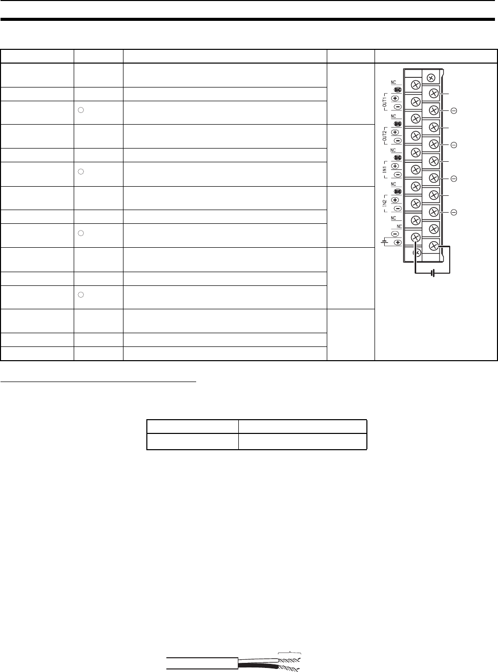
241
B7A Interface Units Section 3-8
■CS1W-B7A22
Preparing and Connecting Cables
Cables
• The current capacity of a wire depends on the ambient temperature and
insulation thickness.
Terminal Screws and Crimp Terminals
M3.5 self-rising screws are used for all power supply wiring terminals.
Note Always turn OFF the Unit's power supply and communications power supply
before attaching or removing connectors.
Use the following procedure to prepare and connect the cables.
1) Preparing the Covering
First, use the following procedure to prepare the cable.
1,2,3... 1. Strip approximately 10 mm of the sheath covering the signal lines to match
the crimp terminals. Next, twist together the wires of each signal line firmly.
Terminal Name Function Word Appearance
B0 SIG OUT1 Connect to SIG terminal on Output B7A Link Ter-
minal.
n
A1 +V Connect to + terminal on external power supply.
B1 OUT1 Connect to – power supply terminal on Output
B7A Link Terminal.
B2 SIG OUT2 Connect to SIG terminal on Output B7A Link Ter-
minal.
n+1
A3 +V Connect to + terminal on external power supply.
B3 OUT2 Connect to – power supply terminal on Output
B7A Link Terminal.
B4 SIG IN1 Connect to SIG terminal on Input B7A Link Ter-
minal.
n+2
A5 +V Connect to + terminal on external power supply.
B5 IN1 Connect to – power supply terminal on Input B7A
Link Terminal.
B6 SIG IN2 Connect to SIG terminal on Input B7A Link Ter-
minal.
n+3
A7 +V Connect to + terminal on external power supply.
B7 IN2 Connect to – power supply terminal on Input B7A
Link Terminal.
A0, A2, A4, A6,
A8, B8
NC Not used. ---
A9 −V Connect to – terminal on external power supply.
B9 +V Connect to + terminal on external power supply.
SIG OUT1
SIG OUT
2
SIG IN1
SIG IN2
OUT1
OUT2
IN1
IN2
−
−
−
−
Terminal connector Recommended wire size
20-pin AWG22 (0.32 mm2)
Approx. 10 mm
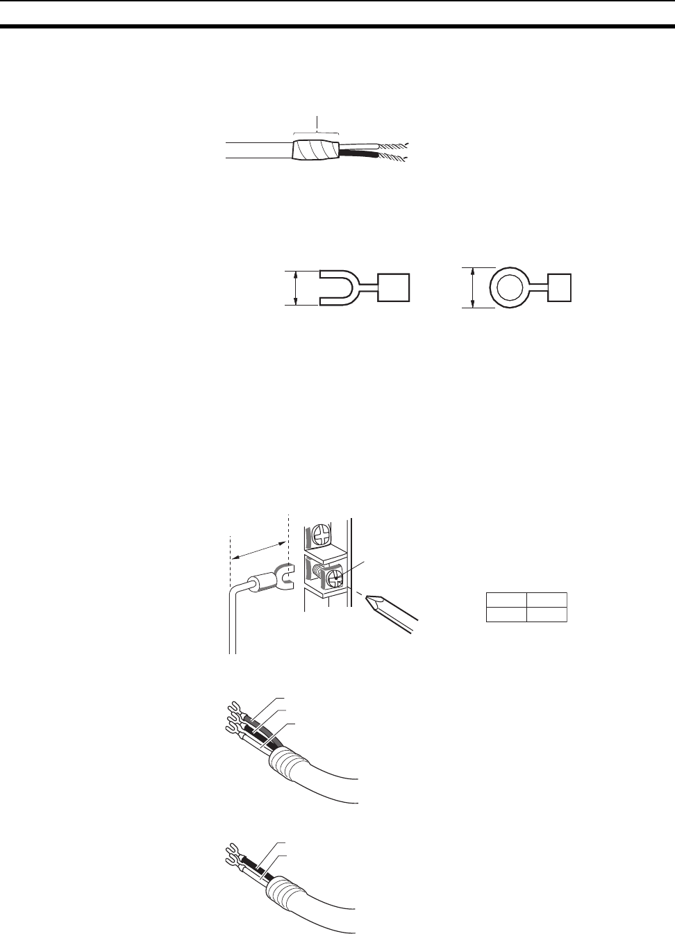
242
B7A Interface Units Section 3-8
2. Use vinyl tape or a heat-shrink tube to cover the end of the VCTF cable
sheath, as shown in the following diagram.
2) Preparing Cable Signal Lines
Attach the crimp terminals to the cable's signal lines.
1,2,3... 1. Attaching Crimp Terminals
Insert the end of the cable into the terminal and crimp.
Note Always use the specified crimp tool to attach the crimp terminals. If
a crimp tool is not used, the cable will not be crimped properly, which
may cause the cable to become detached from the terminal.
2. Insulate the stripped end of each signal line with vinyl tape or heat-shrink
tubing.
Wiring
• Wire the Units so that the I/O indicators are not covered by the wiring.
• Do not place the wiring for I/O Units in the same duct or raceway as power
lines. Inductive noise can cause errors in operation or damage.
• Tighten the terminal screws to the torque of 0.8 N.m.
• Power Supply on One Side (Common Power Supply)
• Power Supply on Both Sides (Separate Power Supplies)
Cover with vinyl tape
or heat-shrinking tube.
6.5 mm max. 7 mm max.
M3.5
Self-rising screw
A
A
20-pin 18 mm
V1
SIG1
G1
SIG1
G1
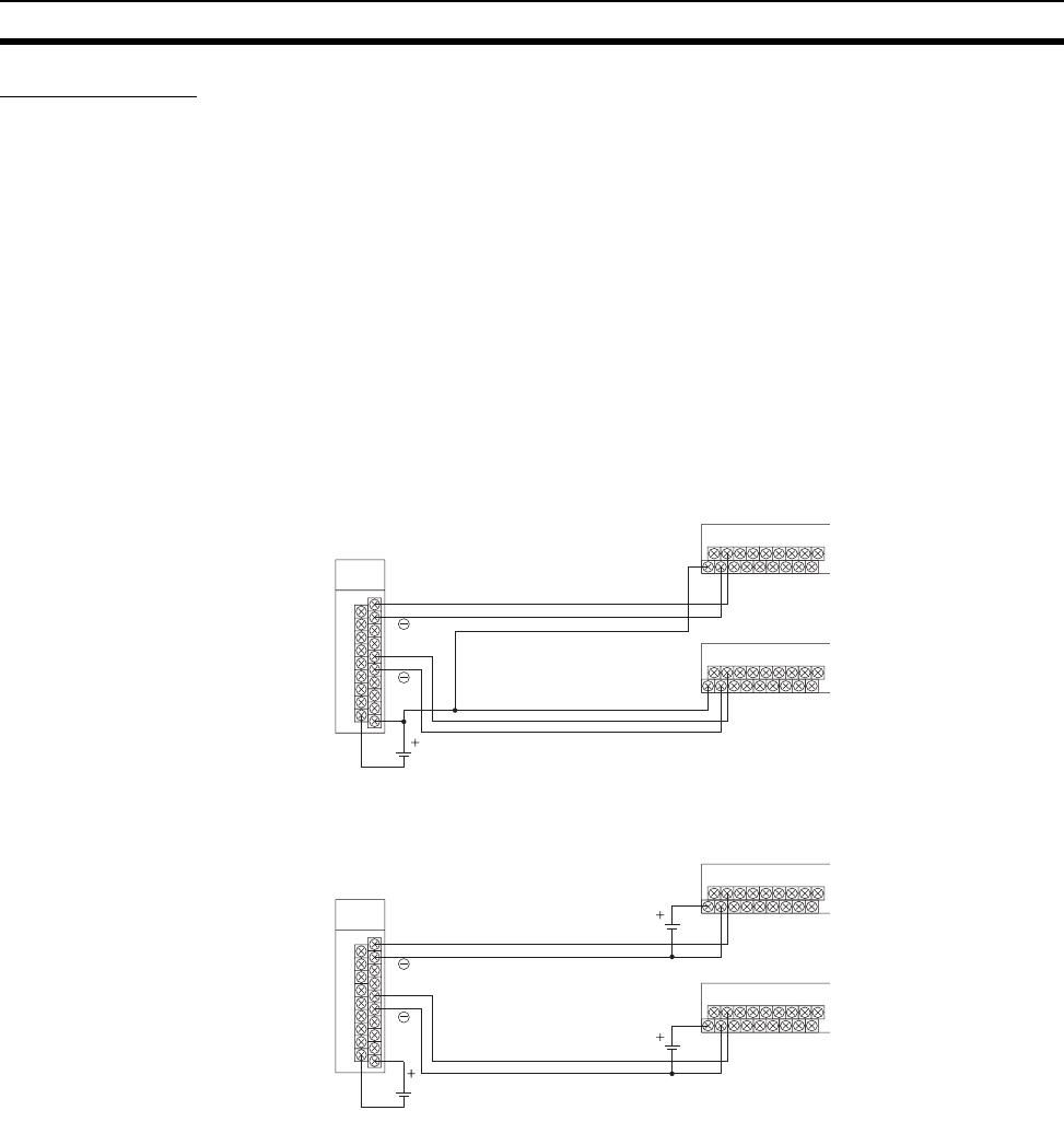
243
B7A Interface Units Section 3-8
Wiring Methods
Note 1. Confirm that terminals are connected correctly. If connections are incor-
rect, the internal components of the B7A Interface Unit and B7A Link Ter-
minal may be damaged.
2. Route the signal lines in separate ducts both inside and outside the control
panel to isolate them from power lines.
3. Connect cables at a distance that is within the range given in the specifi-
cations.
4. Always turn OFF the power to the CPU Unit and all other Units before con-
necting the communications cables.
5. Always lay communications cables within ducts.
Standard Mode
■Common Power Supply
■Separate Power Supplies
High-speed Mode
Note If shielded cable is not used, the maximum transmission distance is 10 m
regardless of whether a common or separate power supplies are used. (Use
VCTF cable of 0.75 mm2 or higher.)
B7A Interface Unit
SIG
SIG
12 to 24 VDC
Transmission distance: 100 m max.
Transmission cable: VCTF, 0.75 mm2 min.
B7A Link Terminal
B7A Link Terminal
B7A Interface Unit
SIG
SIG
12 to 24 VDC
Transmission distance: 500 m max.
Transmission cable: VCTF, 0.75 mm2 max.
B7A Link Terminal
12 to 24 VDC
12 to 24 VDC
B7A Link Terminal
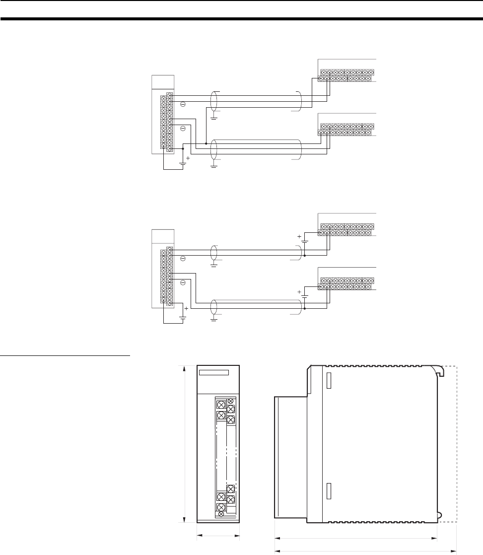
244
B7A Interface Units Section 3-8
■Common Power Supply
■Separate Power Supplies
Dimensions (Unit: mm)
B7A Interface Unit
SIG
SIG
12 to 24 VDC
B7A Link Terminal
Ground
Ground
Shielded cable: 0.75 mm2 max.
Transmission distance: 50 m max.
Shielded cable: 0.75 mm2 max.
B7A Link Terminal
B7A Interface Unit
SIG
SIG
12 to 24 VDC
B7A Link Terminal
Ground
Ground
Shielded cable: 0.75 mm2 max.
Transmission distance: 100 m max.
Shielded cable: 0.75 mm2 max.
12 to 24 VDC
12 to 24 VDC
B7A Link Terminal
35
130
CS
124
147
Backplane
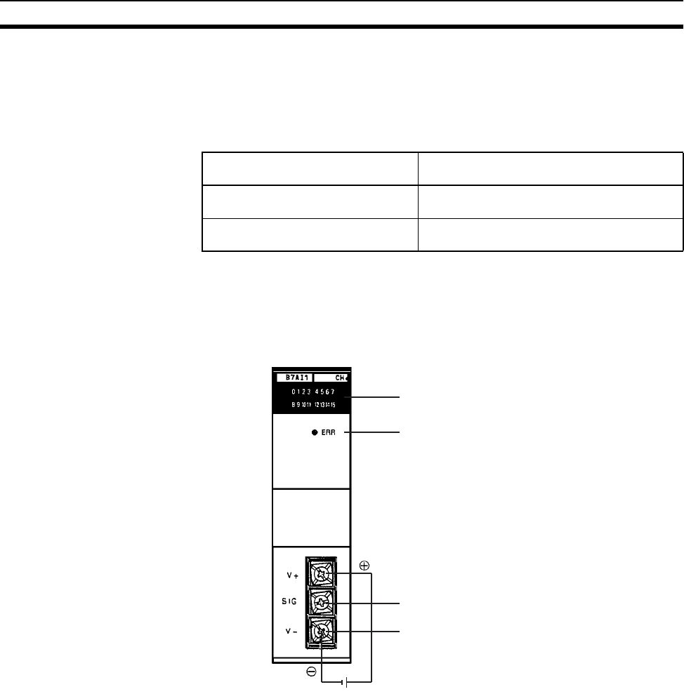
245
B7A Interface Units Section 3-8
3-8-2 C200H Basic B7A Interface Units (C200H Basic I/O Units)
The Basic B7A Interface Unit used with the B7A Link Terminal allows the
transmission and reception of 16-point I/O data over two wires.
The following Basic B7A Interface Unit and B7A Link Terminal models are
available.
Note If the B7A Interface Unit is mounted to a Rack with a C200HW-PD024 24-V
DC Power Supply Unit, supply 24 V DC from an independent power supply to
the B7A Interface Unit or use a transformer to separate the power supply line
to the B7A Interface Unit from the power supply lines to the CPU Unit and I/O
Power Supply Unit.
I/O Indicator Indicates the ON or OFF status of input from the B7A Link Terminal or the ON
and OFF status of output to the B7A Link Terminal.
ERR Indicator Incorporated by the B7AI1 and lit when the B7AI1’s data transmission or
reception is abnormal.
Connection Terminals SIG: Connects to the SIG terminal of the B7A Link Terminal.
V–: Connects to the negative power terminal of the B7A Link Terminal.
!Caution If the terminals are not connected correctly, the internal circuitry of the B7A
Link Terminal will be damaged.
Note 1. The transmission cable must be a VCTF cable with a thickness of
0.75 mm2 minimum.
2. Do not wire power lines or high-tension lines along with the transmission
cable in the same conduit.
B7A Interface Unit
(C200H Basic I/O Unit)
B7A Link Terminals
16-point input: C200H-B7AI1 B7A-T6@1 (Screw terminal models)
B7A-T6D2 (Modular models)
16-point output: C200H-B7AO1 B7A-R6@@1 (Screw terminal models)
B7A-R6A52 (Modular models)
12 to 24 VDC
I/O indicator
Connection terminals for the B7A Link Terminal:
Connect this terminal to the SIG terminal of the
B7A Link Terminal.
Connect this terminal to the negative power ter-
minal of the B7A Link Terminal.
Supply 12 to 24 VDC.
ERR indicator
Connection terminals
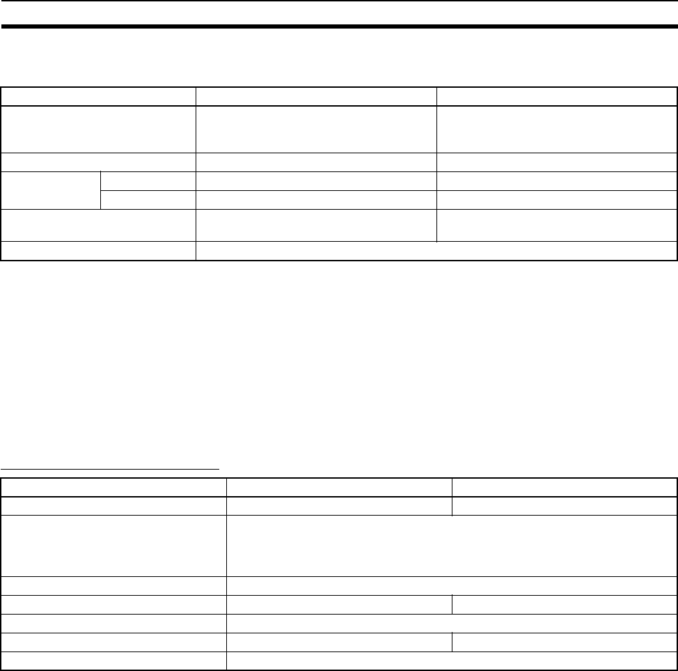
246
B7A Interface Units Section 3-8
Input Mode Selector The B7AI1 incorporates an input mode selector on the back panel of the Unit,
with which the following modes can be set.
The ERR indicator is lit when an error occurs. If the error is corrected, the
ERR indicator is OFF at the next transmission cycle.
When there is a transmission error, the B7A Link Terminal will hold the data
just before the occurrence of the transmission error. If there is a transmission
error because the B7A Link Terminal is turned off, however, data 0 is transmit-
ted in the first transmission cycle when the B7A Link Terminal is turned on
again.
Transmission errors between the C200H-B7AO1 and B7A Link Terminal are
detected by the B7A Link Terminal only. Check the ERR indicator and error bit
for any error.
Performance Specifications
Note 1. The minimum input time refers to the minimum time required for reading
the input signals from the CPU Unit. The ON/OFF width of the signal trans-
mitted from the CPU Unit to the Output Relay of the B7A Interface Unit
should be set to a value larger than the minimum input time.
2. The value of the external power supply does not include the value required
by the B7A Link Terminal.
Input mode 15 points + 1 error 16 points
Function Fifteen-point input from the B7A Link Ter-
minal is effective. Bit 15 is used as trans-
mission error bit.
Sixteen-point input from the B7A Link Ter-
minal is effective.
Switch setting Upper side Lower side
Bit no. allocation 00 to 14 Input 00 to input 14 Input 00 to input 14
15 Transmission error bit Input 15
Status of input indicator lamp 15 Not used Lit when input 15 is ON. Not lit when input
15 is OFF.
Status of the ERR indicator Lit when there is a transmission error and OFF during normal transmission
Item C200H-B7AI1 C200H-B7AO1
I/O points 16 points or 15 points and 1 error input 16 output points
Transmission distance 500 m max. if power is supplied to the Interface Unit and B7A Link Terminal sep-
arately.
100 m max. if power is supplied to the Interface Unit and B7A Link Terminal from
a single power supply. (24 V DC±10%)
Transmission delay Typ. 19.2 ms, 31 ms max.
Minimum input time (See note 1.) ––– 16 ms
Internal current consumption 5 V DC, 100 mA max.
External power supply (See note 2.) 12 to 24 V DC ±10%, 10 mA min. 12 to 24 V DC ±10%, 30 mA min.
Weight 200 g max.
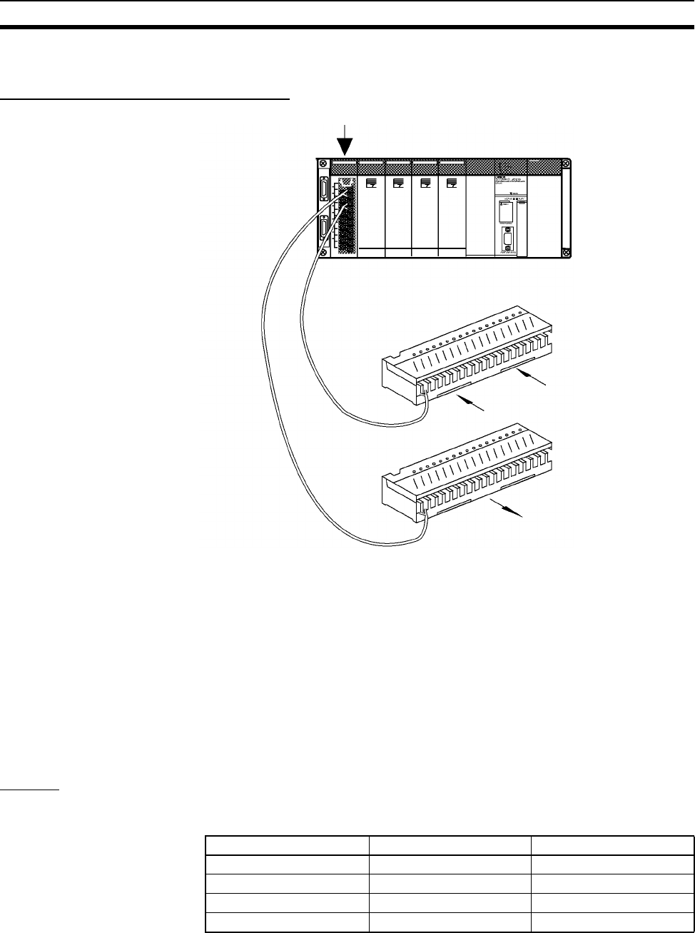
247
B7A Interface Units Section 3-8
3-8-3 B7A Interface Units (C200H Group-2 High-density I/O Units)
Features and System Configuration
A B7A Interface Unit (C200H Group-2 High-density I/O Unit) used with two or
four B7A Link Terminals allows the transmission and reception of 32-point or
64-point I/O data over two-conductor cables.
A B7A Interface Unit (C200H Group-2 High-density I/O Unit) can be mounted
to a CPU Rack or an Expansion I/O Rack. They cannot be mounted to Slave
Racks.
I/O words are allocated in the same way as for C200H Basic I/O Units, i.e.,
according to the position on the Rack. Units with 32 I/O points are allocated
two words; Units with 64 I/O points are allocated four words.
Refer to the B7A Link Terminals Datasheet for more information on B7A Link
Ter m ina ls.
Models
The following B7A Interface Units (C200H Group-2 High-density I/O Units) are
available.
Group-2 B7A Interface Unit
CPU
Unit
Sensor
Switch
Lamps and other loads
Transmission
distance: 500 m
max.
Input B7A Link Terminal
Output B7A Link Terminal
B7A Interface Unit Inputs Outputs
C200H-B7A12 32 points None
C200H-B7A02 None 32 points
C200H-B7A21 16 points 16 points
C200H-B7A22 32 points 32points
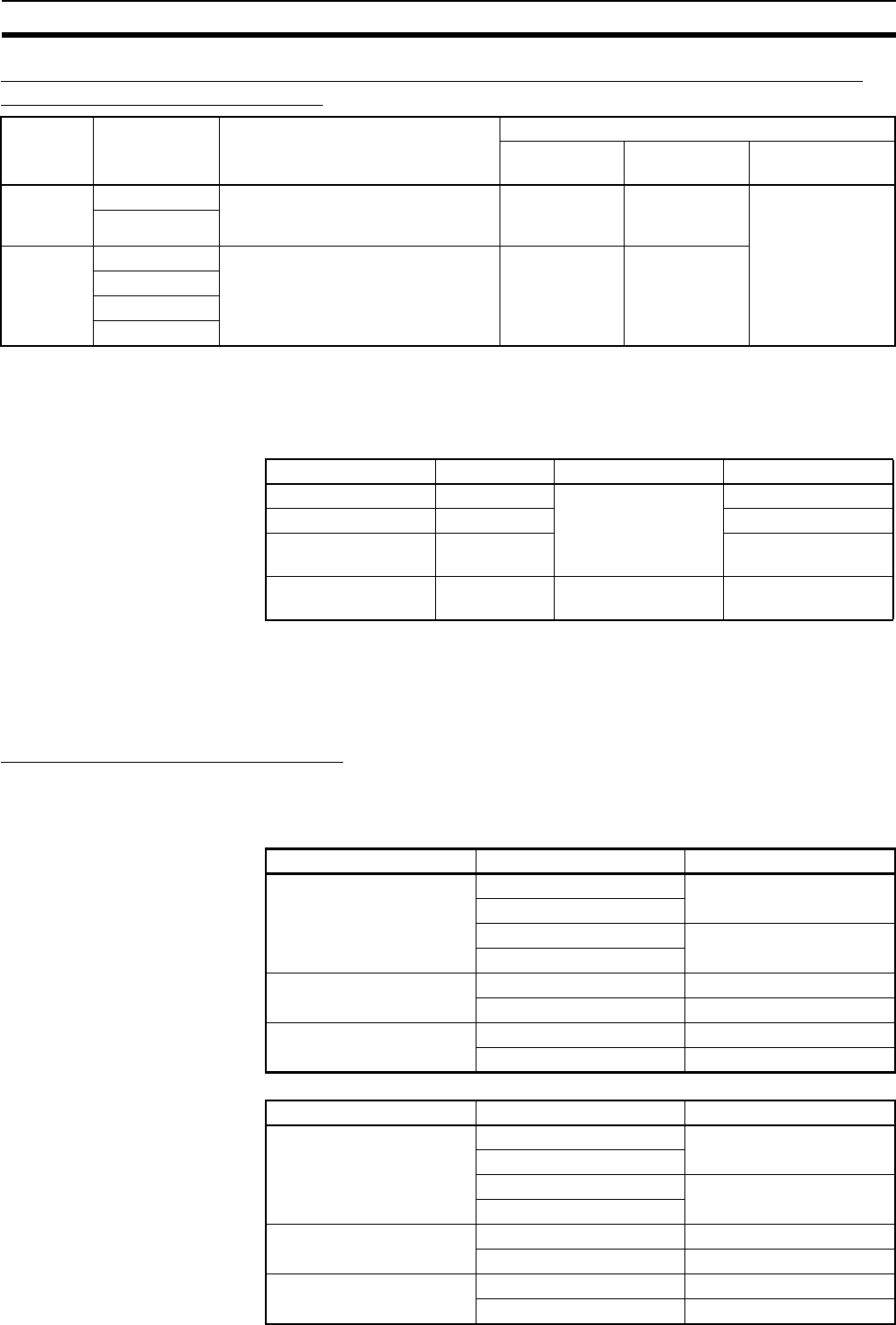
248
B7A Interface Units Section 3-8
Comparison between B7A Interface Units Classified as Basic I/O Units and C200H
Group-2 High-density I/O Units
Note 1. With CS-series PLCs, I/O is allocated to B7A Interface Units (C200H
Group-2 High-density I/O Units) just like other Basic I/O Units (allocating
outputs first and then inputs for I/O Units). The unit number setting on the
front panel of the B7A Interface Unit does not affect I/O allocations.
2. B7A Link Terminals with 10 points or those with 8 input and 8 output points
cannot be connected to the B7A Interface Units. B7A Link Terminals with
16 points, two circuits of 16 points each (32 points total) or 16 points of
mixed I/O can be connected.
Connectable B7A Link Terminals
Only 16-point B7A Link Terminals can be connected to a B7A Interface Unit.
These are listed in the following tables.
Input Terminals
Output Terminals
Type Models Word allocations Connectable B7A Link Terminals
Transmission
delay
Transmission
errors
Points
C200H
Basic I/O
Units
C200H-B7AI1 Same as I/O Units (in order
mounted).
Standard types
only (19.2 ms)
Input status
held automati-
cally
16-point Termi-
nals only (10-
point, 32-point,
and mixed I/O Ter-
minals cannot be
connected.
C200H-B7AO1
C200H
Group 2
High-den-
sity I/O
Units
C200H-B7A12 Same as I/O Units (in order
mounted).
Standard
(19.2 ms) and
high-speed
(3 ms) types
(set via switch)
Switch setting
to hold or reset
Input status.
C200H-B7A02
C200H-B7A21
C200H-B7A22
Name Model Words per Unit Order of allocation
32-point Input Unit C200H-B7A12 2 2 input words
32-point Output Unit C200H-B7A02 2 output words
16-point Input/
16-point Output Unit
C200H-B7A21 1 output word then 1
input word
32-point Input/32-
point Output Unit
C200H-B7A22 4 2 output words then 2
input words
Type Model Transmission delay
Screw terminals B7A-T6@1 Standard (19.2 ms)
B7AS-T6@1
B7A-T6@6 High-speed (3 ms)
B7AS-T6@6
Modular B7A-T6D2 Standard (19.2 ms)
B7A-T6D7 High-speed (3 ms)
PLC connectors B7A-T@E3 Standard (19.2 ms)
B7A-T@E8 High-speed (3 ms)
Type Model Transmission delay
Screw terminals B7A-R6@@1 Standard (19.2 ms)
B7AS-R6@@1
B7A-R6@@6 High-speed (3 ms)
B7AS-R6@@6
Modular B7A-R6A52 Standard (19.2 ms)
B7A-R6A57 High-speed (3 ms)
PLC connectors B7A-R@A@3 Standard (19.2 ms)
B7A-R@A@8 High-speed (3 ms)
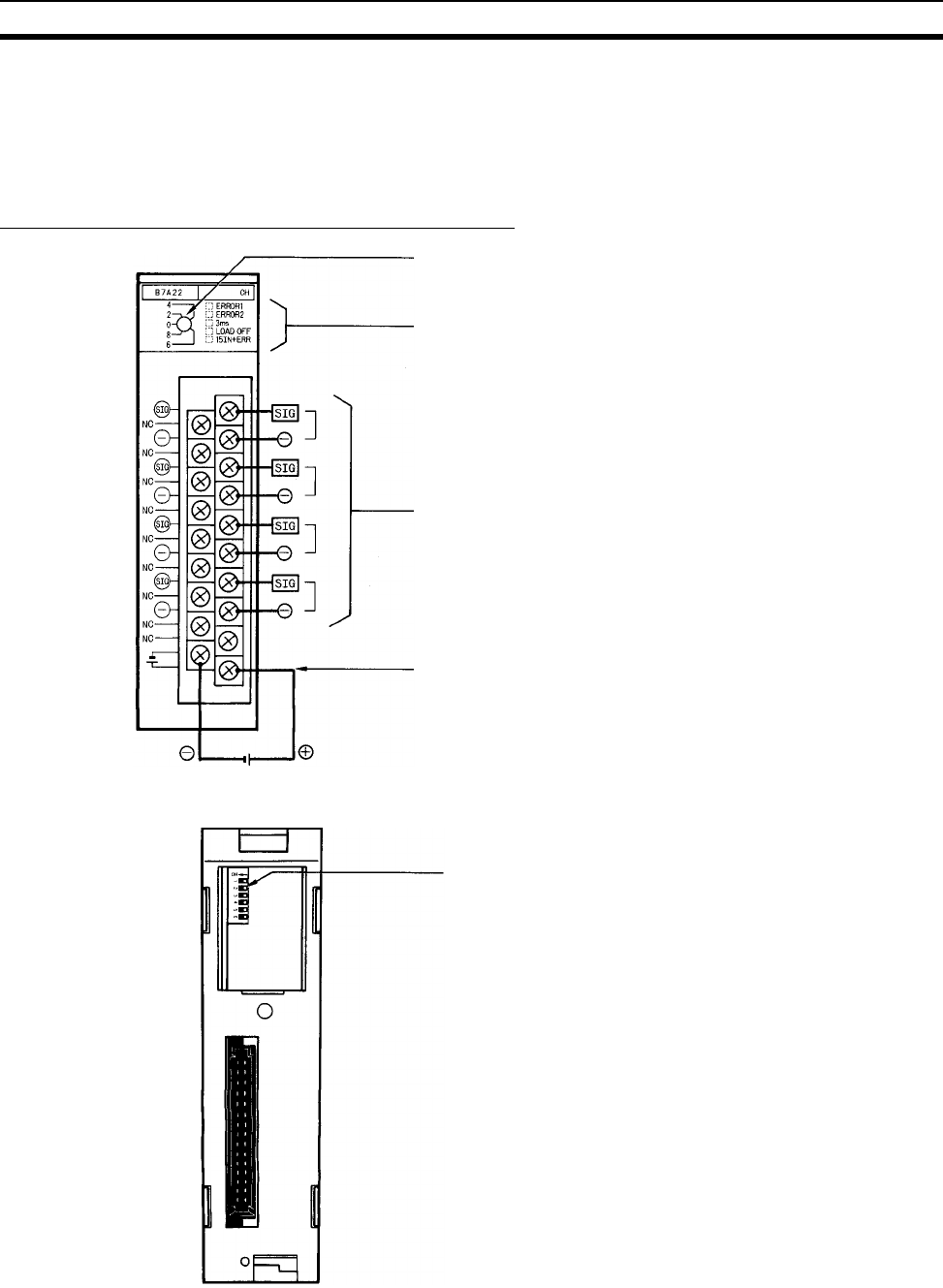
249
B7A Interface Units Section 3-8
Note 1. Do not connect Terminals with different transmission delays to the same
Interface Unit. Doing so will cause a transmission error.
2. Only 16-point or 32-point B7A Link Terminals can be connected to B7A In-
terface Units. Mixed I/O B7A Link Terminals and 10-point B7A Link Termi-
nals cannot be connected.
Parts and Names (C200H-B7A22 shown below)
12 to 24 VDC
External Power Supply Terminals
Supply 12 to 24 VDC.
Connection terminals
Connect to the SIG terminal of the B7A Link Terminal
and to the negative power terminal of the B7A Link
Terminal. The actual use of these terminals depends
on the B7A Interface Unit.
12 to 24 VDC
Front
Status indicators
The indicators depend on the model of B7A Inter-
face Unit.
I/O number switch
Not used for CS PLCs.
DIP switch
Used to set the transmission delay,
transmission error processing mode, in-
put mode, and ERROR indicator opera-
tion.
Back
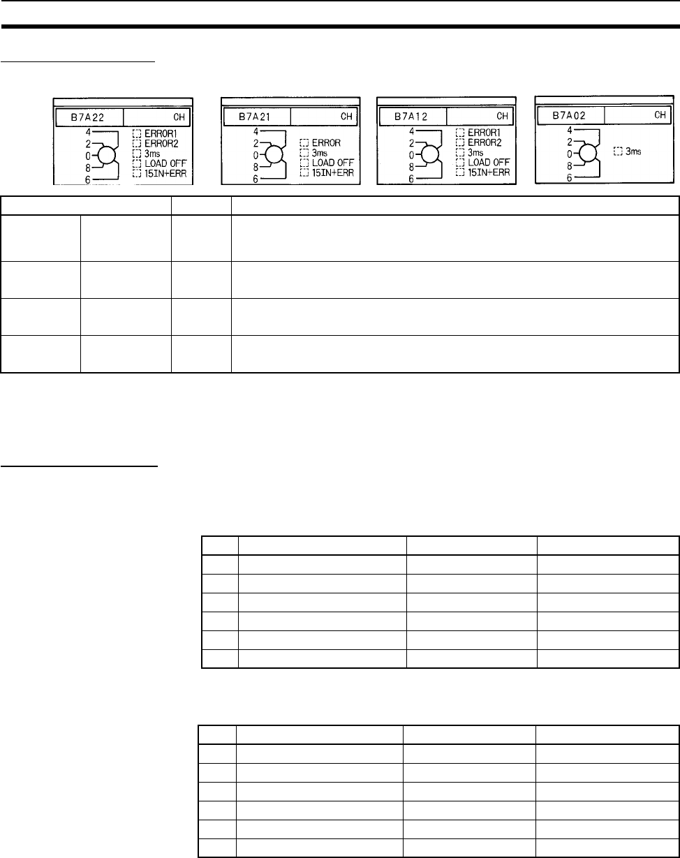
250
B7A Interface Units Section 3-8
Indicator Operation
The indicators depend on the model of B7A Interface Unit, as shown below.
Note With CS-series PLCs, I/O is allocated to Group-2 B7A Interface Units just like
other Basic I/O Units. The unit number setting on the front panel of the Group-
2 B7A Interface Unit is not used and does not affect I/O allocations.
DIP Switch Settings
Set the DIP switch as described before for the various models of B7A Inter-
face Units.
C200H-B7A22/12
Factory settings: Pins 4 and 5 ON, others OFF.
C200H-B7A21
Factory settings: Pin 5 ON, others OFF.
Name Color Function
ERROR 1
ERROR 2
ERROR
Input trans-
mission error
Red Lights when an error occurs in transmissions from an Input B7A Link Terminal.
For the B7A12/22, ERROR 1 is for the first word allocated to the B7A Interface
Unit; ERROR 2 is for the second word.
3ms Transmission
delay setting
Orange Lit when the transmission delay is set to the high-speed setting (3 ms).
Not lit when the transmission delay is set to the standard setting (19.2 ms).
LOAD OFF Transmission
error process
Orange Lit when the processing for transmission errors is set to reset input status.
Not lit when the processing for transmission errors is set to hold input status.
15IN+ERR Input mode
setting
Orange Lit when the input mode is set to use 15 inputs and 1 error input.
Not lit when the input mode is set to use 16 inputs.
Pin Function OFF ON
1 Transmission delay Standard (19.2 ms) High-speed (3 ms)
2 Transmission error process Hold status Reset Inputs
3 Input mode 16 inputs 15 inputs + error input
4 ERROR 1 indicator enable Disabled Enabled
5 ERROR 2 indicator enable Disabled Enabled
6 Not used. NA NA
Pin Function OFF ON
1 Transmission delay Standard (19.2 ms) High-speed (3 ms)
2 Transmission error process Hold status Reset Inputs
3 Input mode 16 inputs 15 inputs + error input
4 ERROR indicator enable Disabled Enabled
5 Not used. NA NA
6 Not used. NA NA

251
B7A Interface Units Section 3-8
C200H-B7A02
Factory settings: All pins OFF.
Transmission Delay Pin 1 is used to set the transmission delay. The same delay is used for all
words allocated to the Unit.
Set the transmission delay to match that of the B7A Link Terminal. A transmis-
sion error will occur if the same transmission delay is not set.
The “3ms” indicator will be lit whenever the high-speed (3 ms) transmission
delay is set.
Transmission Error
Process
Pin 2 is used to turned ON to specify resetting input status when transmission
errors occur. If pin 2 is turned OFF, input status will be held when transmission
errors occur.
The LOAD OFF indicator will be lit whenever pin 2 is turned ON.
Input Mode Pin 3 is turned ON to specify use of only 15 inputs and the use of bit 15 as a
Transmission Error Flag. If pin 3 is OFF, 16 normal inputs can be used.
The “15IN+ERR” indicator will be lit whenever pin 3 is turned ON.
ERROR Indicators Pin 4 or pins 4 and 5 are turned ON to enable the ERROR, ERROR 1, and/or
ERROR 2 indicators. These indicators will not light even if a transmission
error occurs if the corresponding pin is turned OFF.
Transmission Error Precautions
Startup The Transmission Error Flag for the B7A Interface Unit will be OFF when
power is turned on to the CS-series PLCs. If normal transmissions with the
B7A Link Terminal are not possible within about 10 ms, the Transmission Error
Flag (bit 15) will turn ON (i.e., if its operation is enabled by the input mode set-
ting).
All input bits will remain OFF until normal transmissions are achieved.
Inputs When a transmission error occurs, input status will be either held or all inputs
will be reset according to the setting for the transmission error process, and
the Transmission Error Flag (bit 15) will turn ON (i.e., if its operation is enabled
by the input mode setting). The Transmission Error Flag will go OFF and the
input status will return to normal when normal transmissions are achieved
again.
Outputs Transmission errors for Output B7A Link Terminals are not detected at the
B7A Interface Unit and must be confirmed using the error indicators or error
outputs on the Link Terminal.
Wiring
Terminal Names and
Allocations
The use of the terminals depends on the model of the B7A Interface Unit. “m”
indicates the first word allocated to the Unit.
Pin Function OFF ON
1 Transmission delay Standard (19.2 ms) High-speed (3 ms)
2 Not used. NA NA
3 Not used. NA NA
4 Not used. NA NA
5 Not used. NA NA
6 Not used. NA NA
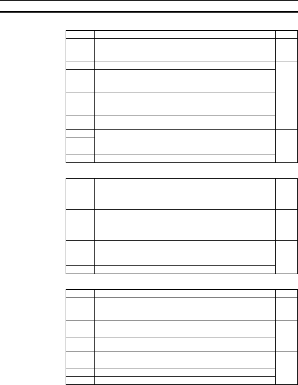
252
B7A Interface Units Section 3-8
C200H-B7A22
C200H-B7A21
C200H-B7A12
Terminal Name Function Word
B0 SIG OUT1 Connect to SIG terminal on Output B7A Link Terminal. m
B1 – OUT1 Connect to – power supply terminal on Output B7A Link
Te r m i n a l .
B2 SIG OUT2 Connect to SIG terminal on Output B7A Link Terminal. m + 1
B3 – OUT2 Connect to – power supply terminal on Output B7A Link
Te r m i n a l .
B4 SIG IN1 Connect to SIG terminal on Input B7A Link Terminal. m + 2
B5 – IN1 Connect to – power supply terminal on Input B7A Link Ter-
minal.
B6 SIG IN2 Connect to SIG terminal on Input B7A Link Terminal. m + 3
B7 – IN2 Connect to – power supply terminal on Input B7A Link Ter-
minal.
B8 NC Not used. ---
A0 to A7
B9 +V Connect to + terminal on external power supply.
A8 –V Connect to – terminal on external power supply.
Terminal Name Function Word
B0 SIG OUT1 Connect to SIG terminal on Output B7A Link Terminal. m
B1 – OUT1 Connect to – power supply terminal on Output B7A Link
Te r m i n a l .
B2, B3 NC Not used. ---
B4 SIG IN1 Connect to SIG terminal on Input B7A Link Terminal. m + 1
B5 – IN1 Connect to – power supply terminal on Input B7A Link Ter-
minal.
B6 to B8 NC Not used. ----
A0 to A7
B9 +V Connect to + terminal on external power supply.
A8 –V Connect to – terminal on external power supply.
Terminal Name Function Word
B0 SIG IN1 Connect to SIG terminal on Input B7A Link Terminal. m
B1 – IN1 Connect to – power supply terminal on Input B7A Link Ter-
minal.
B2, B3 NC Not used. ---
B4 SIG IN2 Connect to SIG terminal on Input B7A Link Terminal. m + 1
B5 – IN2 Connect to – power supply terminal on Input B7A Link Ter-
minal.
B6 to B8 NC Not used. ---
A0 to A7
B9 +V Connect to + terminal on external power supply.
A8 –V Connect to – terminal on external power supply.
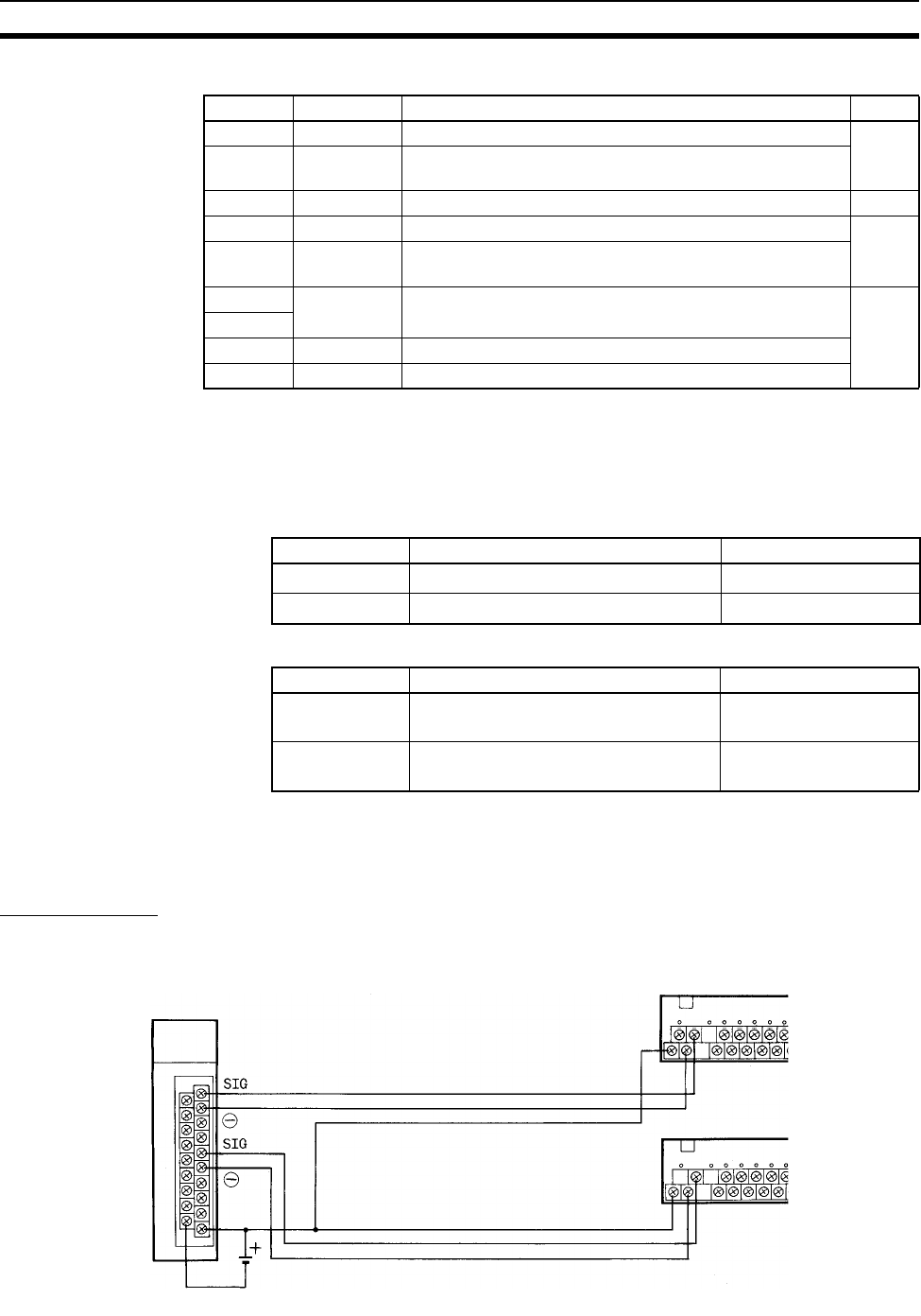
253
B7A Interface Units Section 3-8
C200H-B7A02
Recommended Cables
and Transmission
Distance
The following cables are recommended to connect the B7A Interface Unit to
B7A Link Terminals. The wiring method and transmission distance depend on
the transmission delay and on whether or not a common power supply is
being used for the B7A Link Terminal and the Interface Unit.
Standard Transmission
Delays (19.2 ms): Cap-tire
Cable
High-speed Transmission
Delays (3 ms): Shielded
Cable
Terminal Construction
Use hook-type crimp connectors with a line thickness of 0.25 to 1.65 mm2.
The construction of the terminals is shown in the illustration.
Wiring Method
Standard Transmission Delays (19.2 ms)
Terminal Name Function Word
B0 SIG OUT1 Connect to SIG terminal on Output B7A Link Terminal. m
B1 – OUT1 Connect to – power supply terminal on Output B7A Link
Te r m i n a l .
B2, B3 NC Not used. ---
B4 SIG OUT2 Connect to SIG terminal on Output B7A Link Terminal. m + 1
B5 – OUT2 Connect to – power supply terminal on Output B7A Link
Te r m i n a l .
B6 to B8 NC Not used. ---
A0 to A7
B9 +V Connect to + terminal on external power supply.
A8 –V Connect to – terminal on external power supply.
Power supply Cable Transmission distance
Common VCTF, 0.75 mm2 x 3 conductors 100 m max.
Separate VCTF,0.75 mm2 x 2 conductors 500 m max.
Power supply Cable Transmission distance
Common Shielded cable, 0.75 mm2 x 3 conduc-
tors
50 m max.
Separate Shielded cable, 0.75 mm2 x 2 conduc-
tors
100 m max.
Transmission distance: 100 m max.
Transmission cable: VCTF 0.75 mm
2
or higher
B7A Link Terminal
B7A Link Terminal
12 to 24 V DC
B7A Interface Unit
Common Power Supply
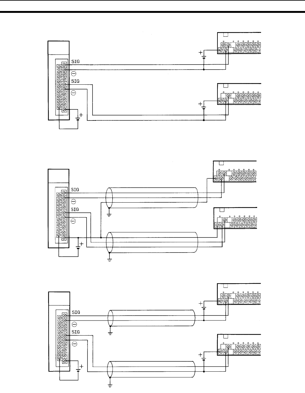
254
B7A Interface Units Section 3-8
High-speed Transmission Delays (3 ms): Shielded Cable
Note 1. We recommend grounding the shielded cable.
2. If shielded cable is not used, the maximum transmission distance is 10 m
regardless of whether a common or separate power supplies are used.
(Use 0.75 mm2 or higher VCTF cable.)
3. To prevent noise on the transmission cable, do not lay it near power cables
or high-voltage lines.
Transmission distance: 500 m max.
Transmission cable: VCTF 0.75 mm
2
or higher
B7A Link Terminal
B7A Link Terminal
12 to 24 V DC
B7A Interface Unit
12 to 24 V DC
12 to 24 V DC
Separate Power Supplies
Transmission distance: 50 m max.
Shielded cable: 0.75 mm2 or higher
B7A Link Terminal
B7A Link Terminal
24 V DC+10%
B7A Interface Unit
Shielded cable: 0.75 mm2 or higher
GND
GND
Common Power Supply
Transmission distance: 100 m max.
Shielded cable: 0.75 mm2 or higher
B7A Link Terminal
B7A Link Terminal
12 to 24 V DC
B7A Interface Unit
Shielded cable: 0.75 mm2 or higher
GND
GND
12 to 24 V DC
12 to 24 V DC
Separate Power Supplies
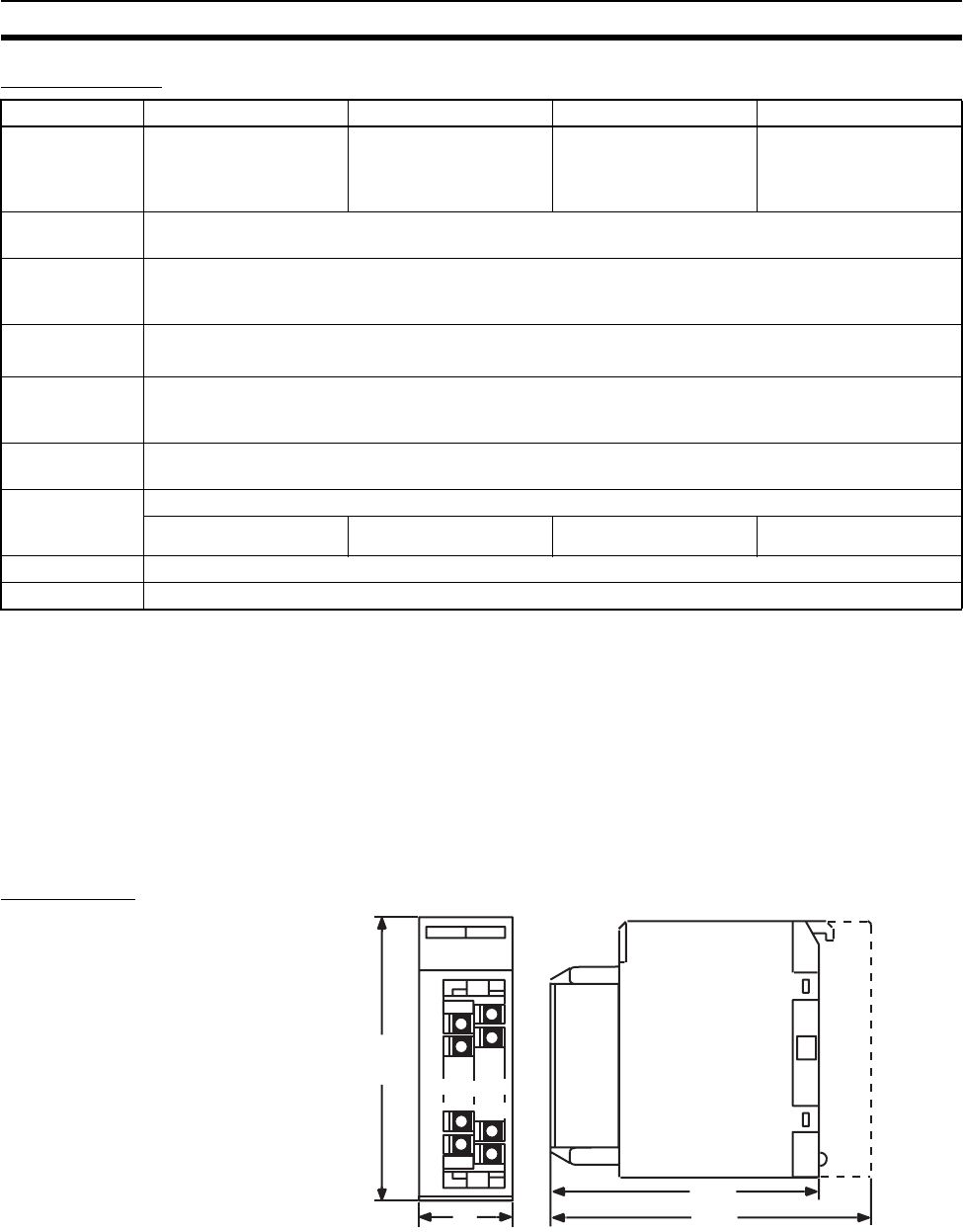
255
B7A Interface Units Section 3-8
Specifications
Note 1. The transmission distance also depends on whether a common or sepa-
rate power supplies are used.
2. The minimum input time refers to the minimum time required for reading
the input signals from the CPU Unit.
3. The ON/OFF width of the signal transmitted from the CPU Unit to the Out-
put Relay of the B7A Interface Unit should be set to a value larger than the
minimum input time.
4. The capacity of the external power supply does not include the capacity re-
quired by the B7A Link Terminal.
Dimensions
Item C200H-B7A12 C200H-B7A02 C200H-B7A21 C200H-B7A22
I/O points 32 input points or
30 input points and 2
error inputs
32 output points 16 output points and
16 input points or
15 input points + 1 error
input
32 output points and
32 input points or
30 input points + 2 error
inputs
Transmission
method
One-way distributed multiplex transmission
Transmission
distance (see
note 1)
Standard: 500 m max.
High-speed: 100 m max.
Transmission
delay
Standard: Typ. 19.2 ms, 31 ms max.
High-speed: Typ. 3 ms, 5 ms max.
Minimum input
time (see note
2, 3)
Standard: 16 ms
High-speed: 2.4 ms
Internal current
consumption
5 V DC, 100 mA max.
External power
supply (see note
4)
12 to 24 V DC ±10%
0.05 A min. 0.06 A min. 0.05 A min. 0.08 A min.
Weight 300 g max.
Dimensions 35 x 130 x 128 mm (W x H x D)
x
xx
x
x
xx
x
35
130
145
128
Back-
plane
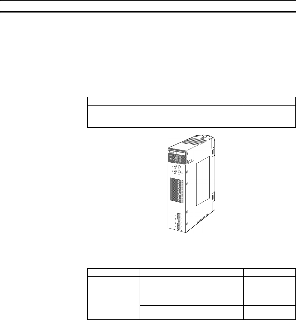
256
Analog Timer Units Section 3-9
3-9 Analog Timer Units
Analog Timer Units are classified as Basic I/O Units.
Analog Timer Units have 4 built-in timers (numbers 0 to 3). The timer settings
can be adjusted using the internal and external variable resistors without
requiring a Programming Device. The timer can also be used as a accumula-
tive register to temporarily pause the timer operation using a timer pause
input.
Models
The Analog Timer Unit is classified as a Basic I/O Unit and is allocated one
word in the I/O Area. The word (16 bits) allocated to the Unit is used for the 4
timers’ start input, pause input, time-up output, and data transfer with the CPU
Unit.
The timer settings are adjusted using the internal and external variable resis-
tors. The timer settings can be selected using the DIP switch for each timer
number from one of the following four settings.
0.1 to 1 s, 1 to 10 s, 10 to 60 s, 1 to 10 min
Name Specifications Model
Analog Timer Unit 4-point timer
Timer settings: 0.1 to 1.0 s, 1.0 to 10 s, 10
to 60 s, 1 to 10 min.
C200H-TM001
Allocated words Bits Details Direction
1 word (16 bits) 4 (bits 0 to 3) Set Bit CPU Unit to Ana-
log Timer Unit
4 (bits 4 to 7) Pause Inputs CPU Unit to Ana-
log Timer Unit
4 (bits 8 to 11) Time-up Outputs Analog Timer Unit
to CPU Unit
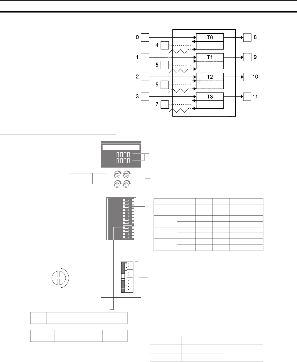
257
Analog Timer Units Section 3-9
Components and Switch Settings
Note 1. When the internal variable resistor is used, make sure that the external
variable resistor connector for the same timer number is open. Otherwise
the internal variable resistor settings will not function properly.
2. Use AWG 28 to AWG 22 lead wires for the external variable resistor con-
nectors.
3. Soldering is not required to wire the external variable resistor connectors.
Wire the connector as shown in the following diagram.
Timer set input Analog Timer Unit Timer up output
Timer pause input
Resistance
value
Resistance
value
Resistance
value
Setting value
Setting value
Setting value
Setting value
Resistance
value
Timer status indicators
The SET indicators in the top row light when the corresponding
timer is operating and the TIME UP indicators in the bottom row
light when the corresponding time is up.
Internal variable resistor
Sets variable resistance of specified
timer setting.
The settings of these resistors are
only effective when the selector
switch on the Unit is ON (set to the
right).
Numbers 0 to 3 correspond to timers
T0 to T3, respectively.
Set or adjust times using the flat-
blade screwdriver supplied with the
Unit. turning the variable resistor
clockwise to increase the time value.
Time range setting
Each timer uses 2 pins. The upper 8 pins 8 to 1 are used for
timers T0 to T3 as follows:
(0: OFF, 1: ON)
External variable resistor connectors
Cable connector for when timer is set with external volume
instead of internal volume.
Turn OFF (set to left) the Internal/external volume selector
switch.
Numbers 0 to 3 correspond to timers T0 to T3.
The external volume resistance is 20 kΩ.
Use the following connectors. The C4K-CN223 (2 m) connector
with cable can also be used.
INT/EXT selector switch
ON Internal variable resistor
OFF External variable resistor
Name
Min.
Max.
Timer Pin 0.1 to 1 s 1 to 10 s 10 to 60 s 1 to 10 m
T0 80101
70011
T1 60101
50011
T2 40101
30011
T3 20101
10011
Contact
ManufacturerModel
Connector Japan Aviation
Electronics
Industry, Ltd.
IL-2S-S3L-(N)
IL-C2-1-10000
T0 T1 T2 T3
SW4 SW3 SW2 SW1
TM001
SET
TIME UP
0123
18
7
6
5
4
3
2
NO
14
3
2
NO
0
1
2
3
0
2
1
3
•
•
•
•
•
•
•
•
•
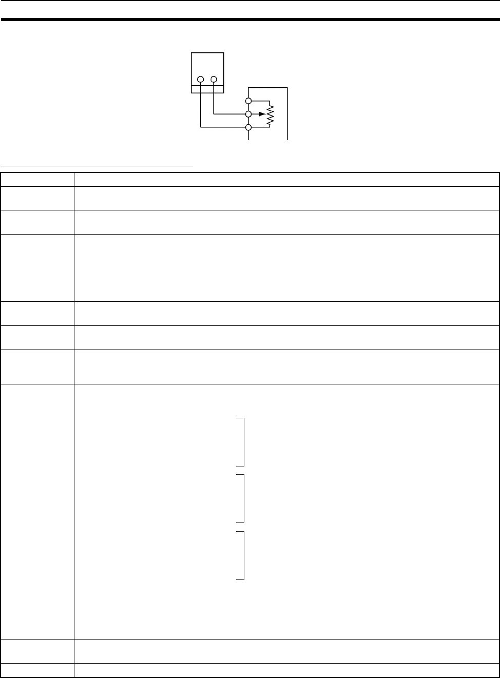
258
Analog Timer Units Section 3-9
Analog Timer Unit Specifications
Analog Timer Unit connector
External variable resistor: 20 kΩ
Diameter: 16
Shaft length: 15 mm
Check manufacturer's specifications
Item Specifications
Oscillation
method
CR oscillation
Number of timer
points
4
Time setting
range
Use the DIP switch to set any of the following four ranges.
0.1 to 1 s (typical)
1 to 10 s (typical)
10 to 60 s (typical)
1 to 10 min (typical)
Timer pause
function
The timing operation can be paused by the user program, so the timers can be used as cumulative reg-
isters.
Operation
indicators
SET and TIME UP
External
variable resistor
Either the external variable resistor or the internal variable resistor can be selected using the INT/EXT
selector switch on the front panel of the Unit. External variable resistors are connected by wiring the
connector. Use 20 kΩ variable resistors
Relay number
allocations
Internal current
consumption
60 mA 5 V DC max.
Weight 200 g max.
One word (16 bits) is allocated in the I/O Area.
Bit I/O Word n
00 Output T0 Set Bit
01 Output T1 Set Bit "1" when time is running
02 Output T2 Set Bit
03 Output T3 Set Bit
04 Output T0 Pause Input Bit 0: Operates
05 Output T1 Pause Input Bit 1: Stops
06 Output T2 Pause Input Bit
07 Output T3 Pause Input Bit
08 Input T0 Completion Flag
09 Input T1 Completion Flag "1" when time is up
10 Input T2 Completion Flag
11 Input T3 Completion Flag
12 --- Not Used
13 --- Not Used
14 --- Not Used
15 --- Not Used
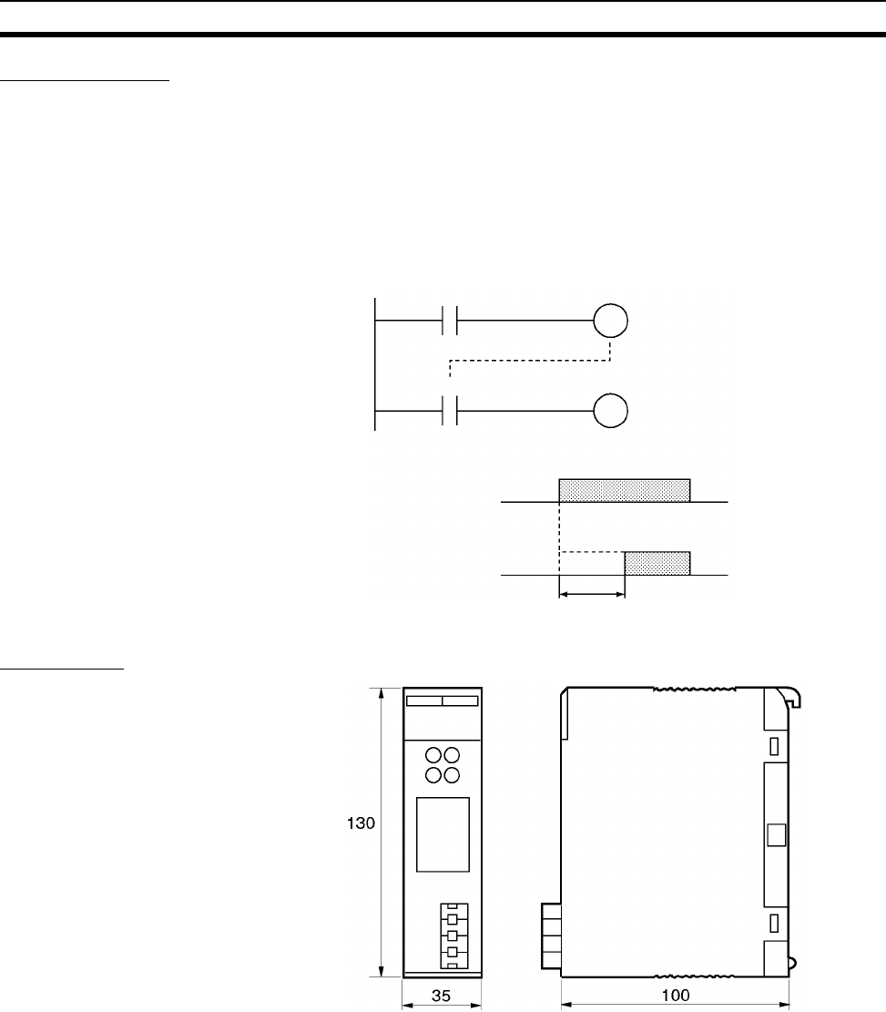
259
Analog Timer Units Section 3-9
Timer Operation
• When the Timer Start Input turns ON, the Timer Set Bits allocated to the
Analog Timer Unit (word n bits 00 to 03) turn ON, and the Analog Timer
will operate. The timer set indicator (SET) on the Analog Timer Unit will
light.
• After the time specified by the internal variable resistor or external vari-
able resistor has elapsed, the Unit’s Completion Output (word n bits 08 to
11) will turn ON, and the Time Up Output will turn ON. The TIME UP indi-
cator on the Analog Timer Unit will turn light.
Dimensions
Timer Start Input
Timer Set Bit
Word n bit 00 to 03
Time Up Output
Word n bit 08 to 11
Timer Start Input
Time Up Output
Timer settin
g
time
Completion Flag

260
Analog Timer Units Section 3-9
261
SECTION 4
Operating Procedures
This section outlines the steps required to assemble and operate a CS-series PLC system.
4-1 Introduction. . . . . . . . . . . . . . . . . . . . . . . . . . . . . . . . . . . . . . . . . . . . . . . . . . . 262
4-2 Examples. . . . . . . . . . . . . . . . . . . . . . . . . . . . . . . . . . . . . . . . . . . . . . . . . . . . . 264

262
Introduction Section 4-1
4-1 Introduction
The following procedure outlines the recommended steps to follow when pre-
paring CS-series PLCs for operation.
1,2,3... 1. Installation
Set the DIP switches on the front of each Unit as required.
Mount the CPU Unit, Power Supply Unit, and other Units to the Backplane.
Install the Inner Board and Memory Card if required.
See 5-2 Installation for details.
2. Wiring
Connect the power supply wiring, I/O wiring, and Programming Device
(CX-Programmer or Programming Console). Connect communications
wiring as required.
See 5-3 Wiring for details on power supply and I/O wiring.
3. Initial Settings (Hardware)
Set the DIP switches an Rotary switches on the front of the CPU Unit and
other Units.
See 6-1 DIP Switch Settings for details.
4. Confirming Programming Device Connection
a) Connect a Programming Device (i.e., the CX-Programmer or a Pro-
gramming Console).
b) Check the power supply wiring and voltage, turn ON the power supply,
and check to be sure the Programming Device will connect to the CPU
Unit.
See 3-3 Programming Devices for details.
5. Registering the I/O Table
Check the Units to verify that they are installed in the right slots. With the
PLC in PROGRAM mode, register the I/O table from the Programming De-
vice (CX-Programmer or Programming Console). (Another method is to
create the I/O table in CX-Programmer and transfer it to the CPU Unit.)
See 8-1 I/O Allocations for details.
6. PLC Setup Settings
With the PLC in PROGRAM mode, change the settings in the PLC Setup
as necessary from the Programming Device (CX-Programmer or Program-
ming Console). (Another method is to change the PLC Setup in CX-Pro-
grammer and transfer it to the CPU Unit.)
See 7-1 PLC Setup for details.
7. DM Area Settings
a) Use a Programming Device (CX-Programmer or Programming Con-
sole) to make any necessary settings in the parts of the DM Area that
are allocated to Special I/O Units, CS-series CPU Bus Units, and Inner
Boards.
b) Reset the power (ON → OFF → ON) or toggle the Restart Bit for each
Unit or Board. See the Unit’s or Board’s Operation Manual for details.
8. Writing the Program
Write the program with a Programming Device (CX-Programmer or Pro-
gramming Console.)
9. Transferring the Program (CX-Programmer Only)

263
Introduction Section 4-1
With the PLC in PROGRAM mode, transfer the program from CX-Pro-
grammer to the CPU Unit. See 7-1 Program Transfer in the CS/CJ Series
Programmable Controllers Programming Manual (W394) for details.
10. Testing Operation
a) Checking I/O Wiring
b) Auxiliary Area Settings (As Required)
Check operation of special Auxiliary Area Settings such as the follow-
ing:
c) Trial Operation
Test PLC operation by switching the PLC to MONITOR mode.
d) Monitoring and Debugging
Monitor operation from the Programming Device. Use functions such
as force-setting/force-resetting bits, tracing, and online editing to de-
bug the program.
See SECTION 7 Program Transfer, Trial Operation, and Debugging in
the CS/CJ Series Programmable Controllers Programming Manual
(W394) for details.
11. Saving and Printing the Program
12. Running the Program
Switch the PLC to RUN mode to run the program.
Output wiring With the PLC in PROGRAM mode, force-set output bits
and check the status of the corresponding outputs.
Input wiring Activate sensors and switches and either check the status
of the indicators on the Input Unit or check the status of the
corresponding input bits with the Programming Device’s
Bit/Word Monitor operation.
Output OFF
Bit
When necessary, turn ON the Output OFF Bit (A50015)
from the program and test operation with the outputs
forced OFF.
Hot Start Set-
tings
When you want to start operation (switch to RUN mode)
without changing the contents of I/O memory, turn ON the
IOM Hold Bit (A50012).
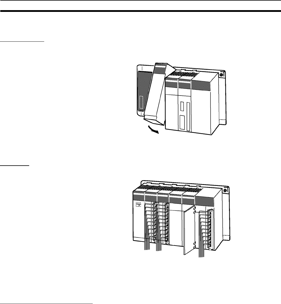
264
Examples Section 4-2
4-2 Examples
1. Installation
Mount the Backplane and install each Unit. When necessary, install the Inner
Board or Memory Card.
Make sure that the total power consumption of the Units is less than the max-
imum capacity of the Power Supply Unit.
2. Wiring
Connect the power supply and I/O wiring.
Note When 220-V AC power (200 to 240 V AC) is being supplied, be sure to
remove the jumper bar that shorts the voltage selector terminals. The Power
Supply Unit will be damaged if 220 V AC is supplied with the jumper bar con-
nected.
3. Initial Settings (Hardware)
Make necessary hardware settings such as the DIP switch settings on the
CPU Unit. Be sure that the communications settings for the peripheral port
and RS-232C port are correct, especially when connecting a Programming
Device (CX-Programmer or Programming Console).
In the following example, a Programming Console is connected to the periph-
eral port so pin 4 is turned OFF. CX-Programmer is connected to the RS-
232C port, so pin 5 is turned ON.
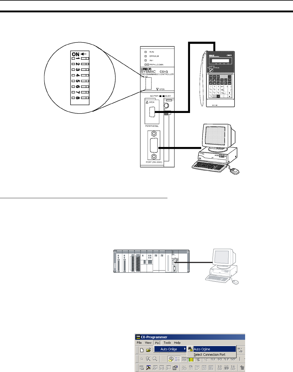
265
Examples Section 4-2
Note When devices other than a Programming Device are connected to the periph-
eral port and RS-232C port, turn ON pin 4 and turn OFF pin 5.
4. Verifying the Programming Device Connection
Connecting to the CX-Programmer
1,2,3... 1. Connect the CX-Programmer's connecting cable to the peripheral port or
RS-232C port.
Note When connecting to the RS-232C port, pin 5 of the CPU Unit's DIP
switch must be ON.
2. When connecting to the RS-232C port, pin 5 of the CPU Unit's DIP switch
must be ON.After checking the power supply wiring and voltage, turn ON
the power and verify the Power Supply Unit's POWER Indicator is lit.
3. Start the CX-Programmer and automatically connect online to the PLC.
Programming Console
Pro
g
rammin
g
Device
CX-Programmer
Support Software
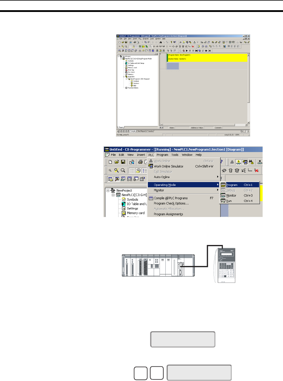
266
Examples Section 4-2
4. When connecting online automatically, the CPU Unit is connected in RUN
mode.Verify that the CX-Programmer has connected online with the PLC.
5. Change the operating mode from RUN mode to PROGRAM mode.
Connecting to the Programming Console
1. Connect the Programming Console to the CPU Unit's peripheral port (the
upper port).
2. Verify that the Programming Console's mode is PROGRAM mode.
3. After checking the power supply wiring and voltage, turn ON the power and
verify the Power Supply Unit's POWER Indicator is lit.
4. Verify that the Programming Console has the following display.
5. Input the password (the Clear and Monitor Keys) and verify that the Pro-
gramming Console has the following display.
Note If the PLC Setup's Startup Mode Setting is set to PRCN (Startup Mode deter-
mined by the Programming Console's mode switch, the default setting), but a
Programming Console isn't connected when the power is turned ON, the CPU
Unit will enter RUN Mode and start operating.
Programming
Console
<PRG> 3:JPN~ENG
PASSWORD!
<PRG> BZ
3:JPN~ENG
MON
CLR
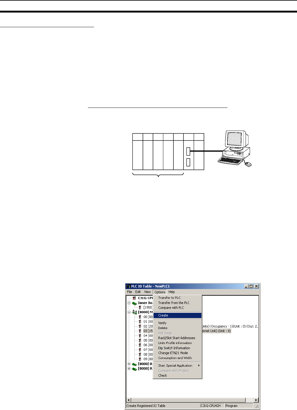
267
Examples Section 4-2
5. Registering the I/O Table
Registering the I/O table allocates I/O memory to the Units actually installed in
the PLC. This operation is required in CS-series PLCs.
Note The user program and parameter area data in CS1-H CPU Units is backed up
in the built-in flash memory. The BKUP indicator will light on the front of the
CPU Unit when the backup operation is in progress. Do not turn OFF the
power supply to the CPU Unit when the BKUP indicator is lit. The data will not
be backed up if power is turned OFF.
■Using the CX-Programmer Online
Mounting All Units and Then Creating I/O Tables
Use the following procedure to register the I/O table with the CX-Programmer
that is connected to the PLC.
1,2,3... 1. Install all of the Units in the PLC.
2. Connect CX-Programmer Connecting Cable to the peripheral port or RS-
232C port. (The power must be OFF.)
Note If the host computer is being connected to the RS-232C port, pin 5
of the CPU Unit’s DIP switch must be set to ON.
3. Start the CX-Programmer and connect online to the PLC.
4. Double-click I/O Table on the project tree in the main window. The I/O Ta-
ble Window will be displayed.
5. Select Options and then Create. The models and positions of Units
mounted to the Racks will be written to the Registered I/O Table in the CPU
Unit.
Install the Units.
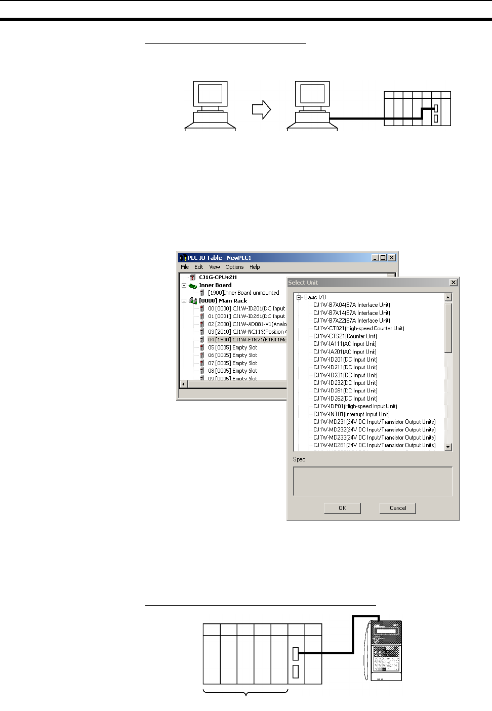
268
Examples Section 4-2
Using the CX-Programmer Offline
Use the following procedure to create the I/O table offline with the CX-Pro-
grammer and later transfer the I/O table from to the CPU Unit.
1,2,3... 1. Double-click I/O Table on the project tree in the main window. The I/O Ta-
ble Window will be displayed.
2. Double-click the Rack to be edited. The slots for that Rack will be dis-
played.
3. Right-click the slots to be edited and select the desired Units from the pull-
down menu.
4. Select Options and then Transfer to PLC to transfer the I/O table to the
CPU Unit.
Note The first word allocated to each Rack can be set by selecting Rack/Slot Start
Addresses from the Option Menu of the PLC IO Table Window of the CX-Pro-
grammer.
■Using a Programming Console
Mounting All Units and Then Creating I/O Tables
Write the
I/O table. Transfer the
I/O table.
Install the Units.
Programming Console

269
Examples Section 4-2
1,2,3... 1. Install all of the Units in the PLC.
2. Connect the Programming Console to the peripheral port.
(It can be connected with the power on.)
3. Perform the following Programming Console operation.
Note With the CS1-H CPU Units, detailed I/O table error information is stored in
A261 whenever the I/O tables cannot be created for any reason. This informa-
tion can be used to facilitate troubleshooting if an error occurs.
6. PLC Setup Settings
These settings are the CPU Unit’s software configuration. See 7-1 PLC Setup
for details on the settings.
Note When a Programming Console is used to set the PLC Setup, the PLC Setup
settings are arranged by word addresses. Refer to the provided Programming
Console settings sheet for details.
CLR 000000 CT00
FUN SHIFT CH
*DM
000000 I/O TBL ?
CHG
000000 I/O TBL
WRIT ????
000000 I/O TBL
WRIT ????
Password
(
9713
)
WRITE
000000CPU BU ST?
0:CLR 1:KEEP
Specify holding or clearing
CPU Bus Unit information.
000000 I/O TBL
WRIT OK
CLR
000000 CT00
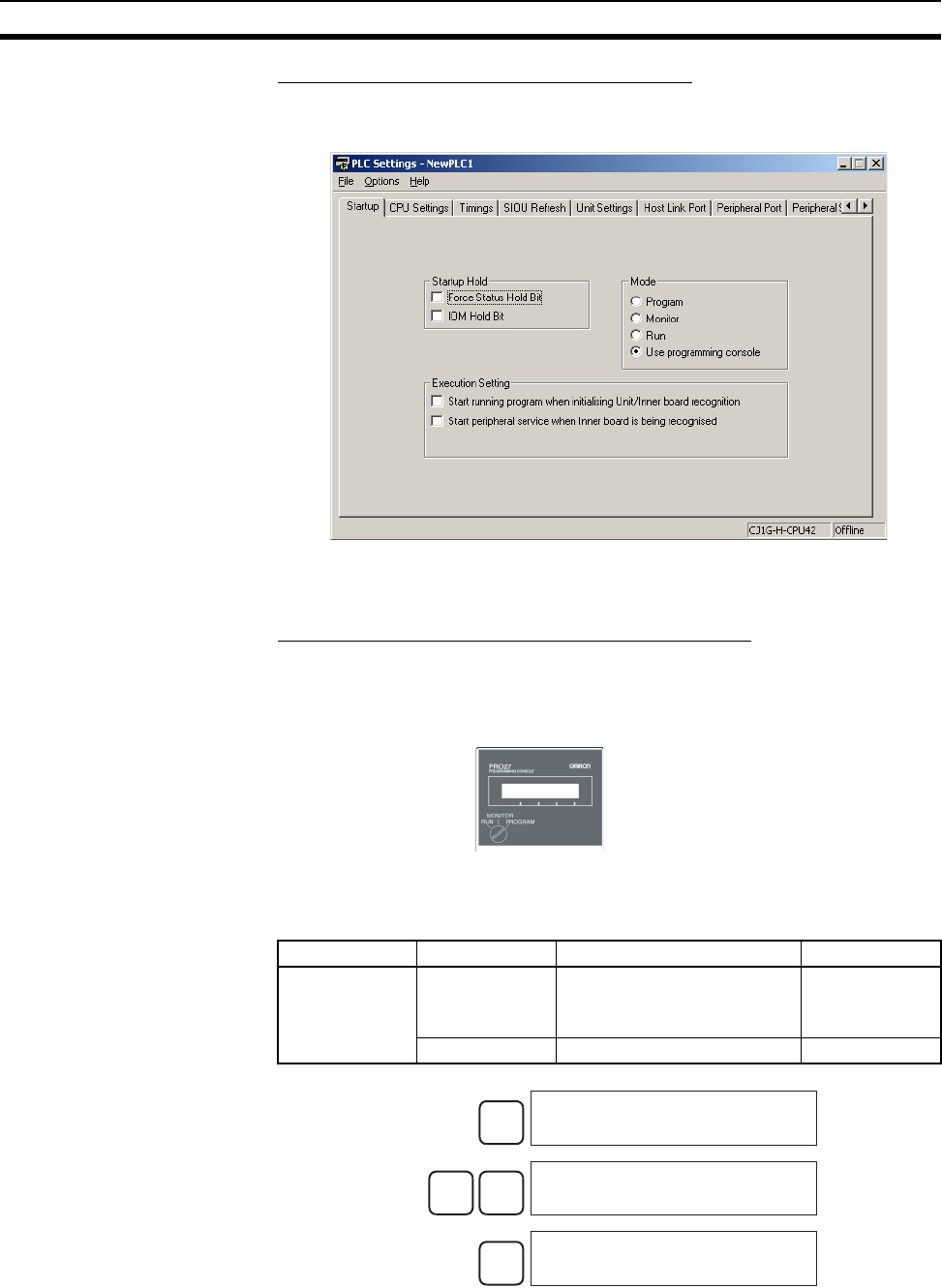
270
Examples Section 4-2
Making the Settings with the CX-Programmer
1. Double-click the Settings Icon in the main window's project directory tree.
The PLC Settings Dialog Box will be displayed.
2. Make the required settings.
3. After completing the settings, transfer the PLC Setup to the PLC.
Making the Settings with the Programming Console
When a Programming Console is used to set the PLC Setup, the PLC Setup
settings are arranged by word addresses. Refer to the provided Programming
Console settings sheet for details.
In this example, the Programming Console is used to set the Watch Cycle
Time (maximum cycle time) in 10-ms units.
The following diagram shows the required Programming Console operations.
Specifying a word address in the PLC Setup.
(Example: 209)
Address Bits Setting Setting range
209 15 Enable for Watch Cycle Time
setting
0: Use default
1: Use setting in
bits 0 to 14.
0 to 14 Watch Cycle Time setting 0001 to 0FA0
Setting with a Programming Console
CLR
000000 CT00
FUN VRFY
PC SETUP
0:MODE1:PC SETUP
1
PC SETUP
+000 0000
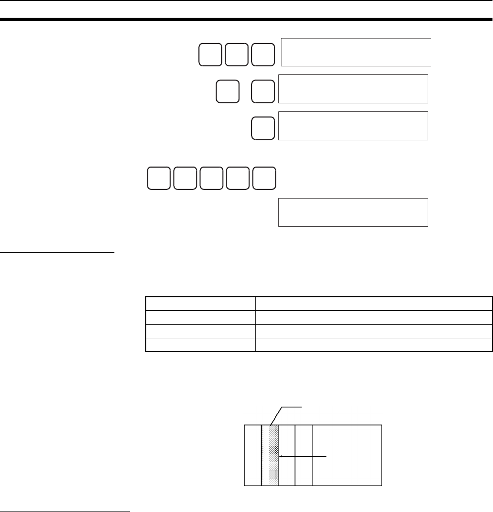
271
Examples Section 4-2
or
Example: Input 8064.
7. DM Area Settings
The following table shows the parts of the DM Area are allocated to Special
I/O Units, CS-series CPU Bus Units, and Inner Boards for initial settings. The
actual settings depend on the model of Unit or Inner Board being used.
After writing the initial settings to the DM Area, be sure to restart the Units by
turning the PLC off and then on again or toggling the Restart Bits for the
affected Units.
8. Writing the Program
Write the program with the CX-Programmer or a Programming Console.
Unlike earlier OMRON PLCs, the CS-series PLC’s program can be divided
into independently executable tasks. A single cyclic task can be written for
program execution like earlier PLCs or several cyclic tasks can be written for a
209PC SETUP
+209
↓ ↑ PC SETUP
+209 0000
CHG
PC SETUP?
+209 0000 0000
8064WRITE
+209 8064
PC SETUP
Unit/Board Allocated words
Special I/O Units D20000 to D29599 (100 words × 96 Units)
CPU Bus Units D30000 to D31599 (100 words × 16 Units)
Inner Board D32000 to D32099 (100 words × 1 Board)
Special I/O Unit or
CS-series CPU Bus Uni
t
Restart
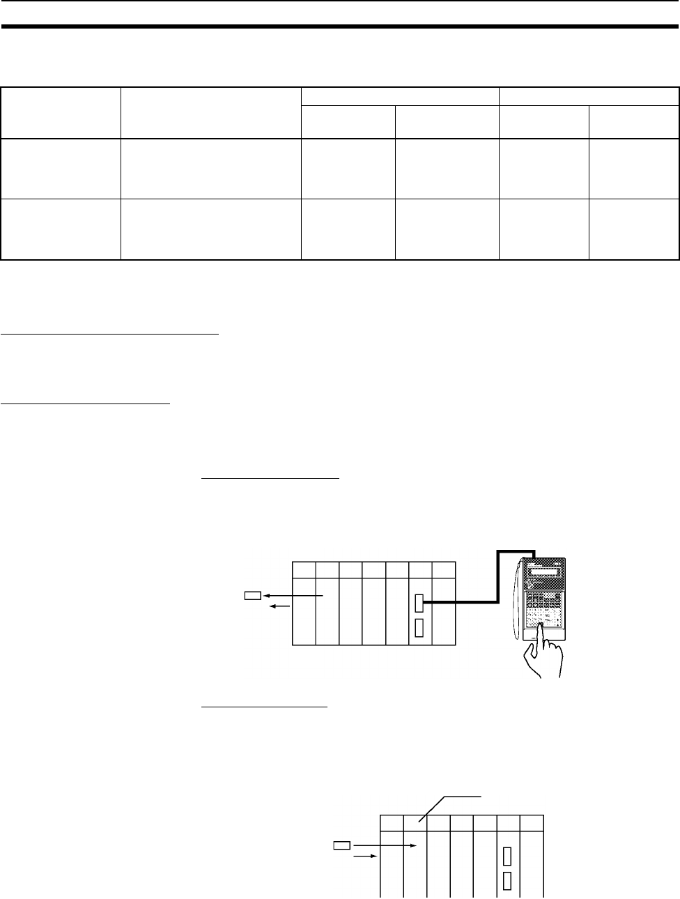
272
Examples Section 4-2
more flexible and efficient program. The following table shows the differences
when programming with CX-Programmer or a Programming Console.
Note When writing the program with a Programming Console, specify whether
there are interrupt tasks during the memory clear operation.
9. Transferring the Program
When the program has been created in a Programming Device other than a
Programming Console, it must be transferred to the PLC’s CPU Unit.
10. Testing Operation
10-a) I/O Wiring Checks
Before performing a Trial Operation in MONITOR mode, check the I/O wiring.
Check Output Wiring
With the PLC in PROGRAM mode, force-set and force-reset output bits and
verify that the corresponding outputs operate properly.
Check Input Wiring
Activate input devices such as sensors and switches and verify that the corre-
sponding indicators on the Input Units light. Also, use the Bit/Word Monitor
operation in the Programming Device to verify the operation of the corre-
sponding input bits.
10-b) Auxiliary Area Settings
Make any required Auxiliary Area settings, such as the ones shown below.
These settings can be made from a Programming Device (including a Pro-
gramming Console) or instructions in the program.
Programming
Device
Relationship between Tasks
and Program
Writing a new program Editing an existing program
Cyclic tasks Interrupt tasks Cyclic tasks Interrupt
tasks
CX-Programmer Specify the type of task and
task number for each program.
All can be writ-
ten.
(Cyclic tasks 0
to 31)
All can be writ-
ten.
(Interrupt tasks 0
to 255)
All can be
edited.
All can be
edited.
Programming Con-
sole
Task = program
(Cyclic task 0 is the main pro-
gram)
Only one can
be written.
(Cyclic task 0)
Several can be
written.
(Interrupt tasks 1
to 3, 100 to 131)
All can be
edited.
All can be
edited.
Force-reset
Input Unit
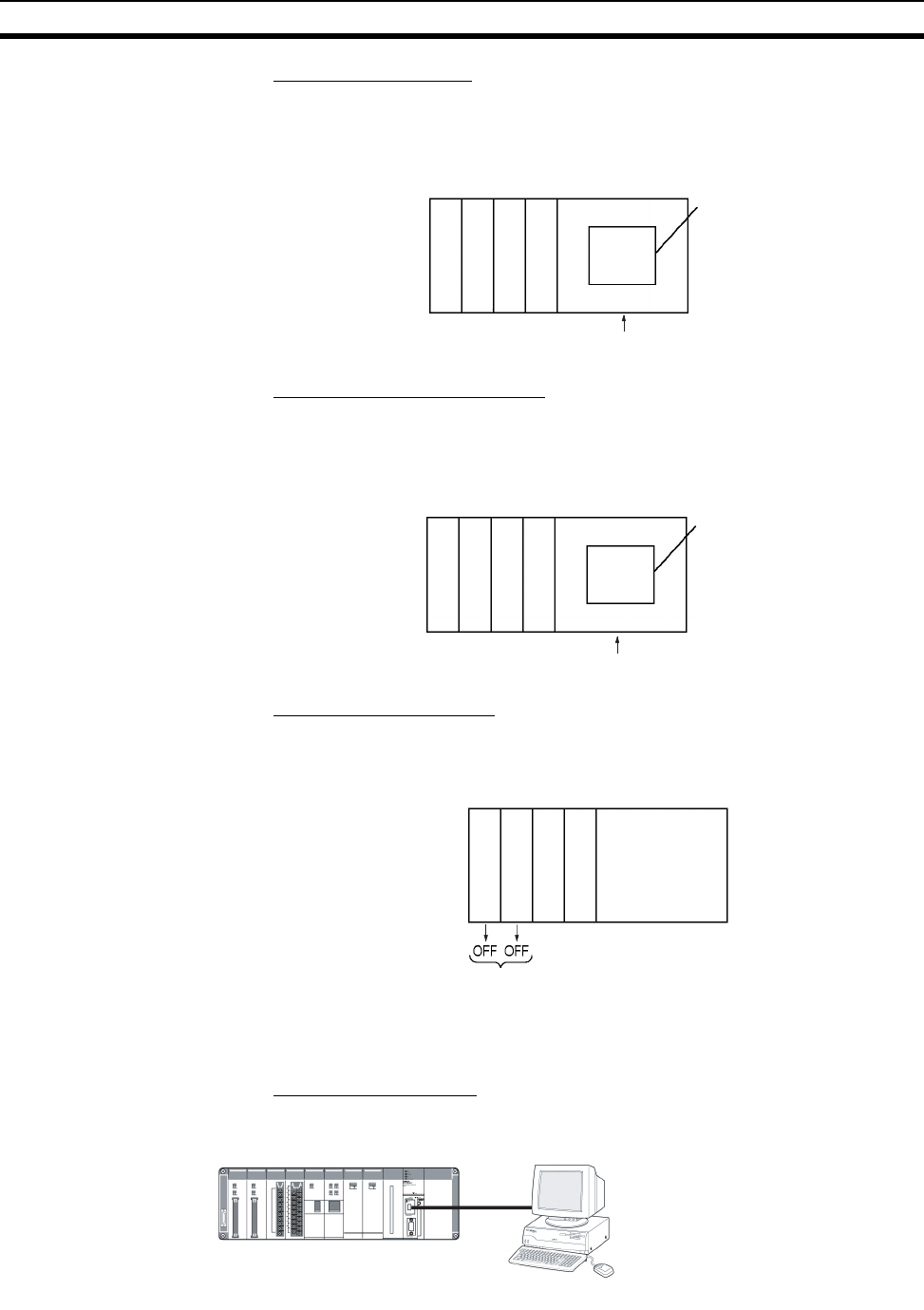
273
Examples Section 4-2
IOM Hold Bit (A50012)
Turning ON the IOM Hold Bit protects the contents of I/O memory (the CIO
Area, Work Area, Timer Completion Flags and PVs, Index Registers, and
Data Registers) that would otherwise be cleared when the operating mode is
switched from PROGRAM mode to RUN/MONITOR mode or vice-versa.
IOM Hold Bit Status at Startup
When the IOM Hold Bit has been turned ON and the PLC Setup is set to pro-
tect the status of the IOM Hold Bit at startup (PLC Setup address 80 bit 15
turned ON), the contents of I/O memory that would otherwise be cleared will
be retained when the PLC is turned ON.
Output OFF Bit (A50015)
Turning ON the Output OFF Bit causes all outputs on Basic I/O Units and
Special I/O Units to be turned OFF. The outputs will be turned OFF regardless
of the PLC’s operating mode.
10-c) Trial Operation
Use the Programming Console or Programming Device (CX-Programmer) to
switch the CPU Unit to MONITOR mode.
Using CX-Programmer
The PLC can be put into MONITOR mode with a host computer running CX-
Programmer.
I/O
memory
Retained
Operatin
g
mode chan
g
ed
I/O
memory
Retained
PLC turned ON.
Output Unit
Output Unit
CX-Pro
g
rammer
Trial Operation
Actual operation
Select PLC, Mode, RUN.
Select PLC, Mode, RUN.
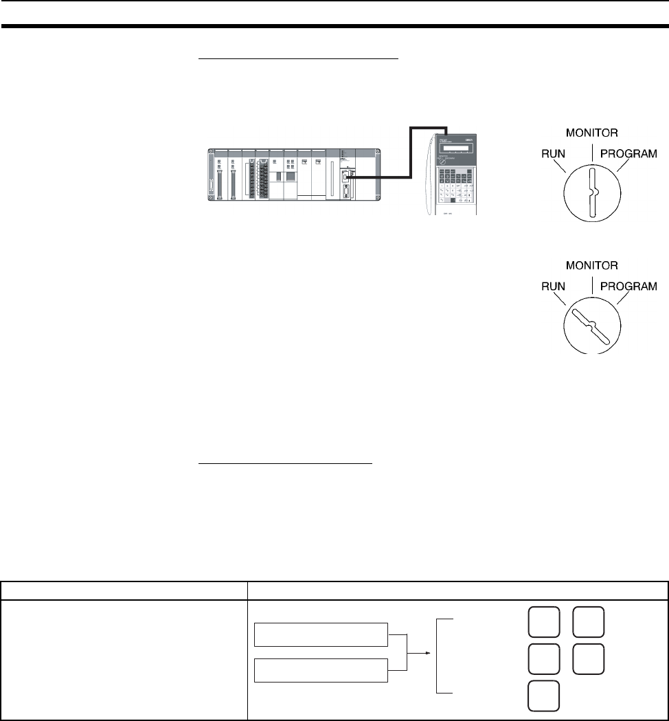
274
Examples Section 4-2
Using a Programming Console
Turn the Mode Switch to MONITOR for the Trial Operation. (Turn the switch to
RUN for full-scale PLC operation.)
10-d) Monitoring and Debugging
There are several ways to monitor and debug PLC operation, including the
force-set and force-reset operations, differentiation monitoring, time chart
monitoring, data tracing, and online editing.
Force-Set and Force-Reset
When necessary, the force-set and force-reset operations can be used to
force the status of bits and check program execution.
When a Programming Console is being used, monitor the bits with Bit/Word
Monitor or 3-word Monitor. Press the SHIFT+SET Keys to force-set a bit or
press the SHIFT+RESET Keys to force-reset a bit. The forced status can be
cleared by pressing the NOT Key.
Programming
Console
Trial Operation
Actual operation
CX-Programmer Programming Console
1. Click the bit to be force-set or force-reset.
2. Select Force On or Off from the PLC
menu.
SHIFT SET
Bit/Word Monitor display
3-word Monitor display
Force-set:
Force-reset:
Clear:
SHIFT SET
NOT
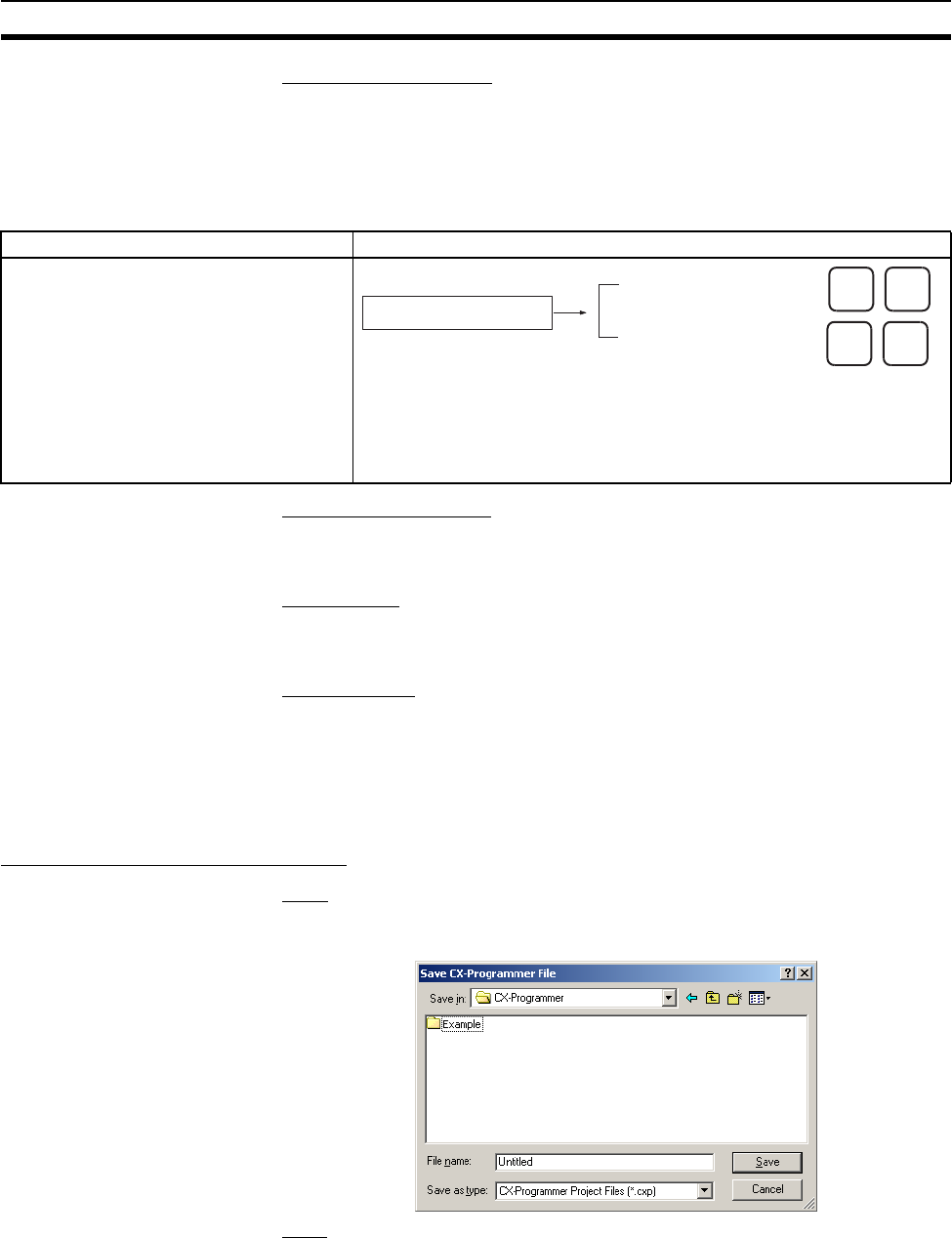
275
Examples Section 4-2
Differentiation Monitor
The differentiation monitor operation can be used to monitor the up or down
differentiation of particular bits.
When a Programming Console is being used, monitor the bit with Bit/Word
Monitor. Press the SHIFT+Up Arrow Keys to specify up differentiation or press
the SHIFT+Down Arrow Keys to specify down differentiation.
Time Chart Monitoring
The CX-Programmer’s time chart monitor operation can be used to check and
debug program execution.
Data Tracing
The CX-Programmer’s data trace operation can be used to check and debug
program execution.
Online Editing
When a few lines of the program in the CPU Unit have to be modified, they
can be edited online with the PLC in MONITOR mode or PROGRAM mode.
When more extensive modifications are needed, upload the program from the
CPU Unit to the host computer, make the necessary changes, and transfer
the edited program back to the CPU Unit.
11. Save and Print the Program
Save
To save a created program, select File - Save or File - Save As from the CX-
Programmer menus.
Print
To print a created program, first preview the print output by selecting the
desired section in the CX-Programmer's project workspace and selecting File
CX-Programmer Programming Console
1. Click the bit for differential monitoring.
2. Click Differential Monitor from the PLC
Menu. The Differential Monitor Dialog Box
will be displayed.
3. Click Rising or Falling.
4. Click the Start Button. The buzzer will
sound when the specified change is
detected and the count will be incremented.
5. Click the Stop Button. Differential moni-
toring will stop.
Bit/Word Monitor display
Detect up-differentiation:
Detect down-differentiation:
SHIFT
SHIFT
276
Examples Section 4-2
- Print Preview from the CX-Programmer menu. If the preview is acceptable,
select File - Print to print.
12. Run the Program
Switch the PLC to RUN mode to run the program.
277
SECTION 5
Installation and Wiring
This section describes how to install a PLC System, including mounting the various Units and wiring the System. Be sure
to follow the instructions carefully. Improper installation can cause the PLC to malfunction, resulting in very dangerous
situations.
5-1 Fail-safe Circuits . . . . . . . . . . . . . . . . . . . . . . . . . . . . . . . . . . . . . . . . . . . . . . . 278
5-2 Installation. . . . . . . . . . . . . . . . . . . . . . . . . . . . . . . . . . . . . . . . . . . . . . . . . . . . 280
5-2-1 Installation and Wiring Precautions . . . . . . . . . . . . . . . . . . . . . . . . . 280
5-2-2 Installation in a Control Panel . . . . . . . . . . . . . . . . . . . . . . . . . . . . . 282
5-2-3 Mounting Height. . . . . . . . . . . . . . . . . . . . . . . . . . . . . . . . . . . . . . . . 284
5-2-4 Mounting Dimensions . . . . . . . . . . . . . . . . . . . . . . . . . . . . . . . . . . . 285
5-2-5 Mounting Units to the Backplane . . . . . . . . . . . . . . . . . . . . . . . . . . . 286
5-2-6 DIN Track Mounting . . . . . . . . . . . . . . . . . . . . . . . . . . . . . . . . . . . . 288
5-2-7 I/O Connecting Cables . . . . . . . . . . . . . . . . . . . . . . . . . . . . . . . . . . . 290
5-2-8 Inner Board Installation . . . . . . . . . . . . . . . . . . . . . . . . . . . . . . . . . . 298
5-3 Wiring . . . . . . . . . . . . . . . . . . . . . . . . . . . . . . . . . . . . . . . . . . . . . . . . . . . . . . . 299
5-3-1 Power Supply Wiring . . . . . . . . . . . . . . . . . . . . . . . . . . . . . . . . . . . . 299
5-3-2 Wiring CS-series and C200H Basic I/O Units . . . . . . . . . . . . . . . . . 310
5-3-3 Wiring CS-series and C200H I/O Units with Connectors . . . . . . . . 312
5-3-4 Connecting I/O Devices . . . . . . . . . . . . . . . . . . . . . . . . . . . . . . . . . . 319
5-3-5 Reducing Electrical Noise . . . . . . . . . . . . . . . . . . . . . . . . . . . . . . . . 323

278
Fail-safe Circuits Section 5-1
5-1 Fail-safe Circuits
Be sure to set up safety circuits outside of the PLC to prevent dangerous con-
ditions in the event of errors in the PLC or external power supply.
Supply Power to the PLC before Outputs
If the PLC’s power supply is turned on after the controlled system’s power
supply, outputs in Units such as DC Output Units may malfunction momen-
tarily. To prevent any malfunction, add an external circuit that prevents the
power supply to the controlled system from going on before the power supply
to the PLC itself.
Managing PLC Errors
When any of the following errors occurs, PLC operation will stop and all out-
puts from Output Units will be turned OFF.
• Operation of the Power Supply Unit’s overcurrent protection circuit
• A CPU error (watchdog timer error) or CPU on standby
• A fatal error* (memory error, I/O bus error, duplicate number error, In-
ner Board stopped error, too many I/O points error, program error, cy-
cle time too long error, or FALS(007) error)
Be sure to add any circuits necessary outside of the PLC to ensure the safety
of the system in the event of an error that stops PLC operation.
Note *When a fatal error occurs, all outputs from Output Units will be turned OFF
even if the IOM Hold Bit has been turned ON to protect the contents of I/O
memory. (When the IOM Hold Bit is ON, the outputs will retain their previous
status after the PLC has been switched from RUN/MONITOR mode to PRO-
GRAM mode.)
Managing Output Malfunctions
It is possible for an output to remain ON due to a malfunction in the internal
circuitry of the Output Unit, such as a relay or transistor malfunction. Be sure
to add any circuits necessary outside of the PLC to ensure the safety of the
system in the event that an output fails to go OFF.
Emergency Stop Circuit
The following emergency stop circuit controls the power supply to the con-
trolled system so that power is supplied to the controlled system only when
the PLC is operating and the RUN output is ON.
An external relay (CR1) is connected to the RUN output from the Power Sup-
ply Unit as shown in the following diagram.
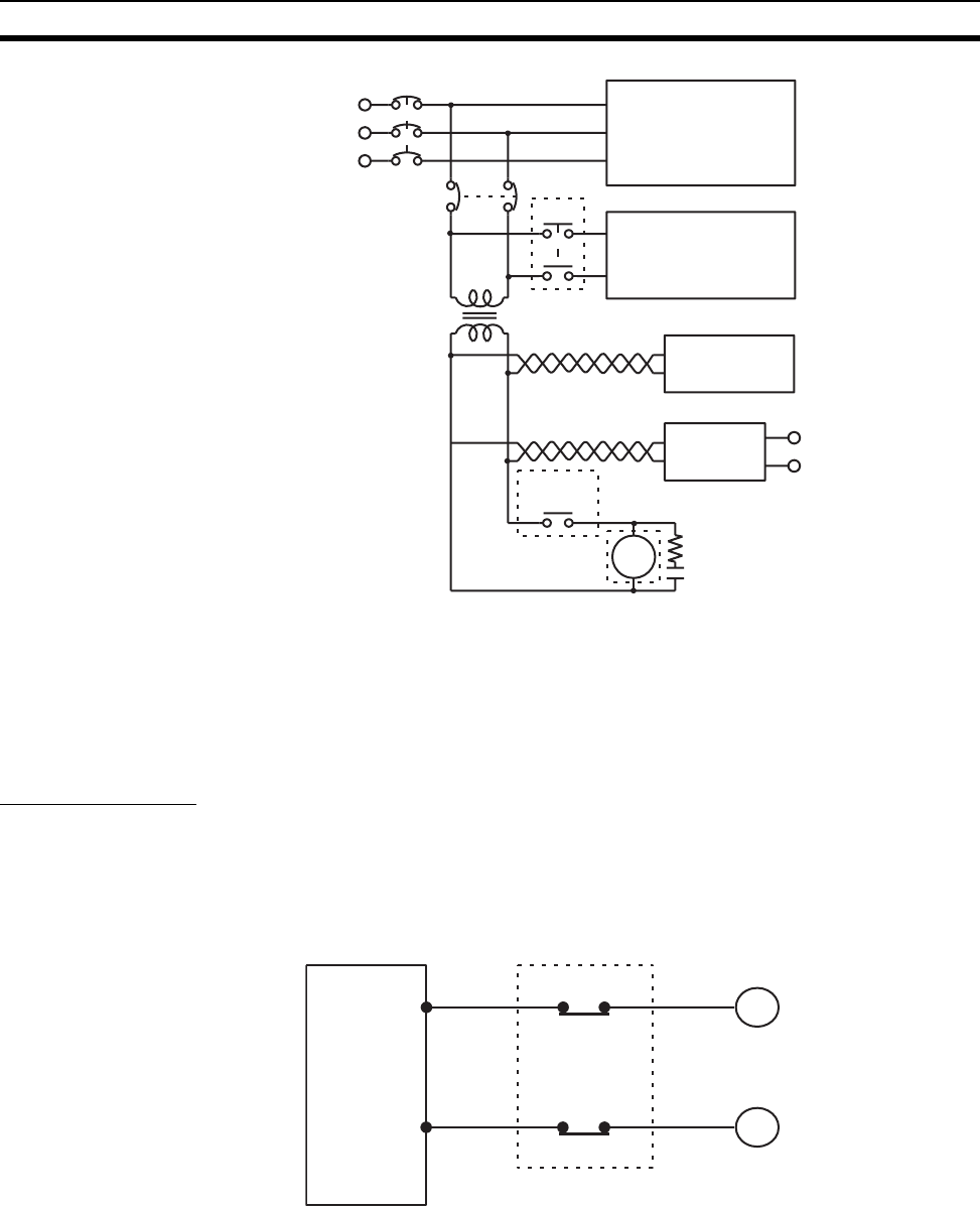
279
Fail-safe Circuits Section 5-1
Note This configuration is possible with the C200HW-PA204R and C200HW-
PA204R Power Supply Units only. When a Power Supply Unit without a RUN
output is used, program the Always ON Flag (A1) as the execution condition
for an output point from an Output Unit. Do not include a circuit that stops the
controlled system by latching the RUN output during operation. Relay con-
tacts are used, and so chattering may cause incorrect operation.
Interlock Circuits
When the PLC controls an operation such as the clockwise and counterclock-
wise operation of a motor, provide an external interlock such as the one
shown below to prevent both the forward and reverse outputs from turning ON
at the same time.
This circuit prevents outputs MC1 and MC2 from both being ON at the same
time even if both CIO 000500 and CIO 000501 are both ON, so the motor is
protected even if the PLC is programmed improperly or malfunctions.
MCB1
MCB2
CR1
Power supply
Controlled system
DC voltage
regulator
Transformer
or noise filter
Twisted-pair wires
PLC RUN
output
+DC
input/output
CR1 Surge suppressor
CS-series PLC
–
(See
note.)
CS-series
PLC
MC2
MC1
000501
000502
MC1
MC2
Motor clockwise
Motor counterclockwise
Interlock circuit

280
Installation Section 5-2
5-2 Installation
5-2-1 Installation and Wiring Precautions
Be sure to consider the following factors when installing and wiring the PLC to
improve the reliability of the system and make the most of the PLC’s functions.
Ambient Conditions
Do not install the PLC in any of the following locations.
• Locations subject to ambient temperatures lower than 0°C or higher than
55°C.
• Locations subject to drastic temperature changes or condensation.
• Locations subject to ambient humidity lower than 10% or higher than
90%.
• Locations subject to corrosive or flammable gases.
• Locations subject to excessive dust, salt, or metal filings.
• Locations that would subject the PLC to direct shock or vibration.
• Locations exposed to direct sunlight.
• Locations that would subject the PLC to water, oil, or chemical reagents.
Be sure to enclose or protect the PLC sufficiently in the following locations.
• Locations subject to static electricity or other forms of noise.
• Locations subject to strong electromagnetic fields.
• Locations subject to possible exposure to radioactivity.
• Locations close to power lines.
Installation in Cabinets or Control Panels
When the PLC is being installed in a cabinet or control panel, be sure to pro-
vide proper ambient conditions as well as access for operation and mainte-
nance.
Temperature Control
The ambient temperature within the enclosure must be within the operating
range of 0°C to 55°C. When necessary, take the following steps to maintain
the proper temperature.
• Provide enough space for good air flow.
• Do not install the PLC above equipment that generates a large amount of
heat such as heaters, transformers, or high-capacity resistors.
• If the ambient temperature exceeds 55°C, install a cooling fan or air con-
ditioner.
CS-series
PLC
Fan
Louver
Control
panel
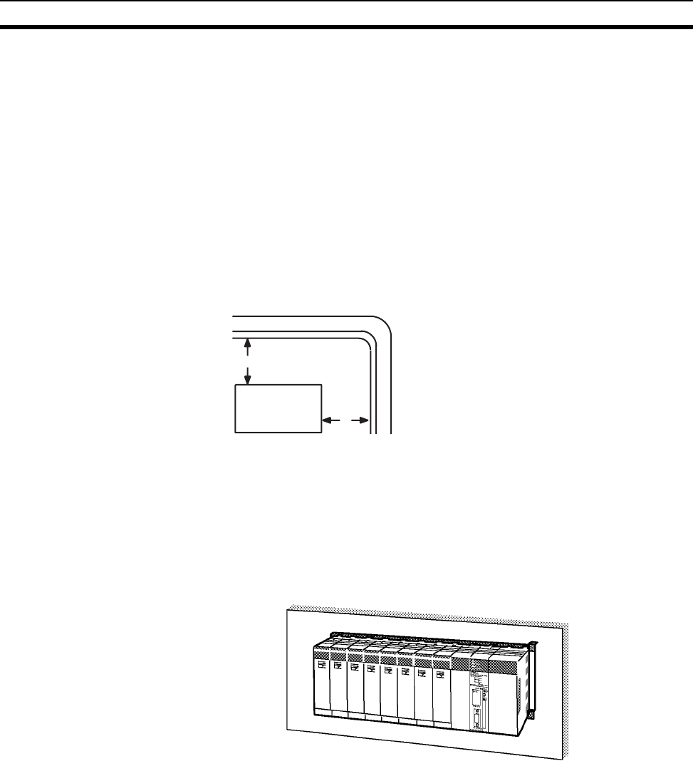
281
Installation Section 5-2
• If a Programming Console will be left on the PLC, the ambient tempera-
ture must be within the Programming Console’s operating range of 0°C to
45°C.
Accessibility for Operation and Maintenance
• To ensure safe access for operation and maintenance, separate the PLC
as much as possible from high-voltage equipment and moving machinery.
• The PLC will be easiest to install and operate if it is mounted at a height of
about 1.3 m (4 feet).
Improving Noise Resistance
• Do not mount the PLC in a control panel containing high-voltage equip-
ment.
• Install the PLC at least 200 mm (6.5 feet) from power lines.
• Ground the mounting plate between the PLC and the mounting surface.
• When I/O Connecting Cables are 10 m or longer, connect the control pan-
els in which Racks are mounted with heavier power wires (3 wires at least
2 mm2 in cross-sectional area).
PLC Orientation
• Each Rack must be mounted in an upright position to provide proper cool-
ing.
CS-series PLC
200 mm min.
200 mm min.
Power lines
To p
Bottom
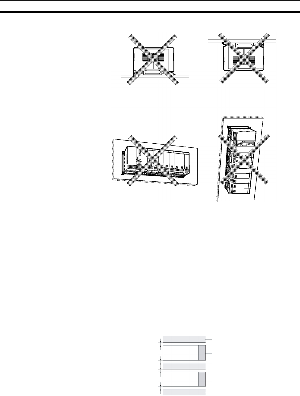
282
Installation Section 5-2
• Do not install a Rack in any of the following positions.
Note Always use the standard installation method. A nonstandard installation will
decrease heat dissipation, and may delay the replacement notification signal
(in particular for C200H-PA204C Power Supply Units with Replacement Notifi-
cation), or degrade or damage the internal elements.
5-2-2 Installation in a Control Panel
• A typical installation is a CPU Rack mounted above an Expansion Rack
on a mounting plate in the control panel.
• The spacing between the CPU Rack and Expansion Rack (or between
two Expansion Racks) should be sufficient to allow space for a wiring
duct, wiring, air circulation, and replacement of Units in the Racks.
Note If the C200HW-PA209R Power Supply Unit is to be used at an ambient tem-
perature of 50 °C or higher, provide a minimum space of 80 mm between the
top of the Unit and any other objects, e.g., ceiling, wiring ducts, structural sup-
ports, devices, etc.
• Up to 7 Expansion Racks can be connected.
Each I/O Connecting Cable can be up to 12 m long, but the sum total of
all cables between the CPU Rack and Expansion Racks must be 12 m or
less.
Duct or other object
C200HW-PA209R
Duct or other object
C200HW-PA209R
Duct or other object
80 mm min.
80 mm min.
80 mm min.
80 mm min.
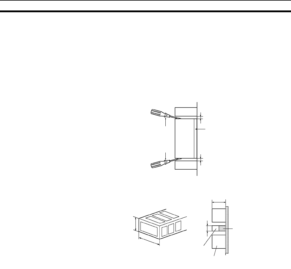
283
Installation Section 5-2
• The mounting plate should be grounded completely and we recommend
using a mounting plate that has been plated with a good conductor to
improve noise resistance.
• If all of the Racks cannot be mounted to the same mounting plate, the
individual plates should be securely connected together using 3 wires of
at least 2 mm2 in cross-sectional area.
• The Backplanes are mounted to the plate(s) with four M4 screws each.
• Whenever possible, route I/O wiring through wiring ducts or raceways.
Install the duct so that it is easy to fish wire from the I/O Units through the
duct. It is handy to have the duct at the same height as the Racks.
Wiring Ducts The following example shows the proper installation of wiring duct.
Note Tighten the Unit mounting screws, PLC Rack mounting screws, terminal block
screws, and cable screws to the following torques.
Unit Mounting Screws
CPU Unit: 0.9 N·m
Power Supply Unit: 0.9 N·m
I/O Units: 0.4 N·m
Backplane Mounting Screws: 0.9 N·m
Ter min al S c r ew s
M3.5: 0.8 N·m
M3: 0.5 N·m
Cable Connector Screws
M2.6: 0.2 N·m
Phillips
screwdrivers Unit
Backplane
20 mm min.
20 mm min.
Duct
Duct
40 mm Duct
118 to 153 mm
CPU
Rack
Expansion
Rack
Mounting
bracket
30 mm
30 mm
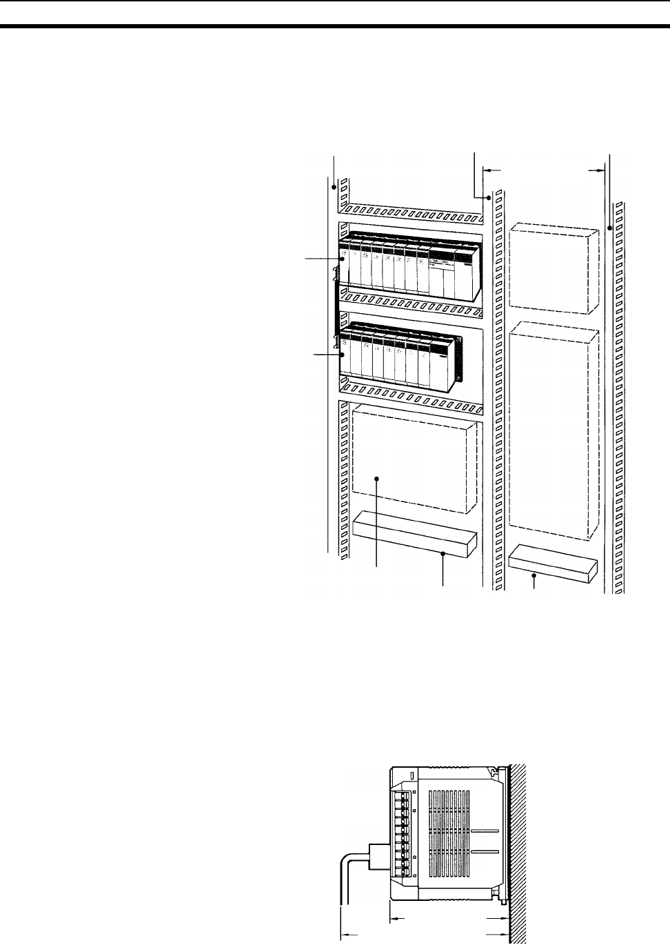
284
Installation Section 5-2
Routing Wiring Ducts Install the wiring ducts at least 20 mm between the tops of the Racks and any
other objects, (e.g., ceiling, wiring ducts, structural supports, devices, etc.) to
provide enough space for air circulation and replacement of Units. If the
C200HW-PA209R Power Supply Unit is to be used at an ambient temperature
of 50 °C or higher, provide a minimum space of 80 mm.
5-2-3 Mounting Height
The mounting height of CPU Racks, Expansion Racks, or Slave Racks is 118
to 153 mm for a CS-series Backplane, depending on I/O Units mounted. If
Programming Devices or connecting cables are attached, the additional
dimensions must be taken into account. Allow sufficient clearance in the con-
trol panel in which the PLC is mounted.
Input duct
CPU Rack
Expansion Rack
Power
equipment
such as
transformers
and magnetic
relays
Breakers,
fuses
Output duct Power duct
200 mm min.
Terminal blocks for
power equipment
Terminal blocks
for PLC
Fuses, relays, timers, etc.
(NOT heat-generating equip-
ment, power equipment, etc.)
118 to 153 mm
Approx. 180 to 223 mm
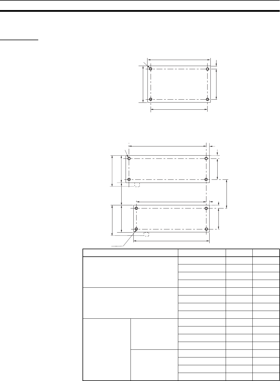
285
Installation Section 5-2
5-2-4 Mounting Dimensions
Backplanes
CPU Backplane with 2 Slots
Note Expansion Backplanes cannot be connected to 2-slot CPU Backplanes.
CPU Backplane with 3, 5, 8, or 10 Slots
157
198.5
6
CS1W-BC023
CPU Backplane
Four, M4
172.3±0.3
145±0.3
Unit: mm
Backplane Model A W
Standard CPU Backplanes CS1W-BC033 246 mm 260 mm
CS1W-BC053 316 mm 330 mm
CS1W-BC083 421 mm 435 mm
CS1W-BC103 491 mm 505 mm
CS-series-only CPU Backplanes CS1W-BC032 246 mm 260 mm
CS1W-BC052 316 mm 330 mm
CS1W-BC082 421 mm 435 mm
CS1W-BC102 491 mm 505 mm
Expansion Back-
planes
CS-series Expan-
sion Backplanes
CS1W-BI033 246 mm 260 mm
CS1W-BI053 316 mm 330 mm
CS1W-BI083 421 mm 435 mm
CS1W-BI103 491 mm 505 mm
C200H Expansion
I/O Backplanes
C200HW-BI031 245 mm 259 mm
C200HW-BI051 316 mm 330 mm
C200HW-BI081-V1 350 mm 364 mm
C200HW-BI101-V1 420 mm 434 mm
132 118±0.3
132 118±0.3
A±0.3
W
66 min. 80 min.
135
(including protruding parts)
135
(including protruding parts)
6
6
6
6
Unit: mm
A±0.3
Four, M4
CPU Backplane
Expansion Backplane
Four, M4
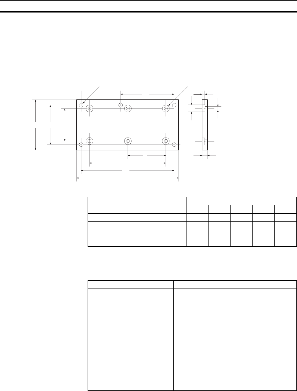
286
Installation Section 5-2
Backplane Insulation Plates
Backplane Insulation Plates can be installed on C200H I/O Backplanes only.
There are four models available, corresponding to the number of slots on the
Backplane. The dimensions at locations A, B, C, D, and E are shown below in
millimeters for each Backplane Insulation Plate.
Insulation Plates for I/O Backplanes
5-2-5 Mounting Units to the Backplane
There are two methods for mounting or removing Units in the Backplane. The
following table shows which method to use for each type of Unit.
Specifications Model Dimensions (mm)
EDCBA
For 3 slots C200HW-ATT32 190 140 --- --- 175
For 5 slots C200HW-ATT52 260 210 --- --- 245
For 8 slots C200HW-ATT82 365 315 --- --- 350
For 10 slots C200HW-ATTA2 435 385 --- --- 420
M4 screws for mounting to PLC
(4/5 places)
5-dia. holes for mounting
Base Insulation Plate
(4/6 places)
135 (118) 110
(B)
C
D
(A)
(E)
12 dia.
6
5 dia.
10
Unit: mm
Group Unit type Installation method Removal method
A CS-series CPU Units,
Power Supply Units,
CS-series Basic I/O
Units,
CS-series Special I/O
Units,
CS-series CPU Bus
Units, and
SYSMAC BUS Remote
I/O Slave Units
Hook the top of the Unit
into the slot on the
Backplane and tighten
the screw on the bottom
of Unit.
Loosen the screw on
the bottom of the Unit
and rotate the Unit
upward.
B C200H Basic I/O Units,
C200H Special I/O
Units
Hook the top of the Unit
into the slot on the
Backplane and secure
the bottom of the Unit
with the Backplane’s
lock lever.
Press and hold the lock
lever at the bottom of
the Unit and rotate the
Unit upward.
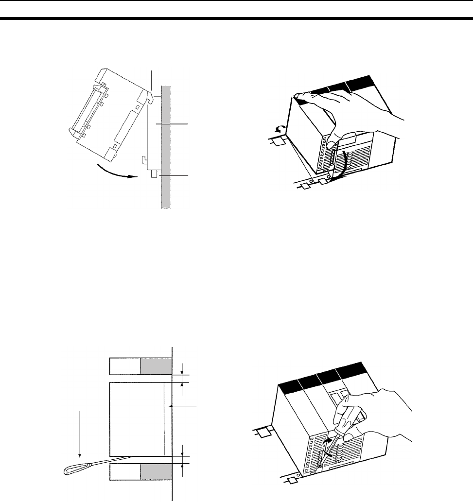
287
Installation Section 5-2
1,2,3... 1. Mount the Unit to the Backplane by hooking the top of the Unit into the slot
on the Backplane and rotating the I/O Unit downwards. (Groups A and B)
2. Make sure that the connector on the back of the Unit is properly inserted
into the connector in the Backplane. (Groups A and B)
3. With the Group-A Units, use a Phillips-head screwdriver to tighten the
screw on the bottom of Unit. The screwdriver must be held at a slight angle,
so be sure to leave enough space below each Rack.
Note The screws at the bottoms of the Units must be tightened to the fol-
lowing torques.
CPU Unit: 0.9 N·m
Power Supply Unit: 0.9 N·m
I/O Units: 0.4 N·m
With Group-B Units, the lock lever will snap into place when the Unit is
properly inserted. Check that the lock lever is engaged and the Unit is se-
cure.
Hook
Backplane
Lock lever
Phillips
screwdriver
20 mm min.
20 mm min.
Backplane
Duct
Units in
group A
Duct
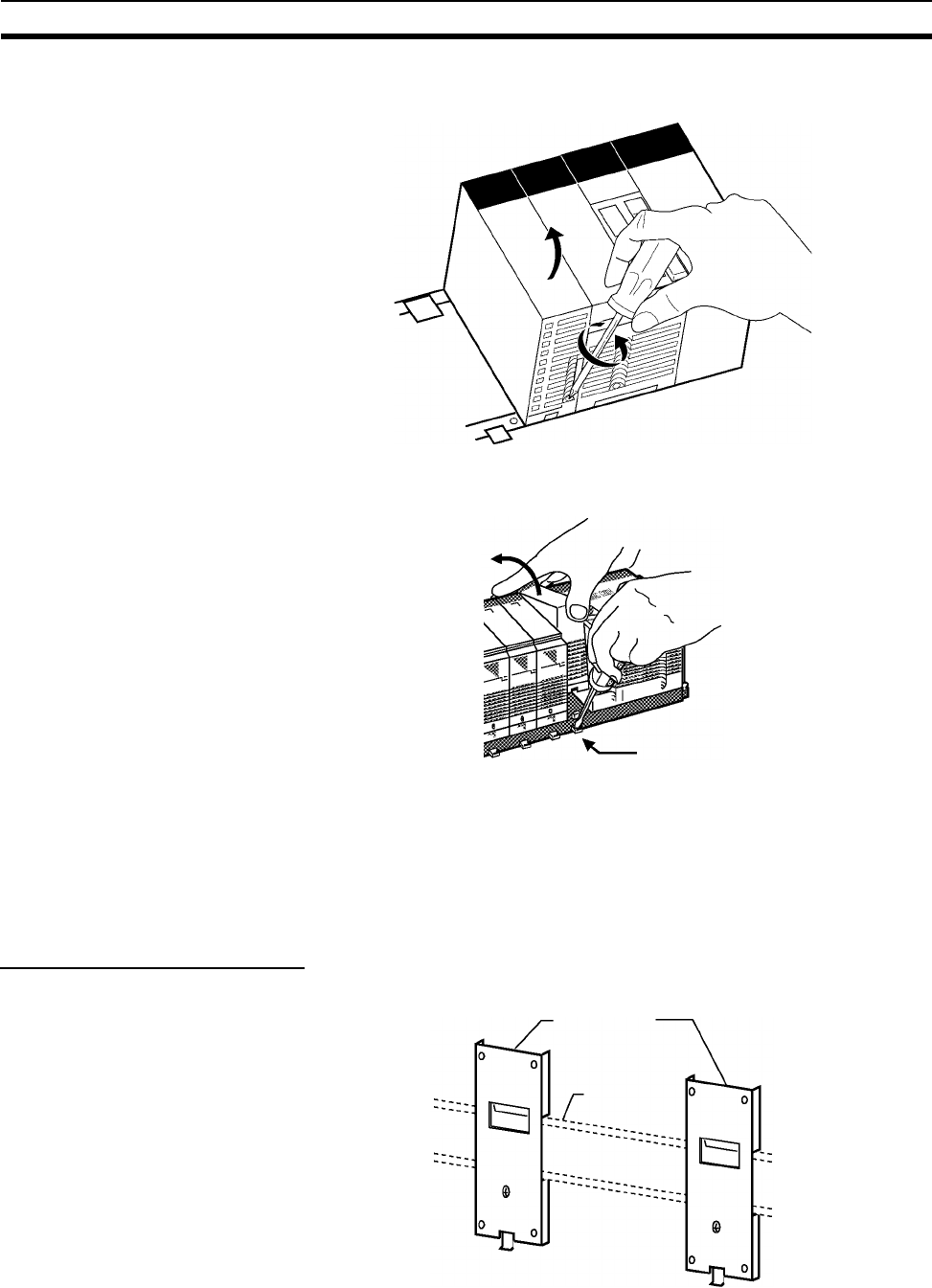
288
Installation Section 5-2
4. To remove a Group-A Unit, use a phillips-head screwdriver to loosen the
screw at the bottom of the Unit, rotate the Unit upward, and remove it.
To remove a Group-B Unit, hold down the lock lever with a tool such as a
screwdriver, rotate the Unit upward, and remove it.
5-2-6 DIN Track Mounting
Do not use DIN Track to mount Backplane in locations subject to vibration;
use locking screws to attach the Backplane directly.
Mount the DIN Track in the control panel with M4 screws in at least three
places. Tighten the mounting screws to a torque of 1.2 N·m.
DIN Track Mounting Bracket
Use DIN Track Mounting Brackets to mount Racks to the DIN Track.
Lock lever
C200H-DIN01
Mounting Bracket
DIN Track
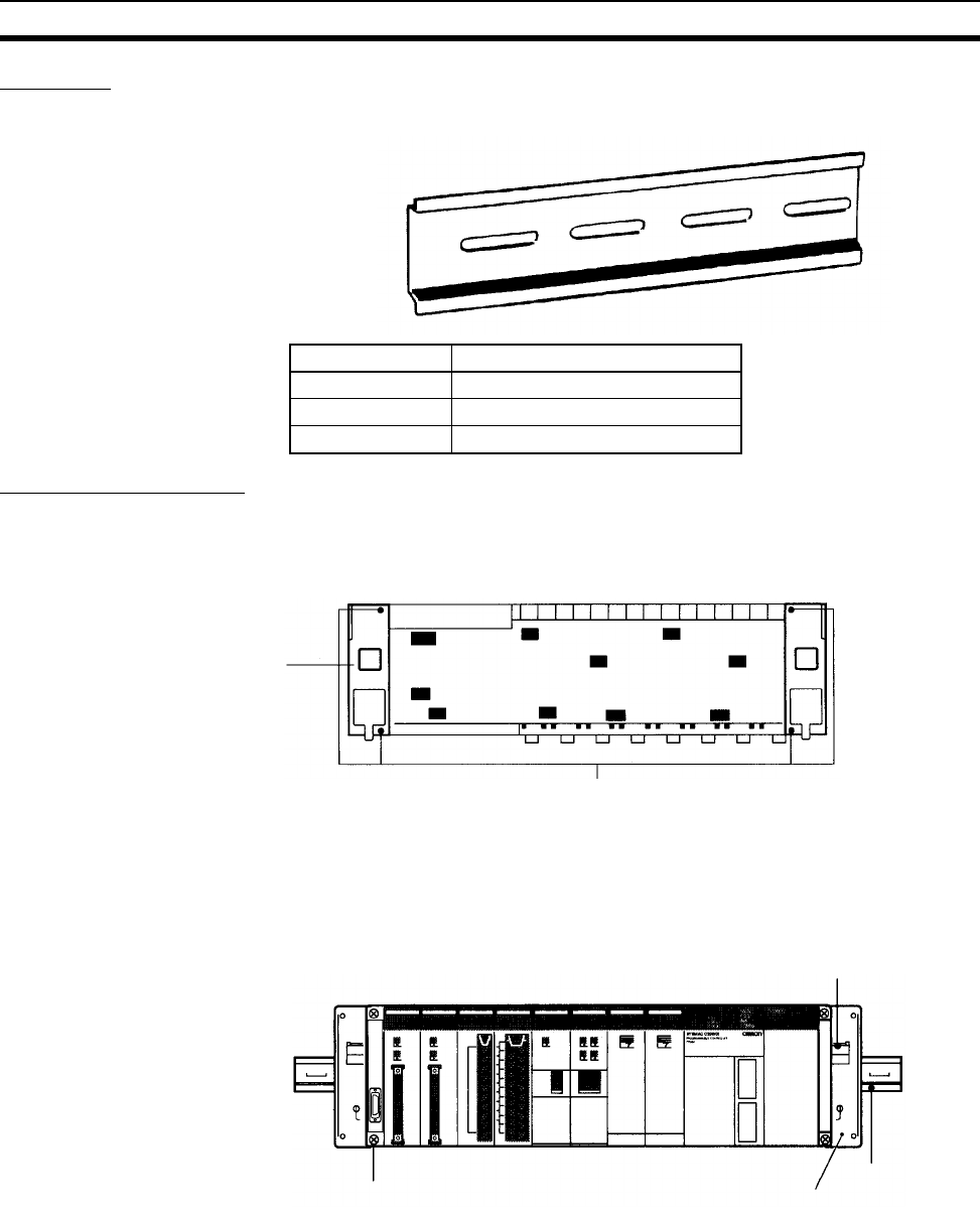
289
Installation Section 5-2
DIN Track
The following DIN Tracks are available.
DIN Track Installation
1,2,3... 1. Attach Mounting Brackets to each side (left and right) of the Backplane as
shown below.
2. Mount the Backplane to the DIN Track so that the hooks on the Mounting
Brackets fit into the upper portion of the DIN Track as shown below.
Model Specification
PFP-50N 50 cm long, 7.3 mm high
PFP-100N 1 m long, 7.3 mm high
PFP-100N2 1 m long, 16 mm high
DIN Track Mounting
Bracket
Backplane (rear view)
There are two Backplane mounting screws each on the left
and right sides of the Backplane. Use these screws to attach
the DIN Track Mounting Brackets to the Backplane.
(Tighten to a torque of 0.9 N·m.)
DIN Track Mountin
g
Bracket
DIN Track
These hooks fit into the DIN Trac
k
Backplane
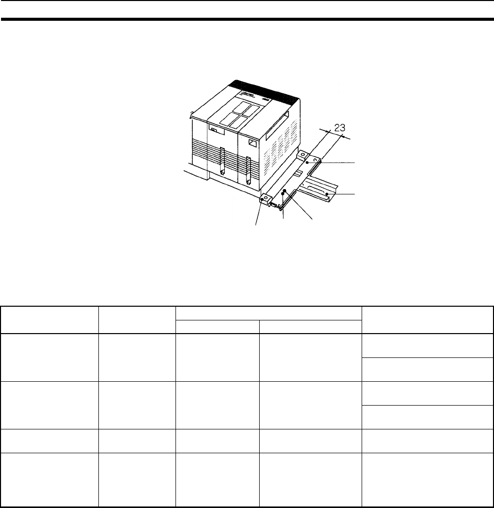
290
Installation Section 5-2
3. Loosen the hold-down bracket’s screws and slide the Backplane upward
so that the Mounting Bracket and Backplane clamp securely onto the DIN
Track. Tighten the screws to a torque of 0.5 N·m.
5-2-7 I/O Connecting Cables
I/O Connecting Cables are used to connect the CPU Rack and Expansion
Racks. There are four types of I/O Connecting Cables.
DIN Track Mounting Bracket
DIN Track
Slide this screw to the top of the
projection and then ti
g
hten it.
Projections
Hold-down bracket
Type Model number Connectors Usage
CPU Rack end Expansion Rack end
CS → CS
I/O Connecting Cables
CS1W-CN@@3 Simple lock con-
nector
Simple lock connector CPU Rack →
CS-series Expansion Rack
CS-series Expansion Rack →
CS-series Expansion Rack
CS → C200H
I/O Connecting Cables
CS1W-CN@@1 Simple lock con-
nector
Two-screw connector CPU Rack →
C200H Expansion I/O Rack
CS-series Expansion Rack →
C200H Expansion I/O Rack
C200H → C200H
I/O Connecting Cables
C200H-CN@@1 Two-screw connec-
tor
Two-screw
connector
C200H Expansion I/O Rack →
C200H Expansion I/O Rack
Cables for CS-series
Long-distance Expan-
sion Racks (CV-series
I/O Connecting
Cables)
CV500-CN@@2 Simple lock con-
nector
Simple lock connector CPU Rack or CS-series Long-
distance Expansion Rack →
CS-series Long-distance
Expansion Rack
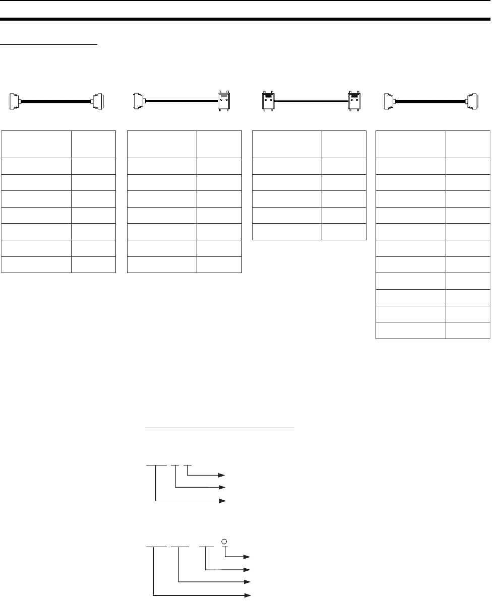
291
Installation Section 5-2
Available Models
Note Restrictions in Using CS-series I/O Connecting Cables
When using a CS1W-CN313 or CS1W-CN713 CS-series I/O Connecting
Cable with a CS1-H CPU Unit, always use a Cable manufactured on Septem-
ber 20, 2001 or later. Do not use Cables that do not have manufacturing num-
bers or Cables manufacture earlier than September 20, 2001.
Manufacturing Number Legend
Four-digit Numbers
Six-digit Numbers
• Install the Racks and select I/O Connecting Cables so that the total length
of all I/O Connecting Cables does not exceed 12 m.
• The following diagram shows where each I/O Connecting Cable must be
connected on each Rack. The Rack will not operate if the cables aren’t
connected properly. (The “up” direction is towards the CPU Unit and
“down” is away from the CPU Unit.)
Model number Cable
length
0.3 m
0.7 m
2 m
3 m
5 m
10 m
12 m
CS1W-CN313
CS1W-CN713
CS1W-CN223
CS1W-CN323
CS1W-CN523
CS1W-CN133
CS1W-CN133B2
0.3 m
0.7 m
2 m
3 m
5 m
10 m
12 m
CS1W-CN311
CS1W-CN711
CS1W-CN221
CS1W-CN321
CS1W-CN521
CS1W-CN131
CS1W-CN131B2
0.3 m
0.7 m
2 m
5 m
10 m
C200H-CN311
C200H-CN711
C200H-CN221
C200H-CN521
C200H-CN131
CS →CS I/O
Connecting Cables
CS →C200H I/O
Connecting Cables C200H → C200H I/O
Connecting Cables
Model number Cable
length
Model number Cable
length
Model number Cable
length
0.3 mCV500-CN312
0.6 mCV500-CN612
1 m
CV500-CN122
2 m
CV500-CN222
3 m
CV500-CN322
5 m
CV500-CN522
10 m
CV500-CN132
20 m
CV500-CN232
30 m
CV500-CN332
40 mCV500-CN432
50 mCV500-CN532
(See note.)
(See note.)
Cables for CS-series Long-
distance Expansion Racks
(CV-series I/O Connecting
Cables)
@@@@
Year (e.g., 1997 = 7, 2001 = 1)
Month (January to September = 1 to 9, October to December = X to Z)
Day of month (01 to 31)
@@@ @
Symbol
Day of month (01 to 31)
Month (January to September = 01 to 12)
Year (e.g., 2003 = 03)
@ @
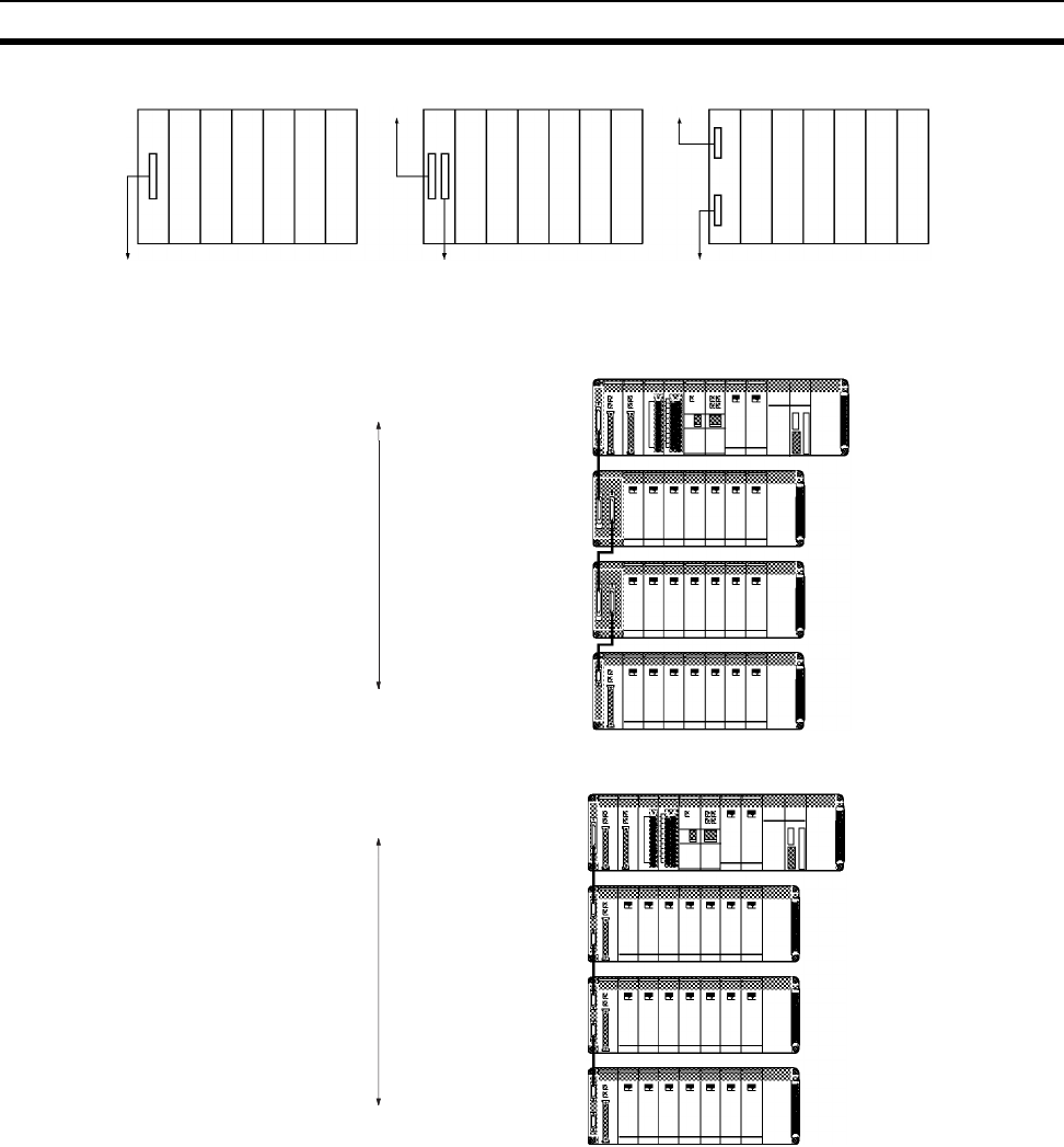
292
Installation Section 5-2
• The following diagram shows two examples of proper Rack connections.
CPU Rack C200H Expansion I/O Rac
k
Down
Up
Down
Up
Down
CS-series Expansion Rack
CPU Rack
CS-series Expansion Rack
C200H Expansion I/O Rac
k
I/O Connecting Cable
I/O Connecting Cable
I/O Connecting Cable
CS-series Expansion Rack
Total cable length: 12 m max.
CPU Rack
C200H Expansion I/O Rac
k
I/O Connecting Cable
I/O Connecting Cable
I/O Connecting Cable
Total cable length: 12 m max.
C200H Expansion I/O Rac
k
C200H Expansion I/O Rac
k
CS → CS
CS → CS
CS → C200H
CS → C200H
C200H → C200H
C200H → C200H
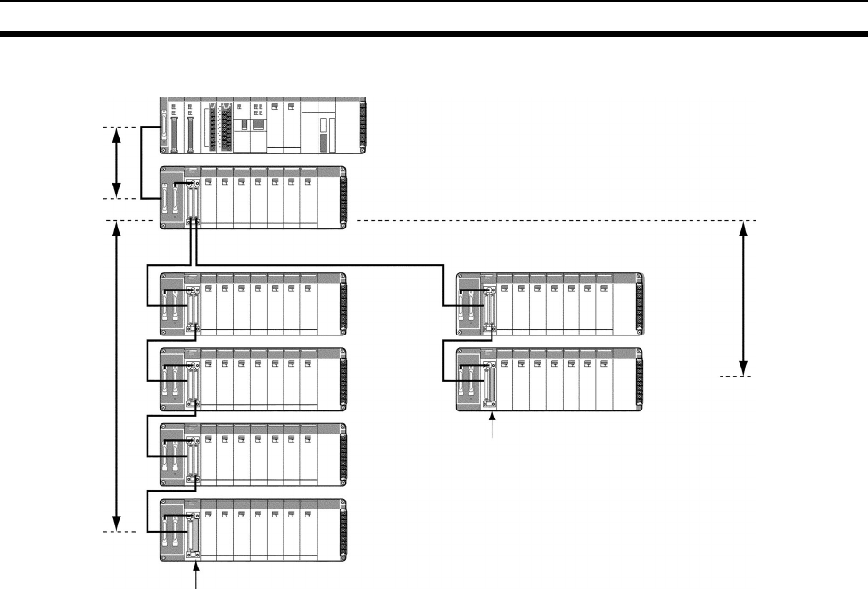
293
Installation Section 5-2
• I/O Control Unit can also be mounted on the CPU Rack.
• Only one CS-series Expansion Rack can be connected.
• The cable length between the CPU Rack and CS-series Expansion Rack
must be 0.7 m max.
• Up to two series of CS-series Long-distance Expansion Racks can be
connected.
• A maximum of seven CS-series and CS-series Long-distance Expansion
Racks can be connected (including all Racks in both series).
• Each series of CS-series Long-distance Expansion Racks must be 50 m
max. with a total of 100 m max. for both series.
• C200H Expansion I/O Racks cannot be connected together with CS-
series Long-distance Expansion Racks.
• A CS-series Expansion Rack cannot be connected to a CS-series Long-
distance Expansion Rack using a CS I/O Connecting Cable.
Example
CPU Rack
(Excluding the
2-slot Rack.)
Terminator
Terminator
Total cable
length: 0.7 m
max.
Total cable
length: 50 m
max.
Total cable
length: 50 m
max.
Series B (0.5 m max.)
CS-series
Expansion
Rack
CS-series Long-
distance
Expansion Rack
CS-series Long-
distance
Expansion Rack
CS-series Long-
distance
Expansion Rack
CS-series Long-
distance
Expansion Rack
CS-series Long-
distance
Expansion Rack
CS-series Long-
distance
Expansion Rack
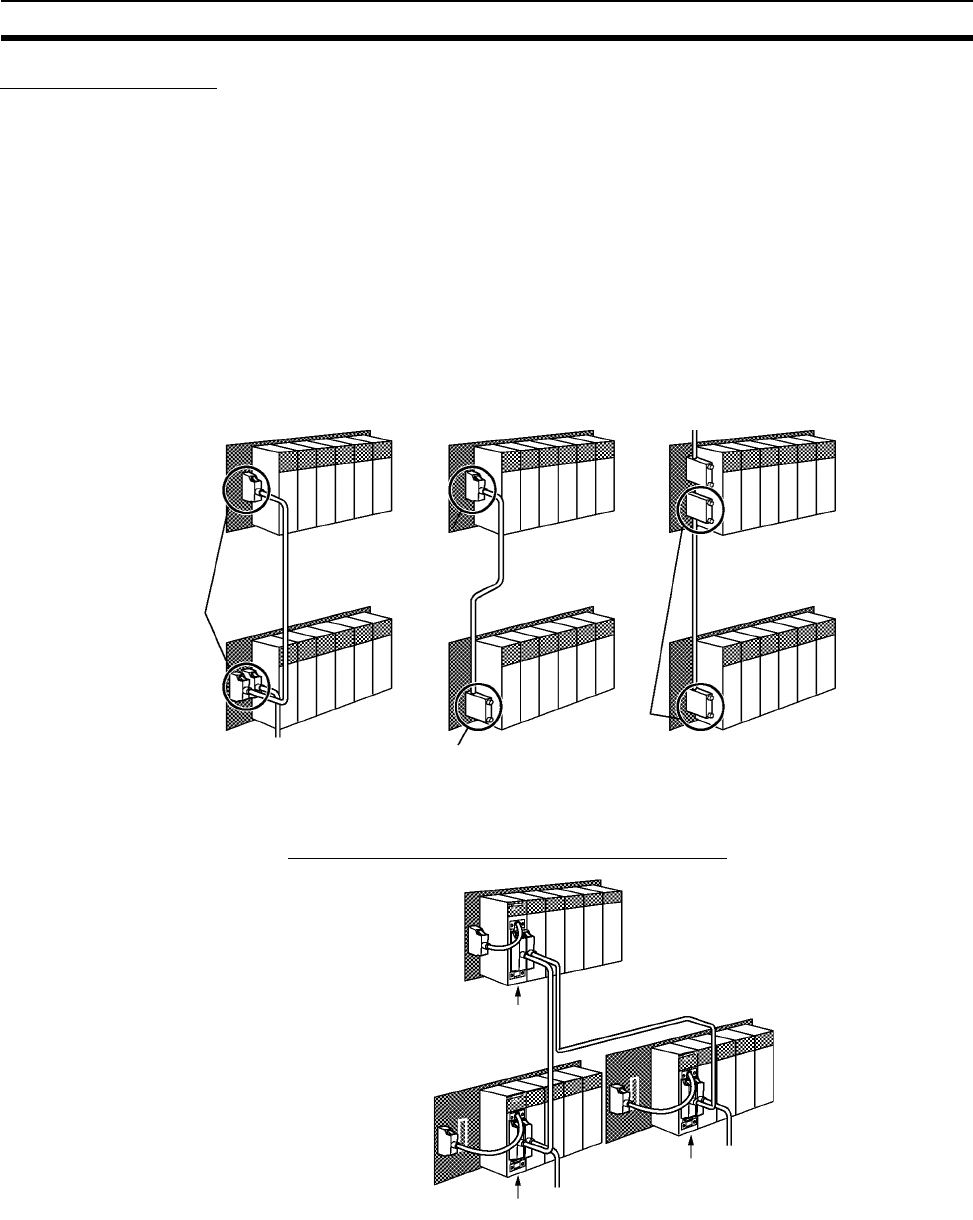
294
Installation Section 5-2
Cable Connections
There are two types of connectors used in the I/O Connecting Cables: Simple
locking connectors for CS-series Racks and screw-in connectors for C200H
Racks.
The connectors can be inserted only one way; they cannot be inserted upside
down. Be sure that the connectors fit properly as they are inserted.
Cables to CS-series Long-distance Expansion Racks
Mounting the I/O Control Unit to the CPU Rack
CS → CS
I/O Connecting Cable
This cable has simple locking
connectors on both ends.
CPU Rack or
Simple locking
connectors
I/O Connecting Cable
This cable has a simple locking
connector on one end and a
screw-in connector on the other.
CPU Rack or
C200H Expansion
I/O Rack
Simple locking
connector
Screw-in
connector
I/O Connecting Cable
This cable has screw-in
connectors on both ends.
C200H Expansion
I/O Rack
C200H Expansion
I/O Rack
Screw-in
connectors
CS-series Expansion Rack CS-series Expansion Rack
CS-series Expansion Rack
CS → C200H C200H → C200H
I/O Control Unit
I/O Interface Unit
Series A
Series B
I/O Interface Unit
CPU Rack
CV-series
Expansion
I/O Cables
CS-series Long-
distance Expansion
Rack
CS-series Long-
distance Expansion
Rack
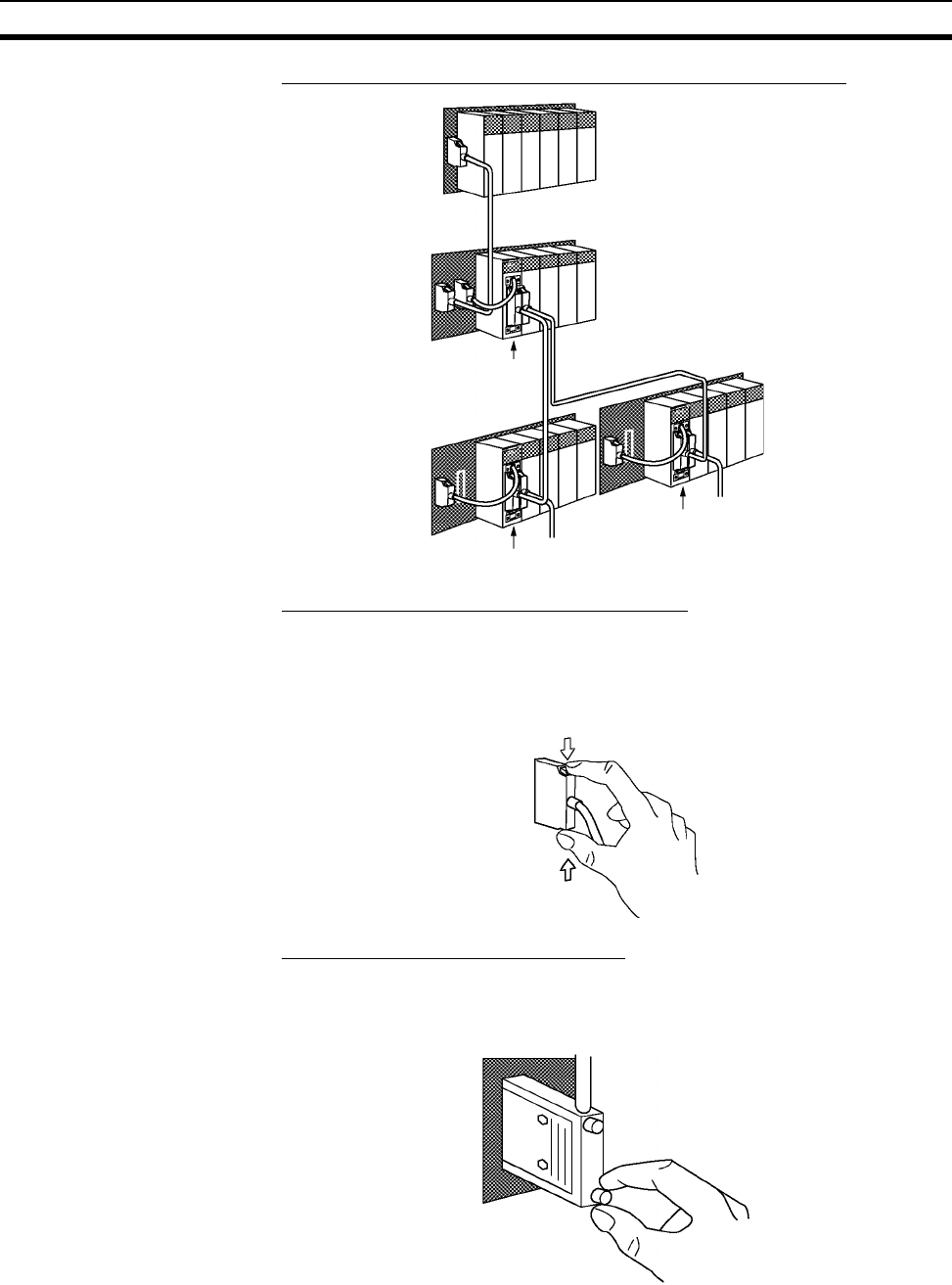
295
Installation Section 5-2
Mounting the I/O Control Unit to a CS-series Expansion Rack
Connecting the Simple Locking Connectors
Insert the connector until it locks in place. The PLC will not operate properly if
the connector isn’t inserted completely.
Note When using an I/O Connecting Cable with a locking connector, be
sure that the connector is firmly locked in place before using it.
Connecting the Screw-in Connectors
Insert the connector and secure it by tightening the two screws to a torque of
0.2 N·m. The PLC will not operate properly if the connector isn’t inserted com-
pletely. To remove the connector, simply loosen the screws and pull it out.
Do not route the I/O Connecting Cables through ducts that contain the I/O or
power wiring.
I/O Control Unit
I/O Interface Unit
Series A
Series B
I/O Interface Unit
CPU Rack
CV-series
Expansion
I/O Cables
CS-series I/O Connecting Cable
CS-series Long-
distance
Expansion Rack
CS-series Long-
distance
Expansion Rack
CS-series Expansion Rack
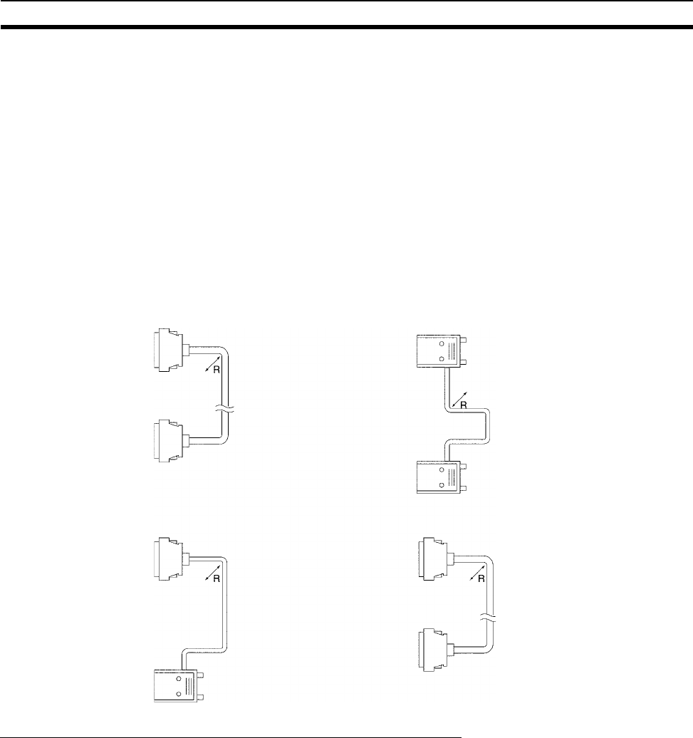
296
Installation Section 5-2
• An I/O bus error will occur and the PLC will stop if an I/O Connecting
Cable’s connector separates from the Rack. Be sure that the connectors
are secure.
• A 75-mm hole will be required if the I/O Connecting Cable must pass
through a hole when connecting a CS-series Long-distance Expansion
Rack and a 63-mm hole will be required for Cables connecting other
Racks. The cables can withstand a pulling force up to 49 N (11 lbs), so be
sure that they aren’t pulled too forcefully.
• Do not cut or reconnect I/O Connecting Cables. Handle them with caution
when mounting the PLC or when using wiring ducts.
• Do not bend the I/O Connecting Cables too severely. The minimum bend-
ing radii are shown in the following diagram.
• Always turn OFF the power supply to the PLC before connecting Cables.
Mounting the Brackets for Securing the Expansion Cable
Expansion Cable Brackets can be used to prevent Expansion Cables from
accidentally coming loose.
Note Expansion Cable Brackets must be ordered separately from Expan-
sion Cables and Backplanes.
Screw holes are required in the Backplane. Use a Backplane manufactured in
August 2007 or later. Earlier Backplanes do not have screw holes, so the
Brackets cannot be mounted. (Refer to Manufacturing Number Legend on
page 291.)
1,2,3... 1. Connect the Cables according to the description in 5-2-7 I/O Connecting
Cables.
(Cable diameter: 8.6 mm)
(Cable diameter: 5.1 mm)
(Cable diameter: 5.1 mm)
R 69 mm
R 41 mm
R 41 mm
(Cable diameter: 10 mm)
R 80 mm
CS → CS I/O Connecting Cable C200H → C200H I/O Connecting Cable
CS → C200H I/O Connecting Cable Cables for CS-series Long-distance Expansion Racks
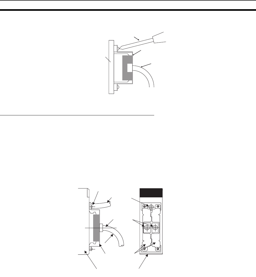
297
Installation Section 5-2
2. Mount the Expansion Cable Bracket from the top, and tighten the screws
(included) on the top and bottom using a Phillips screwdriver.
Tighten the screws to a torque of 0.5 N·m.
Mounting Long-distance Expansion Cable Brackets
Long-distance Expansion Cable Brackets can be used to prevent Expansion
Cables from accidentally coming loose.
Note Two Long-distance Expansion Cable Brackets are included with the
CS1W-II102 I/O Interface Unit.
1,2,3... 1. Connect the Cables according to the description in 5-2-7 I/O Connecting
Cables.
2. Mount the Long-distance Expansion Cable Bracket from the top, and use
a Phillips screwdriver to tighten the screws (included) on the top and bot-
tom.
Phillips screwdriver
Backplane
CS1D-ATT01 Expansion Cable Bracke
t
Expansion Cable
• Tighten the screws to a torque of
0.5 N·m.
• When connecting two Long-dis-
tance Expansion Cables to a sin-
gle Long-distance Expansion
Unit, turn one of the Mounting
Brackets upside down and
attached them from the sides as
shown in the figure to the left.
R
Mounting screws (2 places)
Connection to Backplane
Long-distance
Expansion Cable
Long-distance Expansion Cable
Brackets (included with the
CS1W-II102 I/O Interface Unit)
CS1W-IC102 I/O Control Unit
CS1W-II102 I/O Interface Unit
R≥80 mm
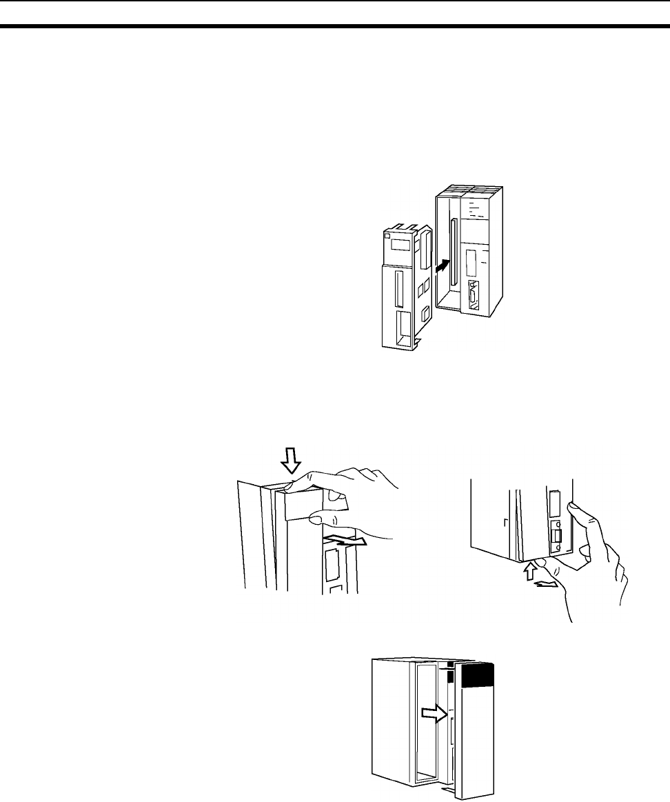
298
Installation Section 5-2
5-2-8 Inner Board Installation
Always turn the power off before installing or removing the Inner Board.
Installing or removing the Inner Board with the power on can cause the CPU
Unit to malfunction, damage internal components, or cause communications
errors.
Before installing the Inner Board, be sure to first touch a grounded metallic
object, such as a metal water pipe, in order to discharge any static build-up.
1,2,3... 1. Press the catches at the top and bottom of the Inner Board compartment
cover and pull the cover forward.
2. Remove the Inner Board compartment cover.
Inner Board
(such as a Serial
Communications
Board)
CPU Unit
Press the top catch. Press the bottom catch.
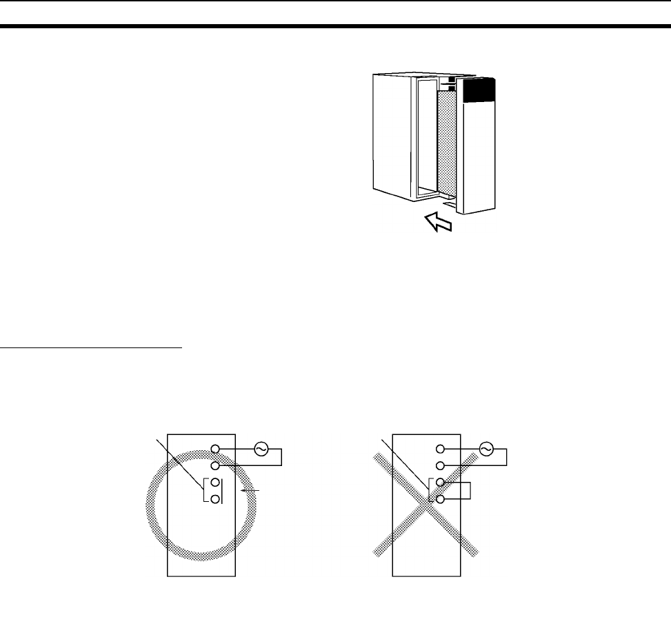
299
Wiring Section 5-3
3. Align the Inner Board with the groove and slide it into the compartment.
5-3 Wiring
5-3-1 Power Supply Wiring
AC Power Supply Units
When 200 to 240 V AC power is being supplied, be sure to remove the jumper
bar that shorts the voltage selector terminals. The Unit will be damaged if 220
V AC is supplied with the jumper bar connected.
Note If 110 V AC power is supplied but the jumper bar has been removed to select
220 V AC, the Unit will not operate because the power supply voltage will be
below the 85% minimum level.
• Do not remove the protective label from the top of the Unit until wiring has
been completed. This label prevents wire strands and other foreign matter
from entering the Unit during wiring procedures.
Voltage selector
terminals
220 V AC
power
Not connected
(OPEN)
Voltage selector
terminals
220 V AC
power
Unit will be damaged
if connected.
INCORRECT!
(Unit will be dama
g
ed.)
CORRECT
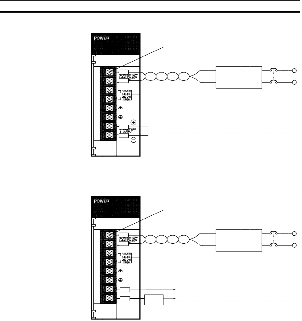
300
Wiring Section 5-3
Note To prevent damage, be sure that the jumper bar on the voltage selector termi-
nals has been removed before applying 220 V AC power.
C200HW-PA204 or C200HW-PA204S Power Supply Unit
Screws (3.5 mm head with
self-raising pressure plate)
1:1 isolation
transformer
Closed for 110 V AC
Open for 220 V AC*
24-V DC output
Note The 24-V DC service power supply is
provided on the C200HW-PA204S only.
AC power
source
100 to 200 V AC
Voltage selector (C200HW-PA204S only):
RUN output2
ON when the PLC is in RUN or MONITOR mode.
OFF when the PLC is in PROGRAM mode or a fatal
error has occurred.
RUN
OUTPUT Power
supply
C200HW-PA204R or C200HW-PA209R Power Supply Unit
Screws (3.5 mm head with
self-raising pressure plate)
1:1 isolation
transformer
Closed for 110 V AC
Open for 220 V AC1
AC power
source
100 to 200 V AC
Voltage selector (C200HW-PA209R only):
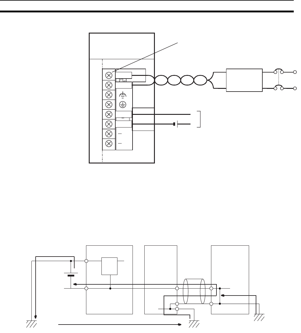
301
Wiring Section 5-3
!Caution Be careful when connecting personal computers or other peripheral devices
to a PLC to which is mounted a non-insulated Unit (CS1W-CLK12/15(-V1),
CS1W-CLK13/53, or CS1W-ETN01) connected to an external power supply.
A short-circuit will be created if the 24 V side of the external power supply is
grounded and the 0 V side of the peripheral device is grounded. When con-
necting a peripheral device to this type of PLC, either ground the 0 V side of
the external power supply or do not ground the external power supply at all.
Note 1. To prevent damage, be sure that the jumper bar on the voltage selector ter-
minals has been removed before applying 220 V AC power.
2. If a Power Supply Unit without a RUN output is being used, an output that
acts as a RUN output can be created by programming the Always ON Flag
(A1) as the execution condition for an output from an Output Unit.
AC Power Source
• Supply 100 to 120 V AC or 200 to 240 V AC.
• The C200HW-PA204/PA204R/PA204C supplies 100 to 240 V AC (allow-
able voltage fluctuation range: 85 to 264 V AC). The C200HW-PA204/
PA204R/PA204C has a wide-range supply voltage (100 to 240 V AC), so
voltage selector terminals are not provided.
C200HW-PA204C Power Supply Unit
ALARM
OUTPUT
30 VDC, 50 mA
NORMAL: ON
ALARM: OFF
PA204C
L
NC
NC
L1
L2 /N 100 to
240 VAC
INPUT
3.5-mm self-rising screws
1:1 isolation
transformer
24 V DC
power supply
Alarm output (replacement notification
output)
ON: Power Supply Unit replacement
not required for at least 6 months.
OFF: Power Supply Unit replacement
required within 6 months.
AC power
source
100 to 240 V AC
24 V
0 V 0 V
SG
FG
FG FG
FG
Incorrect
External power supply
Shield
CPU UnitNon-insulated Unit
Non-insulated
DC power supply Peripheral
cable
Peripheral device
(e.g., personal
computer)
GR
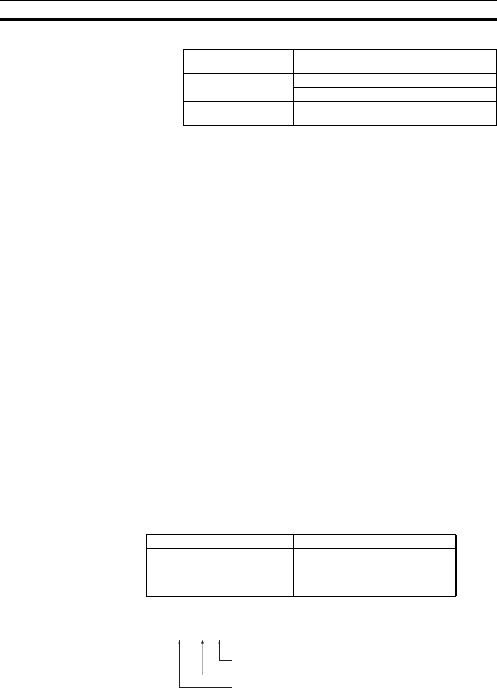
302
Wiring Section 5-3
• Keep voltage fluctuations within the specified range:
• The terminal block indicator L2/N-L1 may appear as L1/N-L2 in some
Units, but the function of the terminals is the same.
• If one power supply phase of the equipment is grounded, connect the
grounded phase side to the L2/N (or L1/N if so indicated) terminal.
Voltage Selector Shorted: 100 to 120 V AC
Open: 200 to 240 V AC
Short-circuit the voltage selector terminals with the jumper bar to select 100 to
120 V AC supply voltage. For 200 to 240 V AC leave them open.
Note The Power Supply Unit will be damaged if 200 to 240 V AC power is supplied
and the voltage selector terminals are connected with the jumper bar.
Isolation Transformer The PLC’s internal noise isolation circuits are sufficient to control typical noise
in power supply lines, but noise between the PLC and ground can be signifi-
cantly reduced by connecting a 1-to-1 isolation transformer. Do not ground the
secondary coil of the transformer.
Power Consumption The power consumption will be 120 VA max. per Rack, but there will be a
surge current of at least 5 times the max. current when power is turned ON.
24-V DC Output
(C200HW-PA204S Only)
Use these terminals as the power supply for 24-V DC Input Units. Never exter-
nally short these terminals; PLC operation will stop if these terminals are
shorted.
Although the 24-V DC output can supply up to 0.8 A, the combined power
consumption for both 5 V DC and 24 V DC must be 30 W or less, i.e., the
capacity of the 24-V DC output will be reduced if the Units mounted to the
Rack consume a lot of current. Refer to Appendix C Unit Current and Power
Consumption for the power consumption of each Unit.
The output voltage of the 24-V DC output will vary with the current consump-
tion of the load as shown in the following table. Be sure to check the current
consumption and allowable voltage ranges of the devices connected before
using these terminals.
Note Lot numbers are as shown in the following diagram.
Power Supply Unit
model
Supply voltage Allowable voltage
fluctuations
C200HW-204S/PA209R 100 to 120 V AC 85 to 132 V AC
200 to 240 V AC 170 to 264 V AC
C200HW-PA204/
PA204R/PA204C
100 to 240 V AC 85 to 264 V AC
Load current on 24-V DC output Less than 0.3 A 0.3 A or higher
Accuracy of 24-V DC output for lot
No. 0197 or later
+17%
–11%
+10%
–11%
Accuracy of 24-V DC output for lot
No. 3187 or earlier
+10%
–20%
0 1 9 7
1997 (Rightmost digit of year)
September (Month: 1 to 9 = Jan. to Sept, X/Y/Z = Oct/Nov/Dec)
01 (Day: 01 to 31)
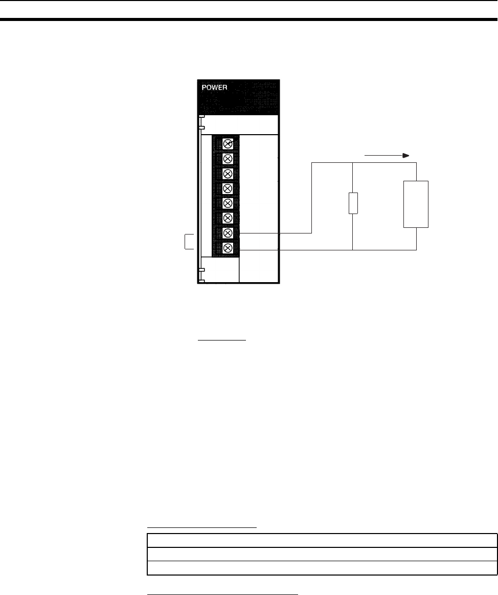
303
Wiring Section 5-3
We recommend connecting a dummy load as shown in the following diagram
if the maximum operating voltage of the connected device is 26.4 V (24 V
+10%).
Note Since the dummy load will generate heat, be careful not to allow any combus-
tible materials to come in contact with the resistor.
Alarm Output (C200HW-PA204C Only)
Connect the alarm output to a PLC's Input Unit or external LED indicator to
enable notification when Power Supply Unit replacement is required.
ON: Power Supply Unit replacement not required for at least 6 months.
OFF: Power Supply Unit replacement required within 6 months.
Output Specifications:
PLC Input Unit Wiring Example
Connect the positive terminals of the 24-V DC power supply to the Input Unit
common (COM) terminals.
Dummy
load
Connected
device
(Photoelectric
Switch, Sen-
sor Input Unit,
etc.
24 V DC
OUTPUT
R
L
IL
Resistance of the dummy load: 120 Ω when IL = 0.1 A
240 Ω when IL = 0.2 A
Not necessary when IL = 0.3 A
(IL: Total current of connected devices)
Power rating of the dummy load (with a safety factor of 5):
30 W (120 Ω) when IL = 0.1 A
15 W (240 Ω) when IL = 0.2 A
R= 24
0.3 – lL
W = (0.3 – lL) × 26.4 × 5
Transistor open-collector output
30 VDC max., 50 mA max.
ON: Residual voltage of 2 V max., OFF: Leakage current of 0.1 mA max.
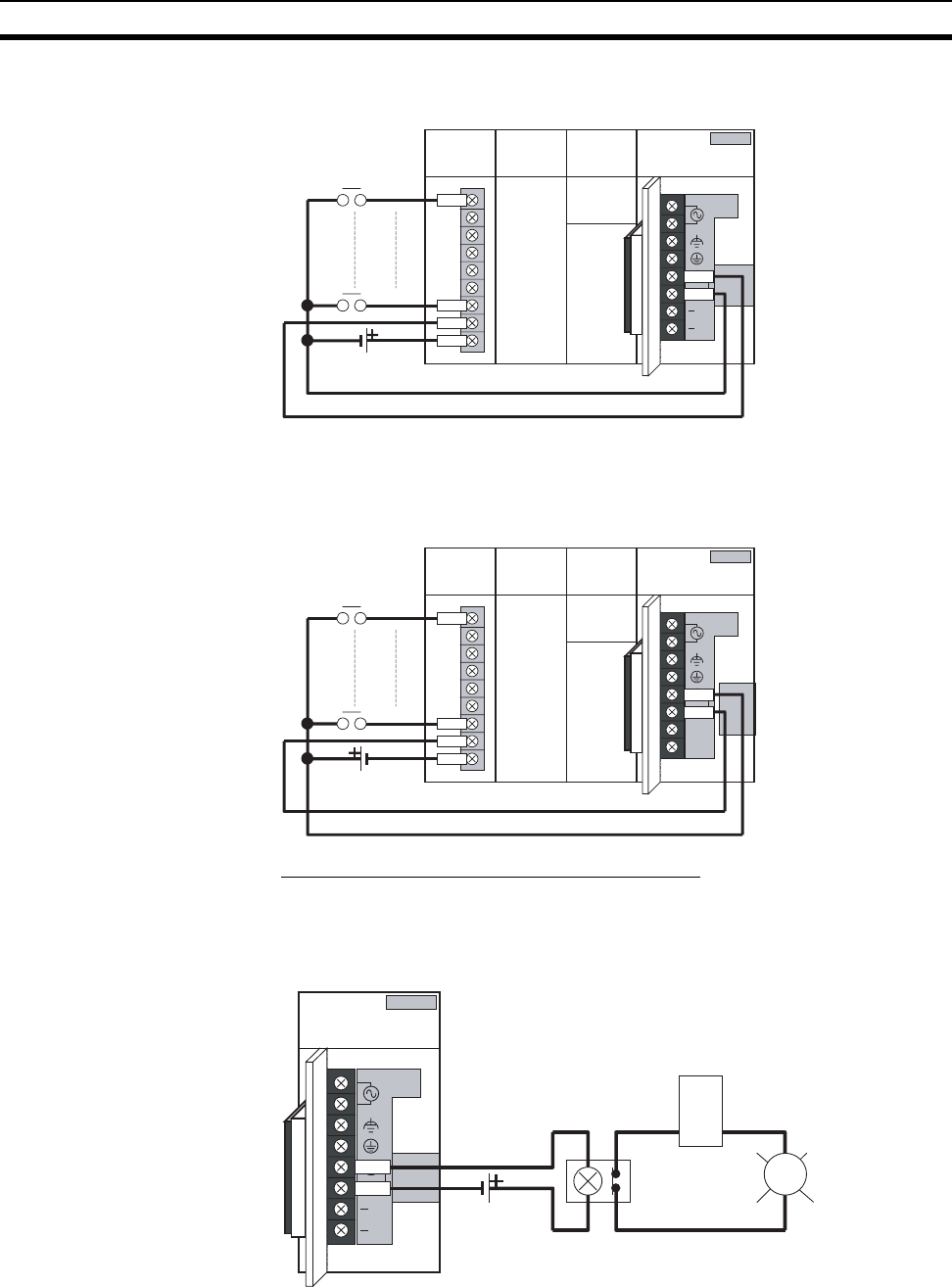
304
Wiring Section 5-3
Connect the negative terminal of the 24-V DC power supply to the Input Unit
common (COM) terminal.
External Display Device Connection Example
The alarm output (replacement notification output) is an NC contact. There-
fore, wire the alarm output using an NC contact or other means to turn ON an
error indicator or LED display as shown in the following diagram.
Note 1. The OL display will also light if the PLC's power supply fails.
2. Separate the alarm output cables from power lines and high-voltage lines.
ALARM
OUTPUT
30 V D C, 50 mA
N ORM ALON
PA204C
L
NC
NC
L1
L2/N 100 to
240
VAC
IN PUT
IN0
IN(N)
IN
(
N+1)
COM
IN Unit
CS1W-ID2**
C200H-ID2** CPU Unit C200HW-PA204C
ALARM OFF
24 V DC
power supply
ALARM
OUTPUT
30 VDC,50 mA
NORMAL: OFF
ALARM: OFF
PA204C
L
−NC
−NC
L1
L2/N 100 to
240 V AC
IN PUT
IN0
IN(N)
IN
(
N+1)
COM
24 V DC
power supply
IN Unit
CS1W-ID2**
C200H-ID2** CPU Unit C200HW-PA204C
ALA RM
OUTPUT
30VD C, 50 mA
NORM AL: ON
PA204C
L
NC
NC
L1
L2/N 100 to
240 VAC
IN PUT
OL
ALARM: OFF
C200HW-PA204C
24 VDC
power supply
Power
supply
Relay
(NC contact)
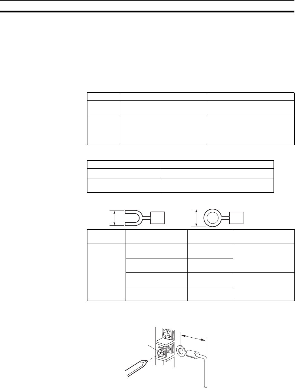
305
Wiring Section 5-3
3. Do not apply a voltage or connect a load to the alarm output that exceeds
the rated voltage or load.
RUN Output
(C200HW-PA204R/209R)
This output is ON whenever the CPU Unit is operating in RUN or MONITOR
mode; it is OFF when the CPU Unit is in PROGRAM mode or a fatal error has
occurred.
The RUN output can be used to control external systems, such as in an emer-
gency stop circuit that turns off the power supply to external systems when
the PLC is not operating. (See 5-1 Fail-safe Circuits for more details on the
emergency stop circuit.)
Wiring
Recommended crimp terminals
Note 1. Use crimp terminals for wiring.
2. Do not connect bare stranded wires directly to the terminals.
!Caution Tighten the AC power supply terminal block screws to the torque of 0.8 N·m.
Loose screws may result in short-circuit, malfunction, or fire.
Note 1. Supply power to all of the Power Supply Units from the same source.
C200HW-PA204R C200HW-PA209R
Contact
form
SPST-NO SPST-NO
Maximum
switching
capacity
250 V AC: 2 A for resistive loads
0.5 A for inductive loads
24 V DC: 2 A
240 V AC:2 A for resistive loads
120 V AC:0.5 A for inductive loads
24 V DC: 2 A for resistive loads
2 A for inductive loads
Terminal screws M3.5 self-rising screws
Recommended wire size AWG 20 to 14 (0.517 to 2.08 mm2)
Recommended tightening
torque
0.8 N·m
Manufacturer Models Shape Applicable wire range
(stranded wire)
JST Mfg. V1.25-YS3A Y-shaped termi-
nal with sleeve 0.25 to 1.65 mm2 (AWG
22 to 16)
V1.25-M3(RAV1.25-3.5) Round terminal
with sleeve
V2-YS3A Y-shaped termi-
nal with sleeve 1.04 to 2.63 mm2 (AWG
16 to 14)
V2-M3(RAV2-3.5) Round terminal
with sleeve
7 mm max. 7 mm max.
20 mm max.
Torque to 0.8 N·m
M3.5 self-raising terminals
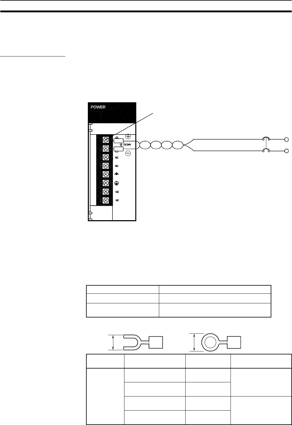
306
Wiring Section 5-3
2. Be sure to check the setting of the voltage selector before supplying power.
3. Do not forget to remove the label from the top of the Power Supply Unit af-
ter wiring the Unit. The label will block air circulation needed for cooling.
DC Power Supplies
Do not remove the protective label from the top of the Unit until wiring has
been completed. This label prevents wire strands and other foreign matter
from entering the Unit during wiring procedures. (Remove the label after wir-
ing has been completed to allow air circulation needed for cooling.)
DC Power Source Supply 24 V DC. Keep voltage fluctuations within the specified range (19.2 to
28.8 V DC).
Power Supply Capacity The maximum power consumption is 40 W per Rack for C200HW-PD024 and
60 W per Rack for C200HW-PD025, but there will be a surge current of about
5 times that level when the power is turned on.
Wiring
Recommended crimp terminals
C200HW-PD024/025 Power Supply Unit
Screw (3.5 mm head with
self-raising pressure plate)
DC
power
source
Terminal screws M3.5 self-rising screws
Recommended wire size AWG 20 to 14 (0.517 to 2.08 mm2)
Recommended tightening
torque
0.8 N·m
Manufacturer Models Shape Applicable wire range
(stranded wire)
JST Mfg. V1.25-YS3A Y-shaped termi-
nal with sleeve 0.25 to 1.65 mm2 (AWG
22 to 16)
V1.25-M3(RAV1.25-3.5) Round terminal
with sleeve
V2-YS3A Y-shaped termi-
nal with sleeve 1.04 to 2.63 mm2 (AWG
16 to 14)
V2-M3(RAV2-3.5) Round terminal
with sleeve
7 mm max. 7 mm max.
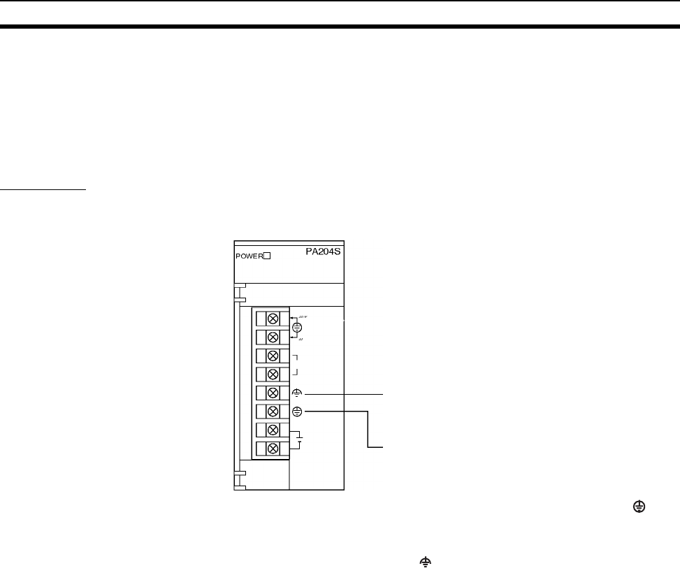
307
Wiring Section 5-3
Note 1. Use crimp terminals for wiring.
2. Do not connect bare stranded wires directly to the terminals.
3. Wire the power supply with the correct polarity. Supply power to all of the
Power Supply Units from the same source.
4. Remove the label after the completion of wiring to ensure proper heat dis-
sipation. Leaving the label attached may result in malfunction.
Grounding
The diagram below shows the location of the ground and line ground termi-
nals.
• To help prevent electrical shock, ground the ground terminal (GR: ) with
a ground resistance of less than 100 Ω using a 14-gauge wire (minimum
cross-sectional area of 2 mm2).
• The line ground terminal (LG: ) is a noise-filtered neutral terminal. If
noise is a significant source of errors or electrical shocks are a problem,
connect the line ground terminal to the ground terminal and ground both
with a ground resistance of less than 100 Ω.
• The ground wire should not be more than 20 m long.
• The following grounding configurations are acceptable.
• The CS-series Backplanes are designed to be mounted so that they are
isolated (separated) from the mounting surface to protect them from the
effects of noise in the installation environment (e.g., the control panel).
(C200HX/HG/HE and C200H Backplanes are mounted directly to the
mounting surface. If Expansion I/O is being affected by control panel or
other environmental noise, use the C200HW-ATT@@ or C200H-ATT@@
Backplane Insulation Plates to isolate the Backplanes.
Note Make sure that the C200HW-PA204C is wired correctly. The C200HW-
PA204C terminals are wired differently from other Power Supply Units.
• Do not share the PLC’s ground with other equipment, such as motors and
inverters, or ground the PLC to the metal structure of a building. The con-
figuration shown in the following diagram may worsen operation.
LG (Noise-filter neutral terminal)
Ground this terminal to less than 100 Ω to improve
noise resistance and prevent electric shock.
GR (Ground terminal)
Ground this terminal to less than 100 Ω to prevent
electric shock.
DC24V/0.8A
OUTPUT
100-200
CLOSE
200-240
OPEN
AC100V-120V/
AC2100-240V/
INPUT
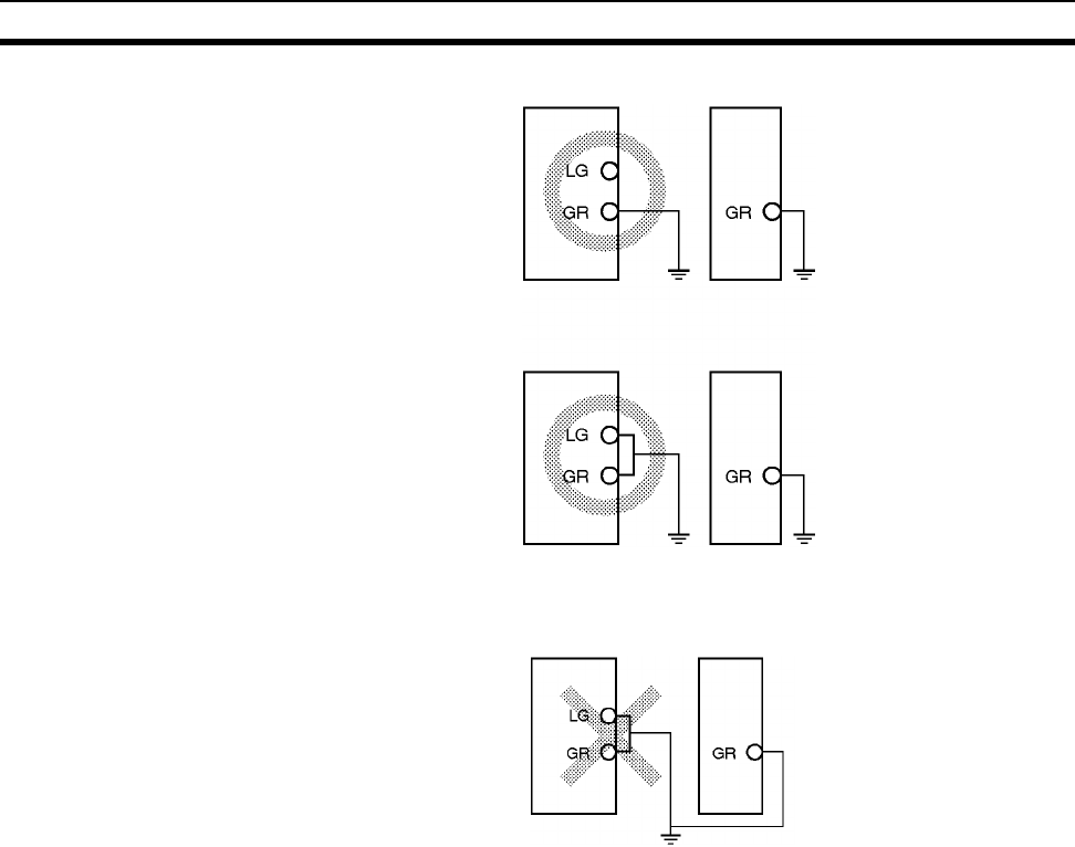
308
Wiring Section 5-3
!Caution Tighten the AC power supply terminal block screws to the torque of 0.8 N·m.
Loose screws may result in short-circuit, malfunction, or fire.
Grounding Long-distance Expansion Racks
A difference in potential will occur between remote ground points if more than
one point is grounded on the CPU Rack and Long-distance Expansion Racks
in a CS-series Long-distance Expansion System. This is caused by high-fre-
quency noise from power lines, potential and phase differences between
power lines, and other factors. To prevent noise from entering on the GR
(ground) terminal as a result of a difference in potential, wire the system as
shown below.
• Connect all of the GR terminals on the Racks and ground them at one
point only to 100 Ω or less.
• Short the LR terminals to the GR terminals.
• Use a ground wire of 2 mm2 min.
• Insert 1:1 isolating transformers into the power supply lines and do not
ground the secondary sides of the transformers.
CS-series PLC Other equipment
Ground
(100 or less)
Ground
(100 or less)
CS-series PLC Other equipment
Ground
(100 or less)
Ground
(100 or less)
CS-series PLC Other equipment
(e.g., motors and inverters)
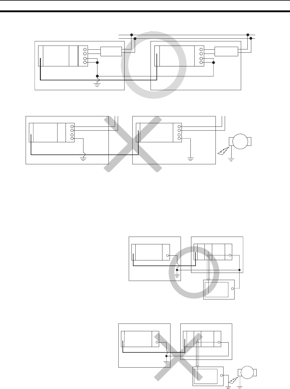
309
Wiring Section 5-3
Recommended Wiring
Wiring Susceptible to Noise
Wiring Communications Lines
When using communications from one or more Rack in the system, ground
the entire system so that only one point is grounded. (Refer to user documen-
tation for the devices connected.) For detailed connection methods, refer to
the Operation Manual for the Communications Unit.
Recommended Wiring
Wiring Susceptible to Noise
GR
L2
L1
LG
GR
L2
L1
LG
CPU
IC101 I102
CPU Rack Expansion Rack
Match to the I/O
Expansion Cable.
I/O Expansion Cable
Control panel Control panel
1:1 Isolating
transformer
1:1 Isolating
transformer
GR
L2
L1
LG
GR
L2
L1
LG
CPU
IC101 I102
CPU Rack Expansion Rack
I/O Expansion Cable
Control panel Control panel Grounded to building
Noise source
GR GR
GR
IC101 II102
CPU Rack Expansion Rack
I/O Expansion Cable
Control panel Control panel
GR GR
GR
IC101 II102
CPU Rack Expansion Rack
I/O Expansion Cable
Control panel Control panel
Noise source
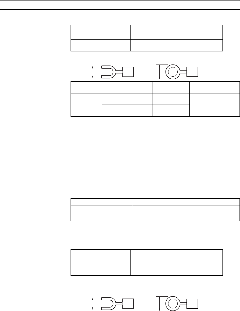
310
Wiring Section 5-3
Wiring
Recommended crimp terminals
Note 1. Use crimp terminals for wiring.
2. Do not connect bare stranded wires directly to the terminals.
5-3-2 Wiring CS-series and C200H Basic I/O Units
I/O Unit Specifications Double-check the specifications for the I/O Units. In particular, do not apply a
voltage that exceeds the input voltage for Input Units or the maximum switch-
ing capacity for Output Units. Doing so may result in breakdown, damage, or
fire.
When the power supply has positive and negative terminals, be sure to wire
them correctly.
Electric Wires The following wire gauges are recommended.
Note The current capacity of electric wire depends on factors such as the ambient
temperature and insulation thickness as well as the gauge of the conductor.
Wiring
Recommended crimp terminals
1. C200H Basic I/O Units with 10-terminal or 19-terminal Terminal Blocks
Terminal screws M3.5 self-rising screws
Recommended wire size AWG 14 min. (2 mm2 min.)
Recommended tightening
torque
0.8 N·m
Manufacturer Models Shape Applicable wire range
(stranded wire)
JST Mfg. V2-YS3A Y-shaped termi-
nal with sleeve 1.04 to 2.63 mm2 (AWG
16 to 14)
V2-M3(RAV2-3.5) Round terminal
with sleeve
7 mm max. 7 mm max.
Terminal Block Connector Wire Size
10-terminal AWG 22 to 18 (0.32 to 0.82 mm2)
19-terminal/20-terminal AWG 22 (0.32 mm2)
Terminal screws M3.5 self-rising screws
Recommended wire size AWG 22 to 18 (0.326 to 0.823 mm2)
Recommended tightening
torque
0.8 N·m
7 mm max. 7 mm max.
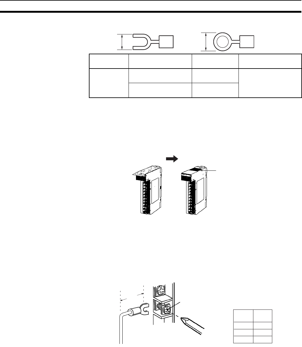
311
Wiring Section 5-3
2. CS-series Basic I/O Units with 20-terminal Terminal Blocks
Note 1. Use crimp terminals for wiring.
2. Do not connect bare stranded wires directly to the terminals.
Do not remove the protective label from the top of the Unit until wiring has
been completed. This label prevents wire strands and other foreign matter
from entering the Unit during wiring procedures. (Remove the label after wir-
ing has been completed to allow air circulation needed for cooling.)
• Wire the Units so that they can be easily replaced. In addition, make sure
that the I/O indicators are not covered by the wiring.
• Do not place the wiring for I/O Units in the same duct or raceway as power
lines. Inductive noise can cause errors in operation.
• Tighten the terminal screws to the torque of 0.8 N·m.
• The terminals have screws with 3.5-mm diameter heads and self-raising
pressure plates. Connect the lead wires to the terminals as shown below.
Terminal Blocks The I/O Units are equipped with removable terminal blocks. The lead wires do
not have to be removed from the terminal block to remove it from an I/O Unit.
The terminal block on a C200H Basic I/O Units can be removed by pressing
the terminal block locks. The terminal block on a CS-series Basic I/O Units
can be removed by taking out the terminal block mounting screws.
Manufacturer Models Shape Applicable wire range
(stranded wire)
JST Mfg. V1.25-YS3A Y-shaped termi-
nal with sleeve 0.25 to 1.65 mm2 (AWG
22 to 16)
V1.25-M3(RAV1.25-3.5) Round terminal
with sleeve
6.5 mm max. 7 mm max.
During wiring After wiring
Remove the label.
Screw (3.5 mm screw with
self-raising pressure plate)
A
A
Terminal
block
10P 23 mm
19P 14 mm
20P 18 mm
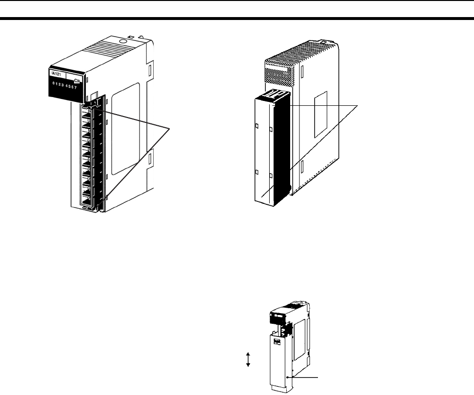
312
Wiring Section 5-3
I/O Unit Covers The C200H-COV11 Cover is available to cover the terminal block on Units
with 10-terminal terminal block connectors. These Covers can be purchased
separately if extra protection is required.
5-3-3 Wiring CS-series and C200H I/O Units with Connectors
This section describes wiring for the following Units:
• C200H Group-2 High-density I/O Units
• CS-series Basic I/O Units with Connectors (32-, 64-, and 96-point Units)
• C200H High-density I/O Units (Special I/O Units)
C200H High-density I/O Units and CS-series Basic I/O Units with connectors
use special connectors to connector to external I/O devices. The user can
combine a special connector with cable or use a preassembled OMRON
cable to connect a High-density I/O Unit to a terminal block or Relay Terminal.
The available OMRON cables are described later in this section.
CS-series Basic I/O Units with connectors have the same connector pin allo-
cations as the C200H High-density I/O Units to make them compatible.
• Be sure not to apply a voltage that exceeds the input voltage for Input
Units or the maximum switching capacity for Output Units.
• When the power supply has positive and negative terminals, be sure to
wire them correctly. Loads connected to Output Units may malfunction if
the polarity is reversed.
• Use reinforced insulation or double insulation on the DC power supply
connected to DC I/O Units when required by EC Directives (low voltage).
• When connecting the connector to the I/O Unit, tighten the connector
screws to a torque of 0.2 N·m.
Terminal block locks
C200H Basic I/O Units
CS-series Basic I/O Units
(including Interrupt Input
Units and High-speed Input
Units)
Terminal block
mounting screws
(black screws
under cover)
Attach
Remove C200H-COV11
I/O Unit cover

313
Wiring Section 5-3
• Turn ON the power after checking the connector’s wiring. Do not pull the
cable. Doing so will damage the cable.
• Bending the cable too sharply can damage or break wiring in the cable.
Available Connectors
Use the following connectors when assembling a connector and cable.
C200H Group-2 High-
density I/O Units and CS-
series Basic 32- and 64-
point I/O Units
The following connectors are recommended for attachment to C200H Group-
2 High-density I/O Units and CS-series 32- and 64-point I/O Units.
Note Solder-type connectors are included with each Unit.
CS-series 96-point Basic
I/O Units
The following connectors are recommended for attachment to CS-series 96-
point I/O Units.
Note Solder-type connectors are included with each Unit.
C200H High-density I/O
Units
The following connectors are recommended for attachment to C200H High-
density I/O Units.
Note Solder-type connectors are included with each Unit.
Wire
We recommend using cable with wire gauges of AWG 24 to AWG 28
(0.2 mm2 to 0.08 mm2). Use cable with external wire diameters of 1.61 mm
max.
Wiring Procedure
The wiring procedure is the same for the C200H Group-2 High-density I/O
Units, CS-series High-density I/O Units, and C200H High-density I/O Units
(C200H Special I/O Units).
1,2,3... 1. Check that each Unit is installed securely.
Note Do not force the cables.
2. Do not remove the protective label from the top of the Unit until wiring has
been completed. This label prevents wire strands and other foreign matter
Connection Pins OMRON set Fujitsu parts
Solder-type
(included with Unit)
40 C500-CE404 Socket: FCN-361J040-AU
Connector bar: FCN-360C040-J2
Crimp-type 40 C500-CE405 Socket: FCN-363J040
Connector bar: FCN-360C040-J2
Contacts: FCN-363J-AU
Crimp-type 40 C500-CE403 FCN-367J040-AU/F
Connection Pins OMRON set Fujitsu parts
Solder-type
(included with Unit)
56 CS1W-CE561 Socket: FCN-361J056-AU
Connector bar: FCN-360C056-J2
Crimp-type 56 CS1W-CE562 Socket: FCN-363J056
Connector bar: FCN-360C056-J2
Contacts: FCN-363J-AU
Crimp-type 56 CS1W-CE563 FCN-367J056-AU/F
Connection Pins OMRON set Fujitsu parts
Solder-type
(included with Unit)
24 C500-CE241 Socket: FCN-361J024-AU
Connector bar: FCN-360C024-J2
Crimp-type 24 C500-CE242 Socket: FCN-363J024
Connector bar: FCN-360C024-J2
Contacts: FCN-363J-AU
Crimp-type 24 C500-CE243 FCN-367J024-AU/F
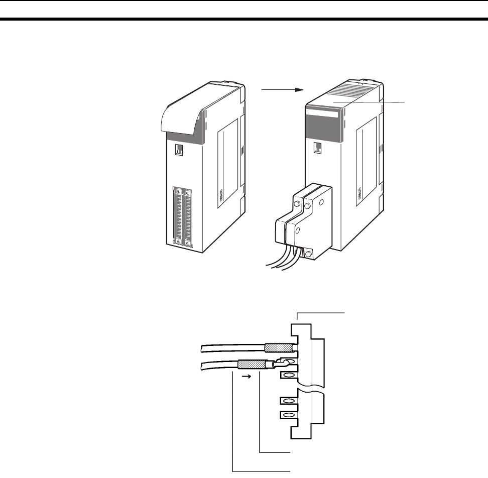
314
Wiring Section 5-3
from entering the Unit during wiring. (Remove the label after wiring has
been completed to allow air circulation needed for cooling.)
3. When solder-type connectors are being used, be sure not to accidentally
short adjacent terminals. Cover the solder joint with heat-shrink tubing.
Note Double-check to make sure that the Output Unit’s power supply leads haven’t
been reversed. If the leads are reversed, the Unit’s internal fuse will blow and
the Unit will not operate.
Remove label
after wiring
After wiringBefore wiring
MACINE
NO.
ID215
RUN
0 1 2 3 4 5 6 7
CN1
8 9 10 11 12 13 14 15
CN2
0 1 2 3 4 5 6 7
8 9 10 11 12 13 14 15
CN1 CN2
B A
A B
12 1
112
C200H-00215
CH
CAUTION
MACINE
NO.
ID215
RUN
0 1 2 3 4 5 6 7
CN1
8 9 10 11 12 13 14 15
CN2
0 1 2 3 4 5 6 7
8 9 10 11 12 13 14 15
CN1 CN2
B A
A B
12 1
112
C200H-00215
CH
Solder-type connector
included with Unit.
Heat-shrink tubing
Wire (0.2 to 0.13 mm
2
)
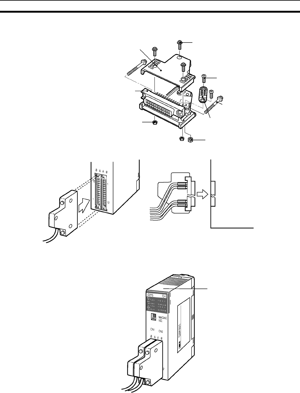
315
Wiring Section 5-3
4. Assemble the connector (included or purchased separately) as shown in
the following diagram.
5. Insert the wired connector.
6. Remove the protective label after wiring has been completed to allow air
circulation needed for cooling.
Tighten the connector-attaching screws to a torque of 0.2 N·m.
Connector bar Small screws (3)
Small screws (2)
Connector-attaching
screws
Cable-securing
bracket
Nuts (2)
Nuts (3)
Socket
Connector
High-density I/O Unit
High-density I/O Unit
Connector
Remove label after wiring.
After wiring
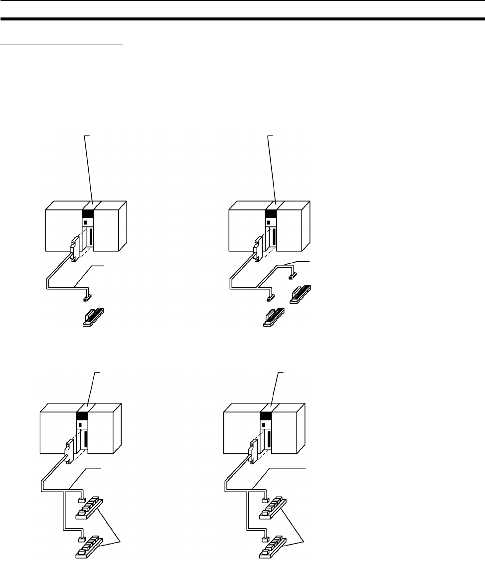
316
Wiring Section 5-3
Preassembled Cables
The following examples show applications for preassembled OMRON Cables.
Contact your OMRON dealer for more details.
C200H Group-2 High-
density I/O Units
The following cables are compatible with C200H Group-2 High-density I/O
Units.
1,2,3... 1. Connecting to a terminal block.
2. Connecting to a Relay Terminal.
C200H Group-2 High-density I/O Unit
C200H-ID216/218 (32 input points)
C200H-ID217/219 (64 input points)*
C200H-OD218/21B (32 output points)
C200H-OD219 (64 output points)*
*(Two sets needed for 64-point Units.)
C200H Group-2 High-density Input Unit
C200H-ID216 (32 input points)
C200H-ID217 (64 input points)*
*(Two sets needed for 64-point Unit.)
XW2Z-@@@B Connecting Cable
for Connector-Terminal Block
Conversion Unit
Connector-Terminal Block
Conversion Unit with Flat Cable
XW2B-40G5 (M3.5 terminal screws)
XW2B-40G4 (M2.5 terminal screws)
XW2Z-@@@D Connecting Cable
for Connector-Terminal Block
Conversion Unit
Connector-Terminal Block
Conversion Unit (common-type)
XW2C-20G5-IN16
16 inputs
16 inputs
C200H Group-2 High-density I/O Unit
C200H-ID216/218 (32 input points)
C200H-ID217/219 (64 input points)*
G79-I@C-@ Connecting Cable
for Relay Terminals
(For I/O Units with PLC32/64-
point connectors.)
C200H Group-2 High-density I/O Unit
C200H-OD218/OD21B (32 output points)
C200H-OD219 (64 output points)*
G79-I@16 Input Relay Terminals
G79-O@C-@ Connecting Cable
for Relay Terminals
(For I/O Units with PLC32/64-point
connectors.)
G7TC-OC16, G70D-@O@16,
G70A-ZOC16-3
Output Relay Terminals
G70D-@O16-1 (OD21B only)
G70A-ZOC16-1 (OD21B only)
*(Two sets needed for 64-point Units.) *(Two sets needed for 64-point Unit.)
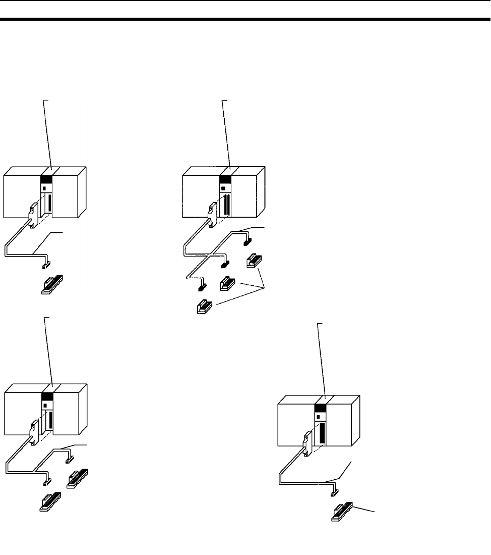
317
Wiring Section 5-3
CS-series Basic I/O Units
with Connectors
The following cables are compatible with CS-series High-density I/O Units.
1,2,3... 1. Connecting to a terminal block. (Two of the following Cables and Conver-
sion Units are required.)
CS-series Basic I/O Unit
CS1W-ID291 (96 input points)
CS1W-OD291 (96 output points)
CS1W-OD292 (96 output points)
CS1W-MD291 (48 inputs, 48 outputs)
CS1W-MD292 (48 inputs, 48 outputs)
CS-series Basic I/O Unit
CS1W-ID291 (96 input points)
CS1W-OD291 (96 output points)
CS1W-OD292 (96 output points)
CS1W-MD291 (48 inputs, 48 outputs)
CS1W-MD292 (48 inputs, 48 outputs)
XW2Z-@@@H-1 Connecting
Cable for Connector-Terminal
Block Conversion Unit
Connector-Terminal Block
Conversion Unit with Flat Cable
XW2B-60G4 or XW2B-60G5
XW2Z-@@@H-3 Connecting
Cable for Connector-Terminal
Block Conversion Unit
Connector-Terminal Block Con-
version Unit with Flat Cable
XW2B-20G5 or XW2B-20G4
2 required 2 required
CS-series Basic I/O Unit
CS1W-ID291 (96 input points)
CS1W-OD291 (96 output points)
CS1W-OD292 (96 output points)
CS1W-MD291 (48 inputs, 48 outputs)
CS1W-MD292 (48 inputs, 48 outputs)
XW2Z-@@@H-2 Connecting
Cable for Connector-Terminal
Block Conversion Unit
Connector-Terminal Block Conversion
Unit with Flat Cable
XW2B-40G4 or XW2B-40G5
2 required
Connector-Terminal Block Conversion
Unit with Flat Cable
XW2B-20G4 or XW2B-20G5
CS-series Basic I/O Unit
CS1W-ID231
CS1W-ID261
CS1W-OD231
CS1W-OD232
CS1W-OD261
CS1W-OD262
CS1W-MD261
CS1W-MD262
Connecting Cable
XW2Z-@@@B
XW2Z-@@@D
Connector-Terminal Block
Conversion Unit
XW2B-40G4, XW2B-40G5, or
XW2C-20GB-IN16 (Connect-
able to Input Unit only.)
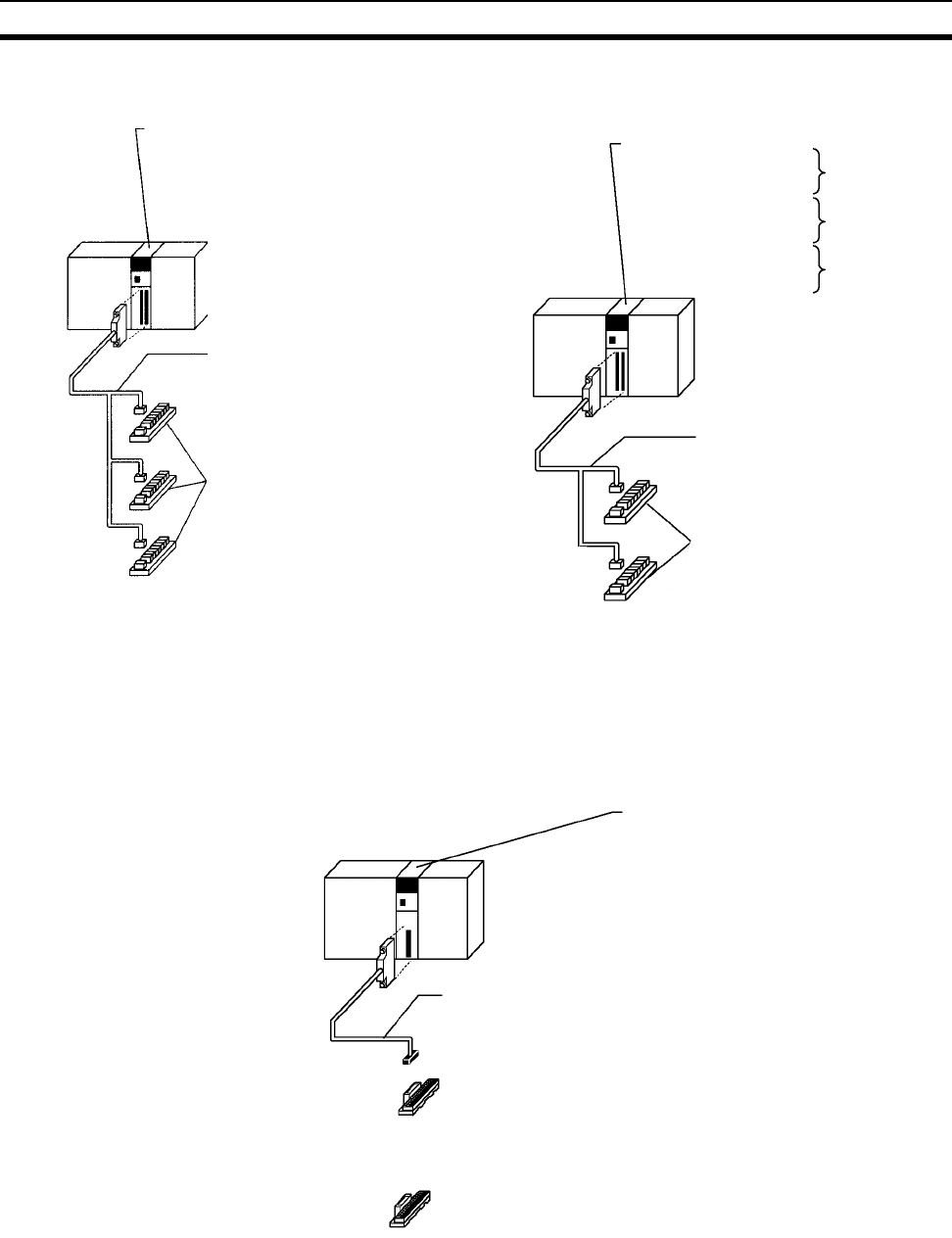
318
Wiring Section 5-3
2. Connecting to a Relay Terminal. (Two of the following Cables and Relay
Terminals are required.)
C200H High-density I/O
Units
The following cables are compatible with C200H High-density I/O Units (a
kind of C200H Special I/O Unit).
1,2,3... 1. Connecting to a terminal block.
CS-series Basic I/O Unit
CS1W-ID291 (96 input points)
CS1W-OD291 (96 output points)
CS1W-OD292 (96 output points)
CS1W-MD291 (48 inputs, 48 outputs)
CS1W-MD292 (48 inputs, 48 outputs)
G79-@@@C-@@@-@@@
Connecting Cable for Relay Terminals
2 required
CS-series Basic I/O Unit
CS1W-ID231
CS1W-ID261
CS1W-MD261 (inputs)
CS1W-OD291
CS1W-OD261
CS1W-MD261 (outputs)
CS1W-OD292
CS1W-OD262
CS1W-MD262 (outputs)
Connecting Cable
#1: G79-I@C-@
#2, #3: G79-O@C-@
#1: G7TC-I@16
#2: G7TC-OC16
#3: G70A-ZOC16-4
#1
#2
#3
G70A-ZOC16-3 and relays
G70D-@O@16
G70D-@O@16-1
G7TC-I@16 Input Relay Terminals or
G7TC-OC16 Output Relay Terminals
(CS1W-OD291/MD291)
G7TC-OC16-1 Output Relay
Terminals (CS1W-OD292/MD292)
2 required
C200H High-density Input Unit
C200H-ID215 (32 input points)
C200H-ID501 (32 input points)
C200H-OD215 (32 output points)
C200H-OD501 (32 output points)
C200H-MD215 (16 inputs/16 outputs)
C200H-MD115 (16 inputs/16 outputs)
C200H-MD501 (16 inputs/16 outputs)
XW2Z-@@@A Connecting Cable for Connector-
Terminal Block Conversion Unit
(For I/O Units with PLC32-point connectors.)
Connector-Terminal Block Conversion Unit
XW2B-20G4/20G5/20G5-D (all 16 points)
XW2B-40G5-T (32-point twin connector)
Connector-Terminal Block Conversion Unit
XW2C-20G5-IN16 (16 input points, common-type)
OR
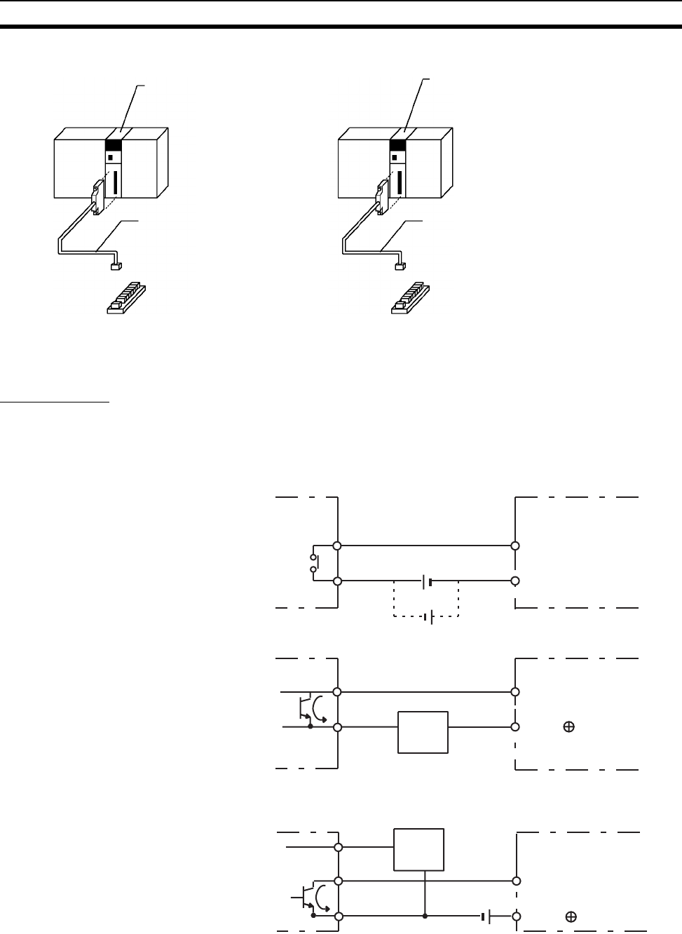
319
Wiring Section 5-3
2. Connecting to a Relay Terminal.
5-3-4 Connecting I/O Devices
Input Devices
Use the following information for reference when selecting or connecting input
devices.
DC Input Units The following types of DC input devices can be connected.
C200H High-density I/O Unit
C200H-ID215 (32 input points)
C200H-ID501 (32 input points)
G79-@C Connecting Cable
for Relay Terminals
(For I/O Units with
PC32/64-point connectors.)
C200H High-density I/O Unit
C200H-OD215 (32 output points)
C200H-OD501 (32 output points)
C200H-MD215 (16 inputs/16 outputs)
G79-I@16
Input Relay Terminal
G79-@C Connecting Cable
for Relay Terminals
(For I/O Units with
PC32/64-point connectors.)
G7TC-OC@@
G70D, G70A
Output Relay Terminal
2 required
2 required
Two-wire DC output
IN DC Input Unit
Sensor
Power
Supply
COM
+
+
COM
NPN open-collector output
Sensor
Power
Supply
IN DC Input Unit
0 V
Output
7 mA
COM
Contact output
IN DC Input Unit
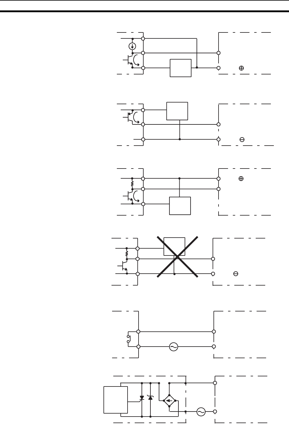
320
Wiring Section 5-3
The circuit below should NOT be used for I/O devices having a voltage output.
AC Input Units The following types of AC input devices can be connected.
+
COM
NPN current output
IN DC Input Unit
0 V
Output
7 mA Sensor
Power
Supply
Current
regulator
+
COM
PNP current output
Sensor
Power
Supply
IN AC/DC Input Unit
0 V
Output
7 mA
0 V
Output
+COM
Voltage current output
Sensor
Power
Supply
IN DC Input Unit
0 V
Output
+
COM
Voltage output
IN DC Input Unit
Sensor
Power
Supply
COM
Contact output
IN AC Input Unit
COM
AC Switching
IN AC Input Unit
Proximity
switch
main
circuit
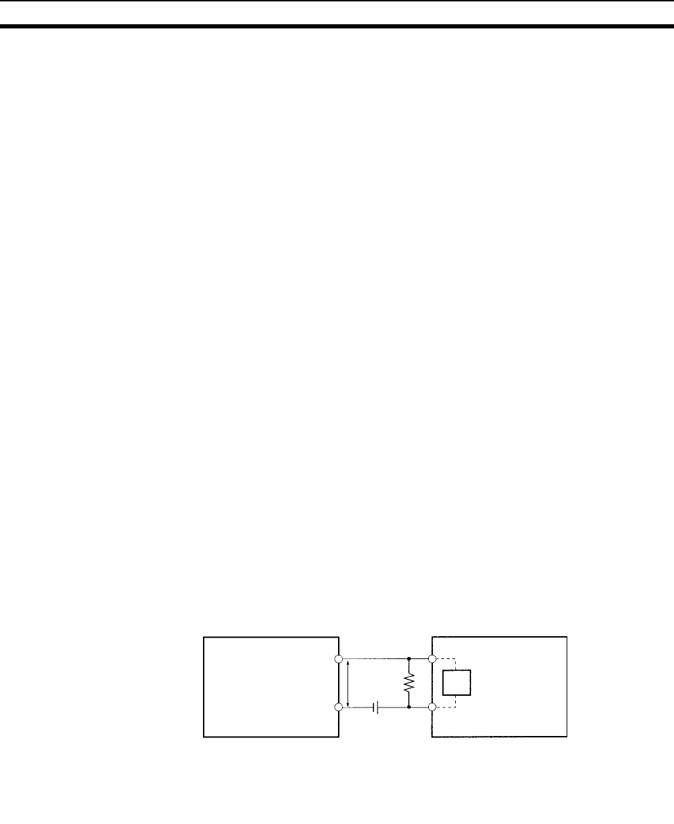
321
Wiring Section 5-3
Note When using a reed switch as the input contact for an AC Input Unit, use a
switch with an allowable current of 1 A or greater. If Reed switches with
smaller allowable currents are used, the contacts may fuse due to surge cur-
rents.
Precautions when
Connecting a Two-wire DC
Sensor
When using a two-wire sensor with a 12-V DC or 24-V DC input device, check
that the following conditions have been met. Failure to meet these conditions
may result in operating errors.
1,2,3... 1. Relation between voltage when the PLC is ON and the sensor residual
voltage:
VON ≤ VCC – VR
2. Relation between voltage when the PLC is ON and sensor control output
(load current):
IOUT (min) ≤ ION ≤ IOUT (max.)
ION = (VCC – VR – 1.5 [PLC internal residual voltage])/RIN
When ION is smaller than IOUT (min), connect a bleeder resistor R. The
bleeder resistor constant can be calculated as follows:
R ≤ (VCC – VR)/(IOUT (min.) – ION)
Power W ≥ (VCC – VR)2/R × 4 [allowable margin]
Note The residual voltage in the PLC is 4.0 V for the following Units:
C200H-ID211/ID212/IM211/IM212/INT01
The residual voltage is 1.5 V for all other Units.
3. Relation between current when the PLC is OFF and sensor leakage cur-
rent:
IOFF ≥ Ileak
If Ileak is larger than IOFF
, connect a breeder resistor. The breeder resistor
constant can be calculated as follows:
R ≤ RIN × VOFF/(Ileak × RIN – VOFF)
Power W ≥ (VCC – VR)2/R × 4 [allowable margin]
4. Precautions on Sensor Surge Current
An incorrect input may occur if a sensor is turned ON after the PLC has
started up to the point where inputs are possible. Determine the time re-
quired for sensor operation to stabilize after the sensor is turned ON and
take appropriate measures, such as inserting into the program a timer de-
lay after turning ON the sensor.
Two-wire sensor
DC Input Unit
V
CC
: Power voltage
V
ON
: PLC ON voltage
I
ON
: PLC ON current
I
OFF
: PLC OFF current
R
IN
: PLC input impedance
: Sensor output residual current
I
OUT
: Sensor control current (load current)
I
leak
: Sensor leakage current
R: Bleeder resistance
V
R
R
V
CC
R
IN
V
R
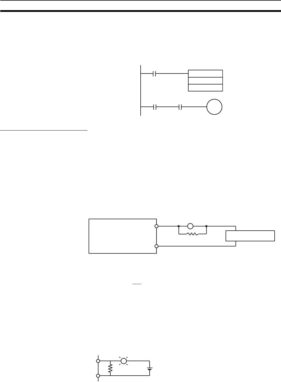
322
Wiring Section 5-3
Example
In this example, the sensor’s power supply voltage is used as the input to
CIO 000000 and a 100-ms timer delay (the time required for an OMRON
Proximity Sensor to stabilize) is created in the program. After the Comple-
tion Flag for the timer turns ON, the sensor input on CIO 000001 will cause
output bit CIO 000100 to turn ON.
Output Wiring Precautions
Output Short-circuit
Protection
If a load connected to the output terminals is short-circuited, output compo-
nents and the and printed circuit boards may be damaged. To guard against
this, incorporate a fuse in the external circuit. Use a fuse with a capacity of
about twice the rated output.
Transistor Output
Residual Voltage
A TTL circuit cannot be connected directly to a transistor output because of
the transistor’s residual voltage. It is necessary to connect a pull-up resistor
and a CMOS IC between the two.
Output Leakage Current If a Triac Output Unit is used to drive a low-current load, the leakage current
may prevent the output device from turning OFF. To prevent this, connect a
bleeder resistor in parallel with the load as shown in the following diagram.
Use the following formula to determine the resistance and rating for the
bleeder resistor.
Output Surge Current When connecting a transistor or triac output to an output device having a high
surge current (such as an incandescent lamp), steps must be taken to avoid
damage to the transistor or triac. Use either of the following methods to
reduce the surge current.
Method 1
Add a resistor that draws about 1/3 of the current consumed by the bulb.
TIM
0000
#0001
000000
000100
TIM0000 000001
PLC Load power supply
OUT
COM
Bleeder resistor
LR
VON: ON voltage of the load (V)
I: Leakage current (mA)
R: Bleeder resistance (KΩ)
VON
I
R <
OUT
COM
L
R+
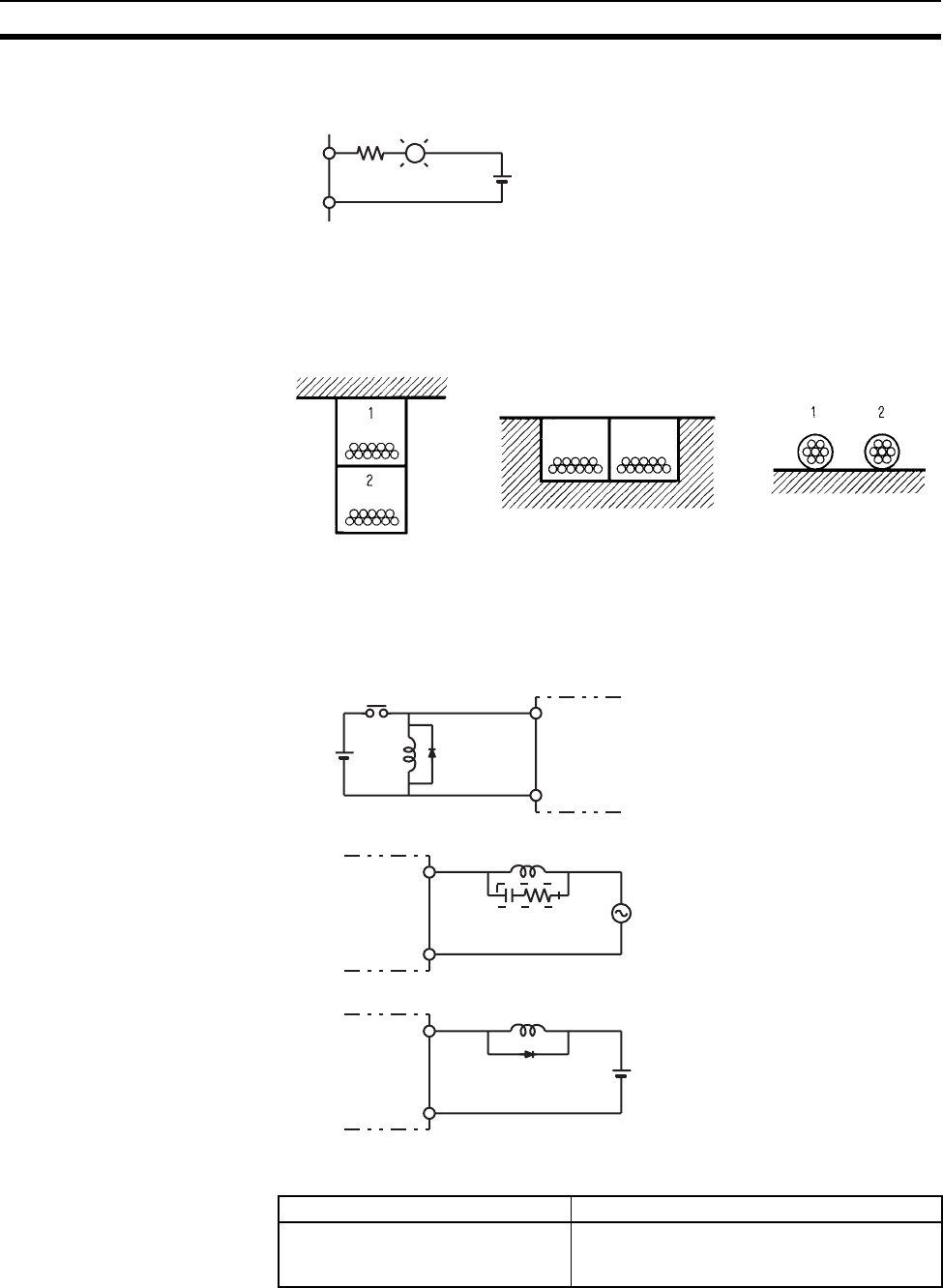
323
Wiring Section 5-3
Method 2
Add a control resistor as shown in the following diagram.
5-3-5 Reducing Electrical Noise
I/O Signal Wiring Whenever possible, place I/O signal lines and power lines in separate ducts or
raceways both inside and outside of the control panel.
If the I/O wiring and power wiring must be routed in the same duct, use
shielded cable and connect the shield to the GR terminal to reduce noise.
Inductive Loads When an inductive load is connected to an I/O Unit, connect a surge suppres-
sor or diode in parallel with the load as shown below.
Note Use surge suppressors and diodes with the following specifications.
L
OUT
COM
+
R
Suspended duct In-floor duct Conduits
1 = I/O cables
2 = Power cables
L
IN
COM
Diode DC input
OUT
COM
Relay output or
triac output
OUT
COM
Relay output or
transistor output Diode
L
L
+
Surge suppressor
Surge suppressor specifications Diode specifications
Resistor: 50 Ω
Capacitor: 0.47 µF
Voltage: 200 V
Breakdown voltage: 3 times load voltage min.
Mean rectification current: 1 A
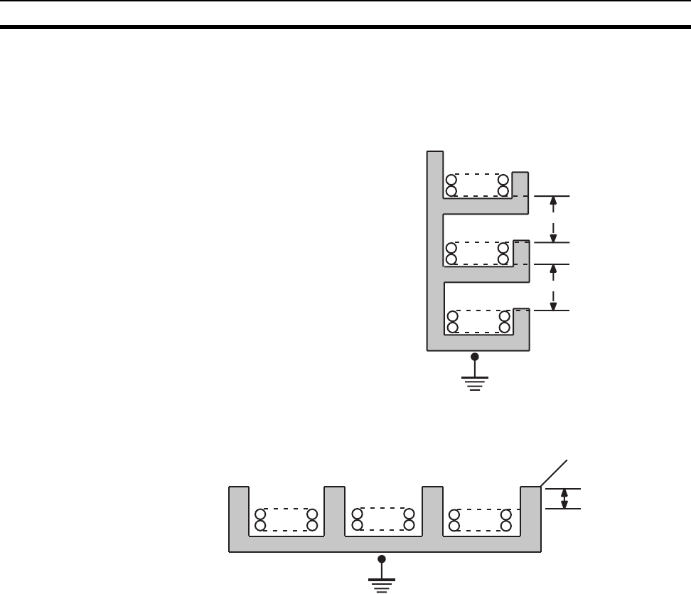
324
Wiring Section 5-3
External Wiring Observe the following precautions for external wiring.
• When multi-conductor signal cable is being used, avoid combining I/O
wires and other control wires in the same cable.
• If wiring racks are parallel, allow at least 300 mm (12 inches) between the
racks.
If the I/O wiring and power cables must be placed in the same duct, they must
be shielded from each other using grounded steel sheet metal.
Low-current cables
Control cables
Power cables
300 mm min.
300 mm min.
Ground to 100 Ω or less
PLC I/O wiring
PLC power supply and
general control circuit wiring
Power lines
Steel sheet metal
200 mm min.
Ground to 100 Ω or less
Power lines
PLC power supply
and general
control wiring
PLC I/O wiring
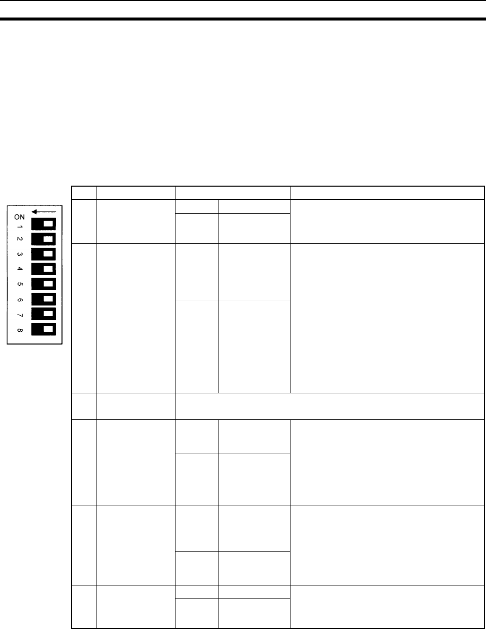
326
DIP Switch Settings Section 6-1
6-1 DIP Switch Settings
There are two kinds of initial settings for a CS-series PLC: hardware settings
and software settings. Hardware settings are made with the CPU Unit’s DIP
switch and software settings are made in the PLC Setup (using a Program-
ming Device).
The DIP switch can be reached by opening the battery compartment cover on
the front of the CPU Unit.
Note Always touch a grounded piece of metal to discharge any static electricity
from your body before touching the DIP switch. Otherwise, the PLC may mal-
function due to static discharge.
Pin Function Setting Description
1 Write-protection
for user program
memory (UM)
(See note 1.)
ON Write-protected User program memory is write-protected when
this pin is ON. Turn ON to prevent the program
from being changed accidentally.
OFF Read/write
2 Automatic trans-
fer of the program
at start-up
ON Yes The program (AUTOEXEC.OBJ) and PLC
Setup (AUTOEXEC.STD) will be transferred
from the Memory Card to the CPU Unit auto-
matically at start-up when this pin is ON. (See
note 4.)
A PLC’s software (program and PLC Setup)
can be completely initialized just by inserting a
new Memory Card and turning on the power.
This can be used to switch the system to a new
arrangement very quickly.
Note When pin 7 is ON, reading from the
Memory Card for easy backup is given
priority; even if pin 2 is ON, the program
will not be automatically transferred.
OFF No
3 CS1-H CPU Unit
Always OFF.
Not used.
4 Peripheral port
communications
parameters
ON Use parameters
set in the PLC
Setup.
• Leave this pin OFF when using a Program-
ming Console or CX-Programmer (periph-
eral bus setting) connected to the peripheral
port.
• Turn this pin ON when the peripheral port is
being used for a device other than a Pro-
gramming Console or CX-Programmer
(peripheral bus setting).
OFF
(default)
Auto-detect Pro-
gramming
Device
(See note 2.)
5 RS-232C port
communications
parameters
ON Auto-detect Pro-
gramming
Device
(See note 3.)
• Leave this pin OFF when the RS-232C port
is being used for a device other CX-Pro-
grammer (peripheral bus setting) such as a
Programmable Terminal or host computer.
• Turn this pin ON when using CX-Program-
mer (peripheral bus setting) connected to the
RS-232C port.
OFF
(default)
Use parameters
set in the PLC
Setup.
6 User-defined pin ON A39512 ON The ON/OFF status of this pin is reflected in
A39512. Use this function when you want to
create an Always-ON or Always-OFF condition
in the program without using an Input Unit.
OFF
(default)
A39512 OFF

327
DIP Switch Settings Section 6-1
Note 1. The following data is write-protected when pin 1 is ON: the user program
and all data in the parameter area such as the PLC Setup and registered
I/O table. Furthermore when pin 1 is ON, the user program and parameter
area won’t be cleared even when the memory clear operation is performed
from a Programming Device.
2. The auto-detect goes through baud rates in the following order: Program-
ming Console → Peripheral bus at 9,600 bps, 19,200 bps, 38,400 bps, and
115,200 bps. Programming Devices that aren’t in peripheral bus mode and
devices in peripheral bus mode operating at 51,200 bps will not be detect-
ed.
3. The auto-detect operation goes through baud rates in the following order:
Peripheral bus at 9,600 bps, 19,200 bps, 38,400 bps, and 115,200 bps.
Programming Devices that aren’t in peripheral bus mode and devices in
peripheral bus mode operating at any other speeds will not be detected.
4. When pin 2 is ON and the power is turned ON, any I/O Memory file (AU-
TOEXEC.IOM, ATEXEC@@.IOM) (prefer to the CS/CJ Series Program-
ming Manual) will also be transferred automatically. Both the program
(AUTOEXEC.OBJ) and the parameter area (AUTOEXEC.STD) must exist
in the Memory Card. I/O Memory files (AUTOEXEC.IOM, ATEX-
EC@@.IOM) are optional.
5. After reading data from the Memory Card to the CPU Unit with the simple
backup operation, the CPU Unit will remain in PROGRAM mode and can-
not be changed to MONITOR or RUN mode until the power supply has
been cycled. After completing the backup operation, turn OFF the power
supply to the CPU Unit, change the settings of pin 7, and then turn the
power supply back ON.
7 Easy backup set-
ting
ON Writing from the
CPU Unit to the
Memory Card
Press and hold the Memory Card Power Supply
Switch for three seconds.
Restoring from
the Memory
Card to the CPU
Unit.
To read from the Memory Card to the CPU Unit,
turn ON the PLC power.
This operation is given priority over automatic
transfer (pin 2 is ON) when power is ON. (See
note 5.)
OFF
(default)
Verifying
contents of
Memory Card.
Press and hold the Memory Card Power Supply
Switch for three seconds.
8 Not used OFF
(default)
Always OFF.
Pin Function Setting Description
DIP switch
settings
PLC Setup settings
Peripheral port settings
Default NT Link Peripheral
bus
Host Link Serial
Gateway
Pin
4
OFF Programming Console or CX-Programmer in Peripheral
Bus Mode
(Auto-detect connected device’s baud rate)
ON Host
computer
or CX-
Program-
mer in
host link
mode
OMRON
PT (NT
Link)
CX-Pro-
grammer in
Peripheral
Bus Mode
Host com-
puter or
CX-Pro-
grammer
in host
link mode
OMRON
compo-
nent
(Compo-
Way/F)
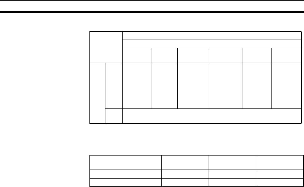
328
DIP Switch Settings Section 6-1
Note Use the following settings for the network on the CX-Programmer and pin 4 on
the DIP switch when connecting the CX-Programmer via the peripheral or RS-
232C port.
When CX-Programmer is set to host link mode, it won’t be possible to commu-
nicate (go online) in the following cases:
• The computer is connected to the CPU Unit’s peripheral port and pin 4 is
OFF.
• The computer is connected to the CPU Unit’s RS-232C port and pin 5 is
ON.
To go online, set CX-Programmer to peripheral bus mode, turn pin 4 ON (turn
pin 5 OFF for the RS-232C port), and set the communications mode to host
link mode in the PLC Setup.
DIP switch
settings
PLC Setup settings
Peripheral port settings
Default NT Link No-
protocol
Peripheral
bus
Host Link Serial
Gateway
Pin
5
OFF Host
computer
or CX-
Program-
mer in
host link
mode
OMRON
PT (NT
Link)
Standard
external
device
CX-Pro-
grammer in
Peripheral
Bus Mode
Host com-
puter or
CX-Pro-
grammer
in host
link mode
OMRON
compo-
nent
(Compo-
Way/F)
ON CX-Programmer in Peripheral Bus Mode
(Auto-detect connected device’s baud rate)
CX-Programmer network
setting
Peripheral port
connections
RS-232C port
connection
PLC Setup
Toolbus (peripheral bus) Turn OFF pin 4. Turn ON pin 5. None
SYSMAC WAY (Host Link) Turn ON bit 4. Turn OFF pin 5. Set to Host Link.
329
SECTION 7
PLC Setup
This section describes the settings in the PLC Setup and how they are used to control CPU Unit operation.
7-1 PLC Setup . . . . . . . . . . . . . . . . . . . . . . . . . . . . . . . . . . . . . . . . . . . . . . . . . . . . 330
7-1-1 Overview of the PLC Setup . . . . . . . . . . . . . . . . . . . . . . . . . . . . . . . 330
7-1-2 PLC Setup Settings . . . . . . . . . . . . . . . . . . . . . . . . . . . . . . . . . . . . . . 332
7-2 Explanations of PLC Setup Settings . . . . . . . . . . . . . . . . . . . . . . . . . . . . . . . . 357
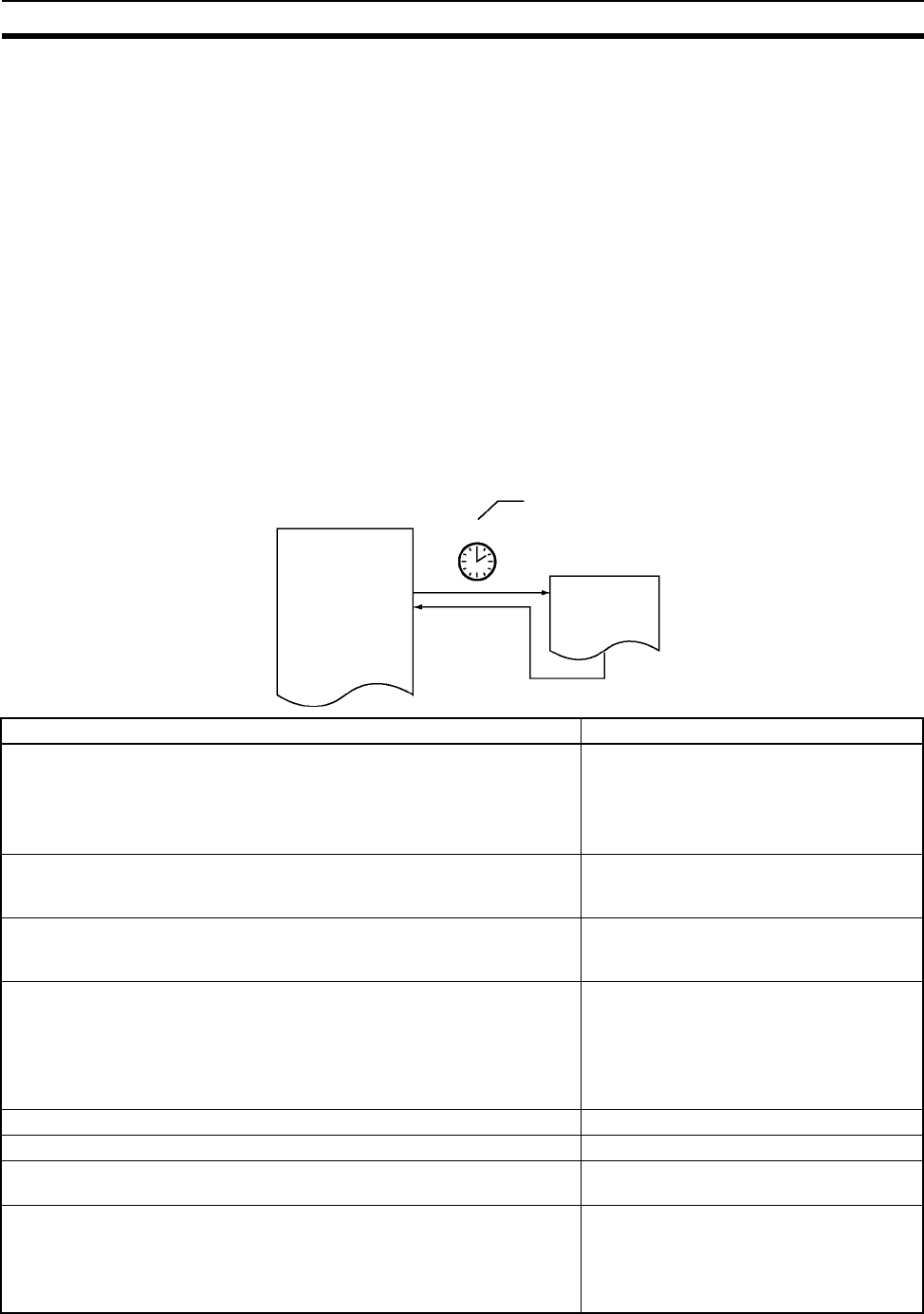
330
PLC Setup Section 7-1
7-1 PLC Setup
7-1-1 Overview of the PLC Setup
The PLC Setup contains basic CPU Unit software settings that the user can
change to customize PLC operation. These settings can be changed from a
Programming Console or other Programming Device. The various settings for
the CPU Unit are made in the PLC Setup.
The following table lists cases in which the PLC Setup must be changed. In
other cases, the PLC can be operated with the default settings.
Note To read or set parameters in the PLC Setup, use the version of CX-Program-
mer that corresponds to the parameters.
For example, with CX-Programmer Ver.3.@,when the PLC Setup is uploaded
from a PLC that was used to set the PLC Setup for CPU Unit Ver. 2.0 or
higher only, the PLC Setup that was set cannot be downloaded again. (The
following screen will be displayed.) Use the CX-Programmer Ver. 4.0 in this
case.
Scheduled Interrupt Time Units
Interval
Scheduled interrupt task
Cases when settings must be changed Setting(s) to be changed
The input response time settings for Basic I/O Units must be changed in the
following cases:
• Chattering or noise occur in CS-series Basic I/O Units.
• Short pulse inputs are being received for intervals longer than the cycle
time.
Basic I/O Unit Input Response Time
Data in all regions of I/O Memory (including the CIO Area, Work Areas,
Timer Flags and PVs, Task Flags, Index Registers, and Data Registers)
must be retained when the PLC’s power is turned on.
IOM Hold Bit Status at Startup
The status of bits force-set or force-reset from a Programming Device
(including Programming Consoles) must be retained when the PLC’s power
is turned on.
Forced Status Hold Bit Status at Startup
• You do not want the operating mode to be determined by the Program-
ming Console’s mode switch setting at startup.
• You want the PLC to go into RUN mode or MONITOR mode and start
operating immediately after startup.
• You want the operating mode to be other than PROGRAM mode when
the power is turned ON.
Startup Mode
Disabling detection of low-battery errors when it is not required. Detect Low Battery
Detecting interrupt-task errors is not required. Detect Interrupt Task Error
Data files are required but a Memory Card cannot be used or the files are
written frequently. (Part of the EM Area will be used as file memory.)
EM File Memory
The peripheral port will not be used with the Programming Console or CX-
Programmer (peripheral bus) communications speed auto-detection and will
not used the default host link communications settings such as 9,600 bps.
Note Pin 4 of the DIP switch on the front of the CPU Unit must be OFF to
change the PLC Setup settings.
Peripheral Port Settings

331
PLC Setup Section 7-1
The RS-232C port will not be used with the Programming Console or CX-
Programmer (peripheral bus) communications speed auto-detection and will
not use the default host link communications settings such as 9,600 bps.
Note Pin 5 of the DIP switch on the front of the CPU Unit must be OFF to
change the PLC Setup settings.
RS-232C Port Settings
You want to speed up communications with a PT via an NT Link. Set the peripheral port or the RS-232C port
communications port baud rate to “high-
speed NT Link.”
You want the intervals for scheduled interrupts to be set in units of 1 ms
rather than 10 ms.
Scheduled Interrupt Time Units
You want CPU Unit operation to be stopped for instruction errors, i.e., when
the ER Flag or AER Flag is turned ON. (You want instruction errors to be
fatal errors.)
You want to find the instructions where instruction errors are occurring
(where the ER Flag is turning ON.
Instruction Error Operation
You want a minimum cycle time setting to create a consistent I/O refresh
cycle.
Minimum Cycle Time
You want to set a maximum cycle time other than 1 second (10 ms to
40,000 ms).
Watch Cycle Time
You want to delay peripheral servicing so that it is executed over several
cycles.
Fixed Peripheral Servicing Time
You want to give priority to servicing peripherals over program execution.
Here, “peripherals” include CPU Bus Units, Special I/O Units, Inner Boards,
the built-in RS-232C port, and the peripheral port.
Peripheral Servicing Priority Mode
A power OFF interrupt task will be used. Power OFF Interrupt Task
You want to extend the detection of a power interruption to 10 to 20 ms. Power OFF Detection Delay Time
You want to shorten the average cycle time when a lot of Special I/O Units
are being used.
You want to extend the I/O refreshing interval for Special I/O Units.
Special I/O Unit Cyclic Refreshing
You want to improve both program execution and peripheral servicing
response.
CPU Processing Mode
You do not want to record user-defined errors for FAL(006) and FPD(269) in
the error log.
FAL Error Log Registration
You want to reduce fluctuation in the cycle time caused by text string pro-
cessing
Background Execution for Table Data, Text
String, and Data Shift Instructions
You do not want to wait for Units and Boards to complete startup processing
to start CPU Unit operation.
Startup Condition
Cases when settings must be changed Setting(s) to be changed
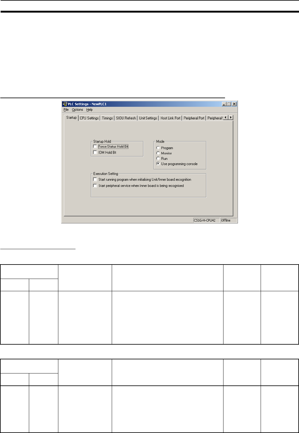
332
PLC Setup Section 7-1
7-1-2 PLC Setup Settings
The Programming Console addresses given in this section are used to access
and change settings in the PLC Setup when using a Programming Console or
the Programming Console function of an NS-series Programming Terminal.
The PLC Setup is stored in the Parameter Area, which can be accessed only
from a Programming Device. Addresses in the Parameter Area cannot be
used as instruction operands in the same way as addresses in the I/O Mem-
ory Area.
Startup Operation Settings (CX-Programmer’s Startup Tab Page)
7-1-2-1 Startup Tab Page
Startup Hold Settings
Forced Status Hold Bit
IOM Hold Bit
Programming
Console address
Settings Function Related
flags and
words
New
setting’s
effective-
ness
Word Bit(s)
+80 14 0: Cleared
1: Retained
Default: 0
This setting determines whether or not the
status of the Forced Status Hold Bit
(A50013) is retained at startup.
When you want all of the bits that have been
force-set or force-reset to retain their forced
status when the power is turned on, turn ON
the Forced Status Hold Bit and set this set-
ting to 1 (ON).
A50013
(Forced Sta-
tus Hold Bit)
Takes effect
at startup
Programming
Console address
Settings Function Related
flags and
words
New
setting’s
effective-
ness
Word Bit(s)
+80 15 0: Cleared
1: Retained
Default: 0
This setting determines whether or not the
status of the IOM Hold Bit (A50012) is
retained at startup.
When you want all of the data in I/O Memory
to be retained when the power is turned on,
turn ON the IOM Hold Bit and set this set-
ting to 1 (ON).
A50012 (IOM
Hold Bit)
Takes effect
at startup

333
PLC Setup Section 7-1
Mode Setting
Execution Settings
Startup Condition
Note This setting applies only to specific Units and Boards.
Specific Units
This setting applies to the ITNC-EIS01-CST and ITNC-EIX01-CST Open Net-
work Controller-CS1 Bus Interface Units.
Specific Boards
There are currently no Inner Boards that are applicable as of July 2006.
Inner Board Setting
Note There are currently no Inner Boards that are applicable as “Specific Boards”
as of July 2006.
Programming
Console address
Settings Function Related
flags and
words
New
setting’s
effective-
ness
Word Bit(s)
+81 --- Use programming console
(PRCN):
Programming Console’s
mode switch
Program: PROGRAM
mode
Monitor: MONITOR mode
Run: RUN mode
Default: Program
This setting determines whether the
Startup Mode will be the mode set on
the Programming Console’s mode switch
or the mode set here in the PLC Setup.
If this setting is PRCN and a Program-
ming Console isn’t connected, startup
mode will depend on the CPU Unit being
used.
CS1 CPU Unit: PROGRAM mode
CS1-H CPU Unit: RUN mode
--- Takes effect
at startup
Programming
Console address
Settings Function Related
flags and
words
New
setting’s
effective-
ness
Word Bit(s)
+83 15 0: Wait for Units and
Boards.
1: Don’t wait.
Default: 0
To start the CPU Unit in MONITOR or PRO-
GRAM mode even if there is one or more
Boards or Units that has not completed star-
tup processing, set this setting to 1 (Don’t
wait for Units and Boards). (The operation
for Inner Boards, however, also depends on
the next setting.)
To wait for all Units and Boards to finish star-
tup processing, set this setting to 0 (Wait for
Units and Boards).
--- Takes effect
at startup
Programming
Console address
Settings Function Related
flags and
words
New
setting’s
effective-
ness
Word Bit(s)
+84 15 0: Wait for Boards.
1: Don’t wait.
Default: 0
To start the CPU Unit in MONITOR or PRO-
GRAM mode even if there is one or more of
Boards that has not completed startup pro-
cessing, set this setting to 1 (Don’t wait for
Boards).
To wait for all Boards to finish startup process-
ing, set this setting to 0 (Wait for Boards).
This setting is valid only if the Startup Condi-
tion is set to 1 (Don’t wait for Units and
Boards).
--- Takes effect
at startup
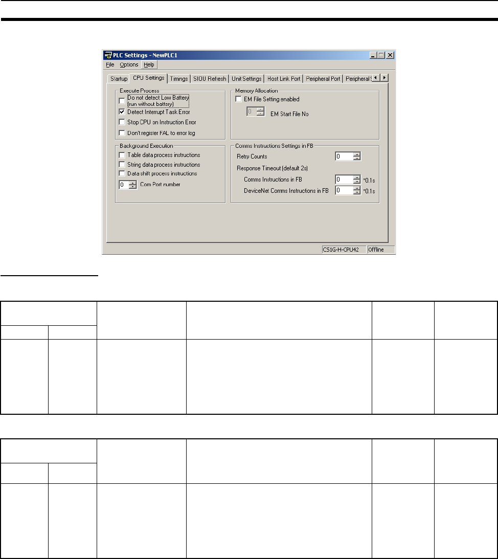
334
PLC Setup Section 7-1
7-1-2-2 CPU Unit Settings (CPU Settings Tab Page on the CX-Programmer)
Execute Process
Detect Low Battery
Detect Interrupt Task Error
Programming
Console address
Settings Function Related
flags and
words
New set-
ting’s effec-
tiveness
Word Bit(s)
+128 15 0: Detect
1: Do not detect
Default: 0
This setting determines whether CPU Unit
battery errors are detected. If this setting is
set to 0 and a battery error is detected, the
ERR/ALM indicator on the CPU Unit will
flash and the Battery Error Flag (A40204)
will be turned ON, but CPU Unit operation
will continue.
A40204 (Bat-
tery Error
Flag)
Takes effect
the next cycle
Programming
Console address
Settings Function Related
flags and
words
New
setting’s
effective-
ness
Word Bit(s)
+128 14 0: Detect
1: Do not detect
Default: 0
This setting determines whether interrupt
task errors are detected. If this setting is set
to 0 and an interrupt task error is detected,
the ERR/ALM indicator on the CPU Unit will
flash and the Interrupt Task Error Flag
(A40213) will be turned ON, but CPU Unit
operation will continue.
A40213
(Interrupt
Task Error
Flag)
Takes effect
the next cycle

335
PLC Setup Section 7-1
Stop CPU on Instruction Error (Instruction Error Operation)
Don’t Register FAL to Error Log
Memory Allocation Settings
EM File Setting Enabled
EM Start File No. (Starting Memory Starting Bank)
Programming
Console address
Settings Function Related
flags and
words
New
setting’s
effective-
ness
Word Bit(s)
+197 15 0: Continue
1: Stop
Default: 0
This setting determines whether instruction
errors (instruction processing errors (ER)
and illegal access errors (AER)) are treated
as non-fatal or fatal errors. When this setting
is set to 1, CPU Unit operation will be
stopped if the ER or AER Flags is turned
ON (even when the AER Flag is turned ON
for an indirect DM/EM BCD error).
Related Flags: A29508 (Instruction Pro-
cessing Error Flag)
A29509 (Indirect DM/EM BCD Error Flag)
A29510 (Illegal Access Error Flag)
A29508,
A29509,
A29510
(If this setting
is set to 0,
these flags
won’t be
turned ON
even if an
instruction
error occurs.)
At start of
operation.
Programming
Console address
Settings Function Related
flags and
words
New
setting’s
effective-
ness
Word Bit(s)
+129 15 0: Record user-
defined FAL errors
in error log.
1: Don’t record user-
defined FAL errors
in error log.
Default: 0
This setting determines if user-defined FAL
errors created with FAL(006) and time moni-
toring for FPD(269) will be recorded in the
error log (A100 to A199). Set it to 1 so pre-
vent these errors from being recorded.
--- Whenever
FAL(006) is
executed
(every cycle)
Programming
Console address
Settings Function Related
flags and
words
New
setting’s
effective-
ness
Word Bit(s)
+136 7 0: None
1: EM File Memory
Enabled
Default: 0
This setting determines whether part of the
EM Area will be used for file memory.
--- After initial-
ization from
Program-
ming Device
or via FINS
command.
Programming
Console address
Settings Function Related
flags and
words
New
setting’s
effective-
ness
Word Bit(s)
+136 0 to 3 0 to 6
Default: 0
If bit 7 (above) is set to 1, the setting here
specifies the EM bank where file memory
begins. The specified EM bank and all sub-
sequent banks will be used as file memory.
This setting will be disabled if bit 7 is set to
0.
A344 (EM
File Memory
Starting
Bank)
After initial-
ization from
Program-
ming Device
or via FINS
command.

336
PLC Setup Section 7-1
Background Execution Settings
Table Data Process Instructions
String Data Process Instructions
Data Shift Process Instructions
Communications Port Number for Background Execution
7-1-2-3 FB Communications Instruction Settings
(Settings for OMRON FB Library)
The following PLC Setup settings are used only when using the OMRON FB
Library.
Number of Resends
Programming
Console address
Settings Function Related
flags and
words
New
setting’s
effective-
ness
Word Bit(s)
+198 15 0: Not executed in
background
1: Executed in back-
ground
Default: 0
This setting determines if Table Data
Instructions will be processed over multiple
cycle times (i.e., processed in the back-
ground).
--- Start of oper-
ation
Programming
Console address
Settings Function Related
flags and
words
New
setting’s
effective-
ness
Word Bit(s)
+198 14 0: Not executed in
background
1: Executed in back-
ground
Default: 0
This setting determines if Text String Data
Instructions will be processed over multiple
cycle times (i.e., processed in the back-
ground).
--- Start of oper-
ation
Programming
Console address
Settings Function Related
flags and
words
New
setting’s
effective-
ness
Word Bit(s)
+198 13 0: Not executed in
background
1: Executed in back-
ground
Default: 0
This setting determines if Data Shift Instruc-
tions will be processed over multiple cycle
times (i.e., processed in the background).
--- Start of oper-
ation
Programming
Console address
Settings Function Related
flags and
words
New
setting’s
effective-
ness
Word Bit(s)
+198 0 to 3 0 to 7: Communica-
tions ports 0 to 7
(internal logical
ports)
The communications port number (internal
logical port) that will be used for background
execution.
--- Start of oper-
ation
Programming
Console address
Settings Function Related
flags and
words
New
setting’s
effective-
ness
Word Bit(s)
+200 0 to 3 0 to F: 0 to 15
Default: 0
Set the number of retries for sending com-
mands when executing DeviceNet explicit
messages or FINS messages within func-
tion blocks.
A58000 to
A58003
Start of
operation

337
PLC Setup Section 7-1
FB Communications Instruction Response Monitoring Time
DeviceNet Communications Instruction Response Monitoring Time
Note The number of resends and response monitoring time must be set by the user
in the FB communications instructions settings in the PLC Setup, particularly
when using function blocks from the OMRON FB Library to execute FINS
messages or DeviceNet explicit messages communications. The values set in
this PLC Setup for OMRON FB Library will be automatically stored in the
related Auxiliary Area words A580 to A582 and used by the function blocks
from the OMRON FB Library.
Programming
Console address
Settings Function Related
flags and
words
New
setting’s
effective-
ness
Word Bit(s)
+201 0 to 15 0001 to FFFF (Unit:
0.1 s, 0.1 to 6553.5)
0000: 2 s
A response timeout occurs when no
response is returned within the time set
here for FINS commands executed within a
function block.
A581 Start of
operation
Programming
Console address
Settings Function Related
flags and
words
New set-
ting’s
effective-
ness
Word Bit(s)
+202 0 to 15 0001 to FFFF (Unit:
0.1 s, 0.1 to 6553.5)
0000: 2 s
A response timeout occurs when no
response is returned within the time set
here for explicit messages commands exe-
cuted within a function block.
A582 Start of oper-
ation
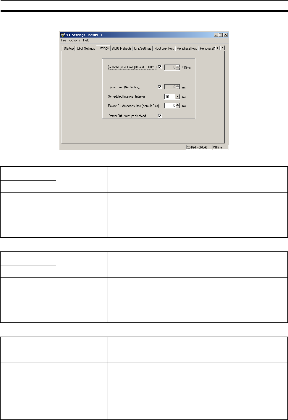
338
PLC Setup Section 7-1
7-1-2-4 Time and Interrupt Settings (CX-Programmer Timings Tab Page)
Enable Watch Cycle Time Setting
Watch Cycle Time
Cycle Time (Minimum Cycle Time)
Programming
Console address
Settings Function Related
flags and
words
New
setting’s
effective-
ness
Word Bit(s)
+209 15 0: Default
1: Bits 0 to 14
Default: 0
Set to 1 to enable the Watch Cycle Time
Setting in bits 0 to 14. Leave this setting at 0
for a maximum cycle time of 1 s.
A40108
(Cycle Time
Too Long
Flag)
Takes effect
at the start of
operation
(Can’t be
changed dur-
ing opera-
tion.)
Programming
Console address
Settings Function Related
flags and
words
New
setting’s
effective-
ness
Word Bit(s)
+209 0 to 14 001 to FA0: 10 to
40,000 ms
(10-ms units)
Default: 001 (1 s)
This setting is valid only when bit 15 of 209
is set to 1. The Cycle Time Too Long Flag
(A40108) will be turned ON if the cycle time
exceeds this setting.
A264 and
A265
(Present
Cycle Time)
Takes effect
at the start of
operation
(Can’t be
changed dur-
ing opera-
tion.)
Programming
Console address
Settings Function Related
flags and
words
New
setting’s
effective-
ness
Word Bit(s)
+208 0 to 15 0001 to 7D00: 1 to
32,000 ms
(1-ms units)
Default: 0000
(No minimum)
Set to 0001 to 7D00 to specify a minimum
cycle time. If the cycle time is less than this
setting, it will be extended until this time
passes. Leave this setting at 0000 for a vari-
able cycle time. (Can’t be changed during
operation.)
This cycle time will apply to the program
execution cycle when a parallel processing
mode is used.
--- Takes effect
at the start of
operation

339
PLC Setup Section 7-1
Schedule Interrupt Interval
Power OFF Detection Time (Power OFF Detection Delay Time)
Power OFF Interrupt Disable
Programming
Console address
Settings Function Related
flags and
words
New
setting’s
effective-
ness
Word Bit(s)
+195 0 to 3 0 hex: 10 ms
1 hex: 1.0 ms
Default: 0 hex
Sets the time interval for the scheduled
interrupt task.
--- Takes effect
at the start of
operation.
(Can’t be
changed dur-
ing opera-
tion.)
Programming
Console address
Settings Function Related
flags and
words
New
setting’s
effective-
ness
Word Bit(s)
+225 0 to 7 00 to 0A:
0 to 10 ms
(1-ms units)
Default: 00
This setting determines how much of a
delay there will be from the detection of a
power interruption (approximately 10 to
25 ms after the AC power supply voltage
drops below 85% of the rated value or DC
power supply voltage drops below 80% of
the rated value) to the confirmation of a
power interruption. The default setting is 0
ms.
When the power OFF interrupt task is
enabled, it will be executed when the power
interruption is confirmed. If the power OFF
interrupt task is disabled, the CPU will be
reset and operation will be stopped.
--- Takes effect
at startup or
at the start of
operation.
(Can’t be
changed dur-
ing opera-
tion.)
Programming
Console address
Settings Function Related
flags and
words
New set-
ting’s
effective-
ness
Word Bit(s)
+225 15 0: Disabled
1: Enabled
Default: 0
When this setting is set to 1, the power OFF
interrupt task will be executed when power
is interrupted.
--- Takes effect
at startup or
at the start of
operation.
(Can’t be
changed dur-
ing opera-
tion.)
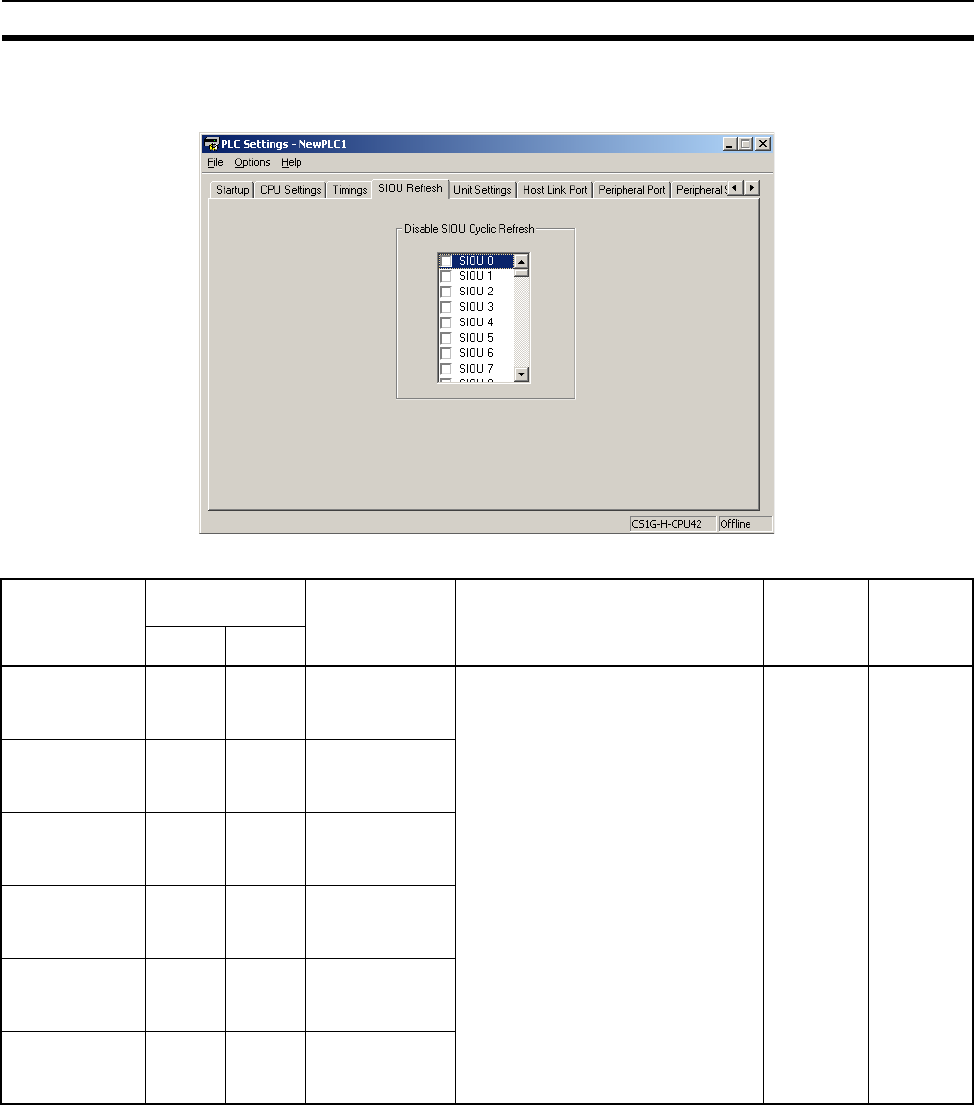
340
PLC Setup Section 7-1
7-1-2-5 Special I/O Unit Cyclic Refreshing (CX-Programmer SIOU Refresh Tab
Page)
Note If a Special I/O Unit is not refreshed periodically from the CPU Unit (at least
every 11 seconds), a CPU Unit monitoring error will occur. (The ERH indicator
and RUN indicator will be lit on the Special I/O Unit.) If cyclic I/O refreshing of
a Special I/O Unit is disabled, use the IORF(097) instruction to refresh the
Unit from the user program.
Item Programming
Console address
Settings Function Related
flags and
words
New
setting’s
effective-
ness
Word Bit(s)
Cyclic Refresh-
ing of Units 0 to
15
+226 0 to 15 0: Enabled
1: Disabled
Default: 0
These settings determine whether
data will be exchanged between the
specified Unit and the Special I/O
Unit’s allocated words (10
words/Unit) during cyclic refreshing
for Special I/O Units.
Turn ON the corresponding bit to dis-
able cyclic refreshing when the Unit
will be refreshed in an interrupt task
by IORF(097), several Special I/O
Units are being used and you don’t
want to extend the cycle time, or the
cycle time is so short that the Special
I/O Unit’s internal processing can’t
keep up.
(Special I/O Units can be refreshed
from the program with IORF(097).)
--- Takes
effect at the
start of
operation
Cyclic Refresh-
ing of Units 16
to 31
+227 0 to 15 0: Enabled
1: Disabled
Default: 0
Cyclic Refresh-
ing of Units 32
to 47
+228 0 to 15 0: Enabled
1: Disabled
Default: 0
Cyclic Refresh-
ing of Units 48
to 63
+229 0 to 15 0: Enabled
1: Disabled
Default: 0
Cyclic Refresh-
ing of Units 64
to 79
+230 0 to 15 0: Enabled
1: Disabled
Default: 0
Cyclic Refresh-
ing of Units 80
to 95
+231 0 to 15 0: Enabled
1: Disabled
Default: 0
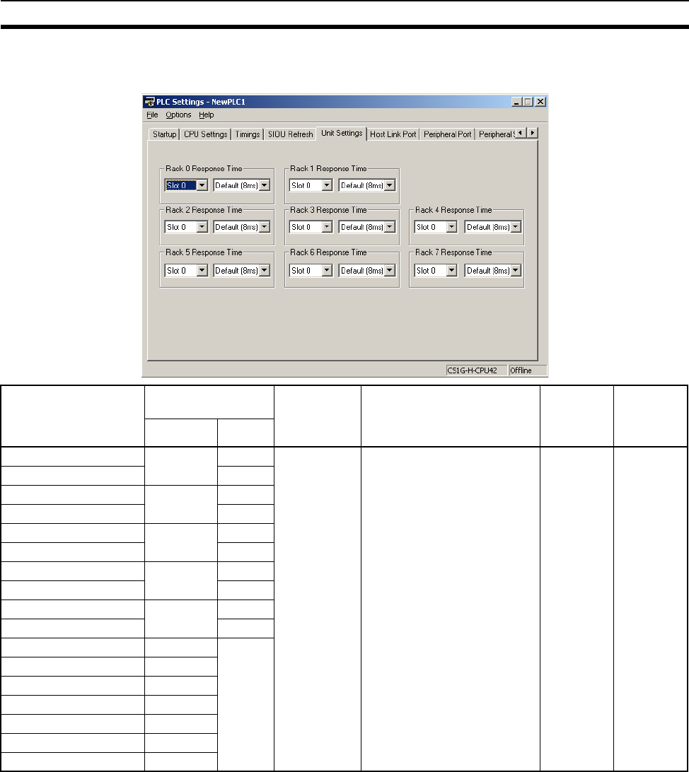
341
PLC Setup Section 7-1
7-1-2-6 Basic I/O Unit Input Response Times (Unit Settings Tab Page on the CX-
Programmer)
Item Programming
Console address
Settings Function Related
flags and
words
New set-
ting’s
effective-
ness
Word Bit(s)
Rack 0, Slot 0 +10 0 to 7 00: 8 ms
10: 0 ms
11: 0.5 ms
12: 1 ms
13: 2 ms
14: 4 ms
15: 8 ms
16: 16 ms
17: 32 ms
Default:
00 (8 ms)
Sets the input response time
(ON response time = OFF
response time) for CS-series
Basic I/O Units. The default
setting is 8 ms and the setting
range is 0.5 ms to 32 ms.
This value can be increased to
reduce the effects of chatter-
ing and noise, or it can be
reduced to allow reception of
shorter input pulses.
A220 to
A259:
Actual
input
response
times for
Basic I/O
Units
Take s
effect at
startup
Rack 0, Slot 1 8 to 15
Rack 0, Slot 2 +11 0 to 7
Rack 0, Slot 3 8 to 15
Rack 0, Slot 4 +12 0 to 7
Rack 0, Slot 5 8 to 15
Rack 0, Slot6 +13 0 to 7
Rack 0, Slot 7 8 to 15
Rack 0, Slot 8 +14 0 to 7
Rack 0, Slot 9 8 to 15
Rack 1, Slots 0 to 9 +15 to 19 See
Rack 0.
Rack 2, Slots 0 to 9 +20 to 24
Rack 3, Slots 0 to 9 +25 to 29
Rack 4, Slots 0 to 9 +30 to 34
Rack 5, Slots 0 to 9 +35 to 39
Rack 6, Slots 0 to 9 +40 to 44
Rack 7, Slots 0 to 9 +45 to 49
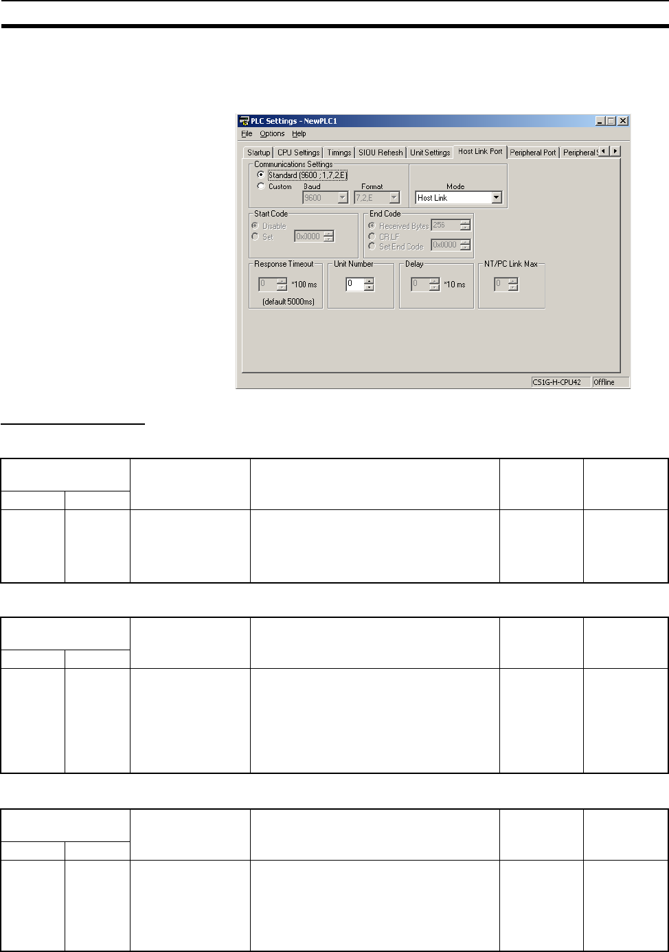
342
PLC Setup Section 7-1
7-1-2-7 Host Link (RS-232C) Port Tab Page
The following settings are valid when pin 5 on the DIP switch on the CPU Unit
is ON.
Host Link Settings
Communications Settings
Mode: Communications Mode
Format: Data Bits
Programming
Console address
Settings Function Related
flags and
words
When set-
ting is read
by CPU Unit
Word Bit(s)
+160 15 0: Standard
1: PLC Setup (cus-
tom)
Default: 0
*The default settings are for 1 start bit, 7
data bits, even parity, 2 stop bits, and a baud
rate of 9,600 bps.
A61902
(RS-232C
Port Settings
Changing
Flag)
At the next
cycle.
Programming
Console address
Settings Function Related
flags and
words
When set-
ting is read
by CPU Unit
Word Bit(s)
+160 8 to 11 00: Host link
05: Host link
Default: 0
This setting determines whether the RS-
232C port will operate in host link mode or
another serial communications mode. (Host
link can be specified with 00 or 05.)
The Peripheral bus mode is for communica-
tions with Programming Devices other than
the Programming Console.
A61902
(RS-232C
Port Settings
Changing
Flag)
At the next
cycle.
Programming
Console address
Settings Function Related
flags and
words
When set-
ting is read
by CPU Unit
Word Bit(s)
+160 3 0: 7 bits
1: 8 bits
Default: 0
These settings are valid only when the com-
munications mode is set to host link or no-
protocol.
These settings are also valid only when the
RS-232C Port Settings Selection is set to 1:
PLC Setup.
A61902
(RS-232C
Port Settings
Changing
Flag)
At the next
cycle.

343
PLC Setup Section 7-1
Format: Stop Bits
Format: Parity
Baud Rate (bps)
Unit Number (for CPU Unit in Host Link Mode)
Programming
Console address
Settings Function Related
flags and
words
When set-
ting is read
by CPU Unit
Word Bit(s)
+160 2 0: 2 bits
1: 1 bit
Default: 0
These settings are valid only when the com-
munications mode is set to host link or no-
protocol.
These settings are also valid only when the
RS-232C Port Settings Selection is set to 1:
PLC Setup.
A61902
(RS-232C
Port Settings
Changing
Flag)
At the next
cycle.
Programming
Console address
Settings Function Related
flags and
words
When set-
ting is read
by CPU Unit
Word Bit(s)
+160 0 to 1 00: Even
01: Odd
10: None
Default: 00
These settings are valid only when the com-
munications mode is set to host link or no-
protocol.
These settings are also valid only when the
RS-232C Port Settings Selection is set to 1:
PLC Setup.
A61902
(RS-232C
Port Settings
Changing
Flag)
At the next
cycle.
Programming
Console address
Settings Function Related
flags and
words
When set-
ting is read
by CPU Unit
Word Bit(s)
+161 0 to 7 00: 9,600 bps
01: 300 bps
02: 600 bps
03: 1,200 bps
04: 2,400 bps
05: 4,800 bps
06: 9,600 bps
07: 19,200 bps
08: 38,400 bps
09: 57,600 bps
0A: 115,200 bps
Default: 00
These settings are valid only when the com-
munications mode is set to host link or no-
protocol.
These settings are also valid only when the
RS-232C Port Settings Selection is set to 1:
PLC Setup.
A61902
(RS-232C
Port Settings
Changing
Flag)
At the next
cycle.
Programming
Console address
Settings Function Related
flags and
words
When set-
ting is read
by CPU Unit
Word Bit(s)
+163 0 to 7 00 to 1F:
(0 to 31)
Default: 00
This setting determines the CPU Unit’s unit
number when it is connected in a 1-to-N
(N=2 to 32) Host Link.
A61902
(RS-232C
Port Settings
Changing
Flag)
At the next
cycle.

344
PLC Setup Section 7-1
NT Link Settings
Mode: Communications Mode
Baud Rate (bps)
NT Link Max. (Maximum Unit Number in NT Link Mode)
Peripheral Bus Settings
Communications Settings
Mode: Communications Mode
Programming
Console address
Settings Function Related
flags and
words
When set-
ting is read
by CPU Unit
Word Bit(s)
+160 8 to 11 02: 1:N NT Link
Default: 0
This setting determines whether the RS-
232C port will operate in host link mode or
another serial communications mode.
Note Communications will not be possible
with PTs set for 1:1 NT Links.
A61902
(RS-232C
Port Settings
Changing
Flag)
At the next
cycle.
Programming
Console address
Settings Function Related
flags and
words
When set-
ting is read
by CPU Unit
Word Bit(s)
+161 0 to 7 00: Standard
0A: High-speed NT
Link*
Default: 00
* Set to 115,200 bps when setting this value
from the CX-Programmer. To return to the
standard setting, leave the setting set to
“PLC Setup” and set the baud rate to 9,600
bps.
A61902
(RS-232C
Port Settings
Changing
Flag)
At the next
cycle.
Programming
Console address
Settings Function Related
flags and
words
When set-
ting is read
by CPU Unit
Word Bit(s)
+166 0 to 3 0 to 7
Default: 0
This setting determines the highest unit
number of PT that can be connected to the
PLC.
A61902
(RS-232C
Port Settings
Changing
Flag)
At the next
cycle.
Programming
Console address
Settings Function Related
flags and
words
When set-
ting is read
by CPU Unit
Word Bit(s)
+160 15 0: Standard*
1: PLC Setup (cus-
tom)
Default: 0
*The default settings are for a baud rate of
9,600 bps.
A61902
(RS-232C
Port Settings
Changing
Flag)
At the next
cycle.
Programming
Console address
Settings Function Related
flags and
words
When set-
ting is read
by CPU Unit
Word Bit(s)
+160 8 to 11 04: Peripheral bus
Default: 0
This setting determines whether the RS-
232C port will operate in host link mode or
another serial communications mode. (Host
link can be specified with 00 or 05.)
The Peripheral Bus mode is for communica-
tions with Programming Devices other than
the Programming Console.
A61902
(RS-232C
Port Settings
Changing
Flag)
At the next
cycle.
345
PLC Setup Section 7-1
Baud Rate (bps)
No-protocol Settings
Standard/Custom Settings
Serial Communications Mode
Data Length
Stop Bits
Programming
Console address
Settings Function Related
flags and
words
When set-
ting is read
by CPU Unit
Word Bit(s)
+161 0 to 7 00: 9,600 bps
06: 9,600 bps
07: 19,200 bps
08: 38,400 bps
09: 57,600 bps
0A: 115,200 bps
Default: 00
Settings 00 and 06 through 0A are valid
when the communications mode is set to
peripheral bus.
A61902
(RS-232C
Port Settings
Changing
Flag)
At the next
cycle.
Programming
Console address
Settings Function Related
flags and
words
When set-
ting is read
by CPU Unit
Word Bit(s)
+160 15 0: Standard
1: Custom
Default: 0
The standard settings are as follows:
1 stop bit, 7-bit data, even parity, 2 stop bits,
9,600 bps
A61902
(RS-232C
Port Settings
Changing
Flag)
At the next
cycle.
(Also can be
changed with
STUP (237).)
Programming
Console address
Settings Function Related
flags and
words
When set-
ting is read
by CPU Unit
Word Bit(s)
+160 08 to 11 03 Hex: No-protocol
Default: 00 Hex
This setting determines whether the RS-
232C port will operate in no-protocol mode
or another serial communications mode.
A61902
(RS-232C
Port Settings
Changing
Flag)
At the next
cycle.
(Also can be
changed with
STUP (237).)
Programming
Console address
Settings Function Related
flags and
words
When set-
ting is read
by CPU Unit
Word Bit(s)
+160 3 0: 7-bit
1: 8-bit
Default: 0
This setting is valid only in no-protocol com-
munications mode. Set the Standard/Cus-
tom setting (word 160, bit 15) to 1 to enable
this setting.
A61902
(RS-232C
Port Settings
Changing
Flag)
At the next
cycle.
(Also can be
changed with
STUP (237).)
Programming
Console address
Settings Function Related
flags and
words
When set-
ting is read
by CPU Unit
Word Bit(s)
+160 2 0: 2 bits
1: 1 bit
Default: 0
This setting is valid only in no-protocol com-
munications mode. Set the Standard/Cus-
tom setting (word 160, bit 15) to 1 to enable
this setting.
A61902
(RS-232C
Port Settings
Changing
Flag)
At the next
cycle.
(Also can be
changed with
STUP (237).)
346
PLC Setup Section 7-1
Parity
Baud Rate
Send Delay
Programming
Console address
Settings Function Related
flags and
words
When set-
ting is read
by CPU Unit
Word Bit(s)
+160 00 to 01 00 Hex: Even
01 Hex: Odd
10 Hex: None
Default: 00
This setting is valid only in no-protocol com-
munications mode. Set the Standard/Cus-
tom setting (word 160, bit 15) to 1 to enable
this setting.
A61902
(RS-232C
Port Settings
Changing
Flag)
At the next
cycle.
(Also can be
changed with
STUP (237).)
Programming
Console address
Settings Function Related
flags and
words
When set-
ting is read
by CPU Unit
Word Bit(s)
+161 00 to 07 00 Hex: 9,600 bps
01 Hex: 300 bps
02 Hex: 600 bps
03 Hex: 1,200 bps
04 Hex: 2,400 bps
05 Hex: 4,800 bps
06 Hex: 9,600 bps
07 Hex: 19,200 bps
08 Hex: 38,400 bps
09 Hex: 57,600 bps
0A Hex: 115,200 bps
Default: 00 Hex
This setting is valid only in no-protocol com-
munications mode. Set the Standard/Cus-
tom setting (word 160, bit 15) to 1 to enable
this setting.
A61902
(RS-232C
Port Settings
Changing
Flag)
At the next
cycle.
(Also can be
changed with
STUP (237).)
Programming
Console address
Settings Function Related
flags and
words
When set-
ting is read
by CPU Unit
Word Bit(s)
+162 00 to 15 0000 to 270F Hex (0
to 99,990 ms)
Unit: 10 ms
Default: 0000
When the TXD(236) instruction is executed,
data will be sent from the RS-232C after the
send delay set here has expired.
A61902
(RS-232C
Port Settings
Changing
Flag)
At the next
cycle.
(Also can be
changed with
STUP (237).)

347
PLC Setup Section 7-1
Start Code/End Code
Serial Gateway Settings
Communications Settings
Mode: Communications Mode
Programming
Console address
Settings Function Related
flags and
words
When set-
ting is read
by CPU Unit
Word Bit(s)
+164 8 to 15 00 to FF
Default: 00
Start code: Set this start code only when the
start code is enabled (1) in bits 12 to 15 of
165.
A61902
(RS-232C
Port Settings
Changing
Flag)
At the next
cycle.
(Also can be
changed with
STUP (237).)
0 to 7 00 to FF
Default: 00
End code: Set this end code only when the
end code is enabled (1) in bits 8 to 11 of
165.
+165 12 0: None
1: Code in 164
Default: 0
Start code setting:
A setting of 1 enables the start code in 164
bits 8 to 15.
8 to 9 0: None
1: Code in 164
2: CR+LF
Default: 0
End code setting:
With a setting of 0, the amount of data being
received must be specified. A setting of 1
enables the end code in bits 0 to 7 of 164. A
setting of 2 enables an end code of CR+LF.
0 to 7 00: 256 bytes
01 to FF:
1 to 255 bytes
Default: 00
Set the data length to be sent and received
with no-protocol communications. The end
code and start code are not included in the
data length.
Set this value only when the end code set-
ting in bits 8 to 11 of 165 is “0: None.”
This setting can be used to change the
amount of data that can be transferred at
one time by TXD(236) or RXD(235). The
default setting is the maximum value of 256
bytes.
Programming
Console address
Settings Function Related
flags and
words
New set-
ting’s effec-
tiveness
Word Bit(s)
+160 15 0: Default (stan-
dard)*
1: PLC Setup (cus-
tom)
Default: 0
*The default settings are for a baud rate of
9,600 bps.
A61901
(RS-232C
Port Settings
Changing
Flag)
Takes effect
the next
cycle.
(Also can be
changed with
STUP (237).)
Programming
Console address
Settings Function Related
flags and
words
New set-
ting’s effec-
tiveness
Word Bit(s)
+160 8 to 11 9: Serial Gateway
Default: 0
This setting determines whether the com-
munications mode for the RS-232C port
port.
The peripheral bus mode is used for all Pro-
gramming Devices except for Programming
Consoles.
A61901 (RS-
232C Port
Settings
Changing
Flag)
Takes effect
the next
cycle.
(Also can be
changed with
STUP (237).)
+160 8 to 11 0: Host Link
5: Host Link
Default: 0
This setting determines whether the com-
munications mode for the RS-232C port.
(Host Link can be used when specified to
either 0 or 5 hex.)
A61901 (RS-
232C Port
Settings
Changing
Flag)
Takes effect
the next
cycle.
(Also can be
changed with
STUP (237).)

348
PLC Setup Section 7-1
Data Bits
Stop Bits
Parity
Baud Rate (bps)
Programming
Console address
Settings Function Related
flags and
words
New set-
ting’s effec-
tiveness
Word Bit(s)
+160 3 0: 7 bits
1: 8 bits
Default: 0
These settings are valid when the RS-232C
Port Settings Selection is set to 1: PLC
Setup.
A61901
(RS-232C
Port Settings
Changing
Flag)
Takes effect
the next
cycle.
(Also can be
changed with
STUP (237).)
Programming
Console address
Settings Function Related
flags and
words
New set-
ting’s effec-
tiveness
Word Bit(s)
+160 2 0: 2 bits
1: 1 bit
Default: 0
These settings are valid when the RS-232C
Port Settings Selection is set to 1: PLC
Setup.
A61901
(RS-232C
Port Settings
Changing
Flag)
Takes effect
the next
cycle.
(Also can be
changed with
STUP (237).)
Programming
Console address
Settings Function Related
flags and
words
New set-
ting’s effec-
tiveness
Word Bit(s)
+160 0 to 1 00: Even
01: Odd
10: None
Default: 00
These setting is valid only when the commu-
nications mode is set to Host Link.
These settings are also valid only when the
RS-232C Port Settings Selection is set to 1:
PLC Setup.
A61902
(RS-232C
Port Settings
Changing
Flag)
Takes effect
the next
cycle.
(Also can be
changed with
STUP (237).)
Programming
Console address
Settings Function Related
flags and
words
New set-
ting’s effec-
tiveness
Word Bit(s)
+161 0 to 7 00: 9,600
01: 300
02: 600
03: 1,200
04 2,400
05: 4,800
06: 9,600
07: 19,200
08: 38,400
09: 57,600
0A: 115,200
Default: 00
These setting is valid only when the commu-
nications mode is set to Host Link.
These settings are also valid only when the
RS-232C Port Settings Selection is set to 1:
PLC Setup.
A61902
(RS-232C
Port Settings
Changing
Flag)
Takes effect
the next
cycle.
(Also can be
changed with
STUP (237).)
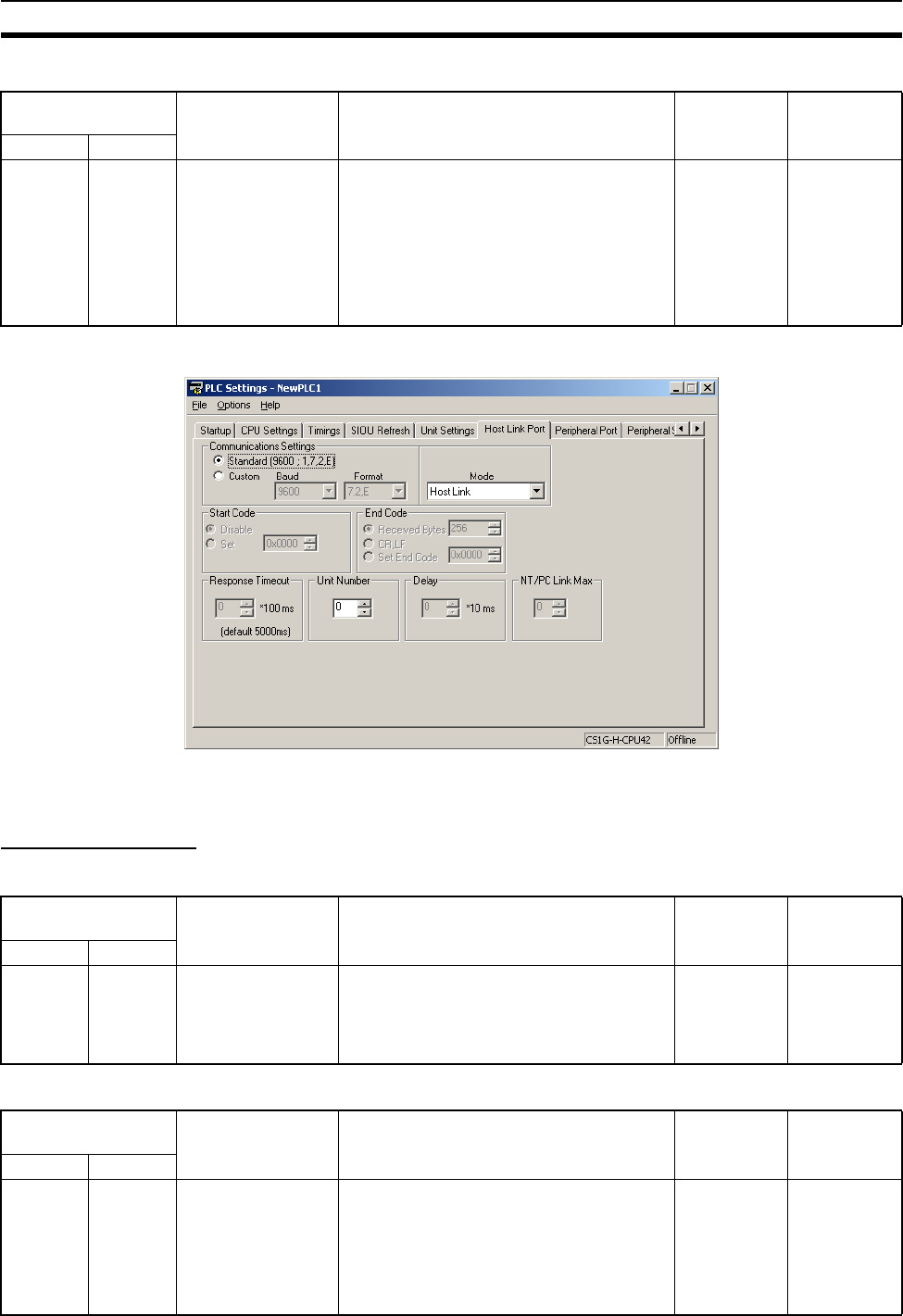
349
PLC Setup Section 7-1
Response Monitoring Time
7-1-2-8 Peripheral Port Tab Page
The following settings are valid when pin 4 on the DIP switch on the CPU Unit
is ON.
Host Link Settings
Communications Settings
Mode: Communications Mode
Programming
Console address
Settings Function Related
flags and
words
New set-
ting’s effec-
tiveness
Word Bit(s)
+167 8 to 15 00: 5 s
01 to FF: 100 to
25,500 ms (Unit:
100 ms)
Default: 00
Monitors the time from when the FINS com-
mand that has been converted into the
specified protocol using Serial Gateway is
sent until the response is received.
Default: 5 s; PLC Setup: 0.1 to 25.5 s
Note: If a timeout occurs, the FINS end
code 0205 hex (response timeout) will be
returned to the FINS source.
A61902
(RS-232C
Port Settings
Changing
Flag)
Takes effect
the next
cycle.
(Also can be
changed with
STUP (237).)
Programming
Console address
Settings Function Related
flags and
words
When set-
ting is read
by CPU Unit
Word Bit(s)
+144 15 0: Standard*
1: PLC Setup (Cus-
tom)
Default: 0
*The default settings are for 1 start bit, 7
data bits, even parity, 2 stop bits, and a baud
rate of 9,600 bps.
A61901
(Peripheral
Port Settings
Changing
Flag)
At the next
cycle.
(Also can be
changed with
STUP (237).)
Programming
Console address
Settings Function Related
flags and
words
When set-
ting is read
by CPU Unit
Word Bit(s)
+144 8 to 11 00: Host Link
05: Host link
Default: 0
This setting determines whether the periph-
eral port will operate in host link mode or
another serial communications mode. (Host
link can be specified with 00 or 05.)
The Peripheral Bus Mode is for communica-
tions with Programming Devices other than
the Programming Console.
A61901
(Peripheral
Port Settings
Changing
Flag)
At the next
cycle.
(Also can be
changed with
STUP (237).)

350
PLC Setup Section 7-1
Format: Data Bits
Format: Stop Bits
Format: Parity
Baud Rate (bps)
Unit Number (for CPU Unit in Host Link Mode)
Programming
Console address
Settings Function Related
flags and
words
When set-
ting is read
by CPU Unit
Word Bit(s)
+144 3 0: 7 bits
1: 8 bits
Default: 0
These settings are valid only when the com-
munications mode is set to Host link.
These settings are also valid only when the
Peripheral Port Settings Selection is set to
1: PLC Setup.
A61901
(Peripheral
Port Settings
Changing
Flag)
At the next
cycle.
(Also can be
changed with
STUP (237).)
Programming
Console address
Settings Function Related
flags and
words
When set-
ting is read
by CPU Unit
Word Bit(s)
+144 2 0: 2 bits
1: 1 bit
Default: 0
These settings are valid only when the com-
munications mode is set to Host link.
These settings are also valid only when the
Peripheral Port Settings Selection is set to
1: PLC Setup.
A61901
(Peripheral
Port Settings
Changing
Flag)
At the next
cycle.
(Also can be
changed with
STUP (237).)
Programming
Console address
Settings Function Related
flags and
words
When set-
ting is read
by CPU Unit
Word Bit(s)
+144 0 and 1 00: Even
01: Odd
10: None
Default: 00
These setting is valid only when the commu-
nications mode is set to Host link.
These settings are also valid only when the
Peripheral Port Settings Selection is set to
1: PLC Setup.
A61901
(Peripheral
Port Settings
Changing
Flag)
At the next
cycle.
(Also can be
changed with
STUP (237).)
Programming
Console address
Settings Function Related
flags and
words
When set-
ting is read
by CPU Unit
Word Bit(s)
+145 0 to 7 00: 9,600 bps
01: 300 bps
02: 600 bps
03: 1,200 bps
04: 2,400 bps
05: 4,800 bps
06: 9,600 bps
07: 19,200 bps
08: 38,400 bps
09: 57,600 bps
0A: 115,200 bps
Default: 00
This setting is valid only when the communi-
cations mode is set to the Host Link mode.
These settings are also valid only when the
Peripheral Port Settings Selection is set to
1: PLC Setup.
A61901
(Peripheral
Port Settings
Changing
Flag)
At the next
cycle.
(Also can be
changed with
STUP (237).)
Programming
Console address
Settings Function Related
flags and
words
When set-
ting is read
by CPU Unit
Word Bit(s)
+147 0 to 7 00 to 1F
(0 to 31)
Default: 00
This setting determines the CPU Unit’s unit
number when it is connected in a 1-to-N
(N=2 to 32) Host Link.
A61901
(Peripheral
Port Settings
Changing
Flag)
At the next
cycle.
(Also can be
changed with
STUP (237).)

351
PLC Setup Section 7-1
NT Link Settings
Mode: Communications Mode
Baud Rate (bps)
NT Link Max. (Maximum Unit Number in NT Link Mode)
Peripheral Bus Settings
Communications Setting
Mode: Communications Mode
Programming
Console address
Settings Function Related
flags and
words
When set-
ting is read
by CPU Unit
Word Bit(s)
+144 8 to 11 02: 1:N NT Link
Default: 0
This setting determines whether the RS-
232C port will operate in host link mode or
another serial communications mode.
Note Communications will not be possible
with PTs set for 1:1 NT Links.
A61902
(RS-232C
Port Settings
Changing
Flag)
At the next
cycle.
(Also can be
changed with
STUP (237).)
Programming
Console address
Settings Function Related
flags and
words
When set-
ting is read
by CPU Unit
Word Bit(s)
+145 0 to 7 00: Standard
0A: High-speed NT
Link*
Default: 00
* Set to 115,200 bps when setting this value
from the CX-Programmer.
A61901
(Peripheral
Port Settings
Changing
Flag)
At the next
cycle.
(Also can be
changed with
STUP (237).)
Programming
Console address
Settings Function Related
flags and
words
When set-
ting is read
by CPU Unit
Word Bit(s)
+150 0 to 3 0 to 7
Default: 0
This setting determines the highest unit
number of PT that can be connected to the
PLC in NT Link mode.
A61901
(Peripheral
Port Settings
Changing
Flag)
At the next
cycle.
(Also can be
changed with
STUP (237).)
Programming
Console address
Settings Function Related
flags and
words
When set-
ting is read
by CPU Unit
Word Bit(s)
+144 15 0: Default (stan-
dard)*
1: PLC Setup (cus-
tom)
Default: 0
*The default settings are for a baud rate of
9,600 bps.
A61901
(Peripheral
Port Settings
Changing
Flag)
At the next
cycle.
(Also can be
changed with
STUP (237).)
Programming
Console address
Settings Function Related
flags and
words
When set-
ting is read
by CPU Unit
Word Bit(s)
+144 8 to 11 4: Peripheral bus
Default: 0
This setting determines whether the com-
munications mode for the peripheral port.
The Peripheral Bus Mode is used for all Pro-
gramming Devices except for Programming
Consoles.
A61901
(Peripheral
Port Settings
Changing
Flag)
At the next
cycle.
(Also can be
changed with
STUP (237).)

352
PLC Setup Section 7-1
Baud Rate (bps)
Serial Gateway Settings
Communications Setting
Mode: Communications Mode
Format: Data Bits
Format: Stop Bits
Programming
Console address
Settings Function Related
flags and
words
When set-
ting is read
by CPU Unit
Word Bit(s)
+145 0 to 7 00: 9,600 bps
06: 9,600 bps
07: 19,200 bps
08: 38,400 bps
09: 57,600 bps
0A: 115,200 bps
Default: 00
The following settings are valid for the
Peripheral Bus Mode: 00 and 06 to 0A hex.
A61901
(Peripheral
Port Settings
Changing
Flag)
At the next
cycle.
(Also can be
changed with
STUP (237).)
Programming
Console address
Settings Function Related
flags and
words
New set-
ting’s effec-
tiveness
Word Bit(s)
+144 15 0: Default (stan-
dard)*
1: PLC Setup (cus-
tom)
*The default settings are for a baud rate of
9,600 bps.
A61901
(Peripheral
Port Settings
Changing
Flag)
Takes effect
the next
cycle.
(Also can be
changed with
STUP (237).)
Programming
Console address
Settings Function Related
flags and
words
New set-
ting’s effec-
tiveness
Word Bit(s)
+144 8 to 11 9: Serial Gateway
Default: 0
This setting determines whether the com-
munications mode for the peripheral port.
The peripheral bus mode is used for all Pro-
gramming Devices except for Programming
Consoles.
A61901
(Peripheral
Port Settings
Changing
Flag)
Takes effect
the next
cycle.
(Also can be
changed with
STUP (237).)
Programming
Console address
Settings Function Related
flags and
words
New set-
ting’s effec-
tiveness
Word Bit(s)
+144 3 0: 7 bits
1: 8 bits
Default: 0
These settings are valid when the Periph-
eral Port Settings Selection is set to 1: PLC
Setup.
A61901
(Peripheral
Port Settings
Changing
Flag)
Takes effect
the next
cycle.
(Also can be
changed with
STUP (237).)
Programming
Console address
Settings Function Related
flags and
words
New set-
ting’s effec-
tiveness
Word Bit(s)
+144 2 0: 2 bits
1: 1 bit
Default: 0
These settings are valid when the Periph-
eral Port Settings Selection is set to 1: PLC
Setup.
A61901
(Peripheral
Port Settings
Changing
Flag)
Takes effect
the next
cycle.
(Also can be
changed with
STUP (237).)

353
PLC Setup Section 7-1
Format: Parity
Baud Rate (bps)
Response Monitoring Time
7-1-2-9 Peripheral Service Tab Page (CPU Processing Mode Settings)
Peripheral Service Mode (Peripheral Servicing Priority Mode)
Instruction Execution Time
Programming
Console address
Settings Function Related
flags and
words
New set-
ting’s effec-
tiveness
Word Bit(s)
+144 0 to 1 00: Even
01: Odd
10: None
Default: 00
These setting is valid only when the commu-
nications mode is set to Host Link.
These settings are also valid only when the
Peripheral Port Settings Selection is set to
1: PLC Setup.
A61901
(Peripheral
Port Settings
Changing
Flag)
Takes effect
the next
cycle.
(Also can be
changed with
STUP (237).)
Programming
Console address
Settings Function Related
flags and
words
New set-
ting’s effec-
tiveness
Word Bit(s)
+145 0 to 7 00: 9,600
01: 300
02: 600
03: 1,200
04 2,400
05: 4,800
06: 9,600
07: 19,200
08: 38,400
09: 57,600
0A: 115,200
Default: 00
These setting is valid only when the commu-
nications mode is set to Host Link.
These settings are also valid only when the
Peripheral Port Settings Selection is set to
1: PLC Setup.
A61901
(Peripheral
Port Settings
Changing
Flag)
Takes effect
the next
cycle.
(Also can be
changed with
STUP (237).)
Programming
Console address
Settings Function Related
flags and
words
New set-
ting’s effec-
tiveness
Word Bit(s)
+151 8 to 15 00: 5 s
01 to FF: 100 to
25,500 ms (Unit:
100 ms)
Default: 00
Monitors the time from when the FINS com-
mand is converted into CompoWay/F using
Serial Gateway and sent until the response
is received.
Default: 5 s; PLC Setup: 0.1 to 25.5 s
Note: If a timeout occurs, the FINS end
code 0205 hex (response timeout) will be
returned to the FINS source.
A61901
(Peripheral
Port Settings
Changing
Flag)
Takes effect
the next
cycle.
(Also can be
changed with
STUP (237).)
Programming
Console address
Settings Function Related
flags and
words
When set-
ting is read
by CPU Unit
Word Bit(s)
+219 08 to 15 00
05 to FF (hex)
Default: 00 (hex)
The Peripheral Servicing Priority Mode will
be used if a time slice is set for instruction
execution (5 to 255 ms in 1-ms increments).
Instructions will be executed at the set time
slice.
00: Disable priority servicing
05 to FF: Time slice for instruction execution
(5 to 255 ms in 1-ms increments)
A266 and
A267
At start of
operation
(Can’t be
changed dur-
ing opera-
tion.)
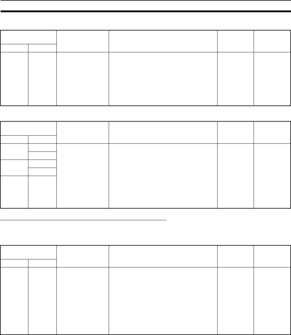
354
PLC Setup Section 7-1
Peripheral Service Execution Time
Target Units (Units for Priority Servicing)
Sync/Async Comms (Parallel Processing Modes)
The following setting is supported only by the CS1-H CPU Units
Execution Mode (Parallel Processing Mode)
Programming
Console address
Settings Function Related
flags and
words
When set-
ting is read
by CPU Unit
Word Bit(s)
+219 00 to 07 00 to FF (hex)
Default: 00 (hex)
This parameter sets the time slice for
peripheral servicing (0.1 to 25.5 ms in 0.1-
ms increments). The specified amount of
time will be used to service peripherals for
each time slice.
00: Disable priority servicing
01 to FF: Time slice for peripheral servicing
(0.1 to 25.5 ms in 0.1-ms increments)
A266 and
A267
At start of
operation
(Can’t be
changed dur-
ing opera-
tion.)
Programming
Console address
Settings Function Related
flags and
words
When set-
ting is read
by CPU Unit
Word Bit(s)
+220 08 to 15 00
10 to 1F
20 to 2F
E1
FC
FD
Default: 00
Up to five Units can be specified for priority
servicing.
00: Disable priority servicing
10 to 1F: CPU Bus Unit unit number (0 to
15) + 10 (hex)
20 to 7F: CS-series Special I/O Unit unit
number (0 to 96) + 20 (hex)
FC: RS-232C port
FD: Peripheral port
--- At start of
operation
(Can’t be
changed dur-
ing opera-
tion.)
00 to 07
+221 08 to 15
00 to 07
+222 08 to 15
Programming
Console address
Settings Function Related
flags and
words
When set-
ting is read
by CPU Unit
Word Bit(s)
+219 08 to 15 00
01
02
Default: 00
This parameter specifies if I/O memory
access is to be included in the peripheral
service processing executed in parallel with
instruction execution.
00: Not specified (disable parallel process-
ing)
01: Synchronous (Synchronous Memory
Access
02: Asynchronous (Asynchronous Memory
Access)
--- At start of
operation
(Can’t be
changed dur-
ing opera-
tion.)
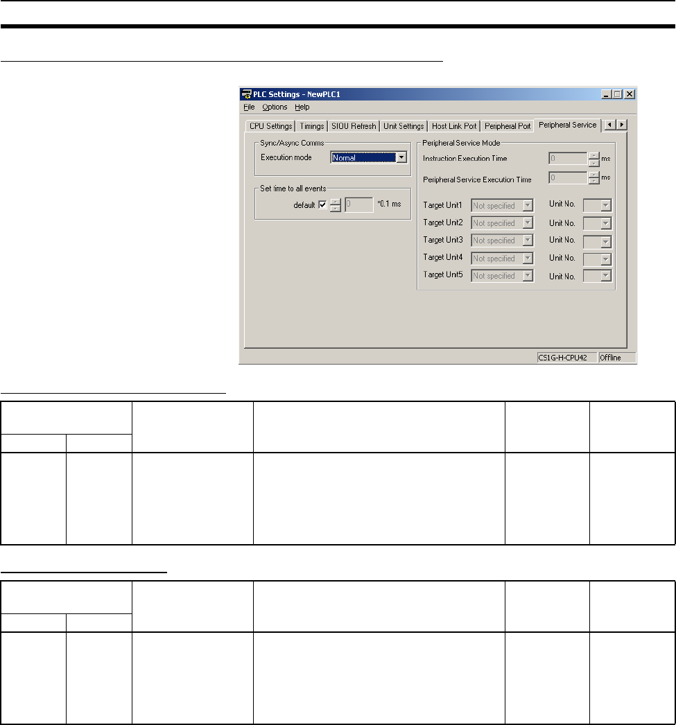
355
PLC Setup Section 7-1
Set Time to All Events (Fixed Peripheral Servicing Time)
Enable Fixed Servicing Time
Fixed Servicing Time
Programming
Console address
Settings Function Related
flags and
words
When set-
ting is read
by CPU Unit
Word Bit(s)
+218 15 0: Default*
1: Bits 0 to 7
Default: 0
Set to 1 to enable the fixed peripheral ser-
vicing time in bits 0 to 7.
*Default: 4% of the cycle time
--- At start of
operation
(Can’t be
changed dur-
ing opera-
tion.)
Programming
Console address
Settings Function Related
flags and
words
When set-
ting is read
by CPU Unit
Word Bit(s)
+218 0 to 7 00 to FF:
0.0 to 25.5 ms
(0.1-ms units)
Default: 00
Set the peripheral servicing time.
This setting is valid only when bit 15 of 218
is set to 1.
--- At start of
operation
(Can’t be
changed dur-
ing opera-
tion.)
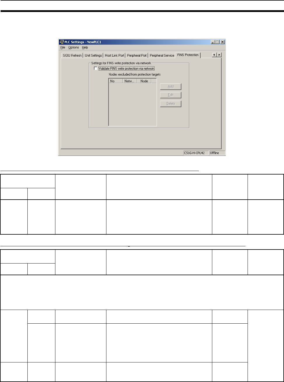
356
PLC Setup Section 7-1
7-1-2-10 FINS Protection Tab Page (Protection Against FINS Writes Across
Networks) (CS-series CPU Unit Ver. 2.0 Only)
Enabling FINS Write Protection (Use FINS Write Protection)
Nodes Excluded from Write Protection (Protection Releasing Addresses)
Programming
Console address
Settings Function Related
flags and
words
New set-
ting’s
effective-
ness
Word Bit(s)
+448 15 0: Disable FINS
write protection
1: Enable FINS write
protection
Default: 0
Enables or disables write protection for the
CPU Unit from FINS command sent over a
network (i.e., all connections except for
serial connections).
--- At any time
Programming
Console address
Settings Function Related
flags and
words
New set-
ting’s
effective-
ness
Word Bit(s)
Set the nodes and networks from which FINS write operations will be enabled. The total number of nodes set to be
excluded from write protection will be automatically set.
A maximum of 32 nodes can be set. If these settings are not made (i.e., if the total number of nodes is 0), write operations
will be disabled for all nodes but the local node.
Note: This setting is valid only when FINS write protection has been enabled.
+449 to
480
8 to 15 0 to 127
(00 to 7F hex)
FINS command source network address --- At any time
0 to 7 1 to 255
(01 to FE hex)
Note: 255 (FF hex)
can be set to include
all nodes in the
specified network.
FINS command source node address ---
+448 0 to 7 0 to 32
(00 to 20 hex)
Number of nodes excluded from protection
(Automatically calculated by the CX-Pro-
grammer; do not set.)
---
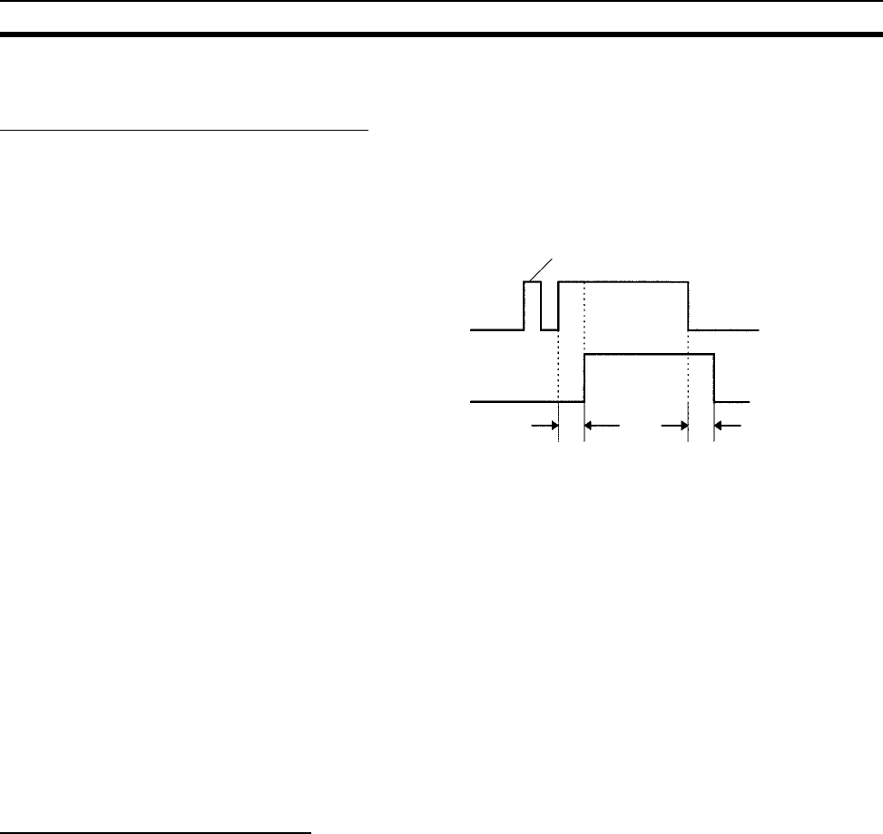
357
Explanations of PLC Setup Settings Section 7-2
7-2 Explanations of PLC Setup Settings
Basic I/O Unit Input Response Time
The input response time can be set for CS-series Basic I/O Units by Rack and
Slot number. Increasing this value reduces the effects of chattering and noise.
Decreasing this value allows reception of shorter input pulses, (but do not set
the ON response time or OFF response time to less than the cycle time).
The default setting for the input response time is 8 ms and the setting range is
0 to 32 ms. When the input response time is set to 0 ms, the only delay will be
the delays in the Unit’s internal elements. For information on the Unit’s internal
elements, refer to Appendix A Specifications of Basic I/O Units and High-den-
sity I/O Units and check the input response time for the Unit that you are
using.
The input response time settings are transferred to the CS-series Basic I/O
Units when the PLC is turned on.
When the Unit’s settings are changed, they are stored in A220 to A259 (Actual
Input Response Times for Basic I/O Units). When the settings in the PLC
Setup have been changed with the PLC in PROGRAM mode, the PLC Setup
settings will differ from the actual settings in the Units. In this case, the values
in A220 to A259 can be checked to see the input response times actually set
in the Units.
IOM Hold Bit Status at Startup
The IOM Hold Bit (A50012) can be turned ON to retain all of the data in I/O
Memory when the CPU Unit’s operating mode is switched between PRO-
GRAM mode and RUN/MONITOR mode. When the PLC is turned on, the
IOM Hold Bit itself will be cleared (OFF) unless it is protected with this PLC
Setup setting.
If the IOM Hold Bit Status at Startup setting is ON, the status of the IOM Hold
Bit will be protected when the PLC is turned on. If this setting is ON and the
IOM Hold BIt itself is ON, all data in I/O memory will be retained when the
PLC is turned on.
Note If the backup battery fails or is disconnected, the IOM Hold Bit will be cleared
whether this setting is ON or OFF.
Input such as a
proximity switch
Pulses shorter than the input
response time are not received.
Input bit
Input response time Input response time
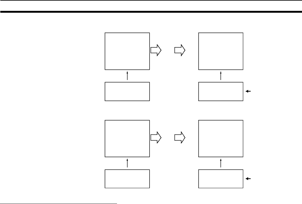
358
Explanations of PLC Setup Settings Section 7-2
Forced Status Hold Bit at Startup
The Forced Status Hold Bit (A50013) can be turned ON to retain the forced
status of all bits that have been force-set or force-reset when the CPU Unit’s
operating mode is switched between PROGRAM mode and RUN/MONITOR
mode. When the PLC is turned on, the Forced Status Hold Bit itself will be
cleared (OFF) unless it is protected with this PLC Setup setting.
If the Forced Status Hold Bit at Startup setting is ON, the status of the Forced
Status Hold Bit will be protected when the PLC is turned on. If this setting is
ON and the Forced Status Hold BIt itself is ON, all force-set and force-reset
bits will retain their forced status when the PLC is turned on.
Note If the backup battery fails or is disconnected, the Forced Status Hold Bit will
be cleared whether this setting is ON or OFF.
Non-retained parts
of I/O memory
Mode switch Retained
IOM Hold Bit: 1
(ON)
Non-retained parts
of I/O memory:
Cleared
Power on Not retained
IOM Hold Bit: 0
(OFF) Not retained when
power is turned on.
Power
OFF
Power
ON
OFF (0): IOM Hold Bit cleared at start-up
Non-retained parts
of I/O memory
Mode switch Retained
IOM Hold Bit: 1
(ON)
Non-retained parts
of I/O memory:
Retained
Power on Retained
IOM Hold Bit: 0
(OFF) Retained when
power is turned on.
Power
OFF
Power
ON
ON (1): IOM Hold Bit protected at start-up
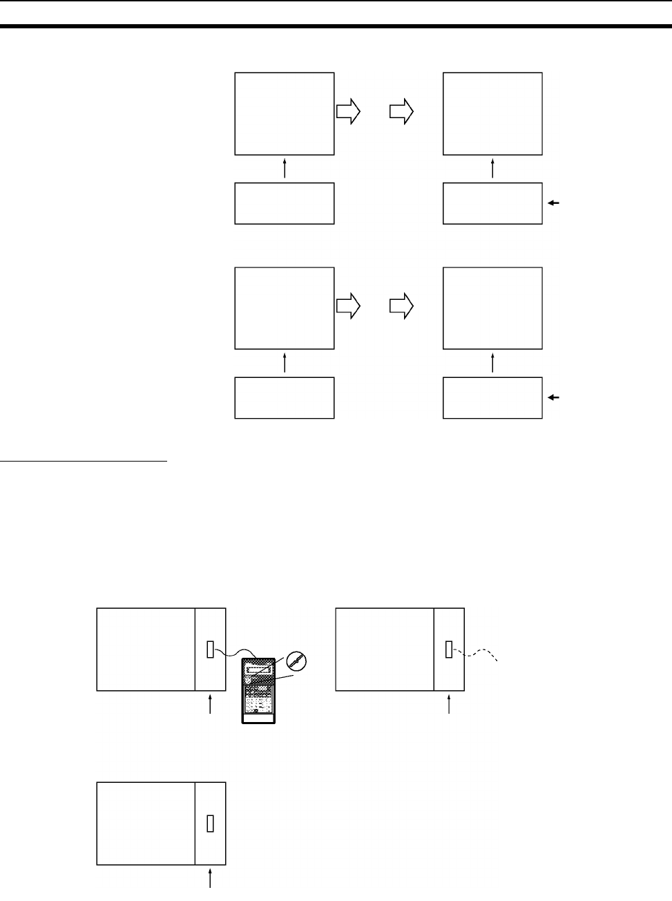
359
Explanations of PLC Setup Settings Section 7-2
Startup Mode Setting
This setting determines whether the startup mode will be the mode set on the
Programming Console’s mode switch or the mode set here in the PLC Setup.
!Caution The CS1-H CPU Unit will start in RUN mode if it is set to use the mode that is
specified on the Programming Console but a Programming Console is not
connected.
Forced bit status
Mode switch Retained
Forced Status
Hold Bit: 1 (ON)
Forced bit status
Power on Not retained
Forced Status
Hold Bit: 0 (OFF) Not retained when
power is turned
ON.
Power
OFF
Power
ON
OFF (0): Forced Status Hold Bit cleared at start-up
Forced bit status
Mode switch Retained
Forced Status
Hold Bit: 1 (ON)
Forced bit status
Power on Retained
Forced Status
Hold Bit: 0 (OFF) Retained when
power is turned
ON.
Power
OFF
Power
ON
ON (1): Forced Status Hold Bit protected at start-up
Power ON
PRCN: Programming Console's mode switch
Mode switch
setting
Power ON
Power ON
Other: PLC Setup's Startup Mode setting
PRG: PROGRAM mode
MON: MONITOR mode
RUN: RUN mode
RUN mode
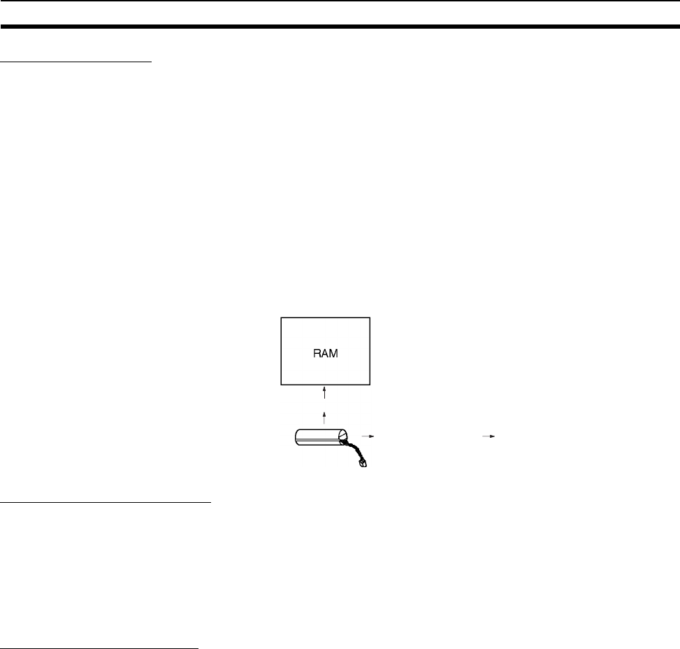
360
Explanations of PLC Setup Settings Section 7-2
Detect Low Battery
This setting determines whether CPU Unit battery errors are detected. Set the
PLC Setup so that battery errors are not detected when using battery-free
operation. Refer to information on battery-free operation in the CS/CJ Series
Programming Manual for details.
If this setting is set to detect errors (0) and a battery error is detected, the Bat-
tery Error Flag (A40204) will be turned ON.
Note 1. The contents of the DM, EM, and HR Areas in the CPU Unit are not backed
up to flash memory; they are backed up only by a Battery. If the Battery
voltage drops, this data may be lost. Provide countermeasures in the pro-
gram using the Battery Error Flag (A40204) to re-initialize data or take oth-
er actions if the Battery voltage drops.
2. A battery error will be detected when the battery is disconnected or its volt-
age drops below the minimum allowed.
Detect Interrupt Task Error
If this setting is set to detect errors (0), an interrupt task error will be detected
in the following cases:
• An interrupt task is executed for more than 10 ms during I/O refreshing of
a C200H Special I/O Unit or SYSMAC BUS Remote I/O.
• IORF(097) is executed in an interrupt task to refresh a Special I/O Unit’s
I/O while that Unit’s I/O is being refreshed during cyclic refreshing.
EM File Memory Settings
These settings are used to specify converting not converting part of the EM
Area to file memory.
CX-Programmer With the CX-Programmer, file memory will be formatted when file memory
conversion and the number of banks to be converted is specified when trans-
ferring the PLC Setup. (EM banks cannot be formatted as file memory unless
they have been specified as file memory in the PLC Setup.)
Once part of the EM Area has been formatted for use as file memory, it can be
converted back to normal EM Area usage by changing these PLC Setup set-
tings back to their previous value and “un-formatting” the EM banks with a
Programming Device.
Programming Console The specified EM bank and all subsequent banks will be set aside as file
memory. Changing these settings using the Programming Console does not
format the specified EM banks; the EM banks must be formatted with a Pro-
gramming Device after changing these PLC Setup settings. When formatting
the EM banks with a Programming Console, refer to 7-2 Memory Card Format
in the Programming Console Operation Manual (W341).
Backup
Disconnected or
voltage too low
Battery Error Flag
(A40204) ON
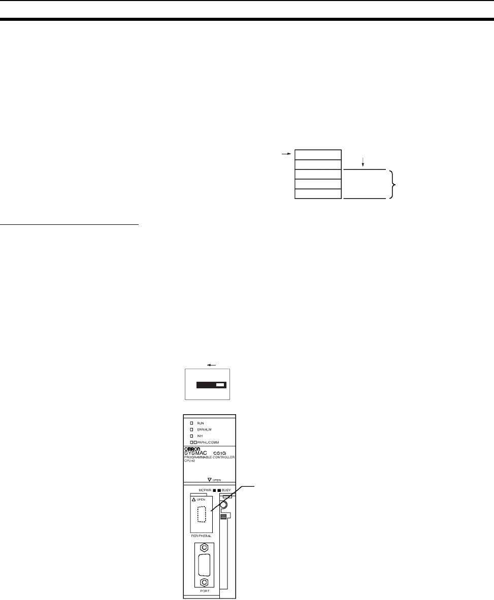
361
Explanations of PLC Setup Settings Section 7-2
Note 1. The actual starting file memory bank is stored in A344 (EM File Memory
Starting Bank). When the settings in the PLC Setup have been changed
but the EM Area hasn’t been formatted, the PLC Setup setting will differ
from the actual file memory setting in the EM Area. In this case, the values
in A344 can be checked to see the actual file memory setting.
2. The EM Area cannot be formatted if the current EM bank is one of the
banks that is being converted to file memory.
The following example shows EM banks 2 to C (12) converted to file memory.
Peripheral Port Settings
These settings are effective only when pin 4 of the DIP switch on the front of
the CPU Unit is ON.
The default settings for the peripheral port are: host link mode, 1 start bit, 7
data bits, even parity, 2 stop bits, and a baud rate of 9,600 bps. Set the periph-
eral port settings in the PLC Setup when you need to change these settings.
Note When pin 4 of the DIP switch on the front of the CPU Unit is OFF, the CPU
Unit automatically detects the communications parameters of a connected
Programming Device (including Programming Consoles). Those automatically
detected parameters are not stored in the PLC Setup.
EM File Memory setting: 1
(EM file memory enabled)
EM Starting Bank setting: 2
Bank 0
Converted EM file memory
Bank C
Bank 1
Bank 2
:
Peripheral port communications settings when DIP
switch pin 4 is ON:
Default settings:
Host link mode, 1 start bit, 7 data bits, even parity,
2 stop bits, and a baud rate of 9,600 bps
User-defined settings:
Set the communications mode (host link, NT Link,
or peripheral bus) and other settings such as the
baud rate.
4
ON
ON
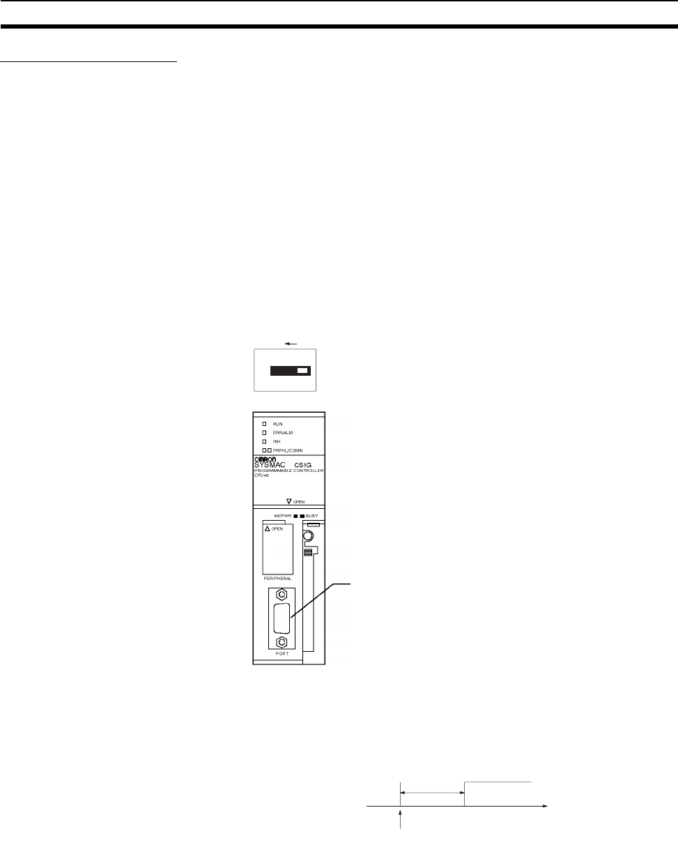
362
Explanations of PLC Setup Settings Section 7-2
RS-232C Port Settings
These settings are effective only when pin 5 of the DIP switch on the front of
the CPU Unit is OFF.
The default settings for the RS-232C port are: host link mode, 1 start bit, 7
data bits, even parity, 2 stop bits, and a baud rate of 9,600 bps. Set the RS-
232C port settings in the PLC Setup when you need to change these settings.
Specify the frame format when no-protocol mode is selected.
The RS-232C port settings can also be changed with STUP(237). The RS-
232C Port Settings Changing Flag (A61902) is turned ON when STUP(237) is
executed and it is turned OFF when the RS-232C port settings have been
changed.
Note When pin 5 of the DIP switch on the front of the CPU Unit is ON, the CPU Unit
automatically detects the communications parameters of a Programming
Device (including Programming Consoles) connected to the RS-232C port.
Those automatically detected parameters are not stored in the PLC Setup.
Note 1. A no-protocol transmission delay (address 162) can be set in no-protocol
mode. The operation of this delay is shown in the following diagram.
2. The following table shows the message formats that can be set for trans-
missions and receptions in no-protocol mode. The format is determined by
the start code (ST) and end code (ED) settings. (From 1 to 256 bytes can
be received in no-protocol mode.)
RS-232C port communications settings when DIP
switch pin 5 is OFF:
Default settings:
Host link mode, 1 start bit, 7 data bits, even parity,
2 stop bits, and a baud rate of 9,600 bps
User-defined settings:
Set the communications mode (host link, NT Link,
no-protocol*, or peripheral bus) and other settings
such as the baud rate.
*See notes 1 and 2 for details on no-protocol mode.
5
ON
ON
Delay
TXD(236)
Transmission Time
No-protocol delay
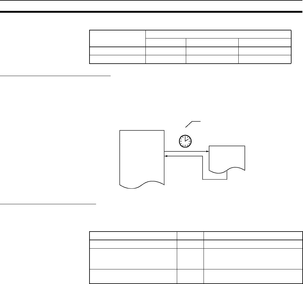
363
Explanations of PLC Setup Settings Section 7-2
Scheduled Interrupt Time Units
This setting determines the time units for the scheduled interrupt interval set-
tings. Set the scheduled interrupt interval from the program with MSKS(690).
Note This setting cannot be changed while the CPU Unit is in RUN or MONITOR
mode.
Instruction Error Operation
This setting determines whether instruction execution errors are treated as
non-fatal (0) or fatal errors (1). A program error will be generated as an
instruction error if any of the following flags is turned ON.
If this setting is OFF (0), PLC operation will continue after one of these errors.
If this setting is ON (1), PLC operation will stop after one of these errors.
Start code setting End code setting
None Yes CR+LF
None DATA DATA+ED DATA+CR+LF
Yes ST+DATA ST+DATA+ED ST+DATA+CR+LF
Scheduled Interrupt Time Units
Interval
Scheduled interrupt task
Instruction error flag Address Cause
Instruction Processing Error Flag A29508 The ER Flag was turned ON.
Indirect DM/EM BCD Error Flag A29509 The contents of a DM/EM word wasn’t
BCD when BCD was required for indi-
rect addressing.
Illegal Access Error Flag A29510 Attempted to access part of memory
that is off-limits from the program.
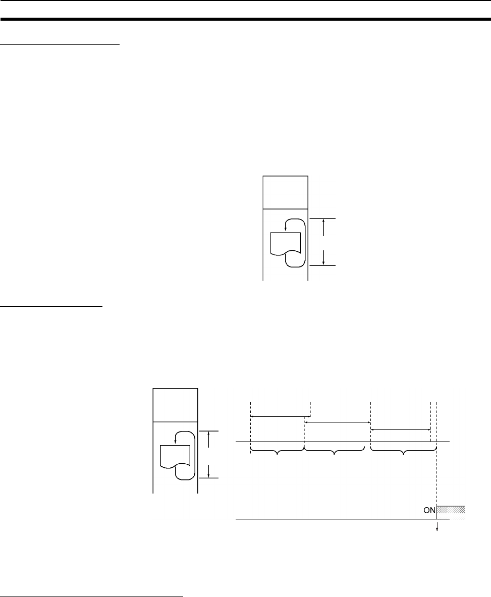
364
Explanations of PLC Setup Settings Section 7-2
Minimum Cycle Time Set the minimum cycle time to a non-zero value to eliminate inconsistencies in
I/O responses. This setting is effective only when the actual cycle time is
shorter than the minimum cycle time setting. If the actual cycle time is longer
than the minimum cycle time setting, the actual cycle time will remain
unchanged.
Note The minimum cycle time setting cannot be changed while the CPU Unit is in
RUN or MONITOR mode. As the length of the cycle time increases, the inter-
val for servicing Programming Devices will also increase. The may slow down
the response to online operations from a Programming Device or make it diffi-
cult to establish an online connection.
Watch Cycle Time If the cycle time exceeds the watch (maximum) cycle time setting, the Cycle
Time Too Long Flag (A40108) will be turned ON and PLC operation will be
stopped. This setting must be changed if the normal cycle time exceeds the
default watch cycle time setting of 1 s.
Note The watch cycle time setting cannot be changed while the CPU Unit is in RUN
or MONITOR mode.
Note The default value for the watch cycle time is 1 s (1,000 ms).
Fixed Peripheral Servicing Time
This setting determines whether the peripheral servicing for the following pro-
cesses is performed with the default settings (4% of the cycle time) or all
together in a fixed servicing time.
Exchange data with CS-series Special I/O Units when necessary
Exchange data with CS-series CPU Bus Units when necessary
Exchange data with peripheral port
Exchange data with serial communications ports
Exchange data with Inner Board
Service file access operations (Memory Card)
Fixed cycle time
Watch
Time
Watch Cycle
Time Watch Cycle
Time Watch Cycle
Time
Actual Cycle
Time
Actual Cycle
Time
Actual Cycle
Time
↓
OVER
Cycle Time
Too Long Flag
A40108
CPU Unit operation
is stopped.
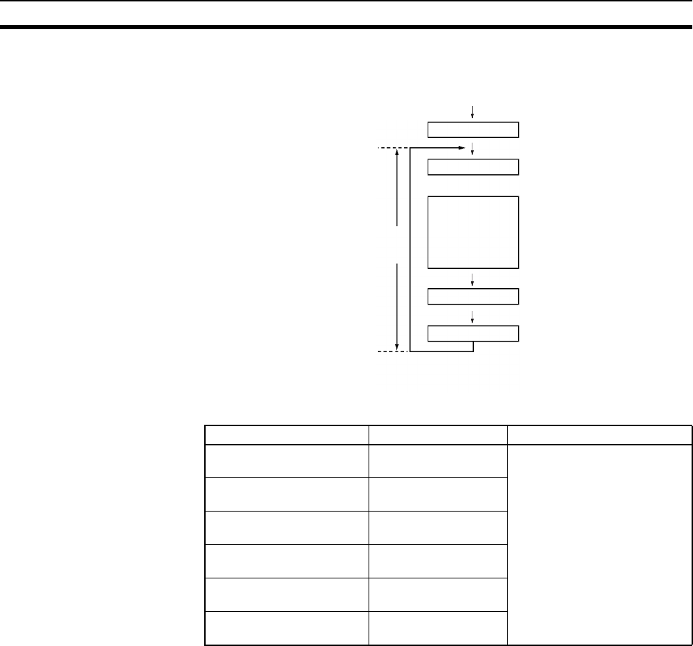
365
Explanations of PLC Setup Settings Section 7-2
Peripheral servicing is performed at the end of the cycle, just after I/O refresh-
ing.
The following table shows a breakdown of the peripheral servicing time.
The default value for each servicing process is 4% of the last cycle’s cycle
time.
In general, we recommend using the default value. Set a uniform servicing
time only when peripheral servicing is being delayed because each service
process is being spread over several cycles.
Note 1. When the peripheral servicing time is set to a time longer than the default
value, the cycle time will also be longer.
2. The fixed peripheral servicing time setting cannot be changed while the
CPU Unit is in RUN mode or MONITOR mode.
3. Use the Peripheral Servicing Priority Mode to give priority to servicing pe-
ripheral over program execution. Refer to the CS/CJ Series Programming
Manual for details.
Peripheral servicing time Default value Setting range
Event service time for
CS-series Special I/O Units
4% of the previous
cycle’s cycle time
Uniform servicing time in ms:
0.0 to 25.5 ms in 0.1-ms units
Event service time for
CS-series CPU Bus Units
Same as above.
Event service time for
peripheral port
Same as above.
Event service time for
RS-232C port
Same as above.
Event service time for
serial communication ports
Same as above.
File access service time for
Memory Card
Same as above.
Power ON
Initialization
Common processes
Program
execution
(Tasks
executed in
order)
I/O refreshing
Peripheral servicing
Cycle
time
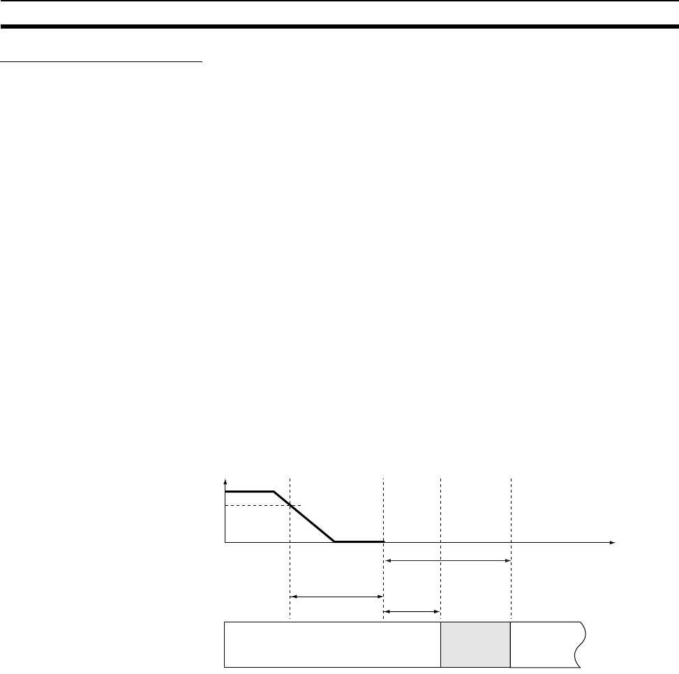
366
Explanations of PLC Setup Settings Section 7-2
Power OFF Interrupt Task
This setting determines whether or not a power OFF interrupt task will be exe-
cuted when a power interruption is detected. (When this setting is set to 0, the
regular program will just stop when a power interruption is detected.)
The power OFF interrupt task will be stopped when the power hold time (pro-
cessing time after power interrupt + power OFF detection delay time) has
elapsed. The maximum power hold time is 10 ms.
When a power OFF detection delay time has to be set, be sure that the power
OFF interrupt task can be executed in the available time (10 ms – power OFF
detection delay time).
Note The power OFF interrupt task setting cannot be changed while the CPU Unit
is in RUN mode or MONITOR mode.
Power OFF Detection
Delay Time
This setting determines how much of a delay there will be from the detection
of a power interruption (approximately after the power supply voltage drops
below 85% of the rated value) until a power interruption is established and the
regular program is stopped. The setting can be between 0 and 10 ms.
It takes a maximum of 10 ms for the internal 5 V DC power supply to drop to
0 V DC after the initial power interrupt detection time. Extend the time until
detection of a power interruption when momentary interruptions in a bad
power supply are causing PLC operation to stop.
Note The power OFF detection delay time setting cannot be changed while the
CPU Unit is in RUN mode or MONITOR mode.
Note The execution time for the power OFF interrupt task must be less than the
maximum time available, namely: 10 ms – power OFF detection delay time.
Refer to CS/CJ Series Programming Manual for details on the power interrupt
task and on CPU Unit operation when power is turned OFF.
Power interrupt
detection time Power OFF
detection
delay time
0 to 10 ms
Power OFF
interrupt task
(See note.)
Regular program Stop
Tim
e
Power Interrupt Detection Time
AC power supply: 10 to 25 ms
(not consistent)
DC power supply: 2 to 5 ms
(not consistent)
Power holding time (fixed: 10 ms)

367
Explanations of PLC Setup Settings Section 7-2
Special I/O Unit Cyclic Refreshing
When a Special I/O Unit will be refreshed in an interrupt task by IORF(097),
always disable cyclic refreshing for that Unit with this setting. The expected
results will not be achieved and the Interrupt Task Error Flag (A40213) will be
turned ON if IORF(097) is executed in an interrupt task during normal I/O
refreshing.
Special I/O Unit CPU Unit
Special
I/O Unit
Area
These settings determine whether or not
data will be exchanged with the 10 words
allocated to each Special I/O Unit in the
Special I/O Unit Area during cyclic I/O
refreshing.

368
Explanations of PLC Setup Settings Section 7-2
369
SECTION 8
I/O Allocations
This section describes I/O allocations to Basic I/O Units, Special I/O Units, and CPU Bus Units, and data exchange with
CPU Bus Units.
8-1 I/O Allocations . . . . . . . . . . . . . . . . . . . . . . . . . . . . . . . . . . . . . . . . . . . . . . . . 370
8-1-1 Unit Types. . . . . . . . . . . . . . . . . . . . . . . . . . . . . . . . . . . . . . . . . . . . . 370
8-1-2 Creating I/O Tables. . . . . . . . . . . . . . . . . . . . . . . . . . . . . . . . . . . . . . 372
8-2 I/O Allocation Methods . . . . . . . . . . . . . . . . . . . . . . . . . . . . . . . . . . . . . . . . . 375
8-2-1 I/O Allocations to Basic I/O Units . . . . . . . . . . . . . . . . . . . . . . . . . . 375
8-2-2 I/O Allocations to Special I/O Units. . . . . . . . . . . . . . . . . . . . . . . . . 380
8-2-3 I/O Allocations to CPU Bus Units . . . . . . . . . . . . . . . . . . . . . . . . . . 381
8-2-4 I/O Allocations to SYSMAC BUS Slave Racks. . . . . . . . . . . . . . . . 381
8-3 Allocating First Words to Racks . . . . . . . . . . . . . . . . . . . . . . . . . . . . . . . . . . . 382
8-4 Allocating First Words to Slots . . . . . . . . . . . . . . . . . . . . . . . . . . . . . . . . . . . . 385
8-5 Detailed Information on I/O Table Creation Errors . . . . . . . . . . . . . . . . . . . . 388
8-6 Data Exchange with CPU Bus Units. . . . . . . . . . . . . . . . . . . . . . . . . . . . . . . . 388
8-6-1 Special I/O Units. . . . . . . . . . . . . . . . . . . . . . . . . . . . . . . . . . . . . . . . 388
8-6-2 Disabling Special I/O Unit Cyclic Refreshing . . . . . . . . . . . . . . . . . 390
8-6-3 CPU Bus Units . . . . . . . . . . . . . . . . . . . . . . . . . . . . . . . . . . . . . . . . . 391
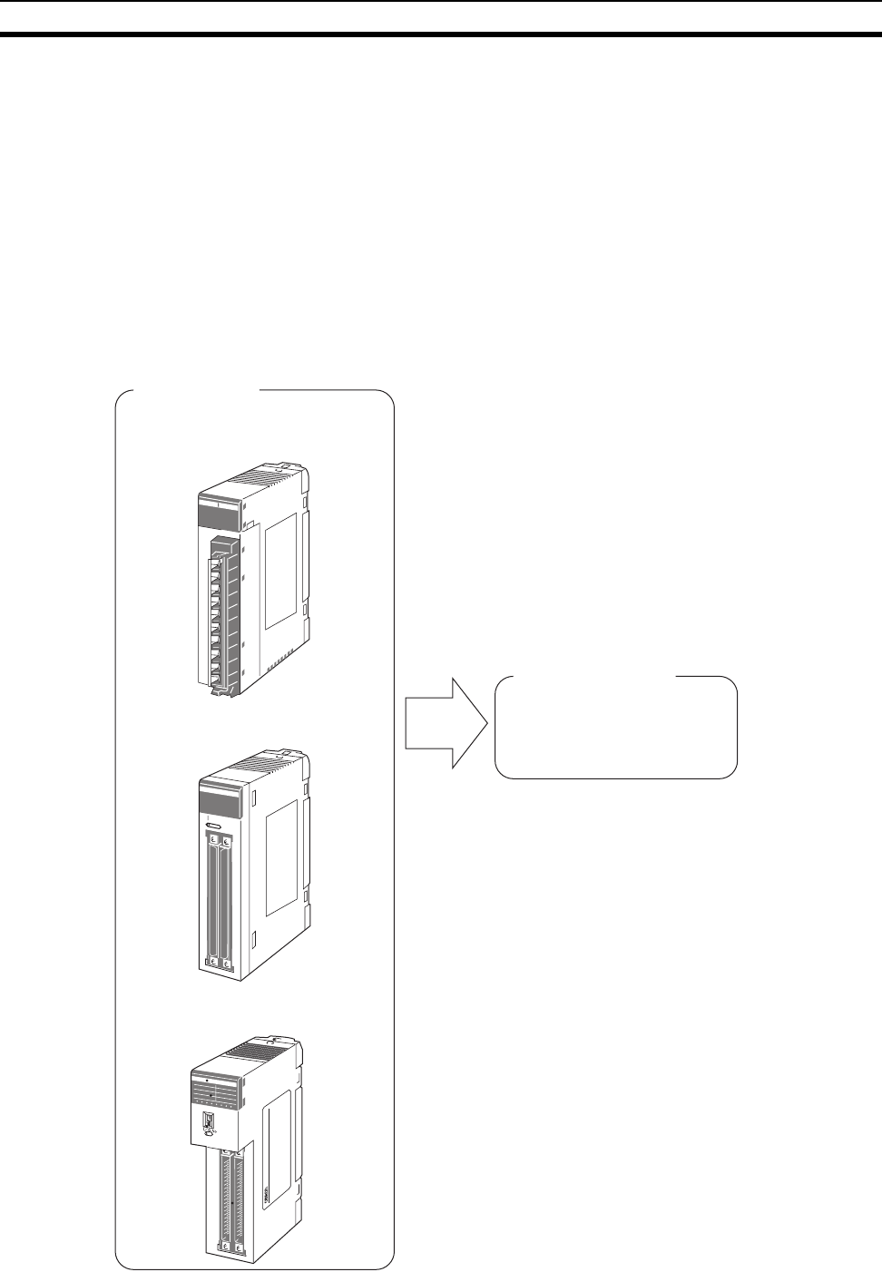
370
I/O Allocations Section 8-1
8-1 I/O Allocations
In CS-series PLCs, memory must be allocated to the Units mounted in the
PLC. I/O tables containing the models and locations of all Units and the allo-
cations made to each must be created and these I/O tables must be regis-
tered in the CPU Unit. When the power supply is turned ON to the CPU Unit,
the I/O tables are compared against the mounted Units to verify their accu-
racy.
8-1-1 Unit Types
Memory is allocated differently to Basic I/O Units, Special I/O Units, and CS-
series CPU Bus Units.
Basic I/O Units
Basic I/O Units
CS-series/C200H Basic I/O Units
CS-series/C200H Group-2
High-density I/O Units
C200H Group-2 High-density
I/O Units (See note 2.)
I/O Area
Allocation
Note 1. The Rack's first word setting can be
changed from the default setting (CIO 0000)
to any word from CIO 0000 to CIO 0999.
The first word setting can be changed only
with a Programming Device other than a
Programming Console.
2. The unit number setting on the front of
C200H Group-2 High-density I/O Units is
ignored. Words are allocated to these Units
based on their location in the Rack, just like
Basic I/O Units.
CIO 0000 to CIO 0319 (See note 1.)
(Memory is allocated in one-word
units based on mounting position in
the Racks.)
00000
0123 4567
CH
0
8
0
8
7
15
7
15
A
B
OD219
1
20
20
1
C200H-00219
CH
CH1
CH2
CN2
CN1
BAAB
0123 4567
CH
1
29
1 CH 0 2 4
10CH 1 3 5
29
1
CN2
CN1
BAAB
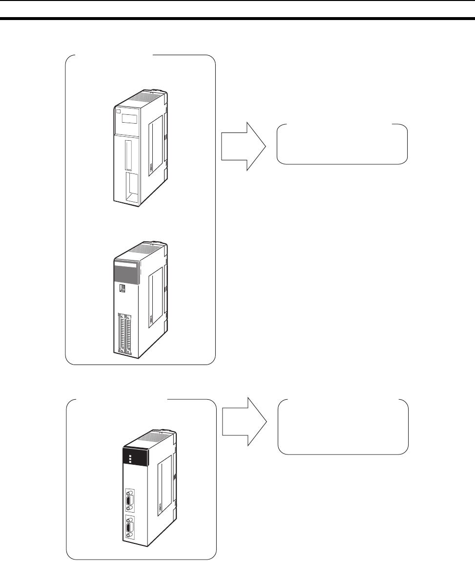
371
I/O Allocations Section 8-1
Special I/O Units
CS-series CPU Bus Units
Special I/O Units
CS-series Special I/O Units
C200H Special I/O Units
(See note 2.)
Special I/O Unit Area
Allocation
Note 1. Although there are 96 unit number settings,
a maximum of 80 Units can actually be
mounted to a PLC because that is the
maximum number of slots possible.
2. Some Units classified as I/O Units (namely
C200H High-density I/O Units) are actually
treated as Special I/O Units.
CIO 2000 to CIO 2959
(Each Unit is allocated ten words
based on its unit number setting.)
MACINE
NO.
ID215
RUN
0 1 2 3 4 5 6 7
CN1
8 9 10 11 12 13 14 15
CN2
0 1 2 3 4 5 6 7
8 9 10 11 12 13 14 15
CN1 CN2
B A
A B
12 1
112
C200H-00215
CH
C200H-00215
CS-series CPU Bus Units CPU Bus Unit Area
Allocation CIO 1500 to CIO 1899
(Each Unit is allocated 25 words
based on its unit number setting.)
C200H-00215
RDY
COMM1
COMM2
SCB21
PORT2
PORT1
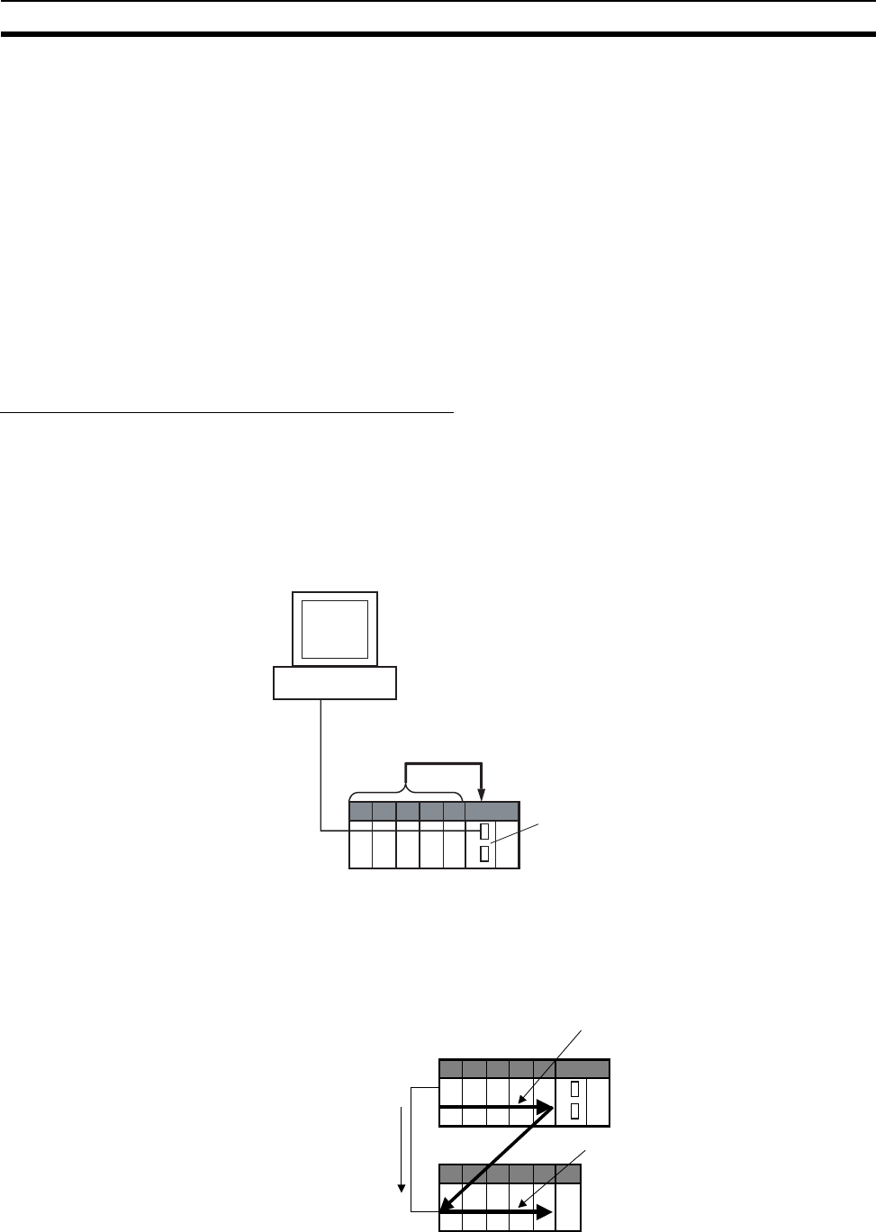
372
I/O Allocations Section 8-1
8-1-2 Creating I/O Tables
There are two ways to allocate I/O memory to CS-series Units.
• Create the I/O tables online based on the Units actually mounted to the
PLC. This can be done from either the CX-Programmer or a Programming
Console. The Programming Device is connected online and then the I/O
tables are created based on the Units that are mounted.
• Create the I/O tables offline without basing them directly on the mounted
Units and then transfer the I/O tables to the PLC. This is done offline on
the CX-Programmer.
The word addresses, number of words, and mounting slot for each Unit are
registered in the CPU Unit as I/O tables. Data is exchanged between the Units
and the CPU Unit, e.g., to help prevent mistakes in mounting when replacing
Units.
Creating I/O Tables Based on Mounted Units
Connect a Programming Console or the CX-Programmer to a CPU Unit in a
PLC with all the Units mounted and create the I/O tables. In the I/O table cre-
ation operation, information on the Unit models and mounting locations are
registered in the parameter area of the CPU Unit as the registered I/O tables
for all Units mounted to the basic PLC system and SYSMAC BUS Remote I/O
Racks.
I/O Memory Allocations
When I/O memory is allocated automatically, words are automatically allo-
cated to Units in the order they are mounted to the Racks. Words are allo-
cated to Units from left to right starting on Rack 0 and then left to right on each
Rack through Rack 7.
CX-Programmer or Programming Console
I/O table creation operation
Online Information on models and
positions of mounted Units:
Registered I/O table
CPU Unit
Registered I/O tables written to
parameter area in CPU Unit.
In order from Rack 0
through Rack 7
Rack 0
Rack 1
In order from left to right starting with slot 00
In order from left to right starting with slot 00
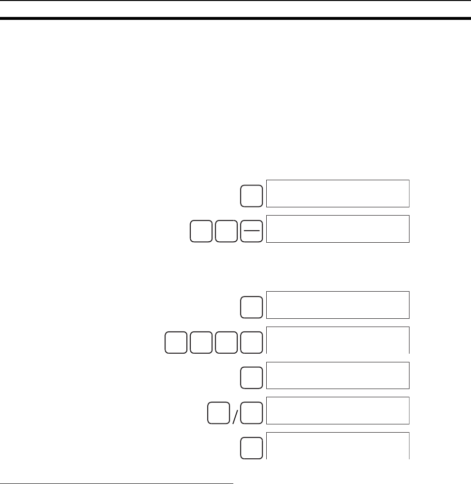
373
I/O Allocations Section 8-1
I/O Table Creation with CX-Programmer
Use the following procedure to create the I/O tables online with the CX-Pro-
grammer.
1,2,3... 1. Double-click IO Table in the project tree in the main window. The I/O Table
Window will be displayed.
2. Select Options - Create. The models and positions of the Units mounted
to the Racks will be written to the CPU Unit as the registered I/O tables.
I/O Table Creation with a Programming Console
Use the following procedure to register the I/O table with a Programming Con-
sole.
Note If the Rack first words have already been set from the CX-Program-
mer, “Rack 1st Word En” will be displayed on the second line (CS1-
H only).
Creating I/O Tables without Mounted Units
With the CX-Programmer, I/O tables can be created offline without mounted
Units and then transferred to the CPU Unit. The information on Unit models
and mounting locations are written to the parameter area of the CPU Unit as
the registered I/O tables.
I/O Table Creation with CX-Programmer
Use the following procedure to create the I/O tables offline with the CX-Pro-
grammer and then transfer them to the CPU Unit. Once the Units that are to
be mounted are set for each Rack, the CX-Programmer will automatically allo-
cate words according to Rack and slot positions starting from CIO 0000.
1,2,3... 1. Double-click IO Table in the project tree in the main window. The I/O Table
Window will be displayed.
2. Double-click the Rack to be edited. The slots will be displayed for the Rack.
3. Right-click the slot to which to assign a Unit and select the Unit from the
pop-up menu.
CLR
000000 CT00
FUN SHIFT CH
*DM
000000 I/O TBL ?
CHG
000000 I/O TBL
WRIT ????
971 3 000000 I/O TBL
WRIT 9713
WRITE
000000CPU BU ST?
0:CLR 1:KEEP
01000000 I/O TBL
WRIT OK
CLR
000000 CT00
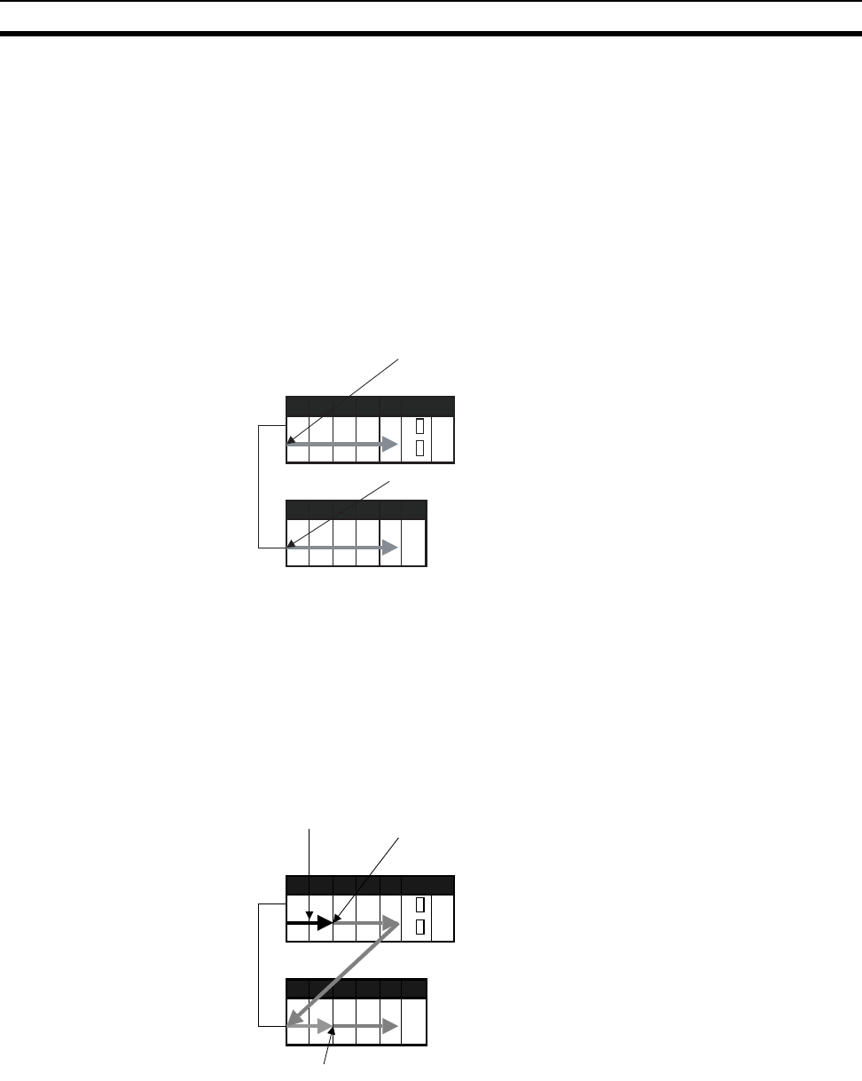
374
I/O Allocations Section 8-1
4. When all the desired Units have been assigned to slots, select Options -
Transfer to PLC. The I/O tables will be transferred.
With the CX-Programmer, you can also assign any desired word to an I/O Unit
regardless of it’s position on the Racks.
Setting the First Word on a Rack
The first word allocated on a Rack can be set to allocate specific words to the
Units on the Rack regardless of the order in which the Rack is connected.
Words will be allocated consecutively to the Units on the Rack in the order
that Units are mounted to the Rack. Refer to 8-3 Allocating First Words to
Racks for details.
Note The first words for Racks cannot be set at the same time as the first words for
slots.
Setting the First Word for a Slot
The first word allocated to the Unit in any slot on any Rack can be set regard-
less of the order of the Rack or the position of the slot. Words are then allo-
cated in sequence to the following Units in the order they are mounted. Refer
to 8-4 Allocating First Words to Slots for details.
Note The first words for Racks cannot be set at the same time as the first words for
slots.
Setting the First Word on Each Rack
Rack 0
Rack 1
The first word for slot 00 on the Rack is set. Words
are then allocated in order to Units from left to right.
The first word for slot 00 on the Rack is set. Words
are then allocated in order to Units from left to right.
Setting the First Words for Specific Slots
Rack 0
Rack 1
A word is set for slot 02 on Rack 1 for group 02.
A word is set for slot 00 on the CPU Rack for group 00.
A word is set for slot 02 on the CPU Rack for group 01.

375
I/O Allocation Methods Section 8-2
Overview
Note 1. Always create I/O tables either online or by editing them offline and trans-
ferring them to the CPU Unit. The CPU Unit will not be able to recognize
Basic I/O Units, Special I/O Units, CPU Bus Units, or Units on SYSMAC
BUS I/O Rack unless I/O tables are registered in the CPU Unit.
2. For CS1-H CPU Unit Ver. 2.0 or later, CPU Bus Units can be used even if
they are not registered in the I/O tables, this function is provided to enable
online connections from Programming Devices running on personal com-
puters (e.g., the CX-Programmer) and is not intended for normal system
operation. Always register I/O tables in the CPU Unit before starting oper-
ation.
3. The C200HX/HG/HE, C200H, and C200HS PLCs use fixed word alloca-
tions for slots, enabling operation without I/O tables. I/O tables were creat-
ed only to prevent Units from being mounted to the wrong slot. With the
CS-series PLCs, the words allocated to any particular slots are not fixed.
Words are merely allocated to the Units actually mounted. If no Unit is
mounted, no words are allocated. If the mounted Unit requires more than
one word, the required number of words is allocated. Operation for CS-se-
ries PLCs is thus not possible unless I/O tables are registered.
8-2 I/O Allocation Methods
8-2-1 I/O Allocations to Basic I/O Units
Basic I/O Units include the following Units:
• CS-series Basic I/O Units
• C200H Basic I/O Units
• C200H Group-2 High-density I/O Units
These Units are allocated words in the I/O Area (CIO 0000 to CIO 0319) and
can be mounted to the CPU Rack, CS-series Expansion Racks, and C200H
Expansion I/O Racks (See note 2).
Note 1. Refer to 2-4 Units for list of specific Basic I/O Units.
2. CS-series Basic I/O Units cannot be mounted to C200H Expansion I/O
Racks.
Method Operation Allocations Rack allocation
order
Slot allocation
order within Rack
Using actual
mounted Units
Perform I/O table
creation online.
Automatic allocations according to
mounting position
In order from Rack 0
to Rack 7
Left to right from
slot 00
Not using
actual
mounted Units
Edit the I/O tables
offline and transfer
them to CPU Unit.
Automatic allocations according to
mounting position
In order from Rack 0
to Rack 7
Left to right from
slot 00
Partial manual
allocation without
restrictions by
mounting position
Allocating Rack
first words
User-set Left to right from
slot 00
Allocation slot first
words
Left to right from
any slot allocated a
first word
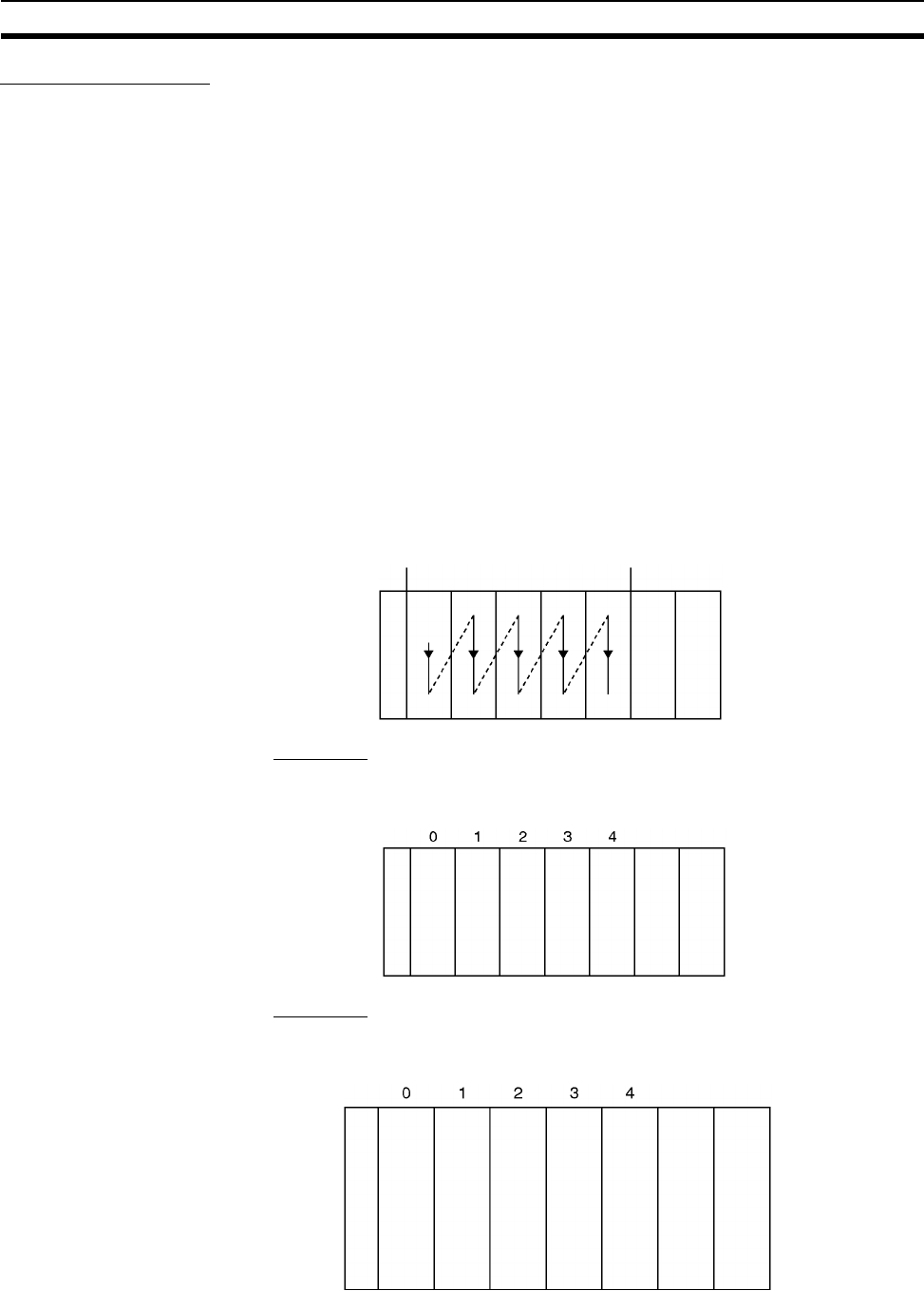
376
I/O Allocation Methods Section 8-2
Allocation Methods
When I/O tables are created in the order of the Racks and the order that Units
are mounted, I/O words will be allocated as described below. If a Program-
ming Console or the CX-Programmer is connected online and the I/O tables
are created automatically according to the Units that are actually mounted,
the CPU Unit will automatically create and register the I/O tables. If the I/O
tables are created offline using the CX-Programmer, the CX-Programmer will
automatically allocate words according to the Unit settings that have been
made.
Basic I/O Units on the CPU Rack
Basic I/O Units on the CPU Rack are allocated words from left to right starting
from CIO 0000 and each Unit is allocated as many words as it requires.
Note 1. Units that have 1 to 16 I/O points are allocated 16 bits (1 word) and Units
that have 17 to 32 I/O points are allocated 32 bits (2 words).
2. I/O words are not allocated to empty slots. To allocate words to an empty
slot, change the I/O table with a Programming Device.
3. The unit number setting on the front of C200H Group-2 High-density I/O
Units is ignored. Words are allocated to these Units based on their location
on the Rack, just like Basic I/O Units.
Example 1
The following example shows the I/O allocations to 5 Basic I/O Units on the
CPU Rack.
Example 2
The following example shows the I/O allocations to 4 Basic I/O Units on the
CPU Rack with one empty slot.
Slot numbers 2, 3, 5, 8, and 10
CPU Rac
k
CIO
0000
CPU Unit
Power Supply Unit
CPU Rac
k
IN
8
CIO
0000
IN
16
CIO
0001
IN
64
CIO
0002
to
0005
OUT
8
CIO
0006
OUT
32
CIO
0007
to
0008
CPU Unit
Power Supply Unit
CPU Rac
k
IN
16
CIO
0000
IN
32
CIO
0001
to
0002
IN
96
CIO
0003
to
0008
Empty OUT
96
CIO
0009
to
0014
CPU Unit
Power Supply Unit
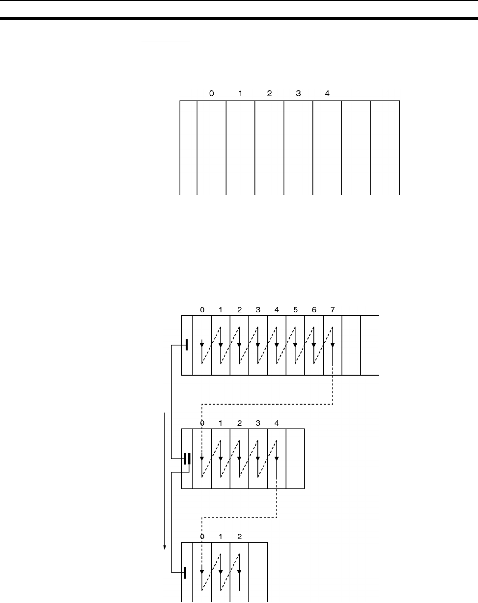
377
I/O Allocation Methods Section 8-2
Example 3
The following example shows the I/O allocations to 5 Basic I/O Units in the
CPU Rack. Two slots are filled with Dummy Units to reserve I/O words for
those slots.
Note Use the CX-Programmer’s I/O table change operation to reserve words for the
empty slots.
Basic I/O Units on CS-series and C200H Expansion Racks
I/O allocation to Basic I/O Units continues from the CPU Rack to the Expan-
sion Rack (CS-series Expansion Rack or C200H Expansion I/O Rack) con-
nected to the CPU Rack. Words are allocated from left to right and each Unit
is allocated as many words as it requires, just like Units in the CPU Rack.
CPU Rac
k
IN
32
CIO
0000
to
0001
OUT
8
CIO
0002
Re-
served
16
CIO
0003
Re-
served
32
CIO
0004
to
0005
IN
8
CIO
0006
CPU Unit
Power Supply Unit
CPU Rac
k
CS-series Expansion Rack
CS-series Expansion Rack
Words are allocated in order
beginning with the Expansion
Rack nearest the CPU Rack.
CIO
0000
CPU Unit
Power Supply Unit
Power Supply Unit
Power Supply Unit
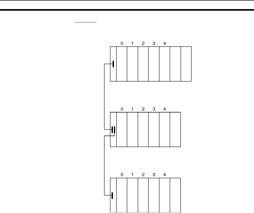
378
I/O Allocation Methods Section 8-2
Example
The following example shows the I/O allocation to Basic I/O Units in the CPU
Rack and two CS-series Expansion Racks.
Note Use the CX-Programmer’s I/O table change operation to reserve a word for
the empty slot.
Allocations to CS-series Long-distance Expansion Racks
In configurations containing CS-series Long-distance Expansion Racks, up to
two series of CS-series Long-distance Expansion Racks can be included.
Words are automatically allocated to the Units mounted to the Racks in order
of rack number and slot in the same way as for other configurations. The CPU
Rack is rack 0, the CS-series Expansion Rack (if there is one) is Rack 1. Rack
numbers are then assigned in order to the Racks in series A of CS-series
Long-distance Expansion Racks and finally to the Racks in series B of CS-
series Long-distance Expansion Racks, to a maximum rack number of 7.
Although words are automatically allocated, the first word on each Rack can
be set.
Note 1. I/O words are not allocated to the I/O Control Units or I/O Interface Units.
2. No C200H Units of any kind can be mounted to CS-series Long-distance
Expansion Racks.
3. CS-series CPU Bus Units should always be placed on the CPU Rack or
CS-series Expansion Rack. Although they can be placed on CS-series
Long-distance Expansion Racks, doing so is not recommended because it
will increase the cycle time.
CPU Rack
IN
16
CIO
0000
IN
32
CIO
0001
and
0002
IN
64
CIO
0003
to
0006
OUT
16
CIO
0007
OUT
32
CIO
0008
and
0009
IN
16
CIO
0010
IN
32
CIO
0011
and
0012
Empty OUT
5
CIO
0013
OUT
12
CIO
0014
IN
8
CIO
0015
IN
16
CIO
0016
OUT
8
CIO
0017
Re-
served
16
CIO
0018
IN
32
CIO
0019
and
0020
CPU Unit
Power Supply Unit
Power Supply Unit
Power Supply Unit
CS-series Expansion
Rack
CS-series Expansion
Rack
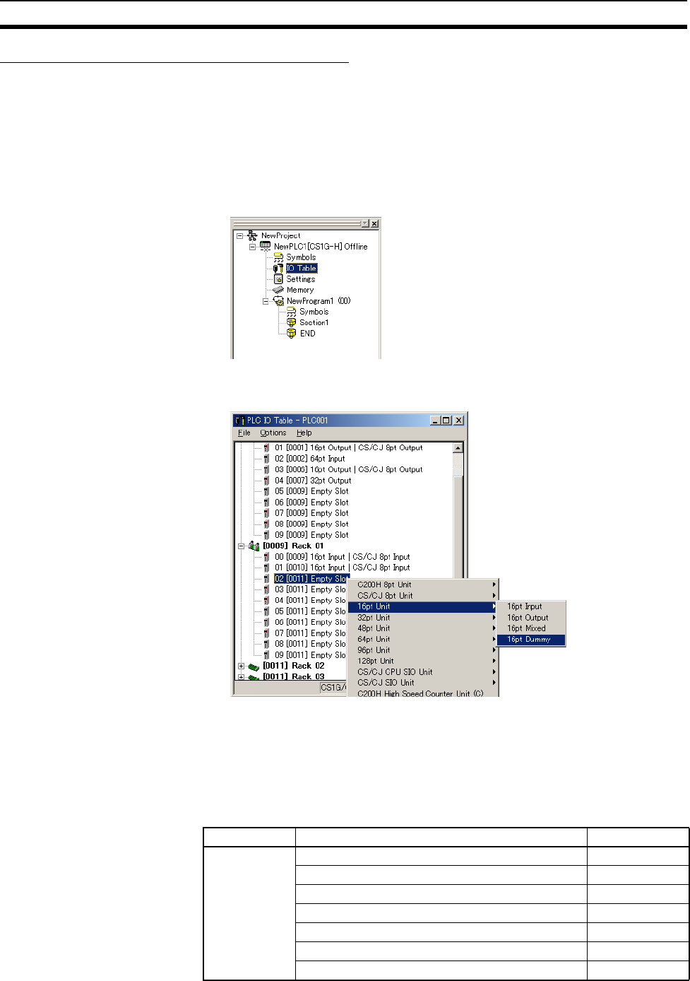
379
I/O Allocation Methods Section 8-2
Reserving I/O Words for Expected Changes
If the system configuration will be changed at a later date, changes to the pro-
gram can be minimized by reserving I/O words in advance for future Unit
changes or additions. To reserve I/O words, edit the I/O table with the CX-Pro-
grammer.
I/O Table Editing Operation
1,2,3... 1. Double-click IO Table in the project tree in the main window. The I/O Table
Window will be displayed.
2. Right-click the slot for which a word is to be reserved and select the Dum-
my item from under the Basic I/O Unit with the correct number of I/O points.
Note 1. Do not execute the I/O table creation operation after completing the above
editing operation. The reserved word settings will be lost.
2. The following High-density I/O Units are not Basic I/O Units, but Special I/O
Units. These Units are allocated 10 words/Unit in the Special I/O Unit Area
(CIO 2000 to CIO 2959) based on their unit number settings. Refer to 8-2-
2 I/O Allocations to Special I/O Units for more details.
Name Specifications Model
High-density
I/O Units
32-point DC Input Unit C200H-ID215
32-point TTL Input Unit C200H-ID501
32-point Transistor Output Unit C200H-OD215
32-point TTL Output Unit C200H-OD501
16-point TTL Input/16-point TTL Output Unit C200H-MD501
16-point DC Input/16-point Transistor Output Unit C200H-MD215
16-point DC Input/16-point Transistor Output Unit C200H-MD115
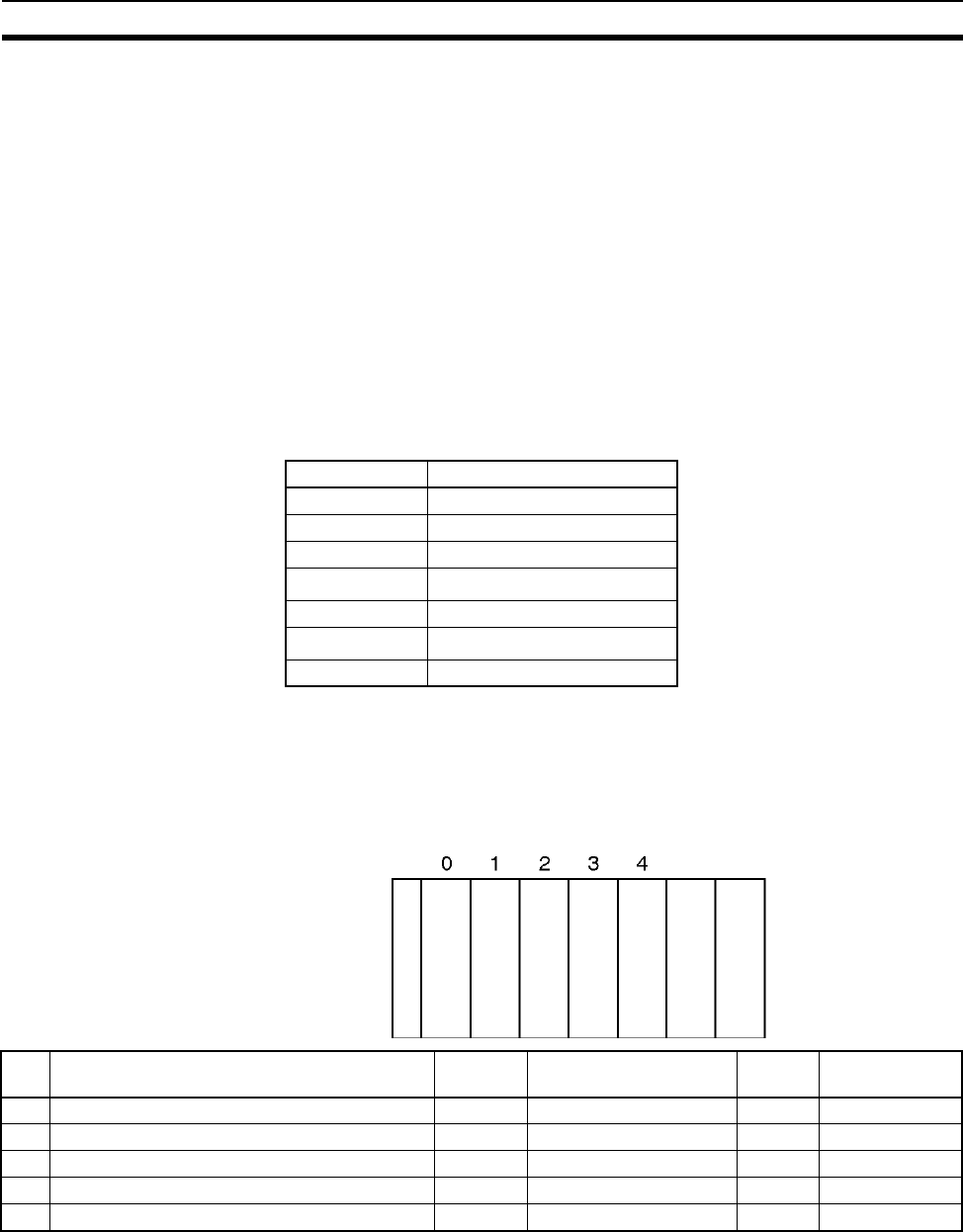
380
I/O Allocation Methods Section 8-2
8-2-2 I/O Allocations to Special I/O Units
Special I/O Units include the following Units:
• CS-series Special I/O Units
• C200H Special I/O Units
Each of these Units is allocated ten words in the Special I/O Unit Area
(CIO 2000 to CIO 2959) according the unit number set on the Unit.
Special I/O Units can be mounted to the CPU Rack, CS-series Expansion
Racks, and C200H Expansion I/O Racks (see note 2).
Note 1. Refer to 2-4 Units for more details on the available Special I/O Units.
2. CS-series Special I/O Units cannot be mounted to C200H Expansion I/O
Racks.
Word Allocation The following table shows which words in the Special I/O Unit Area are allo-
cated to each Unit according to unit number.
Special I/O Units are ignored during I/O allocation to Basic I/O Units. Slots
containing Special I/O Units are treated as empty slots and aren’t allocated
any words in the I/O Area.
Example The following example shows the I/O word allocation to Basic I/O Units and
Special I/O Units in the CPU Rack.
Unit number Words allocated
0 CIO 2000 to CIO 2009
1 CIO 2010 to CIO 2019
2 CIO 2020 to CIO 2029
::
15 CIO 2150 to CIO 2159
::
95 CIO 2950 to CIO 2959
CPU Rac
k
IN
16
CIO
0000
Special
I/O
Unit
CIO
2000
to
2009
OUT
16
CIO
0001
Special
I/O
Unit
CIO
2010
to
2019
OUT
32
CIO
0002
and
0003
CPU Unit
Power Supply Unit
Slot Unit Words
required
Words allocated Unit
number
Group
0 C200H-ID212 16-point DC Input Unit 1 CIO 0000 --- Basic I/O Unit
1 C200H-AD002 Analog Input Unit 10 CIO 2000 to CIO 2009 0 Special I/O Unit
2 C200H-OD21A 16-point Transistor Output Unit 1 CIO 0001 --- Basic I/O Unit
3 C200H-NC211 Position Control Unit 20 CIO 2010 to CIO 2029 1 Special I/O Unit
4 C200H-OD218 32-point Transistor Output Unit 2 CIO 0002 and CIO 0003 --- Basic I/O Unit
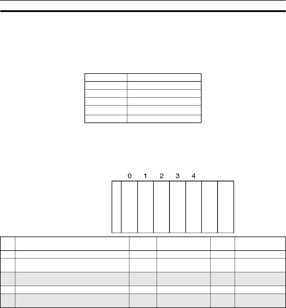
381
I/O Allocation Methods Section 8-2
8-2-3 I/O Allocations to CPU Bus Units
Each CPU Bus Unit is allocated 25 words in the CPU Bus Unit Area
(CIO 1500 to CIO 1899) according the unit number set on the Unit. CPU Bus
Units can be mounted to the CPU Rack or CS-series Expansion Racks.
Word Allocations The following table shows which words in the CS-series CPU Bus Unit Area
are allocated to each Unit.
CS-series CPU Bus Units are ignored during I/O allocation to Basic I/O Units.
Slots containing CS-series CPU Bus Units are treated as empty slots and
aren’t allocated any words in the I/O Area.
Example The following example shows the I/O word allocation to Basic I/O Units, Spe-
cial I/O Units, and CS-series CPU Bus Units in the CPU Rack.
8-2-4 I/O Allocations to SYSMAC BUS Slave Racks
Each SYSMAC BUS Remote I/O Slave Rack is allocated 10 words in the
SYSMAC BUS Area (CIO 3000 to CIO 3079) according the unit number (0 to
7) set on the Slave Unit. No words in the I/O Area are allocated to Units in
Slave Racks.
Each slot in the Slave Rack is allocated one of the Rack’s 10 words. The
words are allocated from left to right. One word is allocated to every slot even
if the slot is empty and the last two words allocated to each Rack are not used
because the Slave Racks have only 8 slots.
The Master and Slave Units themselves do not require any words.
Unit number Words allocated
0 CIO 1500 to CIO 1524
1 CIO 1525 to CIO 1549
2 CIO 1550 to CIO 1574
::
15 CIO 1875 to CIO 1899
CPU Rac
k
IN
16
CIO
0000
Special
I/O
Unit
CIO
2000
to
2009
CPU
Bus
Unit
CIO
1500
to
1521
OUT
16
CIO
0001
CPU
Bus
Unit
CIO
1525
to
1549
CPU Unit
Power Supply Unit
Slot Unit Words
required
Words allocated Unit
number
Group
0 C200H-ID212 16-point DC Input Unit 1 CIO 0000 --- Basic I/O Unit
1 C200H-ASC02/11/21/31 ASCII Unit 10 CIO 2000 to
CIO 2009
0 Special I/O Unit
2C200H-SCU21-V1 Serial Communications Unit 25 CIO 1500 to
CIO 1524
0CS-series CPU Bus
Unit
3 C200H-OD21A 16-point Transistor Output Unit 1 CIO 0001 --- Basic I/O Unit
4C200H-SCU21-V1 Serial Communications Unit 25 CIO 1525 to
CIO 1549
1CS-series CPU Bus
Unit
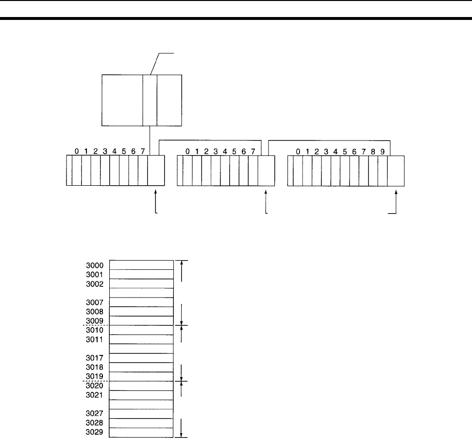
382
Allocating First Words to Racks Section 8-3
Example The following example shows the word allocation to 3 Slave Racks.
CIO 3000 to CIO 3079 can be used as work words/bits when a SYSMAC BUS
System is not being used. Also, even if a SYSMAC BUS System is used,
words that are not allocated in the SYSMAC BUS System, such as CIO 3030
to CIO 3079 in the above example, can be used as work bits/words.
8-3 Allocating First Words to Racks
In the CS-series PLCs, the first word allocated to each Rack can be set with
the CX-Programmer’s I/O table edit operation. For example, the CPU Rack
can be set to be allocated words starting with CIO 0000; the next Rack, words
starting with CIO 0100; the next Rack, words starting with CIO 0200; etc. This
can make it easier to check word allocations to Units without calculating all the
way from the CPU Rack.
Note The first words for Racks cannot be set at the same time as the first words for
slots.
Word Allocations For Racks in which the first word address has been set, words are allocated to
Units in the order that the Units are mounted (from left to right) beginning with
the specified first word. Words are not allocated to empty slots.
Remote I/O Slave Rack
Slave Unit with
unit number 0
SYSMAC BUS Remote I/O
SYSMAC BUS Remote I/O
Master Unit
Slave Unit with
unit number 2
Slave Unit with
unit number 1
Slave Unit with
unit number 0
Slave Unit with
unit number 1
Slave Unit with
unit number 2
Not used.
1
2
3
:
8
Not used.
9
10
:
16
17
18
19
20
:
26
Not used.
Not used.
1 2 3 4 5 6 7 8 19 20 21 22 23 24 25 26 9 10 11 12 13 14 15 16 17 18
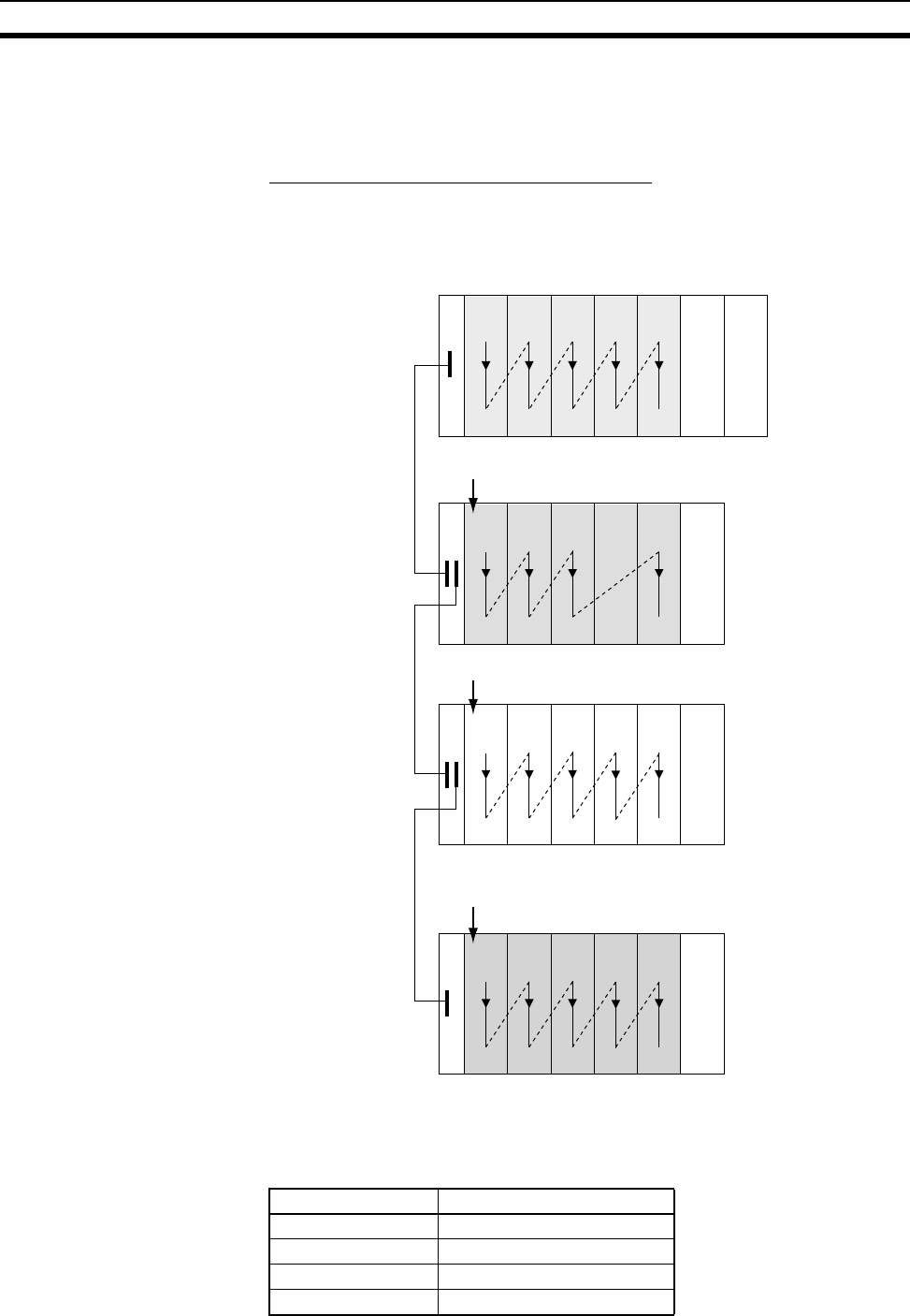
383
Allocating First Words to Racks Section 8-3
For Racks in which the first word address has not been set, words are allo-
cated in rack-number order (lowest to highest) continuing from the last word
allocated to the previous rack and starting with CIO 0000 on the first Rack for
which the first word is not set.
Example: Setting the First Words for Racks
In this example, the first words have been set for Racks 0 (the CPU Rack), 2,
and 3. For simplicity, only 16-bit Units have been used.
Rack First Word Settings
Rack First word
CPU Rack CIO 0100
Rack 1 CIO 0200
Rack 2 Not set
Rack 3 CIO 0300
CPU Rack
CIO
0100
CIO
0101
CIO
0102
CIO
0103 CIO
0104
CS Expansion Rack
CIO
0200
CIO
0201
CIO
0202
CS Expansion Rack
CIO
0000 CIO
0001
CIO
0002 CIO
0004
CS Expansion Rack
CIO
0300
CIO
0301
CIO
0302
Rack number 0
First word:
CIO 0100
Rack number 1
First word:
CIO 0200
CIO
0203
Rack number 2
No first word
setting
Rack number 3
First word:
CIO 0300
CIO
0304
Empty
CPU Unit
Power Supply Unit
Power Supply Unit
Power Supply Unit
Power Supply Unit
CIO
0003
CIO
0303
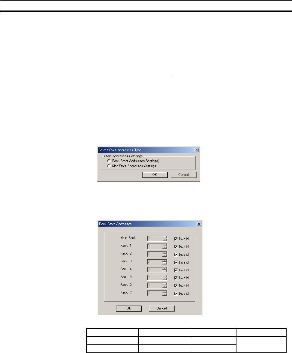
384
Allocating First Words to Racks Section 8-3
Note Rack numbers (0 to 7) are fixed according to the order that the Racks are
physically connected with cable. The CPU Rack is always Rack 0 and the
other Racks are, in order, Racks 1 to 7. These numbers cannot be changed.
In the above example, the shaded Racks are allocated words starting from the
specified first words. The non-shaded Racks are allocated in order from left to
right and in order of Rack starting from CIO 0000.
Setting First Rack Words from the CX-Programmer
The first word allocated on each Rack can be set from the CX-Programmer.
These settings are not possible from a Programming Console.
Note For CS1-H CPU Units, an indication of whether or not the first rack words
have been set will be displayed on a Programming Console.
Use the following procedure to set the first rack words.
1,2,3... 1. Select the Rack/Slot Start Addresses from the Option Menu on the I/O
Table Window. The following dialog box will be displayed.
2. Select the Rack Start Addresses Settings Option and click the OK Button.
3. In the dialog box that will appear, remove the checkmarks from the settings
disabling the first rack word settings and set the address of the first words
for the CPU Rack and Expansion Racks (1 to 7).
4. Click the OK Button.
Note Up to 8 Racks can be set for any CPU Unit model.
Setting Setting range Default Remarks
Rack Start Address 0 to 9000 0 Same for all Racks
Invalid Selected or cleared Selected (invalid)

385
Allocating First Words to Slots Section 8-4
Confirming First Rack Word Settings on a Programming Console
With a CS1-H CPU Unit, the Programming Console can be used to check
whether or not the first word has been set on a Rack. Use the following proce-
dure.
1,2,3... 1. Press the FUN, SHIFT, and CH Keys to start the I/O table creation opera-
tion. If the first work for a Rack has been set, a message saying so will ap-
pear on the second line of the display.
If nothing is displayed, then a first word has not been set.
2. Press the CHG Key, enter the password (9713), and then press the
WRITE Key to continue creating the I/O tables, or press the CLR Key to
cancel the operation and return to the initial display.
Precautions in Setting Rack First Words
• Be sure to make first word settings so that allocated words do not overlap.
The first word setting for a rack can be any address from CIO 0000 to
CIO 0900. If the same word is allocated to two Racks, the I/O tables can-
not be created and the Duplication Error Flag (A26103) in the I/O Table
Error Information will turn ON.
• Always register the I/O table after installing an I/O Unit, after setting a rack
number, or after setting the first word allocation for a Rack. The I/O Table
Registration operation registers the I/O words allocated to the Racks.
• I/O words will not be allocated to empty slots. If an I/O Unit will be
installed later, reserve words for the empty slot by changing the I/O table
with a Programming Device’s I/O Table Change Operation.
• If the actual system configuration is changed after registering the I/O table
so that the number of words or I/O type does not match the I/O table, an
I/O verification error (A40209) or I/O setting error (A40110) will occur. A
CS-series CPU Bus Unit Setting Error (A40203) or Special I/O Unit Set-
ting Error (A40202) may occur as well.
• When a Unit is removed, words can be reserved for the missing Unit using
the I/O Table Change Operation. If a Unit is changed or added, all of the
words in the program following that Unit’s allocated words will be changed
and the I/O Table Registration Operation will have to be performed again.
8-4 Allocating First Words to Slots
In the CS-series PLCs, the first word allocated to a slot on any Rack can be
set with the CX-Programmer’s I/O table edit operation regardless of the posi-
tion of the slot. This feature can be used whenever it’s necessary to control
allocations to specific Units, e.g., to group allocated I/O words by device or cir-
cuit.
The first word can be set for up to 64 slots.
Note The first words for slots cannot be set at the same time as the first words for
Racks.
Word Allocations When setting first words for slots, the first word must be set for slot 00 on the
CPU Rack. The first word can then be set for any slot on any Rack for up to 63
other slots.
FUN SHIFT CH
*DM
000000I/O TBL ?
Rack 1st Word En
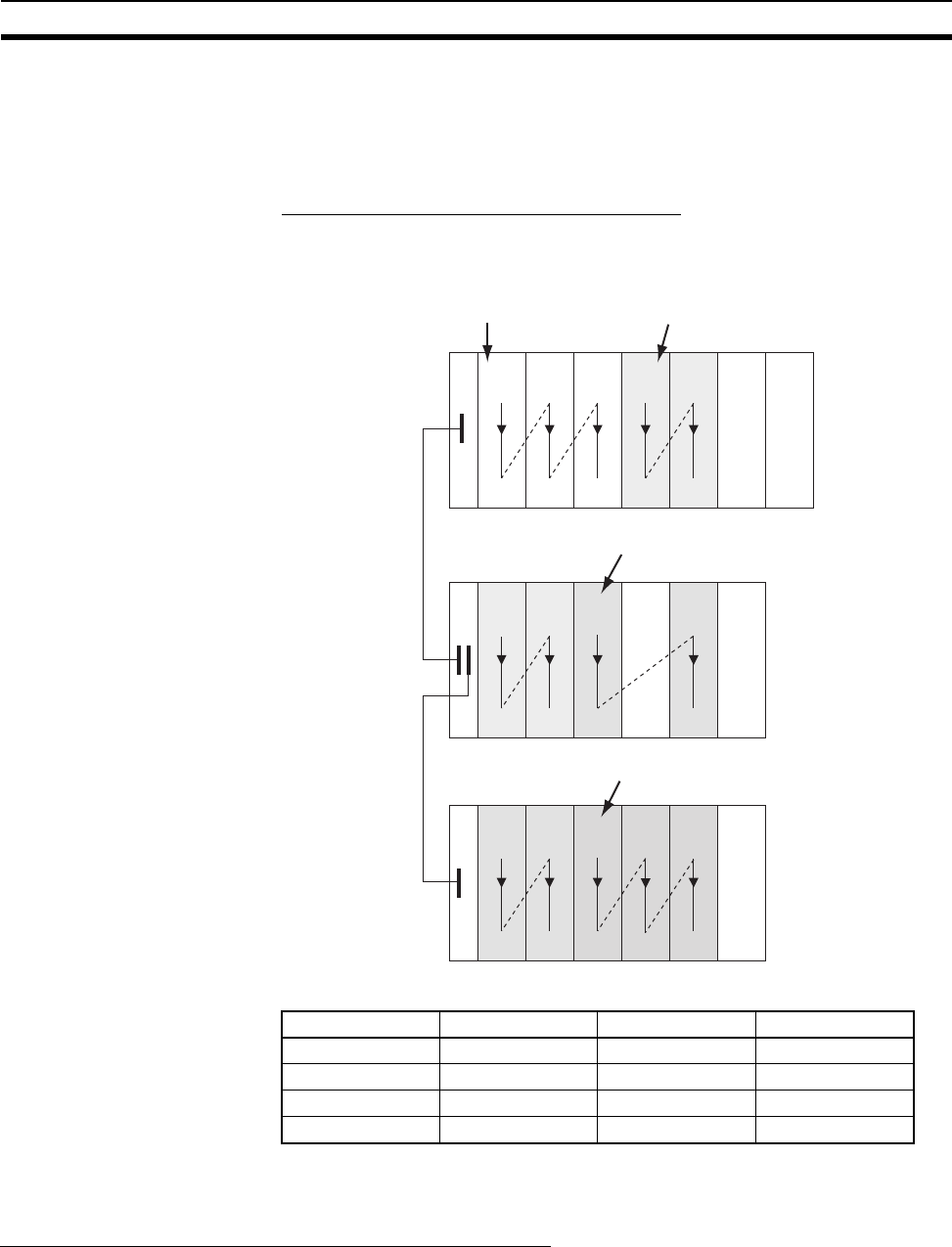
386
Allocating First Words to Slots Section 8-4
Each first word set for a slot creates a group starting with that slot. Words are
allocated starting from the specified word to the first slot in the group and con-
tinuing left to right allocating consecutive words to each Unit until the next
group (i.e., until the next Unit for which a first slot word is set). The next group
can start on the same Rack or on a following Rack.
Example: Setting the First Words for Racks
In this example, a first slot word has been set in the middle of each Rack. For
simplicity, only 16-bit Units have been used.
First Slot Word Settings
Note Group 00 must start at slot 00 on the CPU Rack. Any word can be set. Any
slot can be set on any Rack for groups 01 to 63.
Setting First Slot Words from the CX-Programmer
First slot words can be set from the CX-Programmer. These settings are not
possible from a Programming Console.
Note For CS1-H CPU Units, an indication of whether or not the first rack words
have been set will be displayed on a Programming Console.
Use the following procedure to set the first rack words.
Group Rack Slot Word
00 CPU Rack 00 CIO 0000
01 CPU Rack 03 CIO 0100
02 Rack 1 02 CIO 0200
03 Rack 2 02 CIO 0300
01234
01234
01234
CPU Rack
CIO
0000 CIO
0001 CIO
0002
CIO
0100 CIO
0101
CS Expansion Rac
k
CIO
0102 CIO
0103 CIO
0200
CS Expansion Rack
CIO
0202 CIO
0203 CIO
0300 CIO
0302
Rack number 0
CIO
0201
Empty
CPU Unit
Power Supply Unit
Power Supply Unit
Power Supply Unit
CIO
0301
Group 00 set for first
slot word of CIO 0000
Group 01 set for first
slot word of CIO 0200
Group 02 set for first slot word of CIO 0200
Group 03 set for first slot word of CIO 0300
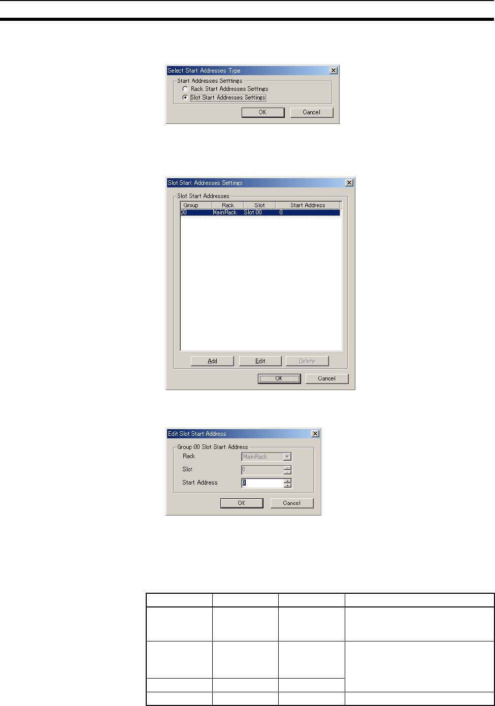
387
Allocating First Words to Slots Section 8-4
1,2,3... 1. Select the Rack/Slot Start Addresses from the Option Menu on the I/O
Table Window. The following dialog box will be displayed.
2. Select the Slot Start Addresses Settings Option and click the OK Button.
3. In the dialog box that will appear, set the first word for slot 00 on the CPU
Rack.
4. To change the setting from CIO 0000, click the Edit Button. The follow di-
alog box will appear.
5. Set the desired word and click the OK Button.
6. To set slot first words for other groups, click the Add Button and make the
appropriate settings for the Rack, slot, and word.
Up to 64 groups can be set for the CS/CJ-series CPU Unit Ver. 2.0. Only 8
groups can be set for the CS/CJ-series CPU Unit Ver. 1.0
Setting Setting range Default Remarks
Group 00 to 63 00 Groups numbers are allocated
automatically in the order the
groups are displayed and set.
Rack CPU Rack
(“MainRack”)
Racks 1 to 7
CPU Rack Group 00 always starts at slot 00
on the CPU Rack.
Slot 00 to 99 0
First word 0 to 999 0 ---

388
Detailed Information on I/O Table Creation Errors Section 8-5
Precautions in Setting First Slot Words
When the I/O tables are edited, the CX-Programmer checks for any duplica-
tions in word allocations caused by first word settings. It is conceivable, how-
ever, that duplications in word allocations could occur after the I/O tables have
been registered, e.g., as the result of replacing a 1-word Unit with a 2-word
Unit. In this case the extra word needed by the new Unit would still also be
allocated to the next Unit.
When the PLC is turned ON, the CPU Unit checks the registered I/O tables
against the actual Units mounted to the PLC. If there are any duplications, and
error will occur and it will be no longer possible to edit the I/O tables. If this
happens, the I/O tables will have to be deleted and recreated or retransferred
from a Programming Devices.
8-5 Detailed Information on I/O Table Creation Errors
With a CS1-H CPU Unit, the contents of A261 provides information on the
Unit causing the error whenever one occurs when creating the I/O tables from
the Programming Console or CX-Programmer. This information will make it
easier to find the Unit causing the problem with troubleshooting I/O tables.
Refer to SECTION 11 Troubleshooting for actual procedures.
8-6 Data Exchange with CPU Bus Units
This section describes how data can be exchanged between Special I/O Units
or CS-series CPU Bus Units, and the CPU Unit.
8-6-1 Special I/O Units
Special I/O Units include C200H Special I/O Units and CS-series Special I/O
Units. Data can be exchanged between Special I/O Units and the CPU Unit
through the Special I/O Unit Area, the DM Area, or FINS commands.
Special I/O Unit Area
(I/O Refreshing)
Data is exchanged each cycle during I/O refreshing of the Special I/O Unit
Area. Basically, 10 words are allocated to each Special I/O Unit based on its
unit number setting. The number of words actually used by the Special I/O
Unit varies; there are models that require 2 words, 4 words, and 20 words.
Name Address Contents When
changing
to RUN
mode
At
startup
Setting
timing
Word Bit
CPU Bus Unit Setup
Area Initialization
Error Flag
A261 00 ON: Error in CPU Bus Unit Setup
Turns OFF when I/O tables are generated normally.
Held Cleared When I/O
tables are
created
I/O Overflow Flag 02 ON: Overflow in maximum number of I/O points.
Turns OFF when I/O tables are generated normally.
Duplication Error Flag 03 ON: The same unit number was used more than
once.
Turns OFF when I/O tables are generated normally.
I/O Bus Error Flag 04 ON: I/O bus error
Turns OFF when I/O tables are generated normally.
SYSMAC BUS Recog-
nition Error Flag
06 ON: SYSMAC BUS detection ended in an error.
Turns OFF when I/O tables are generated normally.
Special I/O Unit Error
Flag
07 ON: Error in a Special I/O Unit
Turns OFF when I/O tables are generated normally.
I/O Unconfirmed Error
Flag
09 ON: I/O detection has not been completed.
Turns OFF when I/O tables are generated normally.
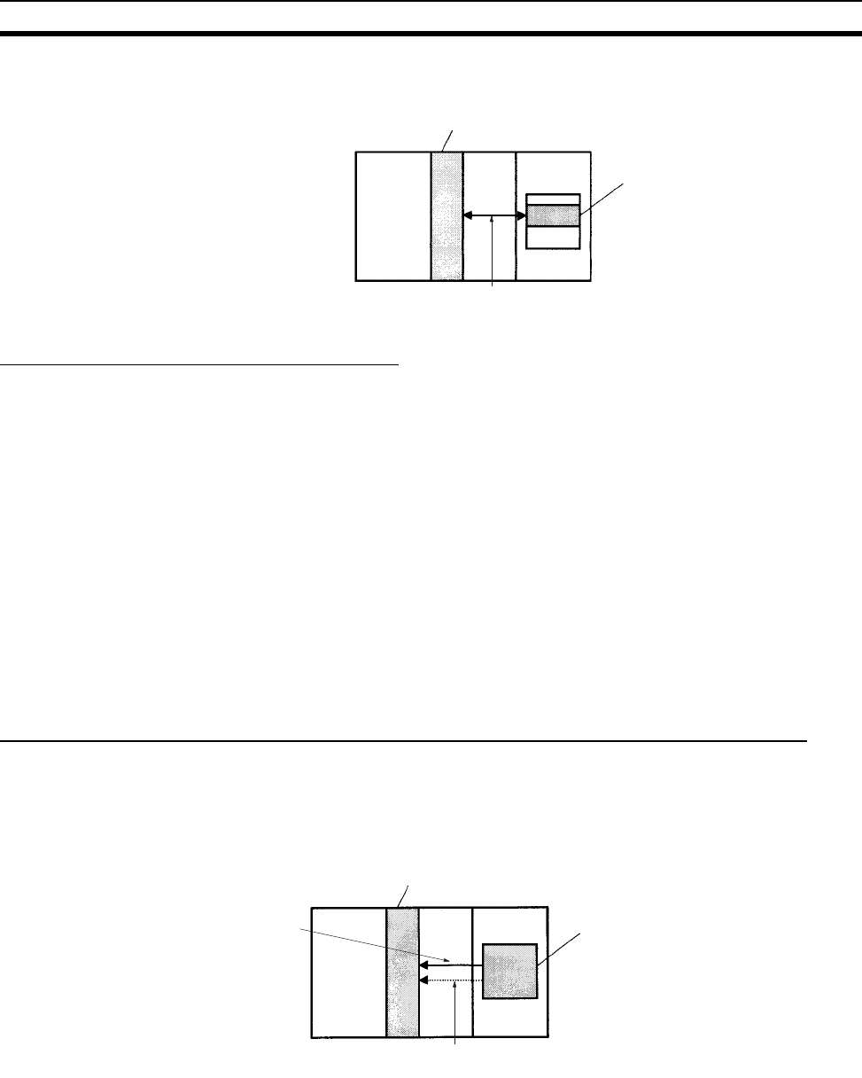
389
Data Exchange with CPU Bus Units Section 8-6
The Special I/O Unit Area ranges from CIO 2000 to CIO 2959 (10 words × 96
Units).
Transfer of Words Allocated in DM Area
C200H Special I/O Units The 100 words allocated to each Unit are transferred from the DM Area to the
Unit when the PLC is turned on or the Unit is restarted. Some C200H Special
I/O Units do not use any of the allocated DM words and others use only a part
of the allocated words.
CS-series Special I/O
Units
There are three times that data may be transferred through the words allo-
cated to each Unit. The timing of data transfers depends on the model being
used.
1,2,3... 1. Data transferred when the PLC is turned on.
2. Data transferred when the Unit is restarted.
3. Data transferred when necessary.
Some models transfer data in both directions, from the DM Area to the Unit
and from the Unit to the DM Area. See the Unit’s Operation Manual for details
on data transfers.
Special I/O Unit Words in the DM Area: D20000 to D29599 (100 Words x 96 Units)
Each Special I/O Unit is allocated 100 words in the DM Area in the range of
D20000 to D29599 (100 words × 96 Units). These 100 words are generally
used to hold initial settings for the Special I/O Unit. When the contents of this
area are changed from the program to reflect a change in the system, the
Restart Bits for affected Units must be turned ON to restart the Units.
Special I/O Unit
CPU Unit
Transferred in
I/O refreshin
g
Special I/O Unit Area
10 words/Unit
Special I/O Unit
CPU Unit
Transferred when power is turned
on or the Unit is restarted. DM Area for Special I/O Units
100 words/Unit
Transferred each cycle
and when necessary.
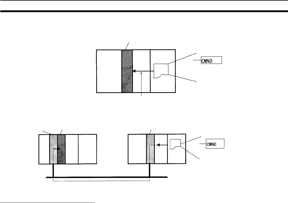
390
Data Exchange with CPU Bus Units Section 8-6
FINS Commands The CMND(490) instruction can be added to the ladder program to issue a
FINS command to the Special I/O Unit.
FINS commands can be transmitted to Special I/O Units in other PLCs in the
network, not just the local PLC.
Special I/O Unit Initialization
Special I/O Units are initialized when the PLC’s power is turned on or the
Unit’s Restart Bit is turned ON. The Unit’s Special I/O Unit Initialization Flag
(A33000 to A33515) will be ON while the Unit is initializing.
I/O refreshing (cyclic I/O refreshing or refreshing by IORF(097)) will not be
performed for a Special I/O Unit while its Initialization Flag is ON.
8-6-2 Disabling Special I/O Unit Cyclic Refreshing
Ten words are allocated to each Special I/O Unit in the Special I/O Unit Area
(CIO 2000 to CIO 2959) based on the unit number set on the front of each
Unit. The data in the Special I/O Unit Area is refreshed in the CPU Unit every
cycle during I/O refreshing (just after execution of the END(001) instruction).
I/O refreshing may take too long if too many Special I/O Units are installed. If
I/O refreshing is taking too much time, the PLC Setup can be set to disable
cyclic refreshing for particular Special I/O Units. (The Special I/O Unit Cyclic
Refreshing Disable Bits are in PLC Setup addresses 226 to 231.)
If the I/O refreshing time is too short, the Unit’s internal processing will not be
able to keep pace, the Special I/O Unit Error Flag (A40206) will be turned ON,
and the Special I/O Unit may not operate properly. In this case, the cycle time
can be extended by setting a minimum cycle time in the PLC Setup or cyclic
I/O refreshing with the Special I/O Unit can be disabled. When cyclic refresh-
ing has been disabled, the Special I/O Unit’s data can be refreshed during
program execution with IORF(097).
Note 1. Always disable a Special I/O Unit’s cyclic refreshing if the Unit’s I/O will be
refreshed in an interrupt task with IORF(097). An interrupt task error
(A40213) will occur if cyclic refreshing and IORF(097) refreshing are per-
formed simultaneously.
2. Whenever disabling a Special I/O Unit’s cyclic refreshing, be sure that the
I/O for that Unit is refreshed with IORF(097) in the program at least every
Special I/O Unit
CPU Unit
The FINS command is transmitted
when CMND(490) has been
executed in the program.
FINS command transmission
Special I/O Unit
CPU Unit
The FINS command is transmitted
when CMND(490) has been
executed in the program.
FINS command transmission
Serial Communications
Unit CPU Unit
Serial Communications Unit
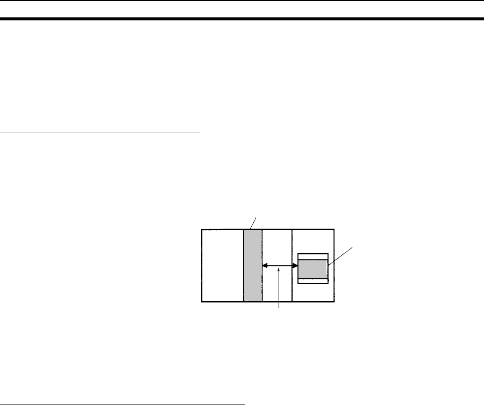
391
Data Exchange with CPU Bus Units Section 8-6
11 seconds during operation. A CPU Unit service monitoring error will oc-
cur in the Special I/O Unit if it is not refreshed every 11 seconds.
8-6-3 CPU Bus Units
Data can be exchanged between CPU Bus Units and the CPU Unit through
the CPU Bus Unit Area, the DM Area, or FINS commands.
CPU Bus Unit Area (I/O Refreshing)
Data is exchanged each cycle during I/O refreshing of the CPU Bus Unit Area.
Basically, 25 words are allocated to each CPU Bus Unit based on its unit num-
ber setting. The number of words actually used by the CPU Bus Unit varies.
The Special I/O Unit Area ranges from CIO 1500 to CIO 1899 (25 words × 16
Units).
Note With CS1-H CPU Units, the CPU BUS I/O REFRESH instruction
(DLNK(226)) can be executed in the ladder program to refresh the
CIO Area words allocated to the CPU Bus Unit of a specified unit
number.
Transfer of Words Allocated in the DM Area
Each CPU Bus Unit is allocated 100 words in the DM Area in the range of
D30000 to D31599 (100 words × 16 Units). There are three times that data
may be transferred through the words allocated to each Unit. The timing of
data transfers depends on the model being used.
1,2,3... 1. Data transferred when the PLC is turned ON.
2. Data transferred each cycle.
3. Data transferred when necessary.
Note With CS1-H CPU Units, the CPU BUS I/O REFRESH instruction
(DLNK(226)) can be executed in the ladder program to refresh the
DM Area words allocated to the CPU Bus Unit of a specified unit
number.
Some models transfer data in both directions, from the DM Area to the Unit
and from the Unit to the DM Area. See the Unit’s Operation Manual for details
on data transfers.
These 100 words are generally used to hold initial settings for the CPU Bus
Unit. When the contents of this area are changed from the program to reflect a
change in the system, the Restart Bits (A50100 to A50115) for affected Units
must be turned ON to restart the Units.
CPU Bus Unit
CPU Unit
CPU Bus Unit Area
25 words/Unit
Transferred in
I/O refreshing
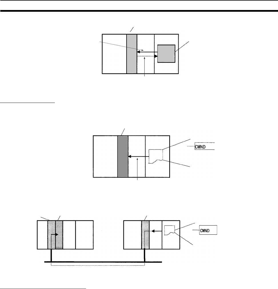
392
Data Exchange with CPU Bus Units Section 8-6
FINS Commands
The CMND(490) instruction can be added to the ladder program to issue a
FINS command to the CPU Bus Unit.
FINS commands can be transmitted to CPU Bus Units in other PLCs in the
network, not just the local PLC.
CPU Bus Unit Initialization
CPU Bus Units are initialized when the PLC’s power is turned on or the Unit’s
Restart Bit is turned ON. The Unit’s CPU Bus Unit Initialization Flag (A30200
to A30215) will be ON while the Unit is initializing.
Cyclic I/O refreshing will not be performed for a CPU Bus Unit while its Initial-
ization Flag is ON.
CPU Bus Unit
CPU Unit
Transferred when power is turned
on or the Unit is restarted.
Transferred each cycle
and when necessary.
DM Area for CPU Bus Units
100 words/Unit
CPU Bus Unit
CPU Unit
The FINS command is transmitted
when CMND(490) has been
executed in the program.
FINS command transmission
CPU Bus Unit
CPU Unit
The FINS command is transmitted
when CMND(490) has been
executed in the program.
Command transmission
Serial Communications
Unit CPU Unit
Serial Communications Unit
393
SECTION 9
Memory Areas
This section describes the structure and functions of the I/O Memory Areas and Parameter Areas.
9-1 Introduction. . . . . . . . . . . . . . . . . . . . . . . . . . . . . . . . . . . . . . . . . . . . . . . . . . . 394
9-2 I/O Memory Areas . . . . . . . . . . . . . . . . . . . . . . . . . . . . . . . . . . . . . . . . . . . . . 395
9-2-1 I/O Memory Area Structure . . . . . . . . . . . . . . . . . . . . . . . . . . . . . . . 395
9-2-2 Overview of the Data Areas . . . . . . . . . . . . . . . . . . . . . . . . . . . . . . . 398
9-2-3 Data Area Properties. . . . . . . . . . . . . . . . . . . . . . . . . . . . . . . . . . . . . 403
9-3 Precautions in Using C200H Special I/O Units . . . . . . . . . . . . . . . . . . . . . . . 404
9-4 CIO Area . . . . . . . . . . . . . . . . . . . . . . . . . . . . . . . . . . . . . . . . . . . . . . . . . . . . . 405
9-5 C200H DeviceNet Area . . . . . . . . . . . . . . . . . . . . . . . . . . . . . . . . . . . . . . . . . 411
9-6 CS-series DeviceNet Area. . . . . . . . . . . . . . . . . . . . . . . . . . . . . . . . . . . . . . . . 412
9-7 PLC Link Area . . . . . . . . . . . . . . . . . . . . . . . . . . . . . . . . . . . . . . . . . . . . . . . . 414
9-8 Data Link Area . . . . . . . . . . . . . . . . . . . . . . . . . . . . . . . . . . . . . . . . . . . . . . . . 416
9-9 CPU Bus Unit Area. . . . . . . . . . . . . . . . . . . . . . . . . . . . . . . . . . . . . . . . . . . . . 417
9-10 Inner Board Area. . . . . . . . . . . . . . . . . . . . . . . . . . . . . . . . . . . . . . . . . . . . . . . 418
9-11 Special I/O Unit Area . . . . . . . . . . . . . . . . . . . . . . . . . . . . . . . . . . . . . . . . . . . 419
9-12 SYSMAC BUS Area. . . . . . . . . . . . . . . . . . . . . . . . . . . . . . . . . . . . . . . . . . . . 421
9-13 I/O Terminal Area . . . . . . . . . . . . . . . . . . . . . . . . . . . . . . . . . . . . . . . . . . . . . . 422
9-14 Work Area . . . . . . . . . . . . . . . . . . . . . . . . . . . . . . . . . . . . . . . . . . . . . . . . . . . . 423
9-15 Holding Area. . . . . . . . . . . . . . . . . . . . . . . . . . . . . . . . . . . . . . . . . . . . . . . . . . 424
9-16 Auxiliary Area. . . . . . . . . . . . . . . . . . . . . . . . . . . . . . . . . . . . . . . . . . . . . . . . . 425
9-17 TR (Temporary Relay) Area . . . . . . . . . . . . . . . . . . . . . . . . . . . . . . . . . . . . . . 448
9-18 Timer Area . . . . . . . . . . . . . . . . . . . . . . . . . . . . . . . . . . . . . . . . . . . . . . . . . . . 449
9-19 Counter Area. . . . . . . . . . . . . . . . . . . . . . . . . . . . . . . . . . . . . . . . . . . . . . . . . . 450
9-20 Data Memory (DM) Area . . . . . . . . . . . . . . . . . . . . . . . . . . . . . . . . . . . . . . . . 451
9-21 Extended Data Memory (EM) Area . . . . . . . . . . . . . . . . . . . . . . . . . . . . . . . . 453
9-22 Index Registers . . . . . . . . . . . . . . . . . . . . . . . . . . . . . . . . . . . . . . . . . . . . . . . . 455
9-23 Data Registers . . . . . . . . . . . . . . . . . . . . . . . . . . . . . . . . . . . . . . . . . . . . . . . . . 461
9-24 Task Flags . . . . . . . . . . . . . . . . . . . . . . . . . . . . . . . . . . . . . . . . . . . . . . . . . . . . 463
9-25 Condition Flags . . . . . . . . . . . . . . . . . . . . . . . . . . . . . . . . . . . . . . . . . . . . . . . . 463
9-26 Clock Pulses . . . . . . . . . . . . . . . . . . . . . . . . . . . . . . . . . . . . . . . . . . . . . . . . . . 466
9-27 Parameter Areas . . . . . . . . . . . . . . . . . . . . . . . . . . . . . . . . . . . . . . . . . . . . . . . 467
9-27-1 PLC Setup. . . . . . . . . . . . . . . . . . . . . . . . . . . . . . . . . . . . . . . . . . . . . 467
9-27-2 Registered I/O Table . . . . . . . . . . . . . . . . . . . . . . . . . . . . . . . . . . . . . 467
9-27-3 Routing Table . . . . . . . . . . . . . . . . . . . . . . . . . . . . . . . . . . . . . . . . . . 468
9-27-4 CPU Bus Unit Settings . . . . . . . . . . . . . . . . . . . . . . . . . . . . . . . . . . . 468
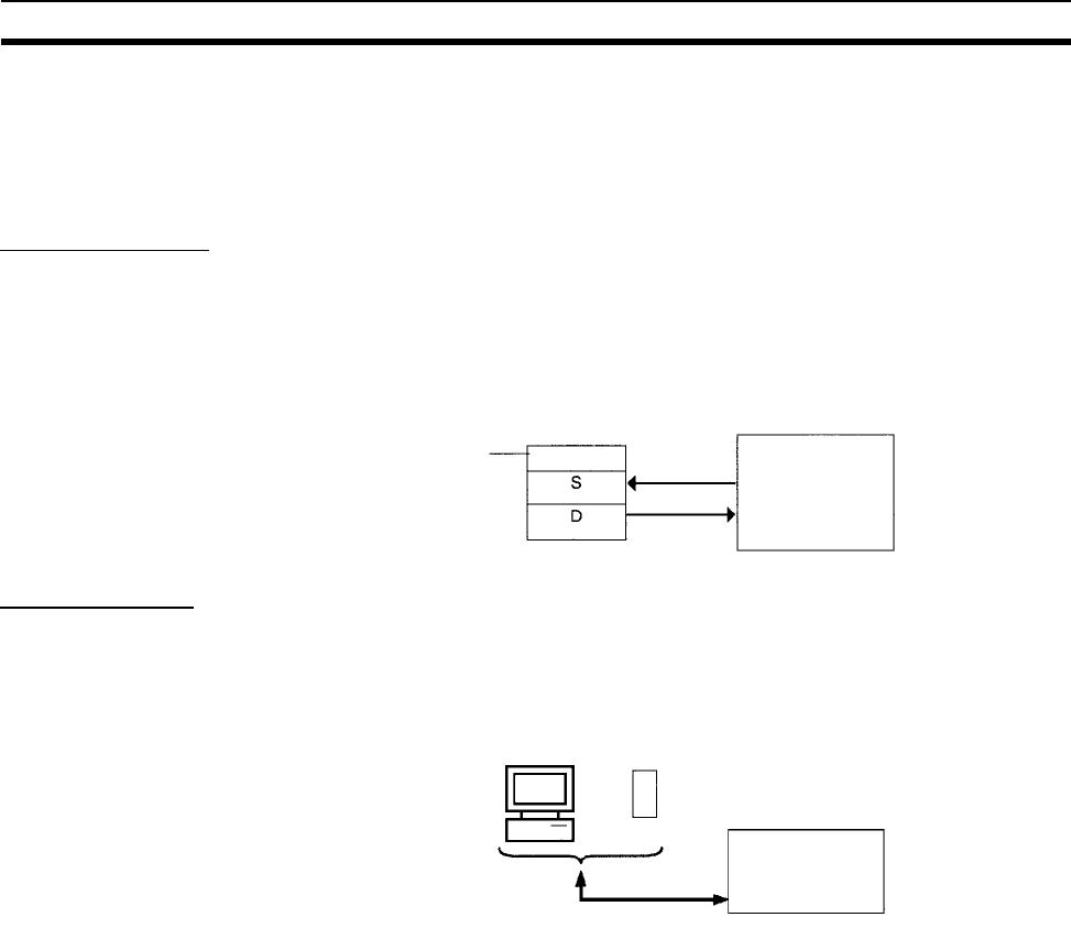
394
Introduction Section 9-1
9-1 Introduction
The CPU Unit’s memory (RAM with battery back-up) can be divided into three
parts: the User Program Memory, I/O Memory Area, and Parameter Area.
This section describes the I/O Memory Area and Parameter Area.
I/O Memory Area
This region of memory contains the data areas which can be accessed by
instruction operands. The data areas include the CIO Area, Work Area, Hold-
ing Area, Auxiliary Area, DM Area, EM Area, Timer Area, Counter Area, Task
Flag Area, Data Registers, Index Registers, Condition Flag Area, and Clock
Pulse Area.
Parameter Area
This region of memory contains various settings that cannot be specified by
instruction operands; they can be specified from a Programming Device only.
The settings include the PLC Setup, I/O Table, Routing Table, and CPU Bus
Unit settings.
Instruction I/O Memory Area
Programming Device
Parameter Area
Programming Device
Parameter Area

395
I/O Memory Areas Section 9-2
9-2 I/O Memory Areas
9-2-1 I/O Memory Area Structure
The following table shows the basic structure of the I/O Memory Area.
Area Size Range Exter-
nal I/O
alloca-
tion
Bit
access
Word
access
Access Change
from
Pro-
gram-
ming
Device
Status at
startup
or mode
change
Forcing
bit sta-
tus
Read Write
CIO
Area
I/O Area 5,120
bits (320
words)
CIO 0000
to
CIO 0319
(See note
1.)
Basic I/O
Units
OK OK OK OK OK Cleared
(See note
5.)
OK
C200H
DeviceNet
Words
1,600
bits (100
words)
Outputs:
CIO 0050
to
CIO 0099
Inputs:
CIO 0350
to
CIO 0399
(See note
2.)
Device-
Net
Slaves
OK OK OK OK OK OK
PLC Link
Words
32 bits (4
words)
CIO 0247
to
CIO 0250
A442
--- OK OK OK OK OK OK
Data Link
Area
3,200
bits (200
words)
CIO 1000
to
CIO 1199
Data link
or PLC
Link
OK OK OK OK OK OK
CPU Bus
Unit Area
6,400
bits (400
words)
CIO 1500
to
CIO 1899
CPU Bus
Units
OK OK OK OK OK OK
Special I/O
Unit Area
15,360
bits (960
words)
CIO 2000
to
CIO 2959
Special
I/O Units
OK OK OK OK OK OK
Inner Board
Area
1,600
bits (100
words)
CIO 1900
to
CIO 1999
Inner
Boards
OK OK OK OK OK OK
SYSMAC
BUS Area
1,280
bits (80
words)
CIO 3000
to
CIO 3079
(See note
8.)
Slave
Racks
OK OK OK OK OK OK
I/O Terminal
Area
512 bits
(32
words)
CIO 3100
to
CIO 3131
(See note
9.)
Slaves
other
than
Racks
OK OK OK OK OK OK
CS-series
DeviceNet
Area
9,600
bits (600
words)
CIO 3200
to
CIO 3799
Device-
Net
Slaves
OK OK OK OK OK OK
Internal I/O
Areas
37,504
bits
(2,344
words)
4,800
bits (300
words)
CIO 1200
to
CIO 1499
CIO 3800
to
CIO 6143
--- OK OK OK OK OK OK
Work Area 8,192
bits (512
words)
W000 to
W511
--- OK OK OK OK OK OK
Holding Area (See
note 10.)
8,192
bits (512
words)
H000 to
H511
--- OK OK OK OK OK Main-
tained
OK

396
I/O Memory Areas Section 9-2
Note 1. The I/O Area can be expanded to CIO 0000 to CIO 0999 by changing the
first words allocated to Racks.
2. C200H DeviceNet Words are used for fixed allocations by the C200H De-
viceNet Master Unit (C200HW-DRM21-V1). The CS-series DeviceNet Unit
(CS1W-DRM21) does not use this same area for fixed allocations, but rath-
er uses the CS-series DeviceNet Area (CIO 3200 to CIO 3799).
3. Bits can be manipulated using TST(350), TSTN(351), SETB(532),
RSTB(533), OUTB(534).
4. Index registers and data registers can be used either individually by task
or they can be shared by all the tasks (CS1-H CPU Units only).
5. If the I/O Memory Hold Bit (A50012) is turned ON, the contents of these
areas will be maintained when the operating mode is changed. If in addi-
tion the IOM Hold Bit is selected under Startup Hold in the PLC Setup, the
contents of these areas will be maintained when the power supply is turned
ON.
6. Timer PVs can be refreshed indirectly by forced setting/resetting the Timer
Completion Flag.
7. Counter PVs can be refreshed indirectly by forced setting/resetting
Counter Completion Flags.
8. These words can be used as work words/bits when SYSMAC BUS Slaves
are not used.
9. These words can be used as work words/bits when I/O Terminals are not
used.
Auxiliary Area 15,360
bits (960
words)
A000 to
A447
--- OK OK OK No No Varies
from
address
to
address.
No
A448 to
A959
OK OK
TR Area 16 bits TR0 to
TR15
--- OK --- OK OK No Cleared No
DM Area 32,768
words
D00000 to
D32767
--- No (See
note 3.)
OK OK OK OK Main-
tained
No
EM Area 32,768
words
per bank
(0 to C,
13 max.)
E0_00000
to
EC_32767
--- No (See
note 3.)
OK OK OK OK Main-
tained
No
Timer Completion
Flags
4,096
bits
T0000 to
T4095
--- OK --- OK OK OK Cleared
(See note
5.)
OK
Counter Completion
Flags
4,096
bits
C0000 to
C4095
--- OK --- OK OK OK Main-
tained
OK
Timer PVs 4,096
words
T0000 to
T4095
--- --- OK OK OK OK Cleared
(See note
5.)
No (See
note 6.)
Counter PVs 4,096
words
C0000 to
C4095
--- --- OK OK OK OK Main-
tained
No (See
note 7.)
Task Flag Area 32 bits TK00 to
TK31
--- OK --- OK No No Cleared No
Index Registers (See
note 4.)
16 regis-
ters
IR0 to
IR15
--- OK OK Indirect
address-
ing only
Specific
instruc-
tions
only
No Cleared
(See note
5.)
No
Data Registers (See
note 4.)
16 regis-
ters
DR0 to
DR15
--- No OK OK OK No Cleared
(See note
5.)
No
Area Size Range Exter-
nal I/O
alloca-
tion
Bit
access
Word
access
Access Change
from
Pro-
gram-
ming
Device
Status at
startup
or mode
change
Forcing
bit sta-
tus
Read Write

397
I/O Memory Areas Section 9-2
10. The Function Block Holding Area words are allocated from H512 to H1535.
These words can be used only for the function block instance area (inter-
nally allocated variable area).
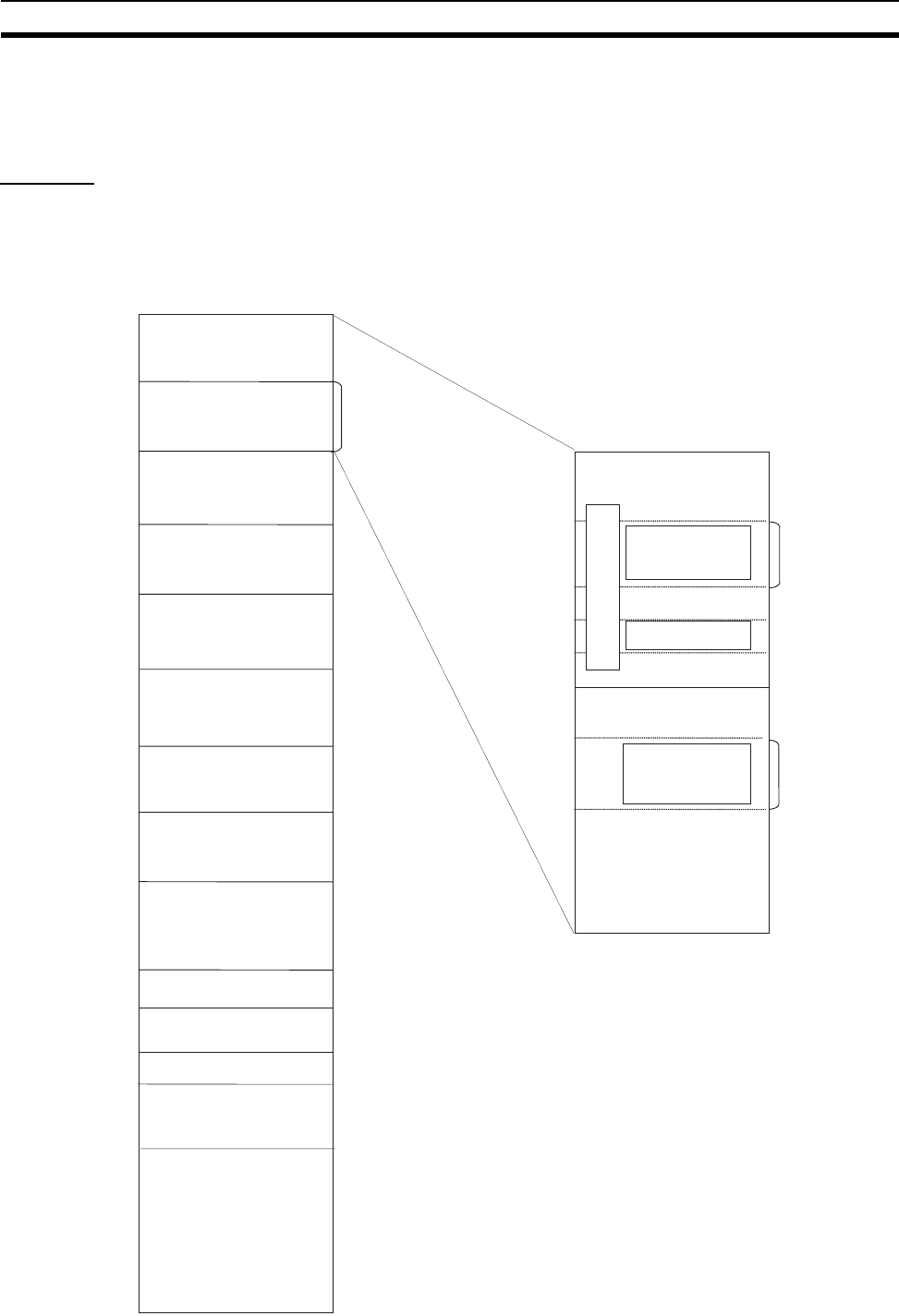
398
I/O Memory Areas Section 9-2
9-2-2 Overview of the Data Areas
The data areas in the CS-series I/O Memory Area are described in detail
below.
CIO Area
It isn’t necessary to input the “CIO” acronym when specifying an address in
the CIO Area. The CIO Area is generally used for data exchanges such as I/O
refreshing with various Units. Words that aren’t allocated to Units may be
used as work words and work bits in the program only.
I/O Area
Data Link Area
Internal I/O Area
CS1 CPU Bus Unit Area
(25 words/Unit)
Inner Board Area
Special I/O Unit Area
(10 words/Unit)
(Not used.)
SYSMAC BUS Area
(Not used.)
I/O Terminal Area
Word
(Not used.)
DeviceNet Area
(Outputs)
DeviceNet Area
(Input)
CIO 0000
CIO 0050
CIO 0099
CIO 0399
CIO 0400
CIO 0999
PLC Link Area
CIO 0247
CIO 0250
CIO 0349
CIO 0350
Internal I/O Area
(Not used.)
CIO 0319
CIO 0320
Bit
15 0
See note 1.
See note 2.
See note 2.
(Not used.)
(Not used.)
15 0
Word
CIO 0319
(CIO 0320)
CIO 0000
(CIO 0999)
CIO 1000
CIO 1199
CIO 1200
CIO 1499
CIO 1500
CIO 1899
CIO 1900
CIO 1999
CIO 2000
CIO 2959
(CIO 2960)
(CIO 2999)
CIO 3000
CIO 3079
(CIO 3080)
(CIO 3099)
CIO 3100
CIO 3131
(CIO 3132)
(CIO 3799)
CIO 3800
CIO 6143
Bit
(CIO 3199)
CIO 3200
CS/CJ Series
DeviceNet Area
I/O Area

399
I/O Memory Areas Section 9-2
Note 1. It is possible to use CIO 0320 to CIO 0999 for I/O words by making the ap-
propriate settings for the first words on the Racks. Settings for the first
words on the Racks can be made using the CX-Programmer to set the first
Rack addresses in the I/O table. The settings range for the first Rack ad-
dresses is from CIO 0000 to CIO 0900.
2. When using a C200H DeviceNet Master Unit (C200HW-DRM21-V1), be
sure the same words are not allocated to both Basic I/O Units and De-
viceNet I/O.
3. The parts of the CIO Area that are labelled “Not used” may be used in pro-
gramming as work bits. In the future, however, unused CIO Area bits may
be used when expanding functions. Always use Work Area bits first.
I/O Area These words are allocated to external I/O terminals on Basic I/O Units. Words
that aren’t allocated to external I/O terminals may be used only in the pro-
gram.
C200H DeviceNet Area These words are allocated to Slaves for DeviceNet Remote I/O Communica-
tions for C200H DeviceNet Master Units (C200HW-DRM21-V1). Allocations
are fixed and cannot be changed. Be sure that allocates to not overlap with
those used for other I/O points.
The CS-series DeviceNet Unit (CS1W-DRM21) does not use this same area
for fixed allocations.
PLC Link Area When PLC Link Units are used to create a PLC Link system, the PLC Link
Area contains flags that indicate PLC Link errors and the operating status of
CPU Units in the PLC Link. CIO 247 to CIO 250 are equivalent to SR 247 to
SR 250 in the C200HX/HG/HE PLCs. (The PLC Link Operating Level Flags,
A44211 and A44212, are equivalent to AR 2411 and AR 2412 in the
C200HX/HG/HE PLCs.)
Link Area These words are used for data links in Controller Link Networks. Words that
aren’t used in data links may be used only in the program.
CPU Bus Unit Area These words are allocated to CPU Bus Units to transfer status information.
Each Unit is allocated 25 words and up to 16 Units (with unit numbers 0 to 15)
can be used. Words that aren’t used by CPU Bus Units may be used only in
the program.
Special I/O Unit Area These words are allocated to CS-series Special I/O Units and C200H Special
I/O Units. Each Unit is allocated 10 words and up to 96 Units (unit numbers 0
to 95) can be used. (C200H Special I/O Units are limited to unit numbers 0 to
F (15).)
Words that aren’t used by Special I/O Units may be used only in the program.
Inner Board Area These words are allocated to Inner Boards such as Communications Boards.
Up to 100 words can be allocated for input and output.
SYSMAC BUS Area These words are allocated to Slave Racks connected to SYSMAC BUS
Remote I/O Master Units. Each Rack is allocated 10 words and up to 8 Racks
(rack numbers 0 to 7) can be used. These words can be used as work
words/bits when SYSMAC BUS Slaves are not used.
I/O Terminal Area These words are allocated to Units other than Slave Racks (such as I/O Inter-
faces and I/O Terminals) that are connected to SYSMAC BUS Remote I/O
Master Units. Each Unit is allocated 1 word except for Optical I/O Units which
take 2 words; up to 32 Units (unit numbers 0 to 31) can be used. These words
can be used as work words/bits when I/O Terminals are not used.

400
I/O Memory Areas Section 9-2
CS-series DeviceNet Area These words are allocated to Slaves for DeviceNet Remote I/O Communica-
tions for CS-series DeviceNet Units (CS1W-DRM21). Allocations are fixed
and cannot be changed. Be sure that allocates to not overlap with those used
for other I/O points.
The C200H DeviceNet Master Unit (C200HW-DRM21-V1) does not use this
same area for fixed allocations
Internal I/O Area These words can be used only in the program; they cannot be used for I/O
exchange with external I/O terminals. Be sure to use the work words provided
in the Work Area (WR) before allocating words in the Internal I/O Area or
other unused words in the CIO Area. It is possible that these words will be
assigned to new functions in future versions of CS-series CPU Units, so the
program may have to be changed before being used in a new CS-series PLC
if CIO Area words are used as work words in the program.
Note CIO 25207 and CIO 25213 will be used for the Module (M-Net) Interface Net-
work Restart Bits when a M-Net Interface Unit is connected to the CS-series
PLC. Do not use these bits are work bits in programming. The M-Net Interface
Unit is restarted by turning ON these bits.
Work Area (WR)
Words in the Work Area can be used only in the program; they cannot be
used for I/O exchange with external I/O terminals. No new functions will be
assigned to this area in future versions of CS-series PLCs, so use this area
for work words and bits before any words in the CIO Area.
Holding Area (HR)
Words in the Holding Area can be used only in the program. These words
retain their content when the PLC is turned on or the operating mode is
switched between PROGRAM mode and RUN or MONITOR mode.
Note The Function Block Holding Area words are allocated from H512 to H1535.
These words can be used only for the function block instance area (internally
allocated variable area). These words cannot be specified as instruction oper-
ands in the user program.
Word Bit
15
W511
Word Bit
15
H511
401
I/O Memory Areas Section 9-2
Auxiliary Area (AR)
The Auxiliary Area contains flags and control bits used to monitor and control
PLC operation. This area is divided into two parts: A000 to A447 are read-
only and A448 to A959 can be read or written. Refer to 9-16 Auxiliary Area for
details on the Auxiliary Area.
Note The undefined addresses of the Auxiliary Area may be allocated to functions
in future version upgrades of the CPU Unit. Do not use these words as CIO
Area words in the user program.
Temporary Relay Area (TR)
The TR Area contains bits that record the ON/OFF status of program
branches. The TR bits are used with mnemonics only.
Data Memory Area (DM)
The DM Area is a multi-purpose data area that can be accessed in word-units
only. These words retain their content when the PLC is turned on or the oper-
ating mode is switched between PROGRAM mode and RUN or MONITOR
mode.
Word Bit
Read-only area
Read-write area
15
A447
A448
A959
Word
D00000
D20000
D29599
D30000
D31599
D32000
D32767
Special I/O Unit Area
(10 words/Unit)
CPU Bus Unit Area
(100 words/Unit)
Inner Board Area
D06032 to D06063: C200H
DeviceNet Status Area

402
I/O Memory Areas Section 9-2
Extended Data Memory Area (EM)
The EM Area is a multi-purpose data area that can be accessed in word-units
only. These words retain their content when the PLC is turned on or the oper-
ating mode is switched between PROGRAM mode and RUN or MONITOR
mode.
The EM Area is divided into 32,767-word regions called banks. The number of
EM banks depends upon the model of CPU Unit, with a maximum of 13 banks
(0 to C). Refer to 2-1 Specifications for details on the number of EM banks
provided in each model of CPU Unit.
Timer Area
There are two timer data areas, the Timer Completion Flags and the Timer
Present Values (PVs). Up to 4,096 timers with timer numbers T0000 to T4095
can be used. The same number is used to access a timer’s Completion Flag
and PV.
Timer Completion Flags These flags are read as bits. A Completion Flag is turned ON by the system
when the corresponding timer times out (the set time elapses).
Timer PVs The PVs are read and written as words (16 bits). The PVs count up or down
as the timer operates.
Counter Area
There are two counter data areas, the Counter Completion Flags and the
Counter Present Values (PVs). Up to 4,096 counters with counter numbers
C0000 to C4095 can be used. The same number is used to access a
counter’s Completion Flag and PV.
Counter Completion Flags These flags are read as bits. A Completion Flag is turned ON by the system
when the corresponding counter counts out (the set value is reached).
Counter PVs The PVs are read and written as words (16 bits). The PVs count up or down
as the counter operates.
Condition Flags
These flags include the Arithmetic Flags such as the Error Flag and Equals
Flag which indicate the results of instruction execution as well as the Always
ON and Always OFF Flags. The Condition Flags are specified with labels
(symbols) rather than addresses.
Clock Pulses
The Clock Pulses are turned ON and OFF by the CPU Unit’s internal timer.
These bits are specified with labels (symbols) rather than addresses.
Task Flag Area (TK)
Task Flags range from TK00 to TK31 and correspond to cyclic tasks 0 to 31. A
Task Flag will be ON when the corresponding cyclic task is in executable
WordWord
E0_00000
E0_32767
EC_00000
EC_32767
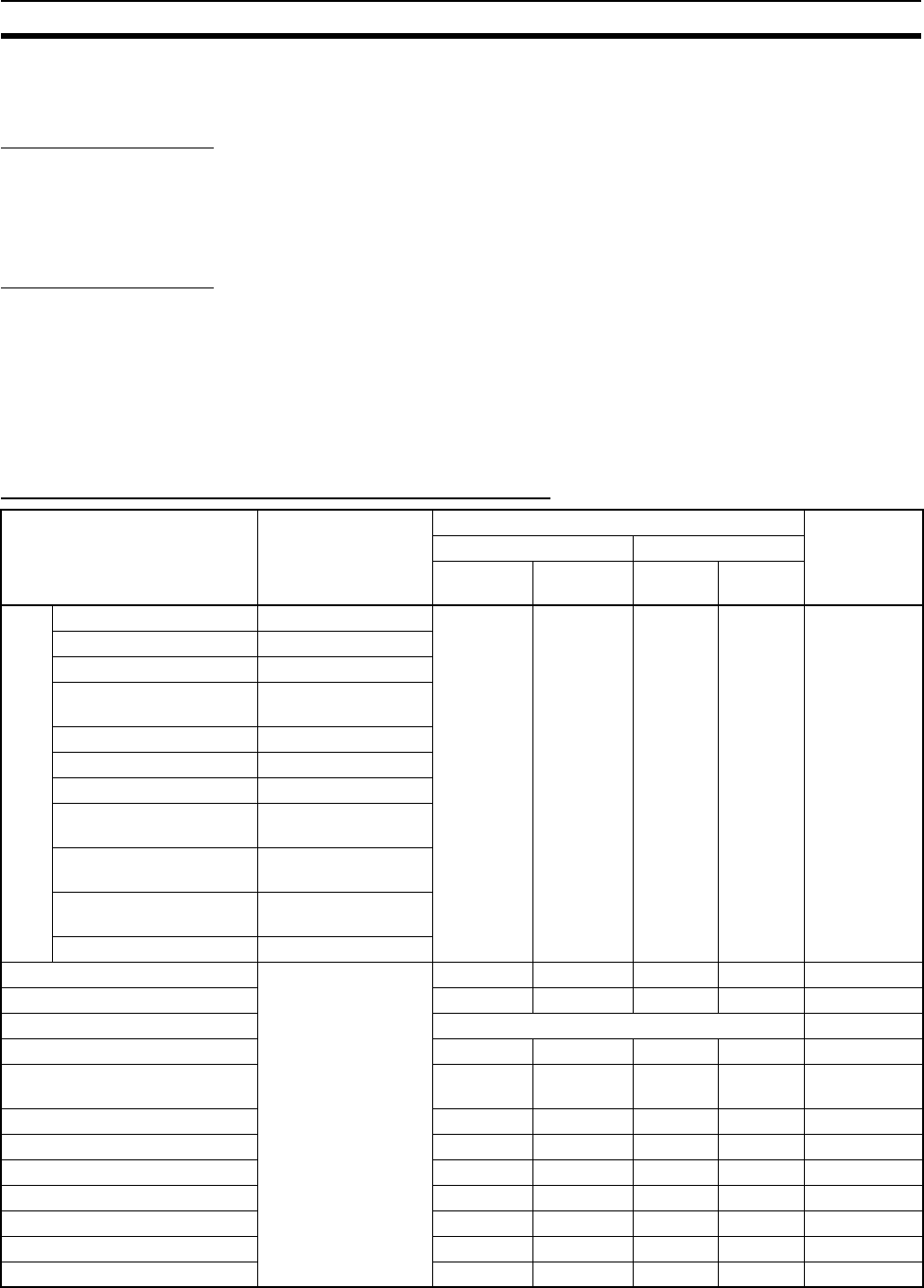
403
I/O Memory Areas Section 9-2
(RUN) status and OFF when the cyclic task hasn’t been executed (INI) or is in
standby (WAIT) status.
Index Registers (IR)
These registers (IR0 to IR15) are used to store PLC memory addresses
(absolute memory addresses in RAM) to indirectly address words in I/O mem-
ory. The Index Registers can be used separately in each task or, for CS1-H
CPU Units, they can be shared by all tasks.
Data Registers (DR)
These registers (DR0 to DR15) are used together with the Index Registers.
When a Data Register is input just before an Index Register, the content of the
Data Register is added to the PLC memory address in the Index Register to
offset that address. The Data Registers are used separately in each task or,
for CS1-H CPU Units, they can be shared by all tasks.
9-2-3 Data Area Properties
Content After Fatal Errors, Forced Set/Reset Usage
Area External allocation Fatal Error Generated Forced Set/
Forced Reset
Functions
Usable?
Execution of FALS(007) Other Fatal Error
IOM Hold
Bit OFF
IOM Hold
Bit ON
IOM Hold
Bit OFF
IOM Hold
Bit ON
CIO
Area
I/O Area Basic I/O Units Retained Retained Cleared Retained Yes
C200H DeviceNet Words DeviceNet Slaves
PLC Link Words None
Data Link Area Controller Link or
PLC Link data links
CPU Bus Units CPU Bus Units
Special I/O Unit Area Special I/O Units
Inner Board Area Inner Boards
SYSMAC BUS Area SYSMAC BUS
Remote I/O Slaves
I/O Terminal Area SYSMAC BUS
Remote I/O Terminals
CS-series DeviceNet
Area
DeviceNet Slaves or
Master
Internal I/O Area None
Work Area (W) None Retained Retained Cleared Retained Yes
Holding Area (H) Retained Retained Retained Retained Yes
Auxiliary Area (A) Status varies from address to address. No
Data Memory Area (D) Retained Retained Retained Retained No
Extended Data Memory Area
(E)
Retained Retained Retained Retained No
Timer Completion Flags (T) Retained Retained Cleared Retained Yes
Timer PVs (T) Retained Retained Cleared Retained No
Counter Completion Flags (C) Retained Retained Retained Retained Yes
Counter PVs (C) Retained Retained Retained Retained No
Task Flags (TK) Retained Retained Cleared Cleared No
Index Registers (IR) Retained Retained Cleared Retained No
Data Registers (DR) Retained Retained Cleared Retained No
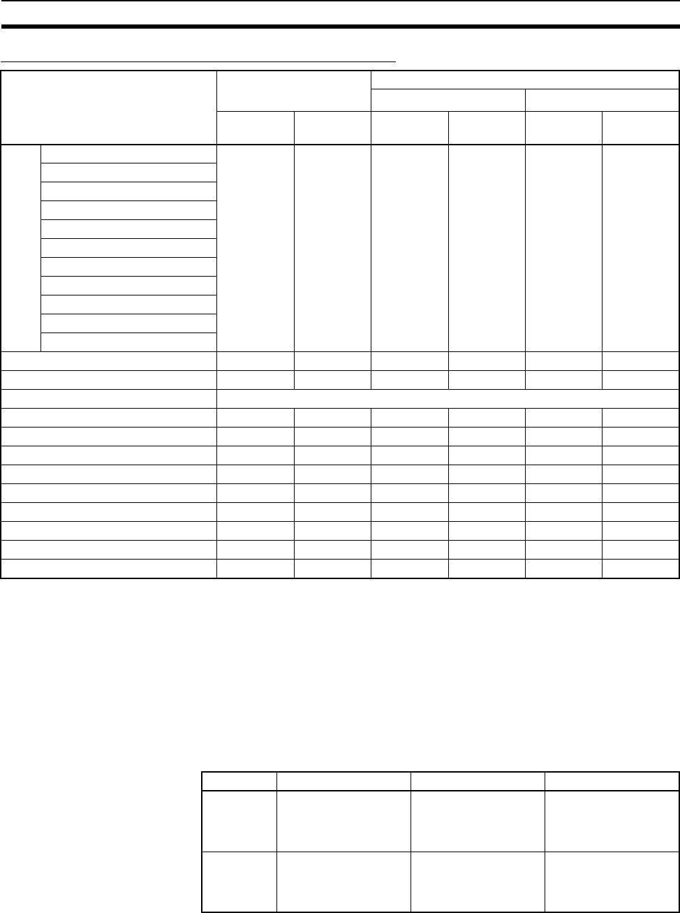
404
Precautions in Using C200H Special I/O Units Section 9-3
Content After Mode Change or Power Interruption
Note 1. Mode changed from PROGRAM to RUN/MONITOR or vice-versa.
2. The PLC Setup’s “IOM Hold Bit Status at Startup” setting determines
whether the IOM Hold Bit’s status is held or cleared when the PLC is turned
on.
9-3 Precautions in Using C200H Special I/O Units
Observe the following precautions when using C200H Special I/O Units.
Memory Areas There are differences between the words allocated to Special I/O Units in the
PLC memory areas, as shown in the following table.
Area Mode Changed1PLC Power OFF to ON
IOM Hold Bit Cleared2IOM Hold Bit Held2
IOM Hold
Bit OFF
IOM Hold
Bit ON
IOM Hold
Bit OFF
IOM Hold
Bit ON
IOM Hold
Bit OFF
IOM Hold
Bit ON
CIO
Area
I/O Area Cleared Retained Cleared Cleared Cleared Retained
C200H DeviceNet Words
PLC Link Words
Data Link Area
CPU Bus Units
Special I/O Unit Area
Inner Board Area
SYSMAC BUS Area
I/O Terminal Area
CS-series DeviceNet Area
Internal I/O Area
Work Area (W) Cleared Retained Cleared Cleared Cleared Retained
Holding Area (H) Retained Retained Retained Retained Retained Retained
Auxiliary Area (A) Status varies from address to address.
Data Memory Area (D) Retained Retained Retained Retained Retained Retained
Extended Data Memory Area (E) Retained Retained Retained Retained Retained Retained
Timer Completion Flags (T) Cleared Retained Cleared Cleared Cleared Retained
Timer PVs (T) Cleared Retained Cleared Cleared Cleared Retained
Counter Completion Flags (C) Retained Retained Retained Retained Retained Retained
Counter PVs (C) Retained Retained Retained Retained Retained Retained
Task Flags (TK) Cleared Cleared Cleared Cleared Cleared Cleared
Index Registers (IR) Cleared Retained Cleared Cleared Cleared Cleared
Data Registers (DR) Cleared Retained Cleared Cleared Cleared Cleared
PLC C200H/C200HS C200HX/HG/HE CS Series
IR/CIO
Area
allocations
IR 100 to IR 199 IR 100 to IR 199
IR 400 to IR 459
CIO 2000 to CIO 2959
(allocated CIO 2000 to
CIO 2159 for unit
numbers 0 up to 15)
DM Area
allocations
DM 1000 to DM 1999 DM 1000 to DM 1999
DM 2000 to DM 2599
D20000 to D29599
(allocated D20000 to
D21599 for unit num-
bers 0 up to 15)

405
CIO Area Section 9-4
Restrictions There are special restrictions in programming, allocations, and data communi-
cations with the CPU Unit for the following C200H Special I/O Units. Refer to
Appendix F Restrictions in Using C200H Special I/O Units for details.
There are no special restrictions for other C200H Special I/O Units.
9-4 CIO Area
I/O Area addresses range from CIO 0000 to CIO 0319 (CIO bits 000000 to
031915), but the area can be expanded to CIO 0000 to CIO 0999 by changing
the first Rack word with any Programming Device other than a Programming
Console. The maximum number of bits that can be allocated for external I/O
will still be 5,120 (320 words) even if the I/O Area is expanded.
Note The maximum number of external I/O points depends upon the CPU Unit
being used.
Words in the I/O Area can be allocated to I/O terminals on Basic I/O Units
(CS-series Basic I/O Units, C200H Basic I/O Units, and C200H Group-2 High-
density I/O Units).
Words are allocated to Basic I/O Units based on the slot position (left to right)
and number of words required. The words are allocated consecutively and
empty slots are skipped. Words in the I/O Area that aren’t allocated to Basic
I/O Units can be used only in the program.
CIO 0000 to CIO 0319 include the C200H DeviceNet Output Area (CIO 0050
to CIO 0099) and the PLC Link Words CIO 0247 to CIO 0250. Be sure that
word allocations do not overlap allocations for other I/O points when using a
C200H DeviceNet Master Unit (C200HS-DRM1-V1) or when using a PLC Link
Unit.
I/O Area Initialization The contents of the I/O Area will be cleared in the following cases:
1,2,3... 1. The operating mode is changed from PROGRAM to RUN or MONITOR
mode or vice-versa and the IOM Hold Bit is OFF.
(See the following explanation of IOM Hold Bit Operation.)
2. The PLC’s power supply is cycled and the IOM Hold Bit is OFF or not pro-
tected in the PLC Setup.
(See the following explanation of IOM Hold Bit Operation.)
3. The I/O Area is cleared from a Programming Device.
4. PLC operation is stopped when a fatal error other than an FALS(007) error
occurs. (The contents of the I/O Area will be retained if FALS(007) is exe-
cuted.)
IOM Hold Bit Operation If the IOM Hold Bit (A50012) is ON, the contents of the I/O Area won’t be
cleared when a fatal error occurs or the operating mode is changed from
PROGRAM mode to RUN or MONITOR mode or vice-versa.
Unit Model number
ASCII Units C200H-ASC02/ASC11/ASC21/ASC31
High-speed Counter Units C200H-CT001-V1/CT002
ID Sensor Units C200H-IDS01-V1/IDS21
Position Control Units C200H-NC111/NC112/NC211
Fuzzy Logic Units C200H-FZ001
High-speed Counter Units C200H-CT021
Motion Control Units C200H-MC221
C200H I/O LInk Units C200H-DRT21
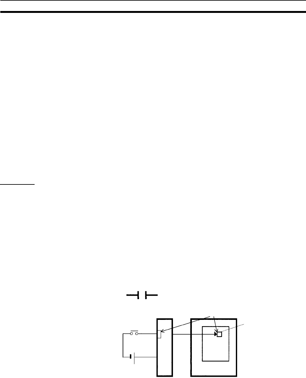
406
CIO Area Section 9-4
If the IOM Hold BIt (A50012) is ON and the PLC Setup’s “IOM Hold Bit Status
at Startup” setting is set to protect the IOM Hold Bit, the contents of the I/O
Area won’t be cleared when the PLC’s power supply is cycled. All I/O bits,
including outputs, will retain the status that they had before the PLC was
turned off.
Note If the I/O Hold Bit is turned ON, the outputs from the PLC will not be turned
OFF and will maintain their previous status when the PLC is switched from
RUN or MONITOR mode to PROGRAM mode. Make sure that the external
loads will not produce dangerous conditions when this occurs. (When opera-
tion stops for a fatal error, including those produced with the FALS(007)
instruction, all outputs from Output Unit will be turned OFF and only the inter-
nal output status will be maintained.)
Forcing bit Status Bits in the I/O Area can be force-set and force-reset.
Note When designating addresses in programming or allocations inside C200H
Special I/O Units, “000” to “255” will specify CIO 0000 to CIO 0255 in the CPU
Unit and “000” to “511” will specify CIO 0000 to CIO 0511 in the CPU Unit.
Other addresses in this area cannot be specified inside the C200H Special
I/O Units.
Input Bits
A bit in the I/O Area is called an input bit when it is allocated to an Input Unit.
Input bits reflect the ON/OFF status of devices such as push-button switches,
limit switches, and photoelectric switches. There are three ways for the status
of input points to be refreshed in the PLC: normal I/O refreshing, immediate
refreshing, and IORF(097) refreshing.
Normal I/O Refreshing The status of I/O points on external devices is read once each cycle after pro-
gram execution.
In the following example, CIO 000101 is allocated to switch 1, an external
switch connected to the input terminal of an Input Unit. The ON/OFF status of
switch 1 is reflected in CIO 000101 once each cycle.
Immediate Refreshing When the immediate refreshing variation of an instruction is specified by
inputting an exclamation point just before the instruction, and the instruction’s
operand is an input bit or word, the word containing the bit or the word itself
will be refreshed just before the instruction is executed. This immediate
refreshing is performed in addition to the normal I/O refreshing performed
once each cycle.
Input Unit
Switch 1
Once
each
cycle
CPU Unit
Bit allocation
CIO 000101
Ladder symbol Mnemonic
000101 LD 000101
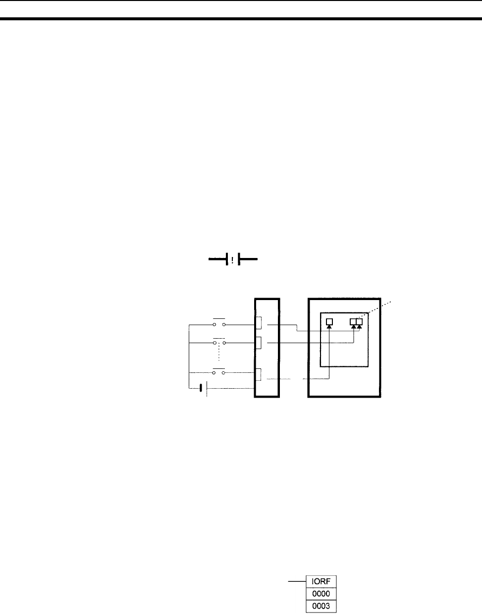
407
CIO Area Section 9-4
Note Immediate refreshing will be performed for input bits allocated to Basic I/O
Units only (excluding C200H Group-2 High-density I/O Units and Basic I/O
Units mounted in Remote I/O Slave Racks), not High-density I/O Units which
are Special I/O Units.
1,2,3... 1. Bit Operand
Just before the instruction is executed, the ON/OFF status of the 16 I/O
points allocated to the word containing the specified bit will be read to the
PLC.
2. Word Operand
Just before the instruction is executed, the ON/OFF status of the 16 I/O
points allocated to the specified word will be read to the PLC.
In the following example, CIO 000101 is allocated to switch 1, an external
switch connected to the input terminal of an Input Unit. The ON/OFF status of
switch 1 is read and reflected in CIO 000101 just before !LD 000101 is exe-
cuted.
IORF(097) Refreshing When IORF(097) (I/O REFRESH) is executed, the input bits in the specified
range of words are refreshed. This I/O refreshing is performed in addition to
the normal I/O refreshing performed once each cycle.
Note IORF(097) refreshes input bits allocated to Basic I/O Units (excluding Basic
I/O Units mounted in Remote I/O Slave Racks), C200H Group-2 High-density
I/O Units, and other High-density I/O Units which are Special I/O Units.
The following IORF(097) instruction refreshes the status of all I/O points in I/O
Area words CIO 0000 to CIO 0003. The status of input points is read from the
Input Units and the status of output bits is written to the Output Units.
In the following example, the status of input points allocated to CIO 0000 and
CIO 0001 are read from the Input Unit. (CIO 0002 and CIO 0003 are allocated
to Output Units.)
Input Unit
Switch 1
Read
just be-
fore
instruc-
tion
execu-
tion.
CPU Unit
CIO 000101
Ladder symbol Mnemonic
000101 !LD 000101
Switch 0
Switch 7
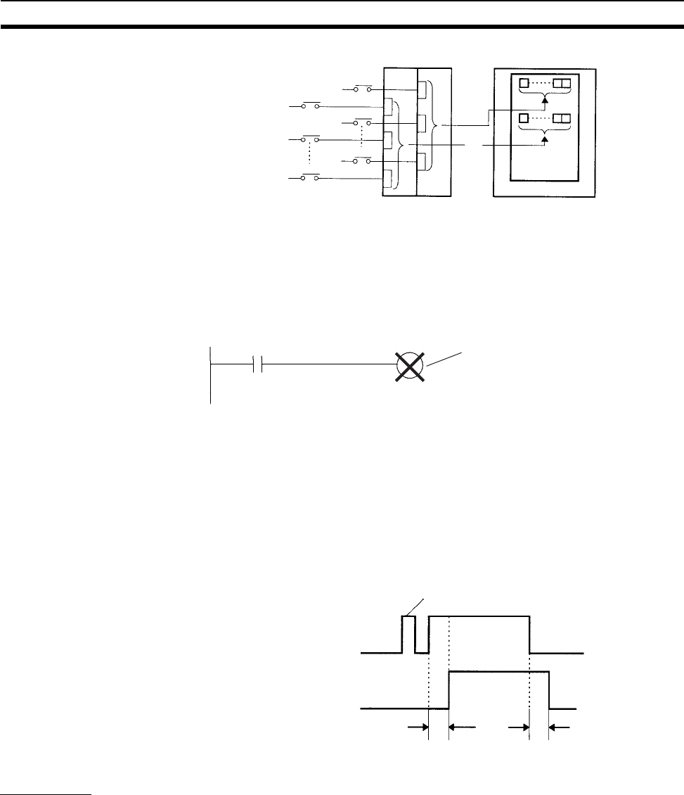
408
CIO Area Section 9-4
Limitations on Input bits There is no limit on the number of times that input bits can be used as nor-
mally open and normally closed conditions in the program and the addresses
can be programmed in any order.
An input bit cannot be used as an operand in an Output instruction.
Input Response Time
Settings
The input response times for each CS-series Input Unit can be set in the PLC
Setup. Increasing the input response time will reduce chattering and the
effects of noise and decreasing the input response time allows higher speed
input pulses to be received.
The default value for input response times is 8 ms and the setting range is 0 to
32 ms.
Note If the time is set to 0 ms, there will still be an ON delay time of 20 µs max. and
an OFF delay time of 300 µs due to delays caused by internal elements.
Output Bits
A bit in the I/O Area is called an output bit when it is allocated to an Output
Unit. The ON/OFF status of an output bits are output to devices such as actu-
ators. There are three ways for the status of output bits to be refreshed to an
Output Unit: normal I/O refreshing, immediate refreshing, and IORF(097)
refreshing.
Normal I/O Refreshing The status of output bits are output to external devices once each cycle after
program execution.
In the following example, CIO 000201 is allocated to an actuator, an external
device connected to an output terminal of an Output Unit. The ON/OFF status
of CIO 000201 is output to that actuator once each cycle.
Input Unit
Switch 16
Read
when
IORF
(097)
is
execu-
ted.
CPU Unit
Switch 17
Switch 31
Switch 0
Switch 1
Switch 15
Not allowed if CIO 000100 is an input bit.
00001 000100
Input from switch
Input bit
Pulses shorter than the time
constant are not received.
Input time constant Input time constant
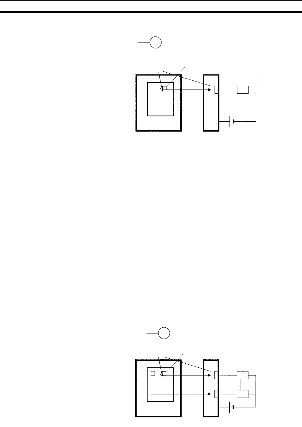
409
CIO Area Section 9-4
Immediate Refreshing When the immediate refreshing variation of an instruction is specified by
inputting an exclamation point just before the instruction, and the instruction’s
operand is an output bit or word, the content of the word containing the bit or
the word itself will be output just after the instruction is executed. This immedi-
ate refreshing is performed in addition to the normal I/O refreshing performed
once each cycle.
Note Immediate refreshing will be performed for output bits allocated to Basic I/O
Units only (excluding C200H Group-2 High-density I/O Units and Basic I/O
Units mounted in Remote I/O Slave Racks), not High-density I/O Units which
are Special I/O Units.
1,2,3... 1. Bit Operand
Just after the instruction is executed, the ON/OFF status of the 16 I/O
points allocated to the word containing the specified bit will be output to the
output device(s).
2. Word Operand
Just after the instruction is executed, the ON/OFF status of the 16 I/O
points allocated to the specified word will be output to the output device(s).
In the following example, CIO 000201 is allocated to an actuator, an external
device connected to the output terminal of an Output Unit. The ON/OFF sta-
tus of CIO 000201 is output to the actuator just after !OUT 000201 is exe-
cuted.
Output Unit
Actuator
Once
each
cycle
CPU Unit
Bit allocation CIO 000201
Ladder symbol Mnemonic
000201 OUT 000201
Ladder symbol Mnemonic
000201 OUT 000201
!
Output
just after
instruc-
tion
execu-
tion.
Output Unit
Actuator
CPU Unit
Bit allocation CIO 000201
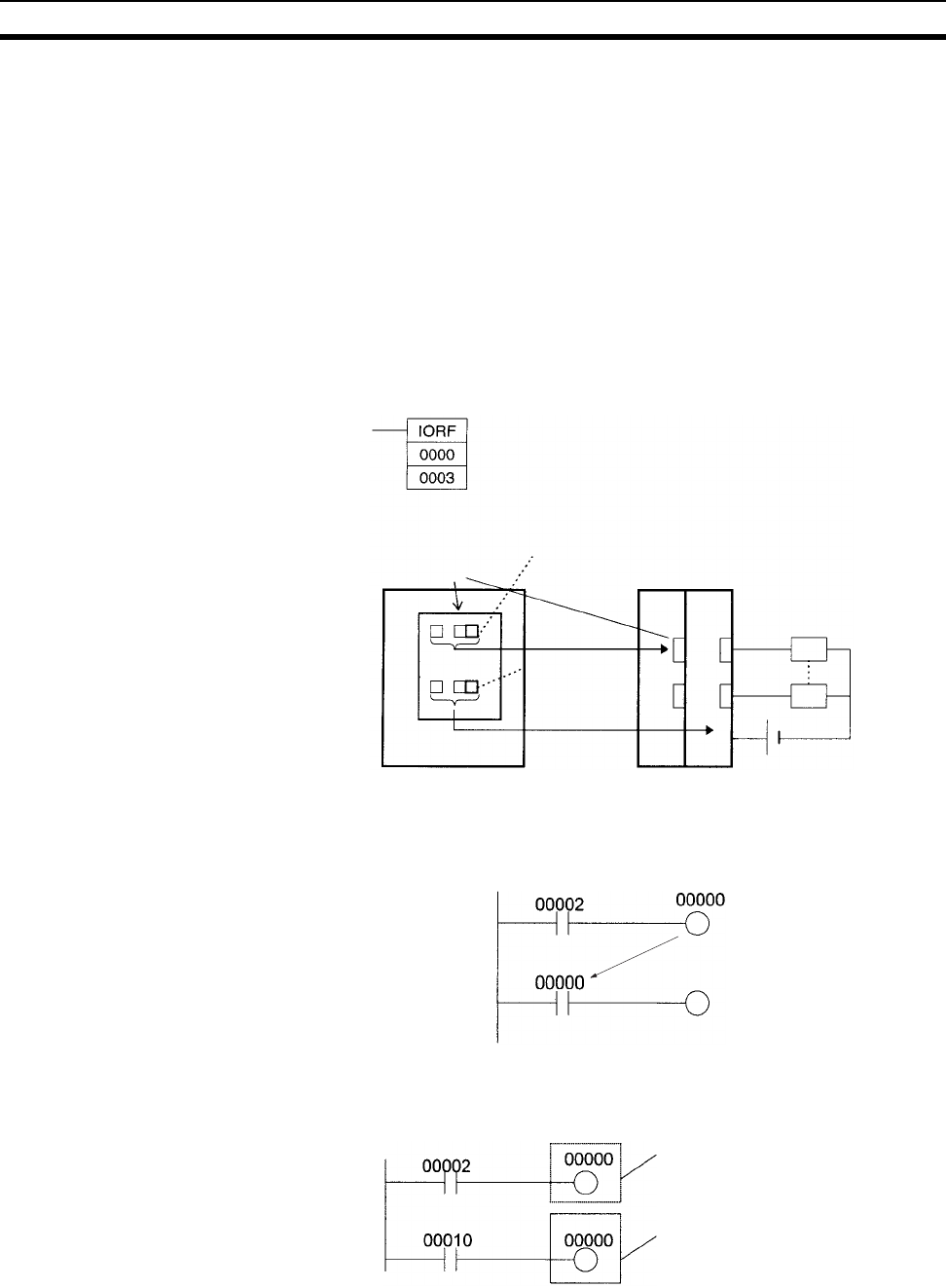
410
CIO Area Section 9-4
IORF(097) Refreshing When IORF(097) (I/O REFRESH) is executed, the ON/OFF status of output
bits in the specified range of words is output to their external devices. This I/O
refreshing is performed in addition to the normal I/O refreshing performed
once each cycle.
Note IORF(097) refreshes output bits allocated to Basic I/O Units (excluding Basic
I/O Units mounted in Remote I/O Slave Racks), C200H Group-2 High-density
I/O Units, and other High-density I/O Units which are Special I/O Units.
The following IORF(097) instruction refreshes the status of all I/O points in I/O
Area words CIO 0000 to CIO 0003. The status of input points is read from the
Input Units and the status of output bits is written to the Output Units.
In this example, the status of input points allocated to CIO 0002 and CIO 0003
are output to the Output Unit. (CIO 0000 and CIO 0001 are allocated to Input
Units.)
Limitations on Output Bits Output bits can be programmed in any order. Output bits can be used as oper-
ands in Input instructions and there is no limit on the number of times that an
output bit is used as a normally open and normally closed condition.
An output bit can be used in only one Output instruction that controls its sta-
tus. If an output bit is used in two or more Output instructions, only the last
instruction will be effective.
Note All outputs on Basic I/O Units and Special I/O Units can be turned OFF by
turning ON the Output OFF Bit (A50015). The status of the output bits won’t
be affected even though the actual outputs are turned OFF.
Output Unit
Actuator
CPU Unit
Bit allocation CIO 0002
Output when
IORF (097)
is executed.
CIO 0003
CIO 000000 is controlled
by CIO 000010.
Only this instruction is
effective.

411
C200H DeviceNet Area Section 9-5
9-5 C200H DeviceNet Area
The C200H DeviceNet Area is divided into two parts:
1,2,3... 1. The DeviceNet Output Area contains 50 words with addresses ranging
from CIO 0050 to CIO 0099.
2. The DeviceNet Input Area contains 50 words with addresses ranging from
CIO 0350 to CIO 0399.
Words in the C200H DeviceNet Area are used for fixed allocations to Slaves
for DeviceNet remote I/O communications for the C200H DeviceNet Master
Unit (C200HW-DRM21-V1).
Note The CS-series DeviceNet Unit (CS1W-DRM21) does not use this
same area for fixed allocations, but rather uses the CS-series De-
viceNet Area (CIO 3200 to CIO 3799).
Data is exchanged regularly to Slaves in the network (independent of the pro-
gram) through the C200H DeviceNet Master Unit (C200HW-DRM21-V1)
mounted in the CPU Rack.
Words can be allocated to Slaves in two ways: fixed allocation (words allo-
cated by node number) or free allocation (user-set word allocation).
• With fixed allocations, words in the C200H DeviceNet Area are allocated
automatically in node-number order.
• With user-set allocations, the user can allocate words to Slaves from the
following words.
CIO 0000 to CIO 0235, CIO 0300 to CIO 0511, CIO 1000 to CIO 1063
H000 to H099
D00000 to D05999
The same ranges can be allocated for both CS-series and C200HX/G/E PLCs
except that LR 00 to LR 63 in the C200HX/G/E PLCs correspond to CIO 1000
to CIO 1063 in the CS-series PLCs. (The entire Master Status Area is from
D06032 to D06063.)
For details on word allocations, refer to the C200HDeviceNet Operation Man-
ual (W267).
C200H DeviceNet Master
Unit (C200HW-DRM21-V1)
CPU Unit
C200H DeviceNet Area
DeviceNet
Slaves
With fixed allocation, words are assigned according to node numbers.
(If a Slave requires two or more words, it will occupy as many node
numbers as words required.)

412
CS-series DeviceNet Area Section 9-6
DeviceNet Area
Initialization
The contents of the DeviceNet Area will be cleared in the following cases:
1,2,3... 1. The operating mode is changed between PROGRAM and RUN or MONI-
TOR mode and the IOM Hold Bit is OFF.
2. The PLC’s power supply is cycled and the IOM Hold Bit is OFF or not pro-
tected in the PLC Setup.
3. The DeviceNet Area is cleared from a Programming Device.
4. PLC operation is stopped when a fatal error other than an FALS(007) error
occurs. (The contents of the DeviceNet Area will be retained when
FALS(007) is executed.)
IOM Hold Bit Operation If the IOM Hold BIt (A50012) is ON, the contents of the DeviceNet Area won’t
be cleared when a fatal error occurs or the operating mode is changed from
PROGRAM mode to RUN or MONITOR mode or vice-versa.
If the IOM Hold BIt (A50012) is ON and the PLC Setup’s “IOM Hold Bit Status
at Startup” setting is set to protect the IOM Hold Bit, the contents of the
DeviceNet Area won’t be cleared when the PLC’s power supply is cycled.
Forcing Bit Status Bits in the DeviceNet Area can be force-set and force-reset.
Note 1. The C200H DeviceNet Output Area overlaps the I/O Area. When using De-
viceNet communications with the default allocations, be sure that words
are not also allocated to other I/O points.
2. With the CS-series CPU Units, words beginning at D06032 are allocated
as follows for the C200H DeviceNet Master Status and the Communica-
tions Cycle Present Value:
DeviceNet Master Status: D06032 + unit number × 2
Communications Cycle Present Value: D06033 + unit number × 2
9-6 CS-series DeviceNet Area
The CS-series DeviceNet Area addresses run from CIO 3200 to CIO 3799
(600 words).
Words in the CS-series DeviceNet Area are used for fixed allocations to
Slaves for DeviceNet remote I/O communications for the CS-series DeviceNet
Unit (CS1W-DRM21).
Note The C200H DeviceNet Master Unit (C200HW-DRM21-V1) does not
use this same area for fixed allocations, but rather uses the C200H
DeviceNet Area (CIO 0050 to CIO0099 and CIO 0350 to CIO 0399).
The Fixed Allocation Setting Switches 1 to 3 (Software Switches) in the CIO
Area words allocated to the DeviceNet Unit determine which fixed allocation
words are used.
Area Master to Slave
(Output Words)
Slave to Master
(Input Words)
Fixed Allocation Area 1 CIO 3200 to CIO 3263 CIO 3300 to CIO 3363
Fixed Allocation Area 2 CIO 3400 to CIO 3463 CIO 3500 to CIO 3563
Fixed Allocation Area 3 CIO 3600 to CIO 3663 CIO 3700 to CIO 3763
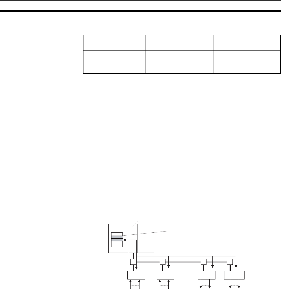
413
CS-series DeviceNet Area Section 9-6
Note If the DeviceNet Unit is set to use the I/O slave function, the following
words are also allocated.
Data is exchanged regularly to Slaves in the network (independent of the pro-
gram) through the CS-series DeviceNet Unit (CS1W-DRM21) mounted in the
CPU Rack.
Words can be allocated to Slaves in two ways: fixed allocation (words allo-
cated by node number) or free allocation (user-set word allocation).
• With fixed allocations, words in the CS-series DeviceNet Area are allo-
cated automatically in node-number order in one of the fixed allocation
areas (1 to 3).
• With user-set allocations, the user can allocate words to Slaves from the
following words.
CIO 0000 to CIO 6143
W000 to W511
H000 to H511
D00000 to D32767
E00000 to E32767 (banks 0 to C)
For details on word allocations, refer to the CS/CJ Series DeviceNet Unit
Operation Manual (W380).
Forcing Bit Status Bits in the CS-series DeviceNet Area can be force-set and force-reset.
DeviceNet Area
Initialization
The contents of the DeviceNet Area will be cleared in the following cases:
1,2,3... 1. The operating mode is changed between PROGRAM and RUN or MONI-
TOR mode and the IOM Hold Bit is OFF.
2. The PLC’s power supply is cycled and the IOM Hold Bit is OFF or not pro-
tected in the PLC Setup.
3. The DeviceNet Area is cleared from a Programming Device.
4. PLC operation is stopped when a fatal error other than an FALS(007) error
occurs. (The contents of the DeviceNet Area will be retained when
FALS(007) is executed.)
Area Master to Slave
(Output Word)
Slave to Master
(Input Word)
Fixed Allocation Area 1 CIO 3370 CIO 3270
Fixed Allocation Area 2 CIO 3570 CIO 3470
Fixed Allocation Area 3 CIO 3770 CIO 3670
CS-series DeviceNet Unit
(CS1W-DRM21)
CPU Unit
CS-series DeviceNet Area
DeviceNet Slaves
With fixed allocations, words are assigned according to node numbers.
(If a Slave requires two or more words, it will use as many node
numbers as words required.)

414
PLC Link Area Section 9-7
IOM Hold Bit Operation If the IOM Hold BIt (A50012) is ON, the contents of the DeviceNet Area won’t
be cleared when a fatal error occurs or the operating mode is changed from
PROGRAM mode to RUN or MONITOR mode or vice-versa.
If the IOM Hold BIt (A50012) is ON and the PLC Setup’s “IOM Hold Bit Status
at Startup” setting is set to protect the IOM Hold Bit, the contents of the
DeviceNet Area won’t be cleared when the PLC’s power supply is cycled.
9-7 PLC Link Area
The PLC Link Area contains 5 words with addresses ranging from CIO 0247
to CIO 0250. A442 is also used for PLC Links. Use these words to monitor
PLC Link errors, monitor CPU Unit operating status, and detect PLC Link
operating levels.
Note The Link Area (CIO 1000 to CIO 1063) is used to exchange data between
PLCs in a PLC Link system, just as the LR Area is used in other OMRON
PLCs. The flags in the PLC Link Area indicate the status of PLC Link opera-
tions.
PLC Link Error Flags
When a transmission error occurs or there is a power interruption at another
Unit after the PLC link is established, the flag corresponding to the other Unit’s
unit number will be turned ON. These flags are read-only, although the PLC
Link Error Flag will be turned ON if the CPU Unit is stopped by a FALS(007)
error.
CPU Unit RUN Flags
The flag corresponding to the a CPU Unit’s unit number will be ON when the
CPU Unit is operating in RUN or MONITOR mode. The corresponding flag will
be OFF when the CPU Unit is in PROGRAM mode. These flags can be used
to determine another Unit’s operating status. These flags are read-only.
Operating Level Detection Flags
The flags in A442 can be used to determine whether a PLC Link Unit is
mounted to the PLC as well as the Unit’s operating level. A44211 will be ON if
the PLC Link Unit is in operating level 1 and A44212 will be ON if the PLC Link
Unit is in operating level 0.

415
PLC Link Area Section 9-7
CIO Area Flags The following table shows the allocation of the CIO Area flags related to PLC
Link operation. (The numbers in parentheses show the allocation for multilevel
systems; operating level 0 is #0 and operating level 1 is #1.)
PLC Link Area
Initialization
The contents of the PLC Link Area will be cleared in the following cases:
1,2,3... 1. The operating mode is changed from PROGRAM mode to RUN/MONITOR
mode or vice-versa and the IOM Hold Bit is OFF.
2. The PLC’s power supply is cycled and the IOM Hold Bit is OFF or not pro-
tected in the PLC Setup.
3. The PLC Link Area is cleared from a Programming Device.
4. PLC operation is stopped when a fatal error other than an FALS(007) error
occurs. (The contents of the PLC Link Area will be retained when
FALS(007) is executed.)
IOM Hold Bit Operation If the IOM Hold BIt (A50012) is ON, the contents of the PLC Link Area won’t
be cleared when a fatal error occurs or the operating mode is changed from
PROGRAM mode to RUN/MONITOR mode or vice-versa.
If the IOM Hold BIt (A50012) is ON and the PLC Setup’s “IOM Hold Bit Status
at Startup” setting is set to protect the IOM Hold Bit, the contents of the PLC
Link Area won’t be cleared when the PLC’s power supply is cycled.
Forcing Bit Status Bits in the PLC Link Area can be force-set and force-reset.
Auxiliary Area Flags A44211 will be ON when the PLC Link Unit is in operating level #1. A44212
will be ON when the Unit is in operating level #0 or a PLC Link Unit isn’t
mounted in the PLC. (The other bits in A442 are not used.)
Refer to 9-16 Auxiliary Area and to Appendix B Auxiliary Area for more details
on A422.
Note 1. The PLC Link Area (CIO 0247 to CIO 0250) overlaps the I/O Area. When
using PLC Link Units, be sure that words are not also allocated to other I/O
points.
2. When designating addresses in programming or allocations inside C200H
Special I/O Units, “247” to “250” will actually specify CIO 0247 to CIO 0250
in the CPU Unit. A422 cannot be specified inside a C200H Special I/O Unit.
Flag type Bit CIO 0247 CIO 0248 CIO 0249 CIO 0250
CPU Unit
RUN Flags
00 Unit 24 (#1, Unit 8) Unit 16 (#1, Unit 0) Unit 8 (#0, Unit 8) Unit 0 (#0, Unit 0)
01 Unit 25 (#1, Unit 9) Unit 17 (#1, Unit 1) Unit 9 (#0, Unit 9) Unit 1 (#0, Unit 1)
02 Unit 26 (#1, Unit 10) Unit 18 (#1, Unit 2) Unit 10 (#0, Unit 10) Unit 2 (#0, Unit 2)
03 Unit 27 (#1, Unit 11) Unit 19 (#1, Unit 3) Unit 11 (#0, Unit 11) Unit 3 (#0, Unit 3)
04 Unit 28 (#1, Unit 12) Unit 20 (#1, Unit 4) Unit 12 (#0, Unit 12) Unit 4 (#0, Unit 4)
05 Unit 29 (#1, Unit 13) Unit 21 (#1, Unit 5) Unit 13 (#0, Unit 13) Unit 5 (#0, Unit 5)
06 Unit 30 (#1, Unit 14) Unit 22 (#1, Unit 6) Unit 14 (#0, Unit 14) Unit 6 (#0, Unit 6)
07 Unit 31 (#1, Unit 15) Unit 23 (#1, Unit 7) Unit 15 (#0, Unit 15) Unit 7 (#0, Unit 7)
PLC Link
Error Flags
08 Unit 24 (#1, Unit 8) Unit 16 (#1, Unit 0) Unit 8 (#0, Unit 8) Unit 0 (#0, Unit 0)
09 Unit 25 (#1, Unit 9) Unit 17 (#1, Unit 1) Unit 9 (#0, Unit 9) Unit 1 (#0, Unit 1)
10 Unit 26 (#1, Unit 10) Unit 18 (#1, Unit 2) Unit 10 (#0, Unit 10) Unit 2 (#0, Unit 2)
11 Unit 27 (#1, Unit 11) Unit 19 (#1, Unit 3) Unit 11 (#0, Unit 11) Unit 3 (#0, Unit 3)
12 Unit 28 (#1, Unit 12) Unit 20 (#1, Unit 4) Unit 12 (#0, Unit 12) Unit 4 (#0, Unit 4)
13 Unit 29 (#1, Unit 13) Unit 21 (#1, Unit 5) Unit 13 (#0, Unit 13) Unit 5 (#0, Unit 5)
14 Unit 30 (#1, Unit 14) Unit 22 (#1, Unit 6) Unit 14 (#0, Unit 14) Unit 6 (#0, Unit 6)
15 Unit 31 (#1, Unit 15) Unit 23 (#1, Unit 7) Unit 15 (#0, Unit 15) Unit 7 (#0, Unit 7)
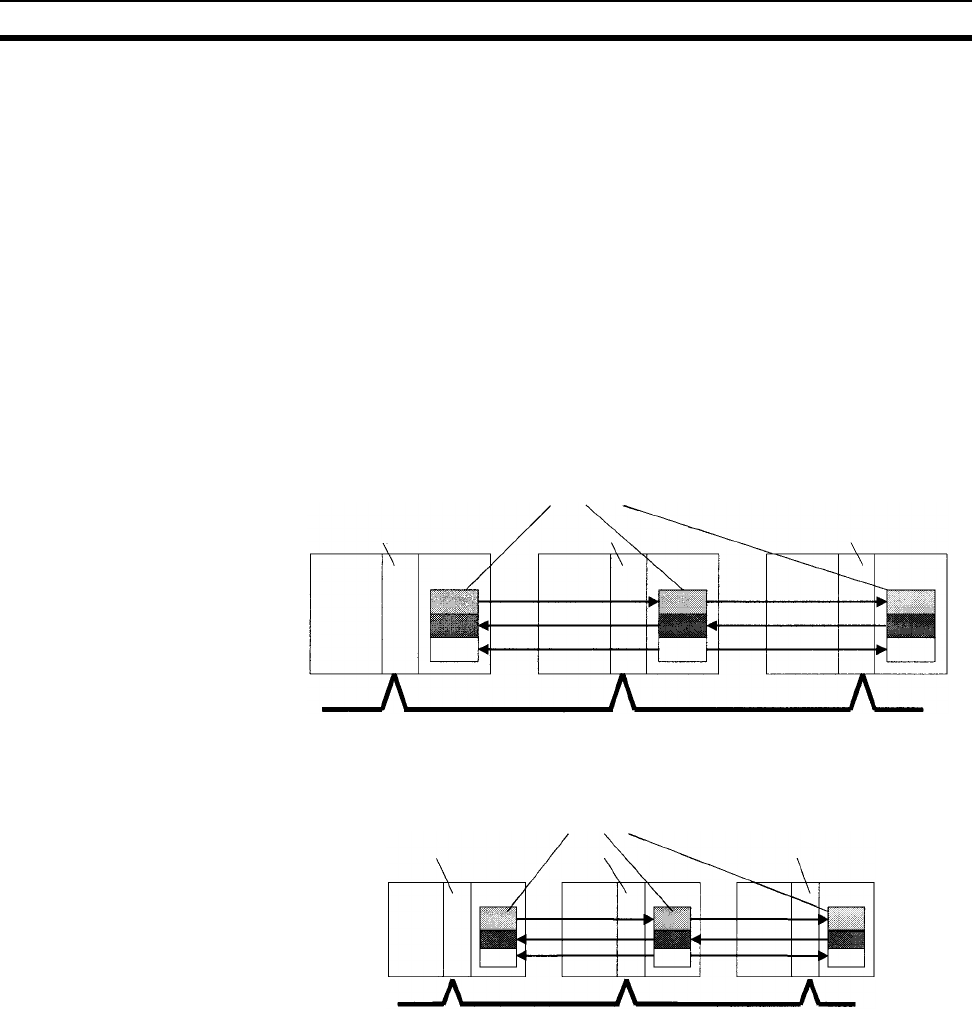
416
Data Link Area Section 9-8
9-8 Data Link Area
Data Link Area addresses range from CIO 1000 to CIO 1199 (CIO
bits 100000 to 119915). Words in the Link Area are used for data links when
LR is set as the data link area for Controller Link Networks. It is also used for
PLC Links.
A data link automatically (independently of the program) shares data with Link
Areas in other CS-series CPU Units in the network through a Controller Link
Unit mounted to the PLC’s CPU Rack.
Data links can be generated automatically (using the same number of words
for each node) or manually. When a user defines the data link manually, he
can assign any number of words to each node and make nodes receive-only
or transmit-only. Refer to the Controller Link Units Operation Manual (W309)
for more details.
Words in the Link Area can be used in the program when LR is not set as the
data link area for Controller Link Networks and PLC Links are not used.
Link Area words are also allocated to PLC Link Systems when a PLC Link is
created by connecting PLC Link Units.
Links to C200HX/HG/HE,
C200HS, and C200H PLCs
Link Area words CIO 1000 to CIO 1063 in CS-series PLCs correspond to Link
Relay Area words LR 00 to LR 63 for data links created in C200HX/HG/HE
PLCs and PLC Links created in C200HX/HG/HE, C200HS, or C200H PLCs.
When converting C200HX/HG/HE, C200HS, or C200H programs for use in
CS-series PLCs, change addresses LR 00 through LR 63 to their equivalent
Link Area addresses CIO 1000 through CIO 1063.
Link Area Initialization The contents of the Link Area will be cleared in the following cases:
1,2,3... 1. The operating mode is changed from PROGRAM mode to RUN/MONITOR
mode or vice-versa and the IOM Hold Bit is OFF.
2. The PLC’s power supply is cycled and the IOM Hold Bit is OFF or not pro-
tected in the PLC Setup.
3. The Link Area is cleared from a Programming Device.
Controller
Link Unit CPU Unit
Link Areas
Controller
Link Unit CPU Unit
Controller
Link Unit CPU Unit
Controller Link Network
PLC Link Unit
CPU Unit
Link Areas
CPU Unit
PLC Link Unit
CPU Unit
PLC Link
Unit
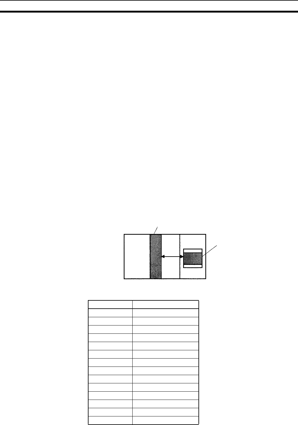
417
CPU Bus Unit Area Section 9-9
4. PLC operation is stopped when a fatal error other than an FALS(007) error
occurs. (The contents of the Link Area will be retained if FALS(007) is ex-
ecuted.)
IOM Hold Bit Operation If the IOM Hold BIt (A50012) is ON and the PLC Setup’s “IOM Hold Bit Status
at Startup” setting is set to protect the IOM Hold Bit, the contents of the Link
Area won’t be cleared when the PLC’s power supply is cycled.
If the IOM Hold BIt (A50012) is ON, the contents of the Link Area won’t be
cleared when a fatal error occurs or the operating mode is changed from
PROGRAM mode to RUN/MONITOR mode or vice-versa.
Forcing Bit Status Bits in the Link Area can be force-set and force-reset.
Note When designating addresses in programming or allocations inside C200H
Special I/O Units, “LR 00” to “LR63” will actually specify CIO 1000 to CIO1063
in the CPU Unit. CIO 1064 to CIO 1199 in the CPU Unit cannot be specified in
the C200H Special I/O Unit.
9-9 CPU Bus Unit Area
The CPU Bus Unit Area contains 400 words with addresses ranging from
CIO 1500 to CIO 1899. Words in the CPU Bus Unit Area can be allocated to
CPU Bus Units to transfer data such as the operating status of the Unit. Each
Unit is allocated 25 words based on the Unit’s unit number setting.
Data is exchanged with CPU Bus Units once each cycle during I/O refreshing,
which occurs after program execution. (Words in this data area cannot be
refreshed with immediate-refreshing or IORF(097).)
Each CPU Bus Unit is allocated 25 words based on its unit number, as shown
in the following table.
Unit number Allocated words
0 CIO 1500 to CIO 1524
1 CIO 1525 to CIO 1549
2 CIO 1550 to CIO 1574
3 CIO 1575 to CIO 1599
4 CIO 1600 to CIO 1624
5 CIO 1625 to CIO 1649
6 CIO 1650 to CIO 1674
7 CIO 1675 to CIO 1699
8 CIO 1700 to CIO 1724
9 CIO 1725 to CIO 1749
A CIO 1750 to CIO 1774
B CIO 1775 to CIO 1799
C CIO 1800 to CIO 1824
D CIO 1825 to CIO 1849
CPU Bus Unit
CPU Unit
I/O
re-
fresh-
ing
CPU Bus Unit Area
(25 words/Unit)
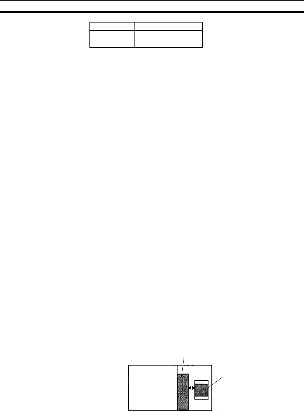
418
Inner Board Area Section 9-10
The function of the 25 words depends upon the CPU Bus Unit being used. For
details, refer to the Unit’s operation manual.
Words in the CPU Bus Unit Area that aren’t allocated to CPU Bus Units can
be used only in the program.
Note The addresses in the CS-series CPU Bus Unit Area cannot be designated
directly in programming or allocations inside C200H Special I/O Units.
CPU Bus Unit Area
Initialization
The contents of the CPU Bus Unit Area will be cleared in the following cases:
1,2,3... 1. The operating mode is changed from PROGRAM to RUN or MONITOR
mode or vice-versa and the IOM Hold Bit is OFF.
2. The PLC’s power supply is cycled and the IOM Hold Bit is OFF or not pro-
tected in the PLC Setup.
3. The CPU Bus Unit Area is cleared from a Programming Device.
4. PLC operation is stopped when a fatal error other than an FALS(007) error
occurs. (The contents of the CPU Bus Unit Area will be retained when
FALS(007) is executed.)
IOM Hold Bit Operation If the IOM Hold BIt (A50012) is ON, the contents of the CS-series CPU Bus
Unit Area won’t be cleared when a fatal error occurs or the operating mode is
changed from PROGRAM mode to RUN/MONITOR mode or vice-versa.
If the IOM Hold BIt (A50012) is ON and the PLC Setup’s “IOM Hold Bit Status
at Startup” setting is set to protect the IOM Hold Bit, the contents of the CS-
series CPU Bus Unit Area won’t be cleared when the PLC’s power supply is
cycled.
Forcing Bit Status Bits in the CPU Bus Unit Area can be force-set and force-reset.
9-10 Inner Board Area
The Inner Board Area contains 100 words with addresses ranging from
CIO 1900 to CIO 1999. Words in the Inner Board Area can be allocated to an
Inner Board to transfer data such as the operating status of the Unit. All 100
words must be allocated to just one Inner Board.
Data is exchanged with the Inner Board once each cycle during normal I/O
refreshing, which occurs after program execution. Depending on the type of
Inner Board that is mounted, data can also be refreshed directly.
The function of the 100 words in the Inner Board Area depends upon the
Inner Board being used. For details, refer to the Board’s Operation Manual.
When the words in the Inner Board Area aren’t allocated to an Inner Board,
they can be used only in the program.
E CIO 1850 to CIO 1874
F CIO 1875 to CIO 1899
Unit number Allocated words
Inner Board
CPU Unit
I/O re-
freshing Inner Board Area
(100 words/Board)

419
Special I/O Unit Area Section 9-11
Inner Board Area
Initialization
The contents of the Inner Board Area will be cleared in the following cases:
1,2,3... 1. The operating mode is changed from PROGRAM mode to RUN/MONITOR
mode or vice-versa and the IOM Hold Bit is OFF.
2. The PLC’s power supply is cycled and the IOM Hold Bit is OFF or not pro-
tected in the PLC Setup.
3. The Inner Board Area is cleared from a Programming Device.
4. PLC operation is stopped when a fatal error other than an FALS(007) error
occurs. (The contents of the Inner Board Area will be retained when
FALS(007) is executed.)
IOM Hold Bit Operation If the IOM Hold BIt (A50012) is ON, the contents of the Inner Board Area
won’t be cleared when a fatal error occurs or the operating mode is changed
from PROGRAM mode to RUN/MONITOR mode or vice-versa.
If the IOM Hold BIt (A50012) is ON and the PLC Setup’s “IOM Hold Bit Status
at Startup” setting is set to protect the IOM Hold Bit, the contents of the Inner
Board Area won’t be cleared when the PLC’s power supply is cycled.
Forcing Bit Status Bits in the Inner Board Area can be force-set and force-reset.
Note The addresses in the Inner Board Area cannot be designated directly in pro-
gramming or allocations inside C200H Special I/O Units.
9-11 Special I/O Unit Area
The Special I/O Unit Area contains 960 words with addresses ranging from
CIO 2000 to CIO 2959. Words in the Special I/O Unit Area are allocated to
CS-series and C200H Special I/O Units to transfer data such as the operating
status of the Unit. Each Unit is allocated 10 words based on its unit number
setting.
Data is exchanged with Special I/O Units once each cycle during I/O refresh-
ing, which occurs after program execution. The words can also be refreshed
with IORF(097).
Note The addresses in the Special I/O Unit Area cannot be designated directly in
programming or allocations inside C200H Special I/O Units.
Special I/O Unit
CPU Unit
I/O
re-
fresh-
ing or
IORF
(097)
Special I/O Unit Area
(10 words/Unit)
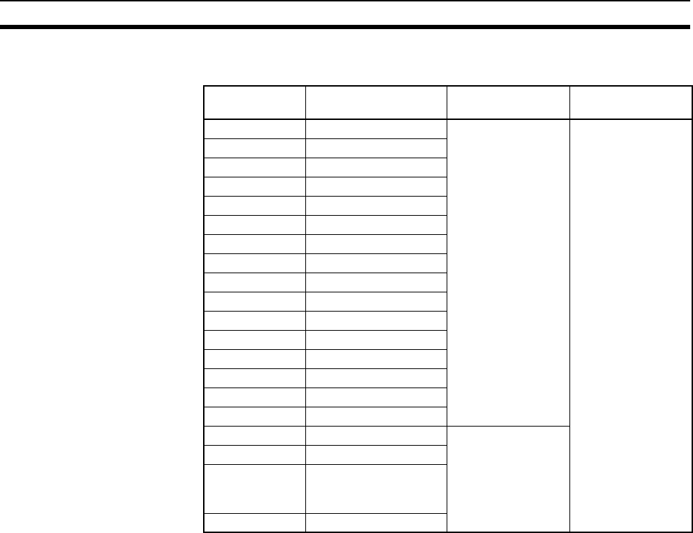
420
Special I/O Unit Area Section 9-11
Each Special I/O Unit is allocated 25 words based on its unit number, as
shown in the following table.
The function of the 10 words allocated to a Unit depends upon the Special I/O
Unit being used. For details, refer to the Unit’s Operation Manual.
Words in the Special I/O Unit Area that aren’t allocated to Special I/O Units
can be used only in the program.
Special I/O Unit Area
Initialization
The contents of the Special I/O Unit Area will be cleared in the following
cases:
1,2,3... 1. The operating mode is changed from PROGRAM mode to RUN/MONITOR
mode or vice-versa and the IOM Hold Bit is OFF.
2. The PLC’s power supply is cycled and the IOM Hold Bit is OFF or not pro-
tected in the PLC Setup.
3. The Special I/O Unit Area is cleared from a Programming Device.
4. PLC operation is stopped when a fatal error other than an FALS(007) error
occurs. (The contents of the Special I/O Unit Area will be retained when
FALS(007) is executed.)
IOM Hold Bit Operation If the IOM Hold BIt (A50012) is ON, the contents of the Special I/O Unit Area
won’t be cleared when a fatal error occurs or the operating mode is changed
from PROGRAM mode to RUN/MONITOR mode or vice-versa.
If the IOM Hold BIt (A50012) is ON and the PLC Setup’s “IOM Hold Bit Status
at Startup” setting is set to protect the IOM Hold Bit, the contents of the Spe-
cial I/O Unit Area won’t be cleared when the PLC’s power supply is cycled.
Forcing Bit Status Bits in the Special I/O Unit Area can be force-set and force-reset.
Unit number Allocated words C200H
Special I/O Units
CS-series
Special I/O Units
0 CIO 2000 to CIO 2009 Valid unit numbers Valid unit numbers
1 CIO 2010 to CIO 2019
2 CIO 2020 to CIO 2029
3 CIO 2030 to CIO 2039
4 CIO 2040 to CIO 2049
5 CIO 2050 to CIO 2059
6 CIO 2060 to CIO 2069
7 CIO 2070 to CIO 2079
8 CIO 2080 to CIO 2089
9 CIO 2090 to CIO 2099
10 (A) CIO 2100 to CIO 2109
11 (B) CIO 2110 to CIO 2119
12 (C) CIO 2120 to CIO 2129
13 (D) CIO 2130 to CIO 2139
14 (E) CIO 2140 to CIO 2149
15 (F) CIO 2150 to CIO 2159
16 CIO 2160 to CIO 2169 Not available on
C200H Units
17 CIO 2170 to CIO 2179
95 CIO 2950 to CIO 2959
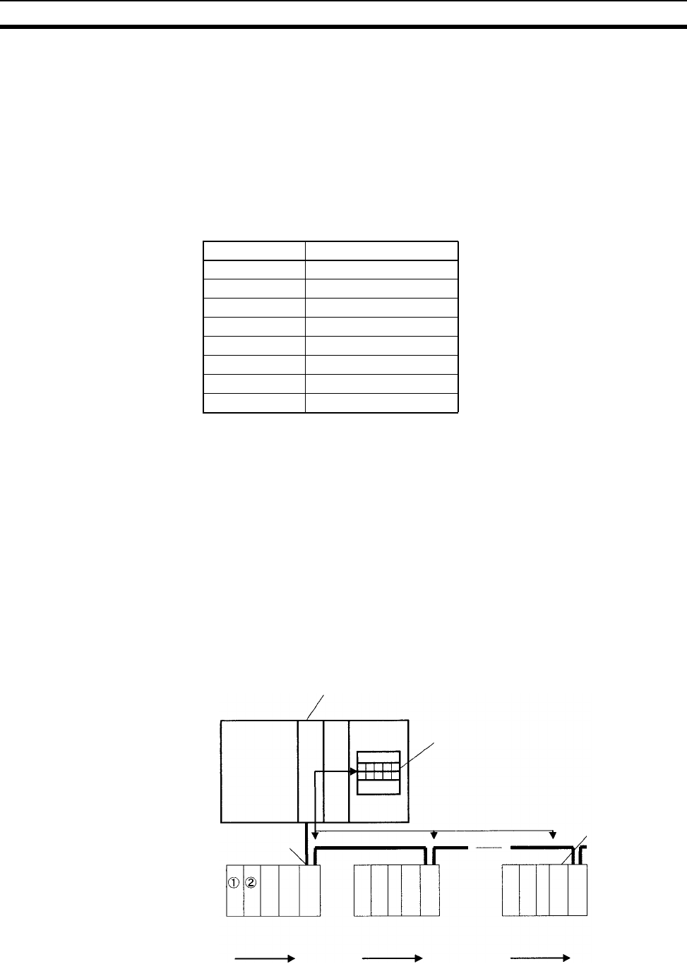
421
SYSMAC BUS Area Section 9-12
9-12 SYSMAC BUS Area
The SYSMAC BUS Area contains 80 words with addresses ranging from
CIO 3000 to CIO 3079. Words in the SYSMAC BUS Area are allocated to
Slave Racks connected to Wired or Optical SYSMAC BUS Remote I/O Master
Units (C200H-RM201 or C200H-RM001-PV1). Up to two Masters can be
mounted to the CPU Rack or a C200H Expansion I/O Rack. A maximum of 8
Slave Racks can be managed by one CPU Unit, whether one or two Masters
are mounted.
Each Slave Rack is allocated 10 words based on the Rack’s rack number set-
ting (0 to 7).
Up to 10 C200H Basic I/O Units can be mounted in a Slave Rack. One word
(16 bits) is allocated to each slot in the Slave Rack from left to right. Alloca-
tions are fixed by slot, e.g., if there is no Unit in a slot, the word normally allo-
cated to that slot will not be used.
Note 1. Up to two Masters can be mounted for any one CPU Unit A maximum of 8
Slave Racks can be managed by one CPU Unit, regardless of whether one
or two Masters are mounted.
2. C200H Special I/O Units can also be mounted to Slave Racks, but they will
be allocated words according to their unit number and will not be allocated
SYSMAC BUS Area words.
3. SYSMAC BUS Units other than Slave Racks (such as I/O Terminals) can
also be connected. These other Units are allocated words in the I/O Termi-
nal Area. Refer to 9-13 I/O Terminal Area for details.
Rack number Allocated words
0 CIO 3000 to CIO 3009
1 CIO 3010 to CIO 3019
2 CIO 3020 to CIO 3029
3 CIO 3030 to CIO 3039
4 CIO 3040 to CIO 3049
5 CIO 3050 to CIO 3059
6 CIO 3060 to CIO 3069
7 CIO 3070 to CIO 3079
Wired or Optical Master Unit
CPU Unit
SYSMAC BUS Area
Slave Rack Slave Rack Slave Rack
Wired or Optical
Slave Unit
Wired or Optical
Slave Unit
Total length 200 m max.,
2 conductors

422
I/O Terminal Area Section 9-13
1,2,3... 1. Ten words are allocated to each Rack based on the rack number set on the
Slave Unit.
2. The ten words in each Rack are allocated to the slots in the Rack from left
to right (one word/slot).
SYSMAC BUS Area
Initialization
The contents of the SYSMAC BUS Area will be cleared in the following cases:
1,2,3... 1. The operating mode is changed from PROGRAM mode to RUN/MONITOR
mode or vice-versa and the IOM Hold Bit is OFF.
2. The PLC’s power supply is cycled and the IOM Hold Bit is OFF or not pro-
tected in the PLC Setup.
3. The SYSMAC BUS Area is cleared from a Programming Device.
4. PLC operation is stopped when a fatal error other than an FALS(007) error
occurs. (The contents of the SYSMAC BUS Area will be retained when
FALS(007) is executed.)
IOM Hold Bit Operation If the IOM Hold BIt (A50012) is ON, the contents of the SYSMAC BUS Area
won’t be cleared when a fatal error occurs or the operating mode is changed
from PROGRAM mode to RUN/MONITOR mode or vice-versa.
If the IOM Hold BIt (A50012) is ON and the PLC Setup’s “IOM Hold Bit Status
at Startup” setting is set to protect the IOM Hold Bit, the contents of the SYS-
MAC BUS Area won’t be cleared when the PLC’s power supply is cycled.
Forcing Bit Status Bits in the SYSMAC BUS Area can be force-set and force-reset.
Note 1. A C200H Expansion I/O Rack can also be connected to a Remote I/O
Slave Rack. If that is done, then the C200H Expansion I/O Rack is counted
as a Remote I/O Slave Rack and allocated the next unit number. The total
number of Remote I/O Slave Racks is eight, of which only two can be
C200H Expansion I/O Racks.
2. The addresses in the SYSMAC BUS Area cannot be designated directly in
programming or allocations inside C200H Special I/O Units.
9-13 I/O Terminal Area
The I/O Terminal Area contains 32 words with addresses ranging from
CIO 3100 to CIO 3131. Words in the I/O Terminal Area can be allocated to
Slaves other than Slave Racks (such as I/O Interfaces, I/O Terminals, and
Optical I/O Units) connected to a Wired or Optical SYSMAC BUS Remote I/O
Master Units (C200H-RM201 or C200H-RM001-PV1). Up to two Masters can
be mounted to the CPU Rack or a C200H Expansion I/O Rack. Up to 32
Slaves are allowed for each CPU Unit.
Each Slave is allocated 1 word based on its unit number setting (0 to 31)
except for Optical I/O Units, which are allocated 2 words each. The words are
allocated according to unit numbers even when two Master Units are being
used.
Unit number Allocated word
0 CIO 3100
1 CIO 3101
31 CIO 3131
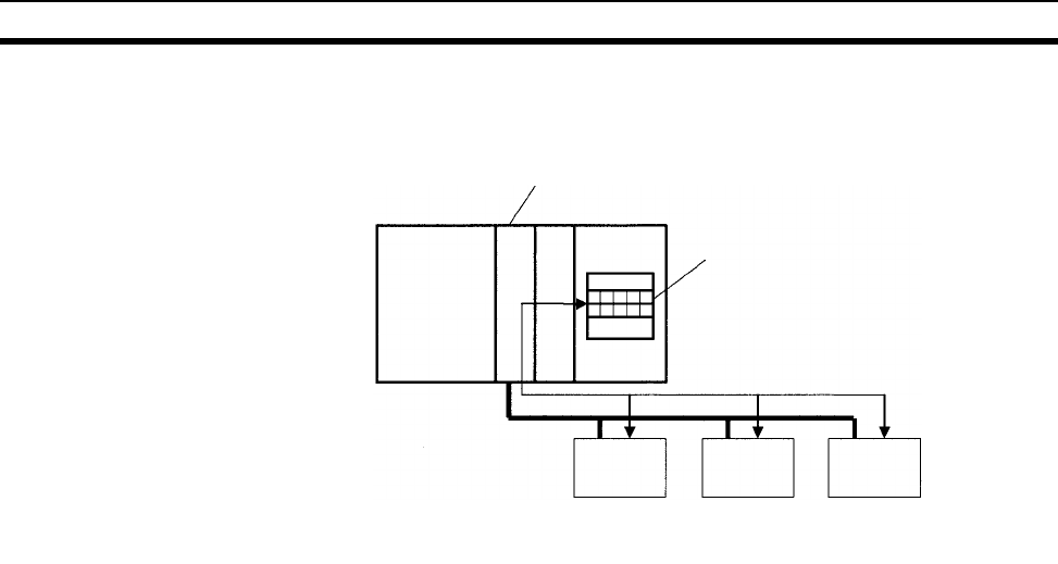
423
Work Area Section 9-14
Both Slave Racks and SYSMAC BUS Slaves other than Slave Racks (such as
I/O Terminals) can be connected. Slave Racks are allocated words in the
SYSMAC BUS Area. Refer to 9-12 SYSMAC BUS Area for details.
Note The addresses in the I/O Terminal Area cannot be designated directly in pro-
gramming or allocations inside C200H Special I/O Units.
I/O Terminal Area
Initialization
The contents of the I/O Terminal Area will be cleared in the following cases:
1,2,3... 1. The operating mode is changed from PROGRAM to RUN or MONITOR
mode or vice-versa and the IOM Hold Bit is OFF.
2. The PLC’s power supply is cycled and the IOM Hold Bit is OFF or not pro-
tected in the PLC Setup.
3. The I/O Terminal Area is cleared from a Programming Device.
4. PLC operation is stopped when a fatal error other than an FALS(007) error
occurs. (The contents of the I/O Terminal Area will be retained when
FALS(007) is executed.)
IOM Hold Bit Operation If the IOM Hold BIt (A50012) is ON, the contents of the I/O Terminal Area
won’t be cleared when a fatal error occurs or the operating mode is changed
from PROGRAM mode to RUN/MONITOR mode or vice-versa.
If the IOM Hold BIt (A50012) is ON and the PLC Setup’s “IOM Hold Bit Status
at Startup” setting is set to protect the IOM Hold Bit, the contents of the I/O
Terminal Area won’t be cleared when the PLC’s power supply is cycled.
Forcing Bit Status Bits in the I/O Terminal Area can be force-set and force-reset.
9-14 Work Area
The Work Area contains 512 words with addresses ranging from W000 to
W511. These words can be used only in the program as work words.
There are unused words in the CIO Area (CIO 1200 to CIO 1499 and
CIO 3800 to CIO 6143) that can also be used in the program, but use any
available words in the Work Area first because the unused words in the CIO
Area may be allocated to new functions in future versions of CS-series CPU
Units.
Work Area Initialization The contents of the Work Area will be cleared in the following cases:
Wired or Optical Master Unit
CPU Unit
I/O Terminal Area
Words are allocated to Slaves other than Slave Racks
(such as I/O Interfaces, I/O Terminals, and Optical I/O
Units) accordin
g
to their unit numbers.

424
Holding Area Section 9-15
1,2,3... 1. The operating mode is changed from PROGRAM to RUN or MONITOR
mode or vice-versa and the IOM Hold Bit is OFF.
2. The PLC’s power supply is cycled and the IOM Hold Bit is OFF or not pro-
tected in the PLC Setup.
3. The Work Area is cleared from a Programming Device.
4. PLC operation is stopped when a fatal error other than an FALS(007) error
occurs. (The contents of the Work Area will be retained when FALS(007)
is executed.)
IOM Hold Bit Operation If the IOM Hold BIt (A50012) is ON, the contents of the Work Area won’t be
cleared when a fatal error occurs or the operating mode is changed from
PROGRAM mode to RUN/MONITOR mode or vice-versa.
If the IOM Hold BIt (A50012) is ON and the PLC Setup’s “IOM Hold Bit Status
at Startup” setting is set to protect the IOM Hold Bit, the contents of the Work
Area won’t be cleared when the PLC’s power supply is cycled.
Forcing Bit Status Bits in the Work Area can be force-set and force-reset.
Note The addresses in the Work Area cannot be designated directly in program-
ming or allocations inside C200H Special I/O Units.
9-15 Holding Area
The Holding Area contains 512 words with addresses ranging from H000 to
H511 (bits H00000 to H51115). These words can be used only in the pro-
gram.
Holding Area bits can be used in any order in the program and can be used as
normally open or normally closed conditions as often as necessary.
Holding Area Initialization Data in the Holding Area is not cleared when the PLC’s power supply is cycled
or the PLC’s operating mode is changed from PROGRAM mode to RUN or
MONITOR mode or vice-versa.
A Holding Area bit will be cleared if it is programmed between IL(002) and
ILC(003) and the execution condition for IL(002) is OFF. To keep a bit ON
even when the execution condition for IL(002) is OFF, turn ON the bit with the
SET instruction just before IL(002).
Self-maintaining Bits When a self-maintaining bit is programmed with a Holding Area bit, the self-
maintaining bit won’t be cleared even when the power is reset.
Note 1. If a Holding Area bit is not used for the self-maintaining bit, the bit will be
turned OFF and the self-maintaining bit will be cleared when the power is
reset.
2. If a Holding Area bit is used but not programmed as a self-maintaining bit
as in the following diagram, the bit will be turned OFF by execution condi-
tion A when the power is reset.
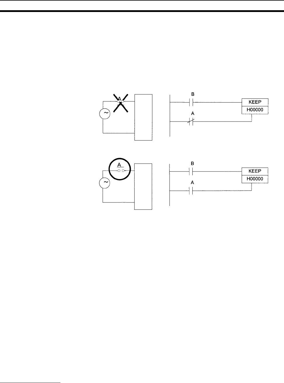
425
Auxiliary Area Section 9-16
3. The Function Block Holding Area words are allocated from H512 to H1535.
These words can be used only for the function block instance area (inter-
nally allocated variable area). These words cannot be specified as instruc-
tion operands in the user program.
Precautions When a Holding Area bit is used in a KEEP(011) instruction, never use a nor-
mally closed condition for the reset input if the input device uses an AC power
supply. When the power supply goes OFF or is temporarily interrupted, the
input will go OFF before the PLC’s internal power supply and the Holding Area
bit will be reset.
Instead, use a configuration like the one shown below.
There are no restrictions in the order of using bit address or in the number of
N.C. or N.O. conditions that can be programmed.
Note When designating addresses in programming or allocations inside C200H
Special I/O Units, “HR 00” to “HR 99” will actually specify H000 to H099 in the
CPU Unit and “AR 00” to “AR 27” will actually specify H100 to H127 in the
CPU Unit. Other addresses in this area cannot be specified inside the C200H
Special I/O Units.
9-16 Auxiliary Area
The Auxiliary Area contains 960 words with addresses ranging from A000 to
A959). These words are preassigned as flags and control bits to monitor and
control operation.
A000 through A447 are read-only, but A448 through A959 can be read or writ-
ten from the program or a Programming Device.
Note 1. The addresses in the Auxiliary Area cannot be designated directly in pro-
gramming or allocations inside C200H Special I/O Units.
2. The undefined addresses of the Auxiliary Area may be allocated to func-
tions in future version upgrades of the CPU Unit. Do not use these words
as CIO Area words in the user program.
Forcing Bit Status
Bits in the Auxiliary Area cannot be force-set and force-reset continuously.
Set input
Input
Unit
Reset input
Set input
Input
Unit
Reset input

426
Auxiliary Area Section 9-16
Writing Auxiliary Area Data
The following operations can be performed from a Programming Device to
write data in the Auxiliary Area.
• Using the CX-Programmer: Online set/reset (not force-set/force-reset)
(only for version 1.2 or higher), changing present values when monitoring
programming addresses (set values dialog box), or transferring data to
the PLC after editing the PLC data tables. Refer to the CX-Programmer
User Manual (W446).
• Using a Programming Console: Temporarily force-setting/force-resetting
bits from the Bit/Word Monitor or the 3-word Monitor operation (see Pro-
gramming Consoles Operation Manual).
Functions
The following table lists the functions of Auxiliary Area flags and control bits.
The table is organized according to the functions of the flags and bits. Some
of these functions are not supported by some CPU Unit models and unit ver-
sions. For more details or to look up a bit by its address, refer to Appendix B
Auxiliary Area.
Initial Settings
CPU Unit Settings
Basic I/O Unit Settings
Name Address Description Access
I/O Response Times in Basic
I/O Units
A22000 to
A25915
Contains the current I/O response times for CS-series Basic
I/O Units.
Read-only
IOM Hold Bit A50012 Determines whether the contents of I/O memory are
retained when the PLC’s power is reset or the PLC’s operat-
ing mode is changed (from PROGRAM to RUN/MONITOR
or vice-versa).
Turn ON this bit to maintain I/O memory when changing
between PROGRAM and RUN or MONITOR mode.
Turn OFF this bit to clear I/O memory when changing the
changing between PROGRAM and RUN or MONITOR
mode.
Read/write
Forced Status Hold BIt A50013 Determines whether the status of force-set and force-reset
bits is maintained when the PLC’s power is reset or the
PLC’s operating mode is changed (between PROGRAM and
RUN or MONITOR mode).
Read/write
Power Interruption Disable
Setting (CS1-H CPU Units
only)
A530 Set to A5A5 hex to disable power interrupts (except the
Power OFF Interrupt task) between DI(693) and EI(694)
instructions.
Read/write
Name Address Description Access
Status of DIP Switch Pin 6 A39512 Contains the status set on pin 6 of the CPU Unit’s DIP
switch. (Refreshed every cycle.)
Read-only
Name Address Description Access
Basic I/O Unit Status Area A05000 to
A08915
Indicates whether fuses in Basic I/O Units are intact or
blown. The flags correspond to rack 0, slot 0 through rack 7,
slot 9.
Read-only

427
Auxiliary Area Section 9-16
CPU Bus Unit Flags/Bits
Special I/O Unit Flags/Bits
Inner Board Flags/Bits
Flags for Programming
Name Address Description Access
CPU Bus Unit Initialization
Flags
A30200 to
A30215
These flags correspond to CPU Bus Units 0 to 15. A flag will
be ON while the corresponding Unit is initializing after the
power is turned ON or the Unit’s Restart Bit (in A501) is
turned ON.
Read-only
CPU Bus Unit Restart Bits A50100 to
A50115
These bits correspond to CPU Bus Units 0 to 15. Turn a bit
from OFF to ON to restart the corresponding Unit.
Read/write
Name Address Description Access
Special I/O Unit Initialization
Flags
A33000 to
A33515
These flags correspond to Special I/O Units 0 to 95. A flag
will be ON while the corresponding Unit is initializing after
the power is turned ON or the Unit’s Restart Bit is turned
ON. (Restart Bits A50200 to A50715 correspond to Units 0
to 95.)
Read-only
Special I/O Unit Restart Bits A50200 to
A50715
These bits correspond to Special I/O Units 0 to 95. Turn a bit
from OFF to ON to restart the corresponding Unit.
Read/write
Name Address Description Access
Inner Board Monitoring Area A35500 to
A35915
The function of these words is defined in the Inner Board. Read-only
Inner Board Restart Bit A60800 Turn the bit from OFF to ON to restart the corresponding
Inner Board.
Read/write
Name Address Description Access
First Cycle Flag A20011 This flag is turned ON for one cycle when program execution
starts (the operating mode is switched from PROGRAM to
RUN/MONITOR).
Read-only
Initial Task Execution Flag A20015 When a task switches from INI to RUN status for the first
time, this flag will be turned ON within the task for one cycle
only.
Read-only
Task Started Flag A20014 When a task switches from WAIT or INI to RUN status, this
flag will be turned ON within the task for one cycle only.
The only difference between this flag and A20015 is that this
flag also turns ON when the task switches from WAIT to
RUN status.
Read-only
10-ms Incrementing Free
Running Timer
A000 This word contains the system timer used after the power is
turned ON.
0000 hex is set when the power is turned ON and this value
is automatically incremented by 1 every 10 ms. The value
returns to 0000 hex after reaching FFFF hex (655,350 ms),
and then continues to be automatically incremented by 1
every 10 ms.
Note: The timer will continue to be incremented when the
operating mode is switched to RUN mode.
Example: The interval can be counted between processing
A and processing B without requiring timer
instructions. This is achieved by calculating the
difference between the value in A000 for process-
ing A and the value in A000 for processing B. The
interval is counted in 10 ms units.
Read-only

428
Auxiliary Area Section 9-16
Cycle Time Information
Task Information
100-ms Incrementing Free
Running Timer
A001 This word contains the system timer used after the power is
turned ON.
0000 hex is set when the power is turned ON and this value
is automatically incremented by 1 every 100 ms. The value
returns to 0000 hex after reaching FFFF hex (655,350 ms),
and then continues to be automatically incremented by 1
every 10 ms.
Note: The timer will continue to be incremented when the
operating mode is switched to RUN mode.
Read-only
1-s Incrementing Free
Running Timer
(Unit version 4.0 or later)
A002 This word contains the system timer used after the power is
turned ON.
0000 hex is set when the power is turned ON and this value
is automatically incremented by 1 every 1 s. The value
returns to 0000 hex after reaching FFFF hex (65,535 s),
and then continues to be automatically incremented by 1
every 1 s.
Note: The timer will continue to be incremented when the
operating mode is switched to RUN mode.
Read-only
Name Address Description Access
Maximum Cycle Time A262 to
A263
These words contain the maximum cycle time in units of
0.1 ms. In a Parallel Processing Mode, the maximum cycle
time of the program execution cycle will be given.
The time is updated every cycle and is recorded in 32-bit
binary (0 to FFFF FFFF, or 0 to 429,496,729.5 ms). (A263 is
the leftmost word.)
Read-only
Present Cycle Time A264 to
A265
These words contain the present cycle time in units of
0.1 ms. In a Parallel Processing Mode, the maximum cycle
time of the program execution cycle will be given. The time is
updated every cycle and is recorded in 32-bit binary (0 to
FFFF FFFF, or 0 to 429,496,729.5 ms). (A265 is the leftmost
word.)
Read-only
Peripheral Servicing Cycle
Time
A268 In Parallel Processing with Synchronous or Asynchronous
Memory Access, this word contains the peripheral servicing
cycle time in units of 0.1 ms. The time is updated every cycle
and is recorded in 16-bit binary (0 to 4E20 hex, or 0.0 to
2,000.0 ms).
Read-only
Name Address Description Access
Task Number when Program
Stopped
A294 This word contains the task number of the task that was
being executed when program execution was stopped
because of a program error.
Read-only
Maximum Interrupt Task Pro-
cessing Time
A440 Contains the Maximum Interrupt Task Processing Time in
units of 0.1 ms.
Read-only
Interrupt Task with Max. Pro-
cessing Time
A441 Contains the task number of the interrupt task with the maxi-
mum processing time. Hexadecimal values 8000 to 80FF
correspond to task numbers 00 to FF. Bit 15 is turned ON
when an interrupt has occurred.
Read-only
IR/DR Operation between
Tasks
A09914 Turn ON this bit to share index and data registers between
all tasks. Turn OFF this bit to use separate index and data
registers between in each task.
Read-only
Name Address Description Access

429
Auxiliary Area Section 9-16
Debugging Information
■Online Editing
■Output Control
■Differentiate Monitor
■Data Tracing
File Memory Information
Name Address Description Access
Online Editing Wait Flag A20110 ON when an online editing process is waiting.
(An online editing request was received while online editing
was disabled.)
Read-only
Online Editing Processing
Flag
A20111 ON when an online editing process is being executed. Read-only
Online Editing Disable Bit Vali-
dator
A52700 to
A52707
The Online Editing Disable Bit (A52709) is valid only when
this byte contains 5A.
Read/write
Online Editing Disable Bit A52709 Turn this bit ON to disable online editing.
(A52700 to A52707 must be set to 5A.)
Read/write
Name Address Description Access
Output OFF Bit A50015 Turn this bit ON to turn OFF all outputs from Basic I/O Units,
Output Units, and Special I/O Units.
Read/write
Name Address Description Access
Differentiate Monitor Com-
pleted Flag
A50809 ON when the differentiate monitor condition has been estab-
lished during execution of differentiation monitoring.
Read/write
Name Address Description Access
Sampling Start Bit A50815 When a data trace is started by turning this bit from OFF to
ON from a Programming Device, the PLC will begin storing
data in Trace Memory by one of the three following methods:
1) Periodic sampling (10 to 2,550 ms)
2) Sampling at execution of TRSM(045)
3) Sampling at the end of every cycle.
Read/write
Trace Start Bit A50814 Turn this bit from OFF to ON to establish the trigger condi-
tion. The offset indicated by the delay value (positive or neg-
ative) determines which data samples are valid.
Read/write
Trace Busy Flag A50813 ON when the Sampling Start Bit (A50815) is turned from
OFF to ON. OFF when the trace is completed.
Read/write
Trace Completed Flag A50812 ON when sampling of a region of trace memory has been
completed during execution of a Trace. OFF when the next
time the Sampling Start Bit (A50815) is turned from OFF to
ON.
Read/write
Trace Trigger Monitor Flag A50811 ON when a trigger condition is established by the Trace Start
Bit (A50814). OFF when the next Data Trace is started by
the Sampling Start bit (A50815).
Read/write
Name Address Description Access
Memory Card Type A34300 to
A34302
Indicates the type of Memory Card, if any, installed. Read-only
Memory Card Format Error
Flag
A34307 ON when the Memory Card is not formatted or a formatting
error has occurred.
Read-only
File Transfer Error Flag A34308 ON when an error occurred while writing data to file memory. Read-only
File Write Error Flag A34309 ON when data cannot be written to file memory because it is
write-protected or the data exceeds the capacity of the file
memory.
Read-only
File Read Error A34310 ON when a file could not be read because of a malfunction
(file is damaged or data is corrupted).
Read-only

430
Auxiliary Area Section 9-16
File Missing Flag A34311 ON when an attempt is made to read a file that doesn’t exist,
or an attempt is made to write to a file in a directory that
doesn’t exist.
Read-only
File Memory Operation Flag A34313 ON while any of the following operations is being executed.
OFF when none of them are being executed.
Memory Card detection started.
CMND instruction sending a FINS command to the local
CPU Unit.
FREAD/FWRIT instructions.
Program replacement using the control bit in the Auxiliary
Area.
Easy backup operation.
If this flag is ON, write and comparison operations to the
Memory Card cannot be executed.
Read-only
Memory Card Detected Flag A34315 ON when a Memory Card has been detected.
OFF when a Memory Card has not been detected.
Read-only
Number of Items to
Transfer
A346 to
A347
These words contain the number of words or fields remain-
ing to be transferred (8-digit hexadecimal).
For binary files (.IOM), the value is decremented for each
word that is read. For text (.TXT) or CSV (.CSV) data, the
value is decremented for each field that is read.
Read-only
Accessing File Data Flag A34314 ON while file data is being accessed. Read-only
EM File Memory Format Error
Flag
A34306 Turns ON when a format error occurs in the first EM bank
allocated for file memory.
Turns OFF when formatting is completed normally.
Read-only
EM File Memory Starting
Bank
A344 Contains the starting bank number of EM file memory (bank
number of the first formatted bank).
This number is read when starting to write data from a Mem-
ory Card. If the largest bank number for which there is an
EM file for simple backup (BACKUPE@.IOM, where repre-
sents consecutive bank numbers) is the same as the largest
bank number supported by the CPU Unit, the EM Area will
be formatted as file memory using the value in A344. If the
maximum bank numbers are different, the EM Area will be
returned to it’s unformatted (not file memory) status.
Read-only
Program Index File Flag A34501 Turns ON when the comment memory contains a program
index file.
0: No file
1: File present
Read-only
Comment File Flag A34502 Turns ON when the comment memory contains a comment
file.
0: No file
1: File present
Symbol Table File Flag A34503 Turns ON when the comment memory contains a symbol
table file.
0: No file
1: File present
File Deletion Flags A39506 The system automatically deleted the remainder of an EM
file memory file that was being updated when a power inter-
ruption occurred.
Read-only
A39507 The system automatically deleted the remainder of a Mem-
ory Card file that was being updated when a power interrup-
tion occurred.
Read-only
Name Address Description Access

431
Auxiliary Area Section 9-16
Simple Backup Write Capacity A397 If a write for a simple backup operation fails, A397 will con-
tain the Memory Card capacity that would have been
required to complete the write operation. The value is in
Kbytes. (This indicates that the Memory Card did not have
the specified capacity when the write operation was started.)
0001 to FFFF hex: Write error (value indicates required
capacity from 1 to 65,535 Kbytes).
A397 will be cleared to 0000 hex when the write is com-
pleted successfully for a simple backup operation.
Read-only
Program Replacement End
Code
A65000 to
A65007
Normal End (i.e., when A65014 is OFF)
01 hex: Program file (.OBJ) replaced.
Error End (i.e., when A65014 is ON)
00 hex: Fatal error
01 hex: Memory error
11 hex: Write-protected
12 hex: Program replacement password error
21 hex: No Memory Card
22 hex: No such file
23 hex: Specified file exceeds capacity (memory error).
31 hex: One of the following in progress:
File memory operation
User program write
Operating mode change
Read-only
Replacement Error Flag A65014 ON when the Replacement Start Bit (A65015) has been
turned ON to replace the program, but there is an error. If
the Replacement Start Bit is turned ON again, the Replace-
ment Error Flag will be turned OFF.
Read/write
Replacement Start Bit A65015 Program replacement starts when the Replacement Start Bit
is turned ON if the Program Password (A651) is valid (A5A5
hex). Do not turn OFF the Replacement Start Bit during pro-
gram replacement.
When the power is turned ON or program replacement is
completed, the Replacement Start Bit will be turned OFF,
regardless of whether replacement was completed normally
or in error.
It is possible to confirm if program replacement is being exe-
cuted by reading the Replacement Start Bit using a Pro-
gramming Device, PT, or host computer.
Read/write
Name Address Description Access
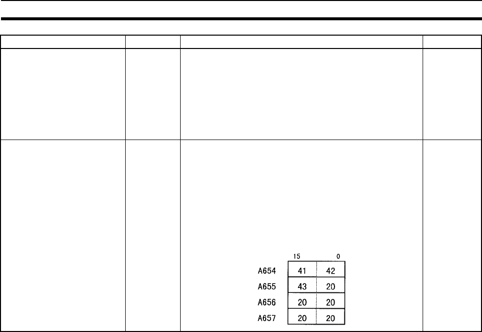
432
Auxiliary Area Section 9-16
Program Password A651 Store the password to replace a program.
A5A5 hex: Replacement Start Bit (A65015) is enabled.
Any other value: Replacement Start Bit (A65015) is dis-
abled.
When the power is turned ON or program replacement is
completed, the Replacement Start Bit will be turned OFF,
regardless of whether replacement was completed normally
or in error.
Read/write
Program File Name A654 to
A657
When program replacement starts, the program file name
will be stored in ASCII. File names can be specified up to
eight characters in length excluding the extension.
File names are stored in the following order: A654 to A657
(i.e., from the lowest word to the highest), and from the high-
est byte to the lowest. If a file name is less than eight charac-
ters, the lowest remaining bytes and the highest remaining
word will be filled with spaces (20 hex). Null characters and
space characters cannot be used within file names.
Example: File name is ABC.OBJ
Read/write
Name Address Description Access

433
Auxiliary Area Section 9-16
Program Error Information
Error Information
■Error Log, Error Code
Name Address Description Access
Program Error Flag
(Fatal error)
A40109 ON when program contents are incorrect. CPU Unit opera-
tion will stop.
Read-only
Program Error Task A294 Provides the type and number of the tack that was being
executed when program execution stops as a result of a pro-
gram error.
Read-only
Instruction Processing Error
Flag
A29508 This flag and the Error Flag (ER) will be turned ON when an
instruction processing error has occurred and the PLC
Setup has been set to stop operation for an instruction error.
Read-only
Indirect DM/EM BCD Error
Flag
A29509 This flag and the Access Error Flag (AER) will be turned ON
when an indirect DM/EM BCD error has occurred and the
PLC Setup has been set to stop operation an indirect
DM/EM BCD error.
Read-only
Illegal Access Error Flag A29510 This flag and the Access Error Flag (AER) will be turned ON
when an illegal access error has occurred and the PLC
Setup has been set to stop operation an illegal access error.
Read-only
No END Error Flag A29511 ON when there isn’t an END(001) instruction in each pro-
gram within a task.
Read-only
Task Error Flag A29512 ON when a task error has occurred. The following conditions
will generate a task error.
1) There isn’t an executable cyclic task.
2) There isn’t a program allocated to the task.
Read-only
Differentiation Overflow Error
Flag
A29513 ON when the specified Differentiation Flag Number exceeds
the allowed value.
Read-only
Illegal Instruction Error Flag A29514 ON when a program that cannot be executed has been
stored.
Read-only
UM Overflow Error Flag A29515 ON when the last address in UM (user program memory)
has been exceeded.
Read-only
Program Address Where
Program Stopped
A298 and
A299
These words contain the 8-digit hexadecimal program
address of the instruction where program execution was
stopped due to a program error.
(A299 contains the leftmost digits.)
Read-only
Name Address Description Access
Error Log Area A100 to
A199
When an error has occurred, the error code, error contents,
and error’s time and date are stored in the Error Log Area.
Read-only
Error Log Pointer A300 When an error occurs, the Error Log Pointer is incremented
by 1 to indicate the location where the next error record will
be recorded as an offset from the beginning of the Error Log
Area (A100).
Read-only
Error Log Pointer Reset Bit A50014 Turn this bit ON to reset the Error Log Pointer (A300) to 00. Read/write
Error Code A400 When a non-fatal error (user-defined FALS(006) or system
error) or a fatal error (user-defined FALS(007) or system
error) occurs, the 4-digit hexadecimal error code is written to
this word.
Read-only

434
Auxiliary Area Section 9-16
■FAL/FALS Error Information
■Memory Error Information
■PLC Setup Error Information
Name Address Description Access
FAL Error Flag
(Non-fatal error)
A40215 ON when a non-fatal error is generated by executing
FAL(006).
Read-only
Executed FAL Number Flags A360 to
A391
The flag corresponding to the specified FAL number will be
turned ON when FAL(006) is executed. Bits A36001 to
A39115 correspond to FAL numbers 001 to 511.
Read-only
FALS Error Flag
(Fatal error)
A40106 ON when a fatal error is generated by the FALS(007)
instruction.
Read-only
FAL/FALS Number for Sys-
tem Error Simulation
A053 Set a dummy FAL/FALS number to use to simulate the sys-
tem error using FAL(006) or FALS(007).
0001 to 01FF hex: FAL/FALS numbers 1 to 511
0000 or 0200 to FFFF hex: No FAL/FALS number for system
error simulation. (No error will be generated.)
Read/write
Name Address Description Access
Memory Error Flag
(Fatal error)
A40115 ON when an error occurred in memory or there was an error
in automatic transfer from the Memory Card when the power
was turned ON.
The ERR/ALM indicator on the front of the CPU Unit will light
and CPU Unit operation will stop when this flag turns ON.
If the automatic data transfer at startup fails, A40309 will be
turned ON. If an error occurs in automatic transfer at startup,
this error cannot be cleared.
Read-only
Memory Error Location A40300 to
A40308
When a memory error occurs, the Memory Error Flag
(A40115) is turned ON and one of the following flags is
turned ON to indicate the memory area where the error
occurred.
A40300: User program
A40304: PLC Setup
A40305: Registered I/O Table
A40307: Routing Table
A40308: CS-series CPU Bus Unit Settings
Read-only
Startup Memory Card Transfer
Error Flag
A40309 ON when an error occurs in automatically transferring a file
from the Memory Card to the CPU Unit at startup, including
when a file is missing or a Memory Card is not mounted.
The error can be cleared by turning OFF the power. (This
error cannot be cleared while the power is ON.)
Read-only
Flash Memory Error A40310 Turns ON when the flash memory fails. Read-only
Name Address Description Access
PLC Setup Error Flag
(Non-fatal error)
A40210 ON when there is a setting error in the PLC Setup. Read-only
PLC Setup Error Location A406 When there is a setting error in the PLC Setup, the location
of that error is written to A406 in 4-digit hexadecimal. The
location is given as the address set on the Programming
Console.
Read-only

435
Auxiliary Area Section 9-16
■Interrupt Task Error Information
■I/O Information
Name Address Description Access
Interrupt Task Error Flag
(Non-fatal error)
A40213 ON when the Detect Interrupt Task Errors setting in the PLC
Setup is set to “Detect” and one of the following occurs.
IORD(222) or IOWR(223) in a cyclic task are competing with
IORD(222) or IOWR(223) in an interrupt task.
An interrupt task is executed for more than 10 ms during I/O
refreshing of a C200H Special I/O Unit or a SYSMAC BUS
I/O Unit.
IORD(222) or IOWR(223) was executed in an interrupt task
when I/O was being refreshed.
Read-only
Interrupt Task Error Cause
Flag
A42615 Indicates the cause of an Interrupt Task Error. Read-only
Interrupt Task Error, Task
Number
A42600 to
A42611
The function of these bits depends upon the status of
A42615 (the Interrupt Task Error Cause Flag).
A42615 OFF:
Contains the interrupt task number when an interrupt task
was executed for more than 10 ms during I/O refreshing of a
C200H Special I/O Unit or a SYSMAC BUS Remote I/O Unit.
A42615 ON:
Contains the Special I/O Unit’s unit number when an attempt
was made to refresh a Special I/O Unit’s I/O from an inter-
rupt task with IORF(097) while the Unit’s I/O was being
refreshed by cyclic I/O refreshing (duplicate refreshing).
Read-only
Name Address Description Access
Basic I/O Unit Error Flag
(Non-fatal error)
A40212 ON when an error has occurred in a Basic I/O Unit (including
C200H Group-2 High-density I/O Units and C200H Interrupt
Input Units).
Read-only
Basic I/O Unit Error, Slot
Number
A40800 to
A40807
Contains the binary slot number where the error occurred
when an error has occurred in a Basic I/O Unit (including
C200H Group-2 High-density I/O Units and C200H Interrupt
Input Units).
Read-only
Basic I/O Unit Error, Rack
Number
A40808 to
A40815
Contains the binary rack number where the error occurred
when an error has occurred in a Basic I/O Unit (including
C200H Group-2 High-density I/O Units and C200H Interrupt
Input Units).
Read-only
I/O Setting Error Flag
(Fatal error)
A40110 ON when an Input Unit has been installed in an Output
Unit’s slot or vice-versa, so the Input and Output Units clash
in the registered I/O table.
Read-only
I/O Verification Error Flag
(Non-fatal error)
A40209 ON when a Basic I/O Unit registered in the I/O Table does
not match the Basic I/O Unit actually installed in the PLC
because a Unit was added or removed.
Read-only
Expansion I/O Rack Number
Duplication Flags
A40900 to
A40907
The corresponding flag will be turned ON when an Expan-
sion I/O Rack’s starting word address was set from a Pro-
gramming Device and two Racks have overlapping word
allocations or a Rack’s starting address exceeds CIO 0901.
Bits 00 to 07 correspond to Racks 0 to 7.
Read-only
Too Many I/O Points Flag
(Fatal error)
A40111 ON when the number of I/O points being used in Basic I/O
Units exceeds the maximum allowed for the PLC.
Read-only

436
Auxiliary Area Section 9-16
Too Many I/O Points, Details A40700 to
A40712
The 6 possible causes of the Too Many I/O Points Error are
listed below. The 3-digit binary value in A40713 to A40715
indicates the cause of the error. (The causes corresponding
to values 0 to 5 are listed below.)
The 13-bit binary value in A40700 to A40712 indicates the
details: the excessive value or the duplicated unit number.
The number of I/O points will be written here when the total
number of I/O points set in the I/O Table (excluding Slave
Racks) exceed the maximum allowed for the CPU Unit.
The number of interrupt inputs will be written here when
there are more than 32 interrupt inputs.
The unit number of the Slave Unit will be written here when a
unit number is duplicated or the number of I/O points on a
C500 Slave Unit exceeds 320.
The unit number of the I/O Terminal (excluding Slave Racks)
will be written here when a unit number is duplicated
The unit number of the Master Unit will be written here when
a unit number is duplicated or the unit number is outside of
the allowed setting range.
The number of Racks will be written here when the number
of Expansion I/O Racks exceeds the maximum.
Read-only
Too Many I/O Points, Cause A40713 to
A40715
These three bits indicate the cause of the Too Many I/O
Points Error. (See A40700 to A40712.)
000 (0): Too many I/O points.
001 (1): Too many Interrupt Input points.
010 (2): Slave Unit’s unit number duplicated or the number
of I/O points on a C500 Slave Unit exceeds 320.
011 (3): I/O Terminal’s unit number duplicated.
100 (4): Master Unit’s unit number duplicated or unit number
is out-of-range (not 0 or 1).
101 (5): Too many Expansion Racks connected.
110 (6): The unit number of the Remote I/O Master Unit is 4,
6, or 7, or an Special I/O Unit’s unit number cannot be
detected.
Read-only
I/O Bus Error Flag
(Fatal error)
A40114 ON when an error occurs in a data transfer between the
CPU Unit and a Unit mounted to a slot.
Read-only
I/O Bus Error Slot Number A40400 to
A40407
Contains the 8-bit binary slot number (00 to 09) where an
I/O Bus Error occurred.
Read-only
I/O Table Errors A26100 ON: Error in CPU Bus Unit Setup
Turns OFF when I/O tables are generated normally.
Read-only
A26102 ON: Overflow in maximum number of I/O points.
Turns OFF when I/O tables are generated normally.
Read-only
A26103 ON: The same unit number was used more than once.
Turns OFF when I/O tables are generated normally.
Read-only
A26104 ON: I/O bus error
Turns OFF when I/O tables are generated normally.
Read-only
A26106 ON: SYSMAC BUS detection ended in an error.
Turns OFF when I/O tables are generated normally.
Read-only
A26107 ON: Error in a Special I/O Unit
Turns OFF when I/O tables are generated normally.
Read-only
A26109 ON: I/O detection has not been completed.
Turns OFF when I/O tables are generated normally.
Read-only
Name Address Description Access

437
Auxiliary Area Section 9-16
■CPU Bus Unit Information
■Special I/O Unit Information
I/O Bus Error Rack Number A40408 to
A40415
Contains the 8-bit binary rack number (00 to 07) where an
I/O Bus Error occurred.
Read-only
Duplication Error Flag
(Fatal error)
A40113 ON in the following cases:
Two CPU Bus Units have been assigned the same unit num-
ber.
Two Special I/O Units have been assigned the same unit
number.
Two Basic I/O Units have been allocated the same data area
words.
The same rack number is set for more than one Expansion
Rack.
Read-only
Name Address Description Access
CPU Bus Unit Number Dupli-
cation Flags
A410 The Duplication Error Flag (A40113) and the corresponding
flag in A410 will be turned ON when a CPU Bus Unit’s unit
number has been duplicated.
Bits 00 to 15 correspond to unit numbers 0 to F.
Read-only
CPU Bus Unit Error, Unit
Number Flags
A417 When an error occurs in a data exchange between the CPU
Unit and a CPU Bus Unit, the CPU Bus Unit Error Flag
(A40207) and the corresponding flag in A417 are turned ON.
Bits 00 to 15 correspond to unit numbers 0 to F.
Read-only
CPU Bus Unit Setting Error,
Unit Number Flags
A427 When a CPU Bus Unit Setting Error occurs, A40203 and the
corresponding flag in A27 are turned ON.
Bits 00 to 15 correspond to unit numbers 0 to F.
Read-only
CPU Bus Unit Setting Error
Flag
(Non-fatal error)
A40203 ON when an installed CPU Bus Unit does not match the
CPU Bus Unit registered in the I/O table.
Read-only
CPU Bus Unit Error Flag
(Non-fatal error)
A40207 ON when an error occurs in a data exchange between the
CPU Unit and a CPU Bus Unit (including an error in the CPU
Bus Unit itself).
Read-only
Name Address Description Access
Special I/O Unit Number
Duplication Flags
A41100 to
A41615
The Duplication Error Flag (A40113) and the corresponding
flag in A411 through A416 will be turned ON when a Special
I/O Unit’s unit number has been duplicated. (Bits A41100 to
A41615 correspond to unit numbers 0 to 95.)
Read-only
Special I/O Unit Setting Error
Flag
(Non-fatal error)
A40202 ON when an installed Special I/O Unit does not match the
Special I/O Unit registered in the I/O table.
Read-only
Special I/O Unit Setting Error,
Unit Number Flags
A42800 to
A43315
When a Special I/O Unit Setting Error occurs, A40202 and
the corresponding flag in these words are turned ON. (Bits
A42800 to A43315 correspond to unit numbers 0 to 95.)
Read-only
Special I/O Unit Error Flag
(Non-fatal error)
A40206 ON when an error occurs in a data exchange between the
CPU Unit and a Special I/O Unit (including an error in the
Special I/O Unit itself).
Read-only
Special I/O Unit Error, Unit
Number Flags
A41800 to
A42315
When an error occurs in a data exchange between the CPU
Unit and a Special I/O Unit, the Special I/O Unit Error Flag
(A40206) and the corresponding flag in these words are
turned ON. (Bits A42800 to A43315 correspond to unit num-
bers 0 to 95.)
Read-only
Name Address Description Access

438
Auxiliary Area Section 9-16
■Inner Board Information
■SYSMAC BUS Remote I/O Information
■PLC Link Information
Name Address Description Access
Inner Board Error Flag
(Non-fatal error)
A40208 ON when an error occurs in a data exchange between the
CPU Unit and the Inner Board (including an error in the Inner
Board itself).
Read-only
Inner Board Error
Information
A424 When an error occurs in a data exchange between the CPU
Unit and the Inner Board, the Inner Board Error Flag
(A40208) and the appropriate error code will be written to
A424.
Read-only
Inner Board Stopped Error
Flag (Fatal error)
A40112 ON when there is an Inner Board Error (watchdog timer
error).
Read-only
Name Address Description Access
SYSMAC BUS Error Flag
(Non-fatal error)
A40205 ON when an error occurs in a data transfer in the SYSMAC
BUS system. The number of the Master involved is indicated
with bits A40500 and A40501.
Read-only
SYSMAC BUS Master Error
Flags
A40500 to
A40501
When a transmission error occurs in the SYSMAC BUS sys-
tem, the flag for the affected Master Unit will be turned ON.
A40500: Flag for Master Unit #0
A40501: Flag for Master Unit #1
Read-only
Slave Number of
SYSMAC BUS Error After
Start-up
A42504 to
A42506
When there is an error in a Slave Rack, these bits contain
the Slave’s unit number.
Read-only
A42504
only
When there is an error in an Optical I/O Unit (excluding
Slave Racks), the status of A42504 (0 or 1) indicates
whether the Unit is low or high.
Read-only
A42508 to
A42515
When there is an error in a Slave Rack, this byte contains
the 2-digit hexadecimal unit number of the Master to which
the Slave is connected.
(0xB0 for Master Unit 0, 0xB1 for Master Unit 1)
Read-only
When there is an error in an Optical I/O Unit, this byte con-
tains its 2-digit hexadecimal unit number (00 to 1F, or 0 to 31
decimal).
Read-only
SYSMAC BUS Slave Number
Refresh Bit
A50900 Turn this bit ON to refresh the error information in A425 (unit
number of Slave where error occurred after startup).
Read/write
Name Address Description Access
PLC Link Operating Level
Flags
A44211 These flags indicate whether a PLC Link Unit is mounted to
the PLC and the PLC Link Unit’s operating level.
ON when the Unit is in operating level #1.
Read-only
A44212 These flags indicate whether a PLC Link Unit is mounted to
the PLC and the PLC Link Unit’s operating level.
ON when the Unit is in operating level #0.
Read-only
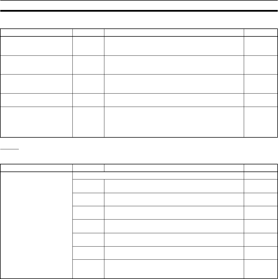
439
Auxiliary Area Section 9-16
■Other PLC Operating Information
Clock
■Clock Information
The internal clock time is saved in the above words in the Auxiliary Area once
every few cycles. For details on internal clock accuracy, refer to 2-1-1 CPU
Unit Specifications.
Name Address Description Access
Battery Error Flag
(Non-fatal error)
A40204 ON if the CPU Unit’s battery is disconnected or its voltage is
low and the PLC Setup has been set to detect this error.
(Detect Low Battery)
Read-only
Cycle Time Too Long Flag
(Fatal error)
A40108 ON if the cycle time exceeds the maximum cycle time set in
the PLC Setup. In the Parallel Processing Modes, the pro-
gram execution cycle time will be used. (Watch Cycle Time)
Read-only
Peripheral Servicing Too Long
Flag
A40515 Turns ON when the peripheral servicing time in a Parallel
Processing Mode exceeds 2 s. This will also cause a cycle
time error and operation will stop.
Read-only
FPD Teaching Bit A59800 Turn this bit ON to set the monitoring time in FPD(269) auto-
matically with the teaching function.
Read/write
Memory Backup Battery Fail-
ure Flag
A39511 Data from the I/O memory areas that are maintained when
power is turned OFF (HR, DM, etc.) are backed up with a
Battery. A39511 turns ON if the Battery voltage drops and
the data can no longer be maintained. The data in the I/O
memory will not be dependable when this happens.
Read-only
Name Address Description Access
Clock Data The clock data from the clock built into the CPU Unit is stored here in BCD. Read-only
A35100 to
A35107
Seconds: 00 to 59 (BCD) Read-only
A35108 to
A35115
Minutes: 00 to 59 (BCD) Read-only
A35200 to
A35207
Hour: 00 to 23 (BCD) Read-only
A35208 to
A35215
Day of the month: 01 to 31 (BCD) Read-only
A35300 to
A35307
Month: 01 to 12 (BCD) Read-only
A35308 to
A35315
Year: 00 to 99 (BCD) Read-only
A35400 to
A35407
Day of the week: 00: Sunday, 01: Monday,
02: Tuesday, 03: Wednesday, 04: Thursday,
05: Friday, 06: Saturday
Read-only

440
Auxiliary Area Section 9-16
■Operation Start and End Times
■Power Supply ON/OFF Time Information
Name Address Description Access
Operation Start Time A515 to
A517
The time that operation started as a result of changing the
operating mode to RUN or MONITOR mode is stored here in
BCD.
A51500 to A51507: Seconds (00 to 59)
A51508 to A51515: Minutes (00 to 59)
A51600 to A51607: Hour (00 to 23)
A51608 to A51615: Day of month (01 to 31)
A51700 to A51707: Month (01 to 12)
A51708 to A51715: Year (00 to 99)
Note: The previous start time is stored after turning ON the
power supply until operation is started.
Read/write
Operation End Time A518 to
A520
The time that operation stopped as a result of changing the
operating mode to PROGRAM mode is stored here in BCD.
A51800 to A51807: Seconds (00 to 59)
A51808 to A51815: Minutes (00 to 59)
A51900 to A51907: Hour (00 to 23)
A51908 to A51915: Day of month (01 to 31)
A52000 to A52007: Month (01 to 12)
A52008 to A52015: Year (00 to 99)
Note: If an error occurs in operation, the time of the error will
be stored. If the operating mode is then changed to PRO-
GRAM mode, the time that PROGRAM mode was entered
will be stored.
Read/write
Name Address Description Access
Startup Time A510 and
A511
These words contain the time (in BCD) at which the power
was turned ON. The contents are updated every time that
the power is turned ON.
A51000 to A51007: Seconds (00 to 59)
A51008 to A51015: Minutes (00 to 59)
A51100 to A51107: Hour (00 to 23)
A51108 to A51115: Day of the month (01 to 31)
Read/write
Power Interruption Time A512 and
A513
These words contain the time (in BCD) at which the power
was interrupted. The contents are updated every time that
the power is interrupted.
A51200 to A51207: Seconds (00 to 59)
A51208 to A51215: Minutes (00 to 59)
A51300 to A51307: Hour (00 to 23)
A51308 to A51315: Day of month (01 to 31)
Read/write
Number of Power
Interruptions
A514 Contains the number of times (in binary) that power has
been interrupted since the power was first turned on. To
reset this value, overwrite the current value with 0000.
Read/write
Total Power ON Time A523 Contains the total time (in binary) that the PLC has been on
in 10-hour units. The data is stored is updated every 10
hours. To reset this value, overwrite the current value with
0000.
Read/write
Power ON Clock Data 1 (See
note.)
A720 to
A722
These words contain the startup date/time (the same time
as the startup time stored in words A510 to A511 as well as
the month and year information) for the last time that power
was turned ON. The data is BCD.
A72000 to A72007: Seconds (00 to 59)
A72008 to A72015: Minutes (00 to 59)
A72100 to A72107: Hour (00 to 23)
A72108 to A72115: Day of month (01 to 31)
A72200 to A72207: Month (01 to 12)
A72208 to A72215: Year (00 to 99)
Read/write

441
Auxiliary Area Section 9-16
Note Supported only by unit version 3.0 or later.
Power ON Clock Data 2 (See
note.)
A723 to
A725
These words contain the startup time/date for the second-to-
last time that power was turned ON.
The data is BCD and the storage format is the same as
words A720 to A722.
Read/write
Power ON Clock Data 3 (See
note.)
A726 to
A728
These words contain the startup time/date for the third-to-
last time that power was turned ON.
The data is BCD and the storage format is the same as
words A720 to A722.
Read/write
Power ON Clock Data 4 (See
note.)
A729 to
A731
These words contain the startup time/date for the fourth-to-
last time that power was turned ON.
The data is BCD and the storage format is the same as
words A720 to A722.
Read/write
Power ON Clock Data 5 (See
note.)
A732 to
A734
These words contain the startup time/date for the fifth-to-last
time that power was turned ON.
The data is BCD and the storage format is the same as
words A720 to A722.
Read/write
Power ON Clock Data 6 (See
note.)
A735 to
A737
These words contain the startup time/date for the sixth-to-
last time that power was turned ON.
The data is BCD and the storage format is the same as
words A720 to A722.
Read/write
Power ON Clock Data 7 (See
note.)
A738 to
A740
These words contain the startup time/date for the seventh-
to-last time that power was turned ON.
The data is BCD and the storage format is the same as
words A720 to A722.
Read/write
Power ON Clock Data 8 (See
note.)
A741 to
A743
These words contain the startup time/date for the eighth-to-
last time that power was turned ON.
The data is BCD and the storage format is the same as
words A720 to A722.
Read/write
Power ON Clock Data 9 (See
note.)
A744 to
A746
These words contain the startup time/date for the ninth-to-
last time that power was turned ON.
The data is BCD and the storage format is the same as
words A720 to A722.
Read/write
Power ON Clock Data 10 (See
note.)
A747 to
A749
These words contain the startup time/date for the tenth-to-
last time that power was turned ON.
The data is BCD and the storage format is the same as
words A720 to A722.
Read/write
Name Address Description Access

442
Auxiliary Area Section 9-16
■User Data Revision Times
Information on Read Protection Using a Password
Name Address Description Access
User Program Date A090 to
A093
These words contain in BCD the date and time that the user
program was last overwritten.
A09000 to A09007: Seconds (00 to 59)
A09008 to A09015: Minutes (00 to 59)
A09100 to A09107: Hour (00 to 23)
A09108 to A09115: Day of month (01 to 31)
A09200 to A09207: Month (01 to 12)
A09208 to A09215: Year (00 to 99)
A09308 to A09307: Day of the week
(00: Sunday, 01: Monday, 02: Tuesday, 03: Wednesday, 04:
Thursday, 05: Friday, 06: Saturday)
Read-only
Parameter Date A094 to
A097
These words contain in BCD the date and time that the
parameters were last overwritten.
A09400 to A09407: Seconds (00 to 59)
A09408 to A09415: Minutes (00 to 59)
A09500 to A09507: Hour (00 to 23)
A09508 to A09515: Day of month (01 to 31)
A09600 to A09607: Month (01 to 12)
A09608 to A09615: Year (00 to 99)
A09708 to A09707: Day of the week
(00: Sunday, 01: Monday, 02: Tuesday, 03: Wednesday, 04:
Thursday, 05: Friday, 06: Saturday)
Read-only
Name Address Description Access
UM Read Protection Flag A09900 Indicates whether the entire user program in the PLC is
read-protected.
0: UM not read-protected.
1: UM read-protected.
Read-only
Task Read Protection Flag A09901 Indicates whether read protection is set for individual tasks.
0: Tasks not read-protected.
1: Tasks read-protected.
Read-only
Program Write Protection for
Read Protection
A09902 Indicates whether the program is write-protected.
0: Write-enabled.
1: Write-protected.
Read-only
Enable/Disable Bit for Pro-
gram Backup
A09903 Indicates whether creating a backup program file (.OBJ) is
enabled or disabled.
0: Enabled.
1: Disabled.
Read-only

443
Auxiliary Area Section 9-16
Communications
■Network
Network Communications Information
Name Address Description Access
Communications Port Enabled
Flags
A20200 to
A20207
ON when a network instruction (SEND(090), RECV(098),
CMND(490), or PMCR(260)) can be executed with the cor-
responding port number or background execution can be
executed with the corresponding port number (CS1-H CPU
Units only). Bits 00 to 07 correspond to communications
ports 0 to 7.
When the simple backup operation is used to performed a
write or compare operation for a Memory Card on a CS1-H
CPU Unit, a communications port will be automatically allo-
cated, and the corresponding flag will be turned ON during
the operation and turned OFF when the operation has been
completed.
Read-only
Communications Port Com-
pletion Codes
A203 to
A210
These words contain the completion codes for the corre-
sponding port numbers when network instructions
(SEND(090), RECV(098), CMND(490), or PMCR(260))
have been executed. The contents will be cleared when
background execution has been completed (for CS1-H CPU
Unit only). Words A203 to A210 correspond to communica-
tions ports 0 to 7.
When the simple backup operation is used to performed a
write or compare operation for a Memory Card on a CS1-H
CPU Unit, a communications port will be automatically allo-
cated, and a completion code will be stored in the corre-
sponding word.
Read-only
Communications Port Error
Flags
A21900 to
A21907
ON when an error occurred during execution of a network
instruction (SEND(090), RECV(098), CMND(490), or
PMCR(260)). Turns OFF then execution has been finished
normally. Bits 00 to 07 correspond to communications ports
0 to 7.
When the simple backup operation is used to performed a
write or compare operation for a Memory Card on a CS1-H
CPU Unit, a communications port will be automatically allo-
cated. The corresponding flag will be turned ON if an error
occurs and will be turned OFF if the simple backup opera-
tion ends normally.
Read-only

444
Auxiliary Area Section 9-16
Auxiliary Area Bits and Words Used when Automatically Allocating
Communications Ports
Name Address Description Access
Network Communications
Port Allocation Enabled Flag
A20215 ON when there is a communications port available for auto-
matic allocation.
Note: Use this flag to confirm whether a communications
port is available for automatic allocation before exe-
cuting communications instructions when using 9 or
more communications instructions simultaneously.
Read-only
First Cycle Flags after Net-
work Communications Fin-
ished
A21400 to
A21407
Each flag will turn ON for just one cycle after communica-
tions have been completed. Bits 00 to 07 correspond to
ports 0 to 7. Use the Used Communications Port Number
stored in A218 to determine which flag to access.
Note: These flags are not effective until the next cycle after
the communications instruction is executed. Delay
accessing them for at least one cycle.
Read-only
First Cycle Flags after Net-
work Communications Error
A21500 to
A21507
Each flag will turn ON for just one cycle after a communica-
tions error occurs. Bits 00 to 07 correspond to ports 0 to 7.
Use the Used Communications Port Number stored in A218
to determine which flag to access. Determine the cause of
the error according to the Communications Port Completion
Codes stored in A203 to A210.
Note: These flags are not effective until the next cycle after
the communications instruction is executed. Delay
accessing them for at least one cycle.
Read-only
Network Communications
Completion Code Storage
Address
A216 to
A217
The completion code for a communications instruction is
automatically stored at the address with the I/O memory
address given in these words. Place this address into an
index register and use indirect addressing through the index
register to read the communications completion code.
Read-only
Used Communications Port
Numbers
A218 Stores the communications port numbers used when a com-
munications instruction is executed using automatic commu-
nication port allocations.
0000 to 0007 hex: Communications port 0 to 7
Read-only

445
Auxiliary Area Section 9-16
Information on Explicit Message Instructions
SYSMAC BUS Communications Information
Name Address Description Access
Explicit Communications Error
Flag
A21300 to
A21307
Turn ON when an error occurs in executing an Explicit Mes-
sage Instruction (EXPLT(720), EGATR(721), ESATR(722),
ECHRD(723), or ECHWR(724)).
Bits 00 to 07 correspond to communications ports 0 to 7.
The corresponding bit will turn ON both when the explicit
message cannot be sent and when an error response is
returned for the explicit message.
The status will be maintained until the next explicit message
communication is executed. The bit will always turn OFF
when the next Explicit Message Instruction is executed.
Read-only
Network Communications
Error Flag
A21900 to
A21907
Turn ON if the explicit message cannot be sent when execut-
ing an Explicit Message Instruction (EXPLT(720),
EGATR(721), ESATR(722), ECHRD(723), or ECHWR(724)).
Bits 00 to 07 correspond to communications ports 0 to 7.
The corresponding bit will turn ON when the explicit mes-
sage cannot be sent.
The status will be maintained until the next explicit message
communication is executed. The bit will always turn OFF
when the next Explicit Message Instruction is executed.
Read-only
Network Communications
Response Code
A203 to
A210
The following codes will be stored when an Explicit Message
Instruction (EXPLT(720), EGATR(721), ESATR(722),
ECHRD(723), or ECHWR(724)) has been executed.
A203 to A210 correspond to communications ports 0 to 7.
If the Explicit Communications Error Flag turns OFF, 0000
hex is stored.
If the Explicit Communications Error Flag is ON and the Net-
work Communications Error Flag is ON, the FINS end code
is stored.
If the Explicit Communications Error Flag is ON and the Net-
work Communications Error Flag is OFF, the explicit mes-
sage end code is stored.
During communications, 0000 hex will be stored and the
suitable code will be stored when execution has been com-
pleted. The code will be cleared when operation is started.
Read-only
Name Address Description Access
SYSMAC BUS Master 1
Restart Bit
A52614 Turn this bit ON to restart SYSMAC BUS Remote I/O Master
Unit 1. (Turned OFF automatically when restart processing
is completed.)
Read/write
SYSMAC BUS Master 0
Restart Bit
A52615 Turn this bit ON to restart SYSMAC BUS Remote I/O Master
Unit 0. (Turned OFF automatically when restart processing
is completed.)
Read/write

446
Auxiliary Area Section 9-16
■Peripheral Port Communications Information
■RS-232C Port Communications Information
■Serial Device Communications Information
Name Address Description Access
Peripheral Port Communica-
tions Error Flag
A39212 ON when a communications error has occurred at the
peripheral port.
Note: This flag is disabled in NT Link (1:N) mode.
Read-only
Peripheral Port Restart Bit A52601 Turn this bit ON to restart the peripheral port. Read/write
Peripheral Port Settings
Change Bit
A61901 ON while the peripheral port’s communications settings are
being changed.
Read/write
Peripheral Port Error Flags A52808 to
A52815
These flags indicate what kind of error has occurred at the
peripheral port.
Read/write
Peripheral Port PT Communi-
cations Flags
A39400 to
A39407
The corresponding bit will be ON when the peripheral port is
communicating with a PT in NT link mode. Bits 0 to 7 corre-
spond to units 0 to 7.
Read-only
Peripheral Port PT Priority
Registered Flags
A39408 to
A39415
The corresponding bit will be ON for the PT that has priority
when the peripheral port is communicating in NT link mode.
Bits 0 to 7 correspond to units 0 to 7.
Read-only
Name Address Description Access
RS-232C Port Communica-
tions Error Flag
A39204 ON when a communications error has occurred at the RS-
232C port.
Note: Do not access this flag in peripheral bus mode, 1:N
NT Link mode, or Serial PLC Link Master/Slave
mode.
Read-only
RS-232C Port Restart Bit A52600 Turn this bit ON to restart the RS-232C port. Read/write
RS-232C Port Settings
Change Bit
A61902 ON while the RS-232C port’s communications settings are
being changed.
Read/write
RS-232C Port Error Flags A52800 to
A52807
These flags indicate what kind of error has occurred at the
RS-232C port.
Read/write
RS-232C Port Send Ready
Flag
(No-protocol mode)
A39205 ON when the RS-232C port is able to send data in no-proto-
col mode.
Read-only
RS-232C Port Reception
Completed Flag
(No-protocol mode)
A39206 ON when the RS-232C port has completed the reception in
no-protocol mode.
Read-only
RS-232C Port Reception
Overflow Flag
(No-protocol mode)
A39207 ON when a data overflow occurred during reception through
the RS-232C port in no-protocol mode.
Read-only
RS-232C Port PT Communi-
cations Flags
A39300 to
A39307
The corresponding bit will be ON when the RS-232C port is
communicating with a PT in NT link mode. Bits 0 to 7 corre-
spond to units 0 to 7.
Read-only
RS-232C Port PT Priority
Registered Flags
A39308 to
A39315
The corresponding bit will be ON for the PT that has priority
when the RS-232C port is communicating in NT link mode.
Bits 0 to 7 correspond to units 0 to 7.
Read-only
RS-232C Port Reception
Counter
(No-protocol mode)
A39300 to
A39315
Indicates (in binary) the number of bytes of data received
when the RS-232C port is in no-protocol mode.
Read-only
Name Address Description Access
Communications Units 0 to
15, Ports 1 to 4 Settings
Change Bits
A62001 to
A63504
The corresponding flag will be ON when the settings for that
port are being changed.
(Bits 1 to 4 in A620 to A635 correspond to ports 1 to 4 in
Communications Units 0 to 15.)
Read/write
Communications Board Ports
1 to 4 Settings Change Bits
A63601 to
A63604
The corresponding flag will be ON when the settings for that
port are being changed.
(Bits 1 to 4 correspond to ports 1 to 4.)
Read/write

447
Auxiliary Area Section 9-16
Instruction-related Information
Background Execution Information
Function Block Information
■Function Block Memory Information
■OMRON FB Library Information
Name Address Description Access
Step Flag A20012 ON for one cycle when step execution is started with
STEP(008).
Read-only
Current EM Bank A301 This word contains the current EM bank number in 4-digit
hexadecimal.
Read-only
Macro Area Input Words A600 to
A603
When MCRO(099) is executed, it copies the input data from
the specified source words (input parameter words) to A600
through A603.
Read/write
Macro Area Output Words A604 to
A607
After the subroutine specified in MCRO(099) has been exe-
cuted, the results of the subroutine are transferred from
A604 through A607 to the specified destination words (out-
put parameter words).
Read/write
Name Address Description Access
DR00 Output for Background
Execution
A597 When a data register is specified as the output for an
instruction processed in the background, A597 receives the
output instead of DR00.
0000 to FFFF hex
Read-only
IR00 Output for Background
Execution
A595 and
A596
When an index register is specified as the output for an
instruction processed in the background, A595 and A596
receive the output instead of IR00.
0000 0000 to FFFF FFFF hex
(A596 contains the leftmost digits.)
Read-only
Equals Flag for Background
Execution
A59801 Turns ON if matching data is found for an SRCH(181)
instruction executed in the background.
Read-only
ER/AER Flag for Background
Execution
A39510 Turns ON if an error or illegal access occurs during back-
ground execution. Turns OFF when power is turned ON or
operation is started.
Read-only
Name Address Description Access
FB Program Data Flag A34500 Turns ON if the FB program memory contains FB program
data.
0: No data
1: Data present
Read-only
Name Address Description Access
FB Communications Instruc-
tion Response Required
A58015 0: Not required
1: Required
Read-only
FB Communications Instruc-
tion Port No.
A58008 to
A58011
0 to 7 hex: Communications port No. 0 to 7
F hex: Automatic allocation
Read-only
FB Communications Instruc-
tion Retries
A58000 to
A58003
Automatically stores the number of retries in the FB commu-
nications instruction settings specified in the PLC Setup.
Read-only
FB Communications Instruc-
tion Response Monitoring
Time
A581 Automatically stores the FB communications instruction
response monitoring time set in the PLC Setup.
0001 to FFFF hex (Unit: 0.1 s; Range: 0.1 to 6553.5)
0000 hex: 2 s
Read-only
FB DeviceNet Communica-
tions Instruction Response
Monitoring Time
A582 Automatically stores the FB DeviceNet communications
instruction response monitoring time set in the PLC Setup.
0001 to FFFF hex (Unit: 0.1 s; Range: 0.1 to 6553.5)
0000 hex: 2 s
Read-only
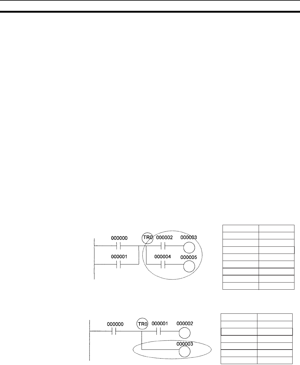
448
TR (Temporary Relay) Area Section 9-17
Note These Auxiliary Area bits/words are not to be written by the user. The number
of resends and response monitoring time must be set by the user in the FB
communications instructions settings in the PLC Setup, particularly when
using function blocks from the OMRON FB Library to execute FINS messages
or DeviceNet explicit messages communications. The values set in the Set-
tings for OMRON FB Library in the PLC Setup will be automatically stored in
the related Auxiliary Area words A580 to A582 and used by the function
blocks from the OMRON FB Library.
9-17 TR (Temporary Relay) Area
The TR Area contains 16 bits with addresses ranging from TR0 to TR15.
These temporarily store the ON/OFF status of an instruction block for branch-
ing. TR bits are useful when there are several output branches and interlocks
cannot be used.
It is not necessary to consider TR bits when displaying ladder diagrams on the
CX-Programmer.
The TR bits can be used as many times as required and in any order required
as long as the same TR bit is not used twice in the same instruction block.
TR bits can be used only with the OUT and LD instructions. OUT instructions
(OUT TR0 to OUT TR15) store the ON OFF status of a branch point and LD
instructions recall the stored ON OFF status of the branch point.
TR bits cannot be changed from a Programming Device.
Examples In this example, a TR bit is used when two outputs have been directly con-
nected to a branch point.
In this example, a TR bit is used when an output is connected to a branch
point without a separate execution condition.
OR
Instruction Operand
LD 000000
000001
OUT
OUT
AND
TR 0
000002
000003
OUT
LD
AND
TR 0
000004
000005
Instruction
LD
Operand
000000
OUT
OUT
AND
TR 0
000001
000002
LD
OUT
TR 0
000003
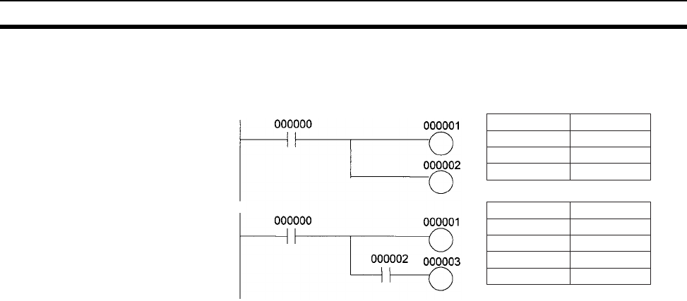
449
Timer Area Section 9-18
Note A TR bit is not required when there are no execution conditions after the
branch point or there is an execution condition only in the last line of the
instruction block.
9-18 Timer Area
The 4,096 timer numbers (T0000 to T4095) are shared by the TIM, TIMX,
TIMH(015), TIMHX(551), TMHH(540), TMHHX(552), TTIM(087),
TTIMX(555), TIMW(813), TIMWX(816), TMHW(815), and TMHWX(817)
instructions. Timer Completion Flags and present values (PVs) for these
instructions are accessed with the timer numbers. (The TIML(542),
TIMLX(553), MTIM(543), and MTIMX(554) instructions do not use timer num-
bers.)
When a timer number is used in an operand that requires bit data, the timer
number accesses the Completion Flag of the timer. When a timer number is
used in an operand that requires word data, the timer number accesses the
PV of the timer. Timer Completion Flags can be used as often as necessary
as normally open and normally closed conditions and the values of timer PVs
can be read as normal word data.
With CS1-H CPU Units, the refresh method for timer PVs can be set from the
CX-Programmer to either BCD or binary.
Note It is not recommended to use the same timer number in two timer instructions
because the timers will not operate correctly if they are timing simultaneously.
(If two or more timer instructions use the same timer number, an error will be
generated during the program check, but the timers will operate as long as the
instructions are not executed in the same cycle.)
Instruction
LD
Operand
000000
OUT 000001
AND
OUT
000002
000003
Instruction
LD
Operand
000000
OUT
OUT
000001
000002

450
Counter Area Section 9-19
The following table shows when timer PVs and Completion Flags will be reset.
Note 1. If the IOM Hold BIt (A50012) is ON, the PV and Completion Flag will be
retained when a fatal error occurs or the operating mode is changed from
PROGRAM mode to RUN or MONITOR mode or vice-versa. The PV and
Completion Flag will be cleared when power is cycled.
2. If the IOM Hold BIt (A50012) is ON and the PLC Setup’s “IOM Hold Bit Sta-
tus at Startup” setting is set to protect the IOM Hold Bit, the PV and Com-
pletion Flag will be retained when the PLC’s power is cycled.
3. Since the TIML(542), TIMLX(553), MTIM(543), and MTIMX(554) instruc-
tions do not use timer numbers, they are reset under different conditions.
Refer to the descriptions of these instructions for details.
4. The present value of TIM, TIMX, TIMH(015), TIMHX(551), TMHH(540),
TMHHX(552), TIMW(813), TIMWX(816), TMHW(815), and TMHWX(817)
timers programmed with timer numbers 0000 to 2047 will be updated even
when jumped between JMP and JME instructions or when in a task that is
on standby. The present value of timers programmed with timer numbers
2048 to 4095 will be held when jumped or when in a task that is on standby.
Forcing Bit Status Timer Completion Flags can be force-set and force-reset.
Timer PVs cannot be force-set or force-reset, although the PVs can be
refreshed indirectly by force-setting/resetting the Completion Flag.
Note When designating addresses in programming or allocations inside C200H
Special I/O Units, “T000” to “T511” will actually specify T0000 to T0511 in the
CPU Unit. T0512 to T4095 cannot be specified inside the C200H Special I/O
Units.
9-19 Counter Area
The 4,096 counter numbers (C0000 to C4095) are shared by the CNT, CNTX,
CNTR(012), CNTRX(548), CNTW(814), and CNTWX(818) instructions.
Counter Completion Flags and present values (PVs) for these instructions are
accessed with the counter numbers.
When a counter number is used in an operand that requires bit data, the
counter number accesses the Completion Flag of the counter. When a
counter number is used in an operand that requires word data, the counter
number accesses the PV of the counter.
With CS1-H CPU Units, the refresh method for counter PVs can be set from
the CX-Programmer to either BCD or binary.
Instruction name Effect on PV and Completion Flag Operation in
Jumps and Interlocks
Mode change1PLC start-up1CNR(545) or
CNRX(547)
Jumps
(JMP-JME) or
Tasks on standby
Interlocks
(IL-ILC)
TIMER: TIM or TIMX PV → 0
Flag → OFF
PV → 0
Flag → OFF
PV → 9999
Flag → OFF
PVs refreshed in
operating timers
PV → SV
(Reset to SV.)
Flag → OFF
HIGH-SPEED TIMER:
TIMH(015) or TIMHX(551)
ONE-MS TIMER:
TMHH(540) or TMHHX(552)
ACCUMULATIVE TIMER:
TTIM(087) or TTIMX(555)
PV Maintained PV Maintained
TIMER WAIT: TIMW(813) or
TIMWX(816)
PVs refreshed in
operating timers
---
HIGH-SPEED TIMER WAIT:
TMHW(815) or TMHWX(817)
---

451
Data Memory (DM) Area Section 9-20
It is not recommended to use the same counter number in two counter
instructions because the counters will not operate correctly if they are count-
ing simultaneously. If two or more counter instructions use the same counter
number, an error will be generated during the program check, but the counters
will operate as long as the instructions are not executed in the same cycle.
The following table shows when counter PVs and Completion Flags will be
reset.
Note When designating addresses in programming or allocations inside C200H
Special I/O Units, “C000” to “C511” will actually specify T0000 to T0511 in the
CPU Unit. C0512 to C4095 cannot be specified inside the C200H Special I/O
Units.
9-20 Data Memory (DM) Area
The DM Area contains 32,768 words with addresses ranging from D00000 to
D32767. This data area is used for general data storage and manipulation
and is accessible only by word.
Data in the DM Area is retained when the PLC’s power is cycled or the PLC’s
operating mode is changed from PROGRAM mode to RUN/MONITOR mode
or vice-versa.
Although bits in the DM Area cannot be accessed directly, the status of these
bits can be accessed with the BIT TEST instructions, TST(350) and
TSTN(351).
Bits in the DM Area cannot be force-set or force-reset.
Note 1. If using a C200H DeviceNet Master Unit (C200HW-DRM21-V1), use the
following words as the status area. Data in this area is updated when the
C200H DeviceNet Master Unit is used, so the area cannot be used for oth-
er applications.
• Master Status: D06032 + (2 x unit number)
• Current Communications Cycle Time: D06033 + (2 x unit number)
The CS-series DeviceNet Unit (CS1W-DRM21) does not use the above
words.
2. When designating addresses in programming or allocations inside Group-
I and Group-II C200H Special I/O Units, DM 0000 to DM 0999 will actually
specify D00000 to D00999 in the CPU Unit and DM 1000 to DM1999 will
actually specify D20000 to D20999 (part of the Special I/O Unit Area) in
the CPU Unit. Other addresses in this area cannot be specified. When des-
ignating addresses in programming or allocations inside Group-III and
Group-IV C200H Special I/O Units, DM 0000 to DM 6655 will actually
specify D00000 to D06655 in the CPU Unit. Other addresses in this area
cannot be specified.
Instruction name Effect on PV and Completion Flag
Reset Mode
change
PLC startup Reset Input CNR(545) or
CNRX(548)
Interlocks
(IL-ILC)
COUNTER: CNT or
CNTX
PV → 0000
Flag → OFF
Maintained Maintained Reset Reset Maintained
REVERSIBLE
COUNTER: CNTR(012)
or CNTRX(548)
COUNTER WAIT:
CNTW(814) or
CNTWX(818)
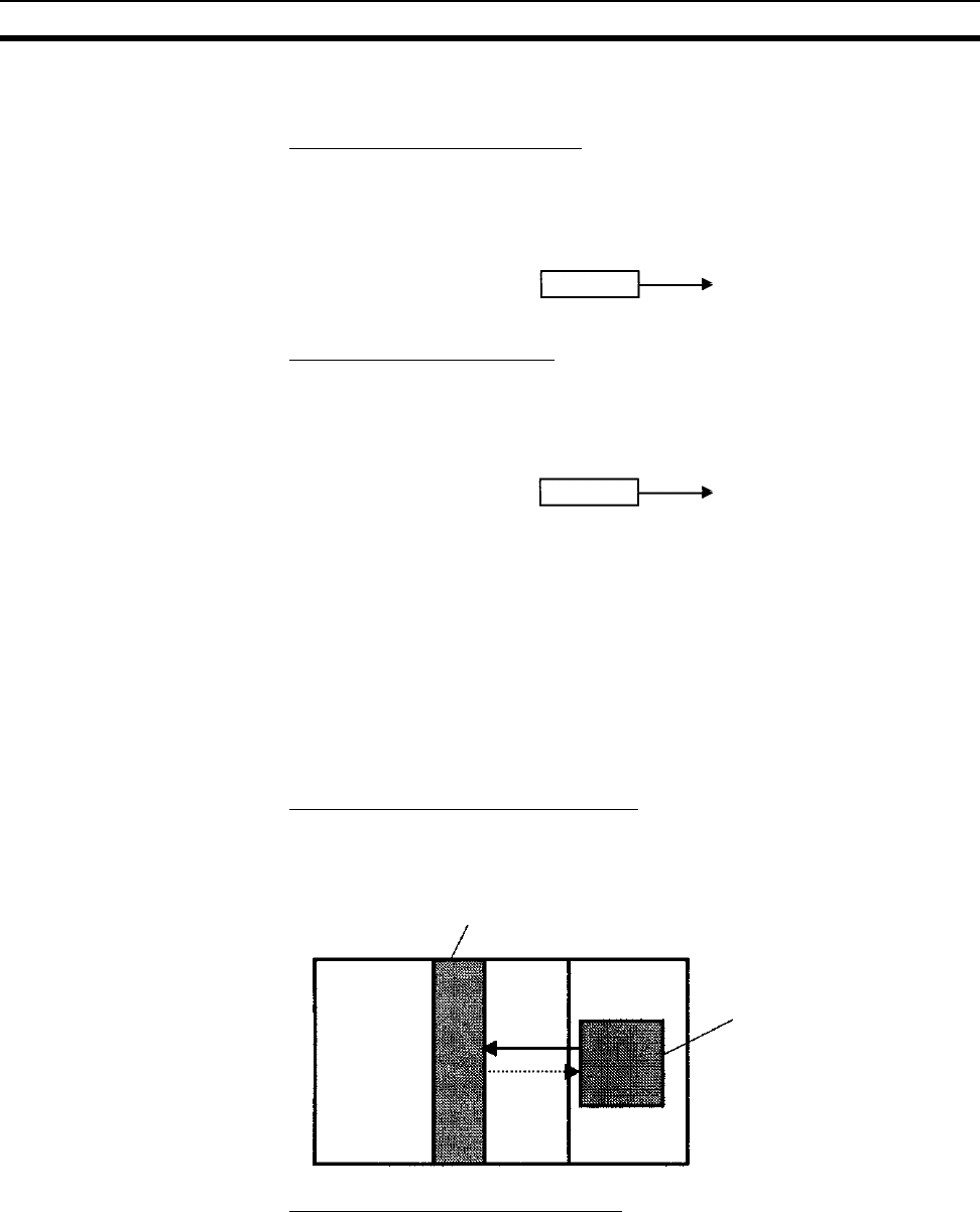
452
Data Memory (DM) Area Section 9-20
Indirect Addressing Words in the DM Area can be indirectly addressed in two ways: binary-mode
and BCD-mode.
Binary-mode Addressing (@D)
When a “@” character is input before a DM address, the content of that DM
word is treated as binary and the instruction will operate on the DM word at
that binary address. The entire DM Area (D00000 to D32767) can be indi-
rectly addressed with hexadecimal values 0000 to 7FFF.
BCD-mode Addressing (*D)
When a “*” character is input before a DM address, the content of that DM
word is treated as BCD and the instruction will operate on the DM word at that
BCD address. Only part of the DM Area (D00000 to D09999) can be indirectly
addressed with BCD values 0000 to 9999.
DM Area Allocation to
Special Units Inner Board
Parts of the DM Area are allocated to Special I/O Units, CS-series CPU Bus
Units, and Inner Boards for functions such as initial Unit settings. The timing
for data transfers is different for these Units, but may occur at any of the three
following times.
1,2,3... 1. Transfer data when the PLC’s power is turned on or the Unit is restarted.
2. Transfer data once each cycle.
3. Transfer data when required.
Refer to the Unit’s Operation Manual for details on data transfer timing.
Special I/O Units (D20000 to D29599)
Each Special I/O Unit is allocated 100 words (based on unit numbers 0 to 95).
Refer to the Unit’s Operation Manual for details on the function of these
words.
CPU Bus Units (D30000 to D31599)
Each CPU Bus Unit is allocated 100 words (based on unit numbers 0 to F).
Refer to the Unit’s Operation Manual for details on the function of these
words. With some CPU Bus Units such as Ethernet Units, initial settings must
be registered in the CPU Unit’s Parameter Area; this data can be registered
with a Programming Device other than a Programming Console.
@D00100 0100 D00256
Address actually used.
*D00100 0100 D00100
Address actually used.
Special I/O Unit
CPU Unit
DM Area for Special I/O Units
(100 words/Unit)
Data trans-
ferred to the
CPU Unit at
cyclic refresh-
ing or when
necessary.
Data trans-
ferred to the
Special I/O
Unit when the
PLC is turned
on or the Unit
is restarted.
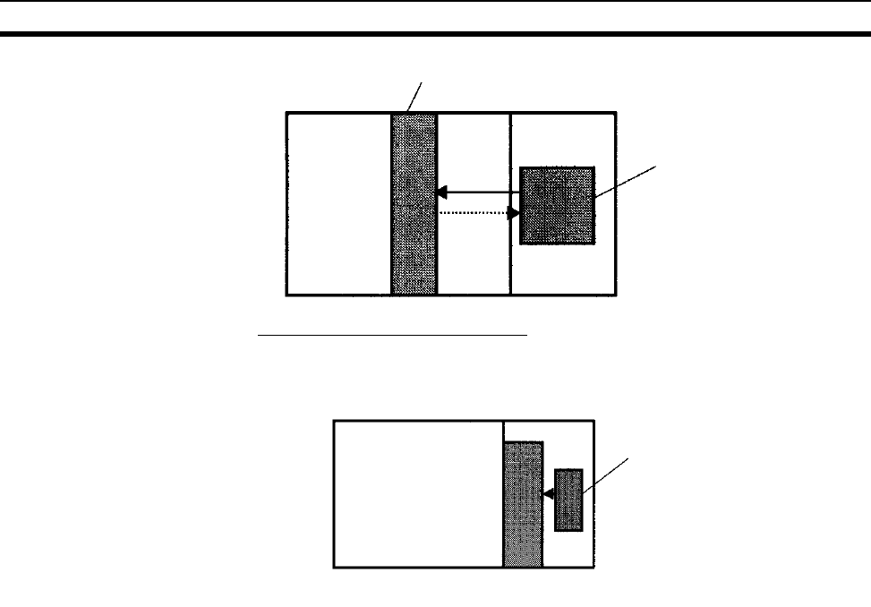
453
Extended Data Memory (EM) Area Section 9-21
Inner Board (D32000 to D32099)
The Inner Board is allocated 100 words. Refer to the Board’s Operation Man-
ual for details on the function of these words.
9-21 Extended Data Memory (EM) Area
The EM Area is divided into 13 banks (0 to C) that each contain 32,768 words.
EM Area addresses range from E0_00000 to EC_32767. This data area is
used for general data storage and manipulation and is accessible only by
word.
Data in the EM Area is retained when the PLC’s power is cycled or the PLC’s
operating mode is changed from PROGRAM mode to RUN/MONITOR mode
or vice-versa.
Although bits in the EM Area cannot be accessed directly, the status of these
bits can be accessed with the BIT TEST instructions, TST(350) and
TSTN(351).
Bits in the EM Area cannot be force-set or force-reset.
Specifying EM Addresses There are two ways to specify an EM address: the bank and address can be
specified at the same time or an address in the current bank can be specified
(after changing the current bank, if necessary). In general, we recommend
specifying the bank and address simultaneously.
1,2,3... 1. Bank and Address Specification
With this method, the bank number is specified just before the EM address.
For example, E2_00010 specifies EM address 00010 in bank 2.
2. Current Bank Address Specification
With this method, just the EM address is specified. For example, E00010
specifies EM address 00010 in the current bank. (The current bank must
be changed with EMBC(281) to access data in another bank. A301 con-
tains the current EM bank number.)
The current bank will be reset to 0 when the operating mode is changed
from PROGRAM mode to RUN/MONITOR mode, unless the IOM Hold Bit
CPU Bus Unit
CPU Unit
Data trans-
ferred to the
CS1 Special
Unit when
the PLC is
turned on or
the Unit is
restarted.
Data trans-
ferred to the
CPU Unit at
cyclic re-
fresh-ing or
when neces-
sary.
DM Area for CPU Bus Units
(100 words/Unit)
CPU Unit
DM Area for Inner Board
(100 words)
Data transferred to the Inner Board when the
PLC is turned on or the Board is restarted.
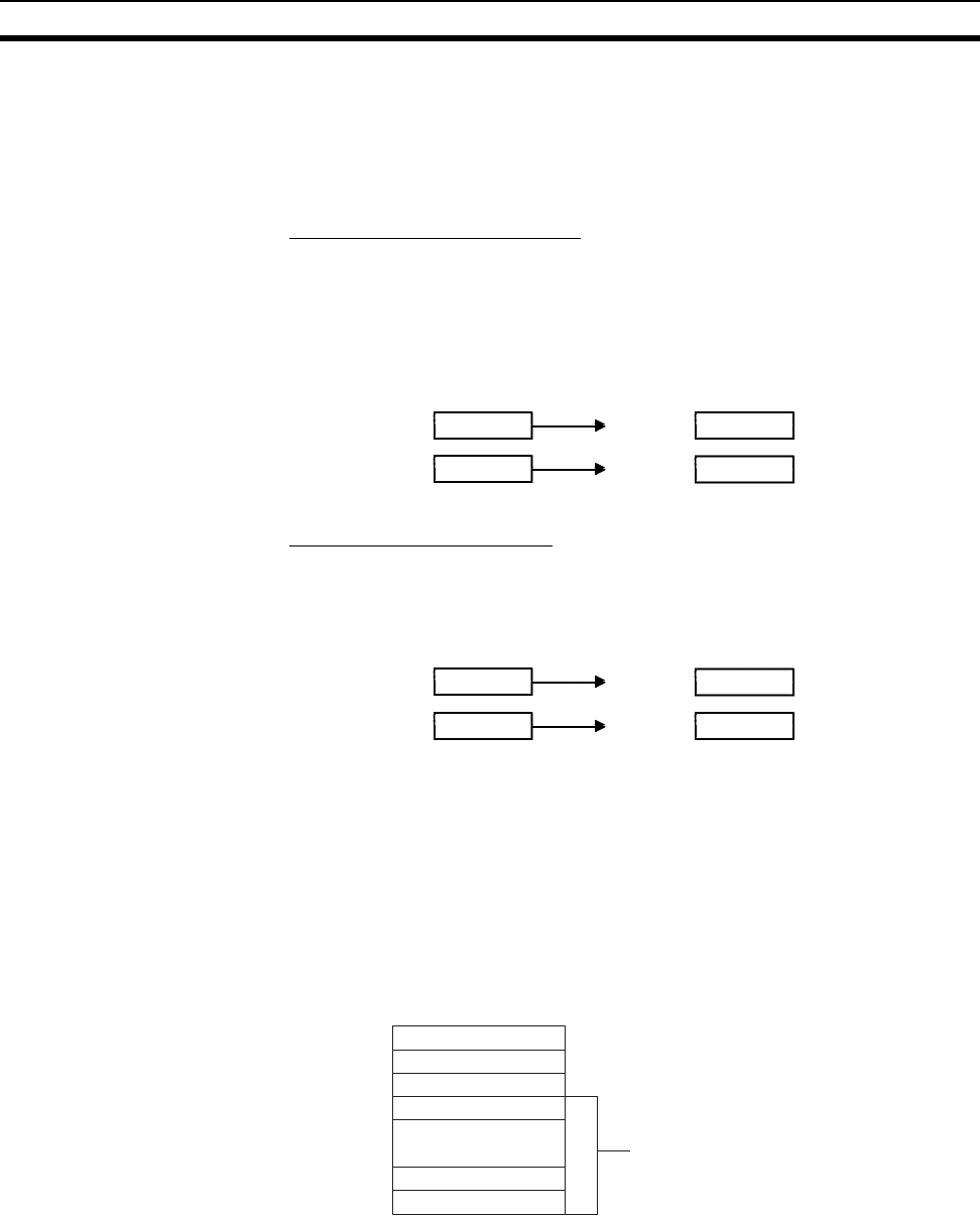
454
Extended Data Memory (EM) Area Section 9-21
(A50012) is ON. The current bank is not changed as the program proceeds
through cyclic tasks and the current bank will be returned to its original val-
ue (in the source cyclic task) if it has been changed in an interrupt task.
Indirect Addressing Words in the EM Area can be indirectly addressed in two ways: binary-mode
and BCD-mode.
Binary-mode Addressing (@E)
When a “@” character is input before a EM address, the content of that EM
word is treated as binary and the instruction will operate on the EM word in
the same bank at that binary address. All of the words in the same EM bank
(E00000 to E32767) can be indirectly addressed with hexadecimal values
0000 to 7FFF and words in the next EM bank (E00000 to E32767) can be
addressed with hexadecimal values 8000 to FFFF.
BCD-mode Addressing (*E)
When a “*” character is input before a EM address, the content of that EM
word is treated as BCD and the instruction will operate on the EM word in the
same bank at that BCD address. Only part of the EM bank (E00000 to
E09999) can be indirectly addressed with BCD values 0000 to 9999.
File Memory Conversion Part of the EM Area can be converted for use as file memory with settings in
the PLC Setup. All EM banks from the specified bank (EM File Memory Start-
ing Bank) to the last EM bank will be converted to file memory.
Once EM banks have been converted to file memory, they cannot be
accessed (read or written) by instructions. An Illegal Access Error will occur if
a file-memory bank is specified as an operand in an instruction.
The following example shows EM file memory when the EM File Memory
Starting Bank has been set to 3 in the PLC Setup.
Note When designating addresses in programming or allocations inside C200H
Special I/O Units, “EM 0000” to “EM 6143” will actually specify E0_00000 to
E0_06143 in the CPU Unit. Other addresses in this area cannot be specified.
(When the current
bank is bank 0.)
@E1_00100 0200 E1_00512
@E00100 0200 E0_00512
Address actually used.
Address actually used.
(When the current
bank is bank 0.)
*E1_00100 0200 E1_00200
*E00100 0200 E0_00200
Address actually used.
Address actually used.
EM bank number
EM file memory
(Cannot be accessed
from instructions.)
0
1
2
3
.
.
B
C
.
Example:
EM File Memory Starting
Bank set to 3 in the PLC Setup
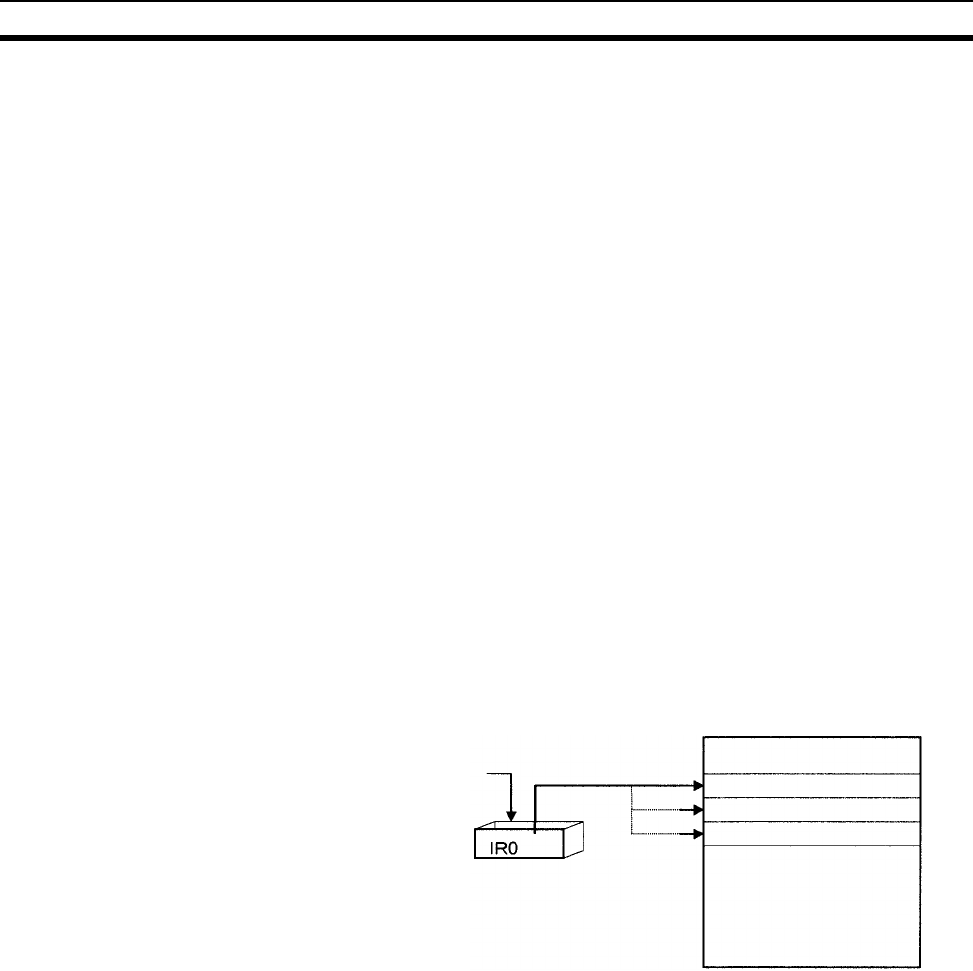
455
Index Registers Section 9-22
9-22 Index Registers
The sixteen Index Registers (IR0 to IR15) are used for indirect addressing.
Each Index Register can hold a single PLC memory address, which is the
absolute memory address of a word in I/O memory. Use MOVR(560) to con-
vert a regular data area address to its equivalent PLC memory address and
write that value to the specified Index Register. (Use MOVRW(561) to set the
PLC memory address of a timer/counter PV in an Index Register.)
Note Refer to Appendix C Memory Map for more details on PLC memory
addresses.
Indirect Addressing When an Index Register is used as an operand with a “,” prefix, the instruction
will operate on the word indicated by the PLC memory address in the Index
Register, not the Index Register itself. Basically, the Index Registers are I/O
memory pointers.
• All addresses in I/O memory (except Index Registers, Data Registers, and
Condition Flags) can be specified seamlessly with PLC memory
addresses. It isn’t necessary to specify the data area.
• In addition to basic indirect addressing, the PLC memory address in an
Index Register can be offset with a constant or Data Register, auto-incre-
mented, or auto-decremented. These functions can be used in loops to
read or write data while incrementing or decrementing the address by one
each time that the instruction is executed.
With the offset and increment/decrement variations, the Index Registers can
be set to base values with MOVR(560) or MOVRW(561) and then modified as
pointers in each instruction.
Note It is possible to specify regions outside of I/O memory and generate an Illegal
Access Error when indirectly addressing memory with Index Registers. Refer
to Appendix C Memory Map for details on the limits of PLC memory
addresses.
Set to a base value
with MOVR(560) or
MOVRW(561).
Pointer
I/O Memory
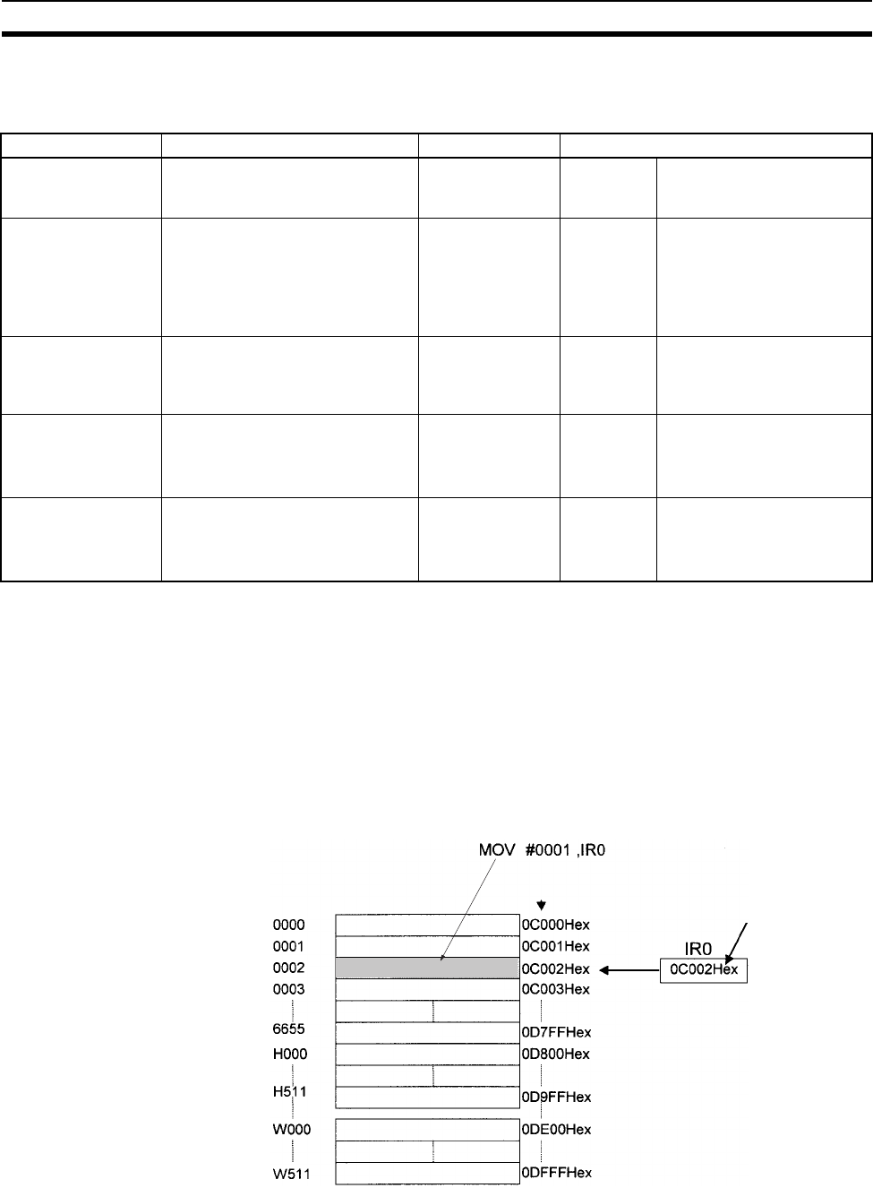
456
Index Registers Section 9-22
The following table shows the variations available when indirectly addressing
I/O memory with Index Registers. (IR@ represents an Index Register from IR0
to IR15.)
Example This example shows how to store the PLC memory address of a word
(CIO 0002) in an Index Register (IR0), use the Index Register in an instruc-
tion, and use the auto-increment variation.
MOVR(560) 0002 IR0 Stores the PLC memory address of
CIO 0002 in IR0.
MOV(021) #0001 ,IR0 Writes #0001 to the PLC memory ad-
dress contained in IR0.
MOV(021) #0020 +1,IR0 Reads the content of IR0, adds 1,
and writes #0020 to that PLC memo-
ry address.
Note 1. Auto-incrementing and auto-decrementing for index registers are per-
formed whenever an instruction using them is executed. Care is required
in application, particularly with instructions like OUT, which are executed
Variation Function Syntax Example
Indirect addressing The content of IR@ is treated as
the PLC memory address of a bit
or word.
,IR@LD ,IR0 Loads the bit at the PLC
memory address contained
in IR0.
Indirect addressing
with constant offset
The constant prefix is added to the
content of IR@ and the result is
treated as the PLC memory
address of a bit or word.
The constant may be any integer
from –2,048 to 2,047.
Constant ,IR@
(Include a + or –
in the constant.)
LD +5,IR0 Adds 5 to the contents of IR0
and loads the bit at that PLC
memory address.
Indirect addressing
with DR offset
The content of the Data Register
is added to the content of IR@ and
the result is treated as the PLC
memory address of a bit or word.
DR@,IR@LD
DR0,IR0
Adds the contents of DR0 to
the contents of IR0 and
loads the bit at that PLC
memory address.
Indirect addressing
with auto-increment
After referencing the content of
IR@ as the PLC memory address
of a bit or word, the content is
incremented by 1 or 2.
Increment by 1:
,IR@+
Increment by 2:
,IR@++
LD , IR0++ Loads the bit at the PLC
memory address contained
in IR0 and then increments
the content of IR0 by 2.
Indirect addressing
with auto-decrement
The content of IR@ is decre-
mented by 1 or 2 and the result is
treated as the PLC memory
address of a bit or word.
Decrement by 1:
,–IR@
Decrement by 2:
,– –IR@
LD , – –IR0 Decrements the content of
IR0 by 2 and then loads the
bit at that PLC memory
address.
Regular
data area
address
PLC memory address
I/O memory MOVE TO REGISTER instruction
MOVR(560) 0002 IR0
Pointer
#0001
#0020

457
Index Registers Section 9-22
every cycle. Refer to 1-1-5 Inputting Data in Operands in the Instructions
Reference for details.
Example
MOVR 000013 IR0
LD P_Off
OUT ,IR0+
With the above programming, OUT will turn OFF CIO 000013 and IR0 will
be incremented to point to CIO 000014.
MOVR 000013 IR0
LD P_Off
SET ,IR0+
SET is executed only when the input condition is ON. With the above pro-
gramming, SET will not be executed and IR0 will not be incremented.
2. The PLC memory addresses are listed in the diagram above, but it isn’t
necessary to know the PLC memory addresses when using Index Regis-
ters.
Since some operands are treated as word data and others are treated as bit
data, the meaning of the data in an Index Register will differ depending on the
operand in which it is used.
1,2,3... 1. Word Operand:
MOVR(560) 0000 IR2
MOV(021) D00000 , IR2
When the operand is treated as a word, the contents of the Index Register
are used “as is” as the PLC memory address of a word.
In this example MOVR(560) sets the PLC memory address of CIO 0002 in
IR2 and the MOV(021) instruction copies the contents of D00000 to
CIO 0002.
2. Bit Operand:
MOVR(560) 000013 ,IR2
SET +5 , IR2
When the operand is treated as a bit, the leftmost 7 digits of the Index Reg-
ister specify the word address and the rightmost digit specifies the bit num-
ber. In this example, MOVR(560) sets the PLC memory address of
CIO 000013 (0C000D hex) in IR2. The SET instruction adds +5 from bit 13
to this PLC memory address, so it turns ON bit CIO 000102.
Index Register
Initialization
The Index Registers will be cleared in the following cases:
1,2,3... 1. The operating mode is changed from PROGRAM mode to RUN/MONITOR
mode or vice-versa and the IOM Hold Bit is OFF.
2. The PLC’s power supply is cycled and the IOM Hold Bit is OFF or not pro-
tected in the PLC Setup.
IOM Hold Bit Operation If the IOM Hold Bit (A50012) is ON, the Index Registers won’t be cleared
when a FALS error occurs or the operating mode is changed from PROGRAM
mode to RUN/MONITOR mode or vice-versa.
If the IOM Hold Bit (A50012) is ON, and the PLC Setup’s “IOM Hold Bit Status
at Startup” setting is set to protect the IOM Hold Bit, and if the Index Registers
are not set to be shared between tasks (default setting), Index Registers will
be held in the following way when power is interrupted. For tasks that were
completed before power was interrupted, the values for the cycle during which
power was interrupted will be held. For tasks that were not completed before
power was interrupted, the values for the cycle before the cycle during which

458
Index Registers Section 9-22
power was interrupted will be held. For example, in a program with three
tasks, tasks 0, 1, and 2, if power is interrupted in the nth cycle during execu-
tion of task 1, then the execution result for the nth cycle of task 0 and the exe-
cution results for the (n−1)th cycle of tasks 1 and 2 will be held.
If the IOM Hold Bit (A50012) is ON, the PLC Setup’s “IOM Hold Bit Status at
Startup” setting is set to protect the IOM Hold Bit, and the Index Registers are
set to be shared between tasks, Index Registers will not be held when the
PLC’s power supply is reset (ON →OFF →ON). The Index Registers may take
undefined values. Be sure to set the values before continuing.
Forcing Bit Status Bits in Index Registers cannot be force-set and force-reset.
Direct Addressing When an Index Register is used as an operand without a “,” prefix, the instruc-
tion will operate on the contents of the Index Register itself (a two-word or
“double” value). Index Registers can be directly addressed only in the instruc-
tions shown in the following table. Use these instructions to operate on the
Index Registers as pointers.
The Index Registers cannot be directly addressed in any other instructions,
although they can usually be used for indirect addressing.
The SRCH(181), MAX(182), and MIN(183) instructions can output the PLC
memory address of the word with the desired value (search value, maximum,
or minimum) to IR0. In this case, IR0 can be used in later instructions to
access the contents of that word.
Precautions
Do not use Index Registers until a PLC memory address has been set in the
register. The pointer operation will be unreliable if the registers are used with-
out setting their values.
The values in Index Registers are unpredictable at the start of an interrupt
task. When an Index Register will be used in an interrupt task, always set a
PLC memory address in the Index Register with MOVR(560) or MOVRW(561)
before using the register in that task.
Instruction group Instruction name Mnemonic
Data Movement
Instructions
MOVE TO REGISTER MOVR(560)
MOVE TIMER/COUNTER PV TO REGISTER MOVRW(561)
DOUBLE MOVE MOVL(498)
DOUBLE DATA EXCHANGE XCGL(562)
Table Data Pro-
cessing Instruc-
tions
SET RECORD LOCATION SETR(635)
GET RECORD NUMBER GETR(636)
Increment/Decre-
ment Instructions
DOUBLE INCREMENT BINARY ++L(591)
DOUBLE DECREMENT BINARY – –L(593)
Comparison
Instructions
DOUBLE EQUAL =L(301)
DOUBLE NOT EQUAL < >L(306)
DOUBLE LESS THAN < L(311)
DOUBLE LESS THAN OR EQUAL < =L(316)
DOUBLE GREATER THAN > L(321)
DOUBLE GREATER THAN OR EQUAL > =L(326)
DOUBLE COMPARE CMPL(060)
Symbol Math
Instructions
DOUBLE SIGNED BINARY ADD WITHOUT
CARRY
+L(401)
DOUBLE SIGNED BINARY SUBTRACT
WITHOUT CARRY
–L(411)

459
Index Registers Section 9-22
Each Index Register task is processed independently, so they do not affect
each other. For example, IR0 used in Task 1 and IR0 used in Task 2 are differ-
ent. Consequently, each Index Register task has 16 Index Registers.
Limitations when Using Index Registers
1,2,3... 1. It is only possible to read the Index Register for the last task executed with-
in the cycle from the Programming Devices. If using Index Registers with
the same number to perform multiple tasks, it is only possible with the Pro-
gramming Devices to read the Index Register value for the last task per-
formed within the cycle from the multiple tasks. Nor is it possible to write
the Index Register value from the Programming Devices.
2. It is not possible to either read or write to the Index Registers using Host
Link commands or FINS commands.
3. The Index Registers cannot share tasks between them for CS1 CPU Units.
(With CS1-H CPU Units, a PLC Setup setting can be made from the CX-
Programmer to share Index Registers between tasks.)
Monitoring and Sharing
Index Registers
It is possible to monitor or share Index Registers as follows:
To use the Programming Devices to monitor the final Index Register values for
each task, or to monitor the Index Register values using Host Link commands
or FINS commands, write a program to store Index Register values from each
task to another area (e.g., DM area) at the end of each task, and to read Index
Register values from the storage words (e.g., DM area) at the beginning of
each task. The values stored for each task in other areas (e.g., DM area) can
then be edited using the Programming Devices, Host Link commands, or
FINS commands.
Note Be sure to use PLC memory addresses in Index Registers.
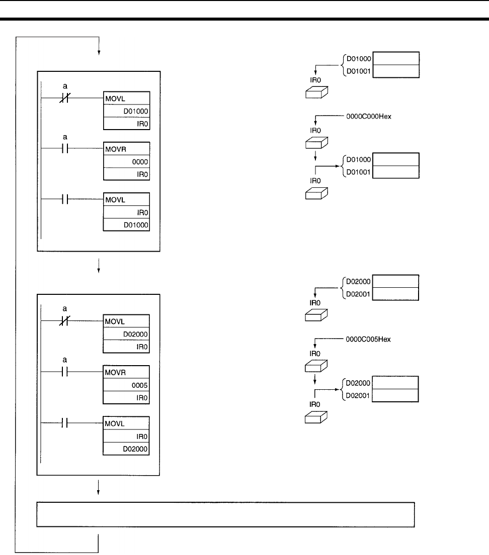
460
Index Registers Section 9-22
Tas k 1
D01001 and D01000
stored in IR0
or
Actual memory address of
CIO 0000 (0000C000 Hex)
stored in IR0
Contents of IR0 stored in
D01001 and D01000
IR storage words for task 1
or
Tas k 2
D02001 and D02000
stored in IR0
or
Actual memory address
CIO 0005 (0000C005 Hex)
stored in IR0
Contents of IR0 stored in
D02001 and D02000
or
Peripheral servicing Read D01001
and D01000 Read D02001
and D02000
IR storage words for task 2
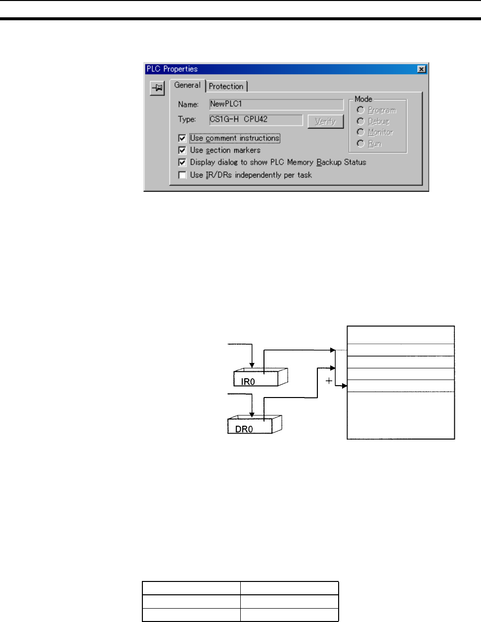
461
Data Registers Section 9-23
Sharing Index Registers The following setting can be made from the PLC properties dialog box on the
CX-Programmer to control sharing index and data registers between tasks.
9-23 Data Registers
The sixteen Data Registers (DR0 to DR15) are used to offset the PLC mem-
ory addresses in Index Registers when addressing words indirectly.
The value in a Data Register can be added to the PLC memory address in an
Index Register to specify the absolute memory address of a bit or word in I/O
memory. Data Registers contain signed binary data, so the content of an
Index Register can be offset to a lower or higher address.
Examples The following examples show how Data Registers are used to offset the PLC
memory addresses in Index Registers.
LD DR0 ,IR0 Adds the contents of DR0 to the contents
of IR0 and loads the bit at that PLC mem-
ory address.
MOV(021) #0001 DR0 ,IR1 Adds the contents of DR0 to the contents
of IR1 and writes #0001 to that PLC
memory address.
Range of Values The contents of data registers are treated as signed binary data and thus
have a range of –32,768 to 32,767.
Data Register Initialization The Data Registers will be cleared in the following cases:
1,2,3... 1. The operating mode is changed from PROGRAM mode to RUN/MONITOR
mode or vice-versa and the IOM Hold Bit is OFF.
2. The PLC’s power supply is cycled and the IOM Hold Bit is OFF or not pro-
tected in the PLC Setup.
Set to a base value
with MOVR(560) or
MOVRW(561). Pointer
I/O Memory
Set with a regular
instruction.
Hexadecimal content Decimal equivalent
8000 to FFFF –32,768 to –1
0000 to 7FFF 0 to 32,767
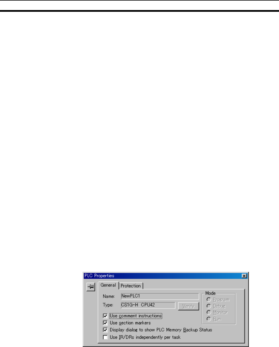
462
Data Registers Section 9-23
IOM Hold Bit Operation If the IOM Hold Bit (A50012) is ON, the Data Registers won’t be cleared when
a FALS error occurs or the operating mode is changed from PROGRAM mode
to RUN/MONITOR mode or vice-versa.
If the IOM Hold Bit (A50012) is ON, and the PLC Setup’s “IOM Hold Bit Status
at Startup” setting is set to protect the IOM Hold Bit, and if the Data Registers
are not set to be shared between tasks (default setting), Data Registers will
be held in the following way when power is interrupted. For tasks that were
completed before power was interrupted, the values for the cycle during which
power was interrupted will be held. For tasks that were not completed before
power was interrupted, the values for the cycle before the cycle during which
power was interrupted will be held. For example, in a program with three
tasks, tasks 0, 1, and 2, if power is interrupted in the nth cycle during execu-
tion of task 1, then the execution result for the nth cycle of task 0 and the exe-
cution results for the (n−1)th cycle of tasks 1 and 2 will be held.
If the IOM Hold Bit (A50012) is ON, the PLC Setup’s “IOM Hold Bit Status at
Startup” setting is set to protect the IOM Hold Bit, and the Data Registers are
set to be shared between tasks, Data Registers will not be held when the
PLC’s power supply is reset (ON →OFF →ON). The Data Registers may take
undefined values. Be sure to set the values before continuing.
Forcing Bit Status Bits in Data Registers cannot be force-set and force-reset.
Precautions Data Registers are normally local to each task. For example, DR0 used in
task 1 is different from DR0 used in task 2. (With CS1-H CPU Units, a PLC
Setup setting can be made from the CX-Programmer to share Data Registers
between tasks.)
The content of Data Registers cannot be accessed (read or written) from a
Programming Device.
Do not use Data Registers until a value has been set in the register. The reg-
ister’s operation will be unreliable if they are used without setting their values.
The values in Data Registers are unpredictable at the start of an interrupt
task. When a Data Register will be used in an interrupt task, always set a
value in the Data Register before using the register in that task.
Sharing Data Registers The following setting can be made from the PLC properties dialog box on the
CX-Programmer to control sharing index and data registers between tasks.

463
Task Flags Section 9-24
9-24 Task Flags
Task Flags range from TK00 to TK31 and correspond to cyclic tasks 0 to 31. A
Task Flag will be ON when the corresponding cyclic task is in executable
(RUN) status and OFF when the cyclic task hasn’t been executed (INI) or is in
standby (WAIT) status.
Note These flags indicate the status of cyclic tasks only (including extra cyclic
tasks), they do not reflect the status of interrupt tasks.
Task Flag Initialization The Task Flags will be cleared in the following cases, regardless of the status
of the IOM Hold Bit.
1,2,3... 1. The operating mode is changed from PROGRAM mode to RUN/MONITOR
mode or vice-versa.
2. The PLC’s power supply is cycled.
Forcing Bit Status The Task Flags cannot be force-set and force-reset.
9-25 Condition Flags
These flags include the Arithmetic Flags such as the Error Flag and Equals
Flag which indicate the results of instruction execution. In earlier PLCs, these
flags were in the SR Area.
The Condition Flags are specified with labels, such as CY and ER, or with
symbols, such as P_Carry and P_Instr_Error, rather than addresses. The sta-
tus of these flags reflects the results of instruction execution, but the flags are
read-only; they cannot be written directly from instructions or Programming
Devices.
Note The CX-Programmer treats condition flags as global symbols beginning with
P_.
All Condition Flags are cleared when the program switches tasks, so the sta-
tus of the ER and AER flags are maintained only in the task in which the error
occurred.
The Condition Flags cannot be force-set and force-reset.
Summary of the Condition
Flags
The following table summarizes the functions of the Condition Flags, although
the functions of these flags will vary slightly from instruction to instruction.
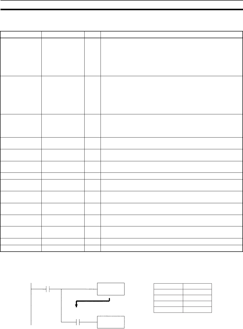
464
Condition Flags Section 9-25
Refer to the description of the instruction for complete details on the operation
of the Condition Flags for a particular instruction.
Using the Condition Flags The Condition Flags are shared by all of the instructions, so their status may
change often in a single cycle. Be sure to read the Condition Flags immedi-
ately after the execution of instruction, preferably in a branch from the same
execution condition.
Since the Condition Flags are shared by all of the instructions, program oper-
ation can be changed from its expected course by interruption of a single task.
Be sure to consider the effects of interrupts when writing the program. Refer
Name Symbol Label Function
Error Flag P_ER ER Turned ON when the operand data in an instruction is incorrect (an
instruction processing error) to indicate that an instruction ended
because of an error.
Note: When the PLC Setup is set to stop operation for an instruction
error (Instruction Error Operation), program execution will be
stopped and the Instruction Processing Error Flag (A29508) will
be turned ON when the Error Flag is turned ON.
Access Error Flag P_AER AER Turned ON when an Illegal Access Error occurs. The Illegal Access
Error indicates that an instruction attempted to access an area of
memory that should not be accessed.
Note: When the PLC Setup is set to stop operation for an instruction
error (Instruction Error Operation), program execution will be
stopped and the Instruction Processing Error Flag (A429510)
will be turned ON when the Access Error Flag is turned ON.
Carry Flag P_CY CY Turned ON when there is a carry in the result of an arithmetic opera-
tion or a “1” is shifted to the Carry Flag by a Data Shift instruction.
The Carry Flag is part of the result of some Data Shift and Symbol
Math instructions.
Greater Than Flag P_GT > Turned ON when the first operand of a Comparison Instruction is
greater than the second or a value exceeds a specified range.
Equals Flag P_EQ = Turned ON when the two operands of a Comparison Instruction are
equal the result of a calculation is 0.
Less Than Flag P_LT < Turned ON when the first operand of a Comparison Instruction is less
than the second or a value is below a specified range.
Negative Flag P_N N Turned ON when the most significant bit (sign bit) of a result is ON.
Overflow Flag P_OF OF Turned ON when the result of calculation overflows the capacity of the
result word(s).
Underflow Flag P_UF UF Turned ON when the result of calculation underflows the capacity of
the result word(s).
Greater Than or
Equals Flag
P_GE >= Turned ON when the first operand of a Comparison Instruction is
greater than or equal to the second.
Not Equal Flag P_NE < > Turned ON when the two operands of a Comparison Instruction are
not equal.
Less Than or
Equals Flag
P_LE < = Turned ON when the first operand of a Comparison Instruction is less
than or equal to the second.
Always ON Flag P_On ON Always ON. (Always 1.)
Always OFF Flag P_Off OFF Always OFF. (Always 0.)
Instruction A
Instruction B
The result from instruction A is
reflected in the Equals Flag.
Instruction A
Instruction B
Instruction
=
LD
AND
Operand
Condition Flag
Example: P_EQ
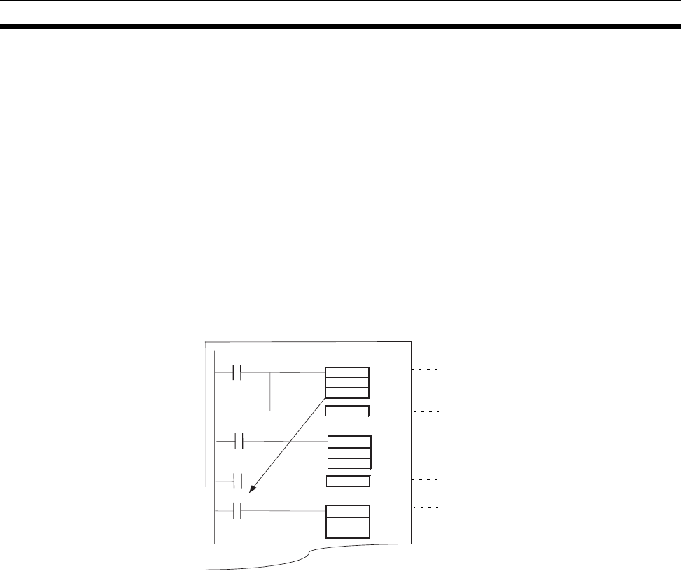
465
Condition Flags Section 9-25
to SECTION 2 Programming of CS/CJ Series Programmable Controllers
(W394) for more details.
The Condition Flags are cleared when the program switches tasks, so the sta-
tus of a Condition Flag cannot be passed to another task. For example the
status of a flag in task 1 cannot be read in task 2. (The flag’s status must be
transferred to a bit.)
Note The condition flags cannot be designated directly in programming or alloca-
tions inside C200H Special I/O Units.
Saving and Loading Condition Flag Status
The CCS(282) and CCL(283) instructions can be used to save and load the
Condition Flag status. These can be used to access the status of the Condi-
tion Flags at other locations in a task or in a different task.
The following example shows how the Equals Flag is used at a different loca-
tion in the same task.
CMP
CCS
CCL
I
nstruction A
I
nstruction B
P_EQ
Stores result of comparison in the Condition
Flags. This will enable loading the results to
use with Instruction B.
Saves status of Condition Flags.
Loads the statuses of the Conditions Flags
that were stored.
The result of the comparison instruction in the
Equals Flag can be used by Instruction B
without interference from Instruction A.
Ta s k
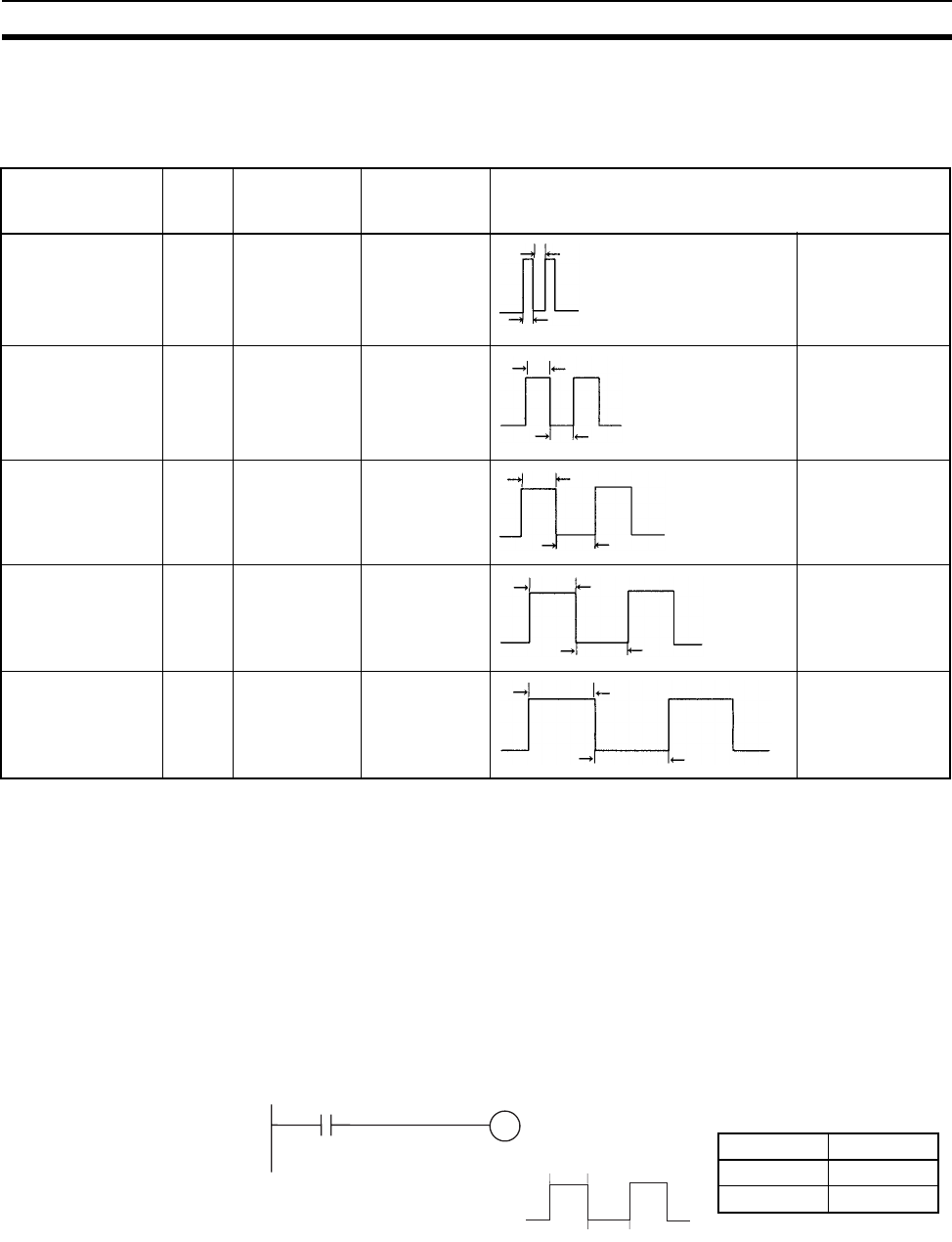
466
Clock Pulses Section 9-26
9-26 Clock Pulses
The Clock Pulses are flags that are turned ON and OFF at regular intervals by
the system.
The Clock Pulses are specified with labels (or symbols) rather than
addresses.
Specify the flags as shown above using the CX-Programmer or Programming
Console.
Note The CX-Programmer treats condition flags as global symbols beginning with
P_.
The Clock Pulses are read-only; they cannot be overwritten from instructions
or Programming Devices.
The Clock Pulses are cleared at the start of operation.
Using the Clock Pulses The following example turns CIO 000000 ON and OFF at 0.5 s intervals.
Note The clock pulses cannot be designated directly in programming or allocations
inside C200H Special I/O Units.
Clock Pulses Update Timing
Clock pulses are updated during program execution, so the ON and OFF sta-
tus may differ at the beginning and end of the program.
Name Label Symbol Programming
Console
name
Operation
0.02 s Clock Pulse 0.02s P_0_02_s 0.02 s ON for 0.01 s
OFF for 0.01 s
0.1 s Clock Pulse 0.1s P_0_1s 0.1 s ON for 0.05 s
OFF for 0.05 s
0.2 s Clock Pulse 0.2s P_0_2s 0.2 s ON for 0.1 s
OFF for 0.1 s
1 s Clock Pulse 1s P_1s 1 s ON for 0.5 s
OFF for 0.5 s
1 min Clock Pulse 1min P_1min 1 min ON for 30 s
OFF for 30 s
0.01 s
0.01 s
0.05 s
0.05 s
0.1 s
0.1 s
0.5 s
0.5 s
30 s
30 s
P_1s 000000
0.5 s
0.5 s
000000
←
←
←
←
Instruction Operand
LD P_1s
OUT 000000
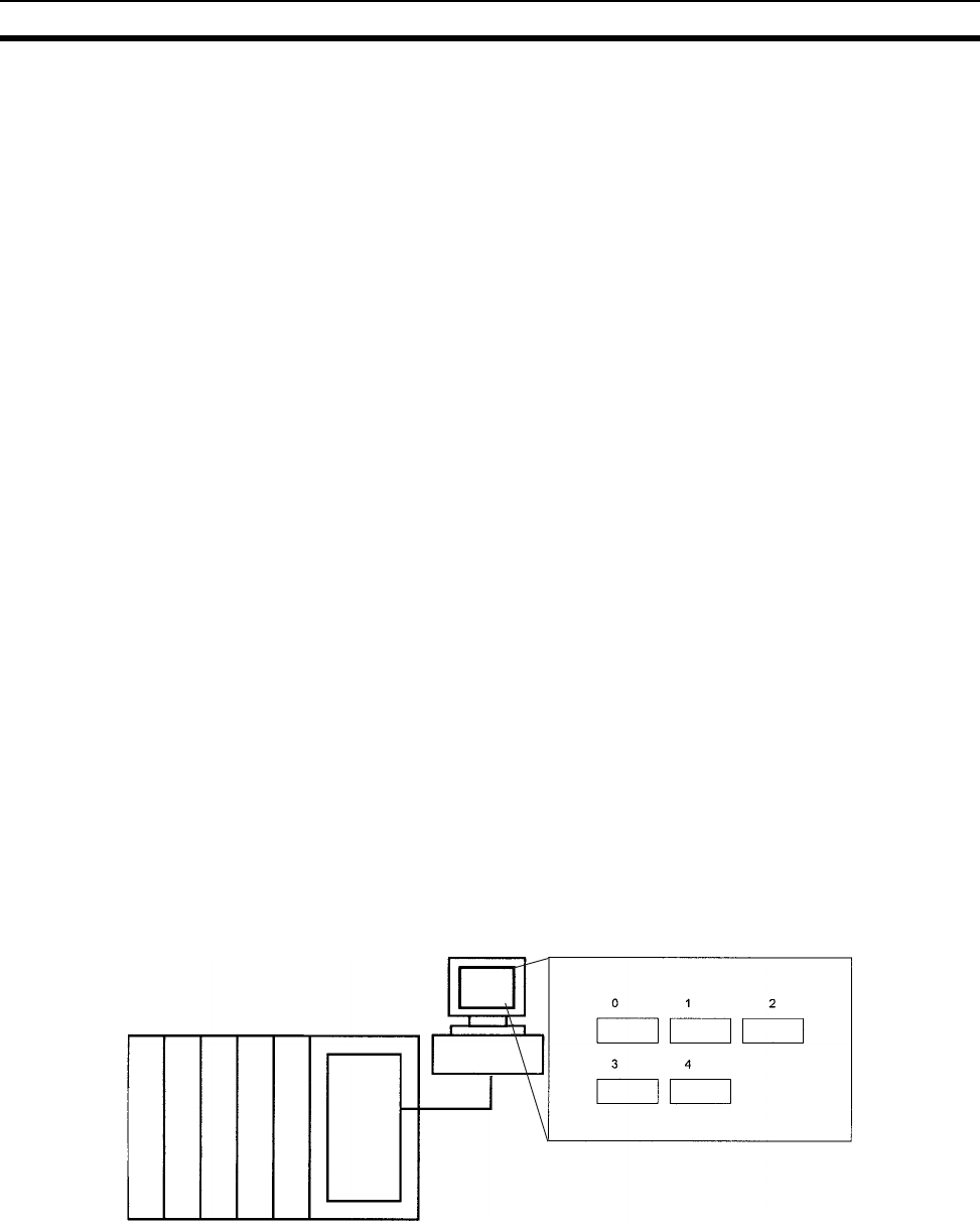
467
Parameter Areas Section 9-27
Error
The clock pulses have a maximum error of 0.01% at 25°C. For long-term time
control, it is recommended that control be based on the internal clock rather
than the clock pulses. The internal clock itself also has an error factor.
9-27 Parameter Areas
Unlike the data areas in I/O memory which can be used in instruction oper-
ands, the Parameter Area can be accessed only from a Programming Device.
The Parameter Area is made up of the following parts.
• The PLC Setup
• The Registered I/O Table
• The Routing Table
• The CPU Bus Unit Settings
9-27-1 PLC Setup
The user can customize the basic specifications of the CPU Unit with the set-
tings in the PLC Setup. The PLC Setup contains settings such as the serial
port communications settings and minimum cycle time setting.
Refer to 7-1 PLC Setup for details on the PLC Setup settings and refer to the
Programming Device’s Operation Manual for details on changing these set-
tings.
9-27-2 Registered I/O Table
The Registered I/O Table is a table in the CPU Unit that contains the informa-
tion on the model and slot location of all of the Units mounted to the CPU
Rack, Expansion I/O Racks, and Slave Racks. The I/O Table is written to the
CPU Unit with a Programming Device operation.
The CPU Unit allocates I/O memory to actual I/O points (on Basic I/O Units or
Remote I/O Units) and CPU Bus Units based on the information in the Regis-
tered I/O Table. Refer to the Programming Device’s Operation Manual for
details on registering the I/O Table.
The I/O Verification Error Flag (A40209) will be turned ON if the models and
locations of the Units actually mounted to the PLC (CPU Rack, Expansion I/O
Racks, and Slave Racks) do not match the information in the Registered I/O
Table.
Programming Device
Output 12 Input 16
Output 16
Commu-
nications
Analog
CPU Unit
Regis-
tered
I/O
Ta b l e
0123 4
Analog
Communications
16-point Output
12-point Output
16-point Input
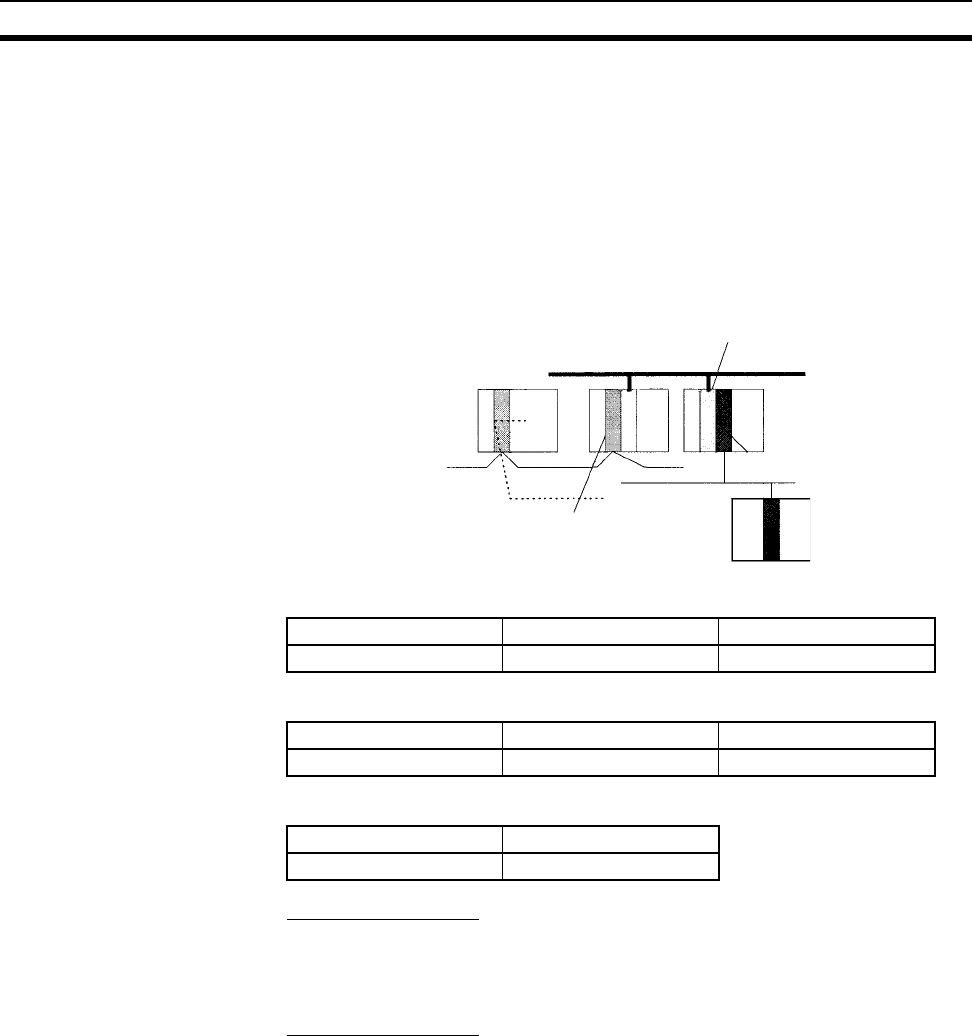
468
Parameter Areas Section 9-27
9-27-3 Routing Table
When transferring data between networks, it is necessary to create a table in
each CPU Unit that shows the communications route from the local PLC’s
Communications Unit to the other networks. These tables of communications
routes are called “Routing Tables.”
Create the Routing Tables with a Programming Device or the Controller Link
Support Software and transfer the tables to each CPU Unit. The following dia-
gram shows the Routing Tables used for a data transfer from PLC #1 to PLC
#4.
1,2,3... 1. Relay Network Table of PLC #1:
2. Relay Network Table of PLC #2:
3. Local Network Table of PLC #3:
Relay Network Table
This table lists the network address and node number of the first relay node to
contact in order to reach the destination network. The destination network is
reached through these relay nodes.
Local Network Table
This table lists the network address and unit number of the Communications
Unit connected to the local PLC.
These are settings for the CS-series CPU Bus Units which are controlled by
the CPU Unit. The actual settings depend on the model of CS-series CPU
Bus Unit being used; refer to the Unit’s Operation Manual for details.
9-27-4 CPU Bus Unit Settings
These settings are not managed directly like the I/O memory’s data areas, but
are set from a Programming Device like the Registered I/O Tables.
Example 1: For Controller Link Units, user-set data link parameters and net-
work parameters are managed as CPU Bus Unit settings.
Example 2: For Ethernet Units, the settings required to operate as an Ether-
net node, such as the IP address table, are managed as CPU Bus Unit set-
tings.
Node number M
Network 1
Network 2
Node number N
Unit number n
Network 3
PLC #1 PLC #2 PLC #3
PLC #4
Destination network Relay network Relay node
31N
Destination network Relay network Relay node
32M
Local network Unit number
3n

469
Parameter Areas Section 9-27
Refer to the Programming Device’s Operation Manual for details on changing
these settings.
Programming Device
CS-series CPU Bus Unit
CPU Unit
CS-series
CPU Bus
Unit Settings

470
Parameter Areas Section 9-27
471
SECTION 10
CPU Unit Operation and the Cycle Time
This section describes the internal operation of the CPU Unit and the cycle used to perform internal processing.
10-1 CPU Unit Operation . . . . . . . . . . . . . . . . . . . . . . . . . . . . . . . . . . . . . . . . . . . . 473
10-1-1 General Flow. . . . . . . . . . . . . . . . . . . . . . . . . . . . . . . . . . . . . . . . . . . 473
10-1-2 I/O Refreshing and Peripheral Servicing . . . . . . . . . . . . . . . . . . . . . 475
10-1-3 Initialization at Startup . . . . . . . . . . . . . . . . . . . . . . . . . . . . . . . . . . . 477
10-2 CPU Unit Operating Modes . . . . . . . . . . . . . . . . . . . . . . . . . . . . . . . . . . . . . . 478
10-2-1 Operating Modes . . . . . . . . . . . . . . . . . . . . . . . . . . . . . . . . . . . . . . . 478
10-2-2 Status and Operations in Each Operating Mode. . . . . . . . . . . . . . . . 479
10-3 Power OFF Operation . . . . . . . . . . . . . . . . . . . . . . . . . . . . . . . . . . . . . . . . . . . 480
10-3-1 Overview. . . . . . . . . . . . . . . . . . . . . . . . . . . . . . . . . . . . . . . . . . . . . . 480
10-3-2 Instruction Execution for Power Interruptions . . . . . . . . . . . . . . . . . 483
10-4 Computing the Cycle Time . . . . . . . . . . . . . . . . . . . . . . . . . . . . . . . . . . . . . . . 485
10-4-1 CPU Unit Operation Flowchart . . . . . . . . . . . . . . . . . . . . . . . . . . . . 485
10-4-2 Cycle Time Overview . . . . . . . . . . . . . . . . . . . . . . . . . . . . . . . . . . . . 486
10-4-3 I/O Unit Refresh Times for Individual Units and Boards. . . . . . . . . 492
10-4-4 Cycle Time Calculation Example . . . . . . . . . . . . . . . . . . . . . . . . . . . 498
10-4-5 Online Editing Cycle Time Extension . . . . . . . . . . . . . . . . . . . . . . . 499
10-4-6 I/O Response Time . . . . . . . . . . . . . . . . . . . . . . . . . . . . . . . . . . . . . . 499
10-4-7 Interrupt Response Times . . . . . . . . . . . . . . . . . . . . . . . . . . . . . . . . . 502
10-5 Instruction Execution Times and Number of Steps . . . . . . . . . . . . . . . . . . . . 503
10-5-1 Sequence Input Instructions . . . . . . . . . . . . . . . . . . . . . . . . . . . . . . . 504
10-5-2 Sequence Output Instructions. . . . . . . . . . . . . . . . . . . . . . . . . . . . . . 505
10-5-3 Sequence Control Instructions . . . . . . . . . . . . . . . . . . . . . . . . . . . . . 505
10-5-4 Timer and Counter Instructions . . . . . . . . . . . . . . . . . . . . . . . . . . . . 506
10-5-5 Comparison Instructions. . . . . . . . . . . . . . . . . . . . . . . . . . . . . . . . . . 507
10-5-6 Data Movement Instructions. . . . . . . . . . . . . . . . . . . . . . . . . . . . . . . 508
10-5-7 Data Shift Instructions . . . . . . . . . . . . . . . . . . . . . . . . . . . . . . . . . . . 509
10-5-8 Increment/Decrement Instructions . . . . . . . . . . . . . . . . . . . . . . . . . . 510
10-5-9 Symbol Math Instructions. . . . . . . . . . . . . . . . . . . . . . . . . . . . . . . . . 510
10-5-10 Conversion Instructions . . . . . . . . . . . . . . . . . . . . . . . . . . . . . . . . . . 511
10-5-11 Logic Instructions . . . . . . . . . . . . . . . . . . . . . . . . . . . . . . . . . . . . . . . 513
10-5-12 Special Math Instructions . . . . . . . . . . . . . . . . . . . . . . . . . . . . . . . . . 514
10-5-13 Floating-point Math Instructions . . . . . . . . . . . . . . . . . . . . . . . . . . . 514
10-5-14 Double-precision Floating-point Instructions. . . . . . . . . . . . . . . . . . 515
10-5-15 Table Data Processing Instructions. . . . . . . . . . . . . . . . . . . . . . . . . . 516
10-5-16 Data Control Instructions . . . . . . . . . . . . . . . . . . . . . . . . . . . . . . . . . 517
10-5-17 Subroutine Instructions. . . . . . . . . . . . . . . . . . . . . . . . . . . . . . . . . . . 518
10-5-18 Interrupt Control Instructions . . . . . . . . . . . . . . . . . . . . . . . . . . . . . . 518
10-5-19 Step Instructions . . . . . . . . . . . . . . . . . . . . . . . . . . . . . . . . . . . . . . . . 518
10-5-20 Basic I/O Unit Instructions . . . . . . . . . . . . . . . . . . . . . . . . . . . . . . . . 519
472
10-5-21 Serial Communications Instructions . . . . . . . . . . . . . . . . . . . . . . . . . 520
10-5-22 Network Instructions . . . . . . . . . . . . . . . . . . . . . . . . . . . . . . . . . . . . . 520
10-5-23 File Memory Instructions . . . . . . . . . . . . . . . . . . . . . . . . . . . . . . . . . 520
10-5-24 Display Instructions. . . . . . . . . . . . . . . . . . . . . . . . . . . . . . . . . . . . . . 521
10-5-25 Clock Instructions . . . . . . . . . . . . . . . . . . . . . . . . . . . . . . . . . . . . . . . 521
10-5-26 Debugging Instructions . . . . . . . . . . . . . . . . . . . . . . . . . . . . . . . . . . . 521
10-5-27 Failure Diagnosis Instructions. . . . . . . . . . . . . . . . . . . . . . . . . . . . . . 522
10-5-28 Other Instructions . . . . . . . . . . . . . . . . . . . . . . . . . . . . . . . . . . . . . . . 522
10-5-29 Block Programming Instructions . . . . . . . . . . . . . . . . . . . . . . . . . . . 522
10-5-30 Text String Processing Instructions. . . . . . . . . . . . . . . . . . . . . . . . . . 524
10-5-31 Task Control Instructions . . . . . . . . . . . . . . . . . . . . . . . . . . . . . . . . . 525
10-5-32 Model Conversion Instructions (Unit Ver. 3.0 or Later Only) . . . . . 525
10-5-33 Special Function Block Instructions (Unit Ver. 3.0 or Later Only). . 525
10-5-34 Function Block Instance Execution Time (CPU Units with Unit
Version 3.0 or Later) . . . . . . . . . . . . . . . . . . . . . . . . . . . . . . . . . . . . . 526

473
CPU Unit Operation Section 10-1
10-1 CPU Unit Operation
10-1-1 General Flow
The following flowchart shows the overall operation of the CPU Unit.
Note The CPU Unit’s processing mode is set to Normal Mode, Parallel Processing
with Synchronous Memory Access, or Parallel Processing with Asynchronous
Memory Access in the PLC Setup (Programming Console address 219, bits
08 to 15). This setting is also possible from the CX-Programmer.
Normal Mode
In the normal mode, the program is executed before I/O is refreshed and
peripherals are serviced. This cycle is executed repeatedly.
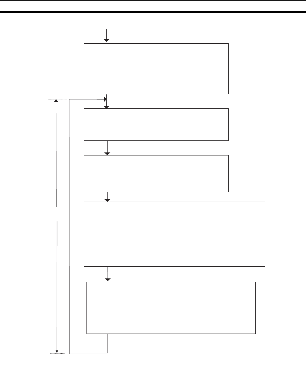
474
CPU Unit Operation Section 10-1
Parallel Processing
The following two types of processing are performed in parallel in either of the
Parallel Processing Modes.
1,2,3... 1. Program execution: Includes user program execution and I/O refreshing. It
is this cycle time that is monitored from a Programming Device.
2. Peripheral servicing: Programming Devices and events from Special I/O
Units and CPU Bus Units are serviced when they occur.
There are two different Parallel Processing Modes. Parallel Processing with
Synchronous Memory Access refreshes I/O memory in the program execution
Startup
initialization
I/O refreshing
(even in
PROGRAM
mode)
Peripheral
servicing
Cycle time
Initialize hardware
memory and system work
area.
Detect I/O.
Automatically transfer data
from Memory Card.
Verify actual Units with
registered I/O tables.
Clear I/O memory.
Check user memory.
Clear forced status, etc.
Check the Battery.
Check for Memory Card
and other devices.
Read DIP switch settings.
Check I/O bus.
Check user program
memory.
Overseeing
processing
Program
execution Operation processing: Execute the user program.
Error processing: Turn OFF outputs. (Reset Units
for bus errors.)
After error: Clear I/O memory is an error occurs
(unless a FALS(007) instruction created the error).
Refresh data for the following
Units.
Basic I/O Units
SYSMAC BUS Remote I/O Master
Units
Special I/O Units (both words
allocated in CIO and DM area and
specific data for each Unit)
CPU Bus Units (both words
allocated in CIO and DM area and
specific data for each Unit)
Inner Boards (both words
allocated in CIO and DM area and
specific data for each Unit)
Perform the following
servicing if any events have
occurred.
Special I/O Unit event
servicing
CPU Bus Unit event servicing
Peripheral port servicing
RS-232C port servicing
Inner Board event servicing
File access servicing
Communications port
servicing
Power ON
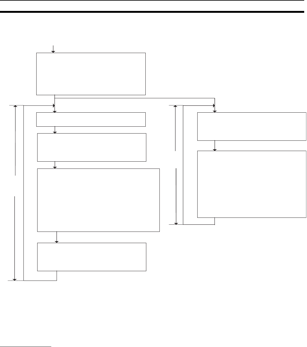
475
CPU Unit Operation Section 10-1
cycle and Parallel Processing with Asynchronous Memory Access refreshes
I/O memory in the peripheral servicing cycle.
Note Always disconnect the Programming Console from the peripheral port during
actual system operation in a Parallel Processing Mode. If the Programming
Console is left attached, excess time will be allocated to increase key
response for the Programming Console, adversely affecting performance.
10-1-2 I/O Refreshing and Peripheral Servicing
I/O Refreshing
I/O refreshing involves cyclically transferring data with external devices using
preset words in memory. I/O refreshing includes the following:
• Refreshing between Basic I/O Units and I/O words in the CIO Area and
refreshing between SYSMAC BUS Remote I/O Master Units and SYS-
MAC BUS and I/O Terminal words in the CIO Area
• Refreshing between Special I/O Units, CPU Bus Units, and Inner Boards,
and the words allocated to these in the CIO Area (and for CPU Bus Units,
words allocated in the DM Area)
• Refreshing Unit-specific data for Special I/O Units, CPU Bus Units, and
Inner Boards.
Startup
initialization
I/O
refreshing
(even in
PROGRAM
mode)
Peripheral
servicing
Program
execution
cycle time
Initialize hardware
memory and system
work area.
Detect I/O.
Automatically transfer
data from Memory
Card.
Verify actual Units with
registered I/O tables.
Clear I/O memory.
Check user memory.
Clear forced status,
etc.
Program
execution
Operation processing: Execute the user
program.
Error processing: Turn OFF outputs.
(Reset Units for bus errors.)
After error: Clear I/O memory is an error
occurs (unless a FALS(007) instruction
created the error).
Refresh data for the following Units.
Basic I/O Units
SYSMAC BUS Remote I/O Master Units
Special I/O Units (both words allocated in
CIO and DM area and specific data for
each Unit)
CPU Bus Units (both words allocated in
CIO and DM area and specific data for
each Unit)
Inner Boards (both words allocated in CIO
and DM area and specific data for each
Unit)
Perform the following servicing if any
events have occurred.
Special I/O Unit event servicing
CPU Bus Unit event servicing
Peripheral port servicing
RS-232C port servicing
Inner Board event servicing
Communications port servicing
Note: In Parallel Processing with
Synchronous Memory Access, any
events requiring I/O memory access are
serviced in the program execution cycle.
Power ON
Read DIP switch settings.
Check I/O bus.
Overseeing
processing Overseeing
processing
Program
Execution
Cycle
Peripheral Servicing Cycle
Check the Battery.
Check I/O bus.
Check user program
memory.
Peripheral
servicing
Perform the following servicing if any events
have occurred.
File access servicing
Note: In Parallel Processing with Synchronous
Memory Access, any events requiring I/O
memory access are serviced here.
Peripheral
servicing
cycle time

476
CPU Unit Operation Section 10-1
All I/O refreshing is performed in the same cycle (i.e., time slicing is not used).
I/O refreshing is always performed after program execution (even in a Parallel
Processing Mode for CS1-H CPU Units).
Units Max. data
exchange
Data exchange area
Basic I/O Units (including C200H
Group-2 I/O Units)
Depends on the
Unit.
I/O Bit Area
SYSMAC BUS Remote I/O Master Unit Depends on the
Unit.
SYSMAC BUS Area and
I/O Terminal Area
Special I/O
Units
(CS-series
and
C200H)
Words allocated in CIO
Area
10 words/Unit
(Depends on the
Unit.)
Special I/O Unit Area
Unit-
specific
data
C200H
DeviceNet Mas-
ter Unit
Depends on the
Unit.
Words set for remote I/O
communications (for
either fixed or user-set
allocations)
CompoBus/S
Master Unit
Depends on the
Unit.
Special I/O Units Area
CS-series
CPU Bus
Units
Words allocated in CIO
Area
25 words/Unit CS-series CPU Bus Unit
Area
Words allocated in DM
Area
100 words/Unit CS-series CPU Bus Unit
Area
Unit-
specific
data
Controller Link
Unit and SYS-
MAC LINK Unit
Depends on the
Unit.
Words set for data links
(for either fixed or user-
set allocations)
CS-series
DeviceNet Unit
Depends on the
Unit.
Words set for remote I/O
communications (for
either fixed or user-set
allocations)
Serial Communi-
cations Unit
Depends on the
protocol macros.
Communications data
set for protocol macros
Ethernet Unit Depends on the
Unit.
Communications data for
socket services initiated
by specific control bit
operations.
Inner
Boards
Words allocated in CIO
Area
100 words/Unit Inner Board Area
Unit-
specific
data
Serial Communi-
cations Board
Depends on the
protocol macros.
Communications data
set for protocol macros

477
CPU Unit Operation Section 10-1
Peripheral Servicing
Peripheral servicing involves servicing non-scheduled events for external
devices. This includes both events from external devices and service requests
to external devices.
Most peripheral servicing for CS-series PLCs involved FINS commands. The
specific amount of time set in the system is allocated to each type of servicing
and executed every cycle. If all servicing cannot be completed within the allo-
cated time, the remaining servicing is performed the next cycle.
Note 1. CS-series Special I/O Units, CS-series CPU Bus Units, RS-232C commu-
nications ports, Inner Boards, and file servicing is allocated 4% of the cycle
time by default (the default can be changed). If servicing is separated over
many cycles, delaying completion of the servicing, set the same allocated
time (same time for all services) rather than a percentage under execute
time settings in the PLC Setup.
2. In either of the Parallel Processing Modes for the CS1-H CPU Unit, all pe-
ripheral servicing except for file access is performed in the peripheral ser-
vicing cycle.
10-1-3 Initialization at Startup
The following initializing processes will be performed once each time the
power is turned ON.
• Detect mounted Units.
• Compare the registered I/O tables and the actual Units.
• Clear the non-holding areas of I/O memory according to the status of the
IOM Hold Bit. (See note 1.)
• Clear forced status according to the status of the Forced Status Hold Bit.
(See note 2.)
• Autoboot using the autotransfer files in the Memory Card if one is
inserted.
• Perform self-diagnosis (user memory check).
Units Servicing
Event servicing for CS-
series Special I/O Units
Non-scheduled servicing for FINS commands from CS-series Special I/O Units, CS-series CPU
Bus Units, and Inner Boards (e.g., requests to start external interrupt tasks)
Non-scheduled servicing for FINS commands from the CPU Unit to the above Units.
Event servicing for CS-
series CPU Bus Units
Event servicing for
Inner Boards
Peripheral port servic-
ing
Non-scheduled servicing for FINS or Host Link commands received via the peripheral or RS-
232C ports from Programming Devices, PTs, or host computers (e.g., requests to transfer pro-
gramming, monitoring, forced-set/reset operations, or online editing
Non-scheduled servicing from the CPU Unit transmitted from the peripheral or RS-232C port
(non-solicited communications)
RS-232C port servicing
Communications port
servicing
Servicing to execute network communications, serial communications, or file memory access
for the SEND, RECV, CMND or PMCR instructions using communications ports 0 to 7 (internal
logical ports)
Servicing to execute background execution using communications ports 0 to 7 (internal logical
ports) (CS1-H CPU Unit only)
File access servicing File read/write operations for Memory Cards or EM file memory.
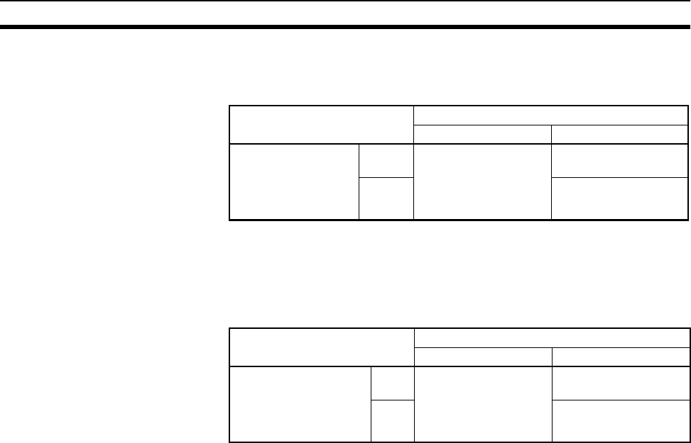
478
CPU Unit Operating Modes Section 10-2
Note 1. The I/O memory is held or cleared according to the status of the IOM Host
Bit and the setting for IOM Hold Bit Status at Startup in the PLC Setup
(read only when power is turned ON).
Mode Change: Between PROGRAMMING mode and RUN or MONITOR
mode
2. The forced status held or cleared according to the status of the Force Sta-
tus Hold Bit and the setting for Forced Status Hold Bit Status at Startup in
the PLC Setup.
Mode Change: Between PROGRAMMING mode and RUN or MONITOR
mode
3. If the CPU Unit is turned OFF after online editing before the backup pro-
cess has been competed, an attempt will be made to recover the program
when power is turned ON again. The BKUP indicator will light during this
process. Refer to the CS/CJ Series Programming Manual (W394) for de-
tails.
10-2 CPU Unit Operating Modes
10-2-1 Operating Modes
The CPU Unit has three operating modes that control the entire user program
and are common to all tasks.
PROGRAM: Programs are not executed and preparations, such as creat-
ing I/O tables, initializing the PLC Setup and other settings,
transferring programs, checking programs, force-setting and
force-resetting can be executed prior to program execution.
MONITOR: Programs are executed, but some operations, such as online
editing, forced-set/reset, and changes to present values in I/O
memory, are enabled for trial operation and other adjust-
ments.
RUN: Programs are executed and some operations are disabled.
Auxiliary bit
PLC Setup setting
IOM Hold Bit (A50012)
Clear (OFF) Hold (ON)
IOM Hold Bit Status
at Startup
(Programming Con-
sole address:
Word 80, bit 15)
Clear
(OFF)
At power ON: Clear
At mode change: Clear
At power ON: Clear
At mode change: Hold
Hold
(ON)
At power ON: Hold
At mode change: Hold
Auxiliary bit
PLC Setup setting
Forced Status Hold Bit (A50013)
Clear (OFF) Hold (ON)
Forced Status Hold
Bit Status at Startup
(Programming Con-
sole address:
Word 80, bit 14)
Clear
(OFF)
At power ON: Clear
At mode change: Clear
At power ON: Clear
At mode change: Hold
Hold
(ON)
At power ON: Hold
At mode change: Hold
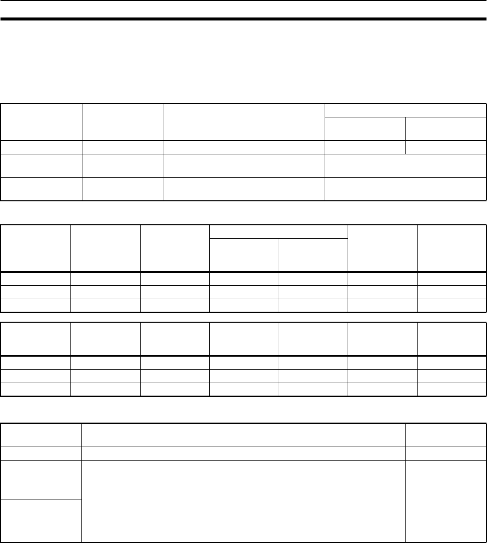
479
CPU Unit Operating Modes Section 10-2
10-2-2 Status and Operations in Each Operating Mode
PROGRAM, RUN, and MONITOR are the three operating modes available in
the CPU Unit. The following lists status and operations for each mode.
Overall Operation
Programming Console Operations
Note The following table shows the relationship of operating modes to tasks.
Mode Program
(See note)
I/O refresh External outputs I/O Memory
Non-holding
areas
Holding areas
PROGRAM Stopped Executed OFF Clear Hold
RUN Executed Executed Controlled by pro-
gram
Controlled by program
MONITOR Executed Executed Controlled by pro-
gram
Controlled by program
Mode Monitor I/O
Memory
Monitor
Program
Transfer Program Check
Program
Create I/O
Table
PLC to
Programming
Device
Programming
Device to PLC
PROGRAM OK OK OK OK OK OK
MONITOR OK OK OK XXX
RUN OK OK OK XXX
Mode PLC Setup Modify
Program
Force-
set/reset
Changing
Timer/Counter
SV
Changing
Timer/Counter
PV
Changing I/O
Memory PV
PROGRAM OK OK OK OK OK OK
RUNXXXXXX
MONITOR X OK OK OK OK OK
Mode Cyclic task status Interrupt task
status
PROGRAM Disabled status (INI) Stopped
RUN • Any task that has not yet been executed, will be in disabled status (INI).
• A task will go to READY status if the task is set to go to READY status at star-
tup or the TASK ON (TKON) instruction has been executed for it.
• A task in READY status will be executed (RUN status) when it obtains the
right to execute.
• A status will go to Standby status if a READY task is put into Standby status
by a TASK OFF (TKOF) instruction.
Executed if inter-
rupt condition is
met.
MONITOR
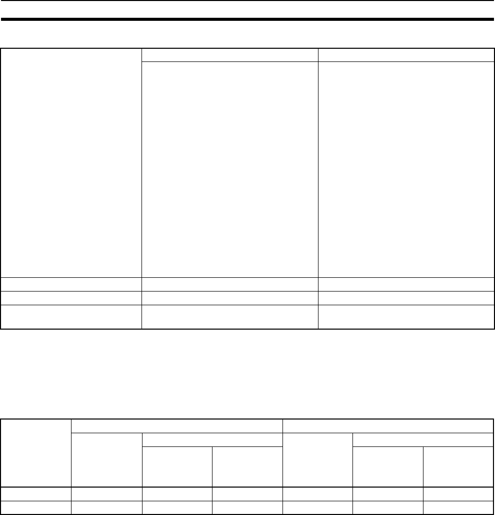
480
Power OFF Operation Section 10-3
Operating Mode Changes and I/O Memory
Note 1. The following processing is performed depending on the status of the I/O
Memory Hold Bit. Output from Output Units will be turned OFF when oper-
ation stops even if I/O bit status is held in the CPU Unit.
2. The cycle time will increase by approximately 10 ms when the operating
mode is changed from MONITOR to RUN mode. This will not, however,
cause an error for exceeding the maximum cycle time limit.
Note Refer to 9-2 I/O Memory Areas for more details on I/O Memory.
10-3 Power OFF Operation
10-3-1 Overview
The following processing is performed if CPU Unit power is turned OFF.
Power OFF processing will be performed if the power supply falls below 85%
of the rated voltage while the CPU Unit is in RUN or MONITOR mode.
1,2,3... 1. The CPU Unit will stop.
2. Outputs from all Output Units will be turned OFF.
Mode Changes Non-holding areas Holding Areas
• I/O bits
• Data Link bits
• CPU Bus Unit bits
• Special I/O Unit bits
• Inner Board bits
• SYSMAC BUS bits
• I/O Terminal bits
• C200H Special I/O Unit bits
• DeviceNet bits
• Work bits
• Timer PV/Completion Flags
• Index Registers
• Data Registers
• Task Flags
(Auxiliary Area bits/words are holding
or non-holding depending on the
address.)
• HR Area
•DM Area
•EM Area
• Counter PV and Completion Flags
(Auxiliary Area bits/words are holding
or non-holding depending on the
address.)
RUN or MONITOR to PROGRAM Cleared (See note 1.) Held
PROGRAM to RUN or MONITOR Cleared (See note 1.) Held
RUN to MONITOR or
MONITOR to RUN
Held (See note 2.) Held
I/O Memory
Hold Bit status
(A50012)
I/O Memory Output bits allocated to Output Units
Mode changed
between
PROGRAM
and RUN/
MONITOR
Operation stopped Mode changed
between
PROGRAM
and RUN/
MONITOR
Operation stopped
Fatal error
other than
FALS
FALS
executed
Fatal error
other than
FALS
FALS
executed
OFF Cleared Cleared Held OFF OFF OFF
ON Held Held Held Held OFF OFF
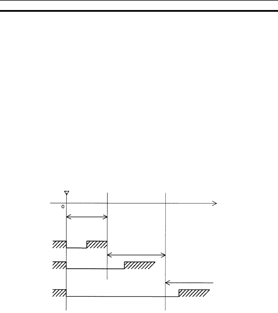
481
Power OFF Operation Section 10-3
Note All output will turn OFF despite an I/O Memory Hold Bit or I/O Memory Hold
Bit at power ON settings in the PLC Setup.
85% of the rated voltage:
AC power: 85 V for a 100 V AC system and 170 V for a 200 V AC system
DC power: 19.2 V DC
The following processing will be performed if power drops only momentarily
(momentary power interruption).
1,2,3... 1. The system will continue to run unconditionally if the momentary power in-
terruption lasts less than 10 ms, i.e., the time it takes the rated voltage at
85% or less to return to 85% or higher is less than 10 ms.
2. A momentary power interruption that lasts more than 10 ms but less than
25 ms is difficult to determine and a power interruption may or may not be
detected.
3. The system will stop unconditionally if the momentary power interruption
lasts more than 25 ms.
If operation stops under the conditions given in items 2 and 3 above, the tim-
ing used to stop operation (or the timing used to start execution of the Power
OFF Interrupt Task) can be delayed by setting the Power OFF Detection Delay
Time (0 to 10 ms) in the PLC Setup. Operation, however, will always be
stopped 10 ms after detecting a momentary power interruption regardless of
the setting in the PLC Setup.
Note The above timing chart shows an example when the power OFF detection
time is set to 0 ms (the default value).
85% of the rated voltage or less
Power supply
voltage
0 to 10 ms
Momentary power
interruption not
detected and op-
eration continues.
Operation will continue or
stop depending on whether
or not a momentary power
interruption is detected.
Momentary power interruption detected
and operation stops.
Time
Power supply
voltage
10 to 15 ms
25 ms and longer
Power supply
voltage
10 ms 25 ms
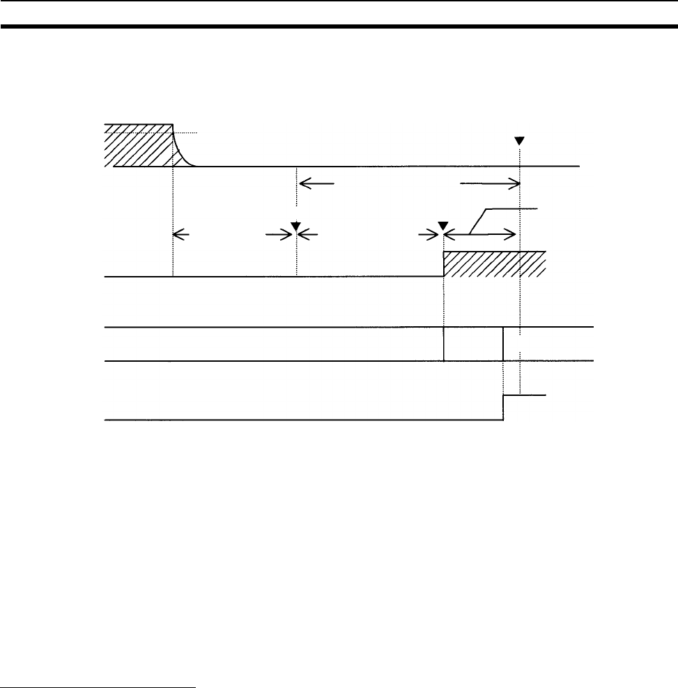
482
Power OFF Operation Section 10-3
The following timing chart shows the CPU Unit power OFF operation in more
detail.
Power OFF Timing Chart
Power OFF Detection Time
The time it takes to detect power OFF after the power supply falls below 85%
of the rated voltage.
Power OFF Detection Delay Time
The delay time after power OFF is detected until it is confirmed. This can be
set in the PLC Setup within a range from 0 to 10 ms. (The default is 0 ms.)
Power Holding Time
The amount of time (fixed at 10 ms) that 5 V will be held internally after power
shuts OFF. The time that it takes for the power OFF interrupt task to execute
must not exceed 10 ms minus the Power OFF Detection Delay Time (process-
ing time after power OFF is confirmed). The power OFF interrupt task will be
ended even if it has not been completely executed the moment this time
expires.
Description of Operation
1,2,3... 1. Power OFF will be detected if the 100 to 120 V AC, 200 to 240 V AC or 24 V
DC power supply falls below 85% of the rated voltage for the power OFF
detection time (somewhere between 10 to 25 ms).
2. If the Power OFF Detection Delay Time is set (0 to 10 ms) in the PLC Set-
up, then the following operations will be performed when the set time ex-
pires.
a) If the power OFF interrupt task is disabled (default PLC Setup setting)
The CPU reset signal will turn ON and the CPU will be reset immedi-
ately.
b) If the power OFF interrupt task is enabled (in the PLC Setup), the CPU
reset signal will turn ON and the CPU will be reset after the power OFF
interrupt task has been executed. Make sure that the power OFF inter-
rupt task will finish executing within 10 ms minus the Power OFF De-
tection Delay Time = processing time after power OFF. The 5-V
internal power supply will be maintained only for 10 ms after power
OFF is detected.
85% of rated
voltage
Power OFF
detected signal
Program execution
status
CPU reset signal
Cyclic tasks or interrupt tasks
not associated with power OFF
Power OFF
interrupt task Stopped
Processing time after
power OFF is confirmed:
10 ms minus Power OFF
Detection Delay Time
Note: The interrupt task
execution time must be
less than or equal to pro-
cessing time after power
OFF is confirmed.
Operation always stopped
at this point regardless.
Power OFF confirmedPower OFF detected
Holding time for 5 V internal
power supply after power
OFF detection: 10 ms.
Power OFF detec-
tion time: Default is
10 to 25 ms (Pow-
er OFF undeter-
mined)
Power OFF Detection
Delay Time: 0 to
10 ms (set in PLC Set-
up)
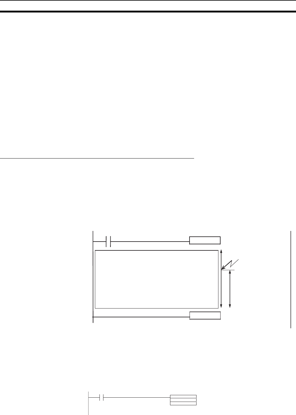
483
Power OFF Operation Section 10-3
10-3-2 Instruction Execution for Power Interruptions
If power is interrupted and the interruption is confirmed when the CPU Unit is
operating in RUN or MONITOR mode, the instruction currently being executed
will be completed (see note) and the following power interruption processing
will be performed.
• If the power OFF interrupt task has not been enabled, the CPU Unit will
be reset immediately.
• If the power OFF interrupt task has been enabled, the task will be exe-
cuted and then the CPU Unit will be reset immediately.
The power OFF interrupt task is enable and disabled in the PLC Setup.
Note The current instruction can be completed only when the time required to com-
plete execution is less than or equal to the processing time after power inter-
ruption detection (10 ms − power interruption detection delay time). If the
instruction is not completed within this time, it will be interrupted and the
above processing will be performed.
Disabling Power Interruption Processing in the Program
With CS1-H CPU Units, if the power OFF interrupt task is disabled, areas of
the program can be protected from power interruptions so that the instructions
will be executed before the CPU Unit performs power OFF processing even if
the power supply is interrupted. This is achieved by using the DISABLE
INTERRUPTS (DI(693)) and ENABLE INTERRUPTS (EI(694)) instructions.
The following procedure is used.
1,2,3... 1. Insert DI(693) before the program section to be protected to disable inter-
rupts and then place EI(694) after the section to enable interrupts.
2. Set the Disable Setting for Power OFF Interrupts in A530 to A5A5 hex to
enable disabling power interruption processing.
Note A530 is normally cleared when power is turned OFF. To prevent this,
the IOM Hold Bit (A50012) must be turned ON and the PLC Setup
must be set to maintain the setting of the IOM Hold Bit at Startup, or
the following type of instruction must be included at the beginning of
the program to set A530 to A5A5 hex.
3. Disable the Power OFF Interrupt Task in the PLC Setup.
DI
W0.00
Interrupt tasks disabled.
Interrupt tasks enabled.
EI
Instructions that cannot be
interrupted when a power
interruption occurs Instructions executed here.
Power interruption
confirmed.
MOV
#A5A5
A530
A20011
First Cycle Flag
Set A530 to A5A5 hex at the
beginning of the program to enable
disabling power interruption
processing.
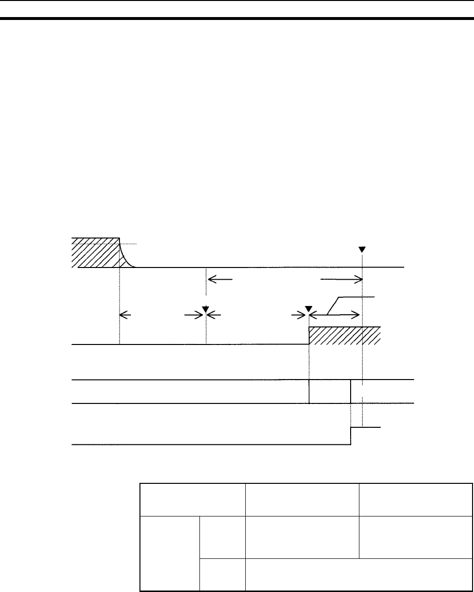
484
Power OFF Operation Section 10-3
With the above procedure, all instructions between DI(693) and EI(694) (or
END) will be completed (see note 1) before the Power OFF Interrupt is exe-
cuted even if the power interruption occurs while executing the instructions
between DI(693) and EI(694).
Note 1. The protected instructions can be completed only when the time required
to complete execution is less than or equal to the processing time after
power interruption detection (10 ms − power interruption detection delay
time). If the instructions is not completed within this time, they will be inter-
rupted and the above processing will be performed.
2. If the Power OFF Interrupt Task is not disabled in the PLC Setup, the Power
OFF Interrupt Task will be executed, and the CPU Unit will be reset without
executing the protected instructions as soon as the power interruption is
detected.
3. If a power interrupt is detected while DI(693) is being executed, the CPU
Unit will be reset without executing the protected instructions.
Interrupt processing is performed according to the contents of A530 and the
PLC Setup as shown below.
85% of rated
voltage
Power OFF
detected signal
Program execution
status
CPU reset signal
Cyclic tasks or interrupt tasks
not associated with power OFF Stopped
Processing time after
power OFF is confirmed:
10 ms minus Power OFF
Detection Delay Time
Note: The interrupt task
execution time must be
less than or equal to pro-
cessing time after power
OFF is confirmed.
Operation always stopped
at this point regardless.
Power OFF confirmedPower OFF detected
Holding time for 5 V internal
power supply after power
OFF detection: 10 ms.
Power OFF Detection
Delay Time: 0 to
10 ms (set in PLC Set-
up)
Instructions between
DI(693) and EI(694)
are executed.
DI(693) EI(694)
Power OFF
detection time:
Default is 10 to 25 ms
(Power OFF undeter-
mined)
A530 A5A5 hex (disabling
power interrupt
processing)
Other
Power OFF
Interrupt Task
(PLC Setup)
Disabled All instructions between
DI(693) and EI(694) are
executed and the CPU Unit
is reset.
Execution of the current
instruction is completed
and the CPU Unit is reset.
Enabled Execution of the current instruction is completed, the
Power OFF Interrupt Task is executed, and the CPU Unit
is reset.
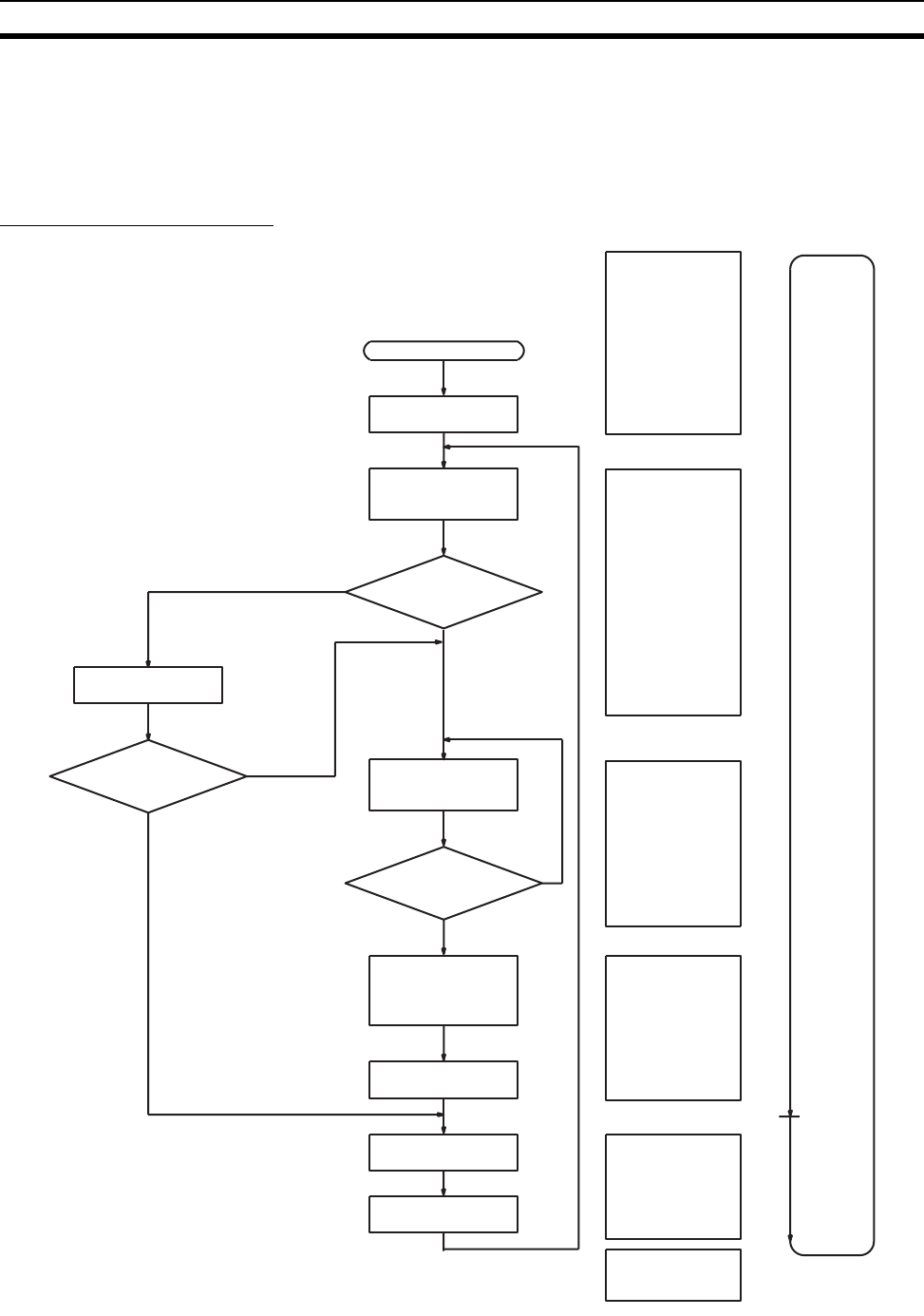
485
Computing the Cycle Time Section 10-4
10-4 Computing the Cycle Time
10-4-1 CPU Unit Operation Flowchart
The CS-series CPU Units process data in repeating cycles from the oversee-
ing processing up to peripheral servicing as shown in the following diagram.
Normal Processing Mode
PLC cycle
time
Resets watchdog
timer and waits un-
til the set cycle
time has elapsed
Power ON
Check OK?
Checks Unit
connection status.
Checks hardware
and user program
memory
Executes user pro-
gram (i.e., executes
READY cyclic tasks).
End of program?
Calculates cycle
time
Services Program-
ming Devices
NO
YES
YES
NO
ERR/ALM indicator
ON or Flashing?
Sets error flags
Flashing (non-
fatal error)
Startup initializa-
tion
Peripheral servic-
ing
Program execu-
tion
Cycle time cal-
culation
I/O refreshing
Overseeing pro-
cessing
ON (fatal error)
Performs I/O re-
freshing
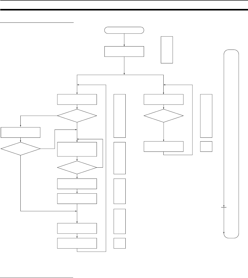
486
Computing the Cycle Time Section 10-4
Parallel Processing Mode
10-4-2 Cycle Time Overview
Normal Processing Mode
The cycle time depends on the following conditions.
• Type and number of instructions in the user program (in all cyclic tasks
that are executed during a cycle, and within interrupt tasks for which the
execution conditions have been satisfied).
• Type and number of Basic I/O Units
• Number of SYSMAC BUS Remote I/O Master Units and number of I/O
points on the Slaves
• Type and number of Special I/O Units, CS-series CPU Bus Units, Inner
Boards, and type of services being executed.
• Specific servicing for the following Units/Boards
• Data link refreshing and the number of data link words for Controller
Link and SYSMAC LINK Units
NO
YES
Power ON
Startup
initialization
Checks Unit
connection status
Program Execution
Cycle Peripheral
Servicing Cycle
Check user program
memory, etc.
Check OK?
Services
peripherals.
Overseeing
processing
Program execution
cycle time
Check OK?
Execute user
program (i.e., READY
cyclic tasks).
Program
completed?
Wait for specified
cycle time.
Calculates cycle
time.
Refreshes I/O.
Services peripherals.
Overseeing
processing
Program
execution
Cycle time
calculations
I/O refreshing
Peripheral
servicing
ERR/ALM
indicator lit or
flashing
Lit: Fatal error
Set error flags.
Check hardware,
etc.
Flashing:
Non-fatal
error
Peripheral
servicing

487
Computing the Cycle Time Section 10-4
• Remote I/O for DeviceNet (Master) Units and the number of remote I/O
words
• Use of protocol macros and the largest communications message
• Socket services for specific control bits for Ethernet Units and the num-
ber of send/receive words
• Fixed cycle time setting in the PLC Setup
• File access in file memory, and the amount of data transferred to/from file
memory
• Event servicing for Special I/O Units, CPU Bus Units, Inner Boards, and
communications ports
• Use of peripheral and RS-232C ports
• Fixed peripheral servicing time in the PLC Setup
Note 1. The cycle time is not affected by the number of tasks that are used in the
user program. The tasks that affect the cycle time are those cyclic tasks
that are READY in the cycle.
2. When the mode is switched from MONITOR mode to RUN mode, the cycle
time will be extended by 10 ms (this will not, however, take the cycle time
over its limit).
The cycle time is the total time required for the PLC to perform the 5 opera-
tions shown in the following tables.
Cycle time = (1) + (2) + (3) + (4) + (5)
1: Overseeing
2: Program Execution
3: Cycle Time Calculation
Details Processing time and fluctuation cause
Checks the I/O bus and user program memory, checks for
battery errors and refreshes the clock.
CS1-H CPU Unit: 0.3 ms
Details Processing time and fluctuation cause
Executes the user program, and calculates the total time
time taken for the instructions to execute the program.
Total instruction execution time
Details Processing time and fluctuation cause
Waits for the specified cycle time to elapse when a minimum
(fixed) cycle time has been set in the PLC Setup.
Calculates the cycle time.
When the cycle time is not fixed, the time for step 3 is
approximately 0.
When the cycle time is fixed, the time for step 3 is the preset
fixed cycle time minus the actual cycle time ((1) + (2) + (4) +
(5)).

488
Computing the Cycle Time Section 10-4
4: I/O Refreshing
5: Peripheral Servicing
Details Processing time and fluctuation cause
Basic I/O Units
(including
C200H Group-
2 I/O Units)
Basic I/O Units are refreshed. Outputs from
the CPU Unit to the I/O Unit are refreshed
first for each Unit, and then inputs.
I/O refresh time for each Unit multiplied by the number of
Units used.
SYSMAC BUS
Remote I/O
Master Unit
SYSMAC BUS remote I/O is refreshed.
Outputs from the CPU Unit to remote I/O
are refreshed first for each Unit, and then
inputs.
I/O refresh time for SYSMAC BUS remote I/O system.
Special I/O
Units
Words allocated in CIO Area I/O refresh time for each Unit multiplied by the number of
Units used.
Unit- specific
data
DeviceNet remote I/O
for C200H DeviceNet
Master Units and Com-
poBus/S remote I/O
CPU Bus Units Words allocated in CIO and DM Areas I/O refresh time for each Unit multiplied by the number of
Units used.
Unit- specific
data
Data links for Control-
ler Link and SYSMAC
LINK Units, DeviceNet
remote I/O for CS-
series DeviceNet Units,
send/receive data for
protocol macros, and
socket services for spe-
cific control bits for
Ethernet Units
I/O refresh time for each Unit multiplied by the number of
Units used.
Inner Boards Words allocated in Inner Board Area I/O refresh time for each Unit multiplied by the number of
Units used.
Unit- specific
data
Example: Send/receive
data for protocol mac-
ros,
Details Processing time and fluctuation cause
Services events for CS-series Special I/O
Units.
Note Peripheral servicing does not include
I/O refreshing,
If a uniform peripheral servicing time hasn’t been set in the PLC Setup for
this servicing, 4% of the previous cycle’s cycle time (calculated in step (3))
will be allowed for peripheral servicing.
If a uniform peripheral servicing time has been set in the PLC Setup, servic-
ing will be performed for the set time. At least 0.1 ms, however, will be ser-
viced whether the peripheral servicing time is set or not.
If no Units are mounted, the servicing time is 0 ms.
Services events for CS-series CPU Bus
Units.
Note Peripheral servicing does not include
I/O refreshing.
Same as above.
Services events for peripheral ports. If a uniform peripheral servicing time hasn’t been set in the PLC Setup for
this servicing, 4% of the previous cycle’s cycle time (calculated in step (3))
will be allowed for peripheral servicing.
If a uniform peripheral servicing time has been set in the PLC Setup, servic-
ing will be performed for the set time. At least 0.1 ms, however, will be ser-
viced whether the peripheral servicing time is set or not.
If the ports are not connected, the servicing time is 0 ms.
Services RS-232C ports. Same as above.

489
Computing the Cycle Time Section 10-4
Parallel Processing with Asynchronous Memory Access
Program Execution Cycle The program execution cycle time depends on the following conditions.
• Type and number of instructions in the user program (in all cyclic tasks
that are executed during a cycle, and within interrupt tasks for which the
execution conditions have been satisfied).
• Type and number of Basic I/O Units
• Number of SYSMAC BUS Remote I/O Master Units and number of I/O
points on the Slaves
• Type and number of Special I/O Units, CS-series CPU Bus Units, Inner
Boards, and type of services being executed.
• Specific servicing for the following Units/Boards
• Data link refreshing and the number of data link words for Controller
Link and SYSMAC LINK Units
• Remote I/O for DeviceNet (Master) Units and the number of remote I/O
words
• Use of protocol macros and the largest communications message
• Socket services for specific control bits for Ethernet Units and the num-
ber of send/receive words
• Fixed cycle time setting in the PLC Setup
• File access in file memory, and the amount of data transferred to/from file
memory
• Fixed peripheral servicing time in the PLC Setup
The program execution cycle time is the total time required for the PLC to per-
form the 5 operations shown in the following tables.
Services Inner Board events. If a uniform peripheral servicing time hasn’t been set in the PLC Setup for
this servicing, 4% of the previous cycle’s cycle time (calculated in step (3))
will be allowed for peripheral servicing.
If a uniform peripheral servicing time has been set in the PLC Setup, servic-
ing will be performed for the set time. At least 0.1 ms, however, will be ser-
viced whether the peripheral servicing time is set or not.
If no Inner Boards are mounted, the servicing time is 0 ms.
Services file access (Memory Card or EM
file memory).
If a uniform peripheral servicing time hasn’t been set in the PLC Setup for
this servicing, 4% of the previous cycle’s cycle time (calculated in step (3))
will be allowed for peripheral servicing.
If a uniform peripheral servicing time has been set in the PLC Setup, servic-
ing will be performed for the set time. At least 0.1 ms, however, will be ser-
viced whether the peripheral servicing time is set or not.
If there is no file access, the servicing time is 0 ms.
Services communications ports. If a uniform peripheral servicing time hasn’t been set in the PLC Setup for
this servicing, 4% of the previous cycle’s cycle time (calculated in step (3))
will be allowed for peripheral servicing.
If a uniform peripheral servicing time has been set in the PLC Setup, servic-
ing will be performed for the set time. At least 0.1 ms, however, will be ser-
viced whether the peripheral servicing time is set or not.
If no communications ports are used, the servicing time is 0 ms.
Details Processing time and fluctuation cause
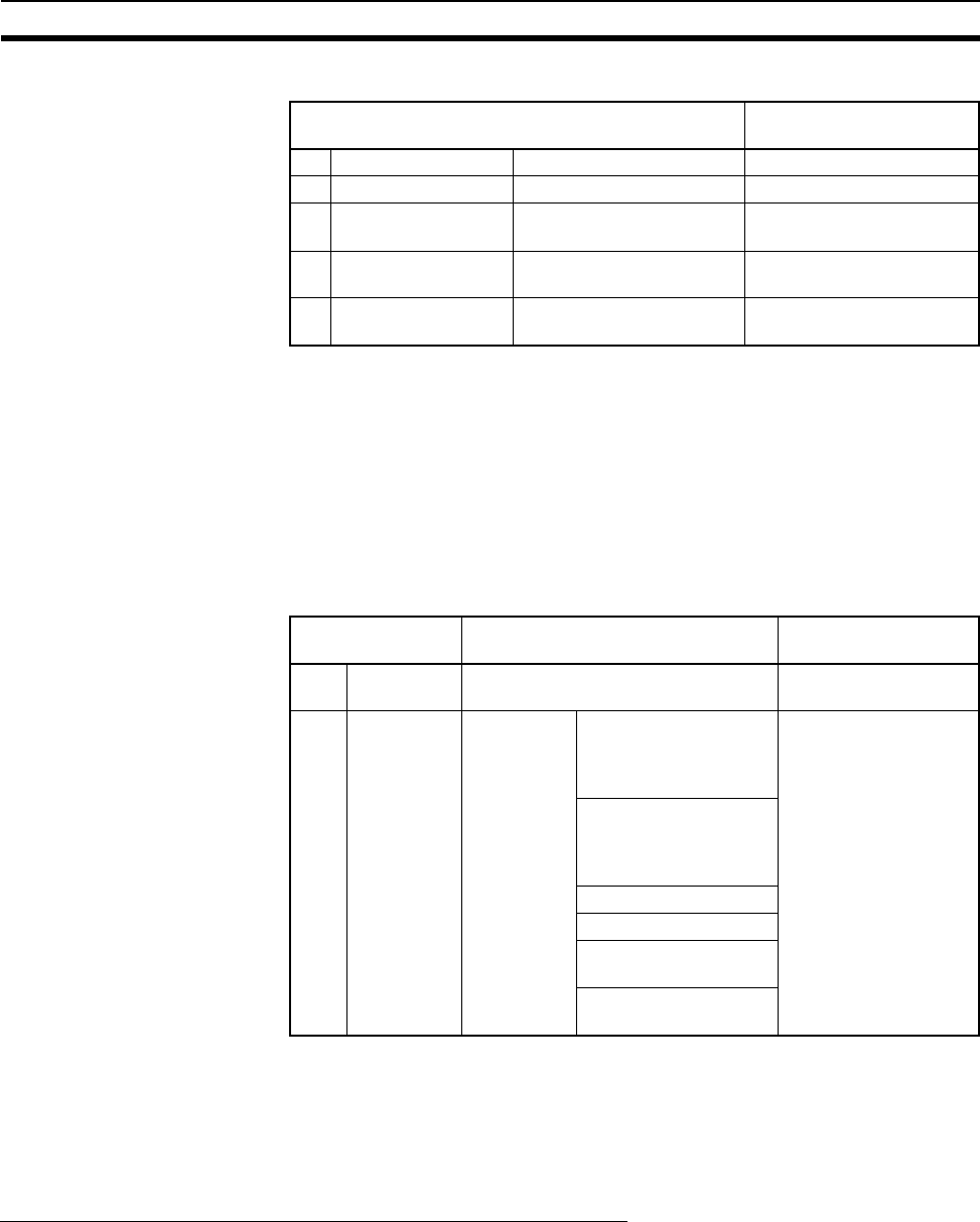
490
Computing the Cycle Time Section 10-4
Cycle time = (1) + (2) + (3) + (4) + (5)
Peripheral Servicing Cycle
Time
The peripheral servicing execution cycle time depends on the following condi-
tions.
• Type and number of Special I/O Units, CS-series CPU Bus Units, Inner
Boards, and type of services being executed.
• Type and frequency of event servicing requiring communications ports.
• Use of peripheral and RS-232C ports
The peripheral servicing cycle time is the total time required for the PLC to
perform the 5 operations shown in the following tables.
Cycle time = (1) + (2)
Note 1. The cycle time display on a Programming Device is the Program Execution
Cycle Time.
2. The peripheral service cycle time varies with the event load and number of
Units that are mounted. In a Parallel Processing Mode, however, this vari-
ation will not affect the program execution cycle time.
Parallel Processing with Synchronous Memory Access
Program Execution Cycle The program execution cycle time depends on the same conditions as the
Normal Mode. Partial peripheral servicing ((5) below), however, is restricted to
servicing for file and I/O memory access.
The program execution cycle time is the total time required for the PLC to per-
form the 5 operations shown in the following tables.
Details Processing time and
fluctuation cause
(1) Overseeing I/O bus check, etc. 0.3 ms
(2) Program execution Same as for Normal Mode. Same as for Normal Mode.
(3) Cycle time calcula-
tion
Waits for the specified
cycle time.
Same as for Normal Mode.
(4) I/O refreshing Same as for Normal Pro-
cessing Mode.
Same as for Normal Pro-
cessing Mode.
(5) Partial peripheral
servicing
Servicing file access Same as for Normal Pro-
cessing Mode.
Name Processing Processing time and
fluctuation cause
(1) Overseeing
processing
Checks user program memory,
checks for battery errors, etc.
0.2 ms
(2) Peripheral
servicing
Performs
services for
the events
give at the
right, includ-
ing I/O
memory
access.
Events with CS-series
Special I/O Units (does
not include I/O refresh-
ing)
1.0 ms for each type of
service
If servicing ends before
1 ms has expired, the
next type of servicing
will be started immedi-
ately without waiting.
Events with CS-series
CPU Bus Units (does
not include I/O refresh-
ing)
Peripheral port events
RS-232C port events
Events with Inner
Boards
Events using communi-
cations ports

491
Computing the Cycle Time Section 10-4
Cycle time = (1) + (2) + (3) + (4) + (5)
Peripheral Servicing Cycle
Time
The peripheral servicing execution cycle time depends on the same condi-
tions as the Parallel Processing with Asynchronous Memory Access. Periph-
eral servicing ((2) below), however, is restricted to servicing that does not
access I/O memory.
The peripheral servicing cycle time is the total time required for the PLC to
perform the 2 operations shown in the following tables.
Cycle time = (1) + (2)
Note 1. The cycle time display on a Programming Device is the Program Execution
Cycle Time.
2. The peripheral service cycle time varies with the event load and number of
Units that are mounted. In a Parallel Processing Mode, however, this vari-
ation will not affect the program execution cycle time.
Details Processing time and
fluctuation cause
(1) Overseeing I/O bus check, etc. 0.3 ms
(2) Program exe-
cution
Same as for Normal Mode. Same as for Normal
Mode.
(3) Cycle time
calculation
Waits for the specified cycle time. Same as for Normal
Mode.
(4) I/O refreshing Same as for Normal Processing Mode. Same as for Normal
Mode.
(5) Partial
peripheral
servicing
Servicing file access (Memory Card or
EM file memory)
Same as for Normal
Mode.
Performs
services for
the events
give at the
right that
requires
I/O mem-
ory access
Events with CS-series
Special I/O Units (does
not include I/O refreshing)
Events with CS-series
CPU Bus Units (does not
include I/O refreshing)
Peripheral port events
RS-232C port events
Events with Inner Boards
Events using communica-
tions ports
Name Processing Processing time and
fluctuation cause
(1) Overseeing
processing
Checks user program memory,
checks for battery errors, etc.
0.2 ms
(2) Peripheral
servicing
Performs
services for
the events
give at the
right,
excluding
those that
require I/O
memory
access.
Events with CS-series
Special I/O Units (does
not include I/O refresh-
ing)
1.0 ms for each type of
service
If servicing ends before
1 ms has expired, the
next type of servicing
will be started immedi-
ately without waiting.
Events with CS-series
CPU Bus Units (does
not include I/O refresh-
ing)
Peripheral port events
RS-232C port events
Events with Inner
Boards
Events using communi-
cations ports

492
Computing the Cycle Time Section 10-4
10-4-3 I/O Unit Refresh Times for Individual Units and Boards
Basic I/O Unit Refresh
Unit Name Model I/O refresh
time per Unit
C200H
Basic I/O
Units
8-point Input Unit C200H-ID211 0.03 ms
8-point Output Unit C200H-OC221 0.03 ms
12-point Output Unit C200H-OA224 0.03 ms
16-point Input Unit C200H-ID212 0.02 ms
16-point Output Unit C200H-OD212 0.03 ms
Interrupt Input Unit C200HS-INT01 0.10 ms
C200H
Group-2
High-den-
sity I/O Unit
(classified
as Basic I/O
Units)
32-point Input Unit C200H-ID216 0.10 ms
32-point Output Unit C200H-OD218 0.10 ms
64-point Input Unit C200H-ID217 0.20 ms
64-point Output Unit C200H-OD219 0.13 ms
32-point B7A Input Units C200H-B7A12 0.1 ms
32-point B7A Output Units C200H-B7A02 0.1 ms
16/16-point B7A I/O Units C200H-B7A21 0.1 ms
32/32-point B7A I/O Units C200H-B7A22 0.2 ms

493
Computing the Cycle Time Section 10-4
CS-series
Basic I/O
Units
16-point DC Input Unit CS1W-ID211 0.004 ms
(See note.)
16-point AC Input Unit CS1W-IA111/211 0.004 ms
(See note.)
8/16-point Relay Output Unit CS1W-OC201/211 0.004 ms
(See note.)
8/16-point Triac Output Unit CS1W-OA201/211 0.004 ms
(See note.)
16-point Transistor Output Unit,
sinking outputs
CS1W-OD211 0.004 ms
(See note.)
16-point Transistor Output Unit,
sourcing outputs
CS1W-OD212 0.004 ms
(See note.)
16-point Interrupt Input Unit CS1W-INT01 0.004 ms
(See note.)
16-point High-speed Input Unit CS1W-IDP01 0.004 ms
(See note.)
32-point DC Input Unit CS1W-ID231 0.007 ms
(See note.)
64-point DC Input Unit CS1W-ID261 0.014 ms
(See note.)
96-point DC Input Unit CS1W-ID291 0.02 ms
(See note.)
32-point Transistor Output Unit,
sinking outputs
CS1W-OD231 0.008 ms
(See note.)
32-point Transistor Output Unit,
sourcing outputs
CS1W-OD232 0.008 ms
(See note.)
64-point Transistor Output Unit,
sinking outputs
CS1W-OD261 0.016 ms
(See note.)
64-point Transistor Output Unit,
sourcing outputs
CS1W-OD262 0.016 ms
(See note.)
96-point Transistor Output Unit,
sinking outputs
CS1W-OD291 0.02 ms
(See note.)
96-point Transistor Output Unit,
sourcing outputs
CS1W-OD292 0.02 ms
(See note.)
32-point DC Input/32-point
Transistor Output Unit, sourc-
ing outputs
CS1W-MD261 0.015 ms
(See note.)
32-point DC Input/32-point
Transistor Output Unit, sinking
outputs
CS1W-MD262 0.015 ms
(See note.)
48-point DC Input/48-point
Transistor Output Unit, sinking
outputs
CS1W-MD291 0.02 ms
(See note.)
48-point DC Input/48-point
Transistor Output Unit, sourc-
ing outputs
CS1W-MD292 0.02 ms
(See note.)
32-point B7A Input Unit CS1W-B7A12 0.1 ms
(See note.)
64-point B7A Output Unit CS1W-B7A02 0.1 ms
(See note.)
16-point Input/16-point Output
B7A I/O Unit
CS1W-B7A21 0.1 ms
(See note.)
32-point Input/32-point Output
B7A I/O Unit
CS1W-B7A22 0.2 ms
(See note.)
Unit Name Model I/O refresh
time per Unit
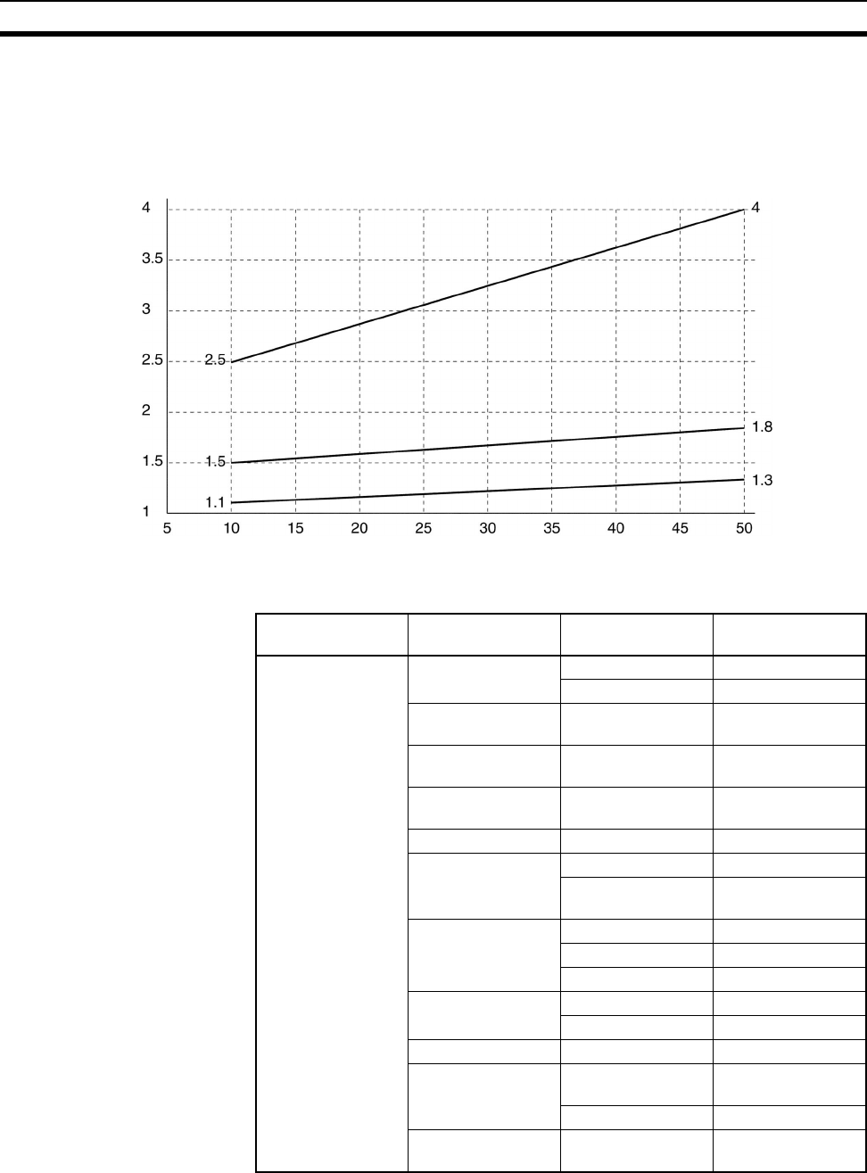
494
Computing the Cycle Time Section 10-4
Note Longer I/O refresh times will be required according to the distance from the
CPU Rack to the Unit when these Units are mounted to CS-series Long-dis-
tance Expansion Racks. Multiply the values given in the table by the factors
on line *1 in the following graph.
Special I/O Unit Refresh
I/O Unit Refresh Time Coefficients for Units on CS-series Long-distance Expansion Racks
Factor
Distance to Unit (m)
(*3)
(*1)
(*2)
Unit Name Model I/O refresh time
per Unit
C200H Special I/O
Units
High-density I/O
Units
C200H-MD215 0.5 ms
C200H-MD501 1.5 ms
Temperature Con-
trol Unit
C200H-TC@@@ 2.6 ms
Heat/Cool Temper-
ature Control Unit
C200H-TV@@@ 2.6 ms
Temperature Sen-
sor Unit
C200H-TS@@@ 1.0 ms
PID Control Unit C200H-PID@@ 2.6 ms
ASCII Unit C200H-ASC02 1.8 ms
C200H-
ASC11/21/31
0.4 ms
Analog Input Unit C200H-AD001 1.0 ms
C200H-AD002 1.4 ms
C200H-AD003 0.7 ms
Analog Output Unit C200H-DA001/002 0.9 ms
C200H-DA003/004 0.6 ms
Analog I/O Unit C200H-MAD01 0.6 ms
High-speed
Counter Unit
C200H-CT001-
V1/CT002
2.4 ms
C200H-CT021 0.5 ms
Position Control
Unit
C200H-NC111/112 2.2 ms
(4.0 ms for read)

495
Computing the Cycle Time Section 10-4
C200H Special I/O
Units, continued
Position Control
Unit, continued
C200H-NC211 5.1 ms
(6.7 ms for read)
C200HW-NC113 2.0 ms
(2.9 ms for read or
write)
C200HW-NC213 2.3 ms
(3.2 ms for read or
write)
C200HW-NC413 4.3 ms
(5.5 ms for read or
write)
Motion Control Unit C200H-MC221 1.2 ms
(2.1 ms for read)
ID Sensor Unit C200H-IDS01-
V1/21
1.8 ms
Cam Positioner Unit C200H-CP114 2.0 ms
Voice Unit C200H-OV001 3.4 ms
Fuzzy Logic Unit C200H-FZ001 1.8 ms
PC Link Unit C200H-LK401 0.3 ms (connected
without data links
operating)
4.1 ms (for 256 data
link points)
7.4 ms (for 512 data
link points)
SYSMAC BUS
Remote I/O Master
Unit
C200H-RM201 1.1 ms x No. of
Units + 0.17 x N,
where N is the No.
of words allocated
to slaves
C200H-RM001-V1
C200H DeviceNet
Master Unit
C200HW-DRM21-
V1
1.72 ms + 0.0022 ×
number of allo-
cated words
C200H DeviceNet
I/O Link Unit
C200HW-DRT21-
V1
1.72 ms + 0.0022 ×
number of allo-
cated words
CompoBus/S Mas-
ter Unit
C200HW-SRM21-
V1
0.4 ms (for the max-
imum of 16 slaves)
0.9 ms (for the max-
imum of 32 slaves)
Unit Name Model I/O refresh time
per Unit

496
Computing the Cycle Time Section 10-4
Note Longer increases in the cycle time will occur according to the distance from
the CPU Rack to the Unit when these Units are mounted to CS-series Long-
distance Expansion Racks. Multiply the values given in the table by the factors
on line *2 in the graph on page 494 for the increases for data link words and
send/receive words.
Unit Name Model I/O refresh time per Unit When a Long-
distance
Expansion Rack is
used (See note.)
CS1-H
CS-series
Special I/O
Units
Analog I/O Unit CS1W-MAD44 0.12 ms 0.2 ms × *2
Analog Input Unit CS1W-AD041/081-V1 0.12 ms 0.2 ms × *2
CS1W-AD161 0.11 ms 0.3 ms × *2
Analog Output Unit CS1W-DA041/08V/08C 0.12 ms 0.2 ms × *2
Isolated Thermocouple
Input Unit
CS1W-PTS01-V1 0.16 ms 0.3 ms × *2
Isolated Resistance Ther-
mometer Input Unit
CS1W-PTS02-V1 0.16 ms 0.3 ms × *2
Isolated Ni508.4Ω Resis-
tance Thermometer Input
Unit
CS1W-PTS03 0.16 ms 0.3 ms × *2
Isolated 2-wire Transmis-
sion Device Input Unit
CS1W-PTW01 0.16 ms 0.3 ms × *2
Isolated DC Input Unit CS1W-PDC01 0.16 ms 0.3 ms × *2
Isolated Control Output Unit
(Analog Output Unit)
CS1W-PMV01 0.16 ms 0.3 ms × *2
Power Transducer Input
Unit
CS1W-PTR01 0.16 ms 0.3 ms × *2
DC Input Unit (100 mA) CS1W-PTR02 0.16 ms 0.3 ms × *2
Isolated Pulse Input Unit CS1W-PPS01 0.16 ms 0.3 ms × *2
Position Control Unit CS1W-NC113/133 0.29 ms (+ 0.7 ms for
each instruction (IOWR/
IORD) used to transfer
data)
Multiply times at left
by factor *2 (See
note.)
CS1W-NC213/233 0.32 ms (+ 0.7 ms for
each instruction (IOWR/
IORD) used to transfer
data)
CS1W-NC413/433 0.41 ms (+ 0.6 ms for
each instruction (IOWR/
IORD) used to transfer
data)
High-speed Counter Unit CS1W-CT021/041 0.14 ms 0.2 ms × *2
Motion Control Unit CS1W-MC221 0.32 ms 0.8 ms × *2
CS1W-MC421 0.42 ms 0.8 ms × *2
Customizable Counter Unit CS1W-HIO01 0.2 ms (+ 0.3 ms if DM
Area or LR Area is used
for data exchange with
CPU Unit)
Multiply times at left
by factor *2 (See
note.)
CS1W-HCP22
CS1W-HCA22
CompoNet Master Unit CS1W-
CRM21
Communica-
tions mode No. 0
0.189 ms Multiply times at left
by factor *2 (See
note.)
Communica-
tions mode No. 1
0.211 ms
Communica-
tions mode No. 2
0.233 ms
Communica-
tions mode No. 3
0.289 ms
Communica-
tions mode No. 8
0.109 + (0.0014 × No. of
allocated words) ms

497
Computing the Cycle Time Section 10-4
Increase in Cycle Time Caused by CPU Bus Units
Note 1. The times given show the performance of the CPU6@H.
Name Model Increase Remarks
Controller Link Unit CS1W-
CLK11/21
(-V1) or
CS1W-
CLK23
CS1-H: 0.1 ms
(See note 1.)
With Long-distance Expansion Rack:
0.2 ms × factor *2
There will be an increase of 0.1 ms +
0.7 µs x number of data link words for
CS1-H CPU Units. (See note 2.)
With Long-distance Expansion Rack:
(1.5 ms + (number of send words × 1 µs))
× factor *3
There will be an additional increase of the
event execution times when message
services are used.
CS1W-
CLK12/52
(-V1) or
CS1W-
CLK13/53
CS1-H: 0.1 ms
(See note 1.)
With Long-distance Expansion Rack:
0.2 ms × factor *2
SYSMAC LINK CS1W-
SLK11/21
CS1-H: 0.1 ms
(See note 1.)
With Long-distance Expansion Rack:
0.2 ms × factor *2
Serial Communications
Unit
CS1W-
SCU21-
V1
CS1-H: 0.22 ms
(See note 1.)
With Long-distance Expansion Rack:
0.2 ms × factor *2
There will be an increase of up to the fol-
lowing time when a protocol macro is
executed:
CS1-H CPU Units: 0.1 ms + 0.7 µs ×
maximum number of data words sent or
received (0 to 500 words)
With Long-distance Expansion Rack:
(1.3 ms + (max. number of send/receive
words × 1 µs)) × factor *3
Max. number of send/receive words = 0
to 500 words
There will be an increase of the event
execution times when Host Links or 1:N
NT Links are used.
DeviceNet Unit CS1W-
DRM21-
V1
CS1-H: 0.4 ms + 0.7 µs for each allo-
cated word
(See note 1.)
With Long-distance Expansion Rack:
(0.7 ms + (number of allocated words ×
1 µs)) × factor *3
---
Ethernet Unit CS1W-
ETN01/11
/21
CS1-H: 0.1 ms
(See note 1.)
With Long-distance Expansion Rack:
0.2 ms × factor *2
If socket services are executed with soft-
ware switches, there will be an increase
of 1.4 µs × the number of bytes
sent/received for CS1-H CPU Units. (See
note 2.)
With Long-distance Expansion Rack:
(number of send or receive bytes × 2 µs)
× factor *3
There will be an increase of the event
execution times when FINS communica-
tions services, socket services for CMND
instructions, or FTP services are per-
formed.
PROFIBUS-DP Master
Unit
CS1W-
PRM21
CS1-H: 0.4 ms + 0.7 µs for each allo-
cated word
Include all words allocated to the slaves,
including unused ones.
For FINS communications with the Unit,
add the number of communications
words to the calculations on the left.
Loop Control Unit CS1W-
LC001
CS1-H: 0.1 ms
(See note 1.)
With Long-distance Expansion Rack:
0.2 × factor *2
---
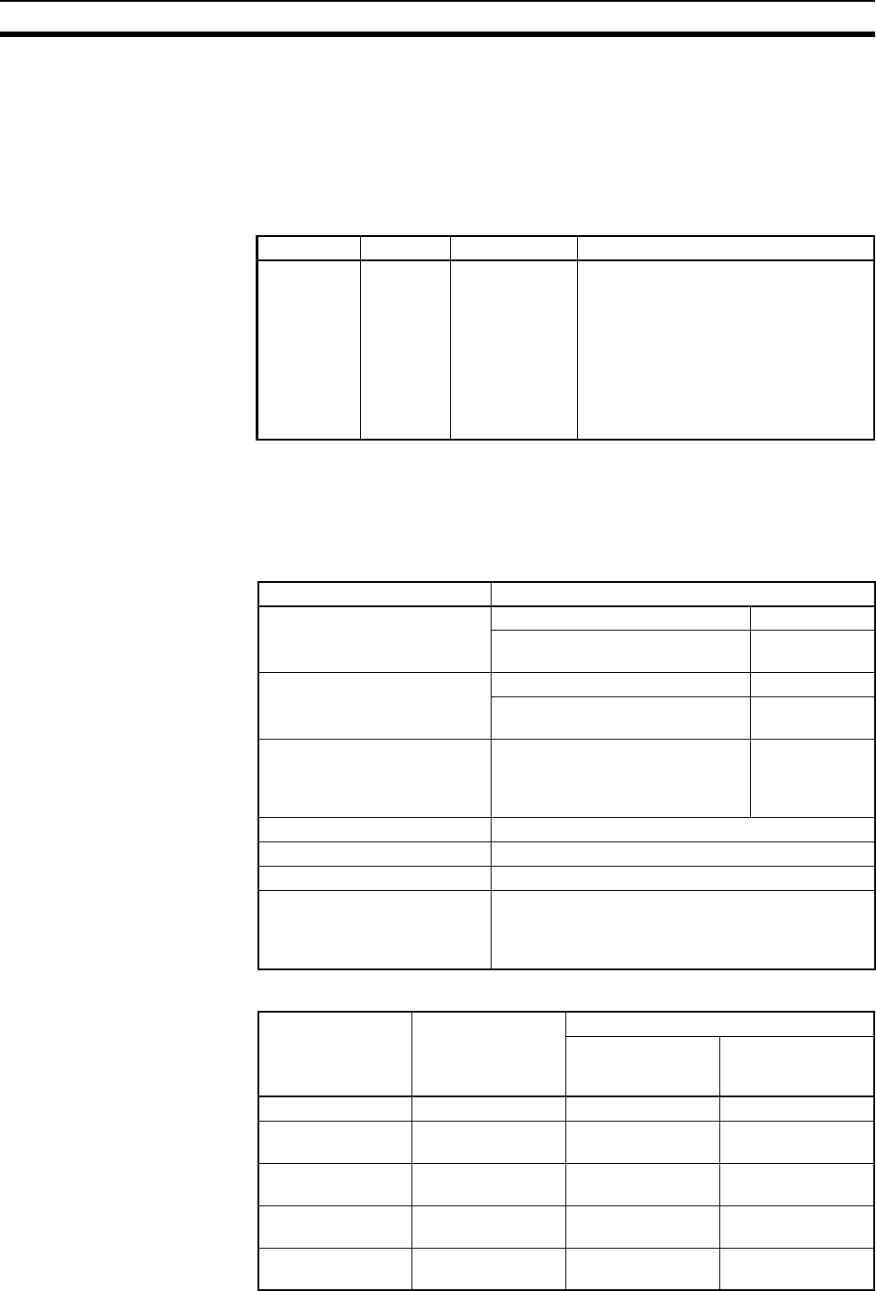
498
Computing the Cycle Time Section 10-4
2. Longer increases in the cycle time will occur according to the distance from
the CPU Rack to the Unit when these Units are mounted to CS-series
Long-distance Expansion Racks. Multiply the values given in the table by
the factors on line *2 in the graph on page 494 for the increases and by the
factors on line *3 for the additional increases for data link words and
send/receive words
Increase in Cycle Time Caused by Inner Board
10-4-4 Cycle Time Calculation Example
The following example shows the method used to calculate the cycle time
when Basic I/O Units only are mounted to the PLC with a CS1G-CPU4@H.
Conditions
Calculation Example
Name Model Increase Remarks
Serial Com-
munications
Board
CS1W-
SCB21/41
-V1
CS1-H: 0.22 ms There will be an increase of up to the
following time when a protocol macro is
executed:
CS1-H CPU Units: 0.7 µs × maximum
number of data words sent or received
(0 to 500 words) + 0.1 ms
There will be an increase of the event
execution times when Host Links or 1:N
NT Links are used.
Item Details
CPU Rack (8 slots) CS1W-ID291 96-point Input Units 4 Units
CS1W-OD291 96-point Output
Units
4 Units
CS-series Expansion Rack (8
slots) × 1 Unit
CS1W-ID291 96-point Input Units 4 Units
CS1W-OD291 96-point Output
Units
4 Units
User program 5 K steps LD instruction
2.5 K steps,
OUT instruc-
tion 2.5 K steps
Peripheral port connection Yes and no
Fixed cycle time processing No
RS-232C port connection No
Peripheral servicing with other
devices (Special I/O Units, CS-
series CPU Bus Units, Inner
Boards, and file access)
No
Process name Calculation Processing time
With
Programming
Device
Without
Programming
Device
(1) Overseeing --- 0.3 ms 0.3 ms
(2) Program execu-
tion
0.04 µs × 2,500 +
0.04 µs × 2,500
0.2 ms 0.2 ms
(3) Cycle time cal-
culation
(Fixed cycle time
not set)
0 ms 0 ms
(4) I/O refreshing 0.02 ms × 8 +
0.02 ms × 8
0.32 ms 0.32 ms
(5) Peripheral ser-
vicing
(Peripheral port
connected only)
0.1 ms 0 ms
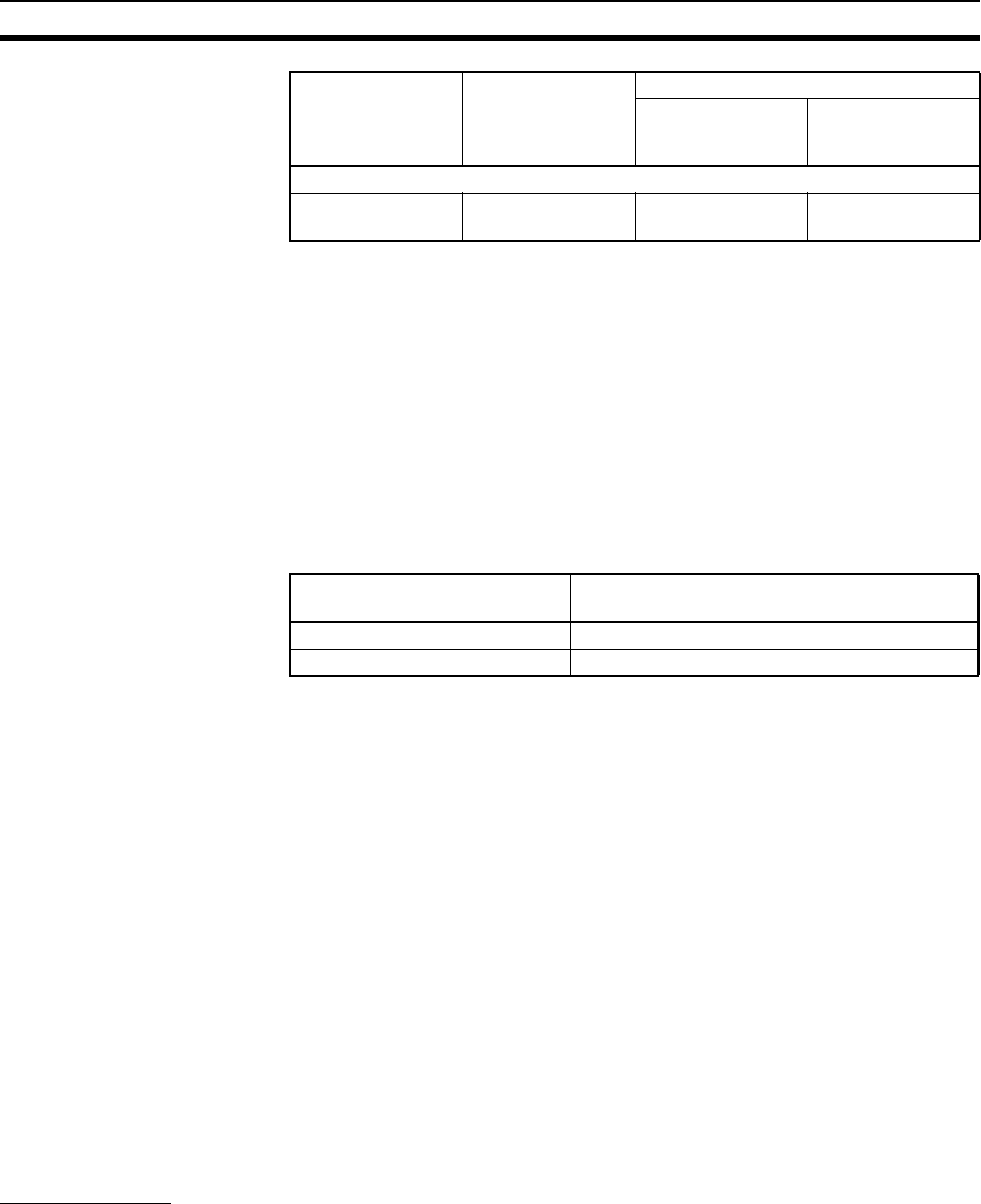
499
Computing the Cycle Time Section 10-4
10-4-5 Online Editing Cycle Time Extension
When online editing is executed from a Programming Device (such as Pro-
gramming Console or CX-Programmer) while the CPU Unit is operating in
MONITOR mode to change the program, the CPU Unit will momentarily sus-
pend operation while the program is being changed. The period of time that
the cycle time is extended is determined by the following conditions.
• Number of steps changed
• Editing operations (insert/delete/overwrite)
• Types of instructions used
If the maximum program size for each task is 64 Ksteps, the following table
provides guidelines for the maximum online editing cycle time extensions.
When editing online, the cycle time will be extended by the time that operation
is stopped.
Note When there is one task, online editing is processed all in the cycle time follow-
ing the cycle in which online editing is executed (written). When there are mul-
tiple tasks (cyclic tasks and interrupt tasks), online editing is separated, so
that for n tasks, processing is executed over n to n ×2 cycles max.
10-4-6 I/O Response Time
The I/O response time is the time it takes from when an Input Unit’s input
turns ON, the data is recognized by the CS-series CPU Unit, and the user
program is executed, up to the time for the result to be output to an Output
Unit’s output terminals.
The length of the I/O response time depends on the following conditions.
• Timing of Input Bit turning ON.
• Cycle time.
• Type of Rack to which Input and Output Units are mounted (CPU Rack,
CPU Expansion Rack, Expansion Rack).
Basic I/O Units
Minimum I/O Response
Time
The I/O response time is shortest when data is retrieved immediately before
I/O refresh of the CPU Unit.
The minimum I/O response time is the total of the Input ON delay, the cycle
time, and the Output ON delay.
Note The Input and Output ON delay differs according to the Unit used.
Cycle time (1) + (2) + (3) + (4)
+ (5)
0.92 ms 0.82 ms
Process name Calculation Processing time
With
Programming
Device
Without
Programming
Device
CPU Unit Guidelines for increase in cycle time for
online editing
CPU6@H CS1-H CPU Units Approx. 8 ms
CPU4@H CS1-H CPU Units Approx. 11 ms
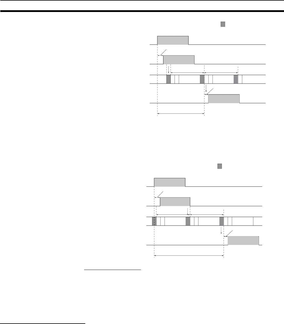
500
Computing the Cycle Time Section 10-4
Maximum I/O Response
Time
The I/O response time is longest when data is retrieved immediately after I/O
refresh of the Input Unit.
The maximum I/O response time is the total of the Input ON delay, (the cycle
time × 2), and the Output ON delay.
Calculation Example
Conditions: Input ON delay 1.5 ms
Output ON delay 0.2 ms
Cycle time 20.0 ms
Minimum I/O response time = 1.5 ms + 20 ms + 0.2 ms = 21.7 ms
Maximum I/O response time = 1.5 ms + (20 ms ×2) + 0.2 ms = 41.7 ms
SYSMAC BUS Remote I/O
The response times for both inputs and outputs are shown here for when
Slave Racks are used.
Minimum Remote I/O
Response Time
The minimum I/O response time is the sum of the Input ON delay, (the cycle
time × 3), and the Output ON delay.
Note The cycle time is longer than the remote I/O transmission time.
I/O refresh
Input
(Interrupt to CPU Unit)
Output
Minimum I/O response time
Output ON delay
Input ON delay
Cycle timeCycle time
Instruction
execution Instruction
execution
I/O refresh
Input
(Interrupt to CPU Unit)
Output
Maximum I/O response time
Output ON delay
Input ON delay
Cycle timeCycle time
Instruction
execution
Instruction
execution
Instruction
execution
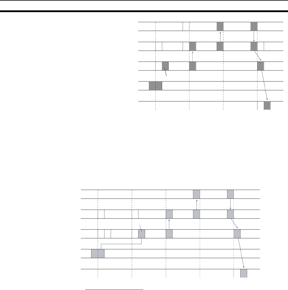
501
Computing the Cycle Time Section 10-4
Remote I/O transmission time = (Remote I/O Slave transmission time per
Slave + I/O Terminal transmission time) × 2
Remote I/O Slave transmission time per Slave = 1.4 ms + 0.2 ms × (total num-
ber of I/O words on Slave Rack)
I/O Terminal transmission time = 2.0 ms × (number of I/O Terminals)
Maximum Remote I/O
Response Time
The maximum I/O response time is the sum of the Input ON delay, (the cycle
time × 4), and the Output ON delay.
Note The cycle time is longer than the remote I/O transmission time.
Calculation Example
Conditions: Input ON delay 1.5 ms
Output ON delay 0.2 ms
Cycle time 20.0 ms
Minimum I/O response time = 1.5 ms + (20 ms ×3) + 0.2 ms = 61.7 ms
Maximum I/O response time = 1.5 ms + (20 ms ×4) + 0.2 ms = 81.7 ms
• When Special I/O Units are mounted to Slave Racks, the cycle time may
be less than or equal to the remote I/O transmission time. In this case, I/O
refresh may not occur between the CPU Unit and the Remote I/O Master
Unit in some cycles.
• Refreshing will be performed for Remote I/O Masters only once in each
cycle, and then only after confirming completion of the remote cycle.
• The short duration of ON/OFF status produced by differentiated instruc-
tions can cause inaccurate signals.
CPU Unit
Remote I/O Master Unit
Remote I/O Slave Unit
Input
Output
Program
execution
Master-to-CPU Unit transmission
Master-to-Slave communications
Slave I/O refresh
CPU Unit
Remote I/O Master Unit
Remote I/O Slave Unit
Input
Output
Program
execution
Master-to-CPU Unit transmission
Master-to-Slave communications
Slave I/O refresh
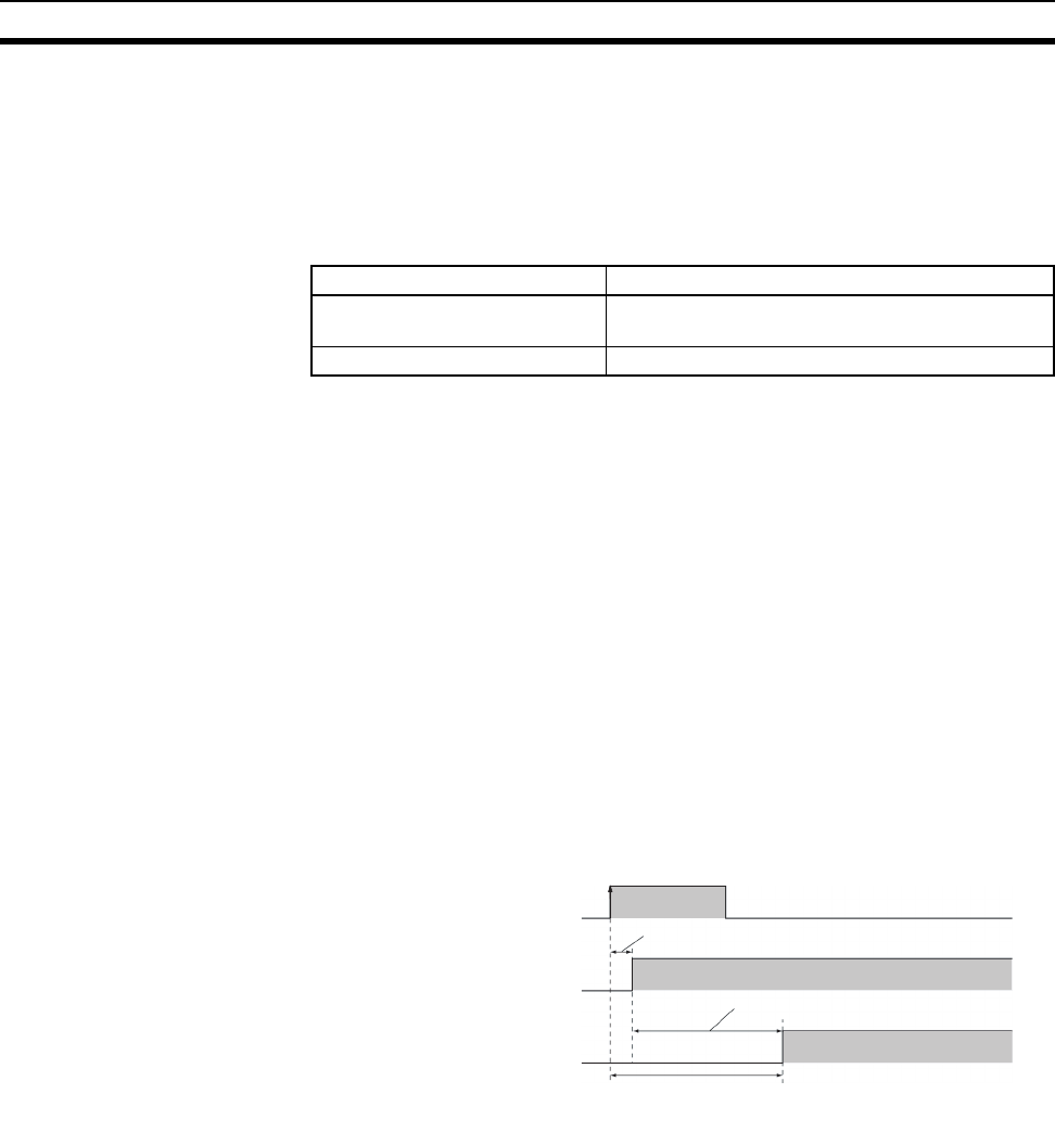
502
Computing the Cycle Time Section 10-4
10-4-7 Interrupt Response Times
I/O Interrupt Tasks The interrupt response time for I/O interrupt tasks is the time taken from when
an input from a CS1W-INT01 or C200HS-INT01 Interrupt Input Unit has
turned ON (or OFF) until the I/O interrupt task has actually been executed.
The length of the interrupt response time for I/O interrupt tasks depends on
the following conditions.
Note 1. The software interrupt response time will be 1 ms if there is a C200H Spe-
cial I/O Unit in the PLC.
• The C200HS-INT01 Interrupt Input Unit’s input ON delay is 0.2 ms
maximum.
• The C200HS-INT01 Interrupt Input Unit’s software interrupt response
time is 1 ms maximum.
2. I/O interrupt tasks can be executed (while an instruction is being executed,
or by stopping the execution of an instruction) during execution of the user
program, I/O refresh, peripheral servicing, or overseeing. The interrupt re-
sponse time is not affected by the Input of the Interrupt Input Unit turning
ON during any of the above processing operations.
Some I/O interrupts, however, are not executed during interrupt tasks even
if the I/O interrupt conditions are satisfied. Instead, the I/O interrupts are
executed in order of priority after the other interrupt task has completed ex-
ecution and the software interrupt response time (1 ms max.) has elapsed.
The interrupt response time of I/O interrupt tasks is the sum of the Input ON
delay (0.2 ms max.) and the software interrupt response time (1 ms max.).
Scheduled Interrupt Tasks The interrupt response time of scheduled interrupt tasks is the time taken
from after the scheduled time specified by the MSKS(690) instruction has
elapsed until the interrupt task has actually been executed.
The length of the interrupt response time for scheduled interrupt tasks is 1 ms
max.
Note Scheduled interrupt tasks can be executed (while an instruction is being exe-
cuted, or by stopping the execution of an instruction) during execution of the
user program, I/O refresh, peripheral servicing, or overseeing. The interrupt
response time is not affected by the scheduled time elapsing during any of the
above processing operations.
Some scheduled interrupts, however, are not executed during other interrupt
tasks even if the scheduled interrupt conditions are satisfied. Instead, the
scheduled interrupts are executed in order of priority after the other interrupt
Item Time
Hardware response Upward differentiation: 0.1 ms, Downward differen-
tiation: 0.5 ms
Software interrupt response 124 µs
Input
(Interrupt Input Unit retrieval)
Interrupt task execution
I/O interrupt task inter-
rupt response time
Software interrupt response time
Input ON delay

503
Instruction Execution Times and Number of Steps Section 10-5
task has completed execution and the software interrupt response time (1 ms
max.) has elapsed.
External Interrupt Tasks The interrupt response time for external interrupt tasks differs depending on
the Unit or Board (Special I/O Unit, CS-series CPU Bus Unit, or Inner Board)
that is requesting the external interrupt task of the CPU Unit and the type of
service requested by the interrupt. For details, refer to the appropriate opera-
tion manual for the Unit or Board being used.
Power OFF Interrupt Tasks Power OFF interrupt tasks are executed within 0.1 ms of the power being con-
firmed as OFF.
10-5 Instruction Execution Times and Number of Steps
The following table lists the execution times for all instructions that are avail-
able for CS-series PLCs.
The total execution time of instructions within one whole user program is the
process time for program execution when calculating the cycle time (See
note.).
Note User programs are allocated tasks that can be executed within cyclic tasks
and interrupt tasks that satisfy interrupt conditions.
Execution times for most instructions differ depending on the CPU Unit used
(CS1@-CPU6@H, CS1@-CPU4@H) and the conditions when the instruction is
executed. The top line for each instruction in the following table shows the
minimum time required to process the instruction and the necessary execu-
tion conditions, and the bottom line shows the maximum time and execution
conditions required to process the instruction.
The execution time can also vary when the execution condition is OFF.
The following table also lists the length of each instruction in the Length
(steps) column. The number of steps required in the user program area for
each of the CS-series instructions varies from 1 to 7 steps, depending upon
the instruction and the operands used with it. The number of steps in a pro-
gram is not the same as the number of instructions.
Note 1. Program capacity for CS-series PLCs is measured in steps, whereas pro-
gram capacity for previous OMRON PLCs, such as the C-series and CV-
series PLCs, was measured in words. Basically speaking, 1 step is equiv-
alent to 1 word. The amount of memory required for each instruction, how-
ever, is different for some of the CS-series instructions, and inaccuracies
will occur if the capacity of a user program for another PLC is converted for
a CS-series PLC based on the assumption that 1 word is 1 step. Refer to
the information at the end of 10-5 Instruction Execution Times and Number
of Steps for guidelines on converting program capacities from previous
OMRON PLCs.
Internal timer
Scheduled interrupt task
Scheduled interrupt time
Software interrupt response time
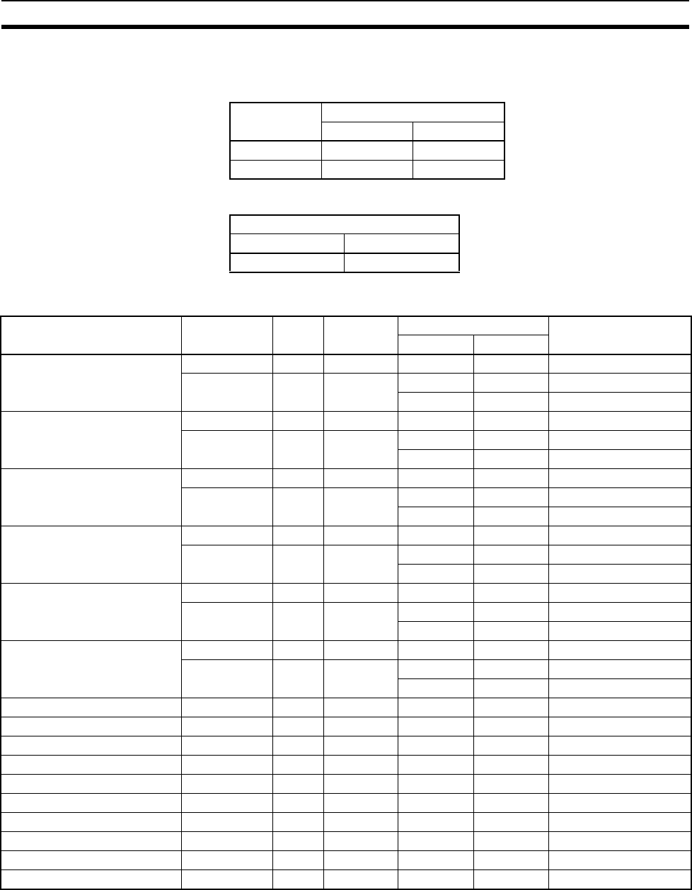
504
Instruction Execution Times and Number of Steps Section 10-5
Most instructions are supported in differentiated form (indicated with ↑, ↓,
@, and %). Specifying differentiation will increase the execution times by
the following amounts.
2. Use the following times as guidelines when instructions are not executed.
10-5-1 Sequence Input Instructions
Note When a double-length operand is used, add 1 to the value shown in the length
column in the following table.
Symbol CS1-H CPU Units
CPU6@HCPU4@H
↑ or ↓+0.24 +0.32
@ or % +0.24 +0.32
CS1-H CPU Units
CPU6@HCPU4@H
Approx. 0.1 Approx. 0.2
Instruction Mnemonic Code Length
(steps)
ON execution time (µs) Conditions
CPU6@HCPU4@H
LOAD LD --- 1 0.02 0.04 ---
!LD --- 2 +21.14 +21.16 Increase for CS Series
+45.1 +45.1 Increase for C200H
LOAD NOT LD NOT --- 1 0.02 0.04 ---
!LD NOT --- 2 +21.14 +21.16 Increase for CS Series
+45.1 +45.1 Increase for C200H
AND AND --- 1 0.02 0.04 ---
!AND --- 2 +21.14 +21.16 Increase for CS Series
+45.1 +45.1 Increase for C200H
AND NOT AND NOT --- 1 0.02 0.04 ---
!AND NOT --- 2 +21.14 +21.16 Increase for CS Series
+45.1 +45.1 Increase for C200H
OR OR --- 1 0.02 0.04 ---
!OR --- 2 +21.14 +21.16 Increase for CS Series
+45.1 +45.1 Increase for C200H
OR NOT OR NOT --- 1 0.02 0.04 ---
!OR NOT --- 2 +21.14 +21.16 Increase for CS Series
+45.1 +45.1 Increase for C200H
AND LOAD AND LD --- 1 0.02 0.04 ---
OR LOAD OR LD --- 1 0.02 0.04 ---
NOT NOT 520 1 0.02 0.04 ---
CONDITION ON UP 521 3 0.3 0.42 ---
CONDITION OFF DOWN 522 4 0.3 0.42 ---
LOAD BIT TEST LD TST 350 4 0.14 0.24 ---
LOAD BIT TEST NOT LD TSTN 351 4 0.14 0.24 ---
AND BIT TEST NOT AND TSTN 351 4 0.14 0.24 ---
OR BIT TEST OR TST 350 4 0.14 0.24 ---
OR BIT TEST NOT OR TSTN 351 4 0.14 0.24 ---

505
Instruction Execution Times and Number of Steps Section 10-5
10-5-2 Sequence Output Instructions
Note When a double-length operand is used, add 1 to the value shown in the length
column in the following table.
10-5-3 Sequence Control Instructions
Instruction Mnemonic Code Length
(steps)
(See note.)
ON execution time (µs) Conditions
CPU-6@HCPU-4@H
OUTPUT OUT --- 1 0.02 0.04 ---
!OUT --- 2 +21.37 +21.37 Increase for CS Series
+49.3 +49.3 Increase for C200H
OUTPUT NOT OUT NOT --- 1 0.02 0.04 ---
!OUT NOT --- 2 +21.37 +21.37 Increase for CS Series
+49.3 +49.3 Increase for C200H
KEEP KEEP 011 1 0.06 0.08 ---
DIFFERENTIATE UP DIFU 013 2 0.24 0.40 ---
DIFFERENTIATE DOWN DIFD 014 2 0.24 0.40 ---
SET SET --- 1 0.02 0.06 ---
!SET --- 2 +21.37 +21.37 Increase for CS Series
+49.3 +49.3 Increase for C200H
RESET RSET --- 1 0.02 0.06 Word specified
!RSET --- 2 +21.37 +21.37 Increase for CS Series
+49.3 +49.3 Increase for C200H
MULTIPLE BIT SET SETA 530 4 5.8 6.1 With 1-bit set
25.7 27.2 With 1,000-bit set
MULTIPLE BIT RESET RSTA 531 4 5.7 6.1 With 1-bit reset
25.8 27.1 With 1,000-bit reset
SINGLE BIT SET SETB 532 2 0.24 0.34 ---
!SETB 3 +21.44 +21.54 ---
SINGLE BIT RESET RSTB 534 2 0.24 0.34 ---
!RSTB 3 +21.44 +21.54 ---
SINGLE BIT OUTPUT OUTB 534 2 0.22 0.32 ---
!OUTB 3 +21.42 +21.52 ---
Instruction Mnemonic Code Length
(steps)
(See note.)
ON execution time (µs) Conditions
CPU-6@HCPU-4@H
END END 001 1 5.5 6.0 ---
NO OPERATION NOP 000 1 0.02 0.04 ---
INTERLOCK IL 002 1 0.06 0.06 ---
INTERLOCK CLEAR ILC 003 1 0.06 0.06 ---
MULTI-INTERLOCK
DIFFERENTIATION HOLD
(See note 2.)
MILH 517 3 6.1 6.5 During interlock
7.5 7.9 Not during interlock and
interlock not set
8.9 9.7 Not during interlock and
interlock set
MULTI-INTERLOCK
DIFFERENTIATION
RELEASE (See note 2.)
MILR 518 3 6.1 6.5 During interlock
7.5 7.9 Not during interlock and
interlock not set
8.9 9.7 Not during interlock and
interlock set

506
Instruction Execution Times and Number of Steps Section 10-5
Note 1. When a double-length operand is used, add 1 to the value shown in the
length column in the following table.
2. Supported only by CPU Units Ver. 2.0 or later.
10-5-4 Timer and Counter Instructions
MULTI-INTERLOCK CLEAR
(See note 2.)
MILC 519 2 5.0 5.6 Interlock not cleared
5.7 6.2 Interlock cleared
JUMP JMP 004 2 0.38 0.48 ---
JUMP END JME 005 2 --- --- ---
CONDITIONAL JUMP CJP 510 2 0.38 0.48 When JMP condition is
satisfied
CONDITIONAL JUMP NOT CJPN 511 2 0.38 0.48 When JMP condition is
satisfied
MULTIPLE JUMP JMP0 515 1 0.06 0.06 ---
MULTIPLE JUMP END JME0 516 1 0.06 0.06 ---
FOR LOOP FOR 512 2 0.52 0.54 Designating a constant
BREAK LOOP BREAK 514 1 0.06 0.06 ---
NEXT LOOP NEXT 513 1 0.18 0.16 When loop is continued
0.22 0.40 When loop is ended
Instruction Mnemonic Code Length
(steps)
(See note.)
ON execution time (µs) Conditions
CPU-6@HCPU-4@H
Instruction Mnemonic Code Length
(steps)
(See note.)
ON execution time (µs) Conditions
CPU-6@HCPU-4@H
TIMER TIM --- 3 0.56 0.88 ---
TIMX 550 3 0.56 0.88 ---
COUNTER CNT --- 3 0.56 0.88 ---
CNTX 546 3 0.56 0.88 ---
HIGH-SPEED TIMER TIMH 015 3 0.88 1.14 ---
TIMHX 551 3 0.88 1.14 ---
ONE-MS TIMER TMHH 540 3 0.86 1.12 ---
TMHHX 552 3 0.86 1.12 ---
ACCUMULATIVE TIMER TTIM 087 3 16.1 17.0 ---
10.9 11.4 When resetting
8.5 8.7 When interlocking
TTIMX 555 3 16.1 17.0 ---
10.9 11.4 When resetting
8.5 8.7 When interlocking
LONG TIMER TIML 542 4 7.6 10.0 ---
6.2 6.5 When interlocking
TIMLX 553 4 7.6 10.0 ---
6.2 6.5 When interlocking
MULTI-OUTPUT TIMER MTIM 543 4 20.9 23.3 ---
5.6 5.8 When resetting
MTIMX 554 4 20.9 23.3 ---
5.6 5.8 When resetting
REVERSIBLE COUNTER CNTR 012 3 16.9 19.0 ---
CNTRX 548 3 16.9 19.0 ---

507
Instruction Execution Times and Number of Steps Section 10-5
Note When a double-length operand is used, add 1 to the value shown in the length
column in the following table.
10-5-5 Comparison Instructions
RESET TIMER/ COUNTER CNR 545 3 9.9 10.6 When resetting 1 word
4.16 ms 4.16 ms When resetting 1,000
words
CNRX 547 3 9.9 10.6 When resetting 1 word
4.16 ms 4.16 ms When resetting 1,000
words
Instruction Mnemonic Code Length
(steps)
(See note.)
ON execution time (µs) Conditions
CPU-6@HCPU-4@H
Input Comparison Instructions
(unsigned)
LD, AND, OR
+=
300 4 0.10 0.16 ---
LD, AND, OR
+ <>
305
LD, AND, OR
+ <
310
LD, AND, OR
+<=
315
LD, AND, OR
+>
320
LD, AND, OR
+>=
325
Input Comparison Instructions
(double, unsigned)
LD, AND, OR
+=+L
301 4 0.10 0.16 ---
LD, AND, OR
+<>+L
306
LD, AND, OR
+<+L
311
LD, AND, OR
+<=+L
316
LD, AND, OR
+>+L
321
LD, AND, OR
+>=+L
326
Input Comparison Instructions
(signed)
LD, AND, OR
+=+S
302 4 0.10 0.16 ---
LD, AND, OR
+<>+S
307
LD, AND, OR
+<+S
312
LD, AND, OR
+<=
317
LD, AND, OR
+>+S
322
LD, AND, OR
+>=+S
327
Instruction Mnemonic Code Length
(steps)
(See note.)
ON execution time (µs) Conditions
CPU-6@HCPU-4@H

508
Instruction Execution Times and Number of Steps Section 10-5
Note 1. When a double-length operand is used, add 1 to the value shown in the
length column in the following table.
2. Supported only by CPU Units Ver. 2.0 or later.
10-5-6 Data Movement Instructions
Input Comparison Instructions
(double, signed)
LD, AND, OR
+=+SL
303 4 0.10 0.16 ---
LD, AND, OR
+<>+SL
308
LD, AND, OR
+<+SL
313
LD, AND, OR
+<=+SL
318
LD, AND, OR
+>+SL
323
LD, AND, OR
+>=+SL
328
Time Comparison Instructions
(See note 2.)
LD, AND, OR
+DT
341 4 25.1 36.4 ON and OFF execution
times are the same as
given at the left.
LD, AND, OR
+<>DT
342 4 25.2 36.4
LD, AND, OR
+<DT
343 4 25.2 36.4
LD, AND, OR
+<=DT
344 4 25.2 36.4
LD, AND, OR
+>DT
345 4 25.1 36.4
LD, AND, OR
+>=DT
346 4 25.2 36.4
COMPARE CMP 020 3 0.04 0.04 ---
!CMP 020 7 +42.1 +42.1 Increase for CS Series
+90.4 +90.4 Increase for C200H
DOUBLE COMPARE CMPL 060 3 0.08 0.08 ---
SIGNED BINARY COMPARE CPS 114 3 0.08 0.08 ---
!CPS 114 7 +35.9 +35.9 Increase for CS Series
+84.1 +84.1 Increase for C200H
DOUBLE SIGNED BINARY
COMPARE
CPSL 115 3 0.08 0.08 ---
TABLE COMPARE TCMP 085 4 14.0 15.2 ---
MULTIPLE COMPARE MCMP 019 4 20.5 22.8 ---
UNSIGNED BLOCK
COMPARE
BCMP 068 4 21.5 23.7 ---
AREA RANGE COMPARE ZCP 088 3 5.3 5.4 ---
DOUBLE AREA RANGE
COMPARE
ZCPL 116 3 5.5 6.7 ---
Instruction Mnemonic Code Length
(steps)
(See note.)
ON execution time (µs) Conditions
CPU-6@HCPU-4@H
Instruction Mnemonic Code Length
(steps)
(See note.)
ON execution time (µs) Conditions
CPU-6@HCPU-4@H
MOVE MOV 021 3 0.18 0.20 ---
!MOV 021 7 +21.38 +21.40 Increase for CS Series
+90.52 +90.52 Increase for C200H

509
Instruction Execution Times and Number of Steps Section 10-5
Note When a double-length operand is used, add 1 to the value shown in the length
column in the following table.
10-5-7 Data Shift Instructions
DOUBLE MOVE MOVL 498 3 0.32 0.34 ---
MOVE NOT MVN 022 3 0.18 0.20 ---
DOUBLE MOVE NOT MVNL 499 3 0.32 0.34 ---
MOVE BIT MOVB 082 4 0.24 0.34 ---
MOVE DIGIT MOVD 083 4 0.24 0.34 ---
MULTIPLE BIT TRANSFER XFRB 062 4 10.1 10.8 Transferring 1 bit
186.4 189.8 Transferring 255 bits
BLOCK TRANSFER XFER 070 4 0.36 0.44 Transferring 1 word
300.1 380.1 Transferring 1,000
words
BLOCK SET BSET 071 4 0.26 0.28 Setting 1 word
200.1 220.1 Setting 1,000 words
DATA EXCHANGE XCHG 073 3 0.40 0.56 ---
DOUBLE DATA EXCHANGE XCGL 562 3 0.76 1.04 ---
SINGLE WORD DISTRIBUTE DIST 080 4 5.1 5.4 ---
DATA COLLECT COLL 081 4 5.1 5.3 ---
MOVE TO REGISTER MOVR 560 3 0.08 0.08 ---
MOVE TIMER/ COUNTER PV
TO REGISTER
MOVRW 561 3 0.42 0.50 ---
Instruction Mnemonic Code Length
(steps)
(See note.)
ON execution time (µs) Conditions
CPU-6@HCPU-4@H
SHIFT REGISTER SFT 010 3 7.4 10.4 Shifting 1 word
433.2 488.0 Shifting 1,000 words
REVERSIBLE SHIFT
REGISTER
SFTR 084 4 6.9 7.2 Shifting 1 word
615.3 680.2 Shifting 1,000 words
ASYNCHRONOUS SHIFT
REGISTER
ASFT 017 4 6.2 6.4 Shifting 1 word
1.22 ms 1.22 ms Shifting 1,000 words
WORD SHIFT WSFT 016 4 4.5 4.7 Shifting 1 word
171.5 171.7 Shifting 1,000 words
ARITHMETIC SHIFT LEFT ASL 025 2 0.22 0.32 ---
DOUBLE SHIFT LEFT ASLL 570 2 0.40 0.56 ---
ARITHMETIC SHIFT RIGHT ASR 026 2 0.22 0.32 ---
DOUBLE SHIFT RIGHT ASRL 571 2 0.40 0.56 ---
ROTATE LEFT ROL 027 2 0.22 0.32 ---
DOUBLE ROTATE LEFT ROLL 572 2 0.40 0.56 ---
ROTATE LEFT WITHOUT
CARRY
RLNC 574 2 0.22 0.32 ---
DOUBLE ROTATE LEFT
WITHOUT CARRY
RLNL 576 2 0.40 0.56 ---
ROTATE RIGHT ROR 028 2 0.22 0.32 ---
DOUBLE ROTATE RIGHT RORL 573 2 0.40 0.56 ---
ROTATE RIGHT WITHOUT
CARRY
RRNC 575 2 0.22 0.32 ---
Instruction Mnemonic Code Length
(steps)
(See note.)
ON execution time (µs) Conditions
CPU-6@HCPU-4@H

510
Instruction Execution Times and Number of Steps Section 10-5
Note When a double-length operand is used, add 1 to the value shown in the length
column in the following table.
10-5-8 Increment/Decrement Instructions
Note When a double-length operand is used, add 1 to the value shown in the length
column in the following table.
10-5-9 Symbol Math Instructions
DOUBLE ROTATE RIGHT
WITHOUT CARRY
RRNL 577 2 0.40 0.56 ---
ONE DIGIT SHIFT LEFT SLD 074 3 5.9 6.1 Shifting 1 word
561.1 626.3 Shifting 1,000 words
ONE DIGIT SHIFT RIGHT SRD 075 3 6.9 7.1 Shifting 1 word
760.5 895.5 Shifting 1,000 words
SHIFT N-BIT DATA LEFT NSFL 578 4 7.5 8.3 Shifting 1 bit
40.3 45.4 Shifting 1,000 bits
SHIFT N-BIT DATA RIGHT NSFR 579 4 7.5 8.3 Shifting 1 bit
50.5 55.3 Shifting 1,000 bits
SHIFT N-BITS LEFT NASL 580 3 0.22 0.32 ---
DOUBLE SHIFT N-BITS LEFT NSLL 582 3 0.40 0.56 ---
SHIFT N-BITS RIGHT NASR 581 3 0.22 0.32 ---
DOUBLE SHIFT N-BITS
RIGHT
NSRL 583 3 0.40 0.56 ---
Instruction Mnemonic Code Length
(steps)
(See note.)
ON execution time (µs) Conditions
CPU-6@HCPU-4@H
INCREMENT BINARY ++ 590 2 0.22 0.32 ---
DOUBLE INCREMENT
BINARY
++L 591 2 0.40 0.56 ---
DECREMENT BINARY – – 592 2 0.22 0.32 ---
DOUBLE DECREMENT
BINARY
– –L 593 2 0.40 0.56 ---
INCREMENT BCD ++B 594 2 6.4 4.5 ---
DOUBLE INCREMENT BCD ++BL 595 2 5.6 4.9 ---
DECREMENT BCD – –B 596 2 6.3 4.6 ---
DOUBLE DECREMENT BCD – –BL 597 2 5.3 4.7 ---
Instruction Mnemonic Code Length
(steps)
(See note.)
ON execution time (µs) Conditions
CPU-6@HCPU-4@H
SIGNED BINARY ADD
WITHOUT CARRY
+ 400 4 0.18 0.20 ---
DOUBLE SIGNED BINARY
ADD WITHOUT CARRY
+L 401 4 0.32 0.34 ---
SIGNED BINARY ADD WITH
CARRY
+C 402 4 0.18 0.20 ---
DOUBLE SIGNED BINARY
ADD WITH CARRY
+CL 403 4 0.32 0.34 ---
BCD ADD WITHOUT CARRY +B 404 4 8.2 8.4 ---
DOUBLE BCD ADD
WITHOUT CARRY
+BL 405 4 13.3 14.5 ---
Instruction Mnemonic Code Length
(steps)
(See note.)
ON execution time (µs) Conditions
CPU-6@HCPU-4@H

511
Instruction Execution Times and Number of Steps Section 10-5
Note When a double-length operand is used, add 1 to the value shown in the length
column in the following table.
10-5-10 Conversion Instructions
BCD ADD WITH CARRY +BC 406 4 8.9 9.1 ---
DOUBLE BCD ADD WITH
CARRY
+BCL 407 4 13.8 15.0 ---
SIGNED BINARY
SUBTRACT WITHOUT
CARRY
– 410 4 0.18 0.20 ---
DOUBLE SIGNED BINARY
SUBTRACT WITHOUT
CARRY
–L 411 4 0.32 0.34 ---
SIGNED BINARY
SUBTRACT WITH CARRY
–C 412 4 0.18 0.20 ---
DOUBLE SIGNED BINARY
SUBTRACT WITH CARRY
–CL 413 4 0.32 0.34 ---
BCD SUBTRACT WITHOUT
CARRY
–B 414 4 8.0 8.2 ---
DOUBLE BCD SUBTRACT
WITHOUT CARRY
–BL 415 4 12.8 14.0 ---
BCD SUBTRACT WITH
CARRY
–BC 416 4 8.5 8.6 ---
DOUBLE BCD SUBTRACT
WITH CARRY
–BCL 417 4 13.4 14.7 ---
SIGNED BINARY MULTIPLY * 420 4 0.38 0.40 ---
DOUBLE SIGNED BINARY
MULTIPLY
*L 421 4 7.23 8.45 ---
UNSIGNED BINARY
MULTIPLY
*U 422 4 0.38 0.40 ---
DOUBLE UNSIGNED
BINARY MULTIPLY
*UL 423 4 7.1 8.3 ---
BCD MULTIPLY *B 424 4 9.0 9.2 ---
DOUBLE BCD MULTIPLY *BL 425 4 23.0 24.2 ---
SIGNED BINARY DIVIDE / 430 4 0.40 0.42 ---
DOUBLE SIGNED BINARY
DIVIDE
/L 431 4 7.2 8.4 ---
UNSIGNED BINARY DIVIDE /U 432 4 0.40 0.42 ---
DOUBLE UNSIGNED
BINARY DIVIDE
/UL 433 4 6.9 8.1 ---
BCD DIVIDE /B 434 4 8.6 8.8 ---
DOUBLE BCD DIVIDE /BL 435 4 17.7 18.9 ---
Instruction Mnemonic Code Length
(steps)
(See note.)
ON execution time (µs) Conditions
CPU-6@HCPU-4@H
BCD-TO-BINARY BIN 023 3 0.22 0.24 ---
DOUBLE BCD-TO-DOUBLE
BINARY
BINL 058 3 6.5 6.8 ---
BINARY-TO-BCD BCD 024 3 0.24 0.26 ---
DOUBLE BINARY-TO-
DOUBLE BCD
BCDL 059 3 6.7 7.0 ---
Instruction Mnemonic Code Length
(steps)
(See note.)
ON execution time (µs) Conditions
CPU-6@HCPU-4@H

512
Instruction Execution Times and Number of Steps Section 10-5
2’S COMPLEMENT NEG 160 3 0.18 0.20 ---
DOUBLE 2’S COMPLEMENT NEGL 161 3 0.32 0.34 ---
16-BIT TO 32-BIT SIGNED
BINARY
SIGN 600 3 0.32 0.34 ---
DATA DECODER MLPX 076 4 0.32 0.42 Decoding 1 digit (4 to
16)
0.98 1.20 Decoding 4 digits (4 to
16)
3.30 4.00 Decoding 1 digit 8 to
256
6.50 7.90 Decoding 2 digits (8 to
256)
DATA ENCODER DMPX 077 4 7.5 7.9 Encoding 1 digit (16 to
4)
49.6 50.2 Encoding 4 digits (16 to
4)
18.2 18.6 Encoding 1 digit (256 to
8)
55.1 57.4 Encoding 2 digits (256
to 8)
ASCII CONVERT ASC 086 4 6.8 7.1 Converting 1 digit into
ASCII
11.2 11.7 Converting 4 digits into
ASCII
ASCII TO HEX HEX 162 4 7.1 7.4 Converting 1 digit
COLUMN TO LINE LINE 063 4 19.0 23.1 ---
LINE TO COLUMN COLM 064 4 23.2 27.5 ---
SIGNED BCD-TO-BINARY BINS 470 4 8.0 8.3 Data format setting No.
0
8.0 8.3 Data format setting No.
1
8.3 8.6 Data format setting No.
2
8.5 8.8 Data format setting No.
3
DOUBLE SIGNED BCD-TO-
BINARY
BISL 472 4 9.2 9.6 Data format setting No.
0
9.2 9.6 Data format setting No.
1
9.5 9.9 Data format setting No.
2
9.6 10.0 Data format setting No.
3
SIGNED BINARY-TO-BCD BCDS 471 4 6.6 6.9 Data format setting No.
0
6.7 7.0 Data format setting No.
1
6.8 7.1 Data format setting No.
2
7.2 7.5 Data format setting No.
3
Instruction Mnemonic Code Length
(steps)
(See note.)
ON execution time (µs) Conditions
CPU-6@HCPU-4@H

513
Instruction Execution Times and Number of Steps Section 10-5
Note 1. When a double-length operand is used, add 1 to the value shown in the
length column in the following table.
2. Supported only by CPU Units Ver. 2.0 or later.
3. Supported only by CPU Units Ver. 4.0 or later.
10-5-11 Logic Instructions
DOUBLE SIGNED BINARY-
TO-BCD
BDSL 473 4 8.1 8.4 Data format setting No.
0
8.2 8.6 Data format setting No.
1
8.3 8.7 Data format setting No.
2
8.8 9.2 Data format setting No.
3
GRAY CODE CONVERSION
(See note 2.)
GRY 474 4 46.9 72.1 8-bit binary
49.6 75.2 8-bit BCD
57.7 87.7 8-bit angle
61.8 96.7 15-bit binary
64.5 99.6 15-bit BCD
72.8 112.4 15-bit angle
52.3 87.2 360° binary
55.1 90.4 360° BCD
64.8 98.5 360° angle
FOUR-DIGIT NUMBER TO
ASCII
(See note 3.)
STR4 601 3 13.79 20.24 ---
EIGHT-DIGIT NUMBER TO
ASCII
(See note 3.)
STR8 602 3 18.82 27.44 ---
SIXTEEN-DIGIT NUMBER TO
ASCII
(See note 3.)
STR16 603 3 30.54 44.41 ---
ASCII TO FOUR-DIGIT
NUMBER
(See note 3.)
NUM4 604 3 18.46 27.27 ---
ASCII TO EIGHT-DIGIT
NUMBER
(See note 3.)
NUM8 605 3 27.27 40.29 ---
ASCII TO SIXTEEN-DIGIT
NUMBER
(See note 3.)
NUM16 606 3 52.31 78.25 ---
Instruction Mnemonic Code Length
(steps)
(See note.)
ON execution time (µs) Conditions
CPU-6@HCPU-4@H
Instruction Mnemonic Code Length
(steps)
(See note.)
ON execution time (µs) Conditions
CPU-6@HCPU-4@H
LOGICAL AND ANDW 034 4 0.18 0.20 ---
DOUBLE LOGICAL AND ANDL 610 4 0.32 0.34 ---
LOGICAL OR ORW 035 4 0.22 0.32 ---
DOUBLE LOGICAL OR ORWL 611 4 0.32 0.34 ---
EXCLUSIVE OR XORW 036 4 0.22 0.32 ---
DOUBLE EXCLUSIVE OR XORL 612 4 0.32 0.34 ---
EXCLUSIVE NOR XNRW 037 4 0.22 0.32 ---
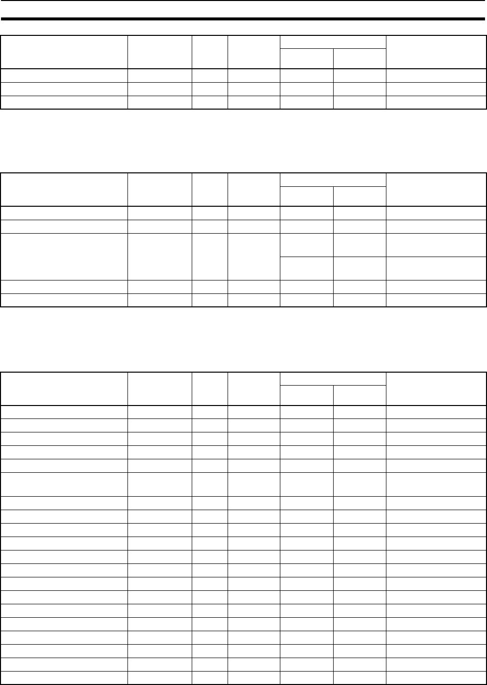
514
Instruction Execution Times and Number of Steps Section 10-5
Note When a double-length operand is used, add 1 to the value shown in the length
column in the following table.
10-5-12 Special Math Instructions
Note When a double-length operand is used, add 1 to the value shown in the length
column in the following table.
10-5-13 Floating-point Math Instructions
DOUBLE EXCLUSIVE NOR XNRL 613 4 0.32 0.34 ---
COMPLEMENT COM 029 2 0.22 0.32 ---
DOUBLE COMPLEMENT COML 614 2 0.40 0.56 ---
Instruction Mnemonic Code Length
(steps)
(See note.)
ON execution time (µs) Conditions
CPU-6@HCPU-4@H
BINARY ROOT ROTB 620 3 49.6 50.0 ---
BCD SQUARE ROOT ROOT 072 3 13.7 13.9 ---
ARITHMETIC PROCESS APR 069 4 6.7 6.9 Designating SIN and
COS
17.2 18.4 Designating line-seg-
ment approximation
FLOATING POINT DIVIDE FDIV 079 4 116.6 176.6 ---
BIT COUNTER BCNT 067 4 0.3 0.38 Counting 1 word
Instruction Mnemonic Code Length
(steps)
(See note.)
ON execution time (µs) Conditions
CPU-6@HCPU-4@H
FLOATING TO 16-BIT FIX 450 3 10.6 10.8 ---
FLOATING TO 32-BIT FIXL 451 3 10.8 11.0 ---
16-BIT TO FLOATING FLT 452 3 8.3 8.5 ---
32-BIT TO FLOATING FLTL 453 3 8.3 8.5 ---
FLOATING-POINT ADD +F 454 4 8.0 9.2 ---
FLOATING-POINT
SUBTRACT
–F 455 4 8.0 9.2 ---
FLOATING-POINT DIVIDE /F 457 4 8.7 9.9 ---
FLOATING-POINT MULTIPLY *F 456 4 8.0 9.2 ---
DEGREES TO RADIANS RAD 458 3 10.1 10.2 ---
RADIANS TO DEGREES DEG 459 3 9.9 10.1 ---
SINE SIN 460 3 42.0 42.2 ---
COSINE COS 461 3 31.5 31.8 ---
TANGENT TAN 462 3 16.3 16.6 ---
ARC SINE ASIN 463 3 17.6 17.9 ---
ARC COSINE ACOS 464 3 20.4 20.7 ---
ARC TANGENT ATAN 465 3 16.1 16.4 ---
SQUARE ROOT SQRT 466 3 19.0 19.3 ---
EXPONENT EXP 467 3 65.9 66.2 ---
LOGARITHM LOG 468 3 12.8 13.1 ---
EXPONENTIAL POWER PWR 840 4 125.4 126.0 ---
Instruction Mnemonic Code Length
(steps)
(See note.)
ON execution time (µs) Conditions
CPU-6@HCPU-4@H
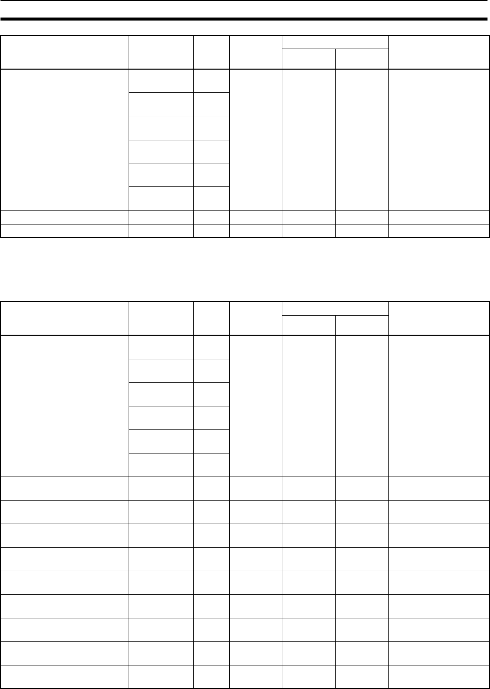
515
Instruction Execution Times and Number of Steps Section 10-5
Note When a double-length operand is used, add 1 to the value shown in the length
column in the following table.
10-5-14 Double-precision Floating-point Instructions
Floating Symbol Comparison LD, AND, OR
+=F
329 3 6.6 8.3 ---
LD, AND, OR
+<>F
330
LD, AND, OR
+<F
331
LD, AND, OR
+<=F
332
LD, AND, OR
+>F
333
LD, AND, OR
+>=F
334
FLOATING- POINT TO ASCII FSTR 448 4 48.5 48.9 ---
ASCII TO FLOATING-POINT FVAL 449 3 21.1 21.3 ---
Instruction Mnemonic Code Length
(steps)
(See note.)
ON execution time (µs) Conditions
CPU-6@HCPU-4@H
DOUBLE SYMBOL
COMPARISON
LD, AND, OR
+=D
335 3 8.5 10.3 ---
LD, AND, OR
+<>D
336
LD, AND, OR
+<D
337
LD, AND, OR
+<=D
338
LD, AND, OR
+>D
339
LD, AND, OR
+>=D
340
DOUBLE FLOATING TO
16-BIT BINARY
FIXD 841 3 11.7 12.1 ---
DOUBLE FLOATING TO
32-BIT BINARY
FIXLD 842 3 11.6 12.1 ---
16-BIT BINARY TO DOUBLE
FLOATING
DBL 843 3 9.9 10.0 ---
32-BIT BINARY TO DOUBLE
FLOATING
DBLL 844 3 9.8 10.0 ---
DOUBLE FLOATING-POINT
ADD
+D 845 4 11.2 11.9 ---
DOUBLE FLOATING-POINT
SUBTRACT
−D 846 4 11.2 11.9 ---
DOUBLE FLOATING-POINT
MULTIPLY
*D 847 4 12.0 12.7 ---
DOUBLE FLOATING-POINT
DIVIDE
/D 848 4 23.5 24.2 ---
DOUBLE DEGREES TO
RADIANS
RADD 849 3 27.4 27.8 ---
Instruction Mnemonic Code Length
(steps)
(See note.)
ON execution time (µs) Conditions
CPU-6@HCPU-4@H

516
Instruction Execution Times and Number of Steps Section 10-5
Note When a double-length operand is used, add 1 to the value shown in the length
column in the following table.
10-5-15 Table Data Processing Instructions
DOUBLE RADIANS TO
DEGREES
DEGD 850 3 11.2 11.9 ---
DOUBLE SINE SIND 851 3 45.4 45.8 ---
DOUBLE COSINE COSD 852 3 43.0 43.4 ---
DOUBLE TANGENT TAND 853 3 20.1 20.5 ---
DOUBLE ARC SINE ASIND 854 3 21.5 21.9 ---
DOUBLE ARC COSINE ACOSD 855 3 24.7 25.1 ---
DOUBLE ARC TANGENT ATAND 856 3 19.3 19.7 ---
DOUBLE SQUARE ROOT SQRTD 857 3 47.4 47.9 ---
DOUBLE EXPONENT EXPD 858 3 121.0 121.4 ---
DOUBLE LOGARITHM LOGD 859 3 16.0 16.4 ---
DOUBLE EXPONENTIAL
POWER
PWRD 860 4 223.9 224.2 ---
Instruction Mnemonic Code Length
(steps)
(See note.)
ON execution time (µs) Conditions
CPU-6@HCPU-4@H
SET STACK SSET 630 3 8.0 8.3 Designating 5 words in
stack area
231.6 251.8 Designating 1,000
words in stack area
PUSH ONTO STACK PUSH 632 3 6.5 8.6 ---
FIRST IN FIRST OUT FIFO 633 3 6.9 8.9 Designating 5 words in
stack area
352.6 434.3 Designating 1,000
words in stack area
LAST IN FIRST OUT LIFO 634 3 7.0 9.0 ---
DIMENSION RECORD TABLE DIM 631 5 15.2 21.6 ---
SET RECORD LOCATION SETR 635 4 5.4 5.9 ---
GET RECORD NUMBER GETR 636 4 7.8 8.4 ---
DATA SEARCH SRCH 181 4 15.5 19.5 Searching for 1 word
2.42 ms 3.34 ms Searching for 1,000
words
SWAP BYTES SWAP 637 3 12.2 13.6 Swapping 1 word
1.94 ms 2.82 ms Swapping 1,000 words
FIND MAXIMUM MAX 182 4 19.2 24.9 Searching for 1 word
2.39 ms 3.36 ms Searching for 1,000
words
FIND MINIMUM MIN 183 4 19.2 25.3 Searching for 1 word
2.39 ms 3.33 ms Searching for 1,000
words
SUM SUM 184 4 28.2 38.5 Adding 1 word
1.42 ms 1.95 ms Adding 1,000 words
FRAME CHECKSUM FCS 180 4 20.0 28.3 For 1-word table length
1.65 ms 2.48 ms For 1,000-word table
length
STACK SIZE READ SNUM 638 3 6.0 6.3 ---
Instruction Mnemonic Code Length
(steps)
(See note.)
ON execution time (µs) Conditions
CPU-6@HCPU-4@H

517
Instruction Execution Times and Number of Steps Section 10-5
Note When a double-length operand is used, add 1 to the value shown in the length
column in the following table.
10-5-16 Data Control Instructions
Note 1. When a double-length operand is used, add 1 to the value shown in the
length column in the following table.
2. Supported only by CPU Units Ver. 2.0 or later.
STACK DATA READ SREAD 639 4 8.0 8.4 ---
STACK DATA OVERWRITE SWRIT 640 4 7.2 7.6 ---
STACK DATA INSERT SINS 641 4 7.8 9.9 ---
354.0 434.8 For 1,000-word table
STACK DATA DELETE SDEL 642 4 8.6 10.6 ---
354.0 436.0 For 1,000-word table
Instruction Mnemonic Code Length
(steps)
(See note.)
ON execution time (µs) Conditions
CPU-6@HCPU-4@H
PID CONTROL PID 190 4 436.2 678.2 Initial execution
332.3 474.9 Sampling
97.3 141.3 Not sampling
LIMIT CONTROL LMT 680 4 16.1 22.1 ---
DEAD BAND CONTROL BAND 681 4 17.0 22.5 ---
DEAD ZONE CONTROL ZONE 682 4 15.4 20.5 ---
TIME-PROPORTIONAL
OUTPUT
(See note 2.)
TPO 685 4 10.4 14.8 OFF execution time
54.5 82.0 ON execution time with
duty designation or dis-
played output limit
61.0 91.9 ON execution time with
manipulated variable
designation and output
limit enabled
SCALING SCL 194 4 37.1 53.0 ---
SCALING 2 SCL2 486 4 28.5 40.2 ---
SCALING 3 SCL3 487 4 33.4 47.0 ---
AVERAGE AVG 195 4 36.3 52.6 Average of an operation
291.0 419.9 Average of 64 opera-
tions
PID CONTROL WITH
AUTOTUNING
PIDAT 191 4 446.3 712.5 Initial execution
339.4 533.9 Sampling
100.7 147.1 Not sampling
189.2 281.6 Initial execution of auto-
tuning
535.2 709.8 Autotuning when sam-
pling
Instruction Mnemonic Code Length
(steps)
(See note.)
ON execution time (µs) Conditions
CPU-6@HCPU-4@H
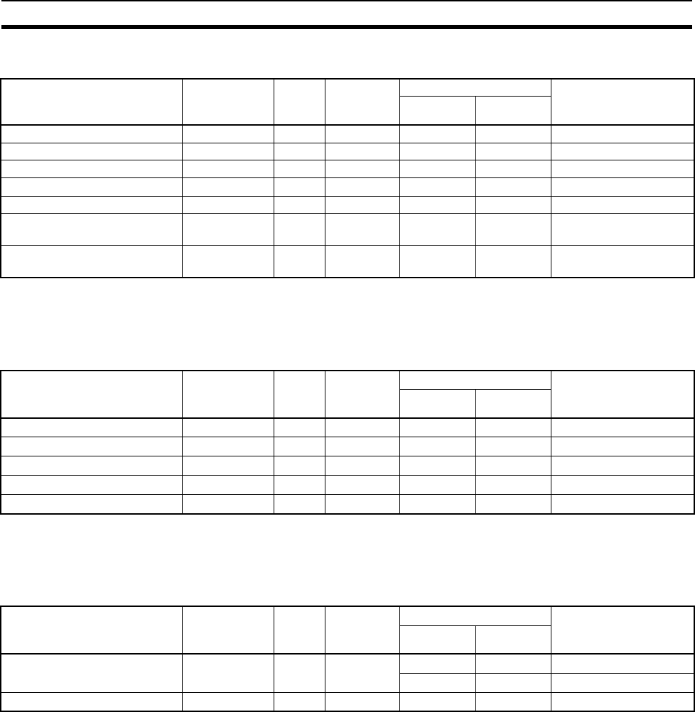
518
Instruction Execution Times and Number of Steps Section 10-5
10-5-17 Subroutine Instructions
Note When a double-length operand is used, add 1 to the value shown in the length
column in the following table.
10-5-18 Interrupt Control Instructions
Note When a double-length operand is used, add 1 to the value shown in the length
column in the following table.
10-5-19 Step Instructions
Note When a double-length operand is used, add 1 to the value shown in the length
column in the following table.
Instruction Mnemonic Code Length
(steps)
(See note.)
ON execution time (µs) Conditions
CPU-6@HCPU-4@H
SUBROUTINE CALL SBS 091 2 1.26 1.96 ---
SUBROUTINE ENTRY SBN 092 2 --- --- ---
SUBROUTINE RETURN RET 093 1 0.86 1.60 ---
MACRO MCRO 099 4 23.3 23.3 ---
GLOBAL SUBROUTINE CALL GSBN 751 2 --- --- ---
GLOBAL SUBROUTINE
ENTRY
GRET 752 1 1.26 1.96 ---
GLOBAL SUBROUTINE
RETURN
GSBS 750 2 0.86 1.60 ---
Instruction Mnemonic Code Length
(steps)
(See note.)
ON execution time (µs) Conditions
CPU-6@HCPU-4@H
SET INTERRUPT MASK MSKS 690 3 25.6 38.4 ---
READ INTERRUPT MASK MSKR 692 3 11.9 11.9 ---
CLEAR INTERRUPT CLI 691 3 27.4 41.3 ---
DISABLE INTERRUPTS DI 693 1 15.0 16.8 ---
ENABLE INTERRUPTS EI 694 1 19.5 21.8 ---
Instruction Mnemonic Code Length
(steps)
(See note.)
ON execution time (µs) Conditions
CPU-6@HCPU-4@H
STEP DEFINE STEP 008 2 17.4 20.7 Step control bit ON
11.8 13.7 Step control bit OFF
STEP START SNXT 009 2 6.6 7.3 ---

519
Instruction Execution Times and Number of Steps Section 10-5
10-5-20 Basic I/O Unit Instructions
Note 1. When a double-length operand is used, add 1 to the value shown in the
length column in the following table.
2. Supported only by CPU Units Ver. 2.0 or later.
Instruction Mnemonic Code Length
(steps)
(See note.)
ON execution time (µs) Conditions
CPU-6@HCPU-4@H
I/O REFRESH IORF 097 3 58.5 63.2 1-word refresh (IN) for
C200H Basic I/O Units
62.6 67.0 1-word refresh (OUT)
for C200H Basic I/O
Units
15.5 16.4 1-word refresh (IN) for
CS-series Basic I/O
Units
17.20 18.40 1-word refresh (OUT)
for CS-series Basic I/O
Units
303.3 343.9 10-word refresh (IN) for
C200H Basic I/O Units
348.2 376.6 10-word refresh (OUT)
for C200H Basic I/O
Units
319.9 320.7 60-word refresh (IN) for
CS-series Basic I/O
Units
358.00 354.40 60-word refresh (OUT)
for CS-series Basic I/O
Units
7-SEGMENT DECODER SDEC 078 4 6.5 6.9 ---
DIGITAL SWITCH INPUT
(See note 2.)
DSW 210 6 50.7 73.5 4 digits, data input
value: 0
51.5 73.4 4 digits, data input
value: F
51.3 73.5 8 digits, data input
value: 0
50.7 73.4 8 digits, data input
value: F
TEN KEY INPUT
(See note 2.)
TKY 211 4 9.7 13.2 Data input value: 0
10.7 14.8 Data input value: F
HEXADECIMAL KEY INPUT
(See note 2.)
HKY 212 5 50.3 70.9 Data input value: 0
50.1 71.2 Data input value: F
MATRIX INPUT
(See note 2.)
MTR 213 5 47.8 68.1 Data input value: 0
48.0 68.0 Data input value: F
7-SEGMENT DISPLAY
OUTPUT
(See note 2.)
7SEG 214 5 58.1 83.3 4 digits
63.3 90.3 8 digits
INTELLIGENT I/O READ IORD 222 4 Read/write times depend
on the Special I/O Unit
for which the instruction
is being executed.
---
INTELLIGENT I/O WRITE IOWR 223 4 ---
CPU BUS I/O REFRESH DLNK 226 4 287.8 315.5 Allocated 1 word

520
Instruction Execution Times and Number of Steps Section 10-5
10-5-21 Serial Communications Instructions
Note 1. When a double-length operand is used, add 1 to the value shown in the
length column in the following table.
2. TXDU(256) and RXDU(255) are supported for unit version 3.0 or later only.
10-5-22 Network Instructions
Note 1. When a double-length operand is used, add 1 to the value shown in the
length column in the following table.
2. Supported only by CPU Units Ver. 2.0 or later.
10-5-23 File Memory Instructions
Instruction Mnemonic Code Length
(steps)
(See note.)
ON execution time (µs) Conditions
CPU-6@HCPU-4@H
PROTOCOL MACRO PMCR 260 5 100.1 142.1 Sending 0 words,
receiving 0 words
134.2 189.6 Sending 249 words,
receiving 249 words
TRANSMIT TXD 236 4 68.5 98.8 Sending 1 byte
734.3 1.10 ms Sending 256 bytes
RECEIVE RXD 235 4 89.6 131.1 Storing 1 byte
724.2 1.11 ms Storing 256 bytes
TRANSMIT VIA SERIAL
COMMUNICATIONS UNIT
TXDU 256 4 131.5 202.4 Sending 1 byte
RECEIVE VIA SERIAL
COMMUNICATIONS UNIT
RXDU 255 4 131 200.8 Storing 1 byte
CHANGE SERIAL PORT
SETUP
STUP 237 3 341.2 400.0 ---
Instruction Mnemonic Code Length
(steps)
(See note.)
ON execution time (µs) Conditions
CPU-6@HCPU-4@H
NETWORK SEND SEND 090 4 84.4 123.9 ---
NETWORK RECEIVE RECV 098 4 85.4 124.7 ---
DELIVER COMMAND CMND 490 4 106.8 136.8 ---
EXPLICIT MESSAGE SEND
(See note 2.)
EXPLT 720 4 127.6 190.0 ---
EXPLICIT GET ATTRIBUTE
(See note 2.)
EGATR 721 4 123.9 185.0 ---
EXPLICIT SET ATTRIBUTE
(See note 2.)
ESATR 722 3 110.0 164.4 ---
EXPLICIT WORD READ
(See note 2.)
ECHRD 723 4 106.8 158.9 ---
EXPLICIT WORD WRITE
(See note 2.)
ECHWR 724 4 106.0 158.3 ---
Instruction Mnemonic Code Length
(steps)
(See note.)
ON execution time (µs) Conditions
CPU-6@HCPU-4@H
READ DATA FILE FREAD 700 5 391.4 632.4 2-character directory +
file name in binary
836.1 1.33 ms 73-character directory
+ file name in binary
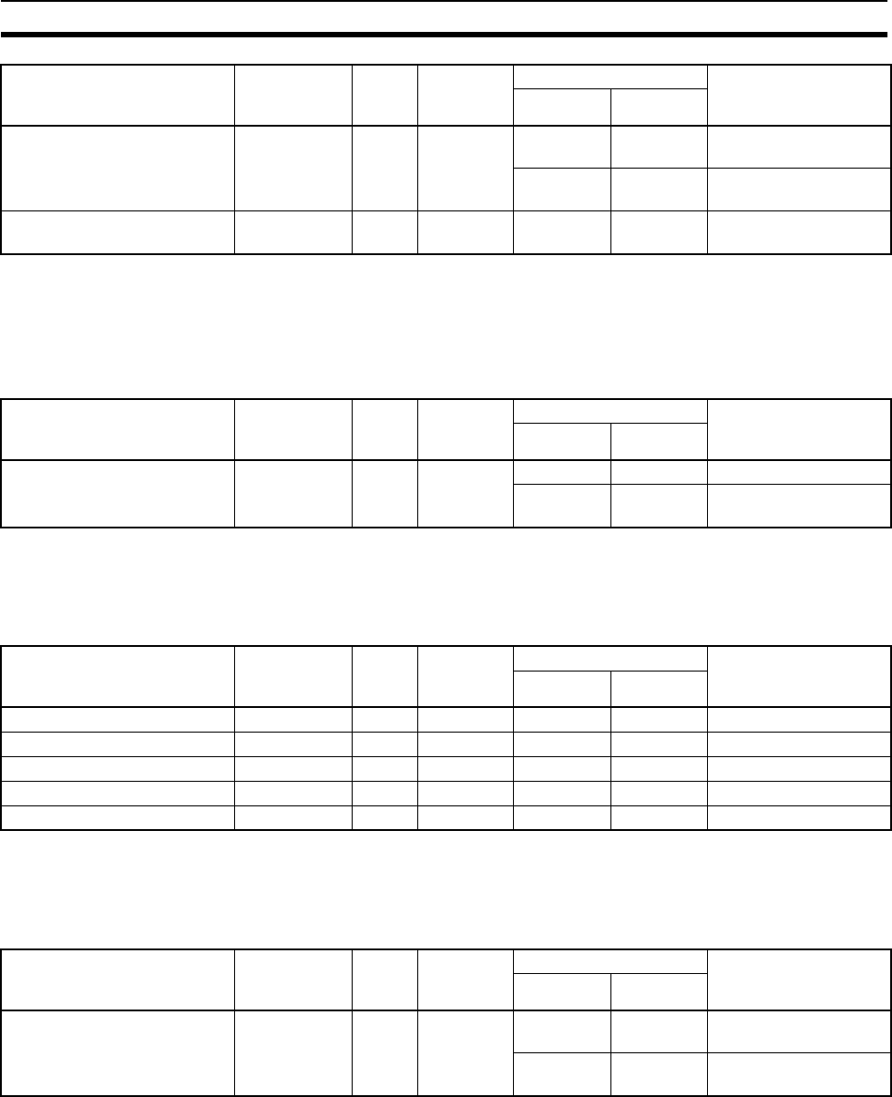
521
Instruction Execution Times and Number of Steps Section 10-5
Note 1. When a double-length operand is used, add 1 to the value shown in the
length column in the following table.
2. Supported only by CPU Units Ver. 4.0 or later.
10-5-24 Display Instructions
Note When a double-length operand is used, add 1 to the value shown in the length
column in the following table.
10-5-25 Clock Instructions
Note When a double-length operand is used, add 1 to the value shown in the length
column in the following table.
10-5-26 Debugging Instructions
Note When a double-length operand is used, add 1 to the value shown in the length
column in the following table.
WRITE DATA FILE FWRIT 701 5 387.8 627.0 2-character directory +
file name in binary
833.3 1.32 ms 73-character directory
+ file name in binary
WRITE TEXT FILE
(See note 2.)
TWRIT 704 5 390.1 619.1 ---
Instruction Mnemonic Code Length
(steps)
(See note.)
ON execution time (µs) Conditions
CPU-6@HCPU-4@H
Instruction Mnemonic Code Length
(steps)
(See note.)
ON execution time (µs) Conditions
CPU-6@HCPU-4@H
DISPLAY MESSAGE MSG 046 3 10.1 14.2 Displaying message
8.4 11.3 Deleting displayed
message
Instruction Mnemonic Code Length
(steps)
(See note.)
ON execution time (µs) Conditions
CPU-6@HCPU-4@H
CALENDAR ADD CADD 730 4 38.3 201.9 ---
CALENDAR SUBTRACT CSUB 731 4 38.6 170.4 ---
HOURS TO SECONDS SEC 065 3 21.4 29.3 ---
SECONDS TO HOURS HMS 066 3 22.2 30.9 ---
CLOCK ADJUSTMENT DATE 735 2 60.5 87.4 ---
Instruction Mnemonic Code Length
(steps)
(See note.)
ON execution time (µs) Conditions
CPU-6@HCPU-4@H
Trace Memory Sampling TRSM 045 1 80.4 120.0 Sampling 1 bit and 0
words
848.1 1.06 ms Sampling 31 bits and 6
words

522
Instruction Execution Times and Number of Steps Section 10-5
10-5-27 Failure Diagnosis Instructions
Note When a double-length operand is used, add 1 to the value shown in the length
column in the following table.
10-5-28 Other Instructions
Note When a double-length operand is used, add 1 to the value shown in the length
column in the following table.
10-5-29 Block Programming Instructions
Instruction Mnemonic Code Length
(steps)
(See note.)
ON execution time (µs) Conditions
CPU-6@HCPU-4@H
FAILURE ALARM FAL 006 3 15.4 16.7 Recording errors
179.8 244.8 Deleting errors (in order
of priority)
432.4 657.1 Deleting errors (all
errors)
161.5 219.4 Deleting errors (individ-
ually)
SEVERE FAILURE ALARM FALS 007 3 --- --- ---
FAILURE POINT DETECTION FPD 269 4 140.9 202.3 When executed
163.4 217.6 First time
185.2 268.9 When executed
207.5 283.6 First time
Instruction Mnemonic Code Length
(steps)
(See note.)
ON execution time (µs) Conditions
CPU-6@HCPU-4@H
SET CARRY STC 040 1 0.06 0.06 ---
CLEAR CARRY CLC 041 1 0.06 0.06 ---
SELECT EM BANK EMBC 281 2 14.0 15.1 ---
EXTEND MAXIMUM CYCLE
TIME
WDT 094 2 15.0 19.7 ---
SAVE CONDITION FLAGS CCS 282 1 8.6 12.5 ---
LOAD CONDITION FLAGS CCL 283 1 9.8 13.9 ---
CONVERT ADDRESS FROM
CV
FRMCV 284 3 13.6 19.9 ---
CONVERT ADDRESS TO CV TOCV 285 3 11.9 17.2 ---
DISABLE PERIPHERAL
SERVICING
IOSP 287 --- 13.9 19.8 ---
ENABLE PERIPHERAL
SERVICING
IORS 288 --- 63.6 92.3 ---
Instruction Mnemonic Code Length
(steps)
(See note.)
ON execution time (µs) Conditions
CPU-6@HCPU-4@H
BLOCK PROGRAM BEGIN BPRG 096 2 12.1 13.0 ---
BLOCK PROGRAM END BEND 801 1 9.6 12.3 ---
BLOCK PROGRAM PAUSE BPPS 811 2 10.6 12.3 ---
BLOCK PROGRAM
RESTART
BPRS 812 2 5.1 5.6 ---
CONDITIONAL BLOCK EXIT (Execution
condition)
EXIT
806 1 10.0 11.3 EXIT condition satisfied
4.0 4.9 EXIT condition not sat-
isfied

523
Instruction Execution Times and Number of Steps Section 10-5
CONDITIONAL BLOCK EXIT EXIT (bit
address)
806 2 6.8 13.5 EXIT condition satisfied
4.7 7.2 EXIT condition not sat-
isfied
CONDITIONAL BLOCK EXIT
(NOT)
EXIT NOT (bit
address)
806 2 12.4 14.0 EXIT condition satisfied
7.1 7.6 EXIT condition not sat-
isfied
Branching IF (execution
condition)
802 1 4.6 4.8 IF true
6.7 7.3 IF false
Branching IF (relay num-
ber)
802 2 6.8 7.2 IF true
9.0 9.6 IF false
Branching (NOT) IF NOT (relay
number)
802 2 7.1 7.6 IF true
9.2 10.1 IF false
Branching ELSE 803 1 6.2 6.7 IF true
6.8 7.7 IF false
Branching IEND 804 1 6.9 7.7 IF true
4.4 4.6 IF false
ONE CYCLE AND WAIT WAIT (execu-
tion condition)
805 1 12.6 13.7 WAIT condition satis-
fied
3.9 4.1 WAIT condition not sat-
isfied
ONE CYCLE AND WAIT WAIT (relay
number)
805 2 12.0 13.4 WAIT condition satis-
fied
6.1 6.5 WAIT condition not sat-
isfied
ONE CYCLE AND WAIT
(NOT)
WAIT NOT
(relay number)
805 2 12.2 13.8 WAIT condition satis-
fied
6.4 6.9 WAIT condition not sat-
isfied
COUNTER WAIT CNTW 814 4 17.9 22.6 Default setting
19.1 23.9 Normal execution
CNTWX 818 4 17.9 22.6 Default setting
19.1 23.9 Normal execution
HIGH-SPEED TIMER WAIT TMHW 815 3 25.8 27.9 Default setting
20.6 22.7 Normal execution
TMHWX 817 3 25.8 27.9 Default setting
20.6 22.7 Normal execution
9.3 10.8 LEND condition not sat-
isfied
Loop Control LOOP 809 1 7.9 9.1 ---
Loop Control LEND (execu-
tion condition)
810 1 7.7 8.4 LEND condition satis-
fied
6.8 8.0 LEND condition not sat-
isfied
Loop Control LEND (relay
number)
810 2 9.9 10.7 LEND condition satis-
fied
8.9 10.3 LEND condition not sat-
isfied
Loop Control LEND NOT
(relay number)
810 2 10.2 11.2 LEND condition satis-
fied
9.3 10.8 LEND condition not sat-
isfied
Instruction Mnemonic Code Length
(steps)
(See note.)
ON execution time (µs) Conditions
CPU-6@HCPU-4@H

524
Instruction Execution Times and Number of Steps Section 10-5
Note When a double-length operand is used, add 1 to the value shown in the length
column in the following table.
10-5-30 Text String Processing Instructions
Note When a double-length operand is used, add 1 to the value shown in the length
column in the following table.
TIMER WAIT TIMW 813 3 22.3 25.2 Default setting
24.9 27.8 Normal execution
TIMWX 816 3 22.3 25.2 Default setting
24.9 27.8 Normal execution
Instruction Mnemonic Code Length
(steps)
(See note.)
ON execution time (µs) Conditions
CPU-6@HCPU-4@H
MOV STRING MOV$ 664 3 45.6 66.0 Transferring 1 character
CONCATENATE STRING +$ 656 4 86.5 126.0 1 character + 1 charac-
ter
GET STRING LEFT LEFT$ 652 4 53.0 77.4 Retrieving 1 character
from 2 characters
GET STRING RIGHT RGHT$ 653 4 52.2 76.3 Retrieving 1 character
from 2 characters
GET STRING MIDDLE MID$ 654 5 56.5 84.6 Retrieving 1 character
from 3 characters
FIND IN STRING FIND$ 660 4 51.4 77.5 Searching for 1 charac-
ter from 2 characters
STRING LENGTH LEN$ 650 3 19.8 28.9 Detecting 1 character
REPLACE IN STRING RPLC$ 661 6 175.1 258.7 Replacing the first of 2
characters with 1 char-
acter
DELETE STRING DEL$ 658 5 63.4 94.2 Deleting the leading
character of 2 charac-
ters
EXCHANGE STRING XCHG$ 665 3 60.6 87.2 Exchanging 1 character
with 1 character
CLEAR STRING CLR$ 666 2 23.8 36.0 Clearing 1 character
INSERT INTO STRING INS$ 657 5 136.5 200.6 Inserting 1 character
after the first of 2 char-
acters
String Comparison
Instructions
LD, AND, OR
+=$
670 4 48.5 69.8 Comparing 1 character
with 1 character
LD, AND, OR
+<>$
671
LD, AND, OR
+<$
672
LD, AND, OR
+>$
674
LD, AND, OR
+>=$
675
Instruction Mnemonic Code Length
(steps)
(See note.)
ON execution time (µs) Conditions
CPU-6@HCPU-4@H
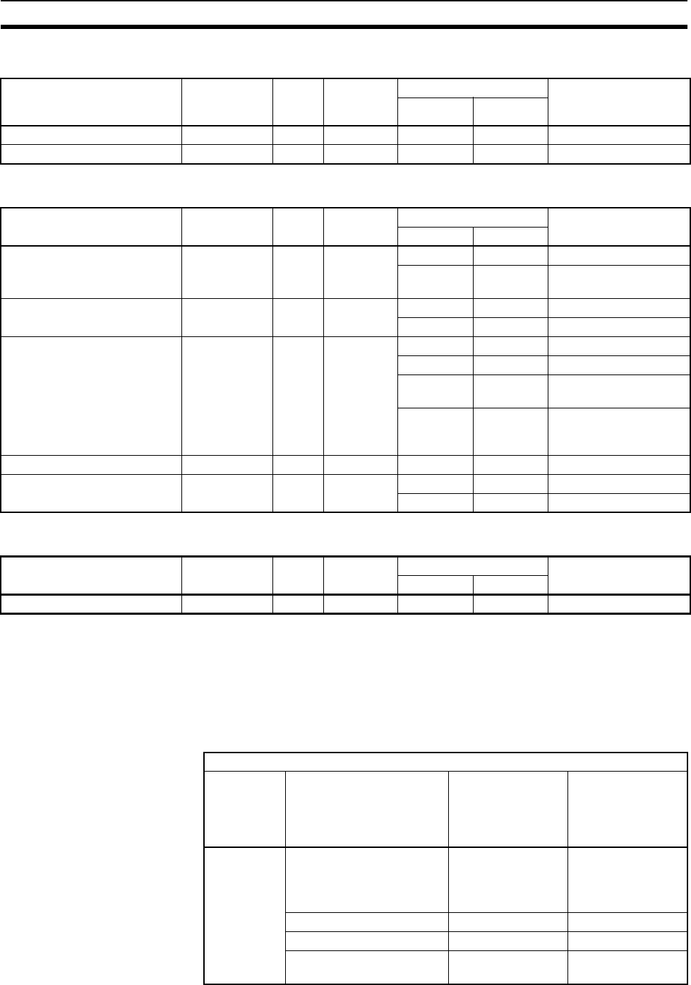
525
Instruction Execution Times and Number of Steps Section 10-5
10-5-31 Task Control Instructions
10-5-32 Model Conversion Instructions (Unit Ver. 3.0 or Later Only)
10-5-33 Special Function Block Instructions (Unit Ver. 3.0 or Later Only)
Guidelines on Converting
Program Capacities from
Previous OMRON PLCs
Guidelines are provided in the following table for converting the program
capacity (unit: words) of previous OMRON PLCs (SYSMAC C200HX/HG/HE,
CVM1, or CV-series PLCs) to the program capacity (unit: steps) of the CS-
series PLCs.
Add the following value (n) to the program capacity (unit: words) of the previ-
ous PLCs for each instruction to obtain the program capacity (unit: steps) of
the CS-series PLCs.
Instruction Mnemonic Code Length
(steps)
(See note.)
ON execution time (µs) Conditions
CPU-6@HCPU-4@H
TASK ON TKON 820 2 19.5 26.3 ---
TASK OFF TKOF 821 2 13.3 19.0 ---
Instruction Mnemonic Code Length
(steps)
ON execution time (µs) Conditions
CPU-6@HCPU-4@H
BLOCK TRANSFER XFERC 565 4 6.4 6.5 Transferring 1 word
481.6 791.6 Transferring 1,000
words
SINGLE WORD DISTRIBUTE DISTC 566 4 3.4 3.5 Data distribute
5.9 7.3 Stack operation
DATA COLLECT COLLC 567 4 3.5 3.85 Data collection
8 9.1 Stack operation
8.3 9.6 Stack operation
1 word FIFO Read
2052.3 2097.5 Stack operation
1,000 words FIFO
Read
MOVE BIT MOVBC 568 4 4.5 4.88 ---
BIT COUNTER BCNTC 621 4 4.9 5 Counting 1 word
1252.4 1284.4 Counting 1,000 words
Instruction Mnemonic Code Length
(steps)
ON execution time (µs) Conditions
CPU-6@HCPU-4@H
GET VARIABLE ID GETID 286 4 14 22.2 ---
CS-series steps = “a” (words) of previous PLC + n
Instructions Variations Value of n when
converting from
C200HX/HG/HE to
CS Series
Value of n when
converting from
CV-series PLC or
CVM1 to CS
Series
Basic
instructions
None OUT, SET, RSET,
or KEEP(011): –1
Other instructions:
0
0
Upward Differentiation None +1
Immediate Refreshing None 0
Upward Differentiation and
Immediate Refreshing
None +2
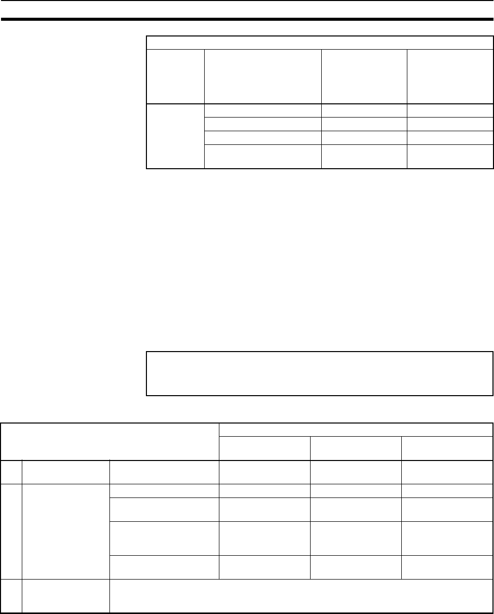
526
Instruction Execution Times and Number of Steps Section 10-5
For example, if OUT is used with an address of CIO 000000 to CIO 25515, the
program capacity of a C200HX/HG/HE PLC would be 2 words per instruction
and that of the CS-series PLC would be 1 (2 – 1) step per instruction.
For example, if !MOV is used (MOVE instruction with immediate refreshing),
the program capacity of a CV-series PLC would be 4 words per instruction
and that of the CS-series PLC would be 7 (4 + 3) steps.
10-5-34 Function Block Instance Execution Time (CPU Units with Unit
Version 3.0 or Later)
Use the following equation to calculate the effect of instance execution on the
cycle time when function block definitions have been created and the
instances copied into the user program using CS/CJ-series CPU Units with
unit version 3.0 or later.
The following table shows the length of time for A, B, and C.
Example: CS1H-CPU63H
Input variables with a 1-word data type (INT): 3
Output variables with a 1-word data type (INT): 2
Total instruction processing time in function block definition section: 10 µs
Execution time for 1 instance = 6.8 µs + (3 + 2) × 0.3 µs + 10 µs = 18.3 µs
Note The execution time is increased according to the number of multiple instances
when the same function block definition has been copied to multiple locations.
Special
instructions
None 0 –1
Upward Differentiation +1 0
Immediate Refreshing None +3
Upward Differentiation and
Immediate Refreshing
None +4
CS-series steps = “a” (words) of previous PLC + n
Instructions Variations Value of n when
converting from
C200HX/HG/HE to
CS Series
Value of n when
converting from
CV-series PLC or
CVM1 to CS
Series
Effect of Instance Execution on Cycle Time
= Startup time (A)
+ I/O parameter transfer processing time (B)
+ Execution time of instructions in function block definition (C)
Operation CPU Unit model
CS1H-CPU6@H
CJ1H-CPU6@H
CS1G-CPU4@H
CJ1G-CPU4@H
CJ1M-CPU@@
A Startup time Startup time not including
I/O parameter transfer
6.8 µs8.8 µs 15.0 µs
B I/O parameter trans-
fer processing time
The data type is
indicated in paren-
theses.
1-bit I/O variable (BOOL) 0.4 µs0.7 µs1.0 µs
1-word I/O variable (INT,
UINT, WORD)
0.3 µs0.6 µs0.8 µs
2-word I/O variable
(DINT, UDINT, DWORD,
REAL)
0.5 µs0.8 µs1.1 µs
4-word I/O variable (LINT,
ULINT, LWORD, LREAL)
1.0 µs1.6 µs2.2 µs
C Function block defi-
nition instruction
execution time
Total instruction processing time (same as standard user program)
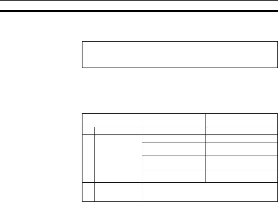
527
Instruction Execution Times and Number of Steps Section 10-5
Number of Function Block
Program Steps (CPU Units
with Unit Version 3.0 or
Later)
Use the following equation to calculate the number of program steps when
function block definitions have been created and the instances copied into the
user program using CS/CJ-series CPU Units with unit version 3.0 or later.
Note The number of instruction steps in the function block definition (p) will not be
diminished in subsequence instances when the same function block definition
is copied to multiple locations (i.e., for multiple instances). Therefore, in the
above equation, the number of instances is not multiplied by the number of
instruction steps in the function block definition (p).
Example:
Input variables with a 1-word data type (INT): 5
Output variables with a 1-word data type (INT): 5
Function block definition section: 100 steps
Number of steps for 1 instance = 57 + (5 + 5) × 6 steps + 100 steps + 27 steps
= 244 steps
Number of steps
= Number of instances × (Call part size m + I/O parameter transfer part size n × Num-
ber of parameters) + Number of instruction steps in the function block definition p
(See note.)
Contents CS/CJ-series CPU Units
with unit version 3.0 or later
m Call part 57 steps
n I/O parameter
transfer part
The data type is
shown in parenthe-
ses.
1-bit I/O variable (BOOL) 6 steps
1-word I/O variable (INT,
UINT, WORD)
6 steps
2-word I/O variable (DINT,
UDINT, DWORD, REAL)
6 steps
4-word I/O variable (LINT,
ULINT, LWORD, LREAL)
12 steps
p Number of instruc-
tion steps in func-
tion block definition
The total number of instruction steps (same as standard
user program) + 27 steps.

528
Instruction Execution Times and Number of Steps Section 10-5
529
SECTION 11
Troubleshooting
This section provides information on hardware and software errors that occur during PLC operation.
11-1 Error Log. . . . . . . . . . . . . . . . . . . . . . . . . . . . . . . . . . . . . . . . . . . . . . . . . . . . . 530
11-2 Error Processing . . . . . . . . . . . . . . . . . . . . . . . . . . . . . . . . . . . . . . . . . . . . . . . 531
11-2-1 Error Categories . . . . . . . . . . . . . . . . . . . . . . . . . . . . . . . . . . . . . . . . 531
11-2-2 Error Information . . . . . . . . . . . . . . . . . . . . . . . . . . . . . . . . . . . . . . . 531
11-2-3 Error Codes and Error Flags . . . . . . . . . . . . . . . . . . . . . . . . . . . . . . . 533
11-2-4 Error Processing Flowchart . . . . . . . . . . . . . . . . . . . . . . . . . . . . . . . 534
11-2-5 Error Messages . . . . . . . . . . . . . . . . . . . . . . . . . . . . . . . . . . . . . . . . . 536
11-2-6 Power Supply Check. . . . . . . . . . . . . . . . . . . . . . . . . . . . . . . . . . . . . 546
11-2-7 Memory Error Check . . . . . . . . . . . . . . . . . . . . . . . . . . . . . . . . . . . . 548
11-2-8 Program Error Check . . . . . . . . . . . . . . . . . . . . . . . . . . . . . . . . . . . . 549
11-2-9 Cycle Time Too Long Error Check . . . . . . . . . . . . . . . . . . . . . . . . . 550
11-2-10 PLC Setup Setting Error Check . . . . . . . . . . . . . . . . . . . . . . . . . . . . 550
11-2-11 Battery Error Check . . . . . . . . . . . . . . . . . . . . . . . . . . . . . . . . . . . . . 551
11-2-12 Environmental Conditions Check . . . . . . . . . . . . . . . . . . . . . . . . . . . 551
11-2-13 I/O Check . . . . . . . . . . . . . . . . . . . . . . . . . . . . . . . . . . . . . . . . . . . . . 552
11-3 Troubleshooting Racks and Units . . . . . . . . . . . . . . . . . . . . . . . . . . . . . . . . . . 553
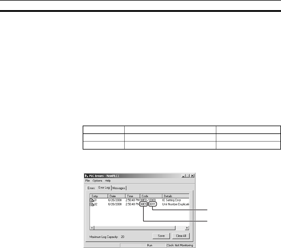
530
Error Log Section 11-1
11-1 Error Log
Each time that an error occurs, the CPU Unit stores error information in the
Error Log Area. The error information includes the error code (stored in
A400), error contents, and time that the error occurred. Up to 20 records can
be stored in the Error Log.
Errors Generated by
FAL(006)/FALS(007)
In addition to system-generated errors, the PLC records user-defined
FAL(006) and FALS(007) errors, making it easier to track the operating status
of the system.
A user-defined error is generated when FAL(006) or FALS(007) is executed in
the program. The execution conditions of these instructions constitute the
user-defined error conditions. FAL(006) generates a non-fatal error and
FALS(007) generates a fatal error that stops program execution.
The following table shows the error codes for FAL(006) and FALS(007).
Check the error log by clicking the Error Log Tab in the PLC Errors Window of
the CX-Programmer.
The above example shows that unit number 17 has been duplicated for Spe-
cial I/O Units.
• Error code 80E9: Unit number duplication error
• Error information: 80 “11”: 11 hex = 17 decimal
For details on error codes and error information, refer to 11-2-5 Error Mes-
sages.
Error Log Structure When more than 20 errors occur, the oldest error data (in A100 to A104) is
deleted, the newest record is stored in A195 to A199, and the other errors are
shifted by one.
Instruction FAL numbers Error codes
FAL(006) #0001 to #01FF (1 to 511 decimal) 4101 to 42FF
FALS(007) #0001 to #01FF (1 to 511 decimal) C101 to C2FF
The error information is displayed
here.
The error code is displayed here.
CS1G-H-CPU42
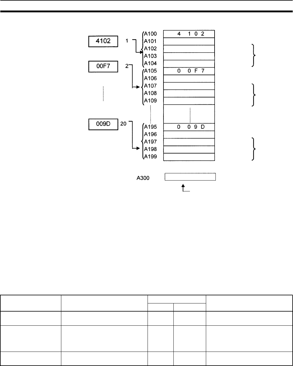
531
Error Processing Section 11-2
The number of records is stored in binary in the Error Log Pointer (A300). The
data in the Error Log can be cleared from a Programming Device.
Note The Error Log Pointer can be reset by turning ON the Error Log Pointer Reset
Bit (A50014), but this operation does not clear the data in the Error Log A100
to A199) itself.
11-2 Error Processing
11-2-1 Error Categories
Errors in CS-series PLCs can be broadly divided into the following three cate-
gories.
11-2-2 Error Information
There are basically four sources of information on errors that have occurred:
1,2,3... 1. The CPU Unit’s indicators
2. The Auxiliary Area Error Flags
3. The Auxiliary Area Error Information Words
Error code Order of
occurrence
Error Log Area
Error code
Year, month
Time of
occurrence
Time of
occurrence
Time of
occurrence
Error Lo
g
Pointer (error counter)
Year, month
Error contents
Minute, second
Day, hour
Year, month
Error code
Error contents
Minute, second
Day, hour
Error code
Error contents
Minute, second
Day, hour
Category Result Indicators Comments
RUN ERR/ALM
CPU Standby The CPU Unit will not start opera-
tion in RUN or MONITOR mode.
OFF OFF ---
Non-fatal Errors
(including FAL(006))
The CPU Unit will continue operat-
ing in RUN or MONITOR mode.
ON
(Green)
Flashing
(Red)
Other indicators will also operate
when a communications error has
occurred or the Output OFF Bit is
ON.
Fatal Errors
(including FALS(007))
The CPU Unit will stop operating in
RUN or MONITOR mode.
OFF ON
(Red)
The indicators will all be OFF
when there is a power interruption.
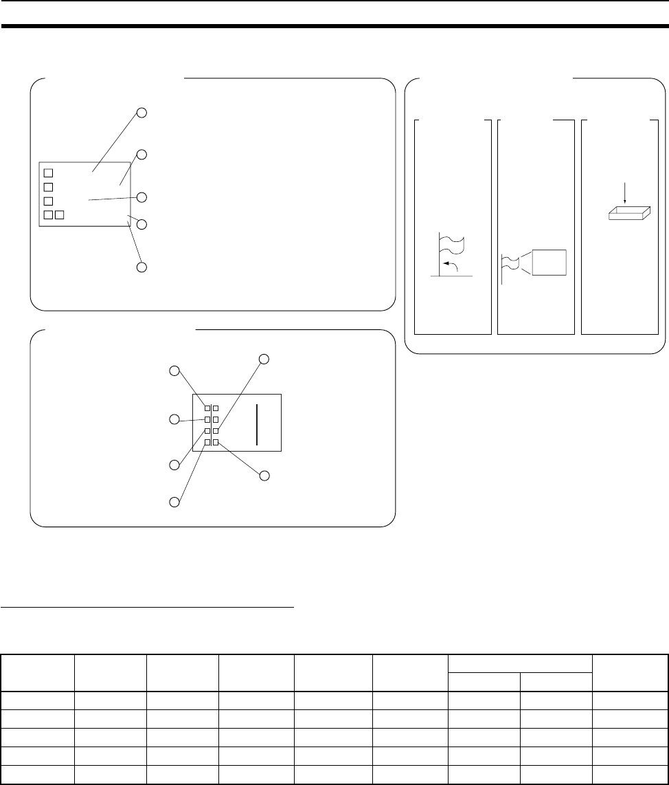
532
Error Processing Section 11-2
4. The Auxiliary Area Error Code Word
Note When two or more errors occur at the same time, the highest (most serious)
error code will be stored in A400.
Indicator Status and Error Conditions
The following table shows the status of the CPU Unit’s indicators for errors
that have occurred in RUN or MONITOR mode.
CPU Unit Indicators Auxiliary Area Flags and Words
RUN:
ERR/ALM:
INH:
PRPHL:
COMM:
Lit when the PLC is in
RUN or MONITOR mode.
Flashing: Non-fatal error
Lit: Fatal error
Lit when Output OFF Bit
has been turned ON.
Lit when the CPU Unit is
communicating through
the peripheral port
Lit when the CPU Unit is
communicating through
the RS-232C port
Error Flags Error Info.
A400 contains
the error code.
(See note.)
RUN
ERR/ALM
INH
PRPHL/COMM
RUN
ERR/ALM
INH
PRPH COMM
BKUP
CS
Error Code
Word (A400)
Flags indicating
the type of error.
Words provid-
ing error infor-
mation.
Error Code
Word (A400)
RUN: Lit when the PLC is in
RUN or MONITOR mode.
ERR/ALM:
Flashing: Non-fatal error
Lit: Fatal Error
.INH: Lit when Output OFF
Bit has been turned ON.
PRPHL: Lit when the CPU
Unit is communicating
through the peripheral port.
.BKUP: Lit when data is
being written to the flash
memory.
.COMM: Lit when the
CPU Unit is
communicating through
the RS-232C port.
CS1-H CPU Unit Indicators
Indicator* CPU error CPU reset CPU
standby
Fatal error Non-fatal
error
Communications error Output
OFF Bit ON
Peripheral RS-232C
RUN OFF OFF OFF OFF ON ON ON ---
ERR/ALM ON OFF OFF ON Flashing --- --- ---
INH OFF OFF --- --- --- --- --- ON
PRPHL --- --- --- --- --- OFF --- ---
COMM --- --- --- --- --- --- OFF ---

533
Error Processing Section 11-2
11-2-3 Error Codes and Error Flags
Classification Error code Error name Page
Fatal system
errors
80F1 Memory error 538
80C0 to 80C7,
80CF
I/O bus error 539
80CB I/O bus error B 539
80E9 Duplicated number error 539
80E1 Too many I/O points 540
80E0 I/O setting error 540
80F0 Program error 541
809F Cycle time too long 542
80EA Expansion Rack number duplicated 539
82F0 Fatal Inner Board error 539
Non-fatal sys-
tem errors
008B Interrupt task error 543
009A Basic I/O error 543
009B PLC Setup setting error 544
00E7 I/O verification error 544
02F0 Inner Board error 544
0200 to 020F CS1-series CPU Bus Unit error 544
0300 to 035F Special I/O Unit error 544
00A0 to 00A1 SYSMAC BUS error 544
00F7 Battery error 544
0400 to 040F CS1-series CPU Bus Unit setting error 545
0500 to 055F Special I/O Unit setting error 545
User-defined
fatal errors
4101 to 42FF FALS(007) error
(C101 to C2FF are stored for FALS
numbers 001 to 511)
543
User-defined
non-fatal errors
C101 to C2FF FAL(006) error
(4101 to 42FF are stored for FAL num-
bers 001 to 511)
542
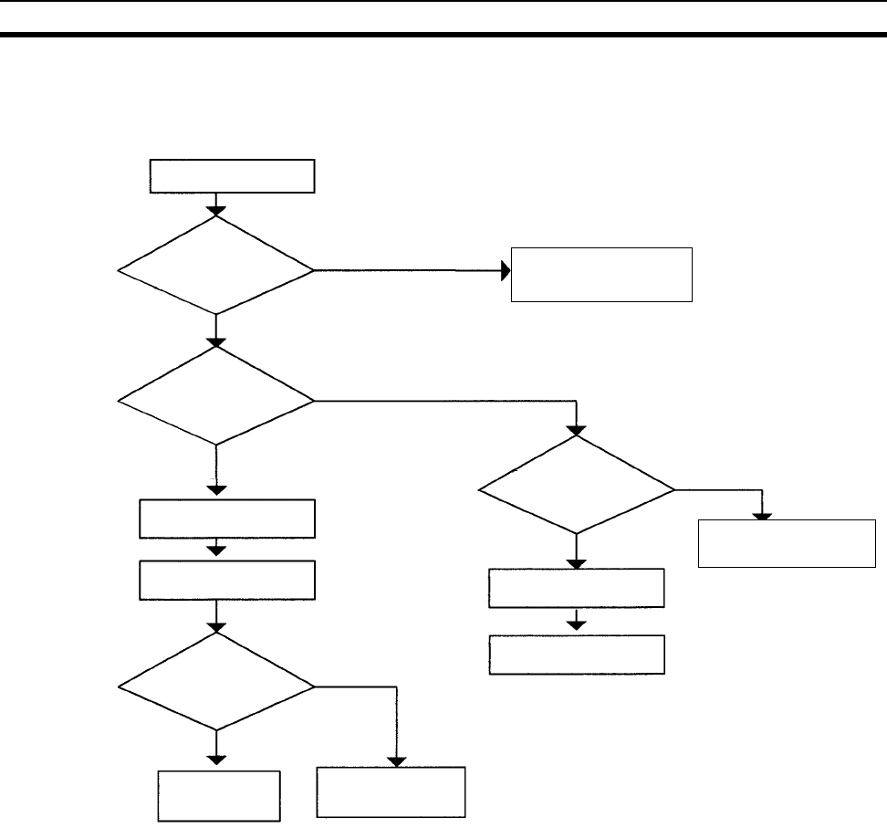
534
Error Processing Section 11-2
11-2-4 Error Processing Flowchart
Use the following flowchart as a guide for error processing with a Program-
ming Console.
Error occurred
during operation
Is the POWER
indicator lit?
Is the RUN indica-
tor lit?
Connect the
Programming Console.
Fatal error
OFF
Lit
Lit
OFF
Is the Programming
Console's display
operating?
- - - - displayed.
Check the Power
Supply (page 16).
Is the ERR/ALM
indicator flashing?
OFF
Flashing
Connect the
Programming Console.
CPU Error
(WDT error)
Non-fatal error
Ye s
ERR/ALM indicator lit.
Check the Power
Supply (page 546)
Check I/O and environmental
conditions (See note 1.)

535
Error Processing Section 11-2
Note 1. The rack number will be given at *.
2. The FAL./FALS number will be given at ***.
3. The unit number will be given at **.
4. The master number will be given at *.
Fatal error
Memory error
I/O bus error
Unit Number
Duplication
error
Fatal Inner
Board error
Too Many I/O
Points error
I/O Table
Setting error
Program error
Rack Number
Duplication
error
Cycle Time
Overrun error
System FALS
error
Non-fatal error
FAL error
Interrupt
Task error
Basic I/O
error
I/O Table
Verification
error
Non-fatal
Inner Board
error
CS1 CPU
Bus Unit error
Special I/O
Unit error
PLC Setup
error
SYSMAC
BUS error
Battery error
CPU
Bus Unit
Setup error
Special I/O
Unit Setup
error
(See note 1.) (See note 2.)
(See note 3.)
(See note 3.)
(See note 4.)
(See note 3.)
(See note 3.)
MEMORY ERR *
I/O BUS ERR
UNIT NO. DPL ERR
RACK NO. DPL ERR
FATAL INNER ERR
TOO MANY I/O PNT
I/O SET ERR
PROGRAM ERR
CYCLE TIME ERR
SYS FAIL FALS
SYS FAIL FAL ***
INTRPT ERR
DENSITY I/O ERR
PC SETUP ERR
I/O VRFY ERR
NO-FTL INNER ERR
CPU BU ERR **
SIOU ERR **
SYSBUS ERR **
BAT LOW
CPU BU STUP **
SIOU SETUP **
(See note 2.)
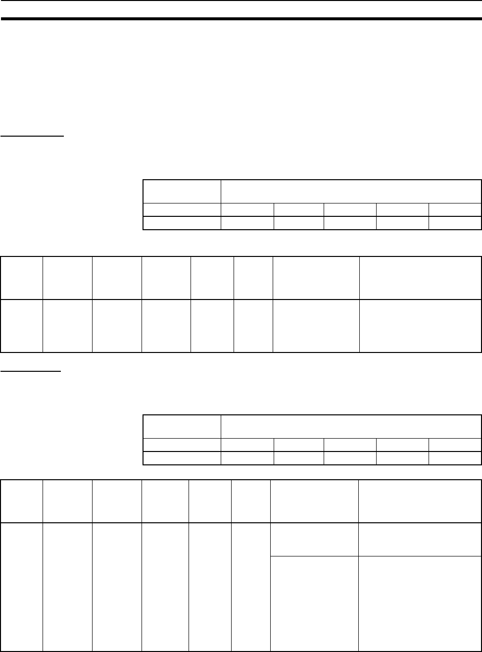
536
Error Processing Section 11-2
11-2-5 Error Messages
The following tables show error messages for errors which can occur in CS-
series PLCs and indicate the likely cause of the errors.
!Caution Always check the safety of the controlled system before turning the power
supply OFF or ON.
CPU Errors
A CPU error has occurred if the indicators have the following conditions in
RUN or MONITOR mode. A Programming Device, such as a Programming
Console, cannot be connected when the CPU Unit is in this state.
CPU Reset
The following indicators status indicates an Expansion Rack power interrup-
tion, not a CPU error. A Programming Device, such as a Programming Con-
sole, cannot be connected when the CPU Unit is in this state.
Note When power supply is interrupted to an Expansion Rack, the CPU Unit will
stop program execution and the same operations as are performed when the
power supply to the CPU Unit is interrupted will be performed. For example, if
the power OFF interrupt task is enabled, it will be executed. If power is then
Power Supply
Unit Indicator
CPU Unit Indicators
POWER RUN ERR/ALM INH PRPHL COMM
ON --- ON --- --- ---
Status Error Program-
ming
Console
display
Error
flags in
Auxiliary
Area
Error
code (in
A400)
Flags
and
word
data
Probable cause Possible remedy
Stopped CPU error – – – – None None None Watchdog timer has
exceeded maxi-
mum setting.
Turn the power OFF and
restart. The Unit may be
faulty. Contact your OMRON
representative if the problem
persists.
Power Supply
Unit Indicator
CPU Unit Indicators
POWER RUN ERR/ALM INH PRPHL COMM
ON OFF OFF OFF --- ---
Status Error Program-
ming
Console
display
Error
flags in
Auxiliary
Area
Error
code (in
A400)
Flags Probable cause Possible remedy
Stopped CPU reset – – – – None None None Power is not being
supplied to an
Expansion Rack.
Supply power to the Expan-
sion Rack.
An I/O Connecting
Cable is not con-
nected properly.
For example, the IN
and OUT connec-
tions between the
CPU Rack and an
Expansion Rack are
reversed.
Turn OFF the power supply,
check the connections all I/O
Connecting Cables, and turn
the power supply back ON.
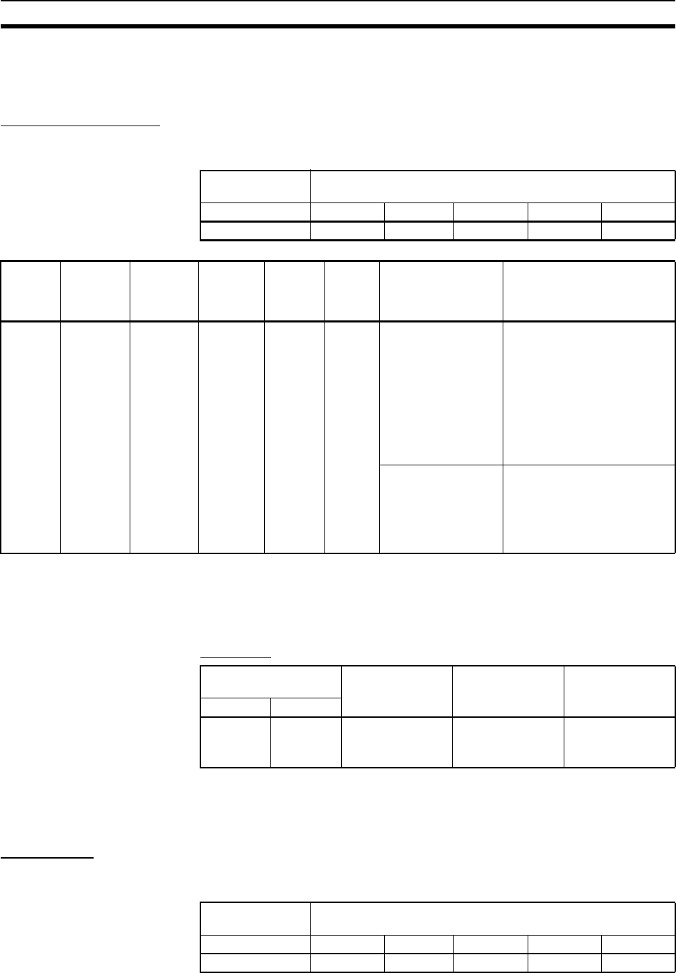
537
Error Processing Section 11-2
restored to the Expansion Rack, the CPU Unit will perform startup processing,
i.e., the same operational status as existed before the power interrupt will not
necessarily be continued.
CPU Standby Errors
A CPU standby error has occurred if the indicators have the following condi-
tions in RUN or MONITOR mode.
Startup Condition The CS1-H CPU Units support a Startup Condition setting.
To start the CPU Unit in MONITOR or PROGRAM mode even if there is one
or more Boards or Units that has not completed startup processing, set the
Startup Condition to 1.
PLC Setup
Note The operation for Inner Boards, however, also depends on the next setting of
the Inner Board Setting in word +84, but 15. This bit must also be turned ON
to not wait for Inner Boards.
Fatal Errors
A fatal error has occurred if the indicators have the following conditions in
RUN or MONITOR mode.
Power Supply
Unit Indicator
CPU Unit Indicators
POWER RUN ERR/ALM INH PRPHL COMM
ON OFF OFF --- --- ---
Status Error Program-
ming
Console
display
Error
flags in
Auxiliary
Area
Error
code (in
A400)
Flags Probable cause Possible remedy
Stopped CPU
standby
error
CPU
WAIT’G
None None None Recognition of one
or more of the fol-
lowing Unit has not
been completed:
CPU Bus Units,
Special I/O Units,
High-density I/O
Units, Interrupt Input
Units, or an Inner
Board.
Turn OFF the power supply,
check the mounting and set-
tings of all the Unit and the
Inner Board, and turn the
power supply back ON.
Power is not being
supplied to a Slave
Rack or the termina-
tor is not recognized
in a Remote I/O Sys-
tem.
Check the power supply to
the Slave Racks and termi-
nating resistance settings for
Remote I/O Systems. Also
check cable connections in
the Remote I/O Systems.
Programming
Console address
Name Settings Default
Word Bit
+83 15 Startup Condition 0: Wait for Units
and Boards.
1: Don’t wait.
0: Wait for Units
and Boards.
Power Supply
Unit Indicator
CPU Unit Indicators
POWER RUN ERR/ALM INH PRPHL COMM
ON OFF ON --- --- ---

538
Error Processing Section 11-2
Connect the CX-Programmer or a Programming Console to display the error
message (in the PLC Error Window on the CX-Programmer). The cause of
the error can be determined from the error message and related Auxiliary
Area flags and words.
Errors are listed in order of importance. When two or more errors occur at the
same time, the more serious error’s error code will be recorded in A400.
If the IOM Hold Bit hasn’t been turned ON to protect I/O memory, all non-
retained areas of I/O memory will be cleared when a fatal error other than
FALS(007) occurs. If the IOM Hold Bit is ON, the contents of I/O memory will
be retained but all outputs will be turned OFF.
If the IOM Hold Bit hasn’t been turned ON to protect I/O memory, all non-
retained areas of I/O memory will be cleared when a fatal error other than
FALS(007) occurs. When the IOM Hold Bit is ON, the contents of I/O memory
will be retained but all outputs will be turned OFF.
Error Program-
ming
Console
display
Error
code (in
A400)
Flag and
word data
Probable cause Possible remedy
Memory
error
MEMORY
ERR
80F1 A40115:
Memory
Error Flag
A403:
Memory
Error Loca-
tion
An error has occurred in
memory. A bit in A403 will
turn ON to show the location
of the error as listed below.
See below.
A40300 ON:
A checksum error has
occurred in the user program
memory. The power was
turned OFF while storing
data to the flash memory
(backup memory).
Check the program and correct the error.
A40304 ON:
A checksum error has
occurred in the PLC Setup.
Clear the entire PLC Setup to 0000 and
reenter the settings.
A40305 ON:
A checksum error has
occurred in the registered
I/O table.
Initialize the registered I/O table and gen-
erate a new I/O table.
A40307 ON:
A checksum error has
occurred in the routing
tables.
Initialize the routing tables and reenter
the tables.
A40308 ON:
A checksum error has
occurred in the CS-series
CPU Bus Unit setup.
Initialize the CS-series CPU Bus Unit
setup and reenter the settings.
A40309 ON:
An error occurred during
automatic transfer from the
Memory Card at startup.
Make sure that the Memory Card is
installed properly and that the correct file
is on the Card.
A40310 ON:
Flash memory has failed.
Retransfer the user program and param-
eter data.

539
Error Processing Section 11-2
I/O Bus
error
I/O BUS
ERR
80C0 to
80C7 or
80CF
A40114: I/O
Bus Error
Flag
A404: I/O
Bus Error
Slot and
Rack Num-
bers
Error has occurred in the bus
line between the CPU and
I/O Units.
A40400 to A40407 contain
the error slot number (00 to
09) in binary. 0F indicates
that the slot cannot be deter-
mined.
A40408 to A40415 contain
the error rack number (00 to
07) in binary. 0F indicates
that the rack cannot be
determined.
Try turning the power OFF and ON
again.
If the error isn’t corrected, turn the power
OFF and check cable connections
between the I/O Units and Racks.
Check for damage to the cable or Units.
Correct the cause of the error and then
turn the Rack’s power supply OFF and
then ON again
I/O BUS
ERR B
80CB A404: I/O
Bus Error
Slot and
Rack Num-
bers
I/O bus error B: CPU Unit is
mounted to a Duplex Back-
plane.
Note:
A40400 to A40407 = 0F hex
A40408 to A40415 = 0B hex
Turn OFF the power, replace the Back-
plane with a CS1W-BC@@@ Backplane,
and turn the power back ON.
Unit/Rack
Number
Duplica-
tion error
UNIT No.
DPL ERR
80E9 A40113:
Duplication
Error Flag
A410: CPU
Bus Unit
Duplicate
Number
Flags
The same number has been
allocated to more than one
CS-series CPU Bus Unit.
Bits A41000 to A41015 cor-
respond to unit numbers 0 to
F.
Check the unit numbers, eliminate the
duplications, and turn the Rack’s power
supply OFF and then ON again.
A40113:
Duplication
Error Flag
A411 to
A416: Spe-
cial I/O Unit
Duplicate
Number
Flags
The same number has been
allocated to more than one
Special I/O Unit.
Bits A41100 to A41615 cor-
respond to unit numbers 0 to
95.
Check the unit numbers, eliminate the
duplications, and turn the Rack’s power
supply OFF and then ON again.
RACK No.
DPL ERR
80EA A409:
Expansion
Rack Dupli-
cate Rack
Number
The same I/O word has
been allocated to more than
one Basic I/O Unit.
Check allocations to Units on the rack
number whose bit in ON in A40900 to
A40907. Correct the allocations so that
no words are allocated more than once,
including to Units on other Racks, and
turn the Rack’s power supply OFF and
then ON again.
An Expansion I/O Rack’s
starting word address
exceeds CIO 0901.
The corresponding bit in
A40900 to A40907 (Racks 0
to 7) will be turned ON.
Check the first word setting for the Rack
indicated in A40900 to A40907 and
change the setting to a valid word
address below CIO 0901 with a Pro-
gramming Device.
Fatal Inner
Board
error
FATAL
INNER
ERR
82F0 A40112:
Inner Board
Stopped
Error Flag
A424: Inner
Board Error
Information
The Inner Board is faulty.
An error occurred on the
Inner bus.
Check the indicators on the Inner Board
and refer to the operation manual for the
Inner Board.
Error Program-
ming
Console
display
Error
code (in
A400)
Flag and
word data
Probable cause Possible remedy

540
Error Processing Section 11-2
To o M a ny
I/O Points
error
TOO
MANY I/O
PNT
80E1 A40111:
To o M a ny
I/O Points
Flag
A407: Too
Many I/O
Points,
Details
The probable causes are
listed below. The 3-digit
binary value (000 to 101) in
A40713 to A40715 indicates
the cause of the error. The
value of these 3 bits is also
output to A40700 to A40712.
1) The total number of I/O
points set in the I/O Table
(excluding Slave Racks)
exceeds the maximum
allowed for the CPU Unit
(bits: 000).
2) There are more than 32
interrupt inputs (bits: 001).
3) The unit number of a
Slave Unit is duplicated or
the number of I/O points on
a C500 Slave Unit exceeds
320 (bits: 010).
4) The unit number of an I/O
Interface (excluding Slave
Racks) is duplicated (bits:
011).
5) The unit number of a Mas-
ter Unit is duplicated or the
unit number is outside of the
allowed setting range (bits:
100).
6) The number of Expan-
sion Racks exceeds the
maximum (bits: 101).
7) C200H Special I/O Unit
not detected or Remote I/O
not detected (bits: 110)
Correct the problem indicated by the
content of A407 and turn the power OFF
and ON again.
I/O Table
Setting
error
I/O SET
ERR
80E0 A40110: I/O
Setting
Error Flag
Input and output word allo-
cations do no agree with
input/output words required
by Units actually mounted.
Check the I/O table with I/O Table Verifi-
cation operation. When the system has
been corrected, register the I/O table
again.
Error Program-
ming
Console
display
Error
code (in
A400)
Flag and
word data
Probable cause Possible remedy

541
Error Processing Section 11-2
Program
error
PRO-
GRAM
ERR
80F0 A40109:
Program
Error Flag
A294 to
A299: Pro-
gram error
information
The program is incorrect.
See the following rows of
this table for details.
The address at which the
program stopped will be out-
put to A298 and A299.
Check A295 to determine the type of
error that occurred and check
A298/A299 to find the program address
where the error occurred.
Correct the program and then clear the
error.
A29511: No END error Be sure that there is an END(001)
instruction at the end of the task speci-
fied in A294 (program stop task number).
A29512: Task error
A task error has occurred.
The following conditions will
generate a task error.
1) There isn’t an executable
cyclic task.
2) There isn’t a program allo-
cated to the task. Check
A294 for the number of the
task missing a program.
3) The task specified in a
TKON(820), TKOF(821), or
MSKS(690) instruction
doesn’t exist.
• Check the startup cyclic task attributes.
• Check the execution status of each
task as controlled by TKON(820) and
TKOF(821).
• Make sure that all of the task numbers
specified in TKON(820), TKOF(821),
and MSKS(690) instructions have cor-
responding tasks. Use MSKS(690) to
mask any I/O or scheduled interrupt
tasks that are not being used and that
do not have programs set for them.
• If the power OFF interrupt task is
enables in the PLC Setup, make sure
that the power OFF interrupt task has
been created.
A29510: Illegal access error
An illegal access error has
occurred and the PLC Setup
has been set to stop opera-
tion for an instruction error.
The following are illegal
access errors:
1. Reading/writing a param-
eter area.
2. Writing memory that is not
installed.
3. Writing an EM bank that is
EM file memory.
4. Writing to a read-only
area.
5. Indirect DM/EM address
that is not in BCD when BCD
mode is specified.
Find the program address where the
error occurred (A298/A299) and correct
the instruction.
A29509: Indirect DM/EM
BCD error
An indirect DM/EM BCD
error has occurred and the
PLC Setup has been set to
stop operation for an instruc-
tion error.
Find the program address where the
error occurred (A298/A299) and correct
the indirect addressing or change to
binary mode.
Error Program-
ming
Console
display
Error
code (in
A400)
Flag and
word data
Probable cause Possible remedy

542
Error Processing Section 11-2
Program
error
(contd.)
PRO-
GRAM
ERR
80F0 A40109:
Program
Error Flag
A294 to
A299: Pro-
gram error
information
A29508: Instruction error
An instruction processing
error has occurred and the
PLC Setup has been set to
stop operation for an instruc-
tion error.
Find the program address where the
error occurred (A298/A299) and correct
the instruction.
Alternatively, set the PLC Setup to
continue operation for an instruction
error.
A29513: Differentiation over-
flow error
Too many differentiated
instructions have been
inserted or deleted during
online editing.
After writing any changes to the program,
switch to PROGRAM mode and then
return to MONITOR mode to continue
editing the program.
A29514: Illegal instruction
error
The program contains an
instruction that cannot be
executed.
Retransfer the program to the CPU Unit.
A29515: UM overflow error
The last address in UM (user
program memory) has been
exceeded.
Use a Programming Device to transfer
the program again.
Cycle
Time
Overrun
error
CYCLE
TIME ERR
809F A40108:
Cycle Time
Too Long
Flag
The cycle time has
exceeded the maximum
cycle time (watch cycle time)
set in the PLC Setup.
Change the program to reduce the cycle
time or change the maximum cycle time
setting.
Check the Maximum Interrupt Task
Processing Time in A440 and see if the
Cycle Time Watch Time can be changed.
The cycle time can be reduced by divid-
ing unused parts of the program into
tasks, jumping unused instructions in
tasks, and disabling cyclic refreshing of
Special I/O Units that don’t require
frequent refreshing.
A40515:
Peripheral
Servicing
Cycle Time
Too Long
Turns ON when the periph-
eral servicing time in a Paral-
lel Processing Mode
exceeds 2 s.
Change the CPU Processing Mode in
the PLC Setup to Normal Mode or
Peripheral Servicing Priority Mode, or
review the system to reduce the event
load.
Parallel processing may not be possible
if the program execution time (given in
A66) is too short (e.g., less than 0.2 ms).
System
FALS error
SYS FAIL
FALS
C101 to
C2FF
A40106:
FALS Error
Flag
FALS(007) has been exe-
cuted in the program.
The error code in A400 will
indicate the FAL number.
The leftmost digit of the code
will be C and the rightmost 3
digits of the code will be from
100 to 2FF hex and will cor-
respond to FAL numbers
001 to 511.
Correct according to cause indicated by
the FAL number (set by user).
Error Program-
ming
Console
display
Error
code (in
A400)
Flag and
word data
Probable cause Possible remedy

543
Error Processing Section 11-2
Non-fatal Errors
A non-fatal error has occurred if the indicators have the following conditions in
RUN or MONITOR mode.
Connect the CX-Programmer or a Programming Console to display the error
message (in the PLC Error Window on the CX-Programmer). The cause of
the error can be determined from the error message and related Auxiliary
Area flags and words.
Errors are listed in order of importance. When two or more errors occur at the
same time, the more serious error’s error code will be recorded in A400.
Power Supply
Unit Indicator
CPU Unit Indicators
POWER RUN ERR/ALM INH PRPHL COMM
ON ON Flashing --- --- ---
Error Program-
ming
Console
display
Error
code (in
A400)
Flag and
word data
Probable cause Possible remedy
System FAL
error
SYS FAIL
FAL
4101 to
42FF
A40215:
FAL Error
Flag
A360 to
A391: Exe-
cuted FAL
Number
Flags
FAL(006) has been exe-
cuted in program.
Executed FAL Number
Flags A36001 to A39115
correspond to FAL numbers
001 to 511.
The error code in A400 will
indicate the FAL number.
The leftmost digit of the
code will be 4 and the right-
most 3 digits of the code will
be from 100 to 2FF hex and
will correspond to FAL num-
bers 001 to 511.
Correct according to cause indicated by
FAL number (set by user).
Interrupt
Task error
INTRPT
ERR
008B A40213:
Interrupt
Task Error
Flag
A426: Inter-
rupt Task
Error, Task
Number
PLC Setup Set to Detect
Interrupt Task Errors:
An interrupt task was exe-
cuted for more than 10 ms
during I/O refreshing of a
C200H Special I/O Unit or a
SYSMAC BUS Remote I/O
Unit.
Check the program. Either disable
detection of interrupt task errors in the
PLC Setup (address 128, bit 14) or cor-
rect the problem in the program.
PLC Setup Set to Detect
Interrupt Task Errors:
Attempted to refresh a Spe-
cial I/O Unit’s I/O from an
interrupt task with
IORF(097) while the Unit’s
I/O was being refreshed by
cyclic I/O refreshing (dupli-
cate refreshing).
Basic I/O
error
DENSITY
I/O ERR
009A A40212:
Basic I/O
Unit Error
Flag
A408: Basic
I/O Unit
Error, Slot
Number
An error has occurred in a
Basic I/O Unit (including
C200H High-density I/O
Units and C200H Interrupt
Input Units).
A408 contains the errant
rack/slot number.
Check the errant Unit for blown fuse, etc.

544
Error Processing Section 11-2
PLC Setup
error
PLC Setup
ERR
009B A40210:
PLC Setup
Error Flag
A406: PLC
Setup Error
Location
There is a setting error in
the PLC Setup. The location
(binary offset) of the error is
written to A406.
Change the indicated setting to a valid
setting.
I/O Table
Verification
error
I/O VRFY
ERR
00E7 A40209: I/O
Verification
Error Flag
A Unit has been added or
removed, so the registered
I/O tables don’t agree with
the actual Units in the PLC.
The I/O Verification Error
Flag goes OFF when the sit-
uation is corrected.
Execute the I/O Table Verify operation to
find the problem location. Create new
I/O tables or replace the Unit to match
the registered I/O tables.
Non-fatal
Inner Board
error
NO-FTL
INNER
ERR
02F0 A40208:
Inner Board
Error Flag
A424: Inner
Board Error
Information
An error occurred in the
Inner Board
Check the Inner Board indicators. Refer
to the Inner Board’s operation manual
for details.
CS-series
CPU Bus
Unit error
CPU BU
ERR
0200 to
020F
A40207:
CS-series
CPU Bus
Unit Error
Flag
A417: CS-
series CPU
Bus Unit
Error, Unit
Number
Flags
An error occurred in a data
exchange between the CPU
Unit and a CS-series CPU
Bus Unit.
The corresponding flag in
A417 is turned ON to indi-
cate the problem Unit. Bits
A41700 to A41715 corre-
spond to unit numbers 0 to
F.
Check the Unit indicated in A417. Refer
to the Unit’s operation manual to find
and correct the cause of the error.
Restart the Unit by toggling its Restart
Bit or turn the power OFF and ON again.
Replace the Unit if it won’t restart.
Special I/O
Unit error
SIOU ERR 0300 to
035F, or
03FF
A40206:
Special I/O
Unit Error
Flag
A418 to
A423: Spe-
cial I/O Unit
Error, Unit
Number
Flags
An error occurred in a data
exchange between the CPU
Unit and a Special I/O Unit.
The corresponding flag in
A418 to A423 is turned ON
to indicate the problem Unit.
Bits A41800 to A42315 cor-
respond to unit numbers 0
to 95.
Check the Unit indicated in A418 to
A423. Refer to the Unit’s operation man-
ual to find and correct the cause of the
error. Restart the Unit by toggling its
Restart Bit or turn the power OFF and
ON again.
Replace the Unit if it won’t restart.
SYSMAC
BUS error
SYSBUS
ERR
00A0 or
00A1
A40205:
SYSMAC
BUS Error
Flag
A405: SYS-
MAC BUS
Master
Error Flags
An error has occurred
between a Master and Slave
Rack.
A Unit has been removed
from or added to a Slave
Rack.
The flag for the affected
Master Unit will be turned
ON.
A40500: Flag for Master
Unit #0
A40501: Flag for Master
Unit #1
Check the condition of the Slave Unit
and the transmission line between the
Master Unit and Slave Unit.
Battery
error
BATT
LOW
00F7 A40204:
Battery
Error Flag
This error occurs when the
PLC Setup has been set to
detect battery errors and the
CPU Unit’s backup battery
is missing or its voltage has
dropped.
Check battery and replace if necessary.
Change the PLC Setup setting if battery-
free operation is being used.
Error Program-
ming
Console
display
Error
code (in
A400)
Flag and
word data
Probable cause Possible remedy
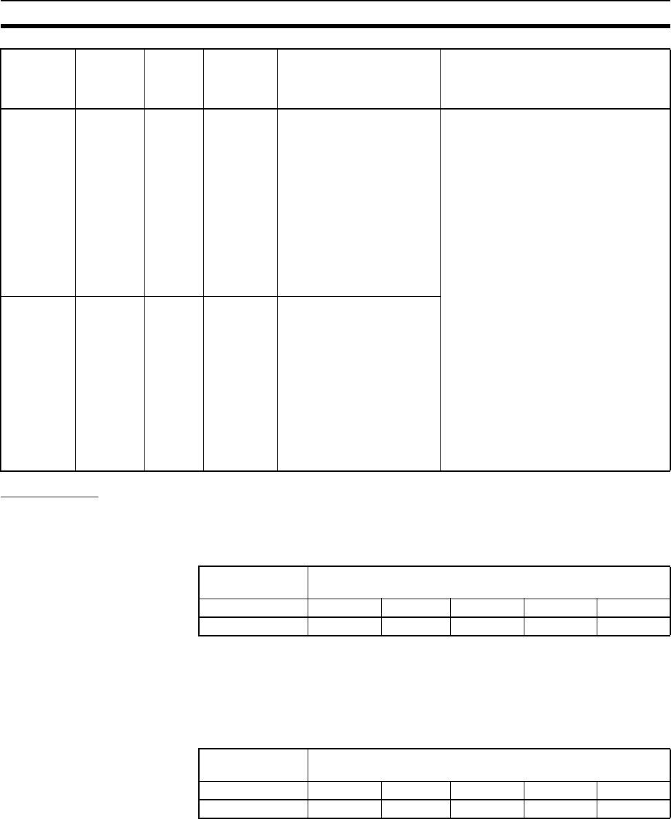
545
Error Processing Section 11-2
Other Errors
Peripheral Port Communications Error
A communications error has occurred in communications with the device con-
nected to the peripheral port if the indicators have the following conditions.
Check the setting of pin 4 on the DIP switch and the peripheral port settings in
the PLC Setup. Also check the cable connections.
RS-232C Port Communications Error
A communications error has occurred in communications with the device con-
nected to the RS-232C port if the indicators have the following conditions.
Check the setting of pin 5 on the DIP switch and the RS-232C port settings in
the PLC Setup. Also check the cable connections. If a host computer is con-
nected, check the communications settings of the serial port on the host com-
puter and the communications program in the host computer.
CS-series
CPU Bus
Unit Setup
error
CPU BU
ST ERR
0400 to
040F
A40203:
CS-series
CPU Bus
Unit Set-
ting Error
Flag
A427: CS-
series CPU
Bus Unit
Setting
Error, Unit
Number
Flags
An installed CS-series CPU
Bus Unit does not match the
CS-series CPU Bus Unit
registered in the I/O table.
The corresponding flag in
A427 will be ON. Bits 00 to
15 correspond to unit num-
bers 0 to F.
Change the registered I/O tables.
Special I/O
Unit Setup
error
SIOU
SETUP
ERR
0500 to
055F
A40202:
Special I/O
Unit Set-
ting Error
Flag
A428 to
A433: Spe-
cial I/O Unit
Setting
Error, Unit
Number
Flags
An installed Special I/O Unit
does not match the Special
I/O Unit registered in the I/O
table.
The corresponding flag in
A428 to A433 will be ON.
Bits A42800 to A43315 cor-
respond to unit numbers 0
to 95.
Error Program-
ming
Console
display
Error
code (in
A400)
Flag and
word data
Probable cause Possible remedy
Power Supply
Unit Indicator
CPU Unit Indicators
POWER RUN ERR/ALM INH PRPHL COMM
ON ON --- --- OFF ---
Power Supply
Unit Indicator
CPU Unit Indicators
POWER RUN ERR/ALM INH PRPHL COMM
ON ON --- --- --- OFF

546
Error Processing Section 11-2
11-2-6 Power Supply Check
The allowable voltage ranges are shown in the following table.
Power Supply Unit Power supply
voltage
Allowable voltage
range
C200HW-PA204S or C200HW-P209R 100 to 120 V AC 85 to 132 V AC
200 to 240 V AC 170 to 264 V AC
C200HW-PA204, C200HW-PA204R, or
C200HW-PA204C
100 to 240 V AC 85 to 264 V AC
C200HW-PD024 24 V DC 20.4 to 28.8 V DC
C200HW-PD025 24 V DC 19.2 to 28.8 V DC
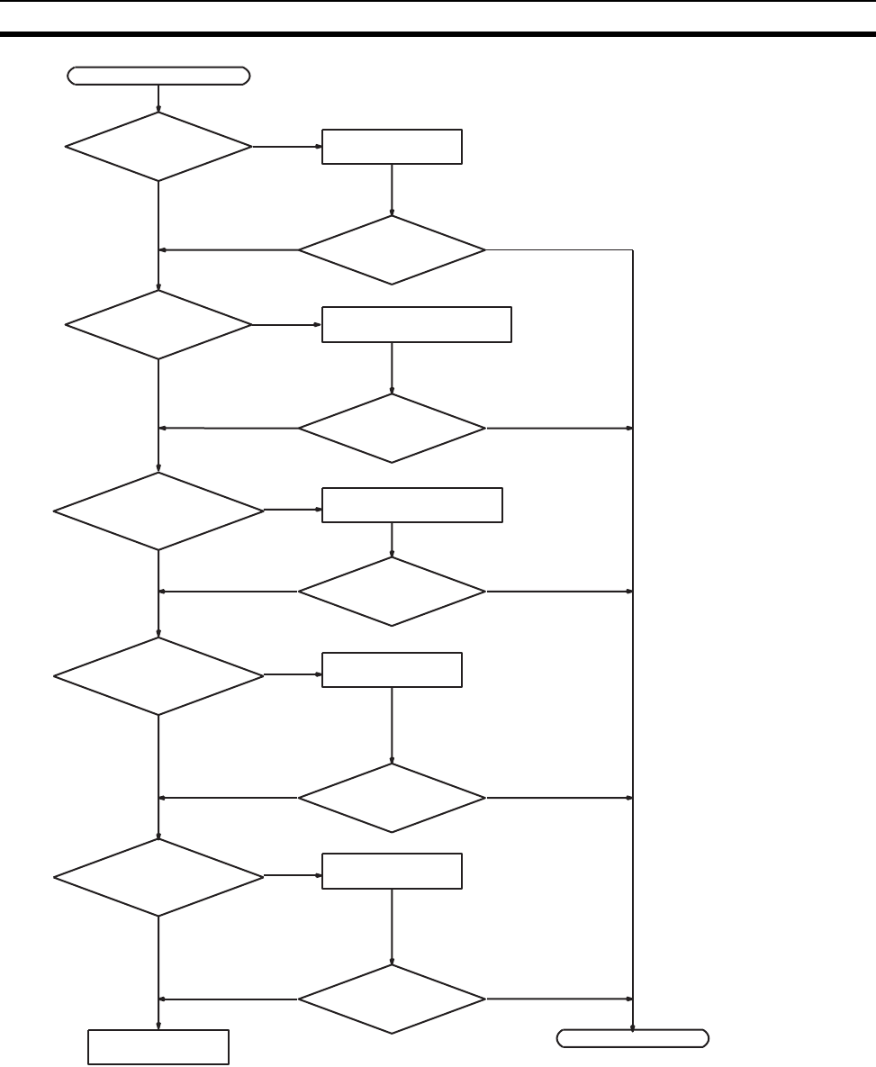
547
Error Processing Section 11-2
Power indicator not lit.
Replace the Power
Supply Unit.
Is power being
supplied?
Is voltage selector
set correctly?
Power supply
voltage in acceptable
range?
Connect power
supply.
Is Power indicator lit?
100 to 120 V AC: Shorted
200 to 240 V AC: Open
Is Power indicator lit?
Set supply voltage with
in acceptable limits.
End
Ye s
No
Not lit Lit
Ye s
No
No
Not lit Is Power indicator lit? Lit
No
Ye s
Ye s
Tighten screws or
replace wires.
No
Not lit Is Power indicator lit? Lit
Ye s
Note Always remove the short
jumper before supplying 200
to 240 V AC. The Power Sup-
ply Unit will be destroyed if
200 to 240 V AC is supply
with the jumper connected.
Are the 24-V DC
terminals shorted ex-
ternally?
Wire the 24-V DC
terminals correctly.
No
Not lit Is Power indicator lit? Lit
Ye s
C200H-PA204S only.
Are there any loose
terminal screws or bro-
ken wires?
C200HW-PA204S,
C200HW-PA209R only.
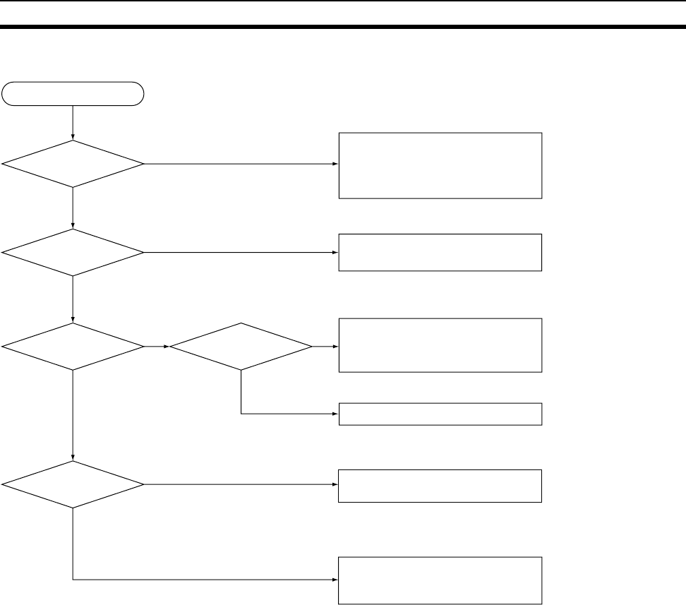
548
Error Processing Section 11-2
11-2-7 Memory Error Check
ON
OFF
ON
OFF
Memory error occurred.
A40309
(autotransfer at
startup error)
ON?
A40310 (flash
memory error)
ON?
Battery connected?
Power
turned OFF during
backup (with BKUP
lit)?
Battery-free
operation
necessary?
Conditions have not been met for
automatic transfer at startup. Confirm
that the required files are on the
Memory Card and the pin 2 on the DIP
switch is OFF.
The write life of the flash memory has
been exceeded. Replace the CPU Unit.
Check to see if battery-free operation has
been set correctly. Retransfer the user
program and parameters and set the PLC
Setup so that battery errors are not detected.
Mount a Battery.
If power was turned OFF during the backup
operation, retransfer the user program and
parameters.
A hardware fault has occurred in
internal memory. Replace the CPU
Unit.
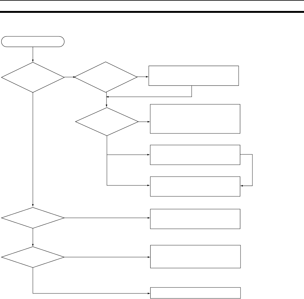
549
Error Processing Section 11-2
11-2-8 Program Error Check
ON
OFF
ON
OFF
ON
OFF
#FFFF
YES
NO
Program error occurred.
A29512 (Task
Error Flag) ON?
A29511 (No END
Flag) ON?
A29508 to A29510
(instruction error
flags) ON?
What is the
value of Task Number
when Program Stopped
(A294)?
An active task does not exist. Check
the usage of TKON(820) and
TKOF(821).
An attempt was made to start a task that
doesn’t exist. Check the MSKS(690)
instruction used to enable the interrupt task
of the specified number.
An attempt was made to start the task of the
specified number with an interrupt. Check
the Inner Board or CPU Bus Unit.
There is no END(001) in the task
that stopped the program (A294).
Add END(001).
The program was stopped for the PLC
Setup setting to stop the program for
instruction errors. Check the program
based on the task (A294) and address
(A298 and A299) that stopped the program.
Turn the power supply OFF and then back
ON again.
#8002, #8003,
#8064 to #8083
Not related
to problem.
Power OFF
interrupt task enabled
in PLC setup?
Not applicable.
Make sure that a power OFF
interrupt task has been created.
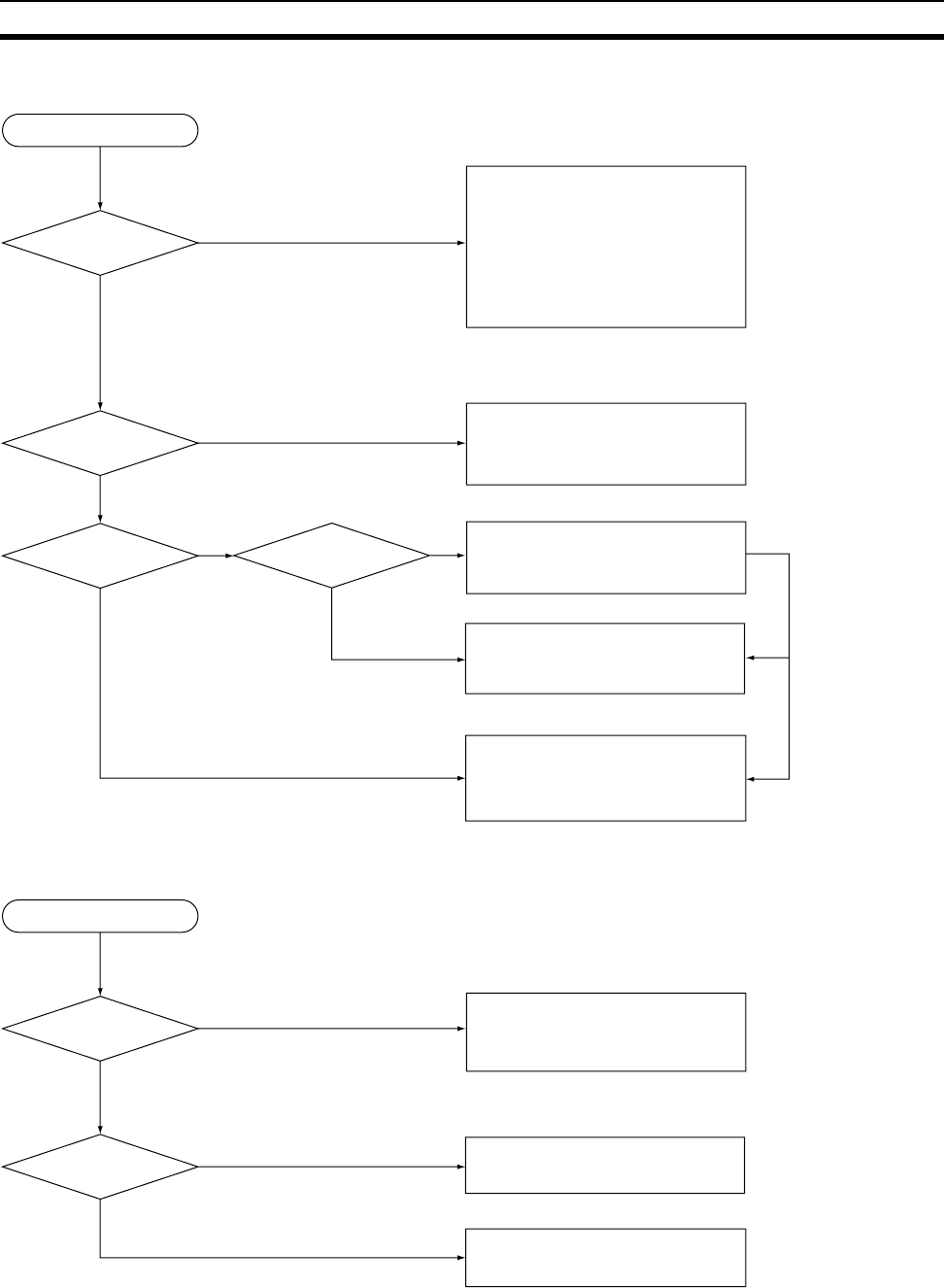
550
Error Processing Section 11-2
11-2-9 Cycle Time Too Long Error Check
11-2-10 PLC Setup Setting Error Check
ON
OFF
ON
OFF
The cycle time was too long.
A40515 (Peripheral
Servicing Cycle Too
Long) ON?
Anticipated cycle time
less than PLC Setup
monitor setting?
Interrupts being
used?
A440
(Maximum Interrupt
Processing Time) value
acceptable?
The peripheral servicing cycle time
exceeded 2 s. Reduce the event load
or set the CPU processing mode in
the PLC Setup to Normal Mode or
Peripheral Servicing Priority Mode.
The Parallel Processing Modes may
not function properly if the program
execution cycle time (A266) is too
short (less than 2 ms.)
The monitoring time was execution
time was exceed for program
execution. Increase the monitoring
time set in the PLC Setup.
The problem may be caused by long
processing times for interrupt tasks. Check
the contents of the task specified in A441
(Task with Highest Processing Time).
There may be more than one interrupt
task occurring, causing the cycle time
to be increased. Reduce the
frequency of interrupts.
There may be a bug in the program. Check
all tasks for the following instructions.
FOR and LOOP
J M P, C J P, a n d C P N
Ye s
No
Ye s
No
Ye s
No
Not related to
problem.
#00DC(220)
PLC Setup setting error occurred.
Value of A406
(location of setting
error)?
PLC Setup written
from Programming
Console?
The CPU processing mode is set to
Peripheral Servicing Priority Mode, but
the priorities have not been set
correctly.
The setting indicated by the contents
of A406 is illegal. Check the setting
from a Programming Console.
A communications error may have occurred
during data transfer from the CX-
Programmer. Retransfer the PLC Setup.
Ye s
No
Other
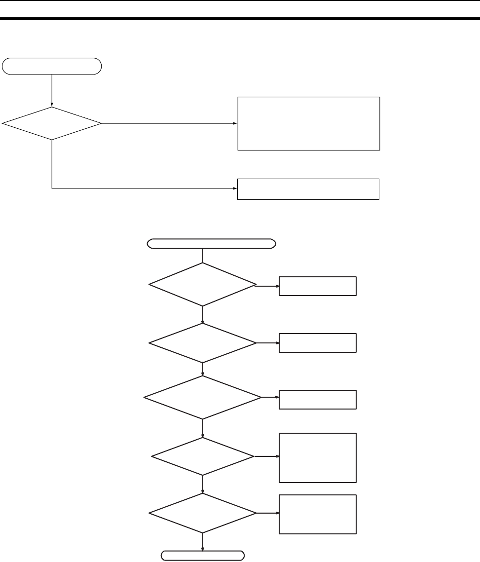
551
Error Processing Section 11-2
11-2-11 Battery Error Check
11-2-12 Environmental Conditions Check
Note Check for corrosive gases, flammable gases, dust, dirt, salts, metal dust,
direct light, water, oils, and chemicals.
Battery error occurred.
Battery-free operation
required?
Set the PLC Setup so that battery
errors are not detected. (DM Area
contents may be unstable when this
setting is used.)
Refer to the CS/CJ Programming
Manual for details.
The Battery is missing or the voltage
has dropped. Replace the Battery.
Ye s
No
Consider using a
fan or cooler.
Environmental conditions check
Is the ambient
temperature
below 55°C?
Is the ambient
temperature above
0°C?
Is noise being
controlled?
Is the installation
environment okay?
Consider using a
heater.
Consider using an
an air conditioner.
Install surge pro-
tectors or other
noise-reducing
equipment at
noise sources.
Check the struc-
ture of the panel
and the installa-
tion site.
End.
Ye s
No
Ye s
No
No
No
No
Ye s
Ye s
Ye s
Is the ambient humidity
between 10% and
90%?
(See note.)
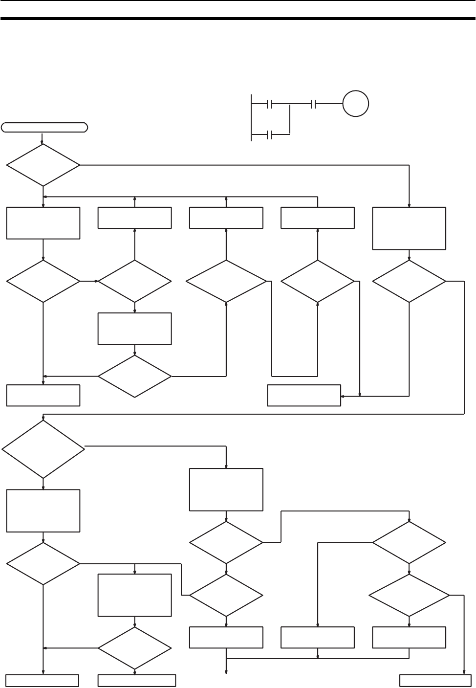
552
Error Processing Section 11-2
11-2-13 I/O Check
The I/O check flowchart is based on the following ladder diagram section
assuming that SOL1 does not turn ON.
Return to START
NORMAL
Indicators of
inputs (000002,
000003) normal?
Check terminal
voltage of 000500
with tester
Indicator of
000500 normal?
YES
Correct wiring Replace terminal
block connector Replace fuse Monitor ON/OFF
status of 000500
with Programming
Device
NO YES YES
Voltage normal?
NORMAL
Output
wiring correct?
YES
Is the
blown fuse indi-
cator lit? Operation OK?
NORMAL
Check output de-
vice SOL1
NORMAL ABNORMAL
Replace Output
Unit
Check terminal
voltages of 000002
and 000003 with
tester
Check terminal
voltages of 000002
and 000003 with
tester
Input
wiring correct?
NO
Correctly wire
Remove external
wiring and mount
Dummy Input Unit
to check
Operation OK?
Check LS1 and LS2
Terminal
screws loose?
NO
Faulty
terminal block
connector con-
tact?
YES
Replace terminal
block connector
Tighten
Replace Input Unit
Replace Input Unit
NO NO ABNORMA
L
NO
YES
ABNORMAL
NORMAL
ABNORMAL
ABNORMAL
NORMAL
YES
NO
YES
(Units with
internal
fuse)
ABNORMAL
NO
Voltage normal?
Voltage normal?
Voltage normal?
START
000500
000002
(LS1)
000003
(LS2)
SOL1
000500
Faulty
terminal block
connector con-
tact?
Disconnect external
wiring and check ter-
minal voltage of
000500 with tester
(Unit with-
out fuse)
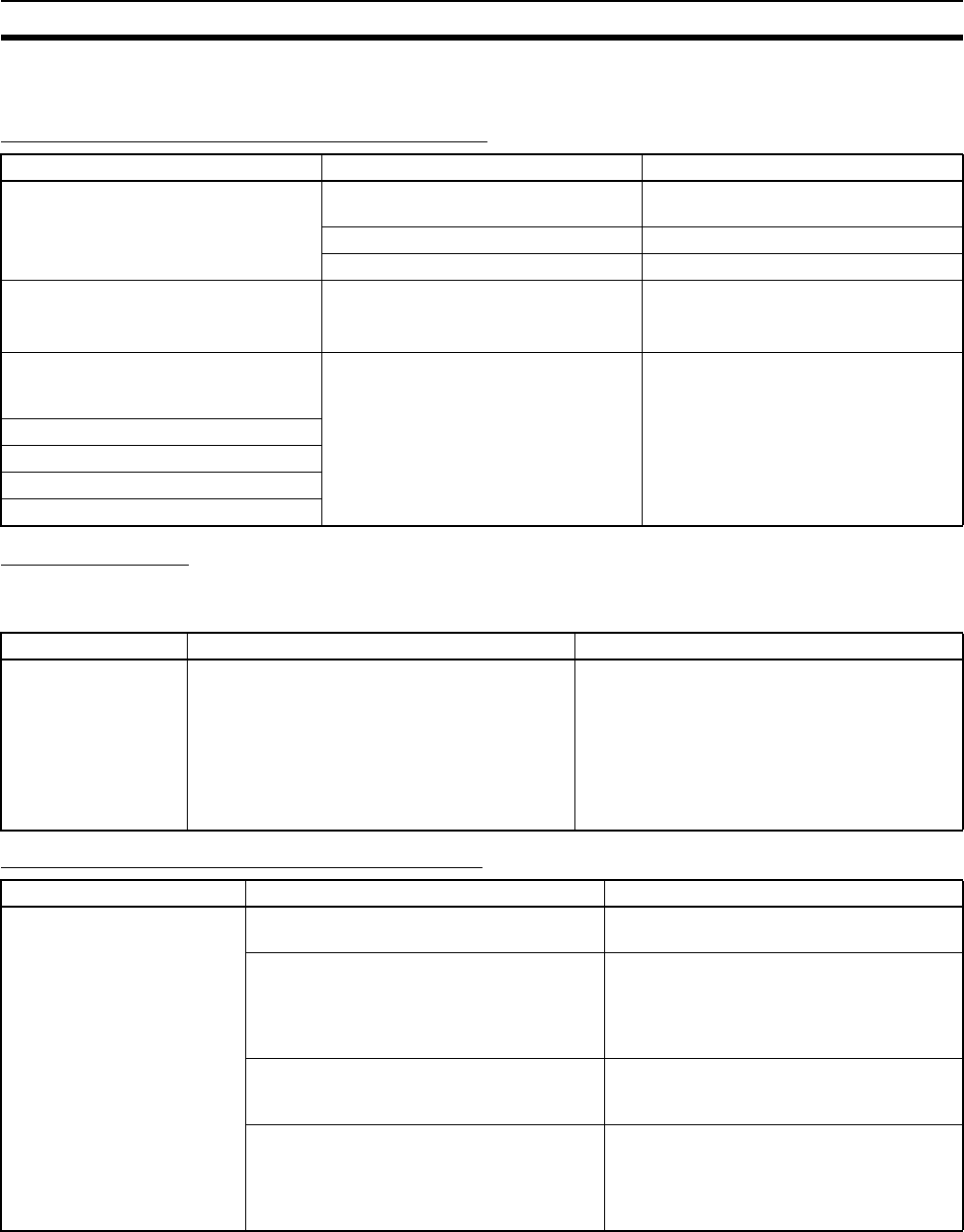
553
Troubleshooting Racks and Units Section 11-3
11-3 Troubleshooting Racks and Units
CPU Racks and Standard Expansion Racks
Special I/O Units
Refer to the Operation Manual for the Special I/O Unit to troubleshoot any
other errors.
CS-series Long-distance Expansion Racks
Symptom Cause Remedy
POWER indicator is not lit. PCB short-circuited or damaged. Replace Power Supply Unit or Back-
plane.
(1) Error in program. Correct program.
(2) Power line is faulty. Replace Power Supply Unit.
RUN output* does not turn ON.
RUN indicator lit.
(*C200HW-PS204R/209R)
Internal circuitry of Power Supply Unit
is faulty.
Replace Power Supply Unit.
Serial Communications Unit or CS-
series CPU Bus Unit does not operate
or malfunctions.
(1) The I/O Connecting Cable is faulty.
(2) The I/O bus is faulty.
Replace the I/O Connecting Cable
Replace the Backplane.
Bits do not operate past a certain point.
Error occurs in units of 8 points.
I/O bit turns ON.
All bits in one Unit do not turn ON.
Symptom Cause Remedy
The ERH and RUN
indicators on the Spe-
cial I/O Unit are lit.
I/O refreshing is not being performed for the
Unit from the CPU Unit (CPU Unit monitoring
error).
It’s possible that cyclic refreshing has been dis-
abled for the Special I/O Unit in the Cyclic
Refresh Disable Setting in the PLC Setup (i.e.,
the bit corresponding to the unit number has
been set to 1).
Change the bit corresponding to the unit num-
ber to 0 to enable cyclic refreshing, or make
sure that the Unit is refreshed from the program
using IORF at least once every 11 s.
Symptom Cause Remedy
CPU Unit won’t operate. (No
response to Programming
Devices and no CPU Unit
indicators are lit.)
(1) Power is not turned ON to an Expansion
Rack.
Turn ON power to all Expansion Racks.
(2) An Expansion Rack is not connected
correctly.
Recheck the connections and configuration
using information in 2-3-3 Expansion Racks,
3-5-4 I/O Control Units, I/O Interface Units,
and Terminators, and 5-2-7 I/O Connecting
Cables.
(3) An I/O Connecting Cable is not wired
correctly.
Reconnect the I/O Connecting Cables in the
correct order for output and input connec-
tors.
(4) A Unit is faulty. Gradually remove/replace Units to deter-
mine the Unit that is faulty, including the
Backplane, Power Supply Unit, I/O Units,
I/O Control/Interface Unit, and I/O Connect-
ing Cable.

554
Troubleshooting Racks and Units Section 11-3
Input Units
Expansion Rack not
detected.
(1) A Terminator is not connected. If the TERM indicator is lit, connect a Termi-
nator.
(2) An Expansion Rack is not connected
correctly.
Recheck the connections and configuration
using information in 2-3-3 Expansion Racks,
3-5-4 I/O Control Units, I/O Interface Units,
and Terminators, and 5-2-7 I/O Connecting
Cables.
(3) A Unit is faulty. Gradually remove/replace Units to deter-
mine the Unit that is faulty, including the
Backplane, Power Supply Unit, I/O Units,
I/O Control/Interface Unit, and I/O Connect-
ing Cable.
I/O bus error or I/O verifica-
tion error occurs.
(1) An I/O Connecting Cable or Terminator
connection is faulty.
Check that I/O Connecting Cables and Ter-
minators are connected correctly.
(2) Expansion cable is not wired correctly Rewire the terminals using the correct OUT-
IN sequence.
(3) Noise or other external factor. Separate all cables from possible sources of
noise or place them in metal ducts.
(4) A Unit is faulty. Gradually remove/replace Units to deter-
mine the Unit that is faulty, including the
Backplane, Power Supply Unit, I/O Units,
I/O Control/Interface Unit, and I/O Connect-
ing Cable.
Cycle time is too long. (1) A CPU Bus Unit that is allocated many
words (e.g., Controller Link Unit) is
mounted to a CS-series Long-distance
Expansion Rack.
Move the CPU Bus Unit to the CPU Rack.
(2) A Unit is faulty. Gradually remove/replace Units to deter-
mine the Unit that is faulty, including the
Backplane, Power Supply Unit, I/O Units,
I/O Control/Interface Unit, and I/O Connect-
ing Cable.
I/O Control Unit and I/O Inter-
face Units do not appear on
CX-Programmer I/O table.
This is not an error. These Units are not allo-
cated I/O words and thus are not registered
in the I/O tables.
---
Symptom Cause Remedy
Not all inputs turn ON or indi-
cators are not lit.
(1) Power is not supplied to Input Unit. Supply power
(2) Supply voltage is low. Adjust supply voltage to within rated range.
(3) Terminal block mounting screws are
loose.
Tighten screws.
(4) Faulty contact of terminal block connec-
tor.
Replace terminal block connector.
Not all inputs turn ON (indica-
tor lit).
Input circuit is faulty. (There is a short at the
load or something else that caused an over-
current to flow.)
Replace Unit.
Not all inputs turn OFF. Input circuit is faulty. Replace Unit.
Specific bit does not turn ON. (1) Input device is faulty. Replace input devices.
(2) Input wiring disconnected. Check input wiring.
(3) Terminal block screws are loose. Tighten screws.
(4) Faulty terminal block connector contact. Replace terminal block connector.
(5) Too short ON time of external input. Adjust input device.
(6) Faulty input circuit Replace Unit.
(7) Input bit number is used for output
instruction.
Correct program.
Symptom Cause Remedy

555
Troubleshooting Racks and Units Section 11-3
Output Units
Specific bit does not turn
OFF.
(1) Input circuit is faulty. Replace Unit.
(2) Input bit number is used for output
instruction.
Correct program.
Input irregularly turns
ON/OFF.
(1) External input voltage is low or unstable. Adjust external input voltage to within rated
range.
(2) Malfunction due to noise. Take protective measures against noise,
such as:
(1) Increase input response time (PLC
Setup)
(2) Install surge suppressor.
(3) Install insulation transformer.
(4) Install shielded cables between the Input
Unit and the loads.
(3) Terminal block screws are loose. Tighten screws.
(4) Faulty terminal block connector contact. Replace terminal block connector.
Error occurs in units of
8 points or 16 points, i.e., for
the same common.
(1) Common terminal screws are loose. Tighten screws.
(2) Faulty terminal block connector contact. Replace terminal block connector.
(3) Faulty data bus Replace Unit.
(4) Faulty CPU Replace CPU.
Input indicator is not lit in nor-
mal operation.
Faulty indicator or indicator circuit. Replace Unit.
Symptom Cause Remedy
Not all outputs turn ON (1) Load is not supplied with power. Supply power
(2) Load voltage is low. Adjust voltage to within rated range.
(3) Terminal block screws are loose. Tighten screws.
(4) Faulty terminal block connector contact. Replace terminal block connector.
(5) An overcurrent (possibly caused by a
short at the load) resulted in a blown
fuse in the Output Unit. (Some Output
Units provide an indicator for blown
fuses.)
Replace fuse or Unit.
(6) Faulty I/O bus connector contact. Replace Unit.
(7) Output circuit is faulty. Replace Unit.
(8) If the INH indicator is lit, the Output OFF
Bit (A50015) is ON.
Turn A50015 OFF.
Not all outputs turn OFF Output circuit is faulty. Replace Unit.
Output of a specific bit num-
ber does not turn ON or indi-
cator is not lit.
(1) Output ON time too short because of a
mistake in programming.
Correct program to increase the time that
the output is ON.
(2) Bit status controlled by multiple instruc-
tions.
Correct program so that each output bit is
controlled by only one instruction.
(3) Faulty output circuit. Replace Unit.
Output of a specific bit num-
ber does not turn ON (indica-
tor lit).
(1) Faulty output device. Replace output device.
(2) Break in output wiring. Check output wiring.
(3) Loose terminal block screws. Tighten screws.
(4) Faulty terminal block connector faulty. Replace terminal block connector.
(5) Faulty output bit. Replace relay or Unit.
(6) Faulty output circuit. Replace Unit.
Output of a specific bit num-
ber does not turn OFF (indi-
cator is not lit).
(1) Faulty output bit. Replace relay or Unit.
(2) Bit does not turn OFF due to leakage
current or residual voltage.
Replace external load or add dummy resis-
tor.
Symptom Cause Remedy

556
Troubleshooting Racks and Units Section 11-3
Output of a specific bit num-
ber does not turn OFF (indi-
cator lit).
(1) Bit status controlled by multiple instruc-
tions.
Correct program.
(2) Faulty output circuit. Replace Unit.
Output irregularly turns
ON/OFF.
(1) Low or unstable load voltage. Adjust load voltage to within rated range
(2) Bit status controlled by multiple instruc-
tions.
Correct program so that each output bit is
controlled by only one instruction.
(3) Malfunction due to noise. Protective measures against noise:
(1) Install surge suppressor.
(2) Install insulation transformer.
(3) Use shielded cables between the Output
Unit and the loads.
(4) Terminal block screws are loose. Tighten screws.
(5) Faulty terminal block connector contact. Replace terminal block connector.
Error occurs in units of
8 points or 16 points, i.e., for
the same common.
(1) Loose common terminal screw. Tighten screws.
(2) Faulty terminal block connector contact. Replace terminal block connector.
(3) An overcurrent (possibly caused by a
short at the load) resulted in a blown
fuse in the Output Unit.
Replace fuse or Unit.
(4) Faulty data bus. Replace Unit.
(5) Faulty CPU. Replace CPU.
Output indicator is not lit
(operation is normal).
Faulty indicator. Replace Unit.
Symptom Cause Remedy
557
SECTION 12
Inspection and Maintenance
This section provides inspection and maintenance information.
12-1 Inspections . . . . . . . . . . . . . . . . . . . . . . . . . . . . . . . . . . . . . . . . . . . . . . . . . . . 558
12-1-1 Inspection Points. . . . . . . . . . . . . . . . . . . . . . . . . . . . . . . . . . . . . . . . 558
12-1-2 Unit Replacement Precautions . . . . . . . . . . . . . . . . . . . . . . . . . . . . . 559
12-2 Replacing User-serviceable Parts . . . . . . . . . . . . . . . . . . . . . . . . . . . . . . . . . . 560
12-2-1 Battery Replacement. . . . . . . . . . . . . . . . . . . . . . . . . . . . . . . . . . . . . 560
12-2-2 Output Unit Fuse Replacement. . . . . . . . . . . . . . . . . . . . . . . . . . . . . 565
12-2-3 Relay Replacement . . . . . . . . . . . . . . . . . . . . . . . . . . . . . . . . . . . . . . 567

558
Inspections Section 12-1
12-1 Inspections
Daily or periodic inspections are required in order to maintain the PLC’s func-
tions in peak operating condition.
12-1-1 Inspection Points
Although the major electronic components in CS-series PLCs have an
extremely long life time, they can deteriorate under improper environmental
conditions. Periodic inspections are thus required to ensure that the required
conditions are being kept.
Inspection is recommended at least once every six months to a year, but more
frequent inspections will be necessary in adverse environments.
Take immediate steps to correct the situation if any of the conditions in the fol-
lowing table are not met.
Inspection Points
No. Item Inspection Criteria Action
1 Source Power
Supply
Check for voltage fluctuations
at the power supply terminals.
The voltage must be within
the allowable voltage fluctu-
ation range.
(See note.)
Use a voltage tester to check the
power supply at the terminals. Take
necessary steps to bring voltage
fluctuations within limits.
2 I/O Power Sup-
ply
Check for voltage fluctuations
at the I/O terminals.
Voltages must be within
specifications for each Unit.
Use a voltage tester to check the
power supply at the terminals. Take
necessary steps to bring voltage
fluctuations within limits.
3 Ambient environ-
ment
Check the ambient tempera-
ture. (Inside the control panel
if the PLC is in a control
panel.)
0 to 55°C Use a thermometer to check the
temperature and ensure that the
ambient temperature remains
within the allowed range of 0 to
55°C.
Check the ambient humidity.
(Inside the control panel if the
PLC is in a control panel.)
Relative humidity must be
10% to 90% with no con-
densation.
Use a hygrometer to check the
humidity and ensure that the ambi-
ent humidity remains within the
allowed range.
Check that the PLC is not in
direct sunlight.
Not in direct sunlight Protect the PLC if necessary.
Check for accumulation of
dirt, dust, salt, metal filings,
etc.
No accumulation Clean and protect the PLC if neces-
sary.
Check for water, oil, or chemi-
cal sprays hitting the PLC.
No spray on the PLC Clean and protect the PLC if neces-
sary.
Check for corrosive or flam-
mable gases in the area of the
PLC.
No corrosive or flammable
gases
Check by smell or use a sensor.
Check the level of vibration or
shock.
Vibration and shock must
be within specifications.
Install cushioning or shock absorb-
ing equipment if necessary.
Check for noise sources near
the PLC.
No significant noise
sources
Either separate the PLC and noise
source or protect the PLC.
4 Installation and
wiring
Check that each Unit is
installed securely.
No looseness Tighten loose screws with a Phil-
lips-head screwdriver.
Check that cable connectors
are fully inserted and locked.
No looseness Correct any improperly installed
connectors.
Check for loose screws in
external wiring.
No looseness Tighten loose screws with a Phil-
lips-head screwdriver.
Check crimp connectors in
external wiring.
Adequate spacing between
connectors
Check visually and adjust if neces-
sary.
Check for damaged external
wiring cables.
No damage Check visually and replace cables if
necessary.
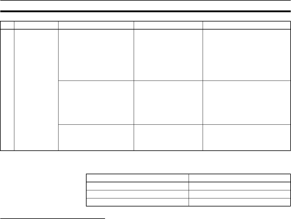
559
Inspections Section 12-1
Note The following table shows the allowable voltage fluctuation ranges for source
power supplies.
Tools Required for Inspections
Required Tools
• Slotted and Phillips-head screwdrivers
• Voltage tester or digital voltmeter
• Industrial alcohol and clean cotton cloth
Tools Required Occasionally
• Synchroscope
• Oscilloscope with pen plotter
• Thermometer and hygrometer (humidity meter)
12-1-2 Unit Replacement Precautions
Check the following after replacing any faulty Unit.
• Do not replace a Unit until the power is turned OFF.
• Check the new Unit to make sure that there are no errors.
• If a faulty Unit is being returned for repair, describe the problem in as
much detail as possible, enclose this description with the Unit, and return
the Unit to your OMRON representative.
• For poor contact, take a clean cotton cloth, soak the cloth in industrial
alcohol, and carefully wipe the contacts clean. Be sure to remove any lint
prior to remounting the Unit.
Note 1. When replacing a CPU Unit, be sure that not only the user program but
also all other data required for operation is transferred to or set in the new
CPU Unit before starting operation, including DM Area and HR Area set-
tings. If data area and other data are not correct for the user program, un-
5 User-service-
able parts
Check whether internal relays
in Relay Output Units have
reached their service life.
No open relay contacts,
improper operation, or
faulty contacts
Refer to Appendix A Speci-
fications of Basic I/O Units
and High-density I/O Units
for information on relay ser-
vice life.
Replace the relay or Unit.
Check whether the CS1W-
BAT01 Battery has reached its
service life.
Life expectancy is 5 years
at 25°C, less at higher tem-
peratures.
(From 0.4 to 5 years
depending on model,
power supply rate, and
ambient temperature.)
Replace the battery when its ser-
vice life has passed even if a bat-
tery error has not occurred.
(Battery life depends upon the
model, the percentage of time in
service, and ambient conditions.)
Check for blown fuses. Preventative maintenance Even if the fuses are not blown,
they should be replace periodically
because they are weakened by
inrush currents.
Supply voltage Allowable voltage range
100 to 120 V AC 85 to 132 V AC
200 to 240 V AC 170 to 264 V AC
24 V DC 19.2 to 28.8 V DC
No. Item Inspection Criteria Action

560
Replacing User-serviceable Parts Section 12-2
expected accidents may occur. Be sure to include the routing tables,
Controller Link Unit data link tables, network parameters, and other CPU
Bus Unit data, which are stored as parameters in the CPU Unit. Refer to
the CPU Bus Unit and Special I/O Unit operation manuals for details on the
data required by each Unit.
2. The simple backup operation can be used to store the user program and
all parameters for the CS1-H CPU Unit, DeviceNet Units, Serial Commu-
nications Units, and other specific Units in a Memory Card as backup files.
A Memory Card and the simple backup operation can be used to easily re-
store data after replacing any of these Units. Refer to the CS/CJ Series
Programming Manual (W394) for details.
12-2 Replacing User-serviceable Parts
The following parts should be replaced periodically as preventative mainte-
nance. The procedures for replacing these parts are described later in this
section.
• Battery (the CPU Unit’s RAM-backup battery)
• Output Unit fuses (in Transistor Output and Triac Output Units)
• Output Unit relays (in Relay Output Units)
12-2-1 Battery Replacement
Battery Functions
The battery retains the following data of the CPU Unit’s RAM when the main
power supply is OFF.
• Retained regions of I/O memory (such as the Holding Area and DM Area)
If the battery is not installed or battery voltage drops too low, the clock will
stop and the data in RAM will not be stable when the main power supply turns
OFF.
Battery Service Life and Replacement Period
At 25°C, the maximum service life for batteries is 5 years whether or not
power is supplied to the CPU Unit while the battery is installed. The battery’s
lifetime will be shorter when it is used at higher temperatures and when power
is not supplied to the CPU Unit for long periods.
The following table shows minimum lifetimes and typical lifetimes for the
backup batterys.
Note The minimum lifetime is the memory backup time at an ambient temperature
of 55°C. The typical lifetime is the memory backup time at an ambient temper-
ature of 25°C.
Model Approx.
maximum lifetime
Approx. minimum
lifetime (See note.)
Typical lifetime
(See note.)
CS1H-CPU@@H 5 years 15,000 hours (1.7
years)
43,000 hours (5
years)
CS1G-CPU@@H 5 years 18,000 hours (2.1
years)
43,000 hours (5
years)
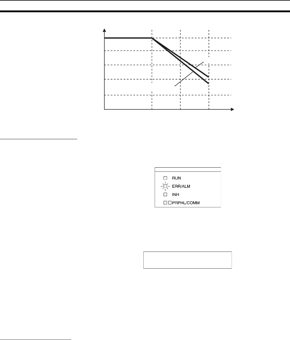
561
Replacing User-serviceable Parts Section 12-2
Low Battery Indicators
If the PLC Setup has been set to detect a low-battery error, the ERR/ALM
indicator on the front of the CPU Unit will flash when the CPU Unit detects that
the battery is nearly discharged.
When the ERR/ALM indicator flashes, connect the CX-Programmer to the
peripheral port and read the error message. If the message “BATT LOW”
appears on the Programming Console* and the Battery Error Flag (A40204) is
ON*, first check whether the battery is properly connected to the CPU Unit. If
the battery is properly connected, replace the battery as soon as possible.
Once a low-battery error has been detected, the battery will fail in 5 days. Bat-
tery failure can be delayed by ensuring that the CPU Unit power is not turned
OFF until the battery has been replaced.
Note *The PLC Setup must be set to detect a low-battery error (Detect Low Bat-
tery). If this setting has not been made, the BATT LOW error message will not
appear on the Programming Console and the Battery Error Flag (A40204) will
not go ON when the battery fails.
Replacement Battery
The battery replacement method depends the CPU Unit’s unit version.
!Caution We recommend replacing the battery with the power OFF to prevent the CPU
Unit’s sensitive internal components from being damaged by static electricity.
The battery can be replaced with the power ON, but be sure to touch a
grounded metal object to discharge any static electricity before replacing the
battery. After replacing the battery, connect a Programming Device and clear
the battery error.
Memory Backup Time
5 yr
4 yr
3 yr
2 yr
1 yr
Ambient temperature
25°C40°C55°C
CS1H-CPU@@H
CS1G-CPU@@H
This
g
ra
p
hic is for reference onl
y
BATT LOW

562
Replacing User-serviceable Parts Section 12-2
Unit Versions and Corresponding Battery Replacement Methods
Note The replacement time indicates the time required to install a new battery after
turning OFF the power (25°C). If the CPU Unit is without a battery for a longer
period of time, data will not be stable.
Replacement Procedure for CS1-H CPU Units (Pre-Ver. 2.0 and Ver. 2.0) with One Battery Connector
Use the following procedure to replace a battery that has been completely dis-
charged.
1,2,3... 1. Turn OFF the power to the CPU Unit. (If the power was already OFF, turn
the power ON for at least one minute before turning the power OFF again.)
Note There is a capacitor in the CPU Unit that will back up memory while the bat-
tery is being replaced. If this capacitor is not completely charged by turning
ON the power supply for one minute, data will not be stable during battery
replacement.
2. Insert a small flat-blade screwdriver into the notch at the bottom of the bat-
tery compartment cover and lift open the cover.
3. Disconnect the connector under the cover of the CPU Unit, remove the old
battery from the compartment, and replace the battery with a new one.
Note Complete the battery replacement procedure (at an ambient temperature of
25°C) within three minutes of turning OFF the power supply. If more than
three minutes elapse without a battery installed in the CPU Unit, data will not
be stable during battery replacement.
Replacement Procedure for CS1-H (Ver. 3.0) CPU Units with Two Battery Connectors
Use the following procedure to replace a battery that has been completely dis-
charged.
When replacing a battery with the power OFF, connect the new battery while
the old battery is in place. Remove the old battery after connecting the new
battery. (There are two pairs of identical connectors for the battery. The old
battery will not be charged even if the new battery is connected at the same
time.)
1,2,3... 1. Turn OFF the power to the CPU Unit. (If the power was already OFF, turn
the power ON for at least ten seconds before turning the power OFF
again.)
2. Insert a small flat-blade screwdriver into the notch at the bottom of the bat-
tery compartment cover and lift open the cover.
Type Unit version Number of
battery
connectors
Replacement
time (see note)
Replacement method
CS1-H CPU Units Pre-Ver. 2.0 1 3 min. Refer to Replacement Procedure
for CS1-H CPU Units (Pre-Ver. 2.0
and Ver. 2.0) with One Battery
Connector.
Unit Ver. 2.0
Unit Ver. 3.0 2 3 min. Refer to Replacement Procedure
for CS1-H (Ver. 3.0) CPU Units
with Two Battery Connectors.
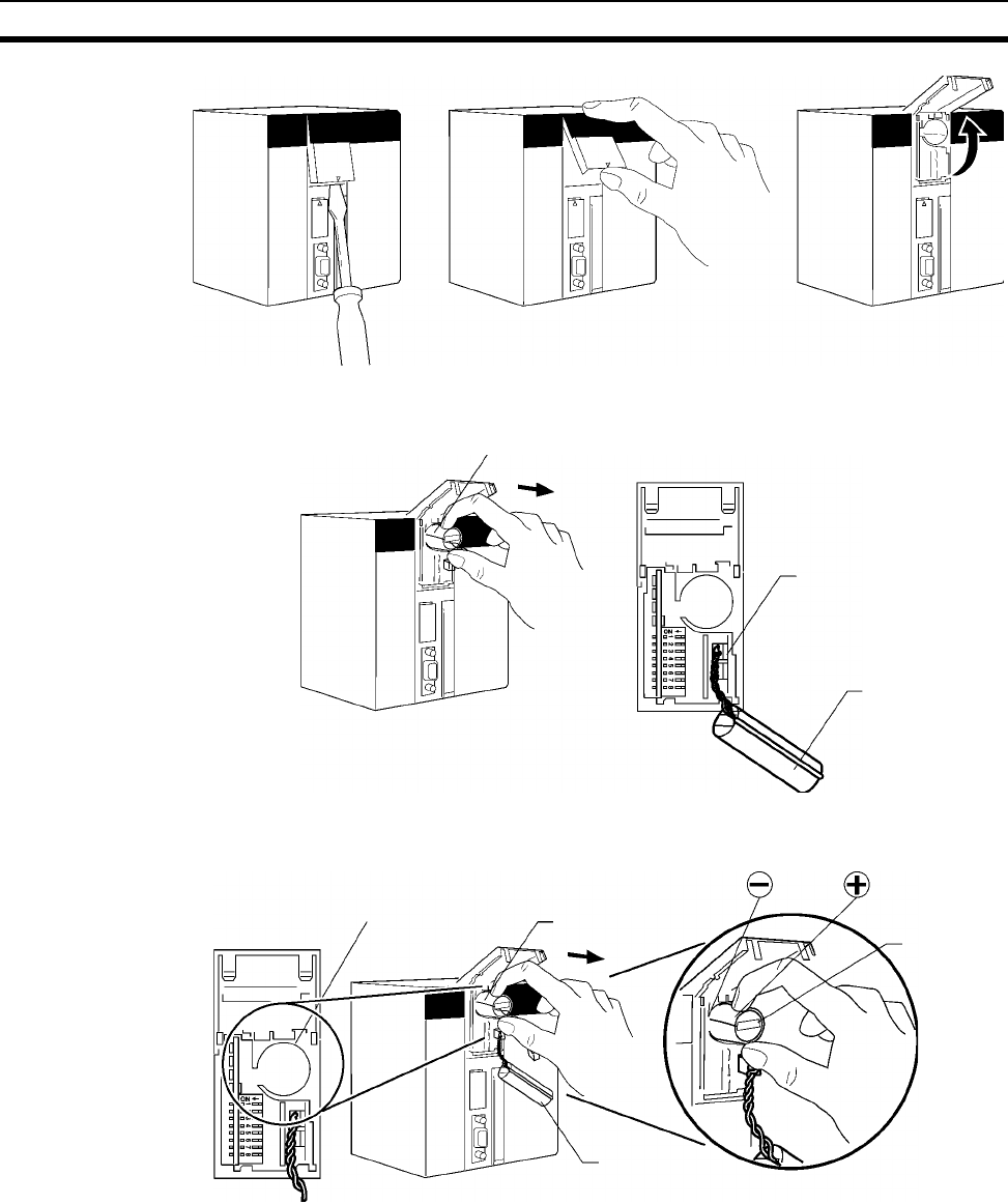
563
Replacing User-serviceable Parts Section 12-2
3. Remove the old battery from the compartment, but leave its connector con-
nected.
4. Insert the new battery into the battery compartment with the cable and
connector facing outward.
5. With the old battery connected, insert the new battery’s connector in the
open connector in the CPU Unit. Be sure that the connector is inserted so
that its red wire is at the top and the white wire is at the bottom.
Old battery
Leave connected.
Old battery
Battery compartment New battery
Old battery
New battery
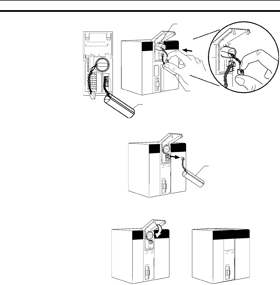
564
Replacing User-serviceable Parts Section 12-2
6. Remove the old battery’s connector.
7. Push the new battery’s wire into the battery compartment and close the
cover.
8. Connect a Programming Device and verify that the Battery Error has been
cleared.
Note 1. If the above procedure is not used and the old battery is disconnected with
the power ON (power ON and no battery connected), memory will still be
backed up. However, be sure to touch a grounded metal object to dis-
charge any static electricity before replacing the battery.
2. With CPU Units that have two battery connectors, leave the old battery at-
tached while connecting the new battery. This prevents a battery error oc-
curring during battery replacement. Remove the old battery after the new
battery is connected.
!Caution With a CS1-H CPU Unit, do not short the battery terminals or charge, disas-
semble, heat, or incinerate the battery. Do not subject the battery to strong
shocks. Doing any of these may result in leakage, rupture, heat generation, or
ignition of the battery.
Old battery
New battery
Old battery
Old battery
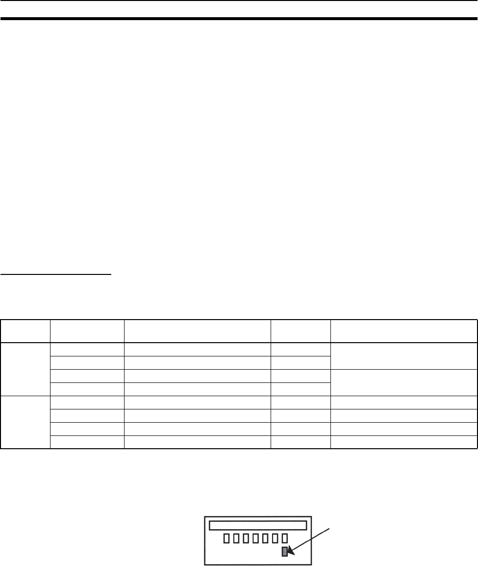
565
Replacing User-serviceable Parts Section 12-2
!Caution Dispose of any battery that has been dropped on the floor or otherwise sub-
jected to excessive shock. Batteries that have been subjected to shock may
leak if they are used.
!Caution Do not allow unqualified persons to replace batteries. UL standards required
that batteries be replaced only by experienced technicians.
!Caution Turn ON the power after replacing the battery for a CPU Unit that has been
unused for a long time. Leaving the CPU Unit unused again without turning
ON the power even once after the battery is replaced may result in a shorter
battery life.
12-2-2 Output Unit Fuse Replacement
The following Transistor and Triac Output Units contain one fuse for each
common. For the C200H-OD411/OD213/OD221/OA223 Units which have a
blown-fuse (F) indicator, replace the fuse if the fuse indicator lights. For the
C200H-OD211/OD212/OA222V/OA224 Units which do not have blown-fuse
indicators, check the fuses if outputs are not produced.
Replacement Fuses
The Output Units are supplied with one spare fuse in the back of each Unit; if
two or more fuses need to be replaced, use replacement fuses which meet
the specifications shown in the following table.
Note The C200H-OD411/OD213/OD221/OA223 Output Units have a blown-fuse
(F) indicator at the location shown in the following diagram. When a fuse
blows in one of these Units, the blown-fuse indicator will light and bit 8 of the
word allocated to the Unit will be turned ON.
Replacement Procedure
1,2,3... 1. Turn OFF the power to the PLC.
2. Remove the terminal block by unlocking the lock levers at the top and bot-
tom of the terminal block. The terminal block can be removed without dis-
connecting the wiring.
Unit type Model Unit specifications Blown-fuse
indicators*
Fuse specifications
Transistor
Output
C200H-OD411 8 outputs, 1 A, 12 to 48 V DC Yes 125 V, 5 A (5.2 mm × 20 mm)
C200H-OD211 12 outputs, 0.3 A, 24 V DC No
C200H-OD212 16 outputs, 0.3 A, 24 V DC No 125 V, 8 A (5.2 mm × 20 mm)
C200H-OD213 8 outputs, 2.1 A, 24 V DC Yes
Tr i a c O u t -
put
C200H-OA221 8 outputs, 1 A, 250 V AC max. Yes 250 V, 5 A (5.2 mm × 20 mm)
C200H-OA222V 12 outputs, 0.3 A, 250 V AC max. No 250 V, 3 A (5.2 mm × 20 mm)
C200H-OA223 8 outputs, 1.2 A, 250 V AC max. Yes 250 V, 5 A (5.2 mm × 20 mm)
C200H-OA224 12 outputs, 0.5 A, 250 V AC max. No 250 V, 3.15 A (5.2 mm × 20 mm)
The "F" indicator lights
when the fuse blows.
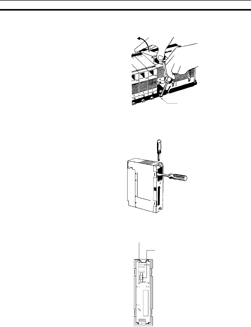
566
Replacing User-serviceable Parts Section 12-2
3. Remove the Output Unit. Push down the lock lever on the Backplane with
a screwdriver and lift the Unit out as shown below.
4. Use a Phillips-head screwdriver to remove the screws from the top and
bottom of the Unit.
5. Use a slotted screwdriver to detach the case from the Unit.
6. Pull out the printed circuit board.
7. Insert a new fuse. A spare fuse is provided inside the rear of the case when
the Unit is delivered.
8. Reverse the steps above to reassemble the Unit.
Lock lever
(4)
(5)
Rear of the case
Spare fuse
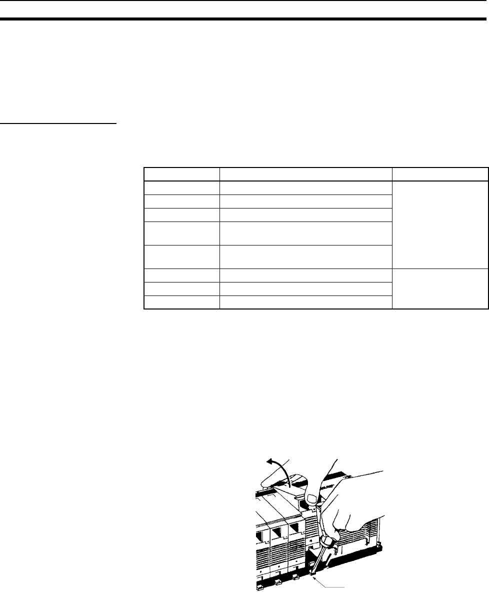
567
Replacing User-serviceable Parts Section 12-2
12-2-3 Relay Replacement
A Relay Output Unit’s relay is probably faulty if one of the Unit’s outputs
remains ON or OFF regardless of the execution of output instructions in the
program. Replace a relay if it remains ON or OFF or if the Unit’s contact is oth-
erwise faulty.
Replacement Relays
The following Output Units are equipped with relay sockets that allow the
Relays to be replaced if they should go bad. Use the Relay listed in the follow-
ing table.
Note Relays cannot be replaced for the C200H-OC222N/OC226N/OC224N or the
CS1W-OC201/OC211.
Replacement Procedure
1,2,3... 1. Turn OFF the power to the PLC.
2. Remove the terminal block by unlocking the lock levers at the top and bot-
tom of the terminal block. The terminal block can be removed without dis-
connecting the wiring.
3. Remove the Output Unit. Push down the lock lever on the Backplane with
a screwdriver and lift the Unit out as shown below.
4. Use a Phillips-head screwdriver to remove the screws from the top and
bottom of the Unit.
Model Unit specifications Replacement Relay
C200H-OC221 8 outputs, 2 A, 250 V AC/24 V DC max. G6B-1174P-FD-US-M
24 V DC
C200H-OC222 12 outputs, 2 A, 250 V AC/24 V DC max.
C200H-OC225 16 outputs, 2 A, 250 V AC/24 V DC max.
C200H-OC223 5 outputs, 2 A, 250 V AC/24 V DC max.
(independent commons)
C200H-OC224 8 outputs, 2 A, 250 V AC/24 V DC max.
(independent commons)
C200H-OC222V 12 outputs, 2 A, 250 V AC/24 V DC max. G6R-1, 24 V DC
C200H-OC226 16 outputs, 2 A, 250 V AC/24 V DC max.
C200H-OC224V 8 outputs, 2 A, 250 V AC/24 V DC max.
Lock lever
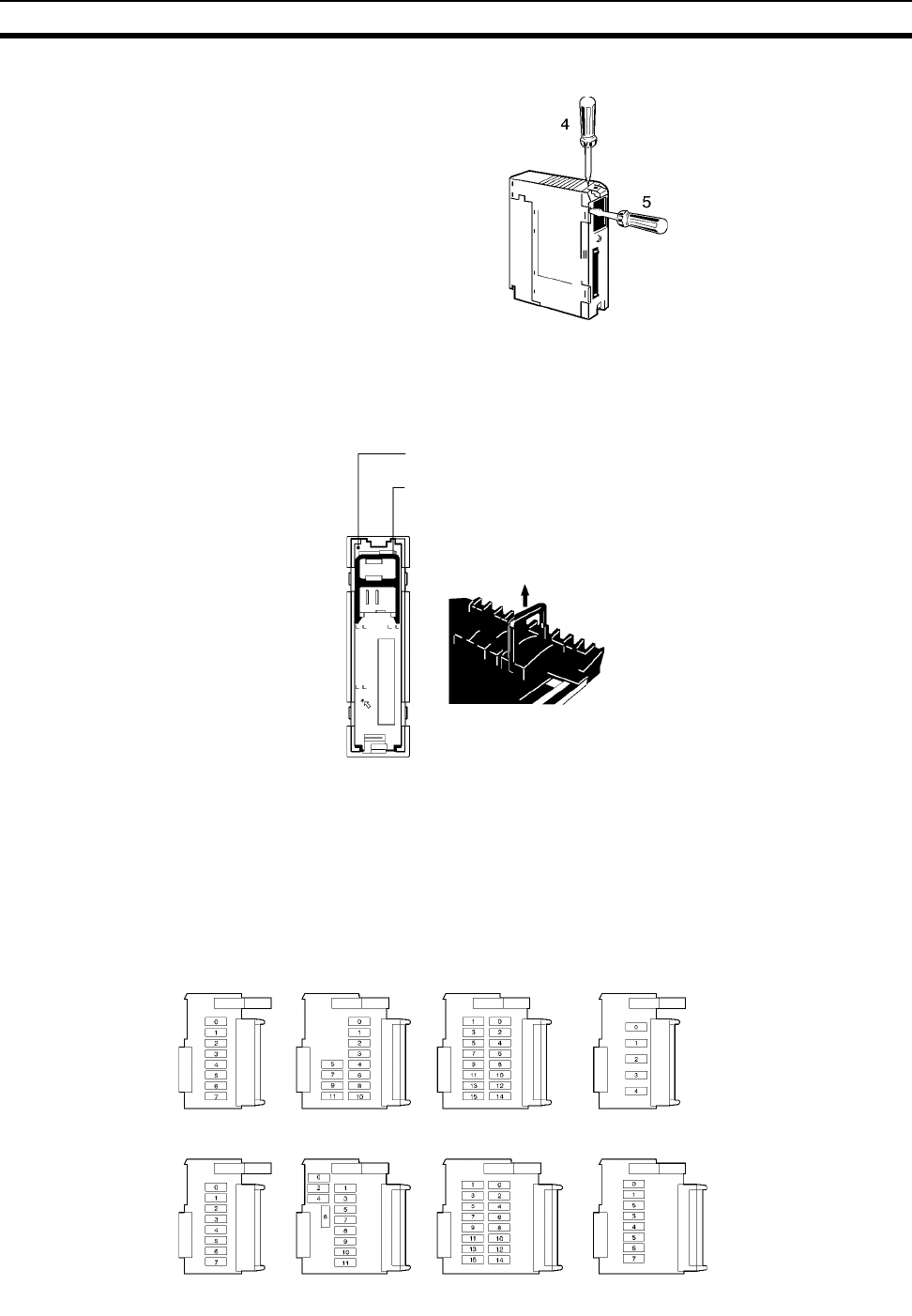
568
Replacing User-serviceable Parts Section 12-2
5. Use a slotted screwdriver to detach the case from the Unit.
6. Pull out the printed circuit board.
7. Replace the faulty Relay with a new one. Use the Relay puller provided in-
side the rear of the case when the Unit is delivered. Relays for the C200H-
OC222V/OC224V/OC226 can be replaced with the P6B-Y1 Relay Puller.
8. Reassemble the Unit by reversing the above procedure and mount it to the
Backplane.
Note 1. Use the P6B-Y1 Relay Puller (sold separately) to remove Relays.
2. Check the pin arrangement before inserting a new Relay into the socket.
Pins can only be inserted one way, so do not try to force them if they do not
go in easily. Applying too much force can bend the pins and render the Re-
lay unusable.
Rear of case
Relay Puller
Grasp the faulty Relay with the
Relay Puller and pull it out.
OC221 OC222 OC225 OC223*
OC224* OC222V OC226 OC224V*
*The Relay Output Units marked with an asterisk have independent commons.

569
Appendix A
Specifications of Basic I/O Units and
High-density I/O Units
Input Units
Category Name Specifications Model Page
C200H/CS-series
Basic Input Units
with Terminal
Blocks
AC Input Units 100 to 120V AC/V DC, 16 inputs,
50/60 Hz
CS1W-IA111 572
100 to 120V AC, 8 inputs, 50/60 Hz C200H-IA121 574
100 to 120V AC, 16 inputs, 50/60 Hz C200H-IA122 575
C200H-IA122V
200 to 240V AC, 8 inputs C200H-IA221 576
200 to 240V AC, 16 inputs C200H-IA222 578
C200H-IA222V
CS1W-IA211 577
AC/DC Input Units 12 to 24 V AC/V DC, 8 inputs C200H-IM211 579
24 V AC/V DC, 16 inputs C200H-IM212 580
DC Input Units 12 to 24 V DC, 8 inputs C200H-ID211 581
12 to 24 V DC, 16 inputs C200H-ID212 582
24 V DC, 16 inputs CS1W-ID211 583
Interrupt Input Units 24 V DC, 16 inputs CS1W-INT01 584
12 to 24 V DC, 8 inputs C200HS-INT01 585
High-speed Input
Unit
24 V DC, 16 inputs CS1W-IDP01 586
CS-series Basic
Input Units with
Connectors
C200H Group-2
High-density Input
Units
DC Input Units 24 V DC, 32 inputs CS1W-ID231 587
C200H-ID216 589
C200H-ID218 590
12 V DC, 64 inputs C200H-ID111 591
24 V DC, 64 inputs CS1W-ID261 593
C200H-ID217 595
C200H-ID219 596
24 V DC, 96 inputs CS1W-ID291 598
Simultaneously ON 24-V DC inputs for
CS1W-ID291/MD291/MD292
600

570
Specifications of Basic I/O Units and High-density I/O Units Appendix A
Output Units
Category Name Specifications Model Page
C200H/CS-
series Basic
Outputs Units
with Terminal
Blocks
Relay Output
Units
250V AC/24V DC, 2 A; 120 V DC, 0.1 A; indepen-
dent contacts, 8 outputs
CS1W-OC201 (See
note.)
602
250V AC/24V DC, 2 A; 120 V DC, 0.1 A; 16 outputs CS1W-OC211 601
250V AC/24V DC, 2 A, independent contacts, 5 out-
puts
C200H-OC223 603
250 V AC/24 V DC, 2 A, independent contacts, 8 out-
puts
C200H-OC224 604
C200H-OC224V/224N 605
250V AC/24V DC, 2 A, 8 outputs C200H-OC221 606
250V AC/24V DC, 2 A, 12 outputs C200H-OC222 607
C200H-OC222V/222N 608
250V AC/24V DC, 2 A, 16 outputs C200H-OC225 609
C200H-OC226/226N 610
Relay contact outputs 612
Triac Output
Units
250 V AC, 1.2 A, with fuse burnout detection circuit,
8 outputs
CS1W-OA201 (See
note.)
619
250 V AC, 1 A, with fuse burnout detection circuit,
8 outputs
C200H-OA221 615
250 V AC, 1.2 A, with fuse burnout detection circuit,
8 outputs
C200H-OA223 616
250 V AC, 0.3 A, 12 outputs C200H-OA222V 617
250 V AC, 0.5 A, 12 outputs C200H-OA224 618
250 V AC, 0.5 A, 16 outputs CS1W-OA211 614
Transistor Out-
put Units, sink-
ing outputs
24 V DC, 2.1 A, 8 outputs C200H-OD213 620
12 to 48 V DC, 1A, 8 outputs C200H-OD411 621
24 V DC, 0.3 A, 12 outputs C200H-OD211 622
24 V DC, 0.3 A, 16 outputs C200H-OD212 623
12 to 24 V DC, 0.5 A, 16 outputs CS1W-OD211 624
Transistor Out-
put Units, sink-
ing
12 to 24 V DC, 0.5 A, 32 outputs CS1W-OD231 625
4.5 V DC/16 mA to 26.4 V/100mA, with fuse burnout
detection circuit, 32 outputs
C200H-OD218 626
12 to 24 V DC, 0.3 A, 64 outputs CS1W-OD261 629
4.5 V DC/16 mA to 26.4 V/100mA, 64 outputs C200H-OD219 630
12 to 24 V DC, 0.1 A, with fuse burnout detection cir-
cuit, 96 outputs
CS1W-OD291 634
Transistor Out-
put Units,
sourcing out-
puts
24 V DC, 0.8 A, load short-circuit protection,
8 outputs.
C200H-OD214 635
5 to 24 V DC, 0.3 A, 8 outputs C200H-OD216 638
5 to 24 V DC, 0.3 A, 12 outputs C200H-OD217 639
24 V DC, 0.5 A, load short-circuit protection,
16 outputs
CS1W-OD212 640
Load short-circuit protection for
CS1W-OD212/OD232/OD262/MD262 and C200H-OD21B
641
24 V DC, 1 A, load short-circuit protection,
16 outputs.
C200H-OD21A 643
24 V DC, 0.5 A, load short-circuit protection,
32 outputs
CS1W-OD232 645
24 V DC, 0.5 A, 32 outputs, sourcing outputs, load
short-circuit protection
C200H-OD21B 646
24 V DC, 0.3 A, load short-circuit protection,
64 outputs
CS1W-OD262 648
24 V DC, with fuse burnout detection circuit, 0.1 A,
96 outputs
CS1W-OD292 649
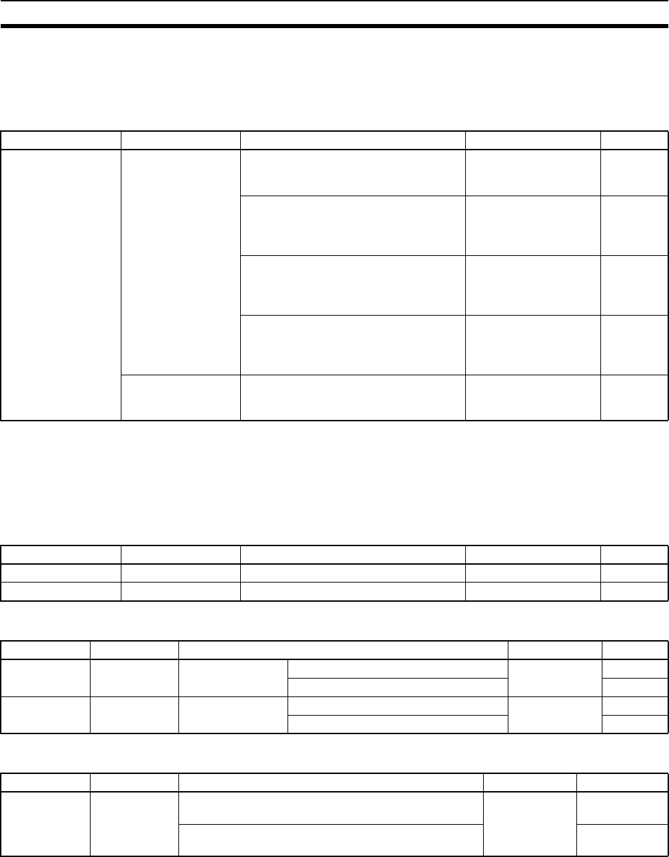
571
Specifications of Basic I/O Units and High-density I/O Units Appendix A
Note This Unit uses only 8 bits for external I/O even though 16 bits (1 word) are allocated. This Unit is also
treated as a 16-point Unit in the I/O tables.
Mixed I/O Units
Note For details on the connectors included with the Unit, refer to the information provided under Accessories
in the tables for Basic I/O Units in the following pages.
Special I/O Units
High-density Input Units
High-density Output Units
Mixed I/O Units
Category Name Specifications Model Page
CS-series Basic I/O
Units with Connec-
tors
DC Input/Transistor
Output Units
24 V DC inputs;
12 to 24 V DC, 0.3-A, sinking outputs;
32 inputs, 32 outputs
CS1W-MD261 652
24 V DC inputs;
12 to 24 V DC, 0.1A, sinking outputs
with fuse burnout detection circuit;
48 inputs, 48 outputs
CS1W-MD291 654
24 V DC inputs
24 V DC, 0.3 A, sourcing outputs with
load short-circuit protection;
32 inputs, 32 outputs
CS1W-MD262 657
24 V DC inputs
24 V DC, 0.1 A, sourcing outputs with
fuse burnout detection circuit;
48 inputs, 48 outputs
CS1W-MD292 659
TTL I/O Unit 5 V DC, 3.5 mA inputs;
5 V DC, 35 mA, outputs;
32 inputs, 32 outputs
CS1W-MD561 662
Category Name Specifications Model Page
TTL Input Units TTL Input Unit 5 V DC, static input mode, 32 inputs C200H-ID501 664
DC Input Units DC Input Unit 24 V DC, static input mode, 32 inputs C200H-ID215 665
Category Name Specifications Model Page
TTL Output
Units
TTL Output
Units
5 V DC, 35 mA Static output mode, 32 outputs C200H-OD501 666
Dynamic output mode, 128 outputs 668
Transistor Out-
put Units
Transistor Out-
put Units
4.5 V DC, 16 mA
to 26.4 V, 100 mA
Static output mode, 32 outputs C200H-OD215 670
Dynamic output mode, 128 outputs 672
Category Name Specifications Model Page
TTL I/O Units TTL I/O Units Static input mode: 5 V DC inputs; 5 V DC, 35 mA out-
puts; 16 inputs, 16 outputs
C200H-MD501 675
Dynamic output mode: 5 V DC, 35 mA outputs;
128 outputs
677
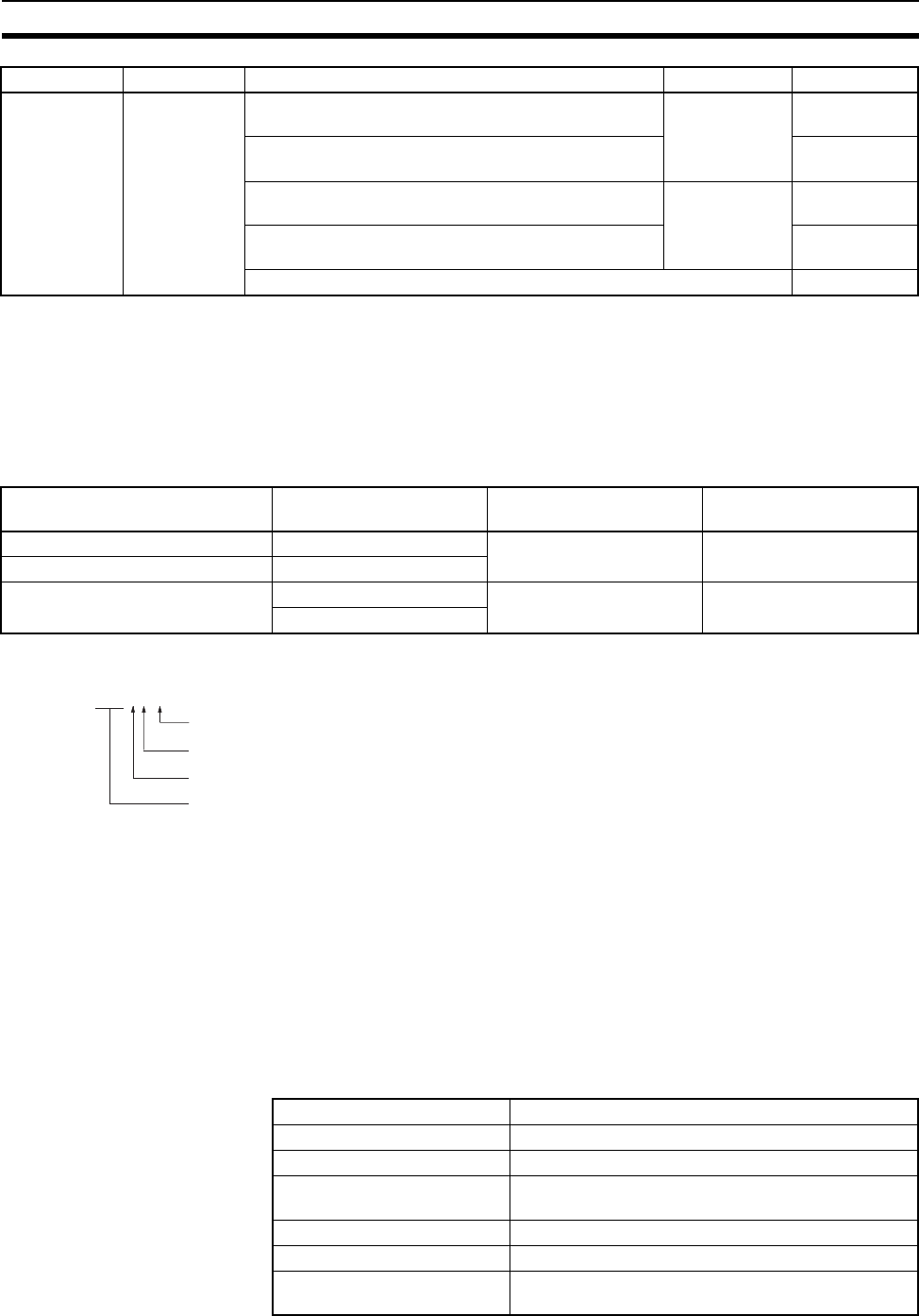
572
Specifications of Basic I/O Units and High-density I/O Units Appendix A
Specifications Changes for Transistor Output Units
Some of the specifications of the following Units with transistor outputs have been improved.
Output elements have been changed from NPN to field-effect transistors (FET). Part of the circuit configuration
has been changed. There are no changes in performance characteristics as a result of these improvements,
but care is required in connecting the polarity of the load power supply. Outputs will not operate dependably if
the polarity is reversed. check the manufacturing number on your Unit before wiring.
Manufacturing Numbers
The following figures and tables provide specifications for Basic I/O Units and High-density I/O Units. Refer to
Section SECTION 3 Nomenclature, Functions, and Dimensions for dimensions.
Reading Terminal Connection Diagrams
• I/O terminals in terminal connection diagrams are shown as viewed from the front panel of the Unit.
• Terminal numbers A0 to A9 and B0 to B9 are used in this manual, but they are not printed on all Units.
• A0 to A20 and B0 to B20 are printed on the Units.
Basic I/O Units
CS1W-IA111 100-V AC Input Unit (16 Points)
DC Input/Tran-
sistor Output
Units
DC Input/Tran-
sistor Output
Units
Static input mode: 12 V DC inputs; 4.5 V DC, 16 mA to
26.4 V 100 mA outputs, 16 inputs, 16 outputs
C200H-MD115 679
Dynamic output mode: 12 V DC, 50 mA outputs;
128 outputs
682
Static input mode: 24 V DC inputs, 24 V DC 16 mA to
26.4 V 100 mA outputs; 16 inputs, 16 outputs
C200H-MD215 684
Dynamic output mode: 24 V DC, 100 mA outputs;
128 outputs
686
Maximum switching capacity of C200H-MD115/MD215 688
Name Model Date of change Manufacturing number
(See below.)
Transistor Output Unit C200H-OD215 Manufactured on or after
November 30, 1999
30Y9 or later
DC Input/Transistor Output Unit C200H-MD215
Transistor Output Units C200H-OD218 Manufactured on or after
January 31, 2000
3110 or later
C200H-OD219
Rated Input Voltage 100 to 120 V AC (50/60 Hz), 100 to 120 V DC
Operating Input Voltage 85 to 132 V AC (50/60 Hz), 85 to 132 V DC
Input Impedance 10 kΩ (50 Hz), 8 kΩ (60 Hz), 69 kΩ (DC)
Input Current 10 mA typical (at 100 V AC), 1.5 mA typical
(at 100 V DC)
ON Voltage 65 V AC min., 75 V DC min.
OFF Voltage 20 V AC max., 25 V DC max.
ON Response Time 18 ms max. when PLC Setup on default setting
(8 ms) (See note.)
Category Name Specifications Model Page
@@Z9@
Year: Last digit of calendar year; e.g., 1999→9, 2000→0
Month: 1 to 9 (January to September), X (October), Y (November), Z (December)
Day: 01 to 31
Factory code (A to Z or blank)
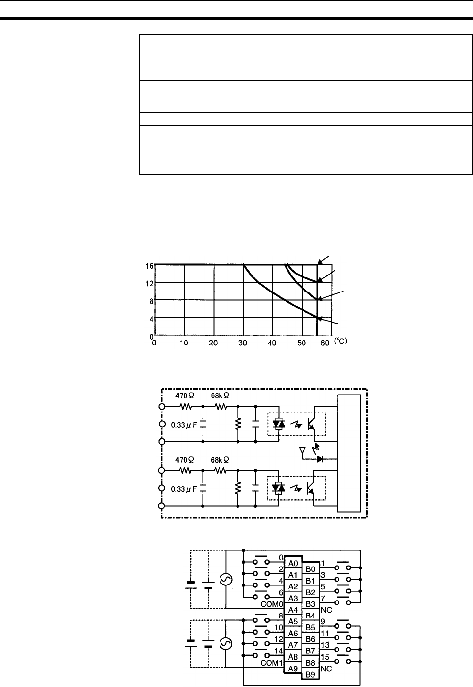
573
Specifications of Basic I/O Units and High-density I/O Units Appendix A
Note The Input ON and OFF response times for Basic I/O Units can be set to 0 ms, 0.5 ms, 1 ms, 2 ms, 4 ms,
8 ms, 16 ms, or 32 ms in the PLC Setup. When the response times have been set to 0 ms, the ON
response time will be 10 ms maximum and the OFF response time will be 40 ms maximum due to inter-
nal element delays.
Number of Inputs ON Simultaneously
Circuit Layout
Terminal Connections
OFF Response Time 63 ms max. when PLC Setup on default setting
(8 ms) (See note.)
Insulation Resistance 20 MΩ between external terminals and the GR termi-
nal (500 V DC)
Dielectric Strength 2,000 V AC between the external terminals and the
GR terminal for 1 minute at a leakage current of
10 mA max.
No. of Circuits 2 (each 8 points/common)
Number of Inputs ON Simulta-
neously
100% simultaneously ON (for 110 V AC, 120 V DC)
Refer to the diagram below.
Internal Current Consumption 110 mA 5 V DC max.
Weight 260 g max.
Ambient temperature
110 V AC, 120 V DC
120 V AC
132 V DC
132 V AC
No. of inputs
ON simulta-
neously
IN0
to
IN7
COM0
IN8
to
IN15
COM1
Input indicator
Internal circuits
2.2 kΩ
2.2 kΩ
100 to 120
V AC/V DC
100 to 120
V AC/V DC
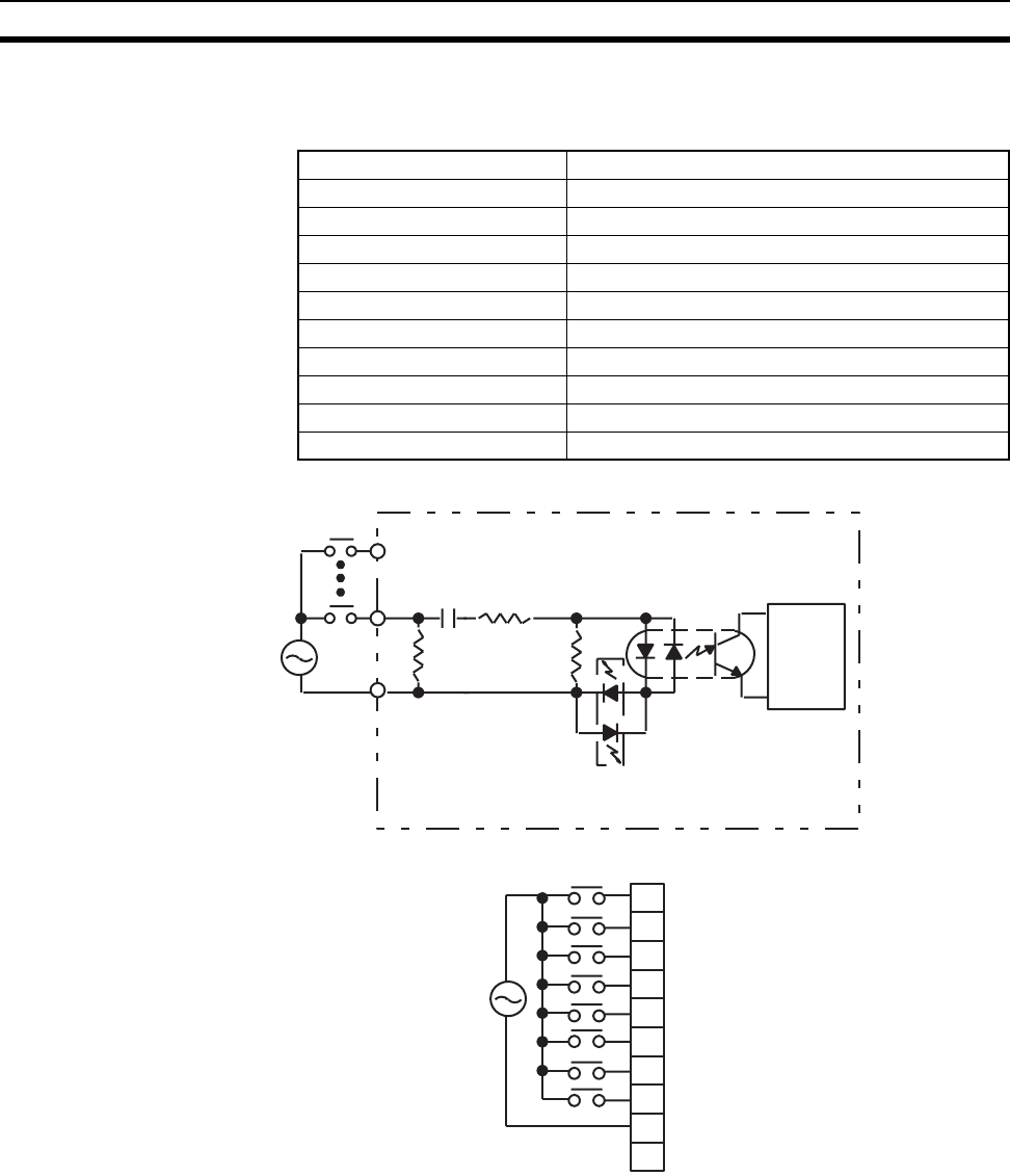
574
Specifications of Basic I/O Units and High-density I/O Units Appendix A
Note Terminal numbers A0 to A9 and B0 to B9 are used in this manual, but they are not printed on the Unit.
C200H-IA121 AC Input Unit (8 Points)
Circuit Configuration
Terminal Connections
Rated Input Voltage 100 to 120 V AC (50/60 Hz)
Operating Input Voltage 85 to 132 V AC (50/60 Hz)
Input Impedance 9.7 kΩ (50 Hz), 8 kΩ (60 Hz)
Input Current 10 mA typical (at 100 V AC)
ON Voltage 60 V AC min.
OFF Voltage 20 V AC max.
ON Response Time 35 ms max. (at 100 V AC, 25°C)
OFF Response Time 55 ms max. (at 100 V AC, 25°C)
No. of Circuits 1 (8 points/common)
Internal Current Consumption 10 mA 5 V DC max.
Weight 250 g max.
IN
IN
COM
Internal
circuits
100 to
120 V AC
470 Ω
Input indicator
0.33 µF
330 kΩ
910 Ω
COM
A0
A1
A2
A3
A4
A5
A6
A7
A8
A9
0
1
2
3
4
5
6
7
NC
100 to
120 V AC
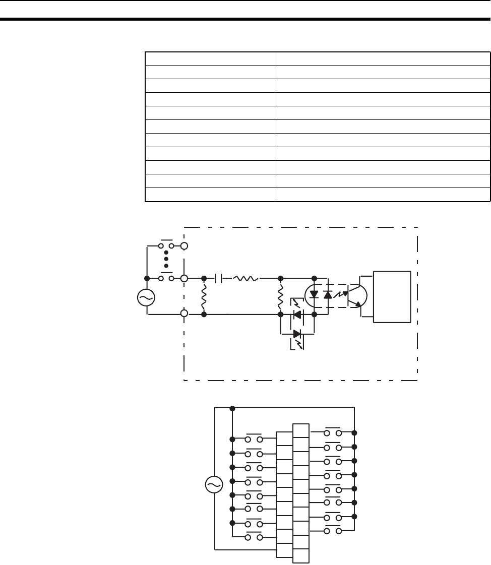
575
Specifications of Basic I/O Units and High-density I/O Units Appendix A
C200H-IA122/IA122V AC Input Unit (16 Points)
Circuit Configuration
Terminal Connections
Rated Input Voltage 100 to 120 V AC (50/60 Hz)
Operating Input Voltage 85 to 132 V AC (50/60 Hz)
Input Impedance 9.7 kΩ (50 Hz), 8 kΩ (60 Hz)
Input Current 10 mA typical (at 100 V AC)
ON Voltage 60 V AC min.
OFF Voltage 20 V AC max.
ON Response Time 35 ms max. (at 100 V AC, 25°C)
OFF Response Time 55 ms max. (at 100 V AC, 25°C)
No. of Circuits 1 (16 points/common)
Internal Current Consumption 10 mA 5 V DC max.
Weight 300 g max./400 g max. (IA122V)
IN
IN
COM
Internal
circuits
100 to
120 V AC
470 Ω
Input indicator
0.33 µF
330 kΩ
910 Ω
A0
A1
A2
A3
A4
A5
A6
A7
A8
B0
B1
B2
B3
B4
B5
B6
B7
B8
B9
COM
1
3
5
7
9
11
13
15
NC
0
2
4
6
8
10
12
14
NC
100 to
120 V AC
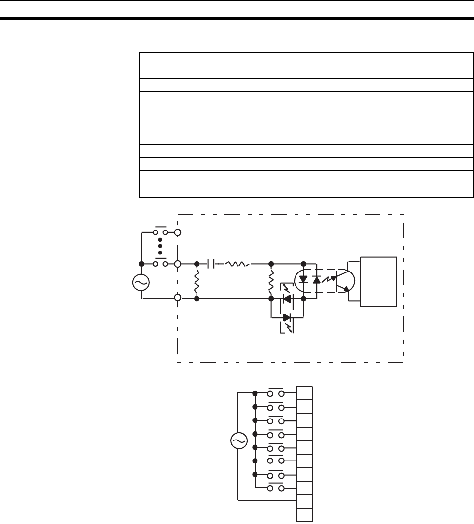
576
Specifications of Basic I/O Units and High-density I/O Units Appendix A
C200H-IA221 AC Input Unit (8 Points)
Circuit Configuration
Terminal Connections
Rated Input Voltage 200 to 240 V AC (50/60 Hz)
Operating Input Voltage 170 to 264 V AC (50/60 Hz)
Input Impedance 21 kΩ (50 Hz), 18 kΩ (60 Hz)
Input Current 10 mA typical (at 200 V AC)
ON Voltage 120 V AC min.
OFF Voltage 40 V AC max.
ON Response Time 35 ms max. (at 200 V AC, 25°C)
OFF Response Time 55 ms max. (at 200 V AC, 25°C)
No. of Circuits 1 (8 points/common)
Internal Current Consumption 10 mA 5 V DC max.
Weight 250 g max.
IN
IN
COM
Internal
circuits
200 to
240 V AC
Input indicator
820 Ω 0.15 µ F
680 kΩ
910 Ω
COM
A0
A1
A2
A3
A4
A5
A6
A7
A8
A9
0
1
2
3
4
5
6
7
NC
200 to
240 V AC
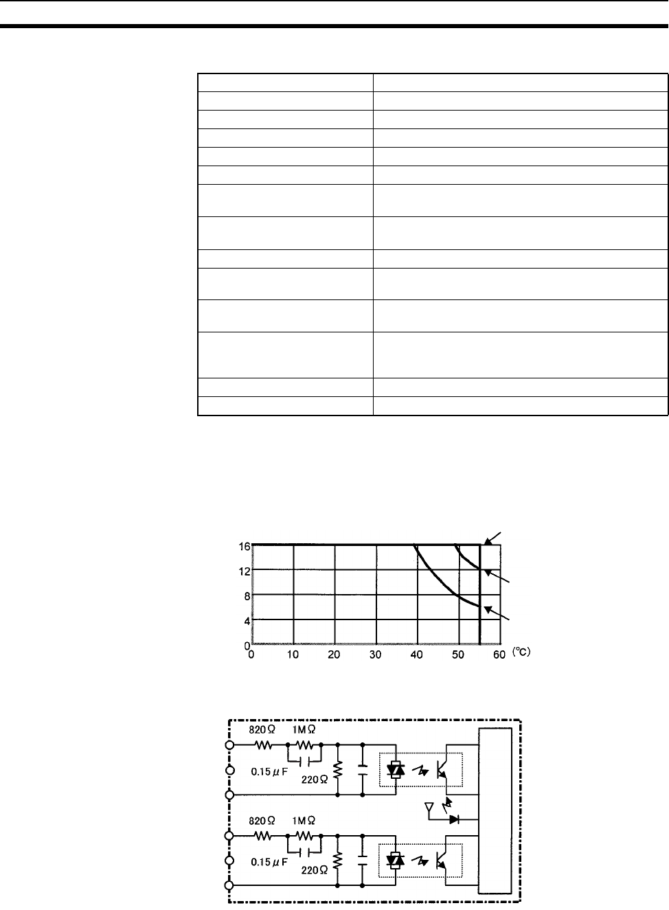
577
Specifications of Basic I/O Units and High-density I/O Units Appendix A
CS1W-IA211 200-V AC Input Unit (16 Points)
Note The Input ON and OFF response times for Basic I/O Units can be set to 0 ms, 0.5 ms, 1 ms, 2 ms, 4 ms,
8 ms, 16 ms, or 32 ms in the PLC Setup. When the response times have been set to 0 ms, the ON
response time will be 10 ms maximum and the OFF response time will be 40 ms maximum due to inter-
nal element delays.
Number of Inputs ON Simultaneously
Circuit Configuration
Rated Input Voltage 200 to 240 V AC (50/60 Hz)
Operating Input Voltage 170 to 264 V AC (50/60 Hz)
Input Impedance 21 kΩ (50 Hz), 18 kΩ (60 Hz)
Input Current 10 mA typical (at 200 V AC)
ON Voltage/ON current 120 V AC min.
OFF Voltage/OFF current 40 V AC max.
ON Response Time 18 ms max. when PLC Setup on default setting
(8 ms) (See note.)
OFF Response Time 48 ms max. when PLC Setup on default setting
(8 ms) (See note.)
No. of Circuits 2 (each 8 points/common)
Number of Inputs ON Simulta-
neously
100% simultaneously ON (for 230 V AC). Refer to
the diagram below.
Insulation Resistance 20 MΩ between external terminals and the GR ter-
minal (500 V DC)
Dielectric Strength 1,000 V AC between the external terminals and the
GR terminal for 1 minute at a leakage current of
10 mA max.
Internal Current Consumption 110 mA 5 V DC max.
Weight 260 g max.
230 V AC
240 V AC
264 V AC
Ambient tem
p
erature
No. of inputs
ON simultaneously
IN0
to
IN7
COM0
IN8
to
IN15
COM1
Input indicator
Internal circuits
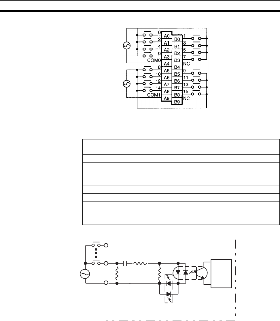
578
Specifications of Basic I/O Units and High-density I/O Units Appendix A
Terminal Connections
Note Terminal numbers A0 to A9 and B0 to B9 are used in this manual, but they are not printed on the Unit.
C200H-IA222/IA222V AC Input Unit (16 Points)
Circuit Configuration
200 to 240 V AC
200 to 240 V AC
Rated Input Voltage 200 to 240 V AC (50/60 Hz)
Input Impedance 21 kΩ (50 Hz), 18 kΩ (60 Hz)
Operating Input Voltage 170 to 264 V DC (50/60 Hz)
Input Current 10 mA typical (at 200 V AC)
ON Voltage 120 V AC min.
OFF Voltage 40 V AC max.
ON Response Time 35 ms max. (at 200 V AC, 25°C)
OFF Response Time 55 ms max. (at 200 V AC, 25°C)
No. of Circuits 1 (16 points/common)
Internal Current Consumption 10 mA 5 V DC max.
Weight 300 g max./400 g max. (IA222V)
IN
IN
COM
Internal
circuits
200 to
240 V AC
Input indicator
680 Ω 0.15 µF
680 kΩ
910 Ω

579
Specifications of Basic I/O Units and High-density I/O Units Appendix A
Terminal Connections
C200H-IM211 AC/DC Input Unit (8 Points)
Circuit Configuration
A0
A1
A2
A3
A4
A5
A6
A7
A8
B0
B1
B2
B3
B4
B5
B6
B7
B8
B9
COM
1
3
5
7
9
11
13
15
NC
0
2
4
6
8
10
12
14
NC
200 to
240 V AC
Rated Input Voltage 12 to 24 V DC/V AC (50/60 Hz)
Operating Input Voltage 10.2 to 26.4 V AC/V DC (50/60 Hz)
Input Impedance 2 kΩ
Input Current 10 mA typical (at 24 V DC)
ON Voltage 10.2 V DC min.
OFF Voltage 3.0 V DC max.
ON Response Time 15 ms max. (at 12 to 24 V DC, 25°C)
OFF Response Time 15 ms max. (at 12 to 24 V DC, 25°C)
No. of Circuits 1 (8 points/common)
Internal Current Consumption 10 mA 5 V DC max.
Weight 200 g max.
IN
IN
COM
Internal
circuits
12 to
24 V AC/DC
2 kΩ
0.01
µF
Input indicator
1.8
kΩ
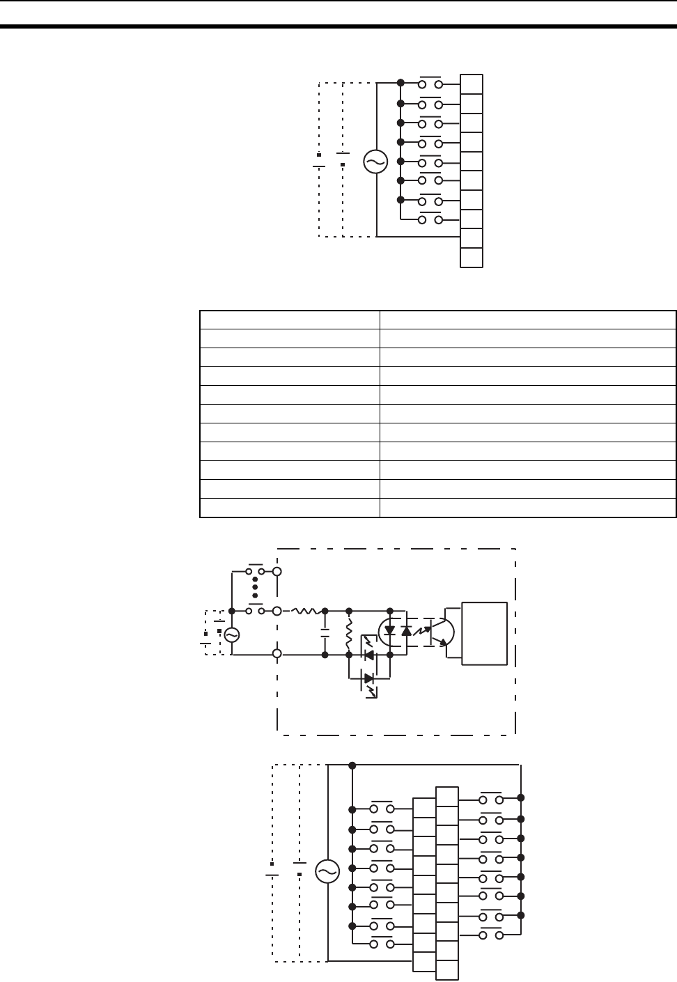
580
Specifications of Basic I/O Units and High-density I/O Units Appendix A
Terminal Connections
C200H-IM212 AC/DC Input Unit (16 Points)
Circuit Configuration
Terminal Connections
COM
A0
A1
A2
A3
A4
A5
A6
A7
A8
A9
0
1
2
3
4
5
6
7
NC
12 to
24 V AC/DC
Rated Input Voltage 24 V DC/V AC (50/60 Hz)
Operating Input Voltage 20.4 to 26.4 V AC/V DC (50/60 Hz)
Input Impedance 3 kΩ
Input Current 7 mA typical (at 24 V DC)
ON Voltage 14.4 V DC min.
OFF Voltage 5.0 V DC max.
ON Response Time 15 ms max. (at 24 V DC, 25°C)
OFF Response Time 15 ms max. (at 24 V DC, 25°C)
No. of Circuits 1 (16 points/common)
Internal Current Consumption 10 mA 5 V DC max.
Weight 250 g max.
IN
IN
COM
Internal
circuits
24 V AC/DC
3 kΩ
0.01
Input indicator
1.8
kΩ
µF
A0
A1
A2
A3
A4
A5
A6
A7
A8
B0
B1
B2
B3
B4
B5
B6
B7
B8
B9
COM
1
3
5
7
9
11
13
15
NC
0
2
4
6
8
10
12
14
NC
24 V AC/DC
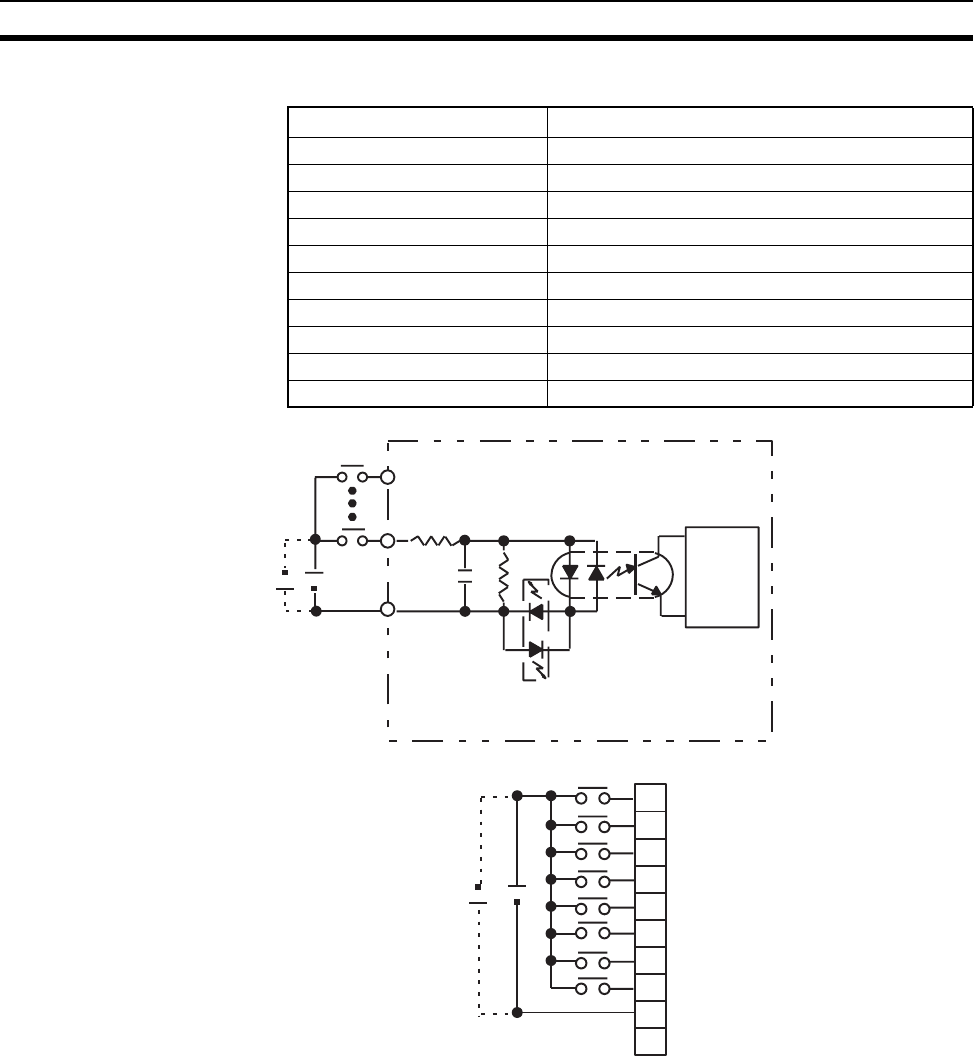
581
Specifications of Basic I/O Units and High-density I/O Units Appendix A
C200H-ID211 DC Input Unit (8 Points)
Circuit Configuration
Terminal Connections
Note Terminal numbers A0 to A9 and B0 to B9 are used in this manual, but they are not printed on the Unit.
Rated Input Voltage 12 to 24 V DC
Operating Input Voltage 10.2 to 26.4 V DC
Input Impedance 2 kΩ
Input Current 10 mA typical (at 24 V DC)
ON Voltage 10.2 V DC min.
OFF Voltage 3.0 V DC max.
ON Response Time 1.5 ms max. (at 12 to 24 V DC, 25°C)
OFF Response Time 1.5 ms max. (at 12 to 24 V DC, 25°C)
No. of Circuits 1 (8 point/common)
Internal Current Consumption 10 mA 5 V DC max.
Weight 200 g max.
IN
IN
COM
Internal
circuits
12 to 24 V DC
2 kΩ
0.01
µF
Input indicator
1.8
kΩ
COM
12 to 24 V DC
A0
A1
A2
A3
A4
A5
A6
A7
A8
A9
0
1
2
3
4
5
6
7
NC
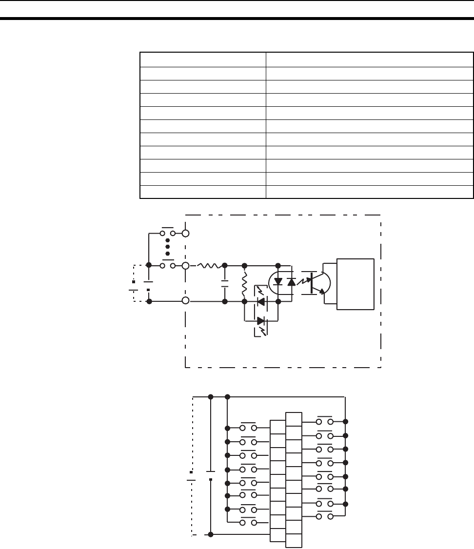
582
Specifications of Basic I/O Units and High-density I/O Units Appendix A
C200H-ID212 DC Input Unit (16 Points)
Circuit Configuration
Terminal Connections
Rated Input Voltage 24 V DC
Operating Input Voltage 20.4 to 26.4 V DC
Input Impedance 3 kΩ
Input Current 7 mA typical (at 24 V DC)
ON Voltage 14.4 V DC min.
OFF Voltage 5.0 V DC max.
ON Response Time 1.5 ms max. (at 24 V DC, 25°C)
OFF Response Time 1.5 ms max. (at 24 V DC, 25°C)
No. of Circuits 1 (16 points/common)
Internal Current Consumption 10 mA 5 V DC max.
Weight 300 g max.
IN
IN
COM
Internal
circuits
24 V DC
3 kΩ
0.01
µF
Input indicator
1.8
kΩ
A0
A1
A2
A3
A4
A5
A6
A7
A8
B0
B1
B2
B3
B4
B5
B6
B7
B8
B9
COM
24 V DC
1
3
5
7
9
11
13
15
NC
0
2
4
6
8
10
12
14
NC
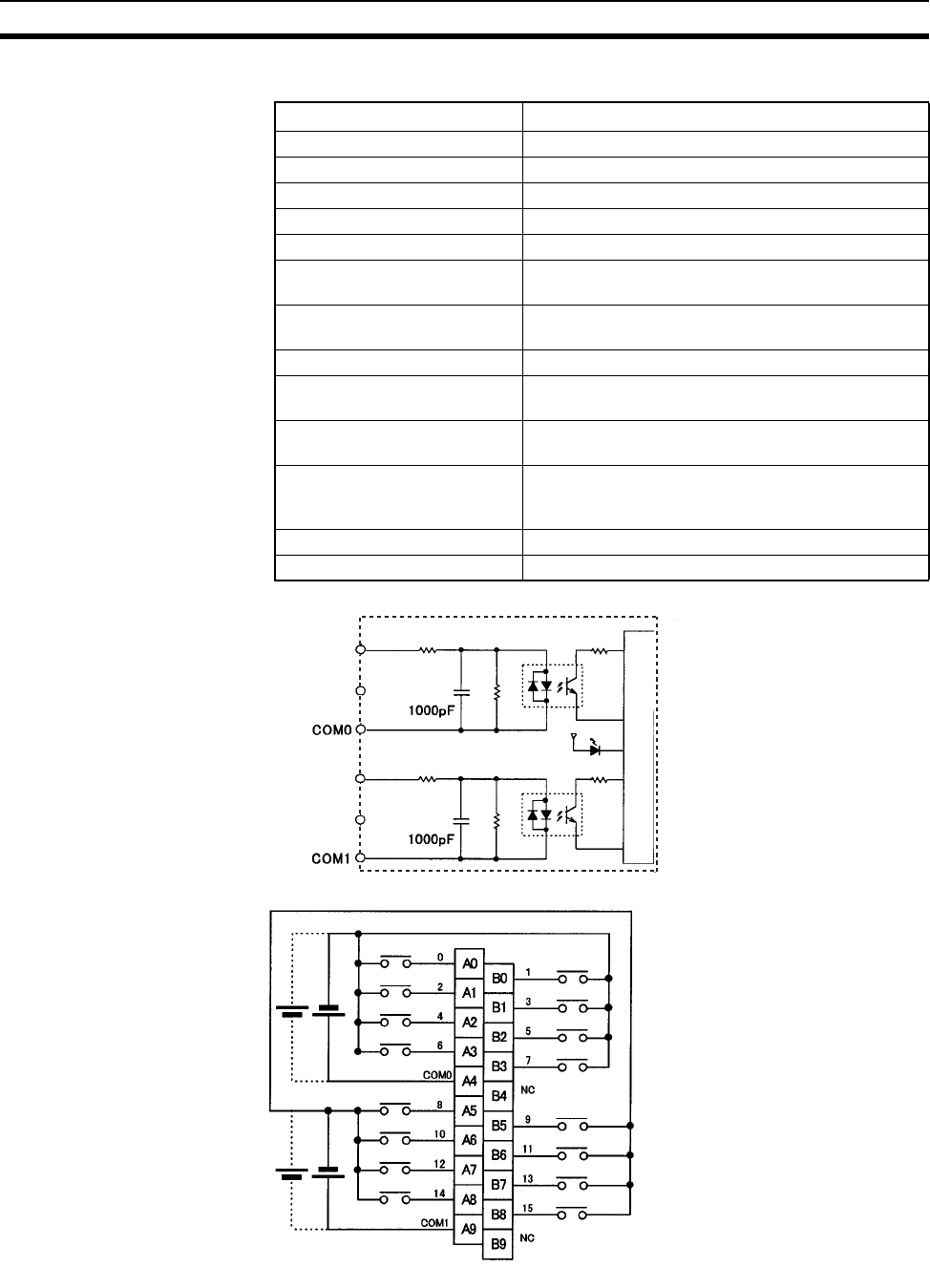
583
Specifications of Basic I/O Units and High-density I/O Units Appendix A
CS1W-ID211 DC Input Unit (16 Points)
Circuit Configuration
Terminal Connections
Note 1. The ON response time will be 20 µs maximum and OFF response time will be 300 µs maximum even
if the response times are set to 0 ms due to internal element delays.
Rated Input Voltage 24 V DC
Operating Input Voltage 20.4 to 26.4 V DC
Input Impedance 3.3 kΩ
Input Current 7 mA typical (at 24 V DC)
ON Voltage/ON Current 14.4 V DC min./3 mA min.
OFF Voltage/OFF Current 5 V DC max./1 mA max.
ON Response Time 8.0 ms max. (Possible to set to between 0 and
32 ms in the PLC Setup.)
OFF Response Time 8.0 ms max. (Possible to set to between 0 and
32 ms using PLC)
No. of Circuits 16 (8 points/common, 2 circuits)
Number of Simultaneously ON
Points
100% simultaneously ON
Insulation Resistance 20 MΩ between external terminals and the GR ter-
minal (100 V DC)
Dielectric Strength 1,000 V AC between the external terminals and the
GR terminal for 1 minute at a leakage current of
10 mA max.
Internal Current Consumption 100 mA 5 V DC max.
Weight 270 g max.
Input indicator
Internal circuits
IN00
to
IN07
IN08
to
IN15
3.3 kΩ
3.3 kΩ
470 Ω
470 Ω
Polarity of the input power supply can connected in either direction.
24
V DC
24
V DC
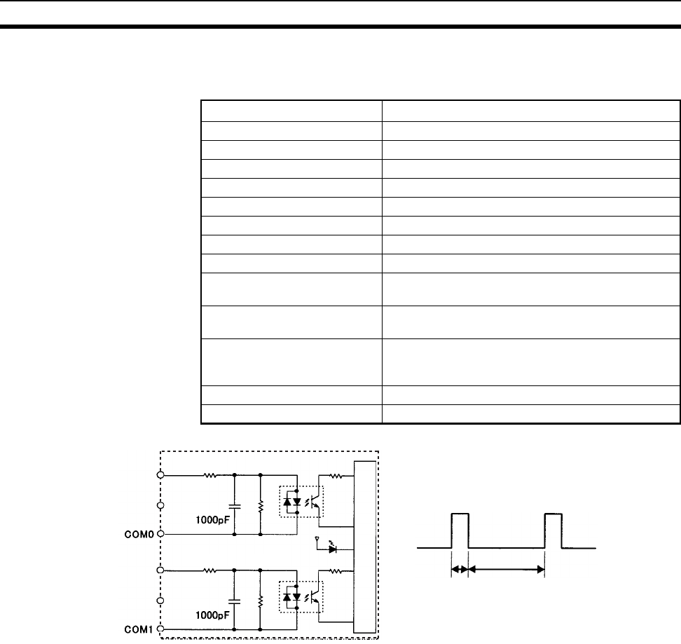
584
Specifications of Basic I/O Units and High-density I/O Units Appendix A
2. Terminal numbers A0 to A9 and B0 to B9 are used in this manual, but they are not printed on the Unit.
CS1W-INT01 Interrupt Input Unit (16 Points)
Circuit Configuration
• Up to two Interrupt Input Units can be mounted to the CPU Rack.
• Interrupts cannot be used when an Interrupt Input Unit is mounted to an Expansion I/O Rack, i.e., it will be
treated as a 16-point Input Unit.
• Set the pulse width of signals input to the Interrupt Input Unit so they satisfy the above conditions.
Rated Input Voltage 24 V DC
Operating Input Voltage 20.4 to 26.4 V DC
Input Impedance 3.3 kΩ
Input Current 7 mA typical (at 24 V DC)
ON Voltage/ON Current 14.4 V DC min./3 mA min.
OFF Voltage/OFF Current 5 V DC max./1 mA max.
ON Response Time 0.1 ms max.
OFF Response Time 0.5 ms max.
No. of Circuits 16 (8 points/common, 2 circuits)
Number of Simultaneously ON
Points
100% simultaneously ON
Insulation Resistance 20 MΩ between external terminals and the GR ter-
minal (100 V DC)
Dielectric Strength 1,000 V AC between the external terminals and the
GR terminal for 1 minute at a leakage current of
10 mA max.
Internal Current Consumption 100 mA 5 V DC max.
Weight 270 g max.
Input indicator
0.5 ms min.
0.1 ms min.
Internal circuits
IN00
to
IN07
IN08
to
IN15
470 Ω
470 Ω
3.3 kΩ
3.3 kΩ
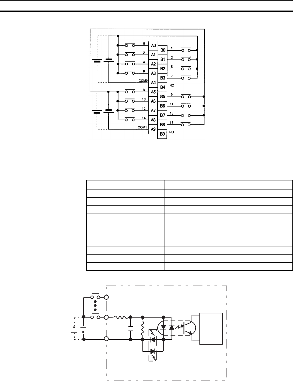
585
Specifications of Basic I/O Units and High-density I/O Units Appendix A
Terminal Connections
Note Terminal numbers A0 to A9 and B0 to B9 are used in this manual, but they are not printed on the Unit.
C200HS-INT01 Interrupt Input Unit (8 Points)
Circuit Configuration
Polarity of the input power supply can connected in either direction.
24
V DC
24
V DC
Rated Input Voltage 12 to 24 V DC
Operating Input Voltage 10.2 to 26.4 V DC
Input Impedance 2 KΩ
Input Current 10 mA typical (24 V DC)
ON Voltage 10.2 V DC min.
OFF Voltage 3.0 V DC max.
ON Response Time 0.2 ms max.
OFF Response Time 0.5 ms max.
No. of Circuits 1 (8 points/common)
Internal Current Consumption 20 mA 5 V DC max.
Weight 200 g max.
IN
IN
COM
Internal
circuits
12 to 24 V DC
2 kΩ
0.01
µF
Input indicator
1.8
kΩ
Either
p
lus or minus can be used for the in
p
ut
p
ower su
pp
l
y
.
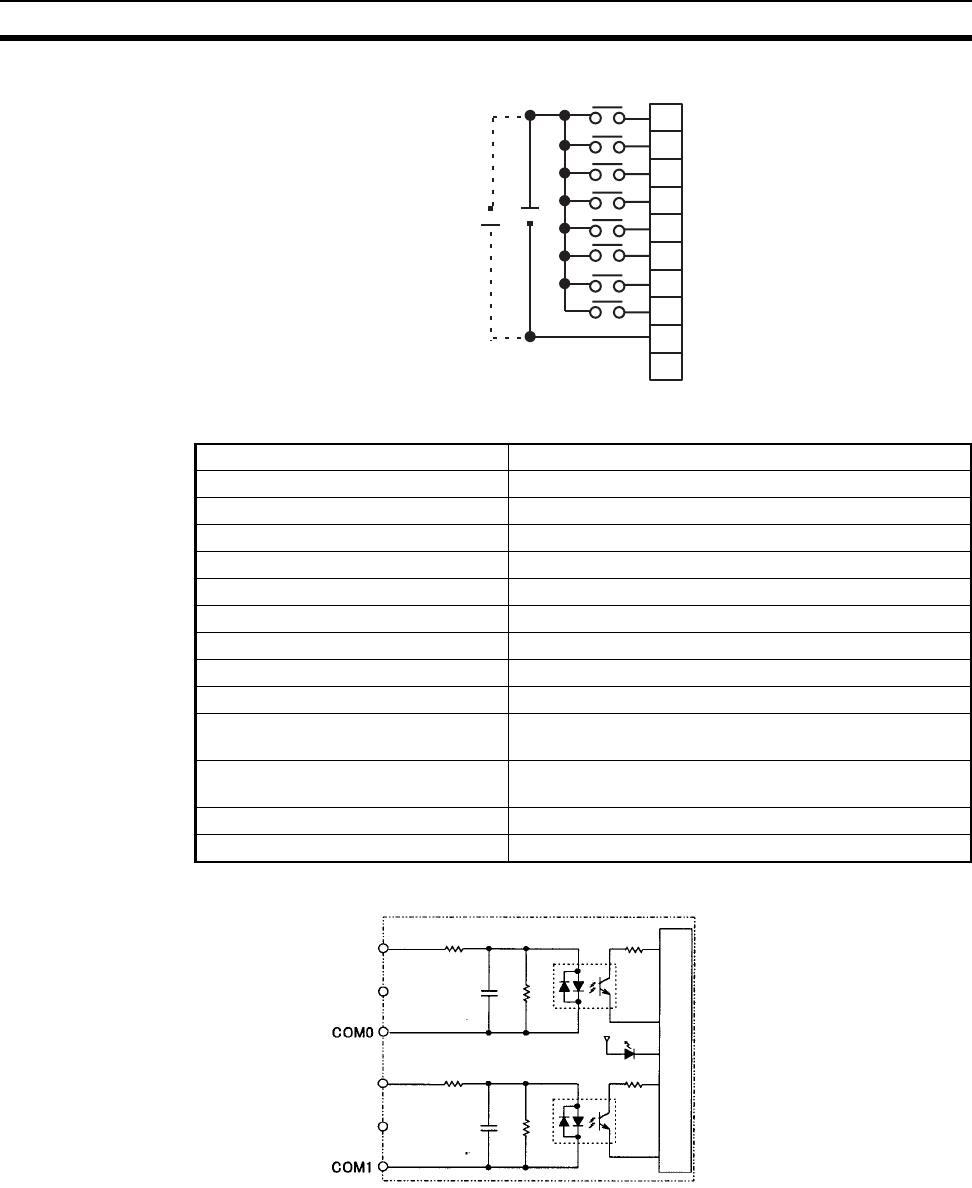
586
Specifications of Basic I/O Units and High-density I/O Units Appendix A
Terminal Connections
CS1W-IDP01 High-speed Input Unit (16 Points)
Circuit Configuration
COM
12 to 24 V DC
A0
A1
A2
A3
A4
A5
A6
A7
A8
A9
0
1
2
3
4
5
6
7
NC
Rated Input Voltage 24 V DC
Operating Input Voltage 20.4 to 26.4 V DC
Input Impedance 3.3 kΩ
Input Current 7 mA typical (at 24 V DC)
ON Voltage/ON Current 14.4 V DC min./3 mA min.
OFF Voltage/OFF Current 5 V DC max./1 mA max.
ON Response Time 0.1 ms max.
OFF Response Time 0.5 ms max.
No. of Circuits 16 (8 points/common, 2 circuits)
Number of Simultaneously ON Points 100% simultaneously ON
Insulation Resistance 20 MΩ between external terminals and the GR terminal
(100 V DC)
Dielectric Strength 1,000 V AC between the external terminals and the GR
terminal for 1 minute at a leakage current of 10 mA max.
Internal Current Consumption 100 mA 5 V DC max.
Weight 270 g max.
Input indicator
Internal circuits
IN00
to
IN07
IN08
to
IN15
470 Ω
3.3 kΩ
470 Ω
3.3 kΩ
1000 pF
1000 pF
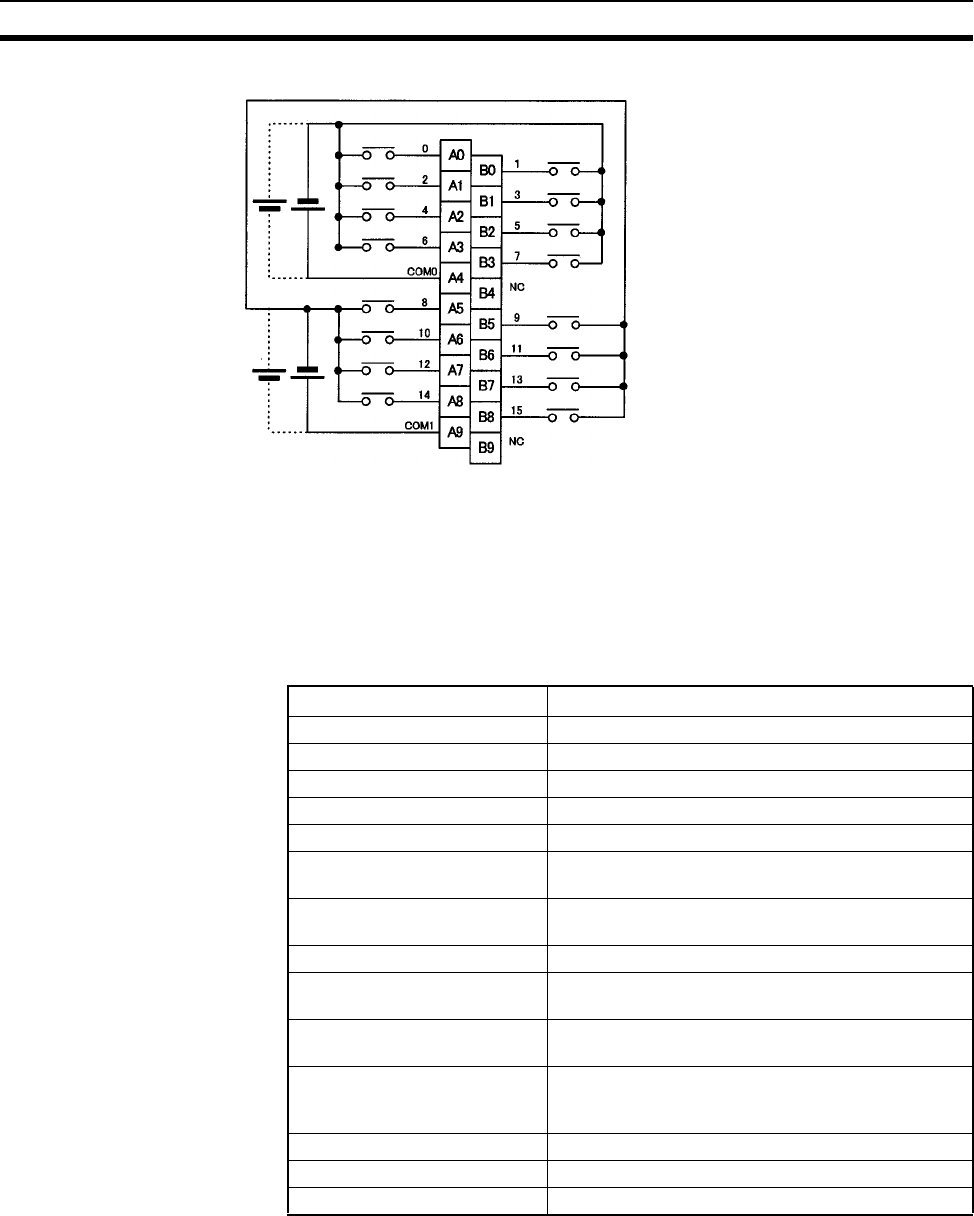
587
Specifications of Basic I/O Units and High-density I/O Units Appendix A
Terminal Connections
• With a High-speed Input Unit, pulse inputs shorter than the cycle time of the CPU Unit can be read.
• The minimum pulse width (ON time) that can be read by the High-speed Input Unit is 0.1 ms.
• Input data in the internal circuits is cleared during the input refresh period.
CS1W-ID231 DC Input Unit (32 Points)
24
V DC
24
V DC
*1 Polarity of the input power supply can be connected in either direction.
*2 Terminal numbers A0 to A9 and B0 to B9 are used in this manual, but
they are not printed the Unit.
Rated Input Voltage 24 V DC
Operating Input Voltage 20.4 to 26.4 V DC
Input Impedance 3.9 kΩ
Input Current 6 mA typical (at 24 V DC)
ON Voltage/ON Current 15.4 V DC min./3 mA min.
OFF Voltage/OFF Current 5 V DC max./1 mA max.
ON Response Time 8.0 ms max. (Can be set to between 0 and 32 in the
PLC Setup.)
OFF Response Time 8.0 ms max. (Can be set to between 0 and 32 in the
PLC Setup)
No. of Circuits 32 (16 points/common, 2 circuits)
Number of Simultaneously ON
Points
70% (11 points/common) (at 24 V DC) (Refer to the
following illustrations.)
Insulation Resistance 20 MΩ between external terminals and the GR ter-
minal (100 V DC)
Dielectric Strength 1,000 V AC between the external terminals and the
GR terminal for 1 minute at a leakage current of
10 mA max.
Internal Current Consumption 150 mA 5 V DC max.
Weight 200 g max.
Accessories One connector for external wiring (soldered)
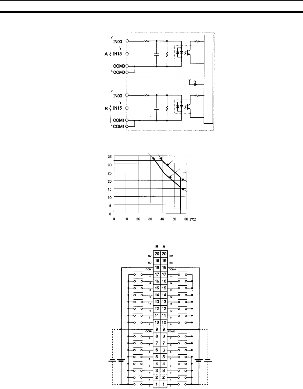
588
Specifications of Basic I/O Units and High-density I/O Units Appendix A
Circuit Configuration
Terminal Connections
• The input power polarity can be connected in either direction provided that the same polarity is set for rows
A and B.
• Both COM0 and COM1 have two pins each. Although they are internally connected, wire all points com-
pletely.
Note The ON response time will be 120 µs maximum and OFF response time will be 300 µs maximum even if
the response times are set to 0 ms due to internal element delays.
Input indicator
Internal circuits
560 Ω
3.9 kΩ
3.9 kΩ
560 Ω
1000 pF
1000 pF
Number of Simultaneously ON Points vs.
Ambient Temperature Characteristic
Input voltage: 24 V DC
Input voltage: 26.4 V DC
22 points at 55°C
16 points at 55°C
32 points at 34°C32 points at 40°C
Ambient Temperature
Number of simultaneously ON points
I/O word "m + 1" I/O word "m"
24
V DC
24
V DC
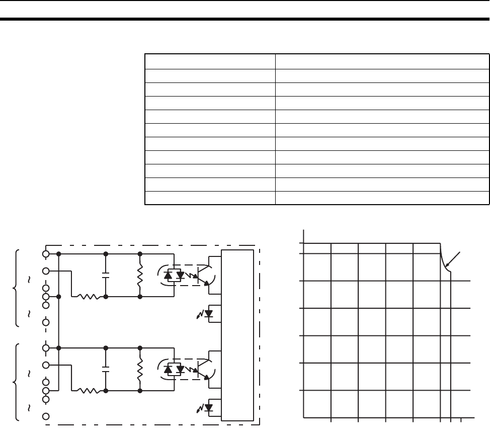
589
Specifications of Basic I/O Units and High-density I/O Units Appendix A
C200H-ID216 DC Input Unit (32 Points)
Circuit Configuration and Simultaneously Usable Points
Rated Input Voltage 24 V DC
Operating Input Voltage 20.4 to 26.4 V DC
Input Impedance 5.6 kΩ
Input Current 4.1 mA (at 24 V DC)
ON Voltage 14.4 V DC min.
OFF Voltage 5.0 V DC max.
ON Response Time 1.0 ms max.
OFF Response Time 1.0 ms max.
No. of Circuits 32 (32 points/common)
Internal Current Consumption 100 mA 5 V DC max.
Weight 180 g max.
Input indicator
Input indicator
Input Voltage:
26.4 V DC
Ambient Temperature (°C)
Simultaneously Usable Points
010203040505560
0
5
10
15
20
25
30
32
1000 pF
680 Ω
5.6 kΩ
COM
IN00
IN07
COM
IN08
IN15
A
Internal
circuits
COM
IN00
IN07
COM
IN08
IN15
B
1000 pF
680 Ω
5.6 kΩ
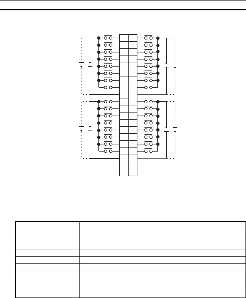
590
Specifications of Basic I/O Units and High-density I/O Units Appendix A
Terminal Connections
Note 1. I/O word “m” is determined by the I/O number setting.
2. The power can be supplied in either polarity, but the same polarity must be used for all COM termi-
nals. Connect power supply wiring to every COM terminal, even though the COM terminals are con-
nected internally.
C200H-ID218 DC Input Unit (32 Points)
I/O word "m" I/O word "m+1"
01
12
23
34
45
56
67
78
COM 9
A
24 V DC
0
1
1
2
2
3
3
4
4
5
5
6
6
7
7
8
COM
9
B
++
24 V DC
810
911
10 12
11 13
12 14
13 15
14 16
15 17
COM 18
8
10
9
10
11
12
13
14
15
COM
++
24 V DC 24 V DC
11
12
13
14
15
16
17
18
NC 19
NC 20
NC
19
NC
20
Rated Input Voltage 24 V DC
Operating Input Voltage 20.4 to 26.4 V DC
Input Impedance 3.9 kΩ
Input Current 6 mA (at 24 V DC)
ON Voltage/ON Current 15.4 V DC min./3.5 mA min.
OFF Voltage/OFF Current 5.0 V DC max./1 mA max.
ON Response Time 1.0 ms max.
OFF Response Time 1.0 ms max.
No. of Circuits 32 (32 points/common)
Internal Current Consumption 100 mA 5 V DC max.
Weight 180 g max.
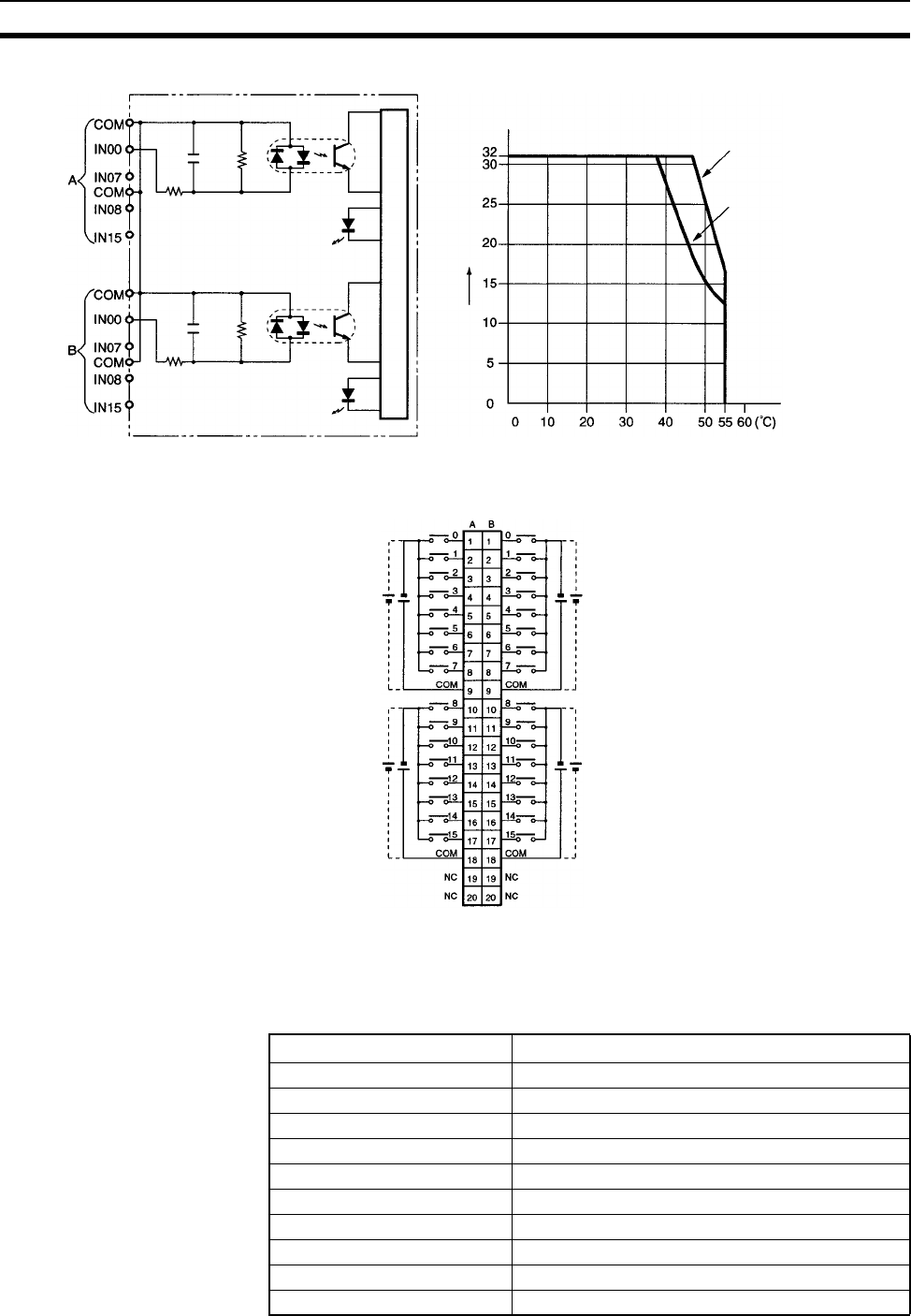
591
Specifications of Basic I/O Units and High-density I/O Units Appendix A
Circuit Configuration
Terminal Connections
Note 1. The polarity of the input power supply can be either positive or negative. The polarity of all commons,
however, must be the same.
2. COM terminals must all be wired even though they are connected internally.
C200H-ID111 DC Input Unit (64 Points)
to
to
to
to
0.01 µF
470 Ω
3.9 kΩ
0.01 µF
470 Ω
3.9 kΩ
Input indicator
Internal circuits
Input indicator
Simultaneously ON points
Ambient Temperature for Simultaneously ON Points
Input voltage: 24.0 V DC
Input voltage: 26.4 V DC
Ambient tem
p
erature
I/O word "m" I/O word "m + 1"
24 V DC
24 V DC
24 V DC
24 V DC
Rated Input Voltage 12 V DC
Operating Input Voltage 10.2 to 13.2 V DC
Input Impedance 2.7 kΩ
Input Current 4.1 mA typical (at 12 V DC)
ON Voltage 8.0 V DC min.
OFF Voltage 3.0 V DC max.
ON Response Time 1.0 ms max.
OFF Response Time 1.0 ms max.
No. of Circuits 2 (32 points/common)
Internal Current Consumption 120 mA 5 V DC max.
Weight 250 g max.
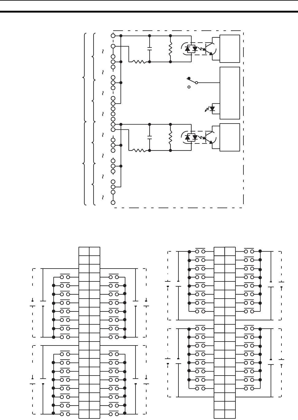
592
Specifications of Basic I/O Units and High-density I/O Units Appendix A
Circuit Configuration
Terminal Connections
Input indicator
Indicator
switch
circuit
COM0
IN00
IN07
COM0
IN08
IN15
A
1000 pF
820
2.7 k
Internal
circuits
COM0
IN00
IN07
COM0
IN08
IN15
COM1
IN00
IN07
COM1
IN08
IN15
Internal
circuits
1000 pF
820
2.7 k
COM1
IN00
IN07
COM1
IN08
IN15
CN1 CN1
CN2
SW
B
A
B
CN2
I/O word "m"I/O word "m+1"
CN1
I/O word "m+3"I/O word "m+2"
CN2
1
2
3
4
5
6
7
8
9
B
0
1
1
2
2
3
3
4
4
5
5
6
6
7
7
8
COM0
9
A
+
12 V DC
10
11
12
13
14
15
16
17
18
8
10
9
10
11
12
13
14
15
COM0
+
12 V DC
11
12
13
14
15
16
17
18
NC 19
NC 20
NC
19
NC
20
0
1
2
3
4
5
6
7
COM0
+
8
9
10
11
12
13
14
15
COM0
+
12 V DC
12 V DC
01
12
23
34
45
56
67
78
COM1 9
A
0
1
1
2
2
3
3
4
4
5
5
6
6
7
7
8
COM1
9
B
++
810
911
10 12
11 13
12 14
13 15
14 16
15 17
COM1 18
8
10
9
10
11
12
13
14
15
COM1
++
11
12
13
14
15
16
17
18
NC 19
NC 20
NC
19
NC
20
12 V DC 12 V DC
12 V DC 12 V DC
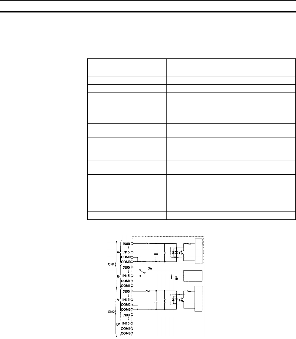
593
Specifications of Basic I/O Units and High-density I/O Units Appendix A
Note The power can be supplied in either polarity, but the same polarity must be used for all COM terminals in
each connector. Connect power supply wiring to every COM terminal, even though the COM terminals in
each connector are connected internally.
CS1W-ID261 DC Input Unit (64 Points)
Circuit Configuration
Rated Input Voltage 24 V DC
Operating Input Voltage 20.4 to 26.4 V DC
Input Impedance 3.9 kΩ
Input Current 6 mA typical (at 24 V DC)
ON Voltage/ON Current 15.4 V DC min./3 mA min.
OFF Voltage/OFF Current 5 V DC max./1 mA max.
ON Response Time 8.0 ms max. (Can be set to between 0 and 32 in the
PLC Setup.)
OFF Response Time 8.0 ms max. (Can be set to between 0 and 32 in the
PLC Setup.)
No. of Circuits 64 (16 points/common, 4 circuits)
Number of Simultaneously ON
Points
50% (8 points/common) (at 24 V DC) (Refer to the
following illustrations.)
Insulation Resistance 20 MΩ between external terminals and the GR ter-
minal (100 V DC)
Dielectric Strength 1,000 V AC between the external terminals and the
GR terminal for 1 minute at a leakage current of
10 mA max.
Internal Current Consumption 150 mA 5 V DC max.
Weight 260 g max.
Accessories Two connectors for external wiring (soldered)
Input indicator
Internal circuits
Internal circuits
Indicator
switching
circuit
560 Ω
3.9 kΩ
560 Ω
3.9 kΩ
1000 pF
1000 pF
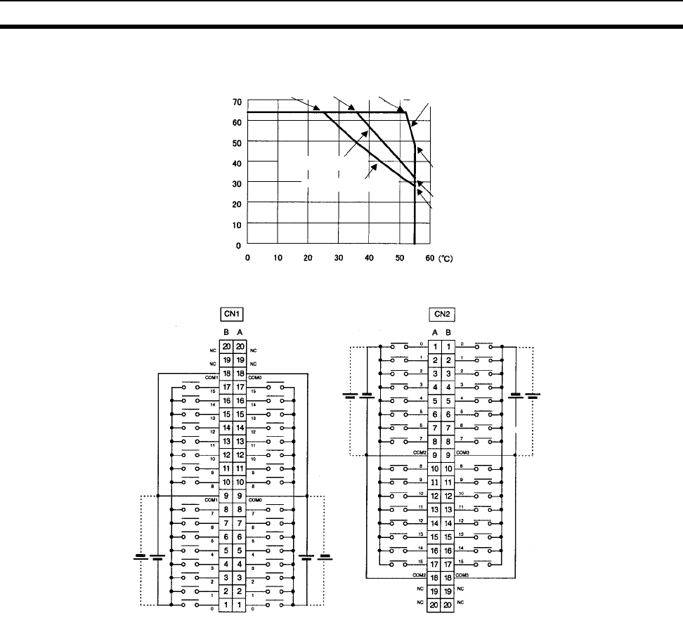
594
Specifications of Basic I/O Units and High-density I/O Units Appendix A
Terminal Connections
• The input power polarity can be connected in either direction provided that the same polarity be set for
rows A and B.
• COM0, COM1, COM2, and COM3 have two pins each. Although they are internally connected, wire all
points completely.
Note The ON response time will be 120 µs maximum and OFF response time will be 300 µs maximum even if
the response times are set to 0 ms due to internal element delays.
Number of Simultaneously ON Points vs.
Ambient Temperature Characteristic
Input voltage: 20.4 V DC
Input voltage: 24 V DC
32 points at 55°C
28 points at 55°C
64 points
at 36°C64 points
at 52°C
64 points
at 25°C
48 points at 55°C
Ambient Tem
p
erature
Number of simultaneously ON points
Input voltage: 26.4 V DC
I/O word "m"I/O word "m+1" I/O word "m+3"I/O word "m+2"
24
V DC
24
V DC
24
V DC
24
V DC
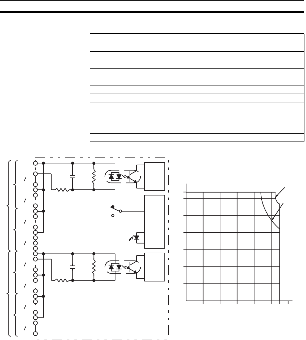
595
Specifications of Basic I/O Units and High-density I/O Units Appendix A
C200H-ID217 DC Input Unit (64 Points)
Circuit Configuration and Simultaneously Usable Points
Rated Input Voltage 24 V DC
Operating Input Voltage 20.4 to 26.4 V DC
Input Impedance 5.6 kΩ
Input Current 4.1 mA typical (at 24 V DC)
ON Voltage 14.4 V DC min.
OFF Voltage 5.0 V DC max.
ON Response Time 1.0 ms max.
OFF Response Time 1.0 ms max.
No. of Circuits 2 (32 points/common)
All 64 points cannot be turned ON simultaneously at
high temperatures. Refer to the following graph.
Internal Current Consumption 120 mA 5 V DC max.
Weight 250 g max.
Input indicator
Input Voltage:
24.0 V DC
Input Voltage:
26.4 V DC
Simultaneously Usable Points
Indicator
switch
circuit
COM0
IN00
IN07
COM0
IN08
IN15
A
1000 pF
680 Ω
5.6 kΩ
Internal
circuits
COM0
IN00
IN07
COM0
IN08
IN15
COM1
IN00
IN07
COM1
IN08
IN15
Internal
circuits
1000 pF
680 Ω
5.6 kΩ
COM1
IN00
IN07
COM1
IN08
IN15
CN1
CN2
SW
B
A
B
010203040505560
0
10
20
30
40
50
60
64
CN1
CN2
Ambient Temperature (°C)
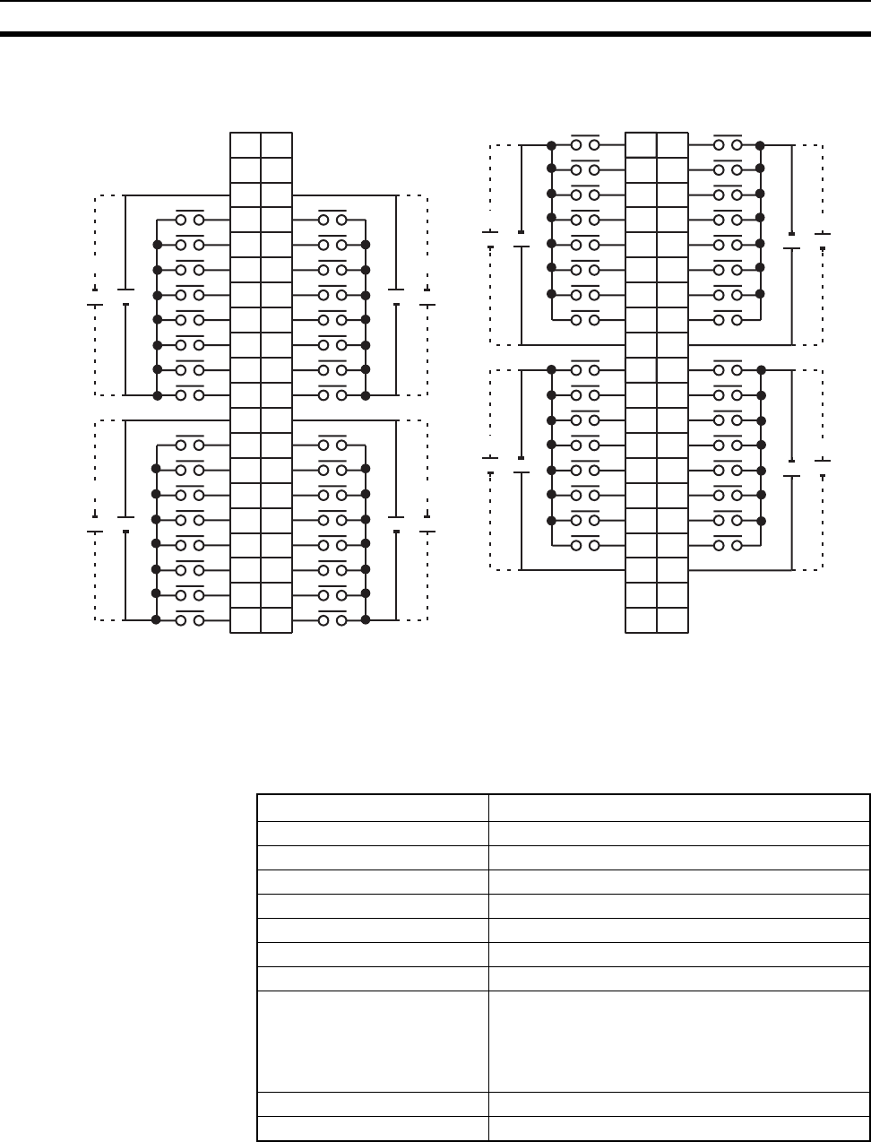
596
Specifications of Basic I/O Units and High-density I/O Units Appendix A
Note 1. I/O word “m” is determined by the I/O number setting.
2. The power can be supplied in either polarity, but the same polarity must be used for all COM terminals
in each connector. Connect power supply wiring to every COM terminal, even though the COM ter-
minals in each connector are connected internally.
C200H-ID219 DC Input Unit (64 Points)
I/O word "m"I/O word "m+1" CN1 I/O word "m+3"I/O word "m+2" CN2
1
2
3
4
5
6
7
8
9
B
0
1
1
2
2
3
3
4
4
5
5
6
6
7
7
8
COM0
9
A
+
24 V DC
10
11
12
13
14
15
16
17
18
8
10
9
10
11
12
13
14
15
COM0
+
24 V DC
11
12
13
14
15
16
17
18
NC 19
NC 20
NC
19
NC
20
0
1
2
3
4
5
6
7
COM0
+
8
9
10
11
12
13
14
15
COM0
+
24 V DC
24 V DC
01
12
23
34
45
56
67
78
COM1 9
A
0
1
1
2
2
3
3
4
4
5
5
6
6
7
7
8
COM1
9
B
++
810
911
10 12
11 13
12 14
13 15
14 16
15 17
COM1 18
8
10
9
10
11
12
13
14
15
COM1
++
11
12
13
14
15
16
17
18
NC 19
NC 20
NC
19
NC
20
24 V DC 24 V DC
24 V DC 24 V DC
Terminal Connections
Rated Input Voltage 24 V DC
Operating Input Voltage 20.4 to 26.4 V DC
Input Impedance 3.9 kΩ
Input Current 6 mA (at 24 V DC)
ON Voltage/ON Current 15.4 V DC min./3.5 mA min.
OFF Voltage/OFF Current 5.0 V DC max./1 mA max.
ON Response Time 1.0 ms max.
OFF Response Time 1.0 ms max.
No. of Circuits 64 (32 points/common)
Note The number of points that can be ON simulta-
neously is limited according to the ambient
temperature. Refer to the following diagram
for details.
Internal Current Consumption 120 mA 5 V DC max.
Weight 250 g max.
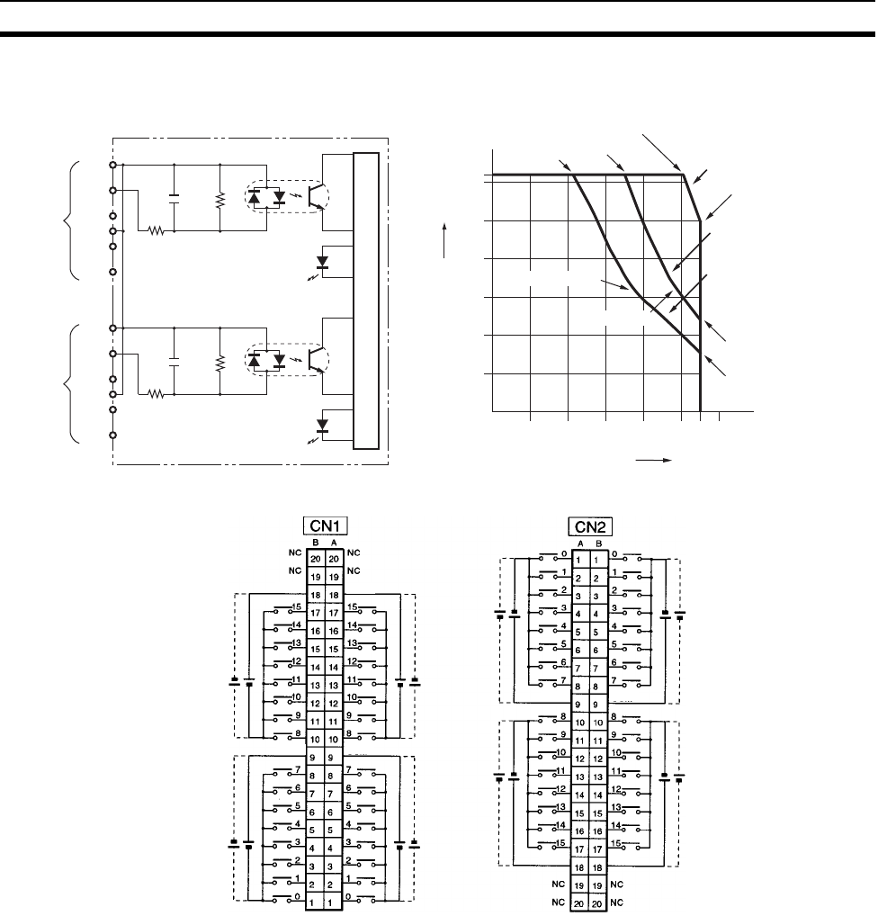
597
Specifications of Basic I/O Units and High-density I/O Units Appendix A
Circuit Configuration
Terminal Connections
Note 1. The polarity of the input power supply can be either positive or negative. The polarity of all commons
for CN1 and CN2, however, must be the same.
2. COM terminals for CN1 and CN2 must all be wired even though they are connected internally.
COM
IN00
IN07
COM
IN08
IN15
3.9 kΩ
0.01 µF
470 Ω
3.9 kΩ
0.01 µF
470 Ω
A
COM
IN00
IN07
COM
IN08
IN15
B
to
to
to
to
64
60
50
40
30
20
10
0
010203040505560(°C)
Input indicator
Internal circuits
Input indicator
Ambient Temperature for Simultaneously ON Points
Simultaneously ON points
Input voltage: 20 V DC
Input voltage: 24.0 V DC
Input voltage: 26.4 V DC
Ambient temperature
64 points
at 22°C
64 points
at 35°C
64 points at 51°C
48 points at 55°C
32 points at 38°C
32 points at 48°C
24 points at 55°C
16 points at 55°C
(m + 1) words (m + 1) words (m + 2) words (m + 3) words
24 V DC
24 V DC
24 V DC
24 V DC
24 V DC
24 V DC
24 V DC
24 V DC
COM0 COM0
COM0 COM0
COM1 COM1
COM1
COM1
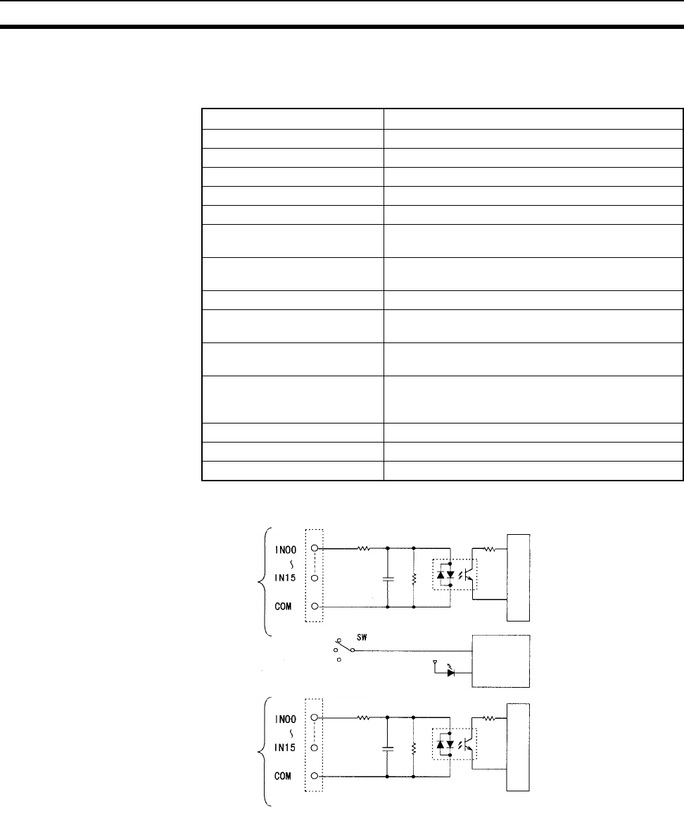
598
Specifications of Basic I/O Units and High-density I/O Units Appendix A
CS-series High-density I/O Units
CS1W-ID291 DC Input Unit (96 Points)
Circuit Configuration
Note 1. The Input ON and OFF response times for Basic I/O Units can be set to 0 ms, 0.5 ms, 1 ms, 2 ms, 4
ms, 8 ms, 16 ms, or 32 ms in the PLC Setup.
2. The ON response time will be 120 µs maximum and OFF response time will be 300 µs maximum even
if the response times are set to 0 ms due to internal element delays.
Rated Input Voltage 24 V DC
Operating Input Voltage 20.4 to 26.4 V DC
Input Impedance 4.7 kΩ
Input Current Approx. 5 mA (at 24 V DC)
ON Voltage/ON Current 17 V DC min./3 mA min.
OFF Voltage/OFF Current 5 V DC max./1 mA max.
ON Response Time 8.0 ms max.(Possible to select one out of eight
times from 0 to 32 ms in the PLC Setup.) (See note.)
OFF Response Time 8.0 ms max. (Possible to select one out of eight
times from 0 to 32 ms in the PLC Setup.) (See note.)
No. of Circuits 6 (16 points/common)
Number of Inputs ON Simulta-
neously
50% (8 points/common) (at 24 V DC) (Depends on
ambient temperature)
Insulation Resistance 20 MΩ between the external terminals and the GR
terminal (100 V DC)
Dielectric Strength 1,000 V AC between the external terminals and the
GR terminal for 1 minute at a leakage current of
10 mA max.
Internal Current Consumption 200 mA 5 V DC max.
Weight 320 g max.
Accessories Two connectors for external wiring (soldered)
Input indicator
Indicator
switch
circuit
x 3 CN1 circuits
x 3 CN2 circuits
Internal circuits
Internal circuits
560 Ω
4.7 kΩ
560 Ω
4.7 kΩ
1000 pF
1000 pF
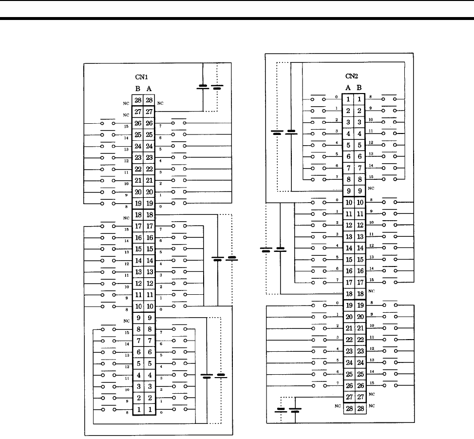
599
Specifications of Basic I/O Units and High-density I/O Units Appendix A
Terminal Connections: CS1W-ID291 24-V DC 96-point Input Unit
• The polarity of the input power supply can be in either direction, as indicated by the dotted lines.
Word (m+2)
Word (m+1)
Word m
Word (m+3)
Word (m+4)
Word (m+5)
24 V DC
24 V DC
24 V DC
24 V DC
24 V DC
24 V DC
COM2
COM1
COM0
COM3
COM4
COM5
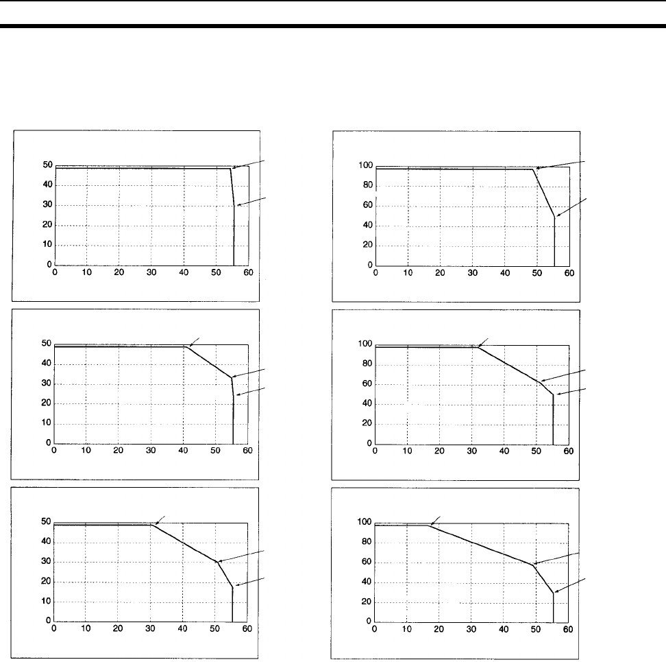
600
Specifications of Basic I/O Units and High-density I/O Units Appendix A
Maximum Number of ON Inputs
The maximum number of 24-V DC inputs that can be ON simultaneously for the CS1W-ID291/MD291/MD292
depends on the ambient temperature, as shown in the following diagrams.
If the maximum number of ON points is exceeded for the CS1W-ID291/MD291/MD292, heat generated by
electronic elements will increase the temperature of the electronic elements and the interior of the Unit. This
will reduce the reliability and life of the electronic elements and cause Unit malfunctions. There will be a delay
in the temperature increase, however, and there will be no problems if all inputs are ON for 10 minutes or less
at the start of operations or any other time that all inputs have been off for at least 2 hours.
CS1W-MD291/MD292 Inputs CS1W-ID291 Inputs
Temperature Characteristic for
Max. ON Inputs (20.4 V)
ON inputs
Ambient temperature (°C)
53°C: 48 pts
55°C: 30 pts
Temperature Characteristic for
Max. ON Inputs (20.4 V)
ON inputs
Ambient temperature (°C)
48°C: 96 pts
55°C: 48 pts
Temperature Characteristic for
Max. ON Inputs (24.0 V)
ON inputs
53°C: 48 pts
55°C: 30 pts
Temperature Characteristic for
Max. ON Inputs (24.0 V)
ON inputs
Ambient temperature (°C)
51°C: 62 pts
55°C: 48 pts
Temperature Characteristic for
Max. ON Inputs (26.4 V)
ON inputs
Ambient temperature (°C)
51°C: 30 pts
55°C: 18 pts
Temperature Characteristic for
Max. ON Inputs (26.4 V)
ON inputs
Ambient temperature (°C)
48°C: 58 pts
55°C: 32 pts
32°C: 96 pts
41°C: 48 pts
17°C: 96 pts
31°C: 48 pts
Ambient temperature (°C)
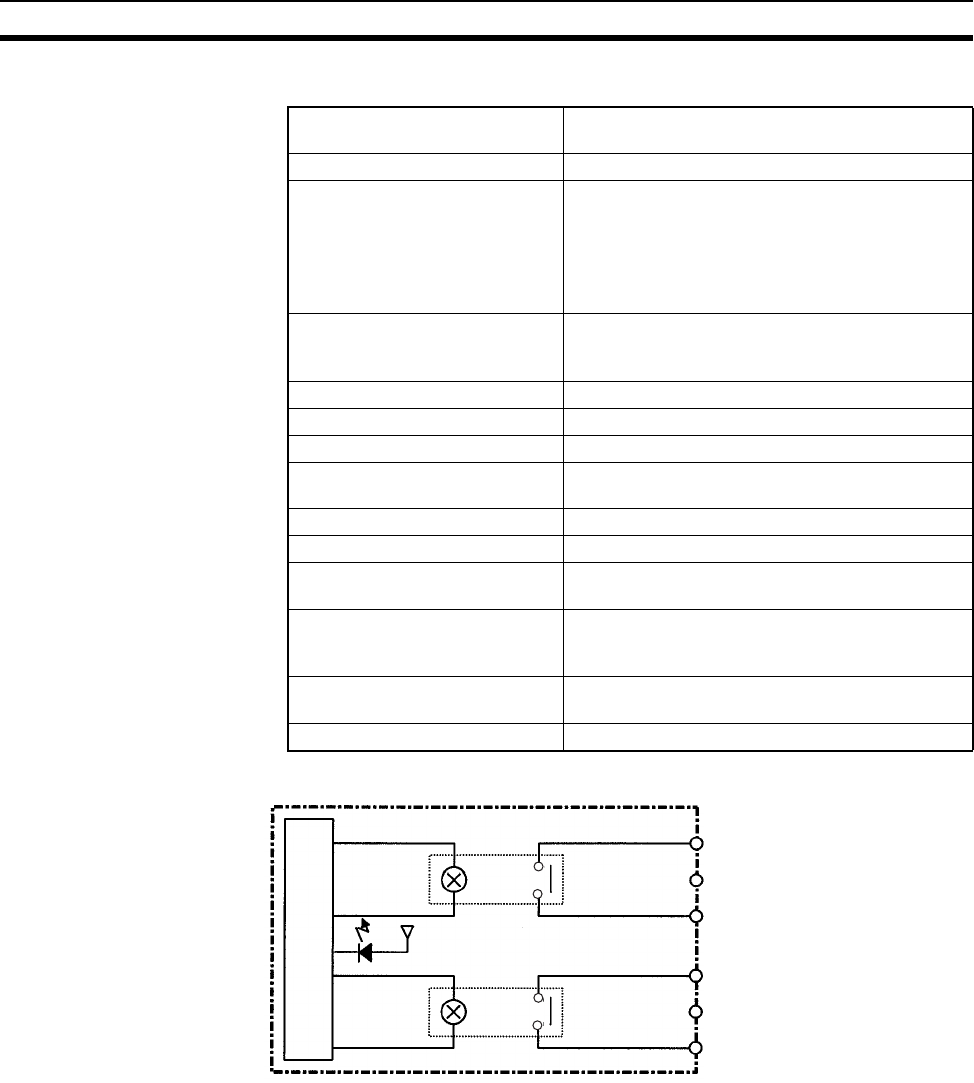
601
Specifications of Basic I/O Units and High-density I/O Units Appendix A
CS1W-OC211 Contact Output Unit (16 points)
Circuit Configuration
Max. Switching Capacity 2 A 250 V AC (cosφ = 1), 2 A 24 V DC (8 A/com-
mon, 16 A/Unit), 0.1 A 120 V DC
Min. Switching Capacity 1 mA 5 V DC
Service Life of Relay Electrical: 150,000 operations (resistive load)/
100,000 operations (inductive load)
Mechanical: 20,000,000 operations
Service life will vary depending on the connected
load. Refer to page 612 for information on service
life according to the load.
Relay replacement NY-24W-K-IE (Fujitsu Takamizawa Component
Ltd.)
Relays cannot be replaced by users.
ON Response Time 15 ms max.
OFF Response Time 15 ms max.
No. of Circuits 2 (each 8 points/common)
Number of Inputs ON Simulta-
neously
16
Surge Protector None
Fuses None
Insulation Resistance 20 MΩ between external terminals and the GR
terminal (500 V DC)
Dielectric Strength 2,000 V AC between the external terminals and
the GR terminal for 1 minute at a leakage current
of 10 mA max.
Internal Current Consumption 130 mA 5 V DC max. 96 mA 26 V DC (6 mA × No.
points ON)
Weight 290 g max.
IN0
to
IN7
COM0
IN8
to
IN15
COM1
Internal circuits
Output indicator
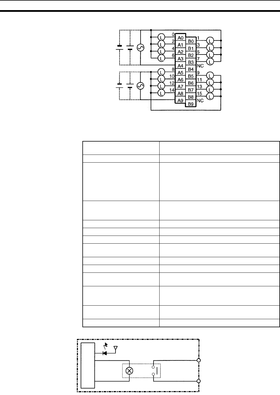
602
Specifications of Basic I/O Units and High-density I/O Units Appendix A
Terminal Connections
Note Terminal numbers A0 to A9 and B0 to B9 are used in this manual, but they are not printed on the Unit.
CS1W-OC201 Contact Output Unit (8 points) (See note 1.)
Circuit Configuration
2 A 250 V AC,
2 A 24 V DC,
0.1 A 120 V DC max.
COM0
COM1
Max. Switching Capacity 2 A 250 V AC (cosφ = 1), 2 A 24 V DC (16 A/Unit),
0.1 A 120 V DC
Min. Switching Capacity 1 mA 5 V DC
Service Life of Relay Electrical: 150,000 operations (resistive load)/
100,000 operations (inductive load)
Mechanical: 20,000,000 operations
Service life will vary depending on the connected
load. Refer to page 612 for information on service
life according to the load.
Relay replacement NY-24W-K-IE (Fujitsu Takamizawa Component
Ltd.)
Relays cannot be replaced by users.
ON Response Time 15 ms max.
OFF Response Time 15 ms max.
No. of Circuits 8 independent contacts
Number of Inputs ON Simulta-
neously
8
Surge Protector None
Fuses None
Insulation Resistance 20 MΩ between external terminals and the GR ter-
minal (500 V DC)
Dielectric Strength 2,000 V AC between the external terminals and the
GR terminal for 1 minute at a leakage current of
10 mA max.
Internal Current Consumption 100 mA 5 V DC max. 48 mA 26 V DC (6 mA × No.
points ON)
Weight 270 g max.
Internal circuits
Output indicator
OUT
OUT
C
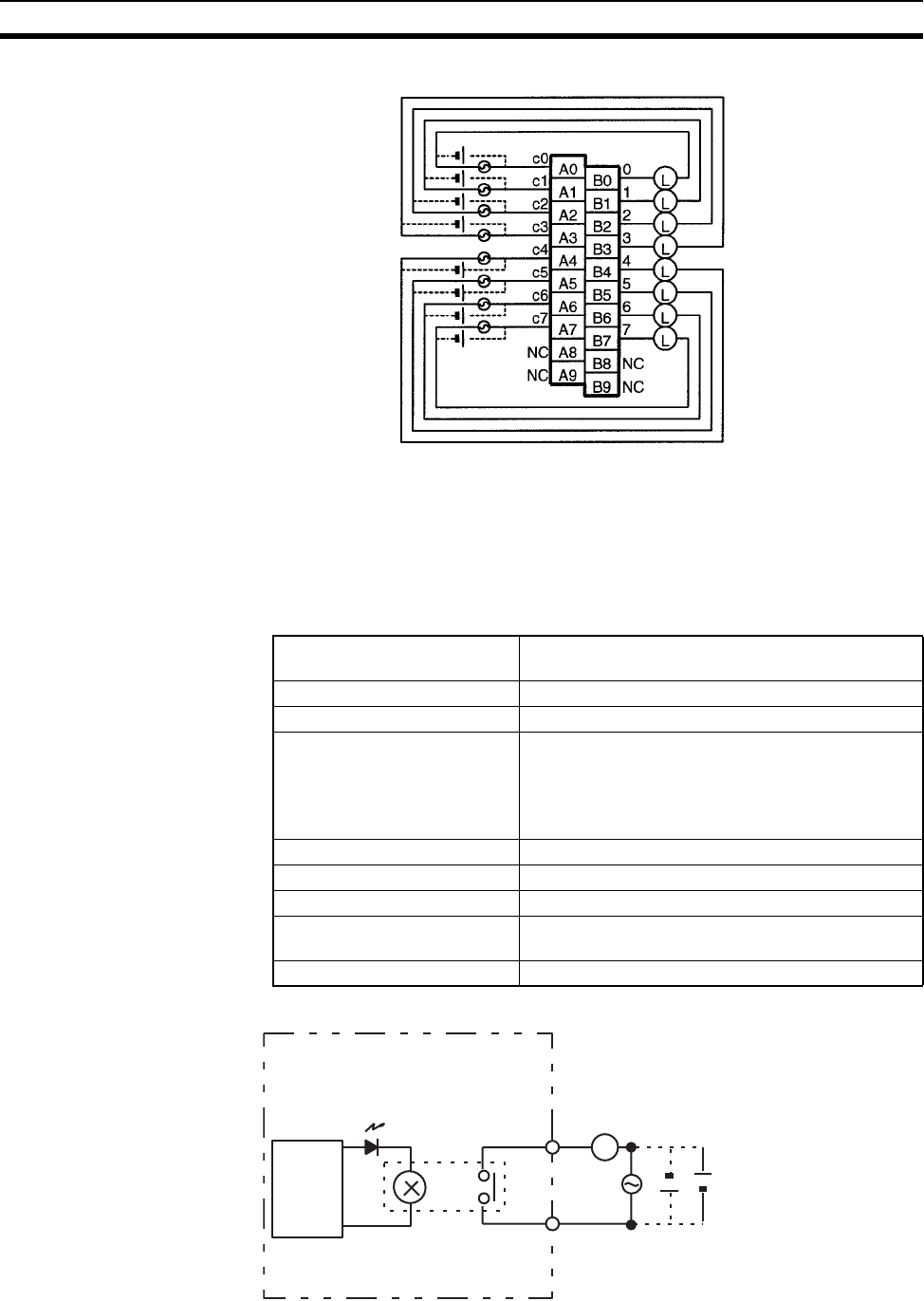
603
Specifications of Basic I/O Units and High-density I/O Units Appendix A
Terminal Connections
Note 1. This Unit uses only 8 bits for external I/O even though 16 bits (1 word) are allocated. This Unit is also
treated as a 16-point Unit in the I/O tables.
2. Terminal numbers A0 to A9 and B0 to B9 are used in this manual, but they are not printed on the Unit.
C200H-OC223 Contact Output Unit (5 Points)
Circuit Configuration
2 A 250 V AC,
2 A 24 V DC,
0.1 A 120 V DC max.
See note 2.
Note: There are no restrictions in the polarit
y
when connectin
g
a DC power supply.
Max. Switching Capacity 2 A 250 V AC (cosφ = 1), 2 A 250 V AC (cosφ = 0.4),
2 A 24 V DC (10 A/Unit)
Min. Switching Capacity 10 mA 5 V DC
Relay G6B-1174-P-FD-US-M (24 V DC) with socket
Service Life of Relay Electrical: 500,000 operations (resistive load)/
100,000 operations (inductive load)
Mechanical: 50,000,000 operations
Service life will vary depending on the current and
ambient temperature.
ON Response Time 10 ms max.
OFF Response Time 10 ms max.
No. of Circuits 5 independent contacts
Internal Current Consumption 10 mA 5 V DC max. 75 mA 26 V DC (8 points ON
simultaneously.)
Weight 250 g max.
Internal
circuits
L
Output indicator
250 V AC
24 V DC max.
OUT
OUTc
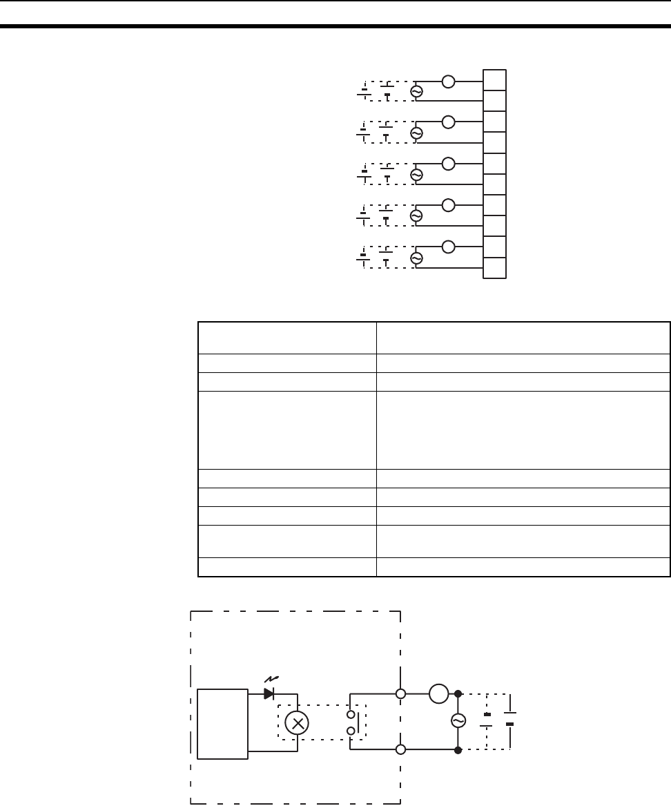
604
Specifications of Basic I/O Units and High-density I/O Units Appendix A
Terminal Connections
C200H-OC224 Contact Output Unit (8 Points)
Circuit Configuration
250 V AC 24 V DC max.
(inductive load: 2 A
resistive load: 2 A)
(10 A/Unit)
A0
A1
A2
A3
A4
A5
A6
A7
A8
A9
0
c0
1
c1
2
c2
3
c3
4
c4
L
L
L
L
L
Max. Switching Capacity 2 A 250 V AC (cosφ = 1), 2 A 250 V AC (cosφ = 0.4),
2 A 24 V DC (16 A/Unit)
Min. Switching Capacity 10 mA 5 V DC
Relay G6B-1174-P-FD-US-M (24 V DC) with socket
Service Life of Relay Electrical: 500,000 operations (resistive load)/
100,000 operations (inductive load)
Mechanical: 50,000,000 operations
Service life will vary depending on the current and
ambient temperature.
ON Response Time 10 ms max.
OFF Response Time 10 ms max.
No. of Circuits 8 independent contacts
Internal Current Consumption 10 mA 5 V DC max. 75 mA 26 V DC (8 points ON
simultaneously.)
Weight 300 g max.
Internal
circuits
L
Output indicator
250 V AC
24 V DC max.
OUT
OUTc
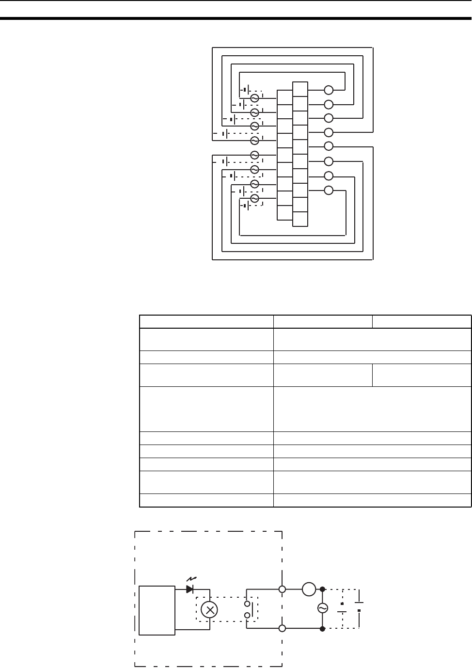
605
Specifications of Basic I/O Units and High-density I/O Units Appendix A
Terminal Connections
C200H-OC224V/OC224N Contact Output Unit (8 Points)
Circuit Configuration
B0
B1
B2
B3
B4
B5
B6
B7
B8
B9
A0
A1
A2
A3
A4
A5
A6
A7
A8
c0
c1
c2
c3
c4
c5
c6
c7
L
L
L
L
L
L
L
L
0
1
2
3
4
5
6
7
250 V AC 24 V DC max.
(inductive load: 2 A
resistive load: 2 A)
NC
NC
NC
See note.
Note: There are no restrictions in the polarity
when connecting a DC power supply.
Item OC224V OC224N
Max. Switching Capacity 2 A 250 V AC (cosφ = 1), 2 A 250 V AC (cosφ =
0.4), 2 A 24 V DC (16 A/Unit)
Min. Switching Capacity 10 mA 5 V DC
Relay G6R-1 (24 V DC) with
socket
G6RN-1-ACD (24 V
DC) PCB soldering
Service Life of Relay Electrical: 300,000 operations
Mechanical: 10,000,000 operations
Service life will vary depending on the current and
ambient temperature.
ON Response Time 15 ms max.
OFF Response Time 15 ms max.
No. of Circuits 8 independent contacts
Internal Current Consumption 10 mA 5 V DC max. 90 mA 26 V DC (8 points ON
simultaneously.)
Weight 350 g max.
Internal
circuits
L
Output indicator
250 V AC
24 V DC max.
OUT
OUTc
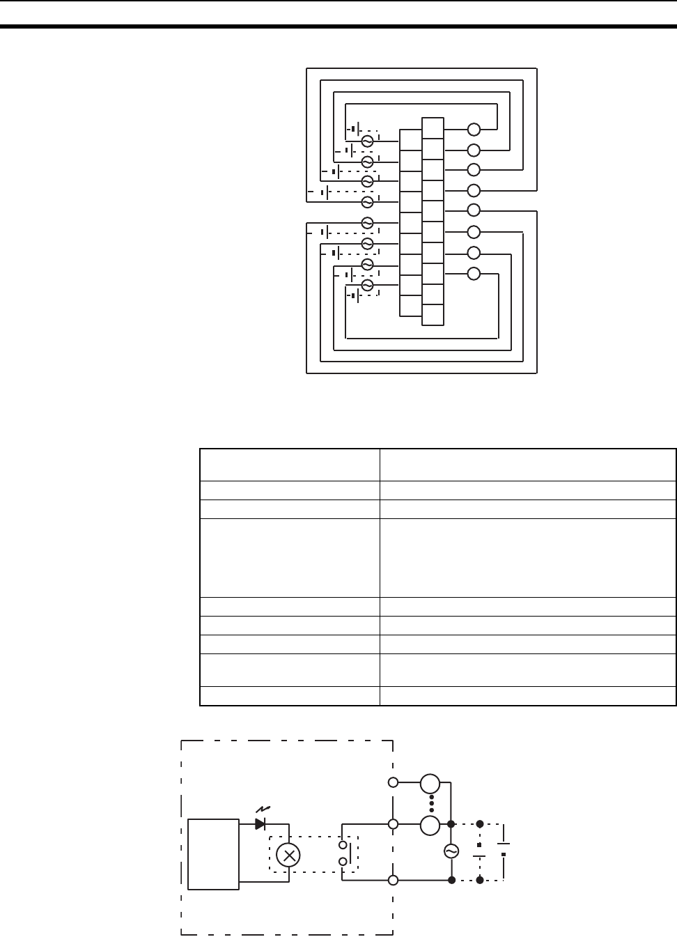
606
Specifications of Basic I/O Units and High-density I/O Units Appendix A
Terminal Connections
C200H-OC221 Contact Output Unit (8 Points)
Circuit Configuration
B0
B1
B2
B3
B4
B5
B6
B7
B8
B9
A0
A1
A2
A3
A4
A5
A6
A7
A8
c0
c1
c2
c3
c4
c5
c6
c7
L
L
L
L
L
L
L
L
0
1
2
3
4
5
6
7
250 V AC 24 V DC max.
(inductive load: 2 A
resistive load: 2 A)
(16 A/Unit)
NC
NC
NC
See note.
Note: There are no restrictions in the polarity
when connecting a DC power supply.
Max. Switching Capacity 2 A 250 V AC (cosφ = 1), 2 A 250 V AC (cosφ = 0.4),
2 A 24 V DC (8 A/Unit)
Min. Switching Capacity 10 mA 5 V DC
Relay G6B-1174P-FD-US-M (24 V DC) with socket
Service Life of Relay Electrical: 500,000 operations (resistive load)/
100,000 operations (inductive load)
Mechanical: 50,000,000 operations
Service life will vary depending on the current and
ambient temperature.
ON Response Time 10 ms max.
OFF Response Time 10 ms max.
No. of Circuits 1 (8 points/common)
Internal Current Consumption 10 mA 5 V DC max. 75 mA 26 V DC (8 points ON
simultaneously.)
Weight 250 g max.
L
L
OUT
COM
OUT
Output indicator
250 V AC 24 V DC max.
Internal
circuits
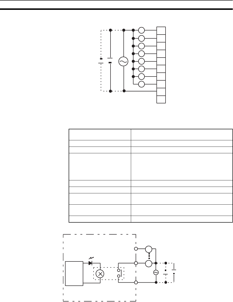
607
Specifications of Basic I/O Units and High-density I/O Units Appendix A
Terminal Connections
C200H-OC222 Contact Output Unit (12 Points)
Circuit Configuration
L
COM
A0
A1
A2
A3
A4
A5
A6
A7
A8
A9
0
1
2
3
4
5
6
7
NC
L
L
L
L
L
L
L
250 V AC 24 V DC max.
(inductive load: 2 A, resistive load: 2 A) (8 A/Unit)
Max. Switching Capacity 2 A 250 V AC (cosφ = 1), 2 A 250 V AC (cosφ = 0.4),
2 A 24 V DC (8 A/Unit)
Min. Switching Capacity 10 mA 5 V DC
Relay G6B-1174P-FD-US-M (24 V DC) with socket
Service Life of Relay Electrical: 500,000 operations (resistive load)/
100,000 operations (inductive load)
Mechanical: 50,000,000 operations
Service life will vary depending on the current and
ambient temperature.
ON Response Time 10 ms max.
OFF Response Time 10 ms max.
No. of Circuits 1 (12 points/common) 8 points max. can be ON
simultaneously.
Internal Current Consumption 10 mA 5 V DC max. 75 mA 26 V DC (8 points ON
simultaneously.)
Weight 300 g max.
L
L
OUT
COM
OUT
Output indicator
250 V AC 24 V DC max.
Internal
circuits
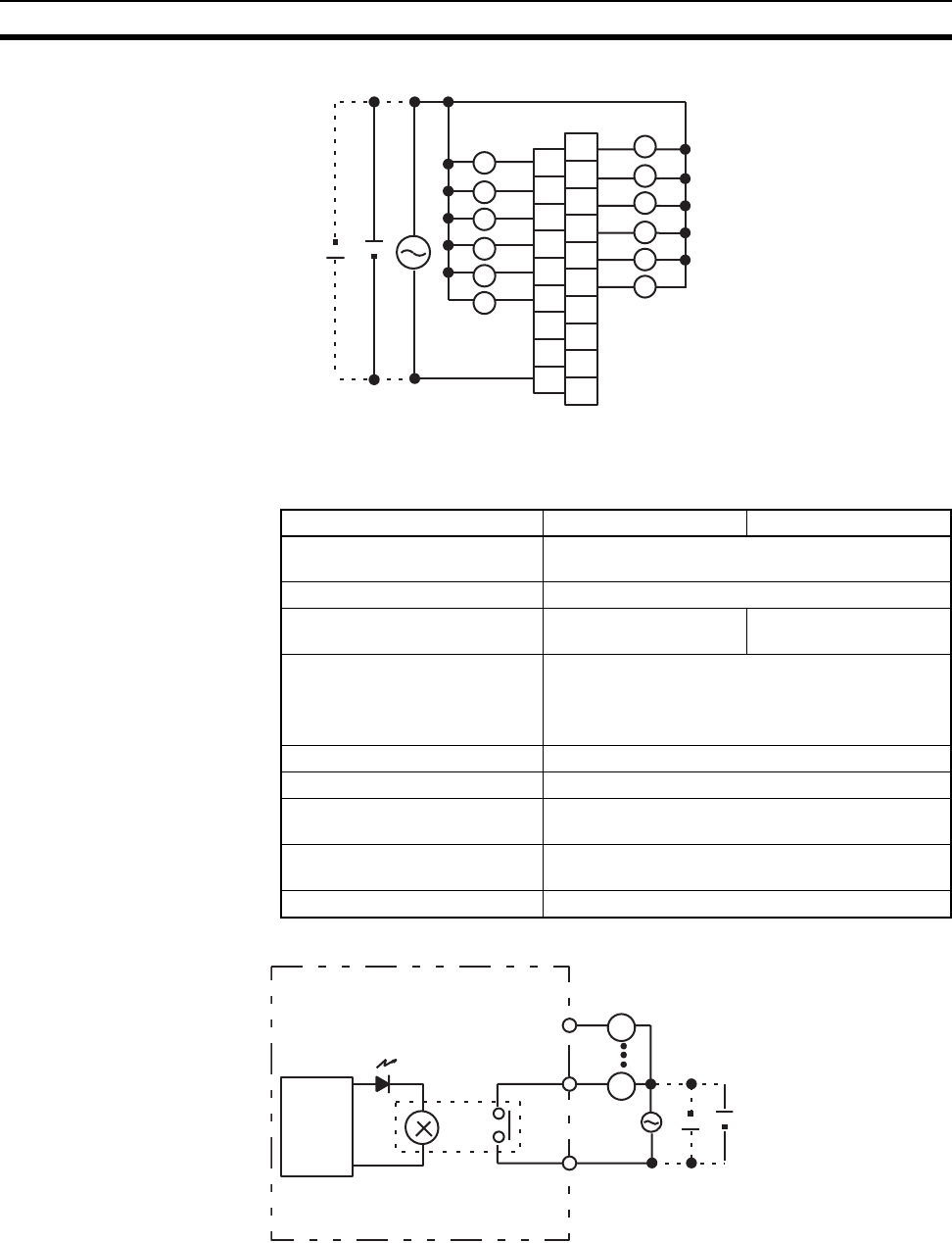
608
Specifications of Basic I/O Units and High-density I/O Units Appendix A
Terminal Connections
C200H-OC222V/OC222N Contact Output Unit (12 Points)
Circuit Configuration
A0
A1
A2
A3
A4
A5
A6
A7
A8
B0
B1
B2
B3
B4
B5
B6
B7
B8
B9
COM
1
3
5
7
9
11
NC
0
2
4
6
8
10
NC
NC
NC
NC
NC
(
inductive load: 2 A, resistive load: 2 A
)
(
8 A/Unit
)
L
L
L
L
L
L
L
L
L
L
L
L
250 V AC 24 V DC max.
Item OC222V OC222N
Max. Switching Capacity 2 A 250 V AC (cosφ = 1), 2 A 250 V AC (cosφ =
0.4), 2 A 24 V DC (8 A/Unit)
Min. Switching Capacity 10 mA 5 V DC
Relay G6R-1 (24 V DC) with
socket
G6RN-1-ACD (24 V DC)
PCB soldering
Service Life of Relay Electrical: 300,000 operations
Mechanical: 10,000,000 operations
Service life will vary depending on the current and
ambient temperature.
ON Response Time 15 ms max.
OFF Response Time 15 ms max.
No. of Circuits 1 (12 points/common) 8 points max. can be ON
simultaneously.
Internal Current Consumption 8 mA 5 V DC max. 90 mA 26 V DC (8 points ON
simultaneously.)
Weight 400 g max.
L
L
OUT
COM
OUT
Output indicator
250 V AC
24 V DC max.
Internal
circuits
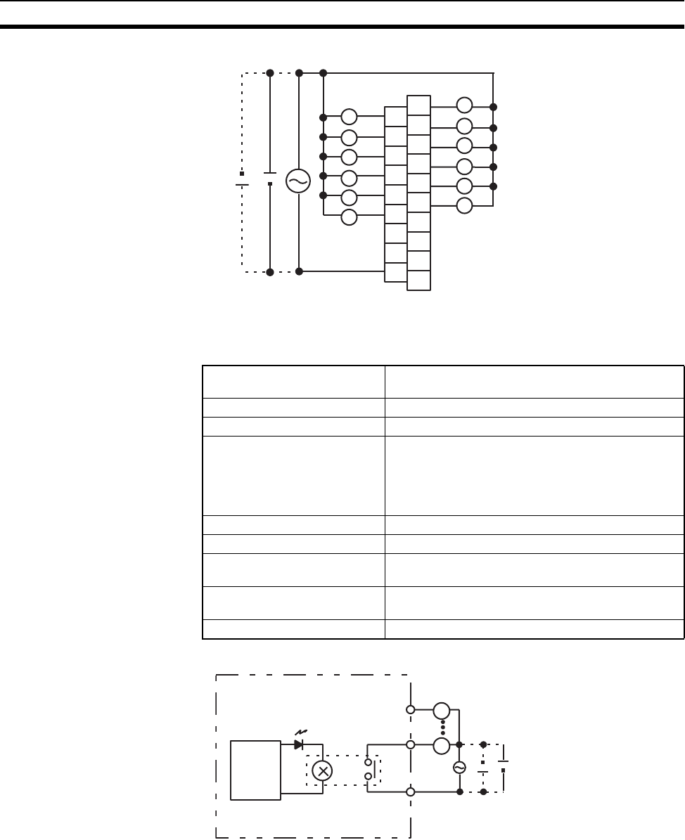
609
Specifications of Basic I/O Units and High-density I/O Units Appendix A
Terminal Connections
C200H-OC225 Contact Output Unit (16 Points)
Circuit Configuration
A0
A1
A2
A3
A4
A5
A6
A7
A8
B0
B1
B2
B3
B4
B5
B6
B7
B8
B9
COM
1
3
5
7
9
11
NC
0
2
4
6
8
10
NC
NC
NC
NC
NC
(
inductive load: 2 A, resistive load: 2 A
)
(
8 A/Unit
)
L
L
L
L
L
L
L
L
L
L
L
L
250 V AC 24 V DC max.
Max. Switching Capacity 2 A 250 V AC (cosφ = 1), 2 A 250 V AC (cosφ = 0.4),
2 A 24 V DC (8 A/Unit)
Min. Switching Capacity 10 mA 5 V DC
Relay G6B-1174P-FD-US-M (24 V DC) with socket
Service Life of Relay Electrical: 500,000 operations (resistive load)/
100,000 operations (inductive load)
Mechanical: 50,000,000 operations
Service life will vary depending on the current and
ambient temperature.
ON Response Time 10 ms max.
OFF Response Time 10 ms max.
No. of Circuits 1 (16 points/common) 8 points max. can be ON
simultaneously.
Internal Current Consumption 50 mA 5 V DC max. 75 mA 26 V DC (8 points ON
simultaneously.)
Weight 400 g max.
L
L
OUT
COM
OUT
Output indicator
250 V AC
24 V DC max.
Internal
circuits
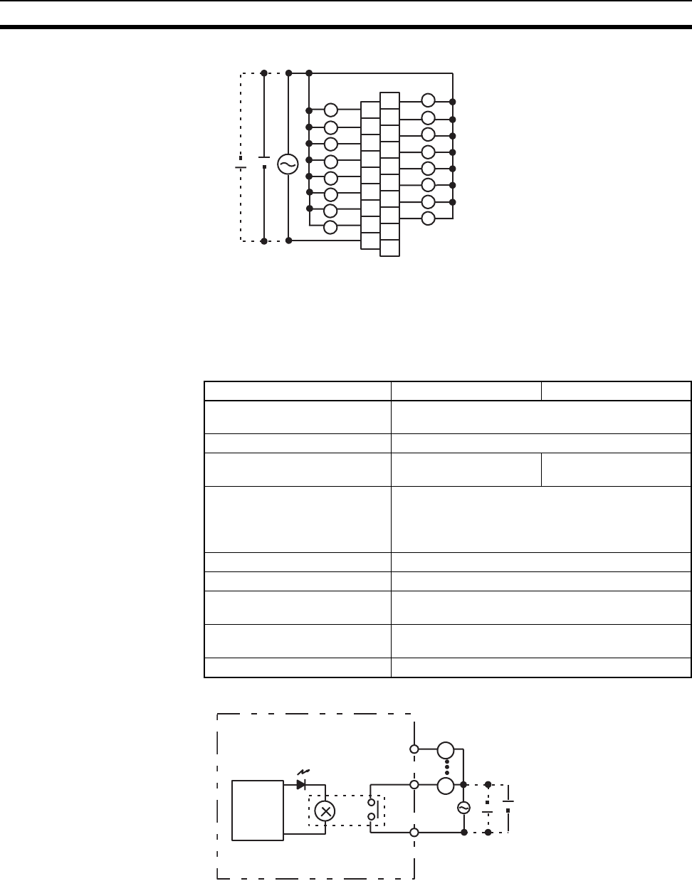
610
Specifications of Basic I/O Units and High-density I/O Units Appendix A
Terminal Connections
Note This Unit can overheat if more than 8 output points are turned ON simultaneously.
C200H-OC226/OC226N Contact Output Unit (16 Points)
Circuit Configuration
A0
A1
A2
A3
A4
A5
A6
A7
A8
B0
B1
B2
B3
B4
B5
B6
B7
B8
B9
COM
1
3
5
7
9
11
NC
0
2
4
6
8
10
NC
L
L
L
L
L
L
L
L
L
L
L
L
15
L
L
12
13 14
L
L
(inductive load: 2 A, resistive load: 2 A) (8 A/Unit)
250 V AC 24 V DC max.
Item OC226 OC226N
Max. Switching Capacity 2 A 250 V AC (cosφ = 1), 2 A 250 V AC (cosφ =
0.4), 2 A 24 V DC (8 A/Unit)
Min. Switching Capacity 10 mA 5 V DC
Relay G6R-1 (24 V DC) with
socket
G6RN-1-ACD (24 V DC)
PCB soldering
Service Life of Relay Electrical: 300,000 operations
Mechanical: 10,000,000 operations
Service life will vary depending on the current and
ambient temperature.
ON Response Time 15 ms max.
OFF Response Time 15 ms max.
No. of Circuits 1 (16 points/common) 8 points max. can be ON
simultaneously.
Internal Current Consumption 30 mA 5 V DC max. 90 mA 26 V DC (8 points ON
simultaneously.)
Weight 500 g max.
L
L
OUT
COM
OUT
Output indicator
250 V AC
24 V DC max.
Internal
circuits
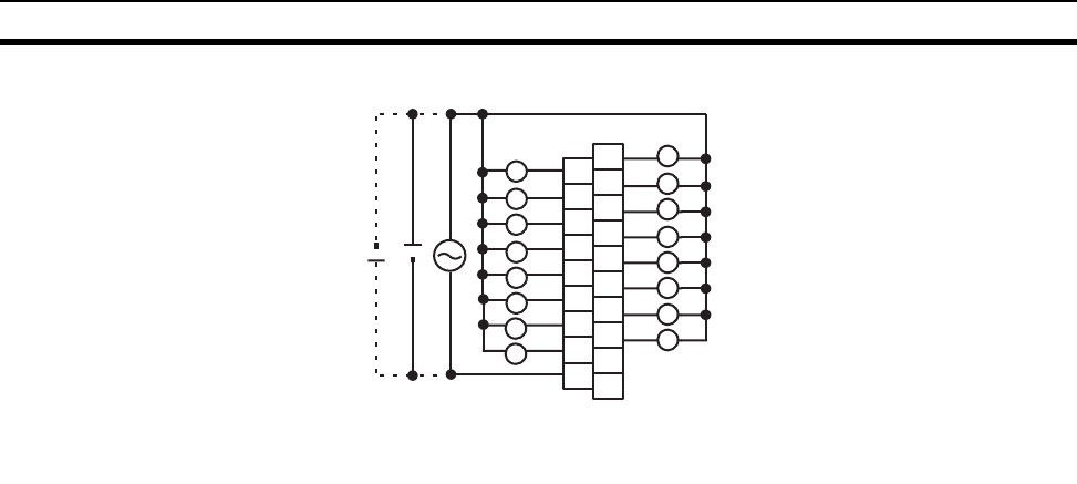
611
Specifications of Basic I/O Units and High-density I/O Units Appendix A
Terminal Connections
Note 1. Mount to the C200H-BC@@1-V1/V2 Backplane.
2. The number of simultaneously ON contact points must be eight or less to ensure proper heat resis-
tance.
About Contact Output Units
There are some differences in the relays used by the C200H and CS-series Contact Output Units. For this rea-
son, when used in the ways shown below, there may be differences in the respective life expectancies of the
relays.
• When using in excess of rated values
• When appropriate surge countermeasures are not taken
• When connected to a load (e.g., relay, solenoid, or motor) that generates a high counterelectromotive force
when power is interrupted
• When connected to a load (e.g., capacitor or lamp) that generates a high inrush current when power is
turned ON
In the above cases, ensure the rated life expectancies of the relays by, for example, taking the appropriate
surge countermeasures as explained in the manual, or using a switching device (as a relay) with ratings appro-
priate for the load.
Life Expectancy of CS1W-OC201/211 Relays
The life expectancy of the CS1W-OC201/211 Contact Output Unit is shown in the following diagrams. Use the
diagrams to calculate the relay service life based on the operating conditions, and replace the relay before the
end of its service life.
Note The diagrams show the life expectancy of the relay itself. Do not use a contact current, therefore, that
exceeds the maximum switching capacity specified in the specifications for each Contact Output Unit. If
a switching capacity exceeding the specifications is used, the reliability and life expectancy of other
parts will be reduced and the Unit may malfunction.
A0
A1
A2
A3
A4
A5
A6
A7
A8
B0
B1
B2
B3
B4
B5
B6
B7
B8
B9
COM
1
3
5
7
9
11
NC
0
2
4
6
8
10
NC
L
L
L
L
L
L
L
L
L
L
L
L
15
L
L
12
13 14
L
L
(
inductive load: 2 A, resistive load: 2 A
)
(
8 A/Unit
)
250 V AC 24 V DC max.
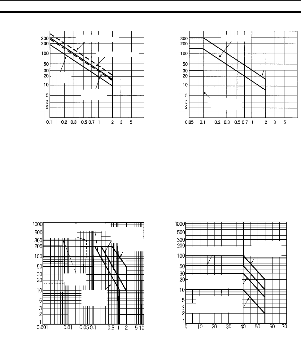
612
Specifications of Basic I/O Units and High-density I/O Units Appendix A
Life Expectancy of C200H-OC221/222/223/224/225 Contact Output Unit
The C200H-OC221/222/223/224/225 Contact Output Unit uses OMRON’s G6B-1174P-FD-US-M Relay. The
life of the G6B-1174P-FD-US-M Relay varies with the contact current and ambient temperature. Refer to the
following graphs to calculate this value, and be sure to replace the Relays before their service life expires.
Note 1. If the Contact Output Unit is panel-mounted, the temperature inside the panel represents the ambient
temperature.
2. The life of the Relay at an ambient temperature of 55°C is one-fifth the life of the Relay at room tem-
perature (0° to 40°C).
Inductive Load
The life of the Relay varies with the load inductance. If any inductive load is connected to the Contact Output
Unit, use an arc killer with the Contact Output Unit using an inductive load.
Be sure to connect a diode in parallel with every DC inductive load that is connected to the Contact Output
Unit.
Max. switching frequency: 1,800 times/h
240 V AC
(cosφ = 0.4)
120 V AC
(cosφ = 0.4)
Service life
Service Life with AC Load
Contact current (A)
Service Life with DC Load
Contact current (A)
Service life
100 to 120 V DC,
τ = 7 to 40 ms
24 V DC τ = 7 ms
120 V AC, resistive load
240 V AC, resistive load
(×104)
(×104)24 V AC, resistive load
Contact Current vs. Life Expectancy
Conditions
Switching frequency: 1,800 times/hour max.
Ambient temperature: 23°C
Life expectancy (x 104 operations)
Contact current (normal current) (A)
OMRON's
MY4 Relay
(200 V AC)
Electromagnetic
valve (250 V AC),
cosφ = 0.08 to
0.1)
OMRON's H3BA
Timer (200 V AC)
OMRON's MA415A
Contactor (200 V AC)
Ambient Temperature vs. Life
Expectancy
Conditions
Switching frequency: 1,800 times/hour max.
Life expectancy (x 104 operations)
Ambient temperature (˚C)
30 V DC, L/R = 40 ms
(electromagnetic valve) 250 V AC, cosφ = 0.4
30 V DC, L/R = 7 ms
(HK, MM, and MY
Hinge-type Relay)
250 V AC, cosφ =
130 V DC, L/R = 0 2 A at 250 V AC, resistive load
2 A at 30 V DC, resistive load
1 A at 250 V AC,
resistive load
1 A at 30 V DC,
resistive load
1 A at 250 V AC, inductive load
(cosφ = 0.4)
1 A at 30 V DC, inductive load
(L/R = 7 ms)
2 A at 250 V AC, inductive
load (cosφ = 0.4)
2 A at 30 V DC, inductive
load (L/R = 7 ms)
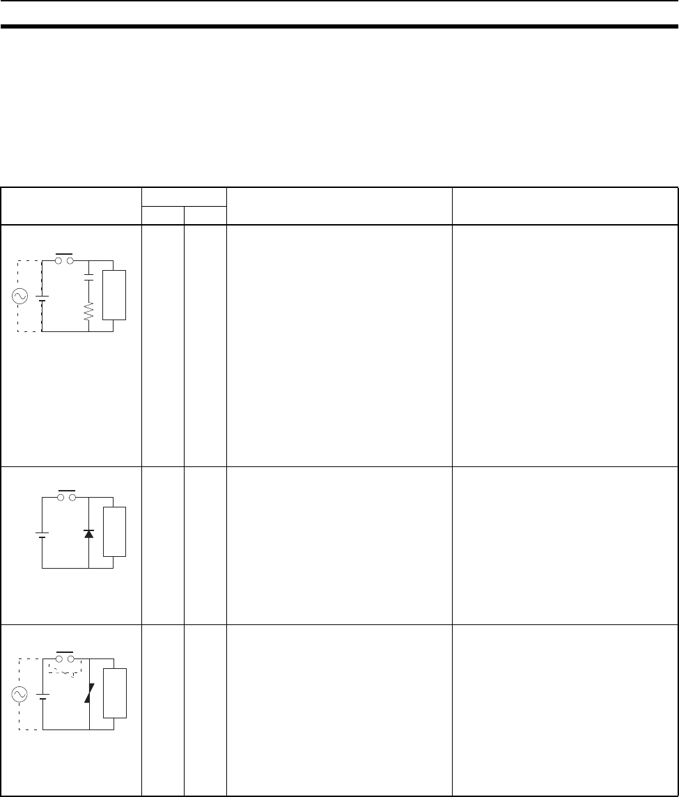
613
Specifications of Basic I/O Units and High-density I/O Units Appendix A
Contact Protection Circuit
Arc killers are used with the Contact Output Unit in order to prolong the life of each Relay mounted to the Con-
tact Output Unit, prevent noise, and reduce the generation of carbide and nitrate deposits. Arc killers can, how-
ever, reduce relay life if not use correctly.
Note Arc killers used with the Contact Output Unit can delay the resetting time required by each Relay
mounted to the Contact Output Unit.
Arc killer circuit examples are listed in the following table.
Note Do not connect a capacitor as an arc killer in parallel with an inductive load as shown in the following dia-
gram. This arc killer is very effective for preventing spark discharge at the moment when the circuit is
opened. However when the contacts are closed, the contacts may be welded due to the current charged
in the capacitor.
DC inductive loads can be more difficult to switch than resistive loads. If appropriate arc killers are used,
however, DC inductive loads will be as easy to switch as resistive loads.
Circuit Current Characteristic Required element
AC DC
Yes Yes If the load is a relay or solenoid, there
is a time lag between the moment the
circuit is opened and the moment the
load is reset.
If the supply voltage is 24 or 48 V,
insert the arc killer in parallel with the
load. If the supply voltage is 100 to
200 V, insert the arc killer between the
contacts.
The capacitance of the capacitor must
be 1 to 0.5 µF per contact current of
1 A and resistance of the resistor must
be 0.5 to 1 Ω per contact voltage of 1 V.
These values, however, vary with the
load and the characteristics of the
relay. Decide these values from experi-
ments, and take into consideration that
the capacitance suppresses spark dis-
charge when the contacts are sepa-
rated and the resistance limits the
current that flows into the load when
the circuit is closed again.
The dielectric strength of the capacitor
must be 200 to 300 V. If the circuit is an
AC circuit, use a capacitor with no
polarity.
No Yes The diode connected in parallel with
the load changes energy accumulated
by the coil into a current, which then
flows into the coil so that the current
will be converted into Joule heat by the
resistance of the inductive load. This
time lag, between the moment the cir-
cuit is opened and the moment the load
is reset, caused by this method is
longer than that caused by the CR
method.
The reversed dielectric strength value
of the diode must be at least 10 times
as large as the circuit voltage value.
The forward current of the diode must
be the same as or larger than the load
current.
The reversed dielectric strength value
of the diode may be two to three times
larger than the supply voltage if the arc
killer is applied to electronic circuits
with low circuit voltages.
Yes Yes The varistor method prevents the impo-
sition of high voltage between the con-
tacts by using the constant voltage
characteristic of the varistor. There is
time lag between the moment the cir-
cuit is opened and the moment the load
is reset.
If the supply voltage is 24 or 48 V,
insert the varistor in parallel with the
load. If the supply voltage is 100 to
200 V, insert the varistor between the
contacts.
---
CR method
Power
supply
Inductive
load
Diode method
Power
supply
Inductive
load
Varistor method
Power
supply
Inductive
load
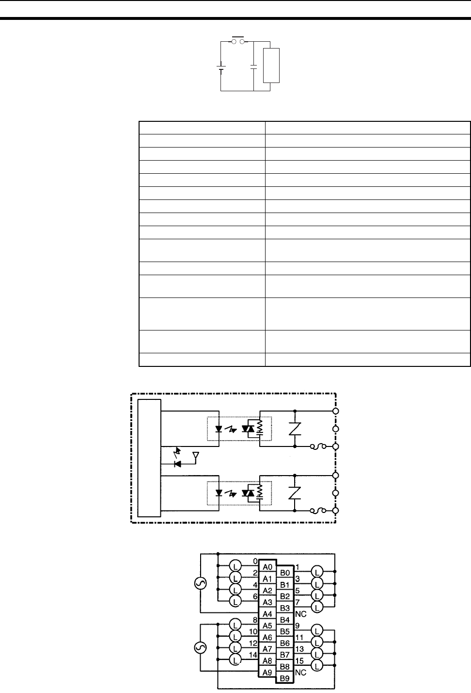
614
Specifications of Basic I/O Units and High-density I/O Units Appendix A
CS1W-OA211 Triac Output Unit (16 Points)
Circuit Configuration
Terminal Connections
Power
supply
Inductive
load
Max. Switching Capacity 0.5 A 250 V AC, 50/60 Hz (2 A/common, 4 A/Unit)
Max. Inrush Current 15 A (pulse width: 10 ms)
Min. Switching Capacity 50 mA 75 V AC
Leakage Current 1.5 mA (200 V AC) max.
Residual Voltage 1.6 V AC max.
ON Response Time 1 ms max.
OFF Response Time 1/2 of load frequency+1 ms or less.
No. of Circuits 2 (8 points/common)
Surge Protector C.R Absorber + Surge Absorber
Fuses 2 × 4 A (1 per common)
The fuse cannot be replaced by the user.
Blown Fuse Detection Circuit None
Insulation Resistance 20 MΩ between the external terminals and the GR
terminal (500 V DC)
Dielectric Strength 2,000 V AC between the external terminals and the
GR terminal for 1 minute at a leakage current of
10 mA max.
Internal Current Consumption 406 mA 5 V DC max. (70 mA + 21 mA × No. of ON
points)
Weight 300 g max.
IN0
to
IN7
COM0
IN8
to
IN15
COM1
Output indicator
Internal circuits
Fuse
Fuse
0.5 A
250 V AC
max.
COM0
COM1
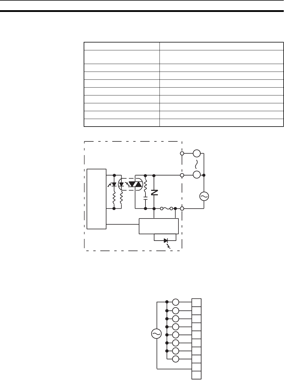
615
Specifications of Basic I/O Units and High-density I/O Units Appendix A
Note Terminal numbers A0 to A9 and B0 to B9 are used in this manual, but they are not printed on the Unit.
C200H-OA221 Triac Output Unit (8 Points)
Circuit Configuration
Note When the fuse blows, the F indicator lights and bit 08 turns ON. Bits 08 through 15 cannot be used as
work bits.
Terminal Connections
Max. Switching Capacity 1 A 250 V AC, 50/60 Hz (4 A/Unit)
Min. Switching Capacity 10 mA (resistive load)/40 mA (inductive load) 10 V
AC
Leakage Current 3 mA (100 V AC) max./6 mA (200 V AC) max.
Residual Voltage 1.2 V max.
ON Response Time 1 ms max.
OFF Response Time 1/2 of load frequency or less.
No. of Circuits 1 (8 points/common)
Internal Current Consumption 140 mA 5 V DC max.
Fuse Rating 5 A 250 V (5.2-dia. × 20)
Weight 250 g max.
Internal
circuits
L
OUT
COM
OUT
Output indicator
L
250 V AC max.
F indicator
Fuse: 5 A 250 V
(
5.2-dia. x 20
)
MF51SH
(
JIS
)
Fuse blowout
detection circuit
Fuse
A0
A1
A2
A3
A4
A5
A6
A7
A8
A9
0
1
2
3
4
5
6
7
L
L
L
L
L
L
L
L
COM
250 V AC max.
(1 A max. 4 A/Unit)
NC
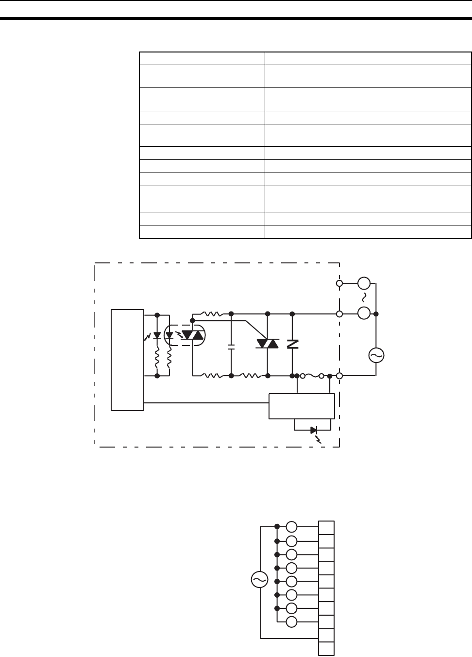
616
Specifications of Basic I/O Units and High-density I/O Units Appendix A
C200H-OA223 Triac Output Unit (8 Points)
Circuit Configuration
Note When the fuse blows, the F indicator lights and bit 08 turns ON. Bits 08 through 15 cannot be used as
work bits.
Terminal Connections
Max. Switching Capacity 1.2 A 250 V AC, 50/60 Hz (4 A/Unit)
Max. Inrush Current 15 A (pulse width: 100 ms)
30 A (pulse width: 10 ms)
Min. Switching Capacity 100 mA 10 V AC/50 mA 24 V AC/10 mA 100 V AC
min.
Leakage Current 1.5 mA (120 V AC) max./3 mA (240 V AC) max.
Residual Voltage 1.5 V AC max. (50 to 1,200 mA)/ 5 V AC max. (10 to
50 mA)
ON Response Time 1 ms max.
OFF Response Time 1/2 of load frequency+1 ms or less.
No. of Circuits 1 (8 points/common)
Internal Current Consumption 180 mA 5 V DC max.
Fuse Rating 5 A 250 V (5.2-dia. × 20)
Power for External Supply N/A
Weight 300 g max.
L
Internal
circuits
OUT
COM
OUT
Output indicator
L
250 V AC max.
Fuse: 5 A 250 V (5.2-dia. x 20) HT (SOC)
Fuse
F indicator
Fuse blowout
detection circuit
A0
A1
A2
A3
A4
A5
A6
A7
A8
A9
0
1
2
3
4
5
6
7
L
L
L
L
L
L
L
L
COM
250 V AC max.
(1.2 A max. 4 A/Unit)
NC
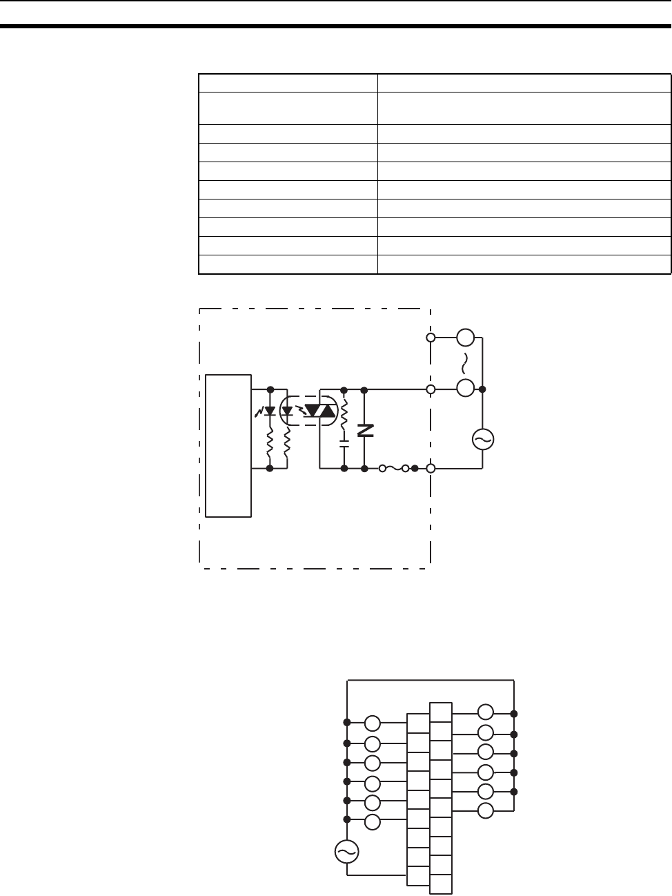
617
Specifications of Basic I/O Units and High-density I/O Units Appendix A
C200H-OA222V Triac Output Unit (12 Points)
Circuit Configuration
Note 1. No blown fuse detector circuit is provided.
2. Check the fuse when there is no output.
Terminal Connections
Max. Switching Capacity 0.3 A 250 V AC, 50/60 Hz (2 A/Unit)
Min. Switching Capacity 10 mA (resistive load)/40 mA (inductive load) 10 V
AC
Leakage Current 3 mA (100 V AC) max./6 mA (200 V AC) max.
Residual Voltage 1.2 V max.
ON Response Time 1/2 of load frequency or less
OFF Response Time 1/2 of load frequency or less.
No. of Circuits 1 (12 points/common)
Internal Current Consumption 200 mA 5 V DC max.
Fuse Rating 3 A 250 V (5.2-dia. × 20)
Weight 400 g max.
Internal
circuits
L
OUT
COM
OUT
Output indicator
L
250 V AC max.
Fuse: 3 A 250 V
(
5.2-dia. x 20
)
MQ4
(
SOC
)
Fuse
A0
A1
A2
A3
A4
A5
A6
A7
A8
B0
B1
B2
B3
B4
B5
B6
B7
B8
B9
COM
1
3
5
7
9
11
NC
0
2
4
6
8
10
NC
NC
NC
NC
250 V AC max.
(0.3 A max., 2 A/Unit)
L
L
L
L
L
L
L
L
L
L
L
L
NC
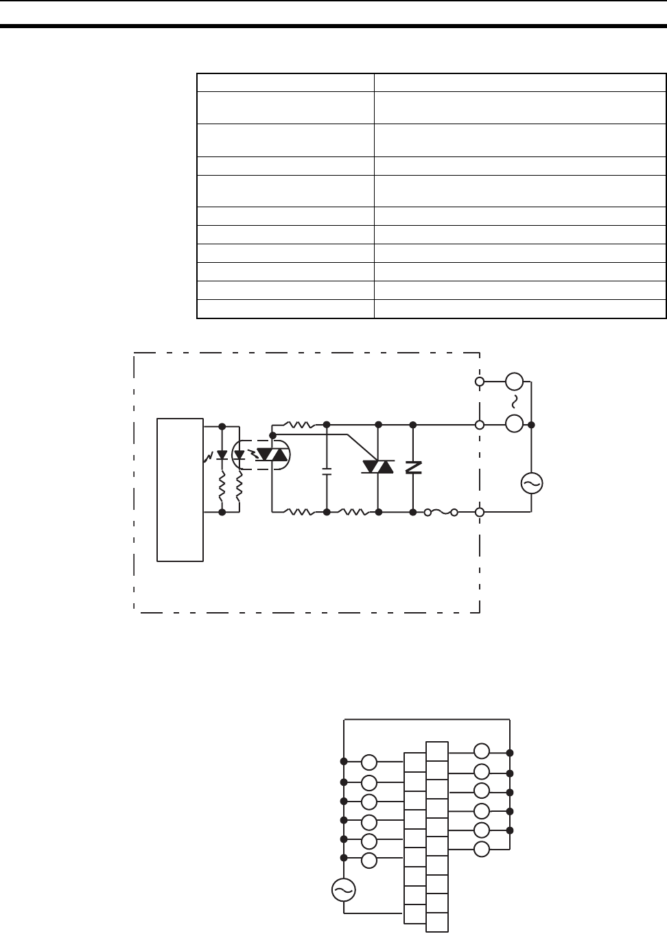
618
Specifications of Basic I/O Units and High-density I/O Units Appendix A
C200H-OA224 Triac Output Unit (12 Points)
Circuit Configuration
Note 1. No blown fuse detector circuit is provided.
2. Check the fuse when there is no output.
Terminal Connections
Max. Switching Capacity 0.5 A 250 V AC, 50/60 Hz (2 A/Unit)
Max. inrush current 10 A (pulse width: 100 ms)
20 A (pulse width: 10 ms)
Min. Switching Capacity 100 mA 10 V AC/50 mA 24 V AC/10 mA 100 V AC
min.
Leakage Current 1.5 mA (120 V AC) max./3 mA (240 V AC) max.
Residual Voltage 1.5 V AC max. (50 to 500 mA)/5 V AC max. (10 to
50 mA)
ON Response Time 1 ms max.
OFF Response Time 1/2 of load frequency + 1 ms or less.
No. of Circuits 1 (12 points/common)
Internal Current Consumption 270 mA 5 V DC max.
Fuse Rating 3.15 A 250 V (5.2-dia. × 20)
Weight 300 g max.
L
Internal
circuits
OUT
COM
OUT
Output indicator
L
250 V AC max.
Fuse: 3.15 A 250 V (5.2-dia. x 20) MT4 (SOC)
Fuse
A0
A1
A2
A3
A4
A5
A6
A7
A8
B0
B1
B2
B3
B4
B5
B6
B7
B8
B9
COM
1
3
5
7
9
11
NC
0
2
4
6
8
10
NC
NC
NC
NC
250 V AC max.
(0.5 A max., 2 A/Unit)
L
L
L
L
L
L
L
L
L
L
L
L
NC
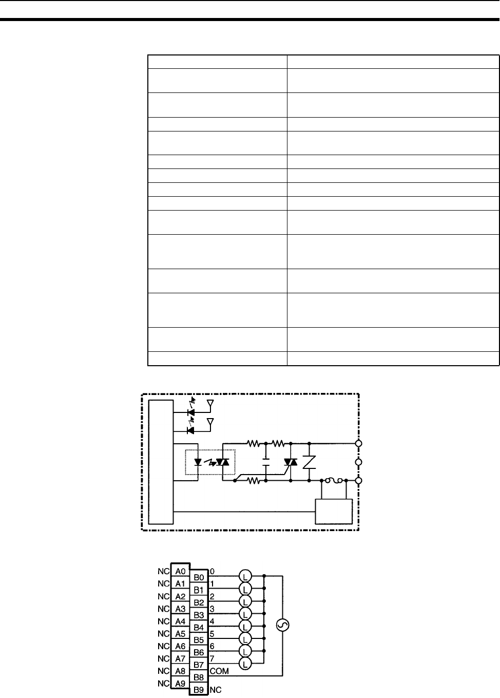
619
Specifications of Basic I/O Units and High-density I/O Units Appendix A
CS1W-OA201 Triac Output Unit (8 Points) (See note 1.)
Circuit Configuration
Terminal Connections
Max. Switching Capacity 1.2 A 250 V AC, 50/60 Hz (4.8 A/Unit)
Max. Inrush Current 10 A (pulse width: 100 ms), 20 A (pulse width:
10 ms)
Min. Switching Capacity 100 mA 10 V AC, 50 mA 24 V AC, 10 mA 100 V
AC min.
Leakage Current 1.5 mA (120 V AC) max., 3.0 mA (240 V AC) max.
Residual Voltage 1.5 V AC max. (50 to 500 mA), 5.0 V AC max. (10
to 50 mA)
ON Response Time 1 ms max.
OFF Response Time 1/2 of load frequency+1 ms or less.
No. of Circuits 1 (8 points/common)
Surge Protector C.R Absorber + Surge Absorber
Fuses 8A
The fuse cannot be replaced by the user.
Blown Fuse Detection Circuit ERR indicator lit when fuse blown. Also, the corre-
sponding Flag in the Basic I/O Unit Information
Area (A050 to A089) will turn ON.
Insulation Resistance 20 MΩ between the external terminals and the GR
terminal (500 V DC)
Dielectric Strength 2,000 V AC between the external terminals and
the GR terminal for 1 minute at a leakage current
of 10 mA max.
Internal Current Consumption 230 mA 5 V DC max. (70 mA + 20 mA × No. of ON
points)
Weight 300 g max.
IN0
to
IN7
COM
Internal circuits
Fuse
Blown fuse
detection
circuit
Output indicator
ERR indicator
1.2 A 250 V AC max.
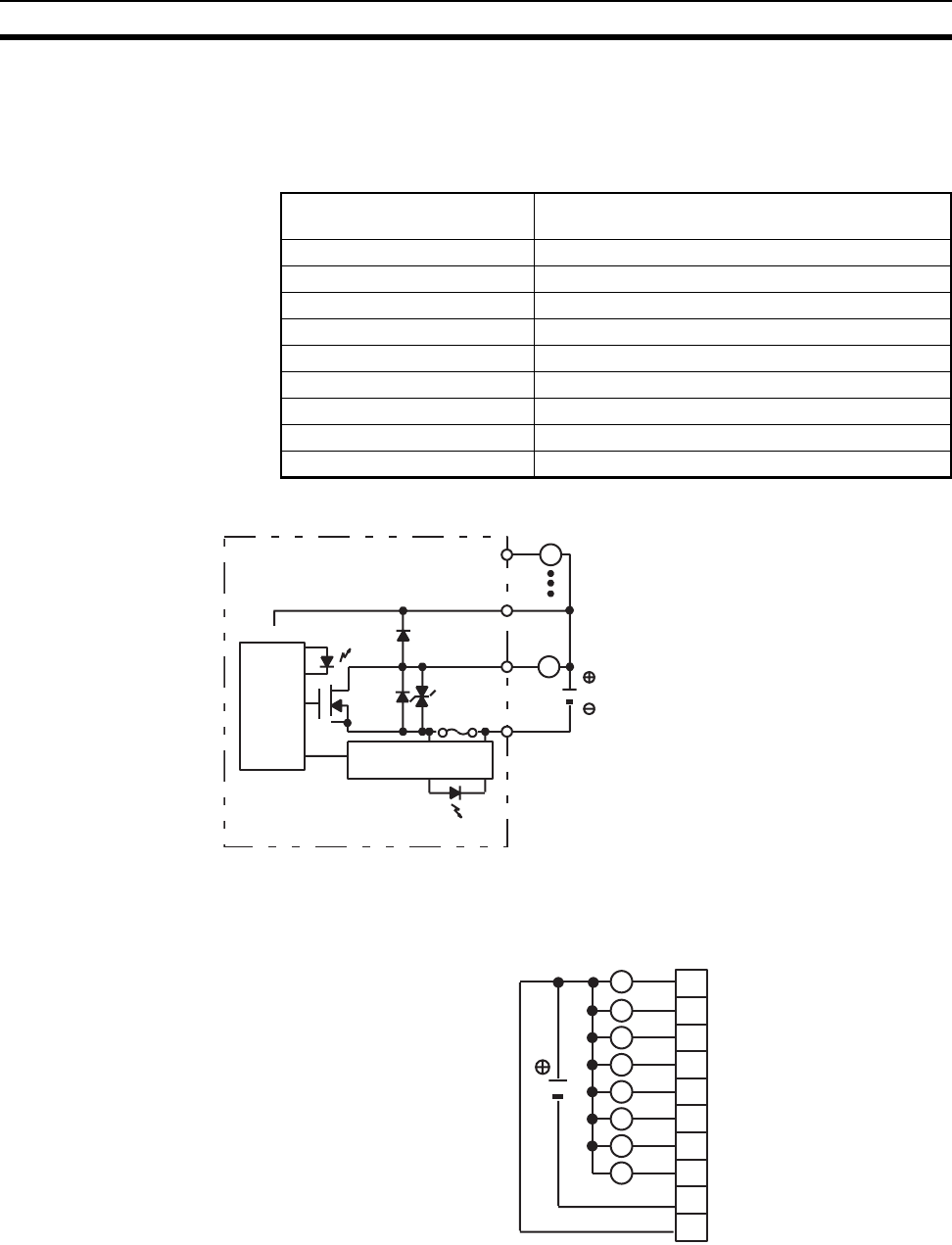
620
Specifications of Basic I/O Units and High-density I/O Units Appendix A
Note 1. This Unit uses only 8 bits for external I/O even though 16 bits (1 word) are allocated. This Unit is also
treated as a 16-point Unit in the I/O tables.
2. Terminal numbers A0 to A9 and B0 to B9 are used in this manual, but they are not printed on the Unit.
C200H-OD213 Transistor Output Unit (8 Points)
Circuit Configuration
Note When the fuse blows, the F indicator lights and bit 08 turns ON. Bits 08 through 15 cannot be used as
work bits.
Terminal Connections
Note 1. Be sure to supply power to A9; otherwise current will leak through the load while the output is OFF.
2. Incorrect load operation may result if polarity is not connected correctly.
Max. Switching Capacity 2.1 A 24 V DC (20.4 to 26.4 V DC) (5.2 A/Unit) NPN
output
Leakage Current 0.1 mA max.
Residual Voltage 1.4 V max.
ON Response Time 0.2 ms max.
OFF Response Time 0.3 ms max.
No. of Circuits 1 (8 points/common)
Internal Current Consumption 140 mA 5 V DC max.
Fuse Rating 8 A 125 V (5.2-dia. × 20)
Power for External Supply 30 mA 20.4 to 26.4 V DC min.
Weight 250 g max.
Internal
circuits
L
OUT
COM
OUT
Output indicator
L
+ V
24 V DC
Fuse blowout
detection circuit
Fuse
F indicator
Fuse: UL-TSC-8A-N1 (SOC)
8 A 125 V 5.2-dia. × 20
24 V DC
(2.1 A max., 5.2 A/Unit)
L
L
L
L
L
L
L
L
A0
A1
A2
A3
A4
A5
A6
A7
A8
A9
0
1
2
3
4
5
6
7
COM (0 V)
24 V DC
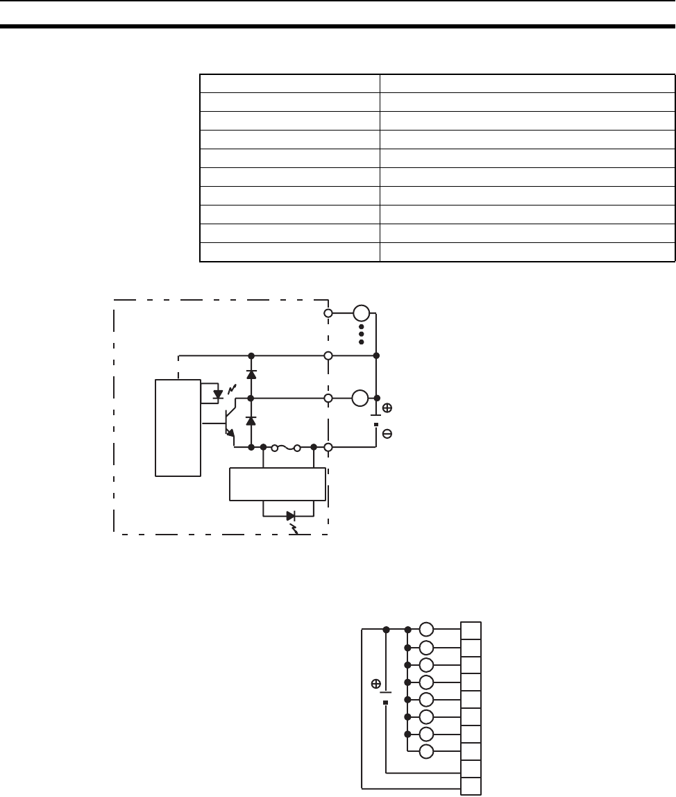
621
Specifications of Basic I/O Units and High-density I/O Units Appendix A
C200H-OD411 Transistor Output Unit (8 Points)
Circuit Configuration
Note When the fuse blows, the F indicator lights and bit 08 turns ON. Bits 08 through 15 cannot be used as
work bits.
Terminal Connections
Note Be sure to supply power to A9; otherwise current will leak through the load while the output is OFF.
Max. Switching Capacity 10.2 to 52.8 V DC 1 A (3 A/Unit)
Leakage Current 0.1 mA max.
Residual Voltage 1.4 V max.
ON Response Time 0.2 ms max.
OFF Response Time 0.3 ms max.
No. of Circuits 1 (8 points/common)
Internal Current Consumption 140 mA 5 V DC max.
Fuse Rating 5 A 125 V (5.2-dia. × 20)
Power for External Supply 30 mA 10.2 to 52.8 V DC min.
Weight 250 g max.
Internal
circuits
L
OUT
COM
OUT
L
F indicator
Fuse blowout
detection circuit
V
Fuse
12 to
48 V DC
Output indicator
Fuse: FGMT (Fuji Terminal Industry Co. Ltd.)
5 A 125 V 5.2-dia. x 20
L
A0
A1
A2
A3
A4
A5
A6
A7
A8
A9
0
1
2
3
4
5
6
7
L
L
L
L
L
L
L
COM (0 V)
12 to 48 V DC
12 to 48 V DC
(1 A max., 3 A/Unit)
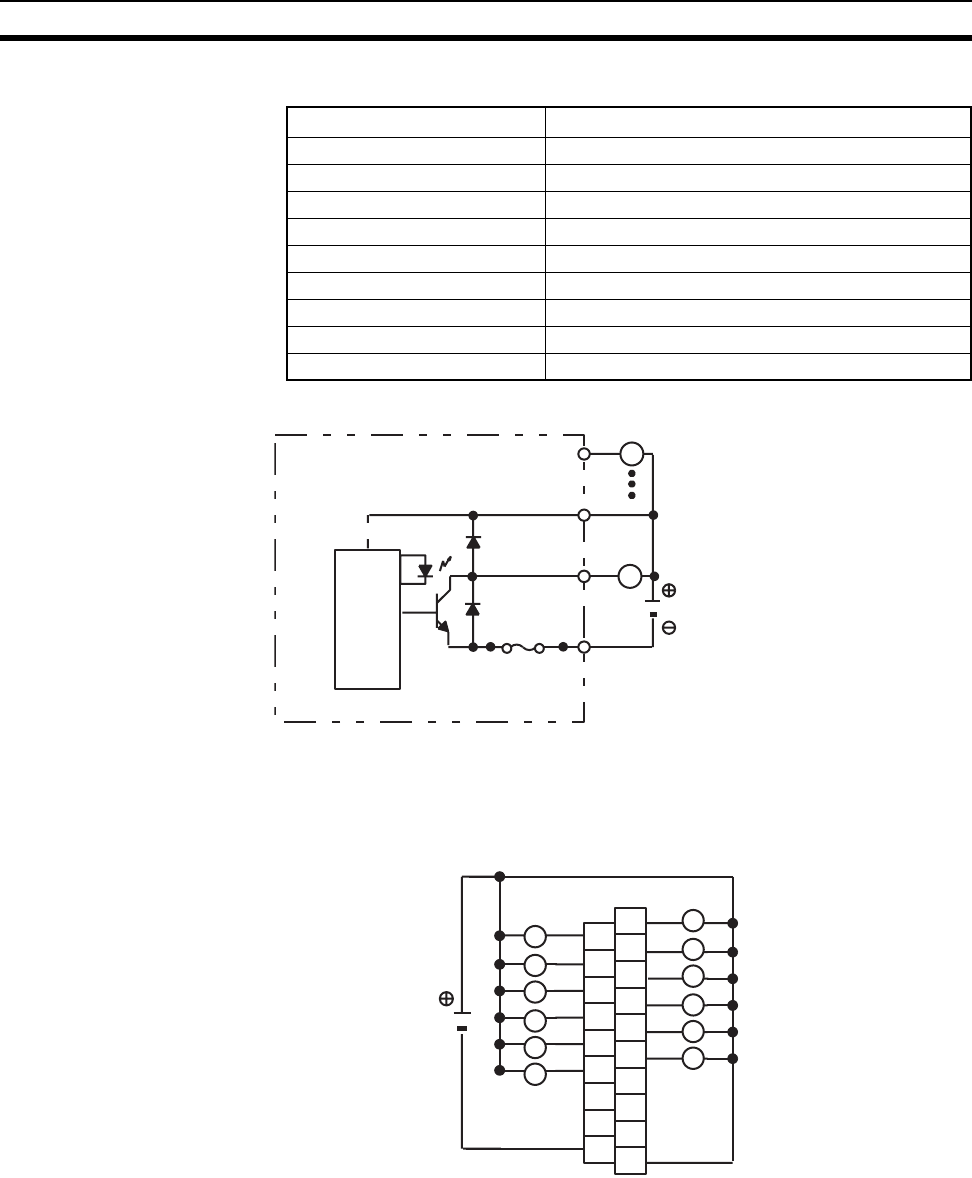
622
Specifications of Basic I/O Units and High-density I/O Units Appendix A
C200H-OD211 Transistor Output Unit (12 Points)
Circuit Configuration
Note 1. No blown fuse detector circuit is provided.
2. Check the fuse when there is no output.
Terminal Connections
Note 1. Be sure to supply power to B9; otherwise current will leak through the load while the output is OFF.
2. Terminal numbers A0 to A9 and B0 to B9 are used in this manual, but they are not printed on the Unit.
Max. Switching Capacity 0.3 A 24 V DC (20.4 to 26.4 V DC) (2 A/Unit)
Leakage Current 0.1 mA max.
Residual Voltage 1.4 V max.
ON Response Time 0.2 ms max.
OFF Response Time 0.3 ms max.
No. of Circuits 1 (12 points/common)
Internal Current Consumption 160 mA 5 V DC max.
Fuse Rating 5 A 125 V (5.2-dia. × 20)
Power for External Supply 25 mA 20.4 to 26.4 V DC min.
Weight 300 g max.
L
OUT
COM
OUT
L
+V
Fuse
24 V DC
Output indicator
Fuse: FGMT (Fuji Terminal Industry Co. Ltd.)
5 A 125 V 5.2-dia. × 20
Internal
circuits
A0
A1
A2
A3
A4
A5
A6
A7
A8
B0
B1
B2
B3
B4
B5
B6
B7
B8
B9
COM (0 V)
1
3
5
7
9
11
NC
0
2
4
6
8
10
24 V DC
(0.3 A max., 2 A/Unit)
L
L
L
L
L
L
L
L
L
L
L
L
+ 24 V DC
NC
NC
NC
NC
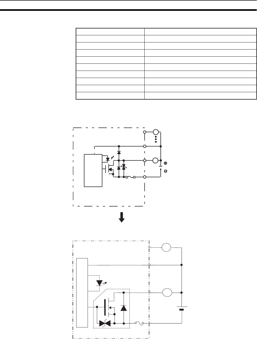
623
Specifications of Basic I/O Units and High-density I/O Units Appendix A
C200H-OD212 Transistor Output Unit (16 Points)
Circuit Configuration
Note 1. No blown fuse detector circuit is provided.
2. Check the fuse when there is no output.
Max. Switching Capacity 0.3 A 24 V DC (20.4 to 26.4 V DC) (4.8 A/Unit)
Leakage Current 0.1 mA max.
Residual Voltage 1.4 V max.
ON Response Time 0.2 ms max.
OFF Response Time 0.3 ms max.
No. of Circuits 1 (16 points/common)
Internal Current Consumption 180 mA 5 V DC max.
Fuse Rating 8 A 125 V (5.2-dia. × 20)
Power for External Supply 35 mA 24 V DC (20.4 to 26.4 V DC) min.
Weight 350 g max.
Internal
circuits
L
OUT
COM
OUT
Output indicator
L
+ V
Fuse: UL-TSC-8A-N1 (SOC)
24 V DC
Fuse
8 A 125 V 5.2-dia. × 20
Units manufactured on or before October 9, 2002
(manufacturing numbers 09X2 or earlier)
Units manufactured on or after October 10, 2002
(manufacturing numbers 10X2H or later)
+V
L
L
24 V DC
OUT
OUT
COM
Output indicator
Internal circuits
Fuse
Built-in FET
to
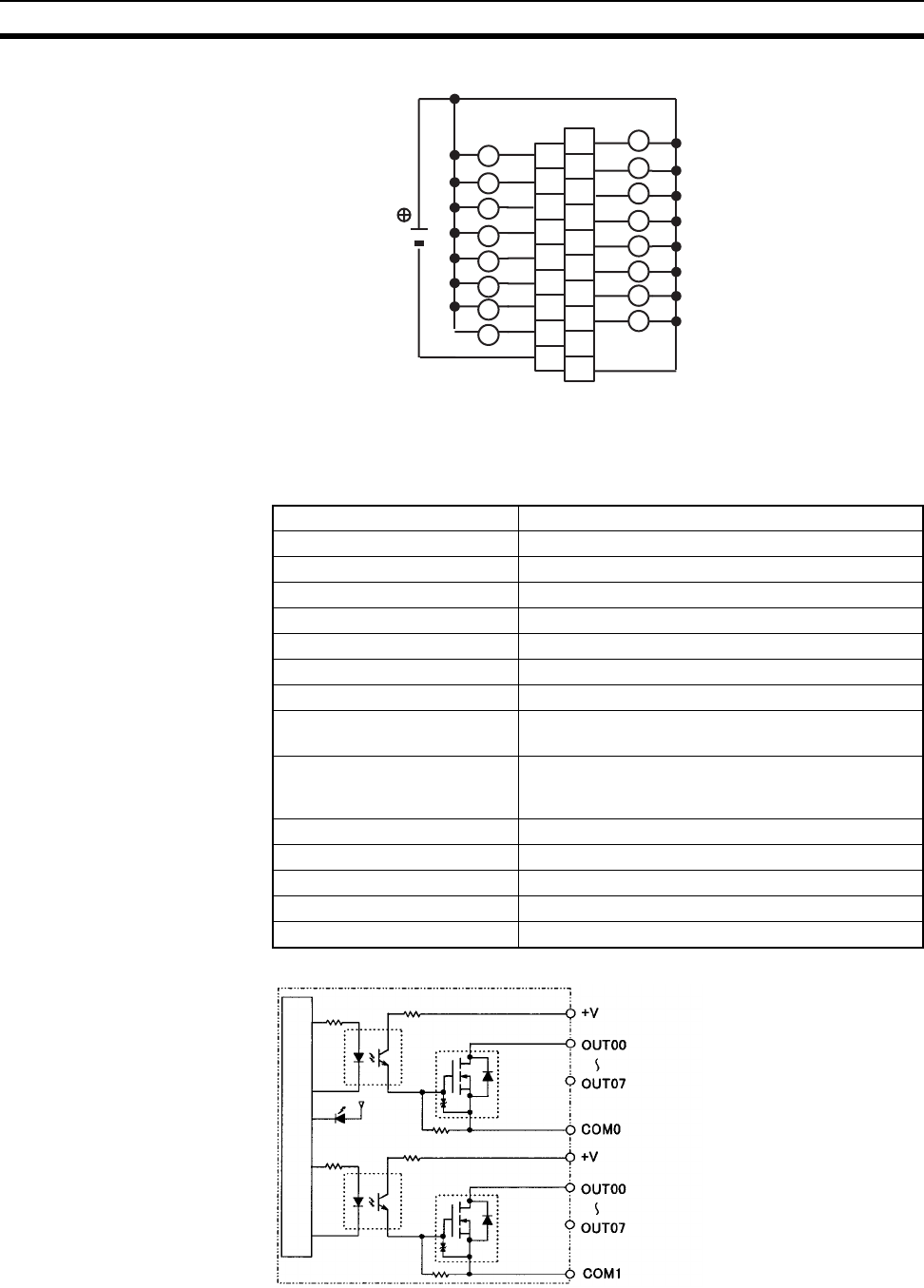
624
Specifications of Basic I/O Units and High-density I/O Units Appendix A
Terminal Connections
Note 1. Be sure to supply power to B9; otherwise current will leak through the load while the output is OFF.
2. Terminal numbers A0 to A9 and B0 to B9 are used in this manual, but they are not printed on the Unit.
CS1W-OD211 Transistor Output Unit (16 Points, Sinking)
Circuit Configuration
A0
A1
A2
A3
A4
A5
A6
A7
A8
B0
B1
B2
B3
B4
B5
B6
B7
B8
B9
COM (0 V)
1
3
5
7
9
11
NC
0
2
4
6
8
10
24 V DC
(0.3 A max.)
L
L
L
L
L
L
L
L
L
L
L
L
+ 24 V DC
L
L
13
15
L
L
12
14
Rated Voltage 12 to 24 V DC
Operating Load Voltage Range 10.2 to 26.4 V DC
Maximum Load Current 0.5 A/point, 4.0 A/common, 8.0 A/Unit
Maximum Inrush Current 4.0 A/point, 10 ms max.
Leakage Current 0.1 mA max.
Residual Voltage 1.5 V max.
ON Response Time 0.5 ms max.
OFF Response Time 1.0 ms max.
Insulation Resistance 20 MΩ between the external terminals and the GR
terminal (100 V DC)
Dielectric Strength 1,000 V AC between the external terminals and the
GR terminal for 1 minute at a leakage current of
10 mA max.
No. of Circuits 16 (8 points/common, 2 circuits)
Internal Current Consumption 5 V DC 170 mA max.
Fuse None
External Power Supply 10.2 to 26.4 V DC, 20 mA min.
Weight 270 g max.
Output indicator
Internal circuits
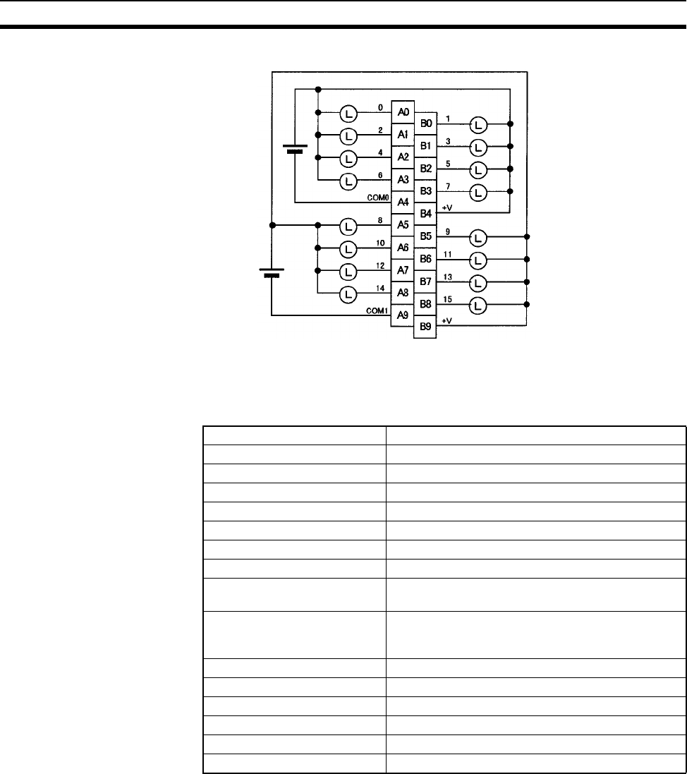
625
Specifications of Basic I/O Units and High-density I/O Units Appendix A
Terminal Connections
Note Terminal numbers A0 to A9 and B0 to B9 are used in this manual, but they are not printed on the Unit.
When wiring, pay careful attention to the polarity. The load may operate incorrectly if the polarity is reversed.
CS1W-OD231 Transistor Output Unit (32 Points, Sinking)
Note The maximum load currents will be 2.0 A/common and 4.0 A/Unit if a pressure-welded connector is
used.
12 to 24 V DC
12 to 24 V DC
Rated Voltage 12 to 24 V DC
Operating Load Voltage Range 10.2 to 26.4 V DC
Maximum Load Current 0.5 A/point, 2.5 A/common, 5.0 A/Unit (See note.)
Maximum Inrush Current 4.0 A/point, 10 ms max.
Leakage Current 0.1 mA max.
Residual Voltage 1.5 V max.
ON Response Time 0.5 ms max.
OFF Response Time 1.0 ms max.
Insulation Resistance 20 MΩ between the external terminals and the GR
terminal (100 V DC)
Dielectric Strength 1,000 V AC between the external terminals and the
GR terminal for 1 minute at a leakage current of
10 mA max.
No. of Circuits 32 (16 points/common, 2 circuits)
Internal Current Consumption 5 V DC 270 mA max.
Fuse None
External Power Supply 10.2 to 26.4 V DC, 30 mA min.
Weight 200 g max.
Accessories One connector for external wiring (soldered)
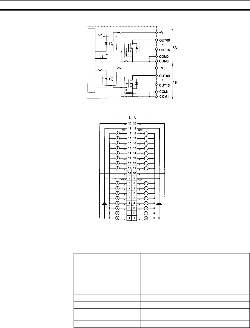
626
Specifications of Basic I/O Units and High-density I/O Units Appendix A
Circuit Configuration
Terminal Connections
• When wiring, pay careful attention to the polarity. The load may operate if the polarity is reversed.
• Although the +V and COM terminals of rows A and B are internally connected, wire all points completely.
C200H-OD218 Transistor Output Unit (32 Points)
Output indicator
Internal circuits
12 to 24 V DC 12 to 24 V DC
I/O word "m"
I/O word "m + 1"
Max. Switching Capacity 16 mA 4.5 V DC to 100 mA 26.4 V DC (see below)
Leakage Current 0.1 mA max.
Residual Voltage 0.8 V max.
ON Response Time 0.1 ms max.
OFF Response Time 0.4 ms max.
No. of Circuits 1 (32 points/common)
Internal Current Consumption 180 mA 5 V DC max.
Fuse Rating 3.5 A (The fuse is not user-replaceable.)
Power for External Supply 110 mA 5 to 24 V DC±10% min.
(3.4 mA × number of ON pts)
Weight 180 g max.
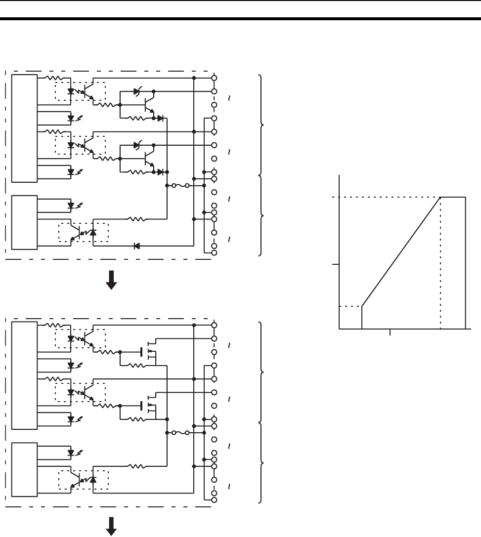
627
Specifications of Basic I/O Units and High-density I/O Units Appendix A
Circuit Configuration and Maximum Switching Capacity
Power Supply Voltage (V)
Max. Switching Capacity (mA/pt)
0 4.5 10 20.4 26.4
50
100
16
0
Units manufactured on or before January 28, 2000
(manufacturing numbers 2810 or earlier)
Output
indicator
Fuse
(3.5 A)
F indicator
Output
indicator
OUT00
OUT07
COM
A
Internal
circuits
4.5 to
26.4 V DC
4.5 to
26.4 V DC
OUT08
OUT15
COM
OUT00
OUT07
COM B
OUT08
OUT15
COM
4.5 to
26.4 V DC
4.5 to
26.4 V DC
Output
indicator
Fuse
blowout
detec-
tion
circuit
Fuse
(3.5 A)
F indicator
Output
indicator
OUT00
OUT07
COM
A
Internal
circuits
4.5 to
26.4 V DC
4.5 to
26.4 V DC
OUT08
OUT15
COM
OUT00
OUT07
COM B
OUT08
OUT15
COM
4.5 to 26.4
V DC
4.5 to
26.4 V DC
Fuse
blowout
detec-
tion
circuit
Units manufactured between January 31, 2000 and
October 9, 2002 (manufacturing numbers 3110 to 09X2)
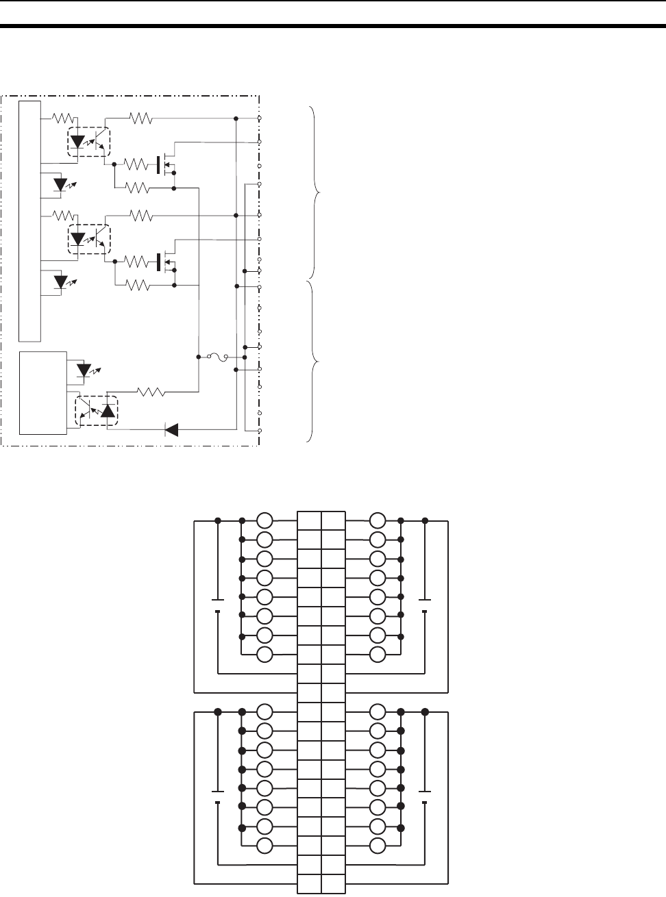
628
Specifications of Basic I/O Units and High-density I/O Units Appendix A
Terminal Connections
Note 1. When the fuse blows, the F indicator will light and the corresponding flag in the Basic I/O Unit Infor-
mation Area (A050 to A089) will turn ON.
2. The interruption of power from the external power supply is treated the same as a fuse blowout.
Units manufactured on or after October 10, 2002
(manufacturing numbers 10X2H or later)
OUT00
OUT08
OUT07
4.5 to
26.4 V DC
OUT15
4.5 to
26.4 V DC
COM
COM
OUT08
OUT15
4.5 to
26.4 V DC
COM
OUT00
OUT07
4.5 to
26.4 V DC
COM
A
B
Internal circuits
Fuse
blowout
detec-
tion cir-
cuit
F indicator
Output
indicator
Output
indicator
Fuse
to
to
to
to
I/O word "m+1"I/O word "m"
L L
1
L0
A
12
23
34
45
56
67
78
9
0
1
1
2
2
3
3
4
4
5
5
6
6
7
7
8
COM
9
B
L
L L
L L
L L
L L
L L
L L
L L
+
4.5 to
26.4 V DC
COM
+
10 10
11
12
13
14
15
16
18
11
12
13
14
15
16
17
18
19
20
19
20
17
8
9
10
11
12
13
14
15
COM
L
L
L
L
L
L
L
+
8
9
10
11
12
13
14
15
COM
L
L
L
L
L
L
L
+
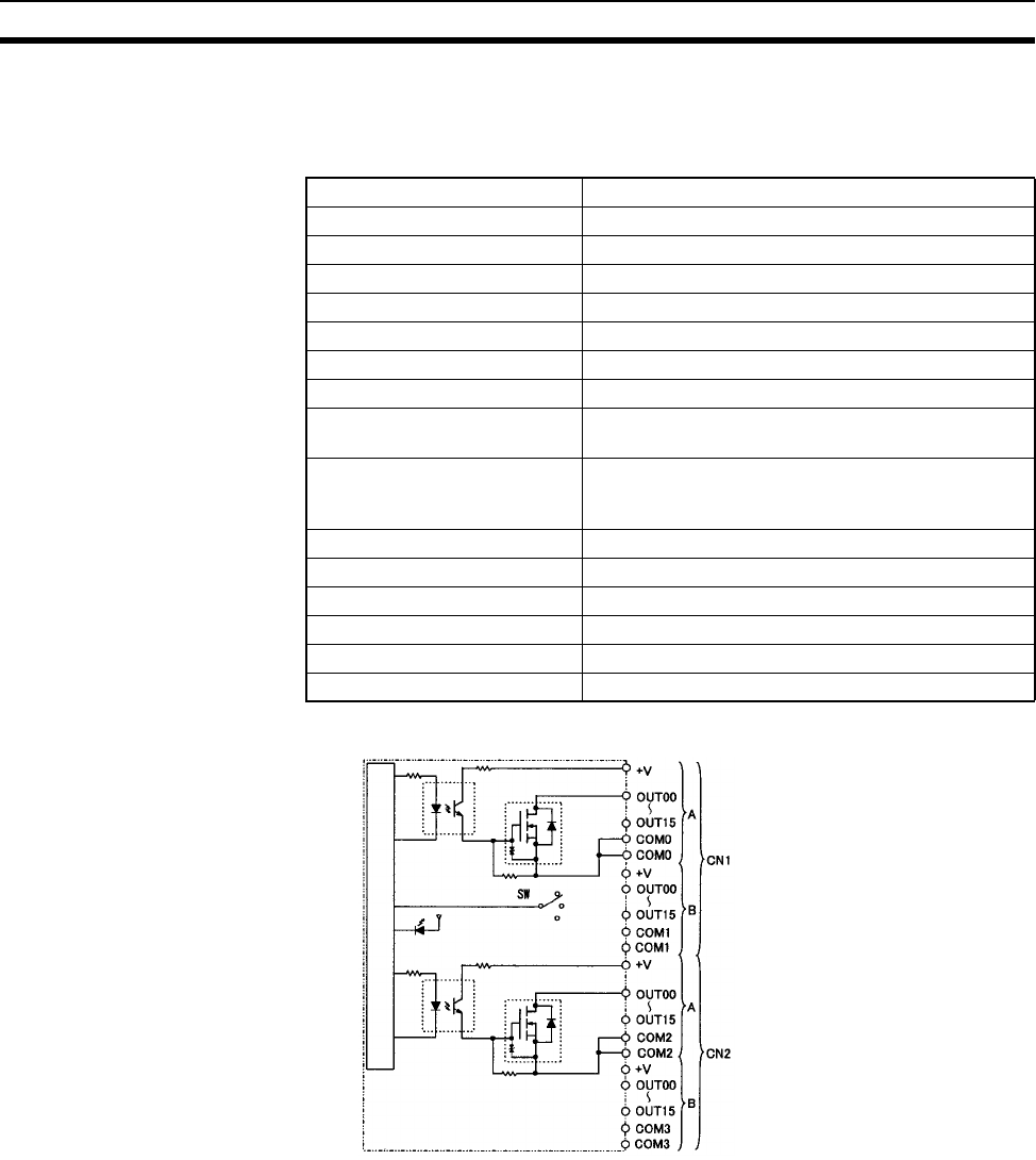
629
Specifications of Basic I/O Units and High-density I/O Units Appendix A
3. Connect power supply wiring to every COM terminal, even though the COM terminals are connected
internally.
CS1W-OD261 Transistor Output Unit (64 Points, Sinking)
Circuit Configuration
Rated Voltage 12 to 24 V DC
Operating Load Voltage Range 10.2 to 26.4 V DC
Maximum Load Current 0.3 A/point, 1.6 A/common, 6.4 A/Unit
Maximum Inrush Current 3.0 A/point, 10 ms max.
Leakage Current 0.1 mA max.
Residual Voltage 1.5 V max.
ON Response Time 0.5 ms max.
OFF Response Time 1.0 ms max.
Insulation Resistance 20 MΩ between the external terminals and the GR
terminal (100 V DC)
Dielectric Strength 1,000 V AC between the external terminals and the
GR terminal for 1 minute at a leakage current of
10 mA max.
No. of Circuits 64 (16 points/common, 4 circuits)
Internal Current Consumption 5 V DC 390 mA max.
Fuse None
External Power Supply 10.2 to 26.4 V DC, 50 mA min.
Weight 260 g max.
Accessories Two connectors for external wiring (soldered)
Output indicator
Internal circuits
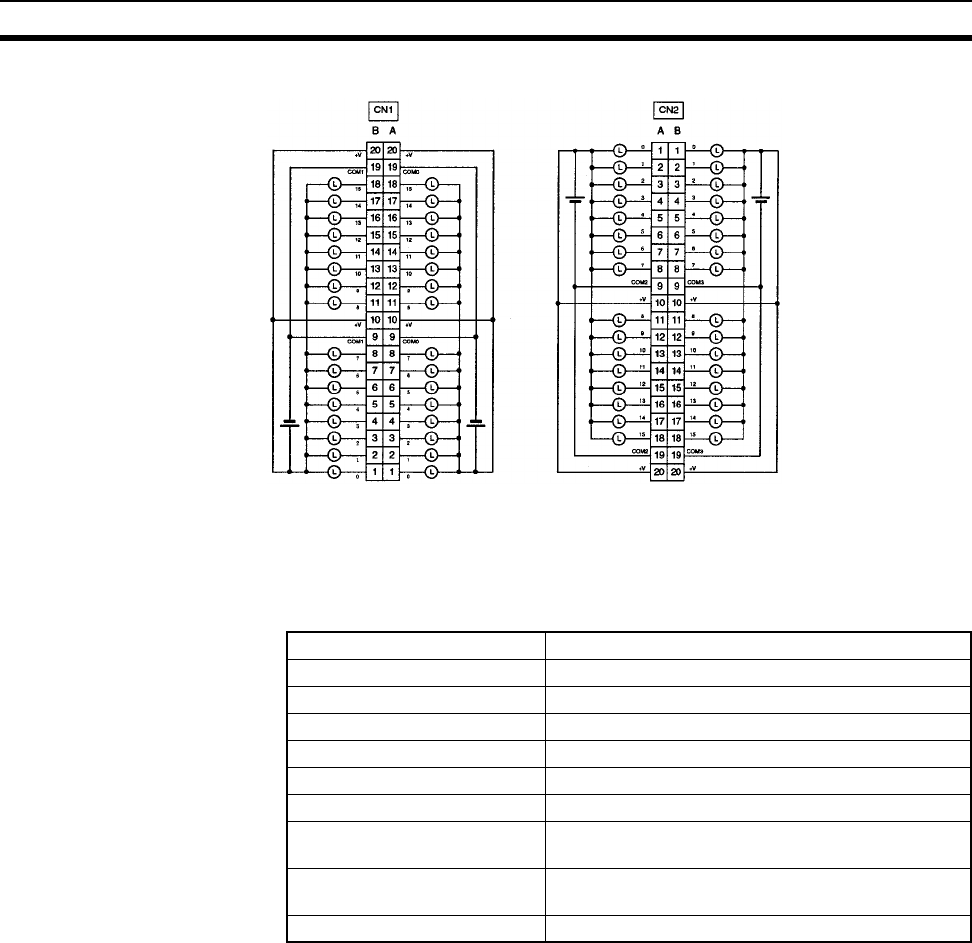
630
Specifications of Basic I/O Units and High-density I/O Units Appendix A
Terminal Connections
• When wiring, pay careful attention to the polarity. The load may operate if the polarity is reversed.
• Although the +V and COM terminals of rows A and B of CN1 and CN2 are internally connected, wire all
points completely.
C200H-OD219 Transistor Output Unit (64 Points)
12 to 24 V DC
12 to 24 V DC
12 to
24 V DC
12 to
24 V DC
12 to
24 V DC
12 to
24 V DC
I/O word "m"I/O word "m+1" I/O word "m+3"I/O word "m+2"
Max. Switching Capacity 16 mA 4.5 V DC to 100 mA 26.4 V DC (see below)
Leakage Current 0.1 mA max.
Residual Voltage 0.8 V max.
ON Response Time 0.1 ms max.
OFF Response Time 0.4 ms max.
No. of Circuits 2 (32 points/common)
Internal Current Consumption 270 mA 5 V DC max.
Fuses Two 3.5 A fuses (1 fuse/common)
The fuses are not user-replaceable.
Power for External Supply 220 mA 5 to 24 V DC±10% min.
(3.4 mA × number of ON pts)
Weight 250 g max.
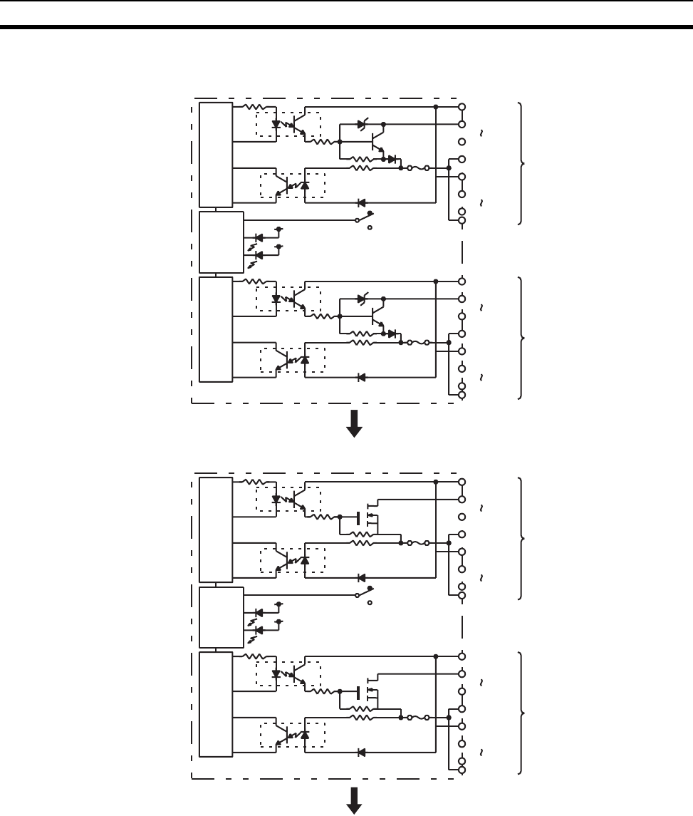
631
Specifications of Basic I/O Units and High-density I/O Units Appendix A
Circuit Configuration
Units manufactured on or before January 28, 2000
(manufacturing numbers 2810 or earlier)
Output indicator
F indicator
OUT00
OUT07
COM0 CN1
OUT08
OUT15
COM0
Internal
circuits
4.5 to
26.4 V DC
4.5 to
26.4 V DC
Fuse
CN1
CN2
SW
OUT00
OUT07
COM1 CN2
OUT08
OUT15
COM1
Internal
circuits
4.5 to
26.4 V DC
4.5 to
26.4 V DC
Fuse
Indicator
switch/
fuse
blowout
detection
circuit
Output indicator
F indicator
OUT00
OUT07
COM0 CN1
OUT08
OUT15
COM0
Internal
circuits
4.5 to
26.4 V DC
4.5 to
26.4 V DC
Fuse
CN1
CN2
SW
OUT00
OUT07
COM1 CN2
OUT08
OUT15
COM1
Internal
circuits
4.5 to
26.4 V DC
4.5 to
26.4 V DC
Fuse
Indicator
switch/
fuse
blowout
detection
circuit
Units manufactured between January 29, 2000 and
October 10, 2002 (manufacturing numbers 3110 to 10X2)
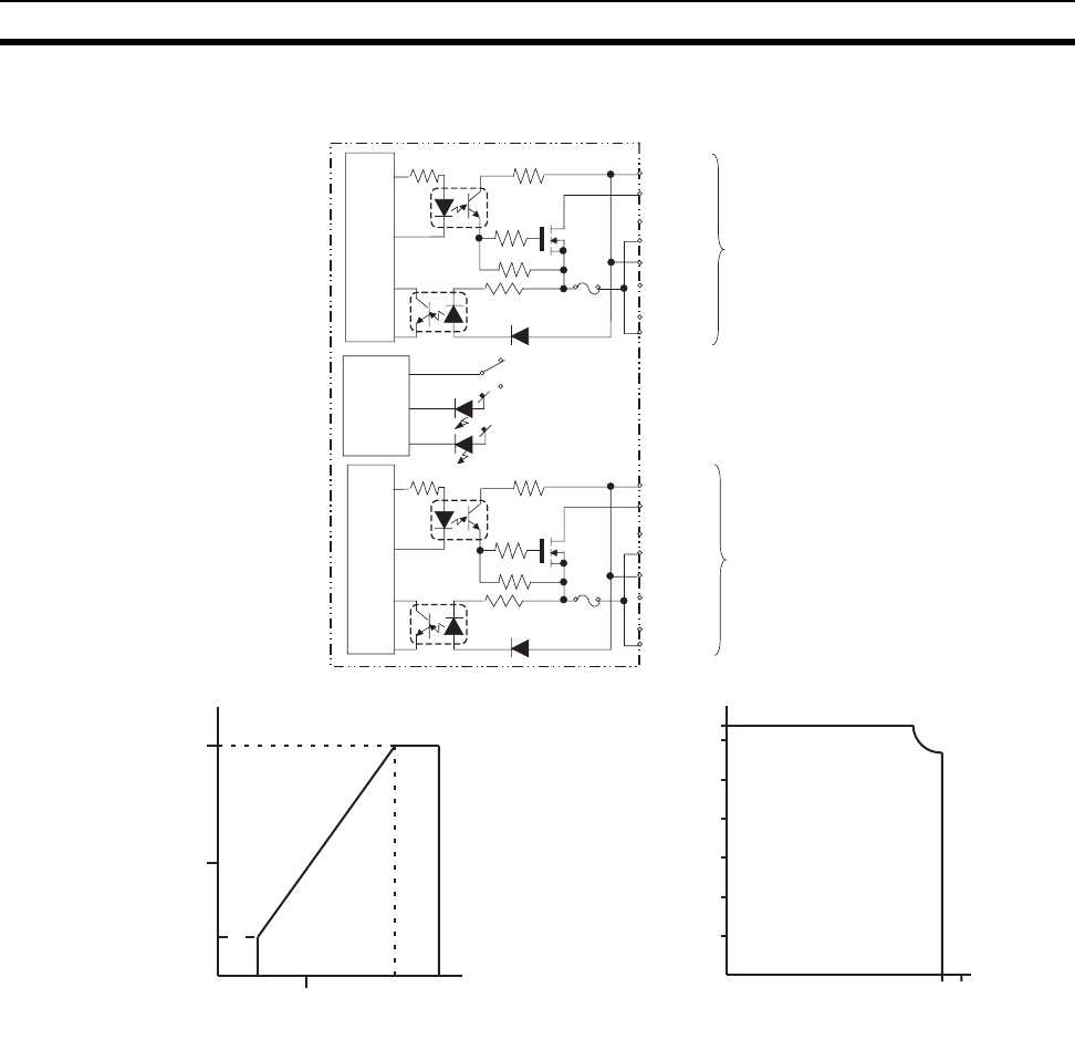
632
Specifications of Basic I/O Units and High-density I/O Units Appendix A
Maximum Switching Capacity
OUT00
OUT08
OUT07
4.5 to
26.4 V DC
OUT15
4.5 to
26.4 V DC
COM0
COM0
CN2
CN1
SW
CN1
OUT00
OUT08
OUT07
4.5 to
26.4 V DC
OUT15
4.5 to
26.4 V DC
COM1
COM1
CN2
Units manufactured on or after October 11, 2002
(manufacturing numbers 11X2H or later)
to
to
to
to
Internal circuits
Indicator
switch/
fuse
blowout
detection
circuit
Internal circuits
Fuse
Fuse
Output indicator
F indicator
Power Supply Voltage (V)
Max. Switching Capacity (mA/pt)
Max. Switching Capacity (A/unit)
Ambient Temperature (°C)
0 4.5 10 20.4 26.4
50
100
16
0
0 10203040505560
0
1.0
2.0
3.0
4.0
5.0
6.0
6.4
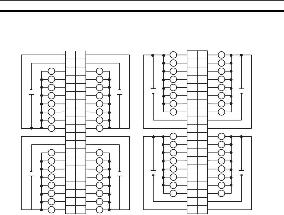
633
Specifications of Basic I/O Units and High-density I/O Units Appendix A
Terminal Connections
Note 1. When either fuse blows, the F indicator will light and the corresponding Flag in the Basic I/O Unit In-
formation Area (A050 to A089) will turn ON.
2. The interruption of power from the external power supply is treated the same as a fuse blowout.
3. Connect power supply wiring to every COM terminal, even though the COM terminals in each con-
nector are connected internally.
I/O word "m"I/O word "m+1"
CN1
I/O word "m+3"I/O word "m+2"
CN2
L
L
1
0
B
12
23
34
45
56
67
78
9
0
1
2
3
4
5
6
7
COM0
A
+
COM0
+
10
11
12
13
14
15
16
18
19
20
17
8
9
10
11
12
13
14
15
COM0
+
8
9
10
11
12
13
14
15
COM0
+
1
2
3
4
5
6
7
8
9
10
11
12
13
14
15
16
18
19
20
17
L
L
L
L
L
L
L
L
L
L
L
L
L
L
L
L
L
L
L
L
L
L
L
L
L
L
L
L
L
1
L0
A
12
23
34
45
56
67
78
9
0
1
1
2
2
3
3
4
4
5
5
6
6
7
7
8
COM1
9
B
L
L L
L L
L L
L L
L L
L L
L L
+
COM1
+
10 10
11
12
13
14
15
16
18
11
12
13
14
15
16
17
18
19
20
19
20
17
8
9
10
11
12
13
14
15
COM1
L
L
L
L
L
L
L
L
+
8
9
10
11
12
13
14
15
COM1
L
L
L
L
L
L
L
L
+
4.5 to
26.4 V DC
L
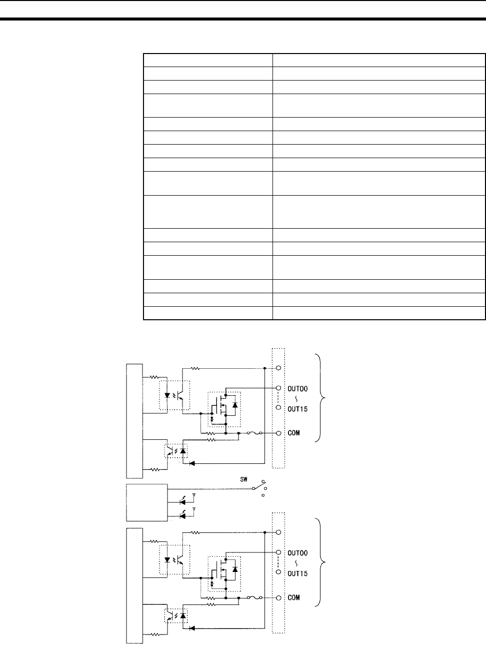
634
Specifications of Basic I/O Units and High-density I/O Units Appendix A
CS1W-OD291 Transistor Output Unit (96 Points, Sinking)
Circuit Configuration
Note 1. The ERR indicator will light if a fuse blows or if the external power supply is turned OFF, and the cor-
responding Flag in the Basic I/O Unit Information Area (A050 to A089) will turn ON.
2. The maximum load currents will be 1.0 A/common and 6.0 A/Unit if a pressure-welded connector is
used.
Rated Voltage 12 to 24 V DC
Operating Load Voltage 10.2 to 26.4 V DC
Maximum Load Current 0.1 A/point, 1.2 A/common, 7.2 A/Unit (See note 2.)
Maximum Inrush Current 1.0 A/point, 10 ms max.
8.0 A/common, 10 ms max.
Leakage Current 0.1 mA max.
Residual Voltage 1.5 V max.
ON Response Time 0.5 ms max.
OFF Response Time 1.0 ms max.
Insulation Resistance 20 MΩ between the external terminals and the GR
terminal (100 V DC)
Dielectric Strength 1,000 V AC between the external terminals and the
GR terminal for 1 minute at a leakage current of
10 mA max.
No. of Circuits 6 (16 points/common)
Internal Current Consumption 480 mA max. at 5 V DC
Fuse 3 A (1 per common)
The fuse cannot be replaced by the user.
External Power Supply 10.2 to 26.4 V DC, 100 mA min.
Weight 320 g max.
Accessories Two connectors for external wiring (soldered)
Output indicator
Indicator
switch circuit
Blown fuse
detection
circuit
x 3 CN1 circuits
10.2 to
26.4 V DC
x 3 CN2 circuits
10.2 to
26.4 V DC
Fuse
ERR indicator
Fuse
Internal circuitsInternal circuits
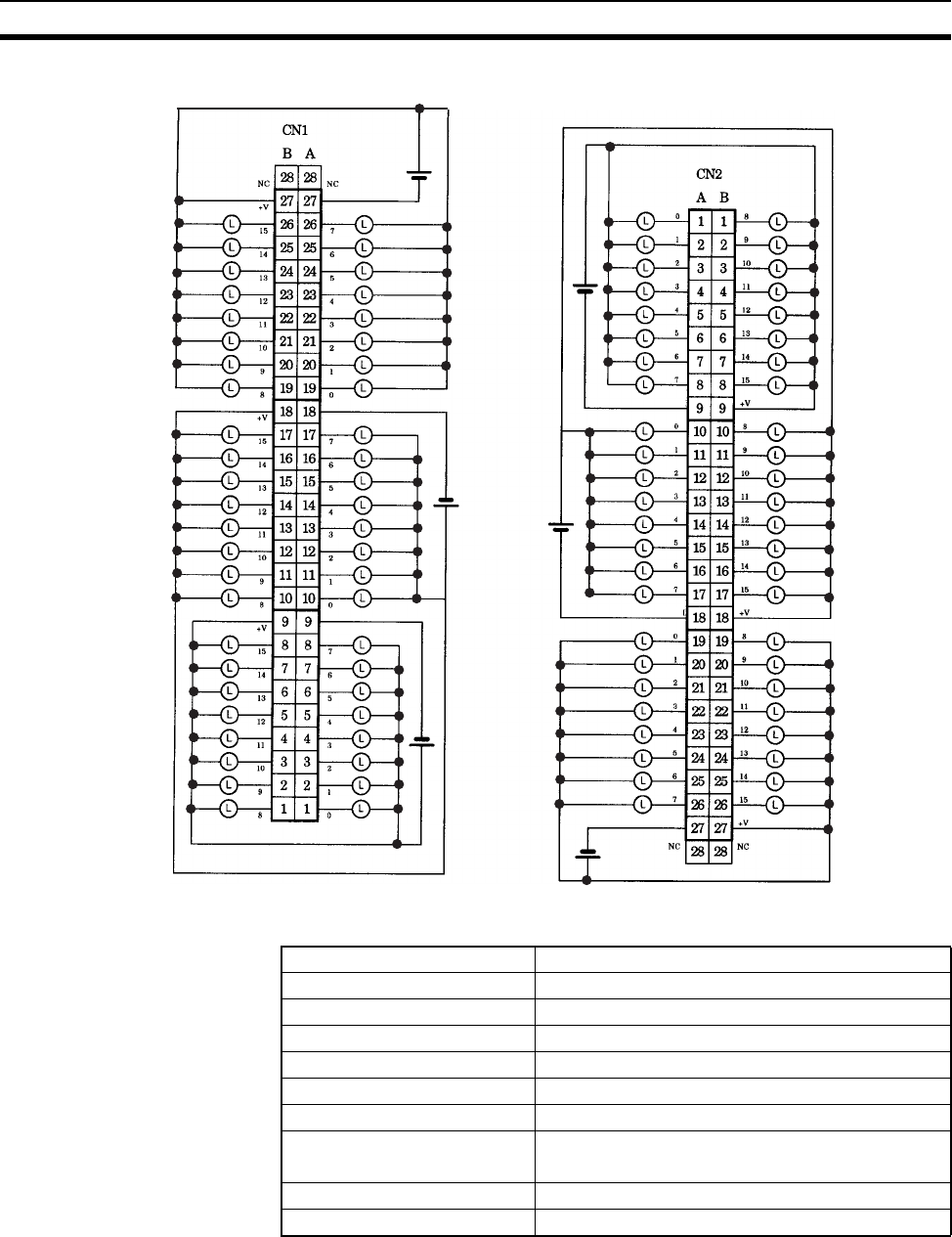
635
Specifications of Basic I/O Units and High-density I/O Units Appendix A
Terminal Connections: CS1W-OD291 24-V DC 96-point Transistor Output Unit (Sinking Outputs)
C200H-OD214 Transistor Output Unit (8 Points, Sourcing)
Word (m+2)
Word (m+1)
Word m
Word (m+3)
Word (m+4)
Word (m+5)
12 to
24 V DC
12 to
24 V DC
12 to
24 V DC
12 to
24 V DC
12 to
24 V DC
12 to
24 V DC
COM2
COM1
COM0
COM5
COM4
COM3
Max. Switching Capacity 24 V DC (20.4 to 26.4 V DC) 0.8 A (2.4 A/Unit)
Leakage Current 1 mA max.
Residual Voltage 1.5 V max.
ON Response Time 1 ms max.
OFF Response Time 1 ms max.
No. of Circuits 1 (8 points/common)
Internal Current Consumption 140 mA 5 V DC max.
Short-circuit protection Overcurrent protection
Thermal protection
Power for External Supply 150 mA 20.4 to 26.4 V DC min.
Weight 250 g max.
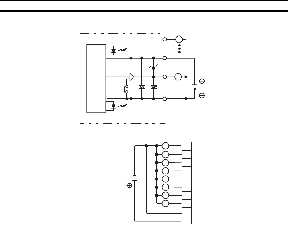
636
Specifications of Basic I/O Units and High-density I/O Units Appendix A
Circuit Configuration
Terminal Connections
Note Be sure to supply power to A9; otherwise current will leak through the load while the output is OFF.
C200H-OD214 Short-circuit Protection
The C200H-OD214 Output Unit is equipped with two types of short-circuit protection: overcurrent protection
and thermal protection. Any short-circuit must be eliminated immediately to protect the Unit.
Overcurrent Protection
When the output current reaches 2 A, the alarm output turns ON, and the alarm indicator lights. Make sure the
surge current of the load does not exceed 2 A, or the alarm may be activated.
Thermal Protection
When the junction temperature of the output transistor reaches its upper limit, the output will turn OFF, the
alarm output will turn ON, and the alarm indicator will flash protect to the transistor.
As shown in the alarm output table given below, there is one alarm indicator and alarm output bit for every two
outputs. The alarm indicator and alarm output bit will function the same regardless of which output an alarm is
detected for.
Thermal protection also works for two outputs at a time. If the thermal protection level is detected for one of the
outputs, the other output will be turned OFF as well.
The output transistor is provided with a cooling plate. If only one of the outputs is short-circuited, heat genera-
tion will be balanced with heat radiation, and the transistor junction temperature may increase high enough to
activate thermal protection. The alarm indicator and alarm output bit, however, will operate so that the alarm
can be detected.
Internal
circuits
COM
OUT
L
+ V
24 V DC
Reset
button
Source
Driver
+
Alarm Output
indicator
Output indicator
OUT
L
L
L
L
L
L
L
L
L
24 V DC
A0
A1
A2
A3
A4
A5
A6
A7
A8
A9
0
1
2
3
4
5
6
7
COM (0 V)
24 V DC
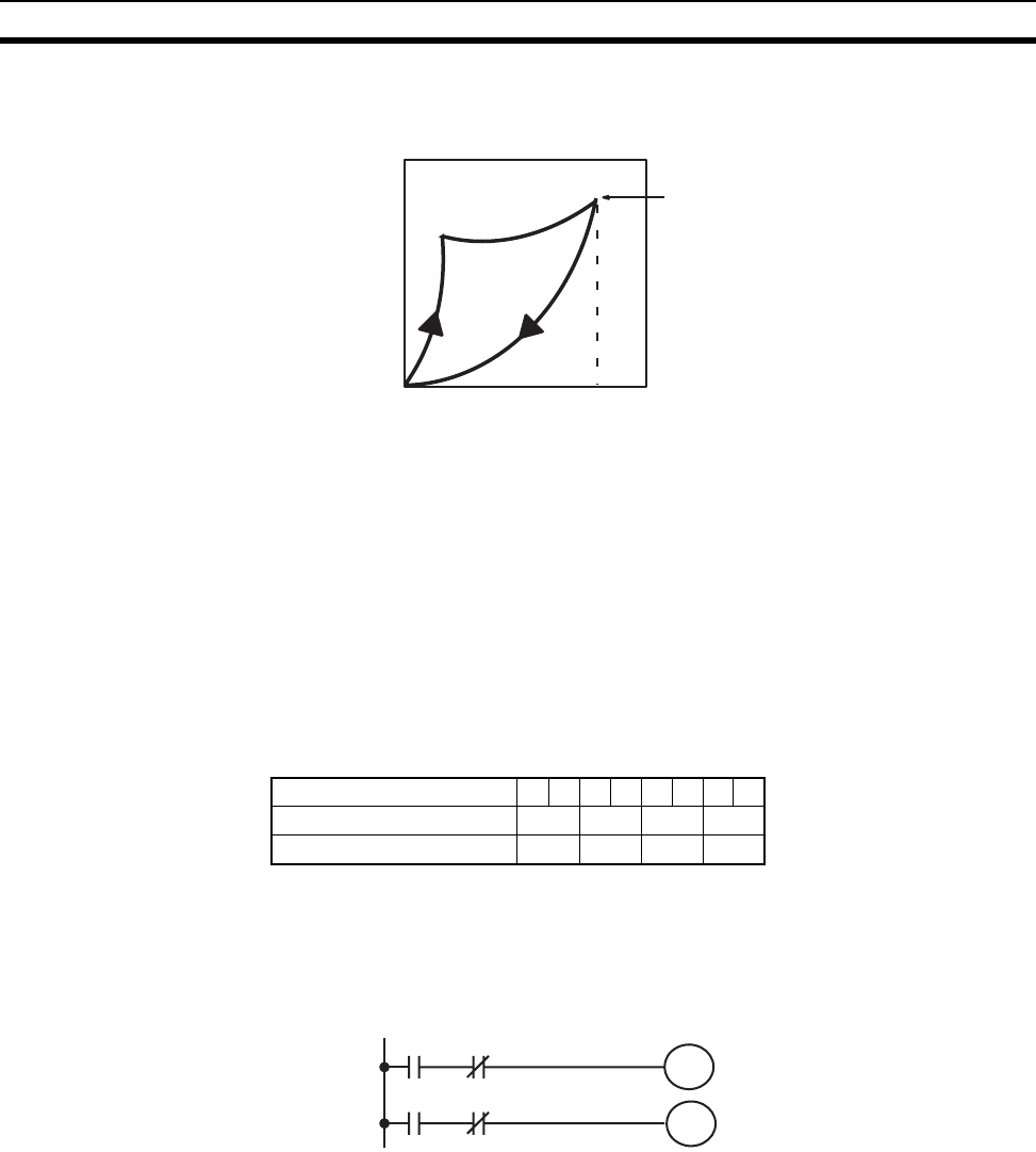
637
Specifications of Basic I/O Units and High-density I/O Units Appendix A
How It Works
When the short-circuit protection activates, the output displays the characteristic shown below.
Clearing the Alarm
When the short-circuit has been eliminated, reset the Unit by pressing the reset button. The alarm indicator will
go out, the alarm output bit will turn OFF, and the output will be reset.
Operating Restrictions
Although the C200H-OD214 is provided with short-circuit protection, these are for protecting internal circuits
against momentary short-circuiting in the load. Leaving short-circuits for any length of time will cause internal
temperature rise, deterioration of elements, discoloration of the case or PCBs, etc. Therefore, observe the fol-
lowing restrictions.
If a short-circuit occurs in an external load, immediately turn OFF the corresponding output. The C200H-
OD214 turns ON an alarm output bit that corresponds with the external load output number. Each pair of out-
puts share one alarm indicator and one alarm output bit as shown below (bits 12 through 15 are not used and
cannot be used as work bits)
Both the alarm indicator and alarm output bit for the short-circuited output turn ON even if only one of the out-
puts is short-circuited. Both outputs should be disconnected until the short-circuit can be traced.
Programming Example
If there is a short-circuit in an output, we want the program to turn that output OFF. Assume that the Unit is
mounted at CIO 000. A program to turn OFF output bits 00 and 01 is shown below.
Since alarm output bit 08 covers both output bits 00 and 01, both these outputs are forced OFF as soon as out-
put bit 08 turns ON (bits A and B can be any other bits required in the program).
Overcurrent
limit alarm
output point
Output current:
2 A (minimum value)
0
Output
Voltage
Output No. 01234567
Alarm indicator No. 0 2 4 6
Alarm Output Point No. 08 09 10 11
00000
00001
A
B
00008
00008
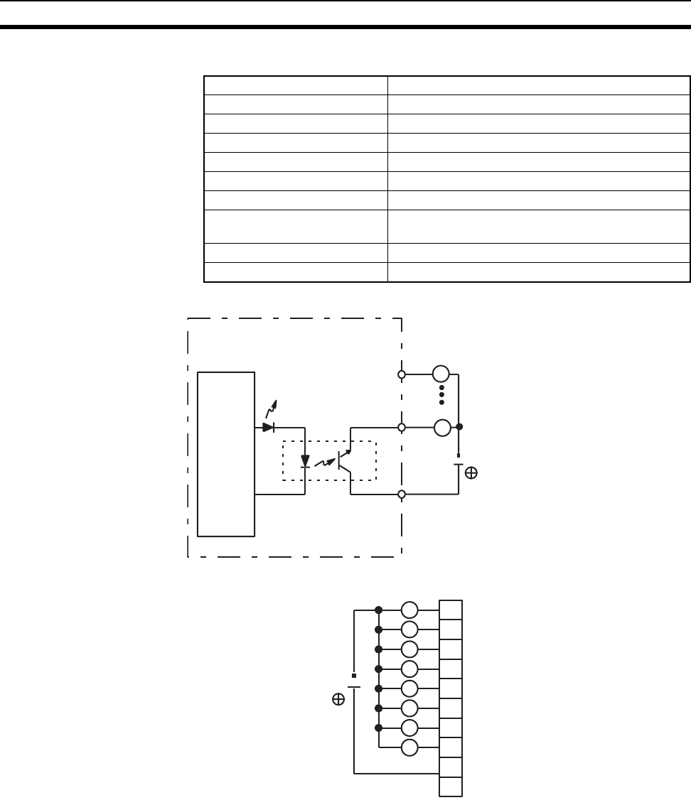
638
Specifications of Basic I/O Units and High-density I/O Units Appendix A
C200H-OD216 Transistor Output Unit (8 Points, Sourcing)
Circuit Configuration
Terminal Connections
Max. Switching Capacity 0.3 A 5 to 24 V DC
Min. Switching Capacity 10 mA 5 V DC
Leakage Current 0.1 mA max.
Residual Voltage 1.5 V max.
ON Response Time 1.5 ms max.
OFF Response Time 2 ms max.
No. of Circuits 1 (8 points/common) positive common (source type)
Internal Current Consumption 10 mA 5 V DC max. 75 mA 26 V DC (8 points ON
simultaneously.)
Fuse Rating None
Weight 250 g max.
Output indicator
OUT
OUT
COM
5 to 24 V DC
L
L
Internal
circuits
A0
A1
A2
A3
A4
A5
A6
A7
A8
A9
0
1
2
3
4
5
6
7
COM
5 to 24 V DC
NC
L
L
L
L
L
L
L
L
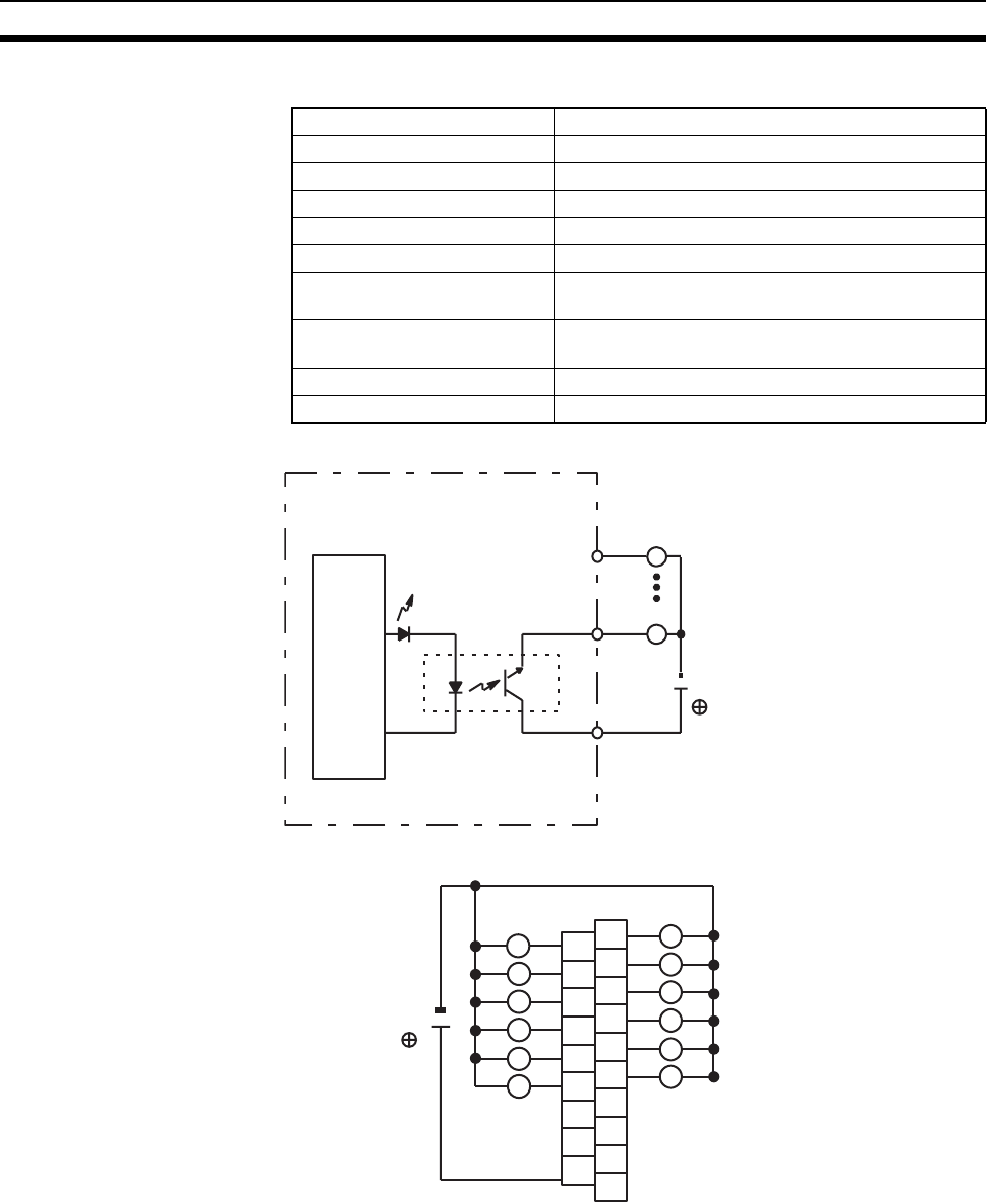
639
Specifications of Basic I/O Units and High-density I/O Units Appendix A
C200H-OD217 Transistor Output Unit (12 Points, Sourcing)
Circuit Configuration
Terminal Connections
Max. Switching Capacity 0.3 A 5 to 24 V DC
Min. Switching Capacity 10 mA 5 V DC
Leakage Current 0.1 mA max.
Residual Voltage 1.5 V max.
ON Response Time 1.5 ms max.
OFF Response Time 2 ms max.
No. of Circuits 1 (12 points/common) positive common (source
type)
Internal Current Consumption 10 mA 5 V DC max. 75 mA 26 V DC (8 points ON
simultaneously.)
Fuse Rating None
Weight 300 g max.
Output indicator
OUT
OUT
COM
L
L
Internal
circuits 5 to
24 V DC
A0
A1
A2
A3
A4
A5
A6
A7
A8
1
3
5
7
9
11
COM
5 to 24 V DC
NC
B0
B1
B2
B3
B4
B5
B6
B7
B8
B9
NC
NC
NC
NC
NC
0
2
4
6
8
10
L
L
L
L
L
L
L
L
L
L
L
L
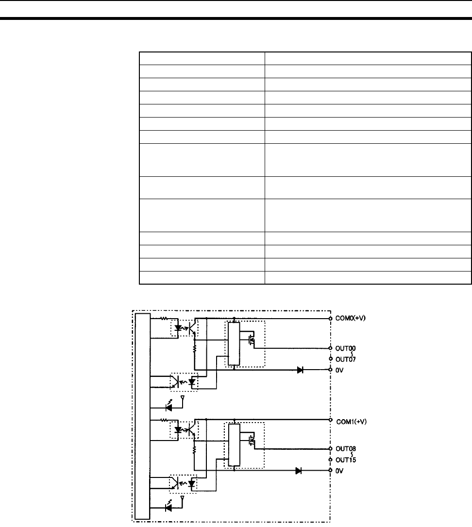
640
Specifications of Basic I/O Units and High-density I/O Units Appendix A
CS1W-OD212 Transistor Output Unit (16 Points, Sourcing)
Circuit Configuration
When overcurrent is detected, the ERR indicator will light, and the corresponding flag in the Basic I/O Unit
Information Area (A050 to A089) will turn ON.
Rated Voltage 24 V DC
Operating Load Voltage Range 20.4 to 26.4 V DC
Maximum Load Current 0.5 A/point, 2.5 A/common, 5.0 A/Unit
Maximum Inrush Current 0.1 mA max.
Leakage Current 1.5 V max.
ON Response Time 0.5 ms max.
OFF Response Time 1.0 ms max.
Load Short-circuit Prevention Detection current: 0.7 to 2.5 A
Automatic restart after error clearance. (Refer to the
following pages.)
Insulation Resistance 20 MΩ between the external terminals and the GR
terminal (100 V DC)
Dielectric Strength 1,000 V AC between the external terminals and the
GR terminal for 1 minute at a leakage current of
10 mA max.
No. of Circuits 16 (8 points/common, 2 circuits)
Internal Current Consumption 5 V DC 170 mA max.
External Power Supply 20.4 to 26.4 V DC, 40 mA min.
Weight 270 g max.
Internal circuits
Output indicator
ERR indicator
Short-circuit
protection
Short-circuit
protection
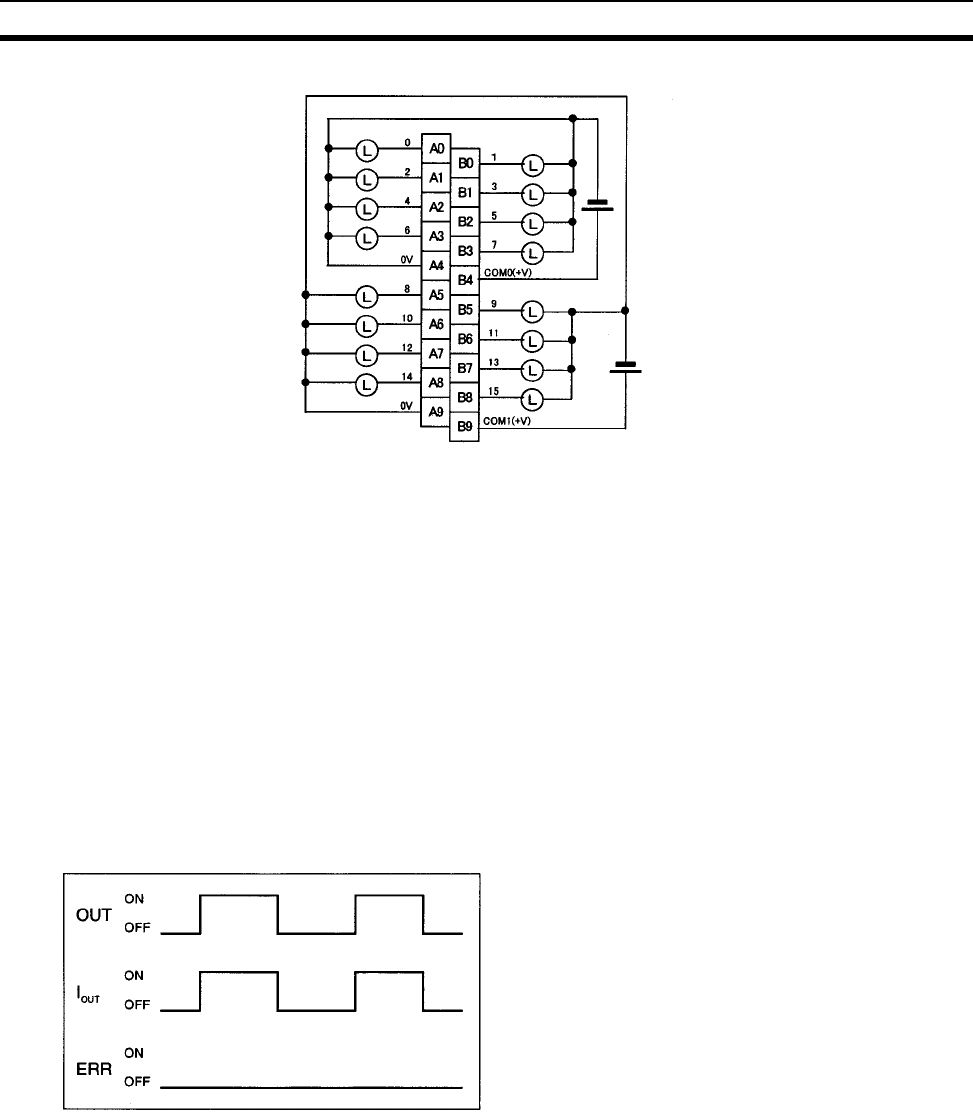
641
Specifications of Basic I/O Units and High-density I/O Units Appendix A
Terminal Connections
Note Terminal numbers A0 to A9 and B0 to B9 are used in this manual, but they are not printed on the Unit.
When wiring, pay careful attention to the polarity of the external power supply. The load may operate if the
polarity is reversed.
Load Short-circuit Protection
This section describes the load short-circuit protection of the CS1W-OD212/OD232/OD262/MD262, C200H-
OD21B Output Units.
As shown below, normally when the output bit turns ON (OUT), the transistor will turn ON and then output cur-
rent (Iout) will flow. If the output (Iout) is overloaded or short-circuited exceeding the detection current (Ilim), the
output current (Iout) will be limited as shown in Figure 2 below. When the junction temperature (Tj) of the output
transistor reaches the thermal shutdown temperature (Tstd), the output will turn OFF to protect the transistor
from being damaged, and the alarm output bit will turn ON to light the ERR indicator. When the junction tem-
perature (Tj) of the transistor drops down to the reset temperature (Tr), the ERR indicator will be automatically
reset and the output current will start flowing.
Figure 1: Normal Condition
24 V DC
24 V DC
OUT: OUTPUT instruction
IOUT: Output current
ERR: Alarm output, ERR indicator
Ilim: Detection current
Tj: Junction temperature of transistor
Tstd: Thermal shutdown temperature
Tr: Reset temperature
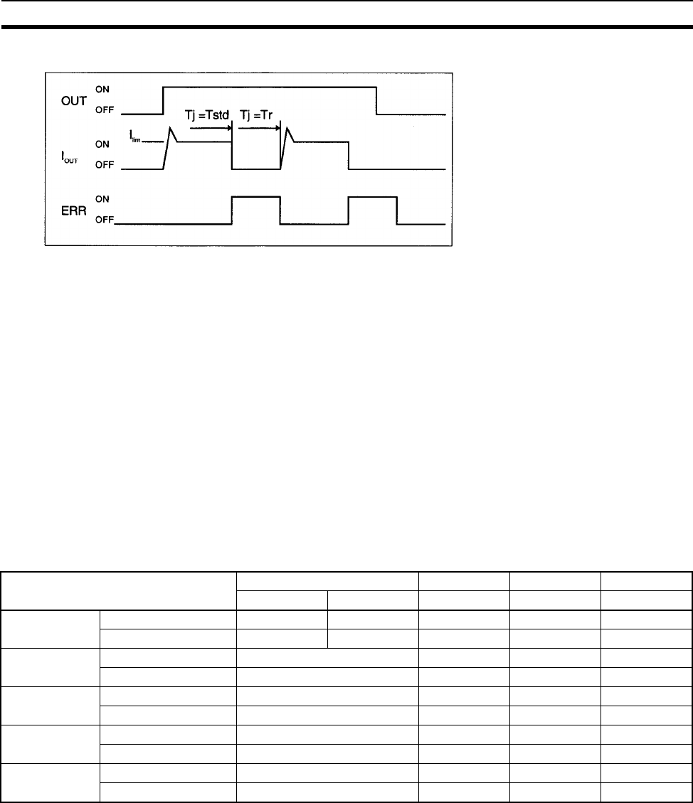
642
Specifications of Basic I/O Units and High-density I/O Units Appendix A
Figure 2: Overload or Short-circuit
Operating Restrictions
Although the CS1W-OD212/OD232/OD262/MD262 and C200H-OD21B are provided with short-circuit protec-
tion, these are for protecting internal circuits against momentary short-circuiting in the load. As shown in Figure
2 below, the short-circuit protection is automatically released when the Tj equals to Tr. Therefore, unless the
cause of short-circuit is removed, ON/OFF operations will be repeated in the output. Leaving short-circuits for
any length of time will cause internal temperature rise, deterioration of elements, discoloration of the case or
PCBs, etc. Therefore, observe the following restrictions.
Restrictions
If a short-circuit occurs in an external load, immediately turn OFF the corresponding output and remove the
cause. The CS1W-OD212/OD232/OD262/MD262 and C200H-OD21B turn ON an alarm output bit that corre-
sponds to the external load output number. There is an alarm output bit for every common.
When an alarm output bit turns ON, use a self-holding bit for the alarm in the user program and turn OFF the
corresponding output.
The alarm output bit is allocated in the Basic I/O Unit Information Area (A050 to A089) for every Unit mounting
slot.
The following table shows the correspondence between output bits and bits in the Basic I/O Unit Information
Area.
For example, when the CS1W-OD212 is mounted in slot 0 on Rack 0, A05001 will turn ON if the output 8 is
short-circuited. When the CS1W-OD262 is mounted in slot 1 of Rack 0, A05011 will turn ON if the output m+3
is short-circuited.
Programming Example
In this example, CS1W-OD212 is mounted in slot 0 of the Rack 0.
This example shows how to turn OFF output bits CIO 000000 to CIO 000007 immediately if the alarm output bit
A05000 turns ON and how to keep the output bits OFF until the cause is removed and the bit is reset using
work bit W000001.
Output bit m m+1 m+2 m+3
0 to 7 8 to 15 0 to 15 0 to 15 0 to 15
CS1W-OD212 Mounted in even slot 0 1 --- --- ---
Mounted in odd slot 8 9 --- --- ---
CS1W-OD232 Mounted in even slot 0 1 --- ---
Mounted in odd slot 8 9 --- ---
CS1W-OD262 Mounted in even slot 0 1 2 3
Mounted in odd slot 8 9 10 11
CS1W-MD262 Mounted in even slot 0 1 --- ---
Mounted in odd slot 8 9 --- ---
C200H-OD21B Mounted in even slot 0 --- --- ---
Mounted in odd slot 8 --- --- ---
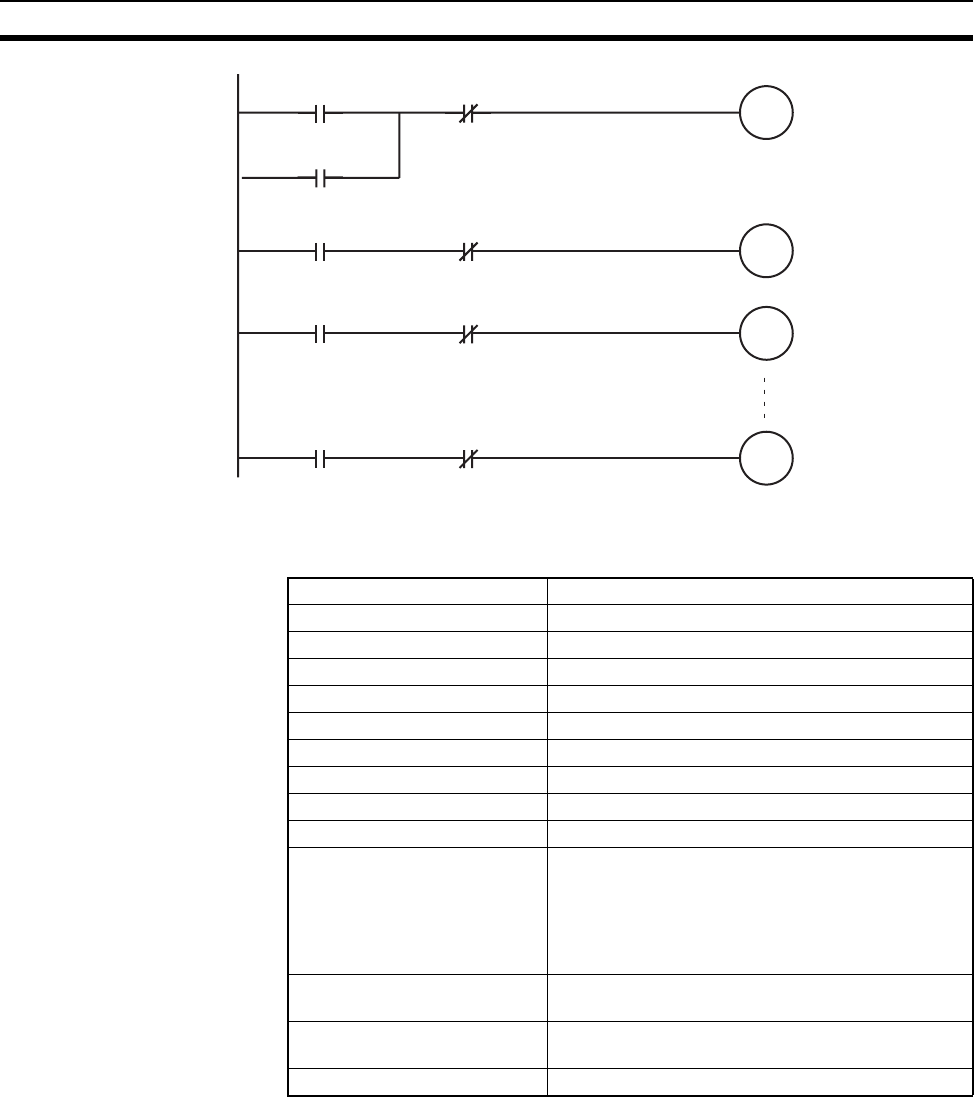
643
Specifications of Basic I/O Units and High-density I/O Units Appendix A
C200H-OD21A Transistor Output Unit (16 Points, Sourcing)
(Load Circuit Protection Provided)
W0000
A05000 W00001
000000
AW00000
W00000
000001
BW00000
000007
HW00000
Max. Switching Capacity 24 V DC (20.4 to 26.4 V DC), 1.0 A (4 A/Unit)
Leakage Current 0.1 mA max.
Residual Voltage 0.8 V max.
ON Response Time 0.1 ms max.
OFF Response Time 0.3 ms max.
No. of Circuits 1 (16 points/common)
Internal Current Consumption 160 mA 5 V DC max.
Load Short-circuit Protection Detection current: 1.2 A min (1.6 A typical)
Power for External Supply 35 mA 20.4 to 26.4 V DC min.
Weight 400 g max.
Alarm Output (See note 1.) No. of outputs: 1 (2 kΩ internal resistor), Output cur-
rent: 10 mA max.,
Connectable Units: Only the following DC Input
Units can be connected:
C200H-ID001, ID211, ID212, IM211 (DC), IM212
(DC), ID215, ID501, MD115, MD215, MD501
Reset Input Used when alarm output turns ON. Value will
depend on the external power supply. (See note 2.)
Load Short-circuit Protection Detection current: 1.2 A min.
(1.6 A typical)
Dimensions B-shape
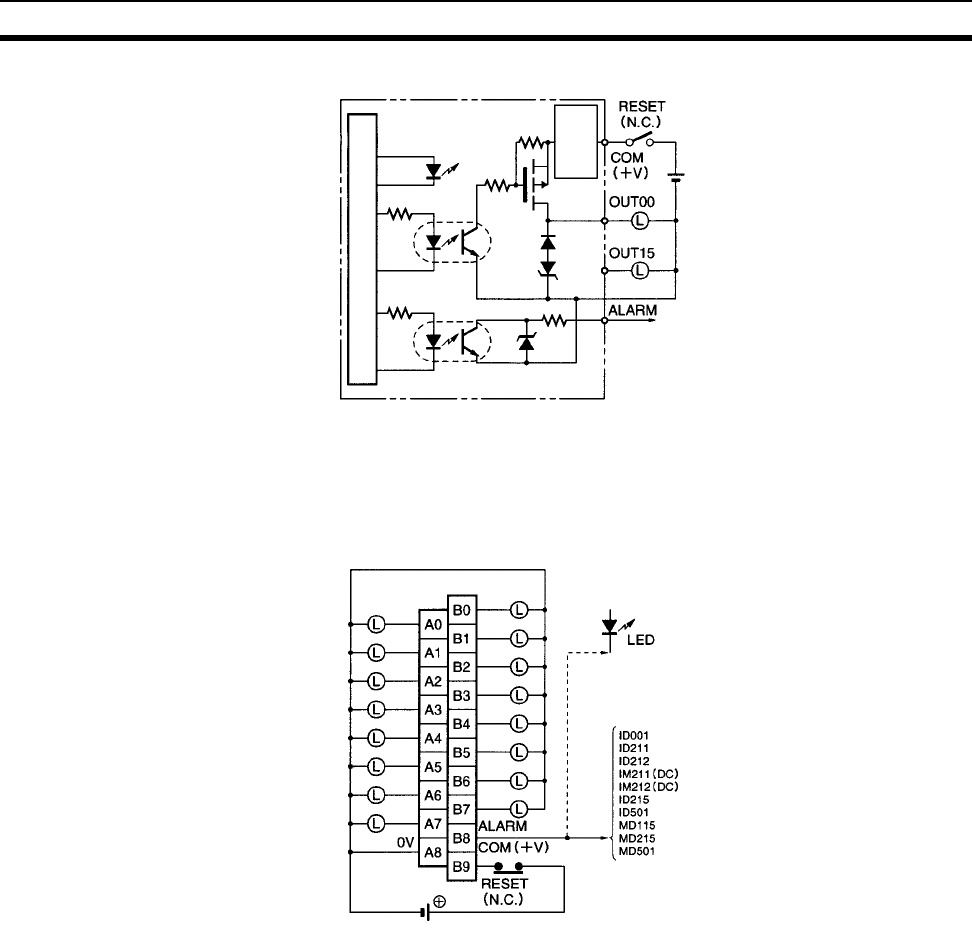
644
Specifications of Basic I/O Units and High-density I/O Units Appendix A
Circuit Configuration
Note When short-circuit/overload protection is activated, all 16 outputs will be switched OFF and the ALARM
output becomes active (low level). The problem can be detected externally by connecting a DC Input
Unit to the ALARM output or by connecting an alarm output indicator. It’s not possible to connect both
the Input Unit and the indicator at the same time.
Terminal Connections
Note When the ALARM output turns ON, remove the cause of the high current and then shut off the external
power supply for approx. 1 second. After confirming that the cause has been removed, turn ON the
power supply again to reset the output. As shown in the diagram, it is recommended that a relay or
switch that turns ON or OFF only the external power supply be connected right before the B9 (+V).
Check that this relay or switch has a contact capacity higher than the external power supply current con-
sumption (35 mA + load current minimum).
Internal circuits
Output
indicator
0 V
2 kΩ
to
Short-circuit
protection
circuit
+24 V DC
24 V DC
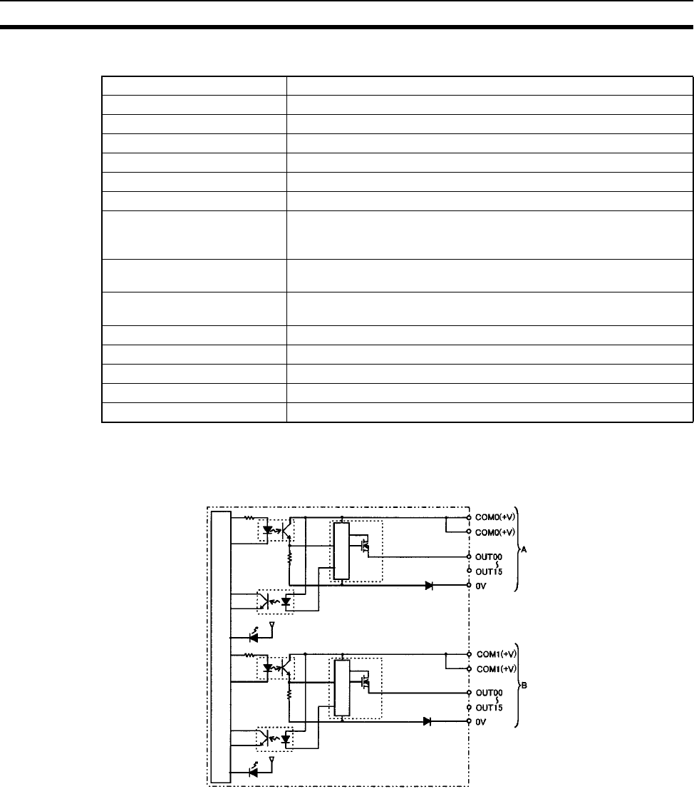
645
Specifications of Basic I/O Units and High-density I/O Units Appendix A
CS1W-OD232 (32 Points, Sourcing)
Note The maximum load currents will be 2.0 A/common and 4.0 A/Unit if a
pressure-welded connector is used.
Circuit Configuration
When the output current of any output exceeds the detection current, the output for that point will turn OFF. At
the same time, the ERR indicator will light and the corresponding flag (one for each common) in the Basic I/O
Unit Information Area (A050 to A089) will turn ON.
Rated Voltage 24 V DC
Operating Load Voltage Range 20.4 to 26.4 V DC
Maximum Load Current 0.5 A/point, 2.5 A/common, 5.0 A/Unit (See note.)
Leakage Current 0.1 mA max.
Residual Voltage 1.5 V max.
ON Response Time 0.5 ms max.
OFF Response Time 1.0 ms max.
Load Short-circuit Prevention Detection current: 0.7 to 2.5 A
Automatic restart after error clearance. (Refer to the above Load
Short-circuit Protection.)
Insulation Resistance 20 MΩ between the external terminals and the GR terminal
(100 V DC)
Dielectric Strength 1,000 V AC between the external terminals and the GR terminal for 1
minute at a leakage current of 10 mA max.
No. of Circuits 32 (16 points/common, 2 circuits)
Internal Current Consumption 5 V DC 270 mA max.
External Power Supply 20.4 to 26.4 V DC, 70 mA min.
Weight 210 g max.
Accessories One connector for external wiring (soldered)
Internal circuits
Output Indicator
ERR indicator
Short-circuit
protection
Short-circuit
protection
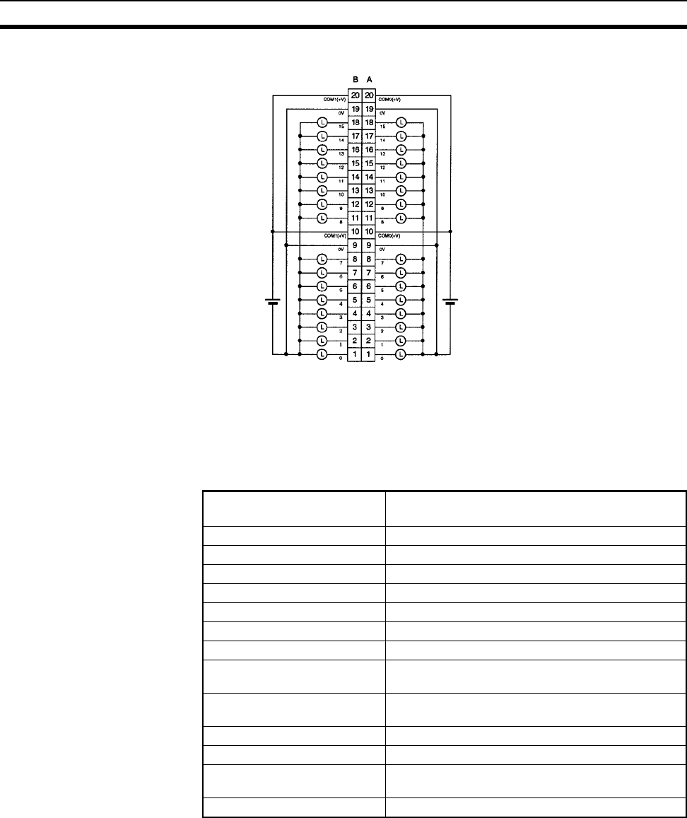
646
Specifications of Basic I/O Units and High-density I/O Units Appendix A
Terminal Connections
• When wiring, pay careful attention to the polarity of the external power supply. The load may operate if the
polarity is reversed.
• Although the COM(+V) and 0V of rows A and B are internally connected, wire all points completely.
Transistor Output Unit C200H-OD21B (32 Points)
(Load Short-circuit Protection Provided)
Note The maximum load currents will be 4.0 A/Unit if a pressure-welded con-
nector is used.
24 V DC 24 V DC
I/O word "m"I/O word "m+1"
Max. Switching Current 0.5 A 24 V DC (20.4 to 26.4 V DC) (5 A/Unit) (See
note.)
Min. Switching Current None
Leakage Current 0.1 mA max.
Residual Voltage 0.8 V max.
ON Response Time 0.1 ms max.
OFF Response Time 0.3 ms max.
No. of Circuits 32 (32 points/common)
Internal Current Consumption 180 mA 5 V DC max.
Fuses One 7 A fuse (1 fuse/common)
The fuses are not user-replaceable.
Power for External Supply 160 mA 20.4 to 26.4 V DC min.
(5 mA × number of ON pts)
Weight 180 g max.
Alarm Indicator Lamp F lights (unless fuse is broken).
Load Short-circuit Prevention
(See note 1.)
Detection current: 0.7 to 2.5 A
Automatic restart after error clearance.
Dimensions C-shape
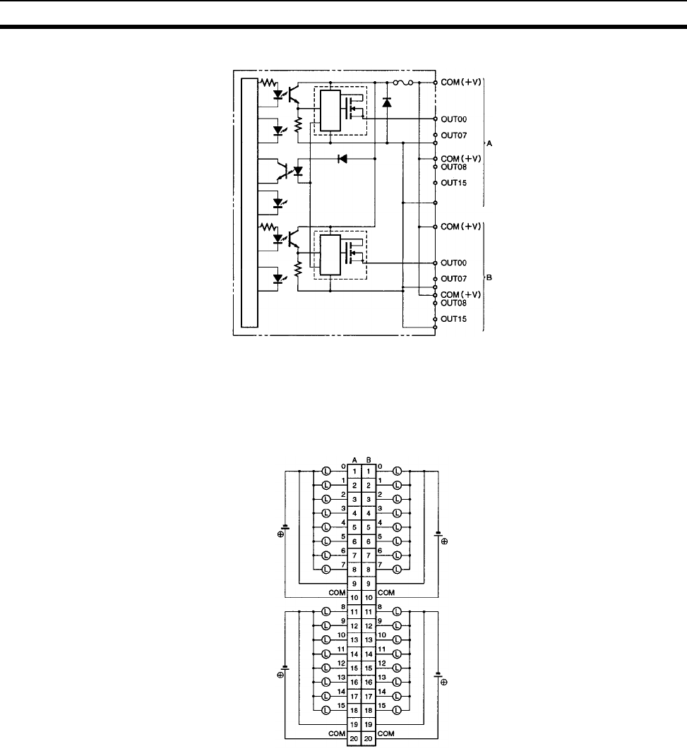
647
Specifications of Basic I/O Units and High-density I/O Units Appendix A
Circuit Configuration
Note When the short-circuit/overload protection is activated for a contact point, the output for that point is
turned OFF. At the same time, lamp “F” lights, and the corresponding Flag in the Basic I/O Unit Informa-
tion Area (A050 to A089) will turn ON. After the cause of the error has been removed, the alarm will be
cleared automatically when the internal temperature of the element drops.
Terminal Connections
Output
indicator
Internal circuits
Alarm
indi-
cator
Output
indicator
to
to
to
to
0 V
0 V
0 V
0 V
Short-circuit
protection
circuit
Short-circuit
protection
circuit
I/O word "m" I/O word "m+1"
24 V DC
24 V DC
24 V DC
24 V DC
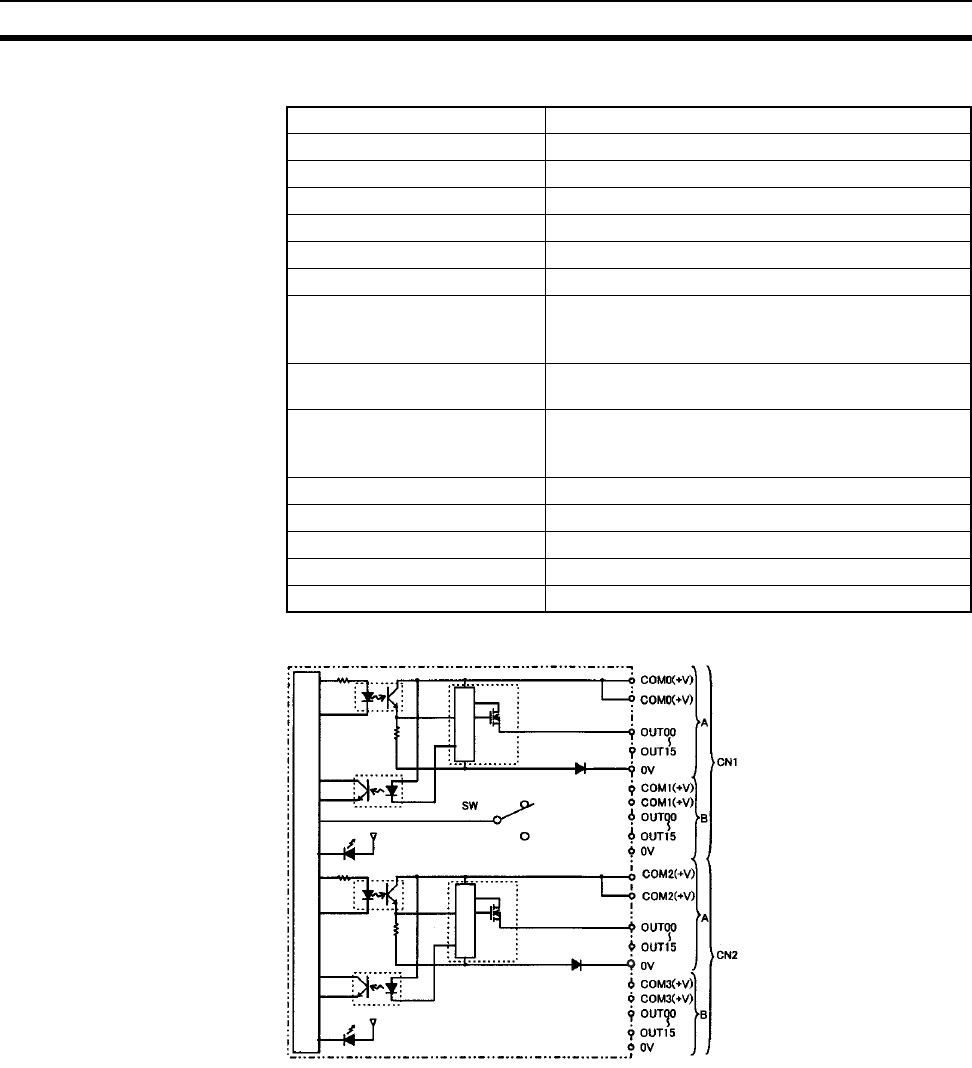
648
Specifications of Basic I/O Units and High-density I/O Units Appendix A
CS1W-OD262 (64 Points, Sourcing)
Circuit Configuration
When overcurrent is detected, the ERR indicator will light. At the same time, the corresponding flag (one for
each common) in the Basic I/O Unit Information Area (A050 to A089) will turn ON.
Rated Voltage 24 V DC
Operating Load Voltage Range 20.4 to 26.4 V DC
Maximum Load Current 0.3 A/point, 1.6 A/common, 6.4 A/Unit
Leakage Current 0.1 mA max.
Residual Voltage 1.5 V max.
ON Response Time 0.5 ms max.
OFF Response Time 1.0 ms max.
Load Short-circuit Prevention Detection current: 0.7 to 2.5 A
Automatic restart after error clearance. (Refer to the
above Load Short-circuit Protection.)
Insulation Resistance 20 MΩ between the external terminals and the GR
terminal (100 V DC)
Dielectric Strength 1,000 V AC between the external terminals and the
GR terminal for 1 minute at a leakage current of
10 mA max.
No. of Circuits 64 (16 points/common, 4 circuits)
Internal Current Consumption 5 V DC 390 mA max.
External Power Supply 20.4 to 26.4 V DC, 130 mA min.
Weight 270 g max.
Accessories Two connectors for external wiring (soldered)
Internal circuits
Output indicator
Short-circuit
protection
Short-circuit
protection
ERR indicator

649
Specifications of Basic I/O Units and High-density I/O Units Appendix A
Terminal Connections
• When wiring, pay careful attention to the polarity of the external power supply. The load may operate if the
polarity is reversed.
• Although the COM(+V) and 0V of rows A and B of CN1 and CN2 are internally connected, wire all points
completely.
CS1W-OD292 Transistor Output Unit (96 Points, Sourcing)
Note The maximum load currents will be 1.0 A/command and 6.0 A/Unit if a
pressure-welded connector is used.
I/O word "m+2" I/O word "m+3"
24 V DC
24 V DC
24 V DC
24 V DC
24 V DC 24 V DC
I/O word "m"I/O word "m+1"
COM2(+V)
COM2(+V) COM3(+V)
COM3(+V)
CN1 CN2
Rated Voltage 12 to 24 V DC
Operating Load Voltage Range 10.2 to 26.4 V DC
Maximum Load Current 0.1 A/point, 1.2 A/common, 7.2 A/Unit (See note.)
Maximum Inrush Current 1.0 A/point, 10 ms max.
8.0 A/common, 10 ms max.
Leakage Current 0.1 mA max.
Residual Voltage 1.5 V max.
ON Response Time 0.5 ms max.
OFF Response Time 1.0 ms max.
Insulation Resistance 20 MΩ between the external terminals and the GR termi-
nal (100 V DC)
Dielectric Strength 1,000 V AC between the external terminals and the GR
terminal for 1 minute at a leakage current of 10 mA max.
No. of Circuits 6 (16 points/common)
Internal Current Consumption 480 mA max. at 5 V DC
Fuse 3 A (1 per common)
The fuse cannot be replaced by the user.
External Power Supply 10.2 to 26.4 V DC, 100 mA min.
Weight 320 g max.
Accessories Two connectors for external wiring (soldered)
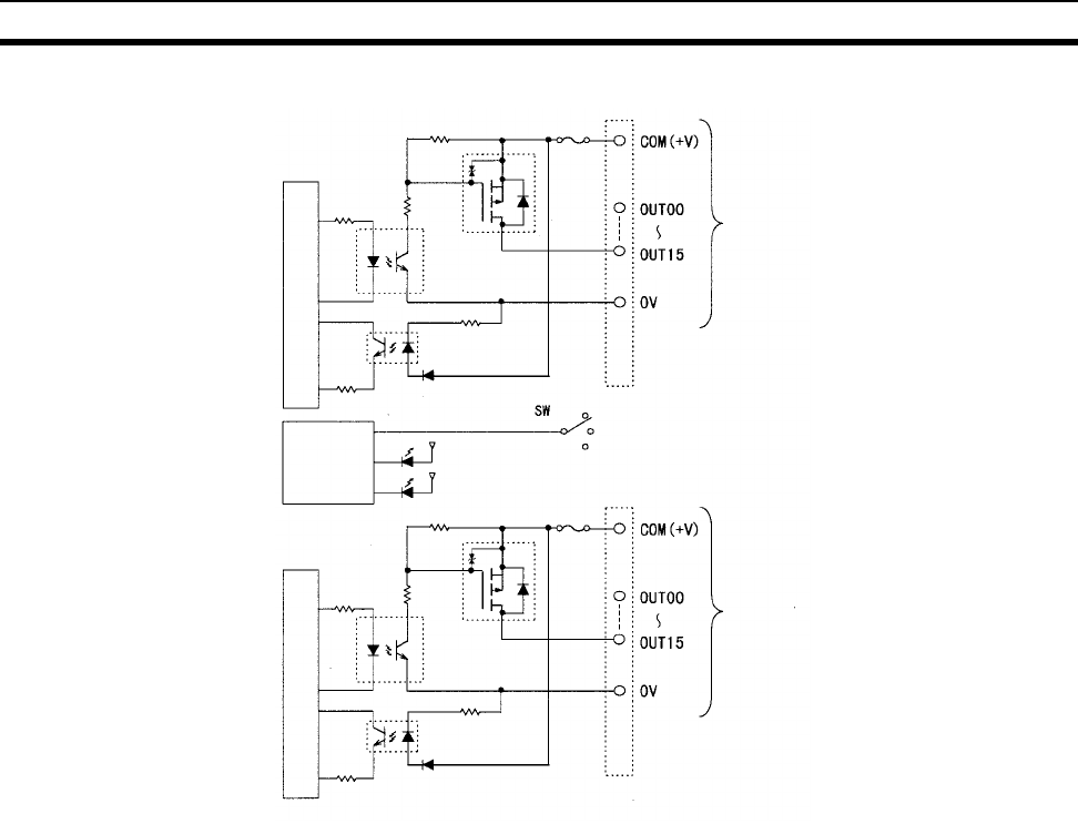
650
Specifications of Basic I/O Units and High-density I/O Units Appendix A
Circuit Configuration
Note The ERR indicator will light if a fuse blows or if the external power supply is turned OFF, and the corre-
sponding Flag in the Basic I/O Unit Information Area (A050 to A089) will turn ON.
Output indicator
Indicator
switch circuit
Blown fuse
detection
circuit
x 3 CN1 circuits
x 3 CN2 circuits
Fuse
ERR indicator
Fuse
Internal circuits
Internal circuits
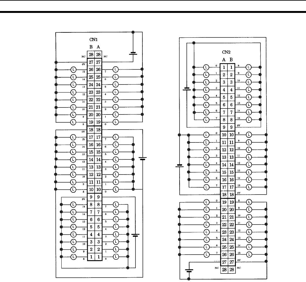
651
Specifications of Basic I/O Units and High-density I/O Units Appendix A
Terminal Connections: CS1W-OD292 24-V DC 96-point Transistor Output Unit (Sourcing Outputs)
Word (m+2)
Word (m+1)
Word m
Word (m+3)
Word (m+4)
Word (m+5)
12 to
24 V DC
12 to
24 V DC
12 to
24 V DC
12 to
24 V DC
12 to
24 V DC
12 to
24 V DC
COM2
COM1
COM0
COM5
COM4
COM3
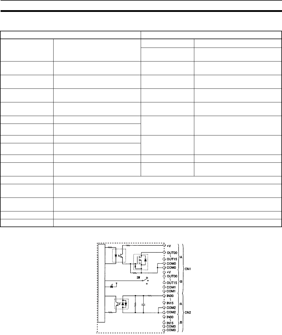
652
Specifications of Basic I/O Units and High-density I/O Units Appendix A
CS1W-MD261 DC Input/Transistor Output Unit (32/32 Points, Sinking)
Circuit Configuration
Output section (CN1) Input section (CN2)
Rated Voltage 12 to 24 V DC Rated Input Voltage 24 V DC
Operating Input Volt-
age
20.4 to 26.4 V DC
Operating Load Volt-
age Range
10.2 to 26.4 V DC Input Impedance 3.9 kΩ
Maximum Load Cur-
rent
0.3 A/point, 1.6 A/common, 3.2 A/
Unit
Input Current 6 mA typical (at 24 V DC)
Maximum Inrush Cur-
rent
3.0/point, 10 ms max. ON Voltage/ON Cur-
rent
15.4 V DC min./3 mA min.
Leakage Current 0.1 mA max. OFF Voltage/OFF
Current
5 V DC min./1 mA min.
Residual Voltage 1.5 V max. ON Response Time 8.0 ms max. (Can be set to between
0 and 32 in the PLC Setup.) (See
notes 1 and 2.)
ON Response Time 0.5 ms max.
OFF Response Time 1.0 ms max. OFF Response Time 8.0 ms max. (Can be set to between
0 and 32 in the PLC Setup.) (See
notes 1 and 2.)
No. of Circuits 32 (16 points/common, 2 circuits)
Fuse None No. of Circuits 32 (16 points/common, 2 circuits)
External Power Sup-
ply
10.2 to 26.4 V DC, 30 mA min. Number of Simulta-
neously ON Points
70% (11 points/common)
(at 24 V DC)
Insulation Resistance 20 MΩ between the external terminals and the GR terminal (100 V DC)
Dielectric Strength 1,000 V AC between the external terminals and the GR terminal for 1 minute at a leakage current
of 10 mA max.
Internal Current Con-
sumption
5 V DC 270 mA max.
Weight 260 g max.
Accessories Two connectors for external wiring (soldered)
Internal circuits
I/O indicator
(Outputs)
(Inputs)
1000 pF
560 Ω
3.9 kΩ
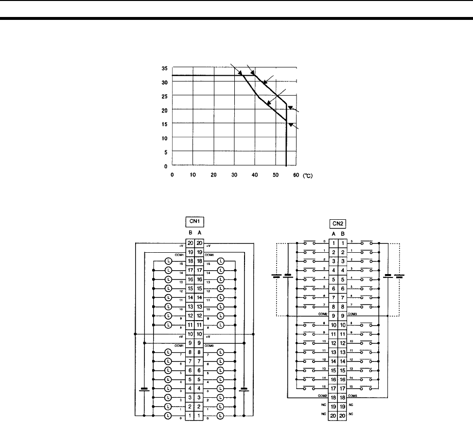
653
Specifications of Basic I/O Units and High-density I/O Units Appendix A
Terminal Connections
• When wiring, pay careful attention to the polarity. The load may operate is polarity is reversed.
• Although the +V and COM terminals of rows A and B of CN1 and CN2 are internally connected, wire all
points completely.
Note 1. The ON response time will be 120 µs maximum and OFF response time will be 300 µs maximum even
if the response times are set to 0 ms due to internal element delays.
2. The input ON and OFF response times for Basic I/O Units can be set to 0, 0.5, 1, 2, 4, 8, 16, or 32 ms
in the PLC Setup.
Number of Simultaneously ON Points vs.
Ambient Temperature Characteristic
Input voltage: 24 V DC
Input voltage: 26.4 V DC
12 points at 55°C
9 points at 55°C
16 points at 33°C 16 points at 45°C
Ambient Temperature
Number of simultaneously ON points
12 to 24 V DC
12 to
24 V DC
24
V DC
24
V DC
Inputs Outputs
I/O word "m" I/O word "m+1"

654
Specifications of Basic I/O Units and High-density I/O Units Appendix A
CS1W-MD291 DC Input/Transistor Output Unit (48/48 Points, Sinking)
Outputs (CN1)
Note The maximum load currents will be 1.0 A/common and 3.0 A/Unit if a
pressure-welded connector is used.
Inputs (CN2)
Note The input ON and OFF response times for Basic I/O Units can be set to 0 ms, 0.5 ms, 1 ms, 2 ms, 4 ms,
8 ms, 16 ms, or 32 ms in the PLC Setup.
Rated Voltage 12 to 24 V DC
Operating Load Voltage Range 10.2 to 26.4 V DC
Maximum Load Current 0.1 A/point, 1.2 A/common, 3.6 A/Unit (See note.)
Maximum Inrush Current 1.0 A/point, 10 ms max.
8.0 A/common, 10 ms max.
Leakage Current 0.1 mA max.
Residual Voltage 1.5 V max.
ON Response Time 0.5 ms max.
OFF Response Time 1.0 ms max.
No. of Circuits 48 points (16 points/common, 3 commons)
Fuse 3-A fuses (1 per common). Three fuses are used.
The fuse cannot be replaced by the user.
External Power Supply 10.2 to 26.4 V DC, 50 mA min.
Insulation Resistance 20 MΩ between the external terminals and the GR
terminal (100 V DC)
Dielectric Strength 1,000 V AC between the external terminals and the
GR terminal for 1 minute at a leakage current of
10 mA max.
Internal Current Consumption 350 mA max. at 5 V DC
Weight 320 g max.
Accessories Two connectors for external wiring (soldered)
Rated Input Voltage 24 V DC
Operating Input Voltage 20.4 to 26.4 V DC
Input Impedance 4.7 kΩ
Input Current Approx. 5 mA (at 24 V DC)
ON Voltage/ON Current 17 V DC min./3 mA min.
OFF Voltage/OFF Current 5.0 V DC max./1 mA max.
ON Response Time 8.0 ms max.(Possible to select one out of eight
times from 0 to 32 ms in the PLC Setup.) (See note
below.)
OFF Response Time 8.0 ms max. (Possible to select one out of eight
times from 0 to 32 ms in the PLC Setup.) (See note
below.)
No. of Circuits 48 points (16 points/common, 3 commons)
Number of Inputs Simulta-
neous ON
50% (8 points/common) (at 24 V DC) (Depends on
ambient temperature.)
Insulation Resistance 20 MΩ between the external terminals and the GR
terminal (100 V DC)
Dielectric Strength 1,000 V AC between the external terminals and the
GR terminal for 1 minute at a leakage current of
10 mA max.
Internal Current Consumption 350 mA max. at 5 V DC
Weight 320 g max.
Accessories Two connectors for external wiring (soldered)
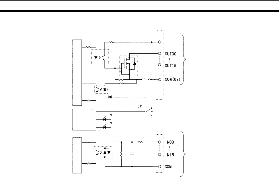
655
Specifications of Basic I/O Units and High-density I/O Units Appendix A
Circuit Configuration
Note 1. The ERR indicator will light if a fuse blows or if the external power supply is turned OFF, and the cor-
responding Flag in the Basic I/O Unit Information Area (A050 to A089) will turn ON.
2. The ON response time will be 120 µs maximum and OFF response time will be 300 µs maximum even
if the response times are set to 0 ms due to internal element delays.
Output indicator
Indicator
switch circuit
Blown fuse
detection
circuit
× 3 CN1 (Output)
10.2 to
26.4 V DC
× 3 CN2 (Input)
Fuse
ERR indicator
Internal circuits
Internal circuits
1000 pF
560 Ω
4.7 kΩ
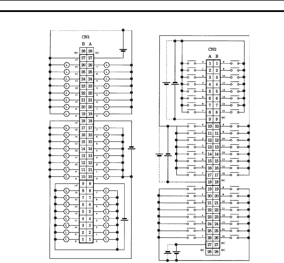
656
Specifications of Basic I/O Units and High-density I/O Units Appendix A
Terminal Connections: CS1W-MD291 24-V DC 48-point Input/48-point Output Unit (Sinking Outputs)
Word (m+2)
Word (m+1)
Word m
Word (m+3)
Word (m+4)
Word (m+5)
12 to
24 V DC
12 to
24 V DC
12 to
24 V DC
24 V DC
24 V DC
24 V DC
COM2
COM1
COM0
COM5
COM4
COM3
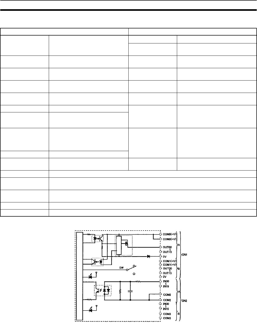
657
Specifications of Basic I/O Units and High-density I/O Units Appendix A
CS1W-MD262 DC Input/Transistor Output Unit (32/32 Points, Sourcing)
Circuit Configuration
Output section (CN1) Input section (CN2)
Rated Voltage 24 V DC Rated Input Voltage 24 V DC
Operating Input Volt-
age
20.4 to 26.4 V DC
Operating Load Volt-
age Range
20.4 to 26.4 V DC Input Impedance 3.9 kΩ
Maximum Load Cur-
rent
0.3 A/point, 1.6 A/common, 3.2 A/
Unit
Input Current 6 mA typical (at 24 V DC)
Leakage Current 0.1 mA max. ON Voltage/ON Cur-
rent
15.4 V DC min./3 mA min.
Residual Voltage 1.5 V max. OFF Voltage/OFF
Current
5 V DC min./1 mA min.
ON Response Time 0.5 ms max. ON Response Time 8.0 ms max. (Can be set to between
0 and 32 in the PLC Setup.) (Refer
to the above Load Short-circuit Pro-
tection.)
OFF Response Time 1.0 ms max.
Load Short-circuit
Prevention
Detection current: 0.7 to 2.5 A
Automatic restart after error clear-
ance. (Refer to the above Load
Short-circuit Protection.)
OFF Response Time 8.0 ms max. (Can be set to between
0 and 32 in the PLC Setup.) (Refer
to the above Load Short-circuit Pro-
tection.)
No. of Circuits 32 (16 points/common, 2 circuits)
External Power Sup-
ply
20.4 to 26.4 V DC, 70 mA min. Number of Simulta-
neously ON Points
70% (11 points/common)
(at 24 V DC)
Insulation Resistance 20 MΩ between the external terminals and the GR terminal (100 V DC)
Dielectric Strength 1,000 V AC between the external terminals and the GR terminal for 1 minute at a leakage current
of 10 mA max.
Internal Current Con-
sumption
5 V DC 270 mA max.
Weight 270 g max.
Accessories Two connectors for external wiring (soldered)
Internal circuits
I/O indicator
(Outputs)
(Inputs)
ERR indicator
Short-circuit
protection
1000 pF
560 Ω
3.9 kΩ
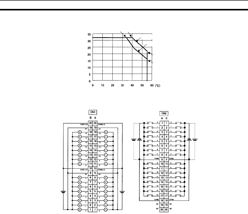
658
Specifications of Basic I/O Units and High-density I/O Units Appendix A
Terminal Connections
• When wiring, pay careful attention to the polarity. The load may operate if the polarity is reversed.
• Although the +V and COM terminals of rows A and B of CN1 and CN2 are internally connected, wire all
points completely.
Note The ON response time will be 120 µs maximum and OFF response time will be 300 µs maximum even if
the response times are set to 0 ms due to internal element delays.
Number of Simultaneously ON Points vs.
Ambient Temperature Characteristic
Input voltage: 24 V DC
Input voltage: 26.4 V DC
22 points at 55°C
16 points at 55°C
32 points at 34°C32 points at 40°C
Ambient Tem
p
erature
Number of simultaneously ON points
24
V DC 24
V DC
24 V DC 24 V DC
I/O word "m"I/O word "m+1" I/O word "m+3"I/O word "m+2"

659
Specifications of Basic I/O Units and High-density I/O Units Appendix A
CS1W-MD292 DC Input/Transistor Output Unit (48/48 Points, Sourcing)
Outputs (CN1)
Note The maximum load currents will be 1.0 A/common and 3.0 A/Unit if a
pressure-welded connector is used.
Inputs (CN2)
Rated Voltage 12 to 24 V DC
Operating Load Voltage Range 10.2 to 26.4 V DC
Maximum Load Current 0.1 A/point, 1.2 A/common, 3.6 A/Unit (See note.)
Maximum Inrush Current 1.0 A/point, 10 ms max.
8.0 A/common, 10 ms max.
Leakage Current 0.1 mA max.
Residual Voltage 1.5 V max.
ON Response Time 0.5 ms max.
OFF Response Time 1.0 ms max.
No. of Circuits 48 points (16 points/common, 3 commons)
Fuse 3 A (1 per common)
The fuse cannot be replaced by the user.
External Power Supply 10.2 to 26.4 V DC, 50 mA min.
Insulation Resistance 20 MΩ between the external terminals and the GR
terminal (100 V DC)
Dielectric Strength 1,000 V AC between the external terminals and the
GR terminal for 1 minute at a leakage current of
10 mA max.
Internal Current Consumption 350 mA max. at 5 V DC
Weight 320 g max.
Accessories Two connectors for external wiring (soldered)
Rated Input Voltage 24 V DC
Operating Input Voltage 20.4 to 26.4 V DC
Input Impedance 4.7 kΩ
Input Current Approx. 5 mA (at 24 V DC)
ON Voltage/ON Current 17 V DC min./3 mA min.
OFF Voltage/OFF Current 5.0 V DC max./1 mA max.
ON Response Time 8.0 ms max. (Possible to select one out of eight
times from 0 to 32 ms in the PLC Setup.) (See note
below.)
OFF Response Time 8.0 ms max. (Possible to select one out of eight
times from 0 to 32 ms in the PLC Setup.) (See note
below.)
No. of Circuits 48 points (16 points/common, 3 commons)
Number of Simultaneously ON
Points
50% (8 points/common) (at 24 V DC) (Depends on
ambient temperature.)
Insulation Resistance 20 MΩ between the external terminals and the GR
terminal (100 V DC)
Dielectric Strength 1,000 V AC between the external terminals and the
GR terminal for 1 minute at a leakage current of
10 mA max.
Internal Current Consumption 350 mA max. at 5 V DC
Weight 320 g max.
Accessories Two connectors for external wiring (soldered)
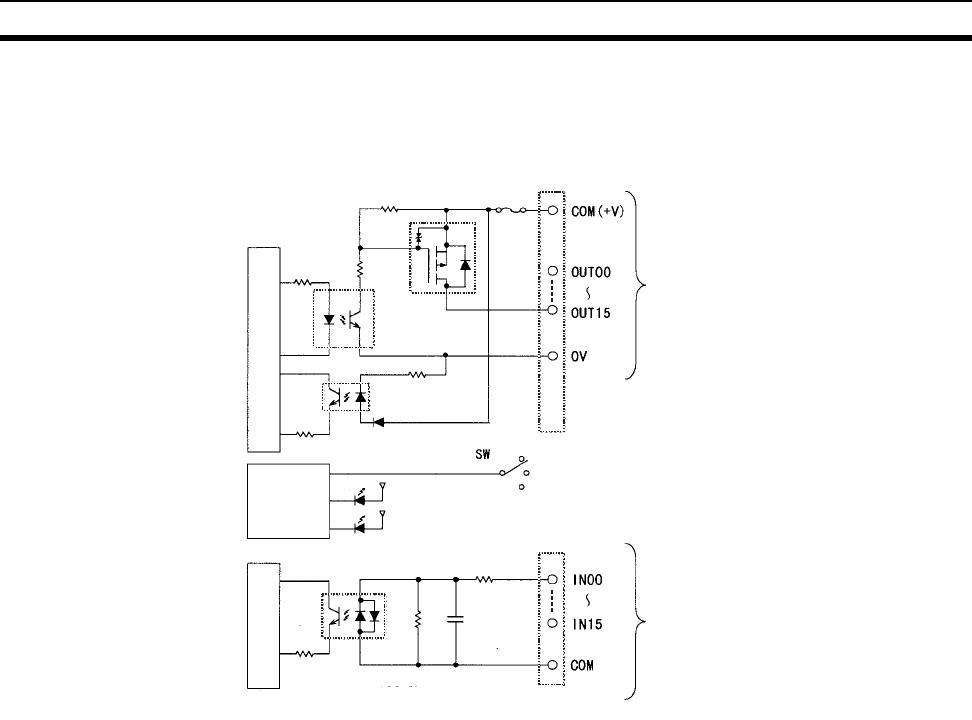
660
Specifications of Basic I/O Units and High-density I/O Units Appendix A
Note The input ON and OFF response times for Basic I/O Units can be set to
0 ms, 0.5 ms, 1 ms, 2 ms, 4 ms, 8 ms, 16 ms, or 32 ms in the PLC
Setup.
Circuit Configuration
Note 1. The ERR indicator will light if a fuse blows or if the external power supply is turned OFF, and the cor-
responding Flag in the Basic I/O Unit Information Area (A050 to A089) will turn ON.
2. The ON response time will be 120 µs maximum and OFF response time will be 300 µs maximum even
if the response times are set to 0 ms due to internal element delays.
Output indicator
Indicator
switch circuit
Blown fuse
detection
circuit
x 3 CN1 (Output)
x 3 CN2 (Input)
Fuse
ERR indicator
Internal circuits
Internal circuits
1000 pF
560 Ω
4.7 kΩ
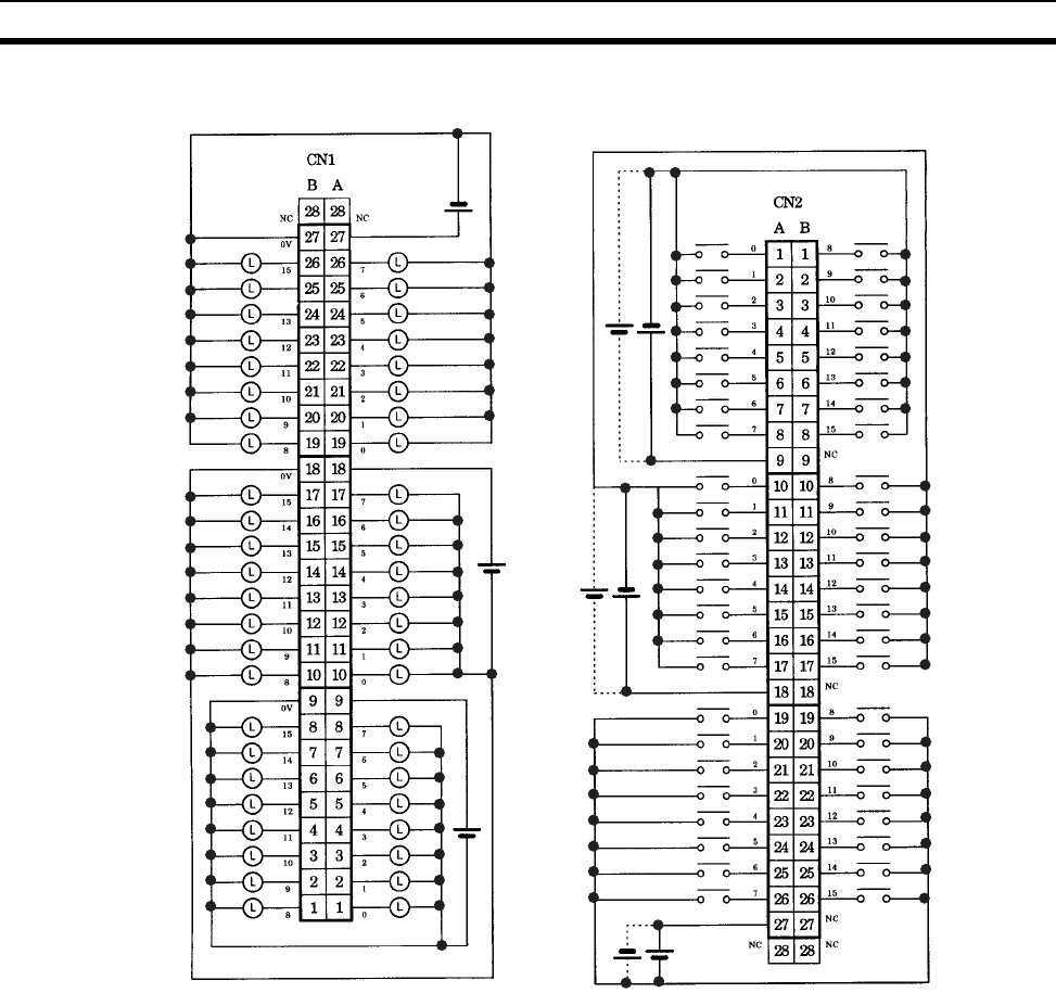
661
Specifications of Basic I/O Units and High-density I/O Units Appendix A
Terminal Connections: CS1W-MD292 24-V DC 48-point Input/48-point Transistor Output Unit (Sourcing
Outputs)
Word (m+2)
Word (m+1)
Word m
Word (m+3)
Word (m+4)
Word (m+5)
12 to
24 V DC
12 to
24 V DC
12 to
24 V DC
24 V DC
24 V DC
24 V DC
COM2
COM1
COM0
COM5
COM4
COM3

662
Specifications of Basic I/O Units and High-density I/O Units Appendix A
CS1W-MD561 TTL I/O Unit (32/32 Points)
Outputs (CN1)
Inputs (CN2)
Note 1. The ON response time will be 120 µs maximum and OFF response time will be 300 µs maximum even
if the response times are set to 0 ms due to internal element delays.
2. The input ON and OFF response times for Basic I/O Units can be set to 0 ms, 0.5 ms, 1 ms, 2 ms,
4 ms, 8 ms, 16 ms, or 32 ms in the PLC Setup.
Rated Voltage 5 V DC±10%
Operating Load Voltage Range 4.5 to 5.5 V DC
Maximum Load Current 35 mA/point, 560 mA/common, 1.12 A/Unit
Leakage Current 0.1 mA max.
Residual Voltage 0.4 V max.
ON Response Time 0.2 ms max.
OFF Response Time 0.3 ms max.
No. of Circuits 32 points (16 points/common, 2 commons)
Fuse None
External Power Supply 5 V DC±10%, 40 mA min. (1.2 mA × No. of ON
points)
Insulation Resistance 20 MΩ between the external terminals and the GR
terminal (100 V DC)
Dielectric Strength 1,000 V AC between the external terminals and the
GR terminal for 1 minute at a leakage current of
10 mA max.
Internal Current Consumption 270 mA max. at 5 V DC
Weight 260 g max.
Accessories Two connectors for external wiring (soldered)
Rated Input Voltage 5 V DC±10%
Input Impedance 1.1 kΩ
Input Current Approx. 3.5 mA (at 5 V DC)
ON Voltage 3.0 V DC min.
OFF Voltage 1.0 V DC max.
ON Response Time 8.0 ms max. (Possible to select one out of eight
times from 0 to 32 ms in the PLC Setup.) (See notes
1 and 2.)
OFF Response Time 8.0 ms max. (Possible to select one out of eight
times from 0 to 32 ms in the PLC Setup.) (See notes
1 and 2.)
No. of Circuits 32 points (16 points/common, 2 commons)
Number of Simultaneously ON
Points
No restrictions
Insulation Resistance 20 MΩ between the external terminals and the GR
terminal (100 V DC)
Dielectric Strength 1,000 V AC between the external terminals and the
GR terminal for 1 minute at a leakage current of
10 mA max.
Internal Current Consumption 270 mA max. at 5 V DC
Weight 260 g max.
Accessories Two connectors for external wiring (soldered)
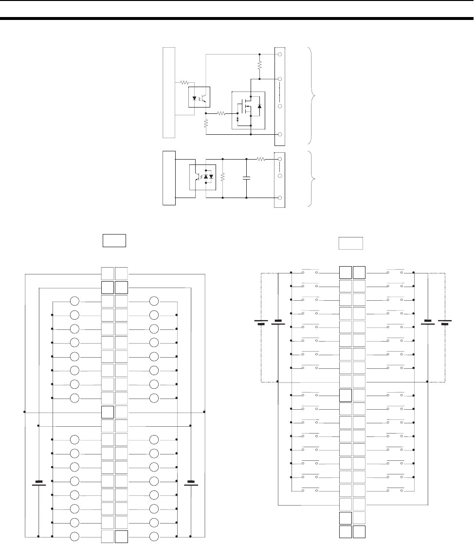
663
Specifications of Basic I/O Units and High-density I/O Units Appendix A
Circuit Configuration
Terminal Connections: CS1W-MD561 TTL 32-point Input/32-point Output Unit
• When wiring, pay careful attention to the polarity. The load may operate if the polarity is reversed.
• Although the +V and COM terminals of rows A and B of CN1 and CN2 are internally connected, wire all
points completely.
IN00
IN15
COM
1.1 k
Ω
1000 pF
2.4 k
Ω
OUT0
0
OUT15
5
+V
COM
4.7 k
Ω
100 Ω
to
to
4.7 k
Ω
Internal circuits
Internal circuits
× 2 CN1
(Output)
× 2 CN2
(Input)
1
2
3
4
5
6
7
8
9
10
11
12
13
14
15
16
17
18
19
20 +V
1
2
3
4
5
6
7
8
9
10
0
1
2
3
4
5
6
7
COM0
+V
0
1
2
3
4
5
6
7
COM1
+V
11
12
13
14
15
16
17
18
19
8
9
10
11
12
13
14
15
COM0
8
9
10
11
12
13
14
15
COM1
20
+V
L
L
L
L
L
L
L
L
L
L
L
L
L
L
L
L
L
L
L
L
L
L
L
L
L
L
L
L
L
L
L
5 V DC
L
AB
CN1
5 V DC
10
21
32
43
54
65
76
87
9COM3
10 8
11 9
12 10
13 11
14 12
15 13
16 14
17 15
18 COM3
19 NC
20 NC
1
0
2
1
3
2
4
3
5
4
6
5
7
6
8
7
9
COM2
10
8
11
9
12
10
13
11
14
12
15
13
16
14
17
15
18
COM2
19
NC
20
NC
5 V DC
BA
CN2
5 V DC
I/O word "m+1" I/O word "m" I/O word "m+2" I/O word "m+3"
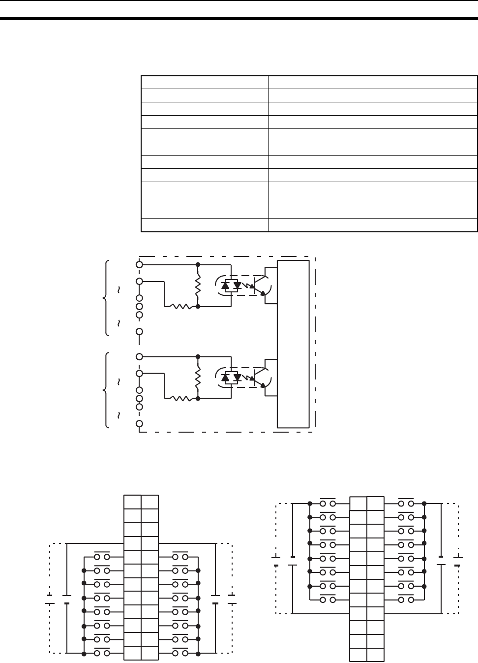
664
Specifications of Basic I/O Units and High-density I/O Units Appendix A
High-density I/O Units (Special I/O Units)
C200H-ID501 TTL Input Unit Used for 32 Static Inputs
Circuit Configuration
Terminal Connections
Note When pin 2 of the Unit’s DIP switch is ON, input points 08 to 15 in connector 2 are high-speed inputs.
Rated Input Voltage 5 V DC ±10%
Input Impedance 1.1 kΩ
Input Current 3.5 mA typical (at 5 V DC)
ON Voltage 3.0 V DC min.
OFF Voltage 1.0 V DC max.
ON Response Time 2.5 ms/15 ms max.
OFF Response Time 2.5 ms/15 ms max.
No. of Circuits 4 (8 points/common)
High-speed Inputs 8 points (connector 2 terminals 8 to 15, when set)
Pulse width: 1 ms/4 ms min. (switchable)
Internal Current Consumption 130 mA 5 V DC max.
Weight 300 g max.
2.4 k
1.1 k
COM0
IN00
IN07
COM1
IN08
IN15
CN1
COM2
IN00
IN07
COM3
IN08
IN15
CN2
2.4 k
1.1 k
The power supply polarity
does not matter.
Internal
circuits
I/O word "n"
CN1
I/O word "n+1"
CN2
B
1
2
3
4
5
6
7
8
9
0
1
2
3
4
5
6
7
COM0
+
NC 10
NC 11
NC
NC
8
9
10
11
12
13
14
15
COM1
+
5 V DC
AB
01
12
23
34
45
56
67
78
COM2 9
8
9
10
11
12
13
14
15
COM3
++
NC 10
NC 11
NC
NC
NC 12
+
A
1
2
3
4
5
6
7
8
9
10
11
12 NC
+
5 V DC
NC 12 NC
+
5 V DC
+
5 V DC
1
2
3
4
5
6
7
8
9
10
11
12
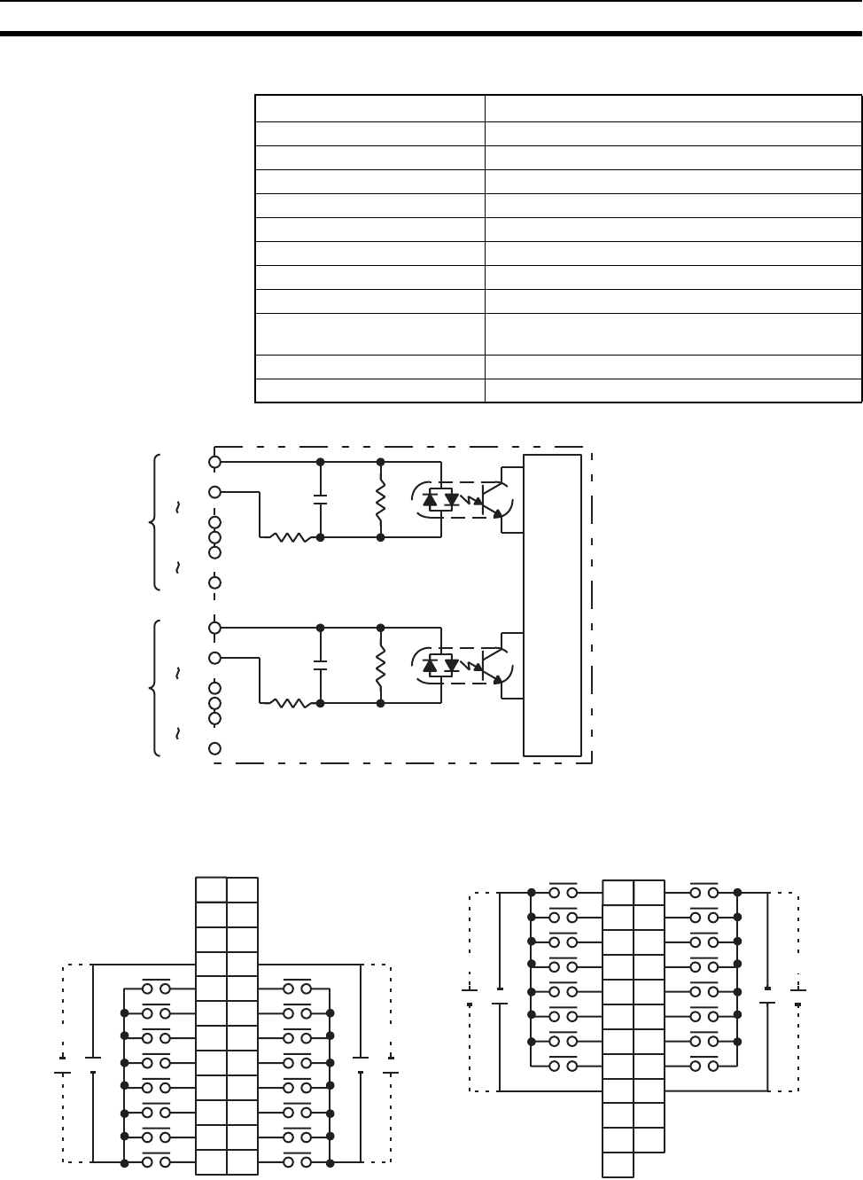
665
Specifications of Basic I/O Units and High-density I/O Units Appendix A
C200H-ID215 DC Input Unit Used for 32 Static Inputs
Circuit Configuration
Terminal Connections
Note 1. When pin 2 of the Unit’s DIP switch is ON, input points 08 to 15 in connector 2 are high-speed inputs.
2. At high temperatures, the number of inputs that can be turned ON simultaneously is limited. Refer to
the graphs on the following page for details.
Rated Input Voltage 24 V DC
Operating Input Voltage 20.4 to 26.4 V DC
Input Impedance 5.6 kΩ
Input Current 4.1 mA (at 24 V DC)
ON Voltage 14.4 V DC min.
OFF Voltage 5.0 V DC max.
ON Response Time 2.5 ms/15 ms max.
OFF Response Time 2.5 ms/15 ms max.
No. of Circuits 4 (8 points/common) (See note 2.)
High-speed Inputs 8 points (connector 2 terminals 8 to 15, when set)
Pulse width: 1 ms/4 ms min. (switchable)
Internal Current Consumption 130 mA 5 V DC max.
Weight 300 g max.
1000 pF
620 Ω
5.6 kΩ
COM0
IN00
IN07
COM1
IN08
IN15
CN1
Internal
circuits
COM2
IN00
IN07
COM3
IN08
IN15
CN2
1000 pF
620 Ω
5.6 kΩ
The power supply polar-
ity does not matter.
I/O word "n"
CN1
I/O word "n+1"
CN2
B
1
2
3
4
5
6
7
8
9
0
1
2
3
4
5
6
7
COM0
+
NC 10
NC 11
NC
NC
8
9
10
11
12
13
14
15
COM1
+
24 V DC
AB
01
12
23
34
45
56
67
78
COM2 9
8
9
10
11
12
13
14
15
COM3
++
NC 10
NC 11
NC
NC
NC 12
+
A
1
2
3
4
5
6
7
8
9
10
11
12 NC
+
24 V DC
NC 12 NC
+
24 V DC
+
24 V DC
1
2
3
4
5
6
7
8
9
10
11
12
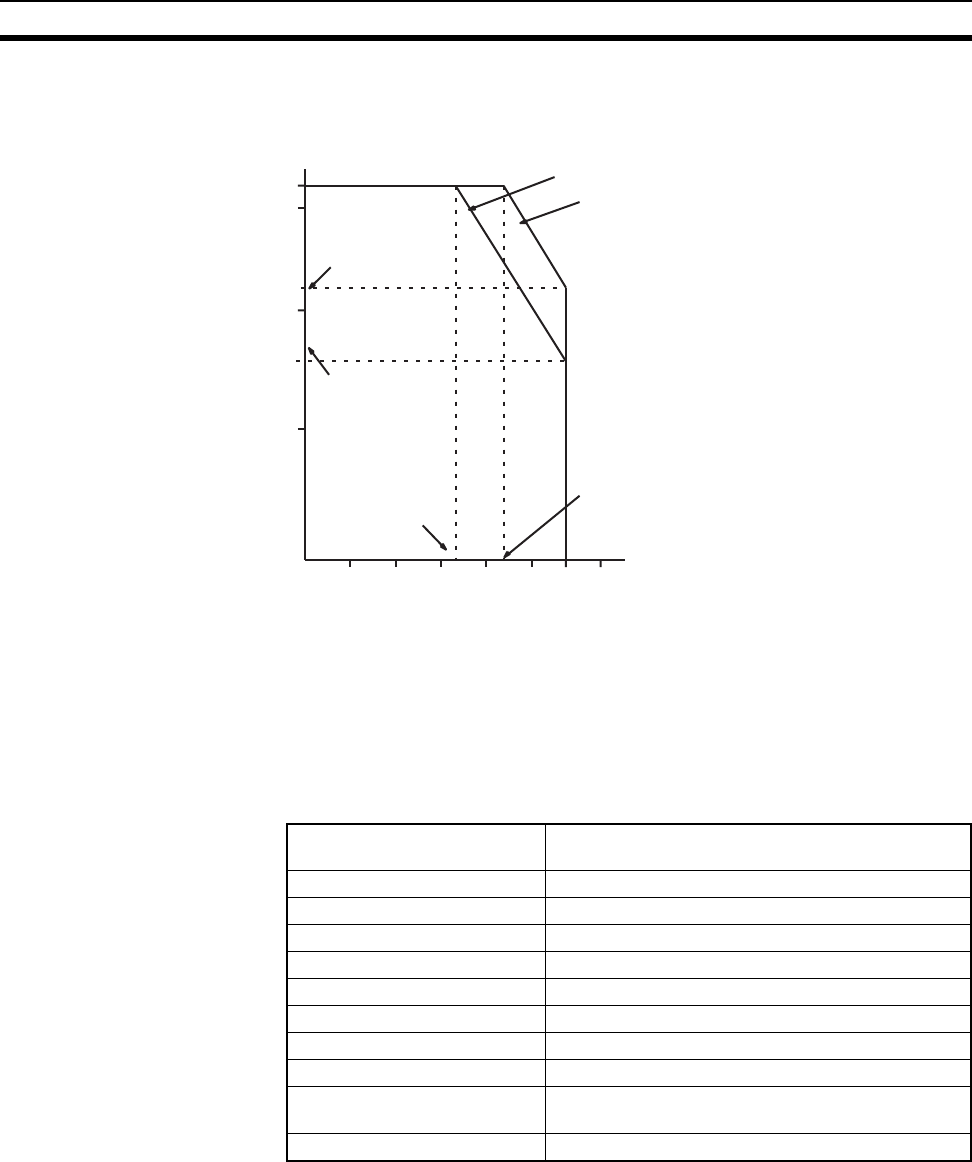
666
Specifications of Basic I/O Units and High-density I/O Units Appendix A
Number of Simultaneous Inputs
The number C200H-ID215 24-V DC inputs that can be ON simultaneously will vary with ambient temperature
as shown in the figure below.
If the number of inputs that are ON exceeds the number that can be ON at the same time, then heat generated
by electronic components will increase the temperature of the components and the case. Higher temperatures
will lower the reliability and service life of the elements and will damage the Unit. Higher temperatures in elec-
tronic components and the case will also cause time delays. There is no particular problem if all input points
are turned ON for less than 10 minutes (if all input points have been OFF for at least 2 hours) under special
conditions, such as during startup work inspections.
C200H-OD501 TTL Output Unit Used for 32 Static Outputs
Ambient Temperature (°C)
Simultaneously Usable Inputs
Input Voltage: 26.4 V DC
Input Voltage: 24.0 V DC
010203040505560
0
10
16
20
30
32
22
34 43
Input Voltage:
16 points ON
Input Voltage:
32 points ON
Input Voltage:
22 points ON
Input Voltage:
24.0 V DC; 43°C,
32 points ON
24.0 V DC; 55°C,
24.0 V DC; 55°C,
24.0 V DC; 34°C,
Max. Switching Capacity 5 V DC±10% 35 mA (280 mA/common, 1.12 A/Unit;
output resistance 4.7 kΩ)
Min. Switching Capacity None
Leakage Current 0.1 mA max.
Residual Voltage 0.4 V max.
ON Response Time 0.2 ms max.
OFF Response Time 0.3 ms max.
No. of Circuits 4 (8 points/common)
Internal Current Consumption 220 mA 5 V DC max.
Fuses 4 (1 fuse/common; fuses are not user-replaceable.)
Power for External Supply 39 mA 5 V DC±10% min. (1.2 mA × no. of outputs
ON)
Weight 300 g max.
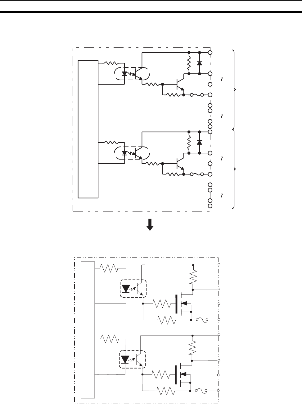
667
Specifications of Basic I/O Units and High-density I/O Units Appendix A
Circuit Configuration
OUT00
OUT07
COM0
CN1
OUT08
OUT15
COM1
Internal
circuits
5 V DC
5 V DC
Fuse
4.7 kΩ
OUT00
OUT07
COM2
CN2
OUT08
OUT15
COM3
5 V DC
5 V DC
Fuse
4.7 kΩ
Units manufactured on or before November 13, 2002
(manufacturing numbers 13Y2 or earlier)
Units manufactured on or after November 14, 2002
(manufacturing numbers 14Y2H or later)
OUT00
OUT07
COM0
4.7 kΩ
5 V DC
OUT00
OUT07
COM1
4.7 kΩ
5 V DC
to
to
to
to
Internal circuits
Fuse
Fuse
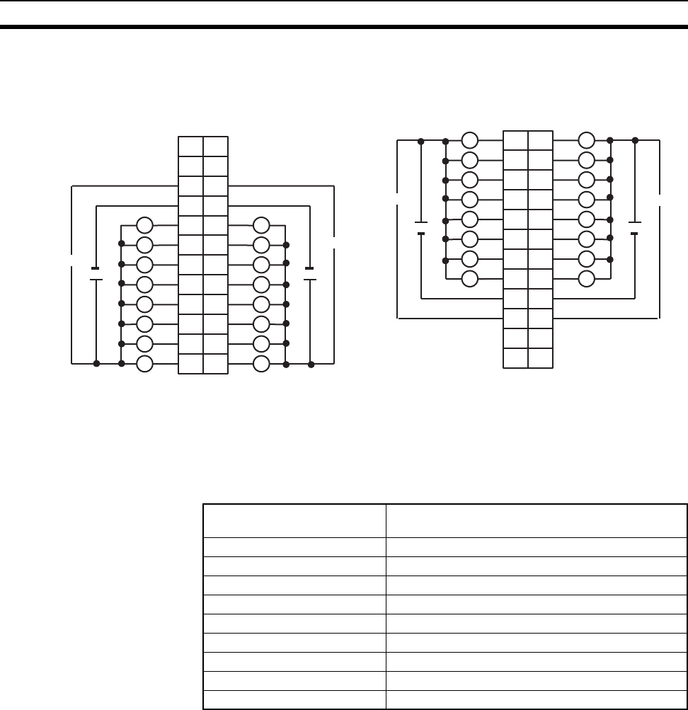
668
Specifications of Basic I/O Units and High-density I/O Units Appendix A
Terminal Connections
Note 1. I/O word “n” is determined by the unit number setting (n = CIO 2000 + 10 × unit number).
2. The Unit will have 32 static output points when pin 1 of it’s DIP switch is OFF.
3. The outputs are negative logic outputs; when there is an output, the terminal has an “L” voltage level.
Each output terminal has an output resistance of 4.7 kΩ.
C200H-OD501 TTL Output Unit Used for 128 Dynamic Inputs
I/O word "n"
CN1
I/O word "n+1"
CN2
L L
L
+5 V DC +5 V DC
B
1
2
3
4
5
6
7
8
9
0
1
2
3
4
5
6
7
COM0
+
10
NC 11 NC
8
9
10
11
12
13
14
15
COM1
+
A B
01
12
23
34
45
56
67
78
COM2 9
8
9
10
11
12
13
14
15
COM3
10
NC 11 NC
NC 12
A
1
2
3
4
5
6
7
8
9
10
11
12 NC
NC 12 NC
1
2
3
4
5
6
7
8
9
10
11
12
5 V DC
5 V DC
5 V DC
5 V DC
L
L
L
L
L
L
L
L
L
L
L
L
L
L
L
+ +
+5 V DC+5 V DC
LL
L L
L L
L L
L L
L L
L L
Max. Switching Capacity 5 V DC±10% 35 mA (280 mA/common, 1.12 A/Unit;
output resistance 4.7 kΩ)
Leakage Current 0.1 mA max.
Residual Voltage 0.4 V max.
ON Response Time 0.2 ms max.
OFF Response Time 0.3 ms max.
No. of Circuits 2 (dynamic, 64 points/circuit)
Internal Current Consumption 220 mA 5 V DC max.
Fuses 4 (1 fuse/common; fuses are not user-replaceable.)
Power for External Supply 39 mA 5 V DC min. (1.2 mA × no. of outputs ON)
Weight 300 g max.
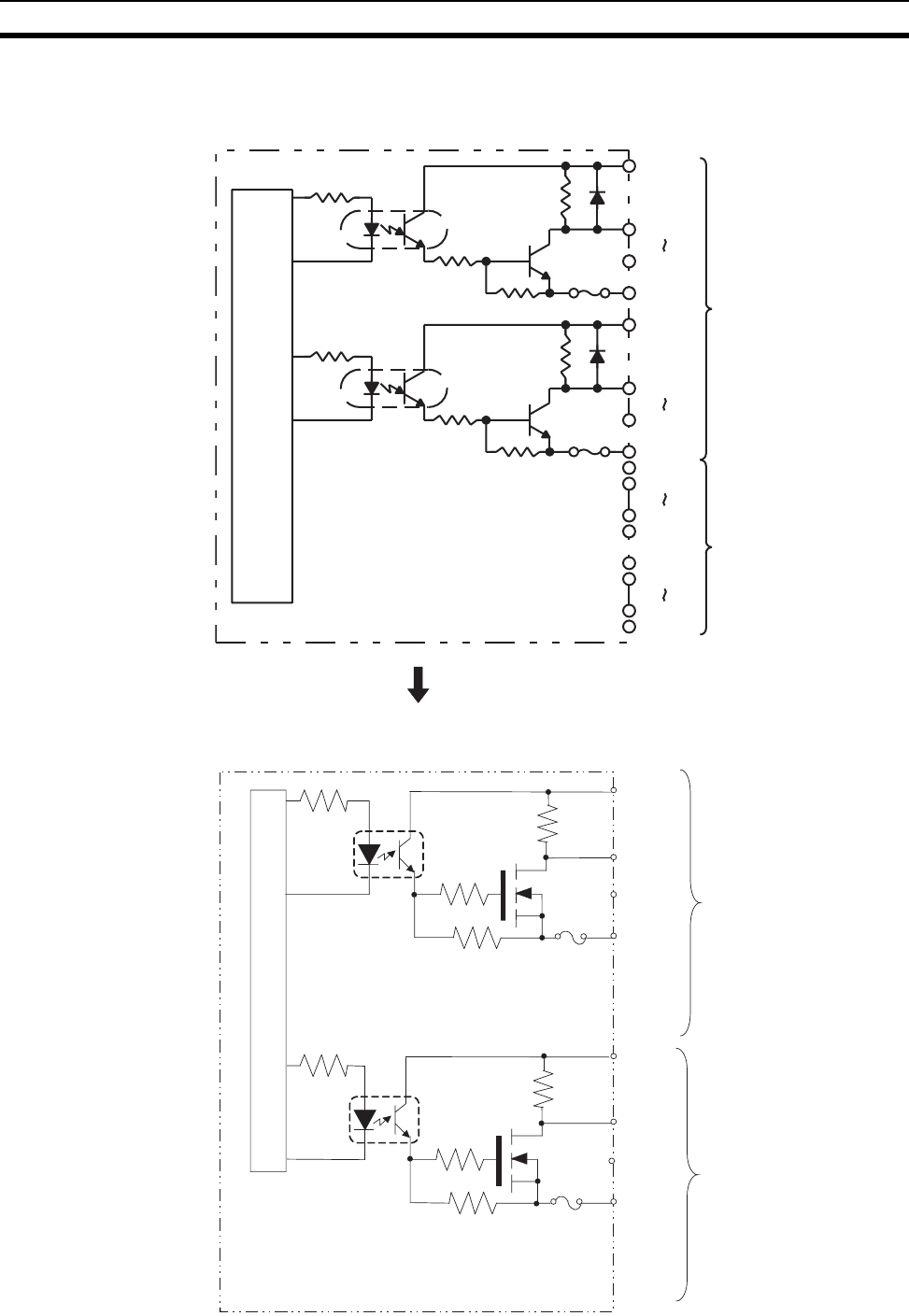
669
Specifications of Basic I/O Units and High-density I/O Units Appendix A
Circuit Configuration
DATA00
DATA07
COM0
CN1
STB00
STB07
COM1
Internal
circuits
5 V DC
5 V DC
Fuse
4.7 kΩ
Fuse
4.7 kΩ
DATA08
DATA15
COM2
STB08
STB15
COM3
5 V DC
5 V DC
CN2
Units manufactured on or before November 13, 2002
(manufacturing numbers 13Y2 or earlier)
Units manufactured on or after November 14, 2002
(manufacturing numbers 14Y2H or later)
DAT00
DAT07
COM0
4.7 kΩ
5 V DC
DAT08
DAT15
COM2
4.7 kΩ
5 V DC
CN2
CN1
STB00
STB07
COM1
5 V DC
STB08
STB15
COM3
5 V DC
to
to
to
to
Internal circuits
Fuse
Fuse
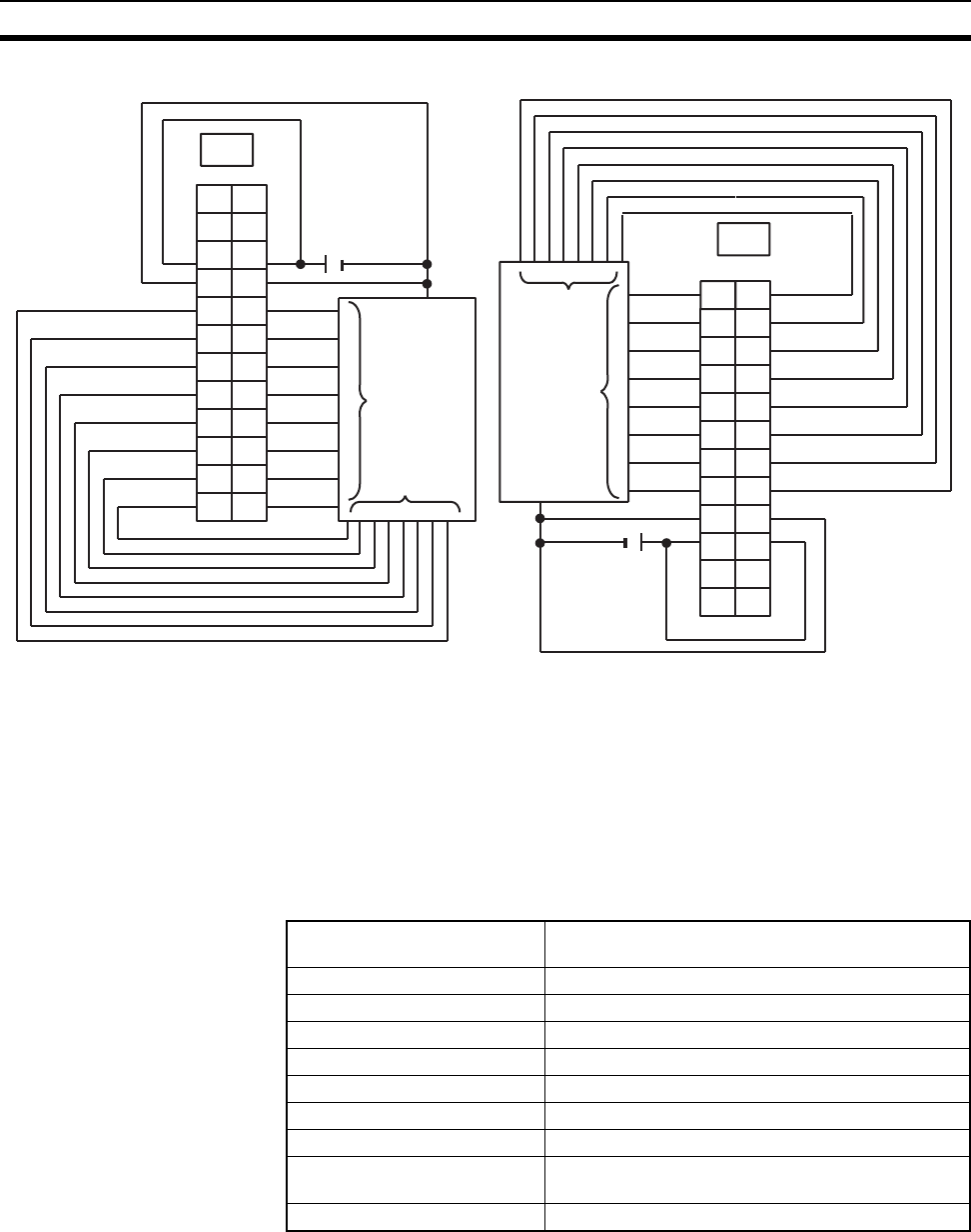
670
Specifications of Basic I/O Units and High-density I/O Units Appendix A
Terminal Connections
Note 1. Refer to the Unit’s operation manual for details on I/O bit allocation.
2. The Unit will have 128 dynamic output points when pin 1 of it’s DIP switch is ON.
3. Set pin 5 of the Unit’s DIP switch ON for positive logic outputs, or OFF for negative logic outputs.
When set for negative logic outputs, the terminal has an “L” voltage level when there is an output.
When set for positive logic outputs, the terminal has an “H” voltage level when there is an output.
4. The strobe signal has negative logic regardless of the setting of pin 5.
5. Each output terminal has an output resistance of 4.7 kΩ.
C200H-OD215 Transistor Output Unit Used for 32 Static Outputs
B
1
2
3
4
5
6
7
8
9
DATA0
DATA1
DATA2
DATA3
DATA4
DATA5
DATA6
DATA7
COM0
+V1 10
NC 11
+V0
NC
STB0
STB1
STB2
STB3
STB4
STB5
STB6
STB7
COM1
NC 12
A
1
2
3
4
5
6
7
8
9
10
11
12 NC
5 V DC
+B
1
2
3
4
5
6
7
8
9
DATA8
DATA9
DATA10
DATA11
DATA12
DATA13
DATA14
DATA15
COM2
+V3
10
NC
11
+V2
NC
STB8
STB9
STB10
STB11
STB12
STB13
STB14
STB15
COM3
NC
12
A
1
2
3
4
5
6
7
8
9
10
11
12
NC
+
5 V DC
CN2
Output device
(such as a nu-
meric display)
Data
input
Strobe
input
Output device
(such as a nu-
meric display)
Data
input
Strobe
input
CN1
Max. Switching Capacity 16 mA, 4.5 V DC to 100 mA, 26.4 V DC
800 mA/common, 3.2 A/Unit
Leakage Current 0.1 mA max.
Residual Voltage 0.7 V max.
ON Response Time 0.2 ms max.
OFF Response Time 0.6 ms max.
No. of Circuits 4 (8 points/common)
Internal Current Consumption 220 mA 5 V DC max.
Fuses 4 (1 fuse/common; fuses are not user-replaceable.)
Power for External Supply 90 mA 5 to 24 V DC±10% min.
(2.8 mA × number of ON outputs)
Weight 300 g max.
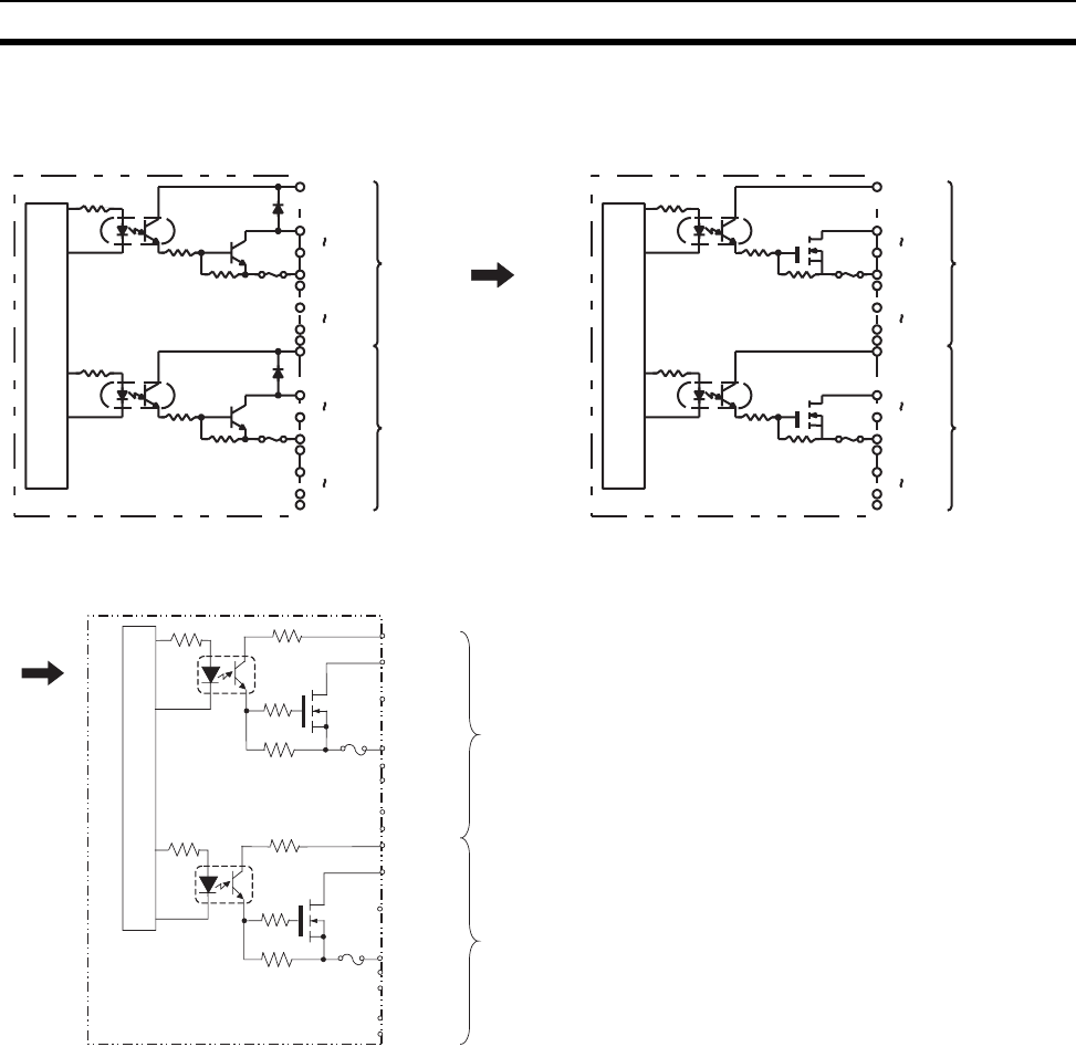
671
Specifications of Basic I/O Units and High-density I/O Units Appendix A
Circuit Configuration
Units manufactured on or before November 29, 1999
(manufacturing numbers 29Y9 or earlier)
OUT00
OUT07
COM0
OUT08
OUT15
COM1
Inter-
nal
cir-
cuits
Fuse
Fuse
CN1
5 to
24 V DC
5 to
24 V DC
OUT00
OUT07
COM2
OUT08
OUT15
COM3
CN2
5 to
24 V DC
5 to
24 V DC
OUT00
OUT07
COM0
OUT08
OUT15
COM1
Inter-
nal
cir-
cuits
Fuse
Fuse
CN1
5 to
24 V DC
5 to
24 V DC
OUT00
OUT07
COM2
OUT08
OUT15
COM3
CN2
5 to
24 V DC
5 to
24 V DC
10 kΩ
10 kΩ
8.2 kΩ
8.2 kΩ
15 kΩ
6.8 kΩ
15 kΩ
6.8 kΩ
Units manufactured on or after October 10, 2002
(manufacturing numbers 10X2H or later)
5 to 24 V DC
12 kΩ
8.2 kΩ
OUT00
OUT07
COM0
100 Ω
12 kΩ
8.2 kΩ
100 Ω
5 to 24 V DC
OUT07
OUT15
COM1
5 to 24 V DC
OUT00
OUT07
COM2
5 to 24 V DC
OUT08
OUT15
COM3
CN2
CN1
to
to
to
to
Inter-
nal
cir-
cuits
Fuse
Fuse
Units manufactured between November 30, 1999 and
October 9, 2002 (manufacturing numbers 30Y9 to 09X2)
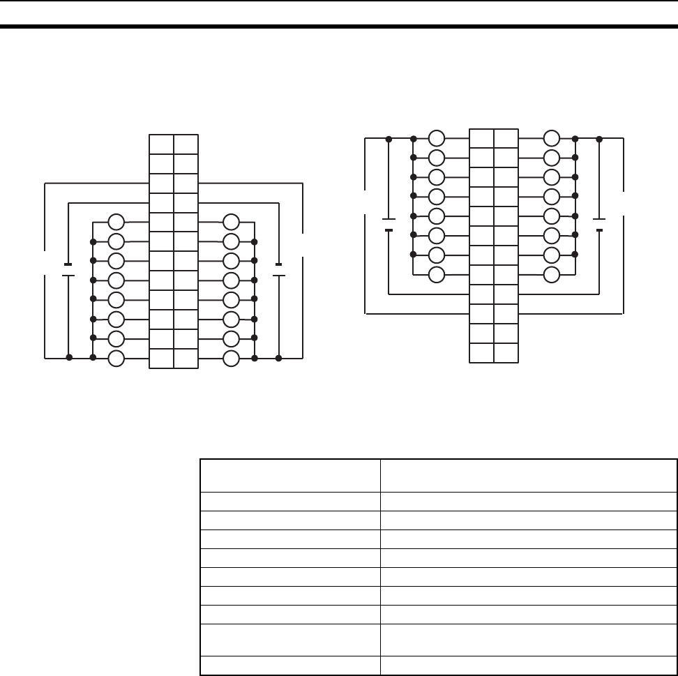
672
Specifications of Basic I/O Units and High-density I/O Units Appendix A
Terminal Connections
Note 1. I/O word “n” is determined by the unit number setting (n = CIO 2000 + 10 × unit number).
2. The Unit will have 32 static output points when pin 1 of it’s DIP switch is OFF.
C200H-OD215 Transistor Output Unit Used for 128 Dynamic Outputs
I/O word "n"
CN1
I/O word "n+1"
CN2
L L
L
+5 to 24 V DC +5 to 24 V DC
B
1
2
3
4
5
6
7
8
9
0
1
2
3
4
5
6
7
COM0
+
10
NC 11 NC
8
9
10
11
12
13
14
15
COM1
+
A B
01
12
23
34
45
56
67
78
COM2 9
8
9
10
11
12
13
14
15
COM3
10
NC 11 NC
NC 12
A
1
2
3
4
5
6
7
8
9
10
11
12 NC
NC 12 NC
1
2
3
4
5
6
7
8
9
10
11
12
5 to 24
V DC
5 to 24
V DC
5 to 24
V DC
5 to 24
V DC
L
L
L
L
L
L
L
L
L
L
L
L
L
L
L
+ +
+5 to 24 V DC+5 to 24 V DC
LL
L L
L L
L L
L L
L L
L L
Max. Switching Capacity 16 mA, 4.5 V DC to 100 mA, 26.4 V DC
800 mA/common, 3.2 A/Unit
Leakage Current 0.1 mA max.
Residual Voltage 0.7 V max.
ON Response Time 0.2 ms max.
OFF Response Time 0.6 ms max.
No. of Circuits 2 (dynamic, 64 points/circuit)
Internal Current Consumption 220 mA 5 V DC max.
Fuses 4 (1 fuse/common; fuses are not user-replaceable.)
Power for External Supply 90 mA 5 to 24 V DC±10% min.
(2.8 mA × number of ON outputs)
Weight 300 g max.
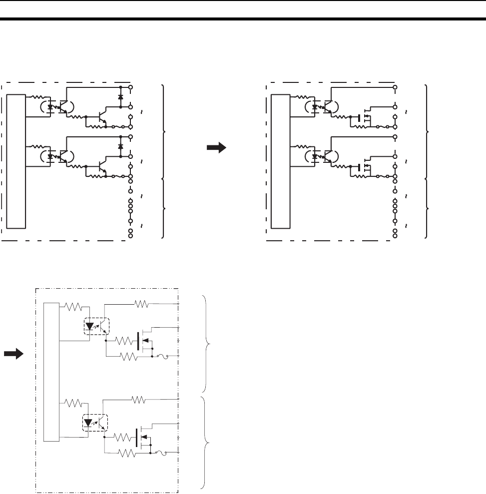
673
Specifications of Basic I/O Units and High-density I/O Units Appendix A
Circuit Configuration
Units manufactured on or before November 29, 1999
(manufacturing numbers 29Y9 or earlier)
DATA00
DATA07
COM0 CN1
STB00
STB07
COM1
Inter-
nal
cir-
cuits
Fuse
Fuse
DATA08
DATA15
COM2
STB08
STB15
COM3
CN2
5 to
24 V DC
5 to
24 V DC
5 to
24 V DC
5 to
24 V DC
DATA00
DATA07
COM0 CN1
STB00
STB07
COM1
Inter-
nal
cir-
cuits
Fuse
Fuse
DATA08
DATA15
COM2
STB08
STB15
COM3
CN2
5 to
24 V DC
5 to
24 V DC
5 to
24 V DC
5 to
24 V DC
10 kΩ
8.2 kΩ
10 kW
8.2 kΩ
15 kΩ
6.8 kΩ
15 kΩ
6.8 kΩ
Units manufactured on or after October 10, 2002
(manufacturing numbers 10X2H or later)
DAT00
DAT07
COM0
8.2 kΩ
5 V DC
DAT08
DAT15
COM2
8.2 kΩ
5 V DC
100 Ω
12 kΩ
100 Ω
12 kΩ
CN2
CN1
STB00
STB07
COM1
5 V DC
STB08
STB15
COM3
5 V DC
to
to
to
to
Inter-
nal
cir-
cuits
Fuse
Fuse
Units manufactured between November 30, 1999 and
October 9, 2002 (manufacturing numbers 30Y9 to 09X2)
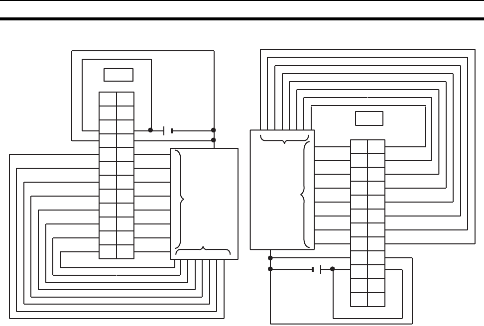
674
Specifications of Basic I/O Units and High-density I/O Units Appendix A
Terminal Connections
Note 1. Refer to the Unit’s operation manual for details on I/O bit allocation.
2. The Unit will have 128 dynamic output points when pin 1 of it’s DIP switch is ON.
3. Set pin 5 of the Unit’s DIP switch ON for positive logic outputs, or OFF for negative logic outputs.
When set for negative logic outputs, the terminal has an “L” voltage level when there is an output.
When set for positive logic outputs, the terminal has an “H” voltage level when there is an output.
4. The strobe signal has negative logic regardless of the setting of pin 5.
5. When the output device (such as a numeric display) does not have a pull-up resistor, it is necessary
to add a pull-up resistor between the + terminal of the power supply and each data (0 to 15) and
strobe (0 to 15) terminal.
B
DATA0
DATA1
DATA2
DATA3
DATA4
DATA5
DATA6
DATA7
COM0
+V1
NC
+V0
NC
STB0
STB1
STB2
STB3
STB4
STB5
STB6
STB7
COM1
NC
1
2
3
4
5
6
7
8
9
10
11
12
A
1
2
3
4
5
6
7
8
9
10
11
12 NC
5 to 24 V DC
+
CN1
A
1
2
3
4
5
6
7
8
9
DATA8
DATA9
DATA10
DATA11
DATA12
DATA13
DATA14
DATA15
COM2
+V3
10
NC
11
+V2
NC
STB8
STB9
STB10
STB11
STB12
STB13
STB14
STB15
COM3
NC
12
B
1
2
3
4
5
6
7
8
9
10
11
12
NC
+
5 to 24 V DC
CN2
Output device
(such as a nu-
meric display)
Data
input
Strobe
input
Output device
(such as a nu-
meric display)
Data
input
Strobe
input
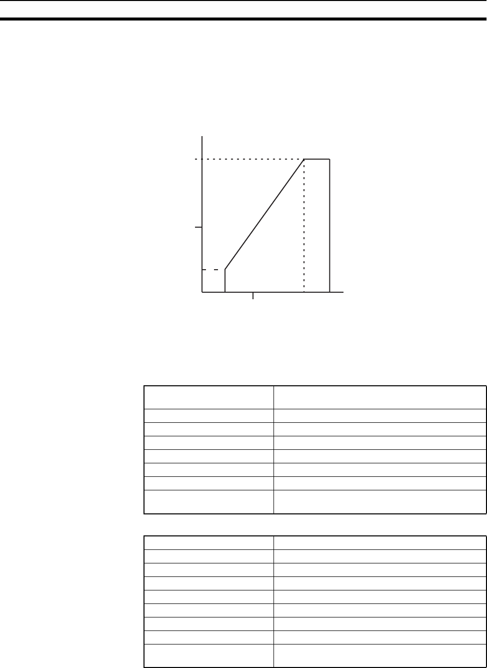
675
Specifications of Basic I/O Units and High-density I/O Units Appendix A
High-density I/O Unit Limitations
Limitations on the switching capacity of C200H-OD215/MD115/MD215 Transistor Output Units and the usable
number of I/O points in the C200H-ID215 and C200H-MD215 are shown below.
Switching Capacity
The switching capacity of C200H-OD215/MD115/MD215 Transistor Output Units depends on the power supply
voltage, as shown below.
C200H-MD501 TTL I/O Unit
Used for 16 Static Inputs and 16 Static Outputs
Output Specifications (Connector 1)
Input Specifications (Connector 2)
Power Supply Volta
g
e (V)
Max. Switching Capacity (mA/pt)
0 4.5 10 20.4 26.4
50
100
16
0
Max. Switching Capacity 5 V DC±10% 35 mA (280 mA/common, 560 mA/
Unit; output resistance 4.7 kΩ)
Leakage Current 0.1 mA max.
Residual Voltage 0.4 V max.
ON Response Time 0.2 ms max.
OFF Response Time 0.3 ms max.
No. of Circuits 2 (8 points/common)
Fuses 2 (1 fuse/common; fuses are not user-replaceable.)
Power for External Supply 20 mA 5 V DC±10% min. (1.2 mA × no. of outputs
ON)
Rated Input Voltage 5 V DC±10%
Input Impedance 1.1 kΩ
Input Current 3.5 mA typical (at 5 V DC)
ON Voltage 3.0 V DC min.
OFF Voltage 1.0 V DC max.
ON Response Time 2.5 ms/15 ms max. (switchable)
OFF Response Time 2.5 ms/15 ms max. (switchable)
No. of Circuits 2 (8 points/common)
High-speed Inputs 8 points (connector 2 terminals 8 to 15, when set)
Pulse width: 1 ms/4 ms min. (switchable)
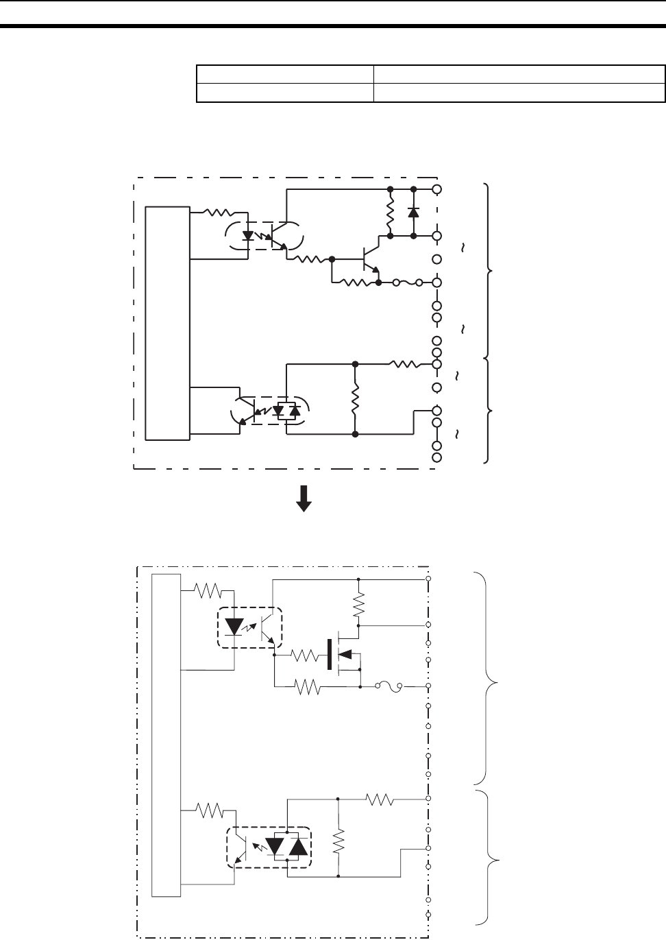
676
Specifications of Basic I/O Units and High-density I/O Units Appendix A
General Specifications
Circuit Configuration
Internal Current Consumption 180 mA 5 V DC max.
Weight 300 g max.
CN1 (Output)
CN2 (Input)
OUT00
OUT07
COM0
OUT08
OUT15
COM1
Internal
circuits
5 V DC
5 V DC
Fuse
4.7 kΩ
COM2
IN08
IN15
COM3
IN00
IN07
1.1 kΩ
2.4 kΩ
Units manufactured on or before November 21, 2002
(manufacturing numbers 21Y2 or earlier)
Units manufactured on or after November 22, 2002
(manufacturing numbers 22Y2H or later)
OUT00
OUT07
COM0
4.7 kΩ
5 V DC
OUT08
OUT15
COM1
5 V DC
IN0 7
IN08
COM2
2.4 kΩ
IN0 0
1.1 kΩ
IN15
COM3
to
to
to
to
CN1 (Output)
CN2 (Input)
Internal circuits
Fuse
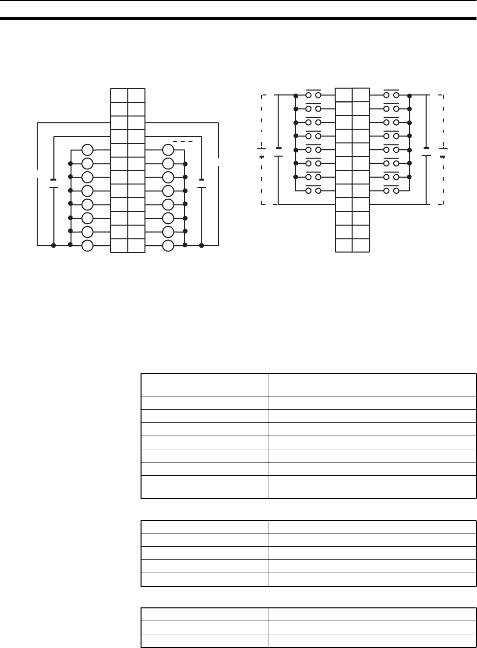
677
Specifications of Basic I/O Units and High-density I/O Units Appendix A
Terminal Connections
Note 1. The Unit will have 16 static output and16 static input points when pin 1 of it’s DIP switch is OFF.
2. When pin 2 of the Unit’s DIP switch is ON, input points 08 to 15 in connector 2 are high-speed inputs.
3. The outputs are negative logic outputs; when there is an output, the terminal has an “L” voltage level.
Each output terminal has an output resistance of 4.7 kΩ.
4. The user is not authorized to change the fuse.
C200H-MD501 TTL I/O Unit Used for 128 Dynamic Inputs
Output Specifications (Connector 1)
Input Specifications (Connector 2)
General Specifications
I/O word "n"
CN1
I/O word "n+1"
CN2
AB
01
12
23
34
45
56
67
78
COM2
9
8
9
10
11
12
13
14
15
COM3
++
NC
10
NC
11
NC
NC
NC
12
NC
+
5 V DC
1
2
3
4
5
6
7
8
9
10
11
12
+
5 V DC
L
+5 V DC +5 V DC
B
1
2
3
4
5
6
7
8
9
0
1
2
3
4
5
6
7
COM0
+
10
NC
11
NC
8
9
10
11
12
13
14
15
COM1
+
NC
12
A
1
2
3
4
5
6
7
8
9
10
11
12
NC
5 V DC
5 V DC
L
L
L
L
L
L
L
L
L
L
L
L
L
L
L
Max. Switching Capacity 5 V DC±10% 35 mA (280 mA/common, 560 mA/
Unit; output resistance 4.7 kΩ)
Min. Switching Capacity None
Leakage Current 0.1 mA max.
Residual Voltage 0.4 V max.
ON Response Time 0.2 ms max.
OFF Response Time 0.3 ms max.
Fuses 2 (1 fuse/common; fuses are not user-replaceable.)
Power for External Supply 20 mA 5 V DC±10% min. (1.2 mA × no. of outputs
ON)
Rated Input Voltage 5 V DC ±10%
Input Impedance 1.1 kΩ
Input Current 3.5 mA (at 5 V DC)
ON Voltage 3.0 V DC min.
OFF Voltage 1.0 V DC max.
No. of Circuits 2 (dynamic, 64 points/circuit)
Internal Current Consumption 180 mA 5 V DC max.
Weight 300 g max.
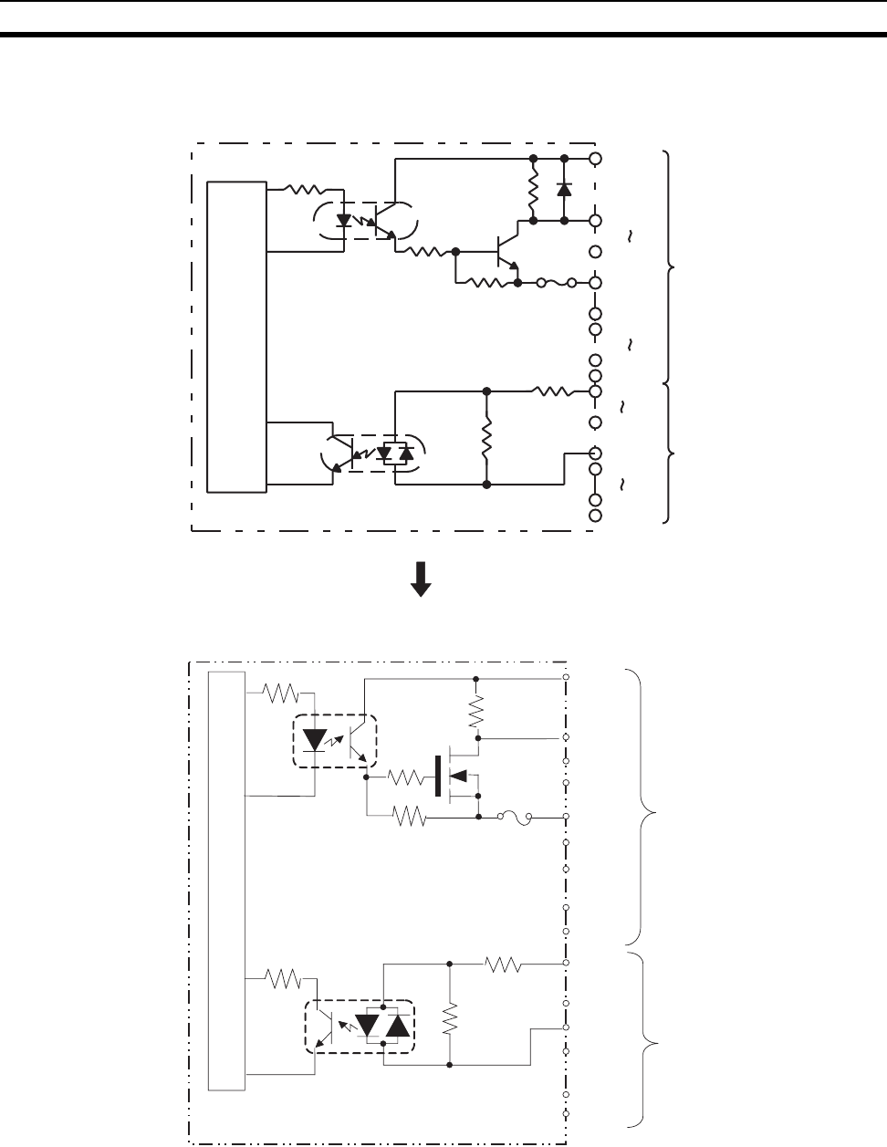
678
Specifications of Basic I/O Units and High-density I/O Units Appendix A
Circuit Configuration
STB00
STB07
COM0
STB08
STB15
COM1
COM2
DATA08
DATA15
COM3
DATA00
DATA07
Internal
circuits
5 V DC
5 V DC
Fuse
4.7 kΩ
1.1 kΩ
2.4 kΩ
CN1
CN2
Units manufactured on or before November 21, 2002
(manufacturing numbers 21Y2 or earlier)
Units manufactured on or after November 22, 2002
(manufacturing numbers 22Y2H or later)
STB00
STB07
COM0
4.7 kΩ
5 V DC
STB08
STB15
COM1
5 V DC
DAT07
DAT08
COM2
2.4 kΩ
DAT00
1.1 kΩ
DAT15
COM3
Internal circuits
Fuse
CN1 (Output)
CN2 (Input)
to
to
to
to
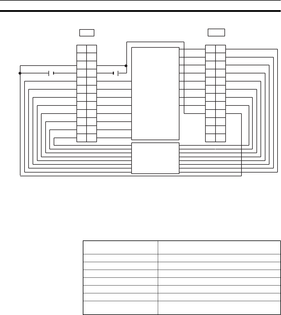
679
Specifications of Basic I/O Units and High-density I/O Units Appendix A
Terminal Connections
Note 1. Refer to the Unit’s operation manual for details on I/O bit allocation.
2. The Unit will have 128 dynamic output points when pin 1 of it’s DIP switch is ON.
3. Each output terminal has an output resistance of 4.7 kΩ.
C200H-MD115 12-V DC Input/Transistor Output Unit
Used for 16 Static Inputs and 16 Static Outputs
Output Specifications (Connector 1)
5 V DC
STB8
STB9
STB10
STB11
STB12
STB13
STB14
STB15
DATA8
A
1
2
3
4
5
6
7
8
9
DATA0
DATA1
DATA2
DATA3
DATA4
DATA5
DATA6
DATA7
COM2
NC
10
NC
11
NC
NC
NC
12
B
1
2
3
4
5
6
7
8
9
10
11
12
NC
CN2
A
1
2
3
4
5
6
7
8
9
COM1
+V0
10
NC
11
+V1
NC
STB0
STB1
STB2
STB3
STB4
STB5
STB6
STB7
COM0
NC
12
B
1
2
3
4
5
6
7
8
9
10
11
12
NC
CN1
DATA9
DATA10
DATA11
DATA12
DATA13
DATA14
DATA15
COM3
++
5 V DC
Keyboard, thumb-
wheel switch, etc.
Keyboard, thumb-
wheel switch, etc.
Max. Switching Capacity 16 mA, 4.5 V DC to 100 mA, 26.4 V DC
800 mA/common, 1.6 A/Unit
Leakage Current 0.1 mA max.
Residual Voltage 0.7 V max.
ON Response Time 0.2 ms max.
OFF Response Time 0.6 ms max.
No. of Circuits 2 (8 points/common)
Fuses 2 (1 fuse/common; fuses are not user-replaceable.)
Power for External Supply 45 mA 5 to 24 V DC±10% min.
(2.8 mA × number of ON outputs)

680
Specifications of Basic I/O Units and High-density I/O Units Appendix A
Input Specifications (Connector 2)
General Specifications
Rated Input Voltage 12 V DC
Operating Input Voltage 10.2 to 13.2 V DC
Input Impedance 2.7 kΩ
Input Current 4.1 mA typical (at 12 V DC)
ON Voltage 8.0 V DC min.
OFF Voltage 3.0 V DC max.
ON Response Time 2.5 ms/15 ms max. (switchable)
OFF Response Time 2.5 ms/15 ms max. (switchable)
No. of Circuits 2 (8 points/common)
High-speed Inputs 8 points (connector 2 terminals 8 to 15, when set)
Pulse width: 1 ms/4 ms min. (switchable)
Internal Current Consumption 180 mA 5 V DC max.
Weight 300 g max.
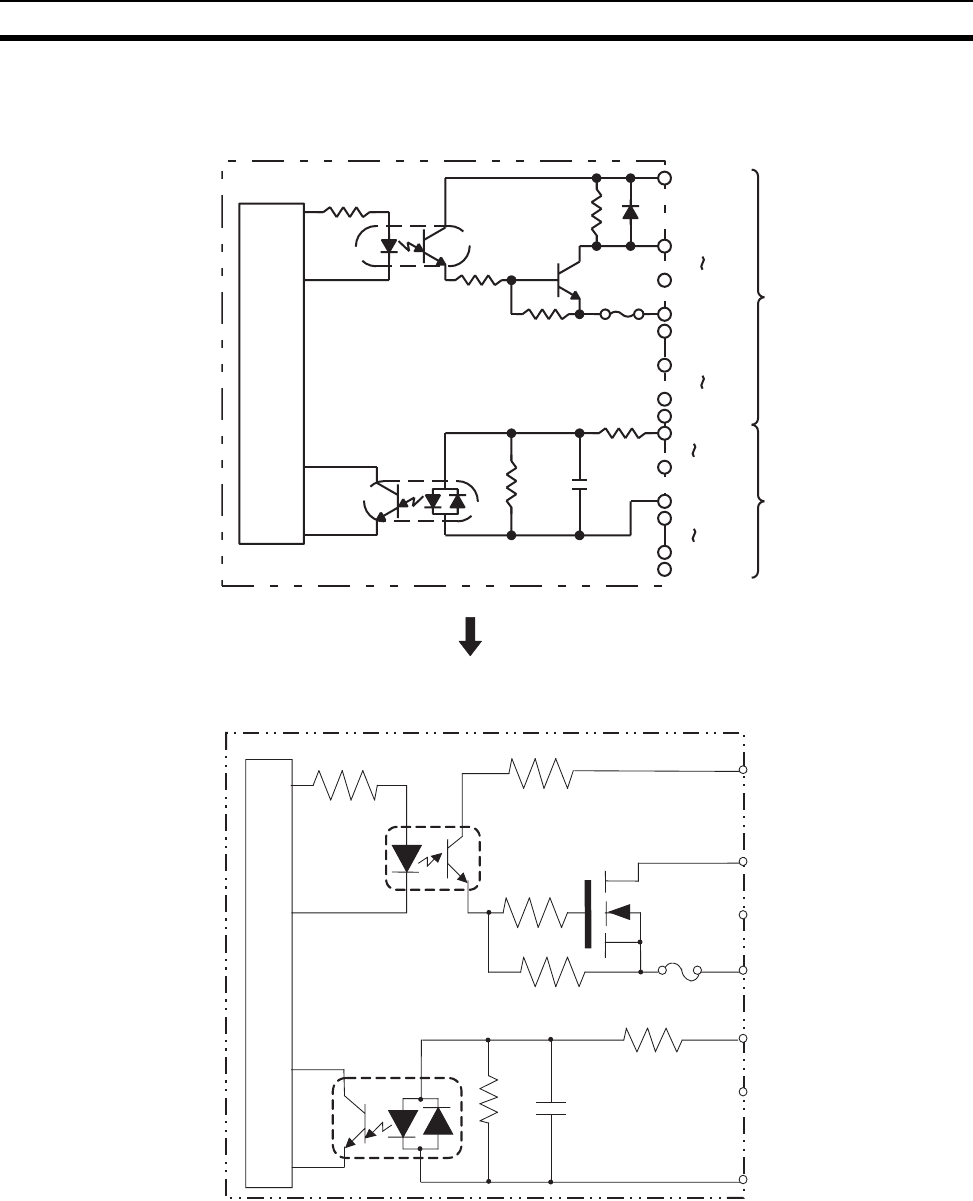
681
Specifications of Basic I/O Units and High-density I/O Units Appendix A
Circuit Configuration
OUT00
OUT07
COM0
OUT08
OUT15
COM1
COM2
IN08
IN15
COM3
IN00
IN07
Internal
circuits
Fuse
4.7 kΩ
2.7 kΩ
CN1
5 to 24
V DC
5 to 24
V DC
CN2
1000 pF
620 Ω
Units manufactured on or before November 17, 2002
(manufacturing numbers 17Y2 or earlier)
Units manufactured on or after November 18, 2002
(manufacturing numbers 18Y2H or later)
OUT00
OUT07
COM0
5 V DC
2.7 kΩ
COM2
620 Ω
1000 pF
IN00
IN07
Internal circuits
Fuse
to
to
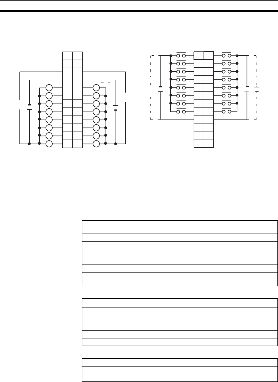
682
Specifications of Basic I/O Units and High-density I/O Units Appendix A
Terminal Connections
Note 1. I/O word “n” is determined by the unit number setting (n = CIO 2000 + 10 × unit number).
2. The Unit will have 16 static output and16 static input points when pin 1 of it’s DIP switch is OFF.
3. When pin 2 of the Unit’s DIP switch is ON, input points 08 to 15 in connector 2 are high-speed inputs.
4. The user is not authorized to change the fuse.
C200H-MD115 12-V DC Input/Transistor Output Unit
Used for 128 Dynamic Inputs
Output Specifications (Connector 1)
Input Specifications (Connector 2)
General Specifications
I/O word "n"
CN1
I/O word "n+1"
CN2
AB
01
12
23
34
45
56
67
78
COM2
9
8
9
10
11
12
13
14
15
COM3
++
NC
10
NC
11
NC
NC
NC
12
NC
+
12 V D
C
1
2
3
4
5
6
7
8
9
10
11
12
+
12 V DC
L
+5 to 24 V DC +5 to 24 V DC
B
1
2
3
4
5
6
7
8
9
0
1
2
3
4
5
6
7
COM0
+
10
NC
11
NC
8
9
10
11
12
13
14
15
COM1
+
NC
12
A
1
2
3
4
5
6
7
8
9
10
11
12
NC
5 to 24
V DC
5 to 24
V DC
L
L
L
L
L
L
L
L
L
L
L
L
L
L
L
Max. Switching Capacity 50 mA, 12 V DC (10.2 to 13.2 V DC), 400 mA/com-
mon, 0.8 A/Unit
Leakage Current 0.1 mA max.
Residual Voltage 0.7 V max.
ON Response Time 0.2 ms max.
OFF Response Time 0.6 ms max.
Fuses 2 (1 fuse/common; fuses are not user-replaceable.)
Power for External Supply 45 mA 5 to 24 V DC±10% min.
(2.8 mA × number of ON outputs)
Rated Input Voltage 12 V DC
Operating Input Voltage 10.2 to 13.2 V DC
Input Impedance 2.7 kΩ
Input Current 4.1 mA typical (at 12 V DC)
ON Voltage 8.0 V DC min.
OFF Voltage 3.0 V DC max.
No. of Circuits 2 (dynamic, 64 points/circuit)
Internal Current Consumption 180 mA 5 V DC max.
Weight 300 g max.
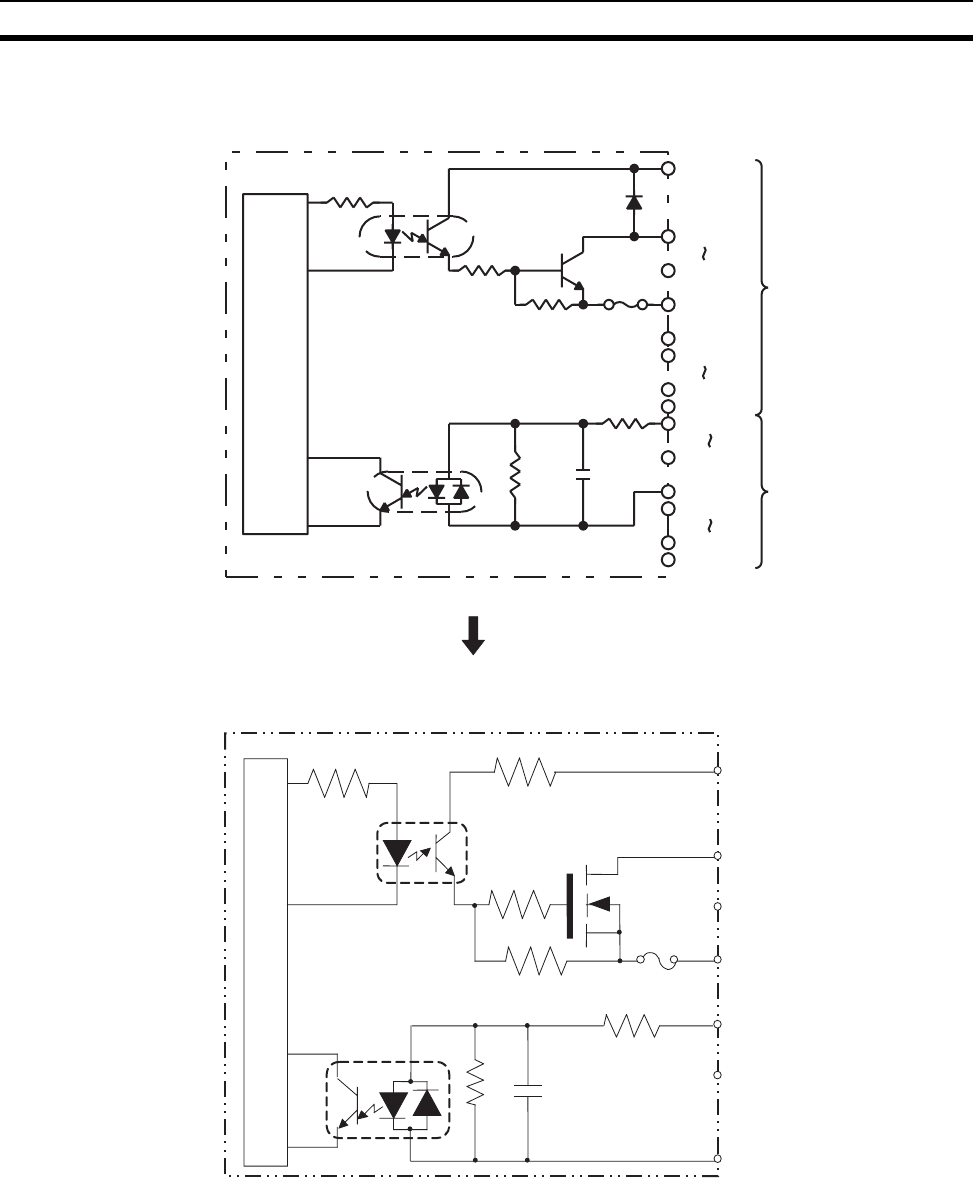
683
Specifications of Basic I/O Units and High-density I/O Units Appendix A
Circuit Configuration
STB00
STB07
COM0
STB08
STB15
COM1
COM2
DATA08
DATA15
COM3
DATA00
DATA07
CN1
CN2
Internal
circuits
Fuse
2.7 kΩ
12 V DC
12 V DC
1000 pF620 Ω
Units manufactured on or before November 17, 2002
(manufacturing numbers 17Y2 or earlier)
Units manufactured on or after November 18, 2002
(manufacturing numbers 18Y2H or later)
OUT00
OUT07
COM0
5 V DC
2.7 kΩ
COM2
620 Ω
1000 pF
IN00
IN07
Internal circuits
Fuse
to
to
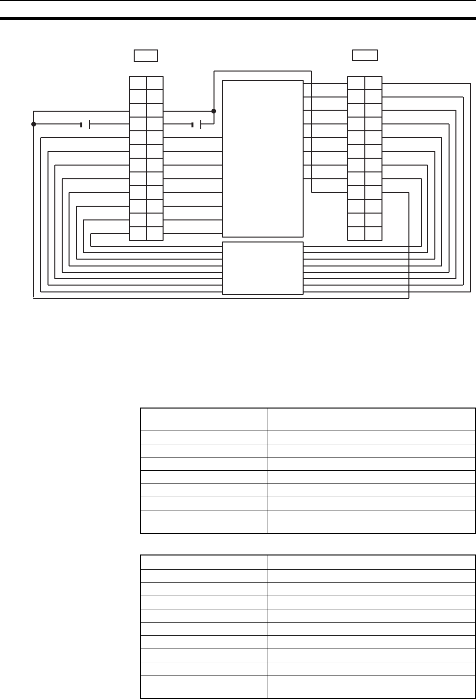
684
Specifications of Basic I/O Units and High-density I/O Units Appendix A
Terminal Connections
Note 1. Refer to the Unit’s operation manual for details on I/O bit allocation.
2. The Unit will have 128 dynamic output points when pin 1 of it’s DIP switch is ON.
3. The user is not authorized to change the fuse.
C200H-MD215 24-V DC Input/Transistor Output Unit
Used for 16 Static Inputs and 16 Static Outputs
Output Specifications (Connector 1)
Input Specifications (Connector 2)
12 V DC
STB8
STB9
STB10
STB11
STB12
STB13
STB14
STB15
DATA8
A
1
2
3
4
5
6
7
8
9
DATA0
DATA1
DATA2
DATA3
DATA4
DATA5
DATA6
DATA7
COM2
NC
10
NC
11
NC
NC
NC
12
B
1
2
3
4
5
6
7
8
9
10
11
12
NC
CN2
A
1
2
3
4
5
6
7
8
9
COM1
+V0
10
NC
11
+V1
NC
STB0
STB1
STB2
STB3
STB4
STB5
STB6
STB7
COM0
NC
12
B
1
2
3
4
5
6
7
8
9
10
11
12
NC
CN1
DATA9
DATA10
DATA11
DATA12
DATA13
DATA14
DATA15
COM3
+ +
12 V DC
Keyboard, thumb-
wheel switch, etc.
Keyboard, thumb-
wheel switch, etc.
Max. Switching Capacity 16 mA, 4.5 V DC to 100 mA, 26.4 V DC
800 mA/common, 1.6 A/Unit
Leakage Current 0.1 mA max.
Residual Voltage 0.7 V max.
ON Response Time 0.2 ms max.
OFF Response Time 0.6 ms max.
No. of Circuits 2 (8 points/common)
Fuses 2 (1 fuse/common; fuses are not user-replaceable.)
Power for External Supply 45 mA 5 to 24 V DC±10% min.
(2.8 mA × number of ON outputs)
Rated Input Voltage 24 V DC
Operating Input Voltage 20.4 to 26.4 V DC
Input Impedance 5.6 kΩ
Input Current 4.1 mA (at 24 V DC)
ON Voltage 14.4 V DC min.
OFF Voltage 5.0 V DC max.
ON Response Time 2.5 ms/15 ms max. (switchable)
OFF Response Time 2.5 ms/15 ms max. (switchable)
No. of Circuits 2 (8 points/common)
High-speed Inputs 8 points (connector 2 terminals 8 to 15, when set)
Pulse width: 1 ms/4 ms min. (switchable)
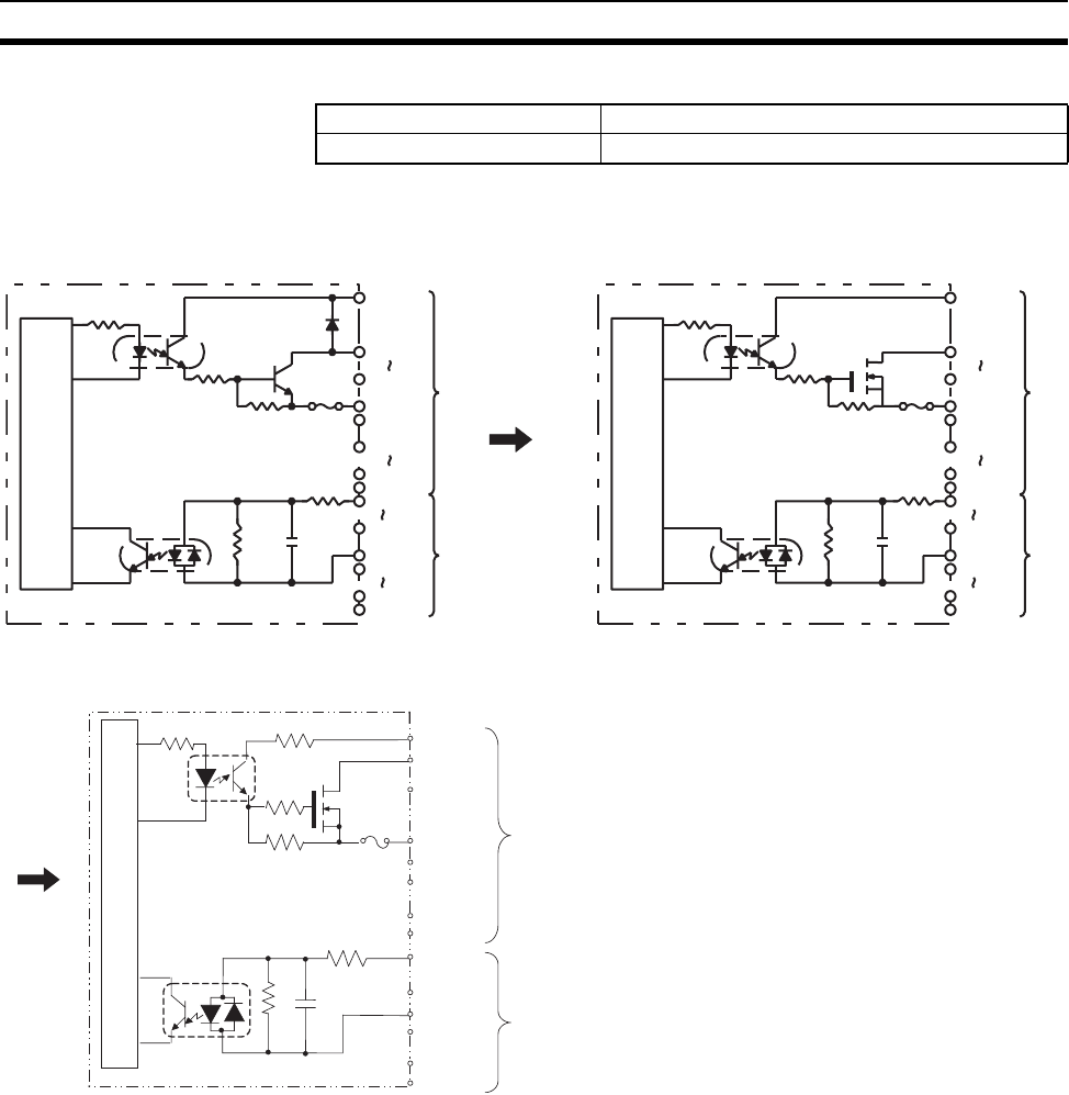
685
Specifications of Basic I/O Units and High-density I/O Units Appendix A
General Specifications
Circuit Configuration
Internal Current Consumption 180 mA 5 V DC max.
Weight 300 g max.
Units manufactured on or before November 29, 1999
(manufacturing numbers 29Y9 or earlier)
OUT00
OUT07
COM0
OUT08
OUT15
COM1
COM2
IN08
IN15
COM3
IN00
IN07
Internal
circuits
Fuse
5.6 kΩ
CN1
5 to
24 V DC
5 to
24 V DC
CN2
1,000 pF
620 Ω
OUT00
OUT07
COM0
OUT08
OUT15
COM1
COM2
IN08
IN15
COM3
IN00
IN07
Internal
circuits
Fuse
CN1
5 to
24 V DC
5 to
24 V DC
CN2
10 k
8.2 k
10 kΩ
8.2 kΩ15 kΩ
6.8 kΩ
5.6 kΩ
1,000 pF620 Ω
Units manufactured on or after October 10, 2002
(manufacturing numbers 10X2H or later)
5 to 24 VDC
12 kΩ
5.6 kΩ
COM2
620 Ω
1000 pF
8.2 kΩOUT00
OUT07
COM0
IN00
IN07
100 Ω
5 to 24 VDC
OUT08
OUT15
COM1
COM3
IN08
IN15
CN1
CN2
Internal circuits
Fuse
to
to
to
to
Units manufactured between November 30, 1999 and
October 9, 2002 (manufacturing numbers 30Y9 to 09X2)
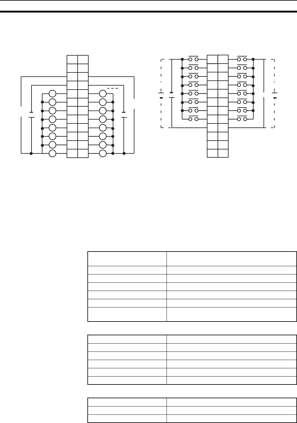
686
Specifications of Basic I/O Units and High-density I/O Units Appendix A
Terminal Connections
Note 1. I/O word “n” is determined by the unit number setting (n = CIO 2000 + 10 × unit number).
2. The Unit will have 16 static output and16 static input points when pin 1 of it’s DIP switch is OFF.
3. At high temperatures, the number of inputs that can be turned ON simultaneously is limited. Refer to
the graph page 688 for details.
4. When pin 2 of the Unit’s DIP switch is ON, input points 08 to 15 in connector 2 are high-speed inputs.
5. The user is not authorized to change the fuse.
C200H-MD215 24-V DC Input/Transistor Output Unit
Used for 128 Dynamic Inputs/Dynamic Outputs
Output Specifications (Connector 1)
Input Specifications (Connector 2)
General Specifications
I/O word "n"
CN1
I/O word "n+1"
CN2
AB
01
12
23
34
45
56
67
78
COM2
9
8
9
10
11
12
13
14
15
COM3
++
NC
10
NC
11
NC
NC
NC
12
NC
+
24 V D
C
1
2
3
4
5
6
7
8
9
10
11
12
+
24 V DC
L
+5 to 24 V DC +5 to 24 V DC
B
1
2
3
4
5
6
7
8
9
0
1
2
3
4
5
6
7
COM0
+
10
NC
11
NC
8
9
10
11
12
13
14
15
COM1
+
NC
12
A
1
2
3
4
5
6
7
8
9
10
11
12
NC
5 to 24
V DC
5 to 24
V DC
L
L
L
L
L
L
L
L
L
L
L
L
L
L
L
Max. Switching Capacity 100 mA, 24 V DC (20.4 to 26.4 V DC), 800 mA/com-
mon, 1.6 A/Unit
Leakage Current 0.1 mA max.
Residual Voltage 0.7 V max.
ON Response Time 0.2 ms max.
OFF Response Time 0.6 ms max.
Fuses 2 (1 fuse/common; fuses are not user-replaceable.)
Power for External Supply 45 mA 5 to 24 V DC±10% min.
(2.8 mA × number of ON outputs)
Rated Input Voltage 24 V DC
Operating Input Voltage 20.4 to 26.4 V DC
Input Impedance 5.6 kΩ
Input Current 4.1 mA (at 24 V DC)
ON Voltage 14.4 V DC min.
OFF Voltage 5.0 V DC max.
No. of Circuits 2 (dynamic, 64 points/circuit)
Internal Current Consumption 180 mA 5 V DC max.
Weight 300 g max.
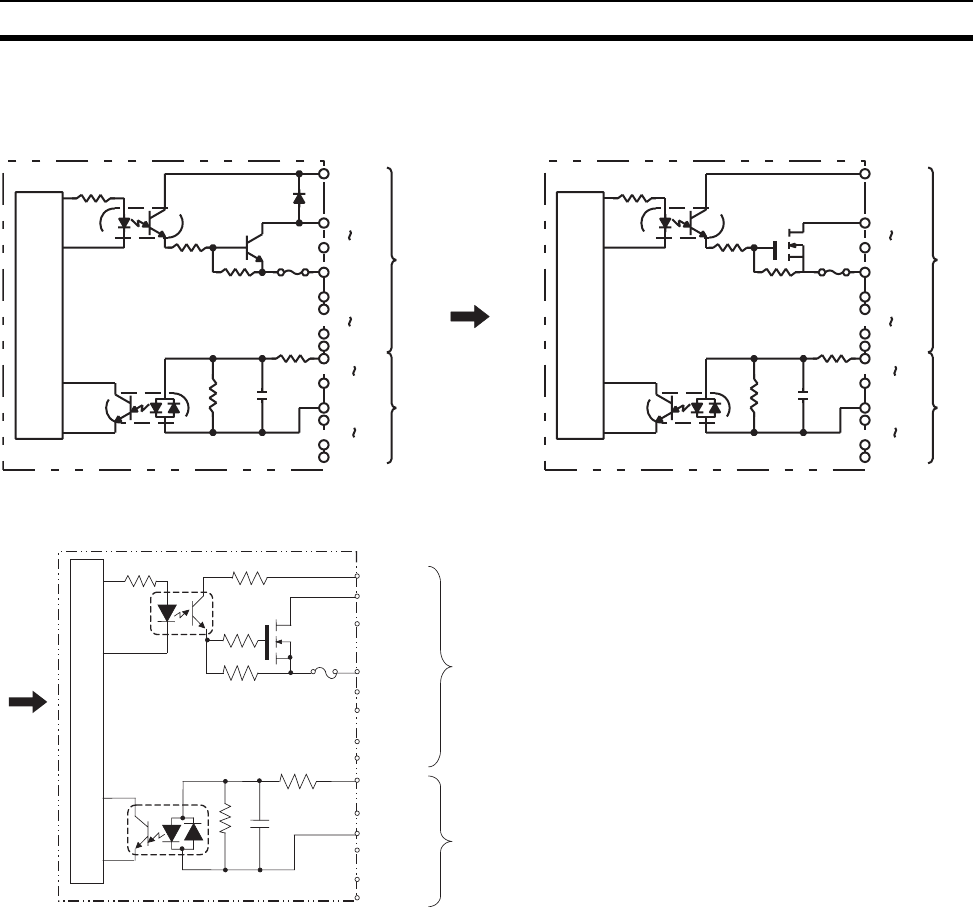
687
Specifications of Basic I/O Units and High-density I/O Units Appendix A
Circuit Configuration
Units manufactured on or before November 29, 1999
(manufacturing numbers 29Y9 or earlier)
STB00
STB07
COM0
STB08
STB15
COM1
COM2
DATA08
DATA15
COM3
DATA00
DATA07
CN1
CN2
Internal
circuits
Fuse
5.6 kΩ
24 V DC
24 V DC
1,000 pF
620 Ω
STB00
STB07
COM0
STB08
STB15
COM1
COM2
DATA0 8
DATA1 5
COM3
DATA0 0
DATA07
CN1
CN2
Internal
circuits
Fuse
24 V DC
24 V DC
10 kΩ
8.2 kΩ15 kΩ
6.8 kΩ
5.6 kΩ
1,000 pF620 Ω
Units manufactured on or after October 10, 2002
(manufacturing numbers 10X2H or later)
5 to 24 V DC
12 kΩ
5.6 kΩ
COM2
620 Ω
1000 pF
8.2 kΩSTB00
STB07
COM0
DAT00
DAT07
100 Ω
5 to 24 V DC
STB08
STB15
COM1
COM3
DAT08
DAT15
CN1
CN2
Internal circuits
Fuse
to
to
to
to
Units manufactured between November 30, 1999 and
October 9, 2002 (manufacturing numbers 30Y9 to 09X2)
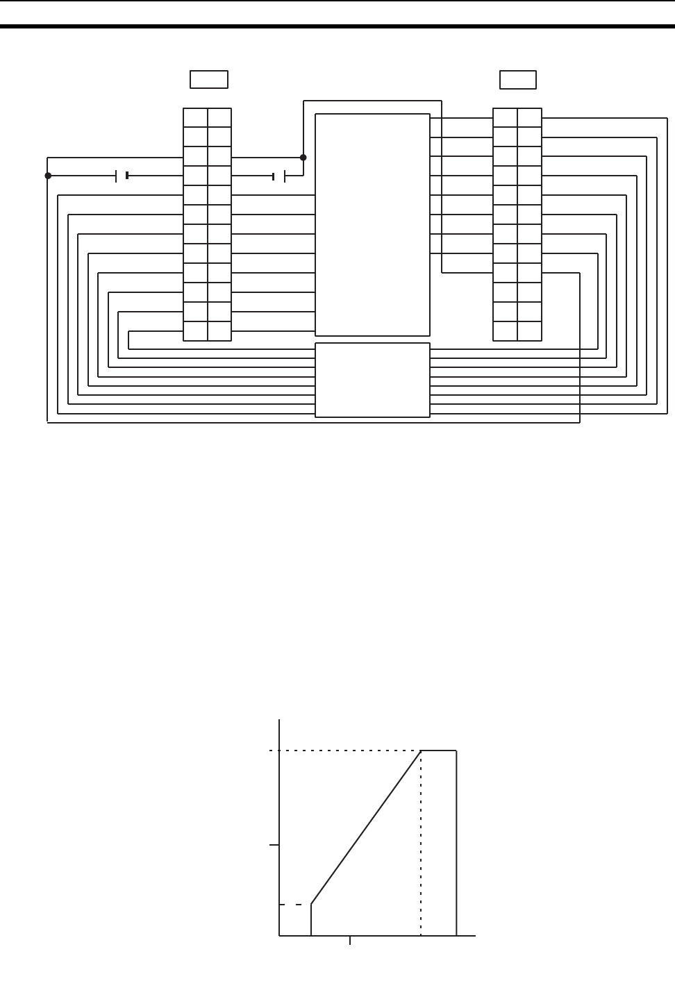
688
Specifications of Basic I/O Units and High-density I/O Units Appendix A
Terminal Connections
Note 1. Refer to the Unit’s operation manual for details on I/O bit allocation.
2. The Unit will have 128 dynamic output points when pin 1 of it’s DIP switch is ON.
3. Each output terminal has an output resistance of 4.7 kΩ.
4. At high temperatures, the number of inputs that can be turned ON simultaneously is limited. Refer to
the graph on the next page for details.
5. The user is not authorized to change the fuse.
High-density I/O Unit Limitations
Limitations on the switching capacity of C200H-OD215/MD115/MD215 Transistor Output Units and the usable
number of I/O points in the C200H-ID215 and C200H-MD215 are shown below.
Switching Capacity
The switching capacity of C200H-OD215/MD115/MD215 Transistor Output Units depends on the power supply
voltage, as shown below.
12 V DC
STB8
STB9
STB10
STB11
STB12
STB13
STB14
STB15
DATA8
A
1
2
3
4
5
6
7
8
9
DATA0
DATA1
DATA2
DATA3
DATA4
DATA5
DATA6
DATA7
COM2
NC
10
NC
11
NC
NC
NC
12
B
1
2
3
4
5
6
7
8
9
10
11
12
NC
CN2
A
1
2
3
4
5
6
7
8
9
COM1
+V0
10
NC
11
+V1
NC
STB0
STB1
STB2
STB3
STB4
STB5
STB6
STB7
COM0
NC
12
B
1
2
3
4
5
6
7
8
9
10
11
12
NC
CN1
DATA9
DATA10
DATA11
DATA12
DATA13
DATA14
DATA15
COM3
++
12 V DC
Keyboard,
thumbwheel
switch, etc.
Keyboard,
thumbwheel
switch, etc.
Power Supply Volta
g
e (V)
Max. Switching Capacity (mA/pt)
0 4.5 10 20.4 26.4
50
100
16
0
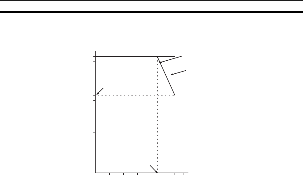
689
Specifications of Basic I/O Units and High-density I/O Units Appendix A
Simultaneous Input and Outputs for the C200H-MD215
The number C200H-MD215 24-V DC inputs that can be ON simultaneously will depend on ambient tempera-
ture as shown in the figure below. There is no limit to the number of outputs that can be ON simultaneously.
Note If the number of C200H-MD215 inputs that are ON exceeds the number that can be ON at the same
time, then heat generated by electronic components will raise the temperature of the components and
the case. This will lower the reliability and service life of the components and will damage the Unit.
Higher temperatures in electronic components and the case will also cause time delays. There is no
problem if all input points are turned ON for less than 10 minutes (if all input points have been OFF for at
least 2 hours) under special conditions, such as during startup work inspections.
Simultaneously Usable Inputs
Ambient Temperature (°C)
Input Voltage: 26.4 V DC
Input Voltage: 24.0 V DC
01020 3040505560
0
5
11
15
16
34 43
10
Input Voltage:
26.4 VDC; 55°,
11 points ON
Input Voltage:
26.4 VDC; 43°,
16 points ON

690
Specifications of Basic I/O Units and High-density I/O Units Appendix A

691
Appendix B
Auxiliary Area
Note The undefined addresses of the Auxiliary Area may be allocated to functions in future version upgrades
of the CPU Unit. Do not use these words as CIO Area words in the user program.
A000 to A447: Read-only Area, A448 to A959: Read/Write Area
Read-only Area (Set by System)
Address Name Function Status
after
mode
change
Status at
startup
Write timing/
Related flags,
settings
Words Bits
A000 --- 10-ms
Increment-
ing Free
Running
Timer
This word contains the system timer used after the
power is turned ON.
0000 hex is set when the power is turned ON and this
value is automatically incremented by 1 every 10 ms.
The value returns to 0000 hex after reaching FFFF hex
(655,350 ms), and then continues to be automatically
incremented by 1 every 10 ms.
Note: The timer will continue to be incremented when
the operating mode is switched to RUN mode.
Example: The interval can be counted between pro-
cessing A and processing B without requir-
ing timer instructions. This is achieved by
calculating the difference between the value
in A000 for processing A and the value in
A000 for processing B. The interval is
counted in 10 ms units.
Retained Cleared Every 10 ms after
power is turned ON
CPU Unit with unit ver-
sion 3.0 or later
A001 --- 100-ms
Increment-
ing Free
Running
Timer
This word contains the system timer used after the
power is turned ON.
0000 hex is set when the power is turned ON and this
value is automatically incremented by 1 every 100 ms.
The value returns to 0000 hex after reaching FFFF hex
(655,350 ms), and then continues to be automatically
incremented by 1 every 10 ms.
Note: The timer will continue to be incremented when
the operating mode is switched to RUN mode.
Retained Cleared Every 100 ms after
power is turned ON
CPU Unit with unit ver-
sion 3.0 or later
A002 --- 1-s Incre-
menting
Free Run-
ning Timer
This word contains a system timer used after the
power is turned ON
0000 hex is set when the power is turned ON and this
value is automatically incremented by 1 every 1 s. The
value returns to 0000 hex after reaching FFFF hex
(65,535 s), and then continues to be automatically
incremented by 1 every 1 s.
Note: The timer will continue to be incremented when
the operating mode is switched to RUN mode.
Retained Cleared Every 1 s after power
is turned ON
CPU Unit with unit ver-
sion. 4.0 or later
A050 A05000
to
A05007
Basic I/O
Unit Infor-
mation,
Rack 0 Slot
0
A bit will turn ON to indicate when a fuse has blows.
The bit numbers correspond to the fuse number on the
Unit.
Only the right-most bit is used for C200H Basic I/O
Units.
1: Fuse blown
0: Normal
--- --- Every cycle
A05008
to
A05015
Basic I/O
Unit Infor-
mation,
Rack 0 Slot
1
--- ---
A051 to
A069
A05100
to
A06915
Basic I/O
Unit Infor-
mation,
Racks 2 to 9
--- ---

692
Auxiliary Area Appendix B
A090 to
A093
--- User
Program
Date
These words contain in BCD the date and time that the
user program was last overwritten.
A09000 to A09007:
Seconds (00 to 59)
A09008 to A09015:
Minutes (00 to 59)
A09100 to A09107: Hour (00 to 23)
A09108 to A09115:
Day of month (01 to 31)
A09200 to A09207: Month (01 to 12)
A09208 to A09215: Year (00 to 99)
A09308 to A09307: Day of the week
(00: Sunday, 01: Monday, 02: Tuesday, 03: Wednes-
day, 04: Thursday, 05: Friday, 06: Saturday)
Retained Retained ---
A094 to
A097
--- Parameter
Date
These words contain in BCD the date and time that the
parameters were last overwritten.
The format is the same as above
Retained Retained ---
A099 A09900 UM Read
Protection
Status
Indicates whether the entire user program in the PLC
is read-protected.
0: UM not read-protected.
1: UM read-protected.
Retained Retained When protection is set
or cleared
CPU Unit with unit ver-
sion 2.0 or later
A09901 Task Read
Protection
Status
Indicates whether read protection is set for individual
tasks.
0: Tasks not read-protected.
1: Tasks read-protected.
Retained Retained When protection is set
or cleared
CPU Unit with unit ver-
sion 2.0 or later
A09902 Program
Write Pro-
tection Sta-
tus when
Read Pro-
tection Is
Set
Indicates whether the program is write-protected.
0: Write-enabled.
1: Write-protected.
Retained Retained When protection is set
or cleared
CPU Unit with unit ver-
sion 2.0 or later
A09903 Enable/Dis-
able Status
for Backing
Up the Pro-
gram to a
Memory
Card
Indicates whether creating a backup program file
(.OBJ) is enabled or disabled.
0: Enabled.
1: Disabled.
Retained Retained When protection is set
or cleared
CPU Unit with unit ver-
sion 2.0 or later
A09914 IR/DR Oper-
ation
between
Tasks
Turn ON this bit to share index and data registers
between all tasks. Turn OFF this bit to use separate
index and data registers between in each task.
0: Independent
1: Shared (default)
Retained Retained ---
A09915 Timer/
Counter PV
Refresh
Mode Flag
Indicates whether the CPU Unit is storing
timer/counter PV in BCD or binary.
0: BCD mode
1: Binary mode
Retained Retained ---
Address Name Function Status
after
mode
change
Status at
startup
Write timing/
Related flags,
settings
Words Bits

693
Auxiliary Area Appendix B
A100 to
A199
All Error Log
Area
When an error has occurred, the error code, error con-
tents, and error’s time and date are stored in the Error
Log Area. Information on the 20 most recent errors
can be stored.
Each error record uses 5 words; the function of these
5 words is as follows:
1) Error code (bits 0 to 15)
2) Error contents (bits 0 to 15)
Error code
Error contents:
Address of Aux. Area word with details or 0000
3) Minutes (bits 8 to 15),
Seconds (bits 0 to 7)
Seconds: 00 to 59, BCD
Minutes: 00 to 59, BCD
4) Day of month (bits 8 to 15),
Hours (bits 0 to 7)
Hours: 00 to 23, BCD
Day of month: 01 to 31, BCD
5) Year (bits 8 to 15),
Month (bits 0 to 7)
Year: 00 to 99, BDC
Month: 00 to 12, BCD
Errors generated by FAL(006) and FALS(007) will also
be stored in this Error Log.
The Error Log Area can be reset from a Programming
Device.
If the Error Log Area is full (20 records) and another
error occurs, the oldest record in A100 to A104 will be
cleared, the other 19 records are shifted down, and
the new record is stored in A195 to A199.
Retained Retained Written when error
occurs
A50014
A300
A400
A200 A20011 First Cycle
Flag
ON for one cycle after PLC operation begins (after the
mode is switched from PROGRAM to RUN or MONI-
TOR, for example).
ON for the first cycle
--- --- ---
A20012 Step Flag ON for one cycle when step execution is started with
STEP(008). This flag can be used for initialization pro-
cessing at the beginning of a step.
ON for the first cycle after execution of STEP(008).
Cleared --- ---
A20014 Task
Started Flag
When a task switches from WAIT or INI to RUN status,
this flag will be turned ON within the task for one cycle
only.
ON for first cycle (including transitions from WAIT and
IN)
The only difference between this flag and A20015 is
that this flag also turns ON when the task switches
from WAIT to RUN status.
Cleared Cleared ---
A20015 First Task
Startup Flag
ON when a task is executed for the first time. This flag
can be used to check whether the current task is being
executed for the first time so that initialization process-
ing can be performed if necessary.
1: First execution
0: Not executable for the first time or not being
executed.
Cleared --- ---
A201 A20110 Online
Editing Wait
Flag
ON when an online editing process is waiting.
(If another online editing command is received while
waiting, the other command won’t be recorded and an
error will occur.)
1: Waiting for online editing
0: Not waiting for online editing
Cleared Cleared A527
A20111 Online
Editing Flag
ON when an online editing process is being executed
1: Online editing in progress
0: Online editing not in progress
Cleared Cleared A527
Address Name Function Status
after
mode
change
Status at
startup
Write timing/
Related flags,
settings
Words Bits

694
Auxiliary Area Appendix B
A202 A20200
to
A20207
Communi-
cations Port
Enabled
Flags
ON when a network instruction (SEND, RECV, CMND,
PMCR, TXDU or RXDU) or background execution can
be executed with the corresponding port number. Bits
00 to 07 correspond to communications ports 0 to 7.
1: Network instruction is not being executed
0: Network instruction is being executed (port busy)
When two or more network instructions are pro-
grammed with the same port number, use the corre-
sponding flag as an execution condition to prevent the
instructions from being executed simultaneously.
(The flag for a given port is turned OFF while a net-
work instruction with that port number is being exe-
cuted.)
(When the simple backup operation is used to per-
formed a write or compare operation for a Memory
Card, a communications port will be automatically allo-
cated, and the corresponding Flag will be turned OFF.)
Cleared --- ---
A20215 Network
Communi-
cations
Automatic
Allocation
Flag
This flag turns ON when a Network Communications
Instruction (SEND(090), RECV(098), CMND(490),
PMCR(260), TXDU(256), or RXDU(255)) can be exe-
cuted using the automatic communications port alloca-
tion function.
1: Communications port available
0: Communications port not available
Note: When using the automatic communications port
allocation function to execute nine or more net-
work communications instructions simulta-
neously, use this flag to perform exclusive
control.
Cleared --- ---
A203 to
A210
All Communi-
cations Port
Completion
Codes
These words contain the completion codes for the cor-
responding port numbers when network instructions
(SEND, RECV, CMND, or PMCR) or background exe-
cution has been executed.
Words A203 to A210 correspond to communications
ports 0 to 7.
Non-zero: Error code
0000: Normal condition
The following codes will be stored when an Explicit
Message Instruction (EXPLT, EGATR, ESATR,
ECHRD, or ECHWR) has been executed.
If the Explicit Communications Error Flag turns OFF,
0000 hex is stored.
If the Explicit Communications Error Flag is ON and
the Network Communications Error Flag is ON, the
FINS end code is stored.
If the Explicit Communications Error Flag is ON and
the Network Communications Error Flag is OFF, the
explicit message end code is stored.
During communications, 0000 hex will be stored and
the suitable code will be stored when execution has
been completed. The code will be cleared when oper-
ation is started.
(The completion code for a given port is cleared to
0000 when a network instruction with that port number
is executed.)
(When the simple backup operation is used to per-
formed a write or compare operation for a Memory
Card, a communications port will be automatically allo-
cated, and a completion code will be stored in the cor-
responding word.)
Cleared --- ---
Address Name Function Status
after
mode
change
Status at
startup
Write timing/
Related flags,
settings
Words Bits

695
Auxiliary Area Appendix B
A213 A21300
to
A21307
Explicit
Communi-
cations
Error Flag
Turn ON when an error occurs in executing an Explicit
Message Instruction (EXPLT, EGATR, ESATR,
ECHRD, or ECHWR).
Bits 00 to 07 correspond to communications ports 0 to
7.
1: Error end
0: Normal end
The corresponding bit will turn ON both when the
explicit message cannot be sent and when an error
response is returned for the explicit message.
The status will be maintained until the next explicit
message communication is executed. The bit will
always turn OFF when the next Explicit Message
Instruction is executed.
Cleared --- A21900 to A21907
A203 to A210
A214 A21400
to
A21407
First Cycle
Flags after
Network
Communi-
cations Fin-
ished
Each flag will turn ON for just one cycle after commu-
nications have been completed. Bits 00 to 07 corre-
spond to ports 0 to 7. Use the Used Communications
Port Number stored in A218 to determine which flag to
access.
1: First cycle after communications finish only
2: Other status
Note: These flags are not effective until the next cycle
after the communications instruction is exe-
cuted. Delay accessing them for at least one
cycle.
Retained Cleared ---
A215 A21500
to
A21507
First Cycle
Flags after
Network
Communi-
cations
Error
Each flag will turn ON for just one cycle after a com-
munications error occurs. Bits 00 to 07 correspond to
ports 0 to 7. Use the Used Communications Port Num-
ber stored in A218 to determine which flag to access.
Determine the cause of the error according to the
Communications Port Completion Codes stored in
A203 to A210.
1: First cycle after communications error only
0: Other status
Note: These flags are not effective until the next cycle
after the communications instruction is exe-
cuted. Delay accessing them for at least one
cycle.
Retained Cleared ---
A216 to
A217
All Network
Communi-
cations
Completion
Code Stor-
age
Address
The completion code for a communications instruction
is automatically stored at the address with the I/O
memory address given in these words. Place this
address into an index register and use indirect
addressing through the index register to read the com-
munications completion code.
Retained Cleared ---
A218 All Used Com-
munica-
tions Port
Numbers
Stores the communications port numbers used when a
communications instruction is executed using auto-
matic communication port allocations.
0000 to 0007 hex: Communications port 0 to 7
Retained Cleared ---
A219 A21900
to
A21907
Communi-
cations Port
Error Flags
ON when an error occurred during execution of a net-
work instruction (SEND, RECV, CMND, or PMCR).
Bits 00 to 07 correspond to communications ports 0 to
7.
1: Error occurred
0: Normal condition
(When the simple backup operation is used to per-
formed a write or compare operation for a Memory
Card, a communications port will be automatically allo-
cated, and the corresponding Flag will be turned OF if
an error occurs.)
Retained --- ---
A220 to
A259
A22000
to
A25915
Basic I/O
Unit Input
Response
Times
These words contain the actual input response times.
0 to 17 hexadecimal
When the Basic I/O Unit input response time setting is
changed in the PLC Setup while the PLC is in PRO-
GRAM mode, the setting in the PLC Setup will not
match the actual value in the Basic I/O Unit unless the
power is turned OFF and then ON again. In that case,
the actual value can be monitored in these words.
Retained See
function
column.
PLC Setup (Basic I/O
Unit Input response
time settings)
Address Name Function Status
after
mode
change
Status at
startup
Write timing/
Related flags,
settings
Words Bits

696
Auxiliary Area Appendix B
A261 A26100 CPU Bus
Unit Setup
Area Initial-
ization Error
Flag
ON: Error in CPU Bus Unit Setup
Turns OFF when I/O tables are generated normally.
ON: Error in CPU Bus Unit Setup
OFF: I/O tables generated normally
Retained Cleared When I/O tables are
generated
A26102 I/O Over-
flow Flag
ON: Overflow in maximum number of I/O points
Turns OFF when I/O tables are generated normally.
ON: Overflow in maximum number of I/O points
OFF: I/O tables generated normally
A40111 (Too many I/O
points)
A26103 Duplication
Error Flag
ON: The same unit number was used more than once.
Turns OFF when I/O tables are generated normally.
ON: The same unit number was used more than once.
OFF: I/O tables generated normally
A40113 (duplicated
number)
A26104 I/O Bus
Error Flag
ON: I/O bus error
Turns OFF when I/O tables are generated normally.
ON: I/O bus error
OFF: I/O tables generated normally
A40114 (I/O but error)
A26106 SYSMAC
BUS Recog-
nition Error
Flag
ON: SYSMAC BUS detection ended in an error.
Turns OFF when I/O tables are generated normally.
ON: SYSMAC BUS detection ended in an error.
OFF: I/O tables generated normally
A26107 Special I/O
Unit Error
Flag
ON: Error in a Special I/O Unit
Turns OFF when I/O tables are generated normally.
ON: Error in a Special I/O Unit
OFF: I/O tables generated normally
A26109 I/O Uncon-
firmed Error
Flag
ON: I/O detection has not been completed.
Turns OFF when I/O tables are generated normally.
ON: I/O detection has not been completed.
OFF: I/O tables generated normally
A262
and
A263
All Maximum
Cycle Time
These words contain the maximum cycle time since
the start of PLC operation (the program execution
cycle time for a Parallel Processing Mode). The cycle
time is recorded in 8-digit hexadecimal with the left-
most 4 digits in A263 and the rightmost 4 digits in
A262.
0 to FFFFFFFF:
0 to 429,496,729.5 ms (0.1ms units)
Cleared Cleared- ---
A264
and
A265
All Present
Cycle Time
These words contain the present cycle time in 8-digit
hexadecimal with the leftmost 4 digits in A265 and the
rightmost 4 digits in A264 (the program execution
cycle time for a Parallel Processing Mode).
0 to FFFFFFFF:
0 to 429,496,729.5 ms
Cleared Cleared ---
A266
and
A267
All Program
Execution
Time + Pri-
ority Periph-
eral
Servicing
Time
Total of all slice times for program execution and all
slice times for peripheral servicing.
00000000 to FFFFFFFF hex
0.0 to 429,496,729.5 ms (0.1-ms increments)
Cleared Cleared ---
A268 All Peripheral
Servicing
Cycle Time
In Parallel Processing with Synchronous or Asynchro-
nous Memory Access, this word contains the periph-
eral servicing cycle time. The time is updated every
cycle and is recorded in 16-bit binary.
0 to 4E20 hex, (0.0 to 2,000.0 ms in units of 0.1 ms)
Cleared Cleared Each cycle
A40515
A294 All Task Num-
ber when
Program
Stopped
This word contains the task number of the task that
was being executed when program execution was
stopped because of a program error.
Normal tasks: 0000 to 001F (task 0 to 31)
Interrupt tasks: 8000 to 80FF (task 0 to 255)
(A298 and A299 contain the program address where
program execution was stopped.)
Cleared Cleared A298/A299
Address Name Function Status
after
mode
change
Status at
startup
Write timing/
Related flags,
settings
Words Bits

697
Auxiliary Area Appendix B
A295 A29508 Instruction
Processing
Error Flag
This flag and the Error Flag (ER) will be turned ON
when an instruction processing error has occurred and
the PLC Setup has been set to stop operation for an
instruction error. CPU Unit operation will stop and the
ERR/ALM indicator will light when this flag goes ON.
1: Error Flag ON
0: Error Flag OFF
Cleared Cleared PLC Setup (Operation
when instruction error
has occurred)
The task number
where the error
occurred will be stored
in A294 and the pro-
gram address will be
stored in A298 and
A299.
A29509 Indirect
DM/EM
BCD Error
Flag
This flag and the Access Error Flag (AER) will be
turned ON when an indirect DM/EM BCD error has
occurred and the PLC Setup has been set to stop
operation an indirect DM/EM BCD error. (This error
occurs when the content of an indirectly addressed
DM or EM word is not BCD although BCD mode has
been selected.) CPU Unit operation will stop and the
ERR/ALM indicator will light when this flag goes ON.
1: Not BCD
0: Normal
Cleared Cleared PLC Setup (Operation
when instruction error
has occurred)
The task number
where the error
occurred will be stored
in A294 and the pro-
gram address will be
stored in A298 and
A299.
A295 A29510 Illegal
Access
Error Flag
This flag and the Access Error Flag (AER) will be
turned ON when an illegal access error has occurred
and the PLC Setup has been set to stop operation an
illegal access error. (This error occurs when a region
of memory is access illegally.) CPU Unit operation will
stop and the ERR/ALM indicator will light when this
flag goes ON.
The following operations are considered illegal access:
1) Reading/writing the system area
2) Reading/writing EM File Memory
3) Writing to a write-protected area
4) Indirect DM/EM BCD error (in BCD mode)
1: Illegal access occurred
0: Normal condition
Cleared Cleared PLC Setup (Operation
when instruction error
has occurred)
The task number
where the error
occurred will be stored
in A294 and the pro-
gram address will be
stored in A298 and
A299.
A29511 No END
Error Flag
ON when there isn’t an END(001) instruction in each
program within a task.
CPU Unit operation will stop and the ERR/ALM indica-
tor will light when this flag goes ON.
1: No END
0: Normal condition
Cleared Cleared The task number
where the error
occurred will be stored
in A294 and the pro-
gram address will be
stored in A298 and
A299.
A29512 Task Error
Flag
ON when a task error has occurred. The following
conditions generate a task error.
There isn’t even one regular task that is executable
(started).
There isn’t a program allocated to the task.
1: Error
0: Normal
Cleared Cleared The task number
where the error
occurred will be stored
in A294 and the pro-
gram address will be
stored in A298 and
A299.
A29513 Differentia-
tion Over-
flow Error
Flag
The allowed value for Differentiation Flags which cor-
respond to differentiation instructions has been
exceeded. CPU Unit operation will stop and the
ERR/ALM indicator will light when this flag goes ON.
1: Error
0: Normal
Cleared Cleared The task number
where the error
occurred will be stored
in A294 and the pro-
gram address will be
stored in A298 and
A299.
A29514 Illegal
Instruction
Error Flag
ON when a program that cannot be executed has
been stored. CPU Unit operation will stop and the
ERR/ALM indicator will light when this flag goes ON.
1: Error
0: Normal
Cleared Cleared The task number
where the error
occurred will be stored
in A294 and the pro-
gram address will be
stored in A298 and
A299.
A29515 UM Over-
flow Error
Flag
ON when the last address in UM (User Memory) has
been exceeded. CPU Unit operation will stop and the
ERR/ALM indicator will light when this flag goes ON.
1: Error
0: Normal
Cleared Cleared ---
Address Name Function Status
after
mode
change
Status at
startup
Write timing/
Related flags,
settings
Words Bits

698
Auxiliary Area Appendix B
A298 to
A299
All Program
Address
Where Pro-
gram
Stopped
These words contain the 8-digit binary program
address of the instruction where program execution
was stopped due to a program error.
Cleared Cleared A294 contains the task
number of the task
where program execu-
tion was stopped.
A300 All Error Log
Pointer
When an error occurs, the Error Log Pointer is incre-
mented by 1 to indicate the location where the next
error record will be recorded as an offset from the
beginning of the Error Log
Area (A100 to A199).
00 to 14 hexadecimal
The Error Log Pointer can be cleared to 00 by turning
A50014 (the Error Log Reset Bit) from OFF to ON.
When the Error Log Pointer has reached 14 (20 deci-
mal), the next record is stored in A195 to A199 when
the next error occurs.
Retained Retained Written when error
occurs
A50014
A301 All Current EM
Bank
This word contains the current EM bank number in 4-
digit hexadecimal. The current bank number can be
changed with the EMBC(281) instruction.
0000 to 000C hexadecimal
Cleared Cleared ---
A302 A30200
to
A30215
CPU Bus
Unit Initializ-
ing Flags
These flags are ON while the corresponding CPU Bus
Unit is initializing after its CPU Bus Unit Restart Bit
(A50100 to A50115) is turned from OFF to ON or the
power is turned ON.
Bits 00 to 15 correspond to unit numbers 0 to 15.
Use these flags in the program to prevent the CPU
Bus Unit’s refresh data from being used while the Unit
is initializing. IORF(097) cannot be executed while an
CPU Bus Unit is initializing.
0: Not initializing
1: Initializing
(Reset to 0 automatically after initialization.)
These bits are turned OFF automatically when initial-
ization is completed.
Retained Cleared Written during initial-
ization
A50100
A330 to
A335
A33000
to
A33515
Special I/O
Unit Initializ-
ing Flags
These flags are ON while the corresponding Special
I/O Unit is initializing after its Special I/O Unit Restart
Bit (A50200 to A50715) is turned from OFF to ON or
the power is turned ON.
The bits in these words correspond to unit numbers 0
to 95 as follows:
A33000 to A33015: Units 0 to 15
A33100 to A33115: Units 16 to 31
----
A33500 to A33515: Units 80 to 95
Use these flags in the program to prevent the Special
I/O Unit’s refresh data from being used while the Unit
is initializing. Also, IORF(097) cannot be executed
while a Special I/O Unit is initializing.
0: Not initializing
1: Initializing
(Reset to 0 automatically after initialization.)
These bits are turned OFF automatically when initial-
ization is completed.
Retained Cleared A50200 to A50715
A339
and
A340
All Maximum
Differentia-
tion Flag
Number
These words contain the maximum value of the differ-
entiation flag numbers being used by differentiation
instructions.
See
Function
column.
Cleared Written at the start of
operation
A29513
Address Name Function Status
after
mode
change
Status at
startup
Write timing/
Related flags,
settings
Words Bits

699
Auxiliary Area Appendix B
A343 A34300
to
A34302
Memory
Card Type
Indicates the type of Memory Card, if any, installed.
This information is recorded when the PLC power is
turned ON or the Memory Card power switch is turned
ON.
0: None
4: Flash ROM
Retained See
Function
column.
See Function column.
---
A34306 EM File
Memory
Format
Error Flag
ON when a format error occurs in the first EM bank
allocated for file memory.
1: Format error
0: No format error
(The flag is turned OFF when formatting is completed
normally.)
Retained Cleared ---
A34307 Memory
Card For-
mat Error
Flag
ON when the Memory Card is not formatted or a for-
matting error has occurred. (The flag is turned OFF
when formatting is completed normally.)
1: Format error
0: No format error
This flag is written when the PLC power is turned ON
or the Memory Card power switch is turned ON.
Retained See
Function
column.
See Function column.
A34308 File Trans-
fer Error
Flag
ON when an error occurred while writing data to file
memory.
1: Error
0: No error
Retained Cleared Written when file data
is written
A34309 File Write
Error Flag
ON when data cannot be written to file memory
because it is write-protected or the data exceeds the
capacity of the file memory.
1: Write not possible
0: Normal condition
Retained Cleared Written when file data
is written
A34310 File Read
Error
ON when a file could not be read because of a mal-
function (file is damaged or data is corrupted).
1: Read not possible
0: Normal condition
Retained Cleared Written when file data
is read
A34311 File Missing
Flag
ON when an attempt is made to read a file that doesn’t
exist, or an attempt is made to write to a file in a direc-
tory that doesn’t exist.
1: Specified file or directory is missing
0: Normal condition
Retained Cleared Written when file data
is read
A34313 File Memory
Operation
Flag
ON while any of the following operations is being exe-
cuted. OFF when none of them are being executed.
CMND instruction sending a FINS command to the
local CPU Unit.
Execution of a File Memory instructions.
Program replacement using the control bit in the Auxil-
iary Area.
Easy backup operation.
1: Instruction being executed.
0: Instruction not being executed.
Retained Cleared Written when file
memory instruction is
executed
A34314 Accessing
File Data
Flag
ON while file data is being accessed. Use this flag to
prevent two file memory instructions from being exe-
cuted at the same time.
1: File being accessed
0: File not being accessed
Retained Cleared ---
A34315 Memory
Card
Detected
Flag
ON when a Memory Card has been detected.
OFF when a Memory Card has not been detected.
1: Memory Card detected
0: Memory Card not detected
Retained Cleared Written when Memory
Card is inserted, or the
power is turned ON.
Address Name Function Status
after
mode
change
Status at
startup
Write timing/
Related flags,
settings
Words Bits

700
Auxiliary Area Appendix B
A344 All EM File
Memory
Starting
Bank
Contains the starting bank number of EM file memory
(bank number of the first formatted bank). All EM
banks from this starting bank to the last bank in EM
are formatted for use as file memory.
To convert the EM Area for use as file memory, first set
the PLC Setup’s EM File Memory Function setting to
1, set the PLC Setup’s EM File Memory Starting Bank
setting, and then format the EM Area from a Program-
ming Device
The PLC Setup’s EM file memory settings won’t agree
with the actual settings unless the EM Area is format-
ted after the PLC Setup’s EM file memory settings
have been changed. In that case, the actual settings
can be determined with this word.
Retained Retained Written when EM file
formatting is per-
formed
PLC Setup (EM File
Memory Function set-
ting and EM File Mem-
ory Starting Bank
setting)
A345 A34500 FB Pro-
gram Data
Flag
Turns ON if the FB program memory contains FB
program data.
Retained Retained When program is
downloaded
A34501 Program
Index File
Flag
Turns ON when the comment memory contains a
program index file.
A34502 Comment
File Flag
Turns ON when the comment memory contains a
comment file.
A34503 Symbol
Tab le F i le
Flag
Turns ON when the comment memory contains a
symbol table file.
A346
and
A347
All Number of
Remaining
Words to
Transfer
These words contain the 8-digit hexadecimal number
of words remaining to be transferred by FREAD(700)
or FWRIT(701). When one of these instructions is exe-
cuted, the number of words to be transferred is written
to A346 and A347.
While the data is being transferred, the value in these
words is decremented.
A326 contains the rightmost 4-digits and A347 con-
tains the leftmost 4-digits.
Check the content of these words to determine
whether or not the planned number of words have
been transferred successfully.
Retained Cleared Written as FREAD or
FWRIT is being exe-
cuted.
Decremented as data
is actually transferred.
A351 to
A354
All Calen-
dar/Clock
Area
These words contain the CPU Unit’s internal clock
data in BCD. The clock can be set from a Program-
ming Device such as a Programming Console, with the
DATE(735) instruction, or with a FINS command
(CLOCK WRITE, 0702).
Retained Retained Written every cycle
A35100
to
A35107
Seconds (00 to 59) (BCD)
A35108
to
A35115
Minutes (00 to 59) (BCD)
A35200
to
A35207
Hours (00 to 23) (BCD)
A35208
to
A35215
Day of the month (01 to 31) (BCD)
A35300
to
A35307
Month (01 to 12) (BCD)
A35308
to
A35315
Year (00 to 99) (BCD)
A35400
to
A35407
Day of the week (00 to 06) (BCD)
00: Sunday, 01: Monday, 02: Tuesday,
03: Wednesday, 04: Thursday,
05: Friday, 06: Saturday
A355 A35500
to
A35915
Inner Board
Monitoring
Area
The function of these words is defined by the Inner
Board.
Deter-
mined by
Inner
Board
Deter-
mined by
Inner
Board
---
Address Name Function Status
after
mode
change
Status at
startup
Write timing/
Related flags,
settings
Words Bits

701
Auxiliary Area Appendix B
A360 to
A391
A36001
to
A39115
Executed
FAL Num-
ber Flags
The flag corresponding to the specified FAL number
will be turned ON when FAL(006) is executed. Bits
A36001 to A39115 correspond to FAL numbers 001 to
511.
The flag will be turned OFF when the error is cleared.
1: That FAL was executed
0: That FAL wasn’t executed
Retained Cleared Written when error
occurs
A40215
A392 A39204 RS-232C
Port Error
Flag
ON when an error has occurred at the RS-232C port.
(Not valid in peripheral bus mode or NT Link mode.)
1: Error
0: No error
Retained Cleared Written when error
occurs
A39205 RS-232C
Port Send
Ready Flag
(No-proto-
col mode)
ON when the RS-232C port is able to send data in no-
protocol mode.
1: Able-to-send
0: Unable-to-send
Retained Cleared Written after transmis-
sion
A39206 RS-232C
Port Recep-
tion Com-
pleted Flag
(No-proto-
col mode)
ON when the RS-232C port has completed the recep-
tion in no-protocol mode.
• When the number of bytes was specified: ON when
the specified number of bytes is received.
• When the end code was specified:
ON when the end code is received or 256 bytes are
received.
Retained Cleared Written after reception
A39207 RS-232C
Port Recep-
tion Over-
flow Flag
(No-proto-
col mode)
ON when a data overflow occurred during reception
through the RS-232C port in no-protocol mode.
• When the number of bytes was specified: ON when
more data is received after the reception was com-
pleted but before RXD(235) was executed.
• When the end code was specified:
ON when more data is received after the end code
was received but before RXD(235) was executed.
ON when 257 bytes are received before the end
code.
1: Overflow
0: No overflow
Retained Cleared ---
A39212 Peripheral
Port Com-
munica-
tions Error
Flag
ON when a communications error has occurred at the
peripheral port. (Not valid in peripheral bus mode or
NT Link mode.)
1: Error
0: No error
Retained Cleared ---
A393 A39300
to
A39307
RS-232C
Port PT
Communi-
cations Flag
The corresponding bit will be ON when the RS-232C
port is communicating with a PT in NT link mode.
Bits 0 to 7 correspond to units 0 to 7.
1: Communicating
0: Not communicating
Retained Cleared Written when there is
a normal response to
the token
A39308
to
A39315
RS-232C
Port PT Pri-
ority Regis-
tered Flags
The corresponding bit will be ON for the PT that has
priority when the RS-232C port is communicating in
NT link mode.
Bits 0 to 7 correspond to units 0 to 7.
These flags are written when the priority registration
command is received.
1: Priority registered
0: Priority not registered
Retained Cleared See Function column.
A39300
to
A39315
RS-232C
Port Recep-
tion Counter
(No-proto-
col mode)
Indicates (in binary) the number of bytes of data
received when the RS-232C port is in no-protocol
mode.
Retained Cleared Written when data is
received
Address Name Function Status
after
mode
change
Status at
startup
Write timing/
Related flags,
settings
Words Bits

702
Auxiliary Area Appendix B
A394 A39400
to
A39407
Peripheral
Port PT
Communi-
cations Flag
The corresponding bit will be ON when the peripheral
port is communicating with a PT in NT link mode.
Bits 0 to 7 correspond to units 0 to 7.
1: Communicating
0: Not communication
Retained Cleared Written when there is
a normal response to
the token
A39408
to
A39415
Peripheral
Port PT Pri-
ority Regis-
tered Flags
The corresponding bit will be ON for the PT that has
priority when the peripheral port is communicating in
NT link mode.
Bits 0 to 7 correspond to units 0 to 7.
These flags are written when the priority registration
command is received.
1: Priority registered
0: Priority not registered
Retained Cleared See Function column.
A395 A39506 File Deleted
Flags
The system deleted the remainder of a Memory Card
file that was being updated when a power interruption
occurred.
1: File deleted
0: No files deleted
Cleared Cleared Written when the sys-
tem deletes the file.
A39507 The system deleted the remainder of an EM file mem-
ory file that was being updated when a power interrup-
tion occurred.
1: File deleted
0: No files deleted
Cleared Cleared Written when the sys-
tem deletes the file.
A39510 ER/AER
Flag for
Back-
ground Exe-
cution
Turns ON if an error or illegal access occurs during
background execution. Turns OFF when power is
turned ON or operation is started.
1: Error
0: No error
(Cleared when background execution is started.)
Cleared Cleared ---
A39511 Memory
Corruption
Detected
Flag
ON when memory corruption is detected when the
power supply is turned ON.
1: Memory corruption
0: Normal operation
Retained See
Function
column.
Written when power is
turned ON.
A39512 DIP Switch
Pin 6 Sta-
tus Flag
The status of pin 6 on the DIP switch on the front of the
CPU Unit is written to this flag every cycle.
1: Pin 6 ON
0: Pin 6 OFF
Retained See
Function
column.
Written every cycle
A397 --- Simple
Backup
Write
Capacity
If a write for a simple backup operation fails, A397 will
contain the Memory Card capacity that would have
been required to complete the write operation. The
value is in Kbytes. (This indicates that the Memory
Card did not have the specified capacity when the
write operation was started.)
A397 will be cleared to 0000 hex when the write is
completed successfully for a simple backup operation.
Retained Retained When write is exe-
cuted
A400 All Error code When a non-fatal error (user-defined FALS(006) or
system error) or a fatal error (user-defined FALS(007)
or system error) occurs, the 4-digit hexadecimal error
code is written to this word. (Refer to Details on Auxil-
iary Area Operation on page 722.) When two or more
errors occur simultaneously, the highest error code will
be recorded.
Refer to page 722 for details on error codes.
Cleared Cleared Written when error
occurs
A401 A40106 FALS Error
Flag
(Fatal error)
ON when a non-fatal error is generated by the
FALS(006) instruction. The CPU Unit will continue
operating and the ERR/ALM indicator will flash.
The corresponding error code will be written to A400.
Error codes C101 to C2FF correspond to FALS num-
bers 001 to 511.
1: FALS(006) executed
0: FALS(006) not executed
This flag will be turned OFF when the FALS errors are
cleared.
Cleared Cleared Written when error
occurs
A400
Address Name Function Status
after
mode
change
Status at
startup
Write timing/
Related flags,
settings
Words Bits

703
Auxiliary Area Appendix B
A401 A40108 Cycle Time
Too Long
Flag
(Fatal error)
ON if the cycle time exceeds the maximum cycle time
set in the PLC Setup (the cycle time monitoring time).
The program execution cycle time is used in a Parallel
Processing Mode.
CPU Unit operation will stop and the ERR/ALM indica-
tor on the front of the CPU Unit will light.
0: Cycle time under max.
1: Cycle time over max.
This flag will be turned OFF when the error is cleared.
Cleared Cleared Written when the cycle
time exceeds max.
PLC Setup (Cycle time
monitoring time)
A40109 Program
Error Flag
(Fatal error)
ON when program contents are incorrect.
CPU Unit operation will stop and the ERR/ALM indica-
tor on the front of the CPU Unit will light. The task
number where the error occurred will be stored in
A294 and the program address will be stored in A298
and A299.
The type of program error that occurred will be stored
in bits 8 to 15 of A295. Refer to the description of A295
or to 2-3 Checking Programs of CS/CJ Series Pro-
grammable Controllers (W394) for more details on
program errors.
1: Error
0: No error
This flag will be turned OFF when the error is cleared.
Cleared Cleared A294,A295, A298 and
A299
A40110 I/O Setting
Error Flag
(Fatal error)
ON when a Unit in the registered I/O tables does not
agree with the Unit in the real I/O tables (i.e., the Unit
actually connected).
CPU Unit operation will stop and the ERR/ALM indica-
tor on the front of the CPU Unit will light.
1: Error
0: No error
This flag will be turned OFF when the error is cleared.
Cleared Cleared A40508
A40111 Too Many
I/O Points
Flag
(Fatal error)
ON when the number of I/O points being used in Basic
I/O Units exceeds the maximum allowed for the PLC.
CPU Unit operation will stop and the ERR/ALM indica-
tor on the front of the CPU Unit will light.
1: Error
0: No error
This flag will be turned OFF when the error is cleared.
Cleared Cleared A407
A40112 Inner Board
Stopped
Error Flag
(Fatal error)
ON when there is an Inner Board Error (Watchdog
timer error).
CPU Unit operation will stop and the ERR/ALM indica-
tor on the front of the CPU Unit will light.
1: Error
0: No error
This flag will be turned OFF when the error is cleared,
but will be turned ON again unless the cause of the
error is eliminated.
Cleared Cleared ---
A40113 Duplication
Error Flag
(Fatal error)
ON in the following cases:
• Two CPU Bus Units have been assigned the same
unit number.
• Two Special I/O Units have been assigned the same
unit number.
• Two Basic I/O Units have been allocated the same
data area words.
CPU Unit operation will stop and the ERR/ALM indica-
tor on the front of the CPU Unit will light.
The duplicated unit number is indicated in A409 to
A416.
1: Duplication error
0: No duplication
(This flag will be turned OFF when the error is
cleared.)
Cleared Cleared A410 to A416
Address Name Function Status
after
mode
change
Status at
startup
Write timing/
Related flags,
settings
Words Bits

704
Auxiliary Area Appendix B
A401 A40114 I/O Bus
Error Flag
(Fatal error)
ON when an error occurs in a data transfer between
the CPU Unit and a Unit mounted to a slot.
CPU Unit operation will stop and the ERR/ALM indica-
tor on the front of the CPU Unit will light.
1: Error
0: No error
The slot number (00 to 09) where the I/O Bus Error
occurred is written to A40400 to A40407 in binary and
the rack number (00 to 07) is written to A40408 to
A40415 in binary
(This flag will be turned OFF when the error is
cleared.)
Cleared Cleared A404
A40115 Memory
Error Flag
(Fatal error)
ON when an error occurred in memory or there was an
error in automatic transfer from the Memory Card
when the power was turned ON.
CPU Unit operation will stop and the ERR/ALM indica-
tor on the front of the CPU Unit will light.
1: Error
0: No error
The location where the error occurred is indicated in
A40300 to A40308, and A40309 will be turned ON if
there was an error during automatic transfer at start-
up.
This flag will be turned OFF when the error is cleared.
(The automatic transfer at start-up error cannot be
cleared without turning off the PLC.)
Cleared Cleared A403
A402 A40202 Special I/O
Unit Setting
Error Flag
(Non-fatal
error)
ON when an installed Special I/O Unit does not match
the Special I/O Unit registered in the I/O table. The
CPU Unit will continue operating and the ERR/ALM
indicator on the front of the CPU Unit will flash.
1: Error
0: No error
The unit number of the Unit where the setting error
occurred is indicated in A428 to A433.
(This flag will be turned OFF when the error is
cleared.)
Cleared Cleared A428 to A433
A40203 CPU Bus
Unit Setting
Error Flag
(Non-fatal
error)
ON when an installed CPU Bus Unit does not match
the CPU Bus Unit registered in the I/O table. The CPU
Unit will continue operating and the ERR/ALM indica-
tor on the front of the CPU Unit will flash.
1: Error
0: No error
The unit number of the Unit where the setting error
occurred is written to A427.
(This flag will be turned OFF when the error is
cleared.)
Cleared Cleared A427
A40204 Battery
Error Flag
(Non-fatal
error)
ON if the CPU Unit’s battery is disconnected or its volt-
age is low and the Detect Battery Error setting has
been set in the PLC Setup.
The CPU Unit will continue operating and the
ERR/ALM indicator on the front of the CPU Unit will
flash.
1: Error
0: No error
This flag can be used to control an external warning
light or other indicator to indicate that the battery
needs to be replaced.
(This flag will be turned OFF when the error is
cleared.)
Cleared Cleared PLC Setup (Detect
Battery Error)
A40205 SYSMAC
BUS Error
Flag
(Non-fatal
error)
ON when an error occurs in a data transfer in the SYS-
MAC BUS system. The number of the Master involved
is indicated with bits A40500 and A40501.
1: Error
0: No error
The CPU Unit will continue operating and the
ERR/ALM indicator on the front of the CPU Unit will
flash. (This flag will be turned OFF when the error is
cleared.)
Cleared Cleared A40500, A40501
Address Name Function Status
after
mode
change
Status at
startup
Write timing/
Related flags,
settings
Words Bits

705
Auxiliary Area Appendix B
A402 A40206 Special I/O
Unit Error
Flag
(Non-fatal
error)
ON when an error occurs in a data exchange between
the CPU Unit and a Special I/O Unit (including an error
in the Special I/O Unit itself).
1: Error
0: No error
The CPU Unit will continue operating and the
ERR/ALM indicator on the front of the CPU Unit will
flash. The Special I/O Unit where the error occurred
will stop operating and the unit number of the Unit
where the data exchange error occurred is indicated in
A418 through A423.
(This flag will be turned OFF when the error is
cleared.)
Cleared Cleared A418 to A423
A40207 CPU Bus
Unit Error
Flag
(Non-fatal
error)
ON when an error occurs in a data exchange between
the CPU Unit and an CPU Bus Unit (including an error
in the CPU Bus Unit itself).
1: Error
0: No error
The CPU Unit will continue operating and the
ERR/ALM indicator on the front of the CPU Unit will
flash. The CPU Bus Unit where the error occurred will
stop operating and the unit number of the Unit where
the data exchange error occurred is indicated in A417.
(This flag will be turned OFF when the error is
cleared.)
Cleared Cleared A417
A40208 Inner Board
Error Flag
(Non-fatal
error)
ON when an error occurs in a data exchange between
the CPU Unit and the Inner Board (including an error
in the Inner Board itself).
1: Error
0: No error
The CPU Unit will continue operating and the
ERR/ALM indicator on the front of the CPU Unit will
flash. The Inner Board will stop operating and details
on the error will be written to A424.
(This flag will be turned OFF when the error is
cleared.)
Cleared Cleared A424
A40209 I/O Verifica-
tion Error
Flag
(Non-fatal
error)
ON when a Basic I/O Unit registered in the I/O Table
does not match the Basic I/O Unit actually installed in
the PLC because a Unit was added or removed.
1: Mismatch
0: No mismatch
The CPU Unit will continue operating and the
ERR/ALM indicator on the front of the CPU Unit will
flash.
(This flag will be turned OFF when the error is
cleared.)
Cleared Cleared ---
A40210 PLC Setup
Error Flag
(Non-fatal
error)
ON when there is a setting error in the PLC Setup. The
CPU Unit will continue operating and the ERR/ALM
indicator on the front of the CPU Unit will flash. The
location of the error will be written to A406.
1: Error
0: No error
(This flag will be turned OFF when the error is
cleared.)
Cleared Cleared A406
A40212 Basic I/O
Unit Error
Flag
(Non-fatal
error)
ON when an error has occurred in a Basic I/O Unit
(including C200H Group-2 High-density I/O Units and
C200H Interrupt Input Units).
1: Error
0: No error
The CPU Unit will continue operating and the
ERR/ALM indicator on the front of the CPU Unit will
flash. The location of the error will be written to A408.
(This flag will be turned OFF when the error is
cleared.)
Cleared Cleared A408
Address Name Function Status
after
mode
change
Status at
startup
Write timing/
Related flags,
settings
Words Bits

706
Auxiliary Area Appendix B
A402 A40213 Interrupt
Task Error
Flag
(Non-fatal
error)
ON when the Detect Interrupt Task Errors setting in
the PLC Setup is set to “Detect” and an interrupt task
is executed for more than 10 ms during I/O refreshing
of a C200H Special I/O Unit or a SYSMAC BUS I/O
Unit.
This flag will also be turned ON if an attempt is made
to refresh a Special I/O Unit’s I/O from an interrupt
task with IORF(097) while the Unit’s I/O is being
refreshed by cyclic I/O refreshing (duplicate refresh-
ing).
The CPU Unit will continue operating and the
ERR/ALM indicator on the front of the CPU Unit will
flash.
1: Error
0: No error
(This flag will be turned OFF when the error is
cleared.)
Cleared Cleared A426, PLC Setup
(Detect Interrupt Task
Errors setting)
A40215 FAL Error
Flag
(Non-fatal
error)
ON when a non-fatal error is generated by executing
FAL(006). The CPU Unit will continue operating and
the ERR/ALM indicator on the front of the CPU Unit
will flash.
The bit in A360 to A391 that corresponds to the FAL
number specified in FALS(006) will be turned ON and
the corresponding error code will be written to A400.
Error codes 4101 to 42FF correspond to FAL numbers
001 to 2FF (0 to 511).
1: FALS(006) error occurred
0: FALS(006) not executed
(This flag will be turned OFF when the error is
cleared.)
Cleared Cleared A360 to A391, A400
A403 A40300
to
A40308
Memory
Error
Location
When a memory error occurs, the Memory Error Flag
(A40115) is turned ON and one of the following flags is
turned ON to indicate the memory area where the
error occurred.
1: Error
0: No error
A40300: User program
A40304: PLC Setup
A40305: Registered I/O Table
A40307: Routing Table
A40308: CPU Bus Unit Settings
When a memory error occurs, the CPU Unit will con-
tinue operating and the ERR/ALM indicator on the
front of the CPU Unit will flash.
(The corresponding flag will be turned OFF when the
error is cleared.)
Cleared Cleared A40115
A40309 Memory
Card Start-
up Transfer
Error Flag
ON when automatic transfer at start-up has been
selected and an error occurs during automatic trans-
fer. An error will occur if there is a transfer error, the
specified file does not exist, or the Memory Card is not
installed.
1: Error
0: No error
(This flag will be turned OFF when the error is cleared
by turning the power off. The error cannot be cleared
without turning the power off.)
Cleared Cleared Written when power is
turned ON
A40310 Flash Mem-
ory Error
Flag
ON when the flash memory is physically destroyed.
1: Error
0: No error
Cleared Cleared Refreshed when error
is detected.
Address Name Function Status
after
mode
change
Status at
startup
Write timing/
Related flags,
settings
Words Bits

707
Auxiliary Area Appendix B
A404 A40400
to
A40407
I/O Bus
Error Slot
Number
Contains the 8-bit binary slot number (00 to 09) where
an I/O Bus Error occurred.
00 to 09 hex (slot No. 0 to 9)
CPU Unit operation will stop and the ERR/ALM indica-
tor on the front of the CPU Unit will light. The I/O Bus
Error Flag (A40114) will be ON.
(This flag will be turned OFF when the error is
cleared.)
Cleared Cleared A40114
A40408
to
A40415
I/O Bus
Error Rack
Number
Contains the 8-bit binary rack number (00 to 07) where
an I/O Bus Error occurred.
CPU Unit operation will stop and the ERR/ALM indica-
tor on the front of the CPU Unit will light. The I/O Bus
Error Flag (A40114) will be ON.
00 to 07 hex (Rack No. 0 to 7)
(This flag will be turned OFF when the error is
cleared.)
Cleared Cleared A40114
A405 A40500
and
A40501
SYSMAC
BUS Mas-
ter Flags
When a transmission error occurs in the SYSMAC
BUS system, the flag for the affected Master Unit will
be turned ON.
A40500: Flag for Master Unit #0
A40501: Flag for Master Unit #1
1: Error
0: No error
(The flag will be turned OFF when the error is
cleared.)
Cleared Cleared ---
A40515 Peripheral
Servicing
Too Long
Flag
Turns ON when the peripheral servicing time in a Par-
allel Processing Mode exceeds 2 s. This will also
cause a cycle time error and operation will stop.
1: Too long (Parallel processing cannot be used.)
0: Not too long (Parallel processing can be used.)
Cleared Cleared A268
A406 All PLC Setup
Error Loca-
tion
When there is a setting error in the PLC Setup, the
location of that error is written to A406 in 4-digit hexa-
decimal. The location is given as the address dis-
played on a Programming Console.
The CPU Unit will continue operating and the
ERR/ALM indicator on the front of the CPU Unit will
flash.
0000 to 01FF hexadecimal
(A406 will be cleared when the cause of the error is
eliminated.)
Cleared Cleared A40210
Address Name Function Status
after
mode
change
Status at
startup
Write timing/
Related flags,
settings
Words Bits

708
Auxiliary Area Appendix B
A407 A40700
to
A40712
Too Many
I/O Points,
Details
The 6 possible causes of the Too Many I/O Points
Error are listed below. The 3-digit binary value in
A40713 to A40715 indicates the cause of the error
(values 0 to 5 correspond to causes 1 to 6, below).
The 13-bit binary value in A40700 to A40712 indicates
the details: the excessive value or the duplicated unit
number.
CPU Unit operation will stop and the ERR/ALM indica-
tor on the front of the CPU Unit will light.
1) The number of I/O points will be written here when
the total number of I/O points set in the I/O Table
(excluding Slave Racks) exceed the maximum
allowed for the CPU Unit.
2) The number of interrupt inputs will be written here
when there are more than 32 interrupt inputs.
3) The unit number of the Slave Unit will be written
here when a unit number is duplicated or the num-
ber of I/O points on a C500 Slave Unit exceeds 320.
4) The unit number of the I/O Terminal (excluding
Slave Racks) will be written here when a unit num-
ber is duplicated.
5) The unit number of the Master Unit will be written
here when a unit number is duplicated or the unit
number is outside of the allowed setting range.
6) The number of Racks will be written here when the
number of Expansion I/O Racks exceeds the maxi-
mum.
(The relevant value will be written here (A40700 to
A40712) when the error occurs. These bits will be
cleared when the error is cleared.)
Cleared Cleared A40111, A40713 to
A40715
A40713
to
A40715
Too Many
I/O Points,
Cause
The 3-digit binary value of these bits indicates the
cause of the Too Many I/O Points Error and shows the
meaning of the value written to bits A40700 to
A40712.
Values of 000 to 101 (0 to 5) correspond to causes 1
through 6 described in “Too Many I/O Points, Cause 1,”
above.
000: Too many I/O total
001: Too many interrupt I/O
010: Duplicate Remote I/O Slave Unit unit numbers or
too many I/O on C500 Remote I/O Slave Units
(more than 320)
011: Duplicate I/O Terminal unit numbers
100: Duplicate Remote I/O Master Unit unit numbers
or undefined unit numbers (not 0 or 1)
101: Too many Racks
(These bits will be cleared when the error is cleared.)
Cleared Cleared ---
A408 A40800
to
A40807
Basic I/O
Unit Error,
Slot Number
When an error has occurred in a Basic I/O Unit (includ-
ing C200H Group-2 High-density I/O Units and C200H
Interrupt Input Units), A40212 will be turned ON and
the slot number where the error occurred will be writ-
ten here in binary.
The CPU Unit will continue operating and the
ERR/ALM indicator on the front of the CPU Unit will
flash.
00 to 09 hexadecimal (Slots 0 to 9)
(These bits will be cleared when the error is cleared.)
Cleared Cleared A40212
A40808
to
A40815
Basic I/O
Unit Error,
Rack Num-
ber
When an error has occurred in a Basic I/O Unit (includ-
ing C200H Group-2 High-density I/O Units and C200H
Interrupt Input Units), A40212 will be turned ON and
the Rack number where the error occurred will be writ-
ten here in binary.
The CPU Unit will continue operating and the
ERR/ALM indicator on the front of the CPU Unit will
flash.
00 to 07 hexadecimal (Racks 0 to 7)
(These bits will be cleared when the error is cleared.)
Cleared Cleared A40212
Address Name Function Status
after
mode
change
Status at
startup
Write timing/
Related flags,
settings
Words Bits

709
Auxiliary Area Appendix B
A409 A40900
to
A40907
Expansion
I/O Rack
Number
Duplication
Flags
The corresponding flag will be turned ON when an
Expansion I/O Rack’s starting word address was set
from a Programming Device and two Racks have over-
lapping word allocations or a Rack’s starting address
exceeds CIO 0901. Bits 00 to 07 correspond to Racks
0 to 7.
1: The same word is allocated on more than one Rack
or the starting word address on the Rack is too high
(i.e., causes the area to be exceeded).
0: No error
(The corresponding flag will be cleared when the error
is cleared.)
Cleared Cleared ---
A410 A41000
to
A41015
CPU Bus
Unit Num-
ber Duplica-
tion Flags
The Duplication Error Flag (A40113) and the corre-
sponding flag in A410 will be turned ON when an CPU
Bus Unit’s unit number has been duplicated. Bits 00 to
15 correspond to unit numbers 0 to F.
CPU Unit operation will stop and the ERR/ALM indica-
tor on the front of the CPU Unit will light.
1: Duplication detected
0: No duplication
Cleared Cleared A40113
A411 to
A416
A41100
to
A41615
Special I/O
Unit Num-
ber Duplica-
tion Flags
The Duplication Error Flag (A40113) and the corre-
sponding flag in A411 through A416 will be turned ON
when a Special I/O Unit’s unit number has been dupli-
cated.
Bits 00 to 15 correspond to unit numbers 0 to F.
(Bits A41100 to A41615 correspond to unit numbers
000 to 05F (0 to 95).)
CPU Unit operation will stop and the ERR/ALM indica-
tor on the front of the CPU Unit will light.
The corresponding bit will also be turned ON when the
Special I/O Unit’s words are also allocated to a Basic
I/O Unit on an Expansion I/O Rack because of the
Expansion I/O Rack’s starting word setting.
1: Duplication detected
0: No duplication
Cleared Cleared A40113
A417 A41700
to
A41715
CPU Bus
Unit Error,
Unit Num-
ber Flags
When an error occurs in a data exchange between the
CPU Unit and an CPU Bus Unit, the CPU Bus Unit
Error Flag (A40207) is turned ON and the bit in A417
corresponding to the unit number of the Unit where the
error occurred is turned ON. Bits 00 to 15 correspond
to unit numbers 0 to F.
1: Error
0: No error
The CPU Unit will continue operating and the
ERR/ALM indicator on the front of the CPU Unit will
flash.
Cleared Cleared A40207
A418 to
A423
A41800
to
A42315
Special I/O
Unit Error,
Unit Num-
ber Flags
When an error occurs in a data exchange between the
CPU Unit and a Special I/O Unit, the Special I/O Unit
Error Flag (A40206) will be turned ON.
Each bit corresponds to a unit number. Bit 00 in A418
to bit 15 in A423 correspond to unit numbers 0 to 95.
The CPU Unit will continue operating and the
ERR/ALM indicator on the front of the CPU Unit will
flash.
1: Error
0: No error
(Bits A41800 to A42315 correspond to unit numbers
000 to 05F (0 to 95).)
The unit number of the Unit where the error occurred
is indicated in A417.
If the unit number of the Unit is uncertain, none of the
flags will be turned ON.
(The flag will be turned OFF when the error is
cleared.)
Cleared Cleared A40206
Address Name Function Status
after
mode
change
Status at
startup
Write timing/
Related flags,
settings
Words Bits

710
Auxiliary Area Appendix B
A424 A42400
to
A42415
Inner Board
Error Infor-
mation
When an error occurs in a data exchange between the
CPU Unit and the Inner Board, the Inner Board Error
Flag (A40208) and the appropriate bits in A424 will be
turned ON.
•The meaning of the bits in A424 depends upon the
model of Inner Board that is being used. Refer to the
Board’s operation manual for details.
A424 will be cleared when the error is cleared.
Cleared Cleared ---
A425 A42504
to
A42506
Slave Num-
ber of SYS-
MAC BUS
Error After
Start-up
When there is an error in a Slave Rack, these bits con-
tain the Slave’s unit number.
0 to 4 hex (Unit No. 0 to 4)
These bits are reset when the system is restarted.
Cleared Cleared Written every cycle
A42504 When there is an error in an Optical I/O Unit (excluding
Slave Racks), the status of A42504 (ON or OFF) indi-
cates whether the Unit is allocated high or low bytes.
This flag is turned OFF when the system is restarted.
1: High
0: Low
A42508
to
A42515
When there is an error in a Slave Rack, this byte con-
tains the 2-digit hexadecimal unit number of the Mas-
ter to which the Slave is connected.
B0: Unit 0
B1: Unit 1
Cleared Cleared Written every cycle
When there is an error in an Optical I/O Unit, this byte
contains its 2-digit hexadecimal unit number (00 to 1F,
or 0 to 31 decimal).
00 to 1F hex (0 to 31)
A426 A42600
to
A42611
Interrupt
Task Error,
Task Num-
ber
When A40213 is ON, the content of these bits
depends upon the status of A42615 (the Interrupt Task
Error Cause Flag).
1) A42615 OFF:
An interrupt task was executed for more than 10 ms
during I/O refreshing of a C200H Special I/O Unit or
a SYSMAC BUS Remote I/O Unit. A42600 to
A42611: contain the interrupt task number.
2) A42615 ON:
An attempt was made to refresh a Special I/O Unit’s
I/O from an interrupt task with IORF(097) while the
Unit’s I/O is being refreshed by cyclic I/O refreshing
(duplicate refreshing). A42600 to A42611: contain
the Special I/O Unit’s unit number.
Task number: 000 to 0FF (0 to 255)
Unit number: 000 to 05F (0 to 95)
These bits will be cleared when the error is cleared.
Cleared Cleared A40213, A42615
A42615 Interrupt
Task Error
Cause Flag
When A40213 (the Interrupt Task Error Flag) is ON,
this flag indicates the cause of the error. The CPU Unit
will continue operating and the ERR/ALM indicator on
the front of the CPU Unit will flash.
A42615 will be ON if a Special I/O Unit was refreshed
from the interrupt task while it was already being
refreshed.
A42615 will be OFF if the interrupt task was executed
for more than 10 ms during I/O refreshing of a C200H
Special I/O Unit or a SYSMAC BUS Remote I/O Unit.
1: Duplicated refreshing
0: Interrupt task executed over 10 ms
Cleared Cleared A40213, A42600 to
A42611
A427 A42700
to
A42715
CPU Bus
Unit Setting
Error, Unit
Number
Flags
When an CPU Bus Unit Setting Error occurs, A40203
and the bit in this word corresponding to the Unit’s unit
number are turned ON. Bits 00 to 15 correspond to
unit numbers 0 to F.
The CPU Unit will continue operating and the
ERR/ALM indicator on the front of the CPU Unit will
flash.
1: Setting error
0: No setting error
Cleared Cleared Written when power is
turned ON or I/O is
recognized
A40203
Address Name Function Status
after
mode
change
Status at
startup
Write timing/
Related flags,
settings
Words Bits

711
Auxiliary Area Appendix B
A428 to
A433
A42800
to
A43315
Special I/O
Unit Setting
Error, Unit
Number
Flags
If a Special I/O Unit Setting Error occurs (i.e., when
A40202 turns ON), the bit corresponding to the unit
number will turn ON. The CPU Unit will continue oper-
ating and the ERR/ALM indicator on the front of the
CPU Unit will flash.
Bits A42800 to A43315 correspond to 00 to 5F (unit
numbers 0 to 95).
Cleared Cleared Written when power is
turned ON or I/O is
recognized
A40202
A440 All Max. Inter-
rupt Task
Processing
Time
Contains the Maximum Interrupt Task Processing
Time in units of 0.1 ms.
(This value is written after the interrupt task with the
max. processing time is executed and cleared when
PLC operation begins.)
Cleared Cleared See Function column.
A441 All Interrupt
Task With
Max. Pro-
cessing
Time
Contains the task number of the interrupt task with the
maximum processing time. Hexadecimal values 8000
to 80FF correspond to task numbers 00 to FF. Bit 15 is
turned ON when an interrupt has occurred.
(This value is written after the interrupt task with the
max. processing time is executed and cleared when
PLC operation begins.)
Cleared Cleared See Function column.
A442 A44211
to
A44212
PLC Link
Operating
Level Detec-
tion Flags
Indicate whether PLC Link Units are mounted to the
PLC as follows:
A44211: PLC Link operating level 1
A44212: PLC Link operating level 0
1: Unit mounted
0: Unit not mounted
Retained Cleared Written when power is
turned ON or when
Unit is restarted.
A247 to A250
Address Name Function Status
after
mode
change
Status at
startup
Write timing/
Related flags,
settings
Words Bits

712
Auxiliary Area Appendix B
Read/Write Area (Set by User)
Addresses Name Function Settings Status
after
mode
change
Status at
startup
Write timing/
Related Flags,
Settings
Word Bit
A500 A50012 IOM Hold Bit Turn this bit ON to preserve the status
of the I/O Memory when shifting from
PROGRAM to RUN or MONITOR mode
or vice versa. The I/O Memory includes
the CIO Area, Transition Flags, Timer
Flags and PVs, Index Registers, Data
Registers, and the Current EM Bank
Number.
(If the status of the IOM Hold Bit itself is
preserved in the PLC Setup (IOM Hold
Bit Status), the status of the I/O Mem-
ory Area will be retained when the PLC
is turned ON or power is interrupted.)
1: Retained
0: Not retained
Retained See
Function
column.
See Function col-
umn.
PLC Setup
(IOM Hold Bit Sta-
tus setting)
A50013 Forced Sta-
tus Hold Bit
Turn this bit ON to preserve the status
of bits that have been force-set or force-
reset when shifting from PROGRAM to
MONITOR mode or vice versa. Bits that
have been force-set or force-reset will
always return to their default status
when shifting to RUN mode.
(If the status of the Forced Status Hold
Bit itself is preserved in the PLC Setup
(Forced Status Hold Bit Status), the sta-
tus of force-set and force-reset bits will
be retained when the PLC is turned ON
or power is interrupted.)
1: Retained
0: Not retained
Retained See
Function
column.
See Function col-
umn.
PLC Setup
(Forced Status
Hold Bit Status
setting)
A50014 Error Log
Reset Bit
Turn this bit ON to reset the Error Log
Pointer (A300) to 00.
The contents of the Error Log Area
itself (A100 to A199) are not cleared.
(This bit is automatically reset to 0 after
the Error Log Pointer is reset.)
0→1: Clear Retained Cleared A100 to A199,
A300
A50015 Output OFF
Bit
Turn this bit ON to turn OFF all outputs
from Basic I/O Units and Special I/O
Units. The INH indicator on the front of
the CPU Unit will light while this bit is
ON.
(The status of the Output OFF Bit is
retained through power interruptions.)
Retained Retained ---
A501 A50100
to
A50115
CPU Bus Unit
Restart Bits
Turn these bits ON to restart (initialize)
the CPU Bus Unit with the correspond-
ing unit number. Bits 00 to 15 corre-
spond to unit numbers 0 to F.
When a restart bit is turned ON, the
corresponding CPU Bus Unit Initializing
Flag (A30200 to A30215) will be turned
ON. Both the restart bit and initializing
flag will be turned OFF automatically
when initialization is completed.
0 to 1: Restart
1 to 0: Restart
completed
Turned OFF by
the system
when the Unit
has been
restarted.
Retained Cleared A30200 to A30215
A502 to
A507
A50200
to
A50715
Special I/O
Unit Restart
Bits
Turn these bits ON to restart (initialize)
the Special I/O Unit with the corre-
sponding unit number. Bits A50200 to
A50715 correspond to unit numbers 0
to 95.
When a restart bit is turned ON, the
corresponding Special I/O Unit Initializ-
ing Flag (A33000 to A33515) will be
turned ON. Both the restart bit and ini-
tializing flag will be turned OFF auto-
matically when initialization is
completed.
0 to 1: Restart
1 to 0: Restart
completed
Turned OFF by
the system
when the Unit
has been
restarted.
Retained Cleared A33000 to A33515

713
Auxiliary Area Appendix B
A508 A50809 Differentiate
Monitor Com-
pleted Flag
ON when the differentiate monitor con-
dition has been established during exe-
cution of differentiation monitoring.
(This flag will be cleared to 0 when dif-
ferentiation monitoring starts.)
1: Monitor con-
dition estab-
lished
0: Not yet
established
Retained Cleared ---
A50811 Trace Trigger
Monitor Flag
ON when a trigger condition is estab-
lished by the Trace Start Bit (A50814).
OFF when the next Data Trace is
started by the Sampling Start bit
(A50815).
1: Trigger con-
dition estab-
lished
0: Not yet
established or
not tracing
Retained Cleared ---
A50812 Trace Com-
pleted Flag
ON when sampling of a region of trace
memory has been completed during
execution of a Trace.
OFF when the next time the Sampling
Start Bit (A50815) is turned from OFF
to ON.
1: Trace com-
pleted
0: Not tracing
or trace in
progress
Retained Cleared ---
A50813 Trace Busy
Flag
ON when the Sampling Start Bit
(A50815) is turned from OFF to ON.
OFF when the trace is completed.
1: Trace in
progress
0: Not tracing
(not sampling)
Retained Cleared ---
A50814 Trace Start Bit Turn this bit from OFF to ON to estab-
lish the trigger condition. The offset
indicated by the delay value (positive or
negative) determines which data sam-
ples are valid.
1: Trace trigger
condition
established
0: Not estab-
lished
Retained Cleared ---
A50815 Sampling
Start Bit
When a data trace is started by turning
this bit from OFF to ON from a Pro-
gramming Device, the PLC will begin
storing data in Trace Memory by one of
the three following methods:
1) Data is sampled at regular intervals
(10 to 2,550 ms).
2) Data is sampled when TRSM(045) is
executed in the program.
3) Data is sampled at the end of every
cycle.
The operation of A50815 can be con-
trolled only from a Programming
Device.
0 to 1: Starts
data trace
(sampling)
Turned ON
from Program-
ming Device.
Retained Cleared ---
A509 A50900 SYSMAC
BUS Slave
Number
Refresh Bit
Turn this bit ON to refresh the error
information in A425 (unit number of
Slave where error occurred after star-
tup).
Retained Cleared A425
A510 to
A511
Start-up Time These words contain the time at which
the power was turned ON. The con-
tents are updated every time that the
power is turned ON. The data is stored
in BCD.
A51000 to A51007: Second (00 to 59)
A51008 to A51015: Minute (00 to 59)
A51100 to A51107: Hour (00 to 23)
A51108 to A51115: Day of month (01 to
31)
See Function
column.
Retained See
Function
column.
Written when
power is turned
ON
A512 to
A513
Power Inter-
ruption Time
These words contain the time at which
the power was interrupted. The con-
tents are updated every time that the
power is interrupted. The data is stored
in BCD.
A51200 to A51207: Second (00 to 59)
A51208 to A51215: Minute (00 to 59)
A51300 to A51307: Hour (00 to 23)
A51308 to A51315: Day of month (01 to
31)
(These words are not cleared at start-
up.)
See Function
column.
Retained Retained Written at power
interruption
Addresses Name Function Settings Status
after
mode
change
Status at
startup
Write timing/
Related Flags,
Settings
Word Bit

714
Auxiliary Area Appendix B
A514 Number of
Power Inter-
ruptions
Contains the number of times that
power has been interrupted since the
power was first turned ON. The data is
stored in binary. To reset this value,
overwrite the current value with 0000.
(This word is not cleared at start-up, but
it is cleared when the Memory Corrup-
tion Detected Flag (A39511) goes ON.)
0000 to FFFF
hexadecimal
Retained Retained Written when
power is turned
ON
A39511
A515 to
A517
Operation
Start Time
The time that operation started as a
result of changing the operating mode
to RUN or MONITOR mode is stored
here in BCD.
A51500 to A51507: Seconds (00 to 59)
A51508 to A51515: Minutes (00 to 59)
A51600 to A51607: Hour (00 to 23)
A51608 to A51615: Day of month (00 to
31)
A51700 to A51707: Month (01 to 12)
A51708 to A51715: Year (00 to 99)
Note: The previous start time is stored
after turning ON the power supply until
operation is started.
See at left. Retained Retained See at left.
A518 to
A520
Operation End
Time
The time that operation stopped as a
result of changing the operating mode
to PROGRAM mode is stored here in
BCD.
A51800 to A51807: Seconds (00 to 59)
A51808 to A51815: Minutes (00 to 59)
A51900 to A51907: Hour (00 to 23)
A51908 to A51915: Day of month (00 to
31)
A52000 to A52007: Month (01 to 12)
A52008 to A52015: Year (00 to 99)
Note: If an error occurs in operation, the
time of the error will be stored. If the
operating mode is then changed to
PROGRAM mode, the time that PRO-
GRAM mode was entered will be
stored.
See at left. Retained Retained See at left.
A523 Total Power
ON Time
Contains the total time that the PLC has
been on in 10-hour units. The data is
stored in binary and it is updated every
10 hours. To reset this value, overwrite
the current value with 0000.
(This word is not cleared at start-up, but
it is cleared to 0000 when the Memory
Corruption Detected Flag (A39511)
goes ON.)
0000 to FFFF
hexadecimal
Retained Retained ---
A526 A52600 RS-232C Port
Restart Bit
Turn this bit ON to restart the RS-232C
port. (Do not use this bit when the port
is operating in peripheral bus mode.)
This bit is turned OFF automatically
when the restart processing is com-
pleted.
0 to 1: Restart Retained Cleared ---
A52601 Peripheral
Port Restart
Bit
Turn this bit ON to restart the peripheral
port.
This bit is turned OFF automatically
when the restart processing is com-
pleted.
0 to1: Restart Retained Cleared ---
A52614 SYSMAC
BUS Master 1
Restart Bit
Turn this bit ON to restart SYSMAC
BUS Remote I/O Master Unit 1.
This bit is turned OFF automatically
when the restart processing is com-
pleted.
0 to 1: Restart Retained Cleared ---
A52615 SYSMAC
BUS Master 0
Restart Bit
Turn this bit ON to restart SYSMAC
BUS Remote I/O Master Unit 0.
This bit is turned OFF automatically
when the restart processing is com-
pleted.
0 to 1: Restart Retained Cleared ---
Addresses Name Function Settings Status
after
mode
change
Status at
startup
Write timing/
Related Flags,
Settings
Word Bit

715
Auxiliary Area Appendix B
A527 A52700
to
A52707
Online Edit-
ing Disable Bit
Validator
The Online Editing Disable Bit
(A52709) is valid only when this byte
contains 5A.
To disable online editing from a Pro-
gramming Device, set this byte to 5A
and turn ON A52709.
(Online editing refers to changing or
adding to the program while the PLC is
operating in MONITOR mode.)
5A:
A52709
enabled
Other value:
A52709 dis-
abled
Retained Cleared A52709
A52709 Online Edit-
ing Disable Bit
Turn this bit ON to disable online edit-
ing. The setting of this bit is valid only
when A52700 to A52707 have been set
to 5A.
1: Disabled
0: Not disabled
Retained Cleared A52700 to A52707
A528 A52800
to
A52807
RS-232C Port
Error Flags
These flags indicate what kind of error
has occurred at the RS-232C port; they
are automatically turned OFF when the
RS-232C port is restarted.
(These flags are valid in Serial Gateway
mode. They are not valid in peripheral
bus mode and only bit 5 is valid in NT
Link mode.)
Bits 0 and 1: Not used.
Bit 2: ON when there was a parity error.
Bit 3: ON when there was a framing
error.
Bit 4: ON when there was an overrun
error.
Bit 5: ON when there was a timeout
error.
Bits 6 and 7: Not used.
See Function
column.
Retained Cleared ---
A52808
to
A52815
Peripheral
Port Error
Code
These flags indicate what kind of error
has occurred at the peripheral port;
they are automatically turned OFF
when the peripheral port is restarted.
(These flags are valid in Serial Gateway
mode. They are not valid in peripheral
bus mode and only bit 13 (timeout
error) is valid in NT Link mode.)
Bits 8 and 9: Not used.
Bit 10: ON when there was a parity
error.
Bit 11: ON when there was a framing
error.
Bit 12: ON when there was an overrun
error.
Bit 13: ON when there was a timeout
error.
Bits 14 and 15: Not used.
See Function
column.
Retained Cleared ---
A529 --- FAL/FALS
Number for
System Error
Simulation
Set a dummy FAL/FALS number to use
to simulate the system error using
FAL(006) or FALS(007).
When FAL(006) or FALS(007) is exe-
cuted and the number in A529 is the
same as the one specified in the oper-
and of the instruction, the system error
given in the operand of the instruction
will be generated instead of a user-
defined error.
0001 to 01FF
hex: FAL/FALS
numbers 1 to
511
0000 or 0200
to FFFF hex:
No FAL/FALS
number for sys-
tem error simu-
lation. (No error
will be gener-
ated.)
Retained Cleared ---
Addresses Name Function Settings Status
after
mode
change
Status at
startup
Write timing/
Related Flags,
Settings
Word Bit

716
Auxiliary Area Appendix B
Note These Auxiliary Area bits/words are not to be written by the user. The number of resends and response
monitoring time must be set by the user in the FB communications instructions settings in the PLC
Setup, particularly when using function blocks from the OMRON FB Library to execute FINS messages
or DeviceNet explicit messages communications. The values set in the Settings for OMRON FB Library
in the PLC Setup will be automatically stored in the related Auxiliary Area words A580 to A582 and used
by the function blocks from the OMRON FB Library.
A530 --- Power Inter-
ruption Dis-
able Setting
Set to A5A5 hex to disable power inter-
rupts (except the Power OFF Interrupt
task) between DI(693) and EI(694)
instructions.
A5A5 hex:
Masking power
interruption
processing
enabled
Other: Mask-
ing power inter-
ruption
processing not
enabled.
Cleared Cleared ---
A580
(See
note.)
A58000
to
A58003
FB Communi-
cations
Instruction
Retries
Automatically stores the number of
retries in the FB communications
instruction settings specified in the PLC
Setup.
0 to F hex As set in
PLC
Setup
Cleared Written at start of
operation
A581
(See
note.)
FB Communi-
cations
Instruction
Response
Monitoring
Time
Automatically stores the FB communi-
cations instruction response monitor-
ing time set in the PLC Setup.
0001 to FFFF
hex (Unit: 0.1 s;
Range: 0.1 to
6553.5)
0000 hex: 2 s
As set in
PLC
Setup
Cleared Written at start of
operation
A582
(See
note.)
FB DeviceNet
Communica-
tions Instruc-
tion Response
Monitoring
Time
Automatically stores the FB DeviceNet
communications instruction response
monitoring time set in the PLC Setup.
0001 to FFFF
hex (Unit: 0.1 s;
Range: 0.1 to
6553.5)
0000 hex: 2 s
As set in
PLC
Setup
Cleared Written at start of
operation
A595
and
A596
--- IR00 Output
for Back-
ground Exe-
cution
When an index register is specified as
the output for an instruction processed
in the background, A595 and A596
receive the output instead of IR00.
0000 0000 to
FFFF FFFF
hex
(A596 contains
the leftmost
digits.)
Cleared Cleared ---
A597 --- DR00 Output
for Back-
ground Exe-
cution
When a data register is specified as the
output for an instruction processed in
the background, A597 receives the out-
put instead of DR00.
0000 to FFFF
hex
Cleared Cleared ---
A598 A59800 FPD Teach-
ing Bit
Turn this bit ON to set the monitoring
time automatically with the teaching
function.
While A59800 is ON, FPD(269) mea-
sures how long it takes for the diagnos-
tic output to go ON after the execution
condition goes ON. If the measured
time exceeds the monitoring time, the
measured time is multiplied by 1.5 and
that value is stored as the new monitor-
ing time.
(The teaching function can be used
only when a word address has been
specified for the monitoring time oper-
and.)
1: Teach moni-
toring time
0: Teaching
function off
Cleared Cleared ---
A59801 Equals Flag
for Back-
ground Exe-
cution
Turns ON if matching data is found for
an SRCH(181) instruction executed in
the background.
1: Search data
found in
table
0: Search data
not found
Cleared Cleared ---
Addresses Name Function Settings Status
after
mode
change
Status at
startup
Write timing/
Related Flags,
Settings
Word Bit

717
Auxiliary Area Appendix B
Addresses Name Function Settings Status
after
mode
change
Status at
startup
Write timing/
Related Flags,
Settings
Word Bit
A600 to
A603
Macro
Area Input
Words
When MCRO(099) is executed, it cop-
ies the input data from the specified
source words (input parameter words)
to A600 through A603 and executes the
specified subroutine with that input
data.
Input data:
4 words
Cleared Cleared ---
A604 to
A607
Macro
Area Out-
put Words
After the subroutine specified in
MCRO(099) has been executed, the
results of the subroutine are transferred
from A604 through A607 to the speci-
fied destination words. (output parame-
ter words).
Output data:
4 words
Cleared Cleared ---
A608 A60800 Inner
Board
Restart
Bit
Turn the corresponding bit ON to restart
(initialize) Inner Board 0 or 1.
The bit is turned OFF automatically
when the restart processing is com-
pleted.
--- Retained Cleared ---
A619 A61901 Periph-
eral Port
Settings
Changing
Flag
ON while the peripheral port’s commu-
nications settings are being changed.
This flag will be turned ON when
STUP(237) is executed and it will be
turned OFF after the settings have
been changed.
1: Changing
0: Not chang-
ing
Retained Cleared ---
A61902 RS-232C
Port Set-
tings
Changing
Flag
ON while the RS-232C port’s communi-
cations settings are being changed.
This flag will be turned ON when
STUP(237) is executed and it will be
turned OFF after the settings have
been changed.
1: Changing
0: Not chang-
ing
Retained Cleared ---
A620 A62001 Communi-
cations
Unit 0,
Port 1
Settings
Changing
Flag
The corresponding flag will be ON
when the settings for that port are being
changed.
The flag will be turned ON when
STUP(237) is executed and it will be
turned OFF by an event issued from the
Serial Communications Unit after the
settings have been changed.
It is also possible for the user to indi-
cate a change in serial port settings by
turning these flags ON.
1: Changing
0: Not chang-
ing
Retained Cleared ---
A62002 Communi-
cations
Unit 0,
Port 2
Settings
Changing
Flag
1: Changing
0: Not chang-
ing
Retained Cleared ---
A62003 Communi-
cations
Unit 0,
Port 3
Settings
Changing
Flag
1: Changing
0: Not chang-
ing
Retained Cleared ---
A62004 Communi-
cations
Unit 0,
Port 4
Settings
Changing
Flag
1: Changing
0: Not chang-
ing
Retained Cleared ---
A621 to
A635
A62100
to
A63504
Communi-
cations
Units 0 to
15, Ports
1 to 4 Set-
tings
Changing
Flag
Same as above. 1: Changing
0: Not chang-
ing
Retained Cleared ---

718
Auxiliary Area Appendix B
A636 A63601 Communi-
cations
Board
Port 1
Settings
Changing
Flag
The corresponding flag will be ON
when the settings for that port are being
changed.
The flag will be turned ON when
STUP(237) is executed and it will be
turned OFF by an event issued from the
Serial Communications Board after the
settings have been changed.
It is also possible for the user to indi-
cate a change in serial port settings by
turning these flags ON.
1: Changing
0: Not chang-
ing
Retained Cleared ---
A63602 Communi-
cations
Board
Port 2
Settings
Changing
Flag
1: Changing
0: Not chang-
ing
Retained Cleared ---
A63603 Communi-
cations
Board
Port 3
Settings
Changing
Flag
1: Changing
0: Not chang-
ing
Retained Cleared ---
A63604 Communi-
cations
Board
Port 4
Settings
Changing
Flag
1: Changing
0: Not chang-
ing
Retained Cleared ---
A650 A65000
to
A65007
Program
Replace-
ment End
Code
• Normal End (i.e., when A65014 is
OFF)
01 hex: Program file (.OBJ) replaced.
• Error End (i.e., when A65014 is ON)
00 hex: Fatal error
01 hex: Memory error
11 hex: Write-protected
12 hex: Program replacement pass-
word error
21 hex: No Memory Card
22 hex: No such file
23 hex: Specified file exceeds capac-
ity (memory error).
31 hex: One of the following in
progress:
• File memory operation
• User program write
• Operating mode change
--- Retained Cleared ---
A65014 Replace-
ment
Error Flag
ON when the Replacement Start Bit
(A65015) is turned ON to replace the
program, but there is an error. If the
Replacement Start Bit is turned ON
again, the Replacement Error Flag will
be turned OFF.
1: Replace-
ment error
0: No replace-
ment error,
or the
Replace-
ment Start
Bit (A65015)
is ON.
Retained Cleared ---
A65015 Replace-
ment Start
Bit
Program replacement starts when the
Replacement Start Bit is turned ON if
the Program Password (A651) is valid
(A5A5 hex). Do not turn OFF the
Replacement Start Bit during program
replacement.
When the power is turned ON or pro-
gram replacement is completed, the
Replacement Start Bit will be turned
OFF, regardless of whether replace-
ment was completed normally or in
error.
It is possible to confirm if program
replacement is being executed by read-
ing the Replacement Start Bit using a
Programming Device, PT, or host com-
puter.
1: Program
replaced
0: Replace-
ment com-
pleted, or
after power
is turned ON
Retained Cleared ---
Addresses Name Function Settings Status
after
mode
change
Status at
startup
Write timing/
Related Flags,
Settings
Word Bit
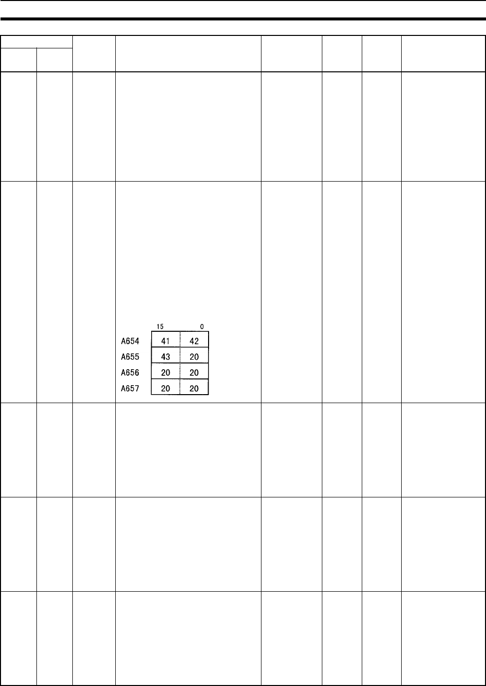
719
Auxiliary Area Appendix B
A651 --- Program
Password
Type in the password to replace a pro-
gram.
A5A5 hex: Replacement Start Bit
(A65015) is enabled.
Any other value: Replacement Start Bit
(A65015) is disabled.
When the power is turned ON or pro-
gram replacement is completed, the
Replacement Start Bit will be turned
OFF, regardless of whether replace-
ment was completed normally or in
error.
--- Retained Cleared ---
A654 to
A657
--- Program
File Name
When program replacement starts, the
program file name will be stored in
ASCII. File names can be specified up
to eight characters in length excluding
the extension.
File names are stored in the following
order: A654 to A657 (i.e., from the low-
est word to the highest), and from the
highest byte to the lowest. If a file name
is less than eight characters, the lowest
remaining bytes and the highest
remaining word will be filled with
spaces (20 hex). Null characters and
space characters cannot be used within
file names.
Example: File name is ABC.OBJ
--- Retained Cleared ---
A720 to
A722
Power ON
Clock
Data 1
(See
note.)
These words contain the same time
data as the startup time stored in words
A510 to A511, as well as the month and
year information.
A72000 to A72007: Seconds (00 to 59)
A72008 to A72015: Minutes (00 to 59)
A72100 to A72107: Hour (00 to 23)
A72108 to A72115: Day of month (00 to
31)
A72200 to A72207: Month (01 to 12)
A72208 to A72215: Year (00 to 99)
See at left. Retained Retained Written when power is
turned ON.
A723 to
A725
Power ON
Clock
Data 2
(See
note.)
These words contain the time at which
the power was turned ON one time
before the startup time stored in words
A510 to A511.
A72300 to A72307: Seconds (00 to 59)
A72308 to A72315: Minutes (00 to 59)
A72400 to A72407: Hour (00 to 23)
A72408 to A72415: Day of month (00 to
31)
A72500 to A72507: Month (01 to 12)
A72508 to A72515: Year (00 to 99)
See at left. Retained Retained Written when power is
turned ON.
A726 to
A728
Power ON
Clock
Data 3
(See
note.)
These words contain the time at which
the power was turned ON two times
before the startup time stored in words
A510 to A511.
A72600 to A72607: Seconds (00 to 59)
A72608 to A72615: Minutes (00 to 59)
A72700 to A72707: Hour (00 to 23)
A72708 to A72715: Day of month (00 to
31)
A72800 to A72807: Month (01 to 12)
A72808 to A72815: Year (00 to 99)
See at left. Retained Retained Written when power is
turned ON.
Addresses Name Function Settings Status
after
mode
change
Status at
startup
Write timing/
Related Flags,
Settings
Word Bit

720
Auxiliary Area Appendix B
A729 to
A731
Power ON
Clock
Data 4
(See
note.)
These words contain the time at which
the power was turned ON three times
before the startup time stored in words
A510 to A511.
A72900 to A72907: Seconds (00 to 59)
A72908 to A72915: Minutes (00 to 59)
A73000 to A73007: Hour (00 to 23)
A73008 to A73015: Day of month (00 to
31)
A73100 to A73107: Month (01 to 12)
A73108 to A73115: Year (00 to 99)
See at left. Retained Retained Written when power is
turned ON.
Note Supported by unit version 3.0 or later.
A732 to
A734
Power ON
Clock
Data 5
(See
note.)
These words contain the time at which
the power was turned ON four times
before the startup time stored in words
A510 to A511.
A73200 to A73207: Seconds (00 to 59)
A73208 to A73215: Minutes (00 to 59)
A73300 to A73307: Hour (00 to 23)
A73308 to A73315: Day of month (00 to
31)
A73400 to A73407: Month (01 to 12)
A73408 to A73415: Year (00 to 99)
See at left. Retained Retained Written when power is
turned ON.
A735 to
A737
Power ON
Clock
Data 6
(See
note.)
These words contain the time at which
the power was turned ON five times
before the startup time stored in words
A510 to A511.
A73500 to A73507: Seconds (00 to 59)
A73508 to A73515: Minutes (00 to 59)
A73600 to A73607: Hour (00 to 23)
A73608 to A73615: Day of month (00 to
31)
A73700 to A73707: Month (01 to 12)
A73708 to A73715: Year (00 to 99)
See at left. Retained Retained Written when power is
turned ON.
A738 to
A740
Power ON
Clock
Data 7
(See
note.)
These words contain the time at which
the power was turned ON six times
before the startup time stored in words
A510 to A511.
A73800 to A73807: Seconds (00 to 59)
A73808 to A73815: Minutes (00 to 59)
A73900 to A73907: Hour (00 to 23)
A73908 to A73915: Day of month (00 to
31)
A74000 to A74007: Month (01 to 12)
A74008 to A74015: Year (00 to 99)
See at left. Retained Retained Written when power is
turned ON.
A741 to
A743
Power ON
Clock
Data 8
(See
note.)
These words contain the time at which
the power was turned ON seven times
before the startup time stored in words
A510 to A511.
A74100 to A74107: Seconds (00 to 59)
A74108 to A74115: Minutes (00 to 59)
A74200 to A74207: Hour (00 to 23)
A74208 to A74215: Day of month (00 to
31)
A74300 to A74307: Month (01 to 12)
A74308 to A74315: Year (00 to 99)
See at left. Retained Retained Written when power is
turned ON.
A744 to
A746
Power ON
Clock
Data 9
(See
note.)
These words contain the time at which
the power was turned ON eight times
before the startup time stored in words
A510 to A511.
A74400 to A74407: Seconds (00 to 59)
A74408 to A74415: Minutes (00 to 59)
A74500 to A74507: Hour (00 to 23)
A74508 to A74515: Day of month (00 to
31)
A74600 to A74607: Month (01 to 12)
A74608 to A74615: Year (00 to 99)
See at left. Retained Retained Written when power is
turned ON.
Addresses Name Function Settings Status
after
mode
change
Status at
startup
Write timing/
Related Flags,
Settings
Word Bit
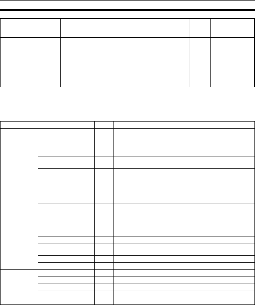
721
Auxiliary Area Appendix B
Note In CS-series PLCs, the following flags are provided in a special read-only area and can be specified with
the labels given in the table. These flags are not contained in the Auxiliary Area. Always use the labels to
specify these flags. Refer to 9-25 Condition Flags and 9-26 Clock Pulses for details.
A747 to
A749
Power ON
Clock
Data 10
(See
note.)
These words contain the time at which
the power was turned ON nine times
before the startup time stored in words
A510 to A511.
A74700 to A74707: Seconds (00 to 59)
A74708 to A74715: Minutes (00 to 59)
A74800 to A74807: Hour (00 to 23)
A74808 to A74815: Day of month (00 to
31)
A74900 to A74907: Month (01 to 12)
A74908 to A74915: Year (00 to 99)
See at left. Retained Retained Written when power is
turned ON.
Note Supported by unit version 3.0 or later.
Flag area Name Label Meaning
Condition Code
Area
Error Flag ER Turns ON when an error occurs in processing an instructions, indi-
cating an error end to the instruction.
Access Error Flag AER Turns ON when an attempt is made to access an illegal area. The
status of this flag is maintain only during the current cycle and only
in the task in which it occurred.
Carry Flag CY Turns ON when there is a carry or borrow in a math operation,
when a bit is shifted into the Carry Flag, etc.
Greater Than Flag >Turns ON when the result of comparing two values is “greater
than,” when a value exceeds a specified range, etc.
Equals Flag =Turns ON when the result of comparing two values is “equals,”
when the result of a math operation is 0, etc.
Less Than Flag <Turns ON when the result of comparing two values is “less than,”
when a value is below a specified range, etc.
Negative Flag NTurns ON when the MSB in the result of a math operation is 1.
Overflow Flag OF Turns ON when the result of a math operation overflows.
Underflow Flag UF Turns ON when the result of a math operation underflows.
Greater Than or Equals
Flag
>= Turns ON when the result of comparing two values is “greater than
or equals.”
Not Equal Flag <> Turns ON when the result of comparing two values is “not equal.”
Less than or Equals Flag <= Turns ON when the result of comparing two values is “less than or
equals.”
Always ON Flag A1 This flag is always ON.
Always OFF Flag A0 This flag is always OFF.
Clock Pulse
Area
0.02-s clock pulse 0.02s Repeatedly turns ON for 0.02 s and OFF for 0.02 s.
0.1-s clock pulse 0.1s Repeatedly turns ON for 0.1 s and OFF for 0.1 s.
0.2-s clock pulse 0.2s Repeatedly turns ON for 0.2 s and OFF for 0.2 s.
1-s clock pulse 1s Repeatedly turns ON for 1 s and OFF for 1 s.
1-min clock pulse 1min Repeatedly turns ON for 1 min and OFF for 1 min.
Addresses Name Function Settings Status
after
mode
change
Status at
startup
Write timing/
Related Flags,
Settings
Word Bit
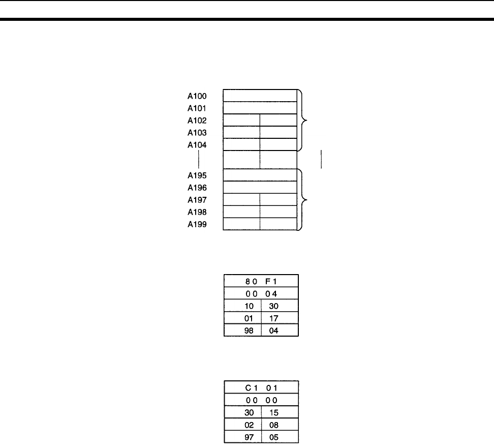
722
Auxiliary Area Appendix B
Details on Auxiliary Area Operation
A100 to A199: Error Log Area
The following data would be generated in an error record if a memory error (error code 80F1) occurred on 1
April 1998 at 17:10:30 with the error located in the PLC Setup (04 hex).
The following data would be generated in an error record if an FALS error with FALS number 001 occurred on
2 May 1997 at 8:30:15.
Error code
Error flag contents
min s
day hr
yr mo
Error code
Error flag contents
min s
day hr
yr mo
Error
record
Error
record
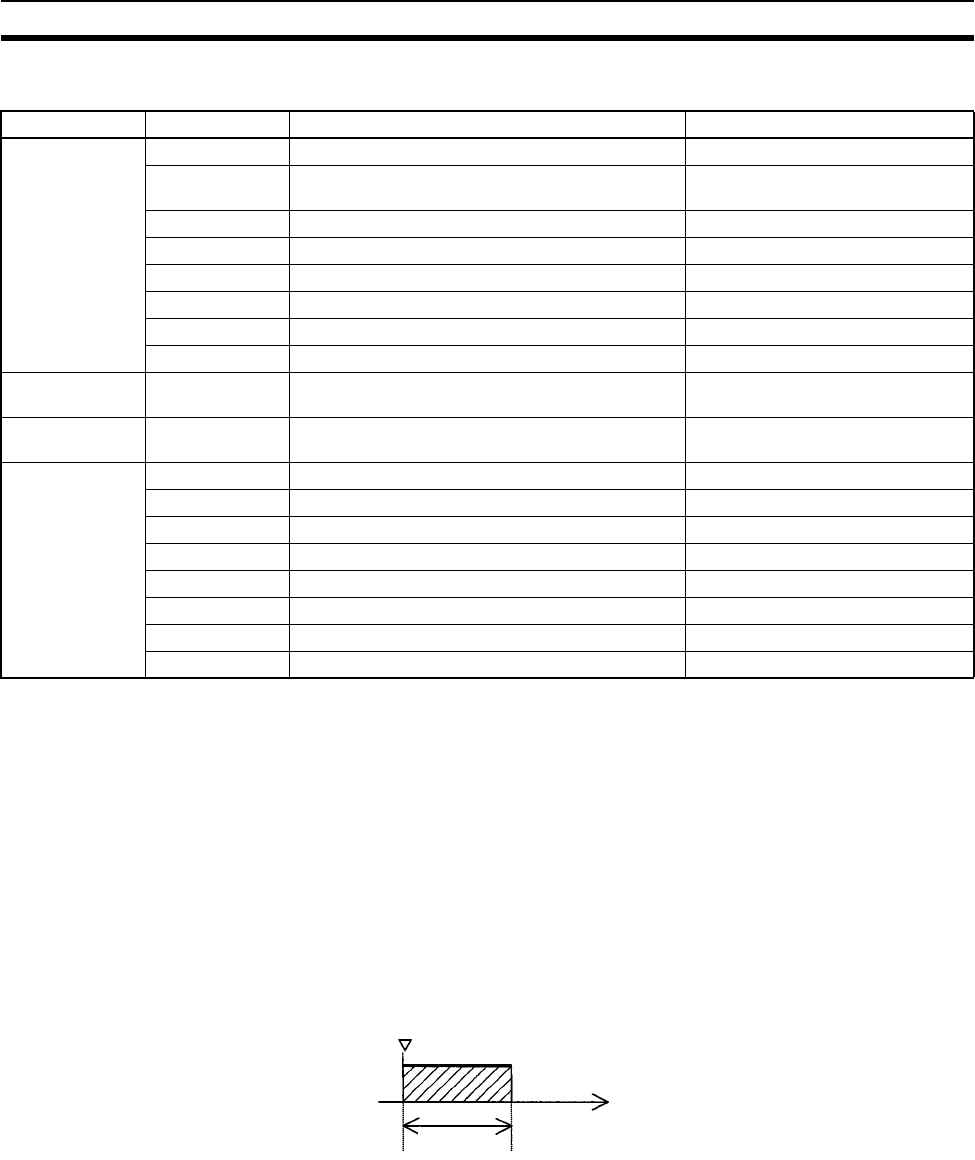
723
Auxiliary Area Appendix B
Error Codes and Error Flags
Note 1. C101 to C2FF will be stored for FALS numbers 001 to 511.
2. 4101 to 42FF will be stored for FAL numbers 001 to 511.
3. The contents of the error flags for a duplicate number error are as follows:
Bits 0 to 7: Unit number (binary), 00 to 5F hex for Special I/O Units, 00 to 0F hex for CS-series CPU
Bus Units
Bits 8 to 14: All zeros.
Bit 15: Unit type, 0 for CS-series CPU Bus Units and 1 for Special I/O Units.
4. Only the contents of A295 is stored as the error flag contents for program errors.
5. 0000 hex will be stored as the error flag contents.
A20011: First Cycle Flag
A20015: Initial Task Flag
A20015 will turn ON during the first time a task is executed after it has reached executable status. It will be ON
only while the task is being executed and will not turn ON if following cycles.
Classification Error code Meaning Error flags
System-defined
fatal errors
80F1 Memory error A403
80C0 to 80C7,
80CF
I/O bus error A404
80E9 Duplicate number error A410, A411 to 416 (See note 3.)
80E1 Too many I/O error A407
80E0 I/O setting error ---
80F0 Program error A295 to 299 (See note 4.)
809F Cycle time too long error ---
80EA Duplicate Expansion Rack number error A40900 to 40907
User-defined
fatal errors
C101 to C2FF FALS instruction executed (See note 1.) ---
User-defined
non-fatal errors
4101 to 42FF FAL instruction executed (See note 2.) ---
System-defined
non-fatal errors
008B Interrupt task error A426
009A Basic I/O error A408
009B PLC Setup setting error A406
0200 to 020F CS-series CPU Bus Unit error A417
0300 to 035F Special I/O Unit error A418 to 423 (See note 5.)
00A0 to 00A1 SYSMAC BUS error A405
0400 to 040F CS-series CPU Bus Unit setup error A427
0500 to 055F Special I/O Unit setup error A428 to 433 (See note 5.)
Execution
started.
Time
1 cycle
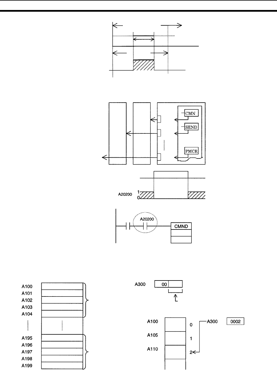
724
Auxiliary Area Appendix B
A20200 to A20207: Communications Port Enabled Flags
A300: Error Record Pointer
Executable status
Executed
1 cycle
A20015
Port 0
Port 1
Port 7
Network communications in-
struction executed for port 0.
Instruction
execution
The program is designed so that CMND(490)
will be executed only when A20200 is ON.
Error record 1
Error record 20
Points to the next record to be used.
Example
Stored
Stored
next
Stored
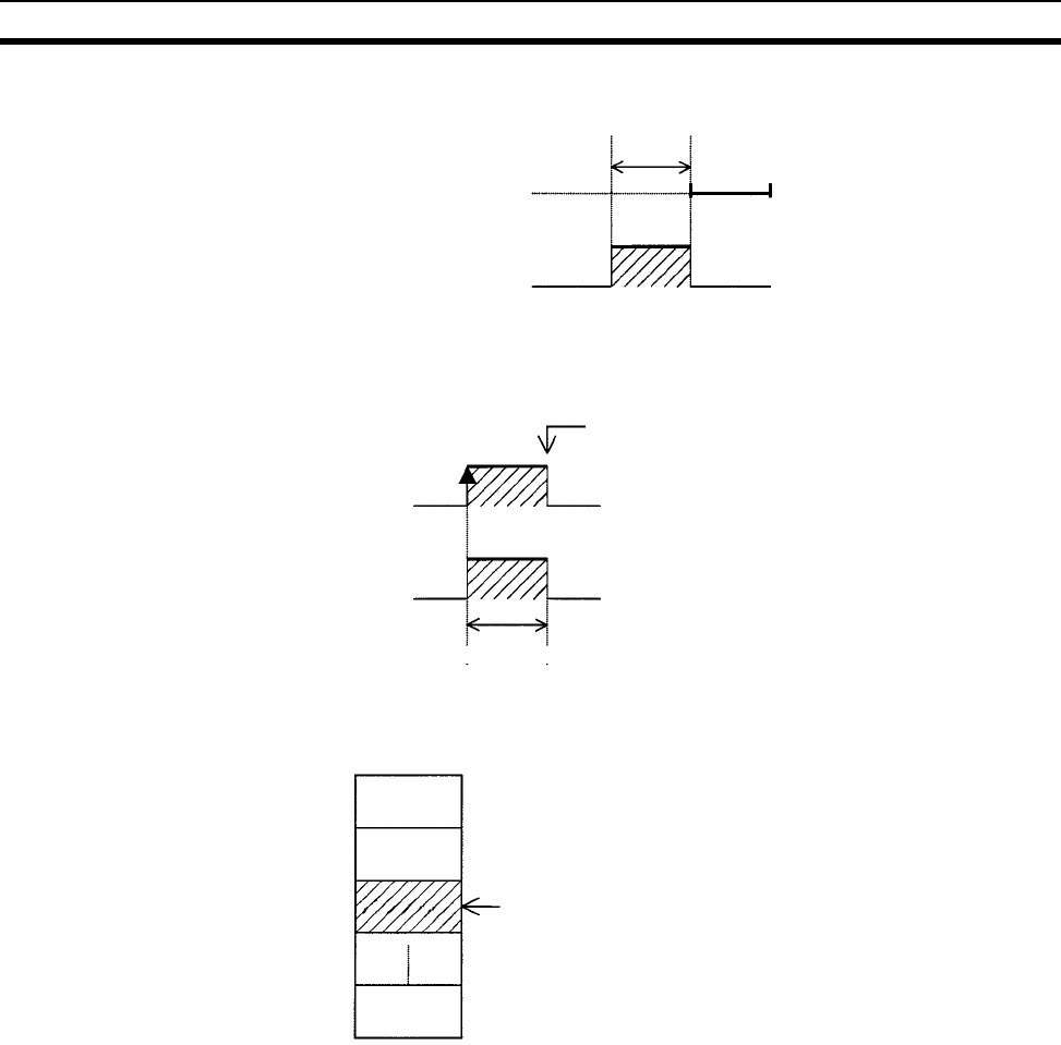
725
Auxiliary Area Appendix B
A20110: Online Editing Wait Flag
A50100 to A50115: CPU Bus Unit Restart Bits and
A30200 to A30215: CPU Bus Unit Initialization Flags
A301: Current EM Bank
Online edit processing
Wait
A20110
Example: Unit No. 1
A50101 (or at startup)
A30201
Automatically turned OFF by system.
Unit initialized.
EM Area
Bank 0
Current Bank
If bank 2 is the current bank, the
E2_00100 can also be address
simply as E00100
Bank 1
Bank 2
Bank C

726
Auxiliary Area Appendix B
A40109: Program Error
A42615: Interrupt Task Error Cause Flag
Error Address
UM Overflow Error Flag A29515
Illegal Instruction Flag A29514
Distribution Overflow Error Flag A29513
Task Error Flag A25912
No END(001) Error Flag A29511
Illegal Area Access Error Flag A29510
Indirect DM/EM Addressing Error Flag A29509
Interrupt
task
10 ms
or more
I/O refresh
Interrupt task
IORF(097)
instruction
Special I/O Unit
Refreshed twice.
727
Appendix C
Memory Map of PLC Memory Addresses
PLC Memory Addresses
PLC memory addresses are set in Index Registers (IR00 to IR15) to indirectly address I/O memory. Normally,
use the MOVE TO REGISTER (MOVR(560)) and MOVE TIMER/COUNTER PV TO REGISTER
(MOVRW(561)) instructions to set PLC memory addresses into the Index Registers.
Some instructions, such as DATA SEARCH (SRCH(181)), FIND MAXIMUM (MAX(182)), and FIND MINIMUM
(MIN(183)), output the results of processing to an Index Register to indicate an PLC memory address.
There are also instructions for which Index Registers can be directly designated to use the PLC memory
addresses stored in them by other instructions. These instructions include DOUBLE MOVE (MOVL(498)),
some symbol comparison instructions (=L, <>L, <L, >L, <=L, and >=L), DOUBLE COMPARE (CMPL(060)),
DOUBLE DATA EXCHANGE (XCGL(562)), DOUBLE INCREMENT BINARY (++L(591)), DOUBLE DECRE-
MENT BINARY (––L(593)), DOUBLE SIGNED BINARY ADD WITHOUT CARRY (+L(401)), DOUBLE SIGNED
BINARY SUBTRACT WITHOUT CARRY (–L(411)), SET RECORD LOCATION (SETR(635)), and GET
RECORD LOCATION (GETR(636)).
The PLC memory addresses all are continuous and the user must be aware of the order and boundaries of the
memory areas. As reference, the PLC memory addresses are provided in a table at the end of this appendix.
Note Directly setting PLC memory addresses in the program should be avoided whenever possible. If PLC
memory addresses are set in the program, the program will be less compatible with new CPU Unit mod-
els or CPU Units for which changed have been made to the layout of the memory.
Memory Configuration
There are two classifications of the RAM memory (with battery backup) in a CS-series CPU Unit.
Parameter Areas: These areas contain CPU Unit system setting data, such as the PLC Setup, CS-series CPU
Bus Unit Setups, etc. An illegal access error will occur if an attempt is made to access any of the parameter
areas from an instruction in the user program.
I/O Memory Areas: These are the areas that can be specified as operands in the instructions in user pro-
grams.

728
Memory Map of PLC Memory Addresses Appendix C
Memory Map
Do not access addresses reserved by the system.
Note The data from the current EM Area bank specified in the program is stored in this area. For example, if
the current bank is bank 1 (20000 to 27FFF), then the data in F8000 to FFFFF will be the same as the
data in 20000 to 27FFF.
Classification PLC memory
addresses (hex)
User addresses Area
I/O memory
areas
00000 to 0B1FF --- Reserved for system.
0B200 to 0B7FF --- Reserved for system.
0B800 to 0B801 TK00 to TK31 Task Flag Area
0B802 to 0B83F --- Reserved for system.
0B840 to 0B9FF A000 to A447 Read-only Auxiliary Area
0BA00 to 0BBFF A448 to A959 Read/Write Auxiliary Area
0BC00 to 0BDFF --- Reserved for system.
0BE00 to 0BEFF T0000 to T4095 Timer Completion Flags
0BF00 to 0BFFF C0000 to C4095 Counter Completion Flags
0C000 to 0D7FF CIO 0000 to CIO 6143 CIO Area
0D800 to 0D9FF H000 to H511 Holding Area
0DA00 to 0DDFF H512 to H1535 Holding Area
These words are used for function blocks only.
0DE00 to 0DFFF W000 to W511 Work Area
0E000 to 0EFFF T0000 to T4095 Timer PVs
0F000 to 0FFFF C0000 to C4095 Counter PVs
10000 to 17FFF D00000 to D32767 DM Area
18000 to 1FFFF E0_00000 to E0_32767 EM Area bank 0
20000 to 27FFF E1_00000 to E1_32767 EM Area bank 1
78000 to 7FFFF EC_00000 to EC_32767 EM Area bank C
F8000 to FFFFF E_0000 to E_32767 EM Area, current bank (See note.)

729
Appendix D
PLC Setup Coding Sheets for
Programming Console
Use the following coding sheets when setting the PLC Setup from a Programming Console.
Value (hex) Rack 0, Slot 0 I/O Response Time
A00 8 ms
10 No filter
11 0.5 ms
12 1 ms
13 2 ms
14 4 ms
15 8 ms
16 16 ms
17 32 ms
B00 8 ms
10 No filter
11 0.5 ms
12 1 ms
13 2 ms
14 4 ms
15 8 ms
16 16 ms
17 32 ms
Address
10@@@@
A
B
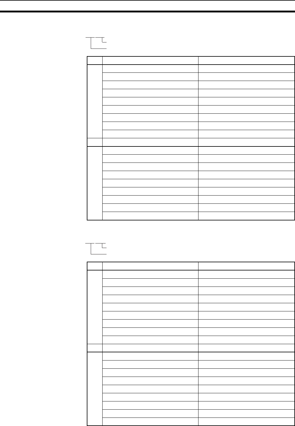
730
PLC Setup Coding Sheets for Programming Console Appendix D
Value (hex) Rack 0, Slot 2 I/O Response Time
A00 8 ms
10 No filter
11 0.5 ms
12 1 ms
13 2 ms
14 4 ms
15 8 ms
16 16 ms
17 32 ms
Value (hex) Rack 0, Slot 3 I/O Response Time
B00 8 ms
10 No filter
11 0.5 ms
12 1 ms
13 2 ms
14 4 ms
15 8 ms
16 16 ms
17 32 ms
Value (hex) Rack 7, Slot 8 I/O Response Time
A00 8 ms
10 No filter
11 0.5 ms
12 1 ms
13 2 ms
14 4 ms
15 8 ms
16 16 ms
17 32 ms
Value (hex) Rack 7, Slot 9 I/O Response Time
B00 8 ms
10 No filter
11 0.5 ms
12 1 ms
13 2 ms
14 4 ms
15 8 ms
16 16 ms
17 32 ms
Address
11@@@@
A
B
Address
49@@@@
A
B
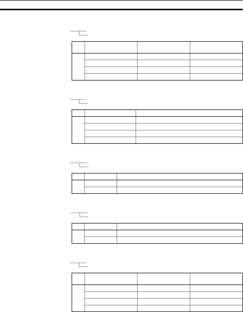
731
PLC Setup Coding Sheets for Programming Console Appendix D
Value (hex) IOM Hold Bit Status at
Startup
Forced Status Hold Bit
Status at Startup
A C000 Retained Retained
8000 Retained Cleared
4000 Cleared Retained
0000 Cleared Cleared
Value (hex) Startup Mode
A PRCN Mode on Programming Console’s mode switch
PRG PROGRAM mode
MON MONITOR mode
RUN RUN mode
Value (hex) Startup Condition (CS1-H CPU Units only)
A 8000 Don’t wait.
0000 Wait for all Units and Boards.
Value (hex) Inner Board Setting (CS1-H CPU Units only)
A 8000 Don’t wait.
0000 Wait for all Boards.
Value (hex) Low Battery Voltage
Detection
Interrupt Task Error
Detection
A C000 Do not detect Do not detect
8000 Do not detect Detect
4000 Detect Do not detect
0000 Detect Detect
Address
80@@@@
A
Address
81@@@@
A
Address
83@@@@
A
Address
84@@@@
A
Address
128@@@@
A
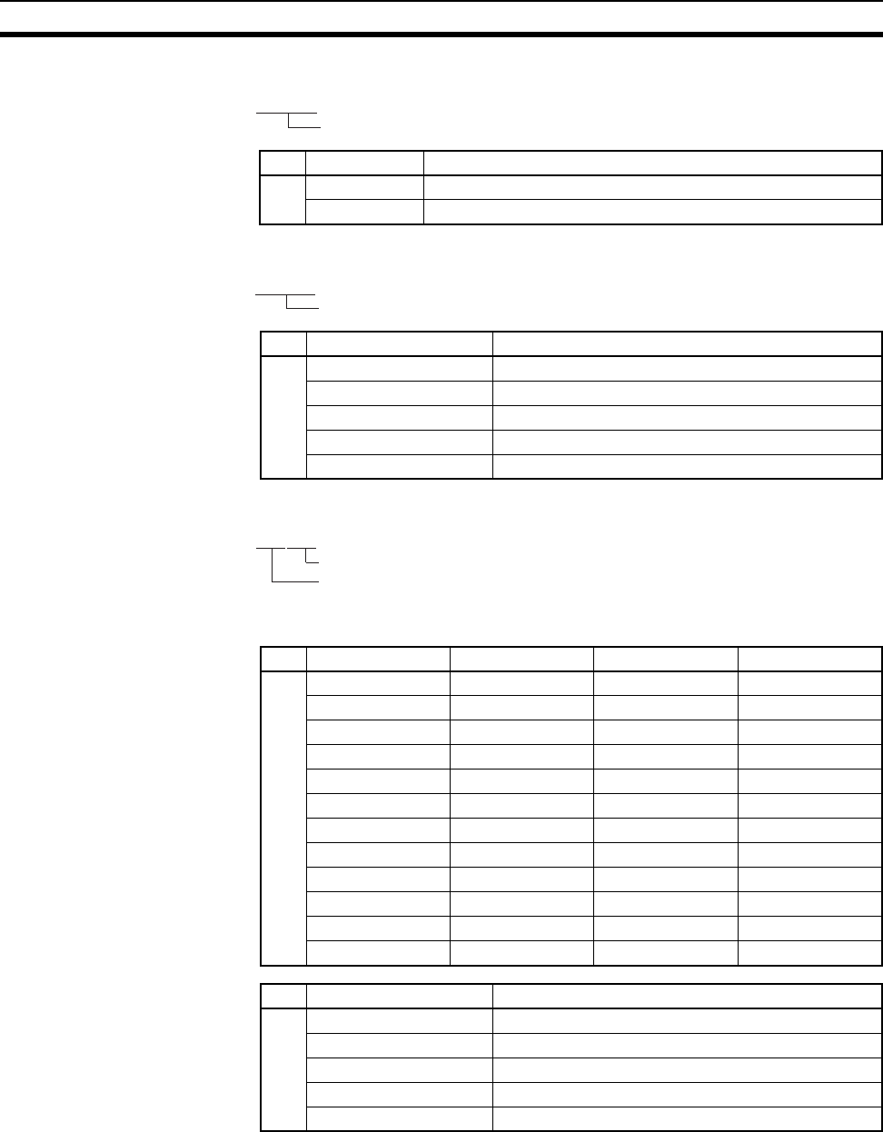
732
PLC Setup Coding Sheets for Programming Console Appendix D
Peripheral Port
Value (hex) FAL Error Log Registration (CS1-H CPU Units only)
A 8000 Don’t store user-defined FAL error in error log.
0000 Store user-defined FAL error in error log.
Value (hex) EM File Memory Conversion
A 0000 None
0080 EM File Memory Enabled: Bank No. 0
0081 EM File Memory Enabled: Bank No. 1
to to
008C EM File Memory Enabled: Bank No. C
Address
129@@@@
A
Address
136@@@@
A
Address
144@@@@
A
B
Value (hex) Data bits Stop bits Parity
A 00 7 bits 2 bits Even
01 7 bits 2 bits Odd
02 7 bits 2 bits None
04 7 bits 1 bit Even
05 7 bits 1 bit Odd
06 7 bits 1 bit None
08 8 bits 2 bits Even
09 8 bits 2 bits Odd
0A 8 bits 2 bits None
0C 8 bits 1 bit Even
0D 8 bits 1 bit Odd
0E 8 bits 1 bit None
Value (hex) Communications mode
B 00 Default (Rightmost 2 digits ignored.)
80 Host link
82 NT link
84 Peripheral bus
85 Host link
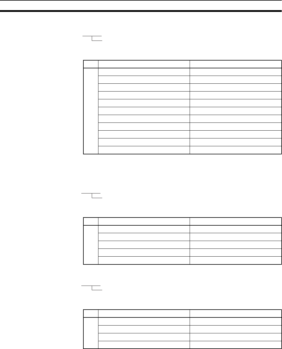
733
PLC Setup Coding Sheets for Programming Console Appendix D
Peripheral Port
Note Set 0000 to 0009 hex for standard NT Links and 000A hex for high-
speed NT Links.
Peripheral Port
Peripheral Port
Address
145@@@@
A
Value (hex) Baud rate
A 0000 9,600 bps
0001 300 bps
0002 600 bps
0003 1,200 bps
0004 2,400 bps
0005 4,800 bps
0006 9,600 bps
0007 19,200 bps
0008 38,400 bps
0009 57,600 bps
000A 115,200 bps
Address
147@@@@
A
Value (hex) Host link Unit No.
A0000 No. 0
0001 No. 1
0002 No. 2
to to
001F No. 31
Address
150@@@@
A
Value (hex) NT Link Mode Maximum Unit No.
A0000 No. 0
0001 No. 1
to to
0007 No. 7
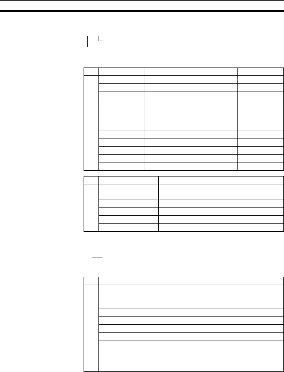
734
PLC Setup Coding Sheets for Programming Console Appendix D
RS-232C Port
RS-232C Port
Note Set 0000 to 0009 hex for standard NT Links and 000A hex for high-
speed NT Links.
Address
160@@@@
A
B
Value (hex) Data bits Stop bits Parity
A 00 7 bits 2 bits Even
01 7 bits 2 bits Odd
02 7 bits 2 bits None
04 7 bits 1 bit Even
05 7 bits 1 bit Odd
06 7 bits 1 bit None
08 8 bits 2 bits Even
09 8 bits 2 bits Odd
0A 8 bits 2 bits None
0C 8 bits 1 bit Even
0D 8 bits 1 bit Odd
0E 8 bits 1 bit None
Value (hex) Communications mode
B 00 Default (Rightmost 2 digits ignored.)
80 Host link
82 NT link
83 No-protocol
84 Peripheral bus
85 Host link
Address
161@@@@
A
Value (hex) Baud rate
A 0000 9,600 bps
0001 300 bps
0002 600 bps
0003 1,200 bps
0004 2,400 bps
0005 4,800 bps
0006 9,600 bps
0007 19,200 bps
0008 38,400 bps
0009 57,600 bps
000A 115,200 bps
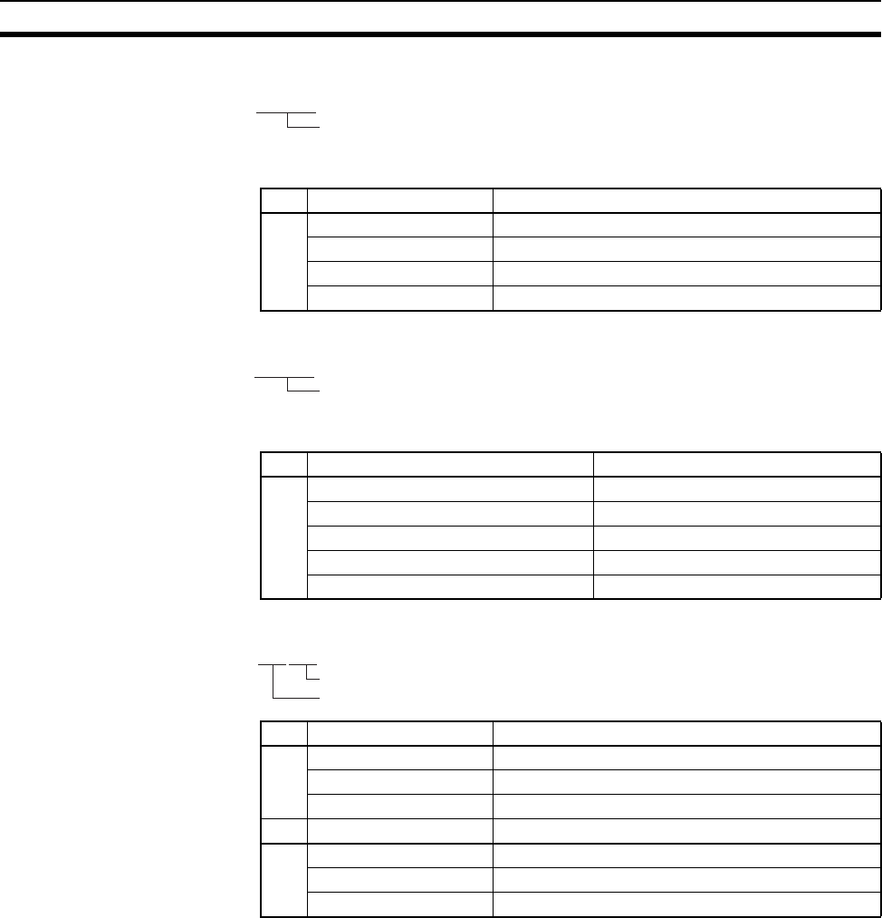
735
PLC Setup Coding Sheets for Programming Console Appendix D
RS-232C Port
RS-232C Port
Address
162@@@@
A
Value (hex) No-protocol mode delay
A0000 0 ms
0001 10 ms
to to
270F 99,990 ms
Address
163@@@@
A
Value (hex) Host link Unit No.
A0000 No. 0
0001 No. 1
0002 No. 2
to to
001F No. 31
Value (hex) No-protocol Mode End Code
A00 00
to to
FF FF
Value (hex) No-protocol Mode Start Code
B00 00
to to
FF FF
Address
164@@@@
A
B
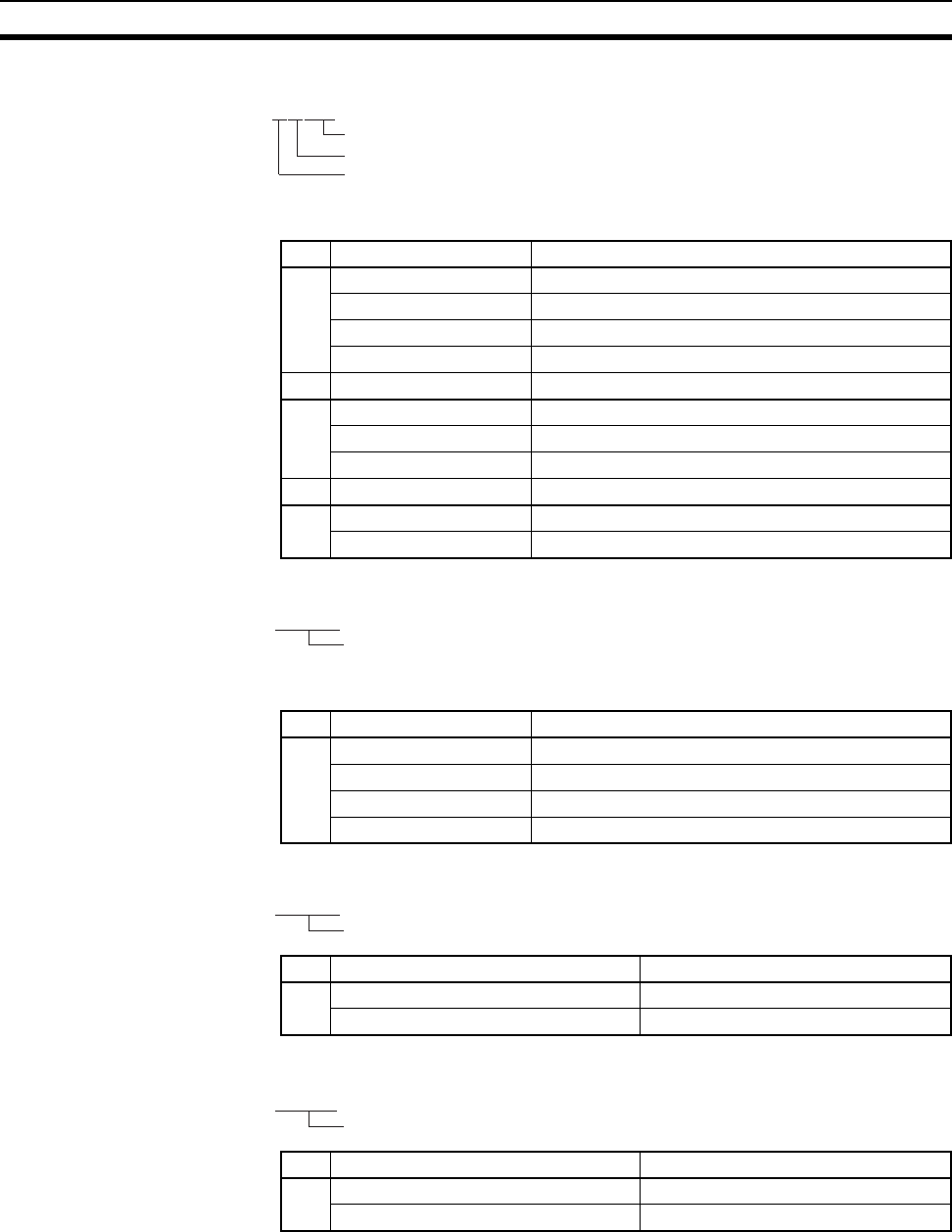
736
PLC Setup Coding Sheets for Programming Console Appendix D
RS-232C Port
RS-232C Port
Address
165@@@@
A
B
C
Value (hex) No-protocol Mode reception data volume
A00 256
01 1
to to
FF 256
Value (hex) No-protocol Mode end code setting
B 0 None (Specify the amount of data being received)
1 Yes (Specify the end code)
2 End code is set to CF+LF
Value (hex) No-protocol Mode start code setting
C0 None
1Yes
Address
166@@@@
A
Value (hex) Maximum Unit No. in NT Link Mode
A0000 No. 0
0001 No. 1
to to
0007 No. 7
Value (hex) Scheduled interrupt time unit
A 0000 10 ms
0001 1.0 ms
Value (hex) Instruction Error Operation
A 0000 Continue operation
8000 Stop operation
Address
195@@@@
A
Address
197@@@@
A
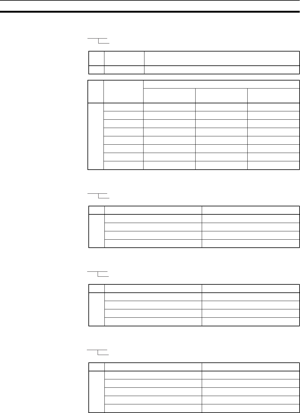
737
PLC Setup Coding Sheets for Programming Console Appendix D
Value (hex) Background Communications Port Number
(CS1-H CPU Units only)
A 0 to 7 Communications port number 0 to 7 (logical port number)
Value (hex) Background Processes (CS1-H CPU Units only)
Table data
instructions
Text string
instructions
Data shifting
instructions
B E00 Yes Yes Yes
C00 Yes Yes No
A00 Yes No Yes
800 Yes No No
600 No Yes Yes
400 No Yes No
100 No No Yes
000 No No No
Value (hex) Minimum Cycle Time
A 0000 Cycle time not fixed
0001 Cycle time fixed: 1 ms
to to
7D00 Cycle time fixed: 32,000 ms
Value (hex) Watch Cycle Time
A 0000 Default: 1,000 ms (1 s)
8001 10 ms
to to
8FA0 40,000 ms
Value (hex) Fixed Peripheral Servicing Time
A 0000 Default (4% of the cycle time)
8000 00 ms
8001 0.1 ms
to to
80FF 25.5 ms
Address
198@@@@
A
Address
208@@@@
A
Address
209@@@@
A
Address
218@@@@
A
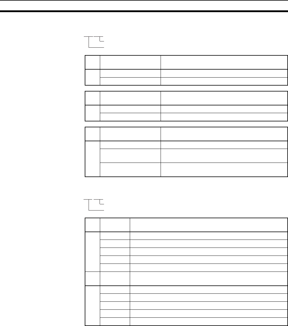
738
PLC Setup Coding Sheets for Programming Console Appendix D
[
Value (hex) Slice Time for Peripheral Servicing in Peripheral
Servicing Priority Mode
A 00 Disable Peripheral Servicing Priority Mode.
01 to FF 0.1 to 25.5 ms (in 0.1-ms increments)
Value (hex) Slice Time for Program Execution in Peripheral
Servicing Priority Mode
B 00 Disable Peripheral Servicing Priority Mode.
05 to FF 5 to 255 (in 1-ms increments)
Value (hex) Slice Time for Program Execution in Parallel
Processing Mode (CS1-H CPU Units only)
B 00 Don’t use Parallel Processing Mode
01 Parallel Processing with Synchronous Memory
Access
02 Parallel Processing with Asynchronous Memory
Access
Value
(hex)
Unit/Port for Priority Servicing
A 00 Disable Peripheral Servicing Priority Mode.
10 to 1F CPU Bus Unit unit number (0 to 15) + 10 hex
20 to 7F CPU Special I/O Unit unit number (0 to 96) + 20 hex
FC RS-232C port
FD Peripheral port
Value
(hex)
Unit/Port for Priority Servicing
B 00 Disable Peripheral Servicing Priority Mode.
10 to 1F CPU Bus Unit unit number (0 to 15) + 10 hex
20 to 7F CPU Special I/O Unit unit number (0 to 96) + 20 hex
FC RS-232C port
FD Peripheral port
Address
219@@@@
A
B
Address
220@@@@
A
B
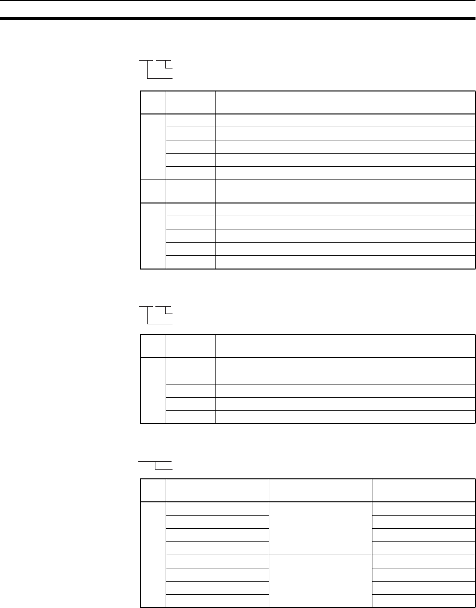
739
PLC Setup Coding Sheets for Programming Console Appendix D
Value
(hex)
Unit/Port for Priority Servicing
A 00 Disable Peripheral Servicing Priority Mode.
10 to 1F CPU Bus Unit unit number (0 to 15) + 10 hex
20 to 7F CPU Special I/O Unit unit number (0 to 96) + 20 hex
FC RS-232C port
FD Peripheral port
Value
(hex)
Unit/Port for Priority Servicing
B 00 Disable Peripheral Servicing Priority Mode.
10 to 1F CPU Bus Unit unit number (0 to 15) + 10 hex
20 to 7F CPU Special I/O Unit unit number (0 to 96) + 20 hex
FC RS-232C port
FD Peripheral port
Value
(hex)
Unit/Port for Priority Servicing
A 00 Disable Peripheral Servicing Priority Mode.
10 to 1F CPU Bus Unit unit number (0 to 15) + 10 hex
20 to 7F CPU Special I/O Unit unit number (0 to 96) + 20 hex
FC RS-232C port
FD Peripheral port
Value (hex) Power OFF Interrupt
Task
Power OFF Detection
Delay Time
A0000 Disabled 0 ms
0001 1 ms
to to
000A 10 ms
8000 Enabled 0 ms
8001 1 ms
to to
800A 10 ms
Address
221@@@@
A
B
Address
222@@@@
Not used.
A
Address
225@@@@
A
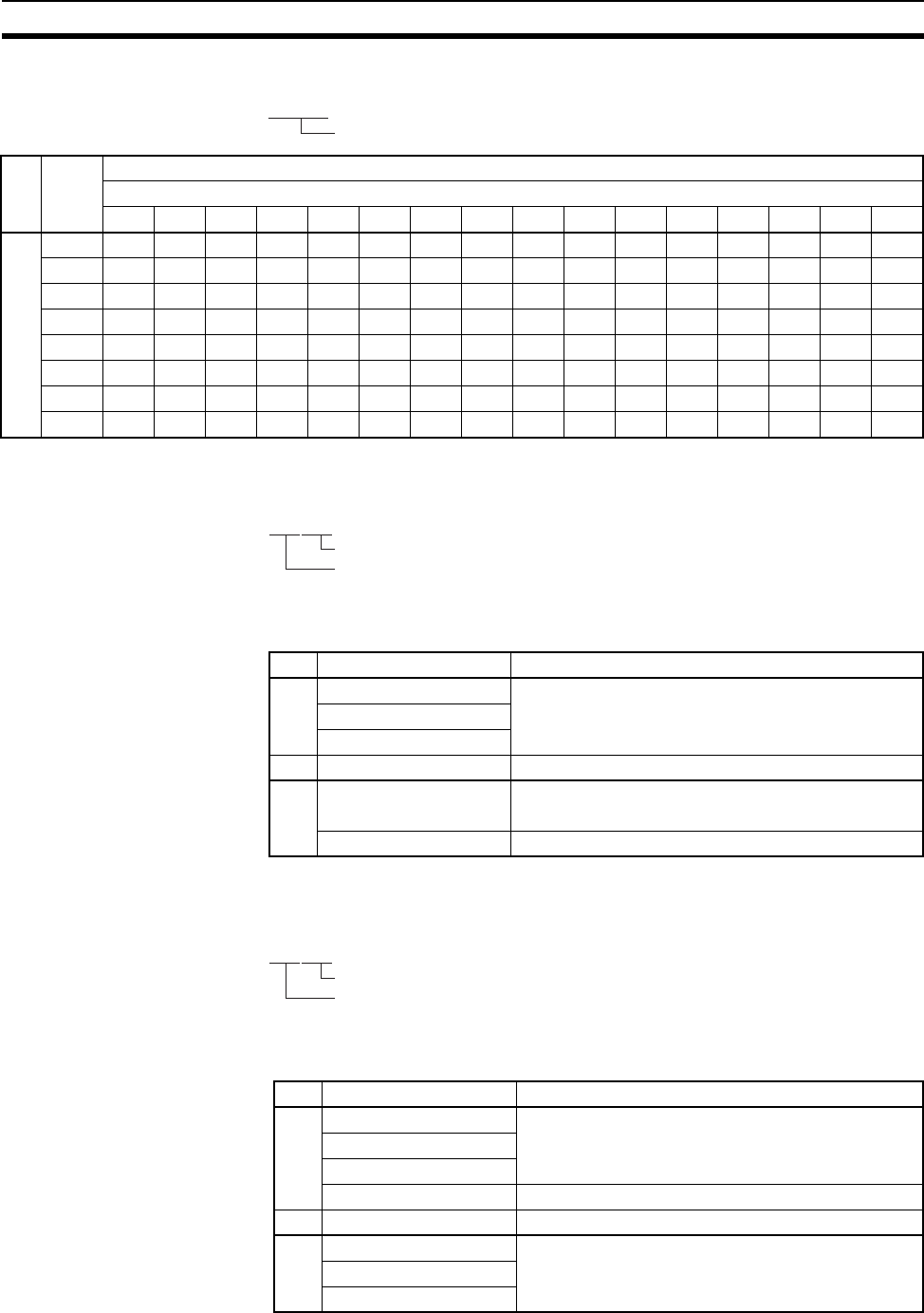
740
PLC Setup Coding Sheets for Programming Console Appendix D
Addresses 227 through 231 are the same as 226.
Use FINS Write Protection and Number of Node Excluded from Write
Protection
Nodes Excluded from Write Protection (Protection Releasing
Addresses, 32 Nodes Maximum)
Address
226@@@@
A
Value
(hex)
Special I/O Unit Cyclic Refreshing 0: Yes 1: No
Unit number
15 14 13 12 11 10 9 8 7 6 5 4 3 2 1 0
A00000000000000000000
00010000000000000001
00020000000000000010
00030000000000000011
00040000000000000100
00050000000000000101
to
FFFF1111111111111111
Address
448@@@@
A
B
Value (hex) Number of Nodes Excluded from Write Protection
A 00 Set the number of nodes excluded from write protec-
tion in Programming Console addresses 448 to 480.
00 to 20 hex (0 to 32 nodes)
to
20
Value (hex) Use FINS Write Protection
B 80 Write protection enabled
00 Write protection disabled
Address
448@@@@
A
B
449@@@@
to
Value (hex) FINS Source Node Address
A 01 Node address of a node to be excluded from write
protection.
to
FE
FF All nodes in specified network.
Value (hex) FINS Source Network Address
B 00 Network address of the node to be excluded from
write protection.
to
7F
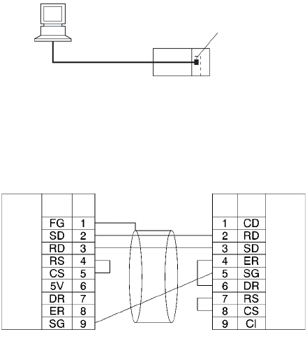
741
Appendix E
Connecting to the RS-232C Port
on the CPU Unit
Connection Examples
The wiring diagrams for connecting to the RS-232C port are provided in this appendix. In actual wiring, we rec-
ommend the use of shielded twisted-pair cables and other methods to improve noise resistance. Refer to Rec-
ommended Wiring Methods later in this appendix for recommended wiring methods.
Connections to Host Computers
Note Connections to a computer running the CX-Programmer are the same as those shown here.
1:1 Connections via RS-232C Port
Note The maximum cable length for an RS-232C connection is 15 m. RS-232C communications specifica-
tions, however, do not cover transmissions at 19.2 Kbps. Refer to documentation of the device being
connected when using this baud rate.
IBM PC/AT or Compatible Computer
RS-232C
RS-232C
port
CPU Unit
RS-232C
interface
Pin
No.
Signal
name
D-sub, 9-pin
connector
(
male
)
Signal
name
Pin
No.
RS-232C
interface
D-sub, 9-pin
connector
(
male
)
Computer
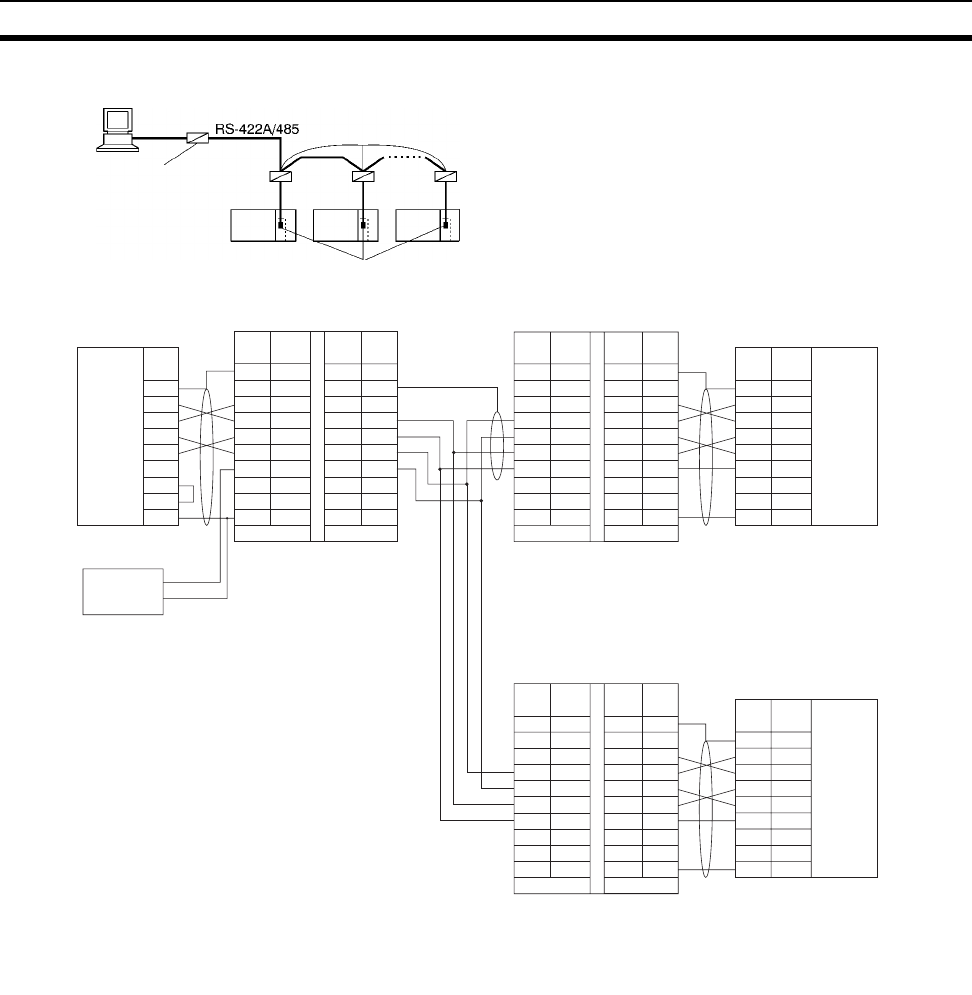
742
Connecting to the RS-232C Port on the CPU Unit Appendix E
1:N Connections via RS-232C Port
Note 1. We recommend using the following NT-AL001 Link Adapter Connecting Cables to connect to NT-
AL001 Link Adapters.
XW2Z-070T-1: 0.7 m
XW2Z-200T-1: 2 m
The recommended cables should be wired as shown below. Each signal wire should be twisted with
the SG (signal ground) wire and placed in a shielded cable to prevent the effects of noise in noise-
prone environments. The 5-V wires can also be twisted with the SG wire to increase noise immunity.
5-V (+)
power (–)
Shield
DIP Switch Settings
Pin 1: ON
Pin 2: ON
(terminating resistance)
Pin 3: OFF
Pin 4: OFF
Pin 5: OFF
Pin 6: OFF
RS-232C CPU Unit
(See note 2.)
DIP Switch Settings
Pin 1: ON
Pin 2: OFF
Pin 3: OFF
Pin 4: OFF
Pin 5: OFF
Pin 6: ON
DIP Switch Settings
Pin 1: ON
Pin 2: ON
Pin 3: OFF
Pin 4: OFF
Pin 5: OFF
Pin 6: ON
RS-232C
RS-232C RS-232C RS-232C
RS-232C ports
Terminating resistance ON
NT-AL001 Link Adapters
NT-AL001
terminating
resistance ON, 5-V
power required
(See
note 1.)
RS-232C
RS-422A
FG
SD
RD
RS
CS
DR
ER
SG
1
2
3
4
5
6
7
8
9
FG
NC
SD
RD
RS
CS
5V
DR
ER
SG
1
2
3
4
5
6
7
8
RS-422RS-232
GRD
SG
SDB
SDA
RDB
RDA
CSB
CSA
1
2
3
4
5
6
7
8
9
FG
SD
RD
RS
CS
5V
DR
ER
SG
1
2
3
4
5
6
7
8
GRD
SG
SDB
SDA
RDB
RDA
CSB
CSA
1
2
3
4
5
6
7
8
9
RS-232RS-422
FG
NC
SD
RD
RS
CS
5V
DR
ER
SG
1
2
3
4
5
6
7
8
9
FG
SD
RD
RS
CS
5V
DR
ER
SG
1
2
3
4
5
6
7
8
GRD
SG
SDB
SDA
RDB
RDA
CSB
CSA
1
2
3
4
5
6
7
8
9
RS-232RS-422
FG
NC
SD
RD
RS
CS
5V
DR
ER
SG
RS-232C
Interface
D-sub, 9-pin
connector (male)
(See
note
2.)
NT-AL001 Link Adapter
Communications Board/Unit
RS-232C
Interface
D-sub, 9-pin
connector (male)
RS-232C
(See
note 1.)
(See
note
2.)
RS-232C
Interface
Personal Computer
D-sub, 9-pin
connector (male)
NT-AL001 Link Adapter
Signal
name
Signal
name Signal
name Signal
name
Signal
name Signal
name
Signal
name
Signal
name Signal
name
Pin
No.
Pin
No.
Pin
No.
Pin
No. Pin
No.
Pin
No.
Pin
No. Pin
No.
NT-AL001 Link Adapter
Shell Shell
Shell
Terminal
block
(terminating resistance)
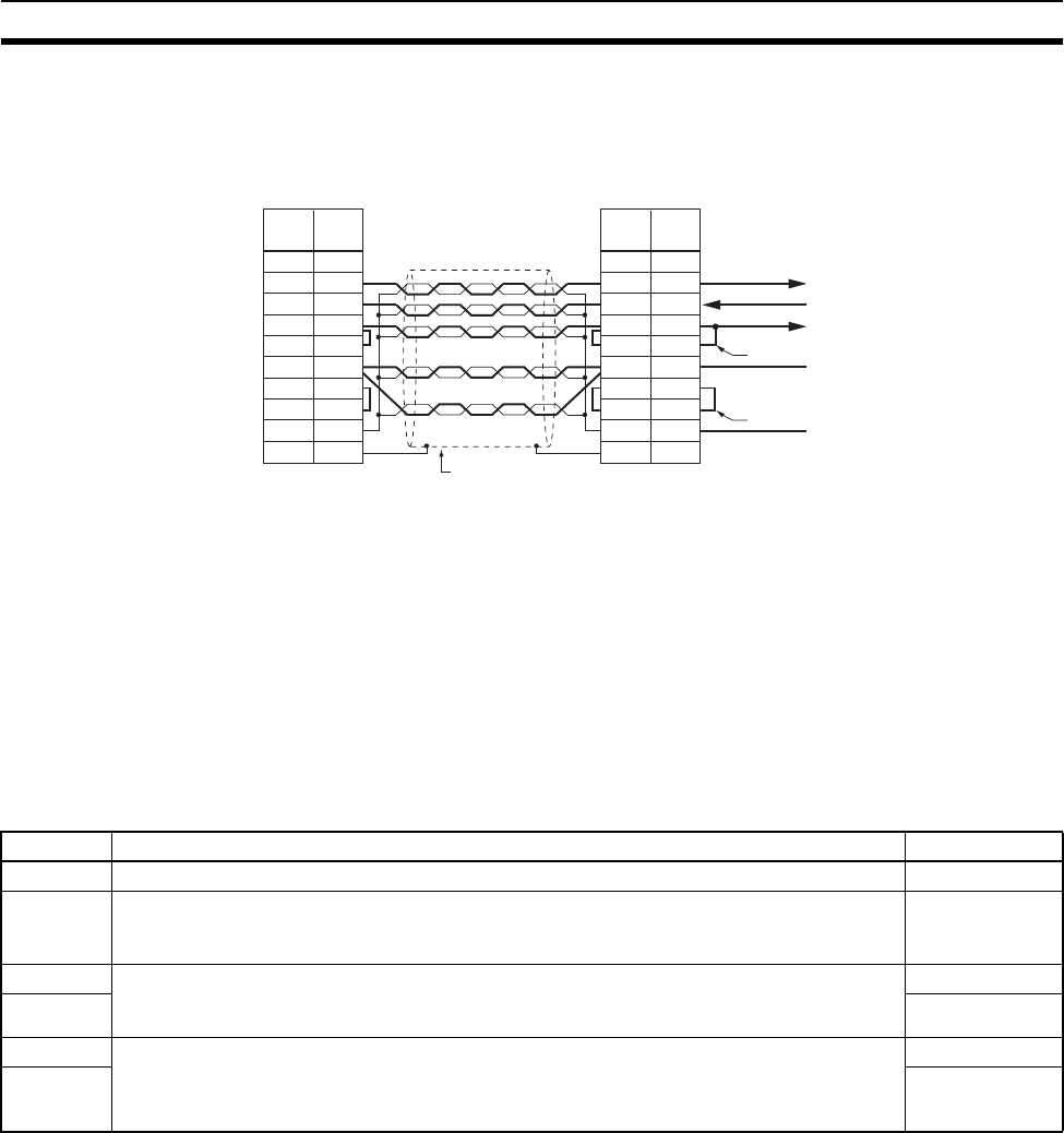
743
Connecting to the RS-232C Port on the CPU Unit Appendix E
Although this wiring is different from that shown in the example above, it can be used to increase
noise immunity if required.
2. When the NT-AL001 Link Adapter is connected to the RS-232C port on the CPU Unit, 5 V is supplied
from pin 6, eliminating the need for a 5-V power supply.
3. Do not use the 5-V power from pin 6 of the RS-232C port for anything other than an NT-AL001, CJ1W-
CIF11 Link Adapter, or NV3W-M@20L Programmable Terminal. Using this power supply for any other
external device may damage the CPU Unit or the external device.
4. The XW1Z-@@0T-1 Cable is designed to connect the NT-AL001 and contains special wiring for the
CS and RS signals. Do not use this cable for any other application. Connecting this cable to other
devices can damage them.
DIP Switch Settings on the NT-AL001 Link Adapter
There is a DIP switch on the NT-AL001 Link Adapter that is used to set RS-422A/485 communications param-
eters. Set the DIP switch as required for the serial communications mode according to the following table.
Note Turn OFF pin 5 and turn ON pin 6 when connected to a CS-series CPU Unit.
FG
SD
RD
RS
CS
5V
DR
ER
SG
FG
1
2
3
4
5
6
7
8
9
1
3
2
4
5
6
7
8
9
RD
SD
RS
CS
5V
DR
ER
SG
FG
Wiring with XW2Z-@@0T-1 (10 Conductors)
Signal
name
Pin
No.
Shell
PLC
Shield
NT-AL001 (interior)
Pin
No.
Not used
Shell
Loopback
Loopback
The arrow indicates
the signal direction.
Signal
name
Pin Function Default setting
1 Not used. (Leave set to ON.) ON
2 Internal terminating resistance setting.
ON: Terminating resistance connected.
OFF: Terminating resistance not connected.
ON
3 2-wire/4-wire setting
Both pins ON: 2-wire communications
Both pins OFF: 4-wire communications
OFF
4OFF
5 Communications mode (See note.)
Both pins OFF: Always send.
5 OFF/6 ON: Send when RS-232C’s CS is high.
5 ON/6 OFF: Send when RS-232C’s CS is low.
ON
6OFF
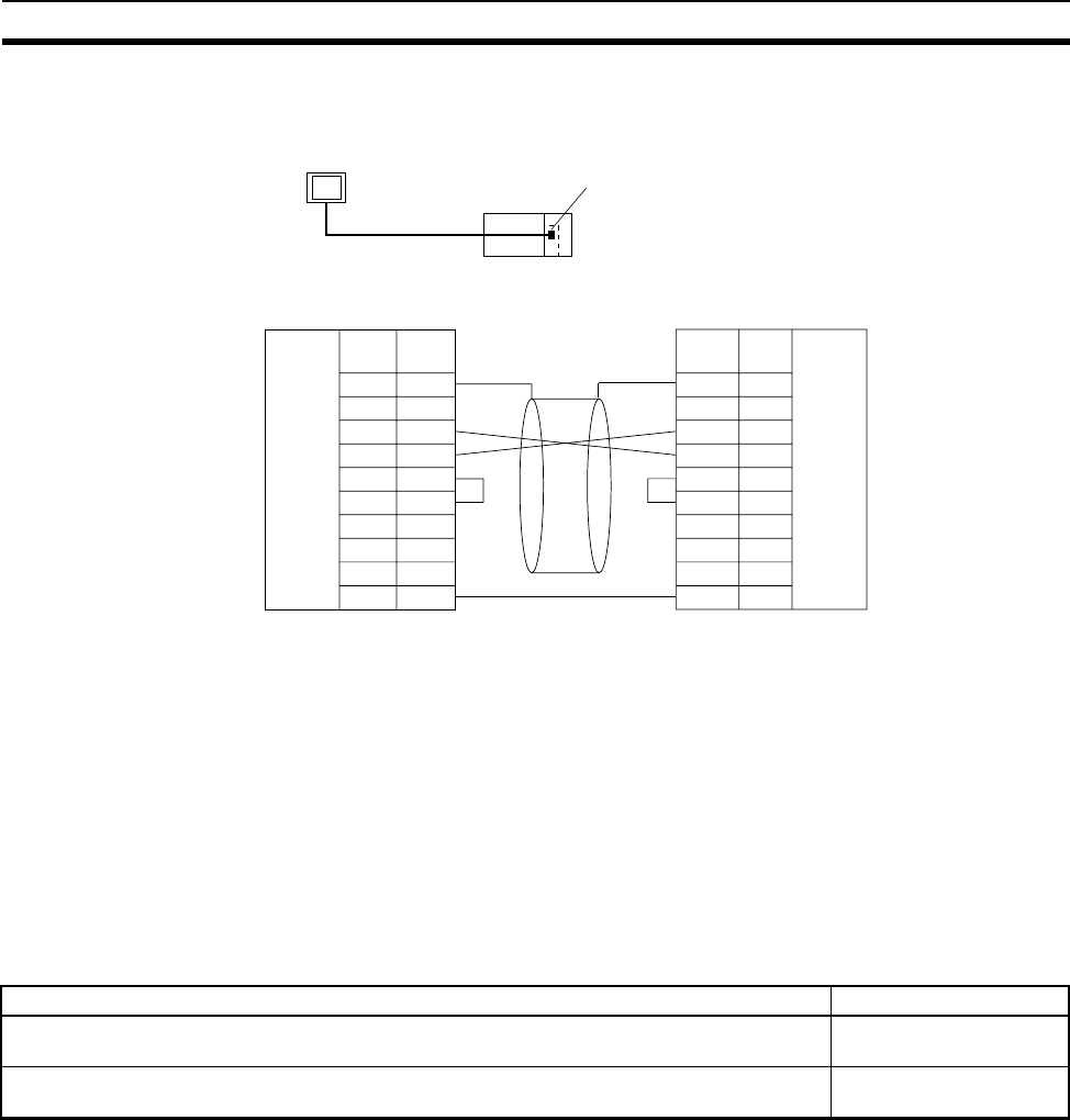
744
Connecting to the RS-232C Port on the CPU Unit Appendix E
Connection Example to Programmable Terminal (PT)
Direct Connection from RS-232C to RS-232C
• Communications Mode: Host Link (unit number 0 only for Host Link)
NT Link (1:N, N = 1 Unit only)
• OMRON Cables with Connectors:
XW2Z-200T-1: 2 m
XW2Z-500T-1: 5 m
Recommended Wiring Methods
We recommend the following wiring methods for RS-232C, especially in environment prone to noise.
1. Use shielded twisted-pair cable for communications cables. The following RS-232C cables are
recommended.
2. Use a twisted-pair cable for each signal line and SG (signal ground) to connect the CPU Unit to a
communications partner. Also, bundle all the SG lines at the Board/Unit and at the other device and
connect them together.
3. Connect the shield line of the communications cable to the hood (FG) of the RS-232C connector at the
Board/Unit. Also, ground the protective earth (GR) terminal of the Power Supply Units on the CPU Rack
and the CS-series Expansion Racks to a resistance of 100 Ω or less. The following example shows
connecting SD-SG, RD-SG, RS-SG, and CS-SG for Serial Communications Mode using a twisted-pair
cable using the peripheral bus.
1
2
3
4
5
6
7
8
9
FG
–
SD
RD
RS
CS
5V
–
–
SG
1
2
3
4
5
6
7
8
9
FG
FG
SD
RD
RS
CS
5V
DR
ER
SG
PT
RS-232C
Host Link or NT Link (1:N)
RS-232C port
Signal
name
Pin
No. Signal
name
Pin
No.
Shell
Shell
RS-232C
interface
RS-232C
interface
D-Sub, 9-pin (male
connector on cable)
CPU Unit PT
D-Sub, 9-pin (male
connector on cable)
Model Manufacturer
UL2464 AWG28×5P IFS-RVV-SB (UL approved)
AWG28×5P IFVV-SB (not UL approved)
Fujikura Ltd.
UL2464-SB (MA) 5P×28AWG (7/0.127) (UL approved)
CO-MA-VV-SB 5P×28AWG (7/0.127) (not UL approved)
Hitachi Cable, Ltd.
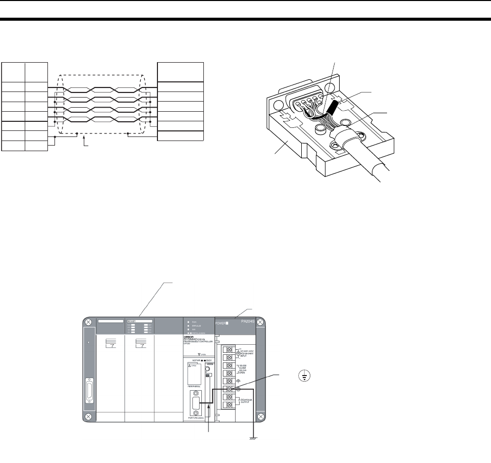
745
Connecting to the RS-232C Port on the CPU Unit Appendix E
Note The hood (FG) is internally connected to the protective earth (GR) terminal on the Power Supply Unit
through the CPU Rack or CS-series Expansion Rack. FG can thus be connected by connecting the pro-
tective earth (GR) terminal on the Power Supply Unit. The hood (FG) is also electrically connected to pin
1 (FG), but the connection resistance between the shield and the FG is smaller for the hood. To reduce
contact resistance between the hood (FG) and the FG, connect the shield both to the hood (FG) and to
pin 1 (FG).
RD
SD
CS
RS
SG
FG
SD
RD
RS
CS
SG
FG
FG
2
3
4
5
9
1
SG signal line
SG signal lines
bundled together
Aluminum foil
XM2S-0911-E
Arrows indicate signal directions.
Signal
name
Pin
No.
Shell
CPU Unit Communications partner
Shield
Signal
name
CPU Unit
Power Supply Unit
GR
Ground to 100 Ω
or less
Shield and GR connected
internally.
The hood will be
grounded if the GR
terminal is grounded.
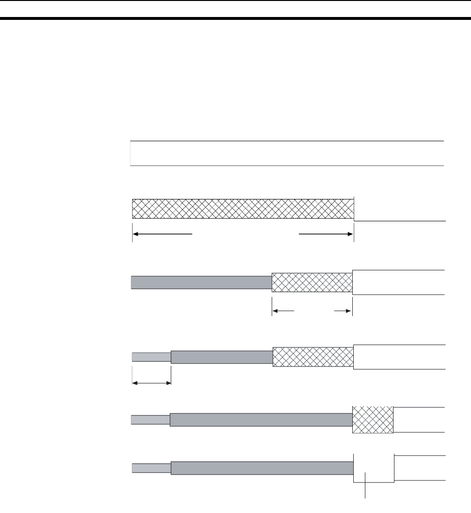
746
Connecting to the RS-232C Port on the CPU Unit Appendix E
Wiring Connectors
Use the following procedures to wire connectors.
1. Preparing the Cable
Lengths for steps in the procedure are provided in the diagrams.
1. Cut the cable to the required length, leaving leeway for wiring and laying the cables.
2. Use a razor blade to cut away the sheath, being careful not to damage the braiding.
3. Use scissors to cut away all but 10 mm of the exposed braiding.
4. Use wire strippers to remove the insulation from the end of each wire.
5. Fold the braiding back over the end of the sheath.
6. Wrap aluminum foil tape over the top of the braiding for one and a half turns.
Connecting the Shield Line to the Hood (FG)
40 mm (RS-232C)
Aluminum foil tape
10 mm
5 mm
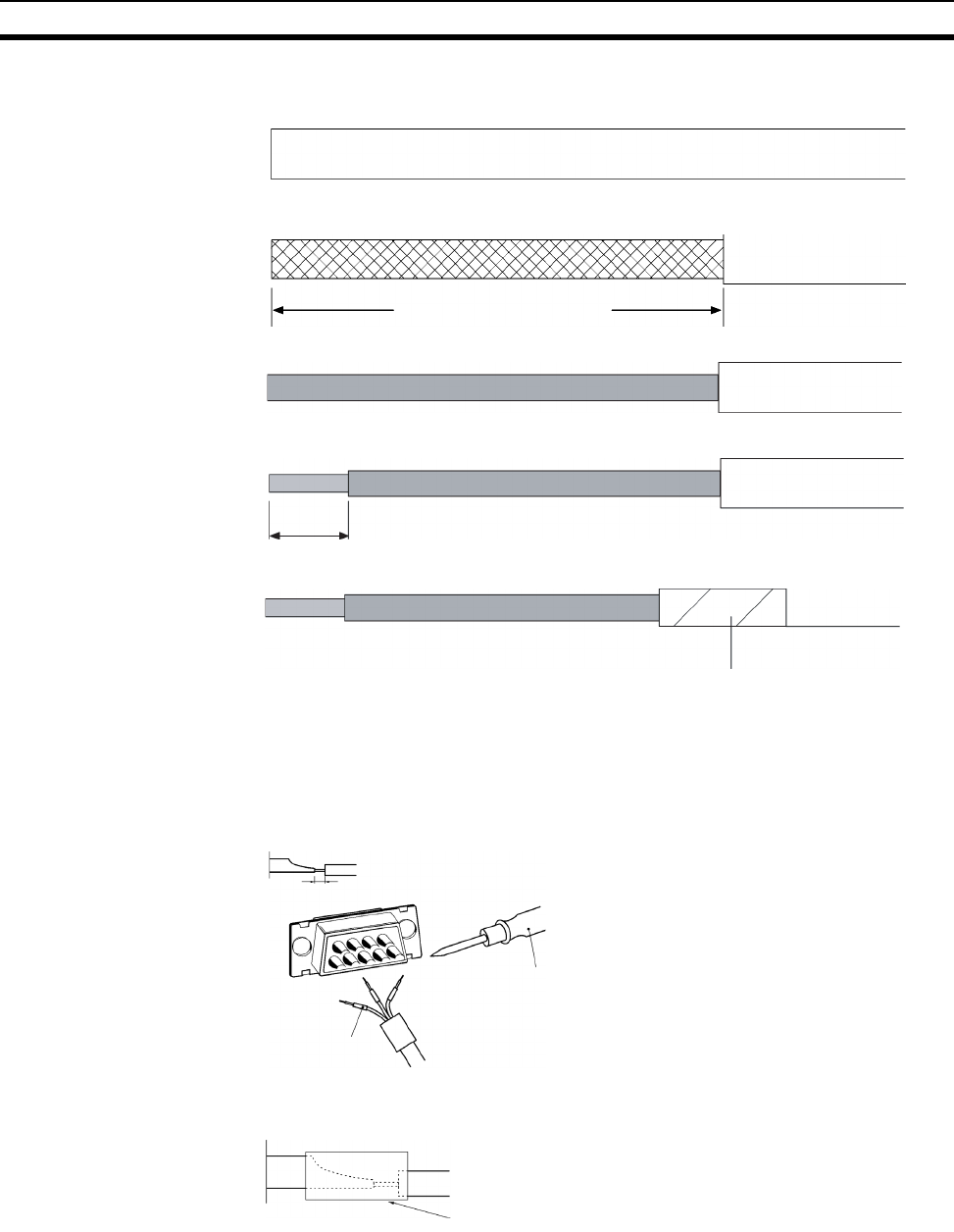
747
Connecting to the RS-232C Port on the CPU Unit Appendix E
2. Soldering
1. Cut the cable to the required length, leaving leeway for wiring and laying the cables.
2. Use a razor blade to cut away the sheath, being careful not to damage the braiding.
3. Use scissors to cut away the exposed braiding.
4. Use wire strippers to remove the insulation from the end of each wire.
5. Wrap electrician's tape over the top and end of the cut sheath.
Not Connecting the Shield to the Hood (FG)
Electrician's tape
40 mm (RS-232C)
5 mm
Heat-shrinkin
g
tube
1. Place heat-shrinking tubes over all wires.
2. Pre-solder all wires and connector terminals.
3. Solder the wires.
4. Move the heat-shrinking tubes onto the soldered area and shrink them into place.
1 mm
Soldering iron
Heat-shrinking tube
(inner dia. 1.5, l = 10)
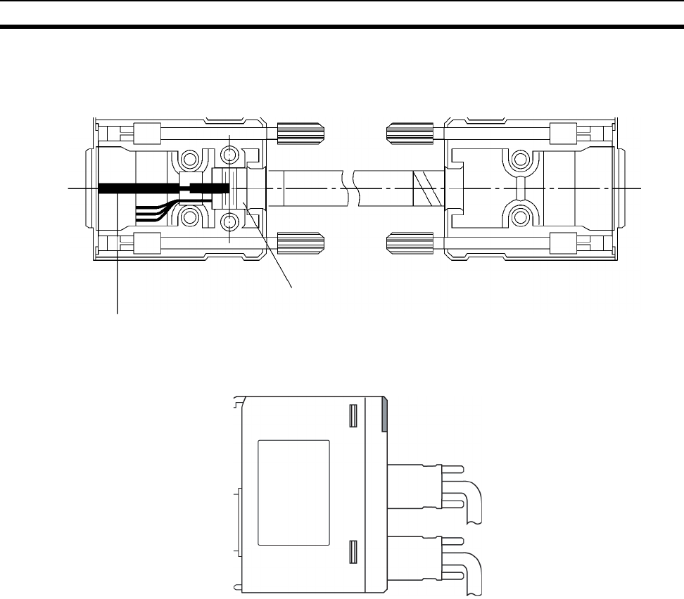
748
Connecting to the RS-232C Port on the CPU Unit Appendix E
3. Assembling the Hood
4. Connection to the CPU Unit
• Always turn OFF the power supply to the PLC before connecting or disconnecting communications cables.
• Tighten the communications connector attachment screws to 0.4 N·m.
Assemble the connector hood as shown.
FG Connection No FG Connection
Aluminum foil tape
Ground plate
Tighten the screws firmly.

749
Appendix F
Restrictions in Using C200H Special
I/O Units
Restrictions in Areas and Addresses
There are restrictions in transferring I/O memory data between C200H Special I/O Units and the CPU Unit. The
restrictions on the Unit depend on the group in which the Unit belongs. The five groups are shown in the follow-
ing tables.
Units that Transfer data
for Programming Inside
the Unit Itself
Units that Transfer data
for Allocated Words
Units that Do Not Transfer
data for Programming or
Allocated Words
If any of the above Units in groups I to IV are used in combination with the following functionality, the restric-
tions described in the rest of this section apply for area and address specifications.
• Data transfers with the CPU Unit from instructions (PLC READ, PLC WRITE, etc.) in the program executed
by the C200H Special I/O Unit. This applies to the ASCII Units only.
• Data transfers with the CPU Unit for allocated words or DM area specifications (i.e., source/destination
areas and addresses).
Note There are no restriction in using the IORD(222) and IOWR(223) instruction in the CPU Unit to transfer
data. These instruction can thus be used in the CPU Unit to transfer data for Units that support data
transfer for IORD(222) and IOWR(223), i.e., C200H-CT021, C200H-MC221, and C200H-ASC11/
ASC21/ASC31.
Group Models
Group I C200H-ASC02 ASCII Unit
Group II C200H-ASC11/21/31 ASCII Units
Group Models
Group III C200H-CT001-V1/CT002 High-speed Counter Units, C200H-IDS01-
V1/ IDS21 ID Sensor Units, C200H-NC111/NC112/NC211 Position
Control Units, C200H-FZ001 Fuzzy Logic Unit
Group IV C200H-CT021 High-speed Counter Unit, C200H-MC221 Motion Con-
trol Unit, C200H-DRT21 C200H I/O LInk Unit, C200HW-NC113/NC213/
NC413 Position Control Units
Group Models
Group V C200H-TS001/TS002/TS101/TS102 Temperature Sensor Units,
C200H-TC001/TC002/TC003/TC101/TC102/TC103 Temperature Con-
troller Units, C200H-PID01/PID02/PID03 PID Control Units, C200H-
TV001/TV002/TV003/TV101/TV102/TV103 Heating/Cooling Units,
C200H-OV001 Voice Unit, C200H-ID501/ID215 High-density Input
Units, C200H-OD501/OD215 High-density Output Units, C200H-
MD501/MD215/MD115 High-density I/O Units, C200HW-SRM21 Com-
poBus/S Master Unit, C200H-AD001/AD002/AD003 Analog Input
Units, C200H-DA001/DA002/DA003/DA004 Analog Output Units,
C200H-MAD01 Analog I/O Unit, C200HW-DRM21-V1 DeviceNet Mas-
ter Unit, C200H-CP114 Cam Positioner Unit, T200H-MIF01 M-Net
Interface Unit

750
Restrictions in Using C200H Special I/O Units Appendix F
Restrictions in Using Existing ASCII Unit Programs
The following replacements in areas and addresses will be made if existing
ASCII Unit programs are used.
For most addresses, a zero (0) will simply be added as the most significant
digit. The following four exceptions exist.
1,2,3... 1. AR 00, AR02 to AR 27 (C200H AR Area words) will specify H100, H102 to
H127 in the CS-series CPU Unit.
2. TIM 000 to TIM 511 and CNT 000 to CNT 511 (C200H Timer/Counter Area
words) will specify T0000 to T0511 in the CS-series CPU Unit.
3. LR 00 to LR 63 (C200H LR Area words) will specify CIO 1000 to CIO 1063
in the CS-series CPU Unit.
4. AR 01 and CIO 281 cannot be specified. Use other addresses.
Corresponding Addresses for C200H-ASC02 (Group I)
Corresponding Addresses for C200H-ASC11/ASC21/ASC31 (Group II)
Area/Address specifications in a C200H CPU Unit Areas/Addresses in a CS-series CPU Unit
Code Area Addresses Area Address
@R IR 000 to 255 CIO 000 to 0255
@L LR LR 00 to LR 63 CIO 1000 to 1063
@H HR HR 00 to HR 99 Holding H000 to H099
@A AR AR 00 Holding H100
AR01 Cannot be accessed. Use another address.
AR02 to AR27 Holding H102 to H127
@G Timer/Counter TIM/CNT 000 to TIM/CNT 511 Timer/Counter T0000 to T0511
@D DM DM 0000 to DM 0999 DM D00000 to D00999
DM 0000 to DM 1999 D20000 to D20999
Area/Address specifications in a C200H CPU Unit Areas/Addresses in a CS-series CPU Unit
Code Area Addresses Area Address
@R IR 000 to 280 CIO 0000 to 0280
281 Cannot be accessed. Use another address.
282 to 511 CIO 0282 to 0511
@L LR LR 00 to LR 63 CIO 1000 to 1063
@H HR HR 00 to HR 99 Holding H000 to H099
@A AR AR 00 Holding H100
AR 01 Cannot be accessed. Use another address.
AR 02 to AR 27 Holding H102 to H127
@G Timer/Counter TIM/CNT 000 to TIM/CNT 511 Timer T0000 to T0511
@D DM DM 0000 to DM 6655 DM D00000 to D6655
@E EM EM 0000 to EM 6143 EM E0_00000 to E0_06143

751
Restrictions in Using C200H Special I/O Units Appendix F
Restrictions in Programming C200H Special I/O Units for the CS Series
(Groups I to IV)
There following restrictions in area and address specifications exist in pro-
gramming inside C200H Special I/O Units (i.e., ASCII Unit) or in specifying
C200H Special I/O Unit allocations for the CS-series CPU Unit.
1,2,3... 1. CIO 0256 to CIO 0999 cannot be specified for Units in Group I or III, CIO
0281, 0512 to CIO 0999 cannot be specified for Units in Group II or IV, and
CIO 1064 to CIO 6143 cannot be specified.
2. Addresses in the Work Area (W000 to W511) cannot be specified.
3. H101 and H128 to H511 cannot be specified, and H100, H102 to H127
must be specified using AR 00, AR02 to AR 27.
4. Timers T0512 to T4095 cannot be specified.
5. Counters (C0000 to C4095) cannot be specified.
6. D01000 to D19999 and D21000 to D32767 in Group I or III D06656 to
D32767 in Group II or IV cannot be specified.
Note If D1000 to D1999 are specified in a C200H Special I/O Unit for data
transfer, the CS Series will interpret them as D20000 to D20999. Do
not use D1000 to D1999.
7. E0_06144 to E0_32767 (bank 0) and E@_00000 to E@_32767 in all banks
except bank 0 cannot be specified.
Special I/O Units in Groups I and III
Area/Address specifications in CS-series CPU Unit Areas/Addresses to use in C200H Special I/O Unit
Area Addresses Area Address
CIO 0000 to 0255 IR 000 to 255
0256 to 0999 Not addressable.
CIO 1000 to 1063 LR LR 00 to LR 63
CIO 1064 to 6143 IR Not addressable.
Work W000 to W511 None ---
Auxiliary A000 to A959 None ---
Holding H000 to H099 HR HR 00 to HR 99
H100 AR AR 00
H101 AR Not addressable.
H102 to H127 AR AR 02 to AR 27
H128 to H511 None ---
Timer T0000 to T0511 Timer/Counter TIM/CNT 000 to TIM/CNT 511
T0512 to Y4095 Not addressable.
Counter C0000 to C4095 Not addressable.
DM D00000 to D00999 DM DM0000 to DM 0999
D06656 to D19999 Not addressable.
D20000 to D20999 DM1000 to DM1999
D21000 to D32767 Not addressable.
EM E0_00000 to E0_32767 None ---
E1_00000 to EC_32767 ---
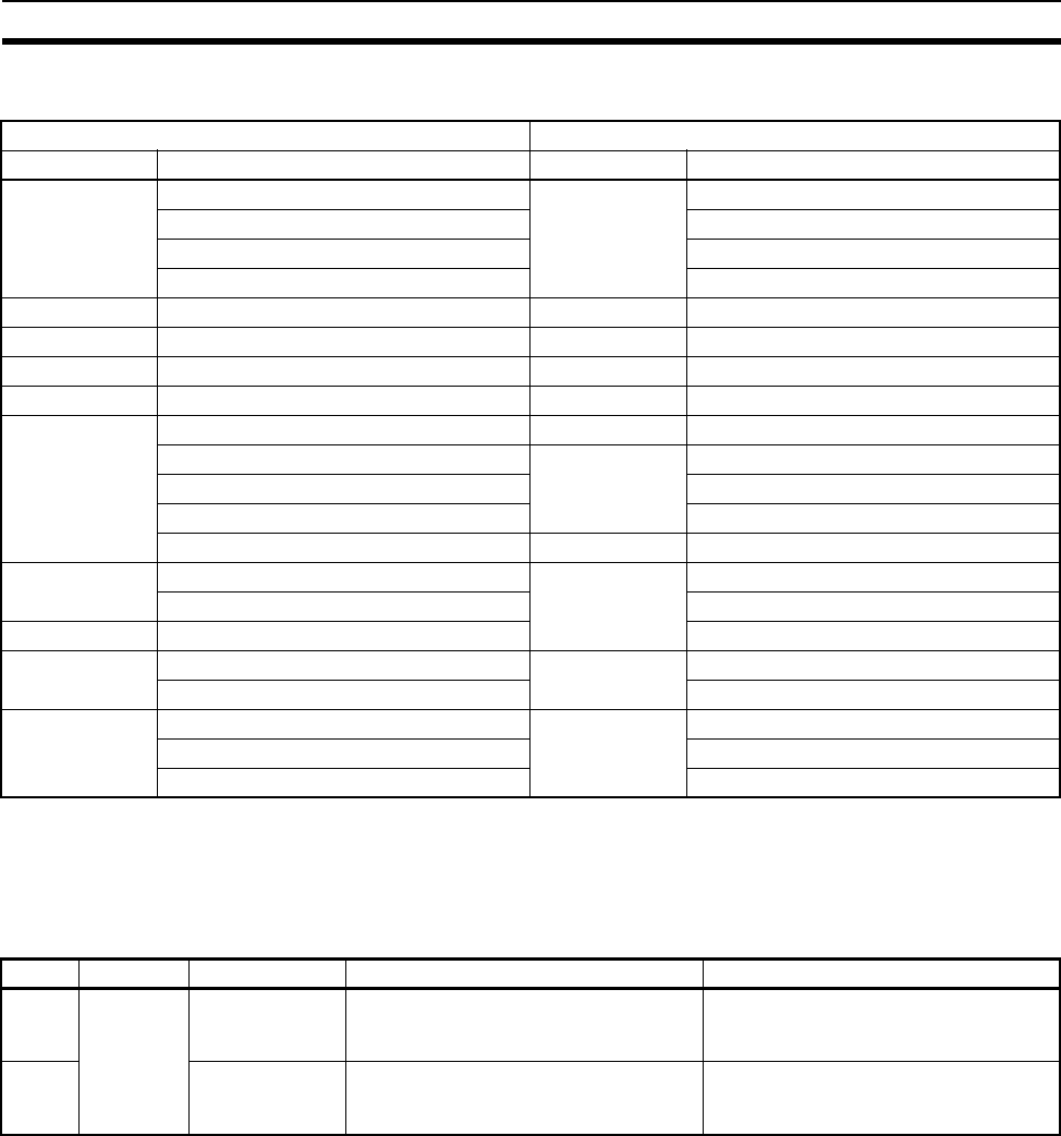
752
Restrictions in Using C200H Special I/O Units Appendix F
Special I/O Units in Groups II and IV
Functions with Addressing Restrictions
Restrictions apply to the following functions.
ASCII Units
Area/Address specifications in CS-series CPU Unit Areas/Addresses to use in C200H Special I/O Unit
Area Addresses Area Address
CIO 0000 to 0280 IR 000 to 280
0281 Not addressable.
0282 to 0511 282 to 511
0512to 0999 Not addressable.
CIO 1000 to 1063 LR LR 00 to LR 63
CIO 1064 to 6143 IR Not addressable.
Work W000 to W511 None ---
Auxiliary A000 to A959 None ---
Holding H000 to H099 HR HR 00 to HR 99
H100 AR AR 00
H101 Not addressable.
H102 to H127 AR 02 to AR 27
H128 to H511 None ---
Timer T0000 to Y0511 Timer/Counter TIM/CNT 000 to TIM/CNT 511
T0512 to Y4095 Not addressable.
Counter C0000 to C4095 Not addressable.
DM D00000 to D06655 DM DM0000 to DM 6655
D06656 to D32767 Not addressable.
EM E0_00000 to E0_06143 EM EM0000 to EM6143
E0_06144 to E0_32767 Not addressable.
E1_00000 to EC_32767 Not addressable.
Group Unit Model Function with restricted addressing Alternative
I ASCII
Units
C200H-ASC02 Areas and addresses in read/write
operands for PLC READ, PLC WRITE,
PLC READ@ and PLC WRITE@.
Write to available addresses and then
transfer to the desired locations. (See
the note following the next table.)
II C200H-ASC11/
ASC21/ASC31
Areas and addresses in read/write
operands for PLC READ, PLC WRITE,
PLC READ@, PLC WRITE@
Use IORD(222) and IOWR(223)
(#00@@).
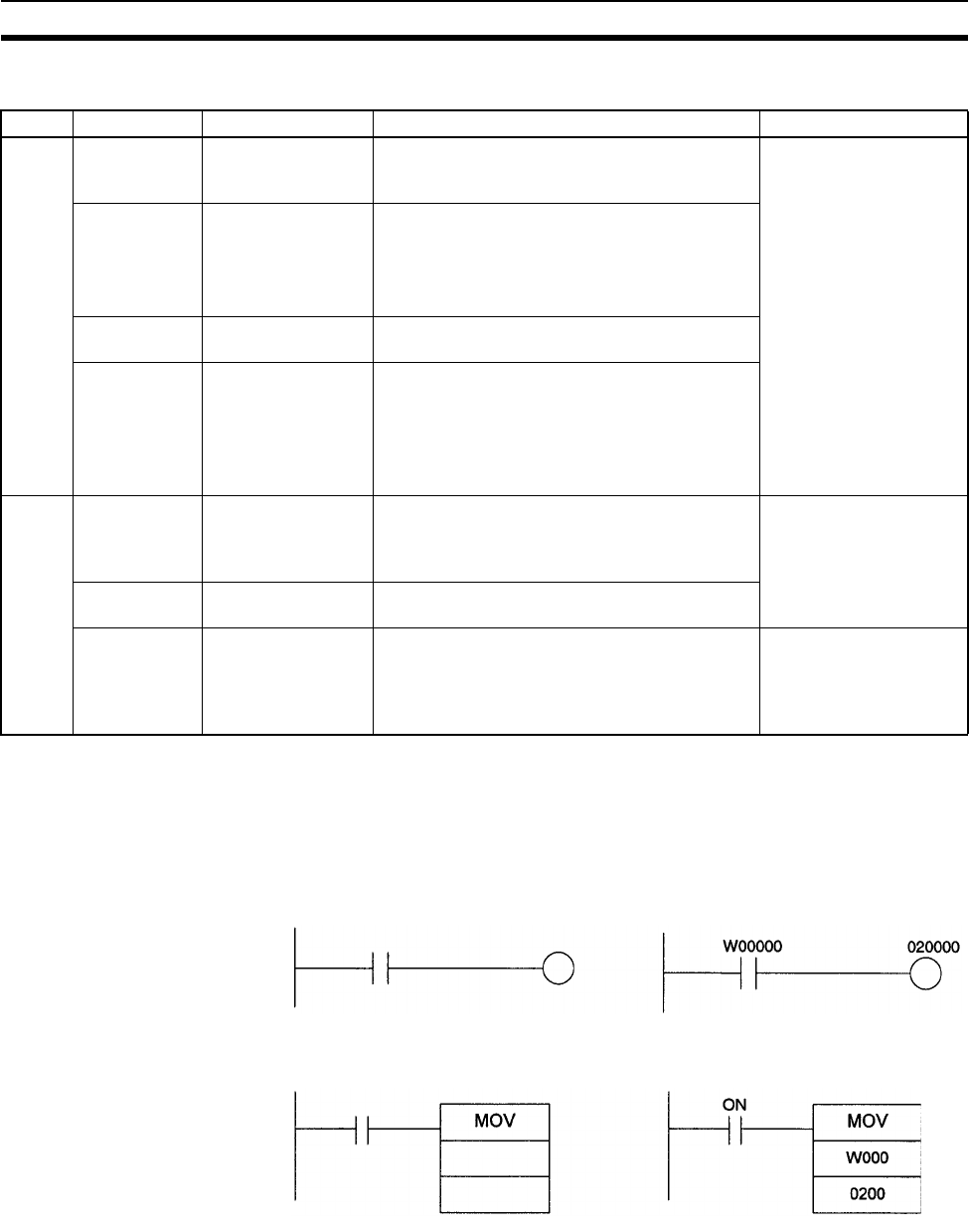
753
Restrictions in Using C200H Special I/O Units Appendix F
Other C200H Special I/O Units
Note Examples of the alternative method are shown below.
Reading CPU Unit Data
from a Special I/O Unit
Write the data from the unsupported address to a supported address and
then read the data from the supported address to the Special I/O Unit.
• Bit Data
•Word Data
Group Unit Model Function with restricted addressing Alternative
III High-speed
Counter Units
C200H-CT001-V1/
CT002
Setting the source areas and addresses in allo-
cated words n+2 and n+3 for transferring words
m to m+99 (high-speed counter system data).
Write to available
addresses and then
transfer to the desired
locations. (See note.)
ID Sensor
Units
C200H-IDS01-V1/
IDS21
Setting the source areas and addresses in allo-
cated word n+2 for command data.
Setting the destination areas and addresses in
allocated word n+3 for storing data read from
Data Carriers.
Position Con-
trol Units
C200H-NC111/
NC112/NC211
Setting the source areas and addresses in allo-
cated word n+4 for position data and speeds.
Fuzzy Logic
Unit
C200H-FZ001 Setting the source areas and addresses in allo-
cated word n+1 for fuzzy input write data to be
transferred to the Fuzzy Logic Unit.
Setting the destination areas and addresses in
allocated word n+3 for fuzzy logic results data
to be read from the Fuzzy Logic Unit.
IV High-speed
Counter Unit
C200H-CT021 Setting the source areas and addresses in allo-
cated word m+4 for upper/lower limits, present
values, and other data to be transferred to the
High-speed Counter Unit.
Use IORD(222) and
IOWR(223).
Motion Con-
trol Unit
C200H-MC221 Setting the source/destination areas and
addresses for expansion information.
C200H I/O
Link Unit
C200HW-DRT21 Setting the areas and addresses in allocated
words n+1 to n+4 in the CPU Unit for automatic
transfer of I/O memory of the CPU Unit to which
the C200H I/O Link Unit is mounted to the
DeviceNet Master Unit.
Write to available
addresses and then
transfer to the desired
locations. (See note.)
Unsupported
Address
Supported
Address
Example
Unsupported
Address
Supported
Address
Example:
Always ON
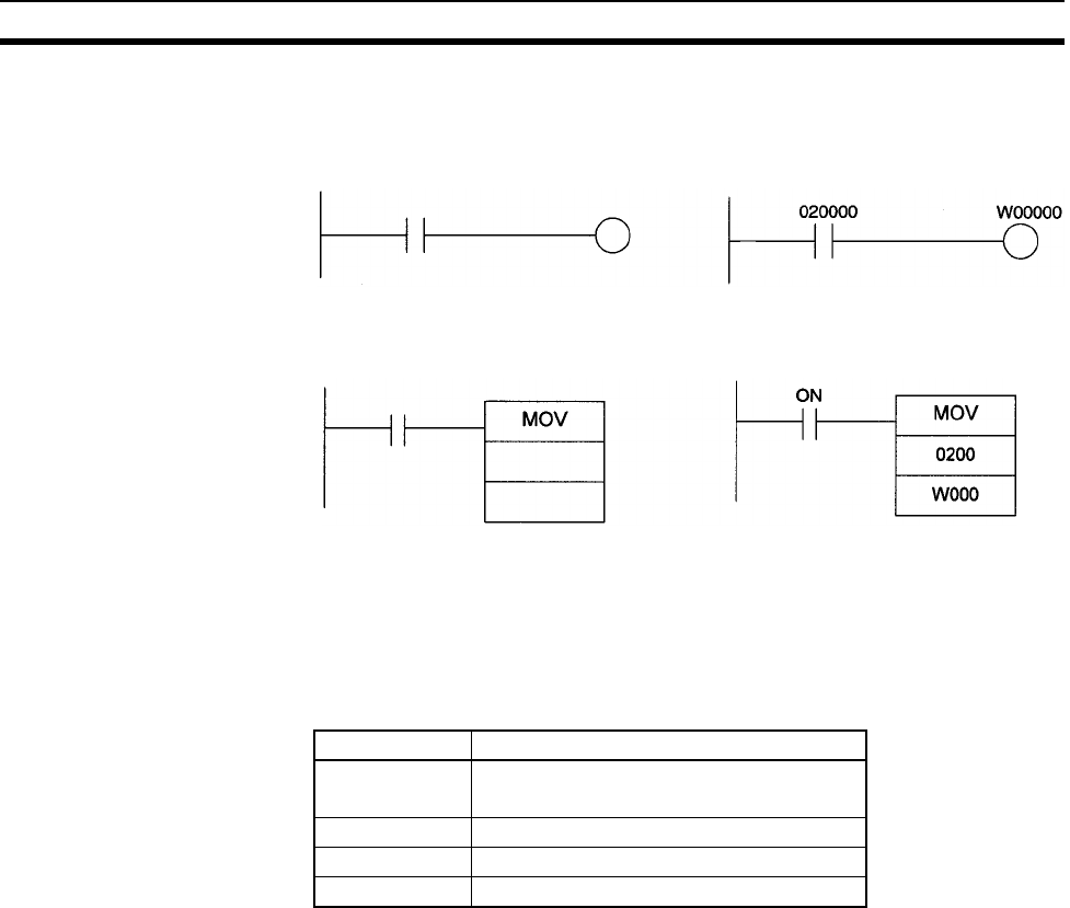
754
Restrictions in Using C200H Special I/O Units Appendix F
Reading Special I/O Unit
Data form the CPU Unit
Read the data from the Special I/O Unit and then write the data from the sup-
ported address to an unsupported address.
• Bit Data
•Word Data
Precautions When Using C200HW-DRM21-V1 DeviceNet Master Unit
When using a DeviceNet Master Unit, limitations apply when using the following functions (except for data
transfer).
Allocation Limitations Only the following areas can be allocated when allocating remote I/O using a
Configurator.
Note 1. When creating master parameters using a configurator, set the PLC model to C200HX/HG/HE(-Z)
(except for the C200HE-CPU11).
2. When reading master parameters from a master using a configurator, set the PLC model to the
C200HX-CPU85.
Limitations when using
DM as the Status Area
When using the DeviceNet Master Unit, the following words will be allocated
in addition to the DM Area words allocated to the Unit as a Special I/O Unit.
Master Status Area: D06032 + (2 × unit number)
Communications cycle time present value: D06033 + (2 × unit number)
Do not use these words for other applications, because data is updated when
the DeviceNet Master Unit is being used.
Unsupported
Address
Supported
Address Example
Unsupported
Address
Supported
Address
Example:
Always ON
Area Allocation words
CIO 0000 to 0235
0300 to 0511
HR H000 to H099
LR 1000 to 1063
DM D00000 to D05999
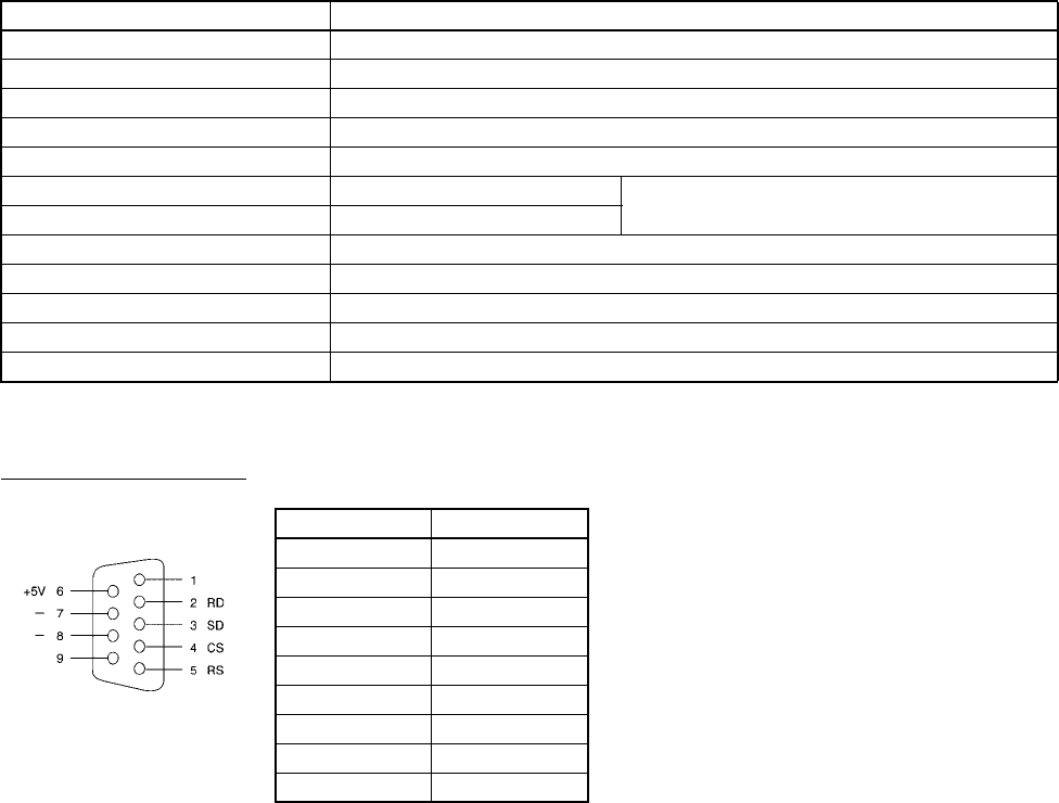
755
Appendix G
CJ1W-CIF11 RS-422A Converter
The CJ1W-CIF11 RS-422A Converter converts RS-232C to RS-422A/485.
Specifications
General Specifications
Electrical Specifications
RS-232C Connector
Note The hood will have the same electrical potential as the connector on the other end of the cable.
Item Specification
Dimensions 18.2 × 34.0 × 38.8 (W × H × D)
Weight 20 g max.
Ambient operating temperature 0 to 55°C
Ambient storage temperature –20 to 75°C
Ambient operating humidity 10% to 90% (with no condensation)
Rated power supply voltage 5 V (Supplied from pin 6 of the RS-232C connector.)
Current consumption 40 mA max.
Operating atmosphere No corrosive gases
Vibration resistance Same as SYSMAC CS/CJ Series.
Shock resistance Same as SYSMAC CS/CJ Series.
Isolation method Not isolated
Maximum communications distance 50 m
Connector Pin Arrangement for
RS-232C Port
FG
SG (0 V)
Pin number Signal
1FG
2RD
3SD
4CS
5RS
6+5V
7, 8 NC
9SG (0 V)
Hood FG
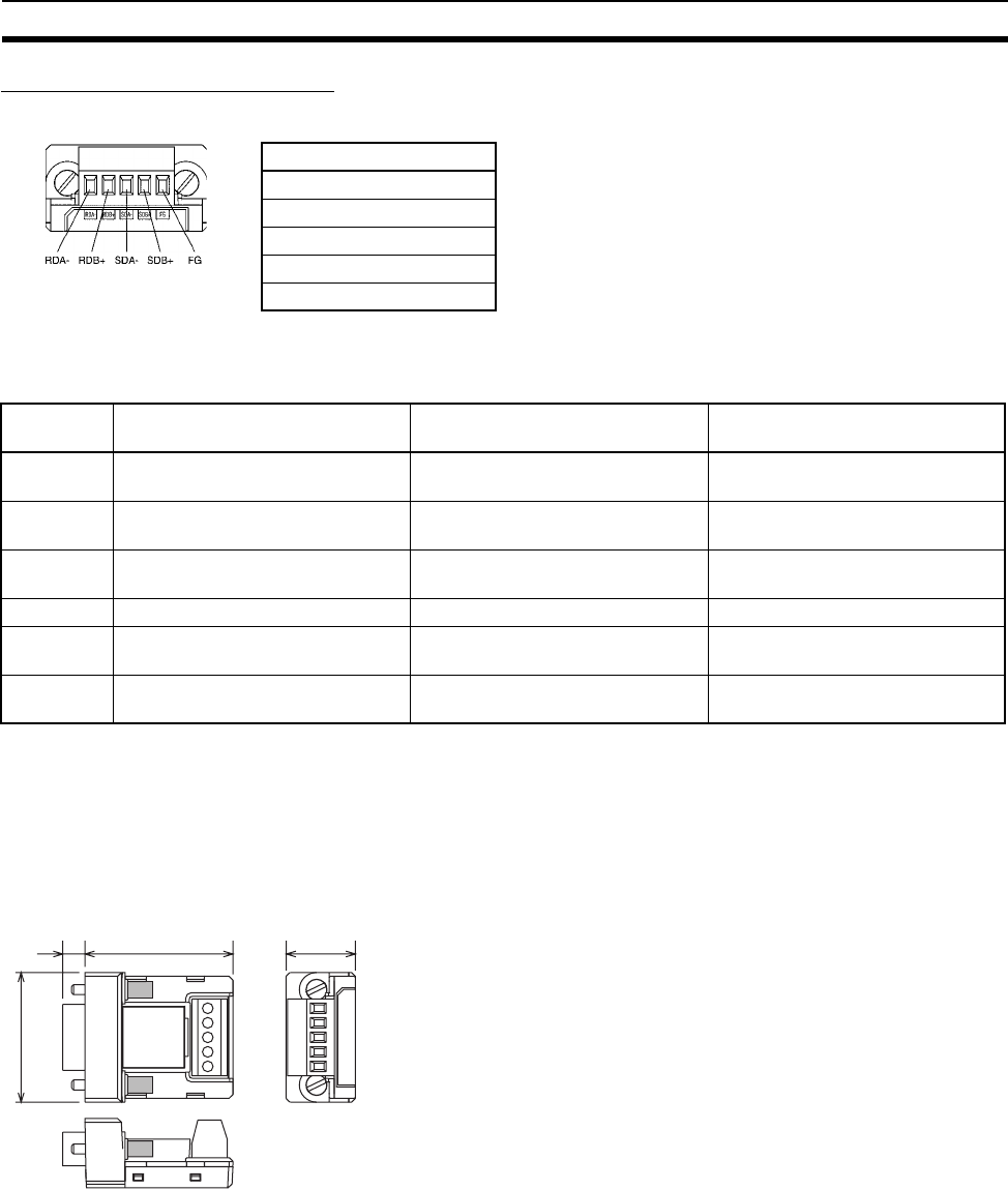
756
CJ1W-CIF11 RS-422A Converter Appendix G
RS-422A/485 Terminal Block
DIP Switch Settings
Note 1. Set pins 2 and 3 to the same setting. (ON for the two-wire method or OFF for the four-wire method.)
2. To prohibit echoback, set pin 5 to ON (with RS control).
3. When connecting to several devices using the four-wire method in a 1:N connection, set pin 6 to ON
(with RS control). When connecting using the two-wire method, set pin 6 to ON (with RS control).
Dimensions
Pin
number
Function ON OFF
1 Terminating resistance With (at both ends of the commu-
nications path)
Without
2 Two-wire/four-wire method selec-
tion (See note 1.)
Two-wire method Four-wire method
3 Two-wire/four-wire method selec-
tion (See note 1.)
Two-wire method Four-wire method
4 Not used. --- ---
5 Selection of RS control for RD
(See note 2.)
With RS control Without RS control (always ready
to receive)
6 Selection of RS control for SD
(See note 3.)
With RS control Without RS control (always ready
to send)
Signal
RDA–
RDB+
SDA–
SDB+
FG
38.8 18.2
5.8
34.0
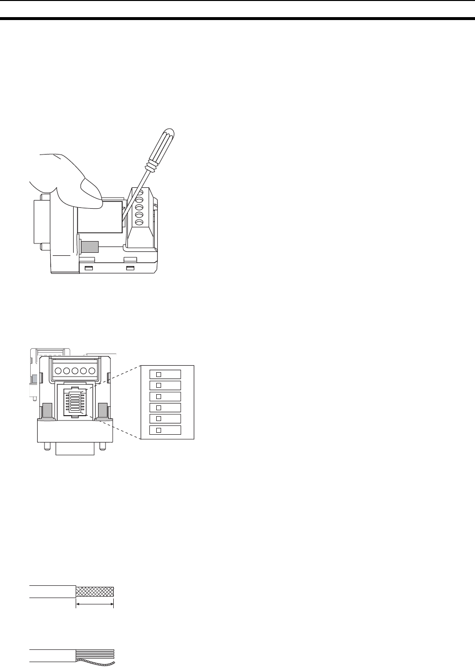
757
CJ1W-CIF11 RS-422A Converter Appendix G
DIP Switch Settings, Wiring, and Installation
Setting the DIP Switch
The DIP switch settings must be changed to perform communications according to settings other than the
default settings.
1. Remove the DIP switch cover using a flat-bladed screwdriver in the way shown below.
Note Press the cover gently while removing it to prevent it from popping out suddenly.
2. Using a fine pair of tweezers or other tool with a fine point, change the settings of the DIP switch pins to
match the desired communications conditions.
3. Be sure to remount the cover after finishing the DIP switch settings.
All the pins are factory-set to OFF.
Wiring the RS-422A/485 Terminal Block
• Use either two-wire or four-wire shielded cable.
Recommended cable: CO-HC-ESV-3P×7/0.2 (Hirakawa Hewtech)
• Connect the shield wire at both ends of the cable carrying RS-422A/485 signals to ground, and ground the
ground terminal on the Power Supply Unit of the CPU or Expansion Rack to 100 Ω max.
1. Taking care not to damage the shield, strip between 30 and 80 mm of sheath off the end of the cable.
2. Carefully twist the shield mesh together to form a single wire, and carefully cut off the material surrounding
the signal wires and any unnecessary signal wires.
1
2
3
4
5
6
O
N
O
N
30 to 80 mm
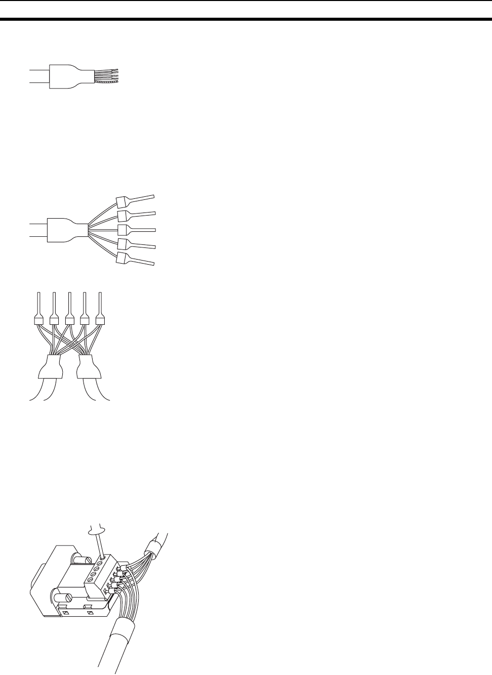
758
CJ1W-CIF11 RS-422A Converter Appendix G
3. Strip the sheath off the signal wires to a length sufficient to attach crimp terminals. Apply vinyl tape or heat-
shrinking tube to the sheathes and stripped parts of communications lines.
4. Attach sticktype crimp terminals to ends of the signal lines and crimp them using a crimp tool.
• Recommend crimp terminals:
Phoenix Contact
AI Series
AI-0.5-8WH-B (serial number: 3201369)
• Recommended crimp tool:
Phoenix Contact ZA3
With four-wire cables, insert two signal lines into each crimp terminal together before crimping.
• Recommend crimp terminals:
Phoenix Contact
AI Series
AI-TWIN2×0.5-8WH (serial number: 3200933)
• Recommended crimp tool:
Phoenix Contact
UD6 (serial number: 1204436)
5. Connect the signal lines and the shield line to the RS-422A/485 terminal block.
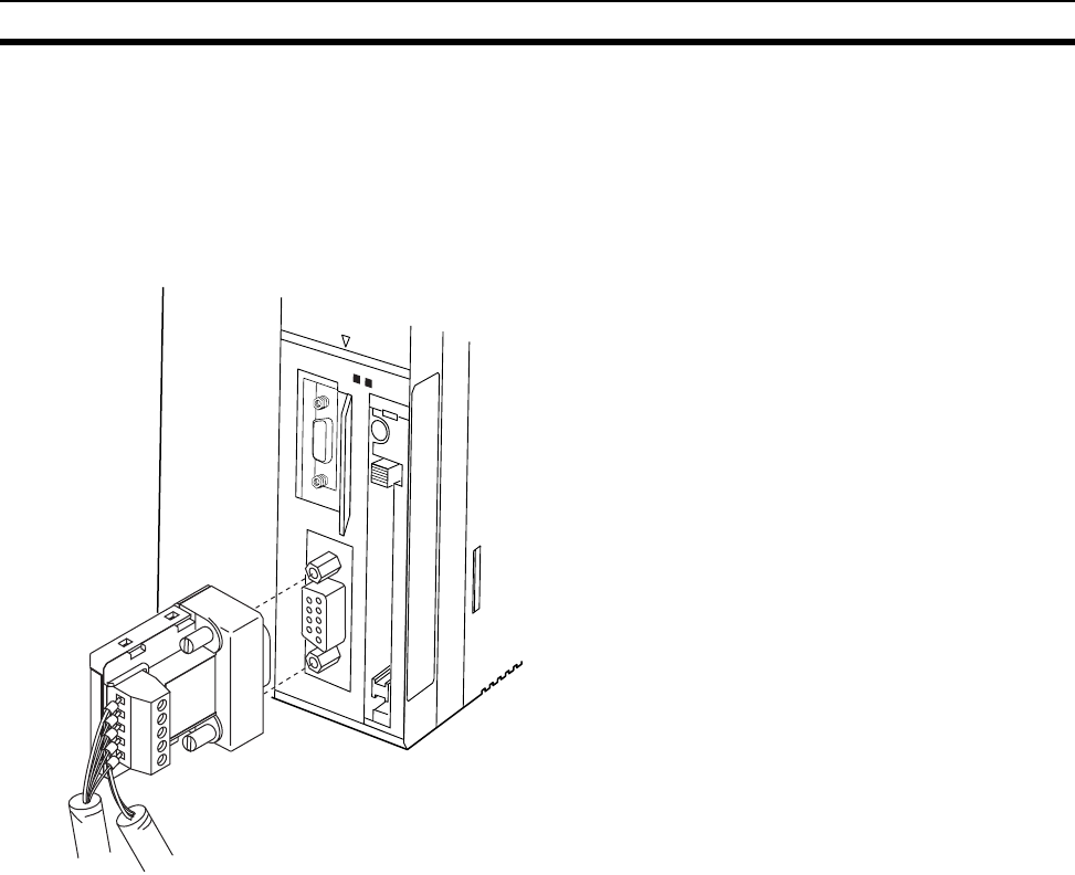
759
CJ1W-CIF11 RS-422A Converter Appendix G
Mounting to the Unit
Mount the Converter to the RS-232C port (D-Sub, 9-pin) of the Unit to be connected in the following way.
1. Align the Converter’s connector with that of the Unit and push it into the Unit’s connector as far as possible.
2. Tighten the mounting screws on either side of the Converter. (Tightening torque: 0.3 N⋅m.)
As an example, connection to a CS1-H CPU Unit is shown below.
OPEN
PERIPHERAL
PORT
BUSYMCPWR
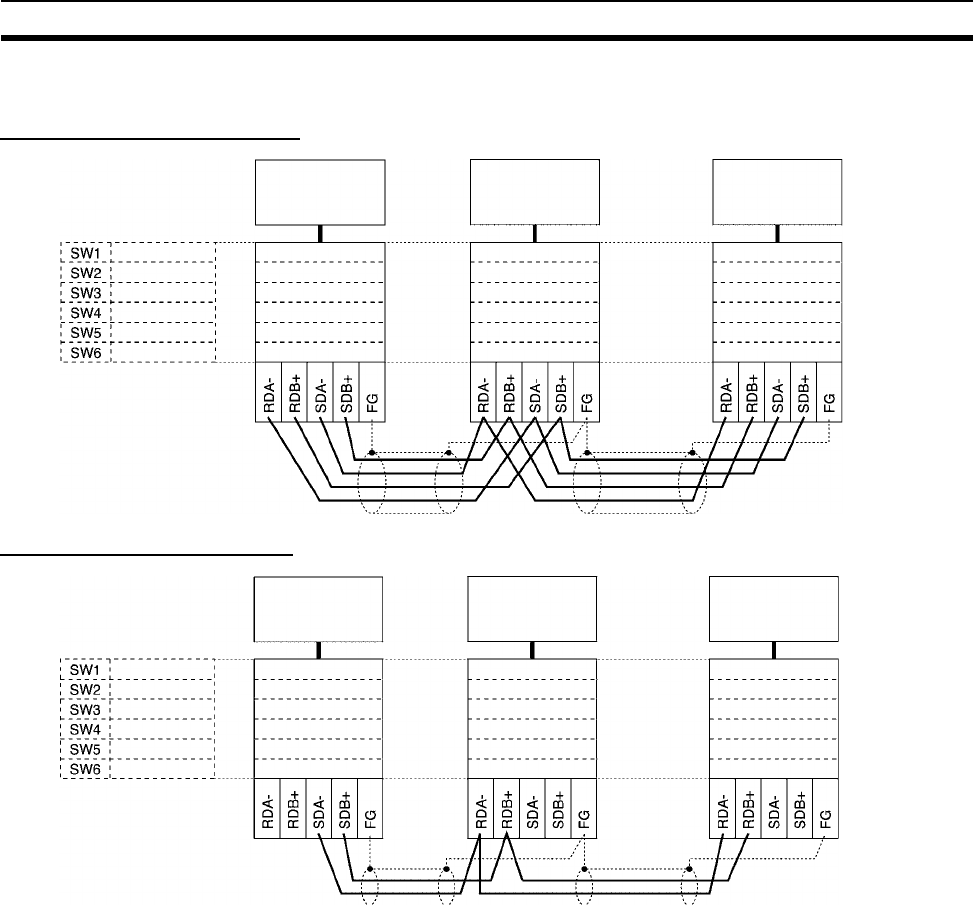
760
CJ1W-CIF11 RS-422A Converter Appendix G
Wiring Examples
Wiring for Four-wire Cable
Wiring for Two-wire Cable
DIP Switch Settings
Terminating resistance
Two-wire/four-wire
Not used.
RD control
SD control
ON (with)
OFF (four-wire)
OFF (four-wire)
OFF
OFF (without)
OFF (without)
OFF (without)
OFF (four-wire)
OFF (four-wire)
OFF
OFF (without)
ON (with)
ON (with)
OFF (four-wire)
OFF (four-wire)
OFF
OFF (without)
ON (with)
Two-wire/four-wire
CS1-H CPU
Unit (master)
CS1-H CPU
Unit (slave 0)
CS1-H CPU
Unit (slave 1)
DIP Switch Settings
Terminating resistance
Two-wire/four-wire
Not used.
RD control
SD control
ON (with)
ON (two-wire)
ON (two-wire)
OFF
OFF (without)
ON (with)
OFF (without)
ON (two-wire)
ON (two-wire)
OFF
OFF (without)
ON (with)
ON (with)
ON (two-wire)
ON (two-wire)
OFF
OFF (without)
ON (with)
Two-wire/four-wire
CS1-H CPU
Unit (master)
CS1-H CPU
Unit (slave 0)
CS1-H CPU
Unit (slave 1)
761
Index
Numerics
24-V DC output power, 302
26-V power supply, 146
A
Access Error Flag, 464
addresses
memory map, 727
allocations
See also I/O allocations
Always OFF Flag, 464
Always ON Flag, 464
Analog Timer Units, 256
dimensions, 259
specifications, 111, 258
applications
precautions, xxxi
arc killers, 612
Auxiliary Area, 425, 691
read/write section, 712–721
read-only section, 691–711
B
B7A Link Terminals, 248
background execution
special flags, 447
background execution settings, 336
Backplane Insulation Plates, 286
Backplanes, 197
Basic I/O Units, 84
available models, 207
basic I/O errors, 543
components, 209
dimensions, 211
error information, 435
fuse status flags, 426, 691
I/O allocations, 375
I/O response time, 357, 426, 499, 695
mounting, 286
specifications, 105, 572–597
wiring, 310
battery
Battery Set, 91
compartment, 161
error, 544
error flag, 439, 704
low battery error detection, 334, 360
replacement, 560, 562
service life, 560
Battery Error Flag, 704
battery-free operation, 16
block programs
instruction execution times, 522
BUSY indicator, 82
C
C200H Expansion I/O Backplanes, 99
C200H High-density I/O Units, 225
C200H Special I/O Units
restrictions on data transfers, 749
C200H-PRO27-E Programming Console, 175
C200HX/HG/HE PLCs
comparison, 62
cables, 91–93, 96, 98–100, 102–103, 290, 316
connections, 294
See also I/O Connecting Cables
Carry Flag, 464
CIO Area, 398
description, 405
circuit configurations
See also specifications
CJ Series
definition, xix
clock
clock data, 439, 700
clock instructions
execution times, 521
clock pulses
flags, 466
communications, 58
baud rate, 350
Communications Port Enabled Flags, 724
data, 85
distances, 136
errors, 545
flags, 443
instruction execution times, 520
network instruction execution times, 520
networks, 132
overview, 135
protocol support, 120
serial communications, 5
specifications, 136
system expansion, 119
Communications Port Enabled Flags, 724
comparison instructions
execution times, 508
compatibility with previous PLCs, 16
CompoBus/S, 134
components
Analog Timer Unit, 257
Basic I/O Units, 209
C200H Expansion I/O Backplanes, 202
C200H High-density Units, 225
CPU Backplane, 197
CPU Unit, 81, 156

762
Index
CS-series Expansion Backplane, 200
Group-2 High-density I/O Units, 223
Power Supply Units, 184
Condition Flags, 463
saving and loading status, 465
connectors, 313
connector pin arrangement, 180
RS-232C connectors, 746
contact protection circuit, 613
control panels
installation, 282
Controller Link, 133
conversion instructions
execution times, 513
cooling
fan, 280
Counter Area, 450
counters
execution times, 506
CPU Backplanes, 197
dimensions, 198
CPU Bus Unit Area
capacity, 148
CPU Bus Units, 84
data exchange, 391
error information, 437
errors, 544
I/O allocations, 381, 417, 452
Initialization Flags, 427, 698
memory area, 417
mounting, 286
refreshing, 14, 391
related flags/bits, 725
Restart Bits, 427, 712
setting area capacity, 148
settings, 468
setup errors, 545
specifications, 118
CPU Racks
description, 89
maximum current consumption, 137
troubleshooting, 553
CPU Unit, 156
capabilities, 84
components, 81, 156
connections, 85
CPU errors, 536
dimensions, 163
DIP switch, 82, 158, 326
indicators, 82
initialization, 477
operation, 473
RS-232C port connections, 741
CPU Units
models, 156
CQM1-PRO01-E Programming Console, 174
CS Series
definition, xix
CS1 CPU Units, 70
CS1-H CPU Unit
features, 13
CS1-H CPU Units, 70, 156
functions, 60
new instructions, 15
CS-series Basic I/O Units
wiring, 312
CS-series CPU Bus Unit Area, 417
CS-series CPU Bus Units
See also CPU Bus Units
CS-series Expansion Backplanes
See also Expansion Backplanes
CS-series High-density I/O Units, 220
current consumption, 137
tables, 140
CX-Programmer, 175, 267
peripheral servicing, 475
cycle time
computing, 485–503
effects of online editing, 499
errors, 542
example calculations, 498
flags, 427
maximum cycle time, 428, 696
present cycle time, 428, 696
setting, 338, 364
Cycle Time Too Long Flag, 439, 703
D
data areas
forcing bit status, 403
overview, 398
status after fatal errors, 403
status after mode changes, 404
status after power interruptions, 404
data control instructions
execution times, 517
Data Link Area, 416
data links, 416
data movement instructions
execution times, 509
Data Registers, 461
data registers
sharing, 14, 403, 428, 462
data shift instructions
execution times, 509
data tracing
related flags/bits, 429
debugging, 274

Index
763
flags, 429
debugging instructions
execution times, 521
decrement instructions
execution times, 510
DeviceNet, 133
See also DeviceNet
DeviceNet Area, 411–412
dimensions, 255
Analog Timer Unit, 259
B7A Interface Unit, 244
Backplane Insulation Plates, 286
Backplanes, 198
Basic I/O Units, 211
C200H Expansion I/O Backplanes, 202
C200H High-density I/O Units, 230
CPU Racks, 80
CPU Unit, 163
CS-series High-density I/O Units, 222
Group-2 High-density I/O Units, 224
installation, 285
Memory Cards, 170
Power Supply Units, 186
DIN track
mounting, 288
DIP switch, 158, 326
display instructions
execution times, 521
DM Area, 451
changing settings, 271
settings, 262
DR00 Output for Background Execution, 447
ducts
wiring, 283
Dynamic Input Mode, 228
Dynamic Output Mode, 227
E
EC Directives, xxxvi
electrical noise, 323
EM Area, 453
current EM bank, 725
EM bank
current EM bank, 725
EM file memory, 163, 454
initializing, 166
PC Setup settings, 335, 360
starting bank, 700
emergency stop circuit, 278
environmental conditions
checking, 551
Equals Flag, 464
Equals Flag for Background Execution, 447
ER/AER Flag for Background Execution, 447
error codes, 702, 723
Error Flag, 464
error log, 530–531, 722
Error Log Area, 433, 530, 693, 722
error messages, 536
errors
basic I/O errors, 447
communications error flags, 443
CPU Bus Units, 437
CPU Rack, 553
CPU standby errors, 537
error codes, 702, 723
error log, 10, 433, 530–531, 722
error messages, 536
Programming Consoles, 535
Expansion I/O Rack, 553
FAL/FALS flags, 434
fatal errors, 537
flags, 464
flash memory, 434
Inner Boards, 447
Input Units, 554
memory error flags, 434
non-fatal, 543
Output Units, 555
PC Setup errors, 447
peripheral service time too long, 439
programming error flags, 447
settings, 335
Special I/O Units, 447
status after fatal errors, 403
SYSMAC Bus, 438
troubleshooting, 529, 531–551
user-programmed errors, 530
Ethernet, 133
execution settings, 333
execution times, 503–526
Expansion Backplanes, 99, 199
Expansion I/O Backplanes, 99, 201
Expansion I/O Racks
troubleshooting, 553
Expansion Racks
description, 94
maximum current consumption, 137
maximum number allowed, 98
external interrupts
response time, 503
F
fail-safe circuits, 278
failure diagnosis instructions
execution times, 522
FAL Error Flag, 434

764
Index
FAL errors, 543
flag, 706
FAL/FALS Number for System Error Simulation, 434
FALS Error Flag, 434
FALS errors, 542
flag, 702
fatal errors, 537
fatal operating errors, 537
features, 3
overview, 2
file management
overview, 8
file memory, 163
converting EM Area to file memory, 454
file names, 165
initializing, 166
instruction execution times, 520
related flags/bits, 429
file memory instructions
execution times, 520
file names, 165
FINS commands, 128, 130, 390, 392
FINS messages, 130
First Cycle Flag, 427, 483, 693, 723
first Rack word
Programming Console display, 384, 386
flags
table, 691
flash memory, 159
data dates, 442
Flash Memory Error, 434
floating-point math instructions
execution times, 514
flowchart
environmental conditions check, 551
error processing flowchart, 534
I/O check, 552
overall CPU operation, 473
PLC cycle, 485
power supply check, 546
Forced Status Hold Bit, 426, 712
functionality, 52
fuses
fuse status flags, 426, 691
replacing, 565
G
general specifications, 78
Greater Than Flag, 464
Greater Than or Equals Flag, 464
grounding, 307
Group-2 High-density I/O Units, 223
components, 223
dimensions, 224
wiring, 312
H
hardware
specifications, 78
High-density I/O Units
dimensions, 222, 230
limitations, 675, 688
See also C200H High-density I/O Units
See also CS-series High-density I/O Units
specifications, 598–611, 664–674
high-speed inputs, 229
Holding Area, 424
Host Link System, 121, 128
I
I/O
checking, 552
I/O allocations, 369
reserving words, 379
I/O Area, 405
initializing, 405
I/O Bus error, 539
I/O Connecting Cables, 290
I/O Control Units, 203
I/O Interface Units, 203
I/O interrupts
response time, 502
setting, 216
I/O memory, 159, 394
addresses, 727
areas, 728
effects of operating mode changes, 480
structure, 395
I/O refreshing, 475
I/O response time, 499–501
Basic I/O Units, 426
calculating, 499
I/O table
errors, 544
registering, 262, 267
I/O Table Setting error, 540
I/O Table Verification error, 544
I/O tables
error information, 388
I/O Terminal Area, 422
I/O Unit Cover, 312
immediate refreshing
input bits and words, 406
output bits and words, 409
increment instructions
execution times, 510

Index
765
index registers, 9, 455
sharing, 14, 403, 428, 461
indicators, 82, 157
CPU Unit, 82, 157
error indications, 531
indirect addressing
DM Area, 452
EM Area, 454
index registers, 455
inductive load surge suppressor, 323
Initial Task Execution Flag, 427
Initial Task Flag, 723
Initial Task Startup Flag, 693
initialization
CPU Bus Units, 698
CPU Unit, 477
file memory, 166
I/O Area, 405
Inner Board Area, 418
Inner Board setting, 333
Inner Boards
error information, 438
fatal Inner Board error, 539
installing, 162, 298
monitoring, 700
non-fatal Inner Board error, 544
related flags/bits, 427
words allocated to Inner Boards, 418, 453
input bits, 406
input devices
wiring, 319
input instructions
execution times, 504
Input Units
specifications, 106
troubleshooting, 554
inputs
high-speed, 229
inspection
procedures, 558–568
installation, 262, 264, 277
control panels, 282
DIN track, 288
environment, 280
ambient conditions, 280
cooling, 280
fail-safe circuits, 278
Inner Boards, 298
mounting height, 284
mounting Units, 286
package contents, 68
precautions, xxxi, 280
instruction execution times, 503–526
instructions
DI(693), 483
EI(694), 483
execution times, 503
failure diagnosis, 10
index registers, 9
loops, 9
ranges, 9
records and tables, 9
stacks, 9
steps per instruction, 503
table data processing instructions, 515
text strings, 9
interrupt control instructions
execution times, 518
Interrupt Input Units, 213
response time, 502
specifications, 585–597
Interrupt Task error, 543
Interrupt Task Error Cause Flag, 726
interrupt tasks
error flag, 726
error information, 435
errors, 543
interrupts, 213
Power OFF Interrupt Task, 339, 366
response time, 502–503
See also I/O interrupts
See also scheduled interrupts
IOM Hold Bit, 426, 712
IORF(097) refreshing
input bits and words, 407
output bits and words, 410
IR/DR Operation between Tasks, 428
IR00 Output for Background Execution, 447
J-L
leakage current
output, 322
Less Than Flag, 464
Less Than or Equals Flag, 464
Link Adapters
current consumption, 146
Link Area, 416
Local Network Table, 468
logic instructions
execution times, 513
loops
instructions, 9
M
maintenance
procedures, 560
Master Units

766
Index
See also Remote I/O Master Units
MCPWR indicator, 82
memory
capacities, 84
memory areas, 72
memory block map, 159
memory map, 728
See also data areas
memory areas, 393
See also memory
Memory Cards, 82–83, 90, 163
dimensions, 170
indicators, 82
initializing, 166
installing, 170
installing in a personal computer, 172
overview, 8
removing, 171
memory error, 538
Memory Error Flag, 434, 704
momentary power interruption, 481
MONITOR mode, 478
monitoring, 274
remote monitoring, 7
mounting
DIN track, 288–289
DIN Track Mounting Bracket, 288
N
Negative Flag, 464
network instructions
execution times, 520
networks, 132
Controller Link, 133
DeviceNet, 133
Ethernet, 133
multilevel networks, 6
overview, 135
related flags/bits, 443–445
new instructions, 15
noise
reducing electrical noise, 323
non-fatal operating errors, 543
no-protocol communications
settings, 345
Not Equal Flag, 464
NT Link
settings, 344, 351
NT Links, 123
maximum unit number, 344
O
online editing
effect on cycle time, 499
Online Editing Flags, 693
Online Editing Wait Flag, 725
related flags/bits, 429
operating environment
precautions, xxx
operating modes
description, 478
effects of mode changes on counters, 451
effects of mode changes on data areas, 404
effects of mode changes on timers, 450
operations allowed in each mode, 479
operation
checking, 265
checking operation, 262
CPU Unit, 473
preparations, 262
testing, 263, 272
trial operation, 273
output bits, 408
output instructions
execution times, 505
Output OFF Bit, 429, 712
Output Units
replacing fuses, 565
replacing relays, 567
specifications, 108
troubleshooting, 555
Overflow Flag, 464
P
parallel processing, 13
parallel processing modes, 354, 474
Parameter Area, 394, 467
Parameter Date, 442
parts
replacing parts, 560
PC Setup, 11, 262, 467
coding sheets, 729
error information, 434
errors, 544
overview, 330
performance, 3
peripheral bus
settings, 344
peripheral devices
See also Programming Devices
peripheral port
communications error, 545
connecting a personal computer, 92
related flags/bits, 446, 702
removing cover, 161
settings, 326, 349, 361
specifications, 179

Index
767
peripheral servicing, 475
priority servicing, 696, 738–739
setting, 355–356, 364
Peripheral Servicing Cycle Time, 428
Peripheral Servicing Priority Mode, 3, 696, 738–739
Peripheral Servicing Too Long Flag, 439
personal computer
connecting, 92
installing a Memory Card, 172
PLC Link
flags, 415
Operating Level Flags, 438, 711
PLC Link Area, 414
PLC Memory Address, 455, 727
PLCs
cooling, 280
power consumption, 137
Power Holding Time, 482
power interruptions
CPU operation for power interruptions, 480–485
disabling, 426, 483
effects on data areas, 404
information, 440, 713
momentary interruptions, 481
Power OFF Detection Delay Time, 339, 366
power OFF interrupt task, 339, 366
power interrupts
holding time, 482
power OFF detection delay, 482
Power OFF Detection Time, 482
power OFF interrupts
response time, 503
power OFF processing, 480–482
power supply
24 V, 302
checking, 546
CPU processing for power interruptions, 480
specifications, 78
Power Supply Units, 183
dimensions, 186
emergency stop, 278
grounding, 307
wiring AC Units, 299
wiring DC Units, 306
precautions, xxvii
applications, xxxi
data transfers for C200H Special I/O Units, 749
general, xxviii
handling precautions, 559
interlock circuits, 279
operating environment, xxx
output surge current, 322
output wiring, 322
periodic inspections, 558
safety, xxviii
safety circuits, 278
printing, 275
Program Error Flag, 703
program errors, 541, 726
PROGRAM mode, 478
Programmable Terminals
RS-232C connection example, 744
programming, 262, 271
capacity, 84
converting programs, 525
error flag, 703
errors, 541
examples, 637
instruction execution times, 503
program capacity, 84
program error information, 433
program errors, 726
remote programming, 7
saving the program, 275
See also tasks
symbols, 4
transferring the program, 262, 272
Programming Consoles, 90, 174
connecting, 91
error messages, 535
PC Setup coding sheets, 729
peripheral servicing, 475
See also Programming Devices
Programming Devices, 172
connecting, 91
connections, 55
peripheral servicing, 475
Windows, 12
protocol macros, 5, 125
system configuration, 124
R
range instructions, 9
record-table instructions, 9
refreshing
I/O refreshing, 406, 408, 475
immediate refreshing, 406, 409
IORF(097), 407, 410
Registered I/O Table, 467
Relay Network Table, 468
Relay Output Units
specifications, 108, 570
relays
Output Unit
replacement, 567
remote I/O communications
CompoBus/S, 134
SYSMAC BUS Slave Racks, 102

768
Index
Remote I/O Master Units
SYSMAC BUS, 103
Remote I/O System, 103
replacement parts, 565, 567
reserving I/O words, 379
response time
settings, 341
Restart Bits
CPU Bus Units, 427
Inner Board, 427
M-Net Interface, 400
peripheral port, 446
RS-232C port, 446
Special I/O Units, 427
SYSMAC BUS, 445
Routing Tables, 468
RS-232C port
communications error, 545
connecting a personal computer, 93
connection examples, 741–744
pin arrangement, 180
precautions, xxxiv
recommended wiring methods, 744
related flags/bits, 446, 701
settings, 326, 342, 362
specifications, 180
RS-422A Converter, 755
RUN mode, 478
RUN output, 305
specifications, 78
S
safety circuits, 278
safety precautions, xxviii
scheduled interrupts
response time, 502
setting, 216
time units, 363
self-maintaining bits, 424
sequence control instructions
execution times, 505
serial communications
communications information, 446
protocols, 120
See also communications
system configuration, 119
serial communications instructions
execution times, 520
setup
initial setup, 262
preparations for operation, 262
short-circuit protection, 322, 636–637, 642–643
simulating system errors, 434
Slave Racks
I/O allocations to SYSMAC BUS Slave Racks, 381, 421
I/O response time, 500
maximum current consumption, 138
SYSMAC BUS, 103
Special I/O Unit Area, 419
Special I/O Units, 84
data exchange, 388
disabling cyclic refreshing, 367
error information, 447
errors, 544
I/O allocations, 380
Initialization Flags, 427, 698
mounting, 286
Restart Bits, 427, 712
restrictions on C200H Units, 749
setup errors, 545
specifications, 111, 664
words allocated to Special I/O Units, 419, 452
special math instructions
execution times, 514
specifications, 69–70
B7A Interface Unit, 233–234
Analog Timer Unit, 258
Analog Timer Units, 111
Basic I/O Units, 572–597
C200H High-density I/O Units, 114, 664–674
C200H Special I/O Units, 114
C200H-IA121, 574
C200H-IA122, 575
C200H-IA122V, 575
C200H-IA221, 576
C200H-IA222, 578
C200H-IA222V, 578
C200H-ID211, 581, 591
C200H-ID212, 582
C200H-ID215, 665
C200H-ID216, 589
C200H-ID217, 595, 598, 634, 649, 654, 659, 662
C200H-ID218, 590
C200H-ID219, 596
C200H-ID501, 664
C200H-IM211, 579
C200H-IM212, 580
C200H-MD115 (dynamic), 682
C200H-MD115 (static), 679
C200H-MD215 (dynamic), 686
C200H-MD215 (static), 684
C200H-MD501 (dynamic), 677
C200H-MD501 (static), 675
C200H-OA221, 614–615
C200H-OA222V, 617
C200H-OA223, 616
C200H-OA224, 618
C200H-OC221, 606
C200H-OC222, 607

Index
769
C200H-OC222V, 608
C200H-OC223, 603
C200H-OC224, 604
C200H-OC224V, 605
C200H-OC225, 609
C200H-OC226, 610
C200H-OD211, 622
C200H-OD212, 623
C200H-OD213, 620
C200H-OD214, 635
C200H-OD215 (dynamic), 672
C200H-OD215 (static), 670
C200H-OD217, 639
C200H-OD218, 626
C200H-OD219, 630
C200H-OD21A, 643
C200H-OD21B, 646
C200H-OD411, 621
C200H-OD501 (dynamic), 668
C200H-OD501 (static), 666
C200HS-INT01, 585
communications, 136
CPU Units, 70
CS-series CPU Bus Units, 118
CS-series High-density I/O Units, 598
CS-series Special I/O Units, 111
functions, 75
general, 78
Input Units, 105
Output Units, 109
peripheral port, 179
RS-232C port, 180
Special I/O Units, 111
specificationsCJ1W-CIF11, 755
stack instructions, 9
execution times, 516
stack processing
execution times, 516
standby errors, 537
standby operating errors, 537
Startup Condition, 537
startup condition, 333
startup mode
setting, 333, 359
Step Flag, 693
step instructions
execution times, 518
subroutine instructions
execution times, 518
subroutines
execution times, 518
Support Software
See also personal computer
switch settings, 264
Analog Timer Unit, 257
Basic I/O Units, 209
C200H Expansion I/O Backplanes, 202
C200H Group-2 High-density Units, 223
C200H High-density I/O Units, 225
C200H High-density Units, 225
CPU Backplane, 197
CPU Unit, 158
CS-series Expansion Backplanes, 200
Power Supply Units, 184
See also DIP switch
symbol math instructions
execution times, 510
SYSMAC BUS
communications information, 445
error information, 438
errors, 544
I/O allocations to other Slaves, 422
I/O allocations to Slave Racks, 381, 421
I/O response time, 500
SYSMAC BUS Area, 421
SYSMAC BUS Slave Racks
description, 102
I/O allocations, 381
maximum current consumption, 138
system configuration, 69
basic, 87
Host Link, 121
NT Link, 123
serial communications, 119
SYSMAC BUS remote I/O, 102
T
task control instructions
execution times, 525
Task Error Flag, 697
Task Flags, 463
Task Started Flag, 427
tasks
description, 3
instruction execution times, 525
related flags/bits, 428
See also interrupt tasks
Task Flags, 463
terminal blocks, 311
Basic I/O Units, 209
terminal connections
See also specifications
Terminators, 203
text strings
instruction execution times, 524
instructions, 9
Timer Area, 449
timers
execution times, 506

770
Index
Too Many I/O Points error, 540
TR Area, 448
tracing
data tracing, 10
See also data tracing
Triac Output Units
specifications, 108, 570
troubleshooting, 529
overview, 10
U
Underflow Flag, 464
Units
available models, 207
classifications, 84
limitations, 103
lists, 91
user program
automatically transferring, 326
disabling, 326
User Program Date, 442
V–W
voltage
setting, 302
wiring, 262, 264, 277, 299
AC Input Units, 320
Basic I/O Units, 310
DC Input Units, 319
I/O devices, 319
I/O Units with Connectors, 312
installing wiring ducts, 283
power supply, 299
precautions, 280
interlock circuits, 279
output surge current, 322
procedure, 313
recommended RS-232C wiring methods, 744
wire size, 313
Work Area, 423
work bits, 423
work words, 423

771
Revision History
A manual revision code appears as a suffix to the catalog number on the front cover of the manual.
The following table outlines the changes made to the manual during each revision. Page numbers refer to the
previous version.
Revision code Date Revised content
01 February 1999 Original production
02 October 1999 Revisions and additions for version-1 CPU Units. See page 118 of the CS-series Pro-
gramming Manual for a list.
03 May 2000 Revisions and additions as follows:
All: “CS1 High-density I/O Unit” changed to “CS1 Basic I/O Units with connectors.”
Page xi: Information on CX-Programmer and CX-Server manuals added.
Page 38: Noise immunity specification changed.
Pages 54 to 57, 84, 85, 120, and 542: Tables reworked and expanded.
Page 63: Note added on Voice Unit.
Page 67: Note added.
Page 87: Voice Unit added to top table. Model numbers added to bottom table.
Pages 122, 124, 181, and 493: CS1 Unit information added.
Pages 124 and 125: Interrupt Input Unit section reworked and section added on High-
speed Input Unit.
Page 127: Subsection moved to end of section.
Pages 132: Section reworked and moved before previous section.
Page 134: Section reworked and renamed.
Page 144: Two sections added.
Page 180: Information added for 20-terminal Units
Pages 182 and 183: Section headings changed and information added.
Page 186 to 188: Models added to diagrams and diagrams added.
Pages 188: Last line of page changed.
Page 191: Information on residual voltages added.
Page 192: Information on sensor surge current and fuse capacity added.
Page 217: Information for task flags changed.
Page 224: Information on DM area allocations for DeviceNet added.
Page 225: Note added.
Pages 292 and 293: “Host link mode” removed from default settings.
Page 459: Less than sign changed to equals sign.
Page 470: Reference to other manual added.
Page 493: Information added.
Page 545: Section starting at bottom of page redone.
Page 548: Information added to I/O interrupt task description.
Page 549: Information added.
Page 551 to 574: “Top: Min. Bottom: Max.” removed from table column heading.
Pages 550 to 554: Small table added on differentiation; ! execution times added.
Page 583: Fatal Inner Board error description rewritten.
Page 588 and 589: Part of Cause removed from non-fatal Inner Board error and low bat-
tery error.
Page 609: Tables added.
Page 611 to end of appendix: CS1 Units added.
Page 620, 621, and 622: OC222N, OC226N, and OC224N added.
Page 627 to 630: Circuit configuration diagrams corrected.
Page 630, 651, 658, and 659: Note added.
Pages 648, 651, 654 to 657, 671, 673, 680, and 682: Diagrams revised.
Page 649: Note changed.
Page 659: Last two sentences removed.
Page 754: Information added to notes.
Page 762: Information added to restrictions at bottom of page.
Cat. No. W339-E1-17
Revision code

772
Revision History
04 August 2000 Revisions and additions to add CS1 Long-distance Expansion Racks and Peripheral Ser-
vicing Mode. Specific changes are as follows:
Page xvii: “Power Supply Unit” added to mounting/dismounting warning.
Pages 4,16, 41, 48 to 51, 84, 118 to 121, 187 to 190, 292, and 613: Changes and addi-
tions for CS1 Long-distance Expansion Racks.
Pages 4, 16, 307, 313, 322, 539, 729, and 792: Changes and additions for Peripheral
Servicing Priority Mode.
Pages 45, 46, 106, and 108: Programming Console model added.
Page 51: CS1W-INT01 added (two locations).
Page 52: Headings corrected in middle of page.
Page 89: Section added on CPU Unit Setting Area capacity.
Page 100: “Etc.” replaced with “SYSMAC LINK link tables and Controller Link link tables.”
Pages 118 to 121: Weights added.
Pages 147 to 151: Information on I/O number switch removed/replaced (not used for
CS1).
Section 7: “CompoBus/D” changed to “DeviceNet” (with references left to CompoBus/D).
Page 234: Status area added to top graphic.
Page 243: Information added to note.
Page 323: Information added to top graphic.
Page 532: Table added to bottom of page.
Pages 560, 562, and 563: Note added after table.
05 January 2001 New products added and other changes made as follows:
Pages 59, 62, 89, 90, 94, 129, 130, 133, 135, 574, 645, 646, 648, 650, 672, 680, 682, and
686: Information added on new products.
Page 325: Paragraph below diagram changed.
Page 631: Remedy added for “Input irregularly turns ON/OFF.”
Pages 631 and 632: Replacing Unit added for 4 remedies.
Page 635: First row for “User-serviceable parts” changed.
Page 642: Model added to note following table.
Page 648: Precautions added before Basic I/O Units.
06 October 2001 New products added to the manual, including the new High-speed CPU Units (CS1-H
CPU Units). (Extensive changes too numerous to list.)
Revision code Date Revised content

Revision History
773
07 September 2002 “PC” was changed to “PLC” throughout the manual. “CS1” was changed to “CS Series”
where appropriate (i.e., when not referring directly to a CPU Unit). In addition, the follow-
ing changes were made:
Page v: Change made to information on OMRON product references.
Page xi: Model numbers changed or added in several places.
Page xv: Precautionary information added.
Page 2: Minor change made to callouts.
Page 5: Line added before graphic.
Page 6: “CompoBus/D” added in one place.
Page 12: Wording changed in second heading.
Pages 14, 17, 348, 349, 349, 350, 402, 422: Information related to new timer/counter
instructions added.
Pages 57, 62, 64, 65, 66, 69, 72, 74, 75, 76, 77, 132: Notes added.
Pages 57, 129, 184: New section headings added.
Page 60: 32 corrected to 64 in two places.
Page 61: Information on new CPU Backplanes added.
Page 64: Information added to middle section.
Pages 67, 69, 76, 102, 143, 145, 163, 211, 262, 391, 469, 573: Information added to
tables.
Page 132: Minor changes made to information in table.
Pages 141, 144: Tables added.
Page 143: Numerical corrections made in two places.
Page 150, 162, 163, 166, 168: Page references removed.
Pages 198, 200, 201: Information reordered.
Page 233, 558, 626, 627, 628: Minor changes made to headings.
Page 256: Third table removed.
Pages 270, 277: Changes made to graphic callouts.
Pages 280, 281: Callout moved.
Page 300: Second graphic replaced.
Pages 356, 360: Changes made to explanation of I/O Hold Bit operation.
Page 377: 25 changed to 15 in bottom graphic.
Page 378: Minor change in wording.
Page 386: Information added before bottom table.
Page 387: Information added before second table.
Page 393: Numerical changes made in two places in table.
Page 395: First note removed.
Pages 400 to 425: Zeroes added before instruction codes where appropriate (i.e., to
make them three digits long.)
Page 406: Numerical corrections made in six places.
Page 454: Minor change made to wording of text before table.
Page 457: Changes made to bottom table in several places.
Page 459: Last heading removed.
Appendix A: Minor changes made to graphics and notation used for input voltage, maxi-
mum switching capacity, and external power supply throughout the Appendix.
Page 553: Information on TTL I/O Unit added.
Page 589: Change made to setting range for A406.
Page 623: Graphic replaced.
Revision code Date Revised content

774
Revision History
08 December 2003 Revisions and additions as follows:
Pages xv to xxv: PLP information updated
Page 18: Rows beginning “Operation after” corrected.
Page 34: “Peripheral bus” removed from second cell in CS-series PLCs column.
Pages 63, 242, 535, and 561: Graphic corrected.
Pages 64, 119, 126, 304, 463, 506, 551, 560, and 616: Note added.
Pages 65, 119, 250, 251, 432, and 631: Note changed.
Page 70: Section on cable restrictions added.
Page 79: “No” in SYSMAC BUS Slave Racks column corrected.
Page 124: Memory Card models corrected.
Page 125: “General-purpose” removed from bottom table.
Pages 133 and 34: Keyboard corrected.
Page 142: Information added to RUN Output section.
Pages 145, 147, 503, and 505: Sentence added to graphic.
Page 165: Model number corrected in bottom table.
Page 226: Paragraph added at top of page.
Page 234: Information added on grounding.
Page 256: Dates changed.
Pages 291 and 294: Paragraph added to bottom of page.
Page 307: Sentence added to SYSMAC BUS Area and I/O Terminal Area descriptions.
Page 322: Address corrected in note.
Page 357: Information added before note.
Page 432: Address corrected under table.
Page 434: Column added to top table.
Page 437: Multiple additions and changes made.
Page 438: “Stopped” status information changed.
Page 473: TTL I/O Unit model number corrected.
Page 474: Manufacturing number description changed.
Pages 478, 501, 502, 515, and 520: Insulation resistance test voltage changed to 500 V
DC.
Pages 524, 528, 531, 565, 566, 568, 569, 571, 572, 574, 575, 577, and 578: Alternate cir-
cuit configuration added.
Page 584: Description of A266 and A267 changed.
Page 590: “A528” added to top right of table.
Page 591: Description of A39506 and A39507 reversed.
Page 602: Description of A50014 changed.
Page 616: Sentence added at top of page.
Page 643: Appendix added.
Revision code Date Revised content

Revision History
775
09 July 2004 Revisions and additions were made throughout the manual for the functionality supported
by the version upgrade to CPU Units with unit version 3.0, including the following changes.
Pages vi to xiv: Reorganized, changed, and added information on unit versions.
Page xix: Added manuals to table.
Page 15: Added new sections 1-3-7 and 1-3-8 with information on new functionality.
Page 18: Added version upgrade information to new section 1-4.
Pages 19 and 21: Added information on function blocks.
Pages 32 and 33: Added notes.
Page 54: Changed 3049 to 3079 for SYSMAC BUS Area.
Page 66: Replaced table for CS1-H and expanded table for CS1.
Page 67: Expanded specifications table.
Page 68: Changed values for SYSMAC Bus Area.
Page 69: Added note to Holding Area.
Page 71: Added information to flash memory
Page 73: Changed information on storing comment data.
Page 85: Changed Memory Card models.
Page 88: Added information on USB connections.
Page 93: Removed note reference for CS-series Expansion Backplanes.
Page 96: Changed 5 Racks to 8 Racks in table.
Page 100: Removed note reference for CS1W-IDP01.
Page 108: Added V1 suffix to Analog Input Units.
Page 109: Added CS1W-PMV02.
Page 111: Added information.
Page 112: Updated diagram and added new information to table.
Page 113: Added new information and diagram.
Page 116: Added new information and diagrams for Serial Gateway.
Page 117: Added note.
Page 119: Added information on Host Link Master.
Page 120: Added information on protocol conversion.
Page 130: Changed current consumption from 0l11 to 0.01 for DC Input Unit.
Page 135: Added V1 suffix to Analog Input Units.
Pages 148 and 149: Changed information on memory block maps.
Pages 152, 154, 156, and 157: Added information to tables and also added information
on comment memory to 157.
Page 225: Added reference information.
Page 259: Changed diagram and added precaution.
Page 291: Added information for function blocks.
Pages 297 and 298: Added information for Serial Gateway.
Pages 327 and 328: Changed 4 to 7 in unit number range, and 3049 to 3079 in SYSMAC
BUS Area range.
Page 341: Changed 800 to 1,280 and 3049 to 3079 in SYSMAC BUS Area. Also added
note for Holding Area.
Pages 344, 345, and 367: Changed information for SYSMAC BUS Area.
Pages 346 and 370: Added note to Holding Area.
Pages 376 and 387: Added information on new words and bits to table.
Page 389: Added note for A39212 and A39204.
Page 390: Added information on new words and bits for function blocks.
Pages 467 and 474: Added information on new instructions.
Page 498: Added error information to table.
Pages 507, 508, and 510: Changes made to precautions and new precautions added.
Page 517: Added note to table.
Pages 525 and 527: Changed voltage for ON/OFF response time.
Page 534: Changed “m” to “m+1” and vice versa in terminal connections diagram.
Page 640: Added TXDU/RXDU instructions in information on A203 to A210. Also added
information for A214 to A218 to table.
Page 646: Added information on A345.
Pages 647 and 648: Added note on Serial Gateway to A39204 and A39212.
Page 650: Changed reference for A40109.
Page 663: Added information to A528
Page 664: Added information for new words A580 to A582.
Page 667: Added information for new words A720 to A749.
10 January 2005 Revisions and additions were made throughout the manual for functionality supported by
the C200HW-PA204C Power Supply Units with Replacement Notification, including the
following changes.
Page xx: Changed table of reference manuals.
Pages xxix, xxx, and xxxi: Added precautionary information.
Pages 11 and 18: Added information on battery replacement notification.
Pages 83, 94, 10, 140, 185, and 515: Added information to table.
Pages 84, 256: Added notes.
Pages 185 and 186: Added information on components and switch settings.
Page 187: Added dimensions diagram and information on selecting Power Supply Units.
Pages 187 and 188: Added models to tables.
Page 188: Added new sub section on battery replacement notification.
Page 273: Added wiring diagram.
Page 274: Added information on AC power source and changed table.
Page 275: Added information on alarm output.
Page 278: Added note and moved diagram to following page.
Pages 590, 591, 592, and 593: Changed fuse information in diagrams.
Pages 531 to 534: Revised information on battery replacement.
Revision code Date Revised content

776
Revision History
11 November 2005 Revisions and additions were made throughout the manual to include information on the
C200HW-PD025, including the following changes.
Page 83: Column added to table and reference to note 7 added for output capacity.
Page 84: Column added to table.
Page 85: Notes 6 and 7 added, column added to table, reference to note 6 added for
safety measures, and reference to the C200HW-PD025 added to note 3.
Pages 95, 107, 142, 187, 190, 191, 287, and 527: Information on C200HW-PD025
added.
Pages 195, 377, 401, and 675: Note added.
Page 685: “VM” changed to “UM” in table.
12 October 2006 Revisions and additions were made throughout the manual to include information on unit
version 4.0 of the CPU Units.
Descriptions and contents were improved.
The 15-Mbyte flash memory was deleted.
Many other changes were made throughout the manual.
13 September 2007 Pages x and xiii: Added upgraded features for release of CX-Programmer 7.2.
Pages xix and xx: Added the CJ1H-CPU@@H-R CPU Units.
Pages 52 to 55: Added the CS1G-CPU4@H and CS1G-CPU4@-E CPU Units.
Pages 78 and 79: Corrected “E2_” to “E0” in “Extended data memory” for CPU Units sup-
porting only one bank.
Page 86: Rewrote row for three-level communications.
Page 93: Corrected data memory capacity for the CS1G-CPU43H, CS1G-CPU42H, and
GS1H-CPU63-EV1.
Pages 99 and 172: Added Memory Card model.
Page 114: Corrected “DC” to “AC” for AC Input Unit.
Page 120 and 159: Corrected model numbers of B7A Interface Units.
Pages 121, 154, 156, 160, and 502: Added the CS1W-AD161.
Page 122: Upgraded versions of Motion Control Units and changed notes.
Page 127: Removed “High-resolution Isolated DC Input Unit” from left column and cor-
rected model number of the High-resolution Motion Control Unit.
Page 151: Corrected model number of B7A Output Unit.
Pages 157 and 162: Removed line for CompoNet Unit in table.
Page 160: Added CompoNet Master Unit.
Page 173: Added section on Memory Card specifications.
Page 206: Added “-V1” to two Backplane model numbers.
Pages 212, 583, 619, 620, 622, 623, 625, and 628: Added “-M” to Relay model number.
Page 252: Corrected model number of C200H Basic Output Unit.
Page 301: Corrected beginning of first paragraph.
Page 302: Added information on connector brackets.
Page 445: Added paragraph at bottom of page and split table.
Page 452: Changed note for A39204.
Page 472: Added column to table, added sentence after table, changed “1 s” in diagram
and accompanying table, and added information at bottom of page.
Page 503: Added Ethernet Unit model number.
Page 574: Removed first two bulleted items and changed the next paragraph.
Page 710: Added TXDU and RXDU to function description in first row and added A21215.
Page 773: Added “(0 V).”
Revision code Date Revised content

Revision History
777
14 December 2008 Page xix: Changed top figure.
Page xx: Updated manual names and versions.
Page xxx: Updated CLK model numbers.
Pages xxxv, 672, and 673: Removed “-E” from “NT-AL001-E.”
Page 55: Changed instruction names in last row of table.
Pages 78 and 79: Changed final Extended Data Memory address for CS1W-CPU67-EV1.
Page 79: Changed programming specification.
Page 100: Moved note.
Page 105: Changed notes.
Page 111: Corrected model numbers for C200H I/O Connecting Cables.
Page 117: Removed note.
Pages 129, 157, and 159: Removed Optical Controller Link Unit (CS1W-CLK11) and
10Base-T Ethernet Unit (CS1W-ETN11).
Page 129: Changed first note and added new note 2.
Page 152: Added Triac Output Unit.
Page 158: Changed current consumption for first row for Analog Input Units.
Page : Removed most of FL-net Unit models.
Pages 228, 229, and 231: Added model numbers and names.
Page 287: Added note.
Pages 313, 314, and 318: Redid Crimp Terminals section.
Page 321: Changed wire sizes in Wire section.
Page 326: Added “#3” to right side of top figure.
Pages 601, 602, 604, 605, 611, and 616: Added voltage to specification for internal cur-
rent consumption.
Page 607: Changed specification for number of circuits.
Page 608: Removed note from table.
Page 616: Moved paragraph to note.
Page 664: Moved note to next page.
Page 672: Changed specification for fuse.
Page 683: Added reference in table to note 2.
Page 731: Changed description of A428 to A433.
Page 739: Added information above A650.
Page 787: Added “PLC memory address” to index.
15 September 2009 Pages xxxv, 192, and 763: Added Programmable Terminal.
Pages 100, 110, 175, 449, 450, 673, 678, 740, and 471: Added note.
Pages 110 and 293: Updated model numbers.
Pages 124 and 156: Added High-speed Counter Units and CompoNet Master Units.
Pages 127 and 148: Corrected model numbers from “C200” to “C200HW.”
Pages 150 and 157: Added information to note.
Page 195: Corrected Output column.
Pages 246 to 248: Corrected terminal numbers and corrected “output” to “input.”
Page 321: Added “/F” in top two tables.
Page 340: Added paragraph at top of page.
Pages 403 and 404: Added and reorganized notes.
Page 504: Added CompoNet Master Units.
Pages 612, 616, 671, 676, and 680: Changed note.
Page 739: Added information to top cell in Name column.
15A December 2009 Page xxix: Changed precaution on safety measures in external circuits.
16 March 2010 Page xx: Versions updated in manual names.
Pages 87 to 89: Columns reorganized.
Page 87: First two rows of specifications changed.
Page 89: Last row of table changed.
Page 90: Note 6 removed and note added.
Pages 100 and 111: Rows for Power Supply Units changed.
Page 195: Table changed.
Page 199: New section added before 3-4-5 Replacement Notification.
Page 204: Information added to sections on startup time and power failure detection volt-
age. Note changed.
Page 205: Top table changed.
Page 308: Model restrictions added to labels in figures.
Page 309: Models added in last paragraph.l
Page 310: Models added in top table.
Page 326: Models corrected at bottom left of top figure.
Page 411: "Cleared" corrected to "Retained" in row for Task Flags.
Page 412: "Retained" corrected to "Cleared" two times in bottom right corner of top table.
Page 430: Note added.
Page 564: Models added in table.
Page 565: Model restrictions added and removed in flowchart.
Revision code Date Revised content

778
Revision History
17 March 2012 Revised entire manual to cover only CS1-H CPU Units (i.e., removed information on CS1
CPU Units.
Made the following changes.
Pages xix and xx: Updated table of related manuals.
Pages 28, 57, 59, and 60: Changed catalog number from W340 to W474 for CS/CJ
Series Instructions Reference Manual.
Page 51: Changed manual reference from W340 to W474.
Page 87: Changed specifications for inrush current.
Pages 127 and 154: Added EtherNet/IP Unit.
Pages 146 and 147: Changed values for CPU Unit in the example calculations (part of
the changes to remove the CS1 CPU Units).
Page 155: Corrected model number of the Customizable Counter Unit.
Page 187: Corrected model number of cable in middle row of second table.
Page 195: Added model numbers at top of page.
Pages 208 and 210: Added information on using CV500-COV01.
Page 309: Changed first sentence in AC Power Supply Units.
Page 326: Added information in parentheses to the bottom part of figure.
Pages 328 and 329: Added “2 required.”
Page 550: Removed screen capture and added a different screen capture and descrip-
tions.
Page 561: Added item to right column of third row of table.
Page 569: Changed upper-middle portion of flowchart.
Revision code Date Revised content

Authorized Distributor:
In the interest of product improvement,
specifications are subject to change without notice.
Cat. No. W339-E1-17
Printed in Japan
0312
© OMRON Corporation 2001 All Rights Reserved.
OMRON Corporation Industrial Automation Company
OMRON ELECTRONICS LLC
One Commerce Drive Schaumburg,
IL 60173-5302 U.S.A.
Tel: (1) 847-843-7900/Fax: (1) 847-843-7787
Regional Headquarters
OMRON EUROPE B.V.
Wegalaan 67-69-2132 JD Hoofddorp
The Netherlands
Tel: (31)2356-81-300/Fax: (31)2356-81-388
Contact: www.ia.omron.com
Tokyo, JAPAN
OMRON ASIA PACIFIC PTE. LTD.
No. 438A Alexandra Road # 05-05/08 (Lobby 2),
Alexandra Technopark,
Singapore 119967
Tel: (65) 6835-3011/Fax: (65) 6835-2711
OMRON (CHINA) CO., LTD.
Room 2211, Bank of China Tower,
200 Yin Cheng Zhong Road,
PuDong New Area, Shanghai, 200120, China
Tel: (86) 21-5037-2222/Fax: (86) 21-5037-2200
