L62b N Cover CS29Z30
User Manual: CS29Z30
Open the PDF directly: View PDF ![]() .
.
Page Count: 129 [warning: Documents this large are best viewed by clicking the View PDF Link!]
- 20051006094058765_s62b-p-cover-0.pdf
- 20051006082409687_CTV_preca-1.pdf
- 20051006131136156_s62b-p-spec-2.pdf
- 20051006082409687_s62b-p-aadj-3.pdf
- 20051129132424703_s62b-p-evapl-4.pdf
- 20051129132424703_s62b-p-eplit-5.pdf
- 20060713162209812_s62b-p-troub-6.pdf
- 20051013092843546_s62b-p-block-7.pdf
- 20051006082409687_s62b-p-wiring-8.pdf
- 20051006082409687_s62b-p-pcb-9.pdf
- 20060704143711906_s62b-p-sdiag-10-a3.pdf
- 20051006082409687_s62b-p-opera-11.pdf
- 20051006082409687_s62b-p-disas-12.pdf
- 20051006082409687_s62b-p-circu-13.pdf
- 20051006082409687_s62b-p-infor-14.pdf

COLOR TELEVISION RECEIVER
Chassis : S62B(P)_Corset
Model : CS29Z30SPBXBWT
COLOR TELEVISION RECEIVER FEATURES
■■Slimfit(Low Depth) CRT
■SRS-WOW
■
■Simple 100Hz
SERVICE Manual
CS-29Z30SPQ

This Service Manual is a property of Samsung Electronics Co.,Ltd.
Any unauthorized use of Manual can be punished under applicable
International and/or domestic law.
©Samsung Electronics Co., Ltd. Sep. 2005
Printed in Korea
AA82-03028A
ELECTRONICS

Table of Contents
Chapter 1 Precaution
■1-1 Safety Precautions . . . . . . . . . . . . . . . . . . . . . . . . . . . . . . . . . . . . . . . . . . . . . . . . . . . . . . . . . . . 1-1
■1-2 Servicing Precautions . . . . . . . . . . . . . . . . . . . . . . . . . . . . . . . . . . . . . . . . . . . . . . . . . . . . . . . . 1-3
■1-3 Static Electricity Precautions . . . . . . . . . . . . . . . . . . . . . . . . . . . . . . . . . . . . . . . . . . . . . . . . . . . 1-4
■1-4 Installation Precautions . . . . . . . . . . . . . . . . . . . . . . . . . . . . . . . . . . . . . . . . . . . . . . . . . . . . . . . 1-5
Chapter 2 Product Specification
■2-1 Product Features . . . . . . . . . . . . . . . . . . . . . . . . . . . . . . . . . . . . . . . . . . . . . . . . . . . . . . . . . . . . 2-1
■2-2 Key Features . . . . . . . . . . . . . . . . . . . . . . . . . . . . . . . . . . . . . . . . . . . . . . . . . . . . . . . . . . . . . . . 2-2
■2-3 Specifications Analysis . . . . . . . . . . . . . . . . . . . . . . . . . . . . . . . . . . . . . . . . . . . . . . . . . . . . . . . . 2-3
■2-4 Accessories . . . . . . . . . . . . . . . . . . . . . . . . . . . . . . . . . . . . . . . . . . . . . . . . . . . . . . . . . . . . . . . . 2-4
Chapter 3 Alignment & Adjustment
■3-1 Service Instruction . . . . . . . . . . . . . . . . . . . . . . . . . . . . . . . . . . . . . . . . . . . . . . . . . . . . . . . . . . . 3-1
■3-2 How to Access Service Mode . . . . . . . . . . . . . . . . . . . . . . . . . . . . . . . . . . . . . . . . . . . . . . . . . . . 3-2
■3-3 Factory Data . . . . . . . . . . . . . . . . . . . . . . . . . . . . . . . . . . . . . . . . . . . . . . . . . . . . . . . . . . . . . . . . 3-3
■3-4 Service Adjustment . . . . . . . . . . . . . . . . . . . . . . . . . . . . . . . . . . . . . . . . . . . . . . . . . . . . . . . . . . 3-24
■3-5 Replacements & Calibration . . . . . . . . . . . . . . . . . . . . . . . . . . . . . . . . . . . . . . . . . . . . . . . . . . . . 3-26
Chapter 4 Exploded View & Part List
■4-1 CS29Z30SPBXBWT . . . . . . . . . . . . . . . . . . . . . . . . . . . . . . . . . . . . . . . . . . . . . . . . . . . . . . . . . . 4-1
Chapter 5 Electrical Part List
■5-1 CS29Z30SPBXBWT . . . . . . . . . . . . . . . . . . . . . . . . . . . . . . . . . . . . . . . . . . . . . . . . . . . . . . . . . . 5-1
Chapter 6 Troubleshooting
■6-1 Checkpoints by Error Mode . . . . . . . . . . . . . . . . . . . . . . . . . . . . . . . . . . . . . . . . . . . . . . . . . . . . 6-1
■6-2 Trouble-shooting with New Features . . . . . . . . . . . . . . . . . . . . . . . . . . . . . . . . . . . . . . . . . . . . . 6-4
■6-3 Troubleshooting Procedures by Error Modes . . . . . . . . . . . . . . . . . . . . . . . . . . . . . . . . . . . . . . . 6-7
■6-4 Troubleshooting Procedures by ASS'Y . . . . . . . . . . . . . . . . . . . . . . . . . . . . . . . . . . . . . . . . . . . 6-8
■6-5 Troubleshooting by Blocks . . . . . . . . . . . . . . . . . . . . . . . . . . . . . . . . . . . . . . . . . . . . . . . . . . . . . 6-12
Chapter 7 Block Diagram
■7-1 Overall Block Diagram . . . . . . . . . . . . . . . . . . . . . . . . . . . . . . . . . . . . . . . . . . . . . . . . . . . . . . . . 7-1
■7-2 Partial Block Diagram . . . . . . . . . . . . . . . . . . . . . . . . . . . . . . . . . . . . . . . . . . . . . . . . . . . . . . . . . 7-3
■7-3 Power current block diagram . . . . . . . . . . . . . . . . . . . . . . . . . . . . . . . . . . . . . . . . . . . . . . . . . . . 7-5

Chapter 8 Wiring Diagram
■8-1 Overall Wiring . . . . . . . . . . . . . . . . . . . . . . . . . . . . . . . . . . . . . . . . . . . . . . . . . . . . . . . . . . . . . . . 8-1
■8-2 Pin Connection . . . . . . . . . . . . . . . . . . . . . . . . . . . . . . . . . . . . . . . . . . . . . . . . . . . . . . . . . . . . . . 8-2
Chapter 9 PCB Diagram
■9-1 Main Board . . . . . . . . . . . . . . . . . . . . . . . . . . . . . . . . . . . . . . . . . . . . . . . . . . . . . . . . . . . . . . . . . 9-1
■9-2 Feature Box Board . . . . . . . . . . . . . . . . . . . . . . . . . . . . . . . . . . . . . . . . . . . . . . . . . . . . . . . . . . . 9-3
■9-3 Deflection Board . . . . . . . . . . . . . . . . . . . . . . . . . . . . . . . . . . . . . . . . . . . . . . . . . . . . . . . . . . . . . 9-5
■9-4 CRT Board . . . . . . . . . . . . . . . . . . . . . . . . . . . . . . . . . . . . . . . . . . . . . . . . . . . . . . . . . . . . . . . . . 9-7
Chapter 10 Schematic Diagram
■10-1 MAIN . . . . . . . . . . . . . . . . . . . . . . . . . . . . . . . . . . . . . . . . . . . . . . . . . . . . . . . . . . . . . . . . . . . . 10-1
■10-2 Feature Box . . . . . . . . . . . . . . . . . . . . . . . . . . . . . . . . . . . . . . . . . . . . . . . . . . . . . . . . . . . . . . . 10-3
■10-3 DEFLECTION . . . . . . . . . . . . . . . . . . . . . . . . . . . . . . . . . . . . . . . . . . . . . . . . . . . . . . . . . . . . . . 10-8
■10-4 CRT . . . . . . . . . . . . . . . . . . . . . . . . . . . . . . . . . . . . . . . . . . . . . . . . . . . . . . . . . . . . . . . . . . . . . 10-9
■10-5 AV . . . . . . . . . . . . . . . . . . . . . . . . . . . . . . . . . . . . . . . . . . . . . . . . . . . . . . . . . . . . . . . . . . . . . . 10-10
■10-6 CONTROL . . . . . . . . . . . . . . . . . . . . . . . . . . . . . . . . . . . . . . . . . . . . . . . . . . . . . . . . . . . . . . . . 10-11
■10-7 LED Module . . . . . . . . . . . . . . . . . . . . . . . . . . . . . . . . . . . . . . . . . . . . . . . . . . . . . . . . . . . . . . . 10-12
■10-8 Master S/W . . . . . . . . . . . . . . . . . . . . . . . . . . . . . . . . . . . . . . . . . . . . . . . . . . . . . . . . . . . . . . . 10-12
Chapter 11 Operation Instruction & Installation
■11-1 Product Features and Functions . . . . . . . . . . . . . . . . . . . . . . . . . . . . . . . . . . . . . . . . . . . . . . . 11-1
Chapter 12 Disassembly & Reassembly
■12-1 Overhaul Disassembly & Reassembly . . . . . . . . . . . . . . . . . . . . . . . . . . . . . . . . . . . . . . . . . . . 12-1
Chapter 13 Circuit Description
■13-1 Overall Block Description . . . . . . . . . . . . . . . . . . . . . . . . . . . . . . . . . . . . . . . . . . . . . . . . . . . . . 13-1
■13-2 Partial Block Description . . . . . . . . . . . . . . . . . . . . . . . . . . . . . . . . . . . . . . . . . . . . . . . . . . . . . 13-3
■13-3 IC Line up . . . . . . . . . . . . . . . . . . . . . . . . . . . . . . . . . . . . . . . . . . . . . . . . . . . . . . . . . . . . . . . . . 13-8
Chapter 14 Reference Information
■14-1 Other issues related to other products . . . . . . . . . . . . . . . . . . . . . . . . . . . . . . . . . . . . . . . . . . . 14-1
■14-2 Technical Terms . . . . . . . . . . . . . . . . . . . . . . . . . . . . . . . . . . . . . . . . . . . . . . . . . . . . . . . . . . . . 14-2
1. Make sure all protective devices are properly installed
including non-metallic handles and compartment covers
when installing or re-installing the chassis or chassis
assemblies.
2. Make sure that no gaps exist between the cabinets for
children to insert their fingers in to prevent children from
receiving electric shocks. Gaps mentioned above include
ventilation holes of a too great magnitude between the
vaccum tube and the cabinet mask, and the improper
installation of the rear cabinet.
Errors may occur when the resistance is below 1.0 ㏁or
over 5.2 ㏁.
In these cases, make sure that the device is repaired
before sending it back to the customer.
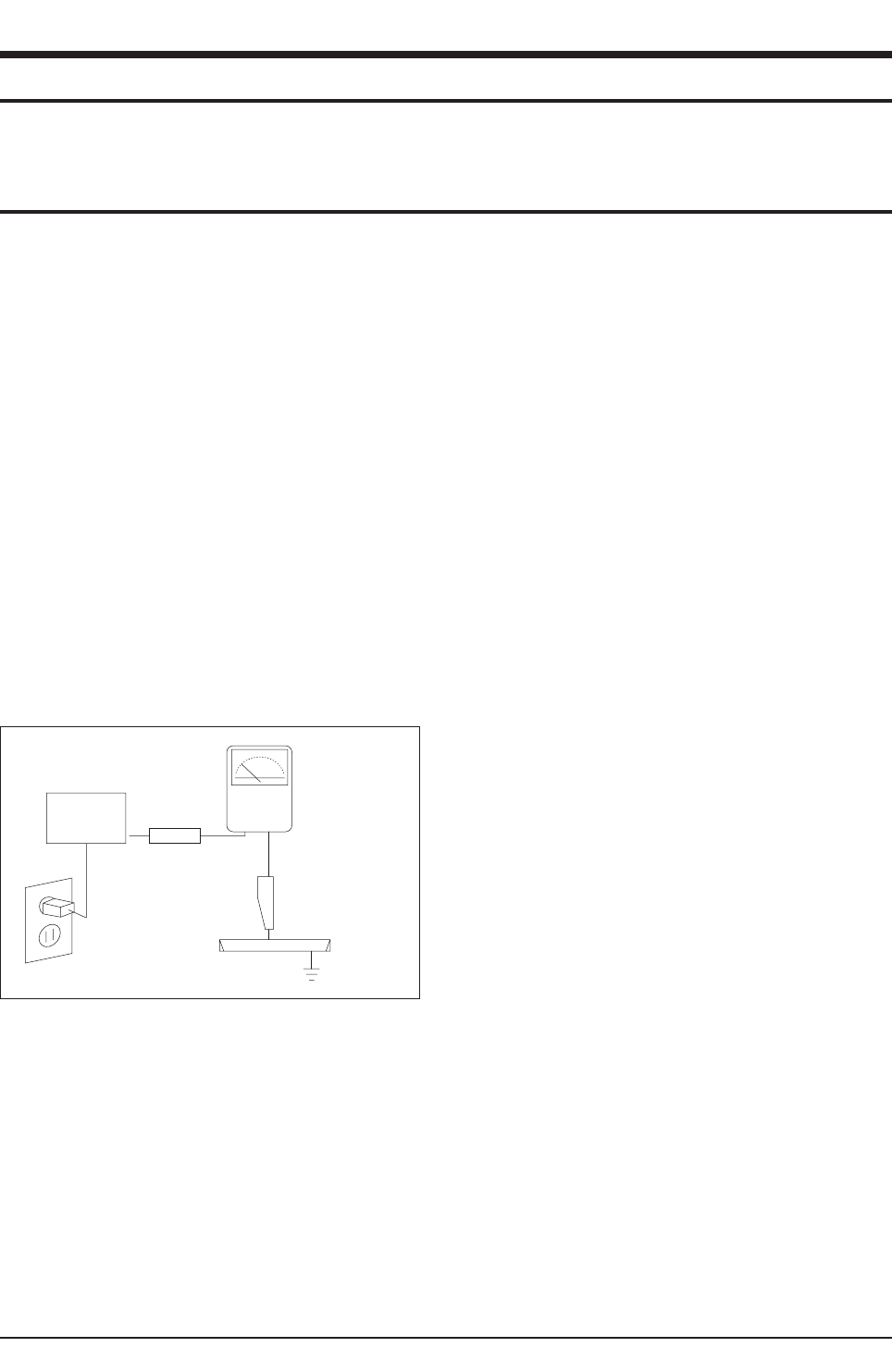
3. Check for Electricity Leakage (Figure 1-1)
Warning: Do not use an insulated transistor for checking
the leakage. Use only those current leakage testers or
mirroring systems that comply with ANSIC 101.1 and the
Underwriter Laboratory's specifications (UL1410, 59.7).
Fig. 1-1 AC Leakage Test
4. A high voltage is maintained within the specified limits
using safety parts, calibration and tolerances. When
voltage exceeds the specified limits, check each special
part.
5. Warning for Engineering Changes:
Never make any changes or additions to the circuit
design or the internal part for this product.
Ex: Do not add any audio or video accessory
connectors. This might cause physical damage.
Furthermore, any changes or additions to the original
design/engineering will invalidate the warranty.
6. Warning - Hot Chassis:
Some TV chassis are directly connected to one end of
the AC power cord for electrical reasons.
Without insulated transistors, the product can only be
repaired safely when the chassis is connected to the
earthed end of the AC power source.
To make sure the AC power cord is properly connected,
follow the instructions below. Use the voltmeter to
measure the voltage between the chassis and the
earthed ground. If the measurement is over 1.0V, unplug
the AC power cord and change the polarity before re-
inserting it. Measure the voltage between the chassis
and the ground again.
7. Some TV chassis are shipped with an additional
secondary grounding system. The secondary system is
adjacent to the AC power line. These two grounding
systems are separated in the circuit using an
unbreakable/unchangeable insulation material.
8. When any parts, material or wiring appear overheated or
damaged, replace them with new regular ones
immediately. When any damage or overheating is
detected, correct this immediately and make a regular
check of possible errors.
9. Check for the original shape of the lead, especially that
of the antenna wiring, any sharp edges, the AC power
and the high voltage power. Carefully check if the wiring
is too tight, incorrectly placed or loose. Never change the
space between the part and the printed circuit board.
Check the AC power cord for possible damages. Keep
the part or the lead away from any heat-emitting
materials.
Precaution
Samsung Electronics 1-1
LEAKAGE
CURRENT
TESTER
DEVICE
UNDER
TEST
TEST ALL
EXPOSED METAL
SURFACES
2-WIRE CORD
ALSO TEST WITH
PLUG REVERSED
(USING AC ADAPTER
PLUG AS REQUIRED) EARTH
GROUND
(READING SHOULD
NOT BE ABOVE
0.5mA)
To avoid possible damages or electric shocks or exposure to radiation, follow the instructions below with regard to safety,
installation, service and ESD..
1. Precaution
1-1 Safety Precautions

10. Safety Indication:
Some electrical circuits or device related materials
require special attention to their safety features, which
cannot be viewed by the naked eye. If an original part is
replaced with another irregular one, the safety or
protective features will be lost even if the new one has a
higher voltage or more watts.
Critical safety parts should be bracketed with ( ).
Use only regular parts for replacements (in particular,
flame resistance and dielectric strength specifications).
Irregular parts or materials may cause electric shock or
fire.
Precaution
1-2 Samsung Electronics
!

1. The service instructions are printed on the cabinet, and
should be followed by any service personnel.
2. Make sure to unplug the AC power cord from the power
source before starting any repairs.
(a) Remove or re-install parts or assemblies.
(b) Disconnect the electric plug or connector, if any.
(c) Connect the test part in parallel with the electrolytic
capacitor.
3. Some parts are placed at a higher position than the
printed board. Insulated tubes or tapes are used for this
purpose. The internal wiring is clamped using buckles to
avoid contact with heat emitting parts. These parts are
installed back to their original position.
4. After the repair, make sure to check if the screws, parts
or cables are properly installed. Make sure no damage is
caused to the repaired part and its surroundings.
5. Check for insulation between the blade of the AC plug
and that of any conductive materials (i.e. the metal
panel, input terminal, earphone jack, etc).
6. Insulation Check Process: Unplug the power cord from
the AC source and turn the switch on. Connect the insu-
lating resistance meter (500v) to the AC plug blade.
The insulating resistance between the blade of the AC
plug and that of the conductive material should be more
than 1 ㏁.
7. Any B+ interlock should not be damaged.
If the metal heat sink is not properly installed, no
connection to the AC power should be made.
8. Make sure the grounding lead of the tester is connected
to the chassis ground before connecting to the positive
lead. The ground lead of the tester should be removed
last.
9. Beware of risks of any current leakage coming into
contact with the high-capacity capacitor.
10. The sharp edges of the metal material may cause
physical damage, so ensure wearing protective gloves
during the repair.
Precaution
Samsung Electronics 1-3
Warning 1: First carefully read the "Safety Instruction" in this service manual.
When there is a conflict between the service and the safety instructions, follow the safety instruction at all times.
Warning 2: Any electrolytic capacitor with the wrong polarity will explode.
1-2 Servicing Precautions

1-3 Static Electricity Precautions
1. Some semi-conductive ("solid state") devices are
vulnerable to static electricity. These devices are known
as ESD. ESD includes the integrated circuit and the field
effect transistor. To avoid any materials damage from
electrostatic shock, follow the instructions described
below.
2. Remove any static electricity from your body by
connecting the earth ground before handling any
semi-conductive parts or ass'ys. Alternatively, wear a
dischargeable wrist-belt.
(Make sure to remove any static electricity before
connecting the power source - this is a safety instruction
for avoiding electric shock)
3. Remove the ESD ass'y and place it on a conductive
surface such as aluminum foil to prevent accumulating
static electricity.
4. Do not use any Freon-based chemicals.
Such chemicals will generate static electricity that
causes damage to the ESD.
5. Use only grounded-tip irons for soldering purposes.
6. Use only anti-static solder removal devices.
Most solder removal devices do not support an
anti-static feature. A solder removal device without an
anti-static feature can store enough static electricity to
cause damage to the ESD.
7. Do not remove the ESD from the protective box until the
replacement is ready. Most ESD replacements are
covered with lead, which will cause a short to the entire
unit due to the conductive foam, aluminum foil or other
conductive materials.
8. Remove the protective material from the ESD
replacement lead immediately after connecting it to the
chassis or circuit ass'y.
9. Take extreme caution in handling any uncovered ESD
replacements. Actions such as brushing clothes or lifting
your leg from the carpet floor can generate enough static
electricity to damage the ESD.
Precaution
1-4 Samsung Electronics
CAUTION
These servicing instructions are for use by
qualified service personnel only.
To reduce the risk of electric shock do not
perform any servicing other than that contained in the
operating instructions unless you are qualified to do so.

Precaution
Samsung Electronics 1-5
1-4 Installation Precautions
1. For safety reasons, more than two people are required
for carrying the product..
2. Keep the power cord away from any heat emitting
devices, as a melted covering may cause fire or electric
shock.
3. Do not place the projector in areas with poor ventilation
such as a bookshelf or closet. The increased internal
temperature may cause fire.
4. Bend the external antenna cable when connecting it to
the product. This is a measure to protect it from being
exposed to moisture. Otherwise, it may cause a fire or
electric shock.
5. Make sure to turn the power off and unplug the power
cord from the outlet before removing the product. Also
check the antenna cable or the external connectors if
they are fully unplugged. Damage to the cord may cause
fire or electric shock.
6. Keep the antenna far away from any high-voltage cables
and install it firmly. Contacting the high-voltage cable or
the antenna falling over may cause fire or electric shock.
7. When connecting the RF antenna, check for a DTV
receiving system and install a separate DTV reception
antenna for areas with no DTV signal.
8. Check the basics of the screen test.
- Image position/size, Tilt adjustment

1-6 Samsung Electronics
MEMO
Product Specification
Samsung Electronics 2-1
2. Product Specification
2-1 Product Features
Block Specfication EU East asia/CIS Remark
CRT - Slimmer than existing CRTs
Existing: 495mm →Slimfit : 365mm Vixlim CRT Vixlim CRT
RF Part - Same as for the Negotiator(S61A) Model TMQZ2-402A, PAL-CW TMQZ2-401A, PAL-CS
Power - Input Voltage : AC 230V (Europe)
- Stand-By : Less than 3W STR-X6750 STR-X6750
Video - PAL/SECAM/NT4.43
- Interlace 100Hz(Simple 100Hz)
VSP9402
CXA2165
VSP9402
CXA2165
Audio - Output : 10W x 2
- Function : A2/Nicam,SRS-WOW STV8237 STV8237
Cabinet
- New Front and Back Cabinets
- 184mm of saved space compared to
the existing model
A11:580mm →Z30:396mm
Z30(OZ) Design Applied
FPTV Looking Design
Black Bezel 2Tone
Color Design
Z30(OZ) Design Applied
FPTV Looking Design
Black Bezel 2Tone
Color Design
■Core Parts Functions
- VSP9402 : RF-CVBS,EXT-CVBS,FRONT Y,C,SCART1 R/G/B input and Video Signal Processing.
- CXA2165 : H-out,VD-P,VD-N,RGB output,Video and Deflection Signal Processing.
- STV8237 : Provides S-IF,Analog audio and Digital audio signal input and decoding functions.
- SDA5550 : I2C-Comunication,Master Control Micom.
- M27W201 : ROM Micom

Product Specification
2-2 Samsung Electronics
2-2 Key Features
Model WS32Z30 / CW29Z30
(Europe)
WS32Z30 / CS29Z30
(CIS)
Voltage AC230V 160~300V
Frequency of Operation 50/60 Hz 50/60 Hz
Dimensions(mm) 934X399X568 (32")
796X421X593 (29")
934X399X568 (32")
796X421X593 (29")
Weight 54.5Kg (32")
43.0Kg (29")
54.5Kg (32")
43.0Kg (29")
■H/W Configuration
- Slimfit(Low Depth) CRT adopted
- Interlace 100Hz(Simple 100Hz)
■S/W Configuration
- 10page TTX(Europe,CIS),200Page TTX (Europe Option)
- Multi System PAL/SECAM(CIS Option:NTSC4.43/NTSC3.58)
- ATS,Auto Wide,Pre Channel,On/Off Timer,Zoom,Blue Screen
■Picture
- System : Video PAL/SECAM/ NTSC3.58(CIS Option)
Sound B/G , D/K , I , L/L' , M(CIS Option)
- Black Level expansion , CTI , VM, Dynamic focus
- AKB(Auto kinetic Bias)
- Still picture , Digital Noise reduction
- PIP (2Tuner) : Option
- Panorama
■Sound
- System : Niacam Stereo , SRS-WOW
- Output : 10W+10W
- Speaker : 2EA
- AVL , Melody , Turbo , Auto Stereo , Auto Mute , Equalize
■In/Out Terminals
- Side : 1 CVBS Input, 1 S-Video Input, Sound L/R
- Rear
* EU/CIS :21P SCART x 2 Input/Output (SCART1 RGB Input)
■Remocon : TM79
■Power Supply
- Europe(230V), CIS(160V- 300V)
■Power Comsumption
- Stand-by : 3W
- Max Power : 180W
Product Specification
Samsung Electronics 2-3
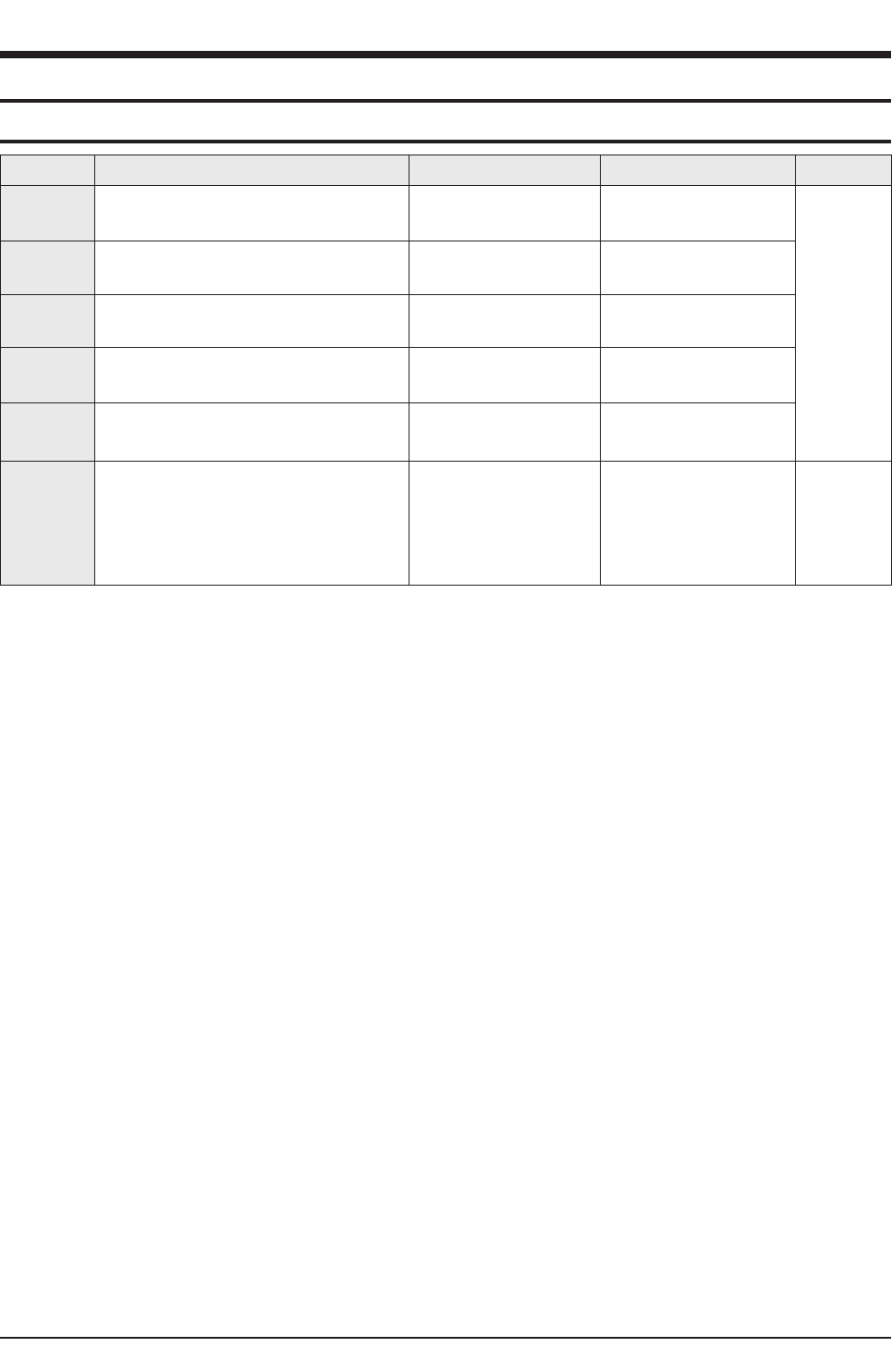
2-3 Specifications Analysis
Model WS32A116VG WS32A116VN WS32Z30/CW29Z30
Chassis K55A S61A S62B
Design
Basic
Product Type FLAT CRT FLAT CRT Slimfit CRT
Digital Display - - -
Screen Size 32 inch 32 inch 32 / 29 inch
Aspect Ratio 16:9 16:9 16:9 / 4:3
Visual
Quality
Progressive Scan - - -
Digital Comb Filter - - -
Screen Pitch 0.68 0.68 0.73
AKB O O O
Digital Noise Reduction O O O
DNIe - - -
3:2 Pull Down Support - - -
Audio
Base/Treble/Balance - - -
Equalizer 5 Band 5 Band 5 Band
AVL O O O
Surround Virtual-Dolby Virtual-Dolby SRS-WOW
Speaker System SEMI-DOME SEMI-DOME Direct
Speaker Output 15W + 15W 15W + 15W 10W + 10W
Function
Dual Screen Function - - -
Double Screen - - -
TTX 10page/200page(Option) 10page/200page(Option) 10page/200page(Option)
Still Picture O O O
Auto Jack Recognition - - -
Ports
Antenna In Rear : 1 Rear : 1 Rear : 1
External In Rear:2, Side:1 Rear:2, Side:1 Rear:2, Side:1
S-Video Side : 1 Side : 1 Side : 1
Y/Pb/Pr - - -
PC - - -
DVI - - -
HDMI - - -
Digital Audio Out - - -
Video Out Rear : 1 Rear : 1 Rear : 1
Audio Out Rear : 1 Rear : 1 -
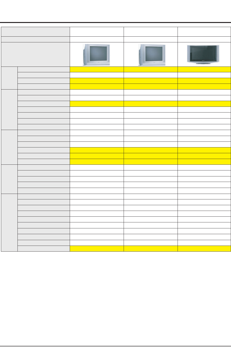
2-4 Accessories
Accessories Item Item code Remark
Supplied Accessories
Remote Control
AAA Alkaline Battery (2)
AA59-00370B
4301-000121
Samsung Service center
Owner's Instructions
Safety Guide Manual
AA68-03635F
AA68-03242E
Warranty Card
Registration Card
AA68-03278B
AA68-03576A
Accessories that can be
purchased additionally
Video Cable /
Audio Cable -
Internal shopping mallAntenna Cable -
Component Cable -
Product Specification
2-4 Samsung Electronics

Alignment & Adjustment
Samsung Electronics 3-1
3. Alignment & Adjustment
3-1 Service Instruction
1. General Adjustment :
In general, a color TV can provide ideal visual quality by adjusting the basic settings such as the vertical size, horizontal size,
focus, etc.
Display a black and white picture on the screen to check if the picture is clearly displayed.
If there are some 'spotted' points on the screen when displaying a black and white picture, degauss the screen using the
degauss coil. If the spotted points remain, re-adjust the purity and the convergence. This completes the basic performance
examination.
Notice.
■These adjustments and the check list are only applied to S62B chassis-applied models.
■Only use 230V for the measurement set. It is recommended using an insulation transformer when supplying power to
the set so as to prevent shock to the set or to yourself.
■These adjustment specifications have been created on the basis of the domestic S62B chassis-applied remote control
model. Some of the contents may be changed subject to the sales location and the product specifications.
2. When replacing the F_Box Board :
Since the software is loaded to the EPROM of the F_box board, check the version of the
software of the EPROM.
To check the version of the software, Enter service mode presee the key on the reomte
control according to the following seguenu.
(in stand-by status) Info→Menu→Mute→Power→ON
The software information will then be displayed below the OSD menu.
The notation of the software information : For example, T_SHPEU_1009 refers to
"CORSET BASIC MODEL Europe. ver.1009".
Since the settings including the Channel
information, Deflection, etc. are saved to the
nvRAM, reconfigure these settings when
replacing the System Board
3. When replacing the Deflection Board :
Tilt adjustment, focus adjustment, screen voltage setting and W/B adjustment are all required.
4. When replacing the Main Board : No adjustments required.
5. When replacing the CRT Ass'y : No adjustments required.
6. When replacing the front panel master power switch : No adjustments required.
7. When replacing the Side AV : No adjustments required.
8. When replacing the control switch : No adjustments required.
Alignment & Adjustment
3-2 Samsung Electronics
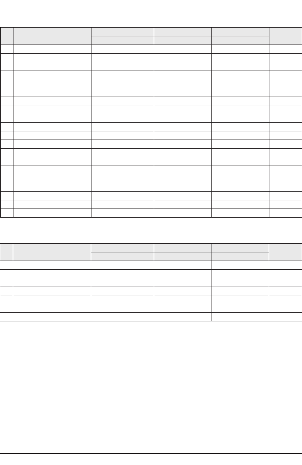
3-2 How to Access Service Mode
MENU Show all menus
▲/ ▼Move the cursor to select an item.
◀/ ▶Adjust the selected configuration value
1. To enter Service Mode, press the keys on the remote control according to the following sequence. (in Stand-by status)
Info →Menu →Mute →Power On
※When failing to enter Service Mode, repeat the procedure above.
2. The initial screen of Service Mode.
< Europe> <Asia/CIS>
3. Functions of the Keys within Service Mode
Service / T_SHPEU_XXXX
Option (XX XX XX)
Deflection
Video Adjust 1
Video Adjust 2
Video Adjust 3
Video Adjust 4
Video Adjust 5
YC Delay
EEPROM
Checksum(XXXX)
Reset / XX-XX-XX
Service / T_SHPAS_XXXX
Deflection
480/576P Deflect Offset
1080i Deflect Offset
4:3 Offset -- Vixlim
Video Adjust 1
Video Adjust 2
Video Adjust 3
Video Adjust 4
Video Adjust 5
Video Adjust 6
DTV Video Adjust
DTV Video Adjust2
YC Delay
EEPROM
Option (XX XX XX)
Checksum(XXXX)
Reset / XX-XX-XX
Alignment & Adjustment
Samsung Electronics 3-3
3-3 Factory Data
■Europe
No item WS32Z306VB CW29Z306VB Remark
Data Data
0V Amp 38 38 Adjust
1 V_SHIFT 26 24 Adjust
2H EW 43 24 Adjust
3H Shift 34 41 Adjust
4V Linearity 6 6 Fix
5 Upper-Linearity 6 2 Fix
6 Lower-Linearity 1 2 Fix
7V SC 3 5 Fix
8H Parablar 42 42 Adjust
9Upper Corner 30 34 Adjust
10 Lower Corner 39 37 Adjust
11 H Trapezium 26 28 Adjust
12 Bow 33 34 Fix
13 Angle 32 34 Fix
14 V Position 40 40 Fix
1. Deflection Adiustment (PAL)
No item WS32Z306VB CW29Z306VB Remark
Data Data
0V Amp 0 0 Fix
1 V_SHIFT 1 0 Fix
2H EW 3 -1 Fix
3H Shift 5 5 Fix
4V Linearity 2 2 Fix
5 Upper-Linearity 1 1 Fix
6 Lower-Linearity -1 -1 Fix
7V SC 0 0 Fix
8H Parablar 1 1 Fix
9Upper Corner -3 -3 Fix
10 Lower Corner 1 1 Fix
11 H Trapezium -8 -8 Fix
12 Bow 1 1 Fix
13 Angle 3 3 Fix
14 V Position 0 1 Fix
2. Deflection Adiustment (NTSC)
Alignment & Adjustment
3-4 Samsung Electronics
Alignment & Adjustment
Samsung Electronics 3-5
No item WS32Z306VB CW29Z306VB Remark
Data Data
0H Parablar_Pal 0 0 Adjust
1Upper Corner_Pal 0 0 Adjust
2Lower Corner_Pal 0 0 Adjust
3 Bow_Pal 0 0 Adjust
4 Angle_Pal 0 0 Adjust
5H Shift_Pal 0 0 Adjust
6H Parablar_NTSC 0 0 Adjust
7Upper Corner_NTSC 0 0 Adjust
8Lower Corner_NTSC 0 0 Adjust
9 Bow_NTSC 0 0 Adjust
10 Angle_NTSC 0 0 Adjust
11 H Shift_NTSC 0 0 Adjust
3. 4:3 Offset__Vixlim
No item WS32Z306VB CW29Z306VB Remark
Data Data
0 EE_R_CUTOFF, 32 32 Adjust
1 EE_G_CUTOFF, 32 32 Fix
2 EE_B_CUTOFF, 32 32 Adjust
3Color On / Off 1 1 Adjust
4CR Offset 30 30 Fix
5CB Offest 30 30 Fix
6R Drive 37 37 Adjust
7G Drive 32->38 38 Fix
8B Drive 29 29 Adjust
9Sub Bright 44 44 Adjust
10 Sub Contrast 6 6 Adjust
11 Sub Color 9 9 Fix
12 Secam sub color 5 5 Fix
13 Sub Tint 28 28 Fix
14 CTI Level 1 1 Fix
15 Color AXIS 1 1 Fix
16 LTI Level 1->3 3 Fix
17 VSU 5 4 Fix
18 Melody volume 9 9 Fix
19 Video mute time 6 6 Fix
4. Video Adjustment 1
Alignment & Adjustment
3-6 Samsung Electronics
No item WS32Z306VB CW29Z306VB Remark
Data Data
0 ABL Mode 3 3 Fix
1 Gamma 2 2 Fix
2DPIC Level 2 2 Fix
3DC Trans 2->1 1 Fix
4 ABL-TH 14 3 Fix
5 VM-Level 2 1 Fix
6 VM-Coring 2 2 Fix
7 VM-f0 2 2 Fix
8 VM-Limit 2 0 Fix
9 VM-Delay 1 1 Fix
10 SHP CD 1 1 Fix
11 SHP f0 1 1 Fix
12 SHP f1& p/o 10 11 Fix
13 AKB Time 13 13 Fix
14 Coring 0 0 Fix
15 Bandpass 7 7 Fix
16 Highpass 8 8 Fix
17 Bandpass_AV 6 6 Fix
18 Highpass_AV 7 7 Fix
19 Nicam MAE value 255 255 Fix
5. Video Adjustment 2
No item WS32Z306VB CW29Z306VB Remark
Data Data
0 H_EHT comp 4 0 Fix
1 V_EHT comp 5 4 Fix
2PIN EHT comp 6 5 Fix
3AFC EHT comp 0 0 Fix
4Sync Phase 0 0 Fix
5NR Value 6 6 Fix
6 PIP Contrast 14 14 Fix
7 PIP Bright 0 0 Fix
8 PIP Tint 63 63 Fix
9 PIP Color 6 6 Fix
10 PIP Pal V Pos 28 28 Fix
11 PIP NTSC V Pos 25 25 Fix
12 PIP H Pos 34 34 Fix
13 PIP R Cut off 0 0 Fix
14 PIP G Cut off 0 0 Fix
15 PIP B Cut off 0 0 Fix
16 PIP R Drive 56 56 Fix
17 PIP G Drive 56 56 Fix
18 PIP B Drive 56 56 Fix
19 PIP VSP Delay 5 5 Fix
6. Video Adjustment 3
Alignment & Adjustment
Samsung Electronics 3-7
No item WS32Z306VB CW29Z306VB Remark
Data Data
03Pip Pal V position 11 11 Fix
13Pip Pal H Position 12 12 Fix
23Pip Ntsc V Position 11 11 Fix
33Pip Ntsc H Position 19 19 Fix
4Sync Phase (480p) 0 0 Fix
5Sync Phase (576p) 1 1 Fix
6Sync Phase (1080i) 0 0 Fix
7. Video Adjustment 4
No item WS32Z306VB CW29Z306VB Remark
Data Data
0R_Drive Warm2 3 3 Fix
1B_Drive Warm2 -9 -9 Fix
2 R_Cutoff_Warm2 6 6 Fix
3 B_Cutoff_Warm2 -11 -11 Fix
4R_Drive Warm1 2 2 Fix
5B_Drive Warm1 -2 -2 Fix
6 R_Cutoff_Warm1 3 3 Fix
7 B_Cutoff_Warm1 -2 -2 Fix
8R_Drive Normal 0 0 Fix
9B_Drive Normal 0 0 Fix
10 R_Cutoff_Normal 0 0 Fix
11 B_Cutoff_Normal 0 0 Fix
12 R_Drive Cool1 0 0 Fix
13 B_Drive Cool1 4 4 Fix
14 R_Cutoff_Cool1 2 2 Fix
15 B_Cutoff_Cool1 6 6 Fix
16 R_Drive Cool2 -2 -2 Fix
17 B_Drive Cool2 6 6 Fix
18 R_Cutoff_Cool2 0 0 Fix
19 B_Cutoff_Cool2 9 9 Fix
8. Video Adjustment 5
Alignment & Adjustment
3-8 Samsung Electronics
No item WS32Z306VB CW29Z306VB Remark
Data Data
0P.YC (AV) Delay -9 -9 Fix
1S.YC (AV) Delay -7 -7 Fix
2N.YC (AV) Delay -8 -8 Fix
3P.BG.YC Delay -8 -8 Fix
4P.DK.YC Delay -10 -10 Fix
5P.I.YC Delay -10 -10 Fix
6P.L.YC Delay -8 -8 Fix
7S.BG.YC Delay -6 -6 Fix
8S.DK.YC Delay -8 -8 Fix
9S.I.YC Delay -10 -10 Fix
10 S.L.YC Delay -4 -4 Fix
11 N.M.YC Delay -7 -7 Fix
12 P.60.YC Delay -10 -10 Fix
13 N.443 YC Delay -8 -8 Fix
9. YC DELAY
No item WS32Z306VB CW29Z306VB Remark
Data Data
0 System 1 1 Fix
1System (VGA) 2 2
2System (480p) 2 2 Fix
3System (1080i) 3 3 Fix
4Dynamic Contrast 90 90 Fix
5Dynamic Brightness 50 50 Fix
6Dynamic Shapness 50 50 Fix
7Dynamic Color 50 50 Fix
8Dynamic Tint 50 50 Fix
9Dynamic Color Tone 2 2 Fix
10 Standard Contrast 70 70 Fix
11 Standard Brightness 50 50 Fix
12 Standard Shapness 50 50 Fix
13 Standard Color 50 50 Fix
14 Standard Tint 50 50 Fix
15 Standard Color Tone 2 2 Fix
16 Movie Contrast 40 40 Fix
17 Movie Brightness 50 50 Fix
18 Movie Shapness 40 40 Fix
19 Movie Color 45 45 Fix
20 Movie Tint 50 50 Fix
21 Movie Color Tone 2 2 Fix
22 Left Blanking (PAL)
23 Right Blanking (PAL)
24 Left Blanking (VGA)
25 Right Blanking (VGA)
26 Left Blanking (480p) 215 185 Fix
10. EEPROM

Alignment & Adjustment
Samsung Electronics 3-9
No item WS32Z306VB CW29Z306VB Remark
Data Data
27 Right Blanking(480p) 169 141 Fix
28 Left Blanking(1080i) 141 77 Fix
29 Right Blanking(1080i) 109 175 Fix
30 Brightness (RGB) 236 236 Fix
31 Contrast (RGB) 165 165 Fix
32 U Saturation (RGB) 94 94 Fix
33 V Saturation (RGB) 36 36 Fix
34 DVD Brightness (YPbPr) 221 5 Fix
35 DVD Contrast (YPbPr) 166 166 Fix
36 DVD U Saturation (YPbPr) 122 230 Fix
37 DVD V Saturation (YPbPr) 57 38 Fix
38 9402 Y Gain 175 175 Fix
39 9402 U Gain 71 71 Fix
40 -
41 9402 V Gain 65 65 Fix
42 CrCb Gain (480p) 119 119 Fix
43 CrCb Gain (1080i) 119 119 Fix
44 LTI Mode 2->1 1 Fix
45 LTI Mode (VGA)
46 LTI Mode (480p) 1 1 Fix
47 LTI Mode (1080i) 1 1 Fix
48 NR ON value1 85 85 Fix
49 NR ON value2 85 85 Fix
50 NR OFF value1 68 68 Fix
51 NR OFF value2 68 68 Fix
52 NR ON value3 170 170 Fix
53 NR ON value4 170 170 Fix
54 NR OFF value3 34 34 Fix
55 NR OFF value4 34 34 Fix
56 -
57 SECAM Sensitivity 28 28 Fix
58 Range of R Gain 32 32 Fix
59 Range of G Gain 32 32 Fix
60 Range of B Gain 32 32 Fix
61 Range of F/B Gain 23 23 Fix
62 -
63 TTX V-Position 40 40 Fix
64 TTX H-Position 180 180 Fix
65 -
66 Pal Sensitivity (AV mode) 215 234
67 wide model 4:3 Normal Parabola 0 0 Fix
68 1080i 50HZ Trepezium 15 15 Fix
69 1080i 60HZ Trepezium 13 13 Fix
70 UP-UCG (Up Corner Semi Control) 0 0 Fix
71 LO-UCG (Low Corner Semi Control) 0 0 Fix
72 Vertical Slicing Level 15 15 Fix

Alignment & Adjustment
3-10 Samsung Electronics
No item WS32Z306VB CW29Z306VB Remark
Data Data
73 Vertical Sync Lowpass-Filter 13 13 Fix
74 Amplifier Current Setting of Oscillator Pad 2 2 Fix
75 PAL Sensitivity 185 185 Fix
76 Chroma Sensitivity(PAL) and the Priority Order 215 215 Fix
77 Adjusting Chroma PLL 1 1
78 WSS 4:3 Panorama
79 NT left blank 79 79 Fix
80 NT Right blank 126 126 Fix
81 Progressive TTX V Position
82 Progressive TTX H-Position
83 3Pip Pal V position
84 3Pip Pal H Position
85 3Pip Ntsc V Position
86 3Pip Ntsc H Position
87 -
88 -
89 -
90 RF SubBright 124 124 Fix
91 TTX Sub Brightness 235 235 Fix
92 Left Blanking 101 101 Fix
93 Right Blanking 153 153 Fix
94 S - ABL 0 0 Fix
95 P - ABL 48 80 Fix
96 Picture Limit Level 3 3 Fix
97 OSD Level (LRGB2_LEV) 10 10 Fix
98 TTX Level (LRGB2_LEV) 3 3 Fix
99 AGCADJ1 238 238 Fix
100 AGCADJ2 110 110 Fix
101 ON TIMER CH memory 1 1 Fix
102 COMPONENT2 OSD Brightness 10 10 Fix
196 TNR1 207 207 Fix
197 TNR2 149 149 Fix
198 TNR3 95 95 Fix
199 TNR4 63 63 Fix
200 TNR5 47 47 Fix
201 TNR6 31 31 Fix
202 Fix
203 Fix
204 Fix
205 HPLL timing 156 156 Fix
206 SECAM MODE INITIAL DATA 76 76 Fix
207 SECAM MODE INITIAL DATA 64 64 Fix
244 Zoom2 H-para offset -1 2 Fix
245 Initialize 171 171 Fix
Alignment & Adjustment
Samsung Electronics 3-11
251 PL preventive measure caused by FBT high pressure 250 250 Fix
252 PL preventive measure caused by FBT high pressure 40 40 Fix
253 PL preventive measure caused by FBT high pressure 150 150 Fix
254 Z00M1 OFFSET -6 -2 Fix
255 Z00M2 OFFSET -10 -5 Fix
No Option Byte WS32Z306VB CW29Z306VB Alterable Change Mode Remark
Data Data
1 CRT Wide 4:3 Wide / 4:3 depending on the CRT
2 AV_JACK Scart Scart Scart / RCA
3 DTV Off Off On / Off
4 PIP Off Off 2-Tuner/1-Tuner/Off depending on the model
5 LNA Off Off On / Off On: 2T PIP LNA All model
Off: 1Tuner/No PIP
6 SEARCH_LNA Off Off On / Off
7 Sound SRS SRS SRS / A2-NICAM
8Auto FM On On On / Off
9 Tilt On On On / Off
10 High Deviation Off Off On / Off
11 Woofer Off Off On / Off
12 TTX Group OSD Language OSD Language Table TTX Language Group
13 TTX List Off Off On / Off On : Australia,Newzealand
Off: Europe,CIS,Asia
14 Digital NR On / Off On On
15 AGC on/off Off Off On / Off
16 Blue Screen On On On / Off
11. Option

Alignment & Adjustment
3-12 Samsung Electronics
No item CIS 29" CIS 32" Asia 29" Remark
Data Data Data
0V Amp 0 0 0 Fix
1 V_SHIFT 3 2 3 Fix
2H EW -1 1 -1 Fix
3H Shift -3 9 -3 Fix
4V Linearity 2 2 2 Fix
5 Upper-Linearity 1 1 1 Fix
6 Lower-Linearity -1 -1 -1 Fix
7V SC 0 0 0 Fix
8H Parablar 2 0 2 Fix
9Upper Corner -1 -3 -1 Fix
10 Lower Corner 2 1 2 Fix
11 H Trapezium -6 -7 -6 Fix
12 Bow 0 0 0 Fix
13 Angle 0 -1 0 Fix
14 V Position 0 0 0 Fix
15 CXA2151 Sub01 68 68 68 Fix
16 CXA2151 Sub02 1 1 1 Fix
17 Zoom1 Tra-offset -4 -6 -2 Fix
18 Zoom2 Tra-offset -7 -10 -8 Fix
2. Deflection Adiustment (NTSC)
■Asia / CIS
No item CIS 29" CIS 32" Asia 29" Remark
Data Data Data
0V Amp 38 29 39 Adjust
1 V_SHIFT 23 23 23 Adjust
2H EW 37 26 37 Adjust
3H Shift 38 40 43 Adjust
4V Linearity 3 6 5 Fix
5 Upper-Linearity 2 6 4 Fix
6 Lower-Linearity 4 1 2 Fix
7V SC 4 3 4 Fix
8H Parablar 38 42 43 Adjust
9Upper Corner 30 30 36 Adjust
10 Lower Corner 36 39 36 Adjust
11 H Trapezium 25 26 37 Adjust
12 Bow 32 33 34 Fix
13 Angle 34 32 30 Fix
14 V Position 40 40 40 Fix
15 CXA2151 Sub01 68 68 68 Fix
16 CXA2151 Sub02 1 1 1 Fix
17 Zoom1 Tra-offset -4 -6 -2 Fix
18 Zoom2 Tra-offset -7 -10 -8 Fix
1. Deflection Adiustment (PAL)

Alignment & Adjustment
Samsung Electronics 3-13
No item CIS 29" CIS 32" Asia 29" Remark
Data Data Data
0V Amp 0 0 0 Fix
1 V_SHIFT -1 -1 2 Fix
2H EW -6 -6 -6 Fix
3H Shift -12 -12 -12 Fix
4V Linearity 0 0 0 Fix
5 Upper-Linearity 0 0 0 Fix
6 Lower-Linearity 0 0 0 Fix
7V SC 0 0 0 Fix
8H Parablar -1 -1 -1 Fix
9Upper Corner 5 5 5 Fix
10 Lower Corner -3 -3 -3 Fix
11 H Trapezium 13 13 13 Fix
12 Bow 0 0 0 Fix
13 Angle 0 0 0 Fix
14 V Position 0 0 0 Fix
15 CXA2151 Sub01 232 232 232 Fix
16 CXA2151 Sub02 97 97 97 Fix
17 Zoom1 Tra-offset 0 0 0 Fix
18 Zoom2 Tra-offset 0 0 0 Fix
3. 576P Deflect Offset
No item CIS 29" CIS 32" Asia 29" Remark
Data Data Data
0V Amp 0 0 0 Fix
1 V_SHIFT 0 0 0 Fix
2H EW -3 -3 -3 Fix
3H Shift -19 -19 -22 Fix
4V Linearity 0 0 0 Fix
5 Upper-Linearity 0 0 0 Fix
6 Lower-Linearity 0 0 0 Fix
7V SC 0 0 0 Fix
8H Parablar 0 0 0 Fix
9Upper Corner 2 2 2 Fix
10 Lower Corner -1 -1 -1 Fix
11 H Trapezium 7 7 7 Fix
12 Bow 0 0 0 Fix
13 Angle 0 0 0 Fix
14 V Position 0 0 0 Fix
15 CXA2151 Sub01 232 232 232 Fix
16 CXA2151 Sub02 97 97 97 Fix
17 Zoom1 Tra-offset 0 0 0 Fix
18 Zoom2 Tra-offset 0 0 0 Fix
4. 480P Deflect Offset
Alignment & Adjustment
3-14 Samsung Electronics
No item CIS 29" CIS 32" Asia 29" Remark
Data Data Data
0H Parablar_Pal 0 0 0 Adjust
1Upper Corner_Pal 0 0 0 Adjust
2Lower Corner_Pal 0 0 0 Adjust
3 Bow_Pal 0 0 0 Fix
4 Angle_Pal 0 0 0 Fix
5H Shift_Pal 0 0 0 Adjust
6H Parablar_NTSC 0 0 0 Adjust
7Upper Corner_NTSC 0 0 0 Adjust
8Lower Corner_NTSC 0 0 0 Adjust
9 Bow_NTSC 0 0 0 Fix
10 Angle_NTSC 0 0 0 Fix
11 H Shift_NTSC 0 0 0 Adjust
6. 4:3 Offset__Vixlim
No item CIS 29" CIS 32" Asia 29" Remark
Data Data Data
0V Amp 12 12 11 Fix
1 V_SHIFT -6 -6 0 Fix
2H EW -22 -22 -22 Fix
3H Shift 0 0 0 Fix
4V Linearity -6 -6 0 Fix
5 Upper-Linearity 0 0 4 Fix
6 Lower-Linearity 5 5 1 Fix
7V SC 0 0 0 Fix
8H Parablar -15 -15 -20 Fix
9Upper Corner 10 10 0 Fix
10 Lower Corner -1 -1 -3 Fix
11 H Trapezium 15 15 10 Fix
12 Bow 1 1 0 Fix
13 Angle -2 -2 0 Fix
14 V Position 0 0 0 Fix
15 CXA2151 Sub01 196 196 196 Fix
16 CXA2151 Sub02 97 97 97 Fix
17 Zoom1 Tra-offset 0 0 0 Fix
18 Zoom2 Tra-offset 0 0 0 Fix
5. 1080i Deflect Offset

Alignment & Adjustment
Samsung Electronics 3-15
No item CIS 29" CIS 32" Asia 29" Remark
Data Data Data
0 EE_R_CUTOFF, 40 40 32 Adjust
1 EE_G_CUTOFF, 32 32 32 Fix
2 EE_B_CUTOFF, 36 36 32 Adjust
3Color On / Off 1 1 1 Adjust
4CR Offset 30 30 30 Fix
5CB Offest 30 30 30 Fix
6R Drive 41 41 37 Adjust
7G Drive 38 38 35 Fix
8B Drive 38 38 29 Adjust
9Sub Bright 44 44 44 Adjust
10 Sub Contrast 9 9 6 Adjust
11 Sub Color_Pal 9 9 18 Fix
12 Sub Color_NTSC 20 20 16 Fix
13 Secam sub color 5 5 5 Fix
14 Sub Tint 28 28 28 Fix
15 CTI Level 1 1 1 Fix
16 Color AXIS 1 1 1 Fix
17 LTI Mode 1 1 1 Fix
18 LTI Level 3 3 3 Fix
19 VSU 3 5 5 Fix
20 Melody volume 9 9 9 Fix
21 Video mute time 6 6 6 Fix
7. Video Adjustment 1
No item CIS 29" CIS 32" Asia 29" Remark
Data Data Data
0 ABL Mode 3 3 3 Fix
1 Gamma 2 2 3 Fix
2DPIC Level 3 3 3 Fix
3DC Trans 1 1 1 Fix
4 ABL-TH 3 3 3 Fix
5 VM-Level 1 1 1 Fix
6 VM-Coring 2 2 2 Fix
7 VM-f0 2 2 2 Fix
8 VM-Limit 0 0 0 Fix
9 VM-Delay 1 1 1 Fix
10 SHP CD 1 1 1 Fix
11 SHP f0 1 1 1 Fix
12 SHP f1& p/o 11 11 11 Fix
13 AKB Time 13 13 13 Fix
14 Coring 0 0 0 Fix
15 Bandpass 7 7 12 Fix
16 Highpass 8 8 11 Fix
17 Bandpass_AV 6 6 10 Fix
18 Highpass_AV 7 7 8 Fix
8. Video Adjustment 2
Alignment & Adjustment
3-16 Samsung Electronics
No item CIS 29" CIS 32" Asia 29" Remark
Data Data Data
03Pip Pal V position 11 11 11 Fix
13Pip Pal H Position 12 12 12 Fix
23Pip Ntsc V Position 11 11 11 Fix
33Pip Ntsc H Position 19 19 19 Fix
4Sync Phase (480p) 1 1 0 Fix
5Sync Phase (576p) 1 1 0 Fix
6Sync Phase (1080i) 0 0 0 Fix
10. Video Adjustment 4
No item CIS 29" CIS 32" Asia 29" Remark
Data Data Data
0 H_EHT comp 0 2 0 Fix
1 V_EHT comp 4 5 4 Fix
2PIN EHT comp 5 6 5 Fix
3AFC EHT comp 0 0 0 Fix
4Sync Phase 0 0 0 Fix
5NR Value 6 6 6 Fix
6 PIP Contrast 14 14 14 Fix
7 PIP Bright 0 0 0 Fix
8 PIP Tint 63 63 63 Fix
9 PIP Color 6 6 6 Fix
10 PIP Pal V Pos 28 28 28 Fix
11 PIP NTSC V Pos 25 25 25 Fix
12 PIP H Pos 34 34 34 Fix
13 PIP R Cut off 0 0 0 Fix
14 PIP G Cut off 0 0 0 Fix
15 PIP B Cut off 0 0 0 Fix
16 PIP R Drive 56 56 56 Fix
17 PIP G Drive 56 56 56 Fix
18 PIP B Drive 56 56 56 Fix
19 PIP VSP Delay 5 5 5 Fix
9. Video Adjustment 3

Alignment & Adjustment
Samsung Electronics 3-17
No item CIS 29" CIS 32" Asia 29" Remark
Data Data Data
0R_Drive Warm2 3 3 7 Fix
1B_Drive Warm2 -9 -9 -19 Fix
2 R_Cutoff_Warm2 6 6 13 Fix
3 B_Cutoff_Warm2 -11 -11 -16 Fix
4R_Drive Warm1 2 2 6 Fix
5B_Drive Warm1 -2 -2 -12 Fix
6 R_Cutoff_Warm1 3 3 6 Fix
7 B_Cutoff_Warm1 -2 -2 -11 Fix
8R_Drive Normal 0 0 4 Fix
9B_Drive Normal 0 0 -9 Fix
10 R_Cutoff_Normal 0 0 3 Fix
11 B_Cutoff_Normal 0 0 -9 Fix
12 R_Drive Cool1 0 0 2 Fix
13 B_Drive Cool1 4 4 -3 Fix
14 R_Cutoff_Cool1 2 2 2 Fix
15 B_Cutoff_Cool1 6 6 -2 Fix
16 R_Drive Cool2 -2 -2 0 Fix
17 B_Drive Cool2 6 6 0 Fix
18 R_Cutoff_Cool2 0 0 0 Fix
19 B_Cutoff_Cool2 9 9 0 Fix
11. Video Adjustment 5
No item CIS 29" CIS 32" Asia 29" Remark
Data Data Data
0R drive offset 1080i 1 1 1 Fix
1G drive offset 1080i 5 5 5 Fix
2R cutoff offset 1080i -11 -11 -11 Fix
3G cutoff offset 1080i -22 -22 -22 Fix
4R drive offset 480P -2 -2 -2 Fix
5G drive offset 480P 0 0 0 Fix
6R cutoff offset 480P -5 -5 -5 Fix
7G cutoff offset 480P -1 -1 -1 Fix
8R drive offset 576P -2 -2 -2 Fix
9G drive offset 576P 0 0 0 Fix
10 R cutoff offset 576P -1 -1 -1 Fix
11 G cutoff offset 576P 8 8 8 Fix
12 R drive offset 480i 0 0 0 Fix
13 G drive offset 480i 1 1 1 Fix
14 R cutoff offset 480i 2 2 2 Fix
15 G cutoff offset 480i 0 0 0 Fix
16 R drive offset 576i -3 -3 -3 Fix
17 G drive offset 576i 0 0 0 Fix
18 R cutoff offset 576i 6 6 6 Fix
19 G cutoff offset 576i 2 2 2 Fix
12. Video Adjustment 6

Alignment & Adjustment
3-18 Samsung Electronics
No item CIS 29" CIS 32" Asia 29" Remark
Data Data Data
0Sub Bright 34 34 34 Fix
1Sub Contrast 11 11 11 Fix
2Sub Color 20 20 20 Fix
3Sub Tint (Hue) 29 29 29 Fix
4Color AXIS 1 1 1 Fix
5LTI mode 1 1 1 Fix
6 VM-Level 2 2 2 Fix
7 VM-Coring 2 2 2 Fix
8 VM-f0 0 0 0 Fix
9 VM-Limit 1 1 1 Fix
10 VM-Delay 2 2 2 Fix
11 SHP CD 1 1 1 Fix
12 SHP f0 1 1 1 Fix
13 SHP f1& p10 12 12 12 Fix
14 LTI level 2 2 2 Fix
14. DTV Video Adjustment(576p)
No item CIS 29" CIS 32" Asia 29" Remark
Data Data Data
0Sub Bright 37 37 37 Fix
1Sub Contrast 10 10 10 Fix
2Sub Color 16 16 16 Fix
3Sub Tint (Hue) 29 29 29 Fix
4Color AXIS 1 1 1 Fix
5LTI mode 1 1 1 Fix
6 VM-Level 2 2 2 Fix
7 VM-Coring 2 2 2 Fix
8 VM-f0 0 0 0 Fix
9 VM-Limit 1 1 1 Fix
10 VM-Delay 2 2 2 Fix
11 SHP CD 1 1 1 Fix
12 SHP f0 1 1 1 Fix
13 SHP f1& p10 12 12 12 Fix
14 LTI level 2 2 2 Fix
13. DTV Video Adjustment(480p)

Alignment & Adjustment
Samsung Electronics 3-19
No item CIS 29" CIS 32" Asia 29" Remark
Data Data Data
0Sub Bright 12 12 12 Fix
1Sub Contrast 0 0 0 Fix
2Sub Color 18 18 18 Fix
3Sub Tint (Hue) 29 29 29 Fix
4Color AXIS 1 1 1 Fix
5LTI mode 1 1 1 Fix
6 VM-Level 2 2 2 Fix
7 VM-Coring 2 2 2 Fix
8 VM-f0 0 0 0 Fix
9 VM-Limit 1 1 1 Fix
10 VM-Delay 2 2 2 Fix
11 SHP CD 1 1 1 Fix
12 SHP f0 1 1 1 Fix
13 SHP f1& p10 12 12 12 Fix
14 LTI level 1 1 1 Fix
15 H_EHT comp_1080i 1 1 0 Fix
16 V_EHT comp_1080i 3 3 4 Fix
17 PIN EHT comp_1080i 5 5 5 Fix
18 ABL TH_1080i 3 3 3 Fix
15. DTV Video Adjustment(1080i)
No item CIS 29" CIS 32" Asia 29" Remark
Data Data Data
0 EEP_GAMMA_480P 1 1 1 Fix
1 EEP_DPIC_LEVEL_480P 2 2 2 Fix
2 DC_TRANS_480P 3 3 3 Fix
3 EEP_GAMMA_576P 1 1 1 Fix
4 EEP_DPIC_LEVEL_576P 2 2 2 Fix
5 DC_TRANS_576P 3 3 3 Fix
6 EEP_GAMMA_1080I 1 1 1 Fix
7EEP_DPIC_LEVEL_1080I 2 2 2 Fix
8DC_TRANS_1080I 3 3 3 Fix
16. DTV Video Adjustment 2

Alignment & Adjustment
3-20 Samsung Electronics
No item CIS 29" CIS 32" Asia 29" Remark
Data Data Data
0P.YC (AV) Delay -9 -9 -9 Fix
1S.YC (AV) Delay -7 -7 -7 Fix
2N.YC (AV) Delay -8 -8 -8 Fix
3P.BG.YC Delay -10 -10 -12 Fix
4P.DK.YC Delay -10 -10 -11 Fix
5P.I.YC Delay -10 -10 -11 Fix
6P.M.YC Delay -10 -10 -10 Fix
7P.L.YC Delay -10 -10 -10 Fix
8S.BG.YC Delay -6 -6 -12 Fix
9S.DK.YC Delay -8 -8 -8 Fix
10 S.I.YC Delay -10 -10 -10 Fix
11 S.M.YC Delay -10 -10 -10 Fix
12 S.L.YC Delay -4 -4 -4 Fix
13 N.M.YC Delay -10 -10 -10 Fix
17. YC DELAY
No item CIS 29" CIS 32" Asia 29" Remark
Data Data Data
0 System 1 1 1 Fix
1System (VGA) 1 1 1 Fix
2System (480p) 2 2 2 Fix
3System (1080i) 3 3 3 Fix
4Dynamic Contrast 90 90 100 Fix
5Dynamic Brightness 50 50 55 Fix
6Dynamic Shapness 50 50 75 Fix
7Dynamic Color 50 50 55 Fix
8Dynamic Tint 50 50 50 Fix
9Dynamic Color Tone 2 2 0 Fix
10 Standard Contrast 70 70 80 Fix
11 Standard Brightness 50 50 50 Fix
12 Standard Shapness 50 50 50 Fix
13 Standard Color 50 50 50 Fix
14 Standard Tint 50 50 50 Fix
15 Standard Color Tone 2 2 2 Fix
16 Movie Contrast 40 40 50 Fix
17 Movie Brightness 50 50 55 Fix
18 Movie Shapness 40 40 25 Fix
19 Movie Color 45 45 40 Fix
20 Movie Tint 50 50 50 Fix
21 Movie Color Tone 2 2 4 Fix
22 Left Blanking (PAL)
23 Right Blanking (PAL)
24 Left Blanking (VGA)
25 Right Blanking (VGA)
18. EEPROM

Alignment & Adjustment
Samsung Electronics 3-21
No item CIS 29" CIS 32" Asia 29" Remark
Data Data Data
26 Left Blanking (480p) 185 185 145 Fix
27 Right Blanking(480p) 141 141 99 Fix
28 Left Blanking(1080i) 77 77 77 Fix
29 Right Blanking(1080i) 175 175 175 Fix
30 Brightness (RGB) 236 236 236 Fix
31 Contrast (RGB) 165 165 165 Fix
32 U Saturation (RGB) 94 94 94 Fix
33 V Saturation (RGB) 36 36 36 Fix
34 DVD Brightness (YPbPr) 5 5 5 Fix
35 DVD Contrast (YPbPr) 166 166 166 Fix
36 DVD U Saturation (YPbPr) 230 230 230 Fix
37 DVD V Saturation (YPbPr) 38 38 38 Fix
38 9402 Y Gain 175 175 175 Fix
39 9402 U Gain 71 71 71 Fix
40 -
41 9402 V Gain 65 65 65 Fix
42 CrCb Gain (480p) 255 255 255 Fix
43 CrCb Gain (1080i) 255 255 255 Fix
44 480i_Sub Bright 44 44 44 Fix
45 480i_Sub Contrast 10 10 10
46 576i_Sub Bright 46 46 46 Fix
47 576i_Sub Contrast 10 10 10 Fix
48 NR ON value1 85 85 85 Fix
49 NR ON value2 85 85 85 Fix
50 NR OFF value1 68 68 68 Fix
51 NR OFF value2 68 68 68 Fix
52 NR ON value3 170 170 170 Fix
53 NR ON value4 170 170 170 Fix
54 NR OFF value3 34 34 34 Fix
55 NR OFF value4 34 34 34 Fix
56 -
57 SECAM Sensitivity 28 28 28 Fix
58 Range of R Gain 32 32 32 Fix
59 Range of G Gain 32 32 32 Fix
60 Range of B Gain 32 32 32 Fix
61 Range of F/B Gain 23 23 23 Fix
62 -
63 TTX V-Position 40 40 40 Fix
64 TTX H-Position 180 180 180 Fix
65 -
66 PAL Sensitivity (AV mode) 234 234 234 Fix
67 wide model 4:3 Normal Parabola 0 0 0 Fix
68 1080i 50HZ Trepezium 255 255 255 Fix
69 1080i 60HZ Trepezium 255 255 255 Fix
70 UP-UCG (Up Corner Semi Control) 0 0 0 Fix
71 LO-UCG (Low Corner Semi Control) 0 0 0 Fix

Alignment & Adjustment
3-22 Samsung Electronics
168 EEP_DTV _contrast offset_1080i 0 0 0 Fix
169 EEP_Gamma_1080i 2 2 2 Fix
196 TNR1 207 207 207 Fix
197 TNR2 149 149 165 Fix
198 TNR3 95 95 111 Fix
199 TNR4 63 63 63 Fix
200 TNR5 47 47 47 Fix
201 TNR6 31 31 31 Fix
202 Fix
203 Fix
204 Fix
205 HPLL timing 156 156 156 Fix
206 SECAM MODE INITIAL DATA 76 76 76 Fix
207 SECAM MODE INITIAL DATA 64 64 64 Fix
No item CIS 29" CIS 32" Asia 29" Remark
Data Data Data
72 Vertical Slicing Level 15 15 15 Fix
73 Vertical Sync Lowpass-Filter 13 13 13 Fix
74
Amplifier Current Setting of Oscillator Pad
2 2 2 Fix
75 PAL Sensitivity 215 215 215 Fix
76 Chroma Sensitivity(PAL) and the Priority Order 215 215 215 Fix
77 Adjusting Chroma PLL 1 1 1
78 WSS 4:3 Panorama 255 255 255
79 NT left blank 150 150 150 Fix
80 NT Right blank 92 92 92 Fix
81 Progressive TTX V Position 255 255 255
82 Progressive TTX H-Position 255 255 255
83 3Pip Pal V position -> Cr Gain 480p 46 46 46
84 3Pip Pal H Position -> Cb Gain 480p 35 35 35
85 3Pip Ntsc V Position -> Cr Gain 576p 43 43 43
86 3Pip Ntsc H Position -> Cb Gain 576p 30 30 30
87 Cr Gain 1080i 22 22 22
88 Cb Gain 1080i 27 27 27
89 -
90 RF SubBright 124 124 124 Fix
91 TTX Sub Brightness 235 235 235 Fix
92 Left Blanking(PAL) 101 101 101 Fix
93 Right Blanking(PAL) 153 153 153 Fix
94 S - ABL 0 0 0 Fix
95 P - ABL 80 80 80 Fix
96 Picture Limit Level 3 3 3 Fix
97 OSD Level (LRGB2_LEV) 10 10 7 Fix
98 TTX Level (LRGB2_LEV) 3 3 3 Fix
99 AGCADJ1 238 238 238 Fix
100 AGCADJ2 110 110 110 Fix
101 ON TIMER CH memory 1 1 1 Fix
102 COMPONENT2 OSD Brightness 10 10 10 Fix
Alignment & Adjustment
Samsung Electronics 3-23
230 EEP_GAMMA_480I 2 2 2 Fix
231 EEP_DPIC_LEVEL_480I 2 2 2 Fix
232 DC_TRANS_480I 3 3 3 Fix
233 EEP_GAMMA_576I 2 2 2 Fix
234 EEP_DPIC_LEVEL_576I 2 2 2 Fix
235 DC_TRANS_576I 3 3 3 Fix
240 EEP_480i H_EW Offset 0 0 0 Fix
241 EEP_480i H_Shift Offset 0 0 0 Fix
242 EEP_576i H_EW Offset -2 -2 -2 Fix
243 EEP_576i H_Shift Offset -5 -5 -5 Fix
244 ZOOM2 PARA 2 2 2 Fix
251 PL preventive measure caused by FBT high pressure 250 250 250 Fix
252 PL preventive measure caused by FBT high pressure 40 40 40 Fix
253 PL preventive measure caused by FBT high pressure 150 150 150 Fix
No Option Byte CIS 29" CIS 32" Asia 29" Middle East 29" Remark
Data Data Data Data
1 CRT 4:3 Wide 4:3 4:3 depending on the CRT
2OSD Group CIS CIS East Asia Arab
3OSD Language CIS CIS English Arab
4AV Jack SCART SCART RCA RCA depending on the CRT
5 DTV Off Off On On On: 2T PIP LNA All model
Off: 1Tuner/No PIP
6 PIP 2-Tuner Off 2-Tuner 2-Tuner
7 LNA On On On On
8Search LNA On On On On
9 Sound SRS SRS SRS SRS
10 carrier mute Off Off Off Off
11 High Deviation Off Off Off Off
12 TTX Group Russian Russian West Europe Arabic TTX Language Group
13 TTX List Off Off Off Off On : Australia,Newzealand
Off: Europe,CIS,Asia
14 TTX On/Off On On On On
15 AGC Off Off Off Off
16 Tilt On On On On
17 Hotel Mode Off Off Off Off
19. Option
Alignment & Adjustment
3-24 Samsung Electronics
3-4 Service Adjustment
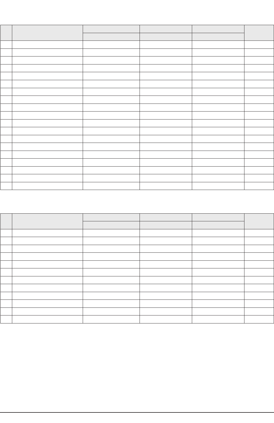
3-4-1 Adjusting the Picture Size
■Since the S62A chassis has the deflection settings data within the Factory Data, the picture size has to be adjusted when
replacing the System Board or the Deflection Board, according to the following procedures.
①Display the Lion pattern. ②Press "Info →Menu →Mute →Power On"
using the remote control and enter Factory Mode.
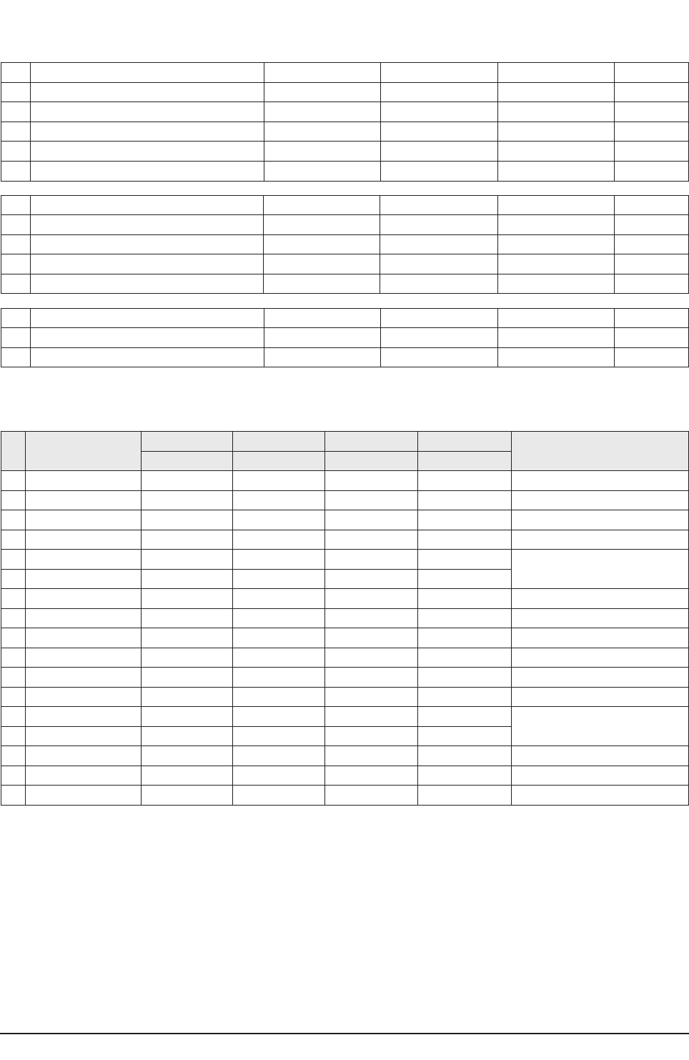
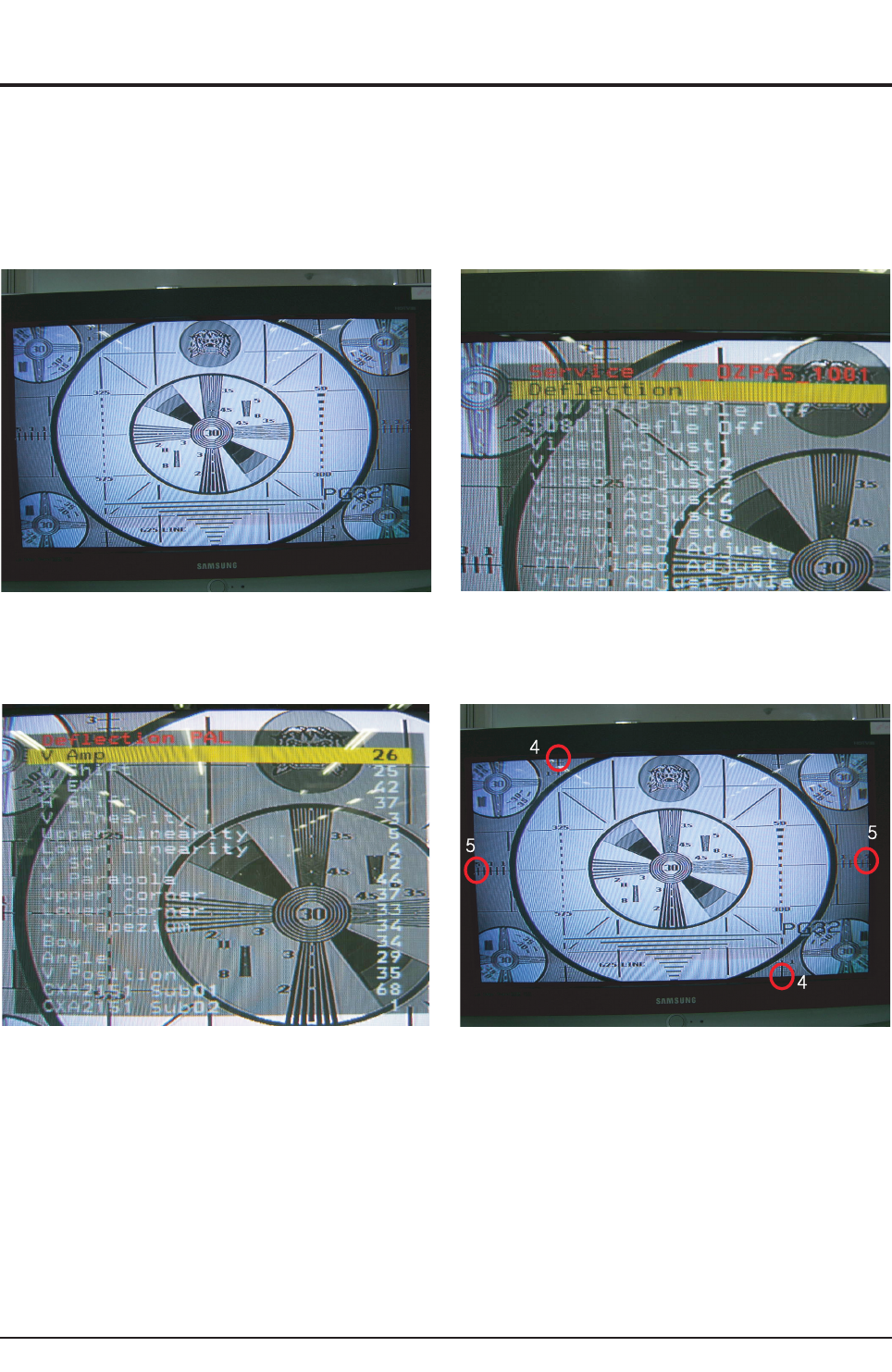
③Enter Deflection Mode. ④Adjust the V-AMP, V-SHIFT, H-AMP and H-SHIFT items so
that the width becomes 5 and the height becomes 4.
Alignment & Adjustment
Samsung Electronics 3-25
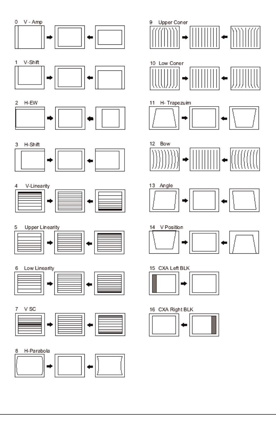
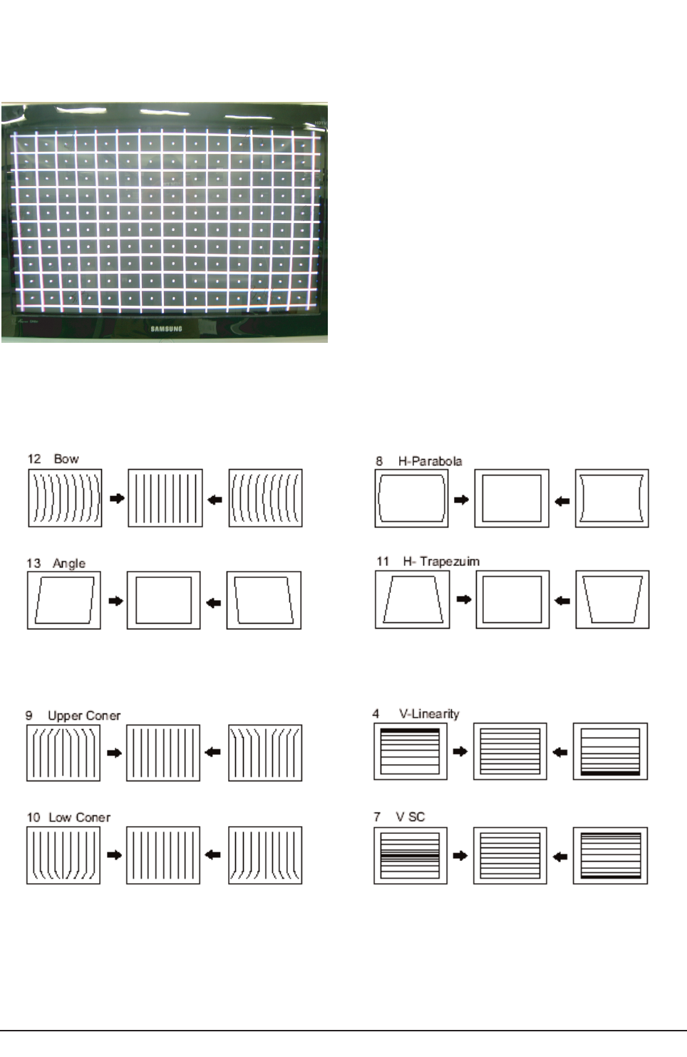
3-4-2 Adjusting the Picture Straight Lines
①Display the Cross Hatch pattern.
②Adjust settings other than V-AMP, V-SHIFT, H-AMP and H-SHIFT so that straight lines are displayed without curves.
⑦When the adjustments are complete, display the Lion pattern and check that the picture size has not been changed.
If there is no change, finish the adjustments.
③Adjust BOW and the Angle settings so that the center line
becomes a straight line.
④Adjust the H-Parabola and H-Trapezium settings so that
the left and right lines become straight.
⑤Adjust the Upper Corner and the Low Corner settings so that
the end of the lines become straight.
⑥Adjust the V-Linearity and V-SC settings so that the
intervals of the horizontal lines become uniform.
Alignment & Adjustment
3-26 Samsung Electronics
3-5 Replacements & Calibration
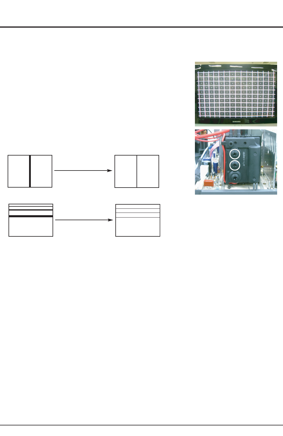
3-5-1 Adjusting the Focus
■Since the S62A chassis has a built-in dynamic focus circuit, take care when adjusting the focus. When the CRT PCB, FBT or
CRT has been replaced, the focus has to be adjusted according to the following procedures.
1. Display the CROSS Hatch pattern.
2. Set the Screen Adjustment to "View as Standard".
3. Turn the Static Focus VR clockwise to the maximum position.
(End of clockwise direction)
4. Turn the Dynamic Focus VR counter clockwise to the maximum position.
(End of counter clockwise direction)
5. Slowly turn the Static Focus VR counter clockwise so that the center vertical line
is the most clearly displayed.
6. Slowly turn the Dynamic Focus VR clockwise so that the 2nd line is the most clearly displayed.
7. Check the entire screen focus and repeat steps 3 to 6, if necessary.
H
V
Static
Focus VR
Dynamic
Focus VR
H
V
After Adjustment
H
V
1
2
3After Adjustment
Alignment & Adjustment
Samsung Electronics 3-27
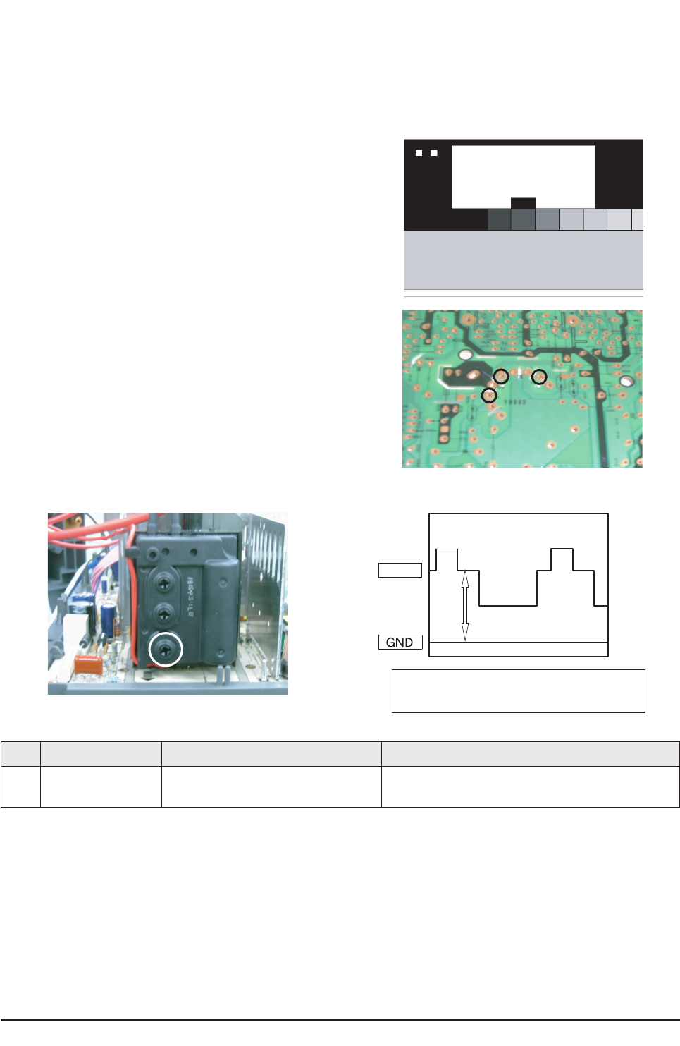
3-5-2 Adjusting the Screen Voltage
1. Select "Info →Menu →Mute →Power On" to enter Service Mode.
2. Initialize all settings to the values appropriate to the corresponding model.
3. Display the Toshiba pattern.
4. Using an Oscilloscope, measure the size of RK, BK and GK to the
Pedestal Level.
5. Adjust the Screen VR of FEB so that the highest point of the Pedestal Level is 175V.
※Screen Voltage Measurement Data
BK
RK
GK
Screen
VR
175V
Adjust Method the Screen Voltage
for Toshiba Pattern by Oscilloscope
No Item Data Required Adjustment
1Screen Voltage The Highest Voltage among RK, GK and
BK 175Vp-p-3V Screen Voltage
Alignment & Adjustment
3-28 Samsung Electronics
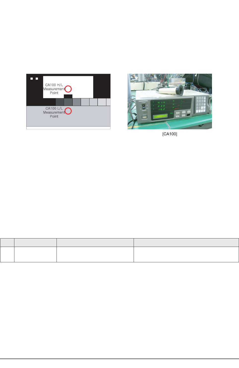
3-5-3 Adjusting the White Balance
1. Initialize all settings to the values appropriate to the corresponding model.
2. Select "Info →Menu →Mute →Power On" to enter Service Mode.
3. Initialize all settings to the values appropriate to the corresponding model.
4. Display the Toshiba pattern and adjust the White Balance using CA100 with the coordinates of the corresponding model.
5. Enter Video Adjust1 of Service Mode. Adjust Low/Light.
- Adjust Sub Bright to set Y.
- Adjust B Cutoff to set y.
- Adjust R Cutoff to set x.
6. Enter Video Adjust1 of Service Mode. Adjust High/Light.
- Adjust Sub Contrast to set Y.
- Adjust B Drive to set y.
- Adjust R Drive to set x.
7. Check Low/Light and readjust it if its value has been changed.
8. If you have readjusted Low/Light, readjust High/Light until the two values are identical to the coordinates of the corresponding
model.
※White Balance Standard Data
3-5-4 Check List for the Screen Voltage and White Balance Adjustment
1. The Screen Voltage and White Balance are connected each other, and both of them have to be configured to the correct values.
2. Adjust the White Balance after the Screen Voltage was adjusted, and check if the Screen Voltage is normal after adjusting the
White Balance.
3. If the White Balance is readjusted, check the Screen Voltage again.
4. When the adjustment is finished, check the following checklist.
- If there is a spot on the screen when turning the TV set off/on, adjust the Screen Voltage again.
- If there is a ghost line on the screen, adjust the Screen Voltage again.
No Item Data Required Adjustment
1White
Balance
x:282±3/ y:290±3/ 40± 3(High)
x:282±3/ y:290±3/ 1.2±0.2(Low) White Balance (Europe)
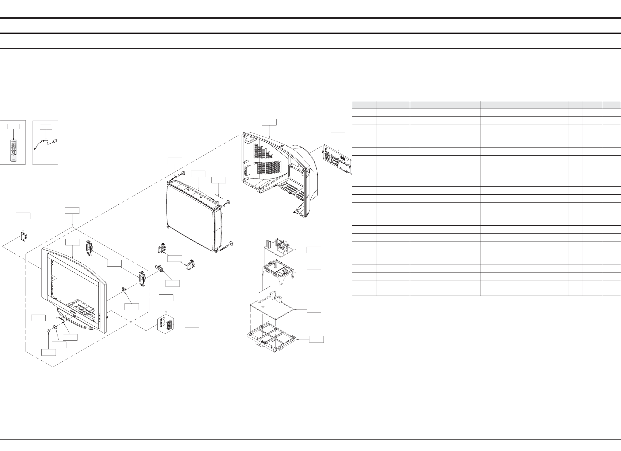
4. Exploded View & Part List
Exploded View & Part List
Samsung Electronics 4-1
T0074 T0268
T0091
T0003
T0175
T0299
T0057
CIS7
CIS3
T0023
T0022
T0098
T0137
T0569
T0527
T0063
T0065
M0006
T0130
M0112
T0070
M0014
T0010
T0275
You can search for the updated part code through ITSELF web site.
URL:http://itself.sec.samsung.co.kr
4-1 CS29Z30SPBXBWT
Loc.No. Code No. Description Specification Q'ty SA/SNA Remark
CIS3 BP64-00331B DECORATION-POWER PJTV,ABS,HB,GR503,SVM30 1 S.N.A
CIS7 AA61-60003J SPRING ETC-CS -,SUS304,-,-,OD6,N7,OD6,-, 1 S.N.A
M0006 AA63-01169B COVER-REAR 29Z30,HIPS,T3.0,FV2,BLK,HQ 1 S.A
M0014 AA94-15674U ASSY PCB MAIN CS29Z30SPBXBWT,S62B,CORSET 1 S.A
M0112 AA63-01167C COVER-FRONT 29Z30,HIPS,T3.0,HB,GR503,SV0 1 S.N.A
T0003 AA96-03383C ASSY COVER P-FRONT 29Z30,CIS,HIPS HB,GR5 1 S.A
T0010 AA61-01425A HOLDER-SUB PCB 32Z30,HIPS V0,T2.0,G4309, 1 S.N.A
T0022 AA64-01201N KNOB CONTROL 32Z30,ABS,HB,BLK 1 S.N.A
T0023 BP64-00326A KNOB POWER 43T9,ABS,HB,BLK,SVM3012 1 S.A
T0057 AA64-01062B BADGE-BRAND ALL,AL,T1.5,10.6,L65,BLK.SIL 1 S.A
T0063 AA03-00443A CRT COLOR A68QFZ893X002,+380,0.258,12.0, 1 S.A
T0065 AA94-15676A ASSY PCB CRT 29 INCH,S62B,CORSET 1 S.N.A
T0070 AA61-01424A HOLDER-CHASSIS 32Z30,HIPS V0,T2.0,G4309, 1 S.N.A
T0074 AA59-00370B REMOCON SAMSUNG,TM79,175*44*23,SAMSUNG S 1 S.A
T0091 AA94-15178A ASSY PCB MISC-A/V SIDE ,OZ,S62A 1 S.A
T0098 AA94-15114A ASSY PCB MISC-CONTROL CT-32Z30HD,CORE 1 S.A
T0130 AA96-03297A ASSY COVER P-TERMINALBOARD 32Z30,CIS,HI 1 S.N.A
T0137 AA94-15179A ASSY PCB MISC-LED ,OZ,S62A 1 S.A
T0175 AA96-03164A ASSY SPEAKER P 8OHM,6*13CM,Z31,10W,SPK+W 1 S.A
T0268 AA39-10006X CBF-POWER CORD -,KKP419C,KLCE-2F,2.286MT 1 S.A
T0275 AA94-14127A ASSY PCB MISC-DEFLECTION 29Z30,S62B,CIS, 1 S.N.A
T0299 AA64-04191A WINDOW-RMC LED 32Z30,PC CLEAR 1 S.N.A
T0527 AA65-00061A CLAMPER CORE-D,COIL NYLON-66,VO,NTR 4 S.N.A
T0569 AA61-00813D SUPPORT-CRT 29Z30(SLIM),HIPS V0,T2.0,GR5 2 S.N.A

5-1 CS29Z30SPBXBWT
5-1Samsung Electronics
Electrical Part List
ASSY CHASSIS
M0017 AA91-09602K ASSY CHASSIS CS29Z30SPBXBWT,S62B,CORSET 1 S.N.A
T0275 AA94-14127A ASSY PCB MISC-DEFLECTION 29Z30,S62B,CIS, 1 S.N.A
C302 2401-000365 C-AL 100uF,20%,50V,WT,TP,10x12.5mm, 1 S.A
C303 2201-000132 C-CERAMIC,DISC 0.1NF,10%,500V,Y5P,TP,6.5 1 S.A
C304 2305-000285 C-FILM,LEAD-PEF 220NF,5%,100V,TP,10.5X5. 1 S.A
C305 2301-001259 C-FILM,LEAD-PPF 100nF,5%,400V,TP,19x8x16 1 S.A
C306 2301-000224 C-FILM,LEAD-PEF 22nF,5%,50V,TP,7.4x3.9x1 1 S.A
C307 2401-000365 C-AL 100uF,20%,50V,WT,TP,10x12.5mm, 1 S.A
C308 2305-000411 C-FILM,LEAD-PEF 470nF,5%,50V,TP,7.3x4.8x 1 S.A
C401 2201-000556 C-CERAMIC,DISC 0.47NF,10%,500V,Y5P,TP,5. 1 S.A
C402 2401-002231 C-AL 470uF,20%,50V,WT,TP,13x20mm,5m 1 S.A
C403 2201-000556 C-CERAMIC,DISC 0.47NF,10%,500V,Y5P,TP,5. 1 S.A
C404 2401-001838 C-AL 470uF,20%,25V,WT,TP,10x16,5 1 S.A
C408 2301-001083 C-FILM,LEAD-PPF 27nF,5%,400V,TP,20x7.5x1 1 S.A
C409 2301-001401 C-FILM,LEAD-PPF 27nF,5%,630V,TP,19x11x17 1 S.A
C412 2301-000383 C-FILM,LEAD-PEF 10nF,5%,50V,TP,6x7x3.2mm 1 S.A
C414 2401-003139 C-AL 1000uF,20%,25V,WT,TP,10*20,5mm 1 S.A
C420 2301-000213 C-FILM,LEAD-PEF 220nF,5%,250V,TP,21.5x11 1 S.A
C421 2201-000556 C-CERAMIC,DISC 0.47NF,10%,500V,Y5P,TP,5. 1 S.A
C422 2401-003920 C-AL 47uF,20%,450V,WT,BK,18x31.5mm,7.5 1 S.A
C423 2306-000272 C-FILM,LEAD-PPF 820NF,5%,400V,BK,29X25.5 1 S.A
C424 2201-000556 C-CERAMIC,DISC 0.47NF,10%,500V,Y5P,TP,5. 1 S.A
C425 2306-000127 C-FILM,LEAD-PPF 120nF,5%,400V,TP,21.5x17 1 S.A
C425BOT 2303-000141 C-FILM,LEAD-PPF 18nF,5%,400V,TP,20x13.5x 1 S.A
C426 2306-001004 C-FILM,LEAD-PPF 300NF,5%,400V,BK,26X14X2 1 S.A
C434 2306-000255 C-FILM,LEAD-PPF 7.4NF,3%,1.6KV,BK,28.5X1 1 S.A
C448 2401-003553 C-AL 100uF,20%,200V,LZ,TP,16x25,7.5 1 S.A
CIS1 0205-001154 OIL-SILICON G746,-,- 0 S.N.A
CIS1 0205-001154 OIL-SILICON G746,-,- 0 S.N.A
CIS1 0205-001154 OIL-SILICON G746,-,- 0 S.N.A
CN301 AA60-40012F PIN-GT 4P,2.36PI,6/12/14mm,NYLON66,LOCKI 1 S.N.A
CN401 3711-003241 HEADER-BOARD TO CABLE BOX,14P,1R,2.5MM,S 1 S.A
CN403 3711-000577 HEADER-BOARD TO CABLE BOX,10P,1R,2.5MM,S 1 S.A
CN909 AA37-00001A CONNECTOR-FBT FIX PIN JM-3500,CPTTV,0.36 1 S.A
CN909 AA37-00001A CONNECTOR-FBT FIX PIN JM-3500,CPTTV,0.36 1 S.A
CR405S 2306-000326 C-FILM,LEAD-PPF 4.7NF,5%,1.6KV,BK,28.5X1 1 S.A
CR406S 2306-000328 C-FILM,LEAD-PPF 6.8NF,5%,1.6KV,BK,28.5X9 1 S.A
CR407S 2301-001418 C-FILM,LEAD-PPF 1.5nF,5%,2kV,TP,29x7x13. 1 S.A
CR425 2301-001539 C-FILM,LEAD-PPF 1000NF,5%,400V,BK,28*25* 1 S.A
D301 0402-000493 DIODE-RECTIFIER 1R5GU41,400V,1.5A,DO-15L 1 S.A
D302 0401-000005 DIODE-SWITCHING 1N4148,75V,150MA,DO-35,T 1 S.A
D401 0402-001295 DIODE-RECTIFIER GUR460L-5700,600V,4A,DO- 1 S.A
D402 0402-001295 DIODE-RECTIFIER GUR460L-5700,600V,4A,DO- 1 S.A
D403 0402-000132 DIODE-RECTIFIER 1N4004,400V,1A,DO-41,TP 1 S.A
D407 0402-000132 DIODE-RECTIFIER 1N4004,400V,1A,DO-41,TP 1 S.A
D411 0402-000534 DIODE-RECTIFIER RG10V,400V,1.2A,DO-201,T 1 S.A
D413 0402-000534 DIODE-RECTIFIER RG10V,400V,1.2A,DO-201,T 1 S.A
D415 0402-000132 DIODE-RECTIFIER 1N4004,400V,1A,DO-41,TP 1 S.A
D418 AA96-50390B ASSY HEAT SINK P AA62-30181L,SCREW,FMP-3 1 S.N.A
DZ302 0403-000699 DIODE-ZENER TZP27B,27-30.8V,1000MW,DO-41 1 S.A
DZ303 0403-001329 DIODE-ZENER MTZJ24B,22.75-23.73V,500MW,D 1 S.A
DZ304 0403-001221 DIODE-ZENER UZ39BSB,35.36-37.19V,500MW,D 1 S.A
DZ305 0403-001329 DIODE-ZENER MTZJ24B,22.75-23.73V,500MW,D 1 S.A
DZ306 0403-000700 DIODE-ZENER TZP33A,5%,1000MW,DO-41,TP 1 S.A
DZ307 0403-000754 DIODE-ZENER MTZJ30C,28.2-29.6V,500MW,DO- 1 S.A
Loc.No. Code No. Description Specification Q'ty SA/SNA Remark
5. Electrical Part List
You can search for the updated part code through ITSELF web site.
URL:http://itself.sec.samsung.co.kr

DZ401 0403-001325 DIODE-ZENER MTZJ15C,14.42-15.02V,500MW,D 1 S.A
EL401 6042-000001 EYELET ID2.2,OD2.7,L3.1,NI+SN,BSP3-1/2H 1 S.N.A
EL402 6042-000001 EYELET ID2.2,OD2.7,L3.1,NI+SN,BSP3-1/2H 1 S.N.A
EL403 6042-000001 EYELET ID2.2,OD2.7,L3.1,NI+SN,BSP3-1/2H 1 S.N.A
EL404 6042-000001 EYELET ID2.2,OD2.7,L3.1,NI+SN,BSP3-1/2H 1 S.N.A
EY301 6042-000002 EYELET ID1.5,OD2,L2.8,NI+SN,BSP3-1/2H 1 S.N.A
EY302 6042-000002 EYELET ID1.5,OD2,L2.8,NI+SN,BSP3-1/2H 1 S.N.A
EY303 6042-000002 EYELET ID1.5,OD2,L2.8,NI+SN,BSP3-1/2H 1 S.N.A
EY304 6042-000002 EYELET ID1.5,OD2,L2.8,NI+SN,BSP3-1/2H 1 S.N.A
EY305 6042-000002 EYELET ID1.5,OD2,L2.8,NI+SN,BSP3-1/2H 1 S.N.A
EY306 6042-000002 EYELET ID1.5,OD2,L2.8,NI+SN,BSP3-1/2H 1 S.N.A
EY307 6042-000002 EYELET ID1.5,OD2,L2.8,NI+SN,BSP3-1/2H 1 S.N.A
EY308 6042-000002 EYELET ID1.5,OD2,L2.8,NI+SN,BSP3-1/2H 1 S.N.A
EY309 6042-000002 EYELET ID1.5,OD2,L2.8,NI+SN,BSP3-1/2H 1 S.N.A
EY310 6042-000002 EYELET ID1.5,OD2,L2.8,NI+SN,BSP3-1/2H 1 S.N.A
EY401 6042-000002 EYELET ID1.5,OD2,L2.8,NI+SN,BSP3-1/2H 1 S.N.A
EY402 6042-000002 EYELET ID1.5,OD2,L2.8,NI+SN,BSP3-1/2H 1 S.N.A
EY403 6042-000002 EYELET ID1.5,OD2,L2.8,NI+SN,BSP3-1/2H 1 S.N.A
EY404 6042-000002 EYELET ID1.5,OD2,L2.8,NI+SN,BSP3-1/2H 1 S.N.A
EY405 6042-000002 EYELET ID1.5,OD2,L2.8,NI+SN,BSP3-1/2H 1 S.N.A
EY406 6042-000002 EYELET ID1.5,OD2,L2.8,NI+SN,BSP3-1/2H 1 S.N.A
EY407 6042-000002 EYELET ID1.5,OD2,L2.8,NI+SN,BSP3-1/2H 1 S.N.A
EY408 6042-000002 EYELET ID1.5,OD2,L2.8,NI+SN,BSP3-1/2H 1 S.N.A
EY409 6042-000002 EYELET ID1.5,OD2,L2.8,NI+SN,BSP3-1/2H 1 S.N.A
EY410 6042-000002 EYELET ID1.5,OD2,L2.8,NI+SN,BSP3-1/2H 1 S.N.A
EY411 6042-000002 EYELET ID1.5,OD2,L2.8,NI+SN,BSP3-1/2H 1 S.N.A
EY412 6042-000002 EYELET ID1.5,OD2,L2.8,NI+SN,BSP3-1/2H 1 S.N.A
EY413 6042-000002 EYELET ID1.5,OD2,L2.8,NI+SN,BSP3-1/2H 1 S.N.A
EY414 6042-000002 EYELET ID1.5,OD2,L2.8,NI+SN,BSP3-1/2H 1 S.N.A
EY415 6042-000002 EYELET ID1.5,OD2,L2.8,NI+SN,BSP3-1/2H 1 S.N.A
EY416 6042-000002 EYELET ID1.5,OD2,L2.8,NI+SN,BSP3-1/2H 1 S.N.A
EY417 6042-000002 EYELET ID1.5,OD2,L2.8,NI+SN,BSP3-1/2H 1 S.N.A
EY418 6042-000002 EYELET ID1.5,OD2,L2.8,NI+SN,BSP3-1/2H 1 S.N.A
EY419 6042-000002 EYELET ID1.5,OD2,L2.8,NI+SN,BSP3-1/2H 1 S.N.A
EY420 6042-000002 EYELET ID1.5,OD2,L2.8,NI+SN,BSP3-1/2H 1 S.N.A
EY421 6042-000002 EYELET ID1.5,OD2,L2.8,NI+SN,BSP3-1/2H 1 S.N.A
EY422 6042-000002 EYELET ID1.5,OD2,L2.8,NI+SN,BSP3-1/2H 1 S.N.A
EY423 6042-000002 EYELET ID1.5,OD2,L2.8,NI+SN,BSP3-1/2H 1 S.N.A
EY424 6042-000002 EYELET ID1.5,OD2,L2.8,NI+SN,BSP3-1/2H 1 S.N.A
EY425 6042-000002 EYELET ID1.5,OD2,L2.8,NI+SN,BSP3-1/2H 1 S.N.A
EY426 6042-000002 EYELET ID1.5,OD2,L2.8,NI+SN,BSP3-1/2H 1 S.N.A
EY427 6042-000002 EYELET ID1.5,OD2,L2.8,NI+SN,BSP3-1/2H 1 S.N.A
EY428 6042-000002 EYELET ID1.5,OD2,L2.8,NI+SN,BSP3-1/2H 1 S.N.A
EY429 6042-000002 EYELET ID1.5,OD2,L2.8,NI+SN,BSP3-1/2H 1 S.N.A
EY430 6042-000002 EYELET ID1.5,OD2,L2.8,NI+SN,BSP3-1/2H 1 S.N.A
EY431 6042-000002 EYELET ID1.5,OD2,L2.8,NI+SN,BSP3-1/2H 1 S.N.A
EY432 6042-000002 EYELET ID1.5,OD2,L2.8,NI+SN,BSP3-1/2H 1 S.N.A
EY433 6042-000002 EYELET ID1.5,OD2,L2.8,NI+SN,BSP3-1/2H 1 S.N.A
EY434 6042-000002 EYELET ID1.5,OD2,L2.8,NI+SN,BSP3-1/2H 1 S.N.A
EY435 6042-000002 EYELET ID1.5,OD2,L2.8,NI+SN,BSP3-1/2H 1 S.N.A
EY436 6042-000002 EYELET ID1.5,OD2,L2.8,NI+SN,BSP3-1/2H 1 S.N.A
EY437 6042-000002 EYELET ID1.5,OD2,L2.8,NI+SN,BSP3-1/2H 1 S.N.A
EY438 6042-000002 EYELET ID1.5,OD2,L2.8,NI+SN,BSP3-1/2H 1 S.N.A
EY439 6042-000002 EYELET ID1.5,OD2,L2.8,NI+SN,BSP3-1/2H 1 S.N.A
EY440 6042-000002 EYELET ID1.5,OD2,L2.8,NI+SN,BSP3-1/2H 1 S.N.A
EY441 6042-000002 EYELET ID1.5,OD2,L2.8,NI+SN,BSP3-1/2H 1 S.N.A
EY442 6042-000002 EYELET ID1.5,OD2,L2.8,NI+SN,BSP3-1/2H 1 S.N.A
EY443 6042-000002 EYELET ID1.5,OD2,L2.8,NI+SN,BSP3-1/2H 1 S.N.A
EY444 6042-000002 EYELET ID1.5,OD2,L2.8,NI+SN,BSP3-1/2H 1 S.N.A
EY445 6042-000002 EYELET ID1.5,OD2,L2.8,NI+SN,BSP3-1/2H 1 S.N.A
EY446 6042-000002 EYELET ID1.5,OD2,L2.8,NI+SN,BSP3-1/2H 1 S.N.A
EY447 6042-000002 EYELET ID1.5,OD2,L2.8,NI+SN,BSP3-1/2H 1 S.N.A
EY448 6042-000002 EYELET ID1.5,OD2,L2.8,NI+SN,BSP3-1/2H 1 S.N.A
EY449 6042-000002 EYELET ID1.5,OD2,L2.8,NI+SN,BSP3-1/2H 1 S.N.A
EY450 6042-000002 EYELET ID1.5,OD2,L2.8,NI+SN,BSP3-1/2H 1 S.N.A
EY451 6042-000002 EYELET ID1.5,OD2,L2.8,NI+SN,BSP3-1/2H 1 S.N.A
EY452 6042-000002 EYELET ID1.5,OD2,L2.8,NI+SN,BSP3-1/2H 1 S.N.A
EY453 6042-000002 EYELET ID1.5,OD2,L2.8,NI+SN,BSP3-1/2H 1 S.N.A
Loc.No. Code No. Description Specification Q'ty SA/SNA Remark
Samsung Electronics5-2
Electrical Part List

5-3Samsung Electronics
Electrical Part List
EY454 6042-000002 EYELET ID1.5,OD2,L2.8,NI+SN,BSP3-1/2H 1 S.N.A
EY455 6042-000002 EYELET ID1.5,OD2,L2.8,NI+SN,BSP3-1/2H 1 S.N.A
EY456 6042-000002 EYELET ID1.5,OD2,L2.8,NI+SN,BSP3-1/2H 1 S.N.A
EY457 6042-000002 EYELET ID1.5,OD2,L2.8,NI+SN,BSP3-1/2H 1 S.N.A
EY458 6042-000002 EYELET ID1.5,OD2,L2.8,NI+SN,BSP3-1/2H 1 S.N.A
EY459 6042-000002 EYELET ID1.5,OD2,L2.8,NI+SN,BSP3-1/2H 1 S.N.A
EY460 6042-000002 EYELET ID1.5,OD2,L2.8,NI+SN,BSP3-1/2H 1 S.N.A
EY461 6042-000002 EYELET ID1.5,OD2,L2.8,NI+SN,BSP3-1/2H 1 S.N.A
EY462 6042-000002 EYELET ID1.5,OD2,L2.8,NI+SN,BSP3-1/2H 1 S.N.A
EY463 6042-000002 EYELET ID1.5,OD2,L2.8,NI+SN,BSP3-1/2H 1 S.N.A
EY464 6042-000002 EYELET ID1.5,OD2,L2.8,NI+SN,BSP3-1/2H 1 S.N.A
EY465 6042-000002 EYELET ID1.5,OD2,L2.8,NI+SN,BSP3-1/2H 1 S.N.A
EY466 6042-000002 EYELET ID1.5,OD2,L2.8,NI+SN,BSP3-1/2H 1 S.N.A
EY467 6042-000002 EYELET ID1.5,OD2,L2.8,NI+SN,BSP3-1/2H 1 S.N.A
EY468 6042-000002 EYELET ID1.5,OD2,L2.8,NI+SN,BSP3-1/2H 1 S.N.A
EY478 6042-000002 EYELET ID1.5,OD2,L2.8,NI+SN,BSP3-1/2H 1 S.N.A
EY479 6042-000002 EYELET ID1.5,OD2,L2.8,NI+SN,BSP3-1/2H 1 S.N.A
GT401 BH71-40300A PIN-HINGE BRASS,D2.36!,HEAT/SINK,SN 1 S.N.A
GT402 BH71-40300A PIN-HINGE BRASS,D2.36!,HEAT/SINK,SN 1 S.N.A
H/S 0402-001296 DIODE-RECTIFIER FMP-3FU,1.5KV,5A,DO-201A 1 S.A
IC301 AA96-50381A ASSY HEAT SINK P ,AA62-30180B,LA7845 1 S.N.A
L2514 3301-000287 BEAD-AXIAL ,3.5x1.0x6.0mm,3000mA,TP,,,50 1 S.N.A
L2514 3301-000287 BEAD-AXIAL ,3.5x1.0x6.0mm,3000mA,TP,,,50 1 S.N.A
L2514 3301-000287 BEAD-AXIAL ,3.5x1.0x6.0mm,3000mA,TP,,,50 1 S.N.A
L301 2701-000114 INDUCTOR-AXIAL 10UH,10%,2534 1 S.A
L303 2701-001040 INDUCTOR-AXIAL 10UH,10%,4514 1 S.A
L414 3301-001660 BEAD-RADIAL 100ohm,3.5x9.0x0.8,50mA,TP,, 1 S.N.A
M0081 6003-000333 SCREW-TAPTITE RH,+,2S,M3,L10,ZPC(YEL),SW 1 S.N.A
M0081 6003-000333 SCREW-TAPTITE RH,+,2S,M3,L10,ZPC(YEL),SW 1 S.N.A
M0081 6003-000333 SCREW-TAPTITE RH,+,2S,M3,L10,ZPC(YEL),SW 1 S.N.A
M0081 6003-000335 SCREW-TAPTITE RH,+,2S,M3,L8,ZPC(YEL),SWR 1 S.N.A
PCB AA41-01149B PCB-DEFLECTION WS32Z30,CEM-1,1L,1.6T,165 1 S.N.A
Q403 AA96-03394B ASSY HEAT SINK P AA62-00072C,SCREW,FJL69 1 S.N.A
Q404 BP96-00020P ASSY HEAT SINK P AA62-00045A,SCREW,FQP63 1 S.N.A
Q409 0505-001116 FET-SILICON BUZ73A,N,200V,22A,0.6ohm,40W 1 S.A
Q409 0505-001723 FET-SILICON FQP630TSTU,N,200V,9A,0.4OHM, 1 S.A
R301 2003-000652 R-METAL OXIDE(S) 330ohm,5%,2W,AF,TP,4x12 1 S.A
R302 2001-001197 R-CARBON(S) 910OHM,5%,1/2W,AA,TP,2.4X6.4 1 S.A
R303 2001-000016 R-CARBON(S) 1OHM,5%,1/2W,AA,TP,2.4X6.4MM 1 S.A
R304 2008-001013 R-FUSIBLE(S) 1.2ohm,5%,2W,AF,TP,3.9x10mm 1 S.A
R305 2006-001081 R-CEMENT 82ohm,5%,5W,CJ,TP,14x10x27mm 1 S.A
R307 2008-000266 R-FUSIBLE(S) 1ohm,5%,2W,AF,TP,3.9x10mm 1 S.A
R308 2001-001197 R-CARBON(S) 910OHM,5%,1/2W,AA,TP,2.4X6.4 1 S.A
R309 2001-000290 R-CARBON 10KOHM,5%,1/8W,AA,TP,1.8X3.2MM 1 S.A
R310 2001-000290 R-CARBON 10KOHM,5%,1/8W,AA,TP,1.8X3.2MM 1 S.A
R314 2004-005051 R-METAL(S) 2.2KOHM,1%,1/2W,AA,TP,2.4X6.4 1 S.A
R315 2004-005051 R-METAL(S) 2.2KOHM,1%,1/2W,AA,TP,2.4X6.4 1 S.A
R316 2001-001129 R-CARBON(S) 330KOHM,5%,1/2W,AA,TP,2.4X6. 1 S.A
R317 2001-000066 R-CARBON(S) 10KOHM,5%,1/2W,AA,TP,2.4X6.4 1 S.A
R318 2006-001081 R-CEMENT 82ohm,5%,5W,CJ,TP,14x10x27mm 1 S.A
R319 2009-001109 R-TEMPERATURE 240ohm,5%,1/4W,AA,TP,2.3x6 1 S.A
R320 2009-001109 R-TEMPERATURE 240ohm,5%,1/4W,AA,TP,2.3x6 1 S.A
R403 2006-001085 R-CEMENT 33ohm,5%,5W,CJ,TP,14x10x27mm 1 S.A
R404 2003-000540 R-METAL OXIDE(S) 1Kohm,5%,2W,AF,TP,4x12m 1 S.A
R405 2003-000540 R-METAL OXIDE(S) 1Kohm,5%,2W,AF,TP,4x12m 1 S.A
R407 2003-000493 R-METAL OXIDE(S) 12ohm,5%,2W,AF,TP,4x12m 1 S.A
R408 2008-001133 R-FUSIBLE(S) 0.75ohm,5%,2W,AF,TP,3.9x10m 1 S.A
R409 2003-000998 R-METAL OXIDE 300ohm,5%,2W,AF,TP,3.9x10m 1 S.A
R410 2003-000998 R-METAL OXIDE 300ohm,5%,2W,AF,TP,3.9x10m 1 S.A
R412 2003-000493 R-METAL OXIDE(S) 12ohm,5%,2W,AF,TP,4x12m 1 S.A
R416 2003-000493 R-METAL OXIDE(S) 12ohm,5%,2W,AF,TP,4x12m 1 S.A
R422 2008-000284 R-FUSIBLE(S) 0.1OHM,10%,2W,AF,TP,3.9X10M 1 S.A
R424 2008-000253 R-FUSIBLE(S) 0.47ohm,5%,1W,AF,TP,3.9x10m 1 S.A
R425 2008-000253 R-FUSIBLE(S) 0.47ohm,5%,1W,AF,TP,3.9x10m 1 S.A
R426 2003-000652 R-METAL OXIDE(S) 330ohm,5%,2W,AF,TP,4x12 1 S.A
R427 2003-000652 R-METAL OXIDE(S) 330ohm,5%,2W,AF,TP,4x12 1 S.A
R428 2004-000698 R-METAL 3.3Kohm,1%,1/4W,AA,TP,2.4x6.4m 1 S.A
R429 2003-000652 R-METAL OXIDE(S) 330ohm,5%,2W,AF,TP,4x12 1 S.A
Loc.No. Code No. Description Specification Q'ty SA/SNA Remark

R430 2004-002016 R-METAL(S) 15Kohm,1%,1/2W,AA,TP,2.5x6.5m 1 S.A
R431 2004-000531 R-METAL 20Kohm,1%,1/2W,AA,TP,2.3x6.5mm 1 S.A
R437 2008-000253 R-FUSIBLE(S) 0.47ohm,5%,1W,AF,TP,3.9x10m 1 S.A
R440 2004-002016 R-METAL(S) 15Kohm,1%,1/2W,AA,TP,2.5x6.5m 1 S.A
R444 2001-001054 R-CARBON(S) 1.6KOHM,5%,1/2W,AA,TP,2.4X6. 1 S.A
R445 2003-000652 R-METAL OXIDE(S) 330ohm,5%,2W,AF,TP,4x12 1 S.A
R448 2008-000284 R-FUSIBLE(S) 0.1OHM,10%,2W,AF,TP,3.9X10M 1 S.A
RR430S 2004-001390 R-METAL(S) 1Kohm,2%,1/2W,AA,TP,2.4x6.4mm 1 S.A
SW401 3409-000138 SWITCH-LEVER 30V,200mA,SP3T,NON SHORTING 1 S.A
T0010 AA27-00057B COIL CHOKE 10mH,YL-9N 15x27.5 C:9.5,0.3m 1 S.A
T0010 AA27-00308B COIL CHOKE 3mH,10%,1.8ohm,0.7,14X20 C6.0 1 S.A
T0010 AA27-00344A COIL CHOKE CORE(K62A),55uH,10%,0.1ohm,17 1 S.A
T0010 AA27-00354A COIL CHOKE WS32Z30HE,140 uH,10%,0.300 ¥Ø 1 S.A
T0066 AA62-30180B HEAT SINK-ES -,A6063 EXTR.,2,WHT,70MM,-, 1 S.N.A
T0066 AA62-30181L HEAT SINK-ES -,A6063 EXTR,-,-,70/34.5,-, 1 S.N.A
T0088 1204-000517 IC-VERTICAL DEF. LA7845,SIP,7P,-,PLASTIC 1 S.A
T0105 AA60-30001A WASHER-PLATE M3,ID3.5,15X8.5,T1.0,SBHG 1 S.N.A
T0175 BP62-00072C HEAT SINK-PS BP62-00072A,T2.0,BP62-00064 1 S.N.A
T0175 AA62-00045A HEAT SINK-PS -,-,T1.0,-,-,DREAM,-,-,-,-, 1 S.N.A
T0239 BH73-00028B SILICON/RUBBER-HS TV ALL,SILICON,26*30*T 1 S.N.A
T0296 AA27-00353A COIL LINEARITY 6.4uH,6,DR 17 X 25 (C:6.5 1 S.A
T401 AA26-50001S TRANS-HORIZ.DRIVE -,-,-,6.0mH,-,-,44uH,- 1 S.A
T444S AA26-00253A TRANS FBT FUH29V004,Corset,2.2mH,U5182,F 1 S.A
0502-001230 TR-POWER FJL6920YDTU,N,200000MW,TO-264 F 1 S.A
AA97-16376A ASSY AUTO-DELFLECTION 29Z30,S62B,CORSET 1 S.N.A
T0098 AA94-15114A ASSY PCB MISC-CONTROL CT-32Z30HD,CORE 1 S.A
CNY01 3711-000058 HEADER-BOARD TO CABLE BOX,4P,1R,2.5MM,AN 1 S.A
DZY03 0403-000508 DIODE-ZENER MTZJ5.6B,5.45-5.73V,500MW,DO 1 S.A
DZY04 2202-000796 C-CERAMIC,MLC-AXIAL 1NF,10%,50V,Y5P,TP,3 1 S.A
LY01 2701-000114 INDUCTOR-AXIAL 10UH,10%,2534 1 S.A
LY02 2701-000114 INDUCTOR-AXIAL 10UH,10%,2534 1 S.A
M0081 6003-001023 SCREW-TAPTITE PWH,+,B,M3,L10,ZPC(YEL),SW 2 S.N.A
M2893 AA39-00387C LEAD CONNECTOR K62A(CORE),UL1007#26,4P,7 1 S.A
PCB AA41-00619A PCB-CONTROL(Z7) CT-29HM8,FR-1,1L,A,1.6T, 1 S.N.A
RY02 2001-000577 R-CARBON 2KOHM,5%,1/8W,AA,TP,1.8X3.2MM 1 S.A
RY03 2001-000007 R-CARBON 3KOHM,5%,1/8W,AA,TP,1.8X3.2MM 1 S.A
RY04 2001-000878 R-CARBON 6.2KOHM,5%,1/8W,AA,TP,1.8X3.2MM 1 S.A
RY05 2001-000009 R-CARBON 20KOHM,5%,1/8W,AA,TP,1.8X3.2MM 1 S.A
RY06 2001-000947 R-CARBON 7.5KOHM,5%,1/8W,AA,TP,1.8X3.2MM 1 S.A
SWY07 3404-000243 SWITCH-TACT 15V,20mA,160gf+-50gf,6x3.4mm 1 S.A
SWY08 3404-000243 SWITCH-TACT 15V,20mA,160gf+-50gf,6x3.4mm 1 S.A
SWY09 3404-000243 SWITCH-TACT 15V,20mA,160gf+-50gf,6x3.4mm 1 S.A
SWY10 3404-000243 SWITCH-TACT 15V,20mA,160gf+-50gf,6x3.4mm 1 S.A
SWY11 3404-000243 SWITCH-TACT 15V,20mA,160gf+-50gf,6x3.4mm 1 S.A
SWY12 3404-000243 SWITCH-TACT 15V,20mA,160gf+-50gf,6x3.4mm 1 S.A
T0022 AA64-01201N KNOB CONTROL 32Z30,ABS,HB,BLK 1 S.N.A
T0057 AA97-15792A ASSY AUTO-CONTROL CT-32Z30HD,CORE 1 S.N.A
T0245 0202-001366 SOLDER-WIRE FLUX -,RS60S,D1.2,63Sn/37Pb, 0 S.N.A
T0091 AA94-15178A ASSY PCB MISC-A/V SIDE ,OZ,S62A 1 S.A
C701 2202-000231 C-CERAMIC,MLC-AXIAL 0.33NF,10%,50V,Y5P,T 1 S.A
C702 2202-000121 C-CERAMIC,MLC-AXIAL 0.1nF,10%,50V,Y5P,-, 1 S.A
C703 2202-000121 C-CERAMIC,MLC-AXIAL 0.1nF,10%,50V,Y5P,-, 1 S.A
C704 2202-000231 C-CERAMIC,MLC-AXIAL 0.33NF,10%,50V,Y5P,T 1 S.A
CN701 3711-000577 HEADER-BOARD TO CABLE BOX,10P,1R,2.5MM,S 1 S.A
DZ701 0403-000708 DIODE-ZENER MTZJ13B,12.55-13.21V,500mW,D 1 S.A
DZ702 0403-000708 DIODE-ZENER MTZJ13B,12.55-13.21V,500mW,D 1 S.A
DZ703 0403-000720 DIODE-ZENER MTZJ9.1B,8.57-9.01V,500MW,DO 1 S.A
JA701 3722-001164 JACK-PIN 3P,3.4mm,SN,WH:YE:RE,#16-22 1 S.A
JK01 3722-000544 JACK-VHS 4P,11.5mm,AG,BLK,N 1 S.A
L701 2701-000114 INDUCTOR-AXIAL 10UH,10%,2534 1 S.A
L702 2701-000168 INDUCTOR-AXIAL 3.3UH,5%,2534 1 S.A
L703 2701-000168 INDUCTOR-AXIAL 3.3UH,5%,2534 1 S.A
L704 2701-000114 INDUCTOR-AXIAL 10UH,10%,2534 1 S.A
M2893 BP39-00056D LEAD CONNECTOR K62A(CORE),UL1185#26,UL/C 1 S.A
R701 2001-000273 R-CARBON 100KOHM,5%,1/8W,AA,TP,1.8X3.2MM 1 S.A
R702 2001-000273 R-CARBON 100KOHM,5%,1/8W,AA,TP,1.8X3.2MM 1 S.A
Loc.No. Code No. Description Specification Q'ty SA/SNA Remark
Samsung Electronics5-4
Electrical Part List

5-5Samsung Electronics
Electrical Part List
T0091 AA41-01125B PCB-A/V SIDE CT-32Z32HD,FR-1,1L,1.6T,245 1 S.N.A
T0245 0202-001366 SOLDER-WIRE FLUX -,RS60S,D1.2,63Sn/37Pb, 0 S.N.A
T0569 AA97-15852A ASSY AUTO-A/V SIDE ,OZ,S62A 1 S.N.A
T0137 AA94-15179A ASSY PCB MISC-LED ,OZ,S62A 1 S.A
0 AA41-01123A PCB-LED CT-32Z30HD,FR-1,1L,A,1.6T,245X24 1 S.N.A
CC01 2401-002291 C-AL 47uF,20%,16V,GP,TP,6.3x5,5 1 S.A
CIS7 AA41-00521A PCB-MASTER S/W CS32Z4,FR-1,1L,A,1.6T,245 1 S.N.A
CN01 3711-001031 HEADER-BOARD TO CABLE BOX,6P,1R,2.5MM,AN 1 S.A
D0254 AA32-00012A MODULE REMOCON ORC-50HF2,38KHZ,940NM,MES 1 S.A
DC01 0401-000005 DIODE-SWITCHING 1N4148,75V,150MA,DO-35,T 1 S.A
DC02 0401-000005 DIODE-SWITCHING 1N4148,75V,150MA,DO-35,T 1 S.A
DZC01 0403-000508 DIODE-ZENER MTZJ5.6B,5.45-5.73V,500MW,DO 1 S.A
EY01 6042-000002 EYELET ID1.5,OD2,L2.8,NI+SN,BSP3-1/2H 1 S.N.A
EY02 6042-000002 EYELET ID1.5,OD2,L2.8,NI+SN,BSP3-1/2H 1 S.N.A
EY03 6042-000002 EYELET ID1.5,OD2,L2.8,NI+SN,BSP3-1/2H 1 S.N.A
EY04 6042-000002 EYELET ID1.5,OD2,L2.8,NI+SN,BSP3-1/2H 1 S.N.A
GTY05 BH71-40300A PIN-HINGE BRASS,D2.36!,HEAT/SINK,SN 1 S.N.A
GTY06 BH71-40300A PIN-HINGE BRASS,D2.36!,HEAT/SINK,SN 1 S.N.A
GTY07 BH71-40300A PIN-HINGE BRASS,D2.36!,HEAT/SINK,SN 1 S.N.A
GTY08 BH71-40300A PIN-HINGE BRASS,D2.36!,HEAT/SINK,SN 1 S.N.A
GTY09 BH71-40300A PIN-HINGE BRASS,D2.36!,HEAT/SINK,SN 1 S.N.A
GTY10 BH71-40300A PIN-HINGE BRASS,D2.36!,HEAT/SINK,SN 1 S.N.A
LD01 0601-001381 LED ROUND,RED/GRN,5.0MM,650/563NM 1 S.A
M0081 6003-000333 SCREW-TAPTITE RH,+,2S,M3,L10,ZPC(YEL),SW 2 S.N.A
M0081 6003-000334 SCREW-TAPTITE RH,+,2S,M3,L6,ZPC(YEL),SWR 2 S.N.A
M2893 BP39-00033C LEAD CONNECTOR K62A(CORE),UL1007#26,UL/C 1 S.A
RC01 2001-000020 R-CARBON(S) 22OHM,5%,1/2W,AA,TP,2.4X6.4M 1 S.A
SW811S 3403-001134 SWITCH-PUSH 250V,5A,DPST,ON-OFF,- 1 S.A
T0023 AA97-05539A ASSY AUTO-MASTER WS36Z48D,KS4A,PAL 1 S.N.A
T0245 0202-001366 SOLDER-WIRE FLUX -,RS60S,D1.2,63Sn/37Pb, 0 S.N.A
T0245 0202-001366 SOLDER-WIRE FLUX -,RS60S,D1.2,63Sn/37Pb, 0 S.N.A
T0245 AA39-20179A LEAD CONNECTOR-ASSY ,3(2)P,300MM,YFH800- 1 S.A
T0286 AA94-15180A ASSY PCB MISC-MASTER S/W ,OZ,S62A 1 S.A
T0523 AA61-00530B BRACKET-MASTER 25M6,29M6,SECC 1 S.N.A
AA97-15853A ASSY AUTO-LED ,OZ,S62A 1 S.N.A
M0014 AA94-15674U ASSY PCB MAIN CS29Z30SPBXBWT,S62B,CORSET 1 S.A
C101 2305-000665 C-FILM,LEAD-PEF 100nF,5%,63V,TP,7.5x4.0x 1 S.A
C102 2401-000025 C-AL 100uF,20%,16V,GP,TP,6.3x11,5 1 S.A
C103 2305-000665 C-FILM,LEAD-PEF 100nF,5%,63V,TP,7.5x4.0x 1 S.A
C104 2401-003578 C-AL 1000uF,20%,10V,GP,TP,8x20mm,5 1 S.A
C105 2305-000665 C-FILM,LEAD-PEF 100nF,5%,63V,TP,7.5x4.0x 1 S.A
C106 2401-000480 C-AL 10uF,20%,50V,GP,TP,5x11,5 1 S.A
C107 2305-000665 C-FILM,LEAD-PEF 100nF,5%,63V,TP,7.5x4.0x 1 S.A
C108 2401-003578 C-AL 1000uF,20%,10V,GP,TP,8x20mm,5 1 S.A
C109 2202-000121 C-CERAMIC,MLC-AXIAL 0.1nF,10%,50V,Y5P,-, 1 S.A
C110 2202-000121 C-CERAMIC,MLC-AXIAL 0.1nF,10%,50V,Y5P,-, 1 S.A
C111 2401-000480 C-AL 10uF,20%,50V,GP,TP,5x11,5 1 S.A
C112 2305-000665 C-FILM,LEAD-PEF 100nF,5%,63V,TP,7.5x4.0x 1 S.A
C113 2201-000426 C-CERAMIC,DISC 0.027NF,5%,50V,SL,TP,5X3M 1 S.A
C114 2201-000426 C-CERAMIC,DISC 0.027NF,5%,50V,SL,TP,5X3M 1 S.A
C116 2401-000913 C-AL 22uF,20%,16V,GP,TP,5x11,5 1 S.A
C117 2401-002463 C-AL 470uF,20%,16V,GP,TP,8x11.5,5 1 S.A
C401 2301-000247 C-FILM,LEAD-PEF 33nF,5%,50V,TP,8.1x4.5x1 1 S.A
C405 2401-002289 C-AL 470uF,20%,35V,WT,TP,10x20,5 1 S.A
C406 2303-000163 C-FILM,LEAD-PPF 2.2nF,5%,800V,TP,15x13x8 1 S.A
C407 2305-000412 C-FILM,LEAD-PEF 470nF,5%,63V,TP,-,5mm 1 S.A
C411 2301-000160 C-FILM,LEAD-PEF 12nF,5%,50V,TP,11.0x6.0x 1 S.A
C416 2305-000289 C-FILM,LEAD-PEF 220nF,5%,63V,TP,-,5mm 1 S.A
C417 2305-000665 C-FILM,LEAD-PEF 100nF,5%,63V,TP,7.5x4.0x 1 S.A
C418 2401-002459 C-AL 220uF,20%,25V,LZ,TP,10x16,5 1 S.A
C419 2301-001664 C-FILM,LEAD-OTHER 100nF,3%,50V,TP,20x16x 1 S.A
C430 2305-000665 C-FILM,LEAD-PEF 100nF,5%,63V,TP,7.5x4.0x 1 S.A
C433 2401-000480 C-AL 10uF,20%,50V,GP,TP,5x11,5 1 S.A
C442 2305-000665 C-FILM,LEAD-PEF 100nF,5%,63V,TP,7.5x4.0x 1 S.A
C443 2401-000039 C-AL 1000uF,20%,16V,GP,TP,10x16,5 1 S.A
C607 2301-000342 C-FILM,LEAD-PEF 2.2nF,5%,50V,TP,7.4x3.9x 1 S.A
Loc.No. Code No. Description Specification Q'ty SA/SNA Remark

C608 2301-000342 C-FILM,LEAD-PEF 2.2nF,5%,50V,TP,7.4x3.9x 1 S.A
C609 2401-001914 C-AL 1uF,20%,50V,BP,TP,5x11,5 1 S.A
C610 2401-001914 C-AL 1uF,20%,50V,BP,TP,5x11,5 1 S.A
C615 2202-000231 C-CERAMIC,MLC-AXIAL 0.33NF,10%,50V,Y5P,T 1 S.A
C616 2202-000231 C-CERAMIC,MLC-AXIAL 0.33NF,10%,50V,Y5P,T 1 S.A
C619 2202-000231 C-CERAMIC,MLC-AXIAL 0.33NF,10%,50V,Y5P,T 1 S.A
C621 2202-000231 C-CERAMIC,MLC-AXIAL 0.33NF,10%,50V,Y5P,T 1 S.A
C628 2202-000231 C-CERAMIC,MLC-AXIAL 0.33NF,10%,50V,Y5P,T 1 S.A
C629 2202-000231 C-CERAMIC,MLC-AXIAL 0.33NF,10%,50V,Y5P,T 1 S.A
C630 2202-000231 C-CERAMIC,MLC-AXIAL 0.33NF,10%,50V,Y5P,T 1 S.A
C634 2202-000231 C-CERAMIC,MLC-AXIAL 0.33NF,10%,50V,Y5P,T 1 S.A
C640 2401-002075 C-AL 4.7uF,20%,50V,GP,TP,5x11,5 1 S.A
C642 2401-001998 C-AL 1000uF,20%,25V,GP,TP,10x20,5mm 1 S.A
C648 2305-000665 C-FILM,LEAD-PEF 100nF,5%,63V,TP,7.5x4.0x 1 S.A
C801 2401-003141 C-AL 2200uF,20%,25V,WT,TP,13x25,5mm 1 S.A
C802 2401-002287 C-AL 470uF,20%,200V,WT,BK,25x40,10 1 S.A
C803 2401-002227 C-AL 330uF,20%,450V,GP,BK,35x45,10 1 S.A
C804 2401-003578 C-AL 1000uF,20%,10V,GP,TP,8x20mm,5 1 S.A
C805 2401-002288 C-AL 470uF,20%,25V,WT,TP,10x20,5 1 S.A
C806 2306-000112 C-FILM,LEAD-PPF 100nF,20%,250V,BK,-,15mm 1 S.A
C807 2301-001435 C-FILM,LEAD-PPF 1.5nF,5%,1.2kV,TP,15x8x1 1 S.A
C808 2401-000947 C-AL 22uF,20%,35V,GP,TP,5x11,5 1 S.A
C809 2301-000192 C-FILM,LEAD-PEF 1nF,5%,50V,TP,5.3x10mm,5 1 S.A
C811 2401-001281 C-AL 4.7uF,20%,50V,WT,TP,5x11,5 1 S.A
C812 2401-000603 C-AL 1UF,20%,50V,GP,TP,5X11,2 1 S.A
C813 2201-000556 C-CERAMIC,DISC 0.47NF,10%,500V,Y5P,TP,5. 1 S.A
C814 2401-003141 C-AL 2200uF,20%,25V,WT,TP,13x25,5mm 1 S.A
C815 2201-000639 C-CERAMIC,DISC 0.68NF,10%,2KV,Y5P,TP,9X5 1 S.A
C816 2201-000599 C-CERAMIC,DISC 0.56NF,10%,500V,Y5P,TP,5. 1 S.A
C817 2305-000289 C-FILM,LEAD-PEF 220nF,5%,63V,TP,-,5mm 1 S.A
C819 2201-000374 C-CERAMIC,DISC 0.22NF,5%,50V,C0G,TP,10.5 1 S.A
C820 2301-000192 C-FILM,LEAD-PEF 1nF,5%,50V,TP,5.3x10mm,5 1 S.A
C821 2301-000356 C-FILM,LEAD-PEF 47nF,5%,50V,TP,7.5x4.0x6 1 S.A
C822 2201-000599 C-CERAMIC,DISC 0.56NF,10%,500V,Y5P,TP,5. 1 S.A
C823 2401-003141 C-AL 2200uF,20%,25V,WT,TP,13x25,5mm 1 S.A
C824 2201-000332 C-CERAMIC,DISC 2.2nF,20%,250V,Y5U,-,9x4m 1 S.A
C825 2401-000142 C-AL 1000uF,20%,16V,WT,TP,10x20,5 1 S.A
C826 2201-000332 C-CERAMIC,DISC 2.2nF,20%,250V,Y5U,-,9x4m 1 S.A
C827 2401-002009 C-AL 100uF,20%,16V,GP,TP,6.3x7,5 1 S.A
C828 2401-000050 C-AL 10uF,20%,16V,GP,TP,5x11,2.5 1 S.A
C829 2301-000016 C-FILM,LEAD-PEF 22nF,5%,100V,TP,7.2x4.5x 1 S.A
C830 2305-000411 C-FILM,LEAD-PEF 470nF,5%,50V,TP,7.3x4.8x 1 S.A
C831 2401-000922 C-AL 22uF,20%,16V,GP,TP,5x5,5 1 S.A
C832 2305-000665 C-FILM,LEAD-PEF 100nF,5%,63V,TP,7.5x4.0x 1 S.A
C833 2401-001513 C-AL 47uF,20%,16V,WT,TP,5x11,5 1 S.A
C834 2201-000599 C-CERAMIC,DISC 0.56NF,10%,500V,Y5P,TP,5. 1 S.A
C835 2401-002594 C-AL 220uF,20%,16V,GP,TP,8x11.5,5 1 S.A
C836 2305-000665 C-FILM,LEAD-PEF 100nF,5%,63V,TP,7.5x4.0x 1 S.A
C837 2401-003141 C-AL 2200uF,20%,25V,WT,TP,13x25,5mm 1 S.A
C838 2401-000164 C-AL 1000uF,20%,25V,WT,TP,12.5x20,5 1 S.A
C901 2203-000204 C-CER,CHIP 100nF,10%,25V,X7R,TP,2012 1 S.A
C901 2202-002037 C-CERAMIC,MLC-AXIAL 100nF,80-20%,50V,Y5V 1 S.A
C902 2401-000025 C-AL 100uF,20%,16V,GP,TP,6.3x11,5 1 S.A
C903 2203-001103 C-CER,CHIP 6.8nF,10%,50V,X7R,1608 1 S.A
C903 2202-000127 C-CERAMIC,MLC-AXIAL 10nF,+80-20%,25V,Y5V 1 S.A
C904 2402-000176 C-AL,SMD 10uF,20%,16V,GP,TP,4.3x4.3x5.4 1 S.A
C905 2203-000440 C-CER,CHIP 1nF,10%,50V,X7R,1608 1 S.A
C906 2203-000357 C-CER,CHIP 0.15nF,5%,50V,C0G,1608 1 S.A
C912 2402-000173 C-AL,SMD 4.7uF,20%,35V,GP,TP,4.3x4.3x5.4 1 S.A
C925 2203-000204 C-CER,CHIP 100nF,10%,25V,X7R,TP,2012 1 S.A
C926 2203-000575 C-CER,CHIP 220nF,10%,25V,X7R,2012 1 S.A
CIS1 0205-001154 OIL-SILICON G746,-,- 0 S.N.A
CIS1 0205-001154 OIL-SILICON G746,-,- 0 S.N.A
CIS1 0205-001154 OIL-SILICON G746,-,- 0 S.N.A
CIS1 0205-001154 OIL-SILICON G746,-,- 0 S.N.A
CIS1 0205-001154 OIL-SILICON G746,-,- 0 S.N.A
CIS3 AA40-10001H TUNER VFTD2-6B/235S-A2,VFTD2-6B/235S-A2, 1 S.A
CIS3 AA40-10001J TUNER VFT-6B/234S,VFT-6B/234S,PAL-M,PAL- 1 S.A
Loc.No. Code No. Description Specification Q'ty SA/SNA Remark
Samsung Electronics5-6
Electrical Part List

5-7Samsung Electronics
Electrical Part List
CM01 2203-001628 C-CER,CHIP 0.03nF,5%,50V,NP0,1608 1 S.A
CM02 2203-001628 C-CER,CHIP 0.03nF,5%,50V,NP0,1608 1 S.A
CM03 2203-000204 C-CER,CHIP 100nF,10%,25V,X7R,TP,2012 1 S.A
CM04 2203-000204 C-CER,CHIP 100nF,10%,25V,X7R,TP,2012 1 S.A
CM05 2203-000204 C-CER,CHIP 100nF,10%,25V,X7R,TP,2012 1 S.A
CM06 2203-000204 C-CER,CHIP 100nF,10%,25V,X7R,TP,2012 1 S.A
CM07 2203-000204 C-CER,CHIP 100nF,10%,25V,X7R,TP,2012 1 S.A
CM08 2203-000204 C-CER,CHIP 100nF,10%,25V,X7R,TP,2012 1 S.A
CM09 2203-000204 C-CER,CHIP 100nF,10%,25V,X7R,TP,2012 1 S.A
CM10 2203-000204 C-CER,CHIP 100nF,10%,25V,X7R,TP,2012 1 S.A
CM11 2203-000204 C-CER,CHIP 100nF,10%,25V,X7R,TP,2012 1 S.A
CM12 2402-001042 C-AL,SMD 100uF,20%,16V,GP,TP,6.6x6.6x5.4 1 S.A
CM15 2203-000257 C-CER,CHIP 10nF,10%,50V,X7R,1608 1 S.A
CM20 2203-000204 C-CER,CHIP 100nF,10%,25V,X7R,TP,2012 1 S.A
CM21 2402-000176 C-AL,SMD 10uF,20%,16V,GP,TP,4.3x4.3x5.4 1 S.A
CM23 2402-000173 C-AL,SMD 4.7uF,20%,35V,GP,TP,4.3x4.3x5.4 1 S.A
CM24 2402-001042 C-AL,SMD 100uF,20%,16V,GP,TP,6.6x6.6x5.4 1 S.A
CM25 2203-000204 C-CER,CHIP 100nF,10%,25V,X7R,TP,2012 1 S.A
CM26 2402-001042 C-AL,SMD 100uF,20%,16V,GP,TP,6.6x6.6x5.4 1 S.A
CM27 2203-000204 C-CER,CHIP 100nF,10%,25V,X7R,TP,2012 1 S.A
CM28 2203-000204 C-CER,CHIP 100nF,10%,25V,X7R,TP,2012 1 S.A
CN03 3711-003245 HEADER-BOARD TO CABLE BOX,14P,1R,2.5MM,A 1 S.A
CN06 3711-004067 HEADER-BOARD TO BOARD BOX,4P,1R,2mm,ANGL 1 S.A
CN07 3711-001031 HEADER-BOARD TO CABLE BOX,6P,1R,2.5MM,AN 1 S.A
CN401 3711-003241 HEADER-BOARD TO CABLE BOX,14P,1R,2.5MM,S 1 S.A
CN601 3711-003043 HEADER-BOARD TO CABLE BOX,4P,1R,2.5MM,ST 1 S.A
CN701 3711-000570 HEADER-BOARD TO CABLE BOX,10P,1R,2.5MM,A 1 S.A
CN802 AA60-40012G PIN-GT 3P,2.36PI,10/5mm,NYLON66,LOCKING 1 S.N.A
CS810 2401-002594 C-AL 220uF,20%,16V,GP,TP,8x11.5,5 1 S.A
CX801S 2306-000318 C-FILM,LEAD-PPF 220nF,20%,275V,BK,26x7x1 1 S.A
CX802S 2306-000321 C-FILM,LEAD-PPF 470NF,20%,275V,BK,31X11X 1 S.A
CY801S 2201-000987 C-CERAMIC,DISC 2.2NF,20%,400V,Y5U,BK,12. 1 S.A
CY802S 2201-000963 C-CERAMIC,DISC 1NF,20%,400V,Y5U,TP,9.5X6 1 S.A
D202 0401-000133 DIODE-SWITCHING RLS4148,75V,150MA,LL-34, 1 S.A
D401 0401-000005 DIODE-SWITCHING 1N4148,75V,150MA,DO-35,T 1 S.A
D402 0401-000005 DIODE-SWITCHING 1N4148,75V,150MA,DO-35,T 1 S.A
D404 0401-000005 DIODE-SWITCHING 1N4148,75V,150MA,DO-35,T 1 S.A
D405 0401-000005 DIODE-SWITCHING 1N4148,75V,150MA,DO-35,T 1 S.A
D406 0402-000132 DIODE-RECTIFIER 1N4004,400V,1A,DO-41,TP 1 S.A
D410 0401-000005 DIODE-SWITCHING 1N4148,75V,150MA,DO-35,T 1 S.A
D412 0402-000534 DIODE-RECTIFIER RG10V,400V,1.2A,DO-201,T 1 S.A
D604 0401-000005 DIODE-SWITCHING 1N4148,75V,150MA,DO-35,T 1 S.A
D801 0401-000006 DIODE-SWITCHING BAV21,250V,200MA,DO-35,T 1 S.A
D801S AA96-00276C ASSY HEAT SINK P -,BRIDGE ,AA62-00052A,G 1 S.N.A
D802 0401-000006 DIODE-SWITCHING BAV21,250V,200MA,DO-35,T 1 S.A
D803 0401-000006 DIODE-SWITCHING BAV21,250V,200MA,DO-35,T 1 S.A
D805 0402-000546 DIODE-RECTIFIER TVR10G,400V,1.0A,DO-41,T 1 S.A
D808 0402-000132 DIODE-RECTIFIER 1N4004,400V,1A,DO-41,TP 1 S.A
D902 0401-000133 DIODE-SWITCHING RLS4148,75V,150MA,LL-34, 1 S.A
D903 0401-000133 DIODE-SWITCHING RLS4148,75V,150MA,LL-34, 1 S.A
D904 0401-000133 DIODE-SWITCHING RLS4148,75V,150MA,LL-34, 1 S.A
DC01 2203-000440 C-CER,CHIP 1nF,10%,50V,X7R,1608 1 S.A
DC02 2203-000440 C-CER,CHIP 1nF,10%,50V,X7R,1608 1 S.A
DC03 2203-000204 C-CER,CHIP 100nF,10%,25V,X7R,TP,2012 1 S.A
DC04 2402-001042 C-AL,SMD 100uF,20%,16V,GP,TP,6.6x6.6x5.4 1 S.A
DC05 2203-000204 C-CER,CHIP 100nF,10%,25V,X7R,TP,2012 1 S.A
DC06 2402-000173 C-AL,SMD 4.7uF,20%,35V,GP,TP,4.3x4.3x5.4 1 S.A
DC07 2203-000491 C-CER,CHIP 2.2nF,10%,50V,X7R,1608 1 S.A
DC08 2203-002494 C-CER,CHIP 470nF,10%,16V,X7R,2012 1 S.A
DC09 2402-000170 C-AL,SMD 1uF,20%,50V,GP,TP,4.3x4.3x5.4, 1 S.A
DC10 2203-000204 C-CER,CHIP 100nF,10%,25V,X7R,TP,2012 1 S.A
DC11 2203-000204 C-CER,CHIP 100nF,10%,25V,X7R,TP,2012 1 S.A
DC12 2402-001042 C-AL,SMD 100uF,20%,16V,GP,TP,6.6x6.6x5.4 1 S.A
DC13 2402-001042 C-AL,SMD 100uF,20%,16V,GP,TP,6.6x6.6x5.4 1 S.A
DC14 2203-000204 C-CER,CHIP 100nF,10%,25V,X7R,TP,2012 1 S.A
DC15 2203-000204 C-CER,CHIP 100nF,10%,25V,X7R,TP,2012 1 S.A
DC16 2203-000204 C-CER,CHIP 100nF,10%,25V,X7R,TP,2012 1 S.A
DC17 2203-000204 C-CER,CHIP 100nF,10%,25V,X7R,TP,2012 1 S.A
Loc.No. Code No. Description Specification Q'ty SA/SNA Remark

DC18 2203-000204 C-CER,CHIP 100nF,10%,25V,X7R,TP,2012 1 S.A
DC19 2203-000204 C-CER,CHIP 100nF,10%,25V,X7R,TP,2012 1 S.A
DC20 2203-002494 C-CER,CHIP 470nF,10%,16V,X7R,2012 1 S.A
DC21 2203-000204 C-CER,CHIP 100nF,10%,25V,X7R,TP,2012 1 S.A
DC22 2203-002494 C-CER,CHIP 470nF,10%,16V,X7R,2012 1 S.A
DC23 2402-000173 C-AL,SMD 4.7uF,20%,35V,GP,TP,4.3x4.3x5.4 1 S.A
DC24 2402-001042 C-AL,SMD 100uF,20%,16V,GP,TP,6.6x6.6x5.4 1 S.A
DC25 2203-000204 C-CER,CHIP 100nF,10%,25V,X7R,TP,2012 1 S.A
DC26 2203-000204 C-CER,CHIP 100nF,10%,25V,X7R,TP,2012 1 S.A
DC27 2203-000204 C-CER,CHIP 100nF,10%,25V,X7R,TP,2012 1 S.A
DC28 2203-000204 C-CER,CHIP 100nF,10%,25V,X7R,TP,2012 1 S.A
DC29 2203-000204 C-CER,CHIP 100nF,10%,25V,X7R,TP,2012 1 S.A
DC30 2402-001042 C-AL,SMD 100uF,20%,16V,GP,TP,6.6x6.6x5.4 1 S.A
DC31 2203-002494 C-CER,CHIP 470nF,10%,16V,X7R,2012 1 S.A
DC32 2203-000575 C-CER,CHIP 220nF,10%,25V,X7R,2012 1 S.A
DC33 2203-002494 C-CER,CHIP 470nF,10%,16V,X7R,2012 1 S.A
DC34 2203-000888 C-CER,CHIP 4.7nF,10%,50V,X7R,1608 1 S.A
DC35 2203-000975 C-CER,CHIP 47nF,10%,25V,X7R,TP,1608,- 1 S.A
DC36 2203-001034 C-CER,CHIP 5.6nF,10%,50V,X7R,1608 1 S.A
DC37 2203-000204 C-CER,CHIP 100nF,10%,25V,X7R,TP,2012 1 S.A
DC38 2203-000204 C-CER,CHIP 100nF,10%,25V,X7R,TP,2012 1 S.A
DC39 2402-000176 C-AL,SMD 10uF,20%,16V,GP,TP,4.3x4.3x5.4 1 S.A
DC40 2203-000440 C-CER,CHIP 1nF,10%,50V,X7R,1608 1 S.A
DC41 2301-001664 C-FILM,LEAD-OTHER 100nF,3%,50V,TP,20x16x 1 S.A
DC43 2402-001042 C-AL,SMD 100uF,20%,16V,GP,TP,6.6x6.6x5.4 1 S.A
DC44 2203-000204 C-CER,CHIP 100nF,10%,25V,X7R,TP,2012 1 S.A
DC45 2203-000575 C-CER,CHIP 220nF,10%,25V,X7R,2012 1 S.A
DC49 2402-000179 C-AL,SMD 47uF,20%,16V,GP,TP,6.6x6.6x5.7m 1 S.A
DC50 2402-000176 C-AL,SMD 10uF,20%,16V,GP,TP,4.3x4.3x5.4 1 S.A
DC51 2301-000224 C-FILM,LEAD-PEF 22nF,5%,50V,TP,7.4x3.9x1 1 S.A
DC52 2402-000176 C-AL,SMD 10uF,20%,16V,GP,TP,4.3x4.3x5.4 1 S.A
DCN02 3711-003495 HEADER-BOARD TO BOARD NOWALL,34P,2R,2.54 1 S.A
DCN03 3711-003495 HEADER-BOARD TO BOARD NOWALL,34P,2R,2.54 1 S.A
DD01 0401-000133 DIODE-SWITCHING RLS4148,75V,150MA,LL-34, 1 S.A
DD02 0401-000133 DIODE-SWITCHING RLS4148,75V,150MA,LL-34, 1 S.A
DD03 0403-001117 DIODE-ZENER RLZ12B,11.44-12.03V,500MW,LL 1 S.A
DD04 0403-001117 DIODE-ZENER RLZ12B,11.44-12.03V,500MW,LL 1 S.A
DD05 0403-001117 DIODE-ZENER RLZ12B,11.44-12.03V,500MW,LL 1 S.A
DD06 0403-001117 DIODE-ZENER RLZ12B,11.44-12.03V,500MW,LL 1 S.A
DD07 0403-001117 DIODE-ZENER RLZ12B,11.44-12.03V,500MW,LL 1 S.A
DD08 0401-000133 DIODE-SWITCHING RLS4148,75V,150MA,LL-34, 1 S.A
DD09 0401-000133 DIODE-SWITCHING RLS4148,75V,150MA,LL-34, 1 S.A
DD10 0401-000133 DIODE-SWITCHING RLS4148,75V,150MA,LL-34, 1 S.A
DD11 0403-000746 DIODE-ZENER RLZ3.9B,3.89-4.16V,500MW,LL- 1 S.A
DD13 0401-000133 DIODE-SWITCHING RLS4148,75V,150MA,LL-34, 1 S.A
DD14 0401-000133 DIODE-SWITCHING RLS4148,75V,150MA,LL-34, 1 S.A
DD15 0401-000133 DIODE-SWITCHING RLS4148,75V,150MA,LL-34, 1 S.A
DD16 0401-000133 DIODE-SWITCHING RLS4148,75V,150MA,LL-34, 1 S.A
DD17 0401-000133 DIODE-SWITCHING RLS4148,75V,150MA,LL-34, 1 S.A
DD18 0401-000133 DIODE-SWITCHING RLS4148,75V,150MA,LL-34, 1 S.A
DD19 0401-000133 DIODE-SWITCHING RLS4148,75V,150MA,LL-34, 1 S.A
DD20 0403-000620 DIODE-ZENER RLZ5.6B,5.45-5.73V,500MW,LL- 1 S.A
DD21 0403-001284 DIODE-ZENER RLZ3.3A,3.16-3.38V,500MW,LL- 1 S.A
DD22 0403-001284 DIODE-ZENER RLZ3.3A,3.16-3.38V,500MW,LL- 1 S.A
DM01 0402-000132 DIODE-RECTIFIER 1N4004,400V,1A,DO-41,TP 1 S.A
DQ01 0501-000344 TR-SMALL SIGNAL KSC1623-G,NPN,200mW,SOT- 1 S.A
DQ02 0501-000280 TR-SMALL SIGNAL KSA1182,PNP,150mW,SOT-23 1 S.A
DQ03 0501-000280 TR-SMALL SIGNAL KSA1182,PNP,150mW,SOT-23 1 S.A
DQ04 0501-000280 TR-SMALL SIGNAL KSA1182,PNP,150mW,SOT-23 1 S.A
DQ05 0501-000280 TR-SMALL SIGNAL KSA1182,PNP,150mW,SOT-23 1 S.A
DQ06 0501-000344 TR-SMALL SIGNAL KSC1623-G,NPN,200mW,SOT- 1 S.A
DQ07 0501-000344 TR-SMALL SIGNAL KSC1623-G,NPN,200mW,SOT- 1 S.A
DQ08 0501-000344 TR-SMALL SIGNAL KSC1623-G,NPN,200mW,SOT- 1 S.A
DQ09 0501-000727 TR-SMALL SIGNAL BC848C,NPN,310mW,SOT-23, 1 S.A
DQ10 0501-000280 TR-SMALL SIGNAL KSA1182,PNP,150mW,SOT-23 1 S.A
DQ11 0501-000344 TR-SMALL SIGNAL KSC1623-G,NPN,200mW,SOT- 1 S.A
DR03 2007-000074 R-CHIP 100ohm,5%,1/10W,TP,1608 1 S.A
DR04 2007-000074 R-CHIP 100ohm,5%,1/10W,TP,1608 1 S.A
Loc.No. Code No. Description Specification Q'ty SA/SNA Remark
Samsung Electronics5-8
Electrical Part List

5-9Samsung Electronics
Electrical Part List
DR05 2007-000074 R-CHIP 100ohm,5%,1/10W,TP,1608 1 S.A
DR06 2007-000074 R-CHIP 100ohm,5%,1/10W,TP,1608 1 S.A
DR08 2007-000691 R-CHIP 3.3Mohm,5%,1/10W,TP,1608 1 S.A
DR09 2007-000074 R-CHIP 100ohm,5%,1/10W,TP,1608 1 S.A
DR10 2007-000074 R-CHIP 100ohm,5%,1/10W,TP,1608 1 S.A
DR11 2007-000074 R-CHIP 100ohm,5%,1/10W,TP,1608 1 S.A
DR13 2007-000086 R-CHIP 5.6Kohm,5%,1/10W,TP,1608 1 S.A
DR14 2007-000086 R-CHIP 5.6Kohm,5%,1/10W,TP,1608 1 S.A
DR15 2007-000869 R-CHIP 4.7Kohm,1%,1/10W,TP,1608 1 S.A
DR16 2007-000074 R-CHIP 100ohm,5%,1/10W,TP,1608 1 S.A
DR17 2007-000074 R-CHIP 100ohm,5%,1/10W,TP,1608 1 S.A
DR18 2007-000074 R-CHIP 100ohm,5%,1/10W,TP,1608 1 S.A
DR19 2007-000074 R-CHIP 100ohm,5%,1/10W,TP,1608 1 S.A
DR21 2007-000074 R-CHIP 100ohm,5%,1/10W,TP,1608 1 S.A
DR22 2007-000107 R-CHIP 470Kohm,5%,1/10W,TP,1608 1 S.A
DR23 2007-000052 R-CHIP 10Kohm,1%,1/10W,TP,1608 1 S.A
DR24 2007-000092 R-CHIP 15Kohm,5%,1/10W,TP,1608 1 S.A
DR25 2007-000077 R-CHIP 470ohm,5%,1/10W,TP,1608 1 S.A
DR27 2007-000107 R-CHIP 470Kohm,5%,1/10W,TP,1608 1 S.A
DR28 2007-000691 R-CHIP 3.3Mohm,5%,1/10W,TP,1608 1 S.A
DR29 2007-000118 R-CHIP 390ohm,5%,1/10W,TP,1608 1 S.A
DR30 2007-000074 R-CHIP 100ohm,5%,1/10W,TP,1608 1 S.A
DR31 2007-000124 R-CHIP 2.2Kohm,5%,1/10W,TP,1608 1 S.A
DR32 2007-000081 R-CHIP 2.7Kohm,5%,1/10W,TP,1608 1 S.A
DR33 2007-000082 R-CHIP 3.3Kohm,5%,1/10W,TP,1608 1 S.A
DR34 2007-000084 R-CHIP 4.7Kohm,5%,1/10W,TP,1608 1 S.A
DR35 2007-000074 R-CHIP 100ohm,5%,1/10W,TP,1608 1 S.A
DR36 2007-000074 R-CHIP 100ohm,5%,1/10W,TP,1608 1 S.A
DR37 2007-000084 R-CHIP 4.7Kohm,5%,1/10W,TP,1608 1 S.A
DR38 2007-000124 R-CHIP 2.2Kohm,5%,1/10W,TP,1608 1 S.A
DR39 2007-000124 R-CHIP 2.2Kohm,5%,1/10W,TP,1608 1 S.A
DR40 2007-000072 R-CHIP 47ohm,5%,1/10W,TP,1608 1 S.A
DR41 2007-000072 R-CHIP 47ohm,5%,1/10W,TP,1608 1 S.A
DR43 2007-000078 R-CHIP 1Kohm,5%,1/10W,TP,1608 1 S.A
DR44 2007-000078 R-CHIP 1Kohm,5%,1/10W,TP,1608 1 S.A
DR45 2007-000078 R-CHIP 1Kohm,5%,1/10W,TP,1608 1 S.A
DR46 2007-000078 R-CHIP 1Kohm,5%,1/10W,TP,1608 1 S.A
DR47 2007-000090 R-CHIP 10Kohm,5%,1/10W,TP,1608 1 S.A
DR49 2007-000074 R-CHIP 100ohm,5%,1/10W,TP,1608 1 S.A
DR50 2007-000074 R-CHIP 100ohm,5%,1/10W,TP,1608 1 S.A
DR51 2007-000074 R-CHIP 100ohm,5%,1/10W,TP,1608 1 S.A
DR52 2007-000211 R-CHIP 1.1Kohm,5%,1/10W,TP,1608 1 S.A
DR53 2007-000211 R-CHIP 1.1Kohm,5%,1/10W,TP,1608 1 S.A
DR54 2007-000211 R-CHIP 1.1Kohm,5%,1/10W,TP,1608 1 S.A
DR55 2007-000211 R-CHIP 1.1Kohm,5%,1/10W,TP,1608 1 S.A
DR56 2007-000211 R-CHIP 1.1Kohm,5%,1/10W,TP,1608 1 S.A
DR57 2007-000211 R-CHIP 1.1Kohm,5%,1/10W,TP,1608 1 S.A
DR58 2007-000074 R-CHIP 100ohm,5%,1/10W,TP,1608 1 S.A
DR59 2007-000074 R-CHIP 100ohm,5%,1/10W,TP,1608 1 S.A
DR60 2007-000074 R-CHIP 100ohm,5%,1/10W,TP,1608 1 S.A
DR61 2007-000090 R-CHIP 10Kohm,5%,1/10W,TP,1608 1 S.A
DR62 2007-000090 R-CHIP 10Kohm,5%,1/10W,TP,1608 1 S.A
DR63 2007-000084 R-CHIP 4.7Kohm,5%,1/10W,TP,1608 1 S.A
DR64 2007-000090 R-CHIP 10Kohm,5%,1/10W,TP,1608 1 S.A
DR65 2007-000074 R-CHIP 100ohm,5%,1/10W,TP,1608 1 S.A
DR66 2007-000088 R-CHIP 7.5Kohm,5%,1/10W,TP,1608 1 S.A
DR71 2007-000074 R-CHIP 100ohm,5%,1/10W,TP,1608 1 S.A
DR72 2007-000074 R-CHIP 100ohm,5%,1/10W,TP,1608 1 S.A
DR73 2007-000074 R-CHIP 100ohm,5%,1/10W,TP,1608 1 S.A
DR74 2007-000074 R-CHIP 100ohm,5%,1/10W,TP,1608 1 S.A
DR80 2007-000090 R-CHIP 10Kohm,5%,1/10W,TP,1608 1 S.A
DR81 2007-000097 R-CHIP 47Kohm,5%,1/10W,TP,1608 1 S.A
DR82 2007-000094 R-CHIP 22Kohm,5%,1/10W,TP,1608 1 S.A
DR86 2007-000080 R-CHIP 2Kohm,5%,1/10W,TP,1608 1 S.A
DR87 2007-000080 R-CHIP 2Kohm,5%,1/10W,TP,1608 1 S.A
DR88 2007-000074 R-CHIP 100ohm,5%,1/10W,TP,1608 1 S.A
DZ401 0403-001325 DIODE-ZENER MTZJ15C,14.42-15.02V,500MW,D 1 S.A
DZ402 0403-000708 DIODE-ZENER MTZJ13B,12.55-13.21V,500mW,D 1 S.A
Loc.No. Code No. Description Specification Q'ty SA/SNA Remark

DZ403 0403-001322 DIODE-ZENER MTZJ8.2B,7.78-8.19V,500MW,DO 1 S.A
DZ404 0403-000508 DIODE-ZENER MTZJ5.6B,5.45-5.73V,500MW,DO 1 S.A
DZ405 0403-000700 DIODE-ZENER TZP33A,5%,1000MW,DO-41,TP 1 S.A
DZ802 0403-000718 DIODE-ZENER MTZJ6.8B,6.52-6.79V,500mW,DO 1 S.A
DZ803 0403-000700 DIODE-ZENER TZP33A,5%,1000MW,DO-41,TP 1 S.A
DZ804 0403-000720 DIODE-ZENER MTZJ9.1B,8.57-9.01V,500MW,DO 1 S.A
DZ805 0403-001320 DIODE-ZENER MTZJ6.2C,6.16-6.4V,500MW,DO- 1 S.A
DZ806 0403-001321 DIODE-ZENER MTZJ6.8C,6.7-6.97V,500MW,DO- 1 S.A
DZ807 0401-000005 DIODE-SWITCHING 1N4148,75V,150MA,DO-35,T 1 S.A
DZ808 0403-000717 DIODE-ZENER MTZJ5.1B,4.94-5.2V,500mW,DO- 1 S.A
DZ809 0403-000714 DIODE-ZENER MTZJ3.3B,3.32-3.53V,500MW,DO 1 S.A
DZ901 0403-000714 DIODE-ZENER MTZJ3.3B,3.32-3.53V,500MW,DO 1 S.A
EC01 2203-005005 C-CER,CHIP 100nF,10%,16V,X7R,1608 1 S.A
EC02 2203-005005 C-CER,CHIP 100nF,10%,16V,X7R,1608 1 S.A
EC03 2203-005005 C-CER,CHIP 100nF,10%,16V,X7R,1608 1 S.A
EC04 2203-005005 C-CER,CHIP 100nF,10%,16V,X7R,1608 1 S.A
EC08 2203-000204 C-CER,CHIP 100nF,10%,25V,X7R,TP,2012 1 S.A
EC09 2203-000204 C-CER,CHIP 100nF,10%,25V,X7R,TP,2012 1 S.A
EC10 2203-000204 C-CER,CHIP 100nF,10%,25V,X7R,TP,2012 1 S.A
EC11 2203-005005 C-CER,CHIP 100nF,10%,16V,X7R,1608 1 S.A
EC12 2203-005005 C-CER,CHIP 100nF,10%,16V,X7R,1608 1 S.A
EC13 2203-000204 C-CER,CHIP 100nF,10%,25V,X7R,TP,2012 1 S.A
EC14 2203-000204 C-CER,CHIP 100nF,10%,25V,X7R,TP,2012 1 S.A
EC15 2203-000204 C-CER,CHIP 100nF,10%,25V,X7R,TP,2012 1 S.A
EC16 2203-005005 C-CER,CHIP 100nF,10%,16V,X7R,1608 1 S.A
EC17 2203-000975 C-CER,CHIP 47nF,10%,25V,X7R,TP,1608,- 1 S.A
EC18 2203-000975 C-CER,CHIP 47nF,10%,25V,X7R,TP,1608,- 1 S.A
EC19 2203-000975 C-CER,CHIP 47nF,10%,25V,X7R,TP,1608,- 1 S.A
EC20 2203-000975 C-CER,CHIP 47nF,10%,25V,X7R,TP,1608,- 1 S.A
EC21 2203-000975 C-CER,CHIP 47nF,10%,25V,X7R,TP,1608,- 1 S.A
EC22 2203-000975 C-CER,CHIP 47nF,10%,25V,X7R,TP,1608,- 1 S.A
EC23 2203-000975 C-CER,CHIP 47nF,10%,25V,X7R,TP,1608,- 1 S.A
EC24 2203-005005 C-CER,CHIP 100nF,10%,16V,X7R,1608 1 S.A
EC25 2203-000783 C-CER,CHIP 0.33nF,5%,50V,C0G,1608 1 S.A
EC26 2203-000783 C-CER,CHIP 0.33nF,5%,50V,C0G,1608 1 S.A
EC27 2203-000783 C-CER,CHIP 0.33nF,5%,50V,C0G,1608 1 S.A
EC28 2203-000681 C-CER,CHIP 0.027nF,5%,50V,C0G,1608 1 S.A
EC29 2203-000681 C-CER,CHIP 0.027nF,5%,50V,C0G,1608 1 S.A
EC30 2203-000681 C-CER,CHIP 0.027nF,5%,50V,C0G,1608 1 S.A
EC31 2203-000681 C-CER,CHIP 0.027nF,5%,50V,C0G,1608 1 S.A
EC32 2203-005005 C-CER,CHIP 100nF,10%,16V,X7R,1608 1 S.A
EC33 2203-005005 C-CER,CHIP 100nF,10%,16V,X7R,1608 1 S.A
EC34 2203-000626 C-CER,CHIP 0.022nF,5%,50V,C0G,1608 1 S.A
EC35 2203-000626 C-CER,CHIP 0.022nF,5%,50V,C0G,1608 1 S.A
EC36 2203-005005 C-CER,CHIP 100nF,10%,16V,X7R,1608 1 S.A
EC37 2203-000204 C-CER,CHIP 100nF,10%,25V,X7R,TP,2012 1 S.A
EC38 2203-000204 C-CER,CHIP 100nF,10%,25V,X7R,TP,2012 1 S.A
EC39 2203-000204 C-CER,CHIP 100nF,10%,25V,X7R,TP,2012 1 S.A
EC40 2203-005005 C-CER,CHIP 100nF,10%,16V,X7R,1608 1 S.A
EC41 2203-005005 C-CER,CHIP 100nF,10%,16V,X7R,1608 1 S.A
EC42 2402-001042 C-AL,SMD 100uF,20%,16V,GP,TP,6.6x6.6x5.4 1 S.A
EC43 2203-005005 C-CER,CHIP 100nF,10%,16V,X7R,1608 1 S.A
EC46 2203-005005 C-CER,CHIP 100nF,10%,16V,X7R,1608 1 S.A
EC47 2402-000179 C-AL,SMD 47uF,20%,16V,GP,TP,6.6x6.6x5.7m 1 S.A
EC48 2402-001221 C-AL,SMD 470UF,20%,16V,-,TP,A8.3XB8.3XL1 1 S.A
EC49 2402-001221 C-AL,SMD 470UF,20%,16V,-,TP,A8.3XB8.3XL1 1 S.A
EC50 2402-000176 C-AL,SMD 10uF,20%,16V,GP,TP,4.3x4.3x5.4 1 S.A
EC51 2402-000176 C-AL,SMD 10uF,20%,16V,GP,TP,4.3x4.3x5.4 1 S.A
EC52 2203-005005 C-CER,CHIP 100nF,10%,16V,X7R,1608 1 S.A
EC53 2203-005005 C-CER,CHIP 100nF,10%,16V,X7R,1608 1 S.A
EC54 2203-005005 C-CER,CHIP 100nF,10%,16V,X7R,1608 1 S.A
EC55 2203-005005 C-CER,CHIP 100nF,10%,16V,X7R,1608 1 S.A
EC56 2203-005005 C-CER,CHIP 100nF,10%,16V,X7R,1608 1 S.A
EC57 2402-000176 C-AL,SMD 10uF,20%,16V,GP,TP,4.3x4.3x5.4 1 S.A
EC58 2203-000681 C-CER,CHIP 0.027nF,5%,50V,C0G,1608 1 S.A
EC60 2402-000176 C-AL,SMD 10uF,20%,16V,GP,TP,4.3x4.3x5.4 1 S.A
EC70 2203-000681 C-CER,CHIP 0.027nF,5%,50V,C0G,1608 1 S.A
EC71 2203-000681 C-CER,CHIP 0.027nF,5%,50V,C0G,1608 1 S.A
Loc.No. Code No. Description Specification Q'ty SA/SNA Remark
Samsung Electronics5-10
Electrical Part List

5-11Samsung Electronics
Electrical Part List
EC72 2203-000681 C-CER,CHIP 0.027nF,5%,50V,C0G,1608 1 S.A
EC73 2402-000176 C-AL,SMD 10uF,20%,16V,GP,TP,4.3x4.3x5.4 1 S.A
EC74 2203-005005 C-CER,CHIP 100nF,10%,16V,X7R,1608 1 S.A
EC75 2203-000783 C-CER,CHIP 0.33nF,5%,50V,C0G,1608 1 S.A
ED66 2203-000681 C-CER,CHIP 0.027nF,5%,50V,C0G,1608 1 S.A
EL204 6042-000001 EYELET ID2.2,OD2.7,L3.1,NI+SN,BSP3-1/2H 1 S.N.A
EL801 6042-000001 EYELET ID2.2,OD2.7,L3.1,NI+SN,BSP3-1/2H 1 S.N.A
EL802 6042-000001 EYELET ID2.2,OD2.7,L3.1,NI+SN,BSP3-1/2H 1 S.N.A
EL803 6042-000001 EYELET ID2.2,OD2.7,L3.1,NI+SN,BSP3-1/2H 1 S.N.A
EL804 6042-000001 EYELET ID2.2,OD2.7,L3.1,NI+SN,BSP3-1/2H 1 S.N.A
EL805 6042-000001 EYELET ID2.2,OD2.7,L3.1,NI+SN,BSP3-1/2H 1 S.N.A
EL806 6042-000001 EYELET ID2.2,OD2.7,L3.1,NI+SN,BSP3-1/2H 1 S.N.A
EL807 6042-000001 EYELET ID2.2,OD2.7,L3.1,NI+SN,BSP3-1/2H 1 S.N.A
EL810 6042-000001 EYELET ID2.2,OD2.7,L3.1,NI+SN,BSP3-1/2H 1 S.N.A
EQ01 0501-000344 TR-SMALL SIGNAL KSC1623-G,NPN,200mW,SOT- 1 S.A
EQ02 0501-000280 TR-SMALL SIGNAL KSA1182,PNP,150mW,SOT-23 1 S.A
EQ03 0501-000344 TR-SMALL SIGNAL KSC1623-G,NPN,200mW,SOT- 1 S.A
EQ06 0501-000344 TR-SMALL SIGNAL KSC1623-G,NPN,200mW,SOT- 1 S.A
ER01 2007-000074 R-CHIP 100ohm,5%,1/10W,TP,1608 1 S.A
ER02 2007-000074 R-CHIP 100ohm,5%,1/10W,TP,1608 1 S.A
ER03 2007-000074 R-CHIP 100ohm,5%,1/10W,TP,1608 1 S.A
ER04 2007-000074 R-CHIP 100ohm,5%,1/10W,TP,1608 1 S.A
ER05 2007-000074 R-CHIP 100ohm,5%,1/10W,TP,1608 1 S.A
ER06 2007-000097 R-CHIP 47Kohm,5%,1/10W,TP,1608 1 S.A
ER07 2007-000077 R-CHIP 470ohm,5%,1/10W,TP,1608 1 S.A
ER08 2007-000093 R-CHIP 20Kohm,5%,1/10W,TP,1608 1 S.A
ER09 2007-000090 R-CHIP 10Kohm,5%,1/10W,TP,1608 1 S.A
ER10 2007-001167 R-CHIP 75ohm,5%,1/10W,TP,1608 1 S.A
ER11 2007-000643 R-CHIP 270ohm,5%,1/10W,TP,1608 1 S.A
ER12 2007-000643 R-CHIP 270ohm,5%,1/10W,TP,1608 1 S.A
ER13 2007-000074 R-CHIP 100ohm,5%,1/10W,TP,1608 1 S.A
ER15 2007-001167 R-CHIP 75ohm,5%,1/10W,TP,1608 1 S.A
ER16 2007-000074 R-CHIP 100ohm,5%,1/10W,TP,1608 1 S.A
ER19 2007-000074 R-CHIP 100ohm,5%,1/10W,TP,1608 1 S.A
ER20 2007-000074 R-CHIP 100ohm,5%,1/10W,TP,1608 1 S.A
ER21 2007-001167 R-CHIP 75ohm,5%,1/10W,TP,1608 1 S.A
ER22 2007-001167 R-CHIP 75ohm,5%,1/10W,TP,1608 1 S.A
ER23 2007-000074 R-CHIP 100ohm,5%,1/10W,TP,1608 1 S.A
ER24 2007-000074 R-CHIP 100ohm,5%,1/10W,TP,1608 1 S.A
ER25 2007-001164 R-CHIP 75ohm,1%,1/10W,TP,1608 1 S.A
ER26 2007-001164 R-CHIP 75ohm,1%,1/10W,TP,1608 1 S.A
ER27 2007-001164 R-CHIP 75ohm,1%,1/10W,TP,1608 1 S.A
ER35 2007-000074 R-CHIP 100ohm,5%,1/10W,TP,1608 1 S.A
ER36 2007-000074 R-CHIP 100ohm,5%,1/10W,TP,1608 1 S.A
ER37 2007-000074 R-CHIP 100ohm,5%,1/10W,TP,1608 1 S.A
ER38 2007-000078 R-CHIP 1Kohm,5%,1/10W,TP,1608 1 S.A
ER39 2007-001167 R-CHIP 75ohm,5%,1/10W,TP,1608 1 S.A
ER40 2007-000074 R-CHIP 100ohm,5%,1/10W,TP,1608 1 S.A
ER41 2007-000070 R-CHIP 0ohm,5%,1/10W,TP,1608 1 S.A
ER42 2007-001164 R-CHIP 75ohm,1%,1/10W,TP,1608 1 S.A
ER43 2007-001167 R-CHIP 75ohm,5%,1/10W,TP,1608 1 S.A
ER44 2007-001167 R-CHIP 75ohm,5%,1/10W,TP,1608 1 S.A
ER45 2007-001167 R-CHIP 75ohm,5%,1/10W,TP,1608 1 S.A
ER46 2007-000078 R-CHIP 1Kohm,5%,1/10W,TP,1608 1 S.A
ER47 2007-001164 R-CHIP 75ohm,1%,1/10W,TP,1608 1 S.A
ER48 2007-001164 R-CHIP 75ohm,1%,1/10W,TP,1608 1 S.A
EX01 2801-004004 CRYSTAL-SMD 20.25MHz,20ppm,28-AAN,13pF,2 1 S.A
EY301 6042-000002 EYELET ID1.5,OD2,L2.8,NI+SN,BSP3-1/2H 1 S.N.A
EY302 6042-000002 EYELET ID1.5,OD2,L2.8,NI+SN,BSP3-1/2H 1 S.N.A
EY303 6042-000002 EYELET ID1.5,OD2,L2.8,NI+SN,BSP3-1/2H 1 S.N.A
EY304 6042-000002 EYELET ID1.5,OD2,L2.8,NI+SN,BSP3-1/2H 1 S.N.A
EY401 6042-000002 EYELET ID1.5,OD2,L2.8,NI+SN,BSP3-1/2H 1 S.N.A
EY402 6042-000002 EYELET ID1.5,OD2,L2.8,NI+SN,BSP3-1/2H 1 S.N.A
EY403 6042-000002 EYELET ID1.5,OD2,L2.8,NI+SN,BSP3-1/2H 1 S.N.A
EY404 6042-000002 EYELET ID1.5,OD2,L2.8,NI+SN,BSP3-1/2H 1 S.N.A
EY601 6042-000002 EYELET ID1.5,OD2,L2.8,NI+SN,BSP3-1/2H 1 S.N.A
EY602 6042-000002 EYELET ID1.5,OD2,L2.8,NI+SN,BSP3-1/2H 1 S.N.A
EY603 6042-000002 EYELET ID1.5,OD2,L2.8,NI+SN,BSP3-1/2H 1 S.N.A
Loc.No. Code No. Description Specification Q'ty SA/SNA Remark

EY604 6042-000002 EYELET ID1.5,OD2,L2.8,NI+SN,BSP3-1/2H 1 S.N.A
EY605 6042-000002 EYELET ID1.5,OD2,L2.8,NI+SN,BSP3-1/2H 1 S.N.A
EY606 6042-000002 EYELET ID1.5,OD2,L2.8,NI+SN,BSP3-1/2H 1 S.N.A
EY607 6042-000002 EYELET ID1.5,OD2,L2.8,NI+SN,BSP3-1/2H 1 S.N.A
EY608 6042-000002 EYELET ID1.5,OD2,L2.8,NI+SN,BSP3-1/2H 1 S.N.A
EY800 6042-000002 EYELET ID1.5,OD2,L2.8,NI+SN,BSP3-1/2H 1 S.N.A
EY801 6042-000002 EYELET ID1.5,OD2,L2.8,NI+SN,BSP3-1/2H 1 S.N.A
EY802 6042-000002 EYELET ID1.5,OD2,L2.8,NI+SN,BSP3-1/2H 1 S.N.A
EY803 6042-000002 EYELET ID1.5,OD2,L2.8,NI+SN,BSP3-1/2H 1 S.N.A
EY804 6042-000002 EYELET ID1.5,OD2,L2.8,NI+SN,BSP3-1/2H 1 S.N.A
EY805 6042-000002 EYELET ID1.5,OD2,L2.8,NI+SN,BSP3-1/2H 1 S.N.A
EY806 6042-000002 EYELET ID1.5,OD2,L2.8,NI+SN,BSP3-1/2H 1 S.N.A
EY807 6042-000002 EYELET ID1.5,OD2,L2.8,NI+SN,BSP3-1/2H 1 S.N.A
EY808 6042-000002 EYELET ID1.5,OD2,L2.8,NI+SN,BSP3-1/2H 1 S.N.A
EY809 6042-000002 EYELET ID1.5,OD2,L2.8,NI+SN,BSP3-1/2H 1 S.N.A
EY810 6042-000002 EYELET ID1.5,OD2,L2.8,NI+SN,BSP3-1/2H 1 S.N.A
EY811 6042-000002 EYELET ID1.5,OD2,L2.8,NI+SN,BSP3-1/2H 1 S.N.A
EY812 6042-000002 EYELET ID1.5,OD2,L2.8,NI+SN,BSP3-1/2H 1 S.N.A
EY813 6042-000002 EYELET ID1.5,OD2,L2.8,NI+SN,BSP3-1/2H 1 S.N.A
EY814 6042-000002 EYELET ID1.5,OD2,L2.8,NI+SN,BSP3-1/2H 1 S.N.A
EY815 6042-000002 EYELET ID1.5,OD2,L2.8,NI+SN,BSP3-1/2H 1 S.N.A
EY816 6042-000002 EYELET ID1.5,OD2,L2.8,NI+SN,BSP3-1/2H 1 S.N.A
EY817 6042-000002 EYELET ID1.5,OD2,L2.8,NI+SN,BSP3-1/2H 1 S.N.A
EY818 6042-000002 EYELET ID1.5,OD2,L2.8,NI+SN,BSP3-1/2H 1 S.N.A
EY819 6042-000002 EYELET ID1.5,OD2,L2.8,NI+SN,BSP3-1/2H 1 S.N.A
EY820 6042-000002 EYELET ID1.5,OD2,L2.8,NI+SN,BSP3-1/2H 1 S.N.A
EY821 6042-000002 EYELET ID1.5,OD2,L2.8,NI+SN,BSP3-1/2H 1 S.N.A
EY822 6042-000002 EYELET ID1.5,OD2,L2.8,NI+SN,BSP3-1/2H 1 S.N.A
EY823 6042-000002 EYELET ID1.5,OD2,L2.8,NI+SN,BSP3-1/2H 1 S.N.A
EY824 6042-000002 EYELET ID1.5,OD2,L2.8,NI+SN,BSP3-1/2H 1 S.N.A
EY825 6042-000002 EYELET ID1.5,OD2,L2.8,NI+SN,BSP3-1/2H 1 S.N.A
EY826 6042-000002 EYELET ID1.5,OD2,L2.8,NI+SN,BSP3-1/2H 1 S.N.A
EY827 6042-000002 EYELET ID1.5,OD2,L2.8,NI+SN,BSP3-1/2H 1 S.N.A
EY828 6042-000002 EYELET ID1.5,OD2,L2.8,NI+SN,BSP3-1/2H 1 S.N.A
EY829 6042-000002 EYELET ID1.5,OD2,L2.8,NI+SN,BSP3-1/2H 1 S.N.A
EY830 6042-000002 EYELET ID1.5,OD2,L2.8,NI+SN,BSP3-1/2H 1 S.N.A
EY831 6042-000002 EYELET ID1.5,OD2,L2.8,NI+SN,BSP3-1/2H 1 S.N.A
EY832 6042-000002 EYELET ID1.5,OD2,L2.8,NI+SN,BSP3-1/2H 1 S.N.A
EY833 6042-000002 EYELET ID1.5,OD2,L2.8,NI+SN,BSP3-1/2H 1 S.N.A
EY834 6042-000002 EYELET ID1.5,OD2,L2.8,NI+SN,BSP3-1/2H 1 S.N.A
EY835 6042-000002 EYELET ID1.5,OD2,L2.8,NI+SN,BSP3-1/2H 1 S.N.A
EY836 6042-000002 EYELET ID1.5,OD2,L2.8,NI+SN,BSP3-1/2H 1 S.N.A
EY837 6042-000002 EYELET ID1.5,OD2,L2.8,NI+SN,BSP3-1/2H 1 S.N.A
EY838 6042-000002 EYELET ID1.5,OD2,L2.8,NI+SN,BSP3-1/2H 1 S.N.A
EY839 6042-000002 EYELET ID1.5,OD2,L2.8,NI+SN,BSP3-1/2H 1 S.N.A
EY840 6042-000002 EYELET ID1.5,OD2,L2.8,NI+SN,BSP3-1/2H 1 S.N.A
EY841 6042-000002 EYELET ID1.5,OD2,L2.8,NI+SN,BSP3-1/2H 1 S.N.A
EY842 6042-000002 EYELET ID1.5,OD2,L2.8,NI+SN,BSP3-1/2H 1 S.N.A
EY843 6042-000002 EYELET ID1.5,OD2,L2.8,NI+SN,BSP3-1/2H 1 S.N.A
EY844 6042-000002 EYELET ID1.5,OD2,L2.8,NI+SN,BSP3-1/2H 1 S.N.A
EY845 6042-000002 EYELET ID1.5,OD2,L2.8,NI+SN,BSP3-1/2H 1 S.N.A
EY846 6042-000002 EYELET ID1.5,OD2,L2.8,NI+SN,BSP3-1/2H 1 S.N.A
EY847 6042-000002 EYELET ID1.5,OD2,L2.8,NI+SN,BSP3-1/2H 1 S.N.A
EY848 6042-000002 EYELET ID1.5,OD2,L2.8,NI+SN,BSP3-1/2H 1 S.N.A
EY849 6042-000002 EYELET ID1.5,OD2,L2.8,NI+SN,BSP3-1/2H 1 S.N.A
EY850 6042-000002 EYELET ID1.5,OD2,L2.8,NI+SN,BSP3-1/2H 1 S.N.A
EY851 6042-000002 EYELET ID1.5,OD2,L2.8,NI+SN,BSP3-1/2H 1 S.N.A
EY852 6042-000002 EYELET ID1.5,OD2,L2.8,NI+SN,BSP3-1/2H 1 S.N.A
EY853 6042-000002 EYELET ID1.5,OD2,L2.8,NI+SN,BSP3-1/2H 1 S.N.A
EY854 6042-000002 EYELET ID1.5,OD2,L2.8,NI+SN,BSP3-1/2H 1 S.N.A
EY855 6042-000002 EYELET ID1.5,OD2,L2.8,NI+SN,BSP3-1/2H 1 S.N.A
EY856 6042-000002 EYELET ID1.5,OD2,L2.8,NI+SN,BSP3-1/2H 1 S.N.A
EY857 6042-000002 EYELET ID1.5,OD2,L2.8,NI+SN,BSP3-1/2H 1 S.N.A
F101 2901-000297 FILTER-EMI ON BOARD -,3A,-,-,3.5x5,TP,- 1 S.A
F801A 3602-000114 FUSE-HOLDER -,-,30mohm 1 S.A
F801B 3602-000114 FUSE-HOLDER -,-,30mohm 1 S.A
FD801S 3601-001228 FUSE-AXIAL LEAD 125V,10A,FAST-ACTING,EPO 1 S.A
FD802 3601-000414 FUSE-CARTRIDGE 250V,5A,SLOW-BLOW,GLASS,5 1 S.A
Loc.No. Code No. Description Specification Q'ty SA/SNA Remark
Samsung Electronics5-12
Electrical Part List

5-13Samsung Electronics
Electrical Part List
FD802S 3601-001086 FUSE-AXIAL LEAD 125V,5A,FAST-ACTING,GLAS 1 S.A
FD803S 3601-001086 FUSE-AXIAL LEAD 125V,5A,FAST-ACTING,GLAS 1 S.A
FD804S 3601-001163 FUSE-AXIAL LEAD 125V,7A,-,EPOXY,2.4X7.1M 1 S.A
GT101 BH71-40300A PIN-HINGE BRASS,D2.36!,HEAT/SINK,SN 1 S.N.A
GT102 BH71-40300A PIN-HINGE BRASS,D2.36!,HEAT/SINK,SN 1 S.N.A
GT103 BH71-40300A PIN-HINGE BRASS,D2.36!,HEAT/SINK,SN 1 S.N.A
GT104 BH71-40300A PIN-HINGE BRASS,D2.36!,HEAT/SINK,SN 1 S.N.A
GT401 BH71-40300A PIN-HINGE BRASS,D2.36!,HEAT/SINK,SN 1 S.N.A
GT804 BH71-40300A PIN-HINGE BRASS,D2.36!,HEAT/SINK,SN 1 S.N.A
GT805 BH71-40300A PIN-HINGE BRASS,D2.36!,HEAT/SINK,SN 1 S.N.A
GT806 BH71-40300A PIN-HINGE BRASS,D2.36!,HEAT/SINK,SN 1 S.N.A
HS801 BP96-00006E ASSY HEAT SINK P BP62-00001A,SCREW,SLA10 1 S.N.A
IC01 1204-001948 IC-VIDEO DECODER VSP9402A,MQFP,80P,14X14 1 S.A
IC012 1203-000162 IC-POSI.ADJUST REG. 317,TO-220,3P,-,PLAS 1 S.A
IC012 1203-001217 IC-POSI.ADJUST REG. 431,TO-92,3P,4.58MIL 1 S.A
IC06 1203-001211 IC-VOL. DETECTOR 7027,SOT-89,3P,-,PLASTI 1 S.A
IC063 AA13-00114A IC HYBRID EMPEROR,7,-20~+125,FORMING,18A 1 S.A
IC104 0801-000662 IC-CMOS LOGIC 74HC123,MULTIVIBATOR,SOP,1 1 S.A
IC112 1103-001177 IC-EEPROM 24WC16,2Kx8,DIP,8P,9.2x6mm,1.8 1 S.A
IC118 1204-001989 IC-VIDEO PROCESS CXA2165Q,QFP,64P,20X14M 1 S.A
IC118 1204-002098 IC-VIDEO PROCESS SDA9489X-B31,SOIC,28P,1 1 S.A
IC401 1202-000103 IC-VOLTAGE COMP. 393,DIP,8P,300MIL,DUAL, 1 S.A
IC602 AA96-02371A ASSY HEAT SINK P AA62-30181S,SCREW,TDA72 1 S.N.A
IC801 AA96-00111W ASSY HEAT SINK P SCREWAA62-30013L,KA278R 1 S.N.A
IC801S AA96-50371S ASSY HEAT SINK P AA62-30181H,SCREW,STR-X 1 S.N.A
IC803 AA96-00111K ASSY HEAT SINK P ,AA62-30013L,KA78R05 1 S.N.A
IC902 1102-001133 IC-EPROM M27W201-80B6,256KX8BIT,DIP,32P, 1 S.A
ICM01 1204-001912 IC-DECODER SDA5550M,P-MQFP,100P,-,PLASTI 1 S.A
ICM04 1203-001814 IC-VOL. DETECTOR 7025,SOT-89,4P,98MIL,PL 1 S.A
ICM07 1204-002462 IC-AUDIO PROCESSOR STV8237,TQFP,80P,14x1 1 S.A
ICS801 AA96-00111K ASSY HEAT SINK P ,AA62-30013L,KA78R05 1 S.N.A
JA701 3722-001884 JACK-SCART 42P,-,SNPB,BLK,- 1 S.A
L101 2701-000115 INDUCTOR-AXIAL 10UH,10%,3070 1 S.A
L102 2701-000159 INDUCTOR-AXIAL 22UH,10%,4298 1 S.A
L103 2701-000115 INDUCTOR-AXIAL 10UH,10%,3070 1 S.A
L104 2701-000159 INDUCTOR-AXIAL 22UH,10%,4298 1 S.A
L105 2701-000115 INDUCTOR-AXIAL 10UH,10%,3070 1 S.A
L2514 3301-000287 BEAD-AXIAL ,3.5x1.0x6.0mm,3000mA,TP,,,50 1 S.N.A
L2514 3301-000287 BEAD-AXIAL ,3.5x1.0x6.0mm,3000mA,TP,,,50 1 S.N.A
L2514 3301-000287 BEAD-AXIAL ,3.5x1.0x6.0mm,3000mA,TP,,,50 1 S.N.A
L2514 3301-000287 BEAD-AXIAL ,3.5x1.0x6.0mm,3000mA,TP,,,50 1 S.N.A
L2514 3301-000287 BEAD-AXIAL ,3.5x1.0x6.0mm,3000mA,TP,,,50 1 S.N.A
L2514 3301-000287 BEAD-AXIAL ,3.5x1.0x6.0mm,3000mA,TP,,,50 1 S.N.A
L2514 3301-000287 BEAD-AXIAL ,3.5x1.0x6.0mm,3000mA,TP,,,50 1 S.N.A
L2514 3301-000287 BEAD-AXIAL ,3.5x1.0x6.0mm,3000mA,TP,,,50 1 S.N.A
L2514 3301-000287 BEAD-AXIAL ,3.5x1.0x6.0mm,3000mA,TP,,,50 1 S.N.A
L2514 3301-000287 BEAD-AXIAL ,3.5x1.0x6.0mm,3000mA,TP,,,50 1 S.N.A
L611 2701-000177 INDUCTOR-AXIAL 33UH,10%,2534 1 S.A
L612 2701-000177 INDUCTOR-AXIAL 33UH,10%,2534 1 S.A
L613 2701-000177 INDUCTOR-AXIAL 33UH,10%,2534 1 S.A
L614 2701-000177 INDUCTOR-AXIAL 33UH,10%,2534 1 S.A
L615 2701-000177 INDUCTOR-AXIAL 33UH,10%,2534 1 S.A
L616 2701-000177 INDUCTOR-AXIAL 33UH,10%,2534 1 S.A
L617 2701-000177 INDUCTOR-AXIAL 33UH,10%,2534 1 S.A
L618 2701-000177 INDUCTOR-AXIAL 33UH,10%,2534 1 S.A
L901 2701-000114 INDUCTOR-AXIAL 10UH,10%,2534 1 S.A
L906 2701-000215 INDUCTOR-AXIAL 8.2UH,10%,2534 1 S.A
LX802S AA29-30002D FILTER LINE NOISE -,10mH,2.8A,-,SQE-3535 1 S.A
LX803S AA29-30002N FILTER LINE NOISE -,16MH,1.5A,AC100~260V 1 S.A
M0014 AA97-16239S ASSY AUTO-MAIN CS29Z30SPBXBWT,K61C,CORSE 1 S.N.A
M0018 AA97-16339A ASSY MICOM ,S62B PAL,ST M27W201,T_SHPAS_ 1 S.A
M0081 6003-000333 SCREW-TAPTITE RH,+,2S,M3,L10,ZPC(YEL),SW 1 S.N.A
M0081 6003-000333 SCREW-TAPTITE RH,+,2S,M3,L10,ZPC(YEL),SW 1 S.N.A
M0081 6003-000335 SCREW-TAPTITE RH,+,2S,M3,L8,ZPC(YEL),SWR 1 S.N.A
M0081 6003-000335 SCREW-TAPTITE RH,+,2S,M3,L8,ZPC(YEL),SWR 1 S.N.A
M0081 6003-000333 SCREW-TAPTITE RH,+,2S,M3,L10,ZPC(YEL),SW 1 S.N.A
M0081 6003-000333 SCREW-TAPTITE RH,+,2S,M3,L10,ZPC(YEL),SW 3 S.N.A
M0107 AA61-10068A BRACKET-PCB M2160,SPTE,T0.3,-,-,-,- 1 S.N.A
Loc.No. Code No. Description Specification Q'ty SA/SNA Remark

M0107 AA61-10068A BRACKET-PCB M2160,SPTE,T0.3,-,-,-,- 1 S.N.A
MC01 2402-000179 C-AL,SMD 47uF,20%,16V,GP,TP,6.6x6.6x5.7m 1 S.A
MC02 2203-000189 C-CER,CHIP 100nF,+80-20%,25V,Y5V,1608 1 S.A
MC03 2402-000176 C-AL,SMD 10uF,20%,16V,GP,TP,4.3x4.3x5.4 1 S.A
MC04 2402-000176 C-AL,SMD 10uF,20%,16V,GP,TP,4.3x4.3x5.4 1 S.A
MC05 2203-000189 C-CER,CHIP 100nF,+80-20%,25V,Y5V,1608 1 S.A
MC06 2203-000189 C-CER,CHIP 100nF,+80-20%,25V,Y5V,1608 1 S.A
MC07 2402-000176 C-AL,SMD 10uF,20%,16V,GP,TP,4.3x4.3x5.4 1 S.A
MC08 2203-000189 C-CER,CHIP 100nF,+80-20%,25V,Y5V,1608 1 S.A
MC09 2203-000189 C-CER,CHIP 100nF,+80-20%,25V,Y5V,1608 1 S.A
MC10 2203-000189 C-CER,CHIP 100nF,+80-20%,25V,Y5V,1608 1 S.A
MC11 2203-000798 C-CER,CHIP 33nF,10%,16V,X7R,TP,1608,- 1 S.A
MC12 2203-000189 C-CER,CHIP 100nF,+80-20%,25V,Y5V,1608 1 S.A
MC13 2402-001006 C-AL,SMD 4.7uF,20%,25V,GP,TP,3.6x6.3x3. 1 S.A
MC14 2402-001006 C-AL,SMD 4.7uF,20%,25V,GP,TP,3.6x6.3x3. 1 S.A
MC15 2203-000189 C-CER,CHIP 100nF,+80-20%,25V,Y5V,1608 1 S.A
MC16 2203-000798 C-CER,CHIP 33nF,10%,16V,X7R,TP,1608,- 1 S.A
MC17 2203-000802 C-CER,CHIP 33nF,10%,50V,X7R,2012 1 S.A
MC18 2203-000802 C-CER,CHIP 33nF,10%,50V,X7R,2012 1 S.A
MC19 2203-000189 C-CER,CHIP 100nF,+80-20%,25V,Y5V,1608 1 S.A
MC20 2402-001160 C-AL,SMD 330UF,20%,16V,WT,TP,1008 1 S.A
MC21 2203-000189 C-CER,CHIP 100nF,+80-20%,25V,Y5V,1608 1 S.A
MC22 2203-000626 C-CER,CHIP 0.022nF,5%,50V,C0G,1608 1 S.A
MC23 2203-000626 C-CER,CHIP 0.022nF,5%,50V,C0G,1608 1 S.A
MC24 2203-000189 C-CER,CHIP 100nF,+80-20%,25V,Y5V,1608 1 S.A
MC25 2203-005005 C-CER,CHIP 100nF,10%,16V,X7R,1608 1 S.A
MC26 2203-000189 C-CER,CHIP 100nF,+80-20%,25V,Y5V,1608 1 S.A
MC27 2203-000236 C-CER,CHIP 0.1nF,5%,50V,C0G,1608 1 S.A
MC28 2203-000257 C-CER,CHIP 10nF,10%,50V,X7R,1608 1 S.A
MC29 2203-006170 C-CER,CHIP 220nF,10%,16V,X7R,1608 1 S.A
MC30 2402-000179 C-AL,SMD 47uF,20%,16V,GP,TP,6.6x6.6x5.7m 1 S.A
MC31 2203-000189 C-CER,CHIP 100nF,+80-20%,25V,Y5V,1608 1 S.A
MC32 2203-000189 C-CER,CHIP 100nF,+80-20%,25V,Y5V,1608 1 S.A
MC33 2402-000176 C-AL,SMD 10uF,20%,16V,GP,TP,4.3x4.3x5.4 1 S.A
MC34 2402-000176 C-AL,SMD 10uF,20%,16V,GP,TP,4.3x4.3x5.4 1 S.A
MC35 2402-000176 C-AL,SMD 10uF,20%,16V,GP,TP,4.3x4.3x5.4 1 S.A
MC36 2402-000176 C-AL,SMD 10uF,20%,16V,GP,TP,4.3x4.3x5.4 1 S.A
MC37 2402-000176 C-AL,SMD 10uF,20%,16V,GP,TP,4.3x4.3x5.4 1 S.A
MC38 2402-001033 C-AL,SMD 220uF,20%,16V,GP,TP,8.3x8.3x10 1 S.A
MC39 2203-000189 C-CER,CHIP 100nF,+80-20%,25V,Y5V,1608 1 S.A
MC40 2402-000179 C-AL,SMD 47uF,20%,16V,GP,TP,6.6x6.6x5.7m 1 S.A
MC41 2203-000189 C-CER,CHIP 100nF,+80-20%,25V,Y5V,1608 1 S.A
MC42 2203-000189 C-CER,CHIP 100nF,+80-20%,25V,Y5V,1608 1 S.A
MC43 2203-000189 C-CER,CHIP 100nF,+80-20%,25V,Y5V,1608 1 S.A
MC44 2402-000179 C-AL,SMD 47uF,20%,16V,GP,TP,6.6x6.6x5.7m 1 S.A
MC45 2203-000189 C-CER,CHIP 100nF,+80-20%,25V,Y5V,1608 1 S.A
MC46 2203-000189 C-CER,CHIP 100nF,+80-20%,25V,Y5V,1608 1 S.A
MC47 2402-000176 C-AL,SMD 10uF,20%,16V,GP,TP,4.3x4.3x5.4 1 S.A
MC48 2402-000176 C-AL,SMD 10uF,20%,16V,GP,TP,4.3x4.3x5.4 1 S.A
MC49 2402-000176 C-AL,SMD 10uF,20%,16V,GP,TP,4.3x4.3x5.4 1 S.A
MC50 2402-000176 C-AL,SMD 10uF,20%,16V,GP,TP,4.3x4.3x5.4 1 S.A
MD01 0403-000620 DIODE-ZENER RLZ5.6B,5.45-5.73V,500MW,LL- 1 S.A
MD02 0401-000133 DIODE-SWITCHING RLS4148,75V,150MA,LL-34, 1 S.A
MR01 2007-000075 R-CHIP 220ohm,5%,1/10W,TP,1608 1 S.A
MR02 2007-000075 R-CHIP 220ohm,5%,1/10W,TP,1608 1 S.A
MR04 2007-000077 R-CHIP 470ohm,5%,1/10W,TP,1608 1 S.A
MR05 2007-000077 R-CHIP 470ohm,5%,1/10W,TP,1608 1 S.A
MR06 2007-000077 R-CHIP 470ohm,5%,1/10W,TP,1608 1 S.A
MR07 2007-000077 R-CHIP 470ohm,5%,1/10W,TP,1608 1 S.A
MR08 2007-000075 R-CHIP 220ohm,5%,1/10W,TP,1608 1 S.A
MR09 2007-000075 R-CHIP 220ohm,5%,1/10W,TP,1608 1 S.A
MR10 2007-000074 R-CHIP 100ohm,5%,1/10W,TP,1608 1 S.A
MR11 2007-000074 R-CHIP 100ohm,5%,1/10W,TP,1608 1 S.A
MR12 2007-000102 R-CHIP 100Kohm,5%,1/10W,TP,1608 1 S.A
MR14 2007-000119 R-CHIP 560ohm,5%,1/10W,TP,1608 1 S.A
MR16 2007-000090 R-CHIP 10Kohm,5%,1/10W,TP,1608 1 S.A
MR17 2007-000077 R-CHIP 470ohm,5%,1/10W,TP,1608 1 S.A
MR18 2007-000077 R-CHIP 470ohm,5%,1/10W,TP,1608 1 S.A
Loc.No. Code No. Description Specification Q'ty SA/SNA Remark
Samsung Electronics5-14
Electrical Part List

5-15Samsung Electronics
Electrical Part List
MR19 2007-000070 R-CHIP 0ohm,5%,1/10W,TP,1608 1 S.A
MR20 2007-000070 R-CHIP 0ohm,5%,1/10W,TP,1608 1 S.A
MX01 2801-004222 CRYSTAL-SMD 27MHZ,30PPM,28-AAN,14PF,50OH 1 S.A
P803T 1404-001154 THERMISTOR-PTC 4.5OHM,+30%/-20%,220V,270 1 S.A
PC06 2203-000041 C-CER,CHIP 0.01nF,0.25pF,50V,C0G,1608 1 S.A
PC07 2203-000041 C-CER,CHIP 0.01nF,0.25pF,50V,C0G,1608 1 S.A
PC08 2203-000257 C-CER,CHIP 10nF,10%,50V,X7R,1608 1 S.A
PC09 2402-000179 C-AL,SMD 47uF,20%,16V,GP,TP,6.6x6.6x5.7m 1 S.A
PC13 2203-001242 C-CER,CHIP 0.082nF,5%,50V,NP0,1608 1 S.A
PC17 2402-000170 C-AL,SMD 1uF,20%,50V,GP,TP,4.3x4.3x5.4, 1 S.A
PC18 2203-000257 C-CER,CHIP 10nF,10%,50V,X7R,1608 1 S.A
PC19 2203-000257 C-CER,CHIP 10nF,10%,50V,X7R,1608 1 S.A
PC20 2402-001019 C-AL,SMD 2.2uF,20%,35V,GP,TP,3.3x3.3x5. 1 S.A
PC21 2203-005005 C-CER,CHIP 100nF,10%,16V,X7R,1608 1 S.A
PC22 2203-000257 C-CER,CHIP 10nF,10%,50V,X7R,1608 1 S.A
PC23 2402-001019 C-AL,SMD 2.2uF,20%,35V,GP,TP,3.3x3.3x5. 1 S.A
PC24 2203-005005 C-CER,CHIP 100nF,10%,16V,X7R,1608 1 S.A
PC25 2203-005005 C-CER,CHIP 100nF,10%,16V,X7R,1608 1 S.A
PC26 2203-000257 C-CER,CHIP 10nF,10%,50V,X7R,1608 1 S.A
PC27 2402-000179 C-AL,SMD 47uF,20%,16V,GP,TP,6.6x6.6x5.7m 1 S.A
PC28 2203-000257 C-CER,CHIP 10nF,10%,50V,X7R,1608 1 S.A
PC29 2402-001042 C-AL,SMD 100uF,20%,16V,GP,TP,6.6x6.6x5.4 1 S.A
PC41 2402-000179 C-AL,SMD 47uF,20%,16V,GP,TP,6.6x6.6x5.7m 1 S.A
PC42 2203-005005 C-CER,CHIP 100nF,10%,16V,X7R,1608 1 S.A
PC43 2402-000179 C-AL,SMD 47uF,20%,16V,GP,TP,6.6x6.6x5.7m 1 S.A
PC801S 0604-001038 PHOTO-COUPLER TR,130-260%,200mW,DIP-4,ST 1 S.A
PCB AA41-01150A PCB SUB-F/BOX WS32Z30,FR-4,4,00,1.6,140* 1 S.N.A
PHR01 2007-000078 R-CHIP 1Kohm,5%,1/10W,TP,1608 1 S.A
PHR07 2007-001167 R-CHIP 75ohm,5%,1/10W,TP,1608 1 S.A
PHR08 2007-001167 R-CHIP 75ohm,5%,1/10W,TP,1608 1 S.A
PHR09 2007-001167 R-CHIP 75ohm,5%,1/10W,TP,1608 1 S.A
PQ01 0501-002049 TR-SMALL SIGNAL BC858,PNP,310mW,SOT-23,T 1 S.A
PQ02 0501-002049 TR-SMALL SIGNAL BC858,PNP,310mW,SOT-23,T 1 S.A
PQ03 0501-002049 TR-SMALL SIGNAL BC858,PNP,310mW,SOT-23,T 1 S.A
PR08 2007-000078 R-CHIP 1Kohm,5%,1/10W,TP,1608 1 S.A
PR09 2007-000074 R-CHIP 100ohm,5%,1/10W,TP,1608 1 S.A
PR10 2007-000074 R-CHIP 100ohm,5%,1/10W,TP,1608 1 S.A
PR20 2007-000129 R-CHIP 27Kohm,5%,1/10W,TP,1608 1 S.A
PR21 2007-000074 R-CHIP 100ohm,5%,1/10W,TP,1608 1 S.A
PR23 2007-000402 R-CHIP 150ohm,5%,1/10W,TP,1608 1 S.A
PR24 2007-000402 R-CHIP 150ohm,5%,1/10W,TP,1608 1 S.A
PR25 2007-000402 R-CHIP 150ohm,5%,1/10W,TP,1608 1 S.A
PR28 2007-000075 R-CHIP 220ohm,5%,1/10W,TP,1608 1 S.A
PR29 2007-000075 R-CHIP 220ohm,5%,1/10W,TP,1608 1 S.A
PR30 2007-000075 R-CHIP 220ohm,5%,1/10W,TP,1608 1 S.A
PR31 2007-001167 R-CHIP 75ohm,5%,1/10W,TP,1608 1 S.A
PR32 2007-000121 R-CHIP 820ohm,5%,1/10W,TP,1608 1 S.A
PR33 2007-000121 R-CHIP 820ohm,5%,1/10W,TP,1608 1 S.A
PX01 2801-004004 CRYSTAL-SMD 20.25MHz,20ppm,28-AAN,13pF,2 1 S.A
Q101 0501-000389 TR-SMALL SIGNAL KSC815,NPN,400mW,TO-92,T 1 S.A
Q402 0501-000389 TR-SMALL SIGNAL KSC815,NPN,400mW,TO-92,T 1 S.A
Q403 0501-000389 TR-SMALL SIGNAL KSC815,NPN,400mW,TO-92,T 1 S.A
Q404 0501-000389 TR-SMALL SIGNAL KSC815,NPN,400mW,TO-92,T 1 S.A
Q405 0501-000389 TR-SMALL SIGNAL KSC815,NPN,400mW,TO-92,T 1 S.A
Q409 0505-001679 FET-SILICON FDC6301N,N,25V,0.22A,5OHM,0. 1 S.A
Q409 0505-000109 FET-SILICON 2N7000,N,60V,200mA,5ohm,400m 1 S.A
Q603 0501-000389 TR-SMALL SIGNAL KSC815,NPN,400mW,TO-92,T 1 S.A
Q604 0501-000389 TR-SMALL SIGNAL KSC815,NPN,400mW,TO-92,T 1 S.A
Q801 0501-000369 TR-SMALL SIGNAL KSC2331-Y,NPN,1000mW,TO- 1 S.A
Q803 0501-000389 TR-SMALL SIGNAL KSC815,NPN,400mW,TO-92,T 1 S.A
Q804 0501-000389 TR-SMALL SIGNAL KSC815,NPN,400mW,TO-92,T 1 S.A
Q901 0501-000344 TR-SMALL SIGNAL KSC1623-G,NPN,200mW,SOT- 1 S.A
Q902 0501-000344 TR-SMALL SIGNAL KSC1623-G,NPN,200mW,SOT- 1 S.A
Q907 0501-000344 TR-SMALL SIGNAL KSC1623-G,NPN,200mW,SOT- 1 S.A
Q908 0501-000344 TR-SMALL SIGNAL KSC1623-G,NPN,200mW,SOT- 1 S.A
R103 2001-000281 R-CARBON 100OHM,5%,1/8W,AA,TP,1.8X3.2MM 1 S.A
R104 2001-000702 R-CARBON 39KOHM,5%,1/8W,AA,TP,1.8X3.2MM 1 S.A
R105 2001-000864 R-CARBON 56KOHM,5%,1/8W,AA,TP,1.8X3.2MM 1 S.A
Loc.No. Code No. Description Specification Q'ty SA/SNA Remark

R106 2001-000281 R-CARBON 100OHM,5%,1/8W,AA,TP,1.8X3.2MM 1 S.A
R107 2001-000969 R-CARBON 75OHM,5%,1/8W,AA,TP,1.8X3.2MM 1 S.A
R108 2001-000786 R-CARBON 47KOHM,5%,1/8W,AA,TP,1.8X3.2MM 1 S.A
R109 2001-000786 R-CARBON 47KOHM,5%,1/8W,AA,TP,1.8X3.2MM 1 S.A
R110 2001-000429 R-CARBON 1KOHM,5%,1/8W,AA,TP,1.8X3.2MM 1 S.A
R111 2001-000869 R-CARBON 56OHM,5%,1/8W,AA,TP,1.8X3.2MM 1 S.A
R112 2001-000938 R-CARBON 68OHM,5%,1/8W,AA,TP,1.8X3.2MM 1 S.A
R113 2001-000281 R-CARBON 100OHM,5%,1/8W,AA,TP,1.8X3.2MM 1 S.A
R401 2001-000591 R-CARBON 3.3KOHM,5%,1/8W,AA,TP,1.8X3.2MM 1 S.A
R402 2001-000734 R-CARBON 4.7KOHM,5%,1/8W,AA,TP,1.8X3.2MM 1 S.A
R403 2001-000221 R-CARBON 1.2KOHM,5%,1/8W,AA,TP,1.8X3.2MM 1 S.A
R404 2001-000522 R-CARBON 22KOHM,5%,1/8W,AA,TP,1.8X3.2MM 1 S.A
R405 2001-000890 R-CARBON 6.8KOHM,5%,1/8W,AA,TP,1.8X3.2MM 1 S.A
R406 2001-000613 R-CARBON 3.9KOHM,5%,1/8W,AA,TP,1.8X3.2MM 1 S.A
R407 2001-000522 R-CARBON 22KOHM,5%,1/8W,AA,TP,1.8X3.2MM 1 S.A
R411 2004-001022 R-METAL 5.6Kohm,1%,1/4W,AA,TP,2.4x6.4m 1 S.A
R413 2004-004015 R-METAL(S) 9.1Kohm,1%,1/2W,AA,TP,2.5x6.5 1 S.A
R414 2004-001971 R-METAL(S) 6.2Kohm,1%,1/2W,AA,TP,2.5x6.5 1 S.A
R415 2001-001178 R-CARBON(S) 680OHM,5%,1/2W,AA,TP,2.4X6.4 1 S.A
R418 2001-000028 R-CARBON(S) 100OHM,5%,1/2W,AA,TP,2.4X6.4 1 S.A
R419 2001-001088 R-CARBON(S) 1KOHM,5%,1/2W,AA,TP,2.4X6.4M 1 S.A
R420 2001-001070 R-CARBON(S) 120OHM,5%,1/2W,AA,TP,2.4X6.4 1 S.A
R421 2001-000002 R-CARBON(S) 200KOHM,5%,1/2W,AA,TP,2.4X6. 1 S.A
R423 2004-001371 R-METAL(S) 1.5Kohm,1%,1/2W,AA,TP,2.4x6.4 1 S.A
R424 2001-001144 R-CARBON(S) 4.7KOHM,5%,1/2W,AA,TP,2.4X6. 1 S.A
R425 2001-001144 R-CARBON(S) 4.7KOHM,5%,1/2W,AA,TP,2.4X6. 1 S.A
R427 2001-000109 R-CARBON(S) 470OHM,5%,1/2W,AA,TP,2.4X6.4 1 S.A
R433 2001-001194 R-CARBON(S) 82KOHM,5%,1/2W,AA,TP,2.4X6.4 1 S.A
R436 2001-001088 R-CARBON(S) 1KOHM,5%,1/2W,AA,TP,2.4X6.4M 1 S.A
R444 2003-001090 R-METAL OXIDE(S) 10Kohm,5%,2W,AF,TP,4x12 1 S.A
R445 2003-001025 R-METAL OXIDE(S) 15Kohm,5%,2W,AF,TP,3.9x 1 S.A
R446 2003-002102 R-METAL OXIDE(S) 68Kohm,5%,2W,AF,TP,4x12 1 S.A
R450 2001-000281 R-CARBON 100OHM,5%,1/8W,AA,TP,1.8X3.2MM 1 S.A
R451 2001-000281 R-CARBON 100OHM,5%,1/8W,AA,TP,1.8X3.2MM 1 S.A
R452 2008-001137 R-FUSIBLE(S) 3.3ohm,5%,1W,AF,TP,3.9x10mm 1 S.A
R453 2004-000612 R-METAL 243ohm,1%,1/4W,AA,TP,2.4x6.4mm 1 S.A
R454 2004-001394 R-METAL(S) 2Kohm,1%,1/2W,AA,TP,2.4x6.4mm 1 S.A
R455 2004-000612 R-METAL 243ohm,1%,1/4W,AA,TP,2.4x6.4mm 1 S.A
R456 2004-000612 R-METAL 243ohm,1%,1/4W,AA,TP,2.4x6.4mm 1 S.A
R601 2009-000021 R-METAL PLATE 0.33ohm,10%,5W,CL,TP,5x14x 1 S.A
R602 2009-000021 R-METAL PLATE 0.33ohm,10%,5W,CL,TP,5x14x 1 S.A
R618 2001-000290 R-CARBON 10KOHM,5%,1/8W,AA,TP,1.8X3.2MM 1 S.A
R621 2001-000331 R-CARBON 12KOHM,5%,1/8W,AA,TP,1.8X3.2MM 1 S.A
R622 2001-000331 R-CARBON 12KOHM,5%,1/8W,AA,TP,1.8X3.2MM 1 S.A
R623 2001-000734 R-CARBON 4.7KOHM,5%,1/8W,AA,TP,1.8X3.2MM 1 S.A
R626 2001-000290 R-CARBON 10KOHM,5%,1/8W,AA,TP,1.8X3.2MM 1 S.A
R627 2001-000290 R-CARBON 10KOHM,5%,1/8W,AA,TP,1.8X3.2MM 1 S.A
R633 2001-000290 R-CARBON 10KOHM,5%,1/8W,AA,TP,1.8X3.2MM 1 S.A
R636 2001-000290 R-CARBON 10KOHM,5%,1/8W,AA,TP,1.8X3.2MM 1 S.A
R646 2001-000734 R-CARBON 4.7KOHM,5%,1/8W,AA,TP,1.8X3.2MM 1 S.A
R647 2001-000734 R-CARBON 4.7KOHM,5%,1/8W,AA,TP,1.8X3.2MM 1 S.A
R670 2001-000281 R-CARBON 100OHM,5%,1/8W,AA,TP,1.8X3.2MM 1 S.A
R671 2001-000281 R-CARBON 100OHM,5%,1/8W,AA,TP,1.8X3.2MM 1 S.A
R801 2001-000273 R-CARBON 100KOHM,5%,1/8W,AA,TP,1.8X3.2MM 1 S.A
R802 2001-000076 R-CARBON 47KOHM,5%,1/4W,AA,TP,2.4X6.4MM 1 S.A
R803 2001-001153 R-CARBON(S) 47ohm,5%,1/2W,AA,TP,2.4x6.4m 1 S.A
R805 2001-001088 R-CARBON(S) 1KOHM,5%,1/2W,AA,TP,2.4X6.4M 1 S.A
R807 2001-000037 R-CARBON(S) 330OHM,5%,1/2W,AA,TP,2.4X6.4 1 S.A
R808 2001-001150 R-CARBON(S) 470KOHM,5%,1/2W,AA,TP,2.4X6. 1 S.A
R809 2001-001150 R-CARBON(S) 470KOHM,5%,1/2W,AA,TP,2.4X6. 1 S.A
R810 2001-001097 R-CARBON(S) 2.4KOHM,5%,1/2W,AA,TP,2.4X6. 1 S.A
R811 2009-001011 R-METAL PLATE 0.18ohm,10%,5W,CL,TP,5x14x 1 S.A
R812 2001-000522 R-CARBON 22KOHM,5%,1/8W,AA,TP,1.8X3.2MM 1 S.A
R814 2001-000429 R-CARBON 1KOHM,5%,1/8W,AA,TP,1.8X3.2MM 1 S.A
R815 2001-001131 R-CARBON(S) 33KOHM,5%,1/2W,AA,TP,2.4X6.4 1 S.A
R816 2004-001983 R-METAL(S) 2.49Kohm,1%,1/2W,AA,TP,2.4x6. 1 S.A
R817 2001-001088 R-CARBON(S) 1KOHM,5%,1/2W,AA,TP,2.4X6.4M 1 S.A
R818 2004-001889 R-METAL(S) 127Kohm,1%,1/2W,AA,TP,2.5x6.5 1 S.A
Loc.No. Code No. Description Specification Q'ty SA/SNA Remark
Samsung Electronics5-16
Electrical Part List

5-17Samsung Electronics
Electrical Part List
R819 2004-001987 R-METAL(S) 4.3Kohm,1%,1/2W,AA,TP,2.4x6.4 1 S.A
R821 2001-000273 R-CARBON 100KOHM,5%,1/8W,AA,TP,1.8X3.2MM 1 S.A
R822 2001-000290 R-CARBON 10KOHM,5%,1/8W,AA,TP,1.8X3.2MM 1 S.A
R823 2003-000586 R-METAL OXIDE(S) 22Kohm,5%,2W,AF,TP,4x12 1 S.A
R824 2003-000586 R-METAL OXIDE(S) 22Kohm,5%,2W,AF,TP,4x12 1 S.A
R825 2003-000586 R-METAL OXIDE(S) 22Kohm,5%,2W,AF,TP,4x12 1 S.A
R830 2001-000290 R-CARBON 10KOHM,5%,1/8W,AA,TP,1.8X3.2MM 1 S.A
R831 2001-000290 R-CARBON 10KOHM,5%,1/8W,AA,TP,1.8X3.2MM 1 S.A
R832 2001-000273 R-CARBON 100KOHM,5%,1/8W,AA,TP,1.8X3.2MM 1 S.A
R833 2001-000734 R-CARBON 4.7KOHM,5%,1/8W,AA,TP,1.8X3.2MM 1 S.A
R834 2001-000037 R-CARBON(S) 330OHM,5%,1/2W,AA,TP,2.4X6.4 1 S.A
R901 2007-000084 R-CHIP 4.7Kohm,5%,1/10W,TP,1608 1 S.A
R901 2001-001126 R-CARBON(S) 300OHM,5%,1/2W,AA,TP,2.4X6.4 1 S.A
R902 2007-000078 R-CHIP 1Kohm,5%,1/10W,TP,1608 1 S.A
R903 2007-000084 R-CHIP 4.7Kohm,5%,1/10W,TP,1608 1 S.A
R904 2007-000084 R-CHIP 4.7Kohm,5%,1/10W,TP,1608 1 S.A
R905 2007-000074 R-CHIP 100ohm,5%,1/10W,TP,1608 1 S.A
R905 2001-000281 R-CARBON 100OHM,5%,1/8W,AA,TP,1.8X3.2MM 1 S.A
R906 2007-000084 R-CHIP 4.7Kohm,5%,1/10W,TP,1608 1 S.A
R906 2001-000281 R-CARBON 100OHM,5%,1/8W,AA,TP,1.8X3.2MM 1 S.A
R907 2001-000281 R-CARBON 100OHM,5%,1/8W,AA,TP,1.8X3.2MM 1 S.A
R908 2007-000084 R-CHIP 4.7Kohm,5%,1/10W,TP,1608 1 S.A
R909 2001-000281 R-CARBON 100OHM,5%,1/8W,AA,TP,1.8X3.2MM 1 S.A
R910 2007-000077 R-CHIP 470ohm,5%,1/10W,TP,1608 1 S.A
R910 2001-000281 R-CARBON 100OHM,5%,1/8W,AA,TP,1.8X3.2MM 1 S.A
R911 2007-000729 R-CHIP 300ohm,5%,1/10W,TP,1608 1 S.A
R911 2001-000281 R-CARBON 100OHM,5%,1/8W,AA,TP,1.8X3.2MM 1 S.A
R912 2007-000090 R-CHIP 10Kohm,5%,1/10W,TP,1608 1 S.A
R913 2007-000088 R-CHIP 7.5Kohm,5%,1/10W,TP,1608 1 S.A
R914 2007-000074 R-CHIP 100ohm,5%,1/10W,TP,1608 1 S.A
R916 2007-000078 R-CHIP 1Kohm,5%,1/10W,TP,1608 1 S.A
R919 2007-000077 R-CHIP 470ohm,5%,1/10W,TP,1608 1 S.A
R920 2007-000077 R-CHIP 470ohm,5%,1/10W,TP,1608 1 S.A
R921 2007-000078 R-CHIP 1Kohm,5%,1/10W,TP,1608 1 S.A
R922 2007-000120 R-CHIP 680ohm,5%,1/10W,TP,1608 1 S.A
R923 2007-000077 R-CHIP 470ohm,5%,1/10W,TP,1608 1 S.A
R924 2007-000084 R-CHIP 4.7Kohm,5%,1/10W,TP,1608 1 S.A
R926 2007-000072 R-CHIP 47ohm,5%,1/10W,TP,1608 1 S.A
R927 2007-000084 R-CHIP 4.7Kohm,5%,1/10W,TP,1608 1 S.A
R928 2007-000078 R-CHIP 1Kohm,5%,1/10W,TP,1608 1 S.A
R930 2007-000078 R-CHIP 1Kohm,5%,1/10W,TP,1608 1 S.A
R932 2007-000090 R-CHIP 10Kohm,5%,1/10W,TP,1608 1 S.A
R935 2007-000090 R-CHIP 10Kohm,5%,1/10W,TP,1608 1 S.A
R936 2007-000080 R-CHIP 2Kohm,5%,1/10W,TP,1608 1 S.A
R938 2007-000084 R-CHIP 4.7Kohm,5%,1/10W,TP,1608 1 S.A
R940 2007-000074 R-CHIP 100ohm,5%,1/10W,TP,1608 1 S.A
R941 2007-000074 R-CHIP 100ohm,5%,1/10W,TP,1608 1 S.A
R942 2007-000074 R-CHIP 100ohm,5%,1/10W,TP,1608 1 S.A
R945 2007-000125 R-CHIP 3.9Kohm,5%,1/10W,TP,1608 1 S.A
R946 2007-000125 R-CHIP 3.9Kohm,5%,1/10W,TP,1608 1 S.A
R947 2007-000074 R-CHIP 100ohm,5%,1/10W,TP,1608 1 S.A
R948 2007-000074 R-CHIP 100ohm,5%,1/10W,TP,1608 1 S.A
R949 2007-000090 R-CHIP 10Kohm,5%,1/10W,TP,1608 1 S.A
R951 2007-000074 R-CHIP 100ohm,5%,1/10W,TP,1608 1 S.A
R952 2007-000125 R-CHIP 3.9Kohm,5%,1/10W,TP,1608 1 S.A
R953 2007-000094 R-CHIP 22Kohm,5%,1/10W,TP,1608 1 S.A
R958 2007-000125 R-CHIP 3.9Kohm,5%,1/10W,TP,1608 1 S.A
R960 2007-000097 R-CHIP 47Kohm,5%,1/10W,TP,1608 1 S.A
R961 2007-000134 R-CHIP 33Kohm,5%,1/10W,TP,1608 1 S.A
R962 2007-000074 R-CHIP 100ohm,5%,1/10W,TP,1608 1 S.A
R964 2007-000090 R-CHIP 10Kohm,5%,1/10W,TP,1608 1 S.A
R965 2007-000090 R-CHIP 10Kohm,5%,1/10W,TP,1608 1 S.A
R966 2007-000090 R-CHIP 10Kohm,5%,1/10W,TP,1608 1 S.A
R967 2007-000130 R-CHIP 39Kohm,5%,1/10W,TP,1608 1 S.A
R968 2007-000090 R-CHIP 10Kohm,5%,1/10W,TP,1608 1 S.A
R969 2007-000130 R-CHIP 39Kohm,5%,1/10W,TP,1608 1 S.A
R970 2007-000090 R-CHIP 10Kohm,5%,1/10W,TP,1608 1 S.A
R971 2007-000084 R-CHIP 4.7Kohm,5%,1/10W,TP,1608 1 S.A
Loc.No. Code No. Description Specification Q'ty SA/SNA Remark

R972 2007-000084 R-CHIP 4.7Kohm,5%,1/10W,TP,1608 1 S.A
RL101 2701-000114 INDUCTOR-AXIAL 10UH,10%,2534 1 S.A
RL102 2701-000114 INDUCTOR-AXIAL 10UH,10%,2534 1 S.A
RL801S 3501-001053 RELAY-POWER 5VDC,530MW,10000MA,1FORMA,15 1 S.A
RM01 2007-000074 R-CHIP 100ohm,5%,1/10W,TP,1608 1 S.A
RM02 2007-000070 R-CHIP 0ohm,5%,1/10W,TP,1608 1 S.A
RM03 2007-000090 R-CHIP 10Kohm,5%,1/10W,TP,1608 1 S.A
RM04 2007-000070 R-CHIP 0ohm,5%,1/10W,TP,1608 1 S.A
RM07 2007-000078 R-CHIP 1Kohm,5%,1/10W,TP,1608 1 S.A
RM08 2007-000074 R-CHIP 100ohm,5%,1/10W,TP,1608 1 S.A
RM09 2007-000074 R-CHIP 100ohm,5%,1/10W,TP,1608 1 S.A
RM10 2007-000074 R-CHIP 100ohm,5%,1/10W,TP,1608 1 S.A
RM11 2007-000074 R-CHIP 100ohm,5%,1/10W,TP,1608 1 S.A
RM12 2007-000074 R-CHIP 100ohm,5%,1/10W,TP,1608 1 S.A
RS801 2001-000734 R-CARBON 4.7KOHM,5%,1/8W,AA,TP,1.8X3.2MM 1 S.A
RX801S 2002-001010 R-COMPOSITION 1.8Mohm,5%,1/2W,AA,TP,3.7x 1 S.A
RY801S 2002-001012 R-COMPOSITION 8.2Mohm,5%,1/2W,AA,TP,3.7x 1 S.A
SC47 2203-000491 C-CER,CHIP 2.2nF,10%,50V,X7R,1608 1 S.A
SC48 2203-000491 C-CER,CHIP 2.2nF,10%,50V,X7R,1608 1 S.A
SC49 2203-000204 C-CER,CHIP 100nF,10%,25V,X7R,TP,2012 1 S.A
SR30 2007-000070 R-CHIP 0ohm,5%,1/10W,TP,1608 1 S.A
SR31 2007-000070 R-CHIP 0ohm,5%,1/10W,TP,1608 1 S.A
SR32 2007-000070 R-CHIP 0ohm,5%,1/10W,TP,1608 1 S.A
SR33 2007-000070 R-CHIP 0ohm,5%,1/10W,TP,1608 1 S.A
SR34 2007-000070 R-CHIP 0ohm,5%,1/10W,TP,1608 1 S.A
SR35 2007-000074 R-CHIP 100ohm,5%,1/10W,TP,1608 1 S.A
SR36 2007-000259 R-CHIP 1.6Kohm,5%,1/10W,TP,1608 1 S.A
SR37 2007-000077 R-CHIP 470ohm,5%,1/10W,TP,1608 1 S.A
T0010 AA27-10002L COIL CHOKE -,24uH,K,-,2A,-,24UH-K,10x10m 1 S.A
T0010 AA27-10002L COIL CHOKE -,24uH,K,-,2A,-,24UH-K,10x10m 1 S.A
T0010 AA27-10002L COIL CHOKE -,24uH,K,-,2A,-,24UH-K,10x10m 1 S.A
T0052 2703-000125 INDUCTOR-SMD 10uH,10%,2012 1 S.A
T0052 2703-000125 INDUCTOR-SMD 10uH,10%,2012 1 S.A
T0052 2703-000392 INDUCTOR-SMD 10uH,5%,4532 1 S.A
T0052 2703-000392 INDUCTOR-SMD 10uH,5%,4532 1 S.A
T0052 2703-000392 INDUCTOR-SMD 10uH,5%,4532 1 S.A
T0052 2703-000392 INDUCTOR-SMD 10uH,5%,4532 1 S.A
T0052 2703-000392 INDUCTOR-SMD 10uH,5%,4532 1 S.A
T0052 2703-000392 INDUCTOR-SMD 10uH,5%,4532 1 S.A
T0052 2703-000392 INDUCTOR-SMD 10uH,5%,4532 1 S.A
T0052 2703-000398 INDUCTOR-SMD 10uH,10%,3225 1 S.A
T0052 2703-000398 INDUCTOR-SMD 10uH,10%,3225 1 S.A
T0052 2703-000398 INDUCTOR-SMD 10uH,10%,3225 1 S.A
T0052 2703-000398 INDUCTOR-SMD 10uH,10%,3225 1 S.A
T0052 2703-000398 INDUCTOR-SMD 10uH,10%,3225 1 S.A
T0052 2703-001070 INDUCTOR-SMD 100uH,10%,4532 1 S.A
T0052 2703-001229 INDUCTOR-SMD 2.2uH,10%,1608 1 S.A
T0052 2703-001229 INDUCTOR-SMD 2.2uH,10%,1608 1 S.A
T0052 2703-001229 INDUCTOR-SMD 2.2uH,10%,1608 1 S.A
T0052 2703-001229 INDUCTOR-SMD 2.2uH,10%,1608 1 S.A
T0052 2703-001229 INDUCTOR-SMD 2.2uH,10%,1608 1 S.A
T0052 2703-001229 INDUCTOR-SMD 2.2uH,10%,1608 1 S.A
T0052 2703-001229 INDUCTOR-SMD 2.2uH,10%,1608 1 S.A
T0052 2703-001229 INDUCTOR-SMD 2.2uH,10%,1608 1 S.A
T0063 AA60-30003A WASHER T1.5,SBHG-1 1 S.N.A
T0066 AA62-30013L HEAT SINK-ES -,-,-,-,44/22,-,WHT,-,-,-,- 1 S.N.A
T0066 AA62-30013L HEAT SINK-ES -,-,-,-,44/22,-,WHT,-,-,-,- 1 S.N.A
T0066 AA62-30181S HEAT SINK-ES CS29K10PF,A6063S,T2.0,26.2, 1 S.N.A
T0066 AA62-30181H HEAT SINK-ES -,AL6063 EXTR.,2,WHT,50MM,- 1 S.N.A
T0077 AA41-01148C PCB MAIN CS29Z30BP,FR-1,1L,1.6T,S62B,1A, 1 S.N.A
T0085 1201-002118 IC-AUDIO AMP TDA7297SA,ZIP,15P,-,DUAL,32 1 S.A
T0087 1203-001225 IC-POSI.FIXED REG. 78R09,TO-220,4P,-,PLA 1 S.A
T0087 1203-001419 IC-POSI.FIXED REG. 4931,TO-252,3P,6.6x10 1 S.A
T0087 1203-002186 IC-POSI.FIXED REG. 18,DPAK,3P,240MIL,PLA 1 S.A
T0087 1203-002186 IC-POSI.FIXED REG. 18,DPAK,3P,240MIL,PLA 1 S.A
T0087 1203-002302 IC-POSI.FIXED REG. 78RM33D,D-PAK,3P,-,PL 1 S.A
T0087 1203-002302 IC-POSI.FIXED REG. 78RM33D,D-PAK,3P,-,PL 1 S.A
T0087 1203-001006 IC-POSI.FIXED REG. 78R05,TO-220F,4P,-,PL 1 S.A
Loc.No. Code No. Description Specification Q'ty SA/SNA Remark
Samsung Electronics5-18
Electrical Part List

5-19Samsung Electronics
Electrical Part List
T0087 1203-002587 IC-POSI.FIXED REG. KA278R05TU,TO-220,4P, 1 S.A
T0087 1203-001944 IC-POSI.FIXED REG. 78RM33,TO-220,3P,-,PL 1 S.A
T0098 BP62-00001A HEAT SINK COMMANDO,A1050P,T2.0,W62.0,H50 1 S.N.A
T0122 2802-001177 RESONATOR-CERAMIC 2.696MHZ,0.4%,BK,10X4. 1 S.A
T0175 AA62-00052A HEAT SINK-PS -,-,-,SILVER,HOLE 18.5mm, 2 1 S.N.A
T0245 0202-001366 SOLDER-WIRE FLUX -,RS60S,D1.2,63Sn/37Pb, 0 S.N.A
T0523 AA95-03423D ASSY SUB PCB-F/BOX S62B,CORSET,CIS 1 S.N.A
T0568 AA39-30007A CBF IF -,T,100mm,1365#26 1 S.A
T0568 3301-001082 BEAD-SMD 60ohm,3225,1500mA,TP,43ohm/40MH 1 S.N.A
T0568 3301-001082 BEAD-SMD 60ohm,3225,1500mA,TP,43ohm/40MH 1 S.N.A
T0568 3301-001082 BEAD-SMD 60ohm,3225,1500mA,TP,43ohm/40MH 1 S.N.A
T0568 3301-001082 BEAD-SMD 60ohm,3225,1500mA,TP,43ohm/40MH 1 S.N.A
T0568 3301-001082 BEAD-SMD 60ohm,3225,1500mA,TP,43ohm/40MH 1 S.N.A
T0568 3301-001082 BEAD-SMD 60ohm,3225,1500mA,TP,43ohm/40MH 1 S.N.A
T0568 3301-001082 BEAD-SMD 60ohm,3225,1500mA,TP,43ohm/40MH 1 S.N.A
T0568 3301-001082 BEAD-SMD 60ohm,3225,1500mA,TP,43ohm/40MH 1 S.N.A
T0568 3301-001082 BEAD-SMD 60ohm,3225,1500mA,TP,43ohm/40MH 1 S.N.A
T0568 3301-001324 BEAD-SMD 15ohm,2012,600mA,TP,,,0.1ohm 1 S.N.A
T0568 3301-001324 BEAD-SMD 15ohm,2012,600mA,TP,,,0.1ohm 1 S.N.A
T0607 AA61-01390A BRACKET-IC CT-29A20HR,SECC,T1.0 1 S.N.A
T0900 1404-001195 THERMISTOR-NTC 5.1ohm,15%,2900,27mW/C,BK 1 S.A
T801S AA26-00200B TRANS SWITCHING 53B135-SC,WS32A20HE,AC16 1 S.A
VP801S 1405-000187 VARISTOR 750V,1250A,12.5x7mm,TP 1 S.A
VX801S 1405-000187 VARISTOR 750V,1250A,12.5x7mm,TP 1 S.A
XM01 2801-004117 CRYSTAL-SMD 6MHZ,30PPM,28-ABX,20PF,150OH 1 S.A
ZM03 0403-000620 DIODE-ZENER RLZ5.6B,5.45-5.73V,500MW,LL- 1 S.A
AA97-15985D ASSY SMD-F/BOX S62B,CORSET,CIS 1 S.N.A
0402-001399 DIODE-BRIDGE GSIB660,600V,6A,SIP-4,BK 1 S.A
0402-001230 DIODE-RECTIFIER FMG-G2CS,1000V,3A,DO-41, 1 S.A
0402-001596 DIODE-RECTIFIER SLA1004,200/700,3.5A,-,S 1 S.A
T0065 AA94-15676A ASSY PCB CRT 29 INCH,S62B,CORSET 1 S.N.A
0 AA41-01158A PCB CRT WS32Z30,FR-1,1L,00,1.6T,160*115, 1 S.N.A
C501 2201-000193 C-CERAMIC,DISC 0.01NF,0.25PF,50V,C0G,TP, 1 S.A
C504 2301-000016 C-FILM,LEAD-PEF 22nF,5%,100V,TP,7.2x4.5x 1 S.A
C505 2301-000016 C-FILM,LEAD-PEF 22nF,5%,100V,TP,7.2x4.5x 1 S.A
C506 2301-000016 C-FILM,LEAD-PEF 22nF,5%,100V,TP,7.2x4.5x 1 S.A
C507 2301-000016 C-FILM,LEAD-PEF 22nF,5%,100V,TP,7.2x4.5x 1 S.A
C508 2301-001211 C-FILM,LEAD-PPF 22nF,5%,400V,TP,20x7x14, 1 S.A
C509 2301-000016 C-FILM,LEAD-PEF 22nF,5%,100V,TP,7.2x4.5x 1 S.A
C511 2301-001211 C-FILM,LEAD-PPF 22nF,5%,400V,TP,20x7x14, 1 S.A
C512 2301-001211 C-FILM,LEAD-PPF 22nF,5%,400V,TP,20x7x14, 1 S.A
C513 2201-000599 C-CERAMIC,DISC 0.56NF,10%,500V,Y5P,TP,5. 1 S.A
C514 2201-000599 C-CERAMIC,DISC 0.56NF,10%,500V,Y5P,TP,5. 1 S.A
C515 2201-000599 C-CERAMIC,DISC 0.56NF,10%,500V,Y5P,TP,5. 1 S.A
C516 2401-000360 C-AL 100uF,20%,50V,GP,TP,8x11.5,5 1 S.A
C517 2201-000173 C-CERAMIC,DISC 10NF,10%,500V,Y5P,BK,16X4 1 S.A
C518 2305-000665 C-FILM,LEAD-PEF 100nF,5%,63V,TP,7.5x4.0x 1 S.A
C519 2401-000430 C-AL 10uF,20%,250V,GP,TP,10x16mm,5m 1 S.A
C520 2401-000703 C-AL 2200uF,20%,25V,GP,-,12.5x25mm, 1 S.A
C521 2201-000173 C-CERAMIC,DISC 10NF,10%,500V,Y5P,BK,16X4 1 S.A
C522 2201-002117 C-CERAMIC,DISC 4.7nF,20%,3kV,Y5U,TP,16x6 1 S.A
C526 2301-001211 C-FILM,LEAD-PPF 22nF,5%,400V,TP,20x7x14, 1 S.A
C528 2401-000832 C-AL 220uF,20%,25V,GP,TP,8x11.5,5 1 S.A
C532 2401-001563 C-AL 47uF,20%,400V,GP,TP,16x25,7.5 1 S.A
C533 2305-000665 C-FILM,LEAD-PEF 100nF,5%,63V,TP,7.5x4.0x 1 S.A
C534 2401-000832 C-AL 220uF,20%,25V,GP,TP,8x11.5,5 1 S.A
C535 2401-000913 C-AL 22uF,20%,16V,GP,TP,5x11,5 1 S.A
CF01 2401-000287 C-AL 100uF,20%,16V,WT,TP,6.3x11,5 1 S.A
CF02 2201-000017 C-CERAMIC,DISC 1nF,10%,50V,Y5P,-,5x3.5mm 1 S.A
CF04 2401-001872 C-AL 10uF,20%,250V,WT,TP,10x16,5 1 S.A
CF05 2201-000019 C-CERAMIC,DISC 10nF,+80-20%,500V,Y5V,TP, 1 S.A
CF06 2201-002103 C-CERAMIC,DISC 0.015NF,5%,500V,C0G,TP,6. 1 S.A
CF07 2201-000604 C-CERAMIC,DISC 0.056NF,+100-0%,500V,SL,T 1 S.A
CF71 2401-000832 C-AL 220uF,20%,25V,GP,TP,8x11.5,5 1 S.A
CF73 2401-000045 C-AL 10uF,20%,160V,GP,TP,10x16,5 1 S.A
CF74 2401-000025 C-AL 100uF,20%,16V,GP,TP,6.3x11,5 1 S.A
CF75 2401-000025 C-AL 100uF,20%,16V,GP,TP,6.3x11,5 1 S.A
Loc.No. Code No. Description Specification Q'ty SA/SNA Remark

CIS1 0205-001154 OIL-SILICON G746,-,- 0 S.N.A
CNC01 3711-003241 HEADER-BOARD TO CABLE BOX,14P,1R,2.5MM,S 1 S.A
CNC02 3711-000577 HEADER-BOARD TO CABLE BOX,10P,1R,2.5MM,S 1 S.A
D501 0401-000005 DIODE-SWITCHING 1N4148,75V,150MA,DO-35,T 1 S.A
D502 0402-000493 DIODE-RECTIFIER 1R5GU41,400V,1.5A,DO-15L 1 S.A
D503 0401-000005 DIODE-SWITCHING 1N4148,75V,150MA,DO-35,T 1 S.A
D504 0402-000132 DIODE-RECTIFIER 1N4004,400V,1A,DO-41,TP 1 S.A
D506 0402-000546 DIODE-RECTIFIER TVR10G,400V,1.0A,DO-41,T 1 S.A
D509 0402-000546 DIODE-RECTIFIER TVR10G,400V,1.0A,DO-41,T 1 S.A
D510 0402-000546 DIODE-RECTIFIER TVR10G,400V,1.0A,DO-41,T 1 S.A
D511 0402-000546 DIODE-RECTIFIER TVR10G,400V,1.0A,DO-41,T 1 S.A
D512 0402-000546 DIODE-RECTIFIER TVR10G,400V,1.0A,DO-41,T 1 S.A
D513 0402-000546 DIODE-RECTIFIER TVR10G,400V,1.0A,DO-41,T 1 S.A
D514 0402-000546 DIODE-RECTIFIER TVR10G,400V,1.0A,DO-41,T 1 S.A
DF08 0402-000546 DIODE-RECTIFIER TVR10G,400V,1.0A,DO-41,T 1 S.A
DU410 1201-000010 IC-OP AMP 2030,PENTAWATT,5P,-,SINGLE,-,C 1 S.A
DZ501 0403-000708 DIODE-ZENER MTZJ13B,12.55-13.21V,500mW,D 1 S.A
DZ502 0403-000708 DIODE-ZENER MTZJ13B,12.55-13.21V,500mW,D 1 S.A
DZ503 0403-000508 DIODE-ZENER MTZJ5.6B,5.45-5.73V,500MW,DO 1 S.A
DZ504 0403-000698 DIODE-ZENER TZP12A,5%,1000MW,DO-41,TP 1 S.A
F101 2901-000297 FILTER-EMI ON BOARD -,3A,-,-,3.5x5,TP,- 1 S.A
F101 2901-000297 FILTER-EMI ON BOARD -,3A,-,-,3.5x5,TP,- 1 S.A
F101 2901-000297 FILTER-EMI ON BOARD -,3A,-,-,3.5x5,TP,- 1 S.A
F101 2901-000297 FILTER-EMI ON BOARD -,3A,-,-,3.5x5,TP,- 1 S.A
FN1 3711-002643 HEADER-BOARD TO CABLE BOX,4P,1R,2.5mm,ST 1 S.A
FV 1 3711-002642 HEADER-BOARD TO CABLE BOX,3P,1R,2.5mm,ST 1 S.A
GT501 BH71-40300A PIN-HINGE BRASS,D2.36!,HEAT/SINK,SN 1 S.N.A
GT502 BH71-40300A PIN-HINGE BRASS,D2.36!,HEAT/SINK,SN 1 S.N.A
GT503 BH71-40300A PIN-HINGE BRASS,D2.36!,HEAT/SINK,SN 1 S.N.A
GT504 BH71-40300A PIN-HINGE BRASS,D2.36!,HEAT/SINK,SN 1 S.N.A
GT505 BH71-40300A PIN-HINGE BRASS,D2.36!,HEAT/SINK,SN 1 S.N.A
GT506 BH71-40300A PIN-HINGE BRASS,D2.36!,HEAT/SINK,SN 1 S.N.A
IC012 1203-000165 IC-POSI.ADJUST REG. 78R12,TO-220,4P,-,PL 1 S.A
IC063 AA13-00111A IC HYBRID STK396-130,WT-32A20HD,12,105C, 1 S.A
IC501 AA96-03027A ASSY HEAT SINK P AA62-00147A,TDA6111Q,HE 1 S.N.A
IC502 AA96-03027A ASSY HEAT SINK P AA62-00147A,TDA6111Q,HE 1 S.N.A
IC503 AA96-03027A ASSY HEAT SINK P AA62-00147A,TDA6111Q,HE 1 S.N.A
IC504 BH99-00038K ASSY HEAT/SINK BH62-00041A,SCREW,TDA2030 1 S.N.A
IC506 0502-000006 TR-POWER KSC1507,NPN,15W,TO-220,TP,120- 1 S.A
L501 2701-001040 INDUCTOR-AXIAL 10UH,10%,4514 1 S.A
L502 2701-000178 INDUCTOR-AXIAL 33UH,10%,3070 1 S.A
LF03 2701-000112 INDUCTOR-AXIAL 100UH,10%,3070 1 S.A
LX085 AA27-90001B COIL-SPARK,GAP S-23,1.5KV,-,-,-,-,-,-,-, 1 S.A
M0081 6003-000334 SCREW-TAPTITE RH,+,2S,M3,L6,ZPC(YEL),SWR 1 S.N.A
M0081 6003-000334 SCREW-TAPTITE RH,+,2S,M3,L6,ZPC(YEL),SWR 1 S.N.A
M2893 BP39-00053A LEAD CONNECTOR P57A/SVP-55WHT,UL1007#26, 1 S.A
Q501 0501-000283 TR-SMALL SIGNAL KSA539,PNP,400mW,TO-92,T 1 S.A
Q502 0501-000283 TR-SMALL SIGNAL KSA539,PNP,400mW,TO-92,T 1 S.A
Q503 0501-000283 TR-SMALL SIGNAL KSA539,PNP,400mW,TO-92,T 1 S.A
Q504 0501-000283 TR-SMALL SIGNAL KSA539,PNP,400mW,TO-92,T 1 S.A
Q505 0501-000389 TR-SMALL SIGNAL KSC815,NPN,400mW,TO-92,T 1 S.A
R501 2001-000241 R-CARBON 1.5KOHM,5%,1/8W,AA,TP,1.8X3.2MM 1 S.A
R502 2001-000241 R-CARBON 1.5KOHM,5%,1/8W,AA,TP,1.8X3.2MM 1 S.A
R504 2001-001045 R-CARBON(S) 1.2KOHM,5%,1/2W,AA,TP,2.4X6. 1 S.A
R505 2001-001045 R-CARBON(S) 1.2KOHM,5%,1/2W,AA,TP,2.4X6. 1 S.A
R506 2004-001892 R-METAL(S) 162Kohm,1%,1/2W,AA,TP,2.5x6.5 1 S.A
R507 2001-000472 R-CARBON 2.7KOHM,5%,1/8W,AA,TP,1.8X3.2MM 1 S.A
R508 2001-000995 R-CARBON 820OHM,5%,1/8W,AA,TP,1.8X3.2MM 1 S.A
R509 2008-000205 R-FUSIBLE(S) 10ohm,5%,1/2W,AF,TP,2.5x6.5 1 S.A
R510 2004-001892 R-METAL(S) 162Kohm,1%,1/2W,AA,TP,2.5x6.5 1 S.A
R511 2004-001892 R-METAL(S) 162Kohm,1%,1/2W,AA,TP,2.5x6.5 1 S.A
R512 2001-001045 R-CARBON(S) 1.2KOHM,5%,1/2W,AA,TP,2.4X6. 1 S.A
R513 2002-001102 R-COMPOSITION 510OHM,10%,1/2W,AA,TP,3.3X 1 S.A
R514 2002-001102 R-COMPOSITION 510OHM,10%,1/2W,AA,TP,3.3X 1 S.A
R515 2002-001102 R-COMPOSITION 510OHM,10%,1/2W,AA,TP,3.3X 1 S.A
R517 2001-000666 R-CARBON 33OHM,5%,1/8W,AA,TP,1.8X3.2MM 1 S.A
R518 2001-000066 R-CARBON(S) 10KOHM,5%,1/2W,AA,TP,2.4X6.4 1 S.A
R519 2001-000397 R-CARBON 180KOHM,5%,1/8W,AA,TP,1.8X3.2MM 1 S.A
Loc.No. Code No. Description Specification Q'ty SA/SNA Remark
Samsung Electronics5-20
Electrical Part List

5-21Samsung Electronics
Electrical Part List
R520 2001-000563 R-CARBON 27KOHM,5%,1/8W,AA,TP,1.8X3.2MM 1 S.A
R522 2001-000290 R-CARBON 10KOHM,5%,1/8W,AA,TP,1.8X3.2MM 1 S.A
R523 2001-000890 R-CARBON 6.8KOHM,5%,1/8W,AA,TP,1.8X3.2MM 1 S.A
R525 2002-001006 R-COMPOSITION 4.7KOHM,15%,1/2W,AA,TP,3.7 1 S.A
R527 2001-000241 R-CARBON 1.5KOHM,5%,1/8W,AA,TP,1.8X3.2MM 1 S.A
R528 2008-000205 R-FUSIBLE(S) 10ohm,5%,1/2W,AF,TP,2.5x6.5 1 S.A
R529 2008-000206 R-FUSIBLE(S) 1ohm,5%,1/2W,AF,TP,2.5x6.5m 1 S.A
R530 2001-000273 R-CARBON 100KOHM,5%,1/8W,AA,TP,1.8X3.2MM 1 S.A
R531 2001-000009 R-CARBON 20KOHM,5%,1/8W,AA,TP,1.8X3.2MM 1 S.A
R532 2004-001893 R-METAL(S) 22Kohm,1%,1/2W,AA,TP,2.5x6.5m 1 S.A
R533 2001-000066 R-CARBON(S) 10KOHM,5%,1/2W,AA,TP,2.4X6.4 1 S.A
R534 2004-004097 R-METAL 1.6Kohm,2%,1/2W,AA,TP,2.4X6.4mm 1 S.A
R535 2001-001103 R-CARBON(S) 20KOHM,5%,1/2W,AA,TP,2.4X6.4 1 S.A
R536 2001-000085 R-CARBON(S) 100KOHM,5%,1/2W,AA,TP,2.4X6. 1 S.A
R537 2001-001196 R-CARBON(S) 9.1KOHM,5%,1/2W,AA,TP,2.4X6. 1 S.A
R538 2001-001062 R-CARBON(S) 10MOHM,5%,1/2W,AA,TP,2.4X6.4 1 S.A
R540 2001-000429 R-CARBON 1KOHM,5%,1/8W,AA,TP,1.8X3.2MM 1 S.A
R541 2008-000205 R-FUSIBLE(S) 10ohm,5%,1/2W,AF,TP,2.5x6.5 1 S.A
R542 2004-001892 R-METAL(S) 162Kohm,1%,1/2W,AA,TP,2.5x6.5 1 S.A
R543 2004-001892 R-METAL(S) 162Kohm,1%,1/2W,AA,TP,2.5x6.5 1 S.A
R544 2004-001892 R-METAL(S) 162Kohm,1%,1/2W,AA,TP,2.5x6.5 1 S.A
R554 2001-000429 R-CARBON 1KOHM,5%,1/8W,AA,TP,1.8X3.2MM 1 S.A
R555 2001-000429 R-CARBON 1KOHM,5%,1/8W,AA,TP,1.8X3.2MM 1 S.A
R556 2001-000429 R-CARBON 1KOHM,5%,1/8W,AA,TP,1.8X3.2MM 1 S.A
R559 2006-001081 R-CEMENT 82ohm,5%,5W,CJ,TP,14x10x27mm 1 S.A
R560 2001-000052 R-CARBON(S) 3.3KOHM,5%,1/2W,AA,TP,2.4X6. 1 S.A
R561 2001-001126 R-CARBON(S) 300OHM,5%,1/2W,AA,TP,2.4X6.4 1 S.A
R562 2001-000085 R-CARBON(S) 100KOHM,5%,1/2W,AA,TP,2.4X6. 1 S.A
R563 2001-000085 R-CARBON(S) 100KOHM,5%,1/2W,AA,TP,2.4X6. 1 S.A
R564 2001-000066 R-CARBON(S) 10KOHM,5%,1/2W,AA,TP,2.4X6.4 1 S.A
R565 2001-001071 R-CARBON(S) 12KOHM,5%,1/2W,AA,TP,2.4X6.4 1 S.A
R566 2001-001040 R-CARBON(S) 0.68OHM,5%,1/2W,AA,TP,2.4X6. 1 S.A
R567 2006-001083 R-CEMENT 120ohm,5%,5W,CJ,TP,14x10x27mm 1 S.A
R568 2006-001083 R-CEMENT 120ohm,5%,5W,CJ,TP,14x10x27mm 1 S.A
RF11 2001-001175 R-CARBON(S) 62OHM,5%,1/2W,AA,TP,2.4X6.4M 1 S.A
RF12 2003-001093 R-METAL OXIDE(S) 12Kohm,5%,2W,AF,TP,3.9x 1 S.A
RF13 2008-000292 R-FUSIBLE(S) 3.3ohm,5%,2W,AF,TP,3.9x10mm 1 S.A
RF35 2003-001024 R-METAL OXIDE(S) 150ohm,5%,2W,AF,TP,3.9x 1 S.A
T0074 1201-001131 IC-VIDEO AMP 6111,SIP,9P,-,SINGLE,-,PLAS 1 S.A
T0081 BH62-00041A HEAT SINK-TR PN17LT,A1050S,T1.0,50,23,WH 1 S.N.A
T0100 AA97-16353A ASSY AUTO-CRT 29 INCH,S62B,CORSET 1 S.N.A
T0175 AA62-00147A HEAT SINK-PS K62A,A1050,T2.0,35mm,40mm,W 1 S.N.A
T0245 0202-001366 SOLDER-WIRE FLUX -,RS60S,D1.2,63Sn/37Pb, 0 S.N.A
T0245 AA39-20010B LEAD CONNECTOR-ASSY ,1P,500,YFH800-01,S, 1 S.A
T0251 AA39-00380B HARNESS WS32Z30,UL1185#26,14,400mm,Blue, 1 S.A
T0310 4715-001036 SURGE ABSORBER 500V,20%,-,-,TP 1 S.N.A
T0310 4715-001036 SURGE ABSORBER 500V,20%,-,-,TP 1 S.N.A
T0310 4715-001036 SURGE ABSORBER 500V,20%,-,-,TP 1 S.N.A
T0603 AA63-10002A BAND-TIE NYLON66 V2,L100,NTR 1 S.N.A
V999S 3704-001197 SOCKET-CRT 8P+SEN,29PI,22.5PI,NI+SN,- 1 S.A
BN62-00004A HEAT SINK-IC NK,SUN,A6063S,T2.5,W28,L40, 1 S.N.A
ASSY COVER REAR
M0002 AA90-05391B ASSY COVER REAR CW29Z306VBXXEC 1 S.N.A
T0069 AA60-00091J SPACER-FELT -,FELT,330X10,-,-,BLK,T0.5,- 3 S.N.A
T0578 AA64-04200U INLAY AV 32Z30,PS,T0.3,SHEET,BLK,SI411DG 1 S.A
T0522 AA65-30008A CLAMPER CORE-CORD -,PE,HB,-,BLK,- 1 S.N.A
M0006 AA63-01169B COVER-REAR 29Z30,HIPS,T3.0,FV2,BLK,HQ 1 S.A
ASSY COVER FRONT
M0001 AA90-05433B ASSY COVER FRONT CS29Z30SPBXBWT 1 S.N.A
Loc.No. Code No. Description Specification Q'ty SA/SNA Remark

M0081 6003-001026 SCREW-TAPTITE RH,+,B,M4,L15,ZPC(BLK),SWR 9 S.N.A
M0081 6003-001026 SCREW-TAPTITE RH,+,B,M4,L15,ZPC(BLK),SWR 2 S.N.A
M0081 6003-001026 SCREW-TAPTITE RH,+,B,M4,L15,ZPC(BLK),SWR 2 S.N.A
M0081 6003-001268 SCREW-TAPTITE TH,+,B,M4,L12,ZPC(YEL),SWR 2 S.N.A
M0081 6003-001268 SCREW-TAPTITE TH,+,B,M4,L12,ZPC(YEL),SWR 2 S.N.A
M0081 6003-001268 SCREW-TAPTITE TH,+,B,M4,L12,ZPC(YEL),SWR 2 S.N.A
CRT+C/F AA60-10050V BOLT-HEX -,SWRCH18A,M6,L30,HH,+,WC,-,Z 4 S.N.A
T0569 AA61-00813D SUPPORT-CRT 29Z30(SLIM),HIPS V0,T2.0,GR5 2 S.N.A
T0609 AA63-60004Z SPACER-GUM,CRT ALL MODEL,NTR RUBBER,-,-, 4 S.N.A
T0003 AA96-03383C ASSY COVER P-FRONT 29Z30,CIS,HIPS HB,GR5 1 S.A
M0081 6003-001268 SCREW-TAPTITE TH,+,B,M4,L12,ZPC(YEL),SWR 1 S.N.A
T0069 AA60-00091J SPACER-FELT -,FELT,330X10,-,-,BLK,T0.5,- 3 S.N.A
M0081 AA60-10002A SCREW-TAPTITE -,ZPC(YEL),M4,L12,RH,+,-,- 4 S.N.A
CIS7 AA61-60003J SPRING ETC-CS -,SUS304,-,-,OD6,N7,OD6,-, 1 S.N.A
M0112 AA63-01167C COVER-FRONT 29Z30,HIPS,T3.0,HB,GR503,SV0 1 S.N.A
T0057 AA64-01062B BADGE-BRAND ALL,AL,T1.5,10.6,L65,BLK.SIL 1 S.A
T0299 AA64-04191A WINDOW-RMC LED 32Z30,PC CLEAR 1 S.N.A
T0175 AA96-03164A ASSY SPEAKER P 8OHM,6*13CM,Z31,10W,SPK+W 1 S.A
T0382 BP61-00509C HOLDER-CARE PJT,ACRYL-FOAM,T0.25,W20.0mm 0 S.N.A
T0382 BP61-00509C HOLDER-CARE PJT,ACRYL-FOAM,T0.25,W20.0mm 0 S.N.A
T0023 BP64-00326A KNOB POWER 43T9,ABS,HB,BLK,SVM3012 1 S.A
CIS3 BP64-00331B DECORATION-POWER PJTV,ABS,HB,GR503,SVM30 1 S.N.A
T0382 BP61-00495C HOLDER-CARE PJT,ACRYL-FOAM,T0.25,W30.0mm 0 S.N.A
ASSY CPT
T0521 AA91-09537A ASSY CPT 29 SDI MST,+380mG,CT-29Z30HD 1 S.N.A
T0063 AA03-00443A CRT COLOR A68QFZ893X002,+380,0.258,12.0, 1 S.A
T0090 AA27-00314A COIL DEGAUSSING-TILT TILT,CPTTV,33.5mH,1 1 S.A
T0527 AA65-00061A CLAMPER CORE-D,COIL NYLON-66,VO,NTR 4 S.N.A
T0089 AA27-00343C COIL DEGAUSSING COOLRUNNING,60Turns,4.5o 1 S.A
T0603 AA96-03677A ASSY TBC WIRE P K62A,29,NTSC,2P 1 S.N.A
CIS1 AA65-00056A CLAMPER CORE-WIRE 32Z30,NYLON-66,V0,NTR 4 S.N.A
ASSY FIXING
T0892 AA91-09623H ASSY FIXING CP2/NO(4.0),H/C300,K61C,CORS 1 S.N.A
M0081 6003-001026 SCREW-TAPTITE RH,+,B,M4,L15,ZPC(BLK),SWR 4 S.N.A
M0081 6003-001026 SCREW-TAPTITE RH,+,B,M4,L15,ZPC(BLK),SWR 1 S.N.A
T0245 AA39-20010C LEAD CONNECTOR-ASSY ,1P,600,YFH800-01,S, 1 S.A
T0070 AA61-01424A HOLDER-CHASSIS 32Z30,HIPS V0,T2.0,G4309, 1 S.N.A
T0010 AA61-01425A HOLDER-SUB PCB 32Z30,HIPS V0,T2.0,G4309, 1 S.N.A
CIS1 AA65-30018A CLAMPER CORE-WIRE DONG-A,NYLON-66,-,-,-, 2 S.N.A
CIS1 AA65-30110A CLAMPER CORE-WIRE ALL MODEL,NYLON 66,V2, 1 S.N.A
T0130 AA96-03297A ASSY COVER P-TERMINAL BOARD 32Z30,CIS,HI 1 S.N.A
T0071 AA64-04278A INLAY-TERMINAL 32Z30,PS SHEET,T0.5,SHINE 1 S.N.A
T0415 AA65-00055A TERMINAL-BOARD 32Z30,HIPS V0,BLK,SHINE,A 1 S.N.A
T0066 AA96-20109C ASSY POWER CORD -,CP2/NO(4.0),H/C300,KKP 1 S.A
3811-001609 WIRE-PVC CU BCWA,300V,ROLL,-,#22,BLK 0 S.N.A
T0268 AA39-10006X CBF-POWER CORD -,KKP419C,KLCE-2F,2.286MT 1 S.A
T0010 AA61-20284A HOLDER P-CORD,PP,-,-,-,BLK,VO,KE-002 1 S.N.A
M2893 MD39-00096E LEAD CONNECTOR CORE(K62A),UL1007#26,14P, 1 S.A
ASSY P/MATERIAL
M0113 AA92-11253B ASSY P/MATERIAL CW29Z306VBXXEC 1 S.N.A
T0376 6902-000001 BAG AIR LDPE,T0.2,L1800,W1000,TRP,,,LDPE 0 S.N.A
T0524 6902-000006 BAG PE HDPE/NITRON/HDPE,T0.02/T0.5/T0.2, 1 S.N.A
T0214 AA60-40006A PIN-STAPLE AUTO,33X17.8X2.4,H18,33X17.8X 6 S.N.A
T0172 AA69-02609A BAND-PP W18,CLEA,1G 5 S.N.A
Loc.No. Code No. Description Specification Q'ty SA/SNA Remark
Samsung Electronics5-22
Electrical Part List

5-23Samsung Electronics
Electrical Part List
ASSYACCESSORY
M0045 AA92-11412C ASSY ACCESSORY WS32Z31SSBXBWT,S62B 1 S.N.A
M0045 AA96-03769C ASSY ACCESSORY WS32Z31SSBXBWT,S62B 1 S.N.A
T0524 6902-000009 BAG PE HDPE,T0.03,L400,W240,TRP,8,2,PE M 1 S.N.A
T0074 AA59-00370B REMOCON SAMSUNG,TM79,175*44*23,SAMSUNG S 1 S.A
5 AA68-00816B CARD WARRANTY-05 ,RUSSINA,2,W/P 120G,BOT 1 S.N.A
T0269 AA68-01120A MANUAL SERVICE -,-,CIS,A4,6PAGE(FOLD),W/ 1 S.N.A
AA68-01402A MANUAL-GOOD WILL LETTER ,CIS,B5,1PAGE,A/ 1 S.N.A
T0610 AA68-03242E MANUAL-SAFETY GUIDE All Model,SAMSUNG,8L 1 S.N.A
T0100 AA68-03278B MANUAL-WARRANTY CARD CIS All model,SAMSU 1 S.N.A
AA68-03576A MANUAL-00 REGISTRATION CARD BWT,RU,RUSSI 1 S.N.A
M0156 AA68-03635B MANUAL USERS-01 COMM,SAMSUNG,UKRAINIAN,C 1 S.N.A
M0596 AA68-03635F MANUAL USERS-00 COMM,SAMSUNG,RUSSIAN,CIS 1 S.N.A
ASSY BOX
M0003 AA92-11432B ASSY BOX CS29Z30SPBXBWT 1 S.N.A
AA69-03086E BOX-00,SET 29Z30,DY-06,AB,YEL,A1,CIS,COM 1 S.N.A
Loc.No. Code No. Description Specification Q'ty SA/SNA Remark

MEMO
Samsung Electronics5-24

Troubleshooting
Samsung Electronics 6-1
6. Troubleshooting
6-1 Checkpoints by Error Mode
■Power LED: Check that the LED works when turning the Master Switch ON/OFF
■LED Indicators: See table 6-2-1 Basic Troubleshooting: LED Diagnosis on the Front Panel.
■In case of a power failure or abnormal screen, check the following items.
1) Check that the power cord is correctly connected to a 220V wall outlet.
2) Check that the Master Switch has been pressed.
3) Check that the transmitter is turned on.
4) Check that transmitter device selection is set to TV.
5) Check that the signal cable is properly connected.
6) Check that channel setting has been set.
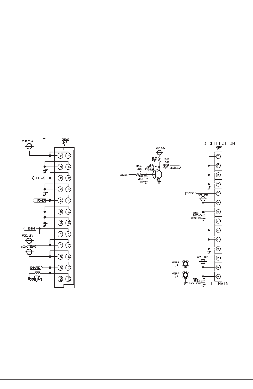
Troubleshooting
6-2 Samsung Electronics
6-1-1 Basic Approaches for Troubleshooting
■Troubleshooting Mechanism :
- The Main Board has Power part which supplies power to Deflection and Feature Box.
- The Feature Box receives all signal inputs,the signal-processed signal is sent to CRTAss'y.
- Deflection and Focus are controlled by the Deflection Board.
■Troubleshooting by Modules
1) Enter Service Mode
(In SET Stand-By Status,if you press "Info"→"Menu"→"Mute" and "Power" button in sequence on the remote control, the
screen is turned on and the Service Mode screen appears.)
2) Check if the System Board is out of order.
Press OPTION →TEST PATTERN →Right direction key:
The COLOR BAR, BLACK pattern and WHITE pattern are displayed on the screen.
If the pattern is not displayed or is displayed abnormally, the DNIe IC (SPD41) or the System Board is out of order.
3) Check if the Power Board, which supplies power to the System Board and the Deflection Board, is out of order.
If you cannot turn the screen on by pressing the POWER ON/OFF button or the screen repeatedly turns on and off when
pressing the POWER ON/Off button, check if the Power Board is out of order. (Refer to the circuit diagram)
4) Check if the Deflection Board is out of order.
When the screen is not properly displayed and the left or right side of the picture is shrunk, or the top or bottom of the screen
is expanded or shrunk, check if the Deflection Board is out of order.
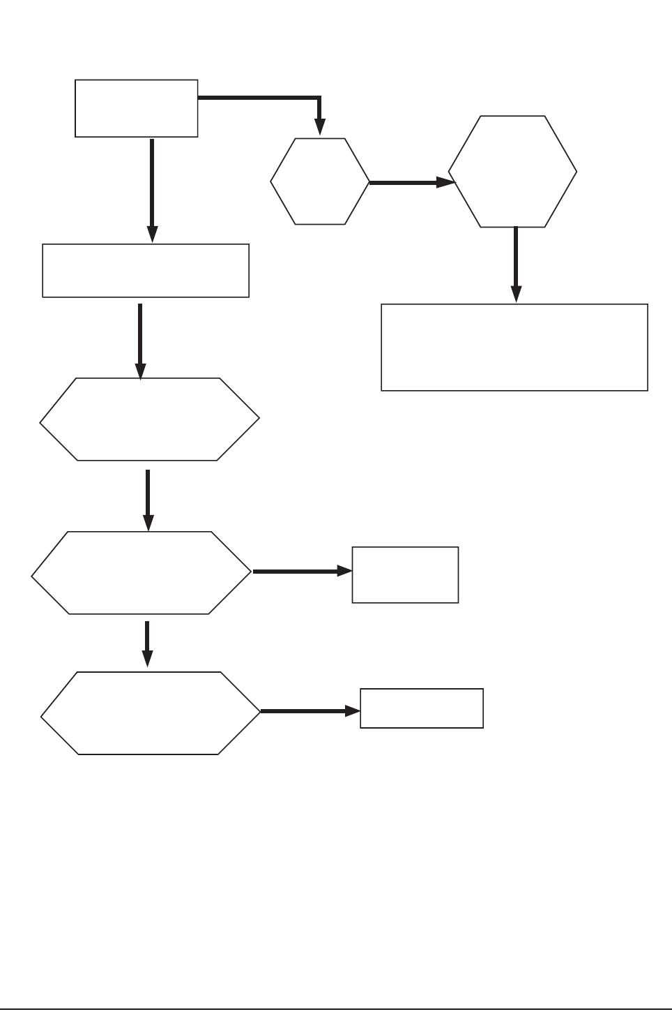
Troubleshooting
Samsung Electronics 6-3
6-1-2 Flow Chart for Malfunction
Does t h e TV wor k?
Is there
something on
the Screen
Do es t h e O S D
menu on t he
screen wor k?
Is the power cord or the
mast er switch out of order ?
Is the cable connecting
t he Power Boar d and t he
Def l ect i on Boar d proper l y
connected?
Is aCRT high voltage
been me asured?
NO
YES
YES
Check t hat t he cables ar e proper l y
connect ed t o M a i n Boar d.
ReplacetheFeatureBox,if necessary.
NO
NO
NO
NO
Connect t he cabl e
NO
NO
Repl ac e t he
Main Board
Is the cable from the
Mai n Boar d t o t he CRT
Ass' y proper l y connect ed?
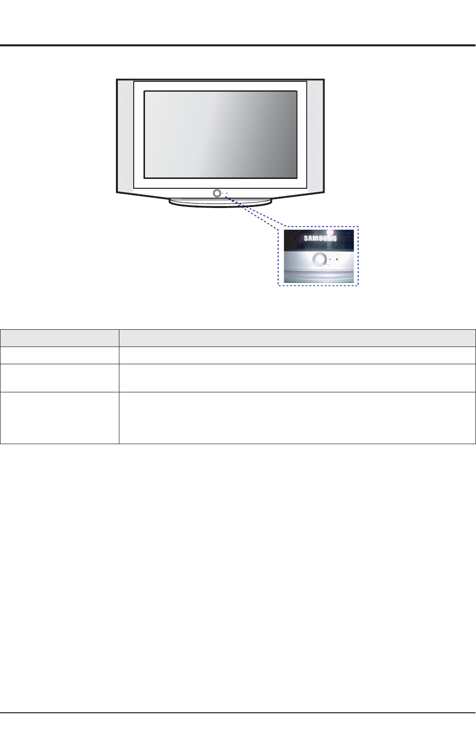
Troubleshooting
6-4 Samsung Electronics
6-2 Troubleshooting Procedures by Error Modes
6-2-1 Basic Troubleshooting: Diagnosis of LED on the Front Panel
6-2-2 Troubleshooting by the Checksum
■Diagnosis of trouble by the checksum is neither reliable nor convenient.
You can only use the checksume of the current direct-view TV to determine whether the software is corrupted or not.
The Checksum value is determined according to the version of the software loaded on the set.
Therefore, you can determine whether the software has been properly downloaded, if you know the correct checksum for that
version of the software.
You can check the checksum according in the following order.
Factory Mode →Checksum →Right Button →Calculate Checksum →Output Checksum (e.g. 0xab2b)
■Checksum Examples
T_COREOAKR1_1010 : checksum = 0xab2b
T_COREOAKR1_1014 : checksum = 0x4faa
Power Description
○This happens when the Master Switch is not pressed or the power cord is disconnected.
●This happens when the power cord is connected and the power switch is pressed.
If you cannot set the power switch on by pressing it, check the power switch Ass'y.
○→◑→●
If you press the power switch of the transmitter or the channel key on the remote control when in
St-BY status, the screen will be turned on.
If the LED blinks and the screen is not displayed, check the connection between the Power and
the System Board.
●: Light is On
◑: Light is Blinking
○: Light is Off
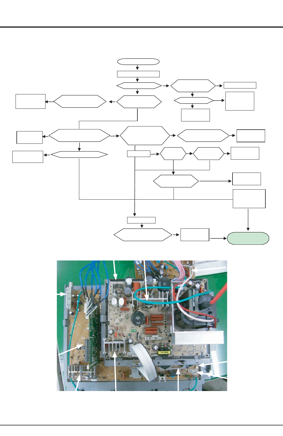
Troubleshooting
Samsung Electronics 6-5
6-3 Troubleshooting Procedures by ASS'Y
6-3-1 NO Power
1. Power Board Check
A
C Voltage Impress
IC803 #1CHECK FP801S FUS
E
CHECK
A
C FUSE CHAN
G
D801S
D801S
BRIGE DIODE
CHANGE
IC803
SPS IC CHANG
IC803 #4
CHECK
CHECK HOT
BLOCK
C815(B+) Voltage
check
F/back Line
Check
L811
Open
R820
Line
Q804
(VCC_5V_C)
Change
Materials
Change
Materials
F-Box Check
and Change the
Module
OVE
R
Change
Materials
12V Line
B+(132V) Line
O
K
F/BACK LINE
CHECK
Change
Materials No-Power
Repair End
L
Q406 H-OUT TR
FA801S/FA802
S
FUSE/
Change
Materials
Change
Materials
Change
Materials
No-Power
■ 12V Line
■ 132V F/B Lin e
NG NG
NG
NG
NG
NG
NG NG
NG
NG
NG
NG
NG
OK
OK
OK
OK
OK
OK
OK
OK or Low
IC501S
FP801S
POWER CORD
IC803S
IC301S
IC601
F/BOX
TU01S
IC804 Q406
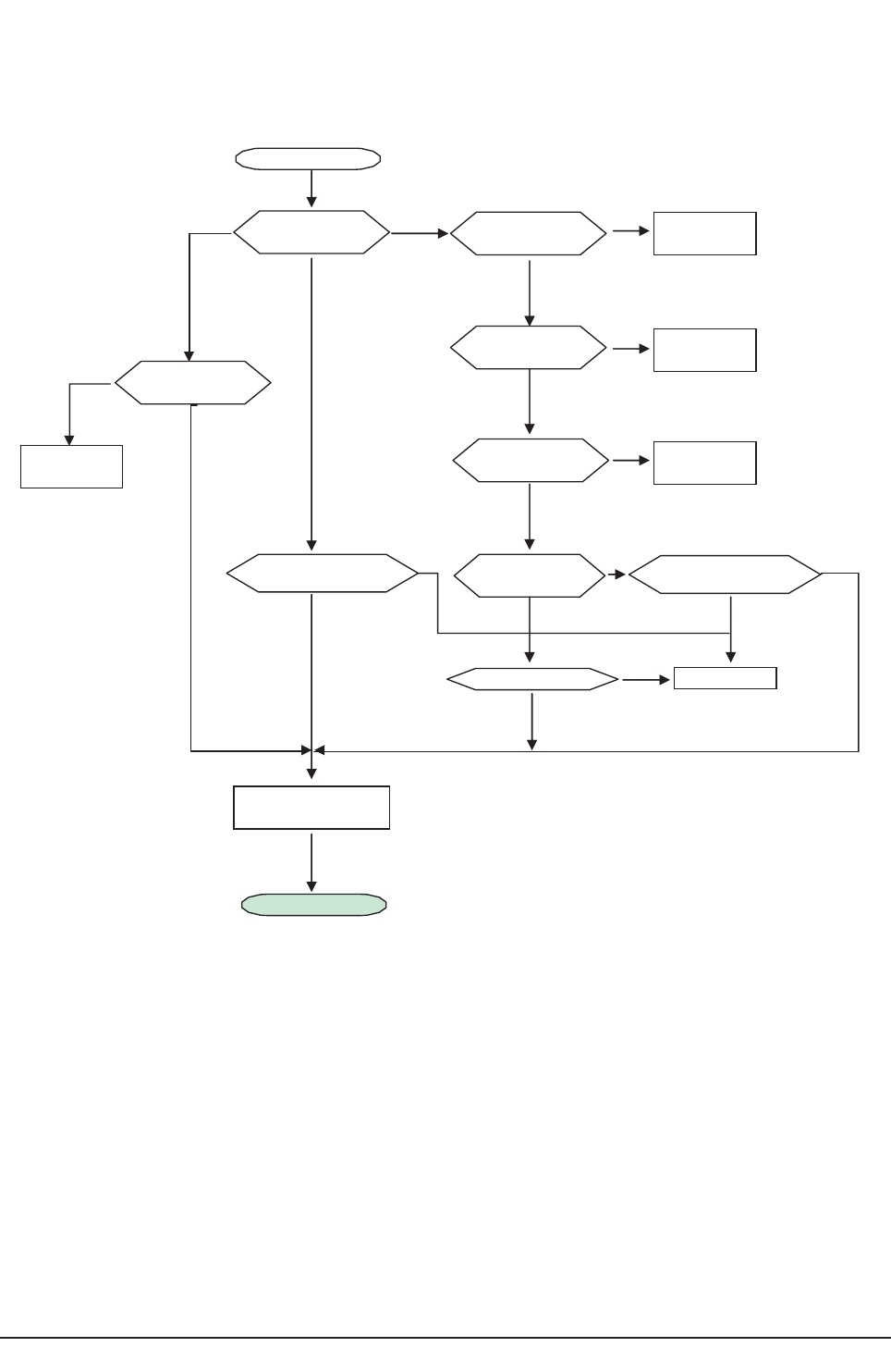
Troubleshooting
6-6 Samsung Electronics
6-3-2 NO Video
1. when the power is normal
RF,VIDEO
CEHCK
TU01
9V check
SCART1/SC
A
2
TU01
5V check
TU01
33V check
TU01 SDA/
SCL check
F-Box Module
Change
IC803 78R09
CHANGE
IC802 78R05
CHANGE
Tuner Change
DZ804 TZP33A
Change
Repair End
EXT: N o
R
F : O k
EXT : O k
RF : N o
Video:N o
RF : N o
Cehck A/V
Cabile
No-Signal
NG
NG
NG
NG
NG
NG
NG
NG
OK
OK
OK
OK
OK
OK
OK
OK
CVBSChe ck
OPENTuer SDA/SCLPIN
CheckSCL/SDA
C117 CVB S CHECK
OPENTuer SDA/SCL
PIN CheckSCL/SDA
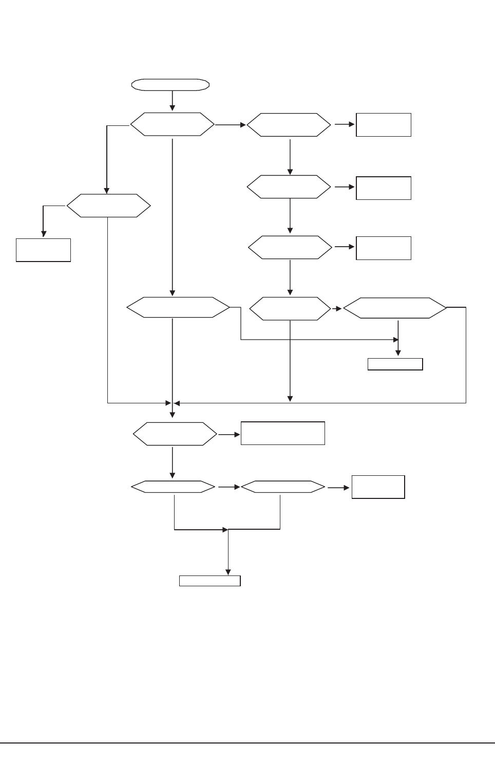
Troubleshooting
Samsung Electronics 6-7
6-3-3 No Sound
1. when the power is normal
Cehck A/V
Cabile
EXT : N o
RF : N o
EXT : O k
RF : N o
EXT : N o
RF : O k
DZ804 TZP33A
Change
Tuner Change
IC802 78R05
CHANGE
IC803 78R09
CHANGE
TU01 SDA/
SCL check
TU01
33V check
TU01
5V check
TU01
9V check
RF,EXT-IN
CEHCK
No-Signal
F-Box Module
Change
Change
Materials
AMP CHANGE
AMPB+ Check FA803S CEHCK
SCART1 /SCART2
CVBS Che ck
OPENTuer SDA/SCL
PIN Check SCL/SDA
OPENTuer SDA/SCL
PIN Check SCL/SDA
F-Box Mod ule
R/L-OU TCheck
NG
NG
NG
NG
NG
NG
NG
NG
NG
NG
OK
OK
OK
OK
OK
OK
OK
OK
OK OK
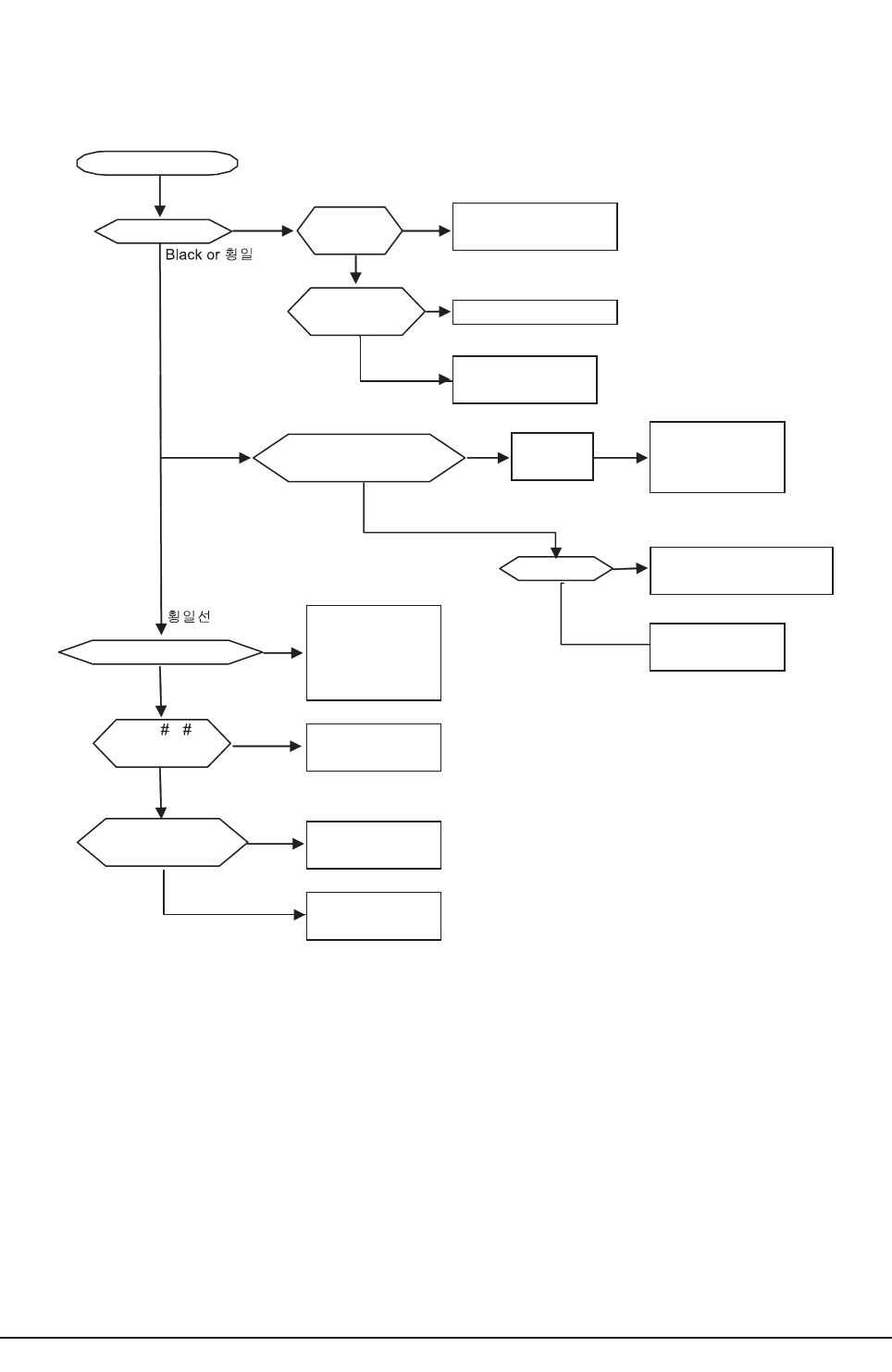
Troubleshooting
6-8 Samsung Electronics
6-3-4 No Raster
1. when the H/V is normal
CRT ASSY
CHECK
Heater Line
Fusible Resistor
change
FBT 16V/-16V Line
Diode and Fusible
Resistor check.
and Change
IC501 B+ Line Check
and Materials change
IC501
Output IC501 TDA6109 change
RGB Line Materials
Check and Change
Raster NG
OK
NG
OK
Black
Raste
Black
Go to the No-Video check
Flow Chart
NG
F-BOX Module
Change
NG
OK
F-BOX Module
Change
NG
Verticla IC
LA7845 Change
OK
OK
OK
NG
F-BOX Module
Change
No-Raster
IC501 B+
CHECK
CHECK
FBT Screen VR MAX
And Screen check
OSDCheck
Raster Check
FBT 1 6/ - 16VCHECK
IC301 4, 5
V-Sync Check
Vertical Block
Materials Check
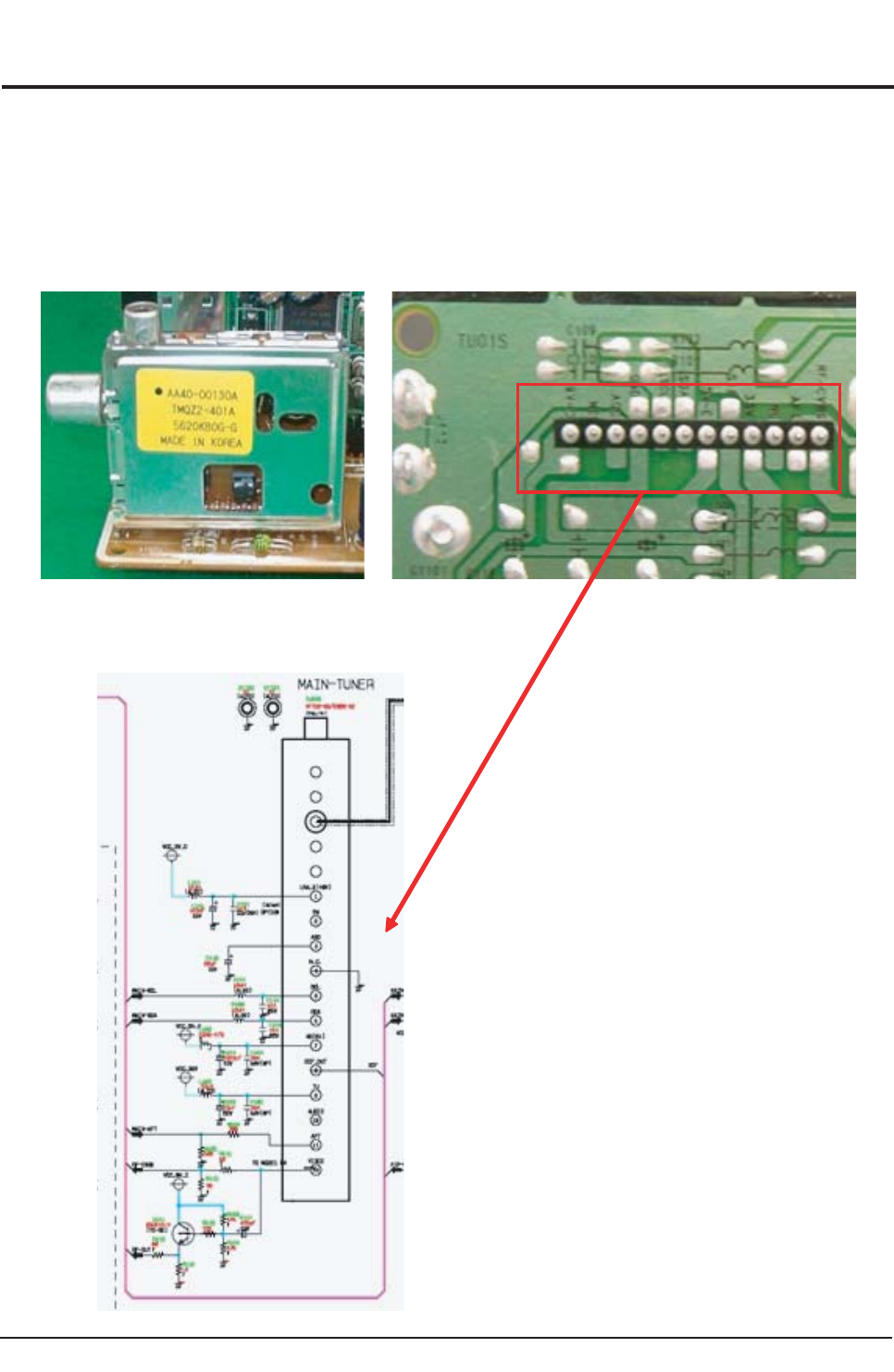
Troubleshooting
Samsung Electronics 6-9
6-4 Troubleshooting by Blocks
6-4-1 Troubleshooting System Boards
1. Tuner Diagnosis
- If no signal is received even though the RF signal from the external aerial is connected to the MAIN Board Tuner, check the
following items.
- Supply Power: 5V, 9V, 33V
- Check for an RF defect: Check the CVBS output
- Check for an AUDIO defect: Check the SiF Signal output
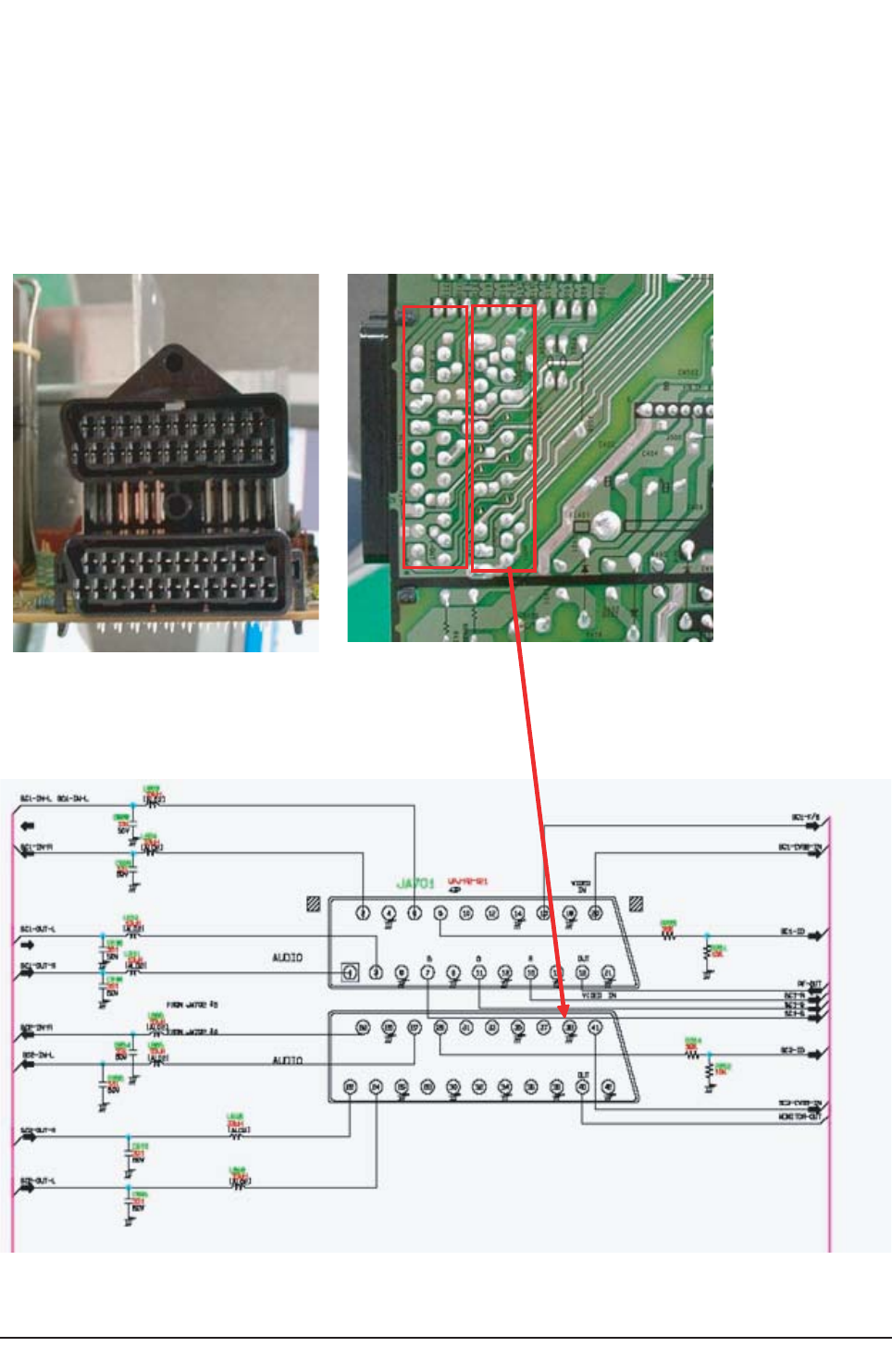
Troubleshooting
6-10 Samsung Electronics
2. External Input Diagnosis
It receives the EXT1/EXT2/signal and consists of monitor output (video and audio).
The signal is input to VSP9402 through the port. If no signal input/output is detected, check the following items.
- Power supply : VSP9402(3.3V,1.8V) , CXA2180(5V)
- Check if the input and output jacks are defective.
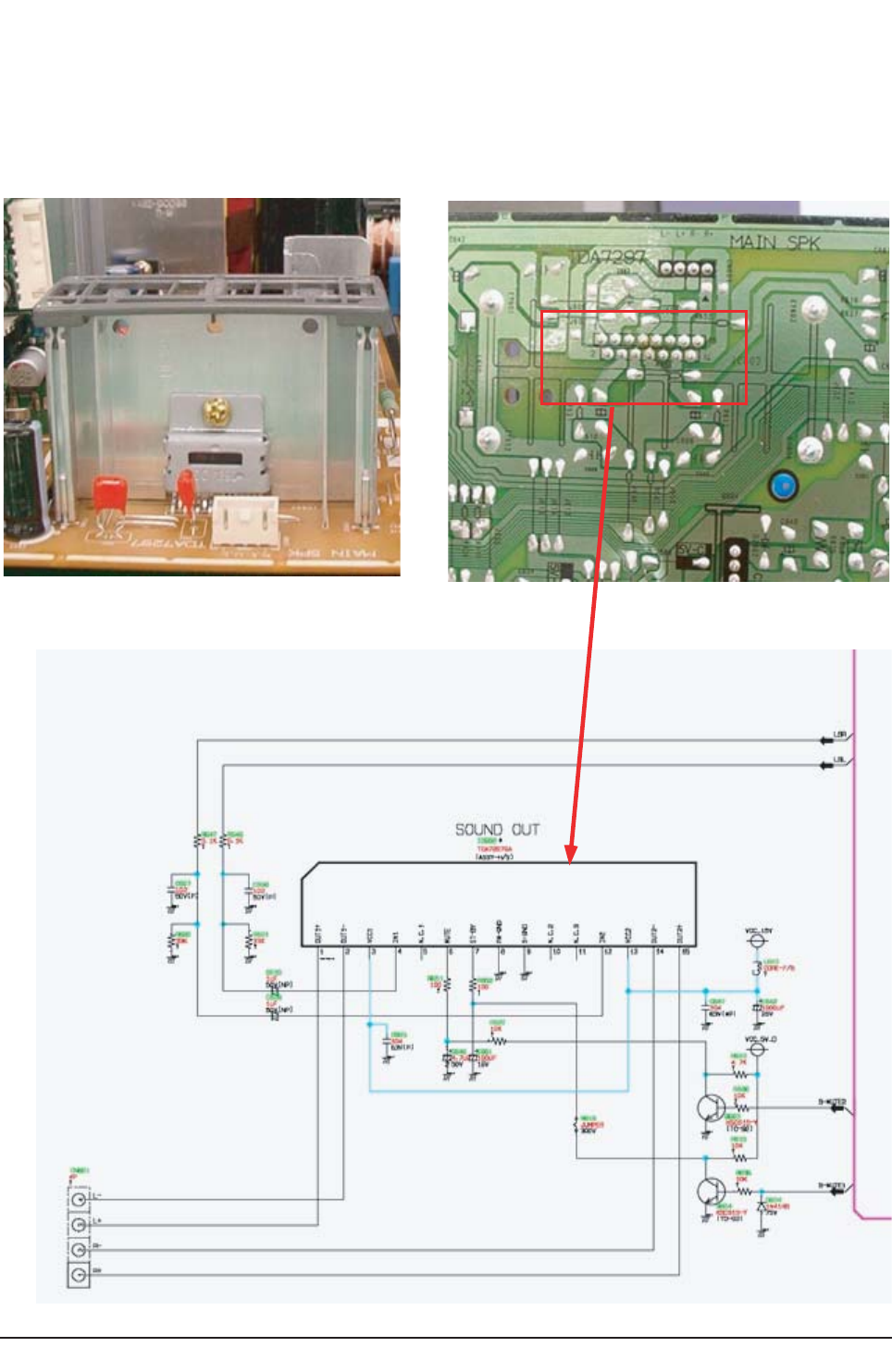
Troubleshooting
Samsung Electronics 6-11
3. DNIe (SPD41) Diagnosis
The signal is received from the Audio Processor (MSP3421G) and sound is output at 10W + 10W power.
- Power supply :15V
- Check for input defects : L/R
- Check for output defects : L+, L-, R+, R-
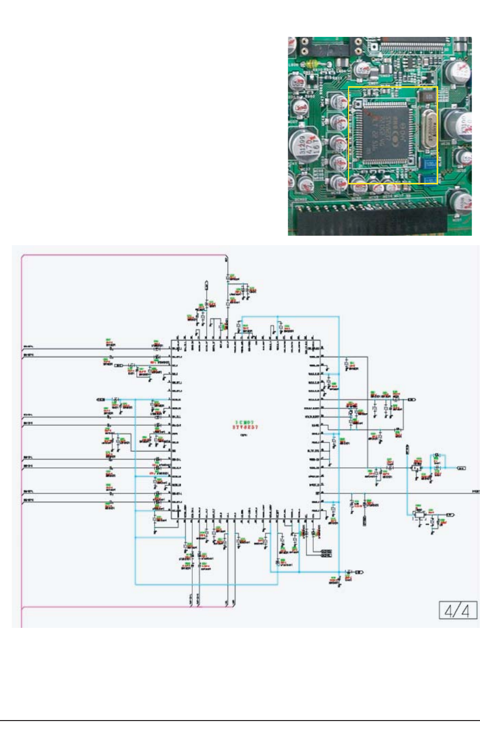
Troubleshooting
6-12 Samsung Electronics
4. STV8237(Audio Processor) Diagnosis
It processes the SIF and SCL 1/2 signal output from the Tuner.
- Power supply : 3.3V,1.8V,9V , 5V
- Check for input defects : SIF, SCL1/2-IN,SCL1/2-OUT
- Check for output defects : SOUND L/R
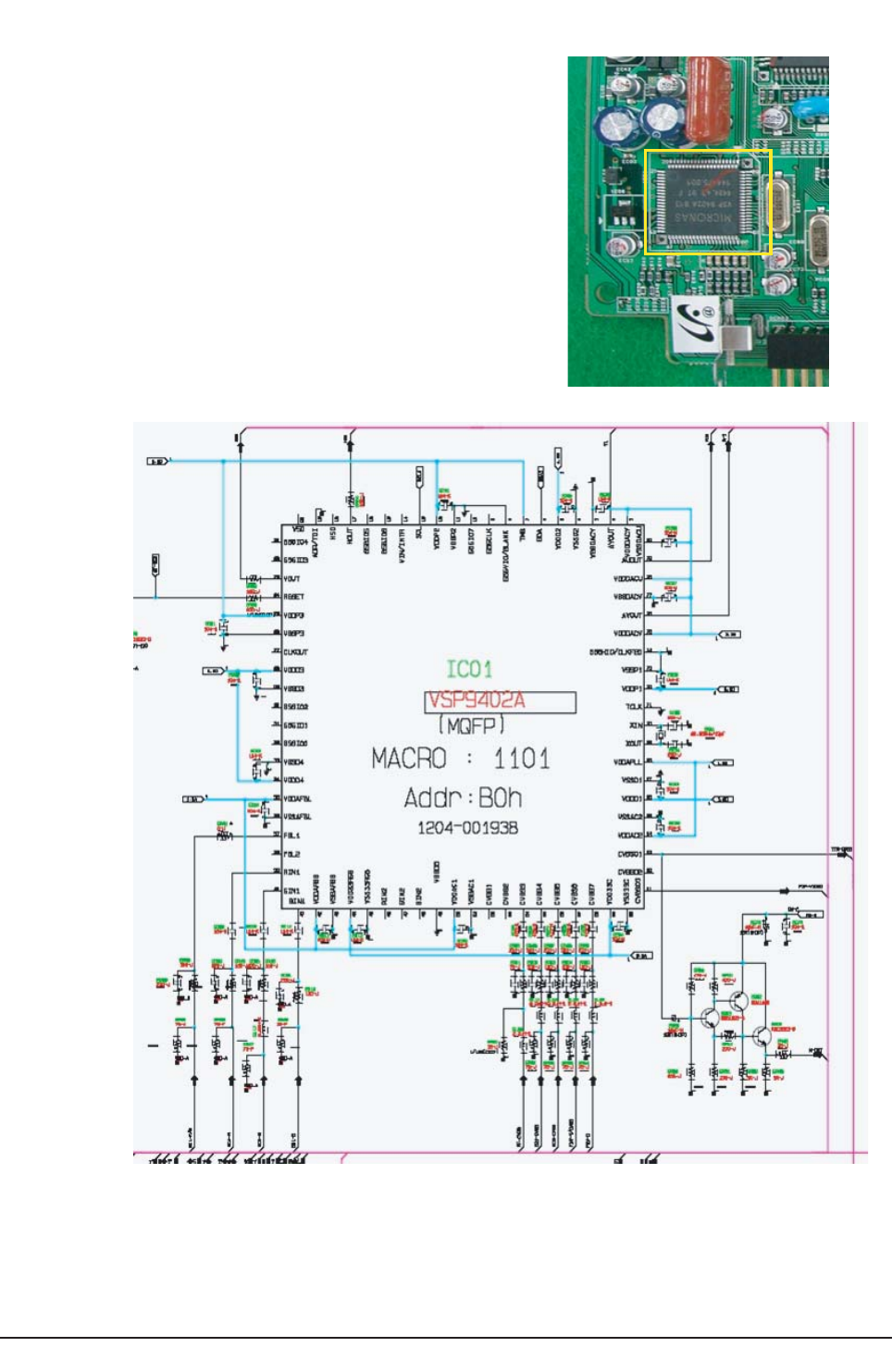
Troubleshooting
Samsung Electronics 6-13
5. VSP9402 Diagnosis
It receives RF, AV1/2/3 and S-VHS (Y,C) signals and outputs to Y/Pb/Pr of
CXA2180Q, M-OUT and V-OUT through internal switching.
- Power supply :1.8V, 3.3V
- Check for input defects : RF, SCL1/2,S-VHS(Y,C)
- Check for output defects :M-OUT,Y,Pb,Pr,HS1,VS1
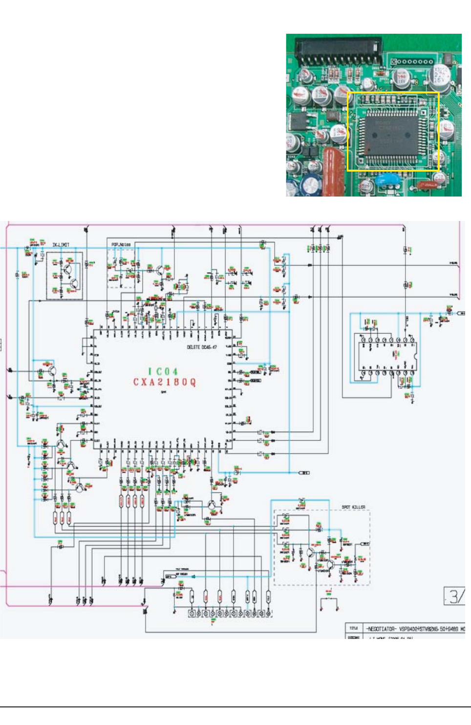
Troubleshooting
6-14 Samsung Electronics
6. CXA2180 Diagnosis
The Y/Pb/Pr signal is received from VSP9405B and CXA2151Q and the
signal is output as R/G/B. It also outputs the V/H Drive, E/W and performs
the ABL and EHT operation.
If V-Drive output is not detected, check for an IC defect.
- Power supply : 5V, 9V
- Check for input defects : Y/Pb/Pr, H/V
- Check for output defects : R/G/B, ABL, EW, V/H-DRIVE
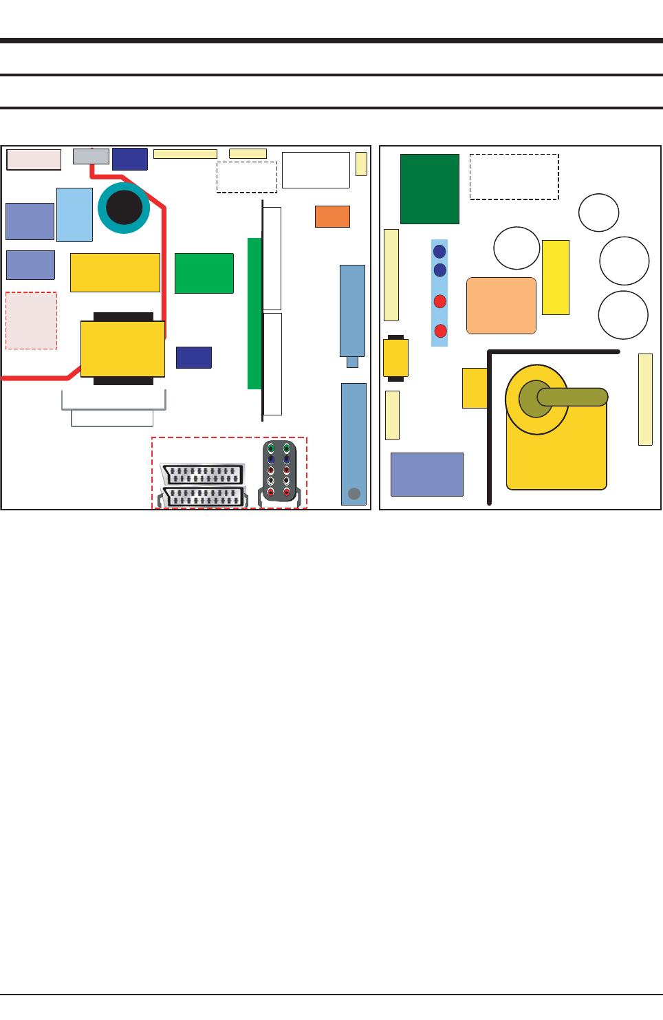
Block Diagram
Samsung Electronics 7-1
7. Block Diagram
7-1 Overall Block Diagram
SM P S
Blo c k C A P
DIODE
RECTIFIER
LIN E F ILTER
PFC
( O ption)
LINE FIL TER
M A IN
TRAN S
RELAY
AC INPUT
A UD IO A MP 4P
14 P 6P
Option
MAIN
TUN ER
PIP
TUN ER
34 P
34P
F
E
A
T
U
R
E
B
O
X
N/ S
BLO C K
Mu lt i D IO D E
IC
EEPRO M
5V
Re g ula to r
5V
Regulator
EW
IC
(KA393)
F B T
Vertic a l
A M P
H - O UT
TR
D y n am icFo c us
TRANS
6P
14P
HDT
10 P
D
A
M
P
E
R
N/ S
B L O CK
IN NER
CO IL
L in e a rity
C O IL
EW
C O IL
W id th
C O IL
C t / C s
C o n d e n s e r
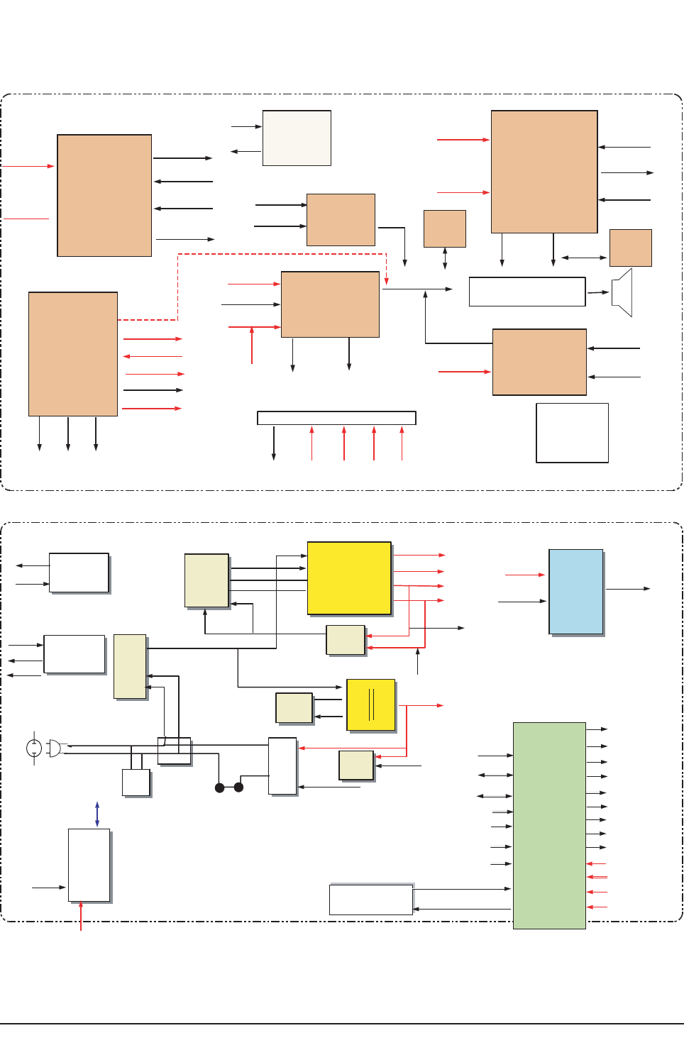
Block Diagram
7-2 Samsung Electronics
D
D
E F L E C T I ON B OA RD
V.H
V006
+B,V241
V
5
.6
1-
reta
eh
V03+
F.D
LBA
TNOCVH
T
HE
WE
O_WE
TNOCVH
V
0
3
V21
V5
.61-
V5.61+ P_DV
N_DV
O_
2
V
O_1
V
KLB-V
Y.D
V5.61+
B-V5+
TNOCVH
V51+
TUO_TDH
KLB_H
drao
b
TRCO
T
LBA
V5.61+
V5.61-
+B,V241
r
eta
eh
V
00
6
+B
rr
ocsucof
F.D
O
_2V
V21
i080
1
rewop
noitcennoc
niam
noitcennoc
i
0
8
0
1
+B,V241
B
-V5+
V51+
V9+
B-V5
V3.3
V9
TRC
f
fo/n
o
E
V
I
RD_H
W
/E
KCOLB
V.H
noitcerroc
V.H
noitcerroc SRH
LACI
T
REV
S.N
TBF
EVIR
DH
K
C
OLB
SUCOF/D
RTS
7576X
CFP
Y
3
2
1
CP
SP
165
2
+B,V61
+B,V5.7
+B,V61
+B,V241
egdirB
edoiD
yaleR
i0801
+B,V5S
rewo
p
tupniCA
repiV
PIDA21
V81
D
k
cab/F
liocgnissuageD
eniL
retliF
V?
?
V32
ccV
SNARTni
aM
SNARTNTS
P
VO
PLO
yaler
1etum-S
n
oitcel
fed
noit
c
e
n
n
o
c
niam
noitc
e
n
n
o
c
etum-
S
rewop
yaler
i08
01
ffo/no
+B,V5
S
+
B,V61
+
B
,V5
.
7
+B,V241
+B,V51
+B
,V
9+B,V5
DNUOS
PMA
7927ADT
B-V5
1
2etum-S
1
et
u
m-S
-L,
LNI
AM
+R,RNIAM
MT
KCOLB
A
DSM
,
LC
SM
V3
3
B
-
V
5
SBVCF
R
T
UOF
R
SB
V
CP
IP
T
F
A
BKA,MV,BGR
tuO
lortn
o
Ctl
i
T
l
o
r
tnoCl
i
oC
-
D
tuO
et
uM
tuONV
,
PV,WE
tuOevirD-H
tuO05_i080
1
nIC/Y
L
C
S/AD
S
L
C
S/AD
S
P
W
DI-2S/
D
I
-
1S
xo
B
-F
tracS
nIBGR,V/A
tuOrotinoM,FR
KL
B
V
/
H
rP,bP,
Y
)
n
o
it
p
O
TFA rewoP
to
p
S
V3.
3
D-V5,C-V5
V9
V21
M A IN B O A RD
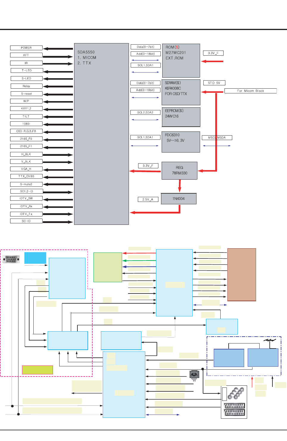
Block Diagram
Samsung Electronics 7-3
7-2-1 Micom Block Diagram
7-2-2 Video Block Diagram
BA7657
/
SBV
C
_
X
TT
TU
O
RO
TINOM
B
,
G
,R
A
G
V
V,H
/
V
,r
P
bP,Y
TUO_
H
evirD
_W
E
e
vi
r
D_H
0
F_
5
612
1F
_
56
1
2
AD
S
,
L
C
S
V33
B-V5
B-V9
TFA
BF,B,G,R:1TRACS
)NOITPOACR(rP,bP,Y:1VTD,1DVD
)1TRACS,1VA(1SBVC
SBVCNIAM
SBVC-PIP
)2TRACS,2VA(2SBVC
C,YV/ATNORF
SBVCV/ATNORF
R
C
A
VG A
PIP
F
I+REN
UT
NIAM
FI/AN
L/
UT
TM BLOCK
TUOSBVCFR
A
DS
,
L
C
S
M
VS
B
F
,B
,
G
,
RD
SO
R- O U T
G- OUT
B - O U T
P_DV
N_DV
BKA
L
B
A
T
HE
KNALB_V
KNA
L
B
_H
B/F,B,G
,
R-PIP
S
BVC-
P
IP
2S
V
2
S
H
2
r
P,2
bP,
2
Y
2SV
2
S
H
)NOITP
O
A
CR
(rP,bP,Y:1VTD,
1
DVD
noitpOVTD
CXA2151
BA7657
74HC123
SDA9489
CRT-ASSY
BLOCK Deflection
BLOCK
CXA2165
V9/V5
V
5
VSP9402
2
S
H
2S
V
2rP,2b
P
,2Y
V8.1/V3.3
7-2 Partial Block Diagram
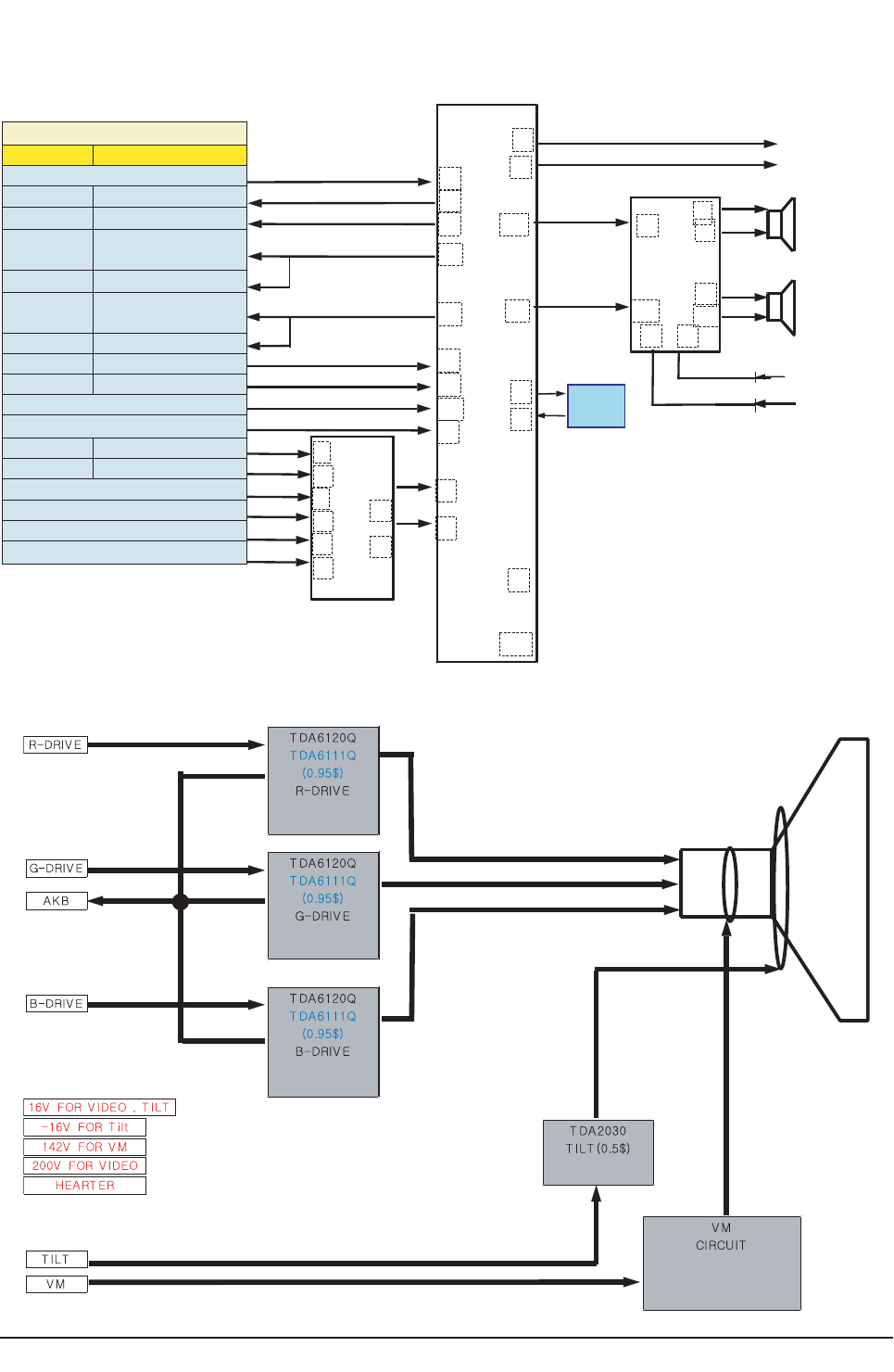
Block Diagram
7-4 Samsung Electronics
7-2-3 Sound Block Diagram
SS
TT
VV
88
22
33
77
2
73
1
14
18
15
9
43
10
19
28
29
30
6
2
14
4
12
7
1
15
1
2
23
24
53
52
66
44
22
22 13
12
17
8
4
21
6
19
IN PU T SOURC E
RCA JA C K SCA RT
M A I N SIF I N PU T
S1 RF OU T - R
S1 RF OU T - L
M ON IT OR
OU T - R S2 M ONIT OR OU T - R
S2 L IN E O U T - R
M ON IT OR
OU T - L S2 M ON I T OR OU T - L
S2 LIN E OU T - L
A V 1 IN - L S1 A U D IO IN - L
AV 1 IN - R S1 A UDIO IN - R
Side- A/ V (A V 3 )IN - L
Si d e-A / V (AV 3 ) I N - R
A V 2 I N - L S2 A U D I O I N - L
A V 2 IN - R S2 A U D I O I N - R
D V D 1 (D T V ) I N - L
DV D 1(DT V ) IN -R
DV D 2 (DT V ) IN - L
D V D2 ( D T V )I N - R
MAIN- L OUT
MAIN- R OUT
Sound Amp
TDA7297
S- MU TE1
From B+
S- MU TE2
From M icom # 49
MA IN
MA IN
SPK- L
SPK- R
L +
L -
R+
R -
SCL
SDA
1166VV
PPQQFFPP
8800PP
●
●
27MHz
X-TAL
7-2-4 CRT Diagram
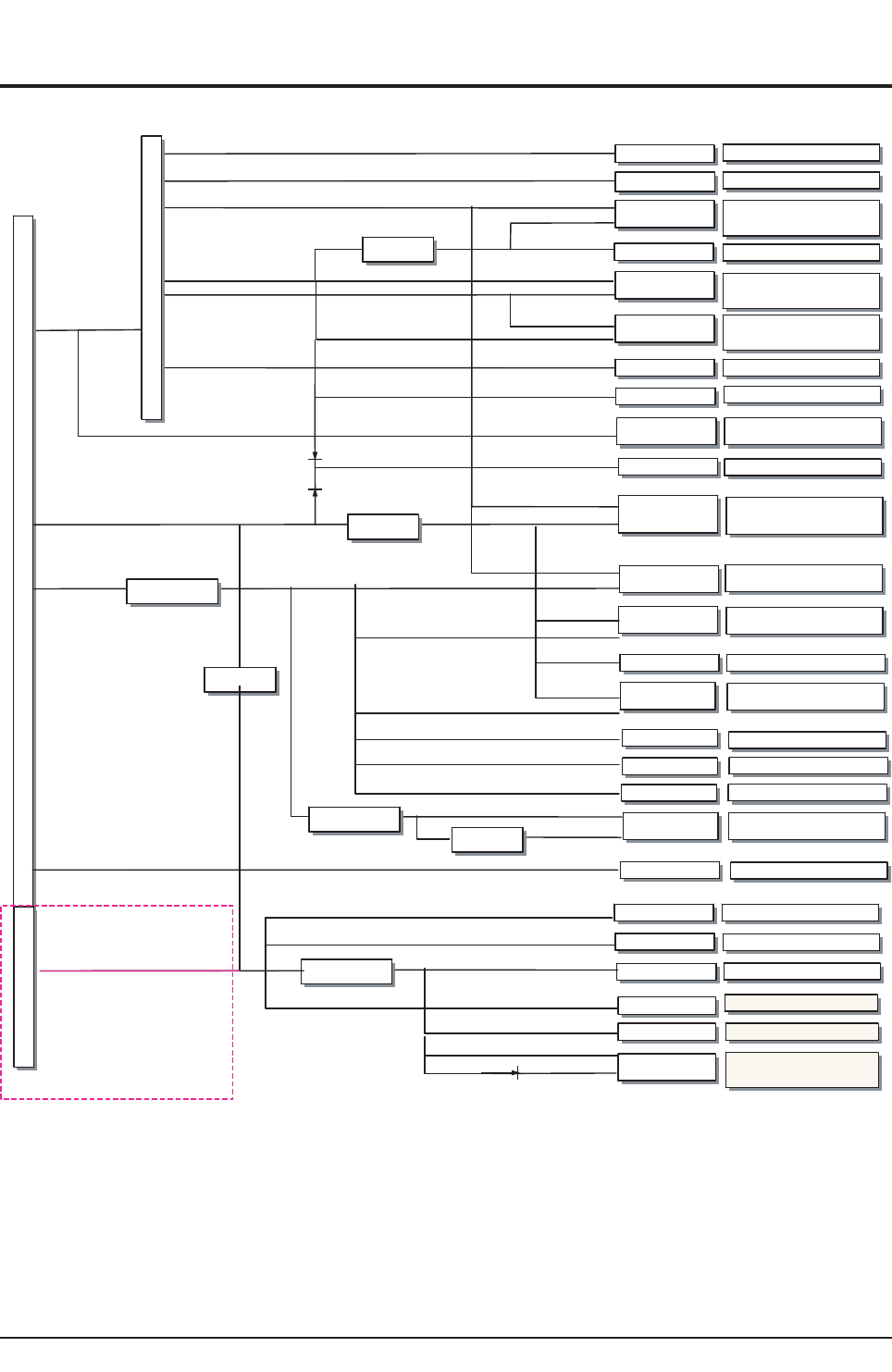
Block Diagram
Samsung Electronics 7-5
7-3 Power current block diagram
S
M
P
S
1 3 5 V / m A
1 2 V - A / m A
M A I N A M P 7 29 7
D- COIL RELAY
LED & CONT ROL
E2PROM 24WC16
5 V - S/ m A
5 V - S/ m A
3 .3 V - S / m A
1 4 V - A / m A
9 V - B / m A
- 1 6 .5 V - B / m A
2 0 V - B / m A
V ID EO_2 0 0V / m A
6 .3 V r m s / m A
3 2 K V / m A
6 0 0 V - B / m A
3 .3 V - B / m A
S
T
D
T
R
A
S
M 2 7 W 2 0 1 - 8 0 F 6
3 .3 V - S/ m A
SD A 5 5 5 0 M
( M I O CM ,T T X )
3 .3 V - S/ m A
2 .5 V - S/ m A
K 6 R 4 0 0 8 C
5 V - S/ m A
7 8 RM 3 3
6 .8 V - S / m A
7 .5 V - A / m A
1 .8 V - B / m A
3 .3 V - S / m A
5 V - C / m A
1 6 V / m A
●
●
●
●
●
●
●
●
●
●
●
●
●
●
●
●
●
●
●
●
●
F
B
T●
●
●
7 8 1 2
●
7 8 R0 9
V ERT ICA L
L A 7 8 4 5
E - W K A 3 9 3
DYN AM IC M C 4 5 5 8 C
V M C ICU RT
2 SA 1 0 1 1 / 2 SC 2 3 4 4
T U N E R M ain
DYNA MIC FOCUS T RANS
C RT B E A M C U RR E N T
C RT H E A T E R
T IL T
T D A 2 0 3 0
T U N E R P IP
( Op t i o n )
HDT
C RT D R IV E
T D A 6 1 1 1 Q X 3
SOU N D PROC ESS
ST V 8 2 3 6
3 2 K V / 1 .6 m A
2 0 V / m A
- 1 6 .5 V / m A
9 V - B / m A
5 V - C / m A
6 .3 V / 3 0 0 m A
- 1 6 .5 V / m A
2 0 V / m A
6 0 0 V / m A
2 0 V / m A
2 0 0 V / m A
1 2 V / m A
C X A 2 1 6 5
( M A T RI X , D E F L E C T I O N )
C X A 2 1 5 1 ( S W I T C H , CON . )
B A 7 6 5 7 ( D T V O p t i o n )
7 4 H C 1 2 3 ( SY N C)
V S P 9 4 0 2
( D E C ,SRC , P IP )
T E A 6 4 2 2 ( O p t i o n )
9 V - B / m A
5 V - B / m A
3 .3 - B V / m A
1 .8 - B V / m A
5 V - B / m A
5 V - B / m A
5 V - B / m A
9 V - B / m A
1 2 V / m A
2 0 V / m A
1 3 5 V / 1 0 0 0 m A
2 0 V / m A
3 3 V / m A
9 V - B / m A
5 V - C / m A
3 3 V / m A
5 V - C / m A
2 7 8 R0 5
9 V - B / m A
L F 1 . 8 V
7 8 0 5
●
●
ST - B y 1 W O p t i o n
7 8 RM 3 3
ASIA

7-6 Samsung Electronics
MEMO
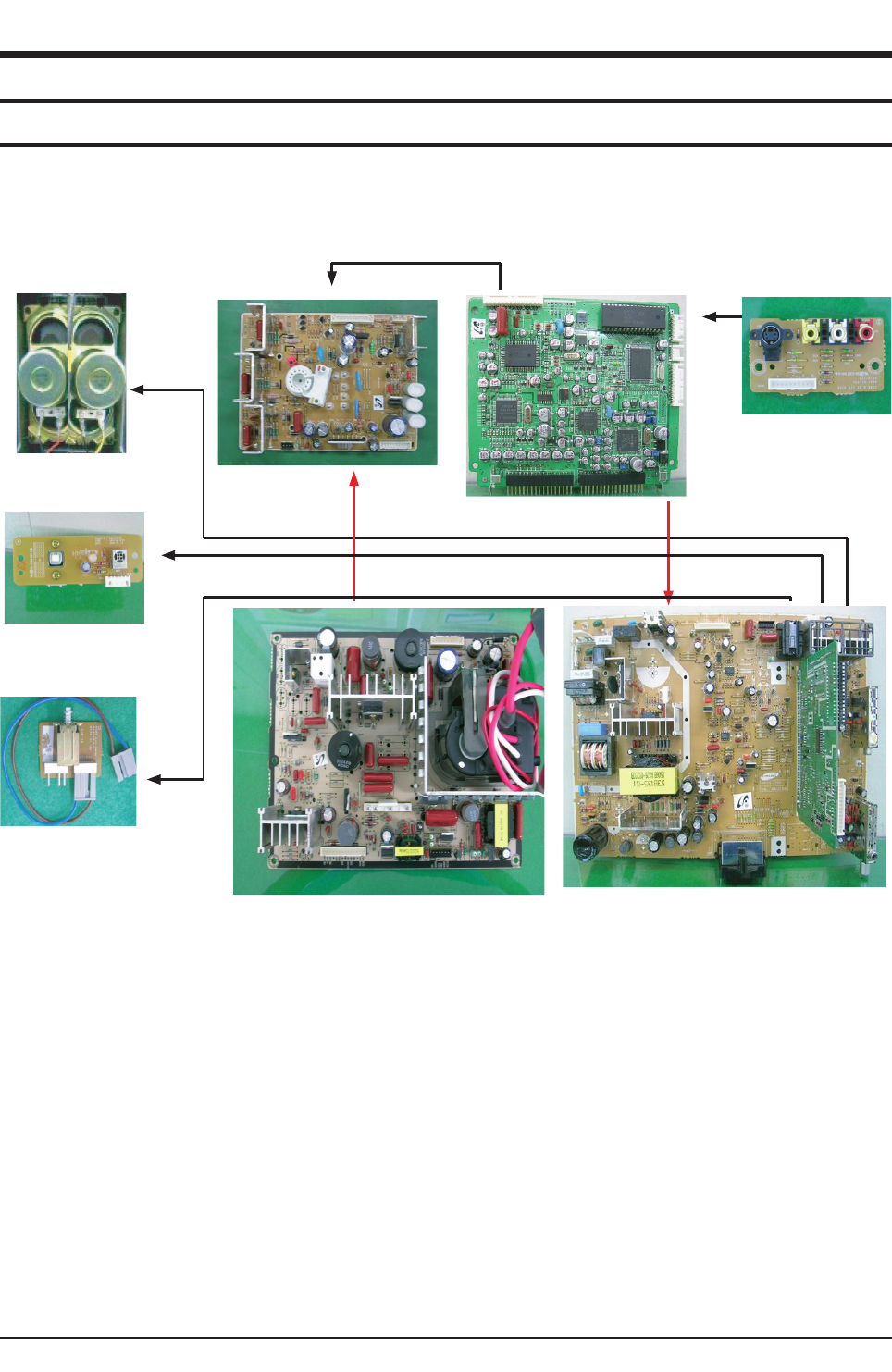
Wiring Diagram
Samsung Electronics 8-1
8. Wiring Diagram
8-1 Overall Wiring
SOUND OUT
KEY- CONTROL
AC - IN
F- BO X I N S E RT
AV-I N
CRT PCB POWER
CRT PCB SIGNAL
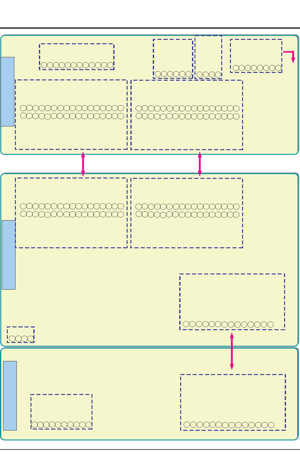
Wiring Diagram
8-2 Samsung Electronics
8-2 Pin Connection
T
T
O CRT
HDRIVE_O U T
VCC_HDT_16V
VC C _20V
VC C _142V
G N D
NC
VC C _142V
ABL
H_PU LSE
VD_P
EW _OU T
V_B LA NK
G N D
VD_N
13
11
9
7
5
3
1
14
12
10
8
6
4
2
TOSPK
-L
+L
-
R
+
R
4
3
2
1
SI D E A V
GND
SC _IN
SY_IN
S- ID
NC
AV1_L_IN
G N D
7
6
5
4
3
2
1
AV1 _R- IN
8
FRONT
CONTROL
POWER(KEY2 )
GND
5V
STD- LED
NC
IR
6
5
4
3
2
1
GND
KEY1
NC
KEY3 ( TV/ VID EO )
4
3
2
1
T O C RT
G N D
B O UT
G O U T
GND
IK
RO U T
GND
7
6
5
4
3
2
1
PO W ER
TILT
A15V
G N D
12
11
10
9
8
D EF LEC TIO N MA IN F- B o x
Sc a rt1 - VI
Scart1 - Vo
Sc art1- Ro
Scart1 - S/ W
Sc a rt2- VI
Sc art1 - RI
Scart1 -Lo
Sc art2 -RI
Sc art2 - Lo
Sc art2 -Ro
Scart1 -LI
13
11
9
7
5
3
1
23
21
19
17
15
14
12
10
8
6
4
2
24
22
20
18
16
EW
H - D rive
H- B lan k
ABL
VCC - 9 V-B
Sc art2- ID
Sc a rt1 - G
Scart1 - B
Sc art1 - R
Sc a rt1- F/B
V-B lank
Sc a rt1-ID
2526
28
2930
3132
33 34
27
Scart2 - Vo
Po w er
S- M ute2
D- C o il
S- M u te 1
Ma in - Lo ut
5V- D
5V- C
SD A 2
3.3V- E
GND
5V- F
13
11
9
7
5
3
1
23
21
19
17
15
14
12
10
8
6
4
2
24
22
20
18
16
VCC- 12V
M a in - Ro ut
SC L 1
C o m p - Pr
SD A1
Co m p - Pb
C o m p - Y
2526
28
2930
31 32
33 34
27
AFT
VN
VP
VCC_- 16.6V
H EATER
VCC_16.6V
NC
VID EO
NC
G N D
VC C - 142V
NC
ABL
7
6
5
4
3
2
1
10
9
8
G N D
GND
GND
GND
G N D
GND
G N D
G N D
GND
GND
G N D
G N D
G N D
GND
G N D
G N D
GND
G N D
G N D
GND
GND
G N D
Sc art1 - VI
Sc a rt1 - Vo
Sc a rt1- Ro
Sc a rt1 - S/ W
Sc a rt2- VI
Sc art1 - RI
Sc a rt1 - Lo
Sc a rt2 - RI
Scart2 -Lo
Sc art2 - Ro
Sc a rt1 - LI
13
11
9
7
5
3
1
23
21
19
17
15
14
12
10
8
6
4
2
24
22
20
18
16
EW
H - D rive
H - B la nk
ABL
VC C - 9 V- B
Sc a rt2- ID
Sc art1 - G
Scart1 - B
Sc art1-R
Sc art1 - F/B
V- B lan k
Scart1- ID
25 26
28
29 30
3132
33 34
27
Scart2 - Vo
Po w er
S- Mute2
D - C o il
S- M u te1
M a in -Lo u t
5V- D
5V- C
SD A 2
3.3V- E
G N D
5V- F
13
11
9
7
5
3
1
23
21
19
17
15
14
12
10
8
6
4
2
24
22
20
18
16
VCC-12V
M a in - R o u t
SCL1
Co m p - Pr
SDA1
Com p - Pb
C o m p -Y
2526
28
29 30
31 32
33 34
27
AFT
VN
VP
G N D
G N D
G N D
G N D
GND
GND
G N D
GND
GND
GND
G N D
G N D
G N D
GND
G N D
G N D
G N D
G N D
GND
G N D
G N D
G N D
H D RIVE_O UT
VC C _H D T_16V
VC C _20V
VCC _1 4 2V
G N D
NC
VCC_142V
ABL
H_PU LSE
VD_P
EW _O U T
V_B LA NK
G N D
VD _N
13
11
9
7
5
3
1
14
12
10
8
6
4
2
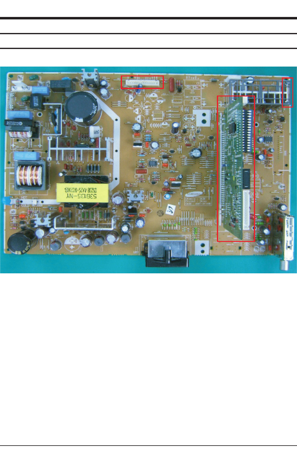
PCB Diagram
Samsung Electronics 9-1
9. PCB Diagram
9-1 Main Board
CCNN440011
CCNN660011
FF__BBOOXX
9-1-1 Assy Main Board
■The System Board that Controls Various Signals for Video Signal Processing and Product Operations
9-1-2 Names & Roles of Key Parts
*CN601 : This is a 4 pin port connected to the Speaker, and sends the signal from the AMP to the speakers.
*CN401 : This is a 14 pin port connected to the Deflection Board and supplies 135V, 16V and receives 20V voltage and the
power on and off signals to the Deflection Board
*GT804 : This is a ground port to prevent high voltage due to lightning and is connected to the Deflection Board.
*CN802 : This is a 3 pin port connected to the AC power cable. It is connected to the power cable socket.
*GT805, GT806 : This is a port connected to the D-Coil surrounding the CRT.
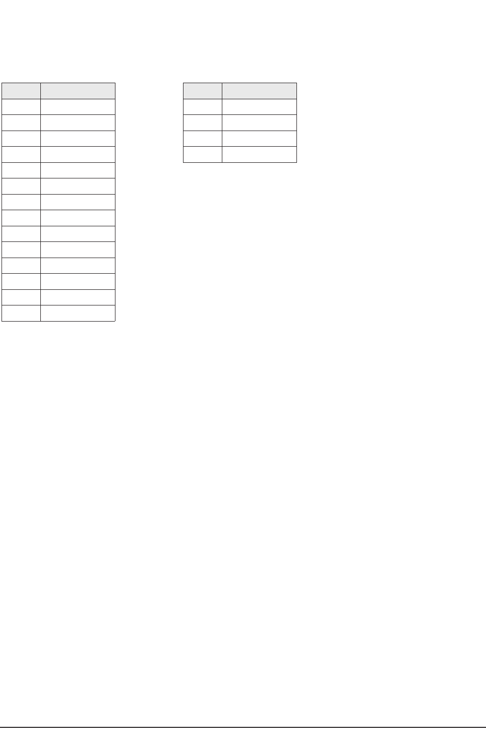
PCB Diagram
9-2 Samsung Electronics
9-1-3 Main Board Connector Pin
CN401
Connected to the Deflection Board
PIN No. Pin Name
1 V_BLANK
2 EW_OUT
3 H_PULSE
4 ABL
5 VD_P
6 VD_N
7 VCC_20V
8 GND
9 HDRIVE_OUT
10 VCC_HTD_16V
11 GND
12 NC
13 VCC_142V
14 VCC_142V
PIN No. Pin Name
1 R+
2 R-
3 L+
4 L-
CN601
Connected to the Speaker Port

PCB Diagram
Samsung Electronics 9-3
9-2 Feature Box Board
9-2-1 Assy Feature Box Board
CCNN0033
CCNN0077
CCNN0066
CCNN7700
1
1
■This controls the path of the electron beams from the CRT electron guns using the deflection coil.
9-2-2 Names & Roles of Key Parts
* CN03 : This is a 14 pin port connected to the CRT Assy's, and outputs final R/G/B signals to the CRT Ass'y.
In addition, it outputs the Tilt, VM, and Power signals for the CRT Drive.
* CN07 : This is a 6 pin port connected to the Master Ass'y, and receives Master Power On/Off, and IR signals.
* CN06 : This is a 4 pin port connected to the Control Ass'y, and receives TV/Video, Menu, Ch Up/Down and Vol -/+ signals.
* CN701 : This is a 10 pin port connected to the Side AV, and receives S-Video2 and AV4 external inputs.
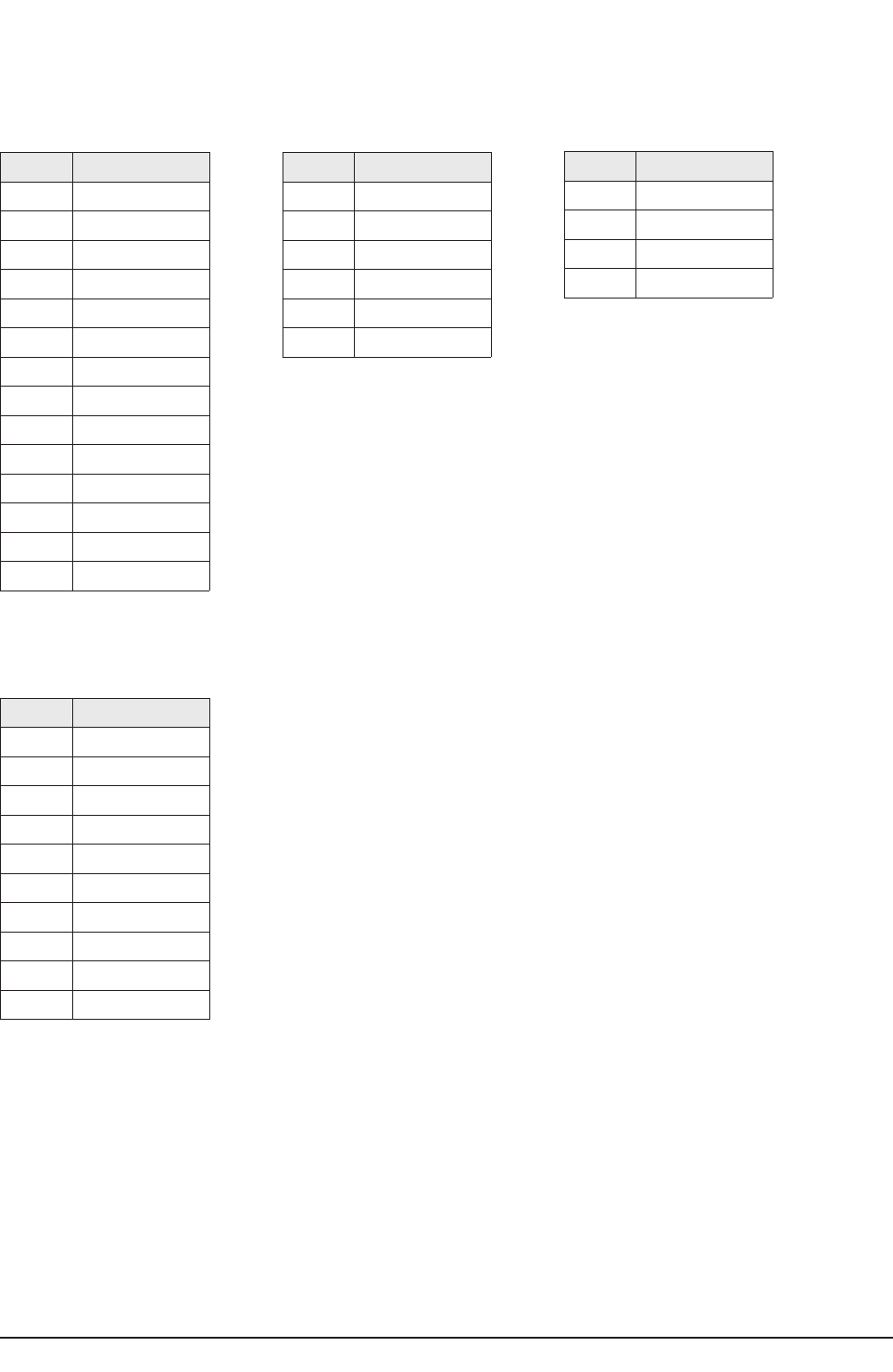
PCB Diagram
9-4 Samsung Electronics
9-2-3 Feature Box Board Connector Pin
CN03
Connected to the CRT Ass'y
CN07
Connected to the Master Ass'y
CN06
Connected to the Control Ass'y
PIN No. Pin Name
1 TILT
2 POWER
3 GND
4 VM
5 12V-A
6 12V-B
7 GND
8 R-OUT
9 GND
10 G-OUT
11 GND
12 B-OUT
13 GND
14 IK
PIN No. Pin Name
1 NC
2 STD-LED
3 GND
4 KEY2
5 5V
6 IR
PIN No. Pin Name
1 KEY3
2 A10
3 KEY1
4 GND
CN701
Connected to the Side AV Port
PIN No. Pin Name
1 S-Y2
2 GND
3 S-C2
4 GND
5AV
6 GND
7 AV4-L
8 GND
9 AV4-R
10 GND
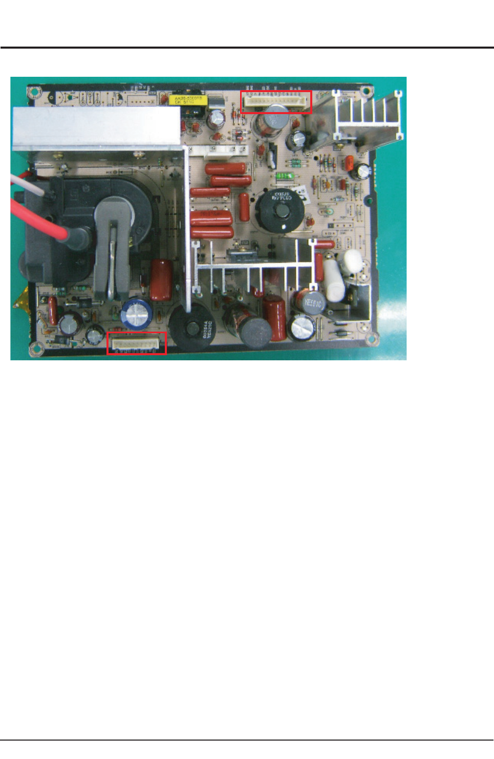
PCB Diagram
Samsung Electronics 9-5
9-3 Deflection Board
9-3-1 Assy Deflection Board
CCNN440011
CCNN440033
■The Assy Power Board supplies DC power. This supplies power to the System and the Deflection Board.
9-3-2 Names & Roles of Key Parts
*CN401 : This is a 14 pin port connected to the Main Board and is supplied 135V, 16V power by the Main Board and the power
on and off signal.
*CN403 : This is a 10 pin port connected to the CRT Ass'y, and supplies power for the CRT and R/G/B signal amplifying AMP.
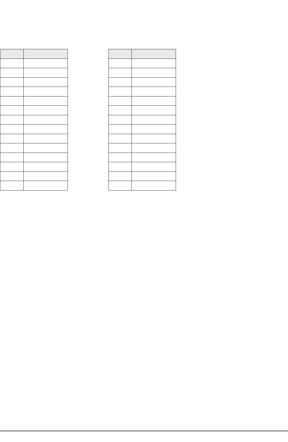
PCB Diagram
9-6 Samsung Electronics
9-3-3 Deflection Board Connector Pin
CN401
Connected to the Main Board
CN403
Connected to the CRT Ass'y
PIN No. Pin Name
1 V_BLANK
2 EW_OUT
3 H_PULSE
4 ABL
5 VD_P
6 VD_N
7 VCC_20V
8 GND
9 HDRIVE_OUT
10 VCC_HTD_16V
11 GND
12 NC
13 VCC_142V
14 VCC_142V
PIN No. Pin Name
1 VCC_200V
2 NC
3 HEATER
4 VCC_-16.5V
5 VCC_20V
6 GND
7 NC
8 ABL
9 NC
10 VCC_135V
11
12
13
14
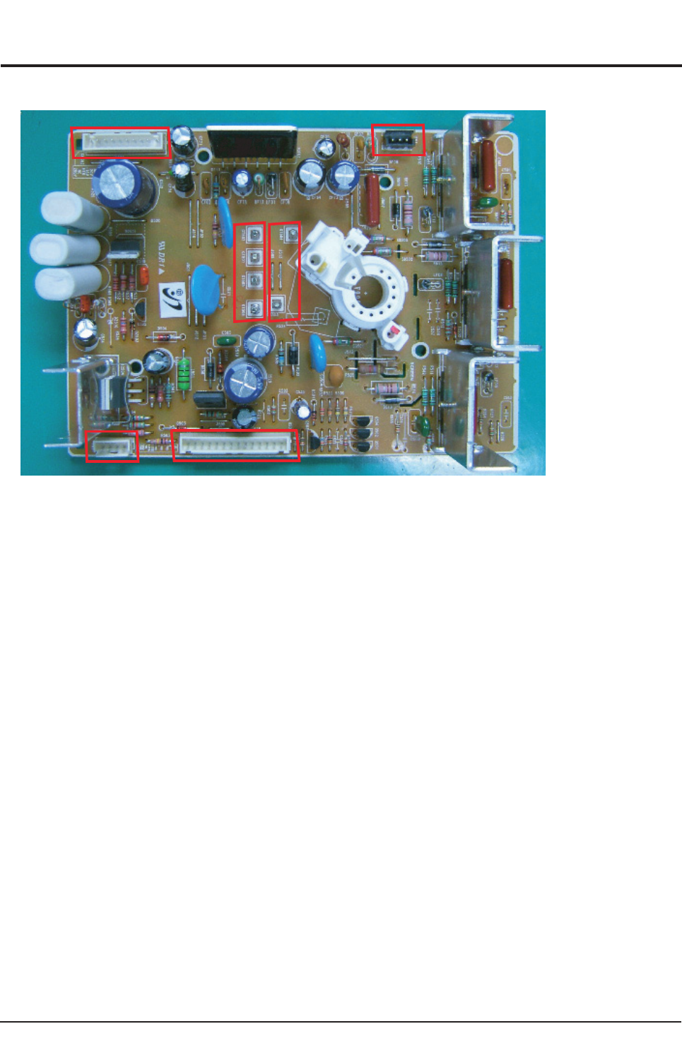
PCB Diagram
Samsung Electronics 9-7
9-4 CRT Board
9-4-1 Assy CRT Board
2
0CNC
10CNC
1VF
1NF
105TG
205TG
505TG
605TG
305TG
405TG
■CRT Drive
This supplies the final R/G/B signal from the F-Box and the CRT deflection signal to the CRT
9-4-2 Names & Roles of Key Parts
*GT503, GT504, GT505, GT506 : This is a port for countermeasures against compulsory discharges and is connected to the
Power Board.
* GT503, GT504 : This is a port connected to the TBC-Wire and plays the role of CRT ground.
* CNC01 : This is a port to receive the R/G/B output signals from the System Board.
* CNC02 : This is a port that receives power for the CRT and AMP from the Deflection Board.
* FV1 : A port to connect the VM signal to the DY Ass'y.
* FN1 : A port to connect signals to the Tilt Coil and is required for the screen slant adjustment.
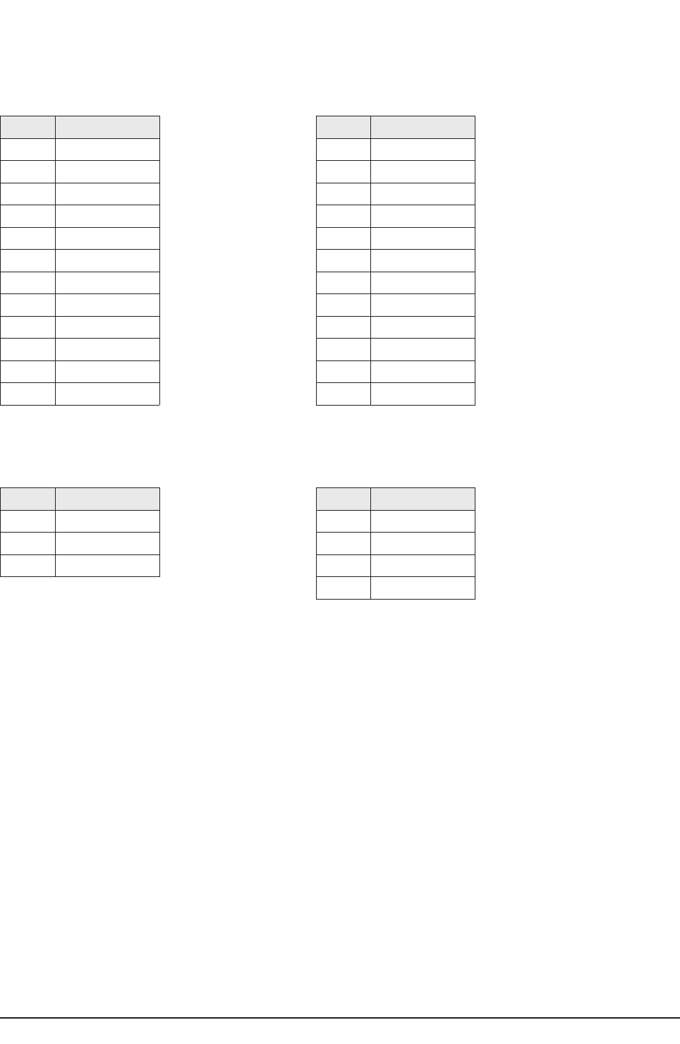
PCB Diagram
9-8 Samsung Electronics
9-4-3 CRT Board Connector Pin
CNC01
Connects the R/G/B signal from the System Board
CNC02
Connects the power from the Deflection Board
FV1
Connects the VM signal to the DY Ass'y
FN1
Connects the signal to the Tilt Coil
PIN No. Pin Name
1 IK
2 GND
3 B
4 GND
5 G
6 GND
7 R
8 GND
9 15V
10 VM
11 PWR
12 TLT
PIN No. Pin Name
1 VCC-200V
2 NC
3 HEATER
4 VCC_-16.5V
5 VCC_20V
6 GND
7 NC
8 ABL
9 NC
10 VCC_142V
11
12
PIN No. Pin Name
1 VM
2 NC
3 VM
PIN No. Pin Name
1 GND
2 GND
3 TILT
4 TILT
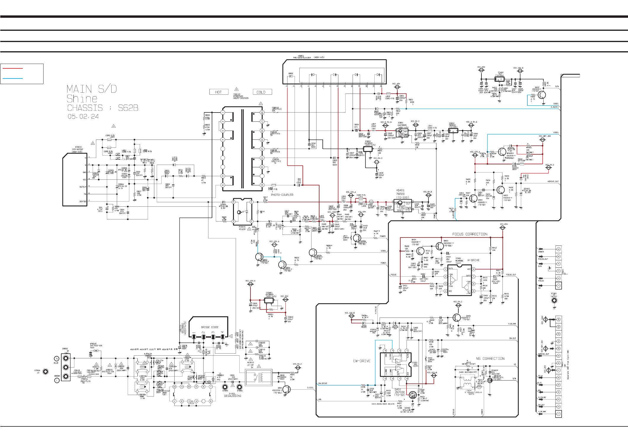
10. Schematic Diagram
Samsung Electronics
Schematic Diagram
10-1
10-1 MAIN
This Document can not be used without Samsung’s authorization.
10-1-1 MAIN 1
Power
Signal
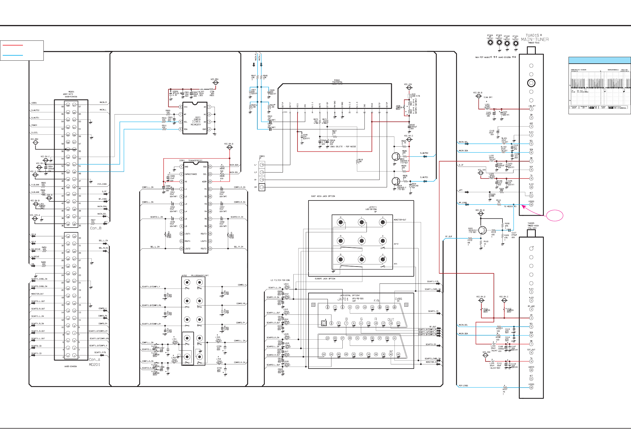
Schematic Diagram
10-2 Samsung Electronics
TP09
This Document can not be used without Samsung’s authorization.
10-1-2 MAIN 2
Power
Signal TP09
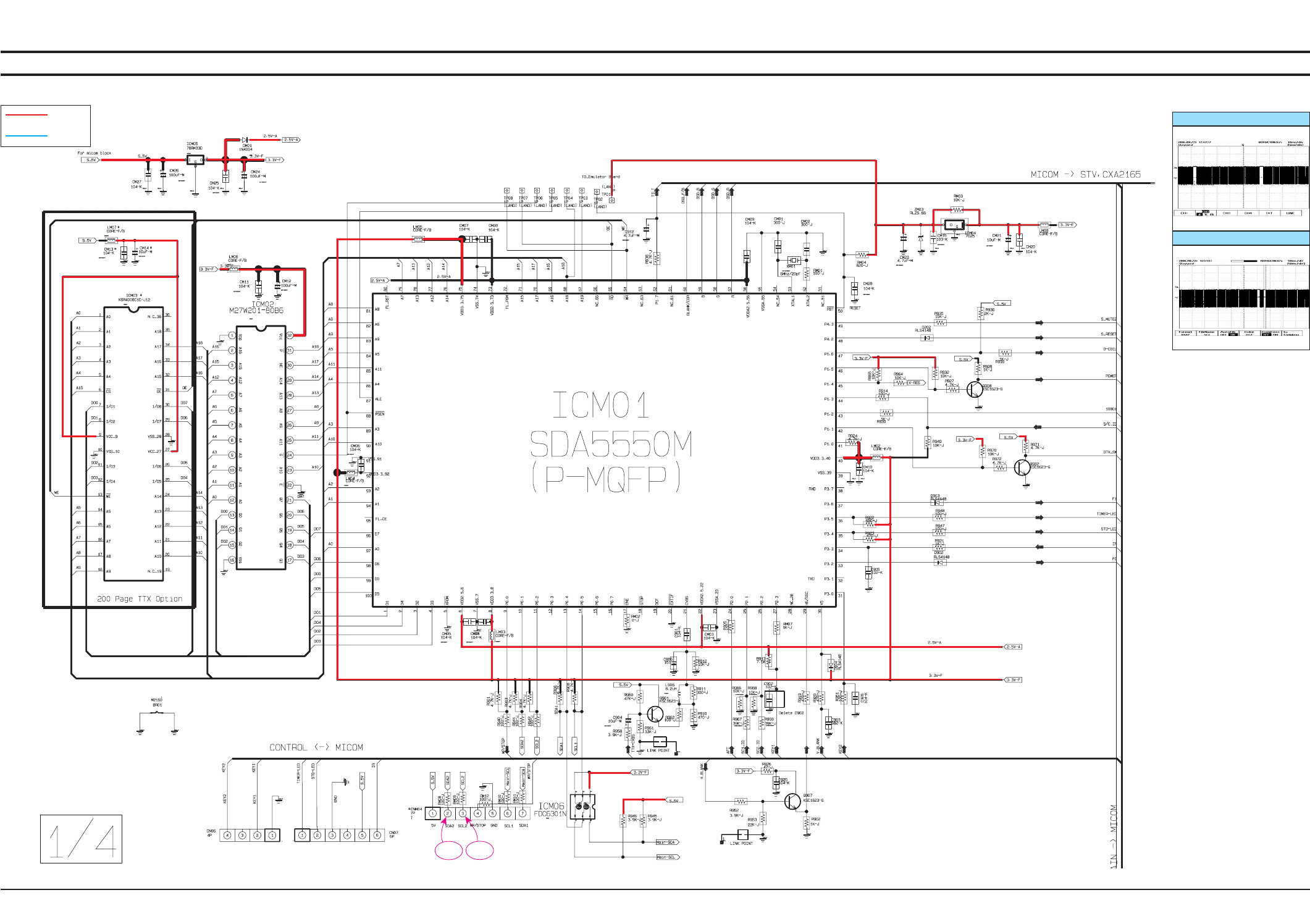
Samsung Electronics
Schematic Diagram
10-3
TP07 TP08
10-2 Feature Box
This Document can not be used without Samsung’s authorization.
10-2-1 Feature Box 1
Power
Signal
TP07
TP08
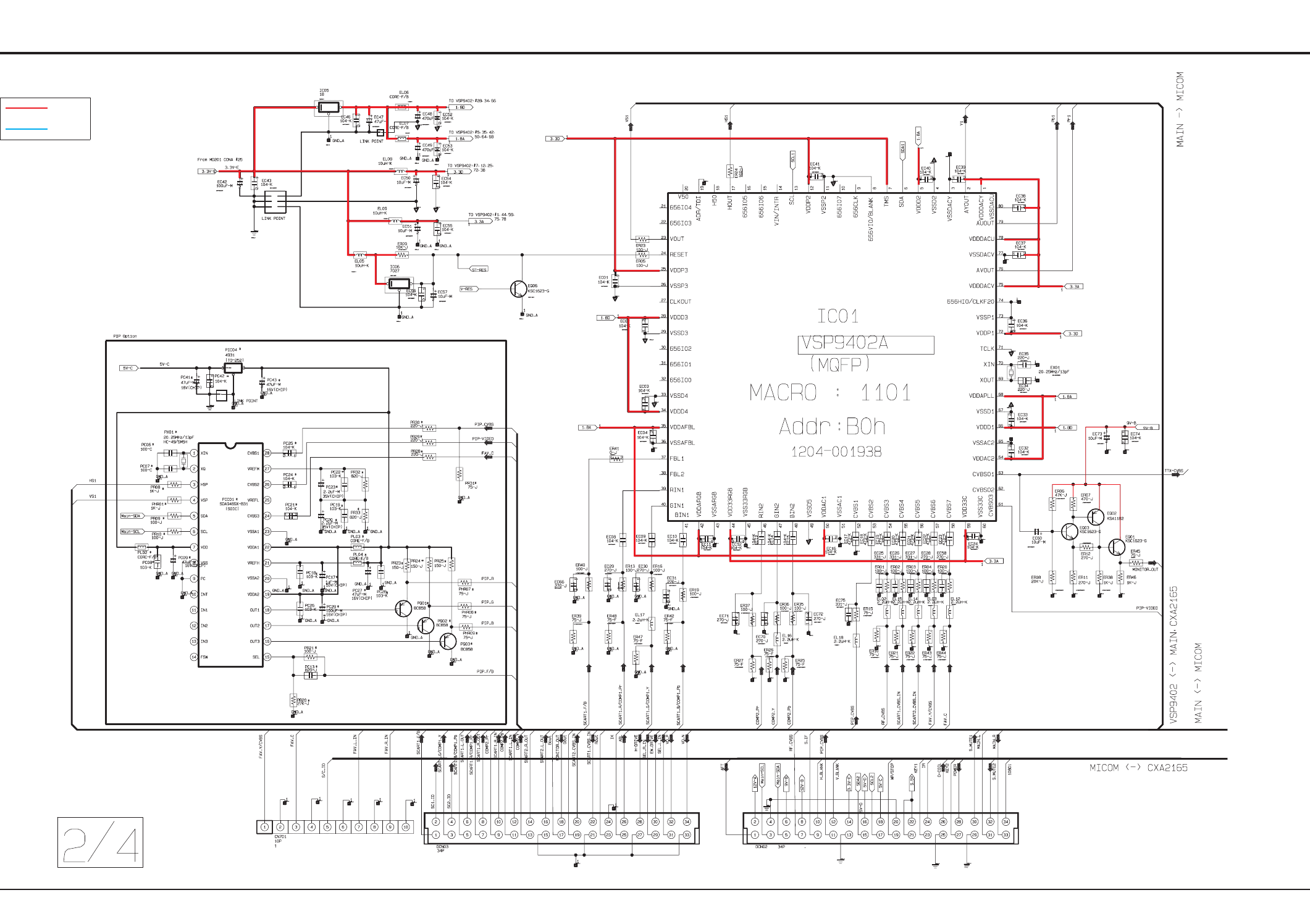
Schematic Diagram
10-4 Samsung Electronics
10-2-2 Feature Box 2
This Document can not be used without Samsung’s authorization.
Power
Signal
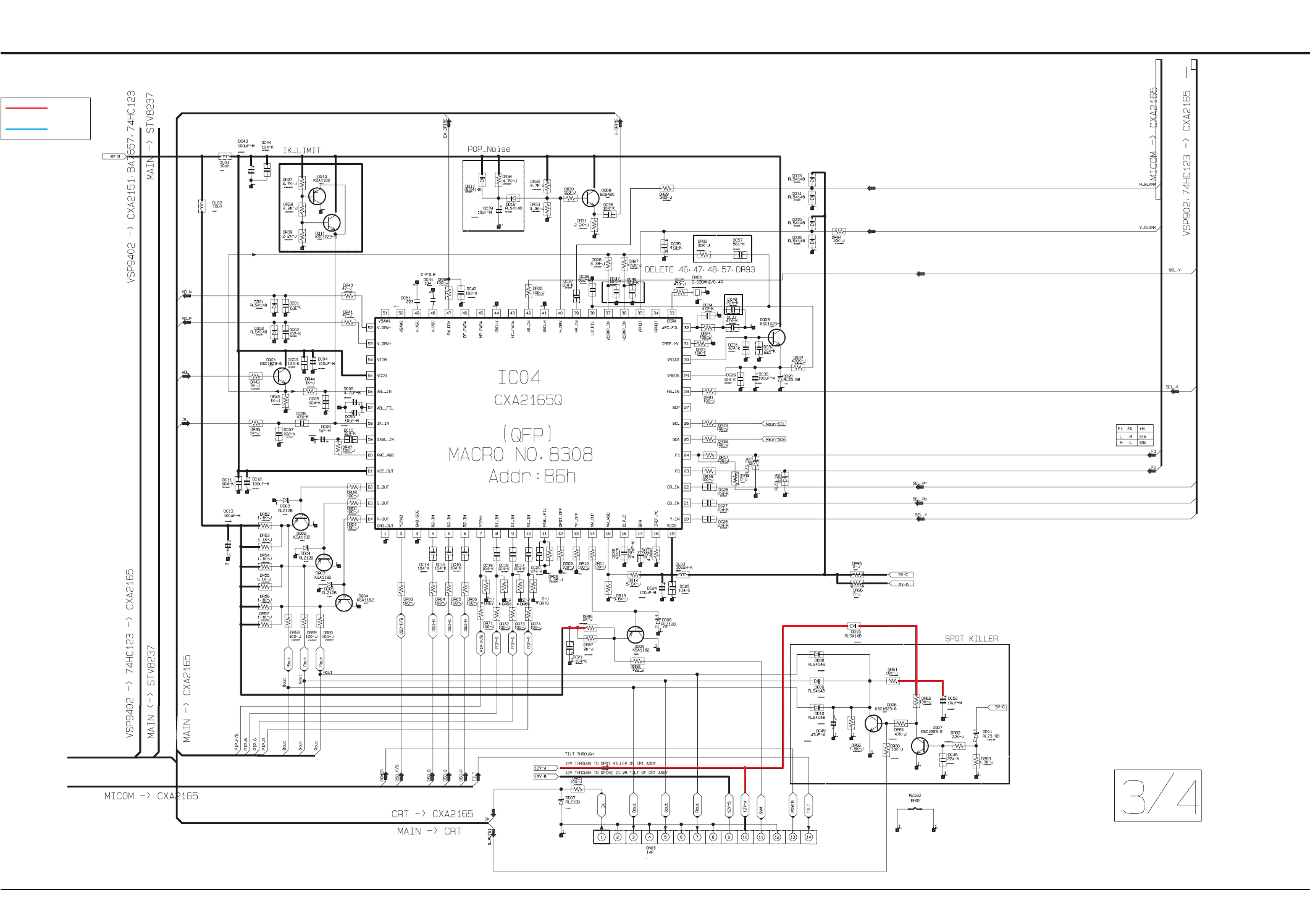
Samsung Electronics
Schematic Diagram
10-5
10-2-3 Feature Box 3
This Document can not be used without Samsung’s authorization.
Power
Signal
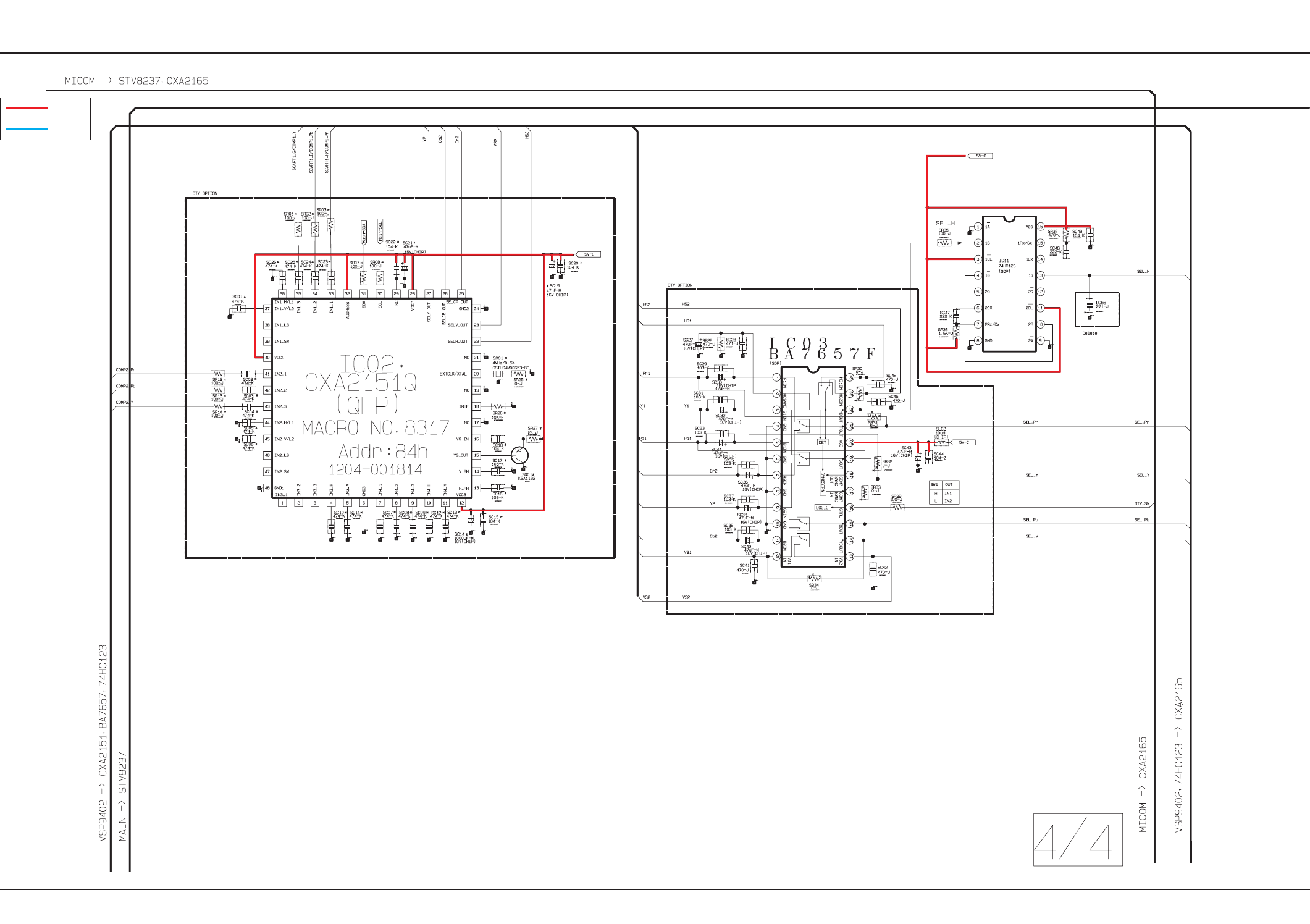
Schematic Diagram
10-6 Samsung Electronics
10-2-4 Feature Box 4
This Document can not be used without Samsung’s authorization.
Power
Signal
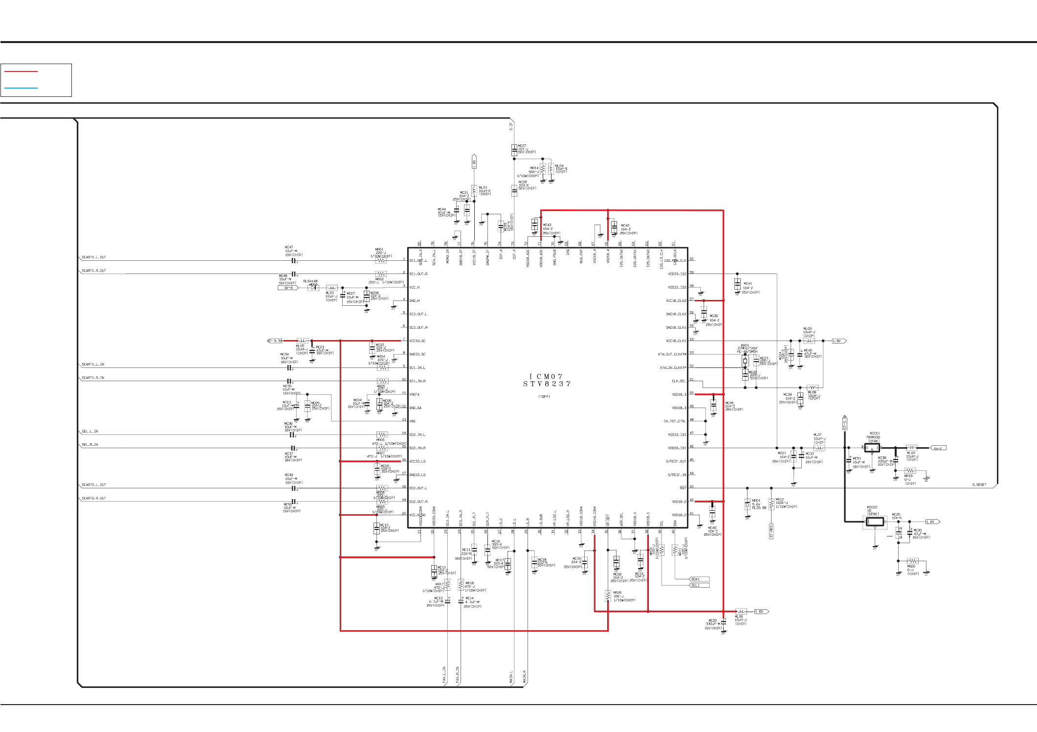
Samsung Electronics
Schematic Diagram
10-7
10-2-5 Feature Box 5
This Document can not be used without Samsung’s authorization.
Power
Signal
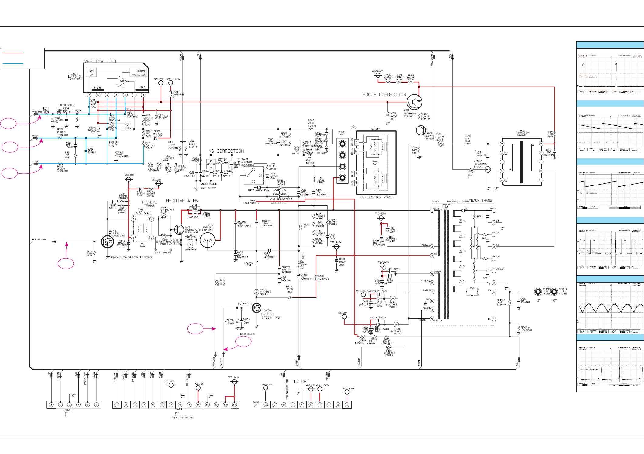
Schematic Diagram
10-8 Samsung Electronics
TP01
TP02
TP03
TP04
TP05
TP06
10-3 DEFLECTION
This Document can not be used without Samsung’s authorization.
Power
Signal
TP01
TP02
TP03
TP04
TP05
TP06
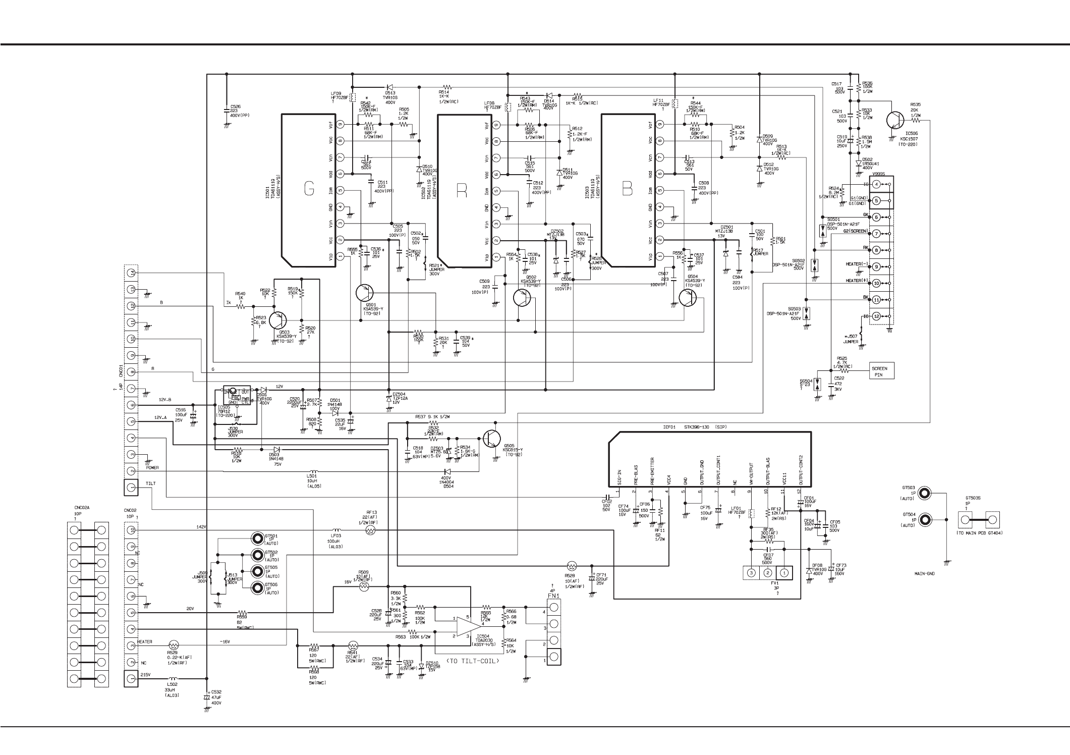
Samsung Electronics
Schematic Diagram
10-9
10-4 CRT
This Document can not be used without Samsung’s authorization.
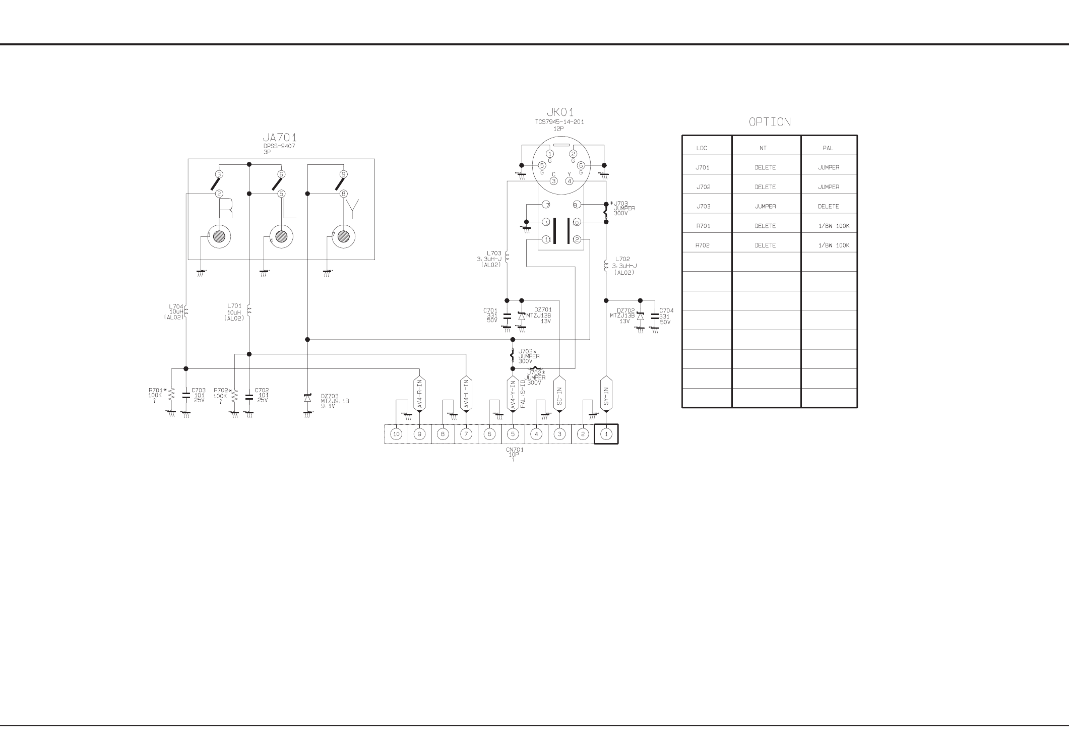
Schematic Diagram
10-10 Samsung Electronics
10-5 AV
This Document can not be used without Samsung’s authorization.
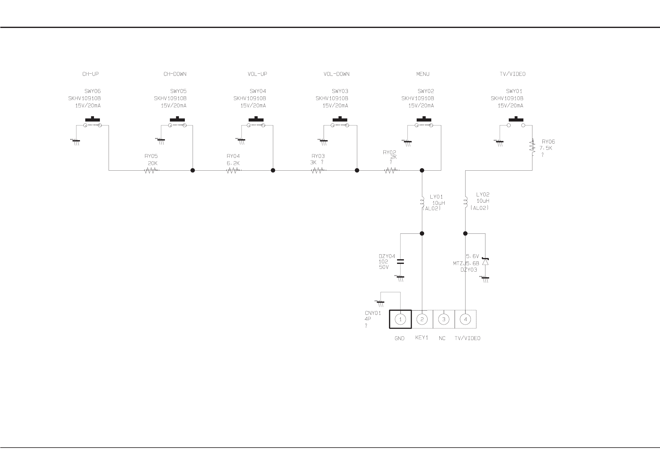
Samsung Electronics
Schematic Diagram
10-11
10-6 CONTROL
This Document can not be used without Samsung’s authorization.
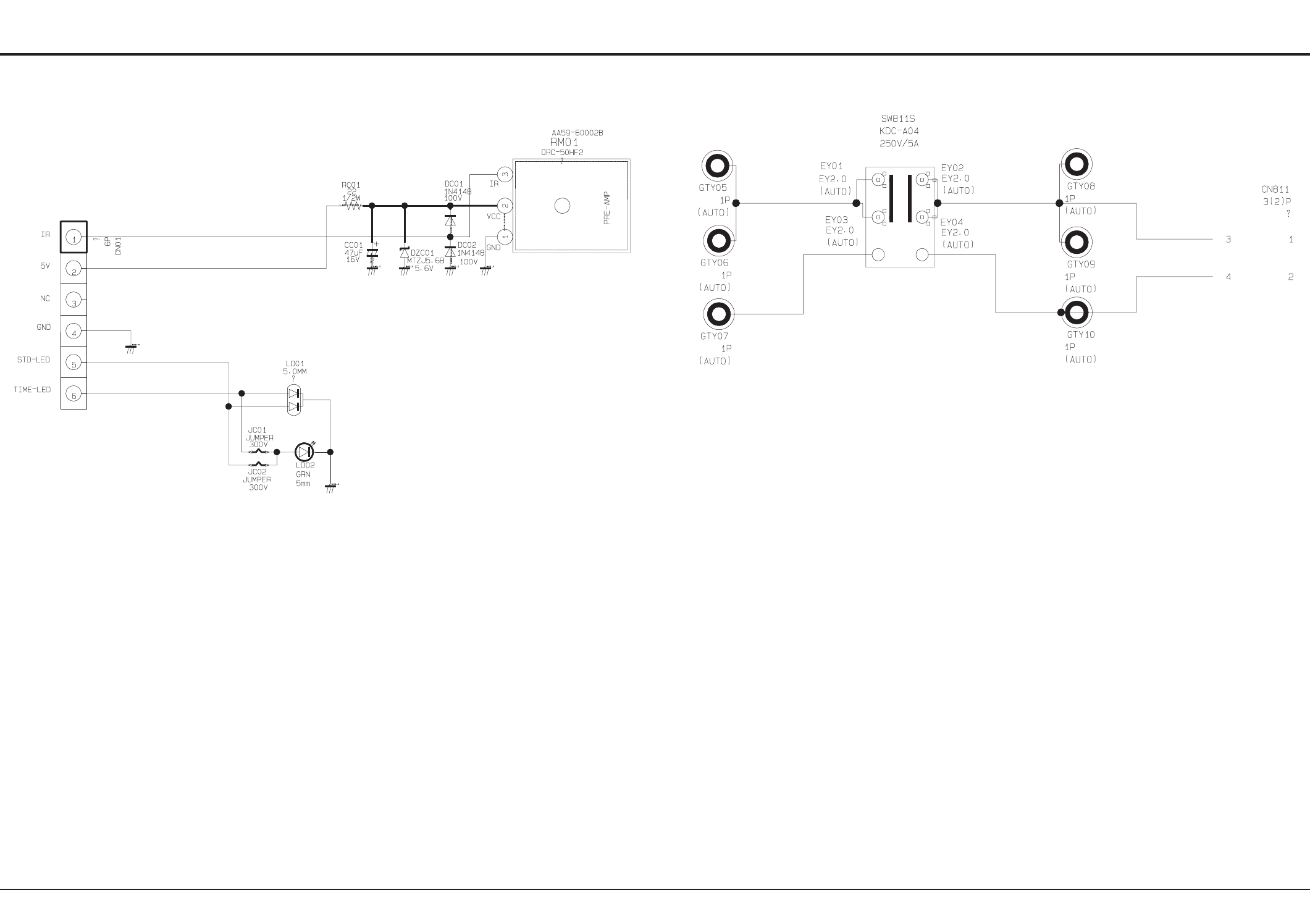
Schematic Diagram
10-12 Samsung Electronics
10-7 LED Module
This Document can not be used without Samsung’s authorization.
10-8 Master S/W
This Document can not be used without Samsung’s authorization.
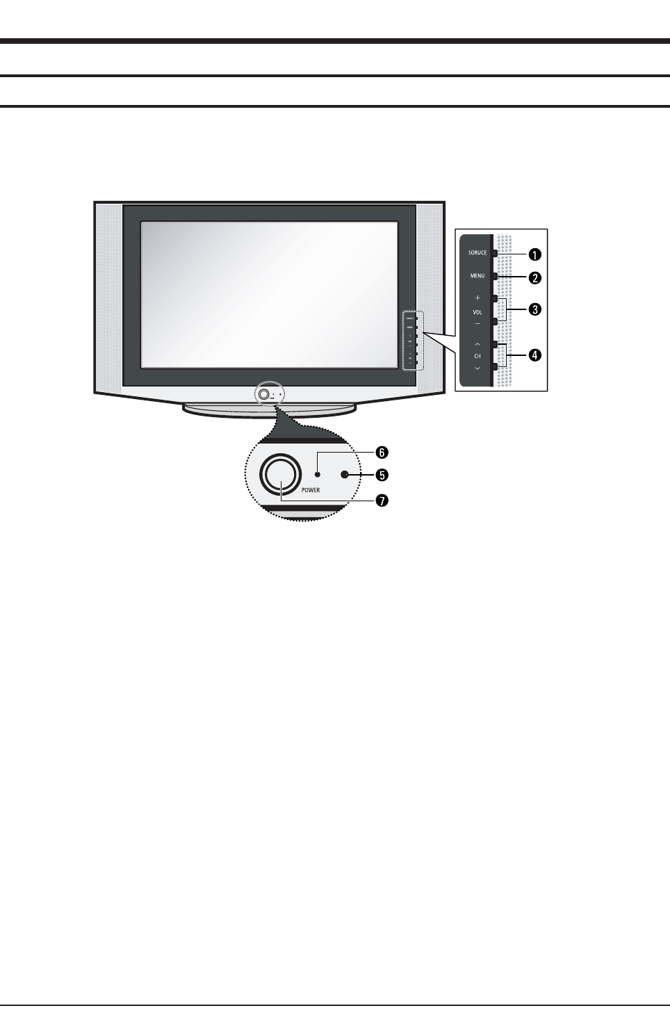
Operation Instruction & Installation
Samsung Electronics 11-1
11. Operation Instruction & Installation
11-1 Product Features and Functions
11-1-1 Control Buttons
You can control your TV's basic features, including the on-screen menu.
To use the more advanced features, you must use the remote control.
①TV/VIDEO
Press to change between viewing TV programs and signals
from other components.
②
②MENU
Press to see an on-screen menu of your TV's features.
③+ VOL -
Press to increase or decrease the volume.
Also used to select items on the on-screen menu.
④
④∧CH ∨∨
Press to change channels. Also press to move between
items on the on-screen menu.
⑤Remote Control Sensor
Aim the remote control towards this spot on the TV.
⑥
⑥Stand-By Indicator
Lights up when you turn the power off.
- Power Off ; Red
- Power On ; Off
- Timer On ; Green
⑦POWER
Press to turn the TV on and off.
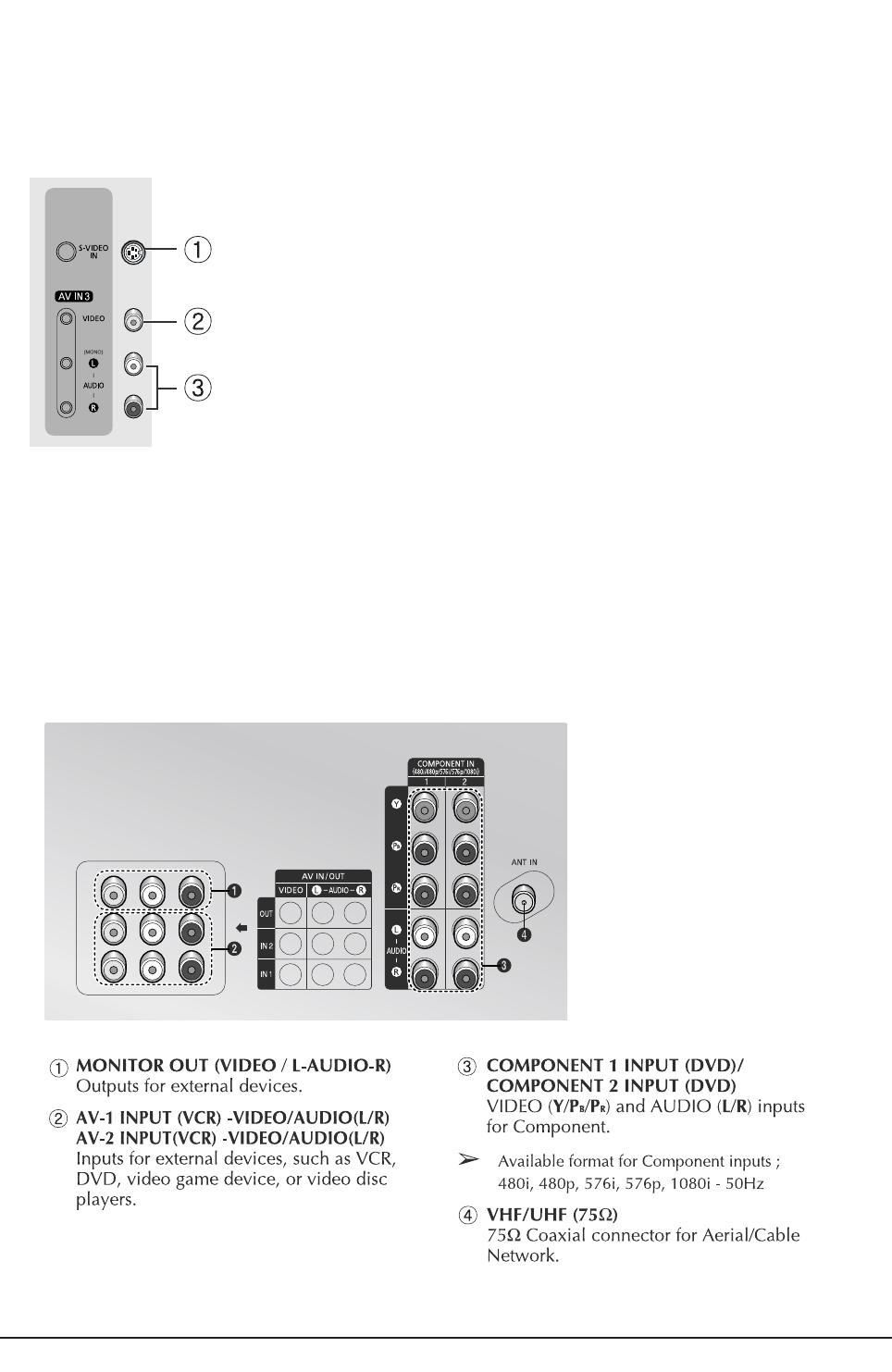
Operation Instruction & Installation
11-2 Samsung Electronics
11-1-3 Connection Jacks (Rear)
Use the rear panel jacks to connect an A/V component that will be connected continuously, such as a VCR or a DVD player.
Because there are three sets of input jacks, you can connect three different A/V components (i.e., a VCR and a DVD, 2 VCRs,
etc.)
11-1-2 Side Panel Jacks
You can use the side panel jacks to connect an A/V component that is used only occasionally, such as a camcorder or video game.
①S-VIDEO INPUT
Connect a S-video signal from a camcorder or video game.
②
②VIDEO INPUT
Used to connect a video signal from a camcorder or video
game.
③AUDIO INPUT
Connect the audio signals from a camcorder or video game.
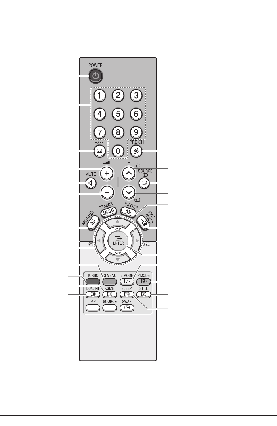
Operation Instruction & Installation
Samsung Electronics 11-3
11-1-4 Remote Control
You can use the remote control up to about 23 feet from the TV. When using the remote, always point it directly at the TV.
You can also use your remote control to operate your VCR, DVD, Cable box, and Samsung Set-top Boxes.
TELEVISION STAND-BY
DIRECT CHANNEL SELECTION
VOLUME INCREASE
TEMPORARY SOUND SWITCH-OFF
MENU DISPLAY
MOVE TO THE REQUIRED
MENU OPTION/
ADJUST AN OPTION VALUE
RESPECTIVELY
TURBO SOUND
EXTERNAL INPUT SELECTION
AUTOMATIC SWITCH-OFF
PICTURE SIZE SELECTION
SOUND MODE SELECTION
EXIT FROM ANY DISPLAY
PREVIOUS CHANNEL
CONFIRM YOUR CHOICE
INFORMATION DISPLAY
PICTURE EFFECT SELECTION
STILL PICTURE
ONE/TWO-DIGIT
CHANNEL SELECTION
SWITCH REPEATEDLY
BETWEEN THE LAST TWO
CHANNELS DISPLAYED
SOUND EFFECT SELECTION
VOLUME DECREASE
NEXT CHANNEL
SOUND MENU DISPLAY
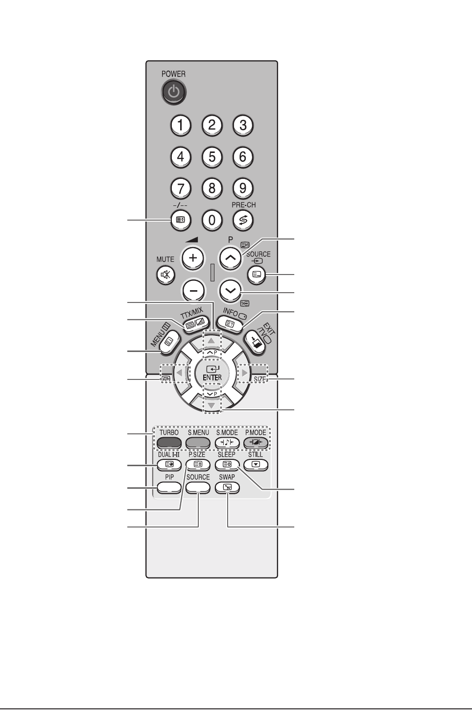
Operation Instruction & Installation
11-4 Samsung Electronics
PROGRAMME
SELECTION BY NAME
SUB PICTURE(PIP)
LOCATION SELECTION
SUB PICTURE(PIP)
SOURCE SELECTION
SUB PICTURE(PIP)
NEXT CHANNEL
TELETEXT DISPLAY/
MIX BOTH TELETEXT INFORMATION
AND THE NORMAL BROADCAST
PIP ON/OFF
FASTEXT TOPIC SELECTION
TELETEXT SUB-PAGE
TELETEXT MODE SELECTION
(LIST/FLOF)
TELETEXT SIZE SELECTION
SUB PICTURE(PIP) SIZE SELECTION
SUB PICTURE(PIP) PREVIOUS
CHANNEL
TELETEXT STORE
INTERCHANGE THE MAIN AND SUB
PICTURE (PIP)
TELETEXT PREVIOUS PAGE
TELETEXT REVEAL
TELETEXT PAGE HOLD
TELETEXT NEXT PAGE
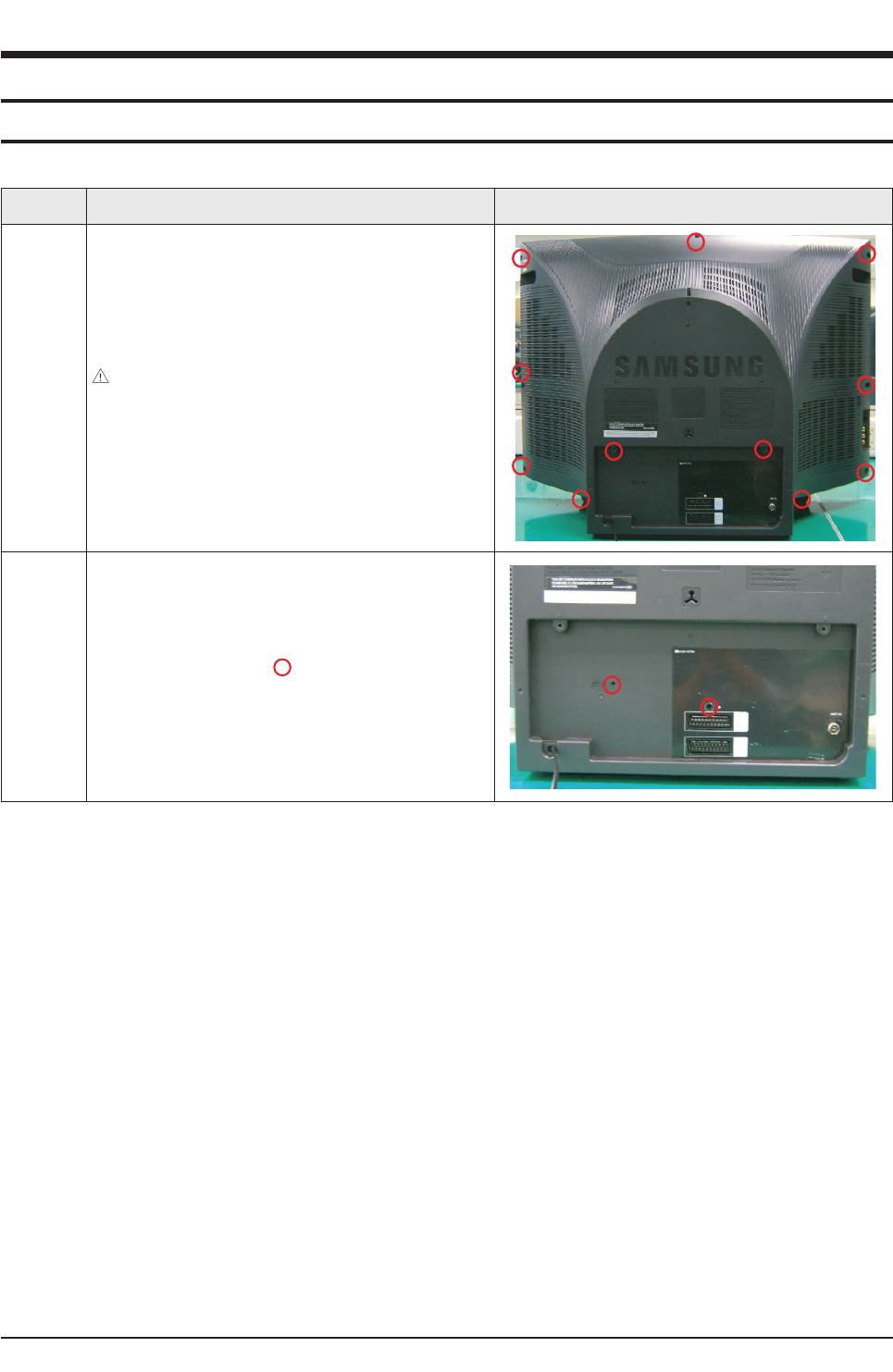
Disassembly & Reassembly
Samsung Electronics 12-1
12. Disassembly & Reassembly
12-1 Overhaul Disassembly & Reassembly
12-1-1 Disassembling the Cabinet
Part Name Description Description Photo
Back
Cover
①Remove the 11 screws fixing the Back Cover.
: RH, +, B, M4, L15, ZPC(BLK), SWRCH18A
6003-001026
②Tap the upper part of the Back Cover 2 or 3 times and pull
the Back Cover to separate it from the unit.
Notice: Disassemble the product after disconnecting the
power cord and discharge the unit to prevent an electric shock
and damage to the product due to static electricity.
Terminal
Board
①Remove the 2 screws fixing the Terminal Board and the
Jacks.
: RH, +, B, M4, L15, ZPC(BLK), SWRCH18A
6003-001026
②Lift the fixing holder up at and pull the Terminal Board to
separate it from the unit.
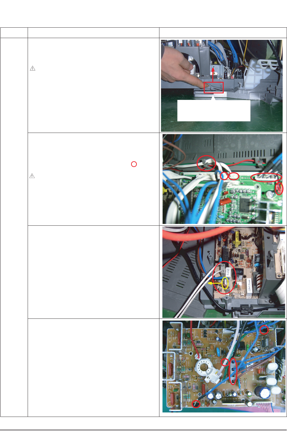
Disassembly & Reassembly
12-2 Samsung Electronics
Part Name Description Description Photo
Chassis
Holder
①Separate the Ass'y Holder chassis from the Front Cabinet.
②Pull the Chassis Holder lifting the fixing clip up.
Notice: Pulling the Chassis Holder by force may damage the
clip or the connector. Pull the Chassis Holder just until the clip
comes off the hole.
①Separate the Speakers, the Side AV Wire, the Side Control,
and the Remote Control Sensor Cable from the Front Cabinet
and the System Board.
②Separate the wire from the Wire fixing holder at .
Notice: Since there is a clip to connect the Connector Header
in the Wire Connector, pulling it by force may damage the clip or
the connector. Press the clip down completely and pull the con-
nector.
①Separate the D-Coil and power cable from the Front Cabinet
and Power Board.
②To separate the power cord, slide the fixing clip and lift the
cable up.
①Separate the CRT Ass'y from the CRT
②Separate the TBC wire, GND, VM and Tilt cables from the
CRT Ass'y sequentially.
Pull the chassis while raising the
clip fixing the Front Cabinet and
the Holder Chassis.
12-1-2 Disassembling the CRT and Chassis
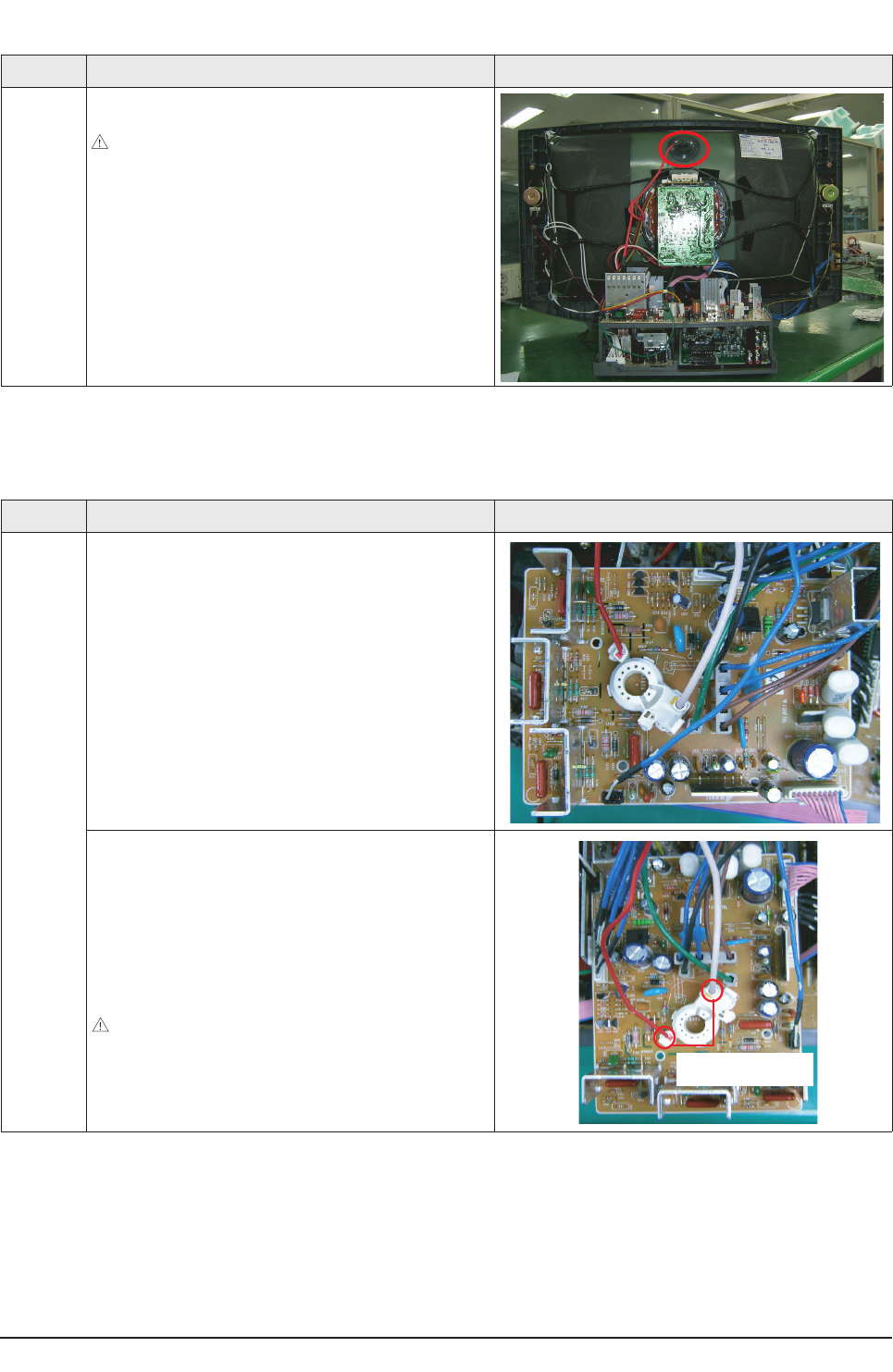
Disassembly & Reassembly
Samsung Electronics 12-3
Part Name Description Description Photo
CRT
Ass'y
①Separate the cables from the Deflection/System Board and
CRT Ass'y.
①Separate the wires from the FBT of the Deflection Board and
the CRT Ass'y.
②To separate the thick red and white wires, pull the wires while
pressing the push-type clip at the connector.
③To separate the thin red wire, insert a pin in the small hold
next to the hole and pull the wire.
Notice: Take care when separating the wires because pulling
the wires by force may damage the socket. In addition, separate
the wires on a flat and clean surface so as to prevent scratching
of the material and the PCB.
Part Name Description Description Photo
Chassis
Holder
①Separate the cables connecting the FBT and the CRT.
Notice: Since there may be a remaining high-voltage current
within the CRT, take care not to touch the CRT hole with metal
or a part of yourself when separating the cables.
Pull the wires while
pressing on the fixing dip
P u l l t h e w i r e s w h il e
p r e s s i n g o n t h e f i x i ng d i p
12-1-3 Disassembling the CRT Ass'y
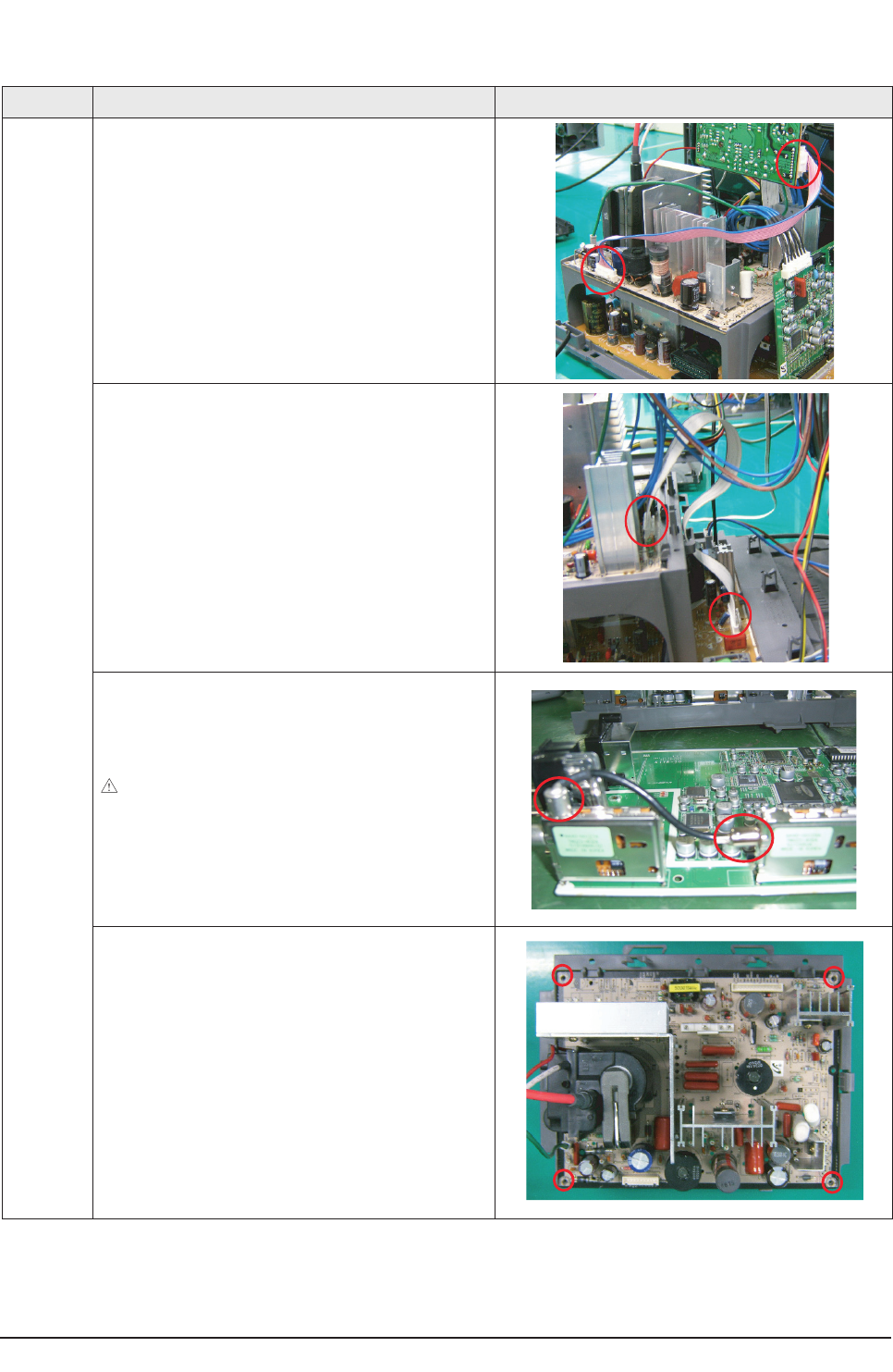
Disassembly & Reassembly
12-4 Samsung Electronics
Part Name Description Description Photo
Deflection
Board
①Separate the 10 pin cable from the CRT Assy's.
①Separate the 14 pin cable from the Main Board.
①Separate the cable from the Splitter and the Tuner.
②First separate the cable from the Splitter using a tool such
as nippers.
Notice: Since pulling the wire by force may damage the
coating of the wire, separate the wire holding the metal part with
the tool.
①Remove the 4 screws fixing the Deflection Ass'y.
: PWH, +, B, M3, L10, ZPC(YEL), SWRCH18A
6003-001023
12-1-4 Disassembling the Deflection Board
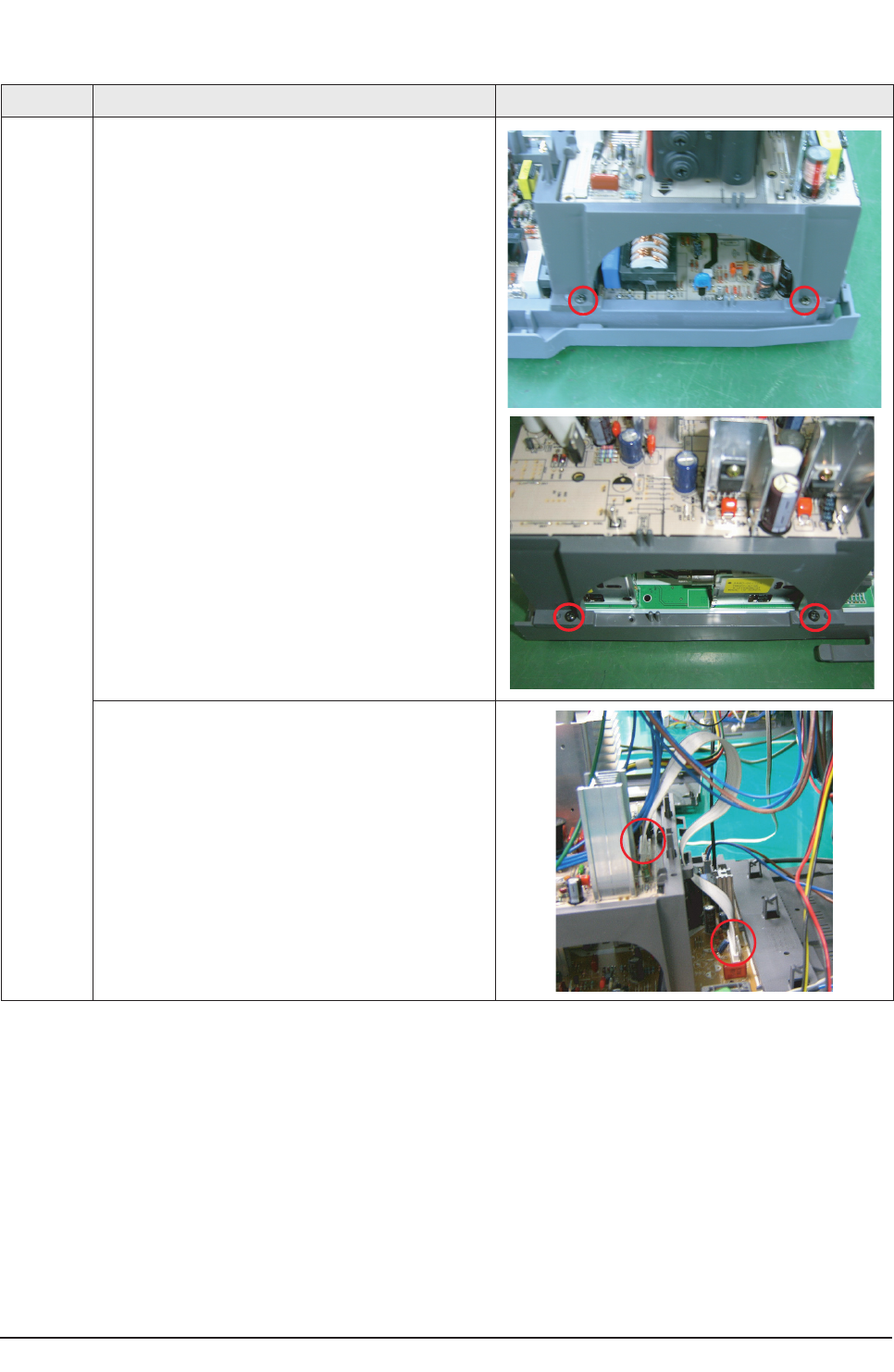
Disassembly & Reassembly
Samsung Electronics 12-5
Part Name Description Description Photo
Power Board ①Remove the 4 screws to separate the holder fixing the
Deflection Board Holder.
: RH, +, B, M4, L15, ZPC(BLK), SWRCH18A
6003-001026
②Separate the holder.
①Separate the cable from the Deflection Board
12-1-5 Disassembling the Power Board

12-6 Samsung Electronics
MEMO
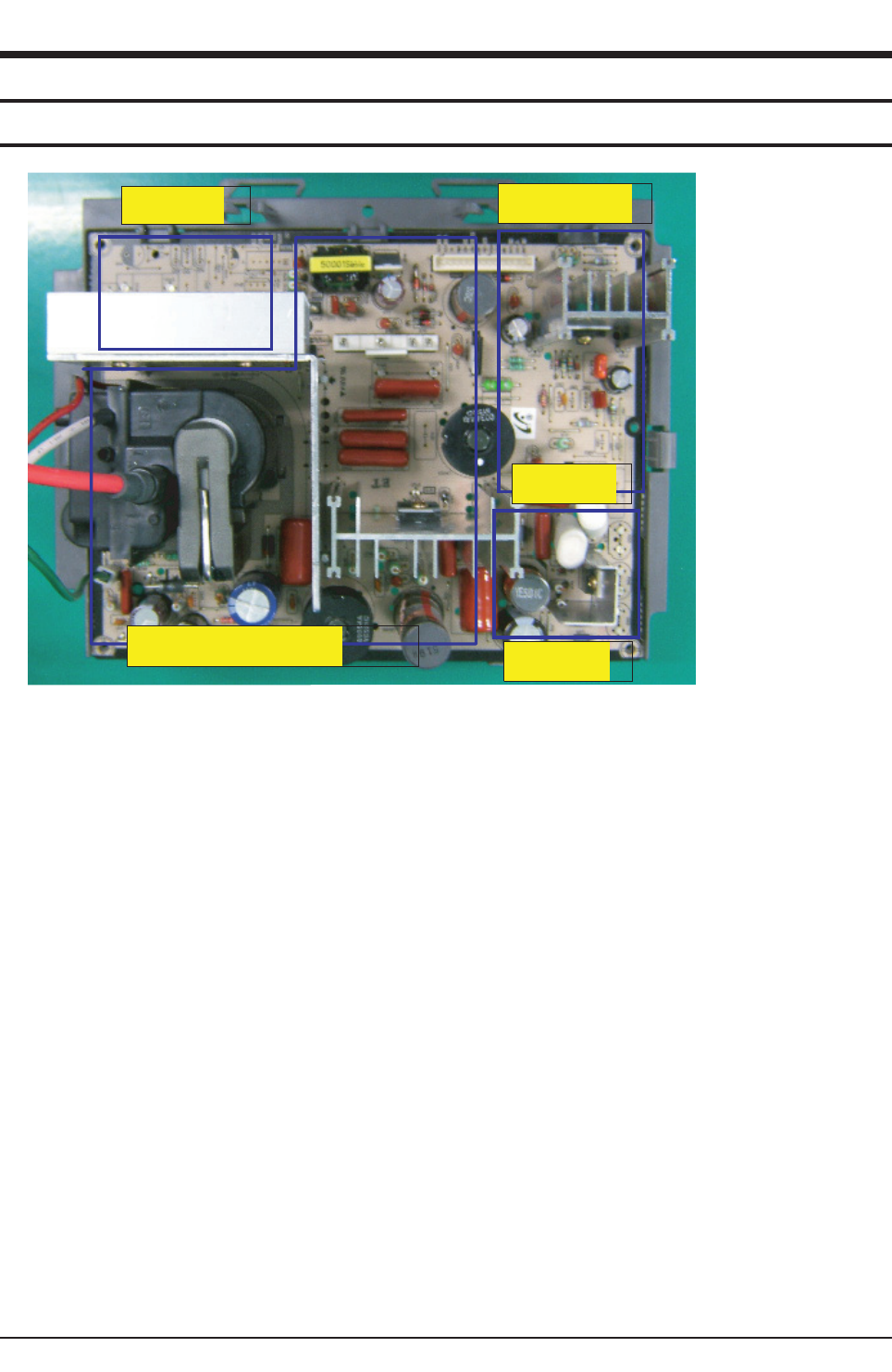
Circuit Description
Samsung Electronics 13-1
13. Circuit Description
13-1 Overall Block Description
E/W Circuit
D/F Circuit Vertical Circuit
N/S Circuit
Horizontal & HRS Circuit
※Bias Circuit structre of S62B is the same as the existing S61A circuit
■Circuit Constitution.
1. Horizontal Bias Part
- Controls the high voltage generation and horizontal bias.. FBT, HDT, CT condenser etc.
2. Vertical Bias & N/S (North / South) Correction Circuit
- While mostly controlling the vertical bias, also corrects the picture lowering of top and bottom. ..LA7845, N/S TRANS, etc.
3. HRS (Horizontal Raster Shift) Correction Circuit
- A correction circuit of Linearity distortion on the left and right side of a picture which is caused by awry electron beam from an
electron gun.. Correction S/W and surrounding circuits.
4. D/F (Dynamic Focus) Correction Circuit.
- Improved Focus feature circuit due to the widened angle of a picture¡¦..D/F Trans, Vertical/Horizontal circuit
5. E/W (East / West) Correction Circuit.
- A circuit for correcting the spool shape which appears on the left and right part of a picture. This is caused by the difference
between the distances from the center of a picture to each corner. KA393, FQP630 etc. (Adopt PWM circuit)
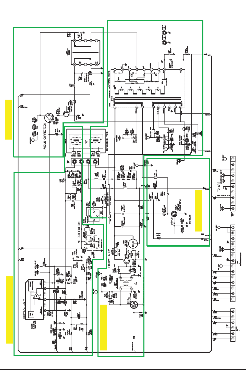
Circuit Description
13-2 Samsung Electronics
Vertical Bias & N/S Correction Circuit D/F Correction Circuit
Horizontal & HRS Circuit
E/W Correction Circuit
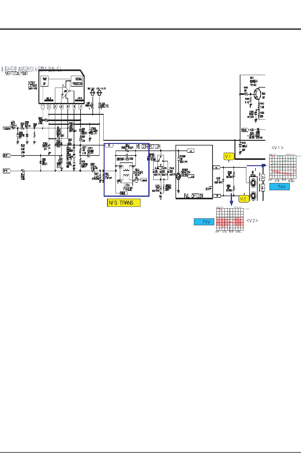
Circuit Description
Samsung Electronics 13-3
13-2 Partial Block Description
13-2-1 Vertical & N/S Correction Circuit
ⓐUnderstanding of N/S Circuit and Operation Principle.
▶What is a N/S correction circuit?
- If the bias angle of a picture widens, the distance from the center of a picture to each corner becomes farther as it moves to
periphery. This causes the picture being distorted (Picture Lowering) vertically in a shape of a spool because of the strong
bias at four corners which are the farthest from the center.
Correction effect to the amount of a correction signal can be made by crossing Parabolic current of a vertical period over the
vertical bias current and applying it.
▶N/S Circuit Constitution and Operation Principle.
- Consists of L304, C305, C439, R312. Symmetrize the up and down amplitude using the saturable reactor of L304 and adjust
N/S Gain by controlling the capacity value of C305 and C439
If the correction vector is excessive, one can slightly reduce the resistance of R312
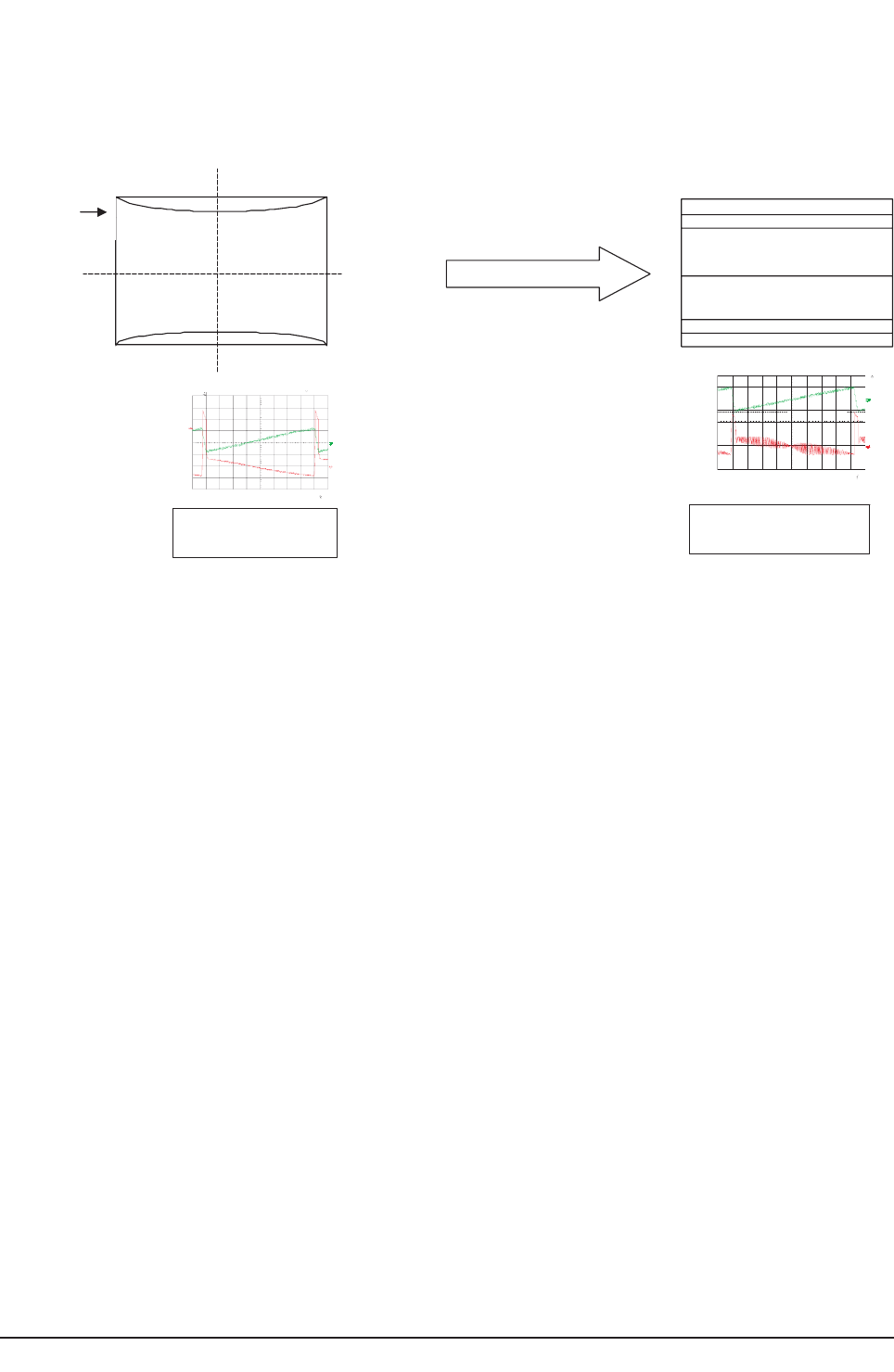
Circuit Description
13-4 Samsung Electronics
de
ppotS
6
2
:
2
4
:
90 4
0
/
5
0
/
4
00
2 v
i
d/sm
2
s
/Sk0
0
2
:
MRON
V0
1
=1H
C
1
:
001 C
D
Vm
0
1=
2
HC
1
:
1
CD
=
re
t
liF
=
N
O
:
g
n
i
h
t
o
o
mS
L
L
UF : WB
=
te
s
ff
O
=
V
0
.
0
:
1
HC
V000
0
.0 :
2
HC
V
0
.
0
:
3
HC
V
0
:
4
HC
=
h
t
gn
eL
dr
o
ceR
=
K
01
:
n
i
aM
K4 : mo
o
Z
=
r
e
gg
ir
T
=
OT
UA
:
e
d
oM
1H
C
E
GDE
:
ep
y
T
s
n
8
.
0
:
yaleD
MUM
I
NI
M
: f
f
odloH
=1
e
car
T
=
V08.6
5
P-
P
V0
0
.
8
4
xaM
V42.
1
1
smR
z
H
5
9
.
95
qer
F
=2e
c
arT
=
Vm
0
2.1
2
P
-P
Vm04.
2
1 x
aM
Vm
80
8
.
6
sm
R
su
0.0
04
l
l
a
F
de
pp
ot
S
2
1
:53
:
41 41/
1
0
/
5
00
2v
i
d
/
sm2s
/
S
k0
0
5
:MR
ON
V
0
2
=1H
C
1
:
0
01 CD
Vm
0
1
=2H
C
1:
1 CD
V
m
06.12
)
2
(
V
=r
e
t
l
i
F
=
NO
:
g
nihto
om
S
LLUF : WB
=
t
e
s
f
fO
=
V0.0
: 1H
C
V
0
0
0
0
.
0
: 2HC
V0.0
: 3H
C
V0.0
:
4H
C
=
h
t
g
ne
L
dro
c
e
R
=
K
0
01
: n
i
aM
K
0
1 : mooZ
=r
eg
g
ir
T
=
O
T
U
A
:
e
doM
1HC
EG
D
E :
epyT
sn0
.
0
:
y
a
l
e
D
MUM
IN
IM
:
f
f
o
d
l
o
H
After correction
e
rutc
iP
no
i
t
r
o
ts
id
<NormalVertical
Signal>
<Vert ical Wave form
after correct i
i
on >
S
d
e
p
pot
41
/
10
/
500
221:5
3:
41
vid
/s
m2
O
N:
MR/
S
k00
5s
HCV02=1
D C1:001
H
CVm01=2
D C:11
V(
2
tli
F=r
e=
o
t gnih:NO
F
UL L
f
f
O==
t
e
s
HC1: V0.0
H
C2: V0000.0
HC3: V0
.0
HC4: V0.0
=
htgn
e
L droceR
=
niaM: K00
1
moo
Z:K
01
rT=reggi=
edo
M:U
AOT
:
epy
TEG
D
E C 1
H
yale
D: sn0.
0
fodloH: fM INIMUM
e
r
utciP
noitrotsiD
ⓑComparison before and after of N/S signal correction
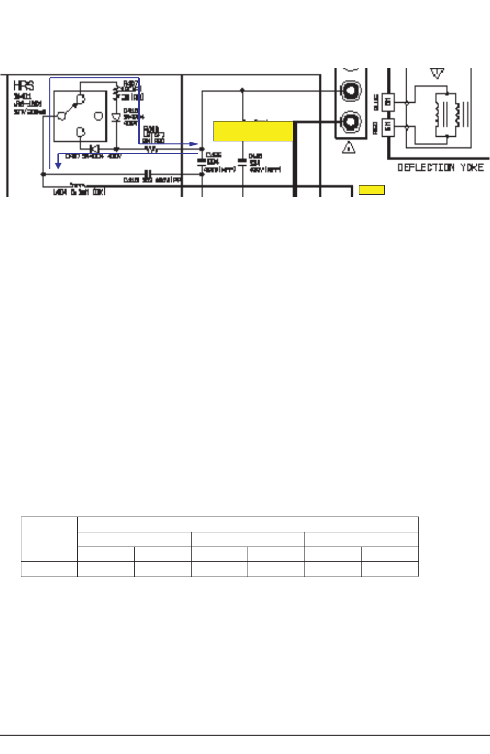
Circuit Description
Samsung Electronics 13-5
13-2-2 HRS Correction
H
H
145 V
: 145. 05V
:145. 10V
Right side
Left side
ⓐUnderstanding and Constitution of HRS Correction
▶What is HRS (Horizontal Raster Shift) circuit?
- When electron BEAM emanates from CRT, it must form the image evenly on the center of a screen. However, the left-right
linearity can be awry due to the micro-distortion of horizontal angle while producing CRT. HRS is a compensatory circuit
which crosses DC voltage over CS condenser on horizontal output board to correct the distortion.
ⓑHRS Circuit Operation and Picture Movement
▶Operational Principle.
- HRS circuit consists of R407, D415, D407, SW401, C415, L404. If switch SW401
(Service S/W) to the direction of R407, it raises the C426 CS condenser voltage through D415 and the picture moves to
right. If switch SW401 to the direction of D417, the picture moves to left.
C415 is functioning as a condenser which stops generating current. It can control the left-right movement since the
rechargeable voltage varies as the condenser capacity value varies.
That is, the larger the C415 capacity value becomes, the bigger the left-right movement will be.
▶Picture Movement during 0HRS Connection
* Direction of SW407 Switch .... Center : Not corrected.
.... D415 : moves to the right of a picture
.... D417 : moves to the left of a picture
Condition
Total Length of a Picture Moved (m/m)
Left Center Right
To Left To Right To Left To Right To Left To Right
After 5.5 6.5 1.5 2 6.5 6
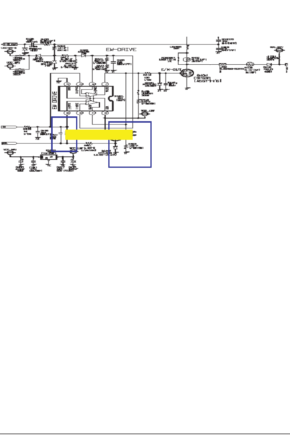
Circuit Description
13-6 Samsung Electronics
13-2-3 E/W Circuit Block
EtiucriC noitcerroC THE
ⓐUnderstanding of E/W Circuit
▶What is an E/W (East / West) Correction Circuit?
- If the bias angle of a picture widens, the distance from the center of a picture to each corner becomes farther as it moves to
periphery. This causes the picture being distorted (Picture Lowering) horizontally in a shape of a spool because of the strong
bias at four corners where are the farthest from the center. E/W is a circuit which corrects the spool-shape on the left and right
part by crossing Parabollic wave form over the horizontal output board and controls the current which flows through terminal
no.47. Parabollic wave comes out from terminal no.47 of CXA2165 CHROMA IC(IC31)
It also controls the horizontal-related factors of Factory data such as picture size, size change and Parabola gain change. It
has an essential role of minimizing the picture swaying (High Voltage Regulation)
ⓑE/W Circuit Constitution and Operation
▶E/W Circuit Constitution and Operation Principles.
- E/W circuit consists of KA393(comparator), FQP630(output TR), and other parts. This uses a method in which PWM controls
the circuit using a comparator. The advantage of this PWM Control method is that POWER Loss hardly occurs and
generates little heat when using low H/S.
Input E/W signal to terminal no 3,5 of IC401(KA393) and carrier wave to terminal no 2,6. Carrier wave can be made by
reducing the horizontal collector voltage and integrating the wave form using D405,R414 and C406.
Then the carrier wave is compared with E/W signal in IC401 and outputs PWM(Pulse Width Modulation) wave form. Bias
current shall be controlled using Q404.
Picture swaying occurs as the picture brightness varies. To correct this, control the high voltage regulation using
Q401(1N7000), R433 and C411 That is, Q401 is a circuit for correcting Static Regulation and used to prevent the picture
size changing as the picture brightness varies.
It detects the ABL voltage and inputs to Q401 Gate through R423 resistance. Then the ABL voltage change is sent to
IC401(KA393) output and controls the DC of Q404(FQP630) Gate terminal, to keep the picture size from changing.
▶E/W Circuit Constitution and Operation Principle.
Also, E/W circuit functions as a compensatory circuit against the picture shaking by reversely compensating the picture
swaying. This is possible by inputting ABL voltage to E/W using R433 as the picture brightness varies.
There are H,V, PIN-COMP as well in Factory data and these correct the high voltage regulation. If the H-COMP capacity
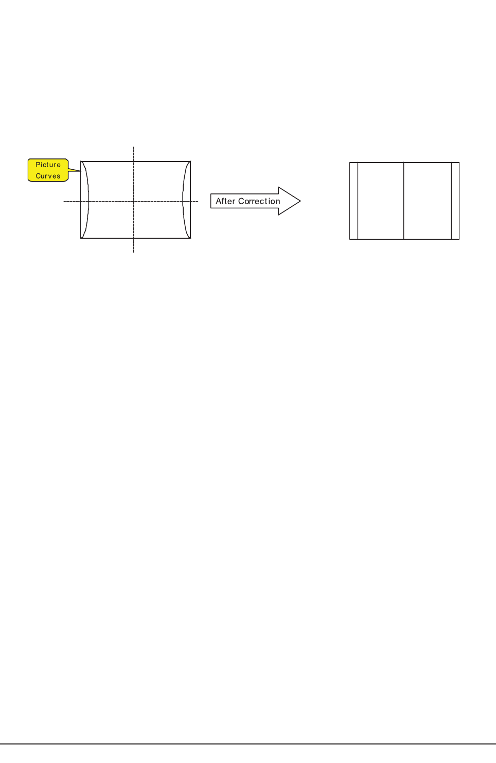
Circuit Description
Samsung Electronics 13-7
value increases, correction vector increases too and this causes a strong picture swaying. On the other hand, if the H-COMP
capacity value decreases, correction vector decreases causing extensive picture size change. V-COMP, likewise, controls the
vertical correction vector and operates in the same mechanism as H-COMP.
PIN-COMP is a function which corrects the movement of four corners of a picture. If the capacity value is excessive, a picture
curves outwards when the picture is bright. COMP capacity value, therefore, should be varied +/- 1step from the factory-
adjusted condition, since a gain widely varies dependant on the SET distribution.
▶Before and After of E/W Circuit Correction

Circuit Description
13-8 Samsung Electronics
13-3 IC Line up
■F-Box Board
Items Descriptions Remarks
Analog Decoder VSP9402
MICOM SDA555X Micro Controller
Component Switch CX2151
Deflection Processor CX2165, SONY
IC COMS LOGIC 74HC123, Philips
PIP SDA9489
Sound IC ST8237
DTV Switch BA7657
SRAM K6R4008C
EPROM M27W201
Regulator 78RM33D 3.3V Regulator
Regulator 18,DPAK 1.8V Regulator
Regulator 4931,TO-252 5V Regulator
■Main Board
Items Descriptions Remarks
BRIDGE DIODE GSIB660
Didode SLA1004L
Trans Switching 53B135-SC
Trans Switching-ST BY EE2020
STR STR-6759(LATIN)
STR STR-6750(EU/CIS)
EW Driver KA393
Vertical Focus MC4558C
■Deflection Board
Items Descriptions Remarks
FET FQP630
Vertical DEF LA7845
Horizontal DEF FJ6920,FMP3FU
■CRT Board
Items Descriptions Remarks
DRIVE IC TDA6111Q
IC HYBRID STK396-130
AMP TDA2030
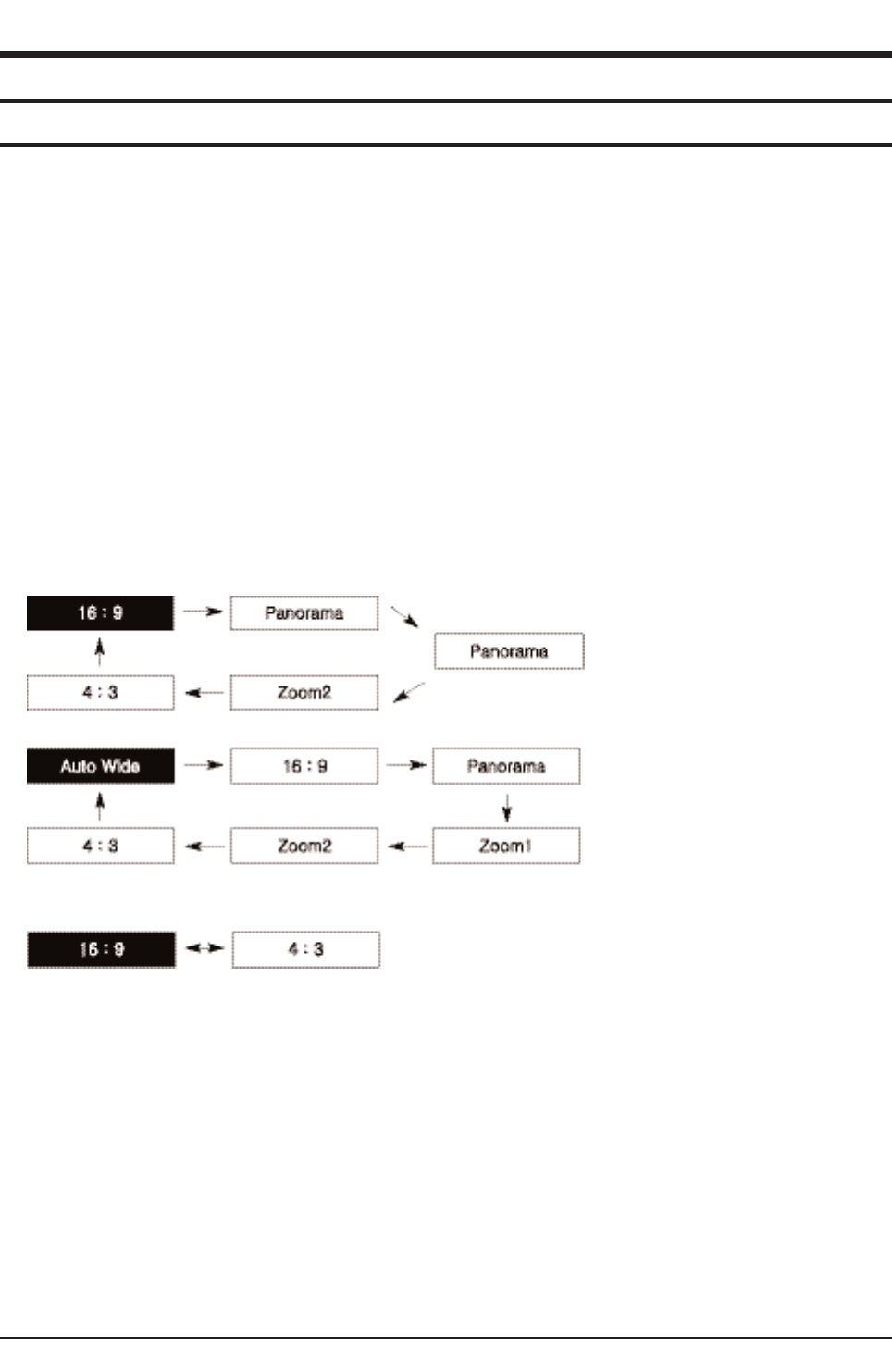
Reference Information
Samsung Electronics 14-1
14. Reference Information
14-1 Other issues related to other products
■SD/HD broadcasts and the TV's display capability are related
1. A digital broadcast should be transmitted in wide screen (an aspect ratio of 16:9) HD. If the broadcasting station converts a
conventional program created in normal screen (aspect ratio of 4:3) into a digital signal and broadcasts the signal, the left and
right of the picture will not be displayed.
This symptom also appears in other manufacturer's TV's. The three appliance companies are trying to resolve the problem
through the Ministry of Information and Communication.
*When watching an SD (normal) broadcast through a Digital (Wide) TV (480P normal broadcast)
*When watching an SD (normal) broadcast through a Digital Ready (Wide) TV (Using a set-top-box)
*When watching an analog (normal) broadcast through a wide TV
(When watching a broadcast after changing the aspect ratio of the TV from 16:9 (wide screen) to 4:3)
2. When watching a DVD title or video tape in wide screen (21:9) through a wide (16:9) TV, watching video from a computer or
game console by selecting the aspect ratio to 4:3, or watching video from a DVD, VCR, computer or game console through a
wide TV by selecting the aspect ratio to normal (4:3) or wide (21:9), the left and right, or top and bottom of the picture will not be
displayed.
This symptom appears in other manufacturer's TV's. The three appliance companies are trying to resolve the problem through
the Ministry of Information and Communication.
■Changing the Order of the Picture Size for 16:9 Display Devices
■Changing the Order of the Picture Size for DTV 1080i/720p Sources
■Restrictions
1. When you want to change the picture size in PIP 'ON', you must turn the PIP off before changing the size.
However, you can change the main picture size even in PIP ON for products with no restrictions.
2. When the picture size is not Normal (4:3 for 4:3 display devices, 16:9 for 16:9 display devices) and you turn PIP on, the picture
size is changed to Normal.
However, you can turn PIP on without changing the picture size for products with no restrictions.
3. In the OSD notation for the picture size, 16:9 is represented as "Wide" instead of "16:9" for devices other than with 16:9 dis
plays.
Ex: For LCD 15:9 devices, "Wide" is displayed on the OSD instead of "16:9".
4. The picture size can be changed even in the blue screen.
However, the picture size should be controlled by the product specifications if the change is impossible due to hardware
restrictions.

Reference Information
14-2 Samsung Electronics
Digital Broadcast
Digital Broadcast is a television broadcasting signal digitized
and transmitted according to the United States' terrestrial digital
broadcast standard, or ATSC.
Mono
A type of audio interface that transmits audio signals through a
single channel.
Through a mono interface, it is hard to experience stereophonic
sound and sound is played only by one speaker.
Reception Sensitivity Amplification
A signal amplification technique that amplifies weak broadcast-
ing signals by applying satellite technology to provide a better
visual quality even for users in regions where only weak broad-
casting signals are available.
Stereo
A type of audio interface that transmits audio signals through 2
channels.
Stereo transmits audio signals for the right and left channels so
that you can experience stereophonic sound, and the sound is
played with 2 speakers.
Analog Broadcast
Analog Broadcast is a television broadcasting signal transmit-
ted according to the NTSC standard.
ANTENNA IN Port
A port to connect the TV aerial using a coaxial cable. It is gen-
erally used to watch public broadcast programs.
English Caption
A function that shows English caption or text information includ-
ed in the broadcasting signal or video tape. You can use this
function to study English by watching AFKN or CC marked
video tapes.
Video/Audio Ports
You may experience poor visual and audio quality when watch-
ing a video tape on channel 3 or 4 through the antenna cable.
You can experience better visual and audio quality connecting
the TV and VCR through the Video/Audio ports. The video port
is distinguished by the color yellow, and the audio ports are dis-
tinguished by the white (left) and red colors (right).
External Input
External Input is connecting video devices such as a VCR,
camcorder, DTV receiver, DVD, etc. as a video source.
Satellite Broadcast
Satellite Broadcast transmits programs via satellite so that the
broadcast is viable in all areas at a high visual and sound quali-
ty. It provides approximately 100 channels including public
broadcast channels. To view satellite broadcast, you have to
install an additional receiver.
Wired Broadcast
Satellite Broadcast refers to movie, entertainment and educa-
tional programs transmitted by the broadcasting station in a
hotel or school.
Audio Multimix
Audio Multimix provides 2 languages for audio when broadcast-
ing a foreign movie, drama, news, etc. You can select and lis-
ten to one of the supported languages or you can select and
listen to both languages simultaneously.
Component Port (Green, Blue, Red)
The Component Port separately transmits the luminance signal
and provides the best quality of all video connection types.
Cable Broadcast
Cable Broadcast transmits programs via cable instead of radio
wave. To view a cable broadcast, you need to subscribe to your
local cable broadcast service provider and install an additional
receiver.
Tuner
A device that enables selecting a specific frequency for a chan-
nel on a TV or radio.
Anynet
Anynet is an AV network system that enables the easy-to-use
AV interface for users by controlling connected AV devices
through the Anynet menu when AV devices of Samsung
Electronics are connected.
DVD (Digital Versatile Disc)
DVD is a large capacity media that can save multimedia con-
tent such as video, game, audio applications, etc. using MPEG-
2 video compression technology on a CD-sized disc.
S-VIDEO IN Port
This is called super video. S-Video is a type of video signal
which has the video luminance and color signals separated in
order to provide a better visual quality.
VHF/UHF
VHF refers to TV channels 2 to 13, and UHF refers to TV chan-
nels 14 to 69.
14-2 Technical Terms
