CSCE462 Lab Manual
User Manual:
Open the PDF directly: View PDF ![]() .
.
Page Count: 30
Laboratory Exercise Manual
CSCE 462: Microcomputer Systems
Texas A&M University

1
TABLE OF CONTENTS
0 CSCE462: Micro-computer System ....................................................................................................... 3
0.1 Introduction .................................................................................................................................. 3
0.2 Safety ............................................................................................................................................ 3
0.3 Lab Rules ....................................................................................................................................... 3
0.4 Submission .................................................................................................................................... 3
0.5 Toolkit Package ............................................................................................................................. 3
1 Lab 0: Lab Setup .................................................................................................................................... 5
1.1 Learning Objective ........................................................................................................................ 5
1.2 Components Needed .................................................................................................................... 5
1.3 Raspberry Pi Basics ........................................................................................................................ 5
1.4 Lab Activities ................................................................................................................................. 5
1.4.1 Storage & installation: Micro-SD card ................................................................................... 5
1.4.2 Install and Setup SSH ............................................................................................................. 6
1.4.3 Python Setup ......................................................................................................................... 6
1.4.4 Keyboard Configuration ........................................................................................................ 7
2 Lab 1: Intro to ARM Assembly on Raspberry PI 3 ................................................................................. 8
2.1 Learning Objective ........................................................................................................................ 8
2.2 Components Needed .................................................................................................................... 8
2.3 Lab Activities ................................................................................................................................. 8
2.3.1 Your First Program ................................................................................................................ 8
2.3.2 Compile and Run ................................................................................................................... 9
2.3.3 LED Blinking ........................................................................................................................... 9
2.4 Questions to Explore ................................................................................................................... 14
2.5 What to Turn In ........................................................................................................................... 14
3 Lab 2: Using GPIO as Input and Output .............................................................................................. 15
3.1 Learning Objectives ..................................................................................................................... 15
3.2 Components Needed .................................................................................................................. 15
3.3 Lab Activities ............................................................................................................................... 15
3.3.1 System Requirement ........................................................................................................... 15
3.3.2 Raspberry Pi 3 Built In Timer ............................................................................................... 16

2
3.3.3 RGB LED ............................................................................................................................... 16
3.3.4 Press Buttons ...................................................................................................................... 17
3.3.5 7 Segments Display ............................................................................................................. 18
3.4 Questions to Explore ................................................................................................................... 18
3.5 What to Turn In ........................................................................................................................... 18
4 Lab 3: Interrupt with Raspberry Pi 3 ................................................................................................... 19
4.1 Learning Objective ...................................................................................................................... 19
4.2 Components Needed .................................................................................................................. 19
4.3 Lab Activities ............................................................................................................................... 19
4.3.1 Interrupt .............................................................................................................................. 19
4.3.2 Your assignment:................................................................................................................. 20
4.4 Questions to Explore ................................................................................................................... 20
4.5 What to Turn In ........................................................................................................................... 20
5 Lab 4: Use of Digital to Analog Converter along with a Microcontroller. ........................................... 21
5.1 Learning Objective: ..................................................................................................................... 21
5.2 Components Needed .................................................................................................................. 21
5.3 Lab Activities ............................................................................................................................... 21
5.3.1 Generating a Square Wave ................................................................................................. 21
5.3.2 Measuring Waveforms using an Oscilloscope .................................................................... 21
5.3.3 Generating Music using Raspberry Pi and a buzzer(optional) ............................................ 22
5.3.4 From Digital Output to Analog Output ............................................................................... 23
5.3.5 Building a Function generator using Raspberry Pi .............................................................. 24
5.4 Questions to Explore ................................................................................................................... 25
5.5 What to Turn In ........................................................................................................................... 25
5.6 Helpful Hints ............................................................................................................................... 25
6 Lab 5: Interfacing Analog to Digital Converter (ADC) with a Microcontroller. ................................... 26
6.1 Learning Objective ...................................................................................................................... 26
6.2 Components Needed .................................................................................................................. 26
6.3 Lab Activities ............................................................................................................................... 26
6.3.1 Introduction to Raspberry Pi’s SPI port ............................................................................... 26
6.3.2 Introduction to MCP3008 ADC ............................................................................................ 26
6.3.3 Reading Data from Sensors(optional) ................................................................................. 27
6.3.4 Building an Oscilloscope with Raspberry Pi and the MCP3008 Chip .................................. 28

3
6.4 Questions to Explore ................................................................................................................... 29
6.5 What to Turn In ........................................................................................................................... 29
0 CSCE462: MICRO-COMPUTER SYSTEM
0.1 INTRODUCTION
This is the lab activity manual for CECS 462: microcomputer system. Lab activities were designed
by Dr. Jyh-Charn Liu and Dr. Rabi N. Mahapatra and edited by Junqi Yang and Aaron Skouby
This lab manual has six different lab activities that covers Basic about Raspberry Pi operating
system, general GPIO, interrupt, analog to digital and digital to analog with a microcomputer.
A group of two is required to do each activity and each group will have exactly one week for each
lab activities. The lab activities was designed based on the assumption that you have some programming
practice with C++/C/Python and have some experience with Linux operating system. Programming was
not part of the learning objects.
0.2 SAFETY
Electrocution and fire hazards can happen even at low voltages. Please also observe the safety
tips related to electronics benches in lab. Always have a partner, and let people know that you are in lab
when you come to lab after the regular hours.
0.3 LAB RULES
1. Do your lab assignment at home or at lab. Come back for grading during your lab session hours.
You may be subject to significant grade loss for missing the lab time submission.
2. The lab is an open, (student) self-managed space. Your attitude in caring for the equipment and
space will directly translate to our costs and future students’ privilege in enjoying this freedom.
3. Lab partner dispute: It is your responsibility to report to the instructor or TAs any partnership
concerns. Team members will share the grade responsibility if you do not report the issue on
time.
4. Return all toolkits in original conditions by the end of the lab section, except for normal wear
and tear. Report damages of parts ASAP.
5. The is no restriction of which table you use during the lab assignment phase
0.4 SUBMISSION
Each Team will have to submit a lab report and to do a live demo with TA during the regular lab
sections. You can find deadlines on the E-campus submission portal. If you failed 3 lab(score<6), you
will fail all.
0.5 TOOLKIT PACKAGE
Each group will obtain a box of equipment. The equipment box will contain:
4
1 X Raspberry Pi 3
1 X SD Card(8GB or 16GB)
1 X Connection Cable
1 X power supply (with/without charger)
1 X breadboard
Each group will be given a bag of small electric parts. It contains:
Several Wires
4-5 X random value resistor
2 X RGB LEDs
2 X push buttons
1 X ADC MCP3008 chip
1 X DAC MCP4725 chip
1 X 7 segment display
2-3 X regular LEDs
Return and check out the package with TA by the end of last lab activities. Report any loss or
damage to TA before handle in the box.

5
1 LAB 0: LAB SETUP
1.1 LEARNING OBJECTIVE
The purpose of this lab is to explain technical and operational issues important to this class. It is
essential that you become familiar with these issues to avoid significant consequences to your safety or
grade. This lab also provides helpful links and a step by step guide to help you get started with your lab
activities.
1.2 COMPONENTS NEEDED
Raspberry Pi 3, MicroSD card with SD adapter, and Ethernet cable
1.3 RASPBERRY PI BASICS
CPU
-Quad Core 1.2GHz Broadcom BCM
2837
-Not compatible with traditional PC
software
-Low power draw
RAM
-1 GB
Display & Audio
-full size HDMI
-3.5mm jack
-4 USB 2 ports
-CSI camera port for connecting a
Raspberry Pi camera
-DSI display port for connecting a
Raspberry Pi touchscreen
-Micro SD port
-wireless LAN and Bluetooth on board
GPIO
40-pin extended GPIO
1.4 LAB ACTIVITIES
1.4.1 Storage & installation: Micro-SD card
1. Insert your Micro-SD card we provided into your computer.
2. You need to format your SD card (even if it is a brand new micro SD card, formatting is
recommended). Format the disk FAT32. Overwriting the disk is recommended (this will take a
while). Most computers have built-in disk formatting tools. If not, software can be found here:
https://www.sdcard.org/downloads/formatter_4/
3. Download Noobs: https://www.raspberrypi.org/downloads/noobs/ (You need to download the
full version which contain Raspbian).
4. Unzip the Noobs file into your micro-SD card.

6
5. Take the micro-SD card and insert it back into your Raspberry Pi 3.
6. Power on your Raspberry Pi 3, the installation process will start automatically. Select Raspbian
to start installation. It will take a while.
7. Finish your installation and Raspberry Pi 3 will auto-restart and you are done!
1.4.2 Install and Setup SSH
You can use SSH to execute command line actions to Raspberry Pi. To setup SSH you will need to
connect your Raspberry Pi 3 to the internet. (Raspberry Pi 3 cannot to connect to TAMU Wi-Fi by
default)
1. Update apt-get package index files
a. sudo apt-get update
2. Install SSH
a. sudo apt-get install ssh
3. Install an SSH client on your machine (if you don’t have one)
a. For Windows:
i. Putty: www.putty.org
4. Then on Raspberry side you do:
a. Open a command line window
b. sudo raspi-config
c. Under interfacing option select SSH and enable it
d. Reboot
e. Check your hostname by: hostname –I
f. Use the command “passwd” to set your own password (original password is
“raspberry”)
5. On your computer
a. Plug in an Ethernet cable to your computer and the Raspberry Pi (so you will not need a
Wi-Fi connection)
b. Ping 127.0.0.1
c. Ping hostname address (this may have changed after you plugged in your Ethernet
cable, if there is more than one hostname see which in works)
d. If both succeed, open Putty, input hostname and login.
1.4.3 Python Setup
We will use Python for some of programming in this class. We will also have 1 or 2 lab to help you get
familiar with ARM assembly on Raspberry Pi 3.
1. sudo apt-get install python-dev
2. sudo apt-get install python-rpi.gpio
3. Python programming guide: https://wiki.python.org/moin/BeginnersGuide
4. Python GPIO guide: https://pypi.python.org/pypi/RPi.GPIO
5. Raspbian should have Python installed as default. There is a folder called “python game” you can
play with to get started with python programming.

7
1.4.4 Keyboard Configuration
The Raspberry Pi 3 will have UK keyboard input as default, for your convenience you will need to switch
the keyboard style into US keyboard input. (This not be a problem if the correct settings were chosen
when installing)
These instructions should help:
http://www.dummies.com/computers/raspberry-pi/raspberry-pi-for-kids-set ting-the-keyboard-layout/

8
2 LAB 1: INTRO TO ARM ASSEMBLY ON RASPBERRY PI 3
2.1 LEARNING OBJECTIVE
In this lab, you will learn how to how low level assembly language are used to control GPIO pins.
Learning Reference: “ARM assembler in Raspberry Pi” Roger Ferrer Ibáñez:
http://thinkingeek.com/2013/01/09/arm-assembler-raspberry-pi-chapter-1/
2.2 COMPONENTS NEEDED
Raspberry Pi 3, LEDs, resistors, and appropriate wires
2.3 LAB ACTIVITIES
2.3.1 Your First Program
In this section, you will follow systematic instructions to create your first assembly program to perform a
simple arithmetic with integer variables; you do not need to demo this to your TA. If you have not
installed the OS yet, please refer to Lab 0 document to finish all pre-installation on Raspberry Pi 3.
Create a file named helloworld.s and edit the file with text editor or command line window. First, we
need to create data types for adding and the output string.
.data
.balign 4
string:
.asciz
"a + b = %d\n"
a:
.word
33
b:
.word
44
c:
.word
0
We start the program with a main function:
Then we put the address of a into register r1, and then put the value stored in that address into r1. We
do the same thing for b:
Then we add r1 to r2 and store the result into r1.
.text
.global main
.extern printf
main:
push {ip, lr} @ push return address + dummy register
r1, =a
r1
, [r1
]
r2
, =b
r2, [r2]
ldr
ldr
ldr
ldr

9
In the next step, we get the address of c into r2, and we copy the value in r1 into c
Then we print out the result, and return the address into pc
2.3.2 Compile and Run
Assemble the code into an object file:
Compile the object file by a C compiler, it will be transformed into a executable:
Run your first program!
2.3.3 LED Blinking
In this section, you are going to write a program using ARM assembly that will blink an external LED on
the breadboard. Demo your final code to your TA in the lab.
1. A C equivalent program is provided here (main code):
add r1, r1, r2
r2, =c
r1, [r2]
ldr
str
as -o helloworld.o helloworld.s
gcc -o helloworld helloworld.o
#include <stdio.h>
#include <stdlib.h>
#include <unistd.h>
#include <fcntl.h>
#include <sys/mman.h>
#include <stdint.h>
#define PERI_BASE 0x3F000000
#define GPIO_BASE (PERI_BASE + 0x200000)
#define FUN_SEL_OFFSET 0x0
#define SET_OFFSET 0x1C
#define CLEAR_OFFSET 0x28
#define OUTPUT 1
int main(void){
int pin = 18; //bcm numbering (RPi standard)
int fd;
void *gpioBase;
if(-1 == (fd = open("/dev/mem", O_RDWR))){
fprintf(stderr, "open() failed.\n");
return 254;
}
if(MAP_FAILED == (gpioBase = mmap(NULL,4096, PROT_READ|PROT_WRITE,
MAP_SHARED, fd, GPIO_BASE))){
fprintf(stderr, "mmap() failed\n");
@ print string
r0, =string
r1
, [r2]
printf
{ip, pc}
ldr
ldr
bl
pop
/helloworld

10
This program blinks an LED using GPIO pins. The GPIO pins are manipulated via registers. These
registers are memory mapped on the Raspberry Pi. The different memory locations of the registers
and how to use them can be found here
(http://www.cl.cam.ac.uk/projects/raspberrypi/tutorials/os/downloads/SoC-Peripherals.pdf). That
guide was written for the Raspberry Pi 1, so the addresses are slightly different. Wherever it says
0x7E****** we will use 0x3F****** on the Raspberry Pi 3. You may notice that there is some
additional code in the above code that seems to be mapping a file to memory. This is a result of the
fact that we are using a Linux-based OS. Linux does not allow the user to have direct access to the
memory. This prevents us from getting directly to our memory-mapped IO. Luckily, Linux allows
access to the memory by using the “file” /dev/mem (as long as the user has root privileges). In the
above code, we are opening that file and mapping the corresponding section into our program’s
memory. This allows us to manipulate the registers as we would if we had direct access to the
memory. After we have access to the registers, the GPIO pin that we are using is set to output
mode. The pin is then turned on and off multiple times. These last parts are done using the
functions below.
int fd;
void *gpioBase;
if(-1 == (fd = open("/dev/mem", O_RDWR))){
fprintf(stderr, "open() failed.\n");
return 254;
}
if(MAP_FAILED == (gpioBase = mmap(NULL,4096, PROT_READ|PROT_WRITE,
MAP_SHARED, fd, GPIO_BASE))){
fprintf(stderr, "mmap() failed\n");
return 254;
}
setPinMode(gpioBase, pin, OUTPUT);
int i;
for(i=0; i<10; i++){
setPinOn(gpioBase, pin);
sleep(1);
setPinOff(gpioBase, pin);
sleep(1);
}
close(fd);
}

11
2. Additional functions for the C program
The first function sets the pin mode. Each GPIO pin has 3 bits that control its mode. Mode 0 is input
and mode 1 is output. Some pins also have other modes but these are not important right now.
Each register controls 10 pins (3*10 is 30 with the 2 highest bits not used). That is why the register
index and shift are computed using 10 and 3. When a pin is in output mode, whether they are on or
off is controlled by the Set and Clear registers. If you want to turn the pin on, set the corresponding
bit in the Set register. If you want to turn the pin off, set the corresponding bit in the Clear register.
Each pin gets 1 bit in the registers. That is why the register index and shift are computed using 32.
3. Setup the memory map in assembly:
void setPinMode(uint32_t* gpioBase, int pin, int mode){
uint32_t* gpioFunSel = (uint32_t*)((char*)gpioBase+FUN_SEL_OFFSET);
int funSelIndex = pin/10;
int funSelShift = 3*(pin%10);
gpioFunSel[funSelIndex] = (gpioFunSel[funSelIndex] | (mode<<funSelShift));
}
void setPinOn(uint32_t* gpioBase, int pin){
uint32_t *gpioSet = (uint32_t*)((char*)gpioBase + SET_OFFSET);
int gpioSCIndex = pin/32;
int gpioSCShift = pin%32;
gpioSet[gpioSCIndex] = (1<<gpioSCShift);
}
void setPinOff(uint32_t* gpioBase, int pin){
uint32_t *gpioClear = (uint32_t*)((char*)gpioBase + CLEAR_OFFSET);
int gpioSCIndex = pin/32;
int gpioSCShift = pin%32;
gpioClear[gpioSCIndex] = (1<<gpioSCShift);
}
main:
push {ip, lr} @stores information needed when the program exits
ldr r1, =O_RDWR
ldr r1, [r1]
ldr r0, =fileName
bl open
mov r11, r0 @save the file discriptor
subs r0, r0, #-1 @will set flags based on the subtraction
beq openError @if r0 == -1 go to openError
sub sp, sp, #8
ldr r0, =GPIO_BASE
ldr r0, [r0]
str r0, [sp, #4]
str r11, [sp]
ldr r3, =MAP_SHARED
ldr r3, [r3]
ldr r2, =PROT_READ
ldr r2, [r2]
ldr r0, =PROT_WRITE

12
Here is the start of the main function. It opens the file and sets up the memory map. Only r0-r3 are
used for parameters for functions, so the last 2 parameters of mmap are placed on the stack. The later
parts of the code that are called when open or mmap fail are included here as well.
4. Data values used in this assembly program
5. Modulus function used in other functions
ldr r0, =PROT_WRITE
ldr r0, [r0]
orr r2, r2, r0
mov r1, #4096
mov r0, #0
bl mmap
add sp, sp, #8
ldr r1, =MAP_FAILED
ldr r1, [r1]
subs r1, r0, r1 @will set flags based on the subtraction
beq mapError @if r0 == MAP_FAILED go to mapError
mov r10, r0 @keep gpioBase
...
openError:
ldr r0, =openFailed
bl printf
mov r0, #1 @puts 1 as the return value
pop {ip, pc}
mapError:
mov r0, r11
bl close
ldr r0, =mapFailed
bl printf
mov r0, #1 @puts 1 as the return value
pop {ip, pc}
.data
pin: .int 18
delay_time: .int 1
output: .int 1
GPIO_BASE: .long 0x3F200000
FUN_SEL_OFFSET: .int 0x0
SET_OFFSET: .int 0x1C
CLEAR_OFFSET: .int 0x28
fileName: .asciz "/dev/mem"
MAP_SHARED: .int 1
MAP_FAILED: .word -1
PROT_READ: .int 1
PROT_WRITE: .int 2
O_RDWR: .int 2
openFailed: .asciz "open() failed\n"
mapFailed: .asciz "mmap() failed\n"
modulus:
push {lr}
udiv r2, r0, r1
mls r0, r1, r2, r0
pop {pc}

13
6. setPinMode function
This function is shows how to build a function in assembly and how to write to the registers. The
functions for setPinOn and setPinOff are similar to this one. For the parameters, r0 is gpioBase, r1 is pin,
and r2 is mode. Something important to notice about this function is that any registers in the range r4-
r11 that are used in the function must be stored on the stack. These registers should be preserved
between function calls. Another thing to notice is that the index is left shifted by 2 when loading and
storing. This is because the registers are a full word long (4 bytes), so a shift in one index is a 4 byte
shift.
7. Running the program
Remember that to access the file “/dev/mem” you must have root privileges. That means you should
run your program using “sudo ./yourProgram”.
8. How to connect a LED(Pin is different, refer to 3.6):
Image source: http://razzpisampler.oreilly.com/ch03.html
setPinMode:
push {r4-r7, lr}
ldr r3, =FUN_SEL_OFFSET
ldr r3, [r3]
add r4, r0, r3 @r4= gpioBase + FUN_SEL_OFFSET (ie gpioFunSel)
mov r5, #10
udiv r6, r1, r5 @r6=pin/10 (ie funSelIndex)
mov r7, r2 @r7 = mode
mov r0, r1
mov r1, r5
bl modulus @r0 = pin%10
mov r1, #3
mul r0, r1, r0 @r0=3*(pin%10) (ie funSelShift)
ldr r1, [r4, r6, lsl #2] @r1=gpioFunSel[funSelIndex]
orr r1, r1, r7, lsl r0 @r1= gpioFunSel[funSelIndex] | (mode<<funSelShift)
str r1, [r4, r6, lsl #2] @write data back to register
pop {r4-r7, pc}
14
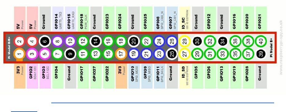
9. Raspberry Pi 3 GPIO:
Image Source: http://www.raspberrypi-spy.co.uk/2012/06/simple-guide-to-the-rpi-gpio-header-
and-pins/
2.4 QUESTIONS TO EXPLORE
Explore and answer the following question in the lab report
1. What is the range of voltage that represent logic low on raspberry Pi?
2. Which instruction set architecture is used in Raspberry Pi?
3. In this lab, we used assembly language to control the output to the GPIO pin on the Raspberry Pi
in order to blink the LED. Do you have an alternative way to blink this external LED? If so, write
down your answer.
4. What can you add to or change in the code in section 3.2 – 3.3 if you want to control the LED
on/off time to different numbers? (For example LED on for 3 second and off for 4 second,
repeat.) Can we replace function delay in our code?
5. Now, if we replace the external LED in this lab by an analog-in buzzer. Can we still produce music
by this buzzer using the same way we do to the LED? If yes, provide your solution. If no, what
needs to be changed in order to produce music?
2.5 WHAT TO TURN IN
Answers to the questions.(5)
Demo the blinking LED to TA in lab.(4)
Attach the code at the end of the lab report.(1)
15
3 LAB 2: USING GPIO AS INPUT AND OUTPUT
3.1 LEARNING OBJECTIVES
In this lab, you are going to learn how to involve user’s control of some actuation, read some
digital data, and output digital data for actuation through Raspberry Pi’s GPIO interface. Input data can
be manipulated inside the Raspberry Pi before writing the outputs. Here are some helpful reading
about GPIO: GPIO - Raspberry Pi Documentation:
https://www.raspberrypi.org/documentation/usage/gpio/
3.2 COMPONENTS NEEDED
Raspberry Pi 3, Raspberry Pi 3, RGB LEDS (We will use blue instead of yellow for traffic signal), press
button switch for control, 7-segment display for time count down, resistors, and appropriate wires
3.3 LAB ACTIVITIES
In this lab activity, you are going to design a stoplight system using GPIO on the Raspberry Pi 3
3.3.1 System Requirement
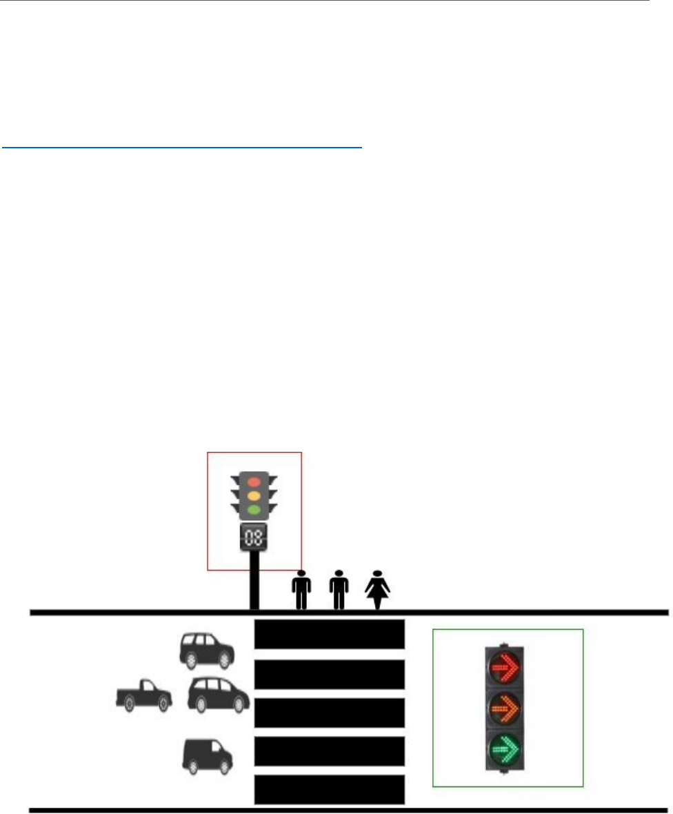
1. Introduction: Imagine a scenario like the image below. You have a heavy traffic street where
people are walking across the street while cars are driving. In this case, an appropriate traffic
light system is needed for this street to ensure everyone’s safety. Your goal is to design a control
system for traffic light 1 (in the red box) & traffic light 2 (in green box)

16
2. Components for traffic light 1: RGB LED, countdown panel (7-segment display) and a press
button (not shown in the figure). One RGB LED should work as it changes color and only one of
the three colors is needed at any time.
3. Components for traffic light 2: RGB LED.
4. Requirements:
a. When button has not been pressed, traffic light 2 stay green
b. When button is pressed, traffic light 2 turn to blue blink 3 times then turn into Red.
c. When Traffic light 2 turn into red, traffic light 1 become green and countdown panel
begin to count down from 9 to 0, in seconds. (In the real world it would be longer)
d. When Countdown reach 4, the traffic light 1 flash with blue light.
e. When Countdown reach 0, the traffic light 1 become red, traffic light 2 become green.
f. When button is pressed once there will be a 15 seconds cool down to be able to make
another valid press.
3.3.2 Raspberry Pi 3 Built In Timer
Implement the stoplight system described above using hardware and the Raspberry Pi. This
system should be demonstrated to the TA. The software controlling the stoplight should be written in
any language you pick. It is suggested that the system can make use of the Raspberry Pi’s built in timer.
Raspberry Pi 3 has multiple different types of timers. Most of these timers are either inconsistent, slow,
or already used by the OS. The Local Arm Timer is not used by the OS and run consistently at a speed of
38.4 MHz because it ticks on every edge (rising and falling) of a crystal clock with frequency of 19.2 MHz.
The description of how to control this timer can be found here
(https://www.raspberrypi.org/documentation/hardware/raspberrypi/bcm2836/QA7_rev3.4.pdf).
The timer works by loading a value into the timer and decrementing that value by one every
tick of the timer. Once the timer reaches 0, it reloads the initial value and sets the interrupt bit (and
actually does an interrupt if the interrupt was enabled). The timer is mainly controlled by a register at
0x40000034. The lower 28 bits (0-27) are the value that is loaded into the timer. The 29th bit (28) is set
to 1 when you want the timer to be enabled and 0 when you don’t. The 30th bit (29) bit is set when you
want timer interrupts to be enabled and 0 when you don’t. The 32nd bit (31) is the interrupt bit. This bit
is set by the hardware when the timer reaches 0. This bit will stay set until it is cleared. To clear the
interrupt bit and reset the timer without triggering an interrupt, a resister a 0x40000038 is used. The
highest bit (31) clears the interrupt bit when a 1 is written to it. The second highest bit (30) will reset
the timer to the load value without triggering an interrupt if a 1 is written to it.
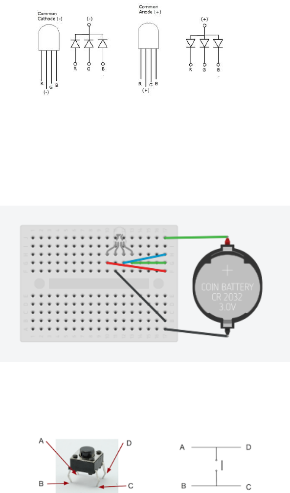
3.3.3 RGB LED
A RGB (Red, Green, Blue) LED produces three different colors of light when you connect the
power source to the different pins. We provide a RGB LED that have the same hardware schema as the
image below. We have a common Cathode (-), which means, the second node should connect to the
ground while the rest of them connect to the output pins on the Raspberry Pi. A positive voltage on the
output pin will cause the corresponding LED to light up.
17
Always remember to connect a resistor to the ground node! The voltage forward each pin is
around 2V(R),3.2V(GB). The red pin will get burned immediately if you connect it directly into a pin. The
blue and green pins can both stay on for several second before they will generate lots of heat and get
burned (if connected directly to the pins).
Circuit Design: A tentative schematic is shown below. You will determine appropriate pins, resistors,
power supplies for your design.
3.3.4 Press Buttons
A press button is a very common component we used to control electronic devices. We
usually use them as a switch to connect/disconnect circuits. First, you will need to understand
the four pins on the press button:
When you're pressing the button, AD will be connected BC, which will connect the
circuit. To protect your raspberry Pi, a resistor is suggested to be placed in the circuit. Also, the
input pin on the Pi will be floating when the button is not pressed (because there are no
complete circuits attached to that pin). To deal with the pin’s voltage floating, it may be
beneficial to put a pull-down resistor attached to the input pin if the other side of the button is
attached to positive voltage. If the button is attached to ground, then a pull-up resistor should
be used. Make sure the resistance is high enough that the input pin can go to the correct
voltage when the button is pressed (preferably significantly higher than the resistor you
placed in series with the switch).

18
3.3.5 7 Segments Display
The data sheet can be found here: https://cdn-shop.adafruit.com/datasheets/CID2379.pdf, this
lab activity only require you to light up one number on the 7-segment display (count down from
9 to 0). Read the data sheet carefully and understand how the 7-segment LED works. Always
connect ground with a resistor first before you connect the other pins.
3.4 QUESTIONS TO EXPLORE
In your report, write down the discussion of the following questions:
1. What is RPI 3 CPU clock Rate?
2. In this lab, we have used a loop to continuously check the signal from the input source(s). Is
there a way to read input from an external button or switch other than simply polling the signal?
3. We used GPIO pins to read input from the Button switches. If you replace the input switch by a
analog-out temperature sensor (model: TMP36), can you read temperature value from the
sensor same way as you did from the switch? If yes, explain. If no, provide a solution to correctly
reading data from a temperature sensor TMP36.
3.5 WHAT TO TURN IN
Schematic of final working circuit for the complete system(1)
Answers to the exploration questions(3)
Demo: Timer(1), Signal light(2), 7-segment(2), press Button(1)
19
4 LAB 3: INTERRUPT WITH RASPBERRY PI 3
4.1 LEARNING OBJECTIVE
In this lab, you are going to learn about using interrupt Driven GPIO.
4.2 COMPONENTS NEEDED
Raspberry Pi 3, RGB LEDS (We will use blue instead of yellow for traffic signal), press button
switch for control, resistors, and appropriate wires
4.3 LAB ACTIVITIES
In lab 2 we designed a system that use a timer to control the LED blink and turn on/off 7
segment display. In this lab we are going to use interrupts instead of read the push button input pins.
4.3.1 Interrupt
When we light up LEDS when corresponding buttons is pressed in lab2, we used a polling
method: calling GPIO.input() in a infinity loop with 0.01 second delay between each iteration, this is not
very efficient, and it will burn CPU power to continuously loop over and over again, even the buttons are
rarely pushed. To improve this, we can use interrupts instead of polling.
A interrupt is a signal generated by a peripheral device that lets the CPU knows that a action is
happening on the device and the software will react depends on the action. The python RPI GPIO library
provides different function to help you describe what type of actions you are waiting for. In this case,
instead of trapping in a loop you can add GPIO.add_event_detect() to tell the program what device
action you are waiting for, and then GPIO.add_event_callback() to set up what action the progam should
take to handle the interrupt.
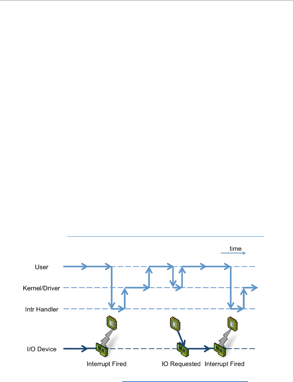
A quick tutorial: http://raspberrywebserver.com/gpio/using-interrupt-driven-gpio.html
Image source: History of Interrupts: https://virtualirfan.com/history-of-interrupts
20
4.3.2 Your assignment:
Write a program that use two buttons to control two LEDs. The first LED should change state
upon the first button’s rising edge. The second LED should light on when the second button is
pressed down and lights off when you release it.
You program should not have loops to polling the button status.
4.4 QUESTIONS TO EXPLORE
1. Discuss the different between polling and interrupt
2. What situation we should use polling and what situation we should use interrupt
4.5 WHAT TO TURN IN
Final implementation C code(1)
Answers to the questions(4)
Demo (5)

21
5 LAB 4: USE OF DIGITAL TO ANALOG CONVERTER ALONG WITH A
MICROCONTROLLER.
5.1 LEARNING OBJECTIVE:
In this lab, you are going to
1. Learn about generating basic waveforms and measuring them using an oscilloscope.
2. Explore generating low frequencies for various sounds and music.
3. Use DAC chip to create different waveforms.
5.2 COMPONENTS NEEDED
Raspberry Pi 3, resistors, buzzer, and DAC chip
We will use a DAC chip MCP4725 for the lab activities below. You are allowed to use the Adafruit open
source library, whose detail can be found here: https://learn.adafruit.com/mcp4725-12-bit-dac-with-
raspberry-pi .
5.3 LAB ACTIVITIES
5.3.1 Generating a Square Wave
A square wave is a waveform in which the amplitude strictly alternates between a fixed minimum and
maximum. A square wave can be created by programming your Raspberry Pi to turn an output pin on
and off.
In lab 1, when you blink your LED, you are sending a square wave out from the pin to the LED. Here is a
simple C solution to generate a square wave with frequency 100 kHz (1/(5+5 μs)):
void squareWave(){
while(1){
setPinOn(gpioBase, pin)
delayMicroseconds(5)
setPinOff(gpioBase, pin)
delayMicroseconds(5)
}
}
By changing the delay period we can change the frequency of the square wave. In the above program
the setPinOn and setPinOff functions are the same ones used in previous labs. The delayMicroseconds
function should be implemented via the timer used in the last lab.
Write a C program or modify the code above to generate digital signal waveforms (square waves) with
frequencies 200 kHz, 600 kHz & 800 kHz.
5.3.2 Measuring Waveforms using an Oscilloscope
Waveforms are specified by their frequency and amplitude. While a regular voltmeter can measure
point values of a signal at a time, an oscilloscope can show the continuous values over a period of time
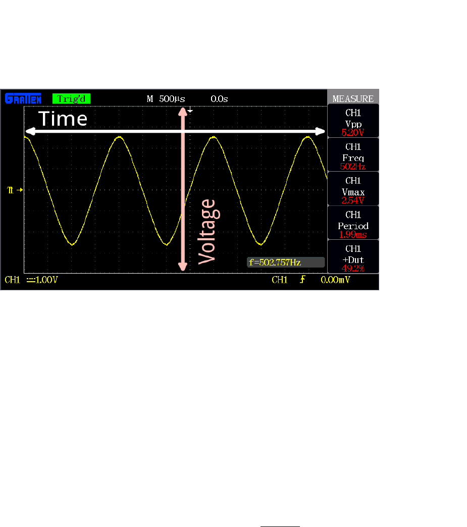
22
of a signal. An oscilloscope can be used to display and analyze waveform of electronic signals. In other
words, it draws a graph of a signal voltage as a function of time.
To view the waveform on the oscilloscope, connect the probe test cable to the signal source (red to
output pin, black to ground pin). Most scopes will produce a two-dimensional graph with time on the x-
axis and voltage on the y-axis.
Figure a. A sample oscilloscope output provided by Sparkfun
On the x-axis, you can find out the timing characteristics, such as frequency, period, duty cycle, &
rising/falling time, using a horizontal control to adjust time scale.
On the y-axis, you can find out the voltage characteristics, such as amplitude and maximum/minimum
voltage, using a vertical control to adjust voltage scale.
In Lab 5, you will be asked to build an oscilloscope to read and visualize the waves you generated in Lab
4. We will discuss the detailed specification about oscilloscope in the next lab.
Read the square wave you generated in the part 1 with an oscilloscope to ensure that you have
generated a wave with the desired frequency. Use control knobs on the oscilloscope panels to measure
the highest voltage and the lowest voltage. Observe whether the highest reading is steady or if there is
noise. Also, determine the fastest frequency that the digital output can create (by changing the
frequency in the program). Record this frequency.
5.3.3 Generating Music using Raspberry Pi and a buzzer (optional)
We will learn how to use a buzzer to output music and write a program to adjust the frequency of a
square wave based on user input.
Generally speaking, a tone is a particular frequency of sound. When we apply an audible signal (voltage,
frequency) to the small buzzer, it makes continuous sound. A buzzer is an actuator that converts
frequency into sound. Please note that a voltage does not make a tone but frequency is the cause of
tone. Let’s make a buzzer produce a C4 (middle C) tone. “Middle C” has a frequency 261.6 Hz (see
helpful hints for more detail).

23
Then we need to generate a square wave that has a frequency equal to 261.6 Hz. This means the every 1
second contains 261.6 cycles of the waveform (1 Hz = 1 cycle per second). The following function will
produce a 261.6 Hz square wave for 1 second:
#include <wiringPi.h>
#include <stdio.h>
#define outputPin 0
#define C4 261.6 //Hz
#define period 1 //second
void tone(){
long half_cycle = (long)(1000000/(2*C4))
long numberOfLoops = (long)(freq*period);
for(int i = 0; i < numberOfLoops; i++){
setPinOn(gpioBase, outputPin);
delayMicroseconds(half_cycle);
setPinOff(gpioBase, outputPin);
delayMicroseconds(half_cycle);
}
}
void run(){
tone();
delay(20);
}
int main(){
//set up gpio. Timer, etc. here
while(1){
run();
}
}
Modify the code above to let the small buzzer produce a piece of music. The tone() function should be
modified into tone(unsigned int frequency, unsigned int period), which will take a frequency input and
a tone period. This tone function will be used multiple times to create the piece of music. Some sample
music notes can be found at the end of the lab manual. Music notes can be hard coded in your main
function. Demonstrate your musical buzzer to the TA.
5.3.4 From Digital Output to Analog Output
Now you are familiar with generating a digital output wave and how to adjust it to a frequency. In this
section you will learn about how to convert a digital signal into an analog signal and how to create
waves other than a square wave.
24
We provided you a DAC MCP4725 12-bit chip (shown in the diagram above), which will help you convert
digital signals into analog. 12 bit means that it will accept up to 4096 possible inputs to provide an
analog input, where 0 is 0V and 4095 is the full scale voltage (which determined by the voltage you
supply to the VCC pin). According to the data sheet the VCC voltage can be in the range 2.7V to 5.5V.
There are six pin on the chip package. SDA will send data from Raspberry pi to the chip (0-4095), and the
SCL (clock) will control the output rate.
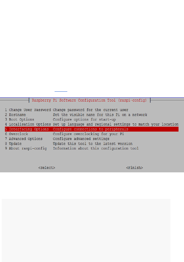
You will need to enable your Raspberry Pi I2C functions in order to send signals via I2C ports. This can
be done via the command “sudo raspi-config”. In the menu that appears, choose option 5, “Interfacing
Options”. Then choose option P5, “I2C”. To control the I2C output to the DAC, you can install Adafruit
Python Library found Here.
Use the code (Python) frame we provided below to generate a sine wave. Check that it is being
generated as expected by displaying it on an oscilloscope.
sin_wave():
t = 0.0
tStep = 0.05
while True:
voltage = 2048*(1.0+0.5*math.sin(6.2832*t))
dac.set_voltage(int(voltage))
t += tStep
time.sleep(0.0005)
5.3.5 Building a Function generator using Raspberry Pi
In this section, you are going to build a function generator using what you learned from sections 1- 4.
The command window should display nothing until an external button is pressed. Then the system
should ask for 3 input:
i. Shape of the waveform (square, triangle, or sin)
ii. Frequency
iii. Maximum output voltage
When the inputs are confirmed, the Raspberry Pi should output the correct wave with correct
characteristic continuously until the button is pressed again. Then the system should ask for 3 inputs
again (continuing the cycle). Demonstrate your finished function generator to the TA.

25
5.4 QUESTIONS TO EXPLORE
1. What is the highest frequency that your Raspberry Pi can generate using digital output? Why is
this the case?
2. Does the highest reading stay steady or fluctuate? If not and there are noise, where does the
noise come from?
3. How can you convert a digital PWM (Pulse width modulation) signal into analog signal. (e.g.
possible circuit design, software conversion)
4. What is the maximum frequency you can produce with your Raspberry Pi functional generator?
5. Explain your design for the functional generator (you can use diagram to visualize your system
state machine, what function you implemented, etc.)
5.5 WHAT TO TURN IN
Answers to the exploration questions(5)
Demo the functional generator: different waveform(3), different frequency(2)
5.6 HELPFUL HINTS
1. Sample Music notes can be used in part 3: format: tone(time (second)) (all 4th octave):
G(0.75) A(0.25) G(0.5) F(0.5) E(0.5) F(0.5) G(1) D(0.5) E(0.5) F(1) E(0.5) F(0.5) G(1) G(0.75) A(0.25)
G(0.5) F(0.5) E(0.5) F(0.5) G(1) D(1) G(1) E(1) C(1)
2. Note frequencies can be found here:
(https://www.seventhstring.com/resources/notefrequencies.html)

26
6 LAB 5: INTERFACING ANALOG TO DIGITAL CONVERTER (ADC) WITH A
MICROCONTROLLER.
6.1 LEARNING OBJECTIVE
In this lab, you are going to
1. Learn about interfacing analog sensors with microcontrollers using A/D converters.
2. Use an ADC chip to analyze analog signals.
3. Examine the characteristics of a signal using an oscilloscope.
6.2 COMPONENTS NEEDED
Raspberry Pi 3, resistors, temperature sensor, ADC chip MCP3008, and light sensor
6.3 LAB ACTIVITIES
6.3.1 Introduction to Raspberry Pi’s SPI port
SPI, or Serial Peripheral interface is a communication bus that is used to interface one or more slave IC
(integrated circuits) to a single master device (Raspberry Pi is the master in this lab). In lab 4, you used
the I2C port as output. However, the SPI port could have been used instead. Please note that SPI is a
faster bus than I2C. On the other hand, I2C can connect many devices with only a 2 wire bus, while each
slave device for SPI requires an additional wire bus. There are three SPI wires shared by all slave devices
on the bus:
a. Master in slave out (MISO), data from slave to master on this port
b. Slave in master out (MOSI), data from master to slave on this port
c. Device clock (CLK), clock for synchronizing communications
Each slave device will have one additional port connected to the master device. This port is for selecting
a device to communicate with. For Raspberry Pi, there are two available ports for you to connect with
your slave devices. Once you connect devices, data transmission can happen. During each clock cycle,
the master sends data on the MOSI line and the slave reads it. At the same time, the slave sends data on
the MISO line, and the master reads it. This behavior is maintained even if only one line has data to
transmit.
To be able to use SPI, you must enable it on the Raspberry Pi. To do this, follow the instructions from
Lab 4 for enabling I2C, except instead of selecting I2C select SPI.
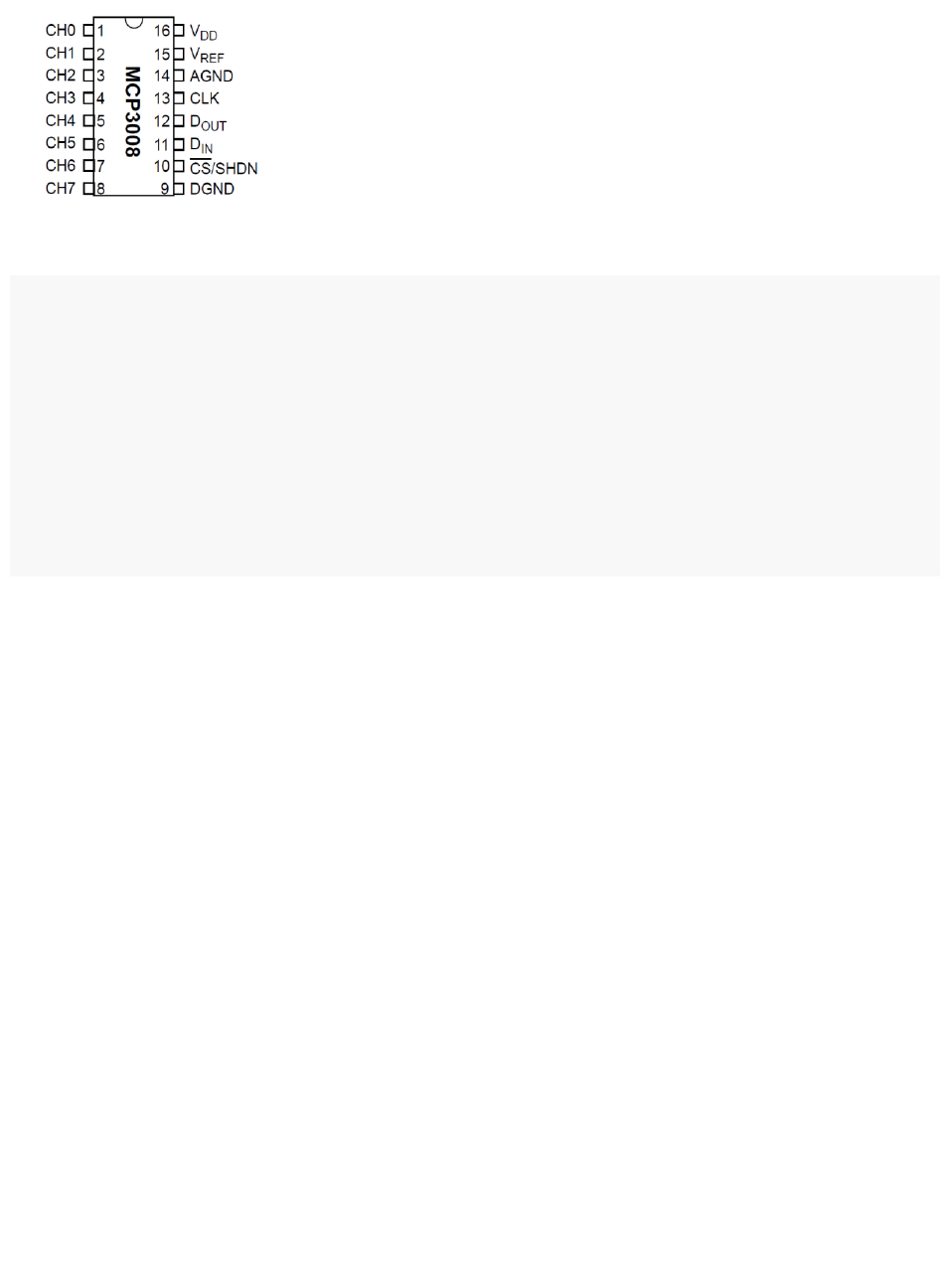
6.3.2 Introduction to MCP3008 ADC
Your Raspberry Pi has no built-in analog inputs. This means it cannot read any data from analog sensors.
The MCP3008 is a 10-bit, 8-channel, SPI-based ADC (analog to digital converter). It communicates with
the Raspberry Pi using the SPI bus on the Raspberry Pi’s GPIO header.
27
The following table shows how you can connect your Raspberry Pi to the chip:
VDD 3.3V
VREF 3.3V
AGND Ground
CLK GPIO11(SPI_SCLK)/Phys23
DOUT GPIO9(SPI_MISO)/Phys21
DIN GPIO10(SPI_MOSI)/Phys19
CS GPIO8(SPI_CE0)/Phys24
DGND Ground
CH0-CH7 Analog Input(8 channel)
When connected to the Raspberry Pi, the ADC chip will take analog input from Ch0-Ch7 and provide 1/0
digital signal to the Dout pin. The following communication happens when the Raspberry Pi tries to read
from the ADC chip:
1. The Raspberry Pi will first send a byte containing the digital value 1. The MCP3008 will send back
its first byte, which is not important, as a response.
2. Then the Raspberry Pi will send a second byte to indicate which channel on the MCP3008 chip
should receive the analog signal.
3. As the result will be a 10 bit data, which cannot be held by a single byte. MCP3008 will send
back the second byte, which contains two bits of the conversion result (which is the 8th and 9th
bit).
4. The Raspberry Pi then sends a response byte to indicate that the previous byte was received,
and then MCP3008 sends back the last byte containing the rest of the bits (bits 0 to 7) of the
converted digital value of the analog signal.
5. Finally, the Raspberry Pi merges bits 8 & 9 with bits 0 through 7 to create the 10 bit digital value
from the conversion.
6.3.3 Reading Data from Sensors(optional)
We will use a photocell (CdS photoresistor) as an example to demonstrate how to read data from sensor
through MCP3008. Under the normal light condition, the resistance of the photocell is about 5-10KΩ,
and in the dark it goes up to 200KΩ. We can use it just like we use a normal resistor.
We can connect one side of a 10k resistor to the power of 3.3V. (To protect the chip, make sure you
connect to the 3.3V pin) Then connect the other side of the 10K resistor to two wires, one connected to
the photoresistor and then to the ground, the other connected to the input pin of MCP3008. With bright
light in the room, the resistance will drop to a low value. This will cause higher current to flow through

28
the photoresistor, resulting in a voltage drop across it. The input voltage will drop to almost 0V. In the
dark, the voltage will go up near 3.3V due to the high resistance in the photocell relative to the
resistance in the resistor.
To read the data, following Python script can be used:
import spidev
# Open SPI bus
spi = spidev.SpiDev()
spi.open(0,0) #1st param is channel
def readChannel(chan):
adc = spi.xfer2([1,(8+chan)<<4,0]) #sends 3 bytes: 1,(8+channel)<<4, 0
#adc will contain 3 bytes (as many as sent)
data = ((adc[1]&3) << 8) + adc[2]
return data
Use your Raspberry Pi to read data from a light sensor and a temperature sensor (Two sensors should
connect to different channels and then use software to read data one by one from the correct
channel). Display the current readings in the command window.
For the temperature sensor, the temperature range is approximately -50°F-280°F corresponding to 0-
3.3V. For the lighting sensor, we will use a scale of 0 to 100 which corresponds to 0-3.3V. You can find
the temperature sensor datasheet here.
6.3.4 Building an Oscilloscope with Raspberry Pi and the MCP3008 Chip
In the previous activity, you accomplished reading data from the MCP3008 and processing that input
data with the Raspberry Pi. In this activity, you are going to build a more complex system, a simple
oscilloscope using your Raspberry Pi with the MCP3008. The simple oscilloscope will have two functions:
1. Recognize a wave: This is a very basic feature that all oscilloscopes should have. In this lab
assignment, you can pick one of the two options to implement:
a. Visualize the waveform on a window using python GUI: You will have to continuously
sample the input wave, and project the data onto a plot just like the oscilloscope you
used in the Lab 4. The system should keep sampling and plotting, and input should be
allowed to switch between the square, sine and triangle waves while the system is
running. The plotting should be paused when system is processing the received data.
b. Display the name of the input wave on a command window: You should implement an
algorithm to distinguish square, sine, and triangle waves based on the data sampled.
Every time your algorithm detects a shape change, print out the name of the shape to
the command window. Be aware that there will be noise when sampling the data
2. Characterizing a wave: The mini-oscilloscope should be able to find out the frequency for the
input waveform and display it to a command window or with your visualized wave.
Build a simple oscilloscope that will meet the requirements as above. You can use Lab 4’s output as
input in this activity. Two team can work each other (one team generate waveform and the other

29
recognize it). Make sure not to have the same Raspberry Pi generating and reading the wave. You can
also use a functional generator in the lab; the oscilloscopes can also generate waveforms. Each team
should provide their own solution by the end of deadline and demonstrate it to the TA. Make sure to
note the sampling rate of your oscilloscope.
6.4 QUESTIONS TO EXPLORE
1. Summarize the difference between SPI and I2C ports. Explain in what situation using the SPI
ports is better than the I2C ports, and vice versa.
2. What are the various types of ADCs in use? Which type of ADC is MCP3008 and what are its
advantages/disadvantages?
3. What is the sampling rate for your oscilloscope?
4. It is important never use the same Raspberry Pi to do waveform generation and waveform
recognition at the same time. Otherwise, you will generate a waveform that frequency keeps
changing or get random readings from the MCP3008. Explain why this is the case.
5. It is highly likely that your sampled data contains lots of noise. How you can filter the noise?
Explain your method.
6.5 WHAT TO TURN IN
Answer to Questions(5)
Oscilloscope code(5): 3 waveform(3), frequency and range(2)
