C SKY V2 CPU Applications Binary Interface Standards Manual
User Manual:
Open the PDF directly: View PDF ![]() .
.
Page Count: 78
- 1 About this Document
- 2 Lower-level Binary interfaces
- 3 High language Issures
- 4 ELF file format
- 5 Runtime library
- 6 Assembly syntax and directives
- 6.1 Section
- 6.2 Input line lengths
- 6.3 Syntax
- 6.4 Assembler directives
- 6.4.1 .align abs-exp [, abs-exp]
- 6.4.2 .ascii “string” {, “string”}
- 6.4.3 .asciz “string” {, “string”}
- 6.4.4 .byte exp {, exp}
- 6.4.5 .comm symbol, length [, align]
- 6.4.6 .data
- 6.4.7 .double float {, float}
- 6.4.8 .equ symbol, expression
- 6.4.9 .export symbol {, symbol}
- 6.4.10 .fill count [, size [, value]]
- 6.4.11 .float float {, float}
- 6.4.12 .ident “string”
- 6.4.13 .import symbol {, symbol}
- 6.4.14 .literals
- 6.4.15 .lcomm symbol, length [, alignment]
- 6.4.16 .long exp {, exp}
- 6.4.17 .section name [, “attributes”]
- 6.4.18 .short exp {, exp}
- 6.4.19 .text
- 6.4.20 .weak symbol [, symbol]
- 6.5 Pseudo-Instructions

C-SKY V2 CPU Applications Binary
Interface Standards Manual
Release 2.1
csky
Nov 15, 2018

Copyright © 2018 Hangzhou C-SKY MicroSystems Co.,Ltd. All rights reserved.
This document is the property of Hangzhou C-SKY MicroSystems Co.,Ltd. This document may only be
distributed to: (i) a C-SKY party having a legitimate business need for the information contained herein,
or (ii) a non-C-SKY party having a legitimate business need for the information contained herein. No
license, expressed or implied, under any patent, copyright or trade secret right is granted or implied by
the conveyance of this document. No part of this document may be reproduced, transmitted, transcribed,
stored in a retrieval system, translated into any language or computer language, in any form or by any
means, electronic, mechanical, magnetic, optical, chemical, manual, or otherwise without the prior written
permission of C-SKY MicroSystems Co.,Ltd.
Trademarks and Permissions
The C-SKY Logo and all other trademarks indicated as such herein are trademarks of Hangzhou C-SKY
MicroSystems Co.,Ltd. All other products or service names are the property of their respective owners.
Notice
The purchased products, services and features are stipulated by the contract made between C-SKY and
the customer. All or part of the products, services and features described in this document may not be
within the purchase scope or the usage scope. Unless otherwise specied in the contract, all statements,
information, and recommendations in this document are provided ”AS IS” without warranties, guarantees
or representations of any kind, either express or implied. The information in this document is subject to
change without notice. Every eort has been made in the preparation of this document to ensure accuracy
of the contents, but all statements, information, and recommendations in this document do not constitute a
warranty of any kind, express or implied.
Hangzhou C-SKY MicroSystems Co.,LTD
Address: 15 Story of Building A, Tiantang software center,XiDouMen road, Xihu district, Hangzhou, China
Post code: 310012
Ocal website: www.c-sky.com
i

Contents
1 About this Document 1
1.1 Abstract ............................................... 1
1.2 Purpose ................................................ 1
1.3 References .............................................. 2
1.4 Current status and anticipated changes .............................. 2
1.5 Overview ............................................... 3
1.5.1 Low-Level Run-Time Binary Interface Standards .................... 3
1.5.2 Object File Binary Interface Standards .......................... 3
1.5.3 Source-Level Standards ................................... 3
1.5.4 Library Standards ..................................... 3
1.5.5 Change history ....................................... 3
2 Lower-level Binary interfaces 4
2.1 Processor Architecture ....................................... 4
2.1.1 Control Registers in C-SKY V2.0 ............................. 5
2.1.2 Primary Data Type ..................................... 6
2.1.3 Composite Data Type ................................... 8
2.2 Function Calling Convention .................................... 9
2.2.1 Register Assignments .................................... 9
2.2.2 Stack Frame Layout .................................... 11
2.2.3 Argument Passing ..................................... 12
2.2.4 Variable Arguments ..................................... 13
2.2.5 Return Values ........................................ 14
2.3 Runtime Debugging Support .................................... 15
2.3.1 Function Prologues in C-SKY V2.0 ............................ 15
2.3.2 Stack Tracing ........................................ 16
3 High language Issures 17
3.1 C preprocessor predenitions .................................... 17
3.2 Inline assembly syntax ....................................... 17
3.2.1 Overview .......................................... 17
3.2.2 Basic usage ......................................... 18
3.2.3 Extended asm ........................................ 18
3.2.4 Examples .......................................... 22
3.3 Name mapping ............................................ 24
4 ELF le format 25
ii

4.1 ELF Header ............................................. 25
4.2 Section Layout ............................................ 27
4.2.1 Section Alignment ..................................... 27
4.2.2 Section Attributs ...................................... 28
4.2.3 Special Sections ....................................... 28
4.3 Symbol Table Format ........................................ 29
4.4 Relocation Information Format ................................... 29
4.4.1 Reclocation Fields ..................................... 29
4.4.2 Relocation Types ...................................... 32
4.5 Program Loading .......................................... 43
4.6 Dynamic Linking ........................................... 45
4.6.1 Dynamic Section ...................................... 46
4.6.2 Global Oset Table ..................................... 46
4.6.3 Function Address ...................................... 47
4.6.4 Procedure Linkage Table .................................. 47
4.7 PIC Examples ............................................ 50
4.7.1 Function proglogue for PIC ................................ 50
4.7.2 Date Objects ........................................ 51
4.7.3 Function Call ........................................ 51
4.7.4 Branching .......................................... 52
4.8 Debugging Information Format ................................... 53
4.8.1 DWARF Register Numbers ................................ 54
5 Runtime library 56
5.1 Compiler assisted Libraries ..................................... 56
5.2 Floating Point Routines ....................................... 57
5.2.1 Arithmetic functions .................................... 57
5.2.2 Conversion functions .................................... 58
5.2.3 Comparison functions ................................... 59
5.3 Long Long integer Routines ..................................... 59
5.3.1 Arithmetic functions .................................... 60
5.3.2 Comparison functions ................................... 61
5.3.3 Trapping Arithmetic Functions .............................. 61
5.3.4 Bit Operations ....................................... 61
6 Assembly syntax and directives 62
6.1 Section ................................................ 62
6.2 Input line lengths .......................................... 62
6.3 Syntax ................................................ 63
6.3.1 Preprocessing ........................................ 63
6.3.2 Symbols ........................................... 63
6.3.3 Constants .......................................... 64
6.3.4 Expressions ......................................... 64
6.3.5 Oprators and Precedence .................................. 64
6.3.6 Instruction Memonics .................................... 65
6.3.7 Instruction Arguments ................................... 65
6.4 Assembler directives ......................................... 66
6.4.1 .align abs-exp [, abs-exp] .................................. 66
6.4.2 .ascii “string” {, “string”} ................................. 67
6.4.3 .asciz “string” {, “string”} ................................. 67
6.4.4 .byte exp {, exp} ...................................... 67
6.4.5 .comm symbol, length [, align] ............................... 67
6.4.6 .data ............................................. 67
6.4.7 .double oat {, oat} .................................... 67
iii

6.4.8 .equ symbol, expression .................................. 68
6.4.9 .export symbol {, symbol} ................................. 68
6.4.10 .ll count [, size [, value]] .................................. 68
6.4.11 .oat oat {, oat} ..................................... 68
6.4.12 .ident “string” ........................................ 68
6.4.13 .import symbol {, symbol} ................................. 68
6.4.14 .literals ............................................ 68
6.4.15 .lcomm symbol, length [, alignment] ............................ 68
6.4.16 .long exp {, exp} ...................................... 69
6.4.17 .section name [, “attributes”] ............................... 69
6.4.18 .short exp {, exp} ...................................... 69
6.4.19 .text ............................................. 69
6.4.20 .weak symbol [, symbol] .................................. 70
6.5 Pseudo-Instructions ......................................... 70
iv

CHAPTER 1
About this Document
This chapter would be organized with several sections as follows.
•Abstract
•Purpose
•References
•Current status and anticipated changes
•Overview
1.1 Abstract
This manual denes the C-SKY V2 CPU Applications Binary Interface (ABI). The ABI consists of a serial
of interfaces which the writer of compiler and assembler might follows, as composing tools for the C-SKY
V2 CPU architecture. These standard covers several aspects of whole tool chain, varing from run-time to
object formats, so as to make sure that diernet tool chain implementations of the C-SKY CPU shoule be
compatible and interoperated.
Although compiler supportive routines are provided, this manual does not describe how to write C-SKY V2
CPU development tools, does not dene the services provided by an operating system, and does not dene
a set of libraries. Those tasks must be performed by suppliers of tools, libraries, and operating systems.
1.2 Purpose
The standards only dened in this manual ensure that all components of development tool for C-SKY V2
CPU (do not include C-SKY V1 CPU) should be fully compatible with each other. Fully compatible tools
could be interoperated, thus, making it is possible to select an optimal tool for each part in the chain instead
of selecting an entire chain on the basis of overall performance. The Technology Center of Hangzhou C-SKY
Microsystems Co., Ltd also provide a test suite to verify compliance with published standards.
1

Chapter 1. About this Document
It is sucial for developer to follow by this standard. Concretely, the standards ensure that compatible
libraries of binary components can be created and maintained. Such libraries make it is possible for developers
to synthesize applications from binary components, and can make libraries of common services stored in on-
chip ROM available to applications executing from o- chip ROM. With established standards, developer
can build up libraries over time with the assurance of continued compatibility.
There are two goals required for implemented to conform to the standard.
• Use of interfaces that allow future optimizations for performance and energy.
For example, when possible, registers are used to pass arguments, even though always using the stack
might be easier. Small programs whose working sets t into the registers are thus not forced to make
unnecessary memory references to the stack just to satisfy the linkage convention.
• Use of interfaces that are compatible with legacy “C” code written for the C-SKY when possible.
For example, whenever possible, C-SKY V2 CPU rules are used to build an argument list. This not
only ts the C-SKY V2 CPU programmer’s expectations, but easily supports
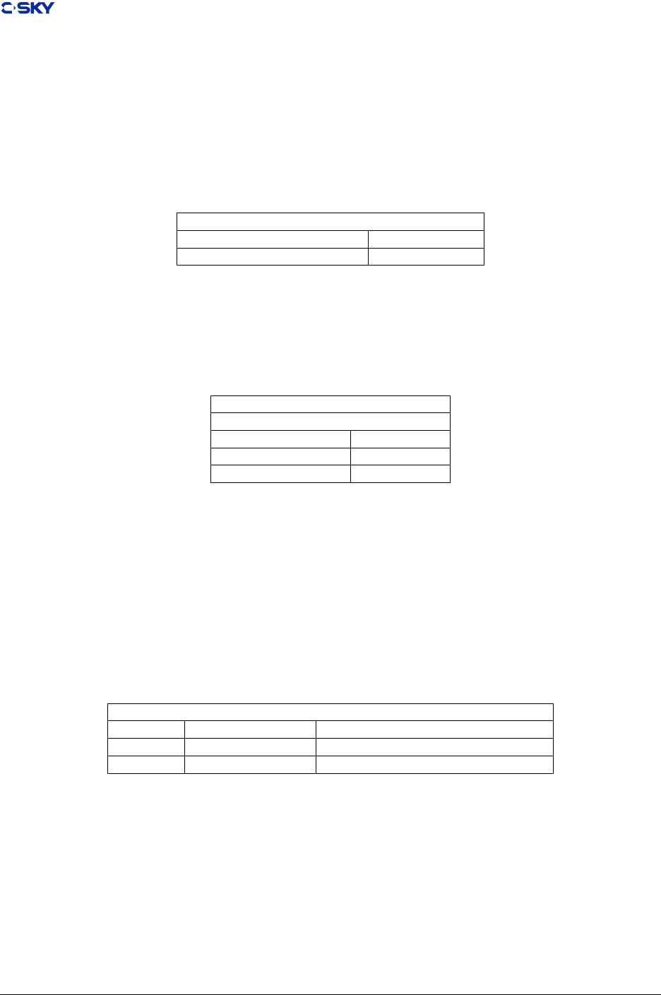
1.3 References
Table 1.1: The references
GC++ABI http://www.codesourcery.com/
cxx-abi/abi.html
Generic C++ ABI
GDWARF http://dwarf.freestandards.org/
Dwarf3Std.php
DWARF 3.0, the generic debug
GABI http://www.sco.com/developers/
gabi/
Generic ELF, 17 th December 2003
draft.
GLSB http://www.linuxbase.org/spec/
refspecs/
gLSB v1.2 Linux Standard Base
Open BSD http://www.openbsd.org/ Open BSD standard
C-SKY CPU ABI V1.0 C-SKY CPU ABI Standards.pdf
1.4 Current status and anticipated changes
1. This manual has been released publicly. This manual is meant to be expandable.
2. Anticipated changes to this document include typographical corrections and clarications.
3. Additional features about C++ ABI would be appended into this document to replect improvment in
the future.
4. Supporting of PE object le format is anticipated to be added to this manual.
5. The Linux system interface for compiled application programs(The ABI for C-SKY V2.0 Linux)is
anticipated to be added to this manual
6. TLS for Linux ABI, Thread Local Storage (TLS) is a class of own data (static storage), like stack,
would be added.
Release 2.1 Copyright © 2018 Hangzhou C-SKY MicroSystems Co.,Ltd. All rights reserved. 2
Chapter 1. About this Document
1.5 Overview
Standards in this manual are intended to preclude creation of incompatible development tools for the C-SKY
V2.0, by ensuring binary compatibility between:
• Object modules generated by dierent tool chains
• Object modules and the C-SKY V2.0 processor
• Object modules and source level debugging tools
Current denitions include the following types of standards.
1.5.1 Low-Level Run-Time Binary Interface Standards
• Processor specic binary interface, such as the instruction set, representation of primitive data types,
and exception handling
• Function calling convention that the method of passing arguments and returning result on calling to
another function arguments are passed and results are returned. This manual will specify how the
arguemnt should be passed by register or stack slot according to its type.
1.5.2 Object File Binary Interface Standards
• Header convention
• Section layout
• Symbol table format
• Relocation information format
• Debugging information format
1.5.3 Source-Level Standards
• C language, e.g. preprocessor predenes, in-line assembly, and name mapping.
• Assembly, e.g. the syntax and directives.
1.5.4 Library Standards
• Compiler assist libraries, including some library functions supporting operation on oating point and
long long integer, for instance, addition of two integer of type long long, etc.
1.5.5 Change history
Table 1.2: Record of Change
Revision Date Changed by Description
V2.0 2011-12-14 LiChunQiang First public release used only for C-SKY V2 CPU
V2.1 2018-04-13 JianpingZeng Second public release used only for C-SKY V2 CPU
Release 2.1 Copyright © 2018 Hangzhou C-SKY MicroSystems Co.,Ltd. All rights reserved. 3

CHAPTER 2
Lower-level Binary interfaces
In order to served as a well documented index, this chapter would be splitted into following several dierent
sections.
•Processor Architecture
•Function Calling Convention
•Runtime Debugging Support
2.1 Processor Architecture
C-SKY processor is a 32-bit high-performance and low-power embedded processor designed for embedded
system or SoC environment. It adopts independently design of architecture and micro-achitecture with
extensible instruction set, which owns great features, e.g. congurable hardware, re-synthesis, easily inte-
gration etc. Additionly, it is excellent in power management. It adopts several strategies to reduce power
consumption including statically designed and dynamic power supply management, low voltage supply, en-
tering low power mode and closing internal function modules. Now, C-SKY CPU instruction system has
two versions:
• C-SKY V1
Any CPUs conrmed C-SKY V1.0 Instructions are always 16-bit and are aligned on a 2-byte boundary.
There are two sub-serials, CK500 & CK600. The serial of CK500 include CK510, Ck520, CK510(ES),
and CK600 include CK610, ck620 and ck610(ESM-F). CK510 is the rst generation of C-SKY IP. Also
CK610 is the second generation of C-SKY IP which is more ecient than CK510. CK520/CK620 adds
OMFLIP, MAC, MTLO, MTHI, MFHI and MFLO instructions based on CK510/CK610 instruction
set.
’E’ means DSP enhancement, ‘S’ means SPM, ‘M’ means MMU, and ‘-F’ means supporting of Float
Point. Pelease consult the CK500 & CK600 Reference Manual to view description for detailed infor-
mation.
• C-SKY V2
4

Chapter 2. Lower-level Binary interfaces
The 2nd generation of instruction set of CK-CPU, which has more power and extensible instructions
set than CK500 & CK600, even though second one is compatible with CK500 & CK600 in the level of
assemble language. C-SKY V2.0 instruction set is the freely mixture of 32-bit and 16-bit instruction,
and it’s alignment boundary is two bytes.
What’s important is:
–Most of 16-bit instructions have been limited to only access 8 of partial general- purpose registers,
r0-r7, known as the low registers. A few number of 16-bit instructions have the legal accessibility
to the high registers, r8-r15.
–In the most of cases, operations should be accomplished by at least two 16-bit instructions so as
to gain more eciency.
You must note that the C-SKY V2.0 instruction sets are not freely exchangebale with V1.0. Conversely,
available function provided by V2.0 is identical to V1.0 for most of applicatios. So that we strongly recom-
mend that you should make sure you are aware of the generated result of specied application when you use
them stimuleously. The two instruction sets dier in how instructions are encoded:
The standards dened in this manual ensure that all parts of development tools for C-SKY V2 CPU (do not
include C-SKY V1 CPU) would be fully compatible.
2.1.1 Control Registers in C-SKY V2.0
The C-SKY ABI V2 denes an array of rules illustrating the developer should how to use the 32
general-purpose 32-bit registers of the C-SKY V2.0 processor. These registers are named r0~r31 or
a0~a6/t0~t10/l0~l10/gb/sp/lr. C-SKY V2.0 Co-processor 0 has up to 32 control registers. These regis-
ters are named cr0 through cr31. The control registers are shown in Table 2.1. These control registers can
access with mtcr/mfcr instructions.
Release 2.1 Copyright © 2018 Hangzhou C-SKY MicroSystems Co.,Ltd. All rights reserved. 5

Chapter 2. Lower-level Binary interfaces
Table 2.1: C-SKY V2 Controls Register
Register Use Convention
Reg Name Function
cr0 psr, cr0 Processor Status Register
cr1 vbr,cr1 Vector Base Register
cr2 epsr,cr2 Shadow Exception PSR
cr3 fpsr,cr3 Shadow Fast Interrpt PSR
cr4 epc,cr4 Shadow Exception Program Counter
cr5 fpc,cr5 Shadow Fast Interrupt PC
cr6 ss0,cr6 Supervisor Scratch Register
cr7 ss1,cr7 Supervisor Sratch Register
cr8 ss2,cr8 Supervisor Scratch Regsiter
cr9 ss3,cr9 Supervisor Scratch Register
cr10 ss4,cr10 Supervisor Scratch Register
cr11 gcr,cr11 Global Control Register
cr12 gsr,cr2 Global Status Register
cr13 cpidr Product ID Register
cr14 cr14 Rerserved
cr15 cr15 Rerserved
cr16 cr16 Rerserved
cr17 cfr Cache Flush Register
cr18 ccr Cache Cong Register
cr19 capr Cachable and Access Popedom Register(MGU processor only)
cr20 pacr Protected Area Cong Register(MGU processor only)
cr21 prsr Protected Area Select Register(MGU processor only)
cr22-cr31 cr22-cr31 Reserved
The ABI does not mandate the semantics of the C-SKY Hardware Accelerator Interface (HAI) because these
semantics vary between C-SKY implementations based on particular chips. C-SKY V2 provides instruction
encodings to move, load, and store values for up to other 15 co-processors (except for co-processor 0).
2.1.2 Primary Data Type
The C-SKY processor works with the following raw data types:
1. unsigned byte of eight bits
2. unsigned halfword of 16 bits
3. unsigned word of 32 bits
4. signed byte of eight bits
5. signed halfword of 16 bits
6. signed word of 32 bits
As the listed above, the data size could be 8-bit bytes, 16-bit halfwords and 32-bit words. The mapping
between these data types and the C language fundamental data type is shown in Table 2.2.
Release 2.1 Copyright © 2018 Hangzhou C-SKY MicroSystems Co.,Ltd. All rights reserved. 6
Chapter 2. Lower-level Binary interfaces
Table 2.2: Mapping of C Fundamental Data Types to the C-SKY
Fundamental Data Types
ANSI C Size(byte) Align C-SKY
char 1 1 unsigned byte
unsigned char 1 1 unsigned byte
signed char 1 1 signed byte
short 2 2 signed halfword
unsigned short 2 2 unsigned halfword
signed short 2 2 signed halfword
long 4 4 signed word
unsigned long 4 4 unsigned word
signed long 4 4 signed word
int 4 4 signed word
unsigned int 4 4 unsigned word
signed int 4 4 signed word
enum 4 4 signed word
pointer 4 4 unsigned word
long long 8 8 signed word[2]
unsigned long long 8 8 unsigned word[2]
oat 4 4 unsigned word
double 8 8 unsigned word[2]
long double 8 8 unsigned word[2]
Memory access to unsigned byte-sized data is directly supported through both ld.b (load byte) and st.b
(store byte) instruction. Signed byte-sized access requires a sextb (sign extension) instruction after the
ld.b. alternatively, memory access to signed byte-sized data can be directly supported through the ld.bs
(load byte) and st.bs (store byte) instructions. Access to unsigned halfword-sized data is directly supported
through the ld.h (load halfword) and st.h (store halfword) instructions. Signed halfword access requires a
sexth (sign extension) instruction after the ld.h. In the other hand, memory access to signed halvword-sized
data can be directly supported through the ld.hs (load byte) and st.hs (store byte) instructions. Memory
access to word-sized data is supported through ld.w (load word) and st.w (store word) instruction. Also,
ld.w suces for both signed and unsigned word access because the operation sets all 32 bits of the loaded
register.
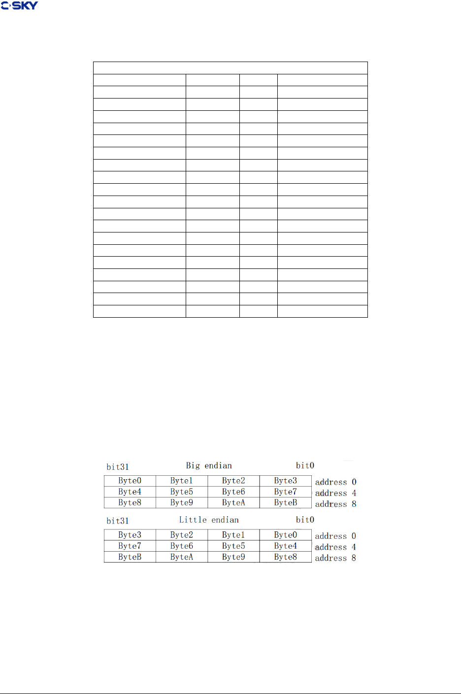
Figure 2.1: Data layout in memory
Release 2.1 Copyright © 2018 Hangzhou C-SKY MicroSystems Co.,Ltd. All rights reserved. 7

Chapter 2. Lower-level Binary interfaces
Table 2.3: Data Layout in register
SSSSSSSSSSSSSS S Byte
00000000000000 Byte
SSSSSSS | S halfword
0000000 | Halfword
Byte0 | Byte1 Byte2 | Byte3
C-SKY V2 CPU supports standard two’s complement data formats. The operand size for each instruction is
either explicitly encoded in the instruction (load/store instructions) or implicitly dened by the instruction
operation (index operations, byte extraction). Typically, instructions operate on all 32 bits of the source
operand(s) and generate a 32-bit result.
C-SKY V2 CPU memory might be working in big endian or little endian byte ordering depending on the
processor conguration (see Figure 2-1 Data Organization in Memory). When conguraed with big endian
mode (by default), the most signicant byte (byte 0) of word 0 is located at address 0. For little endian
mode, the most signicant bye of word 0 is located at address 3. Any data of primitive type is always
naturally aligned in memory, i.e., a long is 4-byte aligned, a short is 2-byte aligned.
Within registers, bits are numbered within a word starting with bit 31 as the most signicant bit (see Figure
2-2 Data Organization in Registers). By convention, byte 0 of a register is the most signicant byte regardless
of Endian mode. This is only an issue when executing the xtrb[0-3] instructions.
The C-SKY processor currently does not support the long long int data type with 64-bit operations. However,
compliant compilers must emulate the data type. The long long int data type, both signed and unsigned, is
eight bytes in length and 4-byte aligned.
Requiring long long int support as part of the ABI insures that the feature will exist in all tool chains, so
that application developers can depend on its existence. Because C-SKY processor can only hold a 32 bits
data in a register, long long or double must be held in two registers(like r1,r2), and the most signicant
word of long long or double always is held in the upper register(like r2), the other word is held in the lower
register(like r1) for big endian or little endian. when storing in memory, the most signicant word of long
long or double always is held in the upper address, the other word is held in the lower address for big
endian or little endian. The C-SKY processor currently support oating point data with coprocessor FPU.
Compliant compilers must support its use. The oating point format to be used is the IEEE standard for
oat and double data types. Supportting for the long double data type is optional but must conform to the
IEEE standard format when provided. Alignments are specically chosen to avoid the possibility of access
faults in the middle of an instruction (with the exception of load/store multiple).
2.1.3 Composite Data Type
There is no two same leaf in the world, compound data types, such as array, structure, union, and bit
elds, have dierent alignment characteristics. Arrays have the same alignment as their individual elements.
Unions and structures have the most restrictive alignment of their members. A structure containing a char,
a short, and an int must have 4-byte alignment to match the alignment of the int eld. In addition, the size
of a union or structure must be an integral multiple of its alignment. Padding must be applied to the end of
a union or structure to make its size a multiple of the alignment. Members must be aligned within a union
or structure according to their type; padding must be introduced between members as necessary to meet this
alignment requirement. Bit elds cannot exceed 32 bits nor can they cross a word (32 bit) boundary. Bit
elds of signed short and unsigned short type are further restricted to 16 bits in size and cannot cross 16-bit
boundaries. Bit elds of signed char and unsigned char types are further restricted to eight bits in size and
cannot cross 8-bit boundaries. Zero-width bit elds pad to the next 8, 16, or 32 bit boundary for char, short,
and int types respectively. Outside of these restrictions, bit elds are packed together with no padding in
between. Bit elds are assigned in big-endian order, i.e., the rst bit eld occupies the most signicant bits
Release 2.1 Copyright © 2018 Hangzhou C-SKY MicroSystems Co.,Ltd. All rights reserved. 8

Chapter 2. Lower-level Binary interfaces
while subsequent elds occupy lesser bits. Unsigned bit elds range from 0 to 2 –1 where “w” is the size in
bits. Signed bit elds range from −2w−1to 2w−1
−1. Plain int bit elds are unsigned. Bit elds impose
alignment restrictions on their enclosing structure or union. The fundamental type of the bit eld (e.g.,
char, short, int) imposes an alignment on the entire structure. In the following example, the structure more
has 4-byte alignment and will have size of four bytes because the fundamental type of the bit elds is int,
which requires 4byte alignment. The second structure, less, requires only 1-byte alignment because that is
the requirement of the fundamental type (char) used in that structure. The alignments are driven by the
underlying type, not the width of the elds. These alignments are to be considered along with any other
structure members. Struct careful requires 4-byte alignment; its bit elds only require 1-byte alignment, but
the eld uy requires 4-byte alignment.
struct more
{
int first :3;
unsigned int second :8;
};
struct less
{
unsigned char third :3;
unsigned char fourth :8;
};
struct careful
{
unsigned char third :3;
unsigned char fourth :8;
int fluffy ;
};
each eld of structure or union starts on the next possible suitably aligned boundary for their data type.
For non-bit elds, this is a suitable byte alignment. Specially, bit eld begin at the next available bit oset
with the following exception: the rst bit eld after a non-bit eld member will be allocated on the next
available byte boundary. In the following example, the oset of the eld “c” is one byte. The structure itself
has 4-byte alignment and is four bytes in size because of the alignment restrictions introduced by using the
“int” under- lying data type for the bit eld.
struct s
{
int bf :5;
char c;
};
This act behaves as same as the rules dened by UNIX System V Release 4 ABIs.
2.2 Function Calling Convention
2.2.1 Register Assignments
2.2.1.1 General Registers
In Table 2.4, showing the required register mapping for function calls. Some registers, such as the stack
pointer, have specic purposes, while others are used for local variables, or to transist function call arguments
and return values.
Certain registers are bound to their purpose because specic instructions use them. For instance, subroutine
call instructions write the return address into r15. The instructions used to save and restore registers on
Release 2.1 Copyright © 2018 Hangzhou C-SKY MicroSystems Co.,Ltd. All rights reserved. 9
Chapter 2. Lower-level Binary interfaces
entry and exit from a function use r14 as a base register, making it most appropriate for the stack pointer
register.
Reference to “Argument Passing“ and “Return Values” section for the detailed illustration of how
arguments are passed or how the compiler handle the return value.
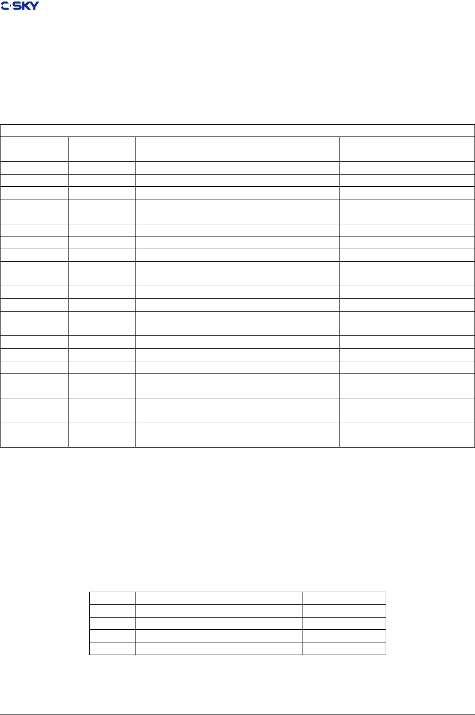
Table 2.4: C-SKY V2.0 Register Assignment
Register Use Convention
Name Software
name
Usage Cross-Call Status
r0-r1 a0-a1 Argument Word 1-2/Return Address Destroyed
r2-r3 a2-a3 Argument Word 3-4 Destroyed
r4-r11 l0-l7 Local Preserved
r12-r13 t0-t1 Temporary registers used for expression
evaluation
Destroyed
r14 sp stack pointer Preserved
r15 lr link Preserved
r16-r17 l8-l9 Local Preserved
r18-r25 t2-t9 Temporary registers used for expression
evaluation
Destroyed
r26 r26 Linker register Reserved
r27 r27 Assembler register reserved
r28 rdb/rgb Data section base address /GOT based Ad-
dress for PIC
reserved/Perserved
r29 rtb Text section base address reserved
r30 r30/svbr Handler Base address reserved
r31 tls TLS register reserved
pc pc Program counter can’t be accessed directly
by instructions
-
hi hi Multiply special register. Holds the most
signicant 32 bits of multiply
Destroyed
lo lo Multiply special register. Holds the least
signicant 32 bits of multiply
Destroyed
2.2.1.2 Float Point Registers
The C-SKY V2.0 provides instruction encodings to move, load, and store values for up to 16 co-processors.
Co-processor 1 adds 16 32/64/128-bit oating-point general registers for single / double / SIMD double.
Floating-point data representation is that specied in IEEE Standard for Binary Floating-Point Arithmetic,
ANSI/IEEE Standard 754-1985. Table 2.5 Registers describes the conventions for using the oating-point
registers.
Table 2.5: Float point Registers
Name Usage Cross-Call status
fr0 Argument Word 1/Return Address Destroyed
fr1-fr3 Argument Word 2-4 Destroyed
fr4-fr7 Temporary registers Destroyed
fr8-fr15 Local registers Preserved
Release 2.1 Copyright © 2018 Hangzhou C-SKY MicroSystems Co.,Ltd. All rights reserved. 10

Chapter 2. Lower-level Binary interfaces
2.2.1.3 Cross-Call Lifetimes
The 32 general-purpose registers are split between those preserved and those destroyed across function calls.
This balances the need for callers to keep values in registers across calls against the need for simple leaf
subroutines to perform operations without allocating stack space and saving registers. The preserved registers
are called non-volatile registers. The registers that are destroyed are called volatile registers. Registers r4
through r7 are preserved because some 16-bit instructions can only access r0-r7 registers, so we can have a
high performance and code density with 16-bit instructions.
The called subroutine can use any of the argument and scratch registers without concerning for restoring
their values. Preserved registers must be saved before being used and restored before returning to the caller.
While the called function is not specically required to save and restore r15. On entry to functionm r15
usually contains the return address, so that it’s value should be written into stack slot for making suring
that the program can nd the target address after callee is nished. The caller must preserve any essential
data stored in argument and scratch registers. Data in these registers does not survive across function calls.
There is no register dedicated as a frame pointer. For non-alloca() functions, the frame pointer can always
be expressed as an oset from the stack pointer. For alloca() functions and functions with very large frames,
a frame pointer can be synthesized into one of the non-volatile registers.
Eliminating the dedicated frame pointer makes another register available for general use, with a corresponding
improvement in generated code. This aects stack tracing for debugging. See 2.3 Runtime Debugging
Support for additional information.
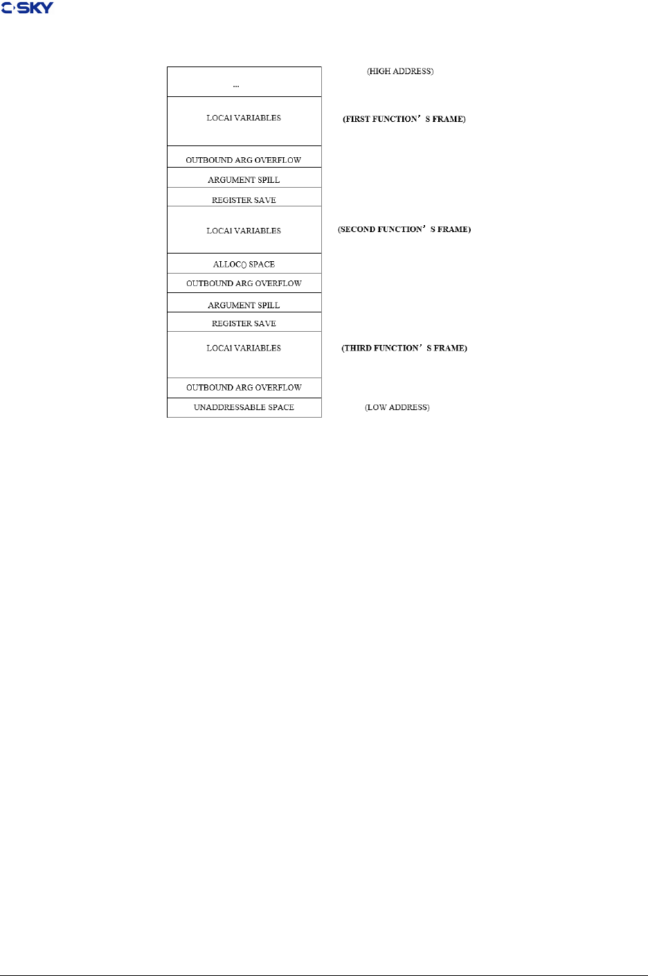
2.2.2 Stack Frame Layout
The stack pointer points to the bottom (low address) of the stack frame. Space at lower addresses than the
stack pointer is considered invalid and may actually be unaddressable. The stack pointer value must always
be a multiple of eight.
As the Stack Frame Layouts depicted, First() calls Second() which calls Third() shows typical stack frames
for three functions, indicating the relative position of local variables, parameters, and return address. The
outbound argument overow must be located at the bottom (low address) of the frame. Any incoming
argument spill generated for vararg and stdarg processing must be at the top (high address) of the frame.
Space allocated by Alloca() must reside between the outbound argument overow and local variable area.
The caller must store argument variables that do not t in the argument registers in the outbound argument
overow area. If all outbound arguments t in registers, this area is not required. A caller may allocate a
succession of argument overow space sucient for the worst-case call, use portions of it as necessary, and
not change the stack pointer between calls. The caller must reserve stack space for return variables that
do not t in the rst two argument registers (e.g., structure returns). This return buer area is typically
adjecent to the local variables. Note that only in the function return structure value, this space would be
allocated.
The caller may store the return address (r15) and the content of other local registers in the register save
area upon entry to the called subroutine. If a called routine does not modify local variables (including r15),
this area is not required.
Local variables that do not t into the local registers are allocated in the Local Variable area of the stack. If
there are no such variables, this area is not required. Beyond these requirements, a routine is free to manage
its stack frame.
2.2.2.1 Extending the Stack
Stack maintenance is the responsibility of system software. In some environments, it may be benetial for
compiler to probe the stack as they extend it in order to allow memory protection hardware to provide
Release 2.1 Copyright © 2018 Hangzhou C-SKY MicroSystems Co.,Ltd. All rights reserved. 11
Chapter 2. Lower-level Binary interfaces
Figure 2.2: Stack Frame Layouts
“guard pages”.
2.2.3 Argument Passing
The C-SKY V2 CPU uses four registers (r0–r3) to pass the rst four words of arguments from the caller to
the called routine. If additional argument space is required, the caller is responsible for allocating this space
on the stack. This space (if needed by a particular caller) is typically allocated upon entry to a subroutine,
reused for each of the calls made from that subroutine that have more arguments than t into the four
registers used for subroutine calls, and deallocated only at the caller’s exit point. All argument overow
allocation and deallocation is the responsibility of the caller.
At entry to a subroutine, the rst word of any argument overow can be found at the address contained in
the stack pointer. Subsequent overow words are located at successively larger addresses.
2.2.3.1 Scalar Arguments
Arguments are passed using registers r0 through r3, with no more than one argument assigned per register.
Argument values that are smaller than a 32-bit register occupy a full register.
In addition, small argument values are right justied and possibly extended within the register. Small
signed arguments (e.g., shorts) are sign extended; small unsigned arguments (e.g., unsigned shorts) are zero
extended, while other small values (e.g., structures of less than four bytes) are not extended, leaving the upper
bits of the register undened. The caller is responsible for sign and zero extensions. Small arguments that
are passed via the argument overow mechanism are placed in the overow word with the same orientation
they would have if passed in a register; a char is passed in the low-order byte of an overow word. Such
small overow arguments need not be sign extended within the argument word as they would be if passed
in a register. Arguments larger than a register must be assigned to multiple argument registers as long as
Release 2.1 Copyright © 2018 Hangzhou C-SKY MicroSystems Co.,Ltd. All rights reserved. 12

Chapter 2. Lower-level Binary interfaces
there are argument registers available. Arguments that would be aligned on 4-byte boundaries in memory
(double, long double, long long, or structures or unions containing a double, long double or long long) can
begin in any numbered register. Once all the argument registers are used, or if there are not enough registers
left to hold a large argument, the argument and any subsequent arguments must be placed in the overow
area described above.
Large arguments can be split in register and in the overow area when there are too few argument registers
to hold the entire argument.
The caller is responsible for allocating argument overow space and for deallocating any space needed for
argument overow. The only argument space that may be allocated or deallocated by the called routine
is space used to place the register arguments in memory. This may be necessary for stdargs or structure
parameters. Alignment is forced for atomic data types; fundamental data types are not split.
2.2.3.2 Structure Arguments
Structures passed as arguments can be partially or wholly passed through the argument registers. A structure
argument may overow onto the stack only when all argument registers are full. In these cases, the caller
must adjust the stack pointer to allocate theoverow area.
Structure arguments that are smaller than 32 bits have their value right justied within the argument register.
The unused upper bits within the register are undened.
Structure arguments larger than 32 bits are packed into consecutive registers. Structures that are not integral
multiples of 32 bits in size have their nal bits left justied within the appropriate register. This allows those
bits to be stored with a 32-bit operation and be adjacent to the preceding portion of the structure.
2.2.4 Variable Arguments
The stdarg C macros provide with a mechanism to handle variable length argument lists. The caller might
not know whether the called function handles variable arguments, so the called routine is responsible for
handling the access to variable argument lists.
2.2.4.1 Spilling Register Arguments
Variable argument lists are most easily handled by spilling one or more of the register arguments so that
they are adjacent to any overow arguments that are on the stack at function entry.
The typical sequence should extend the stack several words, spill the argument registers after the last named
argument into this space, and then proceed with the normal prologues to allocate a stack frame and save
any non-volatile registers. The stdarg macros can use the address of the rst stored argument register for
the va_start macro. The va_arg macro advances this pointer by an amount appropriate to the size of the
type specied.
2.2.4.2 Legacy Code Compatibility
The C-SKY V2 CPU linkage convention provides with a way for variable argument lists to be handled in a
way that is compatible with legacy C code written for processors where the entire argument list is passed in
memory.
The legacy behavior might wastes more instructions, stack slots, and memory references than required by
strict interpretation of the ANSI C standards. Tool generators must provide with this legacy behavior as an
option. It is not required as a default behavior.
Release 2.1 Copyright © 2018 Hangzhou C-SKY MicroSystems Co.,Ltd. All rights reserved. 13

Chapter 2. Lower-level Binary interfaces
To obtain compatibility, the called function must spill all the argument registers, rather than just those
beyond the registers that hold the named arguments. This is more pessimistic than required for the stdarg
denitions, but gain the most compatibility.
Spilling is triggered for functions that take the address of any of their arguments. This allows non-standard
varargs code (C code that works on processors with all arguments passed in memory) to run on the C-SKY
V2 CPU.
The spilled arguments are a snapshot of their values at the time the function is entered. This requirement
does not force the compiler to generate code that keeps the “live” value of the parameters in memory. For
example, the following would not be required to print out the value “4”.
void func(int a, int b, int c, ...)
{
int *ip =0;
use(c);
ip = &b;
ip++;
*ip =4;
printf("c now has value %d\n", c);
}
The compiler is free to keep the value of c in dirent location, either register or stack slot. The only
requirement is to save a snapshot of the parameter passing registers (e.g., r0 through r3) during the function
prologue.
2.2.5 Return Values
2.2.5.1 Scalar Values
Subroutines return values in the argument registers. Return values smaller than 32 bits occupy a full register.
These must be right justied and zero or sign extended to 32 bits before return (refer to “Scalar Arguments”).
Return values of 32 bits or fewer are returned in register r0.
Return values between 33 and 64 bits are returned in the register pair r0/r1. The portion of the data
that would reside at a lower address if stored in memory is in r0. For example, r0 would contain the most
signicant 32 bits of the long long data type.
Return values larger than eight bytes are treated as structure return values and are returned through memory.
The return value is placed in a caller-supplied buer. The buer address is passed from the caller to the
called routine as a hidden rst argument in register r0.
2.2.5.2 Structure Values
Structures can be returned in one of two ways. Small structures (eight bytes or fewer) are returned in the
register pair r0/r1. If the structure consists of four or fewer bytes, the value is returned in r0, right justied.
This matches the way it would be justied when passed as an argument. If the structure consists of ve to
eight bytes, the rst four bytes are returned in r0 and the trailing portion of the structure is returned left
justied in r1.
This alignment is chosen to generate good code for code sequences such as
wom(..., bat(), ...)
where wom takes a structure argument of the same type returned by bat. The only work required is to
perhaps change registers if the call to wom has the structure in some place other than r0/r1.
Release 2.1 Copyright © 2018 Hangzhou C-SKY MicroSystems Co.,Ltd. All rights reserved. 14

Chapter 2. Lower-level Binary interfaces
Structures larger than eight bytes are placed in a buer provided by the caller. The caller must provide with
a buer with sucient size. The buer is typically allocated on the stack, in order to provide re-entrancy
and to avoid any race conditions where a static buer may be overwritten. The address of the buer is
passed to the called function as a hidden rst argument and assigned in register r0. The normal arguments
start in register r1 instead of in r0, restricted by as same constraints as fundamental data type.
The caller must provide this buer for large structures even when the caller does not use the return value
(e.g., the function was called to achieve a side-eect). The called routine can thus assume that the buer
pointer is valid and need not validate the pointer value passed in r0.
When r0 is used to pass a buer address, the called routine must preserve the value passed through r0. The
caller can thus assume that r0 is preserved when the buer address of a large structure is passed in r0. This
is similar to the way where strcat and memcpy return their respective destination addresses.
In generaly, the temporary buer, used for such structure returns, is immediately used as a source for a
memcpy to a nal destination. For example, the sequence
struct s {...}s, sfunc();
s=sfunc();
will often be compiled with sfunc returning into a temporary buer, which is immediately copied into s.
Although the caller must know the address of the temporary buer so as to supply it for the called routine,
the address need not be recalculated. In turn, the called routine can use the address to copy the results into
the temporary buer using memcpy, which returns the destination address (e.g., r0 has the desired value),
or passes it to in-line code which uses r0 as a base register.
2.3 Runtime Debugging Support
It is one of the most dicult for C-SKY V2 CPU to trace stack. Tracing is complicated because the linkage
convention does not mandate a frame pointer register and does not provide with any back-chain construct.
This section describes rules for generating function prologues that can be easily decoded by a debugger
to determine the size of a stack frame, the location of the return address, and the location of any saved
non-volatile registers.
2.3.1 Function Prologues in C-SKY V2.0
Function prologues acquire stack space needed by the function to store local variables. This includes space
the function uses to save non-volatile registers. Prologue instruction sequences can take a number of forms.
A set of working assumptions about function prologues follows.
The function prologue is the only place in the function that acquires stack space, other than later calls to
alloca().
The function prologue uses only the following classes of instructions.
subi sp,imm (Note that this might appear multiple times in a prologue)
subi sp,rx
push
st.w rx, (sp,disp)
mov rn,sp
This is optional support for traceback through alloca() using functions, and also marks the nal instruction
in the prologue.
The function prologue is organized roughly as:
Release 2.1 Copyright © 2018 Hangzhou C-SKY MicroSystems Co.,Ltd. All rights reserved. 15

Chapter 2. Lower-level Binary interfaces
• If stdarg, acquire space to store volatile registers; store volatile registers.
• Acquire space to store non-volatile registers.
• Store non-volatile registers that may be modied in this function.
• Acquire any additional stack space required. This space acquisition might be folded in with earlier
ones if the total space allocated is no more than 32 bytes.
• If needed in this function, copy the stack pointer into one of the non-volatile registers to act as a frame
pointer.
• Larger frames should allocate the register save space and then allocate the remainder of the required
stack space rather than perform a single large stack acquisition. If the stack is acquired in a single
allocation before the non-volatile registers are saved, then another base register is needed to reach the
location for the stored registers. The prologue recognition code in the debugger does not recognize
using alternate base registers to store the non-volatile registers as being part of the prologue.
This sequence allows the stack pointer to be modied several times.
2.3.2 Stack Tracing
Stack tracing for the C-SKY V2 CPU depends on the ability to determine the entry point for a function,
given a PC value in that function. Since there are no unique prologue-only patterns in the instruction stream
that can be identied by scanning backwards from the current PC. So a symbol table for the executable le
must be present. The symbols need not be complete DWARF information.
Placing a specic byte pattern just before the prologue is not sucient to identify the beginning of a function
because the pattern can also appear within the body of the function as part of a literal table. In code-size
sensitive environments, the extra space consumed by such a byte pattern is undesirable.
The stack tracing code iteratively performs the following:
1. Get the current PC.
2. Find the beginning of the containing function. Stop if this can’t be determined.
3. Decode the prologue starting at the function’s entry.
4. Determine the “top of frame” from the framesize information described in the pro- logue. This is
either an adjustment to the stack pointer or a “pseudo-frame pointer” if the prologue ends with a
frame pointer generating instruction.
5. Recover stored non-volatile registers based on the osets described in the prologue. Repeat for the
next frame.
Release 2.1 Copyright © 2018 Hangzhou C-SKY MicroSystems Co.,Ltd. All rights reserved. 16

CHAPTER 3
High language Issures
This chapter would be divided into several sections to be illustrated as follows.
•C preprocessor predenitions
•Inline assembly syntax
•Name mapping
3.1 C preprocessor predenitions
All C language compilers must predene such symbol related to C-SKY CPU, __CKCORE__ ,
__CSKY__ , and __csky__ with the value “1” to indicate that the compiler targets the C-SKY V1.0 pro-
cessor, and the value “2” to indicate that the compiler targets the C-SKY V2.0 processor. __CSKYABI__
, __cskyabi__ with the value “1” to indicate that the compiler targets the C-SKY ABI V1.0, and the value
“2” to indicate that the compiler targets the C-SKY ABI V2.0.
When big endian was congured in target machine, all C language compilers must predene the symbol
__BIG_ENDIAN__ , or symbol __LITTLE_ENDIAN__ .
3.2 Inline assembly syntax
3.2.1 Overview
When developing for the special applications or taking the advantage of recently advanced instructions
which temporally can’t be generated by compiler, it is needed to cast our sight to the assembly language.
With assisttant of assembly code, developer can operate the lower level registers or instructions. This is
machenism named of Inline Assembly provieded by GNU extension to normal C standard. Also, C-SKY
compiler supports this benetial feature based on GCC(GNU compiler collection).
17

Chapter 3. High language Issures
Inline assembly is important primarily because of its ability to operate and make its output visible on C
variables. Because of this capability, “asm” works as an interface between the assembly instructions and the
“C” program that contains it.
3.2.2 Basic usage
format of basic inline assembly is very much straight forward. Its basic form is,
asm("assembly");
Example for C-SKY V2.0 is as follow.
/* move content of r1 to r0. */
asm("mov r0, r1"); /* move 0x2 to r2. */
__asm__("movi r2, 0x");
You might have noticed that here I’ve used asm and __asm__. Both are valid. We can use __asm__
if the keyword asm conicts with something in our program. If we have more than one instructions, we
write one per line in double quotes, and also sux a ’n’ and ’t’ to the instruction, since compiler sends each
instruction as a string to assembler and by using the newline/tab we send correctly formatted lines to
the assembler. The exmaple used for illustrating this as follows.
__asm__ ("mov r8, r0\n\t"
"mov r1, r9\n\t"
"stw r1, (r8,4)\n\t");
If in our code we touch (ie, change the contents) some registers and return from asm without xing those
changes, something bad is going to happen. This is because compiler have no idea about the changes in
the register contents and this leads us to trouble, especially when compiler makes some optimizations. It
will suppose that some register contains the value of some variable that we might have changed without
informing compiler, and it continues like nothing happened. What we can do is either use those instructions
having no side eects or x things when we quit or wait for something to crash. This is where we want some
extended functionality. Extended asm provides us with that functionality.
3.2.3 Extended asm
In basic inline assembly, we had only instructions. In extended assembly, we can also specify the operands. It
allows us to specify the input registers, output registers and a list of clobbered registers. It is not mandatory
to specify the registers to use, we can leave that head ache to compiler and that probably t into compiler’s
optimization scheme better. Anyway the basic format is.
asm ( assembler template
: output operands /* optional */
:input operands /* optional */
:list of clobbered registers /* optional */
);
The assembler template consists of assembly instructions. Each operand is described by an operand-
constraint string followed by the C expression in parentheses. A colon separates the assembler template
from the rst output operand and another separates the last output operand from the rst input, if any.
Commas separate the operands within each group. The total number of operands is limited to ten or to the
maximum number of operands in any instruction pattern in the machine description, whichever is greater.
If there are no output operands but there are input operands, you must place two succensive colons as the
placeholder at where the output operands would go. For instance,
Release 2.1 Copyright © 2018 Hangzhou C-SKY MicroSystems Co.,Ltd. All rights reserved. 18

Chapter 3. High language Issures
asm ("cmpei %0, 0\n\t"
"bt 1\n\t"
"stw %0, (%1, 0)"
"1:\n\t"
:/* no output registers */
:"r" (count), "r"(dest)
:"memory"
);
The above inline lls if :math: count!=0, store count into the memory which dest point to. It also inform
compiler the contents of memory is changed. The following example will be served as role for expositing it
more clearer.
int a=10, b;
asm ("mov r1, %1
mov %0, r1"
:"=r"(b) /* output */
:"r"(a) /* input */
:"r1" /* clobbered register */
);
Here what we did is taking the value of ‘a’ from ‘b through using assembly instructions. Some interesting
points are as follows.
• “b” is the output operand, referred to by %0 and “a” is the input operand, referred to by %1.
• “r” is a constraint on the operands. We’ll see constraints in detail later. For the time being, “r” says
to COMPILER to use any register for storing the operands. output operand constraint should have a
constraint modier “=”. And this modier says that it is the output operand and is write-only.
• There are two %’s prexed to the register name. This helps COMPILER to distinguish between the
operands and registers. operands have a single % as prex.
• The clobbered register r1 after the third colon tells compiler that the value of r1 would to be modied
inside “asm”, so compiler shouldn’t use this register to store any other value.
When the execution of “asm” is complete, “b” will reect the updated value, as it is specied as an output
operand. In other words, the change of “b” inside “asm” is supposed to be reected outside the “asm”.
3.2.3.1 Assembler Template
This section will uses some detailed description to explain the inline assembly grammar, e.g. either each
instruction in inline assembly or all instructions respectively enclosed by double quotes. Also, each instruction
should end with a delimiter, for instance, newline(n) or semicolon(;), ’n’ may be followed by a tab(t).
Operands corresponding to the C expressions are represented by %0, %1 … etc.
3.2.3.2 Operands
C expressions serve as a role for giving operands for the assembly instructions inside “asm”. Each operand
is written as rst an operand constraint in double quotes. For output operands, there’ll be a constraint
modier also within the quotes and then follows the C expression which stands for the operand.
“constraint” (C expression) is the general form. For output operands an additional modier will be there.
Constraints are primarily used to decide the address mode for operands. They are also used for specifying
how the registers would be used.
If there are more than one operands, a comma should be introduced to separate them.
Release 2.1 Copyright © 2018 Hangzhou C-SKY MicroSystems Co.,Ltd. All rights reserved. 19

Chapter 3. High language Issures
In the assembler template, each operand is referenced by number. We might use following rule to number
all operands(including input operands and output operands). By assuming there are n operands, then the
number of each output operand will be numbered as zero with step 1 in ascending order, and the last input
operand is numbered as n-1.
Unlike input operands are not restricted, output operand expressions must be values. They may be expres-
sions. The extended asm feature is usually used for machine instructions which the compiler itself does not
know as existing ;-). If the output expression cannot be directly addressed (for example, it is a bit-eld),
our constraint must allow a register. In that case, compiler will use the register as the output of the asm,
and then store that register contents into the output.
As stated above, ordinary output operands must be write-only; compiler will assume that the values in
these operands before the instruction are dead and need not be generated. Extended asm also supports
input-output or read-write operands.
So now we can concentrate on some examples. We want to add a number by 5. For that we use the instruction
add.
asm ("mov %0, %1\n\t"
"cmplt %0, %0\n\t"
"addc %0, 5"
:"=r" (five_times_x)
:"r" (x)
);
Here our input is in ’x’. We didn’t specify which register to be used. compiler will choose some register for
input, one for output and does what we desired. If we want the input and output to reside in the same
register, we can tell compiler how to do so. Here we use those types of read-write operands. By specifying
proper constraints, here we do it.
asm ("cmplt %0, %0\n\t"
"addc %0, 5"
:"=r" (five_times_x)
:"0" (x)
);
Now the input and output operands are reside in the same register. But we don’t know which register.
In all the two examples above, we didn’t put any register to the clobber list. why? In the rst two examples,
COMPILER decides the registers and it knows what changes happen.
3.2.3.3 Clobber List
Some instructions clobber some hardware registers. We have to list those registers in the clobber-list, ie the
eld after the third ’:’ in the asm function. This is to inform compiler that we will use and modify them
ourselves. So compiler will not assume that the values it loads into these registers will be valid. We shouldn’t
list the input and output registers in this list. Because, compiler knows that “asm” uses them (because they
are specied explicitly as constraints). If the instructions use any other registers, implicitly or explicitly (and
the registers are not present either in input or in the output constraint list), then those registers have to be
specied in the clobbered list.
If our instruction can alter the condition code register, we have to add “cc” to the list of clobbered registers.
If our instruction modies memory in an unpredictable fashion, add “memory” to the list of clobbered
registers. This will cause compiler to not keep memory values cached in registers across the assembler
instruction. We also have to add the volatile keyword if the memory aected is not listed in the inputs or
outputs of the asm.
Release 2.1 Copyright © 2018 Hangzhou C-SKY MicroSystems Co.,Ltd. All rights reserved. 20
Chapter 3. High language Issures
We can read and write the clobbered registers as many times as we like. Consider the example of multiple
instructions in a template; it assumes the subroutine _foo accepts arguments in registers r1 and r2.
asm ("movl r2, %0 \n\t
movl r3, %1 \n\t
jsri _foo"
: /* no outputs */
: "g" (from), "g" (to)
: "r2", "r3"
);
3.2.3.4 Volatile
If you are familiar with kernel sources or some beautiful code like that, you must have seen many functions
declared as volatile or __volatile__ which follows an asm or __asm__.
If our assembly statement must execute where we put it, (i.e. must not be moved out of a loop as an
optimization), putting the keyword volatile after asm and before the ()’s. So as to keep it from moving,
deleting and all, we declare it as.
asm volatile ( ... :... :... :...);
Use __volatile__ when we have to be very much careful.
If our assembly is just for doing some calculations and doesn’t have any side eects, it’s better not to use
the keyword volatile. Avoiding it helps compiler in optimizing the code and making it more beautiful.
In the section Some Useful Recipes, there are many examples for inline asm functions. There we can see the
clobber-list in details.
3.2.3.5 Constraints
Constraints can say whether an operand may be in a register; whether the operand can be a memory
reference, and which kinds of address; whether the operand may be an immediate constant, and which
possible values (ie range of values) it may have…. etc.
There are a number of constraints in which few parts are used frequently. We’ll have a look at those
constraints.
1. Register operand constraint
When operands are specied using this constraint, they get stored in General Purpose Registers(GPR). Take
the following as an example:
asm ("mov %0, %1\n"
:"=r"(myval)
:"=r"(inval));
Here, the variable myval is kept in a register, and the value in inval is copied onto that register. When
the “r” constraint is specied, compiler may keep the variable in any of the available GPRs. To specify the
register, you must directly specify the register name via using specic register constraints. They are:
For example:
__asm__ __volatile__ ("mthi %1"
:"=h"(j)
:"r"(i));
Release 2.1 Copyright © 2018 Hangzhou C-SKY MicroSystems Co.,Ltd. All rights reserved. 21

Chapter 3. High language Issures
2. Memory opernad contraint(m)
When the operands are preversed in the memory, any operations operated on them will occur directly in the
memory location, as opposed to register constraints, which rst store the value into a register to be modied
and then write it back to the stack slot. But register constraints are usually used only when it is absolutely
necessary for them to signicantly speed up the process. Memory constraints can be used most eciently
in cases where a C variable needs to be updated inside “asm” and you really don’t want to use a register to
hold its value. For example, the value of input is stored in the memory location(loc):
3. Matching constraints
In some cases, a single variable may serve as both the input and the output operand. Such cases may be
specied in “asm” by using corresponding constraints.
asm ("inct %0" :"=a"(var):"0"(var));
This constraint can be used on following scenario:
• In cases where input is read from a variable or the variable is modied and modication is written
back to the same variable.
• In cases where separate instances of input and output operands are not necessary.
Using of corresponding of constraints would have signicant impact on ecient use of available registers.
By using constraints, for more precise control over the eects of constraints, compiler will provides us
with constraint modiers. Mostly used constraint modiers are listed as below.
• “=” means that this operand is write-only for this instruction. But, note that previous value is
discarded and replaced by output data.
• “&” means that this operand is an early clobber operand, which is modied before the instruction is
nished using the input operands. Therefore, this operand may not lie in a register that is used as an
input operand or as part of any memory address. An input operand can be tied to an early clobber
operand if its only use it as an input before the early result is broken.
3.2.4 Examples
• addition of two integer
int main(void)
{
int foo = 10, bar = 15;
__asm__ __volatile__(“cmplt
%1, %1\n\t”
"addc %1,%2"
:"=a"(foo)
:"0"(foo), "b"(bar));
printf("foo+bar=%d\n", foo);
return 0;
}
The ‘=’ sign indicates the output register.
__asm__ __volatile__("addu
%0,%1\n"
: "=m" (my_var)
: "ir" (my_int), "m" (my_var)
: /* no clobber-list */);
Release 2.1 Copyright © 2018 Hangzhou C-SKY MicroSystems Co.,Ltd. All rights reserved. 22

Chapter 3. High language Issures
In the output eld, “=m” says that my_var is an output operand and resides in memory. Similarly,
“ir” says that, my_int is integral and should reside in some register (recall the table we saw above).
No registers are in the clobber list.
• Memory access
int main(int argc, char **argv)
{
int i;
char kk[10]
char ch;
__asm__ __volatile__ ("ldw %0, %1"
:"=r"(i)
:"m"(argc));
__asm__ __volatile__ ("stw %1, %0"
:"=o"(kk)
:"r"(i));
__asm__ __volatile__ ("stw %0, %1"
:"=r"(i)
:"V"(argc));
__asm__ __volatile__ ("stw %1, %0"
:"=m"(kk[5])
:"r"(ch));
return 0;
}
• Linux System Calls
ON Linux platform, system calls are implemented using inline assembly. All the system calls are
written as macros. For example, a system call with 1 arguments is dened as a macro as shown below.
#define _syscall1(type, name, atype, a)
type name(atype a)
{
register long __name __asm__("r1") = __NR_##name;
register long __res __asm__("r2") = a;
__asm__ __volatile__ ("trap 0\n\t"
: "=r" (__res)
: "r" (__name),
"0" (__res)
: "r1", "r2");
if ((unsigned long)(__res) >= (unsigned long)(-125))
{
*__errno_location () = -__res;
__res = -1;
}
return (type)__res;
}
Whenever a system call with 1 arguments occurs, the macro shown above is used for executing the
specied function call. After call nishing, the syscall number is placed in r1, then each parameters in
r2. And nally “trap 0” is the instruction which makes the system call work. The return value can be
collected from r2.
Note
“__errno_location()” is a function call, and will return the result in r2, and function call for
CKCORE will clobber r1 – r7, but “register long __res __asm__(“r2”)” use “r2” also, so there
Release 2.1 Copyright © 2018 Hangzhou C-SKY MicroSystems Co.,Ltd. All rights reserved. 23

Chapter 3. High language Issures
is a bug in the above example, It must be:
{
long __error =__res;
*__errno_location () = -__error;
__res = -1;
}
3.3 Name mapping
Externally visibility names a specied name in the C language must be mapped through to assembly language
without change. We will use following example to illustrate this point.
void testfunc() { return;}
it will generates assembly code similar to the following fragment.
testfunc:
rts
Release 2.1 Copyright © 2018 Hangzhou C-SKY MicroSystems Co.,Ltd. All rights reserved. 24

CHAPTER 4
ELF le format
C-SKY V2 CPU tools use ELF object le formats(1.2 version) and DWARF 2.0 debugging information
formats, as described in System V Application Binary Interface, from The Santa Cruz Operation, Inc. ELF
and DWARF provide a suitable basis for representing the information needed for embedded applications.
This section describes particular elds related to the ELF and DWARF formats that dier from the basic
standards for those format.
This chapter will introduces several sections to exposite the ELF le format in detail.
•ELF Header
•Section Layout
•Symbol Table Format
•Relocation Information Format
•Program Loading
•Dynamic Linking
•PIC Examples
•Debugging Information Format
4.1 ELF Header
•e_machine
The e_machine eld of the ELF header contains the decimal value 39 (hexadecimal 0x27) which is
named EM_CSKY.
•e_ident
For le identication in e_ident[] must be the values listed in Table 4.1.
25

Chapter 4. ELF le format
Table 4.1: C-SKY e_Ident Fields
C-SKY e_Ident Fields
eident[EICLASS] ELFCLASS32 For all 32 bit implementations
eident[EIDATA] ELFDATA2LSB or
ELFDATA2M SB
The choice will be governed by the default data or-
der in the execution evironment. ELFDATALSB:
Little Endian ELFDATA2MSB: Big Endian
•e_ags
In ABI v0.1, the ELF header e_ags member contains zero, because the C-SKY processor family
denes no ags at that time. Now e_ags are shown in Table 4.2. Undesignated bits are reserved to
future revisions of this specication.
Release 2.1 Copyright © 2018 Hangzhou C-SKY MicroSystems Co.,Ltd. All rights reserved. 26
Chapter 4. ELF le format
Table 4.2: C-SKY-Specied e_ags
Name Mask Value-Meaning
EF_CSKY_ABIMASK 0xF0000000 The integer value formed by these 8
bits identify extensions to the C-SKY
A BI V0.1; In ABI V0.1, the ELF
header e_ags member contains zero,
because the C-SKY processor family
denes no ags at that time; values
> 0 indicates the object le or exe-
cutbale contains program text using
newer version of CSKY-ABI than C-
SKY ABI V0.1
0b0000: V0.1
0b0001: V1.0
0b0010: V2.0
…
Other information 0x0FFF0000 Other information
EF_CSKY_PIC 0x00010000 This bit is asserted when target le
contains posi tion independent code
that can be relocated in memory
EF_CSKY_CPIC 0x00020000 This bit is asserted when target le
contains code that follows standard
calling convention for calling PIC. It’s
not necessarilly position independent
for object code. The EF_CSKY_PIC
and EF_CSKY_CPIC ag can only
be used exclusively.
Reserved 0x0FFC0000 Reserved
EF_CSKY_PROCESSOR 0x0000FFFF This integer consists of 8 bits, which
used for identing the instruction set
version as follows.
(1<<0): CK510
(1<<1): CK610
(1<<2): CK801
(1<<3): CK810
…
(1<<14): DSP V1.0
(1<<15): MAC set
4.2 Section Layout
4.2.1 Section Alignment
The object generator (compiler or assembler) supplyes alignment information for the linker. The default
alignment is eight bytes. Object producers must ensure that generated objects specify required alignment.
Release 2.1 Copyright © 2018 Hangzhou C-SKY MicroSystems Co.,Ltd. All rights reserved. 27
Chapter 4. ELF le format
For example, an object le must reect the fact that four-byte alignment is required in the data section.
4.2.2 Section Attributs
Table 4.3 denes section attributes that are available for C-SKY V2 CPU tools. These attributes are
additions to the ELF standard ags shown in Table 4.4.
Table 4.3: CKCORE Section Attribute Flags
CKCORE Section Attribute Flags
Name Value
SHF_CKCORE_NOREAD 0x80000000
The SHF_CKCORE_NOREAD attribute allows the specication of code that is executable but not read-
able. Plain ELF assumes that all segments have read attributes, which is why there is no read permission
attribute in the ELF attribute list. In embedded applications, “execute-only” sections that allow hiding the
implementation are often desirable.
Table 4.4: ELF Section Attribute Flags
ELF Section Attribute Flags
Name | Value
SHF_WRITE 0x00000001
SHF_ALLOC 0x00000002
SHF_EXECINSTR 0x00000004
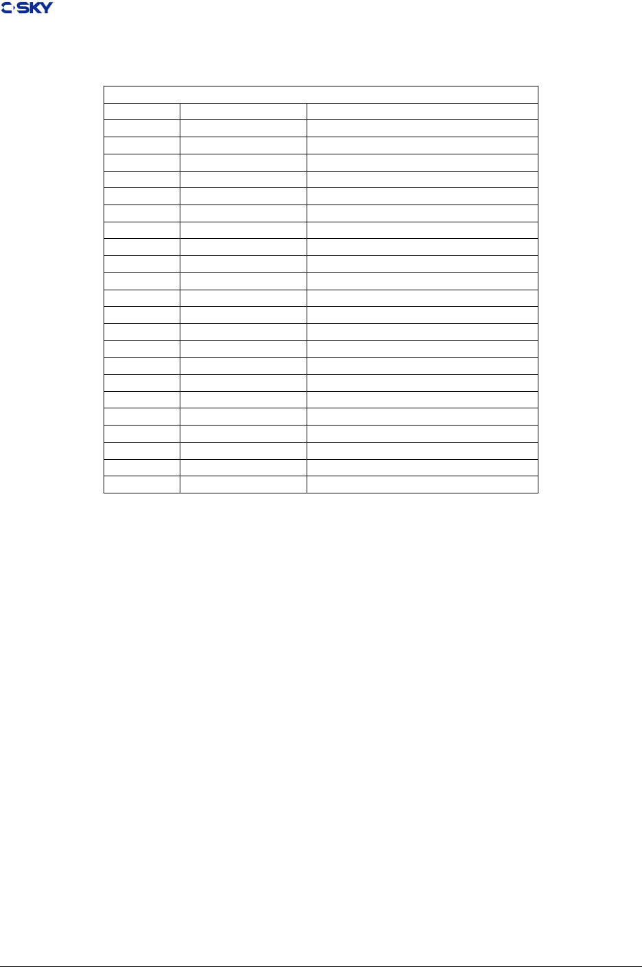
4.2.3 Special Sections
Various sections hold program and control information. Table 4.4 shows sections used by the system, the
indicated types, and attributes. These are additional extensions to ELF standards shown in Table 4.5. The
ELF standard reserves section names beginning with a period (“.”), but applications may use those sections
if their existing meanings are satisfactory.
C-SKY currently support PIC technique, when compiling PIC, the link editor will create .got and .plt
sections, see “ Global Oset Table “ and “ Procedure Linkage Table “.
Table 4.5: C-SKY V2 CPU Tools Special Sections
C-SKY Section names for PIC
Name Type Attributs
.got SHT_PROGBITS SHF_ALLOC+SHF_WRITE
.plt SHT_PROGBITS SHF_ALLOC+SHF_EXECINSTR
Note
It is strongly recommended that read-only constants, such as string literals, would to be placed into the
.rodata section instead of the .text section. The space that these add to .text can have a severe impact on
addressability, requiring the use of larger branch instructions and reducing the chances for sharing of values
in literal tables.
Release 2.1 Copyright © 2018 Hangzhou C-SKY MicroSystems Co.,Ltd. All rights reserved. 28
Chapter 4. ELF le format
Table 4.6: ELF Reserved Section Names
ELF Reserved Section Names
Name Type Attributes
.bss SHT_NOBITS SHF_ALLOC+SHF_WRITE
.comment SHT_PROGBITS none
.data SHT_PROGBITS SHF_ALLOC+SHF_WRITE
.data1 SHT_PROGBITS SHF_ALLOC+SHF_WRITE
.debug SHT_PROGBITS none
.dynamic SHT_DYNAMIC –
.dynstr SHT_STRTAB SHF_ALLOC
.dynsym SHT_DYNSYM SHF_ALLOC
.ni SHT_PROGBITS SHF_ALLOC+SHF_EXECINSTR
.hash SHT_HASH SHF_ALLOC
.init SHT_PROGBITS SHF_ALLOC+SHF_EXECINSTR
.interp SHT_PROGBITS –
.line SHT_PROGBITS none
.note SHT_NOTE none
.rel* SHT_REL –
.rela* SHT_RELA –
.rodata SHT_PROGBITS SHF_ALLOC
.rodata1 SHT_PROGBITS SHF_ALLOC
.shstrtab SHT_STRTAB none
.strtab SHT_STRTAB –
.symtab SHT_SYMTAB –
.text SHT_PROGBITS SHF_ALLOC+SHF_EXECINSTR
4.3 Symbol Table Format
There are no C-SKY V2 CPU symbol table requirements beyond the base ELF standards.
4.4 Relocation Information Format
4.4.1 Reclocation Fields
Relocation entries describe how to alter the instruction and data relocation elds as shown in Table 4.7. The
choice of the relocation type numbers as encoded in the ELF object le is dened in Table 4-8 Relocation
Type Encodings.
Release 2.1 Copyright © 2018 Hangzhou C-SKY MicroSystems Co.,Ltd. All rights reserved. 29

Chapter 4. ELF le format
Table 4.7: Relocation Fields
Field Description CPU
word32 This species a 32-bit eld occupying four bytes. This address is
NOT required to be 4-byte aligned.
all
disp8 This corresponds to the scaled 8-bit displace ment addressing mode.
The relocation is the low-order 8 bits of the 16 bits addressed in
the relocation type. jsri, jmpi, & lrw use this 8-bit displacement
addressing mode.
V1.0
disp11 This corresponds to the scaled 11-bit displac ement addressing
mode. The relocation is the low-order 11 bits of the 16 bits ad-
dressed in the relocation type. br, bf, bt & bsr use this 11-bit
displacement addressing mode.
V2.0 32-bit
disp26 This corresponds to the scaled 26-bit displa cement addressing
mode. The relocation is the low-order 26 bits of the 32 bits ad-
dressed in the relocation type. bsr use this 26-bit displacement
addressing mode.
V2.0 32-bit
disp16 This corresponds to the scaled 16-bit displacement addressing mode.
The relocation is the low-order 16 bits of the 32 bits addressed in
the relocation type. br,be, bne, bez, bnez, bhz, blsz, bhsz, bt, bf,
jmpi, jsri use this 16-bit displacement addressing mode.
V2.0 16-bit
disp10 This corresponds to the scaled 10-bit displacement addressing mode.
The relocation is the low-order 10 bits of the 16 bits addressed in the
relocation type. br, bsr, bt, bf use this 10-bit displacement address
ing mode.
V2.0 16-bit
word_hi16 This corresponds to the most signicant 16 bits in the 32 bits value
of the symbol referred by movih, addi, subi, andi, andni, ori, xori,
pldr, pldw, cmphsi, cmplti, cmpnei, movi instruction. To calculate
symbol value = (word_hi16 << 16 | word_lo16)
V2.0 32-bit
word_lo16 This corresponds to the least signicant 16 bits in the 32 bits value
of the symbol referred by movih, addi, subi, andi, andni, ori, xori,
pldr, pldw, cmphsi, cmplti, cmpnei , movi instruction. To calculate
symbol value = (word_hi16 << 16 | word_lo16)
V2.0 32-bit
gb_disp_hi16 This corresponds to the most signicant 16 bits in the 32 bits value
of the (GOT Base - pc) referred by movih, addi, subi, andi, andni,
ori, xori, pldr, pldw, cmphsi, cmplti, cmpnei, movi instruction. To
calculate GOT Base = (gb_disp_hi16 << 16 gb_disp_lo16) + pc
V2.0 32-bit
gb_disp_lo16 This corresponds to the least signicant 16 bits in the 32 bits value
of the (GOT Base - pc) referred by movih, addi, subi, andi, andni,
ori, xori, pldr, pldw, cmphsi, cmplti, cmpnei, movi instruction. To
calculate GOT Base = (gb_disp_hi16 << 16 gb_disp_lo16) + pc
V2.0 32-bit
gb_oset_hi16 This corresponds to the most signicant 16 bits in the 32 bits value
of the (GOT Base – Symbol value) referred by movih, addi, subi,
andi, andni, ori, xori, pldr, pldw, cmphsi, cmplti, cmpnei, movi
instruction. To calculate symbol value = gb - (gb_oset_hi16 <<
16 | word32_lo16)
V2.0 32-bit
gb_oset_lo16 This corresponds to the most signicant 16 bits in the 32 bits value
of the (GOT Base – Symbol value) referred by movih, addi, subi,
andi, andni, ori, xori, pldr, pldw, cmphsi, cmplti, cmpnei, movi
instruction. To calculate symbol value = gb - (gb_oset_hi16 <<
16 | word32_lo16)
V2.0 32-bit
disp12 This corresponds to the scaled 12-bit displacement addressing mode.
The relocation is the low-order 12 bits of the 32 bits addressed in
the relocation type. ld/st use this 12-bit displacement addressing
mode.
V2.0 32-bit
gb_got_hi16 This corresponds to the most signicant 16 bits in the 32 bits value
of the entry index in GOT referred by movih, addi, subi, andi, andni,
ori, xori, pldr, pldw, cmphsi, cmplti, cmpnei, movi instruction.
V2.0 32-bit
gb_got_lo16 his corresponds to the least signicant 16 bits in the 32 bits value
of the entry index in GOT referred by movih, addi, subi,
V2.0 32-bit
pcword32 This species a 32-bit eld occupying four bytes. This address is
NOT required to be 4-byte aligned.
??
Disp This corresponds to the scaled 18-bit displacement addressing mode.
The relocation is the low-order 18 bits of the 32 bits addressed in the
relocation type. grs, DB addi, lrs, srs use this 18-bit displacement
addressing mode. V2.0 32-bit
V2.0 32-bit
Release 2.1 Copyright © 2018 Hangzhou C-SKY MicroSystems Co.,Ltd. All rights reserved. 30

Chapter 4. ELF le format
The object le supports the 32-bit relocations for 32-bit data (addressing constants in memory). Both
absolute and PC-relative relocations are dened.
Note that the 32 bits where the relocation is to be applied need not be on a 32-bit boundary. The relocation
entry points to the address of the 32 bits to be adjusted by the relocation entry. The relocation adds the
appropriate value (either the 32-bit value or the 32-bit displacement) to the existing contents of the 32 bits
at that address.
A packed data structure can cause a 32-bit relocation to be misaligned in the object le. This might be
done with a C compiler extension, or by means of hand-crafted assembly, in order to save data space (but
the misaligned data must be accessed piece-wise to avoid alignment exceptions). The linker must be able to
deal with this case.
Scaled 11-bit displacement mode is used in br, bf, bt, and bsr instructions. The 11-bit value indicates
the number of halfwords from PC+2 to the target address. The relocation entry must point to the 16-bit
instruction that contains the displacement.
Calculations below assume the actions are transforming a relocatable le into either an executable or a
shared object le. Conceptually, the linker merges one or more relocatable les to form the output. It
rst determines how to combine and locate the input les; then it updates the symbol values, and nally it
performs the relocation.
Relocations applied to executable or shared object les are similar and accomplish the same result. Descrip-
tions below use the following notation.
A
This means the addend used to compute the value of the relocatable eld.
B
This means the base address at which a shared object has been loaded into memory during
execution. Generally a shared object le is built with a 0 base virtual address, but the execution
address will be dierent.
BTEXT
This means the base address of .text section at which an elf le has been loaded into memory
during execution. Generally an elf le is built with a 0 base virtual address, but the execution
address will be dierent.
BDATA
This means the base address of .data section at which an elf le has been loaded into memory
during execution. Generally an elf le is built with a 0 base virtual address, but the execution
address will be dierent.
P
This means the place (section oset or address) of the storage unit being relocated (computed
using r_oset).
S
This means the value of the symbol whose index resides in the relocation entry, unless the the
symbol is STB_LOCAL and is of type STT_SECTION in which case S represents the original
sh_addr minus the nal sh_addr.
G
In C-SKY V1.0 this means the oset into the global oset table at which the address of the
relocation entry symbol resides during execution. In C-SKY V2.0 this means the index into the
Release 2.1 Copyright © 2018 Hangzhou C-SKY MicroSystems Co.,Ltd. All rights reserved. 31
Chapter 4. ELF le format
global oset table at which the address of the relocation entry symbol resides during execution.
See ‘‘PIC Examples’’ and ‘‘Global Oset Table’’ for more information.
GOT
This means the address of the global oset table. See “Global Oset Table”
L
This means the place(section oset or address) of the procedure linkage table entry for a symbol.
A procedure linkage table entry redirects a function call to the proper destination. The link
editor builds the initial procedure linkage table, and the dynamic linker modies the entries
during execution. See “Procedure Linkage Table” below for more information.
A relocation entry r_oset value designates the oset or virtual address of the rst byte of the aected
storage unit. The relocation type species which bits to change and how to calculate their values. Because
C-SKY V2 CPU uses only Elf32_Rela relocation entries, the relocated eld does not hold the addend, but
relocation entry holds it.
4.4.2 Relocation Types
This section describes values and algorithms used for relocations. In particular, it describes values the
compiler/assembler must leave in place and how the linker mod- ies those values.
Table 4.8 shows semantics of relocation operations. Key S indicates the nal value assigned to the symbol
referenced in the relocation record. Key A is the addend value specied in the relocation record. Key P
indicates the address of the relocation (e.g., the address being modied).
Table 4.8: Relocation Type Encodings
Name Value Field Calculation I_SET
R_CKCORE_NONE 0 none none ALL
R_CKCORE_ADDR32 1 word32 S+A ALL
R_CKCORE_PCREL_IMM8BY4 2 dis8 ((S+A-P)>>2)&&0x V1.0
R_CKCORE_PCREL_IMM11BY2 3 disp11 ((S+A-P)>>1)&0x7 V1.0
R_CKCORE_PCREL_IMM4BY2 4 none unsupported, deleted None
R_CKCORE_PCREL32 5 word32 S+A-P ??
R_CKCORE_PCREL_JSR_IMM11BY2 6 disp11 ((S+A-P)>>1)&0x7 V1.0
R_CKCORE_GNU_VTINHERIT 7 - ?? ??
R_CKCORE_GNU_VTENTRY 8 - ?? ??
R_CKCORE_RELATIVE 9 word32 B + A ALL
R_CKCORE_COPY 10 none none ALL
R_CKCORE_GLOB_DAT 11 word32 S ALL
R_CKCORE_JUMP_SLOT 12 word32 S ALL
R_CKCORE_GOTOFF 13 word32 S + A - GOT V1.0
R_CKCORE_GOTPC 14 word32 GOT+A-P V1.0
R_CKCORE_GOT32 15 word32 G V1.0
R_CKCORE_PLT32 16 word32 G V1.0
R_CKCORE_ADDRGOT 17 word32 GOT+G V1.0 32-bit
R_CKCORE_ADDRPLT 18 word32 GOT+G V1.0 32-bit
R_CKCORE_PCREL_IMM26BY2 19 disp26 ((S+A–P)>>1)&0x3 V2.0 32-bit
R_CKCORE_PCREL_IMM16BY2 20 disp16 ((S+A-P)>>1)&0x V2.0 32-bit
R_CKCORE_PCREL_IMM16BY4 21 disp16 ((S+A-P)>>2)&0x V2.0 32-bit
R_CKCORE_PCREL_IMM10BY2 22 disp10 ((S+A-P)>>1)&0x3 V2.0 16-bit
R_CKCORE_PCREL_IMM10BY4 23 disp10 ((S+A-P)>>2)&0x3 V2.0 16-bit
Continued on next page
Release 2.1 Copyright © 2018 Hangzhou C-SKY MicroSystems Co.,Ltd. All rights reserved. 32
Chapter 4. ELF le format
Table 4.8 – continued from previous page
Name Value Field Calculation I_SET
R_CKCORE_ADDR_HI16 24 word_hi16 ((S+A)>>16)&0x V2.0 32-bit
R_CKCORE_ADDR_LO16 25 word_lo16 (S+A)&0x V2.0 32-bit
R_CKCORE_GOTPC_HI16 26 gb_disp_hi16 ((GOT+A-P)>16)&0x V2.0 32-bit
R_CKCORE_GOTPC_LO16 27 gb_disp_lo16 (GOT+A-P)&0x V2.0 32-bit
R_CKCORE_GOTOFF_HI16 28 gb_oset_hi16 ((S+A-GOT) >> 16) & 0x V2.0 32-bit
R_CKCORE_GOTOFF_LO16 29 gb_oset_lo16 (S+A-GOT) & 0x V2.0 32-bit
R_CKCORE_GOT12 30 disp12 G V2.0 32-bit
R_CKCORE_GOT_HI16 31 gb_got_hi16 (G >> 16) & 0x V2.0 32-bit
R_CKCORE_GOT_LO16 32 gb_got_lo16 G & 0x V2.0 32-bit
R_CKCORE_PLT12 33 disp12 G V2.0 32-bit
R_CKCORE_PLT_HI16 34 gb_got_hi16 (G >> 16) & 0x V2.0 32-bit
R_CKCORE_PLT_LO16 35 gb_got_lo16 G & 0x V2.0 32-bit
R_CKCORE_ADDRGOT_HI16 36 gb_got_hi16 (GOT+G*4)& 0x V2.0 32-bit
R_CKCORE_ADDRGOT_LO16 37 gb_got_lo16 (GOT+G*4) & 0x V2.0 32-bit
R_CKCORE_ADDRPLT_HI16 38 gb_got_hi16 ((GOT+G*4) >> 16) & 0x V2.0 32-bit
R_CKCORE_ADDRPLT_LO16 39 gb_got_lo16 (GOT+G*4) & 0x V2.0 32-bit
R_CKCORE_PCREL_JSR_IMM26BY2 40 disp26 ((S+A–P)>>1)&0x3 V2.0 32-bit
R_CKCORE_TOFFSET_LO16 41 disp16 (S+A-BTEXT) & 0x V2.0 32-bit
R_CKCORE_DOFFSET_LO16 42 disp16 (S+A-BTEXT) & 0x V2.0 32-bit
R_CKCORE_PCREL_IMM18BY2 43 disp16 ((S+A–P)>>1)&0x3 V2.0 32-bit
R_CKCORE_DOFFSET_IMM18ABS 44 word_disp18 (S+A-BDATA)&0x3 V2.0 32-bit
R_CKCORE_DOFFSET_IMM18BY2ABS 45 word_disp18 ((S+A-BDATA)>>1)&0x3 V2.0 32-bit
R_CKCORE_DOFFSET_IMM18BY4ABS 46 word_disp18 ((S+A-BDATA)>>2)&0x3 V2.0 32-bit
R_CKCORE_GOTOFF_IMM18 47 disp18 ? V2.0 32-bit
R_CKCORE_GOT_IMM18BY4 48 word_disp18 (G >> 2) V2.0 32-bit
R_CKCORE_PLT_IMM18BY4 49 word_disp 18 (G >> 2) V2.0 32-bit
R_CKCORE_PCREL_IMM7BY4 50 disp7 ((S+A-P) >>2) & 0x7f V2.0 16-bit
4.4.2.1 Static Relocations in Data Sections
R_CKCORE_ADDR32
In DATA sections, absolute 32-bit relocation adds the relocated symbols value to the existing
content of the location specied. Consider the example
.data
D1:
.long 0x10
D2:
.long SYMBOL+ 1234 # <- R_CKCORE_ADDR32 for this word32 field.
The object le emitted by the compiler has a relocation entry for SYMBOL that references the
address of this word. The existing content of the 32 bits at the specied address are overwritten
with the new value.
So in the example, the oset of the relocation is 4, symbol value is SYMBOL in.data section or
other section, addend is 1234.
4.4.2.2 Static Relocations in Text Sections
R_CKCORE_ADDR32
Release 2.1 Copyright © 2018 Hangzhou C-SKY MicroSystems Co.,Ltd. All rights reserved. 33

Chapter 4. ELF le format
In TEXT sections, absolute 32-bit relocation adds the relocated symbols value to the existing
content of the location specied. Consider the example.
Code example for R_CKCORE_ADDR32 in text
.text
...
jmpi
symbol+1234 # <- R_CKCORE_ADDR32 for this word32 field.
...
jsri
printf # <- R_CKCORE_ADDR32 for this word32 field.
The object le emitted by the compiler has a relocation entry for symbol that references the
address of this word. The existing content of the 32 bits at the specied address are overwritten
with the new value.
So for the second relocation entry in the example, the oset is the [jsri located PC- .text base
address], symbol value is printf, addend is 0.
4.4.2.3 Static C-SKY V1 Relocation in Text Sections
R_CKCORE_PCRELIMM8BY4
Occur when jmpi/jsri/lrw instructions reference a target that is in a symbol which is identied
in a new section. For examble: (jsri has the same case)
Code example for R_CKCORE_PCRELIMM8BY4
.text
mycode:
...
lrw r1, [myconst]
...
.data
myconst:
.long
0x12345678
It is a obsoleted relocation type.
R_CKCORE_PCRELIMM11BY2
Occur when br, bf, bt, and bsr instructions (typically bsr) reference a target that is not in the
current object le. They can also occur when the target is in a separate section of the same
object le, but these occurrences must be resolved by the compiler/assembler and not appear as
relocation entries.
Code example for R_CKCORE_PCRELIMM11BY2
.import __exit
.export tbsr
.text
tbsr:
bsr __exit
The relocation is calculated as shown in Table 4-8 Relocation Type Encodings. The existing
contents of the low-order 11 bits of the instruction are overwritten with the newly calculated
displacement.
Release 2.1 Copyright © 2018 Hangzhou C-SKY MicroSystems Co.,Ltd. All rights reserved. 34

Chapter 4. ELF le format
NOTE
The bsr instruction encoding is the distance from PC+2 to the target. This adjustment
must be made in the compiler/assembler. The emitted relocation record for a bsr to
symbol X must be to X+(–2); in other words, the symbol must be X and the addend
eld of the relocation record must contain –2.
R_CKCORE_PCRELIMM4BY2
It is a obsoleted relocation type. This relocation come from MCORE “loopt” instruction, and
C-SKY V2 CPU has no any “loopt”, so this relocation should not appear in any C-SKY V2 CPU
binary les
R_CKCORE_PCREL32
This relocation type computes the dierence between a symbol’s value and the address or section
oset to be relocated. It is a obsoleted relocation type for C-SKY.
R_CKCORE_PCRELJSR_IMM11BY2
Like PCRELIMM11BY2, this relocation indicates that there is a ‘jsri’ at the specied address.
There is a separate relocation entry for the literal pool entry that it references (So there are 2
relocation entry for “jsri” when assemble with –jsri2bsr option), but we might be able to change
the jsri to a bsr if the target turns out to be close enough [even though we won’t reclaim the
literal pool entry, we’ll get some runtime eciency back]. Note that this is a relocation that we
are allowed to safely ignore.
4.4.2.4 Static C-SKY V2.0 Relocation in Text Sections
R_CKCORE_PCREL_IMM26BY2
Occur when br, bsr 32-bit instructions (typically bsr) reference a target that is not in the current
object le. They can also occur when the target is in a separate section of the same object le,
but these occurrences must be resolved by the compiler or assembler and not appear as relocation
entries.
Code example for R_CKCORE_PCREL_IMM26BY2
.import __exit
.export tbsr
.text
tbsr:
bsr __exit
The relocation is calculated as shown in Table 4-8 Relocation Type Encodings. The existing
contents of the low-order 26 bits of the instruction are overwritten with the newly calculated
displacement.
NOTE
The bsr instruction encoding is the distance from PC+2 to the target. This adjustment
must be made in the compiler/assembler. The emitted relocation record for a bsr to
symbol X must be to X+(–2); in other words, the symbol must be X and the addend
eld of the relocation record must contain –2.
R_CKCORE_PCRELJSR_ IMM26BY2
Like R_CKCORE_PCREL_IMM26BY2 , this relocation indicates that there is a ‘jsri’ at the
specied address. There is a separate relocation entry for the literal pool entry that it references
(So there are 2 relocation entry for “jsri” when assemble with –jsri2bsr option), but we might
Release 2.1 Copyright © 2018 Hangzhou C-SKY MicroSystems Co.,Ltd. All rights reserved. 35

Chapter 4. ELF le format
be able to change the jsri to a bsr if the target turns out to be close enough [even though we
won’t reclaim the literal pool entry, we’ll get some runtime eciency back]. Note that this is a
relocation that we are allowed to safely ignore.
R_CKCORE_PRREL_IMM16BY2
Occur when be, bne, bf, bt, bez, bnez, bhz, bhsz, blsz 32-bit instructions reference a target that
is not in the current object le. They can also occur when the target is in a separate section of
the same object le, but these occurrences must be resolved by the compiler or assembler and
not appear as relocation entries.
.import __exit
.export tbsr
.text
tbsr:
bt __exit
The relocation is calculated as shown in Table 4-8 Relocation Type Encodings. The existing
contents of the low-order 16 bits of the instruction are overwritten with the newly calculated
displacement.
NOTE
The bsr instruction encoding is the distance from PC+2 to the target. This adjustment
must be made in the compiler/assembler. The emitted relocation record for a bsr to
symbol X must be to X+(–2); in other words, the symbol must be X and the addend
eld of the relocation record must contain –2.
R_CKCORE_PRREL_IMM16BY4
Occur when jmpi,jsri 32-bit instructions reference a target that is in a symbol which is identied
in a new section or in other object le. For examble: (jsri has the same case)
.text
mycode:
...
jsri [myconst]
...
.data
myconst:
.long
0x12345678
R_CKCORE_PRREL_IMM10BY2
Occur when br, bsr, bf, bt 16-bit instructions reference a target that is not in the current object
le. They can also occur when the target is in a separate section of the same object le, but these
occurrences must be resolved by the compiler or assembler and not appear as relocation entries.
.import __exit
.export tbsr
.text
tbsr:
bt __exit
The relocation is calculated as shown in Table 4-8 Relocation Type Encodings. The existing
contents of the low-order 10 bits of the instruction are overwritten with the newly calculated
displacement.
NOTE
Release 2.1 Copyright © 2018 Hangzhou C-SKY MicroSystems Co.,Ltd. All rights reserved. 36

Chapter 4. ELF le format
The bsr instruction encoding is the distance from PC+2 to the target. This adjustment
must be made in the compiler/assembler. The emitted relocation record for a bsr to
symbol X must be to X+(–2); in other words, the symbol must be X and the addend
eld of the relocation record must contain –2.
R_CKCORE_PRREL_IMM10BY4
Occur when jsri 16-bit instructions reference a target that is in a symbol which is identied in a
new section or in other object le. For examble: (jsri has the same case)
.text
mycode:
...
jsri [myconst]
...
.data
myconst:
.long
0x12345678
R_CKCORE_ADDR_HI16
In C-SKY V2.0 instruction set, there are two instructions movih and ori to move a 32-bit absolute
address into a register, see Figure 4-10 Code example for R_CKCORE_ADDR_HI16. This
relocation type is used to calculate the lower 16-bit in movih instruction.
.text
...
movih rz, (symbol+1234) >> 16
ori
rz, (symbol+1234) & 0xffff
...
R_CKCORE_ADDR_LO16
In C-SKY V2.0 instruction set, there are two instructions movih and ori to move a 32-bit absolute
address into a register, see Figure 4-10 Code example for R_CKCORE_ADDR_HI16. This
relocation type is used to calculate the lower 16-bit in ori instruction.
R_CKCORE_PCREL_IMM18BY4
Occur when grs 32-bit instructions reference a function symbol that is in the text section. They
can occur when the symbol is in the same or dierent object le, but these occurrences must
be resolved by the compiler, assembler and linker, but not appear as relocation entries in the
executable elf le.
.import __exit
.export tbsr
.text
tbsr:
grs r10,__exit
The relocation is calculated as shown in Table 4-8 Relocation Type Encodings. The existing
contents of the low-order 18 bits of the instruction are overwritten with the newly calculated
displacement.
R_CKCORE_DOFFSET_IMM18
Occur when lrs.b/srs.b/addi 32-bit instructions load/store the value of a symbol that is in the
data section with DATA section base address register rdb. They can occur when the symbol is
Release 2.1 Copyright © 2018 Hangzhou C-SKY MicroSystems Co.,Ltd. All rights reserved. 37

Chapter 4. ELF le format
in data section of the same or dierent object le, These occurrences must be resolved by the
compiler, assembler and linker, but not appear as relocation entries in the executable elf le.
.byte
myData
.export tlrsb
.text
tlrsb:
lrs.b r10,myData
The relocation is calculated as shown in Table 4-8 Relocation Type Encodings. The existing
contents of the low-order 18 bits of the instruction are overwritten with the newly calculated
displacement.
R_CKCORE_DOFFSET_IMM18BY2
Occur when lrs.h/srs.h 32-bit instructions load/store the value of a symbol that is in the data
section with DATA section base address register rdb. They can occur when the symbol is in data
section of the same or dierent object le, These occurrences must be resolved by the compiler,
assembler and linker, but not appear as relocation entries in the executable elf le.
.short myData
.export tlrsh
.text
tlrsh:
lrs.w r10,myData
The relocation is calculated as shown in Table 4-8 Relocation Type Encodings. The existing
contents of the low-order 18 bits of the instruction are overwritten with the newly calculated
displacement.
R_CKCORE_DOFFSET_IMM18BY4
Occur when lrs.w/srs.w 32-bit instructions load/store the value of a symbol that is in the data
section with DATA section base address register rdb. They can occur when the symbol is in data
section of the same or dierent object le, These occurrences must be resolved by the compiler,
assembler and linker, but not appear as relocation entries in the executable elf le.
.long myData
.export tlrsw
.text
tlrsw:
lrs.w r10,myData
The relocation is calculated as shown in Table 4-8 Relocation Type Encodings. The existing
contents of the low-order 18 bits of the instruction are overwritten with the newly calculated
displacement.
4.4.2.5 Dynamic Relocations
R_CKCORE_RELATIVE
The linker editor creates this relocation type for dynamic linking. Its oset member gives a
location within a shared object that contains a value representing a relative address. The dynamic
linker computes the corresponding virtual address by adding the virtual address at which the
shared object was loaded to the relative address. Relocation entries for this type must specify 0
for the symbol table index.
Release 2.1 Copyright © 2018 Hangzhou C-SKY MicroSystems Co.,Ltd. All rights reserved. 38

Chapter 4. ELF le format
R_CKCORE_COPY
R_CKCORE_COPY may only appear in executable objects where e_type is set to ET_EXEC.
The eect is to cause the dynamic linker to locate the target symbol in a shared library object
and then to copy the number of bytes specied by the st_size eld to the place. The address of
the place is then used to pre-empt all other references to the specied symbol. It is an error if the
storage space allocated in the executable is insucient to hold the full copy of the symbol. If the
object being copied contains dynamic relocations then the eect must be as if those relocations
were performed before the copy was made. Note
R_CKCORE_COPY is normally only used in SVr4 type environments where the executable
is not position independent and references by the code and read-only data sections cannot be
relocated dynamically to refer to an object that is dened in a shared library. The need for copy
relocations can be avoided if a compiler generates all code references to such objects indirectly
through a dynamically relocatable location, and if all static data references are placed in relocat-
able regions of the image. In practice, however, this is dicult to achieve without source-code
annotation; a better approach is to avoid dening static global data in shared libraries.
R_CKCORE_GLOB_DAT
This relocation type is used to set a global oset table entry to the address of the specied symbol.
The special relocation type allows one to deterimine the correspondence between symbols and
global oset table entries.
R_CKCORE_JMP_SLOT
The link editor creates this relocation type for dynamic linking. Its oset member gives the
location of a GOT entry. The dynamic linker modies the procedure linkage table entry to
transfer control to the designated symbol’s address, see “Procedure Linkage Table”.
R_CKCORE_GOTOFF
In C-SKY V1.0, when referring to a local DATA or FUNCTION in text section, the compiler
and assembler create the code such as:
lrw rx,SYMBOL@GOTOFF
add rx,gb
and set a R_CKCORE_GOTOFF relocation for the linker; According this relocation type, the
linker computes the dierence between a local symbol’s value and the address of the global oset
table. It additionally instructs the link editor to build the global oset table.
R_CKCORE_GOTPC
At the prologue of FUNCTION, the compiler create the code such as:
bsr .L1
.L1:
lrw rx,.L1@GOTPC
add rx,r15
The assembler set a R_CKCORE_GOTPC, According the relocation type, the link editor com-
putes GOT-PC.
R_CKCORE_GOT32
In C-SKY V1.0, when referring to a global DATA or FUNCTION in text section, the compiler
and assembler create the code such as:
Release 2.1 Copyright © 2018 Hangzhou C-SKY MicroSystems Co.,Ltd. All rights reserved. 39

Chapter 4. ELF le format
lrw rx,SYMBOL@GOT
add rx,gb
ld ry,(rx,0)
and set a R_CKCORE_GOT32 relocation for the linker; The linker create an entry in GOT,
computes the index in GOT for the called function symbol of which the value is stored in GOT,
set R_CKCORE_GLOB_DAT for dynamic linkage.
R_CKCORE_PLT32
In C-SKY V1.0, when calling a global FUNC in text section, the compiler and assembler create
the code such as:
lrw rx,FUNC@PLT
add rx,gb
ld ry,(rx,0)
jsr ry
and set R_CKCORE_PLT32 relocation for the linker. The linker create an entry in GOT and
an entry in PLT, computes the index in GOT for the called function symbol of which the value
is stored in GOT, set R_CKCORE_JMP_SLOT relocation for dynamic linkage.
R_CKCORE_GOTOFF_HI16 & R_CKCORE_GOTOFF_LO16
In C-SKY V2.0, when referring to a local DATA or FUNCTION in text section, the compiler
and assembler create the code such as:
movih rx,SYMBOL@GOTOFF_HI16
ori rx,SYMBOL@GOTOFF_LO16
add rx,gb
and set a R_CKCORE_GOTOFF_HI16 & R_CKCORE_GOTOFF_LO16 relocation for the
linker; According this relocation type, the linker computes the dierence between a local symbol’s
value and the address of the global oset table. It additionally instructs the link editor to build
the global oset table.
R_CKCORE_GOTPC_HI16 & R_CKCORE_GOTPC_LO16
In C-SKY V2.0, at the prologue of FUNCTION, the compiler create the code such as:
bsr .L1
.L1:
movih rx,.L1@GOTPC_HI16
ori rx,.L1@ GOTPC_LO16
add rx,r15
The assembler set a R_CKCORE_GOTPC_HI16 & R_CKCORE_GOTPC_HI16, According
these relocation types, the link editor computes GOT-PC.
R_CKCORE_GOT12
In C-SKY V2.0 instruction set, there is instructions ld/st which use 12 disp to the base address
register. When referring to a global DATA or FUNCTION in text section, the compiler and
assembler create the code such as:
ld rx, (gb,SYMBOL@GOT)
set a R_CKCORE_GOT12 relocation for the linker; The linker creates an entry in GOT,
changes the 12-bit elds in the 32-bit instruction with the entry index in GOT, and set
R_CKCORE_GLOB_DAT for dynamic linkage.
Release 2.1 Copyright © 2018 Hangzhou C-SKY MicroSystems Co.,Ltd. All rights reserved. 40

Chapter 4. ELF le format
R_CKCORE_GOT_HI16 & R_CKCORE_GOT_LO16
In C-SKY V2.0 instruction set, there is instructions ld/st which use 12 disp to the base address
register. When referring to a global DATA or FUNCTION in text section, the compiler and
assembler create the code such as:
movih rx, FUNC@GOT_HI16
ori rx, FUNC@GOT_LO16
ldr.w rx, (gb, rx << 0)
set a R_CKCORE_GOT_HI16 & R_CKCORE_GOT_LO16 relocation for the linker; The
linker creates an entry in GOT, changes the immediate elds in the 32-bit movih/ori instructions
with the entry oset in GOT, and set R_CKCORE_GLOB_DAT for dynamic linkage
R_CKCORE_ADDRGOT
In C-SKY V1.0, when referring to a global DATA or FUNCTION in text section of the executable
program, the compiler and assembler create the code such as:
lrw rx,SYMBOL@ADDRGOT
ld
rx, (rx,0)
set R_CKCORE_ADDRGOT relocation for the linker. The linker create an entry in GOT,
computes the GOT entry address for the called function symbol of which the value is stored in
GOT, set R_CKCORE_GLOB_DAT relocation for dynamic linkage.
R_CKCORE_ADDRGOT_HI16 & R_CKCORE_ADDRGOT_LO16
In C-SKY V2.0, when referring to a global DATA or FUNCTION in text section of the executable
program, the compiler and assembler create the code such as:
movih rx,FUNC@ADDRGOT_HI16
ori rx,FUNC@ADDRGOT_LO16
ldw rx, (rx,0)
set a R_CKCORE_ADDRGOT_HI16 & R_CKCORE_ADDRGOT_LO16 relocation for the
linker; The linker create an entry in GOT, computes the GOT entry address for the called
function symbol of which the value is stored in GOT, set R_CKCORE_GLOB_DAT relocation
for dynamic linkage, and changes the immediate elds in the 32-bit movih/ori instructions with
the entry address.
R_CKCORE_PLT12
In C-SKY V2.0 instruction set, there is instructions ld/st which use 12 disp to the base address
register. When calling a global FUNC in text section, the compiler
and assembler create the code such as:
ld rx, (gb,FUNC@PLT)
bsr rx
and set R_CKCORE_PLT12 relocation for the linker. The linker create an entry in GOT and
an entry in PLT, computes the index in GOT for the called function symbol of which the value
is stored in GOT, set R_CKCORE_JMP_SLOT relocation for dynamic linkage.
R_CKCORE_PLT_HI16 & R_CKCORE_PLT_LO16
In C-SKY V2.0 instruction set, there is instructions ld/st which use 12 disp to the base address
register. When calling a global FUNC in text section, the compiler and assembler create the code
such as:
Release 2.1 Copyright © 2018 Hangzhou C-SKY MicroSystems Co.,Ltd. All rights reserved. 41

Chapter 4. ELF le format
movih rx, FUNC@PLT_HI16
ori rx, FUNC@PLT_LO16
ldr.w rx, (gb, rx<<2)
jsr
rx
and set R_CKCORE_PLT_HI16, R_CKCORE_PLT_LO16 relocation for the linker. The
linker create an entry in GOT and an entry in PLT, computes the index in GOT for the called
function symbol of which the value is stored in GOT , set R_CKCORE_JMP_SLOT relocation
for dynamic linkage, and changes the immediate elds in the 32-bit movih/ori instructions with
the index in GOT.
R_CKCORE_ADDRPLT
In C-SKY V1.0, when calling a global FUNC in text section of the executableprogram, the
compiler and assembler create the code such as:
lrw rx,FUNC@ADDRPLT
ld ry,(rx,0)
jsr ry
set R_CKCORE_ADDRPLT relocation for the linker. The linker create an entry in GOT and
an entry in PLT, computes the GOT entry address for the called function symbol of which the
value is stored in GOT, set R_CKCORE_JMP_SLOT relocation for dynamic linkage, and and
changes the immediate elds of the 16-bit lrw instructions with the GOT entry address.
R_CKCORE_ADDRPLT_HI16 & R_CKCORE_ADDRPLT_LO16
In C-SKY V2.0, when calling a global FUNC in text section of the executable program, the
compiler and assembler create the code such as:
movih rx,FUNC@ADDRPLT_HI16
ori rx,FUNC@ADDRPLT_LO16
ld ry,(rx,0)
jsr ry
set R_CKCORE_ADDRPLT_HI16 & R_CKCORE_ADDRPLT_LO16 relocation for the
linker. The linker create an entry in GOT and an entry in PLT, computes the GOT
entry address for the called function symbol of which the value is stored in GOT, set
R_CKCORE_JMP_SLOT relocation for dynamic linkage, and changes the immediate elds
in the 32-bit movih/ori instructions with the entry address.
Table 4.9 describes the function of relocation types for PIC, and when they are deal with.
Release 2.1 Copyright © 2018 Hangzhou C-SKY MicroSystems Co.,Ltd. All rights reserved. 42
Chapter 4. ELF le format
Table 4.9: Relocation Types for PIC
Fields For What Type in Object File(.o) Type in .so
Text Loading GOT Base
Address
R_CKCORE_GOTPC NULL
R_CKCORE_GOTPC_HI16
R_CKCORE_GOTPC_LO16
Refer to Local Data
or Function
R_CKCORE_GOTOOFF NULL
R_CKCORE_GOTOFF_HI16
R_CKCORE_GOTOFF_LO16
Refer to Global Data
or Function
R_CKCORE_GOT32 R_CKCORE_GLOB_DAT
R_CKCORE_GOT12
R_CKCORE_GOT_HI16
R_CKCORE_GOT_LO16
R_CKCORE_ADDRGOT
R_CKCORE_ADDRGOT_HI16
R_CKCORE_ADDRGOT_LO16
Call local function di-
rectly
R_CKCORE_GOTOOFF NULL
R_CKCORE_GOTOFF_HI16
R_CKCORE_GOTOFF_LO16
Call global function di-
rectly
R_CKCORE_PLT32 R_CKCORE_JMP_SLOT
R_CKCORE_PLT12
R_CKCORE_PLT_HI16
R_CKCORE_PLT_LO16
R_CKCORE_ADDRPLT
R_CKCORE_ADDRPLT_HI16
R_CKCORE_ADDRPLT_LO16
Data Refer to local data or
function
R_CKCORE_ADDR32
w/section
R_CKCORE_RELATIVE
Refer to Global Data or
function
R_CKCORE_ADDR32 w/sym R_CKCORE_ADDR32 w/sym
4.5 Program Loading
As the system creates or augments a process image, it logically copies a le segment to a virtual memory
segment. When and if the system physically reads the le depends on the program’s execution behavior,
system load, etc. A process does not require a physical page unless it references a logical page during
execution. Processes commonly leave many pages unreferenced; therefore delaying physical reads frequently
obviates them, improving system performance. To obtain this eciency in practice, executable and shared
object les must have segment images whose virtual addresses are zero, modulo the le system block size.
Virtual addresses and le osets for C-SKY V2 CPU segments are congruent modulo 64 KByte (0x10000) or
larger powers of 2. Because 64 KBytes is the maximum page size, the les are suitable for paging regardless
of physical page size.
Because the page size can be larger than the alignment restriction oset, up to four le pages can hold
impure text or data (depending on page size and le system block size).
• The rst text page contains the ELF header, the program header table, and other information.
• The last text page can hold a copy of the beginning of data.
• The rst data page can have a copy of the end of text.
• The last data page can contain le information note relevant to the running process.
Release 2.1 Copyright © 2018 Hangzhou C-SKY MicroSystems Co.,Ltd. All rights reserved. 43
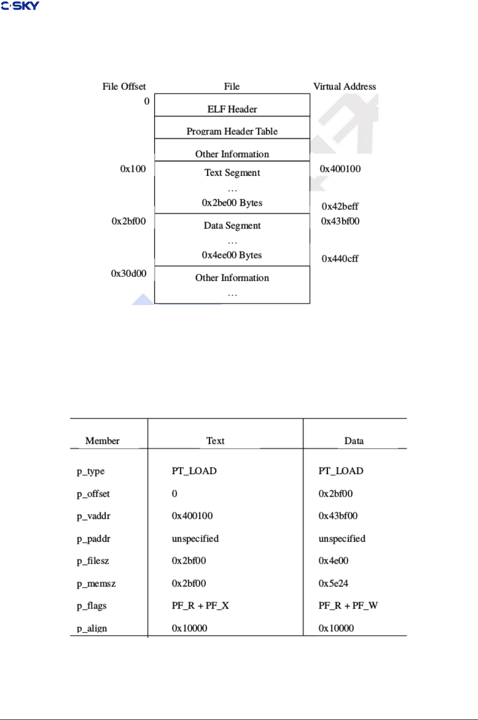
Chapter 4. ELF le format
Figure 4.1: Executable File Example
Figure 4.2: Program Header Segments
Release 2.1 Copyright © 2018 Hangzhou C-SKY MicroSystems Co.,Ltd. All rights reserved. 44
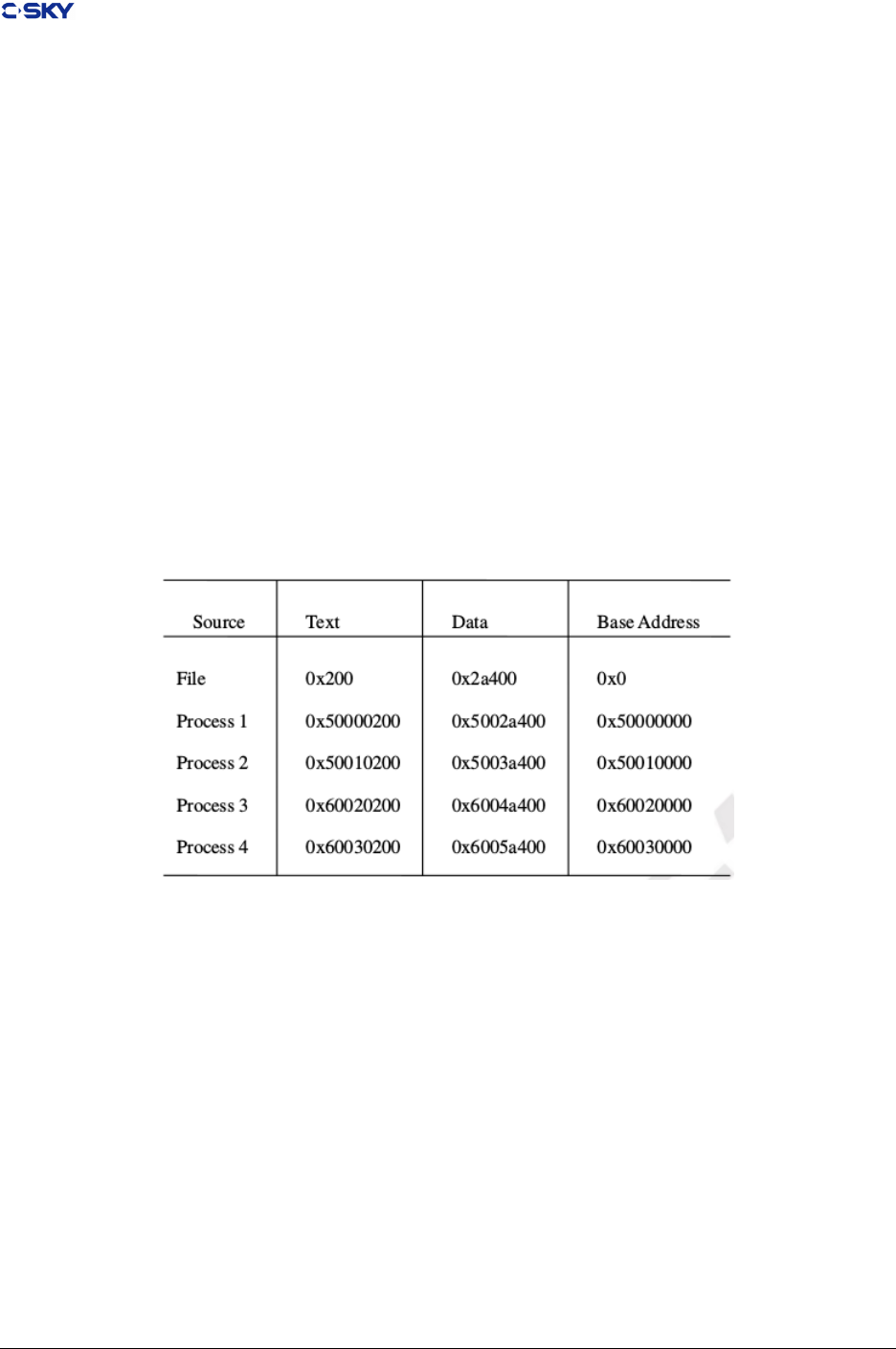
Chapter 4. ELF le format
Logically, the system enforces the memory permissions as if each segment were complete and separate;
segment addresses are adjusted to ensure each logical page in the address space has a single set of permissions.
In the example in Figure 4-15 Executable File example, the le region holding the end of text and the
beginning of data is mapped twice: once at one virtual address for text and once at a dierent virtual
address for data.
The end of the data segment requires special handling for uninitialized data which the system denes to begin
with zero values. Thus if the last data page of a le includes information not in the logical memory page, the
extraneous data must be set to zero, rather than the unknown contents of the executable le. ‘‘Impurities’’
in the other three pages are not logically part of the process image; whether the system expunges them is
unspecied.
One aspect of segment loading diers between executable les and shared objects. Executable le segments
typically contain absolute code [see “PIC Examples“]. To let the process execute correctly, the segments
must reside at the virtual addresses used to build the executable le, with the system using the p_vaddr
values unchanged as virtual addresses. Shared object segments typically contain position-independent code,
allowing a segment virtual address to change from one process to another without invalidating execution
behavior. Though the system chooses virtual addresses for individual processes, it maintains the relative
positions of the segments. Because position independent code uses relative addressing between segments,
the dierence between virtual addresses in memory must match the dierence between virtual addresses in
the le. The following table shows possible shared object virtual address assignments for several processes,
illustrating constant relative positioning. The table also illustrates the base address computations.
Figure 4.3: Shared Object Segment Address Example
4.6 Dynamic Linking
When the system creates a process image, the executable le portion of the process has xed addresses,
and the system chooses shared object library virtual addresses to avoid conicts with other segments in the
process. To maximize text sharing, shared objects conventionally use position-independent code, in which
instructions contain no absolute addresses. Shared object text segments can be loaded at various virtual
addresses without changing the segment images. Thus multiple processes can share a single shared object
text segment, even though the segment resides at a dierent virtual address in each process.
Position-independent code relies on two techniques:
• Control transfer instructions hold addresses relative to the program counter (PC). A PC-relative branch
or function call computes its destination address in terms of the current program counter, not relative
to any absolute address. If the target location exceeds the allowable oset for PC relative addressing,
the program requires an absolute address.
Release 2.1 Copyright © 2018 Hangzhou C-SKY MicroSystems Co.,Ltd. All rights reserved. 45

Chapter 4. ELF le format
• When the program requires an absolute address, it computes the desired value. Instead of embedding
absolute addresses in the the instructions, the compiler generates code to calculate an absolute address
during execution.
Because the processor architecture provides PC relative call, register call and branch instructions, compilers
can easily satisfy the rst condition.
A global oset table provides information for address calculation. Position-independent object les (exe-
cutable and shared object les) have a table in their data segment that holds addresses. When the system
creates the memory image for an object le, the table entries are relocated to reect the absolute virtual
addresses assigned for an individual process. Because data segments are private for each process, the table
entries can change - whereas text segments do not change because multiple processes share them.
In C-SKY V1.0, because the 4-bit oset eld of load and store instructions, the global oset table is limited
to 16 entries (64 bytes), that means 4-bit oset eld of load and store can not be used here, instead, we must
use load #oset with “lrw rx, #oset” instruction into rx, add gb to rx, then load the value of the entry in
GOT with “ldw rz, (rx, 0)”, see Figure 4-26 Load & Store for PIC. Oh, my god!, so we have 1G entries (4G
bytes) in GOT now.
In C-SKY V2.0, due to the 12-bit oset eld of ldw and stw instructions, we use ldw instruction to load the
value of one GOT entry, so the global oset table is limited to 4096 entries (4096 words).
4.6.1 Dynamic Section
Dynamic section entries give information to the dynamic linker. Some of this information is processor-specic,
including the interpretation of some entries in the dynamic structure.
DT_PLTGOT
On the C-SKY V2 CPU architecture, this entry’s d_ptr member gives the address of the rst
entry in the global oset table. As mentioned below, the rst three global oset table entries are
reserved, and two are used to hold procedure linkage table information.
4.6.2 Global Oset Table
Position-independent code cannot, in general, contain absolute virtual addresses. Global oset tables hold
absolute addresses in private data, thus making the addresses available without compromising the position-
independence and sharability of a program’s text. A program references its global oset table using position-
independent addressing and extracts absolute values, thus redirecting position-independent references to
absolute locations.
Initially, the global oset table holds information as required by its relocation entries. After the system
creates memory segments for a loadable object le, the dynamic linker processes the relocation entries,
some of which will be type R_CKCORE_GLOB_DAT referring to the global oset table. The dynamic
linker determines the associated symbol values, calculates their absolute addresses, and sets the appropriate
memory table entries to the proper values. Although the absolute addresses are unknown when the link
editor builds an object le, the dynamic linker knows the addresses of all memory segments and can thus
calculate the absolute addresses of the symbols contained therein.
If a program requires direct access to the absolute address of a symbol, that symbol will have a global oset
table entry. Because the executable le and shared objects have separate global oset tables, a symbol’s
address may appear in several tables. The dynamic linker processes all the global oset table relocations
before giving control to any code in the process image, thus ensuring the absolute addresses are available
during execution.
The rst entry (entry 0) in the table is reserved to hold the address of the dynamic structure, referenced
with the symbol _DYNAMIC. This allows a program, such as the dynamic linker, to nd its own dynamic
Release 2.1 Copyright © 2018 Hangzhou C-SKY MicroSystems Co.,Ltd. All rights reserved. 46

Chapter 4. ELF le format
structure without having yet processed its relocation entries. This is especially important for the dynamic
linker, because it must initialize itself without relying on other programs to relocate its memory image. On
the C-SKY V2 CPU architecture, the second and third entries the global oset table also are reserved. The
second entry (entry 1) is reserved for the ID of this module in the dynamic linker, and the third entry (entry
2) is reserved for a function address in the dynamic linker(dl_linux_reslove), which is used in PLT. See “
Procedure Linkage Table “.
The system may choose dierent memory segment addresses for the same shared object in dierent programs;
it may even choose dierent library addresses for dierent executions of the same program. Nonetheless,
memory segments do not change addresses once the process image is established. As long as a process exists,
its memory segments reside at xed virtual addresses.
A global oset table’s format and interpretation are processor-specic. For the C-SKY V2 CPU architecture,
the symbol _GLOBAL_OFFSET_TABLE_ may be used to access the table.
extern Elf32_Addr _GLOBAL_OFFSET_TABLE_[];
The symbol _GLOBAL_OFFSET_TABLE_ must be the base of the .got section, allowing non-negative
“subscripts’’ into the array of addresses.
4.6.3 Function Address
References to the address of a function from an executable le and the shared objects associated with it must
resolve to the same value. References from within shared objects will normally be resolved by the dynamic
linker to the virtual address of the function itself. References from within the executable le to a function
dened in a shared object will normally be resolved to the real address of the function within the executable
le.
4.6.4 Procedure Linkage Table
Much as the global oset table redirects position-independent address calculations to absolute locations, the
procedure linkage table redirects position-independent function calls to absolute locations. The link editor
cannot resolve execution transfers (such as function calls) from one executable or shared object to another.
Consequently, the link editor arranges to have the program transfer control to entries in the procedure
linkage table. On the C-SKY V2 CPU architecture, procedure linkage tables reside in shared text, but they
use addresses in the private global oset table. The dynamic linker determines the destinations’ absolute
addresses and modies the global oset table’s memory image accordingly. The dynamic linker thus can
redirect the entries without compromising the position-independence and sharability of the program’s text.
Following the steps below, the dynamic linker and the program “cooperate’’ to resolve symbolic references
through the procedure linkage table and the global oset table.
1. When rst creating the memory image of the program, the dynamic linker sets the second and the
third entries in the global oset table to special values. Steps below explain more about these values.
2. If the procedure linkage table is position-independent, the address of the global oset table must reside
in gb. Each shared object le in the process image has its own procedure linkage table, and control
transfers to a procedure linkage table entry only from within the same object le.
Consequently, the calling function is responsible for setting the global oset table base register before
calling the procedure linkage table entry. So the compiler must create codes to calculate the global
oset table base, and set it in gb (GOT base register) at the prologue of the calling function, Just like:
Release 2.1 Copyright © 2018 Hangzhou C-SKY MicroSystems Co.,Ltd. All rights reserved. 47

Chapter 4. ELF le format
Func:
... /* Save registers, such as gb, r15, and others */
bsr L1 /* r15 = L1 = PC+2 now */
L1:
/* R_CKCORE_GOTPCHI16 & ~_GOTPCLO16 in C-SKY V2.0*/
/* R_CKCORE_GOTPC in C-SKY V1.0 */
/* GOTPC is a flag for assembler */
lrw gb , L1@GOTPC /* lrw is a pseudo instruction in C-SKY V2.0 */
add gb , r15 /* so gb = $GOT */
... /* alloc stack space for local variables */
3. For illustration, assume the program calls name1, then the compiler creates the function calling, such
as:
Func:
...
/* Calling name1 function created by compiler, r13 can be other registers */
/* name1@GOT is a flag for assembler */
lrw r13, name1@GOT /* r13 = index * 4 = name1@GOT -$GOT */
add r13, gb
ld r13, (r13, 0) /* r13 = *(name1@GOT) */
jsr r13
Func:
...
/* Calling name1 function created by compiler, r13 can be other registers */
/* name1@GOT is a flag for assembler */
ld r13, (gb, name1@GOT) /* r13 = *(name1@GOT), offset < 4096 */
jsr r13
4. Initially (rst time to calling name1), If the dynamic linker is using lazy binding technique,
(name1@GOT) in the global oset table holds the address of the instructions in PLT, not the real
address of name1. So calling name1 ( jsr r13 instruction ) transfers control to the label .PLT1.
If the lazy binding technique is not used in dynamic linker, or the second time to calling name1 when
lazy binding, the global oset table holds the real address of name1, the dynamic linking is nished.
So if binding directly in the dynamic linker, we need not PLT.
5. For lazy binding, in PLT, each entry includes some instructions, just like Figure 4-21 Codes in PLT
Entry in C-SKY V1.0 and Figure 4-22 Codes in PLT Entry in C-SKY V2.0:
.PLT1: /* for calling name1 */
subi r0, 32 /* to save arguments in stack for name1 */
stw r2, (r0, 0)
stw r3, (r0, 4)
/* load the function address in the dynamic linker */
ldw r2, ( gb , 8)
/* Prepare the arguments in r2&r3 for the dynamic linker */
lrw r3, #offset
/* the offset of relocation for name1 in .reloc */
/* we need not load the ID of this module in the dynamic linker */
/* ID can be gotten with gb(GOT base address) */
jmp r2 /* transfer the control to the dynamic linker*/
.PLT2:
...
Release 2.1 Copyright © 2018 Hangzhou C-SKY MicroSystems Co.,Ltd. All rights reserved. 48

Chapter 4. ELF le format
.PLT1: /* for calling name1 */
/* load the function address in the dynamic linker */
ldw t0, ( gb , 8)
/* Prepare the arguments in r2&r3 for the dynamic linker */
lrw t1, #offset
/* the offset of relocation for name1 in .reloc */
/* we need not load the ID of this module in the dynamic linker */
/* ID can be gotten with gb(GOT base address) */
jmp t0 /* transfer the control to the dynamic linker*/
.PLT2:
...
6. At rst, we must save all arguments of name1 on the stack, but does not save link register (r15). So
the dynamic linker need not save r2~r7 any more. But must save r8 ~r15 if they are used in dynamic
linker.
7. Secondly, the program load the relocation oset (oset) in .dynamic section to r2. The relocation oset
is a 32-bit, non-negative byte oset into the relocation table. The designated relocation entry will have
type R_CKCORE_JMP_SLOT, and its oset will specify the global oset table entry used in step 3.
The relocation entry also contains a symbol table index, thus telling the dynamic linker what symbol
is being referenced, name1 in this case.
8. After getting the relocation oset, the program places the value of the second global oset table entry
(GOT+ 4)/( gb , 4) into r3, thus giving the dynamic linker one word of identifying information. The
program then jumps to the address in the third global oset table entry (GOT + 8)/( gb , 8), which
transfers control to the dynamic linker.
9. When the dynamic linker receives control, it looks at the designated relocation entry, nds the symbol’s
value, stores the “real’’ address for name1 in its global oset table entry, and transfers control to the
desired destination. For example, the implement of _dl_linux_resolve function in the dynamic linker
of uClibc, see Figure 4-23 _dl_linux_resolve Function in the Dynamic linker in C-SKY V1.0 and
Figure 4-24 _dl_linux_resolve Function in the Dynamic linker in C-SKY V2.0
_dl_linux_resolve:
stw r4, (r0,8) /* to save arguments in stack for name1 */
stw r5, (r0,12)
stw r6, (r0,16)
stw r7, (r0,20)
stw r15,(r0,24)
ldw r2, (gb,4) /* load the ID of this module */
bsr _dl_linux_resolver /* r2 = id, r3 = offset(do it in plt*) */
mov r1, r2 /* the address of function is in r2 */
ldw r2, (r0,0) /* Restore the argument of the called function */
ldw r3, (r0,4)
ldw r4, (r0,8)
ldw r5, (r0,12)
ldw r6, (r0,16)
ldw r7, (r0,20)
ldw r15,(r0,24)
addi r0, 32 /* Restore the r0, because r0 is subtracted in PLT table */
jmp r1 /* call the function without saving pc */
_dl_linux_resolve:
subi sp, 32
stm a0-a6, (sp, 0) /* to save arguments in stack for name1 */
stw lr, (sp, 24)
ldw a0, (gb, 4) /* load the ID of this module */
(continues on next page)
Release 2.1 Copyright © 2018 Hangzhou C-SKY MicroSystems Co.,Ltd. All rights reserved. 49

Chapter 4. ELF le format
(continued from previous page)
mov a1, t1 /* offset in .relocation */
bsr _dl_linux_resolver /* a0 = id, a1 = offset(do it in plt*) */
mov t0, a0 /* the address of function is in a0 */
ldm a0-a6, (sp, 0) /* Restore the argument of the called function */
ldw lr, (sp, 24)
addi sp, 32 /* Restore the sp */
jmp t0 /* jump to the function without saving pc */
10. Subsequent instructions at step 3 will call directly to name1, without calling the dynamic linker a
second time. That is, the jsr instruction at step 3 will transfer to name1, instead of transferring to the
.PLT1 instruction.
The LD_BIND_NOW environment variable can change dynamic linking behavior. If its value is non-null,
the dynamic linker evaluates procedure linkage table entries before transferring control to the program.
That is, the dynamic linker processes relocation entries of type R_CKCORE_JMP_SLOT during process
initialization. Otherwise, the dynamic linker evaluates procedure linkage table entries lazily, delaying symbol
resolution and relocation until the rst execution of a table entry.
4.7 PIC Examples
This section discusses example code sequences for basic operations such as calling functions, accessing static
objects, and transferring control from one part of a program to another. As before, examples use the ANSI
C language. Other programming languages may use the same conventions displayed below, but failure to do
so does not prevent a program from conforming to the ABI. Two main object code models are available.
Absolute code Instructions can hold absolute addresses under this model. To execute properly,
the program must be loaded at a specic virtual address, making the program absolute addresses
coincide with the process virtual addresses.
Position-independent code Instructions under this model hold relative addresses, not absolute
addresses. Consequently, the code is not tied to a specic load address, allowing it to execute
properly at various positions in virtual memory.
The following sections describe the dierences between absolute code and position-independent code. Code
sequences for the models (when dierent) appear together, allowing easier comparison
Note The examples below show code fragments with various simplications. They are intended to explain
addressing modes, not to show optimal code sequences or to reproduce compiler output or actual
assembler syntax.
4.7.1 Function proglogue for PIC
This section describes the function prologue for position-independent code. A function prologue rst calcu-
lates the address of the global oset table, leaving the value in register gb, This calculation is a constant
oset between the text and data segments, known at the time the program is linked.
The oset between the start of a function and the global oset table (known because the global oset table
is kept in the data segment) is added to the virtual address of the function to derive the virtual address of
the global oset table. This value is maintained in the gb register throughout the function.
After calculating the gb, a function allocates the local stack space, the gb is a called saved register. See the
codes in Figure 4-18 Codes to caculate GOT base address
Release 2.1 Copyright © 2018 Hangzhou C-SKY MicroSystems Co.,Ltd. All rights reserved. 50

Chapter 4. ELF le format
4.7.2 Date Objects
This section describes data objects with static storage duration. The discussion excludes stack-resident
objects, because programs always compute their virtual addresses relative to the stack pointer.
Figure 4.4: Absolute Load And Store
Position-independent instructions cannot contain absolute addresses. Instead, instructions that reference
symbols hold the symbols’ osets into the global oset table. Combining the oset with the global oset
table address in gb gives the absolute address of the table entry holding the desired address .
Figure 4.5: Load And Store For PIC
4.7.3 Function Call
C-SKY V1 CPU Programs use the jump and link instruction, jsri, to make direct function calls, since the jsri
instruction provides 32 bits of address, direct function calls can appoach full address space (0 ~ 4 GByte),
Release 2.1 Copyright © 2018 Hangzhou C-SKY MicroSystems Co.,Ltd. All rights reserved. 51
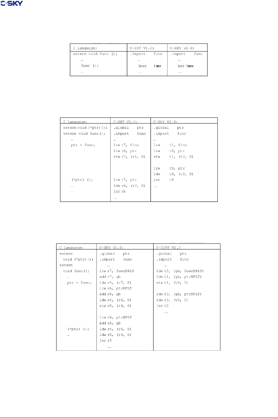
Chapter 4. ELF le format
but C-SKY V2 CPU use the jump and link instruction, bsr, to make direct function calls, since the bsr
instruction provides 26 bits of address, direct function calls can appoach 256 Mbyte address space.
Figure 4.6: Absolute Direct Function Calling
Other indirect function calls are done by computing the address of the called function into a register and
using the jump and link register, jsr.
Figure 4.7: Absolute Indirect Function Calling
Calling position independent code functions is always done with the jsr instruction. The global oset table
holds the absolute addresses of all position independent functions.
Figure 4.8: PIC Function Calling
4.7.4 Branching
C-SKY V2 CPU programs use branch instructions to control execution ow. As dened by the architecture,
branch instructions hold a PC-relative value with a 2 KByte range, allowing a jump to locations up to 2
Release 2.1 Copyright © 2018 Hangzhou C-SKY MicroSystems Co.,Ltd. All rights reserved. 52
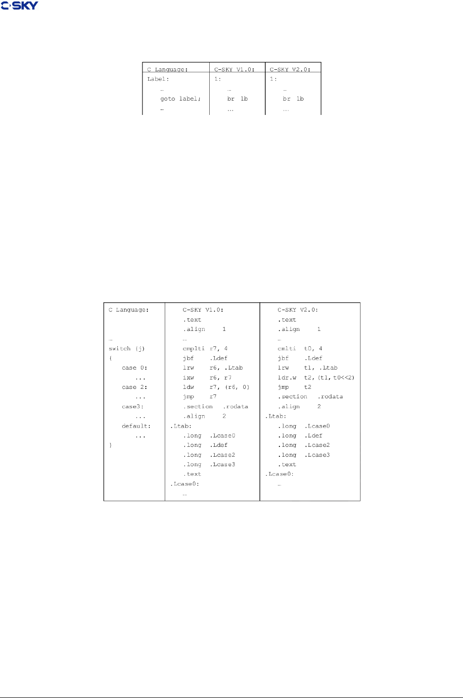
Chapter 4. ELF le format
KBytes away in either direction.
Figure 4.9: Branching
C switch statements provide multiway selection. When case labels of a switch statement satisfy grouping
constraints, the compiler implements the selection with an address table. The address table is placed in a
.rdata section; this so the linker can properly relocate the entries in the address table. Figure 4-31 Absolute
Switch Codes and Figure 4-32 PIC Switch Codes use the following conventions to hide irrelevant details:
• The selection expression resides in register r7(C-SKY V1.0), t0(C-SKY V2.0).
• Case label constants begin at zero.
• Case labels, default, and the address table use assembly names. Lcasei, .Ldef, and .Ltab, respectively.
Address table entries for absolute code contain virtual addresses; the selection code extracts the value of an
entry and jumps to that address. Position-independent table entries hold osets; the selection code compute
the absolute address of a destination.
Figure 4.10: Absolute Switch Codes
4.8 Debugging Information Format
Currently, CSKY V2 toolchain uses DWARF 2.0 described in System V Application Binary Interface, demised
by Santa Cruz Operation, Inc, as it’s internal implementation of debugging support.
Moreover, we don’t extend the standard DWARF 2.0 format by now. Nevertheless, we would augument it
by adding some extensions to standard DWARF 2.0 format in the future.
Release 2.1 Copyright © 2018 Hangzhou C-SKY MicroSystems Co.,Ltd. All rights reserved. 53
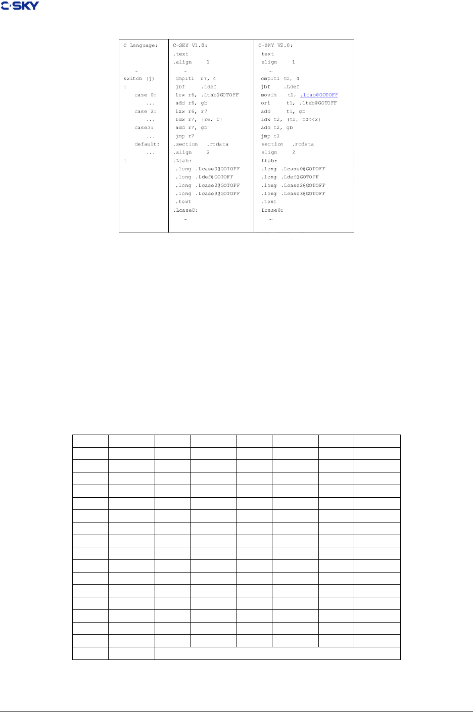
Chapter 4. ELF le format
Figure 4.11: PIC Switch Codes
4.8.1 DWARF Register Numbers
DWARF generally describes the steps a debugger takes to locate variables in a pro- gram being debugged
in machine-independent terms. However, the way in which the OP_REG and OP_BASEREG atoms are
handled is machine-specic — these atoms require that a value (or the pointer to a value) be contained in a
machine-specic reg- ister.
Table 4.10 DWARF Register Atom Mapping for C-SKY V1 CPU shows the mapping between the values
used in those atoms and the CKCORE register set. The entries for r0 through r15 specify the currently
active set of general purpose registers; this is usually the primary register set. The entries for r0’ through
r15’ specify the alternate register le. The control registers are encoded from 32 through 63.
Table 4.10: DWARF Register Atom Mapping for C-SKY V1 CPU
Atom Register Atom Register Atom Register Atom Register
0 r0 1 r1 2 r2 3 r3
4 r4 5 r5 6 r6 7 r7
8 r8 9 r9 10 r10 11 r11
12 r12 13 r13 14 r14 15 r15
16 r0’ 17 r1’ 18 r2’ 19 r3’
20 r4’ 21 r5’ 22 r6’ 23 r7’
24 r8’ 25 r9’ 26 r10’ 27 r11’
28 r12’ 29 r13’ 30 r14’ 31 r15’
32 cr0 33 cr1 34 cr2 35 cr3
36 cr4 37 cr5 38 cr6 39 cr7
40 cr8 41 cr9 42 cr10 43 cr11
44 cr12 45 cr13 46 cr14 47 cr15
48 cr16 49 cr17 50 cr18 51 cr19
52 cr20 53 cr21 54 cr22 55 cr23
56 cr24 57 cr25 58 cr26 59 cr27
60 cr28 61 cr29 62 cr30 63 cr31
64 pc
Release 2.1 Copyright © 2018 Hangzhou C-SKY MicroSystems Co.,Ltd. All rights reserved. 54
Chapter 4. ELF le format
Table 4.11: DWARF Register Atom Mapping for C-SKY V2 CPU
Atom Register Atom Register Atom Register Atom Register
0 r0 1 r1 2 r2 3 r3
4 r4 5 r5 6 r6 7 r7
8 r8 9 r9 10 r10 11 r11
12 r12 13 r13 14 r14 15 r15
16 r16 17 r17 18 r18 19 r19
20 r20 21 r21 22 r22 23 r23
24 r24 25 r25 26 r26 27 r27
28 r28 29 r29 30 r30 31 r31
32 cr0 33 cr1 34 cr2 35 cr3
36 cr4 37 cr5 38 cr6 39 cr7
40 cr8 41 cr9 42 cr10 43 cr11
44 cr12 45 cr13 46 cr14 47 cr15
48 cr16 49 cr17 50 cr18 51 cr19
52 cr20 53 cr21 54 cr22 55 cr23
56 cr24 57 cr25 58 cr26 59 cr27
60 cr28 61 cr29 62 cr30 63 cr31
64 pc 65 r0’ 66 r1’ 67 r2’
68 r3’ 69 r4’ 70 r5’ 71 r6’
72 r7’ 73 r8’ 74 r9’ 75 r10’
76 r11’ 77 r12’ 78 r13’ 79 r14’
80 r15’
Release 2.1 Copyright © 2018 Hangzhou C-SKY MicroSystems Co.,Ltd. All rights reserved. 55

CHAPTER 5
Runtime library
The most of libraries are dependent on platform and OS. In the view of this, they are beyond the scope
of this document and wouldn’t be addressed here. Some library functions are required to provide support
for operations that are not supported directly by the C-SKY V2 CPU hardware. These library routines are
specied in this section.
This chapter consists of following sections.
•Compiler assisted Libraries
•Floating Point Routines
•Long Long integer Routines
5.1 Compiler assisted Libraries
Currently, the C-SKY V2 CPU doesn’t support those instructions operating on oating point number or
long long data types. Compilers should provide the functionality for some of these operations through the
use of support library routines. The C-SKY V2 CPU Technology Center requires a single shared support
library for all tool sets to eliminate redundant code.
The functions to be provided through support routines include:
1. Floating point math routines
2. Long long routines
Compilers that generate in-line code to provide these functions must make no refer- ences to the library
functions.
Compilers that provide these functions by generating subroutine calls to the support libraries must use the
standard interfaces.
In particular, it is required to link objects produced with dierent tool sets into single executables as follows.
• Compiler support library names wouldn’t clash between tool sets
56
Chapter 5. Runtime library
• Compiler support routines are comformed with linkage rules
• Linkers from dierent tool sets must either use the same support library names and interfaces, or
provide a mechanism to indicate where support libraries can be found.
• Routines in the support libraries must satisfy the following constraints.
–The only external state information used is oating point rounding mode
–No global state can be modied
–Identical results must be returned when a routine is re-invoked with the same input arguments
–Multiple calls with the same input arguments can be collapsed into a single call with a cached
result
These properties permit a compiler to make assumptions about variable lifetimes across library subroutine
calls that values in memory won’t change, and previously de-referenced pointers need not be de-referenced
again.
5.2 Floating Point Routines
These routines conform with ABI linkage conventions concerning registers that must be preserved across
function calls. The routines have no side eects. They do not modify memory except as noted, thus allowing
compilers to optimize de-referenced pointer values across calls. The routines always return the same value
for the same inputs, allowing compilers to optimize subsequent calls away.
The data formats are as specied in IEEE 754. The routines are not required to compute results as specied
in IEEE 754. Implementations of these routines must document the degree to which operations conform to
the IEEE standard. Not all users of oating point require IEEE 754 precision and exception handling, and
may not want to incur the overhead that complete conformance requires.
5.2.1 Arithmetic functions
Table 5.1: Floating point arithmetic functions
Functions Description
double __adddf3(double a, double b) addition of a and b with double precision.
double __subdf3(double a, double b) subtract of a and b with double precision.
double __muldf3(double a, double b) multiple of a and b with double precision.
double __divdf3(double a, double b) division of a and b with double precision.
double __negdf2(double a) negative a of type double precision.
oat __addsf3(oat a, oat b) addition of a and b with single precision.
oat __subsf3(oat a, oat b) subtract of a and b with single precision.
oat __mulsf3(oat a, oat b) multiply of a and b with single precision.
oat __divsf3(oat a, oat b) division of a and b with single precision.
oat __negsf2(oat a) negative a of type single precision.
Release 2.1 Copyright © 2018 Hangzhou C-SKY MicroSystems Co.,Ltd. All rights reserved. 57
Chapter 5. Runtime library
5.2.2 Conversion functions
Table 5.2: Floating point conversion functions
Functions Description
double __extendsfdf2(oat a) extending single precisio to double.
oat __truncdfsf2(double a) truncating double precison to single.
int __xsfsi(oat a) convert a to an signed integer, rounding toward zero
int __xdfsi(double a)
long long __xsfdi(oat a) convert a to a signed long long, rounding toward zero
long long __xdfdi(double a)
unsigned int __xunssfsi (oat a) convert a to an unsigned integer, rounding toward zero. Negative
values all become zerounsigned int __xunsdfsi (double
a)
unsigned long long __xunssfdi
(oat a)
convert a to an unsigned long, rounding
unsigned long long __xunsdfdi
(double a)
toward zero. Negative values all become
oat __oatsisf (int i) convert i, a signed integer, to oating point
double __oatsidf (int i)
oat __oatdisf (long i) convert i, a signed long, to oating point
double __oatdidf (long i)
oat __oatunsisf (unsigned int
i)
convert i, an unsigned integer, to oating
point
double __oatunsidf (unsigned
int i)
oat __oatundisf (unsigned
long i)
convert i, an unsigned long, to oating point
double __oatundidf (unsigned
long i)
Release 2.1 Copyright © 2018 Hangzhou C-SKY MicroSystems Co.,Ltd. All rights reserved. 58
Chapter 5. Runtime library
5.2.3 Comparison functions
Table 5.3: Floating point comparison functions
Functions Description
int __cmpsf2 (oat a, oat b) These functions compare a with b. Return ing -1
when a less b, 0 when a equals b, otherwise return
1. Also if eigthr argum ent is NaN returning 1.int __cmpdf2 (double a, double b)
int __unordsf2 (oat a, oat b) When either a or b is NaN, returning nonz ero value.
Otherwise returning zero. There is also a complete
group of higher level functions which correspond
directly to comparison operators. They implement
the ISO C semantics for oating-point comparisons,
taking NaN into account. Pay careful attention to
the return values dened for each set. Under the
hood, all of these routines are implemented as
if (__unordXf2 (a, b))
return E;
return __cmpXf2 (a, b);
where E is a constant chosen to give
the proper behavior for NaN. Thus, the
mean ing of the return value is dierent
for each set. Do not rely on this im-
plementation; only the semantics docu-
mented below are guaranteed.
int __unorddf2 (double a, double b)
int __eqsf2 (oat a, oat b) These functions return zero if neither argument is
NaN, and a and b are equal.int __eqdf2 (double a, double b)
int __nesf2 (oat a, oat b) These functions return a nonzero value if either ar-
gument is NaN, or if a and b are unequal.int __nedf2 (double a, double b)
int __gesf2 (oat a, oat b) These functions return a value greater than or equal
to zero if neither argument is NaN, and a is greater
than or equal to b.int __gedf2 (double a, double b)
int __ltsf2 (oat a, oat b) These functions return a value less than zero if nei-
ther argument is NaN, and a is strictly less than
b.int __ltdf2 (double a, double b)
int __lesf2 (oat a, oat b) These functions return a value less than or equal to
zero if neither argument is NaN, and a is less than
or equal to b.int __ledf2 (double a, double b)
int __gtsf2 (oat a, oat b) These functions return a value greater than zero if
neither argument is NaN, and a is strictly greater
than b.int __gtdf2 (double a, double b
5.3 Long Long integer Routines
These routines comply with ABI linkage conventions concerning registers that must be preserved across
function calls. The routines have no side eects. They do not modify memory except as noted, and thus
allow compilers to optimize de-referenced pointer values across calls. The routines always return the same
value for the same inputs, allowing compilers to optimize subsequent calls away.
Release 2.1 Copyright © 2018 Hangzhou C-SKY MicroSystems Co.,Ltd. All rights reserved. 59

Chapter 5. Runtime library
5.3.1 Arithmetic functions
Table 5.4: long long arithmetic functions
Functions Description
long long __ashldi3 (long long a, int b) This function return the result of
shifting a left by b bits
long long __ashrdi3 (long long a, int b) This function return the result of
arithmetically shifting a right by b
bits
long long __lshrdi3 (long long a, int b) This function return the result of
logically shifting a right by b bits
long __divsi3 (long a, long b) These functions return the quotient
of
the signed division of a and blong long __divdi3 (long long a, long long b)
long __modsi3 (long a, long b) These functions return the remain-
der
of the signed division of a and blong long __moddi3 (long long a, long long b)
long long __muldi3 (long long a, long long b) This function return the product of
a and b
long long __negdi2 (long long a) This function return the negation of
a
unsigned long __udivsi3 ( unsigned long a, unsigned long
b)
These functions return the
quotient of the unsigned division of
a and b
unsigned long long __udivdi3 (unsigned long long a,
unsigned long long b)
unsigned long long __udivmoddi4 (unsigned long long a,
unsigned long long b, unsigned long long *c)
This function calculate both the
quotient and remainder of the un-
signed division of a and b. The
return value is the quotient, and
the remainder is placed in variable
pointed to by c
unsigned long __umodsi3 (unsigned long a, unsigned long
b)
These functions return the remain-
der of the unsigned division of a and
b
unsigned long long __umoddi3 (unsigned long long a,
unsigned long long b)
Release 2.1 Copyright © 2018 Hangzhou C-SKY MicroSystems Co.,Ltd. All rights reserved. 60

Chapter 5. Runtime library
5.3.2 Comparison functions
Table 5.5: long long comparison functions
Functions Description
int __cmpdi2 (long long a, long long b) These function perform a signed comparison of a
and b. If a is less than b, they return 0; if a is
greater than b, they return 2; and if a and b are
equal they return 1
int __ucmpdi2 (unsigned long long a, unsigned
long long b) These function perform an unsigned
comparison of a and b. If a is less than
b, they return 0; if a is greater than b, they
return 2; and if a and b are equal they return
1
5.3.3 Trapping Arithmetic Functions
Table 5.6: long long trapping arithmetic functions
Functions Description
int __absvsi2 (int a) These functions return the absolute value
of along __absvdi2 (long a)
int __addvsi3 (int a, int b) These functions return the sum of a and b; that is a + b.
long __addvdi3 (long a, long b)
int __mulvsi3 (int a, int b) Those functions return product of a and b;
that is a*blong __mulvdi3 (long a, long b)
int __negvsi2 (int a) These functions return the negation of a; that is -a
long __negvdi2 (long a)
int __subvsi3 (int a, int b) These functions return the dierence
between b and a; that is a - blong __subvdi3 (long a, long b)
all following functions implement trapping arithmetic. These functions call the libc function abort upon
signed arithmetic overow.
5.3.4 Bit Operations
Table 5.7: long long bit operations
Functions Description
int __sdi2(long long a) These functions return the index of the least signicant 1-bit in a, or the
value zero if a is zero. The least signicant bit is index one
Release 2.1 Copyright © 2018 Hangzhou C-SKY MicroSystems Co.,Ltd. All rights reserved. 61

CHAPTER 6
Assembly syntax and directives
In this chapter, there are several sub sections would be introduced as follows. If you want to focus on the
specied contents, you can click the corresponding link.
•Section
•Input line lengths
•Syntax
•Assembler directives
•Pseudo-Instructions
6.1 Section
The generated le of assembler consists of several sections whose content is determined by the assembler
input. Section containing code is aligned to 2-byte boundary. Section containing data is aligned so that the
alignment requirements of the data contained in the section is preserved.
6.2 Input line lengths
The assembler may limit input lines, but such a limit must be at least 2100 characters in length. This gives
compiler the ability to construct an expression containing a symbol of maximum supported length (2048
bytes) and a data-allocation pseudo-instruction. For example.
.long longsymbol
The assembler is allowed to support longer lines. If the assembler imposes a limit on the length of an input
line, the assembler must issue a diagnostic if that limit approached.
62

Chapter 6. Assembly syntax and directives
6.3 Syntax
An assembly source le contains a list of one or more assembler statements. Each statement is terminated
with a newline character or a “;” character except that it appears within string literal or comment. Empty
statements (i.e. blank lines) would be ignored.
Each statement consists of zero or more labels, at most one memonic, with the remainder of the statement
being arguments specic to the memonic.
Labels are symbols that are followed by a “:”. Temporary labels are allowed and are indicated by a non-zero
digit (1–9) instead of a symbol. Duplicate temporary labels are allowed and references to them are resolved
by searching for the nearest source line with the label. References to temporary labels must have a “b” or
“f” sux appended to the digit to indicate which direction to search.
Labels that begin with “.” ( period ) are considered local labels. The assembler does not include these
symbols in the symbol table of the generated object le. Memmonics fall into three categories: instructions,
pseudo-instructions, and directives. Instruction memonics map one-to-one into an C-SKY V2 CPU opcode.
Pseudo-instructions map into sequences of C-SKY V2 CPU opcodes. Directives always start with a “.” and
are used to control the assembly and allocate data areas. All memonics are case sensitive and must be
specied in lower case.
White space in assembly source les is ignored except as a separator between memonics and when embedded
within string literals or character constants. Multiple white space characters are functionally equivalent to
a single white space character except within literals and character constants.
Comment in assembly le is indicated by several styles as follows.
• “//” sequence indicates a comment reaching to the end of the line.
• “#” character, when not part of a valid preprocessing directive, indicates a comment reaching to the
end of the line.
Comments are terminated only by the end of the line. The “;” character does not terminate comment. A
multi-line comment, e.g. “/* */”, is not supported since most assemblers are inherently line oriented.
Comments can never begin or end within a string literal or character constant.
6.3.1 Preprocessing
The assembler is not required to provide macro preprocessing. This functionality can be provided by existing
preprocessors that conform to the ANSI standard. If the assembler does provide preprocessing, then it must
conform to the “C” language preprocessing standard and the following paragraph does not apply. An
assembler command line option will enable the following behavior. Any line with a “#” character in the
rst column is assumed to be line and le information from the preprocessor. The assembler must use this
information in error messages. This allows a programmer to relate an error back to the line and le of the
original source le before preprocessing. The le and line information from the preprocessor is in the form:
# number “ filename ”
Any other preprocessor lines that do not match this form are ignored by treating them as comments.
6.3.2 Symbols
Symbols must begin with a character in the set: a–z, A–Z, . (period), or _ (underscore). The remaining
characters in a symbol may be in that set plus the digits 0–9. Symbols are case sensitive and all characters in
Release 2.1 Copyright © 2018 Hangzhou C-SKY MicroSystems Co.,Ltd. All rights reserved. 63

Chapter 6. Assembly syntax and directives
the symbol are signicant. Symbols may be limited in length but that limit must be at least 2048 characters.
If there is a limit on symbol length, symbols that exceed the limit must cause an error message to be emitted.
Silent truncation of long symbols is undesirable. This is intended to avoid silent errors where two long
symbols dier only at some point after the tools have stopped keeping track of signicant characters. The
“$” character is not allowed in a symbol name because it is not a universally supported character on non-U.S.
keyboards.
The special symbols created by temporary labels can only be referenced within a single source le. These
references must consist of a single digit followed by a “b” or “f” to indicate the direction of the nearest
matching label. The “.” symbol will always indicate the current location within the current section at the
start of the current statement. Thus:
movi r3,15
br
.
br .
results in three instructions, two of which branch to themselves. The “.” symbol is used instead of “*”
because it avoids conicts with “*” as a multiply operator.
6.3.3 Constants
The same constants and lexical expression of constants that are available in C are allowed in the assembly.
This includes hex, octal, decimal, oat, double, character, and strings. Both character and string constants
have characters, ‘ and “ respectively, to delimit them. Multiple characters within character constant are each
treated like a base 256 number. e.g. ‘1234’ equals 0x31323334.
The syntax of constants is chosen to be familiar to C programmers. The use of special characters in the
syntax for constants must be avoided as they are used in expressions. In addition, the “$” character is not
a universally supported character on non-U.S. keyboards.
6.3.4 Expressions
Addition, subtraction, multiplication, division, modulus, logical anding, inclusive oring, exclusive oring,
negating, complementing, and shifting operations are supported by the assembler for the generation of
constants or relocatable expressions in the argument portion of a statement. These operations have the
semantics and precedence of their equivalent C language operations. Parenthesis can be used to force
particular bindings of operations. All operations are done as if on 32-bit unsigned values. The syntax of
expressions is chosen to be familiar to C programmers.
Expressions can involve more than one relocatable value as long as the assembler can resolve the expression
to remove all or all but one of the relocatable values. For example, the dierence between two labels in the
same section reduces to an assemble time constant.
Relocatable expressions must evaluate down to a possibly-zero oset from a relocat- able address. The linker
is not required to provide the ability to store the value “5 times the value of this relocatable symbol”.
6.3.5 Oprators and Precedence
Table 6.1 shows the operators available to the assembly programmer. The table is arranged in order of
precedence; the higher precedence operators appear earlier in the table. These are the same operators used
in the C language.
Release 2.1 Copyright © 2018 Hangzhou C-SKY MicroSystems Co.,Ltd. All rights reserved. 64
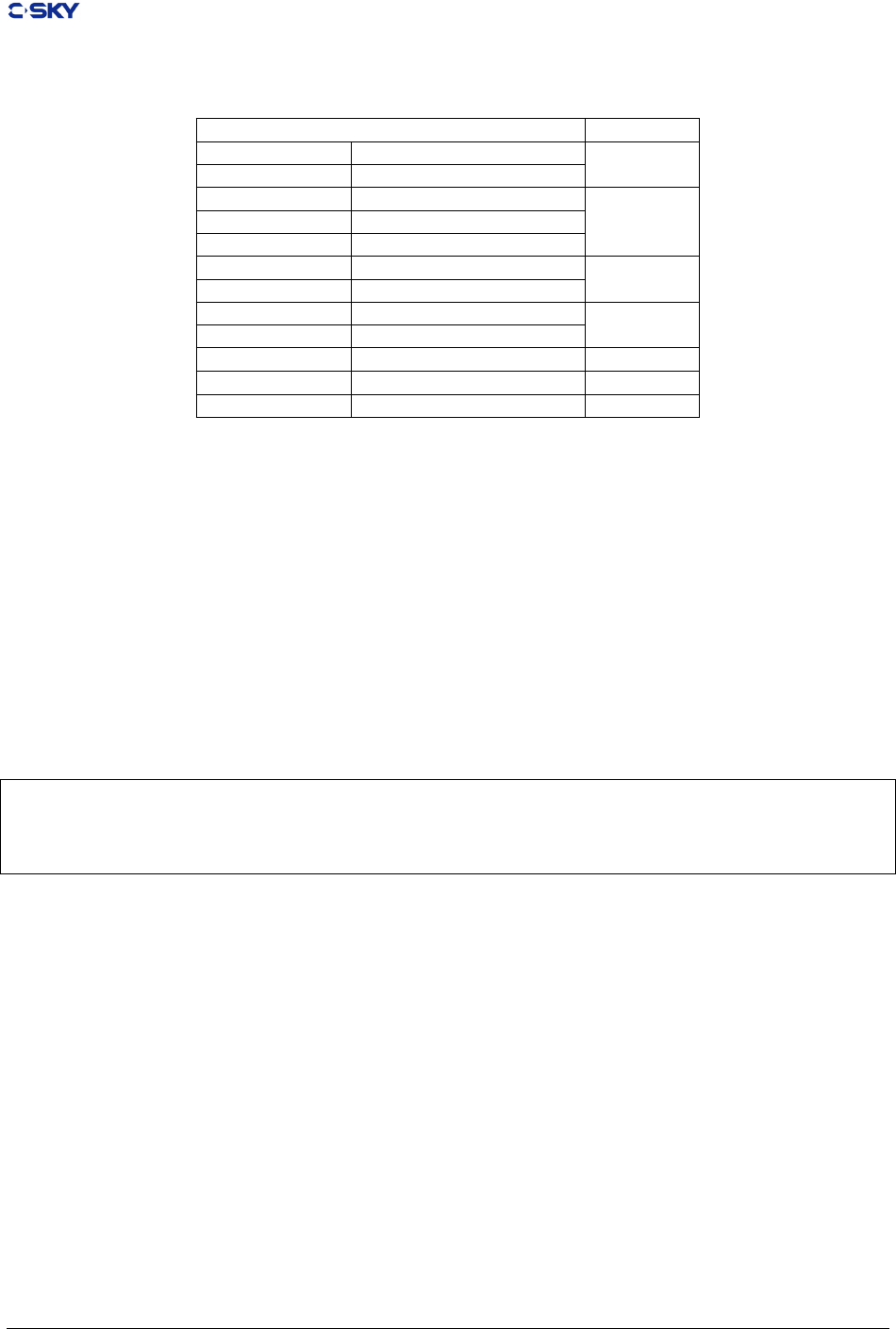
Chapter 6. Assembly syntax and directives
Table 6.1: Assembly Expression Operators
Assembly Expression Operators Precedence
- unary negation 1
~ unary logical complement
* multiplication 2
/ division
% modulus
+ addition 3
- subtraction
<< left shift 4
>> right shift
& logical and 5
^ logical exclusive or 6
| logical inclusive or 7
Operations may be grouped with parentheses to force a particular precedence.
6.3.6 Instruction Memonics
The instruction opcode mnemonics are listed in the C-SKY V2 CPU Reference Manual.
6.3.7 Instruction Arguments
Register arguments within the argument portion of a statement are indicated by the character, “r” or “R”
followed by the register number (0 through 15). Register 0 (r0) can also be specied as “sp”.
Instructions that use the PC relative indirect addressing (lrw, jsri, jmpi) take two argu- ment syntaxes. The
rst syntax is of the form:
lrw r0,0x12345678
lrw r1,0x4321
lrw r2,0x4321
lrw r3,0x4321
he assembler collects these argument values into a literal table, possibly allowing several instructions to
reuse the same slot, and emit them at an appropriate point in the output. Such a point may be after the
nearest unconditional branch. In some situations, such a location might not arise before the span of the
lrw/jsri/jmpi instruction is exhausted. In such cases, the assembler must spill the literal table before the
span is exhausted and provide a branch around the literal table.
The assembler provides a mechanism that allows the user to force a dump of the cur- rently outstanding
literals by using the .literals pseudo-instruction. Any literals that have not yet been emitted are emitted
when this directive is encountered. When the assembler input is exhausted, the assembler emits any literals
that have not yet been emitted, as if a .literals pseudo-instruction was appended to the assembly source.
NOTE
The assembler is allowed, but not required, to attempt to optimize code size by doing “optimal”
literal placement. This interacts with the expansion of jbt and jbf pseudo-operations. Also, if
literals must be output after an instruction that is not an unconditional transfer of control, the
assembler must insure that a branch around the literal table is also generated.
Release 2.1 Copyright © 2018 Hangzhou C-SKY MicroSystems Co.,Ltd. All rights reserved. 65

Chapter 6. Assembly syntax and directives
The second form uses a [label] notation for the literal. In this case, the supplied argument is
the label of the address containing the value to be loaded. This gives the assembler programmer
complete control over the placement and sharing of literals.
rw r0,[lit0]
lrw r1,[lit1]
lrw r2,[lit1]
lrw r3,[lit1]
...
.align 4
Lit0: .long 0x12345678
Lit1: .long 0x4321
NOTE
The user is responsible for insuring that the specied label is 4-byte aligned when using the [label]
literal syntax.
The C-SKY V2 CPU instruction set does not directly support position independent code, so it is
up to the assembler programmer or compiler to synthesize PC-relative branches and subroutine
calls. To help support this, a 32-bit PC relative argument type is allowed and is indicated by an
expression that is evaluated as a delta from “.”. Any symbols in the expression must be within
the same section as the instruction so the assembler can resolve it to a constant oset. This can
be done in the following manner (assuming r1 and r15 are available):
bsr .+2
lrw r1,symbol-.
add r1,r15
jsr r1
...
symbol: subi r0,12
6.4 Assembler directives
Assembler directives are used to control the assembly of the source code as well as reserving and/or initializing
areas for data. All assembler directive mnemonics begin with a “.”.
Only the .align, .comm, and .lcomm directives align the location counter to a known boundary. All other
mnemonics, including .long, do not imply alignment. It is up to the assembler programmer or compiler to
explicitly align these locations to avoid runtime misalignment faults. For operations that specify alignment
values (e.g., .align, .comm, and .lcomm), the value specied is log2 of the alignment. For example, the value
“3” species 8-byte alignment.
All data values emitted by assembler directives will be in big-endian order. This alignment behavior is
needed to support packed data structures. Packed data structures explicitly allow misaligned fundamental
types to save data space at the expense of additional code to pack and unpack the structures. Note that the
ABI does not specify how a user expresses such misaligned references at the C source level. The directive
syntax in this manual uses “[” and “]” to indicate an optional eld. The “{” and “}” syntax indicates zero
or more repetitions of a eld.
6.4.1 .align abs-exp [, abs-exp]
ligns the location counter to the boundary indicated by the rst constant expression. The integral alignment
argument is log2 of the alignment, e.g. the value “3” species 8-byte alignment. Negative alignment values
are treated as zero, indicating 1-byte alignment.
Release 2.1 Copyright © 2018 Hangzhou C-SKY MicroSystems Co.,Ltd. All rights reserved. 66

Chapter 6. Assembly syntax and directives
The second, optional expression is the value to be lled into the bytes between the old location and new
location. If unspecied, the bytes will be lled with zeros.
NOTE
The maximum alignment allowed is not constrained by the assembler. But in order for the
assembler to be able to resolve expressions between symbols in the section, the linker must
guarantee that the resulting section will be aligned to the largest alignment required within the
section. This can be true for every loadable section from every source le, so large alignments
should be used conservatively to avoid large gaps in the nal load image.
6.4.2 .ascii “string” {, “string”}
Reserves and initializes space for one or more strings given. Each assembled string will not be null-terminated
and will ll consecutive addresses. No alignment is implied.
6.4.3 .asciz “string” {, “string”}
Same as .ascii except the strings will be null terminated.
6.4.4 .byte exp {, exp}
Assembles consecutive bytes with the one or more values given by the expression(s). No alignment is implied.
Values larger than eight bits are truncated to t into eight bits. This also generates a warning diagnostic.
6.4.5 .comm symbol, length [, align]
Declares an area of length bytes in the .bss section that will be shared by dierent les. If another le
declares a longer length, then the length will be the maximum of all the declared lengths. The alignment, if
specied, is log2 of the alignment. The value “3” species 8-byte alignment. The units are the same as in
the .align directive. If no alignment is specied, the assembler will naturally align the symbol according to
the largest natural type that can be contained in an entity of that size. Entities of eight bytes and larger are
8-byte aligned, entities of four bytes are 4-byte aligned, entities of two and three bytes are 2-byte aligned,
single-byte entities are 1-byte aligned.
6.4.6 .data
Equivalent to:
.section .data,”RW”
6.4.7 .double oat {, oat}
Assembles oating point values into IEEE 64-bit oating point numbers. The numbers will be consecutive
and no alignment is implied.
Release 2.1 Copyright © 2018 Hangzhou C-SKY MicroSystems Co.,Ltd. All rights reserved. 67

Chapter 6. Assembly syntax and directives
6.4.8 .equ symbol, expression
Sets the value of the symbol to the expression. If the expression value cannot be resolved to an absolute or
relocatable value after all assembler passes are complete, the assembly will be aborted with an error.
6.4.9 .export symbol {, symbol}
Causes the symbol to appear in the emitted symbol table in the resulting object le. The symbol may be
dened within the le or it may be dened within an external le.
6.4.10 .ll count [, size [, value]]
Emits count copies of the value given. Only the least signicant size bytes of value are replicated. The size
must be a value ranging from one through eight; the default size is one byte. The default value is zero. All
three arguments are integral absolute expressions.
6.4.11 .oat oat {, oat}
Assembles oating point values into IEEE 32-bit oating point numbers. The numbers will be consecutive
and no alignment is implied.
6.4.12 .ident “string”
Places the string in the .comment section of the object le reserved for identication purposes. This is used
for version tracking and source-to-binary audit trails.
6.4.13 .import symbol {, symbol}
Indicates that the symbols are dened externally from this le. All undened symbols that are not declared
as imported will cause a warning message to be issued by the assembler. Symbols that have been declared
external but are not referenced should not appear in the symbol table of the emitted object le.
6.4.14 .literals
Causes the assembler’s accumulated literal table for the jmpi, jsri, and lrw instructions for the current section
to be emitted. Can be used by the assembler programmer to ush literal tables at the exact point desired.
6.4.15 .lcomm symbol, length [, alignment]
Reserve length bytes for a named local common area in the .bss section. The allo- cations of symbols in the
.bsssection will be in the same order as the .lcomm statements in the source le.
NOTE
Preserving the allocation order allows the compiler to use xed osets from a bss pointer to access
several related variables. The optional alignment value is log2 of the desired alignment; a value
of “3” species eight byte alignment. If no alignment is specied, the assembler will naturally
align the symbol according to the largest natural type that can be contained in an entity of that
Release 2.1 Copyright © 2018 Hangzhou C-SKY MicroSystems Co.,Ltd. All rights reserved. 68
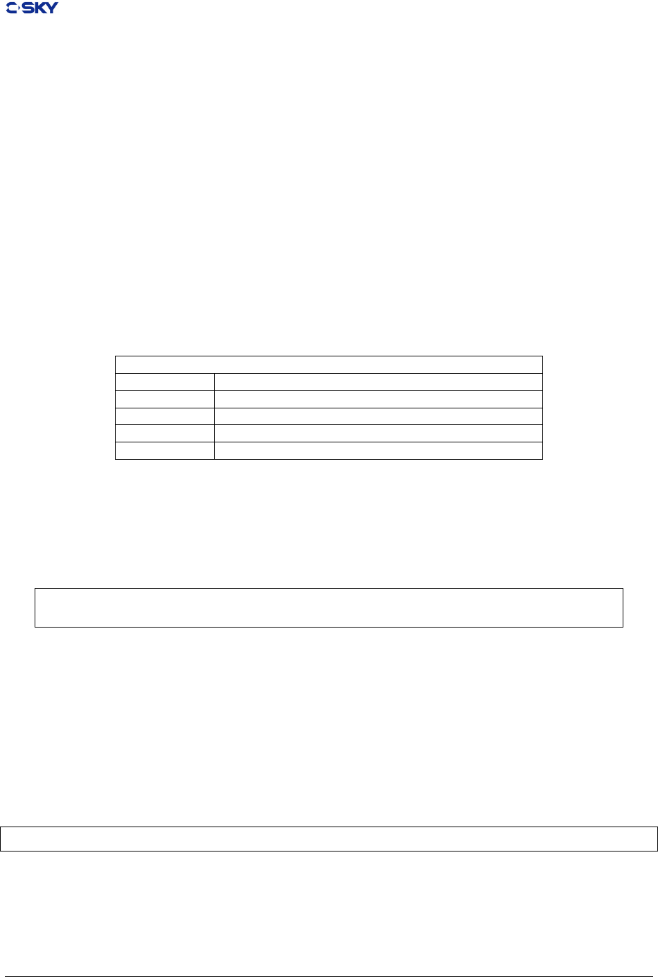
Chapter 6. Assembly syntax and directives
size. Entities of eight bytes and larger are 8-byte aligned, entities of four bytes are 4-byte aligned,
entities of two and three bytes are 2-byte aligned, single-byte entities are 1-byte aligned.
6.4.16 .long exp {, exp}
Emits four byte values consecutively.
6.4.17 .section name [, “attributes”]
Assemble subsequent statements onto the end of the named section. Section names obey the same syntax
as symbol names. The attributes supported are the access permissions (read, write, and execute) and the
allocation bits (yes or no). Permissions and allocation are indicated by any combination of the letters
RWXANrwxan with no separators between them. The attributes are specied as a quoted string. The
attribute characters are explained in Table 6.2.
Table 6.2: CKCORE Section Attribute Encodings
Section Attribute Encodings
R or r Section is to be readable.
W or w Section is to be writable.
X or x Section contains executable code.
A or a Section is to be allocated in the loaded image
N or n Section is NOT to be allocated in the loaded image
A missing attribute list indicates that the section should have all permissions (RWX) and address space will
be allocated in the load map. An empty attribute list (e.g., an empty quoted string) species an allocated
but inaccessible section.
A missing attribute list generates the default permissions.
Multiple specications of a section take the attributes from the rst specication of the section.
.sectionsectionname, ” RX ”
.sectionsectionname, ” RW ”
The RW attribute is ignored and the section sectionname will have read and execute permissions.
6.4.18 .short exp {, exp}
Emits two byte values consecutively.
6.4.19 .text
Equivalent to:
.section.text, ” RX ”
Release 2.1 Copyright © 2018 Hangzhou C-SKY MicroSystems Co.,Ltd. All rights reserved. 69

Chapter 6. Assembly syntax and directives
6.4.20 .weak symbol [, symbol]
Specify a weak external symbol denition. If symbol is not otherwise dened at link time, it has the value
zero. Multiple symbols can be specied on the same line.
The assembler also supports several pseudo-instructions which are expanded into one or more machine
instructions.
Some pseudo-instructions are used to delay selection of instructions until relative addresses are resolved. For
example, a smaller relative branch instruction could be emitted instead of a larger absolute jump instruction
if the decision is delayed until the branch distance is known.
Some pseudo-instructions are for the assembler programmers convenience. For example, the “clear the
condition bit” (clrc) instruction is another mnemonic for a compare of r0 being not equal to r0. Also, the
mnemonics for the load/store instructions (ldb, ldh, ldw, stb, sth, stw) have alternate forms (ld.b, ld.h, ld.w,
st.b, st.h, st.w). Other pseudo-instructions are used to get C-SKY V2.0 compatible with V1.0, for example,
“movt” does exist in V2.0 instruction set, but can be replaced by “inct”.
6.5 Pseudo-Instructions
The assembler also supports several pseudo-instructions (as showed in Table 6.3) which are expanded into
one or more machine instructions.
Some pseudo-instructions are used to delay selection of instructions until relative addresses are resolved. For
example, a smaller relative branch instruction could be emitted instead of a larger absolute jump instruction
if the decision is delayed until the branch distance is known.
Some pseudo-instructions are for the assembler programmers convenience. For example, the “clear the
condition bit” (clrc) instruction is another mnemonic for a compare of r0 being not equal to r0. Also, the
mnemonics for the load/store instructions (ldb, ldh, ldw, stb, sth, stw) have alternate forms (ld.b, ld.h, ld.w,
st.b, st.h, st.w). Other pseudo-instructions are used to get C-SKY V2.0 compatible with V1.0, for example,
“movt” does exist in V2.0 instruction set, but can be replaced by “inct”.
Table 6.3: C-SKY V2 CPU Pseudo Instructions
Pesudo opcode description CPU
clrc cmpne r0,r0 clear the C bit all
cmplei rd,n cmplti rd, n+1 checking if rd is less
than or equal n of signed
type.
all
cmpls rd,rs cmphs rs, rd checking if rd is less
than rs of unsigned
type.
all
cmpgt rd,rs cmplt rs, rd checking if rd is greater
than rs of unsigned
type.
all
jbsr label abiv1:
bsr label
or
jsri label
abiv2:
bsr label
jump to sub-routine all
Continued on next page
Release 2.1 Copyright © 2018 Hangzhou C-SKY MicroSystems Co.,Ltd. All rights reserved. 70

Chapter 6. Assembly syntax and directives
Table 6.3 – continued from previous page
Pesudo opcode description CPU
jbr label abiv1:
br label
or
jmpi label
abiv2:
br label
unconditional jump all
jbf label abiv1:
bf label
or
bt 1f
jmpi label
1:…
abiv2:
bf label(16/32 bits)
or
bt 1f (16 bits)
br/jmpi label(32 bits)
1:…
jump to the specied
sub-procedure if C bit is
zero
all
jbt label abiv1:
bt label
or
bf 1f
jmpi label
1:…
abiv2:
bt label(16/32 bits)
or
bf 1f(16 bits)
br/jmpi label(32 bits)
1:…
jump when C bit is one all
rts jmp r15 return from sub-
procedure
all
neg rd abiv1:
rsubi rd,0
abiv2:
not rd, rd
addi rd, 1
negate the specied
number
all
rotlc rd,1 addc rd,rd addition with carry bit all
rotri rd,imm rotli rd,32-imm circlly rotate immediate all
setc cmphs r0,r0 set the C bit all
tstle rd cmplti rd,1 checking on if value isn’t
positive
all
tstlt rd btsti rd,31 checking on if value is
positive
all
tstne rd cmplnei rd,0 checking on if value isn’t
zero
all
bgeni rz,imm movi rz,immpow
immpow is 2 power imm
set n-th of value as 1,
other as 0.
V2.0
ldq r4-r7,(rx) ldm r4-r7,(rx) r4=(rx,0),r5=(rx,4),
r6=(rx,8),r7=(rx,12)
V2.0
Continued on next page
Release 2.1 Copyright © 2018 Hangzhou C-SKY MicroSystems Co.,Ltd. All rights reserved. 71

Chapter 6. Assembly syntax and directives
Table 6.3 – continued from previous page
Pesudo opcode description CPU
stq r4-r7,(rx) stm r4-r7,(rx) (rx,0)=r4,(rx,4)=r5,
(rx,8)=r6,(rx,12)=r7
V2.0
mov rz,rx mov rz,rx
or
lsli rz,rx,0
rz=rx
result is mov if both of
rz and rz are among r0
to r15. otherwise, result
is lsli.
V2.0
movf rz,rx incf rz,rx,0 move rx to rz if C bit is
0
V2.0
movt rz,rx inct rz,rx,0 move rx to rz if C bit is
1
V2.0
not rz,rx nor rz,rx,rx not the rx and move
reuslt to rz
V2.0
rsub rz,rx,ry subu rz,ry,rx rz=ry-rx V2.0
rsubi rz,rx,ry movi r1,imm16
subu rx,r1,rx
rz=imm16-rx V2.0
sextb rz,rx sext rz,rx,7,0 signed extending of rst
byte of rx and move it to
rz.
V2.0
sexth rz,rx sext rz,rx,15,0 signed extending of rst
word of rx and move it
to rz.
V2.0
zextb rz,rx zext rz,rx,7,0 zero extending of rst
byte of rx and move it
to rz.
V2.0
zexth rz,rx zext rz,rx,15,0 zero extending of rst
word of rx and move it
to rz.
V2.0
lrw rz,imm32 movih rz,imm32_hi16
ori rz�rz,imm32_lo16
load an 32 bits immedi-
ate number to register
V2.0
jbez rx,label bez rx,label
or
bnez rx,1f
br/jmpi label(32 bits)
1:…
jump to sub-procedure
if rx == 0
v2.0
jbnez rx,label bnez rx,label
or
bez rx,1f
br/jmpi label(32 bits)
1:…
jump to sub-procedure
if rx != 0
v2.0
jbhz rx,label bhz rx,label
or
blsz rx,1f
br/jmpi label(32 bits)
1:…
jump to sub-procedure
if rx > 0
v2.0
jblsz rx,label blsz rx,label
or
bhz rx,1f
br/jmpi label(32 bits)
1:…
jump to sub-procedure
if rx <= 0
v2.0
Continued on next page
Release 2.1 Copyright © 2018 Hangzhou C-SKY MicroSystems Co.,Ltd. All rights reserved. 72

Chapter 6. Assembly syntax and directives
Table 6.3 – continued from previous page
Pesudo opcode description CPU
jblz rx,label blz rx,label
or
bhsz rx,1f
br/jmpi label(32 bits)
1…
jump to sub-procedure
if rx < 0
v2.0
jbhsz rx,label bhsz rx,label
or
blz rx,1f
br/jmpi label(32 bits)
1…
jump to sub-procedure
if rx >= 0
v2.0
Release 2.1 Copyright © 2018 Hangzhou C-SKY MicroSystems Co.,Ltd. All rights reserved. 73
