CT Analyzer Brochure Manual ENU
User Manual: CT-Analyzer-Manual-Brochure-ENU
Open the PDF directly: View PDF ![]() .
.
Page Count: 12
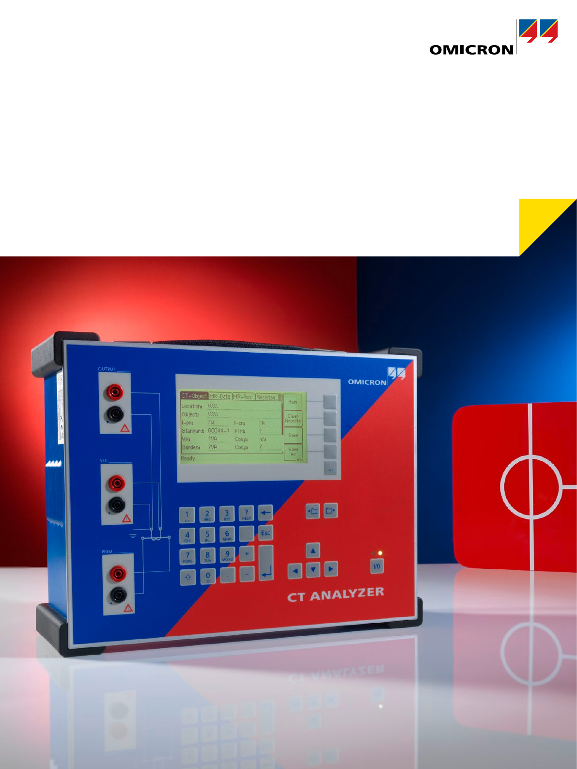
CT Analyzer
Revolution in current transformer testing and calibration
Revolutionary way of CT testing
Current transformers are used for relaying and metering purposes in electrical power systems. They connect the high
power primary side to the protection and metering equipment on the secondary side. Depending on the application they
are used for, current transformers are designed differently.
2
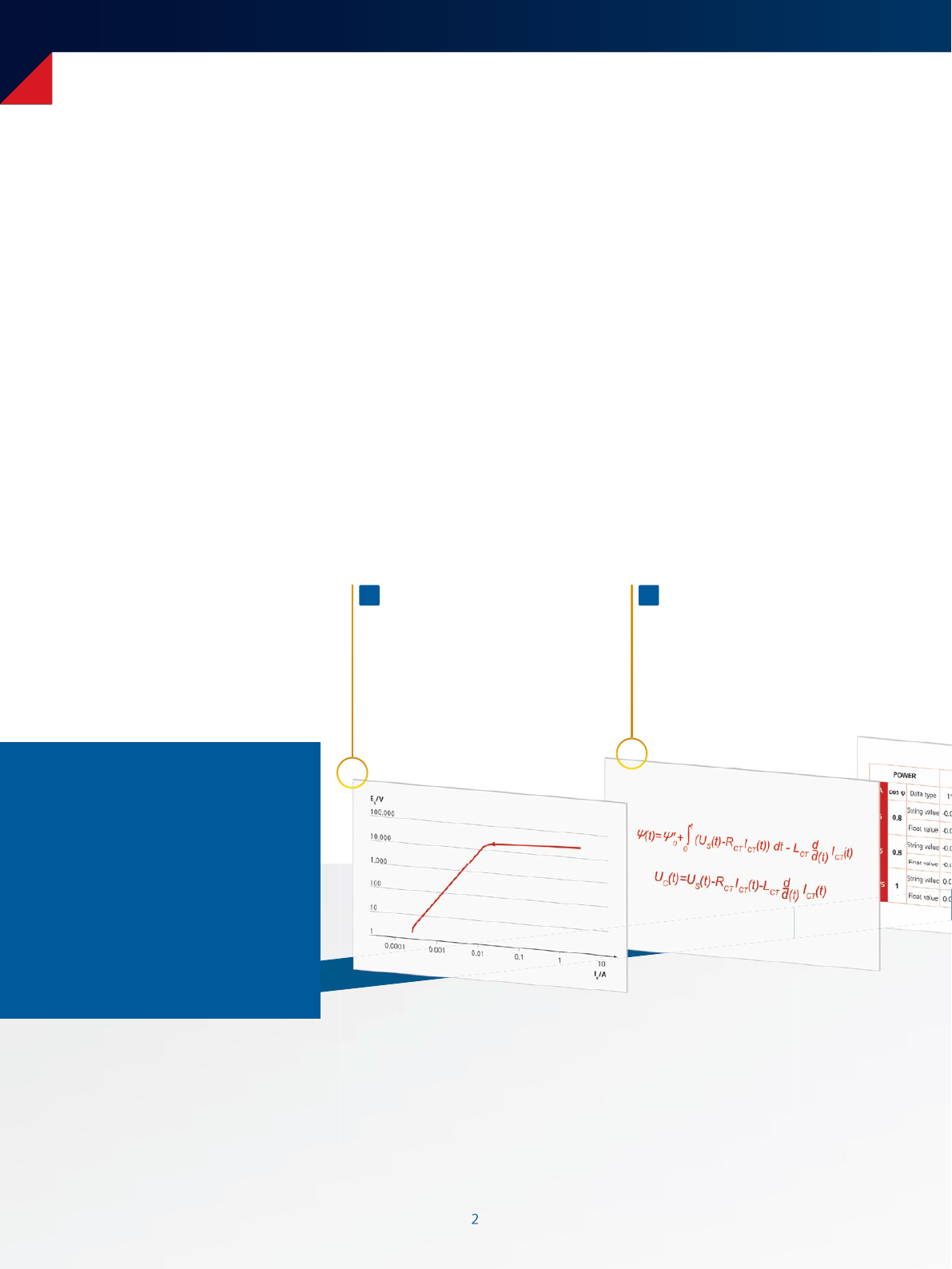
Automated testing procedure
2
Measurement of parameters
Measurement of CT parameters
like excitation curve, eddy current,
ratio, etc.
1Modeling
Definition of CT model elements and
calculation of CT parameters through
embedded mathematical functions
2
The CT Analyzer is designed to
accurately measure all relevant
CTparameters and compare
them to the requirements of the
defined IEEE or IEC standard. Due
to this automated assessment,
testing engineers receive the
‘pass or fail’ decision within
seconds.
Protection current transformers
As it is used to feed protective relays, the CT must be accu-
rate during normal and fault conditions. Failures in transfor-
mation could lead to misoperation of the relay along with
unwanted and costly outages. To test CTs according to the
requirements of modern protection systems, it is compul-
sory to consider the CT performance at rated frequency for
normal and overcurrent operation. Also transient compo-
nents and auto-reclosure systems must be considered.
Metering current transformers
Metering CTs must provide high accuracy up to class 0.1
to guarantee correct metering and billing. It is therefore
essential to test and calibrate the metering CT, as the accu-
racy of the metering chain depends on the accuracy of the
CT feeding the meter.
In contrast to protection CTs, metering CTs should go into
saturation beyond the nominal primary current level to
protect the connected metering equipment.
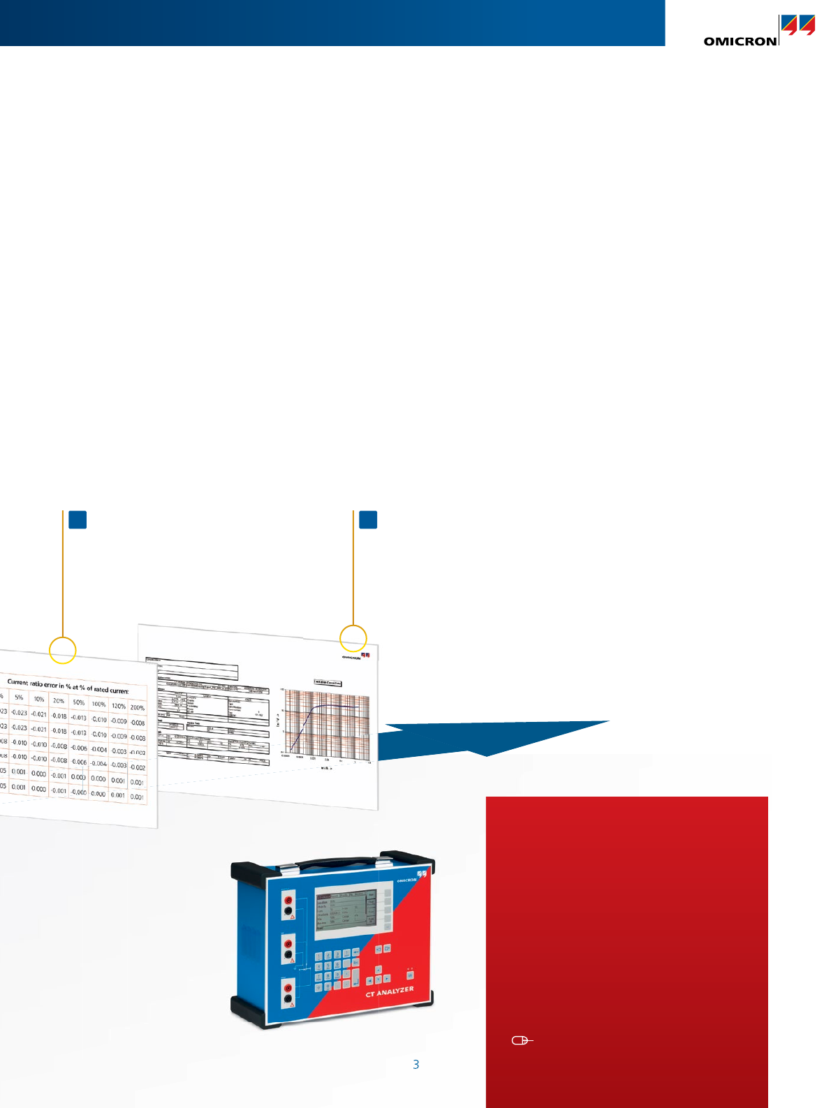
3
Assessment according
to IEEE or IEC standard
Automated comparison of test results with
the defined values / limits according to the
selected IEEE or IEC standard
3Reporting
All data is delivered in an XML file
and can be displayed via the
reporting tool
4
3
3
Your benefits
> Field verification of CTs up to the 0.1
accuracy class due to extremely high
accuracy (0.02%typical)
> Compact and lightweight
(< 8 kg / 17.4 lbs)
> Automatic assessment in accordance
with IEEE and IEC standards
> Reduced testing time (typically <1min)
> High noise immunity for on-site testing
www.omicronenergy.com/CT-Analyzer
CT Analyzer – a new way of testing CTs
The CT Analyzer is the most complete and easy-to-use
testing system for protection and metering CTs according
to IEEE and IEC standards. It allows all types of single and
multi-ratio current transformers to be tested in labs and on
site in power system grids. Manufacturers, utilities, service
providers and other CT operators use the CT Analyzer in
production, labs, test fields, and on site.
The CT Analyzer offers a wide range of measurements,
such as:
> CT ratio and phase-angle accuracy
> CT accuracy for different burdens
> CT winding resistance
> CT excitation characteristics
> CT inductance (saturated and unsaturated)
> ALF and FS (direct and indirect)
> Burden impedance
> CT residual magnetism
IS
IPIS
IP
A
VS
VP
U U
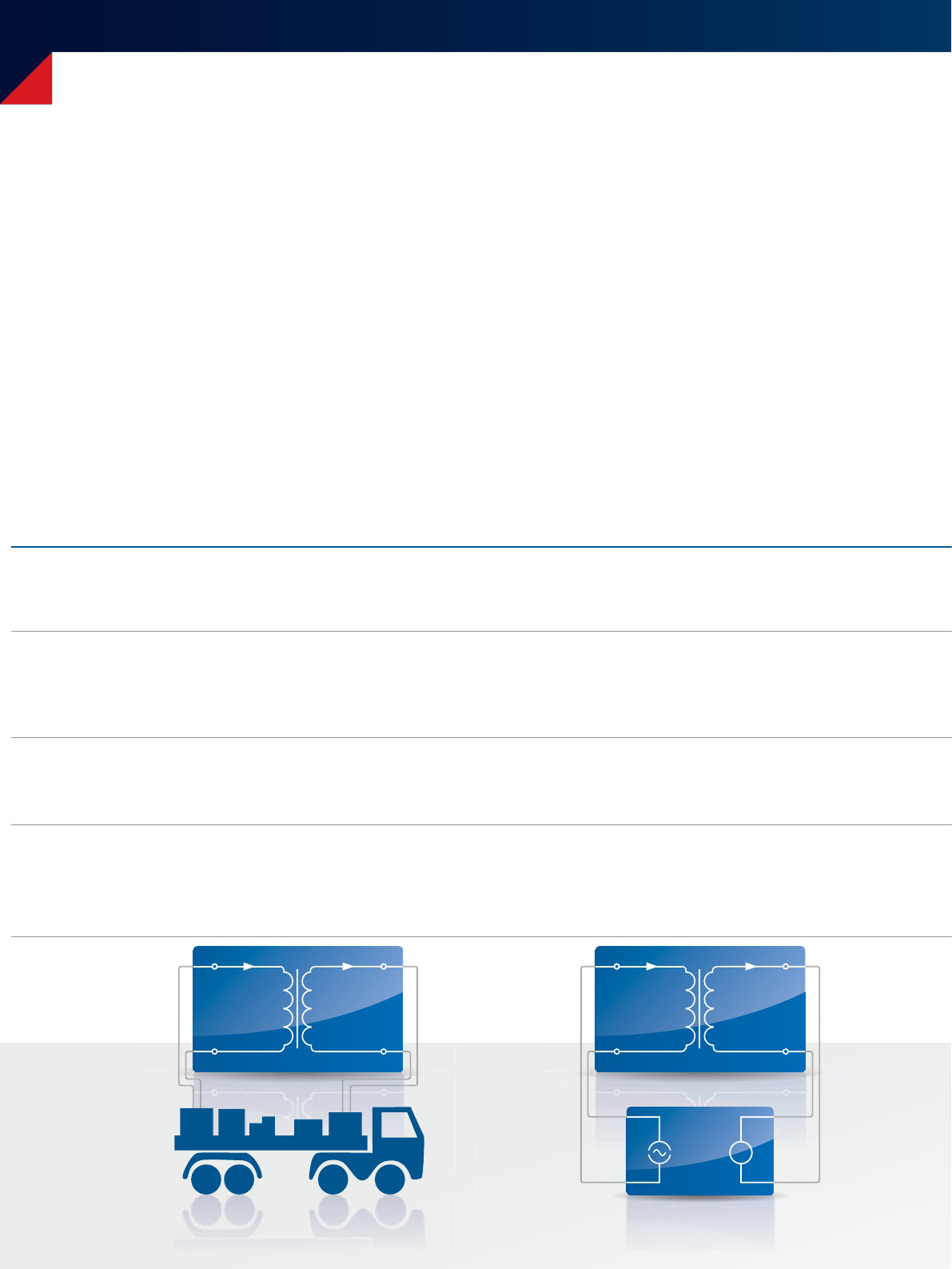
Primary current injectionPrimary nominal current injection
> Approx. 2 tons of equipment (high current source,
huge cables, current booster, burden box etc.)
> High accuracy, but complicated wiring makes
testing error-prone
> Uses dangerously high voltages and currents
(primary nominal current injection)
> Requires several people to set-up and
conduct the test
> Typical current levels of 500 A to 800 A are used
> > 30 kg / 66.1 lbs (Not including additional
equipment, e.g. external burden box)
> Not sufficient for high accuracy metering CTs
> Sensitive to transient distortion from life signals
(due to the use of 50Hz test signals)
> Re-wiring is required for each type of test
(e.g.ratio, polarity, saturation, winding resistance)
> Test results must be assessed manually
Accuracy
Safety
Mobility
Handling
4
The ideal way of testing a current transformer
Due to the continuous expansion of the power system grids the reliability of the installed equipment becomes more and
more important. This makes the use of additional metering and protection CTs necessary. To test all of these
CTs in a cost-effective and reliable way, the ideal CT test device fulfills the following requirements:
Mobility
Test engineers often have to maintain several CTs within
one utility. The ideal CT test device would therefore be
an all-in-one solution, light enough to be carried by
one person. It should be able to measure all parameters
without the need for any further equipment
(such as burden boxes).
Accuracy
Correct billing is only possible if metering CTs work within
their specifications, for all secondary burdens and levels of
primary current that are defined in the standards. To test
and calibrate these metering CTs, measurement equipment
delivering reliable results up to class 0.1 CTs is needed.
Highly accurate CT calibration and verification made mobile
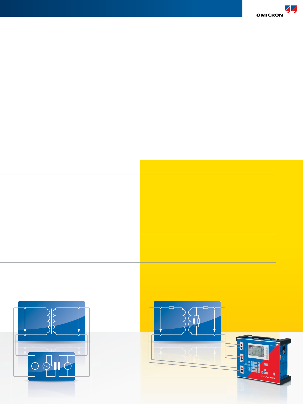
VS
VP
U U
VS(f)VP
Primary current injection
Secondary voltage injection
> Maximum output voltage of 120 V
> < 8kg / 17.4 lbs; ideal for handling on site
> Measurement of class 0.1 metering CTs
> Excellent noise suppression guaranteed
> Highly accurate on-site testing even if activelines
are close to the test object
> One-step test determining all parameters (<1min)
> Automated assessment to standard and
integrated report functionality
> Voltages for saturation tests can be
2,000 V or more
> > 30 kg / 66.1 lbs (Not including additional
equipment, e.g. external burden box)
> Not sufficient for high accuracy metering CTs
Sensitive to transient distortion from life signals
(due to the use of 50Hz test signals)
> Re-wiring is required for each type of test
(e.g.ratio, polarity, saturation, winding resistance)
> Test results must be assessed manually
5
Safety
Equipment for testing CTs on-site must comply to applicable
safety standards and regulations. However, the ideal test
device should avoid the use of high test currents and voltag-
es and conduct tests with as low test voltages as possible to
reduce the operator´s health and safety risks.
Handling
Short measurement times and an automated assessment
to the respective IEC and IEEE standards characterize
modern test equipment. All relevant parameters should
be measured in one test cycle without the need for
rewiring. Printable test reports, including all measured
data and the assessment to the standard, are ideally
created automatically by the test device.
Highly accurate CT calibration and verification made mobile
Model-based CT testing
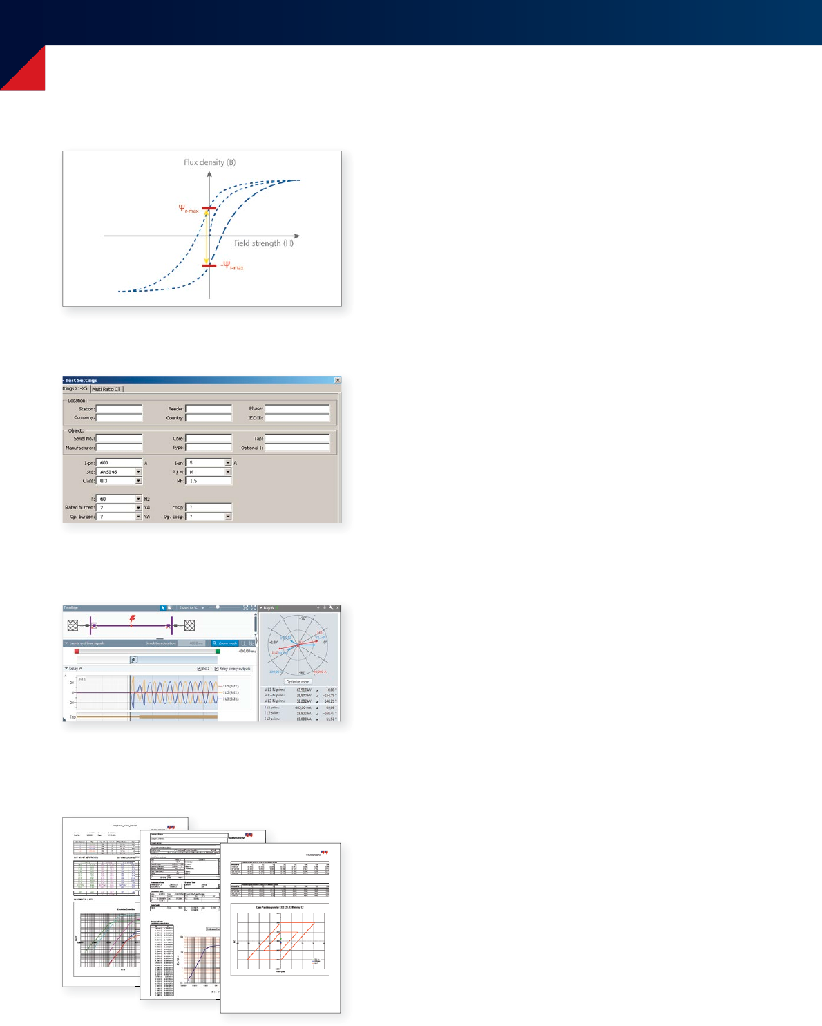
6
Extraordinary features
6
Data handling and reporting
> Test reports can be saved on the Compact Flash Card and
transferred to a PC
> Data and protocols can be shown on a PC via the
ExcelTM file loader program
> Customizable report templates are available, for example:
> Different standards, classes and applications
> Single, multi-core and multi-tap CTs
> Three-phase testing
> Core testing
Remote control
> Full access to all functions of the CT Analyzer via a PC using
the remote interface
> Optimizes the integration into automated testing procedures in
production lines
> Data export into ExcelTM and WordTM
> Customizable testing and reports
RemAlyzer
> Software-based tool to determine the residual magnetism in
current transformers
> Analysis of the remanence condition before putting into
operation the CT to assure proper function
> Simplifies power grid failure analysis after unwanted operation
of protective relays
> Demagnetizes the CT core after measurement
Network simulation and relay testing
> Easy transfer of CT Analyzer measurement data to NetSim
(Test Universe module) and RelaySimTest (stand-alone software)
for network simulation and relay testing
> Calculation of current and voltage signals based on accurate
modelling of energy networks and the resulting time constants
> Behavior analysis of protective system in case of CT saturation
> Support of several simultaneous CT simulations e.g. for test on
differential protection

7
7
„Guessing“ nameplates
> Determination of unknown CT data
> Older CTs can be classified and put into service without
contacting the manufacturer
> Determinable parameters include:
> CT type
> Class
> Ratio
> Knee point
> Power Factor
> Nominal and operating burden
> Winding resistance (primary and secondary)
Manual testing: QuickTest
> Use of the CT Analyzer as a multimeter with an integrated
current and voltage source (DC and AC)
> Perform manual tests (L, Z, R, ratio, polarity, burden etc.) for
trouble-shooting and quick verification on site
> VT ratio check
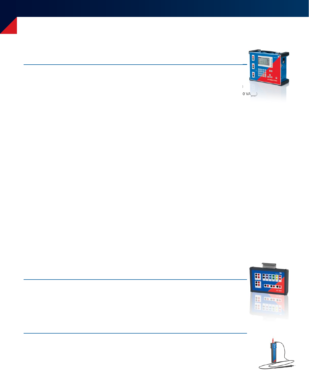
CT SB2 switch box
> Automated testing of multi-tap CTs without the need for
rewiring
> Includes terminals for burden and primary resistance tests
> CTs with up to six taps can be tested
> Automatic wiring check before measuring
> Use attached to the CT Analyzer or as a standalone unit
before test
after test
Simulation and reuse of measurement results
> Existing measurement data can be loaded to the CT Analyzer
at any time
> Recalculation of the CT parameters for different burdens
and primary currents
> No further on-site measurements are necessary to verify whether
a change in the burden will influence the accuracy of a CT
POWER Current ratio error in % at % of rated current
VA cos Phi Burden in % 1% 5% 10% 20% 50% 100% 120% 200%
15 0.8 100 -0.023 -0.023 -0.021 -0.018 -0.013 -0.010 -0.009 -0.008
25 -0.023 -0.023 -0.021 -0.018 -0.013 -0.010 -0.009 -0.008
7.5 0.8 100 -0.008 -0.010 -0.010 -0.008 -0.006 -0.004 -0.003 -0.002
25 -0.008 -0.010 -0.010 -0.008 -0.006 -0.004 -0.003 -0.002
3.75 1100 0.005 0.001 0.000 -0.001 0.000 0.000 0.001 0.001
25 0.005 0.001 0.000 -0.001 -0.000 0.000 0.001 0.001
01100 0.007 0.005 0.004 0.003 0.003 0.003 0.004 0.004
25 0.007 0.005 0.004 0.003 0.003 0.003 0.004 0.004
CPOL2: Polarity checker using QuickTest
> Check of correct polarity along the different connection points
in CTs‘ secondary wiring
> Analysis of sawtooth signal injected by the CT Analyzer
8
Technical data, Services
Technical data CT Analyzer
Environment conditions
Operating temperature -10°C...+50°C / 14°F ... 122°F
Storage temperature -25°C...+70°C / -13°F ... 158°F
Humidity Relative humidity 5 % ... 95 % not condensing
Certificates from independent test institutes
KEMA Test Report
PTB Test Report
Wuhan HV Research Test Report
Phase displacement
Resolution 0.1 min
Accuracy 1min (typical) / 3 min (guaranteed)
Current ratio accuracy
Ratio 1...2000 0.02% (typical) / 0.05% (guaranteed)
Ratio 2000...5000 0.03% (typical) / 0.1% (guaranteed)
Ratio 5000...10000 0.05% (typical) / 0.2% (guaranteed)
Winding resistance
Resolution 1mΩ
Accuracy 0.05% (typical) /
0.1%+1mΩ (guaranteed)
Power supply
Input voltage 100VAC ... 240VAC
Permissible input voltage 85VAC ...264VAC
Frequency 50/60Hz
Permissible frequency 45Hz ... 65Hz
Input power 500VA
Connection Standard AC Socket IEC 60320
Output
Output voltage 0 ... 120VAC
Output current 0 ...5Aeff (15Apeak)
Output power 0 ... 400VAeff (1500VApeak)
Input Current 0.2 A
Dimensions (W x H x D) 284x220x68mm / 11.2x8.7x2.7in
Weight 5.7lbs/2.6kg
Physical dimensions
Size (W × H × D) 360×285×145mm /
9.2×7.2×3.7 in
Weight 8kg / 17.4lbs (without accessories)
Technical data CT SB2
)
(1500VA
peak
)
Optional services
Calibration according to ISO / IEC 17025 for new CT Analyzers
Recalibration according to ISO / IEC 17025 for CT Analyzers
Technical data CPOL2
Measuring range 250 μVRMS ... 300 VRMS
Evaluated signal form Polarity test signal with slope ratio ≥ 3:1
Nominal frequency 52.6 Hz
Power consumption Measurement active: < 100 mW
Standby: 50 μW
Input impedance > 300 kΩ
Batteries Type and number:
2 × 1.5 V Mignon LR6
AA AM4 MN1500
Dimensions (W × H × D) 180 × 55 × 35 mm /
7.1 × 2.2 × 1.4 in
Weight 150 g / 0.33 lb

9
Standard
Package
Advanced
Package
IEEE Metering
Test Set
IEEE Protection
Test Set
Automatic assessment according to
> IEC 61869-2 / 60044-1, or IEEE C57.13 for CTs of accuracy classes ≥ 0.3 ■■■■
> IEC 61869-2 / 60044-1 / 60044-6 / IEEE C57.13 / C57.13.6 for CTs of accuracy classes ≥ 0.1 –■– –
> IEEE C57.13 for CTs of all metering accuracy classes, incl. 0.15 and 0.15S – – ■–
> IEEE C57.13 of protection class CTs –––■
Determination of ALF/ALFi and FS/FSi, Ts, and composite error for nominal and connected burden ■ ■ – –
CT ratio and phase measurement with consideration of nominal and connected secondary burden ■■■■
CT winding resistance measurement (primary and secondary) ■■■■
CT excitation curve
> Saturation characteristic measurement ■■■■
> Comparison of excitation curve to a reference curve ■■■■
CT phase and polarity check ■■■■
Secondary burden measurement ■■■■
Automatic demagnetization of the CT after the test ■■■■
„Nameplate guesser“ function for CTs with unknown data ■■■■
RemAlyzer tool which determines the residual magnetism in CTs □□□□
Remote control interface ■■■■
QuickTest: Manual testing interface (L, Z, R, ratio, polarity, burden etc.) ■■■■
Simulation of measured data with different burdens and currents ■■■■
Knee-point voltage from 1 V up to 4 kV can be measured ■■■■
Knee-point voltage from 1 V up to 30 kV can be measured –■– –
Measurement of transient behavior of TPS, TPX, TPY and TPZ type CTs –■– –
Determination of the transient dimensioning factor (Ktd) –■– –
Considering Duty Cycles C-O / C-O-C-O e.g. auto-reclosure system –■– –
Allows testing of CTs for power frequencies of 50 Hz ■ ■ – –
Allows testing of CTs for power frequencies of 60 Hz ■■■■
CT SB2 (switch box) for measurements of CTs with up to 6 taps including accessories –––■
CPOL2 checks the correct polarity along the different connection points in CTs‘ secondary wiring □□□□
Calibration according to ISO / IEC 17025 for new CT Analyzers □□□□
Recalibration according to ISO / IEC 17025 for CT Analyzers □□□□
■ included □ optional – not included
Features of CT Analyzer Packages
Batteries Type and number:
2 × 1.5 V Mignon LR6
AA AM4 MN1500
Dimensions (W × H × D) 180 × 55 × 35 mm /
7.1 × 2.2 × 1.4 in
Weight 150 g / 0.33 lb
10
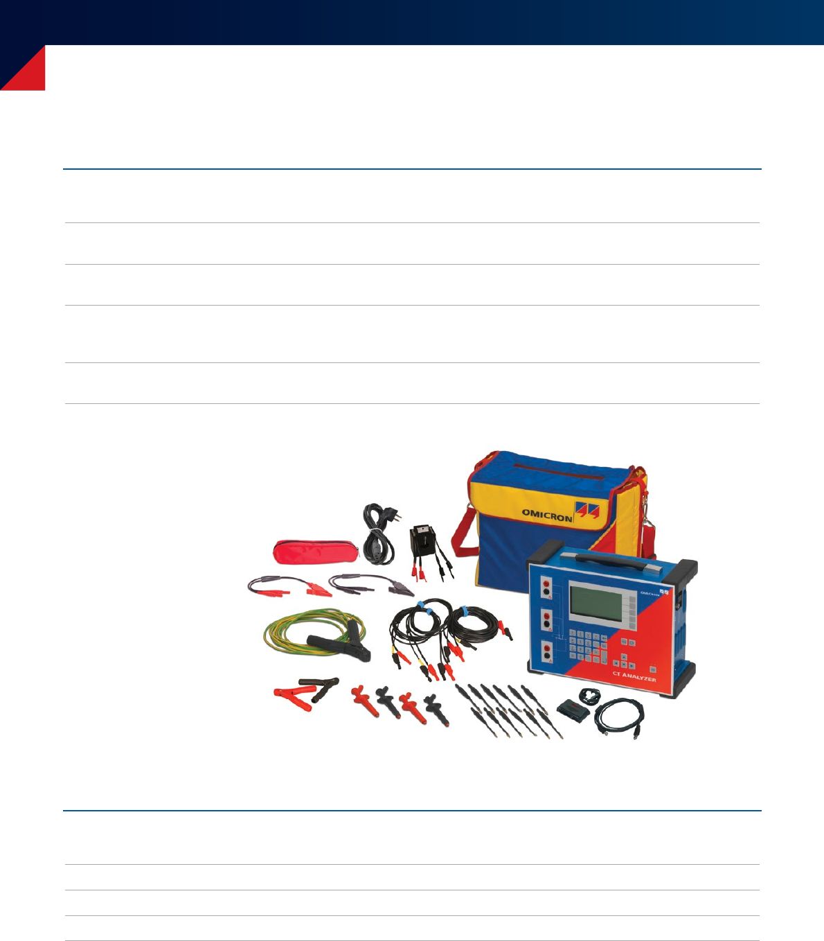
Description Ordering No.
Standard Package incl. accessories For measurements and automatic assessment on CTs with
accuracy classes ≥ 0.3 according to IEC and IEEE standards
VE000656
Advanced Package incl. accessories Expanding standard package functionality
to accuracy classes ≥ 0.1
VE000654
IEEE Metering Test Set For metering CTs with accuracy classes ≥ 0.15
according to IEEE C57.13
(does not support protection CTs)
VE000658
IEEE Protection Test Set For protection CTs according to IEEE C57.13
(does not support metering CTs)
VE000657
Find detailed ordering information and package descriptions on www.omicronenergy.com
Ordering Information
CT Analyzer Packages
Description Ordering No.
Upgrade Standard - Advanced Upgrades Standard Package to Advanced Package VESM0653
IEEE Metering - Advanced Upgrade Upgrades IEEE Metering Test Set to Advanced Package VESM0656
IEEE Protection - Advanced Upgrade Upgrades IEEE Protection Test Set to Advanced Package VESM0654
Package Upgrades
CT Analyzer Standard Package
11
Description Ordering No.
RemAlyzer Determines the residual magnetism in CTs VESM0657
Software Tool
Description Ordering No.
Recalibration of high-precision CT Recalibration of high-precision CT according to
ISO / IEC 17025 (recommended every 1-2 years)
VEDK9055
Calibration of new CT Analyzers Calibration of new CT Analyzer devices
according to ISO / IEC17025 (certificates included)
VEDK9002
Recalibration of
CT Analyzers in service
Recalibration of CT Analyzer devices
according to ISO / IEC17025
(certificates included, recommended every 1-2 years)
VEDK9051
Calibration Services
Description Ordering No.
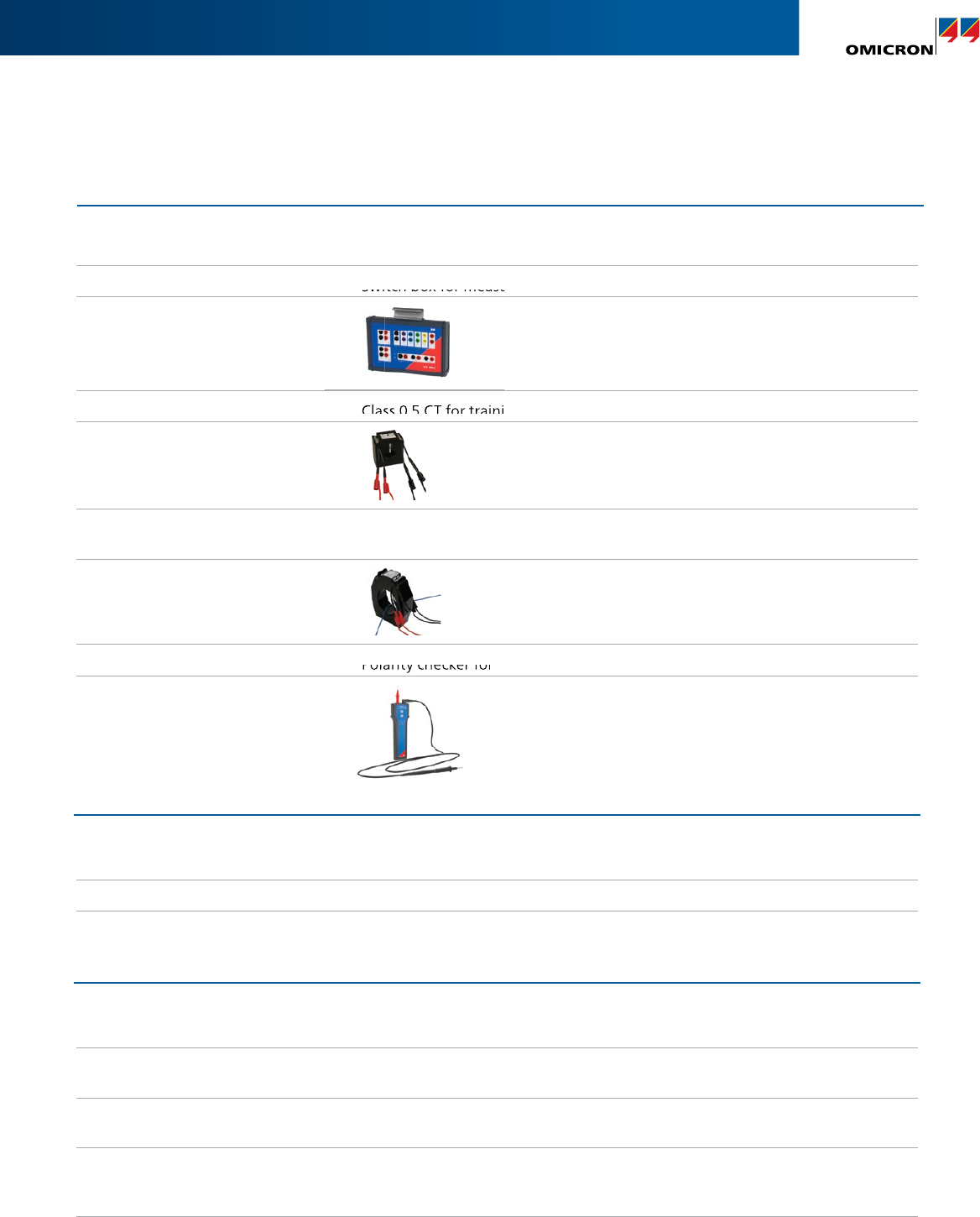
CT SB2 incl. accessories Switch box for measurements on CTs with up to 6 taps VEHZ0696
Training CT Class 0.5 CT for training purposes. FS5, ratio = 300:5 VEHZ0643
Calibration CT High-precision CT (class 0.02) for calibration purposes.
Ratios = 2000:1/2000:5
VEHZ0649
CPOL2 Polarity checker for CTs‘ secondary wiring VEHZ0702
CT Analyzer Accessories
Switch box for measurements on CTs with up to 6 taps
Class 0.5 CT for training purposes. FS5, ratio = 300:5
Polarity checker for CTs‘ secondary wiring
www.omicronenergy.com
The following publications provide further information on the solutions described in this
brochure:
For more information, additional literature, and detailed contact information of our
worldwide offices please visit our website.
Datasheet CT SB2
SwitchBox
Convenient Features
The CT SB2 offers many convenient features for testing:
6 channel secondary connection terminals•
Color-coded terminals and cables to avoid connection errors•
Automatic wiring check to help with trouble-shooting•
Easy test setup using the CT Analyzer User Interface•
Terminals for connection of primary resistance and secondary •
burden for full automatic test without re-wiring during test
CT SB2
Multi-Ratio Switch-Box for CT Analyzer
The CT SB2 Switch-Box is an accessory for the CT Analyzer that
enables the automatic testing of multi-ratio current transformers
(CTs) with up to 6 tap connections (X1 to X6). The CT SB2 is
connected to all the taps of a multi-ratio CT as well as to the CT
Analyzer. Thus every ratio combination can be tested automatically
by the CT Analyzer.
Mobile – Compact – Automated
Depicted: CT SB2
CT SB2
Input Voltage 100 - 240 V
Input Frequency 50 - 60 Hz
Input Current 0.2 A
Output Voltage* 0 - 120 V
Output Current* 0 - 5 A
Output Power* 0 - 400 VA
Dimensions (W x H x D) 284 x 220 x 68 mm
11.2 x 8.7 x 2.7 in
Weight 2.6 kg / 5.7 lbs
Order Number VEHZ0696
Scope of Delivery CT SB2
* Output of CT Analyzer
Flexibility on-site
The CT SB2 can be easily attached to the CT Analyzer or placed
separately beside. With a combined weight of 11 kg / 24 lbs,
the CT Analyzer with the CT SB2 is convenient to carry and handle
on-site. The CT SB2 makes the CT Analyzer the most flexible and
complete solution for testing multi-ratio CTs.
OMICRON is an international company serving the electrical power industry with
innovative testing and diagnostic solutions. The application of OMICRON products
allows users to assess the condition of the primary and secondary equipment on
their systems with complete confidence. Services offered in the area of consulting,
commissioning, testing, diagnosis and training make the product range complete.
Customers in more than 150 countries rely on the company’s ability to supply leading
edge technology of excellent quality. Service centers on all continents provide a broad
base of knowledge and extraordinary customer support. All of this together with our
strong network of sales partners is what has made our company a market leader in the
electrical power industry.
Subject to change without notice.
© OMICRON L2736, June 2017
