CTM2 16 18 20 24 HP Onan Engines
User Manual: CTM2 - 16 18 20 24 HP Onan Engines
Open the PDF directly: View PDF ![]() .
.
Page Count: 224 [warning: Documents this large are best viewed by clicking the View PDF Link!]
16, 18, 20
and 24HP
Onan Engines
John Deere Horicon Works
CTM2 (19APR90)
LITHO IN U.S.A.
ENGLISH

This component technical manual (CTM) contains
necessary instructions to repair the engine.
Use this component technical manual in conjunction
with the machine technical manual. An engine
application listing in the introduction identifies
product-model/engine type-model relationship. See the
machine technical manual for:
• Engine removal and installation.
• Theory of operation, diagnostic, and testing
procedures.
NCAUTION: THIS SAFETY-ALERT
SYMBOL MEANS ATTENTION!
BECOME ALERT! YOUR SAFETY IS
INVOLVED.
When you see this symbol on your machine or in
your manual, be alert to the possibility of personal
injury or death. Follow the instructions in the safety
message.
CTM2,IFC -19-03FEB87
Introduction
CTM2 (19APR90) 16, 18, 20 & 24HP Onan Engines
130495
INTRODUCTION
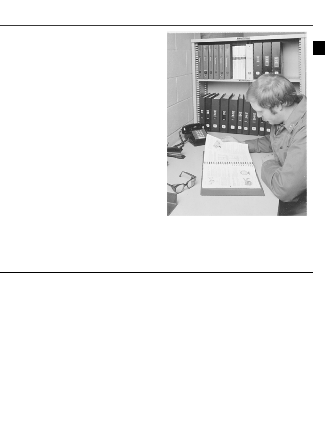
This manual is part of a total service support program.
FOS MANUALS—REFERENCE
TECHNICAL MANUALS—MACHINE SERVICE
COMPONENT MANUALS—COMPONENT SERVICE
Fundamentals of Service (FOS) Manuals cover basic
theory of operation, fundamentals of troubleshooting,
general maintenance, and basic types of failures and
their causes. FOS Manuals are for training new
personnel and for reference by experienced technicians.
Technical Manuals are concise service guides for specific
machines. Technical manuals are on-the-job guides
containing only the vital information needed by an
experienced service technician.
Component Technical Manuals are concise service
guides for specific components. Component Technical
Manuals are written as stand alone manuals covering
multiple machine applications.
RW5559 -UN-23AUG88
O53,INTRO2 -19-03JUL85
Group 00
Introduction
CTM2 (19APR90) 00-1 16, 18, 20 & 24HP Onan Engines
130495
00
1
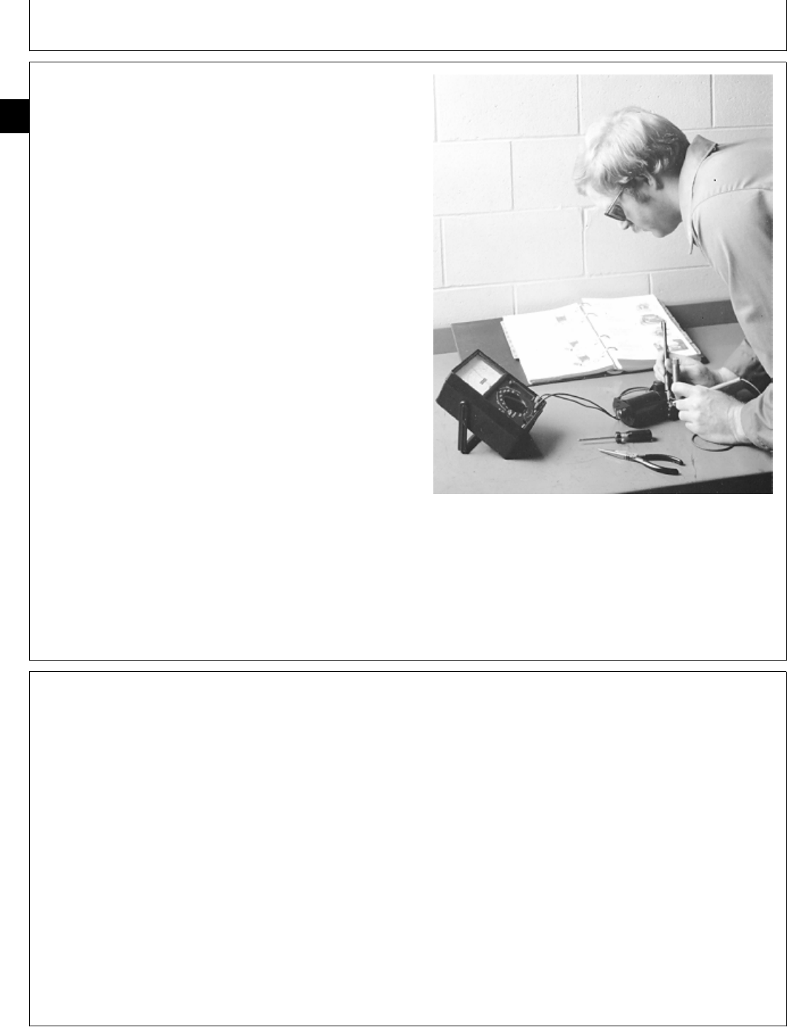
FEATURES OF THIS TECHNICAL MANUAL
John Deere ILLUSTRUCTION format emphasizing
illustrations and concise instructions in easy-to-use
modules.
Emphasis on diagnosis, analysis, and testing so you can
understand the problem and correct it.
Diagnostic information presented with the most logical
and easiest to isolate problems first to help you identify
the majority of routine failures quickly.
Step-by-step instructions for teardown and assembly.
Summary listing at the beginning of each group of all
applicable specifications, wear tolerances, torque values,
essential tools, and materials needed to do the job.
An emphasis throughout on safety—so you do the job
right without getting hurt.
This technical manual was planned and written for
you—an experienced service technician. Keep it in a
permanent binder in the shop where it is handy. Refer to
it when you need to know correct service procedures or
specifications.
RW5560 -UN-23AUG88
ABOUT THIS MANUAL
This Component Technical Manual (CTM-2) covers the
recommended repair procedures for all 16, 18, 20, and
24 HP Onan Engines removed from the machine. These
engines can be repaired on a clean work bench or put
on an engine stand.
Some components may be serviced without removing the
engine from the machine. You may want to determine
the repair procedure before you remove the engine.
Refer to the machine technical manual for engine
removal and installation procedures.
O53,INTRO3 -19-07OCT85
M98,INTR,1 -19-11NOV85
Introduction/About This Manual
CTM2 (19APR90) 00-2 16, 18, 20 & 24HP Onan Engines
130495
00
2
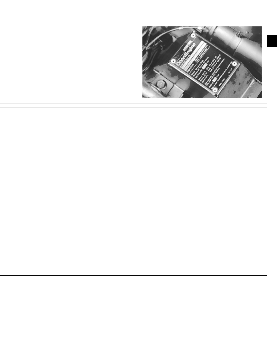
ENGINE SERIAL NUMBER PLATE
The engine serial number plate is located under the air
cleaner.
Refer to the engine model designation on your engine’s
serial number plate to identify repair information covered
in the Component Technical Manual.
M34584 -UN-07SEP88
BASIC ENGINE SPECIFICATIONS
ENGINE B43E B43G P218G B48G and P220G T260
CYLINDER 2 2 2 2 2
CYCLE 4 4 4 4 4
BORE 82.55 mm 82.55 mm 82.55 mm 82.55 mm 90.42 mm
(3.25 in.) (3.25 in.) (3.25 in.) (3.25 in.) (3.56 in.)
STROKE 66.55 mm 66.55 mm 73 mm 73 mm 76.20 mm
(2.62 in.) (2.62 in.) 2.875 in.) (2.87 in.) (3.00 in.)
DISPLACEMENT 710 cm3710 cm3782 cm3782 cm3983 cm3
(43.3 cu in.) (43 cu in.) 47.7 cu in.) (48 cu in.) (60 cu in.)
*HORSEPOWER 12kW (16 hp) 13.5 kW (18 HP) 13.4 kW 15 kW (20 hp) 18 kW (24 hp)
(18 hp)
*Horsepower rating is established by engine manufacturer in
accordance with Standard International Combustion Institute procedure.
It is corrected to (60 ˚F) and 29.92 hg barometer. Laboratory test
engines are equipped with air cleaner and muffler.
M98,INTR,2 -19-07OCT85
M98,INTR,3 -19-10FEB87
Introduction/Engine Specifications
CTM2 (19APR90) 00-3 16, 18, 20 & 24HP Onan Engines
130495
00
3

ENGINE APPLICATION CHART
Refer to the engine application chart to identify
product-model/engine type-model relationship.
CONSUMER PRODUCTS
Lawn and Garden Tractors
Machine No. Engine Model
316 . . . . . . . . . . . . . . . . . . . B43E or P218G
318 . . . . . . . . . . . . . . . . . . . B43G or P218G
420 . . . . . . . . . . . . . . . . . . . B48G or P220G
Front Mowers
Machine No. Engine Model
F910 . . . . . . . . . . . . . . . . . . B48G or P220G
F930 . . . . . . . . . . . . . . . . . . T260
ENGLISH TORQUE SPECIFICATIONS
NOTE: Wrench torque tolerance is ± 20%.
Bolt Three Six
Diameter Plain Head* Radial Dashes* Radial Dashes*
lb-ft N·m lb-ft N·m lb-ft N·m
1/4 in. 6 8 9 12 12 16
5/16 in. 10 14 18 24 25 34
3/8 in. 20 27 30 41 45 61
7/16 in. 30 41 50 68 70 95
1/2 in. 45 61 75 101 110 149
9/16 in. 70 95 110 150 155 210
5/8 in. 95 128 155 210 215 290
3/4 in. 165 225 270 365 385 520
7/8 in. 170 230 435 590 620 840
1 in. 255 345 660 895 930 1260
Torque figures indicated above and in the Specification Sections of this manual are valid for non-greased or
non-oiled threads and heads unless otherwise specified. Therefore, do not grease or oil bolts or cap screws
unless otherwise specified in this manual.
* Torque value for bolts and cap screws are identified by their head
markings.
M98,INTR,4 -19-29JAN87
S11,2000,DD -19-11JUL85
Introduction/Hardware Torque Specifications
CTM2 (19APR90) 00-4 16, 18, 20 & 24HP Onan Engines
130495
00
4

METRIC TORQUE SPECIFICATIONS
NOTE: Wrench torque tolerance is ± 20%.
Bolt Property Class 8.8* Property Class 10.9*
Diameter lb-ft N·m lb-ft N·m
M5 5 6 7 9
M6 8 10 11 15
M8 18 25 26 35
M10 37 50 52 70
M12 66 90 92 125
M16 166 225 229 310
M20 321 435 450 610
M24 554 750 775 1050
Torque figure indicated above and in the Specification Sections of this manual are valid for non-greased or
non-oiled threads and heads unless otherwise specified. Therefore, do not grease or oil bolts or cap screws
unless otherwise specified in this manual.
* Torque value for bolts and cap screws are identified by their head
markings. S11,2000,DE -19-11JUL85
Introduction/Hardware Torque Specifications
CTM2 (19APR90) 00-5 16, 18, 20 & 24HP Onan Engines
130495
00
5

Introduction/Hardware Torque Specifications
CTM2 (19APR90) 00-6 16, 18, 20 & 24HP Onan Engines
130495
00
6
SPECIFICATIONS
Item Measurement Specification
Breather Valve Cover Bolt Torque 2 ± 1 N·m (18 ± 9 lb-in.)
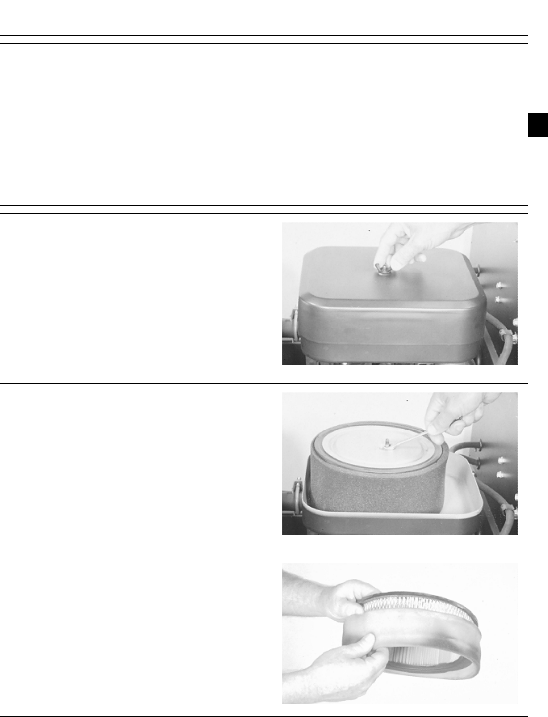
REMOVE AIR CLEANER
1. Remove wing nut and cover.
M36995 -UN-25JAN90
2. Remove lock nut and air cleaner element.
M36996 -UN-25JAN90
3. Remove precleaner. Wash precleaner as necessary.
M31044 -UN-14JUL89
M98,2005K,1 -19-07OCT85
M98,2005K,2 -19-07OCT85
M98,2005K,3 -19-07OCT85
M98,2005K,4 -19-07OCT85
Group 05
Air Cleaner and Breather
CTM2 (19APR90) 05-1 16, 18, 20 & 24HP Onan Engines
130495
05
1
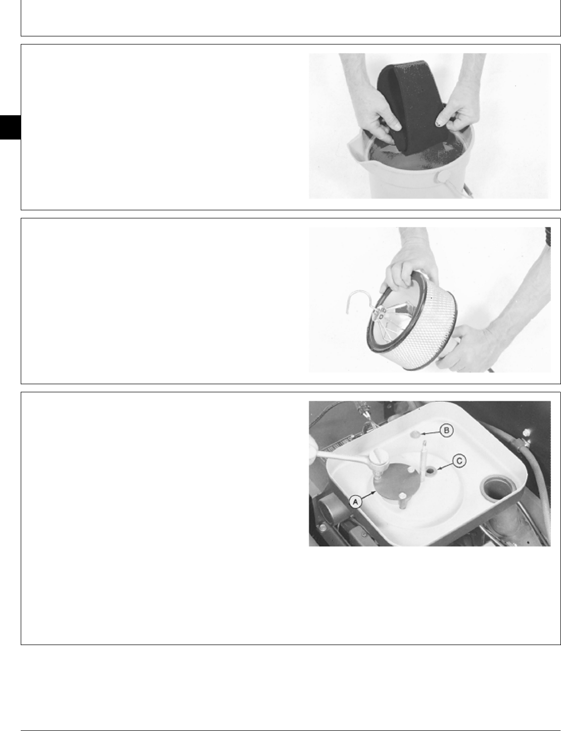
4. Wash precleaner in warm, soapy water. Rinse in
clean water. Squeeze precleaner to remove most of
water. Let precleaner air dry.
M34579 -UN-07SEP88
5. Hold a lighted bulb inside air cleaner element. If you
can see the light through element and the paper appears
clean, the element is still usable. If the element is oily,
dirty, bent, torn, crushed or obstructed in any way, install
a new element.
M34582 -UN-07SEP88
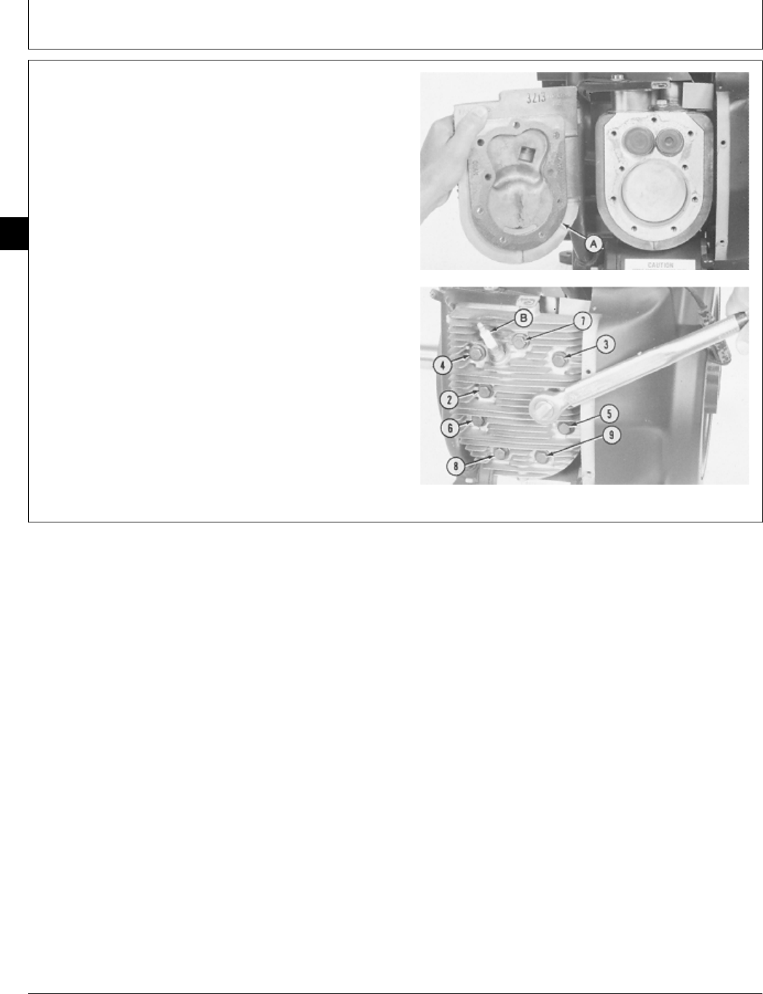
IMPORTANT: Close choke and all openings to keep
objects from falling into carburetor,
flywheel housing, and air intake
system.
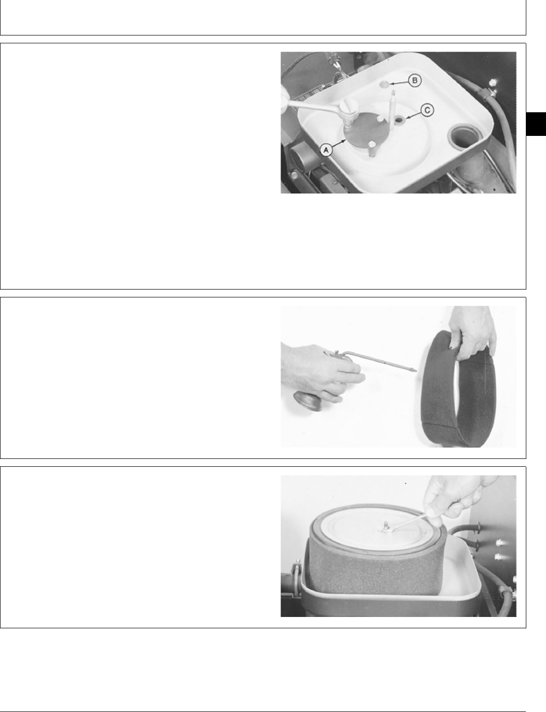
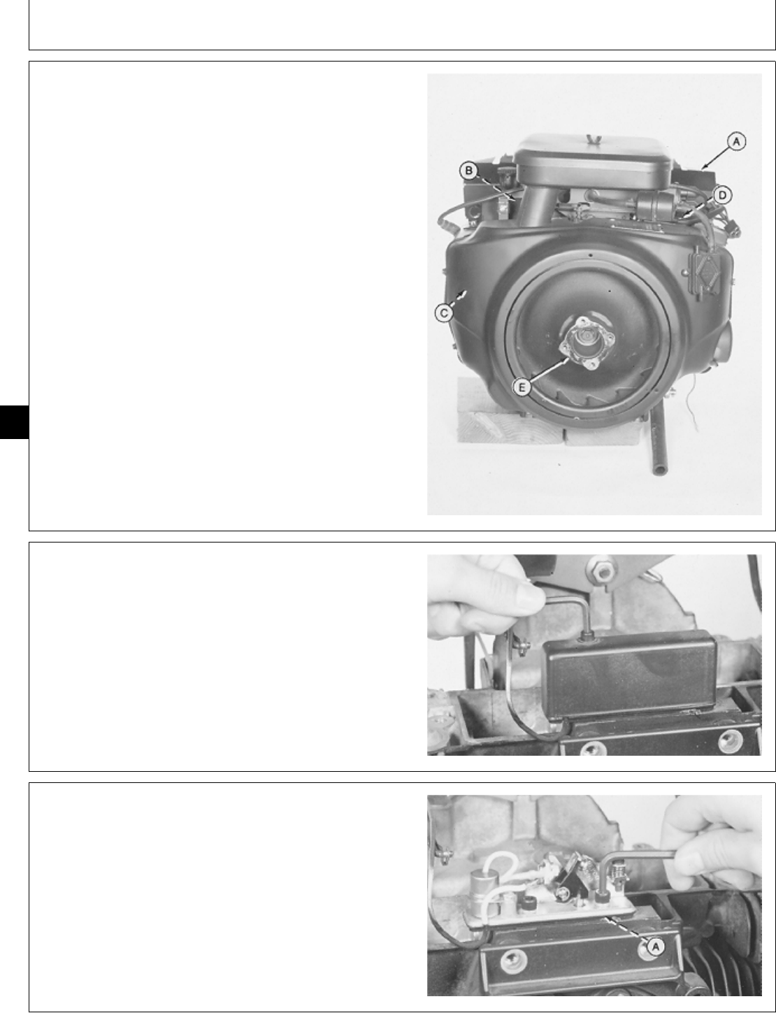
6. Remove three cap screws and splash plate (A).
7. Remove two base cap screws (B).
8. Push breather hose (C) from air cleaner base.
9. Lift air cleaner base from carburetor.
10. Clean inside of base and cover.
11. Inspect air intake hose for cracks or deterioration;
replace if necessary.
M36997 -UN-25JAN90
M98,2005K,5 -19-07OCT85
M98,2005K,6 -19-07OCT85
M98,2005K,7 -19-07OCT85
Air Cleaner and Breather/Air Cleaner
CTM2 (19APR90) 05-2 16, 18, 20 & 24HP Onan Engines
130495
05
2
INSTALL AIR CLEANER
1. Check carburetor intake to make sure the O-ring is in
place.
2. Put air cleaner base on carburetor.
3. Install breather hose (C). Be sure breather hose and
intake hose are tightly installed to prevent dirt from
entering the system.
4. Install and tighten two cap screws (B).
5. Install and fasten splash plate (A) with three screws.
M36997 -UN-25JAN90
6. Apply 1 oz (30 ml) of clean engine oil to precleaner.
7. Squeeze precleaner to distribute oil evenly and to
remove excess oil.
M34580 -UN-07SEP88
8. Put precleaner on air cleaner element. Install element
and holddown.
9. Install lock nut. Tighten until snug only.
M36996 -UN-25JAN90
M98,2005K,8 -19-08OCT85
M98,2005K,9 -19-08OCT85
M98,2005K,10 -19-11NOV85
Air Cleaner and Breather/Air Cleaner
CTM2 (19APR90) 05-3 16, 18, 20 & 24HP Onan Engines
130495
05
3
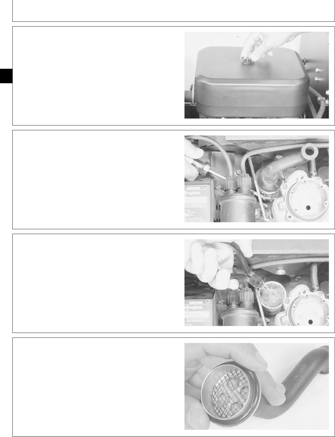
10. Install cover. Fasten with wing nut.
M36995 -UN-25JAN90
REPAIR BREATHER—T260 ENGINE
1. Remove air cleaner. (See Remove Air Cleaner in this
section.)
2. Loosen clamp to remove breather tube.
M36998 -UN-25JAN90
3. Remove filter packing.
4. Wash filter packing in a safe solvent and blow dry
with air pressure. If packing comes apart or is
deteriorated, replace it.
M36999 -UN-25JAN90
5. Wash breather valve with solvent.
Inspect ball valves to be sure they move freely.
Inspect O-ring for cuts or cracks. Replace if defective.
6. When installing breather tube, be sure filter packing is
in breather and that the O-ring is installed on the valve
assembly.
M37002 -UN-25JAN90
M98,2005K,11 -19-08OCT85
M98,2005K,12 -19-08OCT85
M98,2005K,13 -19-08OCT85
M98,2005K,14 -19-08OCT85
Air Cleaner and Breather/Breather, Repair
CTM2 (19APR90) 05-4 16, 18, 20 & 24HP Onan Engines
130495
05
4
REPAIR BREATHER—B43E, B43G, B48G,
P218G, AND P220G ENGINES
1. Remove air cleaner. (See Remove Air Cleaner in this
group.)
2. Pull breather tube from breather assembly.
M37000 -UN-25JAN90
3. Remove filter packing.
4. Wash filter packing in a safe solvent and blow dry
with air pressure. If packing comes apart or is
deteriorated, replace it.
M37001 -UN-25JAN90
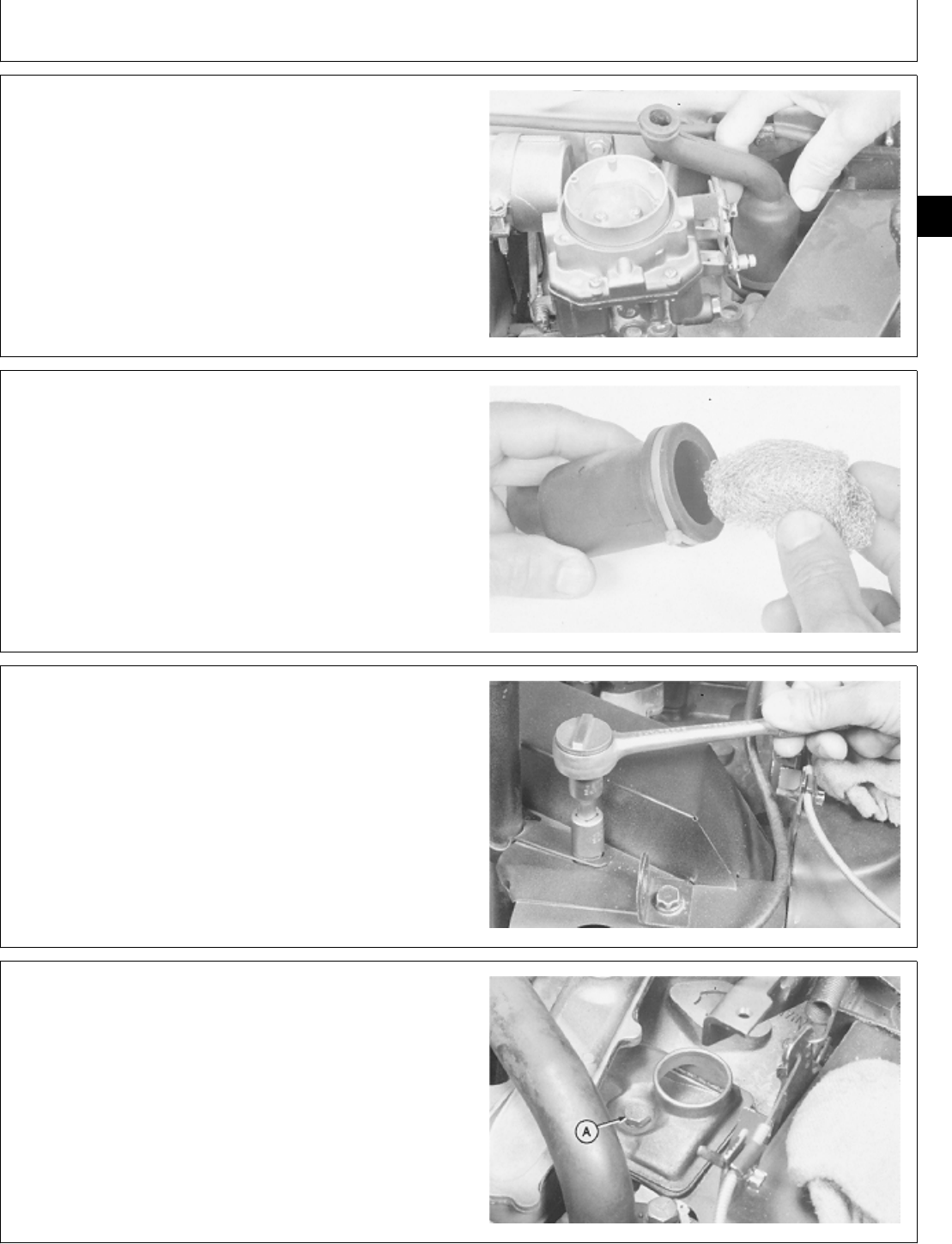
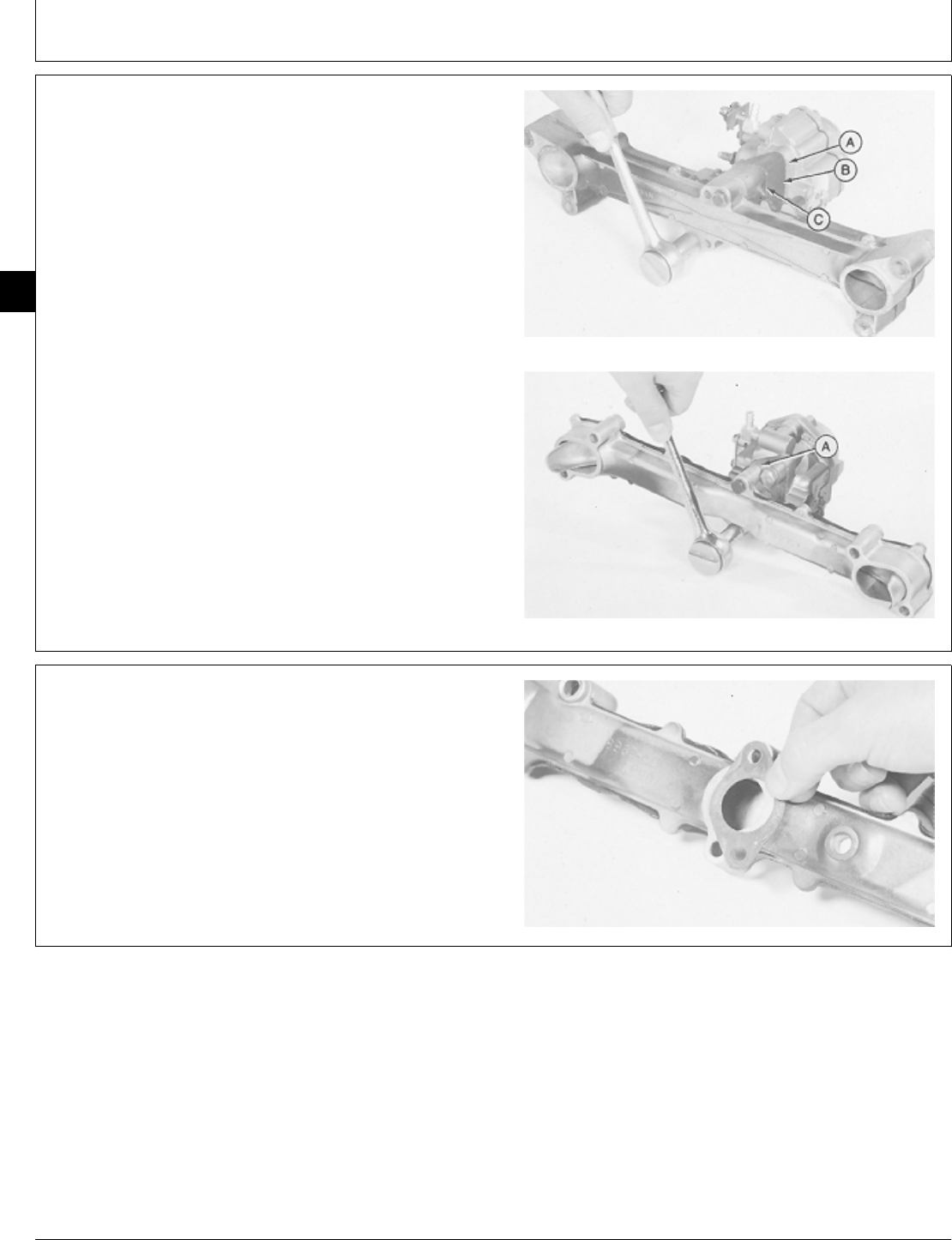
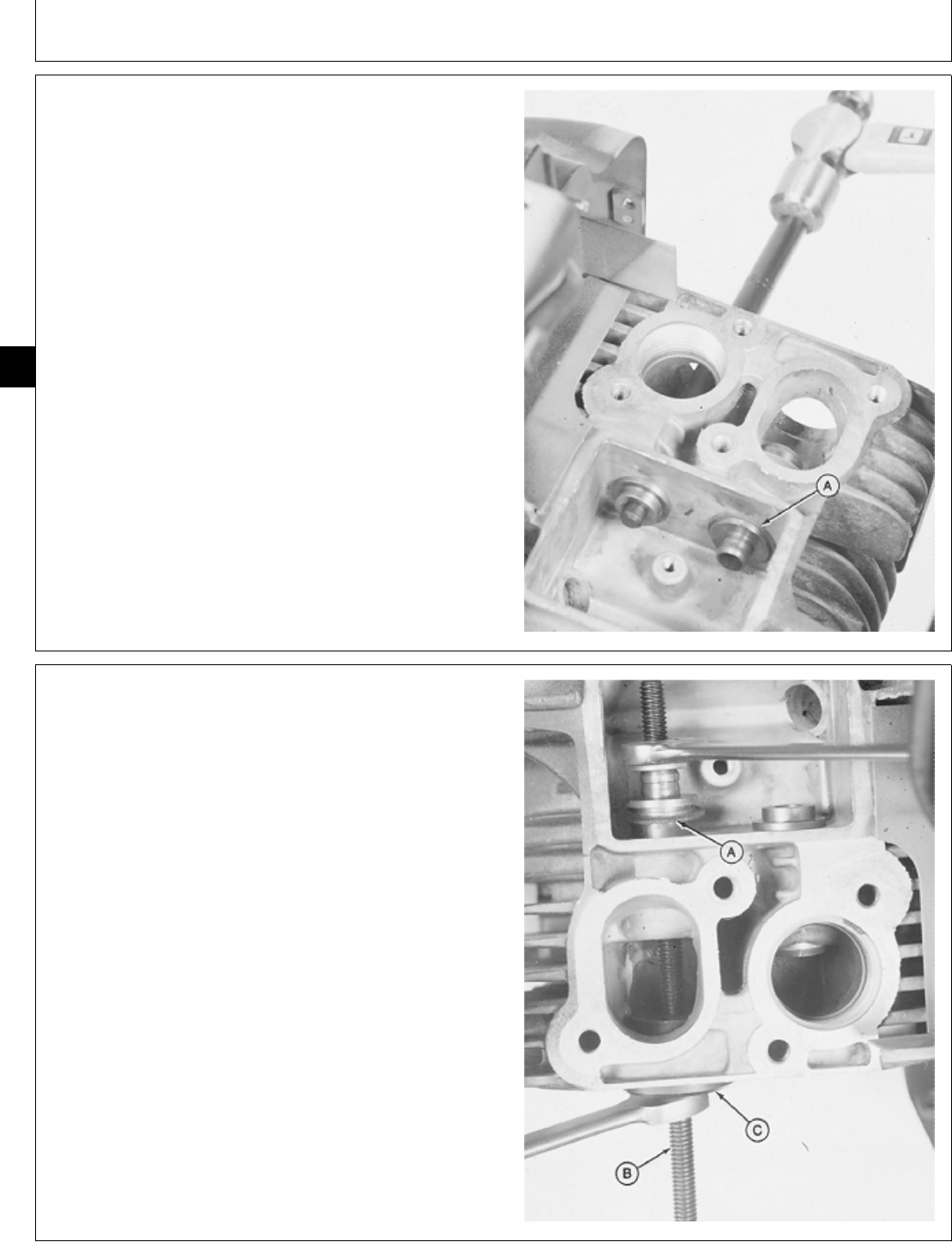
5. Remove three cap screws to remove manifold cover.
M37017 -UN-25JAN90
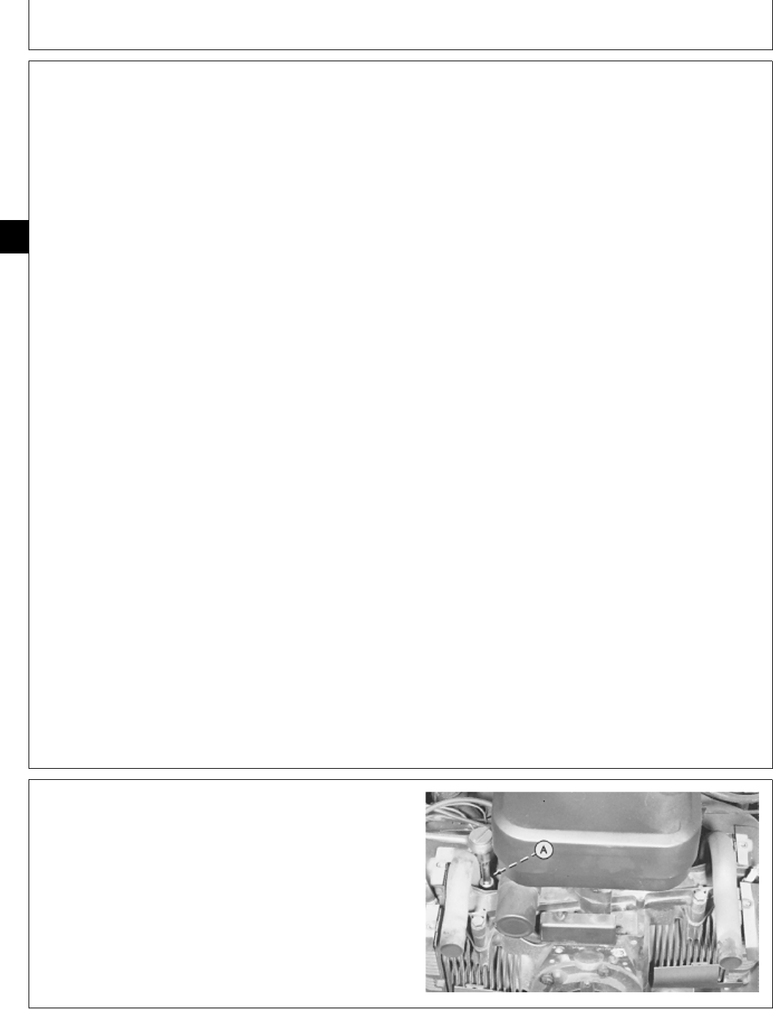
6. Remove cap screw (A).
IMPORTANT: Do not drop small parts into engine
opening when removing breather
assembly.
7. Remove breather assembly.
M37018 -UN-25JAN90
M98,2005K,15 -19-29JAN87
M98,2005K,16 -19-08OCT85
M98,2005K,17 -19-08OCT85
M98,2005K,18 -19-08OCT85
Air Cleaner and Breather/Breather, Repair
CTM2 (19APR90) 05-5 16, 18, 20 & 24HP Onan Engines
130495
05
5
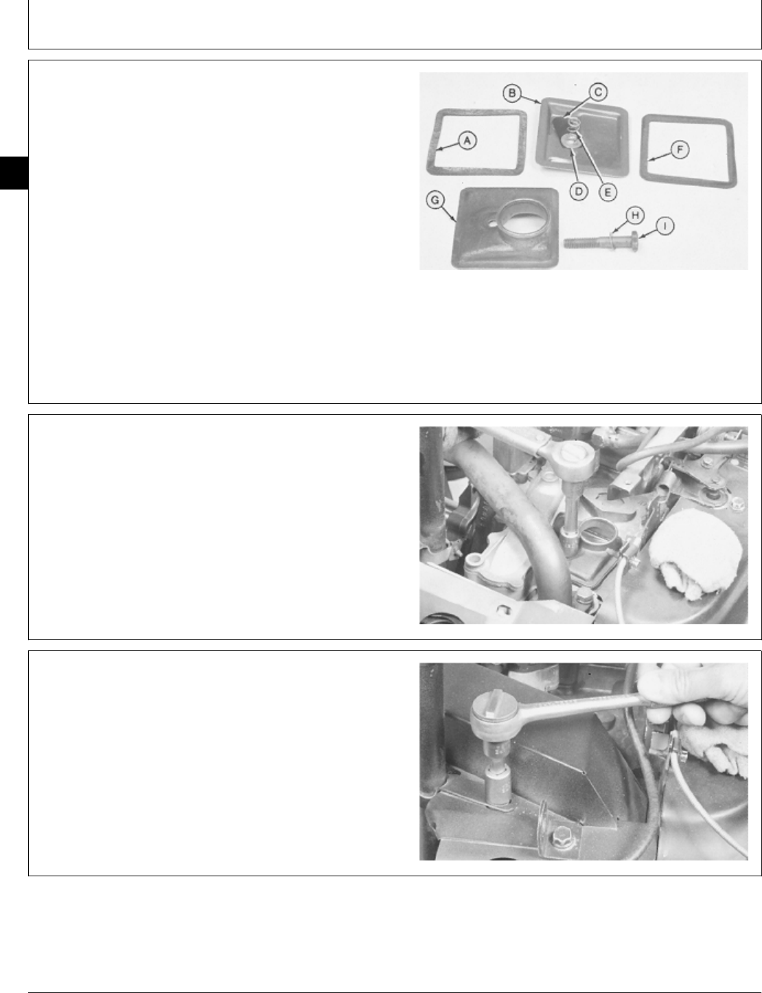
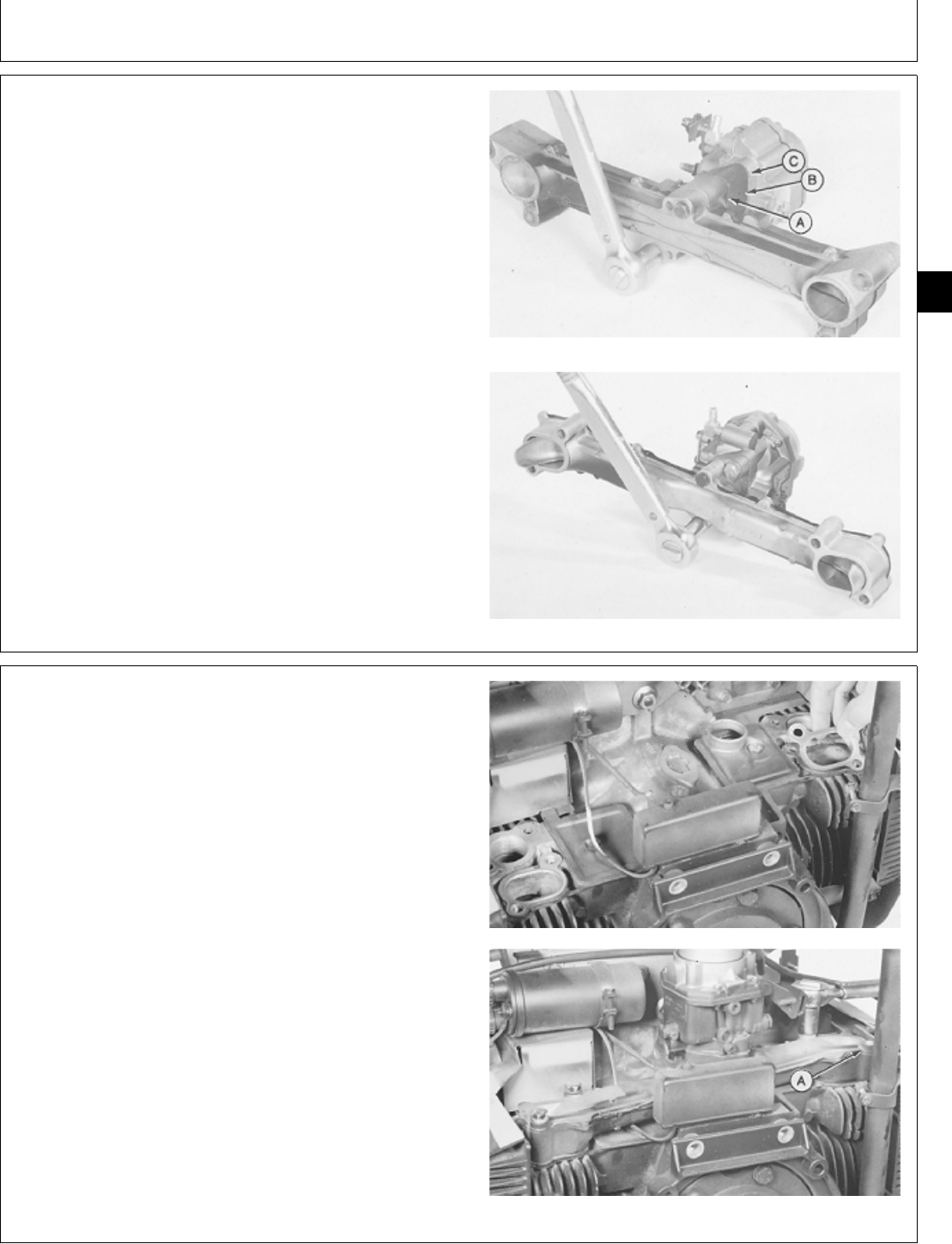
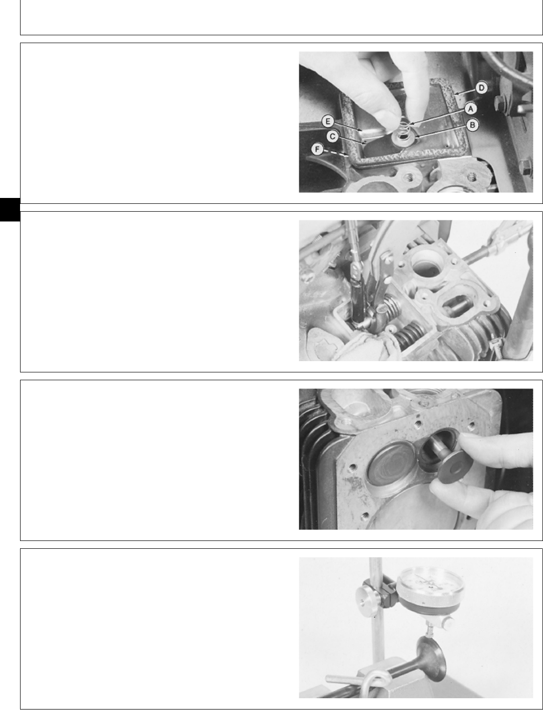
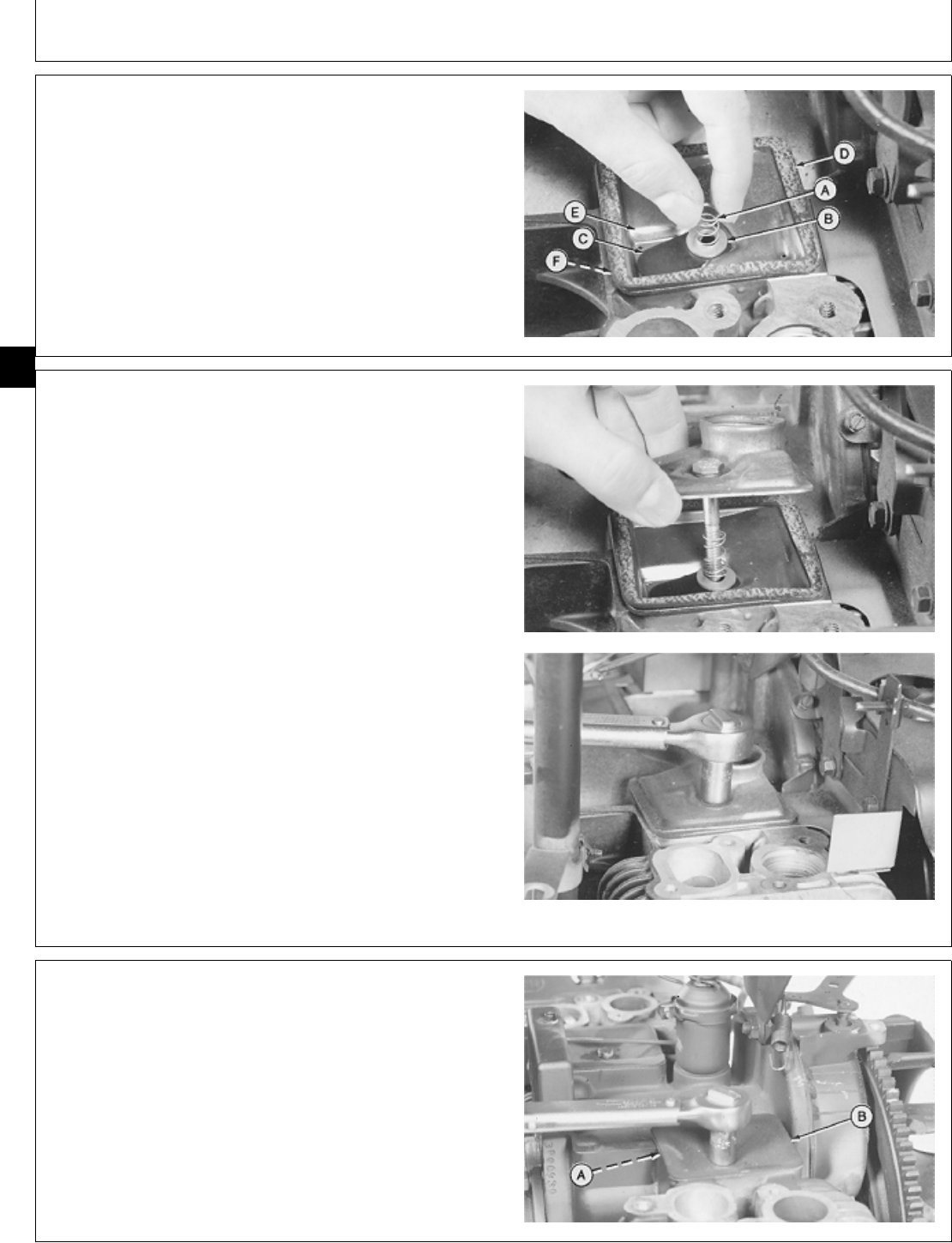
8. Clean parts with solvent. Inspect reed valve (C).
Replace it if cracked or bent. Replace gaskets if broken
or deteriorated.
NOTE: When installing the first gasket, be sure it aligns
with the flange on the deflector (B). Apply a small
amount of clean grease to the gaskets to hold
them in place during installation.
9. Install in order:
A—Gasket
B—Deflector
C—Reed Valve
D—Washer
E—Spring
F—Gasket
G—Valve Cover
H—Washer
I—Cap Screw
M37024 -UN-25JAN90
IMPORTANT: Be sure gaskets are in place before
tightening cap screw. Breather will not
function properly if air leaks are
present.
10. Tighten cap screw to 2 ± 1 N·m (18 ± 9 lb-in.).
M37025 -UN-25JAN90
11. Install manifold cover. Fasten with three cap screws.
M37017 -UN-25JAN90
M98,2005K,19 -19-08OCT85
M98,2005K,20 -19-11NOV85
M98,2005K,21 -19-11NOV85
Air Cleaner and Breather/Breather, Repair
CTM2 (19APR90) 05-6 16, 18, 20 & 24HP Onan Engines
130495
05
6
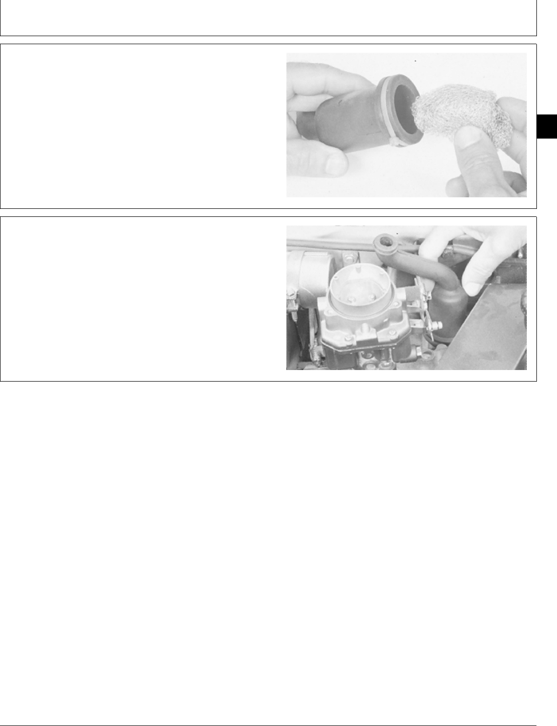
12. Install filter packing in breather tube.
M37001 -UN-25JAN90
13. Push breather tube securely onto valve cover.
M37000 -UN-25JAN90
M98,2005K,22 -19-11NOV85
M98,2005K,23 -19-11NOV85
Air Cleaner and Breather/Breather, Repair
CTM2 (19APR90) 05-7 16, 18, 20 & 24HP Onan Engines
130495
05
7

Air Cleaner and Breather/Breather, Repair
CTM2 (19APR90) 05-8 16, 18, 20 & 24HP Onan Engines
130495
05
8

SERVICE EQUIPMENT AND TOOLS
NOTE: Order tools from the U.S. SERVICE-GARD™ Catalog or from the European Microfiche Tool Catalog
(MTC). Some tools may be available from a local supplier.
Name Use
Feeler Gauge Measure cylinder head flatness
SERVICE PARTS KITS
The following kits are available through your parts
catalog:
Overhaul Gasket Kit
M98,2010K,1 -19-11NOV85
M98,2010K,2 -19-08OCT85
Group 10
Intake Manifold and Cylinder Heads
CTM2 (19APR90) 10-1 16, 18, 20 & 24HP Onan Engines
130495
10
1
SPECIFICATIONS
Item Measurement Specification
MUFFLER AND EXHAUST PIPES
Exhaust Pipe Cap Screw
P218G, P220G, B43E, B43G, B48G Torque 11 ± 3 N·m 97 ± 27 lb-in.)
Engines
T260 Engine Torque 29 ± 2 N·m (257 ± 18 lb-in.)
Lift Bracket Cap Screw Torque 11 ± 3 N·m (97 ± 27 lb-in.)
INTAKE MANIFOLD
Attaching Cap Screw
B43E, B43G, B48G Engines Torque 11 ± 3 N·m (97 ± 27 lb-in.)
T260 Engine Torque 29 ± 2 N·m (257 ± 18 lb-in.)
P218G, P220G Engines Torque 6 N·m (53 lb-in.)
CYLINDER HEAD
Cylinder Head Flatness 0.005—0.10 mm (0.002—0.004 in.)
Attaching Cap Screws or Nuts
P218G, P220G, B43E, B43G, B48G Torque-In Sequence 20 ± 1 N·m (180 ± 12 lb-in.)
Engines
T260 Engine:
(Top six nuts with washers) Torque-In Sequence 16 ± 1 N·m (142 ± 12 lb-in)
(Bottom four nuts) Torque-In Sequence 20 ± 1 N·m (180 ± 12 lb-in.)
Lift Bracket Cap Screw Torque 11 ± 3 N·m (97 ± 27 lb-in.)
REMOVE INTAKE MANIFOLD
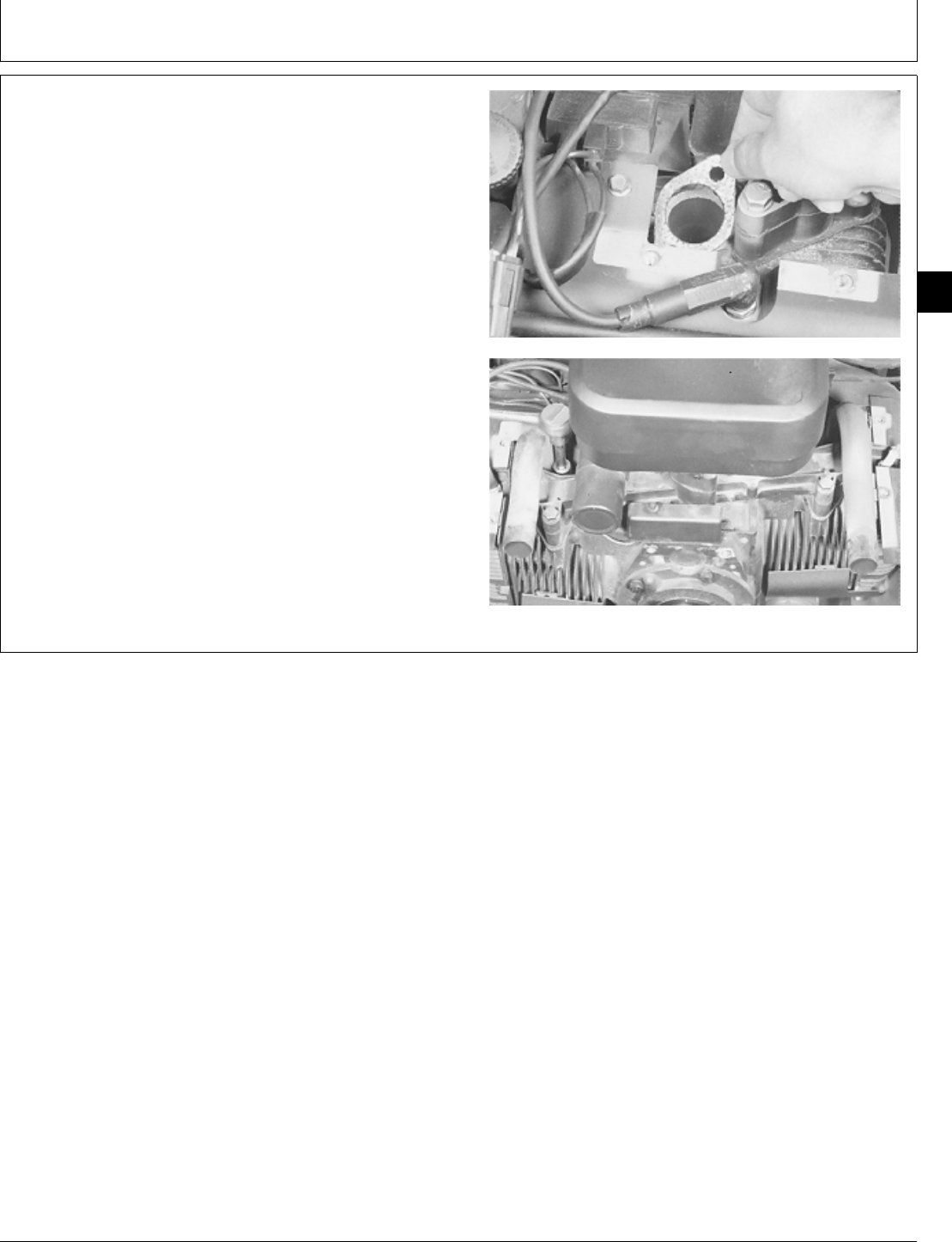
1. Remove muffler. (See machine technical manual.)
2. Remove four cap screws to remove exhaust pipes
and gasket (A). Inspect exhaust pipes for cracks or
damage. Replace as necessary.
3. Remove air cleaner base. (See Group 05 in this
manual.)
M36913 -UN-25JAN90
M98,2010K,3 -19-10FEB87
M98,2010K,4 -19-11NOV85
Intake Manifold and Cylinder Heads/Intake Manifold
CTM2 (19APR90) 10-2 16, 18, 20 & 24HP Onan Engines
130495
10
2
4. For T260 engines, remove two cap screws to remove
coil bracket.
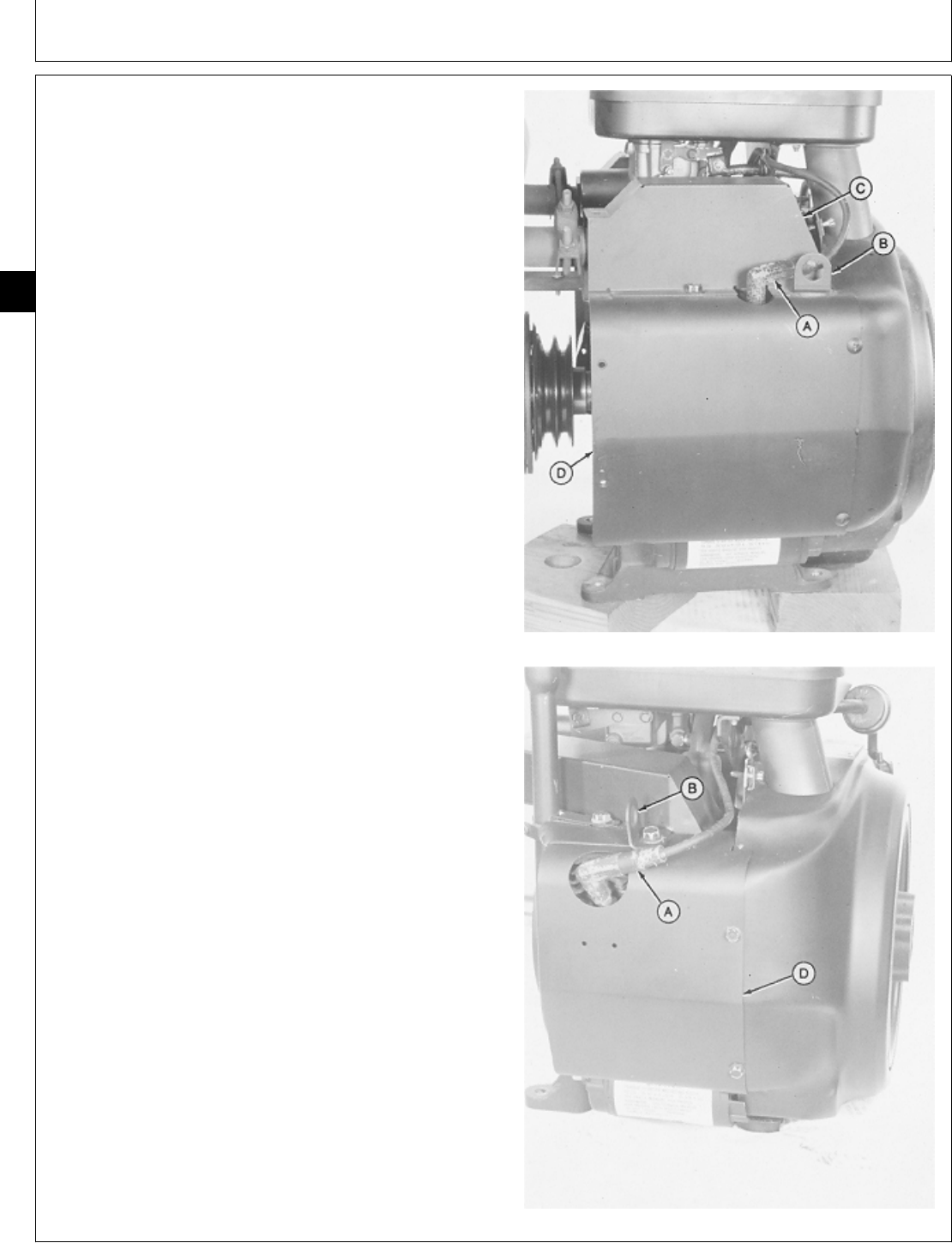
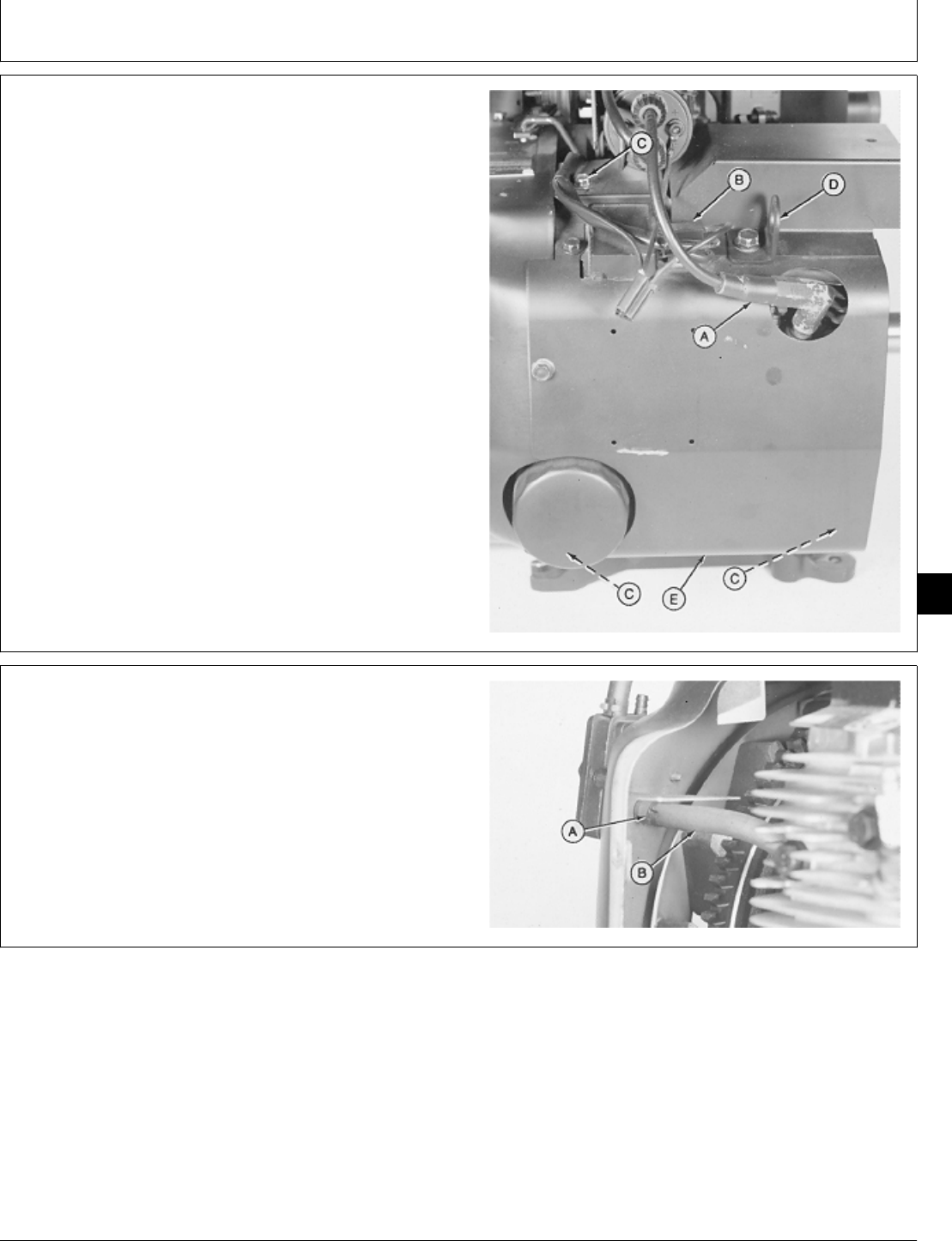
5. Remove clip (A) to disconnect throttle rod.
M36920 -UN-25JAN90
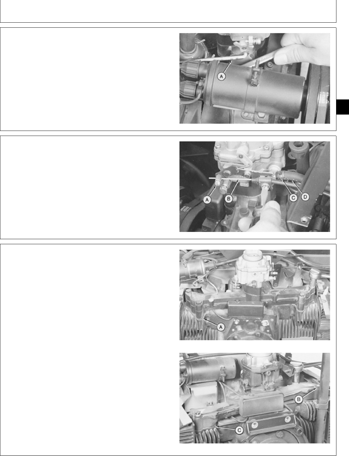
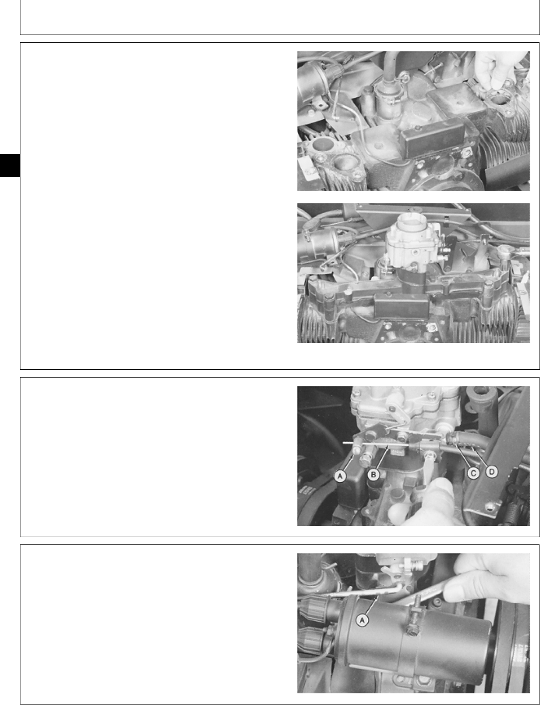
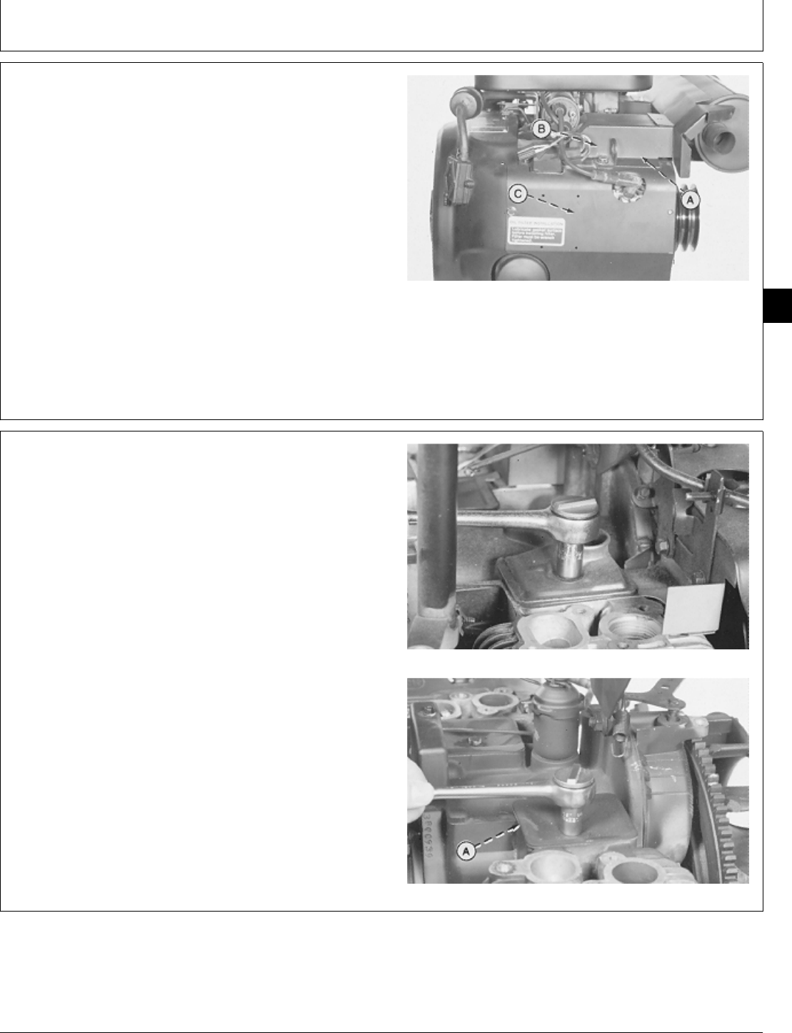
6. If engine is in machine, loosen clamp and screw (A)
to disconnect choke cable (B).
7. If engine is in machine, slide hose clamp (C) back to
disconnect fuel inlet line (D).
A—Screw
B—Choke Cable
C—Hose Clamp
D—Fuel Inlet Line
M36921 -UN-25JAN90
8. For T260 engine, remove four cap screws to remove
intake manifold, carburetor, and gaskets (A).
For B43E, B43G, or B48G engine, remove three cap
screws to remove spacer (B), intake manifold, carburetor,
and gaskets (C).
For P218G and P220G engine, remove four cap screws
to remove intake manifold, carburetor, and gaskets.
T260 Engine
B43E, B43G, B48G Engines
M36922 -UN-25JAN90M36251 -UN-22NOV89
M98,2010K,5 -19-11NOV85
M98,2010K,6 -19-10FEB87
M98,2010K,7 -19-10FEB87
Intake Manifold and Cylinder Heads/Intake Manifold
CTM2 (19APR90) 10-3 16, 18, 20 & 24HP Onan Engines
130495
10
3
9. For T260, P218G or P220G engine, remove two cap
screws to remove carburetor, gasket (A), spacer (B), and
gasket (C).
For B43E, B43G, or B48G engine, remove two cap
screws to remove carburetor and gasket (A).
10. Inspect intake manifold for cracks or holes. Replace
as necessary.
T260, P218G, P220G Engine
B43E, B43G, B48G Engines
M36923 -UN-25JAN90M36252 -UN-22NOV89
INSTALL INTAKE MANIFOLD
1. Install a new gasket on intake manifold.
M36253 -UN-22NOV89
M98,2010K,8 -19-10FEB87
M98,2010K,9 -19-08OCT85
Intake Manifold and Cylinder Heads/Intake Manifold
CTM2 (19APR90) 10-4 16, 18, 20 & 24HP Onan Engines
130495
10
4
2. For T260, P218G, or P220G engine, install gasket (A)
spacer (B), gasket (C), and carburetor on intake
manifold. Install and tighten two cap screws.
For B43E, B43G, or B48G engine, install carburetor on
intake manifold and fasten with cap screws.
T260, P218G, P220G Engine
B43E, B43G, B48G Engines
M36924 -UN-25JAN90M36254 -UN-22NOV89
NOTE: For T260 engine, go to step 5.
3. Install new gaskets with notch in gasket aligned with
notch on intake port.
4. For B43E, B43G, or B48G engine, install intake
manifold and tighten cap screws to 11 ± 3 N·m (97 ± 27
lb-in.). Install spacer (A).
For P218G or P220G engine, install intake manifold and
oil fill tube. Tighten cap screws to 6 N·m (53 lb-in.).
M36255 -UN-29JAN90M36256 -UN-29JAN90
M98,2010K,10 -19-30JAN87
M98,2010K,11 -19-30JAN87
Intake Manifold and Cylinder Heads/Intake Manifold
CTM2 (19APR90) 10-5 16, 18, 20 & 24HP Onan Engines
130495
10
5
5. Install new gaskets on intake ports.
6. Install intake manifold and tighten cap screws to 29 ±
2 N·m (257 ± 18 lb-in.).
T260 engine
M36925 -UN-25JAN90M36926 -UN-25JAN90
7. If engine is in machine, connect fuel inlet line (D) and
fasten with hose clamp (C).
8. If engine is in machine, connect choke cable (B) to
choke linkage. Push choke knob down. Hold choke
linkage upward (choke plate open). Tighten screw (A)
and clamp.
A—Screw
B—Choke Cable
C—Hose Clamp
D—Fuel Inlet Line
M36921 -UN-25JAN90
9. Connect throttle rod and fasten with clip (A).
10. For T260 engine, install coil bracket on intake
manifold. Install and tighten two cap screws.
M36920 -UN-25JAN90
M98,2010K,12 -19-11NOV85
M98,2010K,13 -19-08OCT85
M98,2010K,14 -19-30JAN87
Intake Manifold and Cylinder Heads/Intake Manifold
CTM2 (19APR90) 10-6 16, 18, 20 & 24HP Onan Engines
130495
10
6
11. Install new exhaust pipe gaskets.
12. Install exhaust pipes and fasten with four cap
screws.
EXHAUST PIPE TORQUE SPECIFICATIONS
Engine Measurement Specifications
T260 Cap Screw Torque 29 ± 2 N·m
(257 ± 18 lb-in.)
B43E, B43G, B48G, Cap Screw Torque 11 ± 3 N·m
P218G or P220G (97 ± 27 lb-in.)
13. Install manifold covers and fasten with cap screws.
14. Install air cleaner assembly. (See Group 05 in this
manual.)
M36914 -UN-25JAN90M36915 -UN-25JAN90
M98,2010K,15 -19-10FEB87
Intake Manifold and Cylinder Heads/Intake Manifold
CTM2 (19APR90) 10-7 16, 18, 20 & 24HP Onan Engines
130495
10
7
REMOVE CYLINDER HEAD
1. Park tractor safely.
2. Remove engine. (See machine technical manual.)
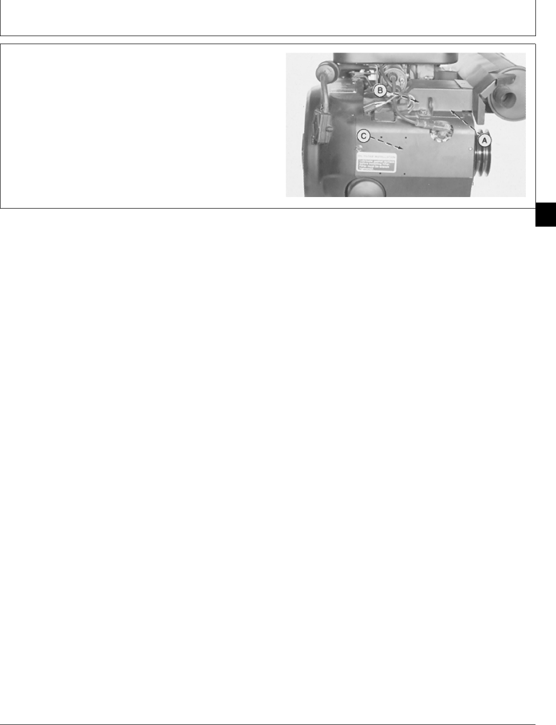
3. Disconnect spark plug wire (A).
4. For T260 engine, remove six cap screws to remove
lift bracket (B), exhaust pipe shroud (C), and right side
shroud (D).
For B43E, B43G, or B48G engine, remove four cap
screws to remove lift bracket (B) and right side shroud
(D).
For P218G or P220G engines, remove air cleaner
assembly (See Group 05 in this manual.) Remove four
cap screws to remove lift bracket and right side shroud.
A—Spark Plug Wire
B—Lift Bracket
C—Exhaust Pipe Shroud
D—Right Side Shroud
T260 Engine
B43E, B43G, B48G Engines
M36927 -UN-25JAN90M36928 -UN-25JAN90
M98,2010K,17 -19-30JAN87
Intake Manifold and Cylinder Heads/Cylinder Head
CTM2 (19APR90) 10-8 16, 18, 20 & 24HP Onan Engines
130495
10
8
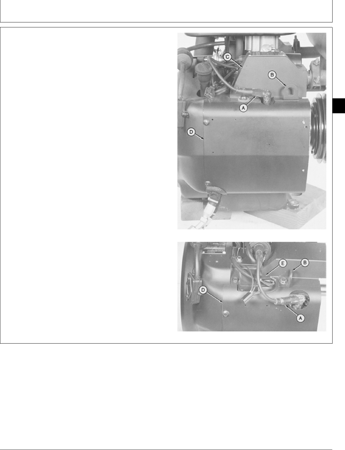
5. Disconnect spark plug wire (A).
6. For T260 engine, remove seven cap screws to
remove lift bracket (B), exhaust pipe shroud (C), and left
side shroud (D).
For B43E, B43G, OR B48G engine, disconnect voltage
regulator leads (E). Remove five cap screws to remove
lift bracket (B) and left side shroud (D).
For P218G or P220G engines, disconnect voltage
regulator leads. Remove four cap screws to remove lift
bracket and left side shroud.
A—Spark Plug Wire
B—Lift Bracket
C—Exhaust Pipe Shroud
D—Left Side Shroud
E—Voltage Regulator Leads
T260 Engine
B43E, B43G, B48G Engines
M36929 -UN-25JAN90M36930 -UN-25JAN90
M98,2010K,18 -19-10FEB87
Intake Manifold and Cylinder Heads/Cylinder Head
CTM2 (19APR90) 10-9 16, 18, 20 & 24HP Onan Engines
130495
10
9
IMPORTANT: Do not remove cylinder heads while
they are hot. Cylinder head may warp.
A hot gasket will be soft and difficult to
remove.
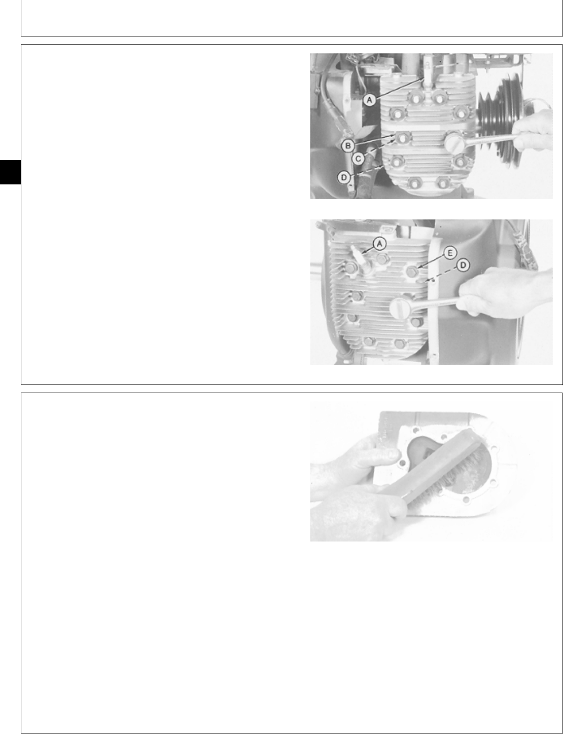
7. Remove spark plug (A).
8. For T260 engine, remove 10 nuts, 20 compression
washers (B), and 10 washers (C) to remove cylinder
head and gasket (D).
For P21G, P220G, B43E, B43G, OR B48G engine,
remove nine cap screws and washers (E) to remove T260 Engine
cylinder head and gasket (D).
A—Spark Plug
B—Compression Washer
(20 Used)
C—Washer (10 Used)
D—Gasket
E—Washer (9 Used)
P218G, P220G, B43E, B43G,B48G
M36931 -UN-25JAN90M36932 -UN-25JAN90
IMPORTANT: Do not damage gasket sealing surface
while cleaning carbon deposits.
9. Carefully clean carbon deposits from combustion
chamber and gasket surface on heads and cylinder block
with a scraper and wire brush.
10. Inspect head for cracks or broken cooling fins. Check
gasket sealing surface for burrs or nicks. Replace head if
damaged.
11. Measure cylinder head flatness in several locations.
CYLINDER HEAD SPECIFICATIONS
Item New Part Wear Tolerance
Flat Within 0.05 mm (0.002 in.) 0.10 mm (0.004 in.)
Replace head if cylinder head is warped more than 0.10
mm (0.004 in.).
M30948 -UN-14JUL89
M98,2010K,19 -19-10FEB87
M98,2010K,20 -19-08OCT85
Intake Manifold and Cylinder Heads/Cylinder Head
CTM2 (19APR90) 10-10 16, 18, 20 & 24HP Onan Engines
130495
10
10
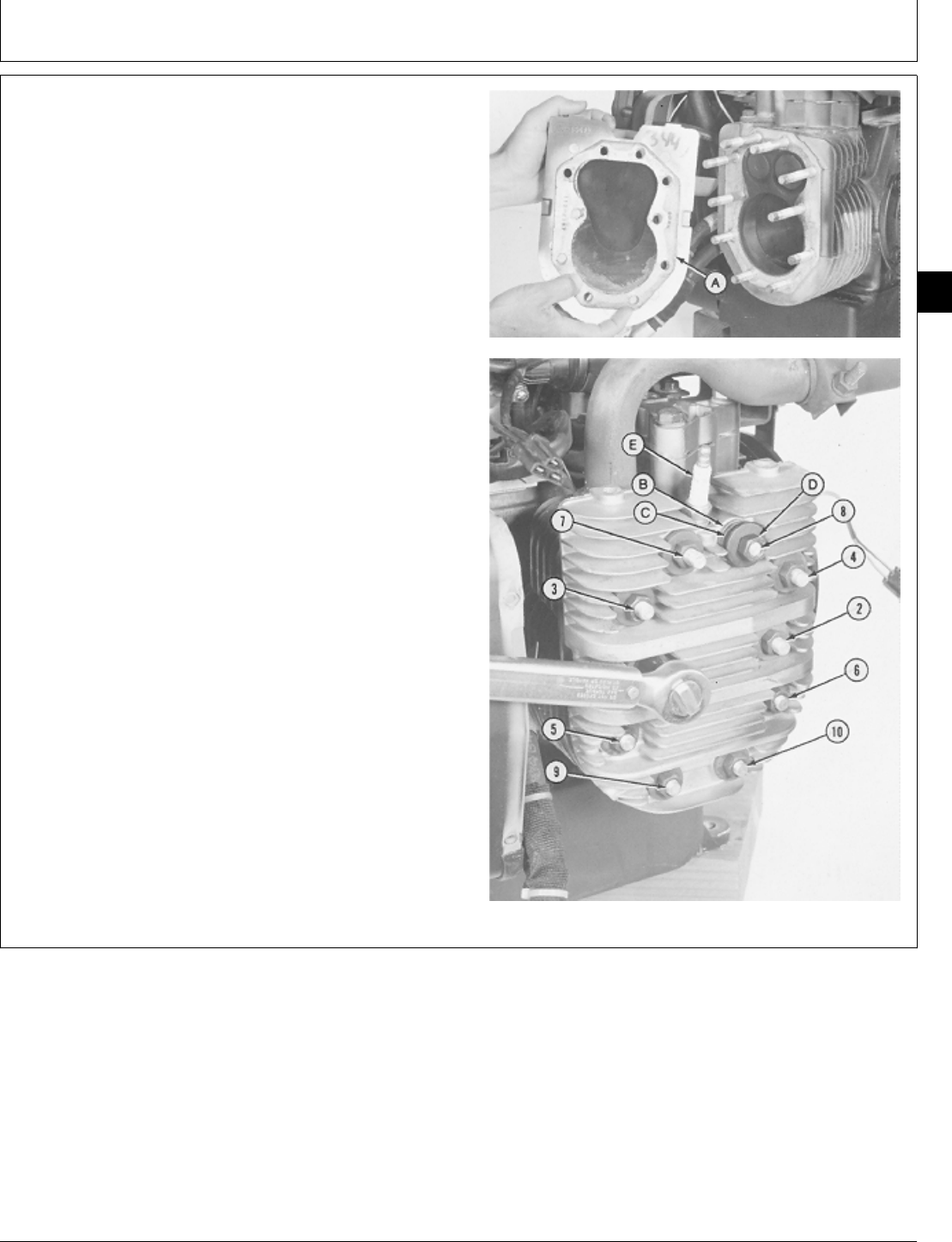
INSTALL CYLINDER HEAD
NOTE: To install cylinder head on P218G, P220G, B43E,
B43G, OR B48G engine, go to step 4.
1. For T260 engine, install a new gasket (A) on cylinder
head.
2. Install cylinder head on cylinder block. Install flat
washer (B), two compression washers (C) with outside
edges contacting each other, and nut (D) on each of the
top six longer studs. Install flat washer and nut on each
of the bottom four shorter studs. Tighten nuts in several
steps in the sequence shown.
NUT TORQUE SPECIFICATIONS
Top six nuts . . . . . . . . . . . . . . . . . . . . 16 ± 1 N·m (142 ± 12 lb-in.)
(with compression washers)
Bottom four nuts . . . . . . . . . . . . . . . . . 20 ± 1 N·m (180 ± 12 lb-in.)
3. Install spark plug (E).
A—Gasket
B—Washer (10 Used)
C—Compression Washer (20 Used)
D—Nut (10 Used)
E—Spark Plug
M36933 -UN-25JAN90M36934 -UN-25JAN90
M98,2010K,21 -19-30JAN87
Intake Manifold and Cylinder Heads/Cylinder Head
CTM2 (19APR90) 10-11 16, 18, 20 & 24HP Onan Engines
130495
10
11
4. For P218G, P220G, B43E, B43G, or B48G engine,
install a new gasket (A) on cylinder head.
5. Install cylinder head on cylinder block with the five
longest cap screws in the top holes of cylinder head.
Tighten cap screws in several steps in the sequence
shown.
CAP SCREW TORQUE SPECIFICATION
Attaching Cap Screws . . . . . . . . . . . . . 20 ± 1 N·m (180 ± 12 lb-in.)
6. Install spark plug (B).
M36935 -UN-25JAN90M36936 -UN-25JAN90
M98,2010K,22 -19-30JAN87
Intake Manifold and Cylinder Heads/Cylinder Head
CTM2 (19APR90) 10-12 16, 18, 20 & 24HP Onan Engines
130495
10
12

7. For T260 engine, install left side shroud (D), exhaust
pipe shroud (C), lift bracket (B) and fasten with seven
cap screws. Tighten lift bracket cap screw to 11 ± 3 N·m
(97 ± 27 lb-in.).
For P218G or P220G engines, install left side shroud, lift
side shroud, lift bracket, and fasten with four cap screws.
Tighten lift bracket cap screw to 11 ± 3 N·m (97 ± 27
lb-in.). Connect voltage regulator leads.
For B43E, B43G, OR B48G engine, install left side
shroud (D), lift bracket (B), and fasten with five cap
screws. Tighten lift bracket cap screw to 11 ± 3 N·m (97
± 27 lb-in.).
Connect voltage regulator leads (E). Install the two stator
leads on “AC” terminals and the battery lead on “B+”
terminal of the voltage regulator.
8. Connect spark plug wire (A).
A—Spark Plug Wire
B—Lift Bracket
C—Exhaust Pipe Shroud
D—Left Side Shroud
E—Voltage Regulator Leads
T260 Engine
B43E, B43G, B48G Engines
M36929 -UN-25JAN90M36930 -UN-25JAN90
M98,2010K,23 -19-10FEB87
Intake Manifold and Cylinder Heads/Cylinder Head
CTM2 (19APR90) 10-13 16, 18, 20 & 24HP Onan Engines
130495
10
13

9. For T260 engine, install right side shroud (D), exhaust
pipe shroud (C), lift bracket (B), and fasten with six cap
screws. Tighten lift bracket cap screw to 11 ± 3 N·m (97
± 27 lb-in.).
For B43E, B43G, OR B48G engine, install right side
shroud (D), lift bracket (B), and fasten with four cap
screws. Tighten lift bracket cap screw to 11 ± 3 N·m (97
± 27 lb-in.).
For P218G or P220G engines, install right side shroud,
lift bracket, and fasten with four cap screws. Tighten lift
bracket cap screw to 11 ± 3 N·m (97 ± 27 lb-in.).
10. Connect spark plug wire (A).
11. Install engine. (See machine technical manual.)
A—Spark Plug Wire
B—Lift Bracket
C—Exhaust Pipe Shroud
D—Right Side Shroud
T260 Engine
B43E, B43G, B48G Engines
M36927 -UN-25JAN90M36928 -UN-25JAN90
M98,2010K,24 -19-10FEB87
Intake Manifold and Cylinder Heads/Cylinder Head
CTM2 (19APR90) 10-14 16, 18, 20 & 24HP Onan Engines
130495
10
14

ESSENTIAL TOOLS
NOTE: Order tools from the U.S. SERVICE-GARD™ Catalog or from the European Microfiche Tool Catalog
(MTC). Some tools may be available from a local supplier.
Number Name Use
JDG 323 Valve Guide Driver Remove valve guides
JDE 118 Valve Guide Driver Remove valve guides
JDG 569 Valve Guide Installer Install valve guides
JDG 507 Valve Seat Cutter Cut seats to 45˚
SERVICE EQUIPMENT AND TOOLS
NOTE: Order tools from the U.S. SERVICE-GARD™ Catalog or from the European Microfiche Tool Catalog
(MTC). Some tools may be available from a local supplier.
Name Use
Feeler Gauge Measure valve clearance
Valve Spring Compressor Remove and install valves
Valve Inspection Center Measure valve out-of-round
Outside Micrometer Measure valves and tappets
Spring Compression Tester Check valve springs
Valve Guide Brush Clean valve guides
Telescoping Gauge Measure tappet and valve guide bores
Valve Seat Cutter Recondition valve seats
Vernier Calipers Measure valve seat width
Blind Hole Puller Set Remove valve seats
Bushing, Bearing, and Seal Driver Set Install valve seats
M98,2015K,1 -19-10FEB87
M98,2015K,2 -19-11NOV85
Group 15
Intake and Exhaust Valves
CTM2 (19APR90) 15-1 16, 18, 20 & 24HP Onan Engines
130495
15
1

SERVICE PARTS KITS
The following kits are available through your parts
catalog:
Valve Gasket Kit
Tappet Kit
Overhaul Gasket Kit
M98,2015K,3 -19-08OCT85
Intake and Exhaust Valves/Service Parts Kits
CTM2 (19APR90) 15-2 16, 18, 20 & 24HP Onan Engines
130495
15
2

SPECIFICATIONS
Intake and Exhaust Valves (B43E, B43G, B48G, AND
T260 Engines)
Item New Specification Wear Tolerance
1. Exhaust Valve Stem O.D. 8.66—8.67 mm 8.64 mm (0.340 in.)
(0.341—0.3414 in.)
2. Intake Valve Stem O.D. 8.70—8.71 mm 8.66 mm (0.341 in.)
(0.3425—0.3429 in.)
3. Valve Face Angle 44˚
4. Valve Face Margin 0.787 mm (0.031 in.)
5. Valve Spring
Free length (approx.) 42.21 mm (1.662 in.)
Test length 34.92 mm (1.375 in.) at
169—187 N (38—42 lb force)
6. Valve Cover Cap Screw Torque 2.1 ± 0.7 N·m (18 ± 6 lb-in.)
Intake and Exhaust Valves (P218G and P220G Engines)
Item New Specification Wear Tolerance
1. Exhaust Valve Stem O.D. 7.061—7.074 mm 7.05 mm (0.2775 in.)
(0.2780—0.2785 in.)
2. Intake Valve Stem O.D. 7.099—7.112 mm 7.07 mm (0.2783 in.).
(0.2795—0.2800 in.)
3. Valve Face Angle 44˚
4. Valve Face Margin 0.787 mm (0.031 in.)
5. Valve Spring
Free length (approx.) 40.64 mm (1.60 in.)
Test length 26.67 mm (1.05 in.) at 245N
(55 lb force)
6. Valve Cover Cap Screw Torque 2.1 ± 0.7 N·m (18 ± 6 lb-in.)
M98,2015K,4 -19-10FEB87
Intake and Exhaust Valves/Specifications
CTM2 (19APR90) 15-3 16, 18, 20 & 24HP Onan Engines
130495
15
3

TAPPETS
Item New Specification Wear Tolerance
Tapped O.D. 18.99—19 mm 18.90 mm (0.744 in.) 2. Tappet Bore
(0.747—0.748 in.)
2. Tappet Bore I.D. 19.06—19.09 mm (0.750—0.751 in.) 19.15 mm (0.754 in.)
3. Tappet-To-Bore Clearance 0.04—0.08 mm (0.0015—0.003 in.) 0.15 mm (0.006 in.)
Valve Seats
Item New Specification Wear Tolerance
1. Valve Seat Angle 45˚
2. Valve Seat Width 0.8—1.2 mm (0.031—0.047 in.)
Valve Guides
Item New Specification Wear Tolerance
Valve Guide I.D. (B43E, 8.74—8.79 mm 8.84 mm (0.348 in.)
B43G, B48G, T260 Engines) (0.344—0.346 in.)
Valve Guide I.D. (P218G, 7.14—7.16 mm 7.19 mm (0.283 in.)
and P220G Engines) (0.281—0.282 in.)
2. Intake Valve Stem Clearance 0.03—0.06 mm 0.13 mm (0.005 in.)
(0.001—0.002 in.)
3. Exhaust Valve Stem Clearance 0.06—0.10 mm 0.15 mm (0.006 in.)
(0.002—0.004 in.)
Valve Clearance
Item New Specification Wear Tolerance
1. Intake Valve 0.13 mm (0.005 in.)
2. Exhaust Valve 0.33 mm (0.013 in.)
M98,2015K,5 -19-10FEB87
Intake and Exhaust Valves/Specifications
CTM2 (19APR90) 15-4 16, 18, 20 & 24HP Onan Engines
130495
15
4
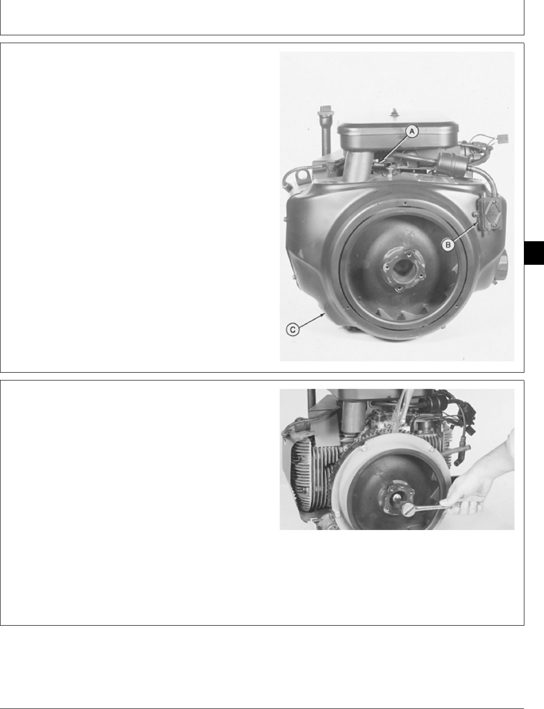
REMOVE INTAKE AND EXHAUST VALVES
1. Remove engine if these components cannot be
removed with engine in unit. (See machine technical
manual.)
2. Remove exhaust pipes with muffler (A).
3. Remove intake manifold (B). (See Remove Intake
Manifold, Group 10 in this manual.)
4. Remove cylinder head (C). (See Remove Cylinder
Head, Group 10 in this manual.)
M36473 -UN-29JAN90
NOTE: Be careful not to lose breather assembly when
removing cover.
5. For P218G, P220G, B43E, B43G, OR B48G engines,
carefully remove cap screw to remove breather manifold
cover.
For T260 engine, remove cap screw to remove valve
cover and gasket (A).
B43E, B43G, B48G Engines
T260 Engine
M36262 -UN-29JAN90M36263 -UN-29JAN90
M98,2015K,6 -19-08OCT85
M98,2015K,7 -19-17FEB87
Intake and Exhaust Valves/Intake and Exhaust Valves
CTM2 (19APR90) 15-5 16, 18, 20 & 24HP Onan Engines
130495
15
5
6. Remove parts (A—F) if equipped and inspect for wear
or damage.
A—Spring
B—Washer
C—Valve
D—Gasket
E—Breather Base
F—Gasket
M36264 -UN-29JAN90
7. Close oil drain hole with a shop towel to prevent
retainers from falling into gear case.
IMPORTANT: Identify valve assembly during removal
so they can be installed in original
ports.
8. Compress valve springs using a valve spring
compressor to remove retainers. Release spring pressure
and remove compressor.
M36265 -UN-29JAN90
9. Remove exhaust and intake valves.
M36266 -UN-29JAN90
10. Clean carbon from valve face, head, and stem using
a wire brush.
11. Remove scratches from valve stems using steel wool
or crocus cloth.
12. Inspect valve for damage, corrosion, pitting, or
burned face.
13. Check valve for out-of-round, bent or warped
condition using a valve inspection center.
M35307 -UN-29AUG88
M98,2015K,8 -19-08OCT85
M98,2015K,9 -19-11NOV85
M98,2015K,10 -19-08OCT85
M98,2015K,11 -19-08OCT85
Intake and Exhaust Valves/Intake and Exhaust Valves
CTM2 (19APR90) 15-6 16, 18, 20 & 24HP Onan Engines
130495
15
6
14. Measure valve stem outside diameter.
B43E, B43G, B48G, AND T260
VALVE STEM SPECIFICATION
Item New Parts Wear Tolerance
Exhaust Valve 8.66—8.67 mm 8.64 mm
(0.341—0.3414 in.) (0.340 in.)
Intake Valve 8.70—8.71 mm 8.66 mm
(0.3425—0.3429 in.) (0.341 in.)
P21G AND P220G
VALVE STEM SPECIFICATIONS
Item New Parts Wear Tolerance
Exhaust Valve 7.061—7.074 mm 7.05 mm
(0.2780—0.2785 in.) (0.2775 in.)
Intake Valve 7.099—7.112 mm 7.07 mm
(0.2795—0.2800 in.) (0.2783 in.)
15. If diameter is less than wear tolerance specification,
replace valve.
M35308 -UN-29AUG88
IMPORTANT: Do not lap valves. The sharp seating
surface between the valve and seat will
be removed resulting in shorter valve
life.
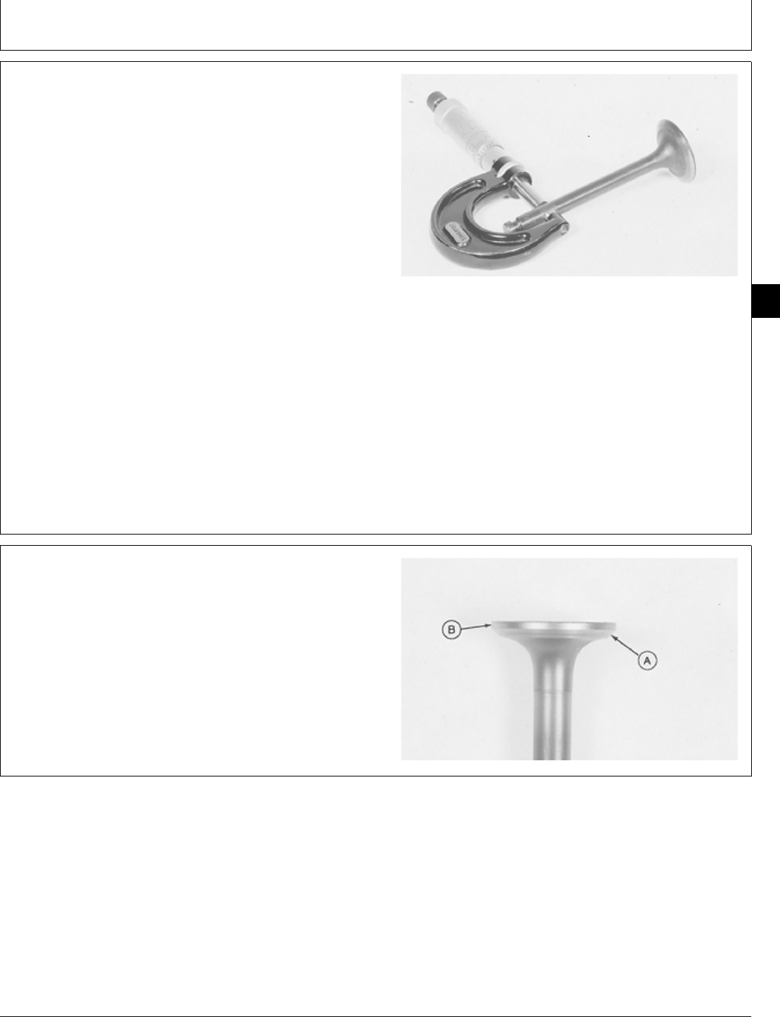
16. If valve faces are worn, burned or pitted, grind
valves to a 44 degree face angle (A) following
manufacturers instructions. If valve face margin (B) is
less than 0.787 mm (0.031 in.) after grinding, replace
valve.
M36267 -UN-29AUG88
M98,2015K,12 -19-10FEB87
M98,2015K,13 -19-08OCT85
Intake and Exhaust Valves/Intake and Exhaust Valves
CTM2 (19APR90) 15-7 16, 18, 20 & 24HP Onan Engines
130495
15
7
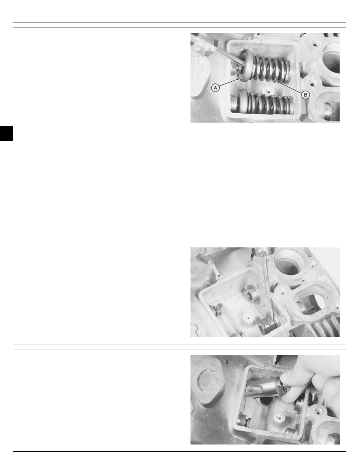
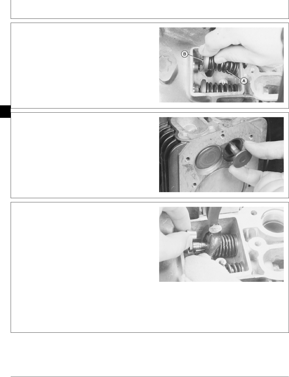
17. Remove rotators (A) and springs (B) using a
screwdriver. Rotator must turn freely.
18. Check spring using a spring compression tester.
B43E, B43G, B48G AND T260
SPRING SPECIFICATIONS
Free length (approximate) . . . . . . . . . . . . . . . . 42.21 mm (1.662 in.)
Test length at 169—187 N . . . . . . . . . . . . . . . . . . . . . . . 34.92 mm
(38—42 lb force . . . . . . . . . . . . . . . . . . . 1.375 in.)
P218G AND P220G
SPRING SPECIFICATIONS
Free Length (approximate) . . . . . . . . . . . . . . . . 40.64 mm (1.60 in.)
Test length at 245N . . . . . . . . . . . . . . . . . . . . . . . . . . . . 26.67 mm
(55 lb force . . . . . . . . . . . . . . . . . . . . . . . 1.05 in.)
M36268 -UN-29JAN90
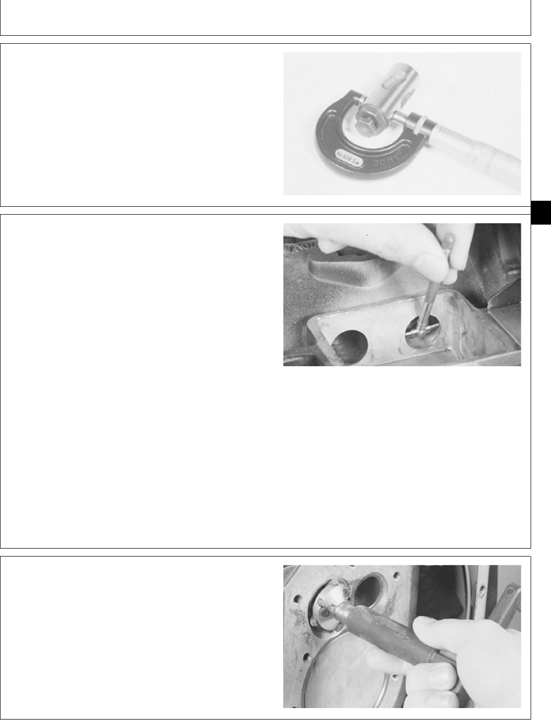
IMPORTANT: Never reuse intake valve seal. The seal
must be replaced each time the valve is
removed.
19. Remove intake valve seal if equipped.
M36269 -UN-29JAN90
20. Remove tappets. Inspect tappets for wear or
damage.
M36270 -UN-29JAN90
M98,2015K,14 -19-10FEB87
M98,2015K,15 -19-08OCT85
M98,2015K,16 -19-08OCT85
Intake and Exhaust Valves/Intake and Exhaust Valves
CTM2 (19APR90) 15-8 16, 18, 20 & 24HP Onan Engines
130495
15
8
21. Measure tappet outside diameter.
TAPPET SPECIFICATIONS
Item New Parts Wear Tolerance
Tappet Diameter 18.99—19 mm 18.90 mm
(0.747—0.748 in.) (0.744 in.)
If tappet diameter is less than 18.90 mm (0.744 in.),
replace tappet.
M36272 -UN-29JAN90
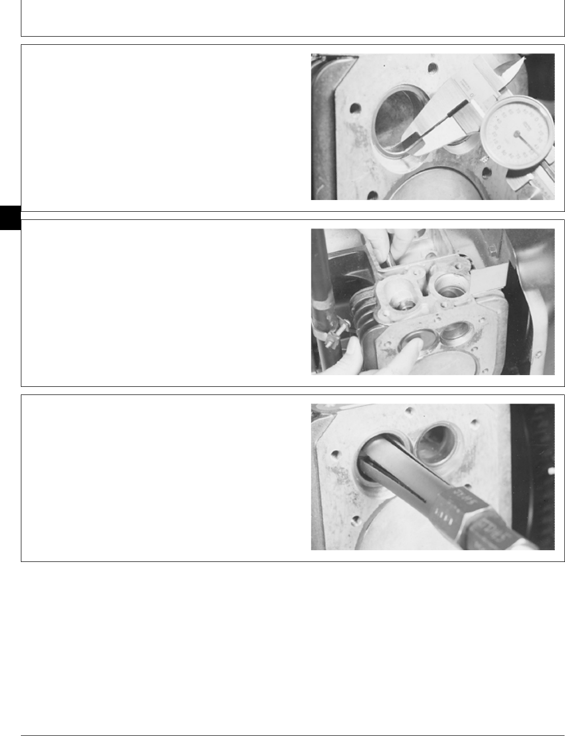
22. Measure tappet bore inside diameter and determine
tappet clearance (tappet bore I.D. minus tappet O.D.).
TAPPET BORE SPECIFICATIONS
Item New Parts Wear Tolerance
Tappet Bore
Diameter 19.06—19.09 mm 19.15 mm
(0.750—0.751 in.) (0.754 in.)
Tappet Clearance 0.04—0.08 mm 0.15 mm
(0.0015—0.003 in.) (0.006 in.)
If tappet bore diameter exceeds 19.15 mm (0.754 in.),
install over-sized tappet or replace cylinder block.
If tappet clearance exceeds 0.15 mm (0.006 in.), install
over-sized tappet, replace tappet or replace cylinder
block.
NOTE: The over-sized tappets available are 0.05 mm
(0.002 in.) and 0.13 mm (0.005 in.).
M36273 -UN-29JAN90
23. Clean valve seats using a wire brush.
24. Inspect valve seats for damage, corrosion, pitting or
warped condition.
25. If necessary, cut seats to a 45 degree seat angle
using a seat cutter such as JDG507.
M36274 -UN-29JAN90
M98,2015K,17 -19-08OCT85
M98,2015K,18 -19-08OCT85
M98,2015K,19 -19-08OCT85
Intake and Exhaust Valves/Intake and Exhaust Valves
CTM2 (19APR90) 15-9 16, 18, 20 & 24HP Onan Engines
130495
15
9
26. Measure valve seat width after cutting. Valve seat
width must be 0.8—1.2 mm (0.031—0.047 in.).
27. If seat is too wide after cutting, use a 30 degree
valve seat cutter to narrow seat to specifications.
IMPORTANT: Do not lap valve seat. Doing so will
result in shorter valve life.
28. Clean the valve seats, valve guides, and valves with
solvent or a vacuum.
M36275 -UN-29JAN90
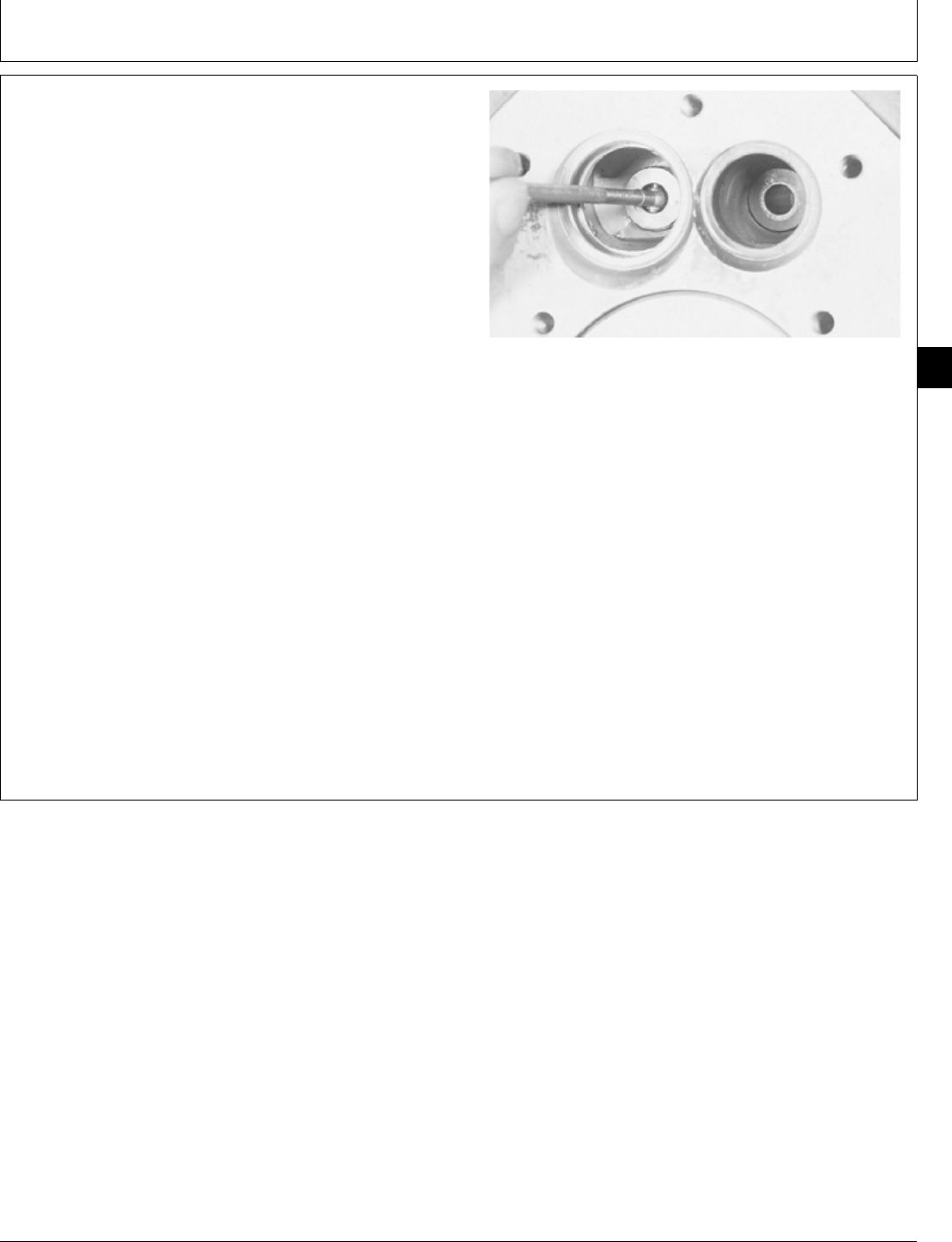
29. After valve grinding or seat cutting, check valves for
a tight and uniform seat.
Apply dye to valve face. Install and hold valve against
seat and turn slightly.
Remove valve and look for a fine clean line on valve
face. The line must be at the center of valve face and
have no open spots. If necessary, cut valve seat again
or replace valve seat.
M36276 -UN-29JAN90
30. Remove valve seats using a blind-hole puller.
M36952 -UN-25JAN90
M98,2015K,20 -19-08OCT85
M98,2015K,21 -19-08OCT85
M98,2015K,22 -19-08OCT85
Intake and Exhaust Valves/Intake and Exhaust Valves
CTM2 (19APR90) 15-10 16, 18, 20 & 24HP Onan Engines
130495
15
10
31. Clean valve guides using a valve guide brush.
32. Measure valve guide inside diameter and determine
valve stem clearance (valve guide I.D. minus valve stem
O.D.).
VALVE GUIDE SPECIFICATIONS
Item New Part Wear Tolerance
Valve Guide 8.74—8.79 mm 8.84 mm
Diameter (B43E, (0.344—0.346 in.) (0.348 in.)
B43G,B48G,T260
Valve Guide 7.14—7.16 mm 7.19 mm
Diameter P218G (0.281—0.282 in.) (0.283 in.)
and P220G)
Intake Valve 0.03—0.06 mm 0.13 mm
Stem Clearance (0.001—0.002 in.) (0.005 in.)
Exhaust Valve 0.06—0.10 mm 0.15 mm
Stem Clearance (0.002—0.004 in.) (0.006 in.)
If valve guide diameter exceeds specifications, replace
valve guide.
If valve stem clearance exceeds wear tolerance
specification, replace valve guide, valve, or both.
M36277 -UN-29JAN90
M98,2015K,23 -19-10FEB87
Intake and Exhaust Valves/Intake and Exhaust Valves
CTM2 (19APR90) 15-11 16, 18, 20 & 24HP Onan Engines
130495
15
11
IMPORTANT: Failure to lean top surface of valve
guide can damage valve guide bore
during removal.
33. Remove carbon from top surface of valve guide
using a wire brush.
34. For B43E, B43G, B48G or T260 engine, remove
valve guides using JDG 323 Valve Guide Driver.
For P218G or P220G engine, remove valve guides using
JDE 118 Valve Guide Driver.
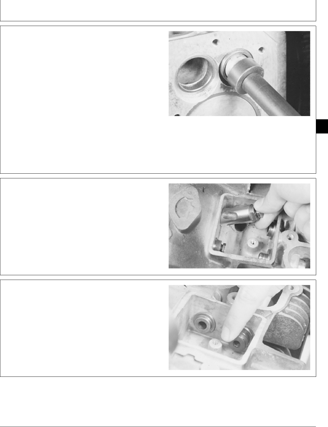
35. Remove gasket (A).
M36278 -UN-29JAN90
INSTALL INTAKE AND EXHAUST VALVES
1. Clean and dry all parts. Apply clean engine oil to all
internal parts. Use a valve gasket kit when assembling
the engine.
2. Install a new gasket (A) on intake valve guide.
3. Install valve guides using JDG 569 Valve Guide
Installer (B) and a large washer (C). Pull valve guides
until shoulder is tight against cylinder block.
M36953 -UN-25JAN90
M98,2015K,24 -19-30JAN87
M98,2015K,25 -19-30JAN87
Intake and Exhaust Valves/Intake and Exhaust Valves
CTM2 (19APR90) 15-12 16, 18, 20 & 24HP Onan Engines
130495
15
12
4. Install valve seats with chamfer away from driver disk.
Push valve seats to bottom of cylinder block bore.
DISKS FOR VALVE SEAT INSTALLATION
Engine Valve Size
B43E, B43G, B48G Intake 1-3/16 and 1-7/16 in.
B43E, B43G, B48G Exhaust 15/16 and 1-3/16 in.
T260 Intake 1-1/8 and 1-1/2 in.
T260 Exhaust 1 and 1-5/16 in.
P218G, P220G Intake 1-7/16 in.
P218G, P220G Exhaust 1-3/16 in.
M36883 -UN-25JAN90
IMPORTANT: Valve assemblies must be installed in
original bores for maximum valve
performance.
5. Install tappets in original bores.
M36270 -UN-29JAN90
IMPORTANT: Never reuse intake valve seal. The seal
must be replaced each time the valve is
removed.
6. Install intake valve seal, if equipped, with lip of seal
toward tappet.
M36279 -UN-29JAN90
M98,2015K,26 -19-30JAN87
M98,2015K,27 -19-08OCT85
M98,2015K,28 -19-08OCT85
Intake and Exhaust Valves/Intake and Exhaust Valves
CTM2 (19APR90) 15-13 16, 18, 20 & 24HP Onan Engines
130495
15
13
7. Install springs (A) and rotators (B).
M36280 -UN-29JAN90
8. Put clean engine oil on valve stems.
9. Install intake and exhaust valves.
M36266 -UN-29JAN90
10. Close oil drain hole with a shop towel to prevent
retainers from falling into gear case.
11. Compress valve springs using a valve spring
compressor.
12. Apply petroleum jelly or retainers to help hold
retainers on valve stem. Install retainers on valve stem
with taper toward rotator. Be sure retainers are seated in
valve stem slot. Slowly release spring pressure to
remove compressor.
M36281 -UN-29JAN90
M98,2015K,29 -19-08OCT85
M98,2015K,30 -19-08OCT85
M98,2015K,31 -19-08OCT85
Intake and Exhaust Valves/Intake and Exhaust Valves
CTM2 (19APR90) 15-14 16, 18, 20 & 24HP Onan Engines
130495
15
14
MEASURE AND ADJUST VALVE
CLEARANCE
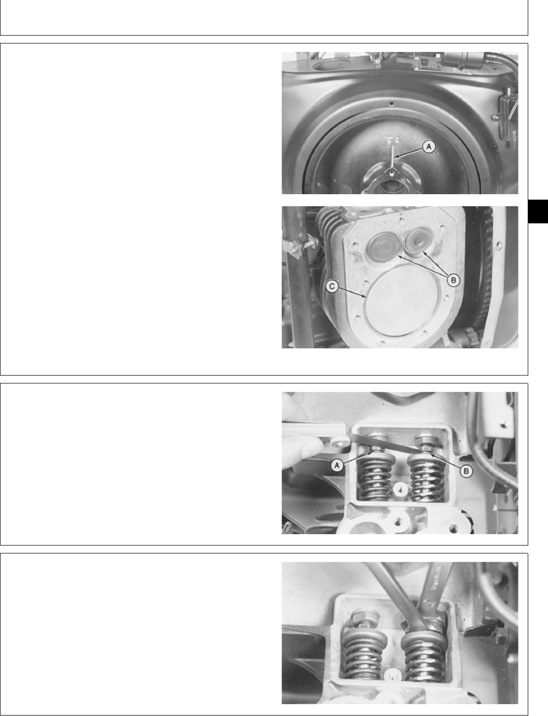
1. Turn the flywheel clockwise until the intake valve
opens and then closes. Continue turning flywheel until
the TDC (top-dead-center) mark (A) on the flywheel is
upward.
Both valves (B) must be closed and the piston (C) must
be at the top of its compression stroke. If the valves are
open, the piston is on the exhaust stroke and the
flywheel must be turned one revolution.
M36282 -UN-29JAN90M36283 -UN-29JAN90
2. Measure valve clearance using a feeler gauge.
VALVE CLEARANCE SPECIFICATION
Item Specification
Intake Valve (A) . . . . . . . . . . . . . . . . . . . . . . . 0.13 mm (0.005 in.)
Exhaust Valve (B) . . . . . . . . . . . . . . . . . . . . . . 0.33 mm (0.013 in.)
M36284 -UN-29JAN90
3. If necessary, hold tappet and turn tappet screw to
adjust valve clearance.
M36285 -UN-29JAN90
M98,2015K,32 -19-08OCT85
M98,2015K,33 -19-08OCT85
M98,2015K,34 -19-08OCT85
Intake and Exhaust Valves/Intake and Exhaust Valves
CTM2 (19APR90) 15-15 16, 18, 20 & 24HP Onan Engines
130495
15
15
CONTINUTE TO INSTALL AND EXHAUST
VALVES
1. Install parts (A—F) if equipped. Be sure washer (B) is
on top of valve (C).
A—Spring
B—Washer
C—Valve
D—Gasket
E—Breather Base
F—Gasket
M36264 -UN-29JAN90
NOTE: For T260 engine, go to Step 3.
2. Install breather manifold cover and cap screw. Check
that cap screw is installed through spring, washer, and
valve. Tighten cap screw to 2.1 ± 0.7 N·m (18 ± 6
lb-in.).
P218G, P220G, B43E, B43G, AND B48G
M36286 -UN-29JAN90M36287 -UN-29JAN90
3. Install new gasket (A). Install valve cover (B) and cap
screw. Tighten cap screw 2.1 ± 0.7 N·m (18 ± 6 lb-in.)
T260 Engine
M36288 -UN-29JAN90
M98,2015K,35 -19-11NOV85
M98,2015K,36 -19-10FEB87
M98,2015K,37 -19-11NOV85
Intake and Exhaust Valves/Intake and Exhaust Valves
CTM2 (19APR90) 15-16 16, 18, 20 & 24HP Onan Engines
130495
15
16
4. Install cylinder head (C). (See Install cylinder Head,
Group 10 in this manual.)
5. Install intake manifold (B). (See Install Intake Manifold,
Group 10 in this manual.)
6. Install exhaust pipes with muffler (A). (See Intake
Manifold, Group 10 in this manual.)
7. Install engine if removed. (See machine technical
manual.)
M36473 -UN-29JAN90
M98,2015K,38 -19-11NOV85
Intake and Exhaust Valves/Intake and Exhaust Valves
CTM2 (19APR90) 15-17 16, 18, 20 & 24HP Onan Engines
130495
15
17

Intake and Exhaust Valves/Intake and Exhaust Valves
CTM2 (19APR90) 15-18 16, 18, 20 & 24HP Onan Engines
130495
15
18

SERVICE EQUIPMENT AND TOOLS
NOTE: Order tools from the U.S. SERVICE-GARD™ Catalog or from the European Microfiche Tool Catalog
(MTC). Some tools may be available from a local supplier.
Name Use
13-Ton Puller Set Remove flywheel
OTHER MATERIAL
Number Name Use
TY9375 John Deere LOCTITE® Pipe Apply to threads of flywheel cap
Sealant with TEFLON®screw
LOCTITE is a trademark of the Loctite Corp.
TEFLON is a trademark of the DuPont Co.
SPECIFICATIONS
Item Measurement Specification
B43E, B43G, B48G, and T260
Engine:
Flywheel Cap Screw Torque 51 ± 3 N·m (38 ± 2 lb-ft)
P218G and P220G Engine: Flywheel Torque 67—75 N·m (50—55 lb-ft)
Cap Screw
Lift Bracket Cap Screw Torque 11 ± 3 N·m (97 ± 27 lb-in.)
M98,2020K,1 -19-08OCT85
M98,2020K,1A -19-08OCT85
M98,2020K,2 -19-10FEB85
Group 20
Flywheel
CTM2 (19APR90) 20-1 16, 18, 20 & 24HP Onan Engines
130495
20
1
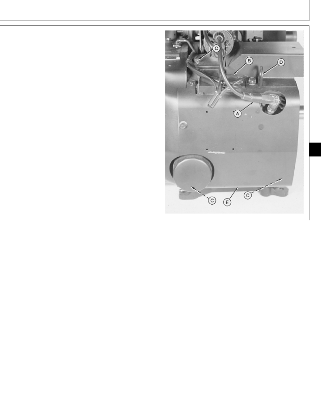
REMOVE FLYWHEEL
1. Remove engine. (See machine technical manual.)
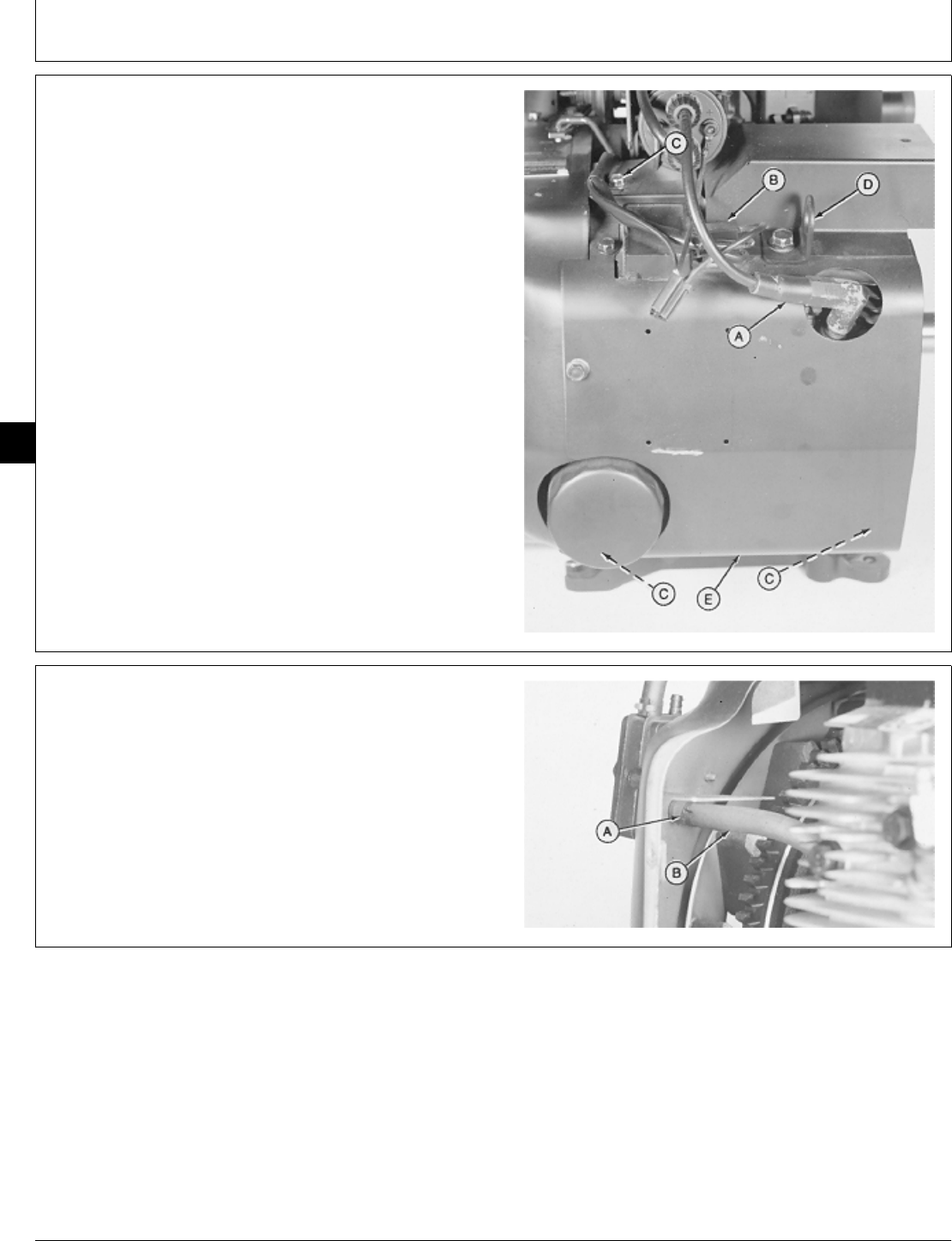
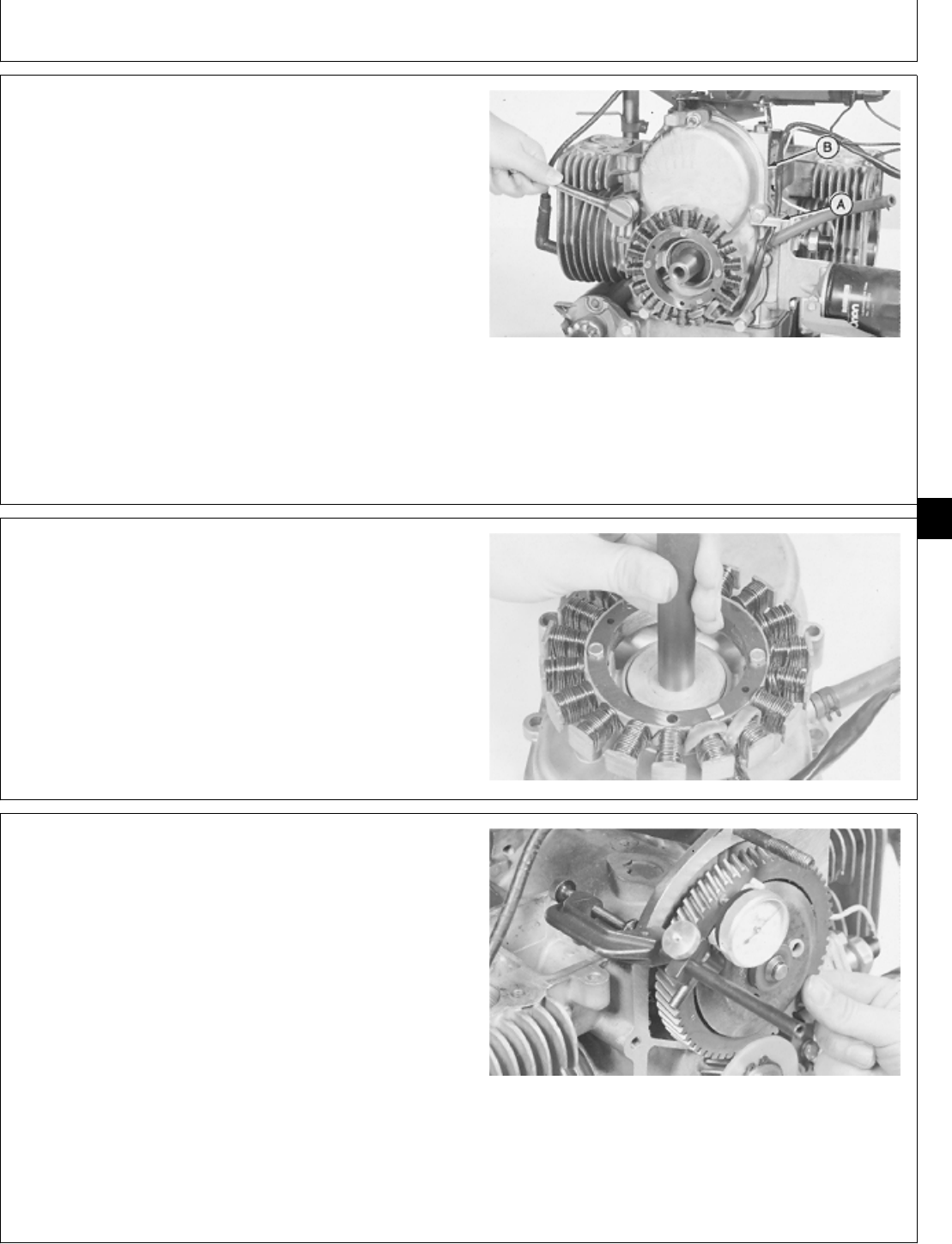
2. Disconnect spark plug wire (A) and voltage regulator
leads (B).
3. Remove five cap screws (C) to remove lift bracket (D)
and right side shroud (E).
A—Spark Plug Wire
B—Voltage Regulator Leads
C—Cap Screw (5 used)
D—Lift Bracket
E—Right Side Shroud
M36289 -UN-29JAN90
4. Loosen hose clamp (A) to disconnect fuel pump
impulse line (B).
M36290 -UN-29JAN90
M98,2020K,3 -19-24OCT85
M98,2020K,4 -19-08OCT85
Flywheel/Flywheel
CTM2 (19APR90) 20-2 16, 18, 20 & 24HP Onan Engines
130495
20
2
5. Disconnect governor spring (A).
6. Remove two screws to remove fuel pump (B).
7. For P218 or P220G engines, remove air clean
assembly. Remove two cap screws to disconnect ignition
coil from flywheel shroud.
8. Disconnect fuel line.
9. Remove five cap screws to remove flywheel shroud
(C).
M36291 -UN-29JAN90
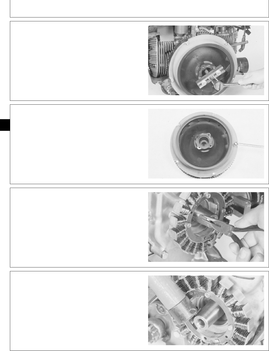
IMPORTANT: Do not use a pry bar in fins to keep
flywheel from turning. Doing so can
damage fins.
10. Fasten locking pliers to ring gear to prevent flywheel
from turning.
NCAUTION: Loosen flywheel cap screw only two
turns. Do not remove cap screw. If cap screw
is removed, flywheel may cause injury when it
comes loose.
11. Loosen cap screw two turns only.
M36292 -UN-29JAN90
M98,2020K,5 -19-30JAN87
M98,2020K,6 -19-30JAN87
Flywheel/Flywheel
CTM2 (19APR90) 20-3 16, 18, 20 & 24HP Onan Engines
130495
20
3
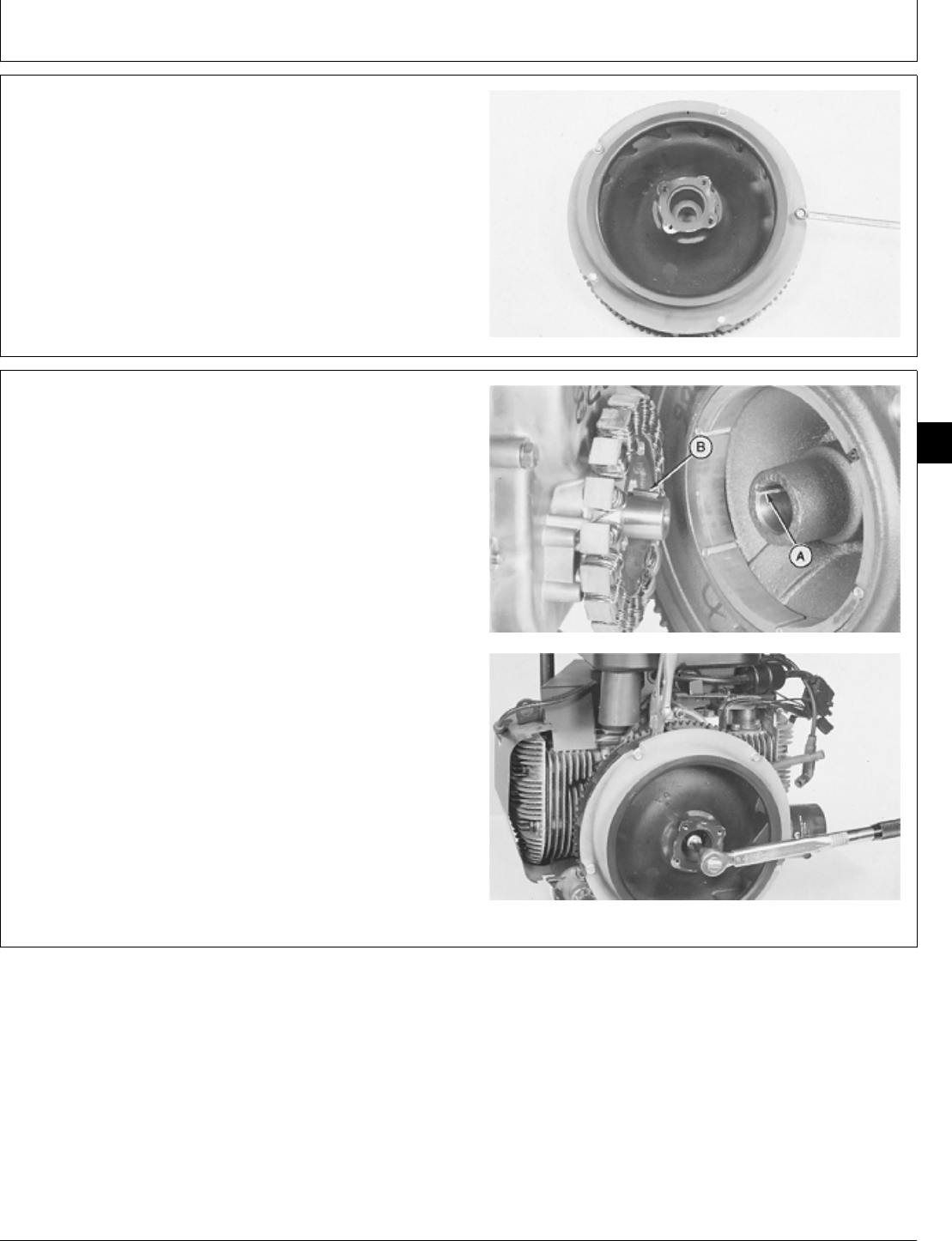
12. For P218G or P220G engines, remove two cap
screws from flywheel.
IMPORTANT: Do not pry on flywheel with a
screwdriver. Ceramic magnets on gear
case cover can be damaged.
13. Loosen flywheel using a puller.
14. Remove puller, cap screw, washer, and flywheel.
M36293 -UN-29JAN90
NOTE: P218G or P220G engine, flywheel and shield are
not shown.
15. If necessary, remove five cap screws to remove
flywheel shield.
16. Inspect flywheel for cracks, broken fins, or broken
magnets. Inspect flywheel ring gear for chipped or
broken teeth. Replace flywheel if damaged.
M36294 -UN-29JAN90
NOTE: Different engine models have different shaped
keys.
17. Remove key.
M36295 -UN-29JAN90
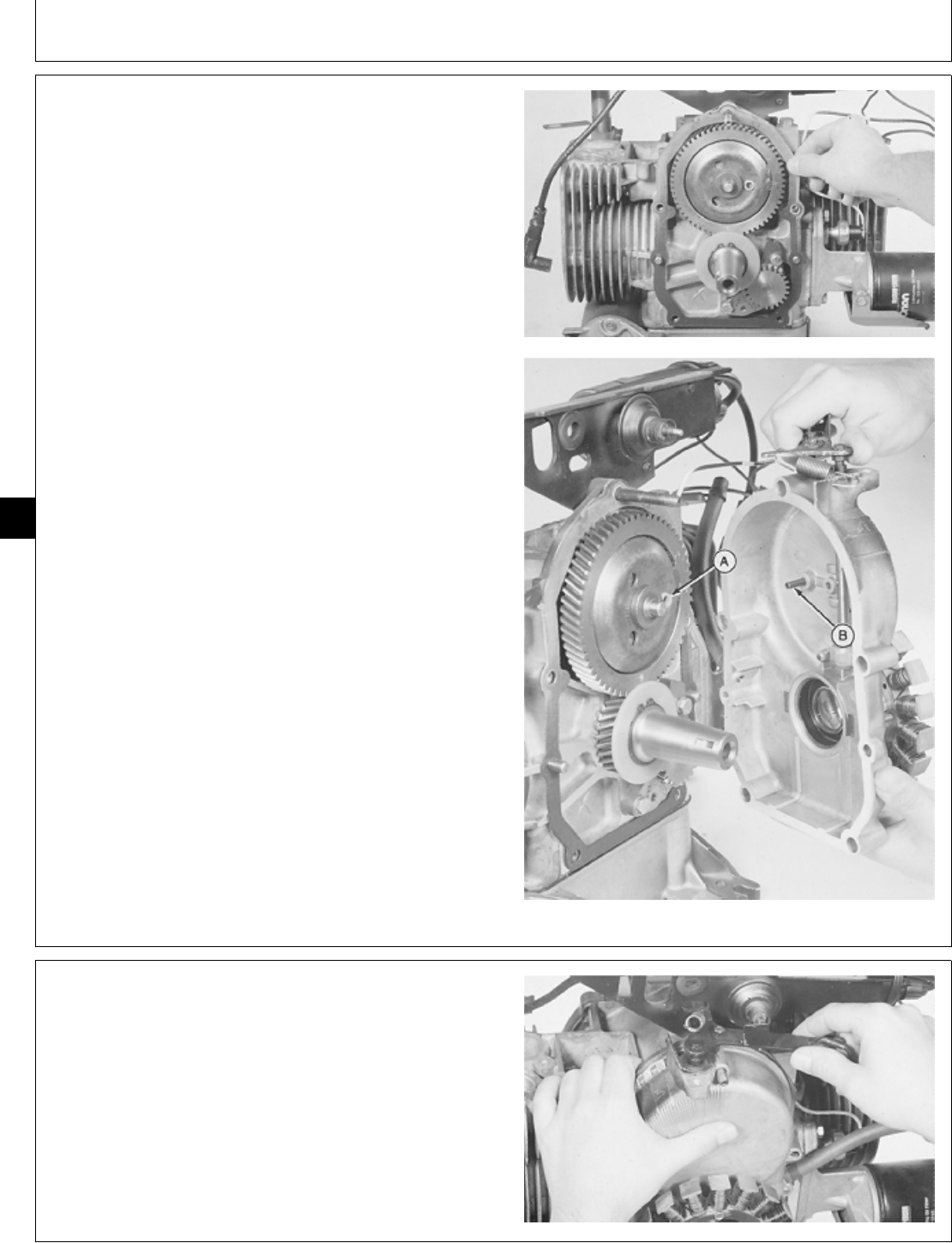
INSTALL FLYWHEEL
1. Install key in crankshaft.
For P218G or P220G engines, align slot in magnetic ring
with slot in crankshaft and install key.
M36296 -UN-29JAN90
M98,2020K,7 -19-30JAN87
M98,2020K,8 -19-30JAN87
M98,2020K,9 -19-10FEB87
M98,2020K,10 -19-30JAN87
Flywheel/Flywheel
CTM2 (19APR90) 20-4 16, 18, 20 & 24HP Onan Engines
130495
20
4
NOTE: P218G or P220G engine, flywheel and shield are
not shown.
2. Install flywheel shield, if removed, and fasten with five
cap screws.
M36294 -UN-29JAN90
IMPORTANT: Do not lubricate crankshaft taper. The
crankshaft taper must be dry to hold
the flywheel tight.
3. Clean crankshaft taper before installing flywheel.
4. Apply pipe sealant on threads of flywheel cap screw.
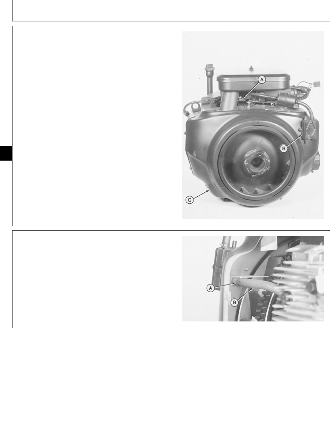
5. Align keyway (A) in flywheel with key (B) in
crankshaft. Install flywheel.
6. Install washer and cap screw.
7. Fasten locking pliers to ring gear to prevent flywheel
from turning.
8. On B43E, B43G, B48G, and T260 Engines: Tighten
cap screw to 51 ± 3 N·m (38 ± 2 lb-ft).
On P218G and P220G Engines: tighten cap screw to
67—75 N·m (50—55 lb-ft).
M36297 -UN-29JAN90M36298 -UN-29JAN90
M98,2020K,11 -19-30JAN87
M98,2020K,12 -19-10FEB85
Flywheel/Flywheel
CTM2 (19APR90) 20-5 16, 18, 20 & 24HP Onan Engines
130495
20
5
9. Install flywheel shroud (C) and fasten with five cap
screws.
10. For P218G or P220G engine, connect ignition coil to
flywheel shroud and fasten with two cap screws. Install
air cleaner assembly.
11. Connect fuel line to carburetor.
12. Install fuel pump (B) and fasten with two screws.
13. Connect governor spring (A) in top hole of arm.
M36291 -UN-29JAN90
14. Connect fuel pump impulse line (B) and fasten with
hose clamp (A).
M36290 -UN-29JAN90
M98,2020K,13 -19-30JAN87
M98,2020K,14 -19-30JAN87
Flywheel/Flywheel
CTM2 (19APR90) 20-6 16, 18, 20 & 24HP Onan Engines
130495
20
6
15. Install right side shroud (E), lift bracket (D) and
fasten with five cap screws (C). Tighten lift bracket cap
screw to 11 ± 3 N·m (97 ± 27 lb-in.).
16. Connect spark plug wire (A) and voltage regulator
leads (B). Install the two stator leads on “AC” terminals
and the battery lead on “B+” terminal of the voltage
regulator.
17. Install engine. (See machine technical manual.)
A—Spark Plug Wire
B—Voltage Regulator Leads
C—Cap Screw (5 used)
D—Lift Bracket
E—Right Side Shroud
M36289 -UN-29JAN90
M98,2020K,15 -19-30JAN87
Flywheel/Flywheel
CTM2 (19APR90) 20-7 16, 18, 20 & 24HP Onan Engines
130495
20
7

Flywheel/Flywheel
CTM2 (19APR90) 20-8 16, 18, 20 & 24HP Onan Engines
130495
20
8

ESSENTIAL TOOLS
NOTE: Order tools from the U.S. SERVICE-GARD™ Catalog or from the European Microfiche Tool Catalog
(MTC). Some tools may be available from a local supplier.
Number Name Use
JDG 325 Crankshaft Seal Installer Install gear cover oil seal
SERVICE EQUIPMENT AND TOOLS
NOTE: Order tools from the U.S. SERVICE-GARD™ Catalog or from the European Microfiche Tool Catalog
(MTC). Some tools may be available from a local supplier.
Name Use
Bushing, Bearing, and Seal Driver Set Remove and install oil seal, bearings, and
camshaft gear
Dial Indicator Measure camshaft gear end play and
backlash
Outside Micrometer Measure camshaft
Telescoping Gauge Measure camshaft bearings
Press Remove and install camshaft gear
OTHER MATERIAL
Number Name Use
TY6304 John Deere LOCTITE® Flexible Apply to camshaft plug surface of
Sealant cylinder block.
TY9375 John Deere LOCTITE Pipe Sealant Apply to threads of clutch adapter
with TEFLON®plate screws, gear cover cap
screws, and breaker point assembly
screw.
LOCTITE is a trademark of the Loctite Corp.
TEFLON is a trademark of the DuPont Co.
M98,2025K,1 -19-09OCT85
M98,2025K,2 -19-11NOV85
M98,2025K,2A -19-11NOV85
Group 25
Camshaft
CTM2 (19APR90) 25-1 16, 18, 20 & 24HP Onan Engines
130495
25
1

SERVICE PARTS KITS
The following kits are available through your parts
catalog:
Overhaul Gasket Kit
M98,2025K,2B -19-09OCT85
Camshaft/Service Parts Kits
CTM2 (19APR90) 25-2 16, 18, 20 & 24HP Onan Engines
130495
25
2

SPECIFICATION
Item New Specification Wear Tolerance
1. End Play: B43E, B43G, 0.08—0.3 mm 0.4 mm (0.018 in.)
B48G, and T260 Engine (0.003—0.012 in.)
End Play: P218G, P220G Engine0.280—1.22 mm 1.65 mm (0.065 in.)
(0.0110—0.0480 in.)
2. Gear Backlash:
B43E, B43G, B48G Engine 0.03—0.15 mm 0.23 mm (0.009 in.)
(0.001—0.006 in.)
T260 Engine 0.05—0.08 mm 0.15 mm (0.006 in.)
(0.002—0.003 in.)
P218G, P220 Engine 0.025—0.127 mm 0.20 mm (0.008 in.)
(0.001—0.005 in.)
3. Governor Cup Travel 5.6 mm (0.22 in.)
4. Journal O.D. 34.90—34.91 mm 34.80 mm (1.370 in.)
(1.374—1.375 in.)
5. Lobe Height:
Intake and Exhaust, B43E 28.37—28.47 mm 27.99 mm (1.102 in.)
(1.117—1.121 in.)
Intake, B43G, B48G 29.57—29.72 mm 29.18 mm (1.149 in.)
(1.164—1.170 in.)
Exhaust, B43G, B48G 29.44—29.59 mm 29.06 mm (1.144 in.)
(1.159—1.165 in.)
Intake and Exhaust, T260 29.57—29.72 mm 29.18 mm (1.149 in.)
(1.164—1.170 in.)
Intake, P218G 29 mm (1.142 in.) 28.49 mm (1.122 in.)
Exhaust, P218G 29.5 mm (1.162 in.) 28.98 mm (1.141 in.)
Intake, P220G 29.7 mm (1.171 in.) 29.18 mm (1.149 in.)
Exhaust, P220G 29.5 mm (1.162 in.) 28.98 mm (1.141 in.)
6. Bearing I.D. 34.95—34.98 mm 35.03 mm (1.379 in.)
(1.376—1.377 in.)
7. Camshaft Clearance 0.038—0.076 mm 0.125 mm (0.005 in.)
(0.0015—0.003 in.)
8. Clutch Adapter Plate 35 ± 1 N·m
Screw Torque (310 ± 9 lb-in.)
9. Gear Cover Cap Screws 12 ± 1 N·m
and Nut Torque (106 ± 9 lb-in.)
M98,2025K,3 -19-10FEB87
Camshaft/Specifications
CTM2 (19APR90) 25-3 16, 18, 20 & 24HP Onan Engines
130495
25
3
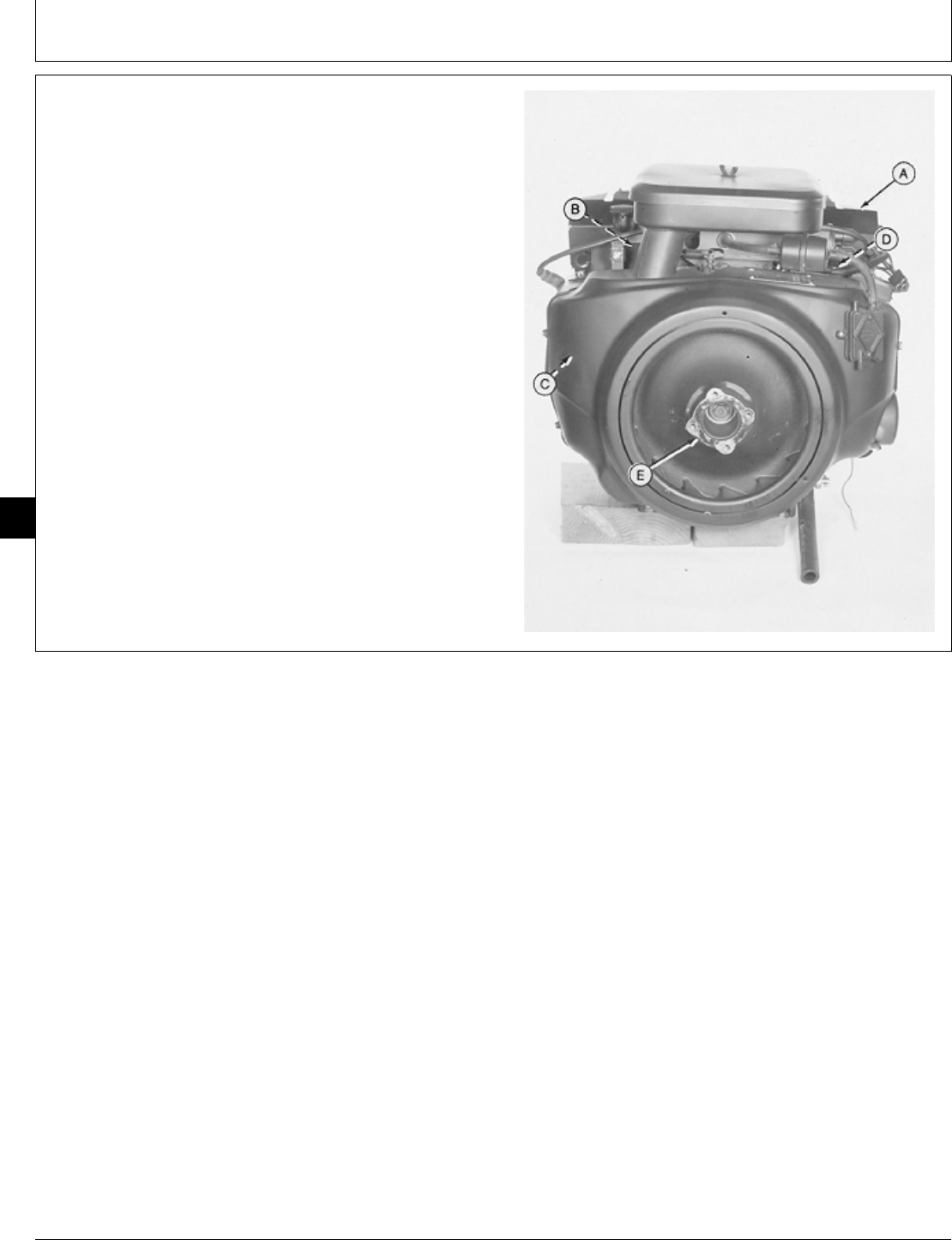
REMOVE CAMSHAFT
1. Remove engine. (See machine technical manual.)
2. Remove muffler and exhaust pipes (A).
3. Remove intake manifold (B). (See Remove Intake
Manifold, Group 10 in this manual.)
4. Remove cylinder heads (C). (See Remove Cylinder
Heads, Group 10 in this manual.)
5. Remove intake and exhaust valves (D). (See Remove
Intake and Exhaust Valves, Group 15 in this manual.)
6. Remove flywheel (E). (See Remove Flywheel, Group
20 in this manual.)
A—Muffler and Exhaust Pipes
B—Intake Manifold
C—Cylinder Heads
D—Intake and Exhaust Valves
E—Flywheel
M36474 -UN-29JAN90
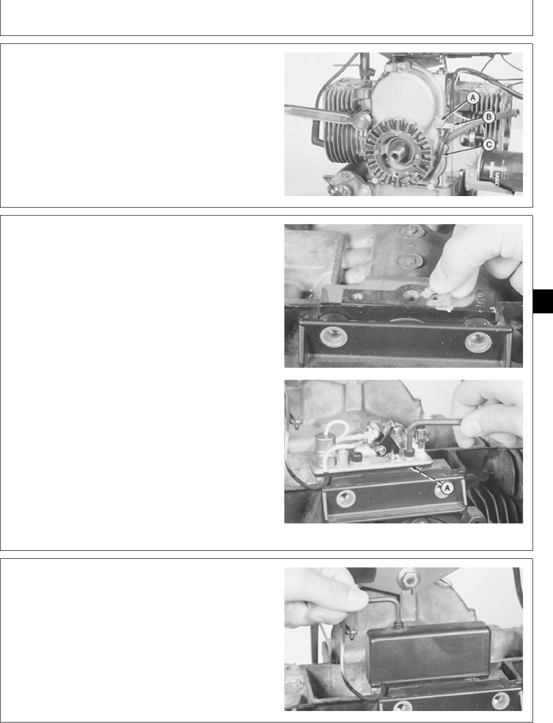
7. Remove Allen screw to remove breaker point cover, if
equipped.
M36299 -UN-29JAN90
NOTE: Be careful not to lose the plunger during breaker
point assembly removal.
8. Remove two screws to remove breaker point
assembly and gasket (A), if equipped.
M36300 -UN-29JAN90
M98,2025K,4 -19-11NOV85
M98,2025K,5 -19-10FEB87
M98,2025K,6 -19-10FEB87
Camshaft/Camshaft
CTM2 (19APR90) 25-4 16, 18, 20 & 24HP Onan Engines
130495
25
4
IMPORTANT: Do not hit gear cover with a metal
hammer or remove cover with a
screwdriver. Doing so may damage
gear cover.
9. Remove four cap screws and nut to remove clip (A),
gear cover, and gasket (B).
For P218G or P220G engine, disconnect wire leads from
ignition coil. Remove crankshaft key and magnetic ring.
10. If gear cover is tight, hit cover lightly with a
soft-faced hammer to loosen it.
M36301 -UN-29JAN90
11. Remove oil seal using a 2 in. driver disk.
M36302 -UN-29JAN90
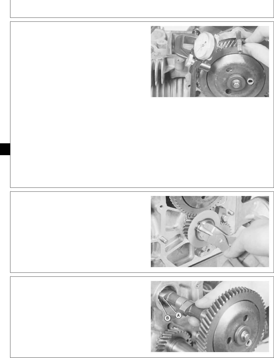
12. Measure camshaft end play.
CAMSHAFT END PLAY SPECIFICATION
Engine New Parts Wear Tolerance
B43E, B43G, B48G 0.08—0.3 mm 0.4 mm
and T260 (0.003—0.012 in.) (0.018 in.)
P218G and P220G 0.280—1.22 mm 1.65 mm
(0.0110—0.0480 in.) (0.065 in.)
If end play exceeds wear tolerance, replace camshaft
thrust washer.
M36303 -UN-29JAN90
M98,2025K,7 -19-10FEB87
M98,2025K,8 -19-09OCT85
M98,2025K,9 -19-02FEB87
Camshaft/Camshaft
CTM2 (19APR90) 25-5 16, 18, 20 & 24HP Onan Engines
130495
25
5
13. Measure camshaft gear backlash.
CAMSHAFT GEAR SPECIFICATIONS
Item New Part Wear Tolerance
B43E, B43G, B48G Engine
Camshaft Gear 0.03—0.15 mm 0.23 mm
Backlash (0.001—0.006 in.) (0.009 in.)
T260 Engine
Camshaft Gear 0.05—0.08 mm 0.15 mm
Backlash (0.002—0.003 in.) (0.006 in.)
P218G, P220G Engine
Camshaft Gear 0.025—0.127 mm 0.20 mm
Backlash (0.001—0.005 in.) (0.008 in.)
If backlash exceeds wear tolerance, replace camshaft
gear and crankshaft gear.
M36304 -UN-29JAN90
14. Remove snap ring to remove thrust washer.
M36305 -UN-29JAN90
IMPORTANT: Do not allow camshaft lobes to hit
bearing surfaces while removing
camshaft. Machined surfaces may be
damaged.
15. Carefully remove camshaft until rear lobe is even
with camshaft bearing. Turn camshaft until lobe (A) fits
into camshaft bearing notch (B). Remove camshaft.
M36307 -UN-29JAN90
M98,2025K,10 -19-10FEB87
M98,2025K,11 -19-09OCT85
M98,2025K,12 -19-09OCT85
Camshaft/Camshaft
CTM2 (19APR90) 25-6 16, 18, 20 & 24HP Onan Engines
130495
25
6
16. Remove thrust washer.
M36306 -UN-29JAN90
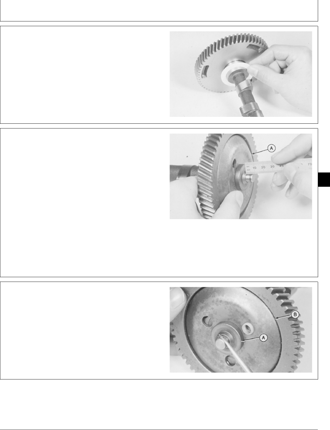
DISASSEMBLE AND INSPECT CAMSHAFT
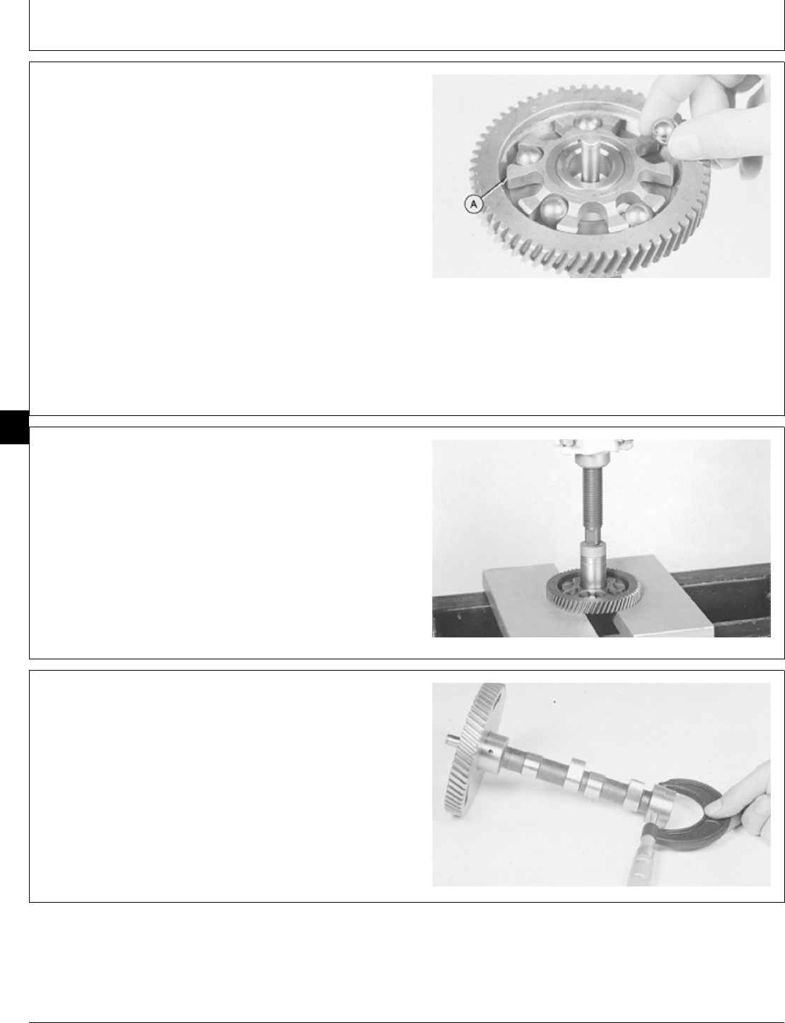
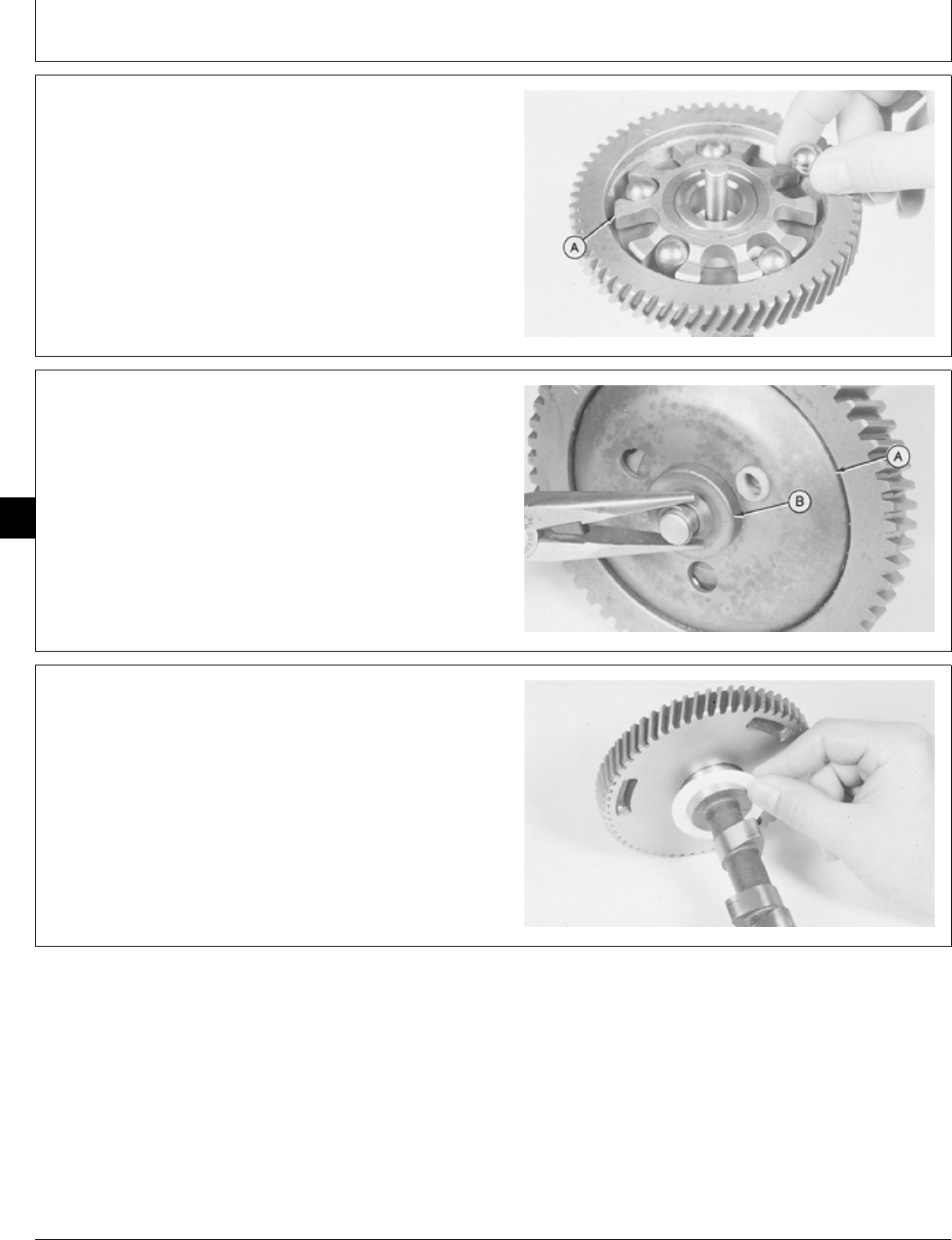
1. Hold cup against flyballs. Measure distance from snap
ring to surface of hub. The distance must be 5.6 mm
(0.22 in.).
If the distance is not correct, replace camshaft assembly.
NOTE: The camshaft and pin are only serviced as an
assembly.
2. The cup (A) must spin freely on the camshaft pin
without excessive play. Replace parts as necessary.
M36308 -UN-29JAN90
3. Remove snap ring to remove hub (A) and cup (B).
4. Inspect cup race for grooved or rough surface.
Replace cup if necessary.
M36309 -UN-29JAN90
M98,2025K,13 -19-09OCT85
M98,2025K,14 -19-09OCT85
M98,2025K,15 -19-09OCT85
Camshaft/Camshaft
CTM2 (19APR90) 25-7 16, 18, 20 & 24HP Onan Engines
130495
25
7
5. Remove flyballs. Inspect flyballs for grooved or flat
spots, replace if necessary.
6. Inspect flyball spacer (A) for wear or damage.
Replace camshaft gear if necessary.
NOTE: The flyball spacer, plate, and camshaft gear are
serviced as an assembly only.
IMPORTANT: If camshaft gear is replaced, always
replace crankshaft gear also.
7. Inspect camshaft gear for chipped or broken teeth.
Replace camshaft gear if necessary.
M36310 -UN-29JAN90
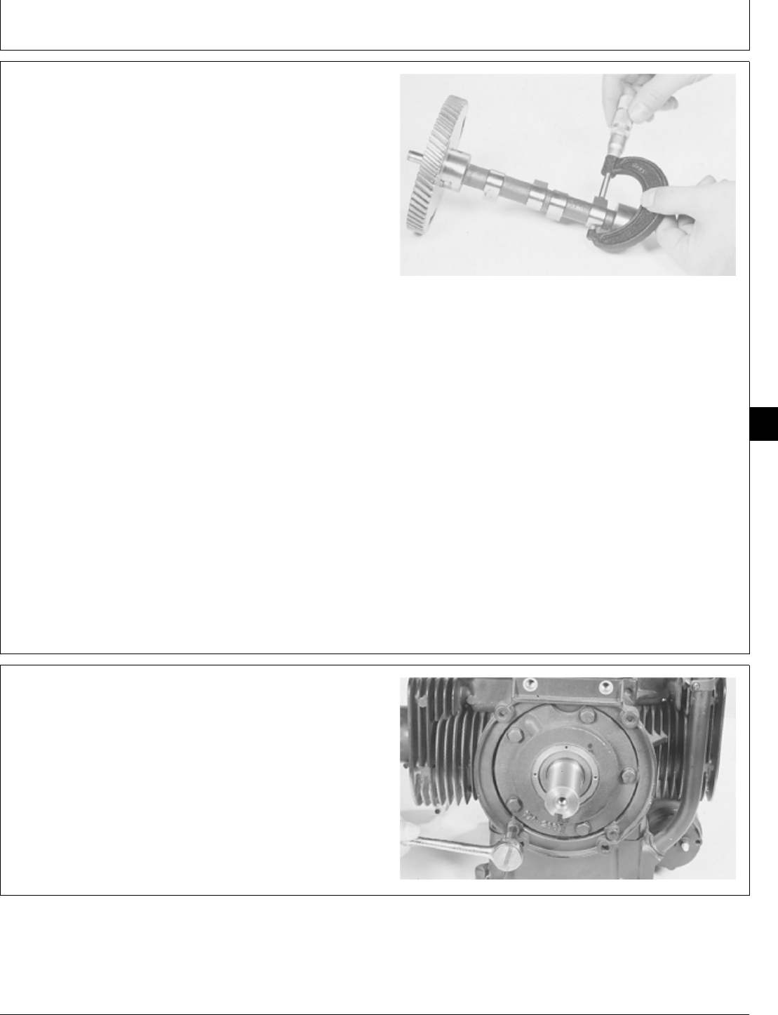
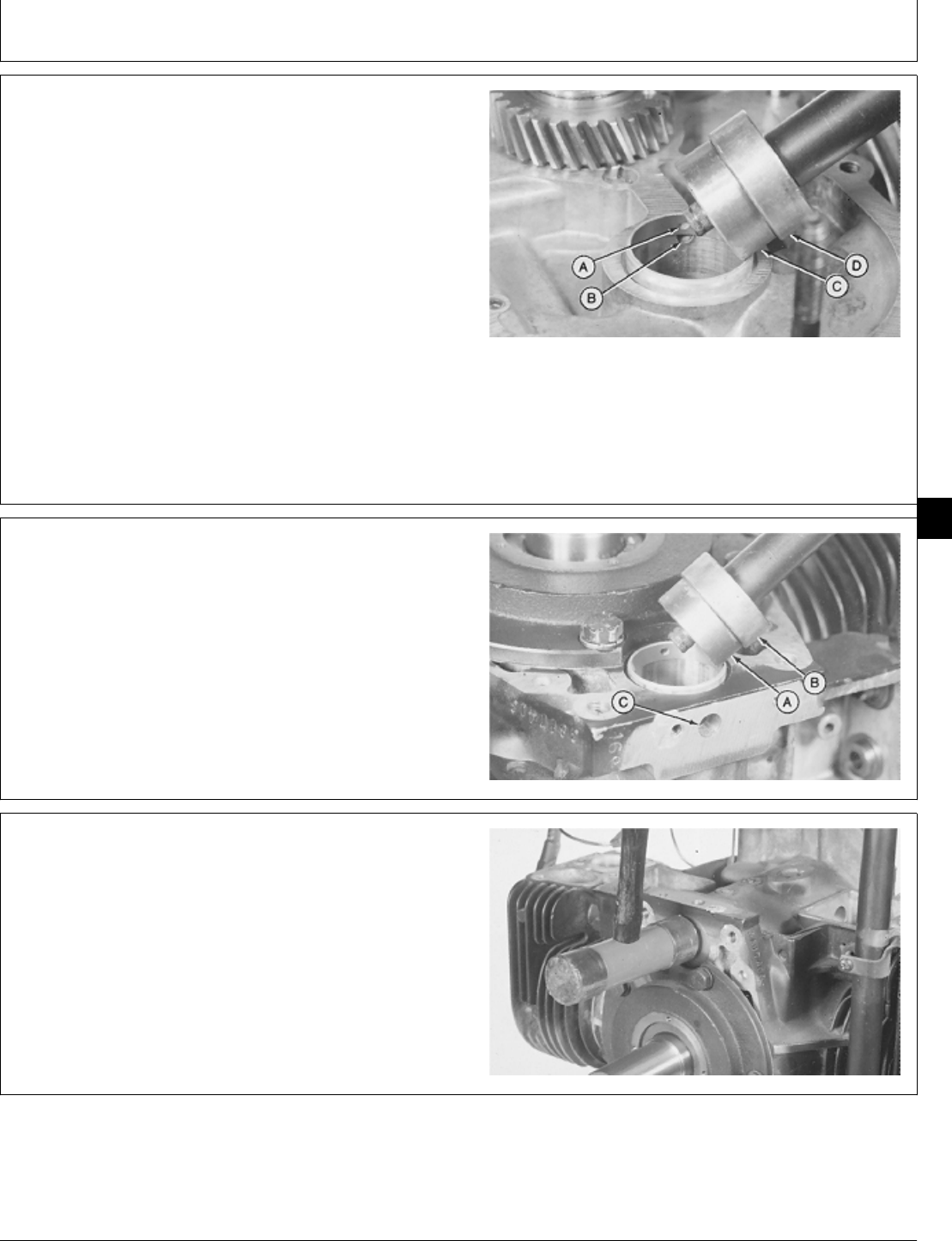
IMPORTANT: Be sure to hold camshaft while
removing camshaft gear.
8. Remove gear using a 1 in. deep-well socket, 1 in.
driver disk, and a press.
9. Remove key.
M30688 -UN-14JUL89
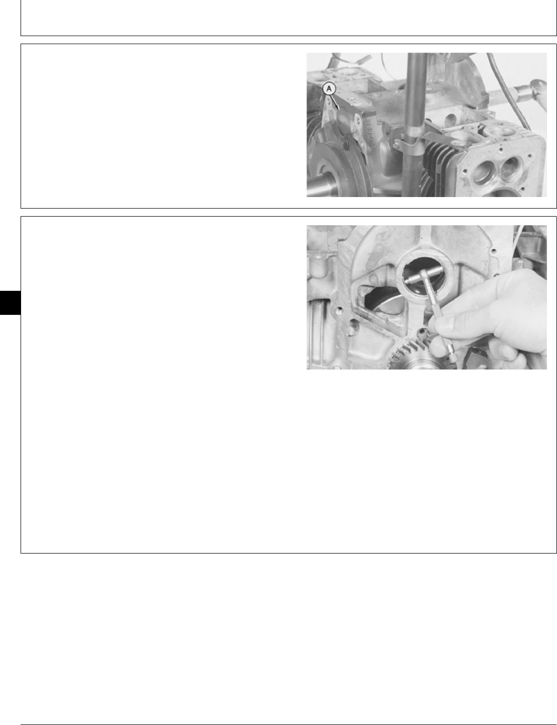
10. Measure camshaft journal outside diameter.
CAMSHAFT JOURNAL SPECIFICATIONS
Item New Part Wear Tolerance
Journal Diameter 34.90—34.91 mm 34.80 mm
(1.374—1.3745 in.) (1.370 in.)
If journal diameter is less than 34.80 mm (1.370 in.),
replace camshaft.
M36311 -UN-29JAN90
M98,2025K,16 -19-09OCT85
M98,2025K,17 -19-11NOV85
M98,2025K,18 -19-11NOV85
Camshaft/Camshaft
CTM2 (19APR90) 25-8 16, 18, 20 & 24HP Onan Engines
130495
25
8
11. Measure camshaft lobe height.
CAMSHAFT LOBE SPECIFICATIONS
Item New Specification Wear Tolerance
Lobe Height:
B43E Intake and 28.37—28.47 mm 27.99 mm
Exhaust (1.117—1.121 in.) (1.102 in.)
B43G, B48G 29.57—29.72 mm 29.18 mm
Intake (1.164—1.170 in.) (1.149 in.)
B43G, B48G 29.44—29.59 mm 29.06 mm
Exhaust (1.159—1.165 in.) (1.144 in.)
T260 Intake and 29.57—29.72 mm 29.18 mm
Exhaust (1.164—1.170 in.) (1.149 in.)
P218G Intake 29 mm (1.142 in.) 28.49 mm
(1.122 in.)
P218G Exhaust 29.5 mm (1.162 in.) 28.98 mm
(1.141 in.)
P220G Intake 29.7 mm (1.171 in.) 29.18 mm
(1.149 in.)
P220G Exhaust 29.5 mm (1.162 in.) 28.98 mm
(1.141 in.)
If lobe height is less than wear tolerance, replace
camshaft.
M36312 -UN-29JAN90
12. If equipped, remove two screws to remove clutch
adapter plate.
M36313 -UN-29JAN90
M98,2025K,19 -19-02FEB87
M98,2025K,20 -19-09OCT85
Camshaft/Camshaft
CTM2 (19APR90) 25-9 16, 18, 20 & 24HP Onan Engines
130495
25
9
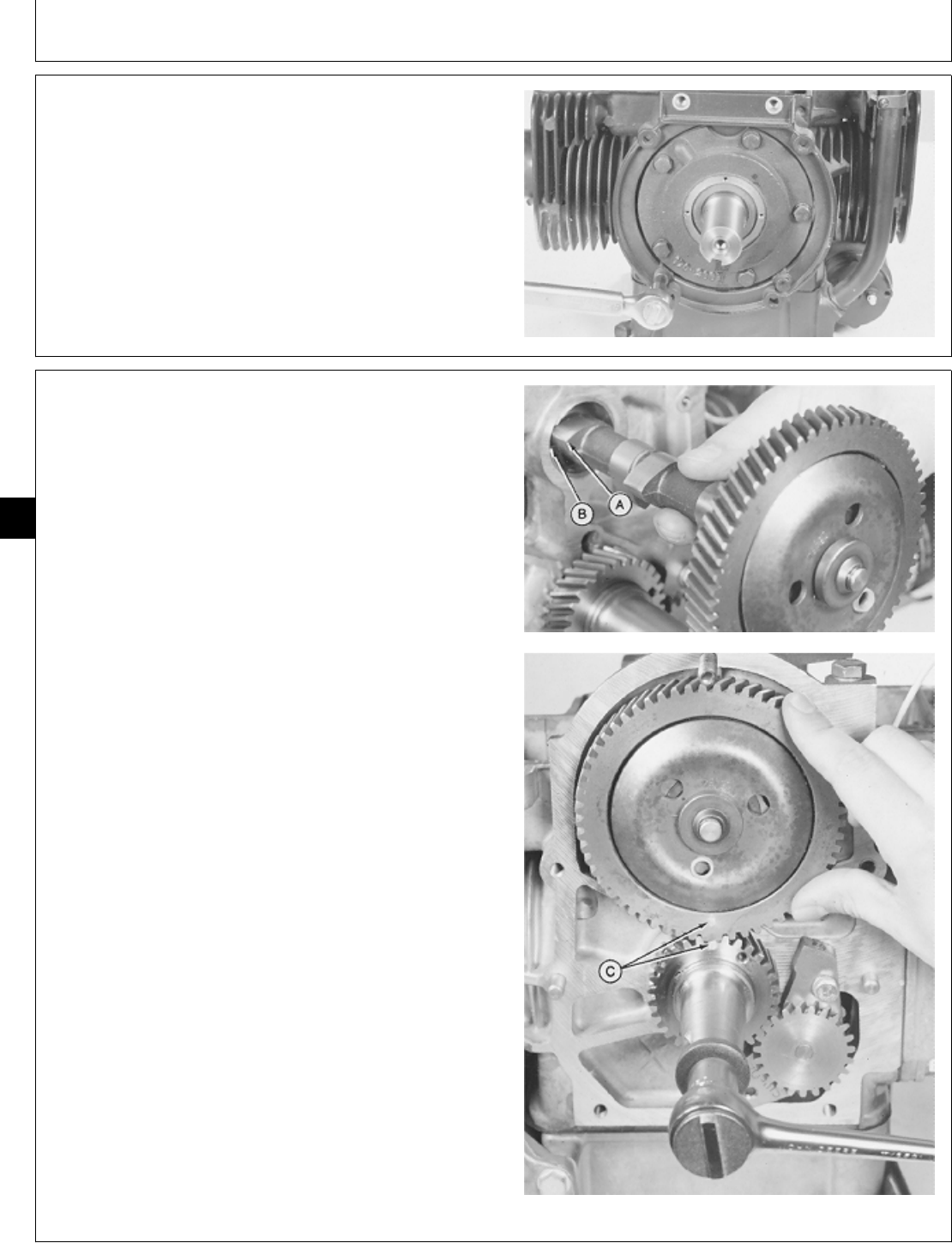
13. Remove plug (A) using a wooden dowel.
M36314 -UN-29JAN90
14. Measure camshaft bearing inside diameter and
determine camshaft clearance (camshaft bearing I.D.
minus camshaft journal O.D.).
CAMSHAFT BEARING SPECIFICATIONS
Item New Part Wear Tolerance
Camshaft Bearing 34.95—34.98 mm 35.03 mm
Diameter (1.376—1.377 in.) (1.379 in.)
Camshaft
Clearance 0.038—0.076 mm 0.125 mm
(0.0015—0.003 in.) (0.005 in.)
If camshaft bearing diameter exceeds 35.03 mm (1.379
in.) replace bearing.
If camshaft clearance exceeds 0.125 mm (0.005 in.),
replace camshaft bearing, camshaft, or both.
M36315 -UN-29JAN90
M98,2025K,21 -19-09OCT85
M98,2025K,22 -19-11NOV85
Camshaft/Camshaft
CTM2 (19APR90) 25-10 16, 18, 20 & 24HP Onan Engines
130495
25
10
15. Remove camshaft bearing using a soft steel rod or
chisel to bend bearing away from side of bore.
M36316 -UN-29JAN90M36317 -UN-29JAN90
ASSEMBLE CAMSHAFT
1. Install key in camshaft.
2. Install gear with timing mark “0” away from camshaft.
3. Align slot in gear with key in shaft.
4. Push camshaft into gear using a 1-3/8 in. driver disk
and a press until camshaft is even with bottom of gear
surface.
M30756 -UN-14JUL89
M98,2025K,23 -19-09OCT85
M98,2025K,24 -19-09OCT85
Camshaft/Camshaft
CTM2 (19APR90) 25-11 16, 18, 20 & 24HP Onan Engines
130495
25
11
5. Apply clean engine oil on camshaft parts before
assembly.
6. Install flyballs in flyball spacer (A) notches.
M36310 -UN-29JAN90
7. Install cup (A), hub (B), and fasten with snap ring.
M36318 -UN-29JAN90
8. Install thrust washer.
M36306 -UN-29JAN90
M98,2025K,25 -19-09OCT85
M98,2025K,26 -19-09OCT85
M98,2025K,27 -19-09OCT85
Camshaft/Camshaft
CTM2 (19APR90) 25-12 16, 18, 20 & 24HP Onan Engines
130495
25
12
INSTALL CAMSHAFT
1. Clean and dry all parts. Apply clean engine oil on all
internal parts before assembly.
NOTE: The service camshaft bearing is half the width of
the original bearing, but the camshaft bearing
surface is the same.
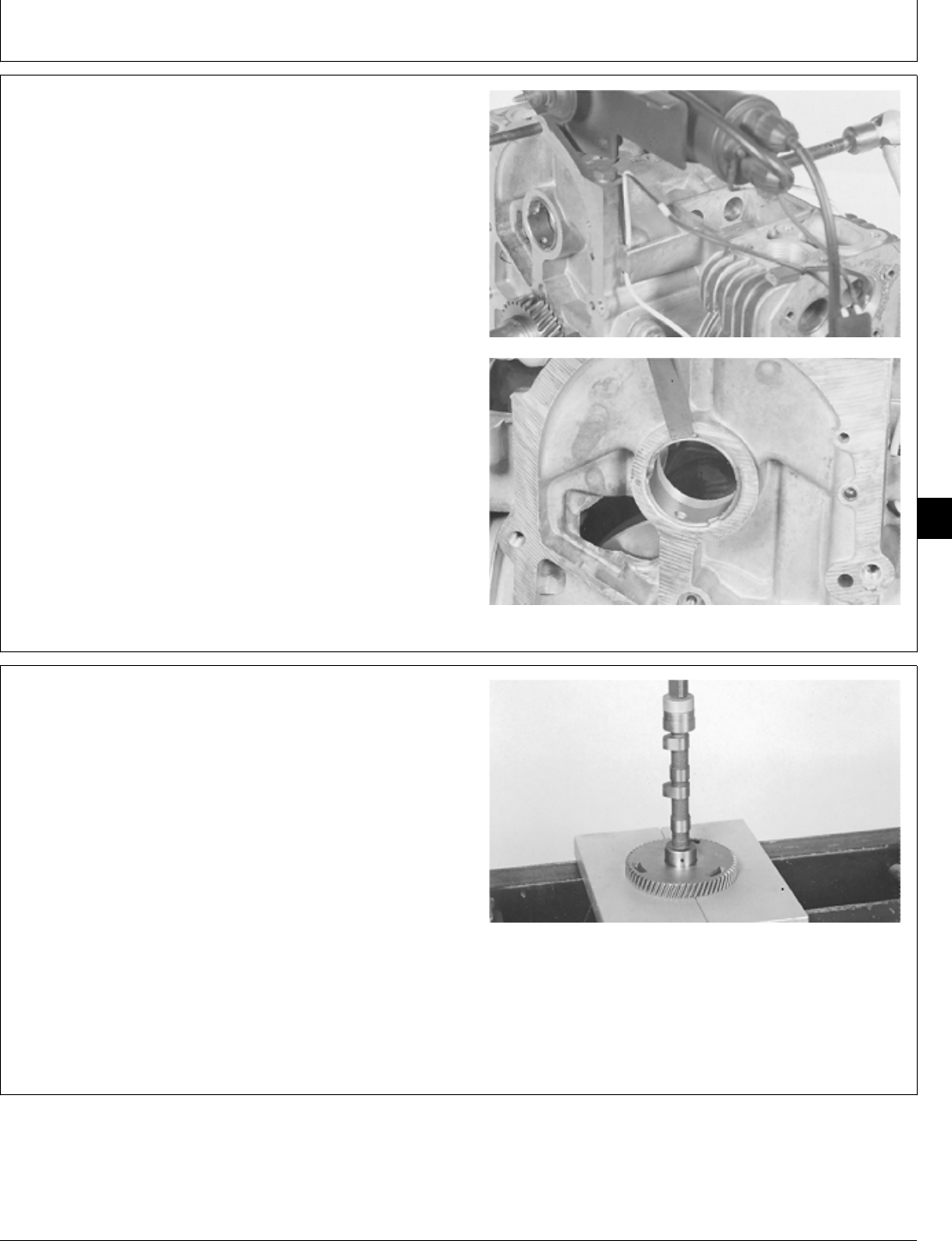
2. Align oil hole (A) in bearing with oil hole (B) in
cylinder block. Install rear bearing using a 1-3/8 in. driver
disk (C) and 1-1/2 in. driver disk (D). Push bearing even
with surface of cylinder block.
A—Bearing Oil Hole
B—Cylinder Block Oil Hole
C—1-3/8 in. Driver Disk
D—1-1/2 in. Driver Disk
M36319 -UN-29JAN90
3. Install front bearing using a 1-3/8 in. driver disk (A)
and 1-1/2 driver disk (B). Push bearing even with bottom
of bore. Be sure bearing is past breaker point plunger
hole (C) in cylinder block.
M36320 -UN-29JAN90
4. Apply flexible sealant on plug surface of cylinder
block.
5. Install plug tight against bottom of cylinder block
counterbore.
M36321 -UN-29JAN90
M98,2025K,28 -19-09OCT85
M98,2025K,29 -19-09OCT85
M98,2025K,30 -19-09OCT85
Camshaft/Camshaft
CTM2 (19APR90) 25-13 16, 18, 20 & 24HP Onan Engines
130495
25
13
6. If equipped, apply pipe sealant on threads of clutch
adapter plate screws.
7. Install clutch adapter plate and two screws. Tighten
screws to 35 ± 1 N·m (310 ± 9 lb-in.).
M36322 -UN-29JAN90
8. Put clean engine oil on camshaft bearing journals.
IMPORTANT: Do not allow camshaft lobe to hit
bearing surfaces while installing
camshaft. Machined surfaces may be
damaged.
9. Install flywheel cap screw in crankshaft to aid in
turning crankshaft for timing mark alignment.
10. Turn camshaft until lobe (A) fits into camshaft
bearing notch (B) and carefully install camshaft.
11. Align timing marks (C) on camshaft and crankshaft
gears and continue to install camshaft.
M36307 -UN-29JAN90M36323 -UN-29JAN90
M98,2025K,31 -19-09OCT85
M98,2025K,32 -19-09OCT85
Camshaft/Camshaft
CTM2 (19APR90) 25-14 16, 18, 20 & 24HP Onan Engines
130495
25
14
12. Align slot (A) in thrust washer with key (B) in
crankshaft.
13. Install thrust washer and snap ring.
M36324 -UN-29JAN90M36305 -UN-29JAN90
14. Install oil seal (A) with lip of seal downward, in gear
cover using JDG 325 Crankshaft Seal Installer (B).
M36325 -UN-29JAN90
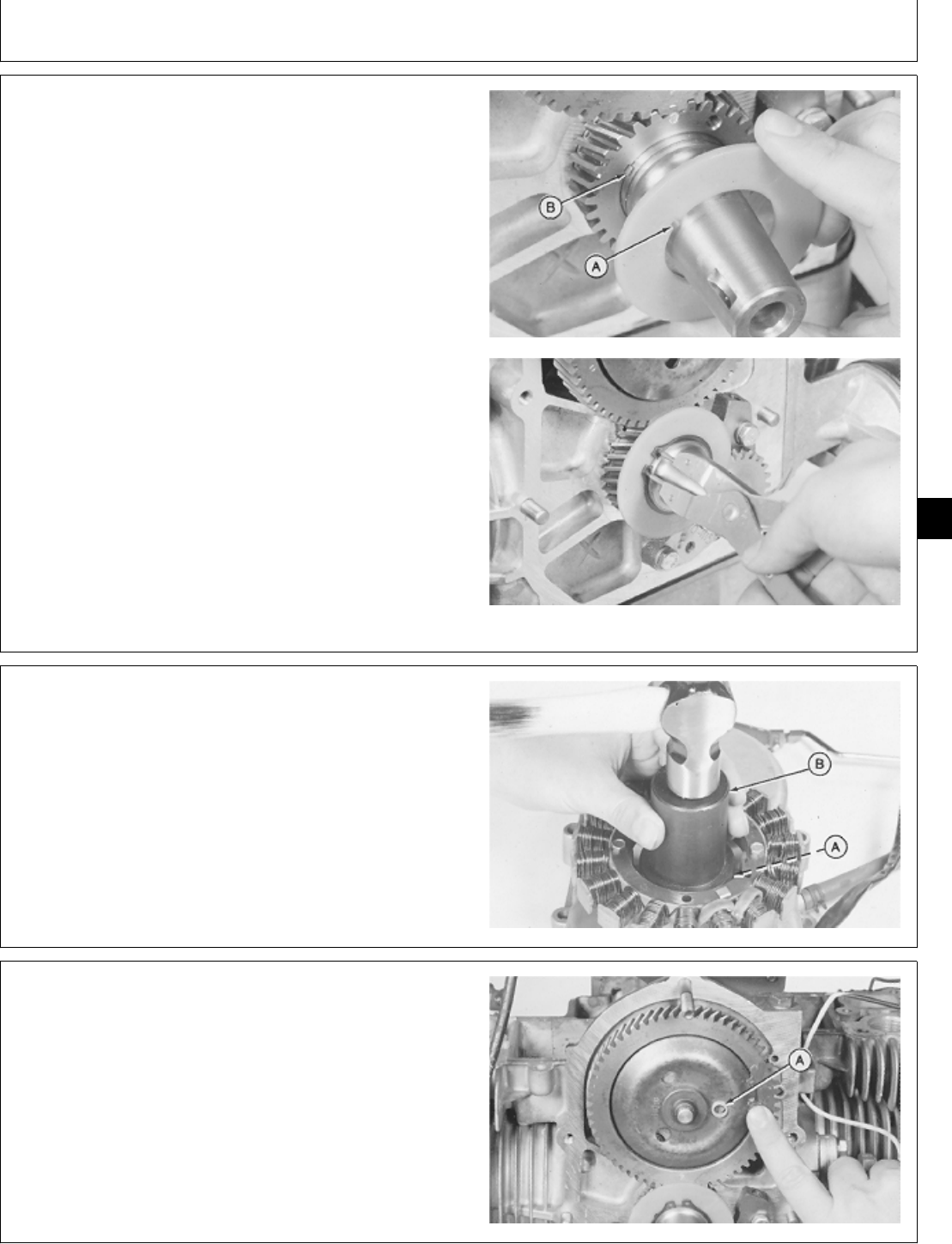
15. Turn cup until the plastic bushing (A) is in the 3
o’clock position.
16. Apply multipurpose grease between cup and
camshaft gear to hold cup in position.
M36326 -UN-29JAN90
M98,2025K,33 -19-09OCT85
M98,2025K,34 -19-09OCT85
M98,2025K,35 -19-11NOV85
Camshaft/Camshaft
CTM2 (19APR90) 25-15 16, 18, 20 & 24HP Onan Engines
130495
25
15
17. Install new gasket on cylinder block.
18. Be sure plastic bushing (A) and pin (B) are aligned.
IMPORTANT: Do not hit gear cover with a metal
hammer during installation. Gear cover
may be damaged.
19. Hold governor arm away from camshaft and carefully
install gear cover.
M36327 -UN-29JAN90M36328 -UN-29JAN90
20. Pull engine forward and move governor arm back
and forth. Governor cup should be felt moving in and
out. If no movement is felt, the pin is not in plastic
bushing. Remove gear cover and repeat steps 18—20.
M36329 -UN-29JAN90
M98,2025K,36 -19-09OCT85
M98,2025K,37 -19-09OCT85
Camshaft/Camshaft
CTM2 (19APR90) 25-16 16, 18, 20 & 24HP Onan Engines
130495
25
16
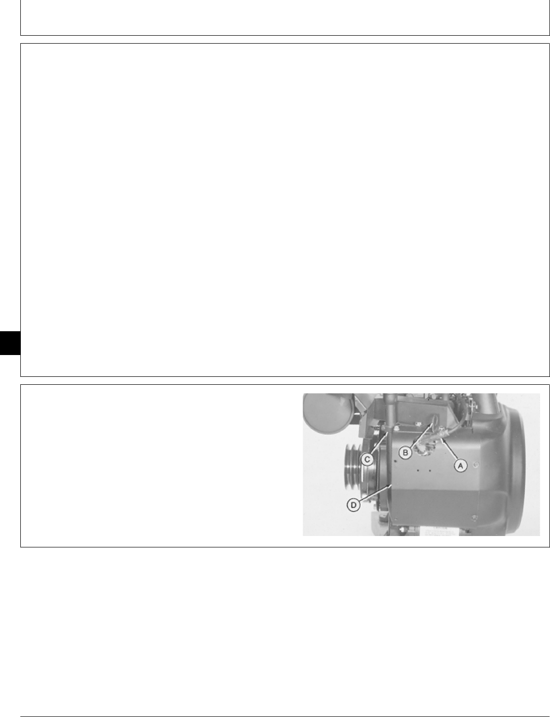
21. Apply pipe sealant on cap screw (A) threads.
22. Install clip (B), four cap screws and nut. Tighten cap
screws and nut to 12 ± 1 N·m (106 ± 9 lb-in.).
23. Install stator wiring (C) in clip.
24. For P218G or P220G engine, connect wires leads to
ignition coil. Install crankshaft key and magnetic ring.
M36330 -UN-29JAN90
25. Install new gasket (A) on cylinder block.
NOTE: Be careful not to lose the plunger during breaker
point assembly installation.
26. Apply clean engine oil on plunger. Remove excess
oil after installation.
27. Apply pipe sealant on Allen screw threads.
28. Install breaker point assembly and fasten with two
Allen screws, if equipped.
M36331 -UN-29JAN90M36300 -UN-29JAN90
29. Install breaker point wire in breaker point assembly
groove.
20. Install breaker point cover and tighten Allen screw.
M36299 -UN-29JAN90
M98,2025K,38 -19-10FEB87
M98,2025K,39 -19-10FEB87
M98,2025K,40 -19-10FEB85
Camshaft/Camshaft
CTM2 (19APR90) 25-17 16, 18, 20 & 24HP Onan Engines
130495
25
17
31. Install flywheel (E). (See Group 20 in this manual.)
32. Install intake and exhaust valves (D). (See Install
intake and Exhaust Valves, Group 15 in this manual.)
33. Install cylinder heads (C). (See Install Cylinder
Heads, Group 10 in this manual.)
34. Install intake manifold (B). (See Install Intake
Manifold, Group 10 in this manual.)
35. Install engine. (See machine technical manual.)
A—Muffler and Exhaust Pipes
B—Intake Manifold
C—Cylinder Heads
D—Intake and Exhaust Valves
E—Flywheel
M36474 -UN-29JAN90
M98,2025K,41 -19-10FEB85
Camshaft/Camshaft
CTM2 (19APR90) 25-18 16, 18, 20 & 24HP Onan Engines
130495
25
18

SERVICE EQUIPMENT AND TOOLS
NOTE: Order tools from the U.S. SERVICE-GARD™ Catalog or from the European Microfiche Tool Catalog
(MTC). Some tools may be available from a local supplier.
Name Use
Feeler Gauge Measure connecting rod end play and piston
ring end gap.
Ridge Reamer Remove ridge from top of cylinder bore.
Outside Micrometer Measure engine components.
Telescoping Gauge Measure connecting rod bores and piston pin
bore.
Piston Ring Expander Remove and install piston rings.
Vernier Calipers Measure piston ring groove width and piston
O.D.
Inside Micrometer Measure piston bore.
Flex Hone To deglaze cylinder bores
Piston Ring Compressor Install pistons in cylinder block.
OTHER MATERIAL
Number Name Use
PLASTIGAGE®Measure connecting rod bearing
clearance
PLASTIGAGE is a trademark of the TRW Corp.
SERVICE PARTS KITS
The following kits are available through your parts
catalog:
Overhaul Gasket Kit
M98,2030K,1 -19-11NOV85
M98,2030K,2 -19-09OCT85
M98,2030K,2A -19-11NOV85
Group 30
Connecting Rods and Pistons
CTM2 (19APR90) 30-1 16, 18, 20 & 24HP Onan Engines
130495
30
1

SPECIFICATIONS
Connecting Rods
Item New Specification Wear Tolerance
1. Side Clearance 0.05—0.41 mm 0.8 mm
(0.002—0.016 in.) (0.03 in.)
2. Connecting Rod Cap Nut Torque:
B43E, B43G, B48G, 18 ± 1 N·m
P218G, P220G Engine (159 ± 9 lb-in.)
3. Connecting Rod Cap Nut Torque:
T260 20 ± 1 N·m
(177 ± 9 lb-in.)
4. Piston Pin Clearance:
B43E, B43G, B48G Engine 0.005—0.010 mm
(0.0002—0.004 in.)
T260 Engine 0.003—0.013 mm
(0.001—0.005 in.)
P218G and P220G Engine 0.001—0.0162 mm
(0.00004—0.00064 in.)
5. Piston O.D.:
B43E, B43G, B48G, 82.42—82.44 mm 82.32 mm
P218G, P220G Engine (3.245—3.246 in.) (3.241 in.)
T260 Engine 90.42—90.45 mm 90.32 mm
(3.560—3.561 in.) (3.556 in.)
6. Cylinder Bore I.D.:
B43E, B43G, B48G, 82.53—82.55 mm 82.68 mm
P218G, P220G Engine (3.249—3.250 in.) (3.255 in.)
T260 Engine 90.488—90.512 mm 90.632 mm
(3.5625—3.5635 in.) (3.5682 in.)
7. Piston-To-Bore Clearance:
B43E, B43G, B48G, 0.076—0.127 mm 0.28 mm
P218G, P220G Engine (0.003—0.005 in.) (0.011 in.)
T260 Engine 0.178—0.229 mm 0.38 mm
(0.007—0.009 in.) (0.015 in.)
8. Cylinder Bore Taper:
B43E, B43G, B48G,
P218G, P220G Engine 0.13 mm (0.005 in.)
T260 Engine 0.08 mm (0.003 in.)
9. Cylinder Bore Out-of-Round 0.08 mm (0.003 in.)
M98,2030K,3 -19-11NOV85
Connecting Rods and Pistons/Specifications
CTM2 (19APR90) 30-2 16, 18, 20 & 24HP Onan Engines
130495
30
2

PISTON
Item New Specification Wear Tolerance
1. Ring Groove Width:
Top Ring 2.032—2.057 mm 2.21 mm
(0.080—0.081 in.) (0.087 in.)
Second Ring 2.032—2.057 mm 2.21 mm
(0.080—0.081 in.) (0.087 in.)
Oil Ring 4.775—4.801 mm 4.95 mm
(0.188—0.189 in.) (0.195 in.)
2. Ring End Gap 0.25—0.51 mm 1.52 mm
(0.010—0.020 in.) (0.060 in.)
3. Piston Pin Bore I.D.:
B43E, B43G, B48G, 17.468—17.478 mm
P218G, P220G Engine (0.6877—0.6881 in.)
T260 Engine 19.055—19.065 mm
(0.7502—0.7506 in.)
4. Rod-to-Crankshaft 0.051—0.084 mm 0.13 mm
Bearing Clearance (0.002—0.0033 in.) (0.0053 in.)
5. Crankshaft Connecting 41.28—41.30 mm 41.25 mm
Rod Journal O.D. (1.6252—1.6260 in.) (1.6242 in.)
6. Connecting Rod
Crankshaft Bore I.D.:
B43E, B43G, B48G, 41.35—41.36 mm 41.39 mm
P218G, P220G Engine (1.6280—1.6285 in.) (1.6295 in.)
T260 Engine 44.46—44.48 mm 44.50 mm
(1.7505—1.7510 in.) (1.7520 in.)
7. Piston Pin O.D.:
B43E, B43G, B48G, 17.463—17.468 mm 17.371 mm
P218G, P220G Engine (0.6875—0.6877 in.) (0.6839 in.)
T260 Engine 19.050—19.055 mm 18.959 mm
(0.7500—0.7502 in.) (0.7464 in.)
8. Connecting Rod
Piston Pin Bore I.D.:
B43E, B43G, B48G, 17.470—17.480 mm
P218G, P220G Engine (0.6878—0.6882 in.)
T260 19.06—19.07 mm
(0.7504—0.7508 in.)
9. Piston Pin Clearance:
B43E, B43G, B48G, 0.005—0.018 mm
P218G, P220G Engine (0.0002—0.00007 in.)
T260 Engine 0.005—0.020 mm
(0.0002—0.0008 in.)
M98,2030K,4 -19-11FEB87
Connecting Rods and Pistons/Specifications
CTM2 (19APR90) 30-3 16, 18, 20 & 24HP Onan Engines
130495
30
3
PISTON—CONTINUED
Item New Specification Wear Tolerance
10. Bores Out-of-Round 0.05 mm (0.002 in.)
Cylinder Head
Item New Specification
1. Attaching Cap Screw Torque:
B43E Engine 23 ± 1 N·m (204 ± 12 lb-in.)
B43G, B48G, P218G, P220G Engine 20 ± 1 N·m (180 ± 12 lb-in.)
2. Attaching Nut Torque (T260 Engine):
Top Six Nuts
(with compression washers) 16 ± 1 N·m (142 ± 12 lb-in.)
Bottom Four Nuts 20 ± 1 N·m (180 ± 12 lb-in.)
3. Oil Base Cap Screw Torque 27 ± 3 N·m (239 ± 27 lb-in.)
4. Lift Bracket Cap Screw Torque 11 ± 3 N·m (97 ± 27 lb-in.)
MEASURE CONNECTING ROD END PLAY
1. Remove engine. (See machine technical manual.)
2. Disconnect spark plug wire (A).
3. Remove six cap screws to remove lift bracket (B), oil
fill tube bracket (C), and left side shroud (D).
A—Spark Plug Wire
B—Lift Bracket
C—Oil Fill Tube Bracket
D—Left Side Shroud
M36472 -UN-29JAN90
M98,2030K,5 -19-02FEB87
M98,2030K,6 -19-09OCT85
Connecting Rods and Pistons/Connecting Rod
CTM2 (19APR90) 30-4 16, 18, 20 & 24HP Onan Engines
130495
30
4
4. Disconnect spark plug wire (A) and voltage regulator
leads (B).
5. Remove five cap screws (C) to remove lift bracket
(D), and right side shroud (E).
A—Spark Plug Wire
B—Voltage Regulator Leads
C—Cap Screw (5 used)
D—Lift Bracket
E—Right Side Shroud
M36289 -UN-29JAN90
6. Loosen hose clamp (A) to disconnect fuel pump
impulse line (B).
M36290 -UN-29JAN90
M98,2030K,7 -19-09OCT85
M98,2030K,8 -19-09OCT85
Connecting Rods and Pistons/Connecting Rod
CTM2 (19APR90) 30-5 16, 18, 20 & 24HP Onan Engines
130495
30
5
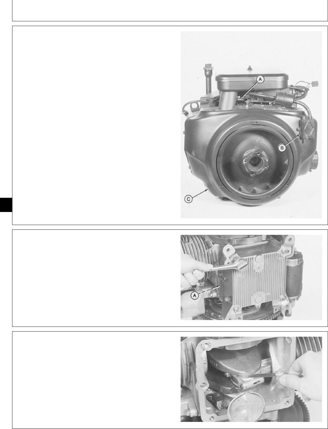
7. Disconnect governor spring (A).
8. Remove two screws to remove fuel pump (B).
9. Remove three cap screws to remove flywheel shroud
(C).
M36291 -UN-29JAN90
10. Remove four cap screws to remove oil base and
gasket (A).
M36374 -UN-29JAN90
11. Measure connecting rod side clearance. New side
clearance specification is 0.05—0.41 mm (0.002—0.016
in.).
If clearance exceeds 0.8 mm (0.03 in.), replace
connecting rod and connecting rod cap.
M36380 -UN-29JAN90
M98,2030K,9 -19-09OCT85
M98,2030K,10 -19-09OCT85
M98,2030K,11 -19-02FEB87
Connecting Rods and Pistons/Connecting Rod
CTM2 (19APR90) 30-6 16, 18, 20 & 24HP Onan Engines
130495
30
6
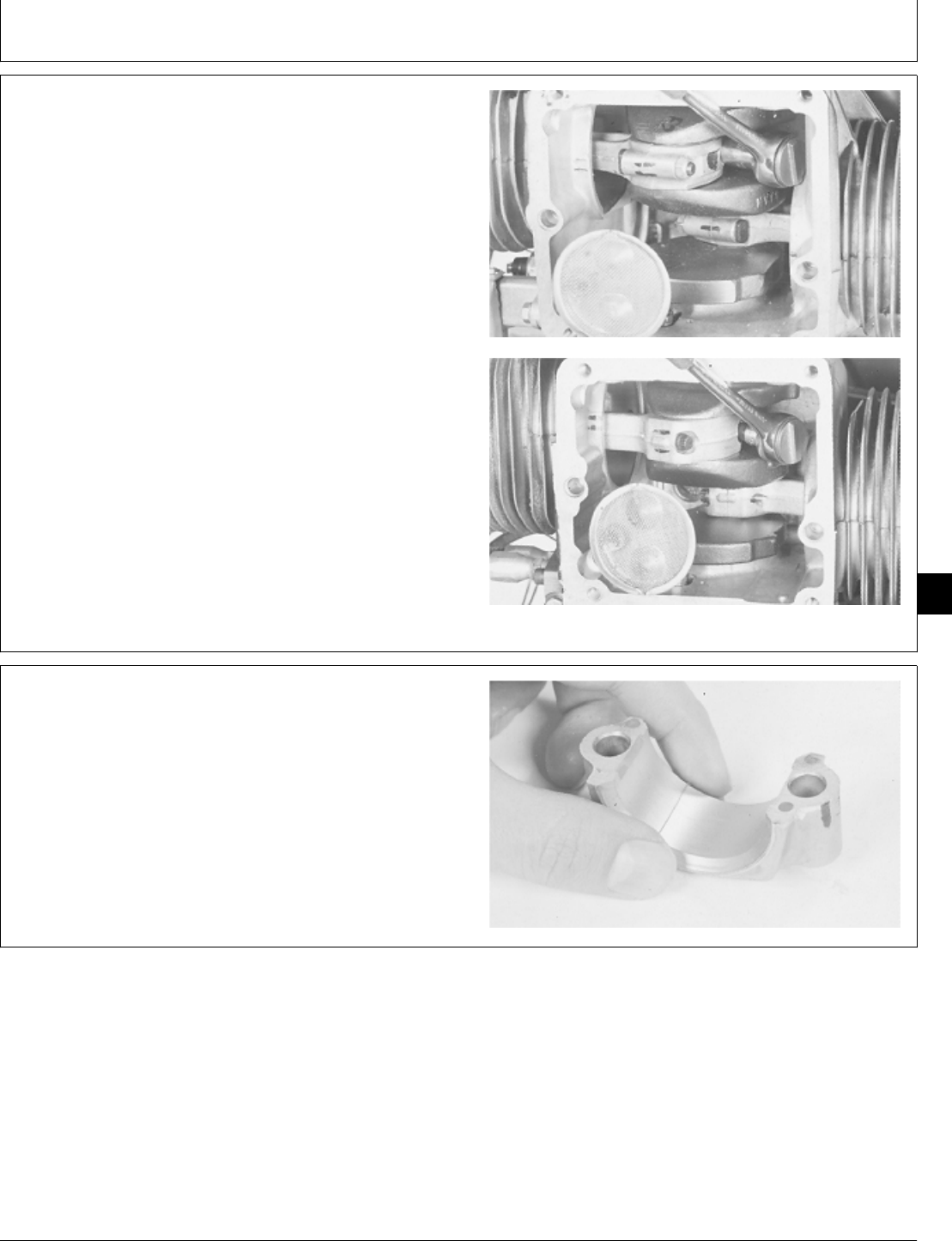
MEASURE CONNECTING ROD BEARING
CLEARANCE
Measure each connecting rod bearing clearance using
the following PLASTIGAGE method or by measuring
after the pistons have been removed.
IMPORTANT: Connecting rod end caps must be
installed on the same connecting rod
and in the same direction to prevent
crankshaft and connecting rod damage.
1. Put identification marks on connecting rods, rod caps,
and cylinder block.
2. Remove nuts to remove connecting rod caps (B43E,
B43G, B48G, P218G and P220G Engines—top photo).
Remove cap screws to remove connecting rod caps
(T260 Engine—bottom photo).
M36381 -UN-29JAN90M36388 -UN-29JAN90
3. Wipe oil from connecting rod bearing surface and
crankshaft journal.
4. Put a piece of PLASTIGAGE or an equivalent on the
full length of the bearing surface about 6 mm (1/4 in.) off
center.
M36382 -UN-29JAN90
M98,2030K,12 -19-02FEB87
M98,2030K,13 -19-09OCT85
Connecting Rods and Pistons/Connecting Rod
CTM2 (19APR90) 30-7 16, 18, 20 & 24HP Onan Engines
130495
30
7
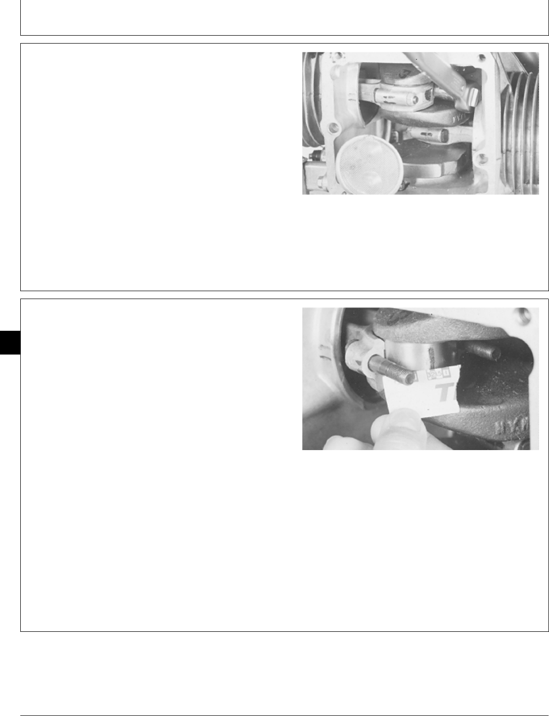
5. Turn crankshaft about 30˚ from bottom of oil pan and
install connecting rod cap. Install and tighten nuts or cap
screws evenly to specifications.
CONNECTING ROD SPECIFICATIONS
Engine Measurement Specifications
B43E, B43G, B48G, Cap Nut Torque 18 ± 1 N·m
P218G, P220G (159 ± 9 lb-in.)
T260 Cap Screw Torque 20 ± 1 N·m
(177 ± 9 lb-in.)
M36383 -UN-29JAN90
6. Remove nuts or cap screws and connecting rod cap.
7. The flattened PLASTIGAGE will be found on either
the bearing surface or crankshaft journal.
8. Use the graduation marks on the envelope to
compare the width of the flattened PLASTIGAGE at its
WIDEST point. Remove PLASTIGAGE.
The number within the graduation marks indicates the
bearing clearance in thousandths of an inch or in
millimeters depending on which side of the envelope is
used.
9. New bearing clearance is 0.051—0.084 mm
(0.002—0.0033 in.).
If clearance exceeds 0.13 mm (0.0053 in.), remove
pistons.
If clearance is correct, install connecting rod caps and
tighten nuts or cap screws to specifications.
M36384 -UN-29JAN90
M98,2030K,14 -19-02FEB87
M98,2030K,15 -19-09OCT85
Connecting Rods and Pistons/Connecting Rod
CTM2 (19APR90) 30-8 16, 18, 20 & 24HP Onan Engines
130495
30
8
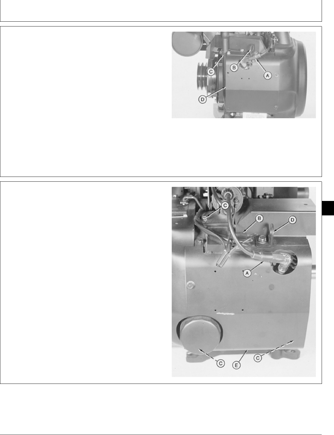
REMOVE PISTONS AND CONNECTING
RODS
1. Remove engine. (See machine technical manual.)
2. Disconnect spark plug wire (A).
3. Remove six cap screws to remove lift bracket (B), oil
fill tube (C), and left side shroud (D).
A—Spark Plug Wire
B—Lift Bracket
C—Oil Fill Tube Bracket
D—Left Side Shroud
M36472 -UN-29JAN90
4. Disconnect spark plug wire (A) and voltage regulator
leads (B).
5. Remove five cap screws (C) to remove lift bracket
(D), and right side shroud (E).
A—Spark Plug Wire
B—Voltage Regulator Leads
C—Cap Screw (5 used)
D—Lift Bracket
E—Right Side Shroud
M36289 -UN-29JAN90
M98,2030K,16 -19-09OCT85
M98,2030K,7 -19-09OCT85
Connecting Rods and Pistons/Pistons and Connecting Rods
CTM2 (19APR90) 30-9 16, 18, 20 & 24HP Onan Engines
130495
30
9
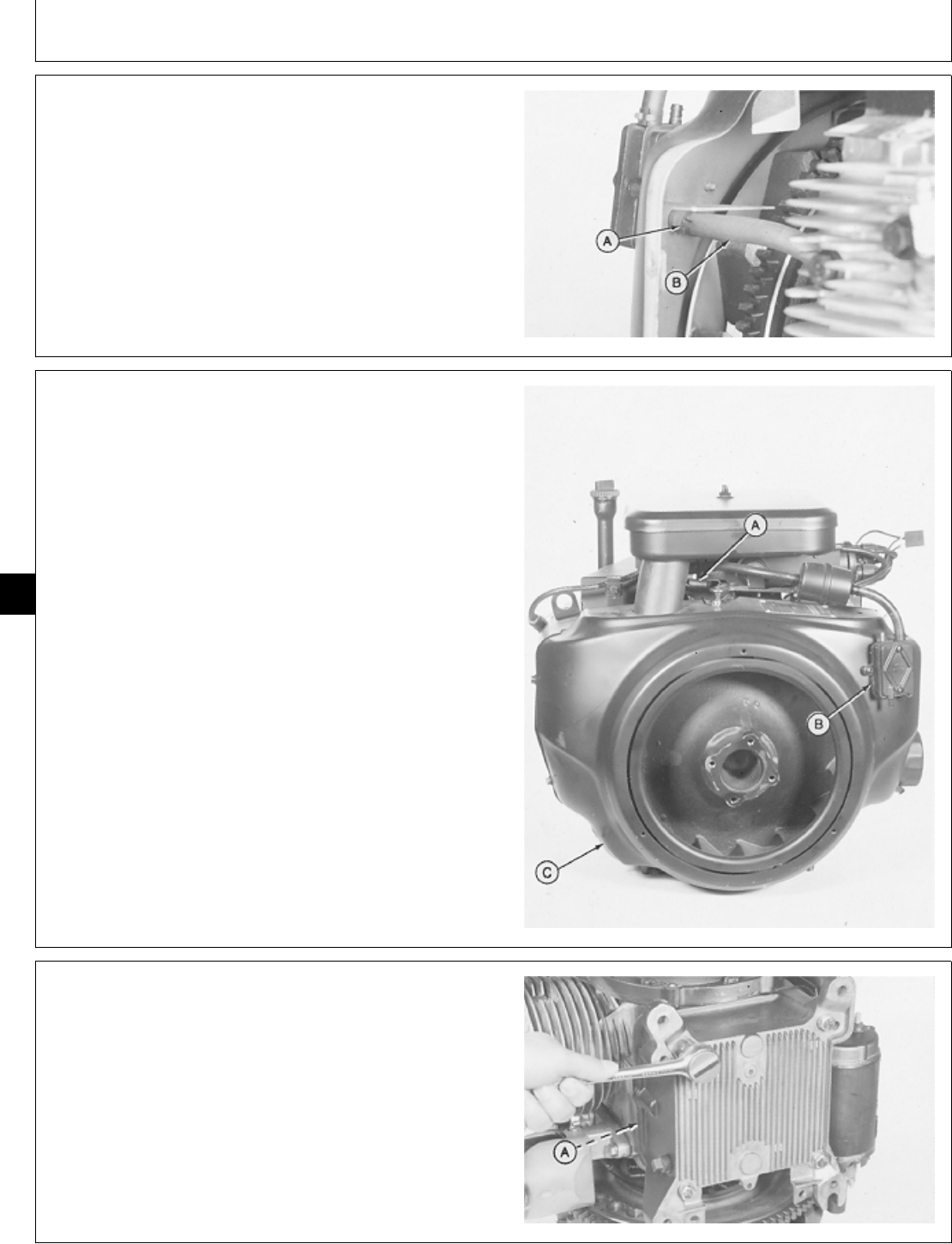
6. Loosen hose clamp (A) to disconnect fuel pump
impulse line (B).
M36290 -UN-29JAN90
7. Disconnect governor spring (A).
8. Remove two screws to remove fuel pump (B).
9. Remove three cap screws to remove flywheel shroud
(C).
M36291 -UN-29JAN90
10. Remove four cap screws to remove oil base and
gasket (A).
M36374 -UN-29JAN90
M98,2030K,8 -19-09OCT85
M98,2030K,9 -19-09OCT85
M98,2030K,10 -19-09OCT85
Connecting Rods and Pistons/Pistons and Connecting Rods
CTM2 (19APR90) 30-10 16, 18, 20 & 24HP Onan Engines
130495
30
10
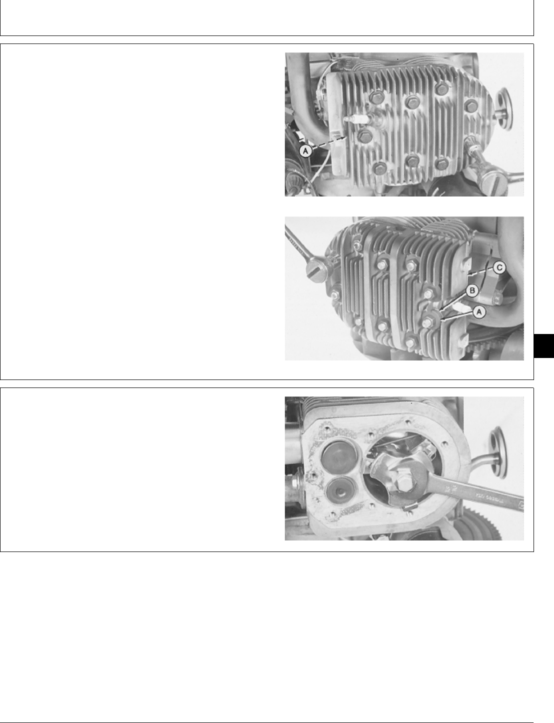
IMPORTANT: Do not remove cylinder heads while
they are hot. Cylinder head may warp.
A hot gasket will be soft and difficult to
remove.
11. Remove nine cap screws to remove cylinder head
and gasket (A).
Remove 10 nuts, 20 compression washers (A), and ten
washers (B) to remove cylinder head and gasket (C).
B43E,B43G,B48G,P21G and P220G
T260 Engine
M36385 -UN-29JAN90M36386 -UN-29JAN90
12. Clean carbon from cylinder bore using a wire brush.
13. Before piston removal, check cylinder bore for ridges.
The ridges can cause damage to piston or rings if ridge
is not removed.
14. If necessary, remove ridge from top of cylinder bore
using a ridge reamer.
M36387 -UN-29JAN90
M98,2030K,17 -19-02FEB87
M98,2030K,18 -19-09OCT85
Connecting Rods and Pistons/Pistons and Connecting Rods
CTM2 (19APR90) 30-11 16, 18, 20 & 24HP Onan Engines
130495
30
11
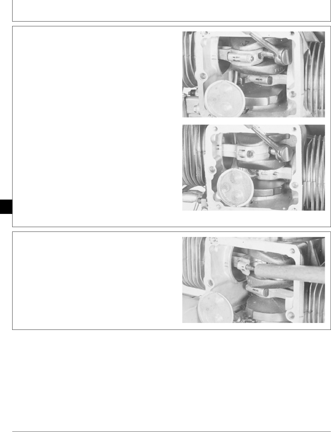
IMPORTANT: Connecting rod caps must be installed
on the same connecting rod and in the
same direction to prevent crankshaft
and connecting rod damage.
15. Put identification marks on connecting rods, rod
caps, and cylinder block.
16. Remove nuts to remove connecting rod caps. (B43E,
B43G, B48G, P218G and P220G Engines—top photo.)
Remove cap screws to remove connecting rod caps.
(T260 Engine-bottom photo)
M36381 -UN-29JAN90M36388 -UN-29JAN90
17. Push piston and connecting rod out of cylinder bore
using a wooden dowel.
M36389 -UN-29JAN90
M98,2030K,19 -19-02FEB87
M98,2030K,20 -19-09OCT85
Connecting Rods and Pistons/Pistons and Connecting Rods
CTM2 (19APR90) 30-12 16, 18, 20 & 24HP Onan Engines
130495
30
12
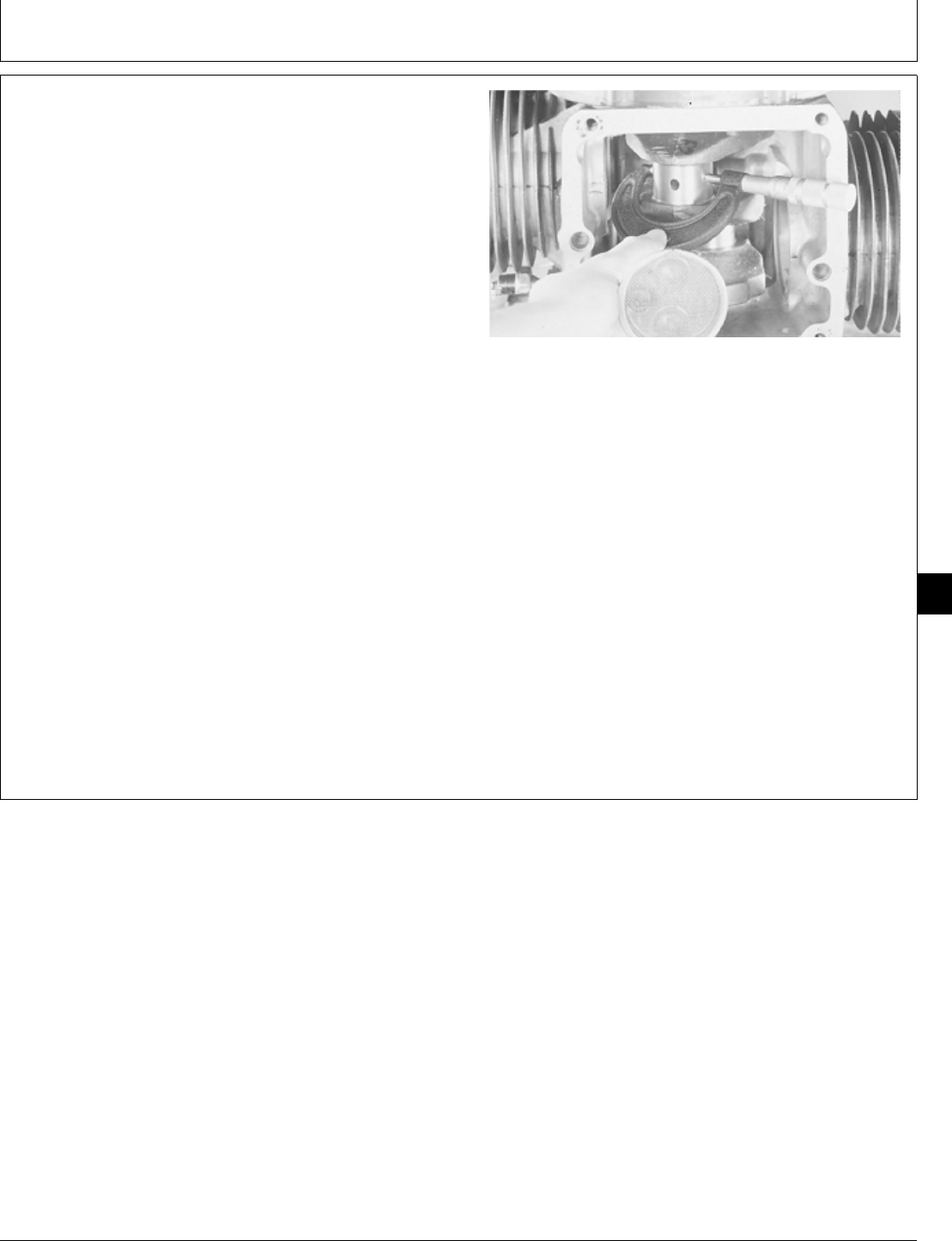
INSPECT PISTONS AND CONNECTING
RODS
1. Measure crankshaft connecting rod journal diameter.
Measure several places around each journal and each
side of journal.
NOTE: If engine has had previous major overhaul,
crankshaft journals may have been ground and
undersize connecting rods installed.
CONNECTING ROD JOURNAL SPECIFICATIONS
Item New Parts Wear Tolerance
Journal O.D. 41.28—41.30 mm 41.25 mm
(1.6252—1.6260 in.) (1.6242 in.)
If journal diameter is less than 41.25 mm (1.6242 in.),
replace crankshaft or have journals ground by a qualified
machine shop. The following undersize connecting rods
are available:
0.25 mm (0.010 in.)
0.50 mm (0.020 in.)
0.76 mm (0.030 in.)
M36390 -UN-29JAN90
M98,2030K,21 -19-11NOV85
Connecting Rods and Pistons/Pistons and Connecting Rods
CTM2 (19APR90) 30-13 16, 18, 20 & 24HP Onan Engines
130495
30
13
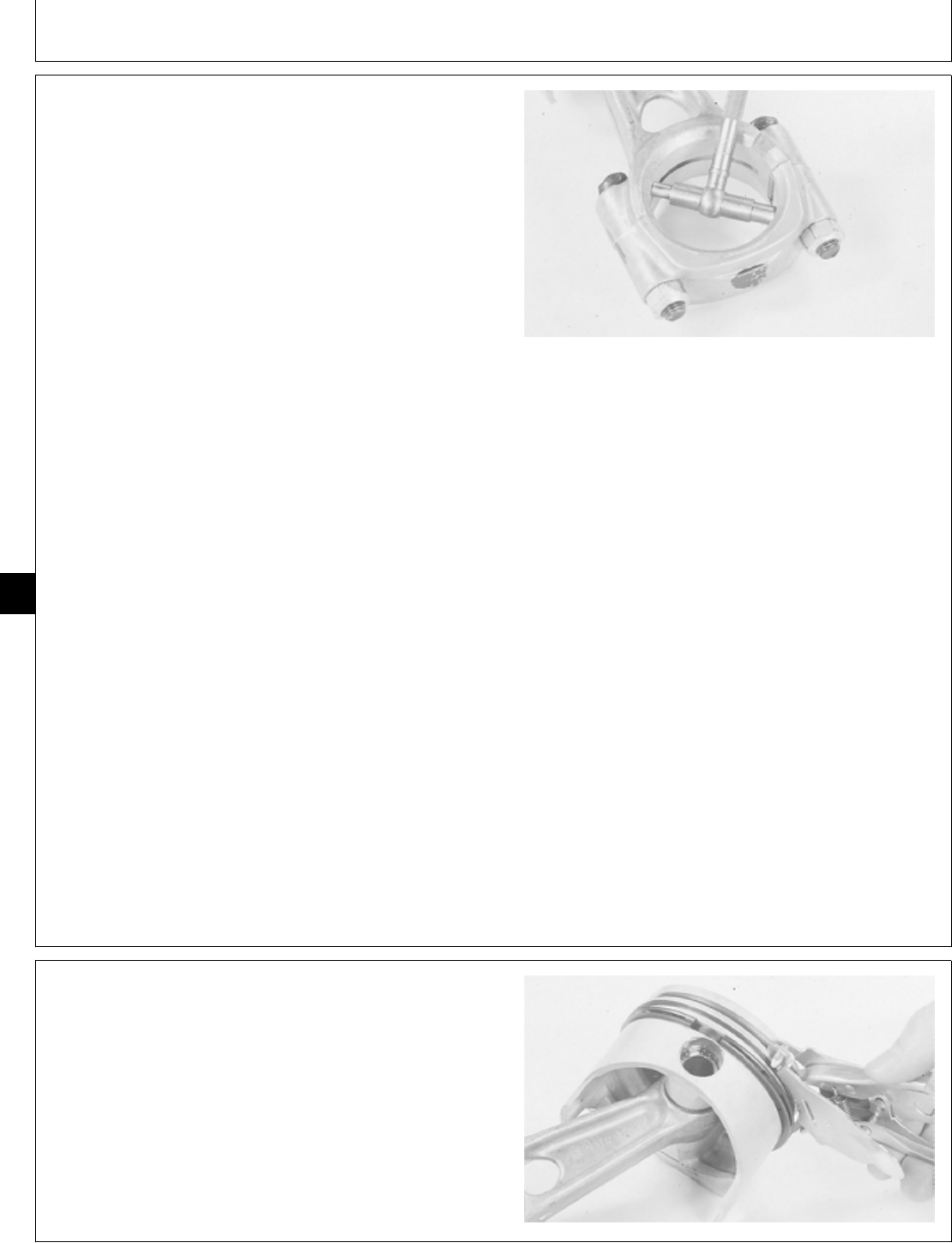
2. Measure connecting rod bore diameter and connecting
rod clearance (bore I.D. minus journal O.D.).
3. Install connecting rod cap on connecting rod. Install
and tighten nuts or cap screws evenly to specifications.
CONNECTING ROD SPECIFICATIONS
Cap Nut Torque
B43E, B43G, B48G,
P218G, P220G
Engines 18 ± 1 N·m (159 ± 9 lb-in.)
Cap Screw Torque
T260 Engine 20 ± 1 N·m (177 ± 9 lb-in.)
Item New Parts Wear Tolerance
Bore I.D.:
B43E,B43G,B48G,
P218G, P220G 41.35—41.36 mm 41.39 mm
Engines (1.6280—1.6285 in.) (1.6295 in.)
T260 Engine 44.46—44.48 mm 44.50 mm
(1.7505—1.7510 in.) (1.7520 in.)
Clearance 0.051—0.084 mm 0.135 mm
(0.0020—0.0033 in.) (0.0053 in.)
If bore diameter exceeds wear tolerance, replace
connecting rod.
If connecting rod clearance exceeds 0.135 mm (0.0053
in.), replace connecting rod or grind crankshaft
connecting rod journals and install undersize connecting
rods.
M36391 -UN-29JAN90
4. Remove piston rings using a piston ring expander.
IMPORTANT: Do not use a caustic cleaning solvent
to remove carbon from pistons; piston
may be damaged.
5. Clean carbon from piston surfaces using a wire brush.
Clean piston ring grooves with a piston ring groove
cleaner or the end of a piston ring filed to a sharp point.
M36392 -UN-29JAN90
M98,2030K,22 -19-02FEB87
M98,2030K,23 -19-09OCT85
Connecting Rods and Pistons/Pistons and Connecting Rods
CTM2 (19APR90) 30-14 16, 18, 20 & 24HP Onan Engines
130495
30
14
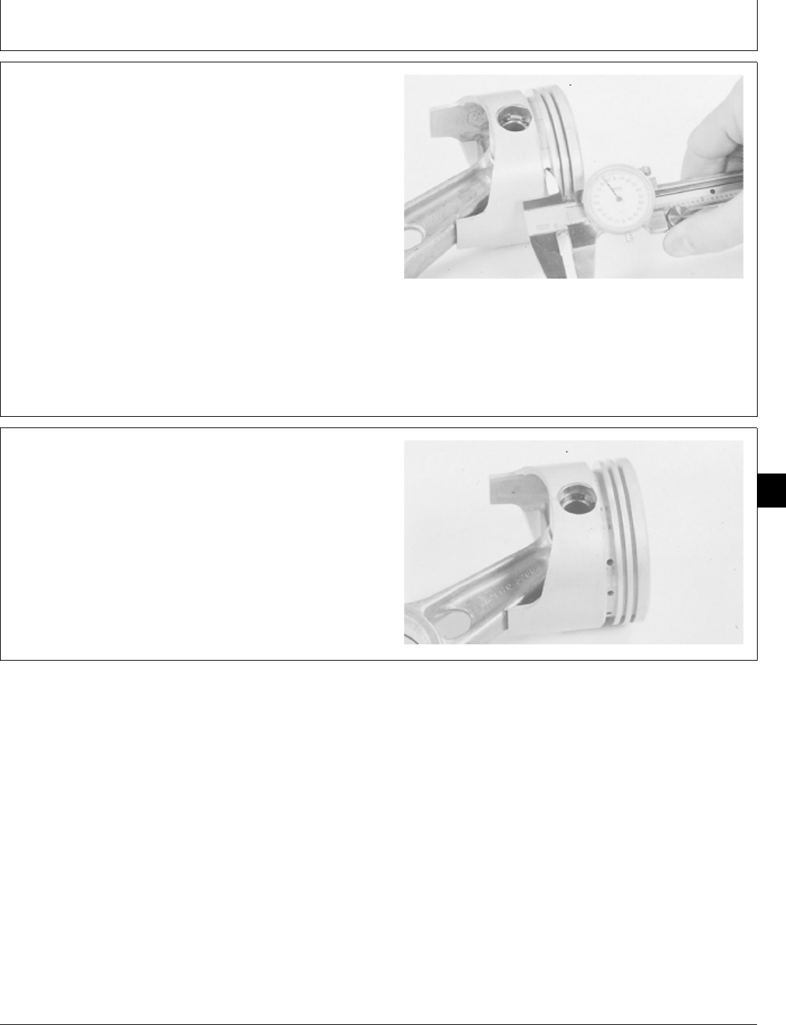
6. Measure piston ring groove width. Measure several
places around each piston.
PISTON RING GROOVE SPECIFICATIONS
Item New Part Wear Tolerance
Top Ring 2.032—02.057 mm 2.21 mm
(0.080—0.081 in.) (0.087 in.)
Second Ring 2.032—2.057 mm 2.21 mm
(0.080—0.081 in.) (0.087 in.)
Oil Ring 4.775—4.801 mm 4.95 mm
(0.188—0.189 in.) (0.195 in.)
If ring groove width exceeds wear tolerance, replace
piston.
M36393 -UN-29JAN90
7. Inspect piston for worn or cracked ring lands.
Excessive piston wear near the edge of the top ring land
indicated preignition.
8. Clean and inspect oil holes in oil ring groove for a
plugged condition. Replace parts as necessary.
M36394 -UN-29JAN90
M98,2030K,24 -19-11NOV85
M98,2030K,25 -19-09OCT85
Connecting Rods and Pistons/Pistons and Connecting Rods
CTM2 (19APR90) 30-15 16, 18, 20 & 24HP Onan Engines
130495
30
15
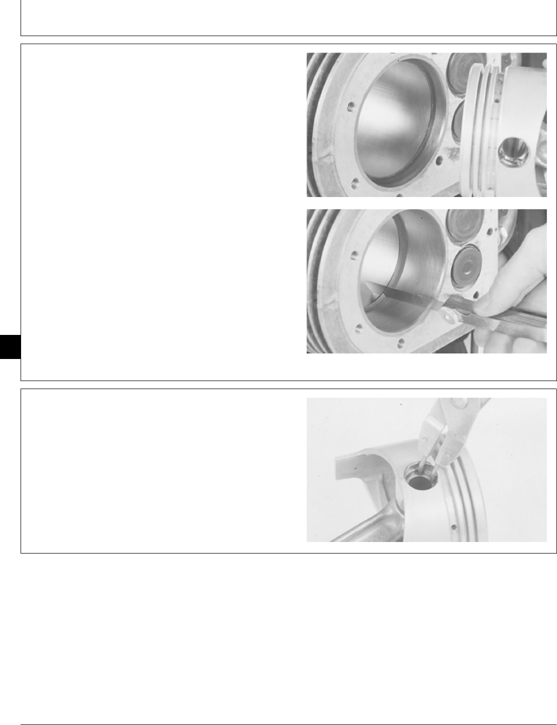
9. Measure piston ring end gap. Push rings into cylinder
bore approximately halfway using piston.
PISTON RING END GAP SPECIFICATIONS
Item New Part Wear Tolerance
All Rings 0.25—0.51 mm 1.52 mm
(0.010—0.020 in.) (0.060 in.)
If end gap exceeds 1.52 mm (0.060 in.), replace rings.
Deglaze cylinder bore before installing new rings.
M36395 -UN-29JAN90M36396 -UN-29JAN90
IMPORTANT: Pistons must be installed in the same
direction and on the same connecting
rod they were removed from.
10. Put a mark on each piston and connecting rod for
proper identification to aid in assembly.
11. Remove two snap rings.
12. Remove piston pin using a wooden dowel.
M36397 -UN-29JAN90
M98,2030K,26 -19-12NOV85
M98,2030K,27 -19-09OCT85
Connecting Rods and Pistons/Pistons and Connecting Rods
CTM2 (19APR90) 30-16 16, 18, 20 & 24HP Onan Engines
130495
30
16
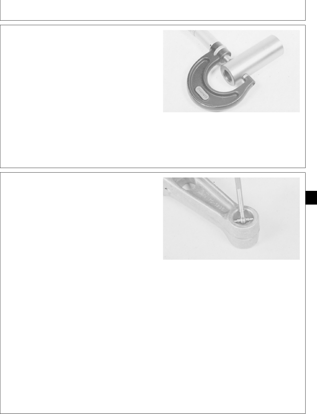
13. Measure diameter of piston pin at six places; two
measurements 90˚ apart at each end and two
measurements 90˚ at center.
PISTON PIN SPECIFICATIONS
Item New Part Wear Tolerance
Pin O.D.
B43E,B43G,B48G,
P218G, P220G 17.463—17.468 mm 17.371 mm
Engine (0.6875—0.6877 in.) (0.6839 in.)
T260 Engine 19.050—19.055 mm 18.959 mm
(0.7500—0.7502 in.) (0.7464 in.)
If pin diameter is less than wear tolerance, install a new
piston pin.
M35365 -UN-29AUG88
14. Measure piston pin bore in connecting rod and piston
pin clearance (bore I.D. minus pin O.D.).
PISTON PIN BORE SPECIFICATIONS
Engine Item New Part
B43E, B43G, B48G, Bore I.D. 17.470—17.480 mm
P218G, P220G (0.6878—0.6882 in.)
B43E, B43G, B48G, Pin Clearance 0.005—0.018 mm
P218G, P220G (0.0002—0.0007 in.)
T260 Bore I.D. 19.06—19.07 mm
(0.7504—0.7508 in.)
T260 Pin Clearance 0.005—0.020 mm
(0.0002—0.0008 in.)
If piston pin bore diameter exceeds specifications,
replace connecting rod.
If pin clearance exceeds specifications, replace
connecting rod, piston pin, or both.
15. Inspect connecting rod cap screws and nuts for
damaged threads. Inspect connecting rods for nicks,
cracks, scored bores, or bores out-of-round more than
0.05 mm (0.002 in.).
M36398 -UN-29JAN90
M98,2030K,28 -19-02FEB87
M98,2030K,29 -19-11FEB87
Connecting Rods and Pistons/Pistons and Connecting Rods
CTM2 (19APR90) 30-17 16, 18, 20 & 24HP Onan Engines
130495
30
17
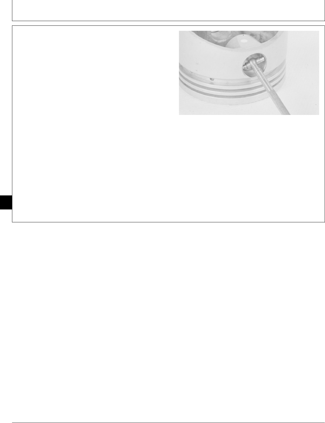
16. Measure piston pin bore in piston and piston pin
clearance (bore I.D. minus pin O.D.).
PISTON PIN BORE SPECIFICATIONS
Engine Item New Part
B43E, B43G, B48G, Bore I.D. 17.468—17.478 mm
P218G, P220G (0.6877—0.6881 in.)
B43E, B43G, B48G Pin Clearance 0.005—0.010 mm
(0.002—0.0004 in.)
P218G, P220G 0.001—0.0162 mm
(0.00004—0.00064 in.)
T260 Bore I.D. 19.005—19.065 mm
(0.7502—0.7506 in.)
T260 Pin Clearance 0.003—0.013 mm
(0.0001—0.0005 in.)
If piston pin bore diameter exceeds specifications,
replace piston.
If piston pin clearance exceeds specifications; replace
piston, piston pin, or both.
M36399 -UN-29JAN90
M98,2030K,30 -19-11FEB87
Connecting Rods and Pistons/Pistons and Connecting Rods
CTM2 (19APR90) 30-18 16, 18, 20 & 24HP Onan Engines
130495
30
18
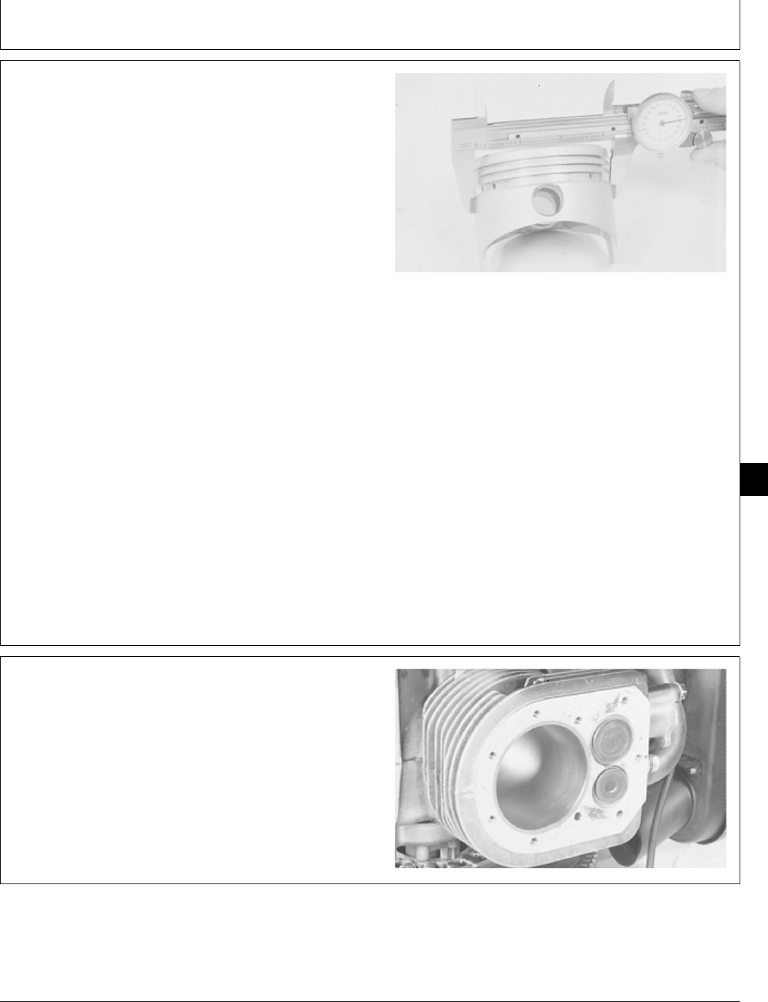
17. Measure piston O.D. perpendicular to piston bore at
a point approximately 30 mm (1.2 in.) from top of piston
or 2.5 mm (0.1 in.) below oil ring groove.
NOTE: If engine has had a previous major overhaul,
oversize pistons and rings may have been
installed.
PISTON SPECIFICATIONS
Item New Part Wear Tolerance
Piston O.D.
B43E, B43G, B48G,
P218G, P220G 82.42—82.44 mm 82.32 mm
Engine (3.245—3.246 in.) (3.241 in.)
T260 Engine 90.42—90.45 mm 90.32 mm
(3.560—3.561 in.) (3.556 in.)
If piston diameter is less than wear tolerance, install a
new piston.
18. Inspect piston for cracks at ring lands, skirts, and pin
bores. Inspect piston for scuffing or scoring; replace as
necessary.
M36400 -UN-29JAN90
19. Inspect cylinder bores for scuffing, scoring, scratches,
cracks, and wear. If cylinder bores are damaged, replace
cylinder block or rebore and hone cylinder for next
oversize piston.
20. If the cylinder bore is not damaged, check cylinder
bore for wear.
M36401 -UN-29JAN90
M98,2030K,31 -19-02FEB87
M98,2030K,32 -19-09OCT85
Connecting Rods and Pistons/Pistons and Connecting Rods
CTM2 (19APR90) 30-19 16, 18, 20 & 24HP Onan Engines
130495
30
19
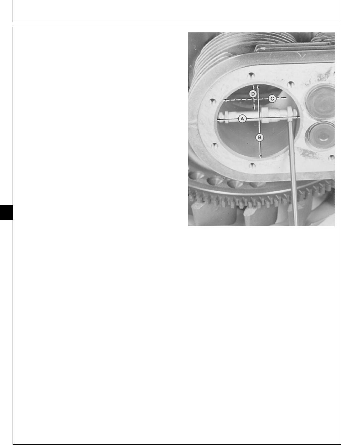
21. Measure piston bore I.D. at four places; two
measurements 90˚ apart at top of ring travel and two
measurements 90˚ apart at bottom of ring travel.
NOTE: If engine has had a previous major overhaul,
oversize pistons and rings may have been
installed.
22. Measure piston clearance (piston bore I.D. minus
piston O.D.).
23. Measure cylinder bore taper (A—C, B—D).
24. Measure cylinder bore out-of round (A—B, C—D).
CYLINDER BORE SPECIFICATIONS
Item New Part Wear Tolerance
Bore I.D.
B43E,B43G, B48G,
P218G, P220G 82.53—82.55 mm 82.68 mm
Engine (3.249—3.250 in.) (3.255 in.)
T260 Engine 90.488—90.512 mm 90.632 mm
(3.5625—3.5635 in.) (3.5682 in.)
Piston Clearance
B43E, B43G, B48G,
P218G, P220G 0.076—0.127 mm 0.28 mm
Engine (0.003—0.005 in.) (0.011 in.)
T260 Engine 0.178—0.229 mm 0.38 mm
(0.007—0.009 in.) (0.015 in.)
Taper
B43E, B43G, B48G,
P218G, P220G 0.13 mm
Engine (0.005 in.)
T260 Engine 0.08 mm
(0.003 in.)
Out-of-Round 0.08 mm
(0.003 in.)
If cylinder bore exceeds wear tolerance, replace cylinder
block or have cylinder rebored by a qualified machine
shop. If cylinder is rebored, oversize piston and rings
must be installed. The following oversize pistons and
rings are available:
0.25 mm (0.010 in.)
0.50 mm (0.020 in.)
0.76 mm (0.030 in.)
If piston clearance exceeds wear tolerance, replace
cylinder block, piston or both, or rebore cylinder. Install
oversize piston and rings.
If taper or out-of-round exceed wear tolerance, replace
cylinder block, or rebore cylinder. Install oversize piston
and rings.
M36402 -UN-29JAN90
M98,2030K,33 -19-11FEB87
Connecting Rods and Pistons/Pistons and Connecting Rods
CTM2 (19APR90) 30-20 16, 18, 20 & 24HP Onan Engines
130495
30
20
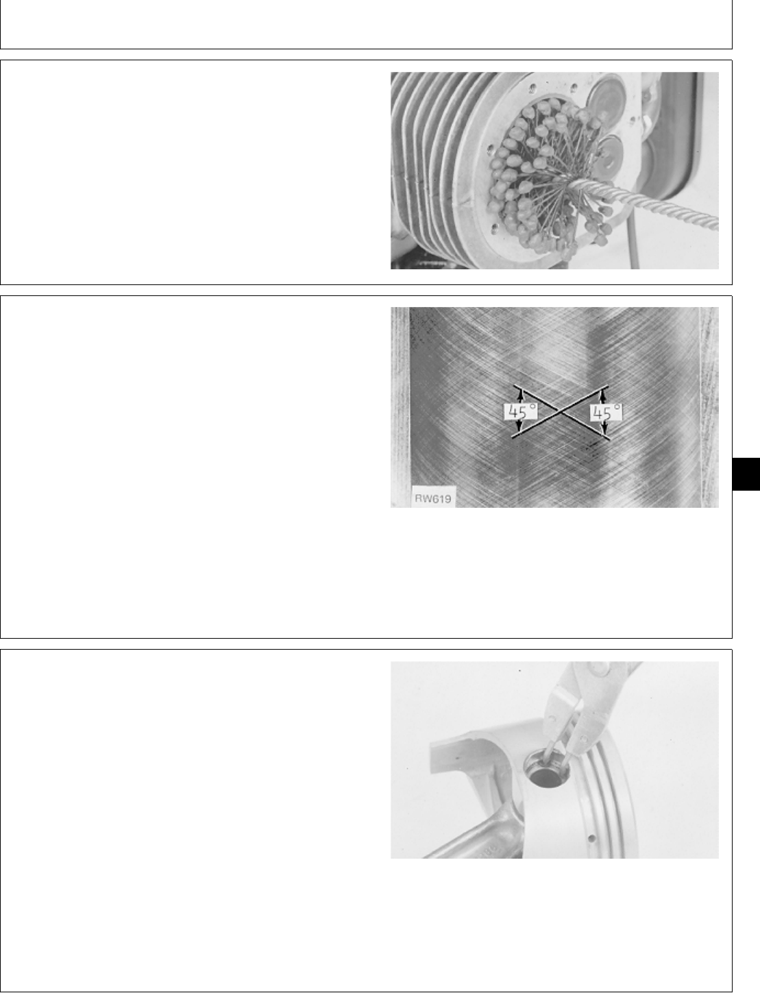
DEGLAZE CYLINDER BORES
NOTE: It is recommended that crankshaft be removed. If
cylinder bores are to be deglazed with crankshaft
installed in engine, put clean shop towels over
crankshaft to protect journal and bearing surfaces
from any abrasives.
1. Deglaze cylinder bores using a flex-hone.
M36403 -UN-29JAN90
NOTE: A cutaway of a cylinder bore is shown for clarity
of photograph.
2. Use flex-hone as instructed by manufacturer to obtain
45˚ crosshatch pattern as shown.
IMPORTANT: Do not use gasoline, kerosene, or
commercial solvents to clean cylinder
bores. Solvents will not remove all
abrasives from cylinder walls.
3. Remove excess abrasive residue from cylinder walls
using a clean dry rag. Clean cylinder walls using clean
white rags and water. Continue to clean cylinder until
white rags show no discoloration.
RW619 -UN-02DEC88
ASSEMBLE PISTONS AND CONNECTING
RODS
IMPORTANT: Pistons must be installed on
connecting rods from which they were
removed.
1. Identification marks on piston must be to the same
side as marks on connecting rod.
2. Put clean engine oil on piston pin. Install pin through
piston and connecting rod.
3. Install snap rings. Be sure snap rings are fastened in
groove all around.
M36397 -UN-29JAN90
M98,2030K,34 -19-10OCT85
M98,2025R,29 -19-31JUL84
M98,2030K,35 -19-10OCT85
Connecting Rods and Pistons/Pistons and Connecting Rods
CTM2 (19APR90) 30-21 16, 18, 20 & 24HP Onan Engines
130495
30
21
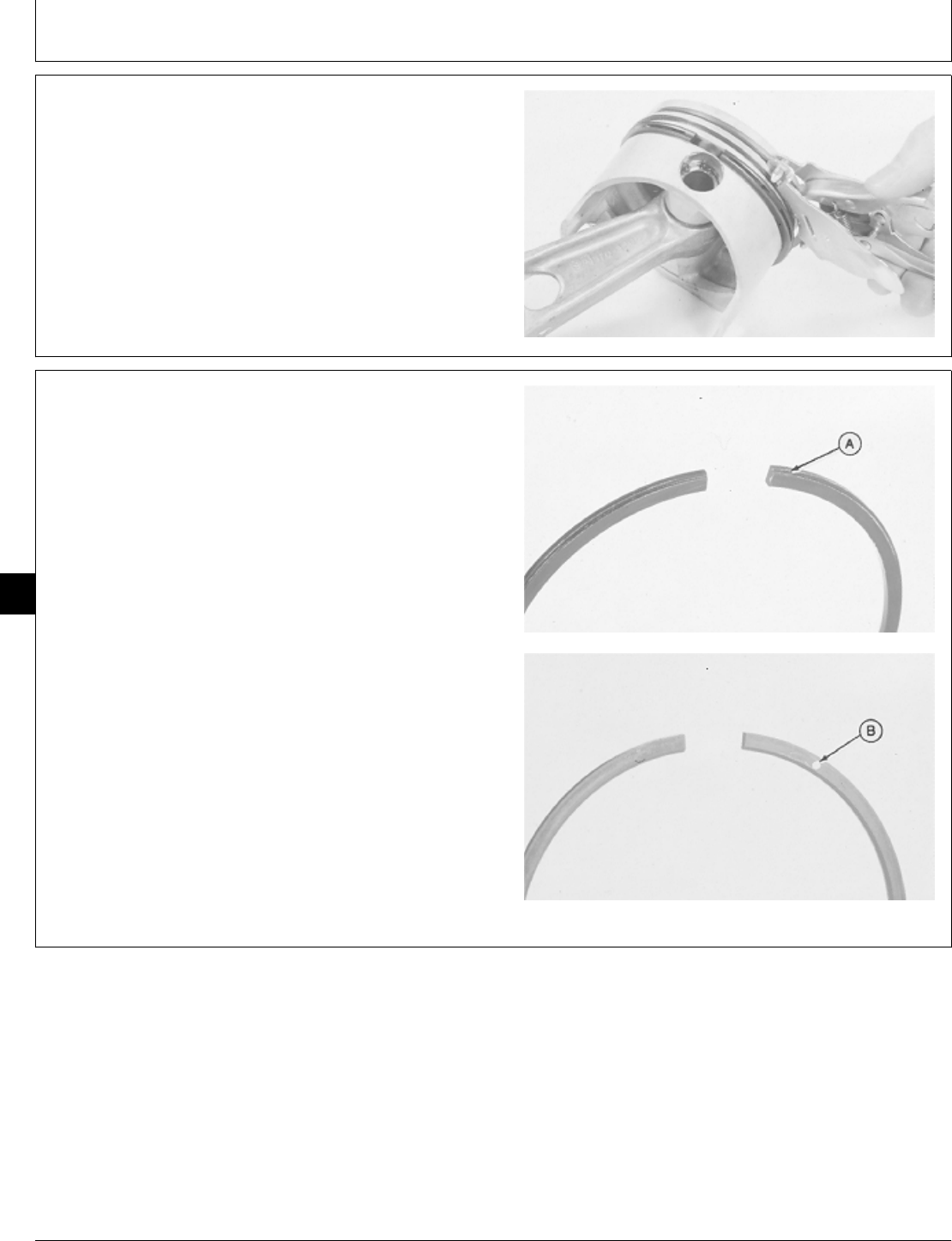
4. Install oil ring expander in bottom piston ring groove.
Turn expander so ends are above either end of the
piston pin.
5. Install oil ring over expander with a piston ring
expander. Turn oil ring so ends are on opposite side of
piston from the expander ends.
M36392 -UN-29JAN90
6. Install second ring in middle groove, with chamfer (A)
toward bottom of piston, or with dot (B) toward top of
piston (T260 only).
7. Install compression ring in top groove, with dot (B)
toward top of piston.
M36406 -UN-29JAN90M36404 -UN-29JAN90
M98,2030K,36 -19-10OCT85
M98,2030K,37 -19-10OCT85
Connecting Rods and Pistons/Pistons and Connecting Rods
CTM2 (19APR90) 30-22 16, 18, 20 & 24HP Onan Engines
130495
30
22
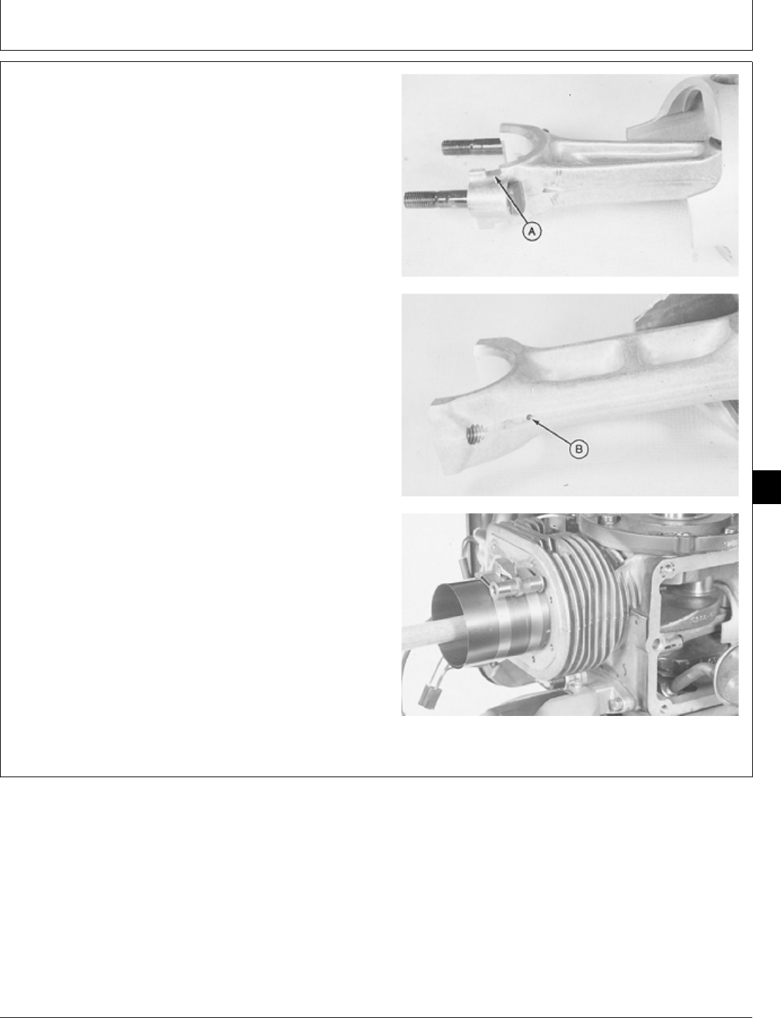
INSTALL PISTONS AND CONNECTING
RODS
IMPORTANT: Pistons must be installed in the same
cylinder they were removed from and in
the same direction. Be careful not to
damage crankshaft rod journal while
installing piston.
1. Apply clean engine oil on piston,s connecting rod
bearing surface, and cylinder bore.
2. Turn crankshaft until rod journal is at bottom of its
stroke.
3. Install piston with notch (A) or oil hole (B) toward
camshaft using a ring compressor. Push piston down
until connecting rod is seated on crankshaft rod journal.
M36363 -UN-29JAN90M36364 -UN-29JAN90M36407 -UN-29JAN90
M98,2030K,38 -19-10OCT85
Connecting Rods and Pistons/Pistons and Connecting Rods
CTM2 (19APR90) 30-23 16, 18, 20 & 24HP Onan Engines
130495
30
23
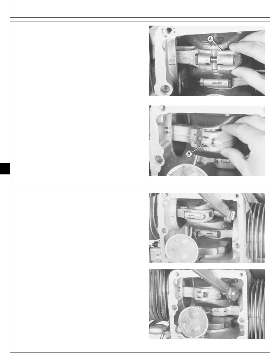
IMPORTANT: Connecting rod caps must be installed
on the same connecting rod they were
removed from and in the same
direction.
4. Apply clean engine oil on connecting rod cap.
5. Install connecting rod cap with this side (A) outward
on connecting rod.
Install connecting rod cap with large tang (B) away from
camshaft on connecting rod. B43E, B43G, B48G, P218G, and P220G
T260 Engine
M36408 -UN-29JAN90M36409 -UN-29JAN90
6. Install and tighten nuts or cap screws evenly to
specifications. Hit connecting rod cap LIGHTLY with a
soft-faced hammer to align it with connecting rod.
CONNECTING ROD SPECIFICATIONS
Engine Measurement Specification
B43E, B43G, B48G, Cap Nut Torque 18 ± 1 N·m
P218G, P220G (159 ± 9 lb-in.)
T260 Cap Screw Torque 20 ± 1 N·m
(177 ± 9 lb-in.)
M36383 -UN-29JAN90M36410 -UN-29JAN90
M98,2030K,39 -19-02FEB87
M98,2030K,40 -19-02FEB87
Connecting Rods and Pistons/Pistons and Connecting Rods
CTM2 (19APR90) 30-24 16, 18, 20 & 24HP Onan Engines
130495
30
24
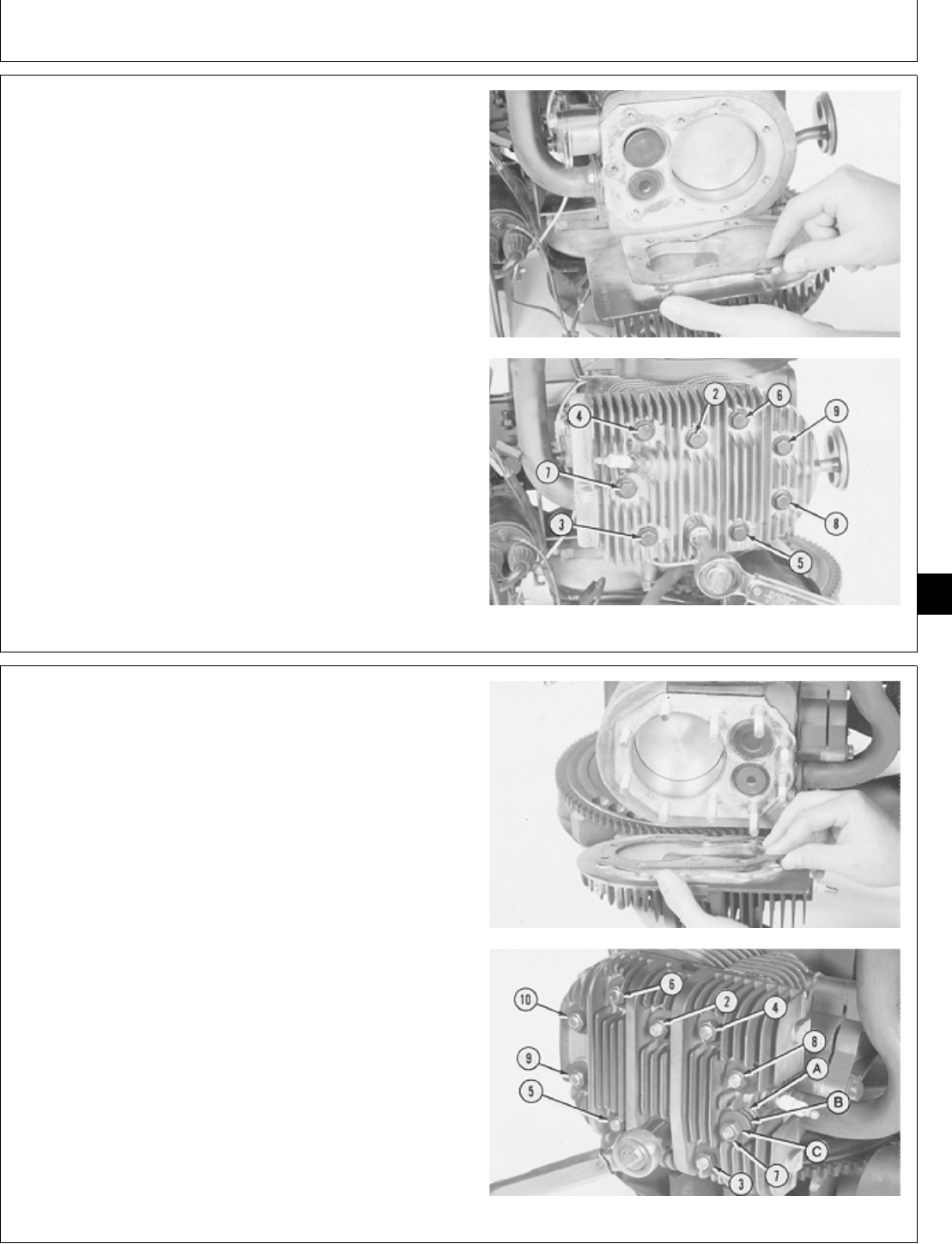
NOTE: To install cylinder head on T260 engine, go to
Step 9.
7. Install a new gasket on cylinder head.
8. Install cylinder head on cylinder block with the five
longest cap screws in the top holes of cylinder head.
Tighten cap screws in several steps in the sequence
shown.
CAP SCREW TORQUE SPECIFICATIONS
B43E, B48G, P218G, P220G Engine . . . . . . . . . . . . . . . 20 ± 1 N·m
(180 ± 12 lb-in.)
B43E Engine . . . . . . . . . . . . . . . . . . . . . . . . . . . . . . . 23 ± 1 N·m
(204 ± 12 lb-in.)
M36411 -UN-29JAN90M36412 -UN-29JAN90
9. Install a new gasket on cylinder head.
10. Install cylinder head on cylnder block. Install flat
washer (A), two compression washers (B) with outside
edges contacting each other, and nut (C) on each of the
top six longer studs. Install flat washer and nut on each
of the bottom four shorter studs. Tighten nuts in several
steps in sequence shown.
NUT TORQUE SPECIFICATIONS
T260 Engine
Top Six Nuts
(with compression washers) . . . . . . . . . . . . . . . . . . . . 16 ± 1 N·m
(142 ± 12 lb-in.)
Bottom Four Nuts . . . . . . . . . . . . . . . . . . . . . . . . . . . 20 ± 1 N·m
(180 ± 12 lb-in.)
M36413 -UN-29JAN90M36414 -UN-29JAN90
M98,2030K,41 -19-11FEB87
M98,2030K,42 -19-10OCT85
Connecting Rods and Pistons/Pistons and Connecting Rods
CTM2 (19APR90) 30-25 16, 18, 20 & 24HP Onan Engines
130495
30
25
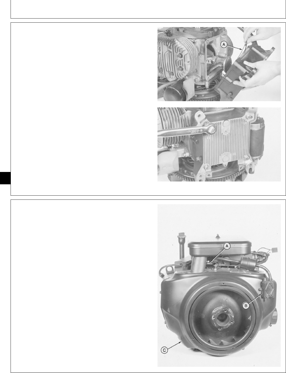
11. Install a new gasket (A) on oil base.
12. Install oil base. Install and tighten four cap screws to
27 ± 3 N·m (239 ± 27 lb-in.).
M36415 -UN-29JAN90M36416 -UN-29JAN90
13. Install flywheel shroud (C) and fasten with three cap
screws.
14. Install fuel pump (B) and fasten with two screws.
15. Connect governor spring (A) in top hole of arm.
M36291 -UN-29JAN90
M98,2030K,43 -19-10OCT85
M98,2030K,44 -19-10OCT85
Connecting Rods and Pistons/Pistons and Connecting Rods
CTM2 (19APR90) 30-26 16, 18, 20 & 24HP Onan Engines
130495
30
26
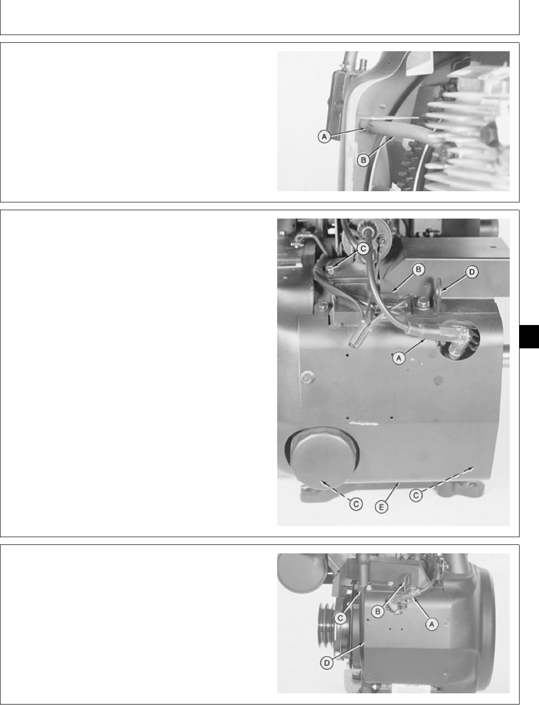
16. Connect fuel pump impulse line (B) and fasten with
hose clamp (A).
M36290 -UN-29JAN90
17. Install right side shroud (E), lift bracket (D), and
fasten with five cap screws (C). Tighten lift bracket cap
screw to 11 ± 3 N·m (97 ± 27 lb-in.).
18. Connect spark plug wire (A) and voltage regulator
leads (B). Install the two stator leads on “AC” terminals
and the battery lead on “B+” terminal of the voltage
regulator.
A—Spark Plug Wire
B—Voltage Regulator Leads
C—Cap Screw (5 used)
D—Lift Bracket
E—Right Side Shroud
M36289 -UN-29JAN90
19. Install left side shroud (D), oil fill tube bracket (C), lift
bracket (B), and fasten with six cap screws. Tighten lift
bracket cap screw to 11 ± 3 N·m (97 ± 27 lb-in.).
20. Connect spark plug wire (A).
21. Install engine. (See machine technical manual.)
A—Spark Plug Wire
B—Lift Bracket
C—Oil Fill Tube Bracket
D—Left Side Shroud
M36472 -UN-29JAN90
M98,2030K,45 -19-10OCT85
M98,2030K,46 -19-10OCT85
M98,2030K,47 -19-10OCT85
Connecting Rods and Pistons/Pistons and Connecting Rods
CTM2 (19APR90) 30-27 16, 18, 20 & 24HP Onan Engines
130495
30
27

Connecting Rods and Pistons/Pistons and Connecting Rods
CTM2 (19APR90) 30-28 16, 18, 20 & 24HP Onan Engines
130495
30
28

ESSENTIAL TOOLS
NOTE: Order tools from the U.S. SERVICE-GARD™ Catalog or from the European Microfiche Tool Catalog
(MTC). Some tools may be available from a local supplier.
Number Name Use
JDG327 Puller Legs Remove crankshaft gear and bearing plate.
JDG 329 Seal Expander Protect and install oil seal on JDG 328.
JDG 328 Crankshaft Seal Installer Install oil seal in bearing plate.
SERVICE EQUIPMENT AND TOOLS
NOTE: Order tools from the U.S. SERVICE-GARD™ Catalog or from the European Microfiche Tool Catalog
(MTC). Some tools may be available from a local supplier.
Name Use
13-Ton Puller Set Remove crankshaft gear and bearing plate.
Bushing, Bearing, and Seal Driver Set Remove crankshaft gear, oil seal, main
bearings.
Ridge Reamer Remove ridge from top of cylinder bore.
Outside Micrometer Measure crankshaft main bearing journals.
Telescoping Gauge Measure crankshaft main bearing.
Feeler Gauge Measure crankshaft end play.
Piston Ring Compressor Install pistons.
OTHER MATERIAL
Number Name Use
T43515 John Deere LOCTITE® Retaining Apply to outside surface of main
Compound bearing
LOCTITE is a trademark of the Loctite Corp.
M98,2035K,1 -19-10OCT85
M98,2035K,2 -19-10OCT85
M98,2035K,3 -19-12NOV85
Group 35
Crankshaft and Main Bearings
CTM2 (19APR90) 35-1 16, 18, 20 & 24HP Onan Engines
130495
35
1

SERVICE PARTS KITS
The following kits are available through your parts
catalog:
Overhaul Gasket Kit
Crankshaft Bearing Kit
Oil Pump Gasket Kit
SPECIFICATIONS
Item Measurement Specification
1. Main Bearing Journal O.D. 50.78—50.80 mm 50.72 mm (1.997 in.)
(1.9992—2.0000 in.)
2. Main Bearing I.D.—B43E, B43G, 50.838—50.902 mm 50.930 mm (2.0051 in.)
B48G, T260 Engines (2.0015—2.0040 in.)
3. Main Bearing I.D. P218G, P220G 50.06—50.88 mm 50.94 mm (2.0055 in.)
Engine (2.0024—2.0034 in.)
4. Bearing Clearance —B43E, 0.064—0.097 mm 0.145 mm (0.0057 in.)
B43G, B48G, T260 Engines (0.0025—0.0038 in.)
5. Bearing Clearance—P218G, 0.061—0.106 mm 0.156 mm (0.006 in.)
P220G Engines (0.0024—0.0042 in.)
6. Bearing Plate Cap Screws Torque 35 ± 1 N·m (310 ± 9 lb-in.)
7. End Play: B43E, B43G, B48G, 0.15—0.30 mm (0.006—0.012
P218G, P220G Engines in.)
T260 Engine 0.13—0.23 mm (0.005—0.009
in.)
8. Connecting Rod Cap Nut Torque 18 ± 1 N·m (159 ± 9 lb-in.)
B43E, B43G, B48G, P218G, P220G
Engines
9. Connecting Rod Cap Screw 20 ± 1 N·m (177 ± 9 lb-in.)
Torque T260 Engine
M98,2035K,4 -19-10OCT85
M98,2035K,5 -19-02FEB87
Crankshaft and Main Bearings/Specifications
CTM2 (19APR90) 35-2 16, 18, 20 & 24HP Onan Engines
130495
35
2
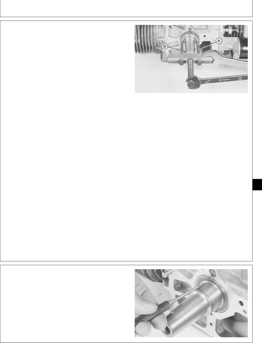
REMOVE CRANKSHAFT AND MAIN
BEARINGS
1. Remove engine. (See machine technical manual.)
2. Remove muffler and exhaust pipes.
3. Remove intake manifold. (See Remove Intake
Manifold, Group 10 in this manual.)
4. Remove cylinder heads. (See Remove Cylinder
Heads, Group 10 in this manual.)
5. Remove intake and exhaust valves. (See Remove
Intake and Exhaust Valves, Group 15 in this manual.)
6. Remove flywheel. (See Remove Flywheel, Group 20
in this manual.)
7. Remove camshaft. (See Remove Camshaft, Group 25
in this manual.)
8. Remove oil pump and oil base. (See Remove Oil
Pump and Remove Oil Base, Group 40 in this manual.)
9. Remove crankshaft gear using JDG 327 Puller Legs
(A), 1 in. driver disk (B), and a puller.
IMPORTANT: If crankshaft gear is replaced, always
replace camshaft gear also.
10. Inspect crankshaft gear for chipped or broken teeth.
Replace crankshaft gear if necessary.
M36332 -UN-29JAN90
11. Remove key if necessary.
M36333 -UN-29JAN90
M98,2035K,6 -19-10OCT85
M98,2035K,7 -19-10OCT85
Crankshaft and Main Bearings/Crankshaft and Main Bearings
CTM2 (19APR90) 35-3 16, 18, 20 & 24HP Onan Engines
130495
35
3
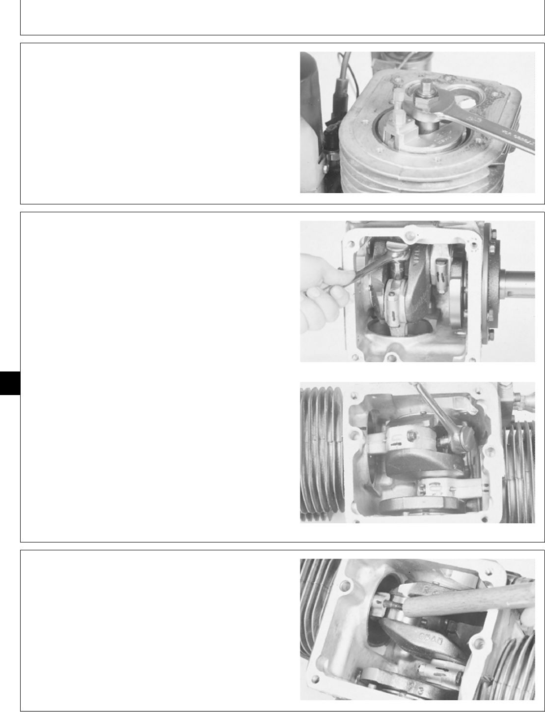
12. If necessary, remove ridge from top of cylinder bore
using a ridge reamer.
M36334 -UN-29JAN90
IMPORTANT: Connecting rod caps must be installed
in the same connecting rod they were
removed from.
13. Put identification marks on connecting rods, rod
caps, and cylinder block to aid in assembly. Remove
nuts to remove connecting rod caps.
Remove cap screws to remove connecting rod caps.
B43E, B43G, B48G, P218G and P220G
T260 Engine
M36335 -UN-29JAN90M36336 -UN-29JAN90
14. Push piston and connecting rod out of cylinder bore
using a wooden dowel.
M36337 -UN-29JAN90
M98,2035K,8 -19-10OCT85
M98,2035K,9 -19-02FEB87
M98,2035K,10 -19-10OCT85
Crankshaft and Main Bearings/Crankshaft and Main Bearings
CTM2 (19APR90) 35-4 16, 18, 20 & 24HP Onan Engines
130495
35
4
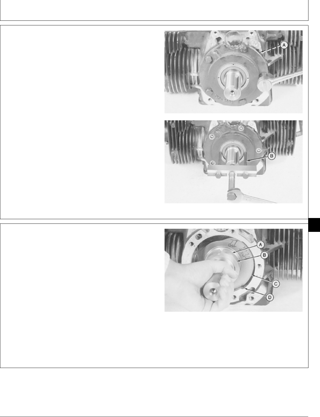
IMPORTANT: Do not remove bearing plate using
screwdrivers. Cylinder block or bearing
plate sealing surface may be damaged.
15. Remove five cap screws to remove bearing plate
and gasket.
16. If bearing plate is tight, remove bearing plate using
JDG 327 Puller Legs (B) and a puller.
M36338 -UN-29JAN90M36339 -UN-29JAN90
17. If equipped, remove thrust washer (A) and shim (B).
IMPORTANT: Do not allow crankshaft lobes to hit
cylinder block while removing
crankshaft. Machined surfaces may be
damaged.
18. Turn crankshaft until lobe (C) fits into cylinder block
notch (D). Carefully remove crankshaft.
A—Thrust Washer
B—Shim
C—Crankshaft Lobe
D—Cylinder Block Notch
M36340 -UN-29JAN90
M98,2035K,11 -19-10OCT85
M98,2035K,12 -19-10OCT85
Crankshaft and Main Bearings/Crankshaft and Main Bearings
CTM2 (19APR90) 35-5 16, 18, 20 & 24HP Onan Engines
130495
35
5
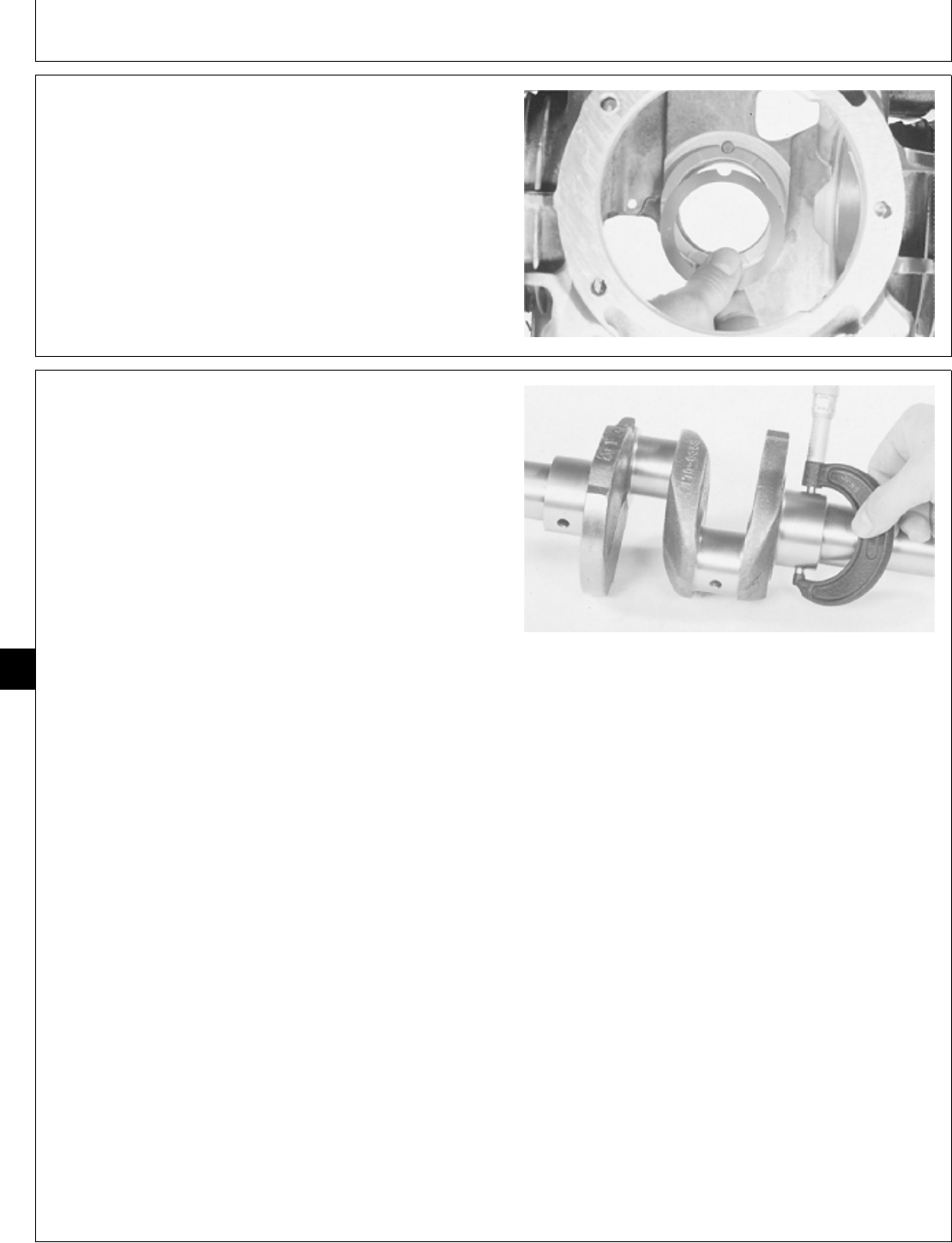
NOTE: Original rear bearing uses a separate thrust
washer. Replacement rear bearing is a one piece
assembly with the thrust washer part of the
bearing.
19. If equipped, remove thrust washer and shim.
M36341 -UN-29JAN90
INSPECT CRANKSHAFT AND MAIN
BEARINGS
1. Measure crankshaft main bearing journal outside
diameter.
NOTE: If engine has had previous major overhaul,
crankshaft journals may have been ground and
undersize bearings installed.
2. Measure several places around each journal and each
side of both journals.
NOTE: For connecting rod journal specifications, see
Piston and Connecting Rods in Group 30 in this
section.
MAIN BEARING JOURNAL SPECIFICATIONS
Item New Parts Wear Tolerance
Journal O.D. 50.78—50.80 mm 50.72 mm
(1.9992—2.0000 in.) (1.997 in.)
If journal diameter is less than 50.72 mm (1.997 in.),
replace crankshaft or have journals ground by a qualified
machine shop. The following undersize main bearings
are available:
0.05 mm (0.002 in.)
0.25 mm (0.010 in.)
0.50 mm (0.020 in.)
0.76 mm (0.030 in.)
M36342 -UN-29JAN90
M98,2035K,13 -19-10OCT85
M98,2035K,14 -19-12NOV85
Crankshaft and Main Bearings/Crankshaft and Main Bearings
CTM2 (19APR90) 35-6 16, 18, 20 & 24HP Onan Engines
130495
35
6
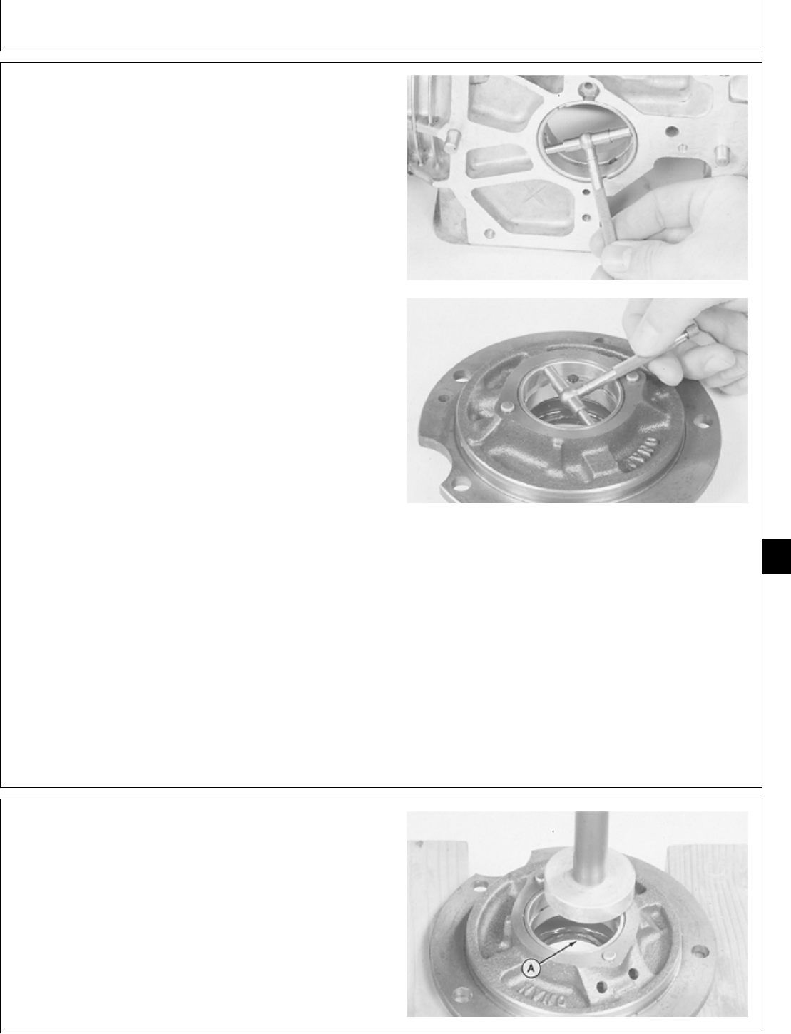
3. Measure main bearing diameter and main bearing
clearance (bearing I.D. minus journal O.D.).
MAIN BEARING SPECIFICATIONS
Item New Part Wear Tolerance
Bearing I.D.
B43E,B43G,B48G, 50.838—50.902 mm 50.930 mm
T260 Engines (2.0015—2.0040 in.) (2.0051 in.)
Bearing Clearance
B43E,B43G,B48G, 0.064—0.097 mm 0.145 mm
T260 Engines (0.0025—0.0038 in.) (0.0057 in.)
Bearing I.D.—
P218G and P220G 50.06—50.88 mm 50.94 mm
Engine (2.0024—2.0034 in.) (2.0055 in.)
Bearing Clearance
P218G and P220G 0.061—0.106 mm 0.156 mm
Engine (0.0024—l0.0042 in.) (0.006 in.)
If bearing diameter exceeds 50.930 mm (2.0051 in.),
replace bearing.
If bearing clearance exceeds 0.145 mm (0.0057 in.),
replace bearing or grind crankshaft journals. Install
undersize bearings.
If bearing diameter and clearance are within
specifications and bearings are not damaged, bearings
can be reused.
M36343 -UN-29JAN90M36344 -UN-29JAN90
4. Remove oil seal (A) using a 2 in. driver disk.
M36345 -UN-29JAN90
M98,2035K,15 -19-12FEB87
M98,2035K,16 -19-10OCT85
Crankshaft and Main Bearings/Crankshaft and Main Bearings
CTM2 (19APR90) 35-7 16, 18, 20 & 24HP Onan Engines
130495
35
7
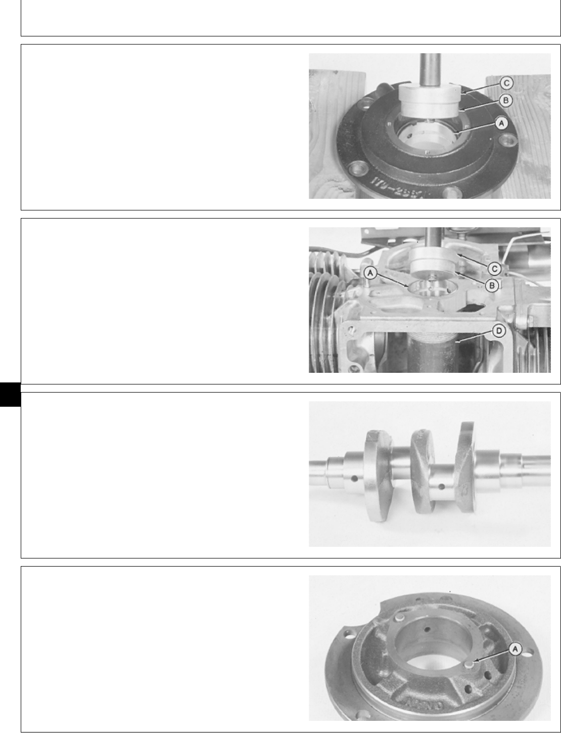
5. Carefully remove crankshaft bearing (A) using a 2 in.
driver disk (B) and 2-1/8 in. disk (C).
M36346 -UN-29JAN90
IMPORTANT: Support cylinder block to avoid
distortion and damage to bearing bore
during removal.
6. Carefully remove crankshaft bearing (A) using 2 in.
driver disk (B), 2-1/8 in. driver disk (C), and a pipe (D).
A—Crankshaft Bearing
B—2 in. Driver Disk
C—2-1/8 in. Driver Disk
D—Pipe
M36347 -UN-29JAN90
7. Clean and inspect oil passages in main bearing
journals, connecting rod journals, main bearing bore in
cylinder block, and main bearing bore in bearing plate.
M36348 -UN-29JAN90
8. Inspect lock pins (A) in bearing plate and cylinder
block for wear or damage. If necessary, remove lock
pins using an Easy-Out tool.
M36349 -UN-29JAN90
M98,2035K,17 -19-10OCT85
M98,2035K,18 -19-10OCT85
M98,2035K,19 -19-10OCT85
M98,2035K,20 -19-10OCT85
Crankshaft and Main Bearings/Crankshaft and Main Bearings
CTM2 (19APR90) 35-8 16, 18, 20 & 24HP Onan Engines
130495
35
8
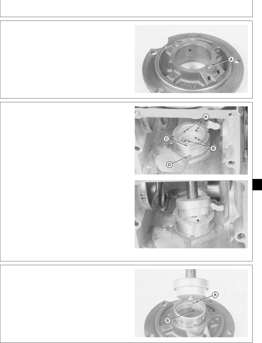
INSTALL CRANKSHAFT AND MAIN
BEARINGS
1. Clean and dry all parts. Apply clean engine oil on all
internal parts before assembly.
2. If necessary, install new lock pins (A) in bearing plate
and cylinder block.
M36349 -UN-29JAN90
3. Clean bearing O.D. and bearing bore in cylinder block
with primer.
4. Apply retaining compound supplies with bearing on
bearing O.D. and bearing bore in cylinder block.
NOTE: Replacement bearing has a flange which is used
as the thrust washer.
5. Align oil holes (A) in bearing with oil holes (B) in
cylinder block. Align notches (C) in bearing with lock pins
(D) in cylinder block.
6. Install bearing using a 2 in. driver disk and 2-3/8 in.
disk. Push bearing tight against cylinder block. Be sure
bearing notch is around lock pin. Remove excess
retaining compound from bearing I.D. and flange.
A—Bearing Oil Holes
B—Cylinder Block Oil Holes
C—Bearing Notches
D—Lock Pins
M36350 -UN-29JAN90M36351 -UN-29JAN90
NOTE: Bearing can be put in a freezer to aid installation.
7. Apply clean engine oil on outside surface of bearing.
8. Align oil hole (A) in bearing with oil hole (B) in bearing
plate. Install bearing using a 2 in. driver disk and 2-3/8
in. disk. Push bearing flush with surface of bearing plate.
M36352 -UN-29JAN90
M98,2035K,21 -19-10OCT85
M98,2035K,22 -19-10OCT85
M98,2035K,23 -19-10OCT85
Crankshaft and Main Bearings/Crankshaft and Main Bearings
CTM2 (19APR90) 35-9 16, 18, 20 & 24HP Onan Engines
130495
35
9
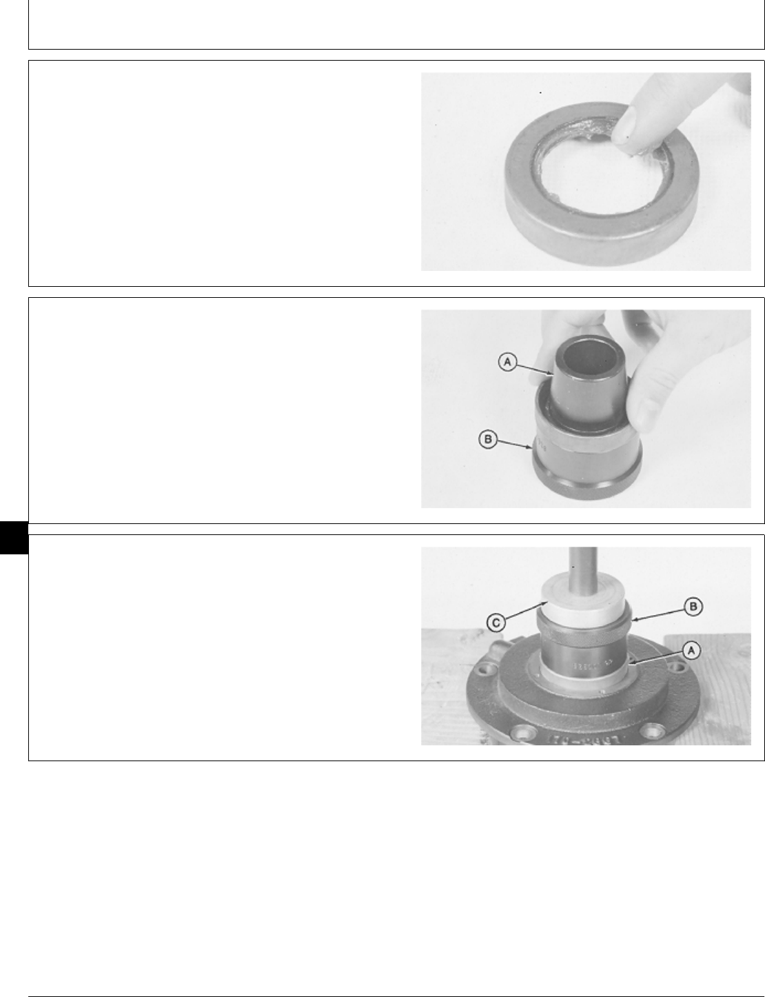
9. Apply multipurpose grease between lips of oil seal.
M36353 -UN-29JAN90
10. Install JDG 329 Seal Expander (A) in JDG 328
Crankshaft Seal Installer (B).
11. Install oil seal with lips toward crankshaft seal
installer. Push oil seal tight against shoulder of
crankshaft seal installer. Remove seal expander ONLY.
M36354 -UN-29JAN90
12. Remove old seal material from oil seal bore in
bearing plate.
13. Install oil seal (A) using JDG 328 Crankshaft Seal
Installer (B) and 2-3/16 in. driver disk (C). Push oil seal
to bottom of bearing plate bore. DO NOT remove
crankshaft seal installer at this time.
M36355 -UN-29JAN90
M98,2035K,24 -19-10OCT85
M98,2035K,25 -19-10OCT85
M98,2035K,26 -19-10OCT85
Crankshaft and Main Bearings/Crankshaft and Main Bearings
CTM2 (19APR90) 35-10 16, 18, 20 & 24HP Onan Engines
130495
35
10
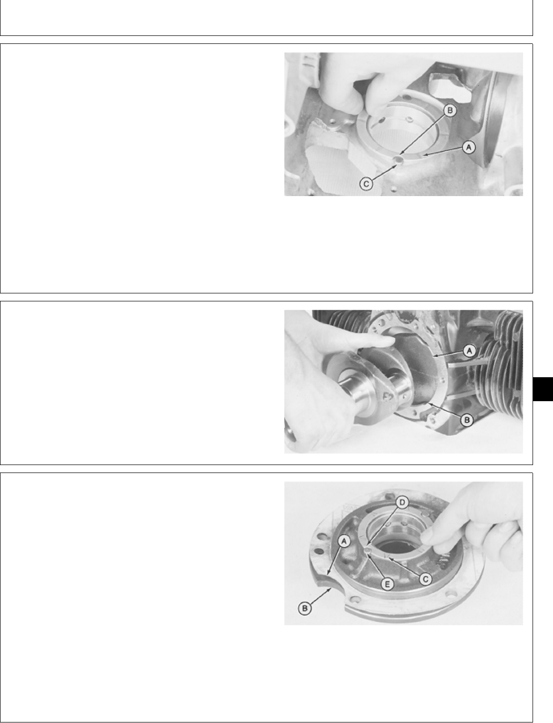
IMPORTANT: Original rear bearing uses a separate
thrust washer. Replacement rear
bearing is a one piece assembly with
the thrust washer part of the bearing.
Do not install thrust washer or shim
when replacement bearing is used.
14. Apply multipurpose grease on plain side of thrust
washer.
15. Install thrust washer with oil grooves (A) toward
crankshaft and notches (B) between lock pins (C). DO
NOT install shim on this side of crankshaft.
M36356 -UN-29JAN90
16. Apply clean engine oil on main bearings and
crankshaft main bearing journals.
IMPORTANT: Do not allow crankshaft lobes to hit
cylinder block while installing
crankshaft. Machined surfaces may be
damaged.
17. Turn crankshaft until lobe (A) fits into cylinder block
notch (B). Carefully install crankshaft.
M36357 -UN-29JAN90
18. Align notch (A) in new gasket with notch (B) in
bearing plate and install gasket.
19. Apply multipurpose grease on plain side of washer.
20. Install thrust washer with oil grooves (C) toward
crankshaft and notches (D) between lock pins (E). DO
NOT install shim at this time.
A—Gasket Notch
B—Bearing Plate Notch
C—Oil Grooves
D—Thrust Washer Notches
E—Lock Pins
M36358 -UN-29JAN90
M98,2035K,27 -19-12NOV85
M98,2035K,28 -19-10OCT85
M98,2035K,29 -19-12NOV85
Crankshaft and Main Bearings/Crankshaft and Main Bearings
CTM2 (19APR90) 35-11 16, 18, 20 & 24HP Onan Engines
130495
35
11
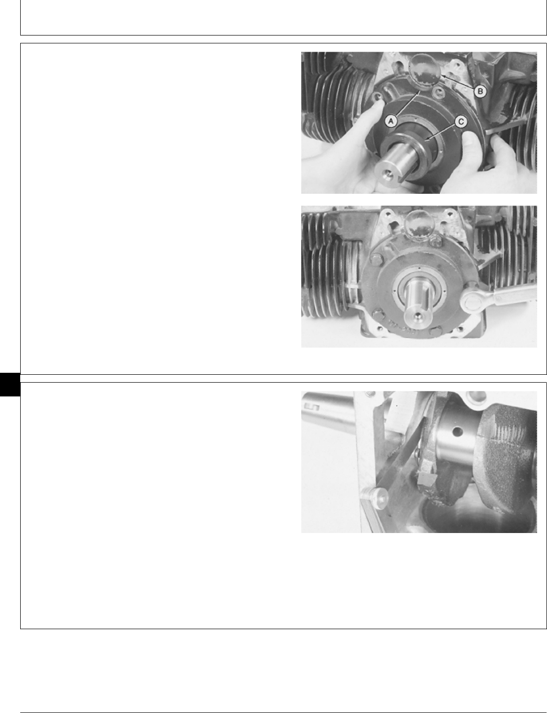
IMPORTANT: Bearing plate will fit tight against
cylinder block only if lock pins are in
thrust washer notches. Do not pull
bearing plate inward using cap screws
as lock pins, thrust washer or
crankshaft may be damaged.
21. Align notch (A) in bearing plate with plug (B).
Carefully install bearing plate. If bearing plate will not fit
tight against cylinder block, remove bearing plate and
check thrust washer position. Remove JDG 328
Crankshaft Seal Installer (C).
22. Install and tighten five cap screws to 35 ± 1 N·m
(310 ± 9 lb-in.).
M36359 -UN-29JAN90M36360 -UN-29JAN90
23. Measure crankshaft end play using a feeler gauge.
CRANKSHAFT SPECIFICATIONS
Engine Measurement Specification
B43E, B43G, B48G, End Play 0.15—0.30 mm
P218G, P220G (0.006—0.012 in.)
T260 End Play 0.13—0.23 mm
(0.005—l0.009 in.)
If end play exceeds specifications, remove bearing plate
and add shim(s).
M36361 -UN-29JAN90
M98,2035K,30 -19-10OCT85
M98,2035K,31 -19-11FEB87
Crankshaft and Main Bearings/Crankshaft and Main Bearings
CTM2 (19APR90) 35-12 16, 18, 20 & 24HP Onan Engines
130495
35
12
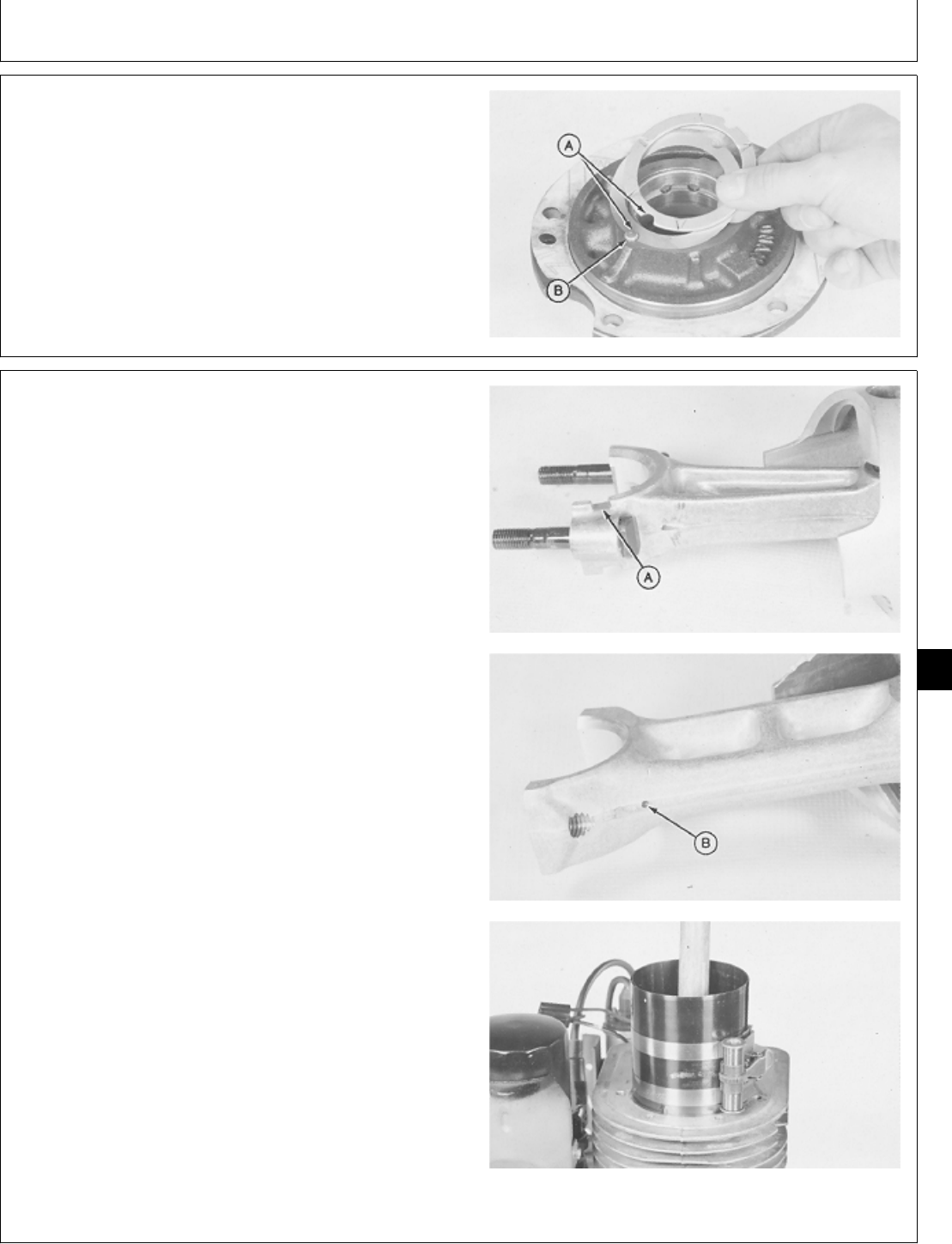
24. Install shim or shims between bearing plate and
thrust washer. Be sure shim and thrust washer notches
(A) are between lock pins (B). Repeat steps 21—23.
NOTE: Shims are available in 0.13 mm (0.005 in.)
thickness only. Use shims as required.
M36362 -UN-29JAN90
IMPORTANT: Pistons must be installed in the same
cylinder they were removed from and in
the same direction.
25. Apply clean engine oil on pistons, connecting rod
bearing, and cylinder bore.
26. Turn crankshaft until rod bearing journal is at bottom
of its stroke.
IMPORTANT: Be careful not to damage crankshaft
rod journal while installing piston.
27. Install pistons with notch (A) or oil hole (B) toward
camshaft using a ring compressor and wooden dowel.
Push piston down until connecting rod is seated on
crankshaft rod journal.
M36363 -UN-29JAN90M36364 -UN-29JAN90M36365 -UN-29JAN90
M98,2035K,32 -19-10OCT85
M98,2035K,33 -19-10OCT85
Crankshaft and Main Bearings/Crankshaft and Main Bearings
CTM2 (19APR90) 35-13 16, 18, 20 & 24HP Onan Engines
130495
35
13
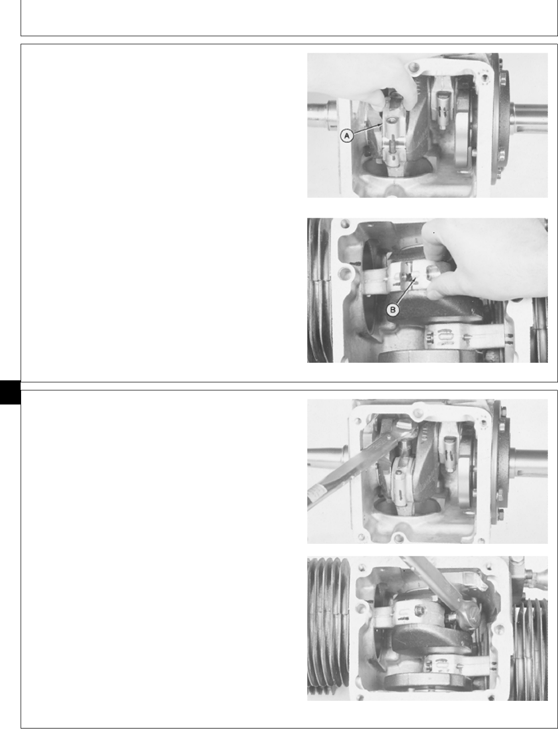
IMPORTANT: Connecting rod caps must be installed
on the same connecting rod they were
removed from and in the same
direction.
28. Apply clean engine oil on connecting rod cap.
29. Install connecting rod cap with this side (A) outward
on connecting rod.
Install connecting rod cap with large tang (B) away from
camshaft on connecting rod. B43E, B43G, B48G, P218G, and P220G
T260 Engine Shown
M36366 -UN-29JAN90M36367 -UN-29JAN90
30. Install and tighten nuts or cap screws evenly to
specifications. Hit connecting rod cap LIGHTLY with a
soft-faced hammer to align it with connecting rod.
CONNECTING ROD SPECIFICATIONS
Engine Measurement Specification
B43E, B43G, B48G, Cap Nut Torque 18 ± 1 N·m
P218G, P220G (159 ± 9 lb-in.)
T260 Cap Screw Torque 20 ± 1 N·m
(177 ± 9 lb-in.)
M36368 -UN-29JAN90M36369 -UN-29JAN90
M98,2035K,34 -19-02FEB87
M98,2035K,35 -19-02FEB87
Crankshaft and Main Bearings/Crankshaft and Main Bearings
CTM2 (19APR90) 35-14 16, 18, 20 & 24HP Onan Engines
130495
35
14
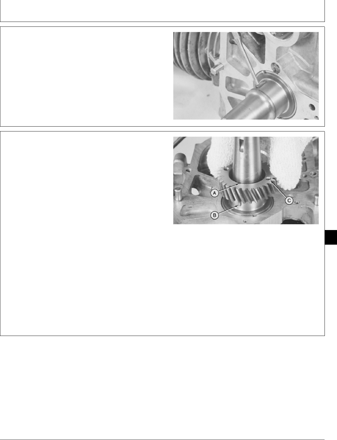
31. Install key if removed.
M36370 -UN-29JAN90
32. Install crankshaft gear using the following heat
method or by driver method. The heat method is
recommended.
NOTE: For driver method, go to Step 33.
HEAT METHOD
a. Heat crankshaft gear to 232˚ C (450˚F) for 1/2 hour
using a bearing oven.
NCAUTION: Gear is hot. Be careful not to burn
hands while installing gear.
b. Align slot (A) in gear with key (B) in crankshaft.
c. Install gear with holes (C) outward on crankshaft.
Push gear tight against crankshaft shoulder.
M36371 -UN-29JAN90
M98,2035K,36 -19-10OCT85
M98,2035K,37 -19-12NOV85
Crankshaft and Main Bearings/Crankshaft and Main Bearings
CTM2 (19APR90) 35-15 16, 18, 20 & 24HP Onan Engines
130495
35
15
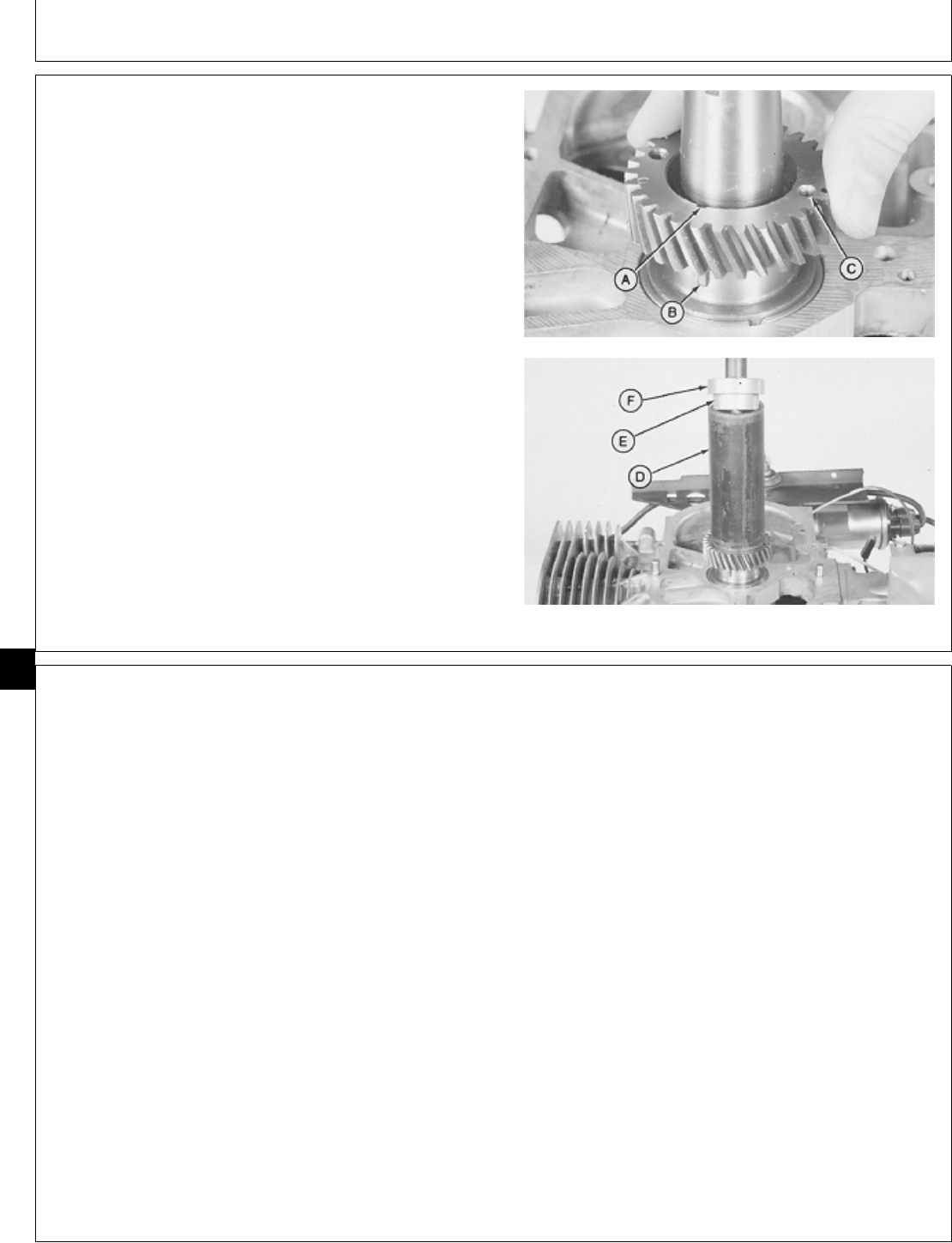
33. Install crankshaft gear using the following driver
method.
DRIVER METHOD
a. Align slot (A) in gear with key (B) in crankshaft.
IMPORTANT: Support engine on crankshaft only. Do
not support engine on cylinder block.
Block may be damaged.
b. Install gear with holes (C) outward on crankshaft using
a 1-5/8 in. I.D. pipe (D), 1-9/16 in. driver disk (E), and
1-15/16 in. driver disk (F). Push gear tight against
crankshaft shoulder.
A—Slot
B—Key
C—Holes
D—1-5/8 in. I.D. Pipe
E—1-9/16 in. Driver Disk
F—1-15/16 in. Driver Disk
M36372 -UN-29JAN90M36373 -UN-29JAN90
34. Install oil pump and oil base. (See Install Oil Pump
and Install Oil Base, Group 40 in this manual.)
35. Install camshaft. (See Install Camshaft, Group 25 in
this manual.)
36. Install flywheel. (See Install Flywheel, Group 20 in
this manual.)
37. Install intake and exhaust valves. (See Install Intake
and Exhaust Valves, Group 15 in this manual.)
38. Install cylinder heads. (See Install Cylinder Heads,
Group 10 in this manual.)
39. Install intake manifold. (See Install Intake manifold,
Group 10 in this manual.)
40. Install muffler and exhaust pipes. (See Install Intake
Manifold, Group 10 in this manual.)
41. Install engine. (See machine technical manual.)
M98,2035K,37A -19-12NOV85
M98,2035K,38 -19-12NOV85
Crankshaft and Main Bearings/Crankshaft and Main Bearings
CTM2 (19APR90) 35-16 16, 18, 20 & 24HP Onan Engines
130495
35
16

ESSENTIAL TOOLS
NOTE: Order tools from the U.S. SERVICE-GARD™ Catalog or from the European Microfiche Tool Catalog
(MTC). Some tools may be available from a local supplier.
Number Name Use
JDG 325 Crankshaft Seal Installer Install gear cover oil seal.
JDG 333 Crowsfoot Wrench Tighten oil filter adapter cap screws.
SERVICE EQUIPMENT AND TOOLS
NOTE: Order tools from the U.S. SERVICE-GARD™ Catalog or from the European Microfiche Tool Catalog
(MTC). Some tools may be available from a local supplier.
Name Use
Bushing, Bearing, and Seal Driver Set Remove gear cover oil seal.
Dial Indicator Measure oil pump gear backlash and starter
pinion gear backlash.
13-Ton Puller Set Remove flywheel
OTHER MATERIAL
Number Name Use
TY 9375 John Deere LOCTITE® Pipe Apply to threads of gear cover,
Sealant with TEFLON®flywheel, and oil filter adapter cap
screws.
LOCTITE is a trademark of the Loctite Corp.
TEFLON is a trademark of the DuPont Co.
M98,2040K,1 -19-11NOV85
M98,2040K,2 -19-11NOV85
M98,2040K,3 -19-11OCT85
Group 40
Lubrication System
CTM2 (19APR90) 40-1 16, 18, 20 & 24HP Onan Engines
130495
40
1

SERVICE PARTS KITS
The following kits are available through your parts
catalog:
Oil Pump Gasket Kit
Overhaul Gasket Kit
M98,2040K,4 -19-11OCT85
Lubrication System/Service Parts Kits
CTM2 (19APR90) 40-2 16, 18, 20 & 24HP Onan Engines
130495
40
2

SPECIFICATIONS
Oil Pump
Item New Specification Wear Tolerance
1. Gear Backlash: B43E, 0.05—0.13 mm 0.23 mm (0.009 in.)
B43G, B48G, T260 Engines (0.002—0.005 in.)
Gear Backlash: P218G, 0.025—0.203 mm 0.36 mm
P220G Engines (0.001—0.008 in.) (0.014 in.)
2. Gear Housing Cap Screw
Torque: B43E, B43G, 19 ± 2 N·m
B48G, T260 Engines (168 ± 18 lb-in.)
Gear Housing Cap Screw
Torque: P218G, P220G 10 N·m
Engines (88 lb-in.)
3. Oil Pump-to-Cylinder 11 ± 1 N·m
Block Cap Screw Torque (97 ± 9 lb-in.)
4. Gear Cover Cap Screw 12 ± 1 N·m
Torque (106 ± 9 lb-in.)
Oil Pressure Regulating Valve
1. Spring Free Length (approx) 25 mm (1.0 in.)
Spring Test Length 13 mm (0.5 in.) at 12 N (2.6 lb force )
2. Oil Pressure Regulating 28 ± 3 N·m
Valve Cap Screw Torque (248 ± 27 lb-in.)
Oil Base
1. Starter-to-Oil Base 34 ± 1 N·m
Cap Screw Torque (301 ± 9 lb-in.)
2. Oil Base-to-Oil Base 27 ± 3 N·m
Block Cap Screw Torque (239 ± 27 lb-in.)
3. Starter Pinion Gear 318 S.N. ( —231,857) 0.51 ± 0.38 mm
Backlash (Adjustable 420 S.N. ( —224, 882) (0.020 ± 0.015 in.)
Starter Bracket Only)
4. B43E, B43G, B48G, T260
Engine: Flywheel Cap Screw 51 ± 3 N·m
Torque (38 ± 2 lb-ft)
5. Lift Bracket Cap Screw 11 ± 3 N·m
Torque (97 ± 27 lb-in.)
Oil Filter Adapter
Item Measurement Specification
1. Attaching Cap Screw Torque 12 ± 1 N·m (106 ± 9 lb-in.)
2. Lift Bracket Cap Screw Torque 11 ± 3 N·m (97 ± 27 lb-in.)
3. Oil Filter Bypass Valve Torque 28 ± 3 N·m (248 ± 27 lb-in.)
Cap Screw (910 and 930
Front Mowers)
M98,2040K,5 -19-11FEB87
Lubrication System/Specifications
CTM2 (19APR90) 40-3 16, 18, 20 & 24HP Onan Engines
130495
40
3
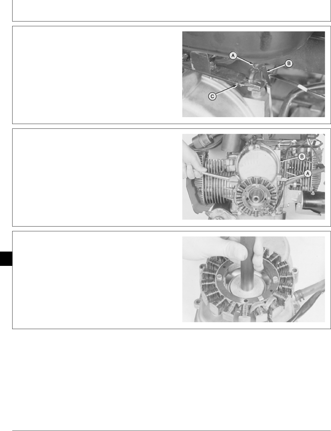
REMOVE OIL PUMP
1. Remove engine. (See machine technical manual.)
2. Remove flywheel. (See Group 20 in this manual.)
3. Remove clip (A) to disconnect governor rod (B) from
governor arm (C).
M36417 -UN-29JAN90
IMPORTANT: Do not hit gear cover with a metal
hammer or remove cover with a
screwdriver. Doing so can damage gear
cover.
4. Remove four cap screws and nut to remove clip (A),
gear cover, and gasket (B).
If gear cover is tight, LIGHTLY hit gear cover with a
soft-hammer to loosen it.
M36418 -UN-29JAN90
5. Remove oil seal using a 2 in. driver disk.
M36302 -UN-29JAN90
M98,2040K,7 -19-11OCT85
M98,2040K,8 -19-11OCT85
M98,2040K,9 -19-11OCT85
Lubrication System/Oil Pump
CTM2 (19APR90) 40-4 16, 18, 20 & 24HP Onan Engines
130495
40
4
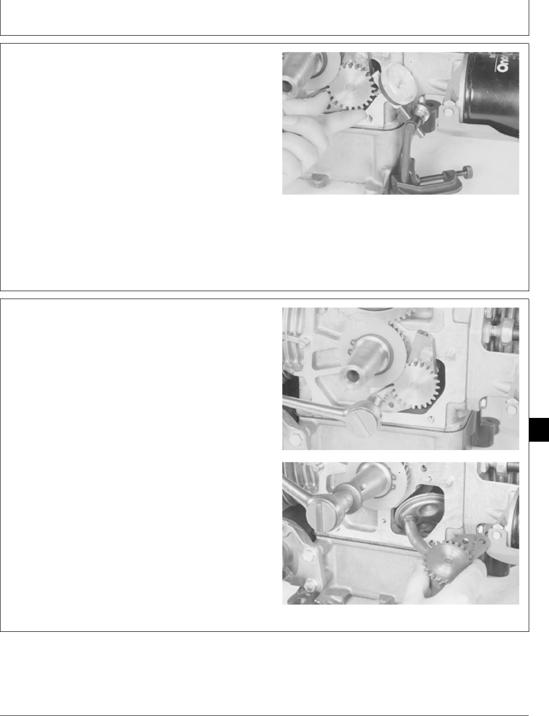
6. Measure oil pump gear backlash.
OIL PUMP GEAR SPECIFICATIONS
Item New Part Wear Tolerance
Backlash—B43E,
B43G, B48G, 0.05—0.13 mm 0.23 mm
T260 Engine (0.002—0.005 in.) (0.009 in.)
Backlash—P218G, 0.025—0.203 mm 0.36 mm
P220G Engine (0.001—0.008 in.) (0.014 in.)
If backlash exceeds specification replace oil pump.
M36419 -UN-29JAN90
7. Remove two cap screws to remove oil pump
assembly. If suction tube hits crankshaft lobe, install
flywheel cap screw in crankshaft. Turn crankshaft until
suction tube can be removed.
M36420 -UN-29JAN90M36421 -UN-29JAN90
M98,2040K,10 -19-02FEB87
M98,2040K,11 -19-11OCT85
Lubrication System/Oil Pump
CTM2 (19APR90) 40-5 16, 18, 20 & 24HP Onan Engines
130495
40
5
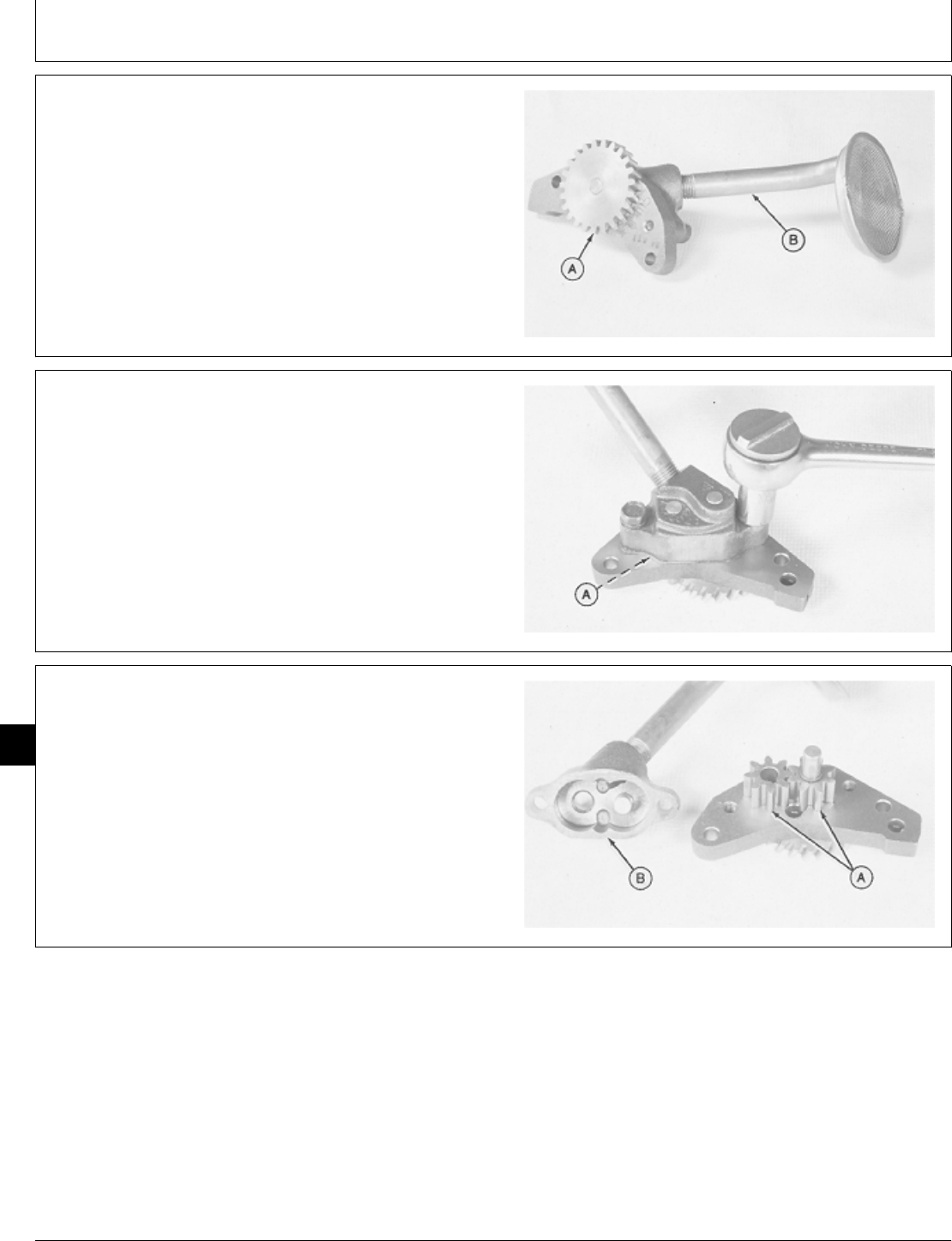
DISASSEMBLE AND INSPECT OIL PUMP
1. Inspect oil pump gear (A) for chipped or broken teeth.
If gear is damaged, replace oil pump assembly.
2. Inspect suction tube (B) for cracks, plugged suction
screen, or damage. If necessary, remove suction tube
using locking pliers.
M36422 -UN-29JAN90
3. Remove two cap screws to remove oil pump housing
and gasket (A).
4. Measure original gasket thickness. New gasket must
be the same thickness as original gasket.
M36423 -UN-29JAN90
5. Inspect gears (A) for chipped or broken teeth, scoring,
and wear.
6. Inspect housing (B) for cracks, wear or damage. If
gears or housing are damaged, replace oil pump
assembly.
M36424 -UN-29JAN90
M98,2040K,12 -19-11OCT85
M98,2040K,13 -19-11OCT85
M98,2040K,14 -19-11OCT85
Lubrication System/Oil Pump
CTM2 (19APR90) 40-6 16, 18, 20 & 24HP Onan Engines
130495
40
6
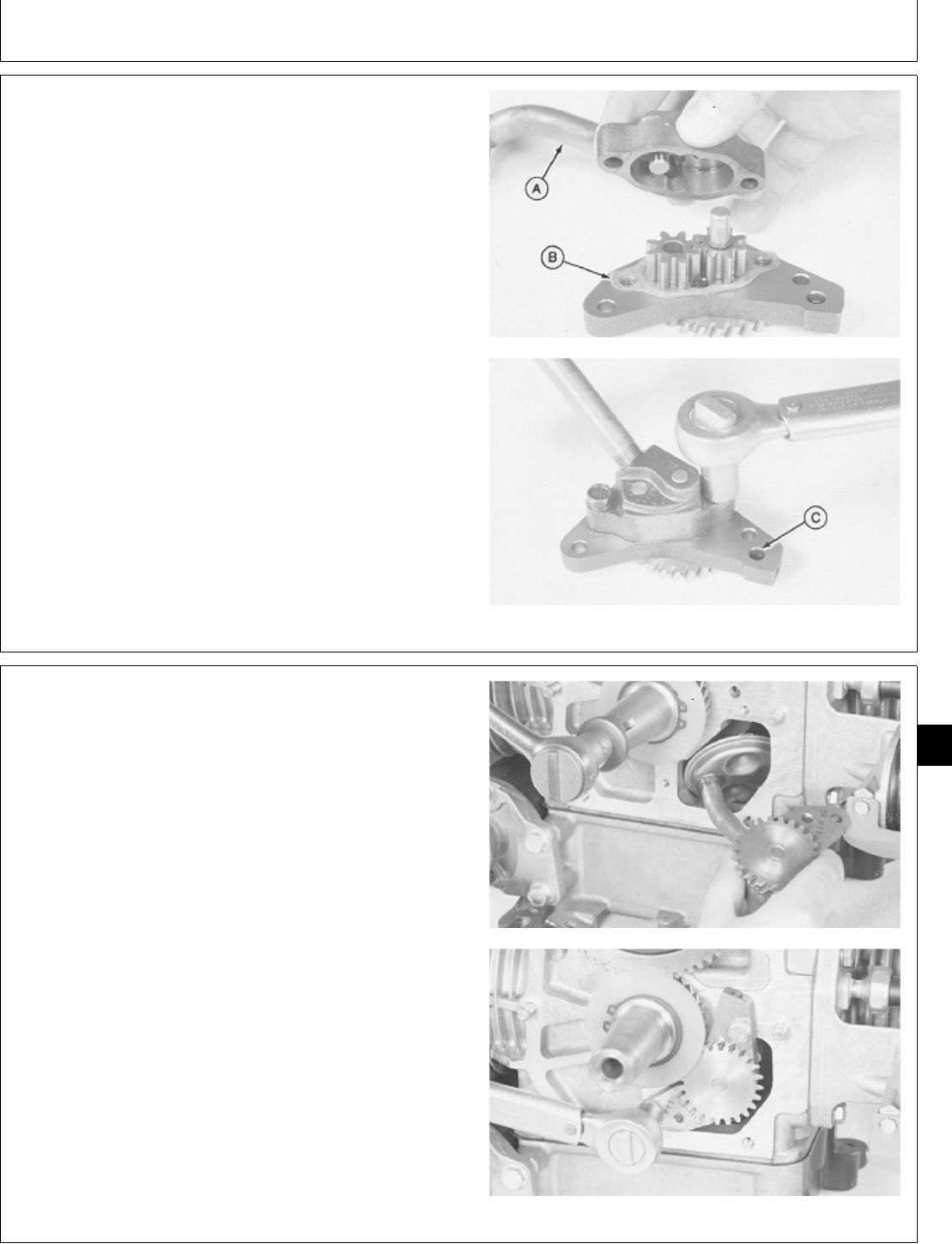
ASSEMBLE OIL PUMP
1. Thoroughly clean and dry parts. Put clean engine oil
on all internal parts.
2. Install suction tube (A), if removed, using locking
pliers.
3. Install a new gasket (B), the same thickness as
original gasket, on housing.
4. Install housing and two cap screws.
For B43E, B43G, B48G, and T260 Engines: tighten cap
screws to 19 ± 2 N·m (168 ± 18 lb-in.).
For P218G and P220G Engines: tighten cap screws to
10 N·m (88 lb-in.).
5. Fill oil pump housing with clean engine oil through
pump outlet port (C).
M36425 -UN-29JAN90M36426 -UN-29JAN90
INSTALL OIL PUMP
1. Turn crankshaft until suction tube does not hit
crankshaft lobe.
2. Install oil pump assembly. Install and tighten two cap
screws to 11 ± 1 N·m (97 ± 9 lb-in.).
M36421 -UN-29JAN90M36427 -UN-29JAN90
M98,2040K,15 -19-11FEB87
M98,2040K,16 -19-11OCT85
Lubrication System/Oil Pump
CTM2 (19APR90) 40-7 16, 18, 20 & 24HP Onan Engines
130495
40
7
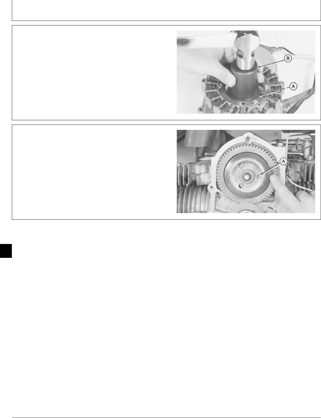
3. Install oil seal (A), with lip of seal downward, in gear
cover suing JDG 325 Crankshaft Seal Installer (B).
M36325 -UN-29JAN90
4. Turn cup until the plastic bushing (A) is in the 3
o’clock position.
5. Apply multipurpose grease between cup and camshaft
gear to hold cup in position.
M36428 -UN-29JAN90
M98,2040K,17 -19-11OCT85
M98,2040K,18 -19-11OCT85
Lubrication System/Oil Pump
CTM2 (19APR90) 40-8 16, 18, 20 & 24HP Onan Engines
130495
40
8
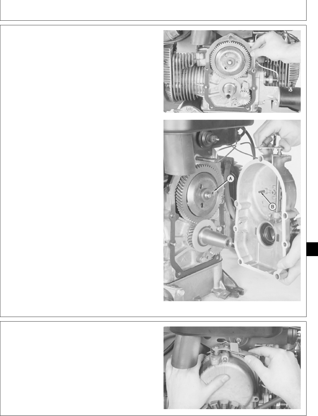
6. Install new gasket on cylinder block.
7. Be sure plastic bushing (A) and pin (B) are aligned.
IMPORTANT: Do not hit gear cover with a metal
hammer during installation. Gear cover
can be damaged.
8. Hold governor arm away from camshaft and carefully
install gear cover.
M36429 -UN-29JAN90M36430 -UN-29JAN90
9. Tip engine forward and move governor arm back and
forth. Governor cup should be felt moving in and out. If
no movement is felt, the pin is not in plastic bushing.
Remove gear cover and repeat Steps 7—9.
M36431 -UN-29JAN90
M98,2040K,19 -19-11OCT85
M98,2040K,20 -19-11OCT85
Lubrication System/Oil Pump
CTM2 (19APR90) 40-9 16, 18, 20 & 24HP Onan Engines
130495
40
9
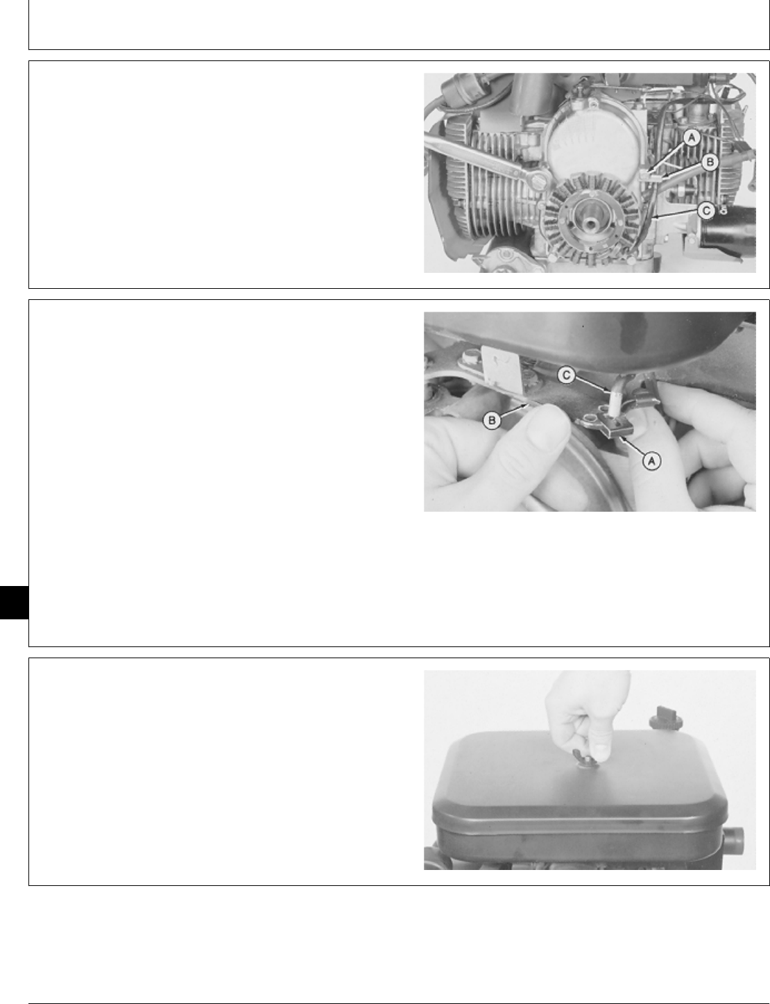
10. Apply pipe sealant on cap screw (A) threads.
11. Install clip (B), four cap screws, and nut. Tighten cap
screws and nut to 12 ± 1 N·m (106 ± 9 lb-in.).
12. Install stator wiring (C) in clip.
M36432 -UN-29JAN90
13. Install clip (A) on governor arm (B). Push governor
rod (C) and governor arm toward carburetor until they
bottom out.
14. Install governor rod in closest governor arm hole. If
governor rod is between two holes, install governor rod
in next hole toward flywheel. Push clip on governor rod.
15. Install flywheel. (See Group 20 in this manual.)
16. Install engine. (See machine technical manual.)
M36433 -UN-29JAN90
REMOVE OIL PRESSURE REGULATING
VALVE
1. Park tractor safely.
2. Disconnect negative (-) battery cable.
NOTE: For T260 engine, go to Step 8.
3. Remove wing nut to remove air cleaner cover.
M36217 -UN-22NOV89
M98,2040K,21 -19-11OCT85
M98,2040K,22 -19-11OCT85
M98,2040K,23 -19-11OCT85
Lubrication System/Oil Pressure Regulating Valve
CTM2 (19APR90) 40-10 16, 18, 20 & 24HP Onan Engines
130495
40
10
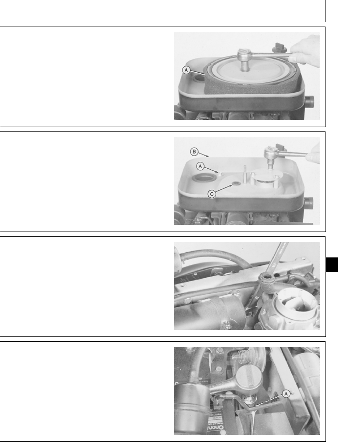
4. Remove lock nut to remove plate and element (A).
M36447 -UN-29JAN90
5. Remove three cap screws to remove splash plate.
6. Remove two cap screws (A) to remove air cleaner
base (B). Pull breather hose (C) out of air cleaner base.
M36448 -UN-29JAN90
7. Loosen nut to remove air cleaner bracket.
M36449 -UN-29JAN90
8. Remove cap screw and washer (A).
M36450 -UN-29JAN90
M98,2040K,24 -19-14OCT85
M98,2040K,25 -19-14OCT85
M98,2040K,26 -19-14OCT85
M98,2040K,27 -19-14OCT85
Lubrication System/Oil Pressure Regulating Valve
CTM2 (19APR90) 40-11 16, 18, 20 & 24HP Onan Engines
130495
40
11
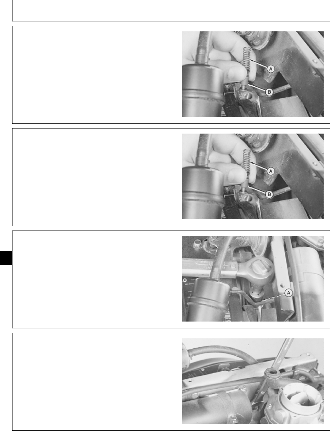
9. Remove spring (A) and valve (B).
10. Inspect spring, valve, and valve bore for wear or
damage.
11. Check spring using a spring compression tester.
SPRING SPECIFICATIONS
Free length (approx.) . . . . . . . . . . . . . . . . . . . . . . . 25 mm (1.0 in.)
Test length at 12 N . . . . . . . . . . . . . . . . . . . . . . . . . . . . . . 13 mm
(2.6 lb force . . . . . . . . . . . . . . 0.5 in.)
M36451 -UN-29JAN90
INSTALL OIL PRESSURE REGULATING
VALVE
1. Thoroughly clean and dry parts.
2. Put clean engine oil on all internal parts.
3. Install valve (B) and spring (A).
M36451 -UN-29JAN90
4. Install washer (A) and cap screw. Tighten cap screw
to 28 ± 3 N·m (248 ± 27 lb-in.).
NOTE: For T260 engine, stop here.
M36452 -UN-29JAN90
5. Install air cleaner bracket. Be sure air cleaner bracket
is level and tighten nut.
M36449 -UN-29JAN90
M98,2040K,28 -19-26NOV85
M98,2040K,29 -19-14OCT85
M98,2040K,30 -19-14OCT85
M98,2040K,31 -19-14OCT85
Lubrication System/Oil Pressure Regulating Valve
CTM2 (19APR90) 40-12 16, 18, 20 & 24HP Onan Engines
130495
40
12
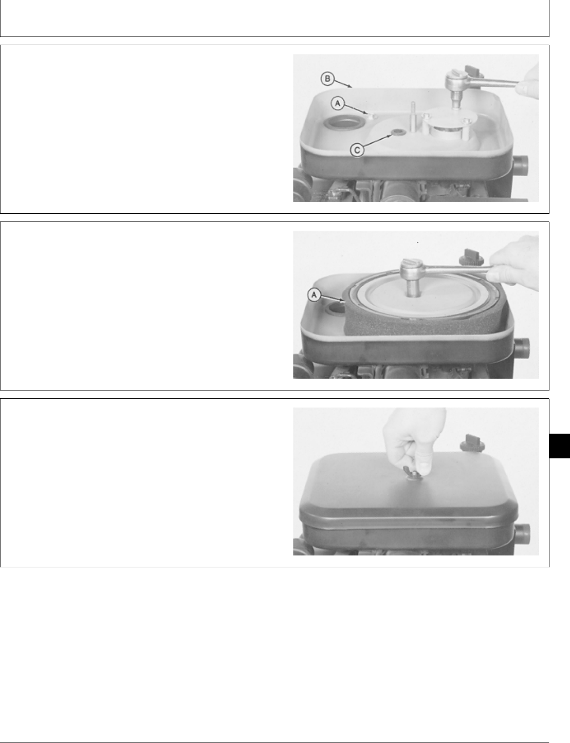
6. Install breather hose (C) in air cleaner base (B).
7. Install air cleaner base on carburetor. Install air intake
hose in flywheel shroud hole.
8. Install and tighten two air cleaner base cap screws
(A).
9. Install splash plate and fasten with three cap screws.
M36448 -UN-29JAN90
10. Install element (A) and plate. Install and tighten lock
nut.
M36447 -UN-29JAN90
11. Install air cleaner cover and tighten wing nut.
12. Connect negative (-) battery cable.
M36217 -UN-22NOV89
M98,2040K,32 -19-14OCT85
M98,2040K,33 -19-14OCT85
M98,2040K,34 -19-14OCT85
Lubrication System/Oil Pressure Regulating Valve
CTM2 (19APR90) 40-13 16, 18, 20 & 24HP Onan Engines
130495
40
13
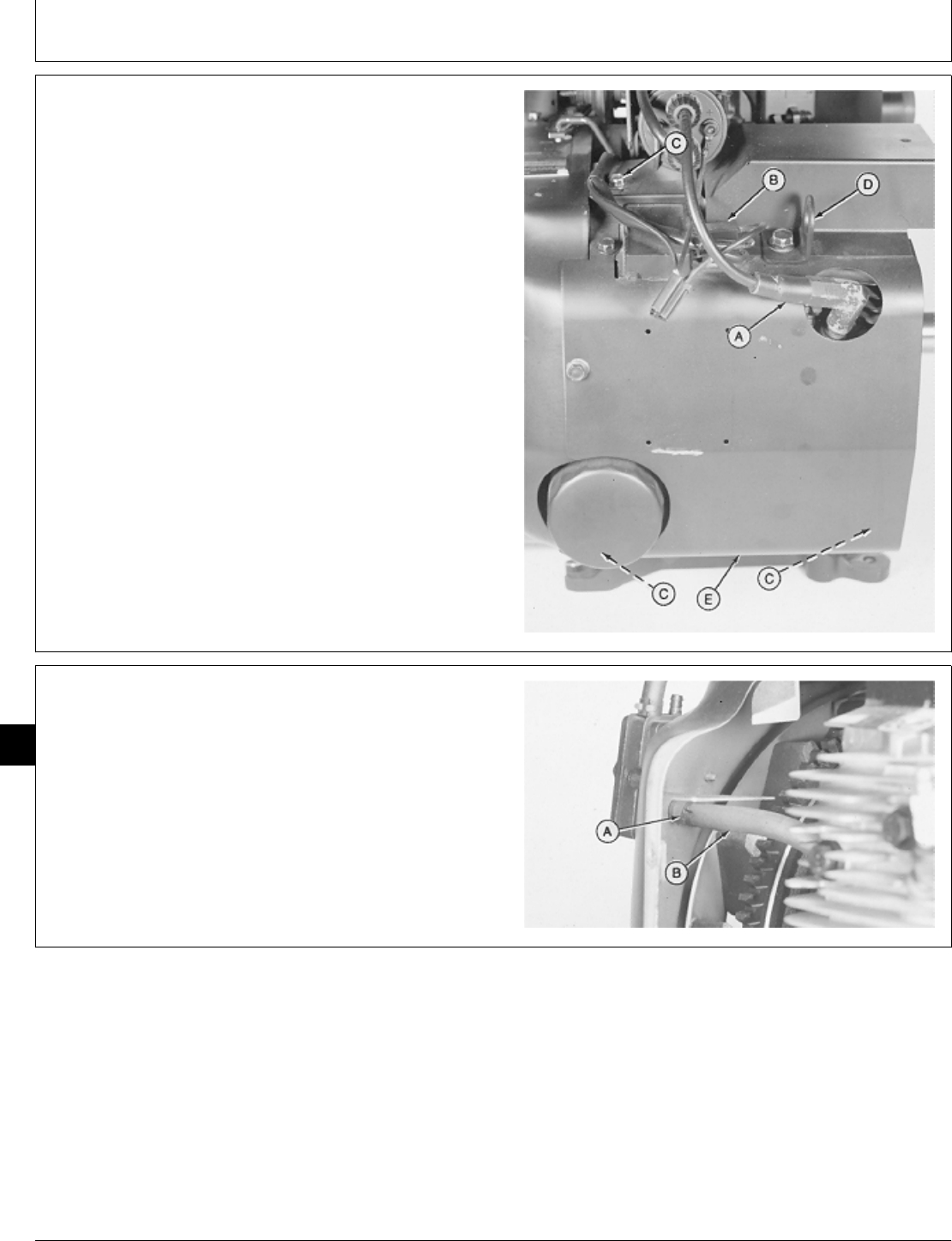
REMOVE AND INSPECT OIL BASE
1. Remove engine. (See machine technical manual.)
2. Disconnect spark plug wire (A) and voltage regulator
leads (B).
3. Remove five cap screws (C) to remove lift bracket (D)
and right side shroud (E).
A—Spark Plug Wire
B—Voltage Regulator Leads
C—Cap Screw (5 used)
D—Lift Bracket
E—Right Side Shroud
M36289 -UN-29JAN90
4. Loosen hose clamp (A) to disconnect fuel pump
impulse line (B).
M36290 -UN-29JAN90
M98,2040K,35 -19-14OCT85
M98,2040K,36 -19-14OCT85
Lubrication System/Oil Base
CTM2 (19APR90) 40-14 16, 18, 20 & 24HP Onan Engines
130495
40
14
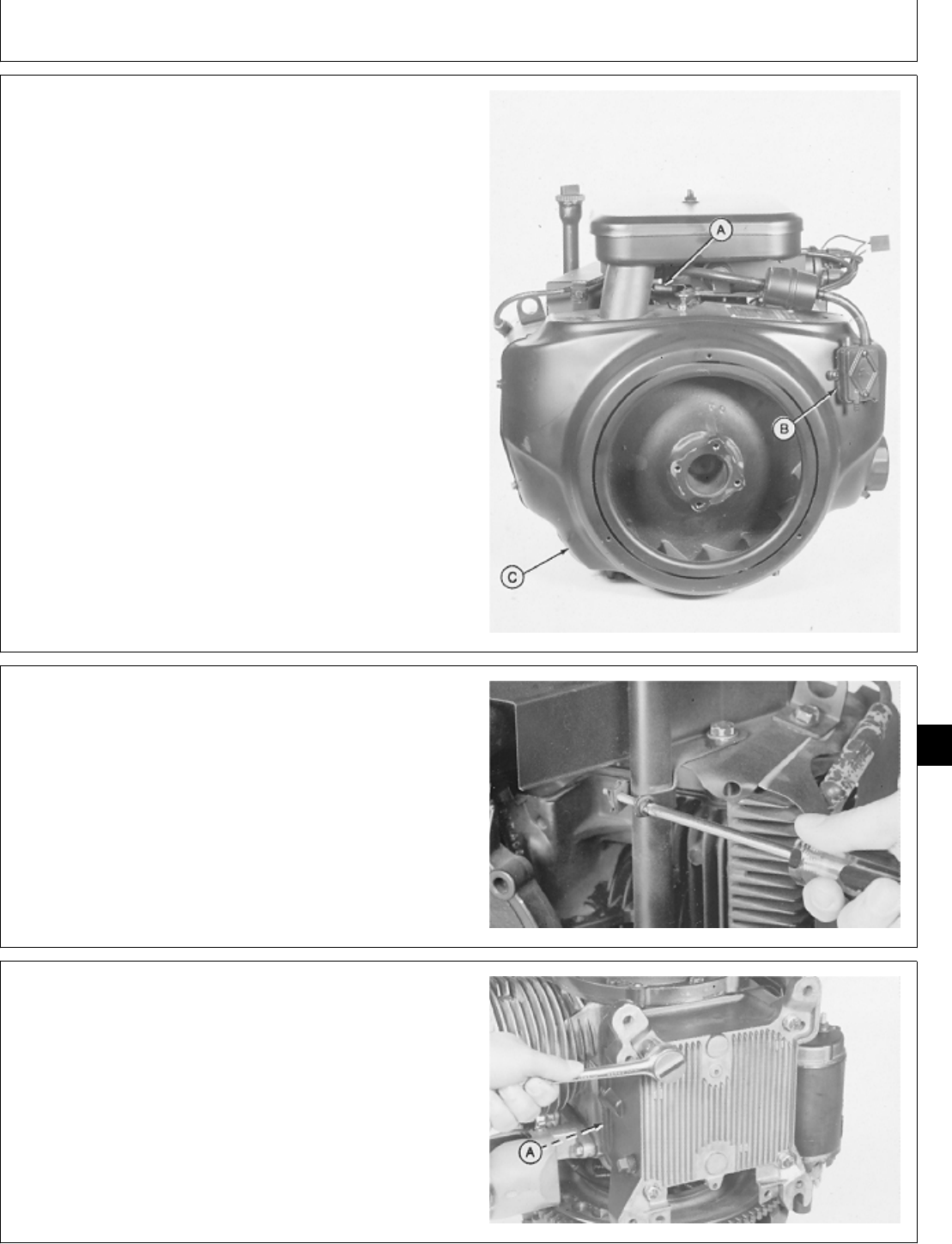
5. Disconnect governor spring (A).
6. Remove two screws to remove fuel pump (B).
7. Remove five cap screws to remove flywheel shroud
(C).
M36291 -UN-29JAN90
8. Remove screw to disconnect oil fill tube bracket.
M36434 -UN-29JAN90
9. Remove four cap screws to remove oil base and
gasket (A).
M36374 -UN-29JAN90
M98,2040K,37 -19-14OCT85
M98,2040K,38 -19-14OCT85
M98,2040K,39 -19-14OCT85
Lubrication System/Oil Base
CTM2 (19APR90) 40-15 16, 18, 20 & 24HP Onan Engines
130495
40
15
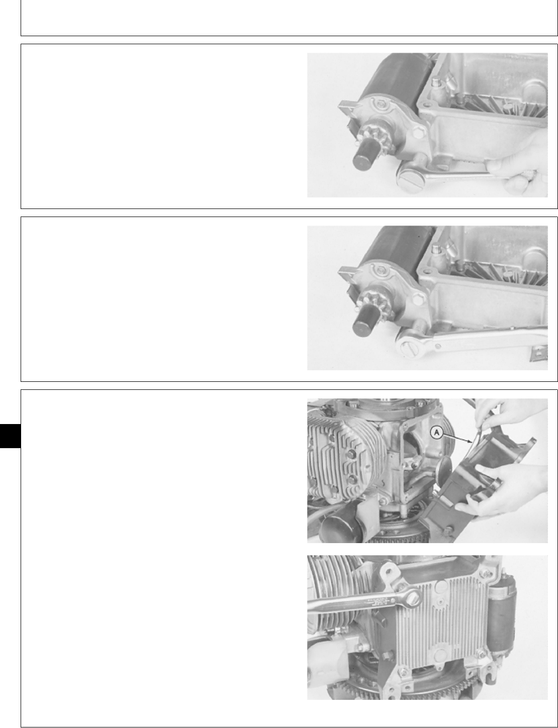
NOTE: On P218G and P220G Engines the starter is not
attached to the oil base.
10. Remove two cap screws to remove starter.
11. Inspect oil base for cracks, broken fins, or damage;
replace if necessary.
M36435 -UN-29JAN90
INSTALL OIL BASE
NOTE: On P218G and P22G Engines the starter is not
attached to the oil base.
1. Install starter and two cap screws. Tighten cap screws
to 34 ± 1 N·m (301 ± 9 lb-in.)
M36436 -UN-29JAN90
2. Install a new gasket (A) on oil base.
3. Install oil base. Install and tighten four cap screws to
27 ± 3 N·m (320 ± 27 lb-in.).
M36415 -UN-29JAN90M36416 -UN-29JAN90
M98,2040K,40 -19-02FEB87
M98,2040K,41 -19-02FEB87
M98,2040K,42 -19-26NOV85
Lubrication System/Oil Base
CTM2 (19APR90) 40-16 16, 18, 20 & 24HP Onan Engines
130495
40
16
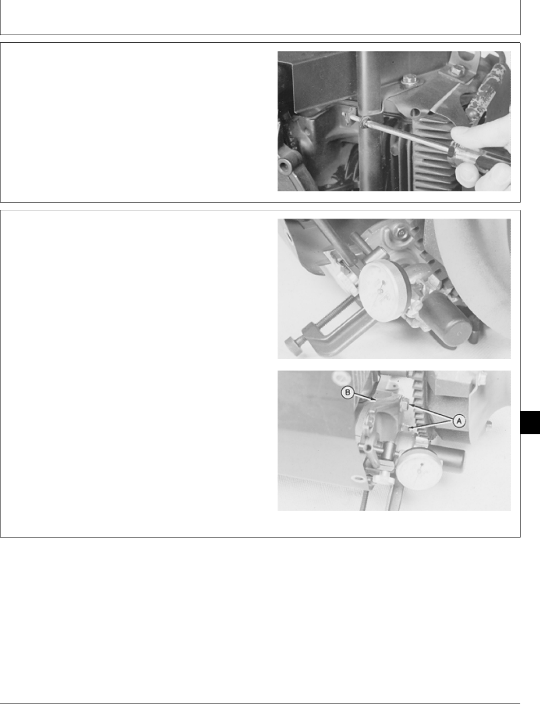
4. Install oil fill tube bracket and fasten with screw.
M36434 -UN-29JAN90
NOTE: For engines with adjustable starter bracket,
measure starter pinion gear backlash using the
following procedure. For all other units with
non-adjustable starter bracket, go to Step 18.
5. Pull starter pinion gear outward until teeth contact
flywheel ring gear. Measure starter pinion gear backlash.
Backlash specification is 0.51 ± 0.38 mm (0.020 ± 0.015
in.).
6. If backlash is not correct, loosen starter cap screws
(A) and move starter bracket (B) to obtain correct
backlash.
Tighten starter cap screws to hold bracket in position.
Check backlash again.
M36437 -UN-29JAN90M36438 -UN-29JAN90
M98,2040K,43 -19-14OCT85
M98,2040K,44 -19-14OCT85
Lubrication System/Oil Base
CTM2 (19APR90) 40-17 16, 18, 20 & 24HP Onan Engines
130495
40
17
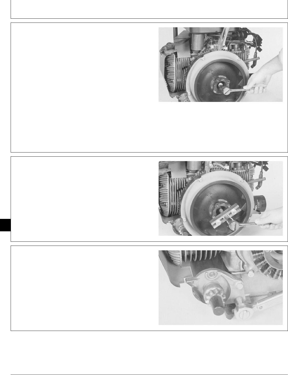
IMPORTANT: Do not hold flywheel from turning with
a pry bar. Doing so can damage fins.
7. Fasten locking pliers to ring gear to prevent flywheel
from turning.
NCAUTION: Loosen flywheel cap screw only two
turns. Do not remove cap screw. If cap screw
is removed, flywheel may cause injury when it
comes loose.
8. Loosen cap screw two turns only.
M36292 -UN-29JAN90
IMPORTANT: Do not pry on flywheel with a
screwdriver. Ceramic magnets or gear
case cover can be damaged.
9. Loosen flywheel using a puller.
10. Remove puller, cap screw, washer, and flywheel.
M36293 -UN-29JAN90
11. Tighten starter cap screws to 34 ± 1 N·m (301 ± 9
lb-in.).
M36439 -UN-29JAN90
M98,2040K,45 -19-21OCT85
M98,2040K,46 -19-21OCT85
M98,2040K,47 -19-21OCT85
Lubrication System/Oil Base
CTM2 (19APR90) 40-18 16, 18, 20 & 24HP Onan Engines
130495
40
18
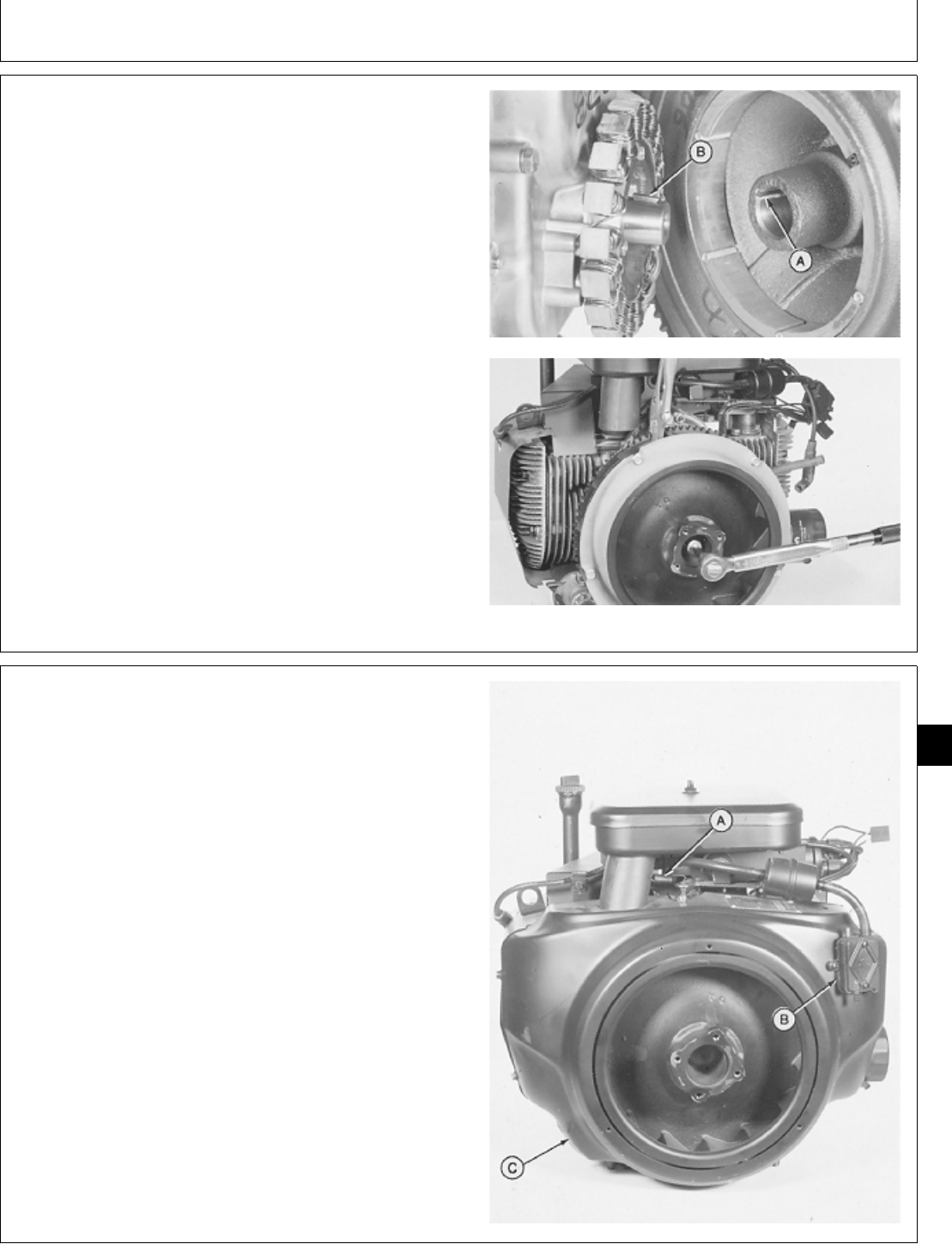
IMPORTANT: Do not lubricate crankshaft taper. The
crankshaft taper must able dry to hold
the flywheel tight.
12. Clean crankshaft taper before installing flywheel.
13. Apply pipe sealant on threads of flywheel cap screw.
14. Align keyway (A) in flywheel with key (B) in
crankshaft. Install flywheel.
15. Install washer and cap screw.
16. Fasten locking pliers to ring gear to prevent flywheel
from turning.
17. On B43E, B43G, B48G, T260 Engines: tighten cap
screw to 51 ± 3 N·m (38 ± 2 lb-ft).
M36297 -UN-29JAN90M36298 -UN-29JAN90
18. Install flywheel shroud (C) and fasten with five cap
screws.
19. Install fuel pump (B) and fasten with two screws.
20. Connect governor spring (A) in top hole of arm.
M36291 -UN-29JAN90
M98,2040K,48 -19-11FEB87
M98,2040K,49 -19-21OCT85
Lubrication System/Oil Base
CTM2 (19APR90) 40-19 16, 18, 20 & 24HP Onan Engines
130495
40
19
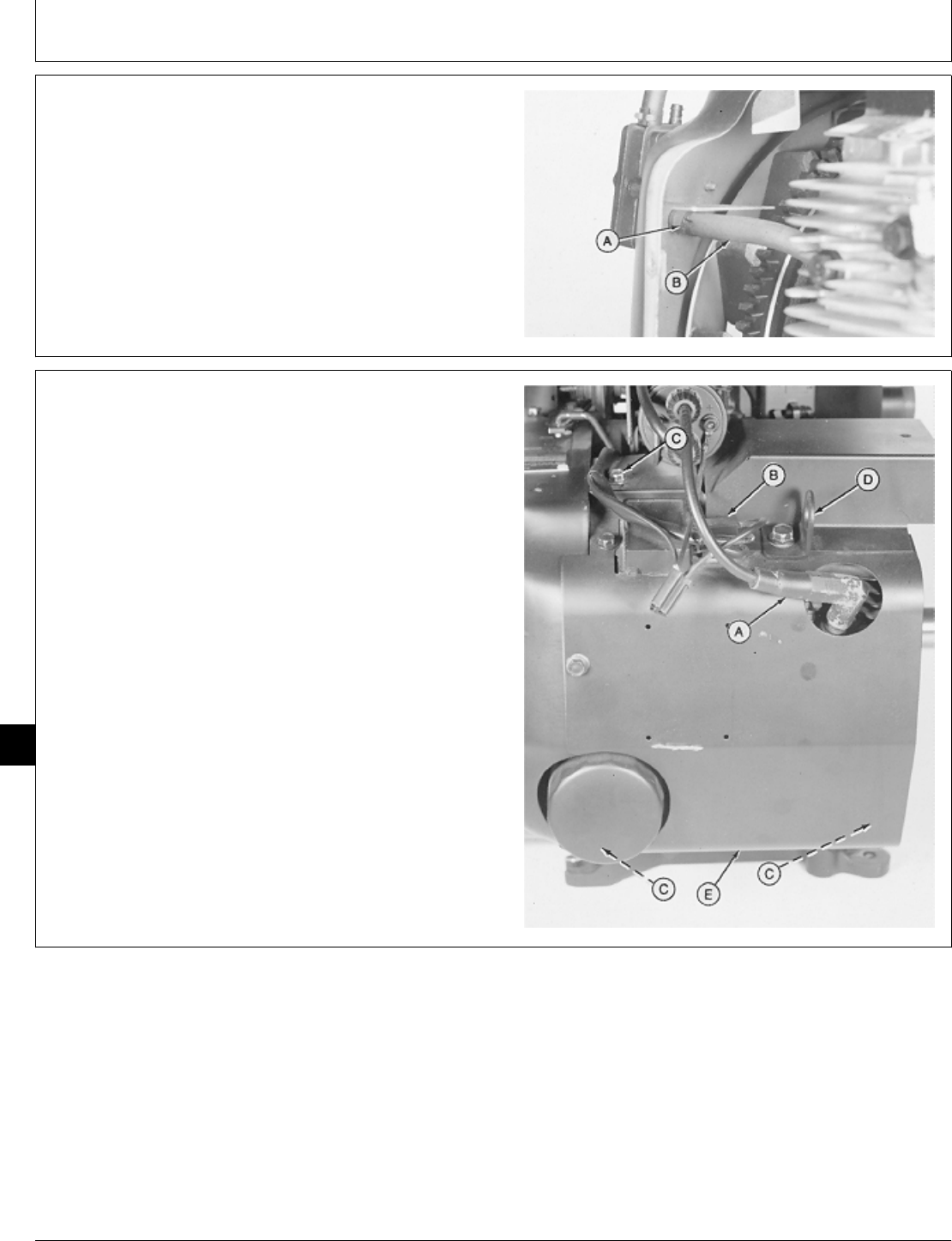
21. Connect fuel pump impulse line (B) and fasten with
hose clamp (A).
M36290 -UN-29JAN90
22. Install right side shroud (E), lift bracket (D), and
fasten with five cap screws (C). Tighten lift bracket cap
screw to 11 ± 3 N·m (97 ± 27 lb-in.).
23. Connect spark plug wire (A) and voltage regulator
leads (B). Install the two stator leads on “AC” terminals
and the battery lead on “B+” terminal of the voltage
regulator.
24. Install engine. (See machine technical manual.)
A—Spark Plug Wire
B—Voltage Regulator Leads
C—Cap Screw (5 used)
D—Lift Bracket
E—Right Side Shroud
M36289 -UN-29JAN90
M98,2040K,50 -19-21OCT85
M98,2040K,51 -19-21OCT85
Lubrication System/Oil Base
CTM2 (19APR90) 40-20 16, 18, 20 & 24HP Onan Engines
130495
40
20
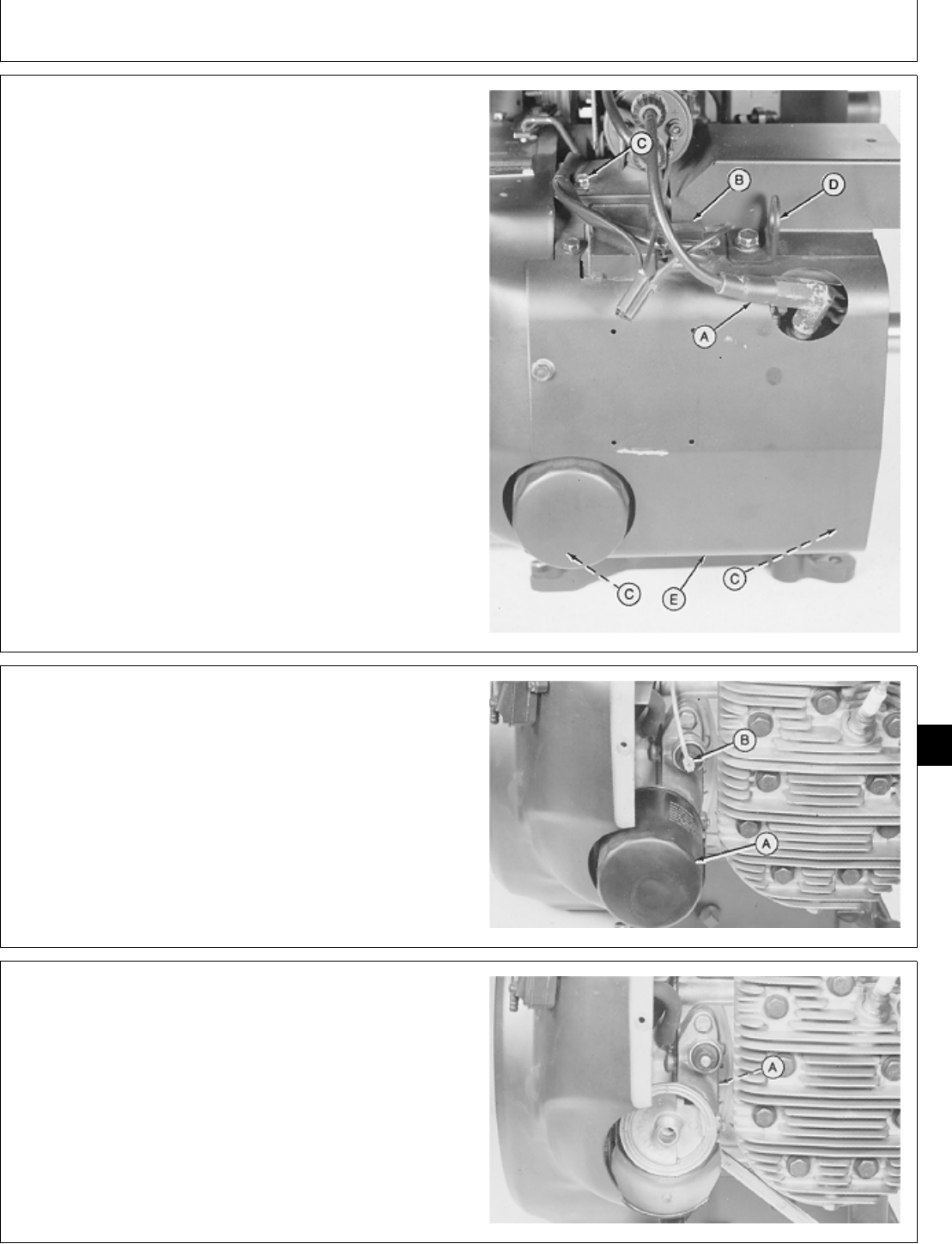
REMOVE OIL FILTER ADAPTER
1. Remove engine. (See machine technical manual.)
2. Disconnect spark plug wire (A) and voltage regulator
leads (B).
3. Remove five cap screws (C) to remove lift bracket
(D), and right side shroud (E).
A—Spark Plug Wire
B—Voltage Regulator Leads
C—Cap Screw (5 used)
D—Lift Bracket
E—Right Side Shroud
M36289 -UN-29JAN90
4. Remove oil filter (A).
5. Disconnect engine oil pressure sender wiring lead (B).
M36440 -UN-29JAN90
6. Remove two cap screws to remove oil filter adapter
and gasket (A).
M36441 -UN-29JAN90
M98,2040K,52 -19-21OCT85
M98,2040K,53 -19-21OCT85
M98,2040K,54 -19-21OCT85
Lubrication System/Oil Filter Adapter
CTM2 (19APR90) 40-21 16, 18, 20 & 24HP Onan Engines
130495
40
21
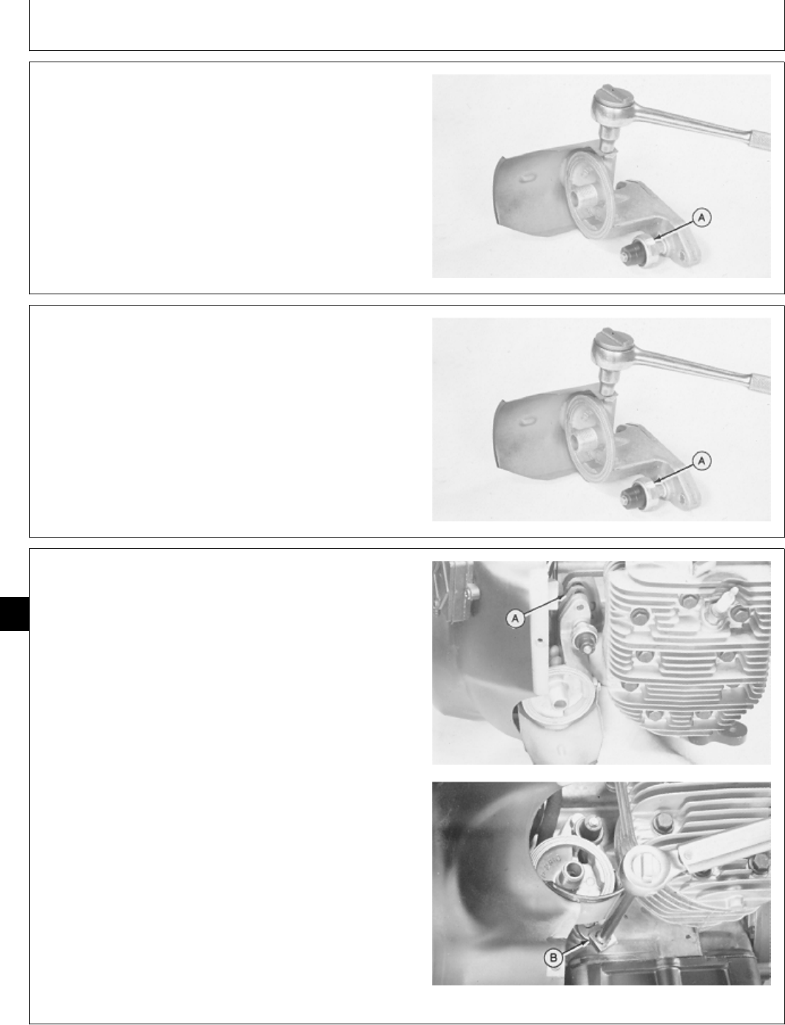
7. Remove two cap screws to remove drain pan.
8. Remove engine oil pressure sender (A).
9. Inspect oil filter adapter for thread damage, cracks or
damage; replace as necessary.
M36442 -UN-29JAN90
INSTALL OIL FILTER ADAPTER
1. Install engine oil pressure sender (A).
2. Install drain pan and fasten with two cap screws.
M36442 -UN-29JAN90
3. Install new gasket (A) on oil filter adapter.
4. Apply pipe sealant on top cap screw threads.
5. Install oil filter adapter and two cap screws. Tighten
cap screws to 12 ± 1 N·m (106 ± 9 lb-in.) using JDG
333 Crowsfoot Wrench (B) or a 1/2 in crowsfoot wrench.
M36443 -UN-29JAN90M36444 -UN-29JAN90
M98,2040K,55 -19-21OCT85
M98,2040K,56 -19-21OCT85
M98,2040K,57 -19-21OCT85
Lubrication System/Oil Filter Adapter
CTM2 (19APR90) 40-22 16, 18, 20 & 24HP Onan Engines
130495
40
22
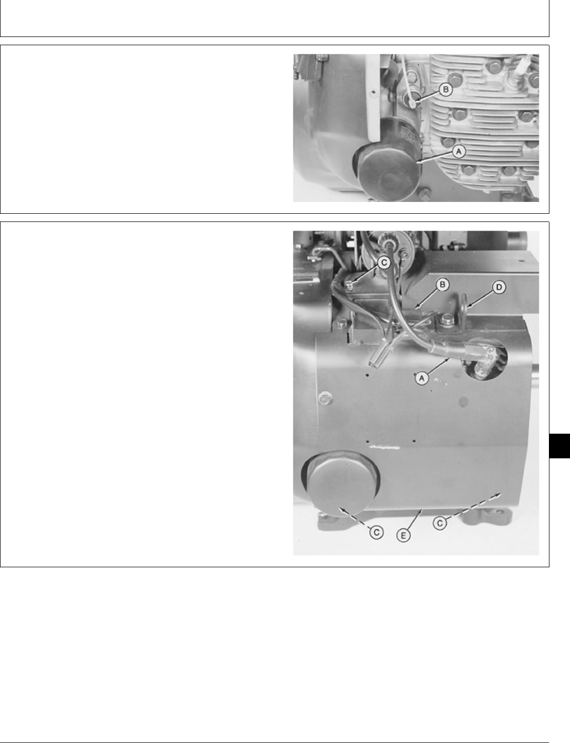
6. Connect engine oil pressure sender wiring lead (B).
7. Install oil filter (A).
M36440 -UN-29JAN90
8. Install right side shroud (E), lift bracket (D), and fasten
with five cap screws (C). Tighten lift bracket cap screw
to 11 ± 3 N·m (97 ± 26 lb-in.).
9. Connect spark plug wire (A) and voltage regulator
leads (B). Install the two stator leads on “AC” terminals
and the battery lead on “B+” terminal of the voltage
regulator.
10. Install engine. (See machine technical manual.)
A—Spark Plug Wire
B—Voltage Regulator Leads
C—Cap Screw (5 used)
D—Lift Bracket
E—Right Side Shroud
M36289 -UN-29JAN90
M98,2040K,58 -19-21OCT85
M98,2040K,59 -19-21OCT85
Lubrication System/Oil Filter Adapter
CTM2 (19APR90) 40-23 16, 18, 20 & 24HP Onan Engines
130495
40
23
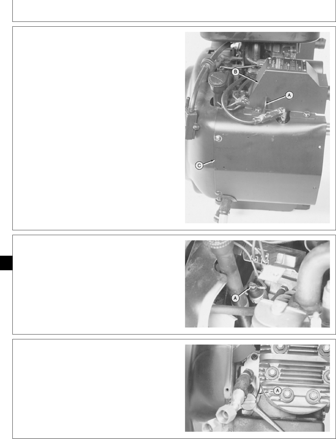
REMOVE OIL LINE ADAPTER
1. Remove engine. (See machine technical manual.)
2. Remove three cap screws to remove lift bracket (A)
and exhaust shroud (B).
3. Remove four cap screws to remove left side shroud
(C).
M36445 -UN-29JAN90
4. Disconnect engine oil pressure sender wiring lead (A).
M36446 -UN-29JAN90
5. Remove two special screw to remove oil adapter and
gasket (A).
M36453 -UN-29JAN90
M98,2040K,60 -19-21OCT85
M98,2040K,61 -19-21OCT85
M98,2040K,62 -19-21OCT85
Lubrication System/Oil Line Adapter
CTM2 (19APR90) 40-24 16, 18, 20 & 24HP Onan Engines
130495
40
24
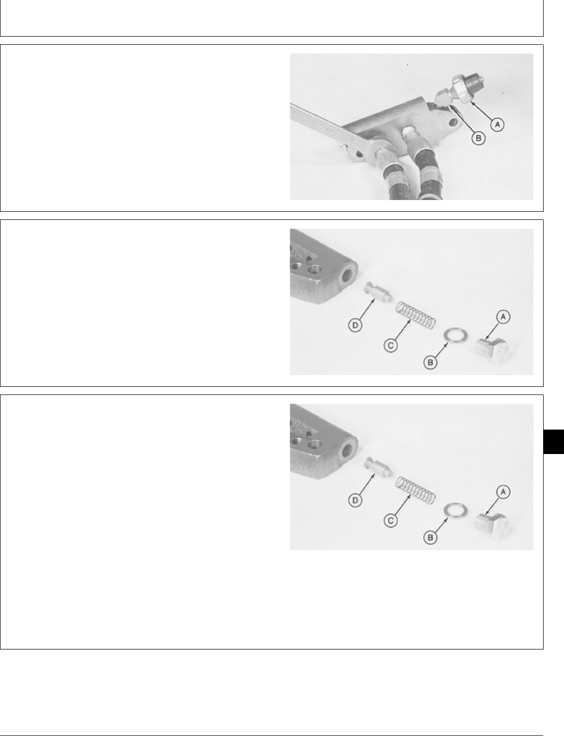
6. Remove oil adapter hoses.
7. Remove engine oil pressure sender (A) and elbow
(B).
M36454 -UN-29JAN90
8. Remove cap screw (A), washer (B), spring (C), and
valve (D).
9. Inspect spring, valve, and valve bore for wear or
damage.
A—Cap Screw
B—Washer
C—Spring
D—Valve
M36455 -UN-29JAN90
INSTALL OIL LINE ADAPTER
1. Thoroughly clean and dry parts.
2. Put clean engine oil on all internal parts.
3. Install valve(D), spring (C), washer (B), and cap screw
(A). Tighten cap screw to 28 ± 3 N·m (248 ± 27 lb-in.).
A—Cap Screw
B—Washer
C—Spring
D—Valve
M36455 -UN-29JAN90
M98,2040K,63 -19-21OCT85
M98,2040K,64 -19-21OCT85
M98,2040K,65 -19-21OCT85
Lubrication System/Oil Line Adapter
CTM2 (19APR90) 40-25 16, 18, 20 & 24HP Onan Engines
130495
40
25
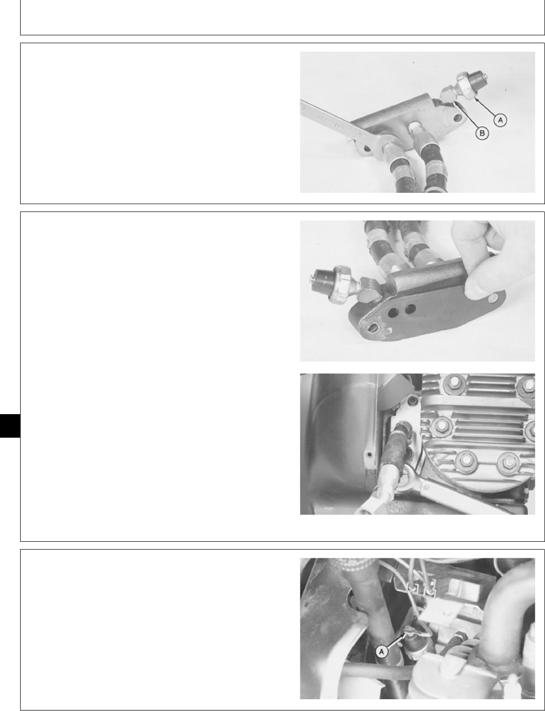
4. Apply pipe sealant on threads of elbow, engine oil
pressure sender and oil adapter hoses.
5. Install elbow (B) and engine oil pressure sender (A).
6. Install oil adapter hoses.
M36454 -UN-29JAN90
7. Install new gasket on oil adapter.
8. Apply pipe sealant on top special screw threads.
9. Install oil adapter and two special screws. Tighten
special screws to 12 ± 1 N·m (106 ± 9 lb-in.).
M36456 -UN-29JAN90M36457 -UN-29JAN90
10. Connect engine oil pressure sender wiring lead (A).
M36446 -UN-29JAN90
M98,2040K,66 -19-21OCT85
M98,2040K,67 -19-21OCT85
M98,2040K,68 -19-21OCT85
Lubrication System/Oil Line Adapter
CTM2 (19APR90) 40-26 16, 18, 20 & 24HP Onan Engines
130495
40
26
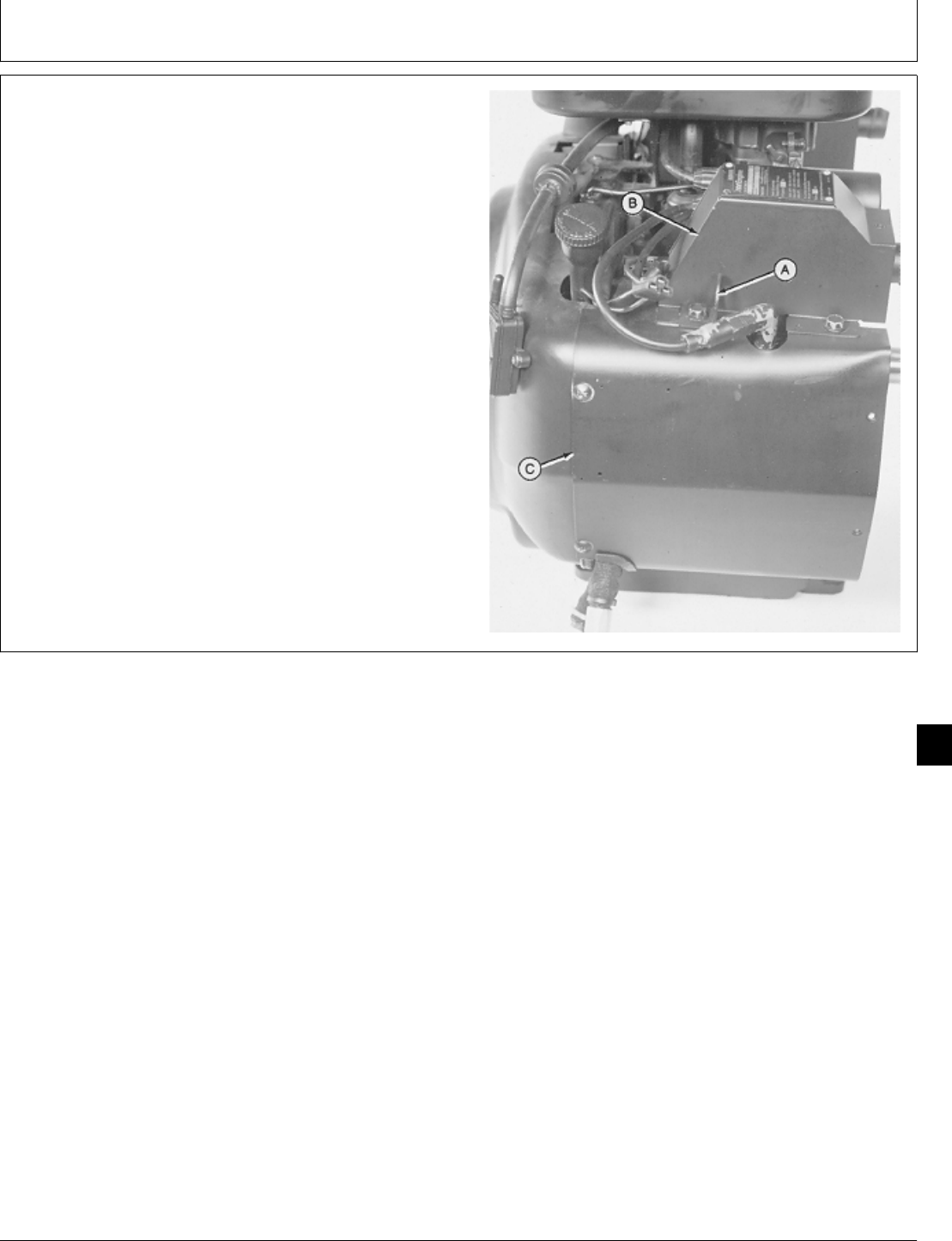
11. Install left side shroud (C) and fasten with four cap
screws.
12. Install exhaust shroud (B), lift bracket (A), and three
cap screws. Tighten lift bracket cap screw to 11 ± 3 N·m
(97 ± 27 lb-in.).
13. Install engine. (See machine technical manual.)
M36445 -UN-29JAN90
M98,2040K,69 -19-21OCT85
Lubrication System/Oil Line Adapter
CTM2 (19APR90) 40-27 16, 18, 20 & 24HP Onan Engines
130495
40
27

Lubrication System/Oil Line Adapter
CTM2 (19APR90) 40-28 16, 18, 20 & 24HP Onan Engines
130495
40
28

SERVICE EQUIPMENT AND TOOLS
NOTE: Order tools from the U.S. SERVICE-GARD™ Catalog or from the European Microfiche Tool Catalog
(MTC). Some tools may be available from a local supplier.
Name Use
Press Remove and install camshaft gear.
Bushing, Bearing, and Seal Driver Set Remove and install gear cover bushing and oil
seal
OTHER MATERIAL
Number Name Use
T43512 John Deere LOCTITE Thread Lock Apply to threads of governor fork
and Sealer (Medium Strength) screws
LOCTITE is a trademark of the Loctite Corp.
SERVICE PARTS KITS
The following kits are available through your parts
catalog:
Overhaul Gasket Kit
SPECIFICATIONS
Item Measurement Specification
Governor Cup Travel 5.6 mm (0.22 in.)
Gear cover surface-to-pin Distance 19 mm (0.75 in.)
M98,2045K,1 -19-21OCT85
M98,2045K,2 -19-21OCT85
M98,2045K,2A -19-11NOV85
M98,2045K,3 -19-21OCT85
Group 45
Governor
CTM2 (19APR90) 45-1 16, 18, 20 & 24HP Onan Engines
130495
45
1
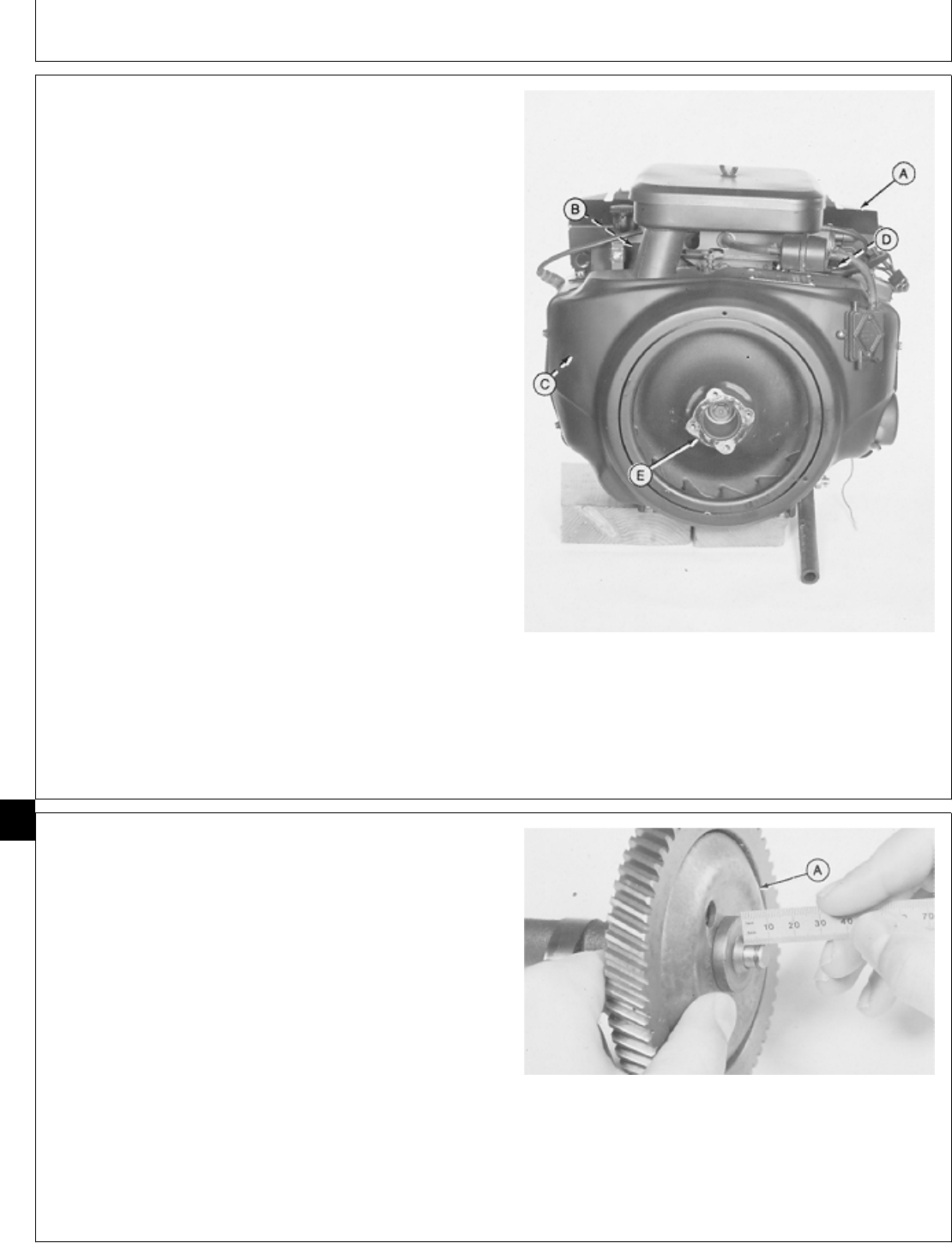
REMOVE GOVERNOR ASSEMBLY AND
GOVERNOR LINKAGE
1. Remove engine. (See machine technical manual.)
2. Remove muffler and exhaust pipes (A).
3. Remove intake manifold (B). (See Remove Intake
Manifold, Group 10 in this manual.)
4. Remove cylinder heads (C). (See Remove Cylinder
Heads, Group 10 in this manual.)
5. Remove intake and exhaust valves (D). (See Remove
Intake and Exhaust Valves, Group 15 in this manual.)
6. Remove flywheel (E). (See Remove Flywheel, Group
20 in this manual.)
7. Remove camshaft. (See Remove Camshaft, Group 25
in this manual.)
A—Muffler and Exhaust Pipes
B—Intake Manifold
C—Cylinder Heads
D—Intake and Exhaust Valves
E—Flywheel
M36474 -UN-29JAN90
DISASSEMBLE AND INSPECT GOVERNOR
ASSEMBLY
1. Hold cup against flyballs. Measure distance from snap
ring to surface of hub. The distance must be 5.6 mm
(0.22 in.).
If the distance is not correct, replace camshaft assembly.
NOTE: The camshaft and pin are only serviced as an
assembly.
2. The cup (A) must spin freely on the camshaft pin
without excessive play. Replace parts as necessary.
M36308 -UN-29JAN90
M98,2045K,4 -19-21OCT85
M98,2045K,5 -19-21OCT85
Governor/Governor Assembly
CTM2 (19APR90) 45-2 16, 18, 20 & 24HP Onan Engines
130495
45
2
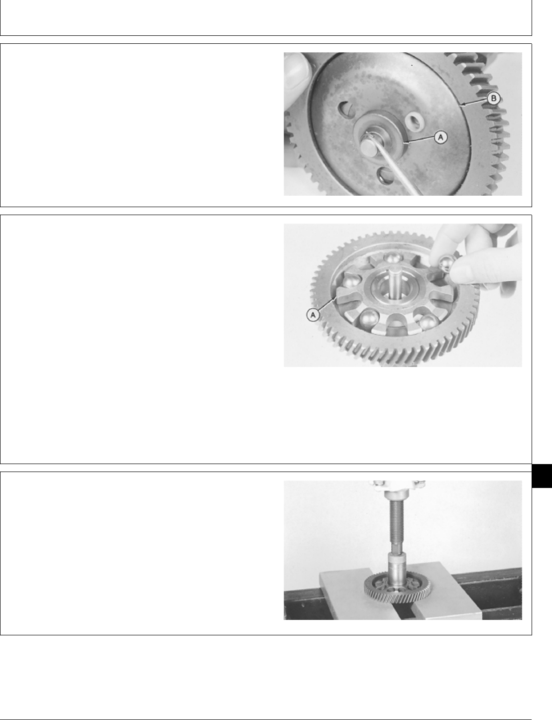
3. Remove snap ring to remove hub (A) and cup (B).
4. Inspect cup race for grooved or rough surface.
Replace cup if necessary.
M36309 -UN-29JAN90
5. Remove flyballs. Inspect flyballs for grooved or flat
spots, replace if necessary.
6. Inspect flyball spacer (A) for wear or damage.
Replace camshaft gear if necessary.
NOTE: The flyball spacer, plate, and camshaft gear are
serviced as an assembly only.
IMPORTANT: If camshaft gear is replaced, always
replace crankshaft gear also.
7. Inspect camshaft gear for chipped or broken teeth.
Replace camshaft gear if necessary.
M36310 -UN-29JAN90
IMPORTANT: Be sure to hold camshaft while
removing camshaft gear.
8. Remove gear using a 1 in. deep-well socket, 1 in.
driver disk, and a press.
9. Remove key.
M30688 -UN-14JUL89
M98,2025K,15 -19-09OCT85
M98,2025K,16 -19-09OCT85
M98,2025K,17 -19-11NOV85
Governor/Governor Assembly
CTM2 (19APR90) 45-3 16, 18, 20 & 24HP Onan Engines
130495
45
3
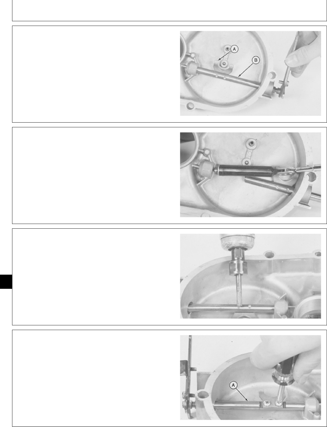
DISASSEMBLE AND INSPECT GOVERNOR
LINKAGE
1. Move governor arm. The governor arm must move
freely without excessive play.
2. Inspect fork (A) and governor arm shaft (B) for wear
or bent condition. Replace parts as necessary.
M36475 -UN-29JAN90
3. Pull governor arm shaft outward.
4. Remove ball bearing from governor arm shaft hole
using a magnet.
M36476 -UN-29JAN90
5. If necessary, remove staked ends of fork screws using
a small grinder.
M36477 -UN-29JAN90
6. Remove two screws to remove fork. If screws are
tight, support governor arm shaft (A) and loosen screws
using an impact driver.
7. Remove governor arm shaft.
M36478 -UN-29JAN90
M98,2045K,6 -19-21OCT85
M98,2045K,7 -19-21OCT85
M98,2045K,8 -19-02FEB87
M98,2045K,9 -19-21OCT85
Governor/Governor Linkage
CTM2 (19APR90) 45-4 16, 18, 20 & 24HP Onan Engines
130495
45
4
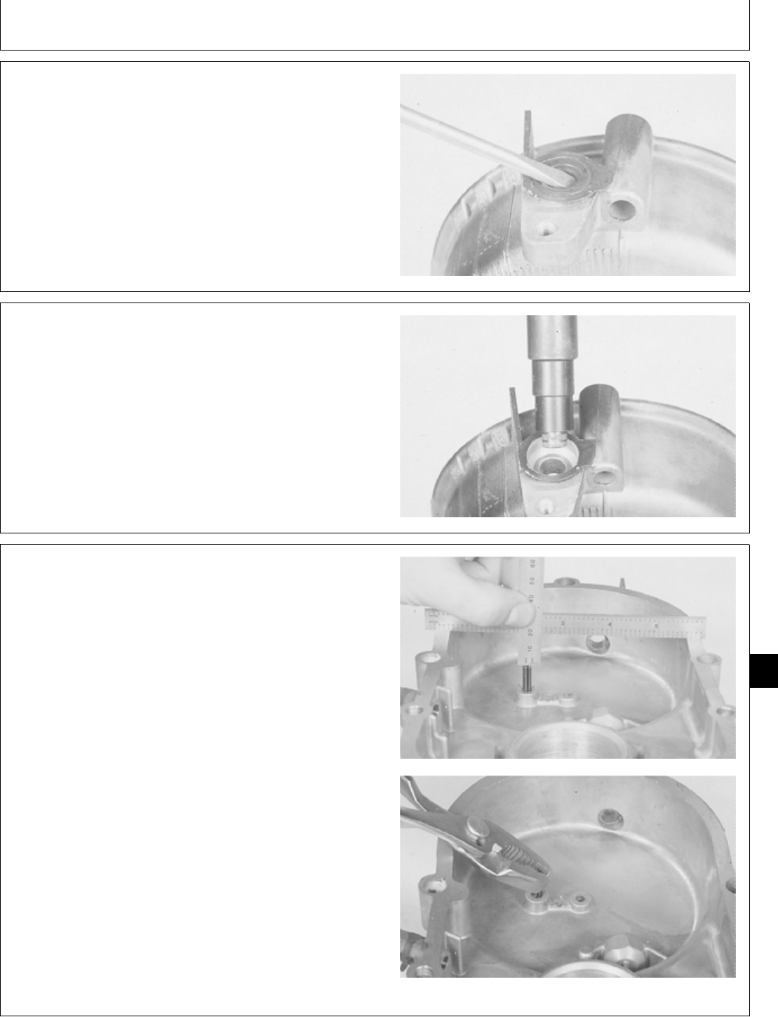
8. Remove seal.
M36479 -UN-29JAN90
9. Remove bushing using a 1/2 in. driver disk and 9/16
in. disk.
M36884 -UN-25JAN90
10. Measure distance from surface of gear cover to pin.
The distance must be 19 mm (0.75 in.). Inspect pin for
damage.
11. If the distance is not correct or pin is damaged,
remove pin.
M36885 -UN-25JAN90M36886 -UN-25JAN90
M98,2045K,10 -19-21OCT85
M98,2045K,11 -19-21OCT85
M98,2045K,12 -19-21OCT85
Governor/Governor Linkage
CTM2 (19APR90) 45-5 16, 18, 20 & 24HP Onan Engines
130495
45
5
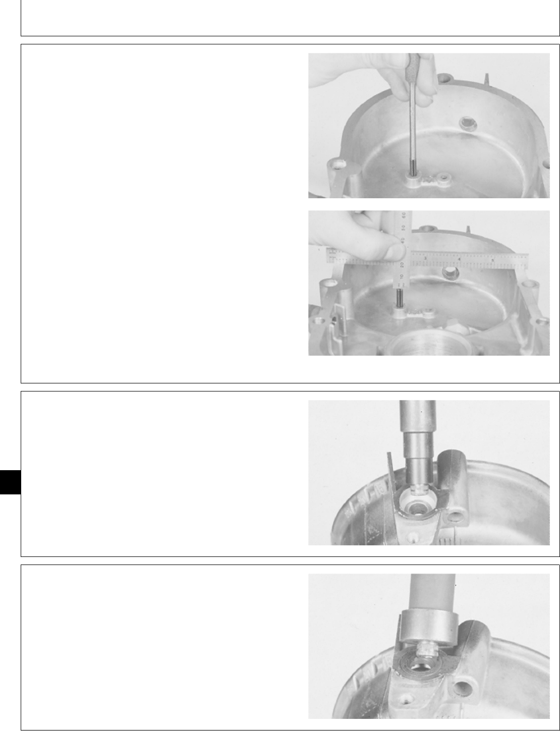
ASSEMBLE GOVERNOR LINKAGE
1. Install new pin in gear cover until pin is 19 mm (0.75
in.) from surface of gear cover.
M36887 -UN-25JAN90M36885 -UN-25JAN90
2. Install new bushing using a 1/2 in. driver disk and
9/16 in. disk. Push bushing even with bottom of oil seal
bore.
M36884 -UN-25JAN90
3. Install new seal, with lips of seal toward driver, using
a 1 in. driver disk. Push seal even with surface of gear
cover.
M36480 -UN-29JAN90
M98,2045K,13 -19-21OCT85
M98,2045K,14 -19-21OCT85
M98,2045K,15 -19-21OCT85
Governor/Governor Linkage
CTM2 (19APR90) 45-6 16, 18, 20 & 24HP Onan Engines
130495
45
6
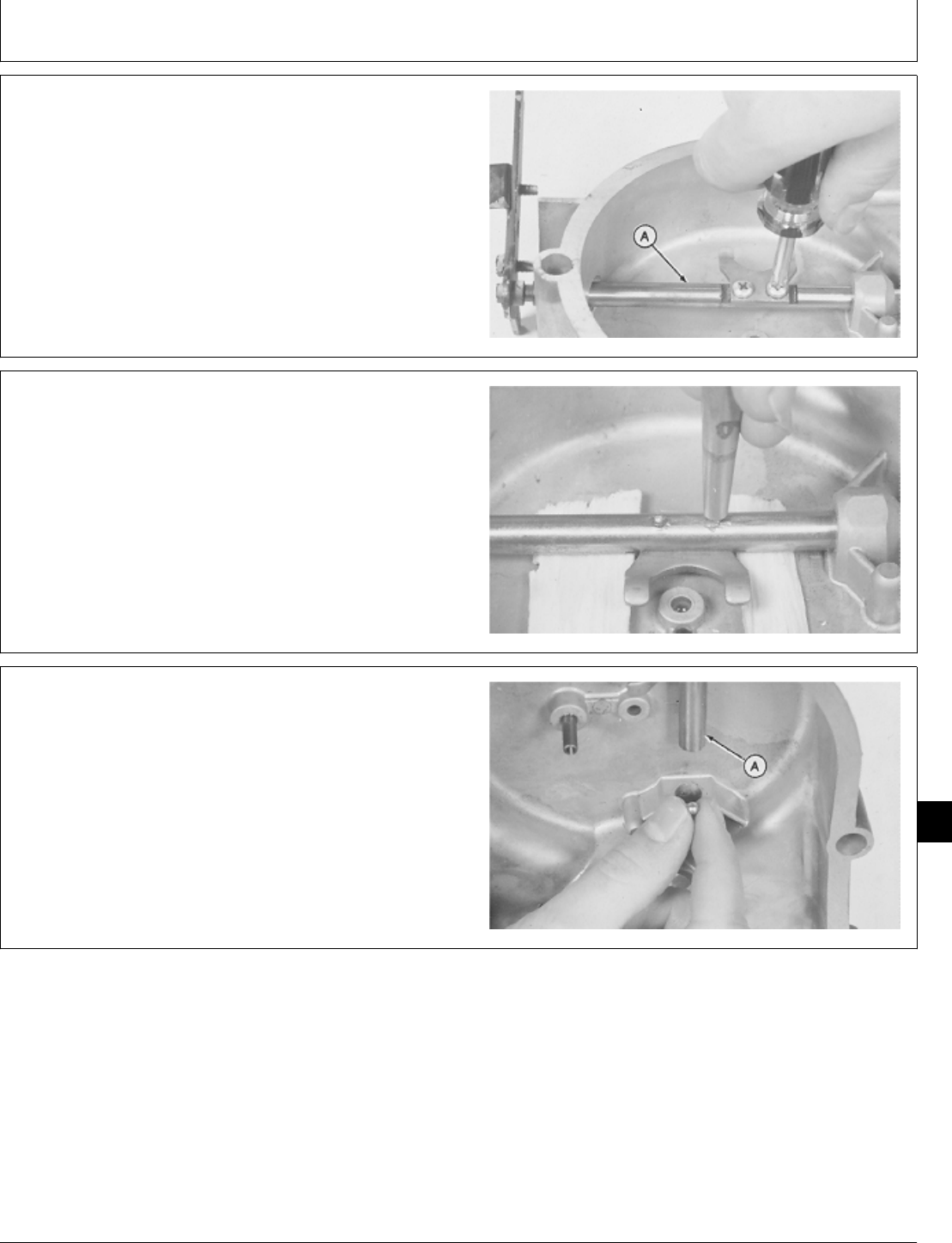
4. Install governor arm shaft (A).
5. Apply thread lock and sealer (medium strength) on
threads of fork screws.
6. Install fork with bent ends upward. Install and tighten
two screws.
M36478 -UN-29JAN90
7. Support governor arm shaft. Hit end of fork screws
using a punch so screws cannot be removed.
M36888 -UN-25JAN90
IMPORTANT: Ball bearing must be installed for
proper governor shaft operation.
8. Install ball bearing in governor arm shaft hole.
9. Install governor arm shaft (A) in governor arm shaft
hole.
M36889 -UN-25JAN90
M98,2045K,16 -19-21OCT85
M98,2045K,17 -19-21OCT85
M98,2045K,18 -19-21OCT85
Governor/Governor Linkage
CTM2 (19APR90) 45-7 16, 18, 20 & 24HP Onan Engines
130495
45
7
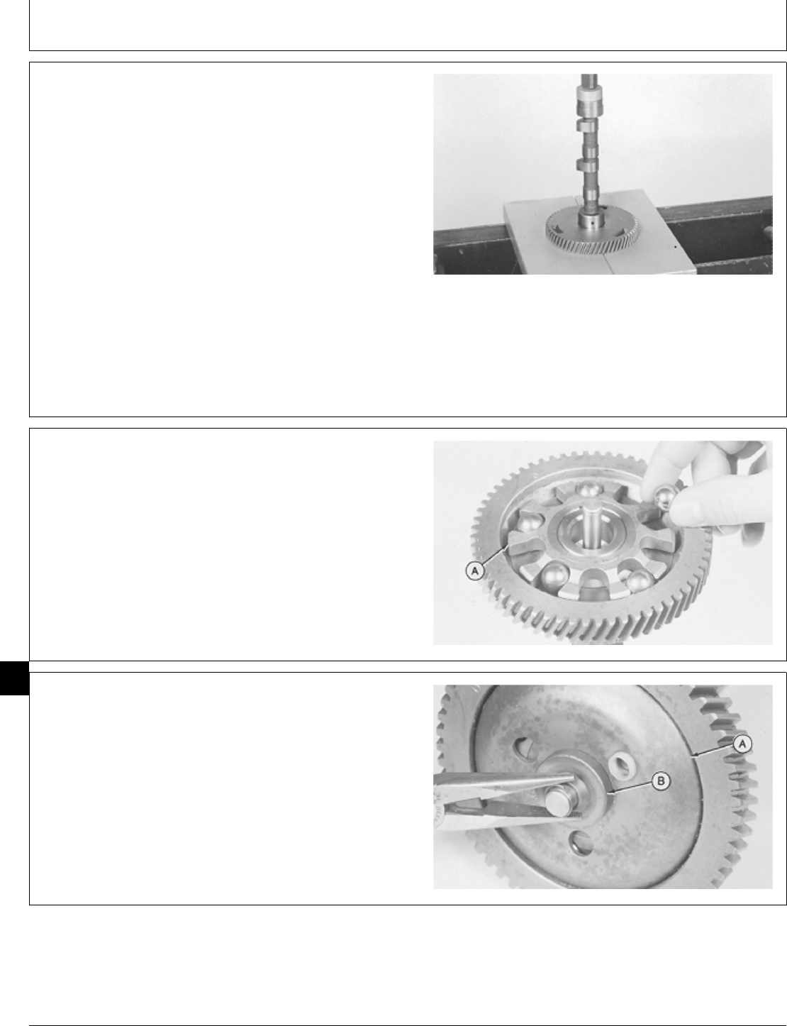
ASSEMBLE GOVERNOR ASSEMBLY
1. Install key in camshaft.
2. Install gear with timing mark “O” away from camshaft.
3. Align slot in gear with key in shaft.
4. Push camshaft into gear using a 1-3/8 in. driver disk
and a press until camshaft is even with bottom of gear
surface.
M30756 -UN-14JUL89
5. Apply clean engine oil on camshaft parts before
assembly.
6. Install flyballs in flyball spacer (A) notches.
M36310 -UN-29JAN90
7. Install cup (A), hub (B), and fasten with snap ring.
M36318 -UN-29JAN90
M98,2045K,19 -19-21OCT85
M98,2025K,25 -19-09OCT85
M98,2025K,26 -19-09OCT85
Governor/Governor Assembly
CTM2 (19APR90) 45-8 16, 18, 20 & 24HP Onan Engines
130495
45
8
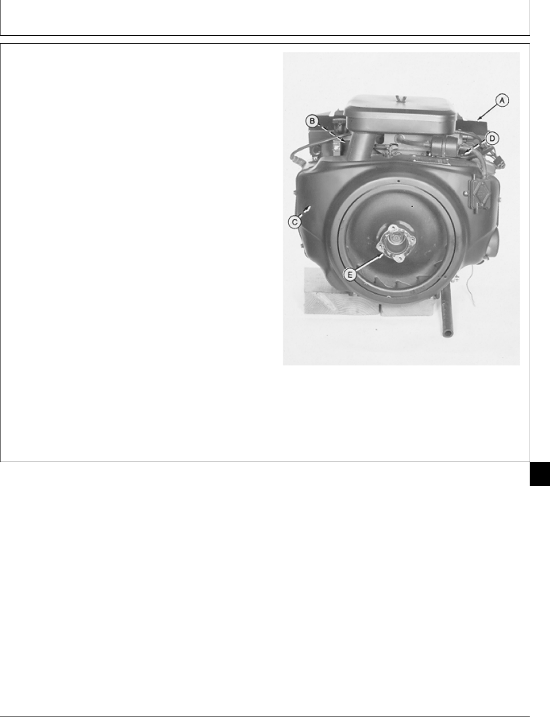
INSTALL GOVERNOR ASSEMBLY AND
GOVERNOR LINKAGE
1. Install camshaft. (See Install Camshaft, Group 25 in
this manual.)
2. Install flywheel (E). (See Install Flywheel, Group 20 in
this manual.)
3. Install intake and exhaust valves (D). (See Install
Intake and Exhaust Valves, Group 15 in this manual.)
4. Install cylinder heads (C). (See Install Cylinder Heads,
Group 10 in this manual.)
5. Install intake manifold (B). (See Install Intake Manifold,
Group 10 in this manual.)
6. Install muffler and exhaust pipes (A). (See Install
Intake Manifold, Group 10 in this manual.)
7. Install engine. (See machine technical manual.)
A—Muffler and Exhaust Pipes
B—Intake Manifold
C—Cylinder Heads
D—Intake and Exhaust Valves
E—Flywheel
M36474 -UN-29JAN90
M98,2045K,20 -19-21OCT85
Governor/Governor Assembly and Linkage
CTM2 (19APR90) 45-9 16, 18, 20 & 24HP Onan Engines
130495
45
9

Governor/Governor Assembly and Linkage
CTM2 (19APR90) 45-10 16, 18, 20 & 24HP Onan Engines
130495
45
10

SERVICE EQUIPMENT AND TOOLS
NOTE: Order tools from the U.S. SERVICE-GARD™ Catalog or from the European Microfiche Tool Catalog
(MTC). Some tools may be available from a local supplier.
Name Use
1/2 in. Crowsfoot Wrench To remove carburetor
SERVICE PARTS KITS
The following kits are available through your parts
catalog:
Choke Shaft Kit
Gasket Kit
Carburetor Float Kit
Float Valve And Seat Kit
Idle Needle Kit
Idle Speed Adjusting Screw Kit
Throttle Shaft Kit
Carburetor Repair Kit
SPECIFICATIONS
Item Measurement Specification
Carburetor Float Level Height from edge of bowl 0 to 1 mm (0.0 to 0.04 in.)
Carburetor Float Drop Depth below edge of bowl 5 mm (0.20 in.) Minimum
Breaker Point Gap Opening 0.41 mm (0.016 in.)
M98,2050K,1 -19-21OCT85
M98,2050K,2 -19-21OCT85
M98,2050K,3 -19-21OCT85
Group 50
Carburetor
CTM2 (19APR90) 50-1 16, 18, 20 & 24HP Onan Engines
130495
50
1
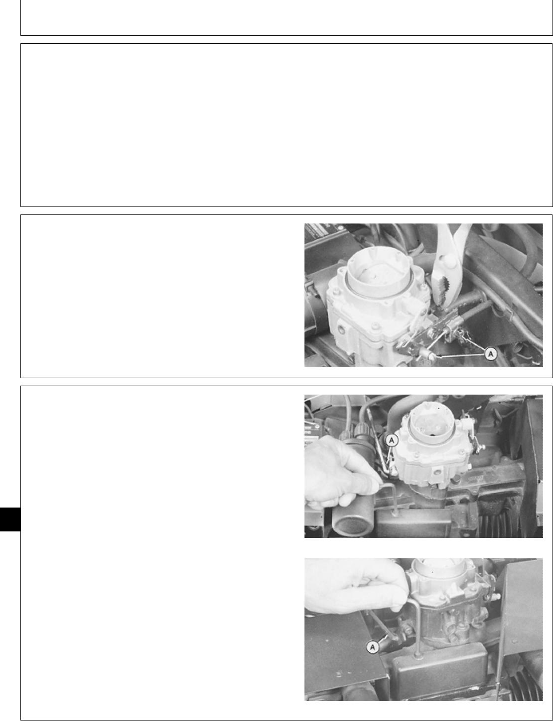
REMOVE CARBURETOR
NOTE: The carburetor removal includes procedures for
all carburetors. The differences are noted. The
carburetor can be removed with engine in
machine.
1. If equipped, turn reserve fuel lever to OFF position.
2. Remove air cleaner assembly. (See Remove Air
Cleaner in Group 05 of this manual.)
3. If engine is in machine, disconnect fuel line from
carburetor.
4. If engine is in machine, loosen choke cable clamp
screws (A). Disconnect cable from carburetor.
M36985 -UN-25JAN90
5. If engine is in machine, remove clip (A) to disconnect
governor control linkage.
6. Loosen set screw. Remove breaker point cover, if
equipped.
T260 Engine
B43E, B43G, or E48G Engine
M36986 -UN-25JAN90M36987 -UN-25JAN90
M98,2050K,4 -19-21OCT85
M98,2050K,5 -19-21OCT85
M98,2050K,6 -19-02FEB87
Carburetor/Carburetor
CTM2 (19APR90) 50-2 16, 18, 20 & 24HP Onan Engines
130495
50
2
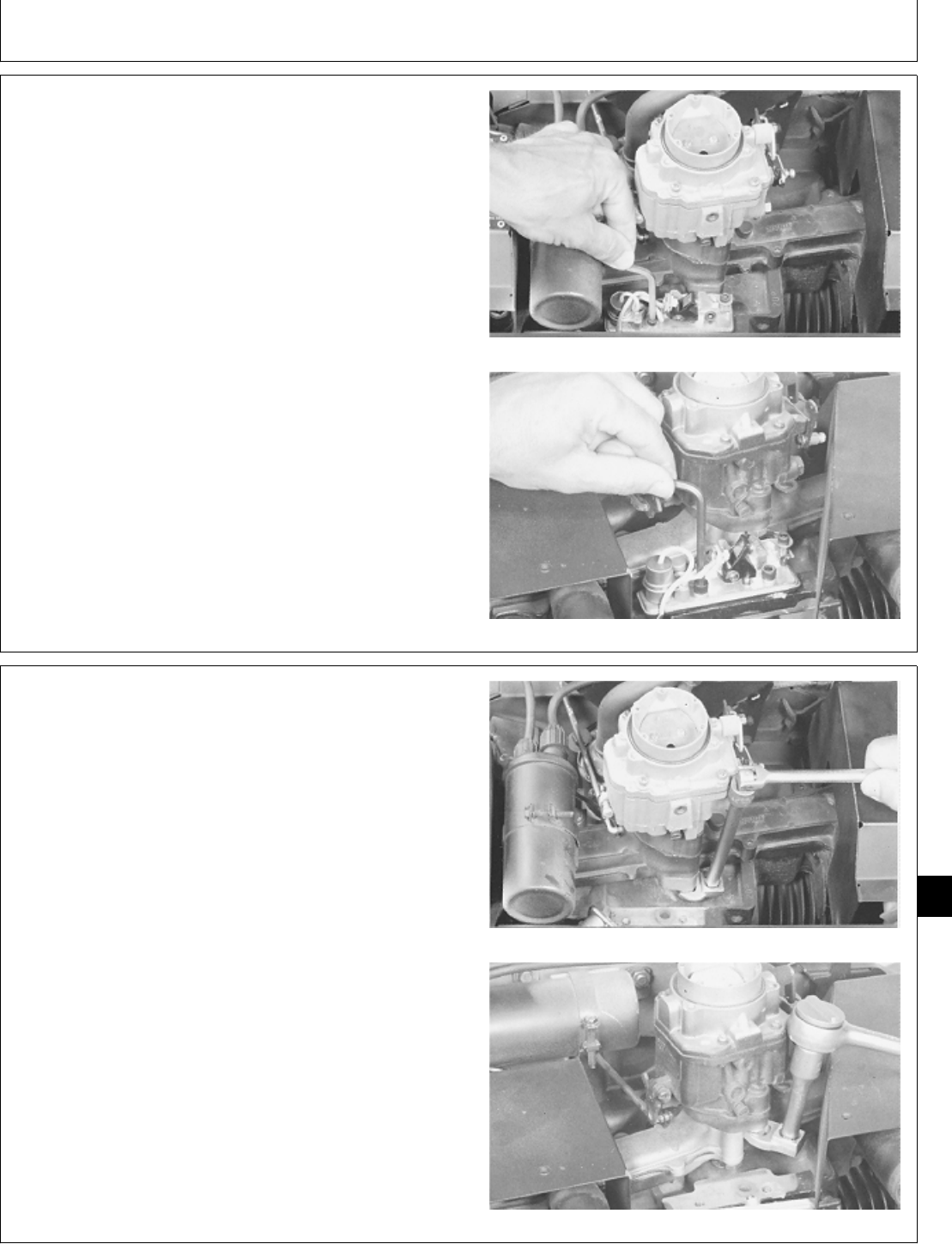
IMPORTANT: Be careful not to lose the point plunger
or to allow dirt to enter the exposed
plunger hole.
7. Loosen two set screws. Move point assembly, if
equipped, out of the way for access to carburetor
mounting bolts.
T260 Engine (Early point assembly)
B43E, B43G, OR B48G Engine (Early
M36988 -UN-25JAN90M36989 -UN-25JAN90
8. Loosen two cap screws with JDG-333 Crowsfoot
Wrench or short handled 1/2 in. open-end wrench.
Remove carburetor.
T260 Engine
B43E, B43G, or B48G Engine
M36990 -UN-25JAN90M36991 -UN-25JAN90
M98,2050K,7 -19-11FEB87
M98,2050K,8 -19-21OCT85
Carburetor/Carburetor
CTM2 (19APR90) 50-3 16, 18, 20 & 24HP Onan Engines
130495
50
3
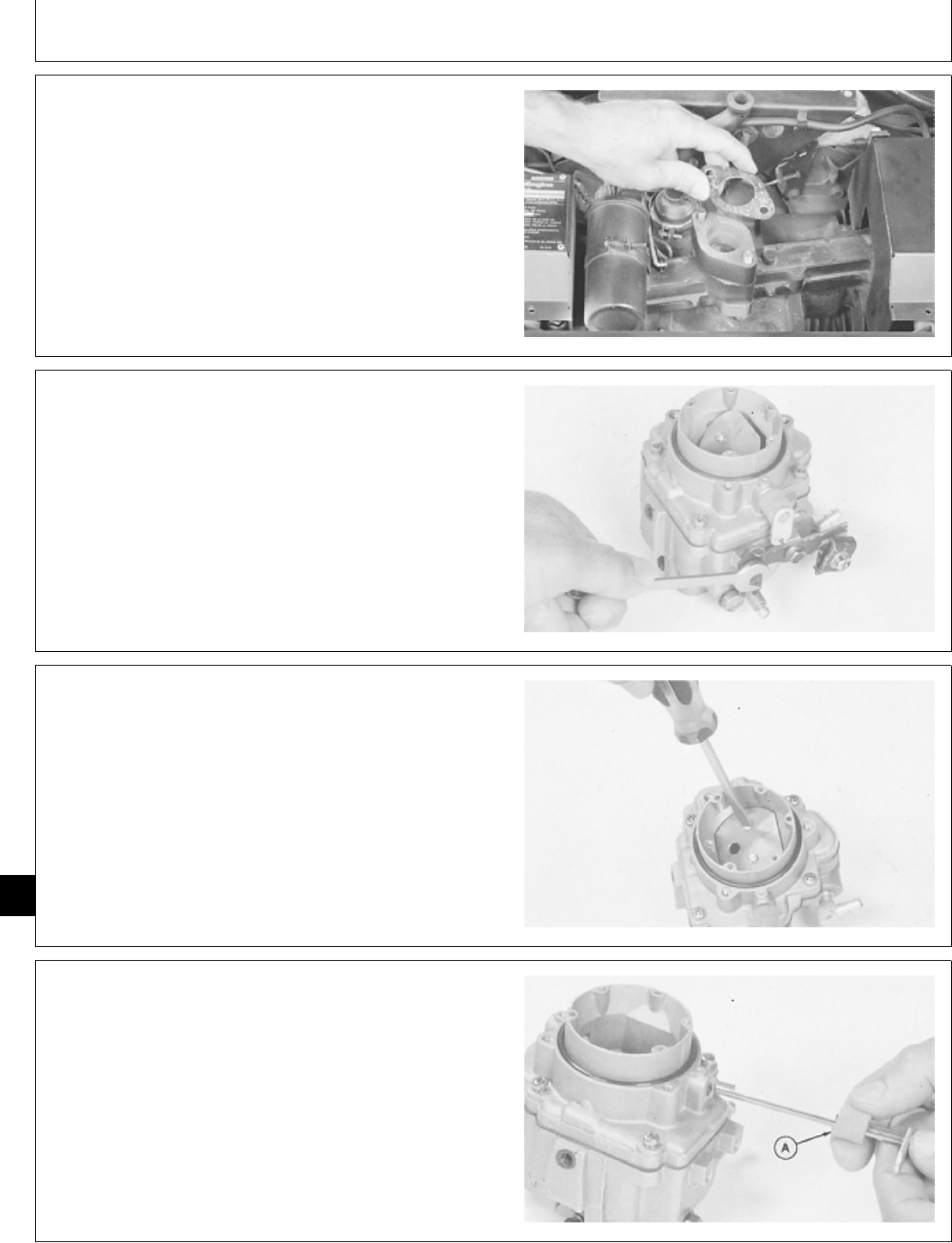
9. Remove gasket.
NOTE: If it is necessary to replace the mounting cap
screws on the T260 engine, the intake manifold
must be removed. (See Remove Intake Manifold,
Group 10 in this manual.)
T260 Engine
M36992 -UN-25JAN90
DISASSEMBLE CARBURETOR
NOTE: Carburetor disassembly includes procedures for
all carburetors. The differences are noted.
1. Remove two cap screws. Remove choke control
bracket.
M36954 -UN-25JAN90
2. Remove two screws and choke valve.
M36955 -UN-25JAN90
3. Remove choke valve shaft.
4. Remove foam seal (A) from shaft.
Inspect choke shaft. Replace shaft if it shows excessive
wear or is bent.
M36956 -UN-25JAN90
M98,2050K,9 -19-21OCT85
M98,2050K,10 -19-21OCT85
M98,2050K,11 -19-21OCT85
M98,2050K,12 -19-21OCT85
Carburetor/Carburetor
CTM2 (19APR90) 50-4 16, 18, 20 & 24HP Onan Engines
130495
50
4

5. Remove two screws and throttle valve.
M36957 -UN-25JAN90
6. Remove throttle valve shaft.
7. Remove foam seal (A) from shaft.
Inspect throttle shaft. Replace shaft if it shows excessive
wear or is bent.
M36958 -UN-25JAN90
8. Remove four screws to remove air intake.
M36959 -UN-25JAN90
M98,2050K,13 -19-21OCT85
M98,2050K,14 -19-21OCT85
M98,2050K,15 -19-21OCT85
Carburetor/Carburetor
CTM2 (19APR90) 50-5 16, 18, 20 & 24HP Onan Engines
130495
50
5
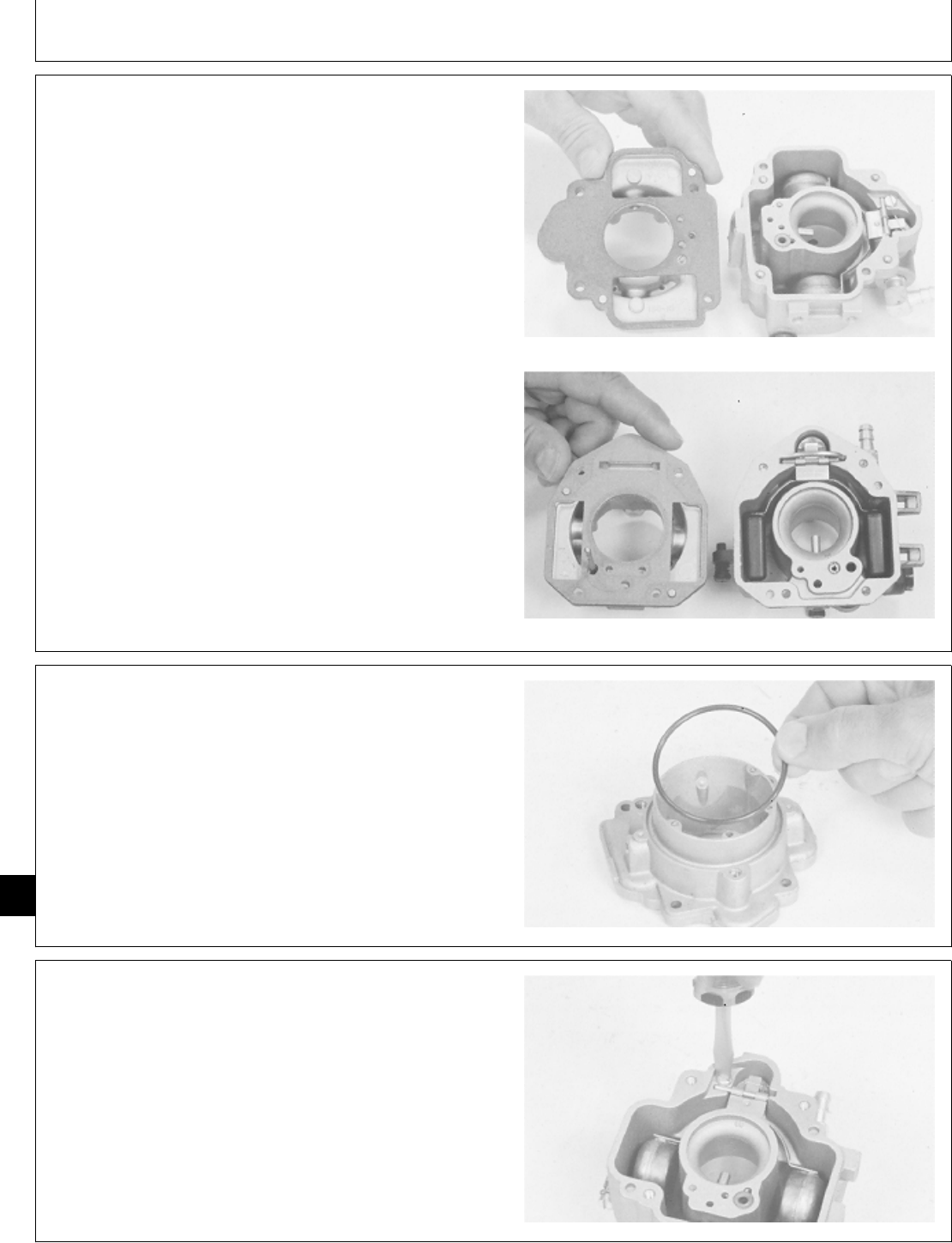
9. Remove and discard gasket.
T260 Engine
B43E, B43G, B48G, P218G or P220G
M36961 -UN-25JAN90M36968 -UN-25JAN90
10. Remove O-ring.
M36960 -UN-25JAN90
11. For T260 engine, remove float retaining screw.
M36964 -UN-25JAN90
M98,2050K,16 -19-02FEB87
M98,2050K,17 -19-21OCT85
M98,2050K,18 -19-21OCT85
Carburetor/Carburetor
CTM2 (19APR90) 50-6 16, 18, 20 & 24HP Onan Engines
130495
50
6
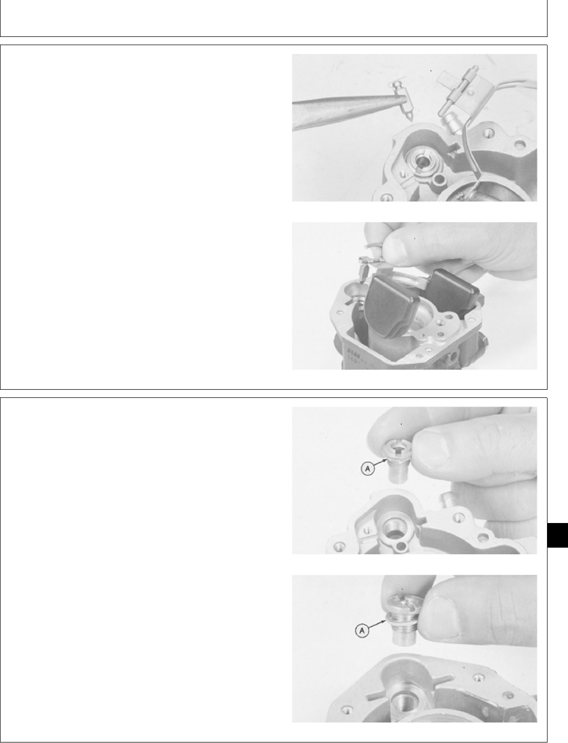
12. Remove float, pivot pin, and needle valve.
Inspect needle valve. Replace valve if it is grooved or
pitted.
Check float for dents or leaks. Replace if defective or
loaded with fuel.
T260 Engine
B43E, B43G, B48G, P218G, or P220G
M36965 -UN-25JAN90M36970 -UN-25JAN90
13. Remove seat. Remove washer (A).
Inspect needle seat area for wear or damage. Replace
seat if defective.
T260 Engine
B43E, B43G, B48G, P218G, or P220G
M36966 -UN-25JAN90M36971 -UN-25JAN90
M98,2050K,19 -19-02FEB87
M98,2050K,20 -19-02FEB87
Carburetor/Carburetor
CTM2 (19APR90) 50-7 16, 18, 20 & 24HP Onan Engines
130495
50
7
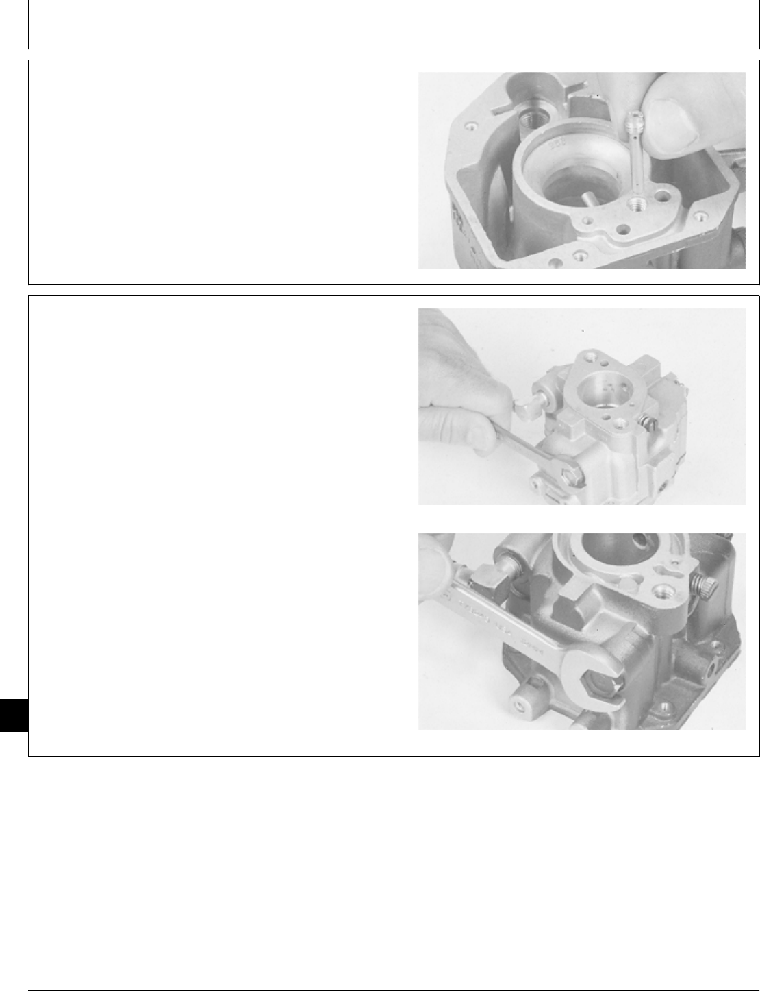
14. For B43E, B43G, B48G, P218G, or P220G engine,
remove slow idle jet.
M36972 -UN-25JAN90
15. Remove reservoir plug and gasket.
T260 Engine
B43E, B43G, B48G, P218G, OR P220G
M36962 -UN-25JAN90M36969 -UN-25JAN90
M98,2050K,21 -19-02FEB87
M98,2050K,22 -19-11FEB87
Carburetor/Carburetor
CTM2 (19APR90) 50-8 16, 18, 20 & 24HP Onan Engines
130495
50
8
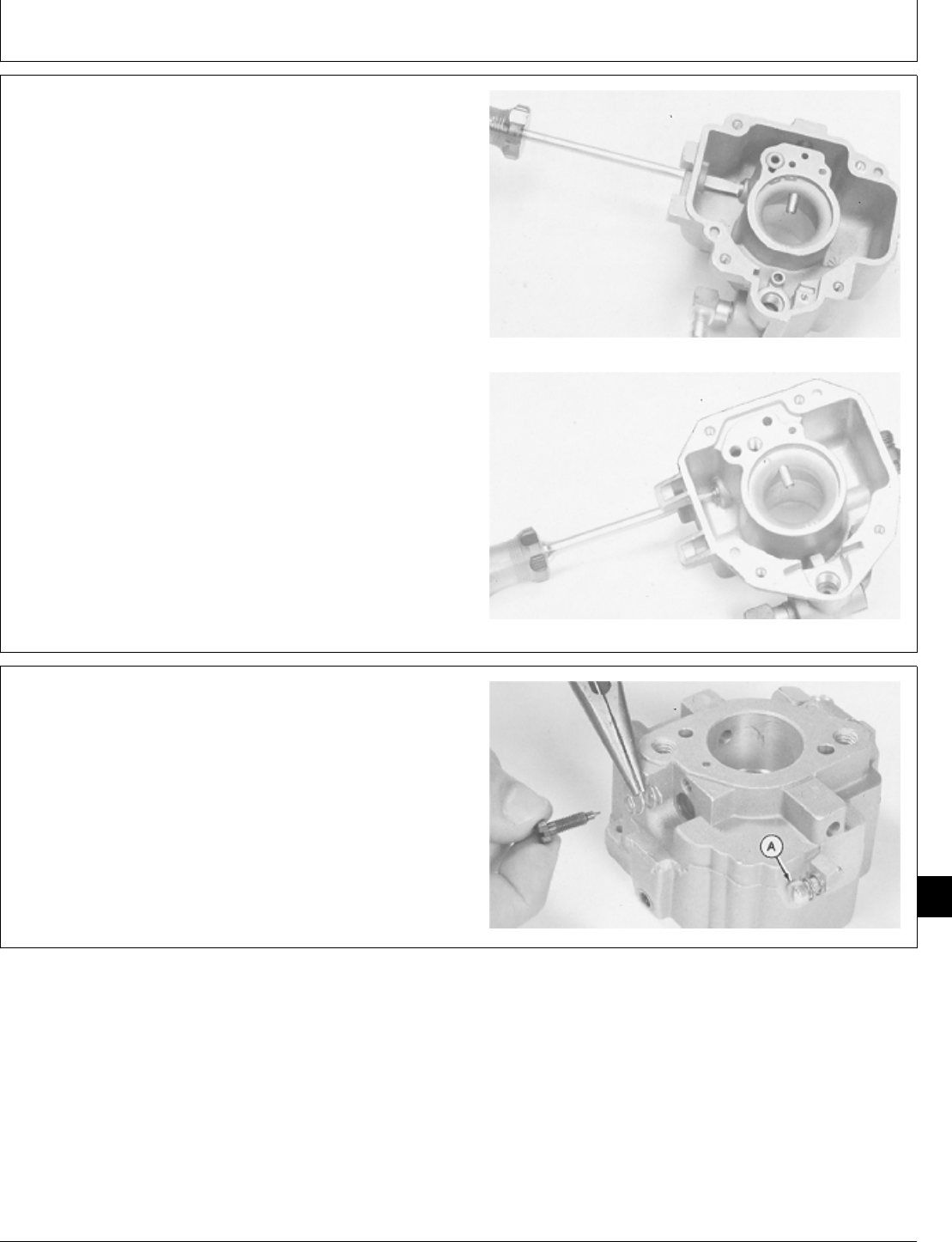
16. Remove main jet.
Inspect main jet. Replace if damaged.
T260 Engine
B43E, B43G, B48G, P218G, or P220G
M36963 -UN-25JAN90M36973 -UN-25JAN90
17. For P218G or P220G engines, remove plastic cap
from idle mixture screw.
18. Remove idle mixture screw and spring.
Inspect seating surface of mixture screw. Replace if worn
or damaged.
19. Remove idle speed screw (A) and spring.
Replace springs if weak or broken.
M36967 -UN-25JAN90
M98,2050K,23 -19-02FEB87
M98,2050K,24 -19-02FEB87
Carburetor/Carburetor
CTM2 (19APR90) 50-9 16, 18, 20 & 24HP Onan Engines
130495
50
9
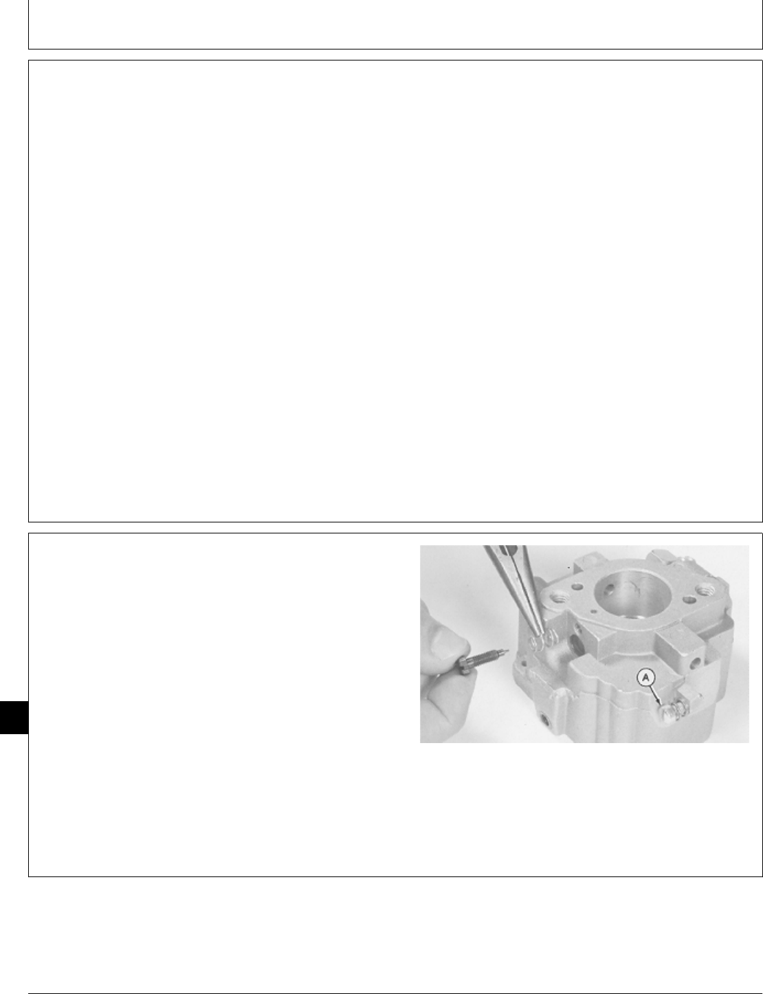
CLEAN CARBURETOR
IMPORTANT: Never clean holes or passages with
small drill bits or wire because a slight
enlargement or burring of these holes
will change the performance of the
carburetor. No other method of
cleaning other than solvent should be
used.
1. Soak all metal components not replaced in carburetor
cleaner. Do not soak non-metal floats or other non-metal
parts.
2. Clean all carbon from carburetor bore. Be careful not
to plug the idle or main fuel ports.
3. Dry out all passages with low pressure air 240 kPa
(2.4 bar) (35 psi). Make sure all holes and passages are
open. Do not use rags or paper to dry parts.
ASSEMBLE CARBURETOR
NOTE: Carburetor assembly includes procedures for all
carburetors. The differences are noted.
Use new seals, gaskets, and O-ring when assembling
carburetor.
1. Install idle speed screw (A) and spring.
2. Install idle mixture screw and spring. Turn idle mixture
screw in until lightly seated, then back it out 1-1/4 turns.
For P218G and P220G engines, install plastic cap on
idle mixture screw.
M36967 -UN-25JAN90
M98,2050K,25 -19-21OCT85
M98,2050K,26 -19-11FEB87
Carburetor/Carburetor
CTM2 (19APR90) 50-10 16, 18, 20 & 24HP Onan Engines
130495
50
10
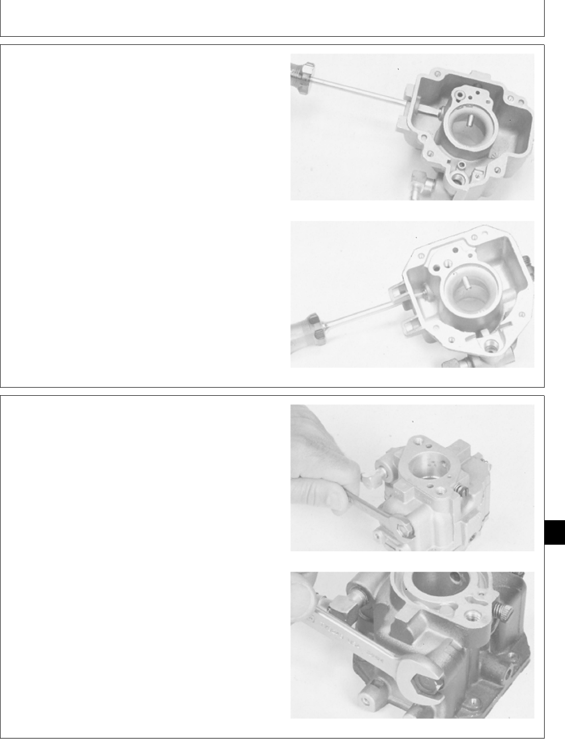
3. Install main jet.
T260 Engine
B43E, B43G, B48G, P218G, or P220G
M36963 -UN-25JAN90M36973 -UN-25JAN90
4. Install reservoir plug and gasket.
T260 Engine
B43E, B43G, B48G, P218G, or P220G
M36962 -UN-25JAN90M36969 -UN-25JAN90
M98,2050K,27 -19-02FEB87
M98,2050K,28 -19-02FEB87
Carburetor/Carburetor
CTM2 (19APR90) 50-11 16, 18, 20 & 24HP Onan Engines
130495
50
11
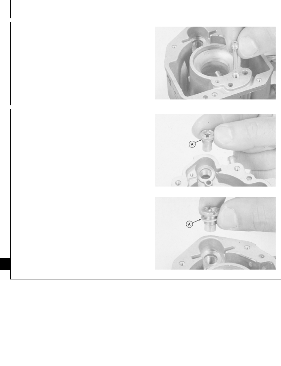
5. For B43E, G43G, B48G, P218G, or P220G engine,
install slow idle jet.
M36972 -UN-25JAN90
6. Install seat and washer (A).
T260 Engine
B43E, B43G, B48G, P218G, or P220G
M36966 -UN-25JAN90M36971 -UN-25JAN90
M98,2050K,29 -19-02FEB87
M98,2050K,30 -19-01JAN87
Carburetor/Carburetor
CTM2 (19APR90) 50-12 16, 18, 20 & 24HP Onan Engines
130495
50
12
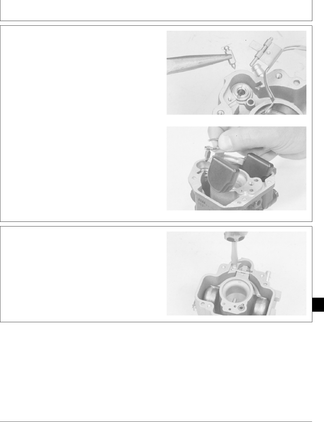
7. Install float, pivot pin, and valve. Be sure wire on
valve is hooked over tab on float.
Install float, pivot pin, and valve. Be sure valve is hooked
on float tab.
T260 Engine
B43E, B43G, B48G, P218G, or P220G
M36965 -UN-25JAN90M36970 -UN-25JAN90
8. For T260 engine, fasten float assembly with retaining
screw. Make sure pivot pin is in the groove and that the
float moves freely without binding.
M36964 -UN-25JAN90
M98,2050K,31 -19-02FEB87
M98,2050K,32 -19-21OCT85
Carburetor/Carburetor
CTM2 (19APR90) 50-13 16, 18, 20 & 24HP Onan Engines
130495
50
13
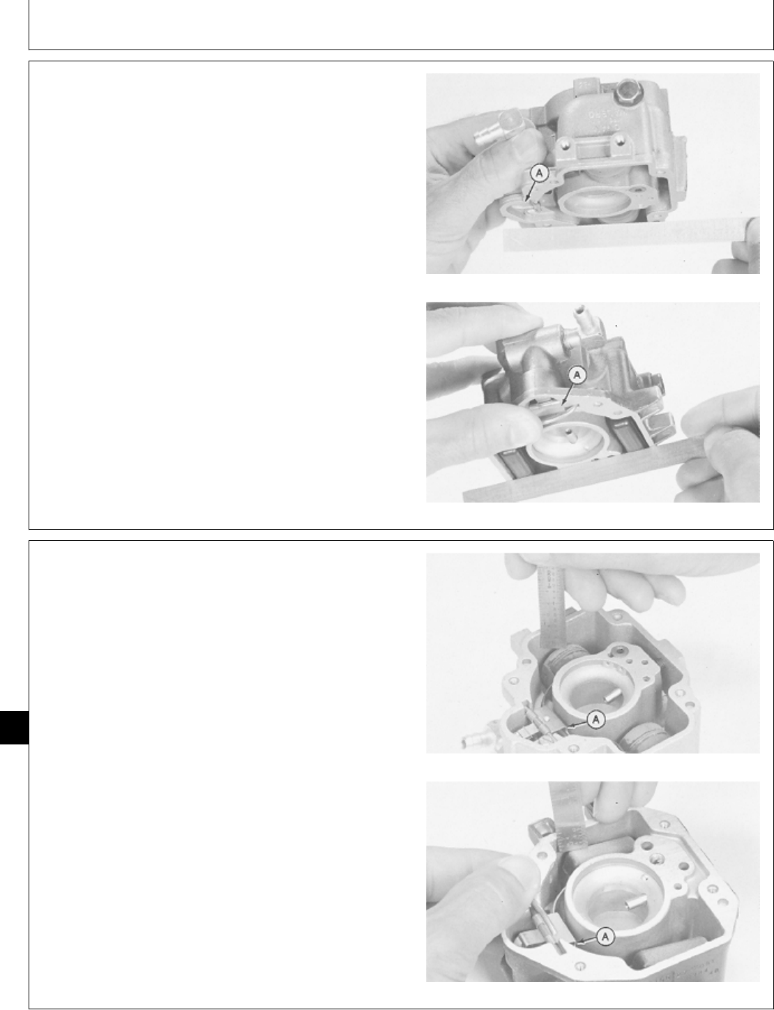
When checking float level and float drop, measure to
float body, not seam.
9. Turn carburetor and check float setting using
straightedge. Adjust floats so that they are even with
edge of bowl or no more than 1 mm (0.04 in.) beyond
edge. Bend float tab (A) to adjust.
Turn carburetor and hold pivot pin in place. Check float
setting using a straightedge. Adjust floats so that they
are even with the edge of bowl or no more than 1 mm
(0.04 in.) beyond edge. Bend float tang (A) to adjust. T260 Engine
B43E, B43G, B48G, P218G, or P220G
M36974 -UN-25JAN90M36975 -UN-25JAN90
10. Turn carburetor right side up and measure float drop.
The distance from top of carburetor body to top of float
must be at least 5 mm (0.20 in.). Bend float arm (A) to
adjust. If float drop is adjusted, check float level again.
T260 Engine
B43,E, B43G, B48G, P218G, or P220G
M36983 -UN-25JAN90M36984 -UN-25JAN90
M98,2050K,33 -19-11FEB87
M98,2050K,34 -19-02FEB87
Carburetor/Carburetor
CTM2 (19APR90) 50-14 16, 18, 20 & 24HP Onan Engines
130495
50
14
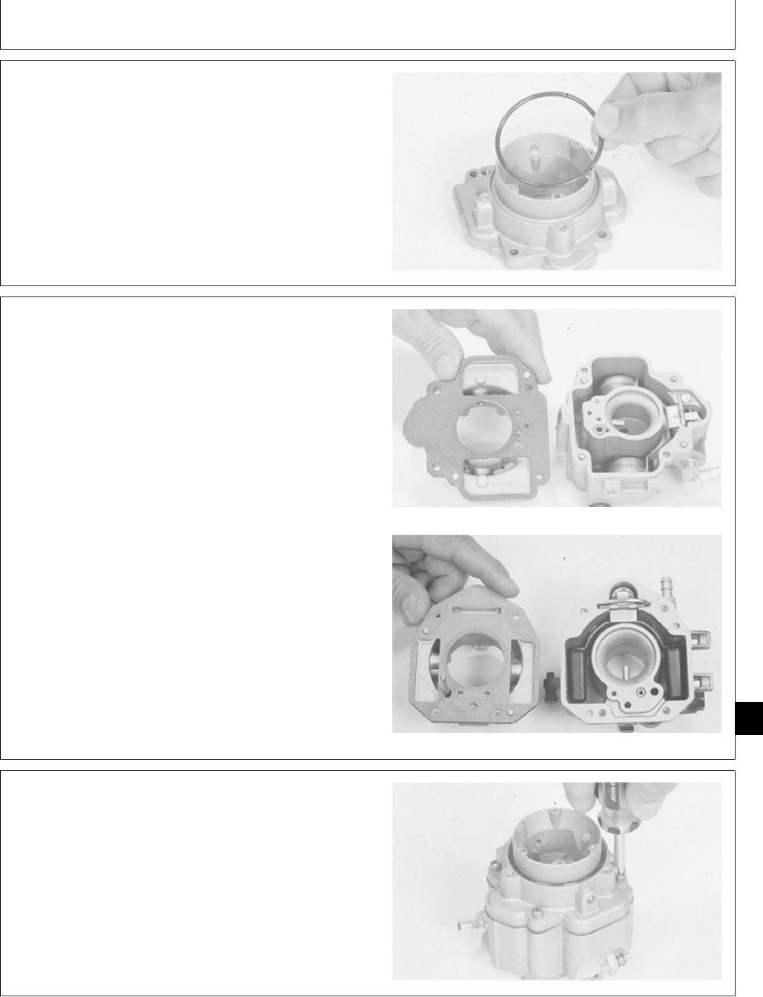
11. Install O-ring on carburetor intake.
M36960 -UN-25JAN90
12. Install gasket.
T260 Engine
B43E, B43G, B48G, P218G, OR P220G
M36961 -UN-25JAN90M36968 -UN-25JAN90
13. Install air intake. Fasten with four screws.
M36959 -UN-25JAN90
M98,2050K,35 -19-21OCT85
M98,2050K,36 -19-02FEB87
M98,2050K,37 -19-21OCT85
Carburetor/Carburetor
CTM2 (19APR90) 50-15 16, 18, 20 & 24HP Onan Engines
130495
50
15
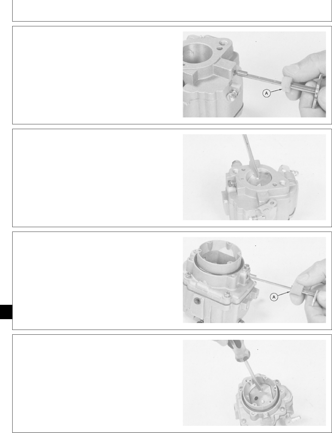
14. Apply a small amount of oil to the foam seal (A).
Install foam seal and throttle valve shaft.
M36958 -UN-25JAN90
15. Install throttle valve. Adjust valve plate so that it is
centered in the bore before tightening the two screws.
To center the plate, back off the throttle stop screw and
completely close the throttle lever. Seat the valve plate
by tapping with a small screwdriver, the tighten screws.
M36957 -UN-25JAN90
16. Apply a small amount of oil to the foam seal (A).
Install foam seal and choke valve shaft.
M36956 -UN-25JAN90
17. Install choke valve. Adjust valve plate so that it is
centered in the bore before tightening two screws.
M36955 -UN-25JAN90
M98,2050K,38 -19-21OCT85
M98,2050K,39 -19-21OCT85
M98,2050K,40 -19-21OCT85
M98,2050K,41 -19-21OCT85
Carburetor/Carburetor
CTM2 (19APR90) 50-16 16, 18, 20 & 24HP Onan Engines
130495
50
16
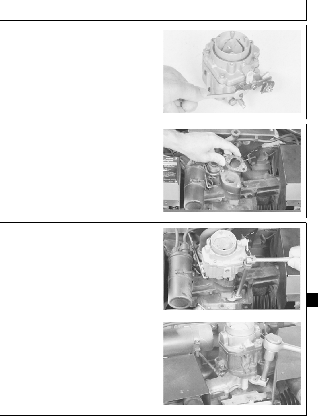
18. Connect choke shaft wire and install choke control
bracket. Fasten with two cap screws.
M36954 -UN-25JAN90
INSTALL CARBURETOR
1. Put new gasket on intake manifold. Install carburetor.
T260 Engine
M36992 -UN-25JAN90
2. Fasten carburetor with two cap screws. Tighten with
JDG-333 Crowsfoot Wrench or short handled 1/2 in.
open-end wrench.
T260 Engine
B43E, B43G, or B48G Engine
M36990 -UN-25JAN90M36991 -UN-25JAN90
M98,2050K,42 -19-21OCT85
M98,2050K,43 -19-21OCT85
M98,2050K,44 -19-21OCT85
Carburetor/Carburetor
CTM2 (19APR90) 50-17 16, 18, 20 & 24HP Onan Engines
130495
50
17
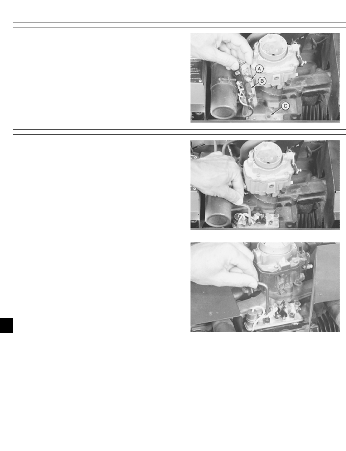
3. Be sure point plunger (A) and gasket (B) are in place.
Be sure plunger hole (C) is uncovered.
4. Apply thread sealant on threads of set screws and
install breaker point assembly, if equipped.
T260 Engine
M36993 -UN-25JAN90
5. Fasten point assembly, if equipped, with two set
screws.
6. Check point gap. Set gap to 0.41 mm (0.016 in.).
T260 Engine (Early point assembly)
B43E, B43G, or B48G Engine (Early
M36988 -UN-25JAN90M36989 -UN-25JAN90
M98,2050K,45 -19-11FEB87
M98,2050K,46 -19-11FEB87
Carburetor/Carburetor
CTM2 (19APR90) 50-18 16, 18, 20 & 24HP Onan Engines
130495
50
18
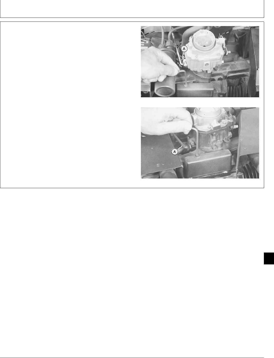
IMPORTANT: Be sure to position breaker point lead
so cover does not pinch it. Engine will
not run if cover and wire make a short
circuit.
7. Install breaker point cover and tighten screw, if
equipped.
8. If engine is in unit, install clip (A) and connect
governor control linkage.
T260 Engine
B43E, B43G, or B48G Engine
M36986 -UN-25JAN90M36987 -UN-25JAN90
M98,2050K,47 -19-11FEB87
Carburetor/Carburetor
CTM2 (19APR90) 50-19 16, 18, 20 & 24HP Onan Engines
130495
50
19
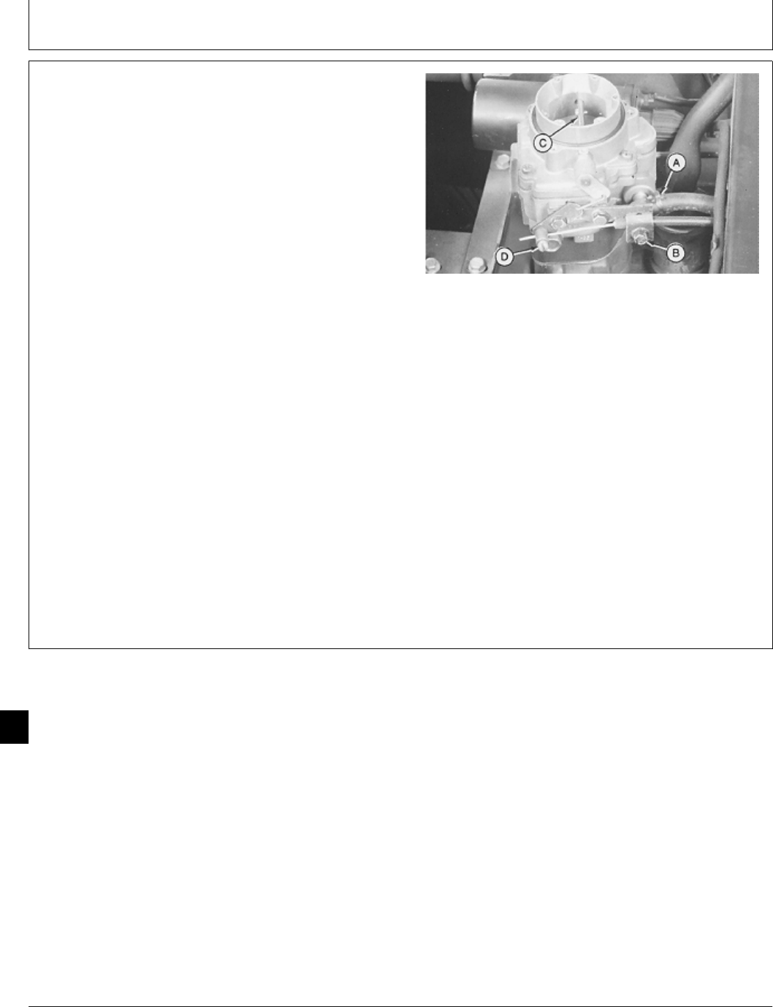
9. If engine is in machine, connect and fasten fuel line to
carburetor with clamp (A).
NOTE: Adjust choke properly for satisfactory engine
starting and operation. The following adjustment
can only be made with engine installed in
machine.
10. Install choke cable in bracket and fasten with screw
(B).
11. Push choke control knob (on instrument panel) in all
the way.
12. Hold choke valve (C) straight up and tighten screw
(D).
13. Pull choke control knob out. Choke valve must be
closed. Push knob in. Valve must be completely open.
Adjust if needed.
14. Check that choke and throttle linkages operate freely.
15. Install air cleaner assembly. (See Install Air Cleaner
in Group 05 of this manual.)
16. Adjust engine speed. (See machine technical
manual.)
M36994 -UN-25JAN90
M98,2050K,48 -19-26NOV85
Carburetor/Carburetor
CTM2 (19APR90) 50-20 16, 18, 20 & 24HP Onan Engines
130495
50
20
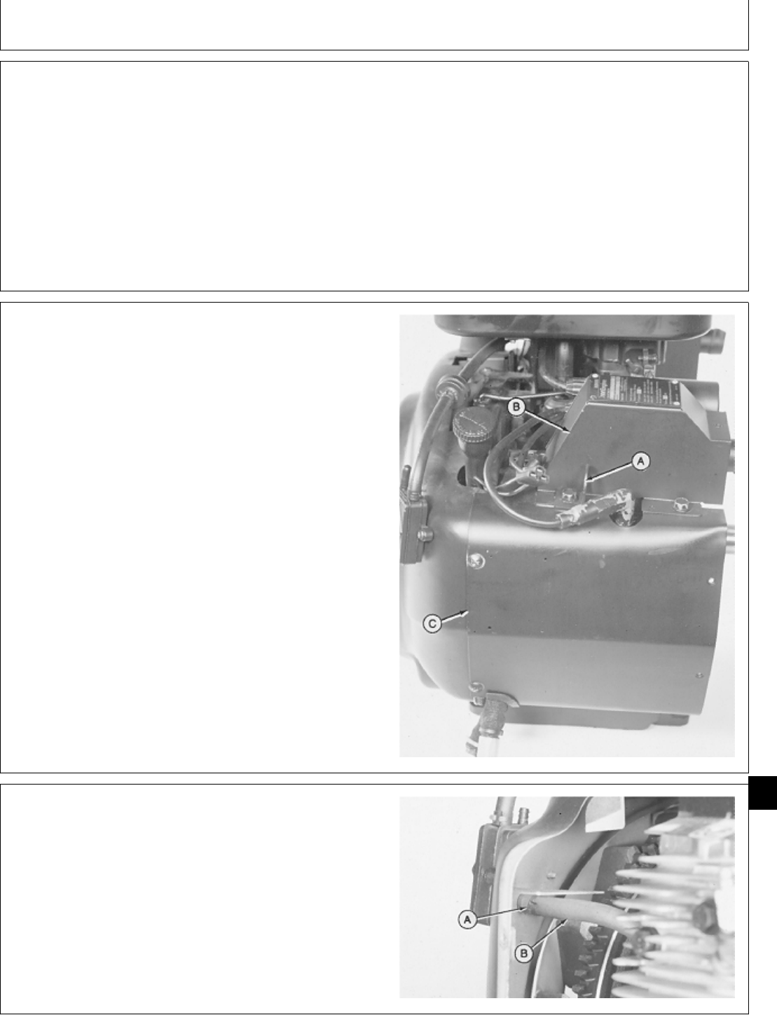
SPECIFICATIONS
Item Measurement Specification
Lift Bracket Cap Screw Torque 11 ± 3 N·m (97 ± 27 lb-in.)
B43E, B43G, B48G, T260 Engine: Torque 51 ± 3 N·m (38 ± 2 lb-ft)
Flywheel Cap Screw
P218G and P220G Engine: Flywheel Torque 67—75 N·m (50—55 lb-ft)
Cap Screw
REMOVE STATOR
1. Remove engine. (See machine technical manual.)
2. Disconnect spark plug wire and voltage regulator
leads.
3. Remove cap screws to remove lift bracket (A) and
manifold cover (B).
4. Remove four cap screws on T260, P218G, or P220G
engine; five cap screws on B43E, B43G, B48G engine to
remove side shroud (C).
M36445 -UN-29JAN90
5. Loosen hose clamp (A) to disconnect fuel impulse line
(B).
M36290 -UN-29JAN90
M98,2055K,1 -19-11FEB87
M98,2055K,2 -19-02FEB87
M98,2060K,6 -19-05NOV85
Group 55
Stator and Rectifier—Regulator
CTM2 (19APR90) 55-1 16, 18, 20 & 24HP Onan Engines
130495
55
1
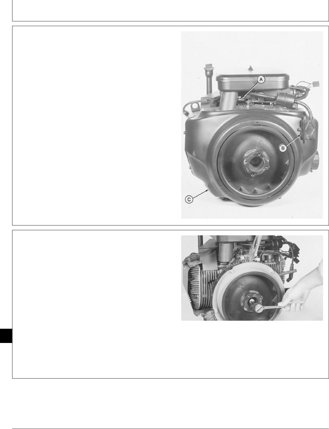
6. Disconnect governor spring (A).
7. Remove two screws to remove fuel pump (B).
8. Remove five cap screws to remove flywheel shroud
(C).
M36291 -UN-29JAN90
IMPORTANT: Do not hold flywheel from turning with
a pry bar. Doing so can damage the
fins.
9. Fasten locking pliers to ring gear to prevent flywheel
from turning.
NCAUTION: Loosen flywheel cap screw only two
turns. Do not remove cap screw. If cap screw
is removed, flywheel may cause injury when it
comes loose.
10. Loosen cap screw two turns only.
M36292 -UN-29JAN90
M98,2060K,7 -19-05NOV85
M98,2055K,3 -19-22OCT85
Stator and Rectifier—Regulator/Stator
CTM2 (19APR90) 55-2 16, 18, 20 & 24HP Onan Engines
130495
55
2
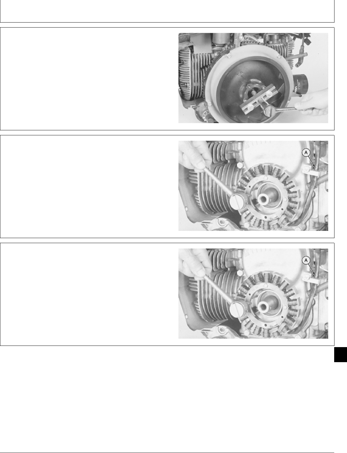
IMPORTANT: Do not pry on flywheel with a
screwdriver. Ceramic magnets and gear
case cover can be damaged.
11. Loosen flywheel using a puller.
12. Remove puller, cap screw, washer, and flywheel.
M36293 -UN-29JAN90
13. Disconnect stator lead from retaining clip (A).
14. Remove three cap screws. Gently pull stator off
mounting posts.
M37155 -UN-25JAN90
INSTALL STATOR
1. Put stator on mounting posts and fasten with three
cap screws. Tighten cap screws evenly so that stator is
held flat against posts.
Connect stator lead in retaining clip (A).
M37155 -UN-25JAN90
M98,2055K,4 -19-22OCT85
M98,2055K,5 -19-22OCT85
M98,2055K,6 -19-22OCT85
Stator and Rectifier—Regulator/Stator
CTM2 (19APR90) 55-3 16, 18, 20 & 24HP Onan Engines
130495
55
3
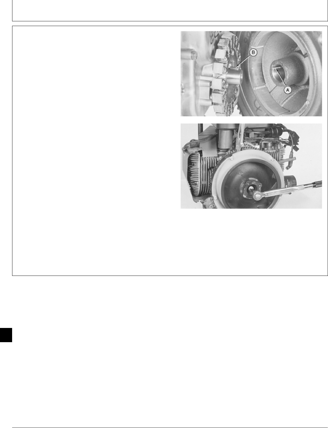
IMPORTANT: Do not lubricate crankshaft taper. The
crankshaft taper must be dry to hold
the flywheel tight.
2. Clean crankshaft taper before installing flywheel.
3. Apply pipe sealant on threads of flywheel cap screw.
4. Align keyway (A) in flywheel with key (B) in crankshaft
and install flywheel.
5. Install washer and cap screw.
IMPORTANT: Do not hold flywheel from turning with
a pry bar in the fins. Doing so may
damage the fins.
6. Fasten locking pliers to ring gear to prevent flywheel
from turning.
7. On B43E, B43G, B48G, T260 engines, tighten cap
screw to 51 ± 3 N·m (38 ± 2 lb-ft).
On P218G and P220G engine, tighten cap screw to
67—75 N·m (50—55 lb-ft).
M36297 -UN-29JAN90M36298 -UN-29JAN90
M98,2060K,73 -19-11FEB87
Stator and Rectifier—Regulator/Stator
CTM2 (19APR90) 55-4 16, 18, 20 & 24HP Onan Engines
130495
55
4
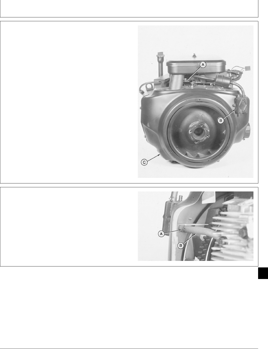
8. Install flywheel shroud (C). Fasten with five cap
screws.
9. Install fuel pump (B). Fasten with two screws.
10. Connect governor spring (A) in top hole of arm.
M36291 -UN-29JAN90
11. Connect fuel pump impulse line (B) and fasten with
hose clamp (A).
M36290 -UN-29JAN90
M98,2055K,7 -19-26NOV85
M98,2055K,8 -19-22OCT85
Stator and Rectifier—Regulator/Stator
CTM2 (19APR90) 55-5 16, 18, 20 & 24HP Onan Engines
130495
55
5
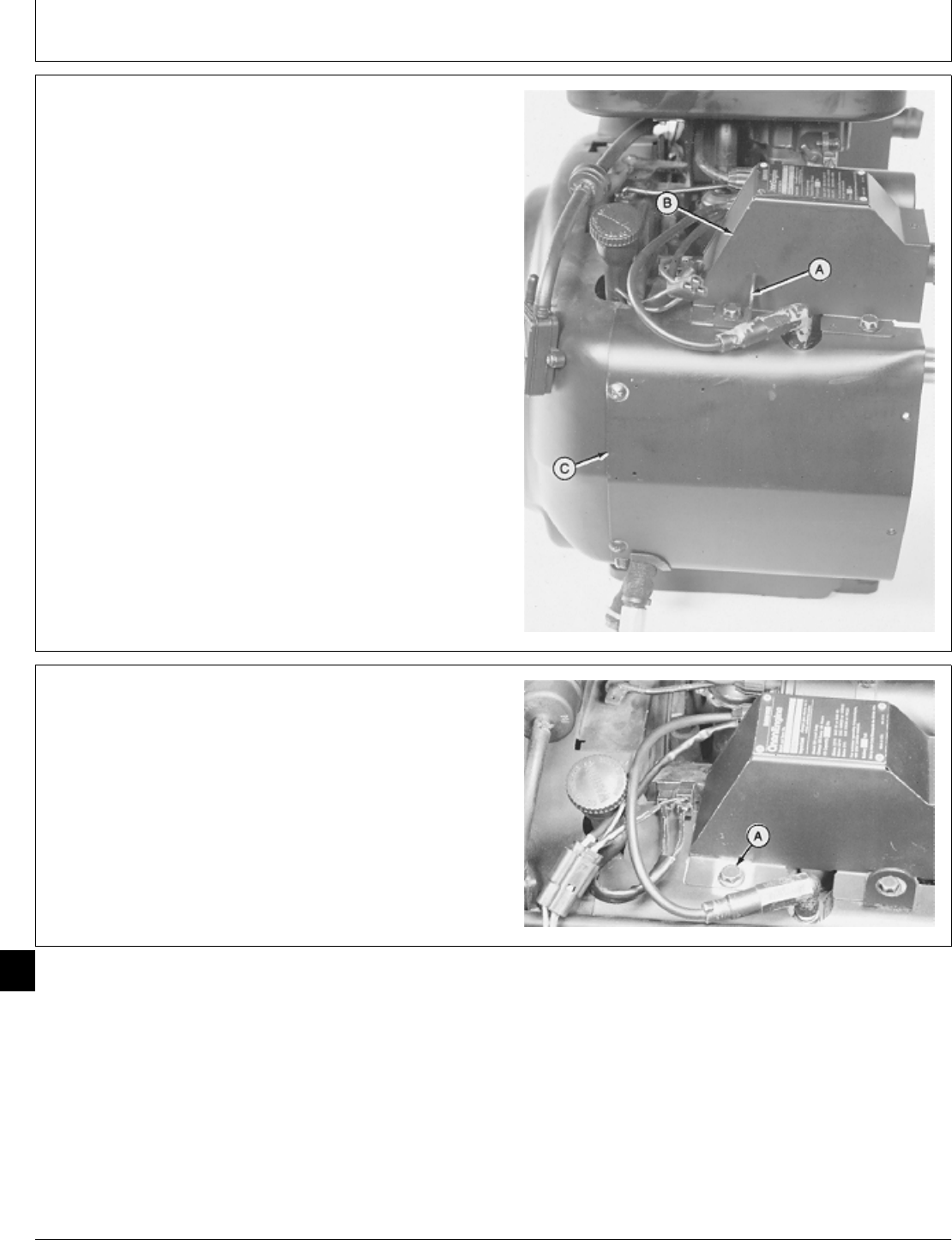
12. Install side shroud (C). Fasten with four cap screws
on T260, P218G, and P220G engine; five cap screws on
B43E, B43G, or B48G engine.
13. Install manifold cover (B) and lift bracket (A). Fasten
with three cap screws on T260 engine; two cap screws
on B43E, or B48G engine. Tighten lift bracket cap screw
to 11 ± 3 N·m (97 ± 27 lb-in.).
14. Connect spark plug wire and voltage regulator leads.
Install the two stator leads on “AC” terminals and the
battery lead on “B+” terminal of voltage regulator.
15. Install engine. (See machine technical manual.)
T260 Engine Shown
M36445 -UN-29JAN90
REPLACE RECTIFIER-REGULATOR
1. For T260 engine only, remove three cap screw (A) to
remove manifold cover.
M37239 -UN-25JAN90
M98,2055K,9 -19-02FEB87
M98,2055K,10 -19-22OCT85
Stator and Rectifier—Regulator/Replace
CTM2 (19APR90) 55-6 16, 18, 20 & 24HP Onan Engines
130495
55
6
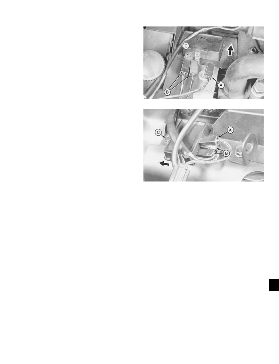
2. Disconnect battery lead (A).
3. Disconnect two stator leads (B).
4. Remove cap screw (C).
5. Push regulator toward cap screw; then lift from
shroud.
6. Install new regulator and fasten with cap screw (C).
7. Connect two stator leads (B) to “AC” terminals. T260 Engine (Top Photo)
8. Connect battery lead (A) to “B+” terminal.
9. For T260 engine only, install manifold cover and
fasten with three cap screws. Tighten lift bracket cap
screw to 11 ± 3 N·m (97 ± 27 lb-in.).
B43E, B43G, B48G, P21G, or P220G
M37240 -UN-25JAN90M37241 -UN-25JAN90
M98,2055K,11 -19-02FEB87
Stator and Rectifier—Regulator/Replace
CTM2 (19APR90) 55-7 16, 18, 20 & 24HP Onan Engines
130495
55
7

Stator and Rectifier—Regulator/Replace
CTM2 (19APR90) 55-8 16, 18, 20 & 24HP Onan Engines
130495
55
8

SERVICE EQUIPMENT AND TOOLS
NOTE: Order tools from the U.S. SERVICE-GARD™ Catalog or from the European Microfiche Tool Catalog
(MTC). Some tools may be available from a local supplier.
Name Use
Volt-Ohm-Amp Meter Check continuity
Armature Growler Check starter armature
13-Ton Puller Set Remove flywheel
Blind Hole Puller Set Pull bushings
Dial Indicator Check armature shaft thrust gap
M98,2060K,1 -19-05NOV85
Group 60
Starter
CTM2 (19APR90) 60-1 16, 18, 20 & 24HP Onan Engines
130495
60
1

SPECIFICATIONS
Item Measurement Specification
BENDIX DRIVE STARTER
Starter Pinion Backlash 0.13—0.89 mm (0.005—0.035)
Brushes Wear Length 6.35 mm (0.25 in.) minimum
Armature Lock Nut Torque 30 ± 3 N·m (265 ± 27 lb-in.)
Battery Terminal Nut Torque 6 ± 1 N·m (53 ± 9 lb-in.)
Negative Brush Cap Screw Torque 4.5 ± 0.5 N·m (40 ± 4.5 lb-in.)
End Cap Thru-Bolts Torque 7 ± 1 N·m (62 ± 9 lb-in.)
SOLENOID DRIVE STARTER
Brushes Wear Length 11.5 mm (0.45 in.) minimum
End Cap Thru-Bolts Torque 5.7 ± 1.1 N·m (50 ± 10 lb-in.)
Solenoid Screws Torque 6 ± 1 N·m (53 ± 9 lb-in.)
Armature Shaft Thrust Gap Clearance 0.1 to 0.5 mm (0.004 to 0.020 in.)
Pinion-to-Stop Ring Gap Clearance 0.5 to 2.0 mm (0.020 to 0.079 in.)
Starter Mounting Cap Screws Torque 34 ± 1 N·m (300 ± 9 lb-in.)
B43E, B43G, B48G, T260 Engines: Torque 51 ± 3 N·m (38 ± 2 lb-ft)
Flywheel Mounting Cap Screw
Lift Bracket Cap Screw Torque 11 ± 3 N·m (97 ± 27 lb-in.)
M98,2060K,2 -19-11FEB87
Starter/Specifications
CTM2 (19APR90) 60-2 16, 18, 20 & 24HP Onan Engines
130495
60
2
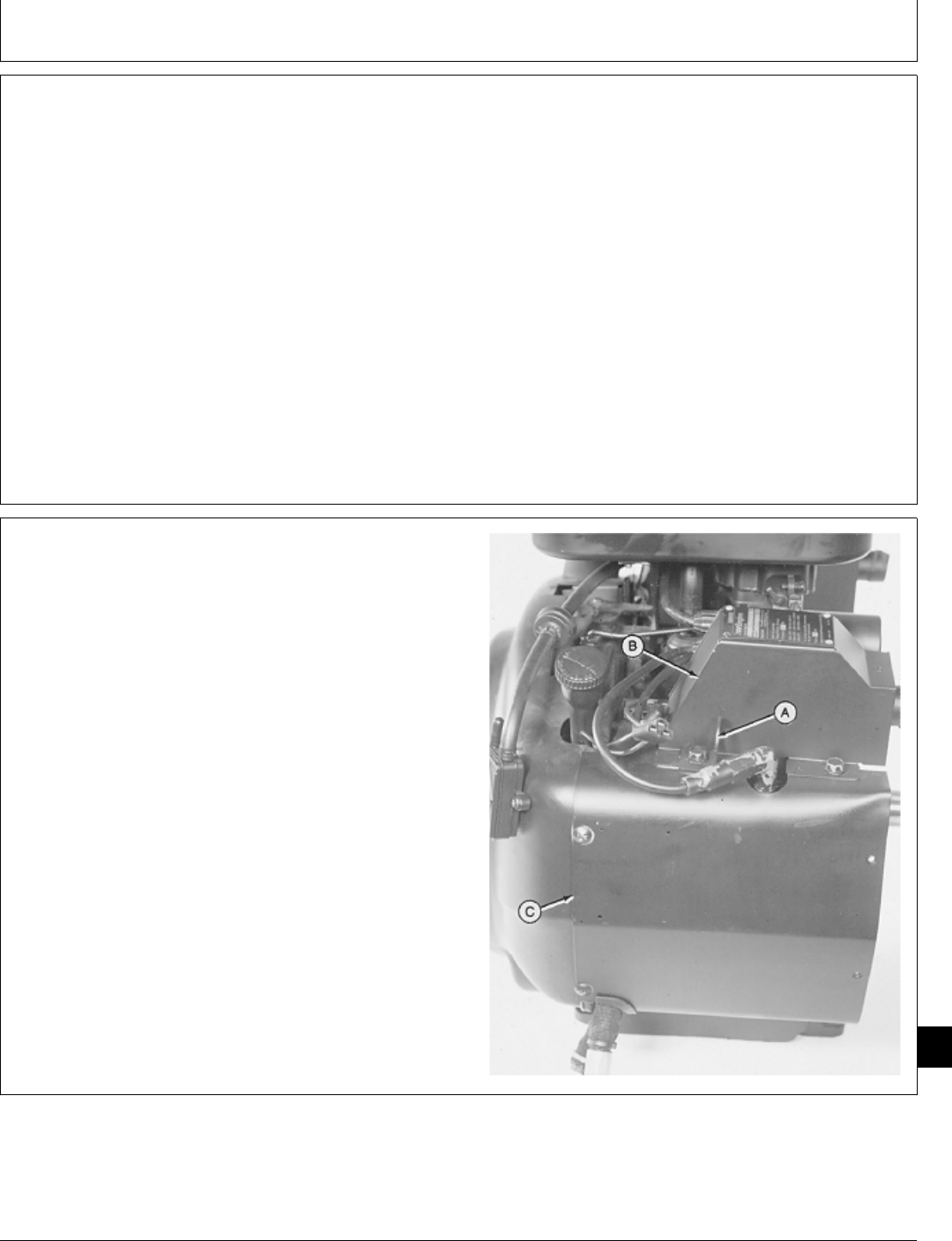
SERVICE PARTS KITS
The following kits are available through your parts
catalog:
Solenoid Kit
Bushing Kit
Brush Kit
Hardware Kit
Clutch Kit
Shift Lever Kit
REMOVE STARTER—B43E, B43G, B48G,
AND T260 ENGINES
NOTE: See Starting Circuit Diagnosis in machine
technical manual before removing starter.
1. Remove engine. (See machine technical manual.)
2. Disconnect spark plug wire and voltage regulator
leads.
3. Remove cap screw to remove lift bracket (A) and
manifold cover (B).
4. Remove four cap screws on T260 engine; five cap
screws on B43E, B43G, or B48G engine, to remove side
shroud (C).
T260 Engine Shown
M36445 -UN-29JAN90
M98,2060K,3 -19-26NOV85
M98,2060K,4 -19-11FEB87
Starter/Starter
CTM2 (19APR90) 60-3 16, 18, 20 & 24HP Onan Engines
130495
60
3
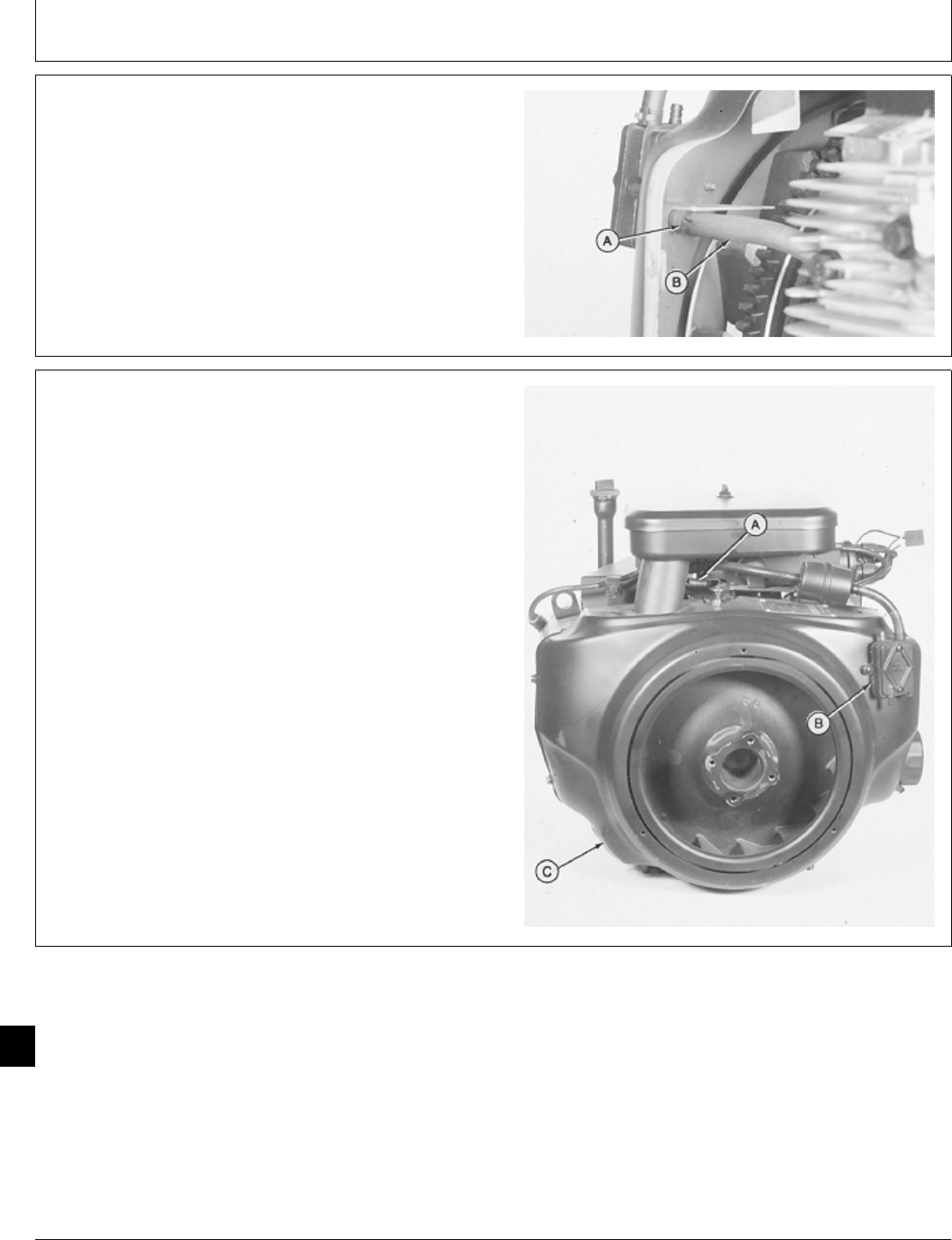
5. Loosen hose clamp (A) to disconnect fuel impulse line
(B).
M36290 -UN-29JAN90
6. Disconnect governor spring (A).
7. Remove two screws to remove fuel pump (B).
8. Remove five cap screws to remove flywheel shroud
(C).
M36291 -UN-29JAN90
M98,2060K,6 -19-05NOV85
M98,2060K,7 -19-05NOV85
Starter/Starter
CTM2 (19APR90) 60-4 16, 18, 20 & 24HP Onan Engines
130495
60
4
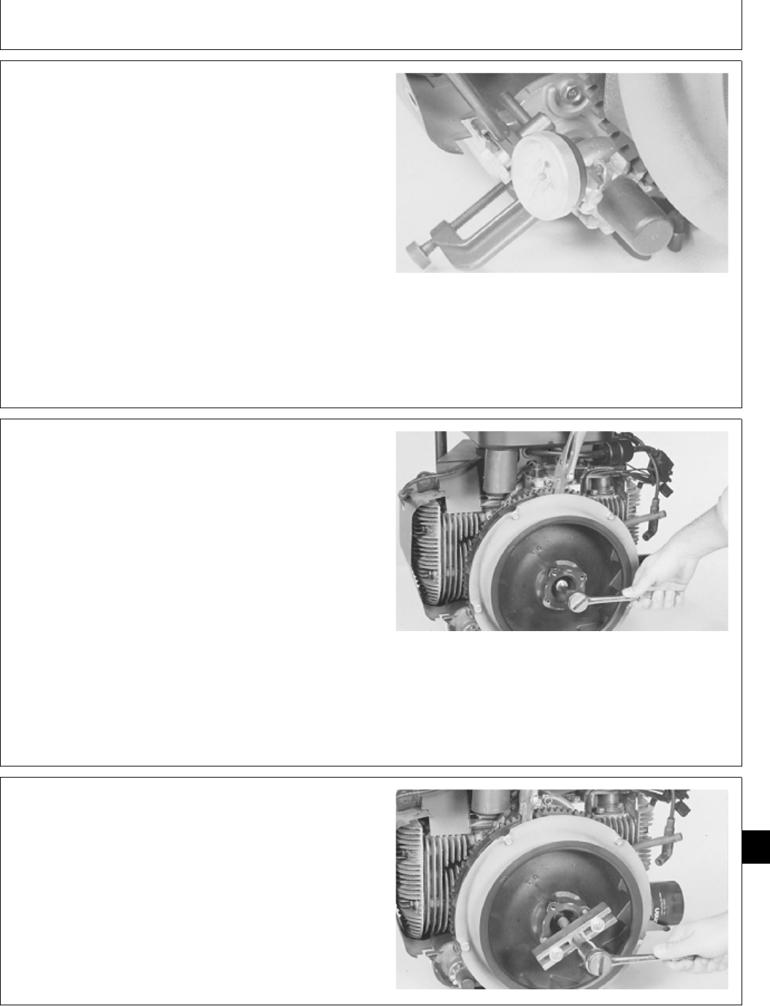
NOTE: Measure starter pinion gear backlash to check for
wear.
9. Pull starter pinion gear outward until teeth contact
flywheel ring gear. Measure starter pinion gear backlash.
STARTER PINION SPECIFICATIONS
Item New Part
Backlash 0.13—0.89 (0.005—0.035 in.)
If backlash exceeds 0.89 mm (0.035 in.), replace starter
pinion.
M36437 -UN-29JAN90
IMPORTANT: Do not hold flywheel from turning with
a pry bar. Doing so can damage the
fins.
10. Fasten locking pliers to ring gear to prevent flywheel
from turning.
NCAUTION: Loosen flywheel cap screw only two
turns. Do not remove cap screw. If cap screw
is removed, flywheel may cause injury when it
comes loose.
11. Loosen cap screw two turns only.
M36292 -UN-29JAN90
IMPORTANT: Do not pry on flywheel with a
screwdriver. Ceramic magnets and gear
case cover can be damaged.
12. Loosen flywheel using a puller.
13. Remove puller, cap screw, washer, and flywheel.
M36293 -UN-29JAN90
M98,2060K,8 -19-05NOV85
M98,2060K,9 -19-05NOV85
M98,2060K,10 -19-05NOV85
Starter/Starter
CTM2 (19APR90) 60-5 16, 18, 20 & 24HP Onan Engines
130495
60
5
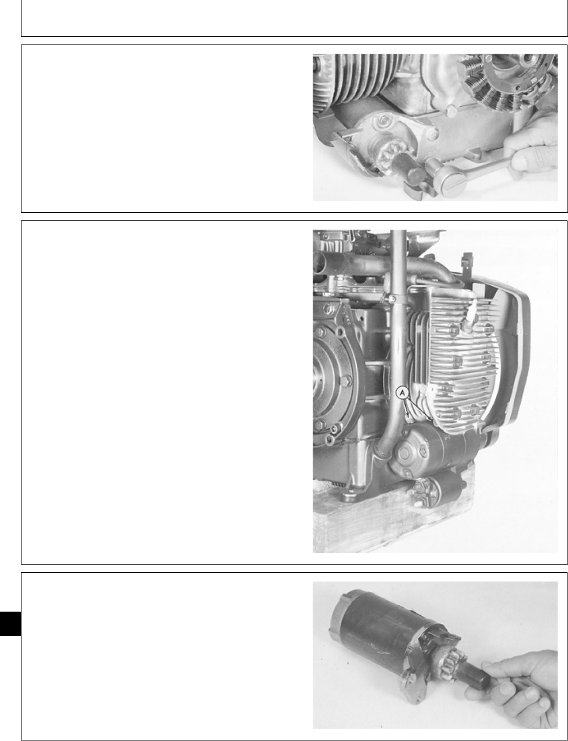
14. Remove two cap screws. Remove starter.
Bendix Drive Starter Shown
M37102 -UN-25JAN90
REMOVE STARTER—P218G AND P220G
ENGINES
NOTE: See Starting Circuit Diagnosis in machine
technical manual before removing starter.
1. Remove engine. (See machine technical manual.)
2. Disconnect spark plug wire.
3. Remove cap screw to remove lift bracket and manifold
cover.
4. Remove cap screws to remove side shroud.
5. Remove cap screws from flywheel shroud. Move
flywheel shroud just far enough to remove starter.
6. Remove two cap screws (A) to remove starter.
M46014 -UN-08JAN90
DISASSEMBLE BENDIX DRIVE STARTER
1. Remove rubber dust cover.
M37104 -UN-25JAN90
M98,2060K,11 -19-05NOV85
M98,2060K,11E -19-11FEB87
M98,2060K,12 -19-05NOV85
Starter/Starter
CTM2 (19APR90) 60-6 16, 18, 20 & 24HP Onan Engines
130495
60
6
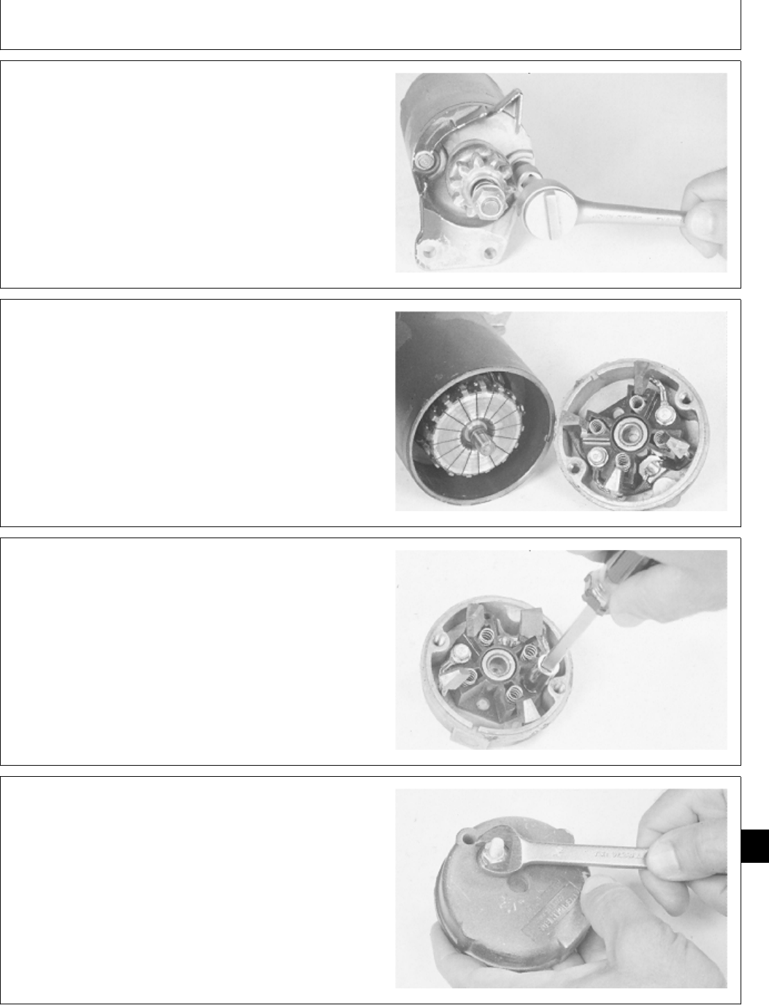
2. Remove two thru-bolts.
M37105 -UN-25JAN90
NOTE: Brush springs may snap out of the end cap when
it is removed. Be careful not to lose springs.
3. Remove end cap.
M37106 -UN-25JAN90
4. Remove two cap screws to remove negative brushes.
M37107 -UN-25JAN90
5. Remove nut to remove positive side brushes.
Check all brushes for cracks or excessive wear. Replace
brushes if they are worn shorter than 6.35 mm (0.25 in.).
Inspect springs. Replace springs if they are weak or
broken.
Always replace springs and brushes as a set if any are
defective.
M37108 -UN-25JAN90
M98,2060K,13 -19-05NOV85
M98,2060K,14 -19-05NOV85
M98,2060K,15 -19-05NOV85
M98,2060K,16 -19-05NOV85
Starter/Starter
CTM2 (19APR90) 60-7 16, 18, 20 & 24HP Onan Engines
130495
60
7
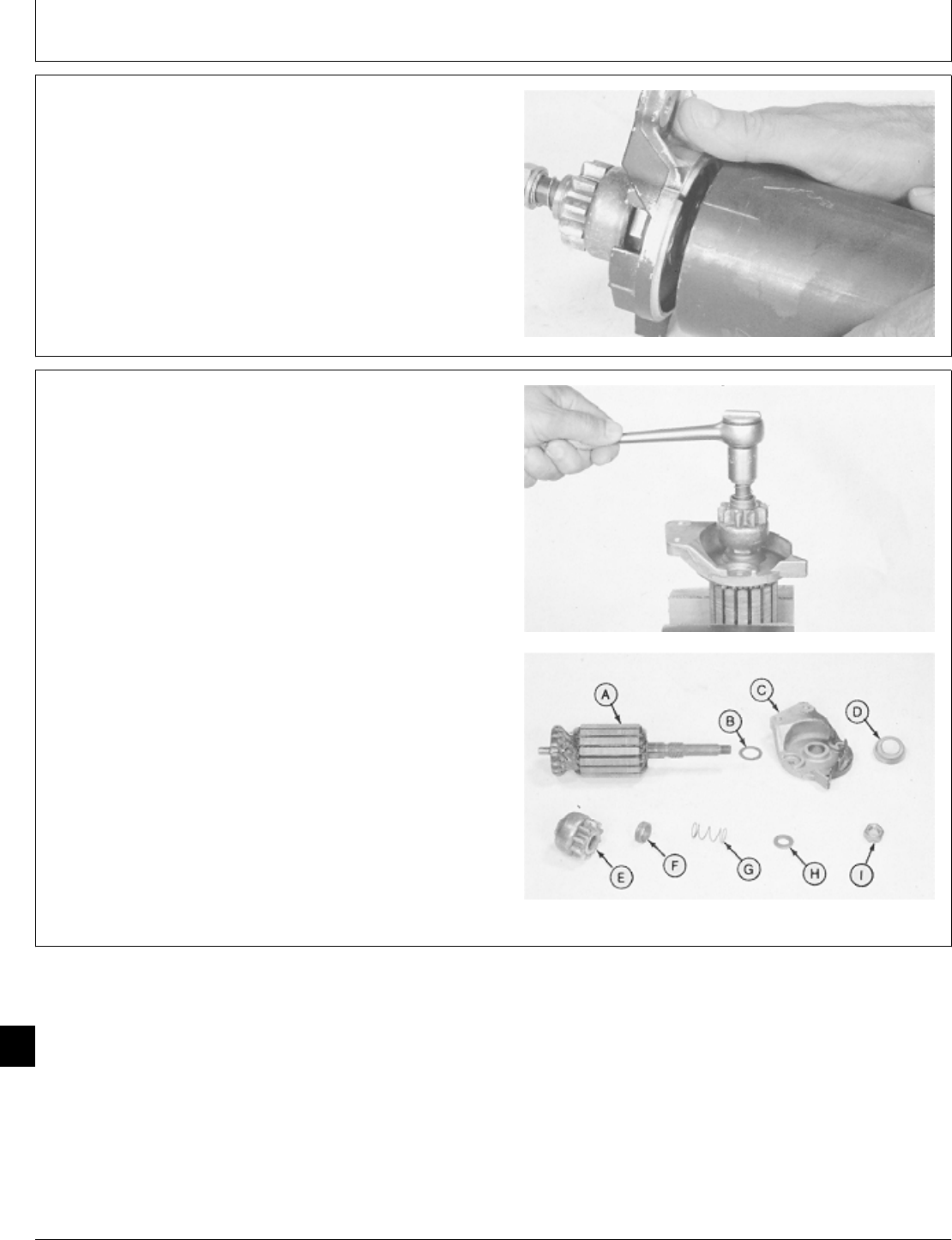
6. Pull armature assembly out of housing.
Clean housing and magnets. Magnets must be securely
glued to inside of housing and must be free of cracks.
Replace housing if magnets are loose or cracked.
M37109 -UN-25JAN90
7. Hold armature in soft-jaw vise.
8. Remove lock nut and disassemble parts (I—A).
Clean and check starter drive components for wear or
damage. Inspect bushing in cap (C) for wear.
Replace damaged or worn parts.
A—Armature
B—Thrust Washer
C—Cap
D—Seal
E—Drive Pinion
F—Spacer
G—Spring
H—Washer
I—Lock Nut
M37110 -UN-25JAN90M37111 -UN-25JAN90
M98,2060K,17 -19-05NOV85
M98,2060K,18 -19-05NOV85
Starter/Starter
CTM2 (19APR90) 60-8 16, 18, 20 & 24HP Onan Engines
130495
60
8
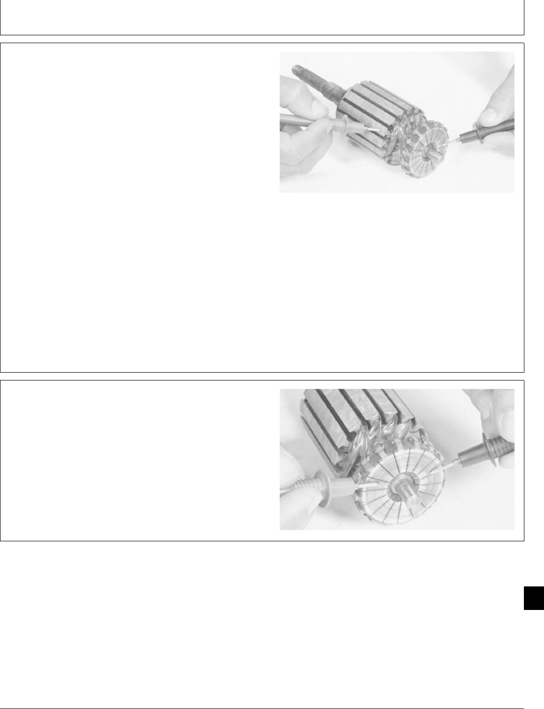
IMPORTANT: Do not clean armature with solvent.
Solvent can damage insulation on
windings. Use only mineral spirits and
a brush.
9. Inspect commutator. Look for roughness, burned bars,
or any material which might cause short circuits between
bars. If necessary, clean and touch up with 400 grit
sandpaper. NEVER use emery cloth. Clean all dust from
armature when finished.
10. Test for grounded windings using an ohmmeter or
test light.
Touch probes on commutator and armature core.
Armature windings are connected in series, so only one
commutator bar needs to be checked.
If test shows continuity, a winding is grounded and the
armature must be replaced.
M37112 -UN-25JAN90
11. Test for open circuited windings using an ohmmeter
or test light.
Touch probes on two different commutator bars. If test
shows no continuity, there is an open circuit and the
armature must be replaced.
M37113 -UN-25JAN90
M98,2060K,19 -19-05NOV85
M98,2060K,20 -19-05NOV85
Starter/Starter
CTM2 (19APR90) 60-9 16, 18, 20 & 24HP Onan Engines
130495
60
9
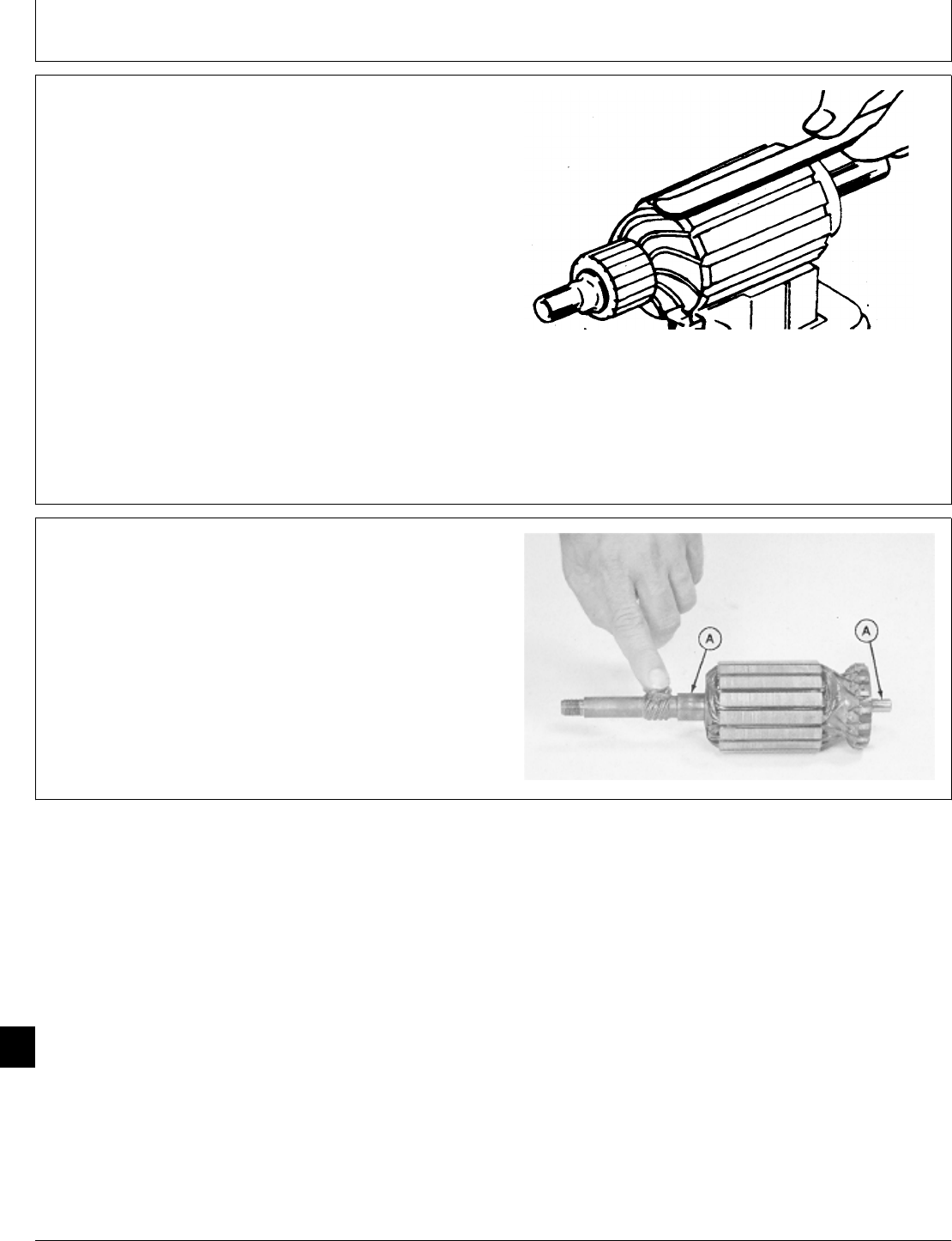
12. Test for short circuited windings using a growler. Put
armature in growler and hold a hacksaw blade above
each slot while slowly rotating armature.
If coil is shorted, the blade will vibrate on the slot.
NOTE: A short circuit most often occurs because of
copper dust or filings between two commutator
segments.
13. If test indicates short circuited windings, clean the
commutator of dust and filings. Check the armature
again. If the test still indicates a short circuit, replace the
armature.
M17166 -UN-24APR89
ASSEMBLE BENDIX DRIVE STARTER
1. Apply a generous film of silicone base grease, such
as GE Versilube 322-L or equivalent, to the worm gear.
2. Apply a thin film of grease to bearing surfaces (A).
M37114 -UN-25JAN90
M98,2060K,21 -19-05NOV85
M98,2060K,22 -19-05NOV85
Starter/Starter
CTM2 (19APR90) 60-10 16, 18, 20 & 24HP Onan Engines
130495
60
10
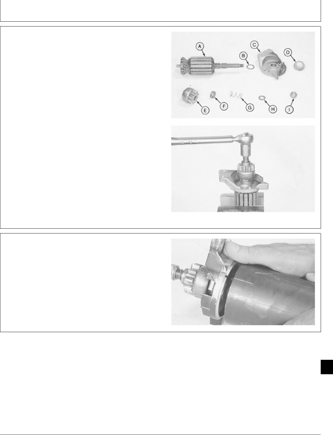
3. Assemble parts (A-I) in sequence order.
4. Hold armature in a soft-jaw vise. Tighten lock nut to
30 ± 3 N·m (265 ± 27 lb-in.).
A—Armature
B—Thrust Washer
C—Cap
D—Seal
E—Drive Pinion
F—Spacer
G—Spring
H—Washer
I—Lock Nut
M37111 -UN-25JAN90M37115 -UN-25JAN90
5. Put armature assembly in housing. Align notch in cap
with mark on housing.
M37109 -UN-25JAN90
M98,2060K,23 -19-05NOV85
M98,2060K,24 -19-05NOV85
Starter/Starter
CTM2 (19APR90) 60-11 16, 18, 20 & 24HP Onan Engines
130495
60
11
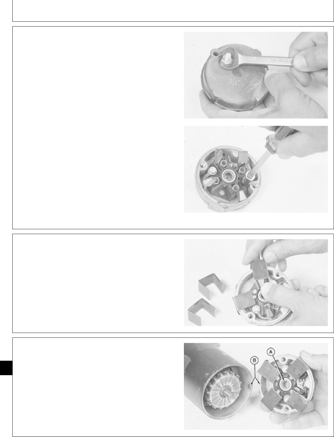
6. Install positive side brushes. Fasten with fiber washer,
flat washer, lock washer, and nut.
Tighten nut to 6 ± 1 N·m (53 ± 9 lb-in.).
7. Install negative brushes. Fasten with cap screws and
tighten to 4.5 ± 0.5 N·m (40 ± 4.5 lb-in.).
8. Install springs.
M37108 -UN-25JAN90M37107 -UN-25JAN90
9. To make temporary brush holders, cut steel banding
into four pieces, 76mm (3 in.) long. Bend flanges 25 mm
(1 in.) long as shown.
10. Push brushes down on the springs and hold them in
place with the four brush holders. Make sure that
chamfered side of brush is up and that the wires do not
rub against the commutator or end cap.
M37116 -UN-25JAN90
11. Apply a light film of grease to bushing (A).
12. Align tab and notch (B); then install end cap on
starter.
M37117 -UN-25JAN90
M98,2060K,25 -19-05NOV85
M98,2060K,26 -19-05NOV85
M98,2060K,27 -19-05NOV85
Starter/Starter
CTM2 (19APR90) 60-12 16, 18, 20 & 24HP Onan Engines
130495
60
12
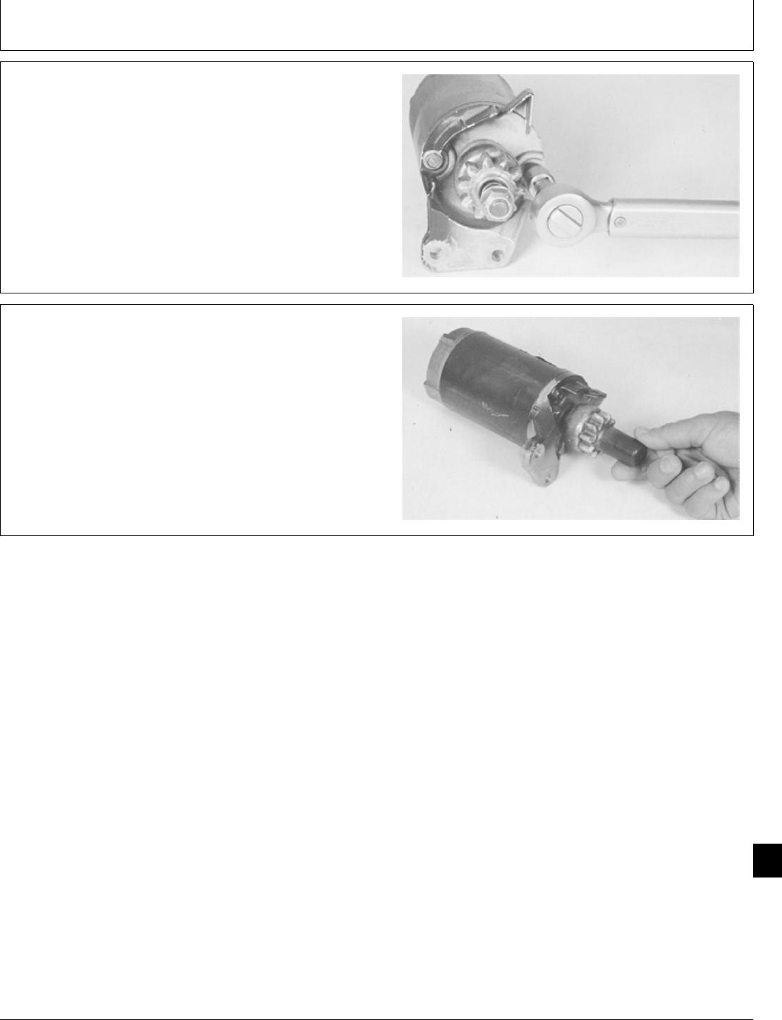
13. Hold end cap in place and remove four temporary
brush holding clips.
14. Be sure notches on both end caps are aligned with
tabs on housing; then fasten with two thru-bolts. Tighten
bolts to 7 ± 1 N·m (62 ± 9 lb-in.).
M37118 -UN-25JAN90
15. Install rubber dust cover.
M37104 -UN-25JAN90
M98,2060K,28 -19-05NOV85
M98,2060K,29 -19-05NOV85
Starter/Starter
CTM2 (19APR90) 60-13 16, 18, 20 & 24HP Onan Engines
130495
60
13
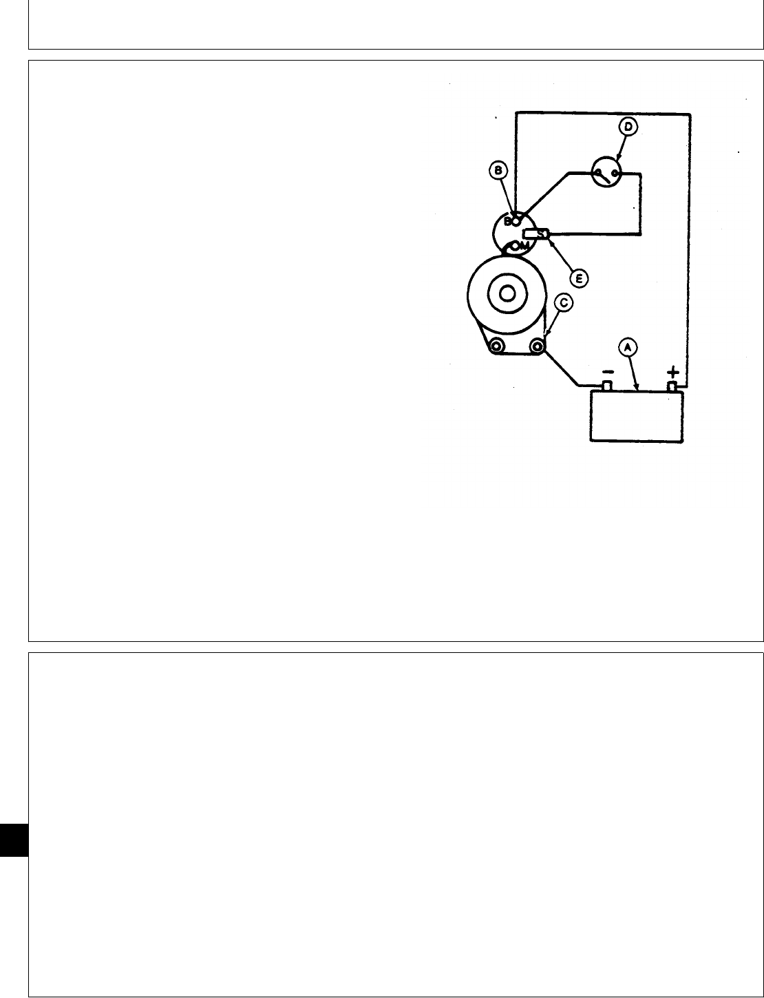
BENCH TEST SOLENOID DRIVE STARTER
NOTE: Perform bench test before disassembling the
starter motor to determine the cause of the
problem.
IMPORTANT: Never operate motor longer than 20
seconds. Allow at least two minutes for
cooling and battery recovery before
operating again. Overheating, caused
by excessive operation, will seriously
damage starting motor.
1. Connect a 12-volt battery (A) to starter battery
terminal (B) and starter frame (C). Use heavy duty
cables.
2. Connect a remote start switch (D) between switch
terminal (E) and battery terminal (B).
NOTE: A short piece of wire with a small clip on the end
will allow a more positive connection at the
switch terminal.
A—12-Volt Battery
B—Battery Terminal
C—Starter Frame
D—Remote Start Switch
E—Switch Terminal
M37149 -UN-29AUG88
When switch is activated, starter should engage and run.
IF SOLENOID CHATTERS; hold-in winding is
open-circuited.
IF NOTHING HAPPENS; either the solenoid pull-in
winding is open-circuited or mechanical parts are
sticking.
IF SOLENOID ENGAGES, BUT MOTOR DOES NOT
RUN; check solenoid switch continuity, brushes,
armature, and field windings.
Solenoid cannot be repaired, replace it.
M98,2060K,30 -19-05NOV85
M98,2060K,31 -19-26NOV85
Starter/Starter
CTM2 (19APR90) 60-14 16, 18, 20 & 24HP Onan Engines
130495
60
14
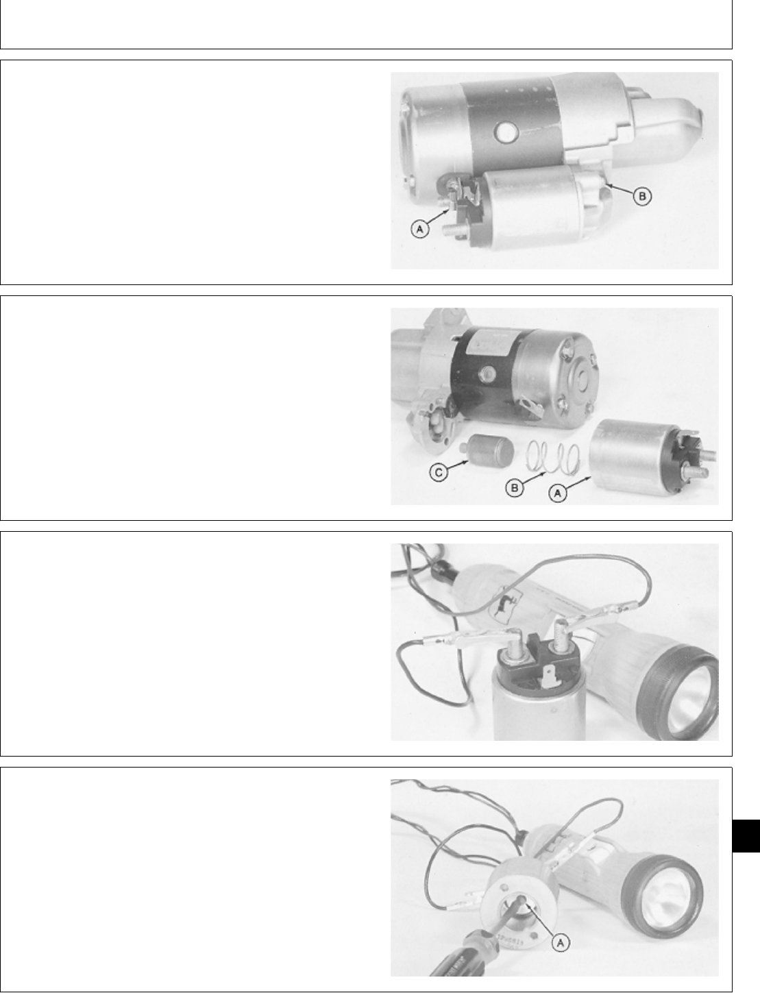
DISASSEMBLE SOLENOID DRIVE STARTER
1. Remove nut (A) to disconnect field coil lead.
2. Remove two screws (B).
M37150 -UN-25JAN90
3. Remove solenoid switch (A), spring (B), and plunger
(C).
Clean and inspect parts. Replace solenoid assembly if
spring is weak or broken or if other parts are defective.
M37129 -UN-25JAN90
NOTE: If bench test indicated solenoid problems, use
an ohmmeter or test light to check switch.
4. Touch one probe of tester to field coil terminal and
other probe to battery terminal. There should be no
continuity.
M37151 -UN-25JAN90
5. With tester probes still on field coil terminal and
battery terminal, push spring loaded switch button (A).
There should be continuity when button is pushed in all
the way.
M37152 -UN-25JAN90
M98,2060K,32 -19-05NOV85
M98,2060K,33 -19-05NOV85
M98,2060K,34 -19-05NOV85
M98,2060K,35 -19-05NOV85
Starter/Starter
CTM2 (19APR90) 60-15 16, 18, 20 & 24HP Onan Engines
130495
60
15
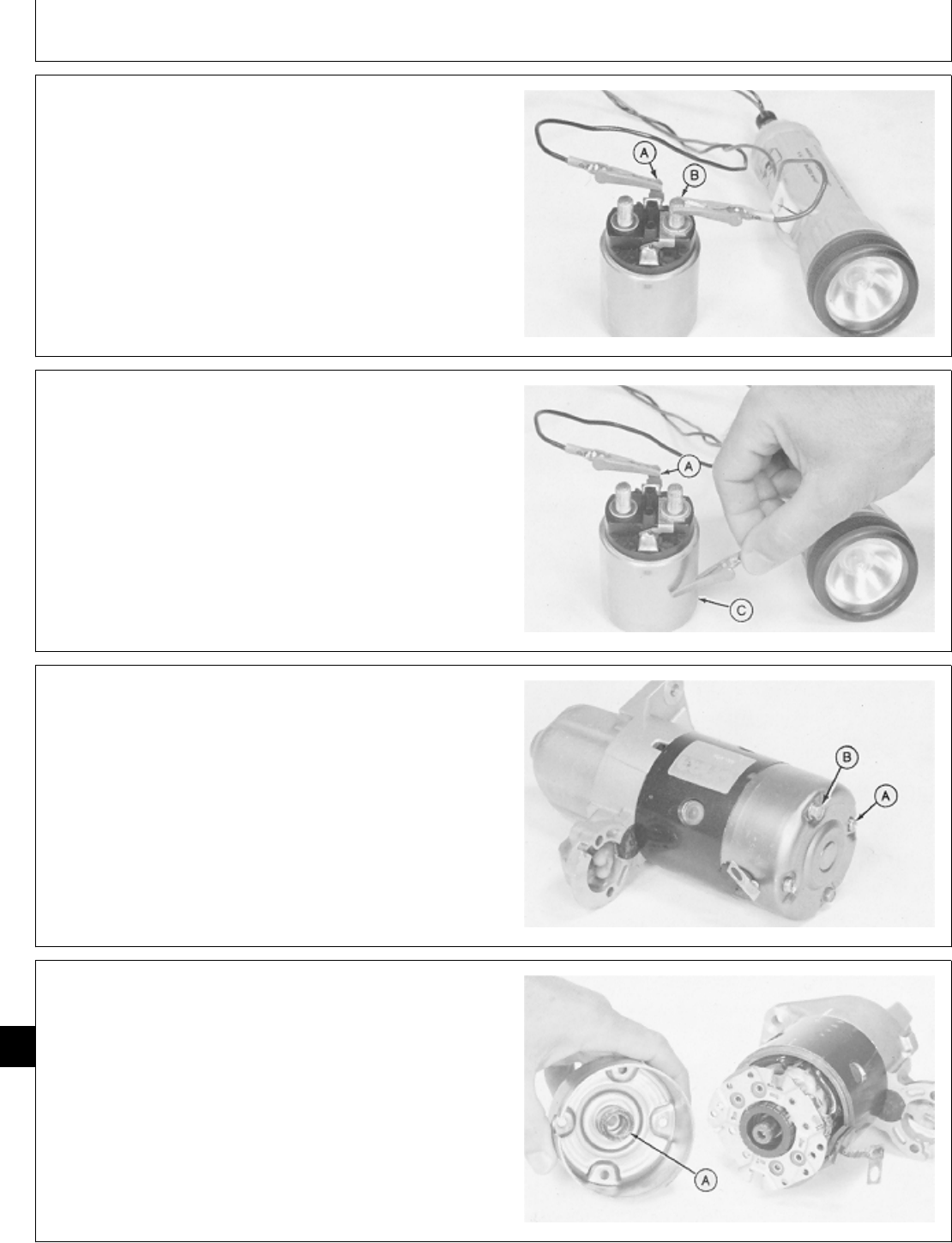
6. Test for open circuits by touching probes to switch
terminal (A) and to field coil terminal (B). There should
be continuity.
M37153 -UN-25JAN90
7. Touch probes to switch terminal (A) and to solenoid
body (C). There should be continuity.
If the solenoid fails any of the tests, it is defective and
must be replaced.
M37154 -UN-25JAN90
8. Remove two screws (A) and two thru-bolts (B).
M37121 -UN-25JAN90
NOTE: Make a mark across front bracket, field coil, and
end cap to align parts in assembly.
9. Remove end cap. Remove thrust washers (A) which
may stick on end cap or around armature shaft.
Inspect bushing in end cap for excessive wear. Replace
end cap assembly if cap is bent or deformed, or if
bushing is worn.
M37122 -UN-25JAN90
M98,2060K,36 -19-05NOV85
M98,2060K,37 -19-05NOV85
M98,2060K,38 -19-05NOV85
M98,2060K,39 -19-05NOV85
Starter/Starter
CTM2 (19APR90) 60-16 16, 18, 20 & 24HP Onan Engines
130495
60
16
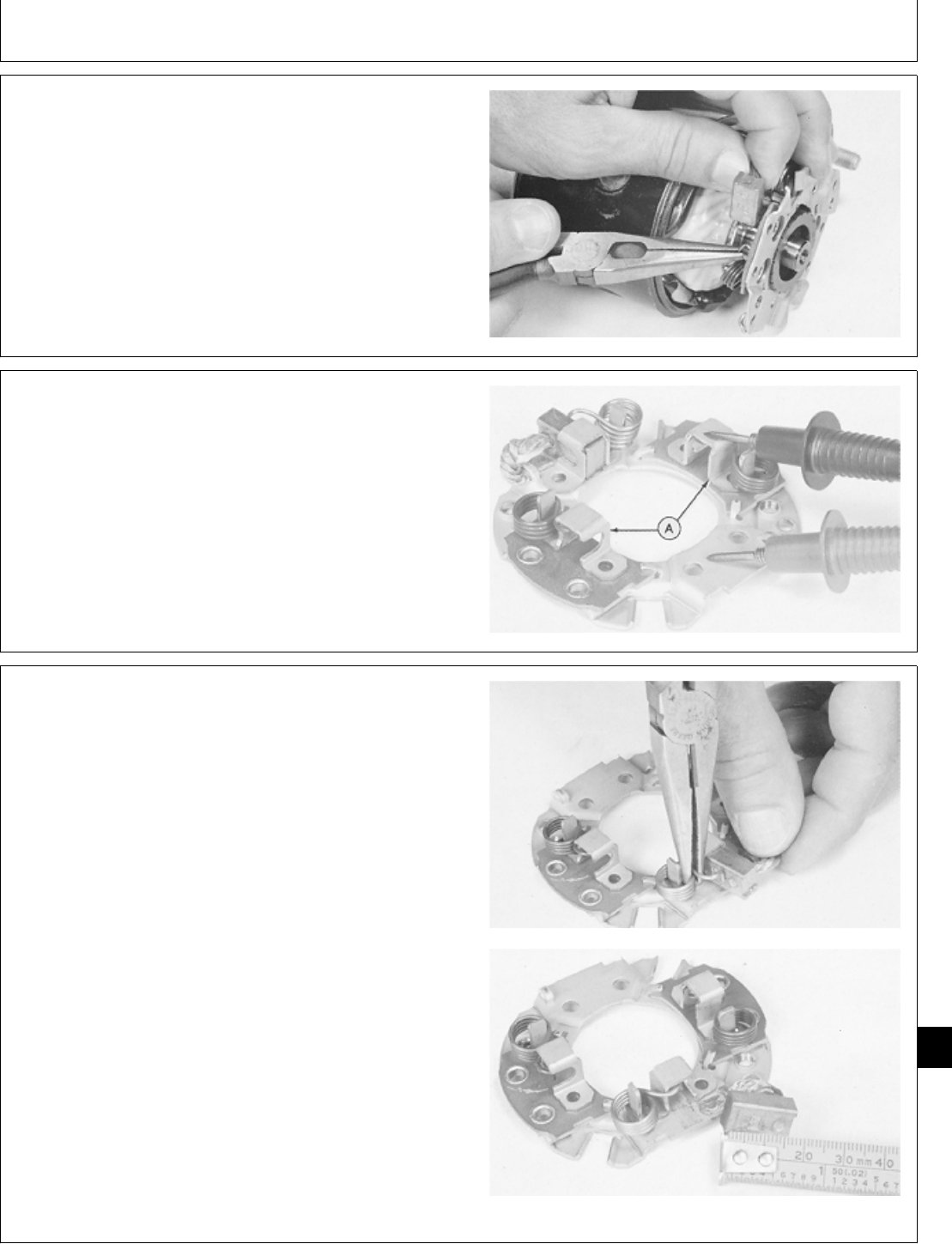
10. Pull springs back to remove two field coil brushes
from brush holder. Remove brush holder.
M37123 -UN-25JAN90
11. Use an ohmmeter or test light to check for continuity.
Touch one probe of tester to brush mounting plate and
other probe to each of the field coil brush holders (A). If
there is continuity, replace the brush holder assembly.
M37139 -UN-29JAN90
12. Pull spring back to remove negative brush.
Measure brush length. Replace brush if worn below
minimum length of 11.5 mm (0.45 in.).
M37124 -UN-25JAN90M37125 -UN-25JAN90
M98,2060K,40 -19-05NOV85
M98,2060K,41 -19-05NOV85
M98,2060K,42 -19-05NOV85
Starter/Starter
CTM2 (19APR90) 60-17 16, 18, 20 & 24HP Onan Engines
130495
60
17
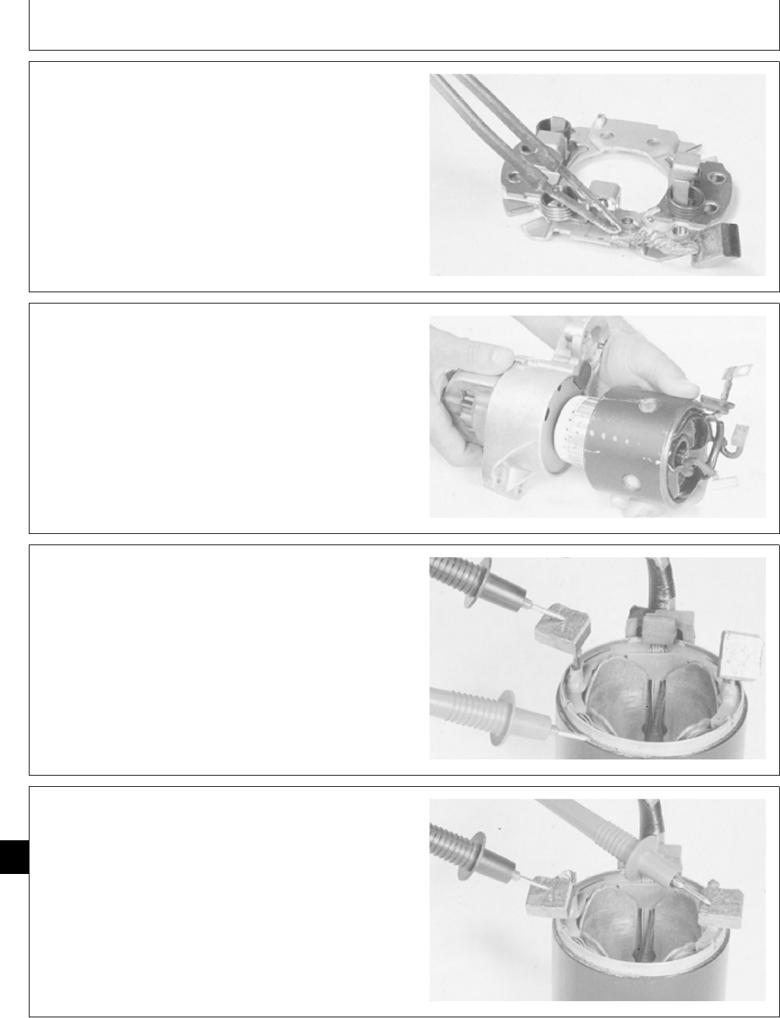
13. To replace negative brush, cut off worn brush and
install new one using a soldering gun and 60-40 rosin
core solder. Newly installed wire should be approximately
same length as the original.
M37140 -UN-29AUG88
14. Remove field coil.
IMPORTANT: Do not clean starter parts with solvent.
Solvent can damage insulation on
windings. Use only mineral spirits and
a brush or wipe clean with a cloth.
Clean and inspect field coil. Check for bare wires or
broken insulation that may cause grounding.
M37126 -UN-25JAN90
15. Test for grounded field winding using an ohmmeter
or test light. Touch one probe of tester to field coil brush
and other probe to field frame. Be sure the brush lead is
not touching the frame. If there is continuity, the coil is
grounded and the field frame assembly must be
replaced.
M36757 -UN-29AUG88
16. Test for open field coil by touching a probe to each
field coil brush. If there is no continuity, the field coil is
open and the field frame assembly must be replaced.
M36758 -UN-29AUG88
M98,2060K,43 -19-05NOV85
M98,2060K,44 -19-05NOV85
M98,2060K,45 -19-05NOV85
M98,2060K,46 -19-05NOV85
Starter/Starter
CTM2 (19APR90) 60-18 16, 18, 20 & 24HP Onan Engines
130495
60
18
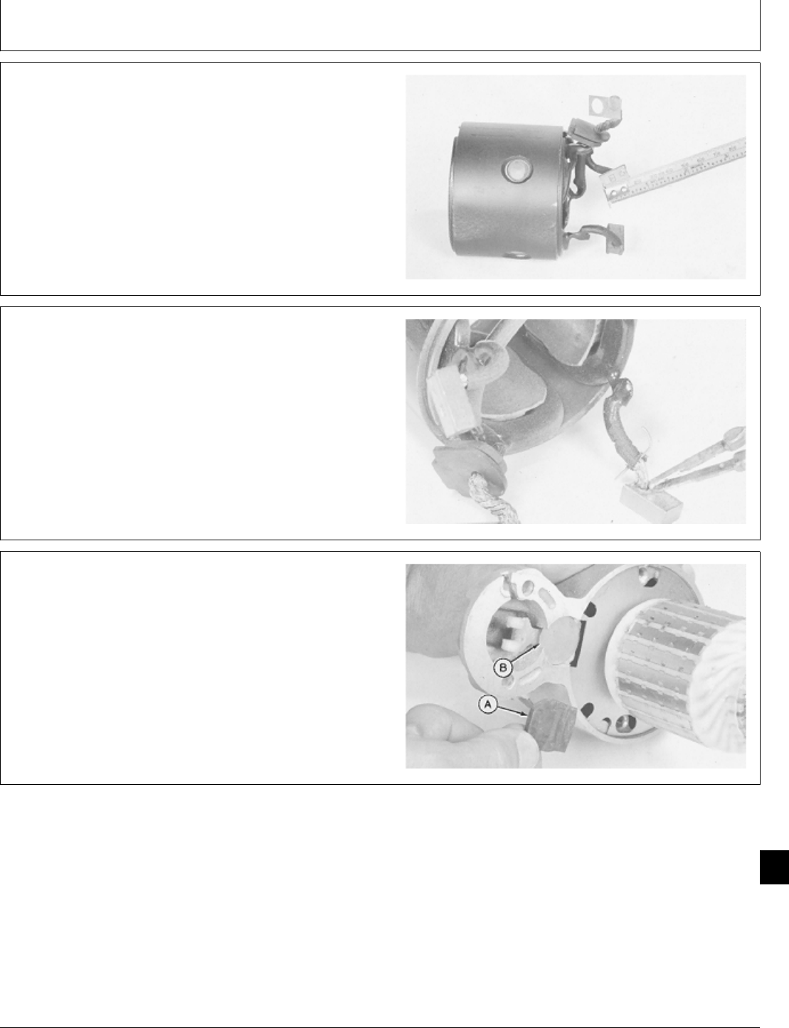
17. Check brushes for cracks or excessive wear.
Replace brushes if they are worn shorter than 11.5 mm
(0.45 in.).
M37127 -UN-25JAN90
18. To replace brushes, melt solder from brush lead
connection and install new brush. If additional solder is
needed, use only 60-40 rosin core solder.
M37141 -UN-25JAN90
19. Remove rubber seal (A) and steel plug (B).
M37130 -UN-25JAN90
M98,2060K,47 -19-05NOV85
M98,2060K,48 -19-05NOV85
M98,2060K,49 -19-05NOV85
Starter/Starter
CTM2 (19APR90) 60-19 16, 18, 20 & 24HP Onan Engines
130495
60
19
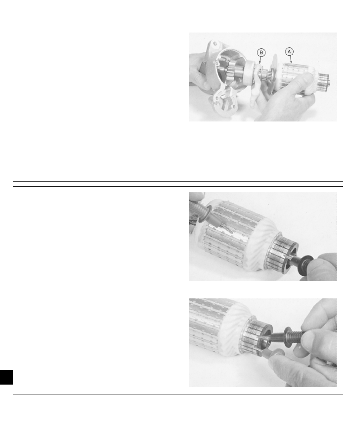
20. Remove armature (A) and lever (B).
Inspect armature for signs of dragging against pole
shoes.
Inspect lever for cracks or excessive wear. Replace if
defective.
Inspect commutator. Look for roughness, burned bars, or
any material which might cause short circuits between
bars. If necessary, clean and touch up with 400
sandpaper. Never use emery cloth. Clean all dust from
armature when finished.
M37131 -UN-25JAN90
21. Test for grounded windings using an ohmmeter or
test light.
Touch probes on armature core and commutator bar.
Armature windings are connected in series, so only one
commutator bar needs to be checked.
If test shows continuity, a winding is grounded and the
armature is defective.
M37132 -UN-25JAN90
22. Test for open circuited windings using an ohmmeter
or test light.
Touch probes on two different commutator bars. If test
shows no continuity, there is an open circuit and the
armature is defective.
M37133 -UN-25JAN90
M98,2060K,50 -19-05NOV85
M98,2060K,51 -19-05NOV85
M98,2060K,52 -19-05NOV85
Starter/Starter
CTM2 (19APR90) 60-20 16, 18, 20 & 24HP Onan Engines
130495
60
20
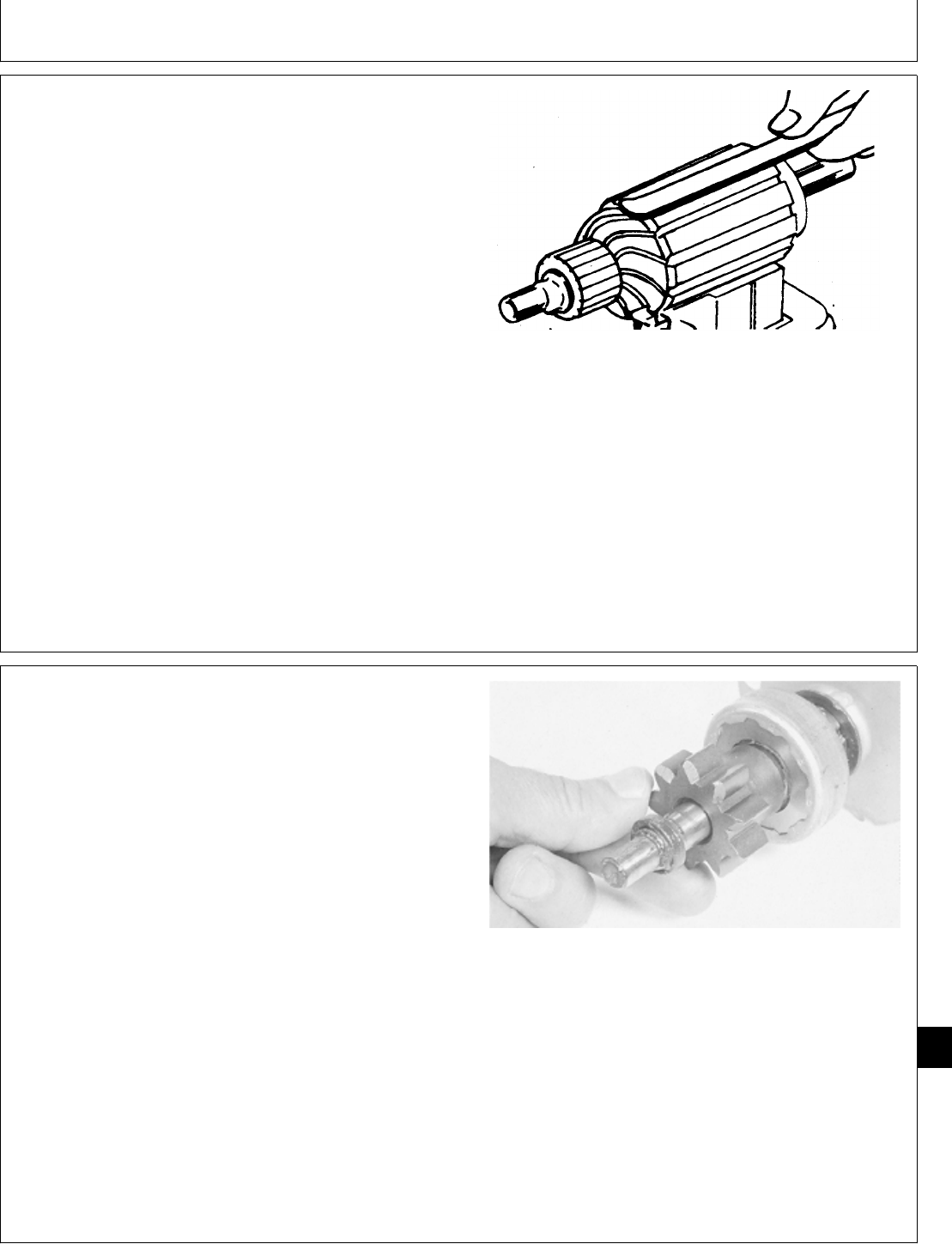
23. Test for short circuited windings using a growler. Put
armature in growler and hold a hacksaw blade above
each slot while slowly rotating armature.
If coil is shorted, the blade will vibrate on the slot.
NOTE: A short circuit most often occurs because of
copper dust or filing between two commutator
segments.
24. If test indicates short circuited windings, clean the
commutator of dust and filings. Check the armature
again. If the test still indicates a short circuit, the
armature is defective.
The armature is not serviceable. If any of the tests
indicate grounded, shorted, or open circuited windings,
replace the entire starter.
M17166 -UN-24APR89
IMPORTANT: Do not clean overrunning clutch in
solvent. The clutch contains grease
which would be removed.
NOTE: Check overrunning clutch before removing it from
armature.
25. Turn clutch drive counterclockwise by hand. Pinion
should turn freely.
26. Turn pinion clockwise. A definite resistance should
be felt.
If clutch is free-wheeling in both directions, or if it shows
resistance when turned counterclockwise, it is defective.
Replace overrunning clutch if it is defective or if pinion
gear shows excessive wear or damage.
M37134 -UN-25JAN90
M98,2060K,53 -19-05NOV85
M98,2060K,54 -19-05NOV85
Starter/Starter
CTM2 (19APR90) 60-21 16, 18, 20 & 24HP Onan Engines
130495
60
21
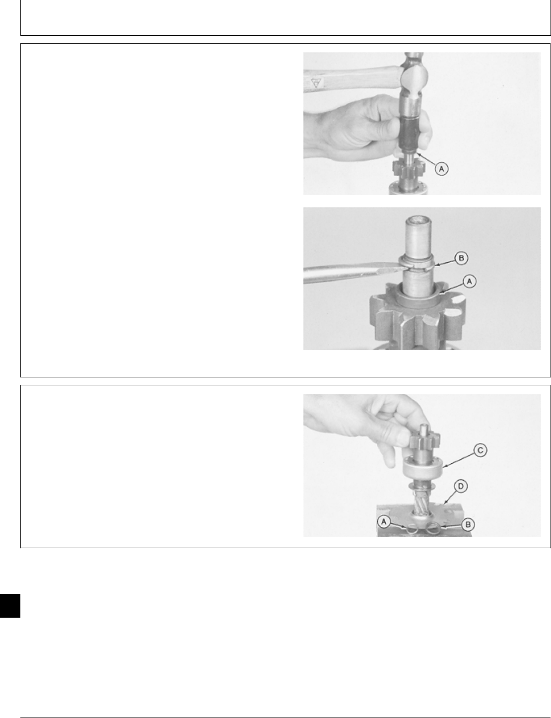
27. Hold armature assembly in a soft-jawed vise. Slide
stop ring (A) down using a piece of pipe.
28. Push snap ring (B) from groove.
M37135 -UN-25JAN90M37136 -UN-25JAN90
29. Remove snap ring (A), stop ring (B), overrunning
clutch (C), and baffle plate (D).
A—Snap Ring
B—Stop Ring
C—Overrunning Clutch
D—Baffle Plate
M37137 -UN-25JAN90
M98,2060K,55 -19-05NOV85
M98,2060K,56 -19-05NOV85
Starter/Starter
CTM2 (19APR90) 60-22 16, 18, 20 & 24HP Onan Engines
130495
60
22
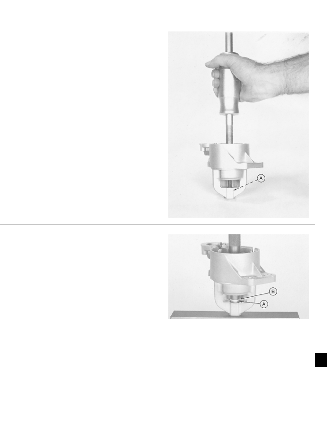
30. Check bushing in front frame for excessive wear.
If it is necessary to remove bushing (A), use a 3/8 in.
blind-hole puller and slide hammer.
NOTE: Thrust washer will be pulled along with bushing.
M37138 -UN-25JAN90
ASSEMBLE SOLENOID DRIVE STARTER
1. If front frame bushing is being replaced, press new
bushing (A) and thrust washer (B) into front frame. Use
a 5/8 in. driver to install washer tight against shoulder of
counterbore.
M37142 -UN-25JAN90
M98,2060K,57 -19-05NOV85
M98,2060K,58 -19-05NOV85
Starter/Starter
CTM2 (19APR90) 60-23 16, 18, 20 & 24HP Onan Engines
130495
60
23
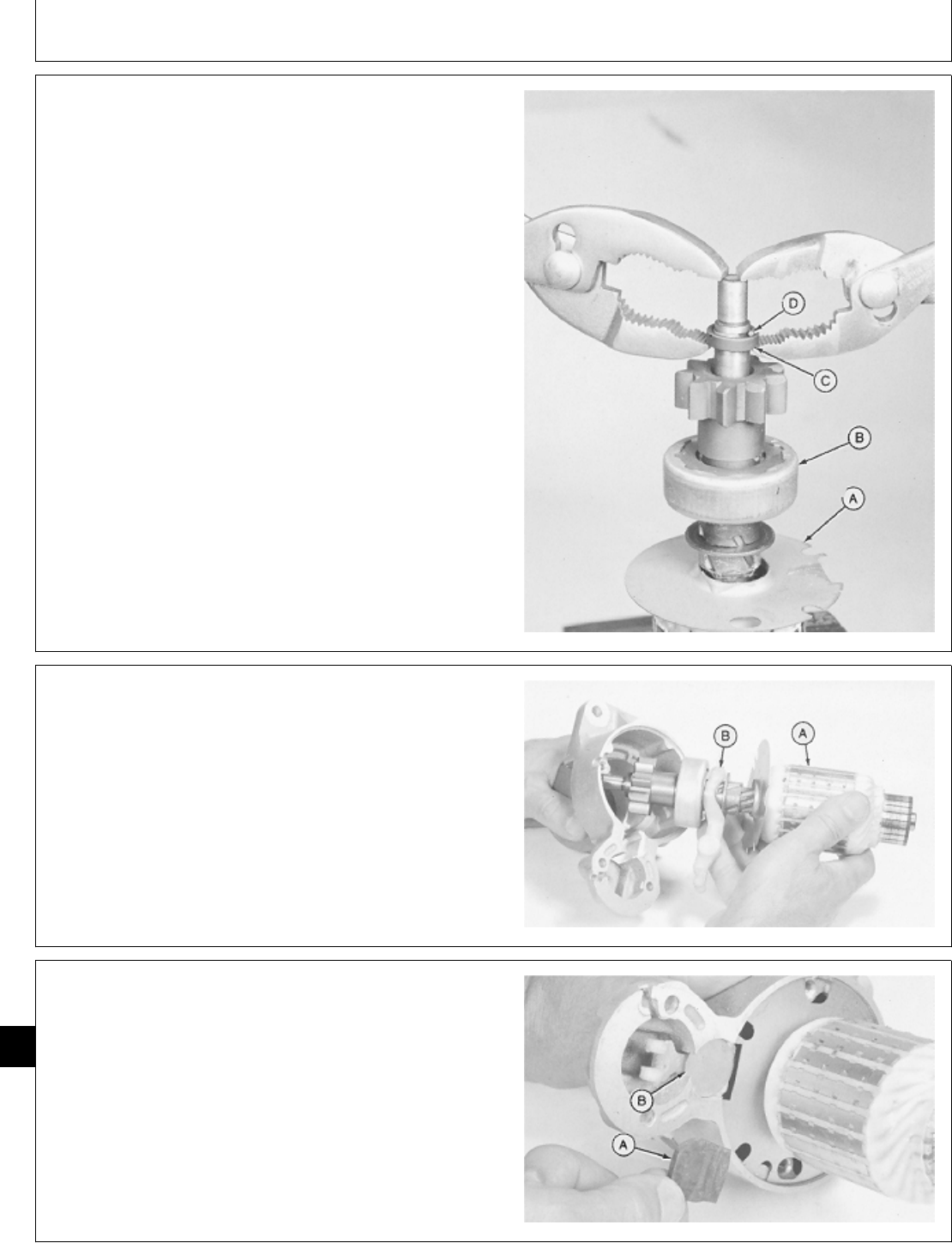
2. Install baffle plate (A), overrunning clutch (B), stop
ring (C), and snap ring (D). Be sure flange of baffle plate
(A) is pointing upward.
3. Put snap ring (D) in groove. Pull stop ring (C) over
the snap ring.
A—Baffle Plate
B—Overrunning Clutch
D—Stop Ring
E—Snap Ring
M37143 -UN-25JAN90
4. Apply Multemp PS No. 2 grease or equivalent to both
ends of armature shaft and to the lever (B). Apply light
oil to the overrunning clutch splines.
5. Install armature assembly (A) and lever (B) into front
frame. Note the position of the lever.
M37131 -UN-25JAN90
6. Install steel plug (B) and rubber seal (A).
M37130 -UN-25JAN90
M98,2060K,59 -19-05NOV85
M98,2060K,60 -19-05NOV85
M98,2060K,61 -19-05NOV85
Starter/Starter
CTM2 (19APR90) 60-24 16, 18, 20 & 24HP Onan Engines
130495
60
24
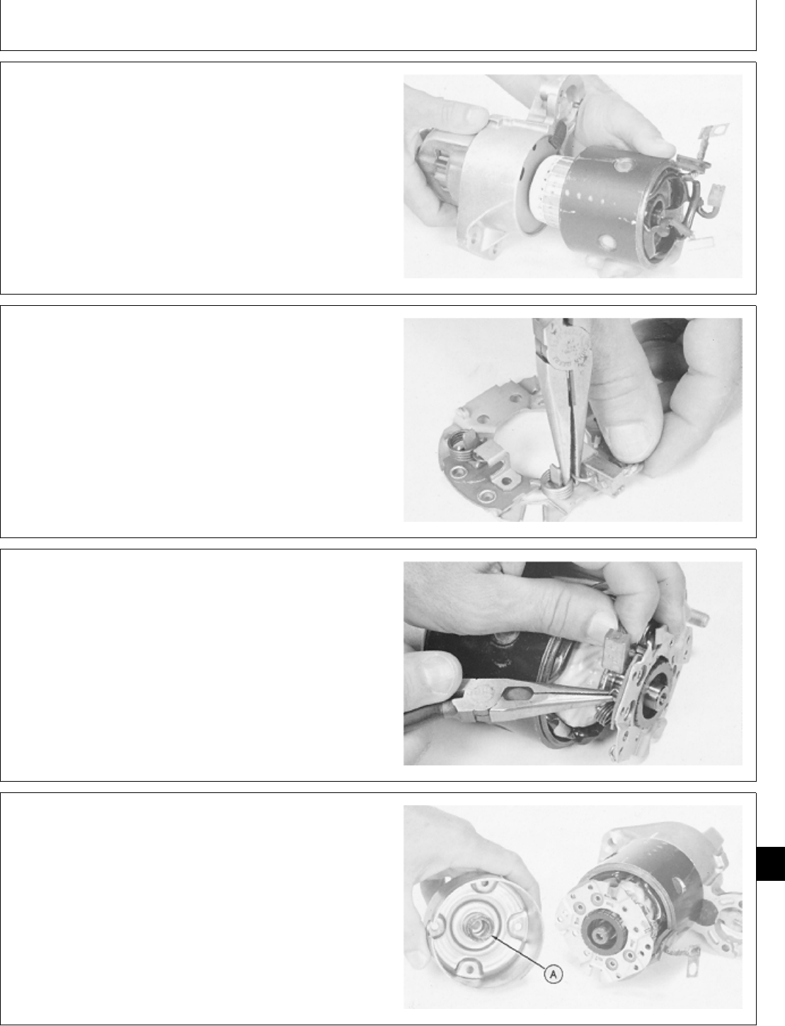
7. Install field coil. Be sure notch in field coil flange
aligns with rubber seal.
M37126 -UN-25JAN90
8. Install negative brush and hold it in place with the
spring.
M37124 -UN-25JAN90
9. Put brush holder assembly on commutator and install
field coil brushes. Pull springs back and push all three
brushes against commutator, then release springs to hold
brushes.
M37123 -UN-25JAN90
NOTE: Install same number of thrust washers as was
removed when disassembling starter.
10. Apply grease to thrust washers (A) to hold them to
end cap.
11. Install end cap. Be sure slot in end cap aligns with
rubber seal.
M37122 -UN-25JAN90
M98,2060K,62 -19-05NOV85
M98,2060K,63 -19-05NOV85
M98,2060K,64 -19-05NOV85
M98,2060K,65 -19-05NOV85
Starter/Starter
CTM2 (19APR90) 60-25 16, 18, 20 & 24HP Onan Engines
130495
60
25
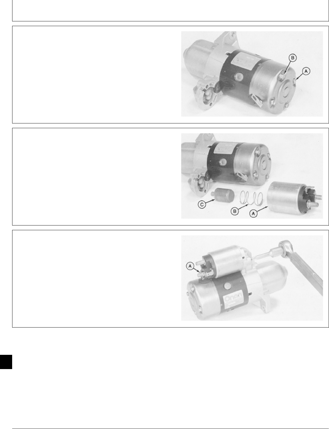
12. Install two screws (A).
13. Install two thru-bolts (B) and tighten to 5.7 ± 1.1 N·m
(50 ± 10 lb-in.).
M37121 -UN-25JAN90
14. Apply grease to the lever fork and apply light oil to
the plunger (C).
15. Connect plunger (C) to lever fork and install spring
(B) and solenoid switch (A). Note position of switch
terminal on solenoid.
M37129 -UN-25JAN90
16. Fasten solenoid with two screws. Tighten screws to
6 ± 1 N·m (53 ± 9 lb-in.).
17. Connect field coil lead and fasten with nut (A).
M37144 -UN-25JAN90
M98,2060K,66 -19-05NOV85
M98,2060K,67 -19-05NOV85
M98,2060K,68 -19-05NOV85
Starter/Starter
CTM2 (19APR90) 60-26 16, 18, 20 & 24HP Onan Engines
130495
60
26
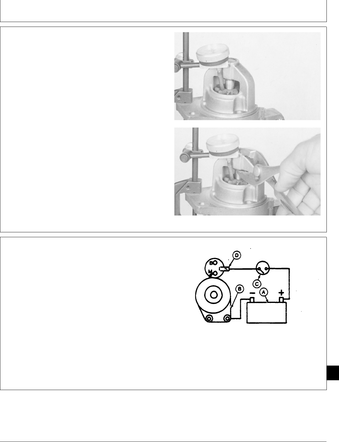
18. Check armature shaft thrust gap. Set dial indicator
on pinion then raise the armature shaft to determine
thrust gap.
SPECIFICATION
Item Nominal Value
Armature Shaft Thrust Gap 0.1 to 0.5 mm
(0.004 to 0.020 in.)
If the thrust gap is not within the nominal value limits,
add or remove thrust washers shown in Step 10.
M37145 -UN-25JAN90M37146 -UN-25JAN90
NOTE: Normally the pinion clearance will not be affected
by servicing the starter unless the solenoid is
replaced.
19. To check pinion clearance, connect a 12-volt battery
(A) to starter frame (B). Connect a remote switch (C)
between solenoid terminal (D) and battery (A). Use
heavy duty cables.
A—12-Volt Battery
B—Starter Frame
C—Remote Start Switch
D—Solenoid Switch Terminal
M37147 -UN-26APR89
M98,2060K,69 -19-05NOV85
M98,2060K,70 -19-05NOV85
Starter/Starter
CTM2 (19APR90) 60-27 16, 18, 20 & 24HP Onan Engines
130495
60
27
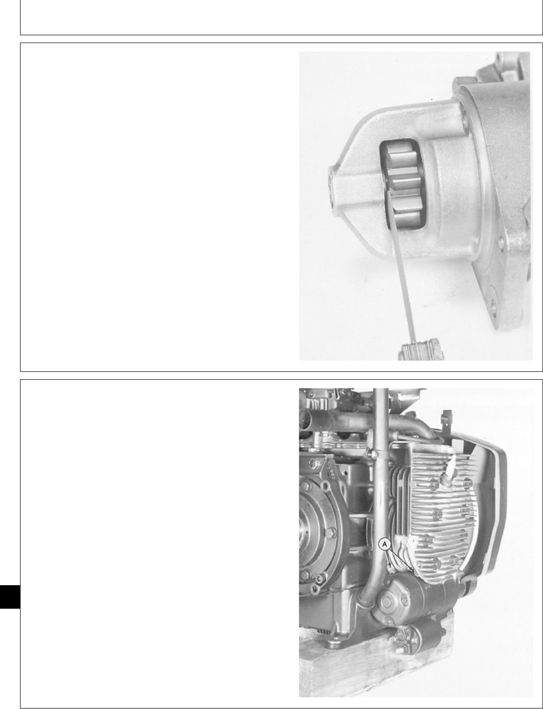
IMPORTANT: To avoid solenoid overheating, do not
leave solenoid activated longer than
necessary to measure clearance.
20. Close the switch to activate solenoid which will shift
the pinion into cranking position. Measure clearance
between the pinion and stop ring.
SPECIFICATION
Item Nominal Value
Pinion-to-Stop Ring 0.5 to 2.0 mm
Clearance (0.020 to 0.079 in.)
If clearance is not within the nominal value limits, add or
remove shims between solenoid and front frame. See
Step 15.
Adding shims provided with Solenoid Repair Kit,
decreases the amount of clearance.
21. After assembly, perform bench test. (See “Bench
Test Solenoid Drive Starter” in this group.)
M37148 -UN-25JAN90
INSTALL STARTER—P218G AND P220G
ENGINES
1. Install starter. Tighten cap screws (A) to 26 N·m (230
lb-in.).
2. Align flywheel shroud and install cap screws.
3. Install side shroud and cap screws.
4. Install manifold and lift bracket. Tighten cap screw to
11 ± 3 N·m (97 ± 27 lb-in.).
5. Connect spark plug wire.
6. Install engine. (See machine technical manual.)
M46014 -UN-08JAN90
M98,2060K,71 -19-05NOV85
M98,2060K,72A -19-02FEB87
Starter/Starter
CTM2 (19APR90) 60-28 16, 18, 20 & 24HP Onan Engines
130495
60
28
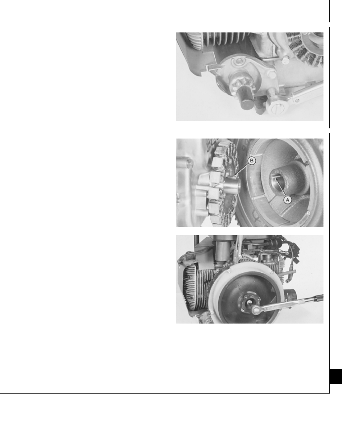
INSTALL STARTER—B43E, B43G, B48G,
AND T260 ENGINES
1. Install starter. Tighten two cap screws to 34 ± 1 N·m
(300 ± 9 lb-in.).
Bendix Drive Starter Shown
M36439 -UN-29JAN90
IMPORTANT: Do not lubricate crankshaft taper. The
crankshaft taper must be dry to hold
the flywheel tight.
2. Clean crankshaft taper before installing flywheel.
3. Apply pipe sealant on threads of flywheel cap screw.
4. Align keyway (A) in flywheel with key (B) in crankshaft
and install flywheel.
5. Install washer and cap screw.
IMPORTANT: Do not hold flywheel from turning with
a pry bar in the fins. Doing so may
damage the fins.
6. Fasten locking pliers to ring gear to prevent flywheel
from turning.
7. On B43E, B43G, B48G, T260 engines, tighten cap
screw to 51 ± 3 N·m (38 ± 2 lb-ft).
On P218G and P220G engine, tighten cap screw to
67—75 N·m (50—55 lb-ft).
M36297 -UN-29JAN90M36298 -UN-29JAN90
M98,2060K,72 -19-11FEB87
M98,2060K,73 -19-11FEB87
Starter/Starter
CTM2 (19APR90) 60-29 16, 18, 20 & 24HP Onan Engines
130495
60
29
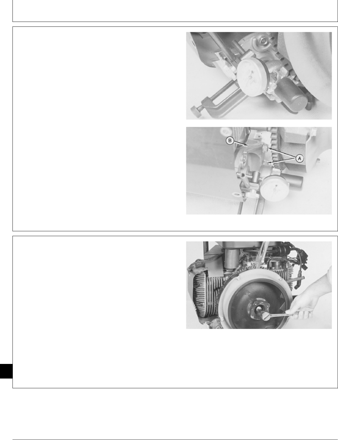
NOTE: For engines with adjustable starter bracket,
measure starter pinion gear backlash using the
following procedure. For all other units with
non-adjustable starter bracket, go to Step 21.
8. Pull starter pinion gear outward until teeth contact
flywheel ring gear. Measure starter pinion gear backlash.
Backlash specification is 0.51 ± 0.38 mm (0.020 ± 0.15
in.).
If backlash is correct, go to Step 21.
9. If backlash is not correct, loosen starter cap screws
(A) and move starter bracket (B) to obtain correct
backlash.
Tighten starter cap screws to hold bracket in position.
Check backlash again.
M36437 -UN-29JAN90M36438 -UN-29JAN90
IMPORTANT: Do not hold flywheel from turning with
a pry bar. Doing so can damage the
fins.
10. Fasten locking pliers to ring gear to prevent flywheel
from turning.
NCAUTION: Loosen flywheel cap screw only two
turns. Do not remove cap screw. If cap screw
is removed, flywheel may cause injury when it
comes loose.
11. Loosen cap screw two turns only.
M36292 -UN-29JAN90
M98,2060K,78 -19-26NOV85
M98,2060K,9 -19-05NOV85
Starter/Starter
CTM2 (19APR90) 60-30 16, 18, 20 & 24HP Onan Engines
130495
60
30
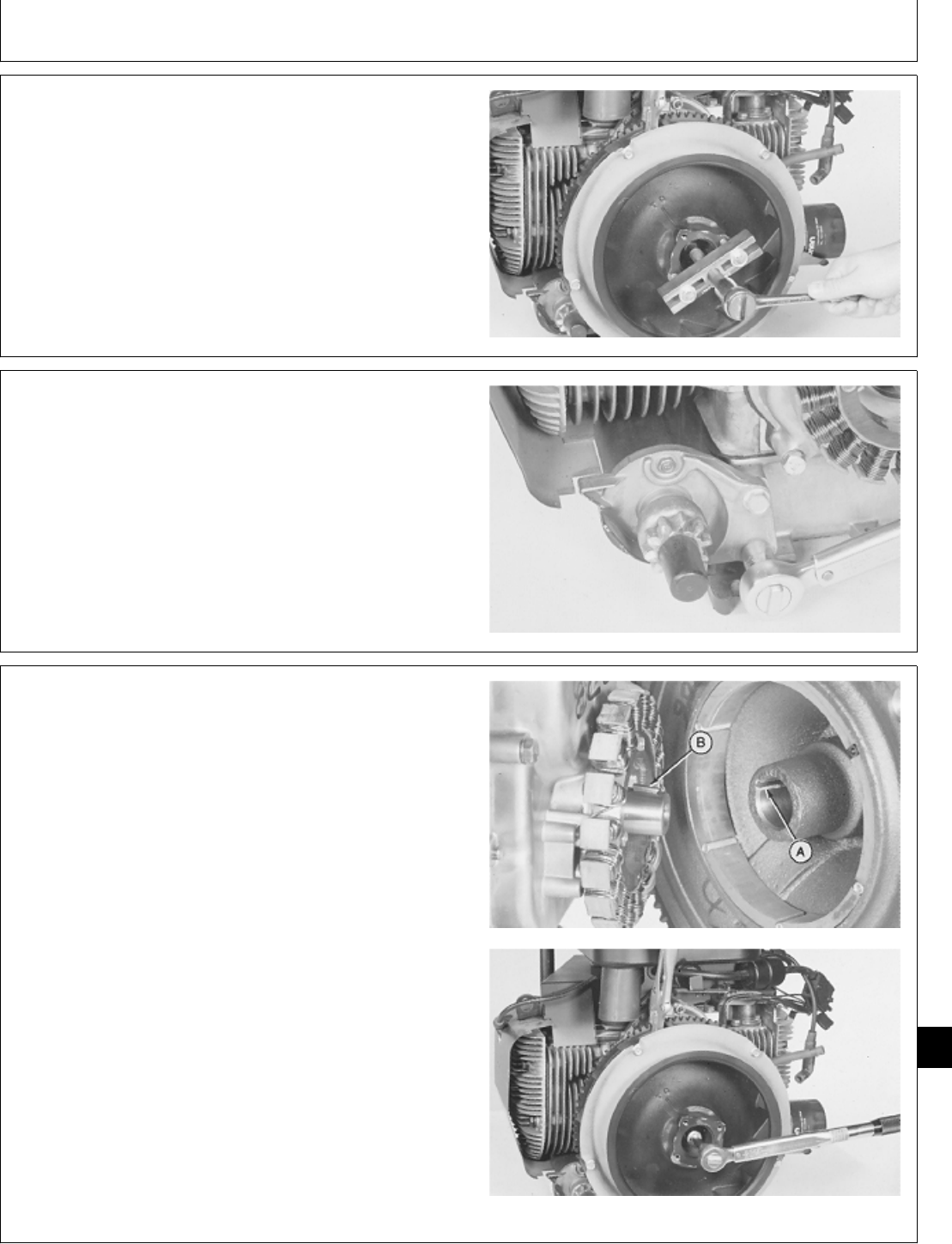
IMPORTANT: Do not pry on flywheel with a
screwdriver. Ceramic magnets and gear
case cover can be damaged.
12. Loosen flywheel using a puller.
13. Remove puller, cap screw, washer, and flywheel.
M36293 -UN-29JAN90
14. Tighten starter cap screws to 34 ± 1 N·m (300 ± 9
lb-in.).
M36439 -UN-29JAN90
IMPORTANT: Do not lubricate crankshaft taper. The
crankshaft taper must be dry to hold
the flywheel tight.
15. Clean crankshaft taper before installing flywheel.
16. Apply pipe sealant on threads of flywheel cap screw.
17. Align keyway (A) in flywheel with key (B) in
crankshaft and install flywheel.
18. Install washer and cap screw.
IMPORTANT: Do not hold flywheel from turning with
a prybar in the fins. Doing so may
damage the fins.
19. Fasten locking pliers to ring gear to prevent flywheel
from turning.
20. Tighten cap screw to 51 ± 3 N·m (38 ± 2 lb-ft).
M36297 -UN-29JAN90M36298 -UN-29JAN90
M98,2060K,10 -19-05NOV85
M98,2060K,79 -19-26NOV85
M98,2060K,80 -19-26NOV85
Starter/Starter
CTM2 (19APR90) 60-31 16, 18, 20 & 24HP Onan Engines
130495
60
31
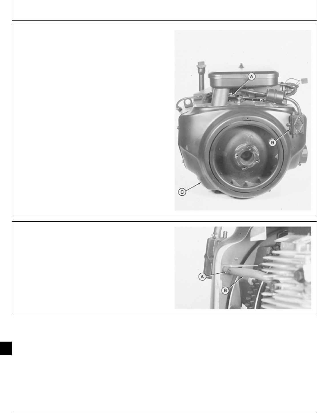
21. Install flywheel shroud (C). Fasten with five cap
screws.
22. Install fuel pump (B). Fasten with two screws.
23. Connect governor spring (A) in top hole of arm.
M36291 -UN-29JAN90
24. Connect fuel pump impulse line (B) and fasten with
hose clamp (A).
M36290 -UN-29JAN90
M98,2060K,75 -19-26NOV85
M98,2060K,76 -19-26NOV85
Starter/Starter
CTM2 (19APR90) 60-32 16, 18, 20 & 24HP Onan Engines
130495
60
32
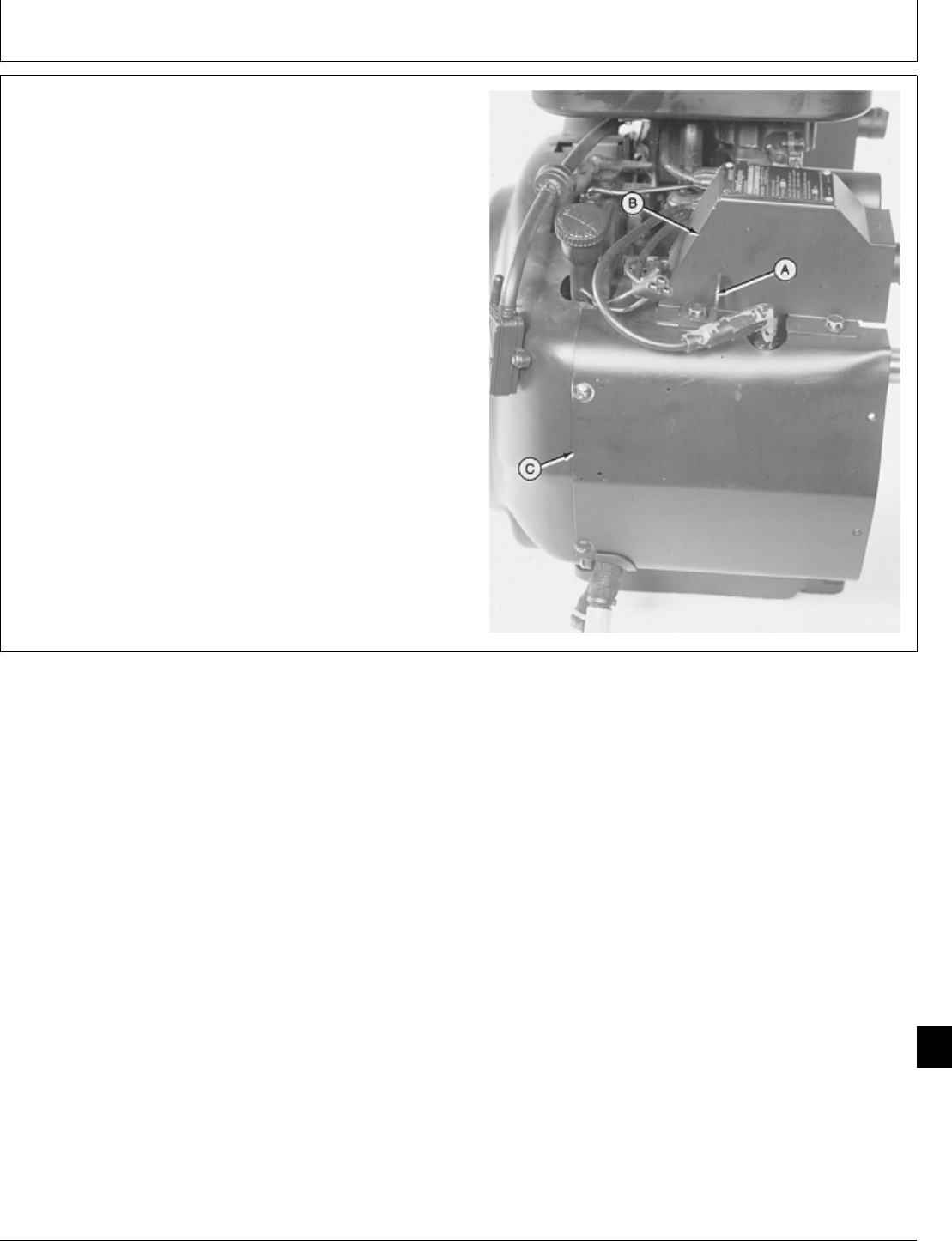
25. Install side shroud (C). Fasten with four cap screws
on T260 engine; five cap screws on B43E, B43G, or
B48G engine.
26. Install manifold cover (B) and lift bracket (A). Fasten
with three cap screws on T260 engine; two cap screws
on B43E, B43G, or B48G engine. Tighten lift bracket cap
screw to 11 ± 3 N·m (97 ± 27 lb-in.).
27. Connect spark plug wire and voltage regulator leads.
Install the two stator leads on “AC” terminals and the
battery lead on “B+” terminal of voltage regulator.
28. Install engine. (See machine technical manual.)
T260 Engine Shown
M36445 -UN-29JAN90
M98,2060K,77 -19-26NOV85
Starter/Starter
CTM2 (19APR90) 60-33 16, 18, 20 & 24HP Onan Engines
130495
60
33

Starter/Starter
CTM2 (19APR90) 60-34 16, 18, 20 & 24HP Onan Engines
130495
60
34
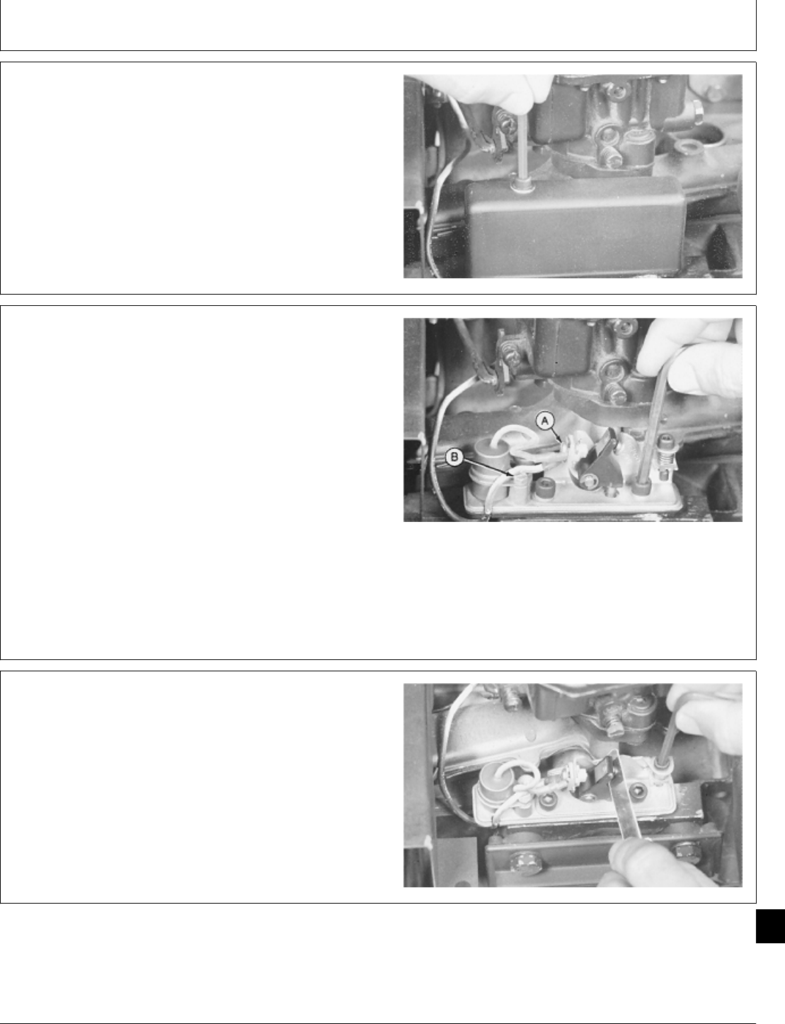
REPLACE BREAKER POINTS AND
CONDENSER—B43E, B43G, B48G, AND
T260 ENGINES
NOTE: On later engines, the condenser is located on
side of air filter bracket.
1. Remove air cleaner assembly. (See Remove Air
Cleaner in Group 05 in this manual.)
2. Remove breaker point cover.
M37242 -UN-25JAN90
3. Remove two set screws to remove breaker points.
4. Loosen screw (A) to disconnect coil and condenser
leads.
5. Remove screw (B) to remove condenser.
6. Install new condenser and point assembly. Apply
thread sealant on threads of set screws and fasten
breaker points.
Early Point Assembly Shown
M37243 -UN-25JAN90
7. Check breaker point gap. Turn engine flywheel until
points are at their widest gap. Adjust gap to 0.41 mm
(0.016 in.) using a flat feeler gauge.
M37244 -UN-25JAN90
M98,2065K,1 -19-02FEB87
M98,2065K,2 -19-05NOV85
M98,2065K,3 -19-05NOV85
Group 65
Ignition System
CTM2 (19APR90) 65-1 16, 18, 20 & 24HP Onan Engines
130495
65
1
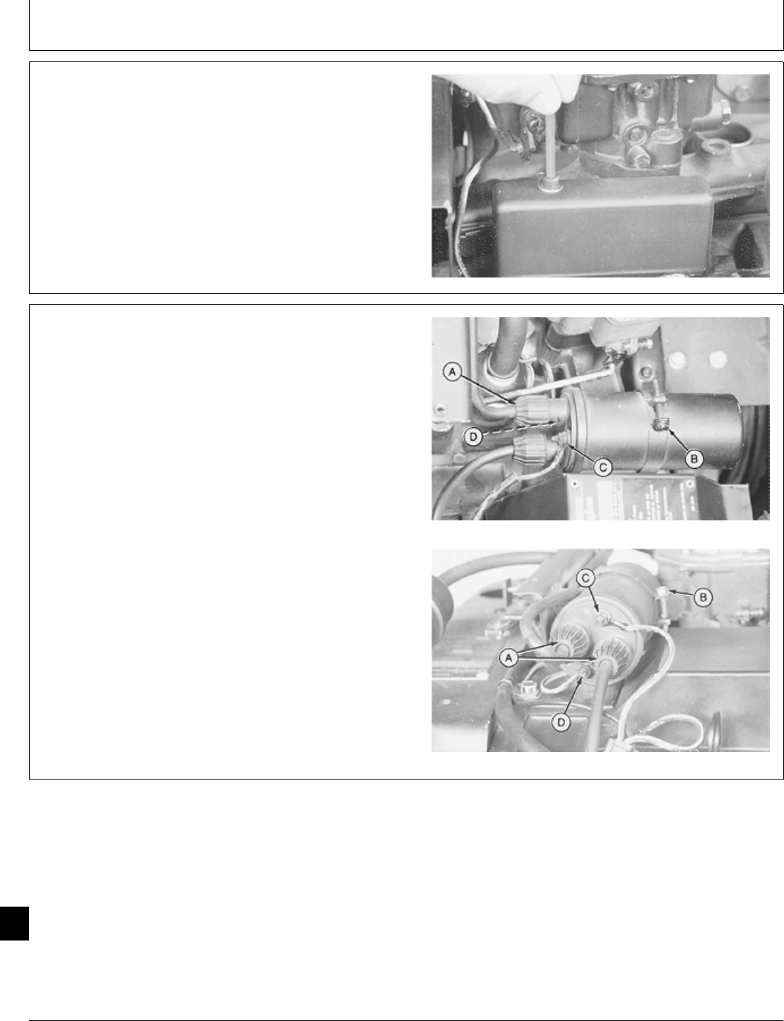
8. Be sure coil lead wire is in notch in the base; then
install breaker point cover. Tighten cover set screw snug
only so cover is not crushed or deformed.
9. Install air cleaner assembly. (See Install Air Cleaner in
Group 05 in this manual.)
M37242 -UN-25JAN90
REPLACE IGNITION COIL—B43E, B43G,
B48G, AND T260 ENGINES
1. Remove air cleaner assembly. (See Remove Air
Cleaner in Group 05 in this manual.)
2. Disconnect spark plug wires (A).
3. Loosen screw (B) to remove coil.
4. Remove wires (C) and (D).
5. To install coil, fasten breaker point lead to negative (-) T260 Engine (Top Photo)
terminal (D) and ignition switch lead to positive (+)
terminal (C).
6. Install coil and fasten with screw clamp (B).
7. Connect spark plug wires (A).
8. Install air cleaner assembly. (See Install Air Cleaner in
Group 05 in this manual.)
B43E, B43G, B48G Engine (Bottom
M37156 -UN-25JAN90M37157 -UN-25JAN90
M98,2065K,4 -19-05NOV85
M98,2065K,5 -19-11FEB87
Ignition System/Ignition Coil
CTM2 (19APR90) 65-2 16, 18, 20 & 24HP Onan Engines
130495
65
2
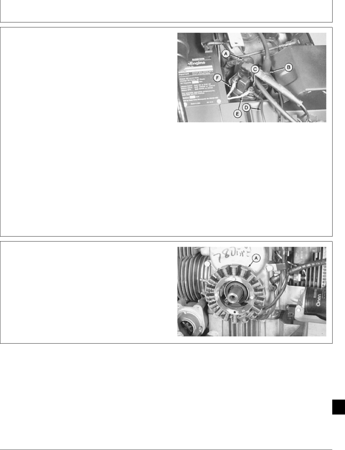
REPLACE IGNITION COIL—P218G AND
P220G ENGINES
1. Remove air cleaner assembly. (See Remove Air
Cleaner in Group 05 in this manual.)
2. Disconnect wire leads (A—F).
3. Remove two cap screws to remove ignition coil.
4. Install ignition coil and two cap screws.
5. Connect wire leads and install air cleaner assembly.
(See Install Air Cleaner in Group 05 in this manual.)
A—Spark Plug Wire
B—Spark Plug Wire
C—Condenser Wire
D—Wiring Harness (Key Switch)
E—Orange Wire (Ignition Coil)
F—Black Wire (Ignition Coil)
M46015 -UN-08JAN90
REPLACE IGNITION MODULE AND
MAGNETIC RING—P218G AND P220G
ENGINES
1. Remove air cleaner assembly. (See Group 05 in this
manual.)
2. Remove flywheel. (See Group 20 in this manual.)
3. Remove three cap screws. Gently pull stator (A) off
mounting posts.
M46016 -UN-08JAN90
M98,2065K,6 -19-11FEB87
M98,2065K,7 -19-11FEB87
Ignition System/Ignition Coil
CTM2 (19APR90) 65-3 16, 18, 20 & 24HP Onan Engines
130495
65
3
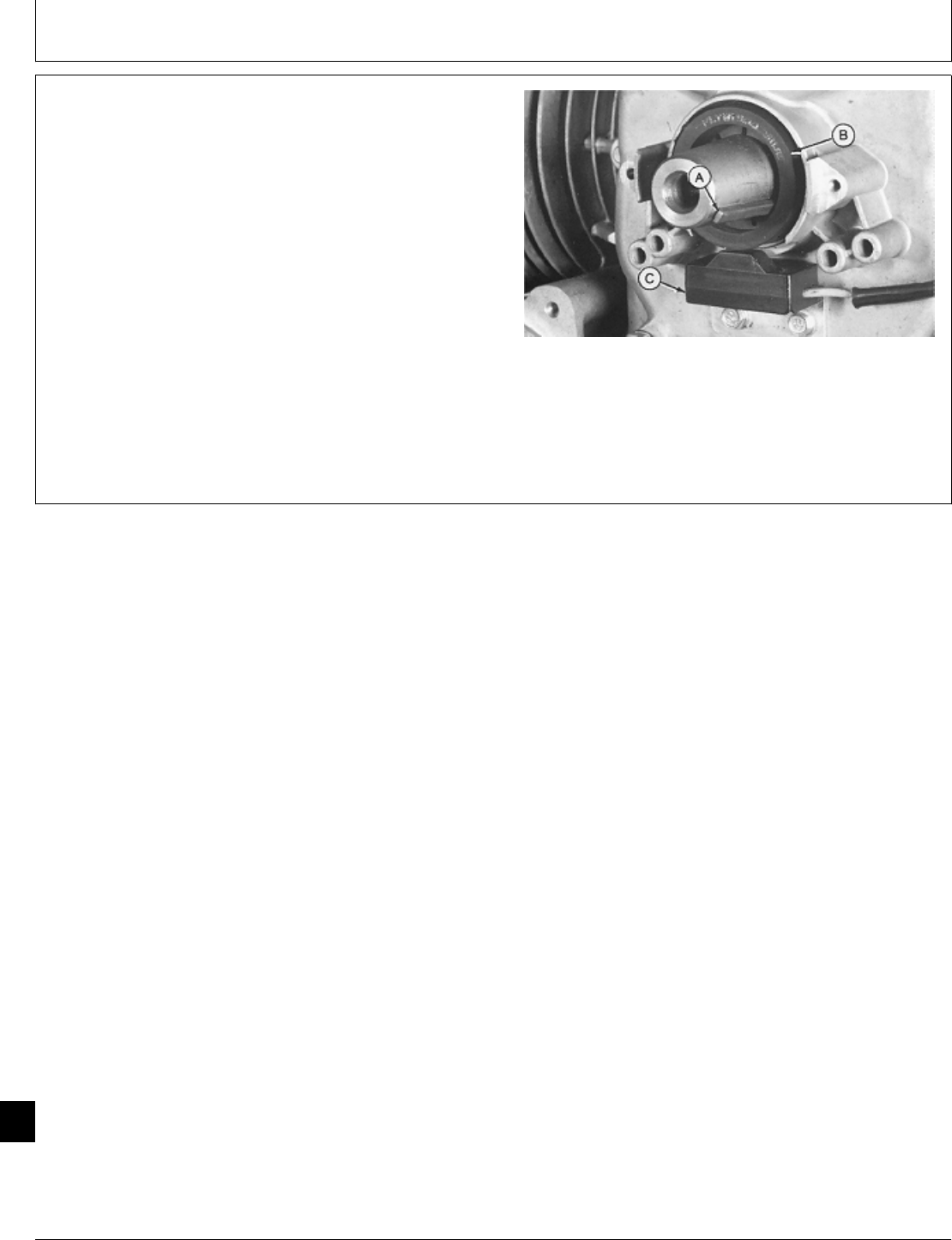
4. Remove key (A) and magnetic ring (B).
5. Remove two cap screws to remove ignition coil (C).
6. Install coil (C), magnetic ring (B)—marked
“FLYWHEEL SIDE”, and key (A).
7. Install starter and cap screws.
8. Install flywheel. (See Group 20 in this manual.)
9. Install air cleaner. (See Group 05 in this manual.)
M46017 -UN-08JAN90
M98,2065K,8 -19-02FEB87
Ignition System/Ignition Coil
CTM2 (19APR90) 65-4 16, 18, 20 & 24HP Onan Engines
130495
65
4

Page
Group 00— . . . . . . . . . . . . . . . . . . . . . . . . . .
Introduction . . . . . . . . . . . . . . . . . . . . . . . . 00-1
About This Manual . . . . . . . . . . . . . . . . . . . 00-2
Engine Serial Number Plate . . . . . . . . . . . . . 00-3
Engine Specifications . . . . . . . . . . . . . . . . . 00-3
Engine Application Chart . . . . . . . . . . . . . . . 00-4
Hardware Torque Specifications . . . . . . . . . . 00-4
Group 05—Air Cleaner and Breather
Specifications . . . . . . . . . . . . . . . . . . . . . . 05-1
Air Cleaner
Remove . . . . . . . . . . . . . . . . . . . . . . . . 05-1
Install . . . . . . . . . . . . . . . . . . . . . . . . . . 05-3
Breather, Repair
T260 Engine . . . . . . . . . . . . . . . . . . . . . 05-4
B43E, B43G, or B48G, Engines . . . . . . . . . 05-5
Group 10—Intake Manifold and Cylinder Heads
Service Equipment and Tools . . . . . . . . . . . . 10-1
Service Parts Kits . . . . . . . . . . . . . . . . . . . 10-1
Specifications . . . . . . . . . . . . . . . . . . . . . . 10-2
Intake Manifold
Remove . . . . . . . . . . . . . . . . . . . . . . . . 10-2
Install . . . . . . . . . . . . . . . . . . . . . . . . . . 10-4
Cylinder Head
Remove . . . . . . . . . . . . . . . . . . . . . . . . 10-8
Install . . . . . . . . . . . . . . . . . . . . . . . . . 10-11
Group 15—Intake and Exhaust Valves
Essential Tools . . . . . . . . . . . . . . . . . . . . . 15-1
Service Equipment and Tools . . . . . . . . . . . . 15-1
Service Parts Kits . . . . . . . . . . . . . . . . . . . 15-2
Specifications . . . . . . . . . . . . . . . . . . . . . . 15-3
Intake and Exhaust Valves
Remove . . . . . . . . . . . . . . . . . . . . . . . . 15-5
Install . . . . . . . . . . . . . . . . . . . . . . . . . 15-12
Measure and Adjust Valve Clearance . . . . 15-15
Group 20—Flywheel
Service Equipment and Tools . . . . . . . . . . . . 20-1
Other Material . . . . . . . . . . . . . . . . . . . . . . 20-1
Page
Specifications . . . . . . . . . . . . . . . . . . . . . . 20-1
Flywheel
Remove . . . . . . . . . . . . . . . . . . . . . . . . 20-2
Install . . . . . . . . . . . . . . . . . . . . . . . . . . 20-4
Group 25—Camshaft
Essential Tools . . . . . . . . . . . . . . . . . . . . . 25-1
Service Equipment and Tools . . . . . . . . . . . . 25-1
Other Material . . . . . . . . . . . . . . . . . . . . . . 25-1
Service Parts Kits . . . . . . . . . . . . . . . . . . . 25-2
Specifications . . . . . . . . . . . . . . . . . . . . . . 25-3
Camshaft
Remove . . . . . . . . . . . . . . . . . . . . . . . . 25-4
Disassemble and Inspect . . . . . . . . . . . . . 25-7
Assemble . . . . . . . . . . . . . . . . . . . . . . 25-11
Install . . . . . . . . . . . . . . . . . . . . . . . . . 25-13
Group 30—Connecting Rods and Pistons
Service Equipment and Tools . . . . . . . . . . . . 30-1
Other Material . . . . . . . . . . . . . . . . . . . . . . 30-1
Service Parts Kits . . . . . . . . . . . . . . . . . . . 30-1
Specifications . . . . . . . . . . . . . . . . . . . . . . 30-2
Connecting Rod
Measure End Play . . . . . . . . . . . . . . . . . . 30-4
Measure Bearing Clearance . . . . . . . . . . . 30-7
Pistons and Connecting Rods
Remove . . . . . . . . . . . . . . . . . . . . . . . . 30-9
Inspect . . . . . . . . . . . . . . . . . . . . . . . . 30-13
Deglaze Cylinder Bores . . . . . . . . . . . . . 30-21
Assemble . . . . . . . . . . . . . . . . . . . . . . 30-21
Install . . . . . . . . . . . . . . . . . . . . . . . . . 30-23
Group 35—Crankshaft and Main Bearings
Essential Tools . . . . . . . . . . . . . . . . . . . . . 35-1
Service Equipment and Tools . . . . . . . . . . . . 35-1
Other Material . . . . . . . . . . . . . . . . . . . . . . 35-1
Service Parts Kits . . . . . . . . . . . . . . . . . . . 35-2
Specifications . . . . . . . . . . . . . . . . . . . . . . 35-2
Continued on next page
COPYRIGHT© 1989
DEERE & COMPANY
Moline, Illinois
All rights reserved
A John Deere ILLUSTRUCTION™ Manual
All information, illustrations and specifications in this manual are based on
the latest information available at the time of publication. The right is
reserved to make changes at any time without notice.
CTM2-19-19APR90
Contents
CTM2 (19APR90) i16, 18, 20 & 24HP Onan Engines
130495
00
05
10
15
20
25
30
35
40
45
50
55
60
65

Page
Crankshaft and Main Bearings
Remove . . . . . . . . . . . . . . . . . . . . . . . . 35-3
Inspect . . . . . . . . . . . . . . . . . . . . . . . . . 35-6
Install . . . . . . . . . . . . . . . . . . . . . . . . . . 35-9
Group 40—Lubrication System
Essential Tools . . . . . . . . . . . . . . . . . . . . . 40-1
Service Equipment and Tools . . . . . . . . . . . . 40-1
Other Material . . . . . . . . . . . . . . . . . . . . . . 40-1
Service Parts Kits . . . . . . . . . . . . . . . . . . . 40-2
Specifications . . . . . . . . . . . . . . . . . . . . . . 40-3
Oil Pump
Remove . . . . . . . . . . . . . . . . . . . . . . . . 40-4
Disassemble and Inspect . . . . . . . . . . . . . 40-6
Assemble . . . . . . . . . . . . . . . . . . . . . . . 40-7
Install . . . . . . . . . . . . . . . . . . . . . . . . . . 40-7
Oil Pressure Regulating Valve
Remove . . . . . . . . . . . . . . . . . . . . . . . 40-10
Install . . . . . . . . . . . . . . . . . . . . . . . . . 40-12
Oil Base
Remove and Inspect . . . . . . . . . . . . . . . 40-14
Install . . . . . . . . . . . . . . . . . . . . . . . . . 40-16
Oil Filter Adapter
Remove . . . . . . . . . . . . . . . . . . . . . . . 40-21
Install . . . . . . . . . . . . . . . . . . . . . . . . . 40-22
Oil Line Adapter
Remove . . . . . . . . . . . . . . . . . . . . . . . 40-24
Install . . . . . . . . . . . . . . . . . . . . . . . . . 40-25
Group 45—Governor
Service Equipment and Tools . . . . . . . . . . . . 45-1
Other Material . . . . . . . . . . . . . . . . . . . . . . 45-1
Service Parts Kits . . . . . . . . . . . . . . . . . . . 45-1
Specifications . . . . . . . . . . . . . . . . . . . . . . 45-1
Governor Assembly and Linkage
Remove . . . . . . . . . . . . . . . . . . . . . . . . 45-2
Governor Assembly
Disassemble and Inspect . . . . . . . . . . . . . 45-2
Governor Linkage
Disassemble and Inspect . . . . . . . . . . . . . 45-4
Assemble . . . . . . . . . . . . . . . . . . . . . . . 45-6
Governor Assembly
Assemble . . . . . . . . . . . . . . . . . . . . . . . 45-8
Governor Assembly and Linkage
Install . . . . . . . . . . . . . . . . . . . . . . . . . . 45-9
Group 50—Carburetor
Service Equipment and Tools . . . . . . . . . . . . 50-1
Service Parts Kits . . . . . . . . . . . . . . . . . . . 50-1
Specifications . . . . . . . . . . . . . . . . . . . . . . 50-1
Page
Carburetor
Remove . . . . . . . . . . . . . . . . . . . . . . . . 50-2
Disassemble . . . . . . . . . . . . . . . . . . . . . 50-4
Clean . . . . . . . . . . . . . . . . . . . . . . . . . 50-10
Assemble . . . . . . . . . . . . . . . . . . . . . . 50-10
Install . . . . . . . . . . . . . . . . . . . . . . . . . 50-17
Group 55—Stator and Rectifier—Regulator
Specifications . . . . . . . . . . . . . . . . . . . . . . 55-1
Stator
Remove . . . . . . . . . . . . . . . . . . . . . . . . 55-1
Install . . . . . . . . . . . . . . . . . . . . . . . . . . 55-3
Rectifier-Regulator
Replace . . . . . . . . . . . . . . . . . . . . . . . . . . 55-6
Group 60—Starter
Service Equipment and Tools . . . . . . . . . . . . 60-1
Specifications . . . . . . . . . . . . . . . . . . . . . . 60-2
Service Parts Kits . . . . . . . . . . . . . . . . . . . 60-3
Starter
Remove . . . . . . . . . . . . . . . . . . . . . . . . 60-3
Repair Bendix Drive Starter . . . . . . . . . . . 60-6
Repair Solenoid Drive Starter . . . . . . . . . 60-15
Install . . . . . . . . . . . . . . . . . . . . . . . . . 60-28
Group 65—Ignition System
Breaker Points and Condenser
Replace . . . . . . . . . . . . . . . . . . . . . . . . . 65-1
Ignition Coil
Replace . . . . . . . . . . . . . . . . . . . . . . . . . 65-2
Contents
CTM2 (19APR90) ii 16, 18, 20 & 24HP Onan Engines
130495
00
05
10
15
20
25
30
35
40
45
50
55
60
65
