Cabling Standard ANSI TIA EIA 568 B Commercial Building Telecommunication Standards Telecommunications
User Manual: 568
Open the PDF directly: View PDF ![]() .
.
Page Count: 62
A
AN
NS
SI
I/
/T
TI
IA
A/
/E
EI
IA
A
5
56
68
8-
-B
B
C
Co
om
mm
me
er
rc
ci
ia
al
l
B
Bu
ui
il
ld
di
in
ng
g
T
Te
el
le
ec
co
om
mm
mu
un
ni
ic
ca
at
ti
io
on
ns
s
C
Ca
ab
bl
li
in
ng
g
S
St
ta
an
nd
da
ar
rd
d
Disclaimer
This information is collected and composed by QUANG DUNG TECHNOLOGY from Cablingdb.com. All
information is copyrighted by Cablingdb.com.
Standards Preservation
This section is not part of the original standards documentation. The purpose of this document is to provide
an easy to understand, condensed version of the original document. A basic level of telecommunications is
assumed. For further information on terms and definitions see our Glossary of Terms section. Whether you
are renovating your existing cable plant or installing a new one, Cablingdb.com urges you to investigate a
standards based solution. This document is not meant to replace the original standards developed by the
various standards bodies and we urge you to purchase the original documents through www.tiaonline.com.
AUTHORIZED & EXCLUSIVE DISTRIBUTOR
Head Office
Suite 202, The Colonnade Building, 27 Nguyen Trung Truc St.,
District 1, Hochiminh City, Vietnam
Tel: 84.8 823-1693 Fax: 84.8 823-1665
Hanoi Office
A11, 3/Fl., Horizon Hotel, 40 Cat Linh St.,
Dong Da District, Hanoi, Vietnam
Tel: 84.4 736-7055 Fax: 84.4 733-2470
Website: www.qd-tek.com.vn Email: info@qd-tek.com

ANSI/TIA/EIA 568-B Commercial Building Telecommunications Cabling Standard
Quang Dung Technology Distribution Company Page 2 of 62
Table of Contents
ANSI/TIA/EIA-568-B.1 COMMERCIAL BUILDING
TELECOMMUNICATIONS CABLING STANDARD
General Requirements
ANSI/TIA/EIA-568-B.2 100 OHM TWISTED PAIR CABLING
STANDARDS
Backbone
Connecting Hardware
Cords and Jumpers
Horizontal
Stranded
ANSI/TIA/EIA-568-B.3 OPTICAL FIBER STANDARDS
Optical Fiber Cabling Components
Addendums
ANSI/TIA/EIA-568-B.1-1 Patch Cord Bend Radius
ANSI/TIA/EIA-568-B.1-2 Grounding & Bonding
ANSI/TIA/EIA-568-B.1-3 Supportable Distances for Optical Fiber
ANSI/TIA/EIA-568-B.1-4 Recognition of Category 6 & 850 Laser
Optimized 50/125µm Multimode Optical Fiber
Cabling
ANSI/TIA/EIA-568-B.2-1 Category 6
ANSI/TIA/EIA-568-B.2-2 Revisions to TIA/EIA-568-B.2
ANSI/TIA/EIA-568-B.2-3 Additional Considerations for Insertion Loss
and Return Loss Pass/Fail Determination
ANSI/TIA/EIA-568-B.2-4 Solderless Connection
Reliability Requirements for Copper Connecting
Hardware
ANSI/TIA/EIA-568-B.2-5 Corrections to TIA/EIA-568-B.2-5
ANSI/TIA/EIA-568-B.3-1 Additional Specifications for 50/125µm Fiber
Optic Cables
Transmission Parameter Charts
Category 3 Cabling, Connecting Hardware, Permanent Link and
Channel
Category 5e Cabling and Connecting Hardware
Category 5e Cords
Category 5e Permanent Link and Channel
Category 6 Cable
Category 6 Connecting Hardware
Category 6 Delay Skew
Category 6 Patch Cord
Category 6 Permanent Link
Category 6 Channel

ANSI/TIA/EIA 568-B Commercial Building Telecommunications Cabling Standard
Quang Dung Technology Distribution Company Page 3 of 62
ANSI/TIA/EIA-568-B.1
Commercial Building Telecommunications
Cabling Standard
General Requirements
HORIZONTAL CABLING
The definition of horizontal cabling is that portion of the cabling system that extends
from the work area outlet, through the cabling in the wall/ceiling/floor and then to the
patch panel in the telecommunications room. The system also includes the patch
cords at the work area outlet, and patch cords in the telecommunications room. When
provisioning for the horizontal cabling system the designer should also consider voice,
fire/safety, video, HVAC and EMS.
A good design should be aimed at minimizing relocations and maintenance of the
horizontal system as it is much more costly to do it later.
Topology
Horizontal cabling will be installed in a star topology, with each work area outlet being
connected via the horizontal cable to the horizontal cross connect in the
telecommunications room. Each floor should have its own telecommunications closet,
sized as per ANSI/TIA/EIA 569.
Any devices required such as baluns and impedance matching devices should not be
installed in the horizontal system, but rather, kept external to the telecommunications
outlet. This will facilitate network changes.
Only one transition point or consolidation point between the horizontal cross connect
and the telecommunications outlet shall be allowed, and bridged taps and splices are
not allowed in the copper horizontal.
Cable Length
The maximum distance between the telecommunications outlet and the horizontal
cross connect shall be no more than 90 meters. The maximum length of all patch
cords and jumpers in the telecommunications closet shall be no more than 5 meters,
and the total length of all patch cords both in the telecommunications closet and at
the work area shall be no more than 5 meters.
Recognized Cables
a. 4-pair 100 ohm unshielded twisted pair (UTP) or screened twisted pair (ScTP).
b. two or more multimode optical cables, either 62.5/125 or 50/125
150 ohm shielded twisted pair (STP-A) is a recognized cable type but is not
recommended for new cabling installations.
All jumpers, patch cords, equipment cords shall meet all applicable standards as
specified in ANSI/TIA/EIA 568-B.2 and B.3.
When hybrid and bundled cables are used, each cable type will meet the requirements
for that cable type, and the bundled or hybrid cable will meet the specifications for
bundled cables. Both of the above requirements are located in ANSI/TIA/EIA 568-B.2
and B.3.
Telecommunications Outlets

ANSI/TIA/EIA 568-B Commercial Building Telecommunications Cabling Standard
Quang Dung Technology Distribution Company Page 4 of 62
Each individual work area shall be serviced with a minimum of two
telecommunications outlets. One will be associated with voice and the other data. One
outlet will be a 4 pair 100 ohm UTP cable rated category 3 or higher. Category 5e is
recommended. The other outlet will be either a 4 pair 100 ohm UTP category 5e, or 2
multimode fibers, either 50/125 or 62.5/125 micron fibers. All connectors must meet
all ANSI/TIA/EIA 568-B.2 and B.3 requirements.
Grounding
The system must be bonded and grounded as per ANSI/TIA/EIA 606.
Backbone Cabling
General
Backbone cabling provides interconnections between telecommunications rooms,
equipment rooms, and entrance facilities. It consists of the cabling, copper and/or
fiber, the terminations, patch cords, jumper cords, intermediate and main cross
connects.
Backbone cabling is expected to serve the needs of the user for 3-10 years based on
current and future needs.
Topology
The backbone cabling will be laid out in a hierarchical star so that each horizontal
cross connect is connected to the main cross connect or to an intermediate cross
connect and then to a main cross connect. There can be no more than two
hierarchical levels of cross connects in the backbone. No more than one cross connect
shall be passed through between the horizontal cross connect and the main cross
connect. This means that between any two horizontal cross connects, the signal must
pass through 3 or fewer cross connect facilities.
Recognized Cables
The following cables are recognized in the backbone and may be used on their own,
or in combination.
a. 100 ohm twisted pair cable
b. either 50/125 micron or 62.5/125 micron multimode fiber.
c. Singlemode fiber.
All patch cords, jumpers, connecting hardware must meet ANSI/TIA/EIA-568-B.2 and
B.3.
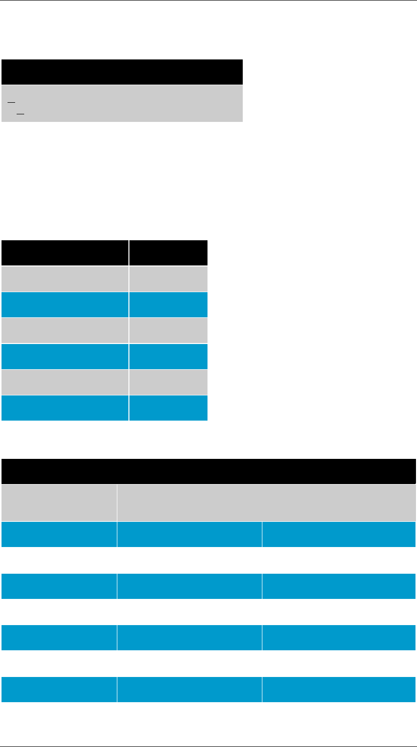
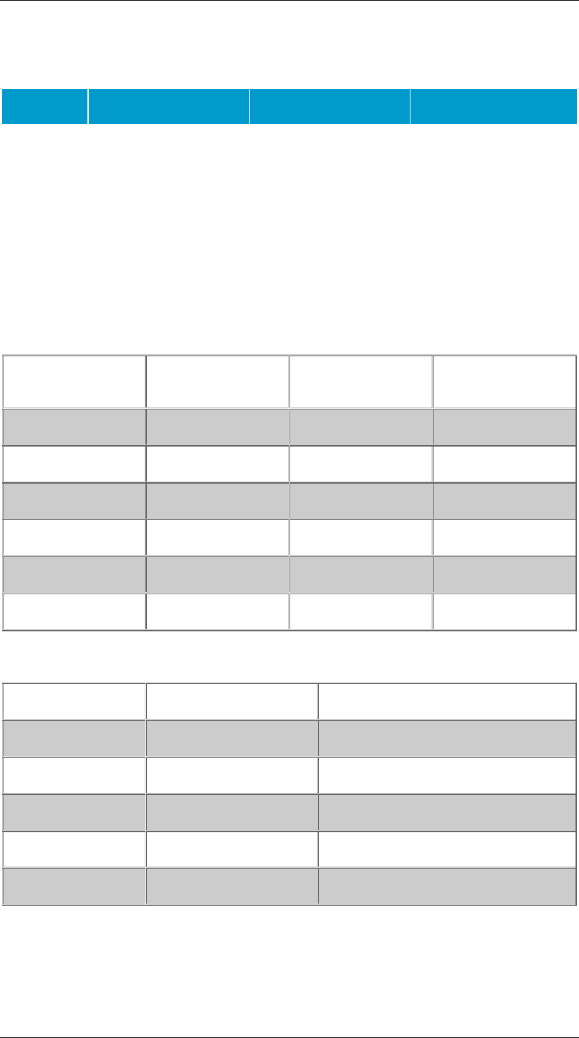
Backbone Cabling Distances
The distances in the table below are inclusive of cable, patch cords, jumpers and
equipment cable.
Maximum Backbone Distance
Media Type Main to Horizontal
Cross Connect Main to Intermediate
Cross Connect Intermediate to
Horizontal Cross
Connect
Copper
(Voice) 800 m (2,624 ft) 500 m (1640 ft) 300 m (984 ft)
Multimode
Fiber 2000 m (6560 ft) 1700 m (5575 ft) 300 m (984 ft)
ANSI/TIA/EIA 568-B Commercial Building Telecommunications Cabling Standard
Quang Dung Technology Distribution Company Page 5 of 62
Singlemode
Fiber 3000 m (9840 ft) 2700 m (8855 ft) 300 m (984 ft)
Jumper and Patch Panel Lengths
Main cross connect jumper and patch cords should not exceed 20 meters.
Intermediate cross connect jumper and patch cords should not exceed 20 meters.
Equipment jumpers should not exceed 30 meters.
Grounding and Bonding
Grounding and bonding practices as per ANSI/TIA/EIA 607 should be followed.
Work Area
General
The work area components are those that extend from the work area outlet to the
telecommunications device(s).
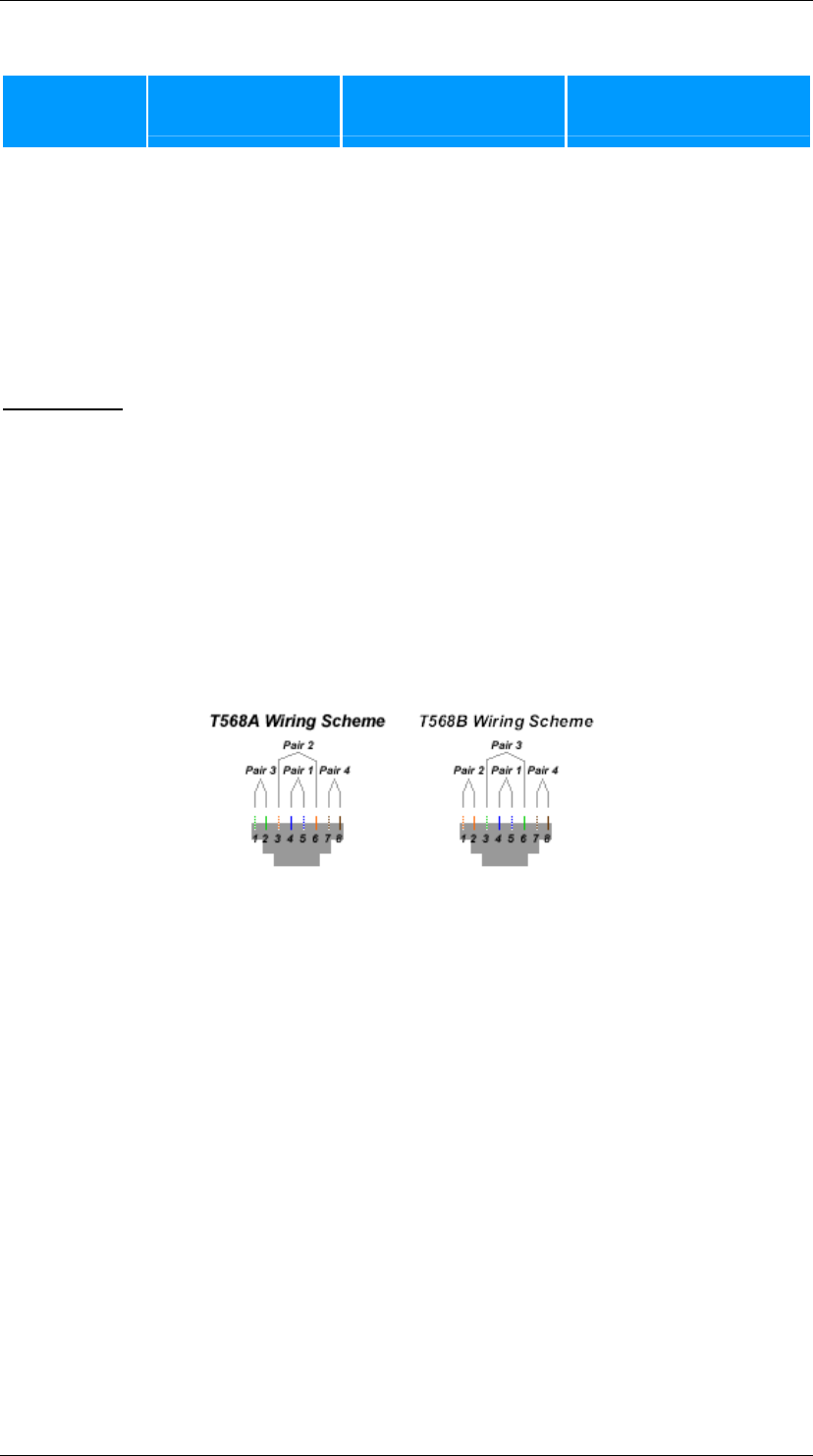
100-Ohm Balanced Twisted-Pair Telecommunications Outlet/Connector
Each 4 pair cable shall be terminated on an 8 position modular jack, and all UTP and
ScTP telecommunications outlets shall meet the requirements of IEC 60603-7, as well
as ANSI/TIA/EIA 568-B.2 and the terminal marking and mounting requirements of
ANSI/TIA/EIA-570-A.
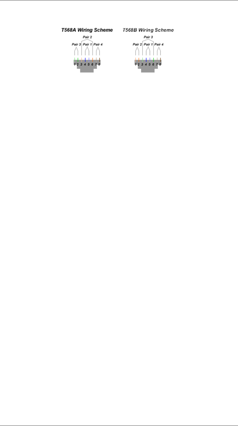
There are two recognized pin out assignments, T568A and T568B.
Optical Fiber Telecommunications Outlet
Horizontal fiber shall be terminated in a duplex outlet meeting ANSI/TIA/EIA 568-B.3.
The 568SC was specified in ANSI/TIA/EIA 568A-A and is still recommended. As well
other connectors such as some small form factor connectors may be used.
Work Area Cords
The maximum length of a work area patch cord is 5 meters. Generally, the patch cord
will have similar connectors on each end. If additional devices are required, such as
adapters, they will not be part of the horizontal cabling system, but rather be
connected via the patch cord.
Open Office Cabling
The open office cabling recognizes that some offices are faced with regular
reconfigurations and require a more flexible cabling system to facilitate these
changes.
Multi-user Telecommunications Outlet-MUTOA
The MUTOA is used where there are frequent changes in office layout. The MUTOA
allows the horizontal cable to remain undisturbed while allowing office

ANSI/TIA/EIA 568-B Commercial Building Telecommunications Cabling Standard
Quang Dung Technology Distribution Company Page 6 of 62
rearrangements. The work area cables originating from the MUTOA are connected
directly to the station equipment without the use of any additional connections.
The MUTOA:
1. Should be located in an area so that each furniture cluster is served by at least 1
MUTOA.
2. Should serve a maximum of 12 work areas.
3. Will have a maximum work area cable length.
4. Shall be attached to a permanent part of the building
5. Shall not be located in the ceiling or furniture, unless that part of the furniture is
permanently affixed to the building.
Administration
The MUTOA is are administered as in ANSI/TIA/EIA-606. The work area cables
connecting a MUTOA to a device are to be assigned a unique identifier and the cable
shall be labelled at both ends. The outlet end shall identify the work area it serves
and the work area end shall identify which MUTOA it is connected to, and what port
on the MUTOA.
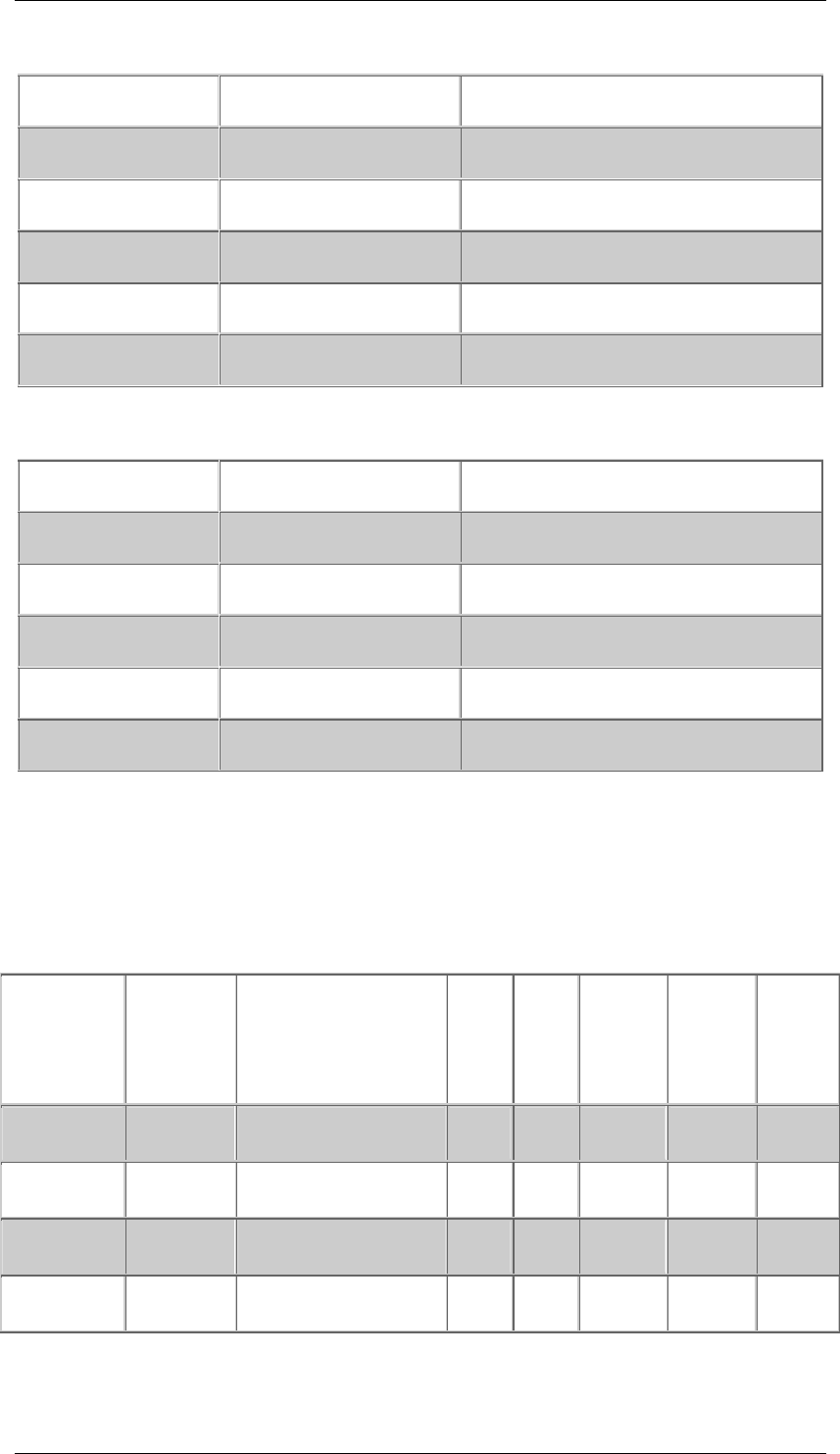
When a MUTOA is used the horizontal cable maximum length will be affected, based
on the length of the work area cord. The maximum length of the work area cord is 22
meters. For purposes of calculating the horizontal cable and the work area cord, the
formula is:
C = (102 - H)/(1 = D)
Where:
C = maximum combined length of the work area cable, equipment cable and patch
cord
H = the length of the horizontal cable (H + C < 100)
D = the derating factor for the patch cord type. (.2 for 24AWG UTP and ScTP, and .5
for 26 AWG ScTP)
There is a second formula for calculations which is not shown here.
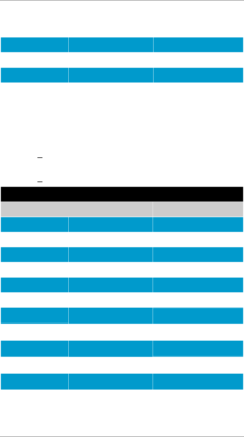
Maximum Work Area Cable Length
Length of Horizontal
Cable Maximum Length of
Work Area Cable Maximum Combined Length
of All Patch and Equipment
Cords
Meters (Ft) Meters (Ft) Meters (Ft)
90 (295) 5 (16) 10 (33)
85 (279) 9 (30) 14 (46)
80 (262) 13 (44) 18 (59)
75 (246) 17 (57) 22 (72)
70 (230) 22 (72) 27 (89)
For fiber optic cables, a reduction of the total 100 meters is not required.
Consolidation Point

ANSI/TIA/EIA 568-B Commercial Building Telecommunications Cabling Standard
Quang Dung Technology Distribution Company Page 7 of 62
A consolidation point is an interconnection point within the horizontal cabling using
compliant connecting hardware. It requires an additional connection point
(telecommunications outlet). Cross connects cannot be used at a CP and no more
than 1 CP is permitted in a horizontal run, nor can a CP and transition point be used
in the same horizontal run. The CP should be located a minimum of 15 meters from
the telecommunications room to reduce the effects of NEXT and return loss.
The CP should be located in a fully accessible and permanent location.
Administration of the CP should follow ANSI/TIA/EIA 606.
Telecommunications Rooms
General
Consult ANSI/TIA/EIA 569 for design and provisioning requirements for
telecommunication rooms.
The telecommunications room may contain horizontal cable, backbone cable and their
connecting hardware, intermediate cross connect or main cross connect for portions
of the backbone system. The TR also provides environmental control for the
telecommunications equipment and splice closures as they relate to the building.
Cross Connection and Interconnection
All connections between horizontal cabling and backbone cables shall be cross
connects. All connecting hardware and cables shall meet the requirements of
ANSI/TIA/EIA 568-B.2 and B.3.
An interconnection will connect the connecting hardware of the horizontal cable (patch
panel) to the telecommunications equipment (eg: hub).
A cross connect will have the connecting hardware of the horizontal system (eg: patch
panel) connected to connecting hardware (patch panel), which is in turn connected to
the common equipment.
Equipment Rooms
Equipment rooms differ from telecommunications rooms in that the ERs generally
contain more complex equipment, but an ER may also be a telecommunications room.
Equipment rooms must conform to ANSI/TIA/EIA 569 requirements.
An equipment room may also contain main cross connects, the intermediate cross
connect used in the backbone hierarchy.
The ER may also act as a telecommunications room and house the horizontal
terminations, telephone provider terminations, premise network terminations and
other miscellaneous terminations.
Entrance Facilities (EF)
General
The entrance facilities serve as the entrance point for the outside plant cable from a
variety of sources such as the telephone company, private network cables and other
access providers. It also houses network protection devices, and may act as the
demarcation point for the regulated access provider.
The EF must conform to ANSI/TIA/EIA-569 requirements.
ANSI/TIA/EIA 568-B Commercial Building Telecommunications Cabling Standard
Quang Dung Technology Distribution Company Page 8 of 62
Functions
Network Demarcation
The EF may be the demarcation (termination point) for the regulated access
provider(s) and private network providers(s). Local regulations will determine where
the demarcation point will be.
Electrical Protection
Interbuilding cables and antennas may require devices to protect from power surges.
The designer/installer should consult the local access provider to determine local
practices and requirements.
Grounding and bonding should be completed as per ANSI/TIA/EIA 607.
Connections
The EF contains the connections and transition points between the cables designated
for outdoor use and cables designated for indoor use.
Cabling Installation Requirements
Cable Placement
Cable should be placed in such a manner as to minimize stress caused by suspending
the cable and cinching the cable too tight. If cable ties are used, they should be
cinched loosely to prevent deforming the cable sheath.
Balanced 100-Ohm Twisted Pair Cabling (UTP and ScTP)
Minimum Bend Radius
Cable Type Bend Radius
4 Pair UTP 4 X cable diameter
4 Pair ScTP 8 X cable diameter
Backbone 10 X cable diameter
Patch Cords Under Review
Maximum Pulling Tension
For 4 pair UTP it is 110 N (25 lbf). For multipair, consult the manufacturers
specifications.
Connecting Hardware Termination
Cables should be terminated with connectors of the same category. Connecting cable
and components of the same category is not enough to ensure performance. Other
factors such a proximity to power cords, termination practices and cable management
are jus some of the factors that may affect performance.
In a system with multiple category components, the system shall be rated as that of
the lowest performing component.
Only strip back as much jacket as required to properly terminate the cable on the
connector. With Category 5e and higher systems the individual pairs should not be

ANSI/TIA/EIA 568-B Commercial Building Telecommunications Cabling Standard
Quang Dung Technology Distribution Company Page 9 of 62
untwisted more that ½". Category 3 systems the pair twists shall be maintained to
within 3" of the terminations.
Patch Cords
Patch cords should be of the same category as the link, and should not be field
terminated. Jumper cords should not be made by removing a jacket from a previously
jacketed cable.
100-Ohm ScTP Grounding
The drain wire on ScTP cable shall be bonded as per ANSI/TIA/EIA 607.
Optical Fiber Cable
Minimum Bend Radius and Maximum Pulling Tension
No Load Condition* Maximum Load*
Intrabuilding 2 or 4 Fiber 25mm 50mm
Intrabuilding Backbone 10 X OD 15 X OD
Interbuilding Backbone 10 X OD 20 X OD
Note: The maximums are noted here in the abscence of any manufacturers
specifications.
Connecting Hardware and Polarity
Optical fiber shall be installed with odd numbered fibers having Position A at one end
and Position B at the other. Even numbered fibers will have position A and B reversed
from the odd numbered fibers. When using the 568SC connector or other duplex
connectors, the above polarity must be maintained.
Patch Cords
Patch cords shall consist of 2 fiber cables of the same fiber type as the system with
connectors at both ends, and shall be positioned A and B as in the connecting
hardware section above, with patch cord A connected to position B on the connecting
hardware, and vice versa for the B position on the patch cord.
Cabling Transmission Performance and Test Requirements
100 Ohm Twisted Pair
General
System performance is directly related to not only the performance of the individual
components, but also the cable installation practices and the number of connectors in
the system.
TSB 67 is now found in annex D of the original documentation.
Channel and Permanent Link Definitions
The Channel is defined as the 90 meters of horizontal cable, the telecommunications
connector and patch cord in the work area as well as 2 connectors and a maximum of
2 patch/equipment cords in the telecommunications room. The maximum allowable
length of patch cords and equipment cords is 10 meters. Also included in the channel
is an optional transition or consolidation point.

ANSI/TIA/EIA 568-B Commercial Building Telecommunications Cabling Standard
Quang Dung Technology Distribution Company Page 10 of 62
The Permanent Link is defined as a maximum of 90 meters of horizontal cable, an
optional transition or consolidation point and one connection on each end. The
Permanent Link does not include the instrument cords or connectors on the field test
equipment.
Test Parameters
The primary tests are:
Wire Map
Length
Insertion Loss
Near End Cross Talk (NEXT)
Power Sum Near End Cross Talk (PSNEXT)
Equal Level Far End Cross Talk (ELFEXT)
Power Sum Equal Level Far End Crosstalk (PSELFEXT)
Return Loss
Propagation Delay
Delay Skew
Wire Map
Checks for proper pin to pin termination, and for each of the 8 conductors the wire
map checks for:
Continuity to the far end
Shorts between any two or more conductors
Reversed Pairs
Split Pairs
Transposed Pairs
Any other miswiring
Length
The physical length of the cable is the actual length derived by measurement of the
cable(s) between the two end points. The electrical length is the length derived from
the propagation delay of the signal and depends on the construction of the cable.
The maximum physical length of the horizontal cable (permanent link) one end of the
cable to the other is 90 meters. The maximum length of the channel model is 100
meters.
Insertion Loss
Insertion loss is the loss derived from inserting a device into a transmission line. The
insertion loss for both the permanent link and the channel models are the total
insertion losses of all the components.
Pair to Pair NEXT Loss
Pair to pair NEXT loss is the measurement of signal coupling from one pair to another.
The result is based on the worst pair to pair measurement.
Power Sum NEXT (PSNEXT) Loss
Power sum NEXT takes into account the statistical crosstalk between all pairs while
energized. This is a calculated amount derived by adding up the crosstalk results
between all pair combinations.
Pair to Pair FEXT and ELFEXT Loss
FEXT is the unwanted coupling of a signal induced by a transmitter at the near end,
measured on the disturbed pair at the far end. ELFEXT is the same measurement of
FEXT, less the effect of attenuation.

ANSI/TIA/EIA 568-B Commercial Building Telecommunications Cabling Standard
Quang Dung Technology Distribution Company Page 11 of 62
Power Sum FEXT and Power Sum ELFEXT
As in Power Sum NEXT, these are computed values based on the sum of all the
possible pair combinations under the respective tests.
Return Loss
Return loss is the value of energy reflected by impedance variations when devices are
inserted into the cabling system.
Propagation Delay
Is the time it takes the signal to travel from one end of the cable/system to the other.
The maximum channel propagation delay is 555ns (nanoseconds) and for the link it is
498 ns, both measured at 10Mhz.
Delay Skew
Delay skew is the signalling delay difference in time (nanoseconds) between the
fastest pair and the slowest pair. The maximum channel delay skew is 50 ns, and in
the permanent link it is 44 ns.
Optical Fiber Transmission Performance and Test Measurements
Link Segment
An optical fiber link includes the connectors, splices (if required) and the passive
cabling between two optical fiber connecting hardware termination points. There are 3
backbone link segments:
MC to IC
MC to HC
IC to HC
Link Segment Performance and Measurement
The most important field test in fiber optic systems is link attenuation. The horizontal
link segments should be tested in one direction at either 850 nm (nanometers) or
1300 nm. The result shall be less than 2.0 dB. In an open office with a consolidation
point, the resulting test shall be less than 2.75 dB, or if using a MUTOA, the result
shall be less than 2.0 dB.
Backbone Link Measurement
The backbone shall be tested in at least one direction at both 850 and 1300
(multimode). For singlemode, the links should be tested at 1310 nm and 1550 nm.
Because of the possibility of splice points etc, the link attenuation equation should be
used to compute the loss value.
The equation is:
Link Attenuation = Cable Attenuation + Connector Insertion Loss + Splice Insertion
Loss
Note: All calculations, equations, and reference test parameters can be found
in the original documentation, available through TIA.
ANSI/TIA/EIA 568-B Commercial Building Telecommunications Cabling Standard
Quang Dung Technology Distribution Company Page 12 of 62
ANSI/TIA/EIA 568-B.2
Commercial Building Telecommunications
Cabling Standard
Part 2 – Balanced Twisted Pair Cabling
Components
BACKBONE CABLE
Multipair cables are defined as cables having more than 4 pairs of 22 AWG to 24 AWG
solid conductors with a thermoplastic insulating cover. The conductors are assembled
into binder groups of 25 pairs that adhere to the standard industry color code
(ANSI/ICEA S-80-576). The individual pairs will be twisted in a manner that will
ensure the performance characteristics meet the transmission requirement of this
Standard. The entire assembly shall be covered by a continuous thermoplastic jacket.
Core Assembly
For cables of more than 25 pairs, the cable will be assembled in groups of 25 pairs,
and each group will be identified by a colored binder as per ANSI/ICEA S-80 576.
Core Wrap
Where applicable, the core may be covered with one or more layers of dielectric.
Core Shield
When a core shield is present, the DC resistance of the core shield shall not exceed a
specific value, calculated by an equation available in the original standards documents
under Section 4.4.5.
Transmission
All measurements are in accordance with ASTM D 4566, corrected to, or tested at
20°C.
DC Resistance < 9.38 ohms/100 mtrs
DC Resistance Unbalance < 5%
Mutual Capacitance < 6.6 nF/100 mtrs (Cat 3)
< 5.6 nF/100 mtrs (Cat 5e)
Capacitance Unbalance < 330 pF/100 mtrs
Characteristic Impedance and Structural Return Loss
Category 3 horizontal cables shall have a Characteristic Impedance of 100 ohms ±
15%. Structural return loss (SRL)is dependent on input impedance, frequency and
cable construction. For category 3 cables the SRL for the worst pair is calculated:
ANSI/TIA/EIA 568-B Commercial Building Telecommunications Cabling Standard
Quang Dung Technology Distribution Company Page 13 of 62
Frequency (MHz) Category 3 (dB)
1< ƒ < 10
10 < ƒ < 16 12
12-10log(ƒ/10)
Return Loss and Insertion Loss
Return Loss and Insertion Loss for backbone cables shall meet the same requirements
as for that of horizontal cable.
NEXT Loss
Next loss in mulitpair cables asses the impact of NEXT on not only adjacent pairs, but
also adjacent groups. In a 25 pair cable the groups are made up as follows:
Group Pairs
1 1-4
2 5-8
3 9-12
4 13-16
5 17-20
6 21-24
The 25th pair in any binder group will meet all the transmission parameters when
used in a 4 pair group.
Category 5e Backbone NEXT Loss @ 20°C ± 3° C (100 mtrs)
Frequency Cat 5e (within 4-pair
group) dB Cat 5e(25th to all other
pairs) dB
.772 67.0 67.0
1.0 65.3 65.3
4.0 56.3 56.3
8.0 51.8 51.8
10.0 50.3 50.3
16.0 47.2 47.2
20.0 45.8 45.8
ANSI/TIA/EIA 568-B Commercial Building Telecommunications Cabling Standard
Quang Dung Technology Distribution Company Page 14 of 62
25.0 44.3 44.3
31.25 42.9 42.9
62.5 38.4 38.4
100 35.3 35.3
PSNEXT Loss
PSNEXT is the combined NEXT from all disturber pairs operating at the same time. It
is a statistical value in accordance with ASTM D4566 calculations. PSNEXT is specified
for backbone Category 3 cables.
The equation for calculating PSNEXT Cat 5e backone cable is:
PSNEXTcable>32.3-15log(ƒ/100) dB
For Cat 3 cable it is:
PSNEXTcable>23-15log(ƒ/16) dB
Backbone Cable PSNEXT Loss @ 20°C ± 3° C (100 meters)
Frequency Category 3 (dB) Category 5e (dB)
.772 43 64
1.0 41 62.3
4.0 32 53.3
8.0 28 48.8
10.0 26 47.3
16.0 23 44.2
20.0 42.8
25.0 41.3
31.25 39.9
62.5 35.4
100 32.3
PSELFEXT

ANSI/TIA/EIA 568-B Commercial Building Telecommunications Cabling Standard
Quang Dung Technology Distribution Company Page 15 of 62
Power Sum ELFEXT is the stastistical calculation of the sum of all far end disturbers on
the near end pair. PSELFEXT is calculated in accordance with ASTM D4566.

ANSI/TIA/EIA 568-B Commercial Building Telecommunications Cabling Standard
Quang Dung Technology Distribution Company Page 16 of 62
Category 5e Backbone Cable PSELFEXT @ 20° C ± 3° C
Frequency (MHz) Category 5e (dB)
1.0 60.8
4.0 48.8
8.0 42.7
10.0 40.8
16.0 36.7
20.0 34.8
25.0 32.8
31.25 30.9
62.5 24.9
100 20.8
Propagation Delay and Delay Skew
Propagation delay in backbone cables shall meet the requirements of propagation
delay in horizontal cables. Similarly, delay skew in all sequential 4 pair groups, eg:
pairs 1-4, shall meet the same requirements as horizontal cable delay skew.
Dielectric Strength
The insulation between each conductor shall be capable of withstanding a minimum
DC potential of 5kV for 3 seconds.
HORIZONTAL
Recognized Categories
Categories 1, 2, 4, and 5 are not recognized as part of the standard and therefore
transmission parameters are not listed.
The only recognized categories are 3,5e and 6. Category 6 was ratified mid 2002, and
the specifications for it can be found in Addendum 1.
Horizontal Cable
The cable shall be 4 twisted pairs of 22-24 AWG solid conductors with a thermoplastic
jacket, and shall meet the requirements of ANSI/ICEA S-80-576 where applicable to 4
pair inside wiring. Bundled and hybrid cables are allowed provided that each cable
type is recognized by ANSI/TIA/EIA-568-B.1, as well as Annex M of this standard.
Hybrid cables must also have better than 3 dB PSNEXT value when compared to the
pair to pair NEXT value for any disturbed pair within the cable, and all pairs external
to the cable but contained within the bundle.
ANSI/TIA/EIA 568-B Commercial Building Telecommunications Cabling Standard
Quang Dung Technology Distribution Company Page 17 of 62
Construction
Conductor Diameter(Max) 1.22 mm (.048")
Cable Diameter (Max) 6.35 mm (.25")
Breaking Strength 400 N (90 lbf)
Bending Radius 25.4 mm (1")
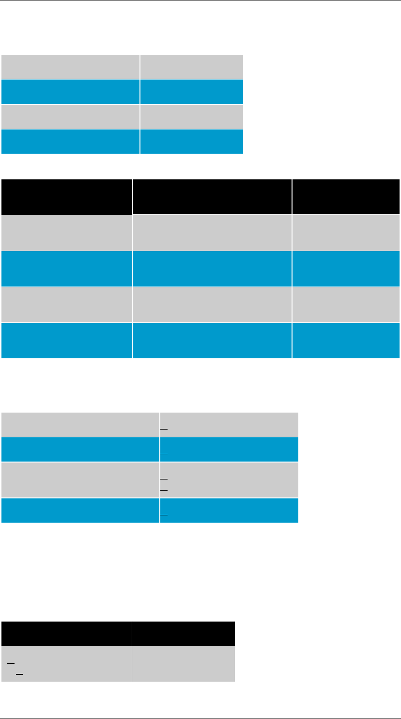
Color Codes
Conductor Identification
(T568A Wiring) Color Code Abbreviation
Pair 1 White-Blue
Blue (W-BL)
(BL)
Pair 2 White-Orange
Orange (W-O)
(O)
Pair 3 White-Green
Green (W-G)
(G)
Pair 4 White-Brown
Brown (W-BR)
BR
Transmission
The following performance characteristics have been measured in accordance with
ASTM D 4566, and measured at, or corrected to 20°C.
DC Resistance < 9.38 ohms/100 mtrs
DC Resistance Unbalance < 5%
Mutual Capacitance < 6.6 nF/100 mtrs (Cat 3)
< 5.6 nF/100 mtrs (Cat 5e)
Capacitance Unbalance < 330 pF/100 mtrs
Characteristic Impedance and Structural Return Loss
Category 3 horizontal cables shall have a Characteristic Impedance of 100 ohms ±
15%. Structural return loss (SRL) is dependent on input impedance, frequency and
cable construction. For category 3 cables the SRL for the worst pair is calculated:
Frequency (MHz) Category 3 (dB)
1< ƒ < 10
10 < ƒ < 16 12
12-10log(ƒ/10)
ANSI/TIA/EIA 568-B Commercial Building Telecommunications Cabling Standard
Quang Dung Technology Distribution Company Page 18 of 62
Return Loss
Return loss is the measurement of the reflected energy caused by impedance
mismatches in the cable and components. This measurement is extremely important
for applications that use full duplex (bi-directional) transmission. Return loss is not
specified for Category 3 cables.
Category 5e Return Loss @ 20°C ± 3°
Frequency (Mhz) Category 5e (dB)
1 < ƒ < 10
10 < ƒ < 20
20 < ƒ < 100
20 + 5log(ƒ)
25
25-7log(ƒ/20)
Insertion Loss
In previous standards, insertion loss was referred to as attenuation. Insertion loss is
the loss of signal strength when a cable is inserted between the transmitter and the
receiver. Insertion loss is measured as per ASTM D 4566 and is shown in dB.
Near End Crosstalk (NEXT) Loss
NEXT is the unwanted coupling of a signal from one pair onto another when a signal is
induced by a transmitter at the near end, and measured in dB.
Power Sum Near End Crosstalk (PSNEXT) Loss
PSNEXT is the combined NEXT from all disturber pairs operating at the same time. It
is a statistical value in accordance with ASTM D4566 calculations. PSNEXT is not
specified for Category 3 cables.
The actual equation for calculating PSNEXT is:
PSNEXTcable>32.3-15log(ƒ/100) dB
Equal Level Far End Crosstalk and Power Sum Equal Level Far End Crosstalk
ELFEXT is the measurement of the unwanted coupling of a signal injected at the far
end into adjacent pairs at the near end, expressed in dB as the difference between
the measured FEXT and the insertion loss (attenuation) of the disturbed pair. Power
Sum ELFEXT is the stastistical calculation of the sum of all far end disturbers on the
near end pair.
Propagation Delay and Delay Skew
Propagation delay is the time it takes a signal to travel from one end to the other,
measured in nanoseconds (ns) as per ASTM D 4566. Delay skew is the signal delay
differential in time (ns) from the fastest pair to the slowest pair.
Propagation Delay, Velocity of Propagation & Delay Skew
@ 20° C ± 3° C
Frequency Maximum Propagation
Delay (ns/100 m) Minimum Velocity of
Propagation (%) Maximum Propagation
Delay Skew (ns/100m)
1 570 58.5% 45
ANSI/TIA/EIA 568-B Commercial Building Telecommunications Cabling Standard
Quang Dung Technology Distribution Company Page 19 of 62
10 545 61.1% 45
100 538 62.0% 45
Bundled and Hybrid Cables
Bundled and hybrid cables may be used in a horizontal applicaton provided that each
cable is recognized under ANSI/TIA/EIA 568-B.1, and meets the transmission and
color code standards as laid out by the original standard in Clause 4.
Cables made up of fiber optic and copper conductors are sometimes referred to as
composite cables.
Category 3 Transmission Performance Standards
Cabling Transmission Performance Standards
Frequency-MHz Insertion Loss-dB
(Solid Cable) Insertion Loss-dB
(Stranded Cable)
NEXT-dB (worst
pair to pair)
.772 2.2 2.7 43
1.0 2.6 3.1 41.3
4.0 5.6 6.7 32.3
8.0 8.5 10.2 27.8
10.0 9.7 11.7 26.3
16.0 13.1 15.7 23.2
Connecting Hardware Transmission Performance Standards
Frequency-MHz Insertion Loss-dB NEXT-dB (Worst pair to pair)
1.0 .1 58
4.0 .2 46
8.0 .3 39.9
10.0 .3 38
16.0 .4 33.9
Permanent Link Transmission Performance Standards
ANSI/TIA/EIA 568-B Commercial Building Telecommunications Cabling Standard
Quang Dung Technology Distribution Company Page 20 of 62
Frequency-MHz Insertion Loss-dB NEXT-dB (worst pair to pair)
1.0 3.5 40.1
4.0 6.2 30.7
8.0 8.9 25.9
10.0 9.9 24.3
16.0 13 21.0
Channel Transmission Performance Standards
Frequency-MHz Insertion Loss-dB Next-dB (worst pair to pair)
1.0 4.2 39.1
4.0 7.3 29.3
8.0 10.2 24.3
10.0 11.5 22.7
16.0 14.9 19.3
Category 5e Transmission Performance Standards
Cabling Transmission Performance Standards
Frequency
(Mhz) Insertion
Loss
(dB)
(Solid)
Insertion
Loss
(dB) (Stranded)
NEXT
(dB)
PS
NEXT
(dB)
ELFEXT
(dB) PS
ELFEXT
(dB)
Return
Loss
(dB)
.772 1.8 - 67.0
64.0
- - -
1.0 2.0 2.4 65.3
62.3
63.8 60.8 20
4.0 4.1 4.9 56.3
53.3
51.8 48.8 23
8.0 5.8 6.9 51.8
48.8
45.7 42.7 24.5

ANSI/TIA/EIA 568-B Commercial Building Telecommunications Cabling Standard
Quang Dung Technology Distribution Company Page 21 of 62
10 6.5 7.8 50.3
47.3
43.8 40.8 25
16 8.2 9.9 47.2
44.2
39.7 36.7 25
20 9.3 11.1 45.8
42.8
37.8 34.8 25
25 10.4 12.5 44.3
41.3
35.8 32.8 24.2
31.25 11.7 14.1 42.9
39.9
33.9 30.9 23.3
62.5 17.0 20.4 38.4
35.4
27.9 24.9 20.7
100 22.0 26.4 35.3
32.3
23.8 20.8 19.0
Connecting Hardware Transmission Performance Standards
Frequency
(MHz) Insertion Loss
(dB) NEXT (dB) Return Loss
(dB) FEXT (dB)
1.0 .1 65 30 65
4.0 .1 65 30 63.1
8.0 .1 64.9 30 57.0
10 .1 63.0 30 55.1
16 .2 58.9 30 51.0
20 .2 57.0 30 49.0
25 .2 55.0 30 47.1
31.25 .2 53.1 30 45.2
62.5 .3 47.1 24.1 39.2
100 .4 43.0 20.0 35.1

ANSI/TIA/EIA 568-B Commercial Building Telecommunications Cabling Standard
Quang Dung Technology Distribution Company Page 22 of 62
STRANDED CONDUCTOR CABLE
Stranded cable is used to construct patch, equipment and work area cords.
Transmission
Stranded cable shall meet the transmission requirements for horizontal cable
except for return loss.
Return Loss
Return loss for stranded cables is measured as per annex C of the original
standard. Annex C details the measurement methods for testing patch cords.
There is an equation that can be used for calculation purposes and is also
available in the standard.
Insertion Loss
Formerly known as attenuation, insertin loss is the decrease in signal strength
between a transmitter and receiver. Insertion loss shall be measured in
accordance with ASTM D4566.
With Category 3 and Category 5e stranded conductors, the insertion loss is
derated by a factor of 1.2. With Category 3 cables all frequencies from .772 to
16 MHz will be derated, and with Category 5e cables all frequencies from 1
MHz to 100MHz are derated by the 1.2 factor.

ANSI/TIA/EIA 568-B Commercial Building Telecommunications Cabling Standard
Quang Dung Technology Distribution Company Page 23 of 62
CONNECTING HARDWARE
General
Compliance to the transmission performance for connecting hardware will help
ensure that the connecting hardware will have minimal impact on the
performance of the cable. Although there are several punch down systems
available, IDC is the desired method.
Connecting hardware is installed at:
1. main cross connect
2. intermediate cross connect
3. horizontal cross connect
4. horizontal cabling transition points
5. consolidation points
6. telecommunications outlets
Unless otherwise stated, all connections of modular jacks and plugs will be
tested in a mated state.
Mounting and Density
The connecting hardware should be flexible enough to mount on racks, walls
and other types of support equipment. Connecting hardware should be dense
enough to minimize space, and should also provide easy cable management.
Design
Cross connect hardware shall be desgned to provide a means to:
1. Cross connect cables with cross connect jumpers or patch cords
2. Connect premise equipment to the UTP network
3. Indentify circuits as per ANSI/TIA/EIA 606
4. Use industry standard colors to identify functional fields, eg: First level
backbone
5. Administer cable and patch cords in an orderly fashion
6. Access and monitor test cabling and premise equipment
7. Protecting exposed terminals
Transition and consolidation points, and telecommunications outlets shall
provide a the appropiate means to terminate the cable and a means to
identify the conductors.
Transmission

ANSI/TIA/EIA 568-B Commercial Building Telecommunications Cabling Standard
Quang Dung Technology Distribution Company Page 24 of 62
Connecting hardware shall be tested in accordance with Annex D of the
original standard. Annex D describes the testing methods for testing 100 ohm
balanced twisted pair cabling.
Recognized Categories
Category 5e 100 ohm connecting hardware specified to 100 MHz.
Category 3 100 ohm connecting hardware specified to 16 MHz.
Insertion Loss
The equation provided in the original standard document will assist in loss
calculations.
Near End Crosstalk
NEXT loss shall be measured in accordance with Annex D of the orginal
standard for all pair combinations. Once again there are equations contained
in the original standard for calculation of NEXT.
Return Loss
Return loss shall be calculated as per Annex D, and for all frequencies from 1-
100MHz the results shall exceed the values calculated as per the equation in
the original standard.
Far End Crosstalk (FEXT)
FEXT shall be measured in accordance with Annex D.
Propagation Delay and Delay Skew
For propagation delay each mated connection is assumed to contribute no
more than 2.5 ns (nanoseconds) from 1 MHz to 100 MHz in both the channel
and link models.
For delay skew each mated connection is assumed to contribute no more than
1.25 ns.
DC Resistance
For category 3, the DC resistance between the input and output connections
of the connecting hardware shall not exceed 0.3 ohms, and for category 5e,
0.2 ohms.
Telecommunications Outlet
Each 4 pair horizontal cable shall be terminated on an 8 position modular
jack. The outlet shall meet the interface requirements of IEC 60603-7. The
standard pin configuration is T568A, and T568B is provided to accommodate
other 8 pin configurations.
ANSI/TIA/EIA 568-B Commercial Building Telecommunications Cabling Standard
Quang Dung Technology Distribution Company Page 25 of 62
Performance Marking
Each piece of connecting hardware should be marked to designate its
performance level. The marking is up to the discretion of the manufacturer
and must be approved by the agency.

ANSI/TIA/EIA 568-B Commercial Building Telecommunications Cabling Standard
Quang Dung Technology Distribution Company Page 26 of 62
CORDS AND CROSS CONNECT JUMPERS
General
Cables used to make patch cords should be stranded. Cables used for patch
cords shall meet all the applicable standards for cords, eg: insulation diameter
and color codes.
Insulated Conductor & Color Codes
The insulation for a patch cord terminated with a modular plug shall not
exceed 1.22 mm. The color coding for the pairs shall have a white conductor
and the other conductor shall be of a visibly distinct color.
Conductor
Identification (T568A
Wiring) Color Code Color Code
(Abbreviation) Option
2
Pair 1 White-Blue (W-BL)
Blue (BL) Green (G)
Red (R)
Pair 2 White-Orange (W-O)
Orange (O) Black (BK)
Yellow (Y)
Pair 3 White-Green (W-G)
Green (G) Blue (BL)
Orange (O)
Pair 4 White-Brown (W-BR)
Brown (BR) Brown (BR)
Slate (S)
Transmission
Cross connect jumpers shall meet the insulation and color code requirements
of section 4.3.4 and 4.3.3.1 of the original standard.
Near End Cross Talk
The NEXT loss for patch, work and area codes shall meet or exceed the values
as per the equation shown and tested as per Annex F in the original standard.
Return Loss
For category 5e patch, work area and equipment cords with modular plugs,
return loss shall be measured according to Annex F, clause 4.

ANSI/TIA/EIA 568-B Commercial Building Telecommunications Cabling Standard
Quang Dung Technology Distribution Company Page 27 of 62
ANSI/TIA/EIA-568 B.3
Optical Fiber Cabling Components Standard
Introduction
The purpose of this standard is to specify the component and transmission
requirements for a fiber optic system.
Normative References
As with most of the telecommunication standards, other standards are
referenced. While the following standards may not be directly referenced
within this document, they are referred to in the original standard, and should
be reviewed for clarification if required.
ANSI/TIA/EIA-455-A-1991
ANSI/ICEA S-83-596-1994
ANSI/ICEA S-87-640-2000
ANSI/TIA/EIA-526-7-1998
ANSI/TIA/EIA-526-14-A-1998
ANSI/TIA/EIA-568B.1
ANSI/TIA/EIA-598-A-1995
ANSI/TIA/EIA-604-3-1997
ANSI/TIA/EIA-606-1993
Optical Fiber Cables
Cable Transmission Performance
Cable Type Cable Type
Wavelength
(nm)
Maximum
Attenuation
(db/km)
Minimum
Transmission
Capacity(Mhz*km)
850 3.5 500
50/125 micron
multimode 1300 1.5 500
850 3.5 160
62.5/125 micron
multimode 1300 1.5 500
singlemode inside 1310 1.0 N/A

ANSI/TIA/EIA 568-B Commercial Building Telecommunications Cabling Standard
Quang Dung Technology Distribution Company Page 28 of 62
plant cable 1550 1.0 N/A
1310 0.5 N/A
singlemode outside
plant cable 1550 0.5 N/A
Note: The manufacturer's documentation on the fiber's performance can be
used to demonstrate compliance with the above performance requirements.
Physical Cable Specifications
The cable may be 50/125 micron or 62.5/125 micron multimode or
singlemode, or a combination of the above, but must be identifiable as per
ANSI/TIA/EIA 598-A, and marked as per the local electrical code.
Inside Plant Cable Specifications
2 and 4 fiber cables used in horizontal and centralized fiber applications shall
support 25mm bend radius under no-load. If 2 and 4 fibers intended to be
pulled through horizontal pathways shall support a bend radius of 50mm
under pull load of no more than 222 Newtons (50 lbf). All other inside plant
cables will support a bend radius of 10 times the cable diameter under no load
(eg: on a reel), and 15 times the diameter when under the rated load limit.
Outside Plant Specifications
OSP optical fiber shall have a water block construction and meet the
requirements for compound flow and water penetration, and have a minimum
pull strength of 2670 Newtons (600 lbf). OSP cable must support a bend
radius of 10 times its diameter under no load (on the reel), and 20 times the
outside diameter when subject to the cable's rated load limit.
Drop Cables
Shall have a minimum pull strength of 1335 Newtons, (300 lbf).
Connecting Hardware
General
All connectors, regardless of type must meet the specifications set out in
Annex A of the original documentation.
Connectors and Adapters
A multimode connector and adapter will be identified with a beige coloring of
the housing or boot, and a singlemode connector and adapter will be
identified with a blue colouring of the housing or boot.
The 568SC Connector
The 568SC connector is a duplex connector made up of two, single SC type
adapters held together in a single unit. Each connector is labelled with either
an "A" or "B". When mating two individual or another 568SC duplex
connector, care must be taken to make sure that and "A" mates with a "B".
Telecommunications Outlet Box

ANSI/TIA/EIA 568-B Commercial Building Telecommunications Cabling Standard
Quang Dung Technology Distribution Company Page 29 of 62
The telecommunications outlet box shall at a minimum be able to house two
terminated fiber optic cables and provide a minimum bend radius of 25mm
(1")
Patch Panels
Patch panels should be flexible enough to be mounted on a rack, wall or other
standard mounting frame.
Connecting hardware should provide for high density termination and provide
easy patch cord management after installation.
The patch panel shall be designed to provide a means to:
1. cross connect cabling with patch cords
2. interconnect premises equipment to the optical fiber cabling
3. identify cabling as specified in ANSI/TIA/EIA-606
4. use standard colors to identify fiber groups as per ANSI/TIA/EIA-606.
5. handle optical fibers and patch cords in a managed fashion
6. access and test fiber optic cable and premises equipment
7. protect the cabling, adapters and connectors.
Connecting Hardware for Centralized Cabling
When using a centralized cable design to join horizontal cables to intrabuilding
backbone cables, the configuration shall be designed to:
1. use either re-mateable connectors or splices, and the connectors or
splices will meet all other requirements contained in the original document.
2. allows mating in single or duplex fashion, but manages the fiber in pairs.
3. provide a method to identify each position
4. allow for the addition and removal of horizontal connections
5. provide storage for non-connected fibers
6. provide a method to add additional cables from the backbone or horizontal
7. provide a method to convert from an interconnection or splice to a
cross connect
8. provide an access point for testing purposes
9. provide adequate protection for the adapters, connectors and cables.
Optical Fiber Splice
Splices should not have an attenuation of .3 dB when measured as per
ANSI/TIA/EIA-455-34.
Multimode fiber shall have a minimum return loss of 20 dB, and return loss for
singlemode shall be 26 dB, when measured as per ANSI/TIA/EIA-455-1.07.
The minimum return loss for singlemode fiber for CATV applications is 55 dB.
Patch Cords
Patch cords shall be a 2 fiber cable and of the same type of fiber optic cable,
indoor construction and meet the transmission requirements and construction
requirements as per the original standard.
Patch cord connectors shall meet the requirements contained in the section
for connectors and adapters.
Patch cords will be duplex in nature and identified in such a manner that one
connector is marked "A" and one connector is marked "B". The connector at
the opposite end of the patch cord will have the labelling reversed.

ANSI/TIA/EIA 568-B Commercial Building Telecommunications Cabling Standard
Quang Dung Technology Distribution Company Page 30 of 62
Test Equipment
Field test instruments for multimode cable shall meet ANSI/TIA/EIA-525-14-
A. Consult also ANSI/TIA/EIA-455-50B and ANSI/TIA/EIA-568-B.1, clause 11
for further clarification.
For singlemode fiber, field test equipment must meet ANSI/TIA/EIA-526-7.

ANSI/TIA/EIA 568-B Commercial Building Telecommunications Cabling Standard
Quang Dung Technology Distribution Company Page 31 of 62
TIA/EIA-568-B.1-1
Part 1: General Requirements
Addendum 1: Patch Cord Bend Radius
Purpose
The purpose of this addendum is to replace sub clause 10.2.1.3 of the original
documentation of TIA/EIA-568-B.1, which addresses patch cord bend radius in
UTP and ScTP cables.
The new subclause states that the minimum inside bend radius for patch
cords under no load conditions shall be 6mm (.25") for 4 pair UTP cables, and
50 mm (2.0") for 4 pair ScTP cables.

ANSI/TIA/EIA 568-B Commercial Building Telecommunications Cabling Standard
Quang Dung Technology Distribution Company Page 32 of 62
TIA/EIA-568-B.1-2
Part 1: General Requirements
Addendum 2: Grounding & Bonding Specifications for
Screened Balanced Twisted-Pair Horizontal Cabling
Purpose
The purpose of this addendum is to revise clause 4.6 of the TIA/EIA-568-B.1
documentation which addresses certain grounding and bonding issues.
4.6 Grounding Considerations
A proper grounding system may improve the EMC performance of the cabling
system.
Grounding and bonding systems shall meet the requirements of TIA/EIA-J-
STD 607-A.
The screen of ScTP cables shall be bonded to the TGB in the
Telecommunications Room. Grounding of equipment at the work area such as
computers, is done through the ground conductor of the equipment power
connection.
Screen connections to the work area equipment shall be done through the
screen of the ScTP work areal cord extending from the telecommunications
outlet to the equipment.
The voltage between the screen and the ground wire shall not exceed 1.0 V
rms, and 1.0 V dc.
The screen of ScTP hardware shall be bonded to the TGB in the
telecommunications room.
The Horizontal cable screen shall be bonded via a screen termination to the
connecting hardware screen termination.
The connecting hardware screen termination shall be verified to ensure all
applicable requirements are met.
Annex Modifications
This addendum also contains Annex A which pertains to the Grounding and
Bonding of Screened Balanced Twisted-Pair Horizontal Cabling. Modifications
to this annex are not addressed in this section, but may be obtained through
TIAOnline.
ANSI/TIA/EIA 568-B Commercial Building Telecommunications Cabling Standard
Quang Dung Technology Distribution Company Page 33 of 62
TIA/EIA-568-B.1-3
Part 1: General Requirements
Addendum 3: Supportable Distances and Channel
Attenuation for Optical Fiber Applications by Fiber
Type
Purpose:
The intent of this addendum is to revise information contained in Table E-1 of
the original standards documentation, specifically it addresses two new
applications, that of 10/100BASE-SX and 10G (Gigabit) Ethernet, and a new
fiber type, 850 nm laser optimized 50/125 multimode fiber.
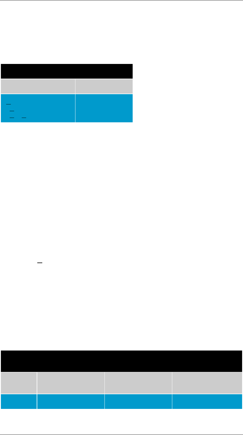
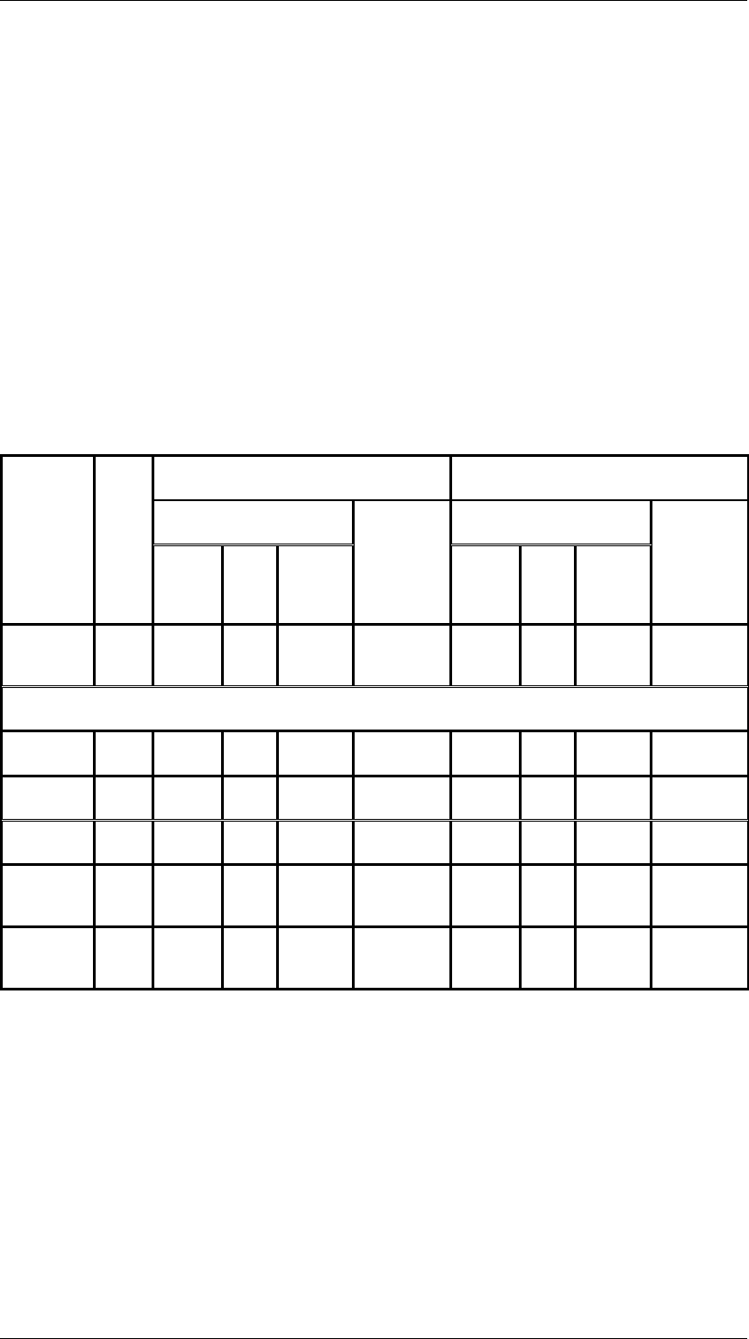
Maximum Supportable Distance (m)
Maximum Channel Attenuation (dB)
Mulitmode Mulitmode
Application
Wave
Length
(nm)
62.5/125
50/125
850 Laser
Optimized
50/125
Singlemode
62.5/125
50/125
850 Laser
Optimized
50/125
Singlemode
10/100
BASE-SX 850 300 300
300 NST 4.0 4.0 4.0 NST
10G Ethernet
10GBASE-S 850 26 82 300 NST 2.6 2.3 2.6 NST
10GBASE-L 1310 NST NST
NST 10000 NST NST
NST 6.0
10GBASE-E 1550 NST NST
NST 40000 NST NST
NST 11.0
10GBASE-
LX4 1300 300 300
300 - 2.5 2.0 2.0 -
10GBASE-
LX4 1310 - - - 10000 - - - 6.6

ANSI/TIA/EIA 568-B Commercial Building Telecommunications Cabling Standard
Quang Dung Technology Distribution Company Page 34 of 62
TIA/EIA-568-B.1-4
Part 1: General Requirements
Addendum 4: Recognition of Category 6 and 850 nm
Laser-Optimized 50/125µm Multimode Optical Fiber
Cabling
Purpose
The purpose of this addendum is to recognize balanced twisted pair Category
6 copper cabling and 850nm laser optimized 50/125µm multimode optical
fiber. The revisions occur in sub clauses 4.4, 4.5, 5.3 and 11.2.2 of TIA/EIA-
568-B.1.
4.4 Recognized Cables
This clause officially recognizes Catgory 3, 5e, 6 UTP cabling as well as ScTP
(Sreened Twisted Pair) which meet the requirements of
ANSI/TIA/EIA-568-B.2-1.
As well, it also recognizes 62.5/125µm or 50/125µm multimode fiber which
meets the requirements contained in ANSI/TIA/EIA-568-B.3-1.
All recognized cables, associated connecting hardware, jumpers, patch cords,
equipment cords and work area cords shall also meet the requirements found
in ANSI/TIA/EIA-568-B.2-1, ANSI/TIA/EIA-568-B.3 and ANSI/TIA/EIA-568-
B.3-1.
As well as meeting the requirements in ANSI/TIA/EIA-568-B.2 and
ANSI/TIA/EIA-568-B.3, bundled and hybrid cables shall also meet the
requirements of ANSI/TIA/EIA-568-B.2-1 and ANSI/TIA/EIA-568-B.3-1.
4.5 Choosing Types of Cables
A minimum of two telecommunications outlets/connectors shall be provided
for each work area. The two telecommunications outlets shall be configured
as:
a) One telecommunications outlet/connector shall be supported by a 4-pair
100 ohm Category 3 or higher, with Category 5e or Category 6 recommended
as specified in ANSI/TIA/EIA-568-B.2 and ANSI/TIA/EIA-568-B.2-1.
b) The other outlet/connector shall be supported by one of the following:
• 4 pair, 100 ohm cable either Category 5e or Category 6 as specified in
ANSI/TIA/EIA-568-B.2 and ANSI/TIA/EIA-568-B.2-1.
• Two fiber multimode fiber, either 62.5/125µm or 50/125µm as specified
in ANSI/TIA/EIA-568-B.3 and ANSI/TIA/EIA-568-B.3-1.
5.3 Recognized Cables-Backbone Cabling
Recognized backbone cables are:
• 100 ohm Category 3, 5e or 6 UTP cables meeting ANSI/TIA/EIA-568-
B.2 and ANSI/TIA/EIA-568-B.2-1.

ANSI/TIA/EIA 568-B Commercial Building Telecommunications Cabling Standard
Quang Dung Technology Distribution Company Page 35 of 62
• multimode optical fiber cable, either 62.5/125µm or 50/125µm as
specified in ANSI/TIA/EIA-568-B.3 and ANSI/TIA/EIA-568-B.3-1.
• singlemode fiber meeting ANSI/TIA/EIA-568-B.3.
All recognized cables, associated connecting hardware, jumpers, patch cords,
equipment cords and work area cords shall also meet the requirements found
in ANSI/TIA/EIA-568-B.2-1, ANSI/TIA/EIA-568-B.3 and ANSI/TIA/EIA-568-
B.3-1.
5.5.1 Intra and Interbuilding Distances
The length of the horizontal cabling for Category 6 cable supporting data
applications up to 250 MHz shall be limited to 90 m (295 ft). This distance
assumes a 5 mtr patch cord at each end. The original documentation contains
the chart describing the distances.
6.2.1 100 ohm Balanced Twisted Pair Telecommunications
Outlet/Connector
The telecommunications outlet/connector for 100 ohm UTP and ScTP shall
meet the requirements of ANSI/TIA/EIA-568-B.2 for Category 3 and 5e, and
ANSI/TIA/EIA-568-B.2-1 for Category 6.
6.3 Work Area Cords
Work area cords are limited to 5 meters as per subclause 4.3 of the original
documentation. Work area cords shall meet or exceed the requirements of
ANSI/TIA/EIA-568-B.2 for Category 3 and 5e, and ANSI/TIA/EIA-568-B.2-1
for Category 6 and ANSI/TIA/EIA-568-B.3 or ANSI/TIA/EIA-568-B.3-1.
11.2.2 Applicability
Category 6 channels and links shall meet or exceed the performance
requirements of ANSI/TIA/EIA-568-B.2-1.

ANSI/TIA/EIA 568-B Commercial Building Telecommunications Cabling Standard
Quang Dung Technology Distribution Company Page 36 of 62
ANSI/TIA/EIA 568-B.2-1 Commercial Building
Telecommunications Cabling Standard
Part 2: Balanced Twisted-Pair Cabling Components
Addendum 1: Transmission Performance Specifications
for 4-Pair 100 Ohm Category 6 Cabling
General
The original document is an addendum to already published document(s), and
because of that fact, references are made to the original specification. As an
overall statement, this document specifies the requirements and specifications
for Category 6 cable, cords and connecting hardware. By definition, Category
6 systems meet transmission requirements up to 250 Mhz.
Recognized Components
Cable
Category 6 cable is by definition a twisted pair, 100 Ohm cable which has
transmission parameters specified up to 250 Mhz. Category 6 cable is also a
recognized cable in addition to those specified in 4.2.2 of ANSI/TIA/EIA-568-
B.2.
Horizontal and Backbone Cable
Category 6 cable may be used for both horizontal and backbone cable.
Recognized horizontal and backbone cable shall be either 4 pair 100 Ohm
UTP, or ScTP, consisting of 22 AWG or 24 AWG solid conductors individually
insulated by a thermoplastic material and then formed into 4 twisted pairs
with an overall thermoplastic jacket. The cable shall meet the requirements of
ANSI/ICEA S-80-576 applicable to four-pair inside wiring cable for plenum or
general cabling within a building, ANSI/ICEA S-90-661-1994. Horizontal cable
shall also meet the requirements of clauses 4.3.3.1 to 4.3.3.6 of
ANSI/TIA/EIA-568-B.2. Backbone cable shall meet the requirements of
clauses 4.4.3.1 to 4.4.3.6 of ANSI/TIA/EIA-568-B.2.
NOTE - Additional requirements for 100 Ohm ScTP cables are located in annex
K of the original ANSI/TIA/EIA-568-B.2 standard.
Bundled and Hybrid Cable
Bundled and hybrid cables may be used for horizontal and backbone cabling
provided that each cable type is meets the requirements of clause 6.1.1 of
this Standard and clause 4.4 of ANSI/TIA/EIA-568-B.1. The cable must also
meet the transmission and color-code specifications for that cable type as
given in ANSI/TIA/EIA-568-B.2, ANSI/TIA/EIA-568-B.3, and clause 7 in the

ANSI/TIA/EIA 568-B Commercial Building Telecommunications Cabling Standard
Quang Dung Technology Distribution Company Page 37 of 62
original documentation of this standard. The cable must also meet total power
sum NEXT loss requirements. The original standard outlines the equation
required for calculation of NEXT.
Connecting Hardware and Cords
Connecting hardware and cords meeting transmission characteristics from 1
Mhz to 250 Mhz are recognized under this standard. In addition patch cords
and cordage must also meet the requirements of clauses 6.1 through 6.3 of
ANSI/TIA/EIA-568-B.2 and clause 7.2.1.3 and 7.4.4 of the original standards
documentation.
TRANSMISSION REQUIREMENTS
General
For each transmission parameter where applicable, the cable, connecting
hardware and cords are tested for the parameter under the following
categories:
Individual test parameter for cable
Individual test parameter for connecting hardware
Permanent Link
Channel
Work Area Cords, Patch Cords and Equipment Cords
In order to calculate the results, an equation is published in the original
standards documentation detailing the parameters and conditions for each
calculation, eg: temperature. In order to accurately determine the
transmission results for each parameter, the equation calculation should be
used. However, for standardization and comparison purposes, the results at
various frequencies are documented in chart form at the end of the section.
The original standards documents also refer to the various test and
measurement methods. Again, for the purposes of this document, it is
assumed that the manufacturers have conformed to the proper test and
measurement methods.
Insertion Loss
Insertion loss was previously referred to as attenuation, which is the change
in signal strength as the signal propagates down the media. Insertion loss is a
measure of the signal loss resulting from the insertion of cabling or a
component between a transmitter and receiver. Insertion loss is the ratio of
signal power at the receiver end to the input power determined from
measured voltages, expressed in dB.
Insertion loss can be calculated by using the equation found in the original
standards documentation and shall meet the values for all frequencies from 1
MHz to 250 Mhz as it pertains to:
Cable Insertion Loss for solid and stranded cable
Connecting Hardware Insertion Loss
Channel Insertion Loss
Permanent Link Insertion Loss
ANSI/TIA/EIA 568-B Commercial Building Telecommunications Cabling Standard
Quang Dung Technology Distribution Company Page 38 of 62
NOTES
1. A 20 % increase in insertion loss is allowed over category 6 horizontal
cable insertion loss for work area and patch cords.
2. The insertion loss of the channel or permanent link does not take
into consideration the 0.1 dB measurement floor of the connecting
hardware insertion loss requirement.
3. The channel insertion loss requirement is derived using the insertion
loss contribution of 4 connections.
4. For the purposes of field measurements, calculated channel limits that
result in insertion loss values less than 3 dB revert to a requirement of 3
dB maximum (see ANSI/TIA/EIA-568-B.2-3).
5. The permanent link insertion loss requirement is derived using the
insertion loss contribution of 3 connections.
6. The maximum value for insertion loss cannot exceed .10 dB.
View Category 6 Minimum Standard Requirements for Insertion Loss:
Cable | Hardware | Permanent Link | Channel
Cable
Frequency
(Mhz) Insertion
Loss
(Solid)
Insertion
Loss
(Stranded)
NEXT
(Worst
pair to
pair
Power
Sum
NEXT
ELFEXT
(Worst
pair to
pair)
Power
Sum
ELFEXT
.772 1.8 - 76.0 74.0 70.0 67.0
1.0 2.0 2.4 74.3 72.3 67.8 64.8
4.0 3.8 4.5 65.3 63.3 55.8 52.8
8.0 5.3 6.4 60.8 58.8 49.7 46.7
10.0 6.0 7.1 59.3 57.3 47.8 44.8
16.0 7.6 9.1 56.2 54.2 43.7 40.7
20.0 8.5 10.2 54.8 52.8 41.8 38.8
25.0 9.5 11.4 53.3 51.3 39.8 36.8
31.25 10.7 12.8 57.9 49.9 37.9 34.9
62.5 15.4 18.5 47.4 45.4 31.9 28.9
100.0 19.8 23.8 44.3 42.3 27.8 24.8
200.0 29.0 34.8 39.8 37.8 21.8 18.8

ANSI/TIA/EIA 568-B Commercial Building Telecommunications Cabling Standard
Quang Dung Technology Distribution Company Page 39 of 62
250.0 32.8 39.4 38.3 36.3 19.8 16.8
Frequency
(Mhz) Return Loss
(Solid) Return Loss
(Stranded) LCL
.772 - - -
1.0 20.0 20.0 40.0
4.0 23.0 23.0 40.0
8.0 24.5 24.5 40.0
10.0 25.0 25.0 40.0
16.0 25.0 25.0 38.0
20.0 25.0 25.0 37.0
25.0 24.3 24.2 36.0
31.25 23.6 23.3 35.1
62.5 21.5 20.7 32.0
100.0 20.1 19.0 30.0
200.0 18.0 16.4 27.0

ANSI/TIA/EIA 568-B Commercial Building Telecommunications Cabling Standard
Quang Dung Technology Distribution Company Page 40 of 62
250.0 17.3 15.6 26.0
ANSI/TIA/EIA 568-B Commercial Building Telecommunications Cabling Standard
Quang Dung Technology Distribution Company Page 41 of 62
Hardware
Frequency
(Mhz) Insertion
Loss NEXT
(Worst
pair to
pair)
FEXT
Return
Loss
LCL Work
Area
Cords
.772 .1 - - - - -
1.0 .1 75.0 75.0
30.0 40.0 19.8
4.0 .1 75.0 71.1
30.0 40.0 21.6
8.0 .1 75.0 65.0
30.0 40.0 22.5
10.0 .1 74.0 63.1
30.0 40.0 22.8
16.0 .1 69.9 59.0
30.0 40.0 23.4
20.0 .1 68.0 57.1
30.0 40.0 23.7
25.0 .1 66.0 55.1
30.0 40.0 24.0
31.25 .11 64.1 53.2
30.0 38.1 23.0
62.5 .16 58.1 47.2
28.1 32.1 20.0
100.0 .20 54.0 46.1
24.0 28.0 18.0
200.0 .28 48.0 37.1
18.0 22.0 15.0
250.0 .32 46.0 35.1
16.0 20.0 14.0
Permanent Link
Frequency
(Mhz) Insertion
Loss NEXT
(Worst
pair to
pair)
Power
Sum
NEXT
ELFEXT
(Worst
pair to
pair)
Power
Sum
ELFEXT
Return
Loss
ANSI/TIA/EIA 568-B Commercial Building Telecommunications Cabling Standard
Quang Dung Technology Distribution Company Page 42 of 62
.772 - - - - - -
1.0 1.9 65.0 62.0 64.2 61.2 19.1
4.0 3.5 64.1 61.8 52.1 49.1 21.0
8.0 5.0 59.4 57.0 46.1 43.1 21.0
10.0 5.5 57.8 55.5 44.2 41.2 21.0
16.0 7.0 54.6 52.2 40.1 37.1 20.0
20.0 7.9 53.1 50.7 38.2 35.2 19.5
25.0 8.9 51.5 49.1 36.2 33.2 19.0
31.25 10.0 50.0 47.5 34.3 31.3 18.5
62.5 14.4 45.1 42.7 28.3 25.3 16.0
100.0 18.6 41.8 39.3 24.2 21.2 14.0
200.0 27.4 36.9 34.3 18.2 15.2 11.0
250.0 31.1 35.3 32.7 16.2 13.2 10.0
Channel
Frequency
(Mhz) Insertion
Loss NEXT
(Worst
Pair to
Pair)
Power
Sum
NEXT
ELFEXT
(Worst
Pair to
Pair)
PSELFEXT
Return
Loss
.772 - - - - - -
1.0 2.1 65.0 62.0 63.3 60.3 19.0
4.0 4.0 63.0 60.5 51.2 48.2 19.0
8.0 5.7 58.2 55.6 45.2 42.2 19.0
10.0 6.3 56.6 54.0 43.3 40.3 19.0
16.0 8.0 53.2 50.6 39.2 36.2 18.0

ANSI/TIA/EIA 568-B Commercial Building Telecommunications Cabling Standard
Quang Dung Technology Distribution Company Page 43 of 62
20.0 9.0 51.6 49.0 37.2 34.2 17.5
25.0 10.1 50.0 47.3 35.3 32.3 17.0
31.25 11.4 48.4 45.7 33.4 30.4 16.5
62.5 16.5 43.4 40.6 27.3 24.3 14.0
100.0 21.3 39.9 37.1 23.3 20.3 12.0
200.0 31.5 34.8 31.9 17.2 14.2 9.0
250.0 35.9 33.1 30.2 15.3 12.3 8.0
Near End Cross Talk (NEXT) and Power Sum Near End Cross Talk
(PSNEXT) Loss
NEXT loss is a measure in dB of the unwanted signal coupling from a
transmitter at the near-end into neighboring pairs, measured at the near-end.
An example of cross talk is hearing a second conversation over a phone line
while you are talking on the same line. In data communications, having an
unwanted signal on a cable can cause network transmission problems. NEXT
loss is expressed relative to the transmit signal level.
Pair to Pair NEXT can be calculated by using the equation found in the original
standards documentation and shall meet the values for all frequencies from
.772 MHz to 250 Mhz. The worst pair to pair result is shown to ensure all pair
to pair combinations meet the transmission requirements.
Near End Cross Talk is shown for:
Cable NEXT
Connecting Hardware NEXT
Permanent Link NEXT
Channel NEXT
Power Sum Near End Cross Talk is the calculated value of NEXT on one pair of
conductors at the near end from all other energized conductor pairs at the
near end. The original standards documentation provides the calculation
proceedures for calculating PSNEXT.
Power Sum NEXT is calculated for:
Cable
Permanent Link
Channel
Connecting hardware NEXT loss shall be measured for all pair combinations in

ANSI/TIA/EIA 568-B Commercial Building Telecommunications Cabling Standard
Quang Dung Technology Distribution Company Page 44 of 62
accordance with annex E. Modular plug cord NEXT loss shall be measured for
all pair combinations in accordance with annex J.
Cabling Pair-to-Pair Channel and Permanent Link NEXT loss
For all frequencies from 1 MHz to 250 MHz, category 6 channel and
permanent link pair-to-pair NEXT loss shall meet the values determined using
the equations available in the original standards documentation. The
maximum value for NEXT loss values shall not be greater than 65 dB for pair
to pair measurements, and 62dB for channel.
Cable Power Sum NEXT Loss
For all frequencies from 0.772 MHz to 250 MHz, category 6 cable power sum
NEXT loss, for a length of 100 m (328 ft) or longer, shall meet the values
determined using the calculations found in the original standards documents.
Work Area, Equipment, and Patch Cord Pair-to-Pair NEXT Loss
Work area, equipment, and patch cords shall pass the requirements of this
clause and Annex J of the original standards documentation. The original
documentation provides the calculation methods for deriving the pair to pair
results.
NEXT calculations take into account total NEXT for the connectors and cable
used.
View Category 6 Minimum Standard Requirements for
Modular Patch Cords
Category 6 Modular Patch Cord NEXT Loss (dB)
Frequency (MHz)
2 Mtr Cord 5 Mtr Cord 10 Mtr Cord
1 65.0 65.0 65.0
4 65.0 65.0 65.0
8 65.0 65.0 64.8
10 65.0 64.5 62.9
16 62.0 60.5 59.0
20 60.1 58.6 57.2
25 58.1 56.8 55.4
31.25 56.2 54.9 53.6
62.5 50.4 49.2 48.1

ANSI/TIA/EIA 568-B Commercial Building Telecommunications Cabling Standard
Quang Dung Technology Distribution Company Page 45 of 62
100 46.4 45.3 44.4
200 40.6 39.8 39.3
250 38.8 38.1 37.6
NOTES
1 Permanent link NEXT and PSNEXT loss test limits are tougher to meet
than channel NEXT and PSNEXT loss test limits. This ensures that
permanent links can be converted into a channel model by using cords that
meet Category 6 minimum standards.
2. A consolidation point in the permanent link may show results below
the measurement accuracy for the permanent link.
3. At least a 5 m (16.4 ft) distance between the consolidation point and
the telecommunications outlet connector should be maintained to help
improve NEXT and PSNEXT.
4. Channel testing can be performed using cabling components that remain
in place.
5. The maximum Pair to Pair NEXT value for connecting hardware shall be 75
dB.
6. The maximum value for PSNEXT is 62.0 dB.
View Category 6 Minimum Standard Requirements for NEXT &
PSNEXT:
Cable | Hardware | Permanent Link | Channel
FEXT and ELFEXT Loss
FEXT loss is a measurement in dB of the unwanted signal coupling from a
transmitter at the far-end into neighboring pairs measured at the near-end.
FEXT loss is the ratio of the power coupled from a disturbing pair into the
disturbed pair relative to the input power at the opposite end of the
transmission lines determined from measured voltages. FEXT loss shall be
measured for all pair combinations in accordance with annex E of the original
standards documentation.
FEXT is measured for:
Connecting Hardware
ELFEXT shall be calculated for all pair combinations of cables and cabling in
accordance with annex C of ANSI/TIA/EIA-568-B.2 and the ASTM D 4566
FEXT loss measurement procedure. Connecting hardware . In addition, since
each pair can be disturbed by more than one pair, power sum equal level far-

ANSI/TIA/EIA 568-B Commercial Building Telecommunications Cabling Standard
Quang Dung Technology Distribution Company Page 46 of 62
end crosstalk (PSELFEXT) is also specified for cabling and cables.
ELFEXT is measured for:
Cable
Permanent Link
Channel
PSELFEXT is measured for:
Cable
Permanent Link
Channel
Pair-to-Pair ELFEXT
Cable pair-to-pair ELFEXT
For all frequencies from 1 MHz to 250 MHz, category 6 cable ELFEXT, for a
length of 100 m (328 ft), shall meet the values determined using calculations
in the original standards documentation.
Connecting Hardware Pair-to-Pair FEXT Loss
For all frequencies from 1 MHz to 250 MHz, category 6 connecting hardware
FEXT loss shall meet the values determined using calculations found in the
original standard documentation. The maximum FEXT value shall not exceed
75 dB.
Permanent Link and Channel Pair-to-Pair ELFEXT
For all frequencies from 1 MHz to 250 MHz, category 6 channel and
permanent link ELFEXT shall meet the values determined using calculations
found in the original standards documentation.
Power Sum ELFEXT (PSELFEXT)
Power sum equal level far-end crosstalk loss takes into account the combined
crosstalk (calculated) value on a receive pair from all far-end disturbers
operating at the same time. The power sum equal level far-end crosstalk
(PSELFEXT) loss calculation is found in the original standards documentation.
Cable Power Sum ELFEXT
For all frequencies from 1 MHz to 250 MHz, category 6 cable power sum
ELFEXT, for a length of 100 m (328 ft), shall meet the values determined by
the equation found in the original standards documentation
Permanent Link and Channel Power Sum ELFEXT
For all frequencies from 1 MHz to 250 MHz, category 6 permanent link and
channel power sum ELFEXT shall meet the values determined using the
equation found in the original standards documentation.
View Category 6 Minimum Standard Requirements for FEXT, ELFEXT &
PSELFEXT:

ANSI/TIA/EIA 568-B Commercial Building Telecommunications Cabling Standard
Quang Dung Technology Distribution Company Page 47 of 62
Cable | Hardware | Permanent Link | Channel
Return Loss
Return loss is a measure of the reflected energy caused by impedance
mismatches in the cabling system. An impedance mismatch occurs when one
component of the system is transitioned to another; eg: the cable is mated to
a connector. This is very important for applications that use simultaneous bi-
directional transmission. Information must be able to flow down the cable in
both directions with a minimal amount of impedance to ensure smooth
network operation.
Return loss is the ratio of the reflected signal power to the input power
determined from measured voltages, expressed in dB. Cable and cabling
return loss shall be measured in accordance with annex C of ANSI/TIA/EIA-
568-B.2. Connecting hardware return loss shall be measured in accordance
with annex D of ANSI/TIA/EIA-568-B.2 for all pairs. Modular plug cords shall
be measured in accordance with annex J for all pairs.
Return Loss is measured for:
Stranded Cable
Solid Cable
Connecting Hardware
Permanent Link
Channel
Patch Cords and Equipment Cords
Horizontal Cable Return Loss
For all frequencies from 1 MHz to 250 MHz, category 6 horizontal cable return
loss, for a length of 100 m (328 ft), shall meet the values determined using
the equation in the original standards documentation.
Stranded Conductor Cable Return Loss
For all frequencies from 1 MHz to 250 MHz, category 6 stranded patch cable
return loss, for a length of 100 m (328 ft), shall meet the values determined
using the equation found in the original standards documentation.
Connecting Hardware Return Loss
For all frequencies from 1 MHz to 250 MHz, category 6 connecting hardware
return loss shall meet the values determined using the equation found in the
original standards documentation.
Work Area, Equipment, and Patch Cord Return Loss
For all frequencies from 1 MHz to 250 MHz, category 6 work area, equipment,
and patch cord return loss shall meet the values determined using the
equation found in the original standards documentation.
Permanent Link and Channel Return Loss

ANSI/TIA/EIA 568-B Commercial Building Telecommunications Cabling Standard
Quang Dung Technology Distribution Company Page 48 of 62
For all frequencies from 1 MHz to 250 MHz, category 6 permanent link and
channel return loss shall meet the values determined using the equation
found in the original standards documentation.
View Category 6 Minimum Standard Requirements for Return Loss:
Cable | Hardware | Permanent Link | Channel
Propagation Delay and Delay Skew
Propagation delay is the time it takes for a signal to travel from one end of a
conducting pair in cabling, cables, or connecting hardware to the opposite end
of that pair. Propagation delay skew is a measurement of the signaling delay
difference from the fastest pair to the slowest. Propagation delay and
propagation delay skew are expressed in nanoseconds (ns).
Cable Propagation Delay
For all frequencies from 1 MHz to 250 MHz, category 6 cable propagation
delay shall meet the values determined using the equation in the original
standards documentation.
Permanent Link and Channel Propagation Delay
The maximum propagation delay for a category 6 channel configuration shall
be less than 555 ns measured at 10 MHz.
The maximum propagation delay for a category 6 permanent link
configuration shall be less than 498ns measured at 10 MHz.
The propagation delay from each installed mated connection is assumed to
not exceed 2.5 ns for all frequencies from 1 MHz to 250 MHz.
Cable Propagation Delay Skew
For all frequencies from 1 MHz to 250 MHz, category 6 cable propagation
delay skew shall not exceed 45 ns/100 m. Testing shall be conducted using a
minimum 100 m of cable.
Permanent Link and Channel Propagation Delay Skew
For purposes of determining the permanent link and channel propagation
delay skew, the propagation delay skew of each installed mated connection is
assumed to be no greater 1.25 ns.
The maximum propagation delay skew for a category 6 permanent link
configuration shall be less than 44 ns measured at 10 MHz, and less than
50ns for a channel configuration.
Propagation Delay and Delay Skew for Category 6 Cable
Frequency
(MHz) Maximum Delay
(ns/100 mtr) Minimum Velocity
of Propagation (%)
Maximum Delay
Skew (ns/100
Mtr)

ANSI/TIA/EIA 568-B Commercial Building Telecommunications Cabling Standard
Quang Dung Technology Distribution Company Page 49 of 62
1 570 58.5 45
10 545 61.1 45
100 538 62.0 45
250 536 62.1 45
Balance
Balance ensures that unwanted signal coupling modes are minimized and is
related to the emission and immunity characteristics of the cabling. Balance
parameters such as Longitudinal Conversion Loss (LCL) and Transverse
Conversion Loss (TCL) are expressed in dB as the ratio of the signal measured
at the device under test (DUT) output port relative to the signal entering the
DUT input port. LCL should be measured for all cable and connecting
hardware pairs in accordance with annex D found in the original standards
documentation.
NOTE - Measurements of LCL and TCL are reciprocal due to symmetry.
Cable and Connecting Hardware LCL
For all frequencies from 1 MHz to 250 MHz, category 6 cable and connecting
hardware LCL should meet the values determined using the equation found in
the original standards documentation. Any calculations that result in LCL
values greater than 40 dB should be shown to be 40 dB minimum.
Longitudinal Conversion Transfer Loss (LCTL)
LCTL for both cable and connecting hardware is currently under review.
View Category 6 Minimum Standard Requirements for LCL:
ANSI/TIA/EIA 568-B Commercial Building Telecommunications Cabling Standard
Quang Dung Technology Distribution Company Page 50 of 62
Category 6 Connecting Hardware Transmission Parameters
Frequency
(Mhz) Insertion
Loss NEXT
(Worst
pair to
pair)
FEXT Return
Loss LCL Work
Area
Cords
.772 .1 - - - - -
1.0 .1 75.0 75.0 30.0 40.0 19.8
4.0 .1 75.0 71.1 30.0 40.0 21.6
8.0 .1 75.0 65.0 30.0 40.0 22.5
10.0 .1 74.0 63.1 30.0 40.0 22.8
16.0 .1 69.9 59.0 30.0 40.0 23.4
20.0 .1 68.0 57.1 30.0 40.0 23.7
25.0 .1 66.0 55.1 30.0 40.0 24.0
31.25 .11 64.1 53.2 30.0 38.1 23.0
62.5 .16 58.1 47.2 28.1 32.1 20.0
100.0 .20 54.0 46.1 24.0 28.0 18.0
200.0 .28 48.0 37.1 18.0 22.0 15.0
250.0 .32 46.0 35.1 16.0 20.0 14.0

ANSI/TIA/EIA 568-B Commercial Building Telecommunications Cabling Standard
Quang Dung Technology Distribution Company Page 51 of 62
TIA/EIA-568-B.2.2
Commercial Building Telecommunications Cabling
Standard
Part 2: Balanced Twisted Pair Cabling Components
Addendum 2
Revisions to TIA/EIA-568-B.2
Purpose:
The purpose of this Addendum is to identify and revise certain clauses within
the original document, TIA/EIA 568-B.2. The most notable changes are to
Tables 13 and 16, which both concern PSNext and NEXT for Category 3 and
5e backbone cables. The major changes are to the Category 3 parameters.
4.3.4.8
Within this section equation 5 is replaced. The new equation can be found in
the orginal documents available from TIAONLINE.
4.4
Revised text has been added which states that 4 pr twisted pair cables shall
comply with clause 4.3, and that multipair backbone cables shall comply with
clauses 4.4.1 through 4.4.6.
4.4.4.9
Revised PSNext Losses for Category 3 and 5e Backbone Cable
Frequency (Mhz) Category 3 (dB Loss) Category 5e (dB Loss)
.772 43.0 64.0
1.0 41.3 62.3
4.0 32.3 53.3
8.0 27.8 48.8
10.0 26.3 47.3
16.0 23.2 44.2
20.0 - 42.8

ANSI/TIA/EIA 568-B Commercial Building Telecommunications Cabling Standard
Quang Dung Technology Distribution Company Page 52 of 62
25.0 - 41.3
31.25 - 39.9
62.5 - 35.4
100.0 - 32.3
5.4.3
Revised Table 20 Connecting Hardware NEXT Loss-Worst Pair
Frequency (Mhz) Category 3 (dB Loss) Category 5e (dB Loss)
1.0 58.1 65.0
4.0 46.0 65.0
8.0 40.0 64.9
10.0 38.1 63.0
16.0 34.0 58.9
20.0 - 57.0
25.0 - 55.0
31.25 - 53.1
62.5 - 47.1
100.0 - 43.1

ANSI/TIA/EIA 568-B Commercial Building Telecommunications Cabling Standard
Quang Dung Technology Distribution Company Page 53 of 62
Commercial Building Telecommunications Cabling
Standard
Part 2: Balanced Twisted Pair Cabling Components
Addendum 3
TIA/EIA-568-B.2-3 Additional Considerations for
Insertion Loss and Return Loss Pass/Fail
Determination
Purpose:
The purpose of this Addendum is to change some wording in clause 1.2.5 of
TIA/EIA-568-B.2
1.2.5
The main wording change states that measured insertion loss values of less
than 3dB shall not be marked with an asterik, and shall not be used for
pass/fail determination.

ANSI/TIA/EIA 568-B Commercial Building Telecommunications Cabling Standard
Quang Dung Technology Distribution Company Page 54 of 62
Commercial Building Telecommunications Cabling
Standard
Part 2: Balanced Twisted Pair Cabling Components
Addendum 4
TIA/EIA-568-B.2-4 Solderless Connection Reliability
Requirements for Copper Connecting Hardware
Purpose:
The purpose of this Addendum is specify solderless connection requirements
for connecting hardware.
4 Definitions
The document defines the following:
• Insulation Displacement Connection
• Insulation Displacement Connection, Accessible
• Insulation Displacement Connection, Non-Accessible
• Insulation Displacement Contact
• Insulation Displacement Termination
• Insulation Piercing Connection
5 Reliability Requirements
Solderless connections shall meet the following requirements:
Connection Type
Reliability
Standard
Crimped IEC 60352-2
Accessible IDC IEC 60352-3
Non Accessible IDC
IEC 60352-4
Press-in connection
IEC 60352-5
IPC IEC 60352-6

ANSI/TIA/EIA 568-B Commercial Building Telecommunications Cabling Standard
Quang Dung Technology Distribution Company Page 55 of 62
Commercial Building Telecommunications Cabling
Standard
Part 2: Balanced Twisted Pair Cabling Requirements
Addendum 5:
TIA/EIA-568-B.2-5 Corrections to TIA/EIA-568-B.2
Purpose
The purpose of this addendum is to revise certain clauses within the original
TIA/EIA-568B.2 document.
D.5.2 Applicability
For the purposes of this standard...D.6.10 is now replaced with D.5.10
D.5.8 De embedding reference jack NEXT loss measurement
Measure the NEXT loss of the de embedded...D.6.5 is changed to D.5.6.
D.6 Modular test plug construction
It is necessary to obtain...D.6.10 is changed to D.5.10
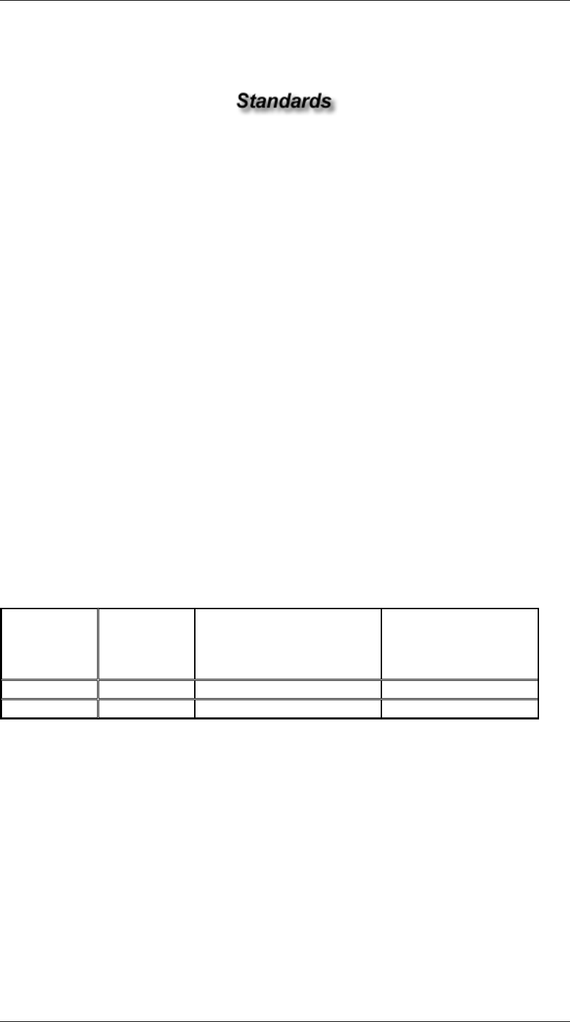
ANSI/TIA/EIA 568-B Commercial Building Telecommunications Cabling Standard
Quang Dung Technology Distribution Company Page 56 of 62
Commercial Building Telecommunications Cabling
Standard
TIA/EIA-568-B.3-1
Part 3 - Additional Transmission Performance
Specifications for
50/125 µm Optical Fiber Cables
Addendum 1
Purpose:
The purpose of this addendum is to identify transmission requirements for
50/125µm fiber optic cable to support 10 Gb/s transmission up to 300 m,
using 850 nm lasers.
Application
Cable specified in this addendum is to be used in commercial buildings or
between buildings in a campus situation. The cable shall also meet the
requirements of ANSI/TIA/EIA-568-B.3 and any further addendums.
Transmission Performance for 850 nm Laser Optimized 50/125µm
Fiber
Wavelength
Maximum
Attenuation
Overfilled Modal
Bandwidth-Length
Product
MHz•km
Effective Modal
Bandwidth-Length
Product
MHz•km
850 nm 3.5 dB/KM 1500 2000
1300 nm 1.5 dB/KM 500 Not Required
Patch Cord Cable
Patch cords used for the above application (10 Gb/s) shall be manufactured
from an indoor cable meeting the above requirements.

ANSI/TIA/EIA 568-B Commercial Building Telecommunications Cabling Standard
Quang Dung Technology Distribution Company Page 57 of 62
TRANSMISSION PARAMETER CHARTS
Category 3 Transmission Performance Standards
Cabling Transmission Performance Standards
Frequency-MHz
Insertion Loss-
dB (Solid
Cable)
Insertion Loss-
dB (Stranded
Cable)
NEXT-dB
(worst pair to
pair)
.772 2.2 2.7 43
1.0 2.6 3.1 41.3
4.0 5.6 6.7 32.3
8.0 8.5 10.2 27.8
10.0 9.7 11.7 26.3
16.0 13.1 15.7 23.2
Connecting Hardware Transmission Performance Standards
Frequency-MHz
Insertion Loss-dB
NEXT-dB (Worst pair to
pair)
1.0 .1 58
4.0 .2 46
8.0 .3 39.9
10.0 .3 38
16.0 .4 33.9
Permanent Link Transmission Performance Standards
Frequency-MHz
Insertion Loss-dB
NEXT-dB (worst pair to pair)
1.0 3.5 40.1
4.0 6.2 30.7
8.0 8.9 25.9
10.0 9.9 24.3
16.0 13 21.0
Channel Transmission Performance Standards
Frequency-MHz
Insertion Loss-dB
Next-dB (worst pair to pair)
1.0 4.2 39.1
4.0 7.3 29.3
8.0 10.2 24.3
10.0 11.5 22.7
16.0 14.9 19.3
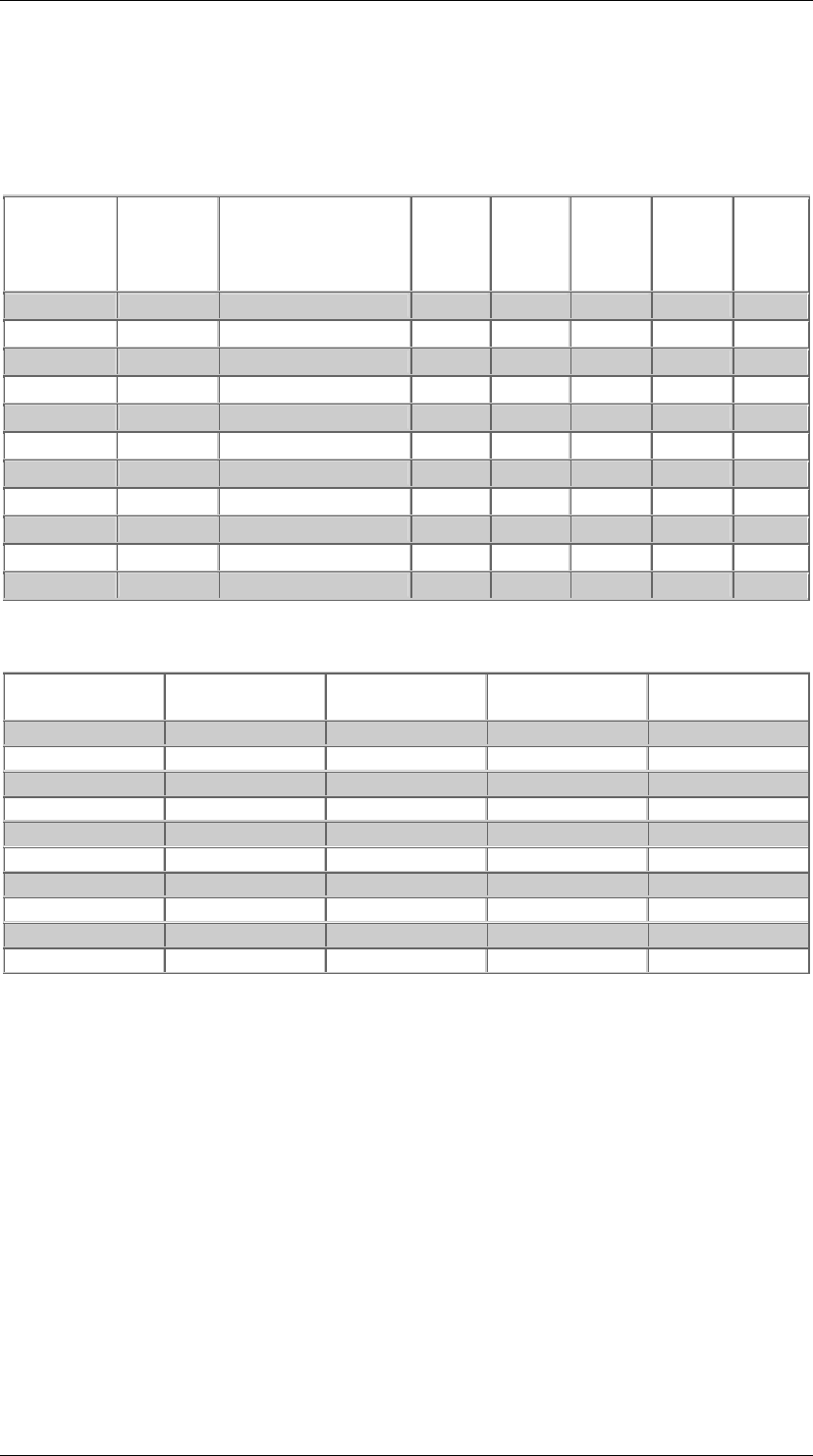
ANSI/TIA/EIA 568-B Commercial Building Telecommunications Cabling Standard
Quang Dung Technology Distribution Company Page 58 of 62
Category 5e Transmission Performance Standards
Cabling Transmission Performance Standards
Frequency
(Mhz) Insertion
Loss
(dB)
(Solid)
Insertion
Loss
(dB) (Stranded)
NEXT
(dB)
PS
NEXT
(dB)
ELFEXT
(dB) PS
ELFEXT
(dB)
Return
Loss
(dB)
.772 1.8 - 67.0 64.0 - - -
1.0 2.0 2.4 65.3 62.3 63.8 60.8 20
4.0 4.1 4.9 56.3 53.3 51.8 48.8 23
8.0 5.8 6.9 51.8 48.8 45.7 42.7 24.5
10 6.5 7.8 50.3 47.3 43.8 40.8 25
16 8.2 9.9 47.2 44.2 39.7 36.7 25
20 9.3 11.1 45.8 42.8 37.8 34.8 25
25 10.4 12.5 44.3 41.3 35.8 32.8 24.2
31.25 11.7 14.1 42.9 39.9 33.9 30.9 23.3
62.5 17.0 20.4 38.4 35.4 27.9 24.9 20.7
100 22.0 26.4 35.3 32.3 23.8 20.8 19.0
Connecting Hardware Transmission Performance Standards
Frequency
(MHz) Insertion Loss
(dB) NEXT (dB) Return Loss
(dB) FEXT (dB)
1.0 .1 65 30 65
4.0 .1 65 30 63.1
8.0 .1 64.9 30 57.0
10 .1 63.0 30 55.1
16 .2 58.9 30 51.0
20 .2 57.0 30 49.0
25 .2 55.0 30 47.1
31.25 .2 53.1 30 45.2
62.5 .3 47.1 24.1 39.2
100 .4 43.0 20.0 35.1
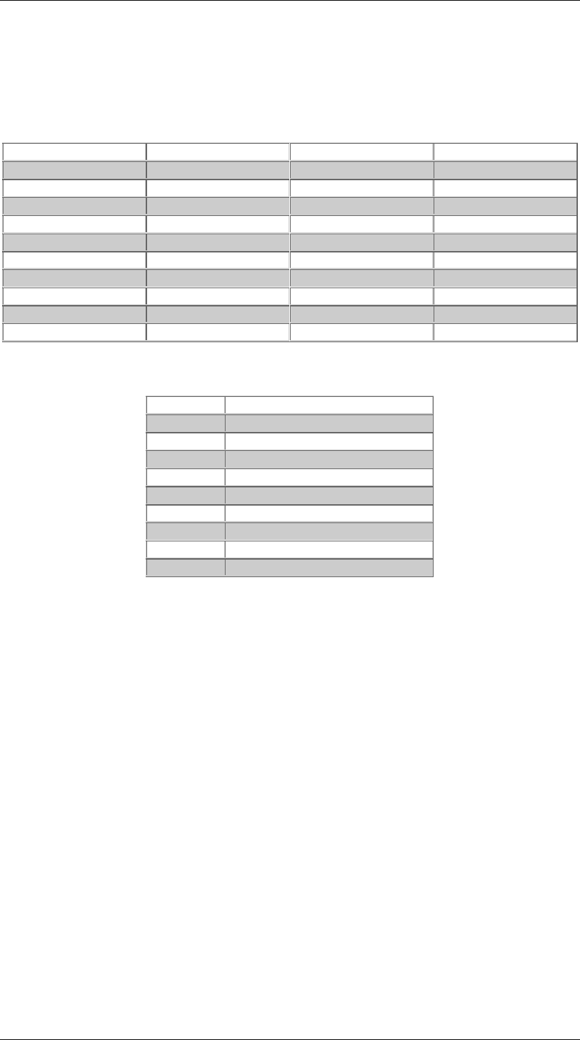
ANSI/TIA/EIA 568-B Commercial Building Telecommunications Cabling Standard
Quang Dung Technology Distribution Company Page 59 of 62
Category 5e NEXT Loss Limits
Frequency (MHz)
2 Meter Limit 5 Meter Limit 10 Meter Limit
1.0 65 65.0 65.0
4.0 62.3 61.5 60.4
8.0 56.4 55.6 54.7
10.0 54.5 53.7 52.8
16.0 50.4 49.8 48.9
20.0 48.6 47.9 47.1
25.0 46.7 46.0 45.3
31.25 44.8 44.2 43.6
62.5 39.0 38.5 38.1
100.0 35.1 34.8 34.6
Category 5e Cord Return Loss (Worst Pair)
Frequency
Return Loss (dB)
1.0 19.8
4.0 21.6
8.0 22.5
10.0 22.8
16.0 23.4
20.0 23.7
31.25 23.0
62.5 20.0
100 18.7
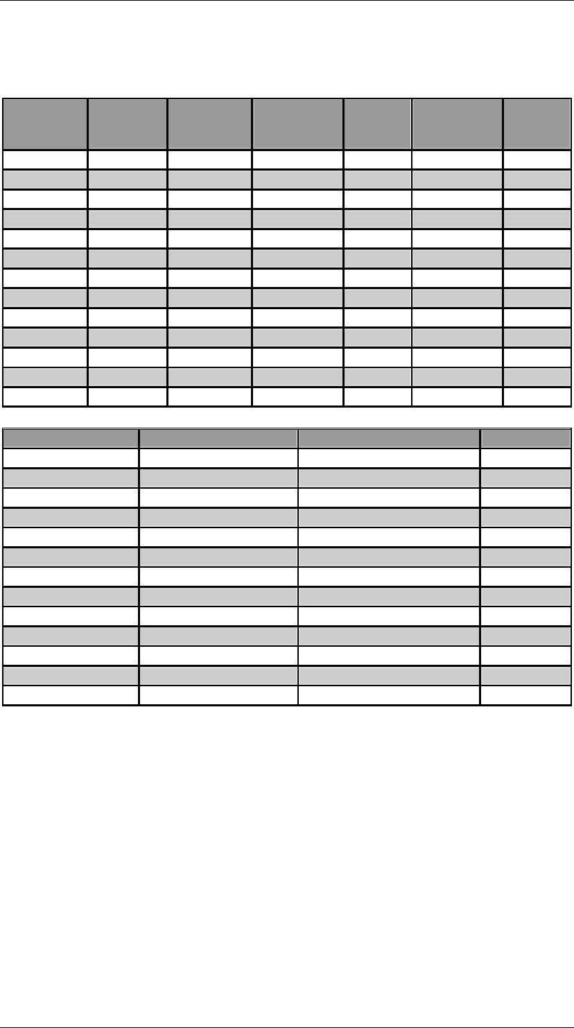
ANSI/TIA/EIA 568-B Commercial Building Telecommunications Cabling Standard
Quang Dung Technology Distribution Company Page 60 of 62
Category 6 Cable Transmission Parameters
Frequency
(Mhz) Insertion
Loss
(Solid)
Insertion
Loss
(Stranded)
NEXT
(Worst pair
to pair
Power
Sum
NEXT
ELFEXT
(Worst pair
to pair)
Power
Sum
ELFEXT
.772 1.8 - 76.0 74.0 70.0 67.0
1.0 2.0 2.4 74.3 72.3 67.8 64.8
4.0 3.8 4.5 65.3 63.3 55.8 52.8
8.0 5.3 6.4 60.8 58.8 49.7 46.7
10.0 6.0 7.1 59.3 57.3 47.8 44.8
16.0 7.6 9.1 56.2 54.2 43.7 40.7
20.0 8.5 10.2 54.8 52.8 41.8 38.8
25.0 9.5 11.4 53.3 51.3 39.8 36.8
31.25 10.7 12.8 57.9 49.9 37.9 34.9
62.5 15.4 18.5 47.4 45.4 31.9 28.9
100.0 19.8 23.8 44.3 42.3 27.8 24.8
200.0 29.0 34.8 39.8 37.8 21.8 18.8
250.0 32.8 39.4 38.3 36.3 19.8 16.8
Frequency (Mhz)
Return Loss (Solid)
Return Loss (Stranded) LCL
.772 - - -
1.0 20.0 20.0 40.0
4.0 23.0 23.0 40.0
8.0 24.5 24.5 40.0
10.0 25.0 25.0 40.0
16.0 25.0 25.0 38.0
20.0 25.0 25.0 37.0
25.0 24.3 24.2 36.0
31.25 23.6 23.3 35.1
62.5 21.5 20.7 32.0
100.0 20.1 19.0 30.0
200.0 18.0 16.4 27.0
250.0 17.3 15.6 26.0
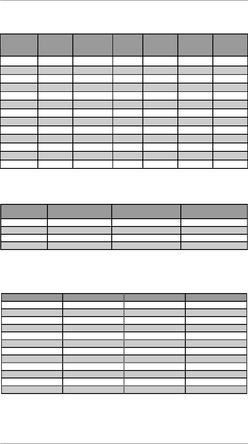
ANSI/TIA/EIA 568-B Commercial Building Telecommunications Cabling Standard
Quang Dung Technology Distribution Company Page 61 of 62
Category 6 Connecting Hardware Transmission Parameters
Frequency
(Mhz) Insertion
Loss NEXT
(Worst pair
to pair)
FEXT Return
Loss LCL Work
Area
Cords
.772 .1 - - - - -
1.0 .1 75.0 75.0 30.0 40.0 19.8
4.0 .1 75.0 71.1 30.0 40.0 21.6
8.0 .1 75.0 65.0 30.0 40.0 22.5
10.0 .1 74.0 63.1 30.0 40.0 22.8
16.0 .1 69.9 59.0 30.0 40.0 23.4
20.0 .1 68.0 57.1 30.0 40.0 23.7
25.0 .1 66.0 55.1 30.0 40.0 24.0
31.25 .11 64.1 53.2 30.0 38.1 23.0
62.5 .16 58.1 47.2 28.1 32.1 20.0
100.0 .20 54.0 46.1 24.0 28.0 18.0
200.0 .28 48.0 37.1 18.0 22.0 15.0
250.0 .32 46.0 35.1 16.0 20.0 14.0
Propagation Delay and Delay Skew for Category 6 Cable
Frequency
(MHz) Maximum Delay
(ns/100 mtr) Minimum Velocity of
Propagation (%) Maximum Delay
Skew (ns/100 Mtr)
1 570 58.5 45
10 545 61.1 45
100 538 62.0 45
250 536 62.1 45
Category 6 Modular Patch Cord NEXT Loss (dB)
Frequency (MHz)
2 Mtr Cord 5 Mtr Cord 10 Mtr Cord
1 65.0 65.0 65.0
4 65.0 65.0 65.0
8 65.0 65.0 64.8
10 65.0 64.5 62.9
16 62.0 60.5 59.0
20 60.1 58.6 57.2
25 58.1 56.8 55.4
31.25 56.2 54.9 53.6
62.5 50.4 49.2 48.1
100 46.4 45.3 44.4
200 40.6 39.8 39.3
250 38.8 38.1 37.6
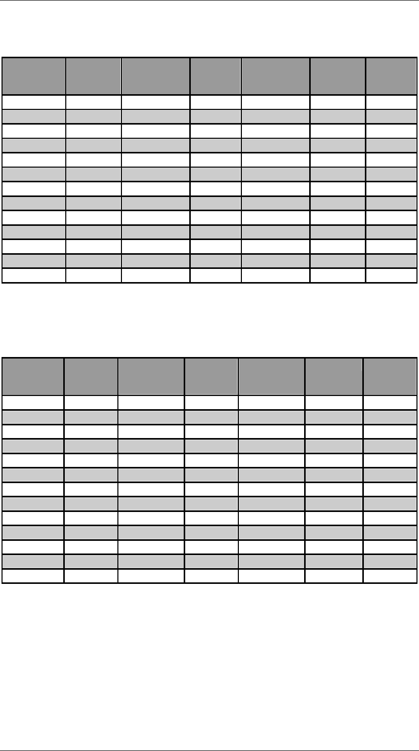
ANSI/TIA/EIA 568-B Commercial Building Telecommunications Cabling Standard
Quang Dung Technology Distribution Company Page 62 of 62
Category 6 Permanent Link Transmission Parameters
Frequency
(Mhz) Insertion
Loss NEXT
(Worst pair
to pair)
Power
Sum
NEXT
ELFEXT
(Worst pair
to pair)
Power
Sum
ELFEXT
Return
Loss
.772 - - - - - -
1.0 1.9 65.0 62.0 64.2 61.2 19.1
4.0 3.5 64.1 61.8 52.1 49.1 21.0
8.0 5.0 59.4 57.0 46.1 43.1 21.0
10.0 5.5 57.8 55.5 44.2 41.2 21.0
16.0 7.0 54.6 52.2 40.1 37.1 20.0
20.0 7.9 53.1 50.7 38.2 35.2 19.5
25.0 8.9 51.5 49.1 36.2 33.2 19.0
31.25 10.0 50.0 47.5 34.3 31.3 18.5
62.5 14.4 45.1 42.7 28.3 25.3 16.0
100.0 18.6 41.8 39.3 24.2 21.2 14.0
200.0 27.4 36.9 34.3 18.2 15.2 11.0
250.0 31.1 35.3 32.7 16.2 13.2 10.0
Category 6 Channel Transmission Parameters
Frequency
(Mhz) Insertion
Loss NEXT
(Worst Pair
to Pair)
Power
Sum
NEXT
ELFEXT
(Worst Pair
to Pair)
PSELFEXT
Return
Loss
.772 - - - - - -
1.0 2.1 65.0 62.0 63.3 60.3 19.0
4.0 4.0 63.0 60.5 51.2 48.2 19.0
8.0 5.7 58.2 55.6 45.2 42.2 19.0
10.0 6.3 56.6 54.0 43.3 40.3 19.0
16.0 8.0 53.2 50.6 39.2 36.2 18.0
20.0 9.0 51.6 49.0 37.2 34.2 17.5
25.0 10.1 50.0 47.3 35.3 32.3 17.0
31.25 11.4 48.4 45.7 33.4 30.4 16.5
62.5 16.5 43.4 40.6 27.3 24.3 14.0
100.0 21.3 39.9 37.1 23.3 20.3 12.0
200.0 31.5 34.8 31.9 17.2 14.2 9.0
250.0 35.9 33.1 30.2 15.3 12.3 8.0
