Calibration Toolkit Manual
CalibrationToolkit_Manual
CalibrationToolkit_Manual
CalibrationToolkit_Manual
CalibrationToolkit_Manual
CalibrationToolkit_Manual
User Manual:
Open the PDF directly: View PDF ![]() .
.
Page Count: 9
CalibrationToolkit Manual
HMW-Alexander
2014-11-19
1 Introduction
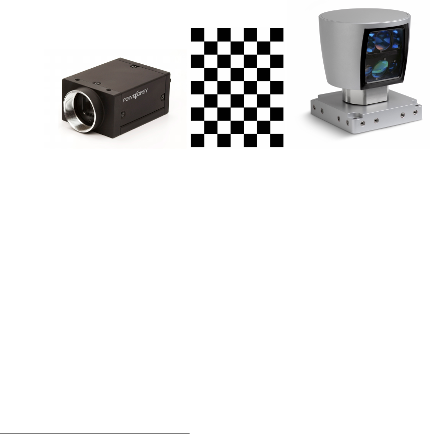
CalibrationToolkit is a pre-compiled static library of Qt-widget for manually calibrating camera and Velodyne
with chessboard (Fig.1). It can not only calibrate camera itself (intrinsic parameters), but also calibrate cam-
era to Velodyne (extrinsic parameters). The calibration process could be either on-line (data from sensors)
or off-line (data from records). CalibrationToolkit is programmed in object-oriented style, therefore, its func-
tionality could be extended conveniently. CalibrationToolkit provides a pseudo-ROS implementation with the
help of ”ROSInterface”0library and this can work in ROS environment properly. Meanwhile, you could also
reimplement it as a real ROS implementation.
Figure 1: Calibration of camera and Velodyne with chessboard
1.1 Requirement
1.1.1 OS
•Linux
1.1.2 Dependency
•Qt-5.x
•OpenCV
•ROS-indigo
•PCL (included in ROS)
•Eigen-3.x
•nlopt
•ROSInterface 0
•GLViewer 0
0https://github.com/RobotSDK/SDK.git
1
1.2 Installation
•Download source code1.
•Open Terminal and change directory to the source code.
•qmake CalibrationToolkit.pro "CONFIG+=release"
•make & make install
•qmake CalibrationToolkit.pro "CONFIG+=debug"
•make & make install
After successful installation, you can find its header file located in:
$(HOME)/SDK/CalibrationToolkit/include
and its library located in:
$(HOME)/SDK/CalibrationToolkit/lib
The installation of ROSInterface and GLViewer is same with CalirbationToolkit and you only need to change
the .pro file’s name from CalibrationToolkit to ROSInterface or GLViewer.
1.3 Structure
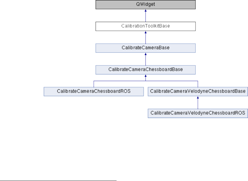
CalibrationToolkit is programmed in object-oriented style and its structure is shown as Fig.2. Therefore, the
extension of CalibrationToolkit is very convenient. You could extend it as multi-LIDAR calibration toolkit from
the CalibrationToolkitBase class, or as Camera calibration toolkit using other patterns from the CalibrateCam-
eraBase class, or as Calibration of camera and 2D LIDAR using chessboard from the CalibrateCameraChess-
boardBase class.
Figure 2: Structure of CalibrationToolkit
The CalibrateCameraChessboardBase class contains all chessboard-based calibration elements for camera
intrinsic calibration except that how to grab camera data, and the CalibrateCameraChessboardROS grabs data
from ROS by implementing the virtual functions bool refreshImage() and bool grabCalibData() with the help of
ROSInterface. Therefore, you could reimplement the CalibrateCameraChessboardBase as real ROS-application
or custom applications using other data sources.
1https://github.com/CPFL/Autoware/tree/master/ros/src/sensing/calibration/packages/camera_lidar3d/
CalibrationToolkit
2
The CalibrateCameraVelodyneChessboardBase class is derived from the CalibrateCameraChessboardBase
class, and it extends the camera extrinsic calibration in Velodyne’s coordinate. Similar to the CalibrateCamer-
aChessboardBase class, the CalibrateCameraVelodyneChessboardBase class contains all chessboard-basaed cali-
bration elements for calibrating camera to Velodyne, except that how to grab camera and Velodyne data, and
similar to the CalibrateCameraChessboardROS class, the CalibrateCameraVelodyneChessboardROS class grabs
data from ROS by implementing the virtual functions bool refreshImage(),bool refreshVelodyne() and bool
grabCalibData(). Therefore, you could also reimplement the CalibrateCameraVelodyneChessboardROS class for
different applications.
2 How to use CalibrationToolkit
2.1 GUI application development
CalibrationToolkit is derived from QWidget2, therefore, it can play a role as widget in Qt-based GUI application.
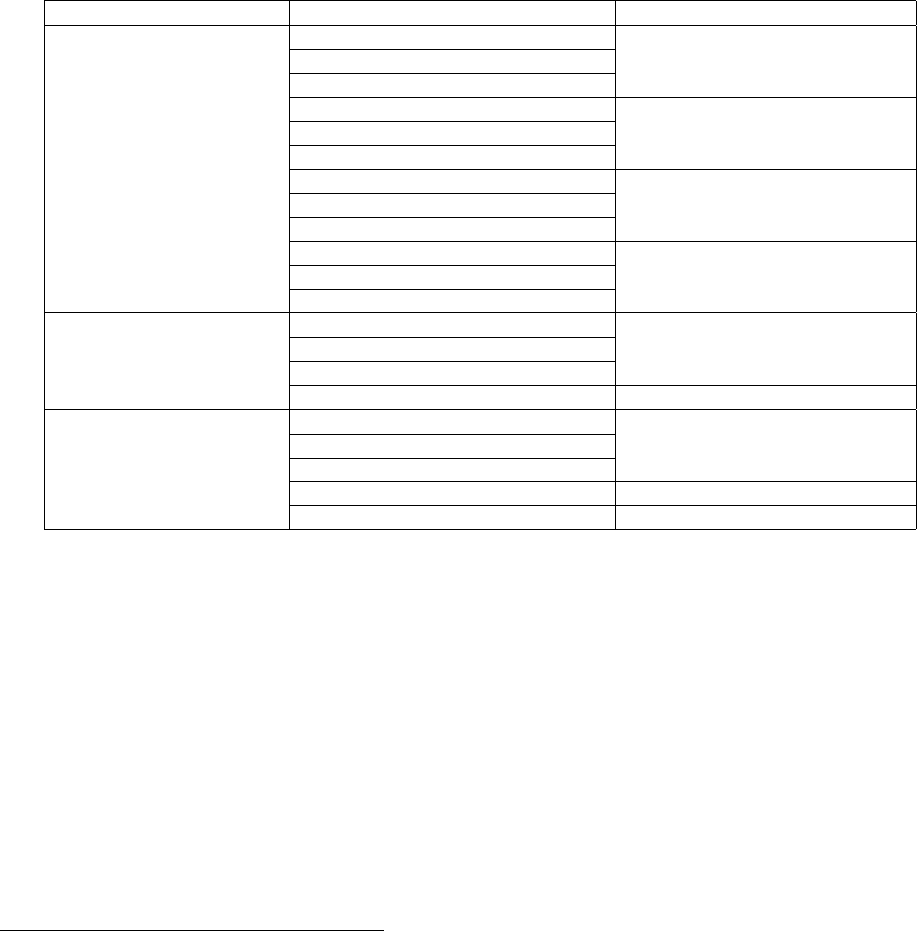
The CalibrationToolkit provides a set of signal-slot functions3(see Tab.1) to call calibration functions and get
status of calibration process.
Table 1: Slot and Signal Functions of CalibrationToolkit
Class SLOT & SIGNAL Function
CalibrationToolkitBase grabCalibDataSlot() Grab calibration data
calibDataGrabbedSignal()
calibDataGrabbedErrorSignal()
calibrateSensorSlot() Calibrate sensor
sensorCalibratedSignal()
sensorCalibratedErrorSignal()
loadCalibResultSlot() Load calibration result
calibResultLoadedSignal()
calibResultLoadedErrorSignal()
saveCalibResultSlot() Save calibration result
calibResultSavedSignal()
calibResultSavedErrorSignal()
CalibrateCameraBase refreshImageSlot() [protected] Refresh image viewer
imageRefreshedSignal()
imageRefreshedErrorSignal()
refreshParametersSlot() Refresh parameters from GUI
CalibrateCamera- refreshVelodyneSlot() [protected] Refresh Velodyne viewer
VelodyneChessboardBase velodyneRefreshedSignal()
velodyneRefreshedErrorSignal()
extractionResultSlot(...) Get extraction result
projectVelodynePointsSlot() Project extractions onto images
To create a simple Qt-based GUI application for calibration (4 steps):
1. You can simply create an application using QtCreator4as shown in Fig.3.
2. Add the dependency in .pro file of the project as follow:
=================================================================================
unix{
INCLUDEPATH += $$(HOME)/SDK/CalibrationToolkit/include
INCLUDEPATH += $$(HOME)/SDK/ROSInterface/include
INCLUDEPATH += $$(HOME)/SDK/GLViewer/include
CONFIG(debug, debug|release){
LIBS += -L$$(HOME)/SDK/CalibrationToolkit/lib -lCalibrationToolkit_Debug
LIBS += -L$$(HOME)/SDK/ROSInterface/lib/ -lROSInterface_Debug
LIBS += -L$$(HOME)/SDK/GLViewer/lib -lGLViewer_Debug
}else{
2https://qt-project.org/doc/qt-5/qwidget.html#details
3http://qt-project.org/doc/qt-5/signalsandslots.html
4http://qt-project.org/wiki/Category:Tools::QtCreator
3
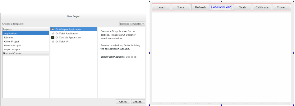
Figure 3: Left: Create Qt Widgets Application. Right: Create a GUI with 6 buttons and a tab area.
LIBS += -L$$(HOME)/SDK/CalibrationToolkit/lib -lCalibrationToolkit_Release
LIBS += -L$$(HOME)/SDK/ROSInterface/lib/ -lROSInterface_Release
LIBS += -L$$(HOME)/SDK/GLViewer/lib -lGLViewer_Release
}
INCLUDEPATH += /usr/include
LIBS += -L/usr/lib/x86_64-linux-gnu -lopencv_core
LIBS += -L/usr/lib/x86_64-linux-gnu -lopencv_highgui
LIBS += -L/usr/lib/x86_64-linux-gnu -lopencv_features2d
LIBS += -L/usr/lib/x86_64-linux-gnu -lopencv_objdetect
LIBS += -L/usr/lib/x86_64-linux-gnu -lopencv_contrib
LIBS += -L/usr/lib/x86_64-linux-gnu -lopencv_calib3d
LIBS += -L/usr/lib/x86_64-linux-gnu -lopencv_imgproc
INCLUDEPATH += /usr/include/pcl-1.7
INCLUDEPATH += /usr/include/eigen3
LIBS += -L/usr/lib -lpcl_common
LIBS += -L/usr/lib -lpcl_filters
LIBS += -L/usr/lib -lpcl_search
LIBS += -L/usr/lib -lpcl_kdtree
LIBS += -L/usr/lib -lpcl_features
INCLUDEPATH += /opt/ros/indigo/include
LIBS += -L/opt/ros/indigo/lib -lroscpp
LIBS += -L/opt/ros/indigo/lib -lrosconsole
LIBS += -L/opt/ros/indigo/lib -lroscpp_serialization
LIBS += -L/opt/ros/indigo/lib -lrostime
LIBS += -L/opt/ros/indigo/lib -lxmlrpcpp
LIBS += -L/opt/ros/indigo/lib -lcpp_common
LIBS += -L/opt/ros/indigo/lib -lrosconsole_log4cxx
LIBS += -L/opt/ros/indigo/lib -lrosconsole_backend_interface
LIBS += -L/usr/lib/x86_64-linux-gnu -lboost_system
LIBS += -L/usr/lib/x86_64-linux-gnu -lnlopt
LIBS += -L/usr/lib/i386-linux-gnu -lGLU
}
=================================================================================
3. Add #include <calibrationtoolkit.h> to header file.
4. Add following code to the .cpp file, you could add this to the construction function of the GUI class
4
generated by QtCreator.
=================================================================================
CalibrateCameraVelodyneChessboardROS * calibration=
new CalibrateCameraVelodyneChessboardROS("/camera/image_raw",1000,10
,"/velodyne_points",1000,10,30,cv::Size2f(0.108,0.108),cv::Size2i(8,6));
ui->tabWidget->addTab(calibration,"Calibration");
connect(ui->grab,SIGNAL(clicked()),calibration,SLOT(grabCalibDataSlot()));
connect(ui->calibrate,SIGNAL(clicked()),calibration,SLOT(calibrateSensorSlot()));
connect(ui->load,SIGNAL(clicked()),calibration,SLOT(loadCalibResultSlot()));
connect(ui->save,SIGNAL(clicked()),calibration,SLOT(saveCalibResultSlot()));
connect(ui->project,SIGNAL(clicked()),calibration,SLOT(projectVelodynePointsSlot()));
connect(ui->refresh,SIGNAL(clicked()),calibration,SLOT(refreshParametersSlot()));
=================================================================================
Then, after compiling, the calibration toolkit for calibrating camera and velodyne is ready for use as shown
in Fig.4 while ROS is running. The sample code could be found at https://github.com/RobotSDK/APP/tree/
master/QtAPP/CalibrationToolkit.
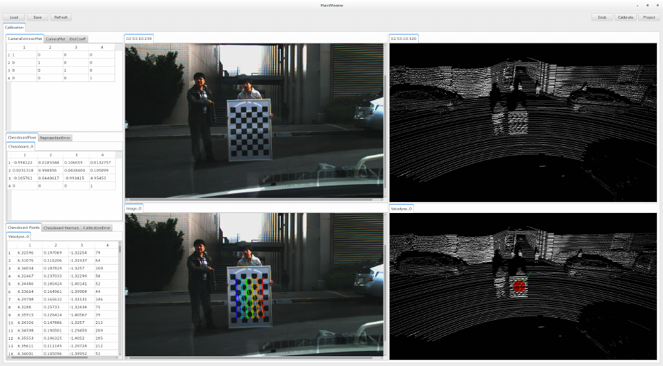
Figure 4: GUI Application of CalibrationToolkit
2.2 Code Explanation
Here, we briefly explain the code in step 4 shown in last subsection:
•Create CalibrationToolkit widget:
CalibrateCameraVelodyneChessboardROS * calibration=
new CalibrateCameraVelodyneChessboardROS("/camera/image_raw",1000,10
,"/velodyne_points",1000,10,30,cv::Size2f(0.108,0.108),cv::Size2i(8,6));
Construction function:
CalibrateCameraVelodyneChessboardROS(
QString cameraTopic, u_int32_t cameraQueueSize, int cameraInterval
5

, QString velodyneTopic, u_int32_t velodyneQueueSize, int velodyneInterval
, float maxRange, cv::Size2f patternSize, cv::Size2i patternNum
, QWidget *parent=0)
Parameters Explanation:
–cameraTopic : Topic name of camera data.
–cameraQueueSize : Queue size for camera data.
–cameraInterval : Time interval of camera data query.
–velodyneTopi : Topic name of Velodyne data.
–velodyneQueueSize : Queue size for Velodyne data.
–velodyneInterval : Time interval of Velodyne data query (ms).
–maxRange : Range filter for Velodyne data (m).
–patternSize : Geometric size of one grid in chessboard (m).
–patternNum : Number of inner cornor in chessboard.
–parent : Parent widget.
You could also use CalibrateCameraChessboardROS for only calibrating intrinsic parameters without
using Velodyne:
CalibrateCameraChessboardROS * calibration=
new CalibrateCameraChessboardROS("/camera/image_raw",1000,10
,cv::Size2f(0.108,0.108),cv::Size2i(8,6));
Construction function:
CalibrateCameraChessboardROS(
QString topic, u_int32_t queueSize, int interval
, cv::Size2f patternSize, cv::Size2i patternNum
, QWidget *parent=0)
•Attach CalibrationToolkit widget to the tab area created in Fig.3 right:
ui->tabWidget->addTab(calibration,"Calibration");
This is Qt TabWidget’s function to add a Tab to show widget5. You could attach the CalibrationToolkit
widget anywhere you want in practice.
•Connect clicked() signal of buttons created in Fig.3 to the CalibrationToolkit’s slot listed in Tab.1:
connect(ui->grab,SIGNAL(clicked()),calibration,SLOT(grabCalibDataSlot()));
connect(ui->calibrate,SIGNAL(clicked()),calibration,SLOT(calibrateSensorSlot()));
connect(ui->load,SIGNAL(clicked()),calibration,SLOT(loadCalibResultSlot()));
connect(ui->save,SIGNAL(clicked()),calibration,SLOT(saveCalibResultSlot()));
connect(ui->project,SIGNAL(clicked()),calibration,SLOT(projectVelodynePointsSlot()));
connect(ui->refresh,SIGNAL(clicked()),calibration,SLOT(refreshParametersSlot()));
You could connect any signals to these slot functions. For example, you could use the timeout() signal of
QTimer6for camera calibration with all possible frames.
You could also connect CalibrationToolkit’s signals to custom slots for status check, because one Calibra-
tionToolkit’s slot corresponds to two signals, one is for success and another on is for failure.
Another important thing is that the public slot function could be called directly instead of using signal-slot
mechanism.
5http://qt-project.org/doc/qt-5/qtabwidget.html#details
6http://qt-project.org/doc/qt-5/qtimer.html#details
6

2.3 Calibration Process
The calibration process for camera and velodyne is consist of three main steps:
•Grab calibration data.
•Extract points on chessboard. (only requred by extrinsic calibration)
•Run optimization for calibration.
2.3.1 Basic operations
Before introducing the calibration process, we need to show how to use the GLViewer, which is for visualizing
Velodyne’s point-cloud.
•Translation : ↑,↓,←,→, PgUp, PgDn
•Rotation : a, d, w, s, q, e
•Projection mode switch : 1 for perspective projection, 2 for orthogonal projection
•In orthogonal projection mode : - or , for small viewport, + or . for large viewport
•Point size : o for small, p for large
•Line width : k for narrow, l for broad
•Change background color : b for color selection
•Change light color : n for color selection
•Clear screen : Delete
2.3.2 Grab calibration data
•Move chessboard around with different poses
–Make sure that the camera and velodyne can both detect the whole chessboard.
–For accurate camera intrinsic calibration, the grabbed chessboards should spread all over the image
as well as in different ranges.
–For accurate camera extrinsic calibration, the rank of the matrix formed by normals of grabbed
chessboards should be 3.
•Trigger grabCalibDataSlot() to grab calibration data.
–If the chessboard can not be seen entirely, the calibDataGrabbedErrorSignal() will be emitted, which
means current frame is useless.
–For the calibration of camera and Velodyne, if there is no Velodyne data, the calibDataGrabbedEr-
rorSignal() will be emitted.
The grabbed data will be shown in QTabWidget5shown in Fig.4 lower two part, one is image and another
one is point-cloud, and each tab contains one frame of data. For the grabbed camera data, the detected inner
corners of chessboard are detected7and drawn8by OpenCV.
After this step, you can calibrate the camera’s intrinsic parameters and calculate the pose of each grabbed
chessboard in camera coordinate. The result will be shown at the left part of Fig.4 as QTableWidget9.
7http://docs.opencv.org/modules/calib3d/doc/camera_calibration_and_3d_reconstruction.html#
findchessboardcorners
8http://docs.opencv.org/modules/calib3d/doc/camera_calibration_and_3d_reconstruction.html#
drawchessboardcorners
9http://qt-project.org/doc/qt-5/qtablewidget.html#details
7

2.3.3 Extract points on chessboard
The extraction of 3D points on chessboard from Velodyne data is done manually. A PlaneExtractor wid-
get derived from GLViewer is developed for manual extraction. After grabbing a frame of Velodyne data, A
PlaneExtractor widget will be created to show the grabbed point-cloud. When the mouse moves in the Plane-
Extractor, a normal indicator (a circle represents plane and a line represents normal in green shown in Fig.4)
is shown for you to extract points on chessboard:
•Click left mouse button to extract the points within the green circle.
•Click right mouse button to cancle the extraction.
The extraction result, points and normal, will be shown at the left part of Fig.4 as QTableWidget9.
2.3.4 Run optimization for calibration
The optimization for calibration is consist of two consecutive steps:
•Camera intrinsic calibration.
•Camera extrinsic calibration, if there exists extraction of points on chessboard.
For camera intrinsic calibration, OpenCV provides a PnP-based method10 and it can also calculate the pose
of each grabbed chessboard. The calibration result contains camera matrix and disortion coefficients.
For camera extrinsic calibration, the principle is to align corresponding planes of grabbed chessboards from
image and point-cloud. The optimization was done by using nlopt library and the objective function is explained
in subsection ”Calibration Theory”. The calibration result is the camera’s position and orientation relative to
the velodyne in the form of translation matrix.
2.3.5 Recalibration
The CalibrationToolkit provides a simple method to check the calibration result. This method will project all
extracted points to the image for result evaluation. If the calibration result is not good, you could continue
grabbing data and try to calibrate again till the calibration result is acceptable. You could also disable some
data for extrinsic calibration via deleting the extracted points from Velodyne by just clicking the right mouse
button.
2.4 Calibration Theory
In this section, we only discuss the camera’s extrinsic calibration. There are two ways to calculate the extrinsic
parameters, euler angles and translations along XYZ axes:
•Simultaneously optimize these six parameters.
•Calculate rotation matrix first, and then optimize translations.
After intrinsic calibration, we could get the position and orientation of each grabbed chessboard in camera
coordinate. Meanwhile, we have extracted the points on each grabbed chessboard from Velodyne point-cloud.
Therefore, our optimization objective is to align these planes by tuning the camera’s extrinsic parameters.
(1) For the first way, the objective function is shown as Eq.1. This optimization is relatively slow and may
converge to local minimum without global optimization.
(α, β, γ, x, y, z)∗= arg min
(α,β,γ,x,y,z)X
i
X
j
((R(α, β, γ)·pi+T(x, y, z)−qi,j )0·(R(α, β, γ)·ni))2(1)
Where,
•(α, β, γ) : euler angles
•(x, y, z) : translations
•R(α, β, γ) : rotation matrix
•T(x, y, z) : translation vector
•pi: ith chessboard’s position in camera coordinate
10http://docs.opencv.org/modules/calib3d/doc/camera_calibration_and_3d_reconstruction.html#calibratecamera
8
•n0
i: ith chessboard’s normal vector in camera coordinate
•qi,j : ith chessboard’s jth point in Velodyne coordinate
(2) For the second way, the calculation of rotation matrix is shown as Eq.2.
R∗·N=M
R∗·(N·N0) = M·N0
R∗= (M·N0)·(N·N0)−1(if rank(N·N0) = 3)
(2)
Where,
•R: rotation matrix
•N: matrix formed by stacking all normals of grabbed chessboards in camera coordinate.
•M: matrix formed by stacking all normals of grabbed chessbaords in Velodyne coordinate.
Then the objective function for translations optimization is shown as Eq.3. This optimization is faster and
converges to global minimum more easily than Eq.1.
(x, y, z)∗= arg min
(x,y,z)X
i
X
j
((R∗·pi+T(x, y, z)−qi,j )0·(R∗·ni))2(3)
3 How to be a real ROS implementation
Currently, the CalibrationToolkit has realized a pseudo-ROS implementation, which could properly work in ROS
environment. However, after all, it is not a real ROS implementation, because the ROSInterface only provides
a communication interface to subscribe message from ROS topic and to publish topic to ROS. Therefore, here
are some suggestions for real ROS implementation.
•I think you could rewrite entire project in ROS way. Because the neccessary elements have been pro-
grammed in CalibrationToolkit and organized in an intuitive object-oriented way.
•Another way is to delete the pseudo-ROS implementation and then just reimplement the CalibrateCam-
eraChessboardBase class and the CalibrateCameraVelodyneChessboardBase by implementing the virtual
functions listed below:
–bool refreshImage() : receive camera data and refresh the image viewer
–bool refreshVelodyne() : receive velodyne data and refresh the point-cloud viewer
–bool grabCalibData() : grab current camera (and velodyne) data for calibration
and remember to connect the data arrival signal to refreshImageSlot() and refreshVelodyneSlot()
•For the GLViewer and PlaneExtractor developed by the author, if you do not want to use them, you could
also replace them at the right position:
–GLViewer :CalibrateCameraVelodyneChessboardBase’s construction function; CalibrateCameraV-
elodyneChessboardROS’s refreshVelodyne() and grabCalibData()
–PlaneExtractor :CalibrateCameraVelodyneChessboardBase’s loadCalibResult(...) and saveCalibRe-
sult(...);CalibrateCameraVelodyneChessboardROS’s grabCalibData()
9
