Capacitor Ordering Information Guide
User Manual:
Open the PDF directly: View PDF ![]() .
.
Page Count: 128 [warning: Documents this large are best viewed by clicking the View PDF Link!]
Electronic Components
Capacitor Ordering Information Guide
KEMET makes it possible.

Why Choose KEMET
KEMET Electronics Corporation is a leading global supplier of
electronic components. We offer our customers the broadest
selection of capacitor technologies in the industry, along
with an expanding range of electromechanical devices,
electromagnetic compatibility solutions and supercapacitors.
Our vision is to be the preferred supplier of electronic
component solutions for customers demanding the highest
standards of quality, delivery and service.


Aluminum Capacitors
Axial Leads ..................................................................................................................................................... 9
Radial Crown ................................................................................................................................................ 10
Screw Terminal ..............................................................................................................................................11
Snap-In ......................................................................................................................................................... 13
Solder Pin/Tag .............................................................................................................................................. 16
Single-Ended ................................................................................................................................................ 16
Surface Mount .............................................................................................................................................. 18
Motor Start .................................................................................................................................................... 20
Ceramic Capacitors
Surface Mount .............................................................................................................................................. 23
Commercial Grade ................................................................................................................................. 23
Flex Mitigation ........................................................................................................................................ 25
Automotive Grade ................................................................................................................................... 28
High Reliability Commercial Off-The-Shelf (COTS) ............................................................................... 33
SnPb End Metallization .......................................................................................................................... 34
Bulk Capacitance ................................................................................................................................... 37
High Temperature ................................................................................................................................... 38
High Voltage ........................................................................................................................................... 40
Aerospace & Defense ............................................................................................................................. 43
RF & Microwave ..................................................................................................................................... 45
Through-Hole ................................................................................................................................................ 46
Commercial Grade ................................................................................................................................. 46
High Temperature ................................................................................................................................... 48
High Voltage ............................................................................................................................................51
Aerospace & Defense ............................................................................................................................. 52
Disc ............................................................................................................................................................... 55
Safety ..................................................................................................................................................... 55
Commercial Grade ................................................................................................................................. 57
Film Capacitors
Through-Hole ................................................................................................................................................ 61
General Purpose .................................................................................................................................... 61
Metallized Polyester ........................................................................................................................ 61
Metallized Paper & Polyphenylene Sulde ....................................................................................... 63
Pulse & AC ............................................................................................................................................. 64
Single Metallized Polypropylene ...................................................................................................... 64
Double Metallized Polypropylene ..................................................................................................... 66
Film/Foil Polypropylene .................................................................................................................... 66
Safety/EMI .............................................................................................................................................. 67
X1 Class ........................................................................................................................................... 67
X2 Class .......................................................................................................................................... 70
Y1 Class ........................................................................................................................................... 73
Y2 Class ...........................................................................................................................................74
Multiple X & Y .................................................................................................................................. 76
TABLE OF CONTENTS

Surface Mount ............................................................................................................................................. 78
Polyester (PET) ...................................................................................................................................... 78
Polyethylene Naphthalate (PEN) ............................................................................................................ 79
Metallized Polyphenylene Sulde (PPS) ................................................................................................. 81
Y2 Class ................................................................................................................................................. 82
Power & Application Optimized ..................................................................................................................... 83
Power Film .............................................................................................................................................. 83
Axial ................................................................................................................................................. 83
Radial ............................................................................................................................................... 84
Screw/Faston Terminal .................................................................................................................... 85
Motor Run Applications .......................................................................................................................... 87
Screw/Faston Terminal .................................................................................................................... 87
High Voltage Transient Suppression ....................................................................................................... 88
Radial ............................................................................................................................................... 88
Low Voltage Transient Suppression ....................................................................................................... 90
Radial ............................................................................................................................................... 90
Capacitive AC Power Supply .................................................................................................................. 91
Radial ............................................................................................................................................... 91
Supercapacitors
Small Cell ...................................................................................................................................................... 95
Radial ..................................................................................................................................................... 95
Surface Mount ........................................................................................................................................ 96
Large Cell ..................................................................................................................................................... 97
Snap-In ................................................................................................................................................... 97
Screw Terminal ....................................................................................................................................... 97
Bank Module .......................................................................................................................................... 97
Tantalum Capacitors
Surface Mount .............................................................................................................................................. 99
Standard Tantalum ................................................................................................................................. 99
Polymer Tantalum KEMET Organic Capacitor (KO-CAP)......................................................................101
Polymer Aluminum Organic Capacitor (AO-CAP) ................................................................................. 104
High Temperature ................................................................................................................................. 104
High Reliability Commercial Off-The-Shelf (COTS) .............................................................................. 105
MIL–PRF CWR Style ............................................................................................................................ 109
Fused ....................................................................................................................................................112
Automotive Grade ..................................................................................................................................112
Space Grade .........................................................................................................................................114
Through-Hole ............................................................................................................................................... 116
Hermetically Sealed Axial ......................................................................................................................116
Radial Dipped ........................................................................................................................................123
Molded Axial ..........................................................................................................................................125
Molded Radial .......................................................................................................................................125
Film Capacitors (cont.)

8
Aluminum Capacitors
ALUMINUM CAPACITORS
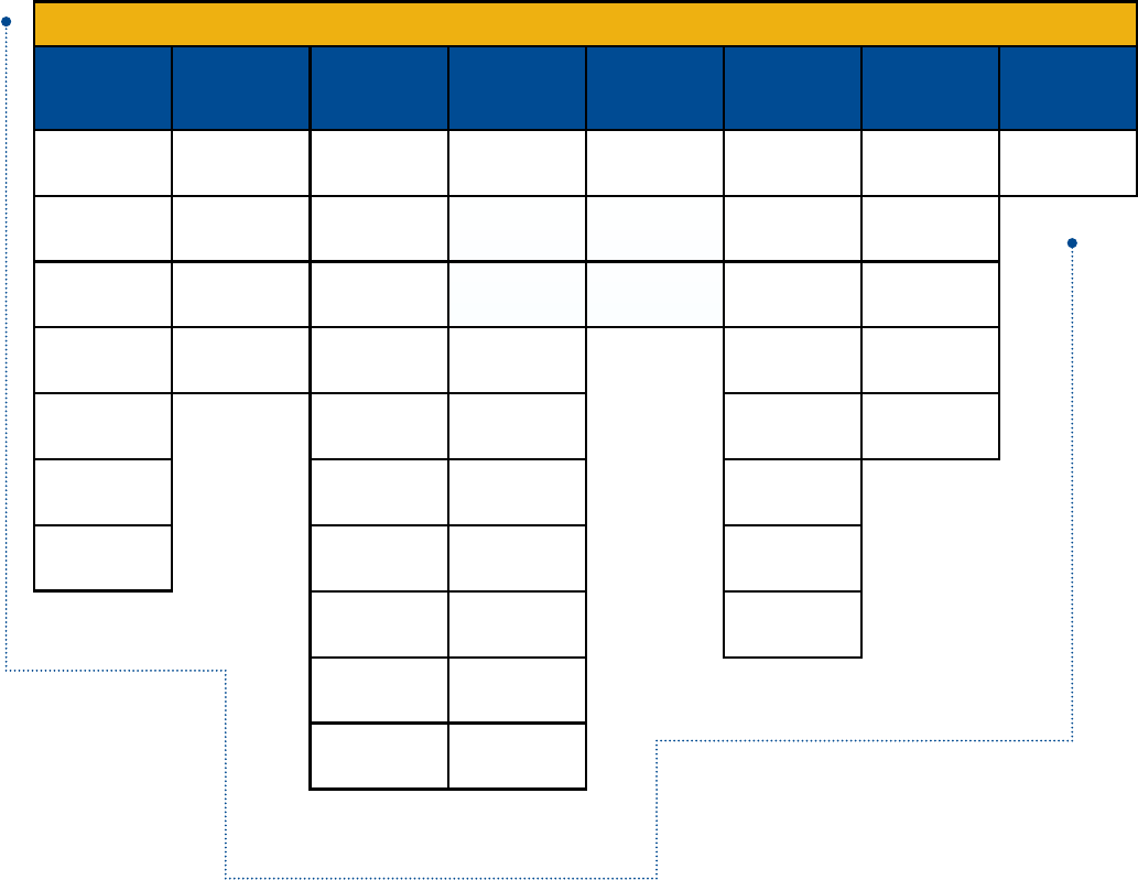
Axial Leads Radial Crown Screw Terminal Snap-In Single-Ended Motor StartSurface MountSolder Pin/Tab
EAK
Long Life
125°C
10 – 63 VDC
PEG220
Very High Ripple Current
150°C
25 – 63 VDC
PEH526
Automotive
125°C
25 – 80 VDC
ESY
Low Impedance
105°C
6.3 – 100 VDC
ALS42/43
High CV Value
105°C
350 – 450 VDC
PEG225
Extremely High Ripple Current
125°C & 150°C
25 – 63 VDC
PEH532
Low ESR & ESL
105°C
35 – 450 VDC
ESW
Low Impedance
105°C
6.3 – 100 VDC
ALS60/61
High CV Value
85°C
550 VDC
PEG226
Extremely High Ripple Current
150°C
25 – 63 VDC
PEH534
Low ESR & ESL
105°C
35 – 450 VDC
EST
Long Life
105°C
6.3 – 63 VDC
PEH169
Low ESR
85°C
10 – 450 VDC
PEH536
Low ESR & ESL
105°C
35 – 450 VDC
PEH169
Low ESR & ESL
105°C
10 – 350 VDC
ELH
Low Impedance
85°C
6.3 – 450 VDC
PEH200
High CV Value
85°C
25 – 500 VDC
ELG
General Purpose
105°C
6.3 – 450 VDC
PEH205
High Ripple
125°C
16 – 100 VDC
PEG124
Very Long Life
105°C & 125°C
10 – 450 VDC
ALC10
Long Life
85°C
35 – 550 VDC
ALS30/31
High CV Value & Long Life
85°C
25 – 500 VDC
PEH126
High Ripple Current
150°C
25 – 63 VDC
ALP/T 20/21
Low ESR
85°C
40 – 450 VDC
ESK
General Purpose
85°C
6.3 – 450 VDC
MS/MD
60°C / 70°C
120 – 300 VAC
A700
Polymer Aluminum
125°C
2 – 16 VDC
PEG126
High Ripple Current
150°C
25 – 63 VDC
ALC10S
Slit Foil Audio
85°C
50 – 100 VDC
ALP/T 22/23
High Ripple
85°C
40 – 450 VDC
ESH
High CV
105°C
6.3 – 500 VDC
ALS32/33
High CV Value & Long Life
85°C
350 – 500 VDC
PEH220
High Ripple Current
150°C
25 – 63 VDC
EDH
Gerneral Purpose
105°C
6.3 – 100 VDC
PEG127
High Ripple Current
150°C
25 – 63 VDC
ALC40
High Ripple Current
105°C
25 – 500 VDC
ALN20S
T-Network
85°C
50 & 100 VDC
ESC
Low ESR
105°C
6.3 – 100 VDC
ALS36/37
High Ripple Current
85°C
25 – 500 VDC
PEH225
High Ripple Current
125°C & 150°C
25 – 63 VDC
EDK
General Purpose
85°C
4 – 450 VDC
PEG130
Very Long Life
105°C
25 – 63 VDC
PEH506
Low ESR & ESL
85°C
35 – 450 VDC
ESG
High Ripple Current
105°C
160 – 450 VDC
ALS40/41
High CV Value
105°C
25 – 500 VDC
PEH226
High Ripple Current
150°C
25 – 63 VDC
EEV
Ultra-Low Impedance
105°C
6.3 – 50 VDC
EXV
Ultra-Low Impedance
105°C
6.3 – 50 VDC
9
Aluminum Capacitors
Axial Leads
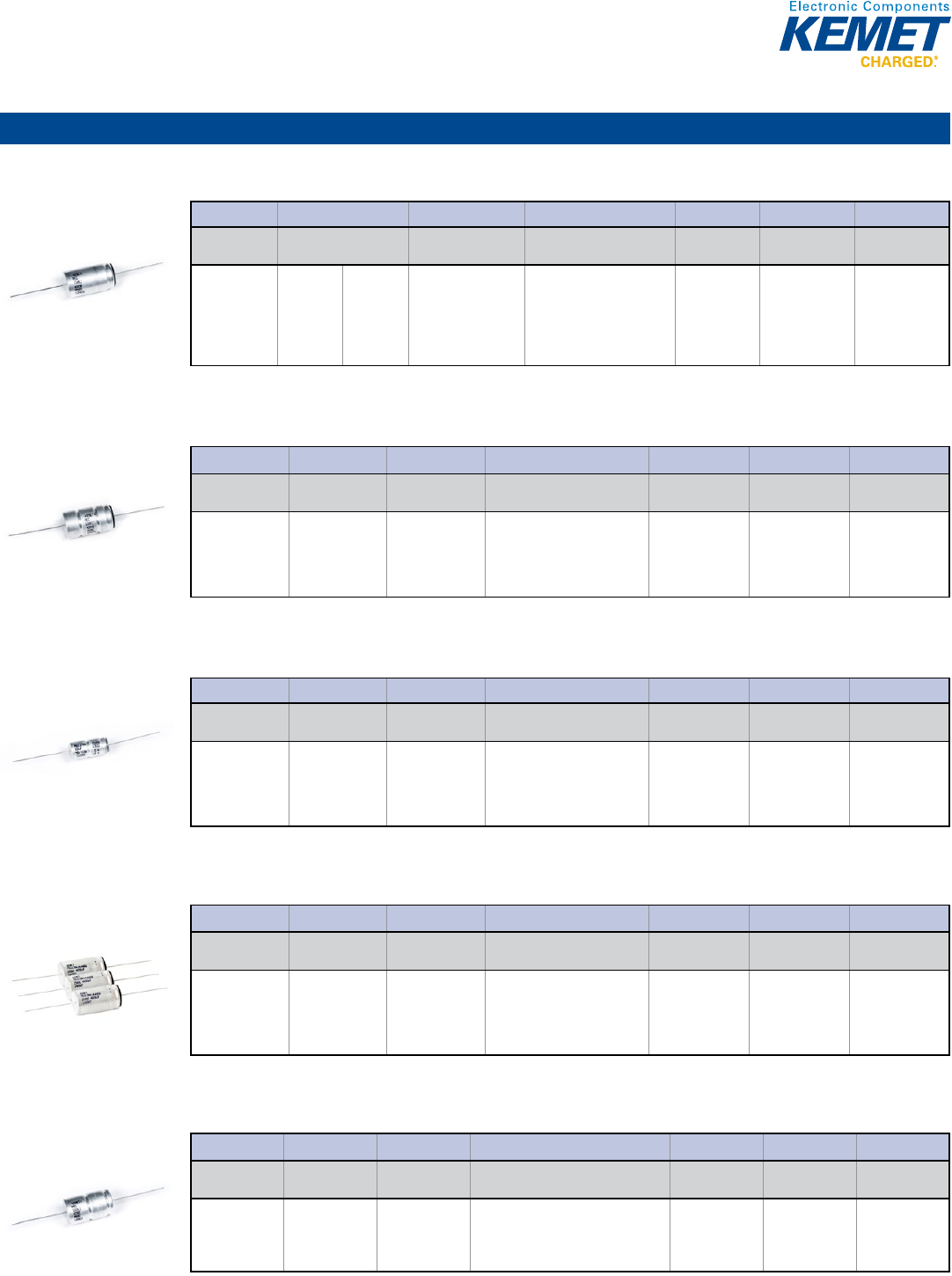
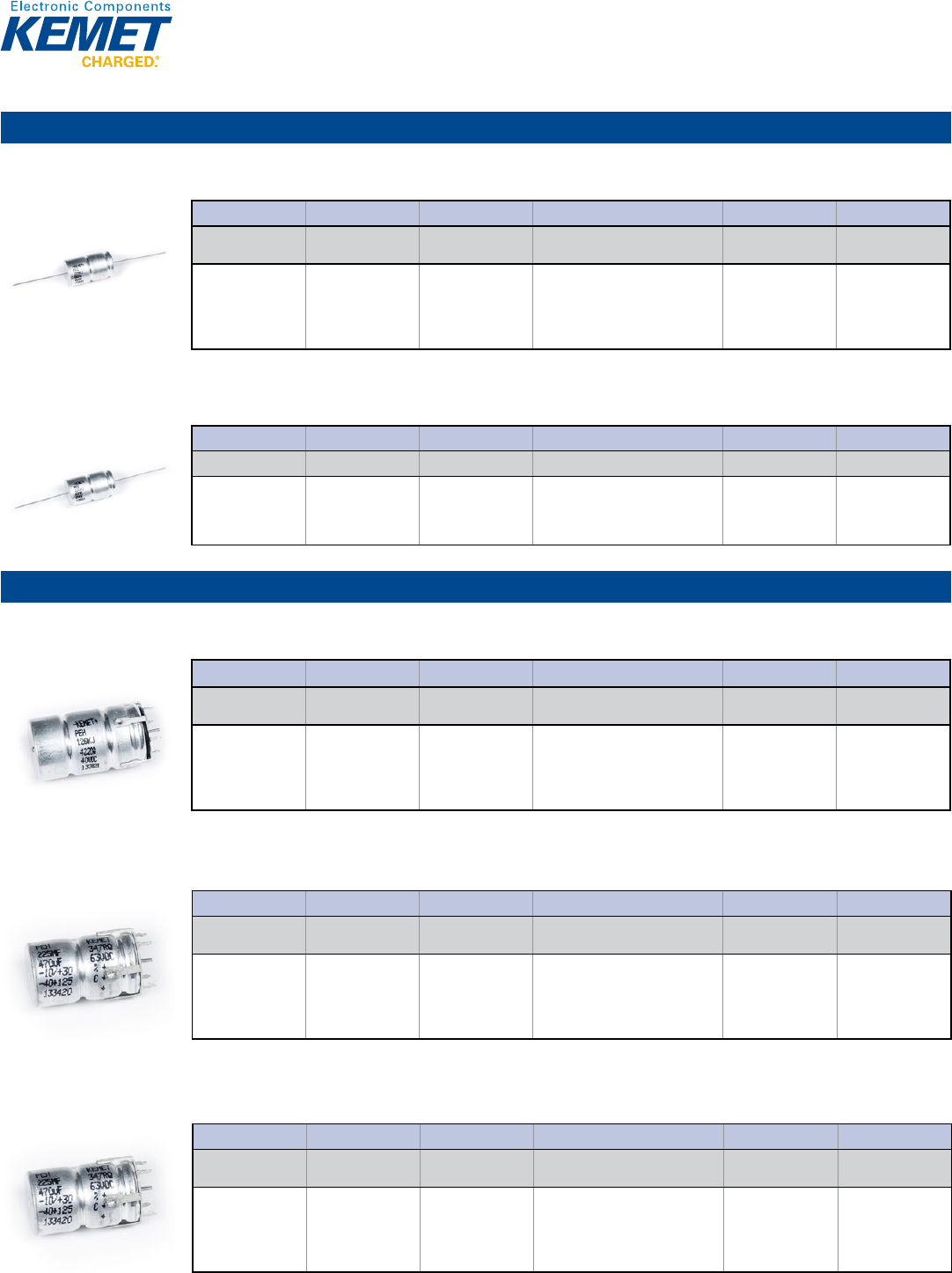
PEG124 Series Very Long Life 105°C & 125°C, 10 – 450 VDC
Capacitance Range: 1 to 4,700 µF • Temperature Range: −40°C to +105°C and −40°C to +125°C • Lifetime: 27,500 Hours
1© KEMET Electronics Corporation • P.O. Box 5928 • Greenville, SC 29606 (864) 963-6300 • www.kemet.com A4011_PEG124 • 4/16/2015
One world. One KEMET
Bene ts
• Operating temperature of +125°C and +105°C
• Very long life, up to 27,000 hours at +105°C
• Low ESR
• Low ESL
• Polarized all-welded design
• Outstanding electrical performance
Applications
KEMET's PEG124 is a high performance axial electrolytic
capacitor. Typical applications include smoothing, coupling/
decoupling and energy storage in telecommunication, power
supply system, data processing, process control and measuring
where long life and high reliability are of paramount importance.
Overview
KEMET's PEG124 is an electrolytic capacitor with very long-
life and outstanding electrical performance. The device has a
polarized all-welded design, tinned copper wire leads, a negative
pole connected to the case, and plastic insulation. long-life
and very high reliability are achieved by dimensioning of the
capacitor, careful selection of materials/methods and discipline in
quality control allowing operation up to +125°C/+105°C.
The PEG124 winding is housed in a cylindrical aluminum can with
a high purity aluminum lid and high quality rubber gasket. The
sealing system is designed for electrolyte leakage-free operation
and a very low gas-diffusion rate of electrolyte. Low ESR is the
result of a low resistive electrolyte/paper system and an all-welded
design.
Axial Aluminum Electrolytic Capacitors
PEG124 Series, +105ºC and +125ºC
Part Number System
PEG124 E F 410 0 Q T1
Series Voltage (VDC) Size Code Capacitance Code (µF) Version
Capacitance
Tolerance Packaging
Axial Aluminum
Electrolytic
E= 10
G = 16
H = 25
K = 40
M = 63
P = 100
R = 200
U = 350
V = 400
Y = 450
See Dimension Table The second two digits
indicate the two most
signi cant digits of the
capacitance value. The
rst digit indicates the total
number digits.
0 = Standard
A-Z = High
Performance
Q = -10 +30%
M = ±20%
T = -10 +50%
See Ordering
Options Table
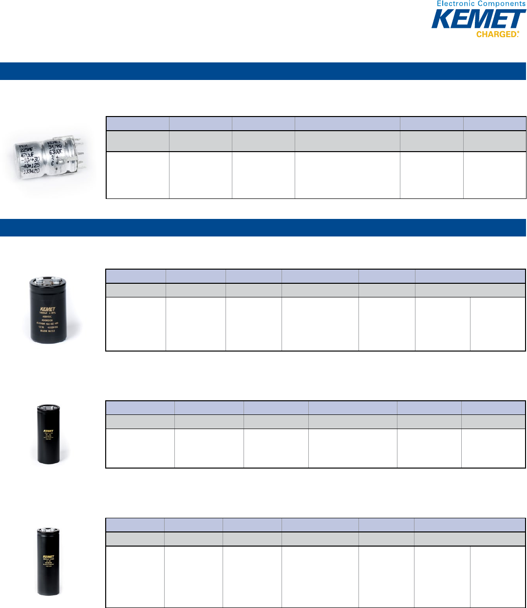
PEG126 Series High Ripple Current 150ºC, 25 – 63 VDC
Capacitance Range: 250 to 4,000 µF • Temperature Range: −40°C to +150°C • Lifetime: D=16 6,300 Hours, D=20 8,400 Hours
1© KEMET Electronics Corporation • P.O. Box 5928 • Greenville, SC 29606 (864) 963-6300 • www.kemet.com A4012_PEG126 • 4/16/2015
One world. One KEMET
Bene ts
• 2,000 hours at +150°C (D20 Case Size)
• Resistance to vibrations
• Resistance to high ambient temperature
• Low ESR
• High ripple capability
• Polarized all-welded design
• Outstanding electrical performance
Overview
KEMET's PEG126 is an electrolytic capacitor with outstanding
electrical performance. The device has a polarized all-welded
design, tinned copper wire leads, a negative pole connected to
the case, and plastic insulation. The PEG126 winding is housed
in a cylindrical aluminum can with a high purity aluminum lid
and high quality rubber gasket. Low ESR is the result of a low
resistive electrolyte/paper system and an all-welded design.
Thanks to its mechanical robustness, the PEG126 is suitable
for use in mobile and aircraft installations with operation up to
+150°C.
Applications
KEMET's PEG126 is a high performance axial electrolytic
capacitor. It is designed for automotive applications with
high demands on resistance to vibrations and high ambient
temperature.
Axial Aluminum Electrolytic Capacitors
PEG126 Series, +150ºC
Part Number System
PEG126 H F 368 E Q E1
Series Voltage (VDC) Size Code Capacitance Code (µF) Version Capacitance
Tolerance Packaging
Axial Aluminum
Electrolytic
H = 25
K = 40
M = 63
See Dimension
Table
The second two digits indicate
the two most signi cant digits of
the capacitance value. The rst
digit indicates the total number
digits.
E = Standard
Q = -10 +30%
M = ±20%
E1 = Bulk
PEG127 Series High Ripple Current 150ºC, 25 – 63 VDC
Capacitance Range: 33 to 1,300 µF • Temperature Range: −40°C to +150°C • Lifetime: 1,600 Hours
1© KEMET Electronics Corporation • P.O. Box 5928 • Greenville, SC 29606 (864) 963-6300 • www.kemet.com A4013_PEG127 • 4/16/2015
One world. One KEMET
Bene ts
• 1,600 hours at +150°C
• Resistance to vibrations
• Resistance to high ambient temperature
• High ripple capability
• Polarized all-welded design
• Outstanding electrical performance
Overview
KEMET's PEG127 is an electrolytic capacitor with outstanding
electrical performance. The device has a polarized all-welded
design, tinned copper wire leads, a negative pole connected to
the case, and plastic insulation. The PEG127 winding is housed
in a cylindrical aluminum can with a high purity aluminum lid and
high quality rubber gasket, as well as high temperature capability
in small case sizes. The PEG127 has 1,600 hours operational life
at +150°C for all case sizes.
Applications
KEMET's PEG127 is a high performance axial electrolytic
capacitor. It is designed for automotive applications with
high demands on resistance to vibrations and high ambient
temperature.
Axial Aluminum Electrolytic Capacitors
PEG127 Series, +150ºC
Part Number System
PEG127 H A 318 0 Q T1
Series Voltage (VDC) Size Code Capacitance Code (µF) Version
Capacitance
Tolerance
Packaging
Axial Aluminum
Electrolytic
H = 25
K = 40
M = 63
See Dimension
Table
The second two digits indicate
the two most signi cant digits of
the capacitance value. The rst
digit indicates the total number
digits.
0 = Standard Q = -10 +30% See Ordering
Options Table
PEG130 Series Very Long Life 105ºC, 25 – 63 VDC
Capacitance Range: 900 to 6,300 µF • Temperature Range: −40°C to +150°C • Lifetime: 160,000 Hours
1© KEMET Electronics Corporation • P.O. Box 5928 • Greenville, SC 29606 (864) 963-6300 • www.kemet.com A4045_PEG130 • 4/16/2015
One world. One KEMET
Bene ts
• Next-generation high performance axial series
• Very long operational life (up to 160,000 hours at 80°C)
• Minimal heat generation
• New low ESR electrolyte/paper system
• Available with capacitances as high as 6,300 µF and voltage
options of 25, 40, and 63 VDC
• Polarised all-welded design
• Outstanding electrical performance
Overview
KEMET's PEG130 Series is an electrolytic capacitor with
outstanding electrical performance. This product is constructed in
a polarized, all-welded design with tinned copper wire leads and
the negative pole connected to the case of the capacitor. The
PEG130 winding is housed in a cylindrical aluminum can with a
high purity aluminium lid and a high quality rubber gasket. The
low ESR is a result of a low resistive electrolyte/paper system
and an all-welded design.
Applications
KEMET's PEG130 is a new generation of high performance axial
electrolytic capacitors, designed for applications with very long
service life requirements. The capacitors are especially suitable
for LED/lamp power supplies, automotive and low voltage power
electronic applications.
Axial Aluminum Electrolytic Capacitors
PEG130 Series, 105ºC
Part Number System
PEG130 H H 436 0 Q L1
Series Voltage (VDC) Size Code Capacitance Code (µF) Version
Capacitance
Tolerance
Packaging
Axial Aluminum
Electrolytic
H = 25
K = 40
M = 63
See Dimension
Table
The second two digits indicate
the two most signi cant digits of
the capacitance value. The rst
digit indicates the total number
digits.
0 = Standard Q = -10 +30% See Ordering
Options Table
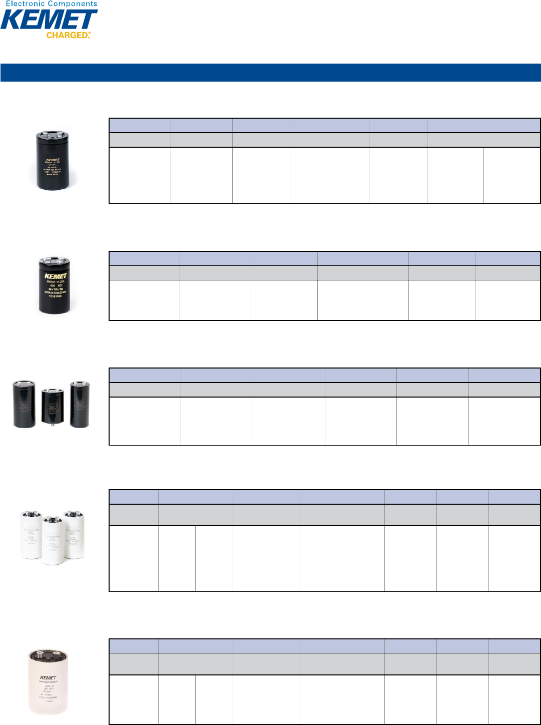
PEG220 Series Very High Ripple Current 150ºC, 25 – 63 VDC
Capacitance Range: 250 to 4,700 µF • Temperature Range: −40°C to +150°C • Lifetime: 2,000 Hours
1© KEMET Electronics Corporation • P.O. Box 5928 • Greenville, SC 29606 (864) 963-6300 • www.kemet.com A4014_PEG220 • 4/16/2015
One world. One KEMET
Bene ts
• 2,000 hours at +150°C
• Very high ripple current
• Up to 21A ripple, RMS, continuous load
• High vibration resistance
• Polarized all-welded design
• Outstanding electrical performance
Overview
KEMET's PEG220 is an electrolytic capacitor with outstanding
electrical performance. The device has a polarized all-welded
design, tinned copper wire leads, and a negative pole connected
to the case. The PEG220 winding is housed in a cylindrical
aluminum can with a high purity aluminum lid and high
quality rubber gasket. Low ESR is the result of a low resistive
electrolyte/paper system and an all-welded design. Thanks to its
mechanical robustness, the PEG220 is suitable for use in mobile
and aircraft installations with operation up to +150°C.
Applications
KEMET's PEG220 is a new generation of high performance axial
electrolytic capacitors. It is designed for automotive applications
with extremely high demands.
Axial Aluminum Electrolytic Capacitors
PEG220 Series, +150ºC
Part Number System
PEG220 H F 415 0 Q E1
Series Voltage (VDC) Size Code Capacitance Code (µF) Version Capacitance
Tolerance Packaging
Axial Aluminum
Electrolytic
H = 25
K = 40
M = 63
See Dimension
Table
The second two digits indicate the
two most signi cant digits of the
capacitance value. The rst digit
indicates the total number digits.
0 = Standard Q = -10 +30%
M = ±20%
E1 = Bulk
10
Aluminum Capacitors
Axial Leads (cont.)
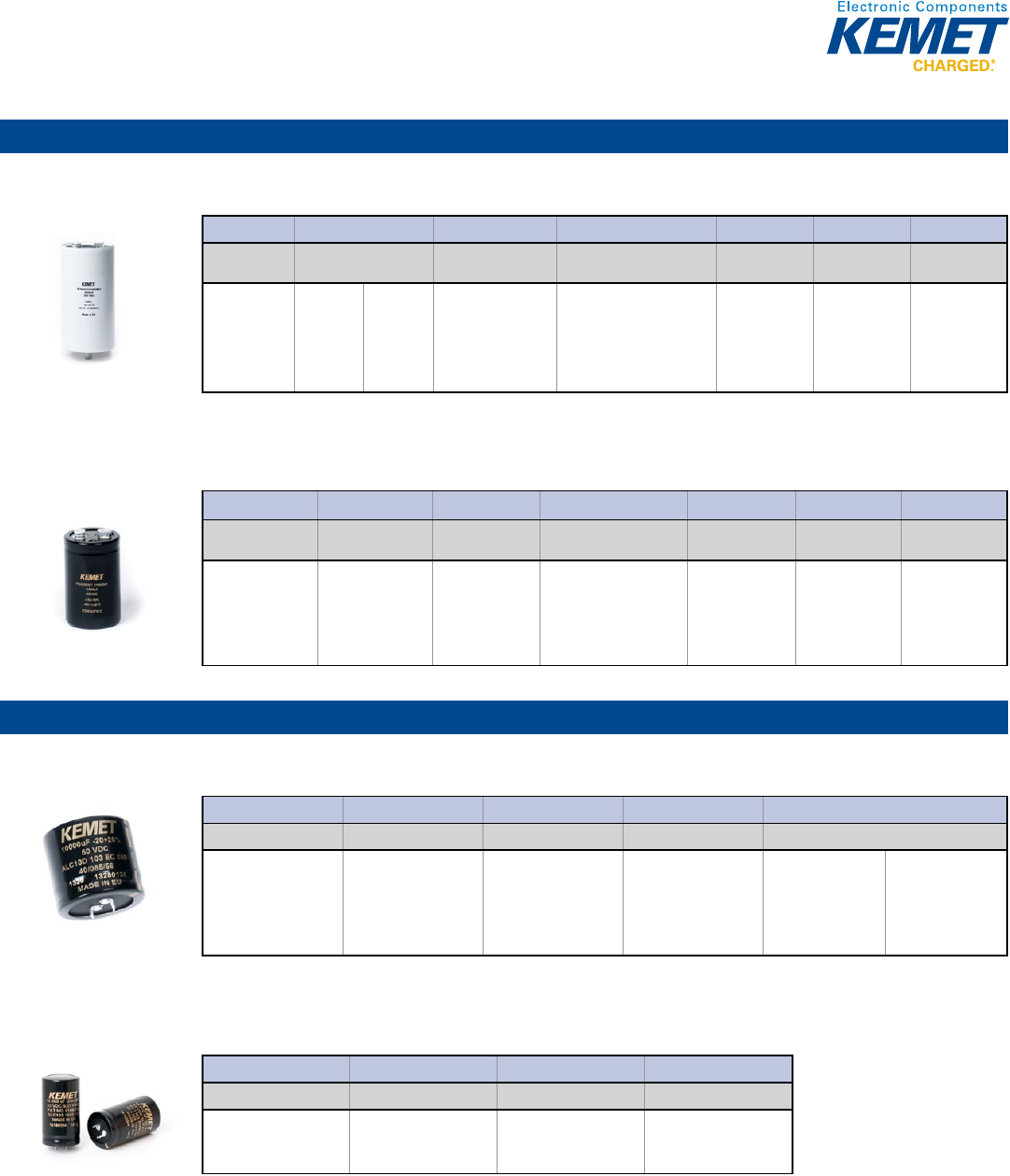
PEG225 Series Extremely High Ripple Current 125°C & 150°C, 25 – 63 VDC
Capacitance Range: 470 to 6,300 µF • Temperature Range: −40°C to +125°C (at UR) and −40°C to +150°C (at reduced voltage) • Lifetime: 2,000 Hours
1© KEMET Electronics Corporation • P.O. Box 5928 • Greenville, SC 29606 (864) 963-6300 • www.kemet.com A4015_PEG225 • 4/16/2015
One world. One KEMET
Bene ts
• 2,000 hours at +150°C
• High CV
• Extremely high ripple current
• Up to 28 A ripple, RMS, continuous load
• High vibration resistance
• Polarized all-welded design
• Outstanding electrical performance
Overview
KEMET's PEG225 is an electrolytic capacitor with outstanding
electrical performance. The device has a polarized all-welded
design, tinned copper wire leads, and a negative pole connected
to the case. The PEG225 winding is housed in a cylindrical
aluminum can with a high purity aluminum lid and high
quality rubber gasket. Low ESR is the result of a low resistive
electrolyte/paper system and an all-welded design. Thanks to its
mechanical robustness, the PEG225 is suitable for use in mobile
and aircraft installations with operation up to +150°C.
Applications
KEMET's PEG225 is a new generation of high performance axial
electrolytic capacitors. It is designed for automotive applications
with extremely high demands.
Axial Aluminum Electrolytic Capacitors
PEG225 Series, +125ºC and +150ºC
Part Number System
PEG225 H F 422 0 M
Series Voltage (VDC) Size Code Capacitance Code (µF) Version Capacitance Tolerance
Axial Aluminum
Electrolytic
H = 25
K = 40
M = 63
See Dimension Table The second two digits indicate the
two most signi cant digits of the
capacitance value. The rst digit
indicates the total number digits.
0 = Standard Q = -10 +30%
M = ±20%
PEG226 Series Extremely High Ripple Current 150°C, 25 – 63 VDC
Capacitance Range: 250 to 4,700 µF • Temperature Range: −40°C to +150°C • Lifetime: 2,000 Hours
1© KEMET Electronics Corporation • P.O. Box 5928 • Greenville, SC 29606 (864) 963-6300 • www.kemet.com A4016_PEG226 • 4/16/2015
One world. One KEMET
Bene ts
• 2,000 hours at +150°C
• Extremely high ripple current
• Up to 28 A ripple, RMS, continuous load
• High vibration resistance
• Polarized all-welded design
• Outstanding electrical performance
Overview
KEMET's PEG226 is an electrolytic capacitor with outstanding
electrical performance. The device has a polarized all-welded
design, tinned copper wire leads, and a negative pole connected
to the case. The PEG226 winding is housed in a cylindrical
aluminum can with a high purity aluminum lid and high
quality rubber gasket. Low ESR is the result of a low resistive
electrolyte/paper system and an all-welded design. Thanks to its
mechanical robustness, the PEG226 is suitable for use in mobile
and aircraft installations with operation up to +150°C.
Applications
KEMET's PEG226 is a new generation of high performance axial
electrolytic capacitors. It is designed for automotive applications
with extremely high demands.
Axial Aluminum Electrolytic Capacitors
PEG226 Series, +150ºC
Part Number System
PEG226 H F 415 0 M
Series Voltage (VDC) Size Code Capacitance Code (µF) Version Capacitance Tolerance
Axial Aluminum
Electrolytic
H = 25
K = 40
M = 63
See Dimension Table The second two digits indicate the
two most signi cant digits of the
capacitance value. The rst digit
indicates the total number digits.
0 = Standard Q = -10 +30%
M = ±20%
Radial Crown
PEH126 High Ripple Current 150°C, 25 – 63 VDC
Capacitance Range: 250 to 4,000 µF • Temperature Range: −40°C to +150°C • Lifetime: 2,000 Hours
1© KEMET Electronics Corporation • P.O. Box 5928 • Greenville, SC 29606 (864) 963-6300 • www.kemet.com A4017_PEH126_220_225_226 • 4/16/2015
One world. One KEMET
Bene ts
• Up to 2,000 hours at +150°C
• Resistance to vibrations
• Resistance to high ambient temperature
• High ripple current
• Low ESR
• Polarized all-welded design
• Outstanding electrical performance
• Radial crown which
allows mounting in a standing position
Overview
These electrolytic capacitors contain a radial crown which
allows them to be mounted in a standing position. They feature
outstanding electrical performance, a polarized, all-welded
design, tinned copper wire leads, a negative pole connected
to the case, and plastic insulation. The winding is housed in a
cylindrical aluminium can with a high purity aluminium lid and a
high quality rubber gasket. Low ESR is a result of a low resistive
electrolyte/paper system and an all-welded design. Thanks to its
mechanical robustness these capacitors are suitable for use in
mobile and aircraft installations with operation up to +150°C.
Applications
KEMET’s PEH126, PEH220, PEH225, and PEH226 are a high
performance electrolytic capacitor. It is designed for automotive
applications with high demands on resistance to vibrations and
high ambient temperature.
Radial Crown Aluminum Electrolytic Capacitors
PEH126, +150°C, PEH220, +150°C,
PEH225, +125ºC and +150ºC, and PEH226, +150ºC
Part Number System
PEH126 H F 368 E Q
Series Voltage (VDC) Size Code Capacitance Code (pF) Version
Capacitance
Tolerance
Radial Crown
Aluminum Electrolytic
with Soldering Star
Termination
H = 25
K = 40
M = 63
See Dimension Table The second two digits indicate the
two most signi cant digits of the
capacitance value. The rst digit
indicates the total number digits.
E = Standard Q = -10 +30%
PEH220 High Ripple Current 150°C, 25 – 63 VDC
Capacitance Range: 250 to 4,700 µF • Temperature Range: −40°C to +150°C • Lifetime: 2,000 Hours
2© KEMET Electronics Corporation • P.O. Box 5928 • Greenville, SC 29606 (864) 963-6300 • www.kemet.com A4017_PEH126_220_225_226 • 4/16/2015
Radial Crown Aluminum Electrolytic Capacitors
PEH126, +150°C, PEH220, +150°C, PEH225, +125ºC and +150ºC, and PEH226, +150ºC
Part Number System cont'd
PEH220 H F 415 0 M
Series Voltage (VDC) Size Code Capacitance Code (pF) Version
Capacitance
Tolerance
Radial Crown
Aluminum Electrolytic
with Soldering Star
Termination
H = 25
K = 40
M = 63
See Dimension Table
The second two digits indicate the
two most signi cant digits of the
capacitance value. The rst digit
indicates the total number digits.
0 = Standard
Q = -10 +30%
M = ±20%
PEH225 H F 422 0 M
Series
Voltage (VDC)
Size Code
Capacitance Code (pF)
Version
Capacitance
Tolerance
Radial Crown
Aluminum Electrolytic
with Soldering Star
Termination
H = 25
K = 40
M = 63
See Dimension Table
The second two digits indicate the
two most signi cant digits of the
capacitance value. The rst digit
indicates the total number digits.
0 = Standard
Q = -10 +30%
M = ±20%
PEH226 H F 415 0 M
Series
Voltage (VDC)
Size Code
Capacitance Code (pF)
Version
Capacitance
Tolerance
Radial Crown
Aluminum Electrolytic
with Soldering Star
Termination
H = 25
K = 40
M = 63
See Dimension Table
The second two digits indicate the
two most signi cant digits of the
capacitance value. The rst digit
indicates the total number digits.
0 = Standard
Q = -10 +30%
M = ±20%
PEH225 High Ripple Current 125ºC & 150ºC, 25 – 63 VDC
Capacitance Range: 470 to 6,300 µF • Temperature Range: −40°C to +125°C (at UR) and −40°C to +150°C (at reduced voltage) • Lifetime: 2,000 Hours
2© KEMET Electronics Corporation • P.O. Box 5928 • Greenville, SC 29606 (864) 963-6300 • www.kemet.com A4017_PEH126_220_225_226 • 4/16/2015
Radial Crown Aluminum Electrolytic Capacitors
PEH126, +150°C, PEH220, +150°C, PEH225, +125ºC and +150ºC, and PEH226, +150ºC
Part Number System cont'd
PEH220 H F 415 0 M
Series
Voltage (VDC)
Size Code
Capacitance Code (pF)
Version
Capacitance
Tolerance
Radial Crown
Aluminum Electrolytic
with Soldering Star
Termination
H = 25
K = 40
M = 63
See Dimension Table
The second two digits indicate the
two most signi cant digits of the
capacitance value. The rst digit
indicates the total number digits.
0 = Standard
Q = -10 +30%
M = ±20%
PEH225 H F 422 0 M
Series Voltage (VDC) Size Code Capacitance Code (pF) Version
Capacitance
Tolerance
Radial Crown
Aluminum Electrolytic
with Soldering Star
Termination
H = 25
K = 40
M = 63
See Dimension Table The second two digits indicate the
two most signi cant digits of the
capacitance value. The rst digit
indicates the total number digits.
0 = Standard Q = -10 +30%
M = ±20%
PEH226 H F 415 0 M
Series
Voltage (VDC)
Size Code
Capacitance Code (pF)
Version
Capacitance
Tolerance
Radial Crown
Aluminum Electrolytic
with Soldering Star
Termination
H = 25
K = 40
M = 63
See Dimension Table
The second two digits indicate the
two most signi cant digits of the
capacitance value. The rst digit
indicates the total number digits.
0 = Standard
Q = -10 +30%
M = ±20%
11
Aluminum Capacitors
Radial Crown (cont.)
PEH226 High Ripple Current 150ºC, 25 – 63 VDC
Capacitance Range: 250 to 4,700 µF • Temperature Range: −40°C to +150°C • Lifetime: 2,000 Hours
2© KEMET Electronics Corporation • P.O. Box 5928 • Greenville, SC 29606 (864) 963-6300 • www.kemet.com A4017_PEH126_220_225_226 • 4/16/2015
Radial Crown Aluminum Electrolytic Capacitors
PEH126, +150°C, PEH220, +150°C, PEH225, +125ºC and +150ºC, and PEH226, +150ºC
Part Number System cont'd
PEH220 H F 415 0 M
Series
Voltage (VDC)
Size Code
Capacitance Code (pF)
Version
Capacitance
Tolerance
Radial Crown
Aluminum Electrolytic
with Soldering Star
Termination
H = 25
K = 40
M = 63
See Dimension Table
The second two digits indicate the
two most signi cant digits of the
capacitance value. The rst digit
indicates the total number digits.
0 = Standard
Q = -10 +30%
M = ±20%
PEH225 H F 422 0 M
Series
Voltage (VDC)
Size Code
Capacitance Code (pF)
Version
Capacitance
Tolerance
Radial Crown
Aluminum Electrolytic
with Soldering Star
Termination
H = 25
K = 40
M = 63
See Dimension Table
The second two digits indicate the
two most signi cant digits of the
capacitance value. The rst digit
indicates the total number digits.
0 = Standard
Q = -10 +30%
M = ±20%
PEH226 H F 415 0 M
Series Voltage (VDC) Size Code Capacitance Code (pF) Version
Capacitance
Tolerance
Radial Crown
Aluminum Electrolytic
with Soldering Star
Termination
H = 25
K = 40
M = 63
See Dimension Table The second two digits indicate the
two most signi cant digits of the
capacitance value. The rst digit
indicates the total number digits.
0 = Standard Q = -10 +30%
M = ±20%
Screw Terminal
ALS30/31 Series High CV Value & Long Life 85°C, 25 – 500 VDC
Capacitance Range: 100 to 680,000 µF • Temperature Range: −40°C to +85°C • Lifetime: 40,000 Hours
1© KEMET Electronics Corporation • P.O. Box 5928 • Greenville, SC 29606 (864) 963-6300 • www.kemet.com A4031_ALS30_31 • 4/16/2015
One world. One KEMET
Bene ts
• Compact size
• Long life, up to 20,000 hours at +85°C (VR, IR applied)
• High ripple current
• Excellent surge voltage capability
• Optimized designs available upon request
Overview
KEMET's ALS30/31 Series of screw terminal capacitors covers
a wide range of case sizes and voltage ratings featuring high
ripple currents and long-life performance. They are ideally suited
for industrial and commercial applications demanding high
reliability and long-life expectancy such as frequency converters,
uninterruptible power supply (UPS) systems and switch mode
power supplies (SMPS).
Applications
Typical applications for KEMET's ALS30/31 Series of capacitors
include smoothing, energy storage or pulse operation in
telecommunication demanding power supplies, process control,
AC motor control, traction, welding, and measuring.
Screw Terminal Aluminum Electrolytic Capacitors
ALS30/31 Series, +85°C
Part Number System
ALS3 0 A 153 DA 025
Series Stud Option Termination Capacitance Code (µF) Size Code Voltage (VDC)
Screw Terminal
Aluminum
Electrolytic
0 = Plain Can
1 = Threaded
mounting stud
See Termination
Table
First 2 digits equals rst 2
signi cant gures, 3rd digit
is the number of additional
zeros.
See Dimension
Table
025 = 25
040 = 40
063 = 63
100 = 100
200 = 200
250 = 250
350 = 350
400 = 400
415 = 415
450 = 450
500 = 500
ALS32/33 Series High CV Value & Long Life 85°C, 350 – 500 VDC
Capacitance Range: 220 to 18,000 µF • Temperature Range: −40°C to +85°C • Lifetime: 40,000 Hours
1© KEMET Electronics Corporation • P.O. Box 5928 • Greenville, SC 29606 (864) 963-6300 • www.kemet.com A4032_ALS32_33 • 4/16/2015
One world. One KEMET
Bene ts
• Case sizes and terminals for the Asian market
• Long life, up to 20,000 hours at +85°C (VR, IR applied)
• High ripple current
• Excellent surge voltage capability
• Optimized designs available upon request
Overview
KEMET’s ALS32/33 Series of screw terminal capacitors meets
the requirements of the Asian market. This range offers high CV
per unit volume coupled with high ripple currents and long-life
performance.
Applications
KEMET’s ALS32/33 Series of capacitors is designed for industrial
and commercial applications such as switch mode power
supplies (SMPS), uninterruptible power supply (UPS) systems,
variable speed drives, frequency inverters, welding equipment,
and energy storage in pulse discharge applications.
Screw Terminal Aluminum Electrolytic Capacitors
ALS32/33 Series, +85°C
Part Number System
ALS3 2 A 391 D2C 350
Series Stud Option Termination Capacitance Code (µF) Size Code Voltage (VDC)
Screw Terminal
Aluminum Electrolytic
2 = Plain Can
3 = Threaded mounting
stud
See Termination
Table
First 2 digits equals rst 2
signi cant gures, 3rd digit is
the number of additional zeros.
See Dimension Table
350 = 350
400 = 400
450 = 450
500 = 500
ALS36/37 Series High Ripple Current 85°C, 25 – 500 VDC
Capacitance Range: 150 to 470,000 µF • Temperature Range: −40°C to +85°C • Lifetime: 40,000 Hours
1© KEMET Electronics Corporation • P.O. Box 5928 • Greenville, SC 29606 (864) 963-6300 • www.kemet.com A4033_ALS36_37 • 4/16/2015
One world. One KEMET
Bene ts
• Imperial case sizes and terminals for the North American
market
• Long life, up to 20,000 hours at +85°C (VR, IR applied)
• High ripple current
• Excellent surge voltage capability
• Optimized designs available upon request
Overview
KEMET's ALS36/37 Series of screw terminal capacitors meets
the requirements of the North American market. This range
offers high CV per unit volume coupled with high ripple currents
and long-life performance. The ALS36/37 Series range is
manufactured in China.
Applications
KEMET's ALS36/37 Series of capacitors is designed for industrial
and commercial applications such as switch mode power
supplies (SMPS), uninterruptible power supply (UPS) systems,
variable speed drives, frequency inverters, welding equipment,
and energy storage in pulse discharge applications.
Screw Terminal Aluminum Electrolytic Capacitors
ALS36/37 Series, +85°C
Part Number System
ALS3 6 A 153 D2C 025
Series Stud Option Termination Capacitance Code (µF) Size Code Voltage (VDC)
Screw Terminal
Aluminum
Electrolytic
6 = Plain Can
7 = Threaded
mounting stud
See Termination
Table
First 2 digits equals rst 2
signi cant gures, 3rd digit
is the number of additional
zeros.
See Dimension
Table
025 = 25
040 = 40
050 = 50
063 = 63
075 = 75
100 = 100
160 = 160
200 = 200
250 = 250
350 = 350
400 = 400
450 = 450
500 = 500
12
Aluminum Capacitors
Screw Terminal (cont.)
ALS40/41 Series High CV Value 105°C, 25 – 500 VDC
Capacitance Range: 150 to 680,000 µF • Temperature Range: −40°C to +105°C • Lifetime: 15,000 Hours
1© KEMET Electronics Corporation • P.O. Box 5928 • Greenville, SC 29606 (864) 963-6300 • www.kemet.com A4036_ALS40_41 • 4/16/2015
One world. One KEMET
Bene ts
• Compact size
• Long life, up to 9,000 hours at +105°C (VR, IR applied)
• High ripple current
• Excellent surge voltage capability
• Optimized designs available upon request
Overview
KEMET's ALS40/41 Series of screw terminal capacitors features
the same high ripple currents and long-life characteristics as the
ALS30/31 Series but can operate at higher temperatures. They
are similarly suited for high reliability and long-life applications
such as frequency converters, uninterruptible power supply
(UPS) systems, and switch mode power supplies (SMPS) but the
extended temperature range allows increased ripple currents at
lower temperatures.
Applications
Typical applications for KEMET's ALS40/41 Series of capacitors
include smoothing, energy storage or pulse operation in
telecommunication demanding power supplies, process control,
frequency inverters, drives, traction, welding, and measuring.
Screw Terminal Aluminum Electrolytic Capacitors
ALS40/41 Series, +105°C
Part Number System
ALS4 0 A 153 DA 025
Series Stud Option Termination Capacitance Code (µF) Size Code Voltage (VDC)
Screw Terminal
Aluminum
Electrolytic
0 = Plain Can
1 = Threaded
mounting stud
See Termination
Table
First 2 digits equals rst 2
signi cant gures, 3rd digit
is the number of additional
zeros.
See Dimension
Table
025 = 25
040 = 40
063 = 63
100 = 100
160 = 160
200 = 200
250 = 250
350 = 350
400 = 400
415 = 415
450 = 450
500 = 500
ALS42/43 Series High CV Value 105°C, 350 – 450 VDC
Capacitance Range: 1,000 to 15,000 µF • Temperature Range: −40°C to +105°C • Lifetime: 15,000 Hours
1© KEMET Electronics Corporation • P.O. Box 5928 • Greenville, SC 29606 (864) 963-6300 • www.kemet.com A4037_ALS42_43 • 4/16/2015
One world. One KEMET
Bene ts
• Case sizes and terminals for the Asian market
• Long life, up to 9,000 hours at +105°C
• High ripple current
• Excellent surge voltage capability
• Optimized designs available upon request
Overview
KEMET's ALS42/43 Series of screw terminal capacitors features
the same high ripple currents and long-life characteristics as the
ALS32/33 Series but can operate at higher temperatures. They
are similarly suited for high reliability and long-life applications
such as frequency converters, uninterruptible power supply
(UPS) systems, and switch mode power supplies (SMPS) but the
extended temperature range allows increased ripple currents at
lower temperatures.
Applications
Typical applications for KEMET's ALS 42/43 Series of capacitors
include smoothing, energy storage or pulse operation in
telecommunication demanding power supplies, process control,
AC motor control, traction, and welding.
Screw Terminal Aluminum Electrolytic Capacitors
ALS42/43 Series, +105°C
Part Number System
ALS4 2 A 102 K3C 350
Series Stud Option Termination Capacitance Code (µF) Size Code Voltage (VDC)
Screw Terminal
Aluminum Electrolytic
2 = Plain Can
3 = Threaded mounting
stud
See Termination
Table
First 2 digits equals rst 2
signi cant gures, 3rd digit is
the number of additional zeros.
See Dimension Table 350 = 350
400 = 400
415 = 415
450 = 450
ALS60/61 Series High CV Value 85°C, 550 VDC
Capacitance Range: 560 to 3,300 μF • Temperature Range: −40°C to +85°C • Lifetime: 20,000 Hours
1© KEMET Electronics Corporation • P.O. Box 5928 • Greenville, SC 29606 (864) 963-6300 • www.kemet.com A4042_ALS60_61 • 4/16/2015
One world. One KEMET
Bene ts
• Long life, up to 20,000 hours at +85°C (VR, IR applied)
• High ripple current
• Excellent surge voltage capability
• Optimized designs available upon request
Overview
KEMET's ALS60/61 Series of screw terminal capacitors is
designed for high voltage, high ripple current applications. They
are ideally suited for industrial and commercial applications
demanding high reliability and long-life expectancy such as
frequency converters, uninterruptible power supply (UPS)
systems and switch mode power supplies (SMPS).
Applications
Typical applications for KEMET's ALS60/61 Series of capacitors
include smoothing, energy storage, demanding power supplies,
AC motor control, traction and welding.
Screw Terminal Aluminum Electrolytic Capacitors
ALS60/61 Series, +85°C
Part Number System
ALS6 0 A 561 KE 550
Series Stud Option Termination Capacitance Code (µF) Size Code Voltage (VDC)
Screw Terminal
Aluminum Electrolytic
0 = Plain Can
1 = Threaded mounting
stud
See Termination Table
First 2 digits equals rst
2 signi cant gures, 3rd
digit is the number of
additional zeros.
See Dimension Table
550 = 550
PEH169 Series Low ESR 85°C, 10 – 450 VDC
Capacitance Range: 68 to 470,000 µF • Temperature Range: −40°C to +85°C • Lifetime: 78,000 Hours
1© KEMET Electronics Corporation • P.O. Box 5928 • Greenville, SC 29606 (864) 963-6300 • www.kemet.com A4035_PEH169_85ºC • 4/16/2015
One world. One KEMET
Bene ts
• High CV value
• Long life, up to 38,000 hours at +85ºC (VR, IR applied)
• Low ESR and ESL
• High stability, 10 years shelf life
• Optimized designs available on request
Overview
KEMET's PEH169 Series is a long-life electrolytic capacitor with
outstanding reliability and electrical performance. The device
has a polarized all-welded design, heavy duty screw terminals,
extended cathode construction, safety vent, and plastic
insulation. The PEH169 Series winding is housed in a cylindrical
aluminum can with a reinforced molded lid incorporating a
safety vent. The sealing system is designed for electrolyte
leakage-free operation and a very low gas-diffusion rate of
electrolyte. Mechanical contact between the winding and case
allows excellent heat transfer from the winding to the ambient,
which means cooler operation. Low ESR is the result of a low
resistive paper/electrolyte system, at least two tabs per foil and
an all-welded design.
Applications
Typical applications for KEMET's PEH169 capacitor
include smoothing, energy storage or pulse operation in
telecommunication demanding power supplies, process control,
AC motor control, traction, welding, and measuring.
Screw Terminal Aluminum Electrolytic Capacitors
PEH169 Series, +85°C
Part Number System
PEH169 E A 510 V M U2
Series Rated Voltage (VDC) Size Code Capacitance Code (µF) Version
Capacitance
Tolerance Stud Option
Screw Terminal
Aluminum
Electrolytic
E = 10
G = 16
H = 25
K = 40
M = 63
P = 100
Q = 160
R = 200
S = 250
U = 350
V = 400
O = 420
Y = 450
See Dimension Table
The second 2 digits indicate
the 2 most signi cant digits
of the capacitance value.
The rst digit indicates the
total number digits.
0 = Standard
Q = -10 +30%
M = ±20%
U2 = Plain Can
B2 = Threaded
mounting stud
PEH169 Series Low ESR & ESL 105°C, 10 – 350 VDC
Capacitance Range: 100 to 330,000 µF • Temperature Range: −40°C to +105°C • Lifetime: 25,000 Hours
1© KEMET Electronics Corporation • P.O. Box 5928 • Greenville, SC 29606 (864) 963-6300 • www.kemet.com A4038_PEH169_105ºC • 4/16/2015
One world. One KEMET
Bene ts
• High performance
• Long life, up to 18,000 hours at +105ºC (VR, IR applied)
• Low ESR and ESL
• High stability, 10 years shelf life
• Optimized designs available on request
Overview
KEMET's PEH169 Series is a long-life electrolytic capacitor with
outstanding reliability and electrical performance. The device
has a polarized all-welded design, heavy duty screw terminals,
extended cathode construction, safety vent, and plastic
insulation. The PEH169 Series winding is housed in a cylindrical
aluminum can with a reinforced molded lid incorporating a
safety vent. The sealing system is designed for electrolyte
leakage-free operation and a very low gas-diffusion rate of
electrolyte. Mechanical contact between the winding and case
allows excellent heat transfer from the winding to the ambient,
which means cooler operation. Low ESR is the result of a low
resistive paper/electrolyte system, at least two tabs per foil and
all-welded design.
Applications
Typical applications for KEMET's PEH169 capacitor
include smoothing, energy storage or pulse operation in
telecommunication demanding power supplies, process control,
AC motor control, traction, welding, and measuring.
Screw Terminal Aluminum Electrolytic Capacitors
PEH169 Series, +105°C
Part Number System
PEH169 E A 468 0 Q U2
Series Rated Voltage (VDC) Size Code Capacitance Code (µF) Version
Capacitance
Tolerance
Stud Option
Screw Terminal
Aluminum
Electrolytic
E = 10
G = 16
H = 25
K = 40
M = 63
P = 100
Q = 160
R = 200
S = 250
U = 350
See Dimension Table The second 2 digits indicate
the 2 most signi cant digits
of the capacitance value.
The rst digit indicates the
total number digits.
0 = Standard Q = -10 +30% U2 = Plain Can
B2 = Threaded
mounting stud
13
Aluminum Capacitors
Screw Terminal (cont.)
PEH200 Series High CV Value 85°C, 25 – 500 VDC
Capacitance Range: 100 to 330,000 µF • Temperature Range: −40°C to +85°C • Lifetime: 60,000 Hours
1© KEMET Electronics Corporation • P.O. Box 5928 • Greenville, SC 29606 (864) 963-6300 • www.kemet.com A4034_PEH200 • 4/16/2015
One world. One KEMET
Bene ts
• High CV value
• Long life, up to 29,000 hours at +85ºC (VR, IR applied)
• Low ESR and ESL
• Compact size
• Optimized designs available upon request
Overview
KEMET's PEH200 Series of capacitors has a polarized all-
welded design, heavy duty screw terminals, extended cathode
construction, safety vent, and plastic insulation. The sealing
system is designed for electrolyte leakage-free operation and
a very low gas-diffusion rate of electrolyte. Mechanical contact
between the winding and aluminum case allows excellent heat
transfer from the winding hot-spot to the ambient, which means
cooler operation and very high current ratings.
Applications
Typical applications for KEMET's PEH200 capacitor include
uninterruptible power supplies (UPS), ground power units
(GPU), welding equipment, and drives where high current
ratings and compact size are important.
Screw Terminal Aluminum Electrolytic Capacitors
PEH200 Series, +85°C
Part Number System
PEH200 H A 515 0 M U2
Series Voltage (VDC) Size Code Capacitance Code (µF) Version
Capacitance
Tolerance Stud Option
Screw Terminal
Aluminum
Electrolytic
H = 25
K = 40
M = 63
P = 100
S = 250
U = 350
X = 385
V = 400
O = 420
Y = 450
Z = 500
See Dimension table The second 2 digits indicate
the 2 most signi cant digits
of the capacitance value.
The rst digit indicates the
total number digits.
0 = Standard Q = -10 + 30%
M = ±20%
U2 = Plain Can
B2 = Threaded
mounting stud
PEH205 Series High Ripple 125°C, 16 – 100 VDC
Capacitance Range: 1,500 to 390,000 µF • Temperature Range: −40°C to +125°C • Lifetime: 6,000 Hours
1© KEMET Electronics Corporation • P.O. Box 5928 • Greenville, SC 29606 (864) 963-6300 • www.kemet.com A4039_PEH205 • 4/16/2015
One world. One KEMET
Bene ts
• Long life, up to 8,000 hours at +125°C (VR, IR applied)
• High ripple current capability
Overview
KEMET's PEH205 Series of capacitors has a polarized all-
welded design, heavy duty screw terminals, extended cathode
construction, safety vent and plastic insulation. The sealing
system is designed for electrolyte leakage-free operation and
a very low gas-diffusion rate of electrolyte. Mechanical contact
between the winding and aluminium case allows excellent heat
transfer from the winding hot-spot to the ambient, which means
cooler operation and very high current ratings.
Applications
Typical applications for KEMET's PEH205 capacitor include high
temperature, high ripple current applications such as welding
equipment, industrial and automotive drives, and high end
professional power supplies.
Screw Terminal Aluminum Electrolytic Capacitors
PEH205 Series, +125°C
Part Number System
PEH205 G A 518 0 Q U3
Series Voltage (VDC) Size Code Capacitance Code (µF) Version Capacitance
Tolerance Stud Option
Screw Terminal
Aluminum
Electrolytic
G = 16
H = 25
K = 40
L = 55
M = 63
P = 100
See Dimension
Table
The second 2 digits
indicate the 2 most
signi cant digits of the
capacitance value. The
rst digit indicates the total
number digits.
0 = Standard
Q = -10 + 30%
U3 = Plain Can
B3 = Threaded
mounting stud
Snap-In
ALC10 Series Long Life 85°C, 35 – 550 VDC
Capacitance Range: 56 to 82,000 µF • Temperature Range: −40°C to +85°C • Lifetime: 29,000 Hours
1© KEMET Electronics Corporation • P.O. Box 5928 • Greenville, SC 29606 (864) 963-6300 • www.kemet.com A4020_ALC10 • 4/16/2015
One world. One KEMET
Bene ts
• Compact size
• Long life, up to 18,000 hours at +85°C (VR, IR applied)
• High ripple current
• High voltage
• Excellent surge voltage capability
• Optimized designs available upon request
Overview
KEMET’s ALC10 Series of snap-in capacitors covers a wide
range of case sizes and voltage ratings. The ALC10 Series is
designed for high voltage, up to 550 VDC, high ripple current
applications and features surge voltage capability and very long-
life performance.
Applications
KEMET’s ALC10 Series of capacitors is ideally suited for
industrial and commercial applications demanding high reliability
and long life expectancy. Typical applications include frequency
converters, uninterruptible power supply (UPS) systems and
switch mode power supplies (SMPS).
Snap-In Aluminum Electrolytic Capacitors
ALC10 Series, +85ºC
Part Number System
ALC10 A392 BB 040
Series Termination Capacitance Code (µF) Size Code Rated Voltage (VDC)
Snap-In type Aluminum
Electrolytic
See Termination Table First two digits represent
signi cant gures. Third
digit speci es number of
zeros.
See Dimension Table 035 = 35
040 = 40
063 = 63
100 = 100
200 = 200
250 = 250
350 = 350
400 = 400
450 = 450
500 = 500
550 = 550
ALC10S Series Slit Foil Audio 85°C, 50 – 100 VDC
Capacitance Range: 10,000 µF • Temperature Range: −40°C to +85°C • Lifetime: 29,000 Hours
1© KEMET Electronics Corporation • P.O. Box 5928 • Greenville, SC 29606 (864) 963-6300 • www.kemet.com A4029_ALC10S • 4/16/2015
One world. One KEMET
Bene ts
• 2 pin snap-in
• Long life, up to 18,000 hours at +85°C (VR, IR applied)
• Slit foil technology
• Speci cally designed for audio applications use only
Overview
KEMET's ALC10S Series of capacitors features improvements in
general construction of the capacitors to achieve better results in
audio, where delity of the waveshape is very important. Great
attention has been paid to the construction details that can affect
performance such as foil type, its connections and mechanical
construction. Details of capacitance and case sizes are available
in KEMET's slit foil capacitor range.
Applications
Modern electrolytic capacitors are designed for use in power
supplies, thus, most aspects of their design have been optimized
for this application. Some advances in design may not be
bene cial in audio applications where the requirements of the
capacitors are very different.
KEMET has produced the ALC10S Series of slit foil capacitors
speci cally for audio applications. Its patented design eliminates
circulating currents in the aluminium foils. This spurious current
fl ow on the capacitor plates is known to occur but not apparent in
most applications.
Pin/Solder Tag/Audio Aluminum Electrolytic Capacitors
ALC10S Series, +85°C
Part Number System
ALC10 S110 2 DF
Series Construction Unique Sequential Number Size Code
Snap-In type Aluminum
Electrolytic
S = Slit foil
See Dimension Table
14
Aluminum Capacitors
Snap-In (cont.)
ALC40 Series High Ripple Current 105°C, 25 – 500 VDC
Capacitance Range: 47 to 120,000 µF • Temperature Range: −40°C to +105°C • Lifetime: 14,000 Hours
1© KEMET Electronics Corporation • P.O. Box 5928 • Greenville, SC 29606 (864) 963-6300 • www.kemet.com A4026_ALC40 • 4/16/2015
One world. One KEMET
Bene ts
• Compact size
• Long life, up to 9,000 hours at +105°C (VR, IR applied)
• High ripple current
• Excellent surge voltage capability
• Optimized designs available upon request
Overview
KEMET's ALC40 Series of snap-in capacitors features the same
high ripple currents and long-life characteristics as the ALC10
Series but can operate at higher temperatures.
Applications
KEMET's ALC40 Series of capacitors is suited for high reliability
and long life applications such as frequency converters,
uninterruptible power supply (UPS) systems and switch mode
power supplies (SMPS). The extended temperature range allows
increased ripple currents at lower temperatures.
Snap-In Aluminum Electrolytic Capacitors
ALC40 Series, +105ºC
Part Number System
ALC40 A822 BB 025
Series Termination Capacitance Code (µF) Size Code Voltage (VDC)
Snap-In type Aluminum
Electrolytic
See Termination Table
First two digits equals rst two
signi cant gures, third digit is the
number of additional zeros.
See Dimension Table
025 = 25
040 = 40
063 = 63
100 = 100
200 = 200
250 = 250
350 = 350
400 = 400
450 = 450
500 = 500
PEH506 Series Low ESR & ESL 85°C, 35 – 450 VDC
Capacitance Range: 68 to 27,000 µF • Temperature Range: −40°C to +85°C • Lifetime: 6,000 Hours
1© KEMET Electronics Corporation • P.O. Box 5928 • Greenville, SC 29606 (864) 963-6300 • www.kemet.com A4019_PEH506 • 4/16/2015
One world. One KEMET
Bene ts
• Snap-In
• Long life, 3,000 hours at +85°C (VR, IR applied)
• PCB mounting
• Low ESR and ESL
• High ripple current
Overview
KEMET's PEH506 is a long-life electrolytic capacitor designed
to offer high ripple current capability and low mounting cost. Low
ESR is the result of a very low resistive paper/electrolyte system.
Low ESR, together with the TDC thermal concept, gives the
PEH506 a high ripple current capability.
Applications
Typical applications for KEMET's PEH506 capacitor include
switch mode power supplies (SMPS), drives, welding equipment,
uninterruptible power supplies (UPS), and other power electronic
applications where high current ratings and compact size are
important.
Snap-In Aluminum Electrolytic Capacitors
PEH506 Series, +85ºC
Part Number System
PEH506 JAC 433 0M2
Series Voltage (VDC) Size Code Capacitance Code (µF) Version
Capacitance
Tolerance
Termination
Snap-In type
Aluminum
Electrolytic
J = 35
M = 63
P = 100
R = 200
S = 250
U = 350
V = 400
Y = 450
See Dimension
Table
The second two digits indicate
the two most signi cant digits of
the capacitance value. The rst
digit indicates the total number
digits.
0 = Standard M = ±20% See Termination
Table
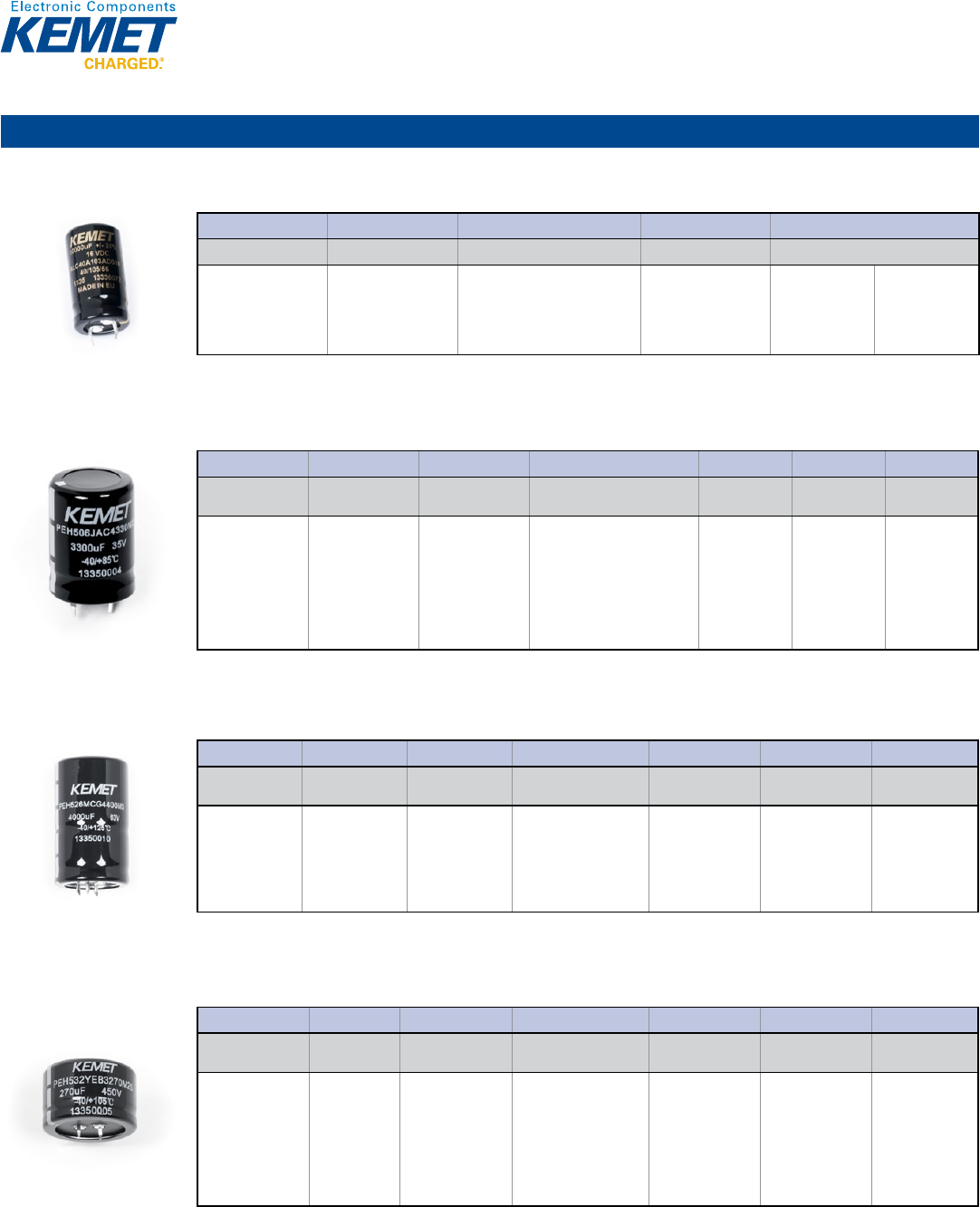
PEH526 Series Automotive 125°C, 25 – 63 VDC
Capacitance Range: 820 to 6,800 µF • Temperature Range: −40°C to +125°C • Lifetime: 20,000 Hours
1© KEMET Electronics Corporation • P.O. Box 5928 • Greenville, SC 29606 (864) 963-6300 • www.kemet.com A4028_PEH526 • 4/16/2015
One world. One KEMET
Bene ts
• Designed for automotive applications
• 3,000 hours at +125°C (VR, IR applied)
• Resistance to vibrations
• Low ESR
• High ripple current capability
Overview
KEMET's PEH526 is an electrolytic capacitor with outstanding
electrical performance. The device is polarized, has a negative
pole connected to the case and a plastic cover for the outer case.
Low ESR is the result of a low resistive electrolyte/paper system.
Together with the TDC thermal concept, this range gives the
PEH526 a very high ripple current capability. It is suitable for
use in both mobile and aircraft applications with operation up to
+125°C.
Applications
KEMET's PEH526 is a high performance electrolytic capacitor
designed for automotive applications with high vibrations and
high ambient temperatures.
Snap-In Aluminum Electrolytic Capacitors
PEH526 Series, +125ºC
Part Number System
PEH526 HAB 427 0 M 3
Series Voltage (VDC) Size Code Capacitance Code (µF) Version Capacitance
Tolerance Termination
Snap-In type
Aluminum
Electrolytic
H = 25
K = 40
M = 63
See Dimension
Table
The second two digits
indicate the two most
signi cant digits of the
capacitance value. The
rst digit indicates the
total number digits.
0 = Standard M = ±20% See Termination
Table
PEH532 Series Low ESR & ESL 105°C, 35 – 450 VDC
Capacitance Range: 68 to 27,000 µF • Temperature Range: −40°C to +105°C • Lifetime: 2,000 Hours
1© KEMET Electronics Corporation • P.O. Box 5928 • Greenville, SC 29606 (864) 963-6300 • www.kemet.com A4023_PEH532 • 4/16/2015
One world. One KEMET
Bene ts
• Snap-In
• 1,500 hours at +105°C (VR, IR applied)
• PCB mounting
• Low ESR and ESL
• High ripple current
Overview
KEMET's PEH532 is a long-life electrolytic capacitor designed
to offer high ripple current capability and low mounting cost. Low
ESR is the result of a very low resistive paper/electrolyte system.
Low ESR, together with the TDC thermal concept, gives the
PEH532 a high ripple current capability.
Applications
Typical applications for KEMET's PEH532 capacitor include
switch mode power supplies (SMPS), drives, welding equipment,
uninterruptible power supplies (UPS), and other power electronic
applications where high current ratings and compact size are
important.
Snap-In Aluminum Electrolytic Capacitors
PEH532 Series, +105ºC
Part Number System
PEH532 JAC 433 0 M 2
Series Voltage (VDC) Size Code Capacitance Code (µF) Version
Capacitance Tolerance
Termination
Snap-In type
Aluminum
Electrolytic
J = 35
M = 63
P = 100
R = 200
S = 250
U = 350
V = 400
Y = 450
See Dimension
Table
The second two digits
indicate the two most
signi cant digits of the
capacitance value. The
rst digit indicates the
total number digits.
0 = Standard M = ±20% See Termination
Table
15
Aluminum Capacitors
Snap-In (cont.)
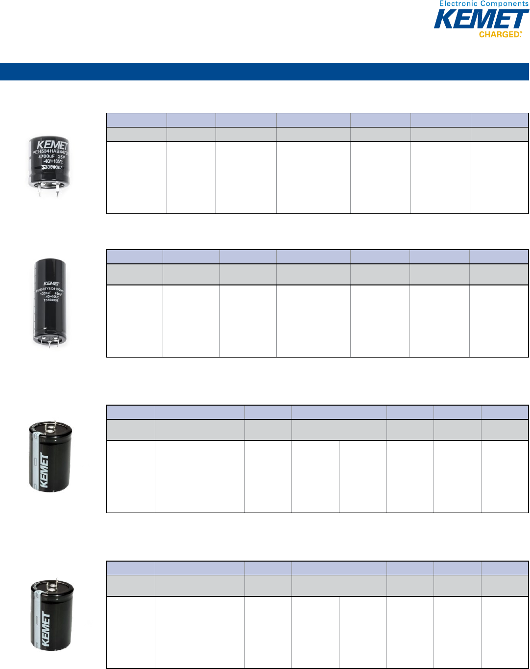
PEH534 Series Low ESR & ESL 105°C, 35 – 450 VDC
Capacitance Range: 150 to 22,000 µF • Temperature Range: −40°C to +105°C • Lifetime: 4,000 Hours
1© KEMET Electronics Corporation • P.O. Box 5928 • Greenville, SC 29606 (864) 963-6300 • www.kemet.com A4024_PEH534 • 4/16/2015
One world. One KEMET
Bene ts
• Snap-In
• 3,000 hours at +105°C (VR, IR applied)
• PCB mounting
• Low ESR and ESL
• High ripple current
Overview
KEMET's PEH534 is a long-life electrolytic capacitor designed
to offer high ripple current capability and low mounting cost. Low
ESR is the result of a very low resistive paper/electrolyte system.
Low ESR, together with the TDC thermal concept, gives the
PEH534 a high ripple current capability.
Applications
Typical applications for KEMET's PEH534 capacitor include
switch mode power supplies (SMPS), drives, welding equipment,
uninterruptible power supplies (UPS), and other power electronic
applications where high current ratings and compact size are
important.
Snap-In Aluminum Electrolytic Capacitors
PEH534 Series, +105ºC
Part Number System
PEH534 JBC 456 0 M 2
Series Voltage (VDC) Size Code Capacitance Code (µF) Version
Capacitance Tolerance
Termination
Snap-In type
Aluminum
Electrolytic
J = 35
M = 63
P = 100
R = 200
S = 250
U = 350
V = 400
Y = 450
See Dimension
Table
The second two digits
indicate the two most
signi cant digits of the
capacitance value. The
rst digit indicates the
total number digits.
0 = Standard M = ±20% See Termination
Table
PEH536 Series Low ESR & ESL 105°C, 35 – 450 VDC
Capacitance Range: 47 to 18,000 µF • Temperature Range: −40°C to +105°C • Lifetime: 6,000 Hours
1© KEMET Electronics Corporation • P.O. Box 5928 • Greenville, SC 29606 (864) 963-6300 • www.kemet.com A4025_PEH536 • 4/16/2015
One world. One KEMET
Bene ts
• Snap-In
• 4,600 hours at +105°C (VR, IR applied)
• PCB mounting
• Low ESR and ESL
• High ripple current
Overview
KEMET's PEH536 is a long-life electrolytic capacitor designed
to offer high ripple current capability and low mounting cost. Low
ESR is the result of a very low resistive paper/electrolyte system.
Low ESR, together with the TDC thermal concept, gives the
PEH536 a high ripple current capability.
Applications
Typical applications for KEMET's PEH536 capacitor include
switch mode power supplies (SMPS), drives, welding equipment,
uninterruptible power supplies (UPS), and other power electronic
applications where high current ratings and compact size are
important.
Snap-In Aluminum Electrolytic Capacitors
PEH536 Series, +105ºC
Part Number System
PEH536 JAD 439 0M2
Series Voltage (VDC) Size Code Capacitance Code (µF) Version
Capacitance
Tolerance Termination
Snap-In type
Aluminum
Electrolytic
J = 35
M = 63
P = 100
R = 200
S = 250
U = 350
V = 400
Y = 450
See Dimension
Table
The second two digits
indicate the two most
signi cant digits of the
capacitance value. The
rst digit indicates the
total number digits.
0 = Standard M = ±20% See Termination
Table
ELH Series Low Impedance 85°C, 6.3 – 450 VDC
Capacitance Range: 47 to 120,000 µF • Temperature Range: −40°C to +85°C • Lifetime: 2,000 Hours
1© KEMET Electronics Corporation • P.O. Box 5928 • Greenville, SC 29606 (864) 963-6300 • www.kemet.com A4018_ELH • 4/16/2015
One world. One KEMET
Bene ts
• Suited for high quality, high reliability applications
• Low impedance
• Operating temperature of up to 85°C
• 2,000 hour operating life
• RoHS Compliant and lead-free
Overview
KEMET's ELH Series of aluminum electrolytic snap-in capacitors
are designed with snap-lock terminals for printed circuit board
mounting. The case is aluminum with an insulated sleeve and
safety vent at the bottom.
Applications
Typical applications include general purpose power electronics,
UPS, SMPS and battery chargers.
Snap-In Aluminum Electrolytic Capacitors
ELH Series, +85ºC
Part Number System
ELH 159 M6R3 AQ1 AA
Series Capacitance Code (pF) Tolerance Rated Voltage (VDC) Electrical
Parameters Size Code Packaging
Snap-In
Aluminum
Electrolytic
Digits 4 – 5 represent the rst
two digits of the capacitance
value. The nal digit indicates
the number of zeros to be
added.
M = ±20% 6R3 = 6.3
010 = 10
016 = 16
025 = 25
035 = 35
050 = 50
063 = 63
080 = 80
100 = 100
160 = 160
180 = 180
200 = 200
250 = 250
350 = 350
400 = 400
450 = 450
A = Standard See Dimension
Table
See Ordering
Options Table
Ordering Options Table
Packaging Type Lead Length (mm) Lead and
Packaging Code
Standard Bulk Packaging Options
Bulk (box)
5.8 ± 1.0
AA
Bulk (box)
4.0 ± 0.2
AV
ELG Series General Purpose 105°C, 6.3 – 450 VDC
Capacitance Range: 47 to 82,000 µF • Temperature Range: −40°C to +105°C • Lifetime: 2,000 Hours
1© KEMET Electronics Corporation • P.O. Box 5928 • Greenville, SC 29606 (864) 963-6300 • www.kemet.com A4021_ELG • 4/16/2015
One world. One KEMET
Bene ts
• Suited for high reliability, low ESR applications
• Operating temperature of up to 105°C
• 2,000 hour operating life
• RoHS Compliant and lead-free
Overview
KEMET's ELG Series of aluminum electrolytic snap-in capacitors
are designed with snap-lock terminals for printed circuit board
mounting. The case is aluminum with an insulated sleeve and
safety vent at the bottom.
Applications
Typical applications include general purpose power electronics,
UPS, SMPS and battery chargers.
Snap-In Aluminum Electrolytic Capacitors
ELG Series, +105ºC
Part Number System
ELG 129 M6R3 AQ1 AA
Series Capacitance Code (pF) Tolerance Rated Voltage (VDC) Electrical
Parameters Size Code Packaging
Snap-In
Aluminum
Electrolytic
Digits 4 – 5 represent the rst
two digits of the capacitance
value. The nal digit indicates
the number of zeros to be
added.
M = ±20%
6R3 = 6.3
010 = 10
016 = 16
025 = 25
035 = 35
050 = 50
063 = 63
080 = 80
100 = 100
160 = 160
180 = 180
200 = 200
250 = 250
350 = 350
400 = 400
450 = 450
A = Standard
See Dimension
Table
See Ordering
Options Table
Ordering Options Table
Packaging Type Lead Length (mm) Lead and
Packaging Code
Standard Bulk Packaging Options
Bulk (box)
5.8 ± 1.0
AA
Bulk (box)
4.0 ± 0.2
AV
16
Aluminum Capacitors
Solder Pin/Tag
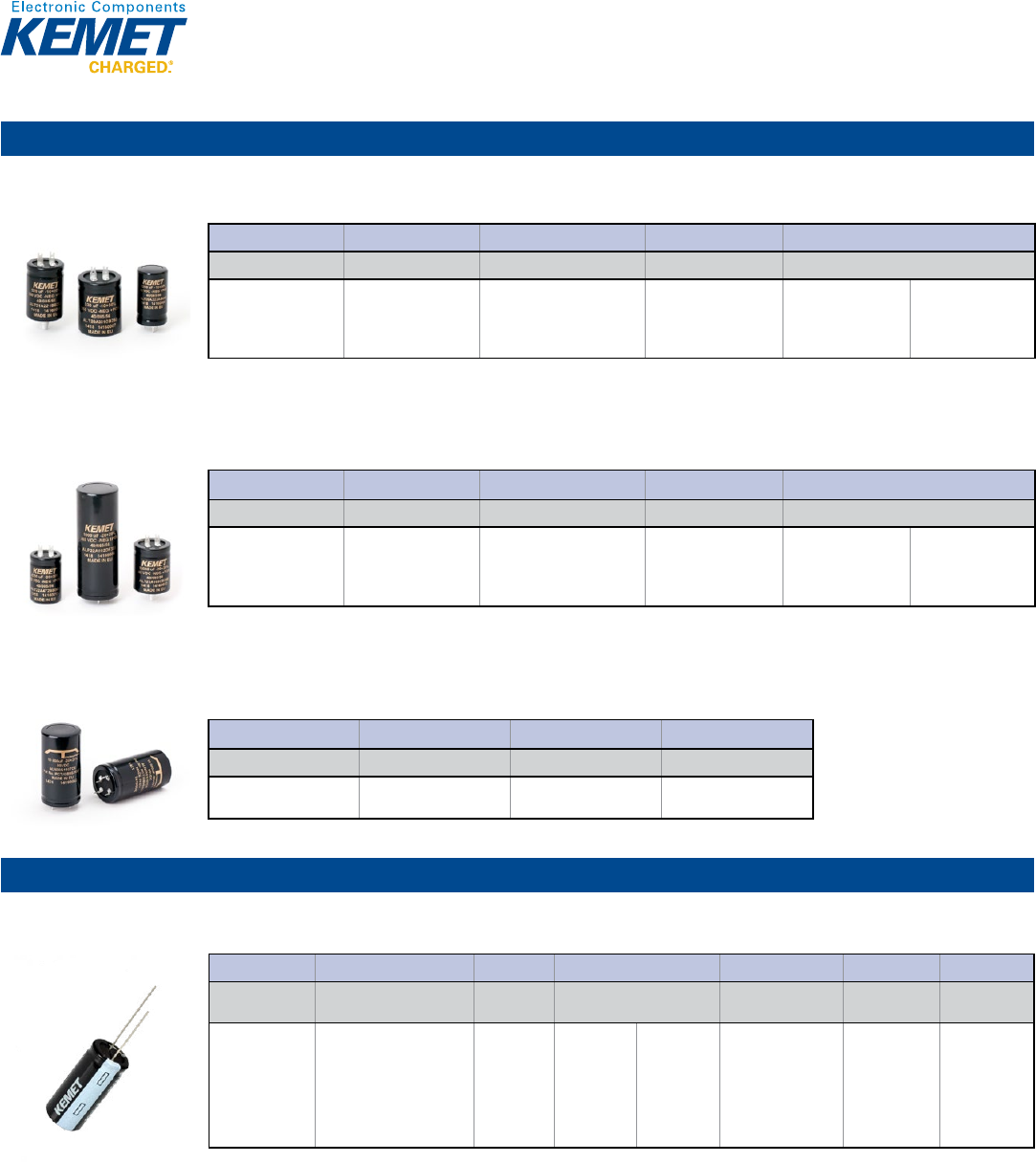
ALP20 and ALT20/21 Series Low ESR 85°C, 40 – 450 VDC
Capacitance Range: 22 to 150,000 µF • Temperature Range: −40°C to +85°C • Lifetime: 26,000 Hours
1© KEMET Electronics Corporation • P.O. Box 5928 • Greenville, SC 29606 (864) 963-6300 • www.kemet.com A4040_ALP_T20_21 • 4/16/2015
One world. One KEMET
Bene ts
• Solder tag (ALT) and DIN standard solder pin (ALP)
• Long life, up to 26,000 hours at +85°C (VR, IR applied)
• ALC snap-in should be considered for new designs
Overview
KEMET's ALP20 and ALT20/21 Series of capacitors features
low ESR, high ripple current ratings and outstandingly good high
frequency impedance.
Applications
It should be pointed out that the ALP solder pin and ALT
solder tag range details are incorporated herein, primarily, for
maintenance/replacement purposes.
Pin/Solder Tag/Audio Aluminum Electrolytic Capacitors
ALP20 and ALT20/21 Series, +85°C
Part Number System
ALP 20A 682 AB 010
Series Version Capacitance Code (µF) Size Code Voltage (VDC)
ALP = Solder pin
ALT = Solder tag
20A = Standard
21A = Threaded
Mounting Stud (ALT
only)
First 2 digits equals rst 2
signi cant gures, 3rd digit is
number of zeros
See Dimension Table 040 = 40
063 = 63
100 = 100
200 = 200
250 = 250
385 = 385
400 = 400
450 = 450
ALP22 and ALT22/23 Series High Ripple 85°C, 40 – 450 VDC
Capacitance Range: 22 to 150,000 µF • Temperature Range: −40°C to +85°C • Lifetime: 26,000 Hours
1© KEMET Electronics Corporation • P.O. Box 5928 • Greenville, SC 29606 (864) 963-6300 • www.kemet.com A4046_ALP_T22_23 • 4/16/2015
One world. One KEMET
Bene ts
• Solder tag (ALT) and DIN standard solder pin (ALP)
• Long life, up to 26,000 hours at +85°C (VR, IR applied)
• ALC snap-in should be considered for new designs
Overview
KEMET's ALP22 and ALT22/23 Series of capacitors features
low ESR, high ripple current ratings and outstandingly good high
frequency impedance. KEMET's ALP/T22/23 series of capacitors
has a very high CV per unit volume.
Applications
It should be pointed out that the ALP solder pin and ALT
solder tag range details are incorporated herein, primarily, for
maintenance/replacement purposes.
Pin/Solder Tag/Audio Aluminum Electrolytic Capacitors
ALP22 and ALT22/23 Series, +85°C
Part Number System
ALP 22A 682 AB 010
Series Version Capacitance Code (µF) Size Code Voltage (VDC)
ALP = Solder pin
ALT = Solder tag
22A = Standard
23A = Threaded
Mounting Stud (ALT
only)
First 2 digits equals rst 2
signi cant gures, 3rd digit is
number of zeros
See Dimension Table 040 = 40
063 = 63
100 = 100
200 = 200
250 = 250
385 = 385
400 = 400
450 = 450
ALN20S Series T-Network 85°C, 50 & 100 VDC
Capacitance Range: 10,000 µF • Temperature Range: −40°C to +85°C • Lifetime: 18,000 Hours
1© KEMET Electronics Corporation • P.O. Box 5928 • Greenville, SC 29606 (864) 963-6300 • www.kemet.com A4030_ALN20S • 4/16/2015
One world. One KEMET
Bene ts
• 4 pin Solder tag
• Long life, up to 18,000 hours at +85°C (VR, IR applied)
• Slit foil technology
• Speci cally designed for audio applications use only.
Overview
KEMET's ALN20S series of capacitors is a new generation
T-Network Capacitor (TNC). The TNC is manufactured by KEMET
in Portugal. In a normal capacitor unwanted resistance and
inductance force the input and output together electrically, making
its unwanted characteristics very critical for performance - Figure 1.
The new TNC behaves differently because the input must fl ow
along the capacitor plate to reach the output. The signal is forced
into pure capacitance with most of the unwanted resistance and
inductance appearing on each side of the bulk capacitance. The
residual defects, therefore, tend to assist capacitance ltering in
the T-Network design - Figure 2.
The TNC is designed for the most demanding ltering situations
and it will rede ne performance standards in many non-audio
applications. For use in audio ampli ers, the TNC incorporates
current slit foil technology to produce the ultimate audio capacitor.
These capacitors give excellent results against standard
components on a direct replacement. However, TNC high
frequency performance is so enhanced that the H.F. compensation
of test ampli ers may need resetting for best results.
Pin/Solder Tag/Audio Aluminum Electrolytic Capacitors
ALN20S Series, +85°C
Part Number System
ALN20 S1053 DD
Series Construction Unique Sequential Number Size Code
Snap-In type Aluminum
Electrolytic
S = Slit foil See Dimension Table
Figure 1: Conventional Capacitor
Figure 2: Network Capacitor
Single-Ended
ESK Series General Purpose 85°C, 6.3 – 450 VDC
Capacitance Range: 0.1 to 22,000 µF • Temperature Range: −40°C to +85°C • Lifetime: 2,000 Hours
1© KEMET Electronics Corporation • P.O. Box 5928 • Greenville, SC 29606 (864) 963-6300 • www.kemet.com A4004_ESK • 4/16/2015
One world. One KEMET
Bene ts
• Operating temperature of up to 85°C
• 2,000 hour operating life
• Case diameters 5 – 22 mm
• Safety vent on the capacitor base
Overview
KEMET's ESK Series of single-ended aluminum electrolytic
capacitors are designed for high-density printed circuit boards.
Applications
Typical applications include general purpose coupling,
decoupling, bypass and ltering.
Single-Ended Aluminum Electrolytic Capacitors
ESK Series, +85ºC
Part Number System
ESK 226 M6R3 A C3 AA
Series Capacitance Code (pF) Tolerance
Rated Voltage
(VDC)
Electrical Parameters Size Code Packaging
Single-Ended
Aluminum
Electrolytic
Digits 4 – 5 represent
the rst two digits of the
capacitance value. The nal
digit indicates the number of
zeros to be added.
M = ±20% 6R3 = 6.3
010 = 10
016 = 16
025 = 25
035 = 35
050 = 50
063 = 63
100 = 100
160 = 160
200 = 200
250 = 250
350 = 350
400 = 400
450 = 450
A = Standard See Dimension
Table
See Ordering
Options Table
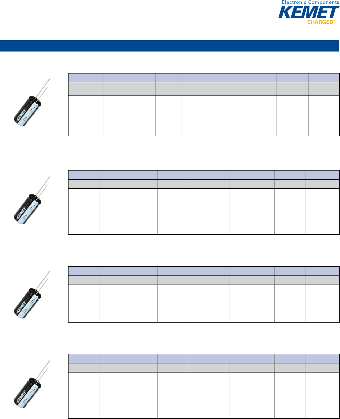
17
Aluminum Capacitors
Single-Ended (cont.)
ESH Series High CV 105°C, 6.3 – 450 VDC
Capacitance Range: 0.47 to 15,000 µF • Temperature Range: −40°C to +105°C • Lifetime: 2,000 Hours
1© KEMET Electronics Corporation • P.O. Box 5928 • Greenville, SC 29606 (864) 963-6300 • www.kemet.com A4005_ESH • 4/16/2015
One world. One KEMET
Bene ts
• Suited for high quality, high reliability applications
• 2,000 hour operating life
• Operating temperature of up to +105°C
• Case diameters 5 – 18 mm
• Safety vent on the capacitor base
Overview
KEMET's ESH Series of single-ended aluminum electrolytic
capacitors are designed for high quality, high reliability
applications.
Applications
Typical applications include general purpose coupling,
decoupling, bypass and ltering.
Single-Ended Aluminum Electrolytic Capacitors
ESH Series, +105ºC
Part Number System
ESH 107 M6R3 A C3 AA
Series Capacitance Code (pF) Tolerance
Rated Voltage
(VDC) Electrical Parameters Size Code Packaging
Single-Ended
Aluminum
Electrolytic
Digits 4 – 5 represent
the rst two digits of the
capacitance value. The nal
digit indicates the number of
zeros to be added.
M = ±20% 6R3 = 6.3
010 = 10
016 = 16
025 = 25
035 = 35
050 = 50
063 = 63
100 = 100
160 = 160
200 = 200
250 = 250
350 = 350
400 = 400
450 = 450
A = Standard See Dimension
Table
See Ordering
Options Table
ESC Series Low ESR 105°C, 6.3 – 100 VDC
Capacitance Range: 4.7 to 15,000 µF • Temperature Range: −40°C to +105°C • Lifetime: 3,000 Hours
1© KEMET Electronics Corporation • P.O. Box 5928 • Greenville, SC 29606 (864) 963-6300 • www.kemet.com A4006_ESC • 4/16/2015
One world. One KEMET
Bene ts
• Low impedance
• Operating temperature of up to +105°C
• 2,000 – 3,000 hour operating life
• Case with Ø D ≥ 6.3 mm
• Safety vent on the capacitor base
Overview
KEMET's ESC Series of single-ended aluminum electrolytic
capacitors are designed for high frequency applications.
Applications
Typical applications include high frequency switch mode circuits.
Single-Ended Aluminum Electrolytic Capacitors
ESC Series, +105ºC
Part Number System
ESC 157 M6R3 A C3 AA
Series Capacitance Code (pF) Tolerance Rated Voltage (VDC) Electrical Parameters Size Code Packaging
Single-Ended
Aluminum
Electrolytic
Digits 4 – 5 represent the rst
two digits of the capacitance
value. The nal digit indicates
the number of zeros to be
added.
M = ±20%
6R3 = 6.3
010 = 10
016 = 16
025 = 25
035 = 35
050 = 50
063 = 63
100 = 100
A = Standard
See Dimension
Table
See Ordering
Options Table
ESG Series High Ripple Current 105°C, 160 – 450 VDC
Capacitance Range: 4.7 to 330 µF • Temperature Range: −40°C to +105°C • Lifetime: 5,000 Hours
1© KEMET Electronics Corporation • P.O. Box 5928 • Greenville, SC 29606 (864) 963-6300 • www.kemet.com A4008_ESG • 4/16/2015
One world. One KEMET
Bene ts
• Suited for long life, high reliability applications
• Operating temperature of up to +105°C
• 5,000 hour operating life
• Case with Ø D ≥ 6.3 mm
• Safety vent on the capacitor base
Overview
KEMET's ESG Series of single-ended aluminum electrolytic
capacitors are designed for long life (5,000 hours) and high
reliability applications.
Applications
Typical applications include electronic ballast and long-life
equipment.
Single-Ended Aluminum Electrolytic Capacitors
ESG Series, +105ºC
Part Number System
ESG 336 M160 A H4 AA
Series Capacitance Code (pF) Tolerance Rated Voltage (VDC) Electrical Parameters Size Code Packaging
Single-Ended
Aluminum
Electrolytic
Digits 4 – 5 represent the rst
two digits of the capacitance
value. The nal digit indicates
the number of zeros to be
added.
M = ±20% 160 = 160
200 = 200
250 = 250
350 = 350
400 = 400
450 = 450
A = Standard See Dimension
Table
See Ordering
Options Table
ESY Series Low Impedance 105°C, 6.3 – 100 VDC
Capacitance Range: 5.6 to 6,800 µF • Temperature Range: −40°C to +105°C • Lifetime: 5,000 Hours
1© KEMET Electronics Corporation • P.O. Box 5928 • Greenville, SC 29606 (864) 963-6300 • www.kemet.com A4007_ESY • 4/16/2015
One world. One KEMET
Bene ts
• Very low impedance
• High ripple current
• Operating temperature of up to +105°C
• 1,000 – 5,000 hour operating life
• Case with Ø D ≥ 6.3 mm
• Safety vent on the capacitor base
Overview
KEMET's ESY Series of single-ended aluminum electrolytic
capacitors are designed for very low impedance and high ripple
current applications.
Applications
Typical applications include high frequency switch mode circuits.
Single-Ended Aluminum Electrolytic Capacitors
ESY Series, +105ºC
Part Number System
ESY 396 M6R3 AB2 AA
Series Capacitance Code (pF) Tolerance Rated Voltage (VDC) Electrical Parameters Size Code Packaging
Single-Ended
Aluminum
Electrolytic
Digits 4 – 5 represent the rst
two digits of the capacitance
value. The nal digit indicates
the number of zeros to be
added.
M = ±20%
6R3 = 6.3
010 = 10
016 = 16
025 = 25
035 = 35
050 = 50
063 = 63
100 = 100
A = Standard
See Dimension
Table
See Ordering
Options Table
18
Aluminum Capacitors
Single-Ended (cont.)
ESW Series Low Impedance 105°C, 6.3 – 100 VDC
Capacitance Range: 6.8 to 15,000 µF • Temperature Range: −40°C to +105°C • Lifetime: 5,000 Hours
1© KEMET Electronics Corporation • P.O. Box 5928 • Greenville, SC 29606 (864) 963-6300 • www.kemet.com A4009_ESW • 4/16/2015
One world. One KEMET
Bene ts
• Suited for long life, high reliability applications
• Operating temperature of up to +105°C
• 3,000 – 6,000 hour operating life
• Case with Ø D ≥ 6.3 mm
• Safety vent on the capacitor base
Overview
KEMET's ESW Series of single-ended aluminum electrolytic
capacitors are designed for long life (3,000 – 5,000 hours) and
high reliability applications.
Applications
Typical applications include high frequency switch mode circuits.
Single-Ended Aluminum Electrolytic Capacitors
ESW Series, +105ºC
Part Number System
ESW 226 M6R3 A C3 AA
Series Capacitance Code (pF) Tolerance Rated Voltage (VDC) Electrical Parameters Size Code Packaging
Single-Ended
Aluminum
Electrolytic
Digits 4 – 5 represent the rst
two digits of the capacitance
value. The nal digit indicates
the number of zeros to be
added.
M = ±20% 6R3 = 6.3
010 = 10
016 = 16
025 = 25
035 = 35
050 = 50
063 = 63
100 = 100
A = Standard See Dimension
Table
See Ordering
Options Table
EST Series Long Life 105°C, 6.3 – 63 VDC
Capacitance Range: 6.8 to 15,000 µF • Temperature Range: −40°C to +105°C • Lifetime: 10,000 Hours
1© KEMET Electronics Corporation • P.O. Box 5928 • Greenville, SC 29606 (864) 963-6300 • www.kemet.com A4010_EST • 4/16/2015
One world. One KEMET
Bene ts
• Long life, up to 10,000 hours
• Low impedance
• Operating temperature of up to +105°C
• Case with Ø D ≥ 6.3 mm
• Safety vent on the capacitor base
Overview
KEMET's EST Series of single-ended aluminum electrolytic
capacitors are designed for low impedance and long life (up to
10,000 hours) applications.
Applications
Typical applications include SMPS, power supplies, adaptors,
chargers, monitors and computers.
Single-Ended Aluminum Electrolytic Capacitors
EST Series, +105ºC
Part Number System
EST 157 M6R3 A C3 AA
Series Capacitance Code (pF) Tolerance Rated Voltage (VDC) Electrical Parameters Size Code Packaging
Single-Ended
Aluminum
Electrolytic
Digits 4 – 5 represent the rst
two digits of the capacitance
value. The nal digit indicates
the number of zeros to be
added.
M = ±20% 6R3 = 6.3
010 = 10
016 = 16
025 = 25
035 = 35
050 = 50
063 = 63
A = Standard See Dimension
Table
See Ordering
Options Table
EAK Series Long Life 125°C, 10 – 63 VDC
Capacitance Range: 47 to 4,700 µF • Temperature Range: −40°C to +105°C • Lifetime: 5,000 Hours
1© KEMET Electronics Corporation • P.O. Box 5928 • Greenville, SC 29606 (864) 963-6300 • www.kemet.com A4047_EAK • 4/16/2015
One world. One KEMET
Bene ts
• Operating temperature of up to +125°C
• 2,000 – 5000 hour operating life
• Safety vent on the capacitor base
Overview
KEMET's EAK Series of aluminum electrolytic single-ended
capacitors are designed for long life (up to 5,000 hours) and
higher operating temperatures of up to 125°C.
Applications
Typical applications include electronic ballast and lighting ballast.
Single-Ended Aluminum Electrolytic Capacitors
EAK Series, +125ºC
Part Number System
EAK 227 M010 AG3 AA
Series Capacitance Code (pF) Tolerance Rated Voltage (VDC) Electrical Parameters Size Code Packaging
Single-Ended
Aluminum
Electrolytic
Digits 4 – 5 represent the rst
two digits of the capacitance
value. The nal digit indicates
the number of zeros to be
added.
M = ±20% 010 = 10
016 = 16
025 = 25
035 = 35
050 = 50
063 = 63
A = Standard See Dimension
Table
See Ordering
Options Table
Surface Mount
A700 Series Polymer Aluminum 125°C, 2 – 16 VDC
Capacitance Range: 6.8 to 560 µF • Temperature Range: −55°C to +125°C • Lifetime: 2,000 Hours
© KEMET Electronics Corporation • P.O. Box 5928 • Greenville, SC 29606 (864) 963-6300 • www.kemet.com T2020_A700 • 4/16/2015 22
Aluminum Organic Capacitor (AO-CAP)
A700 Series Polymer Aluminum
SPICE
For a detailed analysis of speci c part numbers, please visit www.kemet.com for a free download of KEMET's SPICE software.
The KEMET SPICE program is freeware intended to aid design engineers in analyzing the performance of these capacitors over
frequency, temperature, ripple, and DC bias conditions.
Ordering Information
A700 V476 M006 A T E018
Capacitor
Class Series Case Size Capacitance
Code (pF)
Capacitance
Tolerance
Rated Voltage
(VDC)
Failure Rate/
Design
Termination
Finish ESR Code Packaging
(C-Spec)
A =
Aluminum
700 =
Aluminum
Polymer
D, V, X
First two digits
represent
signi cant
gures. Third
digit speci es
number of
zeros.
M = ±20%
002 = 2
2R5 = 2.5
004 = 4
006 = 6.3
008 = 8
010 = 10
12R = 12.5
016 = 16
A = N/A
T = 100%
Matte Tin
(Sn) plated
E = ESR
Last three
digits specify
ESR in mΩ
(018 = 18
mΩ)
Blank = 7"
Reel
7280 = 13"
Reel
Performance Characteristics
Item
Performance Characteristics
Operating Temperature
-55°C to 125°C
Rated Capacitance Range
6.8 – 560 µF at 120 Hz/25°C
Capacitance Tolerance
M Tolerance (20%)
Rated Voltage Range
2 – 16 V
DF (120 Hz)
6%
ESR (100 kHz)
Refer to Part Number Electrical Speci cation Table
Leakage Current
≤ 4 V Rating: ≤ 0.06 CV (µA) at rated voltage after 5 minutes
> 4 V Rating: ≤ 0.04 CV (µA) at rated voltage after 5 minutes
19
Aluminum Capacitors
Surface Mount (cont.)
EDH Series General Purpose 105°C, 6.3 – 100 VDC
Capacitance Range: 1.0 to 1,500 µF • Temperature Range: −40°C to +105°C • Lifetime: 2,000 Hours
1© KEMET Electronics Corporation • P.O. Box 5928 • Greenville, SC 29606 (864) 963-6300 • www.kemet.com A4049_EDH • 4/16/2015
One world. One KEMET
Bene ts
• Surface mount lead terminals
• Low pro le vertical chip
• 105°C/2,000 hours
Overview
KEMET's EDH Series of aluminum electrolytic surface mount
capacitors are designed for high density printed circuit boards.
Applications
Typical applications include audio/visual (AV), computer/monitor,
communications, and switch mode power supplies (SMPS).
Surface Mount Aluminum Electrolytic Capacitors
EDH Series, +105ºC
Part Number System
EDH 226 M6R3 A9B AA
Series Capacitance Code (pF) Tolerance
Rated Voltage
(VDC)
Electrical Parameters Size Code Packaging
Surface Mount
Aluminum
Electrolytic
Digits 4 – 5 represent
the rst two digits of the
capacitance value. The
nal digit indicates the
number of zeros to be
added.
M = ±20%
6R3 = 6.3
010 = 10
016 = 16
025 = 25
035 = 35
050 = 50
063 = 63
100 = 100
A = Standard
See Dimension
Table
AA = T&R
EDK Series General Purpose 85°C, 4 – 100 VDC
Capacitance Range: 0.1 to 1,000 µF • Temperature Range: −40°C to +85°C • Lifetime: 2,000 Hours
1© KEMET Electronics Corporation • P.O. Box 5928 • Greenville, SC 29606 (864) 963-6300 • www.kemet.com A4001_EDK • 4/16/2015
One world. One KEMET
Bene ts
• Surface mount lead terminals
• Low pro le vertical chip
• General purpose +85°C/2,000 hours
Overview
KEMET's EDK Series of aluminum electrolytic surface mount
capacitors are designed for high density printed circuit boards.
Applications
Typical applications include coupling, decoupling, bypass, and
ltering.
Surface Mount Aluminum Electrolytic Capacitors
EDK Series, +85ºC
Part Number System
EDK 226 M004 A9B AA
Series Capacitance Code (pF) Tolerance Rated Voltage (VDC) Electrical Parameters Size Code Packaging
Surface Mount
Aluminum
Electrolytic
Digits 4 – 5 represent
the rst two digits of the
capacitance value. The
nal digit indicates the
number of zeros to be
added.
M = ±20% 004 = 4
6R3 = 6.3
010 = 10
016 = 16
025 = 25
035 = 35
050 = 50
063 = 63
100 = 100
A = Standard See Dimension
Table
AA = Tape & Reel
EEV Series Ultra-Low Impedance 105°C, 6.3 – 50 VDC
Capacitance Range: 4.7 to 1,500 µF • Temperature Range: −40°C to +105°C • Lifetime: 2,000 Hours
1© KEMET Electronics Corporation • P.O. Box 5928 • Greenville, SC 29606 (864) 963-6300 • www.kemet.com A4002_EEV • 4/16/2015
One world. One KEMET
Bene ts
• Surface mount lead terminals
• Low pro le vertical chip
• Ultra-low impedance
• +105°C/2,000 hours
Overview
KEMET's EEV Series of aluminum electrolytic surface mount
capacitors are designed for applications requiring ultra-low
impedance and a low pro le vertical chip.
Applications
Typical applications include audio/visual (AV), computer/monitor,
communications, and switch mode power supplies (SMPS).
Surface Mount Aluminum Electrolytic Capacitors
EEV Series, +105ºC
Part Number System
EEV 226 M6R3 A9B AA
Series Capacitance Code (pF) Tolerance Rated Voltage (VDC) Electrical Parameters Size Code Packaging
Surface Mount
Aluminum
Electrolytic
Digits 4 – 5 represent
the rst two digits of the
capacitance value. The
nal digit indicates the
number of zeros to be
added.
M = ±20% 6R3 = 6.3
010 = 10
016 = 16
025 = 25
035 = 35
050 = 50
A = Standard See Dimension Table AA = Tape & Reel
EXV Series Ultra-Low Impedance 105°C, 6.3 – 50 VDC
Capacitance Range: 1 to 1,000 µF • Temperature Range: −40°C to +105°C • Lifetime: 5,000 Hours
1© KEMET Electronics Corporation • P.O. Box 5928 • Greenville, SC 29606 (864) 963-6300 • www.kemet.com A4003_EXV • 4/16/2015
One world. One KEMET
Bene ts
• Surface mount lead terminals
• Low pro le vertical chip
• Ultra-low impedance
• +105°C/3,000 – 5,000 hours
Overview
KEMET's EXV Series of aluminum electrolytic surface mount
capacitors are designed for applications requiring ultra-low
impedance and a low pro le vertical chip.
Applications
Typical applications include audio/visual (AV), computer/monitor,
communications, and switch mode power supplies (SMPS).
Surface Mount Aluminum Electrolytic Capacitors
EXV Series, +105ºC
Part Number System
EXV 226 M6R3 A9B AA
Series Capacitance Code (pF) Tolerance Rated Voltage (VDC) Electrical Parameters Size Code Packaging
Surface Mount
Aluminum
Electrolytic
Digits 4 – 5 represent
the rst two digits of the
capacitance value. The
nal digit indicates the
number of zeros to be
added.
M = ±20%
6R3 = 6.3
010 = 10
016 = 16
025 = 25
035 = 35
050 = 50
A = Standard
See Dimension
Table
AA = Tape & Reel
20
Aluminum Capacitors
Motor Start
MS/MD Series 60ºC/70°C, 120 – 260 VAC
Capacitance Range: 25 to 750 µF • Temperature Range: MS: −20°C to +60°C, MD: −20°C to +70°C • Lifetime: 500 Hours
1© KEMET Electronics Corporation • P.O. Box 5928 • Greenville, SC 29606 (864) 963-6300 • www.kemet.com A4041_MS_MD • 4/16/2015
One world. One KEMET
Bene ts
• Intermittent AC motor starting
• 6.3 mm double amp tags (quick connect types)
• VDE approved to IEC 60252–2
Overview
KEMET's MS/MD Series of aluminum electrolytic capacitors are
designed for itermittent duty only and capable of withstanding
the AC voltage applied to the motor during starting. The
capacitor construction is comprised of either double anode or
O-style (double anode and fl oating cathode) windings, which
are housed in a molded plastic case. KEMET's MD Series is
VDE approved to IEC 60252-2 for the de ned ratings.
Applications
KEMET's MS/MD Series is a range of aluminium electrolytic
capacitors speci cally designed for AC operation which helps
to start the motor by providing a leading current to the auxiliary
winding. The capacitor is not permanently connected to the
winding of the motor and is usually switched off automatically
after starting.
AC Motor Start Aluminum Electrolytic Capacitors
MS/MD Series, +60ºC/+70°C
Part Number System
080 MS 12 AA M A 1 STD
Capacitance Code
(µF) Rating Voltage (VAC) Size Code Manufacturing
Style
Capacitance
Tolerance Terminal Code Version
Example:
080 = 80 µF
120 = 120 µF
MS = Motor start
single rating
MD = Motor start
dual rating
12 = 120
22 = 220
26 = 260
See Dimension
Table
M = Molded case
A = -0% +25%
K = ±10%
1 = Double amp
tag
STD = Standard

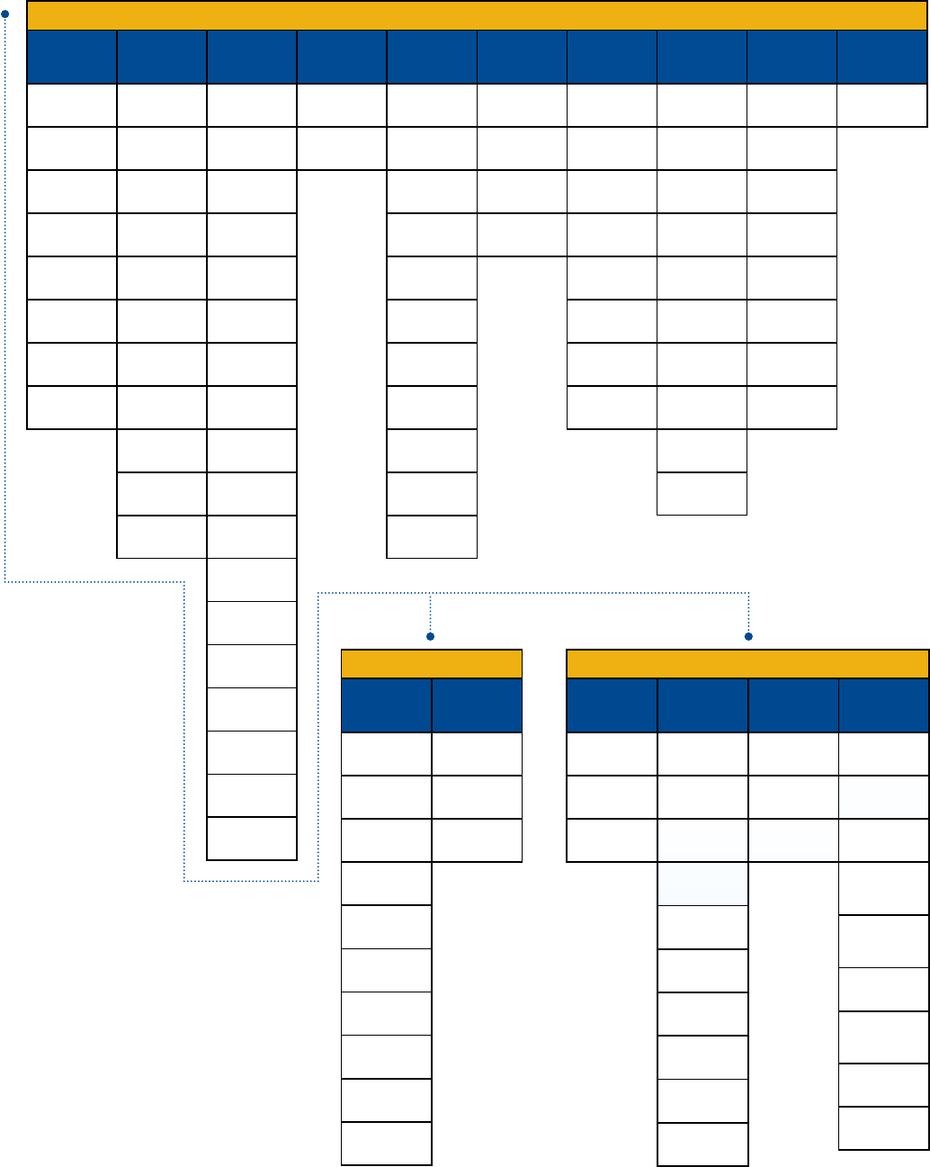
22
Ceramic Capacitors
Commercial
Grade
Flex
Mitigation
Automotive
Grade
High Reliability
Commercial
Off-the-Shelf
(COTS)
Bulk
Capacitance
High
Voltage
(> 500 V)
Aerospace &
Defense
RF &
Microwave
High
Temperature
(> 125°C)
SnPb End
Metallization
C0G
10 – 250 VDC
X7R
6.3 – 250 VDC
X5R
4 – 50 VDC
Y5V
6.3 – 50 VDC
Telecom "Tip & Ring"
X7R
250 VDC
Capacitor Array
C0G
10 – 200 VDC
Capacitor Array
X7R
10 – 200 VDC
Z5U
50 VDC & 100 VDC
C0G
10 – 250 VDC
X7R
6.3 – 250 VDC
X7R
6.3 – 250 VDC
COTS
C0G
10 – 200 VDC
COTS
X7R
6.3 – 250 VDC
KPS High Voltage
X7R
500 – 630 VDC
KPS MIL Series
50 – 1,000 VDC
High Temperature
X8R
25 – 100 VDC
High Temperature
X8L
10 – 50 VDC
Telecom "Tip & Ring"
X7R
250 VDC
Open Mode Design
X7R
16 – 200 VDC
Floating Electrode
X7R
6.3 – 250 VDC
Flexible Termination
X7R
6.3 – 250 VDC
Floating Electrode w/
Flexible Termination
X7R
6.3 – 250 VDC
C0G
10 – 250 VDC
X7R
6.3 – 250 VDC
Capacitor Array
C0G
10 – 200 VDC
Capacitor Array
X7R
10 – 200 VDC
Open Mode Design
X7R
16 – 200 VDC
Flexible Termination
X7R
6.3 – 250 VDC
KPS
X7R
10 – 250 VDC
High Voltage
Flexible Termination
X7R
500 – 3,000 VDC
KPS High Voltage
X7R
500 – 630 VDC
KPS High
Temperature 150°C
X8L
10 – 50 VDC
Flexible Termination
C0G
10 – 250 VDC
Flexible Termination
X8R
25 – 100 VDC
High Temperature
X8R
25 – 100 VDC
High Voltage
X7R
500 – 3,000 VDC
High Voltage Flexible
Termination
C0G
500 – 3,000 VDC
High Temperature
150°C
X8L
10 – 50 VDC
Open Mode Design
X7R
16 – 200 VDC
Floating Electrode
X7R
6.3 – 250 VDC
Flexible Termination
C0G
10 – 250 VDC
Flexible Termination
X7R
6.3 – 250 VDC
High Voltage Flexible
Termination
C0G
500 – 3,000 VDC
High Voltage Flexible
Termination
X7R
500 – 3,000 VDC
Flexible Termination
X8R
25 – 100 VDC
Floating Electrode w/
Flexible Termination
X7R
6.3 – 250 VDC
KPS High Voltage
X7R
500 – 630 VDC
C0G
10 – 250 VDC
KPS
X7R
10 – 250 VDC
ArcShield
TM
Technology
X7R
500 – 1,000 VDC
C0G
500 – 3,000 VDC
X7R
500 – 3,000 VDC
Flexible Termination
C0G
500 – 3,000 VDC
Flexible Termination
X7R
500 – 3,000 VDC
KPS
X7R
500 – 630 VDC
HV-HT Series 200°C
C0G
500 – 2,000 VDC
KPS HV Large Case
C0G
500 – 10K VDC
KPS HV Large Case
X7R
500 – 10K VDC
200°C High Voltage
Pulse Discharge
C0G
500 – 2,000 VDC
MIL-PRF-123
BP & BX
6.3 – 200 VDC
GR900
BP & BX
16 – 200 VDC
MIL-PRF-55681
BP & BX
50 – 100 VDC
DLA 03028
BR & BX
6.3 – 200 VDC
DLA 03029
BR & BX
6.3 – 100 VDC
CBR Series Ultra High Q
C0G
6.3 – 500 VDC
150°C
X8R
25 –100 VDC
150°C
X8L
10 –50 VDC
200°C
C0G
10 – 200 VDC
HV-HT Series 200°C
C0G
500 – 2,000 VDC
KPS 150°C
X8L
10 VDC – 50 VDC
200°C High Voltage
Pulse Discharge
C0G
500 – 2,000 VDC
Flexible Termination
150°C
X8R
25 – 100 VDC
CERAMIC SURFACE MOUNT CAPACITORS
KPS
X7R
10 – 250 VDC
KPS High
Temperature 150°C
X8L
10 – 50 VDC
KPS High
Temperature 150°C
X8L
10 – 50 VDC
Floating Electrode
X7R
6.3 – 250 VDC
Floating Electrode w/
Flexible Termination
X7R
6.3 – 250 VDC
175°C
X7R
16 – 200 VDC
DLA 05006
BP, BR & BX
10 – 200 VDC
DLA 05007
BP, BR & BX
10 – 200 VDC
DLA 91019
BR
25 – 50 VDC
CERAMIC THROUGH-HOLE CAPACITORS
CERAMIC DISC CAPACITORS
Commercial
Grade
High
Temperature
(> 125°C)
High
Voltage
(> 500 V)
Aerospace &
Defense
Safety Commercial
Grade
Aximax
C0G, X7R & Z5U
Axial Conformally Coated
25 – 250 VDC
300 Series Goldmax
C0G, X7R & Z5U
Radial Conformally Coated
25 – 250 VDC
Molded Axial & Radial
C0G & X7R
50 – 200 VDC
MIL-PRF-123
BP & BX
Molded Radial
50 – 100 VDC
GR900 High Reliability
BP & BX
Molded Radial
50 – 200 VDC
MIL-PRF-20
CG
Molded Axial & Radial
50 – 200 VDC
HV
MIL-PRF-46467 Equivalent
BP, BR & BZ
500 – 5,000 VDC
HS High Voltage
Space Quality
C0G & X7R
Radial Conformally Coated
500 – 10,000 VDC
SCR/SCA Standard
Axial & Radial
C0G
50 – 200 VDC
SRR/SRA Standard
Axial & Radial
X7R
50 – 200 VDC
MIL-C-11015/
MIL-PRF-39014
BX & BR
Molded Axial
50 – 100 VDC
MIL-C-11015/
MIL-PRF-39014
BX (X7R)
Molded Radial
50 – 200 VDC
HV 300 Series Goldmax
C0G & X7R
Radial Conformally Coated
500 – 3,000 VDC
HV
C0G & X7R
Radial Conformally Coated
500 –10,000 VDC
HT/HP 200°C
C0G & X7R
Axial & Radial
25 – 200 VDC
HV 200°C
C0G & X7R
Radial Conformally Coated
500 – 4,000 VDC
ACR/ACA 200°C
Axial & Radial
C0G
50 – 100 VDC
ARR/ARA 200°C
Axial & Radial
X7R
50 – 100 VDC
TCR/TCA 260°C
Axial & Radial
C0G
50 – 100 VDC
TRR/TRA 260°C
Axial & Radial
X7R
50 – 100 VDC
VCR 200°C
Axial & Radial
C0G
500 – 5,000 VDC
VRR 200°C
Axial & Radial
X7R
500 – 5,000 VDC
Aximax 150°C
X8L & X8R
Molded Axial
25 – 200 VDC
900
Radial Encapsulated
AC Type
X1 440 VAC/Y2 300 VAC
900
Radial Encapsulated
AS Type
X1 760 VAC/Y1 500 VAC
900
Radial Encapsulated
AH Type
X1 400 VAC/Y1 250 VAC
900
Radial Encasulated
AH Type
X1 400 VAC/Y1 400 VAC
ERO610
Radial AC Type
X1 440 VAC/Y2 250 VAC
ERK610
Radial AC Type
X1 440 VAC/Y2 300 VAC
ERP610
Radial AC Type
X1 760 VAC/Y2 500 VAC
900
Radial Encapsulated
AC Type
X1 400 VAC/Y2 250 VAC
KHA
X7R
1,000 – 2,000 VDC
KHB
Y5P
1,000 – 2,000 VDC
KHC
SL
1,000 – 2,000 VDC
KJN
Y5P, Y5U & Y5V
Y1 250/400 VAC/
X1 440 VAC
KJY
Y5P, Y5U & Y5V
Y2 250 VAC/
X1 400 VAC
HT 200°C
C0G & X7R
Radial Molded
50 – 200 VDC
HV 600 Series Goldmax
C0G & X7R
Radial Conformally Coated
500 – 3,000 VDC
23
Ceramic Capacitors
Surface Mount
Commercial Grade
C0G Dielectric, 10 – 250 VDC
Capacitance Range: 0.50 pF to 0.47 µF • Temperature Range: −55°C to +125°C
© KEMET Electronics Corporation • P.O. Box 5928 • Greenville, SC 29606 (864) 963-6300 • www.kemet.com C1003_C0G • 4/16/2015 1
One world. One KEMET
Bene ts
• -55°C to +125°C operating temperature range
• Lead (Pb)-Free, RoHS, and REACH compliant
• EIA 0201, 0402, 0603, 0805, 1206, 1210, 1808, 1812, 1825,
2220, and 2225 case sizes
• DC voltage ratings of 10 V, 16 V, 25 V, 50 V, 100 V, 200 V and 250 V
• Capacitance offerings ranging from 0.5 pF up to 0.47 μF
• Available capacitance tolerances of ±0.10 pF, ±0.25 pF, ±0.5
pF, ±1%, ±2%, ±5%, ±10%, and ±20%
• No piezoelectric noise
• Extremely low ESR and ESL
• High thermal stability
• High ripple current capability
Overview
KEMET’s C0G dielectric features a 125°C maximum operating
temperature and is considered “stable.” The Electronics
Components, Assemblies & Materials Association (EIA)
characterizes C0G dielectric as a Class I material. Components
of this classi cation are temperature compensating and are
suited for resonant circuit applications or those where Q and
stability of capacitance characteristics are required. C0G exhibits
no change in capacitance with respect to time and voltage and
boasts a negligible change in capacitance with reference to
ambient temperature. Capacitance change is limited to ±30
ppm/ºC from -55°C to +125°C.
Surface Mount Multilayer Ceramic Chip Capacitors (SMD MLCCs)
C0G Dielectric, 10 – 250 VDC (Commercial Grade)
Ordering Information
C1206 C104 J 3 G A C TU
Ceramic
Case Size
(L" x W")
Speci cation/
Series1
Capacitance
Code (pF)
Capacitance
Tolerance2
Rated Voltage
(VDC) Dielectric
Failure Rate/
Design Termination Finish3
Packaging/Grade
(C-Spec)4
0201
0402
0603
0805
1206
1210
1808
1812
1825
2220
2225
C = Standard 2 signi cant digits +
number of zeros.
Use 9 for 1.0 – 9.9 pF
Use 8 for 0.5 – .99 pF
e.g., 2.2 pF = 229
e.g., 0.5 pF = 508
B = ±0.10 pF
C = ±0.25 pF
D = ±0.5 pF
F = ±1%
G = ±2%
J = ±5%
K = ±10%
M = ±20%
8 = 10
4 = 16
3 = 25
5 = 50
1 = 100
2 = 200
A = 250
G = C0G A = N/A C = 100% Matte Sn Blank = Bulk
TU = 7" Reel
Unmarked
1 Flexible termination option is available. Please see FT-CAP product bulletin C1062_C0G_FT-CAP_SMD
2 Additional capacitance tolerance offerings may be available. Contact KEMET for details.
3 Additional termination fi nish options may be available. Contact KEMET for details.
4 Additional reeling or packaging options may be available. Contact KEMET for details.
X7R Dielectric, 6.3 – 250 VDC
Capacitance Range: 10 pF to 47 µF • Temperature Range: −55°C to +125°C
© KEMET Electronics Corporation • P.O. Box 5928 • Greenville, SC 29606 (864) 963-6300 • www.kemet.com C1002_X7R_SMD • 4/16/2015 1
One world. One KEMET
Bene ts
• -55°C to +125°C operating temperature range
• Lead (Pb)-Free, RoHS, and REACH Compliant
• Temperature stable dielectric
• EIA 0402, 0603, 0805, 1206, 1210, 1808, 1812, 1825, 2220,
and 2225 case sizes
• DC voltage ratings of 6.3 V, 10 V, 16 V, 25 V, 35 V, 50 V, 100 V,
200 V, and 250 V
• Capacitance offerings ranging from 10 pF to 47 μF
• Available capacitance tolerances of ±5%, ±10%, and ±20%
• Non-polar device, minimizing installation concerns
• 100% pure matte tin-plated termination nish allowing for
excellent solderability
• SnPb termination nish option available upon request
(5% minimum)
Applications
Typical applications include decoupling, bypass, ltering and
transient voltage suppression.
Overview
KEMET’s X7R dielectric features a 125°C maximum operating
temperature and is considered “temperature stable.” The
Electronics Components, Assemblies & Materials Association
(EIA) characterizes X7R dielectric as a Class II material.
Components of this classi cation are xed, ceramic dielectric
capacitors suited for bypass and decoupling applications or
for frequency discriminating circuits where Q and stability of
capacitance characteristics are not critical. X7R exhibits a
predictable change in capacitance with respect to time and
voltage and boasts a minimal change in capacitance with
reference to ambient temperature. Capacitance change is limited
to ±15% from -55°C to +125°C.
Surface Mount Multilayer Ceramic Chip Capacitors (SMD MLCCs)
X7R Dielectric, 6.3 – 250 VDC (Commercial Grade)
Ordering Information
C1206 C106 M 4 R A C TU
Ceramic
Case Size
(L" x W")
Speci cation/
Series
1
Capacitance
Code (pF)
Capacitance
Tolerance
Rated Voltage
(VDC)
Dielectric
Failure Rate/
Design
Termination
Finish
2
Packaging/
Grade (C-Spec)
3
0402
0603
0805
1206
1210
1808
1812
1825
2220
2225
C = Standard
Two signi cant
digits +
number of
zeros.
J = ±5%
K = ±10%
M = ±20%
9 = 6.3
8 = 10
4 = 16
3 = 25
6 = 35
5 = 50
1 = 100
2 = 200
A = 250
R = X7R A = N/A C = 100%
Matte Sn
Blank = Bulk
TU = 7" Reel
Unmarked
TM = 7" Reel
Marked
1 Flexible termination option is available. Please see FT-CAP product bulletin C1013_X7R_FT-CAP_SMD.
2 Additional termination fi nish options may be available. Contact KEMET for details.
3 Additional reeling or packaging options may be available. Contact KEMET for details.
3 The terms "Marked" and "Unmarked" pertain to laser marking option of components.
X5R Dielectric, 4 – 50 VDC
Capacitance Range: 0.01 μF to 100 μF • Temperature Range: −55°C to +85°C
© KEMET Electronics Corporation • P.O. Box 5928 • Greenville, SC 29606 (864) 963-6300 • www.kemet.com C1006_X5R_SMD • 4/16/2015 1
One world. One KEMET
Bene ts
• -55°C to +85°C operating temperature range
• Lead (Pb)-Free, RoHS and REACH compliant
• Temperature stable dielectric
• EIA 0201, 0402, 0603, 0805, 1206, 1210, and 1812 case sizes
• DC voltage ratings of 4 V, 6.3 V, 10 V, 16 V, 25 V, 35 V, and 50 V
• Capacitance offerings ranging from 0.01 μF to 100 μF
• Available capacitance tolerances of ±10% and ±20%
• Non-polar device, minimizing installation concerns
• 100% pure matte tin-plated termination nish allowing for
excellent solderability
Applications
Typical applications include decoupling, bypass, and ltering.
Overview
KEMET’s X5R dielectric features an 85°C maximum operating
temperature and is considered “semi-stable.” The Electronics
Components, Assemblies & Materials Association (EIA)
characterizes X5R dielectric as a Class II material. Components
of this classi cation are xed, ceramic dielectric capacitors
suited for bypass and decoupling applications or for frequency
discriminating circuits where Q and stability of capacitance
characteristics are not critical. X5R exhibits a predictable change
in capacitance with respect to time and voltage and boasts
a minimal change in capacitance with reference to ambient
temperature. Capacitance change is limited to ±15% from -55°C
to +85°C.
Surface Mount Multilayer Ceramic Chip Capacitors (SMD MLCCs)
X5R Dielectric, 4 – 50 VDC (Commercial Grade)
Ordering Information
C1206 C107 M 9 P A C TU
Ceramic
Case Size
(L" x W")
Speci cation/
Series
Capacitance
Code (pF)
Capacitance
Tolerance
Rated Voltage
(VDC) Dielectric
Failure Rate/
Design
Termination
Finish1
Packaging/Grade
(C–Spec)2
0201
0402
0603
0805
1206
1210
1812
C = Standard Two
signi cant
digits +
number of
zeros.
K = ±10%
M = ±20%
7 = 4
9 = 6.3
8 = 10
4 = 16
3 = 25
6 = 35
5 = 50
P = X5R A = N/A C = 100%
Matte Sn
Blank = Bulk
TU = 7" Reel
Unmarked
TM = 7" Reel
Marked
1 Additional termination fi nish options may be available. Contact KEMET for details.
2 Additional reeling or packaging options may be available. Contact KEMET for details.
2 The terms "Marked" and "Unmarked" pertain to laser marking option of components.
Z5U Dielectric, 50 & 100 VDC
Capacitance Range: 6,800 pF to 2.2 μF • Temperature Range: −10°C to +85°C
© KEMET Electronics Corporation • P.O. Box 5928 • Greenville, SC 29606 (864) 963-6300 • www.kemet.com C1004_Z5U_SMD • 4/16/2015 1
One world. One KEMET
Overview
KEMET’s Z5U dielectric features an 85°C maximum
operating temperature and is considered “general-purpose.”
The Electronics Components, Assemblies & Materials
Association (EIA) characterizes Z5U dielectric as a Class III
material. Components of this classi cation are xed, ceramic
dielectric capacitors suited for bypass and decoupling or other
applications in which dielectric losses, high insulation resistance
and capacitance stability are not of major importance. Z5U exhibits
a predictable change in capacitance with respect to time and
voltage and displays wide variations in capacitance with reference
to ambient temperature. Capacitance change is limited to +22%,
-56% from +10°C to +85°C.
Surface Mount Multilayer Ceramic Chip Capacitors (SMD MLCCs)
Z5U Dielectric, 50 – 100 VDC (Commercial Grade)
Ordering Information
C1825 C225 M 5 U A C TU
Ceramic
Case Size
(L" x W")
Speci cation/
Series
Capacitance
Code (pF)
Capacitance
Tolerance
Rated Voltage
(VDC) Dielectric
Failure Rate/
Design Termination Finish2
Packaging/Grade
(C-Spec)2
0805
1206
1210
1812
1825
2225
C = Standard
2 signi cant digits
+ number of zeros
M = ±20%
Z = +80%/ -20
5 = 50
1 = 100
U = Z5U
A = N/A
C = 100% Matte Sn
Blank = Bulk
TU = 7" Reel
Unmarked
TM = 7" Reel
Marked
1 Additional termination fi nish options may be available. Contact KEMET for details.
2 Additional reeling or packaging options may be available. Contact KEMET for details.
2 The terms "Marked" and "Unmarked" pertain to laser marking option of components.
Bene ts
• +10°C to +85°C operating temperature range
• Lead (Pb)-Free, RoHS and REACH compliant
• EIA 0805, 1206, 1210, 1812, 1825, and 2225 case sizes
• DC voltage ratings of 50 and 100 V
• Capacitance offerings ranging from 6,800 pF to 2.2 μF
• Available capacitance tolerances of ±20% and +80%/ -20%
• Non-polar device, minimizing installation concerns
• 100% pure matte tin-plated termination nish allowing for
excellent solderability
Applications
Typical applications include limited temperature, decoupling and
bypass.
24
Ceramic Capacitors
Surface Mount
Commercial Grade (cont.)
Y5V Dielectric, 6.3 – 50 VDC
Capacitance Range: 0.022 μF to 22 μF • Temperature Range: −30°C to +85°C
© KEMET Electronics Corporation • P.O. Box 5928 • Greenville, SC 29606 (864) 963-6300 • www.kemet.com C1005_Y5V_SMD • 4/16/2015 1
One world. One KEMET
Bene ts
• -30°C to +85°C operating temperature range
• Lead (Pb)-Free, RoHS and REACH compliant
• EIA 0402, 0603, 0805, 1206, and 1210 case sizes
• DC voltage ratings of 6.3 V, 10 V, 16 V, 25 V, and 50 V
• Capacitance offerings ranging from 0.022 μF to 22 μF
• Available capacitance tolerance of +80%/ -20%
• Non-polar device, minimizing installation concerns
• 100% pure matte tin-plated termination nish that allowing for
excellent solderability
Applications
Typical applications include limited temperature, decoupling and
bypass.
Overview
KEMET’s Y5V dielectric features an 85°C maximum
operating temperature and is considered “general-purpose.”
The Electronics Components, Assemblies & Materials
Association (EIA) characterizes Y5V dielectric as a Class III
material. Components of this classi cation are xed, ceramic
dielectric capacitors suited for bypass and decoupling or other
applications in which dielectric losses, high insulation resistance
and capacitance stability are not of major importance. Y5V exhibits
a predictable change in capacitance with respect to time and
voltage and displays wide variations in capacitance with reference
to ambient temperature. Capacitance change is limited to +22%,
-82% from -30°C to +85°C.
Surface Mount Multilayer Ceramic Chip Capacitors (SMD MLCCs)
Y5V Dielectric, 6.3 – 50 VDC (Commercial Grade)
Ordering Information
C1210 C226 Z 4 V A C TU
Ceramic
Case Size
(L" x W")
Speci cation/
Series
Capacitance
Code (pF)
Capacitance
Tolerance
Rated Voltage
(VDC)
Dielectric
Failure Rate/
Design
Termination Finish1
Packaging/Grade
(C-Spec)
2
0402
0603
0805
1206
1210
C = Standard
2 signi cant digits
+ number of zeros
Z = +80%/ -20%
M = ±20%
9 = 6.3
8 = 10
4 = 16
3 = 25
5 = 50
V = Y5V A = N/A C = 100% Matte
Sn
Blank = Bulk
TU = 7" Reel
Unmarked
1 Additional termination fi nish options may be available. Contact KEMET for details.
2 Additional reeling or packaging options may be available. Contact KEMET for details.
2 The terms "Marked" and "Unmarked" pertain to laser marking option of components.
Telecom “Tip and Ring” X7R Dielectric, 250 VDC
Capacitance Range: 180 pF to 1.2 μF • Temperature Range: −55°C to +125°C
© KEMET Electronics Corporation • P.O. Box 5928 • Greenville, SC 29606 (864) 963-6300 • www.kemet.com C1011_X7R_TIP_RING_SMD • 4/16/2015 1
One world. One KEMET
Bene ts
• -55°C to +125°C operating temperature range
• Lead (Pb)-Free, RoHS and REACH compliant
• EIA 0805, 1206, 1210, 1812, 1825, 2220, and 2225 case sizes
• DC voltage rating of 250 V
• Capacitance offerings ranging from 1,000 pF to 6.8 μF
• Available capacitance tolerances of ±10% and ±20%
Overview
KEMET’s 250 V DC Tip and Ring MLCCs in X7R dielectric are
designed and rated for telecommunication ringer circuits where
the capacitor is used to block -48 V to -52 V DC of line voltage
and pass a 16 – 25 Hz AC signal pulse of 70 VRMs to 90 VRMs.
Serving as an excellent replacement for high voltage leaded
lm devices, these smaller surface mount technology footprints
save valuable board space which is critical when creating new
designs.
KEMET Tip and Ring capacitors feature a 125°C maximum
operating temperature and are considered “temperature
stable.” The Electronics Components, Assemblies & Materials
Association (EIA) characterizes X7R dielectric as a Class II
material. Components of this classi cation are xed, ceramic
dielectric capacitors suited for bypass and decoupling applications
or for frequency discriminating circuits where Q and stability
of capacitance characteristics are not critical. X7R dielectric
exhibits a predictable change in capacitance with respect to time
and voltage and boasts a minimal change in capacitance with
reference to ambient temperature. Capacitance change is limited
to ±15% from -55°C to +125°C.
These devices are able to withstand today’s higher lead-free refl ow
processing temperatures and offer superior high frequency ltering
characteristics and low ESR.
Surface Mount Multilayer Ceramic Chip Capacitors (SMD MLCCs)
Telecom “Tip and Ring” X7R Dielectric, 250 VDC
(Commercial Grade)
Ordering Information
C1825 C105 K A R A C TU
Ceramic
Case Size
(L" x W")
Speci cation/
Series
Capacitance
Code (pF)
Capacitance
Tolerance
Rated Voltage
(VDC)
Dielectric
Failure Rate/
Design
Termination Finish1
Packaging/Grade
(C-Spec)
2
0805
1206
1210
1812
1825
2220
2225
C = Standard
X = Flexible
Termination
2 signi cant digits +
number of zeros
J = ±5%
K = ±10%
M = ±20%
A = 250 R = X7R A = N/A C = 100% Matte Sn
L = SnPb (5% Pb
minimum)
Blank = Bulk
TU = 7" Reel
Unmarked
TM = 7" Reel
Marked
1 Additional termination fi nish options may be available. Contact KEMET for details.
2 Additional reeling or packaging options may be available. Contact KEMET for details.
Capacitor Array, C0G Dielectric, 10 – 200 VDC
Capacitance Range: 10 pF to 2,200 pF • Temperature Range: −55°C to +125°C
© KEMET Electronics Corporation • P.O. Box 5928 • Greenville, SC 29606 (864) 963-6300 • www.kemet.com C1016_C0G_ARRAY_SMD • 4/16/2015 1
One world. One KEMET
Overview
KEMET’s Ceramic Chip Capacitor Array in C0G dielectric is an
advanced passive technology where multiple capacitor elements
are integrated into one common monolithic structure. Array
technology promotes reduced placement costs and increased
throughput. This is achieved by alternatively placing one device
rather than two or four discrete devices. Use of capacitor arrays
also saves board space which translates into increased board
density and more functions per board. Arrays consume only
a portion of the space required for standard chips resulting in
savings in inventory and pick/place machine positions.
KEMET’s C0G dielectric features a 125°C maximum operating
temperature and is considered “stable.”The Electronics
Industries Alliance (EIA) characterizes C0G dielectric as a Class
I material. Components of this classi cation are temperature
compensating and are suited for resonant circuit applications
or those where Q and stability of capacitance characteristics are
required. C0G exhibits no change in capacitance with respect to
time and voltage and boasts a negligible change in capacitance
with reference to ambient temperature. Capacitance change is
limited to ±30 ppm/ºC from -55°C to +125°C.
KEMET automotive grade array capacitors meet the demanding
Automotive Electronics Council's AEC–Q200 quali cation
requirements.
Surface Mount Multilayer Ceramic Chip Capacitors (SMD MLCCs)
Capacitor Array, C0G Dielectric, 10 – 200 VDC
(Commercial & Automotive Grade)
Ordering Information
CA 06 4C104 K 4 G A C TU
Ceramic
Array
Case Size
(L" x W")1
Number of
Capacitors
Speci cation/
Series
Capacitance
Code (pF)
Capacitance
Tolerance
Rated Voltage
(VDC) Dielectric
Failure Rate/
Design
Termination
Finish2
Packaging/Grade
(C-Spec)3
05 = 0508
06 = 0612
2 = 2
4 = 4
C = Standard
X = Flexible
Termination
2 signi cant
digits +
number of
zeros
J = ±5%
K = ±10%
M = ±20%
8 = 10
4 = 16
3 = 25
5 = 50
1 = 100
2 = 200
G = C0G A = N/A C = 100%
Matte Sn
L = SnPb (5%
minimum)
Blank = Bulk Bag
(Commercial Grade)
TU = 7" Tape & Reel
(Commercial Grade)
AUTO = 7" Reel
(Automotive Grade)
AUTO 7411 = 13"
Reel/Punched Paper
(Automotive Grade)
AUTO 7210 = 13" Reel/
Embossed Plastic
(Automotive Grade)
1 All previous reference to metric case dimension "1632" has been replaced with an inch standard reference of "0612". Please reference all new designs using the
"0612" nomenclature. "CA064" replaces "C1632" in the ordering code.
2 Additional termination fi nish options may be available. Contact KEMET for details.
2,3 SnPb termination fi nish option is not available on automotive grade product.
3 Additional reeling or packaging options may be available. Contact KEMET for details.
3 Reeling tape options (Paper or Plastic) are dependent on capacitor case size (L"x W") and thickness dimension. See "Chip Thickness/Packaging Quantities" and
"Tape & Reel Packaging Information" sections of this document.
3 For additional Information regarding "AUTO" C-Spec options, see "Automotive C-Spec Information" section of this document.
Capacitor Array, X7R Dielectric, 10 – 200 VDC
Capacitance Range: 330 pF to 0.22 μF • Temperature Range: −55°C to +125°C
© KEMET Electronics Corporation • P.O. Box 5928 • Greenville, SC 29606 (864) 963-6300 • www.kemet.com C1017_X7R_ARRAY_SMD • 4/16/2015 1
One world. One KEMET
Overview
KEMET’s Ceramic Chip Capacitor Array in X7R dielectric is an
advanced passive technology where multiple capacitor elements
are integrated into one common monolithic structure. Array
technology promotes reduced placement costs and increased
throughput. This is achieved by alternatively placing one device
rather than two or four discrete devices. Use of capacitor arrays
also saves board space which translates into increased board
density and more functions per board. Arrays consume only
a portion of the space required for standard chips resulting in
savings in inventory and pick/place machine positions.
KEMET’s X7R dielectric features a 125°C maximum operating
temperature and is considered “temperature stable.” The
Electronics Industries Alliance (EIA) characterizes X7R dielectric
as a Class II material. Components of this classi cation are
xed, ceramic dielectric capacitors suited for bypass and
decoupling applications or for frequency discriminating circuits
where Q and stability of capacitance characteristics are not
critical. X7R exhibits a predictable change in capacitance with
respect to time and voltage and boasts a minimal change in
capacitance with reference to ambient temperature. Capacitance
change is limited to ±15% from -55°C to +125°C.
KEMET automotive grade array capacitors meet the demanding
Automotive Electronics Council's AEC–Q200 quali cation
requirements.
Surface Mount Multilayer Ceramic Chip Capacitors (SMD MLCCs)
Capacitor Array, X7R Dielectric, 10 – 200 VDC
(Commercial & Automotive Grade)
Ordering Information
CA 06 4C104 K4 R ACTU
Ceramic
Array
Case Size
(L" x W")1
Number of
Capacitors
Speci cation/
Series
Capacitance
Code (pF)
Capacitance
Tolerance
Rated Voltage
(VDC) Dielectric Failure Rate/
Design
Termination
Finish2
Packaging/
Grade
(C-Spec)3
05 = 0508
06 = 0612
2 = 2
4 = 4
C = Standard
X = Flexible
Termination
2 signi cant
digits +
number of
zeros
J = ±5%
K = ±10%
M = ±20%
8 = 10
4 = 16
3 = 25
5 = 50
1 = 100
2 = 200
R = X7R
A = N/A
C = 100%
Matte Sn
L = SnPb
(5%
minimum)
See
"Packaging
C-Spec
Ordering
Options Table"
below
1 All previous reference to metric case dimension "1632" has been replaced with an inch standard reference of "0612". Please reference all new designs using the
"0612" nomenclature. "CA064" replaces "C1632" in the ordering code.
2 Additional termination fi nish options may be available. Contact KEMET for details.
2,3 SnPb termination fi nish option is not available on automotive grade product.
3 Additional reeling or packaging options may be available. Contact KEMET for details.
25
Ceramic Capacitors
Surface Mount
Flex Mitigation
Open Mode Design (FO-CAP), X7R Dielectric, 16 – 200 VDC (Commercial & Automotive Grade)
Capacitance Range: 1,000 pF to 6.8 μF • Temperature Range: −55°C to +125°C
© KEMET Electronics Corporation • P.O. Box 5928 • Greenville, SC 29606 (864) 963-6300 • www.kemet.com C1012_X7R_OPENMODE_SMD • 4/16/2015 1
One world. One KEMET
Overview
KEMET’s Ceramic Open Mode capacitor in X7R dielectric is
designed to signi cantly minimize the probability of a low IR or
short circuit condition when forced to failure in a board stress
fl ex situation, thus reducing the potential for catastrophic failure.
The Open Mode capacitor may experience a drop in capaci-
tance; however, a short is unlikely because a crack will not
typically propagate across counter electrodes within the device’s
“active area.” Since there will not be any current leakage associ-
ated with a typical Open Mode fl ex crack, there is no localized
heating and therefore little chance for a catastrophic and poten-
tially costly failure event.
Driven by the demand for a more robust and reliable com-
ponent, the Open Mode capacitor was designed for critical
applications where higher operating temperatures and mechani-
cal stress are a concern. These capacitors are widely used in
automotive circuits as well as power supplies (input and output
lters) and general electronic applications.
Concerned with fl ex cracks resulting from excessive tensile
and shear stresses produced during board fl exure and thermal
cycling? These devices are available with KEMET's Flexible
termination technology which inhibits the transfer of board
stress to the rigid ceramic body, therefore mitigating fl ex cracks
which can result in low IR or short circuit failures. Although fl ex-
ible termination technology does not eliminate the potential for
mechanical damage that may propagate during extreme envi-
ronmental and handling conditions, it does provide superior fl ex
performance over standard termination systems. When combined
with fl exible termination technology these devices offer the ultimate
level of protection against a low IR or short circuit condition. Open
Mode devices compliment KEMET's Floating Electrode (FE-
CAP) and Floating Electrode with Flexible Termination (FF-CAP)
product lines by providing a fail-safe design optimized for mid to
high range capacitance values. These devices exhibit a predict-
able change in capacitance with respect to time and voltage and
boast a minimal change in capacitance with reference to ambient
temperature. Capacitance change is limited to ±15% from -55°C
to +125°C.
Surface Mount Multilayer Ceramic Chip Capacitors (SMD MLCCs)
Open Mode Design (FO-CAP), X7R Dielectric, 16 – 200 VDC
(Commercial & Automotive Grade)
Ordering Information
C1210 J685 K 3 R A C TU
Ceramic
Case Size
(L" x W")
Speci cation/
Series
Capacitance
Code (pF)
Capacitance
Tolerance
Rated Voltage
(VDC) Dielectric
Failure Rate/
Design
Termination
Finish1
Packaging/Grade
(C-Spec)2
0805
1206
1210
1812
F = Open Mode
J = Open Mode
with Flexible
Termination
Two signi cant
digits + number of
zeros
K = ±10%
M = ±20%
4 = 16
3 = 25
5 = 50
1 = 100
2 = 200
R = X7R A = N/A C = 100%
Matte Sn
L = SnPb
(5% Pb
minimum)
See "Packaging
C-Spec
Ordering
Options Table"
below
1 Additional termination fi nish options may be available. Contact KEMET for details.
1, 2 SnPb termination fi nish option is not available on automotive grade product.
2 Additional reeling or packaging options may be available. Contact KEMET for details.
Floating Electrode Design (FE-CAP), X7R Dielectric, 6.3 – 250 VDC (Commercial & Automotive Grade)
Capacitance Range: 150 pF to 0.22 μF • Temperature Range: −55°C to +125°C
© KEMET Electronics Corporation • P.O. Box 5928 • Greenville, SC 29606 (864) 963-6300 • www.kemet.com C1014_X7R_FE-CAP_SMD • 4/16/2015 1
One world. One KEMET
Overview
KEMET’s Floating Electrode (FE-CAP) multilayer ceramic
capacitor in X7R dielectric utilizes a cascading internal electrode
design con gured to form multiple capacitors in series within a
single monolithic structure. This unique con guration results in
enhanced voltage and ESD performance over standard capacitor
designs while allowing for a fail-open condition if mechanically
damaged (cracked). If damaged, the device may experience
a drop in capacitance but a short is unlikely. The FE-CAP is
designed to reduce the likelihood of a low IR or short circuit
condition and the chance for a catastrophic and potentially costly
failure event.
Driven by the demand for a more robust and reliable component,
the FE-CAP was designed for critical applications where
higher operating temperatures and mechanical stress are a
concern. These capacitors are manufactured in state of the art
ISO/TS 16949:2009 certi ed facilities and are widely used in
power supplies (input and output lters) and general electronic
applications.
Combined with the stability of an X7R dielectric, the FE-CAP
complements KEMET’s “Open Mode” devices by providing a
fail-safe design optimized for low to mid range capacitance
values. These devices exhibit a predictable change in capacitance
with respect to time and voltage and boast a minimal change in
capacitance with reference to ambient temperature. Capacitance
change is limited to ±15% from -55°C to +125°C.
In addition to Commercial Grade, Automotive Grade devices
are available which meet the demanding Automotive Electronics
Council's AEC–Q200 quali cation requirements.
Surface Mount Multilayer Ceramic Chip Capacitors (SMD MLCCs)
Floating Electrode Design (FE-CAP), X7R Dielectric,
6.3 – 250 VDC (Commercial & Automotive Grade)
Ordering Information
C0805 S104 K 5 R A C TU
Ceramic
Case Size
(L" x W")
Speci cation/
Series
Capacitance
Code (pF)
Capacitance
Tolerance
Rated Voltage
(VDC)
Dielectric
Failure Rate/
Design
Termination
Finish
1
Packaging/
Grade (C-Spec)
2
0402
0603
0805
1206
1210
1812
S = Floating
Electrode
2 signi cant digits +
number of zeros
J = ±5%
K = ±10%
M = ±20%
9 = 6.3
8 = 10
4 = 16
3 = 25
5 = 50
1 = 100
2 = 200
A = 250
R = X7R
A = N/A
C = 100%
Matte Sn
L = SnPb (5%
Pb minimum)
See
"Packaging
C-Spec
Ordering
Options
Table" below
1
Additional termination fi nish options may be available. Contact KEMET for details.
1,2
SnPb termination fi nish option is not available on automotive grade product.
2
Additional reeling or packaging options may be available. Contact KEMET for details.
Flexible Termination System (FT-CAP), C0G Dielectric, 10 – 250 VDC (Commercial & Automotive Grade)
Capacitance Range: 0.5 pF to 0.47 μF • Temperature Range: −55°C to +125°C
© KEMET Electronics Corporation • P.O. Box 5928 • Greenville, SC 29606 (864) 963-6300 • www.kemet.com C1062_C0G_FT-CAP_SMD • 4/16/2015 1
One world. One KEMET
Overview
KEMET’s Flexible Termination (FT-CAP) Multilayer Ceramic
Capacitor in C0G dielectric incorporates a unique, fl exible
termination system that is integrated with KEMET’s standard
termination materials. A conductive silver epoxy is utilized between
the base metal and nickel barrier layers of KEMET’s standard
termination system in order to establish pliability while maintaining
terminal strength, solderability and electrical performance. This
technology was developed in order to address the primary failure
mode of MLCCs– fl ex cracks, which are typically the result of
excessive tensile and shear stresses produced during board fl exure
and thermal cycling. Flexible termination technology inhibits the
transfer of board stress to the rigid ceramic body, therefore mitigating
fl ex cracks which can result in low IR or short circuit failures.
Although this technology does not eliminate the potential
for mechanical damage that may propagate during extreme
environmental and handling conditions, it does provide superior
fl ex performance over standard termination systems. FT-CAP
complements KEMET’s Open Mode, Floating Electrode (FE-
CAP), Floating Electrode with Flexible Termination (FF-CAP),
and KEMET Power Solutions (KPS) product lines by providing a
complete portfolio of fl ex mitigation solutions.
Combined with the stability of C0G dielectric and designed to
accommodate all capacitance requirements, these fl ex-robust devices
are RoHS Compliant, offer up to 5 mm of fl ex-bend capability and
exhibit no change in capacitance with respect to time and voltage.
Capacitance change with reference to ambient temperature is limited to
±30 ppm/ºC from -55°C to +125°C.
In addition to Commercial Grade, Automotive Grade devices are
available which meet the demanding Automotive Electronics Council's
AEC–Q200 quali cation requirements.
Surface Mount Multilayer Ceramic Chip Capacitors (SMD MLCCs)
Flexible Termination System (FT-CAP), C0G Dielectric,
10 – 250 VDC (Commercial & Automotive Grade)
Ordering Information
C1206 X563 J 3 G A C TU
Ceramic
Case Size
(L" x W")
Speci cation/
Series
Capacitance
Code (pF)
Capacitance
Tolerance
1
Rated Voltage
(VDC)
Dielectric
Failure Rate/
Design
Termination
Finish
2
Packaging/Grade (C-Spec)
3
0603
0805
1206
1210
1812
1825
2220
2225
X = Flexible
Termination
2 signi cant digits +
number of zeros.
Use 9 for 1.0 – 9.9 pF
Use 8 for 0.5 – .99 pF
e.g., 2.2 pF = 229
e.g., 0.5 pF = 508
B = ±0.10 pF
C = ±0.25 pF
D = ±0.5 pF
F = ±1%
G = ±2%
J = ±5%
K = ±10%
M = ±20%
8 = 10
4 = 16
3 = 25
5 = 50
1 = 100
2 = 200
A = 250
G = C0G
A = N/A
C = 100%
Matte Sn
L = SnPb
(5%
minimum)
Blank = Bulk (Commercial
Grade)
TU = 7" Reel (Commercial
Grade)
AUTO = 7" Reel
(Automotive Grade)
AUTO 7411 = 13"
Reel/Punched Paper
(Automotive Grade)
AUTO 7210 = 13" Reel/
Embossed Plastic
(Automotive Grade)
1
Additional capacitance tolerance offerings may be available. Contact KEMET for details.
2
Additional termination fi nish options may be available. Contact KEMET for details.
2,3
SnPb termination fi nish option is not available on Automotive Grade product.
3
Additional reeling or packaging options may be available. Contact KEMET for details.
3
Reeling tape options (Paper or Plastic) are dependent on capacitor case size (L"x W") and thickness dimension. See "Chip Thickness/Packaging Quantities" and
"Tape & Reel Packaging Information" sections of this document.
3
For additional Information regarding "AUTO" C-Spec options, see "Automotive C-Spec Information" section of this document.
26
Ceramic Capacitors
Surface Mount
Flex Mitigation (cont.)
Flexible Termination System (FT-CAP) X7R Dielectric, 6.3 – 250 VDC (Commercial & Automotive Grade)
Capacitance Range: 180 pF to 22 μF • Temperature Range: −55°C to +125°C
© KEMET Electronics Corporation • P.O. Box 5928 • Greenville, SC 29606 (864) 963-6300 • www.kemet.com C1013_X7R_FT-CAP_SMD • 4/16/2015 1
One world. One KEMET
Overview
KEMET’s Flexible Termination (FT-CAP) multilayer ceramic
capacitor in X7R dielectric incorporates a unique, fl exible
termination system that is integrated with KEMET’s standard
termination materials. A conductive silver epoxy is utilized
between the base metal and nickel barrier layers of KEMET’s
standard termination system in order to establish pliability
while maintaining terminal strength, solderability and electrical
performance. This technology was developed in order to
address the primary failure mode of MLCCs– fl ex cracks, which
are typically the result of excessive tensile and shear stresses
produced during board fl exure and thermal cycling. Flexible
termination technology inhibits the transfer of board stress to the
rigid ceramic body, therefore mitigating fl ex cracks which can
result in low IR or short circuit failures.
Although this technology does not eliminate the potential
for mechanical damage that may propagate during extreme
environmental and handling conditions, it does provide superior
fl ex performance over standard termination systems. FT-CAP
complements KEMET’s Open Mode, Floating Electrode (FE-
CAP), Floating Electrode with Flexible Termination (FF-CAP)
and KEMET Power Solutions (KPS) product lines by providing a
complete portfolio of fl ex mitigation solutions.
Combined with the stability of an X7R dielectric and designed to
accommodate all capacitance requirements, these fl ex-robust
devices are RoHS-compliant, offer up to 5 mm of fl ex-bend
capability and exhibit a predictable change in capacitance with
respect to time and voltage. Capacitance change with reference to
ambient temperature is limited to ±15% from -55°C to +125°C.
In addition to commercial grade, automotive grade devices are
available which meet the demanding Automotive Electronics
Council's AEC–Q200 quali cation requirements.
Surface Mount Multilayer Ceramic Chip Capacitors (SMD MLCCs)
Flexible Termination System (FT-CAP) X7R Dielectric,
6.3 – 250 VDC (Commercial & Automotive Grade)
Ordering Information
C1206 X106 K 4 R A C AUTO
Ceramic
Case Size
(L" x W")
Speci cation/
Series
Capacitance
Code (pF)
Capacitance
Tolerance
Rated Voltage
(VDC)
Dielectric
Failure Rate/
Design
Termination
Finish
1
Packaging/Grade
(C-Spec)
2
0603
0805
1206
1210
1808
1812
1825
2220
2225
X = Flexible
Termination
2 signi cant
digits +
number of
zeros
J = ±5%
K = ±10%
M = ±20%
9 = 6.3
8 = 10
4 = 16
3 = 25
5 = 50
1 = 100
2 = 200
A = 250
R = X7R
A = N/A
C = 100%
Matte Sn
L = SnPb (5%
Pb minimum)
See
"Packaging
C-Spec
Ordering
Options Table"
below
1
Additional termination fi nish options may be available. Contact KEMET for details.
1,2
SnPb termination fi nish option is not available on Automotive Grade product.
2
Additional reeling or packaging options may be available. Contact KEMET for details.
High Voltage with Flexible Termination System (HV FT-CAP), C0G Dielectric,
500 – 3,000 VDC (Commercial & Automotive Grade)
Capacitance Range: 1 pF to 0.039 μF • Temperature Range: −55°C to +125°C
© KEMET Electronics Corporation • P.O. Box 5928 • Greenville, SC 29606 (864) 963-6300 • www.kemet.com C1070_C0G_HV_FT-CAP • 4/16/2015 1
One world. One KEMET
Ordering Information
C2225 X393 J C G A C TU
Ceramic Case Size
(L" x W")
Speci cation/
Series
Capacitance
Code (pF)
Capacitance
Tolerance1
Rated Voltage
(VDC) Dielectric Failure Rate/
Design
Termination
Finish2Packaging/Grade (C-Spec)3
0805
1206
1210
1808
1812
1825
2220
2225
X= Flexible
Termination
Two signi cant
digits +
number of zeros.
B = ±0.10 pF
C = ±0.25 pF
D = ±0.5 pF
F = ±1%
G = ±2%
J = ±5%
K = ±10%
M = ±20%
C = 500
B = 630
D = 1000
F = 1500
G = 2000
Z = 2500
H = 3000
G = C0G
A = N/A
C = 100%
Matte Sn
L = SnPb (5%
Pb minimum)
Blank = Bulk Bag
(Commercial Grade)
TU = 7” Reel
(Commercial Grade)
AUTO = 7” Reel
(Automotive Grade)
AUTO 7411 = 13” Reel/
Punched Paper
(Automotive Grade)
AUTO 7210 = 13” Reel/
Embossed Plastic
(Automotive Grade)
1 Additional capacitance tolerance offerings may be available. Contact KEMET for details.
2 Additional termination fi nish options may be available. Contact KEMET for details.
2, 3 SnPb termination fi nish option is not available on automotive grade product.
3 Additional reeling or packaging options may be available. Contact KEMET for details.
3 Reeling tape options (Paper or Plastic) are dependent on capacitor case size (L”x W”) and thickness dimension. See “Chip Thickness/Packaging Quantities” and
“Tape & Reel Packaging Information” sections of this document.
3 For additional Information regarding “AUTO” C-Spec options, see “Automotive C-Spec Information” section of this document.
Overview
KEMET’s High Voltage with Flexible Termination (HV FT-CAP)
surface mount MLCCs in C0G dielectric address the primary
failure mode of MLCCs—fl ex cracks, which are typically
the result of excessive tensile and shear stresses produced
during board fl exure and thermal cycling. Featuring several
of the highest CV (capacitance/voltage) values available in
the industry, these devices utilize a pliable and conductive
silver epoxy between the base metal and nickel barrier layers
of the termination system. The addition of this epoxy layer
inhibits the transfer of board stress to the rigid ceramic body,
therefore mitigating fl ex cracks which can result in low IR or
short circuit failures. Although fl exible termination technology
does not eliminate the potential for mechanical damage that
may propagate during extreme environmental and handling
conditions, it does provide superior fl ex performance over
standard termination systems.
KEMET’s high voltage surface mount MLCCs in C0G dielectric
feature a 125°C maximum operating temperature and offers the
most stable voltage and temperature performance of all ceramic
dielectric materials. C0G (NP0) dielectric capacitors exhibit no
change in capacitance with respect to time and voltage and boasts
a negligible change in capacitance with reference to ambient
temperature. Capacitance change is limited to ±30ppm/ºC from
-55°C to +125°C.
Surface Mount Multilayer Ceramic Chip Capacitors (SMD MLCCs)
High Voltage with Flexible Termination System (HV FT-CAP),
C0G Dielectric, 500 – 3,000 VDC (Commercial & Automotive Grade)
High Voltage with Flexible Termination System (HV FT-CAP) X7R Dielectric,
500 – 3,000 VDC (Commercial & Automotive Grade)
Capacitance Range: 130 pF to 0.33 μF • Temperature Range: −55°C to +125°C
© KEMET Electronics Corporation • P.O. Box 5928 • Greenville, SC 29606 (864) 963-6300 • www.kemet.com C1025_X7R_HV_FT-CAP_SMD • 4/16/2015 1
One world. One KEMET
Overview
KEMET’s High Voltage with Flexible Termination (HV FT-CAP)
surface mount MLCCs in X7R dielectric address the primary
failure mode of MLCCs– fl ex cracks, which are typically the result
of excessive tensile and shear stresses produced during board
fl exure and thermal cycling. Featuring several of the highest
CV (capacitance/voltage) values available in the industry, these
devices utilize a pliable and conductive silver epoxy between the
base metal and nickel barrier layers of the termination system.
The addition of this epoxy layer inhibits the transfer of board
stress to the rigid ceramic body, therefore mitigating fl ex cracks
which can result in low IR or short circuit failures. Although
fl exible termination technology does not eliminate the potential
for mechanical damage that may propagate during extreme
environmental and handling conditions, it does provide superior
fl ex performance over standard termination systems.
The HV FT-CAP offers low leakage current, exhibits low ESR at
high frequencies and nds conventional use as snubbers or lters
in applications such as switching power supplies and lighting
ballasts. Their exceptional performance at high frequencies has
made them a preferred choice of design engineers worldwide.
In addition to their use in power supplies, these capacitors
are widely used in industries related to automotive(hybrid),
telecommunications, medical, military, aerospace, semiconductors
and test/diagnostic equipment.
Combined with the stability of an X7R dielectric and designed to
accommodate all capacitance requirements, these fl ex-robust
devices are RoHS Compliant, offer up to 5 mm of fl ex-bend
capability and exhibits a predictable change in capacitance with
respect to time and voltage. Capacitance change with reference to
ambient temperature is limited to ±15% from -55°C to +125°C.
Automotive Grade is available for applications requiring proven,
reliable performance in harsh environments. Whether under-hood
or in-cabin, these capacitors are designed for mission and safety
critical automotive circuits. Stricter testing protocol and inspection
criteria have been established for automotive grade products in
recognition of potentially harsh environmental conditions. KEMET
automotive grade series capacitors meet the demanding Automotive
Electronics Council's AEC–Q200 quali cation requirements.
Surface Mount Multilayer Ceramic Chip Capacitors (SMD MLCCs)
High Voltage with Flexible Termination System (HV FT-CAP)
X7R Dielectric, 500 – 3,000 VDC (Commercial & Automotive Grade)
Ordering Information
C1210 X154 K C R A C TU
Ceramic
Case Size
(L" x W")
Speci cation/
Series
Capacitance
Code (pF)
Capacitance
Tolerance
Rated Voltage
(VDC) Dielectric
Failure Rate/
Design
Termination
Finish1
Packaging/Grade
(C-Spec)2
0805
1206
1210
1808
1812
1825
2220
2225
X = Flexible
Termination
Two signi cant
digits + number
of zeros.
J = ±5%
K = ±10%
M = ±20%
C = 500
B = 630
D = 1,000
F = 1,500
G = 2,000
Z = 2,500
H = 3,000
R = X7R A = N/A C = 100%
Matte Sn
L = SnPb (5%
Pb minimum)
See "Packaging
C-Spec Ordering
Options Table"
below
1 Additional termination fi nish options may be available. Contact KEMET for details.
1, 2 SnPb termination fi nish option is not available on Automotive Grade product.
2 Additional reeling or packaging options may be available. Contact KEMET for details.
27
Ceramic Capacitors
Surface Mount
Flex Mitigation (cont.)
Flexible Termination System (FT-CAP), Ultra-Stable X8R Dielectric, 25 – 100 VDC (Commercial & Automotive Grade)
Capacitance Range: 430 pF to 0.22 μF • Temperature Range: −55°C to +150°C
© KEMET Electronics Corporation • P.O. Box 5928 • Greenville, SC 29606 (864) 963-6300 • www.kemet.com C1063_X8R_FT-CAP_SMD • 4/16/2015 1
One world. One KEMET
Overview
KEMET’s Flexible Termination (FT-CAP) Multilayer Ceramic
Capacitor in Ultra-Stable X8R dielectric incorporates a unique,
fl exible termination system that is integrated with KEMET’s
standard termination materials. A conductive silver epoxy is
utilized between the base metal and nickel barrier layers of
KEMET’s standard termination system in order to establish
pliability while maintaining terminal strength, solderability and
electrical performance. This technology was developed in order
to address the primary failure mode of MLCCs– fl ex cracks,
which are typically the result of excessive tensile and shear
stresses produced during board fl exure and thermal cycling.
Flexible termination technology inhibits the transfer of board
stress to the rigid ceramic body, therefore mitigating fl ex cracks
which can result in low IR or short circuit failures.
Although this technology does not eliminate the potential
for mechanical damage that may propagate during extreme
environmental and handling conditions, it does provide superior
fl ex performance over standard termination systems. FT-CAP
complements KEMET’s Open Mode, Floating Electrode (FE-
CAP), Floating Electrode with Flexible Termination (FF-CAP),
and KEMET Power Solutions (KPS) product lines by providing a
complete portfolio of fl ex mitigation solutions.
Combined with the stability of KEMET’s Ultra-Stable high
temperature dielectric technology, these fl ex-robust devices
are RoHS Compliant, offer up to 5 mm of fl ex-bend capability
and feature a 150°C maximum operating temperature. Ultra-
Stable X8R dielectric offers the same temperature capability as
conventional X8R but without the capacitance loss due to applied
DC voltage. These devices exhibit no change in capacitance with
respect to voltage and boast a minimal change in capacitance
with reference to ambient temperature. They are also suitable
replacements for higher capacitance and larger footprint devices
that fail to offer capacitance stability. Capacitance change with
respect to temperature is limited to ±15% from -55°C to +150°C.
In addition to Commercial Grade, Automotive Grade devices
are available which meet the demanding Automotive Electronics
Council's AEC-Q200 quali cation requirements.
Surface Mount Multilayer Ceramic Chip Capacitors (SMD MLCCs)
Flexible Termination System (FT-CAP), Ultra-Stable X8R
Dielectric, 25 – 100 VDC (Commercial & Automotive Grade)
Ordering Information
C1206 X104 J 3 H A C AUTO
Ceramic
Case Size
(L" x W")
Speci cation/
Series
Capacitance
Code (pF)
Capacitance
Tolerance
Reated Voltage
(VDC)
Dielectric
Failure Rate/
Design
Termination
Finish
1
Packaging/Grade
(C-Spec)
2
0603
0805
1206
1210
1812
X = Flexible
Termination
2 signi cant
digits +
number of
zeros.
F = ±1%
G = ±2%
J = ±5%
K = ±10%
M = ±20%
3 = 25
5 = 50
1 = 100
H = Ultra-Stable
X8R
A = N/A
C = 100% Matte
Sn
L = SnPb (5%
minimum)
See "Packaging
C-Spec Ordering
Options Table"
below
1 Additional termination fi nish options may be available. Contact KEMET for details.
1,2 SnPb termination fi nish option is not available on Automotive Grade product.
2 Additional reeling or packaging options may be available. Contact KEMET for details.
Floating Electrode Design with Flexible Termination System (FF-CAP), X7R Dielectric,
6.3 – 250 VDC (Commercial & Automotive Grade)
Capacitance Range: 180 pF to 0.22 μF • Temperature Range: −55°C to +125°C
© KEMET Electronics Corporation • P.O. Box 5928 • Greenville, SC 29606 (864) 963-6300 • www.kemet.com C1015_X7R_FF-CAP_SMD • 4/16/2015 1
One world. One KEMET
Surface Mount Multilayer Ceramic Chip Capacitors (SMD MLCCs)
Floating Electrode Design with Flexible Termination System
(FF-CAP), X7R Dielectric, 6.3 – 250 VDC (Commercial & Automotive Grade)
Overview
KEMET’s Floating Electrode with Flexible Termination capacitor
(FF-CAP) combines two existing KEMET technologies–
Floating Electrode and Flexible Termination. The fl oating
electrode component utilizes a cascading internal electrode
design con gured to form multiple capacitors in series within
a single monolithic structure. This unique con guration results
in enhanced voltage and ESD performance over standard
capacitor designs while allowing for a fail-open condition if
mechanically damaged (cracked). The fl exible termination
component utilizes a conductive silver epoxy between the base
metal and nickel barrier layers of KEMET’s standard termination
system in order to establish pliability while maintaining terminal
strength, solderability and electrical performance. Both
technologies address the primary failure mode of MLCCs– fl ex
cracks, which are typically the result of excessive tensile and
shear stresses produced during board fl exure and thermal
cycling.
Although neither technology can eliminate the potential for
mechanical damage that may propagate during extreme
environmental and/or handling conditions, the combination of
these two technologies provide the ultimate level of protection
against a low IR or short circuit condition. The FF-CAP
complements KEMET’s Open Mode, Floating Electrode (FE-CAP),
Flexible Termination (FT-CAP) and KEMET Power Solutions (KPS)
product lines by providing an ultimate fail-safe design optimized
for low to mid range capacitance values. These devices exhibit a
predictable change in capacitance with respect to time and voltage
and boast a minimal change in capacitance with reference to
ambient temperature. Capacitance change is limited to ±15% from
-55°C to +125°C.
In addition to Commercial Grade, Automotive Grade devices
are available which meet the demanding Automotive Electronics
Council's AEC–Q200 quali cation requirements.
Ordering Information
C0805 Y104 K5 R A C TU
Ceramic
Case Size
(L" x W")
Speci cation/
Series
Capacitance
Code (pF)
Capacitance
Tolerance
Rated Voltage
(VDC) Dielectric
Failure Rate/
Design
Termination
Finish1
Packaging/
Grade (C-Spec)2
0603
0805
1206
1210
1812
Y = Floating
Electrode
with Flexible
Termination
2 signi cant digits
+ number of zeros
J = ±5%
K = ±10%
M = ±20%
9 = 6.3
8 = 10
4 = 16
3 = 25
5 = 50
1 = 100
2 = 200
A = 250
R = X7R A = N/A C = 100%
Matte Sn
L = SnPb (5%
Pb minimum)
See
"Packaging
C-Spec
Ordering
Options Table"
below
1 Additional termination fi nish options may be available. Contact KEMET for details.
1,2 SnPb termination fi nish option is not available on automotive grade product.
2 Additional reeling or packaging options may be available. Contact KEMET for details.
KPS Series, X7R Dielectric, 10 – 250 VDC (Commercial Grade)
Capacitance Range: 0.1 μF to 47 μF • Temperature Range: −55°C to +125°C
© KEMET Electronics Corporation • P.O. Box 5928 • Greenville, SC 29606 (864) 963-6300 • www.kemet.com C1020_X7R_KPS_SMD • 4/16/2015 1
One world. One KEMET
Overview
KEMET Power Solutions (KPS) Commercial Series stacked
capacitors utilize a proprietary lead-frame technology to
vertically stack one or two multilayer ceramic chip capacitors
into a single compact surface mount package. The attached
lead-frame mechanically isolates the capacitor/s from the
printed circuit board, therefore offering advanced mechanical
and thermal stress performance. Isolation also addresses
concerns for audible, microphonic noise that may occur when
a bias voltage is applied. A two chip stack offers up to double
the capacitance in the same or smaller design footprint when
compared to traditional surface mount MLCCs devices.
Providing up to 10 mm of board fl ex capability, KPS Series
capacitors are environmentally friendly and in compliance with
RoHS legislation. Available in X7R dielectric, these devices are
capable of Pb-Free refl ow pro les and provide lower ESR, ESL
and higher ripple current capability when compared to other
dielectric solutions.
Combined with the stability of an X7R dielectric, KEMET’s KPS
Series devices exhibit a predictable change in capacitance
with respect to time and voltage and boast a minimal change in
capacitance with reference to ambient temperature. Capacitance
change is limited to ±15% from -55°C to +125°C.
Surface Mount Multilayer Ceramic Chip Capacitors (SMD MLCCs)
KPS Series, X7R Dielectric, 10 – 250 VDC (Commercial Grade)
Ordering Information
C2220 C106 M 5 R 2C7186
Ceramic Case Size
(L" x W")
Speci cation/
Series
Capacitance
Code (pF)
Capacitance
Tolerance1
Rated Voltage
(VDC) Dielectric Failure Rate/Design Leadframe
Finish2
Packaging/Grade
(C-Spec)3
1210
1812
2220
C = Standard 2 signi cant
digits +
number of
zeros
K = ±10%
M = ±20%
8 = 10
4 = 16
3 = 25
5 = 50
1 = 100
A = 250
R = X7R 1 = KPS Single Chip Stack
2 = KPS Double Chip Stack
C = 100%
Matte Sn
7186 = 7" Reel
Unmarked
7289 = 13" Reel
Unmarked
1 Double chip stacks ("2" in the 13th character position of the ordering code) are only available in M (±20%) capacitance tolerance. Single chip stacks ("1" in the
13th character position of the ordering code) are available in K (±10%) or M (±20%) tolerances.
2 Additional leadframe fi nish options may be available. Contact KEMET for details.
3 Additional reeling or packaging options may be available. Contact KEMET for details.
Bene ts
• -55°C to +125°C operating temperature range
• Reliable and robust termination system
• EIA 1210, 1812, and 2220 case sizes
• DC voltage ratings of 10 V, 16 V, 25 V, 50 V, 100 V, and 250 V
• Capacitance offerings ranging from 0.1 μF up to 47 μF
• Available capacitance tolerances of ±10% and ±20%
• Higher capacitance in the same footprint
• Potential board space savings
• Advanced protection against thermal and mechanical stress
• Provides up to 10 mm of board fl ex capability
KPS Series, High Voltage, X7R Dielectric, 500 – 630 VDC (Commercial Grade)
Capacitance Range: 0.047 μF to 1.0 μF • Temperature Range: −55°C to +125°C
© KEMET Electronics Corporation • P.O. Box 5928 • Greenville, SC 29606 (864) 963-6300 • www.kemet.com C1036_X7R_KPS_HV_SMD • 4/16/2015 1
One world. One KEMET
Bene ts
• -55°C to +125°C operating temperature range
• Reliable and robust termination system
• EIA 2220 case size
• DC voltage ratings of 500 V and 630 V
• Capacitance offerings ranging from 0.047 µF up to 1.0 µF
• Available capacitance tolerances of ±10% and ±20%
Overview
KEMET Power Solutions (KPS) High Voltage stacked capacitors
utilize a proprietary lead-frame technology to vertically stack one
or two multilayer ceramic chip capacitors into a single compact
surface mount package. The attached lead-frame mechanically
isolates the capacitor(s) from the printed circuit board, thereby
offering advanced mechanical and thermal stress performance.
Isolation also addresses concerns for audible microphonic
noise that may occur when a bias voltage is applied. A two-chip
stack offers up to double the capacitance in the same or smaller
design footprint when compared to traditional surface mount
MLCC devices. Providing up to 10 mm of board fl ex capability,
KPS Series High Voltage capacitors are environmentally friendly
and in compliance with RoHS legislation.
KEMET’s KPS Series devices in X7R dielectric exhibit a
predictable change in capacitance with respect to time and
voltage, and boast a minimal change in capacitance with reference
to ambient temperature. Capacitance change is limited to ±15%
from -55°C to +125°C. These devices are capable of Pb-Free
refl ow pro les and provide lower ESR, ESL and higher ripple
current capability when compared to other dielectric solutions.
Conventional uses include both snubbers and lters in applications
such as switching power supplies and lighting ballasts. Their
exceptional performance at high frequencies has made high
voltage ceramic capacitors the preferred dielectric choice of
design engineers worldwide. In addition to their use in power
supplies, these capacitors are widely used in industries related
to automotive (hybrid), telecommunications, medical, military,
aerospace, semiconductors, and test/diagnostic equipment.
Surface Mount Multilayer Ceramic Chip Capacitors (SMD MLCCs)
KPS Series, High Voltage, X7R Dielectric,
500 – 630 VDC (Commercial Grade)
Ordering Information
C2220 C105 M C R 2 C 7186
Ceramic
Case Size
(L" x W ")
Speci cation/
Series
Capacitance
Code (pF)
Capacitance
Tolerance1
Rated Voltage
(VDC) Dielectric
Failure Rate/
Design
Leadframe
Finish2
Packaging/Grade
(C-Spec)3
2220 C =
Standard
2 signi cant digits +
number of zeros.
K = ±10%
M = ±20%
C = 500
B = 630
R = X7R 1 = KPS Single
Chip Stack
2 = KPS Double
Chip Stack
C = 100%
Matte Sn
7186 = 7" Reel/
Embossed Plastic
7289 = 13" Reel/
Embossed Plastic
1 Double chip stacks ("2" in the 13th character position of the ordering code) are only available in M (±20%) capacitance tolerance.
Single chip stacks ("1" in the 13th character position of the ordering code) are available in K (±10%) or M (±20%) tolerances.
2 Additional leadframe fi nish options may be available. Contact KEMET for details.
3 Additional reeling or packaging options may be available. Contact KEMET for details.
28
Ceramic Capacitors
Surface Mount
Flex Mitigation (cont.)
KPS HT Series, High Temperature 150°C, X8L Dielectric, 10 – 50 VDC (Commercial Grade)
Capacitance Range: 0.47 μF to 47 μF • Temperature Range: −55°C to +150°C
© KEMET Electronics Corporation • P.O. Box 5928 • Greenville, SC 29606 (864) 963-6300 • www.kemet.com C1038_X8L_KPS_150C_SMD • 4/16/2015 1
One world. One KEMET
Overview
KEMET Power Solutions High Temperature (KPS HT) stacked
capacitors utilize a proprietary lead-frame technology to
vertically stack one or two multilayer ceramic chip capacitors
into a single compact surface mount package. The attached
lead-frame mechanically isolates the capacitor(s) from the
printed circuit board, thereby offering advanced mechanical
and thermal stress performance. Isolation also addresses
concerns for audible, microphonic noise that may occur when
a bias voltage is applied. A two-chip stack offers up to double
the capacitance in the same or smaller design footprint when
compared to traditional surface mount MLCC devices. Providing
up to 10 mm of board fl ex capability, KPS Series capacitors
are environmentally friendly and in compliance with RoHS
legislation. Combined with X8L dielectric, these devices are
capable of reliable operation up to 150°C and are well suited for
high temperature ltering, bypass and decoupling applications.
X8L exhibits a predictable change in capacitance with respect to
time and voltage, and boasts a minimal change in capacitance
with reference to ambient temperature up to 125°C. Beyond
125°C, X8L displays a wider variation in capacitance. Capacitance
change is limited to ±15% from -55°C to +125°C and +15, -40%
from 125°C to 150°C.
In addition to Commercial grade, Automotive grade devices
are available and meet the demanding Automotive Electronics
Council's AEC-Q200 quali cation requirements.
Surface Mount Multilayer Ceramic Chip Capacitors (SMD MLCCs)
KPS HT Series, High Temperature 150°C, X8L Dielectric,
10 – 50 VDC (Commercial & Automotive Grade)
Ordering Information
C2220 C476 M 4 N 2 C 7186
Ceramic
Case Size
(L" x W ")
Speci cation/
Series
Capacitance
Code (pF)
Capacitance
Tolerance
1
Rated Voltage
(VDC)
Dielectric
Failure Rate/
Design
Leadframe
Finish
Packaging/Grade
(C-Spec)
1210
2220
C =
Standard
2 signi cant
digits + number
of zeros.
K = ±10%
M = ±20%
8 = 10
4 = 16
3 = 25
5 = 50
N = X8L
1 = KPS Single
Chip Stack
2 = KPS Double
Chip Stack
C = 100%
Matte Sn
7186 = 7" Reel/Embossed
Plastic (Commercial Grade)
7289 = 13" Reel/Embossed
Plastic (Commercial Grade)
AUTO = Auto Grade 7"Reel
(Embossed Plastic)
AUTO 7289= Auto Grade
13" Reel (Embossed
Plastic)
1
Double chip stacks ("2" in the 13th character position of the ordering code) are only available in M (±20%) capacitance tolerance.
Single chip stacks ("1" in the 13th character position of the ordering code) are available in K (±10%) or M (±20%) tolerances.
2
Additional leadframe fi nish options may be available. Contact KEMET for details.
3
Additional reeling or packaging options may be available. Contact KEMET for details.
3
Reeling tape options (Paper or Plastic) are dependent on capacitor case size (L"x W") and thickness dimension. See "Chip Thickness/Packaging Quantities" and
"Tape & Reel Packaging Information" sections of this document.
3
For additional Information regarding "AUTO" C-Spec options, see "Automotive C-Spec Information" section of this document.
3
All Automotive packaging C-Specs listed exclude packaging of laser mark components. Please contact KEMET if you require a laser marked option.
Automotive Grade
C0G Dielectric, 10 – 250 VDC
Capacitance Range: 0.5 pF to 0.47 μF • Temperature Range: −55°C to +125°C
© KEMET Electronics Corporation • P.O. Box 5928 • Greenville, SC 29606 (864) 963-6300 • www.kemet.com C1022_C0G_AUTO_SMD • 4/16/2015 1
One world. One KEMET
Bene ts
• AEC–Q200 automotive quali ed
• -55°C to +125°C operating temperature range
• Lead (Pb)-Free, RoHS and REACH compliant
• EIA 0402, 0603, 0805, 1206, 1210, 1812, and 2220 case sizes
• DC voltage ratings of 10 V, 16 V, 25 V, 50 V, 100 V, 200 V and 250 V
• Capacitance offerings ranging from 0.5 pF up to 0.47 μF
• Available capacitance tolerances of ±0.10 pF, ±0.25 pF, ±0.5 pF,
±1%, ±2%, ±5%, ±10%, and ±20%
Overview
KEMET’s Automotive Grade Series surface mount capacitors
in C0G dielectric are suited for a variety of applications
requiring proven, reliable performance in harsh environments.
Whether under-hood or in-cabin, these devices emphasize
the vital and robust nature of capacitors required for mission
and safety critical automotive circuits. Stricter testing protocol
and inspection criteria have been established for automotive
grade products in recognition of potentially harsh environmental
conditions. KEMET automotive grade series capacitors meet
the demanding Automotive Electronics Council's AEC–Q200
quali cation requirements
C0G dielectric features a 125°C maximum operating temperature
and is considered “stable.” The Electronics Industries Alliance
(EIA) characterizes C0G dielectric as a Class I material.
Components of this classi cation are temperature compensating
and are suited for resonant circuit applications or those where
Q and stability of capacitance characteristics are required. C0G
exhibits no change in capacitance with respect to time and voltage
and boasts a negligible change in capacitance with reference to
ambient temperature. Capacitance change is limited to ±30 ppm/
ºC from -55°C to +125°C.
Surface Mount Multilayer Ceramic Chip Capacitors (SMD MLCCs)
C0G Dielectric, 10 – 250 VDC (Automotive Grade)
Ordering Information
C1206 C104 J 3 G ACAUTO
Ceramic Case Size
(L" x W")
Speci cation/
Series
Capacitance
Code (pF)
Capacitance
Tolerance1
Rated Voltage
(VDC) Dielectric Failure Rate/
Design Termination Finish2Packaging/Grade
(C-Spec)3
0402
0603
0805
1206
1210
1812
2220
C = Standard
2 signi cant digits
+ number of zeros
Use 9 for
1.0 – 9.9 pF
Use 8 for
0.5 – .99 pF
ex. 2.2 pF = 229
ex. 0.5 pF = 508
B = ±0.10 pF
C = ±0.25 pF
D = ±0.5 pF
F = ±1%
G = ±2%
J = ±5%
K = ±10%
M = ±20%
8 = 10
4 = 16
3 = 25
5 = 50
1 = 100
2 = 200
A = 250
G = C0G A = N/A C = 100% Matte Sn AUTO = 7" Reel
AUTO 7411 = 13"
Reel/Punched
Paper
AUTO 7210 = 13"
Reel/Embossed
Plastic
1 Additional capacitance tolerance offerings may be available. Contact KEMET for details.
2 Additional termination fi nish options may be available. Contact KEMET for details
3 Additional reeling or packaging options may be available. Contact KEMET for details.
3 Reeling tape options (Paper or Plastic) are dependent on capacitor case size (L"x W") and thickness dimension . See "Chip Thickness/Packaging Quantities" and
"Tape & Reel Packaging Information" sections of this document.
3 For additional Information regarding "AUTO" C-Spec options, see "Automotive C-Spec Information" section of this document.
X7R Dielectric, 6.3 – 250 VDC
Capacitance Range: 10 pF to 22 μF • Temperature Range: −55°C to +125°C
© KEMET Electronics Corporation • P.O. Box 5928 • Greenville, SC 29606 (864) 963-6300 • www.kemet.com C1023_X7R_AUTO_SMD • 4/16/2015 1
One world. One KEMET
Bene ts
• AEC–Q200 automotive quali ed
• -55°C to +125°C operating temperature range
• Lead (Pb)-Free, RoHS and REACH compliant
• Temperature stable dielectric
• EIA 0402, 0603, 0805, 1206, 1210, 1812, and 2220, case sizes
• DC voltage ratings of 6.3 V, 10 V, 16 V, 25 V, 50 V, 100 V,
200 V, and 250 V
Overview
KEMET’s Automotive Grade Series surface mount capacitors in
X7R dielectric are suited for a variety of applications requiring
proven, reliable performance in harsh environments. Whether
under-hood or in-cabin, these devices emphasize the vital and
robust nature of capacitors required for mission and safety critical
automotive circuits. Stricter testing protocol and inspection
criteria have been established for automotive grade products
in recognition of potentially harsh environmental conditions .
KEMET automotive grade series capacitors meet the demanding
Automotive Electronics Council's AEC–Q200 quali cation
requirements
X7R dielectric features a 125°C maximum operating temperature
and is considered “temperature stable,” The Electronics
Industries Alliance (EIA) characterizes X7R dielectric as a
Class II material. Components of this classi cation are xed,
ceramic dielectric capacitors suited for bypass and decoupling
applications or for frequency discriminating circuits where Q
and stability of capacitance characteristics are not critical. X7R
exhibits a predictable change in capacitance with respect to time
and voltage and boasts a minimal change in capacitance with
reference to ambient temperature. Capacitance change is limited
to ±15% from -55°C to +125°C.
Surface Mount Multilayer Ceramic Chip Capacitors (SMD MLCCs)
X7R Dielectric, 6.3 – 250 VDC (Automotive Grade)
Ordering Information
C0805 C225 M 4 R A C AUTO
Ceramic Case Size
(L" x W")
Speci cation/
Series
Capacitance
Code (pF)
Capacitance
Tolerance
Rated Voltage
(VDC) Dielectric Failure Rate/
Design Termination Finish1Packaging/Grade
(C-Spec)3
0402
0603
0805
1206
1210
1812
2220
C = Standard
Two signi cant
digits + number
of zeros.
J = ±5%
K = ±10%
M = ±20%
9 = 6.3
8 = 10
4 = 16
3 = 25
5 = 50
1 = 100
2 = 200
A = 250
R = X7R
A = N/A
C = 100% Matte
Sn
AUTO = 7" Reel
AUTO 7411 = 13"
Reel/Punched Paper
AUTO 7210 = 13"
Reel/Embossed
Plastic
1 Additional termination fi nish options may be available. Contact KEMET for details
2 Additional reeling or packaging options may be available. Contact KEMET for details.
3 Reeling tape options (Paper or Plastic) are dependent on capacitor case size (L"x W") and thickness dimension. See "Chip Thickness/Packaging Quantities" and
"Tape & Reel Packaging Information" sections of this document.
3 For additional Information regarding "AUTO" C-Spec options, see "Automotive C-Spec Information" section of this document.
3 All Automotive packaging C-Specs listed exclude packaging of laser mark components. Please contact KEMET if you require a laser marked option.
29
Ceramic Capacitors
Surface Mount
Automotive Grade (cont.)
Capacitor Array, C0G Dielectric, 10 – 200 VDC
Capacitance Range: 10 pF to 2,200 pF • Temperature Range: −55°C to +125°C
© KEMET Electronics Corporation • P.O. Box 5928 • Greenville, SC 29606 (864) 963-6300 • www.kemet.com C1016_C0G_ARRAY_SMD • 4/16/2015 1
One world. One KEMET
Overview
KEMET’s Ceramic Chip Capacitor Array in C0G dielectric is an
advanced passive technology where multiple capacitor elements
are integrated into one common monolithic structure. Array
technology promotes reduced placement costs and increased
throughput. This is achieved by alternatively placing one device
rather than two or four discrete devices. Use of capacitor arrays
also saves board space which translates into increased board
density and more functions per board. Arrays consume only
a portion of the space required for standard chips resulting in
savings in inventory and pick/place machine positions.
KEMET’s C0G dielectric features a 125°C maximum operating
temperature and is considered “stable.”The Electronics
Industries Alliance (EIA) characterizes C0G dielectric as a Class
I material. Components of this classi cation are temperature
compensating and are suited for resonant circuit applications
or those where Q and stability of capacitance characteristics are
required. C0G exhibits no change in capacitance with respect to
time and voltage and boasts a negligible change in capacitance
with reference to ambient temperature. Capacitance change is
limited to ±30 ppm/ºC from -55°C to +125°C.
KEMET automotive grade array capacitors meet the demanding
Automotive Electronics Council's AEC–Q200 quali cation
requirements.
Surface Mount Multilayer Ceramic Chip Capacitors (SMD MLCCs)
Capacitor Array, C0G Dielectric, 10 – 200 VDC
(Commercial & Automotive Grade)
Ordering Information
CA 06 4C104 K 4 G A C TU
Ceramic
Array
Case Size
(L" x W")
1
Number of
Capacitors
Speci cation/
Series
Capacitance
Code (pF)
Capacitance
Tolerance
Rated Voltage
(VDC)
Dielectric
Failure Rate/
Design
Termination
Finish
2
Packaging/Grade
(C-Spec)
3
05 = 0508
06 = 0612
2 = 2
4 = 4
C = Standard
X = Flexible
Termination
2 signi cant
digits +
number of
zeros
J = ±5%
K = ±10%
M = ±20%
8 = 10
4 = 16
3 = 25
5 = 50
1 = 100
2 = 200
G = C0G A = N/A C = 100%
Matte Sn
L = SnPb (5%
minimum)
Blank = Bulk Bag
(Commercial Grade)
TU = 7" Tape & Reel
(Commercial Grade)
AUTO = 7" Reel
(Automotive Grade)
AUTO 7411 = 13"
Reel/Punched Paper
(Automotive Grade)
AUTO 7210 = 13" Reel/
Embossed Plastic
(Automotive Grade)
1 All previous reference to metric case dimension "1632" has been replaced with an inch standard reference of "0612". Please reference all new designs using the
"0612" nomenclature. "CA064" replaces "C1632" in the ordering code.
2 Additional termination fi nish options may be available. Contact KEMET for details.
2,3 SnPb termination fi nish option is not available on automotive grade product.
3 Additional reeling or packaging options may be available. Contact KEMET for details.
3 Reeling tape options (Paper or Plastic) are dependent on capacitor case size (L"x W") and thickness dimension. See "Chip Thickness/Packaging Quantities" and
"Tape & Reel Packaging Information" sections of this document.
3 For additional Information regarding "AUTO" C-Spec options, see "Automotive C-Spec Information" section of this document.
Capacitor Array, X7R Dielectric, 10 – 200 VDC
Capacitance Range: 330 pF to 0.22 μF • Temperature Range: −55°C to +125°C
© KEMET Electronics Corporation • P.O. Box 5928 • Greenville, SC 29606 (864) 963-6300 • www.kemet.com C1017_X7R_ARRAY_SMD • 4/16/2015 1
One world. One KEMET
Overview
KEMET’s Ceramic Chip Capacitor Array in X7R dielectric is an
advanced passive technology where multiple capacitor elements
are integrated into one common monolithic structure. Array
technology promotes reduced placement costs and increased
throughput. This is achieved by alternatively placing one device
rather than two or four discrete devices. Use of capacitor arrays
also saves board space which translates into increased board
density and more functions per board. Arrays consume only
a portion of the space required for standard chips resulting in
savings in inventory and pick/place machine positions.
KEMET’s X7R dielectric features a 125°C maximum operating
temperature and is considered “temperature stable.” The
Electronics Industries Alliance (EIA) characterizes X7R dielectric
as a Class II material. Components of this classi cation are
xed, ceramic dielectric capacitors suited for bypass and
decoupling applications or for frequency discriminating circuits
where Q and stability of capacitance characteristics are not
critical. X7R exhibits a predictable change in capacitance with
respect to time and voltage and boasts a minimal change in
capacitance with reference to ambient temperature. Capacitance
change is limited to ±15% from -55°C to +125°C.
KEMET automotive grade array capacitors meet the demanding
Automotive Electronics Council's AEC–Q200 quali cation
requirements.
Surface Mount Multilayer Ceramic Chip Capacitors (SMD MLCCs)
Capacitor Array, X7R Dielectric, 10 – 200 VDC
(Commercial & Automotive Grade)
Ordering Information
CA 06 4C104 K4 R ACTU
Ceramic
Array
Case Size
(L" x W")1
Number of
Capacitors
Speci cation/
Series
Capacitance
Code (pF)
Capacitance
Tolerance
Rated Voltage
(VDC) Dielectric Failure Rate/
Design
Termination
Finish2
Packaging/
Grade
(C-Spec)3
05 = 0508
06 = 0612
2 = 2
4 = 4
C = Standard
X = Flexible
Termination
2 signi cant
digits +
number of
zeros
J = ±5%
K = ±10%
M = ±20%
8 = 10
4 = 16
3 = 25
5 = 50
1 = 100
2 = 200
R = X7R A = N/A C = 100%
Matte Sn
L = SnPb
(5%
minimum)
See
"Packaging
C-Spec
Ordering
Options Table"
below
1 All previous reference to metric case dimension "1632" has been replaced with an inch standard reference of "0612". Please reference all new designs using the
"0612" nomenclature. "CA064" replaces "C1632" in the ordering code.
2 Additional termination fi nish options may be available. Contact KEMET for details.
2,3 SnPb termination fi nish option is not available on automotive grade product.
3 Additional reeling or packaging options may be available. Contact KEMET for details.
Open Mode Design (FO-CAP), X7R Dielectric, 16 – 200 VDC
Capacitance Range: 1,000 pF to 6.8 μF • Temperature Range: −55°C to +125°C
© KEMET Electronics Corporation • P.O. Box 5928 • Greenville, SC 29606 (864) 963-6300 • www.kemet.com C1012_X7R_OPENMODE_SMD • 4/16/2015 1
One world. One KEMET
Overview
KEMET’s Ceramic Open Mode capacitor in X7R dielectric is
designed to signi cantly minimize the probability of a low IR or
short circuit condition when forced to failure in a board stress
fl ex situation, thus reducing the potential for catastrophic failure.
The Open Mode capacitor may experience a drop in capaci-
tance; however, a short is unlikely because a crack will not
typically propagate across counter electrodes within the device’s
“active area.” Since there will not be any current leakage associ-
ated with a typical Open Mode fl ex crack, there is no localized
heating and therefore little chance for a catastrophic and poten-
tially costly failure event.
Driven by the demand for a more robust and reliable com-
ponent, the Open Mode capacitor was designed for critical
applications where higher operating temperatures and mechani-
cal stress are a concern. These capacitors are widely used in
automotive circuits as well as power supplies (input and output
lters) and general electronic applications.
Concerned with fl ex cracks resulting from excessive tensile
and shear stresses produced during board fl exure and thermal
cycling? These devices are available with KEMET's Flexible
termination technology which inhibits the transfer of board
stress to the rigid ceramic body, therefore mitigating fl ex cracks
which can result in low IR or short circuit failures. Although fl ex-
ible termination technology does not eliminate the potential for
mechanical damage that may propagate during extreme envi-
ronmental and handling conditions, it does provide superior fl ex
performance over standard termination systems. When combined
with fl exible termination technology these devices offer the ultimate
level of protection against a low IR or short circuit condition. Open
Mode devices compliment KEMET's Floating Electrode (FE-
CAP) and Floating Electrode with Flexible Termination (FF-CAP)
product lines by providing a fail-safe design optimized for mid to
high range capacitance values. These devices exhibit a predict-
able change in capacitance with respect to time and voltage and
boast a minimal change in capacitance with reference to ambient
temperature. Capacitance change is limited to ±15% from -55°C
to +125°C.
Surface Mount Multilayer Ceramic Chip Capacitors (SMD MLCCs)
Open Mode Design (FO-CAP), X7R Dielectric, 16 – 200 VDC
(Commercial & Automotive Grade)
Ordering Information
C1210 J685 K 3 R A C TU
Ceramic
Case Size
(L" x W")
Speci cation/
Series
Capacitance
Code (pF)
Capacitance
Tolerance
Rated Voltage
(VDC) Dielectric
Failure Rate/
Design
Termination
Finish1
Packaging/Grade
(C-Spec)2
0805
1206
1210
1812
F = Open Mode
J = Open Mode
with Flexible
Termination
Two signi cant
digits + number of
zeros
K = ±10%
M = ±20%
4 = 16
3 = 25
5 = 50
1 = 100
2 = 200
R = X7R
A = N/A
C = 100%
Matte Sn
L = SnPb
(5% Pb
minimum)
See "Packaging
C-Spec
Ordering
Options Table"
below
1 Additional termination fi nish options may be available. Contact KEMET for details.
1, 2 SnPb termination fi nish option is not available on automotive grade product.
2 Additional reeling or packaging options may be available. Contact KEMET for details.
Floating Electrode Design (FE-CAP), X7R Dielectric, 6.3 – 250 VDC
Capacitance Range: 150 pF to 0.22 μF • Temperature Range: −55°C to +125°C
© KEMET Electronics Corporation • P.O. Box 5928 • Greenville, SC 29606 (864) 963-6300 • www.kemet.com C1014_X7R_FE-CAP_SMD • 4/16/2015 1
One world. One KEMET
Overview
KEMET’s Floating Electrode (FE-CAP) multilayer ceramic
capacitor in X7R dielectric utilizes a cascading internal electrode
design con gured to form multiple capacitors in series within a
single monolithic structure. This unique con guration results in
enhanced voltage and ESD performance over standard capacitor
designs while allowing for a fail-open condition if mechanically
damaged (cracked). If damaged, the device may experience
a drop in capacitance but a short is unlikely. The FE-CAP is
designed to reduce the likelihood of a low IR or short circuit
condition and the chance for a catastrophic and potentially costly
failure event.
Driven by the demand for a more robust and reliable component,
the FE-CAP was designed for critical applications where
higher operating temperatures and mechanical stress are a
concern. These capacitors are manufactured in state of the art
ISO/TS 16949:2009 certi ed facilities and are widely used in
power supplies (input and output lters) and general electronic
applications.
Combined with the stability of an X7R dielectric, the FE-CAP
complements KEMET’s “Open Mode” devices by providing a
fail-safe design optimized for low to mid range capacitance
values. These devices exhibit a predictable change in capacitance
with respect to time and voltage and boast a minimal change in
capacitance with reference to ambient temperature. Capacitance
change is limited to ±15% from -55°C to +125°C.
In addition to Commercial Grade, Automotive Grade devices
are available which meet the demanding Automotive Electronics
Council's AEC–Q200 quali cation requirements.
Surface Mount Multilayer Ceramic Chip Capacitors (SMD MLCCs)
Floating Electrode Design (FE-CAP), X7R Dielectric,
6.3 – 250 VDC (Commercial & Automotive Grade)
Ordering Information
C0805 S104 K 5 R A C TU
Ceramic
Case Size
(L" x W")
Speci cation/
Series
Capacitance
Code (pF)
Capacitance
Tolerance
Rated Voltage
(VDC)
Dielectric
Failure Rate/
Design
Termination
Finish
1
Packaging/
Grade (C-Spec)
2
0402
0603
0805
1206
1210
1812
S = Floating
Electrode
2 signi cant digits +
number of zeros
J = ±5%
K = ±10%
M = ±20%
9 = 6.3
8 = 10
4 = 16
3 = 25
5 = 50
1 = 100
2 = 200
A = 250
R = X7R
A = N/A
C = 100%
Matte Sn
L = SnPb (5%
Pb minimum)
See
"Packaging
C-Spec
Ordering
Options
Table" below
1
Additional termination fi nish options may be available. Contact KEMET for details.
1,2
SnPb termination fi nish option is not available on automotive grade product.
2
Additional reeling or packaging options may be available. Contact KEMET for details.
30
Ceramic Capacitors
Surface Mount
Automotive Grade (cont.)
Flexible Termination System (FT-CAP) X7R Dielectric, 6.3 – 250 VDC
Capacitance Range: 180 pF to 22 μF • Temperature Range: −55°C to +125°C
© KEMET Electronics Corporation • P.O. Box 5928 • Greenville, SC 29606 (864) 963-6300 • www.kemet.com C1013_X7R_FT-CAP_SMD • 4/16/2015 1
One world. One KEMET
Overview
KEMET’s Flexible Termination (FT-CAP) multilayer ceramic
capacitor in X7R dielectric incorporates a unique, fl exible
termination system that is integrated with KEMET’s standard
termination materials. A conductive silver epoxy is utilized
between the base metal and nickel barrier layers of KEMET’s
standard termination system in order to establish pliability
while maintaining terminal strength, solderability and electrical
performance. This technology was developed in order to
address the primary failure mode of MLCCs– fl ex cracks, which
are typically the result of excessive tensile and shear stresses
produced during board fl exure and thermal cycling. Flexible
termination technology inhibits the transfer of board stress to the
rigid ceramic body, therefore mitigating fl ex cracks which can
result in low IR or short circuit failures.
Although this technology does not eliminate the potential
for mechanical damage that may propagate during extreme
environmental and handling conditions, it does provide superior
fl ex performance over standard termination systems. FT-CAP
complements KEMET’s Open Mode, Floating Electrode (FE-
CAP), Floating Electrode with Flexible Termination (FF-CAP)
and KEMET Power Solutions (KPS) product lines by providing a
complete portfolio of fl ex mitigation solutions.
Combined with the stability of an X7R dielectric and designed to
accommodate all capacitance requirements, these fl ex-robust
devices are RoHS-compliant, offer up to 5 mm of fl ex-bend
capability and exhibit a predictable change in capacitance with
respect to time and voltage. Capacitance change with reference to
ambient temperature is limited to ±15% from -55°C to +125°C.
In addition to commercial grade, automotive grade devices are
available which meet the demanding Automotive Electronics
Council's AEC–Q200 quali cation requirements.
Surface Mount Multilayer Ceramic Chip Capacitors (SMD MLCCs)
Flexible Termination System (FT-CAP) X7R Dielectric,
6.3 – 250 VDC (Commercial & Automotive Grade)
Ordering Information
C1206 X106 K 4 R A C AUTO
Ceramic
Case Size
(L" x W")
Speci cation/
Series
Capacitance
Code (pF)
Capacitance
Tolerance
Rated Voltage
(VDC)
Dielectric
Failure Rate/
Design
Termination
Finish
1
Packaging/Grade
(C-Spec)
2
0603
0805
1206
1210
1808
1812
1825
2220
2225
X = Flexible
Termination
2 signi cant
digits +
number of
zeros
J = ±5%
K = ±10%
M = ±20%
9 = 6.3
8 = 10
4 = 16
3 = 25
5 = 50
1 = 100
2 = 200
A = 250
R = X7R
A = N/A
C = 100%
Matte Sn
L = SnPb (5%
Pb minimum)
See
"Packaging
C-Spec
Ordering
Options Table"
below
1
Additional termination fi nish options may be available. Contact KEMET for details.
1,2
SnPb termination fi nish option is not available on Automotive Grade product.
2
Additional reeling or packaging options may be available. Contact KEMET for details.
KPS Series, X7R Dielectric, 10 – 250 VDC
Capacitance Range: 0.1 μF to 47 μF • Temperature Range: −55°C to +125°C
© KEMET Electronics Corporation • P.O. Box 5928 • Greenville, SC 29606 (864) 963-6300 • www.kemet.com C1021_X7R_KPS_AUTO_SMD • 4/16/2015 1
One world. One KEMET
Overview
KEMET Power Solutions (KPS) Automotive Series stacked
capacitors utilize a proprietary lead-frame technology to
vertically stack one or two multilayer ceramic chip capacitors
into a single compact surface mount package. The attached
lead-frame mechanically isolates the capacitor/s from the
printed circuit board, therefore offering advanced mechanical
and thermal stress performance. Isolation also addresses
concerns for audible, microphonic noise that may occur when
a bias voltage is applied. A two chip stack offers up to double
the capacitance in the same or smaller design footprint when
compared to traditional surface mount MLCC devices. Providing
up to 10 mm of board fl ex capability, KPS Series capacitors
are environmentally friendly and in compliance with RoHS
legislation. Available in X7R dielectric, these devices are
capable of Pb-Free refl ow pro les and provide lower ESR, ESL
and higher ripple current capability when compared to other
dielectric solutions.
Combined with the stability of an X7R dielectric, KEMET’s KPS
Series devices exhibit a predictable change in capacitance
with respect to time and voltage and boast a minimal change in
capacitance with reference to ambient temperature. Capacitance
change is limited to ±15% from -55°C to +125°C.
KPS Series automotive grade capacitors meet the demanding
Automotive Electronics Council's AEC–Q200 quali cation
requirements.
Surface Mount Multilayer Ceramic Chip Capacitors (SMD MLCCs)
KPS Series, X7R Dielectric, 10 – 250 VDC (Automotive Grade)
Ordering Information
C2220 C106 M 5 R 2 C AUTO
Ceramic Case Size
(L" x W")
Speci cation/
Series
Capacitance
Code (pF)
Capacitance
Tolerance
1
Rated Voltage
(VDC)
Dielectric Failure Rate/Design
Termination
Finish
2
Packaging/Grade
(C-Spec)
3
1210
1812
2220
C = Standard Two signi cant
digits + number
of zeros
K = ±10%
M = ±20%
8 = 10
4 = 16
3 = 25
5 = 50
1 = 100
A = 250
R = X7R 1 = KPS Single
Chip Stack
2 = KPS Double
Chip Stack
C = 100%
Matte Sn
AUTO = 7" Reel/
Embossed Plastic
AUTO 7289 = 13"
Reel/Embossed
Plastic
1 Double chip stacks ("2" in the 13th character position of the ordering code) are only available in M (±20%) capacitance tolerance.
Single chip stacks ("1" in the 13th character position of the ordering code) are available in K (±10%) or M (±20%) tolerances.
2 Additional termination fi nish options may be available. Contact KEMET for details.
3 Additional reeling or packaging options may be available. Contact KEMET for details.
3 Reeling tape options (Paper or Plastic) are dependent on capacitor case size (L"x W") and thickness dimension. See "Chip Thickness/Packaging Quantities" and
"Tape & Reel Packaging Information" sections of this document.
3 For additional Information regarding "AUTO" C-Spec options, see "Automotive C-Spec Information" section of this document.
3 All Automotive packaging C-Specs listed exclude packaging of laser mark components. Please contact KEMET if you require a laser marked option.
High Voltage with Flexible Termination System (HV FT-CAP) X7R Dielectric, 500 – 3,000 VDC
Capacitance Range: 130 pF to 0.33 μF • Temperature Range: −55°C to +125°C
© KEMET Electronics Corporation • P.O. Box 5928 • Greenville, SC 29606 (864) 963-6300 • www.kemet.com C1025_X7R_HV_FT-CAP_SMD • 4/16/2015 1
One world. One KEMET
Overview
KEMET’s High Voltage with Flexible Termination (HV FT-CAP)
surface mount MLCCs in X7R dielectric address the primary
failure mode of MLCCs– fl ex cracks, which are typically the result
of excessive tensile and shear stresses produced during board
fl exure and thermal cycling. Featuring several of the highest
CV (capacitance/voltage) values available in the industry, these
devices utilize a pliable and conductive silver epoxy between the
base metal and nickel barrier layers of the termination system.
The addition of this epoxy layer inhibits the transfer of board
stress to the rigid ceramic body, therefore mitigating fl ex cracks
which can result in low IR or short circuit failures. Although
fl exible termination technology does not eliminate the potential
for mechanical damage that may propagate during extreme
environmental and handling conditions, it does provide superior
fl ex performance over standard termination systems.
The HV FT-CAP offers low leakage current, exhibits low ESR at
high frequencies and nds conventional use as snubbers or lters
in applications such as switching power supplies and lighting
ballasts. Their exceptional performance at high frequencies has
made them a preferred choice of design engineers worldwide.
In addition to their use in power supplies, these capacitors
are widely used in industries related to automotive(hybrid),
telecommunications, medical, military, aerospace, semiconductors
and test/diagnostic equipment.
Combined with the stability of an X7R dielectric and designed to
accommodate all capacitance requirements, these fl ex-robust
devices are RoHS Compliant, offer up to 5 mm of fl ex-bend
capability and exhibits a predictable change in capacitance with
respect to time and voltage. Capacitance change with reference to
ambient temperature is limited to ±15% from -55°C to +125°C.
Automotive Grade is available for applications requiring proven,
reliable performance in harsh environments. Whether under-hood
or in-cabin, these capacitors are designed for mission and safety
critical automotive circuits. Stricter testing protocol and inspection
criteria have been established for automotive grade products in
recognition of potentially harsh environmental conditions. KEMET
automotive grade series capacitors meet the demanding Automotive
Electronics Council's AEC–Q200 quali cation requirements.
Surface Mount Multilayer Ceramic Chip Capacitors (SMD MLCCs)
High Voltage with Flexible Termination System (HV FT-CAP)
X7R Dielectric, 500 – 3,000 VDC (Commercial & Automotive Grade)
Ordering Information
C1210 X154 K C R A C TU
Ceramic Case Size
(L" x W")
Speci cation/
Series
Capacitance
Code (pF)
Capacitance
Tolerance
Rated Voltage
(VDC) Dielectric Failure Rate/
Design
Termination
Finish1
Packaging/Grade
(C-Spec)2
0805
1206
1210
1808
1812
1825
2220
2225
X = Flexible
Termination
Two signi cant
digits + number
of zeros.
J = ±5%
K = ±10%
M = ±20%
C = 500
B = 630
D = 1,000
F = 1,500
G = 2,000
Z = 2,500
H = 3,000
R = X7R A = N/A C = 100%
Matte Sn
L = SnPb (5%
Pb minimum)
See "Packaging
C-Spec Ordering
Options Table"
below
1 Additional termination fi nish options may be available. Contact KEMET for details.
1, 2 SnPb termination fi nish option is not available on Automotive Grade product.
2 Additional reeling or packaging options may be available. Contact KEMET for details.
KPS Series, High Voltage, X7R Dielectric, 500 – 630 VDC
Capacitance Range: 0.047 μF to 0.47 μF • Temperature Range: −55°C to +125°C
© KEMET Electronics Corporation • P.O. Box 5928 • Greenville, SC 29606 (864) 963-6300 • www.kemet.com C1036_X7R_KPS_HV_SMD • 4/16/2015 1
One world. One KEMET
Bene ts
• -55°C to +125°C operating temperature range
• Reliable and robust termination system
• EIA 2220 case size
• DC voltage ratings of 500 V and 630 V
• Capacitance offerings ranging from 0.047 µF up to 1.0 µF
• Available capacitance tolerances of ±10% and ±20%
Overview
KEMET Power Solutions (KPS) High Voltage stacked capacitors
utilize a proprietary lead-frame technology to vertically stack one
or two multilayer ceramic chip capacitors into a single compact
surface mount package. The attached lead-frame mechanically
isolates the capacitor(s) from the printed circuit board, thereby
offering advanced mechanical and thermal stress performance.
Isolation also addresses concerns for audible microphonic
noise that may occur when a bias voltage is applied. A two-chip
stack offers up to double the capacitance in the same or smaller
design footprint when compared to traditional surface mount
MLCC devices. Providing up to 10 mm of board fl ex capability,
KPS Series High Voltage capacitors are environmentally friendly
and in compliance with RoHS legislation.
KEMET’s KPS Series devices in X7R dielectric exhibit a
predictable change in capacitance with respect to time and
voltage, and boast a minimal change in capacitance with reference
to ambient temperature. Capacitance change is limited to ±15%
from -55°C to +125°C. These devices are capable of Pb-Free
refl ow pro les and provide lower ESR, ESL and higher ripple
current capability when compared to other dielectric solutions.
Conventional uses include both snubbers and lters in applications
such as switching power supplies and lighting ballasts. Their
exceptional performance at high frequencies has made high
voltage ceramic capacitors the preferred dielectric choice of
design engineers worldwide. In addition to their use in power
supplies, these capacitors are widely used in industries related
to automotive (hybrid), telecommunications, medical, military,
aerospace, semiconductors, and test/diagnostic equipment.
Surface Mount Multilayer Ceramic Chip Capacitors (SMD MLCCs)
KPS Series, High Voltage, X7R Dielectric,
500 – 630 VDC (Commercial Grade)
Ordering Information
C2220 C105 M C R 2 C 7186
Ceramic
Case Size
(L" x W ")
Speci cation/
Series
Capacitance
Code (pF)
Capacitance
Tolerance1
Rated Voltage
(VDC) Dielectric Failure Rate/
Design
Leadframe
Finish2
Packaging/Grade
(C-Spec)3
2220 C =
Standard
2 signi cant digits +
number of zeros.
K = ±10%
M = ±20%
C = 500
B = 630
R = X7R 1 = KPS Single
Chip Stack
2 = KPS Double
Chip Stack
C = 100%
Matte Sn
7186 = 7" Reel/
Embossed Plastic
7289 = 13" Reel/
Embossed Plastic
1 Double chip stacks ("2" in the 13th character position of the ordering code) are only available in M (±20%) capacitance tolerance.
Single chip stacks ("1" in the 13th character position of the ordering code) are available in K (±10%) or M (±20%) tolerances.
2 Additional leadframe fi nish options may be available. Contact KEMET for details.
3 Additional reeling or packaging options may be available. Contact KEMET for details.
31
Ceramic Capacitors
Surface Mount
Automotive Grade (cont.)
KPS HT Series, High Temperature 150°C, X8L Dielectric, 10 – 50 VDC
Capacitance Range: 0.47 μF to 47 μF • Temperature Range: −55°C to +150°C
© KEMET Electronics Corporation • P.O. Box 5928 • Greenville, SC 29606 (864) 963-6300 • www.kemet.com C1038_X8L_KPS_150C_SMD • 4/16/2015 1
One world. One KEMET
Overview
KEMET Power Solutions High Temperature (KPS HT) stacked
capacitors utilize a proprietary lead-frame technology to
vertically stack one or two multilayer ceramic chip capacitors
into a single compact surface mount package. The attached
lead-frame mechanically isolates the capacitor(s) from the
printed circuit board, thereby offering advanced mechanical
and thermal stress performance. Isolation also addresses
concerns for audible, microphonic noise that may occur when
a bias voltage is applied. A two-chip stack offers up to double
the capacitance in the same or smaller design footprint when
compared to traditional surface mount MLCC devices. Providing
up to 10 mm of board fl ex capability, KPS Series capacitors
are environmentally friendly and in compliance with RoHS
legislation. Combined with X8L dielectric, these devices are
capable of reliable operation up to 150°C and are well suited for
high temperature ltering, bypass and decoupling applications.
X8L exhibits a predictable change in capacitance with respect to
time and voltage, and boasts a minimal change in capacitance
with reference to ambient temperature up to 125°C. Beyond
125°C, X8L displays a wider variation in capacitance. Capacitance
change is limited to ±15% from -55°C to +125°C and +15, -40%
from 125°C to 150°C.
In addition to Commercial grade, Automotive grade devices
are available and meet the demanding Automotive Electronics
Council's AEC-Q200 quali cation requirements.
Surface Mount Multilayer Ceramic Chip Capacitors (SMD MLCCs)
KPS HT Series, High Temperature 150°C, X8L Dielectric,
10 – 50 VDC (Commercial & Automotive Grade)
Ordering Information
C2220 C476 M 4 N 2 C 7186
Ceramic
Case Size
(L" x W ")
Speci cation/
Series
Capacitance
Code (pF)
Capacitance
Tolerance
1
Rated Voltage
(VDC)
Dielectric
Failure Rate/
Design
Leadframe
Finish
Packaging/Grade
(C-Spec)
1210
2220
C =
Standard
2 signi cant
digits + number
of zeros.
K = ±10%
M = ±20%
8 = 10
4 = 16
3 = 25
5 = 50
N = X8L 1 = KPS Single
Chip Stack
2 = KPS Double
Chip Stack
C = 100%
Matte Sn
7186 = 7" Reel/Embossed
Plastic (Commercial Grade)
7289 = 13" Reel/Embossed
Plastic (Commercial Grade)
AUTO = Auto Grade 7"Reel
(Embossed Plastic)
AUTO 7289= Auto Grade
13" Reel (Embossed
Plastic)
1 Double chip stacks ("2" in the 13th character position of the ordering code) are only available in M (±20%) capacitance tolerance.
Single chip stacks ("1" in the 13th character position of the ordering code) are available in K (±10%) or M (±20%) tolerances.
2 Additional leadframe fi nish options may be available. Contact KEMET for details.
3 Additional reeling or packaging options may be available. Contact KEMET for details.
3 Reeling tape options (Paper or Plastic) are dependent on capacitor case size (L"x W") and thickness dimension. See "Chip Thickness/Packaging Quantities" and
"Tape & Reel Packaging Information" sections of this document.
3 For additional Information regarding "AUTO" C-Spec options, see "Automotive C-Spec Information" section of this document.
3 All Automotive packaging C-Specs listed exclude packaging of laser mark components. Please contact KEMET if you require a laser marked option.
Flexible Termination System (FT-CAP), C0G Dielectric, 10 – 250 VDC
Capacitance Range: 0.5 pF to 0.47 μF • Temperature Range: −55°C to +125°C
© KEMET Electronics Corporation • P.O. Box 5928 • Greenville, SC 29606 (864) 963-6300 • www.kemet.com C1062_C0G_FT-CAP_SMD • 4/16/2015 1
One world. One KEMET
Overview
KEMET’s Flexible Termination (FT-CAP) Multilayer Ceramic
Capacitor in C0G dielectric incorporates a unique, fl exible
termination system that is integrated with KEMET’s standard
termination materials. A conductive silver epoxy is utilized between
the base metal and nickel barrier layers of KEMET’s standard
termination system in order to establish pliability while maintaining
terminal strength, solderability and electrical performance. This
technology was developed in order to address the primary failure
mode of MLCCs– fl ex cracks, which are typically the result of
excessive tensile and shear stresses produced during board fl exure
and thermal cycling. Flexible termination technology inhibits the
transfer of board stress to the rigid ceramic body, therefore mitigating
fl ex cracks which can result in low IR or short circuit failures.
Although this technology does not eliminate the potential
for mechanical damage that may propagate during extreme
environmental and handling conditions, it does provide superior
fl ex performance over standard termination systems. FT-CAP
complements KEMET’s Open Mode, Floating Electrode (FE-
CAP), Floating Electrode with Flexible Termination (FF-CAP),
and KEMET Power Solutions (KPS) product lines by providing a
complete portfolio of fl ex mitigation solutions.
Combined with the stability of C0G dielectric and designed to
accommodate all capacitance requirements, these fl ex-robust devices
are RoHS Compliant, offer up to 5 mm of fl ex-bend capability and
exhibit no change in capacitance with respect to time and voltage.
Capacitance change with reference to ambient temperature is limited to
±30 ppm/ºC from -55°C to +125°C.
In addition to Commercial Grade, Automotive Grade devices are
available which meet the demanding Automotive Electronics Council's
AEC–Q200 quali cation requirements.
Surface Mount Multilayer Ceramic Chip Capacitors (SMD MLCCs)
Flexible Termination System (FT-CAP), C0G Dielectric,
10 – 250 VDC (Commercial & Automotive Grade)
Ordering Information
C1206 X563 J 3 G A C TU
Ceramic
Case Size
(L" x W")
Speci cation/
Series
Capacitance
Code (pF)
Capacitance
Tolerance
1
Rated Voltage
(VDC)
Dielectric
Failure Rate/
Design
Termination
Finish
2
Packaging/Grade (C-Spec)
3
0603
0805
1206
1210
1812
1825
2220
2225
X = Flexible
Termination
2 signi cant digits +
number of zeros.
Use 9 for 1.0 – 9.9 pF
Use 8 for 0.5 – .99 pF
e.g., 2.2 pF = 229
e.g., 0.5 pF = 508
B = ±0.10 pF
C = ±0.25 pF
D = ±0.5 pF
F = ±1%
G = ±2%
J = ±5%
K = ±10%
M = ±20%
8 = 10
4 = 16
3 = 25
5 = 50
1 = 100
2 = 200
A = 250
G = C0G
A = N/A
C = 100%
Matte Sn
L = SnPb
(5%
minimum)
Blank = Bulk (Commercial
Grade)
TU = 7" Reel (Commercial
Grade)
AUTO = 7" Reel
(Automotive Grade)
AUTO 7411 = 13"
Reel/Punched Paper
(Automotive Grade)
AUTO 7210 = 13" Reel/
Embossed Plastic
(Automotive Grade)
1
Additional capacitance tolerance offerings may be available. Contact KEMET for details.
2
Additional termination fi nish options may be available. Contact KEMET for details.
2,3
SnPb termination fi nish option is not available on Automotive Grade product.
3
Additional reeling or packaging options may be available. Contact KEMET for details.
3
Reeling tape options (Paper or Plastic) are dependent on capacitor case size (L"x W") and thickness dimension. See "Chip Thickness/Packaging Quantities" and
"Tape & Reel Packaging Information" sections of this document.
3
For additional Information regarding "AUTO" C-Spec options, see "Automotive C-Spec Information" section of this document.
Flexible Termination System (FT-CAP), Ultra-Stable X8R Dielectric, 25 – 100 VDC
Capacitance Range: 430 pF to 0.22 μF • Temperature Range: −55°C to +150°C
© KEMET Electronics Corporation • P.O. Box 5928 • Greenville, SC 29606 (864) 963-6300 • www.kemet.com C1063_X8R_FT-CAP_SMD • 4/16/2015 1
One world. One KEMET
Overview
KEMET’s Flexible Termination (FT-CAP) Multilayer Ceramic
Capacitor in Ultra-Stable X8R dielectric incorporates a unique,
fl exible termination system that is integrated with KEMET’s
standard termination materials. A conductive silver epoxy is
utilized between the base metal and nickel barrier layers of
KEMET’s standard termination system in order to establish
pliability while maintaining terminal strength, solderability and
electrical performance. This technology was developed in order
to address the primary failure mode of MLCCs– fl ex cracks,
which are typically the result of excessive tensile and shear
stresses produced during board fl exure and thermal cycling.
Flexible termination technology inhibits the transfer of board
stress to the rigid ceramic body, therefore mitigating fl ex cracks
which can result in low IR or short circuit failures.
Although this technology does not eliminate the potential
for mechanical damage that may propagate during extreme
environmental and handling conditions, it does provide superior
fl ex performance over standard termination systems. FT-CAP
complements KEMET’s Open Mode, Floating Electrode (FE-
CAP), Floating Electrode with Flexible Termination (FF-CAP),
and KEMET Power Solutions (KPS) product lines by providing a
complete portfolio of fl ex mitigation solutions.
Combined with the stability of KEMET’s Ultra-Stable high
temperature dielectric technology, these fl ex-robust devices
are RoHS Compliant, offer up to 5 mm of fl ex-bend capability
and feature a 150°C maximum operating temperature. Ultra-
Stable X8R dielectric offers the same temperature capability as
conventional X8R but without the capacitance loss due to applied
DC voltage. These devices exhibit no change in capacitance with
respect to voltage and boast a minimal change in capacitance
with reference to ambient temperature. They are also suitable
replacements for higher capacitance and larger footprint devices
that fail to offer capacitance stability. Capacitance change with
respect to temperature is limited to ±15% from -55°C to +150°C.
In addition to Commercial Grade, Automotive Grade devices
are available which meet the demanding Automotive Electronics
Council's AEC-Q200 quali cation requirements.
Surface Mount Multilayer Ceramic Chip Capacitors (SMD MLCCs)
Flexible Termination System (FT-CAP), Ultra-Stable X8R
Dielectric, 25 – 100 VDC (Commercial & Automotive Grade)
Ordering Information
C1206 X104 J 3 H A C AUTO
Ceramic
Case Size
(L" x W")
Speci cation/
Series
Capacitance
Code (pF)
Capacitance
Tolerance
Reated Voltage
(VDC)
Dielectric
Failure Rate/
Design
Termination
Finish
1
Packaging/Grade
(C-Spec)
2
0603
0805
1206
1210
1812
X = Flexible
Termination
2 signi cant
digits +
number of
zeros.
F = ±1%
G = ±2%
J = ±5%
K = ±10%
M = ±20%
3 = 25
5 = 50
1 = 100
H = Ultra-Stable
X8R
A = N/A
C = 100% Matte
Sn
L = SnPb (5%
minimum)
See "Packaging
C-Spec Ordering
Options Table"
below
1 Additional termination fi nish options may be available. Contact KEMET for details.
1,2 SnPb termination fi nish option is not available on Automotive Grade product.
2 Additional reeling or packaging options may be available. Contact KEMET for details.
Floating Electrode Design with Flexible Termination System (FF-CAP), X7R Dielectric, 6.3 – 250 VDC
Capacitance Range: 180 pF to 0.22 μF • Temperature Range: −55°C to +125°C
© KEMET Electronics Corporation • P.O. Box 5928 • Greenville, SC 29606 (864) 963-6300 • www.kemet.com C1015_X7R_FF-CAP_SMD • 4/16/2015 1
One world. One KEMET
Surface Mount Multilayer Ceramic Chip Capacitors (SMD MLCCs)
Floating Electrode Design with Flexible Termination System
(FF-CAP), X7R Dielectric, 6.3 – 250 VDC (Commercial & Automotive Grade)
Overview
KEMET’s Floating Electrode with Flexible Termination capacitor
(FF-CAP) combines two existing KEMET technologies–
Floating Electrode and Flexible Termination. The fl oating
electrode component utilizes a cascading internal electrode
design con gured to form multiple capacitors in series within
a single monolithic structure. This unique con guration results
in enhanced voltage and ESD performance over standard
capacitor designs while allowing for a fail-open condition if
mechanically damaged (cracked). The fl exible termination
component utilizes a conductive silver epoxy between the base
metal and nickel barrier layers of KEMET’s standard termination
system in order to establish pliability while maintaining terminal
strength, solderability and electrical performance. Both
technologies address the primary failure mode of MLCCs– fl ex
cracks, which are typically the result of excessive tensile and
shear stresses produced during board fl exure and thermal
cycling.
Although neither technology can eliminate the potential for
mechanical damage that may propagate during extreme
environmental and/or handling conditions, the combination of
these two technologies provide the ultimate level of protection
against a low IR or short circuit condition. The FF-CAP
complements KEMET’s Open Mode, Floating Electrode (FE-CAP),
Flexible Termination (FT-CAP) and KEMET Power Solutions (KPS)
product lines by providing an ultimate fail-safe design optimized
for low to mid range capacitance values. These devices exhibit a
predictable change in capacitance with respect to time and voltage
and boast a minimal change in capacitance with reference to
ambient temperature. Capacitance change is limited to ±15% from
-55°C to +125°C.
In addition to Commercial Grade, Automotive Grade devices
are available which meet the demanding Automotive Electronics
Council's AEC–Q200 quali cation requirements.
Ordering Information
C0805 Y104 K5 R A C TU
Ceramic Case Size
(L" x W")
Speci cation/
Series
Capacitance
Code (pF)
Capacitance
Tolerance
Rated Voltage
(VDC) Dielectric Failure Rate/
Design
Termination
Finish1
Packaging/
Grade (C-Spec)2
0603
0805
1206
1210
1812
Y = Floating
Electrode
with Flexible
Termination
2 signi cant digits
+ number of zeros
J = ±5%
K = ±10%
M = ±20%
9 = 6.3
8 = 10
4 = 16
3 = 25
5 = 50
1 = 100
2 = 200
A = 250
R = X7R
A = N/A
C = 100%
Matte Sn
L = SnPb (5%
Pb minimum)
See
"Packaging
C-Spec
Ordering
Options Table"
below
1 Additional termination fi nish options may be available. Contact KEMET for details.
1,2 SnPb termination fi nish option is not available on automotive grade product.
2 Additional reeling or packaging options may be available. Contact KEMET for details.
32
Ceramic Capacitors
Surface Mount
Automotive Grade (cont.)
High Temperature 150°C, Ultra-Stable X8R Dielectric, 25 – 100 VDC
Capacitance Range: 10 pF to 0.22 μF • Temperature Range: −55°C to +150°C
© KEMET Electronics Corporation • P.O. Box 5928 • Greenville, SC 29606 (864) 963-6300 • www.kemet.com C1007_X8R_ULTRA_150C_SMD • 4/16/2015 1
One world. One KEMET
Overview
KEMET’s Ultra-Stable X8R dielectric features a 150°C maximum
operating temperature, offering the latest in high temperature
dielectric technology and reliability for extreme temperature ap-
plications. It offers the same temperature capability as conven-
tional X8R, but without the capacitance loss due to applied DC
voltage. Ultra-Stable X8R exhibits no change in capacitance with
respect to voltage and boasts a minimal change in capacitance
with reference to ambient temperature. It is a suitable replace-
ment for higher capacitance and larger footprint devices that fail
to offer capacitance stability. Capacitance change with respect to
temperature is limited to ±15% from -55°C to +150°C.
Driven by the demand for a more robust and reliable component,
Ultra-Stable X8R dielectric capacitors were developed for critical
applications where reliability and capacitance stability at higher
operating temperatures are a concern. These capacitors are
widely used in automotive circuits as well as general high tem-
perature applications.
In addition to commercial grade, automotive grade devices are
available and meet the demanding Automotive Electronics Coun-
cil’s AEC–Q200 quali cation requirements.
Surface Mount Multilayer Ceramic Chip Capacitors (SMD MLCCs)
High Temperature 150°C, Ultra-Stable X8R Dielectric,
25 – 100 VDC (Commercial & Automotive Grade)
Ordering Information
C1210 C184 K3 H ACAUTO
Ceramic
Case Size
(L" x W")
Speci cation/
Series1
Capacitance
Code (pF)
Capacitance
Tolerance
Rated Voltage
(VDC) Dielectric
Failure Rate/
Design Termination Finish2
Packaging/Grade
(C-Spec)2
0402
0603
0805
1206
1210
1812
C = Standard
2 signi cant
digits + number
of zeros
F = ±1%
G = ±2%
J = ±5%
K = ±10%
M = ±20%
3 = 25
5 = 50
1 = 100
H = Ultra
Stable X8R
A = N/A
C = 100% Matte Sn
L = SnPb (5% Pb
minimum)
Blank = Bulk Bag
(Commercial Grade)
TU = 7” Tape & Reel/
Unmarked (Commercial
Grade)
AUTO = 7” Reel
(Automotive Grade)
AUTO 7411 = 13”
Reel/Punched Paper
(Automotive Grade)
AUTO 7210 = 13” Reel/
Embossed Plastic
(Automotive Grade)
1 Flexible termination option is available. Please see FT-CAP product bulletin C1013_X8R_FT-CAP_SMD
2 Additional termination fi nish options may be available. Contact KEMET for details.
2,3 SnPb termination fi nish option is not available on automotive grade product.
3 Additional reeling or packaging options may be available. Contact KEMET for details.
3 Reeling tape options (Paper or Plastic) are dependent on capacitor case size (L”x W”) and thickness dimension. See “Chip Thickness/Packaging Quantities” and
“Tape & Reel Packaging Information” sections of this document.
3 For additional Information regarding “AUTO” C-Spec options, see “Automotive C-Spec Information” section of this document.
3 The terms “Marked” and “Unmarked” pertain to laser marking option of components.
High Temperature 150°C, X8L Dielectric, 10 – 50 VDC
Capacitance Range: 0.012 μF to 10 μF • Temperature Range: −55°C to +150°C
© KEMET Electronics Corporation • P.O. Box 5928 • Greenville, SC 29606 (864) 963-6300 • www.kemet.com C1008_X8L_150C_SMD • 4/16/2015 1
One world. One KEMET
Overview
KEMET’s X8L dielectric features a 150°C maximum operating
temperature and is considered “general purpose high
temperature.” These components are xed, ceramic dielectric
capacitors suited for high temperature bypass and decoupling
applications or frequency discriminating circuits where Q and
stability of capacitance characteristics are not critical. X8L
exhibits a predictable change in capacitance with respect to time
and voltage and boasts a minimal change in capacitance with
reference to ambient temperature up to 125°C. Beyond 125°C
X8L displays a wider variation in capacitance. Capacitance
change is limited to ±15% from -55°C to +125°C and +15, -40%
from 125°C to 150°C.
Driven by the demand for a more robust and reliable
component, X8L dielectric capacitors were developed for critical
applications where reliability at higher operating temperatures
are a concern. These capacitors are widely used in automotive
circuits as well as general high temperature applications.
Concerned with fl ex cracks resulting from excessive tensile
and shear stresses produced during board fl exure and thermal
cycling? These devices are available with KEMET's Flexible
termination technology which inhibits the transfer of board
stress to the rigid ceramic body, therefore mitigating fl ex cracks
which can result in low IR or short circuit failures. Although
fl exible termination technology does not eliminate the potential
for mechanical damage that may propagate during extreme
environmental and handling conditions, it does provide superior
fl ex performance over standard termination systems.
In addition to commercial grade, automotive grade devices
are available and meet the demanding Automotive Electronics
Council's AEC–Q200 quali cation requirements.
Surface Mount Multilayer Ceramic Chip Capacitors (SMD MLCCs)
High Temperature 150°C, X8L Dielectric, 10 – 50 VDC
(Commercial & Automotive Grade)
Ordering Information
C1210 X106 K 8 N A C TU
Ceramic
Case Size
(L" x W")
Speci cation/
Series1
Capacitance
Code (pF)
Capacitance
Tolerance
Rated Voltage
(VDC) Dielectric
Failure Rate/
Design Termination Finish2
Packaging/Grade
(C-Spec)3
0402
0603
0805
1206
1210
C = Standard
X = Flexible
Termination
2 signi cant
digits +
number of
zeros
J = ±5%
K = ±10%
M = ±20%
8 = 10
3 = 25
5 = 50
N = X8L A = N/A C = 100% Matte Sn
L = SnPb (5% Pb
minimum)
See "Packaging
C-Spec Ordering
Options Table"
below
1 The fl exible termination option is not available on EIA 0402 case size product. "C" must be used in the 6th character position when ordering this case size.
2 Additional termination fi nish options may be available. Contact KEMET for details.
2, 3 SnPb termination fi nish option is not available on Automotive Grade product.
3 Additional reeling or packaging options may be available. Contact KEMET for details.
High Voltage X7R Dielectric, 500 – 3,000 VDC
Capacitance Range: 10 pF to 0.33 μF • Temperature Range: −55°C to +125°C
© KEMET Electronics Corporation • P.O. Box 5928 • Greenville, SC 29606 (864) 963-6300 • www.kemet.com C1010_X7R_HV_SMD • 4/16/2015 1
One world. One KEMET
Overview
KEMET’s high voltage surface mount MLCCs in X7R
Dielectric feature a 125°C maximum operating temperature
and are considered “temperature stable.” The Electronics
Industries Alliance (EIA) characterizes X7R dielectric as a
Class II material. Components of this classi cation are xed,
ceramic dielectric capacitors suited for bypass and decoupling
applications or for frequency discriminating circuits where Q
and stability of capacitance characteristics are not critical. X7R
exhibits a predictable change in capacitance with respect to
time and voltage and boasts a minimal change in capacitance
with reference to ambient temperature. Capacitance change is
limited to ±15% from -55°C to +125°C.
Available in a variety of case sizes and industry leading CV
values (capacitance/voltage), these devices exhibit low leakage
current and low ESR at high frequencies. Conventional uses
include both snubbers and lters in applications such as
switching power supplies and lighting ballasts. Their exceptional
performance at high frequencies has made high voltage MLCC’s
the preferred dielectric choice of design engineers worldwide.
In addition to their use in power supplies, these capacitors
are widely used in industries related to automotive (hybrid),
telecommunications, medical, military, aerospace, semiconductors
and test/diagnostic equipment.
Automotive Grade is available for applications requiring proven,
reliable performance in harsh environments. Whether under-hood
or in-cabin, these capacitors are designed for mission and safety
critical automotive circuits. Stricter testing protocol and inspection
criteria have been established for automotive grade products
in recognition of potentially harsh environmental conditions.
KEMET automotive grade series capacitors meet the demanding
Automotive Electronics Council's AEC–Q200 quali cation
requirements.
Surface Mount Multilayer Ceramic Chip Capacitors (SMD MLCCs)
High Voltage X7R Dielectric, 500 – 3,000 VDC
(Commercial & Automotive Grade)
Ordering Information
C1210 C154 KC R A C TU
Ceramic
Case Size
(L" x W")
Speci cation/
Series
Capacitance
Code (pF)
Capacitance
Tolerance
Rated Voltage
(VDC)
Dielectric
Failure Rate/
Design
Termination
Finish
1
Packaging/Grade
(C-Spec)
2
0805
1206
1210
1808
1812
1825
2220
2225
C = Standard Two signi cant
digits + number
of zeros.
J = ±5%
K = ±10%
M = ±20%
C = 500
B = 630
D = 1,000
F = 1,500
G = 2,000
Z = 2,500
H = 3,000
R = X7R A = N/A C = 100%
Matte Sn
L = SnPb (5%
Pb minimum)
See "Packaging
C-Spec Ordering
Options Table"
below
1 Additional termination fi nish options may be available. Contact KEMET for details.
1, 2 SnPb termination fi nish option is not available on Automotive Grade product.
2 Additional reeling or packaging options may be available. Contact KEMET for details.
33
Ceramic Capacitors
Surface Mount
Automotive Grade (cont.)
High Voltage with Flexible Termination System (HV FT-CAP), C0G Dielectric, 500 – 3,000 VDC
Capacitance Range: 1 pF to 0.039 μF • Temperature Range: −55°C to +125°C
© KEMET Electronics Corporation • P.O. Box 5928 • Greenville, SC 29606 (864) 963-6300 • www.kemet.com C1070_C0G_HV_FT-CAP • 4/16/2015 1
One world. One KEMET
Ordering Information
C2225 X393 J C G A C TU
Ceramic Case Size
(L" x W")
Speci cation/
Series
Capacitance
Code (pF)
Capacitance
Tolerance1
Rated Voltage
(VDC) Dielectric Failure Rate/
Design
Termination
Finish2Packaging/Grade (C-Spec)3
0805
1206
1210
1808
1812
1825
2220
2225
X= Flexible
Termination
Two signi cant
digits +
number of zeros.
B = ±0.10 pF
C = ±0.25 pF
D = ±0.5 pF
F = ±1%
G = ±2%
J = ±5%
K = ±10%
M = ±20%
C = 500
B = 630
D = 1000
F = 1500
G = 2000
Z = 2500
H = 3000
G = C0G
A = N/A
C = 100%
Matte Sn
L = SnPb (5%
Pb minimum)
Blank = Bulk Bag
(Commercial Grade)
TU = 7” Reel
(Commercial Grade)
AUTO = 7” Reel
(Automotive Grade)
AUTO 7411 = 13” Reel/
Punched Paper
(Automotive Grade)
AUTO 7210 = 13” Reel/
Embossed Plastic
(Automotive Grade)
1 Additional capacitance tolerance offerings may be available. Contact KEMET for details.
2 Additional termination fi nish options may be available. Contact KEMET for details.
2, 3 SnPb termination fi nish option is not available on automotive grade product.
3 Additional reeling or packaging options may be available. Contact KEMET for details.
3 Reeling tape options (Paper or Plastic) are dependent on capacitor case size (L”x W”) and thickness dimension. See “Chip Thickness/Packaging Quantities” and
“Tape & Reel Packaging Information” sections of this document.
3 For additional Information regarding “AUTO” C-Spec options, see “Automotive C-Spec Information” section of this document.
Overview
KEMET’s High Voltage with Flexible Termination (HV FT-CAP)
surface mount MLCCs in C0G dielectric address the primary
failure mode of MLCCs—fl ex cracks, which are typically
the result of excessive tensile and shear stresses produced
during board fl exure and thermal cycling. Featuring several
of the highest CV (capacitance/voltage) values available in
the industry, these devices utilize a pliable and conductive
silver epoxy between the base metal and nickel barrier layers
of the termination system. The addition of this epoxy layer
inhibits the transfer of board stress to the rigid ceramic body,
therefore mitigating fl ex cracks which can result in low IR or
short circuit failures. Although fl exible termination technology
does not eliminate the potential for mechanical damage that
may propagate during extreme environmental and handling
conditions, it does provide superior fl ex performance over
standard termination systems.
KEMET’s high voltage surface mount MLCCs in C0G dielectric
feature a 125°C maximum operating temperature and offers the
most stable voltage and temperature performance of all ceramic
dielectric materials. C0G (NP0) dielectric capacitors exhibit no
change in capacitance with respect to time and voltage and boasts
a negligible change in capacitance with reference to ambient
temperature. Capacitance change is limited to ±30ppm/ºC from
-55°C to +125°C.
Surface Mount Multilayer Ceramic Chip Capacitors (SMD MLCCs)
High Voltage with Flexible Termination System (HV FT-CAP),
C0G Dielectric, 500 – 3,000 VDC (Commercial & Automotive Grade)
High Reliability Commercial Off-The-Shelf (COTS)
C0G Dielectric, 10 – 250 VDC for Higher Reliability Applications
Capacitance Range: 0.5 pF to 0.47 μF • Temperature Range: −55°C to +125°C
© KEMET Electronics Corporation • P.O. Box 5928 • Greenville, SC 29606 (864) 963-6300 • www.kemet.com C1026_C0G_COTS_SMD • 4/16/2015 1
One world. One KEMET
Overview
KEMET’s COTS program is an extension of KEMET knowledge
of high reliability test regimes and requirements. KEMET regularly
supplies “up-screened” products by working with customer drawings
and imposing speci ed design and test requirements. The COTS
program offers the same high quality and high reliability components
as up-screened products, but at a lower cost to the customer. This is
accomplished by eliminating the need for customer-speci c drawings
to achieve the reliability level required for customer applications. A
series of tests and inspections have been selected to provide the
accelerated conditioning and 100% screening necessary to eliminate
infant mortal failures from the population.
KEMET’s C0G dielectric features a 125°C maximum operating
temperature and is considered “stable.” The Electronics Components,
Assemblies & Materials Association (EIA) characterizes C0G
dielectric as a Class I material. Components of this classi cation
are temperature compensating and are suited for resonant
circuit applications or those where Q and stability of capacitance
characteristics are required. C0G exhibits no change in capacitance
with respect to time and voltage and boasts a negligible change in
capacitance with reference to ambient temperature. Capacitance
change is limited to ±30 ppm/ºC from -55°C to +125°C.
All COTS testing includes voltage conditioning and post-electrical
testing as per MIL–PRF–55681. For enhanced reliability, KEMET also
provides the following test level options and conformance certi cations:
Surface Mount Multilayer Ceramic Chip Capacitors (SMD MLCCs)
Commercial Off-The-Shelf (COTS) for Higher Reliability
Applications, C0G Dielectric, 10 – 250 VDC
Ordering Information
C1206 T104 K 5 G A CTU
Ceramic
Case Size
(L" x W")
Speci cation/
Series
Capacitance
Code (pF)
Capacitance
Tolerance1
Rated Voltage
(VDC) Dielectric Failure Rate/Design
Termination
Finish2
Packaging/Grade
(C-Spec)3
0402
0603
0805
1206
1210
1812
2220
T = COTS
2 signi cant digits
+ number of zeros
Use 9 for
1.0 – 9.9 pF
Use 8 for
0.5 – .99 pF
ex. 2.2 pF = 229
ex. 0.5 pF = 508
B = ±0.10 pF
C = ±0.25 pF
D = ±0.5 pF
F = ± 1%
G = ±2%
J = ±5%
K = ±10%
M = ±20%
8 = 10
4 = 16
3 = 25
6 = 35
5 = 50
1 = 100
2 = 200
A = 250
G = C0G
A = Testing per MIL–PRF–
55681 PDA 8%
B= Testing per MIL–PRF–
55681 PDA 8%, DPA per
EIA–469
C = Testing per MIL–
PRF–55681 PDA 8%, DPA
per EIA–469, Humidity per
MIL–STD–202, Method 103,
Condition A
C = 100%
Matte Sn
L = SnPb (5%
Pb minimum)
Blank = Bulk
TU = 7" Reel
1 Additional capacitance tolerance offerings may be available. Contact KEMET for details.
2 Additional termination fi nish options may be available. Contact KEMET for details.
3 Additional reeling or packaging options may be available. Contact KEMET for details.
Test Level A Test Level B Test Level C
Voltage Conditioning
DWV
IR@25°C
CAP
DF
Voltage Conditioning
DWV
IR@25°C
CAP
DF
Voltage Conditioning
DWV
IR@25°C
CAP
DF
PDA 8% PDA 8% PDA 8%
C of C DPA DPA
C of C 85/85
C of C
X7R Dielectric, 6.3 – 250 VDC for Higher Reliability Applications
Capacitance Range: 10 pF to 22 μF • Temperature Range: −55°C to +125°C
© KEMET Electronics Corporation • P.O. Box 5928 • Greenville, SC 29606 (864) 963-6300 • www.kemet.com C1027_X7R_COTS_SMD • 4/16/2015 1
One world. One KEMET
Overview
KEMET’s COTS program is an extension of KEMET knowledge
of high reliability test regimes and requirements. KEMET regularly
supplies “up-screened” products by working with customer drawings
and imposing speci ed design and test requirements. The COTS
program offers the same high quality and high reliability components
as up-screened products, but at a lower cost to the customer. This
is accomplished by eliminating the need for customer-speci c
drawings to achieve the reliability level required for customer
applications. A series of tests and inspections have been selected
to provide the accelerated conditioning and 100% screening
necessary to eliminate infant mortal failures from the population.
KEMET’s X7R dielectric features a 125°C maximum operating
temperature and is considered “temperature stable.” The
Electronics Components, Assemblies & Materials Association (EIA)
characterizes X7R dielectric as a Class II material. Components of
this classi cation are xed, ceramic dielectric capacitors suited for
bypass and decoupling applications or for frequency discriminating
circuits where Q and stability of capacitance characteristics are
not critical. X7R exhibits a predictable change in capacitance
with respect to time and voltage and boasts a minimal change in
capacitance with reference to ambient temperature. Capacitance
change is limited to ±15% from -55°C to +125°C.
All COTS testing includes voltage conditioning and post-electrical
testing as per MIL–PRF–55681. For enhanced reliability, KEMET also
provides the following test level options and conformance certi cations:
Surface Mount Multilayer Ceramic Chip Capacitors (SMD MLCCs)
Commercial Off-The-Shelf (COTS) for Higher Reliability
Applications, X7R Dielectric, 6.3 – 250 VDC
Ordering Information
C1210 T104 K 5 R A C TU
Ceramic Case Size
(L" x W")
Speci cation/
Series
Capacitance
Code (pF)
Capacitance
Tolerance
Rated Voltage
(VDC) Dielectric Failure Rate/Design Termination
Finish1
Packaging/Grade
(C-Spec)2
0402
0603
0805
1206
1210
1812
2220
T = COTS
2 signi cant
digits + number
of zeros
J = ±5%
K = ±10%
M = ±20%
9 = 6.3
8 = 10
4 = 16
3 = 25
5 = 50
1 = 100
2 = 200
A = 250
R = X7R
A = Testing per MIL–PRF–
55681 PDA 8%
B= Testing per MIL–PRF–
55681 PDA 8%, DPA per
EIA–469
C = Testing per MIL–PRF–
55681 PDA 8%, DPA per EIA–
469, Humidity per MIL–STD–202,
Method 103, Condition A
C = 100%
Matte Sn
L = SnPb (5%
Pb minimum)
Blank = Bulk
TU = 7" Reel
Unmarked
TM = 7" Reel
Marked
1 Additional termination fi nish options may be available. Contact KEMET for details.
2 Additional reeling or packaging options may be available. Contact KEMET for details.
2 The terms "Marked" and "Unmarked" pertain to laser marking option of components.
Test Level A Test Level B Test Level C
Voltage Conditioning
DWV
IR@25°C
CAP
DF
Voltage Conditioning
DWV
IR@25°C
CAP
DF
Voltage Conditioning
DWV
IR@25°C
CAP
DF
PDA 8% PDA 8% PDA 8%
C of C DPA DPA
C of C 85/85
C of C
34
Ceramic Capacitors
Surface Mount
SnPb End Metallization
C0G Dielectric, 10 – 250 VDC (Commercial Grade)
Capacitance Range: 0.5 pF to 0.47 μF • Temperature Range: −55°C to +125°C
© KEMET Electronics Corporation • P.O. Box 5928 • Greenville, SC 29606 (864) 963-6300 • www.kemet.com C1019_C0G_SnPb_SMD • 4/16/2015 1
One world. One KEMET
Overview
KEMET’s Commercial “L” Series with Tin/Lead Termination
surface mount capacitors in C0G dielectric are designed to meet
the needs of critical applications where tin/lead end metallization
is required. KEMET’s tin/lead electroplating process is designed
to meet a 5% minimum lead content and address concerns for
a more robust and reliable lead containing termination system.
As the bulk of the electronics industry moves towards RoHS
compliance, KEMET continues to provide tin/lead terminated
products for military, aerospace and industrial applications and
will ensure customers have a stable and long-term source of
supply.
KEMET’s C0G dielectric features a 125°C maximum operating
temperature and is considered “stable.” The Electronics
Components, Assemblies & Materials Association (EIA)
characterizes C0G dielectric as a Class I material. Components
of this classi cation are temperature compensating and are suited
for resonant circuit applications or those where Q and stability of
capacitance characteristics are required. C0G exhibits no change
in capacitance with respect to time and voltage and boasts a
negligible change in capacitance with reference to ambient
temperature. Capacitance change is limited to ±30 ppm/ºC from
-55°C to +125°C.
Surface Mount Multilayer Ceramic Chip Capacitors (SMD MLCCs)
Commercial “L” Series, SnPb Termination, C0G Dielectric
10 – 250 VDC (Commercial Grade)
Ordering Information
C1206 C104 J3G A LTU
Ceramic Case Size
(L" x W")
Speci cation/
Series
Capacitance
Code (pF)
Capacitance
Tolerance1
Rated Voltage
(VDC) Dielectric Failure Rate/
Design
Termination
Finish2
Packaging/Grade
(C-Spec)3
0402
0603
0805
1206
1210
1808
1812
1825
2220
2225
C = Standard
Two signi cant
digits +
number of zeros.
Use 9 for 1.0 – 9.9 pF
Use 8 for 0.5 – .99 pF
ex. 2.2 pF = 229
ex. 0.5 pF = 508
B = ±0.10 pF
C = ±0.25 pF
D = ±0.5 pF
F = ±1%
G = ±2%
J = ±5%
K = ±10%
M = ±20%
8 = 10
4 = 16
3 = 25
5 = 50
1 = 100
2 = 200
A = 250
G = C0G
A = N/A
L = SnPb (5%
Pb minimum)
Blank = Bulk
TU = 7" Reel
1 Additional capacitance tolerance offerings may be available. Contact KEMET for details.
2 Additional termination fi nish options may be available. Contact KEMET for details
3 Additional reeling or packaging options may be available. Contact KEMET for details.
Bene ts
• -55°C to +125°C operating temperature range
• Reliable and robust termination system
• EIA 0402, 0603, 0805, 1206, 1210, 1808, 1812, 1825, 2220,
and 2225 case sizes
• DC voltage ratings of 10 V, 16 V, 25 V, 50 V, 100 V, 200 V and 250 V
• Capacitance offerings ranging from 0.5 pF up to 0.47 μF
• Available capacitance tolerances of ±0.10 pF, ±0.25 pF, ±0.5 pF,
±1%, ±2%, ±5%, ±10%, and ±20%
X7R Dielectric, 6.3 – 250 VDC (Commercial Grade)
Capacitance Range: 10 pF to 22 μF • Temperature Range: −55°C to +125°C
© KEMET Electronics Corporation • P.O. Box 5928 • Greenville, SC 29606 (864) 963-6300 • www.kemet.com C1018_X7R_SnPb_SMD • 4/16/2015 1
One world. One KEMET
Overview
KEMET’s Commercial “L” Series with Tin/Lead Termination
surface mount capacitors in X7R dielectric are designed to meet
the needs of critical applications where tin/lead end metallization
is required. KEMET’s tin/lead electroplating process is designed
to meet a 5% minimum lead content and address concerns for
a more robust and reliable lead containing termination system.
As the bulk of the electronics industry moves towards RoHS
compliance, KEMET continues to provide tin/lead terminated
products for military, aerospace and industrial applications and
will ensure customers have a stable and long-term source of
supply.
KEMET’s X7R dielectric features a 125°C maximum operating
temperature and is considered “temperature stable.” The
Electronics Components, Assemblies & Materials Association (EIA)
characterizes X7R dielectric as a Class II material. Components of
this classi cation are xed, ceramic dielectric capacitors suited for
bypass and decoupling applications or for frequency discriminating
circuits where Q and stability of capacitance characteristics are
not critical. X7R exhibits a predictable change in capacitance
with respect to time and voltage and boasts a minimal change in
capacitance with reference to ambient temperature. Capacitance
change is limited to ±15% from -55°C to +125°C.
Surface Mount Multilayer Ceramic Chip Capacitors (SMD MLCCs)
Commercial “L” Series, SnPb Termination, X7R Dielectric
6.3V – 250 VDC (Commercial Grade)
Ordering Information
C1206 C226 K8 R ACTU
Ceramic
Case Size
(L" x W")
Speci cation/
Series
Capacitance
Code (pF)
Capacitance
Tolerance
Rated Voltage
(VDC) Dielectric
Failure Rate/
Design Termination Finish1
Packaging/Grade
(C-Spec)2
0402
0603
0805
1206
1210
1808
1812
1825
2220
2225
C = Standard 2 Signi cant Digits
+ Number of Zeros
J = ±5%
K = ±10%
M = ±20%
9 = 6.3
8 = 10
4 = 16
3 = 25
6 = 35
5 = 50
1 = 100
2 = 200
A = 250
R = X7R A = N/A L = SnPb (5% Pb
minimum)
Blank = Bulk
TU = 7" Reel
Unmarked
TM = 7" Reel
Marked
1 Additional termination fi nish options may be available. Contact KEMET for details
2 Additional reeling or packaging options may be available. Contact KEMET for details.
2 The terms "Marked" and "Unmarked" pertain to laser marking option of components.
Bene ts
• -55°C to +125°C operating temperature range
• Temperature stable dielectric
• Reliable and robust termination system
• EIA 0402, 0603, 0805, 1206, 1210, 1808, 1812, 1825,
2220, and 2225 case sizes
• DC voltage ratings of 6.3 V, 10 V, 16 V, 25 V, 50 V, 100 V,
200 V, and 250 V
C0G Dielectric, 10 – 250 VDC, Commercial Off-The-Shelf (COTS) for Higher Reliability Applications
Capacitance Range: 0.5 pF to 0.47 μF • Temperature Range: −55°C to +125°C
© KEMET Electronics Corporation • P.O. Box 5928 • Greenville, SC 29606 (864) 963-6300 • www.kemet.com C1026_C0G_COTS_SMD • 4/16/2015 1
One world. One KEMET
Overview
KEMET’s COTS program is an extension of KEMET knowledge
of high reliability test regimes and requirements. KEMET regularly
supplies “up-screened” products by working with customer drawings
and imposing speci ed design and test requirements. The COTS
program offers the same high quality and high reliability components
as up-screened products, but at a lower cost to the customer. This is
accomplished by eliminating the need for customer-speci c drawings
to achieve the reliability level required for customer applications. A
series of tests and inspections have been selected to provide the
accelerated conditioning and 100% screening necessary to eliminate
infant mortal failures from the population.
KEMET’s C0G dielectric features a 125°C maximum operating
temperature and is considered “stable.” The Electronics Components,
Assemblies & Materials Association (EIA) characterizes C0G
dielectric as a Class I material. Components of this classi cation
are temperature compensating and are suited for resonant
circuit applications or those where Q and stability of capacitance
characteristics are required. C0G exhibits no change in capacitance
with respect to time and voltage and boasts a negligible change in
capacitance with reference to ambient temperature. Capacitance
change is limited to ±30 ppm/ºC from -55°C to +125°C.
All COTS testing includes voltage conditioning and post-electrical
testing as per MIL–PRF–55681. For enhanced reliability, KEMET also
provides the following test level options and conformance certi cations:
Surface Mount Multilayer Ceramic Chip Capacitors (SMD MLCCs)
Commercial Off-The-Shelf (COTS) for Higher Reliability
Applications, C0G Dielectric, 10 – 250 VDC
Ordering Information
C1206 T104 K 5 G A CTU
Ceramic
Case Size
(L" x W")
Speci cation/
Series
Capacitance
Code (pF)
Capacitance
Tolerance1
Rated Voltage
(VDC) Dielectric Failure Rate/Design
Termination
Finish2
Packaging/Grade
(C-Spec)3
0402
0603
0805
1206
1210
1812
2220
T = COTS
2 signi cant digits
+ number of zeros
Use 9 for
1.0 – 9.9 pF
Use 8 for
0.5 – .99 pF
ex. 2.2 pF = 229
ex. 0.5 pF = 508
B = ±0.10 pF
C = ±0.25 pF
D = ±0.5 pF
F = ± 1%
G = ±2%
J = ±5%
K = ±10%
M = ±20%
8 = 10
4 = 16
3 = 25
6 = 35
5 = 50
1 = 100
2 = 200
A = 250
G = C0G
A = Testing per MIL–PRF–
55681 PDA 8%
B= Testing per MIL–PRF–
55681 PDA 8%, DPA per
EIA–469
C = Testing per MIL–
PRF–55681 PDA 8%, DPA
per EIA–469, Humidity per
MIL–STD–202, Method 103,
Condition A
C = 100%
Matte Sn
L = SnPb (5%
Pb minimum)
Blank = Bulk
TU = 7" Reel
1 Additional capacitance tolerance offerings may be available. Contact KEMET for details.
2 Additional termination fi nish options may be available. Contact KEMET for details.
3 Additional reeling or packaging options may be available. Contact KEMET for details.
Test Level A Test Level B Test Level C
Voltage Conditioning
DWV
IR@25°C
CAP
DF
Voltage Conditioning
DWV
IR@25°C
CAP
DF
Voltage Conditioning
DWV
IR@25°C
CAP
DF
PDA 8% PDA 8% PDA 8%
C of C DPA DPA
C of C 85/85
C of C
35
Ceramic Capacitors
Surface Mount
SnPb End Metallization (cont.)
X7R Dielectric, 6.3 – 250 VDC, Commercial Off-The-Shelf (COTS) for Higher Reliability Applications
Capacitance Range: 10 pF to 22 μF • Temperature Range: −55°C to +125°C
© KEMET Electronics Corporation • P.O. Box 5928 • Greenville, SC 29606 (864) 963-6300 • www.kemet.com C1027_X7R_COTS_SMD • 4/16/2015 1
One world. One KEMET
Overview
KEMET’s COTS program is an extension of KEMET knowledge
of high reliability test regimes and requirements. KEMET regularly
supplies “up-screened” products by working with customer drawings
and imposing speci ed design and test requirements. The COTS
program offers the same high quality and high reliability components
as up-screened products, but at a lower cost to the customer. This
is accomplished by eliminating the need for customer-speci c
drawings to achieve the reliability level required for customer
applications. A series of tests and inspections have been selected
to provide the accelerated conditioning and 100% screening
necessary to eliminate infant mortal failures from the population.
KEMET’s X7R dielectric features a 125°C maximum operating
temperature and is considered “temperature stable.” The
Electronics Components, Assemblies & Materials Association (EIA)
characterizes X7R dielectric as a Class II material. Components of
this classi cation are xed, ceramic dielectric capacitors suited for
bypass and decoupling applications or for frequency discriminating
circuits where Q and stability of capacitance characteristics are
not critical. X7R exhibits a predictable change in capacitance
with respect to time and voltage and boasts a minimal change in
capacitance with reference to ambient temperature. Capacitance
change is limited to ±15% from -55°C to +125°C.
All COTS testing includes voltage conditioning and post-electrical
testing as per MIL–PRF–55681. For enhanced reliability, KEMET also
provides the following test level options and conformance certi cations:
Surface Mount Multilayer Ceramic Chip Capacitors (SMD MLCCs)
Commercial Off-The-Shelf (COTS) for Higher Reliability
Applications, X7R Dielectric, 6.3 – 250 VDC
Ordering Information
C1210 T104 K 5 R A C TU
Ceramic Case Size
(L" x W")
Speci cation/
Series
Capacitance
Code (pF)
Capacitance
Tolerance
Rated Voltage
(VDC) Dielectric Failure Rate/Design Termination
Finish1
Packaging/Grade
(C-Spec)2
0402
0603
0805
1206
1210
1812
2220
T = COTS
2 signi cant
digits + number
of zeros
J = ±5%
K = ±10%
M = ±20%
9 = 6.3
8 = 10
4 = 16
3 = 25
5 = 50
1 = 100
2 = 200
A = 250
R = X7R
A = Testing per MIL–PRF–
55681 PDA 8%
B= Testing per MIL–PRF–
55681 PDA 8%, DPA per
EIA–469
C = Testing per MIL–PRF–
55681 PDA 8%, DPA per EIA–
469, Humidity per MIL–STD–202,
Method 103, Condition A
C = 100%
Matte Sn
L = SnPb (5%
Pb minimum)
Blank = Bulk
TU = 7" Reel
Unmarked
TM = 7" Reel
Marked
1 Additional termination fi nish options may be available. Contact KEMET for details.
2 Additional reeling or packaging options may be available. Contact KEMET for details.
2 The terms "Marked" and "Unmarked" pertain to laser marking option of components.
Test Level A Test Level B Test Level C
Voltage Conditioning
DWV
IR@25°C
CAP
DF
Voltage Conditioning
DWV
IR@25°C
CAP
DF
Voltage Conditioning
DWV
IR@25°C
CAP
DF
PDA 8% PDA 8% PDA 8%
C of C DPA DPA
C of C 85/85
C of C
High Temperature 150°C, Ultra-Stable X8R Dielectric, 25 – 100 VDC (Commercial & Automotive Grade)
Capacitance Range: 10 pF to 0.22 μF • Temperature Range: −55°C to +150°C
© KEMET Electronics Corporation • P.O. Box 5928 • Greenville, SC 29606 (864) 963-6300 • www.kemet.com C1007_X8R_ULTRA_150C_SMD • 4/16/2015 1
One world. One KEMET
Overview
KEMET’s Ultra-Stable X8R dielectric features a 150°C maximum
operating temperature, offering the latest in high temperature
dielectric technology and reliability for extreme temperature ap-
plications. It offers the same temperature capability as conven-
tional X8R, but without the capacitance loss due to applied DC
voltage. Ultra-Stable X8R exhibits no change in capacitance with
respect to voltage and boasts a minimal change in capacitance
with reference to ambient temperature. It is a suitable replace-
ment for higher capacitance and larger footprint devices that fail
to offer capacitance stability. Capacitance change with respect to
temperature is limited to ±15% from -55°C to +150°C.
Driven by the demand for a more robust and reliable component,
Ultra-Stable X8R dielectric capacitors were developed for critical
applications where reliability and capacitance stability at higher
operating temperatures are a concern. These capacitors are
widely used in automotive circuits as well as general high tem-
perature applications.
In addition to commercial grade, automotive grade devices are
available and meet the demanding Automotive Electronics Coun-
cil’s AEC–Q200 quali cation requirements.
Surface Mount Multilayer Ceramic Chip Capacitors (SMD MLCCs)
High Temperature 150°C, Ultra-Stable X8R Dielectric,
25 – 100 VDC (Commercial & Automotive Grade)
Ordering Information
C1210 C184 K3 H ACAUTO
Ceramic
Case Size
(L" x W")
Speci cation/
Series
1
Capacitance
Code (pF)
Capacitance
Tolerance
Rated Voltage
(VDC)
Dielectric
Failure Rate/
Design
Termination Finish2
Packaging/Grade
(C-Spec)
2
0402
0603
0805
1206
1210
1812
C = Standard 2 signi cant
digits + number
of zeros
F = ±1%
G = ±2%
J = ±5%
K = ±10%
M = ±20%
3 = 25
5 = 50
1 = 100
H = Ultra
Stable X8R
A = N/A C = 100% Matte Sn
L = SnPb (5% Pb
minimum)
Blank = Bulk Bag
(Commercial Grade)
TU = 7” Tape & Reel/
Unmarked (Commercial
Grade)
AUTO = 7” Reel
(Automotive Grade)
AUTO 7411 = 13”
Reel/Punched Paper
(Automotive Grade)
AUTO 7210 = 13” Reel/
Embossed Plastic
(Automotive Grade)
1 Flexible termination option is available. Please see FT-CAP product bulletin C1013_X8R_FT-CAP_SMD
2 Additional termination fi nish options may be available. Contact KEMET for details.
2,3 SnPb termination fi nish option is not available on automotive grade product.
3 Additional reeling or packaging options may be available. Contact KEMET for details.
3 Reeling tape options (Paper or Plastic) are dependent on capacitor case size (L”x W”) and thickness dimension. See “Chip Thickness/Packaging Quantities” and
“Tape & Reel Packaging Information” sections of this document.
3 For additional Information regarding “AUTO” C-Spec options, see “Automotive C-Spec Information” section of this document.
3 The terms “Marked” and “Unmarked” pertain to laser marking option of components.
High Temperature 150°C, X8L Dielectric, 10 – 50 VDC (Commercial & Automotive Grade)
Capacitance Range: 0.012 μF to 10 μF • Temperature Range: −55°C to +150°C
© KEMET Electronics Corporation • P.O. Box 5928 • Greenville, SC 29606 (864) 963-6300 • www.kemet.com C1008_X8L_150C_SMD • 4/16/2015 1
One world. One KEMET
Overview
KEMET’s X8L dielectric features a 150°C maximum operating
temperature and is considered “general purpose high
temperature.” These components are xed, ceramic dielectric
capacitors suited for high temperature bypass and decoupling
applications or frequency discriminating circuits where Q and
stability of capacitance characteristics are not critical. X8L
exhibits a predictable change in capacitance with respect to time
and voltage and boasts a minimal change in capacitance with
reference to ambient temperature up to 125°C. Beyond 125°C
X8L displays a wider variation in capacitance. Capacitance
change is limited to ±15% from -55°C to +125°C and +15, -40%
from 125°C to 150°C.
Driven by the demand for a more robust and reliable
component, X8L dielectric capacitors were developed for critical
applications where reliability at higher operating temperatures
are a concern. These capacitors are widely used in automotive
circuits as well as general high temperature applications.
Concerned with fl ex cracks resulting from excessive tensile
and shear stresses produced during board fl exure and thermal
cycling? These devices are available with KEMET's Flexible
termination technology which inhibits the transfer of board
stress to the rigid ceramic body, therefore mitigating fl ex cracks
which can result in low IR or short circuit failures. Although
fl exible termination technology does not eliminate the potential
for mechanical damage that may propagate during extreme
environmental and handling conditions, it does provide superior
fl ex performance over standard termination systems.
In addition to commercial grade, automotive grade devices
are available and meet the demanding Automotive Electronics
Council's AEC–Q200 quali cation requirements.
Surface Mount Multilayer Ceramic Chip Capacitors (SMD MLCCs)
High Temperature 150°C, X8L Dielectric, 10 – 50 VDC
(Commercial & Automotive Grade)
Ordering Information
C1210 X106 K 8 N A C TU
Ceramic
Case Size
(L" x W")
Speci cation/
Series1
Capacitance
Code (pF)
Capacitance
Tolerance
Rated Voltage
(VDC) Dielectric Failure Rate/
Design Termination Finish2Packaging/Grade
(C-Spec)3
0402
0603
0805
1206
1210
C = Standard
X = Flexible
Termination
2 signi cant
digits +
number of
zeros
J = ±5%
K = ±10%
M = ±20%
8 = 10
3 = 25
5 = 50
N = X8L A = N/A C = 100% Matte Sn
L = SnPb (5% Pb
minimum)
See "Packaging
C-Spec Ordering
Options Table"
below
1 The fl exible termination option is not available on EIA 0402 case size product. "C" must be used in the 6th character position when ordering this case size.
2 Additional termination fi nish options may be available. Contact KEMET for details.
2, 3 SnPb termination fi nish option is not available on Automotive Grade product.
3 Additional reeling or packaging options may be available. Contact KEMET for details.
36
Ceramic Capacitors
Surface Mount
SnPb End Metallization (cont.)
Telecom “Tip and Ring” X7R Dielectric, 250 VDC (Commercial & Automotive Grade)
Capacitance Range: 180 pF to 1.2 μF • Temperature Range: −55°C to +125°C
© KEMET Electronics Corporation • P.O. Box 5928 • Greenville, SC 29606 (864) 963-6300 • www.kemet.com C1011_X7R_TIP_RING_SMD • 4/16/2015 1
One world. One KEMET
Bene ts
• -55°C to +125°C operating temperature range
• Lead (Pb)-Free, RoHS and REACH compliant
• EIA 0805, 1206, 1210, 1812, 1825, 2220, and 2225 case sizes
• DC voltage rating of 250 V
• Capacitance offerings ranging from 1,000 pF to 6.8 μF
• Available capacitance tolerances of ±10% and ±20%
Overview
KEMET’s 250 V DC Tip and Ring MLCCs in X7R dielectric are
designed and rated for telecommunication ringer circuits where
the capacitor is used to block -48 V to -52 V DC of line voltage
and pass a 16 – 25 Hz AC signal pulse of 70 VRMs to 90 VRMs.
Serving as an excellent replacement for high voltage leaded
lm devices, these smaller surface mount technology footprints
save valuable board space which is critical when creating new
designs.
KEMET Tip and Ring capacitors feature a 125°C maximum
operating temperature and are considered “temperature
stable.” The Electronics Components, Assemblies & Materials
Association (EIA) characterizes X7R dielectric as a Class II
material. Components of this classi cation are xed, ceramic
dielectric capacitors suited for bypass and decoupling applications
or for frequency discriminating circuits where Q and stability
of capacitance characteristics are not critical. X7R dielectric
exhibits a predictable change in capacitance with respect to time
and voltage and boasts a minimal change in capacitance with
reference to ambient temperature. Capacitance change is limited
to ±15% from -55°C to +125°C.
These devices are able to withstand today’s higher lead-free refl ow
processing temperatures and offer superior high frequency ltering
characteristics and low ESR.
Surface Mount Multilayer Ceramic Chip Capacitors (SMD MLCCs)
Telecom “Tip and Ring” X7R Dielectric, 250 VDC
(Commercial Grade)
Ordering Information
C1825 C105 K A R A C TU
Ceramic
Case Size
(L" x W")
Speci cation/
Series
Capacitance
Code (pF)
Capacitance
Tolerance
Rated Voltage
(VDC) Dielectric
Failure Rate/
Design Termination Finish1
Packaging/Grade
(C-Spec)2
0805
1206
1210
1812
1825
2220
2225
C = Standard
X = Flexible
Termination
2 signi cant digits +
number of zeros
J = ±5%
K = ±10%
M = ±20%
A = 250 R = X7R A = N/A C = 100% Matte Sn
L = SnPb (5% Pb
minimum)
Blank = Bulk
TU = 7" Reel
Unmarked
TM = 7" Reel
Marked
1 Additional termination fi nish options may be available. Contact KEMET for details.
2 Additional reeling or packaging options may be available. Contact KEMET for details.
Open Mode Design (FO-CAP), X7R Dielectric, 16 – 200 VDC (Commercial & Automotive Grade)
Capacitance Range: 1,000 pF to 6.8 μF • Temperature Range: −55°C to +125°C
© KEMET Electronics Corporation • P.O. Box 5928 • Greenville, SC 29606 (864) 963-6300 • www.kemet.com C1012_X7R_OPENMODE_SMD • 4/16/2015 1
One world. One KEMET
Overview
KEMET’s Ceramic Open Mode capacitor in X7R dielectric is
designed to signi cantly minimize the probability of a low IR or
short circuit condition when forced to failure in a board stress
fl ex situation, thus reducing the potential for catastrophic failure.
The Open Mode capacitor may experience a drop in capaci-
tance; however, a short is unlikely because a crack will not
typically propagate across counter electrodes within the device’s
“active area.” Since there will not be any current leakage associ-
ated with a typical Open Mode fl ex crack, there is no localized
heating and therefore little chance for a catastrophic and poten-
tially costly failure event.
Driven by the demand for a more robust and reliable com-
ponent, the Open Mode capacitor was designed for critical
applications where higher operating temperatures and mechani-
cal stress are a concern. These capacitors are widely used in
automotive circuits as well as power supplies (input and output
lters) and general electronic applications.
Concerned with fl ex cracks resulting from excessive tensile
and shear stresses produced during board fl exure and thermal
cycling? These devices are available with KEMET's Flexible
termination technology which inhibits the transfer of board
stress to the rigid ceramic body, therefore mitigating fl ex cracks
which can result in low IR or short circuit failures. Although fl ex-
ible termination technology does not eliminate the potential for
mechanical damage that may propagate during extreme envi-
ronmental and handling conditions, it does provide superior fl ex
performance over standard termination systems. When combined
with fl exible termination technology these devices offer the ultimate
level of protection against a low IR or short circuit condition. Open
Mode devices compliment KEMET's Floating Electrode (FE-
CAP) and Floating Electrode with Flexible Termination (FF-CAP)
product lines by providing a fail-safe design optimized for mid to
high range capacitance values. These devices exhibit a predict-
able change in capacitance with respect to time and voltage and
boast a minimal change in capacitance with reference to ambient
temperature. Capacitance change is limited to ±15% from -55°C
to +125°C.
Surface Mount Multilayer Ceramic Chip Capacitors (SMD MLCCs)
Open Mode Design (FO-CAP), X7R Dielectric, 16 – 200 VDC
(Commercial & Automotive Grade)
Ordering Information
C1210 J685 K 3 R A C TU
Ceramic
Case Size
(L" x W")
Speci cation/
Series
Capacitance
Code (pF)
Capacitance
Tolerance
Rated Voltage
(VDC) Dielectric
Failure Rate/
Design
Termination
Finish1
Packaging/Grade
(C-Spec)2
0805
1206
1210
1812
F = Open Mode
J = Open Mode
with Flexible
Termination
Two signi cant
digits + number of
zeros
K = ±10%
M = ±20%
4 = 16
3 = 25
5 = 50
1 = 100
2 = 200
R = X7R
A = N/A
C = 100%
Matte Sn
L = SnPb
(5% Pb
minimum)
See "Packaging
C-Spec
Ordering
Options Table"
below
1 Additional termination fi nish options may be available. Contact KEMET for details.
1, 2 SnPb termination fi nish option is not available on automotive grade product.
2 Additional reeling or packaging options may be available. Contact KEMET for details.
Floating Electrode Design (FE-CAP), X7R Dielectric, 6.3 – 250 VDC (Commercial & Automotive Grade)
Capacitance Range: 150 pF to 0.22 μF • Temperature Range: −55°C to +125°C
© KEMET Electronics Corporation • P.O. Box 5928 • Greenville, SC 29606 (864) 963-6300 • www.kemet.com C1014_X7R_FE-CAP_SMD • 4/16/2015 1
One world. One KEMET
Overview
KEMET’s Floating Electrode (FE-CAP) multilayer ceramic
capacitor in X7R dielectric utilizes a cascading internal electrode
design con gured to form multiple capacitors in series within a
single monolithic structure. This unique con guration results in
enhanced voltage and ESD performance over standard capacitor
designs while allowing for a fail-open condition if mechanically
damaged (cracked). If damaged, the device may experience
a drop in capacitance but a short is unlikely. The FE-CAP is
designed to reduce the likelihood of a low IR or short circuit
condition and the chance for a catastrophic and potentially costly
failure event.
Driven by the demand for a more robust and reliable component,
the FE-CAP was designed for critical applications where
higher operating temperatures and mechanical stress are a
concern. These capacitors are manufactured in state of the art
ISO/TS 16949:2009 certi ed facilities and are widely used in
power supplies (input and output lters) and general electronic
applications.
Combined with the stability of an X7R dielectric, the FE-CAP
complements KEMET’s “Open Mode” devices by providing a
fail-safe design optimized for low to mid range capacitance
values. These devices exhibit a predictable change in capacitance
with respect to time and voltage and boast a minimal change in
capacitance with reference to ambient temperature. Capacitance
change is limited to ±15% from -55°C to +125°C.
In addition to Commercial Grade, Automotive Grade devices
are available which meet the demanding Automotive Electronics
Council's AEC–Q200 quali cation requirements.
Surface Mount Multilayer Ceramic Chip Capacitors (SMD MLCCs)
Floating Electrode Design (FE-CAP), X7R Dielectric,
6.3 – 250 VDC (Commercial & Automotive Grade)
Ordering Information
C0805 S104 K 5 R A C TU
Ceramic
Case Size
(L" x W")
Speci cation/
Series
Capacitance
Code (pF)
Capacitance
Tolerance
Rated Voltage
(VDC)
Dielectric
Failure Rate/
Design
Termination
Finish
1
Packaging/
Grade (C-Spec)
2
0402
0603
0805
1206
1210
1812
S = Floating
Electrode
2 signi cant digits +
number of zeros
J = ±5%
K = ±10%
M = ±20%
9 = 6.3
8 = 10
4 = 16
3 = 25
5 = 50
1 = 100
2 = 200
A = 250
R = X7R
A = N/A
C = 100%
Matte Sn
L = SnPb (5%
Pb minimum)
See
"Packaging
C-Spec
Ordering
Options
Table" below
1
Additional termination fi nish options may be available. Contact KEMET for details.
1,2
SnPb termination fi nish option is not available on automotive grade product.
2
Additional reeling or packaging options may be available. Contact KEMET for details.
Flexible Termination System (FT-CAP) X7R Dielectric, 6.3 – 250 VDC (Commercial & Automotive Grade)
Capacitance Range: 180 pF to 22 μF • Temperature Range: −55°C to +125°C
© KEMET Electronics Corporation • P.O. Box 5928 • Greenville, SC 29606 (864) 963-6300 • www.kemet.com C1013_X7R_FT-CAP_SMD • 4/16/2015 1
One world. One KEMET
Overview
KEMET’s Flexible Termination (FT-CAP) multilayer ceramic
capacitor in X7R dielectric incorporates a unique, fl exible
termination system that is integrated with KEMET’s standard
termination materials. A conductive silver epoxy is utilized
between the base metal and nickel barrier layers of KEMET’s
standard termination system in order to establish pliability
while maintaining terminal strength, solderability and electrical
performance. This technology was developed in order to
address the primary failure mode of MLCCs– fl ex cracks, which
are typically the result of excessive tensile and shear stresses
produced during board fl exure and thermal cycling. Flexible
termination technology inhibits the transfer of board stress to the
rigid ceramic body, therefore mitigating fl ex cracks which can
result in low IR or short circuit failures.
Although this technology does not eliminate the potential
for mechanical damage that may propagate during extreme
environmental and handling conditions, it does provide superior
fl ex performance over standard termination systems. FT-CAP
complements KEMET’s Open Mode, Floating Electrode (FE-
CAP), Floating Electrode with Flexible Termination (FF-CAP)
and KEMET Power Solutions (KPS) product lines by providing a
complete portfolio of fl ex mitigation solutions.
Combined with the stability of an X7R dielectric and designed to
accommodate all capacitance requirements, these fl ex-robust
devices are RoHS-compliant, offer up to 5 mm of fl ex-bend
capability and exhibit a predictable change in capacitance with
respect to time and voltage. Capacitance change with reference to
ambient temperature is limited to ±15% from -55°C to +125°C.
In addition to commercial grade, automotive grade devices are
available which meet the demanding Automotive Electronics
Council's AEC–Q200 quali cation requirements.
Surface Mount Multilayer Ceramic Chip Capacitors (SMD MLCCs)
Flexible Termination System (FT-CAP) X7R Dielectric,
6.3 – 250 VDC (Commercial & Automotive Grade)
Ordering Information
C1206 X106 K 4 R A C AUTO
Ceramic
Case Size
(L" x W")
Speci cation/
Series
Capacitance
Code (pF)
Capacitance
Tolerance
Rated Voltage
(VDC)
Dielectric
Failure Rate/
Design
Termination
Finish
1
Packaging/Grade
(C-Spec)
2
0603
0805
1206
1210
1808
1812
1825
2220
2225
X = Flexible
Termination
2 signi cant
digits +
number of
zeros
J = ±5%
K = ±10%
M = ±20%
9 = 6.3
8 = 10
4 = 16
3 = 25
5 = 50
1 = 100
2 = 200
A = 250
R = X7R
A = N/A
C = 100%
Matte Sn
L = SnPb (5%
Pb minimum)
See
"Packaging
C-Spec
Ordering
Options Table"
below
1
Additional termination fi nish options may be available. Contact KEMET for details.
1,2
SnPb termination fi nish option is not available on Automotive Grade product.
2
Additional reeling or packaging options may be available. Contact KEMET for details.
37
Ceramic Capacitors
Surface Mount
SnPb End Metallization (cont.)
Floating Electrode Design with Flexible Termination System (FF-CAP), X7R Dielectric,
6.3 – 250 VDC (Commercial & Automotive Grade)
Capacitance Range: 180 pF to 0.22 μF • Temperature Range: −55°C to +125°C
© KEMET Electronics Corporation • P.O. Box 5928 • Greenville, SC 29606 (864) 963-6300 • www.kemet.com C1015_X7R_FF-CAP_SMD • 4/16/2015 1
One world. One KEMET
Surface Mount Multilayer Ceramic Chip Capacitors (SMD MLCCs)
Floating Electrode Design with Flexible Termination System
(FF-CAP), X7R Dielectric, 6.3 – 250 VDC (Commercial & Automotive Grade)
Overview
KEMET’s Floating Electrode with Flexible Termination capacitor
(FF-CAP) combines two existing KEMET technologies–
Floating Electrode and Flexible Termination. The fl oating
electrode component utilizes a cascading internal electrode
design con gured to form multiple capacitors in series within
a single monolithic structure. This unique con guration results
in enhanced voltage and ESD performance over standard
capacitor designs while allowing for a fail-open condition if
mechanically damaged (cracked). The fl exible termination
component utilizes a conductive silver epoxy between the base
metal and nickel barrier layers of KEMET’s standard termination
system in order to establish pliability while maintaining terminal
strength, solderability and electrical performance. Both
technologies address the primary failure mode of MLCCs– fl ex
cracks, which are typically the result of excessive tensile and
shear stresses produced during board fl exure and thermal
cycling.
Although neither technology can eliminate the potential for
mechanical damage that may propagate during extreme
environmental and/or handling conditions, the combination of
these two technologies provide the ultimate level of protection
against a low IR or short circuit condition. The FF-CAP
complements KEMET’s Open Mode, Floating Electrode (FE-CAP),
Flexible Termination (FT-CAP) and KEMET Power Solutions (KPS)
product lines by providing an ultimate fail-safe design optimized
for low to mid range capacitance values. These devices exhibit a
predictable change in capacitance with respect to time and voltage
and boast a minimal change in capacitance with reference to
ambient temperature. Capacitance change is limited to ±15% from
-55°C to +125°C.
In addition to Commercial Grade, Automotive Grade devices
are available which meet the demanding Automotive Electronics
Council's AEC–Q200 quali cation requirements.
Ordering Information
C0805 Y104 K5 R A C TU
Ceramic Case Size
(L" x W")
Speci cation/
Series
Capacitance
Code (pF)
Capacitance
Tolerance
Rated Voltage
(VDC) Dielectric Failure Rate/
Design
Termination
Finish1
Packaging/
Grade (C-Spec)2
0603
0805
1206
1210
1812
Y = Floating
Electrode
with Flexible
Termination
2 signi cant digits
+ number of zeros
J = ±5%
K = ±10%
M = ±20%
9 = 6.3
8 = 10
4 = 16
3 = 25
5 = 50
1 = 100
2 = 200
A = 250
R = X7R
A = N/A
C = 100%
Matte Sn
L = SnPb (5%
Pb minimum)
See
"Packaging
C-Spec
Ordering
Options Table"
below
1 Additional termination fi nish options may be available. Contact KEMET for details.
1,2 SnPb termination fi nish option is not available on automotive grade product.
2 Additional reeling or packaging options may be available. Contact KEMET for details.
Bulk Capacitance
KPS Series, X7R Dielectric, 10 – 250 VDC (Commercial Grade)
Capacitance Range: 0.1 μF to 47 μF • Temperature Range: −55°C to +125°C
© KEMET Electronics Corporation • P.O. Box 5928 • Greenville, SC 29606 (864) 963-6300 • www.kemet.com C1020_X7R_KPS_SMD • 4/16/2015 1
One world. One KEMET
Overview
KEMET Power Solutions (KPS) Commercial Series stacked
capacitors utilize a proprietary lead-frame technology to
vertically stack one or two multilayer ceramic chip capacitors
into a single compact surface mount package. The attached
lead-frame mechanically isolates the capacitor/s from the
printed circuit board, therefore offering advanced mechanical
and thermal stress performance. Isolation also addresses
concerns for audible, microphonic noise that may occur when
a bias voltage is applied. A two chip stack offers up to double
the capacitance in the same or smaller design footprint when
compared to traditional surface mount MLCCs devices.
Providing up to 10 mm of board fl ex capability, KPS Series
capacitors are environmentally friendly and in compliance with
RoHS legislation. Available in X7R dielectric, these devices are
capable of Pb-Free refl ow pro les and provide lower ESR, ESL
and higher ripple current capability when compared to other
dielectric solutions.
Combined with the stability of an X7R dielectric, KEMET’s KPS
Series devices exhibit a predictable change in capacitance
with respect to time and voltage and boast a minimal change in
capacitance with reference to ambient temperature. Capacitance
change is limited to ±15% from -55°C to +125°C.
Surface Mount Multilayer Ceramic Chip Capacitors (SMD MLCCs)
KPS Series, X7R Dielectric, 10 – 250 VDC (Commercial Grade)
Ordering Information
C2220 C106 M 5 R 2C7186
Ceramic
Case Size
(L" x W")
Speci cation/
Series
Capacitance
Code (pF)
Capacitance
Tolerance1
Rated Voltage
(VDC) Dielectric Failure Rate/Design
Leadframe
Finish2
Packaging/Grade
(C-Spec)3
1210
1812
2220
C = Standard 2 signi cant
digits +
number of
zeros
K = ±10%
M = ±20%
8 = 10
4 = 16
3 = 25
5 = 50
1 = 100
A = 250
R = X7R 1 = KPS Single Chip Stack
2 = KPS Double Chip Stack
C = 100%
Matte Sn
7186 = 7" Reel
Unmarked
7289 = 13" Reel
Unmarked
1 Double chip stacks ("2" in the 13th character position of the ordering code) are only available in M (±20%) capacitance tolerance. Single chip stacks ("1" in the
13th character position of the ordering code) are available in K (±10%) or M (±20%) tolerances.
2 Additional leadframe fi nish options may be available. Contact KEMET for details.
3 Additional reeling or packaging options may be available. Contact KEMET for details.
Bene ts
• -55°C to +125°C operating temperature range
• Reliable and robust termination system
• EIA 1210, 1812, and 2220 case sizes
• DC voltage ratings of 10 V, 16 V, 25 V, 50 V, 100 V, and 250 V
• Capacitance offerings ranging from 0.1 μF up to 47 μF
• Available capacitance tolerances of ±10% and ±20%
• Higher capacitance in the same footprint
• Potential board space savings
• Advanced protection against thermal and mechanical stress
• Provides up to 10 mm of board fl ex capability
KPS Series, High Voltage, X7R Dielectric, 500 – 630 VDC (Commercial Grade)
Capacitance Range: 0.047 μF to 1.0 μF • Temperature Range: −55°C to +125°C
© KEMET Electronics Corporation • P.O. Box 5928 • Greenville, SC 29606 (864) 963-6300 • www.kemet.com C1036_X7R_KPS_HV_SMD • 4/16/2015 1
One world. One KEMET
Bene ts
• -55°C to +125°C operating temperature range
• Reliable and robust termination system
• EIA 2220 case size
• DC voltage ratings of 500 V and 630 V
• Capacitance offerings ranging from 0.047 µF up to 1.0 µF
• Available capacitance tolerances of ±10% and ±20%
Overview
KEMET Power Solutions (KPS) High Voltage stacked capacitors
utilize a proprietary lead-frame technology to vertically stack one
or two multilayer ceramic chip capacitors into a single compact
surface mount package. The attached lead-frame mechanically
isolates the capacitor(s) from the printed circuit board, thereby
offering advanced mechanical and thermal stress performance.
Isolation also addresses concerns for audible microphonic
noise that may occur when a bias voltage is applied. A two-chip
stack offers up to double the capacitance in the same or smaller
design footprint when compared to traditional surface mount
MLCC devices. Providing up to 10 mm of board fl ex capability,
KPS Series High Voltage capacitors are environmentally friendly
and in compliance with RoHS legislation.
KEMET’s KPS Series devices in X7R dielectric exhibit a
predictable change in capacitance with respect to time and
voltage, and boast a minimal change in capacitance with reference
to ambient temperature. Capacitance change is limited to ±15%
from -55°C to +125°C. These devices are capable of Pb-Free
refl ow pro les and provide lower ESR, ESL and higher ripple
current capability when compared to other dielectric solutions.
Conventional uses include both snubbers and lters in applications
such as switching power supplies and lighting ballasts. Their
exceptional performance at high frequencies has made high
voltage ceramic capacitors the preferred dielectric choice of
design engineers worldwide. In addition to their use in power
supplies, these capacitors are widely used in industries related
to automotive (hybrid), telecommunications, medical, military,
aerospace, semiconductors, and test/diagnostic equipment.
Surface Mount Multilayer Ceramic Chip Capacitors (SMD MLCCs)
KPS Series, High Voltage, X7R Dielectric,
500 – 630 VDC (Commercial Grade)
Ordering Information
C2220 C105 M C R 2 C 7186
Ceramic
Case Size
(L" x W ")
Speci cation/
Series
Capacitance
Code (pF)
Capacitance
Tolerance
1
Rated Voltage
(VDC)
Dielectric
Failure Rate/
Design
Leadframe
Finish
2
Packaging/Grade
(C-Spec)
3
2220 C =
Standard
2 signi cant digits +
number of zeros.
K = ±10%
M = ±20%
C = 500
B = 630
R = X7R 1 = KPS Single
Chip Stack
2 = KPS Double
Chip Stack
C = 100%
Matte Sn
7186 = 7" Reel/
Embossed Plastic
7289 = 13" Reel/
Embossed Plastic
1 Double chip stacks ("2" in the 13th character position of the ordering code) are only available in M (±20%) capacitance tolerance.
Single chip stacks ("1" in the 13th character position of the ordering code) are available in K (±10%) or M (±20%) tolerances.
2 Additional leadframe fi nish options may be available. Contact KEMET for details.
3 Additional reeling or packaging options may be available. Contact KEMET for details.
KPS HT Series, High Temperature 150°C, X8L Dielectric, 10 – 50 VDC (Commercial & Automotive Grade)
Capacitance Range: 0.47 μF to 47 μF • Temperature Range: −55°C to +150°C
© KEMET Electronics Corporation • P.O. Box 5928 • Greenville, SC 29606 (864) 963-6300 • www.kemet.com C1038_X8L_KPS_150C_SMD • 4/16/2015 1
One world. One KEMET
Overview
KEMET Power Solutions High Temperature (KPS HT) stacked
capacitors utilize a proprietary lead-frame technology to
vertically stack one or two multilayer ceramic chip capacitors
into a single compact surface mount package. The attached
lead-frame mechanically isolates the capacitor(s) from the
printed circuit board, thereby offering advanced mechanical
and thermal stress performance. Isolation also addresses
concerns for audible, microphonic noise that may occur when
a bias voltage is applied. A two-chip stack offers up to double
the capacitance in the same or smaller design footprint when
compared to traditional surface mount MLCC devices. Providing
up to 10 mm of board fl ex capability, KPS Series capacitors
are environmentally friendly and in compliance with RoHS
legislation. Combined with X8L dielectric, these devices are
capable of reliable operation up to 150°C and are well suited for
high temperature ltering, bypass and decoupling applications.
X8L exhibits a predictable change in capacitance with respect to
time and voltage, and boasts a minimal change in capacitance
with reference to ambient temperature up to 125°C. Beyond
125°C, X8L displays a wider variation in capacitance. Capacitance
change is limited to ±15% from -55°C to +125°C and +15, -40%
from 125°C to 150°C.
In addition to Commercial grade, Automotive grade devices
are available and meet the demanding Automotive Electronics
Council's AEC-Q200 quali cation requirements.
Surface Mount Multilayer Ceramic Chip Capacitors (SMD MLCCs)
KPS HT Series, High Temperature 150°C, X8L Dielectric,
10 – 50 VDC (Commercial & Automotive Grade)
Ordering Information
C2220 C476 M 4 N 2 C 7186
Ceramic
Case Size
(L" x W ")
Speci cation/
Series
Capacitance
Code (pF)
Capacitance
Tolerance
1
Rated Voltage
(VDC)
Dielectric
Failure Rate/
Design
Leadframe
Finish
Packaging/Grade
(C-Spec)
1210
2220
C =
Standard
2 signi cant
digits + number
of zeros.
K = ±10%
M = ±20%
8 = 10
4 = 16
3 = 25
5 = 50
N = X8L 1 = KPS Single
Chip Stack
2 = KPS Double
Chip Stack
C = 100%
Matte Sn
7186 = 7" Reel/Embossed
Plastic (Commercial Grade)
7289 = 13" Reel/Embossed
Plastic (Commercial Grade)
AUTO = Auto Grade 7"Reel
(Embossed Plastic)
AUTO 7289= Auto Grade
13" Reel (Embossed
Plastic)
1 Double chip stacks ("2" in the 13th character position of the ordering code) are only available in M (±20%) capacitance tolerance.
Single chip stacks ("1" in the 13th character position of the ordering code) are available in K (±10%) or M (±20%) tolerances.
2 Additional leadframe fi nish options may be available. Contact KEMET for details.
3 Additional reeling or packaging options may be available. Contact KEMET for details.
3 Reeling tape options (Paper or Plastic) are dependent on capacitor case size (L"x W") and thickness dimension. See "Chip Thickness/Packaging Quantities" and
"Tape & Reel Packaging Information" sections of this document.
3 For additional Information regarding "AUTO" C-Spec options, see "Automotive C-Spec Information" section of this document.
3 All Automotive packaging C-Specs listed exclude packaging of laser mark components. Please contact KEMET if you require a laser marked option.
38
Ceramic Capacitors
Surface Mount
Bulk Capacitance (cont.)
KPS MIL Series, SMPS Stacked Capacitors, 25 – 1,000 VDC (Commercial, Military, & Space Grades)
Capacitance Range: 0.047 μF to 75 μF • Temperature Range: −55°C to +125°C
© KEMET Electronics Corporation • P.O. Box 5928 • Greenville, SC 29606 (864) 963-6300 • www.kemet.com C1031_KPS_SMPS_49470_STACKS • 4/16/2015 22
Surface Mount and Through-Hole Multilayer Ceramic Chip Stacked Capacitors – KPS MIL Series, SMPS Stacked Capacitors
MIL–PRF–49470 Ordering Information
M49470 R01 474 K C N
Performance Speci cation
Indicating MIL–PRF–494701
Dielectric Classi cation/
Characteristic2
Performance Speci cation Sheet
Number (Indicating MIL–PRF–49470/1)3
Capacitance
Code (pF)
Capacitance
Tolerance
Rated Voltage
(VDC)
Lead
Con guration4
M49470 = B level
T49470 = T level
A “T” pre x is used in
place of the “M” for T level
product.
Q = BQ
R = BR
X = BX
01 = Unencapsulated
02 = Encapsulated
Two
signi cant
digits +
number of
zeros
J = ±5%
K = ±10%
M = ±20%
A = 50
B = 100
C = 200
E = 500
N = Straight Pin
L = Formed "L"
M = Formed "L"
J = Formed "J"
K = Formed "J"
1 Indicates performance and reliability requirements. "B" level represents standard reliability."T" level represents high reliability.
1 Please refer to performance specifi cation sheet MIL–PRF–49470 for details regarding test levels. The latest revision of the specifi cation sheet is available
through DSCC.
1, 3 Test level option "T" is not available on encapsulated stacked devices (i.e. MIL–PRF–49470/2).
2 Dielectric classifi cation and characteristic details are outlined in the "Electrical Parameters" section of this document.
4 Lead confi guration and dimension details are outlined in the "Dimensions" section of this document.
KPS MIL Series, SMPS Stacks Ordering Information
(Do not use this ordering code if a QPL MIL–SPEC part type is required. Please order using MIL–SPEC ordering code. Details
regarding MIL–PRF–49470 QPL ordering information is outlined above.)
L1 R N 30 C 106 K S 12
Product Family1
Dielectric
Classi cation/
Characteristic2
Lead
Con guration3
Case Size/
Case Code
(CC)
Rated
Voltage
(VDC)
Capacitance
Code (pF)
Capacitance
Tolerance Testing Option4Maximum Height
Dimension (in.)5
L1 =
Unencapsulated
L2 =
Encapsulated
Q = BQ
R = BR
X = BX
W = X7R
N = Straight
L = Formed "L"
M = Formed "L"
J = Formed "J"
K = Formed "J"
30 = CC 3
40 = CC 4
50 = CC 5
3 = 25
5 = 50
1 = 100
2 = 200
C = 500
B = 630
D = 1,000
Two
signi cant
digits +
number of
zeros
J = ±5%
K = ±10%
M = ±20%
B = M49470 "B" Level
T = M49470 "T" Level
C = DSCC87106
S = Commercial
X = Non-Standard
(Customer Speci c
Requirements)
Unencapsulated
12 = 0.12"
24 = 0.24"
36 = 0.36"
48 = 0.48"
65 = 0.65"
Encapsulated
27 = 0.27"
39 = 0.39"
53 = 0.53"
66 = 0.66"
80 = 0.80"
1, 4 Test level option "T" is not available on encapsulated stacked devices, i.e., MIL–PRF–49470/2. If a QPL MIL–Spec part type is required, please order using the
MIL–Spec ordering code.
2 Dielectric classifi cation and characteristic details are outlined in the "Electrical Parameters" section of this document.
3 Lead confi guration and dimension details are outlined in the "Dimensions" section of this document. Additional lead confi gurations may be available. Contact
KEMET for details.
4 Indicates performance and reliability requirements. Testing option details are outlined in the "Performance & Reliability" section of this document.
4 Please refer to performance specifi cation sheet MIL–PRF–49470 for additional details regarding test levels. The latest revision of the specifi cation sheet is
available through DSCC.
4 DSCC Drawing 87106 was cancelled on 01/03/2005. MIL–PRF–49470 capacitors are preferred over DSCC Drawing 87106 capacitors.
5 Maximum height dimensions are provided in product tables 1A, 1B, and 1C of this document
Ordering Information Requirements per DSCC Drawing 87106
DSCC Drawing 87106 was cancelled on 01/03/2005. Customers can continue to order per 87106 requirements using the original DSCC ordering code,i.e., 87106–001.
When available, MIL–PRF–49470 devices are preferred over DSCC Drawing 87106. The MIL–PRF–49470 military specifi cation product provides additional quality
assurance provisions that are not required by the DSCC drawing. These extra provisions create a more robust replacement.
MIL–PRF–49470, DSCC 87106
© KEMET Electronics Corporation • P.O. Box 5928 • Greenville, SC 29606 (864) 963-6300 • www.kemet.com C1031_KPS_SMPS_49470_STACKS • 4/16/2015 22
Surface Mount and Through-Hole Multilayer Ceramic Chip Stacked Capacitors – KPS MIL Series, SMPS Stacked Capacitors
MIL–PRF–49470 Ordering Information
M49470 R01 474 K C N
Performance Speci cation
Indicating MIL–PRF–494701
Dielectric Classi cation/
Characteristic2
Performance Speci cation Sheet
Number (Indicating MIL–PRF–49470/1)3
Capacitance
Code (pF)
Capacitance
Tolerance
Rated Voltage
(VDC)
Lead
Con guration4
M49470 = B level
T49470 = T level
A “T” pre x is used in
place of the “M” for T level
product.
Q = BQ
R = BR
X = BX
01 = Unencapsulated
02 = Encapsulated
Two
signi cant
digits +
number of
zeros
J = ±5%
K = ±10%
M = ±20%
A = 50
B = 100
C = 200
E = 500
N = Straight Pin
L = Formed "L"
M = Formed "L"
J = Formed "J"
K = Formed "J"
1 Indicates performance and reliability requirements. "B" level represents standard reliability."T" level represents high reliability.
1 Please refer to performance specifi cation sheet MIL–PRF–49470 for details regarding test levels. The latest revision of the specifi cation sheet is available
through DSCC.
1, 3 Test level option "T" is not available on encapsulated stacked devices (i.e. MIL–PRF–49470/2).
2 Dielectric classifi cation and characteristic details are outlined in the "Electrical Parameters" section of this document.
4 Lead confi guration and dimension details are outlined in the "Dimensions" section of this document.
KPS MIL Series, SMPS Stacks Ordering Information
(Do not use this ordering code if a QPL MIL–SPEC part type is required. Please order using MIL–SPEC ordering code. Details
regarding MIL–PRF–49470 QPL ordering information is outlined above.)
L1 R N 30 C 106 K S 12
Product Family1
Dielectric
Classi cation/
Characteristic2
Lead
Con guration3
Case Size/
Case Code
(CC)
Rated
Voltage
(VDC)
Capacitance
Code (pF)
Capacitance
Tolerance
Testing Option4
Maximum Height
Dimension (in.)5
L1 =
Unencapsulated
L2 =
Encapsulated
Q = BQ
R = BR
X = BX
W = X7R
N = Straight
L = Formed "L"
M = Formed "L"
J = Formed "J"
K = Formed "J"
30 = CC 3
40 = CC 4
50 = CC 5
3 = 25
5 = 50
1 = 100
2 = 200
C = 500
B = 630
D = 1,000
Two
signi cant
digits +
number of
zeros
J = ±5%
K = ±10%
M = ±20%
B = M49470 "B" Level
T = M49470 "T" Level
C = DSCC87106
S = Commercial
X = Non-Standard
(Customer Speci c
Requirements)
Unencapsulated
12 = 0.12"
24 = 0.24"
36 = 0.36"
48 = 0.48"
65 = 0.65"
Encapsulated
27 = 0.27"
39 = 0.39"
53 = 0.53"
66 = 0.66"
80 = 0.80"
1, 4 Test level option "T" is not available on encapsulated stacked devices, i.e., MIL–PRF–49470/2. If a QPL MIL–Spec part type is required, please order using the
MIL–Spec ordering code.
2 Dielectric classifi cation and characteristic details are outlined in the "Electrical Parameters" section of this document.
3 Lead confi guration and dimension details are outlined in the "Dimensions" section of this document. Additional lead confi gurations may be available. Contact
KEMET for details.
4 Indicates performance and reliability requirements. Testing option details are outlined in the "Performance & Reliability" section of this document.
4 Please refer to performance specifi cation sheet MIL–PRF–49470 for additional details regarding test levels. The latest revision of the specifi cation sheet is
available through DSCC.
4 DSCC Drawing 87106 was cancelled on 01/03/2005. MIL–PRF–49470 capacitors are preferred over DSCC Drawing 87106 capacitors.
5 Maximum height dimensions are provided in product tables 1A, 1B, and 1C of this document
Ordering Information Requirements per DSCC Drawing 87106
DSCC Drawing 87106 was cancelled on 01/03/2005. Customers can continue to order per 87106 requirements using the original DSCC ordering code,i.e., 87106–001.
When available, MIL–PRF–49470 devices are preferred over DSCC Drawing 87106. The MIL–PRF–49470 military specifi cation product provides additional quality
assurance provisions that are not required by the DSCC drawing. These extra provisions create a more robust replacement.
High Temperature (> 125ºC)
High Temperature 150°C, Ultra-Stable X8R Dielectric, 25 – 100 VDC (Commercial & Automotive Grade)
Capacitance Range: 10 pF to 0.22 μF • Temperature Range: −55°C to +150°C
© KEMET Electronics Corporation • P.O. Box 5928 • Greenville, SC 29606 (864) 963-6300 • www.kemet.com C1007_X8R_ULTRA_150C_SMD • 4/16/2015 1
One world. One KEMET
Overview
KEMET’s Ultra-Stable X8R dielectric features a 150°C maximum
operating temperature, offering the latest in high temperature
dielectric technology and reliability for extreme temperature ap-
plications. It offers the same temperature capability as conven-
tional X8R, but without the capacitance loss due to applied DC
voltage. Ultra-Stable X8R exhibits no change in capacitance with
respect to voltage and boasts a minimal change in capacitance
with reference to ambient temperature. It is a suitable replace-
ment for higher capacitance and larger footprint devices that fail
to offer capacitance stability. Capacitance change with respect to
temperature is limited to ±15% from -55°C to +150°C.
Driven by the demand for a more robust and reliable component,
Ultra-Stable X8R dielectric capacitors were developed for critical
applications where reliability and capacitance stability at higher
operating temperatures are a concern. These capacitors are
widely used in automotive circuits as well as general high tem-
perature applications.
In addition to commercial grade, automotive grade devices are
available and meet the demanding Automotive Electronics Coun-
cil’s AEC–Q200 quali cation requirements.
Surface Mount Multilayer Ceramic Chip Capacitors (SMD MLCCs)
High Temperature 150°C, Ultra-Stable X8R Dielectric,
25 – 100 VDC (Commercial & Automotive Grade)
Ordering Information
C1210 C184 K3 H ACAUTO
Ceramic
Case Size
(L" x W")
Speci cation/
Series1
Capacitance
Code (pF)
Capacitance
Tolerance
Rated Voltage
(VDC) Dielectric
Failure Rate/
Design Termination Finish2
Packaging/Grade
(C-Spec)2
0402
0603
0805
1206
1210
1812
C = Standard 2 signi cant
digits + number
of zeros
F = ±1%
G = ±2%
J = ±5%
K = ±10%
M = ±20%
3 = 25
5 = 50
1 = 100
H = Ultra
Stable X8R
A = N/A C = 100% Matte Sn
L = SnPb (5% Pb
minimum)
Blank = Bulk Bag
(Commercial Grade)
TU = 7” Tape & Reel/
Unmarked (Commercial
Grade)
AUTO = 7” Reel
(Automotive Grade)
AUTO 7411 = 13”
Reel/Punched Paper
(Automotive Grade)
AUTO 7210 = 13” Reel/
Embossed Plastic
(Automotive Grade)
1 Flexible termination option is available. Please see FT-CAP product bulletin C1013_X8R_FT-CAP_SMD
2 Additional termination fi nish options may be available. Contact KEMET for details.
2,3 SnPb termination fi nish option is not available on automotive grade product.
3 Additional reeling or packaging options may be available. Contact KEMET for details.
3 Reeling tape options (Paper or Plastic) are dependent on capacitor case size (L”x W”) and thickness dimension. See “Chip Thickness/Packaging Quantities” and
“Tape & Reel Packaging Information” sections of this document.
3 For additional Information regarding “AUTO” C-Spec options, see “Automotive C-Spec Information” section of this document.
3 The terms “Marked” and “Unmarked” pertain to laser marking option of components.
High Temperature 150°C, X8L Dielectric, 10 – 50 VDC (Commercial & Automotive Grade)
Capacitance Range: 0.012 μF to 10 μF • Temperature Range: −55°C to +150°C
© KEMET Electronics Corporation • P.O. Box 5928 • Greenville, SC 29606 (864) 963-6300 • www.kemet.com C1008_X8L_150C_SMD • 4/16/2015 1
One world. One KEMET
Overview
KEMET’s X8L dielectric features a 150°C maximum operating
temperature and is considered “general purpose high
temperature.” These components are xed, ceramic dielectric
capacitors suited for high temperature bypass and decoupling
applications or frequency discriminating circuits where Q and
stability of capacitance characteristics are not critical. X8L
exhibits a predictable change in capacitance with respect to time
and voltage and boasts a minimal change in capacitance with
reference to ambient temperature up to 125°C. Beyond 125°C
X8L displays a wider variation in capacitance. Capacitance
change is limited to ±15% from -55°C to +125°C and +15, -40%
from 125°C to 150°C.
Driven by the demand for a more robust and reliable
component, X8L dielectric capacitors were developed for critical
applications where reliability at higher operating temperatures
are a concern. These capacitors are widely used in automotive
circuits as well as general high temperature applications.
Concerned with fl ex cracks resulting from excessive tensile
and shear stresses produced during board fl exure and thermal
cycling? These devices are available with KEMET's Flexible
termination technology which inhibits the transfer of board
stress to the rigid ceramic body, therefore mitigating fl ex cracks
which can result in low IR or short circuit failures. Although
fl exible termination technology does not eliminate the potential
for mechanical damage that may propagate during extreme
environmental and handling conditions, it does provide superior
fl ex performance over standard termination systems.
In addition to commercial grade, automotive grade devices
are available and meet the demanding Automotive Electronics
Council's AEC–Q200 quali cation requirements.
Surface Mount Multilayer Ceramic Chip Capacitors (SMD MLCCs)
High Temperature 150°C, X8L Dielectric, 10 – 50 VDC
(Commercial & Automotive Grade)
Ordering Information
C1210 X106 K 8 N A C TU
Ceramic
Case Size
(L" x W")
Speci cation/
Series1
Capacitance
Code (pF)
Capacitance
Tolerance
Rated Voltage
(VDC) Dielectric Failure Rate/
Design Termination Finish2Packaging/Grade
(C-Spec)3
0402
0603
0805
1206
1210
C = Standard
X = Flexible
Termination
2 signi cant
digits +
number of
zeros
J = ±5%
K = ±10%
M = ±20%
8 = 10
3 = 25
5 = 50
N = X8L
A = N/A
C = 100% Matte Sn
L = SnPb (5% Pb
minimum)
See "Packaging
C-Spec Ordering
Options Table"
below
1 The fl exible termination option is not available on EIA 0402 case size product. "C" must be used in the 6th character position when ordering this case size.
2 Additional termination fi nish options may be available. Contact KEMET for details.
2, 3 SnPb termination fi nish option is not available on Automotive Grade product.
3 Additional reeling or packaging options may be available. Contact KEMET for details.
39
Ceramic Capacitors
Surface Mount
High Temperature (> 125ºC) (cont.)
High Temperature 200°C, C0G Dielectric, 10 – 200 VDC (Industrial Grade)
Capacitance Range: 0.5 pF to 0.47 μF • Temperature Range: −55°C to +200°C
© KEMET Electronics Corporation • P.O. Box 5928 • Greenville, SC 29606 (864) 963-6300 • www.kemet.com C1001_C0G_200C_SMD • 4/16/2015 1
One world. One KEMET
Ordering Information
C1210 H124 J5G A CTU
Ceramic Case Size
(L" x W")
Speci cation/
Series
Capacitance
Code (pF)
Capacitance
Tolerance1
Rated Voltage
(VDC) Dielectric Failure Rate/
Design
Termination
Finish2Packaging/Grade (C-Spec)3
0402
0603
0805
1206
1210
1812
2220
H= High
Temperature
(200°C)
2 signi cant digits +
number of zeros.
Use 9 for 1.0 – 9.9 pF
Use 8 for 0.5 – .99 pF
e.g., 2.2 pF = 229
e.g., 0.5 pF = 508
B = ±0.10 pF
C = ±0.25 pF
D = ±0.5 pF
F = ±1%
G = ±2%
J = ±5%
K = ±10%
M = ±20%
8 = 10
4 = 16
3 = 25
5 = 50
1 = 100
2 = 200
G = C0G A = N/A C = 100%
Matte Sn
L = SnPb (5%
minimum)
Blank = Bulk
TU = 7” Reel (full reel
quantity)
T050 = 50 pcs / 7” Reel
T100 = 100pcs / 7” Reel
T250 = 250pcs / 7” Reel
T500 = 500pcs / 7” Reel
T1K0 = 1,000 pcs / Reel
1 Additional capacitance tolerance offerings may be available. Contact KEMET for details.
2 Additional termination fi nish options may be available. Contact KEMET for details.
3 Reeling quantities are dependent upon chip size and thickness dimension. When ordering using the “T1K0” packaging option, 1812 thru 2225 case size devices
with chip thickness of ≥1.9 mm (nominal) may be shipped on multiple 7” reels or a single 13” reel. Additional reeling or packaging options may be available.
Contact KEMET for details.
Overview
KEMET’s high temperature surface mount C0G Multilayer
Ceramic Capacitors (MLCCs) feature a robust, proprietary
base metal dielectric system that offers industry-leading
performance relative to capacitance and case size combined
with capacitance stability at extreme temperatures up to
+200°C. This new platform promotes downsizing opportunities
of existing high temperature C0G technology, and offers
replacement opportunities of existing X7R, BX and BR dielectric
technologies.
KEMET’s high temperature C0G dielectric features a 200°C
maximum operating temperature and is considered “stable.” The
Electronics Components, Assemblies & Materials Association
(EIA) characterizes C0G dielectric as a Class I material.
Components of this classi cation are temperature compensating
and are suited for resonant circuit applications or those where
Q and stability of capacitance characteristics are required. C0G
exhibits no change in capacitance with respect to time and voltage
and boasts a negligible change in capacitance with reference to
ambient temperature. Capacitance change is limited to ±30 ppm/
ºC from -55°C to +200°C.
Surface Mount Multilayer Ceramic Chip Capacitors (SMD MLCCs)
High Temperature 200°C, C0G Dielectric, 10 – 200 VDC
(Industrial Grade)
HV-HT Series, High Voltage, High Temperature 200°C, C0G Dielectric, 500 – 2,000 VDC (Industrial Grade)
Capacitance Range: 1 pF to 0.039 μF • Temperature Range: −55°C to +200°C
© KEMET Electronics Corporation • P.O. Box 5928 • Greenville, SC 29606 (864) 963-6300 • www.kemet.com C1069_C0G_HV_HT_200C • 4/16/2015 1
One world. One KEMET
Ordering Information
C2225 H393 J C G A C TU
Ceramic Case Size
(L" x W")
Speci cation/
Series
Capacitance
Code (pF)
Capacitance
Tolerance1
Rated Voltage
(VDC) Dielectric Failure Rate/
Design
Termination
Finish2Packaging/Grade (C-Spec)3
0805
1206
1210
1808
1812
1825
2220
2225
H= High
Temperature
(200°C)
2 signi cant digits +
number of zeros.
B = ±0.10 pF
C = ±0.25 pF
D = ±0.5 pF
F = ±1%
G = ±2%
J = ±5%
K = ±10%
M = ±20%
C = 500
B = 630
D = 1000
F = 1500
G = 2000
G = C0G A = N/A C = 100%
Matte Sn
L = SnPb (5%
Pb minimum)
Blank = Bulk
TU = 7” Reel (full reel
quantity)
T050 = 50 pieces/7” Reel
T100 = 100 pieces/7” Reel
T250 = 250 pieces/7” Reel
T500 = 500 pieces/7” Reel
T1K0 = 1,000 pieces/Reel
1 Additional capacitance tolerance offerings may be available. Contact KEMET for details.
2 Additional termination fi nish options may be available. Contact KEMET for details.
3 Reeling quantities are dependent upon chip size and thickness dimension. When ordering using the “T1K0” packaging option, 1812 thru 2225 case size devices
with chip thickness of ≥1.9 mm (nominal) may be shipped on multiple 7” reels or a single 13” reel. Additional reeling or packaging options may be available.
Contact KEMET for details.
Overview
KEMET’s High Voltage-High Temperature (HV-HT) series
surface mount C0G Multilayer Ceramic Capacitors (MLCCs) are
constructed of a robust and proprietary base metal electrode
(BME) dielectric system that offers industry-leading performance
at extreme temperatures. These surface mountable devices
feature a 200ºC maximum operating temperature and are
speci cally designed to withstand the demands of harsh
industrial environments such as oil exploration and automotive/
avionics engine compartment circuitry. They also offer
higher and more uniform breakdown voltage performance
than competitive products, resulting in increased yields in
customer eld applications. When dealing with expensive high
temperature circuitry and systems, higher yields can quickly
result in signi cant cost savings.
KEMET’s HV-HT series MLCCs are temperature compensating
and are suited for resonant circuit applications or those where
Q and stability of capacitance characteristics are required.
They exhibit no change in capacitance with respect to time
and voltage and boast a negligible change in capacitance with
reference to ambient temperature. Capacitance change is limited
to ±30ppm/ºC from -55°C to +200°C. In addition, these capacitors
exhibit high insulation resistance with low dissipation factor at
elevated temperatures up to 200°C. They also exhibit low ESR
at high frequencies and offer superior volumetric ef ciency over
competitive high temperature precious metal electrode (PME) and
base metal electrode (BME) dielectric system devices.
These devices are Lead (Pb)-Free, RoHS and REACH compliant
without the need of any exemptions.
Surface Mount Multilayer Ceramic Chip Capacitors (SMD MLCCs)
HV-HT Series, High Voltage, High Temperature 200°C,
C0G Dielectric, 500 – 2,000 VDC (Industrial Grade)
Flexible Termination System (FT-CAP), Ultra-Stable X8R Dielectric, 25 – 100 VDC (Commercial & Automotive Grade)
Capacitance Range: 430 pF to 0.22 μF • Temperature Range: −55°C to +150°C
© KEMET Electronics Corporation • P.O. Box 5928 • Greenville, SC 29606 (864) 963-6300 • www.kemet.com C1063_X8R_FT-CAP_SMD • 4/16/2015 1
One world. One KEMET
Overview
KEMET’s Flexible Termination (FT-CAP) Multilayer Ceramic
Capacitor in Ultra-Stable X8R dielectric incorporates a unique,
fl exible termination system that is integrated with KEMET’s
standard termination materials. A conductive silver epoxy is
utilized between the base metal and nickel barrier layers of
KEMET’s standard termination system in order to establish
pliability while maintaining terminal strength, solderability and
electrical performance. This technology was developed in order
to address the primary failure mode of MLCCs– fl ex cracks,
which are typically the result of excessive tensile and shear
stresses produced during board fl exure and thermal cycling.
Flexible termination technology inhibits the transfer of board
stress to the rigid ceramic body, therefore mitigating fl ex cracks
which can result in low IR or short circuit failures.
Although this technology does not eliminate the potential
for mechanical damage that may propagate during extreme
environmental and handling conditions, it does provide superior
fl ex performance over standard termination systems. FT-CAP
complements KEMET’s Open Mode, Floating Electrode (FE-
CAP), Floating Electrode with Flexible Termination (FF-CAP),
and KEMET Power Solutions (KPS) product lines by providing a
complete portfolio of fl ex mitigation solutions.
Combined with the stability of KEMET’s Ultra-Stable high
temperature dielectric technology, these fl ex-robust devices
are RoHS Compliant, offer up to 5 mm of fl ex-bend capability
and feature a 150°C maximum operating temperature. Ultra-
Stable X8R dielectric offers the same temperature capability as
conventional X8R but without the capacitance loss due to applied
DC voltage. These devices exhibit no change in capacitance with
respect to voltage and boast a minimal change in capacitance
with reference to ambient temperature. They are also suitable
replacements for higher capacitance and larger footprint devices
that fail to offer capacitance stability. Capacitance change with
respect to temperature is limited to ±15% from -55°C to +150°C.
In addition to Commercial Grade, Automotive Grade devices
are available which meet the demanding Automotive Electronics
Council's AEC-Q200 quali cation requirements.
Surface Mount Multilayer Ceramic Chip Capacitors (SMD MLCCs)
Flexible Termination System (FT-CAP), Ultra-Stable X8R
Dielectric, 25 – 100 VDC (Commercial & Automotive Grade)
Ordering Information
C1206 X104 J 3 H A C AUTO
Ceramic
Case Size
(L" x W")
Speci cation/
Series
Capacitance
Code (pF)
Capacitance
Tolerance
Reated Voltage
(VDC)
Dielectric
Failure Rate/
Design
Termination
Finish
1
Packaging/Grade
(C-Spec)
2
0603
0805
1206
1210
1812
X = Flexible
Termination
2 signi cant
digits +
number of
zeros.
F = ±1%
G = ±2%
J = ±5%
K = ±10%
M = ±20%
3 = 25
5 = 50
1 = 100
H = Ultra-Stable
X8R
A = N/A
C = 100% Matte
Sn
L = SnPb (5%
minimum)
See "Packaging
C-Spec Ordering
Options Table"
below
1 Additional termination fi nish options may be available. Contact KEMET for details.
1,2 SnPb termination fi nish option is not available on Automotive Grade product.
2 Additional reeling or packaging options may be available. Contact KEMET for details.
High Temperature 175ºC, X7R Dielectric, 16 – 200 VDC (Industrial Grade)
Capacitance Range: 2.7 nF to 3.3 µF • Temperature Range: −55°C to +175°C
© KEMET Electronics Corporation • P.O. Box 5928 • Greenville, SC 29606 (864) 963-6300 • www.kemet.com C1075_X7R_HT_SMD • 4/16/2015 1
One world. One KEMET
Overview
KEMET’s High Temperature X7R Dielectric capacitors are
formulated and designed for extreme temperature applications.
Constructed of a robust and proprietary base metal electrode
(BME) dielectric system, these devices are capable of reliable
operation in temperatures up to 175°C. Providing an attractive
combination of performance and robustness in general high
temperature applications, High Temperature X7R dielectric
capacitors are well suited for high temperature bypass and
decoupling applications or frequency discriminating circuits
where Q and stability of capacitance characteristics are not
critical. They exhibit a predictable change in capacitance with
respect to time, voltage and temperature up to 175°C.
Surface Mount Multilayer Ceramic Chip Capacitors (SMD MLCCs)
High Temperature 175ºC, X7R Dielectric, 16 – 200 VDC
(Industrial Grade)
Ordering Information
C1210 R225 K 3 R A C T050
Ceramic
Case Size
1
(L" x W")
Speci cation/
Series
1
Capacitance
Code (pF)
Capacitance
Tolerance
Rated Voltage
(VDC)
Dielectric
Failure Rate/
Design
Termination
Finish
Packaging/Grade (C-Spec)2
0402
0603
0805
1206
1210
1812
G = 175°C
with standard
termination
R = 175°C
w/ Flexible
Termination
First two digits
represent
signi cant
gures. Third
digit speci es
number of
zeros.
J = ±5%
K = ±10%
M = ±20%
4 = 16
3 = 25
5 = 50
2 = 200
R = X7R A = N/A C = 100%
Matte Sn
Blank = Bulk
7292 = Waffl e Pack/Tray
TU = 7" Reel - Unmarked
(full reel quantity)
T050 = 50 pieces/7" Reel -
Unmarked
T100 = 100 pieces/7" Reel -
Unmarked
T250 = 250 pieces/7" Reel -
Unmarked
T500 = 500 pieces/7" Reel -
Unmarked
T1K0 = 1,000 pieces/Reel -
Unmarked
1 Flexible termination option is only available in 0603 (1608 metric) and larger case sizes.
2 Reeling quantities are dependent upon chip size and thickness dimension. When ordering using the "T1K0" packaging option, 1812 case size devices with
chip thickness of ≥ 1.9 mm (nominal) may be shipped on multiple 7" reels or a single 13" reel. The term "Unmarked" pertains to laser marking of components.
All packaging options labeled as "Unmarked" will contain capacitors that have not been laser marked. Additional reeling or packaging options may be available.
Contact KEMET for details.
40
Ceramic Capacitors
Surface Mount
High Temperature (> 125ºC) (cont.)
KPS HT Series, High Temperature 150°C, X8L Dielectric, 10 – 50 VDC (Commercial & Automotive Grade)
Capacitance Range: 0.47 μF to 47 μF • Temperature Range: −55°C to +150°C
© KEMET Electronics Corporation • P.O. Box 5928 • Greenville, SC 29606 (864) 963-6300 • www.kemet.com C1038_X8L_KPS_150C_SMD • 4/16/2015 1
One world. One KEMET
Overview
KEMET Power Solutions High Temperature (KPS HT) stacked
capacitors utilize a proprietary lead-frame technology to
vertically stack one or two multilayer ceramic chip capacitors
into a single compact surface mount package. The attached
lead-frame mechanically isolates the capacitor(s) from the
printed circuit board, thereby offering advanced mechanical
and thermal stress performance. Isolation also addresses
concerns for audible, microphonic noise that may occur when
a bias voltage is applied. A two-chip stack offers up to double
the capacitance in the same or smaller design footprint when
compared to traditional surface mount MLCC devices. Providing
up to 10 mm of board fl ex capability, KPS Series capacitors
are environmentally friendly and in compliance with RoHS
legislation. Combined with X8L dielectric, these devices are
capable of reliable operation up to 150°C and are well suited for
high temperature ltering, bypass and decoupling applications.
X8L exhibits a predictable change in capacitance with respect to
time and voltage, and boasts a minimal change in capacitance
with reference to ambient temperature up to 125°C. Beyond
125°C, X8L displays a wider variation in capacitance. Capacitance
change is limited to ±15% from -55°C to +125°C and +15, -40%
from 125°C to 150°C.
In addition to Commercial grade, Automotive grade devices
are available and meet the demanding Automotive Electronics
Council's AEC-Q200 quali cation requirements.
Surface Mount Multilayer Ceramic Chip Capacitors (SMD MLCCs)
KPS HT Series, High Temperature 150°C, X8L Dielectric,
10 – 50 VDC (Commercial & Automotive Grade)
Ordering Information
C2220 C476 M 4 N 2 C 7186
Ceramic
Case Size
(L" x W ")
Speci cation/
Series
Capacitance
Code (pF)
Capacitance
Tolerance
1
Rated Voltage
(VDC)
Dielectric
Failure Rate/
Design
Leadframe
Finish
Packaging/Grade
(C-Spec)
1210
2220
C =
Standard
2 signi cant
digits + number
of zeros.
K = ±10%
M = ±20%
8 = 10
4 = 16
3 = 25
5 = 50
N = X8L
1 = KPS Single
Chip Stack
2 = KPS Double
Chip Stack
C = 100%
Matte Sn
7186 = 7" Reel/Embossed
Plastic (Commercial Grade)
7289 = 13" Reel/Embossed
Plastic (Commercial Grade)
AUTO = Auto Grade 7"Reel
(Embossed Plastic)
AUTO 7289= Auto Grade
13" Reel (Embossed
Plastic)
1
Double chip stacks ("2" in the 13th character position of the ordering code) are only available in M (±20%) capacitance tolerance.
Single chip stacks ("1" in the 13th character position of the ordering code) are available in K (±10%) or M (±20%) tolerances.
2
Additional leadframe fi nish options may be available. Contact KEMET for details.
3
Additional reeling or packaging options may be available. Contact KEMET for details.
3
Reeling tape options (Paper or Plastic) are dependent on capacitor case size (L"x W") and thickness dimension. See "Chip Thickness/Packaging Quantities" and
"Tape & Reel Packaging Information" sections of this document.
3
For additional Information regarding "AUTO" C-Spec options, see "Automotive C-Spec Information" section of this document.
3
All Automotive packaging C-Specs listed exclude packaging of laser mark components. Please contact KEMET if you require a laser marked option.
Pulse Discharge, High Voltage, High Temperature 200°C, C0G Dielectric, 500 – 2,000 VDC (Industrial Grade)
Capacitance Range: 0.5 pF to 0.15 μF • Temperature Range: −55°C to +200°C
© KEMET Electronics Corporation • P.O. Box 5928 • Greenville, SC 29606 (864) 963-6300 • www.kemet.com C1035_C0G_PULSE_SMD • 4/16/2015 1
One world. One KEMET
Ordering Information
Contact KEMET for ordering information
Ceramic
Case Size
(L" x W")
Speci cation/
Series
Capacitance
Code (pF)
Capacitance
Tolerance
Rated Voltage
(VDC)1Dielectric
Failure Rate/
Design
Termination
Finish2
Packaging/Grade
(C-Spec)3
2824
3040
3640
4540
H= High Temp
(200°C)
2 signi cant
digits + number
of zeros
J = ±5%
K = ±10%
M = ±20%
C = 500
B = 630
D = 1,000
F = 1,500
G = 2,000
G = C0G
W = Pulse
Discharge
C = 100%
Matte Sn
Contact KEMET for
packaging availability
and details
1 For breakdown voltage (UVBD) values see Table 1, Pulse Discharge Series, Capacitance Range Waterfall.
2 Additional termination fi nish options may be available. Contact KEMET for details.
3 Additional reeling or packaging options may be available. Contact KEMET for details.
B e n e t s
• -55°C to +200°C operating temperature range
• Lead (Pb)-Free, RoHS and REACH compliant
• Base metal technology
• High breakdown voltage capability up to +200°C
• Higher UVBD capability than competitive dielectric technologies
• Capacitance offerings ranging from 0.5 pF up to 0.15 μF
• Available capacitance tolerances of ±5%, ±10% or ±20%
• Extremely low ESR and ESL
• High thermal stability
Overview
KEMET’s Industrial Grade Pulse Discharge Series surface
mount capacitors in C0G Dielectric deliver reliable high voltage
and high temperature performance required for operation
in harsh environments, speci cally Discharge circuitry.
Constructed of a robust and proprietary base metal electrode
(BME) dielectric system, these devices offer industry-leading
performance relative to capacitance and case size. KEMET
Pulse Discharge capacitors average greater than 30% higher
breakdown voltage than competitive precious metal electrode
(PME) devices with similar capacitance & voltage ratings.
Designed for down-hole oil exploration and perforation, these
devices feature a 200°C maximum operating temperature.
The Electronics Industries Alliance (EIA) characterizes C0G
dielectric as a Class I material. Components of this classi cation
are temperature compensating and are suited for resonant
circuit applications or those where Q and stability of capacitance
characteristics are required. Pulse Discharge series capacitors
in C0G dielectric exhibit no change in capacitance with respect
to time and voltage and boast a negligible change in capacitance
with reference to ambient temperature. These devices retain
high insulation resistance with low dissipation factor at elevated
temperatures up 200°C.
KEMET’s Pulse Discharge surface mount MLCCs are
manufactured in state of the art ISO/TS 16949:2009 certi ed
facilities and are proven to function reliably in harsh, high
temperature and high humidity, down-hole environments.
Surface Mount Multilayer Ceramic Chip Capacitors (SMD MLCCs)
Pulse Discharge, High Voltage, High Temperature 200°C,
C0G Dielectric, 500 – 2,000 VDC (Industrial Grade)
High Voltage (> 500 V)
ArcShield™ Technology, High Voltage, X7R Dielectric, 500 – 1,000 VDC (Commercial & Automotive Grade)
Capacitance Range: 2,200 pF to 0.33 μF • Temperature Range: −55°C to +125°C
© KEMET Electronics Corporation • P.O. Box 5928 • Greenville, SC 29606 (864) 963-6300 • www.kemet.com C1034_X7R_HV_ARC_SMD • 4/16/2015 1
One world. One KEMET
Overview
KEMET ”ArcShield” high voltage surface mount capacitors in
X7R Dielectric are designed for use in high voltage applications
susceptible to surface arcing (arc-over discharge).
The phenomenon of surface arcing is caused by a high voltage
gradient between the two termination surfaces or between one
of the termination surfaces and the counter internal electrode
structure within the ceramic body. It occurs most frequently
at application voltages that meet or exceed 300 V, in high
humidity environments, and in chip sizes with minimal bandwidth
separation (creepage distance). This phenomenon can either
damage surrounding components or lead to a breakdown of the
dielectric material, ultimately resulting in a short-circuit condition
(catastrophic failure mode).
“ArcShield” Technology (Patent Pending) features KEMET’s highly
reliable base metal dielectric system combined with a unique
internal shield electrode structure that is designed to suppress an
arc-over event while increasing available capacitance. Developed
on the principle of a partial Faraday cage, this internal system
offers unrivaled performance and reliability when compared to
external surface coating technologies.
For added reliability, KEMET's Flexible Termination technology is
an available option that provides superior fl ex performance over
standard termination systems. This technology was developed to
address fl ex cracks, which are the primary failure mode of MLCCs
and typically the result of excessive tensile and shear stresses
produced during board fl exure and thermal cycling. Flexible
Termination technology inhibits the transfer of board stress to the
rigid body of the MLCC, therefore mitigating fl ex cracks which can
result in low IR or short circuit failures.
KEMET’s “ArcShield” high voltage surface mount MLCCs are
available in automotive grade, which undergo stricter testing
protocol and inspection criteria. Whether under-hood or in-
cabin, these devices are designed for mission and safety-critical
automotive circuits or applications requiring proven, reliable
performance in harsh environments. Automotive grade devices
meet the demanding Automotive Electronics Council’s AEC–Q200
quali cation requirements.
Surface Mount Multilayer Ceramic Chip Capacitors (SMD MLCCs)
ArcShield™ Technology, High Voltage, X7R Dielectric,
500 – 1,000 VDC (Commercial & Automotive Grade)
Ordering Information
C1812 V334 K C R A C TU
Ceramic Case Size
(L" x W")
Speci cation/
Series
Capacitance
Code (pF)
Capacitance
Tolerance
Rated Voltage
(VDC) Dielectric Failure Rate/
Design
Termination
Finish1
Packaging/
Grade (C-Spec)2
0805
1206
1210
1808
1812
V = ArcShield
W = ArcShield
with Flexible
Termination
Two signi cant
digits + number of
zeros.
J = ±5%
K = ±10%
M = ±20%
C = 500
B = 630
D = 1,000
R = X7R A = N/A C = 100%
Matte Sn
L = SnPb (5%
PB minimum)
See
"Packaging
C-Spec
Ordering
Options
Table" below
1 Additional termination fi nish options may be available. Contact KEMET for details.
1, 2 SnPb termination fi nish option is not available on Automotive Grade product.
2 Additional reeling or packaging options may be available. Contact KEMET for details.
High Voltage C0G Dielectric, 500 – 3,000 VDC (Commercial & Automotive Grade)
Capacitance Range: 1 pF to 0.039 μF • Temperature Range: −55°C to +125°C
© KEMET Electronics Corporation • P.O. Box 5928 • Greenville, SC 29606 (864) 963-6300 • www.kemet.com C1009_C0G_HV_SMD • 4/16/2015 1
One world. One KEMET
Ordering Information
C1210 C332 JC G ACTU
Ceramic Case Size
(L" x W")
Speci cation/
Series
Capacitance
Code (pF)
Capacitance
Tolerance1
Rated Voltage
(VDC) Dielectric Failure Rate/
Design
Termination
Finish2
Packaging/Grade
(C-Spec)3
0805
1206
1210
1808
1812
1825
2220
2225
C = Standard Two signi cant
digits + number of
zeros.
Use 9 for
1.0 – 9.9 pF
Use 8 for
0.5 – .99 pF
ex. 2.2 pF = 229
ex. 0.5 pF = 508
B = ±0.10 pF
C = ±0.25 pF
D = ±0.5 pF
F = ±1%
G = ±2%
J = ±5%
K = ±10%
M = ±20%
C = 500
B = 630
D = 1,000
F = 1,500
G = 2,000
Z = 2,500
H = 3,000
G = C0G A = N/A C = 100%
Matte Sn
L = SnPb (5%
Pb minimum)
Blank = Bulk Bag
(Commercial Grade)
TU = 7" Reel
(Commercial Grade)
AUTO = 7" Reel
(Automotive Grade)
AUTO 7411 = 13"
Reel/Punched Paper
(Automotive Grade)
AUTO 7210 = 13" Reel
/Embossed Plastic
(Automotive Grade)
1 Additional capacitance tolerance offerings may be available. Contact KEMET for details.
2 SnPb termination fi nish option is not available on Automotive Grade product.
2, 3 Additional termination fi nish options may be available. Contact KEMET for details.
3 Additional reeling or packaging options may be available. Contact KEMET for details.
3 Reeling tape options (Paper or Plastic) are dependent on capacitor case size (L"x W") and thickness dimension. See "Chip Thickness/Packaging Quantities" and
"Tape & Reel Packaging Information" sections of this document.
3 For additional Information regarding "AUTO" C-Spec options, see "Automotive C-Spec Information" section of this document.
Surface Mount Multilayer Ceramic Chip Capacitors (SMD MLCCs)
High Voltage C0G Dielectric, 500 – 3,000 VDC
(Commercial & Automotive Grade)
Overview
KEMET’s high voltage surface mount MLCCs in C0G dielectric
feature a 125°C maximum operating temperature and are
considered “stable.” The Electronics Industries Alliance (EIA)
characterizes C0G dielectric as a Class I material. Components
of this classi cation are temperature compensating and are suited
for resonant circuit applications or those where Q and stability of
capacitance characteristics are required. C0G exhibits no change in
capacitance with respect to time and voltage and boasts a negligible
change in capacitance with reference to ambient temperature.
Capacitance change is limited to ±30 ppm/ºC from -55°C to +125°C.
These devices exhibit low ESR at high frequencies and nd
conventional use as snubbers or lters in applications such as
switching power supplies and lighting ballasts. Their exceptional
performance at high frequencies has made high voltage MLCCs
the preferred dielectric choice of design engineers worldwide.
In addition to their use in power supplies, these capacitors
are widely used in industries related to automotive (hybrid),
telecommunications, medical, military, aerospace, semiconductors
and test/diagnostic equipment.
Automotive Grade is available for applications requiring proven,
reliable performance in harsh environments. Whether under-hood
or in-cabin, these capacitors are designed for mission and safety
critical automotive circuits. Stricter testing protocol and inspection
criteria have been established for automotive grade products in
recognition of potentially harsh environmental conditions. KEMET
automotive grade series capacitors meet the demanding Automotive
Electronics Council's AEC–Q200 quali cation requirements.
41
Ceramic Capacitors
Surface Mount
High Voltage (> 500 V) (cont.)
High Voltage X7R Dielectric, 500 – 3,000 VDC (Commercial & Automotive Grade)
Capacitance Range: 10 pF to 0.33 μF • Temperature Range: −55°C to +125°C
© KEMET Electronics Corporation • P.O. Box 5928 • Greenville, SC 29606 (864) 963-6300 • www.kemet.com C1010_X7R_HV_SMD • 4/16/2015 1
One world. One KEMET
Overview
KEMET’s high voltage surface mount MLCCs in X7R
Dielectric feature a 125°C maximum operating temperature
and are considered “temperature stable.” The Electronics
Industries Alliance (EIA) characterizes X7R dielectric as a
Class II material. Components of this classi cation are xed,
ceramic dielectric capacitors suited for bypass and decoupling
applications or for frequency discriminating circuits where Q
and stability of capacitance characteristics are not critical. X7R
exhibits a predictable change in capacitance with respect to
time and voltage and boasts a minimal change in capacitance
with reference to ambient temperature. Capacitance change is
limited to ±15% from -55°C to +125°C.
Available in a variety of case sizes and industry leading CV
values (capacitance/voltage), these devices exhibit low leakage
current and low ESR at high frequencies. Conventional uses
include both snubbers and lters in applications such as
switching power supplies and lighting ballasts. Their exceptional
performance at high frequencies has made high voltage MLCC’s
the preferred dielectric choice of design engineers worldwide.
In addition to their use in power supplies, these capacitors
are widely used in industries related to automotive (hybrid),
telecommunications, medical, military, aerospace, semiconductors
and test/diagnostic equipment.
Automotive Grade is available for applications requiring proven,
reliable performance in harsh environments. Whether under-hood
or in-cabin, these capacitors are designed for mission and safety
critical automotive circuits. Stricter testing protocol and inspection
criteria have been established for automotive grade products
in recognition of potentially harsh environmental conditions.
KEMET automotive grade series capacitors meet the demanding
Automotive Electronics Council's AEC–Q200 quali cation
requirements.
Surface Mount Multilayer Ceramic Chip Capacitors (SMD MLCCs)
High Voltage X7R Dielectric, 500 – 3,000 VDC
(Commercial & Automotive Grade)
Ordering Information
C1210 C154 KC R A C TU
Ceramic
Case Size
(L" x W")
Speci cation/
Series
Capacitance
Code (pF)
Capacitance
Tolerance
Rated Voltage
(VDC)
Dielectric
Failure Rate/
Design
Termination
Finish
1
Packaging/Grade
(C-Spec)
2
0805
1206
1210
1808
1812
1825
2220
2225
C = Standard
Two signi cant
digits + number
of zeros.
J = ±5%
K = ±10%
M = ±20%
C = 500
B = 630
D = 1,000
F = 1,500
G = 2,000
Z = 2,500
H = 3,000
R = X7R
A = N/A
C = 100%
Matte Sn
L = SnPb (5%
Pb minimum)
See "Packaging
C-Spec Ordering
Options Table"
below
1 Additional termination fi nish options may be available. Contact KEMET for details.
1, 2 SnPb termination fi nish option is not available on Automotive Grade product.
2 Additional reeling or packaging options may be available. Contact KEMET for details.
High Voltage with Flexible Termination System (HV FT-CAP), C0G Dielectric,
500 – 3,000 VDC (Commercial & Automotive Grade)
Capacitance Range: 1 pF to 0.039 μF • Temperature Range: −55°C to +125°C
© KEMET Electronics Corporation • P.O. Box 5928 • Greenville, SC 29606 (864) 963-6300 • www.kemet.com C1070_C0G_HV_FT-CAP • 4/16/2015 1
One world. One KEMET
Ordering Information
C2225 X393 J C G A C TU
Ceramic Case Size
(L" x W")
Speci cation/
Series
Capacitance
Code (pF)
Capacitance
Tolerance1
Rated Voltage
(VDC) Dielectric Failure Rate/
Design
Termination
Finish2Packaging/Grade (C-Spec)3
0805
1206
1210
1808
1812
1825
2220
2225
X= Flexible
Termination
Two signi cant
digits +
number of zeros.
B = ±0.10 pF
C = ±0.25 pF
D = ±0.5 pF
F = ±1%
G = ±2%
J = ±5%
K = ±10%
M = ±20%
C = 500
B = 630
D = 1000
F = 1500
G = 2000
Z = 2500
H = 3000
G = C0G A = N/A C = 100%
Matte Sn
L = SnPb (5%
Pb minimum)
Blank = Bulk Bag
(Commercial Grade)
TU = 7” Reel
(Commercial Grade)
AUTO = 7” Reel
(Automotive Grade)
AUTO 7411 = 13” Reel/
Punched Paper
(Automotive Grade)
AUTO 7210 = 13” Reel/
Embossed Plastic
(Automotive Grade)
1 Additional capacitance tolerance offerings may be available. Contact KEMET for details.
2 Additional termination fi nish options may be available. Contact KEMET for details.
2, 3 SnPb termination fi nish option is not available on automotive grade product.
3 Additional reeling or packaging options may be available. Contact KEMET for details.
3 Reeling tape options (Paper or Plastic) are dependent on capacitor case size (L”x W”) and thickness dimension. See “Chip Thickness/Packaging Quantities” and
“Tape & Reel Packaging Information” sections of this document.
3 For additional Information regarding “AUTO” C-Spec options, see “Automotive C-Spec Information” section of this document.
Overview
KEMET’s High Voltage with Flexible Termination (HV FT-CAP)
surface mount MLCCs in C0G dielectric address the primary
failure mode of MLCCs—fl ex cracks, which are typically
the result of excessive tensile and shear stresses produced
during board fl exure and thermal cycling. Featuring several
of the highest CV (capacitance/voltage) values available in
the industry, these devices utilize a pliable and conductive
silver epoxy between the base metal and nickel barrier layers
of the termination system. The addition of this epoxy layer
inhibits the transfer of board stress to the rigid ceramic body,
therefore mitigating fl ex cracks which can result in low IR or
short circuit failures. Although fl exible termination technology
does not eliminate the potential for mechanical damage that
may propagate during extreme environmental and handling
conditions, it does provide superior fl ex performance over
standard termination systems.
KEMET’s high voltage surface mount MLCCs in C0G dielectric
feature a 125°C maximum operating temperature and offers the
most stable voltage and temperature performance of all ceramic
dielectric materials. C0G (NP0) dielectric capacitors exhibit no
change in capacitance with respect to time and voltage and boasts
a negligible change in capacitance with reference to ambient
temperature. Capacitance change is limited to ±30ppm/ºC from
-55°C to +125°C.
Surface Mount Multilayer Ceramic Chip Capacitors (SMD MLCCs)
High Voltage with Flexible Termination System (HV FT-CAP),
C0G Dielectric, 500 – 3,000 VDC (Commercial & Automotive Grade)
High Voltage with Flexible Termination System (HV FT-CAP) X7R Dielectric,
500 – 3,000 VDC (Commercial & Automotive Grade)
Capacitance Range: 130 pF to 0.33 μF • Temperature Range: −55°C to +125°C
© KEMET Electronics Corporation • P.O. Box 5928 • Greenville, SC 29606 (864) 963-6300 • www.kemet.com C1025_X7R_HV_FT-CAP_SMD • 4/16/2015 1
One world. One KEMET
Overview
KEMET’s High Voltage with Flexible Termination (HV FT-CAP)
surface mount MLCCs in X7R dielectric address the primary
failure mode of MLCCs– fl ex cracks, which are typically the result
of excessive tensile and shear stresses produced during board
fl exure and thermal cycling. Featuring several of the highest
CV (capacitance/voltage) values available in the industry, these
devices utilize a pliable and conductive silver epoxy between the
base metal and nickel barrier layers of the termination system.
The addition of this epoxy layer inhibits the transfer of board
stress to the rigid ceramic body, therefore mitigating fl ex cracks
which can result in low IR or short circuit failures. Although
fl exible termination technology does not eliminate the potential
for mechanical damage that may propagate during extreme
environmental and handling conditions, it does provide superior
fl ex performance over standard termination systems.
The HV FT-CAP offers low leakage current, exhibits low ESR at
high frequencies and nds conventional use as snubbers or lters
in applications such as switching power supplies and lighting
ballasts. Their exceptional performance at high frequencies has
made them a preferred choice of design engineers worldwide.
In addition to their use in power supplies, these capacitors
are widely used in industries related to automotive(hybrid),
telecommunications, medical, military, aerospace, semiconductors
and test/diagnostic equipment.
Combined with the stability of an X7R dielectric and designed to
accommodate all capacitance requirements, these fl ex-robust
devices are RoHS Compliant, offer up to 5 mm of fl ex-bend
capability and exhibits a predictable change in capacitance with
respect to time and voltage. Capacitance change with reference to
ambient temperature is limited to ±15% from -55°C to +125°C.
Automotive Grade is available for applications requiring proven,
reliable performance in harsh environments. Whether under-hood
or in-cabin, these capacitors are designed for mission and safety
critical automotive circuits. Stricter testing protocol and inspection
criteria have been established for automotive grade products in
recognition of potentially harsh environmental conditions. KEMET
automotive grade series capacitors meet the demanding Automotive
Electronics Council's AEC–Q200 quali cation requirements.
Surface Mount Multilayer Ceramic Chip Capacitors (SMD MLCCs)
High Voltage with Flexible Termination System (HV FT-CAP)
X7R Dielectric, 500 – 3,000 VDC (Commercial & Automotive Grade)
Ordering Information
C1210 X154 K C R A C TU
Ceramic Case Size
(L" x W")
Speci cation/
Series
Capacitance
Code (pF)
Capacitance
Tolerance
Rated Voltage
(VDC) Dielectric Failure Rate/
Design
Termination
Finish1
Packaging/Grade
(C-Spec)2
0805
1206
1210
1808
1812
1825
2220
2225
X = Flexible
Termination
Two signi cant
digits + number
of zeros.
J = ±5%
K = ±10%
M = ±20%
C = 500
B = 630
D = 1,000
F = 1,500
G = 2,000
Z = 2,500
H = 3,000
R = X7R A = N/A C = 100%
Matte Sn
L = SnPb (5%
Pb minimum)
See "Packaging
C-Spec Ordering
Options Table"
below
1 Additional termination fi nish options may be available. Contact KEMET for details.
1, 2 SnPb termination fi nish option is not available on Automotive Grade product.
2 Additional reeling or packaging options may be available. Contact KEMET for details.
KPS Series, High Voltage, X7R Dielectric, 500 – 630 VDC (Commercial Grade)
Capacitance Range: 0.047 μF to 1.0 μF • Temperature Range: −55°C to +125°C
© KEMET Electronics Corporation • P.O. Box 5928 • Greenville, SC 29606 (864) 963-6300 • www.kemet.com C1036_X7R_KPS_HV_SMD • 4/16/2015 1
One world. One KEMET
Bene ts
• -55°C to +125°C operating temperature range
• Reliable and robust termination system
• EIA 2220 case size
• DC voltage ratings of 500 V and 630 V
• Capacitance offerings ranging from 0.047 µF up to 1.0 µF
• Available capacitance tolerances of ±10% and ±20%
Overview
KEMET Power Solutions (KPS) High Voltage stacked capacitors
utilize a proprietary lead-frame technology to vertically stack one
or two multilayer ceramic chip capacitors into a single compact
surface mount package. The attached lead-frame mechanically
isolates the capacitor(s) from the printed circuit board, thereby
offering advanced mechanical and thermal stress performance.
Isolation also addresses concerns for audible microphonic
noise that may occur when a bias voltage is applied. A two-chip
stack offers up to double the capacitance in the same or smaller
design footprint when compared to traditional surface mount
MLCC devices. Providing up to 10 mm of board fl ex capability,
KPS Series High Voltage capacitors are environmentally friendly
and in compliance with RoHS legislation.
KEMET’s KPS Series devices in X7R dielectric exhibit a
predictable change in capacitance with respect to time and
voltage, and boast a minimal change in capacitance with reference
to ambient temperature. Capacitance change is limited to ±15%
from -55°C to +125°C. These devices are capable of Pb-Free
refl ow pro les and provide lower ESR, ESL and higher ripple
current capability when compared to other dielectric solutions.
Conventional uses include both snubbers and lters in applications
such as switching power supplies and lighting ballasts. Their
exceptional performance at high frequencies has made high
voltage ceramic capacitors the preferred dielectric choice of
design engineers worldwide. In addition to their use in power
supplies, these capacitors are widely used in industries related
to automotive (hybrid), telecommunications, medical, military,
aerospace, semiconductors, and test/diagnostic equipment.
Surface Mount Multilayer Ceramic Chip Capacitors (SMD MLCCs)
KPS Series, High Voltage, X7R Dielectric,
500 – 630 VDC (Commercial Grade)
Ordering Information
C2220 C105 M C R 2 C 7186
Ceramic
Case Size
(L" x W ")
Speci cation/
Series
Capacitance
Code (pF)
Capacitance
Tolerance
1
Rated Voltage
(VDC)
Dielectric
Failure Rate/
Design
Leadframe
Finish
2
Packaging/Grade
(C-Spec)
3
2220 C =
Standard
2 signi cant digits +
number of zeros.
K = ±10%
M = ±20%
C = 500
B = 630
R = X7R 1 = KPS Single
Chip Stack
2 = KPS Double
Chip Stack
C = 100%
Matte Sn
7186 = 7" Reel/
Embossed Plastic
7289 = 13" Reel/
Embossed Plastic
1 Double chip stacks ("2" in the 13th character position of the ordering code) are only available in M (±20%) capacitance tolerance.
Single chip stacks ("1" in the 13th character position of the ordering code) are available in K (±10%) or M (±20%) tolerances.
2 Additional leadframe fi nish options may be available. Contact KEMET for details.
3 Additional reeling or packaging options may be available. Contact KEMET for details.
42
Ceramic Capacitors
Surface Mount
High Voltage (> 500 V) (cont.)
HV-HT Series, High Voltage, High Temperature 200°C, C0G Dielectric, 500 – 2,000 VDC (Industrial Grade)
Capacitance Range: 1 pF to 0.039 μF • Temperature Range: −55°C to +200°C
© KEMET Electronics Corporation • P.O. Box 5928 • Greenville, SC 29606 (864) 963-6300 • www.kemet.com C1069_C0G_HV_HT_200C • 4/16/2015 1
One world. One KEMET
Ordering Information
C2225 H393 J C G A C TU
Ceramic
Case Size
(L" x W")
Speci cation/
Series
Capacitance
Code (pF)
Capacitance
Tolerance1
Rated Voltage
(VDC) Dielectric
Failure Rate/
Design
Termination
Finish2Packaging/Grade (C-Spec)3
0805
1206
1210
1808
1812
1825
2220
2225
H= High
Temperature
(200°C)
2 signi cant digits +
number of zeros.
B = ±0.10 pF
C = ±0.25 pF
D = ±0.5 pF
F = ±1%
G = ±2%
J = ±5%
K = ±10%
M = ±20%
C = 500
B = 630
D = 1000
F = 1500
G = 2000
G = C0G A = N/A C = 100%
Matte Sn
L = SnPb (5%
Pb minimum)
Blank = Bulk
TU = 7” Reel (full reel
quantity)
T050 = 50 pieces/7” Reel
T100 = 100 pieces/7” Reel
T250 = 250 pieces/7” Reel
T500 = 500 pieces/7” Reel
T1K0 = 1,000 pieces/Reel
1 Additional capacitance tolerance offerings may be available. Contact KEMET for details.
2 Additional termination fi nish options may be available. Contact KEMET for details.
3 Reeling quantities are dependent upon chip size and thickness dimension. When ordering using the “T1K0” packaging option, 1812 thru 2225 case size devices
with chip thickness of ≥1.9 mm (nominal) may be shipped on multiple 7” reels or a single 13” reel. Additional reeling or packaging options may be available.
Contact KEMET for details.
Overview
KEMET’s High Voltage-High Temperature (HV-HT) series
surface mount C0G Multilayer Ceramic Capacitors (MLCCs) are
constructed of a robust and proprietary base metal electrode
(BME) dielectric system that offers industry-leading performance
at extreme temperatures. These surface mountable devices
feature a 200ºC maximum operating temperature and are
speci cally designed to withstand the demands of harsh
industrial environments such as oil exploration and automotive/
avionics engine compartment circuitry. They also offer
higher and more uniform breakdown voltage performance
than competitive products, resulting in increased yields in
customer eld applications. When dealing with expensive high
temperature circuitry and systems, higher yields can quickly
result in signi cant cost savings.
KEMET’s HV-HT series MLCCs are temperature compensating
and are suited for resonant circuit applications or those where
Q and stability of capacitance characteristics are required.
They exhibit no change in capacitance with respect to time
and voltage and boast a negligible change in capacitance with
reference to ambient temperature. Capacitance change is limited
to ±30ppm/ºC from -55°C to +200°C. In addition, these capacitors
exhibit high insulation resistance with low dissipation factor at
elevated temperatures up to 200°C. They also exhibit low ESR
at high frequencies and offer superior volumetric ef ciency over
competitive high temperature precious metal electrode (PME) and
base metal electrode (BME) dielectric system devices.
These devices are Lead (Pb)-Free, RoHS and REACH compliant
without the need of any exemptions.
Surface Mount Multilayer Ceramic Chip Capacitors (SMD MLCCs)
HV-HT Series, High Voltage, High Temperature 200°C,
C0G Dielectric, 500 – 2,000 VDC (Industrial Grade)
Pulse Discharge, High Voltage, High Temperature 200°C, C0G Dielectric, 500 – 2,000 VDC (Industrial Grade)
Capacitance Range: 0.5 pF to 0.15 μF • Temperature Range: −55°C to +200°C
© KEMET Electronics Corporation • P.O. Box 5928 • Greenville, SC 29606 (864) 963-6300 • www.kemet.com C1035_C0G_PULSE_SMD • 4/16/2015 1
One world. One KEMET
Ordering Information
Contact KEMET for ordering information
Ceramic
Case Size
(L" x W")
Speci cation/
Series
Capacitance
Code (pF)
Capacitance
Tolerance
Rated Voltage
(VDC)
1Dielectric Failure Rate/
Design
Termination
Finish
2
Packaging/Grade
(C-Spec)
3
2824
3040
3640
4540
H= High Temp
(200°C)
2 signi cant
digits + number
of zeros
J = ±5%
K = ±10%
M = ±20%
C = 500
B = 630
D = 1,000
F = 1,500
G = 2,000
G = C0G W = Pulse
Discharge
C = 100%
Matte Sn
Contact KEMET for
packaging availability
and details
1 For breakdown voltage (UVBD) values see Table 1, Pulse Discharge Series, Capacitance Range Waterfall.
2 Additional termination fi nish options may be available. Contact KEMET for details.
3 Additional reeling or packaging options may be available. Contact KEMET for details.
B e n e t s
• -55°C to +200°C operating temperature range
• Lead (Pb)-Free, RoHS and REACH compliant
• Base metal technology
• High breakdown voltage capability up to +200°C
• Higher UVBD capability than competitive dielectric technologies
• Capacitance offerings ranging from 0.5 pF up to 0.15 μF
• Available capacitance tolerances of ±5%, ±10% or ±20%
• Extremely low ESR and ESL
• High thermal stability
Overview
KEMET’s Industrial Grade Pulse Discharge Series surface
mount capacitors in C0G Dielectric deliver reliable high voltage
and high temperature performance required for operation
in harsh environments, speci cally Discharge circuitry.
Constructed of a robust and proprietary base metal electrode
(BME) dielectric system, these devices offer industry-leading
performance relative to capacitance and case size. KEMET
Pulse Discharge capacitors average greater than 30% higher
breakdown voltage than competitive precious metal electrode
(PME) devices with similar capacitance & voltage ratings.
Designed for down-hole oil exploration and perforation, these
devices feature a 200°C maximum operating temperature.
The Electronics Industries Alliance (EIA) characterizes C0G
dielectric as a Class I material. Components of this classi cation
are temperature compensating and are suited for resonant
circuit applications or those where Q and stability of capacitance
characteristics are required. Pulse Discharge series capacitors
in C0G dielectric exhibit no change in capacitance with respect
to time and voltage and boast a negligible change in capacitance
with reference to ambient temperature. These devices retain
high insulation resistance with low dissipation factor at elevated
temperatures up 200°C.
KEMET’s Pulse Discharge surface mount MLCCs are
manufactured in state of the art ISO/TS 16949:2009 certi ed
facilities and are proven to function reliably in harsh, high
temperature and high humidity, down-hole environments.
Surface Mount Multilayer Ceramic Chip Capacitors (SMD MLCCs)
Pulse Discharge, High Voltage, High Temperature 200°C,
C0G Dielectric, 500 – 2,000 VDC (Industrial Grade)
KPS HV, Large Case, SM Series, C0G Dielectric, 500 – 10,000 VDC (Industrial Grade)
Capacitance Range: 10 pF to 0.39 μF • Temperature Range: −55°C to +125°C
© KEMET Electronics Corporation • P.O. Box 5928 • Greenville, SC 29606 (864) 963-6300 • www.kemet.com C1032_C0G_KPS_HIVOLT_SMD • 4/16/2015 1
One world. One KEMET
Bene ts
• -55°C to +125°C operating temperature range
• Large Case Sizes (≥ 1515)
• Formed “L” or “J” leadframe con gurations.
• Group A and B screening per MIL–PRF–49467 available
• Reliable and robust leadframe termination system
• DC voltage ratings of 500 V, 1 KV, 2 KV, 3 KV, 4 KV, 5 KV,
7.5 KV, and 10 KV
• Capacitance offerings ranging from 10 pF up to 0.39 μF
Overview
KPS HV (KEMET Power Solutions, High Voltage), Large
Case (≥ 1515), SM Series capacitors in C0G dielectric are
designed to meet robust performance standards required in
higher reliability industrial applications. Utilizing lead-frame
technology, SM Series devices isolate the multilayer ceramic
chip component from the printed circuit board providing
advanced mechanical and thermal stress performance.
Isolation of the chip component also addresses concerns for
audible, microphonic noise that may occur when a bias voltage
is applied. Although this technology does not eliminate the
potential for mechanical damage that may propagate during
extreme environmental and handling conditions, it does
demonstrate superior performance over non-isolating systems.
Available in both formed "L" and "J" lead con gurations, SM
Series devices offer up to 10 mm of board fl ex capability and
exhibit lower ESR, ESL and higher current discharge capability
when compared to other dielectric solutions.
Combined with the stability of an C0G dielectric, KEMET’s High
Voltage SM Series devices exhibit no change in capacitance with
respect to time and voltage and boasts a negligible change in
capacitance with reference to ambient temperature. Capacitance
change is limited to ±30 ppm/ºC from -55°C to +125°C.
KEMET's Industrial Grade products offer additional screening
options for higher reliability applications. Both Group A and Group
B testing/inspection options per MIL–PRF–49467 are available for
the SM Series.
Surface Mount Multilayer Ceramic Chip Capacitors (SMD MLCCs)
KPS HV, Large Case, SM Series, C0G Dielectric,
500 – 10,000 VDC (Industrial Grade)
Ordering Information
SM20 N472 J501 BM
Style/Size Dielectric
Capacitance
Code (pF)
Capacitance
Tolerance
Rated Voltage
(VDC)
Lead
Con guration
1
Testing/
Inspection Option
2
SM20
SM21
SM22
SM23
SM24
SM25
SM26
SM30
SM31
SM33
SM34
SM35
SM36
N = C0G 2 signi cant digits
+ number of zeros
J = ±5%
K = ±10%
M = ±20%
501 = 500
102 = 1,000
202 = 2,000
302 = 3,000
402 = 4,000
502 = 5,000
752 = 7,500
103 = 10,000
A = Formed "L"
B = Formed "J"
Blank = None
M = Group A per MIL–PRF–49467
1 Standard lead confi guration is formed "J". If the appropriate character is excluded from the ordering code, the assumed lead confi guration will be formed "J".
2 Group B testing/inspection option per MIL–PRF–49467 is available upon request. Please contact KEMET for ordering details.
KPS HV, Large Case, SM Series, X7R Dielectric, 500 – 10,000 VDC (Industrial Grade)
Capacitance Range: 150 pF to 5.6 μF • Temperature Range: −55°C to +125°C
© KEMET Electronics Corporation • P.O. Box 5928 • Greenville, SC 29606 (864) 963-6300 • www.kemet.com C1033_X7R_KPS_HIVOLT_SMD • 4/16/2015 1
One world. One KEMET
Bene ts
• -55°C to +125°C operating temperature range
• Large Case Sizes (≥ 1515)
• Formed “L” or “J” leadframe con gurations
• Group A and B screening per MIL–PRF–49467 available
• Reliable and robust leadframe termination system
• DC voltage ratings of 500 V, 1 KV, 2 KV, 3 KV, 4 KV, 5 KV,
7.5 KV, and 10 KV
• Capacitance offerings ranging from 150 pF up to 5.6 μF
Overview
KPS HV (KEMET Power Solutions, High Voltage), Large Case
(≥ 1515), SM Series capacitors in X7R dielectric are designed to
meet robust performance standards required in higher reliability
industrial applications. Utilizing lead-frame technology, SM Se-
ries devices isolate the multilayer ceramic chip component from
the printed circuit board providing advanced mechanical and
thermal stress performance. Isolation of the chip component
also addresses concerns for audible, microphonic noise that
may occur when a bias voltage is applied. Although this tech-
nology does not eliminate the potential for mechanical damage
that may propagate during extreme environmental and handling
conditions, it does demonstrate superior performance over
non-isolating systems. Available in both formed "L" and "J" lead
con gurations, SM Series devices offer up to 10 mm of board
fl ex capability and exhibit lower ESR, ESL and higher current
discharge capability when compared to other dielectric solutions.
Combined with the stability of an X7R dielectric, KEMET’s High
Voltage SM Series devices exhibit a predictable change in
capacitance with respect to time and voltage and boast a minimal
change in capacitance with reference to ambient temperature.
Capacitance change is limited to ±15% from -55°C to +125°C.
KEMET's Industrial grade products offer additional screening
options for higher reliability applications. Both Group A and Group
B testing/inspection options per MIL–PRF–49467 are available for
the SM Series.
Surface Mount Multilayer Ceramic Chip Capacitors (SMD MLCCs)
KPS HV, Large Case, SM Series, X7R Dielectric,
500 – 10,000 VDC (Industrial Grade)
Ordering Information
SM20 B153 K501 BM
Style/Size Dielectric Capacitance
Code (pF)
Capacitance
Tolerance
Rated Voltage
(VDC)
Lead
Con guration1
Testing/
Inspection Option2
SM20
SM21
SM22
SM23
SM24
SM25
SM26
SM30
SM31
SM33
SM34
SM35
SM36
B = X7R
2 signi cant
digits + number
of zeros
K = ±10%
M = ±20%
501 = 500
102 = 1,000
202 = 2,000
302 = 3,000
402 = 4,000
502 = 5,000
752 = 7,500
103 = 10,000
A = Formed "L"
B = Formed "J"
Blank = None
M = Group A per MIL–PRF–49467
1 Standard lead confi guration is formed "J". If the appropriate character is excluded from the ordering code, the assumed lead confi guration will be formed "J".
2 Group B testing/inspection option per MIL–PRF–49467 is available upon request. Please contact KEMET for ordering details.
43
Ceramic Capacitors
Surface Mount
Aerospace & Defense
MIL–PRF–123, BP & BX Dielectric, 6.3 – 200 VDC
Capacitance Range: 1 pF to 1 μF • Temperature Range: −55°C to +125°C
© KEMET Electronics Corporation • P.O. Box 5928 • Greenville, SC 29606 (864) 963-6300 • www.kemet.com • 4/16/2015 1
One world. One KEMET
Overview
Surface Mount Ceramic Capacitors
MIL–PRF–123, BP and BX Dielectric, 50 and 100 VDC
Ordering Information
C0805 Z101 K5GALA
Ceramic Style/
Size
Speci cation/
Series
Capacitance
Code (pF)
Capacitance
Tolerance
Rated Voltage
(VDC) Dielectric Failure Rate/
Design
Termination
Finish Failure Rate
0805
1206
1210
1808
1812
1825
2225
Z = MIL-
PRF-123
Two signi cant digits +
number of zeros
Use 9 for 1.0 - 9.9 pF
ex. 0.5 pF = 508
ex. 2.2 pF = 229
Use 8 for 0.5 - 0.99 pF
C = ±0.25 pF
D = ±0.5 pF
F = ±1%
J = ±5%
K = ±10%
5 = 50
1 = 100
G = BP (Ultra-
stable)
X = BX (Stable)
A = N/A H = Nickel
guarded,
(solder
coated)
L = 70/30
SnPb plated
A = N/A
MIL–PRF–123
M123 A10 BX B472 KZ
Series Speci cation/
Series Style/Size Dielectric Rated Voltage
(VDC)
Capacitance
Code (pF)
Capacitance
Tolerance Termination Finish
M123 =
MIL-PRF
A = Indicates the
latest characteristics
of the part in the
speci cation sheet.
10 = 0805
11 = 1210
12 = 1808
13 = 2225
21 = 1206
22 = 1812
23 = 1825
BP = G (Ultra-stable)
BX = X (Stable)
B = 50
C= 100
Two signi cant digits +
number of zeros
Use 9 for 1.0 - 9.9 pF
ex. 0.5 pF = 508
ex. 2.2 pF = 229
Use 8 for 0.5 - 0.99 pF
C = ±0.25 pF
D = ±0.5 pF
F = ±1%
J = ±5%
K = ±10%
Z = 70/30 SnPb
plated
S = Nickel
guarded, (solder
coated)
MIL–PRF–123
© KEMET Electronics Corporation • P.O. Box 5928 • Greenville, SC 29606 (864) 963-6300 • www.kemet.com • 4/16/2015 1
One world. One KEMET
Overview
Surface Mount Ceramic Capacitors
MIL–PRF–123, BP and BX Dielectric, 50 and 100 VDC
Ordering Information
C0805 Z101 K5GALA
Ceramic Style/
Size
Speci cation/
Series
Capacitance
Code (pF)
Capacitance
Tolerance
Rated Voltage
(VDC) Dielectric Failure Rate/
Design
Termination
Finish Failure Rate
0805
1206
1210
1808
1812
1825
2225
Z = MIL-
PRF-123
Two signi cant digits +
number of zeros
Use 9 for 1.0 - 9.9 pF
ex. 0.5 pF = 508
ex. 2.2 pF = 229
Use 8 for 0.5 - 0.99 pF
C = ±0.25 pF
D = ±0.5 pF
F = ±1%
J = ±5%
K = ±10%
5 = 50
1 = 100
G = BP (Ultra-
stable)
X = BX (Stable)
A = N/A
H = Nickel
guarded,
(solder
coated)
L = 70/30
SnPb plated
A = N/A
MIL–PRF–123
M123 A10 BX B472 KZ
Series Speci cation/
Series Style/Size Dielectric Rated Voltage
(VDC)
Capacitance
Code (pF)
Capacitance
Tolerance Termination Finish
M123 =
MIL-PRF
A = Indicates the
latest characteristics
of the part in the
speci cation sheet.
10 = 0805
11 = 1210
12 = 1808
13 = 2225
21 = 1206
22 = 1812
23 = 1825
BP = G (Ultra-stable)
BX = X (Stable)
B = 50
C= 100
Two signi cant digits +
number of zeros
Use 9 for 1.0 - 9.9 pF
ex. 0.5 pF = 508
ex. 2.2 pF = 229
Use 8 for 0.5 - 0.99 pF
C = ±0.25 pF
D = ±0.5 pF
F = ±1%
J = ±5%
K = ±10%
Z = 70/30 SnPb
plated
S = Nickel
guarded, (solder
coated)
GR900 High Reliability Series, BP & BX Dielectric, 16 – 200 VDC
Capacitance Range: 1 pF to 1 μF • Temperature Range: −55°C to +125°C
© KEMET Electronics Corporation • P.O. Box 5928 • Greenville, SC 29606 (864) 963-6300 • www.kemet.com • 4/16/2015 1
One world. One KEMET
Overview
Surface Mount Ceramic Capacitors
GR900 High Reliability Series, BP and BX Dielectric,
16 – 200 VDC
Ordering Information
C0805 A103 K 5 X A C A
Ceramic Style/Size Speci cation/
Series
Capacitance
Code (pF)
Capacitance
Tolerance
Rated Voltage
(VDC) Dielectric Failure Rate/
Design
Termination
Finish Failure Rate
0504
0805
1005
1206
1210
1805
1808
1812
1825
2225
A = GR900
Q = Q-Spec
Two signi cant digits +
number of zeros
Use 9 for 1.0 - 9.9 pF
ex. 0.5 pF = 508
ex. 2.2 pF = 229
Use 8 for 0.5 - 0.99 pF
C = ±0.25 pF
D = ±0.5 pF
F = ±1%
G = ±2%
J = ±5%
K = ±10%
M = ±20%
1 = 100
2 = 200
3 =25
4 = 16
5 = 50
G = BP (Ultra-
stable)
X = BX
(Stable)
A = N/A
C = 100% Tin
plated
H = 60/40
SnPb coated
L = 70/30
SnPb plated
G = Gold
plated
A = N/A
44
Ceramic Capacitors
Surface Mount
Aerospace & Defense (cont.)
MIL-PRF-55681, BP & BX Dielectric, 50 – 100 VDC
Capacitance Range: 1 pF to 0.47 μF • Temperature Range: −55°C to +125°C
© KEMET Electronics Corporation • P.O. Box 5928 • Greenville, SC 29606 (864) 963-6300 • www.kemet.com • 4/16/2015 1
One world. One KEMET
Overview
Surface Mount Ceramic Capacitors
MIL-PRF-55681, BP and BX Dielectric, 50 and 100 VDC
Ordering Information
C0805 P101 K 1 G M L A
Ceramic Style/Size Speci cation/
Series
Capacitance
Code (pF)
Capacitance
Tolerance
Rated Voltage
(VDC) Dielectric Failure Rate/
Design
Termination
Finish
Failure
Rate
0805
1206
1210
1805
1808
1812
1825
2225
P = MIL-
PRF-55681
(CDR01 –
CDR06)
N = MIL-
PRF-55681
(CDR31 –
CDR35)
Two signi cant digits
+ number of zeros
Use 9 for 1.0 - 9.9 pF
ex. 0.5 pF = 508
ex. 2.2 pF = 229
Use 8 for 0.5 - 0.99
pF
B = ±0.1 pF
C = ±0.25 pF
D = ±0.5 pF
F = ±1%
J = ±5%
K = ±10%
M = ±20%
5 = 50
1 = 100
G = BP (C0G,
NP0)
X = BX (X7R)
M = 1%/k hours
P = 0.1%/k hours
R = 0.01%/k hours
S = 0.001%/k hours
C = 100% Tin
plated
H = 60/40
SnPb plated
L = 70/30
SnPb plated
A = N/A
MIL–PRF–55681
CDR 01 B P 101 B K Z M A
Series Style/Size Temperature
(°C ) Dielectric Capacitance
Code (pF)
Rated Voltage
(VDC)
Capacitance
Tolerance Termination Finish Failure Rate/
Design
Failure
Rate
C = Ceramic
D = Dielectric,
Fixed Chip
R =
Established
Reliability
01 = 0805
02 = 1805
03 = 1808
04 = 1812
05 = 1825
06 = 2225
31 = 0805
32 = 1206
33 = 1210
34 = 1812
35 = 1825
B = -55 to
+125
P = G (BP,
C0G)
X = BX
(X7R)
Two signi cant
digits + number
of zeros
Use 9 for 1.0 -
9.9 pF
ex. 0.5 pF = 508
ex. 2.2 pF = 229
Use 8 for 0.5 -
0.99 pF
A = 50
B = 100
B = ±0.1 pF
C = ±0.25 pF
D = ±0.5 pF
F = ±1%
J = ±5%
K = ±10%
M = ±20%
S = Solder coated
U = Base metallization,
(solder coated)
W = Base metaliation,
(Tin/Lead alloy)
Y = Base metalization,
(100% Tin)
Z = Base metalization,
metal-tinned (Tin/Lead
alloy)
M = 1%/k
hours
P = 0.1%/k
hours
R = 0.01%/k
hours
S = 0.001%/k
hours
A = N/A
MIL-PRF-55681
© KEMET Electronics Corporation • P.O. Box 5928 • Greenville, SC 29606 (864) 963-6300 • www.kemet.com • 4/16/2015 1
One world. One KEMET
Overview
Surface Mount Ceramic Capacitors
MIL-PRF-55681, BP and BX Dielectric, 50 and 100 VDC
Ordering Information
C0805 P101 K 1 G M L A
Ceramic Style/Size Speci cation/
Series
Capacitance
Code (pF)
Capacitance
Tolerance
Rated Voltage
(VDC) Dielectric Failure Rate/
Design
Termination
Finish
Failure
Rate
0805
1206
1210
1805
1808
1812
1825
2225
P = MIL-
PRF-55681
(CDR01 –
CDR06)
N = MIL-
PRF-55681
(CDR31 –
CDR35)
Two signi cant digits
+ number of zeros
Use 9 for 1.0 - 9.9 pF
ex. 0.5 pF = 508
ex. 2.2 pF = 229
Use 8 for 0.5 - 0.99
pF
B = ±0.1 pF
C = ±0.25 pF
D = ±0.5 pF
F = ±1%
J = ±5%
K = ±10%
M = ±20%
5 = 50
1 = 100
G = BP (C0G,
NP0)
X = BX (X7R)
M = 1%/k hours
P = 0.1%/k hours
R = 0.01%/k hours
S = 0.001%/k hours
C = 100% Tin
plated
H = 60/40
SnPb plated
L = 70/30
SnPb plated
A = N/A
MIL–PRF–55681
CDR 01 B P 101 B K Z M A
Series Style/Size Temperature
(°C ) Dielectric Capacitance
Code (pF)
Rated Voltage
(VDC)
Capacitance
Tolerance Termination Finish Failure Rate/
Design
Failure
Rate
C = Ceramic
D = Dielectric,
Fixed Chip
R =
Established
Reliability
01 = 0805
02 = 1805
03 = 1808
04 = 1812
05 = 1825
06 = 2225
31 = 0805
32 = 1206
33 = 1210
34 = 1812
35 = 1825
B = -55 to
+125
P = G (BP,
C0G)
X = BX
(X7R)
Two signi cant
digits + number
of zeros
Use 9 for 1.0 -
9.9 pF
ex. 0.5 pF = 508
ex. 2.2 pF = 229
Use 8 for 0.5 -
0.99 pF
A = 50
B = 100
B = ±0.1 pF
C = ±0.25 pF
D = ±0.5 pF
F = ±1%
J = ±5%
K = ±10%
M = ±20%
S = Solder coated
U = Base metallization,
(solder coated)
W = Base metaliation,
(Tin/Lead alloy)
Y = Base metalization,
(100% Tin)
Z = Base metalization,
metal-tinned (Tin/Lead
alloy)
M = 1%/k
hours
P = 0.1%/k
hours
R = 0.01%/k
hours
S = 0.001%/k
hours
A = N/A
DLA Drawing 03028 BR & BX Dielectric, 6.3 – 200 VDC, 0603 Case Size (1608 Metric)
Capacitance Range: 100 pF to 0.1 μF • Temperature Range: −55°C to +125°C
© KEMET Electronics Corporation • P.O. Box 5928 • Greenville, SC 29606 (864) 963-6300 • www.kemet.com • 4/16/2015 1
One world. One KEMET
Overview
Surface Mount Ceramic Capacitors
DSCC Approved 03028 (BR/BX Dielectrics)
Ordering Information
03028 BX 104 Y J Z C 7189
Series Dielectric Capacitance
Code (pF)
Rated Voltage
(VDC)
Capacitance
Tolerance Termination Finish1Screening Option Packaging/Grade
(C-Spec)2
03028 =
DSCC
Drawing
Number
(0603 case
size)
BR
BX
2 signi cant digits +
number of zeros
Use 9 for 1.0 - 9.9 pF
ex. 0.5 pF = 508
ex. 2.2 pF = 229
Use 8 for 0.5 - 0.99 pF
W = 6.3
X = 10
Y = 16
Z = 25
A = 50
B = 100
C = 200
J = ±5%
K = ±10%
M = ±20%
U = SnPb (4% Pb
minimum)
Z = SnPb (4% Pb
minimum)
Blank = No group C
testing
C = Full Group C
L = 2,000 hour life
test only
M = 1,000 hour life
test only
H = Low voltage
humidity only
Blank = Bulk bag
7246 = Anti-static
bulk bag
7292 = Waffl e pack
7189 = 7” Reel
marked
DLA Drawing 03029 BR & BX Dielectric, 6.3 – 100 VDC, 0402 Case Size (1005 Metric)
Capacitance Range: 100 pF to 2,200 pF • Temperature Range: −55°C to +125°C
© KEMET Electronics Corporation • P.O. Box 5928 • Greenville, SC 29606 (864) 963-6300 • www.kemet.com • 4/16/2015 1
One world. One KEMET
Overview
Surface Mount Ceramic Capacitors
DLA Approved 03029 (BR/BX Dielectrics)
Ordering Information
03029 BX 222 Z J Z C 7189
Series Dielectric Capacitance
Code (pF)
Rated Voltage
(VDC)
Capacitance
Tolerance Termination Finish1Screening Option Packaging/Grade
(C-Spec)2
03029 =
DSCC
Drawing
Number
(0402 case
size)
BR
BX
Two signi cant digits +
number of zeros
Use 9 for 1.0 - 9.9 pF
ex. 0.5 pF = 508
ex. 2.2 pF = 229
Use 8 for 0.5 - 0.99 pF
W = 6.3
X = 10
Y = 16
Z = 25
A = 50
B = 100
J = ±5%
K = ±10%
M = ±20%
U = SnPb (4% Pb
minimum)
Z = SnPb (4% Pb
minimum)
Blank = No group C
testing
C = Full Group C
L = 2,000 hour life
test only
M = 1,000 hour life
test only
H = Low voltage
humidity only
Blank = Bulk bag
7246 = Anti-static
bulk bag
7292 = Waffl e pack
7189 = 7” Reel
marked
45
Ceramic Capacitors
Surface Mount
Aerospace & Defense (cont.)
DLA Drawing 05006 BP, BR & BX Dielectric, 10 – 200 VDC, 0805 Case Size (2012 Metric)
Capacitance Range: 0.5 pF to 1,800 pF • Temperature Range: −55°C to +125°C
© KEMET Electronics Corporation • P.O. Box 5928 • Greenville, SC 29606 (864) 963-6300 • www.kemet.com • 4/16/2015 1
One world. One KEMET
Overview
Surface Mount Ceramic Capacitors
DSCC Approved 05006 (BR/BX/BP Dielectrics)
Ordering Information
05006 BP 681 ZFZ C 7189
Series Dielectric Capacitance
Code (pF)
Rated Voltage
(VDC)
Capacitance
Tolerance Termination Finish1Screening Option Packaging/Grade
(C-Spec)2
05006 =
DSCC
Drawing
Number
(0805 case
size)
BR
BX
BP
2 signi cant digits +
number of zeros
Use 9 for 1.0 - 9.9 pF
ex. 0.5 pF = 508
ex. 2.2 pF = 229
Use 8 for 0.5 - 0.99 pF
X = 10
Y = 16
Z = 25
A = 50
B = 100
C = 200
C = ±0.25 pF
D = ±0.5 pF
F = ±1%
G = ±2%
J = ±5%
U = SnPb (4% Pb
minimum)
Z = SnPb (4% Pb
minimum)
Blank = No group C
testing
C = Full group C
L = 2,000 hour life
test only
M = 1,000 hour life
test only
H = Low voltage
humidity only
Blank = Bulk bag
7246 = Anti-static
bulk bag
7292 = Waffl e pack
7189 = 7” Reel
marked
DLA Drawing 05007 BP, BR & BX Dielectric, 10 – 200 VDC, 1206 Case Size (3216 Metric)
Capacitance Range: 1 pF to 4,700 pF • Temperature Range: −55°C to +125°C
© KEMET Electronics Corporation • P.O. Box 5928 • Greenville, SC 29606 (864) 963-6300 • www.kemet.com • 4/16/2015 1
One world. One KEMET
Overview
Surface Mount Ceramic Capacitors
DSCC Approved 05007 (BR/BX/BP Dielectrics)
Ordering Information
05007 BP 222 ZFZ C 7189
Series Dielectric Capacitance
Code (pF)
Rated Voltage
(VDC)
Capacitance
Tolerance Termination Finish1Screening Option Packaging/Grade
(C-Spec)2
05007 =
DSCC
Drawing
Number
(1206 case
size)
BR
BX
BP
2 signi cant digits +
number of zeros
Use 9 for 1.0 - 9.9 pF
ex. 0.5 pF = 508
ex. 2.2 pF = 229
Use 8 for 0.5 - 0.99 pF
X = 10
Y = 16
Z = 25
A = 50
B = 100
C = 200
C = ±0.25 pF
D = ±0.5 pF
F = ±1%
G = ±2%
J = ±5%
U = SnPb (4% Pb
minimum)
Z = SnPb (4% Pb
minimum)
Blank = No group C
testing
C = Full group C
L = 2,000 hour life
test only
M = 1,000 hour life
test only
H = Low voltage
humidity only
Blank = Bulk bag
7246 = Anti-static
bulk bag
7292 = Waffl e pack
7189 = 7” Reel
marked
DLA Drawing 91019, BR Dielectric, 25 – 50 VDC, 2220 Case Size (5650 Metric)
Capacitance Range: 0.56 μF to 1 μF • Temperature Range: −55°C to +125°C
© KEMET Electronics Corporation • P.O. Box 5928 • Greenville, SC 29606 (864) 963-6300 • www.kemet.com • 4/16/2015 1
One world. One KEMET
Overview
Surface Mount Ceramic Capacitors
DSCC Approved 91019
Ordering Information
91019 01 -7189
Series Dash Number1Termination Finish2Packaging/Grade (C-Spec)
91019 = DSCC
Drawing Number
(2220 case size)
01
02
03
04
05
Blank = "U" termination nish / SnPb
(4% Pb minimum)
Y = 100% Sn
Z = SnPb (4% Pb minimum)
Blank = Bulk bag
7246 = Anti-static bulk bag
7292 = Waffl e pack
7189 = 7” Reel marked
RF & Microwave
CBR Series, C0G Dielectric, Ultra High Q, Low ESR, 6.3 – 500 VDC
Capacitance Range: 0.1 pF to 100 pF • Temperature Range: −55°C to +125°C
© KEMET Electronics Corporation • P.O. Box 5928 • Greenville, SC 29606 (864) 963-6300 • www.kemet.com C1030_C0G_CBR • 4/16/2015 1
One world. One KEMET
Bene ts
• -55°C to +125°C operating temperature range
• Ultra high Q
• Base metal electrode (BME) dielectric system
• Pb-Free and RoHS Compliant
• 0201, 0402, 0603, and 0805 case sizes (inches)
• DC voltage ratings of 6.3 V, 10 V, 25 V, 50 V, 100 V,
250 V and 500 V
• Capacitance offerings ranging from 0.1 pF up to 100 pF
• Available capacitance tolerances of ±0.05 pF, ±0.1 pF,
±0.25 pF, ±0.5 pF, ±1%, ±2%, ±5%, and ±10%
Overview
KEMET’s CBR Series surface mount multilayer ceramic
capacitors (MLCCs) in C0G dielectric feature a robust and
exceptionally stable copper electrode dielectric system
that offers excellent low loss performance (High Q). These
devices provide extremely low ESR and high self-resonance
characteristics, and are well-suited for resonant circuit
applications or those where Q and stability of capacitance
characteristics are required. CBR Series capacitors exhibit no
change in capacitance with respect to time and voltage, and
boast a negligible change in capacitance with reference to
ambient temperature. Capacitance change is limited to ±30 ppm/
ºC from -55°C to +125°C.
CBR Series devices are suitable for many circuit applications
including RF power ampli ers, mixers, oscillators, low noise
ampli ers, lter networks, antenna tuning, timing circuits, delay
lines, and MRI imaging coils.
Surface Mount Multilayer Ceramic Capacitors (SMD MLCCs) for High Power Applications
CBR Series, C0G Dielectric, Ultra High Q, Low ESR,
6.3 – 500 VDC (RF & Microwave)
Ordering Information
CBR 02 C330 F9 G AC
Series Case Size
(L" x W ")
Speci cation/
Series
Capacitance
Code (pF)
Capacitance
Tolerance
Rated Voltage
(VDC) Dielectric
Termination
Style Termination Finish Packaging/Grade
(C-Spec)1
CBR
02 = 0201
04 = 0402
06 = 0603
08 = 0805
C =
Standard
2 signi cant digits +
number of zeros
Use 9 for 1.0 – 9.9 pF
Use 8 for 0.1 – .99 pF
e.g., 2.2 pF = 229
e.g., 0.5 pF = 508
A = ±0.05 pF
B = ±0.1 pF
C = ±0.25 pF
D = ±0.5 pF
F = ±1%
G = ±2%
J = ±5%
9 = 6.3
8 = 10
3 = 25
5 = 50
1 = 100
2 = 200
A = 250
C = 500
G = C0G
A = N/A
C = 100% Matte Sn
Blank = 7" Reel
Unmarked
1 When ordering CBR series devices, a "suffi x" or "C-Spec" is not required to indicate a 7" reel packaging option. CBR devices are only available and shipped on 7"
reels (paper tape). Bulk bag and cassette packaging options are not available. Please contact KEMET if you have a specifi c, non-standard packaging requirement.
46
Ceramic Capacitors
Through-Hole
Commercial Grade
Aximax, 400 Series, Axial, Conformally Coated, C0G Dielectric, 50 – 200 VDC
Capacitance Range: 1 pF to 0.015 μF • Temperature Range: −55°C to +125°C
© KEMET Electronics Corporation • P.O. Box 5928 • Greenville, SC 29606 (864) 963-6300 • www.kemet.com C1040_AXIMAX_C0G • 4/16/2015 1
One world. One KEMET
Bene ts
• Axial through-hole form factor
• Conformally coated
• -55°C to +125°C operating temperature range
• RoHS Compliant
• DC voltage ratings of 50 V, 100 V and 200 V
• Capacitance offerings ranging from 1.0 pF up to 0.053 μF
• Available capacitance tolerances of ±0.25 pF, ±0.5 pF, ±1%,
±2%, ±5%, and 10%
• High temperature solder lead attach
• Extremely low ESR and ESL
• High thermal stability
• High ripple current capability
• No capacitance change with respect to applied rated DC voltage
• Negligible capacitance change with respect to temperature from
-55°C to +125°C
• No capacitance decay with time
• Non-polar device, minimizing installation concerns
• 100% pure matte tin plated lead nish allowing for excellent
solderability
• SnPb plated lead nish option available upon request (60/40)
• Encapsulation meets fl ammability standard UL 94 V–0
Overview
KEMET’s Aximax conformally coated axial through-hole
ceramic capacitors in C0G dielectric feature a 125°C maximum
operating temperature. The Electronics Industries Alliance (EIA)
characterizes C0G dielectric as a Class I “stable” material.
Components of this classi cation are temperature compensating
and are suited for resonant circuit applications or those where
Q and stability of capacitance characteristics are required. C0G
exhibits no change in capacitance with respect to time and voltage
and boasts a negligible change in capacitance with reference to
ambient temperature. Capacitance change is limited to ±30 ppm/
ºC from -55°C to +125°C. These devices meets the fl ame test
requirements outlined in UL Standard 94 V–0.
Axial Through-Hole Multilayer Ceramic Capacitors
Aximax, 400 Series, Axial, Conformally Coated,
C0G Dielectric, 50 – 200 VDC (Commercial Grade)
Ordering Information
C410 C472 J5 G 5 T A 7200
Ceramic Style/Size Speci cation/
Series
Capacitance
Code (pF)
Capacitance
Tolerance1
Rated Voltage
(VDC) Dielectric Design Lead Finish2Failure
Rate
Packaging/
Grade
(C-Spec)
410
412
420
430
440
C = Standard 2 signi cant digits
+ number of zeros
Use 9 for
1.0 – 9.9 pF
Use 8 for
0.5 – .99 pF
ex. 2.2 pF = 229
ex. 0.5 pF = 508
C = ±0.25 pF
D = ±0.5 pF
F = ±1%
G = ±2%
J = ±5%
K = ±10%
5 = 50
1 = 100
2 = 200
G = C0G 5 = Multilayer T = 100%
Matte Sn
H = SnPb
(60/40)
A = N/A Blank = Bulk
7200 = 12"
Reel
7293 = Ammo
Pack
1 Additional capacitance tolerance offerings may be available. Contact KEMET for details.
2 Lead materials:
Standard: 100% matte tin (Sn) with nickel (Ni) underplate and steel core ( “T” designation).
Alternative 1: 60% tin (Sn)/40% lead (Pb) fi nish with copper-clad steel core ( “H” designation).
Alternative 2: 60% tin (Sn)/40% lead (Pb) fi nish with 100% copper core (available with “H” designation code with C-Spec). Contact KEMET for C-Spec details.
Aximax, 400 Series, Axial, Conformally Coated, X7R Dielectric, 25 – 250 VDC
Capacitance Range: 10 pF to 4.7 μF • Temperature Range: −55°C to +125°C
© KEMET Electronics Corporation • P.O. Box 5928 • Greenville, SC 29606 (864) 963-6300 • www.kemet.com C1041_AXIMAX_X7R • 4/16/2015 1
One world. One KEMET
Bene ts
• Axial through-hole form factor
• Conformally coated
• Encapsulation meets fl ammability standard UL 94 V–0
• -55°C to +125°C operating temperature range
• RoHS Compliant
• X7R Temperature stable dielectric
• DC voltage ratings of 25 V, 50 V, 100 V, 200 V and 250 V
• Capacitance offerings ranging from 10 pF to 4.7 μF
• Available capacitance tolerances of ±5%, ±10% and ±20%
• High temperature solder lead attach
• Non-polar device, minimizing installation concerns
• 100% pure matte tin plated lead nish allowing for excellent
solderability
• SnPb plated lead nish option available upon request (60/40)
Overview
KEMET’s Aximax conformally coated axial through-hole
ceramic capacitors in X7R dielectric feature a 125°C maximum
operating temperature. The Electronics Industries Alliance
(EIA) characterizes X7R dielectric as a Class II “temperature
stable” material. Components of this classi cation are xed,
ceramic dielectric capacitors suited for bypass and decoupling
applications or for frequency discriminating circuits where Q
and stability of capacitance characteristics are not critical. X7R
exhibits a predictable change in capacitance with respect to time
and voltage and boasts a minimal change in capacitance with
reference to ambient temperature. Capacitance change is limited
to ±15% from -55°C to +125°C. These devices meet the fl ame test
requirements outlined in UL Standard 94 V–0..
Axial Through-Hole Multilayer Ceramic Capacitors
Aximax, 400 Series, Axial, Conformally Coated,
X7R Dielectric, 25 – 250 VDC (Commercial Grade)
Ordering Information
C410 C105 K 3 R 5 T A 7200
Ceramic Style/Size Speci cation/
Series
Capacitance
Code (pF)
Capacitance
Tolerance1
Rated Voltage
(VDC) Dielectric Design Lead Finish2Failure
Rate
Packaging/Grade
(C-Spec)
410
412
420
430
440
C = Standard
2 signi cant
digits + number
of zeros
J = ±5%
K = ±10%
M = ±20%
3 = 25
5 = 50
1 = 100
2 = 200
A = 250
R = X7R
5 = Multilayer
T = 100%
Matte Sn
H = SnPb
(60/40)
A = N/A
Blank = Bulk
7200 = 12" Reel
7293 = Ammo
Pack
1 Additional capacitance tolerance offerings may be available. Contact KEMET for details.
2 Lead materials:
Standard: 100% matte tin (Sn) with nickel (Ni) underplate and steel core ( “T” designation).
Alternative 1: 60% tin (Sn)/40% lead (Pb) fi nish with copper-clad steel core ( “H” designation).
Alternative 2: 60% tin (Sn)/40% lead (Pb) fi nish with 100% copper core (available with “H” designation code with C-Spec). Contact KEMET for C-Spec details.
Aximax, 400 Series, Axial, Conformally Coated, Z5U Dielectric, 50 – 100 VDC
Capacitance Range: 1000 pF to 2.2 μF • Temperature Range: +10°C to +85°C
© KEMET Electronics Corporation • P.O. Box 5928 • Greenville, SC 29606 (864) 963-6300 • www.kemet.com C1042_AXIMAX_Z5U • 4/16/2015 1
One world. One KEMET
Bene ts
• Axial through-hole technology
• Conformally coated
• +10°C to +85°C operating temperature range
• RoHS Compliant
• DC voltage ratings of 50 V, 100 V and 200 V
• Capacitance offerings ranging from 6,800 pF to 2.2 μF
• Available capacitance tolerances of ±20% and +80%/-20%
• Non-polar device, minimizing installation concerns
• 100% pure matte tin-plated lead nish allowing for excellent
solderability
• SnPb-plated lead nish option available upon request (60/40)
• Encapsulation meets fl ammability standard UL 94 V–0
Applications
Typical applications include limited temperature, decoupling and
bypass.
Overview
KEMET’s Aximax conformally coated axial through-hole ceramic
capacitors in Z5U dielectric feature an 85°C maximum operating
temperature and are considered “general-purpose.” The
Electronics Industries Alliance (EIA) characterizes Z5U dielectric
as a Class III material. Components of this classi cation are xed,
ceramic dielectric capacitors suited for bypass and decoupling
or other applications in which dielectric losses, high insulation
resistance and capacitance stability are not of major importance.
Z5U exhibits a predictable change in capacitance with respect to
time and voltage and displays wide variations in capacitance with
reference to ambient temperature. Capacitance change is limited
to +22%, -56% from +10°C to +85°C.
Axial Through-Hole Multilayer Ceramic Capacitors
Aximax, 400 Series, Axial, Conformally Coated,
Z5U Dielectric, 50 and 100 VDC (Commercial Grade)
Ordering Information
C410 C105 K 3 U 5 T A 7200
Ceramic Style/Size
Speci cation/
Series
Capacitance
Code (pF)
Capacitance
Tolerance1
Rated Voltage
(VDC) Dielectric Design Lead Finish2
Failure
Rate
Packaging/Grade
(C-Spec)
410
412
420
430
440
C = Standard
Two signi cant
digits + number
of zeros
M = ±20%
Z =+80%, -20%
5 = 50
1 = 100
U = Z5U 5 = Multilayer T = 100%
Matte Sn
H = SnPb
(60/40)
A = N/A Blank = Bulk
7200 = 12" Reel
7293 = Ammo
Pack
1 Additional capacitance tolerance offerings may be available. Contact KEMET for details.
2 Lead materials:
Standard: 100% matte tin (Sn) with nickel (Ni) underplate and steel core ( “T” designation).
Alternative 1: 60% tin (Sn)/40% lead (Pb) fi nish with copper-clad steel core ( “H” designation).
Alternative 2: 60% tin (Sn)/40% lead (Pb) fi nish with 100% copper core (available with “H” designation code with C-Spec). Contact KEMET for C-Spec details.
Goldmax, 300 Series, Radial, Conformally Coated, C0G Dielectric, 50 – 200 VDC
Capacitance Range: 1 pF to 0.15 μF • Temperature Range: −55°C to +125°C
© KEMET Electronics Corporation • P.O. Box 5928 • Greenville, SC 29606 (864) 963-6300 • www.kemet.com C1049_GOLDMAX_C0G • 4/16/2015 1
One world. One KEMET
Bene ts
• Radial through-hole form factor
• Conformally coated
• 0.100", 0.200" and 0.400" lead spacing
• -55°C to +125°C operating temperature range
• RoHS Compliant
• DC voltage ratings of 50 V, 100 V and 200 V
• Capacitance offerings ranging from 1.0 pF up to 0.12 μF
• Available capacitance tolerances of ±0.5 pF, ±1%, ±2%, ±5%,
and ±10%
• High temperature solder lead attach
• Extremely low ESR and ESL
• High thermal stability
• High ripple current capability
• No capacitance change with respect to applied rated DC voltage
• Negligible capacitance change with respect to temperature from
-55°C to +125°C
Overview
KEMET’s Goldmax conformally coated radial through-hole
ceramic capacitors in C0G dielectric feature a 125°C maximum
operating temperature. The Electronics Industries Alliance (EIA)
characterizes C0G dielectric as a Class I “stable” material.
Components of this classi cation are temperature compensating
and are suited for resonant circuit applications or those where
Q and stability of capacitance characteristics are required. C0G
exhibits no change in capacitance with respect to time and voltage
and boasts a negligible change in capacitance with reference to
ambient temperature. Capacitance change is limited to ±30 ppm/
ºC from -55°C to +125°C. These devices meet the fl ame test
requirements outlined in UL Standard 94 V–0.
Radial Through-Hole Multilayer Ceramic Capacitors
Goldmax, 300 Series, Radial, Conformally Coated,
C0G Dielectric, 50 – 200 VDC (Commercial Grade)
Ordering Information
C320 C153 J 5 G 5T A 7301
Ceramic Style/Size
Speci cation/
Series
Capacitance
Code (pF)
Capacitance
Tolerance1
Rated Voltage
(VDC) Dielectric Design
Lead
Finish2
Failure
Rate
Packaging/Grade
(C-Spec)3
315
316
317
318
320
321
322
323
324
325
326
327
328
330
331
333
335
336
340
346
350
356
C = Standard 2 signi cant digits
+ number of zeros
Use 9 for
1.0 – 9.9 pF
Use 8 for
0.5 – .99 pF
ex. 2.2 pF = 229
ex. 0.5 pF = 508
B = ±0.1 pF
C = ±0.25 pF
D = ±0.5 pF
F = ±1%
G = ±2%
J = ±5%
K = ±10%
5 = 50
1 = 100
2 = 200
G = C0G 5 =
Multilayer
T = 100%
Matte Sn
H = SnPb
(60/40)
A = N/A Blank = Bulk
7301 = 12" Reel
7303 = 12" Reel
7293 = Ammo
Pack
1 Additional capacitance tolerance offerings may be available. Contact KEMET for details.
2 Lead materials:
Standard: 100% matte tin (Sn) with nickel (Ni) underplate and steel core ( “T” designation).
Alternative 1: 60% tin (Sn)/40% lead (Pb) fi nish with copper-clad steel core ( “H” designation).
Alternative 2: 60% tin (Sn)/40% lead (Pb) fi nish with 100% copper core (available with “H” designation code with C-Spec). Contact KEMET for C-Spec details.
3 Reeling options:
C-Spec 7301: Recommended for straight lead confi guration part types.
C-Spec 7301: Recommended for formed (bent) lead confi guration part types.
47
Ceramic Capacitors
Through-Hole
Commercial Grade (cont.)
Goldmax, 300 Series, Radial, Conformally Coated, X7R Dielectric, 25 – 250 VDC
Capacitance Range: 100 pF to 10 μF • Temperature Range: −55°C to +125°C
© KEMET Electronics Corporation • P.O. Box 5928 • Greenville, SC 29606 (864) 963-6300 • www.kemet.com C1050_GOLDMAX_X7R • 4/16/2015 1
One world. One KEMET
Bene ts
• Radial through-hole form factor
• Conformally coated
• 0.100", 0.200", and 0.400" lead spacing
• -55°C to +125°C operating temperature range
• RoHS Compliant
• X7R temperature stable dielectric
• DC voltage ratings of 25 V, 50 V, 100 V, 200 V and 250 V
• Capacitance offerings ranging from 100 pF to 10 μF
• Available capacitance tolerances of ±5%, ±10%, ±20% and
+80%/-20%
• High temperature solder lead attach
• Non-polar device, minimizing installation concerns
• 100% pure matte tin-plated lead nish allowing for excellent
solderability
• SnPb-plated lead nish option available upon request (60/40)
• Encapsulation meets fl ammability standard UL 94 V–0
Overview
KEMET’s Goldmax conformally coated radial through-hole
ceramic capacitors in X7R dielectric feature a 125°C maximum
operating temperature. The Electronics Industries Alliance
(EIA) characterizes X7R dielectric as a Class II “temperature
stable” material. Components of this classi cation are xed,
ceramic dielectric capacitors suited for bypass and decoupling
applications or for frequency discriminating circuits where Q
and stability of capacitance characteristics are not critical. X7R
exhibits a predictable change in capacitance with respect to time
and voltage and boasts a minimal change in capacitance with
reference to ambient temperature. Capacitance change is limited
to ±15% from -55°C to +125°C. These devices meet the fl ame test
requirements outlined in UL Standard 94 V–0.
Radial Through-Hole Multilayer Ceramic Capacitors
Goldmax, 300 Series, Radial, Conformally Coated,
X7R Dielectric, 25 – 250 VDC (Commercial Grade)
Ordering Information
C320 C106 K 3 R 5 T A 7301
Ceramic Style/Size Speci cation/
Series
Capacitance
Code (pF)
Capacitance
Tolerance1
Rated Voltage
(VDC) Dielectric Design Lead
Finish2
Failure
Rate
Packaging/Grade
(C-Spec)3
315
316
317
318
320
321
322
323
324
325
326
327
328
330
331
333
335
336
340
346
350
356
C = Standard
2 signi cant
digits + number
of zeros
J = ±5%
K = ±10%
M = ±20%
Z = +80%
-20%
3 = 25
5 = 50
1 = 100
2 = 200
A = 250
R = X7R
5 =
Multilayer
T = 100%
Matte Sn
H = SnPb
(60/40)
A = N/A
Blank = Bulk
7301 = 12" Reel
7303 = 12" Reel
7293 = Ammo
Pack
1 Additional capacitance tolerance offerings may be available. Contact KEMET for details.
2 Lead materials:
Standard: 100% matte tin (Sn) with nickel (Ni) underplate and steel core ( “T” designation).
Alternative 1: 60% tin (Sn)/40% lead (Pb) fi nish with copper-clad steel core ( “H” designation).
Alternative 2: 60% tin (Sn)/40% lead (Pb) fi nish with 100% copper core (available with “H” designation code with C-Spec). Contact KEMET for C-Spec details.
3 Reeling options:
C-Spec 7301: Recommended for straight lead confi guration part types.
C-Spec 7301: Recommended for formed (bent) lead confi guration part types.
Goldmax, 300 Series, Radial, Conformally Coated, Z5U Dielectric, 50 – 200 VDC
Capacitance Range: 100 pF to 10 μF • Temperature Range: +10°C to +85°C
© KEMET Electronics Corporation • P.O. Box 5928 • Greenville, SC 29606 (864) 963-6300 • www.kemet.com C1051_GOLDMAX_Z5U • 4/16/2015 1
One world. One KEMET
Bene ts
• Radial through-hole technology
• Conformally coated
• 0.100", 0.200", and 0.400" lead spacing
• +10°C to +85°C operating temperature range
• RoHS Compliant
• DC voltage ratings of 50 V, 100 V and 200 V
• Capacitance offerings ranging from 1,000 pF to 6.8 μF
• Available capacitance tolerances of ±20%, +100/-0 and +80%/-20%
• Non-polar device, minimizing installation concerns
• 100% pure matte tin-plated lead nish allowing for excellent
solderability
• SnPb-plated lead nish option available upon request (60/40)
• Encapsulation meets fl ammability standard UL 94 V–0
Overview
KEMET’s Goldmax conformally coated radial through-hole
ceramic capacitors in Z5U dielectric feature an 85°C maximum
operating temperature and are considered “general-purpose.”
The Electronics Industries Alliance (EIA) characterizes
Z5U dielectric as a Class III material. Components of this
classi cation are xed, ceramic dielectric capacitors suited for
bypass and decoupling or other applications in which dielectric
losses, high insulation resistance and capacitance stability are
not of major importance. Z5U exhibits a predictable change in
capacitance with respect to time and voltage and displays wide
variations in capacitance with reference to ambient temperature.
Capacitance change is limited to +22%, -56% from +10°C to
+85°C.
Radial Through-Hole Multilayer Ceramic Capacitors
Goldmax, 300 Series, Radial, Conformally Coated,
Z5U Dielectric, 50 – 200 VDC (Commercial Grade)
Ordering Information
C335 C225 M 5 U 5 T A 7303
Ceramic Style/Size Speci cation/
Series
Capacitance
Code (pF)
Capacitance
Tolerance1
Rated Voltage
(VDC) Dielectric Design Lead
Finish2
Failure
Rate
Packaging/Grade
(C-Spec)3
315
316
317
318
320
321
322
323
324
325
326
327
328
330
331
333
335
336
340
346
350
356
C = Standard 2 signi cant
digits + number
of zeros
M = ±20%
Z = +80%, -20%
5 = 50
1 = 100
2 = 200
U = Z5U 5 =
Multilayer
T = 100%
Matte Sn
H = SnPb
(60/40)
A = N/A Blank = Bulk
7301 = 12" Reel
7303 = 12" Reel
7293 = Ammo
Pack
1 Additional capacitance tolerance offerings may be available. Contact KEMET for details.
2 Lead materials:
Standard: 100% matte tin (Sn) with nickel (Ni) underplate and steel core ( “T” designation).
Alternative 1: 60% tin (Sn)/40% lead (Pb) fi nish with copper-clad steel core ( “H” designation).
Alternative 2: 60% tin (Sn)/40% lead (Pb) fi nish with 100% copper core (available with “H” designation code with C-Spec). Contact KEMET for C-Spec details.
3 Reeling options:
C-Spec 7301: Recommended for straight lead confi guration part types.
C-Spec 7301: Recommended for formed (bent) lead confi guration part types.
Radial, Molded, C0G Dielectric, 100 – 200 VDC
Capacitance Range: 1 pF to 0.18 μF • Temperature Range: −55°C to +125°C
© KEMET Electronics Corporation • P.O. Box 5928 • Greenville, SC 29606 (864) 963-6300 • www.kemet.com C1058_C0G_RADIAL_MOLDED • 4/16/2015 1
One world. One KEMET
Bene ts
• Radial through-hole form factor
• Molded case
• -55°C to +125°C operating temperature range
• DC voltage ratings of 50 V, 100 V and 200 V
• Capacitance offerings ranging from 1.0 pF up to 0.18 μF
• Available capacitance tolerances of ±0.5 pF, ±1%, ±2%, ±5%,
and ±10%
• No piezoelectric noise
• Extremely low ESR and ESL
• High thermal stability
• High ripple current capability
• No capacitance change with respect to
applied rated DC voltage
• Negligible capacitance change with respect
to temperature from -55°C to +125°C
• No capacitance decay with time
• Non-polar device, minimizing installation
concerns
• SnPb-plated lead nish (60/40)
• 100% pure matte tin-plated lead nish option available upon
request (RoHS)
• Encapsulation meets fl ammability standard UL 94 V–0
Overview
KEMET’s epoxy molded radial through-hole ceramic capacitors
in C0G dielectric feature a 125°C maximum operating
temperature. The Electronics Industries Alliance (EIA)
characterizes C0G dielectric as a Class I “stable” material.
Components of this classi cation are temperature compensating
and are suited for resonant circuit applications or those where
Q and stability of capacitance characteristics are required. C0G
exhibits no change in capacitance with respect to time and voltage
and boasts a negligible change in capacitance with reference to
ambient temperature. Capacitance change is limited to ±30 ppm/
ºC from -55°C to +125°C. These devices meet the fl ame test
requirements outlined in UL Standard 94 V–0.
Radial Through Hole Multilayer Ceramic Capacitors
Radial, Molded, C0G Dielectric, 50 – 200 VDC
(Commercial Grade)
Ordering Information
C052 C272 F 2 G 5 T A 7303
Ceramic Style/Size
Speci cation/
Series
Capacitance
Code (pF)
Capacitance
Tolerance1
Rated Voltage
(VDC) Dielectric Design Lead Finish2
Failure
Rate
Packaging/Grade
(C-Spec)3
052
062
512
522
C = Standard 2 signi cant digits +
number of zeros
Use 9 for 1.0 – 9.9 pF
Use 8 for 0.5 – .99 pF
ex. 2.2 pF = 229
ex. 0.5 pF = 508
D = ±0.5 pF
F = ±1%
G = ±2%
J = ±5%
K = ±10%
1 = 100
2 = 200
G = C0G 5 = Multilayer T = 100%
Matte Sn
C = SnPb
(60/40)
A = N/A Blank = Bulk
7301 = 12" Reel
7303 = 12" Reel
7293 = Ammo
Pack
1 Additional capacitance tolerance offerings may be available. Contact KEMET for details.
2 Lead materials and fi nishes:
Standard: 60% tin (Sn)/40% lead (Pb) fi nish with 100% copper core ( “C” designation).
Optional (C052 & C062 only): 100% matte tin (Sn) with nickel (Ni) underplate and steel core ( “T” designation).
Alternative lead materials and fi nishes may be available. Contact KEMET for details.
3 Reeling options:
C-Spec 7301: Recommended for straight lead confi guration part types.
C-Spec 7301: Recommended for formed (bent) lead confi guration part types.
Radial, Molded, X7R Dielectric, 50 – 200 VDC
Capacitance Range: 10 pF to 3.3 μF • Temperature Range: −55°C to +125°C
© KEMET Electronics Corporation • P.O. Box 5928 • Greenville, SC 29606 (864) 963-6300 • www.kemet.com C1059_X7R_RADIAL_MOLDED • 4/16/2015 1
One world. One KEMET
Bene ts
• Radial through-hole form factor
• Molded case
• -55°C to +125°C operating temperature range
• RoHS Compliant
• X7R temperature stable dielectric
• DC voltage ratings of 50 V, 100 V and 200 V
• Capacitance offerings ranging from 10 pF to 3.3 μF
• Available capacitance tolerances of ±10% and ±20%
• Non-polar device, minimizing installation concerns
• SnPb-plated lead nish (60/40)
• 100% pure matte tin-plated lead nish option available upon
request (RoHS)
• Encapsulation meets fl ammability standard UL 94 V–0
Overview
KEMET’s epoxy molded radial through-hole ceramic capacitors
in X7R dielectric feature an 125°C maximum operating
temperature and are considered “temperature stable.” The
Electronics Industries Alliance (EIA) characterizes X7R dielectric
as a Class II
material. Components of this classi cation are xed, ceramic
dielectric capacitors suited for bypass and decoupling
applications or for frequency discriminating circuits where Q
and stability of capacitance characteristics are not critical. X7R
exhibits a predictable change in capacitance with respect to time
and voltage and boasts a minimal change in capacitance with
reference to ambient temperature. Capacitance change is limited
to ±15% from -55°C to +125°C. These devices meet the fl ame test
requirements outlined in UL Standard 94 V–0.
Radial Through Hole Multilayer Ceramic Capacitors
Radial, Molded, X7R Dielectric, 50 – 200 VDC
(Commercial Grade)
Ordering Information
C062 C105 K 1 R 5 T A 7301
Ceramic Style/Size Speci cation/
Series
Capacitance
Code (pF)
Capacitance
Tolerance1
Rated Voltage
(VDC) Dielectric Design Lead Finish2Failure
Rate
Packaging/Grade
(C-Spec)3
052
062
512
522
C = Standard 2 signi cant
digits + number
of zeros
K = ±10%
M = ±20%
5 = 50
1 = 100
2 = 200
R = X7R 5 = Multilayer T = 100%
Matte Sn
C = SnPb
(60/40)
A = N/A Blank = Bulk
7301 = 12" Reel
7303 = 12" Reel
7293 = Ammo
Pack
1 Additional capacitance tolerance offerings may be available. Contact KEMET for details.
2 Lead materials and fi nishes:
Standard: 60% tin (Sn)/40% lead (Pb) fi nish with 100% copper core ( “C” designation).
Optional (C052 & C062 only): 100% matte tin (Sn) with nickel (Ni) underplate and steel core ( “T” designation).
Alternative lead materials and fi nishes may be available. Contact KEMET for details.
3 Reeling options:
C-Spec 7301: Recommended for straight lead confi guration part types.
C-Spec 7301: Recommended for formed (bent) lead confi guration part types.
48
Ceramic Capacitors
Through-Hole
Commercial Grade (cont.)
Axial, Molded, C0G Dielectric, 100 – 200 VDC
Capacitance Range: 1 pF to 0.1 μF • Temperature Range: −55°C to +125°C
© KEMET Electronics Corporation • P.O. Box 5928 • Greenville, SC 29606 (864) 963-6300 • www.kemet.com C1045_C0G_AXIAL_MOLDED • 4/16/2015 1
One world. One KEMET
Bene ts
• Axial through-hole form factor
• Molded case
• -55°C to +125°C operating temperature range
• DC voltage ratings of 100 V and 200 V
• Capacitance offerings ranging from 1.0 pF up to 0.18 μF
• Available capacitance tolerances of ±0.5 pF, ±1%, ±2%, ±5%,
and ±10%
• No piezoelectric noise
• Extremely low ESR and ESL
• High thermal stability
• High ripple current capability
• No capacitance change with respect to applied rated DC voltage
• Negligible capacitance change with respect to temperature from
-55°C to +125°C
• No capacitance decay with time
• Non-polar device, minimizing installation concerns
• SnPb-plated lead nish (60/40)
• Encapsulation meets fl ammability standard UL 94 V–0
Overview
KEMET’s epoxy molded axial through-hole ceramic capacitors in
C0G dielectric feature a 125°C maximum operating temperature.
The Electronics Industries Alliance (EIA) characterizes C0G
dielectric as a Class I “stable” material. Components of this
classi cation are temperature compensating and are suited for
resonant circuit applications or those where Q and stability of
capacitance characteristics are required. C0G exhibits no change
in capacitance with respect to time and voltage and boasts a
negligible change in capacitance with reference to ambient
temperature. Capacitance change is limited to ±30 ppm/ºC from
-55°C to +125°C. These devices meet the fl ame test requirements
outlined in UL Standard 94 V–0.
Axial Through-Hole Multilayer Ceramic Capacitors
Axial, Molded, C0G Dielectric, 100 – 200 VDC
(Commercial Grade)
Ordering Information
C114 C681 F 1 G 5 C A 7200
Ceramic
Style/
Size
Speci cation/
Series
Capacitance
Code (pF)
Capacitance
Tolerance1
Rated Voltage
(VDC) Dielectric Design Lead Finish2
Failure
Rate
Packaging/Grade
(C-Spec)
114
124
192
202
222
C = Standard
2 signi cant digits
+ number of zeros
Use 9 for
1.0 – 9.9 pF
Use 8 for
0.5 – .99 pF
ex. 2.2 pF = 229
ex. 0.5 pF = 508
D = ±0.5 pF
F = ±1%
G = ±2%
J = ±5%
K = ±10%
1 = 100
2 = 200
G = C0G
5 = Multilayer
C = SnPb
(60/40)
A = N/A
Blank = Bulk
7200 = 12" Reel
7293 = Ammo
Pack
1 Additional capacitance tolerance offerings may be available. Contact KEMET for details.
2 Lead materials:
Standard: 60% tin (Sn)/40% lead (Pb) fi nish with 100% copper core ( “C” designation).
Alternative lead materials and fi nishes may be available. Contact KEMET for details.
Axial, Molded, X7R Dielectric, 50 – 100 VDC
Capacitance Range: 10 pF to 3.3 μF • Temperature Range: −55°C to +125°C
© KEMET Electronics Corporation • P.O. Box 5928 • Greenville, SC 29606 (864) 963-6300 • www.kemet.com C1046_X7R_AXIAL_MOLDED • 4/16/2015 1
One world. One KEMET
Bene ts
• Axial through-hole form factor
• Molded case
• -55°C to +125°C operating temperature range
• X7R temperature stable dielectric
• DC voltage ratings of 50 V and 100 V
• Capacitance offerings ranging from 10 pF to 3.3 μF
• Available capacitance tolerances of ±10% and ±20%
• Non-polar device, minimizing installation concerns
• SnPb-plated lead nish (60/40)
• Encapsulation meets fl ammability standard UL 94 V–0
Applications
Typical applications include decoupling, bypass, ltering and
transient voltage suppression.
Overview
KEMET’s epoxy molded axial through-hole ceramic
capacitors in X7R dielectric feature a 125°C maximum
operating temperature. The Electronics Industries Alliance
(EIA) characterizes X7R dielectric as a Class II “temperature
stable” material. Components of this classi cation are xed,
ceramic dielectric capacitors suited for bypass and decoupling
applications or for frequency discriminating circuits where Q
and stability of capacitance characteristics are not critical. X7R
exhibits a predictable change in capacitance with respect to time
and voltage and boasts a minimal change in capacitance with
reference to ambient temperature. Capacitance change is limited
to ±15% from -55°C to +125°C. These devices meet the fl ame test
requirements outlined in UL Standard 94 V–0.
Axial Through-Hole Multilayer Ceramic Capacitors
Axial, Molded, X7R Dielectric, 50 – 100 VDC
(Commercial Grade)
Ordering Information
C114 C472 M 1 R 5 C A 7200
Ceramic Style/Size Speci cation/
Series
Capacitance
Code (pF)
Capacitance
Tolerance1
Rated Voltage
(VDC) Dielectric Design Lead Finish2Failure
Rate
Packaging/Grade
(C-Spec)
114
124
192
202
222
C = Standard 2 signi cant
digits + number
of zeros
K = ±10%
M = ±20%
5 = 50
1 = 100
R = X7R 5 = Multilayer C = SnPb
(60/40)
A = N/A Blank = Bulk
7200 = 12" Reel
7293 = Ammo
Pack
1 Additional capacitance tolerance offerings may be available. Contact KEMET for details.
2 Lead materials:
Standard: 60% tin (Sn)/40% lead (Pb) fi nish with 100% copper core ( “C” designation).
Alternative lead materials and fi nishes may be available. Contact KEMET for details.
High Temperature (> 125ºC)
High Temperature 200°C, Radial, Molded, C0G Dielectric, 50 – 200 VDC (Industrial Grade)
Capacitance Range: 1 pF up to 0.22 μF • Temperature Range: −55°C to +200°C
© KEMET Electronics Corporation • P.O. Box 5928 • Greenville, SC 29606 (864) 963-6300 • www.kemet.com C1073_HT_C0G_RADIAL_MOLDED • 4/16/2015 1
One world. One KEMET
Overview
KEMET’s High Temperature 200ºC epoxy molded radial
through-hole ceramic capacitors in C0G dielectric features a
robust and proprietary base metal dielectric system that offers
industry-leading performance in extreme high pressure and
high temperature environments up to 200°C. These capacitors
are designed speci cally to withstand the severe shock and
vibration conditions associated with deep-well and horizontal
drilling activities and are well suited for use in aerospace
engine compartments, geophysical probes, hybrid and electric
automotive motor drives and defense applications.
As high temperature electronic module complexity increases,
the size reduction of components becomes more and more
critical. These devices are signi cantly smaller by volume
than most competitor radial molded capacitors, allowing for
downsizing and replacement opportunities of larger high
temperature precious metal electrode (PME) and base metal
electrode (BME) dielectric system devices. They feature gold-
plated lead wires for temperature resistance and an epoxy molded
case for environmental protection and mechanical durability.
With virtually no capacitance change at 200°C and rated voltage
applied, these radial molded capacitors in C0G dielectric are
temperature compensating and are suited for resonant circuit
applications or those where Q and stability of capacitance
characteristics are required. They exhibit no change in capacitance
with respect to time and voltage and boast a negligible change in
capacitance with reference to ambient temperature. Capacitance
change is limited to ±30ppm/ºC from -55°C to +200°C. In addition,
these capacitors exhibit high insulation resistance with low
dissipation factor at elevated temperatures up to 200°C, as well as
low ESR at high frequencies.
Radial Through-Hole Multilayer Ceramic Capacitors
High Temperature 200°C, Radial, Molded, C0G Dielectric,
50 – 200 VDC (Industrial Grade)
Ordering Information
C052 H272 F 2 G 5 GA7301
Ceramic Style/Size
Speci cation/
Series
Capacitance
Code (pF)
Capacitance
Tolerance1
Rated Voltage
(VDC) Dielectric Design Lead Finish2
Failure
Rate
Packaging
C-Spec3
052
062
H = High Temp
200ºC
2 Sig. Digits + Number
of Zeros
Use 9 for 1.0 – 9.9 pF
ex. 2.2 pF = 229
B = ±0.1 pF
C = ±0.25 pF
D = ±0.5 pF
F = ±1%
G = ±2%
J = ±5%
K = ±10%
5 = 50
1 = 100
2 = 200
G = C0G 5 = Multilayer G = Gold (Au) A = N/A Blank = Bulk Bag
T250 = 250 pcs /
12" Reel
T500 = 500 pcs /
12" Reel
T1K0 = 1,000
pcs / 12" Reel
7301 = Full Reel
Qty / 12" Reel
7303 = Full Reel
Qty / 12" Reel
7061 = Bulk Tray
1 Additional capacitance tolerance offerings may be available. Contact KEMET for details.
2 Wire lead materials and fi nishes: Alternative lead materials and fi nishes may be available. Contact KEMET for details.
3 Default packaging for this product series is "Bulk Bag". KEMET will assume "Bulk Bag" packaging is required when the 15th thru 18th character positions are left blank.
3 C-Spec 7301 can only be used when ordering 052 style/size.
3 C-Spec 7303 can only be used when ordering 062 style/size.
49
Ceramic Capacitors
Through-Hole
High Temperature (> 125ºC) (cont.)
High Temperature 200°C, Radial, Molded, X7R Dielectric, 50 – 200 VDC (Industrial Grade)
Capacitance Range: 1,000 pF up to 1 μF • Temperature Range: −55°C to +200°C
© KEMET Electronics Corporation • P.O. Box 5928 • Greenville, SC 29606 (864) 963-6300 • www.kemet.com C1074_HT_X7R_RADIAL_MOLDED • 4/16/2015 1
One world. One KEMET
Overview
KEMET’s High Temperature 200ºC epoxy molded radial
through-hole ceramic capacitors in X7R dielectric feature a
robust and proprietary dielectric system that offers industry-
leading performance in extreme high pressure and high
temperature environments up to 200°C. These capacitors
are designed speci cally to withstand the severe shock and
vibration conditions associated with deep-well and horizontal
drilling activities and are well suited for use in aerospace
engine compartments, geophysical probes, hybrid and electric
automotive motor drives and defense applications.
As high temperature electronic module complexity increases,
the size reduction of components becomes more and more
critical. These devices are signi cantly smaller by volume
than most competitor radial molded capacitors, allowing for
downsizing and replacement opportunities of larger high
temperature precious metal electrode (PME) and base metal
electrode (BME) dielectric system devices. They feature gold-
plated lead wires for temperature resistance and an epoxy molded
case for environmental protection and mechanical durability.
These epoxy molded radial through-hole ceramic capacitors
in X7R dielectric achieve high dielectric breakdown, low
leakage current and minimal parametric shift while maintaining
predictable performance characteristics with respect to variations
in temperature, applied voltage and time. These devices are
suited for bypass and decoupling applications or for frequency
discriminating circuits where Q and stability of capacitance
characteristics are not critical. Capacitance change is limited to
±15% from -55°C to +125°C and +15% / -55% at +200°C.
Radial Through-Hole Multilayer Ceramic Capacitors
High Temperature 200°C, Radial, Molded, X7R Dielectric,
50 – 200 VDC (Industrial Grade)
Ordering Information
C062 H105 K 5 R 5 G A 7303
Ceramic
Style/Size Speci cation/
Series
Capacitance
Code (pF)
Capacitance
Tolerance1
Rated Voltage
(VDC) Dielectric Design Lead Finish2Failure
Rate
Packaging
C-Spec3
052
062
H = High Temp
200ºC
2 signi cant digits +
number of zeros
Use 9 for 1.0 – 9.9 pF
ex. 2.2 pF = 229
J = ±5%
K = ±10%
M = ±20%
5 = 50
1 = 100
2 = 200
R = X7R 5 = Multilayer G = Gold (Au) A = N/A Blank = Bulk Bag
T250 = 250 pcs /
12" Reel
T500 = 500 pcs /
12" Reel
T1K0 = 1,000
pcs / 12" Reel
7301 = Full Reel
Qty / 12" Reel
7303 = Full Reel
Qty / 12" Reel
7061 = Bulk Tray
1 Additional capacitance tolerance offerings may be available. Contact KEMET for details.
2 Wire lead materials and fi nishes: Alternative lead materials and fi nishes may be available. Contact KEMET for details.
3 Default packaging for this product series is "Bulk Bag". KEMET will assume "Bulk Bag" packaging is required when the 15th thru 18th character positions are left blank.
3 C-Spec 7301 can only be used when ordering 052 style/size.
3 C-Spec 7303 can only be used when ordering 062 style/size.
HT/HP Series, 200ºC, C0G & X7R Dielectric, Axial & Radial, 25 – 200 VDC
Capacitance Range: 5.6 pF to 2.7 μF • Temperature Range: −55°C to +200°C
© KEMET Electronics Corporation • P.O. Box 5928 • Greenville, SC 29606 (864) 963-6300 • www.kemet.com • 4/16/2015 1
One world. One KEMET
Overview
Through-Hole Ceramic Capacitors
HT/HP Series, 200ºC, C0G & X7R Dielectric, Axial & Radial,
50 – 5,000 VDC
Ordering Information
HT06 A W 472 K N
Style/Size Rated Voltage
(VDC) Dielectric Capacitance
Code (pF)
Capacitance
Tolerance Lead Finish
HT05 – HT16
HP05 – HP16
A = 25
B = 50
C = 100
D = 200
N = C0G (NP0)
W = X7R
2 signi cant digits +
number of zeros
J = ±5%
K = ±10%
M = ±20%
N = Nickel (Standard)
C = Solder Coated Clad
Steel
HV Series, 200ºC, C0G & X7R Dielectric, Radial Conformally Coated, 500 – 4,000 VDC
Capacitance Range: 10 pF to 1.0 μF • Temperature Range: −55°C to +200°C
© KEMET Electronics Corporation • P.O. Box 5928 • Greenville, SC 29606 (864) 963-6300 • www.kemet.com • 4/16/2015 1
One world. One KEMET
Overview
Through-Hole Ceramic Capacitors
HV Series, 200ºC, C0G & X7R Dielectric,
Radial Conformally Coated, 500 – 4,000 VDC
Ordering Information
10 HV12 W472 K N M
Rated Voltage
(VDC) Style/Size Dielectric Capacitance
Code (pF)
Capacitance
Tolerance Lead Finish Group A Screening
05 = 500
10 = 1,000
20 = 2,000
30 = 3,000
40 = 4,000
HV10 – HV16 N = C0G (NP0)
W = X7R
2 signi cant digits +
number of zeros
J = ±5%
K = ±10%
M = ±20%
N = Nickel (Standard)
C = Solder Coated
Clad Steel
MIL-PRF-49467
(Subgroup 1) except
Corona
ACR/ACA/ARR/ARA Series, 200ºC, C0G & X7R Dielectric, Axial & Radial, 50 – 100 VDC
Capacitance Range: 10 pF to 5.6 μF • Temperature Range: −55°C to +200°C
© KEMET Electronics Corporation • P.O. Box 5928 • Greenville, SC 29606 (864) 963-6300 • www.kemet.com • 4/16/2015 1
One world. One KEMET
Overview
Through-Hole Ceramic Capacitors
ACR/ACA/ARR/ARA Series, 200ºC, C0G & X7R Dielectric,
Axial & Radial, 50 – 100 VDC
Ordering Information
A C R06 B103 K G S
Series Dielectric Lead
Con guration Case Size Rated Voltage
(VDC)
Capacitance
Code (pF)
Capacitance
Tolerance Lead Finish Grade/
Test Level
A = High
Temperature
Axial and
Radial
Capacitors
C = C0G (NP0)/BP
R = X7R (BX)
A = Axial
R = Radial
05 – 09 =
Radial
16 – 69 =
Axial
B = 50
D = 100
S = Special
2 signi cant digits
+ number of zeros
J = ±5%
K = ±10%
M = ±20%
W = Solder
Coated Copper
Clad Steel
G = Gold Plated
Copper Clad
Steel
S = Standard
A = MIL-PRF-39014,
Group A Test
A = MIL-PRF-20
(C0G)
X = Special
50
Ceramic Capacitors
Through-Hole
High Temperature (> 125ºC) (cont.)
TCR/TRR/TCA/TRA Series, 260ºC, C0G & X7R Dielectric, Axial & Radial, 50 – 100 VDC
Capacitance Range: 10 pF to 5.6 μF • Temperature Range: −55°C to +200°C
© KEMET Electronics Corporation • P.O. Box 5928 • Greenville, SC 29606 (864) 963-6300 • www.kemet.com • 4/16/2015 1
One world. One KEMET
Overview
Through-Hole Ceramic Capacitors
TCR/TRR/TCA/TRA Series, 260ºC, C0G & X7R Dielectric,
Axial & Radial, 50 – 100 VDC
Ordering Information
T C R 06 B103 K G S
Series Dielectric Lead
Con guration Case Size Rated Voltage
(VDC)
Capacitance
Code (pF)
Capacitance
Tolerance Lead Finish Grade/
Test Level
T = High
Temperature
Axial and
Radial
Capacitors
C = C0G (NP0)/BP
R = X7R (BX)
A = Axial
R = Radial
05 – 09 =
Radial
16 – 69 =
Axial
B = 50
D = 100
2 signi cant digits
+ number of zeros
J = ±5%
K = ±10%
M = ±20%
W = Solder
Coated Copper
Clad Steel
G = Gold Plated
Copper Clad
Steel
S = Standard
A = MIL-PRF-20,
Group A Test (C0G)
A = MIL-PRF-39014
(X7R)
X = Special
VCR/VRR Series, 200ºC, C0G & X7R Dielectric, Radial, 500 – 5,000 VDC
Capacitance Range: 10 pF to 1.5 μF • Temperature Range: −55°C to +200°C
© KEMET Electronics Corporation • P.O. Box 5928 • Greenville, SC 29606 (864) 963-6300 • www.kemet.com • 4/16/2015 1
One world. One KEMET
Overview
Through-Hole Ceramic Capacitors
VCR/VRR Series, 200ºC, C0G & X7R Dielectric,
Radial, 500 – 5,000 VDC
Ordering Information
V C R 40 M102 K W A
Series Dielectric Lead
Con guration
Case
Size
Rated Voltage
(VDC)
Capacitance
Code (pF)
Capacitance
Tolerance Lead Finish Grade/
Test Level
V = High
Voltage Radial
Capacitors
C = C0G (NP0)/BP
R = X7R (BX)
R = Radial 07
40
50
60
70
80
L = 500
M = 1,000
T = 2,000
V = 3,000
W = 4,000
X = 5,000
2 signi cant digits
+ number of zeros
J = ±5%
K = ±10%
M = ±20%
W = Solder
Coated Copper
Clad Steel
G = Gold Plated
Copper Clad
Steel
S = Standard
A = MIL-PRF-20,
Group A Test
X = Special
Aximax, 400 Series, Axial, Conformally Coated, X8L Dielectric, 25 – 50 VDC (Commercial & Automotive Grade)
Capacitance Range: 0.1 μF to 2.2 μF • Temperature Range: −55°C to +150°C
© KEMET Electronics Corporation • P.O. Box 5928 • Greenville, SC 29606 (864) 963-6300 • www.kemet.com C1072_AXIMAX_X8L • 4/16/2015 1
One world. One KEMET
Overview
KEMET’s Aximax conformally coated axial through-hole
ceramic capacitors in X8L dielectric feature a 150°C maximum
operating temperature and is considered "general purpose high
temperature". These components are xed, ceramic dielectric
capacitors suited for high temperature bypass and decoupling
applications or frequency discriminating circuits where Q and
stability of capacitance characteristics are not critical. X8L
exhibits a predictable change in capacitance with respect to time
and voltage and boasts a minimal change in capacitance with
reference to ambient temperature up to 125°C. Beyond 125°C
X8L displays a wider variation in capacitance. Capacitance
change is limited to ±15% from -55°C to +125°C and +15, -40%
from 125°C to 150°C.
Driven by the demand for a more robust and reliable component,
X8L dielectric capacitors were developed for critical applications
where reliability at higher operating temperatures are a concern.
These capacitors are widely used in automotive circuits as well as
general high temperature applications.
In addition to commercial grade, automotive grade devices
are available and meet the demanding Automotive Electronics
Council's AEC-Q200 quali cation requirements.
These devices meet the fl ame test requirements outlined in UL
Standard 94V-0.
Axial Through-Hole Multilayer Ceramic Capacitors
Aximax, 400 Series, Axial, Conformally Coated, X8L
Dielectric, 25 – 50 VDC (Commercial & Automotive Grade)
Ordering Information
C410 C105 K3N 5 TA7200
Ceramic Style/Size
Speci cation/
Series
Capacitance
Code (pF)
Capacitance
Tolerance
1
Rated Voltage
(VDC)
Dielectric Design Lead Finish2
Failure
Rate
Packaging/Grade
(C-Spec)
410
430
C = Standard 2 signi cant
digits + number
of zeros
J = ±5%
K = ±10%
M = ±20%
3 = 25 V
5 = 50 V
N = X8L 5 =
Multilayer
T = 100%
Matte Sn
H = SnPb
(60/40)
A = N/A Blank = Bulk
7200 = 12" Reel
7293 = Ammo pack
AUTO = Automotive
grade
1 Additional capacitance Tolerance offerings may be available. Contact KEMET for details.
2 Lead materials:
Standard: 100% matte tin (Sn) with nickel (Ni) underplate and steel core ( “T” designation).
Alternative 1: 60% tin (Sn)/40% lead (Pb) fi nish with copper-clad steel core ( “H” designation).
Additional lead fi nish options may be available. Contact KEMET for details
Aximax, 400 Series, Axial, Conformally Coated, X8R Dielectric, 50 – 200 VDC (Commercial & Automotive Grade)
Capacitance Range: 100 pF to 0.082 μF • Temperature Range: −55°C to +150°C
© KEMET Electronics Corporation • P.O. Box 5928 • Greenville, SC 29606 (864) 963-6300 • www.kemet.com C1071_AXIMAX_X8R • 4/16/2015 1
One world. One KEMET
Overview
KEMET’s Aximax conformally coated axial through-hole ceramic
capacitors in Ultra-Stable X8R dielectric feature a 150°C
maximum operating temperature, offering the latest in high
temperature dielectric technology and reliability for extreme
temperature applications. It offers the same temperature
capability as conventional X8R, but without the capacitance
loss due to applied DC voltage. Ultra-Stable X8R exhibits no
change in capacitance with respect to voltage and boasts
a minimal change in capacitance with reference to ambient
temperature. It is a suitable replacement for higher capacitance
and larger footprint devices that fail to offer capacitance
stability. Capacitance change with respect to temperature is
limited to ±15% from -55ºC to 150ºC. Driven by the demand
for a more robust and reliable component, the Ultra-Stable X8R
dielectric Aximax though-hole capacitors were developed for
critical applications where reliability and capacitance stability at
higher operating temperatures are a concern. These capacitors
are widely used in automotive circuits as well as general high
temperature applications.
In addition to Commercial Grade, Automotive Grade devices
are available and meet the demanding Automotive Electronics
Council's AEC-Q200 quali cation requirements.
These devices meet the fl ame test requirements outlined in UL
Standard 94V-0.
Axial Through-Hole Multilayer Ceramic Capacitors
Aximax, 400 Series, Axial, Conformally Coated, Ultra-Stable
X8R Dielectric, 50 – 200 VDC (Commercial & Automotive Grade)
Ordering Information
C410 C472 J5H 5 TA7200
Ceramic Style/Size
Speci cation/
Series
Capacitance
Code (pF)
Capacitance
Tolerance
1
Rated Voltage
(VDC)
Dielectric Design Lead Finish2
Failure
Rate
Packaging/Grade
(C-Spec)
410
430
C = Standard 2 signi cant
digits + number
of zeros
F = ±1%
G = ±2%
J = ±5%
K = ±10%
5 = 50
1 = 100
2 = 200
H = Ultra-
Stable X8R
5 = Multilayer T = 100%
Matte Sn
H = SnPb
(60/40)
A = N/A Blank = Bulk
7200 = 12" Reel
7293 = Ammo
pack
AUTO =
Automotive grade
1 Additional capacitance Tolerance offerings may be available. Contact KEMET for details.
2 Lead materials:
Standard: 100% matte tin (Sn) with nickel (Ni) underplate and steel core ( “T” designation).
Alternative 1: 60% tin (Sn)/40% lead (Pb) fi nish with copper-clad steel core ( “H” designation).
Additional lead fi nish options may be available. Contact KEMET for details
51
Ceramic Capacitors
Through-Hole
High Voltage (> 500 V)
High Voltage Goldmax, 300 Series, Radial, Conformally Coated, C0G Dielectric, 500 – 3,000 VDC (Commercial Grade)
Capacitance Range: 1 pF to 0.039 μF • Temperature Range: −55°C to +125°C
© KEMET Electronics Corporation • P.O. Box 5928 • Greenville, SC 29606 (864) 963-6300 • www.kemet.com C1054_HV_GOLDMAX_300_C0G • 4/16/2015 1
One world. One KEMET
Overview
KEMET’s 300 Series High Voltage Goldmax conformally coated
radial through-hole ceramic capacitors in C0G dielectric feature
a 125°C maximum operating temperature. The Electronics
Industries Alliance (EIA) characterizes C0G dielectric as a
Class I “stable” material. Components of this classi cation are
temperature compensating and are suited for resonant circuit
applications or those where Q and stability of capacitance
characteristics are required. C0G exhibits no change in
capacitance with respect to time and voltage and boasts a
negligible change in capacitance with reference to ambient
temperature. Capacitance change is limited to ±30 ppm/ºC from
-55°C to +125°C.
These devices exhibit low ESR at high frequencies and nd
conventional use as snubbers or lters in applications such as
switching power supplies and lighting ballasts. Their exceptional
performance at high frequencies has made them a preferred
choice of design engineers worldwide. In addition to their use in
power supplies, these capacitors are widely used in industries
related to telecommunications, medical, military, aerospace,
semiconductors and test/diagnostic equipment.
Radial Through-Hole Multilayer Ceramic Capacitors
High Voltage Goldmax, 300 Series, Radial, Conformally
Coated, C0G Dielectric, 500 – 3,000 VDC (Commercial Grade)
Ordering Information
C320 C332 J C G 5T A 7301
Ceramic
Style/Size Speci cation/
Series
Capacitance
Code (pF)
Capacitance
Tolerance1
Rated Voltage
(VDC) Dielectric Design Lead
Finish2
Failure
Rate
Packaging/Grade
(C-Spec)3
315
316
317
318
320
321
322
323
324
325
326
327
328
330
331
333
335
336
340
346
350
356
C = Standard
2 signi cant digits +
number of zeros
Use 9 for
1.0 – 9.9 pF
Use 8 for
0.5 – .99 pF
ex. 2.2 pF = 229
ex. 0.5 pF = 508
B = ±0.1 pF
C = ±0.25 pF
D = ±0.5 pF
F = ±1%
G = ±2%
J = ±5%
K = ±10%
C = 500
B = 630
D = 1,000
F = 1,500
G = 2,000
Z = 2,500
H = 3,000
G = C0G 5 =
Multilayer
T = 100%
Matte Sn
H = SnPb
(60/40)
A = N/A Blank = Bulk
7301 = 12" Reel
7303 = 12" Reel
7293 = Ammo
Pack
1 Additional capacitance tolerance offerings may be available. Contact KEMET for details.
2 Lead materials:
Standard: 100% matte tin (Sn) with nickel (Ni) underplate and steel core ( “T” designation).
Alternative 1: 60% tin (Sn)/40% lead (Pb) fi nish with copper-clad steel core ( “H” designation).
3 Reeling options:
C-Spec 7301: Recommended for straight lead confi guration part types.
C-Spec 7301: Recommended for formed (bent) lead confi guration part types.
Bene ts
• Radial through-hole form factor
• Conformally coated
• 0.100", 0.200" and 0.400" lead spacing
• -55°C to +125°C operating temperature range
• RoHS Compliant
• DC voltage ratings of 500 V, 1K V, 1.5 KV, 2 KV, 2.5 KV and 3 KV
• Capacitance offerings ranging from 1.0 pF up to 0.12 μF
High Voltage Goldmax, 300 Series, Radial, Conformally Coated, X7R Dielectric, 500 – 3,000 VDC (Commercial Grade)
Capacitance Range: 10 pF to 0.56 μF • Temperature Range: −55°C to +125°C
© KEMET Electronics Corporation • P.O. Box 5928 • Greenville, SC 29606 (864) 963-6300 • www.kemet.com C1055_HV_GOLDMAX_300_X7R • 4/16/2015 1
One world. One KEMET
Bene ts
• Radial through-hole form factor
• Conformally coated
• 0.100", 0.200" and 0.400" lead spacing
• -55°C to +125°C operating temperature range
• RoHS Compliant
• X7R temperature stable dielectric
• DC voltage ratings of 500 V, 1K V, 1.5 KV, 2 KV, 2.5 KV and 3 KV
Overview
KEMET’s 300 Series High Voltage Goldmax conformally coated
radial through-hole ceramic capacitors in X7R dielectric feature
a 125°C maximum operating temperature. The Electronics
Industries Alliance (EIA) characterizes X7R dielectric as a
Class II “temperature stable” material. Components of this
classi cation are xed, ceramic dielectric capacitors suited
for bypass and decoupling applications or for frequency
discriminating circuits where Q and stability of capacitance
characteristics are not critical. X7R exhibits a predictable
change in capacitance with respect to time and voltage and
boasts a minimal change in capacitance with reference to
ambient temperature. Capacitance change is limited to ±15% from
-55°C to +125°C.
These devices offer low leakage current, exhibit low ESR at high
frequencies and nd conventional use as snubbers or lters
in applications such as switching power supplies and lighting
ballasts. Their exceptional performance at high frequencies has
made them a preferred choice of design engineers worldwide. In
addition to their use in power supplies, these capacitors are widely
used in industries related to telecommunications, medical, military,
aerospace, semiconductor and test/diagnostic equipment.
Radial Through-Hole Multilayer Ceramic Capacitors
High Voltage Goldmax, 300 Series, Radial, Conformally
Coated, X7R Dielectric, 500 – 3,000 VDC (Commercial Grade)
Ordering Information
C320 C473 K C R 5 T A 7301
Ceramic
Style/Size
Speci cation/
Series
Capacitance
Code (pF)
Capacitance
Tolerance
1
Rated Voltage
(VDC)
Dielectric Design
Lead
Finish
2
Failure
Rate
Packaging/Grade
(C-Spec)
3
315
316
317
318
320
321
322
323
324
325
326
327
328
330
331
333
335
336
340
346
350
356
C = Standard
2 signi cant digits +
number of zeros
J = ±5%
K = ±10%
M = ±20%
C = 500
B = 630
D = 1,000
F = 1,500
G = 2,000
Z = 2,500
H = 3,000
R = X7R 5 =
Multilayer
T = 100%
Matte Sn
H = SnPb
(60/40)
A = N/A Blank = Bulk
7301 = 12" Reel
7303 = 12" Reel
7293 = Ammo
Pack
1 Additional capacitance tolerance offerings may be available. Contact KEMET for details.
2 Lead materials:
Standard: 100% matte tin (Sn) with nickel (Ni) underplate and steel core ( “T” designation).
Alternative 1: 60% tin (Sn)/40% lead (Pb) fi nish with copper-clad steel core ( “H” designation).
3 Reeling options:
C-Spec 7301: Recommended for straight lead confi guration part types.
C-Spec 7301: Recommended for formed (bent) lead confi guration part types.
High Voltage Goldmax, 600 Series, Radial, Conformally Coated, C0G Dielectric, 500 – 3,000 VDC (Commercial Grade)
Capacitance Range: 12 pF to 0.1 μF • Temperature Range: −55°C to +125°C
© KEMET Electronics Corporation • P.O. Box 5928 • Greenville, SC 29606 (864) 963-6300 • www.kemet.com C1056_HV_GOLDMAX_600_C0G • 4/16/2015 1
One world. One KEMET
Bene ts
• Radial through-hole form factor
• Conformally coated
• Lead spacing per MIL–PRF–49467
• -55°C to +125°C operating temperature range
• RoHS Compliant
• DC voltage ratings of 500 V, 1 KV, 1.5 KV, 2 KV, 2.5 KV and 3 KV
• Capacitance offerings ranging from 1.0 pF up to 0.1 μF
Overview
KEMET’s 600 Series High Voltage Goldmax conformally
coated radial through-hole ceramic capacitors meet special
lead spacing requirements per MIL–PRF–49467. Offered in
C0G dielectric, these capacitors feature a 125°C maximum
operating temperature. The Electronics Industries Alliance (EIA)
characterizes C0G dielectric as a Class I “stable” material.
Components of this classi cation are temperature compensating
and are suited for resonant circuit applications or those where
Q and stability of capacitance characteristics are required.
C0G exhibits no change in capacitance with respect to time
and voltage and boasts a negligible change in capacitance with
reference to ambient temperature. Capacitance change is limited
to ±30 ppm/ºC from -55°C to +125°C.
These devices exhibit low ESR at high frequencies and nd
conventional use as snubbers or lters in applications such as
switching power supplies and lighting ballasts. Their exceptional
performance at high frequencies has made them a preferred
choice of design engineers worldwide. In addition to their use in
power supplies, these capacitors are widely used in industries
related to telecommunications, medical, military, aerospace,
semiconductors and test/diagnostic equipment.
Radial Through Hole Multilayer Ceramic Capacitors
High Voltage Goldmax , 600 Series, Radial, Conformally
Coated, C0G Dielectric, 500 – 3,000 VDC (Commercial Grade)
Ordering Information
C627 C182 J D G 5 T A 7301
Ceramic
Style/Size
Speci cation/
Series
Capacitance
Code (pF)
Capacitance
Tolerance1
Rated Voltage
(VDC) Dielectric Design
Lead
Finish2
Failure
Rate
Packaging/Grade
(C-Spec)3
617
622
623
627
628
630
631
637
638
640
641
642
643
647
648
657
658
667
668
C = Standard
Two signi cant digits +
number of zeros
Use 9 for 1.0 – 9.9 pF
Use 8 for 0.5 – .99 pF
ex. 2.2 pF = 229
ex. 0.5 pF = 508
C = ±0.25 pF
D = ±0.5 pF
J = ±5%
K = ±10%
M = ±20%
C = 500
D = 1,000
F = 1,500
G = 2,000
Z = 2,500
H = 3,000
G = C0G 5 =
Multilayer
T = 100%
Matte Sn
H = SnPb
(60/40)
A = N/A Blank = Bulk
7301 = 12" Reel
7303 = 12" Reel
7293 = Ammo
Pack
1 Additional capacitance tolerance offerings may be available. Contact KEMET for details.
2 Lead materials:
Standard: 100% matte tin (Sn) with nickel (Ni) underplate and steel core ( “T” designation).
Alternative 1: 60% Tin (Sn)/40% Lead (Pb) fi nish with copper-clad steel core ( “H” designation).
Alternative 2: 60% Tin (Sn)/40% Lead (Pb) fi nish with 100% copper core (available with “H” designation code with C-Spec). Contact KEMET for C-Spec details.
3 Reeling options:
C-Spec 7301: Recommended for straight lead confi guration part types.
C-Spec 7301: Recommended for formed (bent) lead confi guration part types.
High Voltage Goldmax, 600 Series, Radial, Conformally Coated, X7R Dielectric, 500 – 3,000 VDC (Commercial Grade)
Capacitance Range: 150 pF to 2.9 μF • Temperature Range: −55°C to +125°C
© KEMET Electronics Corporation • P.O. Box 5928 • Greenville, SC 29606 (864) 963-6300 • www.kemet.com C1057_HV_GOLDMAX_600_X7R • 4/16/2015 1
One world. One KEMET
Bene ts
• Radial through-hole form factor
• Conformally coated
• Lead spacing per MIL–PRF–49467
• -55°C to +125°C operating temperature range
• RoHS Compliant
• X7R temperature stable dielectric
Overview
KEMET’s 600 Series High Voltage Goldmax conformally coated
radial through-hole ceramic capacitors meet special lead
spacing requirements per MIL–PRF–49467. Offered in X7R
dielectric, these capacitors feature a 125°C maximum operating
temperature and are considered “temperature stable.” The
Electronics Industries Alliance (EIA) characterizes X7R dielectric
as a Class II material. Components of this classi cation are
xed, ceramic dielectric capacitors suited for bypass and
decoupling applications or for frequency discriminating circuits
where Q and stability of capacitance characteristics are not
critical. X7R exhibits a predictable change in capacitance with
respect to time and voltage and boasts a minimal change in
capacitance with reference to ambient temperature. Capacitance
change is limited to ±15% from -55°C to +125°C.
These devices offer low leakage current, exhibit low ESR at high
frequencies and nd conventional use as snubbers or lters in
applications such as switching power supplies and in lighting
ballasts. Their exceptional performance at high frequencies has
made them a preferred choice of design engineers worldwide. In
addition to their use in power supplies, these capacitors are widely
used in industries related to telecommunications, medical, military,
aerospace, semiconductor and test/diagnostic equipment.
Radial Through Hole Multilayer Ceramic Capacitors
High Voltage Goldmax, 600 Series, Radial, Conformally
Coated, X7R Dielectric, 500 – 3,000 VDC (Commercial Grade)
Ordering Information
C627 C224 K C R 5 T A 7301
Ceramic
Style/Size
Speci cation/
Series
Capacitance
Code (pF)
Capacitance
Tolerance
1
Rated Voltage
(VDC)
Dielectric Design
Lead
Finish
2
Failure
Rate
Packaging/Grade
(C-Spec)
3
617
622
623
627
628
630
631
637
638
640
641
642
643
647
648
657
658
667
668
C = Standard
2 signi cant digits +
number of zeros
J = ±5%
K = ±10%
M = ±20%
Z = +80%, -20%
C = 500
D = 1,000
F = 1,500
G = 2,000
Z = 2,500
H = 3,000
R = X7R 5 =
Multilayer
T = 100%
Matte Sn
H = SnPb
(60/40)
A = N/A Blank = Bulk
7301 = 12" Reel
7303 = 12" Reel
7293 = Ammo
Pack
1 Additional capacitance tolerance offerings may be available. Contact KEMET for details.
2 Lead materials:
Standard: 100% matte tin (Sn) with nickel (Ni) underplate and steel core ( “T” designation).
Alternative 1: 60% Tin (Sn)/40% Lead (Pb) fi nish with copper-clad steel core ( “H” designation).
Alternative 2: 60% Tin (Sn)/40% Lead (Pb) fi nish with 100% copper core (available with “H” designation code with C-Spec). Contact KEMET for C-Spec details.
3 Reeling options:
C-Spec 7301: Recommended for straight lead confi guration part types.
C-Spec 7301: Recommended for formed (bent) lead confi guration part types.
52
Ceramic Capacitors
Through-Hole
High Temperature (> 150ºC) (cont.)
HV Series, C0G and X7R, Radial Conformally Coated, 500 – 10,000 VDC
Capacitance Range: 12 pF to 5.6 μF • Temperature Range: −55°C to +125°C
© KEMET Electronics Corporation • P.O. Box 5928 • Greenville, SC 29606 (864) 963-6300 • www.kemet.com • 4/16/2015 1
One world. One KEMET
Overview
Through-Hole Ceramic Capacitors
HV Series, C0G and X7R Dielectric,
Radial Conformally Coated, 500 – 10,000 VDC
Ordering Information
10 HV23 N102 K N M
Rated Voltage
(VDC) Style/Size Dielectric Capacitance
Code (pF)
Capacitance
Tolerance Lead Finish Group A Screening
05 = 500
10 = 1,000
20 = 2,000
30 = 3,000
40 = 4,000
50 = 5,000
75 = 7,500
100 = 10,000
HV20 – HV36 N = C0G (NP0)
B = X7R
2 signi cant digits +
number of zeros
J = ±5%
K = ±10%
M = ±20%
N = Nickel
C = Solder Coated
Clad Steel (Standard)
MIL-PRF-49467
(Subgroup 1) except
Corona
Aerospace & Defense
MIL–PRF–123, BP & BX Dielectric, Molded Radial, 50 – 100 VDC
Capacitance Range: 4.7 pF to 1 μF • Temperature Range: −55°C to +125°C
© KEMET Electronics Corporation • P.O. Box 5928 • Greenville, SC 29606 (864) 963-6300 • www.kemet.com • 4/16/2015 1
One world. One KEMET
Overview
Through-Hole Ceramic Capacitors
MIL–PRF–123, BP and BX Dielectric, Molded Radial,
50 and 100 VDC
Ordering Information
C052 Z102 K5G5CA
Ceramic Style/Size Speci cation/
Series
Capacitance
Code (pF)
Capacitance
Tolerance
Rated Voltage
(VDC) Dielectric Design Lead Finish Failure Rate
052
062
512
Z = MIL-
PRF-123
Two signi cant digits +
number of zeros
Use 9 for 1.0 - 9.9 pF
ex. 0.5 pF = 508
ex. 2.2 pF = 229
Use 8 for 0.5 - 0.99 pF
C = ±0.25 pF
D = ±0.5 pF
F = ±1%
J = ±5%
K = ±10%
5 = 50
1= 100
G = BP (Ultra-
stable)
X = BX (Stable)
5 = Standard
C = Solder
coated copper
(standard)
A = N/A
MIL–PRF–123
M123 A01 BX B103 KC
Series Speci cation/
Series Style/Size Dielectric Rated Voltage
(VDC)
Capacitance
Code (pF)
Capacitance
Tolerance Lead Finish
M123 = MIL-
PRF
A = Indicates the
latest characteristics
of the part in the
speci cation sheet.
01 = 052
02 = 062
03 = 512
BP = G (Ultra-stable)
BX = X (Stable)
B = 50
C= 100
Two signi cant digits +
number of zeros
Use 9 for 1.0 - 9.9 pF
ex. 0.5 pF = 508
ex. 2.2 pF = 229
Use 8 for 0.5 - 0.99 pF
C = ±0.25 pF
D = ±0.5 pF
F = ±1%
J = ±5%
K = ±10%
C = Solder coated
copper
MIL–PRF–123
© KEMET Electronics Corporation • P.O. Box 5928 • Greenville, SC 29606 (864) 963-6300 • www.kemet.com • 4/16/2015 1
One world. One KEMET
Overview
Through-Hole Ceramic Capacitors
MIL–PRF–123, BP and BX Dielectric, Molded Radial,
50 and 100 VDC
Ordering Information
C052 Z102 K5G5CA
Ceramic Style/Size Speci cation/
Series
Capacitance
Code (pF)
Capacitance
Tolerance
Rated Voltage
(VDC) Dielectric Design Lead Finish Failure Rate
052
062
512
Z = MIL-
PRF-123
Two signi cant digits +
number of zeros
Use 9 for 1.0 - 9.9 pF
ex. 0.5 pF = 508
ex. 2.2 pF = 229
Use 8 for 0.5 - 0.99 pF
C = ±0.25 pF
D = ±0.5 pF
F = ±1%
J = ±5%
K = ±10%
5 = 50
1= 100
G = BP (Ultra-
stable)
X = BX (Stable)
5 = Standard
C = Solder
coated copper
(standard)
A = N/A
MIL–PRF–123
M123 A01 BX B103 KC
Series Speci cation/
Series Style/Size Dielectric Rated Voltage
(VDC)
Capacitance
Code (pF)
Capacitance
Tolerance Lead Finish
M123 = MIL-
PRF
A = Indicates the
latest characteristics
of the part in the
speci cation sheet.
01 = 052
02 = 062
03 = 512
BP = G (Ultra-stable)
BX = X (Stable)
B = 50
C= 100
Two signi cant digits +
number of zeros
Use 9 for 1.0 - 9.9 pF
ex. 0.5 pF = 508
ex. 2.2 pF = 229
Use 8 for 0.5 - 0.99 pF
C = ±0.25 pF
D = ±0.5 pF
F = ±1%
J = ±5%
K = ±10%
C = Solder coated
copper
GR900 High Reliability, BP & BX Dielectric, Molded Radial, 50 – 200 VDC
Capacitance Range: 1 pF to 3.3 μF • Temperature Range: −55°C to +125°C
© KEMET Electronics Corporation • P.O. Box 5928 • Greenville, SC 29606 (864) 963-6300 • www.kemet.com • 4/16/2015 1
One world. One KEMET
Overview
Through-Hole Ceramic Capacitors
GR900 High Reliability, BP and BX Dielectric,
Molded Radial, 50 – 200 VDC
Ordering Information
C052 B223 K 1 X 5 C A
Ceramic Style/Size Speci cation/
Series
Capacitance
Code (pF)
Capacitance
Tolerance
Rated Voltage
(VDC) Dielectric Design Lead Finish Failure Rate
052
062
512
B = Leaded
devices
Two signi cant digits +
number of zeros
Use 9 for 1.0 - 9.9 pF
ex. 0.5 pF = 508
ex. 2.2 pF = 229
Use 8 for 0.5 - 0.99 pF
C = ±0.25 pF
D = ±0.5 pF
F = ±1%
G = ±2%
J = ±5%
K = ±10%
M = ±20%
1 = 100
2 = 200
5 = 50
G = C0G (CG,
BP)
X = X7R (BX)
5 = Standard
C = Solder
coated copper
(standard)
A = N/A
53
Ceramic Capacitors
Through-Hole
Aerospace & Defense
MIL-PRF-20, CG, Molded Axial & Radial, 50 – 200 VDC
Capacitance Range: 1 pF to 0.1 μF • Temperature Range: −55°C to +125°C
© KEMET Electronics Corporation • P.O. Box 5928 • Greenville, SC 29606 (864) 963-6300 • www.kemet.com • 4/16/2015 1
One world. One KEMET
Overview
Through-Hole Ceramic Capacitors
MIL-PRF-20, CG, Molded Axial & Radial, 50 – 200 VDC
Ordering Information
C052 G102 J 1 G 5 C A
Ceramic Style/Size Speci cation Capacitance
Code (pF)
Capacitance
Tolerance
Rated Voltage
(VDC) Dielectric Design Lead Finish Failure Rate
C052 – C522
(Radial)
C114 – C222
(Axial)
G – MIL-
PRF-20
2 signi cant
digits + number
of zeros
C = ±0.25 pF
D = ±0.5 pF
F = ±1%
G = ±2%
J = ±5%
K = ±10%
1 = 100
2 = 200
5 = 50
G = C0G, CG 5 = Standard C = 60/40 Tin/
Lead (SnPb)
A = N/A
M = 1.0%
P = 0.1%
R = 0.01%
S = 0.001%
MIL–C–11015/MIL–PRF–39014, BX & BR, Molded Axial & Radial, 50 – 200 VDC
Capacitance Range: Axial: 10 pF to 3.3 μF, Radial: 10 pF to 0.1 μF • Temperature Range: −55°C to +125°C
© KEMET Electronics Corporation • P.O. Box 5928 • Greenville, SC 29606 (864) 963-6300 • www.kemet.com • 4/16/2015 1
One world. One KEMET
Overview
Through-Hole Ceramic Capacitors
MIL–C–11015/MIL–PRF–39014, BX & BR,
Molded Axial & Radial , 50 – 100 VDC
Ordering Information
C052 K102 K 2 X 5 C A
Ceramic Style/Size Speci cation Capacitance
Code (pF)
Capacitance
Tolerance
Rated Voltage
(VDC) Dielectric Design Lead Finish Failure Rate
C052 – C066
(Radial)
C114 – C222
(Axial)
Military
T – MIL-
PRF-39014
K –
MIL- C -11015
2 signi cant
digits + number
of zeros
K = ±10%
M = ±20%
1 = 100 V
2 = 200 V
5 = 50 V
X = BX (X7R)
R = BR
5 = Multilayer C = 60/40 Tin/
Lead (SnPb)
A = N/A
M = 1.0%
P = 0.1%
R = 0.01%
S = 0.001%
HV Series, MIL–PRF–49467 Equivalent, BP BR & BZ, 500 – 5,000 VDC
Capacitance Range: 15 pF to 1.0 μF • Temperature Range: −55°C to +125°C
© KEMET Electronics Corporation • P.O. Box 5928 • Greenville, SC 29606 (864) 963-6300 • www.kemet.com • 4/16/2015 1
One world. One KEMET
Overview
Through-Hole Ceramic Capacitors
HV Series, MIL–PRF–46467 Equivalent, BP BR and BZ,
500 – 5,000 VDC
Ordering Information
10 HV60 R102 K C
Rated Voltage
(VDC) Style/Size Dielectric Capacitance
Code (pF)
Capacitance
Tolerance
Grade/
Test Level
05 = 500
06 = 600
10 = 1,000
20 = 2,000
30 = 3,000
40 = 4,000
50 = 5,000
HV60 – HV69 P = BP C0G (NP0)
R = BR (X7R)
Z = BZ (X7R)
Two signi cant digits +
number of zeros
J = ±5%
K = ±10%
M = ±20%
C = CSAM
HS Series High Voltage Space Quality, C0G & X7R, Radial, 500 – 10,000 VDC
Capacitance Range: 12 pF to 5.6 µF • Temperature Range: −55°C to +125°C
© KEMET Electronics Corporation • P.O. Box 5928 • Greenville, SC 29606 (864) 963-6300 • www.kemet.com • 4/16/2015 1
One world. One KEMET
Overview
Through-Hole Ceramic Capacitors
HS Series High Voltage Space Quality, C0G & X7R,
Radial
Ordering Information
10 HS24 B103 K C F
Rated Voltage
(VDC) Style/Size Dielectric Capacitance
Code (pF)
Capacitance
Tolerance
Grade/
Test Level Lead Finish
05 = 500
10 = 1,000
20 = 2,000
30 = 3,000
40 = 4,000
50 = 5,000
75 = 7,500
100 = 10,000
HS20 – HS36
B = X7R
N = BP C0G (NP0)
2 signi cant digits +
number of zeros
J = ±5%
K = ±10%
M = ±20%
P = 0/+100%
Z = -20%/+80%
C = CSAM
INERT LIQUID
(BURN-IN)
Standard for > 2kV;
Add “F” if required
for 500 V or 1 kV
parts
54
Ceramic Capacitors
Through-Hole
Aerospace & Defense (cont.)
SCA Series, Axial, C3 Technology, C0G Dielectric, 50 – 200 VDC (Commercial Grade)
Capacitance Range: 10 pF to 0.1 μF • Temperature Range: −55°C to +125°C
© KEMET Electronics Corporation • P.O. Box 5928 • Greenville, SC 29606 (864) 963-6300 • www.kemet.com C1047_C0G_AXIAL_SCA • 4/16/2015 1
One world. One KEMET
Bene ts
• Axial through-hole form factor
• Non-encapsulated
• Proprietary and robust C3 Technology design
• -55°C to +125°C operating temperature range
• DC voltage ratings of 50 V, 100 V and 200 V
• Capacitance offerings ranging from 10 pF up to 0.1 μF
• Available capacitance tolerances of ±5%, ±10% and ±20%
Overview
KEMET’s SCA Series axial through-hole ceramic capacitors in
C0G dielectric feature proprietary Ceramic Cased Capacitor (C3)
Technology and are designed to meet the needs of critical, high
reliability and higher temperature applications. C3 Technology
features a unique lead attach con guration with direct internal
connection to the Multilayer Ceramic Capacitor (MLCC)
electrode system. This con guration promotes superior “pull
away” performance and uniform coef cient of linear expansion
characteristics at elevated temperatures when compared to
conventional through-hole technologies. Design details are
outlined in U.S. Patent Number 4931899.
C0G dielectric features a 125°C maximum operating temperature
and is considered “stable.” The Electronics Industries Alliance
(EIA) characterizes C0G dielectric as a Class I material.
Components of this classi cation are temperature compensating
and are suited for resonant circuit applications or those where
Q and stability of capacitance characteristics are required. C0G
exhibits no change in capacitance with respect to time and voltage
and boasts a negligible change in capacitance with reference to
ambient temperature. Capacitance change is limited to ±30 ppm/
ºC from -55°C to +125°C.
Axial Through-Hole Multilayer Ceramic Capacitors
SCA Series, Axial, C3 Technology, C0G Dielectric,
50 – 200 VDC (Commercial Grade)
Ordering Information
S C A 69 B104 J W S
Speci cation/
Series
Dielectric
Lead
Con guration
Style/Size
Rated Voltage
(VDC)
Capacitance
Code (pF)
Capacitance
Tolerance
1Lead Finish2
Screening
Option
Packaging/Grade
(C-Spec)
S=Standard C = C0G A = Axial 16
25
39
50
69
B = 50
D = 100
F = 200
2 signi cant digits
+ number of zeros
Use 9 for
1.0 – 9.9 pF
Use 8 for
0.5 – .99 pF
ex. 2.2 pF = 229
ex. 0.5 pF = 508
J = ±5%
K = ±10%
M = ±20%
W = SnPb
(60/40)
G = Au
S = Standard
A = Group A
(MIL–PRF–20)
Blank = Tray
1 Additional capacitance tolerance offerings may be available. Contact KEMET for details.
2 Lead materials:
Standard: 60% tin (Sn)/40% lead (Pb) fi nish with 100% copper core ( “C” designation).
Alternative lead materials and fi nishes may be available. Contact KEMET for details.
SCR Series, Radial, C3 Technology, C0G Dielectric, 50 – 200 VDC (Commercial Grade)
Capacitance Range: 12 pF to 0.15 μF • Temperature Range: −55°C to +125°C
© KEMET Electronics Corporation • P.O. Box 5928 • Greenville, SC 29606 (864) 963-6300 • www.kemet.com C1060_C0G_RADIAL_SCR • 4/16/2015 1
One world. One KEMET
Bene ts
• Radial through-hole form factor
• Non-encapsulated
• Proprietary & robust C3 Technology design
• 0.200" and 0.400" lead spacing
• -55°C to +125°C operating temperature range
• DC voltage ratings of 50 V, 100 V and 200 V
• Capacitance offerings ranging from 10 pF up to 0.18 μF
• Available capacitance tolerances of ±5%, ±10% and ±20%
Overview
KEMET’s radial through-hole ceramic SCR Series capacitors in
C0G dielectric feature proprietary Ceramic Cased Capacitor (C3)
Technology and are designed to meet the needs of critical, high
reliability and higher temperature applications. C3 Technology
features a unique lead attach con guration with direct internal
connection to the Multilayer Ceramic Capacitor (MLCC)
electrode system. This con guration promotes superior “pull
away” performance and uniform coef cient of linear expansion
characteristics at elevated temperatures when compared to
conventional through-hole technologies. Design details are
outlined in U.S. Patent Number 4931899.
C0G dielectric features a 125°C maximum operating temperature
and is considered “stable.” The Electronics Industries Alliance
(EIA) characterizes C0G dielectric as a Class I material.
Components of this classi cation are temperature compensating
and are suited for resonant circuit applications or those where
Q and stability of capacitance characteristics are required. C0G
exhibits no change in capacitance with respect to time and voltage
and boasts a negligible change in capacitance with reference to
ambient temperature. Capacitance change is limited to ±30 ppm/
ºC from -55°C to +125°C.
Radial Through Hole Multilayer Ceramic Capacitors
SCR Series, Radial, C3 Technology, C0G Dielectric,
50 – 200 VDC (Commercial Grade)
Ordering Information
S C R 09 D184 J W S
Speci cation/
Series Dielectric
Lead
Con guration Style/Size
Rated Voltage
(VDC)
Capacitance Code
(pF)
Capacitance
Tolerance1Lead Finish2
Screening
Option
Packaging/Grade
(C-Spec)
S=Standard C = C0G R =Radial 05
06
07
08
09
B = 50
D = 100
F = 200
2 signi cant digits +
number of zeros
Use 9 for 1.0 – 9.9 pF
Use 8 for 0.5 – .99 pF
ex. 2.2 pF = 229
ex. 0.5 pF = 508
J = ±5%
K = ±10%
M = ±20%
W = SnPb
(60/40)
G = Au
S = Standard
A = Group A
(MIL–PRF–20)
Blank = Tray
1 Additional capacitance tolerance offerings may be available. Contact KEMET for details.
2 Lead materials:
Standard: 60% tin (Sn)/40% lead (Pb) fi nish with 100% copper core ( “C” designation).
Alternative lead materials and fi nishes may be available. Contact KEMET for details.
SRA Series, Axial, C3 Technology, X7R Dielectric, 50 – 200 VDC (Commercial Grade)
Capacitance Range: 1,000 pF to 5.6 μF • Temperature Range: −55°C to +125°C
© KEMET Electronics Corporation • P.O. Box 5928 • Greenville, SC 29606 (864) 963-6300 • www.kemet.com C1048_X7R_AXIAL_SRA • 4/16/2015 1
One world. One KEMET
Bene ts
• Axial through-hole form factor
• Non-encapsulated
• Proprietary & robust C3 Technology design
• -55°C to +125°C operating temperature range
• DC voltage ratings of 50 V, 100 V and 200 V
• Capacitance offerings ranging from 1,000 pF up to 5.6 μF
• Available capacitance tolerances of ±5%, ±10% and ±20%
• Temperature stable dielectric
• Non-polar device, minimizing installation concerns
• SnPb-coated lead nish (60/40)
• Gold-plated lead nish option available upon request (RoHS)
Overview
KEMET’s SRA Series axial through-hole ceramic capacitors in
X7R dielectric feature proprietary Ceramic Cased Capacitor (C3)
Technology and are designed to meet the needs of critical, high
reliability and higher temperature applications. C3 Technology
features a unique lead attach con guration with direct internal
connection to the Multilayer Ceramic Capacitor (MLCC)
electrode system. This con guration promotes superior “pull
away” performance and uniform coef cient of linear expansion
characteristics at elevated temperatures when compared to
conventional through-hole technologies. Design details are
outlined in U.S. Patent Number 4931899.
X7R dielectric features a 125°C maximum operating temperature
and is considered “temperature stable.” The Electronics Industries
Alliance (EIA) characterizes X7R dielectric as a Class II material.
Components of this classi cation are xed, ceramic dielectric
capacitors suited for bypass and decoupling applications or
for frequency discriminating circuits where Q and stability of
capacitance characteristics are not critical. X7R exhibits a
predictable change in capacitance with respect to time and voltage
and boasts a minimal change in capacitance with reference to
ambient temperature. Capacitance change is limited to ±15% from
-55°C to +125°C.
Axial Through-Hole Multilayer Ceramic Capacitors
SRA Series, Axial, C3 Technology, X7R Dielectric,
50 – 200 VDC (Commercial Grade)
Ordering Information
S R A 69 B475 J W S
Speci cation/
Series Dielectric
Lead
Con guration Style/Size
Rated Voltage
(VDC)
Capacitance
Code (pF)
Capacitance
Tolerance1Lead Finish2
Screening
Option
Packaging/Grade
(C-Spec)
S=Standard R = X7R A = Axial 16
25
39
50
69
B = 50
D = 100
F = 200
2 signi cant
digits +
number of
zeros
J = ±5%
K = ±10%
M = ±20%
W = SnPb
(60/40)
G = Au
S = Standard
A = Group A
(MIL–PRF–39014)
Blank = Tray
1 Additional capacitance tolerance offerings may be available. Contact KEMET for details.
2 Lead materials:
Standard: 60% tin (Sn)/40% lead (Pb) fi nish with 100% copper core ( “C” designation).
Alternative lead materials and fi nishes may be available. Contact KEMET for details.
SRR Series, Radial, C3 Technology, X7R Dielectric, 50 – 200 VDC (Commercial Grade)
Capacitance Range: 680 pF to 4.7 μF • Temperature Range: −55°C to +125°C
© KEMET Electronics Corporation • P.O. Box 5928 • Greenville, SC 29606 (864) 963-6300 • www.kemet.com C1061_X7R_RADIAL_SRR • 4/16/2015 1
One world. One KEMET
Bene ts
• Radial through-hole form factor
• Non-encapsulated
• Proprietary and robust C3 Technology design
• 0.200" and 0.400" lead spacing
• -55°C to +125°C operating temperature range
• DC voltage ratings of 50 V, 100 V and 200 V
• Capacitance offerings ranging from 680 pF up to 4.7 μF
• Available capacitance tolerances of ±5%, ±10% and ±20%
• Temperature stable dielectric
• Non-polar device, minimizing installation concerns
• SnPb-coated lead nish (60/40)
• Gold-plated lead nish option available upon request (RoHS)
Overview
KEMET’s SRR Series radial through-hole ceramic capacitors in
X7R dielectric feature proprietary Ceramic Cased Capacitor (C3)
Technology and are designed to meet the needs of critical, high
reliability and higher temperature applications. C3 Technology
features a unique lead attach con guration with direct internal
connection to the Multilayer Ceramic Capacitor (MLCC)
electrode system. This con guration promotes superior “pull
away” performance and uniform coef cient of linear expansion
characteristics at elevated temperatures when compared to
conventional through-hole technologies. Design details are
outlined in U.S Patent Number 4931899.
X7R dielectric features a 125°C maximum operating temperature
and is considered “temperature stable.” The Electronics Industries
Alliance (EIA) characterizes X7R dielectric as a Class II material.
Components of this classi cation are xed, ceramic dielectric
capacitors suited for bypass and decoupling applications or
for frequency discriminating circuits where Q and stability of
capacitance characteristics are not critical. X7R exhibits a
predictable change in capacitance with respect to time and voltage
and boasts a minimal change in capacitance with reference to
ambient temperature. Capacitance change is limited to ±15% from
-55°C to +125°C.
Radial Through Hole Multilayer Ceramic Capacitors
SRR Series, Radial, C3 Technology, X7R Dielectric,
50 – 200 VDC (Commercial Grade)
Ordering Information
S R R 09 D475 J W S
Speci cation/
Series
Dielectric
Lead
Con guration
Style/Size
Rated Voltage
(VDC)
Capacitance
Code (pF)
Capacitance
Tolerance
1
Lead Finish
2
Screening Option
Packaging/
Grade (C-Spec)
S=Standard
R = X7R
R =Radial
05
06
07
08
09
B = 50 V
D = 100 V
F = 200 V
2 signi cant digits
+ number of
zeros
J = ±5%
K = ±10%
M = ±20%
W = SnPb
(60/40)
G = Au
S = Standard
A = Group A
(MIL–PRF–39014)
Blank = Tray
1
Additional capacitance tolerance offerings may be available. Contact KEMET for details.
2
Lead materials:
Standard: 60% tin (Sn)/40% lead (Pb) fi nish with 100% copper core ( “C” designation).
Alternative lead materials and fi nishes may be available. Contact KEMET for details.
55
Ceramic Capacitors
Disc
Safety
Safety Standard Recognized, 900 Series, Radial Disc, Encapsulated, AC Type, X1 400 VAC/Y2 250 VAC (Industrial Grade)
Capacitance Range: 2 pF to 10,000 pF • Temperature Range: −40°C to +125°C
© KEMET Electronics Corporation • P.O. Box 5928 • Greenville, SC 29606 (864) 963-6300 • www.kemet.com C1064_X1_400 VAC_Y2_250 VAC • 4/16/2015 1
One world. One KEMET
Overview
KEMET’s 900 series encapsulated radial through-hole ceramic
disc capacitors are speci cally designed for interference-
suppression AC line ltering applications. Having internationally
recognized safety certi cations, these capacitors are well-suited
for applications that require keeping potentially disruptive or
damaging line transients and EMI out of susceptible equipment.
They are also an ideal solution when needing to suppress line
disturbances at the source.
Safety Certi ed Capacitors are classi ed as either X and/or Y
capacitors. Class X capacitors are primarily used in line-to line
(across-the-line) applications. In this application there is no
danger of electric shock to humans should the capacitor fail, but
could result in a risk of re. The class Y capacitor is primarily
used in line-to-ground (line by-pass) applications. In this ap-
plication, failure of the capacitor could lead to danger of electric
shock.
With a working voltage of 400 VAC in line-to-line (Class X)and
250 VAC in line-to-ground (Class Y) applications, these safety
capacitors meet the impulse test criteria outlined in IEC Standard
60384. Meeting subclass X1 and Y2 requirements, these devices
are certi ed to withstand impulses up to 4 KV (X1) and 5 KV (Y2)
respectively. These encapsulated devices also meet the fl ame test
requirements outlined in UL Standard 94V-0.
Radial Through-Hole Ceramic Disc Capacitors
Safety Standard Recognized, 900 Series, Radial Disc,
Encapsulated, AC Type, X1 400 VAC/Y2 250 VAC (Industrial Grade)
Ordering Information
C9 8 1 U 103 M Y V D A A 7317
Ceramic
Series
Body
Diameter
Lead
Spacing
1,2,4 Spec.
Capacitance
Code (pF)
Capacitance
Tolerance
Rated
Voltage
Dielectric/
Temp. Char.
Design
Lead
C o n g .
1,3,4
Failure
Rate
Packaging
(C-Spec)
2,3,4
C9 =
Ceramic
900
Series
0 = 7.0 mm
1 = 8.0 mm
2 = 9.0 mm
3 = 10.0 mm
4 = 11.0 mm
6 = 13.0 mm
8 = 15.0 mm
5 = 5.0 mm
7 = 7.5 mm
1 = 10.0 mm
U =
Safety
2 signi cant
digits +
number of
zeroes
Use 9 for
1.0 -
9.9 pF
e.g., 2.2 pF
= 229
C = ±0.25 pF
D = ±0.5 pF
J = ±5%
K = ±10%
M = ±20%
Y = X1
400 VAC
/Y2 250
VAC
N = CH
(NP0)
S = SL
Y = Y5P
W = Y5U
V = Y5V
D =
Disc
A =
Straight
B = Vertical
Kink
C =
Outside
Kink
D = Inside
Kink
A =
N/A
7317 = Ammo Pack
WL30 = Bulk/3.0 mm
Lead length
WL35 = Bulk/3.5 mm
Lead length
WL40 = Bulk/4.0 mm
Lead length
WL45 = Bulk/4.5 mm
Lead length
WL50 = Bulk/5.0 mm
Lead length
WL20 = Bulk/20 mm
Lead length
1 Due to a high risk of arcing, "Inside Kink" lead confi guration cannot be combined with the 5 mm lead spacing option. The "Inside Kink" option is only available on
capacitors with lead spacing of 7.5 mm or 10 mm.
2 Capacitor body diameter will limit available lead spacing and packaging options. See "Dimensions" and "Product Ordering Codes and Ratings" sections of this
document to determine availability.
3 "Vertical Kink", "Outside Kink" and "Inside Kink" lead confi gurations cannot be combined with the bulk/20 mm lead length option (WL20). 20 mm lead length is
only available on capacitors with straight leads (lead confi guration ordering code "A"). For nonstandard lead length inquiries, please contact KEMET.
4 Bulk packaging lead length availability is dependent upon "Lead Confi guration" and "Lead Spacing." See "Dimensions" section of this document to verify
availability of a specifi c lead length option. For nonstandard lead length inquiries, please contact KEMET.
Safety Standard Recognized, 900 Series, Radial Disc, Encapsulated, AC Type, X1 440 VAC/Y2 300 VAC (Industrial Grade)
Capacitance Range: 2 pF to 10,000 pF • Temperature Range: −40°C to +125°C
© KEMET Electronics Corporation • P.O. Box 5928 • Greenville, SC 29606 (864) 963-6300 • www.kemet.com C1065_X1_440 VAC_Y2_300 VAC • 4/16/2015 1
One world. One KEMET
Overview
KEMET’s 900 Series encapsulated radial through-hole ceramic
disc capacitors are speci cally designed for interference-
suppression AC line ltering applications. Having internationally
recognized safety certi cations, these capacitors are well-suited
for applications that require keeping potentially disruptive or
damaging line transients and EMI out of susceptible equipment.
They are also an ideal solution in situations where there is a
need to suppress line disturbances at the source.
Safety Certi ed Capacitors are classi ed as either X and/or Y
capacitors. Class X capacitors are primarily used in line-to-line
(across-the-line) applications. In this application there is no
danger of electric shock to humans should the capacitor fail, but
could result in a risk of re. The class Y capacitor is primarily
used in line-to-ground (line by-pass) applications. In this ap-
plication, failure of the capacitor could lead to danger of electric
shock.
With a working voltage of 440 VAC in line-to-line (Class X) and
300 VAC in line-to-ground (Class Y) applications, these safety
capacitors meet the impulse test criteria outlined in IEC Standard
60384. Meeting subclass X1 and Y2 requirements, these devices
are certi ed to withstand impulses up to 4 KV (X1) and 5 KV (Y2)
respectively. These encapsulated devices also meet the fl ame test
requirements outlined in UL Standard 94V–0.
Radial Through-Hole Ceramic Disc Capacitors
Safety Standard Recognized, 900 Series, Radial Disc,
Encapsulated, AC Type, X1 440 VAC/Y2 300 VAC (Industrial Grade)
Ordering Information
C9 7 1 U 472 M Z W D A A 7317
Ceramic
Series
Body
Diameter
Lead
Spacing1,3 Spec. Capacitance
Code (pF)
Capacitance
Tolerance
Rated
Voltage
Dielectric/
Temp. Char. Design Lead
C o n g . 2,3
Failure
Rate
Packaging
(C-Spec)2,3
C9 =
Ceramic
900
Series
0 = 7.0 mm
1 = 8.0 mm
2 = 9.0 mm
3 = 10.0 mm
4 = 11.0 mm
6 = 13.0 mm
8 = 15.0 mm
7 = 7.5 mm
1 = 10.0 mm
U =
Safety
2 signi cant
digits +
number of
zeroes
Use 9 for
1.0 -
9.9 pF
e.g., 2.2 pF
= 229
C = ±0.25 pF
D = ±0.5 pF
J = ±5%
K = ±10%
M = ±20%
Z = X1
440 VAC
/Y2 300
VAC
N = CH
(NP0)
S = SL
Y = Y5P
W = Y5U
V = Y5V
D =
Disc
A =
Straight
B = Vertical
Kink
C =
Outside
Kink
D = Inside
Kink
A =
N/A
7317 = Ammo Pack
WL30 = Bulk/3.0 mm
Lead length
WL35 = Bulk/3.5 mm
Lead length
WL40 = Bulk/4.0 mm
Lead length
WL45 = Bulk/4.5 mm
Lead length
WL50 = Bulk/5.0 mm
Lead length
WL20 = Bulk/20 mm
Lead length
1 Capacitor body diameter will limit available lead spacing and packaging options. See "Dimensions" and "Product Ordering Codes and Ratings" sections of this
document to determine availability.
2 "Vertical Kink","Outside Kink" and "Inside Kink" lead confi gurations cannot be combined with the bulk/20 mm lead length option (WL20). 20 mm lead length is
only available on capacitors with straight leads (lead confi guration ordering code "A"). For nonstandard lead length inquiries, please contact KEMET.
3 Bulk packaging lead length availability is dependent upon "Lead Confi guration" and "Lead Spacing." See "Dimensions" section of this document to verify
availability of a specifi c lead length option. For nonstandard lead length inquiries, please contact KEMET.
Safety Standard Recognized, 900 Series, Radial Disc, Encapsulated, AS Type, X1 760 VAC/Y1 500 VAC (Industrial Grade)
Capacitance Range: 2,200 pF • Temperature Range: −25°C to +125°C
© KEMET Electronics Corporation • P.O. Box 5928 • Greenville, SC 29606 (864) 963-6300 • www.kemet.com C1066_X1_760 VAC_Y1_500 VAC • 4/16/2015 1
One world. One KEMET
Overview
KEMET’s 900 series encapsulated radial through-hole ceramic
disc capacitors are speci cally designed for interference-
suppression AC line ltering applications. Having internationally
recognized safety certi cations, these capacitors are well-suited
for applications that require keeping potentially disruptive or
damaging line transients and EMI out of susceptible equipment.
They are also an ideal solution when needing to suppress line
disturbances at the source.
Safety Certi ed Capacitors are classi ed as either X and/or
Y capacitors. Class X capacitors are primarily used in line-to
line (across-the-line) applications. In this application there is
no danger of electric shock to humans should the capacitor
fail, but could result in a risk of re. The class Y capacitor is
primarily used in line-to-ground (line by-pass) applications. In
this application, failure of the capacitor could lead to danger of
electric shock.
With a working voltage of 760 VAC in line-to-line (Class X)and
500 VAC in line-to-ground (Class Y) applications, these safety
capacitors meet the impulse test criteria outlined in IEC Standard
60384. Meeting subclass X1 and Y1 requirements, these devices
are certi ed to withstand impulses up to 4 KV (X1) and 8 KV (Y1)
respectively. These encapsulated devices also meet the fl ame test
requirements outlined in UL Standard 94V-0.
Radial Through-Hole Ceramic Disc Capacitors
Safety Standard Recognized, 900 Series, Radial Disc,
Encapsulated, AS Type, X1 760 VAC/Y1 500 VAC (Industrial Grade)
Ordering Information
C9 6 1 U 222 M W W D A A 7317
Ceramic
Series
Body
Diameter
Lead
Spacing1Spec.
Capacitance
Code (pF)
Capacitance
Tolerance
Rated
Voltage
Dielectric/
Temp. Char. Design
Lead
C o n g . 1
Failure
Rate
Packaging
(C-Spec)1
C9 =
Ceramic
900
Series
6 = 13.0 mm
1 = 10.0 mm
U =
Safety
2 signi cant
digits +
number of
zeroes
M = ±20% W = X1
760 VAC
/Y1 500
VAC
W = Y5U D =
Disc
A =
Straight
B = Vertical
Kink
C =
Outside
Kink
A =
N/A
7317 = Ammo Pack
WL35 = Bulk/3.5 mm
Lead length
WL40 = Bulk/4.0 mm
Lead length
WL45 = Bulk/4.5 mm
Lead length
WL20 = Bulk/20 mm
Lead length
1 "Vertical Kink" and "Outside Kink" lead confi gurations cannot be combined with the bulk/20 mm lead length option (WL20). 20 mm lead length is only available on
capacitors ordered with straight leads (lead confi guration ordering code "A"). For nonstandard lead length inquiries, please contact KEMET.
56
Ceramic Capacitors
Disc
Safety (cont.)
Safety Standard Recognized, 900 Series, Radial Disc, Encapsulated, AH Type, X1 400 VAC/Y1 250 VAC (Industrial Grade)
Capacitance Range: 2.0 pF to 4,700 pF • Temperature Range: −25°C to +125°C
© KEMET Electronics Corporation • P.O. Box 5928 • Greenville, SC 29606 (864) 963-6300 • www.kemet.com C1067_X1_400 VAC_Y1_250 VAC • 4/16/2015 1
One world. One KEMET
Overview
KEMET’s 900 series encapsulated radial through-hole ceramic
disc capacitors are speci cally designed for interference-
suppression AC line ltering applications. Having internationally
recognized safety certi cations, these capacitors are well-suited
for applications that require keeping potentially disruptive or
damaging line transients and EMI out of susceptible equipment.
They are also an ideal solution when needing to suppress line
disturbances at the source.
Safety Certi ed Capacitors are classi ed as either X and/or
Y capacitors. Class X capacitors are primarily used in line-to
line (across-the-line) applications. In this application there is
no danger of electric shock to humans should the capacitor
fail, but could result in a risk of re. The class Y capacitor is
primarily used in line-to-ground (line by-pass) applications. In
this application, failure of the capacitor could lead to danger of
electric shock.
With a working voltage of 400 VAC in line-to-line (Class X)and
250 VAC in line-to-ground (Class Y) applications, these safety
capacitors meet the impulse test criteria outlined in IEC Standard
60384. Meeting subclass X1 and Y1 requirements, these devices
are certi ed to withstand impulses up to 4 KV (X1) and 8 KV (Y1)
respectively. These encapsulated devices also meet the fl ame test
requirements outlined in UL Standard 94V-0.
Radial Through-Hole Ceramic Disc Capacitors
Safety Standard Recognized, 900 Series, Radial Disc,
Encapsulated, AH Type, X1 400 VAC/Y1 250 VAC (Industrial Grade)
Ordering Information
C9 1 1 U 620 J U S D A A 7317
Ceramic
Series
Body
Diameter
Lead
Spacing
1Spec.
Capacitance
Code (pF)
Capacitance
Tolerance
Rated
Voltage
Dielectric/
Temp. Char.
Design
Lead
C o n g .
2
Failure
Rate
Packaging
(C-Spec)
1,2
C9 =
Ceramic
900
Series
0 = 7.0 mm
1 = 8.0 mm
2 = 9.0 mm
3 = 10.0 mm
4 = 11.0 mm
5 = 12.0 mm
7 = 14.0 mm
1 = 10.0 mm U =
Safety
2 signi cant
digits +
number of
zeroes
Use 9 for
1.0 -
9.9pF
e.g., 2.2pF
= 229
C = ±0.25pF
D = ±0.5pF
J = ±5%
K = ±10%
M = ±10%
U = X1
400 VAC
/Y1 250
VAC
N = CH
(NP0)
S = SL
Y = Y5P
W = Y5U
V = Y5V
D =
Disc
A =
Straight
B =
Vertical
Kink
C =
Outside
Kink
A =
N/A
7317 = Ammo Pack
WL30 = Bulk/3.0 mm
Lead length
WL35 = Bulk/3.5 mm
Lead length
WL40 = Bulk/4.0 mm
Lead length
WL45 = Bulk/4.5 mm
Lead length
WL50 = Bulk/5.0 mm
Lead length
WL20 = Bulk/20 mm
Lead length
1 "Vertical Kink" and "Outside Kink" lead confi gurations cannot be combined with the bulk/20 mm lead length option (WL20). 20 mm lead length is only available on
capacitors ordered with straight leads (lead confi guration ordering code "A"). For nonstandard lead length inquiries, please contact KEMET.
2 Bulk packaging lead length availability is dependent upon "Lead Confi guration." See "Dimensions" section of this document to verify availability of a specifi c lead
length option. For nonstandard lead length inquiries, please contact KEMET.
Safety Standard Recognized, 900 Series, Radial Disc, Encapsulated, AH Type, X1 400 VAC/Y1 400 VAC (Industrial Grade)
Capacitance Range: 2.0 pF to 4,700 pF • Temperature Range: −25°C to +125°C
© KEMET Electronics Corporation • P.O. Box 5928 • Greenville, SC 29606 (864) 963-6300 • www.kemet.com C1068_X1_400 VAC_Y1_400 VAC • 4/16/2015 1
One world. One KEMET
Overview
KEMET’s 900 series encapsulated radial through-hole ceramic
disc capacitors are speci cally designed for interference-
suppression AC line ltering applications. Having internationally
recognized safety certi cations, these capacitors are well-suited
for applications that require keeping potentially disruptive or
damaging line transients and EMI out of susceptible equipment.
They are also an ideal solution when needing to suppress line
disturbances at the source.
Safety Certi ed Capacitors are classi ed as either X and/or
Y capacitors. Class X capacitors are primarily used in line-to
line (across-the-line) applications. In this application there is
no danger of electric shock to humans should the capacitor
fail, but could result in a risk of re. The class Y capacitor is
primarily used in line-to-ground (line by-pass) applications. In
this application, failure of the capacitor could lead to danger of
electric shock.
With a working voltage of 400 VAC in line-to-line (Class X)and
400 VAC in line-to-ground (Class Y) applications, these safety
capacitors meet the impulse test criteria outlined in IEC Standard
60384. Meeting subclass X1 and Y1 requirements, these devices
are certi ed to withstand impulses up to 4 KV (X1) and 8 KV (Y1)
respectively. These encapsulated devices also meet the fl ame test
requirements outlined in UL Standard 94V-0.
Radial Through-Hole Ceramic Disc Capacitors
Safety Standard Recognized, 900 Series, Radial Disc,
Encapsulated, AH Type, X1 400 VAC/Y1 400 VAC (Industrial Grade)
Ordering Information
C9 3 1 U 101 J V S D A A 7317
Ceramic
Series
Body
Diameter
Lead
Spacing
1Spec.
Capacitance
Code (pF)
Capacitance
Tolerance
Rated
Voltage
Dielectric/
Temp. Char.
Design
Lead
C o n g .
2
Failure
Rate
Packaging
(C-Spec)
1,2
C9 =
Ceramic
900
Series
0 = 7.0 mm
1 = 8.0 mm
2 = 9.0 mm
3 = 10.0 mm
4 = 11.0 mm
5 = 12.0 mm
6 = 13.0 mm
7 = 14.0 mm
1 = 10.0 mm
U =
Safety
2 signi cant
digits +
number of
zeroes
Use 9 for
1.0 -
9.9 pF
e.g., 2.2 pF
= 229
C = ±0.25 pF
D = ±0.5 pF
J = ±5%
K = ±10%
M = ±20%
V = X1
400 VAC
/Y1 400
VAC
N = CH
(NP0)
S = SL
Y = Y5P
W = Y5U
V = Y5V
D =
Disc
A =
Straight
B = Vertical
Kink
C =
Outside
Kink
A =
N/A
7317 = Ammo Pack
WL30 = Bulk/3.0 mm
Lead length
WL35 = Bulk/3.5 mm
Lead length
WL40 = Bulk/4.0 mm
Lead length
WL45 = Bulk/4.5 mm
Lead length
WL50 = Bulk/5.0 mm
Lead length
WL20 = Bulk/20 mm
Lead length
1 "Vertical Kink" and "Outside Kink" lead confi gurations cannot be combined with the bulk/20 mm lead length option (WL20). 20 mm lead length is only available on
capacitors ordered with straight leads (lead confi guration ordering code "A"). For nonstandard lead length inquiries, please contact KEMET.
2 Bulk packaging lead length availability is dependent upon "Lead Confi guration." See "Dimensions" section of this document to verify availability of a specifi c lead
length option. For nonstandard lead length inquiries, please contact KEMET.
ERO610 Series, Radial AC Type, X1 440 VAC/Y2 250 VAC
Capacitance Range: 1,000 pF to 12,000 pF • Temperature Range: −40°C to +125°C
© KEMET Electronics Corporation • P.O. Box 5928 • Greenville, SC 29606 (864) 963-6300 • www.kemet.com • 4/16/2015 1
One world. One KEMET
Overview
Ceramic Disc Capacitors
ERO610 Series, Radial AC Type, X1 440 VAC/Y2 250 VAC
Ordering Information
ERO610 R J 4250 KBF0
Series Safety Class/Sub-Class Lead Spacing Capacitance Code (pF) Capacitance Tolerance Lead Con guration
& Packaging
ERO610
R = X1/Y2
J = 5.0 mm
K = 7.5 mm
Digits 2 – 4 indicate the rst three
signi cant gures of capacitance
in p F.
The rst digit indicates the total
number of signi cant gures of
capacitance.
Example: 12,000 pF = 5120
1,800 pF = 4180
150 pF = 3150
K = ±10%
M = ±20%
Please refer to
datasheet
57
Ceramic Capacitors
Disc
Safety (cont.)
ERK610 Series, Radial AC Type, X1 440 VAC/Y2 300 VAC
Capacitance Range: 33 pF to 4,700 pF • Temperature Range: −40°C to +125°C
© KEMET Electronics Corporation • P.O. Box 5928 • Greenville, SC 29606 (864) 963-6300 • www.kemet.com • 4/16/2015 1
One world. One KEMET
Overview
Ceramic Disc Capacitors
ERK610 Series, Radial AC Type, X1 440 VAC/Y2 300 VAC
Ordering Information
ERK610 R K 4470 KCF0
Series Safety Class/Sub-Class Lead Spacing Capacitance Code (pF) Capacitance Tolerance Lead Con guration
& Packaging
ERK610
R = X1/Y2
K = 7.5 mm
Digits 2 – 4 indicate the rst three
signi cant gures of capacitance
in p F.
The rst digit indicates the total
number of signi cant gures of
capacitance.
Example: 12,000 pF = 5120
1,800 pF = 4180
150 pF = 3150
K = ±10%
M = ±20%
Please refer to
datasheet
ERP610 Series, Radial AC Type, X1 760 VAC/Y2 500 VAC
Capacitance Range: 33 pF to 4,700 pF • Temperature Range: −40°C to +125°C
© KEMET Electronics Corporation • P.O. Box 5928 • Greenville, SC 29606 (864) 963-6300 • www.kemet.com • 4/16/2015 1
One world. One KEMET
Overview
Ceramic Disc Capacitors
ERP610 Series, Radial AC Type, X1 760 VAC/Y2 500 VAC
Ordering Information
ERP610 V H 4470 KEF0
Series Safety Class/Sub-Class Lead Spacing Capacitance Code (pF) Capacitance Tolerance Lead Con guration
& Packaging
ERP610
V = X1 / Y1
H = 12.5 mm
Digits 2 – 4 indicate the rst three
signi cant gures of capacitance
in p F.
The rst digit indicates the total
number of signi cant gures of
capacitance.
Example: 12,000 pF = 5120
1,800 pF = 4180
150 pF = 3150
K = ±10%
M = ±20%
Please refer to
datasheet
KJN Series, Y5P, Y5U & Y5V Dielectric, Y1 250/400 VAC/X1 440 VAC
Capacitance Range: 100 pF to 4,700 pF • Temperature Range: −25°C to +125°C
© KEMET Electronics Corporation • P.O. Box 5928 • Greenville, SC 29606 (864) 963-6300 • www.kemet.com • 4/16/2015 1
One world. One KEMET
Overview
Ceramic Disc Capacitors
KJN Series, Y5P, Y5U & Y5V Dielectric,
Y1 250/400 VAC/X1 440 VAC
Ordering Information
KJN 331 K Q 35 F G
Series Capacitance
Code (pF)
Capacitance
Tolerance Rated Voltage Size (mm) Lead Spacing
(mm) Temperature Code
2 signi cant
digits + number
of zeros
K = ±10%
M = ±20%
Q = 440 VDC/X1,
250 VAC/ Y1
28 = 7
31 = 8
35 = 9
39 = 10
43 = 11
47 = 12
51 = 13
55 = 14
59 = 15
63 = 16
67 = 17
71 = 18
79 = 20
87 = 22
F = 10
G = 12.5
A = Y5U or better
B = Y5V
G = Y5P
KJY Series, Y5P, Y5U & Y5V Dielectric, Y2 250 VAC/X1 400 VAC
Capacitance Range: 100 pF to 10,000 pF • Temperature Range: −25°C to +125°C
© KEMET Electronics Corporation • P.O. Box 5928 • Greenville, SC 29606 (864) 963-6300 • www.kemet.com • 4/16/2015 1
One world. One KEMET
Overview
Ceramic Disc Capacitors
KJY Series, Y5P, Y5U & Y5V Dielectric,
Y2 250 VAC/X1 400 VAC
Ordering Information
KJY 102 M R 31 F A
Series Capacitance
Code (pF)
Capacitance
Tolerance Rated Voltage Size (mm) Lead Spacing
(mm) Temperature Code
2 signi cant
digits + number
of zeros
K = ±10%
M = ±20%
R = 400 VAC/X1,
250 VAC/Y2
28 = 7
31 = 8
35 = 9
39 = 10
43 = 11
47 = 12
51 = 13
55 = 14
59 = 15
63 = 16
67 = 17
71 = 18
79 = 20
87 = 22
F = 10
G = 12.5
A = Y5U or better
B = Y5V
G = Y5P
58
Ceramic Capacitors
Disc
Commercial Grade
KHA Series, X7R Dielectric, 1,000 – 2,000 VDC
Capacitance Range: 100 pF to 4,700 pF • Temperature Range: −55°C to +125°C
© KEMET Electronics Corporation • P.O. Box 5928 • Greenville, SC 29606 (864) 963-6300 • www.kemet.com • 4/16/2015 1
One world. One KEMET
Overview
Ceramic Disc Capacitors
KHA Series, X7R Dielectric, 1,000 – 2,000 VDC
Ordering Information
KHA 152 K N 35 C H
Series Capacitance
Code (pF)
Capacitance
Tolerance Rated Voltage Size (mm) Lead Spacing
(mm) Temperature Code
2 signi cant
digits + number
of zeros
K = ±10%
M = ±20%
N = 1,000 VDC
P = 2,000 VDC
28 = 7
31 = 8
35 = 9
39 = 10
43 = 11
47 = 12
51 = 13
55 = 14
59 = 15
63 = 16
67 = 17
71 = 18
79 = 20
87 = 22
C = 5
D = 7.5
H = X7R
KHB Series, Y5P Dielectric, 1,000 – 2,000 VDC
Capacitance Range: 100 pF to 10,000 pF • Temperature Range: −25°C to +85°C
© KEMET Electronics Corporation • P.O. Box 5928 • Greenville, SC 29606 (864) 963-6300 • www.kemet.com • 4/16/2015 1
One world. One KEMET
Overview
Ceramic Disc Capacitors
KHB Series, Y5P Dielectric, 1,000 – 2,000 VDC
Ordering Information
KHB 122 K N 31 D G
Series Capacitance
Code (pF)
Capacitance
Tolerance Rated Voltage Size (mm) Lead Spacing
(mm) Temperature Code
2 signi cant
digits + number
of zeros
K = ±10%
M = ±20%
N = 1,000 VDC
P = 2,000 VDC
28 = 7
31 = 8
35 = 9
39 = 10
43 = 11
47 = 12
51 = 13
55 = 14
59 = 15
63 = 16
67 = 17
71 = 18
79 = 20
87 = 22
C = 5
D = 7.5
G = Y5P
KHC Series, SL Dielectric, 1,000 – 2,000 VDC
Capacitance Range: 15 pF to 560 pF • Temperature Range: −55°C to +125°C
© KEMET Electronics Corporation • P.O. Box 5928 • Greenville, SC 29606 (864) 963-6300 • www.kemet.com • 4/16/2015 1
One world. One KEMET
Overview
Ceramic Disc Capacitors
KHC Series, SL Dielectric, 1,000 – 2,000 VDC
Ordering Information
KHC 820 K N 28 D C
Series Capacitance
Code (pF)
Capacitance
Tolerance Rated Voltage Size (mm) Lead Spacing
(mm) Temperature Code
2 signi cant
digits + number
of zeros
K = ±10%
M = ±20%
N = 1,000 VDC
P = 2,000 VDC
28 = 7
31 = 8
35 = 9
39 = 10
43 = 11
47 = 12
51 = 13
55 = 14
59 = 15
63 = 16
67 = 17
71 = 18
79 = 20
87 = 22
C = 5
D = 7.5
C = SL

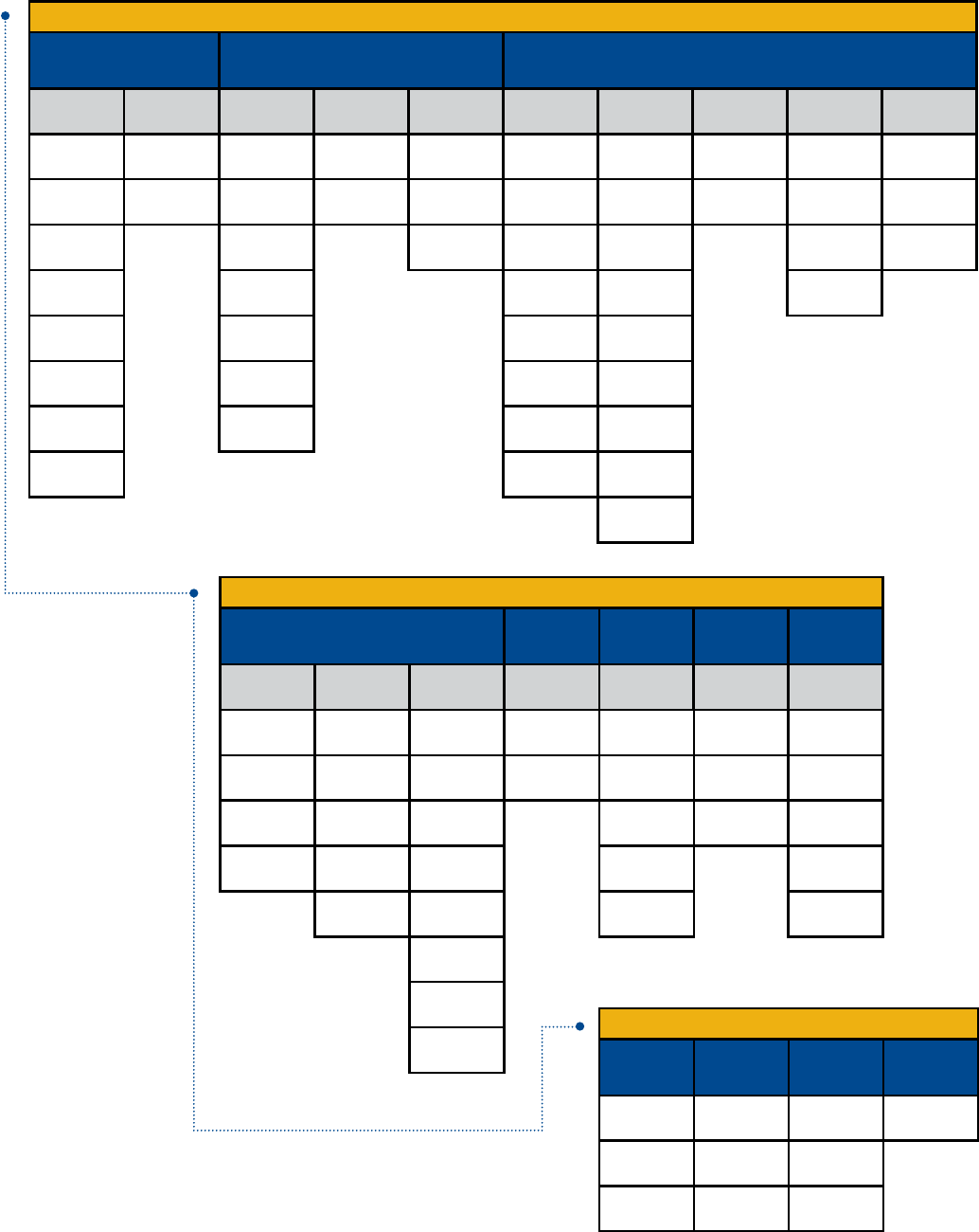
60
Film Capacitors
THROUGH-HOLE FILM CAPACITORS
General Purpose Pulse & AC Safety/EMI
Metallized
Polyester
PME261 (P561)
Impregnated Paper
400 – 1,000 VDC
F461 – 464
Halogen Free
160 – 2,500 VDC
PHE450 (F450)
DC Applications
250 – 3,000 VAC
R76
DC & Pulse Applications
250 – 2,000 VDC
R73
Radial
100 – 2,000 VDC
F871 – F873
Halogen Free
Metallized Polypropylene
330/480/760 VAC
R49
Metallized Polypropylene
310 VAC/330 VAC
R47
Metallized Polypropylene
440 VAC
P278
Metallized Impregnated
Paper
480 VAC
P410
Metallized Impregnated
Paper
300 VAC
PME271E (P277)
Metallized Impregnated
Paper
300 VAC
PHE844 (F844)
Metallized Polypropylene
440/480 VAC
R47
Metallized Polypropylene
440 VAC/520 VAC
P295
Metallized Impregnated
Paper
500 VAC
F881
Halogen Free
Metallized Polypropylene
300 VAC
PHZ9004 (9004)
Metallized Polypropylene
300 VAC (3x X2)
PMZ2074 (P374)
Metallized Impregnated
Paper
275 VAC (2x X2)
PZB300 (P300)
Metallized Impregnated
Paper
275 VAC (X2 + 2x Y2)
PME271Y (P271)
Impregnated Paper
250 VAC
R41
Metallized Polypropylene
300 VAC
PME271Y A – E (P272)
Impregnated Paper
300 VAC
PME295 (P295)
Metallized Impregnated
Paper
440 VAC/480 VAC
R46
Metallized Polypropylene
310 VAC
R46 (Miniature)
Metallized Polypropylene
275 VAC
R46 – 125°C
Metallized Polypropylene
275 VAC
PME264 (P264)
Metallized Impregnated
Paper
660 VAC
P409
Metallized Impregnated
Paper
275 VAC
PME271M (P276)
Metallized Impregnated
Paper
275 VAC
PFR (F411)
Radial
63 – 1,000 VDC
A72
Axial
100 – 2,000 VDC
R79
5 mm Lead Spacing
160 – 630 VDC
R75
160 – 2,000 VDC
R74
AC Applications
250 – 900 VDC
R71
SMPS PFC Applications
420 – 1,000 VDC
A70
Axial
160 – 630 VDC
SMR (F211)
Polyphenylene Sulfide
150°C
50 – 400 VDC
F622 – 125°C
Halogen Free
5 mm (Stacked)
50 – 630 VDC
R60
10 – 37.5 mm
50 – 1,000 VDC
R66
7.5 mm Lead Spacing
50 – 630 VDC
R82
5 mm Lead Spacing
50 – 400 VDC
RSB – 125°C
5 mm (Stacked)
50 – 630 VDC
Metallized Paper &
Polyphenylene Sulfide
Single Metallized
Polypropylene
Double Metallized
Polypropylene
Film/Foil
Polypropylene X1 Class X2 Class Y1 Class Y2 Class Multiple X & Y
A50
Axial
50 – 1,000 VDC
MDK (F683/4/5/7/8)
Dual In-Line
High Current
50 – 630 VDC
Polyester
(PET)
Polyethylene
Naphthalate
(PEN)
Metallized
Polyphenylene
Sulfide
(PPS)
Y2 Class
SURFACE MOUNT FILM CAPACITORS
LDE
Unencapsulated Stacked
50 – 1,000 VDC
LDB
Unencapsulated Stacked
16 VDC & 50 VDC
SMP253 (P101)
Metallized Impregnated
Paper
250 VAC
SMC (F125)
Encapsulated Stacked
50 – 400 VDC
SPC (F127)
Encapsulated Double
Metallized
100 – 630 VDC
GMC (F115)
Encapsulated Stacked
Size 2220 – 6560
50 – 630 VDC
F161
Encapsulated Stacked
50 – 400 VDC
MDC (F153/4/5/7/8)
Dual In-Line
High Current
50 – 630 VDC
MDS (F173/4/5)
Dual In-Line
High Current
50 – 630 VDC
GPC (F117)
Encapsulated Double
Metallized
63 – 1,000 VDC
Power Film Motor Run
Applications
High Voltage
Transient
Suppression
Low Voltage
Transient
Suppression
Capacitive
AC Power Supply
Axial Radial Screw/Faston
Terminal
Screw/Faston
Terminal Radial Radial Radial
POWER & APPLICATION OPTIMIZED FILM CAPACITORS
C4DC
GTO Snubbing
850 – 1,400 VDC/
500 – 700 VAC
C4AS
2 or 4 Leads
850 – 3,000 VDC/
500 – 750 VAC
C4DE
Low Inductance
DC Link
400 – 1,000 VDC
PMR205 (P405)
Integrated Resistor
Metallized Impregnated Paper
125 VAC/250 VDC
F5A
Integrated
Varistor
18 – 63 VDC
R47 X1 – X2
Metallized Polypropylene
440 VAC
F862
Metallized Polypropylene
310 VAC
R75 2/L
Metallized Polypropylene
230 VAC / 250 VAC
PME271E (P277)
Metallized Impregnated
Paper
300 VAC
PME271M X2 (P276)
Metallized Impregnated
Paper
275 VAC
F5B
Integrated Suppression
Diode
18– 63 VDC
F5D
Integrated
Ceramic Capacitor
63 – 100 VDC
P409
Integrated Resistor
Metallized Impregnated Paper
275 VAC
P410
Integrated 100 Ω Resistor
Metallized Impregnated Paper
300 VAC
PMZ2035 (P435)
Integrated 100 Ω Resistor
Metallized Impregnated Paper
300 VDC
F43
Integrated Resistor
Metallized Polypropylene
250 – 630 VDC
C27
Plastic Case
425 – 450 VAC
C87
Aluminum Case
470 VAC
C93
Filter Applications
400 – 600 VDC
C44A
General Purpose & Snubbing
400 – 1,500 VDC/
250 – 630 VAC
C44B
General Purpose & Snubbing
1,200 – 2,400 VDC/
500 – 1,000 VAC
C44P/C20A
PFC & AC Filter
330 – 1,000 VAC/
700 – 2,300 VDC
C44U
DC Link
700 – 1,300 VDC
C4AE
2 or 4 Leads
DC Link
450 – 1,100 VDC
C4BS
IGBT Direct Mount
850 – 3,000 VDC/
550 – 750 VAC
C4AT
2 or 4 Leads
250 – 850 VDC/
160 – 450 VAC
C4BT
IGBT Direct Mount
400 – 850 VDC/
250 – 450 VAC
C4C
Axial Round
850 – 3,000 VDC/
450 – 750 VAC
C4DR
GTO Clamping
400 – 3,000 VDC/
160 – 1,500 VAC
C4G
Axial Round
250 – 850 VDC/
160 – 450 VAC
C44H
PFC & AC Filter
330 – 440 VAC/
700 – 1,000 VDC
C9T
PFC & AC Filter
415 – 690 VAC
F862
Metallized Polypropylene
310 VAC
R74 – 125°C
AC Applications
500 – 700 VDC
PHE845 (F845)
Metallized Polypropylene
760 VAC
F611 & F612
5 – 37.5 mm
50 – 1,000 VDC
F861
Metallized Polypropylene
310 VAC
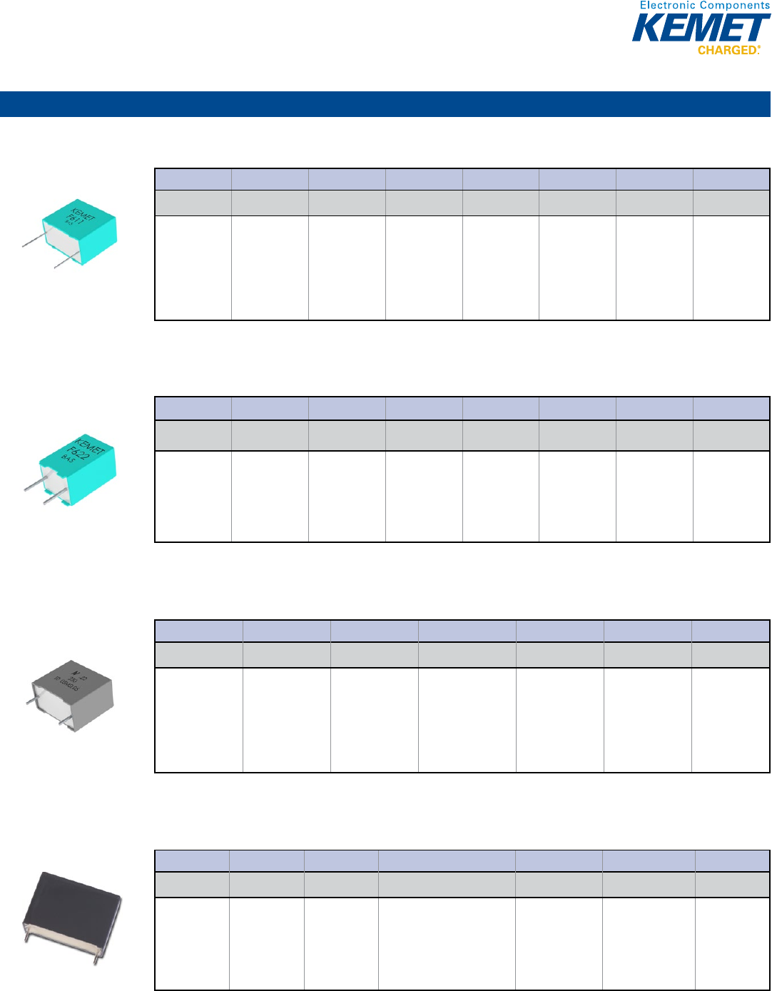
61
Film Capacitors
Metallized Polyester
F611 & F612 Series Metallized Polyester Film, 5 – 37.5 mm Lead Spacing, 50 – 1,000 VDC
Capacitance Range: 0.001 to 180 μF • Temperature Range: −55°C to +105°C
© KEMET Electronics Corporation • P.O. Box 5928 • Greenville, SC 29606 (864) 963-6300 • www.kemet.com F3065_F611_F612 • 4/16/2015 1
One world. One KEMET
Bene ts
• Voltage range: 50 – 1,000 VDC
• Capacitance range: 0.001 – 180 µF
• Lead spacing: 5 – 37.5 mm
• Capacitance tolerance: ±10%, ±20%, ±5% on request
• Climatic category: 55/105/56, IEC 60068–1
• Tape and reel packaging in accordance with IEC 60286–2
• RoHS Compliant and lead-free terminations
• Operating temperature range of -55˚C to +105˚C
Overview
The F611 and F612 Series is constructed of metallized wound or
stacked polyester lm capacitor with radial leads of tinned wire.
Radial leads are electrically welded to the contact metal layer on
the ends of the capacitor winding. The capacitor is encapsulated
in a self-extinguishing material meeting the requirements of UL 94
V–0.
Applications
Typical applications include blocking, coupling, decoupling,
bypassing and interference suppression in low voltage
applications such as automotive. Not for use with the mains.
General Purpose, Pulse and DC Transient Suppression
F611 & F612 Series Metallized Polyester Film,
5 – 37.5 mm Lead Spacing, 50 – 1,000 VDC
Part Number System
F611 J F 104 M050 C
Capacitor Class Series
Lead Spacing
(mm)
Size Code
Capacitance Code
(pF)
Capacitance
Tolerance
Rated Voltage
(VDC)
Packaging
F = Film Metallized
Polyester
611 = Wound
612 = Stacked
J = 5
K = 7.5
A = 10.0
B = 15.0
D = 22.5
F = 27.5
R = 37.5
See Dimension
Table
First two digits
represent
signi cant
gures. Third
digit speci es
number of zeros.
J = ±5%
K = ±10%
M = ±20%
050 = 50
063 = 63
100 = 100
160 = 160
250 = 250
400 = 400
630 = 630
1K0 = 1,000
See Ordering
Options Table
F622 Series, 125ºC, Halogen Free, 5 mm (Stacked), 50 – 630 VDC
Capacitance Range: 0.001 to 2.2 μF • Temperature Range: −55°C to +125°C
© KEMET Electronics Corporation • P.O. Box 5928 • Greenville, SC 29606 (864) 963-6300 • www.kemet.com F3066_F622 • 4/16/2015 1
One world. One KEMET
Bene ts
• Voltage range: 50 – 630 VDC
• Capacitance range: 0.001 – 2.2 µF
• Lead spacing: 5 mm
• Capacitance tolerance: ±10%, ±20%, ±5% on request
• Climatic category: 55/125/56
• Tape and reel packaging in accordance with IEC 60286–2
• RoHS Compliant and lead-free terminations
• Operating temperature range of -55˚C to +125˚C
• Designed for high performance, high temperature applications
Overview
The F622 Series is constructed of metallized stacked polyester
lm capacitor with radial leads of tinned wire. Radial leads are
electrically welded to the contact metal layer on the ends of
the capacitor winding. The capacitor is encapsulated in a self-
extinguishing material meeting the requirements of UL 94 V–0.
Applications
Typical applications include high performance, high temperature
blocking, coupling, decoupling, bypassing and interference
suppression in low voltage applications such as automotive. Not
for use with the mains.
General Purpose, Pulse and DC Transient Suppression
F622 Series Metallized Polyester Film,
5 mm Lead Spacing, 50 – 630 VDC
Part Number System
F622 J F 104 M050 C
Capacitor Class Series Lead Spacing
(mm) Size Code Capacitance Code
(pF)
Capacitance
Tolerance
Rated Voltage
(VDC) Packaging
F = Film Metallized
Polyester
J = 5 See Dimension
Table
First two digits
represent
signi cant
gures. Third
digit speci es
number of zeros.
J = ±5%
K = ±10%
M = ±20%
050 = 50
063 = 63
100 = 100
250 = 250
400 = 400
500 = 500
630 = 630
See Ordering
Options Table
R60 Series, Radial, 10 – 37.5 mm Lead Spacing, 50 – 1,000 VDC (Automotive Grade)
Capacitance Range: 0.001 to 220 μF • Temperature Range: −55°C to +105°C
© KEMET Electronics Corporation • P.O. Box 5928 • Greenville, SC 29606 (864) 963-6300 • www.kemet.com F3103_R60 • 4/16/2015 1
One world. One KEMET
Bene ts
• Voltage range: 50 – 1000 VDC
• Capacitance range: 0.001 µF – 150.0 µF
• Lead spacing: 10.0 – 37.5 mm
• Capacitance tolerance: ±5%, ±10%, ±20%
• Climatic category: 55/105/56
• Operating temperature range of -55˚C to +105˚C
• RoHS compliance and lead-free terminations
• Tape and reel packaging in accordance with IEC 60286–2
• Self-healing
• Automotive (AEC–Q200) grades available up to pitch 22.5 mm
Overview
The R60 Series is constructed of metallized polyester lm
(wound or stacked technology) with radial leads of tinned wire.
Radial leads are electrically welded to the contact metal layer on
the ends of the capacitor winding. The capacitor is encapsulated
in a self-extinguishing solvent resistant plastic case with
thermosetting resin material meeting the UL 94V–0 requirements.
Automotive Grade devices are available (up to lead spacing 22.5
mm) and meet the demanding Automotive Electronics. Council's
AEC–Q200 quali cation requirements.
Applications
Typical applications include blocking, coupling, decoupling,
bypassing and interference suppression in low voltage
applications such as automotive. Not suitable for across-the-line
application (see Suppressor Capacitors).
General Purpose Metallized Polyester Film Capacitors
R60 Series, Radial, 10 – 37.5 mm Lead Spacing,
50 – 1,000 VDC (Automotive Grade)
Part Number System
R60 M F 2470 AA 60 K
Series Rated Voltage (VDC) Length (mm) Capacitance Code (pF) Packaging Internal Use
Capacitance
Tolerance
Metallized Polyester
C = 50
D = 63
E = 100
G = 160
I = 250
M = 400
P = 630
Q = 1000
F = 10
I = 15
N = 22.5
R = 27.5
W = 37.5
Digits 2-4 indicate the
rst three digits of the
capacitance value.
First digit indicates the
number of zeros to be
added.
See Ordering
Options Table
00
01
30
40
50
6A
L0
L1
J = ±5%
K = ±10%
M = ±20%
R66 Series, Radial, 7.5 mm Lead Spacing, 50 – 630 VDC (Automotive Grade)
Capacitance Range: 0.001 to 4.7 μF • Temperature Range: −55°C to +105°C
© KEMET Electronics Corporation • P.O. Box 5928 • Greenville, SC 29606 (864) 963-6300 • www.kemet.com F3102_R66 • 4/16/2015 1
One world. One KEMET
Bene ts
• Voltage range: 50 – 630 VDC
• Capacitance range: 0.001 µF – 4.7 µF
• Lead Spacing: 7.5 mm
• Capacitance tolerance: ±5%, ±10%, ±20%
• Climatic category: 55/105/56
• Operating temperature range of -55˚C to +105˚C
• RoHS compliance and lead-free terminations
• Tape and reel packaging in accordance with IEC 60286–2
• Self-healing
• Automotive (AEC–Q200) grades available
Overview
The R66 Series is constructed of metallized polyester lm
(wound or stacked technology) with radial leads of tinned wire.
Radial leads are electrically welded to the contact metal layer on
the ends of the capacitor winding. The capacitor is encapsulated
in a self-extinguishing solvent resistant plastic case with
thermosetting resin material meeting the UL 94V–0 requirements.
Automotive Grade devices are available and meet the
demanding Automotive Electronics Council's AEC–Q200
quali cation requirements.
Applications
Typical applications include blocking, coupling, decoupling,
bypassing and interference suppression in low voltage
applications such as automotive. Not suitable for across-the-line
application (see Suppressor Capacitors).
General Purpose Metallized Polyester Film Capacitors
R66 Series, Radial, 7.5 mm Lead Spacing, 50 – 630 VDC
(Automotive Grade)
Part Number System
R66 E D 3100 AA 7A J
Series
Rated Voltage
(VDC)
Length (mm) Capacitance Code (pF)
Lead and
Packaging Code
Internal Use
Capacitance
Tolerance
Metallized
Polyester
C = 50
D = 63
E = 100
I = 250
M = 400
P = 630
D = 7.5 Digits 2-4 indicate the rst three
digits of the capacitance value.
First digit indicates the number of
zeros to be added.
See Ordering
Options Table
10
6A
7A
J = ±5%
K = ±10%
M = ±20%
Through-Hole – General Purpose
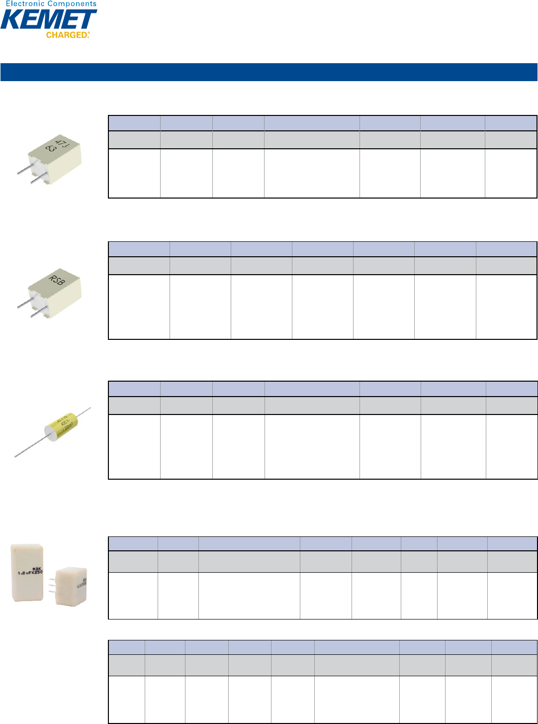
62
Film Capacitors
Metallized Polyester (cont.)
R82 Series, 5 mm Lead Spacing, 50 – 400 VDC (Automotive Grade)
Capacitance Range: 0.001 to 4.7 μF • Temperature Range: −55°C to +105°C
© KEMET Electronics Corporation • P.O. Box 5928 • Greenville, SC 29606 (864) 963-6300 • www.kemet.com F3101_R82 • 4/16/2015 1
One world. One KEMET
Bene ts
• Voltage range: 50 – 400 VDC
• Capacitance range: 0.001 µF – 4.7 µF
• Lead Spacing: 5 mm
• Capacitance tolerance: ±5%, ±10%, ±20%
• Climatic category: 55/105/56
• Operating temperature range of -55˚C to +105˚C
• RoHS compliance and lead-free terminations
• Tape and reel packaging in accordance with IEC 60286–2
• Self-healing
• Automotive (AEC–Q200) grades available
Overview
The R82 Series is constructed of metallized polyester lm
(wound or stacked technology) with radial leads of tinned wire.
Radial leads are electrically welded to the contact metal layer on
the ends of the capacitor winding. The capacitor is encapsulated
in a self-extinguishing solvent resistant plastic case with
thermosetting resin material meeting the UL 94V–0 requirements.
Automotive grade devices are available and meet the demanding
Automotive Electronics Council's AEC–Q200 quali cation
requirements.
Applications
Typical applications include blocking, coupling, decoupling, timing
and oscillator circuits. Not suitable for across-the-line application
(see Suppressor Capacitors).
General Purpose Metallized Polyester Film Capacitors
R82 Series, Radial, 5 mm Lead Spacing, 50 – 400 VDC
(Automotive Grade)
Part Number System
R82 D C 3470 AA 60 J
Series
Rated Voltage
(VDC)
Length (mm) Capacitance Code (pF)
Lead and
Packaging Code
Internal Use
Capacitance
Tolerance
Metallized
Polyester
C = 50
D = 63
E = 100
I = 250
M = 400
C = 5.0 Digits 2-4 indicate the rst three
digits of the capacitance value.
First digit indicates the number of
zeros to be added.
See Ordering
Options Table
30
50
60
70
J = ±5%
K = ±10%
M = ±20%
RSB Series, 125ºC, 5 mm (Stacked), 50 – 630 VDC (Automotive Grade)
Capacitance Range: 0.001 to 2.2 μF • Temperature Range: −55°C to +125°C
© KEMET Electronics Corporation • P.O. Box 5928 • Greenville, SC 29606 (864) 963-6300 • www.kemet.com F3067_RSB • 4/16/2015 1
One world. One KEMET
Bene ts
• Voltage range: 50 – 630 VDC
• Capacitance range: 0.001 – 2.2 µF
• Lead spacing: 5 mm
• Capacitance tolerance: ±20%, ±10% standard,
±5% on request
• Climatic category: 55/125/56
• Operating temperature range of -55˚C to +125˚C
• RoHS Compliant and lead-free terminations
• Tape and reel packaging in accordance with IEC 60286–2
• Self-healing
• Automotive (AEC–Q200) grades available
Overview
The RSB Series is constructed of metallized polyester lm
(stacked technology) with radial leads of tinned wire. Radial leads
are electrically welded to the contact metal layer on the ends of
the capacitor winding. The capacitor is encapsulated in a self-
extinguishing solvent resistant plastic case with thermosetting
resin material meeting the UL 94V–0 requirements.
Automotive grade devices are available and meet the demanding
Automotive Electronics Council's AEC–Q200 quali cation
requirements.
Applications
Typical applications include high performance, high temperature,
blocking, coupling, decoupling for a signal from DC to high
frequency, pulse, logic and timing circuit, lamp capacitor for
electronic compact lamps, inverter for LCD monitors, automotive
DC motor suppression. Not suitable for across-the-line
application (see Suppressor Capacitors).
General Purpose Metallized Polyester Film Capacitors
RSB Series, 5 mm Lead Spacing, 50 – 630 VDC
(Automotive Grade)
Part Number System
RSB D C 3100 AA 00 J
Series Rated Voltage (VDC) Length (mm)
Capacitance Code
(pF)
Packaging Internal Use
Capacitance
Tolerance
Metallized Polyester
C = 50
D = 63
E = 100
I = 250
M = 400
W = 500
P = 630
C = 5.0
The last three digits
represent signi cant
g u r e s .
First digit speci es
number of zeros.
See Ordering
Options Table
30
50
60
70
J = ±5%
K = ±10%
M = ±20%
A50 Series Axial Pulse DC Transient, 50 – 1,000 VDC (Automotive Grade)
Capacitance Range: 0.001 to 10 µF • Temperature Range: −55°C to +105°C
© KEMET Electronics Corporation • P.O. Box 5928 • Greenville, SC 29606 (864) 963-6300 • www.kemet.com F3071_A50_AXIAL • 4/16/2015 1
One world. One KEMET
Bene ts
• Voltage range: 50 – 1,000 VDC
• Capacitance range: 0.001 – 10 µF
• Diameter: 5 – 22 mm
• Length 11 – 33 mm
• Capacitance tolerance: ±5%, ±10%, ±20%
• Climatic category: 55/105/56
• Operating temperature range of -55˚C to +105˚C
• RoHS Compliant and lead-free terminations
• Tape and reel packaging in accordance with IEC 60286–1
• Self-Healing
• Automotive (AEC–Q200) grades available
Overview
The A50 Series is constructed of metallized polyester lm
(wound technology) with axial leads of tinned wire. Axial leads
are electrically welded to the contact metal layer on the ends of
the capacitor winding. The capacitor is encapsulated in polyester
tape wrapping with thermosetting resin end lled.
Automotive grade devices are available and meet the demanding
Automotive Electronics Council's AEC–Q200 quali cation
requirements.
Applications
Typical applications include blocking, coupling, decoupling,
bypassing and interference suppression in low voltage
applications such as automotive. Not suitable for across-the-line
application (see Suppressor Capacitors).
General Purpose, Pulse and DC Transient Suppression
A50 Series Metallized Polyester Film, Axial, 50 – 1,000 VDC
(Automotive Grade)
Part Number System
A50 C F 3470 AA 00 J
Series
Rated Voltage
(VDC)
Length (mm) Capacitance Code (pF)
Lead and
Packaging Code
Internal Use
Capacitance
Tolerance
Metallized
Polyester
C = 50
D = 63
E = 100
I = 250
M = 400
P = 630
Q = 1000
F = 11
H= 14
K = 20.5
Q = 28
T = 33
Digits 2 – 4 indicate the rst three
digits of the capacitance value.
First digit indicates the number of
zeros to be added.
See Ordering
Options Table
00, 60 (Standard) J = ±5%
K = ±10%
M = ±20%
MDK Series, Dual In-Line, High Current, 50 – 630 VDC
Capacitance Range: 0.033 to 15 μF • Temperature Range: −55°C to +125°C
Legacy Part Number System
© KEMET Electronics Corporation • P.O. Box 5928 • Greenville, SC 29606 (864) 963-6300 • www.kemet.com F3076_MDK • 4/16/2015 1
One world. One KEMET
Bene ts
• Rated voltage: 50 – 630 VDC
• Rated voltage: 30 – 220 VAC
• Capacitance range: 0.033 – 15 µF
• Capacitance tolerance: ±5%, ±10%, other tolerances on request
• Climatic category: 55/125/56
• RoHS Compliant and lead-free terminations
• Operating temperature range of -55˚C to +125˚C
Overview
Dual in-line (DIL) metallized polyester (PET) lm capacitor.
Encapsulation in self-extinguishing material meeting the
requirements of UL 94 V–0.
Applications
Typical applications include high frequency switched-mode power
supplies, DC/DC converters and input/output ltering.
General Purpose, Pulse and DC Transient Suppression
MDK Series Metallized Polyester Film, Dual In-Line,
Low ESR/ESL, 50 – 630 VDC
Legacy Part Number System
MDK 10 333 K50 A52 P3 TUBE
Series
Lead Spacing
(mm) Capacitance Code (pF) Capacitance
Tolerance
Rated Voltage
(VDC) Size Code Number of Leads
per Side Packaging Code
Dual In-Line,
Metallized
Polyester
10
15
First two digits indicate the two most
signi cant digits of the capacitance
value in picofarads. The third digit is
the number of following zeros.
J = ±5
K = ±10%
Other tolerances
on request
50
100
250
400
630
See
Dimension
Table
P3 = 3 leads
P4 = 4 leads
P5 = 5 leads
P7 = 7 leads
P8 = 8 leads
See Ordering
Options Table
New KEMET Part Number System
F68 3 A A 333 K050 T
Capacitor
Class
Series
Number of
Leads per Side
Lead Spacing
(mm)
Size Code
Capacitance Code (pF)
Capacitance
Tolerance
Rated Voltage
(VDC)
Packaging
Code
F = Film
Dual In-Line,
Metallized
Polyester
3 = 3 leads
4 = 4 leads
5 = 5 leads
7 = 7 leads
8 = 8 leads
A = 10
B = 15
A = Standard
box size
First two digits indicate the
two most signi cant digits
of the capacitance value in
picofarads. The third digit is
the number of following zeros.
J = ±5
K = ±10%
Other
tolerances on
request
050 = 50
100 = 100
250 = 250
400 = 400
630 = 630
See Ordering
Options Table
New KEMET Part Number System
© KEMET Electronics Corporation • P.O. Box 5928 • Greenville, SC 29606 (864) 963-6300 • www.kemet.com F3076_MDK • 4/16/2015 1
One world. One KEMET
Bene ts
• Rated voltage: 50 – 630 VDC
• Rated voltage: 30 – 220 VAC
• Capacitance range: 0.033 – 15 µF
• Capacitance tolerance: ±5%, ±10%, other tolerances on request
• Climatic category: 55/125/56
• RoHS Compliant and lead-free terminations
• Operating temperature range of -55˚C to +125˚C
Overview
Dual in-line (DIL) metallized polyester (PET) lm capacitor.
Encapsulation in self-extinguishing material meeting the
requirements of UL 94 V–0.
Applications
Typical applications include high frequency switched-mode power
supplies, DC/DC converters and input/output ltering.
General Purpose, Pulse and DC Transient Suppression
MDK Series Metallized Polyester Film, Dual In-Line,
Low ESR/ESL, 50 – 630 VDC
Legacy Part Number System
MDK 10 333 K50 A52 P3 TUBE
Series
Lead Spacing
(mm)
Capacitance Code (pF)
Capacitance
Tolerance
Rated Voltage
(VDC)
Size Code
Number of Leads
per Side
Packaging Code
Dual In-Line,
Metallized
Polyester
10
15
First two digits indicate the two most
signi cant digits of the capacitance
value in picofarads. The third digit is
the number of following zeros.
J = ±5
K = ±10%
Other tolerances
on request
50
100
250
400
630
See
Dimension
Table
P3 = 3 leads
P4 = 4 leads
P5 = 5 leads
P7 = 7 leads
P8 = 8 leads
See Ordering
Options Table
New KEMET Part Number System
F68 3 A A 333 K050 T
Capacitor
Class Series Number of
Leads per Side
Lead Spacing
(mm) Size Code Capacitance Code (pF) Capacitance
Tolerance
Rated Voltage
(VDC)
Packaging
Code
F = Film
Dual In-Line,
Metallized
Polyester
3 = 3 leads
4 = 4 leads
5 = 5 leads
7 = 7 leads
8 = 8 leads
A = 10
B = 15
A = Standard
box size
First two digits indicate the
two most signi cant digits
of the capacitance value in
picofarads. The third digit is
the number of following zeros.
J = ±5
K = ±10%
Other
tolerances on
request
050 = 50
100 = 100
250 = 250
400 = 400
630 = 630
See Ordering
Options Table
Through-Hole – General Purpose
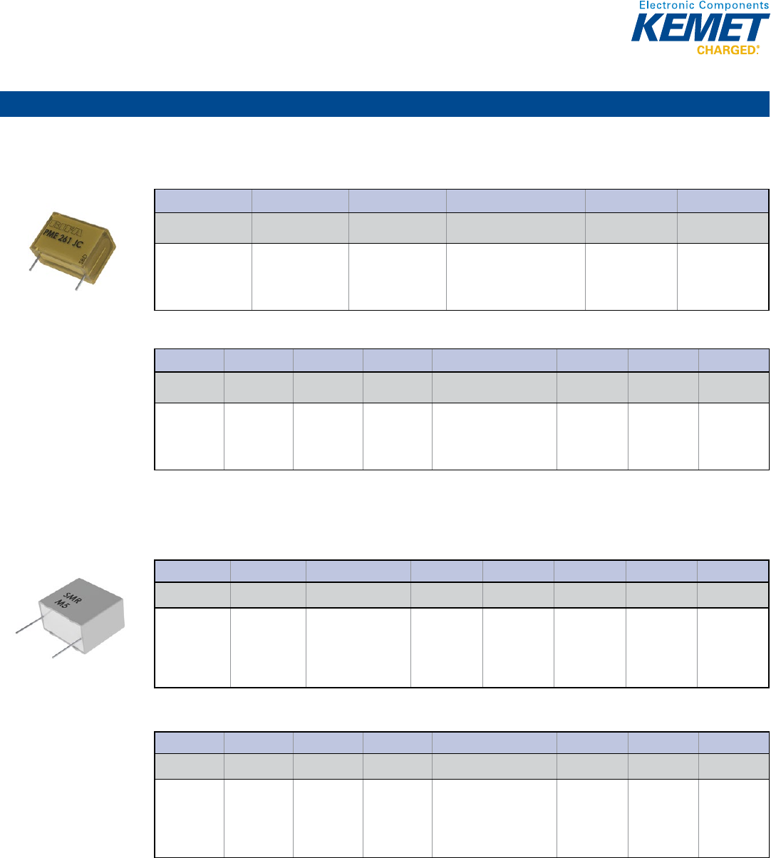
63
Film Capacitors
Metallized Paper & Polyphenylene Sulfide
PME261 Series Impregnated Paper, 10.2 – 25.4 mm Lead Spacing, 400 – 1,000 VDC
Capacitance Range: 0.001 to 1 µF • Temperature Range: −40°C to +70°C AC app & −40°C to +100°C DC app
Legacy Part Number System
© KEMET Electronics Corporation • P.O. Box 5928 • Greenville, SC 29606 (864) 963-6300 • www.kemet.com F3070_PME261 • 4/16/2015 1
One world. One KEMET
Bene ts
• Voltage range: 400 – 1,000 VDC; 220 – 500 VAC
• Capacitance range: 0.001 – 1 µF
• Lead spacing: 10.2 – 25.4 mm
• Capacitance tolerance: ±10%, ±20%, ±5% on request
• Climatic category: 40/70/56, IEC 60068–1
• Tape and reel packaging in accordance with IEC 60286–2
• RoHS Compliant and lead-free terminations
• Operating temperature range of -40˚C to +70˚C in AC applications
• Operating temperature range of -40˚C to +100˚C in DC applications
• Excellent self-healing properties. Ensures long life even when
subjected to frequent over-voltages.
• Good resistance to ionization due to impregnated dielectric
Overview
The PME261 Series is constructed of multilayer metallized paper,
encapsulated and impregnated in self-extinguishing material
meeting the requirements of UL 94 V–0.
Applications
For general use in DC and low frequency pulse applications.
General Purpose, Pulse and DC Transient Suppression
PME261 Series Metallized Impregnated Paper,
10.2 – 25.4 mm Lead Spacing, 400 – 1,000 VDC
Legacy Part Number System
PME261 K A 5100 KR30
Series Rated Voltage (VAC) Lead Spacing (mm) Capacitance Code (pF)
Capacitance
Tolerance Packaging
Metallized Paper
K = 220
E = 300
J = 500
A = 10.2
B = 15.2
C = 20.3
E = 25.4
Digits 2 – 4 indicate the rst three
digits of the capacitance value.
First digit indicates the
total number of digits in the
capacitance value
J = ±5%
K = ±10%
M = ±20%
See Ordering
Options Table
New KEMET Part Number System
P561 H E 103 K220 A
Capacitor Class
Series
Lead Spacing
(mm)
Size Code
Capacitance Code (pF)
Capacitance
Tolerance
Rated Voltage
(VAC)
Packaging
P = Paper
Metallized
Paper
General
Purpose
H = 10.2
Q = 15.2
C = 20.3
E = 25.4
See Dimension
Table
First two digits indicate the
two most signi cant digits
of the capacitance value in
picofarads. The third digit is
the number of following zeros.
J = ±5%
K = ±10%
M = ±20%
220 = 220
300 = 300
500 = 500
See Ordering
Options Table
New KEMET Part Number System
© KEMET Electronics Corporation • P.O. Box 5928 • Greenville, SC 29606 (864) 963-6300 • www.kemet.com F3070_PME261 • 4/16/2015 1
One world. One KEMET
Bene ts
• Voltage range: 400 – 1,000 VDC; 220 – 500 VAC
• Capacitance range: 0.001 – 1 µF
• Lead spacing: 10.2 – 25.4 mm
• Capacitance tolerance: ±10%, ±20%, ±5% on request
• Climatic category: 40/70/56, IEC 60068–1
• Tape and reel packaging in accordance with IEC 60286–2
• RoHS Compliant and lead-free terminations
• Operating temperature range of -40˚C to +70˚C in AC applications
• Operating temperature range of -40˚C to +100˚C in DC applications
• Excellent self-healing properties. Ensures long life even when
subjected to frequent over-voltages.
• Good resistance to ionization due to impregnated dielectric
Overview
The PME261 Series is constructed of multilayer metallized paper,
encapsulated and impregnated in self-extinguishing material
meeting the requirements of UL 94 V–0.
Applications
For general use in DC and low frequency pulse applications.
General Purpose, Pulse and DC Transient Suppression
PME261 Series Metallized Impregnated Paper,
10.2 – 25.4 mm Lead Spacing, 400 – 1,000 VDC
Legacy Part Number System
PME261 K A 5100 KR30
Series
Rated Voltage (VAC)
Lead Spacing (mm)
Capacitance Code (pF)
Capacitance
Tolerance
Packaging
Metallized Paper
K = 220
E = 300
J = 500
A = 10.2
B = 15.2
C = 20.3
E = 25.4
Digits 2 – 4 indicate the rst three
digits of the capacitance value.
First digit indicates the
total number of digits in the
capacitance value
J = ±5%
K = ±10%
M = ±20%
See Ordering
Options Table
New KEMET Part Number System
P561 H E 103 K220 A
Capacitor Class Series
Lead Spacing
(mm) Size Code Capacitance Code (pF)
Capacitance
Tolerance
Rated Voltage
(VAC) Packaging
P = Paper
Metallized
Paper
General
Purpose
H = 10.2
Q = 15.2
C = 20.3
E = 25.4
See Dimension
Table
First two digits indicate the
two most signi cant digits
of the capacitance value in
picofarads. The third digit is
the number of following zeros.
J = ±5%
K = ±10%
M = ±20%
220 = 220
300 = 300
500 = 500
See Ordering
Options Table
SMR Series Polyphenylene Sulde Film, +150°C, 5.0 – 27.5 mm Lead Spacing, 50 – 400 VDC
Capacitance Range: 0.001 to 22 μF • Temperature Range: −55°C to +150°C
Legacy Part Number System
© KEMET Electronics Corporation • P.O. Box 5928 • Greenville, SC 29606 (864) 963-6300 • www.kemet.com F3072_SMR • 4/16/2015 1
One world. One KEMET
Bene ts
• Voltage range: 50 – 400 VDC; 30 – 200 VAC
• Capacitance range: 0.001 – 22 µF
• Lead spacing: 5 – 27.5 mm
• Capacitance tolerance: ±10%, ±20%, ±2.5% and ±5%
on request
• Climatic category: 55/150/56, IEC 60068–1
• Tape and reel packaging in accordance with IEC 60286–2
• RoHS Compliant and lead-free terminations
• Category temperature range -55 to +150°C
• Rated temperature +125°C
Overview
The SMR Series is a metallized polyphenylene sul de lm
capacitor with vacuum-evaporated aluminum electrodes. Radial
leads of tinned wire are electrically welded to the contact metal
layer on the ends of the capacitor winding. The capacitor
is encapsulated in self-extinguishing material meeting the
requirements of UL 94 V–0.
Applications
Typical applications include automotive and other applications
with high ambient temperatures, as well as those requiring high
stability and low losses. The capacitor offers excellent sound
quality in audio applications.
General Purpose, Pulse and DC Transient Suppression
SMR Series Metallized Polyphenylene Sul de Film, +150°C,
5.0 – 27.5 mm Lead Spacing, 50 – 400 VDC
Legacy Part Number System
SMR 5104 K50 J01 L4 BULK
Series
Lead Spacing (mm)
Capacitance Code (pF)
Capacitance
Tolerance
Rated Voltage
(VDC)
Size Code Lead Length Packaging
Metallized PPS 5 = 5.0
7.5 = 7.5
10 = 10.0
15 = 15.0
22.5 = 22.5
27.5 = 27.5
First two digits indicate
the two most signi cant
digits of the capacitance
value in picofarads. The
third digit is the number
of following zeros.
H = ±2.5%
J = ±5%
K = ±10%
M = ±20%
50 = 50
63 = 63
100 = 100
250 = 250
400 = 400
See Dimension
Table
Letter "L"
followed by lead
length in mm
See Ordering
Options Table
New KEMET Part Number System
F211 J F 104 K050 C
Capacitor Class
Series
Lead Spacing
(mm)
Size Code
Capacitance Code (pF)
Capacitance
Tolerance
Rated Voltage
(VDC)
Packaging
F = Film
Metallized PPS
J = 5.0
K = 7.5
A = 10.0
B = 15.0
D = 22.5
F = 27.5
See Dimension
Table
First two digits indicate the
two most signi cant digits
of the capacitance value in
picofarads. The third digit is
the number of following zeros.
R = ±2.5%
J = ±5%
K = ±10%
M = ±20%
050 = 50
063 = 63
100 = 100
250 = 250
400 = 400
See Ordering
Options Table
New KEMET Part Number System
© KEMET Electronics Corporation • P.O. Box 5928 • Greenville, SC 29606 (864) 963-6300 • www.kemet.com F3072_SMR • 4/16/2015 1
One world. One KEMET
Bene ts
• Voltage range: 50 – 400 VDC; 30 – 200 VAC
• Capacitance range: 0.001 – 22 µF
• Lead spacing: 5 – 27.5 mm
• Capacitance tolerance: ±10%, ±20%, ±2.5% and ±5%
on request
• Climatic category: 55/150/56, IEC 60068–1
• Tape and reel packaging in accordance with IEC 60286–2
• RoHS Compliant and lead-free terminations
• Category temperature range -55 to +150°C
• Rated temperature +125°C
Overview
The SMR Series is a metallized polyphenylene sul de lm
capacitor with vacuum-evaporated aluminum electrodes. Radial
leads of tinned wire are electrically welded to the contact metal
layer on the ends of the capacitor winding. The capacitor
is encapsulated in self-extinguishing material meeting the
requirements of UL 94 V–0.
Applications
Typical applications include automotive and other applications
with high ambient temperatures, as well as those requiring high
stability and low losses. The capacitor offers excellent sound
quality in audio applications.
General Purpose, Pulse and DC Transient Suppression
SMR Series Metallized Polyphenylene Sul de Film, +150°C,
5.0 – 27.5 mm Lead Spacing, 50 – 400 VDC
Legacy Part Number System
SMR 5104 K50 J01 L4 BULK
Series
Lead Spacing (mm)
Capacitance Code (pF)
Capacitance
Tolerance
Rated Voltage
(VDC)
Size Code
Lead Length
Packaging
Metallized PPS
5 = 5.0
7.5 = 7.5
10 = 10.0
15 = 15.0
22.5 = 22.5
27.5 = 27.5
First two digits indicate
the two most signi cant
digits of the capacitance
value in picofarads. The
third digit is the number
of following zeros.
H = ±2.5%
J = ±5%
K = ±10%
M = ±20%
50 = 50
63 = 63
100 = 100
250 = 250
400 = 400
See Dimension
Table
Letter "L"
followed by lead
length in mm
See Ordering
Options Table
New KEMET Part Number System
F211 J F 104 K050 C
Capacitor Class Series
Lead Spacing
(mm)
Size Code Capacitance Code (pF)
Capacitance
Tolerance
Rated Voltage
(VDC)
Packaging
F = Film
Metallized PPS
J = 5.0
K = 7.5
A = 10.0
B = 15.0
D = 22.5
F = 27.5
See Dimension
Table
First two digits indicate the
two most signi cant digits
of the capacitance value in
picofarads. The third digit is
the number of following zeros.
R = ±2.5%
J = ±5%
K = ±10%
M = ±20%
050 = 50
063 = 63
100 = 100
250 = 250
400 = 400
See Ordering
Options Table
Through-Hole – General Purpose
64
Film Capacitors
Single Metallized Polypropylene
F461 – 464 Series Halogen Free, 160 – 2,500 VDC
Capacitance Range: 0.001 to 56 μF • Temperature Range: −55°C to +105°C
© KEMET Electronics Corporation • P.O. Box 5928 • Greenville, SC 29606 (864) 963-6300 • www.kemet.com F3028_F461-464 • 4/16/2015 1
One world. One KEMET
General Purpose, Pulse and DC Transient Suppression
F461 – 464 Series Single Metallized Polypropylene Film
Overview
The F461 – 464 Series is a metallized polypropylene lm
encapsulated with self-extinguishing resin in a box of material
meeting the requirements of UL 94 V–0. Four different winding
constructions are used depending on voltage and lead spacing.
Please see Table 1 for more information.
Applications
Typical applications include pulse operation in switched mode
power supply (SMPS), televisions, computer monitors, electrical
ballasts and other high frequency applications demanding stable
operation.
Bene ts
• Rated voltage: 160 – 2,500 VDC
• Rated voltage: 90 – 900 VAC
• Capacitance range: 0.001 – 56 µF
• Lead spacing: 5 – 37.5 mm
• Capacitance tolerance: ±5%, ±10%, other tolerances on request
• Climatic category: 55/105/56, IEC 60068–1
• Tape and reel packaging in accordance with IEC 60286–2
• RoHS Compliant and lead-free terminations
• Category temperature range of -55˚C to +105˚C
• Rated temperature +85˚C
Part Number System
F 46x K E 223 J160 C
Capacitor
Class
Series
Lead Spacing
(mm)
Size Code Capacitance Code (pF)
Capacitance
Tolerance
Rated Voltage (VDC)
Lead and
Packaging Code
F = Film Metallized
Polypropylene
x = sections in
construction
J = 5
K = 7.5
A = 10
B = 15
D = 22.5
F = 27.5
R = 37.5
See Dimension
Table
First two digits indicate the
two most signi cant digits
of the capacitance value in
picofarads. The third digit
is the number of following
zeros.
J = ±5%
K = ±10%
On Request:
F = ±1%
G = ±2%
M = ±20%
160 = 160
250 = 250
400 = 400
630 = 630
1K0 = 1000
1L2 = 1250
1K6 = 1600
2K0 = 2000
2K5 = 2500
See Ordering
Options Table
R79 Series Radial, 5 mm Lead Spacing, 160 – 630 VDC
Capacitance Range: 0.001 to 0.22 μF • Temperature Range: −55°C to +105°C
© KEMET Electronics Corporation • P.O. Box 5928 • Greenville, SC 29606 (864) 963-6300 • www.kemet.com F3107_R79 • 4/16/2015 1
One world. One KEMET
Bene ts
• Voltage range: 160 – 630 VDC
• Capacitance range: 0.001 – 0.22 µF
• Lead Spacing: 5 mm
• Capacitance tolerance: ±5%, ±10%, ±20%
• Climatic category: 55/105/56 IEC 60068-1
• Operating temperature range of -55˚C to +105˚C
• RoHS compliance and lead-free terminations
• Tape and reel packaging in accordance with IEC 60286–2
• Self-healing
Overview
The R79 Series is constructed of metallized polypropylene lm
with radial leads of tinned wire. The radial leads are electrically
welded to the metal layer on the ends of the capacitor winding.
The capacitor is encapsulated in a self-extinguishing solvent
resistant plastic case with thermosetting resin material meeting
the UL 94V–0 requirements.
Applications
Typical applications include timing, oscillator circuits, high
frequency coupling and decoupling applications. Not suitable for
across-the-line application (see Suppressor Capacitors).
Polypropylene Pulse/High Frequency Capacitors
R79 Series Single Metallized Polypropylene Film, Radial,
5 mm Lead Spacing, Multipurpose Applications
Part Number System
R79 G C 2390 AA 40 K
Series Rated Voltage (VDC) Lead Spacing (mm) Capacitance Code (pF)
Lead and
Packaging Code
Internal Use
Capacitance
Tolerance
Metallized
Polypropylene
G = 160
I = 250
M = 400
P = 630
C = 5 Digits 2 – 4 indicate the
rst three digits of the
capacitance value.
First digit indicates the
number of zeros to be
added.
See Ordering
Options Table
40
45
H = 2.5%
J = ±5%
K = ±10%
R75 Series Radial, DC & Pulse Applications 160 – 2,000 VDC (Automotive Grade)
Capacitance Range: 220 pF to 33 μF • Temperature Range: −55°C to +105°C
© KEMET Electronics Corporation • P.O. Box 5928 • Greenville, SC 29606 (864) 963-6300 • www.kemet.com F3106_R75 • 4/16/2015 1
One world. One KEMET
Bene ts
• Voltage range: 160 – 2,000 VDC
• Capacitance range: 220 pF – 33 µF
• Lead Spacing: 7.5 – 37.5 mm
• Capacitance tolerance: ±5%, ±10%, ±20%
• Climatic category: 55/105/56 IEC 60068-1
• Operating temperature range of -55˚C to +105˚C
• RoHS compliance and lead-free terminations
• Tape and reel packaging in accordance with IEC 60286–2
• Self-healing
• Automotive (AEC–Q200) grades available up to lead spacing
22.5mm
Overview
The R75 Series is constructed of metallized polypropylene lm
with radial leads of tinned wire. The radial leads are electrically
welded to the metal layer on the ends of the capacitor winding.
The capacitor is encapsulated in a self-extinguishing solvent
resistant plastic case with thermosetting resin material meeting
the UL 94V–0 requirements. Two different winding constructions
are used depending on voltage parameters and lead spacing.
Please see the Performance Characteristics for more
information.
Automotive grade devices are available (up to lead spacing 22.5
mm) and meet the demanding Automotive Electronics Council's
AEC–Q200 quali cation requirements.
Applications
Typical applications include defl ection circuits in televisions
(S-correction), resonant capacitor in electronic ballast and
compact lamp, power factor correction and coupling capacitor
in switched mode power supply (SMPS), timing and oscillator
circuits. Not suitable for across-the-line application (see
Suppressor Capacitors).
Polypropylene Pulse/High Frequency Capacitors
R75 Series Single Metallized Polypropylene Film, Radial,
DC and Pulse Applications (Automotive Grade)
Part Number System
R75 P N 2820 AA 30 K
Series Rated Voltage (VDC) Lead Spacing (mm) Capacitance Code (pF)
Lead and
Packaging Code
Internal Use
Capacitance
Tolerance
Metallized
Polypropylene
G = 160
I = 250
M = 400
P = 630
Q = 1,000
R = 1,250
T = 1,600
U = 2,000
D = 7.5
F = 10
I = 15
N = 22.5
R = 27.5
W = 37.5
Digits 2 – 4 indicate the
rst three digits of the
capacitance value.
First digit indicates the
number of zeros to be
added.
See Ordering
Options Table
00
10
30
40
50
60
70
80
J = ±5%
K = ±10%
M = ±20%
R74 Series Radial, AC Applications 250 – 900 VAC (Automotive Grade)
Capacitance Range: 470 pF to 3.3 μF • Temperature Range: −55°C to +105°C
© KEMET Electronics Corporation • P.O. Box 5928 • Greenville, SC 29606 (864) 963-6300 • www.kemet.com F3104_R74 • 4/16/2015 1
One world. One KEMET
Bene ts
• Voltage range: 250 – 900 VAC
• Capacitance range: 470 pF – 3.3 µF
• Lead Spacing: 10 – 37.5 mm
• Capacitance tolerance: ±5%, ±10%
• Climatic category: 55/105/56 IEC 60068-1
• Operating temperature range of -55˚C to +105˚C
• RoHS compliance and lead-free terminations
• Tape and reel packaging in accordance with IEC 60286–2
• Self-healing
• Automotive (AEC–Q200) grades available up to lead spacing
22.5 mm
Applications
Typical applications include electronic lighting such as automotive
headlamps and ballasts, as well as pulse applications with high
AC voltage and high current. Not suitable for across-the-line
application (see Suppressor Capacitors).
Overview
The R74 Series is constructed of metallized polypropylene lm
with radial leads of tinned wire. The radial leads are electrically
welded to the metal layer on the ends of the capacitor winding.
The capacitor is encapsulated in a self-extinguishing solvent
resistant plastic case with thermosetting resin material meeting
the UL 94V–0 requirements. Four different winding constructions
are used depending on voltage parameters. Please see the
Performance Characteristics for more information.
Automotive Grade devices are available (up to lead spacing 22.5
mm) and meet the demanding Automotive Electronics Council's
AEC–Q200 quali cation requirements.
Polypropylene Pulse/High Frequency Capacitors
R74 Series Single Metallized Polypropylene Film, Radial,
AC Applications (Automotive Grade)
Part Number System
R74 5 N 2180 AA 00 J
Series Rated Voltage (VAC) Lead Spacing (mm) Capacitance Code (pF)
Lead and
Packaging Code
Internal Use
Capacitance
Tolerance
Metallized
Polypropylene
L = 250
N = 400
5 = 500
6 = 600
7 = 700
9 = 900
F = 10
I = 15
N = 22.5
R = 27.5
W = 37.5
Digits 2 – 4 indicate the
rst three digits of the
capacitance value.
First digit indicates the
number of zeros to be
added.
See Ordering
Options Table
00
30
60
J = ±5%
K = ±10%
Through-Hole – Pulse & AC
65
Film Capacitors
Single Metallized Polypropylene (cont.)
R74 Series 125°C Radial, AC Applications 500 – 700 VAC (Automotive Grade)
Capacitance Range: 470 pF to 0.018 μF • Temperature Range: −55°C to +125°C
© KEMET Electronics Corporation • P.O. Box 5928 • Greenville, SC 29606 (864) 963-6300 • www.kemet.com F3029_R74 125ºC • 4/16/2015 1
One world. One KEMET
Bene ts
• Voltage range: 500 – 700 VAC
• Capacitance range: 470 pF – 0.018 µF
• Lead Spacing: 10.0 – 22.5 mm
• Capacitance tolerance: ±5%, ±10%
• Climatic category: 55/125/56 IEC 60068-1
• Operating temperature range of -55˚C to +125˚C
• RoHS compliance and lead-free terminations
• Tape and reel packaging in accordance with IEC 60286–2
• Self-healing
• Automotive (AEC–Q200) grades available
Overview
The R74 Series 125°C is constructed of metallized polypropylene
lm with radial leads of tinned wire. The radial leads are
electrically welded to the metal layer on the ends of the capacitor
winding. The capacitor is encapsulated in a self-extinguishing
solvent resistant plastic case with thermosetting resin material
meeting the UL 94V–0 requirements. Two different winding
constructions are used depending on voltage parameters. Please
see the Performance Characteristics for more information.
Automotive grade devices are available and meet the demanding
Automotive Electronics Council's AEC–Q200 quali cation
requirements.
Applications
Typical applications include electronic lighting such as
automotive headlamps and ballasts, as well as pulse applications
with high AC voltage and high current. Not suitable for across-
the-line application (see Suppressor Capacitors).
Polypropylene Pulse/High Frequency Capacitors
R74 Series 125°C Single Metallized Polypropylene Film,
Radial, AC Applications (Automotive Grade)
Part Number System
R74 5 F 1100 AA H 0 J
Series
Rated Voltage
(VAC)
Lead Spacing (mm) Capacitance Code (pF)
Lead and
Packaging Code
Dimensions and
Electrical Characteristics
Internal Use
Capacitance
Tolerance
Metallized
Polypropylene
5 = 500
7 = 700
F = 10.0
I = 15.0
N = 22.5
Digits 2 – 4 indicate the
rst three digits of the
capacitance value.
First digit indicates the
number of zeros to be
added.
See Ordering
Options Table
H = 125ºC 0 (Standard) J = ±5%
K = ±10%
R71 Series Radial, SMPS PFC Applications 420 – 1,000 VDC
Capacitance Range: 0.01 to 22 μF • Temperature Range: −55°C to +105°C
© KEMET Electronics Corporation • P.O. Box 5928 • Greenville, SC 29606 (864) 963-6300 • www.kemet.com F3030_R71 • 4/16/2015 1
One world. One KEMET
Bene ts
• Voltage range: 420 – 1,000 VDC
• Capacitance range: 0.01 µF – 22 µF
• Lead Spacing: 10 – 37.5 mm
• Capacitance tolerance: ±10%, ±20%, ±5% (on request)
• Climatic category: 55/105/56 IEC 60068-1
• Operating temperature range of -55˚C to +105˚C
• RoHS compliance and lead-free terminations
• Tape and reel packaging in accordance with IEC 60286–2
• Self-healing
Overview
The R71 Series is constructed of metallized polypropylene lm
with radial leads of tinned wire. The radial leads are electrically
welded to the metal layer on the ends of the capacitor winding.
The capacitor is encapsulated in a self-extinguishing solvent
resistant plastic case with thermosetting resin material meeting
UL 94V–0 requirements.
Applications
Typical applications include power factor correction and pulse
applications. Not suitable for across-the-line application (see
Suppressor Capacitors).
Polypropylene Pulse/High Frequency Capacitors
R71 Series Single Metallized Polypropylene Film, Radial,
SMPS PFC Applications
Part Number System
R71 M F 2100 AA 00 J
Series Rated Voltage (VDC) Lead Spacing (mm) Capacitance Code (pF)
Lead and
Packaging Code
Internal Use
Capacitance
Tolerance
Metallized
Polypropylene
M = 420
V = 520
P = 630
Q = 1,000
F = 10.0
I = 15.0
N = 22.5
R = 27.5
W = 37.5
Digits 2 – 4 indicate the
rst three digits of the
capacitance value.
First digit indicates the
number of zeros to be
added.
See Ordering
Options Table
00, 10, 20, 30, 40
(Standard)
J = ±5%
K = ±10%
M = ±20%
A70 Series Axial 160 – 630 VDC
Capacitance Range: 0.001 to 4.7 μF • Temperature Range: −55°C to +105°C
© KEMET Electronics Corporation • P.O. Box 5928 • Greenville, SC 29606 (864) 963-6300 • www.kemet.com F3032_A70_AXIAL • 4/16/2015 1
One world. One KEMET
Bene ts
• Voltage range: 160 – 630 VDC
• Capacitance range: 0.001 µF – 4.7 µF
• Diameter: 5 – 21.5 mm
• Length: 11 – 33 mm
• Capacitance tolerance: ±5%, ±10%, ±20%
• Climatic category: 55/105/56 IEC 60068-1
• Operating temperature range of -55˚C to +105˚C
• RoHS compliance and lead-free terminations
• Tape and reel packaging in accordance with IEC 60286–1
• Self-healing
Overview
The A70 Series is constructed of metallized polypropylene lm
with axial leads of tinned wire. The axial leads are electrically
welded to the metal layer on the ends of the capacitor winding.
The capacitor is encapsulated in a polyester tape wrapping case
with thermosetting resin material.
Applications
Typical applications include temperature compensation circuits,
timing, oscillator circuits, power factor correction and coupling
capacitors in switched mode power supply (SMPS) applications.
Not suitable for across-the-line application (see Suppressor
Capacitors).
Polypropylene Pulse/High Frequency Capacitors
A70 Series Single Metallized Polypropylene Film, Axial
Part Number System
A70 G F 2220 AA 00 J
Series Rated Voltage (VDC) Length (mm) Capacitance Code (pF)
Lead and
Packaging Code
Internal Use
Capacitance
Tolerance
Metallized
Polypropylene
G = 160
I = 250
M = 400
P = 630
F = 11
H= 14
K = 20.5
Q = 28
T = 33
Digits 2 – 4 indicate the
rst three digits of the
capacitance value.
First digit indicates the
number of zeros to be
added.
See Ordering
Options Table
00 (Standard)
J = ±5%
K = ±10%
M = ±20%
Through-Hole – Pulse & AC
66
Film Capacitors
Double Metallized Polypropylene
PHE450 Series Radial, 250 – 3,000 VAC
Capacitance Range: 0.00033 to 10 μF • Temperature Range: −55°C to +105°C
Legacy Part Number System
© KEMET Electronics Corporation • P.O. Box 5928 • Greenville, SC 29606 (864) 963-6300 • www.kemet.com F3033_PHE450 • 4/16/2015 1
One world. One KEMET
Bene ts
• Rated voltage: 250 – 3,000 VDC
• Rated voltage: 180 – 1,000 VAC
• Capacitance range: 0.00033 – 10 µF
• Lead spacing: 7.5 – 37.5 mm
• Capacitance tolerance: ±5%, other tolerances on request
• Climatic category: 55/105/56, IEC 60068–1
• Tape and reel packaging in accordance with IEC 60286–2
• RoHS Compliant and lead-free terminations
• Category temperature range of -55˚C to +105˚C
Overview
The PHE450 Series is a polypropylene dielectric with double
metallized polyester lm as electrodes. The capacitor is
encapsulated in self-extinguishing resin in a box of material
meeting the requirements of UL 94 V–0.
Applications
Typical applications include high frequency applications with
high current stress such as defl ection circuits in televisions and
protection circuits in switched mode power supply (SMPS) and
electronic ballasts.
General Purpose, Pulse and DC Transient Suppression
PHE450 Series Double Metallized Polypropylene Film
Legacy Part Number System
PHE450 P B 5180 JB04 R06
Series Rated Voltage (VDC) Lead Spacing (mm) Capacitance Code (pF)
Capacitance
Tolerance
Optional Box Code
Lead and
Packaging Code
Metallized
Polypropylene
H = 250
K = 400
M = 630
P = 1000
R = 1600
S = 2000
T = 2500
X = 3000
K = 7.5
A = 10.0
B = 15.0
D = 22.5
F = 27.5
R = 37.5
Digits 2 – 4 indicate the rst
three digits of the capacitance
value.
First digit indicates the number
of zeros to be added.
J = ±5%
On request:
F = ±1%
G = ±2%
H = ±2.5%
K = ±10%
M = ±20%
See Dimension
Table
See Ordering
Options Table
New KEMET Part Number System
F450 B D 183 J1K0 C
Capacitor
Class
Series
Lead Spacing (mm)
Size Code
Capacitance Code (pF)
Capacitance
Tolerance
Rated Voltage
(VDC)
Lead and
Packaging Code
F = Film
Metallized
Polypropylene
K = 7.5
A = 10.0
B = 15.0
D = 22.5
F = 27.5
R = 37.5
See Dimension
Table
First two digits indicate the
two most signi cant digits
of the capacitance value in
picofarads. The third digit
is the number of following
zeros.
J = ±5%
On request:
F = ±1%
G = ±2%
H = ±2.5%
K = ±10%
M = ±20%
250 = 250
400 = 400
630 = 630
1K0 = 1000
1K6 = 1600
2K0 = 2000
2K5 = 2500
3K0 = 3000
See Ordering
Options Table
New KEMET Part Number System
© KEMET Electronics Corporation • P.O. Box 5928 • Greenville, SC 29606 (864) 963-6300 • www.kemet.com F3033_PHE450 • 4/16/2015 1
One world. One KEMET
Bene ts
• Rated voltage: 250 – 3,000 VDC
• Rated voltage: 180 – 1,000 VAC
• Capacitance range: 0.00033 – 10 µF
• Lead spacing: 7.5 – 37.5 mm
• Capacitance tolerance: ±5%, other tolerances on request
• Climatic category: 55/105/56, IEC 60068–1
• Tape and reel packaging in accordance with IEC 60286–2
• RoHS Compliant and lead-free terminations
• Category temperature range of -55˚C to +105˚C
Overview
The PHE450 Series is a polypropylene dielectric with double
metallized polyester lm as electrodes. The capacitor is
encapsulated in self-extinguishing resin in a box of material
meeting the requirements of UL 94 V–0.
Applications
Typical applications include high frequency applications with
high current stress such as defl ection circuits in televisions and
protection circuits in switched mode power supply (SMPS) and
electronic ballasts.
General Purpose, Pulse and DC Transient Suppression
PHE450 Series Double Metallized Polypropylene Film
Legacy Part Number System
PHE450 P B 5180 JB04 R06
Series
Rated Voltage (VDC)
Lead Spacing (mm)
Capacitance Code (pF)
Capacitance
Tolerance
Optional Box Code
Lead and
Packaging Code
Metallized
Polypropylene
H = 250
K = 400
M = 630
P = 1000
R = 1600
S = 2000
T = 2500
X = 3000
K = 7.5
A = 10.0
B = 15.0
D = 22.5
F = 27.5
R = 37.5
Digits 2 – 4 indicate the rst
three digits of the capacitance
value.
First digit indicates the number
of zeros to be added.
J = ±5%
On request:
F = ±1%
G = ±2%
H = ±2.5%
K = ±10%
M = ±20%
See Dimension
Table
See Ordering
Options Table
New KEMET Part Number System
F450 B D 183 J1K0 C
Capacitor
Class
Series Lead Spacing (mm) Size Code Capacitance Code (pF)
Capacitance
Tolerance
Rated Voltage
(VDC)
Lead and
Packaging Code
F = Film Metallized
Polypropylene
K = 7.5
A = 10.0
B = 15.0
D = 22.5
F = 27.5
R = 37.5
See Dimension
Table
First two digits indicate the
two most signi cant digits
of the capacitance value in
picofarads. The third digit
is the number of following
zeros.
J = ±5%
On request:
F = ±1%
G = ±2%
H = ±2.5%
K = ±10%
M = ±20%
250 = 250
400 = 400
630 = 630
1K0 = 1000
1K6 = 1600
2K0 = 2000
2K5 = 2500
3K0 = 3000
See Ordering
Options Table
R76 Series Radial, DC & Pulse Applications 250 – 2,000 VDC (Automotive Grade)
Capacitance Range: 100 pF to 15 μF • Temperature Range: −55°C to +105°C
© KEMET Electronics Corporation • P.O. Box 5928 • Greenville, SC 29606 (864) 963-6300 • www.kemet.com F3034_R76 • 4/16/2015 1
One world. One KEMET
Bene ts
• Voltage range: 250 – 2,000 VDC
• Capacitance range: 100 pF – 15 µF
• Lead Spacing: 7.5 mm – 37.5 mm
• Capacitance tolerance: ±5%, ±10%, ±20%
• Climatic category: 55/105/56 IEC 60068-1
• Operating temperature range of -55˚C to +105˚C
• RoHS compliance and lead-free terminations
• Tape and reel packaging in accordance with IEC 60286–2
• Self-healing
• Automotive (AEC–Q200) grades available up to lead spacing
22.5mm
Overview
The R76 Series is constructed of polypropylene lm and double
metallized polyester lm as electrodes with radial leads of tinned
wire. The radial leads are electrically welded to the metal layer on
the ends of the capacitor winding. The capacitor is encapsulated
in a self-extinguishing solvent resistant plastic case with
thermosetting resin material meeting the UL 94V–0 requirements.
Two different winding constructions are used depending on
voltage parameters. Please see the Performance Characteristics
for more information.
Automotive grade devices are available (up to lead spacing 22.5
mm) and meet the demanding Automotive Electronics Council's
AEC–Q200 quali cation requirements.
Applications
Typical applications include defl ection circuits in televisions
(S-correction and fl yback tuning) and monitors, switching spikes
suppression in switched mode power supplies (SMPS), lamp
capacitors for electronic ballasts and compact lamps, and
snubber and silicon-controlled recti er (SCR) commutation
circuits as well as applications with high voltage and high current.
Not suitable for across-the-line application (see Suppressor
Capacitors).
Polypropylene Pulse/High Frequency Capacitors
R76 Series Double Metallized Polypropylene Film, Radial,
DC and Pulse Applications (Automotive Grade)
Part Number System
R76 I D 1680 AA 00 H
Series Rated Voltage (VDC) Lead Spacing (mm) Capacitance Code (pF)
Lead and
Packaging Code
Internal Use
Capacitance
Tolerance
Metallized
Polypropylene
I = 250
M = 400
P = 630
Q = 1000
T = 1600
U = 2000
D = 7.5
F = 10.0
I = 15.0
N = 22.5
R = 27.5
W = 37.5
Digits 2 – 4 indicate the
rst three digits of the
capacitance value.
First digit indicates the
number of zeros to be
added.
See Ordering
Options Table
00, 30, 40, 70
(Standard)
H = ±2.5%
(for C ≥ 0.001 µF only)
J = ±5%
K = ±10%
Film/Foil Polypropylene
R73 Series Radial 100 – 2,000 VDC (Automotive Grade)
Capacitance Range: 100 pF to 2.2 μF • Temperature Range: −55°C to +105°C
© KEMET Electronics Corporation • P.O. Box 5928 • Greenville, SC 29606 (864) 963-6300 • www.kemet.com F3037_R73 • 4/16/2015 1
One world. One KEMET
Bene ts
• Voltage range: 100 – 2,000 VDC
• Capacitance range: 100 pF – 2.2 µF
• Lead Spacing: 15 – 37.5 mm
• Capacitance tolerance: ±2.5% (for 2-section construction only)
±5%, ±10%
• Climatic category: 55/105/56 IEC 60068-1
• Operating temperature range of -55˚C to +105˚C
• RoHS compliance and lead-free terminations
• Tape and reel packaging in accordance with IEC 60286–2
• Self-healing
• Automotive (AEC–Q200) grades available up to lead spacing
22.5mm
Overview
The R73 Series is constructed of polypropylene lm and metal foil
or metallized lm and metal foil with radial leads of tinned wire.
The radial leads are electrically welded to the metal layer on the
ends of the capacitor winding. The capacitor is encapsulated in a
self-extinguishing solvent resistant plastic case with thermosetting
resin material meeting the UL 94V–0 requirements. Two different
winding constructions are used depending on voltage parameters.
Please see the Performance Characteristics for more information.
Automotive grade devices are available (up to lead spacing 22.5
mm) and meet the demanding Automotive Electronics Council's
AEC–Q200 quali cation requirements.
Applications
Typical applications include defl ection circuits in televisions
(fl yback tuning), switching spikes suppression in switched mode
power supply (SMPS), snubber and silicon-controlled recti er
(SCR) commutation circuits, and switching circuits in electronic
ballasts, as well as applications with high voltage and very
high current. Not suitable for across-the-line application (see
Suppressor Capacitors).
Polypropylene Pulse/High Frequency Capacitors
R73 Series Polypropylene Film/Foil, Radial
(Automotive Grade)
Part Number System
R73 E I 2470 AA 00 H
Series Rated Voltage (VDC) Lead Spacing (mm) Capacitance Code (pF)
Lead and
Packaging Code
Internal Use
Capacitance
Tolerance
Polypropylene
Film/Foil
E = 100
G = 160
I = 250
M = 400
P = 630
Q = 1000
R = 1250
T = 1600
U = 2000
I = 15.0
N = 22.5
R = 27.5
W = 37.5
Digits 2 – 4 indicate the
rst three digits of the
capacitance value.
First digit indicates the
number of zeros to be
added.
See Ordering
Options Table
00, 10, 30, 40
(Standard)
H = ±2.5% (for
2-section construction
only)
J = ±5%
K = ±10%
Through-Hole – Pulse & AC
67
Film Capacitors
Film/Foil Polypropylene (cont.)
PFR Series Radial 63 – 1,000 VDC
Capacitance Range: 100 pF to 0.022 μF • Temperature Range: −55°C to +100°C
Legacy Part Number System
© KEMET Electronics Corporation • P.O. Box 5928 • Greenville, SC 29606 (864) 963-6300 • www.kemet.com F3036_PFR • 4/16/2015 1
One world. One KEMET
Bene ts
• Rated voltage: 63 – 1,000 VDC
• Rated voltage: 40 – 250 VAC
• Capacitance range: 0.0001 – 0.022 µF
• Lead spacing: 5 mm
• Capacitance tolerance: ±1%, ±2%, ±2.5%, ±5%, ±10%
• Climatic category: 55/100/56, IEC 60068–1
• Tape and reel packaging in accordance with IEC 60286–2
• RoHS Compliant and lead-free terminations
• Category temperature range of -55˚C to +100˚C
Overview
The PFR Series is a capacitor with polypropylene lm and metal
foil electrodes, encapsulated in self-extinguishing resin in a box of
material meeting the requirements of UL 94 V–0.
Applications
Typical applications include high speed applications requiring
low losses at high frequencies and high dV/dt, such as electrical
ballasts, televisions, video and telecommunications.
General Purpose, Pulse and DC Transient Suppression
PFR Series Polypropylene Film/Foil, Radial
Legacy Part Number System
PFR 5101 J63 J11 L4 BULK
Series Lead Spacing (mm) Capacitance Code (pF)
Capacitance
Tolerance
Rated Voltage
(VDC)
Size Code Lead Length
Lead and
Packaging Code
Polypropylene
Film/Foil
5 (Standard) First two digits indicate the
two most signi cant digits
of the capacitance value in
picofarads. The third digit is the
number of following zeros.
F = ±1%
G = ±2%
H = ±2.5%
J = ±5%
K = ±10%
63 = 63
100 = 100
250 = 250
400 = 400
630 = 630
1000 = 1000
See Dimension
Table
Letter "L"
followed by lead
length in mm
See Ordering
Options Table
New KEMET Part Number System
F411 J H 101 J063 C
Capacitor
Class
Series
Lead Spacing (mm)
Size Code
Capacitance Code (pF)
Capacitance
Tolerance
Rated Voltage
(VDC)
Lead and
Packaging Code
F = Film
Polypropylene
Film/Foil
J = 5.0
See Dimension
Table
First two digits indicate the
two most signi cant digits
of the capacitance value in
picofarads. The third digit
is the number of following
zeros.
F = ±1%
G = ±2%
H = ±2.5%
J = ±5%
K = ±10%
063 = 63
100 = 100
250 = 250
400 = 400
630 = 630
1K0 = 1000
See Ordering
Options Table
New KEMET Part Number System
© KEMET Electronics Corporation • P.O. Box 5928 • Greenville, SC 29606 (864) 963-6300 • www.kemet.com F3036_PFR • 4/16/2015 1
One world. One KEMET
Bene ts
• Rated voltage: 63 – 1,000 VDC
• Rated voltage: 40 – 250 VAC
• Capacitance range: 0.0001 – 0.022 µF
• Lead spacing: 5 mm
• Capacitance tolerance: ±1%, ±2%, ±2.5%, ±5%, ±10%
• Climatic category: 55/100/56, IEC 60068–1
• Tape and reel packaging in accordance with IEC 60286–2
• RoHS Compliant and lead-free terminations
• Category temperature range of -55˚C to +100˚C
Overview
The PFR Series is a capacitor with polypropylene lm and metal
foil electrodes, encapsulated in self-extinguishing resin in a box of
material meeting the requirements of UL 94 V–0.
Applications
Typical applications include high speed applications requiring
low losses at high frequencies and high dV/dt, such as electrical
ballasts, televisions, video and telecommunications.
General Purpose, Pulse and DC Transient Suppression
PFR Series Polypropylene Film/Foil, Radial
Legacy Part Number System
PFR 5101 J63 J11 L4 BULK
Series
Lead Spacing (mm)
Capacitance Code (pF)
Capacitance
Tolerance
Rated Voltage
(VDC)
Size Code
Lead Length
Lead and
Packaging Code
Polypropylene
Film/Foil
5 (Standard)
First two digits indicate the
two most signi cant digits
of the capacitance value in
picofarads. The third digit is the
number of following zeros.
F = ±1%
G = ±2%
H = ±2.5%
J = ±5%
K = ±10%
63 = 63
100 = 100
250 = 250
400 = 400
630 = 630
1000 = 1000
See Dimension
Table
Letter "L"
followed by lead
length in mm
See Ordering
Options Table
New KEMET Part Number System
F411 J H 101 J063 C
Capacitor
Class
Series Lead Spacing (mm) Size Code Capacitance Code (pF)
Capacitance
Tolerance
Rated Voltage
(VDC)
Lead and
Packaging Code
F = Film
Polypropylene
Film/Foil
J = 5.0
See Dimension
Table
First two digits indicate the
two most signi cant digits
of the capacitance value in
picofarads. The third digit
is the number of following
zeros.
F = ±1%
G = ±2%
H = ±2.5%
J = ±5%
K = ±10%
063 = 63
100 = 100
250 = 250
400 = 400
630 = 630
1K0 = 1000
See Ordering
Options Table
A72 Series Axial 100 – 2,000 VDC
Capacitance Range: 47 pF to 0.33 μF • Temperature Range: −55°C to +105°C
© KEMET Electronics Corporation • P.O. Box 5928 • Greenville, SC 29606 (864) 963-6300 • www.kemet.com F3039_A72_AXIAL • 4/16/2015 1
One world. One KEMET
Bene ts
• Voltage range: 100 – 2,000 VDC
• Capacitance range: 47 pF – 0.33 µF
• Diameter: 5 – 22.5 mm
• Length: 11 – 33 mm
• Capacitance tolerance: ±5%, ±10%, ±20%
• Climatic category: 55/105/56 IEC 60068-1
• Operating temperature range of -55˚C to +105˚C
• RoHS compliance and lead-free terminations
• Tape and reel packaging in accordance with IEC 60286–1
• Self-healing
Overview
The A72 Series is constructed of polypropylene lm and metal
foil or metallized lm and metal foil with axial leads of tinned wire.
The axial leads are electrically welded to the metal layer on the
ends of the capacitor winding. The capacitor is encapsulated in a
polyester tape wrapping case with thermosetting resin material.
Two different winding constructions are used depending on
voltage parameters. Please see the Performance Characteristics
for more information.
Applications
Typical applications include switching spikes suppression and
resonant capacitors in switched mode power supply (SMPS),
and defl ection circuits in televisions (S-correction and fl yback
tuning) as well as applications with high voltage and high current.
Not suitable for across-the-line application (see Suppressor
Capacitors).
Polypropylene Pulse/High Frequency Capacitors
A72 Series Polypropylene Film/Foil, Axial
Part Number System
A72 E F 1470 AA 00 J
Series Rated Voltage (VDC) Length (mm) Capacitance Code (pF)
Lead and
Packaging Code
Internal Use
Capacitance
Tolerance
Polypropylene
Film/Foil
E = 100
I = 250
M = 400
P = 630
Q = 1000
S = 1500
U = 2000
F = 11
H= 14
K = 20.5
Q = 28
T = 33
Digits 2 – 4 indicate the
rst three digits of the
capacitance value.
First digit indicates the
number of zeros to be
added.
See Ordering
Options Table
00, 02 (Standard)
J = ±5%
K = ±10%
M = ±20%
X1 Class
F871 – F873 Series, Halogen Free, Metallized Polypropylene, 330/480/760 VAC
Capacitance Range: 0.001 to 8.2 μF • Temperature Range: −40°C to +110°C
© KEMET Electronics Corporation • P.O. Box 5928 • Greenville, SC 29606 (864) 963-6300 • www.kemet.com F3002_F871_X1_330 • 4/16/2015 1
One world. One KEMET
Bene ts
• Approvals: ENEC, UL, cUL, CQC
• Rated voltage: 330 VAC 50/60 Hz
• Capacitance range: 0.001 – 8.2 µF
• Lead spacing: 10 – 37.5 mm
• Capacitance tolerance: ±20%, ±10%
• Climatic category 40/110/56, IEC 60068–1
• Tape and reel in accordance with IEC 60286–2
• RoHS Compliant and lead-free terminations
• Operating temperature range of -40˚C to +110˚C
• 100% screening factory test at 2,500 VDC
Overview
The F871 Series is constructed of metallized polypropylene lm
encapsulated with self-extinguishing resin in a box of material
recognized to UL 94 V–0.
Applications
For worldwide use as electromagnetic interference (EMI)
suppression lter in across-the-line applications requiring X1 safety
classi cation. Not for use in "series with mains" type applications.
AC Line EMI Suppression and RC Networks
F871 Series Polypropylene Metallized Film, Class X1, 330 VAC
Part Number System
F871 B K 104 M330 C
Capacitor Class Series Lead Spacing (mm) Size Code Capacitance Code (pF)
Capacitance
Tolerance
Voltage (VAC)
Lead and
Packaging Code
F = Film X1, Metallized
Polypropylene
A = 10
B = 15
D = 22.5
F = 27.5
R = 37.5
See Dimension
Table
First two digits represent
signi cant gures. Third
digit speci es number
of zeros.
K = ±10%
M = ±20%
330 See Ordering
Options Table
Ordering Options Table
Lead Spacing
Nominal (mm) Type of Leads and Packaging Lead Length
(mm)
Lead and
Packaging
Code
10
Standard Lead and Packaging Options
Bulk (Bag)–Short Leads
4 +2/-0
C
Bulk (Bag)–Long Leads
17 +0/-1
A
Tape & Reel (Standard Reel)
H0= 18.5 +/-0.5
L
Other Lead and Packaging Options
Bulk (Bag)–Max Length Leads
20 +5/-0
ALL0L
Ammo Pack
H0= 18.5 +/-0.5
R
Tape & Reel (Large Reel)
H0= 18.5 +/-0.5
P
Through-Hole – Pulse & AC
68
Film Capacitors
X1 Class (cont.)
R49 Series, Metallized Polypropylene, 310 VAC
Capacitance Range: 0.01 to 2.2 μF • Temperature Range: −40°C to +110°C
© KEMET Electronics Corporation • P.O. Box 5928 • Greenville, SC 29606 (864) 963-6300 • www.kemet.com F3098_R49_X1_310 • 4/16/2015 1
One world. One KEMET
Bene ts
• Approvals: ENEC, UL, cUL
• Class X1 (IEC 60384-14)
• Rated voltage: 310 VAC 50/60 Hz
• Capacitance range: 0.01 – 2.2 µF
• Lead spacing: 10.0 – 27.5 mm
• Capacitance tolerance: ±20%, ±10%
• Climatic category: 40/110/56, IEC 60068–1
• Tape and reel in accordance with IEC 60286–2
• RoHS Compliant and lead-free terminations
• Operating temperature range of -40˚C to +110˚C
• 100% screening factory test at 2,200 VDC/1,500 VAC
• Self-healing properties
Metallized Polypropylene Film EMI Suppression Capacitors
R49 Series, Class X1, 310 VAC, 110ºC
Part Number System
R49 A I 3100 00 01 M
Series
Rated Voltage
(VAC)
Lead Spacing
(mm) Capacitance Code (pF)
Lead and
Packaging Code Internal Use
Capacitance
Tolerance
X1, Metallized
Polypropylene
A = 310
F = 10.0
I = 15.0
N = 22.5
R = 27.5
Digits 2 – 4 indicate the
rst three digits of the
capacitance value.
First digit indicates the
number of zeros to be
added.
See Ordering
Options Table
01
M1
K = ±10%
M = ±20%
Overview
The R49 Series is constructed of metallized polypropylene lm
encapsulated with self-extinguishing resin in a box of material
meeting the requirements of UL 94 V–0.
Applications
For use as electromagnetic interference (EMI) suppression lter
in across-the-line applications requiring X1 safety classi cation.
Intended for use in situations where exposure to a shock in the
event of capacitor failure is not possible. Not for use in "series
with mains" type applications. X1 classi ed capacitors are for use
only in a permanently connected apparatus with a connection to
mains which cannot be loosened without the use of a tool.
R49 Series, Metallized Polypropylene, 330 VAC
Capacitance Range: 0.047 to 6.8 μF • Temperature Range: −40°C to +110°C
© KEMET Electronics Corporation • P.O. Box 5928 • Greenville, SC 29606 (864) 963-6300 • www.kemet.com F3099_R49_X1_330 • 4/16/2015 1
One world. One KEMET
Bene ts
• Approvals: ENEC, UL, cUL
• Class X1 (IEC 60384-14)
• Rated voltage: 330 VAC 50/60 Hz
• Capacitance range: 0.047 – 6.8 µF
• Lead spacing: 15.0 – 37.5 mm
• Capacitance tolerance: ±20%, ±10%
• Climatic category: 40/110/56, IEC 60068–1
• Tape and reel in accordance with IEC 60286–2
• RoHS Compliant and lead-free terminations
• Operating temperature range of -40˚C to +110˚C
• 100% screening factory test at 2,200 VDC/1,500 VAC
• Self-healing properties
Metallized Polypropylene Film EMI Suppression Capacitors
R49 Series, Class X1, 330 VAC, 110ºC
Part Number System
R49 A N 3150 00 B1 M
Series
Rated Voltage
(VAC)
Lead Spacing
(mm)
Capacitance Code (pF)
Lead and
Packaging Code
Internal Use
Capacitance
Tolerance
X1, Metallized
Polypropylene
A = 330 I = 15.0
N = 22.5
R = 27.5
W = 37.5
Digits 2 – 4 indicate the
rst three digits of the
capacitance value.
First digit indicates the
number of zeros to be
added.
See Ordering
Options Table
A1
A2
A3
B1
B2
K = ±10%
M = ±20%
Overview
The R49 Series is constructed of metallized polypropylene lm
encapsulated with self-extinguishing resin in a box of material
meeting the requirements of UL 94 V–0.
Applications
For use as electromagnetic interference (EMI) suppression lter
in across-the-line applications requiring X1 safety classi cation.
Intended for use in situations where exposure to a shock in the
event of capacitor failure is not possible. Not for use in "series
with mains" type applications. X1 classi ed capacitors are for use
only in a permanently connected apparatus with a connection to
mains which cannot be loosened without the use of a tool.
R47 Series, Metallized Polypropylene, 440 VAC (Automotive Grade)
Capacitance Range: 0.0047 to 2.2 μF • Temperature Range: −40°C to +110°C
© KEMET Electronics Corporation • P.O. Box 5928 • Greenville, SC 29606 (864) 963-6300 • www.kemet.com F3097_R47_X1_440 • 4/16/2015 1
One world. One KEMET
Bene ts
• Approvals: ENEC, UL, cUL
• Class X1 (IEC 60384-14)
• Rated voltage: 440 VAC 50/60 Hz
• Capacitance range: 0.0047 – 2.2 µF
• Lead spacing: 10.0 – 37.5 mm
• Capacitance tolerance: ±20%, ±10%
• Climatic category: 40/110/56, IEC 60068–1
• Tape and reel in accordance with IEC 60286–2
• RoHS Compliant and lead-free terminations
• Operating temperature range of -40˚C to +110˚C
• 100% screening factory test at 2,700 VDC/1,700 VAC
• Self-healing properties
• Automotive (AEC–Q200) grades available up to
22.5 mm Lead Spacing
Overview
The R47 Series is constructed of metallized polypropylene lm
encapsulated with self-extinguishing resin in a box of material
meeting the requirements of UL 94 V–0.
Automotive Grade devices are available (up to 22.5 mm Lead
Spacing) and meet the demanding Automotive Electronics
Council's AEC–Q200 quali cation requirements.
Applications
For use as a electromagnetic interference (EMI) suppression lter
in across-the-line applications requiring X1 safety classi cation.
Intended for use in situations where exposure to a shock in the
event of capacitor failure is not possible. X1 classi ed capacitors
are for use only in a permanently connected apparatus with a
connection to mains which cannot be loosened without the use of
a tool.
Metallized Polypropylene Film EMI Suppression Capacitors
R47 Series, Class X1, 440 VAC, 110ºC
(Automotive Grade)
Part Number System
R47 4 I 2100 00 A1 M
Series Rated Voltage
(VAC)
Lead Spacing
(mm)
Capacitance Code (pF) Lead and
Packaging Code
Internal Use Capacitance
Tolerance
X1, Metallized
Polypropylene
4 = 440 F = 10.0
I = 15.0
N = 22.5
R = 27.5
W = 37.5
Digits 2 – 4 indicate the
rst three digits of the
capacitance value.
First digit indicates the
number of zeros to be
added.
See Ordering
Options Table
A1
A2
A3
K = ±10%
M = ±20%
P278 Series, Metallized Impregnated Paper, 480 VAC
Capacitance Range: 0.001 to 0.15 μF • Temperature Range: −40°C to +110°C
© KEMET Electronics Corporation • P.O. Box 5928 • Greenville, SC 29606 (864) 963-6300 • www.kemet.com F3087_P278_X1_480 • 4/16/2015 1
One world. One KEMET
Bene ts
• Approvals: ENEC, UL, cUL
• Rated voltage: 480 VAC 50/60 Hz
• Capacitance range: 0.001 – 0.15 µF
• Lead spacing: 10.2 – 25.4 mm
• Capacitance tolerance: ±20%
• Climatic category: 40/110/56, IEC 60068–1
• Tape and reel in accordance with IEC 60286–2
• RoHS Compliant and lead-free terminations
• Operating temperature range of -40˚C to +110˚C
• 100% screening factory test at 2,700 VDC
• Highest possible safety regarding active and passive
fl ammability
• Excellent self-healing properties which ensure long life even
when subjected to frequent over voltages
• Good resistance to ionization due to impregnated paper
dielectric
• Impregnated paper ensures excellent stability and reliability
properties, particularly in applications with continuous operation
Overview
The P278 Series is constructed of multilayer metallized paper
encapsulated and impregnated in self-extinguishing material
meeting the requirements of UL 94 V–0.
Applications
Typical applications include worldwide use as an electromagnetic
interference suppressor in all X1 and across-the-line applications.
AC Line EMI Suppression and RC Networks
P278 Series Metallized Impregnated Paper,
Class X1, 480 VAC
Part Number System
P278 H E 102 M480 A
Capacitor Class Series
Lead Spacing
(mm)
Size Code Capacitance Code (pF)
Capacitance
Tolerance
Rated Voltage
(VAC)
Lead and
Packaging Code
P = Paper X1, Metallized
Paper
H = 10.2
Q = 15.2
C = 20.3
S = 22.5
E = 25.4
See Dimension
Table
First two digits indicate the
two most signi cant digits
of the capacitance value in
picofarads. The third digit
is the number of following
zeros.
M = ±20% 480 = 480 See Ordering
Options Table
Through-Hole – Safety/EMI
69
Film Capacitors
X1 Class (cont.)
P410 Series, Metallized Impregnated Paper 300 VAC
Capacitance Range: 0.022 to 0.1 μF • Temperature Range: −40°C to +85°C
© KEMET Electronics Corporation • P.O. Box 5928 • Greenville, SC 29606 (864) 963-6300 • www.kemet.com F3090_P410_X1_300 • 4/16/2015 1
One world. One KEMET
Bene ts
• Approvals: ENEC, UL, cUL
• Rated voltage: 300 VAC 50/60 Hz
• Capacitance range: 0.022 – 0.1 µF
• Capacitance tolerance: ± 20%
• Resistance range: 100 Ω
• Resistance tolerance: ± 30%
• Lead spacing: 15.2 – 25.4 mm
• Climatic category: 40/085/56/B, IEC 60068-1
• Tape and reel packaging in accordance with IEC 60286-2
• RoHS Compliant and lead-free terminations
• Operating temperature range of -40˚C to +85˚C
• Excellent self-healing properties which ensure long life even
when subjected to frequent over-voltages
• Good resistance to ionization due to impregnated paper dielectric
• High dV/dt capability
• Impregnated paper ensures excellent stability and reliability
properties, particularly in applications with continuous operation
Overview
The P410 Series is constructed of multilayer metallized paper
encapsulated and impregnated in self-extinguishing material
meeting the requirements of UL 94 V–0.
Applications
Typical applications include worldwide use in contact protection,
contact interference suppression and transient suppression.
AC Line EMI Suppression and RC Networks
P410 Series Metallized Impregnated Paper
Class X1, 300 VAC
Part Number System
P410 Q M 223 M300 AH101
Capacitor
Class Series
Lead Spacing
(mm) Size Code Capacitance Code (pF)
Capacitance
Tolerance
Rated Voltage
(VAC)
Lead and
Packaging Code
Resistance (Ω)
P=
Metallized
Paper
RC Snubber
Q = 15.2
C = 20.3
E = 25.4
See
Dimension
Table
First two digits represent
signi cant gures. Third
digit speci es number of
zeros.
M = ±20%
300 = 300
See Ordering
Options Table
H + rst two digits
representing
signi cant
gures. Third digit
speci es number
of zeros.
PME271E Series, Metallized Impregnated Paper, 300 VAC
Capacitance Range: 0.01 to 0.22 μF • Temperature Range: −40°C to +110°C
© KEMET Electronics Corporation • P.O. Box 5928 • Greenville, SC 29606 (864) 963-6300 • www.kemet.com F3014_PME271E_X1_300 • 4/16/2015 1
One world. One KEMET
Bene ts
• Approvals: ENEC, UL
• Rated voltage: 300 VAC 50/60 Hz
• Capacitance range: 0.01 – 0.22 µF
• Lead spacing: 15.2 – 25.4 mm
• Capacitance tolerance: ±20% for C ≤ 0.1 µF, ±10% for C > 0.1 µF
• Climatic category: 40/110/56/B, IEC 60068–1
• Tape and reel packaging in accordance with IEC 60286–2
• RoHS Compliant and lead-free terminations
• Operating temperature range of -40˚C to +110˚C
• 100% screening factory test at 2,150 VDC
• Highest possible safety regarding active and passive
fl ammability
Overview
The PME271E Series consists of multilayer metallized paper,
encapsulated and impregnated in self-extinguishing material
meeting the requirements of UL 94 V–0.
Applications
Typical applications include worldwide use as an electromagnetic
interference suppressor in all X1 and across-the-line applications.
AC Line EMI Suppression and RC Networks
PME271E Series Metallized Impregnated Paper,
Class X1, 300 VAC
Legacy Part Number System
PME271 E(D) 510(0) MR30
Series
Rated Voltage (VAC)
Lead Spacing (mm)
Capacitance Code (pF)
Capacitance
Tolerance
Lead and
Packaging Code
X1, Metallized Paper
E = 300
Blank = Standard
D = 22.5
Digits 2 – 4(3) indicates the rst
three digits of the capacitance
value. First digit indicates the total
number of digits in the capacitance
value.
M = ±20% (for C ≤
0.1 µF)
K = ±10% (for C >
0.1 µF)
See Ordering
Options Table
New KEMET Part Number System
P277 Q E 103 M300 A
Capacitor
Class Series Lead Spacing (mm) Size Code Capacitance Code (pF) Capacitance
Tolerance
Rated Voltage
(VAC)
Lead and
Packaging Code
P = Paper X1, Metallized
Paper
Q = 15.2
C = 20.3
S = 22.5
E = 25.4
See Dimension
Table
First two digits indicate the
two most signi cant digits
of the capacitance value in
picofarads. The third digit
is the number of following
zeros.
M = ±20% (for C
≤ 0.1 µF)
K = ±10% (for C >
0.1 µF)
300 = 300 See Ordering
Options Table
PHE844 Series, Metallized Polypropylene, 440/480 VAC
Capacitance Range: 0.1 to 2.2 μF • Temperature Range: −40°C to +105°C
Legacy Part Number System
© KEMET Electronics Corporation • P.O. Box 5928 • Greenville, SC 29606 (864) 963-6300 • www.kemet.com F3108_PHE844_X1_440-480 • 4/16/2015 1
One world. One KEMET
Bene ts
• Approvals: ENEC, UL, cUL
• Class X1 (IEC 60384-14)
• Rated Voltage: 440 VAC 50/60 Hz (ENEC), 480VAC
50/60 Hz (UL, cUL)
• Capacitance range: 0.1 – 2.2 µF
• Lead spacing: 22.5 – 37.5 mm
• Capacitance tolerance: ±20%, ±10%
• Climatic category 40/105/56/B, IEC 60068-1
• Tape and reel in accordance with IEC 60286-2
• RoHS Compliant and lead-free terminations
• Operating temperature range of -40˚C to +105˚C
• 100% screening factory test at 3,000 VDC
• Self-healing properties
Overview
The PHE844 Series is constructed of metallized polypropylene
lm encapsulated with self-extinguishing resin in a box of material
meeting the requirements of UL 94 V–0.
Applications
For use as a electromagnetic interference (EMI) suppression
lter in across-the-line applications requiring X1 safety
classi cation. Suitable for use in situations where failure of the
capacitor would not lead to danger of electric shock.
Metallized Polypropylene Film EMI Suppression Capacitors
PHE844 Series, Class X1, 440/480 VAC, 105°C
Legacy Part Number System
PHE844 R D 6100 M R06L2
Series Rated Voltage (VAC) Lead Spacing (mm) Capacitance Code (pF) Capacitance
Tolerance
Lead and
Packaging Code
X1, Metallized
Polypropylene
R = 440
D = 22.5
F = 27.5
R = 37.5
Digits 2-4 indicate the rst three digits of
the capacitance value.
First digit indicates the total number of
digits in the capacitance value
K = ±10%
M = ±20%
See Ordering
Options Table
New KEMET Part Number System
F844 D H 104 M440 C
Capacitor
Class
Series
Lead Spacing
(mm)
Size Code
Capacitance Code (pF)
Capacitance
Tolerance
Rated Voltage
(VAC)
Lead and
Packaging Code
F = Film
X1, Metallized
Polypropylene
D = 22.5
F = 27.5
R = 37.5
See
Dimension
Table
First two digits indicate the two
most signi cant digits of the
capacitance value in picofarads.
The third digit is the number of
following zeroes.
K = ±10%
M = ±20%
440 = 440
See Ordering
Options Table
New KEMET Part Number System
© KEMET Electronics Corporation • P.O. Box 5928 • Greenville, SC 29606 (864) 963-6300 • www.kemet.com F3108_PHE844_X1_440-480 • 4/16/2015 1
One world. One KEMET
Bene ts
• Approvals: ENEC, UL, cUL
• Class X1 (IEC 60384-14)
• Rated Voltage: 440 VAC 50/60 Hz (ENEC), 480VAC
50/60 Hz (UL, cUL)
• Capacitance range: 0.1 – 2.2 µF
• Lead spacing: 22.5 – 37.5 mm
• Capacitance tolerance: ±20%, ±10%
• Climatic category 40/105/56/B, IEC 60068-1
• Tape and reel in accordance with IEC 60286-2
• RoHS Compliant and lead-free terminations
• Operating temperature range of -40˚C to +105˚C
• 100% screening factory test at 3,000 VDC
• Self-healing properties
Overview
The PHE844 Series is constructed of metallized polypropylene
lm encapsulated with self-extinguishing resin in a box of material
meeting the requirements of UL 94 V–0.
Applications
For use as a electromagnetic interference (EMI) suppression
lter in across-the-line applications requiring X1 safety
classi cation. Suitable for use in situations where failure of the
capacitor would not lead to danger of electric shock.
Metallized Polypropylene Film EMI Suppression Capacitors
PHE844 Series, Class X1, 440/480 VAC, 105°C
Legacy Part Number System
PHE844 R D 6100 M R06L2
Series
Rated Voltage (VAC)
Lead Spacing (mm)
Capacitance Code (pF)
Capacitance
Tolerance
Lead and
Packaging Code
X1, Metallized
Polypropylene
R = 440
D = 22.5
F = 27.5
R = 37.5
Digits 2-4 indicate the rst three digits of
the capacitance value.
First digit indicates the total number of
digits in the capacitance value
K = ±10%
M = ±20%
See Ordering
Options Table
New KEMET Part Number System
F844 D H 104 M440 C
Capacitor
Class Series
Lead Spacing
(mm) Size Code Capacitance Code (pF)
Capacitance
Tolerance
Rated Voltage
(VAC)
Lead and
Packaging Code
F = Film X1, Metallized
Polypropylene
D = 22.5
F = 27.5
R = 37.5
See
Dimension
Table
First two digits indicate the two
most signi cant digits of the
capacitance value in picofarads.
The third digit is the number of
following zeroes.
K = ±10%
M = ±20%
440 = 440 See Ordering
Options Table
Through-Hole – Safety/EMI
70
Film Capacitors
X1 Class (cont.)
PHE845 Series, Metallized Polypropylene, 760 VAC
Capacitance Range: 0.01 to 1.0 μF • Temperature Range: −40°C to +105°C
Legacy Part Number System
© KEMET Electronics Corporation • P.O. Box 5928 • Greenville, SC 29606 (864) 963-6300 • www.kemet.com F3109_PHE845_X1_760 • 4/16/2015 1
One world. One KEMET
Bene ts
• Approvals: ENEC, UL, cUL
• Class X1 (IEC 60384-14)
• Rated Voltage: 760VAC 50/60Hz
• Capacitance range: 0.01 – 1.0 µF
• Lead spacing: 22.5 – 37.5 mm
• Capacitance tolerance: ±20%, ±10%
• Climatic category 40/105/56/B, IEC 60068-1
• Tape and reel in accordance with IEC 60286-2
• RoHS Compliant and lead-free terminations
• Operating temperature range of -40˚C to +105˚C
• 100% screening factory test at 4,250 VDC
• Self-healing properties
Overview
The PHE845 Series is constructed of metallized polypropylene
lm encapsulated with self-extinguishing resin in a box of material
meeting the requirements of UL 94 V–0.
Applications
For use as a electromagnetic interference (EMI) suppression
lter in across-the-line applications requiring X1 safety
classi cation. Suitable for use in situations where failure of the
capacitor would not lead to danger of electric shock.
Metallized Polypropylene Film EMI Suppression Capacitors
PHE845 Series, Class X1, 760 VAC, 105°C
Legacy Part Number System
PHE845 V D 5100 M R06L2
Series Rated Voltage (VAC) Lead Spacing (mm) Capacitance Code (pF)
Capacitance
Tolerance
Lead and
Packaging Code
X1, Metallized
Polypropylene
V = 760 D = 22.5
F = 27.5
R = 37.5
Digits 2-4 indicate the rst three digits of
the capacitance value.
First digit indicates the total number of
digits in the capacitance value
K = ±10%
M = ±20%
See Ordering
Options Table
New KEMET Part Number System
F845 D D 103 M760 C
Capacitor
Class
Series
Lead Spacing
(mm)
Size Code
Capacitance Code (pF)
Capacitance
Tolerance
Rated Voltage
(VAC)
Lead and
Packaging Code
F = Film
X1, Metallized
Polypropylene
D = 22.5
F = 27.5
R = 37.5
See
Dimension
Table
First two digits indicate the two
most signi cant digits of the
capacitance value in picofarads.
The third digit is the number of
following zeroes.
K = ±10%
M = ±20%
760 = 760
See Ordering
Options Table
New KEMET Part Number System
© KEMET Electronics Corporation • P.O. Box 5928 • Greenville, SC 29606 (864) 963-6300 • www.kemet.com F3109_PHE845_X1_760 • 4/16/2015 1
One world. One KEMET
Bene ts
• Approvals: ENEC, UL, cUL
• Class X1 (IEC 60384-14)
• Rated Voltage: 760VAC 50/60Hz
• Capacitance range: 0.01 – 1.0 µF
• Lead spacing: 22.5 – 37.5 mm
• Capacitance tolerance: ±20%, ±10%
• Climatic category 40/105/56/B, IEC 60068-1
• Tape and reel in accordance with IEC 60286-2
• RoHS Compliant and lead-free terminations
• Operating temperature range of -40˚C to +105˚C
• 100% screening factory test at 4,250 VDC
• Self-healing properties
Overview
The PHE845 Series is constructed of metallized polypropylene
lm encapsulated with self-extinguishing resin in a box of material
meeting the requirements of UL 94 V–0.
Applications
For use as a electromagnetic interference (EMI) suppression
lter in across-the-line applications requiring X1 safety
classi cation. Suitable for use in situations where failure of the
capacitor would not lead to danger of electric shock.
Metallized Polypropylene Film EMI Suppression Capacitors
PHE845 Series, Class X1, 760 VAC, 105°C
Legacy Part Number System
PHE845 V D 5100 M R06L2
Series
Rated Voltage (VAC)
Lead Spacing (mm)
Capacitance Code (pF)
Capacitance
Tolerance
Lead and
Packaging Code
X1, Metallized
Polypropylene
V = 760
D = 22.5
F = 27.5
R = 37.5
Digits 2-4 indicate the rst three digits of
the capacitance value.
First digit indicates the total number of
digits in the capacitance value
K = ±10%
M = ±20%
See Ordering
Options Table
New KEMET Part Number System
F845 D D 103 M760 C
Capacitor
Class Series Lead Spacing
(mm) Size Code Capacitance Code (pF) Capacitance
Tolerance
Rated Voltage
(VAC)
Lead and
Packaging Code
F = Film
X1, Metallized
Polypropylene
D = 22.5
F = 27.5
R = 37.5
See
Dimension
Table
First two digits indicate the two
most signi cant digits of the
capacitance value in picofarads.
The third digit is the number of
following zeroes.
K = ±10%
M = ±20%
760 = 760
See Ordering
Options Table
X2 Class
F861 Series Metallized Polypropylene Film, 310 VAC
Capacitance Range: 0.01 – 4.7 µF • Temperature Range: −40°C to +110°C
© KEMET Electronics Corporation • P.O. Box 5928 • Greenville, SC 29606 (864) 963-6300 • www.kemet.com F3001_F861_X2_310 • 4/16/2015 1
One world. One KEMET
Bene ts
• Approvals: ENEC, UL, cUL, CQC
• Rated voltage: 310 VAC 50/60 Hz
• Capacitance range: 0.01 – 4.7 µF
• Lead spacing: 7.5 – 37.5 mm
• Capacitance tolerance: ±20%, ±10%
• Climatic category: 40/110/56, IEC 60068–1
• Tape and reel in accordance with IEC 60286–2
• RoHS Compliant and lead-free terminations
• Operating temperature range of -40˚C to +110˚C
• 100% screening factory test at 1,900 VDC
Overview
The F861 Series is constructed of metallized polypropylene lm
encapsulated with self-extinguishing resin in a box of material
meeting the requirements of UL 94 V–0.
Applications
For use as electromagnetic interference (EMI) noise suppression
in across-the-line applications requiring X2 safety classi cation
according to IEC 60384-14. Not for use in "series with mains" and
as AC Power ltering type applications.
AC Line EMI Suppression and RC Networks
F861 Series Metallized Polypropylene Film, Class X2, 310 VAC
Part Number System
F861 B C 104 M310 C
Capacitor Class Series
Lead Spacing (mm)
Size Code Capacitance Code (pF) Capacitance
Tolerance Voltage (VAC) Lead and
Packaging Code
F = Film
X2, Metallized
Polypropylene
K = 7.5
A = 10
B = 15
D = 22.5
F = 27.5
R = 37.5
See Dimension
Table
First two digits
represent signi cant
gures. Third digit
speci es number of
zeros.
K = ±10%
M = ±20%
310
See Ordering
Options Table
Ordering Options Table
Lead Spacing
Nominal (mm) Type of Leads and Packaging Lead Length
(mm)
Lead and
Packaging
Code
7.5
Standard Lead and Packaging Options
Bulk (Bag) – Short Leads
4 +2/-0
C
Bulk (Bag) – Long Leads
17 +0/-1
A
Tape & Reel (Standard Reel)
H0= 18.5 +/-0.5
L
Other Lead and Packaging Options
Bulk (Bag) – Max Length Leads
20 +5/-0
ALL0L
Ammo Pack
H0= 18.5 +/-0.5
R
F862 Series, Metallized Polypropylene for Harsh Environmental Conditions, 310 VAC (Automotive Grade)
Capacitance Range: 0.047 to 4.7 μF • Temperature Range: −40°C to +110°C
© KEMET Electronics Corporation • P.O. Box 5928 • Greenville, SC 29606 (864) 963-6300 • www.kemet.com F3092_F862_X2_310 • 4/16/2015 1
One world. One KEMET
Bene ts
• Approvals: ENEC, UL, cUL, CQC
• Rated voltage: 310 VAC 50/60 Hz
• Capacitance range: 0.1 – 4.7 µF
• Lead spacing: 15.0 – 27.5 mm
• Capacitance tolerance: ±20%, ±10%
• Climatic category: 40/110/56, IEC 60068-1
• Tape and reel in accordance with IEC 60286-2
• RoHS Compliant and lead-free terminations
• Operating temperature range of -40˚C to +110˚C
• 100% screening factory test at 1,900 VDC
• Quali cation based on AEC-Q200 guidelines
Overview
The F862 Series is constructed of metallized polypropylene
lm encapsulated with self-extinguishing resin in a box material
recognized by UL 94 V–0. The F862 Series is ideal for harsh
environmental conditions and meets the demanding Automotive
Electronics Council's AEC–Q200 quali cation requirements.
Applications
Typical applications include connection in series with the
mains, capacitive power supplies and energy meters, with
special emphasis in automotive applications for severe ambient
conditions.
AC Line EMI Suppression and RC Networks
F862 Series Metallized Polypropylene Film for Harsh
Environmental Conditions, Class X2, 310 VAC (Automotive Grade)
Part Number System
F862 B C 104 M310 C
Capacitor Class Series
Lead Spacing
(mm) Size Code Capacitance Code (pF)
Capacitance
Tolerance Voltage (VAC)
Lead and
Packaging Code
F = Film X2, Metallized
Polypropylene
B = 15
D = 22.5
F = 27.5
See Dimension
Table
First two digits represent
signi cant gures. Third
digit speci es number
of zeros.
K = ±10%
M = ±20%
310 See Ordering
Options Table
Through-Hole – Safety/EMI
71
Film Capacitors
X2 Class (cont.)
R47 Series, Metallized Polypropylene, 440 VAC (Automotive Grade)
Capacitance Range: 0.0047 to 2.2 μF • Temperature Range: −40°C to +110°C
© KEMET Electronics Corporation • P.O. Box 5928 • Greenville, SC 29606 (864) 963-6300 • www.kemet.com F3096_R47_X2_440 • 4/16/2015 1
One world. One KEMET
Bene ts
• Approvals: ENEC, UL, cUL
• Class X2 (IEC 60384-14)
• Rated voltage: 440 VAC 50/60 Hz
• Capacitance range: 0.0047 – 2.2 µF
• Lead spacing: 10.0 – 37.5 mm
• Capacitance tolerance: ±20%, ±10%
• Climatic category: 40/110/56, IEC 60068–1
• Tape and reel in accordance with IEC 60286–2
• RoHS Compliant and lead-free terminations
• Operating temperature range of -40˚C to +110˚C
• 100% screening factory test at 2,200 VDC/1,500 VAC
• Self-healing properties
• Automotive (AEC–Q200) grades available up to
22.5 mm Lead Spacing
Overview
The R47 Series is constructed of metallized polypropylene lm
encapsulated with self-extinguishing resin in a box of material
meeting the requirements of UL 94 V–0.
Automotive Grade devices are available (up to 22.5 mm Lead
Spacing) and meet the demanding Automotive Electronics
Council's AEC–Q200 quali cation requirements.
Applications
For worldwide use in electromagnetic interference (EMI)
suppression in across-the-line applications requiring X2 safety
classi cation. Intended for use in situations where capacitor
failure would not result in exposure to electric shock.
Metallized Polypropylene Film EMI Suppression Capacitors
R47 Series, Class X2, 440 VAC, 110ºC
(Automotive Grade)
Part Number System
R47 4 F 1470 00 01 M
Series
Rated Voltage (VAC)
Lead Spacing (mm) Capacitance Code (pF)
Lead and
Packaging Code Internal Use
Capacitance
Tolerance
X2, Metallized
Polypropylene
4 = 440
F = 10.0
I = 15.0
N = 22.5
R = 27.5
W = 37.5
Digits 2 – 4 indicate the
rst three digits of the
capacitance value.
First digit indicates the
number of zeros to be
added.
See Ordering
Options Table
01
02
03
K = ±10%
M = ±20%
R47 Series, Metallized Polypropylene, 520 VAC, 85ºC (Automotive Grade)
Capacitance Range: 0.0047 to 2.2 μF • Temperature Range: −40°C to +85°C
© KEMET Electronics Corporation • P.O. Box 5928 • Greenville, SC 29606 (864) 963-6300 • www.kemet.com F3008_R47_X2_520 • 4/16/2015 1
One world. One KEMET
Bene ts
• Approvals: ENEC, UL, cUL
• Class X2 (IEC 60384-14)
• Rated voltage: 520 VAC 50/60 Hz
• Capacitance range: 0.0047 – 2.2 µF
• Lead spacing: 10.0 – 37.5 mm
• Capacitance tolerance: ±20%, ±10%
• Climatic category: 40/85/56, IEC 60068–1
• Tape and reel in accordance with IEC 60286–2
• RoHS Compliant and lead-free terminations
• Operating temperature range of -40˚C to +85˚C
• 100% screening factory test at 2,200 VDC/1,500 VAC
• Self-healing properties
• Automotive (AEC–Q200) grades available up to
22.5 mm Lead Spacing
Overview
The R47 Series is constructed of metallized polypropylene lm
encapsulated with self-extinguishing resin in a box of material
meeting the requirements of UL 94 V–0.
Automotive Grade devices are available (up to 22.5 mm Lead
Spacing) and meet the demanding Automotive Electronics
Council's AEC–Q200 quali cation requirements.
Applications
For worldwide use in electromagnetic interference (EMI)
suppression in across-the-line applications requiring X2 safety
classi cation. Intended for use in situations where capacitor
failure would not result in exposure to electric shock.
Metallized Polypropylene Film EMI Suppression Capacitors
R47 Series, Class X2, 520 VAC, 85ºC
(Automotive Grade)
Part Number System
R47 5 I 2100 00 01 M
Series
Rated Voltage (VAC)
Lead Spacing (mm) Capacitance Code (pF) Lead and
Packaging Code Internal Use Capacitance
Tolerance
X2, Metallized
Polypropylene
5 = 520
F = 10.0
I = 15.0
N = 22.5
R = 27.5
W = 37.5
Digits 2 – 4 indicate the
rst three digits of the
capacitance value.
First digit indicates the
number of zeros to be
added.
See Ordering
Options Table
01
02
03
K = ±10%
M = ±20%
R46 Series, Metallized Polypropylene, 310 VAC
Capacitance Range: 0.01 to 10 μF • Temperature Range: −40°C to +110°C
© KEMET Electronics Corporation • P.O. Box 5928 • Greenville, SC 29606 (864) 963-6300 • www.kemet.com F3095_R46_X2_310_110C • 4/16/2015 1
One world. One KEMET
Bene ts
• Approvals: ENEC, UL, cUL, CQC
• Class X2 (IEC 60384-14)
• Rated voltage: 310 VAC 50/60 Hz
• Capacitance range: 0.01 – 10 µF
• Lead spacing: 10.0 – 37.5 mm
• Capacitance tolerance: ±20%, ±10%
• Climatic category: 40/110/56, IEC 60068–1
• Tape and reel in accordance with IEC 60286–2
• RoHS Compliant and lead-free terminations
• Operating temperature range of -40˚C to +110˚C
• 100% screening factory test at 2,200 VDC/1,500 VAC
• Self-healing properties
Overview
The R46 Series is constructed of metallized polypropylene lm
encapsulated with self-extinguishing resin in a box of material
meeting the requirements of UL 94 V–0.
Applications
For worldwide use in electromagnetic interference (EMI)
suppression in across-the-line applications requiring X2 safety
classi cation. Intended for use in situations where capacitor
failure would not result in exposure to electric shock. Not for use
in "series with mains" type applications.
Metallized Polypropylene Film EMI Suppression Capacitors
R46 Series, Class X2, 310 VAC, 110ºC
Part Number System
R46 3 N 3150 00 01 M
Series
Rated Voltage
(VAC)
Lead Spacing
(mm) Capacitance Code (pF)
Lead and
Packaging Code Internal Use
Capacitance
Tolerance
X2, Metallized
Polypropylene
3 = 310
F = 10.0
I = 15.0
N = 22.5
R = 27.5
W = 37.5
Digits 2 – 4 indicate the
rst three digits of the
capacitance value.
First digit indicates the
number of zeros to be
added.
See Ordering
Options Table
01
02
L2
M1
M2
N0
N1
N2
K = ±10%
M = ±20%
R46 (Miniature) Series, Metallized Polypropylene, 275 VAC
Capacitance Range: 0.033 to 10 μF • Temperature Range: −40°C to +110°C
© KEMET Electronics Corporation • P.O. Box 5928 • Greenville, SC 29606 (864) 963-6300 • www.kemet.com F3094_R46_X2_275_110C_MIN • 4/16/2015 1
One world. One KEMET
Bene ts
• Approvals: ENEC, UL, cUL, CQC
• Class X2 (IEC 60384-14)
• Rated voltage: 275 VAC 50/60 Hz
• Capacitance range: 0.033 – 10 µF
• Lead spacing: 10.0 – 37.5 mm
• Capacitance tolerance: ±20%, ±10%
• Climatic category: 40/110/56, IEC 60068–1
• Tape and reel in accordance with IEC 60286–2
• RoHS Compliant and lead-free terminations
• Operating temperature range of -40˚C to +110˚C
• 100% screening factory test at 2,200 VDC/1,500 VAC
• Self-healing properties
Overview
The R46 Series is constructed of metallized polypropylene lm
encapsulated with self-extinguishing resin in a box of material
meeting the requirements of UL 94 V–0.
Applications
For worldwide use in electromagnetic interference (EMI)
suppression in across-the-line applications requiring X2 safety
classi cation. Intended for use in situations where capacitor
failure would not result in exposure to electric shock. Not for use
in "series with mains" type applications.
Metallized Polypropylene Film EMI Suppression Capacitors
R46 (Miniature) Series, Class X2, 275 VAC, 110ºC
Part Number System
R46 K I 3470 00 P0 M
Series
Rated Voltage
(VAC)
Lead Spacing
(mm) Capacitance Code (pF)
Lead and
Packaging Code Internal Use
Capacitance
Tolerance
X2, Metallized
Polypropylene
K = 275 F = 10.0
I = 15.0
N = 22.5
R = 27.5
W = 37.5
Digits 2 – 4 indicate the
rst three digits of the
capacitance value.
First digit indicates the
number of zeros to be
added.
See Ordering
Options Table
P0
P1
P2
P3
K = ±10%
M = ±20%
Through-Hole – Safety/EMI
72
Film Capacitors
X2 Class (cont.)
R46 Series, Metallized Polypropylene, 275 VAC, 125ºC
Capacitance Range: 0.01 to 1 μF • Temperature Range: −40°C to +125°C
© KEMET Electronics Corporation • P.O. Box 5928 • Greenville, SC 29606 (864) 963-6300 • www.kemet.com F3006_R46_X2_275_125C • 4/16/2015 1
One world. One KEMET
Bene ts
• Approvals: ENEC, UL, cUL
• Class X2 (IEC 60384-14)
• Rated voltage: 275 VAC 50/60 Hz
• Capacitance range: 0.01 – 1 µF
• Lead spacing: 10.0 – 22.5 mm
• Capacitance tolerance: ±20%, ±10%
• Climatic category: 40/125/56, IEC 60068–1
• Tape and reel in accordance with IEC 60286–2
• RoHS Compliant and lead-free terminations
• Operating temperature range of -40˚C to +125˚C
• 100% screening factory test at 2,200 VDC/1,500 VAC
• Self-healing properties
Overview
The R46 Series is constructed of metallized polypropylene lm
encapsulated with self-extinguishing resin in a box of material
meeting the requirements of UL 94 V–0.
Applications
For worldwide use in electromagnetic interference (EMI)
suppression in across-the-line applications requiring X2 safety
classi cation. Intended for use in situations where capacitor
failure would not result in exposure to electric shock. Not for use
in "series with mains" type applications.
Metallized Polypropylene Film EMI Suppression Capacitors
R46 Series, Class X2, 275 VAC, 125ºC
Part Number System
R46 K N 3220 00 H1 M
Series Rated Voltage
(VAC)
Lead Spacing
(mm) Capacitance Code (pF) Lead and
Packaging Code Internal Use Capacitance
Tolerance
X2, Metallized
Polypropylene
K = 275
F = 10.0
I = 15.0
N = 22.5
Digits 2 – 4 indicate the
rst three digits of the
capacitance value.
First digit indicates the
number of zeros to be
added.
See Ordering
Options Table
H = High
Temperature
H1
H2
H3
H4
K = ±10%
M = ±20%
PME264 Series Metallized Impregnated Paper, 660 VAC
Capacitance Range: 0.001 to 0.1 μF • Temperature Range: −40°C to +85°C
Legacy Part Number System
© KEMET Electronics Corporation • P.O. Box 5928 • Greenville, SC 29606 (864) 963-6300 • www.kemet.com F3012_PME264_X2_660 • 4/16/2015 1
One world. One KEMET
Bene ts
• Approvals: ENEC, UL, cUL
• Rated voltage: 660 VAC 50/60 Hz
• Capacitance range: 0.001 – 0.1 µF
• Lead spacing: 15.2 – 25.4 mm
• Capacitance tolerance: ±20%
• Climatic category: 40/85/56, IEC 60068–1
• Tape and reel in accordance with IEC 60286–2
• RoHS Compliant and lead-free terminations
Overview
The PME264 Series is constructed of multilayer metallized paper
encapsulated and impregnated in self-extinguishing material
meeting the requirements of UL 94 V–0.
Applications
Typical applications include worldwide use in electromagnetic
interference suppression in all X2 and across-the-line
applications. These capacitors are also for use in high AC
and DC voltage applications such as commutator capacitor in
converters and ignition circuits.
AC Line EMI Suppression and RC Networks
PME264 Series Metallized Impregnated Paper,
Class X2, 660 VAC
Legacy Part Number System
PME264 N B 5100 MR30
Series Rated Voltage (VAC) Lead Spacing (mm) Capacitance Code (pF) Capacitance
Tolerance
Lead and
Packaging Code
X2, Metallized Paper N = 660 B = 15.2
C = 20.3
E = 25.4
Digits 2 – 4(3) indicates the rst
three digits of the capacitance
value. First digit indicates the
total number of digits in the
capacitance value.
M = ±20% See Ordering
Options Table
New KEMET Part Number System
P264 Q E 103 M660 A
Capacitor
Class
Series
Lead Spacing (mm)
Size Code
Capacitance Code (pF)
Capacitance
Tolerance
Rated Voltage
(VAC)
Lead and
Packaging Code
P = Paper
X2, Metallized
Paper
Q = 15.2
C = 20.3
E = 25.4
See Dimension
Table
First two digits indicate the
two most signi cant digits
of the capacitance value in
picofarads. The third digit
is the number of following
zeros.
M = ±20%
660 = 660
See Ordering
Options Table
New KEMET Part Number System
© KEMET Electronics Corporation • P.O. Box 5928 • Greenville, SC 29606 (864) 963-6300 • www.kemet.com F3012_PME264_X2_660 • 4/16/2015 1
One world. One KEMET
Bene ts
• Approvals: ENEC, UL, cUL
• Rated voltage: 660 VAC 50/60 Hz
• Capacitance range: 0.001 – 0.1 µF
• Lead spacing: 15.2 – 25.4 mm
• Capacitance tolerance: ±20%
• Climatic category: 40/85/56, IEC 60068–1
• Tape and reel in accordance with IEC 60286–2
• RoHS Compliant and lead-free terminations
Overview
The PME264 Series is constructed of multilayer metallized paper
encapsulated and impregnated in self-extinguishing material
meeting the requirements of UL 94 V–0.
Applications
Typical applications include worldwide use in electromagnetic
interference suppression in all X2 and across-the-line
applications. These capacitors are also for use in high AC
and DC voltage applications such as commutator capacitor in
converters and ignition circuits.
AC Line EMI Suppression and RC Networks
PME264 Series Metallized Impregnated Paper,
Class X2, 660 VAC
Legacy Part Number System
PME264 N B 5100 MR30
Series
Rated Voltage (VAC)
Lead Spacing (mm)
Capacitance Code (pF)
Capacitance
Tolerance
Lead and
Packaging Code
X2, Metallized Paper
N = 660
B = 15.2
C = 20.3
E = 25.4
Digits 2 – 4(3) indicates the rst
three digits of the capacitance
value. First digit indicates the
total number of digits in the
capacitance value.
M = ±20%
See Ordering
Options Table
New KEMET Part Number System
P264 Q E 103 M660 A
Capacitor
Class Series Lead Spacing (mm) Size Code Capacitance Code (pF)
Capacitance
Tolerance
Rated Voltage
(VAC)
Lead and
Packaging Code
P = Paper
X2, Metallized
Paper
Q = 15.2
C = 20.3
E = 25.4
See Dimension
Table
First two digits indicate the
two most signi cant digits
of the capacitance value in
picofarads. The third digit
is the number of following
zeros.
M = ±20%
660 = 660
See Ordering
Options Table
P409 Series Metallized Polypropylene, 275 VAC
Capacitance Range: 0.047 to 0.47 μF • Temperature Range: −40°C to +85°C
© KEMET Electronics Corporation • P.O. Box 5928 • Greenville, SC 29606 (864) 963-6300 • www.kemet.com F3089_P409_X2_275 • 4/16/2015 1
One world. One KEMET
Bene ts
• Approvals: ENEC, UL, cUL
• Rated voltage: 275 VAC 50/60 Hz
• Capacitance range: 0.047 – 0.47 µF
• Capacitance tolerance: ±20%
• Resistance range: 22 – 470 Ω
• Resistance tolerance: ±30%
• Lead spacing: 15.2 – 25.4 mm
• Climatic category: 40/085/56/B, IEC 60068–1
• Tape and reel packaging in accordance with IEC 60286–2
• RoHS Compliant and lead-free terminations
• Operating temperature range of -40˚C to +85˚C
• Excellent self-healing properties which ensure long life even
when subjected to frequent over voltages
• Good resistance to ionization due to impregnated paper dielectric
• High dV/dt capability
• Impregnated paper ensures excellent stability and reliability
properties, particularly in applications with continuous operation
Overview
The P409 Series is constructed of multilayer metallized paper
encapsulated and impregnated in self-extinguishing material
meeting the requirements of UL 94 V–0.
Applications
Typical applications include worldwide use in contact protection,
contact interference suppression and transient suppression.
AC Line EMI Suppression and RC Networks
P409 Series Metallized Impregnated Paper
Class X2, 275 VAC
Part Number System
P409 Q M 473 M275 AH470
Capacitor
Class Series Lead Spacing
(mm) Size Code Capacitance Code (pF) Capacitance
Tolerance
Rated Voltage
(VAC)
Lead and
Packaging Code
Resistance (Ω)
P=
Metallized
Paper
RC Snubber
Q = 15.2
C = 20.3
E = 25.4
See
Dimension
Table
First two digits represent
signi cant gures. Third
digit speci es number of
zeros.
M = ±20%
275 = 275
See Ordering
Options Table
H + rst two digits
representing
signi cant
gures. Third digit
speci es number
of zeros.
Through-Hole – Safety/EMI
73
Film Capacitors
X2 Class (cont.)
PME271M Series Metallized Impregnated Paper, 275 VAC
Capacitance Range: 0.001 to 0.6 μF • Temperature Range: −40°C to +110°C
Legacy Part Number System
© KEMET Electronics Corporation • P.O. Box 5928 • Greenville, SC 29606 (864) 963-6300 • www.kemet.com F3011_PME271M_X2_275 • 4/16/2015 1
One world. One KEMET
Bene ts
• Approvals: ENEC, UL, cUL
• Rated voltage: 275 VAC 50/60 Hz
• Capacitance range: 0.001 - 0.6 µF
• Lead spacing: 10.2 – 25.4 mm
• Capacitance tolerance: M = ±20% (for C ≤ 0.1 µF), K = ±10%
(for C > 0.1 µF)
• Climatic category: 40/110/56, IEC 60068–1
• Tape and reel in accordance with IEC 60286–2
• RoHS Compliant and lead-free terminations
• Operating temperature range of -40˚C to +110˚C
• 100% screening factory test at 2,150 VDC
Overview
The PME271M Series is constructed of multilayer metallized
paper encapsulated and impregnated in self-extinguishing
material meeting the requirements of UL 94 V–0.
Applications
Typical applications include worldwide use in electromagnetic
interference suppression in all X2 and across-the-line
applications.
AC Line EMI Suppression and RC Networks
PME271M Series Metallized Impregnated Paper,
Class X2, 275 VAC
Legacy Part Number System
PME271 M(B) 610(0) MR30
Series Rated Voltage (VAC) Lead Spacing (mm) Capacitance Code (pF) Capacitance
Tolerance
Lead and
Packaging Code
X2, Metallized Paper M = 275 Blank = Standard
A = 10.2
B = 15.2
D = 22.5
Digits 2 – 4(3) indicates the rst
three digits of the capacitance
value. First digit indicates the
total number of digits in the
capacitance value.
M = ±20%
(for C ≤ 0.1 µF)
K = ±10%
(for C > 0.1 µF)
See Ordering
Options Table
New KEMET Part Number System
P276 Q E 104 M275 A
Capacitor
Class
Series
Lead Spacing (mm)
Size Code
Capacitance Code (pF)
Capacitance
Tolerance
Rated Voltage
(VAC)
Lead and
Packaging Code
P = Paper
X2, Metallized
Paper
H = 10.2
Q = 15.2
C = 20.3
S = 22.5
E = 25.4
See Dimension
Table
First two digits indicate the
two most signi cant digits
of the capacitance value in
picofarads. The third digit
is the number of following
zeros.
M = ±20%
(for C ≤ 0.1 µF)
K = ±10%
(for C > 0.1 µF)
275 = 275
See Ordering
Options Table
New KEMET Part Number System
© KEMET Electronics Corporation • P.O. Box 5928 • Greenville, SC 29606 (864) 963-6300 • www.kemet.com F3011_PME271M_X2_275 • 4/16/2015 1
One world. One KEMET
Bene ts
• Approvals: ENEC, UL, cUL
• Rated voltage: 275 VAC 50/60 Hz
• Capacitance range: 0.001 - 0.6 µF
• Lead spacing: 10.2 – 25.4 mm
• Capacitance tolerance: M = ±20% (for C ≤ 0.1 µF), K = ±10%
(for C > 0.1 µF)
• Climatic category: 40/110/56, IEC 60068–1
• Tape and reel in accordance with IEC 60286–2
• RoHS Compliant and lead-free terminations
• Operating temperature range of -40˚C to +110˚C
• 100% screening factory test at 2,150 VDC
Overview
The PME271M Series is constructed of multilayer metallized
paper encapsulated and impregnated in self-extinguishing
material meeting the requirements of UL 94 V–0.
Applications
Typical applications include worldwide use in electromagnetic
interference suppression in all X2 and across-the-line
applications.
AC Line EMI Suppression and RC Networks
PME271M Series Metallized Impregnated Paper,
Class X2, 275 VAC
Legacy Part Number System
PME271 M(B) 610(0) MR30
Series
Rated Voltage (VAC)
Lead Spacing (mm)
Capacitance Code (pF)
Capacitance
Tolerance
Lead and
Packaging Code
X2, Metallized Paper
M = 275
Blank = Standard
A = 10.2
B = 15.2
D = 22.5
Digits 2 – 4(3) indicates the rst
three digits of the capacitance
value. First digit indicates the
total number of digits in the
capacitance value.
M = ±20%
(for C ≤ 0.1 µF)
K = ±10%
(for C > 0.1 µF)
See Ordering
Options Table
New KEMET Part Number System
P276 Q E 104 M275 A
Capacitor
Class Series Lead Spacing (mm) Size Code Capacitance Code (pF) Capacitance
Tolerance
Rated Voltage
(VAC)
Lead and
Packaging Code
P = Paper X2, Metallized
Paper
H = 10.2
Q = 15.2
C = 20.3
S = 22.5
E = 25.4
See Dimension
Table
First two digits indicate the
two most signi cant digits
of the capacitance value in
picofarads. The third digit
is the number of following
zeros.
M = ±20%
(for C ≤ 0.1 µF)
K = ±10%
(for C > 0.1 µF)
275 = 275 See Ordering
Options Table
Y1 Class
P295 Series Metallized Impregnated Paper, 500 VAC
Capacitance Range: 470 to 4,700 pF • Temperature Range: −40°C to +115°C
© KEMET Electronics Corporation • P.O. Box 5928 • Greenville, SC 29606 (864) 963-6300 • www.kemet.com F3088_P295_Y1_500 • 4/16/2015 1
One world. One KEMET
Bene ts
• Approvals: ENEC, UL, cUL
• Rated voltage: 500 VAC 50/60 Hz
• Capacitance range: 470 – 4,700 pF
• Lead spacing: 15.0 mm
• Capacitance tolerance: ±20%
• Climatic category: 40/115/56/B, IEC 60068–1
• Tape and reel packaging in accordance with IEC 60286–2
• RoHS Compliant and lead-free terminations
• Operating temperature range of -40˚C to +115˚C
• 100% screening factory test at 4,000 VAC, 50 Hz, 2 seconds
• Highest possible safety regarding active and passive
fl ammability
• Excellent self-healing properties ensure long life even when
subjected to frequent over voltages
• Good resistance to ionization due to impregnated dielectric
• High dV/dt capability
• Impregnated paper provides excellent stability and reliability
properties, particularly in applications with continuous operation
Overview
The P295 Series is constructed of multilayer metallized paper
encapsulated and impregnated in self-extinguishing material
meeting the requirements of UL 94 V–0.
Applications
Typical applications include safety capacitors for bridging of
double or reinforced insulation applications requiring voltage test
up to 4,000 VAC at 60 seconds. P295 Series capacitors can be
left in place during this test.
AC Line EMI Suppression and RC Networks
P295 Series Metallized Impregnated Paper,
Class Y1, 500 VAC
Part Number System
P295 B E 471 M500 A
Capacitor
Class
Series
Lead Spacing
(mm)
Size Code Capacitance Code (pF)
Capacitance
Tolerance
Rated Voltage
(VAC)
Lead and
Packaging Code
P = Paper Y1, Metallized
Paper
B = 15.0 See
Dimension
Table
First two digits indicate the two
most signi cant digits of the
capacitance value in picofarads.
The third digit is the number of
following zeros.
M = ±20% 500 = 500 See Ordering
Options Table
Through-Hole – Safety/EMI
74
Film Capacitors
Y1 Class (cont.)
PME295 Series Metallized Impregnated Paper, 440 VAC/480 VAC
Capacitance Range: 470 to 4,700 pF • Temperature Range: −40°C to +115°C
Legacy Part Number System
© KEMET Electronics Corporation • P.O. Box 5928 • Greenville, SC 29606 (864) 963-6300 • www.kemet.com F3064_PME295_Y1_440-480 • 4/16/2015 1
One world. One KEMET
Bene ts
• Approvals: ENEC, UL, cUL
• Rated voltage: 440 VAC/480 VAC 50/60 Hz
• Capacitance range: 470 – 4700 pF
• Lead spacing: 15.0 mm
• Capacitance tolerance: ±20%
• Climatic category: 40/115/56/B, IEC 60068–1
• Tape and reel packaging in accordance with IEC 60286–2
• RoHS Compliant and lead-free terminations
• Operating temperature range of -40˚C to +115˚C
• 100% screening factory test at 4,000 VAC, 50 Hz, 2 seconds
Overview
The PME295 Series is constructed of multilayer metallized paper
encapsulated and impregnated in self-extinguishing material
meeting the requirements of UL 94 V–0.
Applications
Typical applications include safety capacitors for bridging of
double or reinforced insulation applications requiring voltage test
up to 4,000 VAC at 60 seconds. PME295 Series capacitors can
be left in place during this test.
AC Line EMI Suppression and RC Networks
PME295 Series Metallized Impregnated Paper,
Class Y1, 440 VAC/480 VAC
Legacy Part Number System
PME295 R B 3470 MR30
Series Rated Voltage (VAC) Lead Spacing (mm) Capacitance Code (pF)
Capacitance
Tolerance
Lead and
Packaging Code
Y1, Metallized Paper R = 440 B = 15.0 Digits 2 – 4 (3) indicate the rst
three digits of the capacitance
value.
Digit 1 indicates the total number
of digits in the capacitance value.
M = ±20% See Ordering
Options Table
New KEMET Part Number System
P295 B E 471 M440 A
Capacitor
Class
Series
Lead Spacing (mm)
Size Code
Capacitance Code (pF)
Capacitance
Tolerance
Rated Voltage
(VAC)
Lead and
Packaging Code
P = Paper
Y1, Metallized
Paper
B = 15.0
See Dimension
Table
First two digits indicate the
two most signi cant digits
of the capacitance value in
picofarads. The third digit
is the number of following
zeros.
M = ±20%
440 = 440
See Ordering
Options Table
New KEMET Part Number System
© KEMET Electronics Corporation • P.O. Box 5928 • Greenville, SC 29606 (864) 963-6300 • www.kemet.com F3064_PME295_Y1_440-480 • 4/16/2015 1
One world. One KEMET
Bene ts
• Approvals: ENEC, UL, cUL
• Rated voltage: 440 VAC/480 VAC 50/60 Hz
• Capacitance range: 470 – 4700 pF
• Lead spacing: 15.0 mm
• Capacitance tolerance: ±20%
• Climatic category: 40/115/56/B, IEC 60068–1
• Tape and reel packaging in accordance with IEC 60286–2
• RoHS Compliant and lead-free terminations
• Operating temperature range of -40˚C to +115˚C
• 100% screening factory test at 4,000 VAC, 50 Hz, 2 seconds
Overview
The PME295 Series is constructed of multilayer metallized paper
encapsulated and impregnated in self-extinguishing material
meeting the requirements of UL 94 V–0.
Applications
Typical applications include safety capacitors for bridging of
double or reinforced insulation applications requiring voltage test
up to 4,000 VAC at 60 seconds. PME295 Series capacitors can
be left in place during this test.
AC Line EMI Suppression and RC Networks
PME295 Series Metallized Impregnated Paper,
Class Y1, 440 VAC/480 VAC
Legacy Part Number System
PME295 R B 3470 MR30
Series
Rated Voltage (VAC)
Lead Spacing (mm)
Capacitance Code (pF)
Capacitance
Tolerance
Lead and
Packaging Code
Y1, Metallized Paper
R = 440
B = 15.0
Digits 2 – 4 (3) indicate the rst
three digits of the capacitance
value.
Digit 1 indicates the total number
of digits in the capacitance value.
M = ±20%
See Ordering
Options Table
New KEMET Part Number System
P295 B E 471 M440 A
Capacitor
Class
Series Lead Spacing (mm) Size Code Capacitance Code (pF)
Capacitance
Tolerance
Rated Voltage
(VAC)
Lead and
Packaging Code
P = Paper Y1, Metallized
Paper
B = 15.0 See Dimension
Table
First two digits indicate the
two most signi cant digits
of the capacitance value in
picofarads. The third digit
is the number of following
zeros.
M = ±20% 440 = 440 See Ordering
Options Table
Y2 Class
F881 Series, Halogen Free, Metallized Polypropylene, 300 VAC
Capacitance Range: 0.01 to 1.0 μF • Temperature Range: −40°C to +110°C
© KEMET Electronics Corporation • P.O. Box 5928 • Greenville, SC 29606 (864) 963-6300 • www.kemet.com F3005_F881_Y2_300 • 4/16/2015 1
One world. One KEMET
Bene ts
• Approvals: ENEC, UL, cUL, CQC
• Rated voltage: 300 VAC 50/60 Hz
• Capacitance range: 0.01 – 1.0 µF
• Lead spacing: 22.5 – 37.5 mm
• Capacitance tolerance: ±20%, ±10%
• Climatic category: 40/110/56, IEC 60068–1
• Tape and reel in accordance with IEC 60286–2
• RoHS Compliant and lead-free terminations
• Operating temperature range of -40˚C to +110˚C
• 100% screening factory test at 4,000 VDC and 2,500 VAC
Overview
The F881 Series is constructed of metallized polypropylene lm
encapsulated with self-extinguishing resin in a box of material
meeting the requirements of UL 94 V–0.
Applications
For worldwide use as electromagnetic interference (EMI)
suppression in all "line to earth" applications requiring Y2 safety
classi cation.
AC Line EMI Suppression and RC Networks
F881 Series Metallized Polypropylene Film, Class Y2, 300 VAC
Part Number System
F881 B C 103 M300 C
Capacitor Class Series Lead Spacing
(mm) Size Code Capacitance
Code (pF)
Capacitance
Tolerance Voltage (VAC) Lead and Packaging Code
F = Film
Y2, Metallized
Polypropylene
K = 7.5
A = 10
B = 15
D = 22.5
F = 27.5
R = 37.5
See Dimension
Table
First two digits
represent signi cant
gures. Third digit
speci es number of
zeros.
K = ±10%
M = ±20%
300
See Ordering
Options Table
Ordering Options Table
Lead Spacing
Nominal (mm) Type of Leads and Packaging Lead Length
(mm)
Lead and
Packaging
Code
7.5
Standard Lead and Packaging Options
Bulk (Bag) – Short Leads
4 +2/-0
C
Bulk (Bag) – Long Leads
17 +0/-1
A
Tape & Reel (Standard Reel)
H0= 18.5 +/-0.5
L
Other Lead and Packaging Options
Bulk (Bag) – Max Length Leads
20 +5/-0
ALL0L
Ammo Pack
H0= 18.5 +/-0.5
R
R41 Series, Metallized Polypropylene, 300 VAC (Automotive Grade)
Capacitance Range: 0.001 to 1 μF • Temperature Range: −40°C to +110°C
© KEMET Electronics Corporation • P.O. Box 5928 • Greenville, SC 29606 (864) 963-6300 • www.kemet.com F3100_R41_Y2_300 • 4/16/2015 1
One world. One KEMET
Bene ts
• Approvals: ENEC, UL, cUL, CQC
• Class Y2 / X1 (IEC 60384-14)
• Rated voltage: 300 VAC 50/60 Hz
• Capacitance range: 0.001 – 1 µF
• Lead spacing: 7.5 – 37.5 mm (7.5 mm in progress)
• Capacitance tolerance: ±20%, ±10%
• Climatic category: 40/110/56, IEC 60068–1
• Tape and reel in accordance with IEC 60286–2
• RoHS Compliant and lead-free terminations
• Operating temperature range of -40˚C to +110˚C
• 100% screening factory test at 5,000 VDC/2,500 VAC
• Self-healing properties
• Automotive (AEC–Q200) grades available up to
22.5 mm Lead Spacing
Overview
The R41 Series is constructed of metallized polypropylene lm
encapsulated with self-extinguishing resin in a box of material
meeting the requirements of UL 94 V–0.
Automotive Grade devices are available (up to 22.5 mm Lead
Spacing) and meet the demanding Automotive Electronics
Council's AEC–Q200 quali cation requirements.
Applications
For use in electromagnetic interference (EMI) suppression
lter in across-the-line applications requiring Y2 / X1 safety
classi cation. Intended for use in situations where capacitor
failure would not result in exposure to electric shock. Not for use
in "series with mains" type applications.
Metallized Polypropylene Film EMI Suppression Capacitors
R41 Series, Class Y2, 300 VAC, 110ºC
(Automotive Grade)
Part Number System
R41 3 I 2330 00 M1 M
Series
Rated Voltage
(VAC)
Lead Spacing
(mm) Capacitance Code (pF)
Lead and
Packaging Code Internal Use
Capacitance
Tolerance
Y2, Metallized
Polypropylene
3 = 300
D = 7.5
F = 10.0
I = 15.0
N = 22.5
R = 27.5
W = 37.5
Digits 2 – 4 indicate the
rst three digits of the
capacitance value.
First digit indicates the
number of zeros to be
added.
See Ordering
Options Table
00
M1
K = ±10%
M = ±20%
Through-Hole – Safety/EMI
75
Film Capacitors
Y2 Class (cont.)
PME271Y A–E Series Metallized Impregnated Paper, 300 VAC
Capacitance Range: 0.001 to 0.15 μF • Temperature Range: −40°C to +115°C
Legacy Part Number System
© KEMET Electronics Corporation • P.O. Box 5928 • Greenville, SC 29606 (864) 963-6300 • www.kemet.com F3017_PME271YA_Y2_300 • 4/16/2015 1
One world. One KEMET
Bene ts
• Approvals: ENEC, UL, CSA, CQC
• Rated voltage: 300 VAC 50/60 Hz
• Capacitance range: 0.001 – 0.15 µF
• Lead spacing: 10.2 – 25.4 mm
• Capacitance tolerance: ±20% for C > 0.1 µF, ±10% for C ≤ 0.1 µF
• Climatic category: 40/115/56/B, IEC 60068–1
• Tape and reel packaging in accordance with IEC 60286–2
• RoHS Compliant and lead-free terminations
• Operating temperature range of -40˚C to +115˚C
• 100% screening factory test at 3,000 VDC
• The highest possible safety regarding active and passive fl ammability
Overview
The PME271Y A–E Series is constructed of multilayer metallized
paper encapsulated and impregnated in self-extinguishing
material meeting the requirements of UL 94 V–0.
Applications
Typical applications include worldwide use as electromagnetic
interference suppressor in all Y2 applications, line-to-earth.
AC Line EMI Suppression and RC Networks
PME271Y A–E Series Metallized Impregnated Paper,
Class Y2, 300 VAC
Legacy Part Number System
PME271 Y A 4100 MR30
Series Rated Voltage (VAC) Lead Spacing (mm) Capacitance Code (pF)
Capacitance
Tolerance
Lead and
Packaging Code
Y2, Metallized Paper Y = 300 A = 10.2
B = 15.2
C = 20.3
D = 22.5
E = 25.4
Digits 2 – 4(3) indicates the rst
three digits of the capacitance
value. First digit indicates the total
number of digits in the capacitance
value.
M = ±20%
(for C ≤ 0.1 µF)
K = ±10%
(for C > 0.1 µF)
See Ordering
Options Table
New KEMET Part Number System
P272 H E 102 M300 A
Capacitor
Class
Series
Lead Spacing (mm)
Size Code
Capacitance Code (pF)
Capacitance
Tolerance
Rated Voltage
(VAC)
Lead and
Packaging Code
P = Paper
Y2, Metallized
Paper
H = 10.2
Q = 15.2
C = 20.3
D = 22.5
E = 25.4
See Dimension
Table
First two digits indicate the
two most signi cant digits
of the capacitance value in
picofarads. The third digit
is the number of following
zeros.
M = ±20%
(for C ≤ 0.1 µF)
K = ±10%
(for C > 0.1 µF)
300 = 300
See Ordering
Options Table
New KEMET Part Number System
© KEMET Electronics Corporation • P.O. Box 5928 • Greenville, SC 29606 (864) 963-6300 • www.kemet.com F3017_PME271YA_Y2_300 • 4/16/2015 1
One world. One KEMET
Bene ts
• Approvals: ENEC, UL, CSA, CQC
• Rated voltage: 300 VAC 50/60 Hz
• Capacitance range: 0.001 – 0.15 µF
• Lead spacing: 10.2 – 25.4 mm
• Capacitance tolerance: ±20% for C > 0.1 µF, ±10% for C ≤ 0.1 µF
• Climatic category: 40/115/56/B, IEC 60068–1
• Tape and reel packaging in accordance with IEC 60286–2
• RoHS Compliant and lead-free terminations
• Operating temperature range of -40˚C to +115˚C
• 100% screening factory test at 3,000 VDC
• The highest possible safety regarding active and passive fl ammability
Overview
The PME271Y A–E Series is constructed of multilayer metallized
paper encapsulated and impregnated in self-extinguishing
material meeting the requirements of UL 94 V–0.
Applications
Typical applications include worldwide use as electromagnetic
interference suppressor in all Y2 applications, line-to-earth.
AC Line EMI Suppression and RC Networks
PME271Y A–E Series Metallized Impregnated Paper,
Class Y2, 300 VAC
Legacy Part Number System
PME271 Y A 4100 MR30
Series
Rated Voltage (VAC)
Lead Spacing (mm)
Capacitance Code (pF)
Capacitance
Tolerance
Lead and
Packaging Code
Y2, Metallized Paper
Y = 300
A = 10.2
B = 15.2
C = 20.3
D = 22.5
E = 25.4
Digits 2 – 4(3) indicates the rst
three digits of the capacitance
value. First digit indicates the total
number of digits in the capacitance
value.
M = ±20%
(for C ≤ 0.1 µF)
K = ±10%
(for C > 0.1 µF)
See Ordering
Options Table
New KEMET Part Number System
P272 H E 102 M300 A
Capacitor
Class Series Lead Spacing (mm) Size Code Capacitance Code (pF)
Capacitance
Tolerance
Rated Voltage
(VAC)
Lead and
Packaging Code
P = Paper Y2, Metallized
Paper
H = 10.2
Q = 15.2
C = 20.3
D = 22.5
E = 25.4
See Dimension
Table
First two digits indicate the
two most signi cant digits
of the capacitance value in
picofarads. The third digit
is the number of following
zeros.
M = ±20%
(for C ≤ 0.1 µF)
K = ±10%
(for C > 0.1 µF)
300 = 300 See Ordering
Options Table
PME271Y Series Metallized Impregnated Paper, 250 VAC
Capacitance Range: 0.001 to 0.1 μF • Temperature Range: −40°C to +100°C
Legacy Part Number System
© KEMET Electronics Corporation • P.O. Box 5928 • Greenville, SC 29606 (864) 963-6300 • www.kemet.com F3016_PME271Y_Y2_250 • 4/16/2015 1
One world. One KEMET
Bene ts
• Approvals: ENEC, UL, CSA, CQC
• Rated voltage: 250 VAC 50/60 Hz
• Capacitance range: 0.001 – 0.1 µF
• Lead spacing: 10.2 – 25.4 mm
• Capacitance tolerance: ±20%
• Climatic category: 40/100/56/B, IEC 60068–1
• Tape and reel packaging in accordance with IEC 60286–2
• RoHS Compliant and lead-free terminations
• Operating temperature range of -40˚C to +100˚C
• 100% screening factory test at 3,000 VDC
• Highest possible safety regarding active and passive
fl ammability
Overview
The PME271Y Series is constructed of multilayer metallized
paper encapsulated and impregnated in self-extinguishing
material meeting the requirements of UL 94 V–0.
Applications
Typical applications include worldwide use as electromagnetic
interference suppressor in all Y2 applications, line-to-earth.
AC Line EMI Suppression and RC Networks
PME271Y Series Metallized Impregnated Paper,
Class Y2, 250 VAC
Legacy Part Number System
PME271 Y410 MR30
Series Rated Voltage (VAC) Capacitance Code (pF)
Capacitance
Tolerance
Lead and
Packaging Code
Y2, Metallized Paper Y = 250 Digits 2 – 4(3) indicates the rst three
digits of the capacitance value. First digit
indicates the total number of digits in the
capacitance value.
M = ±20% See Ordering
Options Table
New KEMET Part Number System
P271 H E 102 M250 A
Capacitor
Class
Series
Lead Spacing (mm)
Size Code
Capacitance Code (pF)
Capacitance
Tolerance
Rated Voltage
(VAC)
Lead and
Packaging Code
P = Paper
Y2, Metallized
Paper
H = 10.2
Q = 15.2
C = 20.3
E = 25.4
See Dimension
Table
First two digits indicate the
two most signi cant digits
of the capacitance value in
picofarads. The third digit
is the number of following
zeros.
M = ±20%
250 = 250
See Ordering
Options Table
New KEMET Part Number System
© KEMET Electronics Corporation • P.O. Box 5928 • Greenville, SC 29606 (864) 963-6300 • www.kemet.com F3016_PME271Y_Y2_250 • 4/16/2015 1
One world. One KEMET
Bene ts
• Approvals: ENEC, UL, CSA, CQC
• Rated voltage: 250 VAC 50/60 Hz
• Capacitance range: 0.001 – 0.1 µF
• Lead spacing: 10.2 – 25.4 mm
• Capacitance tolerance: ±20%
• Climatic category: 40/100/56/B, IEC 60068–1
• Tape and reel packaging in accordance with IEC 60286–2
• RoHS Compliant and lead-free terminations
• Operating temperature range of -40˚C to +100˚C
• 100% screening factory test at 3,000 VDC
• Highest possible safety regarding active and passive
fl ammability
Overview
The PME271Y Series is constructed of multilayer metallized
paper encapsulated and impregnated in self-extinguishing
material meeting the requirements of UL 94 V–0.
Applications
Typical applications include worldwide use as electromagnetic
interference suppressor in all Y2 applications, line-to-earth.
AC Line EMI Suppression and RC Networks
PME271Y Series Metallized Impregnated Paper,
Class Y2, 250 VAC
Legacy Part Number System
PME271 Y410 MR30
Series
Rated Voltage (VAC)
Capacitance Code (pF)
Capacitance
Tolerance
Lead and
Packaging Code
Y2, Metallized Paper
Y = 250
Digits 2 – 4(3) indicates the rst three
digits of the capacitance value. First digit
indicates the total number of digits in the
capacitance value.
M = ±20%
See Ordering
Options Table
New KEMET Part Number System
P271 H E 102 M250 A
Capacitor
Class Series Lead Spacing (mm) Size Code Capacitance Code (pF) Capacitance
Tolerance
Rated Voltage
(VAC)
Lead and
Packaging Code
P = Paper
Y2, Metallized
Paper
H = 10.2
Q = 15.2
C = 20.3
E = 25.4
See Dimension
Table
First two digits indicate the
two most signi cant digits
of the capacitance value in
picofarads. The third digit
is the number of following
zeros.
M = ±20%
250 = 250
See Ordering
Options Table
Through-Hole – Safety/EMI
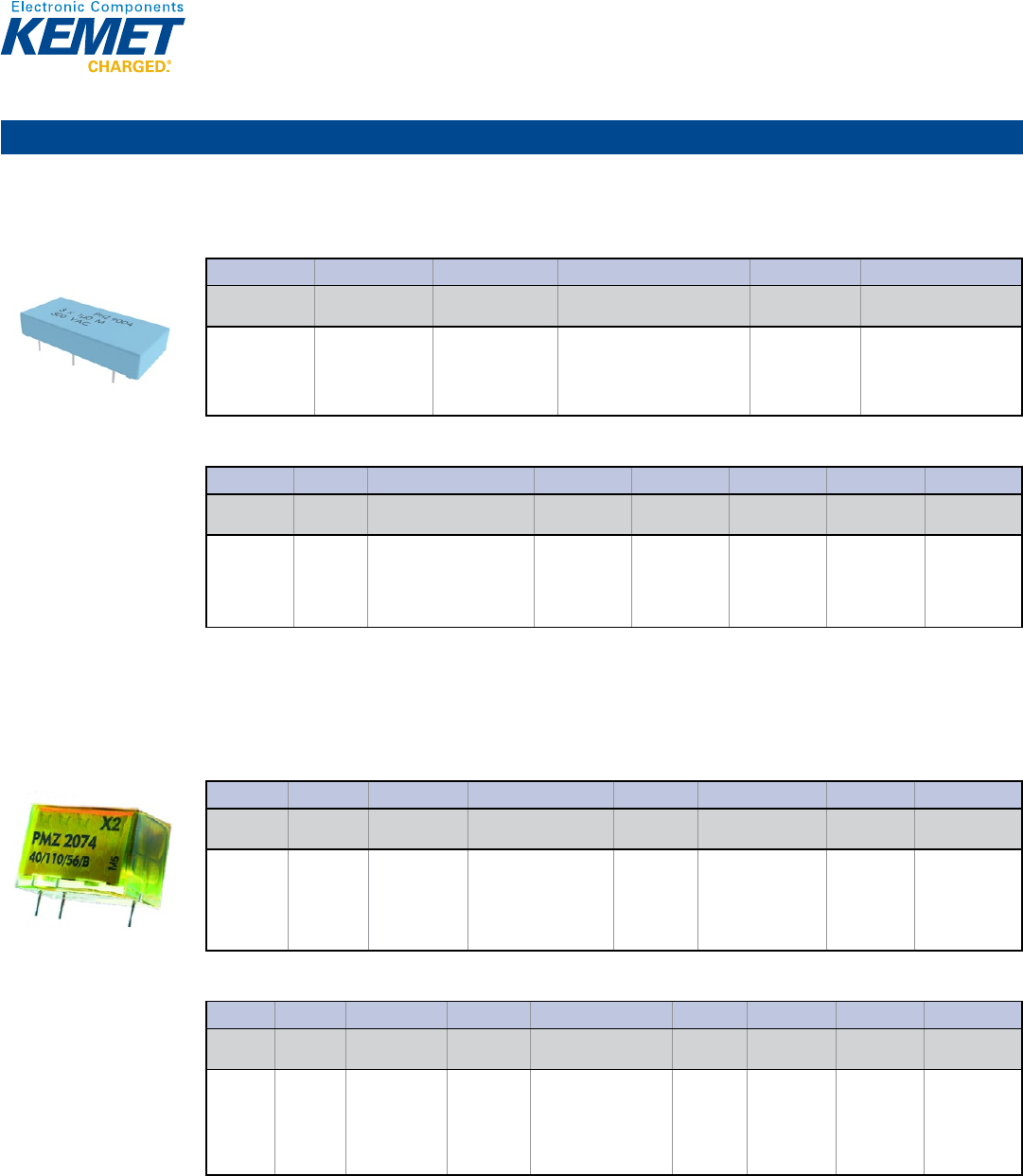
76
Film Capacitors
Multiple X & Y
PHZ9004 Series Metallized Polypropylene Film, 300 VAC 3x X2 with Separate Terminals for Three-Phase Filtering
Capacitance Range: 3 x 1.0 μF • Temperature Range: −55°C to +105°C
Legacy Part Number System
© KEMET Electronics Corporation • P.O. Box 5928 • Greenville, SC 29606 (864) 963-6300 • www.kemet.com F3021_PHZ9004_3xX2_300 • 4/16/2015 1
One world. One KEMET
Bene ts
• Rated voltage: 300 VAC 50/60 Hz
• Capacitance range: 3 x 1.0 µF
• Lead spacing: 27.5 mm
• Capacitance tolerance: ±20%, other tolerances on request
• Climatic category: 55/105/56, IEC 60068–1
• Tape and reel in accordance with IEC 60286–2
• RoHS Compliant and lead-free terminations
• Operating temperature range of -55˚C to +105˚C
• 100% screening factory test at 2,200 VDC
Overview
The PHZ9004 Series is constructed of metallized polypropylene
lm encapsulated with self-extinguishing resin in a box of
material meeting the requirements of UL 94 V–0.
Applications
Typical applications include worldwide use as an electromagnetic
interference suppressor in X2 and across-the-line applications for
three phases.
AC Line EMI Suppression and RC Networks
PHZ9004 Series Metallized Polypropylene Film, 300 VAC
3x X2 with Separate Terminals for Three-Phase Filtering
Legacy Part Number System
PHZ9004 E F 7100 M R06L2
Series Rated Voltage (VAC) Lead Spacing (mm) Capacitance Code (pF) Capacitance
Tolerance
Lead and
Packaging Code
Triple Capacitor
X2, Metallized
Polypropylene
E = 300
F = 27.5
Digits 2 – 4(3) indicates the rst
three digits of the capacitance
value.
First digit indicates the total number
of digits in the capacitance value.
M = ±20%
See Ordering
Options Table
New KEMET Part Number System
9004 AA 105 M300 CDECT V680
Capacitor Class
Size Code
Capacitance Code (pF)
Capacitance
Tolerance
Rated Voltage
(VAC)
Lead and
Packaging Code
C-Spec
V-Spec
Triple
Capacitor X2,
Metallized
Polypropylene
See
Dimension
Table
First two digits indicate the
two most signi cant digits
of the capacitance value in
picofarads. The third digit is
the number of following zeros.
M = ±20%
300 = 300
See Ordering
Options Table
Optional
additional
characters at
KEMET’s option
Part Number
speci c version
code
New KEMET Part Number System
© KEMET Electronics Corporation • P.O. Box 5928 • Greenville, SC 29606 (864) 963-6300 • www.kemet.com F3021_PHZ9004_3xX2_300 • 4/16/2015 1
One world. One KEMET
Bene ts
• Rated voltage: 300 VAC 50/60 Hz
• Capacitance range: 3 x 1.0 µF
• Lead spacing: 27.5 mm
• Capacitance tolerance: ±20%, other tolerances on request
• Climatic category: 55/105/56, IEC 60068–1
• Tape and reel in accordance with IEC 60286–2
• RoHS Compliant and lead-free terminations
• Operating temperature range of -55˚C to +105˚C
• 100% screening factory test at 2,200 VDC
Overview
The PHZ9004 Series is constructed of metallized polypropylene
lm encapsulated with self-extinguishing resin in a box of
material meeting the requirements of UL 94 V–0.
Applications
Typical applications include worldwide use as an electromagnetic
interference suppressor in X2 and across-the-line applications for
three phases.
AC Line EMI Suppression and RC Networks
PHZ9004 Series Metallized Polypropylene Film, 300 VAC
3x X2 with Separate Terminals for Three-Phase Filtering
Legacy Part Number System
PHZ9004 E F 7100 M R06L2
Series
Rated Voltage (VAC)
Lead Spacing (mm)
Capacitance Code (pF)
Capacitance
Tolerance
Lead and
Packaging Code
Triple Capacitor
X2, Metallized
Polypropylene
E = 300
F = 27.5
Digits 2 – 4(3) indicates the rst
three digits of the capacitance
value.
First digit indicates the total number
of digits in the capacitance value.
M = ±20%
See Ordering
Options Table
New KEMET Part Number System
9004 AA 105 M300 CDECT V680
Capacitor Class Size Code Capacitance Code (pF) Capacitance
Tolerance
Rated Voltage
(VAC)
Lead and
Packaging Code C-Spec V-Spec
Triple
Capacitor X2,
Metallized
Polypropylene
See
Dimension
Table
First two digits indicate the
two most signi cant digits
of the capacitance value in
picofarads. The third digit is
the number of following zeros.
M = ±20% 300 = 300 See Ordering
Options Table
Optional
additional
characters at
KEMET’s option
Part Number
speci c version
code
PMZ2074 Series Metallized Impregnated Paper, 275 VAC 2x X2 with One Common Terminal
Capacitance Range: 0.15 μF + 0.033 μF, 0.15 μF + 0.047 μF, 0.15 μF + 0.068 μF, 0.22 μF + 0.082 μF, 0.22 μF + 0.1 μF
Temperature Range: −40°C to +110°C
Legacy Part Number System
© KEMET Electronics Corporation • P.O. Box 5928 • Greenville, SC 29606 (864) 963-6300 • www.kemet.com F3020_PMZ2074_2xX2_275 • 4/16/2015 1
One world. One KEMET
Bene ts
• Approvals: ENEC
• Rated voltage: 275 VAC 50/60 Hz
• Capacitance: 0.15 µF + 0.033 µF, 0.15 µF + 0.047 µF, 0.15 µF +
0.068 µF, 0.22 µF + 0.082 µF, 0.22 µF + 0.1 µF
• Lead spacing: 20.3 mm
• Capacitance tolerance: ±20%, ±10%
• Climatic category: 40/110/56/B, IEC 60068–1
• RoHS Compliant and lead-free terminations
• Operating temperature range of -40˚C to +110˚C
• 100% screening factory test at 2,150 VDC
Overview
The PMZ2074 Series is constructed of multilayer metallized
paper encapsulated and impregnated in self-extinguishing
material meeting the requirements of UL 94 V–0.
Applications
Typical applications include worldwide use as an electromagnetic
interference suppressor in all X2, across-the-line applications or
other demanding applications where two capacitors are utilized
in series.
AC Line EMI Suppression and RC Networks
PMZ2074 Series Metallized Impregnated Paper,
275 VAC 2x X2 with One Common Terminal
Legacy Part Number System
PMZ2074 M C 615 M533 MR30
Series
Rated Voltage
(VAC)
Lead Spacing
(mm) Capacitance Code (pF) Capacitance
Tolerance Capacitance Code (pF) Internal Use Lead and
Packaging Code
Double
Capacitor X2,
Metallized
Paper
M = 275 C = 20.3 Digits 2 – 3 indicate the
rst three digits of the C1
capacitance value.
First digit indicates the
total number of digits in the
capacitance value.
K = ±10%
M = ±20%
Digits 2 – 3 indicate the
rst three digits of the
C2 capacitance value.
First digit indicates the
total number of digits in
the capacitance value.
M (Standard) See Ordering
Options Table
New KEMET Part Number System
P374 C L 154 M275 AC333
Capacitor
Class
Series
Lead Spacing
(mm)
Size Code
X Capacitance Code (pF)
Capacitance
Tolerance
Rated Voltage
(VAC)
Lead and
Packaging Code
Y Capacitance
Code
P = Paper
Double
Capacitor
X2,
Metallized
Paper
C = 20.3
See Dimension
Table
First two digits indicate
the two most signi cant
digits of the capacitance
value in picofarads. The
third digit is the number
of following zeros.
M = ±20%
275 = 275
See Ordering
Options Table
C + rst two
digits represent
signi cant
gures. Third digit
speci es number
of zeros.
New KEMET Part Number System
© KEMET Electronics Corporation • P.O. Box 5928 • Greenville, SC 29606 (864) 963-6300 • www.kemet.com F3020_PMZ2074_2xX2_275 • 4/16/2015 1
One world. One KEMET
Bene ts
• Approvals: ENEC
• Rated voltage: 275 VAC 50/60 Hz
• Capacitance: 0.15 µF + 0.033 µF, 0.15 µF + 0.047 µF, 0.15 µF +
0.068 µF, 0.22 µF + 0.082 µF, 0.22 µF + 0.1 µF
• Lead spacing: 20.3 mm
• Capacitance tolerance: ±20%, ±10%
• Climatic category: 40/110/56/B, IEC 60068–1
• RoHS Compliant and lead-free terminations
• Operating temperature range of -40˚C to +110˚C
• 100% screening factory test at 2,150 VDC
Overview
The PMZ2074 Series is constructed of multilayer metallized
paper encapsulated and impregnated in self-extinguishing
material meeting the requirements of UL 94 V–0.
Applications
Typical applications include worldwide use as an electromagnetic
interference suppressor in all X2, across-the-line applications or
other demanding applications where two capacitors are utilized
in series.
AC Line EMI Suppression and RC Networks
PMZ2074 Series Metallized Impregnated Paper,
275 VAC 2x X2 with One Common Terminal
Legacy Part Number System
PMZ2074 M C 615 M533 MR30
Series
Rated Voltage
(VAC)
Lead Spacing
(mm)
Capacitance Code (pF)
Capacitance
Tolerance
Capacitance Code (pF)
Internal Use
Lead and
Packaging Code
Double
Capacitor X2,
Metallized
Paper
M = 275
C = 20.3
Digits 2 – 3 indicate the
rst three digits of the C1
capacitance value.
First digit indicates the
total number of digits in the
capacitance value.
K = ±10%
M = ±20%
Digits 2 – 3 indicate the
rst three digits of the
C2 capacitance value.
First digit indicates the
total number of digits in
the capacitance value.
M (Standard)
See Ordering
Options Table
New KEMET Part Number System
P374 C L 154 M275 AC333
Capacitor
Class
Series
Lead Spacing
(mm)
Size Code X Capacitance Code (pF)
Capacitance
Tolerance
Rated Voltage
(VAC)
Lead and
Packaging Code
Y Capacitance
Code
P = Paper Double
Capacitor
X2,
Metallized
Paper
C = 20.3
See Dimension
Table
First two digits indicate
the two most signi cant
digits of the capacitance
value in picofarads. The
third digit is the number
of following zeros.
M = ±20% 275 = 275 See Ordering
Options Table
C + rst two
digits represent
signi cant
gures. Third digit
speci es number
of zeros.
Through-Hole – Safety/EMI
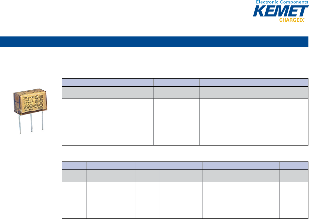
77
Film Capacitors
Multiple X & Y (cont.)
PZB300 Series Metallized Impregnated Paper, 275 VAC Delta Conguration X2 + 2x Y2
Capacitance Range: X Value 0.1 μF and 0.15 μF, Y Value 0.0022 μF, 0.0033 μF and 0.0047 μF • Temperature Range: −40°C to +100°C
Legacy Part Number System
© KEMET Electronics Corporation • P.O. Box 5928 • Greenville, SC 29606 (864) 963-6300 • www.kemet.com F3019_PZB300_X2_2xY2_275 • 4/16/2015 1
One world. One KEMET
Bene ts
• Approvals: ENEC, UL, CSA
• Rated voltage: 275 VAC 50/60 Hz
• Capacitance X Value: 0.1 µF and 0.15 µF
• Capacitance Y Value: 0.0022 µF, 0.0033 µF and 0.0047 µF
• Lead spacing: 20 mm
• Capacitance tolerance: ±20%
• Climatic category: 40/100/56/B, IEC 60068–1
• Tape and reel packaging in accordance with IEC 60286–2
• RoHS Compliant and lead-free terminations
• Operating temperature range of -40˚C to +100˚C
Overview
The PZB300 Series is constructed of multilayer metallized paper
encapsulated and impregnated in self-extinguishing material
meeting the requirements of UL 94 V–0.
Applications
Typical applications include interference suppressors with X2 +
2x Y2 capacitors in a delta con guration.
AC Line EMI Suppression and RC Networks
PZB300 Series Metallized Impregnated Paper,
275 VAC Delta Con guration X2 + 2x Y2
Legacy Part Number System
PZB300 M C 11 R30
Series Rated Voltage (VAC) Lead Spacing (mm) Capacitance Code (pF)
Lead and
Packaging Code
Delta EMI,
X2 + 2x Y2,
Metallized Paper
M = 275 C = 20.0 The rst digit indicates the value of the
X capacitor:
1 = 0.10 µF
2 = 0.15 µF
The second digit indicates the value of
the Y capacitor:
1 = 0.0022 µF
2 = 0.0033 µF
3 = 0.0047 µF
See Ordering
Options Table
New KEMET Part Number System
P300 P L 104 M275 AC222
Capacitor
Class
Series
Lead Spacing
(mm)
Size Code
X Capacitance Code (pF)
Capacitance
Tolerance
Rated Voltage
(VAC)
Lead and
Packaging Code
Y Capacitance
Code
P = Paper
Delta EMI,
X2 + 2x Y2,
Metallized
Paper
P = 20
See
Dimension
Table
First two digits indicate
the two most signi cant
digits of the capacitance
value in picofarads. The
third digit is the number
of following zeros.
M = ±20%
275 = 275
See Ordering
Options Table
C + rst two
digits represent
signi cant
gures. Third
digit speci es
number of
zeros.
New KEMET Part Number System
© KEMET Electronics Corporation • P.O. Box 5928 • Greenville, SC 29606 (864) 963-6300 • www.kemet.com F3019_PZB300_X2_2xY2_275 • 4/16/2015 1
One world. One KEMET
Bene ts
• Approvals: ENEC, UL, CSA
• Rated voltage: 275 VAC 50/60 Hz
• Capacitance X Value: 0.1 µF and 0.15 µF
• Capacitance Y Value: 0.0022 µF, 0.0033 µF and 0.0047 µF
• Lead spacing: 20 mm
• Capacitance tolerance: ±20%
• Climatic category: 40/100/56/B, IEC 60068–1
• Tape and reel packaging in accordance with IEC 60286–2
• RoHS Compliant and lead-free terminations
• Operating temperature range of -40˚C to +100˚C
Overview
The PZB300 Series is constructed of multilayer metallized paper
encapsulated and impregnated in self-extinguishing material
meeting the requirements of UL 94 V–0.
Applications
Typical applications include interference suppressors with X2 +
2x Y2 capacitors in a delta con guration.
AC Line EMI Suppression and RC Networks
PZB300 Series Metallized Impregnated Paper,
275 VAC Delta Con guration X2 + 2x Y2
Legacy Part Number System
PZB300 M C 11 R30
Series
Rated Voltage (VAC)
Lead Spacing (mm)
Capacitance Code (pF)
Lead and
Packaging Code
Delta EMI,
X2 + 2x Y2,
Metallized Paper
M = 275
C = 20.0
The rst digit indicates the value of the
X capacitor:
1 = 0.10 µF
2 = 0.15 µF
The second digit indicates the value of
the Y capacitor:
1 = 0.0022 µF
2 = 0.0033 µF
3 = 0.0047 µF
See Ordering
Options Table
New KEMET Part Number System
P300 P L 104 M275 AC222
Capacitor
Class Series
Lead Spacing
(mm) Size Code X Capacitance Code (pF)
Capacitance
Tolerance
Rated Voltage
(VAC)
Lead and
Packaging Code
Y Capacitance
Code
P = Paper
Delta EMI,
X2 + 2x Y2,
Metallized
Paper
P = 20
See
Dimension
Table
First two digits indicate
the two most signi cant
digits of the capacitance
value in picofarads. The
third digit is the number
of following zeros.
M = ±20%
275 = 275
See Ordering
Options Table
C + rst two
digits represent
signi cant
gures. Third
digit speci es
number of
zeros.
Through-Hole – Safety/EMI
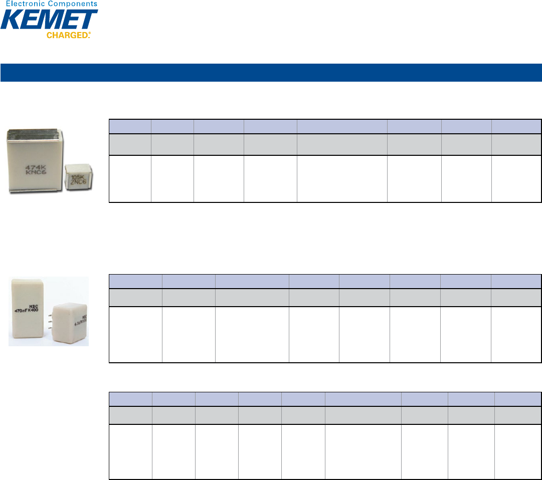
78
Film Capacitors
Polyester (PET)
F161 Series Encapsulated Stacked, Size 2220 – 6560, 50 – 400 VDC
Capacitance Range: 0.01 to 12 μF • Temperature Range: −55°C to +125°C
© KEMET Electronics Corporation • P.O. Box 5928 • Greenville, SC 29606 (864) 963-6300 • www.kemet.com F3086_F161 • 4/16/2015 1
One world. One KEMET
Bene ts
• Rated voltage: 50 – 400 VDC
• Rated voltage: 30 – 200 VAC
• Capacitance range: 0.01 – 12 µF
• EIA size: 2220 – 6560
• Capacitance tolerance: ±5%, ±10%, other tolerances on request
• Climatic category: 55/125/56
• RoHS Compliant and lead-free terminations
• Operating temperature range of -55˚C to +125˚C
Overview
KEMET’s F161 Series polyester (PET) lm capacitor for surface
mounting is encapsulated in self-extinguishing material meeting
the requirements of UL 94 V–0.
Applications
Typical applications include bypassing and signal coupling. F161
is a general purpose series designed for the highest reliability.
General Purpose and High Stability
F161 Series Encapsulated Stacked, Size 2220 – 6560,
50 – 400 VDC
Part Number System
F161 P L 102 K050 V
Capacitor
Class Series Chip Size Size Code Capacitance Code (pF)
Capacitance
Tolerance
Rated Voltage
(VDC) Packaging Code
F = Film Metallized
Polyester
Stacked
Technology
P = 2220
S = 2824
W = 4036
Y = 5045
Z = 6560
See Dimension
Table
First two digits indicate the
two most signi cant digits
of the capacitance value in
picofarads. The third digit is
the number of following zeros.
J = ±5
K = ±10%
Other tolerances
on request
050 = 50
063 = 63
100 = 100
250 = 250
400 = 400
See Ordering
Options Table
MDC Series Dual In-Line, High Current, 50 – 630 VDC
Capacitance Range: 0.033 to 15 μF • Temperature Range: −55°C to +125°C
Legacy Part Number System
© KEMET Electronics Corporation • P.O. Box 5928 • Greenville, SC 29606 (864) 963-6300 • www.kemet.com F3074_MDC • 4/16/2015 1
One world. One KEMET
Bene ts
• Rated voltage: 50 – 630 VDC
• Rated voltage: 30 – 220 VAC
• Capacitance range: 0.033 – 15 µF
• Capacitance tolerance: ±5%, ±10%, other tolerances on request
• Climatic category: 55/125/56
• RoHS Compliant and lead-free terminations
• Operating temperature range of -55˚C to +125˚C
Overview
Dual in-line (DIL) metallized polyester (PET) lm capacitor for
surface mounting. Encapsulation in self-extinguishing material
meeting the requirements of UL 94 V–0.
Applications
Typical applications include high frequency switched-mode power
supplies, DC/DC converters and input/output ltering.
Surface Mount Polyester (PET) Film Capacitor
MDC Series Dual In-Line, 50 – 630 VDC, High Current
Legacy Part Number System
MDC 10 333 K50 A52 P3 TUBE
Series
Lead Spacing
(mm)
Capacitance Code (pF)
Capacitance
Tolerance
Rated Voltage
(VDC)
Size Code
Number of Leads
per Side
Packaging Code
Dual In-Line,
Metallized
Polyester
10
15
First two digits indicate
the two most signi cant
digits of the capacitance
value in picofarads. The
third digit is the number of
following zeros.
J = ±5
K = ±10%
Other tolerances
on request
50
100
250
400
630
See Dimension
Table
P3 = 3 leads
P4 = 4 leads
P5 = 5 leads
P7 = 7 leads
P8 = 8 leads
See Ordering
Options Table
New KEMET Part Number System
F15 3 A A 333 K050 T
Capacitor
Class
Series
Number of
Leads per Side
Lead Spacing
(mm)
Size Code
Capacitance Code (pF)
Capacitance
Tolerance
Rated Voltage
(VDC)
Packaging Code
F = Film
Dual In-Line,
Metallized
Polyester
3 = 3 leads
4 = 4 leads
5 = 5 leads
7 = 7 leads
8 = 8 leads
A = 10
B = 15
A = Standard
box size
First two digits indicate the
two most signi cant digits
of the capacitance value in
picofarads. The third digit
is the number of following
zeros.
J = ±5
K = ±10%
Other
tolerances on
request
050 = 50
100 = 100
250 = 250
400 = 400
630 = 630
See Ordering
Options Table
New KEMET Part Number System
© KEMET Electronics Corporation • P.O. Box 5928 • Greenville, SC 29606 (864) 963-6300 • www.kemet.com F3074_MDC • 4/16/2015 1
One world. One KEMET
Bene ts
• Rated voltage: 50 – 630 VDC
• Rated voltage: 30 – 220 VAC
• Capacitance range: 0.033 – 15 µF
• Capacitance tolerance: ±5%, ±10%, other tolerances on request
• Climatic category: 55/125/56
• RoHS Compliant and lead-free terminations
• Operating temperature range of -55˚C to +125˚C
Overview
Dual in-line (DIL) metallized polyester (PET) lm capacitor for
surface mounting. Encapsulation in self-extinguishing material
meeting the requirements of UL 94 V–0.
Applications
Typical applications include high frequency switched-mode power
supplies, DC/DC converters and input/output ltering.
Surface Mount Polyester (PET) Film Capacitor
MDC Series Dual In-Line, 50 – 630 VDC, High Current
Legacy Part Number System
MDC 10 333 K50 A52 P3 TUBE
Series
Lead Spacing
(mm)
Capacitance Code (pF)
Capacitance
Tolerance
Rated Voltage
(VDC)
Size Code
Number of Leads
per Side
Packaging Code
Dual In-Line,
Metallized
Polyester
10
15
First two digits indicate
the two most signi cant
digits of the capacitance
value in picofarads. The
third digit is the number of
following zeros.
J = ±5
K = ±10%
Other tolerances
on request
50
100
250
400
630
See Dimension
Table
P3 = 3 leads
P4 = 4 leads
P5 = 5 leads
P7 = 7 leads
P8 = 8 leads
See Ordering
Options Table
New KEMET Part Number System
F15 3 A A 333 K050 T
Capacitor
Class
Series
Number of
Leads per Side
Lead Spacing
(mm)
Size Code Capacitance Code (pF)
Capacitance
Tolerance
Rated Voltage
(VDC)
Packaging Code
F = Film Dual In-Line,
Metallized
Polyester
3 = 3 leads
4 = 4 leads
5 = 5 leads
7 = 7 leads
8 = 8 leads
A = 10
B = 15
A = Standard
box size
First two digits indicate the
two most signi cant digits
of the capacitance value in
picofarads. The third digit
is the number of following
zeros.
J = ±5
K = ±10%
Other
tolerances on
request
050 = 50
100 = 100
250 = 250
400 = 400
630 = 630
See Ordering
Options Table
Surface Mount
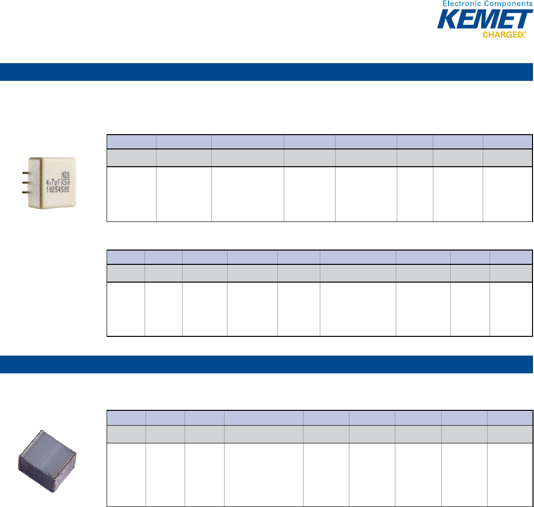
79
Film Capacitors
Polyester (PET) (cont.)
MDS Series Dual In-Line Low Prole, High Current, 50 – 630 VDC
Capacitance Range: 0.033 to 6.8 μF • Temperature Range: −55°C to +125°C
Legacy Part Number System
© KEMET Electronics Corporation • P.O. Box 5928 • Greenville, SC 29606 (864) 963-6300 • www.kemet.com F3075_MDS • 4/16/2015 1
One world. One KEMET
Bene ts
• Rated voltage: 50 – 630 VDC
• Rated voltage: 30 – 220 VAC
• Capacitance range: 0.033 – 6.8 µF
• Capacitance tolerance: ±5%, ±10%, other tolerances on request
• Climatic category: 55/125/56
• RoHS Compliant and lead-free terminations
• Operating temperature range of -55˚C to +125˚C
Overview
Dual in-line (DIL) metallized polyester (PET) lm capacitor.
Encapsulation in self-extinguishing material meeting the
requirements of UL 94 V–0.
Applications
Typical applications include high frequency switched-mode power
supplies, DC/DC converters and input/output ltering.
Surface Mount Polyester (PET) Film Capacitor
MDS Series Dual In-Line Low Pro le, 50 – 630 VDC,
High Current
Legacy Part Number System
MDS 10 333 K50 A52 P3 TUBE
Series Lead Spacing (mm) Capacitance Code (pF)
Capacitance
Tolerance
Rated Voltage (VDC) Size Code
Number of Leads
per Side
Packaging Code
Dual In-Line,
Metallized
Polyester
10
15
First two digits indicate
the two most signi cant
digits of the capacitance
value in picofarads. The
third digit is the number of
following zeros.
J = ±5
K = ±10%
Other tolerances
on request
050 = 50
100 = 100
250 = 250
400 = 400
630 = 630
See
Dimension
Table
P3 = 3 leads
P4 = 4 leads
P5 = 5 leads
See Ordering
Options Table
New KEMET Part Number System
F17 3 A A 333 K050 T
Capacitor
Class
Series
Number of
Leads per Side
Lead Spacing
(mm)
Size Code
Capacitance Code (pF)
Capacitance
Tolerance
Rated Voltage
(VDC)
Packaging
Code
F = Film
Dual In-Line,
Metallized
Polyester
3 = 3 leads
4 = 4 leads
5 = 5 leads
A = 10
B = 15
A = Standard
box size
First two digits indicate the
two most signi cant digits
of the capacitance value in
picofarads. The third digit
is the number of following
zeros.
J = ±5
K = ±10%
Other tolerances
on request
050 = 50
100 = 100
250 = 250
400 = 400
630 = 630
See Ordering
Options Table
New KEMET Part Number System
© KEMET Electronics Corporation • P.O. Box 5928 • Greenville, SC 29606 (864) 963-6300 • www.kemet.com F3075_MDS • 4/16/2015 1
One world. One KEMET
Bene ts
• Rated voltage: 50 – 630 VDC
• Rated voltage: 30 – 220 VAC
• Capacitance range: 0.033 – 6.8 µF
• Capacitance tolerance: ±5%, ±10%, other tolerances on request
• Climatic category: 55/125/56
• RoHS Compliant and lead-free terminations
• Operating temperature range of -55˚C to +125˚C
Overview
Dual in-line (DIL) metallized polyester (PET) lm capacitor.
Encapsulation in self-extinguishing material meeting the
requirements of UL 94 V–0.
Applications
Typical applications include high frequency switched-mode power
supplies, DC/DC converters and input/output ltering.
Surface Mount Polyester (PET) Film Capacitor
MDS Series Dual In-Line Low Pro le, 50 – 630 VDC,
High Current
Legacy Part Number System
MDS 10 333 K50 A52 P3 TUBE
Series
Lead Spacing (mm)
Capacitance Code (pF)
Capacitance
Tolerance
Rated Voltage (VDC)
Size Code
Number of Leads
per Side
Packaging Code
Dual In-Line,
Metallized
Polyester
10
15
First two digits indicate
the two most signi cant
digits of the capacitance
value in picofarads. The
third digit is the number of
following zeros.
J = ±5
K = ±10%
Other tolerances
on request
050 = 50
100 = 100
250 = 250
400 = 400
630 = 630
See
Dimension
Table
P3 = 3 leads
P4 = 4 leads
P5 = 5 leads
See Ordering
Options Table
New KEMET Part Number System
F17 3 A A 333 K050 T
Capacitor
Class
Series
Number of
Leads per Side
Lead Spacing
(mm)
Size Code Capacitance Code (pF)
Capacitance
Tolerance
Rated Voltage
(VDC)
Packaging
Code
F = Film Dual In-Line,
Metallized
Polyester
3 = 3 leads
4 = 4 leads
5 = 5 leads
A = 10
B = 15
A = Standard
box size
First two digits indicate the
two most signi cant digits
of the capacitance value in
picofarads. The third digit
is the number of following
zeros.
J = ±5
K = ±10%
Other tolerances
on request
050 = 50
100 = 100
250 = 250
400 = 400
630 = 630
See Ordering
Options Table
Polyethylene Naphthalate (PEN)
LDE Series Unencapsulated Stacked Chip, Size 1206 – 6054, 50 – 1,000 VDC (Automotive Grade)
Capacitance Range: 0.001 to 4.7 μF • Temperature Range: −55°C to +125°C
© KEMET Electronics Corporation • P.O. Box 5928 • Greenville, SC 29606 (864) 963-6300 • www.kemet.com F3078_LDE • 4/16/2015 1
One world. One KEMET
Bene ts
• Rated voltage: 50 – 1,000 VDC
• Rated voltage: 40 – 250 VAC
• Capacitance range: 0.001 – 4.7 µF
• EIA size: 1206 – 6054
• Capacitance tolerance: ±10%, ±20%, ±5% on request
• Climatic category: 55/125/56
• RoHS Compliant and lead-free terminations
• Operating temperature range of -55˚C to +125˚C
• Automotive (AEC–Q200) grades available
Overview
Polyethylene naphthalate (PEN) lm capacitor for surface
mounting which meets the demanding Automotive Electronics
Council's AEC–Q200 quali cation requirements.
Applications
Typical applications include bypassing and signal coupling. LDE
is a general purpose series designed for the highest reliability
and high temperature service. Not suitable for across-the-line
application (see suppressor capacitors).
Surface Mount Polyethylene Naphthalate (PEN) Film Capacitor
LDE Series Unencapsulated Stacked Chip,
Size 1206 – 6054, 50 – 1,000 VDC (Automotive Grade)
Part Number System
LDE C C 2560 M A 5 N 00
Series
Rated Voltage
(VDC)
Size Code Capacitance Code (pF)
Capacitance
Tolerance
Dielectric Version Packaging Code Internal Use
Metallized
PEN
C = 50
D = 63
E = 100
I = 250
M = 400
P = 630
Q = 1000
See
Dimension
Table
Digits 2 – 4 indicate the
rst three digits of the
capacitance value.
First digit indicates the
number of zeros to be
added.
K = ±10%
M = ±20%
J = ±5% on
request
A = PEN 5 = Standard
0 = Miniature
See Ordering
Options Table
00 (Standard)
Surface Mount
80
Film Capacitors
Polyethylene Naphthalate (PEN) (cont.)
GMC Series Encapsulated Stacked, Size 2220 – 6560, 50 – 630 VDC
Capacitance Range: 0.001 to 5.6 μF • Temperature Range: −55°C to +125°C
Legacy Part Number System
© KEMET Electronics Corporation • P.O. Box 5928 • Greenville, SC 29606 (864) 963-6300 • www.kemet.com F3079_GMC • 4/16/2015 1
One world. One KEMET
Bene ts
• Rated voltage: 50 – 630 VDC
• Rated voltage: 30 – 300 VAC
• Capacitance range: 0.001 – 5.6 µF
• EIA size: 2220 – 6560
• Capacitance tolerance: ±5%, ±10%, other tolerances on request
• Climatic category: 55/125/56
• RoHS Compliant and lead-free terminations
• Operating temperature range of -55˚C to +125˚C
Overview
Polyethylene naphthalate (PEN) lm capacitor for surface
mounting. Encapsulation in self-extinguishing material meeting
the requirements of UL 94 V–0.
Applications
Typical applications include bypassing and signal coupling. GMC
is a general purpose series designed for the highest reliability
and high temperature service. Not suitable for across-the-line
application (see suppressor capacitors).
Surface Mount Polyethylene Naphthalate (PEN) Film Capacitor
GMC Series Encapsulated, Size 2220 – 6560, 50 – 630 VDC
Legacy Part Number System
GMC 5.7 102 K50 J31 TR12
Series Chip Length (mm) Capacitance Code (pF)
Capacitance
Tolerance
Rated Voltage
(VDC)
Size Code Packaging Code
Metallized PEN 5.7
7.3
10.2
12.7
16.5
First two digits indicate the
two most signi cant digits
of the capacitance value in
picofarads. The third digit is
the number of following zeros.
J = ±5%
K = ±10%
Other tolerances
on request
50
63
100
250
400
630
See Dimension
Table
See Ordering
Options Table
New KEMET Part Number System
F115 P L 102 K050 V
Capacitor Class
Series
Chip Size
Size Code
Capacitance Code (pF)
Capacitance
Tolerance
Rated Voltage
(VDC)
Packaging Code
F = Film
Metallized PEN
P = 2220
S = 2824
W = 4036
Y = 5045
Z = 6560
See Dimension
Table
First two digits indicate the
two most signi cant digits
of the capacitance value in
picofarads. The third digit is
the number of following zeros.
J = ±5%
K = ±10%
Other tolerances
on request
050 = 50
063 = 63
100 = 100
250 = 250
400 = 400
630 = 630
See Ordering
Options Table
New KEMET Part Number System
© KEMET Electronics Corporation • P.O. Box 5928 • Greenville, SC 29606 (864) 963-6300 • www.kemet.com F3079_GMC • 4/16/2015 1
One world. One KEMET
Bene ts
• Rated voltage: 50 – 630 VDC
• Rated voltage: 30 – 300 VAC
• Capacitance range: 0.001 – 5.6 µF
• EIA size: 2220 – 6560
• Capacitance tolerance: ±5%, ±10%, other tolerances on request
• Climatic category: 55/125/56
• RoHS Compliant and lead-free terminations
• Operating temperature range of -55˚C to +125˚C
Overview
Polyethylene naphthalate (PEN) lm capacitor for surface
mounting. Encapsulation in self-extinguishing material meeting
the requirements of UL 94 V–0.
Applications
Typical applications include bypassing and signal coupling. GMC
is a general purpose series designed for the highest reliability
and high temperature service. Not suitable for across-the-line
application (see suppressor capacitors).
Surface Mount Polyethylene Naphthalate (PEN) Film Capacitor
GMC Series Encapsulated, Size 2220 – 6560, 50 – 630 VDC
Legacy Part Number System
GMC 5.7 102 K50 J31 TR12
Series
Chip Length (mm)
Capacitance Code (pF)
Capacitance
Tolerance
Rated Voltage
(VDC)
Size Code
Packaging Code
Metallized PEN
5.7
7.3
10.2
12.7
16.5
First two digits indicate the
two most signi cant digits
of the capacitance value in
picofarads. The third digit is
the number of following zeros.
J = ±5%
K = ±10%
Other tolerances
on request
50
63
100
250
400
630
See Dimension
Table
See Ordering
Options Table
New KEMET Part Number System
F115 P L 102 K050 V
Capacitor Class Series Chip Size Size Code Capacitance Code (pF)
Capacitance
Tolerance
Rated Voltage
(VDC)
Packaging Code
F = Film
Metallized PEN
P = 2220
S = 2824
W = 4036
Y = 5045
Z = 6560
See Dimension
Table
First two digits indicate the
two most signi cant digits
of the capacitance value in
picofarads. The third digit is
the number of following zeros.
J = ±5%
K = ±10%
Other tolerances
on request
050 = 50
063 = 63
100 = 100
250 = 250
400 = 400
630 = 630
See Ordering
Options Table
GPC Series Encapsulated Double Metallized, Size 2824 – 6560, 63 – 1,000 VDC
Capacitance Range: 470 pF to 1.0 μF • Temperature Range: −55°C to +125°C
Legacy Part Number System
© KEMET Electronics Corporation • P.O. Box 5928 • Greenville, SC 29606 (864) 963-6300 • www.kemet.com F3080_GPC • 4/16/2015 1
One world. One KEMET
Bene ts
• Rated voltage: 63 – 1,000 VDC
• Rated voltage: 40 – 350 VAC
• Capacitance range: 0.00047 – 1.0 µF
• EIA size: 2824 – 6560
• Capacitance tolerance: ±10%, ±20%, other tolerances on request
• Climatic category: 55/125/56
• RoHS Compliant and lead-free terminations
• Operating temperature range of -55˚C to +125˚C
Overview
Film capacitor for surface mounting. Double sided metallized
polyethylene naphthalate (PEN) as electrode. Clear PEN as
dielectric. Rugged box encapsulation in self-extinguishing
material meeting the requirements of UL 94 V–0.
Applications
The GPC Series is designed for high frequency coupling and
decoupling as well as general high speed applications requiring
high dV/dt such as pulse operation in switched-mode power
supply (SMPS). Not suitable for across-the-line application (see
suppressor capacitors).
Surface Mount Polyethylene Naphthalate (PEN) Film Capacitor
GPC Series Encapsulated Double Metallized,
Size 2824 – 6560, 63 – 1,000 VDC
Legacy Part Number System
GPC 7.3 471 K63 K31 TR12
Series Chip Length (mm) Capacitance Code (pF)
Capacitance
Tolerance
Rated Voltage
(VDC)
Size Code Packaging Code
Double Metallized
PEN
7.3
10.2
12.7
16.5
First two digits indicate the
two most signi cant digits
of the capacitance value in
picofarads. The third digit is
the number of following zeros.
K = ±10%
M = ±20%
Other tolerances
on request
63
100
160
250
400
630
1,000
See Dimension
Table
See Ordering
Options Table
New KEMET Part Number System
F117 S G 471 K063 V
Capacitor
Class
Series
Chip Size
Size Code
Capacitance Code (pF)
Capacitance
Tolerance
Rated Voltage
(VDC)
Packaging Code
F = Film
Double
Metallized PEN
S = 2824
W = 4036
Y = 5045
Z = 6560
See Dimension
Table
First two digits indicate the
two most signi cant digits
of the capacitance value in
picofarads. The third digit is
the number of following zeros.
K = ±10%
M = ±20%
Other tolerances
on request
063 = 63
100 = 100
160 = 160
250 = 250
400 = 400
630 = 630
1K0 = 1,000
See Ordering
Options Table
New KEMET Part Number System
© KEMET Electronics Corporation • P.O. Box 5928 • Greenville, SC 29606 (864) 963-6300 • www.kemet.com F3080_GPC • 4/16/2015 1
One world. One KEMET
Bene ts
• Rated voltage: 63 – 1,000 VDC
• Rated voltage: 40 – 350 VAC
• Capacitance range: 0.00047 – 1.0 µF
• EIA size: 2824 – 6560
• Capacitance tolerance: ±10%, ±20%, other tolerances on request
• Climatic category: 55/125/56
• RoHS Compliant and lead-free terminations
• Operating temperature range of -55˚C to +125˚C
Overview
Film capacitor for surface mounting. Double sided metallized
polyethylene naphthalate (PEN) as electrode. Clear PEN as
dielectric. Rugged box encapsulation in self-extinguishing
material meeting the requirements of UL 94 V–0.
Applications
The GPC Series is designed for high frequency coupling and
decoupling as well as general high speed applications requiring
high dV/dt such as pulse operation in switched-mode power
supply (SMPS). Not suitable for across-the-line application (see
suppressor capacitors).
Surface Mount Polyethylene Naphthalate (PEN) Film Capacitor
GPC Series Encapsulated Double Metallized,
Size 2824 – 6560, 63 – 1,000 VDC
Legacy Part Number System
GPC 7.3 471 K63 K31 TR12
Series
Chip Length (mm)
Capacitance Code (pF)
Capacitance
Tolerance
Rated Voltage
(VDC)
Size Code
Packaging Code
Double Metallized
PEN
7.3
10.2
12.7
16.5
First two digits indicate the
two most signi cant digits
of the capacitance value in
picofarads. The third digit is
the number of following zeros.
K = ±10%
M = ±20%
Other tolerances
on request
63
100
160
250
400
630
1,000
See Dimension
Table
See Ordering
Options Table
New KEMET Part Number System
F117 S G 471 K063 V
Capacitor
Class
Series Chip Size Size Code Capacitance Code (pF)
Capacitance
Tolerance
Rated Voltage
(VDC)
Packaging Code
F = Film Double
Metallized PEN
S = 2824
W = 4036
Y = 5045
Z = 6560
See Dimension
Table
First two digits indicate the
two most signi cant digits
of the capacitance value in
picofarads. The third digit is
the number of following zeros.
K = ±10%
M = ±20%
Other tolerances
on request
063 = 63
100 = 100
160 = 160
250 = 250
400 = 400
630 = 630
1K0 = 1,000
See Ordering
Options Table
Surface Mount
81
Film Capacitors
Metallized Polyphenylene Sulfide (PPS)
LDB Series Unencapsulated Stacked Chip, Size 1206 – 1812, 16 & 50 VDC
Capacitance Range: 0.0033 to 0.1 μF • Temperature Range: −55°C to +125°C
© KEMET Electronics Corporation • P.O. Box 5928 • Greenville, SC 29606 (864) 963-6300 • www.kemet.com F3082_LDB • 4/16/2015 1
One world. One KEMET
Bene ts
• Rated voltage: 16 & 50 VDC
• Capacitance range: 0.0033 – 0.1 µF
• EIA size: 1206 – 1812
• Capacitance tolerance: ±2%, ±5%
• Climatic category: 55/125/56
• RoHS Complaint and lead-free terminations
• Operating temperature range of -55˚C to +125˚C
Overview
Polyphenylene sulphide (PPS) lm capacitor for surface
mounting.
Applications
Typical applications include timing, ltering and use as a memory
capacitor. The LDB Series is designed for high stability, accuracy
and temperature.
Surface Mount Metallized PPS Film Capacitor
LDB Series Unencapsulated Stacked Chip,
Size 1206 – 1812, 16 & 50 VDC
Part Number System
LDB A A 2120 GC5N0
Series
Rated Voltage
(VDC) Size Code Capacitance Code (pF)
Capacitance
Tolerance Dielectric Version
Packaging Code
Internal Use
Metallized PPS A = 16
C = 50
See Dimension
Table
Digits 2 – 4 indicate the
rst three digits of the
capacitance value.
First digit indicates the
number of zeros to be
added.
G = ±2%
J = ±5%
C = PPS 5 = Standard See Ordering
Options Table
0 (Standard)
SMC Series Encapsulated Stacked, Size 2220 – 6560, 50 – 400 VDC
Capacitance Range: 0.001 to 3.3 μF • Temperature Range: −55°C to +125°C
Legacy Part Number System
© KEMET Electronics Corporation • P.O. Box 5928 • Greenville, SC 29606 (864) 963-6300 • www.kemet.com F3083_SMC • 4/16/2015 1
One world. One KEMET
Bene ts
• Rated voltage: 50 – 400 VDC
• Rated voltage: 30 – 200 VAC
• Capacitance range: 0.001 – 3.3 µF
• EIA size: 2220 – 6560
• Capacitance tolerance: ±2%, ±2.5%, ±5%
• Climatic category: 55/125/56
• RoHS Compliant and lead-free terminations
• Operating temperature range of -55˚C to +125˚C
Overview
Polyphenylene sulphide (PPS) lm capacitor for surface
mounting. Encapsulation in self-extinguishing material meeting
the requirements of UL 94 V–0.
Applications
Typical applications include timing, ltering and use as a memory
capacitor. The SMC Series is designed for high stability, accuracy
and temperature. Not suitable for across-the-line application (see
suppressor capacitors).
Surface Mount Metallized PPS Film Capacitor
SMC Series Encapsulated, Size 2220 – 6560, 50 – 400 VDC
Legacy Part Number System
SMC 5.7 102 J50 J31 TR12
Series Chip Length (mm)
Capacitance Code
(pF)
Capacitance
Tolerance
Rated Voltage
(VDC) Size Code Packaging
Metallized PPS
5.7
7.3
10.2
12.7
16.5
First two digits
represent signi cant
gures. The third digit
speci es number of
zeros.
G = ±2%
H = ±2.5%
J = ±5%
50
100
250
400
See Dimension Table
See Ordering
Options Table
New KEMET Part Number System
F125 P L 102 J050 V
Capacitor Class
Series
Chip Size
Size Code
Capacitance Code (pF)
Capacitance
Tolerance
Rated Voltage
(VDC)
Packaging
F = Film
Metallized PPS
P = 2220
S = 2820
W = 4036
Y = 5045
Z = 6560
See Dimension
Table
First two digits represent
signi cant gures. The third
digit speci es number of
zeros.
G = ±2%
R = ±2.5%
J = ±5%
050 = 50
100 = 100
250 = 250
400 = 400
See Ordering
Options Table
New KEMET Part Number System
© KEMET Electronics Corporation • P.O. Box 5928 • Greenville, SC 29606 (864) 963-6300 • www.kemet.com F3083_SMC • 4/16/2015 1
One world. One KEMET
Bene ts
• Rated voltage: 50 – 400 VDC
• Rated voltage: 30 – 200 VAC
• Capacitance range: 0.001 – 3.3 µF
• EIA size: 2220 – 6560
• Capacitance tolerance: ±2%, ±2.5%, ±5%
• Climatic category: 55/125/56
• RoHS Compliant and lead-free terminations
• Operating temperature range of -55˚C to +125˚C
Overview
Polyphenylene sulphide (PPS) lm capacitor for surface
mounting. Encapsulation in self-extinguishing material meeting
the requirements of UL 94 V–0.
Applications
Typical applications include timing, ltering and use as a memory
capacitor. The SMC Series is designed for high stability, accuracy
and temperature. Not suitable for across-the-line application (see
suppressor capacitors).
Surface Mount Metallized PPS Film Capacitor
SMC Series Encapsulated, Size 2220 – 6560, 50 – 400 VDC
Legacy Part Number System
SMC 5.7 102 J50 J31 TR12
Series
Chip Length (mm)
Capacitance Code
(pF)
Capacitance
Tolerance
Rated Voltage
(VDC)
Size Code
Packaging
Metallized PPS
5.7
7.3
10.2
12.7
16.5
First two digits
represent signi cant
gures. The third digit
speci es number of
zeros.
G = ±2%
H = ±2.5%
J = ±5%
50
100
250
400
See Dimension Table
See Ordering
Options Table
New KEMET Part Number System
F125 P L 102 J050 V
Capacitor Class Series Chip Size Size Code Capacitance Code (pF) Capacitance
Tolerance
Rated Voltage
(VDC) Packaging
F = Film
Metallized PPS
P = 2220
S = 2820
W = 4036
Y = 5045
Z = 6560
See Dimension
Table
First two digits represent
signi cant gures. The third
digit speci es number of
zeros.
G = ±2%
R = ±2.5%
J = ±5%
050 = 50
100 = 100
250 = 250
400 = 400
See Ordering
Options Table
Surface Mount
82
Film Capacitors
Metallized Polyphenylene Sulfide (PPS) (cont.)
SPC Series Encapsulated Double Metallized, Size 2824 – 6560, 100 – 630 VDC
Capacitance Range: 470 pF to 0.68 μF • Temperature Range: −55°C to +125°C
Legacy Part Number System
© KEMET Electronics Corporation • P.O. Box 5928 • Greenville, SC 29606 (864) 963-6300 • www.kemet.com F3084_SPC • 4/16/2015 1
One world. One KEMET
Bene ts
• Rated voltage: 100 – 630 VDC
• Rated voltage: 63 – 350 VAC
• Capacitance range: 0.00047 – 0.68 µF
• EIA size: 2824 – 6560
• Capacitance tolerance: ±2%, ±2.5%, ±5%, ±10%
• Climatic category: 55/125/56
• RoHS Compliant and lead-free terminations
• Operating temperature range of -55˚C to +125˚C
Overview
Film capacitor for surface mounting. Double sided metallized lm
as electrode. Plain polyphenylene sul de (PPS) as dielectric.
Rugged box encapsulation in self-extinguishing material meeting
the requirements of UL 94 V–0.
Applications
The SPC Series is designed for high frequency coupling and
decoupling as well as general high speed applications requiring
high dV/dt such as pulse operation in switched-mode power
supply (SMPS). Not suitable for across-the-line application (see
suppressor capacitors).
Surface Mount Metallized PPS Film Capacitor
SPC Series Encapsulated Double Metallized,
Size 2824 – 6560, 100 – 630 VDC
Legacy Part Number System
SPC 7.3 471 K100 K31 TR12
Series Chip Length (mm)
Capacitance Code
(pF)
Capacitance
Tolerance
Rated Voltage
(VDC)
Size Code Packaging
Double Metallized
PPS
7.3
10.2
12.7
16.5
First two digits
represent signi cant
gures. The third digit
speci es number of
zeros.
G = ±2%
H = ±2.5%
J = ±5%
K = ±10%
100
250
400
630
See Dimension Table
See Ordering
Options Table
New KEMET Part Number System
F127 S G 471 K100 V
Capacitor Class
Series
Chip Size
Size Code
Capacitance Code (pF)
Capacitance
Tolerance
Rated Voltage
(VDC)
Packaging
F = Film
Double
Metallized PPS
S = 2824
W = 4036
Y = 5045
Z = 6560
See Dimension
Table
First two digits represent
signi cant gures. The third
digit speci es number of
zeros.
G = ±2%
R = ±2.5%
J = ±5%
K = ±10%
100
250
400
630
See Ordering
Options Table
New KEMET Part Number System
© KEMET Electronics Corporation • P.O. Box 5928 • Greenville, SC 29606 (864) 963-6300 • www.kemet.com F3084_SPC • 4/16/2015 1
One world. One KEMET
Bene ts
• Rated voltage: 100 – 630 VDC
• Rated voltage: 63 – 350 VAC
• Capacitance range: 0.00047 – 0.68 µF
• EIA size: 2824 – 6560
• Capacitance tolerance: ±2%, ±2.5%, ±5%, ±10%
• Climatic category: 55/125/56
• RoHS Compliant and lead-free terminations
• Operating temperature range of -55˚C to +125˚C
Overview
Film capacitor for surface mounting. Double sided metallized lm
as electrode. Plain polyphenylene sul de (PPS) as dielectric.
Rugged box encapsulation in self-extinguishing material meeting
the requirements of UL 94 V–0.
Applications
The SPC Series is designed for high frequency coupling and
decoupling as well as general high speed applications requiring
high dV/dt such as pulse operation in switched-mode power
supply (SMPS). Not suitable for across-the-line application (see
suppressor capacitors).
Surface Mount Metallized PPS Film Capacitor
SPC Series Encapsulated Double Metallized,
Size 2824 – 6560, 100 – 630 VDC
Legacy Part Number System
SPC 7.3 471 K100 K31 TR12
Series
Chip Length (mm)
Capacitance Code
(pF)
Capacitance
Tolerance
Rated Voltage
(VDC)
Size Code
Packaging
Double Metallized
PPS
7.3
10.2
12.7
16.5
First two digits
represent signi cant
gures. The third digit
speci es number of
zeros.
G = ±2%
H = ±2.5%
J = ±5%
K = ±10%
100
250
400
630
See Dimension Table
See Ordering
Options Table
New KEMET Part Number System
F127 S G 471 K100 V
Capacitor Class Series Chip Size Size Code Capacitance Code (pF)
Capacitance
Tolerance
Rated Voltage
(VDC)
Packaging
F = Film
Double
Metallized PPS
S = 2824
W = 4036
Y = 5045
Z = 6560
See Dimension
Table
First two digits represent
signi cant gures. The third
digit speci es number of
zeros.
G = ±2%
R = ±2.5%
J = ±5%
K = ±10%
100
250
400
630
See Ordering
Options Table
Y2 Class
SMP253 Series Metallized Impregnated Paper, 250 VAC
Capacitance Range: 1,000 to 4,700 pF • Temperature Range: −40°C to +100°C
Legacy Part Number System
© KEMET Electronics Corporation • P.O. Box 5928 • Greenville, SC 29606 (864) 963-6300 • www.kemet.com F3018_SMP253_Y2_250 • 4/16/2015 1
One world. One KEMET
Bene ts
• Approvals: ENEC, UL, CSA
• Rated voltage: 250 VAC 50/60 Hz
• Capacitance range: 0.001 – 0.0047 µF
• Size code: 5045, 12.7 mm
• Capacitance tolerance: ±20%
• Climatic category: 40/100/56/B, IEC 60068–1
• Tape and reel packaging in accordance with IEC 60286–3
• RoHS Compliant and lead-free terminations
• Operating temperature range of -40˚C to +100˚C
• 100% screening factory test at 3,000 VDC
• Highest possible safety regarding active and passive
fl ammability
• Excellent self-healing properties ensure long life even when
subjected to frequent over voltages
• Good resistance to ionization due to impregnated dielectric
• High dV/dt capability
• Impregnated paper ensures excellent stability and reliability
properties, particularly in applications with continuous operation
Overview
The SMP253 Series is constructed of multilayer metallized paper,
encapsulated and impregnated in self-extinguishing material
meeting the requirements of UL 94 V–0.
Applications
Typical applications include worldwide use as electromagnetic
interference suppressor in all Y2 applications, line-to-earth.
General Purpose, Pulse and DC Transient Suppression
SMP253 Series Metallized Impregnated Paper, Class Y2,
250 VAC, Surface Mount Device
Legacy Part Number System
SMP253 M A 4100 M TR24
Series Rated Voltage (VAC) Chip Length (mm) Capacitance Code (pF)
Capacitance
Tolerance
Lead and
Packaging Code
Y2, Metallized Paper M = 250 A = 12.7 Digits 2 – 4(3) indicates the rst
three digits of the capacitance
value. First digit indicates the
total number of digits in the
capacitance value.
M = ±20% See Ordering
Options Table
New KEMET Part Number System
P101 AA 102 M250 V
Capacitor Class
Series
Chip Size
Capacitance Code (pF)
Capacitance
Tolerance
Rated Voltage
(VAC)
Lead and
Packaging Code
P = Paper
Y2, Metallized
Paper
See Dimension
Table
First two digits indicate the two
most signi cant digits of the
capacitance value in picofarads.
The third digit is the number of
following zeros.
M = ±20%
250 = 250
See Ordering
Options Table
New KEMET Part Number System
© KEMET Electronics Corporation • P.O. Box 5928 • Greenville, SC 29606 (864) 963-6300 • www.kemet.com F3018_SMP253_Y2_250 • 4/16/2015 1
One world. One KEMET
Bene ts
• Approvals: ENEC, UL, CSA
• Rated voltage: 250 VAC 50/60 Hz
• Capacitance range: 0.001 – 0.0047 µF
• Size code: 5045, 12.7 mm
• Capacitance tolerance: ±20%
• Climatic category: 40/100/56/B, IEC 60068–1
• Tape and reel packaging in accordance with IEC 60286–3
• RoHS Compliant and lead-free terminations
• Operating temperature range of -40˚C to +100˚C
• 100% screening factory test at 3,000 VDC
• Highest possible safety regarding active and passive
fl ammability
• Excellent self-healing properties ensure long life even when
subjected to frequent over voltages
• Good resistance to ionization due to impregnated dielectric
• High dV/dt capability
• Impregnated paper ensures excellent stability and reliability
properties, particularly in applications with continuous operation
Overview
The SMP253 Series is constructed of multilayer metallized paper,
encapsulated and impregnated in self-extinguishing material
meeting the requirements of UL 94 V–0.
Applications
Typical applications include worldwide use as electromagnetic
interference suppressor in all Y2 applications, line-to-earth.
General Purpose, Pulse and DC Transient Suppression
SMP253 Series Metallized Impregnated Paper, Class Y2,
250 VAC, Surface Mount Device
Legacy Part Number System
SMP253 M A 4100 M TR24
Series
Rated Voltage (VAC)
Chip Length (mm)
Capacitance Code (pF)
Capacitance
Tolerance
Lead and
Packaging Code
Y2, Metallized Paper
M = 250
A = 12.7
Digits 2 – 4(3) indicates the rst
three digits of the capacitance
value. First digit indicates the
total number of digits in the
capacitance value.
M = ±20%
See Ordering
Options Table
New KEMET Part Number System
P101 AA 102 M250 V
Capacitor Class Series Chip Size Capacitance Code (pF)
Capacitance
Tolerance
Rated Voltage
(VAC)
Lead and
Packaging Code
P = Paper
Y2, Metallized
Paper
See Dimension
Table
First two digits indicate the two
most signi cant digits of the
capacitance value in picofarads.
The third digit is the number of
following zeros.
M = ±20%
250 = 250
See Ordering
Options Table
Surface Mount
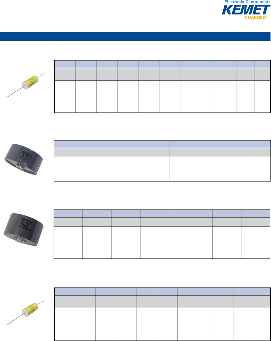
83
Film Capacitors
Axial
C4C Series, Axial Round, 850 – 3,000 VDC/450 – 750 VAC
Capacitance Range: 0.0068 to 2.5 μF • Temperature Range: −40°C to +85°C
© KEMET Electronics Corporation • P.O. Box 5928 • Greenville, SC 29606 (864) 963-6300 • www.kemet.com F3042_C4C_AXIAL • 4/16/2015 1
One world. One KEMET
Bene ts
• Self-healing
• Low losses
• High ripple current
• High contact reliability
• Suitable for high frequency applications
• PP metallized and PET double-sided metallized foil
Overview
The C4C Series is a polypropylene metallized lm and polyester
double-metallized foil with polyester tape wrapping lled with
resin and tinned copper wires.
Applications
Typical applications include snubber, clamping, resonance,
coupling/decoupling, pulse and blocking.
Printed Circuit Board Mount Power Film Capacitors
C4C Series, Axial Round, 850 – 3,000 VDC/450 – 750 VAC
Part Number System
C4 C A M U B 3100 AA 0 J
Series Type Fire
Protection
Rated Voltage
(VDC) Insulation Lead Diameter
(mm)
Capacitance Code
(pF)
Lead and
Packaging Code
Capacitor
Length (mm) Tolerance
C4 = MKP
capacitors
C = Round
body,
snubber
application
A = No re
retardant
S = Fire
retardant (on
request)
M = 850
P = 1,200
W = 2,000
Y = 3,000
U = Polyester
tape & resin
protection
0 =
Uninsulated
(on request)
B = 0.8
C = 1.0
D = 1.2
Digits 2 – 4 indicate
the rst three digits
of the capacitance
value.
First digit indicates
the number of zeros
to be added.
AA (Standard) 0 = 33
1 = 44
3 = 58
J = 5%
K = 10%
C4DC Series, GTO Snubbing, 850 – 1,400 VDC/500 – 700 VAC
Capacitance Range: 0.5 to 6 μF • Temperature Range: −40°C to +85°C
© KEMET Electronics Corporation • P.O. Box 5928 • Greenville, SC 29606 (864) 963-6300 • www.kemet.com • 4/16/2015 1
One world. One KEMET
Bene ts
Overview Applications
Power Film Capacitors
C4DC Series, GTO Snubbing, 850 – 1,400 VDC/500 – 700 VAC
Part Number System
C4DC M A Q 4150 AA0 J
Series
Rated Voltage
(VDC)
Case Terminal Style Capacitance Code (pF) Internal Code Tolerance
C4DC = MKP,
GTO Application
M = 850
N = 1000
R = 1400
A = Axial plastic
case
Q = M8 Threaded
Inserts
Digits 2 – 4 indicate the
rst three digits of the
capacitance value.
First digit indicates the
number of zeros to be added.
AA0 = Standard J = 5%
K = 10%
C4DR Series, GTO Clamping, 400 – 3,000 VDC/160 – 1,000 VAC
Capacitance Range: 1 to 220 μF • Temperature Range: −40°C to +85°C
© KEMET Electronics Corporation • P.O. Box 5928 • Greenville, SC 29606 (864) 963-6300 • www.kemet.com • 4/16/2015 1
One world. One KEMET
Bene ts
Overview Applications
Power Film Capacitors
C4DR Series, GTO Snubbing,
400 – 3,000 VDC/160 – 1,000 VAC
Part Number System
C4DR F A Q 5250 AA0 J
Series
Rated Voltage
(VDC)
Case Terminal Style Capacitance Code (pF) Internal Code Tolerance
C4DR = MKP,
Clamping
Application
F = 400
H = 600
J = 700
M = 850
P = 1,200
S = 1,500
Y = 3,000
A = Axial plastic
case
Q = M8 threaded
inserts
Digits 2-4 indicate the
rst three digits of the
capacitance value.
First digit indicates the
number of zeros to be added.
AA0 = Standard
J = 5%
K = 10%
C4G Series, Axial Round, 250 – 850 VDC/160 – 450 VAC
Capacitance Range: 0.15 to 40 μF • Temperature Range: −40°C to +85°C
© KEMET Electronics Corporation • P.O. Box 5928 • Greenville, SC 29606 (864) 963-6300 • www.kemet.com F3040_C4G_AXIAL • 4/16/2015 1
One world. One KEMET
Bene ts
• Self-healing
• Low losses
• High ripple current
• High contact reliability
• Suitable for high frequency applications
• PP metallized
Overview
The C4G Series is a polypropylene metallized lm with polyester
tape wrapping lled with resin and tinned copper wires.
Applications
Typical applications include clamping, blocking, coupling/
decoupling, AC harmonic ltering and low power.
Printed Circuit Board Mount Power Film Capacitors
C4G Series, Axial Round, 250 – 850 VDC/160 – 450 VAC
Part Number System
C4 GADUB 4100 AA 4 J
Series Type Fire
Protection
Rated Voltage
(VDC) Insulation Lead
Diameter (mm)
Capacitance Code
(pF)
Lead and
Packaging Code
Capacitor
Length (mm) Tolerance
C4 = MKP
capacitors
G = Round
body,
switching
application
A = No re
retardant
S = Fire
retardant (on
request)
D = 250
F = 400
H = 600
J = 700
M = 850
U = Polyester
tape & resin
protection
0 =
Uninsulated
(on request)
B = 0.8
C = 1.0
D = 1.2
Digits 2 – 4 indicate
the rst three digits
of the capacitance
value.
First digit indicates
the number of zeros
to be added.
AA (Standard)
4 = 20.5
5 = 28
0 = 33
1 = 44
3 = 58
J = 5%
K = 10%
Power & Application Optimized – Power Film
84
Film Capacitors
Radial
C4AE Series, Radial, 2 or 4 Leads, 450 – 1,100 VDC, for DC Link
Capacitance Range: 1 to 100 μF • Temperature Range: −40°C to +105°C
© KEMET Electronics Corporation • P.O. Box 5928 • Greenville, SC 29606 (864) 963-6300 • www.kemet.com F3046_C4AE_RADIAL • 4/16/2015 1
One world. One KEMET
Bene ts
• Self-healing
• Low losses
• High ripple current
• High capacitance density
• High contact reliability
• Suitable for high frequency applications
Overview
The C4AE Series is a polypropylene metallized lm with
rectangular plastic box type lled with resin and 2 or 4 tinned
copper wires.
Applications
Typical applications include DC ltering and energy storage.
Printed Circuit Board Mount Power Film Capacitors
C4AE Series, Radial, 2 or 4 Leads, 450 – 1,100 VDC,
for DC Link
Part Number System
C4 A E G B W 4 4 5 0 A 1 W J
Series DC Voltage Case Code Terminals Code Capacitance Code
(pF) Variants
Terminals
Diameter
(mm)
Case Letter
2
Tolerance
C4 = MKP
Capacitors
A = Box
- Wire
Terminals
E = DC
Link
E = 300 V
G = 450 V
H = 600 V
I = 800 V
J = 700 V
K = 750 V
L = 500 V
M = 850 V
N = 1000 V
O = 900 V
Q = 1100 V
U = 1300 V
B = Box
plastic case
U = Single
copper wire
W = Double
copper wire
Z = Special wire
Digits 9, 10, &
11 indicate the
rst 3 digits of
capacitance
value.
Digit 8 indicates
the number
of zeroes that
must be added
to obtain rated
capacitance in pF.
A =
Standard
B = Special
H1 = 100°C
1 = 0.8
2 = 1
3 = 1.2
0, A, B,
C, D, E,
F, G, H,
J, L, M,
N, W, X,
Y, 1, 2
J = 5%
K = 10%
It is not possible to manufacture every part number which could be created from coding description. Please refer to table of standard part numbers and ask KEMET
for other possibilities.
1 True 100°C high temperature fi lm with no voltage derating available on request
2 Please see Dimension Table
C4AS Series, 2 or 4 Leads, 850 – 3,000 VDC/500 – 750 VAC
Capacitance Range: 0.022 to 5 μF • Temperature Range: −40°C to +85°C
© KEMET Electronics Corporation • P.O. Box 5928 • Greenville, SC 29606 (864) 963-6300 • www.kemet.com • 4/16/2015 1
One world. One KEMET
Bene ts
Overview Applications
Power Film Capacitors
C4AS Series, 2 or 4 Leads, 850 – 3,000 VDC
Part Number System
C4 AS M B U 3150 A3 A J
Series Type
Rated Voltage
(VDC)
Case
Number of
Leads
Capacitance Code (pF)
Lead Diameter
(mm)
Size Code Tolerance
C4 = MKP
Capacitors
AS = Radial
box, snubber
application
M = 850
N = 1,000
P = 1,200
W = 2,000
Y = 3,000
B = Plastic
box with
epoxy resin
sealing
U = 2 lead
W = 4 lead
Digits 2-4 indicate the
rst three digits of the
capacitance value.
First digit indicates the
number of zeros to be
added.
A1 = 0.8
A3 = 1.2
See
Dimension
Table
J = 5%
K = 10%
C4AT Series, 2 or 4 Leads, 250 – 850 VDC/160 – 450 VAC
Capacitance Range: 0.22 to 60 μF • Temperature Range: −40°C to +85°C
© KEMET Electronics Corporation • P.O. Box 5928 • Greenville, SC 29606 (864) 963-6300 • www.kemet.com • 4/16/2015 1
One world. One KEMET
Bene ts
Overview Applications
Power Film Capacitors
C4AT Series, 2 or 4 Leads, 250 – 850 VDC/160 – 450 VAC
Part Number System
C4 AT D B U 4100 A3 0 J
Series Type
Rated Voltage
(VDC)
Case
Number of
Leads
Capacitance Code (pF)
Lead Diameter
(mm)
Size Code Tolerance
C4 = MKP
Capacitors
AT = Radial
box, switching
application
D = 250
F = 400
G = 450
H = 600
J = 700
M = 850
B = Plastic
box with
epoxy resin
sealing
U = 2 lead
W = 4 lead
Digits 2-4 indicate the
rst three digits of the
capacitance value.
First digit indicates the
number of zeros to be
added.
A1 = 0.8
A3 = 1.2
See
Dimension
Table
J = 5%
K = 10%
C4BS Series, IGBT Box, 850 – 3,000 VDC/550 – 750 VAC
Capacitance Range: 0.047 to 5 μF • Temperature Range: −40°C to +85°C
© KEMET Electronics Corporation • P.O. Box 5928 • Greenville, SC 29606 (864) 963-6300 • www.kemet.com • 4/16/2015 1
One world. One KEMET
Bene ts
Overview Applications
Power Film Capacitors
C4BS Series, IGBT Box, 850 – 3,000 VDC/550 – 750 VAC
Part Number System
C4 BS M B X 3470 Z E E J
Series Type
Rated Voltage
(VDC)
Case
Number of
Leads
Capacitance Code (pF) Internal Code
Termination
Style
Size Code Tolerance
C4 = MKP
Capacitors
for Power
Applications
BS = Radial
box with tab
terminals,
IGBT
application
M = 850
N = 1,000
P = 1,200
W = 2,000
Y = 3,000
B = Plastic
box with
epoxy resin
sealing
X =
Standard
Digits 2-4 indicate the
rst three digits of the
capacitance value.
First digit indicates the
number of zeros to be
added.
Z =
Standard
A = Style A
B = Style B
E = Style E
F = Style F
G = Style G
See
Dimension
Table
J = 5%
K = 10%
Power & Application Optimized – Power Film
85
Film Capacitors
Radial (cont.)
C4BT Series, IGBT Box, 400 – 850 VDC/250 – 450 VAC
Capacitance Range: 1 to 60 μF • Temperature Range: −40°C to +85°C
© KEMET Electronics Corporation • P.O. Box 5928 • Greenville, SC 29606 (864) 963-6300 • www.kemet.com • 4/16/2015 1
One world. One KEMET
Bene ts
Overview Applications
Power Film Capacitors
C4BT Series, IGBT Box, 400 – 850 VDC/250 – 450 VAC
Part Number System
C4 BT F B X 4330 Z E E J
Series Type
Rated Voltage
(VDC)
Case
Number of
Leads
Capacitance Code (pF) Internal Code
Termination
Style
Size Code Tolerance
C4 = MKP
Capacitors
for Power
Applications
BT = Radial
box with tab
terminals,
switching
application
F = 400
M = 850
B = Plastic
box with
epoxy resin
sealing
X =
Standard
Digits 2 – 4 indicate
the rst three digits of
the capacitance value.
First digit indicates the
number of zeros to be
added.
Z =
Standard
A = Style A
E = Style E
See
Dimension
Table
J = 5%
K = 10%
Screw/Faston Terminal
C4DE Series, Low Inductance DC Link, 400 – 1,000 VDC
Capacitance Range: 47 to 380 μF • Temperature Range: −40°C to +85°C
© KEMET Electronics Corporation • P.O. Box 5928 • Greenville, SC 29606 (864) 963-6300 • www.kemet.com • 4/16/2015 1
One world. One KEMET
Bene ts
Overview Applications
Power Film Capacitors
C4DE Series, Low Inductance DC Link, 400 – 1,000 VDC
Part Number System
C4DE F P Q 6175 A8T K
Series
Rated Voltage
(VDC)
Case & Fixing
Bolt Code
Terminal Style
Capacitance Code
(pF)
Internal Code Tolerance
C4DE = MKP, DC
Link Application
F = 400
H = 600
I = 800
N = 1,000
P = Cylindrical
plastic case with
xing feet
Q = M8 threaded
inserts
Digits 2-4 indicate the rst three
digits of the capacitance value.
First digit indicates the number of
zeros to be added.
A8T = Standard
K = 10%
C44A Series, Aluminum Case, 400 – 1,500 VDC
Capacitance Range: 1 to 330 μF • Temperature Range: −40°C to +85°C
© KEMET Electronics Corporation • P.O. Box 5928 • Greenville, SC 29606 (864) 963-6300 • www.kemet.com • 4/16/2015 1
One world. One KEMET
Bene ts
Overview Applications
Power Film Capacitors
C44A Series, Aluminum Case, 400 – 1,500 VDC
Part Number System
C44A F F P 5150 ZA0 J
Series
Rated Voltage
(VDC)
Case & Fixing
Bolt Code
Terminal Style
Capacitance Code
(pF)
Internal Code Tolerance
C44A = MKP,
General Purpose
F = 400
H = 600
J = 700
M = 850
P = 1,200
S = 1,500
F = Cylindrical
aluminum case
with M8 bolt
G = Cylindrical
aluminum case
with M12 bolt
P = M6 Threaded posts
R = M10 Threaded posts
Q = M8 Threaded posts (on
request)
2 = Simple faston 6.3 x 0.8
mm (on request)
3 = Double faston 6.3 x 0.8
mm (on request)
Digits 2-4 indicate the
rst three digits of the
capacitance value.
First digit indicates the
number of zeros to be
added.
ZA0, ZB0, ZC0,
ZD0, ZE0, ZF0,
ZG0, ZH0 =
Standard
J = 5%
K = 10%
C44B Series, Aluminum Case, Snubber Applications, 1,200 – 2,400 VDC
Capacitance Range: 0.047 to 4 μF • Temperature Range: −40°C to +85°C
© KEMET Electronics Corporation • P.O. Box 5928 • Greenville, SC 29606 (864) 963-6300 • www.kemet.com • 4/16/2015 1
One world. One KEMET
Bene ts
Overview Applications
Power Film Capacitors
C44B Series, Aluminum Case Snubber Application,
1,200 – 2,400 VDC
Part Number System
C44B P F 001 3100 ZB0 J
Series
Rated Voltage
(VDC)
Case & Fixing
Bolt Code
Terminal Style
Capacitance Code
(pF)
Internal Code Tolerance
C44B = MKP,
Snubber
Application
P = 1,200
W = 2,000
X = 2,400
F = Cylindrical
aluminum case
with M8 bolt
G = Cylindrical
aluminum case
with M12 bolt
P = M6 Threaded posts
1 = Single fasten 2.8 x 0.8
mm
Digits 2-4 indicate the
rst three digits of the
capacitance value.
First digit indicates the
number of zeros to be
added.
ZA0, ZB0, ZC0 =
Standard
J = 5%
K = 10%
Power & Application Optimized – Power Film
86
Film Capacitors
Screw/Faston Terminal (cont.)
C44H Series, 330 – 440 VAC, 700 – 1,000 VDC, for PFC and AC Filter
Capacitance Range: 100 to 600 µF • Temperature Range: −40°C to +75°C
© KEMET Electronics Corporation • P.O. Box 5928 • Greenville, SC 29606 (864) 963-6300 • www.kemet.com F3054_C44H_RADIAL • 4/16/2015 1
One world. One KEMET
Bene ts
• Overpressure safety device
• High peak current capability
• Long lifetime
• Self-healing
Overview
The C44H Series are a polypropylene metallized lm with
cylindrical aluminium can type lled with liquid resin, screw
terminals, plastic deck and overpressure safety device.
Applications
Typical applications include commutation, power factor correction
and AC harmonic ltering.
Aluminum Can Power Film Capacitors
C44H Series, 330 – 440 VAC, 700 – 1,000 VDC,
for PFC and AC Filter
Part Number System
C44H L G P 6100 A A S J
Series Rated Voltage
Case & Fixing
Bolt Code Terminal Style Capacitance Code (pF) Internal Code Internal Code Tolerance
C44H = MKP
Capacitors for
AC ltering
L = 330 Vrms
K = 440 Vrms
G = Cylindrical
aluminum case
with M12 bolt
P = M6
Threaded Posts
R = M10
Threaded Posts
Digits 9-11 indicate the
rst three digits of the
capacitance value.
Digit 8 indicates the number
of zeros to be added.
A = Standard
Z = Special
J = 5%
K = 10%
It is not possible to manufacture every part number which could be created from coding description. Please refer to table of standard part numbers and ask KEMET
for other possibilities.
C44P/C20A Series, for PFC & AC Filter, 330 – 1,000 VAC/700 – 2,300 VDC
Capacitance Range: 10 to 600 μF • Temperature Range: −40°C to +80°C
© KEMET Electronics Corporation • P.O. Box 5928 • Greenville, SC 29606 (864) 963-6300 • www.kemet.com F3050_C44P_RADIAL • 4/16/2015 1
One world. One KEMET
Bene ts
• Overpressure safety device
• High peak current capability
• High torque screw terminals with plastic insulator
• Long lifetime
• Self-healing
Overview
The C44P/C20A Series are a polypropylene metallized lm with
cylindrical aluminium can type lled with oil, screw terminals,
plastic insulator and overpressure safety device.
Applications
Typical applications include commutation, power factor correction
and AC harmonic ltering.
Aluminum Can Power Film Capacitors
C44P/C20A Series, 330 – 1,000 VAC, 700 – 2,300 VDC,
for PFC and AC Filter
Part Number System
C44 PL G R 6 1 0 0 A A S J
Series Application Rated Voltage (VAC) Case
Type
Terminal
Style Capacitance Code (pF) Internal Code Internal
Codes Tolerance
MKP
Capacitors
for Power
Applications
44 = 330 – 440 VAC
20 = 550 – 1,000
VAC
AC Filter
P = C44
A = C20
For C44P:
L = 330
K = 440
For C20A:
K = 550
L = 640
Q = 780
Z = 1000
G =
M12
bolt
R = Male
M10
Digits 9 – 11 indicate
the rst 3 digits of
capacitance value. Digit
8 indicates the number
of zeros that must be
added to obtain rated
capacitance in pF.
A = Standard
Z = Special
J = 5%
K = 10%
It is not possible to manufacture every part number which could be created from coding description. Please refer to table of standard part numbers and ask KEMET
for other possibilities.
C44U Series, for DC Link, 700 – 1,300 VDC
Capacitance Range: 50 to 600 μF • Temperature Range: −40°C to +85°C
© KEMET Electronics Corporation • P.O. Box 5928 • Greenville, SC 29606 (864) 963-6300 • www.kemet.com F3049_C44U_RADIAL • 4/16/2015 1
One world. One KEMET
Bene ts
• Controlled self-healing
• Low losses
• High ripple current
• High capacitance density
• Long lifetime
Overview
The C44U Series is a polypropylene segmented metallized
lm with cylindrical aluminium can type lled with resin, screw
terminals and plastic deck.
Applications
Typical applications include DC ltering and energy storage.
Aluminum Can Power Film Capacitors
C44U Series, 700 – 1,300 VDC, for DC Link
Part Number System
C4 4 U Q G T 6 5 0 0 F 8 S K
Series DC Voltage Case & Fixing Terminals Code Capacitance Code (pF) Variants Case
Diameter Film Type Tolerance
MKP
Capacitors
for Power
Applications
Cylindrical
types
DC-
Link
J = 700 V
O = 900 V
Q = 1100 V
U = 1300 V
G = Cylindrical
case with
threaded bolt
M12
E = Cylindrical
case without
threaded bolt
T = M6 female
terminals
Q = M8 male
terminals
Y = M8 female
terminals
Digits 9, 10, & 11 indicate
the rst 3 digits of
capacitance value.
Digit 8 indicates the
number of zeroes that
must be added in order to
obtain rated capacitance
in p F.
A = 85°C
Hot Spot
temperature
series
F = 70°C
Hot Spot
temperature
series
7 = 76
mm
8 = 85
mm
T =
Standard
l m
S =
Segmented
l m
J = 5%
K = 10%
C93 Series, Aluminum Case, Filter Applications, 400 – 600 VDC
Capacitance Range: 10 to 100 μF • Temperature Range: −25°C to +55°C
© KEMET Electronics Corporation • P.O. Box 5928 • Greenville, SC 29606 (864) 963-6300 • www.kemet.com • 4/16/2015 1
One world. One KEMET
Bene ts
Overview Applications
Power Film Capacitors
C93 Series, Aluminum Case Filter Applications,
400 – 600 VDC
Part Number System
C93 0 Z G 3 5500 ZA0 X
Series
Rated Voltage
(VAC)
Internal Code
Case & Mounting
Terminal Style
Capacitance Code
(pF)
Internal Code Tolerance
C93 = Single
Phase
Power Factor
Correction
Capacitors
0 = 320
1 = 415
3 = 460
Z = Standard G = Cylindrical
aluminum case
with M12 bolt
3 = Double
fasten
Digits 2-4 indicate the rst three
digits of the capacitance value.
First digit indicates the number of
zeros to be added.
ZA0, RA0
& RS0 =
Standard
X = -5/+15%
Power & Application Optimized – Power Film
87
Film Capacitors
Screw/Faston Terminal (cont.)
C9T Series, Aluminum Case, PFC & AC Filter, 415 – 690 VAC
Capacitance Range: 19.2 to 184.8 μF • Temperature Range: −25°C to +55°C
© KEMET Electronics Corporation • P.O. Box 5928 • Greenville, SC 29606 (864) 963-6300 • www.kemet.com • 4/16/2015 1
One world. One KEMET
Bene ts
Overview Applications
Power Film Capacitors
C9T Series, Aluminum Case PFC & AC Filter, 415 –690 VAC
Part Number System
C9T S 5 A D 5308 AA0 X
Series Type
Rated Voltage
(VAC)
Terminal Style
Internal
Connection
Capacitance Code
(pF)
Internal Code Tolerance
C9T =
Cylindrical
Three-Phase
Capacitors
S = Slim A = 525
D = 690
5 = 415
6 = 450
A = Single
quick connect
B = Double
quick connect
M = Screw
Terminal
D = Delta
Y = Star
Digits 2-4 indicate the rst three
digits of the capacitance value.
First digit indicates the number of
zeros to be added.
AA0 =
Standard
X = -5% /
+15%
C27 Series, Plastic Case, 425 – 450 VAC
Capacitance Range: 1 to 100 μF • Temperature Range: −25°C to +100°C
© KEMET Electronics Corporation • P.O. Box 5928 • Greenville, SC 29606 (864) 963-6300 • www.kemet.com • 4/16/2015 1
One world. One KEMET
Bene ts
Overview Applications
Power Film Capacitors
C27 Series, Plastic Case, 250 –500 VAC
Part Number System
C27 4 A C 2 4100 AA 4 J
Series Marking
Case & Fixing
Bolt Code
Terminal Style
Capacitance Code
(pF)
Packaging Internal Use Tolerance
C27 =
Motor Run
Capacitors
4 = 30,000 hours/420
VAC (Class A) or 10,000
hours/470 VAC (Class B)
6 = 10,000 hours/420 VAC
(Class B) or 3,000 hours/470
VAC (Class C)
7 = 10,000 hours/275 VAC
(Class C) or 1,000 hours/425
VAC (Class D)
A = C274
C = C276
L = C277
C =
Cylindrical
plastic case
with M8
bolt
2 = Single fasten 6.3 x 0.8
3 = Double fasten 6.3 x 0.8
A = Polar cable (tinned end)
B = Polar cable (untinned
end)
F = Bipolar cable (40 mm
unsheathed, 8 mm exposed
end)
Digits 2 – 4
indicate the rst
three digits of
the capacitance
value.
First digit
indicates the
number of zeros
to be added.
AA, AF,
AL, LG =
Standard
0, 1, 2, 5 =
Standard
J = 5%
C87 Series, Aluminum Case, 470 VAC
Capacitance Range: 1 to 80 μF • Temperature Range: −25°C to +85°C
© KEMET Electronics Corporation • P.O. Box 5928 • Greenville, SC 29606 (864) 963-6300 • www.kemet.com • 4/16/2015 1
One world. One KEMET
Bene ts
Overview Applications
Power Film Capacitors
C87 Series, Aluminum Case, 470 VAC
Part Number System
C87 0 C F 2 4300 AA 4 J
Series Marking
Case & Fixing Bolt
Code
Terminal Style
Capacitance Code
(pF)
Packaging Internal Use Tolerance
C87 =
Motor Run
Capacitors
0 = 10,000 hours/420 VAC
(Class B) or 3,000 hours/470
VAC (Class C)
8 = 30,000 hours/420
VAC (Class A) or 10,000
hours/470 VAC (Class B)
1 = Legacy (not for new
design)
5 = Legacy (not for new
design)
A, C, W =
Standard
F = Cylindrical
aluminum can
with M8 bolt
G = Cylindrical
aluminum can
with M12 bolt
2 = Single fasten
6.3 x 0.8
3 = Double fasten
6.3 x 0.8
Digits 2 – 4
indicate the rst
three digits of the
capacitance value.
First digit indicates
the number of
zeros to be added.
AA=
Standard
0, 1, 2, 4, 5
= Standard
J = 5%
K = 10%
Power & Application Optimized – Power Film/Motor Run Applications
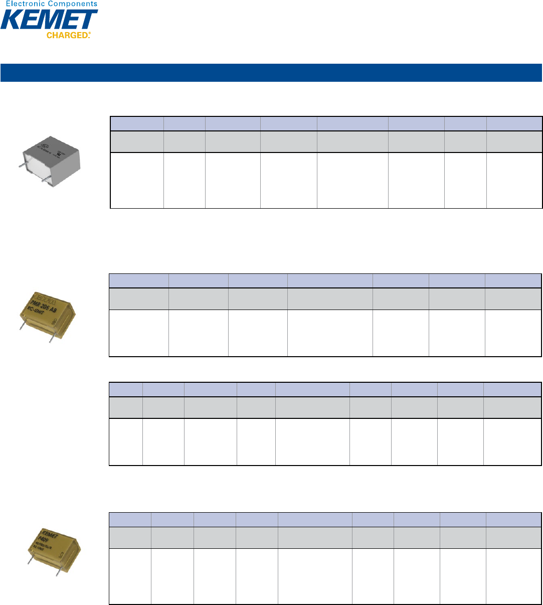
88
Film Capacitors
Radial
F43 Series, Integrated Resistor Metallized Polypropylene, 250 – 630 VDC
Capacitance Range: 0.01 to 1.0 μF • Temperature Range: −55°C to +100°C
© KEMET Electronics Corporation • P.O. Box 5928 • Greenville, SC 29606 (864) 963-6300 • www.kemet.com F3023_F43 • 4/16/2015 1
One world. One KEMET
Bene ts
• Approvals (for 275 VAC only): ENEC, UL
• Rated voltage: 160 VAC/250 VDC, 200 VAC/400 VDC,
220 VAC/630 VDC, and Class X2, 275 VAC
• Capacitance range: 0.01 – 1.0 µF
• Lead spacing: 15.0 – 27.5 mm
• Capacitance tolerance: ±20%, ±10%
• Climatic category: 55/100/56, IEC 60068–1 and 40/100/56
(275 VAC), IEC 60068–1
• Tape and reel packaging in accordance with IEC 60286–2
• RoHS Compliant and lead-free terminations
• Operating temperature range: -55˚C to +100˚C and -40˚C to
+100˚C (275 VAC)
Overview
The F43 Series is constructed of metallized polypropylene lm
encapsulated with self-extinguishing resin in a box of material
meeting the requirements of UL 94 V–0.
Applications
Typical applications include worldwide use in contact protection,
contact interference suppression and transient suppression.
AC Line EMI Suppression and RC Networks
F43 Series Metallized Polypropylene Film, 160 VAC/250 VDC,
200 VAC/400 VDC, 220 VAC/630 VDC & Class X2, 275 VAC
Part Number System
F43 K N 3100 XX 01 M
Capacitor Class Series
Rated Voltage
(VAC) Lead Spacing (mm) Capacitance Code (pF)
Lead and
Packaging Code Internal Use
Capacitance
Tolerance
Legacy PN: F
New KEMET PN:
Omit this character
RC Snubber,
Metallized
Polypropylene
I = 160
M = 200
P = 220
K = 275 (X2)
I = 15.0
N = 22.5
R = 27.5
Digits 2 – 4 indicate
the rst three digits of
the capacitance value.
First digit indicates the
number of zeros to be
added.
Contact KEMET
for packaging
availability and
details
00, 01, 04
(Standard)
K = ±10%
M = ±20%
PMR205 Series Integrated Resistor Metallized Impregnated Paper, 125 VAC/250 VDC
Capacitance Range: 0.1 to 1.0 μF • Temperature Range: −40°C to +85°C
Legacy Part Number System
© KEMET Electronics Corporation • P.O. Box 5928 • Greenville, SC 29606 (864) 963-6300 • www.kemet.com F3024_PMR205 • 4/16/2015 1
One world. One KEMET
Bene ts
• Rated voltage: 125 VAC/250 VDC, 50/60 Hz
• Capacitance range: 0.1 – 1.0 µF
• Capacitance tolerance: ±20%
• Resistance range: 22 – 680 Ω
• Resistance tolerance: ±30%
• Lead spacing: 15.2 – 25.4 mm
• Climatic category: 40/085/56/B, IEC 60068–1
• Tape and reel packaging in accordance with IEC 60286–2
• RoHS Compliant and lead-free terminations
• Operating temperature range of -40˚C to +85˚C
• Excellent self-healing properties which ensure long life even
when subjected to frequent over voltages
• Good resistance to ionization due to impregnated paper dielectric
• High dV/dt capability
• Impregnated paper ensures excellent stability and reliability
properties, particularly in applications with continuous operation
Overview
The PMR205 Series is constructed of multilayer metallized paper
encapsulated and impregnated in self-extinguishing material
meeting the requirements of UL 94 V–0.
Applications
Typical applications include worldwide use in contact protection,
contact interference suppression and transient suppression.
AC Line EMI Suppression and RC Networks
PMR205 Series Metallized Impregnated Paper,
125 VAC/250 VDC
Legacy Part Number System
PMR205 A B 6100 M033 R30
Series Rated Voltage (VAC) Lead Spacing (mm) Capacitance Code (pF) Capacitance
Tolerance
Resistance (Ω) Lead and
Packaging Code
RC Snubber,
Metallized Paper
A = 125 B = 15.2
C = 20.3
E = 25.4
Digits 2 – 4 (3) indicates
the rst three digits of the
capacitance value. First digit
indicates the total number of
digits in the capacitance value.
M = ±20% Resistance Value
in Ω
See Ordering
Options Table
New KEMET Part Number System
P405 Q E 104 M125 AH330
Capacitor
Class
Series
Lead Spacing
(mm)
Size Code
Capacitance Code (pF)
Capacitance
Tolerance
Rated Voltage
(VAC)
Lead and
Packaging Code
Resistance (Ω)
P =
Metallized
Paper
RC Snubber
Q = 15.2
C = 20.3
E = 25.4
See
Dimension
Table
First two digits represent
signi cant gures. Third
digit speci es number of
zeros.
M = ±20%
125 = 125
See Ordering
Options Table
H + rst two digits
representing
signi cant gures.
Third digit speci es
number of zeros.
New KEMET Part Number System
© KEMET Electronics Corporation • P.O. Box 5928 • Greenville, SC 29606 (864) 963-6300 • www.kemet.com F3024_PMR205 • 4/16/2015 1
One world. One KEMET
Bene ts
• Rated voltage: 125 VAC/250 VDC, 50/60 Hz
• Capacitance range: 0.1 – 1.0 µF
• Capacitance tolerance: ±20%
• Resistance range: 22 – 680 Ω
• Resistance tolerance: ±30%
• Lead spacing: 15.2 – 25.4 mm
• Climatic category: 40/085/56/B, IEC 60068–1
• Tape and reel packaging in accordance with IEC 60286–2
• RoHS Compliant and lead-free terminations
• Operating temperature range of -40˚C to +85˚C
• Excellent self-healing properties which ensure long life even
when subjected to frequent over voltages
• Good resistance to ionization due to impregnated paper dielectric
• High dV/dt capability
• Impregnated paper ensures excellent stability and reliability
properties, particularly in applications with continuous operation
Overview
The PMR205 Series is constructed of multilayer metallized paper
encapsulated and impregnated in self-extinguishing material
meeting the requirements of UL 94 V–0.
Applications
Typical applications include worldwide use in contact protection,
contact interference suppression and transient suppression.
AC Line EMI Suppression and RC Networks
PMR205 Series Metallized Impregnated Paper,
125 VAC/250 VDC
Legacy Part Number System
PMR205 A B 6100 M033 R30
Series
Rated Voltage (VAC)
Lead Spacing (mm)
Capacitance Code (pF)
Capacitance
Tolerance
Resistance (Ω)
Lead and
Packaging Code
RC Snubber,
Metallized Paper
A = 125
B = 15.2
C = 20.3
E = 25.4
Digits 2 – 4 (3) indicates
the rst three digits of the
capacitance value. First digit
indicates the total number of
digits in the capacitance value.
M = ±20%
Resistance Value
in Ω
See Ordering
Options Table
New KEMET Part Number System
P405 Q E 104 M125 AH330
Capacitor
Class Series
Lead Spacing
(mm) Size Code Capacitance Code (pF)
Capacitance
Tolerance
Rated Voltage
(VAC)
Lead and
Packaging Code Resistance (Ω)
P =
Metallized
Paper
RC Snubber Q = 15.2
C = 20.3
E = 25.4
See
Dimension
Table
First two digits represent
signi cant gures. Third
digit speci es number of
zeros.
M = ±20% 125 = 125 See Ordering
Options Table
H + rst two digits
representing
signi cant gures.
Third digit speci es
number of zeros.
P409 Series Integrated Resistor Metallized Impregnated Paper, Class X2, 275 VAC
Capacitance Range: 0.047 to 0.47 μF • Temperature Range: −40°C to +85°C
© KEMET Electronics Corporation • P.O. Box 5928 • Greenville, SC 29606 (864) 963-6300 • www.kemet.com F3089_P409_X2_275 • 4/16/2015 1
One world. One KEMET
Bene ts
• Approvals: ENEC, UL, cUL
• Rated voltage: 275 VAC 50/60 Hz
• Capacitance range: 0.047 – 0.47 µF
• Capacitance tolerance: ±20%
• Resistance range: 22 – 470 Ω
• Resistance tolerance: ±30%
• Lead spacing: 15.2 – 25.4 mm
• Climatic category: 40/085/56/B, IEC 60068–1
• Tape and reel packaging in accordance with IEC 60286–2
• RoHS Compliant and lead-free terminations
• Operating temperature range of -40˚C to +85˚C
• Excellent self-healing properties which ensure long life even
when subjected to frequent over voltages
• Good resistance to ionization due to impregnated paper dielectric
• High dV/dt capability
• Impregnated paper ensures excellent stability and reliability
properties, particularly in applications with continuous operation
Overview
The P409 Series is constructed of multilayer metallized paper
encapsulated and impregnated in self-extinguishing material
meeting the requirements of UL 94 V–0.
Applications
Typical applications include worldwide use in contact protection,
contact interference suppression and transient suppression.
AC Line EMI Suppression and RC Networks
P409 Series Metallized Impregnated Paper
Class X2, 275 VAC
Part Number System
P409 Q M 473 M275 AH470
Capacitor
Class
Series
Lead Spacing
(mm)
Size Code Capacitance Code (pF)
Capacitance
Tolerance
Rated Voltage
(VAC)
Lead and
Packaging Code
Resistance (Ω)
P=
Metallized
Paper
RC Snubber Q = 15.2
C = 20.3
E = 25.4
See
Dimension
Table
First two digits represent
signi cant gures. Third
digit speci es number of
zeros.
M = ±20% 275 = 275 See Ordering
Options Table
H + rst two digits
representing
signi cant
gures. Third digit
speci es number
of zeros.
Power & Application Optimized – High Voltage Transient Suppression
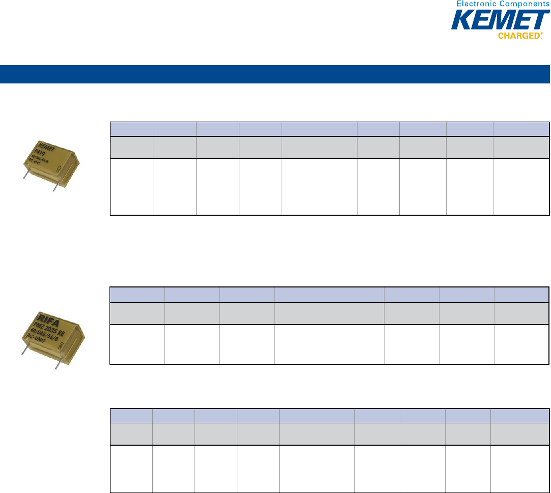
89
Film Capacitors
Radial (cont.)
P410 Series, Integrated 100 Ω Resistor Metallized Impregnated Paper, 300 VAC
Capacitance Range: 0.022 to 0.1 μF • Temperature Range: −40°C to +85°C
© KEMET Electronics Corporation • P.O. Box 5928 • Greenville, SC 29606 (864) 963-6300 • www.kemet.com F3090_P410_X1_300 • 4/16/2015 1
One world. One KEMET
Bene ts
• Approvals: ENEC, UL, cUL
• Rated voltage: 300 VAC 50/60 Hz
• Capacitance range: 0.022 – 0.1 µF
• Capacitance tolerance: ± 20%
• Resistance range: 100 Ω
• Resistance tolerance: ± 30%
• Lead spacing: 15.2 – 25.4 mm
• Climatic category: 40/085/56/B, IEC 60068-1
• Tape and reel packaging in accordance with IEC 60286-2
• RoHS Compliant and lead-free terminations
• Operating temperature range of -40˚C to +85˚C
• Excellent self-healing properties which ensure long life even
when subjected to frequent over-voltages
• Good resistance to ionization due to impregnated paper dielectric
• High dV/dt capability
• Impregnated paper ensures excellent stability and reliability
properties, particularly in applications with continuous operation
Overview
The P410 Series is constructed of multilayer metallized paper
encapsulated and impregnated in self-extinguishing material
meeting the requirements of UL 94 V–0.
Applications
Typical applications include worldwide use in contact protection,
contact interference suppression and transient suppression.
AC Line EMI Suppression and RC Networks
P410 Series Metallized Impregnated Paper
Class X1, 300 VAC
Part Number System
P410 Q M 223 M300 AH101
Capacitor
Class Series
Lead Spacing
(mm) Size Code Capacitance Code (pF)
Capacitance
Tolerance
Rated Voltage
(VAC)
Lead and
Packaging Code Resistance (Ω)
P=
Metallized
Paper
RC Snubber
Q = 15.2
C = 20.3
E = 25.4
See
Dimension
Table
First two digits represent
signi cant gures. Third
digit speci es number of
zeros.
M = ±20%
300 = 300
See Ordering
Options Table
H + rst two digits
representing
signi cant
gures. Third digit
speci es number
of zeros.
PMZ2035 Series, Integrated 100 Ω Resistor Metallized Impregnated Paper, 440 VAC/1,000 VDC
Capacitance Range: 0.1 μF • Temperature Range: −40°C to +85°C
Legacy Part Number System
© KEMET Electronics Corporation • P.O. Box 5928 • Greenville, SC 29606 (864) 963-6300 • www.kemet.com F3027_PMZ2035 • 4/16/2015 1
One world. One KEMET
Bene ts
• Approvals: ENEC
• Rated voltage: 440 VDC 50/60 Hz
• Capacitance: 0.1 µF
• Capacitance tolerance: ±10%, other tolerances on request
• Resistance: 150 Ω
• Resistance tolerance: ±30%
• Lead spacing: 25.4 mm
• Climatic category: 40/085/56/B, IEC 60068–1
• RoHS Compliant and lead-free terminations
• Operating temperature range of -40˚C to +85˚C
• Excellent self-healing properties which ensure long life even
when subjected to frequent over voltages
• Good resistance to ionization due to impregnated paper
dielectric
• High dV/dt capability
• Impregnated paper ensures excellent stability and reliability
properties, particularly in applications with continuous operation
Overview
The PMZ2035 Series is constructed of multilayer metallized
paper encapsulated and impregnated in self-extinguishing
material meeting the requirements of UL 94 V–0.
Applications
Typical applications include worldwide use in contact protection,
contact interference suppression and transient suppression.
AC Line EMI Suppression and RC Networks
PMZ2035 Series Metallized Impregnated Paper, Class X1,
440 VAC/1,000 VDC
Legacy Part Number System
PMZ2035 R E 6100 K150 R30
Series Rated Voltage
(VAC) Lead Spacing (mm) Capacitance Code (pF) Capacitance
Tolerance Resistance (Ω) Lead and
Packaging Code
RC Snubber,
Metallized Paper
R = 440
E = 25.4
Digits 2 – 4 (3) indicates the rst
three digits of the capacitance value.
First digit indicates the total number
of digits in the capacitance value.
K = ±10%
M = ±20%
Resistance Value
in Ω
See Ordering
Options Table
New KEMET Part Number System
P435 E J 104 K440 AH151
Capacitor
Class
Series
Lead Spacing
(mm)
Size Code
Capacitance Code (pF)
Capacitance
Tolerance
Rated Voltage
(VAC)
Lead and
Packaging Code
Resistance (Ω)
P = Metallized
Paper
RC Snubber
E = 25.4
See
Dimension
Table
First two digits represent
signi cant gures. Third
digit speci es number of
zeros.
K = ±10%
M = ±20%
440 = 440
See Ordering
Options Table
H + rst two digits
representing
signi cant gures.
Third digit speci es
number of zeros.
New KEMET Part Number System
© KEMET Electronics Corporation • P.O. Box 5928 • Greenville, SC 29606 (864) 963-6300 • www.kemet.com F3027_PMZ2035 • 4/16/2015 1
One world. One KEMET
Bene ts
• Approvals: ENEC
• Rated voltage: 440 VDC 50/60 Hz
• Capacitance: 0.1 µF
• Capacitance tolerance: ±10%, other tolerances on request
• Resistance: 150 Ω
• Resistance tolerance: ±30%
• Lead spacing: 25.4 mm
• Climatic category: 40/085/56/B, IEC 60068–1
• RoHS Compliant and lead-free terminations
• Operating temperature range of -40˚C to +85˚C
• Excellent self-healing properties which ensure long life even
when subjected to frequent over voltages
• Good resistance to ionization due to impregnated paper
dielectric
• High dV/dt capability
• Impregnated paper ensures excellent stability and reliability
properties, particularly in applications with continuous operation
Overview
The PMZ2035 Series is constructed of multilayer metallized
paper encapsulated and impregnated in self-extinguishing
material meeting the requirements of UL 94 V–0.
Applications
Typical applications include worldwide use in contact protection,
contact interference suppression and transient suppression.
AC Line EMI Suppression and RC Networks
PMZ2035 Series Metallized Impregnated Paper, Class X1,
440 VAC/1,000 VDC
Legacy Part Number System
PMZ2035 R E 6100 K150 R30
Series
Rated Voltage
(VAC)
Lead Spacing (mm)
Capacitance Code (pF)
Capacitance
Tolerance
Resistance (Ω)
Lead and
Packaging Code
RC Snubber,
Metallized Paper
R = 440
E = 25.4
Digits 2 – 4 (3) indicates the rst
three digits of the capacitance value.
First digit indicates the total number
of digits in the capacitance value.
K = ±10%
M = ±20%
Resistance Value
in Ω
See Ordering
Options Table
New KEMET Part Number System
P435 E J 104 K440 AH151
Capacitor
Class
Series
Lead Spacing
(mm)
Size Code Capacitance Code (pF)
Capacitance
Tolerance
Rated Voltage
(VAC)
Lead and
Packaging Code
Resistance (Ω)
P = Metallized
Paper
RC Snubber E = 25.4 See
Dimension
Table
First two digits represent
signi cant gures. Third
digit speci es number of
zeros.
K = ±10%
M = ±20%
440 = 440 See Ordering
Options Table
H + rst two digits
representing
signi cant gures.
Third digit speci es
number of zeros.
Power & Application Optimized – High Voltage Transient Suppression
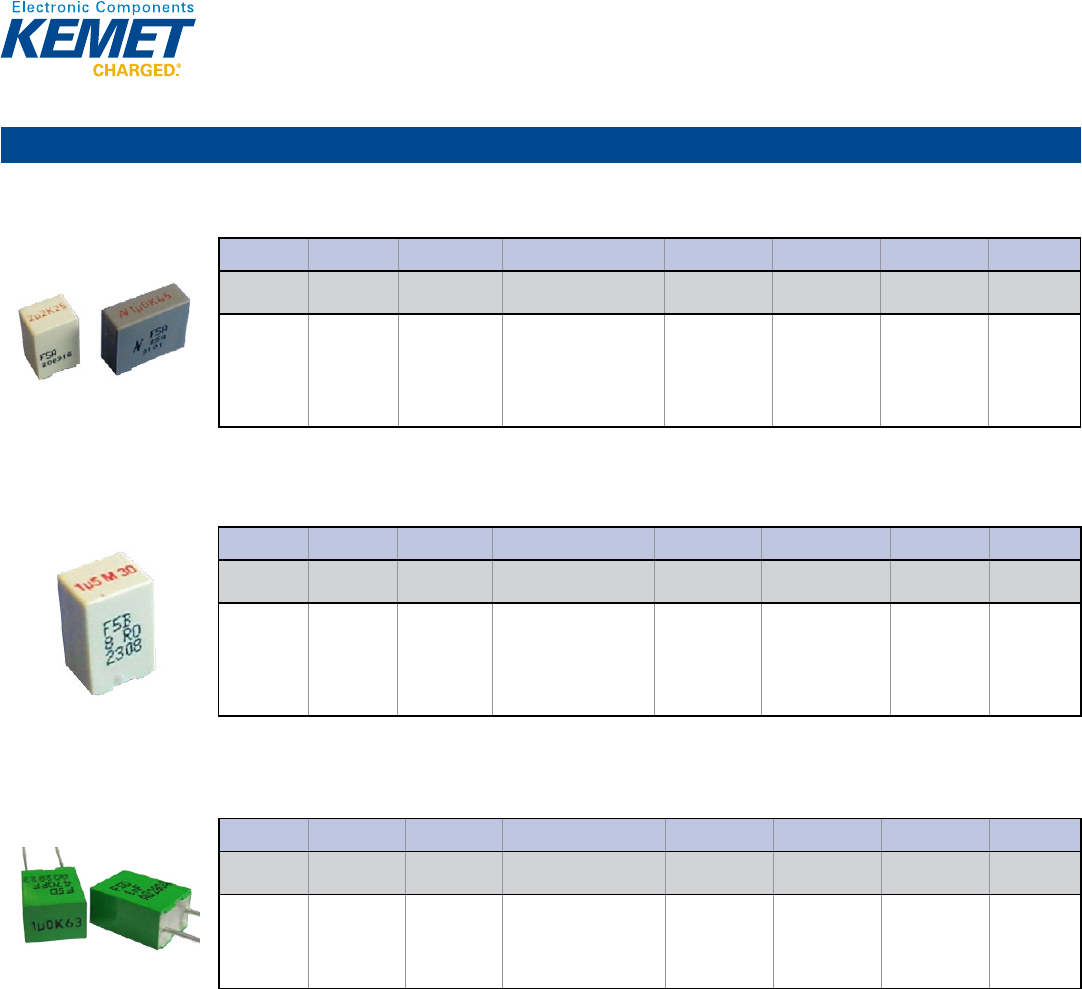
90
Film Capacitors
Radial
F5A Series Metallized Polyester Film with Integrated Varistor, 18 – 63 VDC
Capacitance Range: 0.1 to 2.2 μF • Temperature Range: −55°C to +125°C
© KEMET Electronics Corporation • P.O. Box 5928 • Greenville, SC 29606 (864) 963-6300 • www.kemet.com F3068_F5A • 4/16/2015 1
One world. One KEMET
Bene ts
• Low inductive MKT capacitors in parallel construction with a
ceramic varistor in a single case provide superior suppression
results
• Approvals: AEC–Q200, ISO 7637
• Rated voltage: 18 – 63 VDC
• Capacitance range: 0.1 μF to 2.2 μF
• Lead spacing: 5 – 10 mm
• Capacitance tolerance: ±10%, ±20%
• Climatic category: 55/125/56 IEC 60068–1
• Tape and reel packaging in accordance with IEC 60286–2
• RoHS Compliant and lead-free terminations
• Operating temperature range: -55˚C to +125˚C
Overview
The F5A Series is a metallized polyester (MKT) lm capacitor
with integrated ceramic varistor encapsulated in a thermosetting
resin- lled plastic box with tinned wire leads. Box material is
solvent resistant and fl ame retardant meeting the requirements of
UL 94 V–0.
Applications
Typical applications include worldwide use as EMI/RFI and
transient voltage suppressors for automotive motors and other
suppression applications. These include engine blower fans,
central locking systems, heating/air-conditioning blowers,
electric sun roofs, electric window regulators, fuel/oil pumps,
electric windshield wipers and electrically operated seats. This
through-hole EMI/RFI suppression element is mainly used for
automotive applications without a printed circuit board, e.g.,
motor suppression or mixed through-hole and surface mount
printed circuit boards.
Low Voltage Transient Suppression
F5A Series Metallized Polyester Film
with Integrated Ceramic Varistor, 18 – 63 VDC
Part Number System
F5A H C 4100 DQ A 6 K
Series
Rated Voltage
(VDC)
Lead Spacing
(mm) Capacitance Code (pF)
Lead and
Packaging Code
Varistor Voltage
V
v
@ 1 mA Size Code
Capacitance
Tolerance
Film
Capacitor/
Ceramic
Varistor Unit
B = 18
H = 25
J = 30
N = 45
C = 50
D = 63
C = 5
F = 10
Digits 2 – 4 indicate the
rst three digits of the
capacitance value. First
digit indicates the number
of zeros to be added.
See Ordering
Options Table
See Varistor
Voltage Table
See Dimension
Table
K = ±10%
M = ±20%
Circuit Diagram
F5B Series Metallized Polyester Film with Integrated Suppression Diode, 18 – 63 VDC
Capacitance Range: 0.1 to 2.2 μF • Temperature Range: −55°C to +125°C
© KEMET Electronics Corporation • P.O. Box 5928 • Greenville, SC 29606 (864) 963-6300 • www.kemet.com F3069_F5B • 4/16/2015 1
One world. One KEMET
Bene ts
• Low inductive MKT capacitors in parallel construction with a
high power bidirectional transient voltage suppressor diode in
a single case provide superior suppression results
• Approvals: AEC–Q200 (in progress), ISO7637
• Rated voltage: 18 – 63 VDC
• Capacitance range: 0.1 μF to 2.2 μF
• Lead spacing: 5 mm
• Capacitance tolerance: ±10%, ±20%
• Climatic category: 55/125/56, IEC 60068-1
• Tape and reel packaging in accordance with IEC 60286-2
• RoHS Compliant and lead-free terminations
• Operating temperature range: -55˚C to +125˚C
Overview
The F5B Series is a metallized polyester (MKT) lm capacitor
with an integrated suppression diode encapsulated in a
thermosetting resin- lled plastic box with tinned wire leads. Box
material is solvent resistant and fl ame retardant meeting the
requirements of UL 94 V–0.
Applications
Typical applications include worldwide use as EMI/RFI and
advanced transient voltage suppressors for automotive motors
and other suppression applications such as engine blower
fans, central locking systems, heating/air-conditioning blowers,
electric sun roofs, electric window regulators, fuel/oil pumps,
electric windshield wipers and electrically operated seats. This
through-hole EMI/RFI suppression element is mainly used for
automotive applications without a printed circuit board, e.g.,
motor suppression or mixed through-hole and surface mount
printed circuit boards.
Low Voltage Transient Suppression
F5B Series Metallized Polyester Film
with Integrated Suppression Diode 18 – 63 VDC
Part Number System
F5B H C 4100 DQ A 7 K
Series Rated Voltage
(VDC)
Lead Spacing
(mm) Capacitance Code (pF) Lead and
Packaging Code
Diode Breakdown
Voltage V
BR
@ 1 mA Size Code Capacitance
Tolerance
Film
Capacitor/
Diode Unit
B = 18
H = 25
J = 30
N = 45
C = 50
D = 63
C = 5 Digits 2 – 4 indicate the
rst three digits of the
capacitance value. First
digit indicates the number
of zeros to be added.
See Ordering
Options Table
See Diode
Breakdown Voltage
Table
See Dimension
Table
K = ±10%
M = ±20%
Circuit Diagram
F5D Series Metallized Polyester Film with Integrated Ceramic Capacitor, 63 – 100 VDC
Capacitance Range: 0.1 to 2.2 μF • Temperature Range: −55°C to +125°C
© KEMET Electronics Corporation • P.O. Box 5928 • Greenville, SC 29606 (864) 963-6300 • www.kemet.com F3022_F5D • 4/16/2015 1
One world. One KEMET
Bene ts
• Low inductive MKT capacitors in parallel construction with
a ceramic capacitor in a single case provide superior
suppression results
• Approvals: AEC–Q200, ISO 7637–2
• Rated voltage: 63 – 100 VDC
• Capacitance range: 0.1 – 2.2 μF
• Capacitance tolerance: ±10%, ±20%
• Climatic category: 55/125/56, IEC 60068–1
• Tape and reel packaging in accordance with IEC 60286–2
• RoHS Compliant and lead-free terminations
• Operating temperature range: -55˚C to +125˚C
Overview
The F5D Series is a metallized polyester (MKT) lm
capacitor with integrated ceramic capacitor encapsulated in a
thermosetting resin- lled plastic box with tinned wire leads. Box
material is solvent resistant and fl ame retardant meeting the
requirements of UL 94 V–0.
Applications
Typical applications include worldwide use as EMI/RFI
suppressors for automotive motors and other suppression
applications such as engine blower fans, central locking systems,
heating/air-conditioning blowers, electric sun roofs, electric
window regulators, fuel/oil pumps, electric windshield wipers
and electrically operated seats. This through-hole EMI/RFI
suppression element is mainly used for automotive applications
without a printed circuit board, e.g., motor suppression or mixed
through-hole and surface mount printed circuit boards.
Low Voltage Transient Suppression
F5D Series Metallized Polyester Film
with Integrated Ceramic Capacitor, 63 – 100 VDC
Part Number System
F5D D C 3100 DQ W 5 M
Series Rated Voltage
(VDC)
Lead Spacing
(mm) Capacitance Code (pF) Lead and
Packaging Code
Ceramic Capacitor
Value Size Code Capacitance
Tolerance
Film
Capacitor/
Ceramic
Capacitor Unit
D = 63
E = 100
C = 5 mm
F= 10 mm
Digits 2 – 4 indicate the
rst three digits of the
capacitance value. First
digit indicates the number
of zeros to be added.
See Ordering
Options Table
See Ceramic
Capacitor Table
See Dimension
Table
K = ±10%
M = ±20%
Circuit Diagram
Power & Application Optimized – Low Voltage Transient Suppression
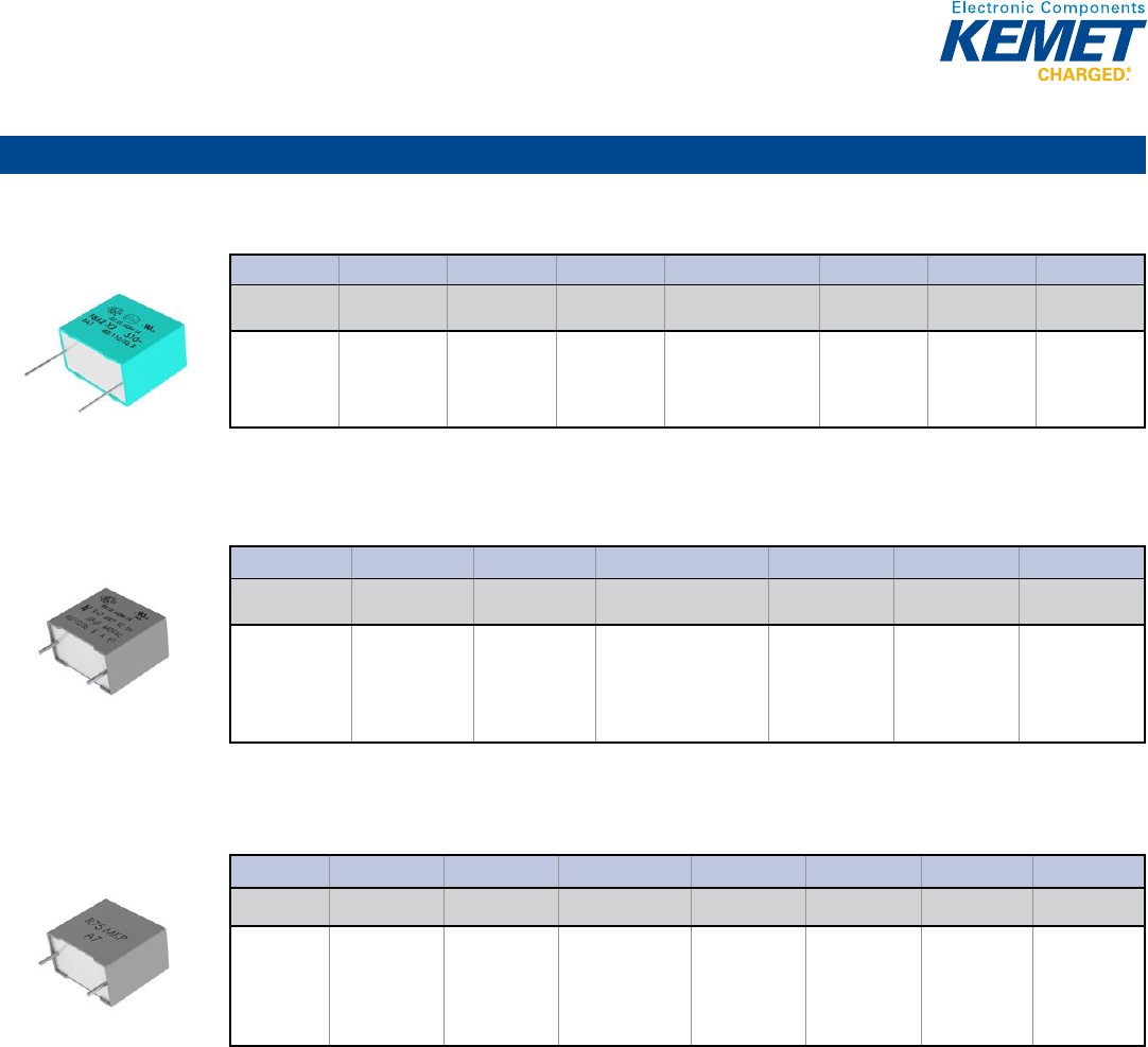
91
Film Capacitors
Radial
F862 Series, Metallized Polypropylene, 310 VAC (Automotive Grade)
Capacitance Range: 0.1 to 4.7 μF • Temperature Range: −40°C to +110°C
© KEMET Electronics Corporation • P.O. Box 5928 • Greenville, SC 29606 (864) 963-6300 • www.kemet.com F3092_F862_X2_310 • 4/16/2015 1
One world. One KEMET
Bene ts
• Approvals: ENEC, UL, cUL, CQC
• Rated voltage: 310 VAC 50/60 Hz
• Capacitance range: 0.1 – 4.7 µF
• Lead spacing: 15.0 – 27.5 mm
• Capacitance tolerance: ±20%, ±10%
• Climatic category: 40/110/56, IEC 60068-1
• Tape and reel in accordance with IEC 60286-2
• RoHS Compliant and lead-free terminations
• Operating temperature range of -40˚C to +110˚C
• 100% screening factory test at 1,900 VDC
• Quali cation based on AEC-Q200 guidelines
Overview
The F862 Series is constructed of metallized polypropylene
lm encapsulated with self-extinguishing resin in a box material
recognized by UL 94 V–0. The F862 Series is ideal for harsh
environmental conditions and meets the demanding Automotive
Electronics Council's AEC–Q200 quali cation requirements.
Applications
Typical applications include connection in series with the
mains, capacitive power supplies and energy meters, with
special emphasis in automotive applications for severe ambient
conditions.
AC Line EMI Suppression and RC Networks
F862 Series Metallized Polypropylene Film for Harsh
Environmental Conditions, Class X2, 310 VAC (Automotive Grade)
Part Number System
F862 B C 104 M310 C
Capacitor Class Series Lead Spacing
(mm) Size Code Capacitance Code (pF) Capacitance
Tolerance Voltage (VAC) Lead and
Packaging Code
F = Film
X2, Metallized
Polypropylene
B = 15
D = 22.5
F = 27.5
See Dimension
Table
First two digits represent
signi cant gures. Third
digit speci es number
of zeros.
K = ±10%
M = ±20%
310
See Ordering
Options Table
R47 Series, Metallized Polypropylene, 440 VAC (Automotive Grade)
Capacitance Range: 0.0047 to 2.2 μF • Temperature Range: −40°C to +110°C
© KEMET Electronics Corporation • P.O. Box 5928 • Greenville, SC 29606 (864) 963-6300 • www.kemet.com F3096_R47_X2_440 • 4/16/2015 1
One world. One KEMET
Bene ts
• Approvals: ENEC, UL, cUL
• Class X2 (IEC 60384-14)
• Rated voltage: 440 VAC 50/60 Hz
• Capacitance range: 0.0047 – 2.2 µF
• Lead spacing: 10.0 – 37.5 mm
• Capacitance tolerance: ±20%, ±10%
• Climatic category: 40/110/56, IEC 60068–1
• Tape and reel in accordance with IEC 60286–2
• RoHS Compliant and lead-free terminations
• Operating temperature range of -40˚C to +110˚C
• 100% screening factory test at 2,200 VDC/1,500 VAC
• Self-healing properties
• Automotive (AEC–Q200) grades available up to
22.5 mm Lead Spacing
Overview
The R47 Series is constructed of metallized polypropylene lm
encapsulated with self-extinguishing resin in a box of material
meeting the requirements of UL 94 V–0.
Automotive Grade devices are available (up to 22.5 mm Lead
Spacing) and meet the demanding Automotive Electronics
Council's AEC–Q200 quali cation requirements.
Applications
For worldwide use in electromagnetic interference (EMI)
suppression in across-the-line applications requiring X2 safety
classi cation. Intended for use in situations where capacitor
failure would not result in exposure to electric shock.
Metallized Polypropylene Film EMI Suppression Capacitors
R47 Series, Class X2, 440 VAC, 110ºC
(Automotive Grade)
Part Number System
R47 4 F 1470 00 01 M
Series
Rated Voltage (VAC)
Lead Spacing (mm) Capacitance Code (pF)
Lead and
Packaging Code
Internal Use
Capacitance
Tolerance
X2, Metallized
Polypropylene
4 = 440 F = 10.0
I = 15.0
N = 22.5
R = 27.5
W = 37.5
Digits 2 – 4 indicate the
rst three digits of the
capacitance value.
First digit indicates the
number of zeros to be
added.
See Ordering
Options Table
01
02
03
K = ±10%
M = ±20%
R75 2/L Series Metallized Polypropylene, 230 VAC/250 VAC
Capacitance Range: 0.01 to 10 μF • Temperature Range: −55°C to +105°C
© KEMET Electronics Corporation • P.O. Box 5928 • Greenville, SC 29606 (864) 963-6300 • www.kemet.com • 4/16/2015 1
One world. One KEMET
Bene ts
Overview Applications
Polypropylene Pulse/High Frequency Capacitors
R75 2/L Series DC and Pulse Applications
230 VAC and 250 VAC
Part Number System
R75 2/L R3680 DQ 3 – K
Series
Rated Voltage
(VAC)
Lead Spacing
(mm)
Capacitance
Code (pF)
Ordering Code
Electrical
Characteristics
Internal use
Capacitance
Tolerance
2 = 230
L = 250
I = 15
N = 22.5
R = 27.5
W = 37.5
Two signi cant digits
+ number of zeros
DQ
GY
CK
AA
40
50
Dimensions
and electrical
characteristics
(0 – 9)
J = ±5%
K = ±10%
M = ±20%
Power & Application Optimized – Capacitive AC Power Supply
92
Film Capacitors
Radial (cont.)
PME271E Series Metallized Impregnated Paper, Class X1, 300 VAC
Capacitance Range: 0.01 to 0.22 μF • Temperature Range: −40°C to +110°C
Legacy Part Number System
© KEMET Electronics Corporation • P.O. Box 5928 • Greenville, SC 29606 (864) 963-6300 • www.kemet.com F3014_PME271E_X1_300 • 4/16/2015 1
One world. One KEMET
Bene ts
• Approvals: ENEC, UL
• Rated voltage: 300 VAC 50/60 Hz
• Capacitance range: 0.01 – 0.22 µF
• Lead spacing: 15.2 – 25.4 mm
• Capacitance tolerance: ±20% for C ≤ 0.1 µF, ±10% for C > 0.1 µF
• Climatic category: 40/110/56/B, IEC 60068–1
• Tape and reel packaging in accordance with IEC 60286–2
• RoHS Compliant and lead-free terminations
• Operating temperature range of -40˚C to +110˚C
• 100% screening factory test at 2,150 VDC
• Highest possible safety regarding active and passive
fl ammability
Overview
The PME271E Series consists of multilayer metallized paper,
encapsulated and impregnated in self-extinguishing material
meeting the requirements of UL 94 V–0.
Applications
Typical applications include worldwide use as an electromagnetic
interference suppressor in all X1 and across-the-line applications.
AC Line EMI Suppression and RC Networks
PME271E Series Metallized Impregnated Paper,
Class X1, 300 VAC
Legacy Part Number System
PME271 E(D) 510(0) MR30
Series Rated Voltage (VAC) Lead Spacing (mm) Capacitance Code (pF)
Capacitance
Tolerance
Lead and
Packaging Code
X1, Metallized Paper E = 300 Blank = Standard
D = 22.5
Digits 2 – 4(3) indicates the rst
three digits of the capacitance
value. First digit indicates the total
number of digits in the capacitance
value.
M = ±20% (for C ≤
0.1 µF)
K = ±10% (for C >
0.1 µF)
See Ordering
Options Table
New KEMET Part Number System
P277 Q E 103 M300 A
Capacitor
Class
Series
Lead Spacing (mm)
Size Code
Capacitance Code (pF)
Capacitance
Tolerance
Rated Voltage
(VAC)
Lead and
Packaging Code
P = Paper
X1, Metallized
Paper
Q = 15.2
C = 20.3
S = 22.5
E = 25.4
See Dimension
Table
First two digits indicate the
two most signi cant digits
of the capacitance value in
picofarads. The third digit
is the number of following
zeros.
M = ±20% (for C
≤ 0.1 µF)
K = ±10% (for C >
0.1 µF)
300 = 300
See Ordering
Options Table
New KEMET Part Number System
© KEMET Electronics Corporation • P.O. Box 5928 • Greenville, SC 29606 (864) 963-6300 • www.kemet.com F3014_PME271E_X1_300 • 4/16/2015 1
One world. One KEMET
Bene ts
• Approvals: ENEC, UL
• Rated voltage: 300 VAC 50/60 Hz
• Capacitance range: 0.01 – 0.22 µF
• Lead spacing: 15.2 – 25.4 mm
• Capacitance tolerance: ±20% for C ≤ 0.1 µF, ±10% for C > 0.1 µF
• Climatic category: 40/110/56/B, IEC 60068–1
• Tape and reel packaging in accordance with IEC 60286–2
• RoHS Compliant and lead-free terminations
• Operating temperature range of -40˚C to +110˚C
• 100% screening factory test at 2,150 VDC
• Highest possible safety regarding active and passive
fl ammability
Overview
The PME271E Series consists of multilayer metallized paper,
encapsulated and impregnated in self-extinguishing material
meeting the requirements of UL 94 V–0.
Applications
Typical applications include worldwide use as an electromagnetic
interference suppressor in all X1 and across-the-line applications.
AC Line EMI Suppression and RC Networks
PME271E Series Metallized Impregnated Paper,
Class X1, 300 VAC
Legacy Part Number System
PME271 E(D) 510(0) MR30
Series
Rated Voltage (VAC)
Lead Spacing (mm)
Capacitance Code (pF)
Capacitance
Tolerance
Lead and
Packaging Code
X1, Metallized Paper
E = 300
Blank = Standard
D = 22.5
Digits 2 – 4(3) indicates the rst
three digits of the capacitance
value. First digit indicates the total
number of digits in the capacitance
value.
M = ±20% (for C ≤
0.1 µF)
K = ±10% (for C >
0.1 µF)
See Ordering
Options Table
New KEMET Part Number System
P277 Q E 103 M300 A
Capacitor
Class Series Lead Spacing (mm) Size Code Capacitance Code (pF) Capacitance
Tolerance
Rated Voltage
(VAC)
Lead and
Packaging Code
P = Paper X1, Metallized
Paper
Q = 15.2
C = 20.3
S = 22.5
E = 25.4
See Dimension
Table
First two digits indicate the
two most signi cant digits
of the capacitance value in
picofarads. The third digit
is the number of following
zeros.
M = ±20% (for C
≤ 0.1 µF)
K = ±10% (for C >
0.1 µF)
300 = 300 See Ordering
Options Table
PME271M Series Metallized Impregnated Paper, Class X2, 275 VAC
Capacitance Range: 0.001 to 0.6 μF • Temperature Range: −40°C to +110°C
Legacy Part Number System
© KEMET Electronics Corporation • P.O. Box 5928 • Greenville, SC 29606 (864) 963-6300 • www.kemet.com F3011_PME271M_X2_275 • 4/16/2015 1
One world. One KEMET
Bene ts
• Approvals: ENEC, UL, cUL
• Rated voltage: 275 VAC 50/60 Hz
• Capacitance range: 0.001 - 0.6 µF
• Lead spacing: 10.2 – 25.4 mm
• Capacitance tolerance: M = ±20% (for C ≤ 0.1 µF), K = ±10%
(for C > 0.1 µF)
• Climatic category: 40/110/56, IEC 60068–1
• Tape and reel in accordance with IEC 60286–2
• RoHS Compliant and lead-free terminations
• Operating temperature range of -40˚C to +110˚C
• 100% screening factory test at 2,150 VDC
Overview
The PME271M Series is constructed of multilayer metallized
paper encapsulated and impregnated in self-extinguishing
material meeting the requirements of UL 94 V–0.
Applications
Typical applications include worldwide use in electromagnetic
interference suppression in all X2 and across-the-line
applications.
AC Line EMI Suppression and RC Networks
PME271M Series Metallized Impregnated Paper,
Class X2, 275 VAC
Legacy Part Number System
PME271 M(B) 610(0) MR30
Series Rated Voltage (VAC) Lead Spacing (mm) Capacitance Code (pF) Capacitance
Tolerance
Lead and
Packaging Code
X2, Metallized Paper M = 275 Blank = Standard
A = 10.2
B = 15.2
D = 22.5
Digits 2 – 4(3) indicates the rst
three digits of the capacitance
value. First digit indicates the
total number of digits in the
capacitance value.
M = ±20%
(for C ≤ 0.1 µF)
K = ±10%
(for C > 0.1 µF)
See Ordering
Options Table
New KEMET Part Number System
P276 Q E 104 M275 A
Capacitor
Class
Series
Lead Spacing (mm)
Size Code
Capacitance Code (pF)
Capacitance
Tolerance
Rated Voltage
(VAC)
Lead and
Packaging Code
P = Paper
X2, Metallized
Paper
H = 10.2
Q = 15.2
C = 20.3
S = 22.5
E = 25.4
See Dimension
Table
First two digits indicate the
two most signi cant digits
of the capacitance value in
picofarads. The third digit
is the number of following
zeros.
M = ±20%
(for C ≤ 0.1 µF)
K = ±10%
(for C > 0.1 µF)
275 = 275
See Ordering
Options Table
New KEMET Part Number System
© KEMET Electronics Corporation • P.O. Box 5928 • Greenville, SC 29606 (864) 963-6300 • www.kemet.com F3011_PME271M_X2_275 • 4/16/2015 1
One world. One KEMET
Bene ts
• Approvals: ENEC, UL, cUL
• Rated voltage: 275 VAC 50/60 Hz
• Capacitance range: 0.001 - 0.6 µF
• Lead spacing: 10.2 – 25.4 mm
• Capacitance tolerance: M = ±20% (for C ≤ 0.1 µF), K = ±10%
(for C > 0.1 µF)
• Climatic category: 40/110/56, IEC 60068–1
• Tape and reel in accordance with IEC 60286–2
• RoHS Compliant and lead-free terminations
• Operating temperature range of -40˚C to +110˚C
• 100% screening factory test at 2,150 VDC
Overview
The PME271M Series is constructed of multilayer metallized
paper encapsulated and impregnated in self-extinguishing
material meeting the requirements of UL 94 V–0.
Applications
Typical applications include worldwide use in electromagnetic
interference suppression in all X2 and across-the-line
applications.
AC Line EMI Suppression and RC Networks
PME271M Series Metallized Impregnated Paper,
Class X2, 275 VAC
Legacy Part Number System
PME271 M(B) 610(0) MR30
Series
Rated Voltage (VAC)
Lead Spacing (mm)
Capacitance Code (pF)
Capacitance
Tolerance
Lead and
Packaging Code
X2, Metallized Paper
M = 275
Blank = Standard
A = 10.2
B = 15.2
D = 22.5
Digits 2 – 4(3) indicates the rst
three digits of the capacitance
value. First digit indicates the
total number of digits in the
capacitance value.
M = ±20%
(for C ≤ 0.1 µF)
K = ±10%
(for C > 0.1 µF)
See Ordering
Options Table
New KEMET Part Number System
P276 Q E 104 M275 A
Capacitor
Class Series Lead Spacing (mm) Size Code Capacitance Code (pF)
Capacitance
Tolerance
Rated Voltage
(VAC)
Lead and
Packaging Code
P = Paper X2, Metallized
Paper
H = 10.2
Q = 15.2
C = 20.3
S = 22.5
E = 25.4
See Dimension
Table
First two digits indicate the
two most signi cant digits
of the capacitance value in
picofarads. The third digit
is the number of following
zeros.
M = ±20%
(for C ≤ 0.1 µF)
K = ±10%
(for C > 0.1 µF)
275 = 275 See Ordering
Options Table
Power & Application Optimized – Capacitive AC Power Supply

94
Supercapacitors
SUPERCAPACITORS
Small Cell Large Cell
FA
5.5 V & 11 V
70°C
S301
2.7 V
65°C
S501
2.7 V
65°C
S02
16 V – 48 V
65°C
FC
3.5 V – 5.5 V
70°C
S301 Development
Balancing Kit
FE
5.5 V
70°C
Radial Screw TerminalSnap-InSurface Mount Bank Module
FG
3.5 V & 5.5 V
70°C & 85°C
FM
3.5 V, 5.5 V & 6.5 V
70°C & 85°C
FT
5.5 V
85°C
FY
5.5 V
70°C
HV
2.5 V & 2.7 V
60°C & 70°C
FR
5.5 V
85°C
FS
5.5 V, 11 V & 12 V
70°C
95
Supercapacitors
Radial
FA Series, 5.5 V – 11 V, 70ºC
Capacitance Range: 0.022 to 1 F • Temperature Range: −25°C to +70°C
1© KEMET Electronics Corporation • P.O. Box 5928 • Greenville, SC 29606 (864) 963-6300 • www.kemet.com S6018_FA • 4/16/2015
One world. One KEMET
Bene ts
• Wide range of temperature from -25°C to +70°C
• Maintenance free
• 5.5 VDC and 11.0 VDC
• Highly reliable against liquid leakage
• Lead-free and RoHS Compliant
Overview
FA Series Supercapacitors, also known as Electric Double-
Layer Capacitors (EDLCs), are intended for high energy storage
applications.
Applications
Supercapacitors have characteristics ranging from traditional
capacitors and batteries. As a result, supercapacitors can be
used like a secondary battery when applied in a DC circuit.
These devices are best suited for use in low voltage DC hold-up
applications such as embedded microprocessor systems with
fl ash memory.
Supercapacitors
FA Series
Part Number System
FA 0H 104 Z F
Series
Maximum Operating Voltage
Capacitance Code (F)
Capacitance
Tolerance
Environmental
FA
0H = 5.5 VDC
1A = 11.0 VDC
First two digits represent
signifi cant fi gures. Third digit
specifi es number of zeros.
Z = -20/+80%
F = Lead-free
FE Series, 5.5 V, 70ºC
Capacitance Range: 0.047 to 1.5 F • Temperature Range: −40°C to +70°C
1© KEMET Electronics Corporation • P.O. Box 5928 • Greenville, SC 29606 (864) 963-6300 • www.kemet.com S6019_FE • 4/16/2015
One world. One KEMET
Bene ts
• Wide range of temperature from -40°C to +70°C
• Maintenance free
• Maximum operating voltage: 5.5 VDC
• Highly reliable against liquid leakage
• Lead-free and RoHS Compliant
Overview
FE Series Supercapacitors, also known as Electric Double-
Layer Capacitors (EDLCs), are intended for high energy storage
applications.
Applications
Supercapacitors have characteristics ranging from traditional
capacitors and batteries. As a result, supercapacitors can be
used like a secondary battery when applied in a DC circuit.
These devices are best suited for use in low voltage DC hold-up
applications such as embedded microprocessor systems with
fl ash memory.
Supercapacitors
FE Series
Part Number System
FE 0H 104 Z F
Series
Maximum Operating Voltage
Capacitance Code (F)
Capacitance
Tolerance
Environmental
FE
0H = 5.5 VDC
First two digits represent
signifi cant fi gures. Third digit
specifi es number of zeros.
Z = -20/+80%
F = Lead-free
FG Series, 3.5 V – 5.5 V, 70ºC & 85ºC
Capacitance Range: 0.01 to 4.7 F • Temperature Range: −25°C to +70°C (FG, FGH) and −40°C to +85°C (FGR)
1© KEMET Electronics Corporation • P.O. Box 5928 • Greenville, SC 29606 (864) 963-6300 • www.kemet.com S6013_FG • 4/16/2015
One world. One KEMET
Bene ts
• Wide range of temperature from -25°C to +70°C (FG & FGH
types) and -40°C to +85°C (FGR type)
• Maintenance free
• 3.5 VDC and 5.5 VDC
• Highly reliable against liquid leakage
• Lead-free and RoHS Compliant
Overview
FG Series Supercapacitors, also known as Electric Double-
Layer Capacitors (EDLCs), are intended for high energy storage
applications.
Applications
Supercapacitors have characteristics ranging from traditional
capacitors and batteries. As a result, supercapacitors can be
used like a secondary battery when applied in a DC circuit.
These devices are best suited for use in low voltage DC hold-up
applications such as embedded microprocessor systems with
fl ash memory.
Supercapacitors
FG Series
Part Number System
FG 0H 104 Z F
Series
Maximum Operating Voltage
Capacitance Code (F)
Capacitance
Tolerance
Environmental
FG
FGH
FGR
0V = 3.5 VDC
0H = 5.5 VDC
First two digits represent
signifi cant fi gures. Third digit
specifi es number of zeros.
Z = -20/+80%
F = Lead-free
FM Series, 3.5 V – 6.5 V, 70ºC & 85ºC
Capacitance Range: 0.01 to 0.22 F • Temperature Range: −25°C to +70°C (all types except FMR) and −40°C to +85°C (FMR)
1© KEMET Electronics Corporation • P.O. Box 5928 • Greenville, SC 29606 (864) 963-6300 • www.kemet.com S6012_FM • 4/16/2015
One world. One KEMET
Bene ts
• Rectangular case
• Wide range of temperature from -25°C to +70°C (all types
except FMR) and -40°C to +85°C (FMR type)
• Maintenance free
• 3.5 VDC, 5.5 VDC, and 6.5 VDC
• Highly reliable against liquid leakage
• Lead-free and RoHS Compliant
• Leads can be transverse mounted
Overview
FM Series Supercapacitors, also known as Electric Double-
Layer Capacitors (EDLCs), are intended for high energy storage
applications.
Applications
Supercapacitors have characteristics ranging from traditional
capacitors and batteries. As a result, supercapacitors can be
used like a secondary battery when applied in a DC circuit.
These devices are best suited for use in low voltage DC hold-up
applications such as embedded microprocessor systems with
fl ash memory.
Supercapacitors
FM Series
Part Number System
FM 0H 223 Z F TP 16
Series
Maximum
Operating Voltage
Capacitance Code (F)
Capacitance
Tolerance
Environmental
Tape Type
Height
(excluding lead)
FM
FME
FML
FMR
FMC
0V = 3.5 VDC
0H = 5.5 VDC
0J = 6.5 VDC
First two digits
represent signifi cant
fi gures. Third digit
specifi es number of
zeros.
Z = -20/+80%
F = Lead-free
TP = AMMO
-L1 = Transverse
mounting
Blank = Bulk
16 = 16 mm
18 = 18 mm
Blank = Bulk
FR Series, 5.5 V, 85ºC
Capacitance Range: 0.022 to 1 F • Temperature Range: −40°C to +85°C
1© KEMET Electronics Corporation • P.O. Box 5928 • Greenville, SC 29606 (864) 963-6300 • www.kemet.com S6016_FR • 4/16/2015
One world. One KEMET
Bene ts
• Wide range of temperature from -40°C to +85°C
• Maintenance free
• Maximum operating voltage: 5.5 VDC
• Highly reliable against liquid leakage
• Lead-free and RoHS Compliant
Overview
FR Series Supercapacitors, also known as Electric Double-
Layer Capacitors (EDLCs), are intended for high energy storage
applications.
Applications
Supercapacitors have characteristics ranging from traditional
capacitors and batteries. As a result, supercapacitors can be
used like a secondary battery when applied in a DC circuit.
These devices are best suited for use in low voltage DC hold-up
applications such as embedded microprocessor systems with
fl ash memory.
Supercapacitors
FR Series
Part Number System
FR 0H 104 Z F
Series
Maximum Operating Voltage
Capacitance Code (F)
Capacitance
Tolerance
Environmental
FR
0H = 5.5 VDC
First two digits represent
signifi cant fi gures. Third digit
specifi es number of zeros.
Z = -20/+80%
F = Lead-free
Small Cell
96
Supercapacitors
Radial (cont.)
FS Series, 5.5 V – 12 V, 70ºC
Capacitance Range: 0.022 to 5 F • Temperature Range: −25°C to +70°C
1© KEMET Electronics Corporation • P.O. Box 5928 • Greenville, SC 29606 (864) 963-6300 • www.kemet.com S6017_FS • 4/16/2015
One world. One KEMET
Bene ts
• Wide range of temperature from -25°C to +70°C
• Maintenance free
• 5.5 VDC, 11.0 VDC, and 12.0 VDC
• Highly reliable against liquid leakage
• Lead-free and RoHS Compliant
Overview
FS Series Supercapacitors, also known as Electric Double-
Layer Capacitors (EDLCs), are intended for high energy storage
applications.
Applications
Supercapacitors have characteristics ranging from traditional
capacitors and batteries. As a result, supercapacitors can be
used like a secondary battery when applied in a DC circuit.
These devices are best suited for use in low voltage DC hold-up
applications such as embedded microprocessor systems with
fl ash memory.
Supercapacitors
FS Series
Part Number System
FS 0H 104 Z F
Series
Maximum Operating Voltage
Capacitance Code (F)
Capacitance
Tolerance
Environmental
FS
0H = 5.5 VDC
1A = 11.0 VDC
1B = 12.0 VDC
First two digits represent
signifi cant fi gures. Third digit
specifi es number of zeros.
Z = -20/+80%
F = Lead-free
FT Series, 5.5 V, 85ºC
Capacitance Range: 0.1 to 5.6 F • Temperature Range: −40°C to +85°C
1© KEMET Electronics Corporation • P.O. Box 5928 • Greenville, SC 29606 (864) 963-6300 • www.kemet.com S6014_FT • 4/16/2015
One world. One KEMET
Bene ts
• Wide range of temperature from -40°C to +85°C
• Maintenance free
• Maximum operating voltage: 5.5 VDC
• Highly reliable against liquid leakage
• Lead-free and RoHS Compliant
Overview
FT Series Supercapacitors, also known as Electric Double-
Layer Capacitors (EDLCs), are intended for high energy storage
applications.
Applications
Supercapacitors have characteristics ranging from traditional
capacitors and batteries. As a result, supercapacitors can be
used like a secondary battery when applied in a DC circuit.
These devices are best suited for use in low voltage DC hold-up
applications such as embedded microprocessor systems with
fl ash memory.
Supercapacitors
FT Series
Part Number System
FT 0H 104 Z F
Series
Maximum Operating Voltage
Capacitance Code (F)
Capacitance
Tolerance
Environmental
FT
FTW
0H = 5.5 VDC
First two digits represent
signifi cant fi gures. Third digit
specifi es number of zeros.
Z = -20/+80%
F = Lead-free
FY Series, 5.5 V, 70ºC
Capacitance Range: 0.01 to 2.2 F • Temperature Range: −25°C to +70°C
1© KEMET Electronics Corporation • P.O. Box 5928 • Greenville, SC 29606 (864) 963-6300 • www.kemet.com S6015_FY • 4/16/2015
One world. One KEMET
Bene ts
• Wide range of temperature from -25°C to +70°C
• Maintenance free
• Maximum operating voltage: 5.5 VDC
• Highly reliable against liquid leakage
• Lead-free and RoHS Compliant
Overview
FY Series Supercapacitors, also known as Electric Double-
Layer Capacitors (EDLCs), are intended for high energy storage
applications.
Applications
Supercapacitors have characteristics ranging from traditional
capacitors and batteries. As a result, supercapacitors can be
used like a secondary battery when applied in a DC circuit.
These devices are best suited for use in low voltage DC hold-up
applications such as embedded microprocessor systems with
fl ash memory.
Supercapacitors
FY Series
Part Number System
FY 0H 104 Z F
Series
Maximum Operating Voltage
Capacitance Code (F)
Capacitance
Tolerance
Environmental
FYD
FYH
FYL
0H = 5.5 VDC
First two digits represent
signifi cant fi gures. Third digit
specifi es number of zeros.
Z = -20/+80%
F = Lead-free
HV Series, 2.5 V – 2.7 V, 60ºC & 70ºC
Capacitance Range: 1 to 200 F • Temperature Range: −25°C to +60°C and −25°C to +70°C
1© KEMET Electronics Corporation • P.O. Box 5928 • Greenville, SC 29606 (864) 963-6300 • www.kemet.com S6020_HV • 4/16/2015
One world. One KEMET
Bene ts
• Wide range of temperature from -25°C to +60°C
and -25°C to +70°C
• Maintenance free
• 2.5 VDC and 2.7 VDC
• Highly reliable against liquid leakage
• Lead-free and RoHS Compliant
Overview
HV Series Supercapacitors, also known as Electric Double-
Layer Capacitors (EDLCs), are intended for high energy storage
applications.
Applications
Supercapacitors have characteristics ranging from traditional
capacitors and batteries. As a result, supercapacitors can be
used like a secondary battery when applied in a DC circuit.
These devices are best suited for use in low voltage DC hold-up
applications such as embedded microprocessor systems with
fl ash memory.
Supercapacitors
HV Series
Part Number System
HVZ 0E 105 N F - LT
Series
Maximum Operating
Voltage
Capacitance Code (F)
Capacitance
Tolerance
Environmental
Terminal
HVZ
0E = 2.7 VDC
(50 F type has 2.5 VDC)
First two digits represent
signifi cant fi gures. Third
digit specifi es number of
zeros.
N = ±30%
F = Lead-free
-LT = Snap-in
Blank = Standard
Surface Mount
FC Series, 3.5 V – 5.5 V, 70ºC
Capacitance Range: 0.1 to 1 F • Temperature Range: −25°C to +70°C
1© KEMET Electronics Corporation • P.O. Box 5928 • Greenville, SC 29606 (864) 963-6300 • www.kemet.com S6011_FC • 4/16/2015
One world. One KEMET
Bene ts
• Surface mount without holder
• Wide range of temperature from -25°C to +70°C
• Maintenance free
• Operational Voltage: 3.5 – 5.5 VDC
• Highly reliable against liquid leakage
• Lead-free and RoHS Compliant
Overview
FC Series Supercapacitors, also known as Electric Double-
Layer Capacitors (EDLCs), are surface mount type components
intended for high energy storage applications. The FC Series is
designed specifi cally for refl ow soldering, allowing them to be
attached to a printed circuit board (PCB) directly.
Applications
Supercapacitors have characteristics ranging from traditional
capacitors and batteries. As a result, supercapacitors can be
used like a secondary battery when applied in a DC circuit.
These devices are best suited for use in low voltage DC hold-up
applications such as embedded microprocessor systems with
fl ash memory.
Supercapacitors
FC Series
Part Number System
FC 0H 104 Z F TB R 24 -SS
Series
Surface Mount
Maximum
Operating Voltage
Capacitance Code (F)
Capacitance
Tolerance
Environmental
Tape Type
Orientation
Tape Width
C-Spec
FCS
FC
0V = 3.5 VDC
0H = 5.5 VDC
First two digits
represent signifi cant
fi gures. Third digit
specifi es number of
zeros.
Z = -20/+80%
F = Lead-free
TB =
Embossed
R = Positive
electrode
forward
24 = 24 mm
32 = 32 mm
44 = 44 mm
-SS = 3 digit serial
number marked
on top
Blank = No serial
number marking
Small Cell
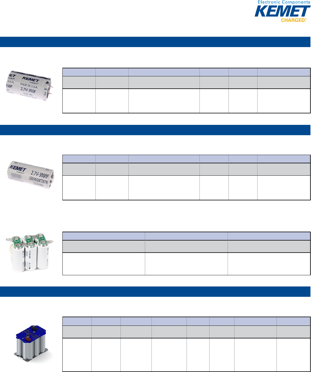
97
Supercapacitors
Snap-In
S501 Series, 2.7 V, 65ºC
Capacitance Range: 100 to 350 F • Temperature Range: −40°C to +65°C
1© KEMET Electronics Corporation • P.O. Box 5928 • Greenville, SC 29606 (864) 963-6300 • www.kemet.com S6003_S501 • 4/16/2015
One world. One KEMET
Bene ts
• Board mountable
• Solderable
• High power
• High rate cycling
• Long life
• Operating temperature range of -40˚C to +65˚C
• High cycle life > 500,000 cycles
• RoHS Compliant
• Made in USA
Overview
KEMET S501 Series Supercapacitors use a proprietary electrode
design to deliver a very high power density. This product features
high power performance of up to 350 F capacity in a single
ended, board mountable, snap-in termination construction.
Applications
Typical applications include automotive subsystems, backup
power/UPS, handheld/portable devices, hybrid energy storage,
hybrid drivetrains, windmill pitch control, emergency lighting,
medical devices, power correction, engine starting, and
renewable energy.
Snap-In Supercapacitors
S501 Series, Snap-In, 2.7 V, 65ºC
Part Number System
S501 DC 107 V2R7 A
Series
Size Code (D x L)
Capacitance Code (µF)
Capacitance
Tolerance
Rated Voltage
(VDC)
Termination Code
Supercapacitor,
Snap-In
Termination
DC = 22 x 45
LF = 35 x 60
LI = 35 x 69
LR = 35 x 89
First two digits represent signifi cant fi gures.
Third digit specifi es number of zeros.
V = -5/+10%
W = -0/+20%
2R7 = 2.7
A = 2 pin, 10 mm lead spacing,
5.9 mm terminal length
U = 4 pin standard snap-in style
Screw Terminal
S301 Series, 2.7 V, 65ºC
Capacitance Range: 1,200 to 3,000 F • Temperature Range: −40°C to +65°C
1© KEMET Electronics Corporation • P.O. Box 5928 • Greenville, SC 29606 (864) 963-6300 • www.kemet.com S6001_S301 • 4/16/2015
One world. One KEMET
Bene ts
• Weldable screw terminals
• Highest power performance available
• High power
• High rate cycling
• Long life
• Operating temperature range of -40˚C to +65˚C
• High cycle life > 1,000,000 cycles
• RoHS Compliant
• Made in USA
Overview
KEMET S301 Series Supercapacitors utilize a proprietary
electrode design to deliver a very high power density. This
product features high power performance up to 3,000 F capacity
in a weldable axial screw termination cell.
Applications
Typical applications include automotive subsystems, engine
starting, rail systems, hybrid drive trains, material handling/utility
vehicles, regenerative brake energy capture, backup power,
grid/power correction, and UPS/carry through power.
Screw Terminal Supercapacitors
S301 Series, Screw Termination, 2.7 V, 65ºC
Part Number System
S301 RV 308 T2R7 W
Series
Size Code (D x L)
Capacitance Code (µF)
Capacitance
Tolerance
Rated Voltage
(VDC)
Termination Code
Supercapacitor,
Screw Termination
RP = 60.5 x 80.5
RS = 60.5 x 108.5
RV = 60.5 x 144
First two digits represent signifi cant fi gures.
Third digit specifi es number of zeros.
R = -0%
2R7 = 2.7
2 threaded inserts per end,
20 mm lead spacing, M6
S301 Development Balancing Kit
Capacitance Range: 1,200 to 3,000 F • Temperature Range: −40°C to +105°C
S0K MOD 0001
Series
Con guration
Model
Supercapacitor Development Balancing Kit
Module
Additional Hardware Required:
Six (6) KEMET S301 Screw Terminal
Supercapacitors,
60 mm cell diameter only
Bank Module
S02 Series, Modules with Cells in Extruded Metal Holder, 16 V – 48 V, 65ºC
Capacitance Range: 165 to 500 F • Temperature Range: −40°C to +65°C
1© KEMET Electronics Corporation • P.O. Box 5928 • Greenville, SC 29606 (864) 963-6300 • www.kemet.com S6009_S02 • 4/16/2015
One world. One KEMET
Bene ts
• 16 – 48.6 V rated voltage
• Individually balanced cells
• IP–65 rated, (IP–67 optional)
• Threaded, protected terminals
• Operating temperature range of -40˚C to +65˚C
• Optional state of charge indicator
• Cycle life > 500,000 cycles
• RoHS Compliant
• Made in USA
Overview
KEMET S02 Series Supercapacitors are bank modules with cells
in extruded metal holder.
Applications
Renewable energy systems
Starting systems
Automotive subsystems
Backup power/UPS
Ride through/power conditioning
Hybrid drive systems
Bank Module Supercapacitors
S02 Series, Modules with Cells in Extruded Metal Holder
Part Number System
S02 A T 5006 R016 AU808
Series
Confi guration
Code Balancing
Confi guration Code
Capacitor Type
Capacitance Code
(µF)
Capacitance
Tolerance
Rated Voltage
(VDC)
Termination Code
C-Spec
Supercapacitor,
Bank Modules
with cells in
extruded metal
holder
A = Analog with
clamping
T =Array, 2
dimensions
D = Array, 3
dimensions
First three digits
represent signifi cant
fi gures. Fourth digit
specifi es number of
zeros.
R = -0%
016 = 16 V
048 = 48 V
A = The fi rst mechanical
confi guration of a
particular part number
B = Refers only
to part number
S02AT1656R048BU808
Blank = No monitor
U808 = Digital
Overvoltage
and analog over
temperature
monitor
Large Cell
98
TANTALUM SURFACE MOUNT CAPACITORS
Standard Tantalum
Polymer Tantalum
KEMET Organic
Capacitor
(KO-CAP)
Polymer Aluminum
Organic Capacitor
(AO-CAP)
High Temperature MIL-PRF CWR
Series
Automotive Grade Space GradeFused
High Reliability
Commercial
Off-The-Shelf
(COTS)
TANTALUM THROUGH-HOLE CAPACITORS
Hermetically Sealed Axial Radial Dipped Molded Axial Molded Radial
T110
MIL-PRF-39003 Polar
& T212 (CSR13)
T111
MIL-PRF-39003
Non-Polar &
T213 (CSR91)
T140
MIL-PRF-39003 Polar
& T242 (CSR23)
T215
High Temperature
Solder (CSR13)
T216
MIL-PRF-39003
(CSS13) & T256 (CSS33)
T222
MIL-PRF-39003 Polar
Miniature (CSR09)
T210/T240/GR500
High Reliability
T330
Precision Molded
Polar
T340
Precision Molded
Polar
T370 & T378
(CX06)
MIL-PRF-49137/6
T322/T323
(CX01/CX05)
MIL-PRF-49137/1 & 5
T35X
Polar
T363 (CX02) &
T369 (CX12)
MIL-PRF-49137/2
T368
High Capacitance
T396 & T398
3 Leaded
T225
High Temperature
Solder (CSR09)
T245
High Temperature
Solder (CSR23)
T252
MIL-PRF-39003
(CSR33)
T255
High Temperature
Solder (CSR33)
T262
MIL-PRF-30093
(CSR21)
T550
Polymer 105°C Rated
T551
Polymer 125°C Rated
T489
Low DC Leakage MnO2
T490
High CV MnO2
T491
Industrial Grade MnO2
T495
Surge Robust MnO2
T510
Multiple Anode MnO2
TSM
Tantalum Stack MnO2
T494
Industrial Grade Low
ESR MnO2
T498
150°C Rated MnO2
T499
175°C Rated MnO2
T500
200°C Rated MnO2
T493
MnO2 (CWR11)
T495
Surge Robust MnO2
DLA 95158
T513
Multiple Anode MnO2
T497
MnO2 (CWR09/19/29)
T419
(CWR19)
MIL-PRF-55365/11
T429
(CWR29)
MIL-PRF-55365/11
T492
(CWR11)
MIL-PRF-55365/8
T540
Single Anode Polymer
T541
Multiple Anode
Polymer
T543
Polymer
A700
125°C Rated
T520
105°C Rated
T521
High Voltage
T522
Reduced Leakage
T525
125°C Rated
T527
Facedown Terminal
T528
Low ESL/Facedown
Terminal
T529
Small Case Size
Substrate Terminal
T530
High Capacitance
125°C Rated
T545
High Energy
TSP
Tantalum Stack
Polymer
T428
High Volumetric
Efficiency Facedown
MnO2
T409
(CWR09)
MIL-PRF-55365/4
T489
Low DC Leakage
MnO2
T491
MnO2
T494
Low ESR MnO2
T495
Surge Robust MnO2
T498
150°C Rated MnO2
T499
175°C Rated MnO2
T510
Multiple Anode MnO2
T591
High Performance
Polymer
T493
COTS MnO2 (CWR11)
T496
COTS Fail-Safe
Fused MnO2
T497
COTS MnO2
(CWR09/19/29)
T496
MnO2
T496
Fused MnO2
T510
Multiple Anode MnO2
Tantalum Capacitors
99
Tantalum Capacitors
Surface Mount
Standard Tantalum
T489 Series Low DC Leakage MnO2
Capacitance Range: 0.1 to 470 µF • Temperature Range: −55°C to +125°C
© KEMET Electronics Corporation • P.O. Box 5928 • Greenville, SC 29606 (864) 963-6300 • www.kemet.com T2024_T489 • 4/16/2015 22
Tantalum Surface Mount Capacitors – Standard Tantalum
T489 Series Low DC Leakage MnO2
SPICE
For a detailed analysis of speci c part numbers, please visit www.kemet.com for a free download of KEMET's SPICE software. The
KEMET SPICE program is freeware intended to aid design engineers in analyzing the performance of these capacitors over frequen-
cy, temperature, ripple, and DC bias conditions.
Ordering Information
T489 B156 M16 A T E800
Capacitor
Class Series Case Size Capacitance
Code (pF)
Capacitance
Tolerance
Rated Voltage
(VDC)
Failure Rate/
Design Termination Finish ESR
T =
Tantalum
Low DC
Leakage
Series
A, B, C,
D, X
First two digits represent
signi cant gures. Third
digit speci es number of
zeros.
K = ±10%
M = ±20%
006 = 6.3
010 = 10
016 = 16
020 = 20
025 = 25
035 = 35
050 = 50
A = N/A
T = 100% Matte Tin
(Sn) Plated
H = Standard Solder
Coated (SnPb 5% Pb
minimum)
G = Gold Plated
Last three digits
specify ESR in mΩ.
(800 = 800 mΩ)
Performance Characteristics
Item
Performance Characteristics
Operating Temperature
-55°C to 125°C
Rated Capacitance Range
0.10 µF to 470 µF at 120 Hz/25°C
Capacitance Tolerance
K Tolerance (±10%), M Tolerance (±20%)
Rated Voltage Range
6.3 – 50 V
DF(120 Hz)
Refer to Part Number Electrical Speci cation
ESR (100 kHz)
Refer to Part Number Electrical Speci cation
Leakage Current
≤ 0.0075 CV (µA) at rated voltage after 5 minutes
Reliability
0.50%/1,000 hours at 85°C, VR with 0.1 Ω series resistance
T490 Series Commercial Grade High CV MnO2
Capacitance Range: 47 to 470 µF • Temperature Range: −55°C to +40°C
© KEMET Electronics Corporation • P.O. Box 5928 • Greenville, SC 29606 (864) 963-6300 • www.kemet.com T2004_T490 • 4/16/2015 22
Tantalum Surface Mount Capacitors – Standard Tantalum
T490 Series Commercial Grade MnO2
SPICE
For a detailed analysis of speci c part numbers, please visit www.kemet.com for a free download of KEMET's SPICE software.
The KEMET SPICE program is freeware intended to aid design engineers in analyzing the performance of these capacitors over
frequency, temperature, ripple, and DC bias conditions.
Ordering Information
T490 B227 M006 A T
Capacitor
Class Series Case Size Capacitance
Code (pF)
Capacitance
Tolerance
Rated Voltage
(VDC)
Failure Rate/
Design Termination Finish Packaging (C-Spec)
T =
Tantalum
Industrial
A, B, T
First two digits
represent signi cant
gures. Third digit
speci es number of
zeros.
M = ±20%
004 = 4
006 = 6.3
010 = 10
A = N/A
T = 100% Matte Tin (Sn)
plated
H = Standard solder
coated (SnPb 5% Pb
minimum)
G = Gold plated (A, B
only)
Blank = 7" Reel
7280 = 13" Reel
Performance Characteristics
Item
Performance Characteristics
Operating Temperature
-55°C to 40°C
Rated Capacitance Range
47 – 470 µF at 120 Hz/25°C
Capacitance Tolerance
M Tolerance (20%)
Rated Voltage Range
4 – 10 V
ESR (100 kHz)
Refer to Part Number Electrical Speci cation Table
Leakage Current
≤ 0.01 CV (μA) at rated voltage after 5 minutes
T491 Series Industrial Grade MnO2
Capacitance Range: 0.1 to 1,000 μF • Temperature Range: −55°C to +125°C
© KEMET Electronics Corporation • P.O. Box 5928 • Greenville, SC 29606 (864) 963-6300 • www.kemet.com T2005_T491 • 4/16/2015 22
Tantalum Surface Mount Capacitors – Standard Tantalum
T491 Series Industrial Grade MnO2
SPICE
For a detailed analysis of speci c part numbers, please visit www.kemet.com for a free download of KEMET's SPICE software.
The KEMET SPICE program is freeware intended to aid design engineers in analyzing the performance of these capacitors over
frequency, temperature, ripple, and DC bias conditions.
Ordering Information
T491 X157 K020 A T
Capacitor
Class Series Case Size Capacitance
Code (pF)
Capacitance
Tolerance
Rated Voltage
(VDC)
Failure Rate/
Design Termination Finish Packaging (C-Spec)
T =
Tantalum
Industrial
A, B, C, D,
E, S, T, U,
V, W, X
First two digits
represent
signi cant
gures. Third digit
speci es number
of zeros.
K = ±10%
M = ±20%
2R5 = 2.5
003 = 3
004 = 4
006 = 6.3
010 = 10
016 = 16
020 = 20
025 = 25
035 = 35
050 = 50
A = N/A
T = 100% Matte Tin (Sn)
plated
H = Standard solder
coated (SnPb 5% Pb
minimum)
G = Gold plated (A, B, C,
D, X only)
N = Non-magnetic 100%
Tin (Sn)
M = Non-magnetic (SnPb)
Blank = 7" Reel
7280 = 13" Reel
Performance Characteristics
Item
Performance Characteristics
Operating Temperature
-55°C to 125°C
Rated Capacitance Range
0.1 – 1,000 µF at 120 Hz/25°C
Capacitance Tolerance
K Tolerance (10%), M Tolerance (20%)
Rated Voltage Range
2.5 – 50 V
DF (120 Hz)
Refer to Part Number Electrical Speci cation Table
ESR (100 kHz)
Refer to Part Number Electrical Speci cation Table
Leakage Current
≤ 0.01 CV (µA) at rated voltage after 5 minutes
100
Tantalum Capacitors
Surface Mount
Standard Tantalum (cont.)
T494 Series Industrial Grade Low ESR MnO2
Capacitance Range: 0.1 to 1,000 μF • Temperature Range: −55°C to +125°C
© KEMET Electronics Corporation • P.O. Box 5928 • Greenville, SC 29606 (864) 963-6300 • www.kemet.com T2008_T494 • 4/16/2015 22
Tantalum Surface Mount Capacitors – Low ESR
T494 Series Industrial Grade MnO2
SPICE
For a detailed analysis of speci c part numbers, please visit www.kemet.com for a free download of KEMET's SPICE software.
The KEMET SPICE program is freeware intended to aid design engineers in analyzing the performance of these capacitors over
frequency, temperature, ripple, and DC bias conditions.
Ordering Information
T494 T336 M004 AT
Capacitor
Class Series Case Size Capacitance
Code (pF)
Capacitance
Tolerance
Rated Voltage
(VDC)
Failure Rate/
Design Termination Finish Packaging
(C-Spec)
T =
Tantalum
Industrial -
Low ESR
A, B, C, D,
E, S, T, U,
V, X
First two digits
represent signi cant
gures. Third digit
speci es number of
zeros.
K = ±10%
M = ±20%
2R5 = 2.5
003 = 3
004 = 4
006 = 6.3
010 = 10
016 = 16
020 = 20
025 = 25
035 = 35
050 = 50
A = N/A T = 100% Matte Tin (Sn)
plated
H = Standard solder
coated (SnPb 5% Pb
minimum)
G = Gold plated (A, B, C,
D, X only)
N = Non-magnetic 100%
Tin (Sn)
M = Non-magnetic (SnPb)
Blank = 7" Reel
7280 = 13" Reel
Performance Characteristics
Item
Performance Characteristics
Operating Temperature
-55°C to 125°C
Rated Capacitance Range
0.1 – 1,000 µF at 120 Hz/25°C
Capacitance Tolerance
K Tolerance (10%), M Tolerance (20%)
Rated Voltage Range
2.5 – 50 V
DF (120 Hz)
Refer to Part Number Electrical Speci cation Table
ESR (100 kHz)
Refer to Part Number Electrical Speci cation Table
Leakage Current
≤ 0.01 CV (µA) at rated voltage after 5 minutes
T495 Series Surge Robust MnO2
Capacitance Range: 0.47 to 1,000 μF • Temperature Range: −55°C to +125°C
© KEMET Electronics Corporation • P.O. Box 5928 • Greenville, SC 29606 (864) 963-6300 • www.kemet.com T2009_T495 • 4/16/2015 22
Tantalum Surface Mount Capacitors – Low ESR
T495 Series Surge Robust MnO2
SPICE
For a detailed analysis of speci c part numbers, please visit www.kemet.com for a free download of KEMET's SPICE software.
The KEMET SPICE program is freeware intended to aid design engineers in analyzing the performance of these capacitors over
frequency, temperature, ripple, and DC bias conditions.
Ordering Information
T495 X107 M010 A T E045
Capacitor
Class Series Case
Size
Capacitance
Code (pF)
Capacitance
Tolerance
Rated Voltage
(VDC)
Failure Rate/
Design Termination Finish ESR Packaging
(C-Spec)
T =
Tantalum
Surge
Robust
Low ESR
A, B,
C, D,
E, M,
T, U,
V, X
First two digits
represent signi cant
gures. Third digit
speci es number of
zeros.
K = ±10%
M = ±20%
2R5 = 2.5
004 = 4
006 = 6.3
010 = 10
016 = 16
020 = 20
025 = 25
035 = 35
050 = 50
A = N/A
T = 100% Matte Tin
(Sn) plated
H = Standard solder
coated (SnPb 5% Pb
minimum)
G = Gold plated (A, B,
C, D, X only)
Last three
digits specify
ESR in mΩ.
(45 = 45 mΩ)
Blank = 7"
Reel
7280 = 13"
Reel
Performance Characteristics
Item
Performance Characteristics
Operating Temperature
-55°C to 125°C
Rated Capacitance Range
0.47 – 1,000 µF at 120 Hz/25°C
Capacitance Tolerance
K Tolerance (10%), M Tolerance (20%)
Rated Voltage Range
2.5 – 50 V
DF (120 Hz)
Refer to Part Number Electrical Speci cation Table
ESR (100 kHz)
Refer to Part Number Electrical Speci cation Table
Leakage Current
≤ 0.01 CV (µA) at rated voltage after 5 minutes
T510 Series Multiple Anode MnO2
Capacitance Range: 10 to 1,000 μF • Temperature Range: −55°C to +125°C
© KEMET Electronics Corporation • P.O. Box 5928 • Greenville, SC 29606 (864) 963-6300 • www.kemet.com T2014_T510 • 4/16/2015 22
Tantalum Surface Mount Capacitors – Low ESR
T510 Series Multiple Anode MnO2
SPICE
For a detailed analysis of speci c part numbers, please visit www.kemet.com for a free download of KEMET's SPICE software.
The KEMET SPICE program is freeware intended to aid design engineers in analyzing the performance of these capacitors over
frequency, temperature, ripple, and DC bias conditions.
Ordering Information
T510 X477 M006 A T E800
Capacitor
Class Series Case Size Capacitance
Code (pF)
Capacitance
Tolerance Voltage Failure Rate/
Design Lead Material ESR Packaging
(C-Spec)
T =
Tantalum
Multiple
Anode
Low ESR
E, X First two digits
represent signi cant
gures. Third digit
speci es number of
zeros.
K = ±10%
M = ±20%
004 = 4 V
006 = 6.3 V
010 = 10 V
016 = 16 V
020 = 20 V
025 = 25 V
035 = 35 V
050 = 50 V
A = N/A
Z = N/A
T = 100% Matte Tin
(Sn) Plated
H = Standard Solder
Coated (SnPb 5%
Pb minimum)
G = Gold Plated (A,
B, C, D, X only)
Last three
digits specify
ESR in mΩ.
(800 = 800
mΩ)
Blank = 7" Reel
7280 = 13" Reel
Performance Characteristics
Item
Performance Characteristics
Operating Temperature
-55°C to 125°C
Rated Capacitance Range
10 – 1,000 µF @ 120 Hz/25°C
Capacitance Tolerance
K Tolerance (10%), M Tolerance (20%)
Rated Voltage Range
4 – 50 V
DF (120 Hz)
Refer to Part Number Electrical Speci cation Table
ESR (100 kHz)
Refer to Part Number Electrical Speci cation Table
Leakage Current
≤ 0.01 CV (µA) at rated voltage after 5 minutes
101
Tantalum Capacitors
Surface Mount
Standard Tantalum (cont.)
Tantalum Stack MnO2 (TSM) Series
Capacitance Range: 9.4 to 2,000 μF • Temperature Range: −55°C to +125°C
© KEMET Electronics Corporation • P.O. Box 5928 • Greenville, SC 29606 (864) 963-6300 • www.kemet.com T2021_TSM • 4/16/2015 22
Tantalum Surface Mount Capacitors – Low ESR
Tantalum Stack MnO2 (TSM) Series
SPICE
For a detailed analysis of speci c part numbers, please visit www.kemet.com for a free download of KEMET's SPICE software.
The KEMET SPICE program is freeware intended to aid design engineers in analyzing the performance of these capacitors over
frequency, temperature, ripple, and DC bias conditions.
Ordering Information
TSM 2D 447 K10 A H 61 20 D493
Capacitor
Class Series
Case
Size
Capacitance
Code (pF)
Capacitance
Tolerance Voltage
Failure Rate/
Design Lead Material Surge ESR C-Spec 2
T =
Tantalum
Stacks
MnO2
Cathode
2C, 3C,
4C, 6C,
2D, 3D,
4D, 6D,
2X, 3X,
4X, 6X
First two digits
represent
signi cant
gures. Third
digit speci es
number of
zeros.
K = ±10%
M = ±20%
006 = 6.3 V
010 = 10 V
016 = 16 V
020 = 20 V
025 = 25 V
035 = 35 V
050 = 50 V
A = N/A
B =
0.1%/1,000
hours
C =
0.01%/1,000
hours
H = Standard
Solder Coated
(SnPb 5% Pb
minimum)
C = Hot Solder
Dipped
B = Gold
Plated
T = 100% Tin
61 = None
62 = 10 Cycles
25°C After
Weibull
63 = 10 cycles,
-55°C and 85°C
After Weibull
64 = 10 cycles,
-55°C and 85°C
Before Weibull
10 = ESR-
Standard
20 = ESR-Low
30 = ESR-
Ultra-low
Designates
discrete
component
series.
D493 =
T493
Note: These TSM Stacks are specifi c to T493 COTS.
Performance Characteristics
Item
Performance Characteristics
Operating Temperature
-55°C to 125°C
Rated Capacitance Range
9.4 – 2,000 μF @ 120 Hz/25°C
Capacitance Tolerance
K Tolerance (10%), M Tolerance (20%)
Rated Voltage Range
6 – 50 V
DF (120 Hz)
Refer to Part Number Electrical Speci cation Table
ESR (100 kHz)
Refer to Part Number Electrical Speci cation Table
Leakage Current
≤ 0.01 CV (µA) at rated voltage after 5 minutes
Polymer Tantalum KEMET Organic Capacitor (KO-CAP)
T520 Series Polymer Tantalum
Capacitance Range: 10 to 1,500 μF • Temperature Range: −55°C to +105°C
© KEMET Electronics Corporation • P.O. Box 5928 • Greenville, SC 29606 (864) 963-6300 • www.kemet.com T2015_T520 • 4/16/2015 22
KEMET Organic Capacitor (KO-CAP) – Low ESR
T520 Series Polymer Tantalum
SPICE
For a detailed analysis of speci c part numbers, please visit www.kemet.com for a free download of KEMET's SPICE software.
The KEMET SPICE program is freeware intended to aid design engineers in analyzing the performance of these capacitors over
frequency, temperature, ripple, and DC bias conditions.
Ordering Information
T520 V157 M006 ATE045
Capacitor
Class Series Case
Size
Capacitance
Code (pF)
Capacitance
Tolerance
Rated Voltage
(VDC)
Failure Rate/
Design Termination Finish ESR Code Packaging
(C-Spec)
T =
Tantalum
520 =
Polymer
A, B,
C, D,
H, L,
M, Q,
T, U,
V, W,
X, Y
First two digits
represent
signi cant
gures. Third digit
speci es number
of zeros.
M = ±20% 2R5 = 2.5
003 = 3
004 = 4
006 = 6.3
008 = 8
010 = 10
011 = 11
12R = 12.5
016 = 16
020 = 20
025 = 25
A = N/A T = 100% Matte Tin
(Sn) plated
H = Tin/Lead (SnPb)
solder coated (5% Pb
minimum)
P = Ni-Pd-Au plated
N = Non-magnetic
100% Tin (Sn)
M = Non-magnetic
(SnPb)
E = ESR
Last three digits
specify ESR in
mΩ. (045 = 45
mΩ)
Blank = 7"
Reel
7280 = 13"
Reel
Performance Characteristics
Item
Performance Characteristics
Operating Temperature
-55°C to 105°C
Rated Capacitance Range
10 – 1,500 µF at 120 Hz/25°C
Capacitance Tolerance
M Tolerance (20%)
Rated Voltage Range
2.5 – 25 V
DF (120 Hz)
≤ 10%
ESR (100 kHz)
Refer to Part Number Electrical Speci cation Table
Leakage Current
≤ 0.1 CV (μA) at rated voltage after 5 minutes
T521 Series High Voltage Polymer Tantalum
Capacitance Range: 15 to 330 μF • Temperature Range: −55°C to +105°C and −55°C to +125°C
© KEMET Electronics Corporation • P.O. Box 5928 • Greenville, SC 29606 (864) 963-6300 • www.kemet.com T2016_T521 • 4/16/2015 22
KEMET Organic Capacitor (KO-CAP) – Low ESR
T521 Series High Voltage Polymer Tantalum
Environmental Compliance
RoHS Compliant (6/6) according to Directive 2002/95/EC when ordered with 100% Sn solder.
SPICE
For a detailed analysis of speci c part numbers, please visit www.kemet.com for a free download of KEMET's SPICE software.
The KEMET SPICE program is freeware intended to aid design engineers in analyzing the performance of these capacitors over
frequency, temperature, ripple, and DC bias conditions.
Ordering Information
T521 V226 M025 A T E060
Capacitor
Class Series
Case
Size
Capacitance
Code (pF)
Capacitance
Tolerance
Rated Voltage
(VDC)
Failure Rate/
Design
Termination
Finish ESR Code
Packaging
(C-Spec)
T =
Tantalum
521 =
High
Voltage
Polymer
B, T,
D, Q,
V, W,
X
First two digits
represent
signi cant
gures. Third
digit speci es
number of zeros.
M = ±20% 016 = 16
020 = 20
025 = 25
035 = 35
050 = 50
063 = 63
A = N/A T = 100% Matte
Tin (Sn) plated
H = Tin/Lead
(SnPb) solder
coated (5% Pb
minimum)
E = ESR
Last three digits
specify ESR in
mΩ. (060 = 60
mΩ)
Blank = 7" Reel
7280 = 13" Reel
Performance Characteristics
Item
Performance Characteristics
Operating Temperature
-55°C to 105°C/125°C (Refer to part number for maximum temperature rating)
Rated Capacitance Range
4.7 – 330 µF at 120 Hz/25°C
Capacitance Tolerance
M Tolerance (20%)
Rated Voltage Range
16 – 63 V
DF (120 Hz)
≤ 10% - Refer to Part Number Electrical Speci cation Table
ESR (100 kHz)
Refer to Part Number Electrical Speci cation Table
Leakage Current
≤ 0.1 CV (µA) at rated voltage after 5 minutes
102
Tantalum Capacitors
Surface Mount
Polymer Tantalum KEMET Organic Capacitor (KO-CAP) (cont.)
T522 Series Reduced Leakage Polymer Tantalum
Capacitance Range: 150 to 470 μF • Temperature Range: −55°C to +105°C
© KEMET Electronics Corporation • P.O. Box 5928 • Greenville, SC 29606 (864) 963-6300 • www.kemet.com T2030_T522 • 4/16/2015 22
KEMET Organic Capacitor (KO-CAP) – Low ESR
T522 Series Reduced Leakage Polymer Tantalum
SPICE
For a detailed analysis of speci c part numbers, please visit www.kemet.com for a free download of KEMET's SPICE software.
The KEMET SPICE program is freeware intended to aid design engineers in analyzing the performance of these capacitors over
frequency, temperature, ripple, and DC bias conditions.
Ordering Information
T522 V157 M006 A T E025
Capacitor
Class Series Case
Size
Capacitance
Code (pF)
Capacitance
Tolerance
Rated Voltage
(VDC)
Failure Rate/
Design
Termination
Finish ESR Code Packaging
(C-Spec)
T =
Tantalum
522 =
Reduced
Leakage
Polymer
V, Y
First two digits
represent signi cant
gures. Third digit
speci es number of
zeros.
M = ±20%
006 = 6.3
A = N/A
T = 100% Matte
Tin (Sn) plated
H = Tin/Lead
(SnPb) solder
coated (5% Pb
minimum)
E = ESR
Last three digits
specify ESR in
mΩ. (025 = 25
mΩ)
Blank = 7" Reel
7280 = 13" Reel
Performance Characteristics
Item
Performance Characteristics
Operating Temperature
-55°C to 105°C
Rated Capacitance Range
150 – 470 uF at 120 Hz/25°C
Capacitance Tolerance
M Tolerance (20%)
Rated Voltage Range
6.3 V
DF (120 Hz)
≤ 10%
ESR (100 kHz)
Refer to Part Number Electrical Speci cation Table 1
Leakage Current
≤ 0.03 CV (μA) at rated voltage after 10 minutes
T525 Series Polymer Tantalum 125ºC
Capacitance Range: 10 to 680 μF • Temperature Range: −55°C to +125°C
© KEMET Electronics Corporation • P.O. Box 5928 • Greenville, SC 29606 (864) 963-6300 • www.kemet.com T2017_T525 • 4/16/2015 22
KEMET Organic Capacitor (KO-CAP) – Low ESR
T525 Series Polymer Tantalum 125°C
SPICE
For a detailed analysis of speci c part numbers, please visit www.kemet.com for a free download of KEMET's SPICE software.
The KEMET SPICE program is freeware intended to aid design engineers in analyzing the performance of these capacitors over
frequency, temperature, ripple, and DC bias conditions.
Ordering Information
T525 D337 M006 A T E025
Capacitor
Class Series Case Size Capacitance
Code (pF)
Capacitance
Tolerance
Rated Voltage
(VDC)
Failure Rate/
Design
Termination
Finish ESR Packaging
(C-Spec)
T =
Tantalum
525 =
125°C
Rated
Polymer
A, B, D,
T, Y
First two digits
represent
signi cant
gures. Third digit
speci es number
of zeros.
M = ±20%
2R5 = 2.5
003 = 3
004 = 4
006 = 6.3
008 = 8
010 = 10
016 = 16
A = N/A
T = 100% Matte
Tin (Sn) Plated
H = Tin/Lead
(SnPb) Solder
Coated (5% Pb
minimum)
Last three
digits specify
ESR in mΩ.
(025 = 25
mΩ)
Blank = 7" Reel
7280 = 13" Reel
Performance Characteristics
Item
Performance Characteristics
Operating Temperature
-55°C to 125°C
Rated Capacitance Range
10 – 680 µF at 120 Hz/25°C
Capacitance Tolerance
M Tolerance (20%)
Rated Voltage Range
2.5 – 16 V
DF (120 Hz)
≤ 10%
ESR (100 kHz)
Refer to Part Number Electrical Speci cation Table
Leakage Current
≤ 0.1 CV (µA) at rated voltage after 5 minutes
T527 Series Facedown Terminal Polymer Tantalum
Capacitance Range: 22 to 100 μF • Temperature Range: −55°C to +105°C
© KEMET Electronics Corporation • P.O. Box 5928 • Greenville, SC 29606 (864) 963-6300 • www.kemet.com T2069_T527 • 4/16/2015 22
KEMET Organic Capacitor (KO-CAP) – Low ESR
T527 Series Facedown Terminal Polymer Tantalum
Ordering Information
T527 I476 M 006 A T E200
Capacitor
Class Series Case Size Capacitance
Code (pF)
Capacitance
Tolerance Voltage Failure Rate/
Design Lead Material ESR Code
T =
Tantalum
527 =
Facedown
Terminal
Polymer
I = 3216 First two digits represent
signi cant gures. Third
digit speci es number
of zeros.
e.g., 476 = 47 µF
M = ±20% 004 = 4 V
006 = 6.3 V
010 = 10 V
A = N/A T = 100% Tin
(Sn)
E = ESR
Last three digits
specify ESR in mΩ
(200 = 200 mΩ)
Performance Characteristics
Item
Speci cations
Operating Temperature
-55°C to 105°C
Rated Capacitance Range
22 µF to 100 µF @ 120 Hz/25°C
Capacitance Tolerance
M Tolerance (20%)
Rated Voltage Range
4 – 10 V
DF (120 Hz)
Refer to Part Number Electrical Speci cation Table
ESR (100 kHz)
Refer to Part Number Electrical Speci cation Table
Leakage Current
Refer to Part Number Electrical Speci cation Table
T528 Series Low ESL Facedown Terminal Polymer Tantalum
Capacitance Range: 33 to 470 μF • Temperature Range: −55°C to +105°C
© KEMET Electronics Corporation • P.O. Box 5928 • Greenville, SC 29606 (864) 963-6300 • www.kemet.com T2018_T528 • 4/16/2015 22
KEMET Organic Capacitor (KO-CAP) – Low ESR
T528 Series Low ESL Facedown Terminal Polymer Tantalum
SPICE
For a detailed analysis of speci c part numbers, please visit www.kemet.com for a free download of KEMET's SPICE software.
The KEMET SPICE program is freeware intended to aid design engineers in analyzing the performance of these capacitors over
frequency, temperature, ripple, and DC bias conditions.
Ordering Information
T528 Z337 M2R5 A T E009
Capacitor
Class Series Case Size Capacitance
Code (pF)
Capacitance
Tolerance
Rated Voltage
(VDC)
Failure Rate/
Design
Termination
Finish ESR Code Packaging
(C-Spec)
T =
Tantalum
528 =
Low ESL
Facedown
Terminal
Polymer
B = 3528-21
W = 7343-15
Z = 7343-17
First two digits
represent
signi cant
gures. Third digit
speci es number
of zeros.
M = ±20%
002 = 2
2R5 = 2.5
004 = 4
006 = 6.3
A = N/A
T = 100%
Matte Tin (Sn)
plated
P = Ni-Pd-Au
plated
E = ESR
Last three
digits specify
ESR in mΩ
(009 = 9 mΩ)
Blank = 7"
Reel
7280 = 13"
Reel
Performance Characteristics
Item
Performance Characteristics
Operating Temperature
-55°C to 105°C
Rated Capacitance Range
33 – 470 µF at 120 Hz/25°C
Capacitance Tolerance
M Tolerance (20%)
Rated Voltage Range
2 – 6.3 V
DF (120 Hz)
≤ 10%
ESR (100 kHz)
Refer to Part Number Electrical Speci cation Table
Leakage Current
≤ 0.1 CV (µA) at rated voltage after 5 minutes
103
Tantalum Capacitors
Surface Mount
Polymer Tantalum KEMET Organic Capacitor (KO-CAP) (cont.)
T529 Series Small Case Size Substrate Terminal Polymer Tantalum
Capacitance Range: 22 to 150 μF • Temperature Range: −55°C to +105°C
© KEMET Electronics Corporation • P.O. Box 5928 • Greenville, SC 29606 (864) 963-6300 • www.kemet.com T2070_T529 • 4/16/2015 22
KEMET Organic Capacitor (KO-CAP) – Low ESR
T529 Series Small Case Size Substrate Terminal Polymer Tantalum
Environmental Compliance
RoHS Compliant (6/6) according to Directive 2002/95/EC. Halogen free.
Ordering Information
T529 P476 M 006 A A E200
Capacitor
Class Series Case Size Capacitance
Code (pF)
Capacitance
Tolerance Voltage Failure Rate/
Design Lead Material ESR Code
T =
Tantalum
529 =
Substrate
Terminal
Polymer
P = 2012-10
I = 3216-10
First two digits
represent signi cant
gures. Third digit
speci es number of
zeros.
e.g., 476 = 47 µF
M = ±20%
006 = 6.3 V
010 = 10 V
A = N/A
A = Ni - Au
E = ESR
Last three digits
specify ESR in mΩ
(200 = 200 mΩ)
Performance Characteristics
Item
Speci cations
Operating Temperature
-55°C to 105°C
Rated Capacitance Range
22 µF to 150 µF @ 120 Hz/25°C
Capacitance Tolerance
M Tolerance (20%)
Rated Voltage Range
6.3 V and 10 V
DF (120 Hz)
Refer to Part Number Electrical Speci cation Table
ESR (100 kHz)
Refer to Part Number Electrical Speci cation Table
Leakage Current
Refer to Part Number Electrical Speci cation Table
T530 Series High Capacitance Polymer Tantalum 125ºC
Capacitance Range: 150 to 1,500 μF • Temperature Range: −55°C to +125°C
© KEMET Electronics Corporation • P.O. Box 5928 • Greenville, SC 29606 (864) 963-6300 • www.kemet.com T2019_T530 • 4/16/2015 22
KEMET Organic Capacitor (KO-CAP) – Low ESR
T530 Series High Capacitance Polymer Tantalum 125°C
SPICE
For a detailed analysis of speci c part numbers, please visit www.kemet.com for a free download of KEMET's SPICE software.
The KEMET SPICE program is freeware intended to aid design engineers in analyzing the performance of these capacitors over
frequency, temperature, ripple, and DC bias conditions.
Applications
Typical applications include high speed server, microprocessor decoupling and high ripple current applications.
Ordering Information
T530 X337 M010 ATE005
Capacitor
Class Series Case Size
Capacitance
Code (pF)
Capacitance
Tolerance
Rated Voltage
(VDC)
Failure Rate/
Design
Termination
Finish ESR Code
Packaging
(C-Spec)
T =
Tantalum
530 = High
Capacitance
125°C Rated
Polymer
D, X, Y First two digits
represent signi cant
gures. Third digit
speci es number of
zeros.
M = ±20% 2R5 = 2.5
003 = 3
004 = 4
006 = 6.3
010 = 10
016 = 16
A = N/A T = 100% Matte
Tin (Sn) plated*
H = Standard
solder Coated
(SnPb 5% Pb
minimum)
E = ESR
Last three
digits
specify ESR
in mΩ (005
= 5 mΩ )
Blank = 7"
Reel
7280 = 13"
Reel
* For gold plated termination please contact KEMET representative
Performance Characteristics
Item
Performance Characteristics
Operating Temperature
-55°C to 125°C
Rated Capacitance Range
150 – 1,500 µF at 120 Hz/25°C
Capacitance Tolerance
M Tolerance (20%)
Rated Voltage Range
2.5 – 16 V
DF (120 Hz)
8%
ESR (100 kHz)
Refer to Part Number Electrical Speci cation Table
Leakage Current
≤ 0.1 CV (µA) at rated voltage after 5 minutes
T545 Series High Energy Polymer Tantalum
Capacitance Range: 33 to 1,500 μF • Temperature Range: −55°C to +125°C
© KEMET Electronics Corporation • P.O. Box 5928 • Greenville, SC 29606 (864) 963-6300 • www.kemet.com T2060_T545 • 4/16/2015 22
KEMET Organic Capacitor (KO-CAP) – Low ESR
T545 Series High Energy Polymer Tantalum
Environmental Compliance
RoHS Compliant (6/6) according to Directive 2002/95/EC when ordered with 100% Sn solder.
SPICE
For a detailed analysis of speci c part numbers, please visit www.kemet.com for a free download of KEMET's SPICE software.
The KEMET SPICE program is freeware intended to aid design engineers in analyzing the performance of these capacitors over
frequency, temperature, ripple, and DC bias conditions.
Ordering Information
T545 H108 M006 A T E055
Capacitor
Class Series Case Size Capacitance Code (pF)
Capacitance
Tolerance
Rated Voltage
(VDC)
Failure Rate/
Design
Termination
Finish ESR
Packaging
(C-Spec)
T =
Tantalum
High
Energy
Polymer
Tantalum
H, V, W,
X, Y
First two digits represent
signi cant gures. Third
digit speci es number
of zeros.
M = ±20%
K = ±10 %
006 = 6.3
008 = 8
010 = 10
016 = 16
020 = 20
A = N/A T = 100%
Tin (Sn)
ESR in mΩ Blank = 7" Reel
7280 = 13" Reel
Performance Characteristics
Item
Performance Characteristics
Operating Temperature
-55°C to 125°C
Rated Capacitance Range
47 μF – 1,500 μF at 120 Hz/25°C
Capacitance Tolerance
K Tolerance (10%), M Tolerance (20%)
Rated Voltage Range
6.3 – 20 V
DF (120 Hz)
Refer to Part Number Electrical Speci cation Table
ESR (100 kHz)
Refer to Part Number Electrical Speci cation Table
Leakage Current
≤ 0.1 CV (µA) at rated voltage after 5 minutes
Tantalum Stack Polymer (TSP) Series
Capacitance Range: 66 to 4,080 μF • Temperature Range: −55°C to +125°C
© KEMET Electronics Corporation • P.O. Box 5928 • Greenville, SC 29606 (864) 963-6300 • www.kemet.com T2029_TSP • 4/16/2015 22
KEMET Organic Capacitor (KO-CAP) – Low ESR
Tantalum Stack Polymer (TSP) Series
SPICE
For a detailed analysis of speci c part numbers, please visit www.kemet.com for a free download of KEMET's SPICE software.
The KEMET SPICE program is freeware intended to aid design engineers in analyzing the performance of these capacitors over
frequency, temperature, ripple, and DC bias conditions.
Ordering Information
TSP 2D 207 M010 A H 65 20 D540
Capacitor
Class
Series
Case Size
Capacitance
Code (pF)
Capacitance
Tolerance
Voltage
Failure Rate/
Design
Lead Material Surge ESR C-Spec 2
T =
Tantalum
Stacks
Polymer
Cathode
2B, 3B,
4B, 6B,
2D, 3D,
4D, 6D
First two digits
represent
signi cant
gures. Third digit
speci es number
of zeros.
M = ±20%
003 = 3 V
004 = 4 V
006 = 6.3 V
010 = 10 V
016 = 16 V
A = N/A
H = Standard
Solder
Coated
(SnPb 5% Pb
minimum)
65 = No Surge
66 = 10 cycles
@ 25°C
67 = 10 cycles
-55°C and 85°C
10 = ESR -
Standard
20 = ESR-
Low
Designates
discrete
component
series.
D540 =
T540
Note: These TSP Stacks are specifi c to T540 COTS.
Performance Characteristics
Item
Performance Characteristics
Operating Temperature
-55°C to 125°C
Rated Capacitance Range
66 – 4080 μF @ 120 Hz/25° C
Capacitance Tolerance
M Tolerance (20%)
Rated Voltage Range
3 – 16 V
DF (120 Hz)
Refer to Part Number Electrical Speci cation Table
ESR (100 kHz)
Refer to Part Number Electrical Speci cation Table
Leakage Current
≤ 0.1 CV (µA) at rated voltage after 5 minutes
104
Tantalum Capacitors
Surface Mount
Polymer Aluminum Organic Capacitor (AO-CAP)
A700 Series Polymer Aluminum
Capacitance Range: 6.8 to 560 µF • Temperature Range: −55°C to +125°C
© KEMET Electronics Corporation • P.O. Box 5928 • Greenville, SC 29606 (864) 963-6300 • www.kemet.com T2020_A700 • 4/16/2015 22
Aluminum Organic Capacitor (AO-CAP)
A700 Series Polymer Aluminum
SPICE
For a detailed analysis of speci c part numbers, please visit www.kemet.com for a free download of KEMET's SPICE software.
The KEMET SPICE program is freeware intended to aid design engineers in analyzing the performance of these capacitors over
frequency, temperature, ripple, and DC bias conditions.
Ordering Information
A700 V476 M006 A T E018
Capacitor
Class Series Case Size Capacitance
Code (pF)
Capacitance
Tolerance
Rated Voltage
(VDC)
Failure Rate/
Design
Termination
Finish ESR Code Packaging
(C-Spec)
A =
Aluminum
700 =
Aluminum
Polymer
D, V, X
First two digits
represent
signi cant
gures. Third
digit speci es
number of
zeros.
M = ±20%
002 = 2
2R5 = 2.5
004 = 4
006 = 6.3
008 = 8
010 = 10
12R = 12.5
016 = 16
A = N/A
T = 100%
Matte Tin
(Sn) plated
E = ESR
Last three
digits specify
ESR in mΩ
(018 = 18
mΩ)
Blank = 7"
Reel
7280 = 13"
Reel
Performance Characteristics
Item
Performance Characteristics
Operating Temperature
-55°C to 125°C
Rated Capacitance Range
6.8 – 560 µF at 120 Hz/25°C
Capacitance Tolerance
M Tolerance (20%)
Rated Voltage Range
2 – 16 V
DF (120 Hz)
6%
ESR (100 kHz)
Refer to Part Number Electrical Speci cation Table
Leakage Current
≤ 4 V Rating: ≤ 0.06 CV (µA) at rated voltage after 5 minutes
> 4 V Rating: ≤ 0.04 CV (µA) at rated voltage after 5 minutes
High Temperature
T498 Series Automotive Grade MnO2 150ºC
Capacitance Range: 0.33 to 220 μF • Temperature Range: −55°C to +150°C
© KEMET Electronics Corporation • P.O. Box 5928 • Greenville, SC 29606 (864) 963-6300 • www.kemet.com T2053_T498_AUTO • 4/16/2015 22
Tantalum Surface Mount Capacitors – Automotive Grade
T498 Series Automotive Grade MnO2 150°C
SPICE
For a detailed analysis of speci c part numbers, please visit www.kemet.com for a free download of KEMET's SPICE software. The
KEMET SPICE program is freeware intended to aid design engineers in analyzing the performance of these capacitors over frequen-
cy, temperature, ripple, and DC bias conditions.
Ordering Information
T498 X227 M010 A T E500
Capacitor
Class Series
Case
Size
Capacitance
Code (pF)
Capacitance
Tolerance
Rated Voltage
(VDC)
Failure Rate/
Design Termination Finish ESR
Packaging
(C-Spec)
T =
Tantalum
High
Temperature
150ºC
A, B, C, D, X First two digits
represent
signi cant
gures. Third
digit speci es
number of
zeros.
K = ±10%
M = ±20%
006 = 6.3
010 = 10
015 = 15
020 = 20
025 = 25
035 = 35
050 = 50
A = N/A T = 100% Matte
Tin (Sn) plated*
G = Gold plated
H = Standard
solder coated
(SnPb 5% Pb
minimum)
E = ESR
Last three
digits specify
ESR in mΩ
(500 = 500
mΩ)
Blank = 7"
Reel
7280 = 13"
Reel
Performance Characteristics
Item
Performance Characteristics
Operating Temperature
-55°C to 150°C
Rated Capacitance Range
0.33 – 220 μF at 120 Hz/25°C
Capacitance Tolerance
K Tolerance (10%), M Tolerance (20%)
Rated Voltage Range
6 – 50 V
DF (120 Hz)
Refer to Part Number Electrical Speci cation Table
ESR (100 kHz)
Refer to Part Number Electrical Speci cation Table
Leakage Current
≤ 0.01 CV (µA) at rated voltage after 5 minutes
T499 Series Automotive Grade MnO2 175ºC
Capacitance Range: 0.15 to 220 μF • Temperature Range: −55°C to +175°C
© KEMET Electronics Corporation • P.O. Box 5928 • Greenville, SC 29606 (864) 963-6300 • www.kemet.com T2054_T499_AUTO • 4/16/2015 22
Tantalum Surface Mount Capacitors – Automotive Grade
T499 Series Automotive Grade MnO2 175°C
SPICE
For a detailed analysis of speci c part numbers, please visit www.kemet.com for a free download of KEMET's SPICE software. The
KEMET SPICE program is freeware intended to aid design engineers in analyzing the performance of these capacitors over frequen-
cy, temperature, ripple, and DC bias conditions.
Ordering Information
T499 X227 M010 A T E500
Capacitor
Class Series Case
Size
Capacitance
Code (pF)
Capacitance
Tolerance
Rated Voltage
(VDC)
Failure Rate/
Design
Termination
Finish ESR Packaging
(C-Spec)
T =
Tantalum
High
Temperature
175ºC
A, B,
C, D,
X
First two digits
represent
signi cant
gures. Third digit
speci es number
of zeros.
K = ±10%
M = ±20%
006 = 6.3
010 = 10
015 = 15
020 = 20
025 = 25
035 = 35
050 = 50
A = N/A
T = 100% Matte
Tin (Sn) plated
G = Gold plated
H = Standard
solder coated
(SnPb 5% Pb
minimum)
E = ESR Last
three digits
specify ESR
in mΩ (500 =
500 mΩ)
Blank = 7"
Reel
7280 = 13"
Reel
Performance Characteristics
Item
Performance Characteristics
Operating Temperature
-55°C to 175°C
Rated Capacitance Range
0.15 – 220 μF at 120 Hz/25°C
Capacitance Tolerance
K Tolerance (10%), M Tolerance (20%)
Rated Voltage Range
6 – 50 V
DF(120 Hz)
Refer to Part Number Electrical Speci cation Table
ESR (100 kHz)
Refer to Part Number Electrical Speci cation Table
Leakage Current
≤ 0.01 CV (µA) at rated voltage after 5 minutes
T500 Series MnO2 200ºC
Capacitance Range: 33 to 220 μF • Temperature Range: −55°C to +200°C
© KEMET Electronics Corporation • P.O. Box 5928 • Greenville, SC 29606 (864) 963-6300 • www.kemet.com T2063_T500 • 4/16/2015 22
Tantalum Surface Mount Capacitors – High Temperature
T500 Series MnO2 200°C
Ordering Information
T500 X227 M010 A G 61 10
Capacitor
Class
Series
Case
Size
Capacitance Code
(pF)
Capacitance
Tolerance
Rated Voltage
(VDC)
Failure Rate/
Design
Termination
Finish
Performance ESR
T =
Tantalum
High
Temperature
200°C
X
First two digits
represent
signi cant
gures. Third
digit speci es
number of zeros.
K = ±10%
M = ±20%
010 = 10
016 = 16
035 = 35
A = N/A
B= 0.1%/1,000
hours
G = Gold
plated
61 = Surge None
62 = Surge at
25°C after Weibull
63 = Surge -55°C
and +85°C after
Weibull
10 = Standard
ESR
Performance Characteristics
Item
Performance Characteristics
Operating Temperature
-55°C to 200°C
Rated Capacitance Range
33 – 220 µF at 120 Hz/25°C
Capacitance Tolerance
K Tolerance (10%), M Tolerance (20%)
Rated Voltage Range
10 – 35 V
DF (120 Hz)
Refer to Part Number Electrical Speci cation Table
ESR (100 kHz)
Refer to Part Number Electrical Speci cation Table
Leakage Current
≤ 0.01 CV (µA) at rated voltage after 5 minutes
105
Tantalum Capacitors
Surface Mount
High Reliability Commercial Off-The-Shelf (COTS)
T428 Series High Volumetric Efciency Facedown COTS MnO2
Capacitance Range: 15 to 470 μF • Temperature Range: −55°C to +125°C
© KEMET Electronics Corporation • P.O. Box 5928 • Greenville, SC 29606 (864) 963-6300 • www.kemet.com T2058_T428 • 4/16/2015 22
Tantalum Surface Mount Capacitors – High Reliability
T428 Series High Volumetric Ef ciency Facedown Commercial Off-The-Shelf (COTS) MnO2
SPICE
For a detailed analysis of speci c part numbers, please visit www.kemet.com for a free download of KEMET's SPICE software.
The KEMET SPICE program is freeware intended to aid design engineers in analyzing the performance of these capacitors over
frequency, temperature, ripple, and DC bias conditions.
Ordering Information
T428 P227 K006 A H 61 10
Capacitor
Class Series Case
Size
Capacitance
Code (pF)
Capacitance
Tolerance Voltage Failure Rate/
Design Lead Material Surge ESR
T =
Tantalum
High
Volumetric
Ef ciency
Facedown
Hi-Rel MnO2
COTS
P
First two digits
represent
signi cant
gures. Third
digit speci es
number of
zeros.
J = ±5%
K = ±10%
M = ±20%
004 = 4 V
006 = 6.3 V
010 = 10 V
016 = 16 V
020 = 20 V
025 = 25 V
035 = 35 V
050 = 50 V
A = N/A
B = 0.1%/1,000
hours
H = Standard solder
coated (SnPb 5% Pb)
T = 100% tin (Sn)
61 = None
62 = 10 cycles,
25°C
63 = 10 cycles,
-55°C and 85°C
10 = Standard
20 = Low
30 = Ultra-low
Performance Characteristics
Item
Performance Characteristics
Operating Temperature
-55°C to 125°C
Rated Capacitance Range
15 – 470 μF @ 120 Hz/25°C
Capacitance Tolerance
J Tolerance (5%), K Tolerance (10%), M Tolerance (20%)
Rated Voltage Range
4 – 50 V
DF (120 Hz)
Refer to Part Number Electrical Speci cation Table
ESR (100 kHz)
Refer to Part Number Electrical Speci cation Table
Leakage Current
≤ 0.01 CV (µA) at rated voltage after 5 minutes
T493 Series COTS MnO2 (CWR11 Style)
Capacitance Range: 0.1 μF to 470 μF • Temperature Range: −55°C to +125°C
© KEMET Electronics Corporation • P.O. Box 5928 • Greenville, SC 29606 (864) 963-6300 • www.kemet.com T2007_T493 • 4/16/2015 22
Tantalum Surface Mount Capacitors – High Reliability
T493 Series Commercial Off-The-Shelf (COTS) MnO2 (CWR11 Style)
Bene ts
• F-Tech and Simulated Breakdown Voltage (SBDS) screening
options available
• Taped and reeled per EIA 481
• Symmetrical, compliant terminations
• Laser-marked case
• 100% surge current test available on all case sizes
• Termination options B, C, H, K, T, N & M
• Weibull failure options B and C
• Voltage rating of 4 – 63 VDC
• Operating temperature range of -55˚C to +125˚C
• Capacitance values of 0.1 μF to 470 μF
• All parts tested per Group A of MIL–PRF–55365
• Approved for DLA Drawing 07016 applications*
* Defense Logistics Agency (DLA), previously identifi ed as DSCC
Applications
Typical applications include decoupling and ltering in military and aerospace applications.
Environmental Compliance
RoHS Compliant (6/6) according to Directive 2002/95/EC when ordered with 100% Sn solder.
SPICE
For a detailed analysis of speci c part numbers, please visit www.kemet.com for a free download of KEMET's SPICE software.
The KEMET SPICE program is freeware intended to aid design engineers in analyzing the performance of these capacitors over
frequency, temperature, ripple, and DC bias conditions.
Ordering Information
T493 D227 K006 C H 61 20
Capacitor
Class
Series
Case
Size
Capacitance
Code (pF)
Capacitance
Tolerance
Rated Voltage
(VDC)
Failure Rate/
Design
Termination Finish Surge ESR
T =
Tantalum
Military
COTS
A, B,
C, D,
E, X
First two digits
represent
signi cant
gures. Third
digit speci es
number of
zeros.
J = ±5%
K = ±10%
M = ±20%
004 = 4
006 = 6.3
010 = 10
016 = 16
020 = 20
025 = 25
035 = 35
050 = 50
063 = 63
A = N/A
B = 0.1%/1,000
hours
C = 0.01%/1,000
hours
C = Hot solder dipped
H = Standard solder
coated (SnPb 5% Pb
minimum)
B = Gold plated
K = Solder fused
T = 100% Tin
N = Non-magnetic
100% Tin (Sn)
M = Non-magnetic
(SnPb)
61 = None
62 = 10 Cycles after
Weibull, 25ºC
63 = 10 cycles after
Weibull, -55ºC and
85ºC after Weibull
64 = 10 cycles
before Weibull,-55°
and +85°C
10 = ESR –
Standard
20 = ESR –
Low
30 = ESR –
Ultra low
For detailed part number offerings, please refer to: Table 1A – COTS, Table 1B – DLA Drawing 07016
DLA Drawing 07016
© KEMET Electronics Corporation • P.O. Box 5928 • Greenville, SC 29606 (864) 963-6300 • www.kemet.com T2007_T493 • 4/16/2015 33
Tantalum Surface Mount Capacitors – High Reliability
T493 Series Commercial Off-The-Shelf (COTS) MnO2 (CWR11 Style)
Ordering Information – DLA Drawing 07016
07016- 001 K B H A
Drawing Number Dash Number
Capacitance
Tolerance
Reliability Grade Termination Finish Surge
See Part Number
Table
J = ±5%
K = ±10%
M = ±20%
B = 0.1%/1,000 hours
C = 0.01%/1,000 hours
C = Hot solder dipped
H = Standard solder coated
(SnPb 5% Pb minimum)
B = Gold plated
A = + 25ºC after Weibull
B = -55ºC and +85ºC after
Weibull
C = -55ºC and + 85ºC before
Weibull
Z or no option= No test
required
For detailed part number offerings, please refer to: Table 1A – COTS, Table 1B – DLA Drawing 07016
Ordering Information – F-Tech & Simulated Breakdown Screening (SBDS)
T493 D226 K020 C H 61 20
Capacitor
Class
Series
Case
Size
Capacitance
Code (pF)
Capacitance
Tolerance
Rated Voltage
(VDC)
Failure Rate/
Design
Termination Finish
Surge
Screening/ESR
T =
Tantalum
Military
COTS
A, B,
C, D,
E, X
First two digits
represent
signi cant
gures. Third
digit speci es
number of
zeros.
J = ±5%
K = ±10%
M = ±20%
020 = 20
025 = 25
035 = 35
050 = 50
063 = 63
A = N/A
B =
0.1%/1,000
hours
C =
0.01%/1,000
hours
C = Hot solder dipped
H = Standard solder
coated (SnPb 5% Pb
minimum)
B = Gold plated K =
Solder fused
K = Solder fused
T = 100% Tin
N = Non-magnetic
100% Tin (Sn)
M = Non-magnetic
(SnPb)
61 = None
62 = 10 Cycles
after Weibull, 25ºC
63 = 10 cycles after
Weibull, -55ºC and
85ºC after Weibull
64 = 10 cycles
before Weibull,-55°
and +85°C
11 = F-Tech +
SBDS *
12 = SBDS
13 = F-Tech *
21 = Low ESR + 11
22= Low ESR + 12
23 = Low ESR + 13
31= Ultra Low ESR
+ 11
32 = Ultra Low ESR
+ 12
33 = Ultra Low ESR
+ 13
* Select "C", "D" and "X" case sizes in 20 V and higher rated voltage
For detailed part number offerings, please refer to: Table 1A – COTS, Table 1B – DLA Drawing 07016
Performance Characteristics
Item
Performance Characteristics
Operating Temperature
-55°C to 125°C
Rated Capacitance Range
0.1 – 470 μF at 120 Hz/25°C
Capacitance Tolerance
J Tolerance (5%), K Tolerance (10%), M Tolerance (20%)
Rated Voltage Range
4 – 63 V
DF (120 Hz)
Refer to Part Number Electrical Speci cation Table
ESR (100 kHz)
Refer to Part Number Electrical Speci cation Table
Leakage Current
≤ 0.01 CV (µA) at rated voltage after 5 minutes
F-Tech & Simulated Breakdown Screening (SBDS)
© KEMET Electronics Corporation • P.O. Box 5928 • Greenville, SC 29606 (864) 963-6300 • www.kemet.com T2007_T493 • 4/16/2015 33
Tantalum Surface Mount Capacitors – High Reliability
T493 Series Commercial Off-The-Shelf (COTS) MnO2 (CWR11 Style)
Ordering Information – DLA Drawing 07016
07016- 001 K B H A
Drawing Number
Dash Number
Capacitance
Tolerance
Reliability Grade
Termination Finish
Surge
See Part Number
Table
J = ±5%
K = ±10%
M = ±20%
B = 0.1%/1,000 hours
C = 0.01%/1,000 hours
C = Hot solder dipped
H = Standard solder coated
(SnPb 5% Pb minimum)
B = Gold plated
A = + 25ºC after Weibull
B = -55ºC and +85ºC after
Weibull
C = -55ºC and + 85ºC before
Weibull
Z or no option= No test
required
For detailed part number offerings, please refer to: Table 1A – COTS, Table 1B – DLA Drawing 07016
Ordering Information – F-Tech & Simulated Breakdown Screening (SBDS)
T493 D226 K020 C H 61 20
Capacitor
Class
Series
Case
Size
Capacitance
Code (pF)
Capacitance
Tolerance
Rated Voltage
(VDC)
Failure Rate/
Design
Termination Finish Surge Screening/ESR
T =
Tantalum
Military
COTS
A, B,
C, D,
E, X
First two digits
represent
signi cant
gures. Third
digit speci es
number of
zeros.
J = ±5%
K = ±10%
M = ±20%
020 = 20
025 = 25
035 = 35
050 = 50
063 = 63
A = N/A
B =
0.1%/1,000
hours
C =
0.01%/1,000
hours
C = Hot solder dipped
H = Standard solder
coated (SnPb 5% Pb
minimum)
B = Gold plated K =
Solder fused
K = Solder fused
T = 100% Tin
N = Non-magnetic
100% Tin (Sn)
M = Non-magnetic
(SnPb)
61 = None
62 = 10 Cycles
after Weibull, 25ºC
63 = 10 cycles after
Weibull, -55ºC and
85ºC after Weibull
64 = 10 cycles
before Weibull,-55°
and +85°C
11 = F-Tech +
SBDS *
12 = SBDS
13 = F-Tech *
21 = Low ESR + 11
22= Low ESR + 12
23 = Low ESR + 13
31= Ultra Low ESR
+ 11
32 = Ultra Low ESR
+ 12
33 = Ultra Low ESR
+ 13
* Select "C", "D" and "X" case sizes in 20 V and higher rated voltage
For detailed part number offerings, please refer to: Table 1A – COTS, Table 1B – DLA Drawing 07016
Performance Characteristics
Item
Performance Characteristics
Operating Temperature
-55°C to 125°C
Rated Capacitance Range
0.1 – 470 μF at 120 Hz/25°C
Capacitance Tolerance
J Tolerance (5%), K Tolerance (10%), M Tolerance (20%)
Rated Voltage Range
4 – 63 V
DF (120 Hz)
Refer to Part Number Electrical Speci cation Table
ESR (100 kHz)
Refer to Part Number Electrical Speci cation Table
Leakage Current
≤ 0.01 CV (µA) at rated voltage after 5 minutes
106
Tantalum Capacitors
Surface Mount
High Reliability Commercial Off-The-Shelf (COTS) (cont.)
T495 Series Surge Robust COTS MnO2
Capacitance Range: 4.7 to 220 μF • Temperature Range: −55°C to +125°C
© KEMET Electronics Corporation • P.O. Box 5928 • Greenville, SC 29606 (864) 963-6300 • www.kemet.com T2071_T495_COTS • 4/16/2015 22
Tantalum Surface Mount Capacitors – High Reliability
T495 Series Surge Robust Commercial Off-The-Shelf (COTS) Low ESR MnO2 DLA Drawing 95158
Ordering Information
T495 X107 M010 A H 4095
Capacitor
Class Series Case Size Capacitance
Code (pF)
Capacitance
Tolerance Voltage
Failure Rate/
Design Lead Material Customer
Speci cation
Packaging
(C-Spec)
T =
Tantalum
Surge
Robust
Low ESR
C, D, X First two digits
represent signi cant
gures. Third digit
speci es number of
zeros.
K = ±10%
M = ±20%
006 = 6.3 V
010 = 10 V
016 = 16 V
020 = 20 V
025 = 25 V
035 = 35 V
050 = 50 V
A = N/A H = Standard
Solder Coated
(SnPb 5% Pb
minimum)
B = Gold Plated
Tested to meet
the Established
Reliability
Blank = 7" Reel
7280 = 13" Reel
Ordering Information – DLA Drawing 95158
95158- 07 M H
Drawing Number
Dash Number
Capacitance
Tolerance
Termination Finish
Capacitor, Fixed,
Tantalum Chip,
Low ESR
See Part Number
List
K = ±10%
M = ±20%
H = Solder Plated
B= Gold Plated
Performance Characteristics
Item
Performance Characteristics
Operating Temperature
-55°C to 125°C
Rated Capacitance Range
4.7 μF – 220 μF @ 120 Hz/25° C
Capacitance Tolerance
K Tolerance (10%), M Tolerance (20%)
Rated Voltage Range
6 V – 50 V
DF (120 Hz)
Refer to Part Number Electrical Speci cation Table
ESR (100 kHz)
Refer to Part Number Electrical Speci cation Table
Leakage Current
Refer to Part Number Electrical Speci cation Table
DLA Drawing 95158
© KEMET Electronics Corporation • P.O. Box 5928 • Greenville, SC 29606 (864) 963-6300 • www.kemet.com T2071_T495_COTS • 4/16/2015 22
Tantalum Surface Mount Capacitors – High Reliability
T495 Series Surge Robust Commercial Off-The-Shelf (COTS) Low ESR MnO2 DLA Drawing 95158
Ordering Information
T495 X107 M010 A H 4095
Capacitor
Class
Series
Case Size
Capacitance
Code (pF)
Capacitance
Tolerance
Voltage
Failure Rate/
Design
Lead Material
Customer
Speci cation
Packaging
(C-Spec)
T =
Tantalum
Surge
Robust
Low ESR
C, D, X
First two digits
represent signi cant
gures. Third digit
speci es number of
zeros.
K = ±10%
M = ±20%
006 = 6.3 V
010 = 10 V
016 = 16 V
020 = 20 V
025 = 25 V
035 = 35 V
050 = 50 V
A = N/A
H = Standard
Solder Coated
(SnPb 5% Pb
minimum)
B = Gold Plated
Tested to meet
the Established
Reliability
Blank = 7" Reel
7280 = 13" Reel
Ordering Information – DLA Drawing 95158
95158- 07 M H
Drawing Number Dash Number Capacitance
Tolerance Termination Finish
Capacitor, Fixed,
Tantalum Chip,
Low ESR
See Part Number
List
K = ±10%
M = ±20%
H = Solder Plated
B= Gold Plated
Performance Characteristics
Item
Performance Characteristics
Operating Temperature
-55°C to 125°C
Rated Capacitance Range
4.7 μF – 220 μF @ 120 Hz/25° C
Capacitance Tolerance
K Tolerance (10%), M Tolerance (20%)
Rated Voltage Range
6 V – 50 V
DF (120 Hz)
Refer to Part Number Electrical Speci cation Table
ESR (100 kHz)
Refer to Part Number Electrical Speci cation Table
Leakage Current
Refer to Part Number Electrical Speci cation Table
T496 Series Fused COTS MnO2
Capacitance Range: 0.15 to 470 μF • Temperature Range: −55°C to +125°C
© KEMET Electronics Corporation • P.O. Box 5928 • Greenville, SC 29606 (864) 963-6300 • www.kemet.com T2062_T496_COTS • 4/16/2015 22
Tantalum Surface Mount Capacitors – High Reliability
T496 Series Fused Commercial Off-The-Shelf (COTS) MnO2 and DLA Drawing 04053
SPICE
For a detailed analysis of speci c part numbers, please visit www.kemet.com for a free download of KEMET's SPICE software.
The KEMET SPICE program is freeware intended to aid design engineers in analyzing the performance of these capacitors over
frequency, temperature, ripple, and DC bias conditions.
Ordering Information
T496 X227 M010 B T 61 10
Capacitor
Class Series Case
Size
Capacitance
Code (pF)
Capacitance
Tolerance
Rated Voltage
(VDC)
Failure Rate/
Design
Termination
Finish Performance ESR Packaging
(C-Spec)
T =
Tantalum
Fail
Safe
B, C,
D, X
First two digits
represent
signi cant
gures. Third
digit speci es
number of
zeros.
K = ±10%
M = ±20%
004 = 4
006 = 6.3
010 = 10
015 = 15
020 = 20
025 = 25
035 = 35
050 = 50
B = 0.1%/1,000
hours
C = 0.01%/1,000
hours
D = 0.001%/
1,000 hours
A = Non-Weibull
Graded
T = 100% Matte
Tin (Sn) plated
H = Standard
solder coated
(SnPb 5% Pb
minimum)
C = Hot solder
dipped
K = Solder Fused
61 = Surge None
62 = Surge
at 25°C
after Weibull
63 = Surge
-55°C and +85°C
after Weibull
64 = Surge
-55°C and +85°C
before Weibull
10 =
Standard
20 = Low
Blank = 7"
Reel
7280 = 13"
Reel
Ordering Information DLA Drawing 04053
04053- 001 B
Drawing Number
Dash Number
Reliability Grade
See Part Number List
B = 0.1%/1,000 hours
C = 0.01%/1,000 hours
D = 0.001%/1,000 hours
A = Non-Weibull Graded
Performance Characteristics
Item
Performance Characteristics
Operating Temperature
-55°C to 125°C
Rated Capacitance Range
0.15 μF – 470 μF at 120 Hz/25°C
Capacitance Tolerance
K Tolerance (10%), M Tolerance (20%)
Rated Voltage Range
4 – 50 V
DF (120 Hz)
Refer to Part Number Electrical Speci cation Table
ESR (100 kHz)
Refer to Part Number Electrical Speci cation Table
Leakage Current
≤ 0.01 CV (µA) at rated voltage after 5 minutes
DLA Drawing 04053
© KEMET Electronics Corporation • P.O. Box 5928 • Greenville, SC 29606 (864) 963-6300 • www.kemet.com T2062_T496_COTS • 4/16/2015 22
Tantalum Surface Mount Capacitors – High Reliability
T496 Series Fused Commercial Off-The-Shelf (COTS) MnO2 and DLA Drawing 04053
SPICE
For a detailed analysis of speci c part numbers, please visit www.kemet.com for a free download of KEMET's SPICE software.
The KEMET SPICE program is freeware intended to aid design engineers in analyzing the performance of these capacitors over
frequency, temperature, ripple, and DC bias conditions.
Ordering Information
T496 X227 M010 B T 61 10
Capacitor
Class
Series
Case
Size
Capacitance
Code (pF)
Capacitance
Tolerance
Rated Voltage
(VDC)
Failure Rate/
Design
Termination
Finish
Performance
ESR
Packaging
(C-Spec)
T =
Tantalum
Fail
Safe
B, C,
D, X
First two digits
represent
signi cant
gures. Third
digit speci es
number of
zeros.
K = ±10%
M = ±20%
004 = 4
006 = 6.3
010 = 10
015 = 15
020 = 20
025 = 25
035 = 35
050 = 50
B = 0.1%/1,000
hours
C = 0.01%/1,000
hours
D = 0.001%/
1,000 hours
A = Non-Weibull
Graded
T = 100% Matte
Tin (Sn) plated
H = Standard
solder coated
(SnPb 5% Pb
minimum)
C = Hot solder
dipped
K = Solder Fused
61 = Surge None
62 = Surge
at 25°C
after Weibull
63 = Surge
-55°C and +85°C
after Weibull
64 = Surge
-55°C and +85°C
before Weibull
10 =
Standard
20 = Low
Blank = 7"
Reel
7280 = 13"
Reel
Ordering Information DLA Drawing 04053
04053- 001 B
Drawing Number Dash Number Reliability Grade
See Part Number List
B = 0.1%/1,000 hours
C = 0.01%/1,000 hours
D = 0.001%/1,000 hours
A = Non-Weibull Graded
Performance Characteristics
Item
Performance Characteristics
Operating Temperature
-55°C to 125°C
Rated Capacitance Range
0.15 μF – 470 μF at 120 Hz/25°C
Capacitance Tolerance
K Tolerance (10%), M Tolerance (20%)
Rated Voltage Range
4 – 50 V
DF (120 Hz)
Refer to Part Number Electrical Speci cation Table
ESR (100 kHz)
Refer to Part Number Electrical Speci cation Table
Leakage Current
≤ 0.01 CV (µA) at rated voltage after 5 minutes
107
Tantalum Capacitors
Surface Mount
High Reliability Commercial Off-The-Shelf (COTS) (cont.)
T497 Series COTS MnO2 (CWR09/19/29 Style)
Capacitance Range: 0.1 to 150 μF • Temperature Range: −55°C to +125°C
© KEMET Electronics Corporation • P.O. Box 5928 • Greenville, SC 29606 (864) 963-6300 • www.kemet.com T2011_T497 • 4/16/2015 22
Tantalum Surface Mount Capacitors – High Reliability
T497 Series Commercial Off-The-Shelf (COTS) MnO2 (CWR09/19/29 Style)
Bene ts
• F-Tech and Simulated Breakdown Voltage (SBDS) screening
options available
• Taped and reeled per EIA 481
• Symmetrical, compliant terminations
• Laser-marked case
• 100% surge current test available on all case sizes
• Termination options B, H, and T
• Weibull failure options B and C
• Voltage rating of 4 – 50 VDC
• Operating temperature range of -55˚C to +125˚C
• Capacitance values of 0.1 μF to 150 μF
• 100% thermal shock
Applications
Typical applications include decoupling and ltering in military, medical, and aerospace applications.
Environmental Compliance
RoHS Compliant (6/6) according to Directive 2002/95/EC when ordered with 100% Sn solder.
SPICE
For a detailed analysis of speci c part numbers, please visit www.kemet.com for a free download of KEMET's SPICE software.
The KEMET SPICE program is freeware intended to aid design engineers in analyzing the performance of these capacitors over
frequency, temperature, ripple, and DC bias conditions.
Ordering Information
T497 G226 K020 A H 61 10
Capacitor
Class
Series
Case
Size
Capacitance
Code (pF)
Capacitance
Tolerance
Voltage
Failure Rate/
Design
Lead Material Surge X-ray
T =
Tantalum
High Grade
COTS
A, B,
C, D,
E, F,
G, H,
X
First two digits
represent
signi cant gures.
Third digit speci es
number of zeros.
K = ±10%
M = ±20%
004 = 4 V
006 = 6.3 V
010 = 10 V
016 = 16 V
020 = 20 V
025 = 25 V
035 = 35 V
050 = 50 V
A = N/A
B =
0.1%/1,000
hours
C =
0.01%/1,000
hours
T = 100% Matte
Tin (Sn) Plated
H = Standard
Solder Coated
(SnPb 5% Pb
minimum)
B = Gold Plated
61 = Standard (in-
process)
62 = 10 Cycles After
Weibull, 25°C
63 = 10 Cycles After
Weibull, -55° and 85°C
64 = 10 Cycles Before
Weibull, -55° and 85°C
10 = None
15 = 100%
Ordering Information – F-Tech & Simulated Breakdown Screening (SBDS)
F-Tech & Simulated Breakdown Screening (SBDS)
© KEMET Electronics Corporation • P.O. Box 5928 • Greenville, SC 29606 (864) 963-6300 • www.kemet.com T2011_T497 • 4/16/2015 33
Tantalum Surface Mount Capacitors – High Reliability
T497 Series Commercial Off-The-Shelf (COTS) MnO2 (CWR09/19/29 Style)
T497 H226 K020 A H 61 10
Capacitor
Class
Series
Case
Size
Capacitance
Code (pF)
Capacitance
Tolerance
Voltage
Failure Rate/
Design
Lead Material Surge Design/Screening
T =
Tantalum
High
Grade
COTS
H First two digits
represent
signi cant
gures. Third digit
speci es number
of zeros.
K = ±10%
M = ±20%
020 = 20V
025 = 25V
035 = 35V
050 = 50V
A = N/A
B=0.1%/1,000
hours
C=.01%/1,000
hours
T = 100%
Matte Tin (Sn)
Plated
H = Standard
Solder
Coated
(SnPb 5% Pb
minimum)
B = Gold
Plated
61 = Standard (in-
process)
62 = 10 Cycles After
Weibull, 25°C
63 = 10 Cycles After
Weibull, -55° and 85°C
64 = 10 Cycles Before
Weibull, -55° and 85°C
10 = Standard
11 = F-Tech &
SBDS *
12 = SBDS
13 = F-Tech *
15 = 100% X-ray
16 = F-Tech & SBDS
& 100% X-ray *
17 = SBDS & 100%
X-ray
18 = F-Tech & 100%
X-ray *
* Select "C", "D" and "X" case sizes in 20V and higher rated voltage
Performance Characteristics
Item
Performance Characteristics
Operating Temperature
-55°C to 125°C
Rated Capacitance Range
0.1 µF – 150 µF @ 120 Hz/25°C
Capacitance Tolerance
K Tolerance (10%), M Tolerance (20%)
Rated Voltage Range
4 – 50 V
DF (120 Hz)
Refer to Part Number Electrical Speci cation Table
ESR (100 kHz)
Refer to Part Number Electrical Speci cation Table
Leakage Current
≤ 0.01 CV (µA) at rated voltage after 5 minutes
T513 Series COTS Multiple Anode MnO2
Capacitance Range: 15 to 1,000 μF • Temperature Range: −55°C to +125°C
© KEMET Electronics Corporation • P.O. Box 5928 • Greenville, SC 29606 (864) 963-6300 • www.kemet.com T2049_T513 • 4/16/2015 22
Tantalum Surface Mount Capacitors – High Reliability
T513 Series Commercial Off-The-Shelf (COTS) Multiple Anode Low ESR COTS MnO2
SPICE
For a detailed analysis of speci c part numbers, please visit www.kemet.com for a free download of KEMET's SPICE software. The
KEMET SPICE program is freeware intended to aid design engineers in analyzing the performance of these capacitors over frequen-
cy, temperature, ripple, and DC bias conditions.
Ordering Information
T513 X108 K004 B H 61 10
Capacitor
Class Series
Case
Size
Capacitance
Code (pF)
Capacitance
Tolerance Voltage
Failure Rate/
Design Lead Material Surge ESR
T =
Tantalum
Multiple
Anode
COTS
D, E,
X
First two digits
represent
signi cant
gures. Third
digit speci es
number of zeros.
K = ±10%
M = ±20%
004 = 4 V
006 = 6.3 V
010 = 10 V
016 = 16 V
020 = 20 V
025 = 25 V
035 = 35 V
A = N/A
B = 0.1%/1,000
hours
C = Hot Solder
Dipped
H = Standard
Solder Coated
(SnPb 5% Pb
minimum)
B = Gold Plated
K = Solder Fused
T = 100% Tin
61 = None
62 = 10 cycles, 25°C
after Weibull
63 = 10 cycles, -55°C
& 85°C after Weibull
64 = 10 cycles,
-55°C & 85°C before
Weibull
10 = Standard
ESR
20 = Low ESR
30 = Ultra Low
ESR
Performance Characteristics
Item
Performance Characteristics
Operating Temperature
-55°C to 125°C
Rated Capacitance Range
15 – 1,000 μF @ 120 Hz/25°C
Capacitance Tolerance
K Tolerance (10%), M Tolerance (20%)
Rated Voltage Range
4 – 35 VDC
DF (120 Hz)
Refer to Part Number Electrical Speci cation Table
ESR (100 kHz)
Refer to Part Number Electrical Speci cation Table
Leakage Current
≤ 0.01 CV (μA) at rated voltage after 5 minutes
108
Tantalum Capacitors
Surface Mount
High Reliability Commercial Off-The-Shelf (COTS) (cont.)
T540 Series COTS Single Anode Polymer Tantalum
Capacitance Range: 4.7 to 680 μF • Temperature Range: −55°C to +125°C
© KEMET Electronics Corporation • P.O. Box 5928 • Greenville, SC 29606 (864) 963-6300 • www.kemet.com T2022_T540 • 4/16/2015 22
KEMET Organic Capacitor (KO-CAP) – High Reliability
T540 Series Commercial Off-The-Shelf (COTS) Single Anode Polymer Tantalum
SPICE
For a detailed analysis of speci c part numbers, please visit www.kemet.com for a free download of KEMET's SPICE software.
The KEMET SPICE program is freeware intended to aid design engineers in analyzing the performance of these capacitors over
frequency, temperature, ripple, and DC bias conditions.
Ordering Information
T540 D107 M10 A H 65 10
Capacitor
Class
Series
Case
Size
Capacitance
Code (pF)
Capacitance
Tolerance
Voltage
Failure Rate/
Design
Lead Material Surge Option ESR
Packaging
(C-Spec)
T =
Tantalum
540 =
Polymer
COTS
B, C, D First two digits
represent signi cant
gures. Third digit
speci es number of
zeros.
M = ±20% 2R5 = 2.5 V
003 = 3 V
004 = 4 V
006 = 6.3 V
010 = 10 V
016 = 16 V
020 = 20 V
025 = 25 V
035 = 35 V
050 = 50 V
063 = 63 V
A = N/A
H = Standard
Solder
Coated
(SnPb 5% Pb
minimum)
65 = 4 cycles
at 25°C *
66 = 10
cycles at
25°C *
67 = 10
cycles -55°C
and 85°C *
10 = ESR -
Standard
20 = ESR -
Low
Blank = 7"
Reel
7280 = 13"
Reel
* After Voltage Aging
Ordering Information – DLA Drawing 04051
04051- 001 A
Drawing Number
Dash Number
Surge Current Option
04051
See Part Number List
Blank = 4 cycles +25°C ±5°C
Before Voltage Aging
A = 10 cycles +25°C ±5°C After
Voltage Aging
B = 10 cycles -55°C ±5°C, +0°C
±5°C, and +85°C ±5°C After
Voltage Aging
DLA Drawing 04051
© KEMET Electronics Corporation • P.O. Box 5928 • Greenville, SC 29606 (864) 963-6300 • www.kemet.com T2022_T540 • 4/16/2015 22
KEMET Organic Capacitor (KO-CAP) – High Reliability
T540 Series Commercial Off-The-Shelf (COTS) Single Anode Polymer Tantalum
SPICE
For a detailed analysis of speci c part numbers, please visit www.kemet.com for a free download of KEMET's SPICE software.
The KEMET SPICE program is freeware intended to aid design engineers in analyzing the performance of these capacitors over
frequency, temperature, ripple, and DC bias conditions.
Ordering Information
T540 D107 M10 A H 65 10
Capacitor
Class
Series
Case
Size
Capacitance
Code (pF)
Capacitance
Tolerance
Voltage
Failure Rate/
Design
Lead Material
Surge Option
ESR
Packaging
(C-Spec)
T =
Tantalum
540 =
Polymer
COTS
B, C, D
First two digits
represent signi cant
gures. Third digit
speci es number of
zeros.
M = ±20%
2R5 = 2.5 V
003 = 3 V
004 = 4 V
006 = 6.3 V
010 = 10 V
016 = 16 V
020 = 20 V
025 = 25 V
035 = 35 V
050 = 50 V
063 = 63 V
A = N/A
H = Standard
Solder
Coated
(SnPb 5% Pb
minimum)
65 = 4 cycles
at 25°C *
66 = 10
cycles at
25°C *
67 = 10
cycles -55°C
and 85°C *
10 = ESR -
Standard
20 = ESR -
Low
Blank = 7"
Reel
7280 = 13"
Reel
* After Voltage Aging
Ordering Information – DLA Drawing 04051
04051- 001 A
Drawing Number Dash Number Surge Current Option
04051 See Part Number List Blank = 4 cycles +25°C ±5°C
Before Voltage Aging
A = 10 cycles +25°C ±5°C After
Voltage Aging
B = 10 cycles -55°C ±5°C, +0°C
±5°C, and +85°C ±5°C After
Voltage Aging
T541 Series COTS Multiple Anode Polymer Tantalum
Capacitance Range: 10 to 1,500 μF • Temperature Range: −55°C to +125°C
© KEMET Electronics Corporation • P.O. Box 5928 • Greenville, SC 29606 (864) 963-6300 • www.kemet.com T2023_T541 • 4/16/2015 22
KEMET Organic Capacitor (KO-CAP) – High Reliability
T541 Series Commercial Off-The-Shelf (COTS) Multiple Anode Polymer Tantalum
SPICE
For a detailed analysis of speci c part numbers, please visit www.kemet.com for a free download of KEMET's SPICE software.
The KEMET SPICE program is freeware intended to aid design engineers in analyzing the performance of these capacitors over
frequency, temperature, ripple, and DC bias conditions.
Ordering Information
T541 D157 M10 A H 65 10
Capacitor
Class Series
Case
Size
Capacitance
Code (pF)
Capacitance
Tolerance Voltage
Failure Rate/
Design Lead Material Surge Option ESR
Packaging
(C-Spec)
T =
Tantalum
541 =
Polymer
COTS
Multiple
Anode
D, X,
Y
First two digits
represent
signi cant
gures. Third digit
speci es number
of zeros.
M = ±20%
2R5 = 2.5 V
003 = 3 V
004 = 4 V
006 = 6.3 V
010 = 10 V
016 = 16 V
020= 20 V
025 = 25 V
035 = 35 V
050 = 5 0 V
063 = 63 V
A = N/A H = Standard
Solder
Coated
(SnPb 5% Pb
minimum)
65 = 4 cycles
@ 25°C *
66 = 10
cycles @
25°C *
67 = 10
cycles -55°C
and 85°C
10 = ESR -
Standard
20 = ESR -
Low
30 = ESR -
Ultra Low ESR
Blank = 7"
Reel
7280 = 13"
Reel
* After Voltage Aging
Ordering Information – DLA Drawing 04052
04052- 001 A
Drawing Number
Dash Number
Surge Current Option
04052
See Part number List
Blank = 4 cycles +25°C ±5°C
Before Voltage Aging
A = 10 cycles +25°C ±5°C After
Voltage Aging
B = 10 cycles -55°C ±5°C, +0°C
±5°C, and +85°C ±5°C After
Voltage Aging
DLA Drawing 04052
© KEMET Electronics Corporation • P.O. Box 5928 • Greenville, SC 29606 (864) 963-6300 • www.kemet.com T2023_T541 • 4/16/2015 22
KEMET Organic Capacitor (KO-CAP) – High Reliability
T541 Series Commercial Off-The-Shelf (COTS) Multiple Anode Polymer Tantalum
SPICE
For a detailed analysis of speci c part numbers, please visit www.kemet.com for a free download of KEMET's SPICE software.
The KEMET SPICE program is freeware intended to aid design engineers in analyzing the performance of these capacitors over
frequency, temperature, ripple, and DC bias conditions.
Ordering Information
T541 D157 M10 A H 65 10
Capacitor
Class
Series
Case
Size
Capacitance
Code (pF)
Capacitance
Tolerance
Voltage
Failure Rate/
Design
Lead Material
Surge Option
ESR
Packaging
(C-Spec)
T =
Tantalum
541 =
Polymer
COTS
Multiple
Anode
D, X,
Y
First two digits
represent
signi cant
gures. Third digit
speci es number
of zeros.
M = ±20%
2R5 = 2.5 V
003 = 3 V
004 = 4 V
006 = 6.3 V
010 = 10 V
016 = 16 V
020= 20 V
025 = 25 V
035 = 35 V
050 = 5 0 V
063 = 63 V
A = N/A
H = Standard
Solder
Coated
(SnPb 5% Pb
minimum)
65 = 4 cycles
@ 25°C *
66 = 10
cycles @
25°C *
67 = 10
cycles -55°C
and 85°C
10 = ESR -
Standard
20 = ESR -
Low
30 = ESR -
Ultra Low ESR
Blank = 7"
Reel
7280 = 13"
Reel
* After Voltage Aging
Ordering Information – DLA Drawing 04052
04052- 001 A
Drawing Number Dash Number Surge Current Option
04052 See Part number List Blank = 4 cycles +25°C ±5°C
Before Voltage Aging
A = 10 cycles +25°C ±5°C After
Voltage Aging
B = 10 cycles -55°C ±5°C, +0°C
±5°C, and +85°C ±5°C After
Voltage Aging
109
Tantalum Capacitors
Surface Mount
High Reliability Commercial Off-The-Shelf (COTS) (cont.)
T543 Series COTS Polymer Tantalum
Capacitance Range: 4.7 to 1,500 μF • Temperature Range: −55°C to +105°C
© KEMET Electronics Corporation • P.O. Box 5928 • Greenville, SC 29606 (864) 963-6300 • www.kemet.com T2061_T543 • 4/16/2015 22
KEMET Organic Capacitor (KO-CAP) – Low ESR
T543 Series Commercial Off-The-Shelf (COTS) Polymer Tantalum
Environmental Compliance
RoHS Compliant (6/6) according to Directive 2002/95/EC when ordered with 100% Sn solder.
SPICE
For a detailed analysis of speci c part numbers, please visit www.kemet.com for a free download of KEMET's SPICE software.
The KEMET SPICE program is freeware intended to aid design engineers in analyzing the performance of these capacitors over
frequency, temperature, ripple, and DC bias conditions.
Ordering Information
T543 D156 K035 AH E 100
Capacitor
Class Series Case Size Capacitance Code
(pF)
Capacitance
Tolerance Voltage Failure Rate/
Design Lead Material Surge ESR Packaging
(C-Spec)
T =
Tantalum
Polymer
Tantalum
COTS
A, B, C,
D, H, L,
M, T, U,
V, W,
X, Y
First two digits
represent signi cant
gures. Third digit
speci es number of
zeros.
K = ±10%
M = ±20%
2R5 = 2.5 V
003 = 3 V
004 = 4 V
006 = 6.3 V
010 = 10 V
12R = 12.5 V
016 = 16 V
020 = 20 V
025 = 25 V
035 = 35 V
050 = 50 V
063 =63 V
A = N/A H = Standard
Solder Coated
(SnPb 5% Pb
minimum)
T = 100% Tin
(Sn)
E = None
S = 10 cycles
25°C
W = 10
cycles -55°C
and 85°C
ESR
in mΩ
Blank = 7" Reel
7280 = 13" Reel
Performance Characteristics
Item
Performance Characteristics
Operating Temperature
-55°C to 105°C
Rated Capacitance Range
4.7 – 1,500 μF @ 120 Hz/25°C
Capacitance Tolerance
K Tolerance (10%), M Tolerance (20%)
Rated Voltage Range
2.5 – 63 V
DF (120 Hz)
Refer to Part Number Electrical Speci cation Table
ESR (100 kHz)
Refer to Part Number Electrical Speci cation Table
Leakage Current
≤ 0.1 CV (µA) at rated voltage after 5 minutes
MIL–PRF CWR Style
T409 Series MIL–PRF–55365/4 (CWR09 Style)
Capacitance Range: 0.1 to 100 μF • Temperature Range: −55°C to +125°C
© KEMET Electronics Corporation • P.O. Box 5928 • Greenville, SC 29606 (864) 963-6300 • www.kemet.com T2001_T409 • 4/16/2015 22
Tantalum Surface Mount Capacitors – MIL–PRF (CWR Style)
T409 Series MIL–PRF–55365/4 (CWR09 Style)
KEMET Ordering Information
T409 A225 K004 A H 4252 7280
Capacitor
Class
Series
Case
Size
Capacitance
Code (pF)
Capacitance
Tolerance
Voltage Failure Rate/Design Lead Material Surge
Packaging
(C-Spec)
T =
Tantalum
CWR 09
Established
Reliability
A, B,
C, D,
E, F,
G, H
First two digits
represent
signi cant
gures. Third
digit speci es
number of
zeros.
J = ±5%
K = ±10%
M = ±20%
004 = 4 V
006 = 6.3 V
010 = 10 V
015 = 15 V
020 = 20 V
025 = 25 V
035 = 35 V
050 = 50 V
Weibull
A = non-ER
B = (0.1%/1,000 hours)
C = (0.01%/1,000 hours)
D = (0.001%/1,000 hours)
T = (0.01%/1,000 hours)
Exponential
M = (1.0%/1,000 hours)
P = (0.1%/1,000 hours)
R = (0.01%/1,000 hours)
S =(0.001%/1,000 hours)
C = Hot Solder
Dipped
H = Standard
Solder Coated
(SnPb 5% Pb
minimum)
B = Gold Plated
K = Solder
Fused
4250= 25ºC
after Weibull
4251 = -55ºC
and 85ºC after
Weibull
4252 = -55ºC
and 85ºC
before Weibull
TLVL = Weibull
Grade Level
"T"
Blank = 7" Reel
7280 = 13" Reel
7610 = Bag
7005 = Moisture
bags
Ordering Information – Defense MIL–PRF–55365/4
CWR09 J H 105 K C A
Capacitor Style
Voltage
Termination
Finish
Capacitance Code (pF)
Capacitance
Tolerance
Reliability Level
Surge Current Option
Per MIL–PRF–
55365/4
C = 4 V
D = 6 V
F = 10 V
H = 15 V
J = 20 V
K = 25 V
M = 35 V
N = 50 V
B = Gold Plated
C = Hot solder
dipped
H = Solder
Plated
K = Solder
fused
First two digits
represent signi cant
gures. Third digit
speci es number of
zeros.
J = ±5%
K = ±10%
M = ±20%
Weibull
A = non-ER
B = (0.1%/1,000 hours)
C = (0.01%/1,000 hours)
D =(0.001%/1,000 hours)
T= T Level* (0.01%/1,000 hours)
Exponential
M = (1.0%/1,000 hours)
P = (0.1%/1,000 hours)
R = (0.01%/1,000 hours)
S =(0.001%/1,000 hours)
A = +25°C after Weibull
B = -55°C +85°C after Weibull
C = -55°C +85°C before Weibull
Blank = No Surge
* When T Level is ordered, no Surge Current Option is needed
Performance Characteristics
Item
Performance Characteristics
Operating Temperature
-55°C to 125°C
Rated Capacitance Range
0.1 – 100 µF @ 120 Hz/25°C
Capacitance Tolerance
J Tolerance (5%), K Tolerance (10%), M Tolerance (20%)
Rated Voltage Range
4 – 50 V
DF (120 Hz)
Refer to Part Number Electrical Speci cation Table
ESR (100 kHz)
Refer to Part Number Electrical Speci cation Table
Leakage Current
≤ 0.01 CV (µA) at rated voltage after 5 minutes
MIL–PRF–55365/4
© KEMET Electronics Corporation • P.O. Box 5928 • Greenville, SC 29606 (864) 963-6300 • www.kemet.com T2001_T409 • 4/16/2015 22
Tantalum Surface Mount Capacitors – MIL–PRF (CWR Style)
T409 Series MIL–PRF–55365/4 (CWR09 Style)
KEMET Ordering Information
T409 A225 K004 A H 4252 7280
Capacitor
Class
Series
Case
Size
Capacitance
Code (pF)
Capacitance
Tolerance
Voltage
Failure Rate/Design
Lead Material
Surge
Packaging
(C-Spec)
T =
Tantalum
CWR 09
Established
Reliability
A, B,
C, D,
E, F,
G, H
First two digits
represent
signi cant
gures. Third
digit speci es
number of
zeros.
J = ±5%
K = ±10%
M = ±20%
004 = 4 V
006 = 6.3 V
010 = 10 V
015 = 15 V
020 = 20 V
025 = 25 V
035 = 35 V
050 = 50 V
Weibull
A = non-ER
B = (0.1%/1,000 hours)
C = (0.01%/1,000 hours)
D = (0.001%/1,000 hours)
T = (0.01%/1,000 hours)
Exponential
M = (1.0%/1,000 hours)
P = (0.1%/1,000 hours)
R = (0.01%/1,000 hours)
S =(0.001%/1,000 hours)
C = Hot Solder
Dipped
H = Standard
Solder Coated
(SnPb 5% Pb
minimum)
B = Gold Plated
K = Solder
Fused
4250= 25ºC
after Weibull
4251 = -55ºC
and 85ºC after
Weibull
4252 = -55ºC
and 85ºC
before Weibull
TLVL = Weibull
Grade Level
"T"
Blank = 7" Reel
7280 = 13" Reel
7610 = Bag
7005 = Moisture
bags
Ordering Information – Defense MIL–PRF–55365/4
CWR09 J H 105 K C A
Capacitor Style Voltage Termination
Finish Capacitance Code (pF)
Capacitance
Tolerance Reliability Level Surge Current Option
Per MIL–PRF–
55365/4
C = 4 V
D = 6 V
F = 10 V
H = 15 V
J = 20 V
K = 25 V
M = 35 V
N = 50 V
B = Gold Plated
C = Hot solder
dipped
H = Solder
Plated
K = Solder
fused
First two digits
represent signi cant
gures. Third digit
speci es number of
zeros.
J = ±5%
K = ±10%
M = ±20%
Weibull
A = non-ER
B = (0.1%/1,000 hours)
C = (0.01%/1,000 hours)
D =(0.001%/1,000 hours)
T= T Level* (0.01%/1,000 hours)
Exponential
M = (1.0%/1,000 hours)
P = (0.1%/1,000 hours)
R = (0.01%/1,000 hours)
S =(0.001%/1,000 hours)
A = +25°C after Weibull
B = -55°C +85°C after Weibull
C = -55°C +85°C before Weibull
Blank = No Surge
* When T Level is ordered, no Surge Current Option is needed
Performance Characteristics
Item
Performance Characteristics
Operating Temperature
-55°C to 125°C
Rated Capacitance Range
0.1 – 100 µF @ 120 Hz/25°C
Capacitance Tolerance
J Tolerance (5%), K Tolerance (10%), M Tolerance (20%)
Rated Voltage Range
4 – 50 V
DF (120 Hz)
Refer to Part Number Electrical Speci cation Table
ESR (100 kHz)
Refer to Part Number Electrical Speci cation Table
Leakage Current
≤ 0.01 CV (µA) at rated voltage after 5 minutes
110
Tantalum Capacitors
Surface Mount
MIL–PRF CWR Style (cont.)
T419 Series MIL–PRF–55365/11 (CWR19 Style)
Capacitance Range: 0.33 to 330 μF • Temperature Range: −55°C to +125°C
© KEMET Electronics Corporation • P.O. Box 5928 • Greenville, SC 29606 (864) 963-6300 • www.kemet.com T2002_T419 • 4/16/2015 22
Tantalum Surface Mount Capacitors – MIL–PRF (CWR Style)
T419 Series MIL–PRF–55365/11 (CWR19 Style)
KEMET Ordering Information
T419 A225 K004 A H 4251 7280
Capacitor
Class Series Case
Size
Capacitance
Code (pF)
Capacitance
Tolerance Voltage Failure Rate/Design Lead Material Surge Packaging
(C-Spec)
T =
Tantalum
CWR19
Established
Reliability
A, B,
C, D,
E, F,
G, H,
X
First two
digits
represent
signi cant
gures. Third
digit speci es
number of
zeros.
J = ±5%
K = ±10%
M = ±20%
004 = 4 V
006 = 6.3 V
010 = 10 V
015 = 15 V
020 = 20 V
025 = 25 V
035 = 35 V
Weibull
A = non-ER
B = (0.1%/1,000 hours)
C = (0.01%/1,000 hours)
D = (0.001%/1,000 hours)
T = (0.01%/1,000 hours)
Exponential
M = (1.0%/1,000 hours)
P = (0.1%/1,000 hours)
R = (0.01%/1,000 hours)
S =(0.001%/1,000 hours)
C = Hot Solder
Dipped
H = Standard
Solder Coated
(SnPb 5% Pb
minimum)
B = Gold Plated
K = Solder
Fused
Blank = No Surge
4250= 25ºC after
Weibull
4251 = -55ºC and
85ºC after Weibull
4252 = -55ºC
and 85ºC before
Weibull
TLVL = Weibull
Grade Level "T"
Blank = 7" Reel
7280 = 13" Reel
7610 = Bag
7005 = Moisture
bags
Ordering Information – Defense MIL–PRF–55365/11
CWR19 K H 225 K C D A
Capacitor Style
Voltage
Termination Finish
Capacitance Code (pF)
Capacitance
Tolerance
Reliability Level
Case Code
Surge Current Option
Per MIL–PRF–
55365/11
C = 4 V
D = 6 V
F = 10 V
H = 15 V
J = 20 V
K = 25 V
M = 35 V
B = Gold Plated
C = Hot solder
dipped
H = Solder Plated
K = Solder fused
First two digits
represent signi cant
gures. Third digit
speci es number of
zeros.
J = ±5%
K = ±10%
M = ±20%
Weibull
A = non-ER
B = (0.1%/1,000 hours)
C = (0.01%/1,000 hours)
D =(0.001%/1,000 hours)
T= T Level* (0.01%/1,000
hours)
Exponential
M = (1.0%/1,000 hours)
P = (0.1%/1,000 hours)
R = (0.01%/1,000 hours)
S =(0.001%/1,000 hours)
A, B, C, D, E,
F, G, H, X
A = +25°C after
Weibull
B = -55°C +85°C after
Weibull
C = -55°C +85°C
before Weibull
Z = None
* When T Level is ordered, no Surge Current Option is needed
Performance Characteristics
Item
Performance Characteristics
Operating Temperature
-55°C to 125°C
Rated Capacitance Range
0.33 – 330 µF @ 120 Hz/25°C
Capacitance Tolerance
J Tolerance (5%), K Tolerance (10%), M Tolerance (20%)
Rated Voltage Range
4 – 35 V
DF (120 Hz)
Refer to Part Number Electrical Speci cation Table
ESR (100 kHz)
Refer to Part Number Electrical Speci cation Table
Leakage Current
≤ 0.01 CV (µA) at rated voltage after 5 minutes
MIL–PRF–55365/11
© KEMET Electronics Corporation • P.O. Box 5928 • Greenville, SC 29606 (864) 963-6300 • www.kemet.com T2002_T419 • 4/16/2015 22
Tantalum Surface Mount Capacitors – MIL–PRF (CWR Style)
T419 Series MIL–PRF–55365/11 (CWR19 Style)
KEMET Ordering Information
T419 A225 K004 A H 4251 7280
Capacitor
Class
Series
Case
Size
Capacitance
Code (pF)
Capacitance
Tolerance
Voltage
Failure Rate/Design
Lead Material
Surge
Packaging
(C-Spec)
T =
Tantalum
CWR19
Established
Reliability
A, B,
C, D,
E, F,
G, H,
X
First two
digits
represent
signi cant
gures. Third
digit speci es
number of
zeros.
J = ±5%
K = ±10%
M = ±20%
004 = 4 V
006 = 6.3 V
010 = 10 V
015 = 15 V
020 = 20 V
025 = 25 V
035 = 35 V
Weibull
A = non-ER
B = (0.1%/1,000 hours)
C = (0.01%/1,000 hours)
D = (0.001%/1,000 hours)
T = (0.01%/1,000 hours)
Exponential
M = (1.0%/1,000 hours)
P = (0.1%/1,000 hours)
R = (0.01%/1,000 hours)
S =(0.001%/1,000 hours)
C = Hot Solder
Dipped
H = Standard
Solder Coated
(SnPb 5% Pb
minimum)
B = Gold Plated
K = Solder
Fused
Blank = No Surge
4250= 25ºC after
Weibull
4251 = -55ºC and
85ºC after Weibull
4252 = -55ºC
and 85ºC before
Weibull
TLVL = Weibull
Grade Level "T"
Blank = 7" Reel
7280 = 13" Reel
7610 = Bag
7005 = Moisture
bags
Ordering Information – Defense MIL–PRF–55365/11
CWR19 K H 225 K C D A
Capacitor Style Voltage Termination Finish Capacitance Code (pF) Capacitance
Tolerance Reliability Level Case Code Surge Current Option
Per MIL–PRF–
55365/11
C = 4 V
D = 6 V
F = 10 V
H = 15 V
J = 20 V
K = 25 V
M = 35 V
B = Gold Plated
C = Hot solder
dipped
H = Solder Plated
K = Solder fused
First two digits
represent signi cant
gures. Third digit
speci es number of
zeros.
J = ±5%
K = ±10%
M = ±20%
Weibull
A = non-ER
B = (0.1%/1,000 hours)
C = (0.01%/1,000 hours)
D =(0.001%/1,000 hours)
T= T Level* (0.01%/1,000
hours)
Exponential
M = (1.0%/1,000 hours)
P = (0.1%/1,000 hours)
R = (0.01%/1,000 hours)
S =(0.001%/1,000 hours)
A, B, C, D, E,
F, G, H, X
A = +25°C after
Weibull
B = -55°C +85°C after
Weibull
C = -55°C +85°C
before Weibull
Z = None
* When T Level is ordered, no Surge Current Option is needed
Performance Characteristics
Item
Performance Characteristics
Operating Temperature
-55°C to 125°C
Rated Capacitance Range
0.33 – 330 µF @ 120 Hz/25°C
Capacitance Tolerance
J Tolerance (5%), K Tolerance (10%), M Tolerance (20%)
Rated Voltage Range
4 – 35 V
DF (120 Hz)
Refer to Part Number Electrical Speci cation Table
ESR (100 kHz)
Refer to Part Number Electrical Speci cation Table
Leakage Current
≤ 0.01 CV (µA) at rated voltage after 5 minutes
111
Tantalum Capacitors
Surface Mount
MIL–PRF CWR Style (cont.)
T429 Series MIL–PRF–55365/11 (CWR29 Style)
Capacitance Range: 0.1 to 330 μF • Temperature Range: −55°C to +125°C
© KEMET Electronics Corporation • P.O. Box 5928 • Greenville, SC 29606 (864) 963-6300 • www.kemet.com T2003_T429 • 4/16/2015 22
Tantalum Surface Mount Capacitors – MIL–PRF (CWR Style)
T429 Series MIL–PRF–55365/11 (CWR29 Style)
KEMET Ordering Information
T429 A225 K004 AH4251 7280
Capacitor
Class
Series
Case
Size
Capacitance
Code (pF)
Capacitance
Tolerance
Voltage Failure Rate/Design Lead Material Surge
Packaging
(C-Spec)
T =
Tantalum
CWR29
Established
Reliability
A, B,
C, D,
E, F,
G, H,
X
First two digits
represent
signi cant
gures. Third
digit speci es
number of
zeros.
J = ±5%
K = ±10%
M = ±20%
004 = 4 V
006 = 6.3 V
010 = 10 V
015 = 15 V
020 = 20 V
025 = 25 V
035 = 35 V
050 = 50 V
Weibull
A = non-ER
B = (0.1%/1,000 hours)
C = (0.01%/1,000 hours)
D =(0.001%/1,000 hours)
T = (0.01%/1,000 hours)
Exponential
M = (1.0%/1,000 hours)
P = (0.1%/1,000 hours)
R = (0.01%/1,000 hours)
S =(0.001%/1,000 hours)
C = Hot Solder
Dipped
H = Standard
Solder Coated
(SnPb 5% Pb
minimum)
B = Gold Plated
K = Solder
Fused
Blank = No surge
4250= 25ºC after
Weibull
4251 = -55ºC and
85ºC after Weibull
4252 = -55ºC
and 85ºC before
Weibull
TLVL= Weibull
Grade Level "T"
Blank = 7"
Reel
7280 = 13"
Reel
7610 = Bag
7005 =
Moisture
bags
Ordering Information – Defense MIL–PRF–55365/11
CWR29 K H 225 K C D A
Capacitor Style
Voltage
Termination Finish
Capacitance Code (pF)
Capacitance
Tolerance
Reliability Level
Case Code
Surge Current Option
Per MIL–PRF–
55365/11
C = 4 V
D = 6 V
F = 10 V
H = 15 V
J = 20 V
K = 25 V
M = 35 V
N = 50 V
B = Gold Plated
C = Hot solder
dipped
H = Solder Plated
K = Solder fused
First two digits
represent signi cant
gures. Third digit
speci es number of
zeros.
J = ±5%
K = ±10%
M = ±20%
Weibull
A = non-ER
B = (0.1%/1,000 hours)
C = (0.01%/1,000 hours)
D =(0.001%/1,000 hours)
T = T Level* (0.01%/1,000
hours)
Exponential
M = (1.0%/1,000 hours)
P = (0.1%/1,000 hours)
R = (0.01%/1,000 hours)
S =(0.001%/1,000 hours)
A, B, C,
D, E, F, G,
H, X
A = +25°C after
Weibull
B = -55°C +85°C after
Weibull
C = -55°C +85°C
before Weibull
Z = None
* When T Level is ordered, no Surge Current Option is needed
Performance Characteristics
Item
Performance Characteristics
Operating Temperature
-55°C to 125°C
Rated Capacitance Range
0.1 – 330 µF @ 120 Hz/25°C
Capacitance Tolerance
J Tolerance (5%), K Tolerance (10%), M Tolerance (20%)
Rated Voltage Range
4 – 50 V
DF (120 Hz)
Refer to Part Number Electrical Speci cation Table
ESR (100 kHz)
Refer to Part Number Electrical Speci cation Table
Leakage Current
≤ 0.01 CV (µA) at rated voltage after 5 minutes
MIL–PRF–55365/11
© KEMET Electronics Corporation • P.O. Box 5928 • Greenville, SC 29606 (864) 963-6300 • www.kemet.com T2003_T429 • 4/16/2015 22
Tantalum Surface Mount Capacitors – MIL–PRF (CWR Style)
T429 Series MIL–PRF–55365/11 (CWR29 Style)
KEMET Ordering Information
T429 A225 K004 AH4251 7280
Capacitor
Class
Series
Case
Size
Capacitance
Code (pF)
Capacitance
Tolerance
Voltage
Failure Rate/Design
Lead Material
Surge
Packaging
(C-Spec)
T =
Tantalum
CWR29
Established
Reliability
A, B,
C, D,
E, F,
G, H,
X
First two digits
represent
signi cant
gures. Third
digit speci es
number of
zeros.
J = ±5%
K = ±10%
M = ±20%
004 = 4 V
006 = 6.3 V
010 = 10 V
015 = 15 V
020 = 20 V
025 = 25 V
035 = 35 V
050 = 50 V
Weibull
A = non-ER
B = (0.1%/1,000 hours)
C = (0.01%/1,000 hours)
D =(0.001%/1,000 hours)
T = (0.01%/1,000 hours)
Exponential
M = (1.0%/1,000 hours)
P = (0.1%/1,000 hours)
R = (0.01%/1,000 hours)
S =(0.001%/1,000 hours)
C = Hot Solder
Dipped
H = Standard
Solder Coated
(SnPb 5% Pb
minimum)
B = Gold Plated
K = Solder
Fused
Blank = No surge
4250= 25ºC after
Weibull
4251 = -55ºC and
85ºC after Weibull
4252 = -55ºC
and 85ºC before
Weibull
TLVL= Weibull
Grade Level "T"
Blank = 7"
Reel
7280 = 13"
Reel
7610 = Bag
7005 =
Moisture
bags
Ordering Information – Defense MIL–PRF–55365/11
CWR29 K H 225 K C D A
Capacitor Style Voltage Termination Finish Capacitance Code (pF)
Capacitance
Tolerance
Reliability Level Case Code Surge Current Option
Per MIL–PRF–
55365/11
C = 4 V
D = 6 V
F = 10 V
H = 15 V
J = 20 V
K = 25 V
M = 35 V
N = 50 V
B = Gold Plated
C = Hot solder
dipped
H = Solder Plated
K = Solder fused
First two digits
represent signi cant
gures. Third digit
speci es number of
zeros.
J = ±5%
K = ±10%
M = ±20%
Weibull
A = non-ER
B = (0.1%/1,000 hours)
C = (0.01%/1,000 hours)
D =(0.001%/1,000 hours)
T = T Level* (0.01%/1,000
hours)
Exponential
M = (1.0%/1,000 hours)
P = (0.1%/1,000 hours)
R = (0.01%/1,000 hours)
S =(0.001%/1,000 hours)
A, B, C,
D, E, F, G,
H, X
A = +25°C after
Weibull
B = -55°C +85°C after
Weibull
C = -55°C +85°C
before Weibull
Z = None
* When T Level is ordered, no Surge Current Option is needed
Performance Characteristics
Item
Performance Characteristics
Operating Temperature
-55°C to 125°C
Rated Capacitance Range
0.1 – 330 µF @ 120 Hz/25°C
Capacitance Tolerance
J Tolerance (5%), K Tolerance (10%), M Tolerance (20%)
Rated Voltage Range
4 – 50 V
DF (120 Hz)
Refer to Part Number Electrical Speci cation Table
ESR (100 kHz)
Refer to Part Number Electrical Speci cation Table
Leakage Current
≤ 0.01 CV (µA) at rated voltage after 5 minutes
112
Tantalum Capacitors
Surface Mount
MIL–PRF CWR Style (cont.)
T492 Series MIL–PRF–55365/8 (CWR11 Style)
Capacitance Range: 0.1 to 100 μF • Temperature Range: −55°C to +125°C
© KEMET Electronics Corporation • P.O. Box 5928 • Greenville, SC 29606 (864) 963-6300 • www.kemet.com T2006_T492 • 4/16/2015 22
Tantalum Surface Mount Capacitors – MIL–PRF (CWR Style)
T492 Series MIL–PRF–55365/8 (CWR11 Style)
KEMET Ordering Information
T492 D156 K020 A C 4251
Capacitor
Class Series Case
Size
Capacitance
Code (pF)
Capacitance
Tolerance Voltage Failure Rate/Design Lead Material Surge (C-Spec)
T =
Tantalum
CWR11
Established
Reliability
A, B,
C, D
First two digits
represent
signi cant
gures. Third digit
speci es number
of zeros.
J = ±5%
K = ±10%
M = ±20%
004 = 4 V
006 = 6.3 V
010 = 10 V
015 = 15 V
020 = 20 V
025 = 25 V
035 = 35 V
050 = 50 V
Weibull
A = non-ER
B = (0.1%/1,000 hours)
C = (0.01%/1,000 hours)
D = (0.001%/1,000 hours)
T = (0.01%/1,000 hours)
Exponential
M = (1.0%/1,000 hours)
P = (0.1%/1,000 hours)
R = (0.01%/1,000 hours)
S =(0.001%/1,000 hours
C = Hot Solder Dipped
H = Standard Solder
Coated (SnPb 5% Pb
minimum)
B = Gold Plated
K = Solder Fused
4250= 25ºC after
Weibull
4251 = -55ºC and 85ºC
after Weibull
4252 = -55ºC and 85ºC
before Weibull
TLVL= Weibull Grade
Level "T"
Ordering Information – Defense MIL–PRF–55365/8
CWR11 M H 105 K B A
Capacitor Style
Voltage
Termination Finish
Capacitance Code (pF)
Capacitance
Tolerance
Reliability Level
Surge Current
Option
Per MIL–PRF–
55365/8
C = 4 V
D = 6 V
F = 10 V
H = 15 V
J = 20 V
K = 25 V
M = 35 V
N = 50 V
B = Gold Plated
C = Hot solder dipped
H = Solder Plated
K = Solder fused
First two digits represent
signi cant gures. Third
digit speci es number of
zeros.
J = ±5%
K = ±10%
M = ±20%
Weibull
A = non-ER
B = (0.1%/1,000 hours)
C = (0.01%/1,000 hours)
D =(0.001%/1,000 hours)
T= T Level* (0.01%/1,000 hours)
Exponential
M = (1.0%/1,000 hours)
P = (0.1%/1,000 hours)
R = (0.01%/1,000 hours)
S =(0.001%/1,000 hours
A = +25°C after
Weibull
B = -55°C +85°C
after Weibull
C = -55°C +85°C
before Weibull
Blank = None
* When T Level is ordered, no Surge Current Option is needed
Performance Characteristics
Item
Performance Characteristics
Operating Temperature
-55°C to 125°C
Rated Capacitance Range
0.1 – 100 µF @ 120 Hz/25°C
Capacitance Tolerance
J Tolerance (5%), K Tolerance (10%), M Tolerance (20%)
Rated Voltage Range
4 – 50 V
DF (120 Hz)
Refer to Part Number Electrical Speci cation Table
ESR (100 kHz)
Refer to Part Number Electrical Speci cation Table
Leakage Current
≤ 0.01 CV (µA) at rated voltage after 5 minutes
MIL–PRF–55365/8
© KEMET Electronics Corporation • P.O. Box 5928 • Greenville, SC 29606 (864) 963-6300 • www.kemet.com T2006_T492 • 4/16/2015 22
Tantalum Surface Mount Capacitors – MIL–PRF (CWR Style)
T492 Series MIL–PRF–55365/8 (CWR11 Style)
KEMET Ordering Information
T492 D156 K020 A C 4251
Capacitor
Class
Series
Case
Size
Capacitance
Code (pF)
Capacitance
Tolerance
Voltage
Failure Rate/Design
Lead Material
Surge (C-Spec)
T =
Tantalum
CWR11
Established
Reliability
A, B,
C, D
First two digits
represent
signi cant
gures. Third digit
speci es number
of zeros.
J = ±5%
K = ±10%
M = ±20%
004 = 4 V
006 = 6.3 V
010 = 10 V
015 = 15 V
020 = 20 V
025 = 25 V
035 = 35 V
050 = 50 V
Weibull
A = non-ER
B = (0.1%/1,000 hours)
C = (0.01%/1,000 hours)
D = (0.001%/1,000 hours)
T = (0.01%/1,000 hours)
Exponential
M = (1.0%/1,000 hours)
P = (0.1%/1,000 hours)
R = (0.01%/1,000 hours)
S =(0.001%/1,000 hours
C = Hot Solder Dipped
H = Standard Solder
Coated (SnPb 5% Pb
minimum)
B = Gold Plated
K = Solder Fused
4250= 25ºC after
Weibull
4251 = -55ºC and 85ºC
after Weibull
4252 = -55ºC and 85ºC
before Weibull
TLVL= Weibull Grade
Level "T"
Ordering Information – Defense MIL–PRF–55365/8
CWR11 M H 105 K B A
Capacitor Style Voltage Termination Finish Capacitance Code (pF)
Capacitance
Tolerance Reliability Level
Surge Current
Option
Per MIL–PRF–
55365/8
C = 4 V
D = 6 V
F = 10 V
H = 15 V
J = 20 V
K = 25 V
M = 35 V
N = 50 V
B = Gold Plated
C = Hot solder dipped
H = Solder Plated
K = Solder fused
First two digits represent
signi cant gures. Third
digit speci es number of
zeros.
J = ±5%
K = ±10%
M = ±20%
Weibull
A = non-ER
B = (0.1%/1,000 hours)
C = (0.01%/1,000 hours)
D =(0.001%/1,000 hours)
T= T Level* (0.01%/1,000 hours)
Exponential
M = (1.0%/1,000 hours)
P = (0.1%/1,000 hours)
R = (0.01%/1,000 hours)
S =(0.001%/1,000 hours
A = +25°C after
Weibull
B = -55°C +85°C
after Weibull
C = -55°C +85°C
before Weibull
Blank = None
* When T Level is ordered, no Surge Current Option is needed
Performance Characteristics
Item
Performance Characteristics
Operating Temperature
-55°C to 125°C
Rated Capacitance Range
0.1 – 100 µF @ 120 Hz/25°C
Capacitance Tolerance
J Tolerance (5%), K Tolerance (10%), M Tolerance (20%)
Rated Voltage Range
4 – 50 V
DF (120 Hz)
Refer to Part Number Electrical Speci cation Table
ESR (100 kHz)
Refer to Part Number Electrical Speci cation Table
Leakage Current
≤ 0.01 CV (µA) at rated voltage after 5 minutes
Fused
T496 Series Fused MnO2
Capacitance Range: 0.15 to 477 μF • Temperature Range: −55°C to +125°C
© KEMET Electronics Corporation • P.O. Box 5928 • Greenville, SC 29606 (864) 963-6300 • www.kemet.com T2010_T496 • 4/16/2015 22
Tantalum Surface Mount Capacitors – Fused
T496 Series Fused MnO2
SPICE
For a detailed analysis of speci c part numbers, please visit www.kemet.com for a free download of KEMET's SPICE software.
The KEMET SPICE program is freeware intended to aid design engineers in analyzing the performance of these capacitors over
frequency, temperature, ripple, and DC bias conditions.
Ordering Information
T496 X227 M010 A T E500
Capacitor
Class
Series Case Size
Capacitance
Code (pF)
Capacitance
Tolerance
Rated Voltage
(VDC)
Failure Rate/
Design
Termination
Finish
ESR
Packaging
(C-Spec)
T =
Tantalum
Fail Safe B, C, D, X First two digits
represent
signi cant
gures. Third digit
speci es number
of zeros.
K = ±10%
M = ±20%
004 = 4
006 = 6.3
010 = 10
016 = 16
020 = 20
025 = 25
035 = 35
050 = 50
A = N/A T = 100%
Matte Tin (Sn)
plated
H = Standard
solder coated
(SnPb 5% Pb
minimum)
E = ESR
Last three
digits specify
ESR in mΩ
(500 = 500
mΩ)
Blank = 7"
Reel
7280 = 13"
Reel
Performance Characteristics
Item
Performance Characteristics
Operating Temperature
-55°C to 125°C
Rated Capacitance Range
0.15 – 477 µF at 120 Hz/25°C
Capacitance Tolerance
K Tolerance (10%), M Tolerance (20%)
Rated Voltage Range
4 – 50 V
DF (120 Hz)
Refer to Part Number Electrical Speci cation Table
ESR (100 kHz)
Refer to Part Number Electrical Speci cation Table
Leakage Current
≤ 0.01 CV (µA) at rated voltage after 5 minutes
Automotive Grade
T489 Series Automotive Grade Low DC Leakage MnO2
Capacitance Range: 0.10 to 470 μF • Temperature Range: −55°C to +125°C
© KEMET Electronics Corporation • P.O. Box 5928 • Greenville, SC 29606 (864) 963-6300 • www.kemet.com T2057_T489_AUTO • 4/16/2015 22
Tantalum Surface Mount Capacitors – Automotive Grade
T489 Series Automotive Grade Low DC Leakage MnO2
SPICE
For a detailed analysis of speci c part numbers, please visit www.kemet.com for a free download of KEMET's SPICE software. The
KEMET SPICE program is freeware intended to aid design engineers in analyzing the performance of these capacitors over frequen-
cy, temperature, ripple, and DC bias conditions.
Ordering Information
T489 B156 M16 A T A800
Capacitor
Class Series Case
Size
Capacitance
Code (pF)
Capacitance
Tolerance Voltage Failure Rate/
Design Lead Material C-Spec Packaging
(C-Spec)
T =
Tantalum
Low DC
Leakage
Series
A, B,
C, D,
X
First two digits
represent
signi cant
gures. Third
digit speci es
number of
zeros.
K = ±10%
M = ±20%
006 = 6.3 V
010 = 10 V
016 = 16 V
020 = 20 V
025 = 25 V
035 = 35 V
050 = 50 V
A = N/A
T = 100% matte tin
(Sn) plated
H = Standard solder
coated (SnPb 5% Pb
minimum)
G = Gold plated
A = Automotive
grade
800 = ESR value
(800 = 800 mΩ)
Blank = 7" Reel
7280 = 13" Reel
Performance Characteristics
Item
Performance Characteristics
Operating Temperature
-55°C to 125°C
Rated Capacitance Range
0.10 μF to 470 μF @ 120 Hz/25°C
Capacitance Tolerance
K Tolerance (±10%), M Tolerance (±20%)
Rated Voltage Range
6.3 – 50 V
DF (120 Hz)
Refer to Part Number Electrical Speci cation
ESR (100 kHz)
Refer to Part Number Electrical Speci cation
Leakage Current
≤ 0.0075 CV (µA) at rated voltage after 5 minutes
Reliability
0.50%/1,000 hours at 85°C, VR with 0.1 Ω series resistance
113
Tantalum Capacitors
Surface Mount
Automotive Grade (cont.)
T491 Series Automotive/Industrial Grade MnO2
Capacitance Range: 0.1 to 470 μF • Temperature Range: −55°C to +125°C
© KEMET Electronics Corporation • P.O. Box 5928 • Greenville, SC 29606 (864) 963-6300 • www.kemet.com T2050_T491_AUTO • 4/16/2015 22
Tantalum Surface Mount Capacitors – Automotive Grade
T491 Series Automotive/Industrial Grade MnO2
SPICE
For a detailed analysis of speci c part numbers, please visit www.kemet.com for a free download of KEMET's SPICE software.
The KEMET SPICE program is freeware intended to aid design engineers in analyzing the performance of these capacitors over
frequency, temperature, ripple, and DC bias conditions.
Ordering Information
T491 X157 K020 ATAUTO
Capacitor
Class
Series Case Size
Capacitance
Code (pF)
Capacitance
Tolerance
Rated Voltage
(VDC)
Failure Rate/
Design
Termination Finish C-Spec 1
Packaging
(C-Spec)
T =
Tantalum
Industrial
A, B, C, D,
E, S, T, U,
V, X
First two digits
represent
signi cant
gures. Third
digit speci es
number of
zeros.
K = ±10%
M = ±20%
2R5 = 2.5
003 = 3
004 = 4
006 = 6.3
010 = 10
016 = 16
020 = 20
025 = 25
035 = 35
050 = 50
A = N/A
T = 100% Matte Tin
(Sn) plated*
H = Standard solder
coated (SnPb 5% Pb
minimum)
G = Gold plated (A, B,
C, D, X only)
N = Non-magnetic
100% Tin (Sn)
M = Non-magnetic
(SnPb)
AUTO =
Automotive
Grade
(AUTO =
AEC–Q200
Certi cation)
Blank = 7"
Reel
7280 = 13"
Reel
Performance Characteristics
Item
Performance Characteristics
Operating Temperature
-55°C to 125°C
Rated Capacitance Range
0.1 – 470 µF at 120 Hz/25°C
Capacitance Tolerance
K Tolerance (10%), M Tolerance (20%)
Rated Voltage Range
6.3 – 50 V
DF (120 Hz)
Refer to Part Number Electrical Speci cation Table
ESR (100 kHz)
Refer to Part Number Electrical Speci cation Table
Leakage Current
≤ 0.01 CV (µA) at rated voltage after 5 minutes
T494 Series Automotive/Industrial Grade MnO2
Capacitance Range: 0.1 to 1,000 μF • Temperature Range: −55°C to +125°C
© KEMET Electronics Corporation • P.O. Box 5928 • Greenville, SC 29606 (864) 963-6300 • www.kemet.com T2051_T494_AUTO • 4/16/2015 22
Tantalum Surface Mount Capacitors – Automotive Grade
T494 Series Automotive/Industrial Grade Low ESR MnO2
SPICE
For a detailed analysis of speci c part numbers, please visit www.kemet.com for a free download of KEMET's SPICE software.
The KEMET SPICE program is freeware intended to aid design engineers in analyzing the performance of these capacitors over
frequency, temperature, ripple, and DC bias conditions.
Ordering Information
T494 T336 M004 A T AUTO
Capacitor
Class
Series Case Size
Capacitance
Code (pF)
Capacitance
Tolerance
Rated Voltage
(VDC)
Failure Rate/
Design
Termination Finish C-Spec 1
Packaging (C-Spec)
T =
Tantalum
Industrial
- Low
ESR
A, B, C,
D, E, S, T,
U, V, X
First two digits
represent signi cant
gures. Third digit
speci es number of
zeros.
K = ±10%
M = ±20%
2R5 = 2.5
003 = 3
004 = 4
006 = 6.3
010 = 10
016 = 16
020 = 20
025 = 25
035 = 35
050 = 50
A = N/A T = 100% Matte
Tin (Sn) plated
H = Standard
solder coated
(SnPb 5% Pb
minimum)
G = Gold plated
(A, B, C, D, X
only)
AUTO =
Automotive
Grade
(AUTO =
AEC–Q200
Certi cation)
Blank = 7" Reel
7280 = 13" Reel
Performance Characteristics
Item
Performance Characteristics
Operating Temperature
-55°C to 125°C
Rated Capacitance Range
0.1 – 1,000 µF at 120 Hz/25°C
Capacitance Tolerance
K Tolerance (10%), M Tolerance (20%)
Rated Voltage Range
2.5 – 50 V
DF (120 Hz)
Refer to Part Number Electrical Speci cation Table
ESR (100 kHz)
Refer to Part Number Electrical Speci cation Table
Leakage Current
≤ 0.01 CV (µA) at rated voltage after 5 minutes
T495 Series Automotive Grade Surge Robust MnO2
Capacitance Range: 0.1 to 1,000 μF • Temperature Range: −55°C to +125°C
© KEMET Electronics Corporation • P.O. Box 5928 • Greenville, SC 29606 (864) 963-6300 • www.kemet.com T2052_T495_AUTO • 4/16/2015 22
Tantalum Surface Mount Capacitors – Automotive Grade
T495 Series Automotive Grade Surge Robust Low ESR MnO2
Applications
Typical applications include decoupling and ltering in automotive end applications, such as DC/DC converters, portable electronics,
telecommunications, and control units requiring high ripple current capability.
Ordering Information
T495 X107 M010 ATA080
Capacitor
Class Series Case Size Capacitance
Code (pF)
Capacitance
Tolerance
Rated Voltage
(VDC)
Failure Rate/
Design Termination Finish ESR Packaging
(C-Spec)
T =
Tantalum
Surge
Robust
Low ESR
A, B, C,
D, E, T,
V, X
First two digits
represent
signi cant
gures. Third
digit speci es
number of zeros.
K = ±10%
M = ±20%
2R5 = 2.5
004 = 4
006 = 6.3
010 = 10
016 = 16
020 = 20
025 = 25
035 = 35
050 = 50
A = N/A T = 100% Matte Tin
(Sn) plated
H = Standard solder
coated (SnPb 5% Pb
minimum)
G = Gold plated (A, B,
C, D, X only)
N = Non-magnetic
100% Tin (Sn)
M = Non-magnetic
(SnPb)
A = AUTO grade
product
080 = Maximum
ESR in mΩ
at room
temperature (80
mΩ)
Blank = 7" Reel
7280 = 13" Reel
Performance Characteristics
Item
Performance Characteristics
Operating Temperature
-55°C to 125°C
Rated Capacitance Range
0.47 – 680 µF at 120 Hz/25°C
Capacitance Tolerance
K Tolerance (10%), M Tolerance (20%)
Rated Voltage Range
6.3 – 50 V
DF (120 Hz)
Refer to Part Number Electrical Speci cation Table
ESR (100 kHz)
Refer to Part Number Electrical Speci cation Table
Leakage Current
≤ 0.01 CV (µA) at rated voltage after 5 minutes
T498 Series Automotive Grade MnO2 150ºC
Capacitance Range: 0.33 to 220 μF • Temperature Range: −55°C to +150°C
© KEMET Electronics Corporation • P.O. Box 5928 • Greenville, SC 29606 (864) 963-6300 • www.kemet.com T2053_T498_AUTO • 4/16/2015 22
Tantalum Surface Mount Capacitors – Automotive Grade
T498 Series Automotive Grade MnO2 150°C
SPICE
For a detailed analysis of speci c part numbers, please visit www.kemet.com for a free download of KEMET's SPICE software. The
KEMET SPICE program is freeware intended to aid design engineers in analyzing the performance of these capacitors over frequen-
cy, temperature, ripple, and DC bias conditions.
Ordering Information
T498 X227 M010 A T E500
Capacitor
Class Series Case
Size
Capacitance
Code (pF)
Capacitance
Tolerance
Rated Voltage
(VDC)
Failure Rate/
Design Termination Finish ESR Packaging
(C-Spec)
T =
Tantalum
High
Temperature
150ºC
A, B, C, D, X
First two digits
represent
signi cant
gures. Third
digit speci es
number of
zeros.
K = ±10%
M = ±20%
006 = 6.3
010 = 10
015 = 15
020 = 20
025 = 25
035 = 35
050 = 50
A = N/A
T = 100% Matte
Tin (Sn) plated*
G = Gold plated
H = Standard
solder coated
(SnPb 5% Pb
minimum)
E = ESR
Last three
digits specify
ESR in mΩ
(500 = 500
mΩ)
Blank = 7"
Reel
7280 = 13"
Reel
Performance Characteristics
Item
Performance Characteristics
Operating Temperature
-55°C to 150°C
Rated Capacitance Range
0.33 – 220 μF at 120 Hz/25°C
Capacitance Tolerance
K Tolerance (10%), M Tolerance (20%)
Rated Voltage Range
6 – 50 V
DF (120 Hz)
Refer to Part Number Electrical Speci cation Table
ESR (100 kHz)
Refer to Part Number Electrical Speci cation Table
Leakage Current
≤ 0.01 CV (µA) at rated voltage after 5 minutes
114
Tantalum Capacitors
Surface Mount
Automotive Grade (cont.)
T499 Series Automotive Grade MnO2 175ºC
Capacitance Range: 0.15 to 220 μF • Temperature Range: −55°C to +175°C
© KEMET Electronics Corporation • P.O. Box 5928 • Greenville, SC 29606 (864) 963-6300 • www.kemet.com T2054_T499_AUTO • 4/16/2015 22
Tantalum Surface Mount Capacitors – Automotive Grade
T499 Series Automotive Grade MnO2 175°C
SPICE
For a detailed analysis of speci c part numbers, please visit www.kemet.com for a free download of KEMET's SPICE software. The
KEMET SPICE program is freeware intended to aid design engineers in analyzing the performance of these capacitors over frequen-
cy, temperature, ripple, and DC bias conditions.
Ordering Information
T499 X227 M010 A T E500
Capacitor
Class Series
Case
Size
Capacitance
Code (pF)
Capacitance
Tolerance
Rated Voltage
(VDC)
Failure Rate/
Design
Termination
Finish ESR
Packaging
(C-Spec)
T =
Tantalum
High
Temperature
175ºC
A, B,
C, D,
X
First two digits
represent
signi cant
gures. Third digit
speci es number
of zeros.
K = ±10%
M = ±20%
006 = 6.3
010 = 10
015 = 15
020 = 20
025 = 25
035 = 35
050 = 50
A = N/A T = 100% Matte
Tin (Sn) plated
G = Gold plated
H = Standard
solder coated
(SnPb 5% Pb
minimum)
E = ESR Last
three digits
specify ESR
in mΩ (500 =
500 mΩ)
Blank = 7"
Reel
7280 = 13"
Reel
Performance Characteristics
Item
Performance Characteristics
Operating Temperature
-55°C to 175°C
Rated Capacitance Range
0.15 – 220 μF at 120 Hz/25°C
Capacitance Tolerance
K Tolerance (10%), M Tolerance (20%)
Rated Voltage Range
6 – 50 V
DF(120 Hz)
Refer to Part Number Electrical Speci cation Table
ESR (100 kHz)
Refer to Part Number Electrical Speci cation Table
Leakage Current
≤ 0.01 CV (µA) at rated voltage after 5 minutes
T510 Series Automotive Grade Multiple Anode MnO2
Capacitance Range: 10 to 1,000 μF • Temperature Range: −55°C to +125°C
© KEMET Electronics Corporation • P.O. Box 5928 • Greenville, SC 29606 (864) 963-6300 • www.kemet.com T2055_T510_AUTO • 4/16/2015 22
Tantalum Surface Mount Capacitors – Automotive Grade
T510 Series Automotive Grade Multiple Anode Low ESR MnO2
SPICE
For a detailed analysis of speci c part numbers, please visit www.kemet.com for a free download of KEMET's SPICE software.
The KEMET SPICE program is freeware intended to aid design engineers in analyzing the performance of these capacitors over
frequency, temperature, ripple, and DC bias conditions.
Ordering Information
T510 X477 M006 A T A030
Capacitor
Class Series Case Size Capacitance
Code (pF)
Capacitance
Tolerance Voltage Failure Rate/
Design Lead Material ESR Packaging
(C-Spec)
T =
Tantalum
Multiple
Anode
Low ESR
E, X
First two digits
represent
signi cant
gures. Third
digit speci es
number of
zeros.
K = ±10%
M = ±20%
004 = 4 V
006 = 6.3 V
010 = 10 V
015 = 15 V
020 = 20 V
025 = 25 V
035 = 35 V
050 = 50 V
A = N/A
T = 100% Matte Tin
(Sn) Plated*
H = Standard Solder
Coated (SnPb 5%
Pb minimum)
G = Gold Plated (A,
B, C, D, X only)
A = AUTO grade
product
030 = Maximum
ESR in mΩ at
room temperature
(30mΩ)
Blank = 7" Reel
7280 = 13" Reel
Performance Characteristics
Item
Performance Characteristics
Operating Temperature
-55°C to 125°C
Rated Capacitance Range
10 – 1,000 µF @ 120 Hz/25°C
Capacitance Tolerance
K Tolerance (10%), M Tolerance (20%)
Rated Voltage Range
4 – 50 V
DF (120 Hz)
Refer to Part Number Electrical Speci cation Table
ESR (100 kHz)
Refer to Part Number Electrical Speci cation Table
Leakage Current
≤ 0.01 CV (µA) at rated voltage after 5 minutes
T591 Series High Performance Automotive Grade Polymer Tantalum 105°C & 125°C
Capacitance Range: 33 to 220 μF • Temperature Range: −55°C to +105°C & −55°C to +125°C
© KEMET Electronics Corporation • P.O. Box 5928 • Greenville, SC 29606 (864) 963-6300 • www.kemet.com T2073_T591 • 4/16/2015 22
KEMET Organic Capacitor (KO-CAP) – Automotive Grade
T591 Series High Performance Automotive Grade Polymer Tantalum 105°C/125°C
Environmental Compliance
RoHS Compliant (6/6) according to Directive 2002/95/EC when ordered with 100% Sn solder.
SPICE
For a detailed analysis of speci c part numbers, please visit www.kemet.com for a free download of KEMET's SPICE software.
The KEMET SPICE program is freeware intended to aid design engineers in analyzing the performance of these capacitors over
frequency, temperature, ripple, and DC bias conditions.
Ordering Information
T591 D107 M010 A T E025
Capacitor
Class Series Case Size Capacitance Code (pF) Capacitance
Tolerance
Rated Voltage
(VDC)
Failure Rate/
Design
Termination
Finish ESR
T =
Tantalum
591 =
Automotive
Grade
Polymer
B, D, V First two digits
represent signi cant
gures. Third digit
speci es number of
zeros.
M = ±20% 2R5 = 2.5
006 = 6.3
010 = 10
A = N/A T = 100% Tin
(Sn)
Maximum ESR
in mΩ,
025 = 25 mΩ
Performance Characteristics
Item
Performance Characteristics
Operating Temperature
-55°C to 105°C / 125°C
Rated Capacitance Range
33 – 220 µF at 120 Hz/25°C
Capacitance Tolerance
M Tolerance (20%)
Rated Voltage Range
2.5 – 10 V
DF (120 Hz)
Refer to Part Number Electrical Speci cation Table
ESR (100 kHz)
Refer to Part Number Electrical Speci cation Table
Leakage Current
≤ 0.1 CV (µA) at rated voltage after 5 minutes
Space Grade
T493 Series Space Grade (COTS) MnO2 (CWR11 Style)
Capacitance Range: 0.1 to 330 μF • Temperature Range: −55°C to +125°C
© KEMET Electronics Corporation • P.O. Box 5928 • Greenville, SC 29606 (864) 963-6300 • www.kemet.com T2025_T493_SPACE • 4/16/2015 22
Tantalum Surface Mount Capacitors – Space Grade
T493 Series Space Grade Commercial Off-The-Shelf (COTS) MnO2 (CWR11 Style)
SPICE
For a detailed analysis of speci c part numbers, please visit www.kemet.com for a free download of KEMET's SPICE software. The
KEMET SPICE program is freeware intended to aid design engineers in analyzing the performance of these capacitors over frequency,
temperature, ripple, and DC bias conditions.
Ordering Information
T493 D227 K006 C H 61 2 A
Capacitor
Class Series
Case
Size
Capacitance
Code (pF)
Capacitance
Tolerance Voltage
Failure Rate/
Design Lead Material Surge ESR Testing
T =
Tantalum
CRW11
Style
Space
Grade
A, B,
C, D,
X
First two digits
represent
signi cant
gures. Third
digit speci es
number of
zeros.
J = ±5%
K = ±10%
M = ±20%
004 = 4 V
006 = 6.3 V
010 = 10 V
016 = 16 V
020 = 20 V
025 = 25 V
035 = 35 V
050 = 50 V
C =
.01%/1,000
hours
C = Hot Solder
Dipped
H = Standard
Solder Coated
(SnPb 5% Pb
minimum)
B = Gold Plated
K = Solder
Fused
T = 100% Tin
61 = None
62 = 10 Cycles
after Weibull,25°C
63 = 10 Cycles,
after Weibull,-55°C
and 85°C
64 = 10 Cycles
before Weibull,
-55°C and 85°C
65 = 10 Cycles
Before and After
Weibull, -55°C and
85°C
1 = ESR -
Standard
2 = ESR -
Low
A = Option A
B = Option B
C = Option C
Performance Characteristics
Item
Performance Characteristics
Operating Temperature
-55°C to 125°C
Rated Capacitance Range
0.1 – 330 μF @ 120 Hz/25°C
Capacitance Tolerance
J Tolerance (5%), K Tolerance (10%), M Tolerance (20%)
Rated Voltage Range
4 – 50 V
DF (120 Hz)
Refer to Part Number Electrical Speci cation Table
ESR (100 kHz)
Refer to Part Number Electrical Speci cation Table
Leakage Current
≤ 0.01 CV (mA) at rated voltage after 5 minutes
115
Tantalum Capacitors
Surface Mount
Space Grade (cont.)
T496 Series Space Grade Fail-Safe Fused MnO2
Capacitance Range: 0.15 to 470 μF • Temperature Range: −55°C to +125°C
© KEMET Electronics Corporation • P.O. Box 5928 • Greenville, SC 29606 (864) 963-6300 • www.kemet.com T2026_T496_SPACE • 4/16/2015 22
Tantalum Surface Mount Capacitors – Space Grade
T496 Series Space Grade Fail-Safe Fused MnO2
SPICE
For a detailed analysis of speci c part numbers, please visit www.kemet.com for a free download of KEMET's SPICE software.
The KEMET SPICE program is freeware intended to aid design engineers in analyzing the performance of these capacitors over
frequency, temperature, ripple, and DC bias conditions.
Ordering Information
T496 X227 M010 C T 61 2 A
Capacitor
Class Series Case
Size
Capacitance
Code (pF)
Capacitance
Tolerance Voltage Failure Rate/
Design Lead Material Surge ESR Testing
T =
Tantalum
Fail
Safe -
Space
Grade
B, C,
D, X
First two digits
represent
signi cant
gures. Third
digit speci es
number of
zeros.
K = ±10%
M = ±20%
004 = 4 V
006 = 6.3 V
010 = 10 V
016 = 16 V
020 = 20 V
025 = 25 V
035 = 35 V
050 = 50 V
C =
0.01%/1,000
hours
C = Hot Solder
Dipped
T = 100% Matte
Tin (Sn) Plated
H = Standard
Solder Coated
(SnPb 5% Pb
minimum)
61 = None
62 = 10 Cycles
after Weibull,25°C
63 = 10 Cycles,
after Weibull,-
55°C and 85°C
64 = 10 Cycles
before Weibull,
-55°C and 85°C
65 = 10 Cycles
Before and After
Weibull, -55°C
and 85°C
1 = ESR -
Standard
2 = ESR -
Low
A = Option A
B = Option B
C = Option C
Performance Characteristics
Item
Performance Characteristics
Operating Temperature
-55°C to 125°C
Rated Capacitance Range
0.15 – 470 µF @ 120 Hz/25°C
Capacitance Tolerance
K Tolerance (10%), M Tolerance (20%)
Rated Voltage Range
4 – 50 V
DF (120 Hz)
Refer to Part Number Electrical Speci cation Table
ESR (100 kHz)
Refer to Part Number Electrical Speci cation Table
Leakage Current
≤ 0.01 CV (µA) at rated voltage after 5 minutes
T497 Series Space Grade (COTS) MnO2 (CWR09/19/29 Style)
Capacitance Range: 0.1 to 150 μF • Temperature Range: −55°C to +125°C
© KEMET Electronics Corporation • P.O. Box 5928 • Greenville, SC 29606 (864) 963-6300 • www.kemet.com T2027_T497_SPACE • 4/16/2015 22
Tantalum Surface Mount Capacitors – Space Grade
T497 Series Space Grade Commercial Off-The-Shelf (COTS) MnO2 (CWR09/19/29 Style)
SPICE
For a detailed analysis of speci c part numbers, please visit www.kemet.com for a free download of KEMET's SPICE software. The
KEMET SPICE program is freeware intended to aid design engineers in analyzing the performance of these capacitors over frequency,
temperature, ripple, and DC bias conditions.
Ordering Information
T497 G226 K020 C H 61 2A
Capacitor
Class Series
Case
Size
Capacitance
Code (pF)
Capacitance
Tolerance Voltage
Failure Rate/
Design Lead Material Surge ESR Testing
T =
Tantalum
High
Grade
- Space
Grade
A, B,
C, D,
E, F,
G, H,
X
First two
digits
represent
signi cant
gures. Third
digit speci es
number of
zeros.
K = ±10%
M = ±20%
004 = 4 V
006 = 6.3 V
010 = 10 V
015 = 15 V
020 = 20 V
025 = 25 V
035 = 35 V
050 = 50 V
C =
0.01%/1,000
hours
C = Hot Solder
Dipped
T = 100% Matte
Tin (Sn) Plated
H = Standard
Solder Coated
(SnPb 5% Pb
minimum)
B = Gold Plated
61 = None
62 = 10 Cycles
after Weibull,25°C
63 = 10 Cycles,
after Weibull,-55°C
and 85°C
64 = 10 Cycles
before Weibull,
-55°C and 85°C
65 = 10 Cycles
Before and After
Weibull, -55°C and
85°C
1 = ESR -
Standard
2 = ESR -
Low
A = Option A
B = Option B
C = Option C
Performance Characteristics
Item
Performance Characteristics
Operating Temperature
-55°C to 125°C
Rated Capacitance Range
0.1 – 150 µF @ 120 Hz/25°C
Capacitance Tolerance
K Tolerance (10%), M Tolerance (20%)
Rated Voltage Range
4 – 50 V
DF (120 Hz)
Refer to Part Number Electrical Speci cation Table
ESR (100 kHz)
Refer to Part Number Electrical Speci cation Table
Leakage Current
≤ 0.01CV (µA) at rated voltage after 5 minutes
T510 Series Space Grade Multiple Anode MnO2
Capacitance Range: 10 to 1,000 μF • Temperature Range: −55°C to +125°C
© KEMET Electronics Corporation • P.O. Box 5928 • Greenville, SC 29606 (864) 963-6300 • www.kemet.com T2028_T510_SPACE • 4/16/2015 22
Tantalum Surface Mount Capacitors – Space Grade
T510 Series Space Grade Multiple Anode Low ESR MnO2
SPICE
For a detailed analysis of speci c part numbers, please visit www.kemet.com for a free download of KEMET's SPICE software.
The KEMET SPICE program is freeware intended to aid design engineers in analyzing the performance of these capacitors over
frequency, temperature, ripple, and DC bias conditions.
Ordering Information
T510 X477 M006 C T 61 1 A
Capacitor
Class Series Case
Size
Capacitance
Code (pF)
Capacitance
Tolerance Voltage Failure Rate/
Design Lead Material Surge ESR Testing
T =
Tantalum
Ultra
Low
ESR -
Space
Grade
E, X First two digits
represent
signi cant
gures. Third
digit speci es
number of
zeros.
K = ±10%
M = ±20%
004 = 4 V
006 = 6.3 V
010 = 10 V
C =
0.01%/1,000
hours
C = Hot Solder
Dipped
T = 100%
Matte Tin (Sn)
Plated
H = Standard
Solder Coated
(SnPb 5% Pb
minimum)
61 = None
62 = 10 Cycles after
Weibull,25°C
63 = 10 Cycles, after
Weibull,-55°C and
85°C
64 = 10 Cycles
before Weibull,
-55°C and 85°C
65 = 10 Cycles
Before and After
Weibull, -55°C and
85°C
1 = ESR -
Standard
A = Option A
B = Option B
C = Option C
Performance Characteristics
Item
Performance Characteristics
Operating Temperature
-55°C to 125°C
Rated Capacitance Range
330 – 1,000 µF @ 120 Hz/25°C
Capacitance Tolerance
K Tolerance (10%), M Tolerance (20%)
Rated Voltage Range
4 – 10 V
DF (120 Hz)
Refer to Part Number Electrical Speci cation Table
ESR (100 kHz)
Refer to Part Number Electrical Speci cation Table
Leakage Current
≤ 0.01 CV (µA) at rated voltage after 5 minutes
116
Tantalum Capacitors
Through-Hole
Hermetically Sealed Axial
T110 Series MIL–PRF–39003 Polar Type & T212 (CSR13 Style)
Capacitance Range: 0.0047 to 330 μF • Temperature Range: −55°C to +125°C
© KEMET Electronics Corporation • P.O. Box 5928 • Greenville, SC 29606 (864) 963-6300 • www.kemet.com T2031_T110_AXIAL_T212 • 4/16/2015 22
Tantalum Through-Hole Capacitors – Hermetically Sealed
T110 Series Axial MIL–PRF–39003 Polar Type and T212 (CSR13 Style)
Ordering Information – T110
T110 A105 K050 A T 7200
Capacitor
Class
Series
Case
Size
Capacitance Code
(pF)
Capacitance
Tolerance
Rated Voltage
(VDC)
Failure Rate/Military
Product Only
Termination
Finish
Speci cation
T =
Tantalum
Hermetically
Sealed Axial
capacitor
A, B,
C, D
First two digits
represent signi cant
gures. Third digit
speci es number of
zeros.
J = ±5%
K = ±10%
M = ±20%
006 = 6
010 = 10
015 = 15
020 = 20
035 = 35
050 = 50
060 = 60
075 = 75
100 = 100
125 = 125
A = N/A T = 1 0 0 % T i n
S= Standard
(Sn/Pb)
All capacitors are sleeved
unless speci ed.
0100 = Without sleeve
7200 = Tape & Reel
7293 & 7443 = Ammo
Ordering Information – T212 (CSR13 Style)
MIL product
T212 A105 K050 B S 7200
Capacitor
Class
Series
Case
Size
Capacitance Code
(pF)
Capacitance
Tolerance
Rated Voltage
(VDC)
Failure Rate/Military
Product Only
Termination
Finish
Speci cation
T =
Tantalum
Hermetically
Sealed Axial
Military grade
capacitor
A, B,
C, D
First two digits
represent signi cant
gures. Third digit
speci es number of
zeros.
J = ±5%
K = ±10%
M = ±20%
006 = 6
010 = 10
015 = 15
020 = 20
035 = 35
050 = 50
075 = 75
100 = 100
Graded:
B = 0.1%/k hours
C = 0.01%/k hours
D = 0.001%/k hours
G= 1.0 %/k hours
Exponential:
M = 1%/k hours
P = 0.1%/k hours
R = 0.01%/k hours
S = 0.001%/k hours
S = Standard
(Sn/Pb)
All capacitors are sleeved
unless speci ed.
0100 = Without sleeve
7200 = Tape & Reel
7293 & 7443 = Ammo
4250 = "A" surge current
4251 = "B" surge current
4252 = "C" surge current
Ordering Information – MIL–PRF–39003
M39003 /01 6003 A
Capacitor Class
Slash
Dash Number
Surge Option
Military
Speci cation
Number
Speci cation
Sheet Number
Failure Rate
Level
A = C-4250
B = C-4251
C = C-4252
Blank - No surge
Orders should be entered by the military specifi cation number, including the dash number and surge option letter (A, B or C).
T212 (CSR13 Style)
© KEMET Electronics Corporation • P.O. Box 5928 • Greenville, SC 29606 (864) 963-6300 • www.kemet.com T2031_T110_AXIAL_T212 • 4/16/2015 22
Tantalum Through-Hole Capacitors – Hermetically Sealed
T110 Series Axial MIL–PRF–39003 Polar Type and T212 (CSR13 Style)
Ordering Information – T110
T110 A105 K050 A T 7200
Capacitor
Class
Series
Case
Size
Capacitance Code
(pF)
Capacitance
Tolerance
Rated Voltage
(VDC)
Failure Rate/Military
Product Only
Termination
Finish
Speci cation
T =
Tantalum
Hermetically
Sealed Axial
capacitor
A, B,
C, D
First two digits
represent signi cant
gures. Third digit
speci es number of
zeros.
J = ±5%
K = ±10%
M = ±20%
006 = 6
010 = 10
015 = 15
020 = 20
035 = 35
050 = 50
060 = 60
075 = 75
100 = 100
125 = 125
A = N/A
T = 1 0 0 % T i n
S= Standard
(Sn/Pb)
All capacitors are sleeved
unless speci ed.
0100 = Without sleeve
7200 = Tape & Reel
7293 & 7443 = Ammo
Ordering Information – T212 (CSR13 Style)
MIL product
T212 A105 K050 B S 7200
Capacitor
Class
Series
Case
Size
Capacitance Code
(pF)
Capacitance
Tolerance
Rated Voltage
(VDC)
Failure Rate/Military
Product Only
Termination
Finish
Speci cation
T =
Tantalum
Hermetically
Sealed Axial
Military grade
capacitor
A, B,
C, D
First two digits
represent signi cant
gures. Third digit
speci es number of
zeros.
J = ±5%
K = ±10%
M = ±20%
006 = 6
010 = 10
015 = 15
020 = 20
035 = 35
050 = 50
075 = 75
100 = 100
Graded:
B = 0.1%/k hours
C = 0.01%/k hours
D = 0.001%/k hours
G= 1.0 %/k hours
Exponential:
M = 1%/k hours
P = 0.1%/k hours
R = 0.01%/k hours
S = 0.001%/k hours
S = Standard
(Sn/Pb)
All capacitors are sleeved
unless speci ed.
0100 = Without sleeve
7200 = Tape & Reel
7293 & 7443 = Ammo
4250 = "A" surge current
4251 = "B" surge current
4252 = "C" surge current
Ordering Information – MIL–PRF–39003
M39003 /01 6003 A
Capacitor Class
Slash
Dash Number
Surge Option
Military
Speci cation
Number
Speci cation
Sheet Number
Failure Rate
Level
A = C-4250
B = C-4251
C = C-4252
Blank - No surge
Orders should be entered by the military specifi cation number, including the dash number and surge option letter (A, B or C).
MIL–PRF–39003
© KEMET Electronics Corporation • P.O. Box 5928 • Greenville, SC 29606 (864) 963-6300 • www.kemet.com T2031_T110_AXIAL_T212 • 4/16/2015 22
Tantalum Through-Hole Capacitors – Hermetically Sealed
T110 Series Axial MIL–PRF–39003 Polar Type and T212 (CSR13 Style)
Ordering Information – T110
T110 A105 K050 A T 7200
Capacitor
Class
Series
Case
Size
Capacitance Code
(pF)
Capacitance
Tolerance
Rated Voltage
(VDC)
Failure Rate/Military
Product Only
Termination
Finish
Speci cation
T =
Tantalum
Hermetically
Sealed Axial
capacitor
A, B,
C, D
First two digits
represent signi cant
gures. Third digit
speci es number of
zeros.
J = ±5%
K = ±10%
M = ±20%
006 = 6
010 = 10
015 = 15
020 = 20
035 = 35
050 = 50
060 = 60
075 = 75
100 = 100
125 = 125
A = N/A
T = 1 0 0 % T i n
S= Standard
(Sn/Pb)
All capacitors are sleeved
unless speci ed.
0100 = Without sleeve
7200 = Tape & Reel
7293 & 7443 = Ammo
Ordering Information – T212 (CSR13 Style)
MIL product
T212 A105 K050 B S 7200
Capacitor
Class
Series
Case
Size
Capacitance Code
(pF)
Capacitance
Tolerance
Rated Voltage
(VDC)
Failure Rate/Military
Product Only
Termination
Finish
Speci cation
T =
Tantalum
Hermetically
Sealed Axial
Military grade
capacitor
A, B,
C, D
First two digits
represent signi cant
gures. Third digit
speci es number of
zeros.
J = ±5%
K = ±10%
M = ±20%
006 = 6
010 = 10
015 = 15
020 = 20
035 = 35
050 = 50
075 = 75
100 = 100
Graded:
B = 0.1%/k hours
C = 0.01%/k hours
D = 0.001%/k hours
G= 1.0 %/k hours
Exponential:
M = 1%/k hours
P = 0.1%/k hours
R = 0.01%/k hours
S = 0.001%/k hours
S = Standard
(Sn/Pb)
All capacitors are sleeved
unless speci ed.
0100 = Without sleeve
7200 = Tape & Reel
7293 & 7443 = Ammo
4250 = "A" surge current
4251 = "B" surge current
4252 = "C" surge current
Ordering Information – MIL–PRF–39003
M39003 /01 6003 A
Capacitor Class
Slash
Dash Number
Surge Option
Military
Speci cation
Number
Speci cation
Sheet Number
Failure Rate
Level
A = C-4250
B = C-4251
C = C-4252
Blank - No surge
Orders should be entered by the military specifi cation number, including the dash number and surge option letter (A, B or C).
117
Tantalum Capacitors
Through-Hole
Hermetically Sealed Axial (cont.)
T111 Series MIL–PRF–39003 Non-Polar & T213 (CSR91 Style)
Capacitance Range: 0.0023 to 160 μF • Temperature Range: −55°C to +125°C
© KEMET Electronics Corporation • P.O. Box 5928 • Greenville, SC 29606 (864) 963-6300 • www.kemet.com T2032_T111_AXIAL_T213 • 4/16/2015 22
Tantalum Through-Hole Capacitors – Hermetically Sealed
T111 Series Axial MIL–PRF–39003 Non-Polar and T213 (CSR91 Style)
Ordering Information – T111
T111 A105 K050 A S
Capacitor
Class
Series
Case
Size
Capacitance Code
(pF)
Capacitance
Tolerance
Rated Voltage
(VDC)
Failure Rate/Military
Product Only
Termination
Finish
Speci cation
T =
Tantalum
Hermetically
Sealed Axial
capacitor
A, B,
C, D
First two digits
represent signi cant
gures. Third digit
speci es number of
zeros.
K = ±10%
M = ±20%
006 = 6
010 = 10
015 = 15
020 = 20
035 = 35
050 = 50
075 = 75
100 = 100
A = N/A S= Standard
(Sn/Pb)
All capacitors are sleeved
unless speci ed.
Ordering Information – T213 (CSR91 Style)
MIL product
T213 A115 K020 B S 7200
Capacitor
Class
Series
Case
Size
Capacitance Code
(pF)
Capacitance
Tolerance
Rated Voltage
(VDC)
Failure Rate/Military
Product Only
Termination
Finish
Speci cation
T =
Tantalum
Hermetically
Sealed Axial
Military grade
capacitor
A, B,
C, D
First two digits
represent signi cant
gures. Third digit
speci es number of
zeros.
K = ±10%
M = ±20%
006 = 6
010 = 10
015 = 15
020 = 20
035 = 35
050 = 50
075 = 75
100 = 100
Graded:
B = 0.1%/k hours
C = 0.01%/k hours
D = 0.001%/k hours
G= 1.0 %/k hours
Exponential:
M = 1%/k hours
P = 0.1%/k hours
R = 0.01%/k hours
S = 0.001%/k hours
S = Standard
(Sn/Pb)
All capacitors are sleeved
unless speci ed.
0100 = Without sleeve
7200 = Tape & Reel
7293 & 7443 = Ammo
4250 = "A" surge current
4251 = "B" surge current
4252 = "C" surge current
Ordering Information – MIL–PRF–39003
M39003 /04 3007 A
Capacitor Class
Slash
Dash Number
Surge Option
Military
Speci cation
Number
Speci cation
Sheet Number
Failure Rate
Level
A = C-4250
B = C-4251
C = C-4252
Blank - No surge
Orders should be entered by the military specifi cation number, including the dash number and surge option letter (A, B or C).
T213 (CSR91 Style)
© KEMET Electronics Corporation • P.O. Box 5928 • Greenville, SC 29606 (864) 963-6300 • www.kemet.com T2032_T111_AXIAL_T213 • 4/16/2015 22
Tantalum Through-Hole Capacitors – Hermetically Sealed
T111 Series Axial MIL–PRF–39003 Non-Polar and T213 (CSR91 Style)
Ordering Information – T111
T111 A105 K050 A S
Capacitor
Class
Series
Case
Size
Capacitance Code
(pF)
Capacitance
Tolerance
Rated Voltage
(VDC)
Failure Rate/Military
Product Only
Termination
Finish
Speci cation
T =
Tantalum
Hermetically
Sealed Axial
capacitor
A, B,
C, D
First two digits
represent signi cant
gures. Third digit
speci es number of
zeros.
K = ±10%
M = ±20%
006 = 6
010 = 10
015 = 15
020 = 20
035 = 35
050 = 50
075 = 75
100 = 100
A = N/A
S= Standard
(Sn/Pb)
All capacitors are sleeved
unless speci ed.
Ordering Information – T213 (CSR91 Style)
MIL product
T213 A115 K020 B S 7200
Capacitor
Class
Series
Case
Size
Capacitance Code
(pF)
Capacitance
Tolerance
Rated Voltage
(VDC)
Failure Rate/Military
Product Only
Termination
Finish
Speci cation
T =
Tantalum
Hermetically
Sealed Axial
Military grade
capacitor
A, B,
C, D
First two digits
represent signi cant
gures. Third digit
speci es number of
zeros.
K = ±10%
M = ±20%
006 = 6
010 = 10
015 = 15
020 = 20
035 = 35
050 = 50
075 = 75
100 = 100
Graded:
B = 0.1%/k hours
C = 0.01%/k hours
D = 0.001%/k hours
G= 1.0 %/k hours
Exponential:
M = 1%/k hours
P = 0.1%/k hours
R = 0.01%/k hours
S = 0.001%/k hours
S = Standard
(Sn/Pb)
All capacitors are sleeved
unless speci ed.
0100 = Without sleeve
7200 = Tape & Reel
7293 & 7443 = Ammo
4250 = "A" surge current
4251 = "B" surge current
4252 = "C" surge current
Ordering Information – MIL–PRF–39003
M39003 /04 3007 A
Capacitor Class
Slash
Dash Number
Surge Option
Military
Speci cation
Number
Speci cation
Sheet Number
Failure Rate
Level
A = C-4250
B = C-4251
C = C-4252
Blank - No surge
Orders should be entered by the military specifi cation number, including the dash number and surge option letter (A, B or C).
MIL–PRF–39003
© KEMET Electronics Corporation • P.O. Box 5928 • Greenville, SC 29606 (864) 963-6300 • www.kemet.com T2032_T111_AXIAL_T213 • 4/16/2015 22
Tantalum Through-Hole Capacitors – Hermetically Sealed
T111 Series Axial MIL–PRF–39003 Non-Polar and T213 (CSR91 Style)
Ordering Information – T111
T111 A105 K050 A S
Capacitor
Class
Series
Case
Size
Capacitance Code
(pF)
Capacitance
Tolerance
Rated Voltage
(VDC)
Failure Rate/Military
Product Only
Termination
Finish
Speci cation
T =
Tantalum
Hermetically
Sealed Axial
capacitor
A, B,
C, D
First two digits
represent signi cant
gures. Third digit
speci es number of
zeros.
K = ±10%
M = ±20%
006 = 6
010 = 10
015 = 15
020 = 20
035 = 35
050 = 50
075 = 75
100 = 100
A = N/A
S= Standard
(Sn/Pb)
All capacitors are sleeved
unless speci ed.
Ordering Information – T213 (CSR91 Style)
MIL product
T213 A115 K020 B S 7200
Capacitor
Class
Series
Case
Size
Capacitance Code
(pF)
Capacitance
Tolerance
Rated Voltage
(VDC)
Failure Rate/Military
Product Only
Termination
Finish
Speci cation
T =
Tantalum
Hermetically
Sealed Axial
Military grade
capacitor
A, B,
C, D
First two digits
represent signi cant
gures. Third digit
speci es number of
zeros.
K = ±10%
M = ±20%
006 = 6
010 = 10
015 = 15
020 = 20
035 = 35
050 = 50
075 = 75
100 = 100
Graded:
B = 0.1%/k hours
C = 0.01%/k hours
D = 0.001%/k hours
G= 1.0 %/k hours
Exponential:
M = 1%/k hours
P = 0.1%/k hours
R = 0.01%/k hours
S = 0.001%/k hours
S = Standard
(Sn/Pb)
All capacitors are sleeved
unless speci ed.
0100 = Without sleeve
7200 = Tape & Reel
7293 & 7443 = Ammo
4250 = "A" surge current
4251 = "B" surge current
4252 = "C" surge current
Ordering Information – MIL–PRF–39003
M39003 /04 3007 A
Capacitor Class Slash Dash Number Surge Option
Military
Speci cation
Number
Speci cation
Sheet Number
Failure Rate
Level
A = C-4250
B = C-4251
C = C-4252
Blank - No surge
Orders should be entered by the military specifi cation number, including the dash number and surge option letter (A, B or C).
118
Tantalum Capacitors
Through-Hole
Hermetically Sealed Axial (cont.)
T140 Series MIL–PRF–39003 Polar Type & T242 (CSR23 Style)
Capacitance Range: 0.82 to 1,200 μF • Temperature Range: −55°C to +125°C
© KEMET Electronics Corporation • P.O. Box 5928 • Greenville, SC 29606 (864) 963-6300 • www.kemet.com T2034_T140_AXIAL_T242 • 4/16/2015 22
Tantalum Through-Hole Capacitors – Hermetically Sealed
T140 Series Axial MIL–PRF–39003 Polar Type and T242 (CSR23 Style)
Ordering Information – T140
T140 A105 K050 A S 7200
Capacitor
Class
Series
Case
Size
Capacitance Code
(pF)
Capacitance
Tolerance
Rated Voltage
(VDC)
Failure Rate/Military
Product Only
Termination
Finish
Speci cation
T =
Tantalum
Hermetically
Sealed Axial
Capacitor
A, B,
C, D
First two digits
represent signi cant
gures. Third digit
speci es number of
zeros.
K = ±10%
M = ±20%
006 = 6
010 = 10
015 = 15
020 = 20
030 = 30
035 = 35
060 = 60
050 = 50
060 = 60
A = N/A S = Standard
(Sn/Pb)
T = 100% Tin
All capacitors are sleeved
unless speci ed.
0100 = Without sleeve 7200
= Tape & Reel
7293 & 7443 = Ammo
4250 = 10 cycles, 25°C
after Weibull
4251 = 10 cycles, -55 &
85°C after Weibull
4252 = 10 cycles, -55 &
85°C before Weibull
Ordering Information – T242 (CSR23 Style)
T242 A105 K050 A S C
Capacitor
Class
Series
Case
Size
Capacitance Code
(pF)
Capacitance
Tolerance
Rated Voltage
(VDC)
Failure Rate/Military
Product Only
Termination
Finish
Speci cation
T =
Tantalum
T242 =
CSR23
A, B,
C, D
First two digits
represent signi cant
gures. Third digit
speci es number of
zeros.
K = ±10%
M = ±20%
006 = 6
010 = 10
015 = 15
020 = 20
030 = 30
035 = 35
060 = 60
050 = 50
060 = 60
Graded:
B = 0.1%/k hours
C = 0.01%/k hours
D = 0.001%/k hours
G = 1.0%/k hours
Exponential:
M = 1%/k hours
P = 0.1%/k hours
R = 0.01%/k hours
S = 0.001%/k hours
S = Standard
All capacitors are sleeved
unless speci ed.
0100 = Without sleeve
7200 = Tape & Reel
7293 & 7443= Ammo
4250 = 10 cycles, 25°C
after Weibull
4251 = 10 cycles, -55 &
85°C after Weibull
4252 = 10 cycles, -55 &
85°C before Weibull
Ordering Information – MIL–PRF 39003
M39003 /03 3075 A
Capacitor Class
Slash
Dash Number
Surge Option
Military
Speci cation
Number
Speci cation
Sheet Number
Failure Rate
Level
A = C-4250
B = C-4251
C = C-4252
Blank - No surge
Orders should be entered by the military specifi cation number, including the dash number and surge option letter (A, B or C).
T242 (CSR23 Style)
© KEMET Electronics Corporation • P.O. Box 5928 • Greenville, SC 29606 (864) 963-6300 • www.kemet.com T2034_T140_AXIAL_T242 • 4/16/2015 22
Tantalum Through-Hole Capacitors – Hermetically Sealed
T140 Series Axial MIL–PRF–39003 Polar Type and T242 (CSR23 Style)
Ordering Information – T140
T140 A105 K050 A S 7200
Capacitor
Class
Series
Case
Size
Capacitance Code
(pF)
Capacitance
Tolerance
Rated Voltage
(VDC)
Failure Rate/Military
Product Only
Termination
Finish
Speci cation
T =
Tantalum
Hermetically
Sealed Axial
Capacitor
A, B,
C, D
First two digits
represent signi cant
gures. Third digit
speci es number of
zeros.
K = ±10%
M = ±20%
006 = 6
010 = 10
015 = 15
020 = 20
030 = 30
035 = 35
060 = 60
050 = 50
060 = 60
A = N/A
S = Standard
(Sn/Pb)
T = 100% Tin
All capacitors are sleeved
unless speci ed.
0100 = Without sleeve 7200
= Tape & Reel
7293 & 7443 = Ammo
4250 = 10 cycles, 25°C
after Weibull
4251 = 10 cycles, -55 &
85°C after Weibull
4252 = 10 cycles, -55 &
85°C before Weibull
Ordering Information – T242 (CSR23 Style)
T242 A105 K050 A S C
Capacitor
Class
Series
Case
Size
Capacitance Code
(pF)
Capacitance
Tolerance
Rated Voltage
(VDC)
Failure Rate/Military
Product Only
Termination
Finish
Speci cation
T =
Tantalum
T242 =
CSR23
A, B,
C, D
First two digits
represent signi cant
gures. Third digit
speci es number of
zeros.
K = ±10%
M = ±20%
006 = 6
010 = 10
015 = 15
020 = 20
030 = 30
035 = 35
060 = 60
050 = 50
060 = 60
Graded:
B = 0.1%/k hours
C = 0.01%/k hours
D = 0.001%/k hours
G = 1.0%/k hours
Exponential:
M = 1%/k hours
P = 0.1%/k hours
R = 0.01%/k hours
S = 0.001%/k hours
S = Standard
All capacitors are sleeved
unless speci ed.
0100 = Without sleeve
7200 = Tape & Reel
7293 & 7443= Ammo
4250 = 10 cycles, 25°C
after Weibull
4251 = 10 cycles, -55 &
85°C after Weibull
4252 = 10 cycles, -55 &
85°C before Weibull
Ordering Information – MIL–PRF 39003
M39003 /03 3075 A
Capacitor Class
Slash
Dash Number
Surge Option
Military
Speci cation
Number
Speci cation
Sheet Number
Failure Rate
Level
A = C-4250
B = C-4251
C = C-4252
Blank - No surge
Orders should be entered by the military specifi cation number, including the dash number and surge option letter (A, B or C).
MIL–PRF–39003
© KEMET Electronics Corporation • P.O. Box 5928 • Greenville, SC 29606 (864) 963-6300 • www.kemet.com T2034_T140_AXIAL_T242 • 4/16/2015 22
Tantalum Through-Hole Capacitors – Hermetically Sealed
T140 Series Axial MIL–PRF–39003 Polar Type and T242 (CSR23 Style)
Ordering Information – T140
T140 A105 K050 A S 7200
Capacitor
Class
Series
Case
Size
Capacitance Code
(pF)
Capacitance
Tolerance
Rated Voltage
(VDC)
Failure Rate/Military
Product Only
Termination
Finish
Speci cation
T =
Tantalum
Hermetically
Sealed Axial
Capacitor
A, B,
C, D
First two digits
represent signi cant
gures. Third digit
speci es number of
zeros.
K = ±10%
M = ±20%
006 = 6
010 = 10
015 = 15
020 = 20
030 = 30
035 = 35
060 = 60
050 = 50
060 = 60
A = N/A
S = Standard
(Sn/Pb)
T = 100% Tin
All capacitors are sleeved
unless speci ed.
0100 = Without sleeve 7200
= Tape & Reel
7293 & 7443 = Ammo
4250 = 10 cycles, 25°C
after Weibull
4251 = 10 cycles, -55 &
85°C after Weibull
4252 = 10 cycles, -55 &
85°C before Weibull
Ordering Information – T242 (CSR23 Style)
T242 A105 K050 A S C
Capacitor
Class
Series
Case
Size
Capacitance Code
(pF)
Capacitance
Tolerance
Rated Voltage
(VDC)
Failure Rate/Military
Product Only
Termination
Finish
Speci cation
T =
Tantalum
T242 =
CSR23
A, B,
C, D
First two digits
represent signi cant
gures. Third digit
speci es number of
zeros.
K = ±10%
M = ±20%
006 = 6
010 = 10
015 = 15
020 = 20
030 = 30
035 = 35
060 = 60
050 = 50
060 = 60
Graded:
B = 0.1%/k hours
C = 0.01%/k hours
D = 0.001%/k hours
G = 1.0%/k hours
Exponential:
M = 1%/k hours
P = 0.1%/k hours
R = 0.01%/k hours
S = 0.001%/k hours
S = Standard
All capacitors are sleeved
unless speci ed.
0100 = Without sleeve
7200 = Tape & Reel
7293 & 7443= Ammo
4250 = 10 cycles, 25°C
after Weibull
4251 = 10 cycles, -55 &
85°C after Weibull
4252 = 10 cycles, -55 &
85°C before Weibull
Ordering Information – MIL–PRF 39003
M39003 /03 3075 A
Capacitor Class Slash Dash Number Surge Option
Military
Speci cation
Number
Speci cation
Sheet Number
Failure Rate
Level
A = C-4250
B = C-4251
C = C-4252
Blank - No surge
Orders should be entered by the military specifi cation number, including the dash number and surge option letter (A, B or C).
T210/T240/GR500 Series High Reliability
Capacitance Range: 0.0047 to 330 μF • Temperature Range: −55°C to +125°C
© KEMET Electronics Corporation • P.O. Box 5928 • Greenville, SC 29606 (864) 963-6300 • www.kemet.com T2047_GR500_T210 • 4/16/2015 22
Tantalum Through-Hole Capacitors – Hermetically Sealed
GR500/T210 Series High Reliability
Ordering Information
T210 A105 K050 R S
Capacitor
Class Series Case
Size Capacitance Code (pF) Capacitance
Tolerance
Rated Voltage
(VDC) Failure Rate Termination Finish
T =
Tantalum
210 = GR500/J
(KEMET) High
Reliability, Solid
Electrolyte, Graded,
Hermetic Seal, Axial
Lead, Polar
A, B,
C, D
First two digits
represent signi cant
gures. Third digit
speci es number of
zeros to follow.
J = ±5%
K = ±10%
M = ±20%
006 = 6.3
010 = 10
015 = 15
020 = 20
025 = 25
035 = 35
050 = 50
075 = 75
100 = 100
M = 1%/k hours
P = 0.1/k hours
R = 0.01%/k hours
S = 0.001%/k hours
S = Standard
(Solder-coated nickel)
Performance Characteristics
Item
Performance Characteristics
Operating Temperature
-55°C to 125°C
Rated Capacitance Range
0.0047 – 330 μF at 120 Hz/25°C
Capacitance Tolerance
J Tolerance (5%), K Tolerance (10%), M Tolerance (20%)
Rated Voltage Range
6 – 100 V
DF (120 Hz at 25°C)
Refer to Part Number Electrical Speci cation Table
ESR and Impedance (100 kHz at 25°C)
Refer to Part Number Electrical Speci cation Table
Leakage Current
Refer to Part Number Electrical Speci cation Table (at rated voltage up to +85°C and 2/3 of rated
voltage applied at 125°C)
Failure Rate
M - 1%/k hours, P - 0.1%/k hours, R - 0.01%/k hours, S - 0.001%/k hours
119
Tantalum Capacitors
Through-Hole
Hermetically Sealed Axial (cont.)
T215 Series High Temperature Solder (CSR13 Style)
Capacitance Range: 0.0047 to 330 μF • Temperature Range: −55°C to +125°C
© KEMET Electronics Corporation • P.O. Box 5928 • Greenville, SC 29606 (864) 963-6300 • www.kemet.com T2064_T215 • 4/16/2015 22
Tantalum Through-Hole Capacitors – Hermetically Sealed
T215 Series Axial High Temperature Solder (CSR13 Style)
Ordering Information
T215 A105 K050 B S 7200
Capacitor
Class Series
Case
Size
Capacitance Code
(pF)
Capacitance
Tolerance
Rated Voltage
(VDC)
Failure Rate/Military
Product Only
Termination
Finish Speci cation
T =
Tantalum
Hermetically
Sealed
Axial High
Temperature
Solder
A, B,
C, D
First two digits
represent signi cant
gures. Third digit
speci es number of
zeros.
J = ±5%
K = ±10%
M = ±20%
006 = 6
010 = 10
015 = 15
020 = 20
035 = 35
050 = 50
075 = 75
100 = 100
Graded:
B = 0.1%/k hours
C = 0.01%/k hours
D = 0.001%/k hours
G= 1.0 %/k hours
Exponential:
M = 1%/k hours
P = 0.1%/k hours
R = 0.01%/k hours
S = 0.001%/k hours
S = Standard
(Sn/Pb)
All capacitors are sleeved
unless speci ed.
0100 = Without sleeve
7200 = Tape & Reel
7293 & 7443 = Ammo
4250 = 10 cycles, 25°C
after Weibull
4251 = 10 cycles, -55 &
85°C after Weibull
4252 = 10 cycles, -55 &
85°C before Weibull
Ordering Information – (CSR13 Style)
M39003 /01 6003 E
Capacitor Class
Slash
Dash Number
Surge Option
Military
Speci cation
Number
Speci cation
Sheet Number
Failure Rate
Level
D = C-4250
E = C-4251
F = C-4252
H = No C-Spec
Orders should be entered by the military specifi cation number, including the dash number and surge option letter (D, E, F, or H).
Performance Characteristics
Item
Performance Characteristics
Operating Temperature
-55°C to 125°C
Rated Capacitance Range
0.0047 μF – 330 μF at 120 Hz/25°C
Capacitance Tolerance
J Tolerance (5%), K Tolerance (10%), M Tolerance (20%)
Rated Voltage Range
6 – 100 V
DF (120 Hz at 25°C)
Refer to Part Number Electrical Speci cation Table
ESR and Impedance (100 kHz at 25°C)
Refer to Part Number Electrical Speci cation Table (for reference only)
Leakage Current
Refer to Part Number Electrical Speci cation Table (at rated voltage up to +85°C and 2/3 of rated
voltage applied at 125°C)
Failure Rate (MIL–PRF–39003, CSR13
capacitors only)
Approved failure rate: Graded G (1.0%/k hours), B (0.1%/k hours), C (0.01%/k hours), D (0.001%/k
hours) and Exponential M (1.0%/k hours), P ( 0.1%/k hours), R (0.01%/k hours), S (0.001%/k hours)
CSR13 Style
© KEMET Electronics Corporation • P.O. Box 5928 • Greenville, SC 29606 (864) 963-6300 • www.kemet.com T2064_T215 • 4/16/2015 22
Tantalum Through-Hole Capacitors – Hermetically Sealed
T215 Series Axial High Temperature Solder (CSR13 Style)
Ordering Information
T215 A105 K050 B S 7200
Capacitor
Class
Series
Case
Size
Capacitance Code
(pF)
Capacitance
Tolerance
Rated Voltage
(VDC)
Failure Rate/Military
Product Only
Termination
Finish
Speci cation
T =
Tantalum
Hermetically
Sealed
Axial High
Temperature
Solder
A, B,
C, D
First two digits
represent signi cant
gures. Third digit
speci es number of
zeros.
J = ±5%
K = ±10%
M = ±20%
006 = 6
010 = 10
015 = 15
020 = 20
035 = 35
050 = 50
075 = 75
100 = 100
Graded:
B = 0.1%/k hours
C = 0.01%/k hours
D = 0.001%/k hours
G= 1.0 %/k hours
Exponential:
M = 1%/k hours
P = 0.1%/k hours
R = 0.01%/k hours
S = 0.001%/k hours
S = Standard
(Sn/Pb)
All capacitors are sleeved
unless speci ed.
0100 = Without sleeve
7200 = Tape & Reel
7293 & 7443 = Ammo
4250 = 10 cycles, 25°C
after Weibull
4251 = 10 cycles, -55 &
85°C after Weibull
4252 = 10 cycles, -55 &
85°C before Weibull
Ordering Information – (CSR13 Style)
M39003 /01 6003 E
Capacitor Class Slash Dash Number Surge Option
Military
Speci cation
Number
Speci cation
Sheet Number
Failure Rate
Level
D = C-4250
E = C-4251
F = C-4252
H = No C-Spec
Orders should be entered by the military specifi cation number, including the dash number and surge option letter (D, E, F, or H).
Performance Characteristics
Item
Performance Characteristics
Operating Temperature
-55°C to 125°C
Rated Capacitance Range
0.0047 μF – 330 μF at 120 Hz/25°C
Capacitance Tolerance
J Tolerance (5%), K Tolerance (10%), M Tolerance (20%)
Rated Voltage Range
6 – 100 V
DF (120 Hz at 25°C)
Refer to Part Number Electrical Speci cation Table
ESR and Impedance (100 kHz at 25°C)
Refer to Part Number Electrical Speci cation Table (for reference only)
Leakage Current
Refer to Part Number Electrical Speci cation Table (at rated voltage up to +85°C and 2/3 of rated
voltage applied at 125°C)
Failure Rate (MIL–PRF–39003, CSR13
capacitors only)
Approved failure rate: Graded G (1.0%/k hours), B (0.1%/k hours), C (0.01%/k hours), D (0.001%/k
hours) and Exponential M (1.0%/k hours), P ( 0.1%/k hours), R (0.01%/k hours), S (0.001%/k hours)
T216 Series MIL–PRF–39003 (CSS13 Style) & T256 (CSS33 Style)
Capacitance Range: CSS13: 0.12 to 330 μF, CSS33: 1.2 to 1,000 μF • Temperature Range: −55°C to +125°C
© KEMET Electronics Corporation • P.O. Box 5928 • Greenville, SC 29606 (864) 963-6300 • www.kemet.com T2037_T216_AXIAL_T256 • 4/16/2015 22
Tantalum Through-Hole Capacitors – Hermetically Sealed
T216 Series Axial MIL–PRF–39003 (CSS13 Style) and T256 (CSS33 Style)
Ordering Information – T216/T256
T216 A106 K050 C S
Capacitor
Class Series Case
Size
Capacitance
Code (pF)
Capacitance
Tolerance
Rated Voltage
(VDC) Failure Rate Termination
Finish C-Spec
T =
Tantalum
216
(MIL–C–39003/10,
CSS13)
256
(MIL–C–39003/10,
CSS33)
A, B,
C, D
First two digits
represent
signi cant
gures. Third digit
speci es number
of zeros.
K = ±10% 006 = 6
010 = 10
015 = 15
020 = 20
035 = 35
050 = 50
075 = 75
Graded:
B = 0.1%/k hours
C = 0.01%/k hours
S = Standard
(Solder-coated
nickel)
Blank = Sleeved
0100 = Unsleeved
7200 = Tape & Reel
7200 = Tape & Reel
7293 & 7443 =
Ammo
Ordering Information – T216 (CSS13 Style)
MIL product
M39003 /10 2049 S
Capacitor Class
Slash
Dash Number
Sleeve
Military Speci cation
Number
Speci cation Sheet
Number
Failure Rate Level
S = Sleeved
U = Unsleeved use C - 0100
Ordering Information – T256 (CSS33 Style)
MIL product
M39003 /10 2549 S
Capacitor Class
Slash
Dash Number
Sleeve
Military Speci cation
Number
Speci cation Sheet
Number
Failure Rate Level
S = Sleeved
U = Unsleeved use C - 0100
Performance Characteristics
Item
Performance Characteristics
Operating Temperature
-55°C to 125°C
Rated Capacitance Range
CSS13 = 0.12 μF – 330 μF at 120 Hz/25°C
CSS33 = 1.2 μF – 1000 μF at 120 Hz/25°C
Capacitance Tolerance
K Tolerance (10%)
Rated Voltage Range
CSS13 = 6 – 75 V
CSS33 = 6 – 50 V
DF (120 Hz at 25°C)
Refer to Part Number Electrical Speci cation Table
ESR and Impedance (100 kHz at 25°C)
Refer to Part Number Electrical Speci cation Table
Leakage Current
Refer to Part Number Electrical Speci cation Table (at rated voltage up to +125°C)
Failure Rate (MIL-PRF-39003,
CSS13 & CSS33 capacitors only)
Approved failure rate: C (0.01%/k hours) - Graded
CSS13 Style
© KEMET Electronics Corporation • P.O. Box 5928 • Greenville, SC 29606 (864) 963-6300 • www.kemet.com T2037_T216_AXIAL_T256 • 4/16/2015 22
Tantalum Through-Hole Capacitors – Hermetically Sealed
T216 Series Axial MIL–PRF–39003 (CSS13 Style) and T256 (CSS33 Style)
Ordering Information – T216/T256
T216 A106 K050 C S
Capacitor
Class
Series
Case
Size
Capacitance
Code (pF)
Capacitance
Tolerance
Rated Voltage
(VDC)
Failure Rate
Termination
Finish
C-Spec
T =
Tantalum
216
(MIL–C–39003/10,
CSS13)
256
(MIL–C–39003/10,
CSS33)
A, B,
C, D
First two digits
represent
signi cant
gures. Third digit
speci es number
of zeros.
K = ±10%
006 = 6
010 = 10
015 = 15
020 = 20
035 = 35
050 = 50
075 = 75
Graded:
B = 0.1%/k hours
C = 0.01%/k hours
S = Standard
(Solder-coated
nickel)
Blank = Sleeved
0100 = Unsleeved
7200 = Tape & Reel
7200 = Tape & Reel
7293 & 7443 =
Ammo
Ordering Information – T216 (CSS13 Style)
MIL product
M39003 /10 2049 S
Capacitor Class Slash Dash Number Sleeve
Military Speci cation
Number
Speci cation Sheet
Number
Failure Rate Level
S = Sleeved
U = Unsleeved use C - 0100
Ordering Information – T256 (CSS33 Style)
MIL product
M39003 /10 2549 S
Capacitor Class
Slash
Dash Number
Sleeve
Military Speci cation
Number
Speci cation Sheet
Number
Failure Rate Level
S = Sleeved
U = Unsleeved use C - 0100
Performance Characteristics
Item
Performance Characteristics
Operating Temperature
-55°C to 125°C
Rated Capacitance Range
CSS13 = 0.12 μF – 330 μF at 120 Hz/25°C
CSS33 = 1.2 μF – 1000 μF at 120 Hz/25°C
Capacitance Tolerance
K Tolerance (10%)
Rated Voltage Range
CSS13 = 6 – 75 V
CSS33 = 6 – 50 V
DF (120 Hz at 25°C)
Refer to Part Number Electrical Speci cation Table
ESR and Impedance (100 kHz at 25°C)
Refer to Part Number Electrical Speci cation Table
Leakage Current
Refer to Part Number Electrical Speci cation Table (at rated voltage up to +125°C)
Failure Rate (MIL-PRF-39003,
CSS13 & CSS33 capacitors only)
Approved failure rate: C (0.01%/k hours) - Graded
CSS33 Style
© KEMET Electronics Corporation • P.O. Box 5928 • Greenville, SC 29606 (864) 963-6300 • www.kemet.com T2037_T216_AXIAL_T256 • 4/16/2015 22
Tantalum Through-Hole Capacitors – Hermetically Sealed
T216 Series Axial MIL–PRF–39003 (CSS13 Style) and T256 (CSS33 Style)
Ordering Information – T216/T256
T216 A106 K050 C S
Capacitor
Class
Series
Case
Size
Capacitance
Code (pF)
Capacitance
Tolerance
Rated Voltage
(VDC)
Failure Rate
Termination
Finish
C-Spec
T =
Tantalum
216
(MIL–C–39003/10,
CSS13)
256
(MIL–C–39003/10,
CSS33)
A, B,
C, D
First two digits
represent
signi cant
gures. Third digit
speci es number
of zeros.
K = ±10%
006 = 6
010 = 10
015 = 15
020 = 20
035 = 35
050 = 50
075 = 75
Graded:
B = 0.1%/k hours
C = 0.01%/k hours
S = Standard
(Solder-coated
nickel)
Blank = Sleeved
0100 = Unsleeved
7200 = Tape & Reel
7200 = Tape & Reel
7293 & 7443 =
Ammo
Ordering Information – T216 (CSS13 Style)
MIL product
M39003 /10 2049 S
Capacitor Class
Slash
Dash Number
Sleeve
Military Speci cation
Number
Speci cation Sheet
Number
Failure Rate Level
S = Sleeved
U = Unsleeved use C - 0100
Ordering Information – T256 (CSS33 Style)
MIL product
M39003 /10 2549 S
Capacitor Class Slash Dash Number Sleeve
Military Speci cation
Number
Speci cation Sheet
Number
Failure Rate Level S = Sleeved
U = Unsleeved use C - 0100
Performance Characteristics
Item
Performance Characteristics
Operating Temperature
-55°C to 125°C
Rated Capacitance Range
CSS13 = 0.12 μF – 330 μF at 120 Hz/25°C
CSS33 = 1.2 μF – 1000 μF at 120 Hz/25°C
Capacitance Tolerance
K Tolerance (10%)
Rated Voltage Range
CSS13 = 6 – 75 V
CSS33 = 6 – 50 V
DF (120 Hz at 25°C)
Refer to Part Number Electrical Speci cation Table
ESR and Impedance (100 kHz at 25°C)
Refer to Part Number Electrical Speci cation Table
Leakage Current
Refer to Part Number Electrical Speci cation Table (at rated voltage up to +125°C)
Failure Rate (MIL-PRF-39003,
CSS13 & CSS33 capacitors only)
Approved failure rate: C (0.01%/k hours) - Graded
120
Tantalum Capacitors
Through-Hole
Hermetically Sealed Axial (cont.)
T222 Series MIL–PRF–39003 Polar Miniature (CSR09 Style)
Capacitance Range: 0.047 to 18 μF • Temperature Range: −55°C to +125°C
© KEMET Electronics Corporation • P.O. Box 5928 • Greenville, SC 29606 (864) 963-6300 • www.kemet.com T2033_T222_AXIAL • 4/16/2015 22
Tantalum Through-Hole Capacitors – Hermetically Sealed
T222 Series Axial MIL–PRF–39003 Polar Miniature (CSR09 Style)
Ordering Information
T222 A225 K010 B S C
Capacitor
Class
Series
Case
Size
Capacitance
Code (pF)
Capacitance
Tolerance
Rated Voltage
(VDC)
Failure Rate/Military
Product Only
Termination
Finish
Speci cation
T =
Tantalum
T222
(CSR09)
A, B
First two digits
represent signi cant
gures. Third digit
speci es number of
zeros.
J = ±5%
K = ±10%
006 = 6
010 = 10
015 = 15
020 = 20
035 = 35
050 = 50
075 = 75
Graded:
B = 0.1%/k hours
C = 0.01%/k hours
D = 0.001%/k hours
G = 1.0%/k hours
Exponential:
M = 1%/k hours
P = 0.1%/k hours
R = 0.01%/k hours
S = 0.001%/k hours
S = Standard
Positive: Alloy
52 (solder-
coated)
Negative:
Solder-
coated nickel
All capacitors are sleeved
unless speci ed.
7200 = Tape & Reel
7293 & 7443 = Ammo
Ordering Information – T222 (CSR09 Style)
MIL product
M39003 /02 2061 D
Capacitor Class
Slash
Dash Number
Surge Option
Military
Speci cation
Number
Speci cation
Sheet Number
Failure Rate
Level
D = C-4250
E = C-4251
F = C-4252
H = No C-Spec
Orders should be entered by the military specifi cation number, including the dash number and surge option letter (D, E, F, or H).
Performance Characteristics
Item
Performance Characteristics
Operating Temperature
-55°C to 125°C
Rated Capacitance Range
0.047 – 18 μF at 120 Hz/25°C
Capacitance Tolerance
J Tolerance (5%), K Tolerance (10%)
Rated Voltage Range
6 – 75 V
DF (120 Hz at 25°C)
Refer to Part Number Electrical Speci cation Table
ESR and Impedance (100 kHz at 25°C)
Refer to Part Number Electrical Speci cation Table (for reference only)
Leakage Current
Refer to Part Number Electrical Speci cation Table (at rated voltage up to +85°C and 2/3 of rated
voltage applied at 125°C)
Failure Rate (MIL–39003, CSR13 capacitors only)
Approved failure rate: S (0.001%/k hours) - Exponential, D (0.001%/k hours) - Graded
CSR09 Style
© KEMET Electronics Corporation • P.O. Box 5928 • Greenville, SC 29606 (864) 963-6300 • www.kemet.com T2033_T222_AXIAL • 4/16/2015 22
Tantalum Through-Hole Capacitors – Hermetically Sealed
T222 Series Axial MIL–PRF–39003 Polar Miniature (CSR09 Style)
Ordering Information
T222 A225 K010 B S C
Capacitor
Class
Series
Case
Size
Capacitance
Code (pF)
Capacitance
Tolerance
Rated Voltage
(VDC)
Failure Rate/Military
Product Only
Termination
Finish
Speci cation
T =
Tantalum
T222
(CSR09)
A, B
First two digits
represent signi cant
gures. Third digit
speci es number of
zeros.
J = ±5%
K = ±10%
006 = 6
010 = 10
015 = 15
020 = 20
035 = 35
050 = 50
075 = 75
Graded:
B = 0.1%/k hours
C = 0.01%/k hours
D = 0.001%/k hours
G = 1.0%/k hours
Exponential:
M = 1%/k hours
P = 0.1%/k hours
R = 0.01%/k hours
S = 0.001%/k hours
S = Standard
Positive: Alloy
52 (solder-
coated)
Negative:
Solder-
coated nickel
All capacitors are sleeved
unless speci ed.
7200 = Tape & Reel
7293 & 7443 = Ammo
Ordering Information – T222 (CSR09 Style)
MIL product
M39003 /02 2061 D
Capacitor Class Slash Dash Number Surge Option
Military
Speci cation
Number
Speci cation
Sheet Number
Failure Rate
Level
D = C-4250
E = C-4251
F = C-4252
H = No C-Spec
Orders should be entered by the military specifi cation number, including the dash number and surge option letter (D, E, F, or H).
Performance Characteristics
Item
Performance Characteristics
Operating Temperature
-55°C to 125°C
Rated Capacitance Range
0.047 – 18 μF at 120 Hz/25°C
Capacitance Tolerance
J Tolerance (5%), K Tolerance (10%)
Rated Voltage Range
6 – 75 V
DF (120 Hz at 25°C)
Refer to Part Number Electrical Speci cation Table
ESR and Impedance (100 kHz at 25°C)
Refer to Part Number Electrical Speci cation Table (for reference only)
Leakage Current
Refer to Part Number Electrical Speci cation Table (at rated voltage up to +85°C and 2/3 of rated
voltage applied at 125°C)
Failure Rate (MIL–39003, CSR13 capacitors only)
Approved failure rate: S (0.001%/k hours) - Exponential, D (0.001%/k hours) - Graded
T225 Series High Temperature Solder (CSR09 Style)
Capacitance Range: 0.047 to 18 μF • Temperature Range: −55°C to +125°C
© KEMET Electronics Corporation • P.O. Box 5928 • Greenville, SC 29606 (864) 963-6300 • www.kemet.com T2065_T225 • 4/16/2015 22
Tantalum Hermetically Sealed/Axial Through-Hole Capacitors
T225 Series High Temperature Solder
Ordering Information
T225 A225 K010 B S 7200
Capacitor
Class Series Case
Size
Capacitance Code
(pF)
Capacitance
Tolerance
Rated Voltage
(VDC)
Failure Rate/Military
Product Only
Termination
Finish Speci cation
T =
Tantalum
Hermetically
Sealed
Axial High
Temperature
Solder
A, B
First two digits
represent signi cant
gures. Third digit
speci es number of
zeros to follow.
J = ±5%
K = ±10%
006 = 6
010 = 10
015 = 15
020 = 20
035 = 35
050 = 50
075 = 75
Graded:
B = 0.1%/k hours
C = 0.01%/k hours
D = 0.001%/k hours
G = 1.0%/k hours
Exponential:
M = 1%/k hours
P = 0.1%/k hours
R = 0.01%/k hours
S = 0.001%/k hours
S = Standard
All capacitors are sleeved
unless speci ed.
0100 = Without sleeve 7200
= Tape & Reel
7293 & 7443 = Ammo
4250 = 10 cycles, 25°C
after Weibull
4251 = 10 cycles, -55 &
85°C after Weibull
4252 = 10 cycles, -55 &
85°C before Weibull
Ordering Information – (CSR09 Style)
M39003 /02 3036 A
Capacitor Class
Slash
Dash Number
Surge Option
Military
Speci cation
Number
Speci cation
Sheet Number
Failure Rate
Level
A = C-4250
B = C-4251
C = C-4252
Blank - No surge
Orders should be entered by the military specifi cation number, including the dash number and surge option letter (A, B or C).
Performance Characteristics
Item
Performance Characteristics
Operating Temperature
-55°C to 125°C
Rated Capacitance Range
0.047 – 18 μF at 120 Hz/25°C
Capacitance Tolerance
J Tolerance (5%), K Tolerance (10%)
Rated Voltage Range
6 – 75 V
DF (120 Hz at 25°C)
Refer to Part Number Electrical Speci cation Table
ESR and Impedance (100 kHz at 25°C)
Refer to Part Number Electrical Speci cation Table (for reference only)
Leakage Current
Refer to Part Number Electrical Speci cation Table (at rated voltage up to +85°C and 2/3 of rated
voltage applied at 125°C)
Failure Rate (MIL–PRF–39003, CSR09
capacitors only)
Approved failure rate: Graded G (1.0%/k hours), B (0.1%/k hours), C (0.01%/k hours), D (0.001%/k
hours) and Exponential M (1.0%/k hours), P (0.1%/k hours), R (0.01%/k hours), S (0.001%/k hours)
CSR09 Style
© KEMET Electronics Corporation • P.O. Box 5928 • Greenville, SC 29606 (864) 963-6300 • www.kemet.com T2065_T225 • 4/16/2015 22
Tantalum Hermetically Sealed/Axial Through-Hole Capacitors
T225 Series High Temperature Solder
Ordering Information
T225 A225 K010 B S 7200
Capacitor
Class
Series
Case
Size
Capacitance Code
(pF)
Capacitance
Tolerance
Rated Voltage
(VDC)
Failure Rate/Military
Product Only
Termination
Finish
Speci cation
T =
Tantalum
Hermetically
Sealed
Axial High
Temperature
Solder
A, B
First two digits
represent signi cant
gures. Third digit
speci es number of
zeros to follow.
J = ±5%
K = ±10%
006 = 6
010 = 10
015 = 15
020 = 20
035 = 35
050 = 50
075 = 75
Graded:
B = 0.1%/k hours
C = 0.01%/k hours
D = 0.001%/k hours
G = 1.0%/k hours
Exponential:
M = 1%/k hours
P = 0.1%/k hours
R = 0.01%/k hours
S = 0.001%/k hours
S = Standard
All capacitors are sleeved
unless speci ed.
0100 = Without sleeve 7200
= Tape & Reel
7293 & 7443 = Ammo
4250 = 10 cycles, 25°C
after Weibull
4251 = 10 cycles, -55 &
85°C after Weibull
4252 = 10 cycles, -55 &
85°C before Weibull
Ordering Information – (CSR09 Style)
M39003 /02 3036 A
Capacitor Class Slash Dash Number Surge Option
Military
Speci cation
Number
Speci cation
Sheet Number
Failure Rate
Level
A = C-4250
B = C-4251
C = C-4252
Blank - No surge
Orders should be entered by the military specifi cation number, including the dash number and surge option letter (A, B or C).
Performance Characteristics
Item
Performance Characteristics
Operating Temperature
-55°C to 125°C
Rated Capacitance Range
0.047 – 18 μF at 120 Hz/25°C
Capacitance Tolerance
J Tolerance (5%), K Tolerance (10%)
Rated Voltage Range
6 – 75 V
DF (120 Hz at 25°C)
Refer to Part Number Electrical Speci cation Table
ESR and Impedance (100 kHz at 25°C)
Refer to Part Number Electrical Speci cation Table (for reference only)
Leakage Current
Refer to Part Number Electrical Speci cation Table (at rated voltage up to +85°C and 2/3 of rated
voltage applied at 125°C)
Failure Rate (MIL–PRF–39003, CSR09
capacitors only)
Approved failure rate: Graded G (1.0%/k hours), B (0.1%/k hours), C (0.01%/k hours), D (0.001%/k
hours) and Exponential M (1.0%/k hours), P (0.1%/k hours), R (0.01%/k hours), S (0.001%/k hours)
121
Tantalum Capacitors
Through-Hole
Hermetically Sealed Axial (cont.)
T245 Series High Temperature Solder (CSR23 Style)
Capacitance Range: 1.2 to 1,000 μF • Temperature Range: −55°C to +125°C
© KEMET Electronics Corporation • P.O. Box 5928 • Greenville, SC 29606 (864) 963-6300 • www.kemet.com T2067_T245 • 4/16/2015 22
Tantalum Through-Hole Capacitors – Hermetically Sealed
T245 Series Axial High Temperature Solder (CSR23 Style)
Ordering Information
T245 A105 K050 A S 7200
Capacitor
Class Series
Case
Size
Capacitance Code
(pF)
Capacitance
Tolerance
Rated Voltage
(VDC)
Failure Rate/Military
Product Only
Termination
Finish Speci cation
T =
Tantalum
Hermetically
Sealed
Axial High
Temperature
Solder
A, B,
C, D
First two digits
represent signi cant
gures. Third digit
speci es number of
zeros.
K = ±10%
M = ±20%
006 = 6
010 = 10
015 = 15
020 = 20
035 = 35
050 = 50
Graded:
B = 0.1%/k hours
C = 0.01%/k hours
D = 0.001%/k hours
G = 1.0%/k hours
Exponential:
M = 1%/k hours
P = 0.1%/k hours
R = 0.01%/k hours
S = 0.001%/k hours
S = Standard All capacitors are sleeved
unless speci ed.
0100 = Without sleeve
7200 = Tape & Reel
7293 & 7443 = Ammo
4250 = 10 cycles, 25°C
after Weibull
4251 = 10 cycles, -55 &
85°C after Weibull
4252 = 10 cycles, -55 &
85°C before Weibull
Ordering Information – (CSR23 Style)
M39003 /03 3075 E
Capacitor Class
Slash
Dash Number
Surge Option
Military
Speci cation
Number
Speci cation
Sheet Number
Failure Rate
Level
D = C-4250
E = C-4251
F = C-4252
H = No C-Spec
Orders should be entered by the military specifi cation number, including the dash number and surge option letter (D, E, F, or H).
Performance Characteristics
Item
Performance Characteristics
Operating Temperature
-55°C to 125°C
Rated Capacitance Range
1.2 – 1,000 μF at 120 Hz/25°C
Capacitance Tolerance
K Tolerance (10%), M Tolerance (20%)
Rated Voltage Range
6 – 50 V
DF (120 Hz at 25°C)
Refer to Part Number Electrical Speci cation Table
Leakage Current
Refer to Part Number Electrical Speci cation Table (at rated voltage up to +85°C and 2/3 of rated
voltage applied at 125°C)
Failure Rate (MIL–PRF–39003, CSR23
capacitors only)
Approved failure rate: Graded G (1.0%/k hours), B (0.1%/k hours), C (0.01%/k hours), D (0.001%/k
hours) and Exponential M (1.0%/k hours), P (0.1%/k hours), R (0.01%/k hours), S (0.001%/k hours)
CSR23 Style
© KEMET Electronics Corporation • P.O. Box 5928 • Greenville, SC 29606 (864) 963-6300 • www.kemet.com T2067_T245 • 4/16/2015 22
Tantalum Through-Hole Capacitors – Hermetically Sealed
T245 Series Axial High Temperature Solder (CSR23 Style)
Ordering Information
T245 A105 K050 A S 7200
Capacitor
Class
Series
Case
Size
Capacitance Code
(pF)
Capacitance
Tolerance
Rated Voltage
(VDC)
Failure Rate/Military
Product Only
Termination
Finish
Speci cation
T =
Tantalum
Hermetically
Sealed
Axial High
Temperature
Solder
A, B,
C, D
First two digits
represent signi cant
gures. Third digit
speci es number of
zeros.
K = ±10%
M = ±20%
006 = 6
010 = 10
015 = 15
020 = 20
035 = 35
050 = 50
Graded:
B = 0.1%/k hours
C = 0.01%/k hours
D = 0.001%/k hours
G = 1.0%/k hours
Exponential:
M = 1%/k hours
P = 0.1%/k hours
R = 0.01%/k hours
S = 0.001%/k hours
S = Standard
All capacitors are sleeved
unless speci ed.
0100 = Without sleeve
7200 = Tape & Reel
7293 & 7443 = Ammo
4250 = 10 cycles, 25°C
after Weibull
4251 = 10 cycles, -55 &
85°C after Weibull
4252 = 10 cycles, -55 &
85°C before Weibull
Ordering Information – (CSR23 Style)
M39003 /03 3075 E
Capacitor Class Slash Dash Number Surge Option
Military
Speci cation
Number
Speci cation
Sheet Number
Failure Rate
Level
D = C-4250
E = C-4251
F = C-4252
H = No C-Spec
Orders should be entered by the military specifi cation number, including the dash number and surge option letter (D, E, F, or H).
Performance Characteristics
Item
Performance Characteristics
Operating Temperature
-55°C to 125°C
Rated Capacitance Range
1.2 – 1,000 μF at 120 Hz/25°C
Capacitance Tolerance
K Tolerance (10%), M Tolerance (20%)
Rated Voltage Range
6 – 50 V
DF (120 Hz at 25°C)
Refer to Part Number Electrical Speci cation Table
Leakage Current
Refer to Part Number Electrical Speci cation Table (at rated voltage up to +85°C and 2/3 of rated
voltage applied at 125°C)
Failure Rate (MIL–PRF–39003, CSR23
capacitors only)
Approved failure rate: Graded G (1.0%/k hours), B (0.1%/k hours), C (0.01%/k hours), D (0.001%/k
hours) and Exponential M (1.0%/k hours), P (0.1%/k hours), R (0.01%/k hours), S (0.001%/k hours)
T252 Series MIL–PRF–39003 (CSR33 Style)
Capacitance Range: 1.2 to 1,000 μF • Temperature Range: −55°C to +125°C
© KEMET Electronics Corporation • P.O. Box 5928 • Greenville, SC 29606 (864) 963-6300 • www.kemet.com T2035_T252_AXIAL • 4/16/2015 22
Tantalum Through-Hole Capacitors – Hermetically Sealed
T252 Series Axial MIL–PRF–39003 (CSR33 Style)
Ordering Information
T252 A125 K050 M S C
Capacitor
Class
Series
Case
Size
Capacitance
Code (pF)
Capacitance
Tolerance
Rated Voltage
(VDC)
Failure Rate/Military
Product Only
Termination
Finish
Speci cation
T =
Tantalum
252
(CSR33)
A, B,
C, D
First two digits
represent signi cant
gures. Third digit
speci es number of
zeros.
K = ±10%
M = ±20%
006 = 6
010 = 10
015 = 15
020 = 20
035 = 35
050 = 50
Graded:
B = 0.1%/k hours
C = 0.01%/k hours
D = 0.001%/k hours
Exponential:
M = 1%/k hours
P = 0.1%/k hours
R = 0.01%/k hours
S = 0.001%/k hours
S = Standard
All capacitors are sleeved
unless speci ed.
0100 = Without sleeve
7200 = Tape & Reel
7293 & 7443 = Ammo
4250 = 10 cycles, 25°C after
Weibull
4251 = 10 cycles, -55 &
85°C after Weibull
4252 = 10 cycles, -55 &
85°C before Weibull
Ordering Information – T252 (CSR33 Style)
MIL product
M39003 /06 4073 B
Capacitor Class
Slash
Dash Number
Surge Option
Military
Speci cation
Number
Speci cation
Sheet Number
Failure Rate
Level
B = C-4251
C = C-4252
Orders should be entered by the military specifi cation number, including the dash number and surge option letter (B, or C).
Performance Characteristics
Item
Performance Characteristics
Operating Temperature
-55°C to 125°C
Rated Capacitance Range
1.2 – 1,000 μF at 120 Hz/25°C
Capacitance Tolerance
K Tolerance (10%), M Tolerance (20%)
Rated Voltage Range
6 – 50 V
DF (120 Hz at 25°C)
Refer to Part Number Electrical Speci cation Table
ESR and Impedance (100 kHz at 25°C)
Refer to Part Number Electrical Speci cation Table (for reference only)
Leakage Current
Refer to Part Number Electrical Speci cation Table (at rated voltage up to +85°C and 2/3 of rated
voltage applied at 125°C)
Failure Rate (MIL–39003, CSR13 capacitors only)
Approved failure rate: S (0.001%/k hours) - Exponential, D (0.001%/k hours) - Graded
CSR33 Style
© KEMET Electronics Corporation • P.O. Box 5928 • Greenville, SC 29606 (864) 963-6300 • www.kemet.com T2035_T252_AXIAL • 4/16/2015 22
Tantalum Through-Hole Capacitors – Hermetically Sealed
T252 Series Axial MIL–PRF–39003 (CSR33 Style)
Ordering Information
T252 A125 K050 M S C
Capacitor
Class
Series
Case
Size
Capacitance
Code (pF)
Capacitance
Tolerance
Rated Voltage
(VDC)
Failure Rate/Military
Product Only
Termination
Finish
Speci cation
T =
Tantalum
252
(CSR33)
A, B,
C, D
First two digits
represent signi cant
gures. Third digit
speci es number of
zeros.
K = ±10%
M = ±20%
006 = 6
010 = 10
015 = 15
020 = 20
035 = 35
050 = 50
Graded:
B = 0.1%/k hours
C = 0.01%/k hours
D = 0.001%/k hours
Exponential:
M = 1%/k hours
P = 0.1%/k hours
R = 0.01%/k hours
S = 0.001%/k hours
S = Standard
All capacitors are sleeved
unless speci ed.
0100 = Without sleeve
7200 = Tape & Reel
7293 & 7443 = Ammo
4250 = 10 cycles, 25°C after
Weibull
4251 = 10 cycles, -55 &
85°C after Weibull
4252 = 10 cycles, -55 &
85°C before Weibull
Ordering Information – T252 (CSR33 Style)
MIL product
M39003 /06 4073 B
Capacitor Class Slash Dash Number Surge Option
Military
Speci cation
Number
Speci cation
Sheet Number
Failure Rate
Level
B = C-4251
C = C-4252
Orders should be entered by the military specifi cation number, including the dash number and surge option letter (B, or C).
Performance Characteristics
Item
Performance Characteristics
Operating Temperature
-55°C to 125°C
Rated Capacitance Range
1.2 – 1,000 μF at 120 Hz/25°C
Capacitance Tolerance
K Tolerance (10%), M Tolerance (20%)
Rated Voltage Range
6 – 50 V
DF (120 Hz at 25°C)
Refer to Part Number Electrical Speci cation Table
ESR and Impedance (100 kHz at 25°C)
Refer to Part Number Electrical Speci cation Table (for reference only)
Leakage Current
Refer to Part Number Electrical Speci cation Table (at rated voltage up to +85°C and 2/3 of rated
voltage applied at 125°C)
Failure Rate (MIL–39003, CSR13 capacitors only)
Approved failure rate: S (0.001%/k hours) - Exponential, D (0.001%/k hours) - Graded
122
Tantalum Capacitors
Through-Hole
Hermetically Sealed Axial (cont.)
T255 Series High Temperature Solder (CSR33 Style)
Capacitance Range: 1.2 to 1,000 μF • Temperature Range: −55°C to +125°C
© KEMET Electronics Corporation • P.O. Box 5928 • Greenville, SC 29606 (864) 963-6300 • www.kemet.com T2066_T255 • 4/16/2015 22
Tantalum Through-Hole Capacitors – Hermetically Sealed
T255 Series Axial High Temperature Solder (CSR33 Style)
Ordering Information
T255 A125 K050 M S C
Capacitor
Class Series
Case
Size
Capacitance Code
(pF)
Capacitance
Tolerance
Rated Voltage
(VDC)
Failure Rate/Military
Product Only
Termination
Finish Speci cation
T =
Tantalum
Hermetically
Sealed
Axial High
Temperature
Solder
A, B,
C, D
First two digits
represent signi cant
gures. Third digit
speci es number of
zeros to follow.
K = ±10%
M = ±20%
006 = 6
010 = 10
015 = 15
020 = 20
035 = 35
050 = 50
Graded:
B = 0.1%/k hours
C = 0.01%/k hours
D = 0.001%/k hours
G = 1.0%/k hours
Exponential:
M = 1%/k hours
P = 0.1%/k hours
R = 0.01%/k hours
S = 0.001%/k hours
S = Standard 4251 = 10 cycles, -55 &
85°C after Weibull
4252 = 10 cycles, -55 &
85°C before Weibull
7200 = Tape & Reel
7293 & 7443 = Ammo
Ordering Information – T255 (CSR33 Style)
M39003 /06 4073 H
Capacitor Class
Slash
Dash Number
Surge Option
Military
Speci cation
Number
Speci cation
Sheet Number
Failure Rate
Level
E = C-4251
F = C-4252
H = Hi Temp
Solder Only
Orders should be entered by the military specifi cation number, including the dash number and surge option letter (E, F or H).
Performance Characteristics
Item
Performance Characteristics
Operating Temperature
-55°C to 125°C
Rated Capacitance Range
1.2 –1,000 μF at 120 Hz/25°C
Capacitance Tolerance
K Tolerance (10%), M Tolerance (20%)
Rated Voltage Range
6 – 50 V
DF (120 Hz at 25°C)
Refer to Part Number Electrical Speci cation Table
ESR and Impedance (100 kHz at 25°C)
Refer to Part Number Electrical Speci cation Table (for reference only)
Leakage Current
Refer to Part Number Electrical Speci cation Table (at rated voltage up to +85°C and 2/3 of rated
voltage applied at 125°C)
Failure Rate (MIL–PRF–39003, CSR33
capacitors only)
Approved failure rate: Graded G (1.0%/k hours), B (0.1%/k hours), C (0.01%/k hours), D (0.001%/k
hours) and Exponential M (1.0%/k hours), P (0.1%/k hours), R (0.01%/k hours), S (0.001%/k hours)
CSR33 Style
© KEMET Electronics Corporation • P.O. Box 5928 • Greenville, SC 29606 (864) 963-6300 • www.kemet.com T2066_T255 • 4/16/2015 22
Tantalum Through-Hole Capacitors – Hermetically Sealed
T255 Series Axial High Temperature Solder (CSR33 Style)
Ordering Information
T255 A125 K050 M S C
Capacitor
Class
Series
Case
Size
Capacitance Code
(pF)
Capacitance
Tolerance
Rated Voltage
(VDC)
Failure Rate/Military
Product Only
Termination
Finish
Speci cation
T =
Tantalum
Hermetically
Sealed
Axial High
Temperature
Solder
A, B,
C, D
First two digits
represent signi cant
gures. Third digit
speci es number of
zeros to follow.
K = ±10%
M = ±20%
006 = 6
010 = 10
015 = 15
020 = 20
035 = 35
050 = 50
Graded:
B = 0.1%/k hours
C = 0.01%/k hours
D = 0.001%/k hours
G = 1.0%/k hours
Exponential:
M = 1%/k hours
P = 0.1%/k hours
R = 0.01%/k hours
S = 0.001%/k hours
S = Standard
4251 = 10 cycles, -55 &
85°C after Weibull
4252 = 10 cycles, -55 &
85°C before Weibull
7200 = Tape & Reel
7293 & 7443 = Ammo
Ordering Information – T255 (CSR33 Style)
M39003 /06 4073 H
Capacitor Class Slash Dash Number Surge Option
Military
Speci cation
Number
Speci cation
Sheet Number
Failure Rate
Level
E = C-4251
F = C-4252
H = Hi Temp
Solder Only
Orders should be entered by the military specifi cation number, including the dash number and surge option letter (E, F or H).
Performance Characteristics
Item
Performance Characteristics
Operating Temperature
-55°C to 125°C
Rated Capacitance Range
1.2 –1,000 μF at 120 Hz/25°C
Capacitance Tolerance
K Tolerance (10%), M Tolerance (20%)
Rated Voltage Range
6 – 50 V
DF (120 Hz at 25°C)
Refer to Part Number Electrical Speci cation Table
ESR and Impedance (100 kHz at 25°C)
Refer to Part Number Electrical Speci cation Table (for reference only)
Leakage Current
Refer to Part Number Electrical Speci cation Table (at rated voltage up to +85°C and 2/3 of rated
voltage applied at 125°C)
Failure Rate (MIL–PRF–39003, CSR33
capacitors only)
Approved failure rate: Graded G (1.0%/k hours), B (0.1%/k hours), C (0.01%/k hours), D (0.001%/k
hours) and Exponential M (1.0%/k hours), P (0.1%/k hours), R (0.01%/k hours), S (0.001%/k hours)
T262 Series MIL–PRF–39003 (CSR21 Style)
Capacitance Range: 5.6 to 330 μF • Temperature Range: −55°C to +125°C
© KEMET Electronics Corporation • P.O. Box 5928 • Greenville, SC 29606 (864) 963-6300 • www.kemet.com T2036_T262_AXIAL • 4/16/2015 22
Tantalum Through-Hole Capacitors – Hermetically Sealed
T262 Series Axial MIL–PRF–39003 (CSR21 Style)
Ordering Information
T262 C106 K050 C C
Capacitor
Class
Series Case Size
Capacitance
Code (pF)
Capacitance
Tolerance
Rated Voltage
(VDC)
Failure Rate Termination Finish
T =
Tantalum
Hermetically
Sealed Axial
Capacitor
C, D First two digits
represent signi cant
gures. Third digit
speci es number of
zeros.
J = ±5%
K = ±10%
M = ±20%
006 = 6
010 = 10
015 = 15
020 = 20
035 = 35
050 = 50
Graded:
B = 0.1%/k hours
C = 0.01%/k hours
D = 0.001%/k hours
Exponential:
M = 1%/k hours
P = 0.1%/k hours
R = 0.01%/k hours
S = 0.001%/k hours
All capacitors are sleeved
unless speci ed.
0100 = Without sleeve
7200 = Tape & Reel
7293 & 7443 = Ammo
4251 = 10 cycles, -55 &
85°C after Weibull
4252 = 10 cycles, -55 &
85°C before Weibull
Ordering Information – T262 (CSR21 Style)
MIL product
M39003 /09 3074 B
Capacitor Class
Slash
Dash Number
Surge Option
Military
Speci cation
Number
Speci cation
Sheet Number
Failure Rate
Level
B = C-4251
C = C-4252
Orders should be entered by the military specifi cation number, including the dash number and surge option letter (B, or C).
Performance Characteristics
Item
Performance Characteristics
Operating Temperature
-55°C to 125°C
Rated Capacitance Range
5.6 – 330 μF at 120 Hz/25°C
Capacitance Tolerance
J Tolerance (5%), K Tolerance (10%), M Tolerance (20%)
Rated Voltage Range
6 – 50 V
DF (120 Hz at 25°C)
Refer to Part Number Electrical Speci cation Table
ESR and Impedance (100 kHz at 25°C)
Refer to Part Number Electrical Speci cation Table
Leakage Current
Refer to Part Number Electrical Speci cation Table (at rated voltage up to +85°C and 2/3 of rated
voltage applied at 125°C)
Failure Rate (MIL–39003, CSR13 capacitors only)
Approved failure rate: S (0.001%/k hours) - Exponential, D (0.001%/k hours) - Graded
CSR21 Style
© KEMET Electronics Corporation • P.O. Box 5928 • Greenville, SC 29606 (864) 963-6300 • www.kemet.com T2036_T262_AXIAL • 4/16/2015 22
Tantalum Through-Hole Capacitors – Hermetically Sealed
T262 Series Axial MIL–PRF–39003 (CSR21 Style)
Ordering Information
T262 C106 K050 C C
Capacitor
Class
Series
Case Size
Capacitance
Code (pF)
Capacitance
Tolerance
Rated Voltage
(VDC)
Failure Rate
Termination Finish
T =
Tantalum
Hermetically
Sealed Axial
Capacitor
C, D
First two digits
represent signi cant
gures. Third digit
speci es number of
zeros.
J = ±5%
K = ±10%
M = ±20%
006 = 6
010 = 10
015 = 15
020 = 20
035 = 35
050 = 50
Graded:
B = 0.1%/k hours
C = 0.01%/k hours
D = 0.001%/k hours
Exponential:
M = 1%/k hours
P = 0.1%/k hours
R = 0.01%/k hours
S = 0.001%/k hours
All capacitors are sleeved
unless speci ed.
0100 = Without sleeve
7200 = Tape & Reel
7293 & 7443 = Ammo
4251 = 10 cycles, -55 &
85°C after Weibull
4252 = 10 cycles, -55 &
85°C before Weibull
Ordering Information – T262 (CSR21 Style)
MIL product
M39003 /09 3074 B
Capacitor Class Slash Dash Number Surge Option
Military
Speci cation
Number
Speci cation
Sheet Number
Failure Rate
Level
B = C-4251
C = C-4252
Orders should be entered by the military specifi cation number, including the dash number and surge option letter (B, or C).
Performance Characteristics
Item
Performance Characteristics
Operating Temperature
-55°C to 125°C
Rated Capacitance Range
5.6 – 330 μF at 120 Hz/25°C
Capacitance Tolerance
J Tolerance (5%), K Tolerance (10%), M Tolerance (20%)
Rated Voltage Range
6 – 50 V
DF (120 Hz at 25°C)
Refer to Part Number Electrical Speci cation Table
ESR and Impedance (100 kHz at 25°C)
Refer to Part Number Electrical Speci cation Table
Leakage Current
Refer to Part Number Electrical Speci cation Table (at rated voltage up to +85°C and 2/3 of rated
voltage applied at 125°C)
Failure Rate (MIL–39003, CSR13 capacitors only)
Approved failure rate: S (0.001%/k hours) - Exponential, D (0.001%/k hours) - Graded
123
Tantalum Capacitors
Through-Hole
Hermetically Sealed Axial (cont.)
T550 Series Polymer Hermetic Seal (PHS) 105ºC & DLA Series
Capacitance Range: 20 to 820 μF • Temperature Range: −55°C to +105°C
© KEMET Electronics Corporation • P.O. Box 5928 • Greenville, SC 29606 (864) 963-6300 • www.kemet.com T2059_T550 • 4/16/2015 22
Tantalum Through-Hole Capacitors – Hermetically Sealed
T550 Axial Polymer Hermetic Seal (PHS) 105ºC and DLA Series
Ordering Information
T550 B107 M025 A T 4251
Capacitor
Class
Series
Case
Size
Capacitance
Code (pF)
Capacitance
Tolerance
Rated Voltage
(VDC)
Failure Rate/
Design
Termination Finish
Surge
Option
Sleeve Option
T =
Tantalum
550 =
Polymer
Hermetic
Seal
B
First two digits
represent signi cant
gures. Third digit
speci es number of
zeros.
K = ±10%
M = ±20%
006 = 6.3
008 = 8
015 = 15
025 = 25
040 = 40
050 = 50
060 = 60
075= 75
A = N/A
B* = Standard
reliability
T* = High
reliability
T = 100% tin (Sn)
plated
H = Tin/lead (SnPb)
solder coated
(5% Pb minimum)
4251**
= Surge
current,
10 cycles,
-55°C and
+85°C
Blank = Sleeved
0100 = Unsleeved
7200 = Tape &
Reel
7293 & 7443 =
Ammo
* Only available on select parts. Refer to part number table for details.
** Only available for failure rate designator A
Ordering Information – DLA Series
13030 -01 K A S L B
Drawing
Number
Dash Number
Capacitance
Tolerance
Surge Current
Testing
Insulation
Lead Length
Level
See Part
Number
Table
K = ±10%
M = ±20%
A = +25°C ±
5°C, 10 cycles,
after constant
voltage
conditioning
S = Sleeved
U = Unsleeved
L = 1.50
inches
(standard)
B = Standard
reliability
T = High
reliability
Performance Characteristics
Item
Performance Characteristics
Operating Temperature
-55°C to 105°C
Rated Capacitance Range
20 μF to 820 μF at 120 Hz/25°C *
Capacitance Tolerance
K Tolerance (10%), M Tolerance (20%)
Rated Voltage Range
6 – 75 V
DF (120 Hz at 25°C)
Refer to Part Number Electrical Speci cation Table
ESR (100 kHz at 25°C)
Refer to Part Number Electrical Speci cation Table
Leakage Current
Refer to Part Number Electrical Speci cation Table
(at rated voltage up to +85°C and 78% of rated voltage applied at 105°C)
Packaging
According MIL–PRF–39006
KEMET does not recommend storage above 85ºC.
* Additional case sizes and capacitance/voltage are under development.
DLA Series
© KEMET Electronics Corporation • P.O. Box 5928 • Greenville, SC 29606 (864) 963-6300 • www.kemet.com T2059_T550 • 4/16/2015 22
Tantalum Through-Hole Capacitors – Hermetically Sealed
T550 Axial Polymer Hermetic Seal (PHS) 105ºC and DLA Series
Ordering Information
T550 B107 M025 A T 4251
Capacitor
Class
Series
Case
Size
Capacitance
Code (pF)
Capacitance
Tolerance
Rated Voltage
(VDC)
Failure Rate/
Design
Termination Finish
Surge
Option
Sleeve Option
T =
Tantalum
550 =
Polymer
Hermetic
Seal
B
First two digits
represent signi cant
gures. Third digit
speci es number of
zeros.
K = ±10%
M = ±20%
006 = 6.3
008 = 8
015 = 15
025 = 25
040 = 40
050 = 50
060 = 60
075= 75
A = N/A
B* = Standard
reliability
T* = High
reliability
T = 100% tin (Sn)
plated
H = Tin/lead (SnPb)
solder coated
(5% Pb minimum)
4251**
= Surge
current,
10 cycles,
-55°C and
+85°C
Blank = Sleeved
0100 = Unsleeved
7200 = Tape &
Reel
7293 & 7443 =
Ammo
* Only available on select parts. Refer to part number table for details.
** Only available for failure rate designator A
Ordering Information – DLA Series
13030 -01 K A S L B
Drawing
Number Dash Number Capacitance
Tolerance
Surge Current
Testing Insulation Lead Length Level
See Part
Number
Table
K = ±10%
M = ±20%
A = +25°C ±
5°C, 10 cycles,
after constant
voltage
conditioning
S = Sleeved
U = Unsleeved
L = 1.50
inches
(standard)
B = Standard
reliability
T = High
reliability
Performance Characteristics
Item
Performance Characteristics
Operating Temperature
-55°C to 105°C
Rated Capacitance Range
20 μF to 820 μF at 120 Hz/25°C *
Capacitance Tolerance
K Tolerance (10%), M Tolerance (20%)
Rated Voltage Range
6 – 75 V
DF (120 Hz at 25°C)
Refer to Part Number Electrical Speci cation Table
ESR (100 kHz at 25°C)
Refer to Part Number Electrical Speci cation Table
Leakage Current
Refer to Part Number Electrical Speci cation Table
(at rated voltage up to +85°C and 78% of rated voltage applied at 105°C)
Packaging
According MIL–PRF–39006
KEMET does not recommend storage above 85ºC.
* Additional case sizes and capacitance/voltage are under development.
T551 Series Polymer Hermetic Seal (PHS) 125ºC
Capacitance Range: 20 to 820 μF • Temperature Range: −55°C to +125°C
© KEMET Electronics Corporation • P.O. Box 5928 • Greenville, SC 29606 (864) 963-6300 • www.kemet.com T2072_T551 • 4/16/2015 22
Tantalum Through-Hole Capacitors – Hermetically Sealed
T551 Axial Polymer Hermetic Seal (PHS) 125ºC Series
Ordering Information
T551 B107 M025 A T 4251
Capacitor
Class Series
Case
Size
Capacitance
Code (pF)
Capacitance
Tolerance
Rated Voltage
(VDC)
Failure Rate/
Design Termination Finish Surge Option Sleeve Option
T =
Tantalum
551 =
Polymer
Hermetic
Seal
B First two digits
represent
signi cant gures.
Third digit speci es
number of zeros.
K = ±10%
M = ±20%
006 = 6.3 V
008 = 8 V
015 = 15 V
025 = 25 V
040 = 40 V
050 = 50 V
060 = 60 V
A = N/A T = 100% tin (Sn)
plated
H = Tin/lead (SnPb)
solder coated (5%
Pb minimum)
4251 = Surge
current,
10 cycles,
-55°C and
+85°C
Blank = Sleeved
0100 = Unsleeved
7200 = Tape &
Reel
7293 & 7443 =
Ammo
Performance Characteristics
Item
Performance Characteristics
Operating Temperature
-55°C to 125°C
Rated Capacitance Range
20 μF to 820 μF at 120 Hz/25°C *
Capacitance Tolerance
K Tolerance (10%), M Tolerance (20%)
Rated Voltage Range
6 – 60 V
DF (120 Hz at 25°C)
Refer to Part Number Electrical Speci cation Table
ESR (100 kHz at 25°C)
Refer to Part Number Electrical Speci cation Table
Leakage Current
Refer to Part Number Electrical Speci cation Table
(at rated voltage up to +85°C and 66% of rated voltage applied at 125°C)
Packaging
According MIL–PRF–39006
KEMET does not recommend storage above 85ºC.
* Additional case sizes and capacitance/voltage are under development.
Radial Dipped
T350, T351, T352, T353, T354, T355 and T356 Series UltraDip II Polar
Capacitance Range: 0.1 to 680 μF • Temperature Range: −55°C to +125°C
© KEMET Electronics Corporation • P.O. Box 5928 • Greenville, SC 29606 (864) 963-6300 • www.kemet.com • 4/16/2015 1
One world. One KEMET
Overview
Tantalum Through-Hole Capacitors – Radial Dipped
T350, T351, T352, T353, T354, T355 and T356 Series
UltraDip II Polar
Ordering Information
T35X A105 M035 A S
Capacitor
Class Series Case
Size Capacitance Code (pF) Capacitance
Tolerance
Rated Voltage
(VDC) Failure Rate Termination Finish Speci cation
T =
Tantalum
350
351
352
353
354
355
356
A, B,
C, D,
E, F,
G, H,
J, K,
L, M
First two digits
represent signi cant
gures. Third digit
speci es number of
zeros to follow.
M = ±20%
K = ±10%
J = ±5%
(Available on
spec i a l orde r)
003 = 3
006 = 6
010 = 10
016 = 16
020 = 20
025 = 25
035 = 35
050 = 50
Not Applicable S = Standard
7301 & 7303 = Tape
& Reel
7305 & 7317 =
Ammo
124
Tantalum Capacitors
Through-Hole
Radial Dipped (cont.)
T363 and T369 Series MIL-PRF-49137/2 (CX02 and CX12 Style)
Capacitance Range: 0.1 to 330 μF • Temperature Range: −55°C to +85°C
© KEMET Electronics Corporation • P.O. Box 5928 • Greenville, SC 29606 (864) 963-6300 • www.kemet.com • 4/16/2015 1
One world. One KEMET
Overview
Tantalum Through-Hole Capacitors – Radial Dipped
T363 and T369 Series MIL-PRF-49137/2
(CX02 and CX12 Style)
Ordering Information
T35X A105 M035 A S
Capacitor
Class Series Case
Size
Capacitance Code
(pF)
Capacitance
Tolerance
Rated Voltage
(VDC) Failure Rate Termination Finish Speci cation
T =
Tantalum
363
369
A, B,
C, D
First two digits
represent signi cant
gures. Third digit
speci es number of
zeros to follow.
M = ±20%
K = ±10%
006 = 6
010 = 10
015 = 15
020 = 20
025 = 25
035 = 35
050 = 50
Not Applicable
S = Standard
7301 & 7303 = Tape
& Reel
7305 & 7317 =
Ammo
CX 02 D225 K
Capacitor Class Series Voltage Capacitance Code
(pF)
Capacitance
Tolerance
CX = MIL-PRF
02 = T363
12 = T369
D = 6 V
F = 10 V
H = 15 V
J = 20 V
K = 25 V
M = 35 V
N = 50 V
First two digits
represent
signi cant
gures. Third
digit speci es
number of zeros
to follow.
K = ±10%
M = ±20%
MIL–PRF–49137/2 (CX02 & CX12 Style)
© KEMET Electronics Corporation • P.O. Box 5928 • Greenville, SC 29606 (864) 963-6300 • www.kemet.com • 4/16/2015 1
One world. One KEMET
Overview
Tantalum Through-Hole Capacitors – Radial Dipped
T363 and T369 Series MIL-PRF-49137/2
(CX02 and CX12 Style)
Ordering Information
T35X A105 M035 A S
Capacitor
Class Series Case
Size
Capacitance Code
(pF)
Capacitance
Tolerance
Rated Voltage
(VDC) Failure Rate Termination Finish Speci cation
T =
Tantalum
363
369
A, B,
C, D
First two digits
represent signi cant
gures. Third digit
speci es number of
zeros to follow.
M = ±20%
K = ±10%
006 = 6
010 = 10
015 = 15
020 = 20
025 = 25
035 = 35
050 = 50
Not Applicable
S = Standard
7301 & 7303 = Tape
& Reel
7305 & 7317 =
Ammo
CX 02 D225 K
Capacitor Class Series Voltage Capacitance Code
(pF)
Capacitance
Tolerance
CX = MIL-PRF
02 = T363
12 = T369
D = 6 V
F = 10 V
H = 15 V
J = 20 V
K = 25 V
M = 35 V
N = 50 V
First two digits
represent
signi cant
gures. Third
digit speci es
number of zeros
to follow.
K = ±10%
M = ±20%
T368 Series UltraDip II
Capacitance Range: 5.6 to 330 μF • Temperature Range: −55°C to +85°C
© KEMET Electronics Corporation • P.O. Box 5928 • Greenville, SC 29606 (864) 963-6300 • www.kemet.com • 4/16/2015 1
One world. One KEMET
Overview
Tantalum Through-Hole Capacitors – Radial Dipped
T368 Series UltraDip II
Ordering Information
T368 C106 M035 A S
Capacitor
Class Series Case
Size
Capacitance Code
(pF)
Capacitance
Tolerance
Rated Voltage
(VDC) Failure Rate Termination Finish Speci cation
T =
Tantalum
T368
C, D
First two digits
represent signi cant
gures. Third digit
speci es number of
zeros to follow.
M = ±20%
K = ±10%
006 = 6
010 = 10
015 = 15
020 = 20
025 = 25
035 = 35
050 = 50
Not Applicable
S = Standard
7301 & 7303= Tape
& Reel
7305 & 7317 =
Ammo
T396 and T398 Series UltraDip III (3 Leaded)
Capacitance Range: 0.1 to 680 μF • Temperature Range: −55°C to +125°C
© KEMET Electronics Corporation • P.O. Box 5928 • Greenville, SC 29606 (864) 963-6300 • www.kemet.com • 4/16/2015 1
One world. One KEMET
Overview
Tantalum Through-Hole Capacitors – Radial Dipped
T396 and T398 Series UltraDip III (3 Leaded)
Ordering Information
T39X A105 M035 A S
Capacitor
Class Series Case
Size Capacitance Code (pF) Capacitance
Tolerance
Rated Voltage
(VDC) Failure Rate Termination Finish Speci cation
T =
Tantalum
T396 Straight
Leads
T398 Straight
Leads
A, B,
C, D,
E, F,
G, H,
J, K,
L, M
First two digits
represent signi cant
gures. Third digit
speci es number of
zeros to follow.
M = ±20%
K = ±10%
(Special
order only)
003 = 3
006 = 6
010 = 10
016 = 16
020 = 20
025 = 25
035 = 35
050 = 50
Not Applicable
S = Standard
7301 & 7303 = Tape
& Reel
7305 & 7317 =
Ammo
125
Tantalum Capacitors
Through-Hole
Molded Axial
T322 & T323 Series MIL–PRF–49137/1 and 5 (CX01 & CX05 Style)
Capacitance Range: 0.1 to 330 μF • Temperature Range: −55°C to +85°C
© KEMET Electronics Corporation • P.O. Box 5928 • Greenville, SC 29606 (864) 963-6300 • www.kemet.com T2039_T322_AXIAL_T323 • 4/16/2015 22
Tantalum Through-Hole Capacitors – Molded Axial
T322 and T323 Series MIL–PRF 49137/1 & 5 (CX01 and CX05 Style)
Ordering Information
T32X A474 M035 ASC
Capacitor
Class Series
Case
Size
Capacitance Code
(pF)
Capacitance
Tolerance
Rated Voltage
(VDC)
Failure Rate/Military
Product Only Termination Finish Speci cation
T =
Tantalum
Sub-Miniature,
Molded, Polar,
Solid Tantalum.
Insert appropriate
number to replace
letter ""X"" = 322
or 323 (CX01 or
CX05).
A, B,
C, D,
E, F
First two digits
represent signi cant
gures. Third digit
speci es number of
zeros to follow.
J = ±5%
K = ±10%
M = ±20%
002 = 2
004 = 4
006 = 6
010 = 10
015 = 15
020 = 20
025 = 25
035 = 35
050 = 50
Not Applicable S = Standard ( When necessary)
Reeling per EIA
Speci cation
RS-296
CX 05 D225 K
Capacitor Class
Series
Voltage
Capacitance Code
(pF)
Capacitance
Tolerance
CX = MIL-PRF
01 = T322
05 = T323
D = 6 V
F = 10 V
H = 15 V
J = 20 V
K = 25 V
M = 35 V
N = 50 V
First two digits
represent
signi cant
gures. Third digit
speci es number
of zeros to follow.
K = ±10%
M = ±20%
Performance Characteristics
Item
Performance Characteristics
Operating Temperature
-55°C to 125°C
Rated Capacitance Range
0.1 – 330 μF @ 120 Hz/25°C
Capacitance Tolerance
J Tolerance (5%), K Tolerance (10%), M Tolerance (20%)
Rated Voltage Range
2 – 50 V
DF (120 Hz @ 25°C)
Refer to Part Number Electrical Speci cation Table
ESR and Impedance (100 kHz @ 25°C)
Refer to Part Number Electrical Speci cation Table (for reference only)
Leakage Current
Refer to Part Number Electrical Speci cation Table (@ rated voltage up to +85°C and 2/3 of rated
voltage applied at 125°C)
MIL-PRF-49137/1/5 (CX01 & CX05 Style)
© KEMET Electronics Corporation • P.O. Box 5928 • Greenville, SC 29606 (864) 963-6300 • www.kemet.com T2039_T322_AXIAL_T323 • 4/16/2015 22
Tantalum Through-Hole Capacitors – Molded Axial
T322 and T323 Series MIL–PRF 49137/1 & 5 (CX01 and CX05 Style)
Ordering Information
T32X A474 M035 ASC
Capacitor
Class
Series
Case
Size
Capacitance Code
(pF)
Capacitance
Tolerance
Rated Voltage
(VDC)
Failure Rate/Military
Product Only
Termination Finish
Speci cation
T =
Tantalum
Sub-Miniature,
Molded, Polar,
Solid Tantalum.
Insert appropriate
number to replace
letter ""X"" = 322
or 323 (CX01 or
CX05).
A, B,
C, D,
E, F
First two digits
represent signi cant
gures. Third digit
speci es number of
zeros to follow.
J = ±5%
K = ±10%
M = ±20%
002 = 2
004 = 4
006 = 6
010 = 10
015 = 15
020 = 20
025 = 25
035 = 35
050 = 50
Not Applicable
S = Standard
(When necessary)
Reeling per EIA
Speci cation
RS-296
CX 05 D225 K
Capacitor Class Series Voltage Capacitance Code
(pF)
Capacitance
Tolerance
CX = MIL-PRF 01 = T322
05 = T323
D = 6 V
F = 10 V
H = 15 V
J = 20 V
K = 25 V
M = 35 V
N = 50 V
First two digits
represent
signi cant
gures. Third digit
speci es number
of zeros to follow.
K = ±10%
M = ±20%
Performance Characteristics
Item
Performance Characteristics
Operating Temperature
-55°C to 125°C
Rated Capacitance Range
0.1 – 330 μF @ 120 Hz/25°C
Capacitance Tolerance
J Tolerance (5%), K Tolerance (10%), M Tolerance (20%)
Rated Voltage Range
2 – 50 V
DF (120 Hz @ 25°C)
Refer to Part Number Electrical Speci cation Table
ESR and Impedance (100 kHz @ 25°C)
Refer to Part Number Electrical Speci cation Table (for reference only)
Leakage Current
Refer to Part Number Electrical Speci cation Table (@ rated voltage up to +85°C and 2/3 of rated
voltage applied at 125°C)
Molded Radial
T330 Series Precision Molded Polar
Capacitance Range: 0.1 to 220 μF • Temperature Range: −55°C to +125°C
© KEMET Electronics Corporation • P.O. Box 5928 • Greenville, SC 29606 (864) 963-6300 • www.kemet.com T2040_T330 • 4/16/2015 22
Tantalum Through-Hole Capacitors – Molded Radial
T330 Series Precision Molded Polar
Ordering Information
T330 B104 M035 A S
Capacitor
Class
Series
Case
Size
Capacitance Code (pF)
Capacitance
Tolerance
Rated Voltage
(VDC)
Failure Rate Termination Finish Speci cation
T =
Tantalum
Radial Lead
Precision
Molded Polar
Solid Tantalum
A, B,
C, D
First two digits
represent signi cant
gures. Third digit
speci es number of
zeros to follow.
K = ±10%
M = ±20%
J = ±5%
(available on
request)
006 = 6
010 = 10
015 = 15
020 = 20
025 = 25
035 = 35
050 = 50
Not Applicable
S = Standard
(Solder-coated
nickel)
T = 100% tin (Sn)
plated
7301 = Tape & Reel
7305 & 7317 =
Ammo
Performance Characteristics
Item
Performance Characteristics
Operating Temperature
-55°C to 125°C
Rated Capacitance Range
0.1 – 220 μF @ 120 Hz/25°C
Capacitance Tolerance
M Tolerance (20%) standard, K Tolerance (10%), J Tolerance (5%) special order
Rated Voltage Range
6 - 50V
DF (120 Hz @ 25°C)
Refer to Part Number Electrical Speci cation Table
ESR and Impedance
(100 kHz @ 25°C)
Refer to Part Number Electrical Speci cation Table (for reference only)
Leakage Current
Refer to Part Number Electrical Speci cation Table (@ rated voltage up to +85°C and 2/3 of rated voltage applied at 125°C)
T340 Series Precision Molded Radial Lead
Capacitance Range: 0.1 to 330 μF • Temperature Range: −55°C to +125°C
© KEMET Electronics Corporation • P.O. Box 5928 • Greenville, SC 29606 (864) 963-6300 • www.kemet.com • 4/16/2015 1
One world. One KEMET
Overview
Tantalum Through-Hole Capacitors – Molded Radial
T340 Series Precision Molded Radial Lead
Ordering Information
T340 A105 M035 A S
Capacitor
Class Series Case
Size Capacitance Code (pF) Capacitance
Tolerance
Rated Voltage
(VDC) Failure Rate Termination Finish Speci cation
T =
Tantalum
Radial Lead
Precision
Molded
Polar Solid
Tantalum
A, B,
C, D,
E, F
First two digits
represent signi cant
gures. Third digit
speci es number of
zeros to follow.
M = ±20%
(standard)
K = ±10%
J = ±5%
(available on
request)
003 = 3
006 = 6
010 = 10
015 = 15/16
020 = 20
025 = 25
035 = 35
040 = 40
050 = 50
Not Applicable S = Standard
(Solder-coated
copperweld)
7301 = Tape &
Reel
7305 & 7317 =
Ammo
126
Tantalum Capacitors
Through-Hole
Molded Radial (cont.)
T370 and T378 Series Micron MIL-PRF-4913716 (CX06 Style)
Capacitance Range: T370: 0.68 to 220 μF, T378: 2.2 to 220 μF • Temperature Range: −55°C to +125°C
© KEMET Electronics Corporation • P.O. Box 5928 • Greenville, SC 29606 (864) 963-6300 • www.kemet.com • 4/16/2015 1
One world. One KEMET
Overview
Tantalum Through-Hole Capacitors – Molded Radial
T370 and T378 Series Micron MIL-PRF-49137/6 (CX06 Style)
Ordering Information
T37X D475 M035 A S
Capacitor
Class Series Case
Size Capacitance Code (pF) Capacitance
Tolerance
Rated Voltage
(VDC) Failure Rate Termination Finish Speci cation
T =
Tantalum
370
378
C, D,
E, F
First two digits
represent signi cant
gures. Third digit
speci es number of
zeros to follow.
M = ±20%
K = ±10%
J = ±5%
L = 40%, -20%
003 = 3
004 = 4
006 = 6.3
010 = 10
015 = 15
020 = 20
025 = 25
035 = 35
Not Applicable S = Standard
(Solder-coated
nickel)
7301 = Tape &
Reel
7305 & 7317 =
Ammo
CX 06 D225 K
Capacitor Class Series Voltage Capacitance Code
(pF)
Capacitance
Tolerance
CX = MIL-PRF
06 = T378
A = 2 V
B = 3 V
C = 4 V
D = 6 V
F = 10 V
H = 15 V
J = 20 V
K = 25 V
M = 35 V
First two digits
represent
signi cant
gures. Third
digit speci es
number of zeros
to follow.
K = ±10%
M = ±20%
MIL-PRF-49137/6 (CX06 Style)
© KEMET Electronics Corporation • P.O. Box 5928 • Greenville, SC 29606 (864) 963-6300 • www.kemet.com • 4/16/2015 1
One world. One KEMET
Overview
Tantalum Through-Hole Capacitors – Molded Radial
T370 and T378 Series Micron MIL-PRF-49137/6 (CX06 Style)
Ordering Information
T37X D475 M035 A S
Capacitor
Class Series Case
Size Capacitance Code (pF) Capacitance
Tolerance
Rated Voltage
(VDC) Failure Rate Termination Finish Speci cation
T =
Tantalum
370
378
C, D,
E, F
First two digits
represent signi cant
gures. Third digit
speci es number of
zeros to follow.
M = ±20%
K = ±10%
J = ±5%
L = 40%, -20%
003 = 3
004 = 4
006 = 6.3
010 = 10
015 = 15
020 = 20
025 = 25
035 = 35
Not Applicable
S = Standard
(Solder-coated
nickel)
7301 = Tape &
Reel
7305 & 7317 =
Ammo
CX 06 D225 K
Capacitor Class Series Voltage Capacitance Code
(pF)
Capacitance
Tolerance
CX = MIL-PRF 06 = T378 A = 2 V
B = 3 V
C = 4 V
D = 6 V
F = 10 V
H = 15 V
J = 20 V
K = 25 V
M = 35 V
First two digits
represent
signi cant
gures. Third
digit speci es
number of zeros
to follow.
K = ±10%
M = ±20%

©2015 KEMET. All rights reserved.
COIG0415
Countries and Areas listed below represent KEMET operations
throughout the world.
Bulgaria
China
Finland
France
Germany
Hong Kong
India
Indonesia
Italy
Japan
Macedonia
Malaysia
Mexico
Portugal
Singapore
South Korea
Sweden
Taiwan
United Kingdom
USA
Corporate Headquarters
KEMET Corporation
2835 KEMET Way
Simpsonville, SC 29681
USA
864.963.6300
www.kemet.com
Electronic Components
