Carver HR 742 Owners Manual
User Manual:
Open the PDF directly: View PDF ![]() .
.
Page Count: 37

HR-732
& HR-742
Sonic Holognaphf
Receivens
with
ACCD
FM Tuning
Section
/I\ m /l\
/ ,l \ RrsK
oF
ELEcrRrc sHocK / | \
/ t \"'-.-riorioioi'En"--'l
: \
CAUTION:
TO REDUCE THE RISK
OF
ELECTRIC SHOCK
DO NOT REMOVE
COVER
(OR
BACK)
NO
USER.SERVICEABLE
PARTS INSIDE
REFER SERVICING
TO
OUALIFIED
PERSONNEL
Safety
Instructions
1. Read lnstructions - All the safety and operation
instructions should be read before the Carver
Component is operated.
2. Retain Instructions - The safety and operating
instructions should be kept for future reference.
3. Heed Wamings - All wamings on the Compo-
nent and in these operating instructions should be
followed.
4. Follow Instructions - All operating and other
instructions should be followed.
5. Water and Moisture - The Component should
not be used
near water - for example, near a bath-
tub, washbowl, kitchen sink, laundrytub, in awet
basement, or near a swimming pool, etc.
6. Ventilation - The Component should be
situated so that its location or position does not
interfere
with its proper ventilation. For example,
the Component should not be situated on a bed,
sofa, rug or similar surface that may block any
ventilation openings;
or placed
in a built-in installa-
tion such as a bookcase
or cabinet that may impede
the flow of air through ventilation openings.
7. Heat-The Component
shouldbe situated away
from heat sources such
as radiators, or other devices
which produce heat.
B.
Power
Sources
- The Component should be
connected to a power supply only of the type
described
in these operation instructions or as
marked on the Component.
9. Power Cord I'rotection - Power-supply
cords
should be routed so that they are
not likely to be
walked upon or pinched by items placed
upon or
against them, paying particular attention to cords at
plugs,
convenience receptacles, and the point where
they exit the Component.
The lightning flash with arrowhead symbol
within
an equilateral triangle
is intended to alert
the user to the oresence of uninsulated
"dangerous
voltage" within
the
product's
enclosure, that may be of sufficient
magnitude
to constitute a risk of electric shock to oersons.
The
exclamation ooint
within
an eouilateral
triangle
is intended to alert the user of the
presence
of important
operating and
main-
tenance
(servicing)
instructions
in
the
literature
accompanying the appliance.
10. Cleaning
- The Component should be cleaned
only as recommended in this manual.
11. Non-use
Periods
-The power cord of the
Component shouldbe unplugged from the ouflet
when unused
for a long period of time.
12. Object and Uquid Entry - Care
should be
taken so that objects do not fall into and liquids are
not spilled into the inside of the Component.
13. Damage Requiring Service
- The Component
should be serviced onlyby qualified service
person-
nelwhen:
A. The power-supply
cord or the plW has been
damaged; or
B.
Obiects
have fallen, or liquid has spilled
into
the Componen! or
C. The Component has been exposed to rain; or
D. The Component does not appear to operate
normally or exhibits a marked change
in
performance;
or
E. The Component has been dropped, or its
cabinet damaged.
PORTABLE CARTWARNING
Carts and stands
-
The
Component should be
used only with a cart or
stand that is recom-
mended by the
manufactirrer. A
Component and
cart combination
should be moved
with care. Quick
stops,
excessive
torce, and uneven
sunaces may cause
the Comoonent and
cart combination to
ovefium.
Can'tWait?
If you're super-impatient (and/or are expert at
stereo
theater installation, you can skip ahead
to
the "nitty gritty" information which is marked
with tabs on the upper right hand corner
of
manual pages.
Otherwise,
we suggest you read
the entire
manual carefullybefore proceeding. The HR-732
andHR-742
offer a
wide variety of connection
options which you should consider
in advance.
14.
SeMcing-The user should
not attempt
to
service
the Componentbeyond those
means
described in this operating manual. All other
servicing
should be referred
to qualified service
penonnel.
15. To prevent elecLric
shock,
do not use this
polarLed plugwith an extension
cord, receptacle
or
other ouflet unless
the blades can be ftrlly inserted
to
prevent blade
exposure.
Pour preevenir
les
chocs 6lectriques
ne pas
utiliser
cette
fiche polarised
av€cun prolongateuq,
un prise
de
courant ou une autre
sortie
de courant, sauf
si les
lames peuvent €tre ins6r6es
i fond sans laisser
aucune
pariie d d6couvert.
1"6. Grounding or Polarization
- Precautions
should
be taken so that the grounding or polarization
means
of the Component is not defeated.
17. Intemal/Extemal Voltage
Selectors
- Intemal or
extemal line voltage selector
switches, if any,
should
onlybe reset
and re-equipped
with a proper plug for
altemate
voltage
by a qualified service
technician.
See
an Authorized Carver Dealer
for more
information.
18.
Attachment Plugs for Altemate Line Voltage
(Dual voltage
models
ody)- See your Authorized
Carver Dealer
for information on the attachment
plug for altemate voltage
use. This pertains
to dual-
voltage
units only.
19. Power Lines - An outdoor antenna should
be located away from power lines.
WARNING
- To reduce
the risk of fire or electric
shoc( do not expose
this appliance
to rain or
moisture.
GROUND CLAMP
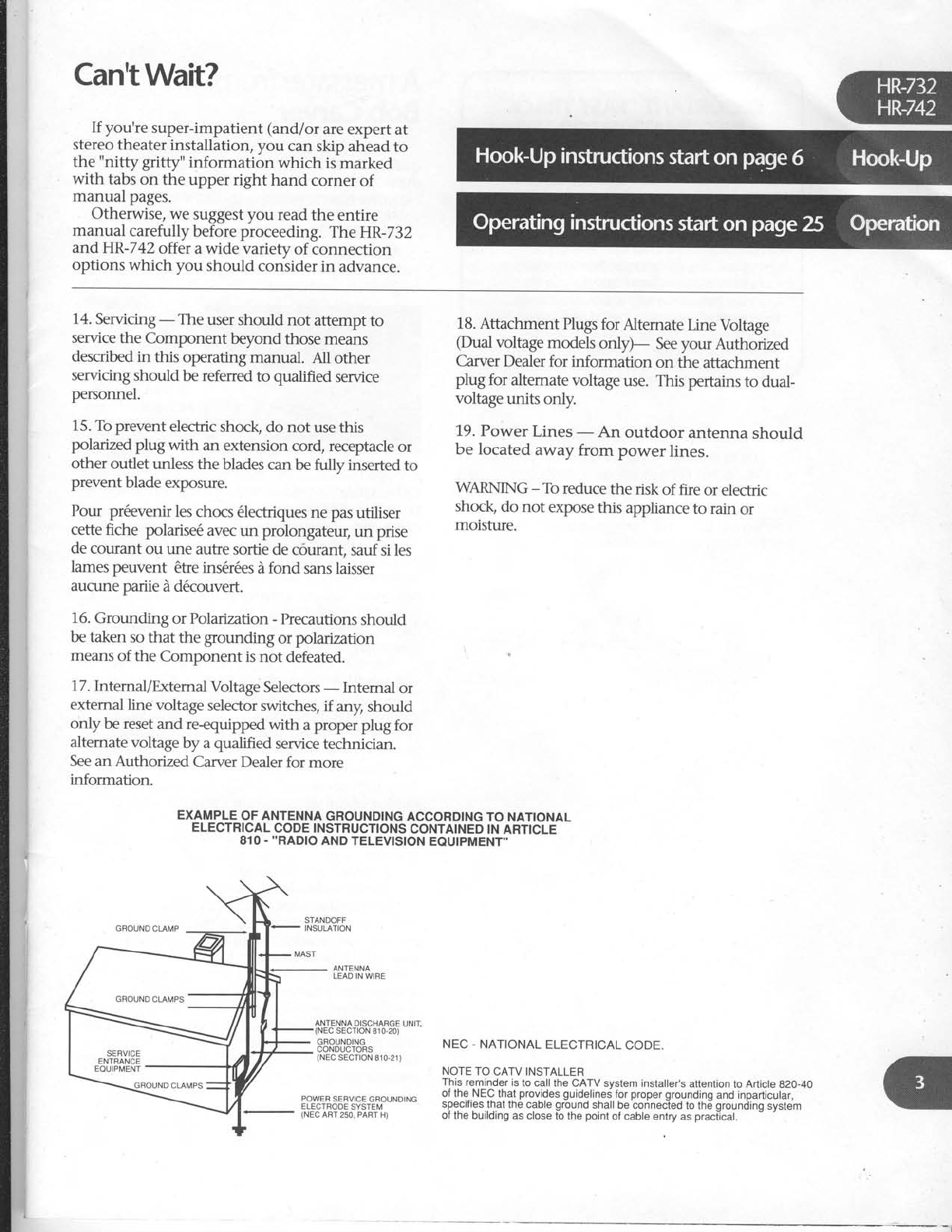
EXAMPLE
OF
ANTENNA
GROUNDING
ACCORDING
TO NATIONAL
ELECTRICAL
CODE INSTRUCTIONS
CONTAINED
IN ARTICLE
810
- ''RADIO
AND TELEVISION
EQUIPMENT''
ANTENNA
LEAD IN WIRE
DISCHABGE
UNIT,
roN 810-20)
GROUNDING
CONDUCTORS
(NEC
SECTTON 810-21)
NEC - NATIONAL
ELECTRICAL
CODE.
NOTE TO
CATV INSTALLER
This reminder
is
to call
the CATV system installer's
attention
to Article
g2O-40
of
the. NEC that
provides
guidelines
for
proper
grounding
and inparticular,
specrtres
that the cabte
ground
shall
be connected
to the
grounding
system
of
the building
as close tb
the
point
of
cable entry
as
praciical.
POWER
SERVICE
GROUNDING
ELECTRODE
SYSTEM
(NEC
ART
250. PART H)

IMPORTANT
"FAST
TRACK'
INFORMI\TION
FOR THE
IMPATIENT
USER
Whilethe
HR-732 and HR-742
ore
pretty
intuitive in
theirconnection ond
operotion, there ARE important
Wints
which
moy not
be apparent, uen to on
expeienced audiophile.
These
points
(including
differences
between the two
receiver models)
ore noted in boxes like
this one.
So even if
you
just
skim
the
monuol, make
sure to reod eoch
box,
A message
from
Bob
Caruer
Congratulations on purchasing
a truly top
quality stereo receiver;
a design that combines
overall sonic
excellence, useful features
and
exclusive
Carver technology.
The basics
At the heart
of the
HR-732/HR-742is
a superb
audio/video switcher/preamplifier with moving
magnet phono stage and inputs for three audio-
only sources
plus three
audio/video
sources
(picture
and
sound).
Distortion
and
noise
are excep-
tionally low.
Dynarnic head-
room is
high
enough
to handle
the most aggressively recorded
CD or LaserDisc. Moreover,
we think that vou'll
be impressed with the HR-732/HR-742'soverall
musicality, a subjective quality
that defies quanti-
fication. Part
of this derives from overall design.
Part is
attention to detail. For
example, by
motorizing what is essentially
a standard,
low-
distortion volume
control potentiometer
such as
is
used in our Reference Preamplifiers,
we can
eliminate potential
overload problems
and simul-
taneously
simplify the circuitry.
Sonic Holographf
Included
in the HR-732lHR-742's preamplifier
section is
a Sonic Hologram
Generator. Sonic
Holograph/o is an exclusive
Carver
invention
that helps
restore the true
spacial characteristics
of recordings.
It can bring
you a
more realistic
listening
experience through pyschoacoustic
pro-
cessing of the stereo signals. Instead of the
flat,
between-the-loudspeaker imaging
associated
with conventional stereo,
Sonic
Holographf
generates
a sonic image
- a sound stage
- that's
remarkably believable
and convincing. You'll
experience a noticeable increase in sound stage
depth as well as width. Furthermore,
it works
with any stereo input including CD's, tapes,
records, FM
broadcasts and VHS Hi-Fi video
soundtracks, and
does
not require additional
speakers. It DOES, however, require
careful set up
and speaker
placement.
In other
words,
to get
the full effect,
vou'll have
to take some time and
read
the instructions carefully
to fine tune Sonic
Holographf to your room and speakers.
. . but
the results
can be absolutely astonishing. We get
many letters
from Carver
owners
who simply
cannot live without the improvements Sonic
HolographyP
makes on their favorite music.
Serious
power amplifier sections
The HR-732 provides
60 watts per channel
while the HR-742's
rated
output is 80 watts per
channel. Both power amplifier sections
use large
power supplies which give
your speakers
the
"muscle" to fully realize
dynamic musical peaks.
Even
at moderate
listening levels,
bass
will be
tighter and more authoritative thanks to the high
current/high voltage
output of the power amp
section. Both receivers
can also handle low im-
pedance
dips as low as two ohms which can
occur
with many popular speakers
(see
page
15
and 18 for more complete explanations
of
speaker impedances).
Asymmetrical Charge-Coupled FM Detection
This circuitry (ACCD
for short) can improve
FM reception on stations which are plagued
with
multipath distortion and noise
. It works by
dynamically evaluating
three aspects
of the in-
coming FM signal: signal strength, modulation
level and multipath content. Based on the qual-
ity of the signal, ACCD uses as much of the
undistorted L/R
component (stereo)
component
as
possible
to regenerate
accurate
stereo sound.
ACCD can't work miracles
on really terrible re-
ception, but it can make
a significant difference
on many stations.
Simplicity as a design goal
Frankly,
there are 60 and BO-watt receivers
on
the market with more flashing lights, buttons
and
bells and whistles.
Some of them are so com-
plicated
that they seem
to take a degree in
computer programming to operate. When de-
signing the HR-732
andHR-742,
we included
only those features which we knew to be truly
useful
and that would not degrade the overall
sound of the receiver. Our design
goals
are
reflected perfectly
in the elegant
appearance
and
sonic
excellence of these receivers.
Madewhere?
Carver is American-owned
and based in
Lymnwood,
Washington. Of the almost 250
people
who work here,
most are engaged in
building Carver home, mobile and professional
audio products. Carver's goal
is and always will
be to provide audiophile-quality products
at
affordable
prices. Thus,
we strive
to take advan-
tage
of manufacturing economies
and methods
wherever
it is possible
without lowering product
quality. As a result, we
use outside
and overseas
production facilities
for some
products
and indi-
cated this clearly on the packing
box. Suffice
it to
say
that the HR-732
andHR-742
are
great values
because we have chosen
the most effective pro-
duction source for these particular models.
Aboutthis manual
In response
to Carver
customer
suggestions,
we're
trying a new style
of manual that's de-
signed
to cover more possible
hook-ups
and
better
explain the operation of the HR-732/HR-
742. As
a result,
this manual may seem much
more complicated
than those which come with
some receivers.
If you're new to hooking up ste-
reo
equipment, we think that you will appreciate
our detailed approach. However, we've
also pro-
vided a
means
bywhich the advanced
user can
quickly grasp
the key points and differences
of
the HR-7
32
IHR-7
42. Important information is
enclosed in boxes like the one on the previous
page. Even
if you don't read
any other part of the
manual, please
check out each of these
boxes be-
fore proceeding.
Onceagain, thankyou!
There
are a mind-boggling number of receiver
brands and models
on the market today. We ap-
preciate
your choice of the Carver HR-732
or
HR-742.
Their clean appearance
belies
the wealth
of features
and great
sound
that each is capable
of. I hope that you will have
many years
of lis-
tening enjoyment.
Sincerely,
W- G"*^
Bob Carver
Hook-Up
Save
the packing box and
your sales
invoice!
lp p1i; yegesnV
for
repocking
your
HR-732/HR-742
ffit
ever
needs
ie:ice
(orif
you
move).
Keep
the
soles
receiptfrom
the store
where
you
bought your
H R-
7
3 2
/
HR-742.
. . |) to
establish
the
durotion
of
your
Wanonty;
2) for penonol
nsuronce
purposes.
..,"Y1:l_9_p:li3g the box, please
check
for any
vlslDte
srg-n
ot damage
that did not appear
on the
ourslcle
ot the box. If you DO encouhter
what
appears
to be
concealed
damage,
please
consult
your Carver
Dealer
before
furt[erinpacking or
installing
the
unit.
Alongwith the
steps
noted
above,
take
a
mo_
ment and fill in the following information for
convenient
reference:
Model:
tl HR-732 aHR-742
Sonic
Holographf Receiver
Serial
number
. Fln_ally,
take
a
moment to fill out and return
the Warranty Card
that came
with yo"i-i*".
receiver.
Placement
The
real
no-no,s
are
listedon the
first
page
of
thjs manual. They,re
ba
sically
I
egall
f ;o'rded
warnings
about
common sense
sIuffiike,,don,t
usg
the
HR-732/HR-742
in your
swimminN
piol,, and
"
don't
take
this
receiver
intimally withtouii ioctots
presciption" etc.
Assuming
your
overall
location
is
okay,
the
HR-732lHRll+2
canU"
porttio""J ,, ouit'of u
"stack".of
com-ponents.
However,
Ua
iura "ot to
DrocK
alr
flow trom the
receiver,s
top panel
venti_
lation-
areas.
If
you set
another
.o-'p5"L"i ""
l9p
ot
the
HR-732
orHR-742,
make
iure
that
its
"feet"
provide
at
least
a l/4-inch gup
U"t*""" tfr"
component
and
the HR_732|HR_742.
Connection
tips
We're
about to launch into the actual
nitty
gltg -._.
" I "cti
ng-cable
fr enzy
th
at,s
neiessary
wnen
you install
a-new
component. First,
though,
consider
the
following
tips-
I Make
sure
all components are
OFF
before
making any connections.
I Make
sure
that ,,left
is
hooked to left
and
right is
hooked
to right,,
at
eactr
connection. The obvioui way to assure
!!is is.tqa;lignone
hook_up
corO piug
color
to left
and
the
other
to rieht.'
_Generally
RED
is
used
to signi# RIGHT.
White,
grey
or
black
then ripresents
left.
I Whenever
possible,
keep
power cords
away
from signal
cablesiiirputs
from
CD
player,
tape
deck,
etc.)
to prevent
hum. This
is
especially
impoitant
for
phono cables
which cirry verv
weak
signals.
While hum is
lejs
of i problem
today
than it was
in the past,
nbise
can
still find its way into your system
if a
component,s
power cord becomes
too
intimately
involved
with a
hook up
. cable. Carver
components,
power'cords
' and convenience
outlets
ardail "; ih;
right side
of the chassis
(when viewed
from the-back). This allows
you to
bundle all the component power
cords
and keep
them separate
frorn signal
connections.
t Type
ofhookup
cables.
Alsocalledinter_
connects,
patch cords
or RCA
cables.
There
are
lots of different grades
of
hookup -cables.
you can
piy as
much as
$30
per
foot for some
of them! Whether
or
not you hear
an
improvement
in
sound
quality with ,,audiophile,,
inter_
connects
is
up to your
own ears.
l-towever,
really
CHEAp
or old connec_
tion cables
can
sometimes
DlS_connect
themselves
inside,
causing
hum or
aloss
of sound
in one or both cfiannels. ne_
fore
you send
a
component in for
s-eM9e,
swap
hook_up
cables
to see
if
they're
the
culprit. The
other
area
of
concern
are
video signals.
These
are
far
higher
in frequency
than audio
anO
cin
otten
benefit
from a
higher
quality
in_
terconnect.
Several
companies
mike
sp.cialized
audio/video cables
with two
audio and one video conductor. Check
'em
out.
I DON'T
PANIC.
While there
are
more
than thirty possible
connections
on the
back.
of the
HR-732lHR
_7
42, matchinx
lhgm u.p
with your
existing
equtpmerit
is
simple^.
_Besides,
you
probably
won,t
use
all of them anywav.
Purchased
at
Date
of purchase
Hook-up...an
overuiew
There
are basically
three kinds of connections
on the HR-732/HR-742
(or
any
other A/V receiver
for that matter): one-way incoming, one-way
out-going and two-way.
One-way
connections simply route the signal
from a sound
or video source to the correspond-
ing input on the back
of theHR-732lHR-742.
The HR-732
IHR-7
42 has
one-way incoming
connections
for:
I CD Player
I Turntable
I TV (sound
and picture)
I CDV (LaserDisc
or combi player
such
as
our.MD/V-S00)
I AM & FM Antennas
I Cable
FM input
I Main In (HR-742
only. Rarely
used, see
page
14)
One-way
OUTgoing connections are:
I Video
Monitor
I Loudspeakers
I Pre
Out (HR-742
only. Rarely
used,
see
page
14)
These
are easy connections. We discuss
each
in detail below. Just
make
sure that "lefts go to
lefts
and rights go to rights."
Two-way connections can get
c6nsiderably
more
complicated. Theycenter
around
the
HR-732lHR-742's
audio and video
tape
functions
and are
referred
to as tape monitor loops.
"Loops" because
a signal from the HR-7321
HR-742 goes
out to another
component
and then
back
to the receiver.
Two-way connections are as follows:
I Tape
(lN & OUT)
I VCR
(lN and OUT)
The audio tape loop is where you would con-
nect a cassette
deck, an equalizer
or other signal
processor
such as our DPL-33
Dolby
Surround
Processor.
If you're
connecting
any sort
of
external processor
to your HR-732/HR-742,
take
special
care to follow our instructions, illustra-
tions and general
unsolicited advice in the
sections
that follow.
IndMdudConnections
Instead
of a really complicated
drawing with
all possible
connections
crammed into it, we will
discuss
and illustrate
each
possible
hook-up
indi-
vidually, since that's how you'll make
them: one
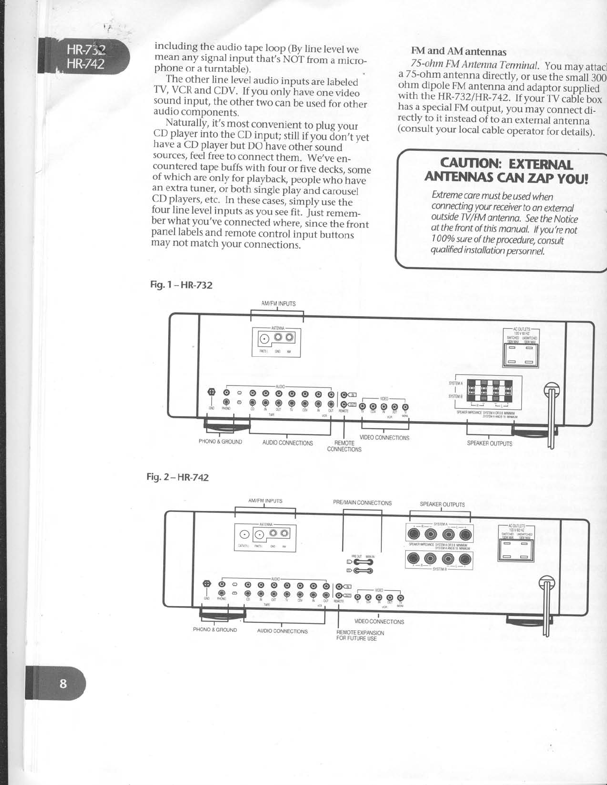
at a time. Figures 7
and2 on the next
page
show
the rear panels
of the HR-732
andHR-742. Figure
3 is a general
overview
of what can be
connected
to either receiver.
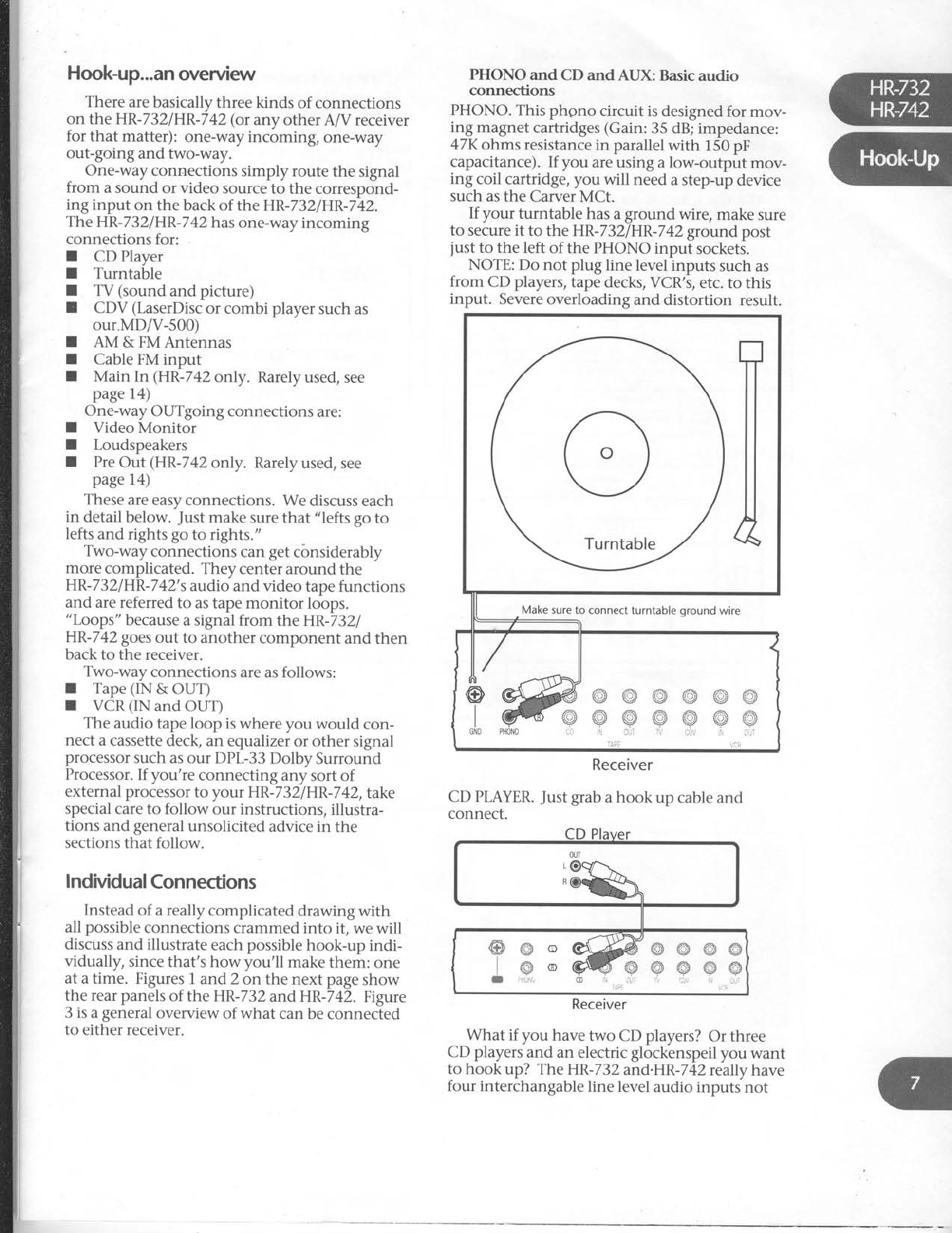
PHONO and CD and AUX: Basic
audio
connections
PHONO.
This phono circuit is
designed for mov-
ing magnet
cartridges
(Gain:
35 dB;
impedance:
47K
ohms resistance
in parallel
with 150
pF
capacitance).
If you are using a low-output mov-
ing coil cartridge, you will need
a step-up
device
such
as the Carver
MCt.
If your turntable has
a
ground wire, make
sure
to secure it to the HR-732IHR-742
ground
post
just
to the left of the PHONO input sockets.
NOTE: Do not plug line level
inputs such as
from CD players,
tape
decks, VCR's,
etc. to this
input. Severe
overloading and distortion result.
Receiver
CD PLAYER.
Just
grab
a hook up cable
and
connect.
What if you have two CD players?
Or three
CD players
and an electric glockenspeil
you want
to hook up? The HR-732
and.HR-742
really have
four interchangable
line level
audio inputs not
Make
sure to connect
turntable
oround wire
Receiver

Hook-Up
Save
the packing box and
your sales
invoke!
The
box
is necessary
for repocking
your
HR-732/HR-742
ff it ever needs
service
(orif you
move).
Keep
the
soles
receipt
from
the
store
where you
bought you
r H R-
7 3 2
/
HR-742.
. . I) to
estoblish
the
durotbn
of
your
Wananty;
2) for personal
tnsuronce
putwses.
Ugon opening the box, please
check for any
visible sign
of damage
that did not appear
on the
outside
of the box. If you DO encouhler what
appears
to be concealed
damage,
please
consult
your Carver
Dealer
before
further unpacking or
installing
the unit.
Along with the steps
noted above,
take
a
mo-
ment and fill in the following information for
convenient reference:
Model:I HR-732
aHR-742
Sonic
Holographf Receiver
Serial
number
Purchased
at
Date
of purchase
Connection
tips
We're about to launch into the actual
nitty
gritty connecting-cable
frenzy
that,s
necessary
when you install
a new
component. First,
though, consider
the following tips.
I Make sure
all components are
OFF
before
making any connections.
I Make sure
that "left is hooked to left
and right is
hooked to right,, at each
connection. The obvious
way to assure
this is
to assign
one hook-up
cord plug
color to left and the other to right.
Generally
RED
is used
to signify RIGHT.
White, grey
or black
then represents
left.
IWhenever
possible,
keep power
cords
away
from signal
cables
(inputs from
CD player,
tape
deck,
etc.)
to prevent
hum. This is
especially
impoitant for
phono cables
which carry very weak
signals.
While
hum is leis
of
i problem
today than it was
in the past,
noise
can
still find its way into your system
if a
component's power cord becomes
too
intimately involved with a hook up
cable. Carver
components' power cords
and convenience
outlets are
all on the
right side
of the chassis
(when viewed
from the back). This allows
you to
bundle
all
the
component
power
cords
and keep
them separate
from signal
connections.
Type
ofhookup
cables.
Also
called
inter-
connects,
patch
cords
or RCA
cables.
There
are lots of different grades
of
hookup cables.
You can pay as much as
$30
per
foot for some
of them! Whether
or not you hear
an improvement in
sound
quality
with "audiophile"
inter-
connects
is
up to your own ears.
However,
really CHEAP
or old connec-
tion cables
can
sometimes
DlS-connect
themselves
inside,
causing
hum or
a loss
of sound
in one
or
both channels.
Be-
fore you send
a component in for
service,
swap
hook-up cables
to see
if
they're the culprit. The other area
of
concern
are video signals.
These
are far
higher in frequency
than audio and can
often benefit from a higher quality in-
terconnect. Several
companies
make
specialized
audio/video cables
with two
audio
and
one
video
conductor.
Check
'em
out.
DON'T
PANIC.
While there
are more
than thirty possible
connections
on the
back
of the HR-732/HR
-7
42, matching
them
up with your existing
equipment
is
simple.
Besides,
you probably
won,t
use
all of them anyway.
T
Finally, take
a moment to fill out and return
the Warranty Card
th'at
came with your Carver
receiver.
Placement
The real
no-no's
are listed
on the first page
of
this manual. They're
basically
legally
worded
warnings
about
common sense
stuff like,,don,t
use the
HR-732/HR-742
in your
swimming
pool,,
and
"
don't
take
this receiver
intemally
withou{
a doctor,s
prescription"
etc.
Assuming
your overall location is
okay,
the
HR-732/HR-742canbe
positioned
as
pait of a
"stack"
of components.
However,
be
sure
not to
block air flow from the receiver's
top panel
venti-
lation areas.
If you set
another
component
on
top of the HR-732
or HR-742,
make
sure
that its
"feet"
provide
at least
a 1/4-inch
gap
between
the
component
and
the
HR-7321HR-742.
t
I
mincluding the audio tape
loop (By
line level
we
mean
any
signal
input
that,s
NOT
from
a
micro_
pnone
or
a
turntable).
The
other
line level
audio
inputs
are
labeled
TV, VCR
and CDV. If you only have
one video
sound input, the other two can
be
used
for other
audio
components.
^_Naturally,
it's
most
convenient
to plug
your
CD
play_er
into the
CD
input; still
if ybu i<ln,t yet
have
a CD
player
but DO have
othei,ou.ra
sources/
feel
free
to connect them. We,ve
en_
c9ur1t91ed
tape
buffs with four or fiv-e
decks,
some
ot which are
only for playback,
people
who have
an
extra
tuner,
or
both single
play
and
carousel
CD
players,
etc. In these
cises,
simply
use
the
four line level
inputs
as you see
fit. ;tist remem_
Der
wnat you've connected
where,
since
the front
panel
labels
and
remote
control
input buttons
may
not match
your connections.
Fig.l
-HR-732
FMandAMantennas
75-ohm
FM
AntennaTerminal.
you may attacl
a 75-ohm antenna directly, or use
the sm'all
:OO.
ohm dipole FM
antenna and adaptor
s,rppileO
with the
HR-732iHR-742.
If youifV caUte
Uox
ha;.a
snegigl
FM
output,
you may.orr.r".idi_
rectly
to it instead
of to an
external
antenna
(consult
your local cable
operator
for detaili).
CAUflON: EXTERNI|I
ANTENITU\Ii
CAtrt
ZAp yOU!
Extreme
core
must
be used
when
conneding
your
receiver
to an
external
outside
TV/FM
ontenna.
See
the Notice
ot the
front
of this
monuol.
lf you,re
not
100o/o
sure
of
the
procedure,
consult
qua
lified
i nsto
llatbn
person
nel.
PHONO
&
GBOUND
Fig.2-HR-742
AUDIO
CONNECTIONS REI\4OTE
CONNECTIONS
VIDEO
CONNECTIONS
PRVI\,4AIN
CONNECTIONS
I
VIDEO CONNECTIONS
SPEAKER
OUTPUTS
AM/FM
INPUTS
PHONO
& GROUND
SPEAKER
OUTPUTS
REI\,4OTE
EXPANSION
FOR
FUTURE
USE
AI\,4/FM
INPUTS
o 6 ' o o 6'e-elJ16ro
,1,,R'9Pgpgpgl.F SMEA
MP€MT
SYStrSAS33
M]NMUM
SYSEMANDO6MtrMUil
AUDIO
CONNECTIONS
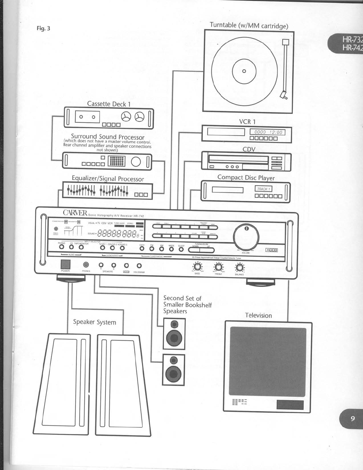
Fig.3 Turntable
(w/MM
cartridge)
Cassette
Deck
l
VCR
1
, ,
Surround
Sound
processor
(wnrcn
does.
not have
a master
volume
control.
Kear
channel
amplifier
and
speaker
connections
not
shown)
o
0u";po1 l--r_
| | yooo@
0 trtrtrtrEffi
ol
ll i-l '*rl
U trtrtrtrtrtr
U
t+l++ttt+l
t+l++ttt+l
trtrtr
C{R\m.""rc Horos,aphy
A/v
aeceive,
HR-742
9_ 9 _9 9 o ".,@.
".,q .:@,
PNoNES sptrE's ffi H.L*FAM *;*
TB.BLE
* " -"8 -**E nsLA , ry cov vcq ,.\.or D,o LF,o r
ITI
w;T:4 ll r-r,-rr.
".€.:
" I : **, i_titij,5j_:i
i:i,yl]s'_ ffi
o
o
o
o
Second
Set
of
Smaller
Bookshelf
Speakers
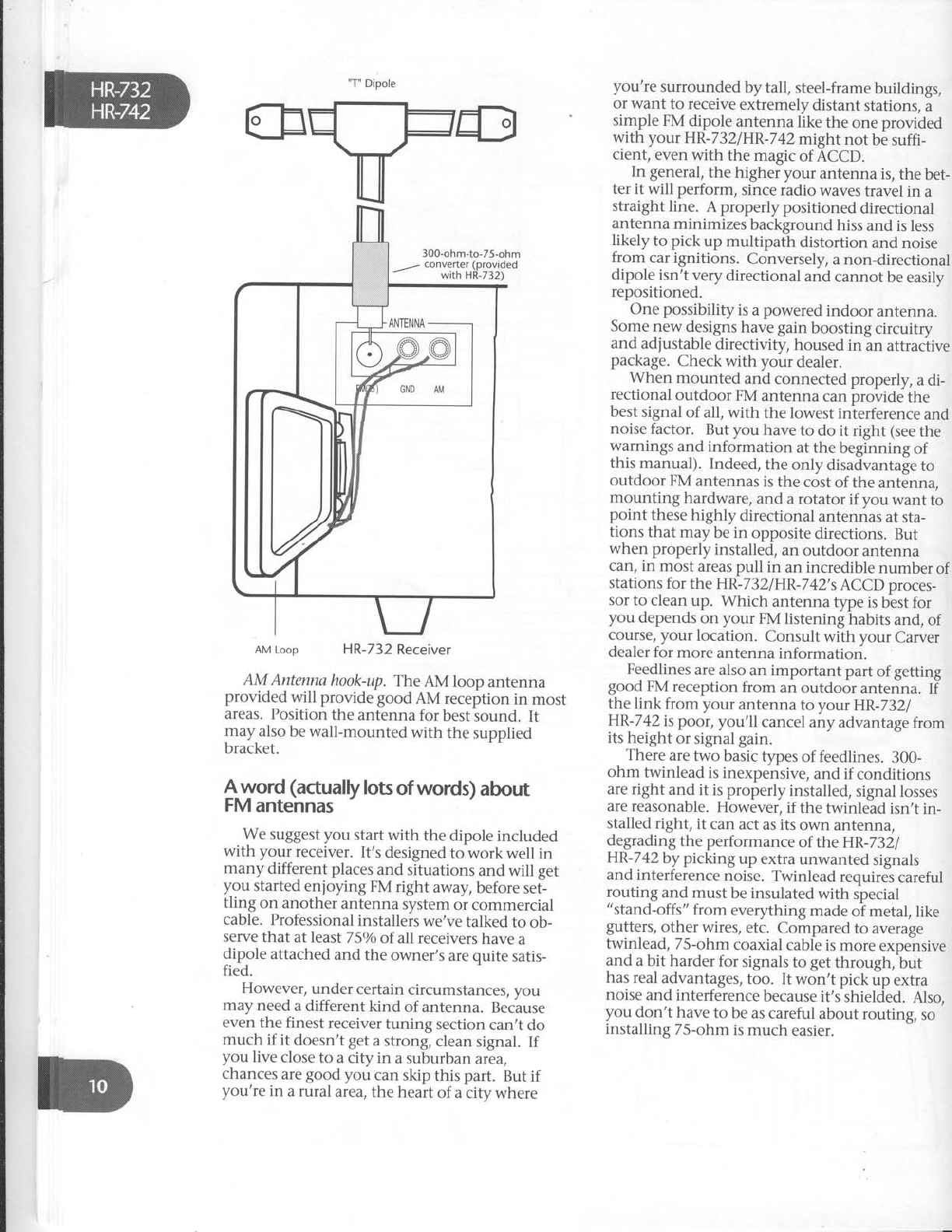
"T"
Dipole
AM Loop HR-732 Receiver
AM Antennahook-up.
The
AM loop antenna
provided will provide good AM reception
in most
areas. Position
the
antenna
for best
sound. It
may also
be wall-mounted
with the
supplied
bracket.
$-v_vord
(actually
lots
of words)
about
FM
antennas
We suggest you start with the dipole included
with your receiver.
It's
designed
to work well in
many different places
and situations
and will get
you started
enjoying FM right away,
before
set-
tling on another
antenna
system
or commercial
cable. Professional
installers
we've
talked
to ob-
serve
that at least
7 5o/o
of all receivers
have
a
dipole
attached
and
the owner's
are
quite
satis-
fied.
However,
under
certain
circumstances,
vou
may
need
a different
kind of antenna.
Because
even
the finest
receiver
tuning section
can,t
do
much if it doesn't
get
a
strong,
clean
signal.
If
you live
close
to a
city in a suburban
area,
chances
are
good
you can skip
this part. But
if
you're
in a rural
area,
the
heart
of a
city where
you're surrounded
by tall, steel-frame
buildings,
or want to receive
extremely
distant stations,
a
simple
FM
dipole
antenna
llt<e
the
one provided
with your HR-732/HR-742might
not be
suffi-
cient,
even
with the magic
of ACCD.
In general,
the higher your antenna is, the bet-
ter it will perform, since radio waves
travel in a
straight line. A properly positioned directional
antenna
minimizes
background
hiss
and is
less
likely to pick up multipath distortion and noise
from car ignitions. Conversely,
a non-directional
dipole
isn't very
directional
and
cannot
be easily
repositioned
One possibility
is
a
powered
indoor antenna.
Some new designs
have gain boosting circuitry
and adjustable
directivity, housed
in an attraclive
package.
Check
with your dealer.
When mounted and connected
properly, a di-
rectional outdoor FM antenna can
provide the
best
signal
of all, with the lowest
interference
and
noise
factor. But you have
to do it right (see
the
warnings
and
information at
the
beginning
of
this manual). Indeed,
the only disadvantage
to
outdoor
FM
antennas
is
the
cost of the
antenna,
mounting hardware,
and a rotator if you want to
point these
highly directional
antennas
at
sta-
tions
that may
be in opposite
directions.
But
when properly
installed,
an
outdoor
antenna
can, in most
areas pull in an incredible
number
of
stations
for the HR-732lHR-742's
ACCD proces-
sor
to clean
up. Which antenna type is
best for
you depends
on your FM
listening
habits
and,
of
course, your location. Consult with your Carver
dealer for
more
antenna
information.
Feedlines
are also
an important part
of getting
good
FM
reception
from an outdoor
antenna.
If
the link from your antenna to your HR-7321
HR-742
is poor, you'll cancel
any advantage
from
its
height
or
signal gain.
There
are two basic
types
of feedlines.
300-
ohm twinlead
is
inexpensive,
and
if conditions
are right and it is properly
installed,
signal
losses
are reasonable.
However,
if the twinlead
isn't
in-
stalled
right,
it can
act as its
own antenna,
degrading
the performance
of the HR-7321
HR-742
by picking up extra unwanted signals
and interference
noise. Twinlead requires
careful
routing
and
must
be insulated
with
special
"stand-offs"
from everything
made
of metal,
like
gutters,
other wires,
etc. Compared
to average
twinlead,
75-ohm
coaxial
cable is
more
expensive
and a bit harder
for signals
to get
through, but
has real
advantages,
too. It won't pick
up extra
noise
and interference
because
it's
shielded.
Also,
you don't have
to be
as careful
about routing, so
installing
75-ohm
is
much easier.
CATVinput
This label is potentially confusing, since it's re-
ally just another FM antenna input intended for
connection to cable
boxes that have FM outputs.
cAw INPUT
FOR FM
ONrY
NOTVIDEO
DO NOT
use this input
as a VCR
con nectbn. Connectinq
the
video
portbn
of
yourVCRtoihe
HR-.32/HR-
742
should be mode
using RCAtype
cords
ond the composite video
inputs
ma*edVCRVIDEO
lN.
TV & CDV (IN): One-way audio/video
connections
(If you loathe TV or only have
a S-inch set in
your spare bathroom, you can skip this section
and go
directly
to page
14. Otherwise...)
The
HR-732lHR-742
enables
you to connect
and select from multiple video sources including
combi Laser
players
and stereo TV's, with or
without video outputs.
A "video source" is
defined as
ofie having com-
posite
video
cable
plus
left
and right stereo audio
cables.
Thus both the TV and CDV video inputs
have
THREE
sockets each,
two for audio towards
the left hand side of the back
panel, and and one
for composite video towards
the right side.
What's
composite?
A "composite" video out-
put will have
an RCA phono-type socket
(like the
ones used for audio connections
but with a
differ-
ent-colored plastic
center),
rather
than a 75-ohm
coax connection which sticks out and has screw
threads on it. All VCR,
CDV,
"combi" and
LaserDisc
players
have
composite video outputs.
VCR:
Two-way audio/video connection
Note that your receiver's
VCR
connections in-
clude both audio IN & OUT and video IN & OUT.
This allows
you to record
from another video in-
put routed through the receiver
to your VCR. It
also
enables you to use a VHS
Hi-Fi VCR
as a high
quality audio recording device.
Considering your audio/video options
First, you should have
a clear idea what it is
you want to do with theHR-732lHR-742's
video
features.
.We
included
video
connections
for two maior
reasons. First,
so you can have Home Video
Theater
sound when you watch VCR
movies.
Second,
so
you can
easily switch video sources
us-
ing the HR-732iHR-742's
remote
and also copy
between
two video sources, for example,
a
VCR
and a LaserDisc,
or two VCR's.
What follows are a series
of connections
which
give
you different audio/video options. We often
get
calls
from new Carver owners
who ask
"Well,
which is really RIGHT?". That completely de-
pends
on what kind of video equipment you own
and just how closely you intend to integrate
things. Look through the hook ups once
and see
which pertain to you.
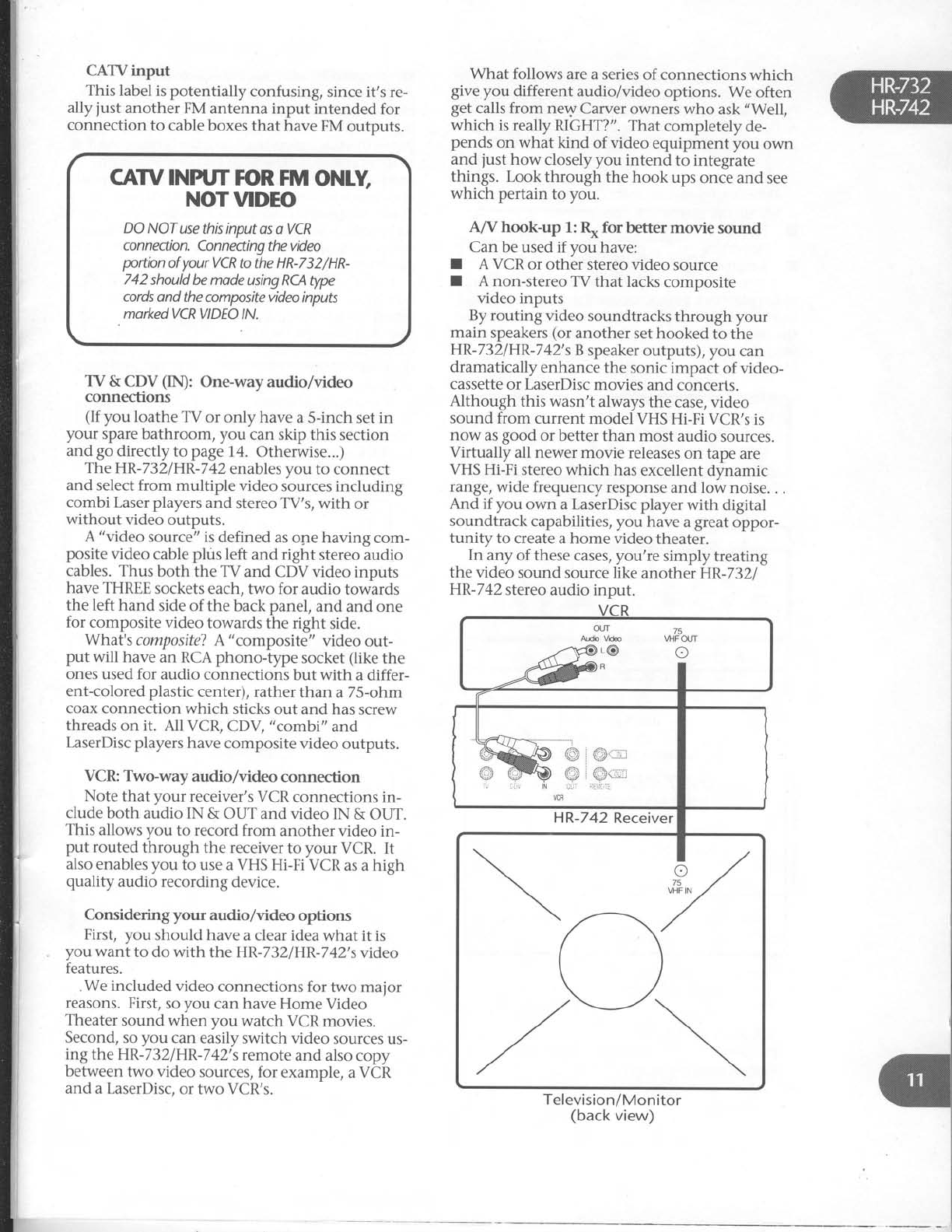
A/V hook-up 1: R* for better movie sound
Can
be used if you have:
t A VCR
or other stereo video source
I A non-stereo
TV that lacks
composite
video inputs
By routing video soundtracks
through your
main speakers
(or another set hooked to the
HR-732/HR-742's
B
speaker
outputs), you can
dramatically enhance
the sonic impact of video-
cassette
or LaserDisc
movies
and concerts.
Although this wasn't always the case, video
sound
from current model VHS
Hi-Fi VCR's
is
now as
good or better than most audio sources.
Virfually all newer
movie releases
on tape are
VHS
Hi-Fi stereo which has
excellent
dynamic
range, wide frequency
response
and low noise.
. .
And if you own a LaserDisc
player
with digital
soundtrack
capabilities, you have
a
great
oppor-
tunity to create a home video theater.
In any of these
cases,
you're
simply
treating
the video sound source like another HR-732.
HR-742
stereo
audio input.
Television/Monitor
(back
view)
75
VI-IFOUT
I
i iir N
VCR
HR-742
Receiver
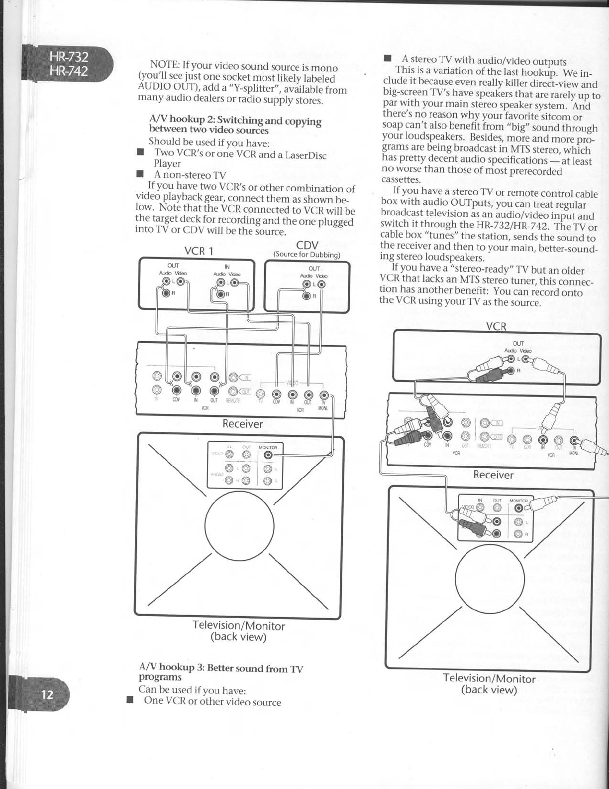
NOTE:
If your video
sound
source
is
mono
(y_ou'll
see
just
one
socket
most
likely
labeled
AUDIO
OUT),
add
a,,y-splitter,,,
aviilable
from
many audio
dealers
or radio
supply
stores.
R/V hookup 2:.Switching
and copying
betwe€n two video sources
Should
be
used
ifyou have:
I Two VCR's
or
one
VCR
and
a LaserDisc
Player
I A non-stereo
TV
Jf
you have
two VCR,s
or other combination of
video
playback
gear,
connect
them as
shown
be_
Iow. Note
that the
VCR
connected
to VCR
will be
the target
deck
for recording
and the one plugged
into TV
or CDV
will be
the
source.
I A stereo
TV with audio/video
outDuts
This
is
a variation
of the
last
hookub. We
in_
clude
it because
even
really
killer
direci_view
and
big-screen
TV's
have
speakers
that are
rarely
up to
par
with your main stereo
speaker
system.
An^d
there's
no reason
why youriavorite'sitcom or
soap
can't also
benefit
irom ,,big,,
so,rna
tt rough
your loudspeakers.
Besides,
moie and more
pro_
grams
are
being broadcast
in MTS
stereo,
which
has pretty
decent
audio
specifications
_ at
least
no worse
than those
of most
prerecorded
cassettes.
- If you have
a stereo
TV or remote
control cable
box
with audio
OUTputs,
you
can
treat,.21m
Droadcast
television
as
an
audio/video
inp-ut
and
switch
it through
the
HR_732iHR_742.
The
t.V
or
cable
box "tunes"
the
station,
sends
the
sound
to
the
receiver
and
then to your
main,
better_sound_
ing
stereo
loudspeakers.
_ - ]I yg" have
a
-"stereo-ready,,
TV but an older
VCR
that lacks
an MTS
stereo
tuner, this connec_
tion has
another
benefit: you can
record
onto
the
VCR
using
your
TV as
the
source.
VCR 1CDV
(Source
for Dubbing)
OUT IN
Adb Vda Audb Vd@
a€:'l .r8:
Jt il-- +
-1
Itlllt
oll
oll
o @ll
e
kk p,'
Receiver
Q
I
Television/Monitor
(back
view)
A/V hookup 3: Better sound from TV
progmms
Can
be
used
if you have:
One
VCR
or other
video
source
Television/Monitor
(back
view)
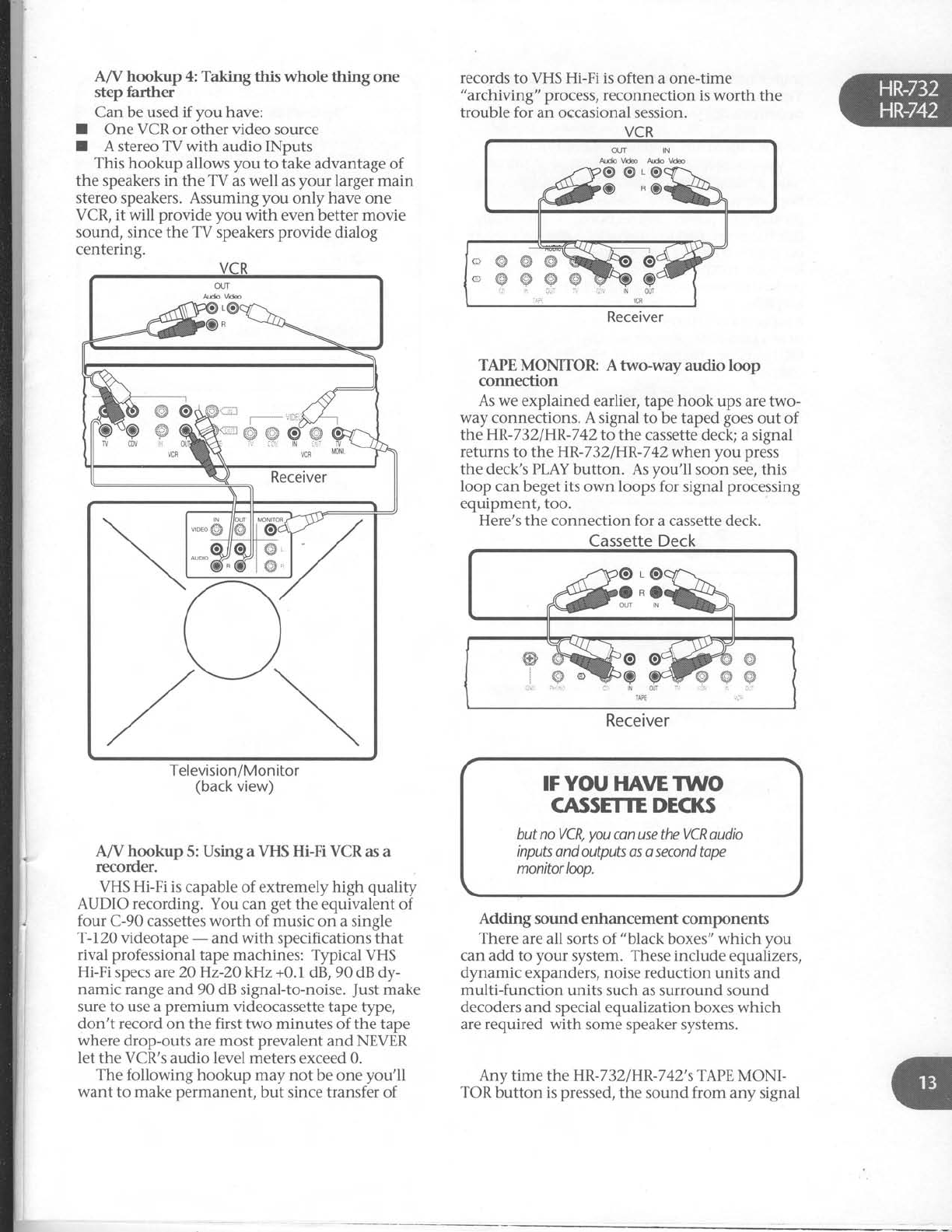
A/V hookup 4: Takingthis wholethingone
step farther
Can be used if you have:
I One VCR
or other video source
I A stereo
TV with audio INputs
This hookup allows
you to take advantage of
the speakers in the TV as
well as
your larger main
stereo speakers. Assuming
you only have one
VCR, it will provide you with even better movie
sound,
since the TV speakers
provide dialog
centering.
Television/Monitor
(back
view)
A/V hookup 5: Using a VHS Hi-Fi VCR as a
recorder.
VHS Hi-Fi is capable of extremely high quality
AUDIO recording.
You can
get
the
equivalent of
four C-90 cassettes
worth of music on a single
T-72O videotape
- and with specifications that
rival professional
tape machines: Typical VHS
Hi-Fi
specs are20Hz-2O kHz +0.1 dB, 90
dB dy-
namic range
and 90 dB signal-to-noise.
Just
make
sure to use a
premium videocassette tape
type,
don't record
on the first two minutes of the tape
where drop-outs
are
most prevalent
and NEVER
let the VCR's audio level meters
exceed 0.
The following hookup may not be one
you'll
want to make permanent,
but since transfer of
records
to VHS Hi-Fi is
often a one-time
"archiving" process,
reconnection is
worth the
trouble for an occasional session.
TAPE MONITOR: A two-way audio loop
connection
As we explained earlier,
tape
hook ups are two-
way connections. A signal to be taped
goes
out of
the HR-732/HR-742
to the cassette deck; a signal
returns
to the HR-732/HR-742whenyou press
the deck's
PLAY
button. As
you'll soon see, this
loop can
beget
its own loops for signal
processing
equipment, too.
Here's the connection for a cassette deck.
Cassette Deck
&3:;b
*m3ffi.
Receiver
IF YOU
HAVE TWO
CASSETTE DECKS
but
no VCR,
you
can use the VCR oudio
inputs
ond outputs os o second tape
monitorloop.
Adding sound enhancement components
There
are all sorts of "black
boxes"
which you
can
add to your system. These include equalizers,
dlmamic
expanders,
noise
reduction units and
multi-function units such as surround sound
decoders
and special equalization boxes which
are required with some speaker systems.
Any time the HR-7
32
IHR-7
42's TAPE
MONI-
TOR
button is
pressed,
the sound from any signal
c'@@s
cw#p
irir ,r ai:
Receiver
sSH.=@Ag@
*r"'GR v(F MoNl
_source
will be
affected
by the signal
processor.
Yet
you can still record
d"a pfui Ui.i -i-tf, tn"
cassette
deck.
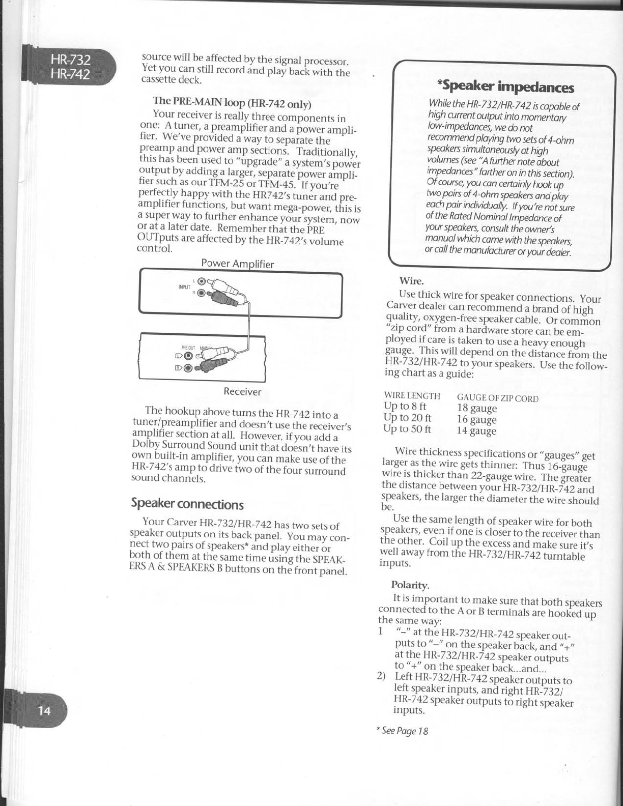
The PRE-MAINloop (HR_742
only)
Your
receiver
is
really
three
compbnents
in
::_"' ,f,lll"r, a
preamplifier
and
u pore, ampli_
ner. we've
provided
a
way
to sepaiate
the
ff::11l gq_pow:r
amp
sections-.
Traditionally,
rnls
nas
been
used
to ,,upgrade,,
a
system,s
power
outputby adding
a
la_rger,
separate
power
ampli_
fier
such
as
our
rpv-25
"i rt'v_+s-.
ii;;;;"
Hl::l[119ry1wiilr,
the
HR742,stu"6,
*o pr._
ampttller
tunctions,
but
want
mega_power,
this
is
a
super
way
to
further
enhance
yduriystem,
now
or
at
a later
date.
Remember
ttrit
ttre
irne
--
OUTputs
are
affected
by
the
UR_Z+Z;,
"oLm"
control.
Receiver
. Th9 hookup above
turns the HR_742into
a
tuner/preamplifier
and
doesn,t
use
the
receiver,s
amplifier section
at all. Howe"e., if vo, uai u
Dolby Surround
Sound
unit that do6sn;t
tiive its
own built-in amplifier,
you can
make
use
of the
raK-
/
+z'
,s
amp
to drive
two of the
four surround
sound
channels.
Speakerconnections
Your
Carver
HR-232/HR
_742hastwo
sets
of
speaker
outputs
on its
back
panel. yo, _av.on_
,1::,t
tyg,puirs
of
speakers*
and
play
eirher
or
Dotn
ot them at
the
same
time using
the
SpEAK_
ERS
A & SPEAKERS
B
buttons
on th;fr;;i panet.
Use
thick wire
for speaker
connections.
your
Carver
dealer
can
recommend
a
brand
of high
quality,
oxygen-free
speaker
caUte.
Oicorr-o.
zrp
cord" trom a
hardware
store
can
be
em_
ployed if care
is
taken to use
a
heavy
"rrougl,
$3lg_"^ ^I!1 will depend
on the disiance
frtm the
HR-732/HR
-7
42
to your speakers.
Ure
lt e folo*_
ing chart
as
a
guidei
WIRE
LENGTH GAUGE
OF
ZIP
CORD
J]n
to
q
rt l8 gauge
Up
to
20
ft l6 fauge
Up
to
50
ft l4 gauge
, " "Y] :.^,H:f
qess
sRecification
s
or,,gauges,,
get
rarger
as
the
wire
gets
thinner:
Thus16_!auge
wire
is
thicker
than
22_gaug"
*ir"- ih. ii"l,.,
the
distance
berween
y5.,rftn_z:i Er*Tii u"a
speakers,
the
larger
the
diameter
the
wire
shoutd
be.
Use
the
same-length
of speaker
wire
for both
speaKers/
even
if one
is
closer
to the
receiver
than
theother. Coil up the
excess
and
make
sure
it,s
wel away
from the
HR_732/HR_742turntable
inputs.
Polarity.
It is
important to make
sure
that both speakers
connected
to the
A or B
terminals
are
hook?d
up
the same
way:
7 tt-" at
the
HR-23
2lHR-Tl}speaker
out_
puts
to "-,, on the
speaker
bick, and
,,+,,
at
the
HR-732lHR_742
speaker
outputs
^ to
"+"
on
the
speaker
back...and...
'
z) Left
HR-732lHR-742
speaker
outputs
to
left
sp.eaker
inputs,
anil right HRi3ti-
r-rn-
/
+z
speaker
outputs
to right speaker
inputs.
*
See
Poge
1
8
*Speaker
im@ances
While
the
HR-732/HR-742
is
copobte
of
high.cunent
output
into
momentory
low-impedances,
we
do
not
recommend
ploying
two sets
of
4_ohm
speakes
simultoneously
ot hiah
volumes
(see
"Afufthei
notedbout
impedonces"
forther
on
in this
section).
O. f courye,
you
con
certointy
hook
up
wo,p"iry
?f
1.ohm
speaken
ond piay
eoch
poir
indMdually.
tf
you,re
not
sure
ot
the
Roted
Nominal
lmpedonce
of
your
speoken,
consult
the
owner,s
monual
which
comewith
the
speokers,
or
call
the
manufacturer
or
yoir deoler.
Wire.
If you're using special
speaker interconnects,
"
+" and"-" will be identified. If you're using
plain appliance-type
zip cord, the two conductors
will be
differentiated in one of several ways. They
may be different colors
(silver
vs.
copper). One
may have fine grooves
on its outside. Or one
may have
a
piece"of
yarn included in one of the
conductors (visible
after you strip off the insula-
tion). It doesn't matter which one you decide to
call
"
+" or "
-" , just be consistant
on both speak-
ers.
Speakerhookup
The
HR-742
speaker
terminals
are designed
to
accept
bare
wire, spade lugs
or banana
plugs. The
HR-732's
speaker terminals are intended only for
bare wire.
1. If you're
using
bare wire,
strip 712" of
insulation from each wire and make
sure to carefully
twist all the fine strands
together. If even one is loose
and can
touch the opposite
terminal, a short
circuit may result.
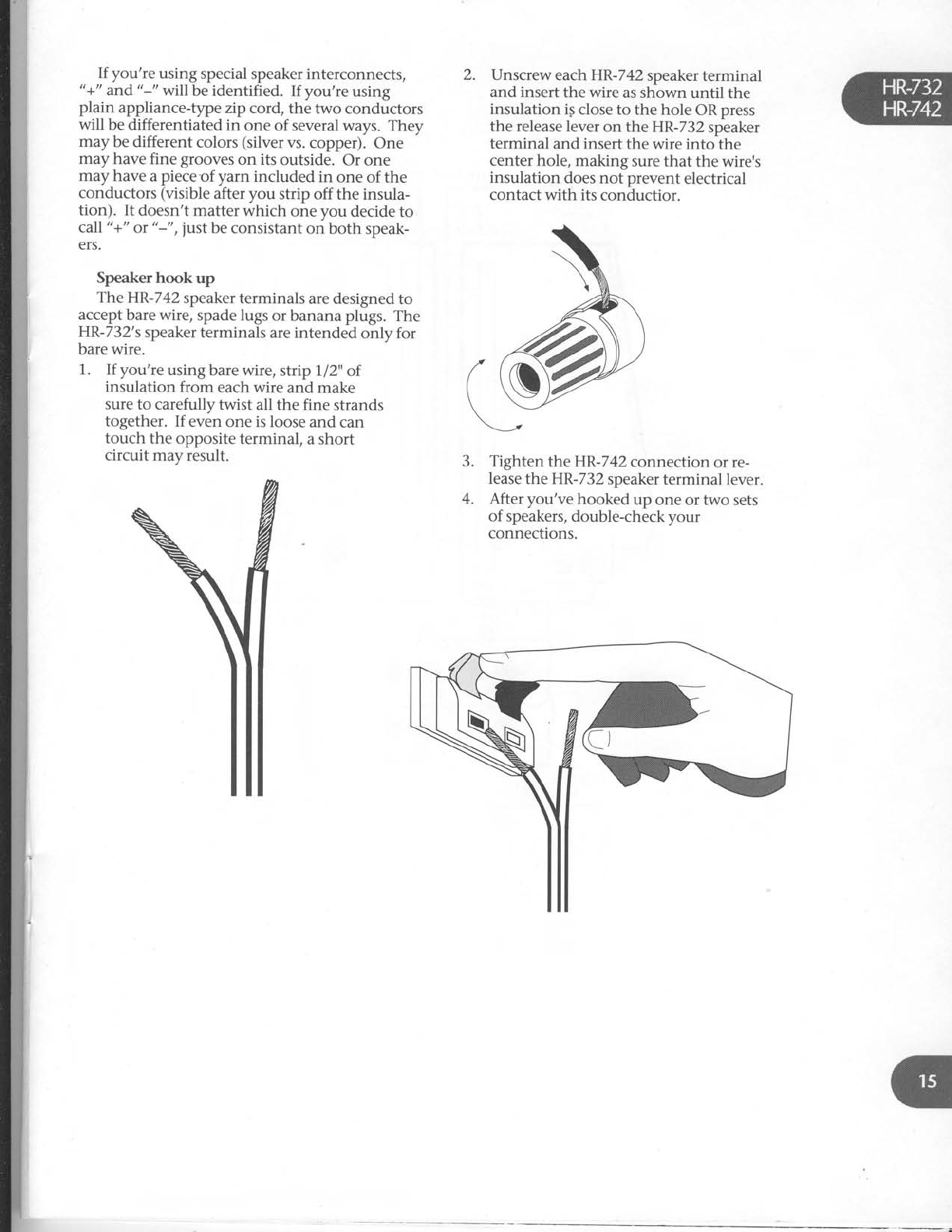
2. Unscrew each HR-742
speaker
terminal
and insert
the wire as shown until the
insulation
ig close to the hole
OR
press
the release lever
on the HR-732
speaker
terminal and insert
the wire into the
center hole, making sure that the wire's
insulation does not prevent electrical
contact with its conductior.
Tighten theHR-742 connection or re-
lease
the HR-732
speaker
terminal lever.
After you've hooked up one or two sets
of speakers,
double-check your
connections.
3.
4.

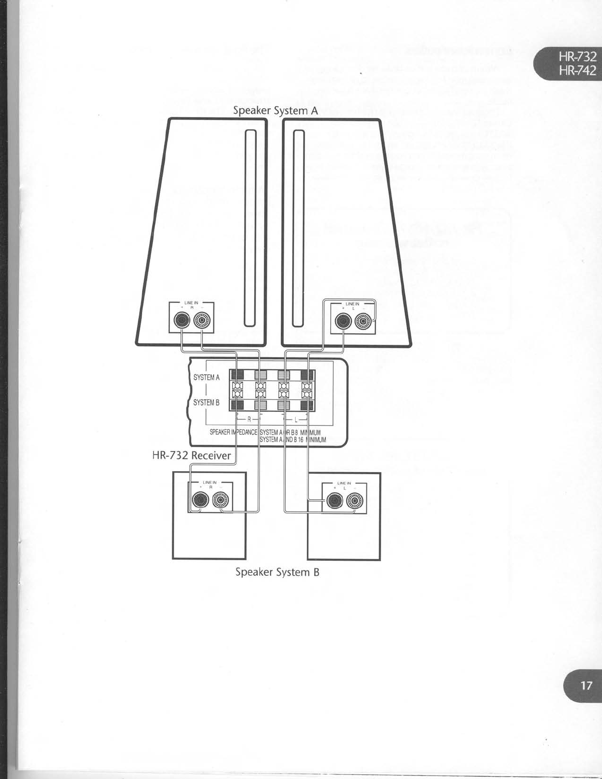
Speaker
System
A
[@
titl
[56"'6d
SPEAXEF MPEDANCE
SYSTEM
AOR B
8 M]N
MUM
SYSTEMAANDEl6
MINMUM
Q,@ @.Q
--fsYsrEr"rEl-f-
HR-742
Receiver
L]NE N{o'ol
Speaker
System
B
HR-732
Receiver
Speaker
System B
Convenience
outlets
We cover
these last
because
we don,t want to
encourage
yoy to plug anything in or turn any-
thing on until all other connections
have
been
made.
. There
are
two AC outlets on the back
of vour
Carver
HR-732/HR-742.
The
one marked '
SWITCHED
provides
power
only when the
HR-732/HR-742is
turned
on and is
useful
for
components which you use every
time you play
your system
such
as
an equalizer,
a
speaker
equal-
ization box, etc.
or your most-used
sound source
- a CD player,
for example.
HR-732/HR-742spitched
outlet warning
Do not plug
o
power
amplifier
into
the
H R- 7
3 2
/ H R-
7 4 2's
switched
outlet.
Make
sure
thot total
power
consumptbn
of
any other
components
plugged
into this
outlet
does not
exceed
| 00 wotts.
An UNSWITCHED
AC outlet is
also provided.
It's
always
live
as long as the HR-732lip,-Z+Zis
plugged
into the wall. A device
connected
here
may be left permanently on, or may be switched
off with its own switch. NOTE: In orderto avoid
potential turn-on thumps, anything plugged
in
here
should
be
powered
up BEFORE
the
HR-732l
HR-742
is turned
on.
The
fi
nal obvious
connection
You guessed
it. After making sure
that the HR-
732lHR-742
is
off, plug its power cord into a
properly polarized
wall receptacle (see
Safety
In-
structions
77
and
18atthebeginningof
this
manual). The
HR-732lHR-742
may
be connected
to an extension
cord or multiple outlet plug, pro-
vided they have
the proper
polarization (one
wider and one narrower prong). If you are
using
an extension
cord, we recommend 16 gauge
or
heavier.
*A
fu rther
note
abut speaker
impedances
(extra
infoimation
for
thosewho hdve
multiple
speaker
qystemt
like
to play
loird
music
with
lots
of bass
in it'orjust like
to read
owne/s manuals)
Why do we publish specifications
for ,,2-ohm
dynamic power" and then warn you about
not
using two sets
of 4-ohm speakers
at the same
time? Because
impedance
has
several
variables
and becomes
a factor at different times.
Speakers
are not simply resistive
loads. Instead
they are
complex and reactive,
drawing dispro-
portionately large
currents
in reaction
to
transient voltage
signals.
Because
music is
dy-
namic, with multiple instantaneous
peak
power
demands,
the speaker
is
constantly bbmbarded
with short transient voltage
drive signals
and
constantly drawing short "in-rush" currents. The
overall long-termvoltage
and power draws
are not
significantly higher than those
of a resistive
load.
But at any given moment, short terrn peak
cur-
rents
must be
delivered
far in excess
of the
average,demands.
If these
cannot be supplied
by
an amplifier, distortion and reduced
dynamic
range
result. Impedance
is a
complex product of
factors
such
as resistance,
inductive reactance
and capacitive
reactance.
Realistically,
it,s
a
rating of how the speaker
will behave when con-
nected
to an amplifier and playing music. The
lower the impedance,
the more amplifier current
will be required.
Modern speaker
systems
most often have
NOMINAL impedance
ratings
of 4, 6,
or 8
ohms.
This rating can be found in your speaker
hand-
book, is
often printed on the backof the
loudspeaker
and can also
be found in Audio
Magazine's
Annual Equipment
Directory.
The
HR-732lHR-742
is
designed
for
CONTINUOUS
use with 4-ohm or 8-ohm speaker
impedances.
If you're
just
using
one
set of ipeak-
ers,
there's
no problem - virtually anything you
connect
to the
HR-732/HR-742willhave
a nomi_
HR-732/HR-742
unsryitched
outlet warning
lf you're
using
o seporote
power
amplifierto
drive
sunound
sound
speakers,
a subwnfer
or
in
conjunctbn
with
the HR-732/HR-742's
PRE
OUT
connectbn,
take care
when plugging
stuff into
the HR-7
3
2
/H
R-742's
tJ
N-
switched
outlet. The power
ratingfor
this
outlet is 1
00 wotts. Consult
the
power
amplifier's
owners
monuol
to
determine
its
overall
power
consumption
if in
doubt.
Speaker Pair
ASpeaker
Pair
BGombined
lmpedance 0K or
not
0K
nal impedance
of 4,
6, or 8 ohms. But
if you're
connecting TWO sets of speakers,
the impedance
of both sets becomes important - and
interactive.
Total impedance
(Z)
of such a system is calcu-
lated with the following formula:
7-= Z.XZ,
Zr+
Z,
Where Z, andZ, arethe individual impedances
of the two speaker-rystems. That leads
to the
following chart:
Simultaneous
speaker opelation
And yet its published "Nominal
Impedance" is
6
ohms! Obviously, 6 ohms is
an optimistic
average, NOT a
qonstant.
Note also
that this popular, widely-distributed
speaker
takes its most serious impedance plunge
in the lowest
frequencies where
the most power
is required from a receiver's
amplifier section.
This
design's
perilous
50 Hz
and 100 Hz dips
correspond with many musical
instruments
including kick drums, floor tom drums, tympani,
plucked double bass viols and electric bass
gui-
tars. You can imagine how an amplifier is
taxed
on a well-recorded
CD at realistic listening levels
with this speaker.
In addition, because music has
a
wide and
constantly varying frequency
distribution (and
listeners
have wildly different views
on where
to
set bass and loudness
controls),
problems
stem-
ming from intermittantly low speaker
impedances
can crop up unexpectedly.
Whether anything unpleasant happens
when
a speaker's impedance
dips into the 2-ohm
range
during a song depends
on the amplifier design
-
particularly its ability to produce
large
amounts
of current for short periods
of time into low im-
pedances.
We have
designed the HR-732
and
HR-742
to satisfy such momentary power de-
mands
and the receivers'
"2-ohm dynamic
power" rating reflects
this ability. Still, it doesn't
mean
you should operate the receiver into a con-
stant 2-ohm load.
Following a short section
on the HR-7321
HR-742's remote control and a
guided
tour of the
receiver's
front panel
features, you'll be
ready
to
start enjoying your new component.
8
6
o
A
4
8
8
o
8
i
4
3.4
J
2.7
2
OK
Maybe0K-
Maybe0K.
NO
NO
.lf
you
don't
play
the
speaker systems too loudly
at
the
same
time
As you can see, two sets
of B-ohm speakers in
parallel
represents
a 4-ohm total load,
well within
the operating parameters
of your HR-7321
HR-742. However,
two sets
of 4-ohm speakers is
a
2-ohm load and is not recommended. All of this
is
predicated
on operating both sets of speakers
AT ONCE. If you never intend to operate tlvo
pair at the same time, both pair can be
4 ohms
nominal impedance.
Now what about "2-ohm dynamic power"?
First, it's important to understand that
NOMINAL is
a fancy way of saying
"sort of".
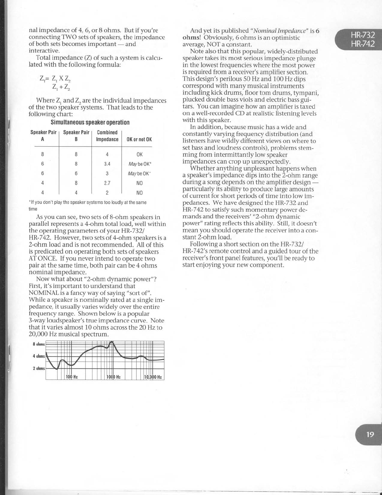
While a speaker is nominally rated
at a single im-
pedance,
it usually varies widely over the entire
frequenry range. Shown below is
a
popular
3-way loudspeaker's
true impedance
curve. Note
that it varies
almost 10
ohms across the 20 Hz to
20,000 Hz musical spectrum.
8 ohnrs
4
ohnrr
2
ohnrs
l
fi
I
I
I
I'a
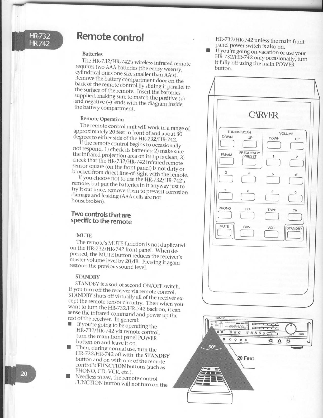
Remote
control
Batteries
The HR-
732
I
HR_7
42'
s
wireless
infrared remote
requires
two AAA
batteries
lttre
eensy
wiensy,
cylindrical
ones
one
size
smalleitt "i, aatl.
Remov^e
the battery
compartment door on the
back
of the remote contrbt Uy
ifid"Jiip"arattet to
the
surface
of the
remote. Iniert the'batieries
]igpl,^"9:.1-aking
sure
to
match
the
posiiive
1+l
ano.negative
(_) ends
with the
diagram
inside
the
battery
compartment.
Remote Operation
The remote control unit will work in a
range
of
approximately 20 feet
in front of and iLout :O
degrees
to either
side
of the un_)iiii_|+2.
If the remote control begins
to oliisionaffy
Lo,l9;no"g, 1)
check
its
batteries;
Z;
mike sure
ure
lnrrareo
proiection.a_r_ea
on its
tip is
clean;
3)
check
that
t6e
un-zszlun
z+z'iiii{ri;;;;o..
sensor
square (on
the
front panel)
is
not dirty or
blo_cked
from direct tine_or_iighi
{"iir, it J."_o,..
If you choose
not to use
th"e
HR_732lIld
_742,s
:.q9t",but put the
batteries
in it anvrniv
iust to
l?_i._""t once,
remove
them to pr*;;iiJrroston
oamage
and leaking
(AAA
cells
are
not
housebroken
).
Two
controls
that are
specific
to the remote
MUTE
The
remote,s
MUTE
function
is
not
duplicated
on
the
HR-732lHR_742
frontpu".f.-
*t!"" a"_
pressed,
the
MUTE
button
reduces
tfre
ieieirrer,,
master
volume
level
by
20
9.8.
nressing
iiigui"
restores
the
previous
sound
tevel.
STANDBY
HR-732/HR-742
unless
the
main front
panel
power
switch
is
also
on.
I jfJojlg gotng on vacation
or use
your
HR-
732lHR
_7
42
onty
o..urionuirvl
Li"
il,"ftH:tt
"sing
the
main
powEfi
'
_- STANDBy
is
a
sort
of second
ON/OFF
switch.
If y.ou
turn off the receivervia
,.-ot" .l.ri.of,
STANDBY
shuts
off virtuatty att
oiit . iJ."i"., ."_
cept
the
remote
sensor
circuitry. Then
whln you
want to turn the
HR_732/HR_l+2bacioi,
it.u.,
sense
the
infrared
command
u"O
potv", "p tt.
rest
of
the
receiver.
In
general:
I JfJgt'lqgging
to
bi operating
the
H
R-
732l
H
R_
Z
42
vi
a
remote
co--n
trol,
turn the
main front panel
pOWER
'
button on and
leavelt
on.
I fl.1. during
normal
use,
turn
the
HR-732/HR
_7
sz oft
witn
tt " -sieNnev
button and
on with one
of tfre
iemo-te"'
control,s
FIINCTION
buttons
Gucn
ii
fIO-ryO,CD, VCR,
etc.). \v.^lrr
qJ
I Ng-e_d]ess
to say,
the remote control
FUNCTION
button will not lui"-r" tfr.
20 Feet
HR-732/HR-742
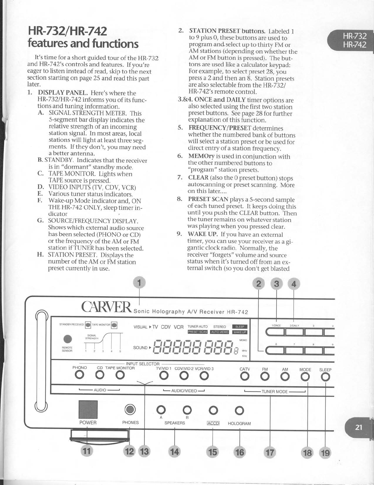
features
and
functions
It's time for a short guided tour of the HR-732
andHR-742's
controls and features.
If you,re
eager
to listen instead
of read,
skip to the next
section
starting on page
25 andread
this part
later.
1.. DISPLAY
PANEL. Here's
where
the
HR-732/HR-742informs
you of its
func-
tions and tuning information.
A. SIGNAL
STRENGTH
METER.
This
S-segment
bar display
indicates
the
relative
strength of an incoming
station signal. In most areas,
local
stations
will light at least
three seg-
ments. If they don't, you may need
a better
antenna.
B. STANDBY.
Indicates
that the receiver
is in "dormant" standby
mode.
C. TAPE
MONITOR. Lighis
when
TAPE
source
is pressed.
D. VIDEO INPUTS (TV,
CDV, VCR)
E. Various
tuner status indicators.
F. Wake-up
Mode indicator and, ON
THE
HR-7 42 ONLY, sleep
timer in-
dicator
G. SOURCE/FREQUENCYDISPLAY.
Shows which external
audio source
has
been
selected
(PHONO
or CD)
or the frequency
of the AM or FM
station if TUNER
has
been
selected.
H. STATION
PRESET.
Displays
the
number of the AM or FM station
preset
currently
in use.
2. STATIONPRESETbuttons.
Labeled
1
to 9 plus 0, these
buttons are
used
to
program andselect
up to thirty FM or
AM stations
(depending
on whether the
AM or FM button is pressed).
The but-
tons are used
like a calculator
keypad:
For
example,
to select preset
28,you
press
a
2 and then an 8. Station presets
are
also
selectable
from the HR-7321
HR-7 42's
remote
control.
3.&4. ONCE
and DAILY timer options are
also
selected
using the first two station
preset
buttons. See
page
28 forfurther
explanation of this function.
5. FREQUENCY/PRESETdetermines
whether the numbered bank of buttons
will select
a station preset
or be used
for
direct entry of a station frequency.
6. MEMOry is used
in conjunction
with
the other numbered buttons to
"program" station presets.
7. CLEAR
(also
the 0 preset
button) stops
autoscanning
or preset
scanning. More
on this
later....
8. PRESET
SCAN plays
a
S-second
sample
of each
tuned preset. It keeps
doing fhis
until you push the CLEAR
button. Then
the tuner remains
on whatever
station
was playing when you pressed
clear.
9. WAKE UP. If you have
an external
timer, you can
use
your receiver
as a
gi-
gantic clock radio. Normally, the
receiver
"forgets" volume and source
status when it's turned off from an ex-
ternal switch (so
you don't get
blasted
INPUT
SELECTOR
CD TAPE
MONITOR
ooo TVA/ID
1 CDVAr'ID
2 VCR/VID
3
ooo AM MODE SLEEP
ooooo
,l
CAFVER rln,"
"o,onraphy
A/V
Receiver
HR-742
VTSUAL
>TV CDV VCR ruNERAUro
srEREo
@
@@@
so u N D
>
f_ryt3t;?t$
f3
ful
f$ l#
*'
-,
t AUDIO/VIDEOJ -TUNEBMODEJ
o
ffi
o
HOLOGRAM
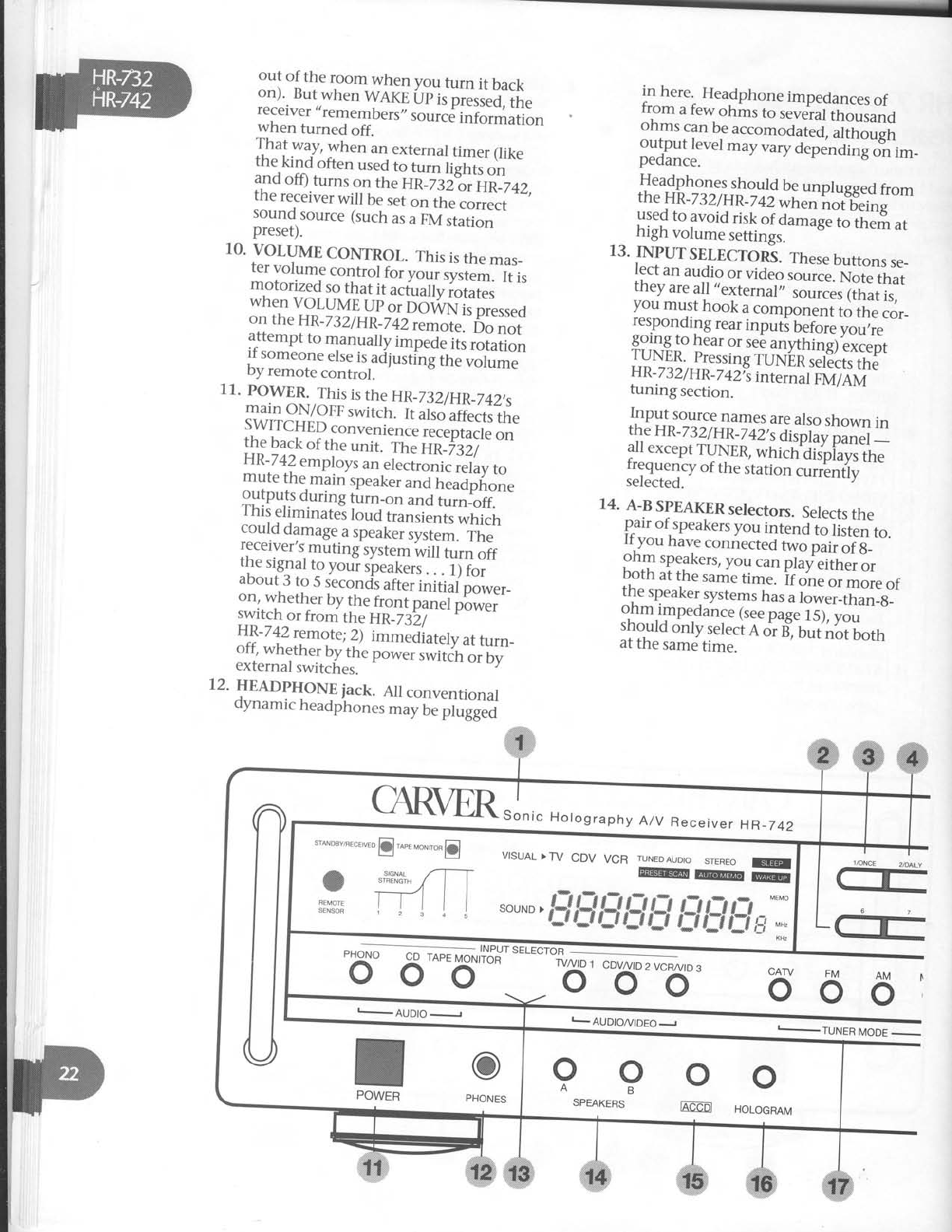
out of the room when you furn it back
on).
But
when
WAKE
itp
i, pi.rr.ilrn"
receiver,,remembers,,
rot'rr.d
irrloiilation
when turned off.
That way, when an external
timer (like
the kindoften used
t. t i" ii"iil, ""
and
off)
turns
on
tne
Un_jsi?r'ntz+2,
the
receiver
will be
set
on th-eI;;*"
soun{
source
(such
as
u
eVit"tir""'
preset).
10.
VOLUME
CONTROL.
This
is
the
mas_
ter
volume
control
fo, you.
sysi"*' f, r,
motorized
so
that
it actually
iotui"i '
when
VOLUME
Up
o. Do-ilrN"i;p'."rr"o
on
the
HR-732/HR _7
42
remote."6.
".,
attempt
to manually
impede
lts
rotation
if someone
etse
is,adl
ust-i'nf
ih;"r;t#"
by
remote
control.
11.
POWER.
This
is
the
HR_73
2/HR_742,s
main
ON/OFF
switch.
It ahd
ili".trit "
SWITCHED
convenienc"
;;";;;;1" ;"
the
back
of
the
unit. The
Hti_%;)" "'
!\1a] employs
an
electronii
i"'iuu
to
mure
the
main
soeaker
and
headpfione
gllip".T
during
tLrn_on
and
turn_off.
I
nls
etrmrnates
Ioud
transients
which
co_uld
damage
a
speakeruy;-il.'i;;'
receiver,s
muting
system
*itt turr,
oif
the
signal
t_o
youi
qpeakers
.
.
. ilf;;"
about
3
to 5
secondls
after
initijplwer_
on,
whether
by
the
front
panel
p6*"i'
lyit_ch or from the HR_7
3i/-' -1
,-v
vr
L'
HI-7!Z remote;
Z; immeJiately
at
turn_
o-ff,^whether
by
the
power
switifr
oiUy'
external
switches.
12.
HEADPIION!
iack. AIt
conventionat
oynamic
headphones
may
be
plrgg;;
in here. Headphone
impedances
of
fr.om
a
few
ohms
to several
thousand
ohms
can
be
accomodut"O,
uitt "rgil
output level
may vary dependi;;;;l_-
pedance.
Headphones
shoulct
be
unplugged
from
the HR_7
32/HR_
r
+zwnen not beins
used
to avoid risk of aamagelt ,i_,'"r?,
",
high volume settmgs.
13.
INPUTSELECTORS.
These
buttons
se_
lect an audio or "io"o ,oui.". No;'iH,
theyare
all,,external"
ril;; iilil;
you
must
hook
a
component
to the
cor_
responding
rear
inputi before
you;is'"
ggj-ng
to hear
or
see
anythi"gf
,"r..rt
ryry$ pressing
ruNiii;;j:G,;I'
HR-
232lHR
_7
42Ys
i"t.."ur piurTerui"
tuning section.
Input source
names
are
also
shown in
th,e
H
R-
732l
HR_7
42,
sdi;pt;y ;;;;i :
all
except
TUNER,
which'OiJpiavi
the
I:gy.l.y of
the
station
.rri!"tiv "''
selected.
14.
A-B
SPEAKER
selectors.
Selects
the
pair
of
speakers
you
intend
to
iiit"n to.
If
you
have
connected
t*o pii, LiS_'"
ohm
speakers,
you
can
play
eitnlilr
both
ar
the
same
time.
if o;e oirnJi. or
the
speaker.systems
rru,
i io*#,^r_,#]sl'
:nm.qnpe_dance
(see
page
15),
you
should
only
select
A
or
B",
Uuf
i,irifotr,
at
the
same
time.
ff
#
I_AUDIO/VIDEOJ I-TUNER MODE -
CAR\trR.J","
Holography
A/V
Receiv
er HR_742
.to*ou"r
."r'uro
@.o". "o",ro,
@
.ffi
fi{il
SENSOR r ; 45
VISUAL
>TV CDV VCR TU
##-ffi
souND
>
##### #fd#l#*
"-.
oo
Ag
SPEAKERS oo
IAEED HoLoGRAM
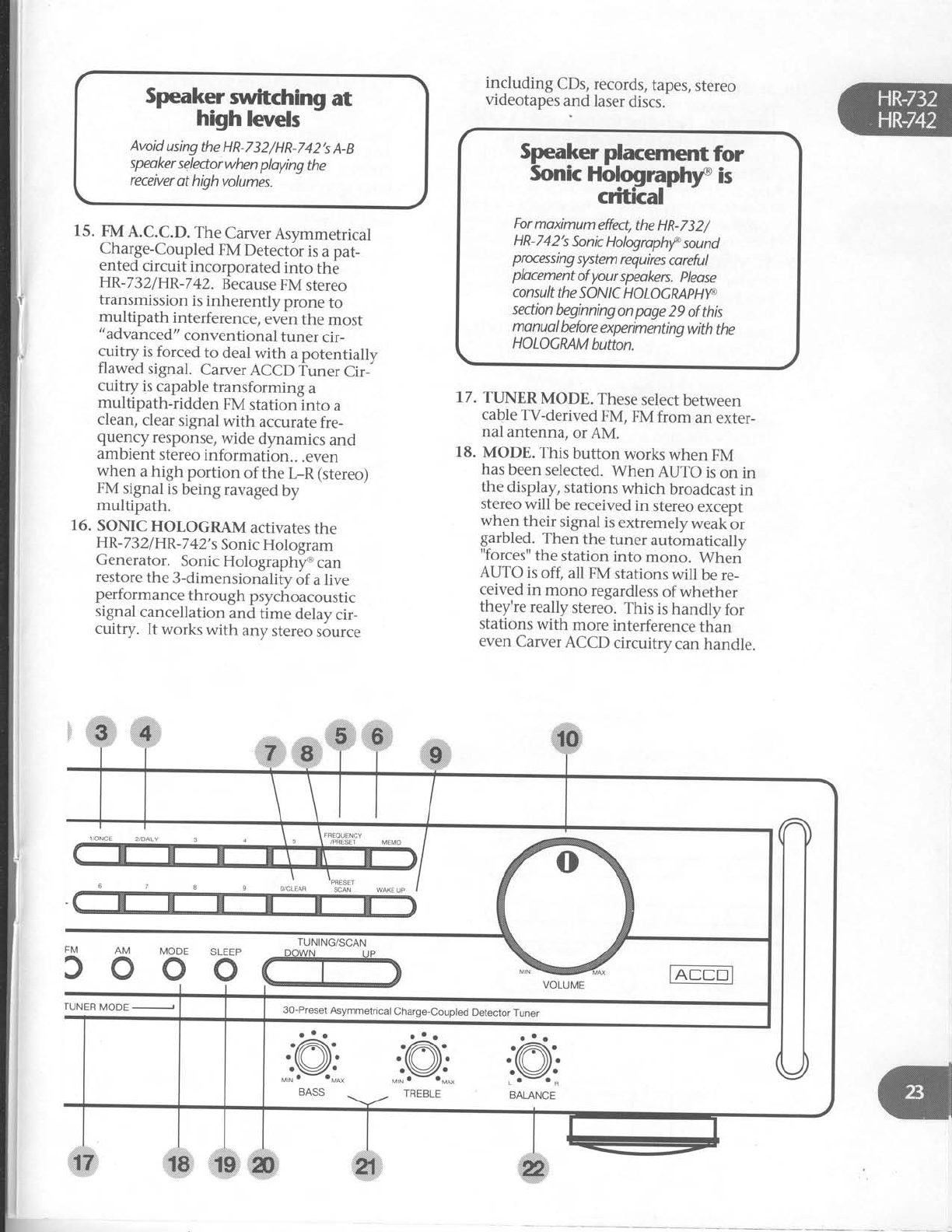
ker mftchin gat
high levels
Avoid
using
the HR-732/HR-742's
A-B
speoker
selectorwhen
ploying
the
receiver
at high
volumes.
15. FM
A.C.C.D.
The
Carver
Asymmetrical
Charge-Coupled
FM
Detector
is
a pat-
ented
circuit incorporated into the
HR-732/HR-742.
Because
FM
stereo
transmission
is
inherently prone to
multipath interference,
even
the most
"advanced"
conventional tuner cir-
cuitry is
forced
to deal
with a potentially
flawed signal. Carver
ACCD Tuner Cir-
cuitry is
capable
transforming a
multipath-ridden FM stationlnto a
clean,
clear
signal
with accurate
fre-
quency response,
wide dynamics and
ambient
stereo
information.. .even
when a high portion of the t-R (stereo)
FM
signal
is
being
ravaged
by
multipath.
16. SONIC
HOLOGRAM activates
the
HR-
732lHR
-7
42'
s
Sonic
Hologram
Generator. Sonic
Holographltr can
restore
the
3-dimensionality
of a live
performance
th
rough
psychoacoustic
signal
cancellation and time delay
cir-
cuitry. lt works
with any
stereo
source
including CDs,
records,
tapes,
stereo
videotapes
and laser
discs.-
17. TTINER
MODE. These
select
between
cable
TV-derived
FM, FM from an exter-
nal antenna,
or
AM.
18. MODE. This button works when FM
has
been
selected.
When AUTO is
on in
the display,
stations
which broadcast
in
stereo
will be
received
in stereo
except
when their signal
is
extremely
weakbr
grrbled. Then the tuner automatically
"forces"
the station into mono. Wheri
AUTO is
off, all FM stations
will be re-
ceived
in mono regardless
of whether
they're
really stereo.
This is
handly for
stations
with more
interference
than
even
Carver
ACCD circuitry can
handle.
Speaker placement
for
Sonic
Holographry is
critkal
For
moximum
effect,
the
HR-732/
HR-742's
Sonic
Hologrophrf
sannd
prxessing
system
requires
coreful
plocement
of
your
speakers.
please
con
su lt the
so N I
c H
o LoG
RAP
Hyc.
section
beginningon
pge 29 of this
monuol
before
experimenting
with
the
HOLOGMM
button.
TUNING/SCAN
300o
30-Preset
Asymmetrical
Charge-Coupled
Detector
Tuner
rUNER
MODE

19. SLEEP (HP.-742
ONty). This
button
programs
the receiver
to shut off at a
later
time. Each
time the
button is
pressed,
the
amout
of time before
the
re_
ceiver
automatically turns itself off is
increased
by 10
minutes
up to 50
min_
utes
and
then by 3O-minu[e
increments
trom 60
to l2O
minutes. This
sounds
complicated,
but we
explain
its
function
more
extensively
in the
next section.
20. TTINING/SCAN (Up/DOwN). These
two buttons "behave"
differentlv, de_
pending
on whether
you
I
) iusitao
them,2)hold
them
dbwn
momeniarilv
and
then
let
go
or
3) hold
them
down
continuously. When the
FREeUENCy/
PRESET
button is
in pRESET
position,
here's
how TUNING/SCAN
behaves:'
A. MANUAL TTINING . Tap and imme_
diately
release
either
Up
or DOhfN
(TUNING/SCAN)
and
they
work just
like
a good
ole
tuning knob. The'tuner
simply
steps
up (or
down)
the FM
band
in 0.1
Mhz increments.
If there
is
no
station
at,
say,88.7,
you
will hear
only
inter-station
hiss
(which
is
a
great
tesf
slgnal
source
for calibrating cassette
decks
wifh variable
bias
coitrols).
B.
AUTOMATIC SCAN. press
either
Up
or DO\tVN
a little longer (about
2 sec_
onds) and
then release
to invoke
AUTO
SCAN.
The
tuner
searches
up or
down
the
FM
band
and
then stops
at
the
first
"strong"
station
it encouniers
(,,strong,,
is
a relative
term,
depending
on what
kind of reception
you get
iriyour area
and
what type
of antenna
ydu have).
Pushing
UP
or DO\AIN
for at least
2 iec_
onds again
takes
you to the next strong
station. If, while in AUTO
mode,
vou -
tune
above
108.0,
auto-scanning
con_
tinues
at
the ,,bottom,,
of the
diil (97.5
)
and proceeds
back
up. Conversely,
if
you turn "down,,
below
g7.5,
scanning
continues
down from 109.0.
C. EXPRESS
MODE. If you reallvwant
to speed
up or down thedial, leave
ei_
ther UP
or DO\zVN
held down. After a
few
seconds,
the
tuner
goes
into suDer_
mondo fast
mode,
whiizing,throudh
the
AM or FM
band
at warp
speed
intil
you release
pressure
on the
button.
Then
the
tuner
goes
back
into AUTO_
MATIC
SCAN
mode,
stopping
at
the
first
strong
station.
D. ANOTHER
USE.
When the
FRE_
QUENCY/PRESETbutton
is
in pRESET
mode,
you can
select
a
preset
by
press_
ing
the
uP
or
DO\ArN (Tuxtxc/scaNi
buttons. Press
once
to advance
one pre_
set;
hold it down to zip quickly through
them.
21. BASS
& TREBLE
tone controls. At
their
center
detent
position,
there
is no
ffi
ctvlODE
oSLEEP
o
IDE '
TUNING/SCAN
.@
BALANCE
30-Preset
Asymmetrical
Charge-Coupled
Detector
Tuner
i*,#f
boost
or cut. Maximum rotation in ei-
ther
direction
produces
10
dB ofboost
or cut. The bass
tone control operates
from 1 kHz down, the treble from 1 kHz
on up.
22. BALANCE
CONTROL. Adiusts
the left/
right distribution
of sound
to your
speakers.
It is
useful when one
speaker
is
closer to your listening position
than
the other,
or with some poorly centered
recorded
material.
The
sweep of the
HR-732/HR-7
42's
BALANCE
control
is
intentionally not linear. That
is, small
movements
off center produce
smaller
shifts in the stereo image
per
degree
of
rotation than near
the extreme
left and
right positions.
This
makes
small
corrections
more
convenient.
If patience
has prevailed
and you have read
this whole section
BEFORE playing
with your
HR-732/HR-742,we
congratulate you. Now for
the fun part!
Enjoyng your
HR-732/
HR-742
If you have
experience
with serious
stereo
components,
you probably
won't need
to read
this section
- assuming,
of course,
that you've
read
the
previous
section
(HR-732/HR
-7
42
Func-
tions
and Features).
But
for those
who only
change
stereo
systems
every decade
or so,
we've
included step-by-step
instructions for frequently-
used
functions. Don't be
embarrassed
to read
through them.
Ashorttestdrive
Because
theHR-732lHR-742
is
essentially
the
nerve
center of your stereo
system, lots of stuff
has
been connected
to it, in fact,
every other ste-
reo
component you own. So it's
a
good
idea
to
double-check
and confirm your work up to this
point.
1. Check
all connections,
first
to confirm
the correct
components are plugged
in
to the appropriate
HR-732lHR-7
42 in-
puts.
Then make
sure lefts
are
connected
to lefts,
etc. Finally,
double-
double-check your speaker connections.
2. Turn the HR-732/HR-742VOLUME
control
down to MIN.
3. Now turn on your system in the
following order:
A.
Any components
not connected
to
the HR-7 32
I
HR-7
42' s
SWITCHED
outlets.
B. The HR-732/HR-742
(if this
is the first
time it's
been turned
on, use
the main
POWERbutton).
4. Select
CD or PHONO
(depending
on
what you've
connected)
using
the
receiver's
front panel
INPUT
SELECT
controls
or the remote
control.
5. Select
SPEAKERS A or B with the receiver
front panel
pushbuttons.
6. Press
PLAY
on the sound source
and
gently
turn up the HR-732/HR-742's
VOLUME. Chances
are,
vou'll hear
something.
Successl If the music
source
is
operating and you hear
silence,
turn
to the
section in this manual
called
"HELP!"
beginning
on page
35.
7 . Next, play your other sound sources
to
confirm that they're
hooked
up
properly.
8. Rotate
the
balance control
to the left
and see if the sound
moves in the
same
direction. If it seems
to move
the oppo-
site way, your speaker-to-HR-7321
HR-742
connections have
been
reversed
and
need
to be
switched.
If the HR-7321
HR-742
is part of a
completely new sys-
tem, you should
check
speaker
phasing
as
well. This
is
covered
in mostlpeakei
owner's
manuals.
6.
7.
If you don't want to store
a
station
as
a
preset, ("
W
Z Z
2...F
ast-Acting
Sedative
El-
euator
Music
for the
Sedentary')
press
the
UP/SCAN
button again
immediately.
When you've
preset
all the
AM stations
you wart, press
FM and follow steps
4
through 6 again.
Manual Preset
Selection
If you know exactly
which station
you want to
commit to a
preset,
have
a special
order,
or
want
to re-program
a preset (your favorite
punk polka
station
changed
formats
to elevator
music),
you
can
manually
tune and
program
presets.
1. Select
AM, FM
or CATV
(HR-742
onlv)
from
the
TUNER
MODE
buttons.
2. Press
the FREQENCY
PRESET
button if
necessary
to get
frequency
display.
3. Press
UP
or DO\MN
until you,ve
found
the
desired
station.
4. Press
MEMO. The
MEMOTv
indicator
flashes
for about
5 seconds.
5. Press
the
appropriate
preset
button (s).
For
example,
if you
want to ,,title,,
that
station
Preset
24, press
the,'2,,
and
then
the
"
4" button. If you wish
to label
it
Preset
10, press
the "1" and
then the
uo,t.
6. Repeat
steps
1
through 5 for other pre-
sets.
NOTE:
If a station
was
already
entered
into a
given
preset,
it will be
erased
if you
choose
the
same preset
number
for a new
station.
Erasing
a Preset
1. Select
preset
number.
2. Press
MEMO and
CLEAR.
preset
will be
erased.
1.
2.
3.
4.
5.
6.
Entering ltGset Number
Sequences
To
select
a
preset
number
less
than I 0
(1 thru
9),
the fastest
woy is
to
press
"0" ond
then
the number,
for
ixomple
"05"
for preset
5. tf
you
don't,
the '
receMer
Wuses
forfive
seconds,
waiting
for
o second
number
to
be entered
before finolly
deciding
thot
you
onf
intended
to enter
a
sinale number.
Conversely, you
have
dbout
5 seconds
to enter
both
digits
of
a two
digit
code.
lf you
tory longer
betvveen
numben,
the
receiver
will
oct
only
on
the first
diqit
entered.
Tuning
an FM
orAM station.
Make
sure
that the appropriate
antenna
is
connected
to the
HR-732lHR-742.
Turn on the HR-7
32
I
HR-7
42.
Select
FM,
AM or CATV (HR-742
onlv)
from
the TUNER
MODE
buttons.
Advance
the HR-7
32
I
HR-7
42,svolume
control
about
714
of the way.
Either
press
TUNING and
then Up
or
DO\^rN,
or SCAN
and then Up or
DO\4rN
to tune a station.
Adjust
the
volume
and
make
any
other
adiustments
you
wish.
Setting
FM/AM
station presets.
Your
Carver
HR-732/HR
-7
42 canmemorize
and
recall
up to 30 FM
and
AM stations
in any
or-
der, i.e.
Preset
1
can be
an FM
station
at
101.5and
preset
2 canbe
an AM station
atTlO
etc. For
con-
venience,
we
suggest
that you put your station
presets
in order
of ho-w
often you listen
to the
sta_
tion. But
hey,
it's your receiver...so
do
it how
you want!
The
HR-732lHR-742's
memory
will retain
pre-
set
information for about 3 days
after
it is
disconnected.
This
helps
prev'ent
electronic
am-
nesia
when moving your system
around
or from
power
outages.
Automatic Preset
Selection
If you just
want to "browse',
around
the FM
and
AM dials
to select presets....
1. Select
FM
or CATV
(HR-74}only) from
the
TUNER
MODE
buttons.
2. Press
the FREQENCY
PRESET
button if
necessary
so frequency
is
displayed.
3. Push
and hold MEMO
button.
4. Push
and
release
UP
button, release
MEMO
button. The
tuner
will scan
until
it finds
a
strong
station
and play
a
sample
of it.
5. If you want that station
("
KWIZ! All
Punk
Polka!")
as
a
preset,
do nothing
(except
hold the
MEMO button down).
The
station
will be memorized
and
assigned
a
preset (starting
with 1). Then
the scanning
will continue
up the FM
band.
"Samplinq"
Stations
with
Preset
Scaln
If you want to knowwhat's playing on each
preset
(or simply forgot which was
which), the
HR-732
andHR-742
can give
you a S-second
pre-
view of each preiet station, starting with preset
1
and continuing until you find something you
like or give
up and play a
CD.
1. Press
the PRESET
SCAN
button.
2. The PRESET
SCAN indicator light will
begin
flashing.
3. Press
theUP
or DOWN buttons to start
scanning
through the presets.
4. When you find one you want to stay
with, press
0/CLEAR:
l. Turn on the cassette
deck
and HR-7321
HR-742.
Press
TAPE
MONITOR on the HR-7321
HR-742
front panel or TAPE
on the
remote
control.
After
loading
a tape you KNOW has
mu-
sic
on it, press
PLAY
on the
cassette
deck.
Ad
j
ust the HR-7
32
I
HR-7
42'
s volume
control or press
DO\ 4\I or UP
on the
remote
control.
Press
one of the input selector
buttons
to choose
the sound source
from which
you
wish
to record.
Most likely,
this will
be
CD, PHONO
or AM/FM/CAW
(tuner).
After
loading
a blank
cassette
into the
deck
and making
any necessary
adjust-
ments for tape
type, noise
reduction,
etc., put the
deck into REC/PAUSE.
Press
PLAY
on the
sound
source
(unless
of course it's
the HR-732/HR-742's
TUNER).
The sound you hear
coming
over your speakers
is
the
SOURCE.
Adjust
record
levels
on the
deck
and
begin
recording.
To hear
the sound as it is
being returned
from the
cassette
deck,
press
the
TAPE
MONITORbutton on the HR-7321
HR-742
front panel.
Playinq
video
throuqh theHR-732/
lR-717
(via
A{flodk-up
1
and2-page11)
1.
2.
Turn on your video source
(most
likely a
VCR),
the TV and
the HR-732
or
HR-742,
PressW/VID
1,
CDV/VID
2orTVlytD
3 on the receiver's
front panel or via
remote
control. A corresponding
indi-
cator
will light up on the receiver,s
display panel.
Select
SPEAKERs
A or B with the receiver
front panel
pushbuttons.
Activate
the video source
and adjust
the
HR-732lHR-7
42's volume,
tone
controls
etc.
to your own taste.
To switch between
video sources,
sim-
ply press
the appropriate
input selection
button.
3.
4.
I
1.
2.
T
I
2.
3.
4.
1.
2.
3.
4.
5.
j
ll
i!
j
i
l
i
I
I
l
I
!
l
I
l
l
I
I
I
I
i
l
t,
F
I
I
I
I
I
I
I
I
I
t
Plalng
atape
Recording
atape
Mdeo
dubbing
Turn on your
video
SOURCE
(VID 1
or
VID 2), youTTARGETVCR
(connected
to VID 3),
the TV and theHR-7321
HR-742.
Select
the appropriate
video source
(TV/
VID 1
or CDV/VID 2)
via
front panet
button or remote control.
3. "Cue
up" the
tape
or LD
to the
place
where
you want to start recording.
4. Press
PLAY
on the
SOURCE
and
RECORD
ON
thc TARGET
dCCK.
Stereo
TV
sound
through your
main
speakers
(if
youiW has
stereo
outputs)
1. Turn
onyourTVandthe HR-7321
HR-742.
2. Press
TV/VID 1
on the receiver,s
front
panel
or via remote control.
3. Select
SPEAKERs
A or B with the receiver
front panel
pushbuttons.
4. Tune the station/program on the TV
and ad
just
the HR-7
32
IHR-
742's
vol-
ume,
tone
controls
etc.
to your
own
tastes.
To switch to a VCR,
simply press
the
appropriate
input selection
button.
Depending
on the TV,
it's
own volume
control may or mav not affect
the
sound
levei arriving at the HR-7321
HR-7
42. If VOLUME on the TV does
affect
its
AUDIO
OUT volume,
adiust
this volume relatively high and reduce
the
HR-732lHR-742's
volume
for re-
duced
hiss.
Wake.up
mode
The HR-Z32lHR-74Zcan
be
used
with an
exter_
nal timer to furn thereceiver on at a p.e_arrangeO
time. Consult
your Carver
Dealer
for'informa_
uon on special
timers
designed
for stereo
equipment. you can also
ise -a
stanAirO
ptug_in
house
light timer if it is
rated
fo; ;ti;;is amps.
In either case,
the receiver
t u, to n" p-_
grammed so
that it can ,,remember,,
th'e
source,
etc.
when it comes
back
on.
1. Press
WAKE
Up. The
Wake
Uo
indicator
will begin
to
flash. r
2. While.,,Wake
Up,,
is
lit,
press
MEMO.
Now the ,,Memo,,
indicalor
flashes
and
SEL
appears
in the
alphanumeri.A;_ -
play.
3. Select
the
desired
input. For
AM or FM,
just press
the
numbbr
of the
preset.
- -
4. Press
I/ONCE or 2/DAILy (preset
but_
tons 1 and2), depending on whether
you want the receiver
tolust turn on to
these
settings
once
or every
Ouy
at tfre
-
same
time.
5. The
"Wake
Up,,
indicator
will once
agatn
ttght
up. This
means
you,re
through and
everything,s
set
correctly.
6. Set
the
timer
and
leave
the HR_7321
HR-742
power button on.
I To review
the wake_up
,,program,,,
press
WAKE
Up twice any tim6 tfrE,"."iu'"i i,
turned on. The actual
wake_up
progiu_
(source
and
preset)
will be
,"tu'i.i"J.''-^'
I If you're
using
a
cassette
deck
with full
togic
(so-called
,,feather
touch,,)
con_
trols for a
source,
make
sure
ttrat its -
TIMER
pLAy SWITCH
is
set
to on. Oth_
erwise
it will ,,sleep,,
through the
timei,s
call.
)StulgJhe.stgep
timer
\rrK.-/lzonn
- The HR-T4}includes a
built_in timer that turns
the receiver
off after
a preset
period of time. It,s
handy for bedtime list^ening
iut." yor, ,.rsp.ct
that you m.1r
fa]l
asleep
and
don,t;";ith;;;_
ceiver
on.all
night. nui it can
also
n""i!Jio
conround
burglars (your
receiver
plays
for an
nour or so
after
you,ve
left),
or
simply
as
a
timer
for
those
instances
*h"" i;;i-pffiirsi a.
something else
after,
for example,
u'niff no", of
listening.
1. While theHR-742is
on,
press
the
SLEEp
button.
2. You
will now press
the SLEEp
button
one or more times to ,,program,,
the
duration before
the receivdr
automati_
cally
shuts
off. Each
time
you pr"i, --
SLEEP,
the
amount
of time befbre
turn_
off increases
as
follows:
1st
push
2nd push
3nd
push
4th push
5th push
6th push
7th
push
8th push
10
minutes
20
minutes
30
minutes
40
minutes
50
minutes
60
minutes
90
minutes
120
minutes
Erasewake-up
mode
Press
WAKE
Up button if necessarv
to
exit
WAKE
Up
mode.
(WAKE
Upg'oei
out).
Press
WAKE IJp
twice,
then CLEAR.
Wake
up settings
will then be
erased.
9th push returns
to 10
minutes
and starts
the cycle
again.
I Note
that the
first
60
minutes
ur"-oro_
grammed
in ten
minute
incremenis
_
just
press
the
button once
for each
ten
minutes more you want the HR_7
ai-lo
stay
on. After that, the duration in_
creases
by 30-minute
intervals.
Cleaning
. You'll
want towipe off the
HR_232/HR
_742,s
rro-nt
panel and chassis
from time_to_time
with a
;oft, dry cloth. If you fru,ne
,omeinlns ,tuUoor,,
ro
remove,
use
a
mild dish.
soap
or
det-ergent
spar_
ingly applied to a soft
cloth; d6nlt ur"ir?ot or,
ammonia,
or
other
strong
solvents.
1.
2.
3.
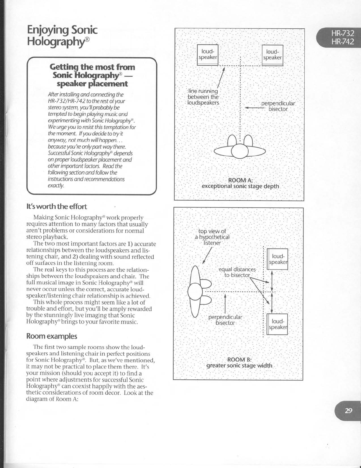
Enjoyng
Sonic
Holographf
After
instolling
and connedingthe
HR-732/HR-742
tothe restof
your
stereo
slrtem,
you'llprobobly
be
tempted
to begin
playing
music ond
expeimenting
with
Sonic Hologrophrf
.
We
urge
you
to resist
this temptation for
the moment.
lf you
decide to try it
onwayl not much will hoppen.
. .
becouse
you're
only
pott woy
there.
Successfu I Son k H
olog ro
phf depe n ds
on proper
loudspeoker plocement
ond
other importont
fodors.
Reod the
following
section ond follow
the
i nstruction
s o nd recom
me ndations
exodly.
lfsworth the effort
Making Sonic Holographf work properly
requires
attention to many factors
that usually
aren't problems
or considerations
for normal
stereo playback.
The two most important factors
are 1) accurate
relationships
between
the loudspeakers
and
lis-
tening chair, and 2) dealing with sound reflected
off surfaces in the listening
room.
The real keys
to this process
are the relation-
ships
between
the loudspeakers
and chair. The
full musical
image in Sonic Holographf will
never
occur unless
the correct,
accurate loud-
speaker/listening
chair relationship
is achieved.
This whole process
might seem like a lot of
trouble and effort, but you'll be amply rewarded
by the stunningly
live
imaging
that Sonic
Holographf brings to your favorite music.
Room
examples
The first two sample rooms show the loud-
speakers
and listening
chair in perfect
positions
for Sonic Holographf. But,
as
we've
mentioned,
it may
not be
practical
to place
them there. It's
your mission (should
you accept it) to find a
point where adjustments
for successful
Sonic
Holographf can coexist happily with the aes-
thetic
considerations
of room decor. Look
at the
diagram
of Room
A:
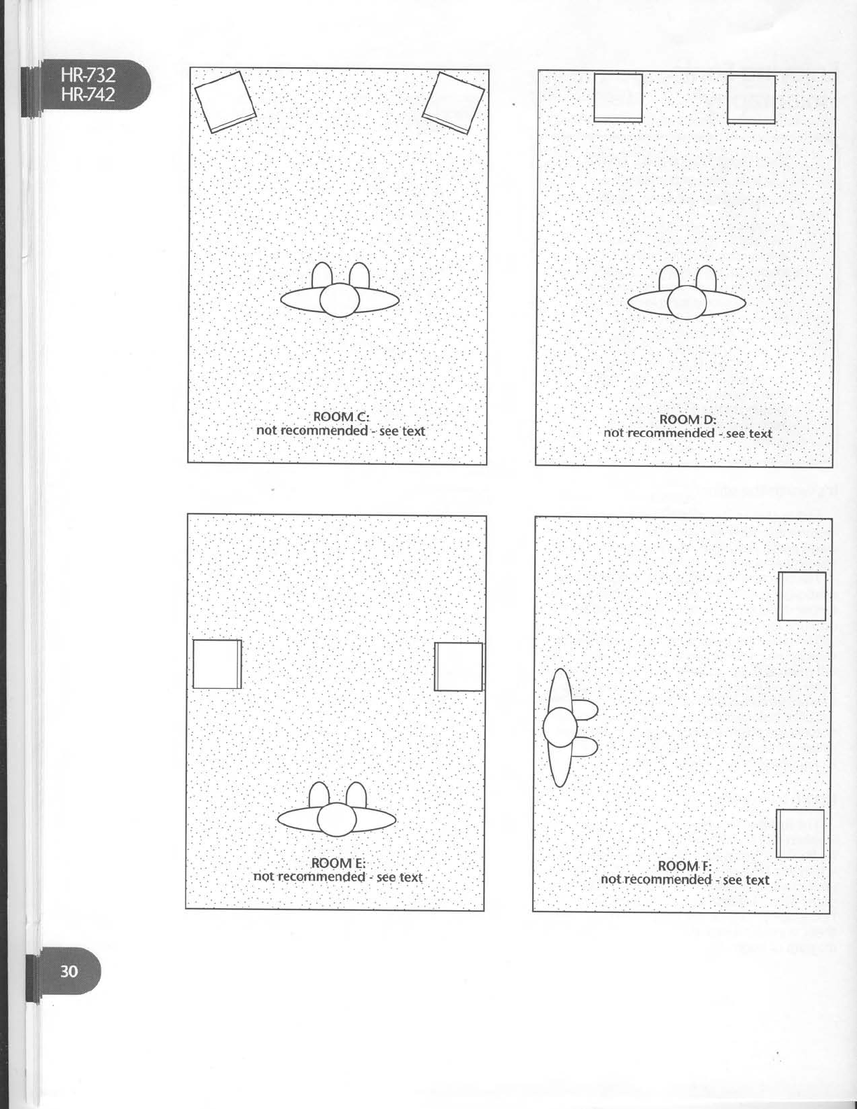
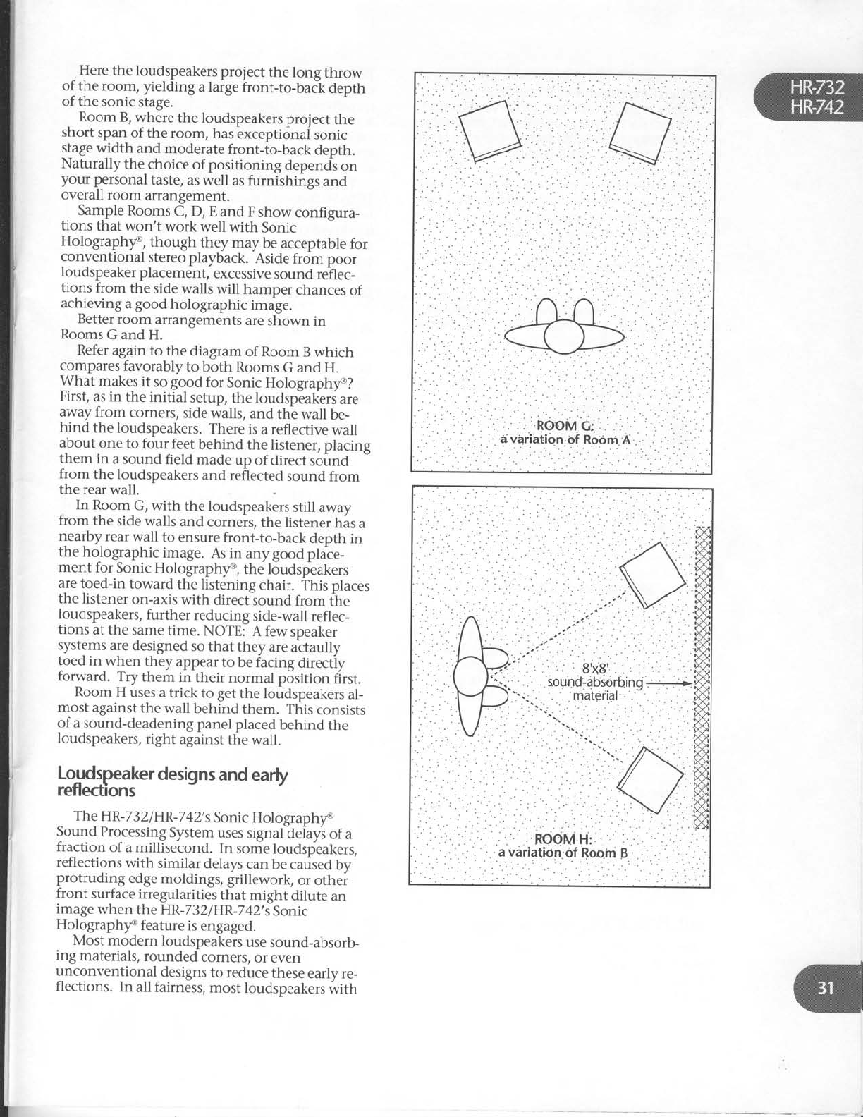
I
^
Here
the loudspeakers
prolect the long throw
of the room, yielding a large
front-to-back depth
of the sonic
stage.
Room B, where the loudspeakers
project the
short span
of the room, has
exceptional sonic
slage
width and moderate
front-to-back depth.
Naturally the choice
of positioning depends
on
your p€rsonal
taste,
as well as
furnishings and
overall room arrangement.
Sample
Rooms
C, D, E and F show configura-
tions that won't work well with Sonic
Holographf, though they may be acceptable
for
conventional stereo playback. Aside
from poor
loudspeaker
placement,
excessive
sound
rehec-
tions from the side
walls will hamper chances
of
achieving
a
good holographic i-ug".
Better
room arrangements
are
shown in
Rooms
G and
H.
Refer
again
to the diagram
of Room B which
compares
favorably to both Rooms
G and H.
What makes
it so good for Sonic
Holographf?
First,
as in the initial setup,
the loudspeaktrs
are
away
from corners,
side
walls,
and the wall be-
hind the loudspeakers.
There
is
a reflective
wall
about one to four feet
behind the listener,
placing
them in a sound field made
up of direct sound
from the loudspeakers
and reflected
sound from
the rear
wall.
In Room
G, with the loudspeakers
still away
from the side walls and corners,
the listener
has
a
nearby
rear
wall to ensure
front-to-back depth in
the
holographic
image.
As in anygood plate-
ment for Sonic
Holographf, the loudspeakers
are
toed-in toward the listening chair. This places
the listener
on-axis
with direct sound from the
loudspeakers,
further reducing side-wall
refl
ec-
tions at the same
time. NOTE: A few speaker
systems
are
designed
so
that they are actaully
toed inwhen they appear
to be facing
directiy
forward. Try them in their normal position first.
Room H uses
a
trick to get
the loudspeakers
al-
most
against
the wall behind
them. This
consists
of a
sound-deadening
panel
placed
behind
the
loudspeakers,
right afainst
the wall.
Loudspeaker
designs
and
early
reflections
The HR-732
IHR-7
42's
Sonic
Holographf
Sound
Processing
System
uses signal
delays
of a
fraction
of a millisecond.
In some
loudspeakers,
reflections
with similar delays
can
be caused
bv
protruding edge
moldings, grillework, or othei
front surface
irregularities
that might dilute an
image
when the
HR-732/HR-7
42's
Sonic
Holographf feature
is
engaged.
Most modern loudspeakers
use
sound-absorb-
ing materials,
rounded corners,
or even
unconventional designs
to reduce
these
early
re-
flections. In all fairness,
most loudspeakers
rlvith
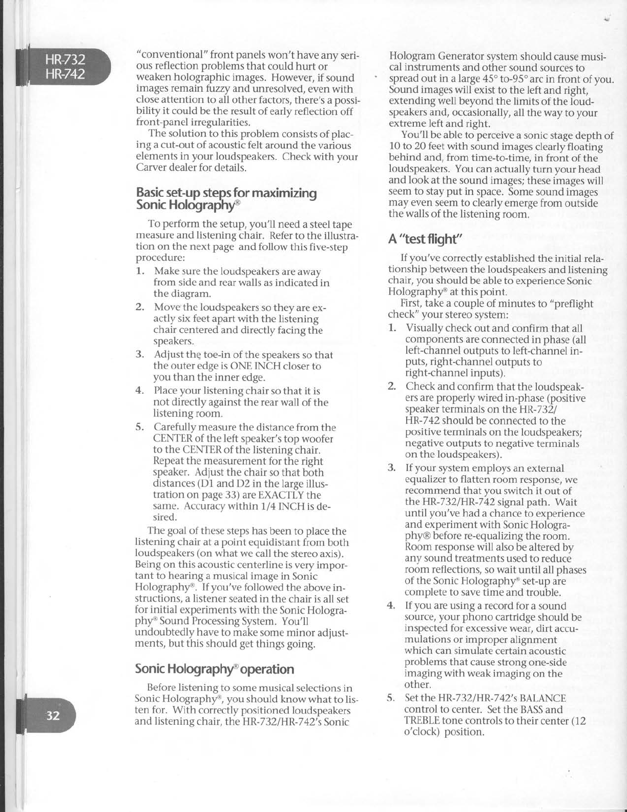
"conventional"
front panels
won't have
any
seri-
ous reflection problems
that could hurt or
weaken
holographic
images.
However,
if sound
images
remain fuzzy andunresolved,
even
with
close attention
to all other factors,
there's
a
possi-
bility it could be
the result
of early reflection off
front-panel irregularities.
The
solution
to this
problem
consists
of plac-
ing a cut-out of acoustic felt around the various
elements
in your loudspeakers.
Check with your
Carver dealer
for details.
Hologram
Generator
system
should
cause musi-
cal
instruments and other sound sources
to
spread
out in a large 45"
to-95"
arc in front of
you.
Sound images
will exist
to the left
and right,
extending well
beyond
the limits
of the loud-
speakers
and, occasionally,
all the way to your
extreme left
and right.
You'll be
able to perceive
a
sonic stage
depth of
10
to 20 feet with sound images
clearly floating
behind and, from time-to-time, in front of the
loudspeakers.
You can
actually turn your head
and look at the sound images;
these images
will
seem to stay put in space. Some
sound images
may even seem
to clearly
emerge from outside
the walls
of the listening
room.
A "testflighf'
If you've
correctly
established
the initial rela-
tionship
between the loudspeakers
and listening
chair, you should
be able
to experience
Sonic
Holographf at this point.
First,
take a
couple of minutes
to "preflight
check" your stereo
system:
1. Visually
check
out and
confirm that all
components
are connected
in phase
(al,
left-channel
outputs
to left-channel
in-
puts,
right-channel
outputs
to
right-channel
inputs).
2. Check
and confirm that the
loudspeak-
ers are properly
wired
in-phase
(positive
speaker
terminals
on the HR-7321
HR-742
should
be connected
to the
positive
terminals
on the loudspeakers;
negative
outputs to negative
terminals
on the loudspeakers).
If your system
employs an
external
equalizer
to flatten
room response,
we
recommend
that you switch
it out of
the HR-732/HR-742
signal path. Wait
until you've
had a
chance to experience
and experiment
with Sonic Hologra-
phy@
before re-equalizing
the room.
Room response
will also be altered
by
any
sound treatments
used
to reduce
room reflections,
so
wait
until all
phases
of the Sonic Holographyo
set-up
are
complete
to save
time and
trouble.
If you are
using a record
for a sound
source/
your phono cartridge
should be
inspected
for excessive
wear,
dirt accu-
mulations
or improper
alignment
which can simulate
certain
acoustic
problems
that cause
strong
one-side
imaging with weak imaging
on the
other.
Set the
HR-732lHR-742's
BALANCE
control
to center. Set
the BASS
and
TREBLE
tone
controls to their center
(12
o'clock) position.
Basic
set-up
steps for m
Sonic Holcigrapihy' :xrm|Zng
To perform the setup, you'll need
a steel tape
measure
and listening
chair. Refer
to the illustra-
tion on the next page
and follow this five-step
procedure:
1. Make
sure
the loudspeakers
are
away
from side and rear walls
as indicated
in
the
diagram.
2. Move'the
loudspeakers
so they are
ex-
actly
six feet apart
with the listening
chair
centered
and directly facing
the
speakers.
3. Adiust
the
toe-in of the speakers
so that
the outer
edge is
ONE INCH closer to
you than the inner edge.
4. Place your listening
chair
so that it is
not directly against
the rear wall of the
listening
room.
5. Carefully
measure
the distance
from the
CENTER
of the left speaker's
top woofer
to the CENTER
of the listening
chair.
Repeat
the measurement
for the right
speaker.
Adjust
the chair
so that both
distances
(D1
and D2 in the
large illus-
tration on page
33) are EXACTLY
the
same. Accuracy
within 1/4 INCH is de-
sired.
The goal
of these
steps has
been to place
the
listening
chair
at a
point equidistant
from both
loudspeakers
(on
what we
call the
stereo axis).
Being
on this acoustic
centerline is very
impor-
tant to hearing
a musical image
in Sonic
Holograph/o. If you've followed the above in-
structions,
a listener
seated in the chair
is all set
for initial experiments
with the Sonic Hologra-
ph/o Sound Processing
System. You'll
undoubtedly have
to make
some minor adjust-
ments,
but this
should get
things going.
Sonic Holographf operation
Before listening
to some musical
selections
in
Sonic
Holographf, you should know what to lis-
ten for. With correctly positioned
loudspeakers
and listening
chair, the
HR-7 32
I
HR-
742's
Sonic
3.
4.
5.
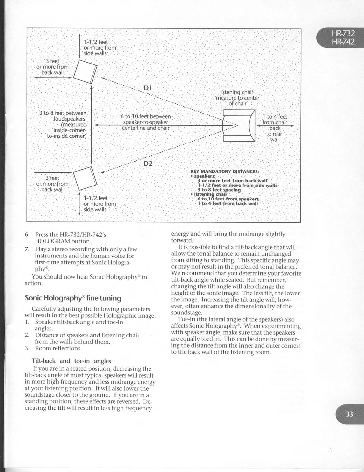
''
:.:
: ...
.,
....:
'. .:-.j'
' "'-U"i '
''-"'^ D2
.
' :.
: .
6. Press
the HR-732/HR-742's
HOLOGRAMbutton.
7. PIay
a stereo recording with only a few
instruments and the human voice for
first-time attempts at Sonic Hologra-
pht'.
You should now hear
Sonic Holograph/e in
action.
Sonic Holographf fine
tuning
Carefully adjusting the following parameters
will result
in the best possible
Holographic
image:
1. Speaker
tilt-back angle
and toe-in
angles.
2. Distance
of speakers
and listening
chair
from the
walls
behind
them.
3. Room
reflections.
Tilt-back and toe-in angles
If you are in a seated
position,
decreasing the
tilt-back angle of most typical speakers will result
in more high frequency
and less midrange energy
at
your
listening position. It will also lower
the
soundstage
closer to the
ground. If you are in a
standing position,
these
effects are reversed. De-
creasing the
tilt will result in less
high frequency
energy and will bring the midrange slightly
forward.
It is possible
to find a tilt-back angle
that will
allow the tonal balance to remain unchanged
from sitting to standing. This specific angle may
or may not result in the preferred
tonal balance.
We recommend that vou determine
vour favorite
tilt-back
angle while s'eated. But rem'ember,
changing the tilt angle
will also change
the
height
of the sonic image.
The less tilt, the
lower
the image.
Increasing
the tilt angle will, how-
ever, often
enhance the
dimensionality of the
soundstage.
Toe-in (the lateral
angle of the speakers) also
affects Sonic Holographt'. When experimenting
with speaker angle, make
sure that the speakers
are equally toed in. This can be
done by measur-
ing the distance from the inner and outer corners
to the
back
wall of the listening
room.
i
I
I
Otherconsiderations
Here
are
some
other factors
which affect
Sonic
Hologram generation:
Relationship of speaken to fiont and back
wails
- The_purpose
of keeping
the loudspeakers
away
from the walls is
to provide a direct,
ipeaker-to-
ear
sound path with a minimum of extra,
unwanted reflections
off nearby
room surfaces.
Just
as
secondary
reflected
sound arrivals
confuse
the ear in normal stereo playback,
they also
ruin
attempts at creating
holographic images.
Always
keep
in mind the importance of accurate
loud- -
speaker/listening
chair relationships
and
keeping
the loudspeakers
relatively close
together.
Room reflections
For
the
best
possible
Sonic
Hologram
genera-
tion, the area
around and behind your speakers
should
be relatively
dead.
If the
back
and
side
walls are
too reflective,
they may generate
addi-
tional sound reflections
which can interfere
with
Sonic
Holography@.
Acoustic treatrnent
The object of acoustically
treating the listening
room is to create
what's known as a live end/dead
end configuration. This design
makes
the area
around the loudspeakers
acoustically
"dead,,,
while the area
around the listener
is kept live.
Thus
random
sound
reflections
reach
a listener
long after
the
direct
sound,
establishing
a uni-
form sound
field.
The reflections
most in need
of correction in
your listening
room are
the usually
strong,
side-
wall reflections
from surfaces
near
each
loudspeaker.
Any treatment
should
be applied
to the wall
extending two feet
above
and below the
midrange
and high-frequency
loudspeaker
ele-
ments, standing two to three
feet from the
leading
edge
of the
loudspeaker
cabinet.
The
treatment
itself
may
be quite
simple.
Open,
full book
cases
or record
shelves,
heavy
fabri,c
hangings,
or draperies
made
of hear.y
ma-
terial will work well as an
acoustic
treatment
for
many situations.
Sound
panels
made
from thick
cork or acoustical
tile can
be covered
with a
vari-
ety
of other
sound-absorbing
materials,
too.
Since
side-wall
sound
treatments
are relatively
small (usually
less
than four feet
by four feet),
you
could use attractive
grille cloths or foam panels
to
improve the appearance.
However,
loudipeaker
grille cloths or covers
by themselves
are not effec-
tive
sound
absorbers.
Scrap
carpeting
can be
effective
when used
with other sound-absorbing
materials.
HR-
732lHR
-7
42 pow
er off .
Line
cord disconnected.
Poor
fit between
AC plug and wall
receptacle.
Power
off at wall receptacle
(check
with
tester
or lamp).
Remember
that the main power switch
and power LED
must be
on for you to be
able to turn on theHR-732lHR:74Zby
remote
control.
No
sound
(power
OK and
on)
HELP!
A
trouble-
shooting
guide
If you're having trouble or suspect
a
problem,
try som_e
simple
trouble-shooting first. Usually,
the problem lies
elsewhere
in the system
or
connections,
not with the HR-732
orHR-742.
No
sound
(HR-732/HR-742does
not
light
up)
1.
2.
3.
4.
q
1. HR-732lHR-742input
select
buttons
set
to inactive
source.
2. Tape
Monitor has
been pressed
(check
the
fluorescent
display)
when there,s no
component connected
to the loop.
3. MUTE
button onHR-732lHR-742
remote
is
activated.
4. Wrong SPEAKER
button has
been
pressed.
. . or neither
has
been
selected.
5. Selected
input is simply
not functioning
or the connecting hook up cables
are
malfunctioning.
6. Program
source
has
a
problem. For
ex-
ample,
tuner is
between
stations,
tape is
on a
blank
segment,
CD
player
is
on
pause.
No
sound
in
one
channel.
1. Defective
cable
from music source
to
HR-732tHR-742.
2. Speaker
wire
loose
or disconnected.
3. HR-732lHR-742
BALANCE
control
fully
clockwise
or
counterclockwise.
4. Speaker
fuse
blown.
!-"r.d
howl,
squeal
or whistle
while
mprng.
1. TAPEMONITORisengagedwhilemi-
crophones
are connected
to tape
deck
for recording.
No
sound
when AM or FM is
selectd.
1. AM loop antennanotconnected.
2. FM
dipole
or external antenna
has not
been
connected.
3. Tuning section
has not been
tuned to
an existing
station.
Solovoices or
instruments sound
thin, shrill or distorted.
1. Treble tone control set to maximum
boost.
2. Phono cartridge
wired out of phase
(re-read
instructions
which came
with
the cartridge and check out all four con-
nections betr,veen cartridge
and
tonearm).
3. Speakers are
connected out of phase.
Sound
is weakwhen PHONO
input is
selectd.
1. A low-output moving coil cartridge
has
been
connected.
Add a step-up
transformer such as the Carver MCt.
Hum and constant
noise
1. Defective
signal
cables.
2. Improper fit between signal
cable
plug
and sockets.
3. Signal cables
have been routed too close
to AC cables,
power transformers
or
motors.
4. Turntable or cassette deck
may be ori-
ented in such
a way that it is picking up
induced hum from AC wall wiring.
Change
component's position slightly.
Intermittent
noise, voices or hum
causd by
RFlinterferencefrom
CB,
WorAM radio.
Determine where the RFI
(radio fre-
quency interference) is entering the
system
by disconnecting individual
sound sources, then the HR-7321
HR-742.
Use
higher quality interconnect cables
with better shielding.
Wrap turntable input cables
in
aluminum foil.
Place 0.01 microfarad capacitors
across
the HR-732lHR-742's left and
right
speaker terminals.
1.
Remote control
won't work
1. Batteries are dead or missing.
2. Remote is to6 far from or at too much of
an angle
in relation to the remote sensor
on the HR-732|HR-742.
3. Remote
sensor
onHR-732lHR-742 or rc-
mote control transmitter panel are
dirty.
Seruice
Assistance
We suggest
that you read the LIMITED WAR-
RANTY completely to fully understand
what your
service coverage
constitutes and its duration.
Please
promptly complete and return the WAR-
RANTY REGISTRATION CARD
to make
administrating your LIMITED WARRANTY
quicker and easier
later on. AIso be sure to save
the sales
receipt in a safe
place. It will be neces-
sarv
for warranW service.
if your HR-7i2lHR-742 shouldrequire
service,
we suggest
you first contact the Authorized
Carver
Dealer from whom you purchased it.
Should
the Dealer be unable'to take care of your
needs,
you may contact the CARVER Service
De-
partment by phoning (206) 7 7 5-6245, or by
writing CARVER
CORPORATION, Service
Depart-
ment, P.O. Box 1237,Lynnwood,
WA 98046.
We
will then direct
you to the nearest in our national
network of Authorized Warranty Service Centers,
or give you detailed
instructions on how to re-
turn the product to us for prompt action.
We wish you many hours of musical enjoy-
ment. If you should
have
questions
or
comments,
please write to us at the
address
above.
Patent
Notice
(our
lawyer
insists.
.
.)
The circuitry
and application
of the CARVER
Sonic
Holographf Sound
Processing System
are
protected by United States
Patent 4,218,585
and
corresponding
foreign
patents.
O 1991
All rights reserved,
CARVER
CORPORA-
TION P.O.
8oxL237,
Lynnwood,
WA 98046
QOO
7 7 5-1202.
Pttb# 910303-4;
Part# 990-2-
113-00.
Written and
desktop-published
in
America
PRINTED
IN TAPAN
2.
3.
4.
{
'{
a
{
.{
T
d
{
Printed in
J6pan J
124JW1210 {
,.{
'.i
'd
>-
,
