Casio VZ 8M Owners Manual
Casio VZ-8M Owners Manual Casio VZ-8M Owners Manual
User Manual: Casio VZ-8M Owners Manual
Open the PDF directly: View PDF ![]() .
.
Page Count: 171 [warning: Documents this large are best viewed by clicking the View PDF Link!]
niGITAL
SYNTHESIZER
OPERATION
MANUAL
1
MANUAL
DE
OPERACION
117
r
DIGITAL
SYNTHESIZER
tern,
manual
highly
innovative
digital
ition)
Modular
Sound
Source
sys-
im
your
new
VZ-8M,
be
sure
to
read
this
often.
r
CAUTION
RISK
OF
ELECTRIC
SHOCK
DO
NOT
OPEN
CAUTION:
to
reduce
the
risk
of
electric
SHOCK,
DO
NOT
REMOVE
COVER
(OR
BACK).
NO
USER-SERVICEABLE
PARTS
INSIDE.
REFER
SERVICING
TO
QUALIFIED
SERVICE
PERSONNEL."
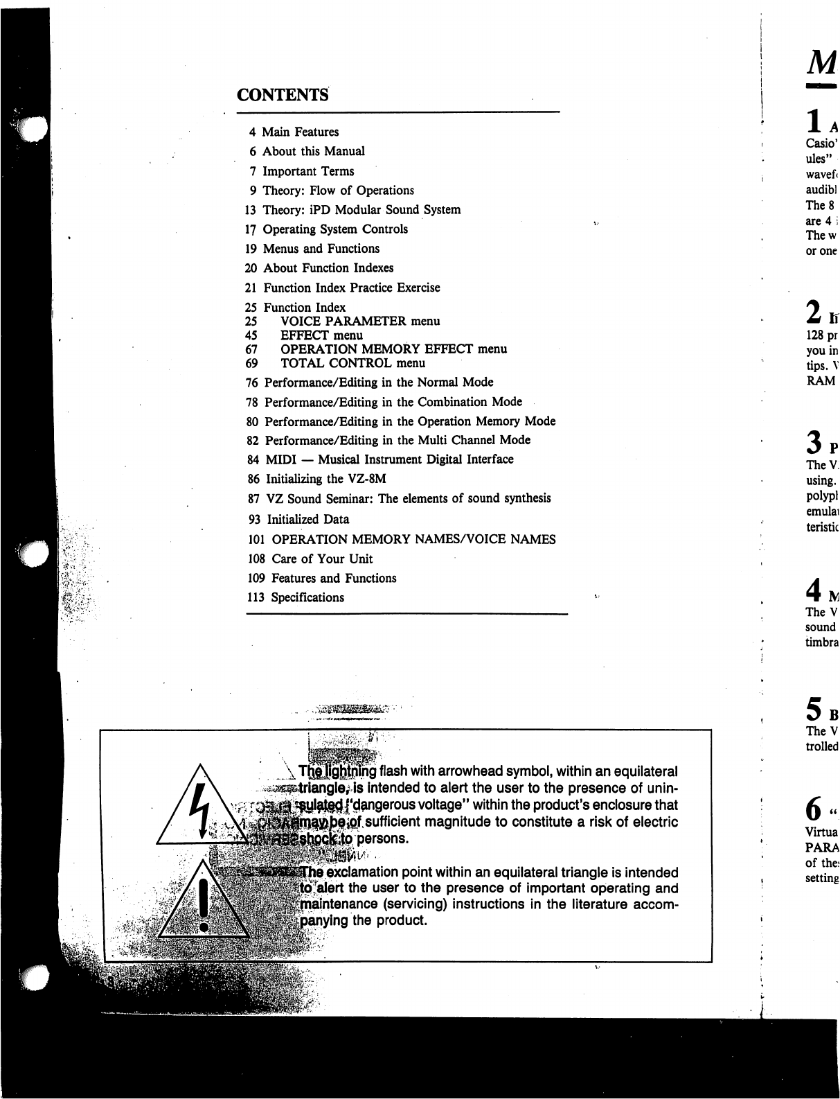
CONTENTS
4
Main
Features
6
About
this
Manual
7
Important
Terms
9
Theory:
Flow
of
Operations
13
Theory:
iPD
Modular
Sound
System
17
Operating
System
Controls
19
Menus
and
Functions
20
About
Function
Indexes
21
Function
Index
Practice
Exercise
25
Function
Index
25
VOICE
PARAMETER
menu
45
EFFECT
menu
67
OPERATION
MEMORY
EFFECT
menu
69
TOTAL
CONTROL
menu
76
Performance/Editing
in
the
Normal
Mode
78
Performance/Editing
in
the
Combination
Mode
80
Performance/Editing
in
the
Operation
Memory
Mode
82
Performance/Editing
in
the
Multi
Channel
Mode
84
MIDI
—
Musical
Instrument
Digital
Interface
86
Initializing
the
VZ-8M
87
VZ
Sound
Seminar:
The
elements
of
sound
synthesis
93
Initialized
Data
101
OPERATION
MEMORY
NAMES/VOICE
NAMES
108
Care
of
Your
Unit
109
Features
and
Functions
113
Specifications
ng
flash
with
arrowhead
symbol,
within
an
equilateral
intended
to
alert
the
user
to
the
presence
of
unin-
j'd^ngerous
voltage"
within
the
product's
enclosure
that
ipf
sufficient
magnitude
to
constitute
a
risk
of
electric
persons.
exclamation
point
within
an
equilateral
triangle
is
intended
alert
the
user
to
the
presence
of
important
operating
and
intenance
(servicing)
instructions
in
the
literature
accom-
ing
the
product.
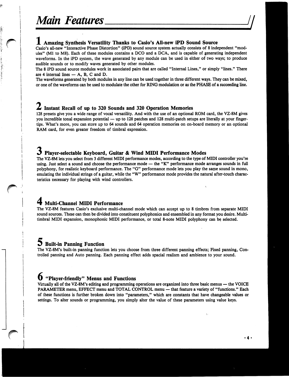
Main
Features
A
Amazing
Synthesis
Versatility
Thanks
to
Casio's
All-new
iPD
Sound
Source
Casio's
all-new
"Interactive
Phase
Distortion"
(iPD)
sound
source
system
actually
consists
of
8
independent
"mod
ules"
(Ml
to
M8).
Each
of
these
modules
contains
a
DCO
and
a
DCA,
and
is
capable
of
generating
independent
waveforms.
In
the
iPD
system,
the
wave
generated
by
any
module
can
be
used
in
either
of
two
ways;
to
produce
audible
sounds
or
to
modify
waves
generated
by
other
modules.
The
8
iPD
sound
source
modules
work
in
associated
pairs
that
are
called
"Internal
Lines,"
or
simply
"lines."
There
are
4
internal
lines
—
A,
B,
C
and D.
The
waveforms
generated
by
both
modules
in
any
line
can
be used
together
in
three
different
ways.
They
can
be
mixed,
or
one
of
the
waveforms
can
be
used
to
modulate
the
other
for
RING
modulation
or
as
the
PHASE
of
a
succeeding
line.
Z*
Instant
Recall
of
up
to
320
Sounds
and
320
Operation
Memories
128
presets
give
you
a
wide
range
of
vocal
versatility.
And
with
the
use
of
an
optional
ROM
card,
the
VZ-8M
gives
you
incredible
tonal
expansion
potential
—
up
to
128
patches
and
128
multi-patch
setups
are
literally
at
your
finger
tips.
What's
more,
you
can
store
up
to
64
sounds
and
64
operation
memories
on
on-board
memory
or
an
optional
RAM
card,
for
even
greater
freedom
of
timbral
expression.
Player-selectable
Keyboard,
Guitar
&
Wind
MIDI
Performance
Modes
The
VZ-8M
lets
you
select
from
3
different
MIDI
performance
modes,
according
to the
type
of
MIDI
controller
you're
using.
Just
select
a
sound
and
choose
the
performance
mode
—
the
"K"
performance
mode
arranges
sounds
in
full
polyphony,
for
realistic
keyboard
performance.
The
"G"
performance
mode
lets
you
play
the
same
sound
in
mono,
emulating
the
individual
strings
of
a
guitar,
while
the
"W"
performance
mode
provides
the
natural
after-touch
charac
teristics
necessary
for
playing
with
wind
controllers.
Multi-Channel
MIDI
Performance
The
VZ-8M
features
Casio's
exclusive
multi-channel
mode
which
can
accept
up
to
8
timbres
from
separate
MIDI
sound
sources.
These
can
then
be
divided
into
constituent
polyphonies
and
ensembled
in
any
format
you
desire.
Multi-
timbral
MIDI
expansion,
monophonic
MIDI
performance,
or
total
8-note
MIDI
polyphony
can
be
selected.
Jj^
Built-in
Panning
Function
The
VZ-8M's
built-in
panning
function
lets
you
choose
from
three
different
panning
effects;
Fixed
panning,
Con
trolled
panning
and
Auto
panning.
Each
panning
effect
adds
spacial
realism
and
ambience
to
your
sound.
U
"Player-friendly"
Menus
and
Functions
Virtually
all
of
the
VZ-8M's
editing
and
programming
operations
are
organized
into
three basic
menus
—
the
VOICE
PARAMETER
menu,
EFFECT
menu
and
TOTAL
CONTROL
menu
—
that
feature
a
variety
of
"functions."
Each
of
these
functions
is
further
broken
down
into
"parameters,"
which
are
constants
that
have
changeable
values
or
settings.
To
alter
sounds
or
programming,
you
simply
alter
the
value
of
these
parameters
using value
keys.
/
Combination
Mode
Provides
Layered
and
Split
Voicing
The
VZ-8M's
"Combination"
mode
lets
you
mix
together
up
to
8
different
patches
in
any
of
9
different
patch
mix
or
patch
split
configurations.
(1
+
2,
3
+
4,
1
+
2
+
3
+
4,
1+2+3
+
4
+
5
+
6+7
+
8,
1/3,
1
+
2/3,
1/3
+
4,
1+2/3+4,
1/2/3/4)
You
can
set
effect
and
amp
levels
independently
for
each
patch.
8
Velocity
Split
&
Positional
Cross
Fade
The
VZ-8M
puts
powerful
multi-voice
performance
in
your
hands,
with
advanced
features
such
as
velocity
split
and
positional
cross
fade.
Set
up
multi-layered
voices
with
up
to
3
split
points,
and
"fade"
the
voices
into
one
another
so
there's
no
audible
"split
point"
with
the
cross
fade
function,
or
control
multiple
voices
through
velocity
message
using
velocity
split.
y
Optional
ROM
&
RAM
Cards
Choose
from
optional
ROM
or
RAM
cards
for
expanded
sound
storage
and
recall
capabilities.
Each
ROM
card
holds
an
impressive
128
patches
and
128
different
operation
memories.
With
a
RAM
card,
you
can
store
up
to
64
patches
and
64
operation
memories.
What's
more,
VZ-8M
patches
can
be
used
in
a
Casio
PG
series
guitar
synth.
Whil.
tal
sy
it
do
a
ref«
Whei
to
co
MID
Once
need
"The
with
Semi:
Next.
throu
Whei
capal
Be
su
will
*
The!
Fort
Most
you'l
own
About
this
Manual
H
While
you
may
not
realize
it
quite
yet,
this
unit
is
an
incredibly
complex
digi
tal
synthesizer
that
has
a
lot
more
in
common
with
a
personal
computer
than
it
does
an
"electronic"
musical
instrument.
This
manual
is
intended
only
as
a
reference
to
provide
instructions
on
the
most
basic
operations.
When
you
take
the
unit
out
of
its
box
for
the
first
time,
you'll
probably
want
to
connect
it
to
an
external
keyboard,
guitar
or
wind
controller
equipped
with
MIDI
and
plug
it
in
immediately
to
see
how
it
sounds.
Once
you're
ready
to
begin
studying
the
true
power
of
this
synth
module,
you'll
need
to
have
a
basic
knowledge
of
its
iPD
modular
sound
source
system.
Read
"Theory:
iPD
Modular
Sound
System"
thoroughly
—
if
you're
not
familiar
with
basic
sound
synthesis
terms
and
theory,
be
sure
to
study
the
"VZ
Sound
Seminar"
as
well.
Next,
you
should
familiarize
yourself
with
the operating
system
controls.
Read
through
the
"Operating
System
Controls"
for
an
introduction
to
these
controls.
When
you're
ready
to
start
using
the
advanced
editing
and
sound
data
storage
capabilities,
you'll
need
to
learn
how
to
use
the
"FUNCTION
INDEXES".
Be
sure
to
work
through
the
"Function
Index
Practice
Exercise"
as
well.
These
will
give
you
a
fairly
solid
understanding
of
basic
synthesis
operations.
The
FUNCTION
INDEXES
will
be
an
invaluable
aid
in
all
editing
operations.
For
this
reason,
be
sure
to
keep
this
manual
handy
whenever
editing
sounds.
Most
importantly,
remember
that
this
manual
is
meant
as
a
reference
only
—
you'll
only
be
able to
realize
the
true
power
of
this
unit
as
you
apply
it
to
your
own
musical
performance.

Important
Terms
Throughout
this
manual
you
will
encounter
terms
(words)
which
you
may
—
or
may
not
—
be
familiar
with.
Before
jumping
into
the
operations,
it's
important
to
make
sure
that
you
understand
the
basic
usage
of
these
terms
in
this
manual.
Take
a
few
moments
to
read
through
these
words
and
become
familiar
with
them
—
you'll
find
it
will
enhance
your
over
all
understanding
of
this
unit.
Jl
MENU
FUNCTION
PARAMETER
VALUE
MODULE
INTERNAL
LINE
EXTERNAL
PHASE
PATCH
OPERATION
MEMORY
ENVELOPE
MODE
A
displayed
list
of
the
various
FUNCTIONS
you
can
use
to
edit
sounds.
There
are
three
basic
Menus
which
can
be
selected;
the
VOICE
PARAMETER
menu
(VOICE
menu),
EFFECT
menu,
and
TOTAL
CONTROL
menu
(TOTAL
menu).
Any
of
the
items
listed
on
the
menus.
Each
Function
contains
a
variety
of
PARAMETERS,
and
is
identified
by
a
two-digit
number.
For
example,
Function
02
in
VOICE
PARAMETER
menu
contains
parameters
related
to
detuning.
A
constant
control
which
features
variable
levels.
These
parameters
control
not
only
data
that
affects
the
various
components
of a
sound,
but
also
aspects
of
the
overall
setup.
The
level
or
setting
assigned
to
an
individual
parameter.
The
iPD
sound
source
features
8
independent
"modules."
These
can
be
thought
of
as
independent
—
but
interrelated
—
oscillators
with
controls.
Sound
source
MODULES
work
together
in
"pairs."
These
pairs
form
what
is
known
as
an
INTERNAL
LINE,
or
simply
"line."
For
example,
Module
1
and
Module
2
(Ml
and
M2)
form
Internal
Line
A
—
known
in
this
manual
as
LINE
A.
M3
and
M4
form
LINE
B,
etc.
In
addition
to
using
the
output
of
any
LINE
to
create
audible
sounds,
you
can
uti
lize
the
output
to
modulate
the
succeeding
line.
For
example,
the
output
of
LINE
A
can
be
used
to
modulate
LINE
B.
This
configuration
is
known
as
"External
Phase."
(Refer
to
"Theory:
iPD
Modular
Sound
System"
for
details.)
With
analog
synthesizers,
a
"patch"
literally
referred
to
the
way
in
which
various
synthesizer
blocks
or
modules
were
hard-wired
(hooked
up).
With
digital
synthesizers,
this
term
has
come
to
refer
to
completed
sound
data
which
can
be
output
by
the
synthesizer.
In
this
manual,
you
can
think
of
"patch"
as
referring
to
any
complet
ed
sound
data
coming
from
modules
1
through
8.
An
operation
memory
is
literally
a
full
"multi-timbral
setup"
or
"performance
setup",
complete
with
specifications
for
multiple
patches
(when
desired),
keyboard
and
velocity
split,
MIDI
settings,
etc.
The
onboard
memory
allows
storage
of
128
preset
operation
memories.
A
voltage
which
changes
as
a
function
of
time.
Envelopes
are
generally triggered
by
controllers,
and
are
used
to
shape
the
amplitude
(volume)
and
pitch
of
a
note.
A
particular
operational
function
or
condition.
In
"VZ
language",
there
are
4
bas
ic
operational
modes,
including
the
NORMAL
mode,
the
COMBINATION
mode,
the
OPERATION
MEMORY
mode, and
the
MULTI
CHANNEL
mode.
Each
of
these
serves
an
independent
purpose
described
later in this
manual.
PERFORMANCE
MODE
KMODE
GMODE
WMODE
VOICE-09
EFFECT-05
CONTROL-04
OPE
EFFECT
PROG
NO
KEYS
MOD
WHEEL
DEF
CONTROL
PAGE
KEYS
COMBI
MODE
MULTI
CH
MODE
M
ON/OFF
KEY
There
are
3
basic
"MIDI
Performance
Modes",
which
should
not
be
confused
with
the
basic
operational
"modes".
The
"Performance
Modes"
are
actually preset
parameter
setups
programmed
for
each
sound
individually,
which
can
be
selected
to
"match"
the
selected
sound
with
the
type
of
MIDI
controller
you
are
using.
For
example,
if
you're
using
a
MIDI
keyboard,
you'll
want
to
select
the
"K"
or
key
board
performance
mode.
In
addition
to
"K",
there
are
"G"
(Guitar)
and
"W"
(Wind)
MIDI
performance
modes.
Short
for
"Keyboard
Mode"
—
one
of
three
VZ-8M
MIDI
performance
modes.
Short
for
"Guitar
Mode"
—
one
of
three
VZ-8M
MIDI
performance
modes.
Short
for
"Wind
Mode"
—
one
of
three
VZ-8M
MIDI
performance
modes.
Throughout
this
text,
the
names
of
each
of
the
three
main
"menus"
is
listed
in
cap
ital
letters.
In
this
case,
VOICE-09
indicates
function
"09"
in
the
"Voice
Parameter"
menu
—
the
"AMP
ENV"
function.
Throughout
this
text,
the
names
of
each
of
the
three
main
"menus"
is
listed
in
cap
ital
letters.
In
this
case,
EFFECT-05
indicates
function
"05"
in
the
"Effect"
menu
—
the
"DEF
CONTROL"
function.
Throughout
this
text,
the
names
of
each
of
the
three
main
"menus"
is
listed
in
cap
ital
letters.
In
this
case,
CONTROL-04
indicates
function
"04"
in
the
"Total
Con
trol"
menu
—
the
"MIDI
CHANNEL"
function.
Indicates
the
EFFECT
menu
in
the
OPERATION
MEMORY
mode.
For
example,
"OPE
EFFECT-01"
represents
function
"01"
in
the
OPERATION
MEMORY
mode's
EFFECT
menu
—
the
"OP
TUNE"
function.
Short
for
"Program
Number
Keys".
These
keys
are
used
in
a
variety
of
sound
syn
thesis
and
editing
operations.
Short
for
"Modulation
Wheel".
Short
for
"Definable
Control".
Used
to
"scroll"
or
advance
up
and
down
the
selected
VZ
menu.
Short
for
"Combination
Mode"
—
one
of
the
4
basic
operational
modes
used
in
synthesis,
editing
and
performance.
Short
for
"Multi
Channel
Mode"
—
another
of
the
basic
operational
modes.
Short
for
"Module
ON/OFF
Key"
—
keys
used
to
turn
the
VZ's
sound
source
mod
ules
ON
and
OFF.
Theory:
Flow
of
Operations
ji
Although
the
VZ-8M
features
a
complex
operating
system,
it
has
been
designed
so
that
actual
operations
are
quite
simple
—
after
a
few
hours
you'll
be
amazed
at
how
simple
the
unit
is
to
operate,
and
how
versatile
it
is.
In
order
to
appreciate
the
beauty
of
the
VZ,
it's
important
to
have
a
clear
initial
understanding
of
its
basic
"flow
of
operations"
—
in
other
words
the
basic
order
of
operations
you
will
probably
want
to
follow
to
make
the
most
of
this
synthesizer.
Simply
speaking,
operations
can
be
divided
into
four
different
types
—
these
correspond
to
the
four
basic
operational
"modes"
—
the
NORMAL
mode,
the
COMBINATION
mode,
the
OPERATION
MEMORY
mode
and
the
MULTI
CHANNEL
mode.
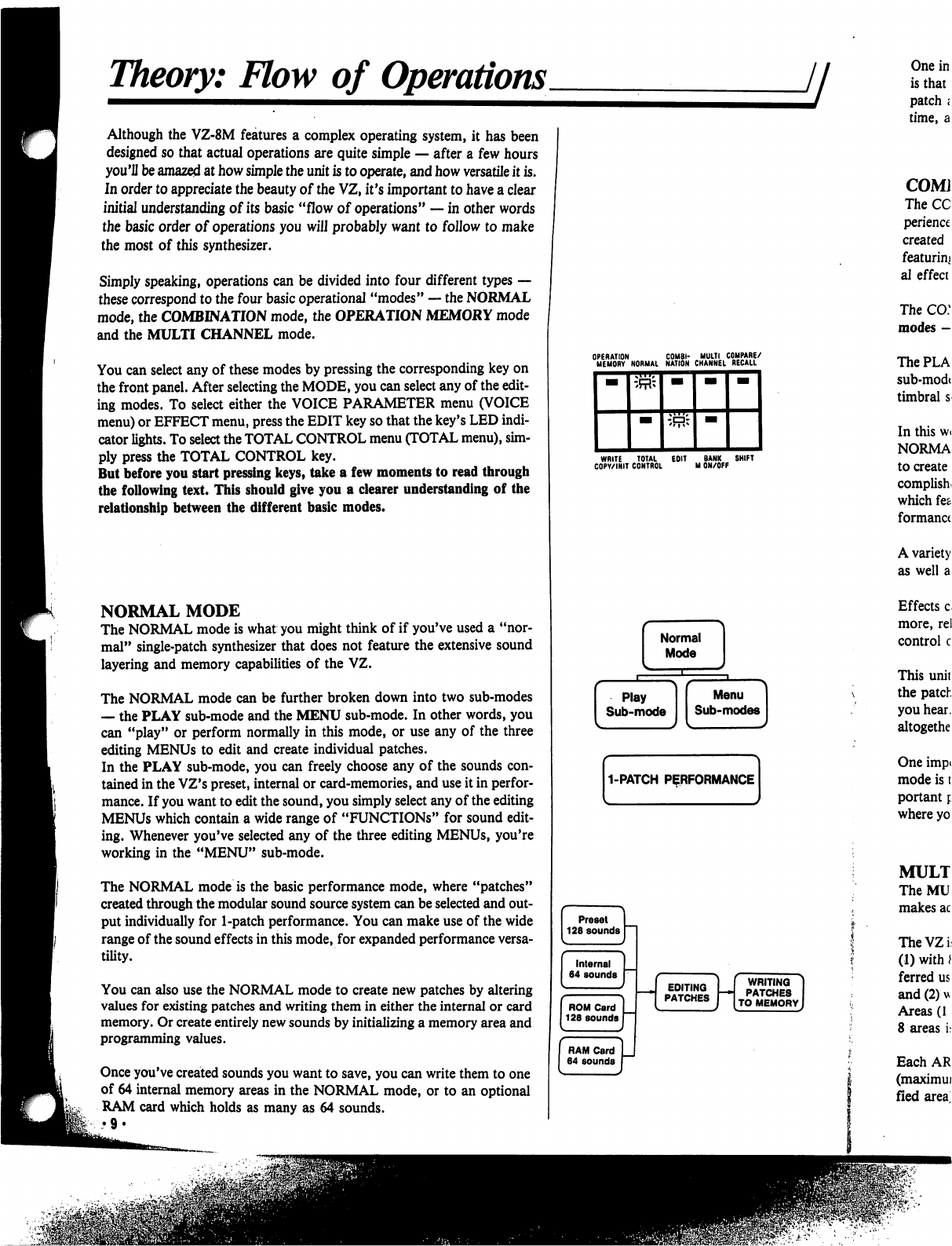
You
can
select
any
of
these
modes
by
pressing
the
corresponding
key
on
the
front
panel.
After
selecting
the
MODE,
you
can
select
any
of
the
edit
ing
modes.
To
select
either
the
VOICE
PARAMETER
menu
(VOICE
menu)
or
EFFECT
menu,
press
the
EDIT
key
so
that
the
key's
LED
indi
cator
lights.
To
select
the
TOTAL
CONTROL
menu
(TOTAL
menu),
sim
ply
press
the
TOTAL
CONTROL
key.
But
before
you
start
pressing
keys,
take
a
few
moments
to
read
through
the
following
text.
This
should
give
you
a
clearer
understanding
of
the
relationship
between
the
different
basic
modes.
NORMAL
MODE
The
NORMAL
mode
is
what
you
might
think
of
if
you've
used
a
"nor
mal"
single-patch
synthesizer
that
does
not
feature
the
extensive
sound
layering
and
memory
capabilities
of
the
VZ.
The
NORMAL
mode
can be
further
broken
down
into
two
sub-modes
—
the
PLAY
sub-mode
and
the
MENU
sub-mode.
In
other
words,
you
can
"play"
or
perform
normally
in
this
mode,
or
use
any
of
the
three
editing
MENUs
to
edit
and
create
individual patches.
In
the
PLAY
sub-mode,
you
can
freely
choose
any
of
the
sounds
con
tained
in
the
VZ's
preset,
internal
or
card-memories,
and
use
it
in
perfor
mance.
If
you
want
to
edit
the
sound,
you
simply
select
any
of
the
editing
MENUs
which
contain
a
wide
range
of
"FUNCTIONS"
for
sound
edit
ing.
Whenever
you've
selected
any
of
the
three
editing
MENUs,
you're
working
in
the
"MENU"
sub-mode.
The
NORMAL
mode
is
the
basic
performance
mode,
where
"patches"
created
through
the
modular
sound
source
system
can
be
selected
and
out
put
individually
for
1-patch
performance.
You
can
make
use
of
the
wide
range
of
the
sound
effects in
this
mode,
for
expanded
performance
versa
tility.
You
can
also
use
the
NORMAL
mode
to
create
new
patches
by
altering
values
for
existing
patches
and
writing
them
in
either
the
internal
or card
memory.
Or
create
entirely
new
sounds
by
initializing
a
memory
area
and
programming
values.
Once
you've
created
sounds
you
want
to
save,
you
can
write
them
to
one
of
64
internal
memory
areas
in
the
NORMAL
mode,
or
to
an
optional
RAM
card
which
holds
as
many
as
64
sounds.
WRITE
TOTAL
EOIT
BANK
SHIFT
COPY/INIT
CONTROL
M
ON/OFF
WRITING
PATCHES
TO
MEMORY
f
RE/
•LL
JfPV
f
WRITING
PATCHES
0
MEMORY
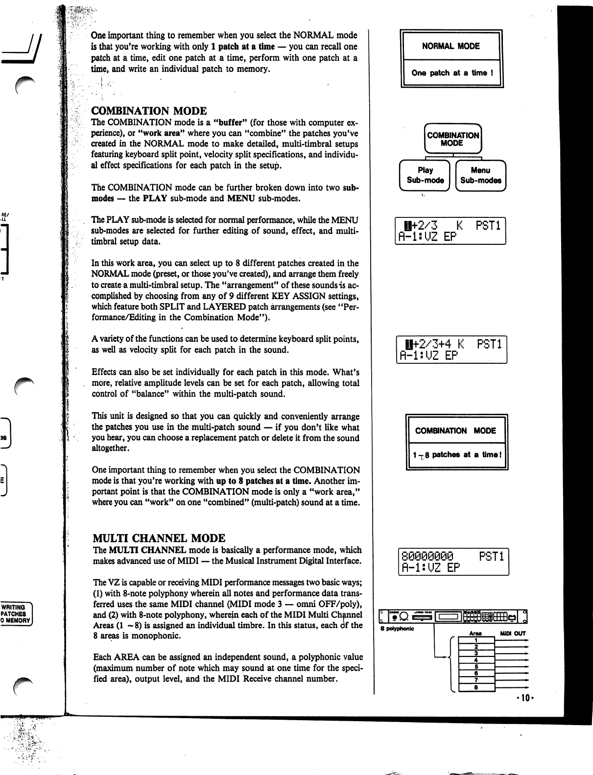
One
important
thing
to
remember
when
you
select
the
NORMAL
mode
is
that
you're
working
with
only
1
patch
at
a
time
—
you
can
recall
one
patch
at
a
time,
edit
one
patch
at
a
time,
perform
with
one
patch
at
a
time,
and
write
an
individual
patch
to
memory.
COMBINATION
MODE
The
COMBINATION
mode
is
a
"buffer"
(for
those
with
computer
ex
perience),
or
"work
area"
where
you
can
"combine"
the
patches
you've
created
in
the
NORMAL
mode
to
make
detailed,
multi-timbral
setups
featuring
keyboard
split
point,
velocity
split
specifications,
and
individu
al
effect
specifications
for
each
patch
in
the
setup.
The
COMBINATION
mode
can
be
further
broken
down
into
two
sub-
modes
—
the
PLAY
sub-mode
and
MENU
sub-modes.
The
PLAY
sub-mode
is
selected
for
normal
performance,
while
the
MENU
sub-modes
are
selected
for
further
editing
of
sound,
effect,
and
multi-
timbral
setup
data.
In
this
work
area,
you
can
select
up
to
8
different
patches
created
in
the
NORMAL
mode
(preset,
or
those
you've
created),
and
arrange
them
freely
to
create
a
multi-timbral
setup.
The
"arrangement"
of
these
sounds
is
ac
complished
by
choosing
from
any
of 9
different
KEY
ASSIGN
settings,
which
feature
both
SPLIT
and
LAYERED
patch
arrangements
(see
"Per
formance/Editing
in
the
Combination
Mode").
A
variety
of
the
functions
can
be
used
to
determine
keyboard
split
points,
as
well
as
velocity
split
for
each
patch
in
the
sound.
Effects
can
also
be
set
individually
for
each
patch
in
this
mode.
What's
more,
relative
amplitude
levels
can
be
set
for
each
patch,
allowing
total
control
of
"balance"
within
the
multi-patch
sound.
This
unit
is
designed
so
that
you
can
quickly
and
conveniently
arrange
the
patches
you
use
in
the
multi-patch
sound
—
if
you
don't
like
what
you
hear,
you
can
choose
a
replacement
patch
or
delete
it
from
the
sound
altogether.
One
important
thing
to
remember
when
you
select
the
COMBINATION
mode
is
that
you're
working
with
up
to
8
patches
at
a
time.
Another
im
portant
point
is
that
the
COMBINATION
mode
is
only
a
"work
area,"
where
you
can
"work"
on
one
"combined"
(multi-patch)
sound
at
a
time.
MULTI
CHANNEL
MODE
The
MULTI
CHANNEL
mode
is
basically
a
performance
mode,
which
makes
advanced
use
of
MIDI
—
the
Musical
Instrument
Digital
Interface.
The
VZ
is
capable
or
receiving
MIDI
performance
messages
two
basic
ways;
(1)
with
8-note
polyphony
wherein
all
notes
and
performance
data
trans
ferred
uses the
same
MIDI
channel
(MIDI
mode
3
—
omni
OFF/poly),
and
(2)
with
8-note
polyphony,
wherein
each
of
the
MIDI
Multi
Channel
Areas
(1
—8)
is
assigned
an
individual
timbre.
In
this
status,
each
of
the
8
areas
is
monophonic.
Each
AREA
can
be
assigned
an
independent
sound,
a
polyphonic
value
(maximum
number
of
note
which
may
sound
at
one
time
for
the
speci
fied
area),
output
level,
and
the
MIDI
Receive
channel
number.
NORMAL
MODE
One
patch
at
a
time
!
combination]
MODE
I
Ii+2/3
K
PST1
R-l:UZ
EP
H+2/3+4
K
PST1
fl-UUZ
EP
COMBINATION
MODE
1-8
patches
at
a
time!
fl-l:UZ
EP
PST1
8
polyphonic
Area
MUM
OUT
r
OPERATION
MEMORY
MODE
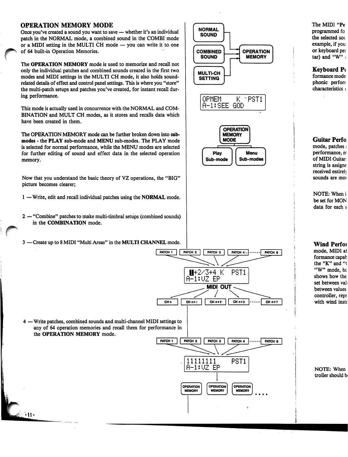
Once
you've
created
a
sound
you
want
to
save
—
whether
it's
an
individual
patch
in
the
NORMAL
mode,
a
cpmbined
sound
in
the
COMBI
mode
or
a
MIDI
setting
in
the
MULTI
CH
mode
—•
you
can
write
it
to
one
of
64
built-in
Operation
Memories.
The
OPERATION
MEMORY
mode
is
used
to
memorize
and
recall
not
only
the
individual
patches
and
combined
sounds
created
in
the
first
two
modes
and
MIDI
settings
in
the
MULTI
CH
mode,
it
also
holds
sound-
related
details
of
effect
and
control
panel
settings.
This
is
where
you
"store"
the
multi-patch
setups
and
patches
you've
created,
for
instant
recall
dur
ing
performance.
This
mode
is
actually
used
in
concurrence
with
the
NORMAL
and
COM
BINATION
and
MULT
CH
modes,
as
it
stores
and
recalls
data
which
have
been
created
in
them.
The
OPERATION
MEMORY
mode
can
be
further
broken
down
into
sub-
modes
-
the
PLAY
sub-mode
and
MENU
sub-modes.
The
PLAY
mode
is
selected
for
normal
performance,
while
the
MENU
modes
are
selected
for
further
editing
of
sound
and
effect
data
in
the
selected
operation
memory.
Now
that
you
understand
the
basic
theory
of
VZ
operations,
the
"BIG"
picture
becomes
clearer;
1
—Write,
edit
and
recall
individual
patches
using
the
NORMAL
mode.
r
2
—
"Combine"
patches
to
make
multi-timbral
setups
(combined
sounds)
in
the
COMBINATION
mode.
3
—
Create
up
to
8
MIDI
"Multi
Areas"
in
the
MULTI
CHANNEL
mode.
|
PATCH
1
| |
PATCH
2
|
|
PATCH
3
|
|
PATCH
4
. | |
PATCH
8
|
0+2/3+4
K
PST1
R-isUZ
EP
MIDI
OUT
/
4
—Write
patches,
combined
sounds
and
multi-channel
MIDI
settings
to
any
of
64
operation
memories
and
recall
them
for
performance
in
the
OPERATION
MEMORY
mode.
CHn
CHn+l
CH
n+2
|
PATCH
1
|
|
PATCH
2
|
|
PATCH
3
| |
PATCH
4
|
|
PATCH
8
11111111
PST1
fl-ls'JZ
EP
The
MIDI
"Pe
programmed
fo
the
selected
soi
example,
if
you
or
keyboard
pei
tar)
and
"W"
»
Keyboard
Pc
formance
mode
phonic
perforr
characteristics
i
Guitar
Perf
o
mode,
patches;
performance,
rr
of
MIDI
Guitar,
string
is
assigne
received
entireh
sounds
are
moi
NOTE:
When
i
be
set
for
MON
data
for
each
s
Wind
Perfor
mode,
MIDI
af
formance
capab
the
"K"
and
"(
"W"
mode,
he
shows
how
the
set
between
val>
between
values
controller,
repr
with
wind
instr
NOTE:
When
troller
should
b<

/0^\
The
MIDI
"Performance
Modes"
are
actually
preset
parameter
setups,
programmed
for
each
sound
individually,
which
can
be
selected
to
"match"
the
selected
sound
with
the
type
of
MIDI
controller
you
are
using.
For
example,
if
you're
using
"a
MIDI
keyboard,
you'll
want
to
select
the
"K"
or
keyboard
performance
mode.
In
addition
to
"K",
there
are
"G"
(Gui
tar)
and
"W"
(Wind)
MIDI
performance
modes.
Keyboard
Performance
Mode
—
In
the
"K"
or
"Keyboard"
per
formance
mode,
patches
and
multi-patch
sounds
are
setup
for
MIDI
poly
phonic
performance,
matched
to
the
performance
capabilities
and
characteristics
of
MIDI
keyboards.
Guitar
Performance
Mode
—
In
the
"G"
or
"Guitar"
performance
mode,
patches
and
multi-patch
sounds
are
setup
for
MIDI
monophonic
performance,
matched
to
the
performance
capabilities
and
characteristics
of
MIDI
Guitars,
including
Casio
PG
and
MG
series
guitars.
As
each
guitar
string
is
assigned
an
individual
MIDI
channel,
MIDI
bend
messages
are
received
entirely
independently
for
each
string.
In
addition,
string
release
sounds
are
more
natural
than
with
poly
performance.
NOTE:
When
in
"G"
performance
mode,
the
transmitting
guitar
should
be
set
for
MONO
performance,
allowing
independent
transmission
of
bend
data
for
each
string.
Wind
Performance
Mode
—
In
the
"W"
or
"Wind"
performance
mode,
MIDI
aftertouch
data
is
automatically
adapted
to
match
the
per
formance
capabilities
and
characteristics
of
MIDI
wind
controllers.
In
both
the
"K"
and
"G"
modes,
MIDI
data
changes
as
shown
in
FIG-A.
In
the
"W"
mode,
however,
this
same
data
changes
as
shown
in
FIG-B.
This
shows
how
the
SENS
parameter
affects
aftertouch
characteristics
when
set
between
values
of
"0" and
"91".
The
changes
in
these
characteristics
between
values
of
"92"
and
"99"
make
it
easier
to
perform
using
a
wind
controller,
reproducing
the
delicate
dynamic
changes
which
are
possible
with
wind
instruments.
FIG-A
<
NORMAL
AFTER
TOUCH
>
FIG-B
[KEYBOARD
MODE]
VZ-8M
MIDI
KEYBOARD
NORMflL
K
PST1
fl-lsUZ
EP
1+2/3+4
K
R-isUZ
EP
PST1
(GUITAR
MODE]
VZ-8M
MIDI
GUITAR
--1ststring
\
--2nd
string
\
•
-3rd
string
|
.-4th
string
•-5th
string
/
■•
-6th
string
/
NORMflL
fi-lsUZ
EP
8
PST1
1+2/3+4
G
R-inUZ
EP
PST1
(WIND
MODE]
VZ-8M
NORMflL
W
fl-l:UZ
EP
PST1
1+2/3+4
W
fl-lsUZ
EP
PST1
MAX
AMP
MIN
XSENSITIVITY»O
-SENSmVITY»99
<WIND
MODE
AFTER
TOUCH
>
„
SENSITMTYoO
MAX
AMP
MIN
''''/''<—[-SENSITMTY=91
AMP
MIN
»MAX
MIDI
DATA
MAX
MIN
-MAX
MIDI
DATA
SENSITIVITY»92
•SENSITMTY=99
MIDI
DATA
NOTE:
When
in
"W"
performance
mode,
the
transmitting
wind
con
troller
should
be
set
so
that
after
touch
data
can
be
used
to
affect
volume.
Theory:
iPD
Modular
Sound
System
l
I;!'1
At
the
heart
of
the
VZ's
amazing
sound
synthesis
capabilities
is
an
all-
new
"iPD"
(interactive
Phase
Distortion)
sound
source.
In
order
to
get
the
most
out
of
your
unit,
it
is
vitally
important
that
you
understand
at
least
the
basic
theory
behind
this
new
sound
source.
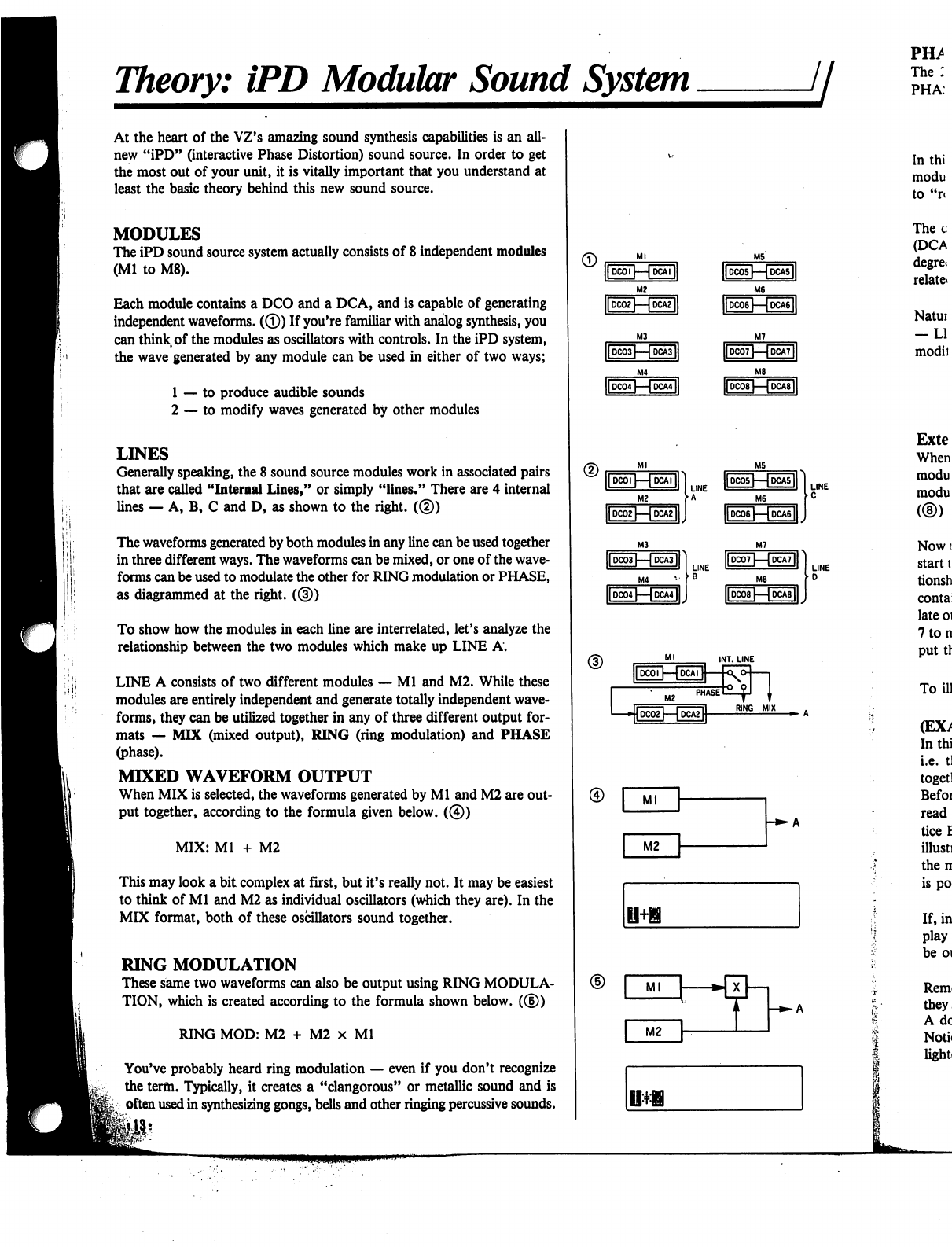
MODULES
The
iPD
sound
source
system
actually
consists
of
8
independent
modules
(Ml
to
M8).
Each
module
contains
a
DCO
and
a
DCA,
and
is
capable
of
generating
independent
waveforms.
(©)
If
you're
familiar
with
analog
synthesis,
you
can
think
of
the
modules
as
oscillators
with
controls.
In
the
iPD
system,
the
wave
generated
by any
module
can
be
used
in
either
of
two
ways;
1
—
to
produce
audible
sounds
2
—
to
modify
waves
generated
by
other
modules
LINES
Generally
speaking,
the
8
sound
source
modules
work
in
associated
pairs
that
are
called
"Internal
Lines,"
or
simply
"lines."
There
are
4
internal
lines
—
A,
B,
C
and
D,
as
shown
to
the
right.
(®)
The
waveforms
generated
by
both
modules
in
any
line
can
be
used
together
in
three
different
ways.
The
waveforms
can
be
mixed,
or
one
of
the
wave
forms
can
be
used
to
modulate
the
other
for
RING
modulation
or
PHASE,
as
diagrammed
at
the
right.
((§))
To
show
how
the
modules
in
each
line
are
interrelated,
let's
analyze
the
relationship
between
the
two
modules
which
make
up
LINE
A.
LINE
A
consists
of
two
different
modules
—
Ml
and
M2.
While
these
modules
are
entirely
independent
and
generate
totally
independent
wave
forms,
they
can
be
utilized
together
in
any
of
three
different
output
for
mats
—
MIX
(mixed
output),
RING
(ring
modulation)
and
PHASE
(phase).
MIXED
WAVEFORM
OUTPUT
When
MIX
is
selected,
the
waveforms
generated
by
Ml
and
M2
are
out
put
together,
according
to
the
formula
given
below.
(©)
MIX:
Ml
+
M2
This
may
look
a
bit
complex
at
first,
but
it's
really
not.
It
may
be
easiest
to
think
of
Ml
and
M2
as
individual
oscillators
(which
they
are).
In the
MIX
format,
both of
these
oscillators
sound
together.
RING
MODULATION
These
same
two
waveforms
can
also
be
output
using
RING
MODULA
TION,
which
is
created
according
to
the
formula
shown
below.
(®)
RING
MOD:
M2
+
M2
x
Ml
You've
probably
heard
ring
modulation
—
even
if
you
don't
recognize
the
term.
Typically,
it
creates
a
"clangorous"
or
metallic
sound
and
is
often
used
in
synthesizing
gongs,
bells
and
other
ringing
percussive
sounds.
■»-
A
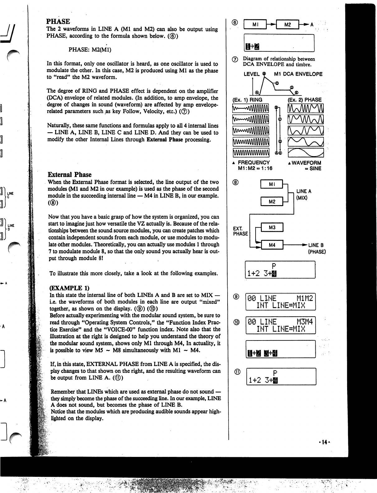
PHASE
The
2
waveforms
in
LINE
A
(Ml
and
M2)
can
also
be
output
using
PHASE,
according
to
the
formula
shown
below.
((§))
PHASE:
M2(M1)
In
this
format,
only
one
oscillator
is
heard,
as
one
oscillator
is
used
to
modulate
the
other.
In
this
case,
M2
is
produced
using
Ml
as
the
phase
to
"read"
the
M2
waveform.
The
degree
of
RING
and
PHASE
effect
is
dependent
on
the
amplifier
(DCA)
envelope
of
related
modules.
(In
addition,
to
amp
envelope,
the
degree
of
changes
in
sound
(waveform)
are
affected
by
amp
envelope-
related
parameters such
,as
key
Follow,
Velocity,
etc.)
(©)
Naturally,
these
same
functions
and
formulas
apply
to
all
4
internal
lines
—
LINE
A,
LINE
B,
LINE
C
and
LINE
D.
And
they
can
be
used
to
modify
the
other
Internal
Lines
through
External
Phase
processing.
External
Phase
When
the
External
Phase
format
is
selected,
the
line
output
of
the
two
modules
(Ml
and
M2
in
our
example)
is
used
as
the
phase
of
the
second
module
in
the
succeeding
internal
line
—
M4
in
LINE
B,
in
our
example.
Now
that
you
have
a
basic
grasp
of
how
the
system
is
organized,
you
can
start
to
imagine
just
how
versatile
the
VZ
actually
is.
Because
of
the
rela
tionships
between
the
sound
source
modules,
you
can
create
patches
which
contain
independent
sounds
from
each
module,
or
use
modules
to
modu
late
other
modules.
Theoretically,
you
can
actually
use
modules
1
through
7
to
modulate
module
8,
so
that
the
only
sound
you
actually
hear
is
out
put
through
module
8!
To
illustrate
this
more
closely,
take
a
look
at
the following
examples.
(EXAMPLE
1)
In
this
state
the
internal
line
of
both
LINEs
A
and
B
are
set
to
MIX
—
i.e.
the
waveforms
of
both
modules
in
each
line
are
output
"mixed"
together,
as
shown
on
the
display.
((§))
(®)
Before
actually
experimenting
with
the
modular
sound
system,
be
sure
to
read
through
"Operating
System
Controls,"
the
"Function
Index
Prac
tice
Exercise"
and
the
"VOICE-00"
function
index.
Note
also that
the
illustration
at
the
right
is
designed
to
help
you
understand
the
theory
of
the
modular
sound
system,
shows
only
Ml
through
M4,
In
actuality,
it
is
possible
to
view
M5
~
M8
simultaneously
with
Ml
~
M4.
If,
in
this
state,
EXTERNAL
PHASE
from
LINE
A
is
specified,
the
dis
play
changes
to that
shown
on
the
right,
and
the
resulting
waveform
can
be
output
from
LINE
A.
(©)
Remember
that
LINEs
which
are
used
as
external
phase
do
not
sound
—
they
simply
become
the
phase
of
the
succeeding
line.
In
our
example,
LINE
A
does
not
sound,
but
becomes
the
phase
of
LINE
B.
Notice
that
the
modules
which
are
producing
audible
sounds
appear
high
lighted
on
the
display.
Ml
\-*»\
M2
(7)
Diagram
of
relationship
between
DCA
ENVELOPE
and
timbre.
LEVEL
M1
DCA
ENVELOPE
(Ex.
1)
RING
(Ex.
2)
PHASE
a
FREQUENCY
M1:M2«=1:16
▲
WAVEFORM
-SINE
LINE
A
(MIX)
EXT.
PHASE
■►LINEB
(PHASE)
1+2
3H
P
Q@
LINE
M1M2
INT
LINE=MIX
)
LINE
M3M4
INT
LINE=MIX
1+2
3+H
'14-
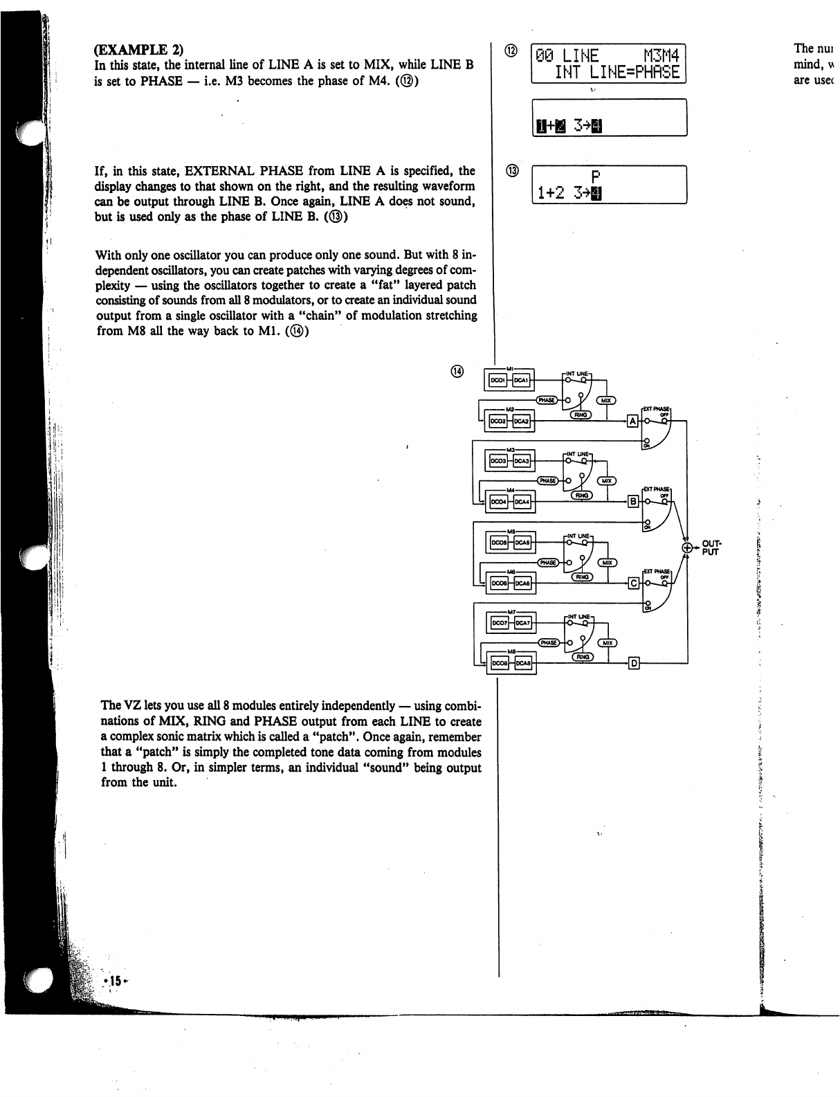
(EXAMPLE
2)
In
this
state,
the
internal
line
of
LINE
A
is
set
to
MIX,
while
LINE
B
is
set
to
PHASE
—
i.e.
M3
becomes
the
phase
of
M4.
(@)
If,
in
this
state,
EXTERNAL
PHASE
from
LINE
A
is
specified,
the
display
changes
to
that
shown
on
the
right,
and
the
resulting
waveform
can
be
output
through
LINE
B.
Once
again,
LINE
A
does
not
sound,
but
is
used
only
as
the
phase
of
LINE
B.
(@)
With
only
one
oscillator
you
can
produce
only
one
sound.
But
with
8
in
dependent
oscillators,
you
can
create
patches
with
varying
degrees
of
com
plexity
—
using
the
oscillators
together
to create
a
"fat"
layered
patch
consisting
of
sounds
from
all
8
modulators,
or
to
create
an
individual
sound
output
from
a
single
oscillator
with
a
"chain"
of
modulation
stretching
from
M8
all
the
way
back
to
Ml.
(@)
09
LINE
M3M4
INT
LINE=PHRSE
The
nui
mind,
u
are
usec
1+2
3*H
The
VZ
lets
you
use
all
8
modules
entirely
independently
—
using
combi
nations
of
MIX,
RING
and
PHASE
output
from
each
LINE
to
create
a
complex
sonic
matrix
which
is
called
a
"patch".
Once
again,
remember
that
a
"patch"
is
simply
the
completed
tone data
coming
from
modules
1
through
8.
Or,
in
simpler
terms,
an
individual
"sound"
being
output
from
the
unit.
•15-
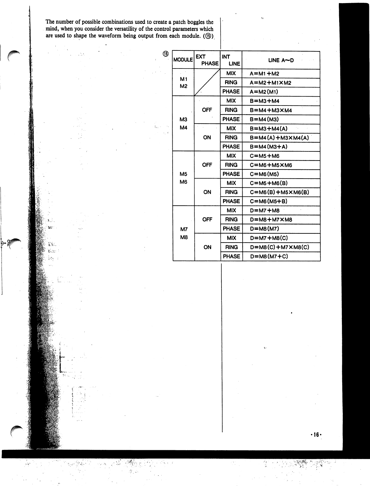
The
number
of
possible
combinations
used
to
create
a
patch
boggles
the
mind,
when
you
consider
the
versatility
of
the
control
parameters
which
are
used
to
shape
the
waveform
being
output
from
each
module.
(©)
16-
Operating
System
Controls.
jj
In
some
ways,
your
VZ
is
very
similar
to
a
computer,
as
it
is
capable
of
storing
and
generating
a
large
amount
of
digital
sound
data.
This
"data
processing"
is
maintained
by
the
"Operating
System,"
which
you
can
think
of
as
a
collection
of
system
programs
that
control
the
overall
operation
of
the
unit.
The
main
interface
with
the
operating
system
can
be
found
in
the
menu
functions.
These
functions
contain
a
number
of
parameters,
which
deter
mine
the
various
characteristics
of
the
sounds.
In
fact,
sound
synthesis
on
the
unit
basically
consists
of
inputting
values
for
these
parameters.
With
a
computer,
you
generally
execute
a
certain
program,
and
use
a
cur
sor
to
move
to
different
positions
in
the
displayed
page,
and
use
the
key
board
to
input
commands,
values,
text,
etc. (this
is,
of
course
a
simplified
explanation.)
Your
unit
works
much
in
the
same
way,
and
it
features
a
number
of
basic
"Operating
System
Controls"
which
are
used
to
perform
the
same
func
tions
a
computer
keyboard
or
mouse
would
perform.
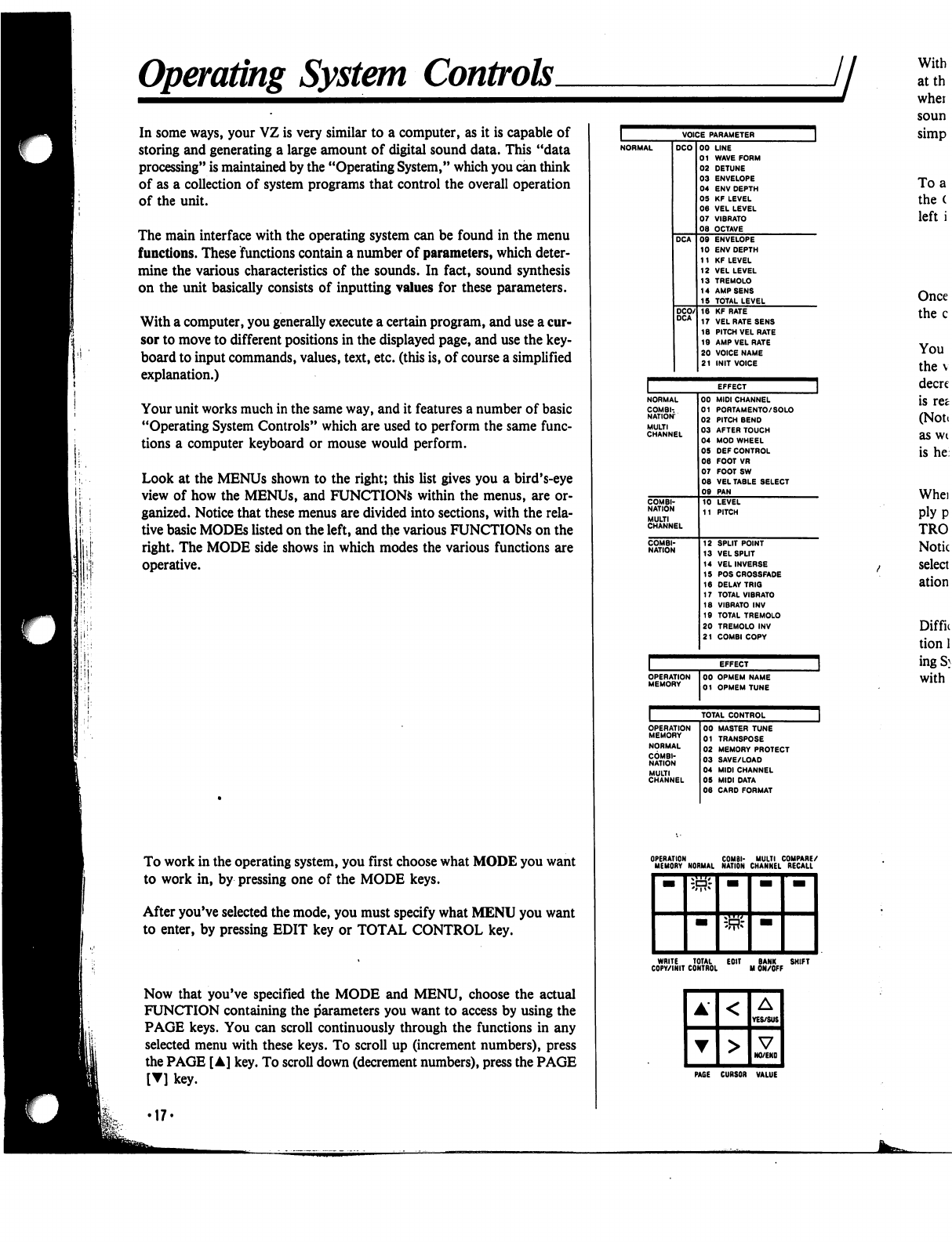
Look
at
the
MENUs
shown
to
the
right;
this
list
gives
you
a
bird's-eye
view
of
how
the
MENUs,
and
FUNCTIONS
within
the
menus,
are
or
ganized.
Notice
that
these
menus
are
divided
into
sections,
with
the
rela
tive
basic
MODEs
listed
on
the
left,
and
the
various
FUNCTIONS
on
the
right.
The
MODE
side
shows
in
which
modes
the
various
functions
are
operative.
To
work
in
the
operating
system,
you
first
choose
what
MODE
you
want
to
work
in,
by
pressing
one
of
the
MODE
keys.
After
you've
selected
the
mode,
you
must
specify
what
MENU
you
want
to
enter,
by
pressing
EDIT
key
or
TOTAL
CONTROL
key.
Now
that
you've
specified
the
MODE
and
MENU,
choose
the
actual
FUNCTION
containing
the
parameters
you
want
to access
by
using
the
PAGE
keys.
You
can
scroll
continuously
through
the
functions
in
any
selected
menu
with
these
keys.
To
scroll
up
(increment
numbers),
press
the
PAGE
[A]
key.
To
scroll
down
(decrement
numbers),
press
the
PAGE
[▼]
key.
EFFECT
NORMAL
COMBI-.
NATION
MULTI
CHANNEL
00
MIDI
CHANNEL
01
PORTAMENTO/
SOLO
02
PITCH
BEND
03
AFTER
TOUCH
04
MOD
WHEEL
05
DEF
CONTROL
06
FOOT
VR
07
FOOTSW
08
VEL
TABLE
SELECT
09
PAN
10
LEVEL
11
PITCH
12
SPLIT
POINT
13
VELSPUT
14
VELINVERSE
15
POSCROSSFADE
16
DELAY
TRIG
17
TOTAL
VIBRATO
18
VIBRATO
INV
19
TOTAL
TREMOLO
20
TREMOLO
INV
21
COMBI
COPY
OPERATION
MEMORY
00
OPMEM
NAME
01
OPMEM
TUNE
With
atth
whei
soun
simp
To
a
the
(
left
i
Once
the
c
You
the
v
decre
is
ret
(Note
as
wt
is
he
Whei
ply
p
TRO
Notic
select
ation
Diffn
tion
1
ingS}
with
OPERATION
COMBI-
MULTI
COMPARE/
MEMORY
NORMAL
NATION
CHANNEL
RECALL
WRITE
TOTAL
EOIT
BANK
SHIFT
COPY/INIT
CONTROL
M
ON/OFF
PAGE
CURSOR
VALUE
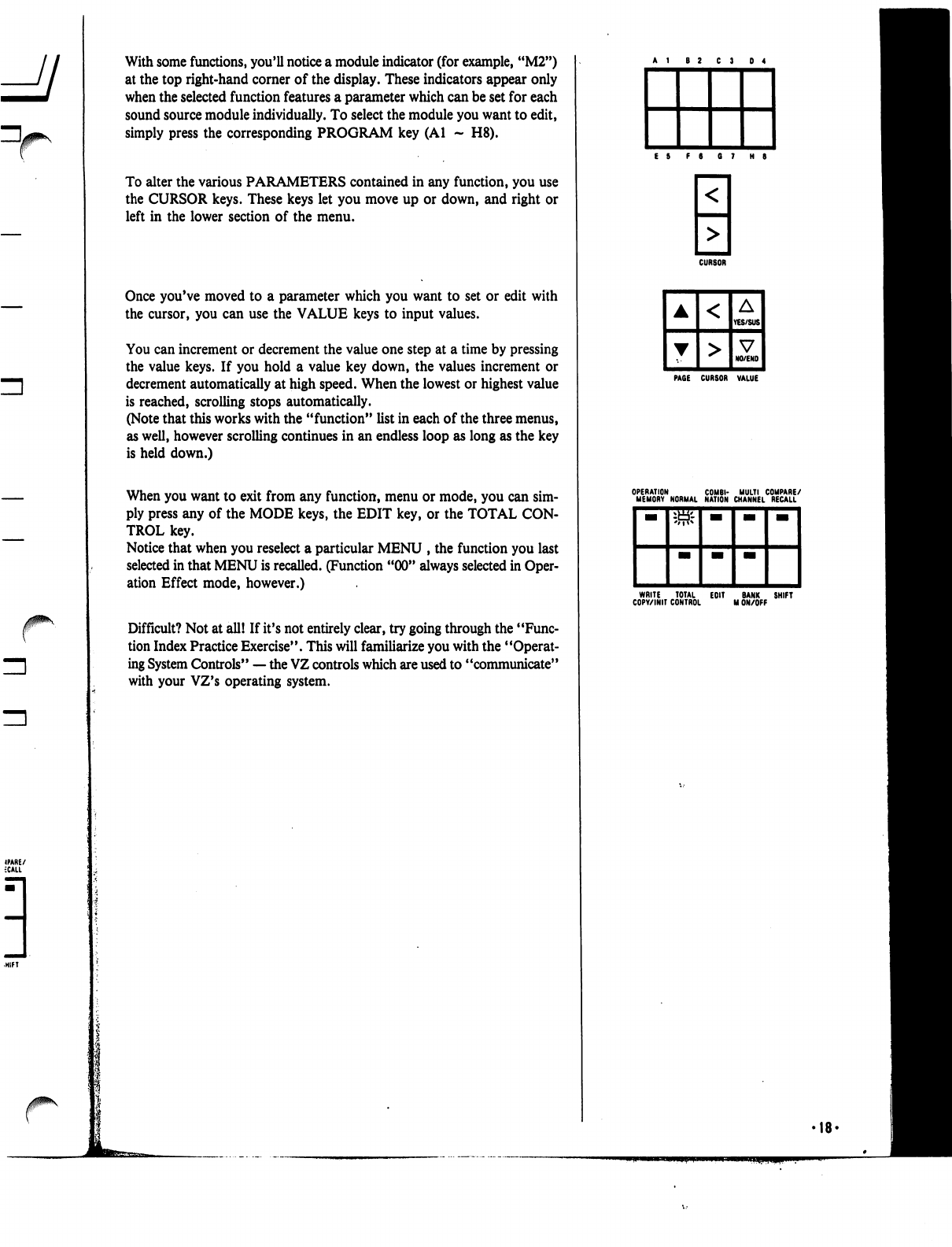
With
some
functions,
you'll
notice
a
module
indicator
(for
example,
"M2")
at
the
top
right-hand
corner
of
the
display.
These
indicators
appear
only
when
the
selected
function
features
a
parameter
which
can
be
set
for
each
sound
source
module
individually.
To
select
the
module
you
want
to
edit,
simply
press
the
corresponding
PROGRAM
key
(Al
-
H8).
To
alter
the
various
PARAMETERS
contained
in
any
function,
you
use
the
CURSOR
keys.
These
keys
let
you
move
up
or
down,
and
right
or
left
in
the
lower
section
of
the
menu.
Once
you've
moved
to
a
parameter
which
you
want
to
set
or
edit
with
the
cursor,
you
can
use
the
VALUE
keys
to
input
values.
You
can
increment
or
decrement
the
value
one
step
at
a
time
by
pressing
the
value
keys.
If
you
hold
a
value
key
down,
the
values
increment
or
decrement
automatically
at
high
speed.
When
the
lowest or
highest
value
is
reached,
scrolling
stops
automatically.
(Note
that
this
works
with
the
"function"
list
in
each
of
the
three
menus,
as
well,
however
scrolling
continues
in
an
endless
loop
as
long
as
the
key
is
held
down.)
When
you
want
to
exit
from
any
function,
menu
or
mode,
you
can sim
ply
press
any
of
the
MODE
keys,
the
EDIT
key,
or
the
TOTAL
CON
TROL
key.
Notice
that
when
you
reselect
a
particular
MENU
,
the
function
you
last
selected
in
that
MENU
is
recalled.
(Function
"00"
always
selected
in
Oper
ation
Effect
mode,
however.)
Difficult?
Not
at
all!
If
it's
not
entirely
clear,
try
going
through
the
"Func
tion
Index
Practice
Exercise".
This
will
familiarize
you
with
the
"Operat
ing
System
Controls"
—
the
VZ
controls
which
are
used
to
"communicate"
with
your
VZ's
operating
system.
CURSOR
PAGE
CURSOR
VALUE
WRITE
TOTAL
EOIT
BANK
SHIFT
COPY/INIT
CONTROL
M
ON/OFF
•18'
Menus
and
Functions
jj
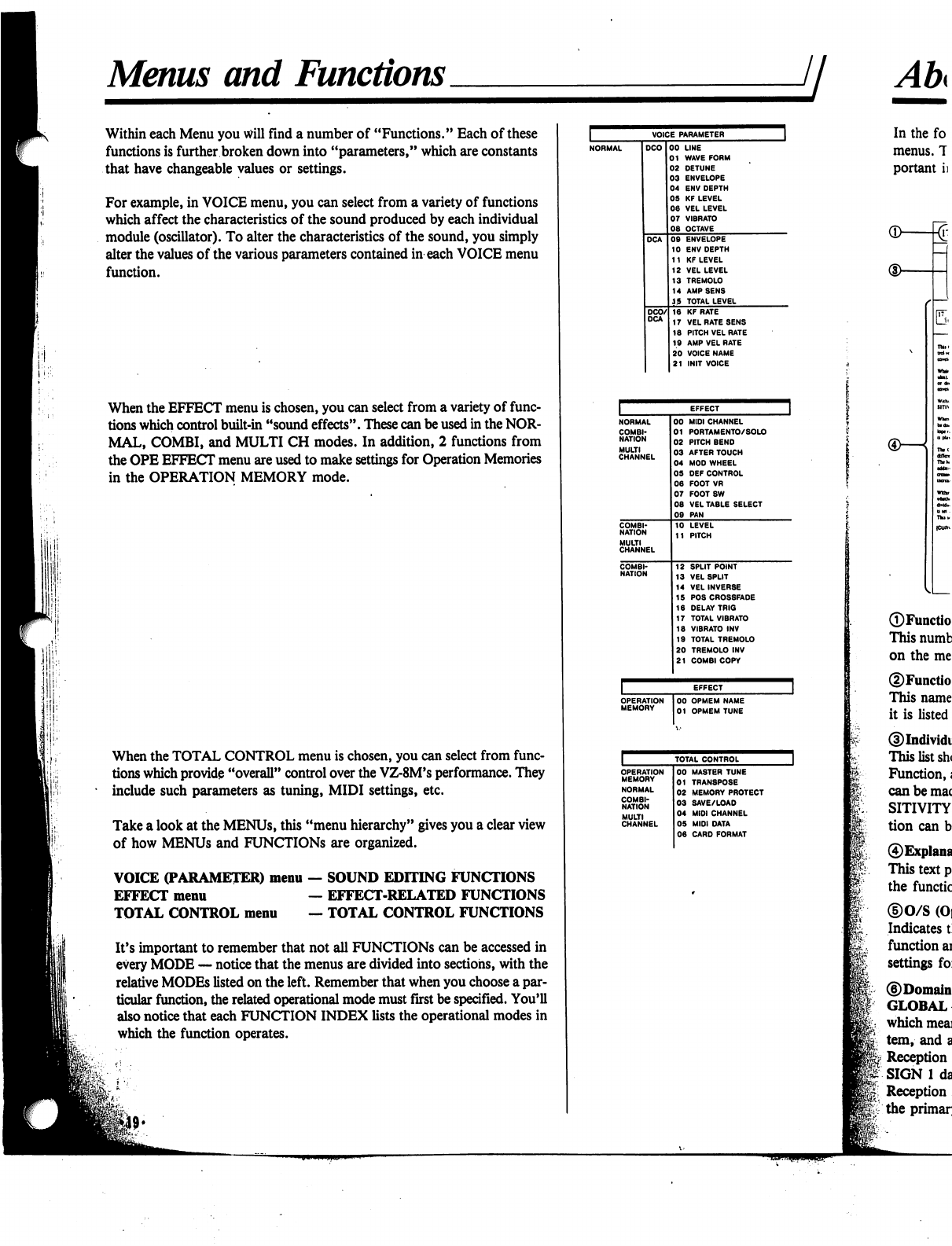
Within
each
Menu
you
will
find
a
number
of
"Functions."
Each
of
these
functions
is
further
broken
down
into
"parameters,"
which
are
constants
that
have
changeable
values
or
settings.
For
example,
in
VOICE
menu,
you
can
select
from
a
variety
of
functions
which
affect
the
characteristics
of
the
sound
produced
by
each
individual
module
(oscillator).
To
alter
the
characteristics
of
the
sound,
you
simply
alter
the
values
of
the
various
parameters
contained
in
each
VOICE
menu
function.
When
the
EFFECT
menu
is
chosen,
you
can
select
from
a
variety
of
func
tions
which
control
built-in
"sound
effects".
These
can
be
used
in
the
NOR
MAL,
COMBI,
and
MULTI
CH
modes.
In
addition,
2
functions
from
the
OPE
EFFECT
menu
are
used
to
make
settings
for
Operation
Memories
in
the
OPERATION
MEMORY
mode.
When
the
TOTAL
CONTROL
menu
is
chosen,
you
can
select
from
func
tions
which
provide
"overall"
control
over
the
VZ-8M's
performance.
They
*
include
such
parameters
as
tuning,
MIDI
settings,
etc.
Take
a
look
at
the
MENUs,
this
"menu
hierarchy"
gives
you
a
clear
view
of
how
MENUs
and
FUNCTIONS
are
organized.
VOICE
(PARAMETER)
menu
—
SOUND
EDITING
FUNCTIONS
EFFECT
menu
—
EFFECT-RELATED
FUNCTIONS
TOTAL
CONTROL
menu
—
TOTAL
CONTROL
FUNCTIONS
It's
important
to
remember
that
not
all
FUNCTIONS
can
be
accessed
in
every
MODE
—
notice
that
the
menus
are
divided
into
sections,
with
the
relative
MODEs
listed
on
the
left.
Remember
that
when
you
choose
a
par
ticular
function,
the
related
operational
mode
must
first
be
specified.
You'll
also
notice
that
each
FUNCTION
INDEX
lists
the
operational
modes
in
which
the
function
operates.
VOICE
PARAMETER
LINE
WAVE
FORM
DETUNE
ENVELOPE
ENV
DEPTH
KF
LEVEL
VEL
LEVEL
VIBRATO
OCTAVE
ENVELOPE
ENV
DEPTH
KF
LEVEL
VEL
LEVEL
TREMOLO
AMP
SENS
TOTAL
LEVEL
KF
RATE
VEL
RATE
SENS
PITCH
VEL
RATE
AMP
VEL
RATE
VOICE
NAME
INIT
VOICE
OPERATION
MEMORY
00
OPMEM
NAME
01
OPMEM
TUNE
TOTAL
CONTROL
COMBI
NATION
MULTI
CHANNEL
00
MASTER
TUNE
01
TRAN8POSE
02
MEMORY
PROTECT
03
SAVE/LOAD
04
MIDI
CHANNEL
05
MIDI
DATA
06
CARD
FORMAT
®—

About
Function
Indexes
ji
^
r
VEL
RATE
(DCO/DCA)
To
ENABLE
(nafct
cflttM
da
VEL
RATB
to
toy
lhiwfcidQr
RATE
Mains
b
(total
(rftaid
I
cart-
RATE
to
tadiacp
is
both
cat
000
tad
OCA
No.
IT
("VEL
RATi
SENS"),
tht
SEN-
SmviTY
and
CUKVE
Within
runoim
No.
It
r"A
VBL
RATE"),
you
on
ipajfy
whether
or
not
tht
VBL
RATB
cum
wtt
affM
tht
In-
dMdual
itepi
of
tht
AMP
BNV
{OCA
b
M
ulna
VOICB4*.
ThaM
atunp
can
bt
aiadt
for
atca
nodakt
(Ml-Mt>
iadMdMlh.
Whtn
SENSITIVITY
It
MiWiwtoa
At
SENSHTVITYb
railed,
tat
fa*-
To
BNASLB
tht
VBL
RATB
(ot
any
tup
la
tat
amlopt.
ttapty
mo*t
Iht
cunor
to
tat
dnlnd
iup
potkloa
aad
prat
tht
VES
kty
(~B"
b
dbplaytd).
To
dbaMt,
dnpty
prat
tat
NO
kay
r**
b
tfbpkyai).
Tte
CURVE
paTKMUt
Ira
you
ctoow
from
eat
of
I
«r«r«»
VELOCITY
RATE
cwxn»«^riow>«lbcto».
TW
bortoatal
sdi
*f
tht
VELOCITV
COR
VE
npratan
nha
to
tat
ratt
tht
rax
of
ttptta
tat
cawtoot
(DCO/DCA)
in
»tkt
mp
dt&tr.Nou.
Aoavw.
(Am
Umt
m
Whta
fuocttoo
No.
II
f"P
VEL
RATE"),
you
on
wbttho
or
ooi
tht
VEL
RATB
nm
wU
iffM
tht
b»
dMdttl
wpt
of
tht
PITCH
BNV
(DCO
cowtopt)
wtkh
b
M
mint
VOICED.
TkU
Kttlni
b
itoUI.
tfftctini
iU
I nodufct
(MI
•
Mil.
In
the
following
section,
you
will
find
information
on
each "function"
for
all
three
menus.
The
function
"indexes"
listed
on
the
following
pages
contain
a
variety
of
im
portant
information
on
the
function
and
its
parameters,
as
shown
below;
MODULAR
—
In
some
functions,
settings
can
be
made
for
each
iPD
module
individually.
In
this
case,
the
set
ting
is
said
to
be
"modular."
LINE
—
In
other
functions,
settings
are
made
for
each
module
"LINE"
(remember,"
this
is
a
set
of
modules
—
M1M2,
for
example).
PATCH
—
In
the
COMBI
mode,
some
parameters
af
fect
each
patch
independently.
In
this
case,
the
patch
presently
being
edited
is
shown
highlighted
on
the
dis
play.
You
can
select
a
patch
to
edit
with
the
PROG
NO
keys.
8-PATCH
MIX
GLOBAL
—
When
an
8-patch
mix
is
used
in
the
COMBI
mode,
some
parameters
affect
all
8
patches
globally.
8-PATCH
MIX
COUPLE
—
When
an
8-patch
mix
is
used
in
the
COMBI
mode,
certain
parameters
affect
the
patches
in
"couples". In
this
case,
settings
made
for
patch
1,
for
example,
will
also
affect
patch
5.
The
couple
as
signments
are;
1<*5,
2<-*6,
3<->7,
4<->8.
Note
that
both
patches
in
each
"couple"
are
highlighted
on
the
display
when
either
is
selected.
AREA
—
When
parameters
are
displayed
along
with
the
Area
number
in
the
MULTI
CH
mode,
the
data
affects
each
area
independently.
You
can
select
an
area
to
edit
with
the
PROG
NO
keys.
©Related
Functions
Lists
the
other
editing
functions
that
are
closely
inter
related
with
the
selected
function.
In
this
case,
the
P
VEL
RATE
(VOICE-18)
function
is
closely
related
to
such
functions
as
VOICE-17
(the
VEL
RATE
SENSITIVI
TY
function),
and
VOICE-09
(the
DCA
ENVELOPE
function).
©Modes
Lists
all
of
the
"operational
modes"
—
NORMAL,
COMBINATION,
etc.
—
in
which
the
function
oper
ates.
(See
the
menu
table
on
the
preceding
page.
The
left-
hand
column
of
the
menu
hierarchy
shows
the
MODEs
related
to
the
FUNCTIONS
on
the
right.)
©Menu
This
"tab"
at
the
edge
of
the
page
shows
which
"menu"
the
function
can
be
accessed
in.
In
this
case,
"VOICE"
indicates
that
the
VELOCITY
RATE
SENSITIVITY
function
can
be
accessed
in
the
VOICE
PARAMETER
menu.
REMEMBER....
These
indexes
provide
only
basic
information
on
each
function
and
parameter.
Many
of
these
functions
and
parameters
are
interrelated,
and
it
would
take
literally
volumes
to
provide
a
technical
explanation
of
how
they
actually
affect
the
sounds.
To
gain
a
practical
under
standing,
be
sure
to
go
through
the
PRACTICE
EXER
CISE
found
on
the
next
page.
•20-
©Function
Number
This
number
corresponds
to
the
number
of
the
function
on
the
menu
table
on
the
preceding
page.
©Function
Name
This
name
corresponds
to
the
name
of
the
function
as
it
is
listed
the
menu
table
on
the
preceding
page.
©Individual
parameters
and
value
range
This
list
shows
all
the
parameters
contained
in
the
selected
Function,
as well
as the
range
of
values
or
settings
which
can
be
made
for
each
parameter.
For
example,
the
SEN
SITIVITY
parameter
in
the
VELOCITY
RATE
func
tion
can
be
set
at
any
level
between
0
and
31.
©Explanation
of
function/parameters
This
text
provides
a
brief
explanation
of
the
purpose
of
the
function,
as
well
as
its
individual
parameters.
©0/S
(Operating
System)
control
operation
Indicates
the
basic
keys
and
controls
used
to
select
the
function
and
move
through
the
display
hierarchy
to
edit
settings
for
each
parameter.
©Domain
GLOBAL
—
In
some
functions,
settings
are
"Global,"
which
means
the
settings
effect
the
entire
operating
sys
tem,
and
all
the
sounds
in
it.
Reception
in
the
COMBI
mode
is
limited
to
KEY
AS
SIGN
1
data.
Reception
in
the
"G"
performance
mode
is
limited
to
the
primary
channel
set
in
EFFECT-00.
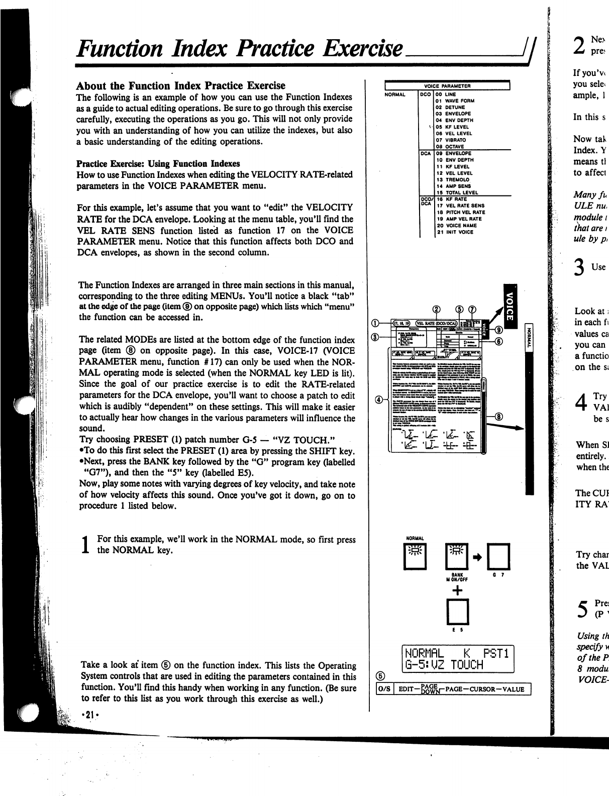
Function
Index
Practice
Exercise
About
the
Function
Index
Practice
Exercise
The
following
is
an
example
of
how
you
can
use
the
Function
Indexes
as
a
guide
to
actual
editing
operations.
Be
sure
to
go
through
this
exercise
carefully,
executing
the
operations
as
you
go.
This
will
not only
provide
you
with
an
understanding
of
how
you
can
utilize
the
indexes,
but
also
a
basic
understanding
of
the
editing
operations.
Practice
Exercise:
Using
Function
Indexes
How
to
use
Function
Indexes
when
editing
the
VELOCITY
RATE-related
parameters
in
the
VOICE
PARAMETER
menu.
For
this
example,
let's
assume
that
you
want
to
"edit"
the
VELOCITY
RATE
for
the
DCA
envelope.
Looking
at
the
menu
table,
you'll
find
the
VEL
RATE
SENS
function
listed
as
function
17
on
the
VOICE
PARAMETER
menu.
Notice
that
this
function
affects
both
DCO
and
DCA
envelopes,
as
shown
in
the
second
column.
The
Function
Indexes
are
arranged
in
three
main
sections
in
this
manual,
corresponding
to
the
three
editing
MENUs.
You'll
notice
a
black
"tab"
at
the
edge
of
the
page
(item
®
on
opposite
page)
which
lists
which
"menu"
the
function
can
be
accessed
in.
The
related
MODEs
are
listed
at
the
bottom
edge of
the
function
index
page
(item
®
on
opposite
page).
In
this
case,
VOICE-17
(VOICE
PARAMETER
menu,
function
#
17)
can
only
be
used
when
the
NOR
MAL
operating
mode
is
selected
(when
the
NORMAL
key
LED
is
lit).
Since
the
goal
of
our
practice
exercise
is
to
edit
the
RATE-related
parameters
for
the
DCA
envelope,
you'll
want
to
choose
a
patch
to
edit
which
is
audibly
"dependent"
on
these
settings.
This
will
make
it
easier
to
actually
hear
how
changes
in
the
various
parameters
will
influence the
sound.
Try
choosing
PRESET
(1)
patch
number
G-5
—
"VZ
TOUCH."
•To
do
this
first
select
the
PRESET
(1)
area
by
pressing
the
SHIFT
key.
•Next,
press
the
BANK
key
followed
by
the
"G"
program
key
(labelled
"G7"),
and
then
the
"5"
key
(labelled
E5).
Now,
play
some
notes
with
varying
degrees
of
key
velocity,
and
take
note
of
how
velocity
affects
this
sound.
Once
you've
got
it
down,
go
on
to
procedure
1
listed
below.
i
For
this
example,
we'll
work
in
the
NORMAL
mode,
so
first
press
the
NORMAL
key.
Take
a
look
at
item
<§)
on
the
function
index.
This
lists
the
Operating
System
controls
that
are
used
in
editing
the
parameters
contained
in
this
function.
You'll
find
this
handy
when
working
in
any
function.
(Be
sure
to
refer
to
this
list
as
you
work
through
this
exercise
as
well.)
•21?
(D—kr
NORMflL
K
PST1
G-5:UZ
TOUCH
|O/S
I
EDIT-g^j-PAGE-CURSOR-VALUE
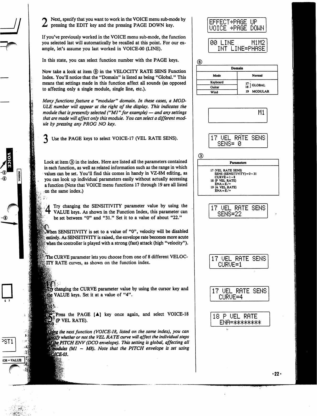
6 7
2
Next,
specify
that
you
want
to
work
in
the
VOICE
menu
sub-mode
by
pressing
the
EDIT
key
and
the
pressing
PAGE
DOWN
key.
If
you've
previously
worked
in
the
VOICE
menu
sub-mode,
the
function
you
selected
last
will
automatically
be
recalled
at
this
point.
For
our
ex
ample,
let's
assume
you
last
worked
in
VOICE-00
(LINE).
In
this
state,
you
can
select
function
number
with
the
PAGE
keys.
Now
take
a
look
at
item
®
in
the
VELOCITY
RATE
SENS
Function
Index.
You'll
notice
that
the
"Domain"
is
listed
as
being
"Global."
This
means
that
settings
made
in
this
function
affect
all
sounds
(as
opposed
to
affecting
only
a
single
module,
single
line,
etc.).
Many
functions
feature
a
"modular"
domain.
In
these
cases,
a
MOD
ULE
number
will
appear
at
the
right
of
the
display.
This
indicates
the
module
that
is
presently
selected
("Ml
"for
example)
—
and
any
settings
that
are
made
will
affect
only
this
module.
You
can
select
a
different
mod
ule
by
pressing
any
PROG
NO
key.
Use
the
PAGE
keys
to
select
VOICE-17
(VEL
RATE
SENS).
Look
at
item
®
in
the
index.
Here
are
listed
all
the
parameters
contained
in
each
function,
as
well
as
related
information
such
as
the
range
in
which
values
can
be
set.
You'll
find
this
comes
in
handy
in
VZ-8M
editing,
as
you
can
look
up
individual
parameters
easily
without
actually
accessing
a
function
(Note
that
VOICE
menu
functions
17
through
19
are
all
listed
on
the
same
index.)
4
Try
changing
the
SENSITIVITY
parameter
value
by
using
the
VALUE
keys.
As
shown
in
the
Function
Index,
this
parameter
can
be
set
between
"0" and
"31."
Set
it
to
a
value
of
about
"22."
,
SENSITIVITY
is
set
to
a
value
of
"0",
velocity
will
be
disabled
'i
entirely.
As
SENSITIVITY
is
raised,
the
envelope
rate
becomes
more
acute
|
when
the
controller
is
played
with
a
strong
(fast)
attack
(high
"velocity").
|TThe
CURVE
parameter
lets
you
choose
from
one
of
8
different
VELOC
ITY
RATE
curves,
as
shown
on
the
function
index.
r
changing
the
CURVE
parameter
value
by
using
the
cursor
key
and
)
VALUE
keys.
Set
it
at
a
value
of
"4".
ft..
j'Press
the
PAGE
[A]
key
once
again,
and
select
VOICE-18
'(P
VEL
RATE).
\
the
next
function
(VOICE-18,
listed
on
the
same
index),
you
can
}
whether
or
not
the
VEL
RA
TE
curve
will
affect
the
individual
steps
t
PITCH
ENV
(DCO
envelope).
This
setting
is
global,
affecting
all
(Ml
~
M8).
Note
that
the
PITCH
envelope
is
set
using
EFFECT+PflGE
UP
UOICE
+PRGE
DOWN
98
LINE
M1M2
INT
LINE=PHflSE
Domain
Mode
Keyboard
Guitar
Wind
Normal
\l}
GLOBAL
19
MODULAR
Ml
17
UEL
RflTE
SENS
SENS=
0
Parameters
17
(VEL
RATE
SENS)
SENS
(SENSITIVITY)=0-31
CURVE=1-8
18
(P
VEL
RATE)
ENA
= E/»
19
(A
VEL.
RATE)
ENA
E/
IT
UEL
RflTE
SENS
SENS=22
IT
UEL
RflTE
SENS
CURUE=1
IT
UEL
RflTE
SENS
CURUE=4
18
P
UEL
RflTE
ENfl=*****##*
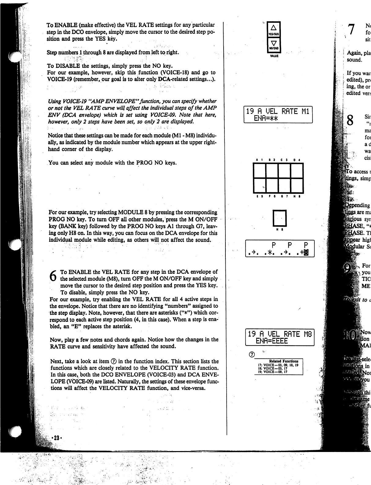
1;!'
1
i
.
I
To
ENABLE
(make
effective)
the
VEL
RATE
settings
for
any
particular
step
in
the
DCO
envelope,
simply
move
the
cursor
to
the
desired
step
po
sition
and
press
the
YES
key.
Step
numbers
1
through
8
are
displayed
from
left
to
right.
To
DISABLE
the
settings,
simply
press
the
NO
key.
For
our
example,
however,
skip
this
function
(VOICE-18)
and
go
to
VOICE-19
(remember,
our
goal
is
to
alter
only
DCA-related
settings...).
Using
VOICE-19
"AMP
ENVELOPE"
function,
you
can
specify
whether
or
not
the
VEL
RA
TE
curve
will
affect
the
individual
steps
of
the
AMP
ENV
(DCA
envelope)
which
is
set
using
VOICE-09.
Note
that
here,
however,
only
2
steps
have
been
set,
so
only
2
are
displayed.
Notice
that
these
settings
can
be
made
for
each
module
(Ml
-
M8)
individu
ally,
as
indicated
by
the
module
number
which
appears
at
the
upper
right-
hand
corner
of
the
display.
You
can
select
any
module
with
the
PROG
NO
keys.
For
our
example,
try
selecting
MODULE
8
by
pressing
the
corresponding
PROG
NO
key.
To
turn
OFF
all
other
modules,
press
the
M
ON/OFF
key
(BANK
key)
followed
by
the
PROG
NO
keys
Al
through
G7,
leav
ing
only
H8
on.
In
this
way,
you
can
focus
on
the
DCA
envelope
for
this
individual
module
while
editing,
as
others
will
not
affect
the
sound.
6
To
ENABLE
the
VEL
RATE
for
any
step in
the
DCA
envelope
of
the
selected
module
(M8),
turn
OFF
the
M
ON/OFF
key
and
simply
move
the cursor
to
the
desired
step
position
and
press
the
YES
key.
To
disable,
simply
press
the
NO
key.
For
our
example,
try
enabling
the
VEL
RATE
for
all
4
active
steps
in
the
envelope.
Notice
that
there
are
no
identifying
"numbers"
assigned
to
the
step
display.
Note,
however,
that
there
are
asterisks
("#")
which
cor
respond
to
each
active
step
position
(4,
in
this
case).
When
a
step
is
ena
bled,
an
"E"
replaces
the
asterisk.
Now,
play
a
few
notes
and
chords
again.
Notice
how
the
changes
in
the
RATE
curve
and
sensitivity
have
affected
the
sound.
Next,
take
a
look
at
item
®
in
the
function
index.
This
section
lists
the
functions
which
are
closely
related
to
the
VELOCITY
RATE
function.
In
this
case,
both
the
DCO
ENVELOPE
(VOICE-03)
and
DCA
ENVE
LOPE
(VOICE-09)
are
listed.
Naturally,
the
settings
of
these
envelope
func
tions
will
affect
the
VELOCITY
RATE
function,
and
vice-versa.
•23*
A
YES/SUS
V
NO/ENO
19
fl
UEL
RflTE
Ml
ENfl=:+:*
E
5
F
8
6
7
H
8
□
H
S
P
P P
19
fl
UEL
RflTE
ENFNEEEE
Related
Functions
17;
VOICE-03,
09.
18,
19
18;
VOICE-03,
17
19;
VOICE-09,
17
8
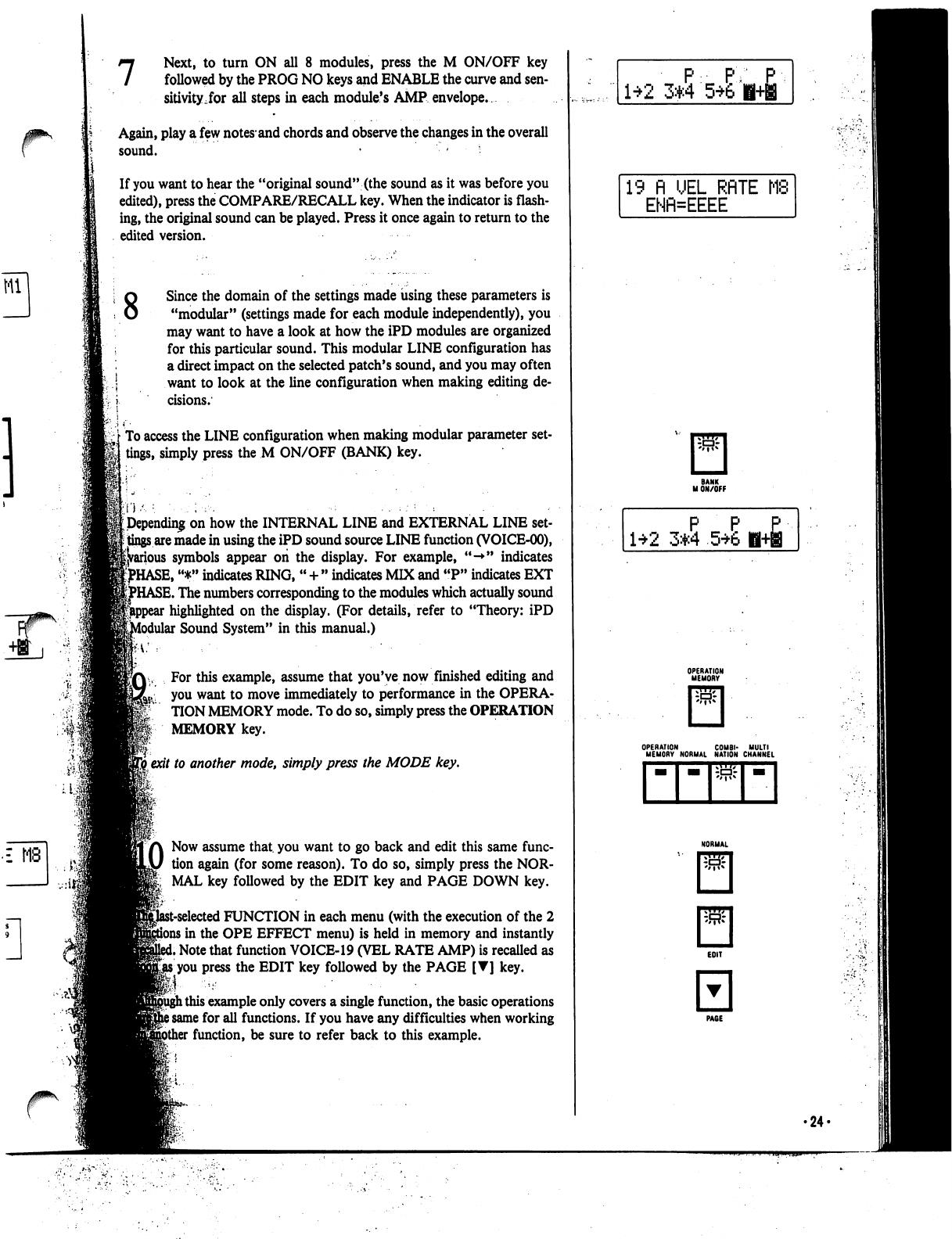
7
Next,
to
turn
ON
all
8
modules,
press
the
M
ON/OFF
key
followed
by
the
PROG
NO
keys
and
ENABLE
the
curve
and
sen
sitivity,for
all
steps
in
each
module's
AMP
envelope.
Again,
play
a
few
notes*
and
chords
and
observe
the
changes
in
the
overall
sound.
• -
•
If
you
want
to
hear
the
"original
sound"
(the
sound
as
it
was
before
you
edited),
press
the
COMPARE/RECALL
key.
When
the
indicator
is
flash
ing,
the
original
sound
can
be
played.
Press
it
once
again
to
return to the
edited
version.
8
£
MB
Since
the
domain
of
the
settings
made
using
these
parameters
is
"modular"
(settings
made
for
each
module
independently),
you
may
want
to
have
a
look
at
how
the
iPD
modules
are
organized
for
this
particular
sound.
This
modular
LINE
configuration
has
a
direct
impact
on
the
selected
patch's
sound,
and
you
may
often
want
to
look
at
the
line
configuration
when
making
editing
de
cisions.
To
access
the
LINE
configuration
when
making
modular
parameter
set
tings,
simply
press
the
M
ON/OFF
(BANK)
key.
Depending
on
how
the
INTERNAL
LINE
and
EXTERNAL
LINE
set
tings
are
made
in
using
the
iPD
sound
source
LINE
function
(VOICE-00),
►us
symbols
appear
on
the
display.
For
example,
"-*"
indicates
^HASE,
"*"
indicates
RING,
"
+
"
indicates
MIX
and
"P"
indicates
EXT
HASE.
The
numbers
corresponding
to
the
modules
which
actually
sound
highlighted
on
the
display.
(For
details,
refer
to
"Theory:
iPD
Modular
Sound
System"
in
this
manual.)
For
this
example,
assume
that
you've
now
finished
editing
and
you
want
to
move
immediately
to
performance
in
the
OPERA-
TION
MEMORY
mode.
To
do
so,
simply
press
the
OPERATION
MEMORY
key.
I
exit
to
another
mode,
simply
press
the
MODE
key.
LO
Now
assume
that,
you
want
to
go back
and
edit
this
same
func
tion
again
(for
some
reason).
To
do
so,
simply
press
the
NOR
MAL
key
followed
by
the
EDIT
key
and
PAGE
DOWN
key.
it-selected
FUNCTION
in
each
menu
(with
the
execution
of
the
2
i
in
the
OPE
EFFECT
menu)
is
held
in
memory
and
instantly
i
Note
that
function
VOICE-19
(VEL
RATE
AMP)
is
recalled
as
gjts
you
press
the
EDIT
key
followed
by
the
PAGE
[T]
key.
l
this
example
only
covers
a
single
function,
the
basic
operations
i
same
for
all
functions.
If
you
have
any
difficulties
when
working
function,
be
sure
to
refer
back
to
this
example.
P
PY
1*2
3*4
56'
19 n
UEL
RRTE
MS
ENfl=EEEE
P P
£
1*2
3*4
5*6
H+B
OPERATION
COMBI-
MULTI
MEMORY
NORMAL
NATION
CHANNEL
•24-
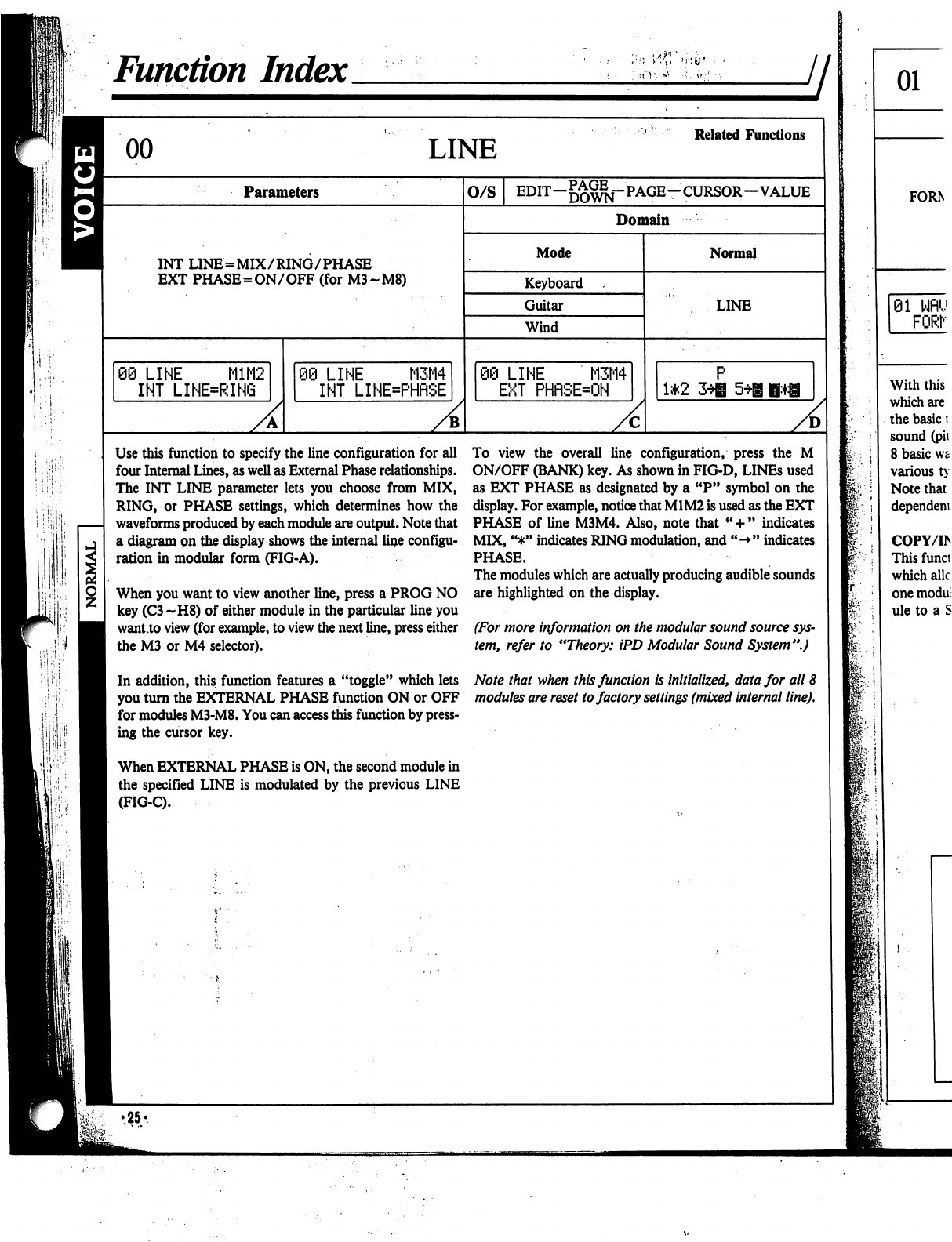
h
•:
■'.
i
,;
Function
Index
LINE
Related
Functions
Parameters
INT
LINE
=
MIX/RING/PHASE
EXT
PHASE
=
ON/OFF
(for
M3-M8)
06
LINE
M1M2
INT
LINE=RING
)
LINE
M3M4
INT
LINE=PHflSE
O/S
EDIT-^^-PAGE-CURSOR-VALUE
Domain
Mode
Keyboard
Guitar
Wind
:i
LINE
M3M4
EXT
PHRSEON
Normal
LINE
1*2
A
Use
this
function
to
specify
the
line
configuration
for
all
four
Internal
Lines,
as
well
as
External
Phase
relationships.
The
INT
LINE
parameter
lets
you
choose
from
MIX,
RING,
or
PHASE
settings,
which
determines
how
the
waveforms
produced
by
each
module
are
output.
Note
that
a
diagram
on
the
display
shows
the
internal
line
configu
ration
in
modular
form
(FIG-A).
When
you
want
to
view
another
line,
press
a
PROG
NO
key
(C3~H8)
of
either
module
in
the
particular
line
you
want
to
view
(for
example,
to
view
the
next
line,
press
either
the
M3
or
M4
selector).
In
addition,
this
function
features
a
"toggle"
which
lets
you
turn
the
EXTERNAL
PHASE
function
ON
or
OFF
for
modules
M3-M8.
You
can
access
this
function
by
press
ing
the
cursor
key.
When
EXTERNAL
PHASE
is
ON,
the
second
module
in
the
specified
LINE
is
modulated
by
the
previous
LINE
(FIG-C).
To
view
the
overall
line
configuration,
press
the
M
ON/OFF
(BANK)
key.
As
shown
in
FIG-D,
LINEs
used
as
EXT
PHASE
as
designated
by
a
"P"
symbol
on
the
display.
For
example,
notice
that
M1M2
is
used
as
the
EXT
PHASE
of
line
M3M4.
Also,
note
that
"
+
"
indicates
MIX,
"*"
indicates
RING
modulation,
and
"->"
indicates
PHASE.
The
modules
which
are
actually
producing
audible
sounds
are
highlighted
on
the
display.
(For
more
information
on
the
modular
sound
source
sys
tem,
refer
to
"Theory:
iPD
Modular
Sound
System".)
Note
that
when
this
function
is
initialized,
data
for
all
8
modules
are
reset
to
factory
settings
(mixed
internal
line).
f:
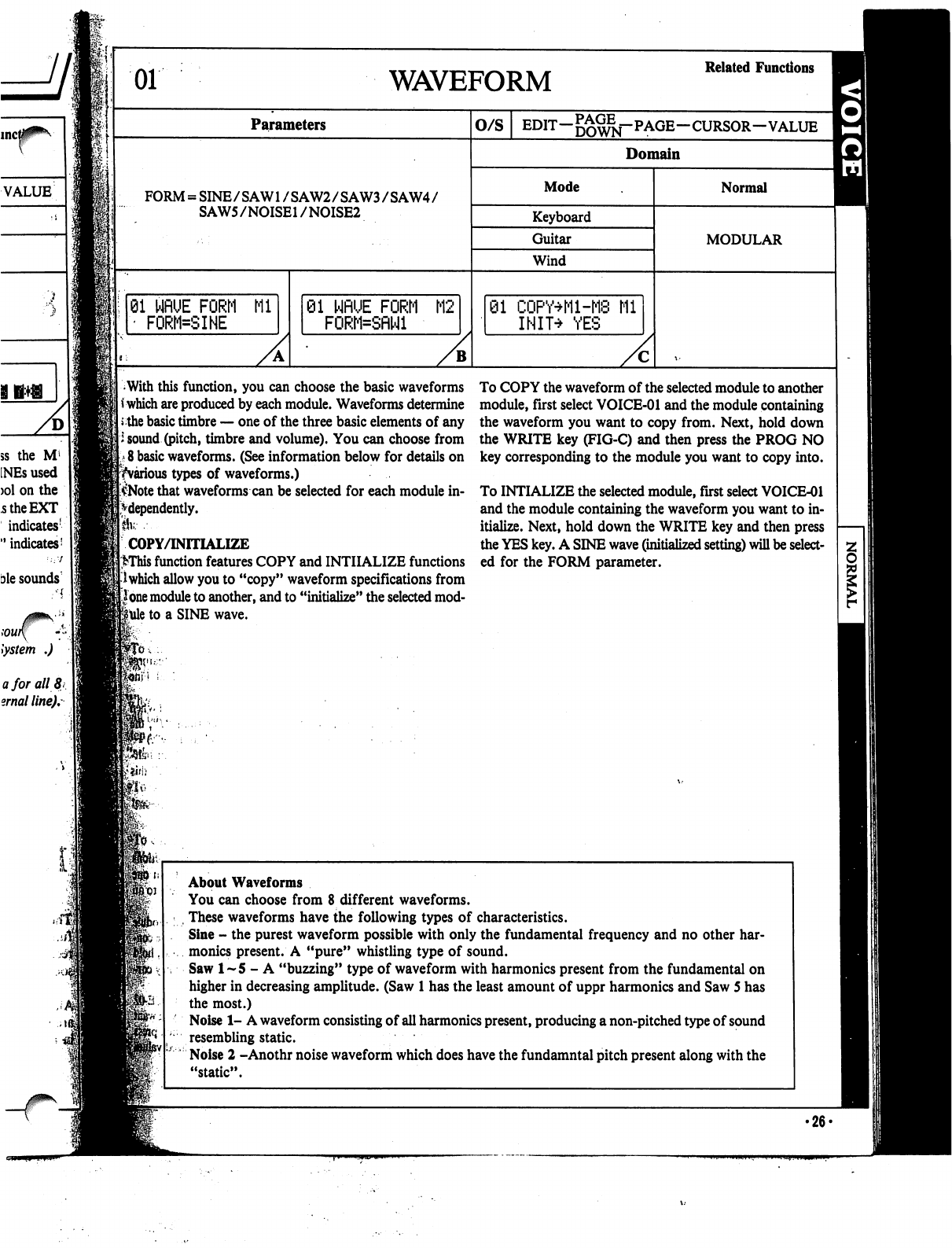
01
WAVEFORM
Related
Functions
Parameters
O/S
EDIT-^^j-PAGE-CURSOR-VALUE
^
Domain
FORM
=
SINE/SAW1
/SAW2/SAW3/SAW4/
SAW5/NOISE1
/NOISE2
Mode
Keyboard
Guitar
Wind
01
WflUE
FORM
Ml
'
FORM=SINE
81
NflUE
FORM
M2
FORM=SflNl
01
CQPY+M-M8
Ml
INIT^
YES
Normal
MODULAR
With
this
function,
you
can
choose
the
basic
waveforms
*
which
are
produced
by
each
module.
Waveforms
determine
the
basic
timbre
—
one
of
the
three
basic
elements
of
any
i
sound
(pitch,
timbre
and
volume).
You
can
choose
from
8
basic
waveforms.
(See
information
below
for
details
on
^various
types
of
waveforms.)
$Note
that
waveforms
can
be
selected
for
each
module
in
dependently.
Ik---
COPY/INITIALIZE
>This
function
features
COPY
and
INITIALIZE
functions
I
which
allow
you
to
"copy"
waveform
specifications
from
lone
module
to
another,
and
to
"initialize"
the
selected
mod
ule
to
a
SINE
wave.
To
COPY
the
waveform
of
the
selected
module
to
another
module,
first
select
VOICE-01
and
the
module
containing
the
waveform
you
want
to
copy
from.
Next,
hold
down
the
WRITE
key
(FIG-C)
and
then
press
the
PROG
NO
key
corresponding
to
the
module
you
want
to
copy
into.
To
INTIALIZE
the
selected
module,
first
select
VOICE-01
and
the
module
containing
the
waveform
you
want
to
in
itialize.
Next,
hold
down
the
WRITE
key
and
then
press
the
YES
key.
A
SINE
wave
(initialized
setting)
will
be
select
ed
for
the
FORM
parameter.
ft*
About
Waveforms
You
can
choose
from
8
different
waveforms.
,
These
waveforms
have
the
following
types
of
characteristics.
Sine
-
the
purest
waveform
possible
with
only
the
fundamental
frequency
and
no
other
har
monics
present.
A
"pure"
whistling
type
of
sound.
Saw
1-5
-
A
"buzzing"
type
of
waveform
with
harmonics
present
from
the
fundamental
on
higher
in
decreasing
amplitude.
(Saw
1
has
the
least
amount
of
uppr
harmonics
and
Saw
5
has
the
most.)
Noise
1-
A
waveform
consisting
of
all
harmonics
present,
producing
a
non-pitched
type
of
sound
resembling
static.
Noise
2
-Anothr
noise
waveform
which
does
have
the
fundamntal
pitch
present
along
with
the
"static".
•26*
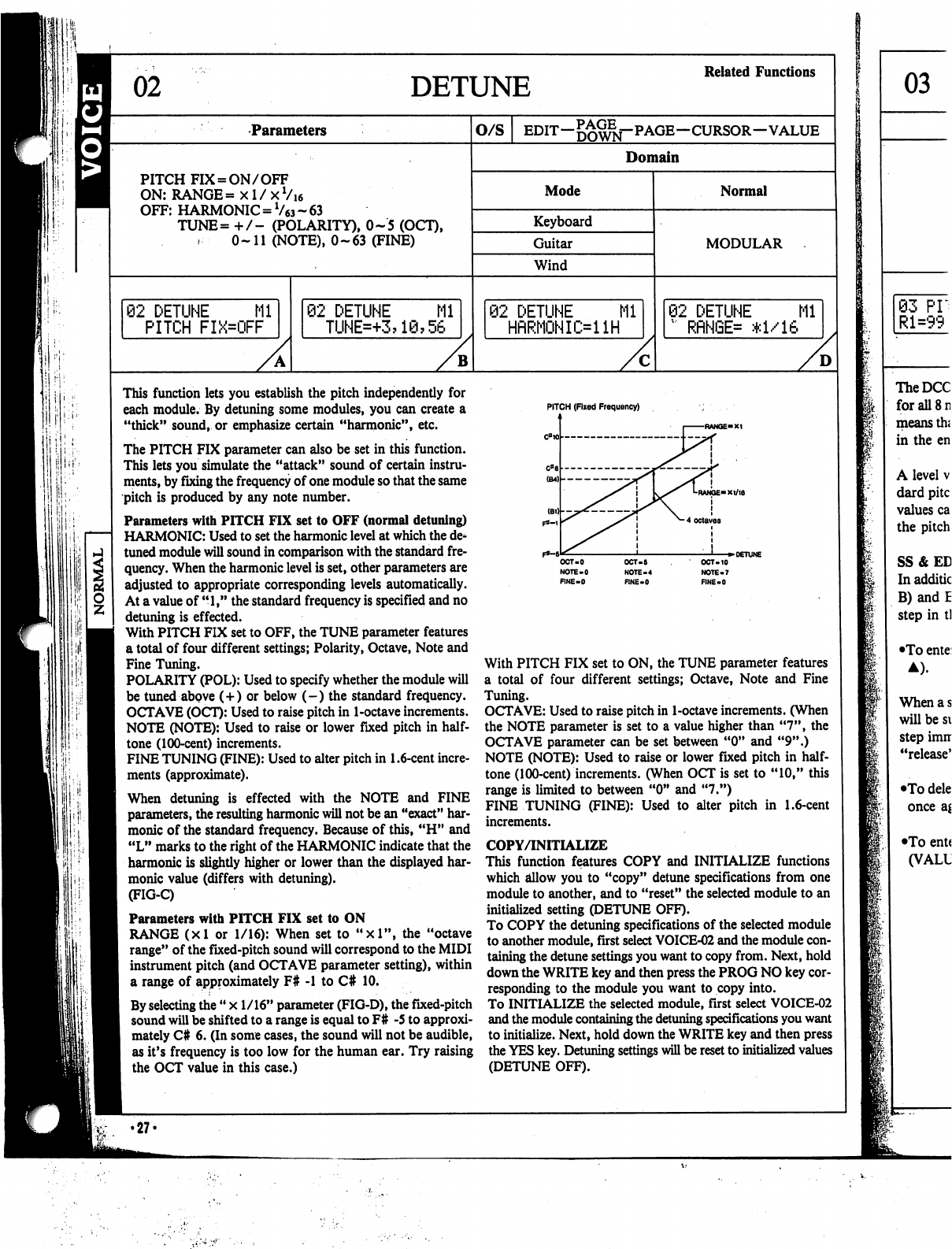
DETUNE
Related
Functions
Parameters
O/S
EDIT—
—CURSOR—VALUE
Domain
PITCH
FIX
=
ON/OFF
ON:
RANGE=
xl/xVi6
OFF:
HARMONIC
=
V63
~
63
TUNE=
+
/-
(POLARITY),
0-5
(OCT),
0-11
(NOTE),
0-63
(FINE)
Mode
Keyboard
Guitar
Wind
Normal
MODULAR
92
DETUNE
Ml
PITCH
FIX=OFF
02
DETUNE
Mi
TUNE=+3?1@?56
2
DETUNE
Mi
HfiRMONIi>ilH
02
DETUNE
Ml
"
RflNGE=
*1/16
B
D
if:.
1
iill:
This
function
lets
you
establish
the
pitch
independently
for
each
module.
By
detuning
some
modules,
you
can
create
a
"thick"
sound,
or
emphasize
certain
"harmonic",
etc.
The
PITCH
FIX
parameter
can
also
be
set
in
this
function.
This
lets
you
simulate
the
"attack"
sound
of
certain
instru
ments,
by
fixing
the
frequency
of
one
module
so
that
the
same
pitch
is
produced
by
any
note
number.
Parameters
with
PITCH
FIX
set
to
OFF
(normal
detuning)
HARMONIC:
Used
to
set
the
harmonic
level
at
which
the
de
tuned
module
will
sound
in
comparison
with
the
standard
fre
quency.
When
the
harmonic
level
is
set,
other
parameters
are
adjusted
to
appropriate
corresponding
levels
automatically.
At
a
value
of
"1,"
the
standard
frequency
is
specified
and
no
detuning
is
effected.
With
PITCH
FIX
set
to
OFF,
the
TUNE
parameter
features
a
total
of
four
different
settings;
Polarity,
Octave,
Note
and
Fine
Tuning.
POLARITY
(POL):
Used
to
specify
whether
the
module
will
be
tuned
above
(+)
or
below
(-)
the
standard
frequency.
OCTAVE
(OCT):
Used
to
raise
pitch
in
1-octave
increments.
NOTE
(NOTE):
Used
to
raise
or
lower
fixed pitch
in
half
tone
(100-cent)
increments.
FINE
TUNING
(FINE):
Used
to
alter
pitch
in
1.6-cent
incre
ments
(approximate).
When
detuning
is
effected
with
the
NOTE
and
FINE
parameters,
the
resulting
harmonic
will
not
be
an
"exact"
har
monic
of
the
standard
frequency.
Because of
this,
"H"
and
"L"
marks
to
the
right
of
the
HARMONIC
indicate that
the
harmonic
is
slightly
higher
or
lower
than
the
displayed
har
monic
value
(differs
with
detuning).
(FIG-C)
Parameters
with
PITCH
FIX
set
to
ON
RANGE
(xl
or
1/16):
When
set
to
"xl",
the
"octave
range"
of
the
fixed-pitch
sound
will
correspond
to
the
MIDI
instrument
pitch
(and
OCTAVE
parameter
setting),
within
a
range
of
approximately
F#
-1
to
C#
10.
By
selecting
the
"
x
1/16"
parameter
(FIG-D),
the
fixed-pitch
sound
will
be
shifted
to
a
range
is
equal
to
F#
-5
to
approxi
mately
C#
6.
(In
some
cases,
the
sound
will
not
be
audible,
as
it's
frequency
is
too
low
for
the
human
ear.
Try
raising
the
OCT
value
in
this
case.)
•27-
PITCH
(Fixed
Frequency)
OCT-5
NOTE-4
RNE-0
OCT-10
NOTE-7
FINE-0
With
PITCH
FIX
set
to
ON,
the
TUNE
parameter
features
a
total
of
four
different
settings;
Octave,
Note
and
Fine
Tuning.
OCTAVE:
Used
to
raise
pitch
in
1-octave
increments.
(When
the
NOTE
parameter
is
set
to
a
value
higher
than
"7",
the
OCTAVE
parameter
can be
set
between
"0"
and
"9".)
NOTE
(NOTE):
Used
to
raise
or
lower
fixed
pitch
in
half
tone
(100-cent)
increments.
(When
OCT
is
set
to
"10,"
this
range
is
limited
to
between
"0"
and
"7.")
FINE
TUNING
(FINE):
Used
to
alter
pitch
in
1.6-cent
increments.
COPY/INITIALIZE
This
function
features
COPY
and
INITIALIZE
functions
which
allow
you
to
"copy"
detune
specifications
from
one
module
to
another,
and
to
"reset"
the
selected
module
to
an
initialized
setting
(DETUNE
OFF).
To
COPY
the
detuning
specifications
of
the
selected
module
to
another
module,
first
select
VOICE-02
and
the
module
con
taining
the
detune
settings
you
want
to
copy
from.
Next,
hold
down
the
WRITE
key
and
then
press
the
PROG
NO
key
cor
responding
to
the
module
you
want
to
copy
into.
To
INITIALIZE
the
selected
module,
first
select
VOICE-02
and
the
module
containing
the
detuning
specifications
you
want
to
initialize.
Next,
hold
down
the
WRITE
key
and
then
press
the
YES
key.
Detuning
settings
will
be
reset
to
initialized
values
(DETUNE
OFF).
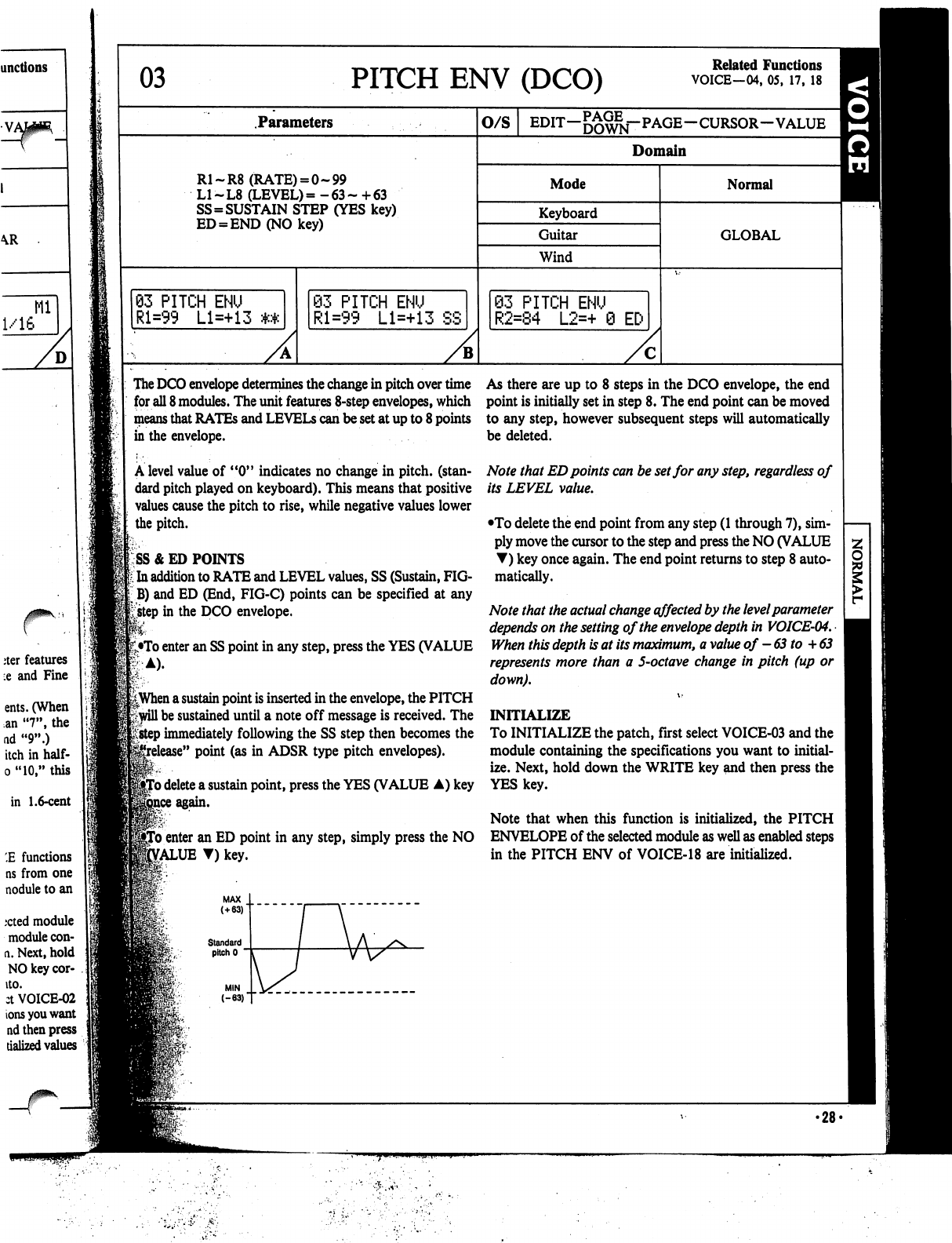
03
PITCH
ENV
(DCO)
Related
Functions
VOICE—04,
05,
17,
18
Parameters
R1-R8
(RATE)
=
0-99
L1-L8
(LEVEL)=
-63-
+63
SS=SUSTAIN
STEP
(YES
key)
ED
=
END(NOkey)
93
PITCH
ENU
Rl=99
Ll=+13
The
DCO
envelope
determines
the
change
in
pitch
over
time
As
there
are
up
to
8
steps
in
the
DCO
envelope,
the
end
for
all
8
modules.
The
unit
features
8-step
envelopes,
which
point
is
initially
set
in
step
8.
The
end
point
can
be
moved
means
that
RATEs
and
LEVELS
can
be
set
at
up
to
8
points
to
any
step,
however
subsequent
steps
will
automatically
in
the
envelope.
be
deleted.
A
level
value
of
"0"
indicates
no
change
in
pitch,
(stan
dard
pitch
played
on
keyboard).
This
means
that
positive
values
cause
the
pitch
to
rise,
while
negative
values
lower
the
pitch.
SS
& ED
POINTS
t
In
addition
to
RATE
and
LEVEL
values,
SS
(Sustain,
FIG-
jB)
and
ED
(End,
FIG-C)
points
can
be
specified
at
any
£step
in
the
DCO
envelope.
•To
enter
an SS
point
in
any
step,
press
the
YES
(VALUE
83
PITCH
ENU
Rl=99
Ll=+13
SS
O/S
EDIT-^^j-PAGE-CURSOR-VALUE
Domain
Mode
Keyboard
Guitar
Wind
S3
PITCH
ENU
R2=84
L2=+
0
EC-
Normal
GLOBAL
||When
a
sustain
point
is
inserted
in
the
envelope,
the
PITCH
Frwill
be
sustained
until
a
note
off
message
is
received.
The
*;
step
immediately
following
the
SS
step
then
becomes
the
e"
point
(as
in
ADSR
type
pitch
envelopes).
'o
delete
a
sustain
point,
press
the
YES
(VALUE
A)
key
Note
that
ED
points
can
be
set
for
any
step,
regardless
of
its
LEVEL
value.
•To
delete
the
end
point
from
any
step
(1
through
7),
sim
ply
move
the
cursor
to
the
step
and
press
the
NO
(VALUE
T)
key
once
again.
The
end
point
returns
to
step
8
auto
matically.
Note
that
the
actual
change
effected
by
the
level
parameter
depends
on
the
setting
of
the
envelope
depth
in
VOICE-04.
When
this
depth
is
at
its
maximum,
a
value
of
-63
to
+
63
represents
more
than
a
5-octave
change
in
pitch
(up
or
down).
INITIALIZE
To
INITIALIZE
the
patch,
first
select
VOICE-03
and
the
module
containing
the
specifications
you
want
to
initial
ize.
Next,
hold
down
the
WRITE
key
and
then
press
the
YES
key.
Note
that
when
this
function
is
initialized,
the
PITCH
To
enter
an
ED
point
in
any
step,
simply
press
the
NO
ENVELOPE
of
the
selected
module
as
well
as
enabled
steps
£ALUE
T)
key.
in
the
PITCH
ENV
of
VOICE-18
are
initialized.
•28-
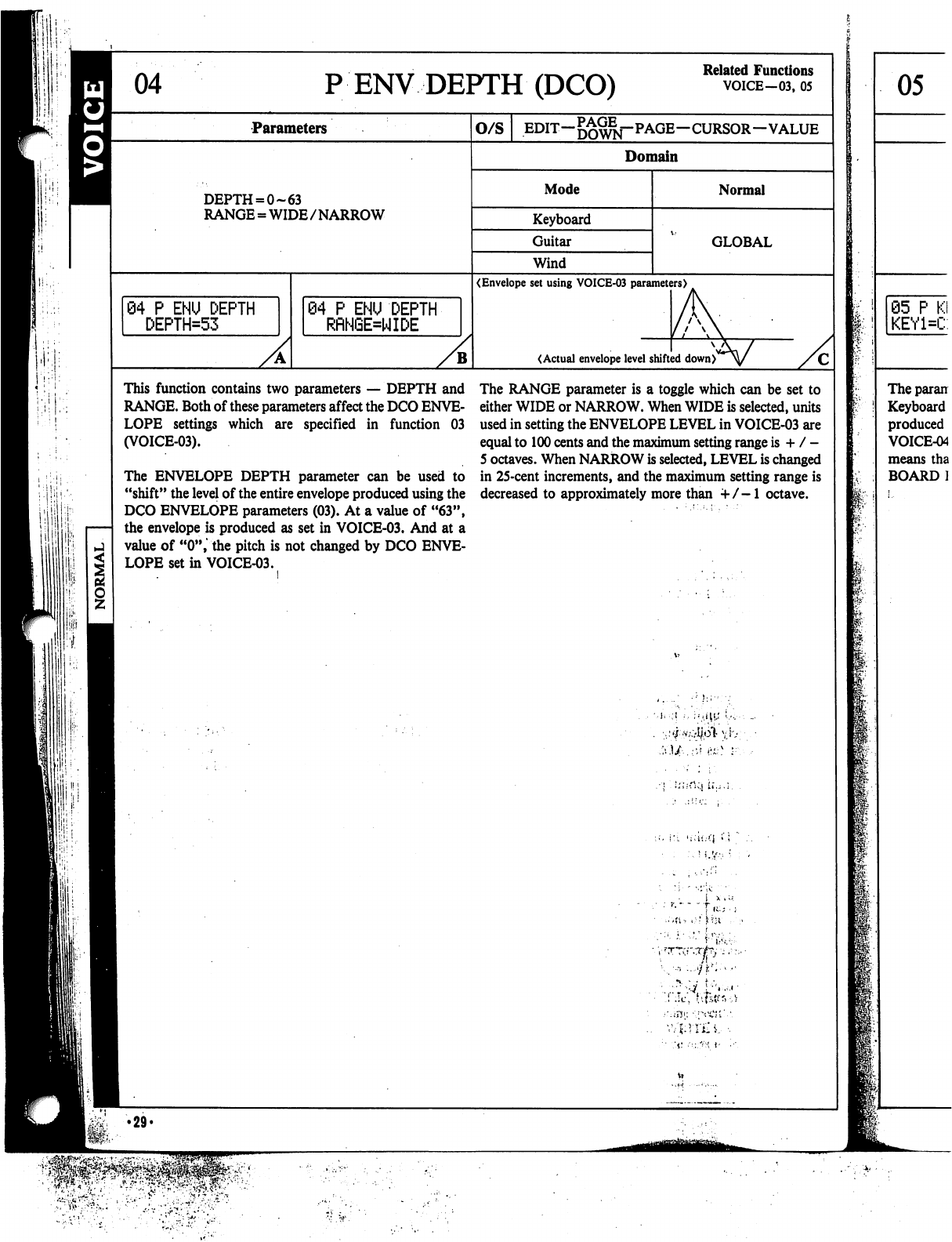
PENV
DEPTH
(DCO)
Related
Functions
VOICE-03,
05
Parameters
O/S
EDIT—
—CURSOR—VALUE
Domain
DEPTH
= 0-63
RANGE
=
WIDE/NARROW
Mode
Keyboard
Guitar
Wind
Normal
GLOBAL
04
P
ENU
DEPTH
DEPTH=53
(Envelope
set
using
VOICE-03
parameters)
84
P
ENU
DEPTH
RRNGE=WIDE
(Actual
envelope
level
shifted
down)
This
function
contains
two
parameters
—
DEPTH
and
RANGE.
Both
of
these
parameters
affect
the
DCO
ENVE
LOPE
settings
which
are
specified
in
function
03
(VOICE-03).
The
ENVELOPE
DEPTH
parameter
can
be
used
to
"shift"
the
level
of
the
entire
envelope
produced
using
the
DCO
ENVELOPE
parameters
(03).
At
a
value
of
"63",
the
envelope
is
produced
as
set
in
VOICE-03.
And
at
a
value
of
"0",
the
pitch
is
not
changed
by
DCO
ENVE
LOPE
set
in
VOICE-03.
The
RANGE
parameter
is
a
toggle
which
can
be
set
to
either
WIDE
or
NARROW.
When
WIDE
is
selected,
units
used
in
setting
the
ENVELOPE
LEVEL
in
VOICE-03
are
equal
to
100
cents
and
the
maximum
setting
range
is
+
/
-
5
octaves.
When
NARROW
is
selected,
LEVEL
is
changed
in
25-cent
increments,
and
the
maximum
setting
range
is
decreased
to
approximately
more
than
+/-1
octave.
I
I
'.liii-rMi
U.,.;.
I
l!
!;
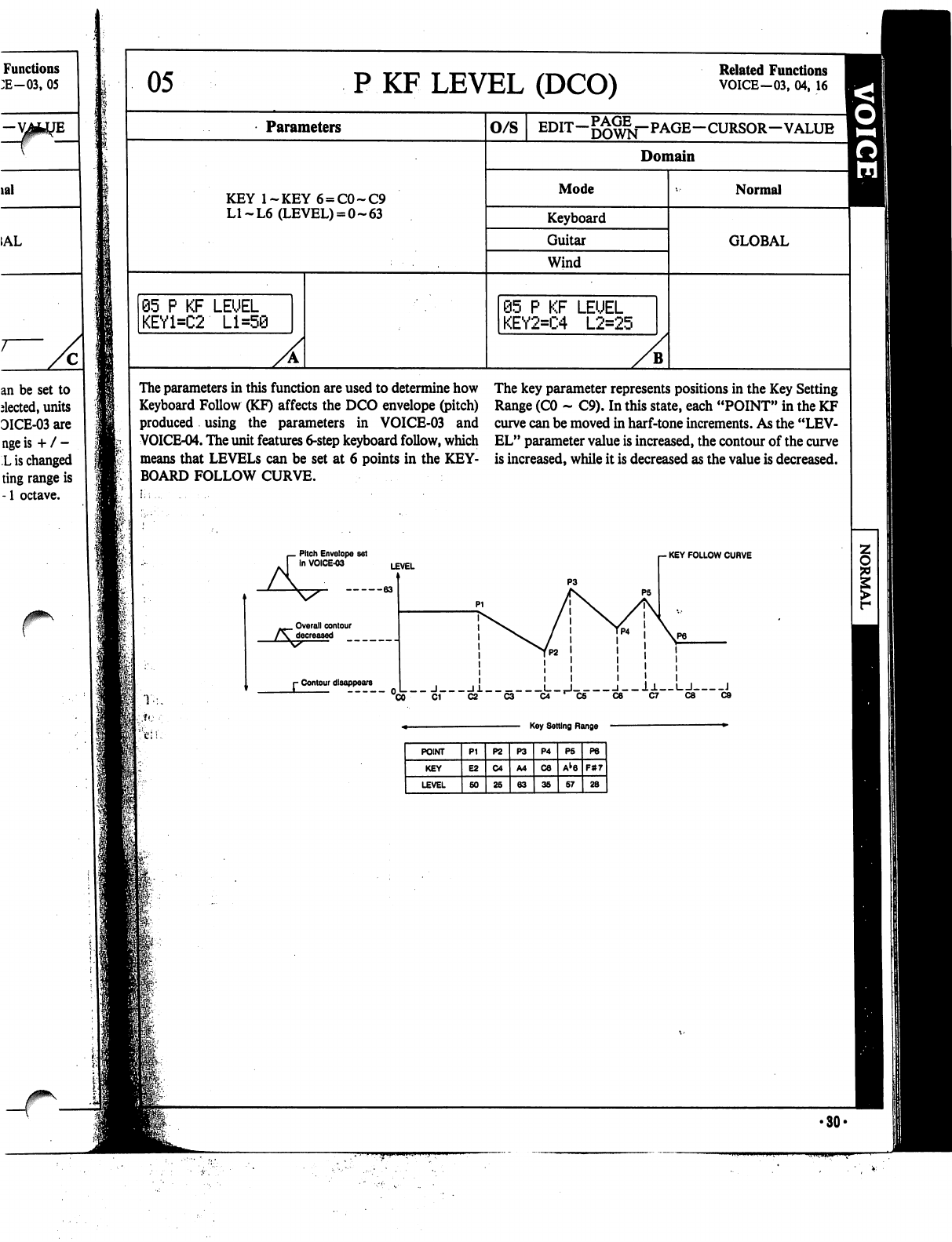
Functions
:E-03,
05
lal
=
1AL
an be
set
to
elected,
units
DICE-03
are
nge
is
+
/
-
L
is
changed
ting
range
is
-1
octave.
05
P
KF
LEVEL
(DCO)
Related
Functions
VOICE-03,
04,
16
Parameters
KEY
l~KEY6
=
C0~C9
LI~L6
(LEVEL)
=
0-63
05
P
KF
LEUEL
KEY1=C2
Ll=5@
O/S
Domain
Mode
Keyboard
Guitar
Wind
@5
P
KF
LEUEL
KEY2=C4
L2=25
B
Normal
GLOBAL
The
parameters
in
this
function
are
used
to
determine
how
Keyboard
Follow
(KF)
affects
the
DCO
envelope
(pitch)
produced
using
the
parameters
in
VOICE-03
and
VOICE-04.
The
unit features
6-step
keyboard
follow,
which
means
that
LEVELS
can
be
set
at
6
points
in
the
KEY
BOARD
FOLLOW
CURVE.
Pitch
Envelope
set
In
VOICE-03
The
key
parameter
represents
positions
in
the
Key
Setting
Range
(CO
-
C9).
In
this
state,
each
"POINT"
in
the
KF
curve
can
be
moved
in
harf-tone
increments.
As
the
"LEV
EL"
parameter
value
is
increased,
the
contour
of
the
curve
is
increased,
while
it
is
decreased
as
the
value
is
decreased.
-
KEY
FOLLOW
CURVE
Overall
contour
r
Contour
disappears
_
J
11
L_,J
l__l±
I
I
J
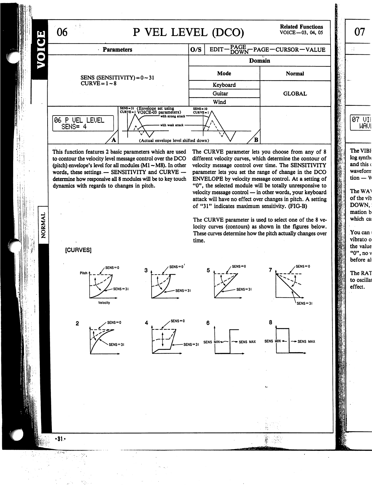
P
VEL
LEVEL
(DCO)
Related
Functions
VOICE—03,
04,
05
Parameters
O/S
EDIT-g^^j-PAGE-CURSOR-VALUE
Domain
SENS
(SENSITIVITY)
=
0-31
CURVE=1~8
Mode
Keyboard
Guitar
Wind
Normal
GLOBAL
06
P
UEL
LEUEL
SENS=
4
sens-3i
(Envelope
set
using
curve-i
VOICE-03
parameters)
l\S
with
strong
attack
with
weak
attack
<Actual
envelope
level
shifted
down)
This
function
features
2
basic
parameters
which
are
used
to
contour
the
velocity
level
message
control
over
the
DCO
(pitch)
envelope's
level
for
all
modules
(Ml
~M8).
In other
words,
these
settings
—
SENSITIVITY
and
CURVE
—
determine
how
responsive
all
8
modules
will
be
to
key
touch
dynamics
with
regards
to
changes
in
pitch.
The
CURVE
parameter
lets
you
choose
from
any
of
8
different
velocity
curves,
which
determine
the
contour
of
velocity
message
control
over
time.
The
SENSITIVITY
parameter
lets
you
set
the
range
of
change
in
the
DCO
ENVELOPE
by
velocity
message
control.
At
a
setting
of
"0",
the
selected
module
will
be
totally
unresponsive
to
velocity
message
control
—
in
other
words,
your
keyboard
attack
will
have
no
effect
over
changes
in
pitch.
A
setting
of
"31"
indicates
maximum
sensitivity.
(FIG-B)
The
CURVE
parameter
is
used
to
select
one
of
the
8
ve
locity
curves
(contours)
as
shown
in
the
figures
below.
These
curves
determine
how
the
pitch
actually
changes
over
time.
[CURVES]
SENS
=
31
SENS
=
31
SENS
=
0
SENS=3I
Velocity
XSENS
=
SENS
=
0
SENS
=
SENS9
31
SENS
MIN
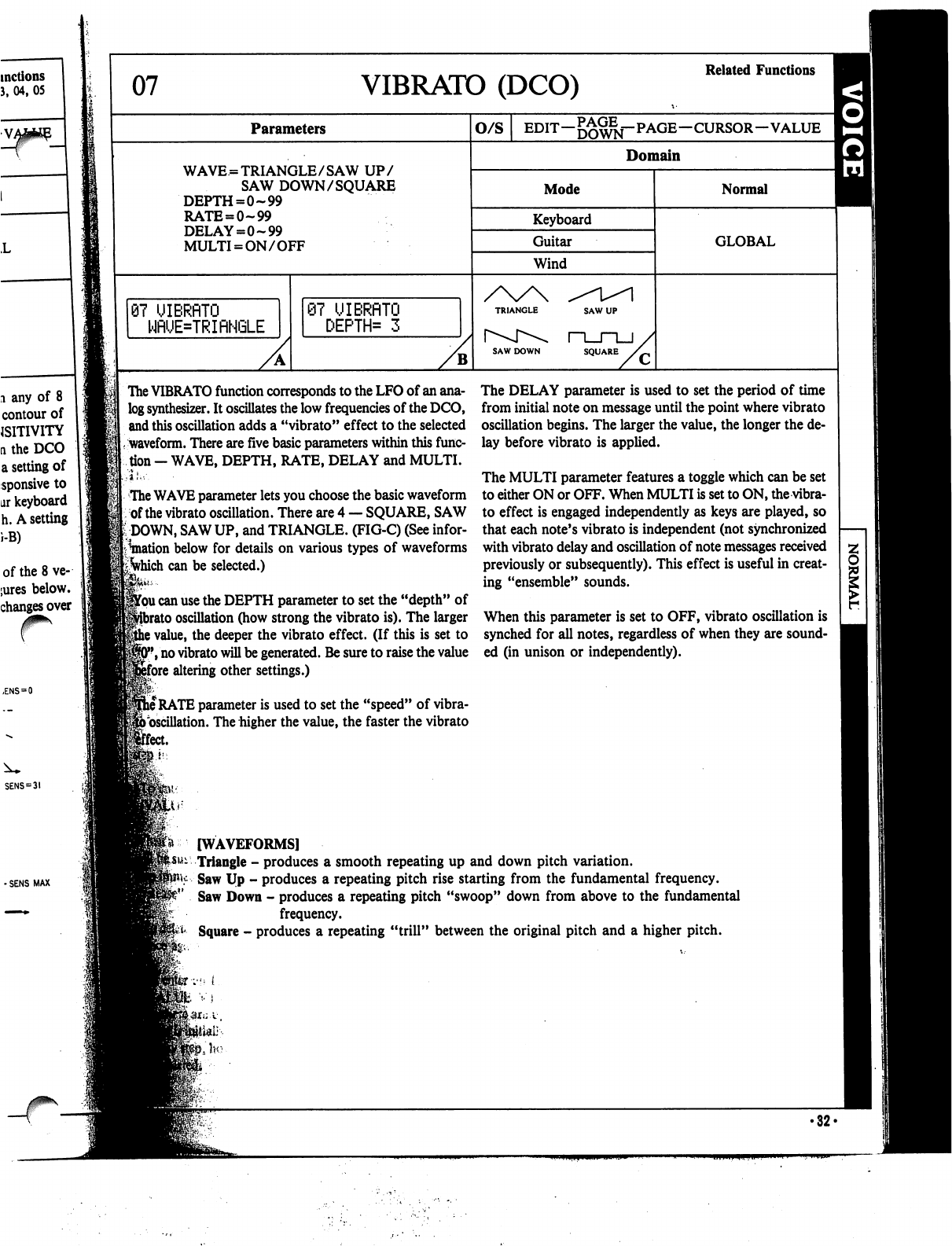
07
VIBRATO
(DCO)
Related
Functions
Parameters
O/S
EDIT—j^^j-PAGE—CURSOR—VALUE
WAVE
=
TRIANGLE/SAW
UP/
SAW
DOWN/SQUARE
DEPTH=0~99
RATE
=
0-99
DELAY=0-99
MULTI
=
ON/OFF
Domain
Mode
Keyboard
Guitar
Wind
Normal
GLOBAL
87
UIBRflTO
WRUE=TRIRNGLE
87
UIBRflTO
DEPTH*
3
SAW
DOWN
SQUARE
The
VIBRATO
function
corresponds
to
the
LFO
of
an
ana
log
synthesizer.
It
oscillates
the
low
frequencies
of
the
DCO,
and
this
oscillation
adds
a
"vibrato"
effect
to
the
selected
waveform.
There
are
five
basic
parameters
within
this
func
tion
-
WAVE,
DEPTH,
RATE,
DELAY
and
MULTI.
The
WAVE
parameter
lets
you
choose
the
basic
waveform
of
the
vibrato
oscillation.
There
are
4
—
SQUARE,
SAW
DOWN,
SAW
UP,
and
TRIANGLE.
(FIG-C)
(See
infor
mation
below
for
details
on
various
types
of
waveforms
ifyhich
can
be
selected.)
jfou
can
use
the
DEPTH
parameter
to
set
the
"depth"
of
)
oscillation
(how
strong
the
vibrato
is).
The
larger
i
value,
the
deeper
the
vibrato
effect.
(If
this
is
set
to
*,
no
vibrato
will
be
generated.
Be
sure
to
raise
the
value
ifore
altering
other
settings.)
j
RATE
parameter
is
used
to
set
the
"speed"
of
vibra-
foscillation.
The
higher
the
value,
the
faster
the
vibrato
[feet.
The
DELAY
parameter
is
used
to
set
the
period
of
time
from
initial
note
on
message
until
the
point
where
vibrato
oscillation
begins.
The
larger
the
value,
the
longer
the
de
lay
before
vibrato
is
applied.
The
MULTI
parameter
features
a
toggle
which
can be
set
to
either
ON
or
OFF.
When
MULTI
is
set
to
ON,
the
vibra
to
effect
is
engaged
independently
as
keys
are
played,
so
that
each
note's
vibrato
is
independent
(not
synchronized
with
vibrato
delay
and
oscillation
of
note
messages
received
previously
or
subsequently).
This
effect
is
useful
in
creat
ing
"ensemble"
sounds.
When
this
parameter
is
set
to
OFF,
vibrato
oscillation
is
synched
for
all
notes,
regardless
of
when
they
are
sound
ed
(in
unison
or
independently).
[WAVEFORMS]
Triangle
-
produces
a
smooth
repeating
up
and
down
pitch
variation.
Saw
Up
-
produces a
repeating
pitch
rise
starting
from
the
fundamental
frequency.
Saw
Down
-
produces
a
repeating
pitch
"swoop"
down
from
above
to
the
fundamental
frequency.
Square
-
produces
a
repeating
"trill"
between
the
original
pitch
and
a
higher
pitch.
'•;•"
i
•32<
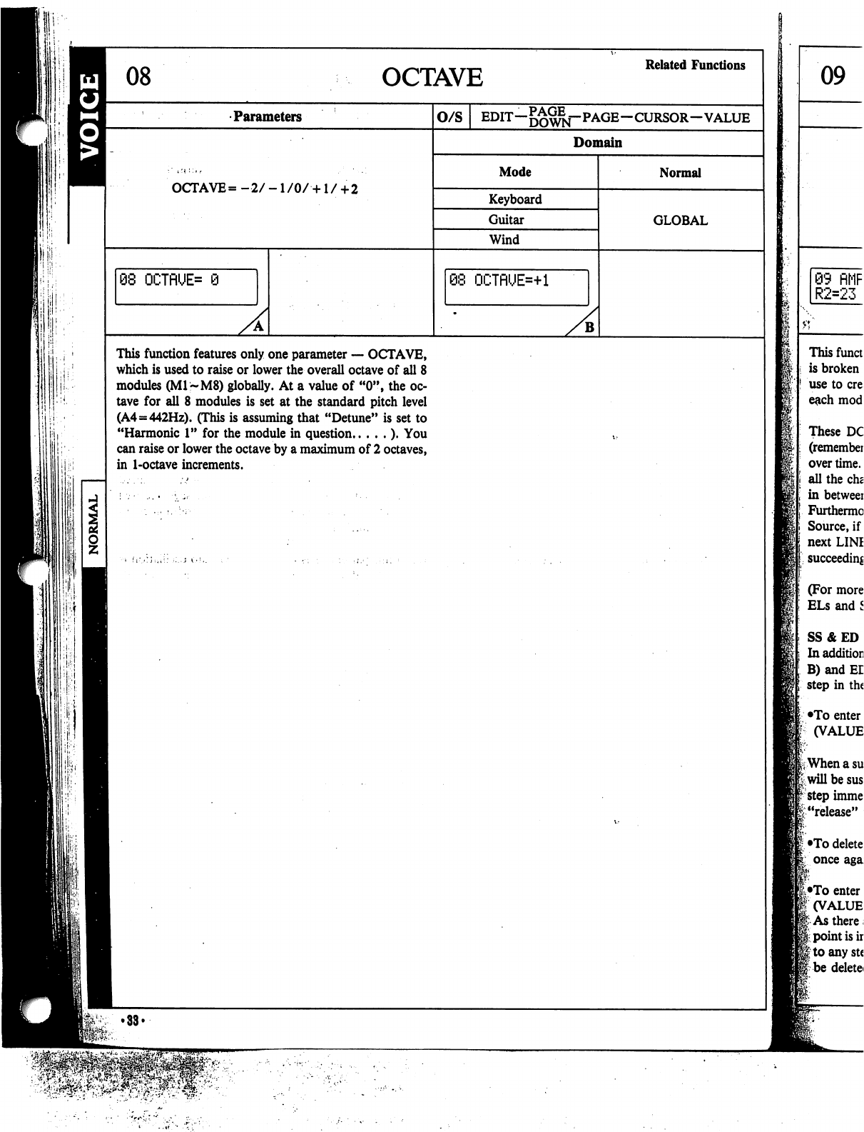
OCTAVE
Related
Functions
•Parameters
O/S
--CURSOR-VALUE
Domain
Mode
OCTAVE
=
-2/
-1
/0/
•+1
/
+
2
Keyboard
Guitar
Wind
Normal
GLOBAL
68
OCTflUE=
9
08
OCTnUE=+l
B
This
function
features
only
one
parameter
—
OCTAVE,
which
is
used
to
raise
or
lower
the
overall
octave
of
all
8
modules
(M1~M8)
globally.
At
a
value
of
"0",
the
oc
tave
for
all
8
modules
is
set
at
the
standard
pitch
level
(A4=442Hz).
(This
is
assuming
that
"Detune"
is
set
to
"Harmonic
1"
for
the
module
in
question
).
You
can
raise
or
lower
the
octave
by
a
maximum
of
2
octaves,
in
1-octave
increments.
ilil
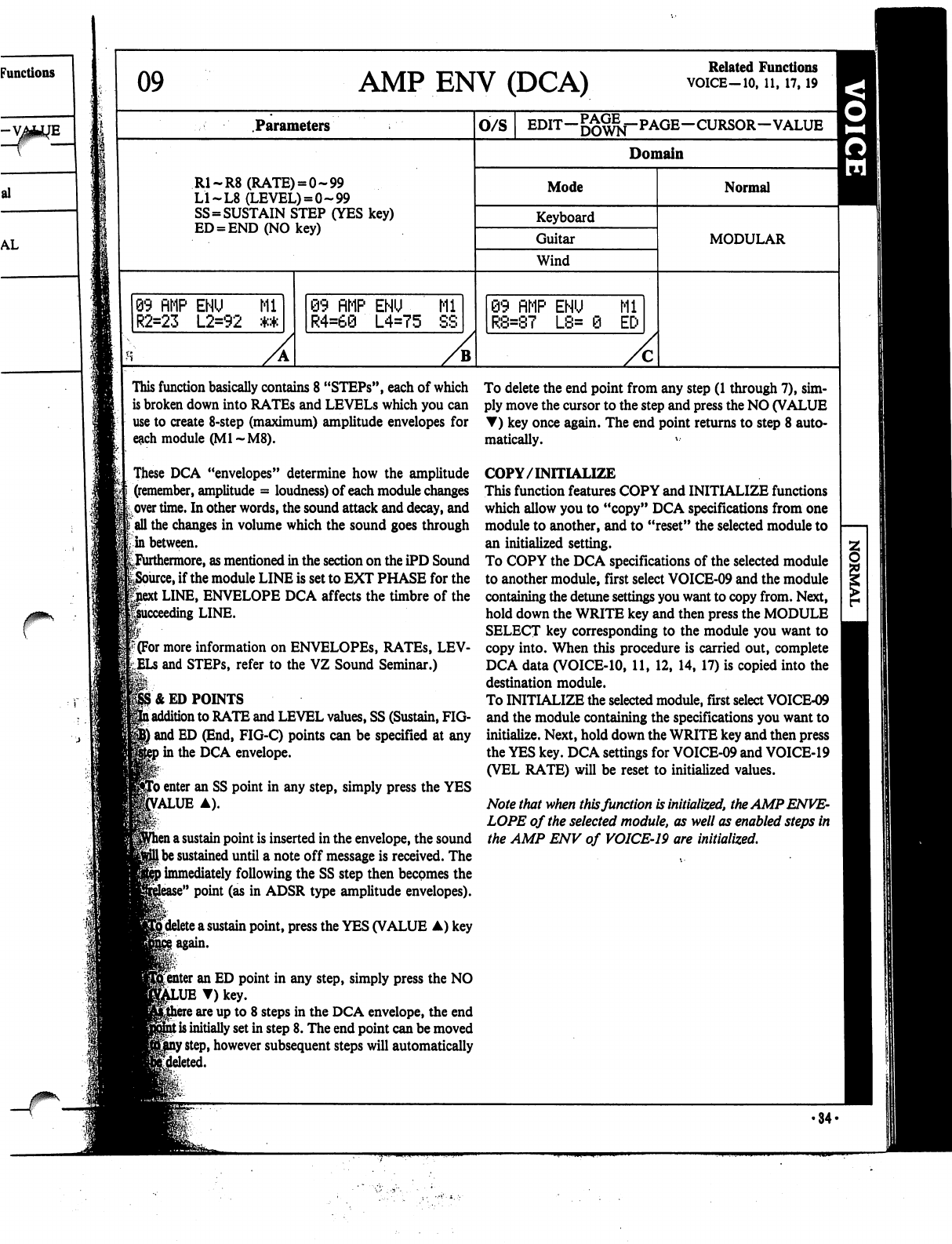
09
AMP
ENV
(DCA)
Related
Functions
VOICE-10,
11,
17,19
Parameters
O/S
EDIT-^^f-PAGE-CURSOR-VALUE
^
Domain
R1-R8
(RATE)
=
0-99
LI
~L8
(LEVEL)
=
0-99
SS=SUSTAIN
STEP
(YES
key)
ED
=
END
(NO
key)
Mode
Keyboard
Guitar
Wind
Normal
MODULAR
99
RMP
ENU
Ml
R2=23
L2=92
**
09
flMP
ENU
Ml
R4=60
L4=75
SS
89
fiMP
ENU
Ml
R8=87
L8=
0
ED
This
function
basically
contains
8
"STEPs",
each
of
which
is
broken
down
into
RATEs
and
LEVELS
which
you
can
use
to create
8-step
(maximum)
amplitude
envelopes
for
e&ch
module
(Ml
~M8).
These
DCA
"envelopes"
determine
how
the
amplitude
(remember,
amplitude
=
loudness)
of
each
module
changes
over
time.
In
other
words,
the
sound
attack
and
decay,
and
\
all
the
changes
in
volume
which
the
sound
goes
through
in
between.
^Furthermore,
as
mentioned
in
the
section
on
the
iPD
Sound
e,
if
the
module
LINE
is
set
to
EXT
PHASE
for
the
t
LINE,
ENVELOPE
DCA
affects
the
timbre
of
the
ding
LINE.
f(For
more
information
on
ENVELOPES,
RATEs,
LEV-
and
STEPs,
refer
to
the
VZ
Sound
Seminar.)
1&
ED
POINTS
l
addition
to
RATE
and
LEVEL
values,
SS
(Sustain,
FIG-
|
and
ED
(End,
FIG-C)
points
can
be
specified
at
any
»in
the
DCA
envelope.
fro
enter
an
SS
point
in
any
step,
simply
press
the
YES
Value
a).
i
a
sustain
point
is
inserted
in
the envelope,
the
sound
I
be
sustained
until
a
note
off
message
is
received.
The
)
immediately
following
the
SS
step
then
becomes
the
e"
point
(as in
ADSR
type
amplitude
envelopes).
^delete
a
sustain
point,
press
the
YES
(VALUE
A)
key
^
I
again.
r.-
Renter
an
ED
point
in
any
step,
simply
press
the
NO
T)
key.
\
are
up
to
8
steps
in
the
DCA
envelope,
the
end
t
is
initially
set
in
step
8.
The
end
point
can
be
moved
f
step,
however
subsequent
steps
will
automatically
To
delete
the
end
point
from
any
step
(1
through
7),
sim
ply
move
the
cursor
to
the
step
and
press
the
NO
(VALUE
T)
key
once
again.
The
end
point
returns
to
step
8
auto
matically.
*••
COPY/INITIALIZE
This
function
features
COPY
and
INITIALIZE
functions
which
allow
you
to
"copy"
DCA
specifications
from
one
module
to
another,
and
to
"reset"
the
selected
module
to
an
initialized
setting.
To
COPY
the
DCA
specifications
of
the
selected
module
to
another
module,
first
select
VOICE-09
and
the
module
containing
the
detune
settings
you
want
to
copy
from.
Next,
hold
down
the
WRITE
key
and
then
press
the
MODULE
SELECT
key
corresponding
to
the
module
you
want
to
copy
into.
When
this
procedure
is
carried
out,
complete
DCA
data
(VOICE-10,
11,
12,
14,
17)
is
copied
into
the
destination
module.
To
INITIALIZE
the
selected
module,
first
select
VOICE-09
and
the
module
containing
the
specifications
you
want
to
initialize.
Next,
hold
down
the
WRITE
key
and
then
press
the
YES
key.
DCA
settings
for
VOICE-09
and
VOICE-19
(VEL
RATE)
will
be
reset
to
initialized
values.
Note
that
when
this
function
is
initialized,
the
AMP
ENVE
LOPE
of
the
selected
module,
as
well
as
enabled
steps
in
the
AMP
ENV
of
VOICE-19
are
initialized.
•34-
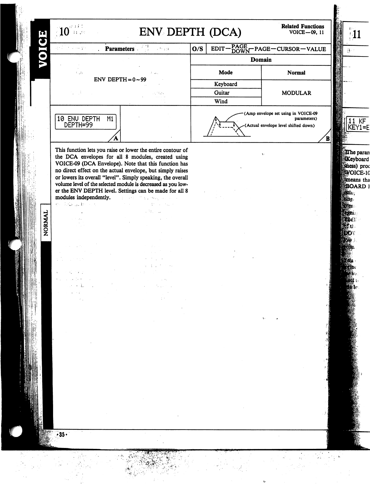
P'iP
iii-i
10
ENV
DEPTH
(DCA)
Related
Functions
VOICE—09,
11
11
.
Parameters
ENV DEPTH
=
0-99
10-ENU
DEPTH
Ml
DEPTH=99
O/S
EDIT—DOWN"
PAGE—CURSOR—VALUE
Domain
Mode
Keyboard
Guitar
Wind
Normal
MODULAR
<Amp
envelope
set
using
in
VOICE-09
parameters)
<Actual
envelope
level
shifted
down)
This
function
lets
you
raise
or
lower
the
entire
contour
of
the
DCA
envelopes
for
all
8
modules,
created
using
VOICE-09
(DCA
Envelope).
Note
that
this
function
has
no
direct
effect
on
the
actual
envelope,
but
simply
raises
or
lowers
its
overall
"level".
Simply
speaking,
the
overall
volume
level
of
the
selected
module
is
decreased
as
you
low
er
the
ENV
DEPTH
level.
Settings
can
be
made
for
all
8
modules
independently.
.
«:■
;,•,.••
,i.
}:■■
■
•.
■
•
;•••..
B
fie-.
U
'35*
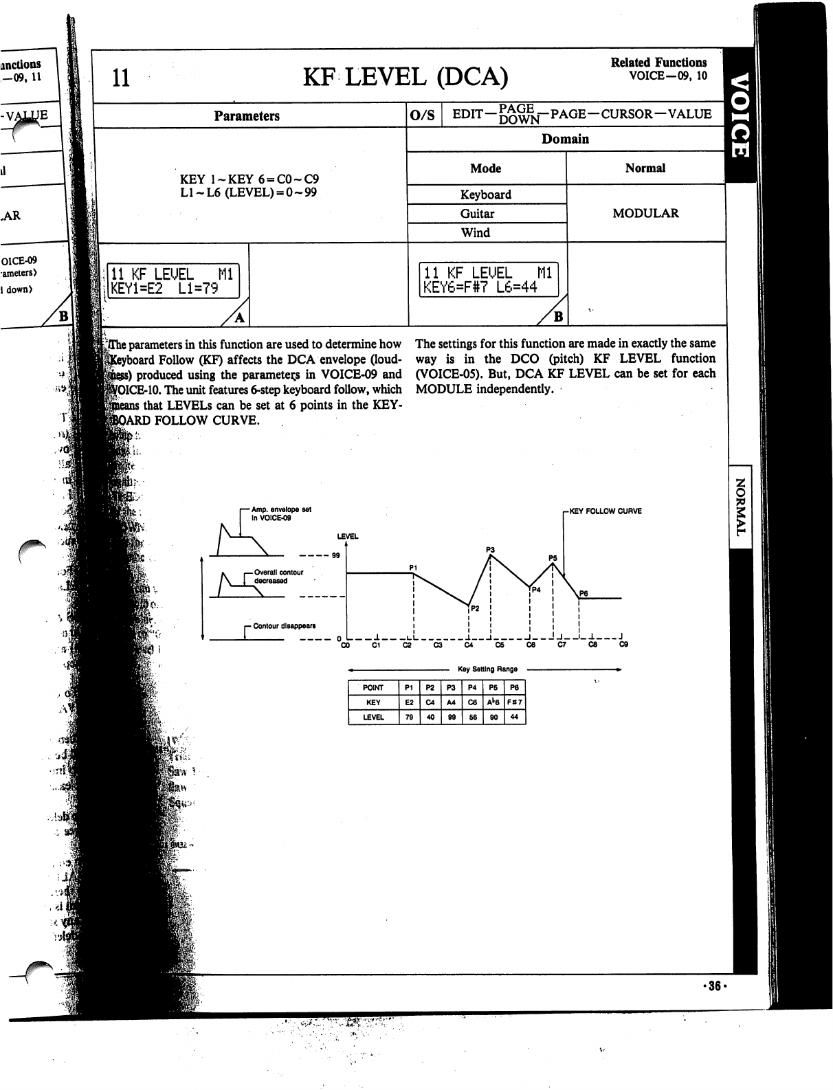
yThe
parameters
in
this
function
are
used
to
determine
how
The
settings
for
this
function
are
made
in
exactly
the
same
1
Follow
(KF)
affects
the
DCA
envelope
(loud-
way
is
in
the
DCO
(pitch)
KF
LEVEL
function
ss)
produced
using
the
parameters
in
VOICE-09
and
(VOICE-05).
But,
DCA
KF
LEVEL
can
be
set
for
each
MCE-10.
The
unit
features 6-step
keyboard
follow,
which
MODULE
independently.
i
that
LEVELS
can
be
set
at
6
points
in
the
KEY-
3ARD
FOLLOW
CURVE.
r
Amp.
envelope
set
fn
VOICE-09
-KEY
FOLLOW
CURVE
LEVEL
Overall
contour
decreased
- Contour
disappears
J.
i_i
j.
i
i
!j_-j_-1
J
0
■
••■>>«
•36-
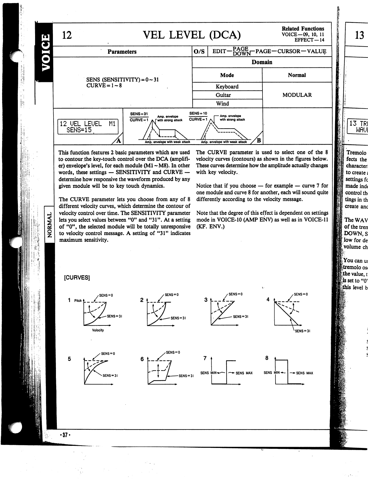
12
VEL
LEVEL
(DCA)
Related
Functions
VOICE-09,
10,
11
EFFECT—14
Parameters
SENS
(SENSITIVITY)
=
0-31
CURVE=1~8
12
UEL
LEUEL
Ml
SENS=15
O/S
EDIT—
—CURSOR—VALUE
Domain
Mode
Keyboard
Guitar
Wind
SENS-10
Amp.
envelope
with
strong
attack
Amp,
envelope
with
weak
attack
Amp,
envelope
with
weak
attack
Normal
MODULAR
This
function
features
2
basic
parameters
which
are
used
to
contour
the
key-touch
control
over
the
DCA
(amplifi
er)
envelope's
level,
for
each
module
(Ml
~M8).
In
other
words,
these
settings
—
SENSITIVITY
and
CURVE
—
determine
how
responsive
the
waveform
produced
by
any
given
module
will
be
to
key
touch
dynamics.
The
CURVE
parameter
lets
you
choose
from
any
of
8
different
velocity
curves,
which
determine
the
contour
of
velocity
control
over
time.
The
SENSITIVITY
parameter
lets
you
select
values
between
"0"
and
"31".
At
a
setting
of
"0",
the
selected
module
will
be
totally
unresponsive
to
velocity
control
message.
A
setting
of
"31"
indicates
maximum
sensitivity.
The
CURVE
parameter
is
used
to
select
one
of
the
8
velocity
curves
(contours)
as
shown
in
the
figures
below.
These
curves
determine
how
the
amplitude
actually
changes
with
key
velocity.
Notice
that
if
you
choose
—
for
example
—
curve
7
for
one
module
and
curve
8
for
another,
each
will
sound
quite
differently
according
to
the
velocity
message.
Note
that
the
degree
of
this
effect
is
dependent
on
settings
mode
in
VOICE-10
(AMP
ENV)
as
well
as
in
VOICE-11
(KF.
ENV.)
[CURVES]
1
Pitch*
/_
SENS
=
SENS
=
SENS
"31
3
t—/—,
SENS
=
3!
SENS
=
3!
Velocity
13
13
TRI
WflUI
Tremolo
fects
the
character!
to
create«
settings
fc
made
ind<
control
th<
tings
in
th
create
anc
The
WAV
ofthetren
DOWN,
S
|;low
for
de
<.volume
ch
I
You
can
us
|tremolo
os<
|the
value,
t
|issetto"0'
level
b
SENS
=
31
SENS
=
0
SENS
=
3I
SENS
MINi
~+
SENS
MAX
SENS
MIN
-*-
—►SENS
MAX
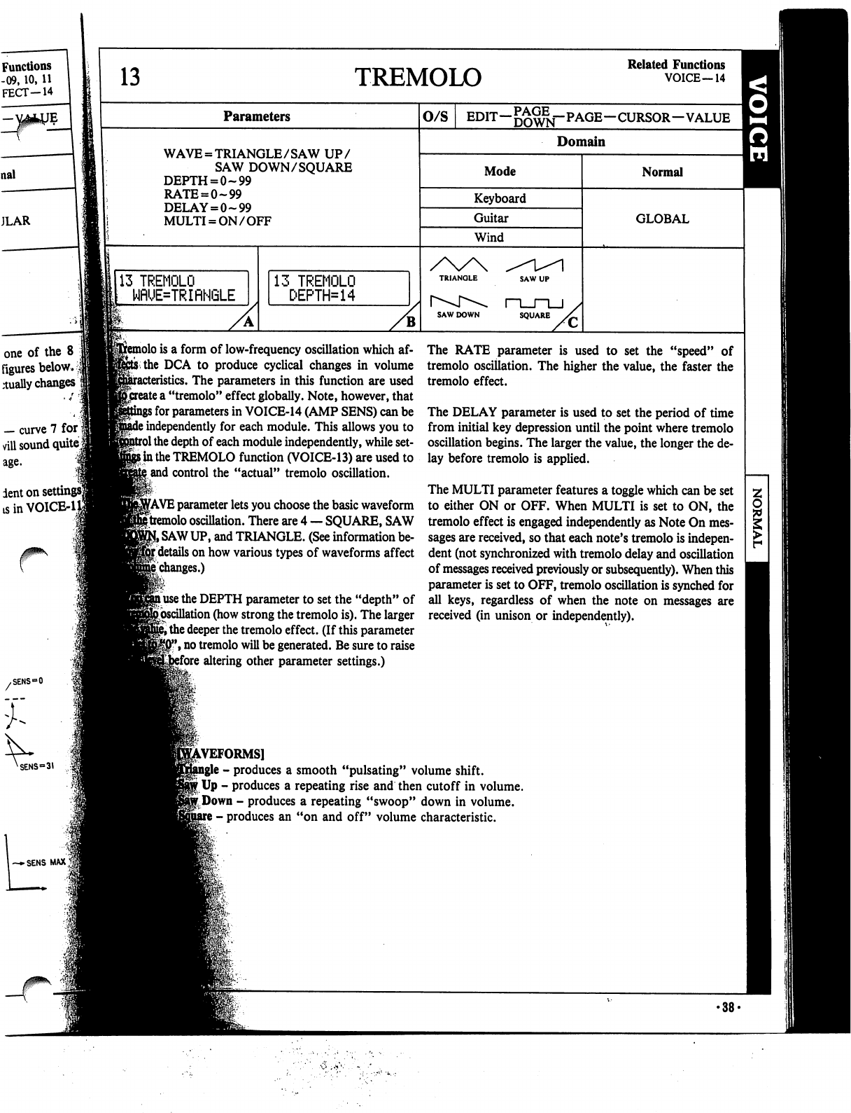
13
Parameters
WAVE
=
TRIANGLE/SAW
UP/
SAW
DOWN/SQUARE
DEPTH
=
0-99
RATE
=
0~99
DELAY
=
0-99
MULTI
=
ON/OFF
113
TREMOLO
WflUE=TRIflNGLE
Functions
-09,
10,
11
FECT-14
one
of
the
8
figures
below.
$
dually
changes
—
curve
7
for
viil
sound
quite
lent
on
set
tsinVOICE-1
TREMOLO
Related
Functions
VOICE—14
13
TREMOLO
DEPTH*14
O/S
EDIT—^^—PAGE—CURSOR—VALUE
|H
Domain
Mode
Keyboard
Guitar
Wind
SQUARE
Normal
GLOBAL
>lo
is
a
form
of
low-frequency
oscillation
which
af-
thc
DCA
to
produce
cyclical
changes
in
volume
The
parameters
in
this
function
are
used
ite
a
"tremolo"
effect
globally.
Note,
however,
that
for
parameters
in
VOICE-14
(AMP
SENS)
can
be
independently
for
each
module.
This
allows
you
to
the
depth
of
each
module
independently,
while
set-
i*
in
the
TREMOLO
function
(VOICE-13)
are
used
to
and
control
the
"actual"
tremolo
oscillation.
fAVE
parameter
lets
you
choose
the
basic
waveform
tremolo
oscillation.
There
are
4
—
SQUARE,
SAW
SAW
UP,
and
TRIANGLE.
(See
information
be-
details
on
how
various
types
of
waveforms
affect
changes.)
use
the
DEPTH
parameter
to
set
the
"depth"
of
{.oscillation
(how
strong
the
tremolo
is).
The
larger
""
the
deeper
the
tremolo
effect.
(If
this
parameter
,
no
tremolo
will
be
generated.
Be
sure
to
raise
'ore
altering
other
parameter
settings.)
The
RATE
parameter
is
used
to
set
the
"speed"
of
tremolo
oscillation.
The
higher
the
value,
the
faster
the
tremolo
effect.
The
DELAY
parameter
is
used
to
set
the
period
of
time
from
initial
key
depression
until
the
point
where
tremolo
oscillation
begins.
The
larger
the
value,
the
longer
the
de
lay
before
tremolo
is
applied.
The
MULTI
parameter
features
a
toggle
which
can
be
set
to
either
ON
or
OFF.
When
MULTI
is
set
to
ON,
the
tremolo
effect
is
engaged
independently
as
Note
On
mes
sages are
received,
so
that
each
note's
tremolo
is
indepen
dent
(not
synchronized
with
tremolo
delay
and
oscillation
of
messages
received
previously
or
subsequently).
When
this
parameter
is
set
to
OFF,
tremolo
oscillation
is
synched
for
all
keys,
regardless
of
when
the
note
on
messages
are
received
(in
unison
or
independently).
REFORMS]
-
produces
a
smooth
"pulsating"
volume
shift.
Up
-
produces
a
repeating
rise
and
then
cutoff
in
volume.
r
Down
-
produces
a
repeating
"swoop"
down
in
volume.
-
produces
an
"on
and
off"
volume
characteristic.
•38-

AMP
SENS
(DCA)
Related
Functions
VOICE-13
EFFECT—03-06,
19
Parameters
SENS
(SENSITIVITY)
=
0-7
O/S
EDIT—
—CURSOR-VALUE
Domain
Mode
Keyboard
Guitar
Wind
Normal
MODULAR
::•
J
15
14
flMP
SENS
SENS=0
Ml
14
flMP
SENS
SENS-7
M2
B
15
TOTfit
LEUEU
llji!;.'
llifi-hi
i
!
!
I
This
function
features
only
one
parameter,
SENSITIVI-
When
SENSITIVITY
is
set
to
a
value
of
"0",
the
all
ef-
TY,
which
is
set
independently
for
each
module.
This
"sen-
sitivity"
level
determines
how
"sensitive"
each
module
is
to
the
effects
listed
below.
(Or,
in
simpler
terms,
SENSI
TIVITY
determines
the
degree
of
"depth"
or
"strength"
the
effects
have
in
the
specified
module.)
(Related
Functions)
VOICE-13
TREMOLO
DEPTH
EFFECT-03
TREMOLO
DEPTH
(After
Touch)
EFFECT-04
TREMOLO
DEPTH
(Modulation
Wheel)
EFFECT-05
TREMOLO
DEPTH
(Definable
Control)
EFFECT-06
TREMOLO
DEPTH
(Foot
VR)
EFFECT-03
DCA
ENV
BIAS
(After
Touch)
EFFECT-04
DCA
ENV
BIAS
(Modulation
Wheel)
EFFECT-05
DCA
ENV
BIAS
(Definable
Control)
EFFECT-06
DCA
ENV
BIAS
(Foot
VR)
EFFECT-19
DEPTH
(Total
Tremolo)
fects
listed
below
will
not
affect
the
specified
module's
sound.
At
a
value
of
"7",
the
effects
will
be
strongest.
•39-
'
This
functio
f
which
is
usec
of
the
unit
I:
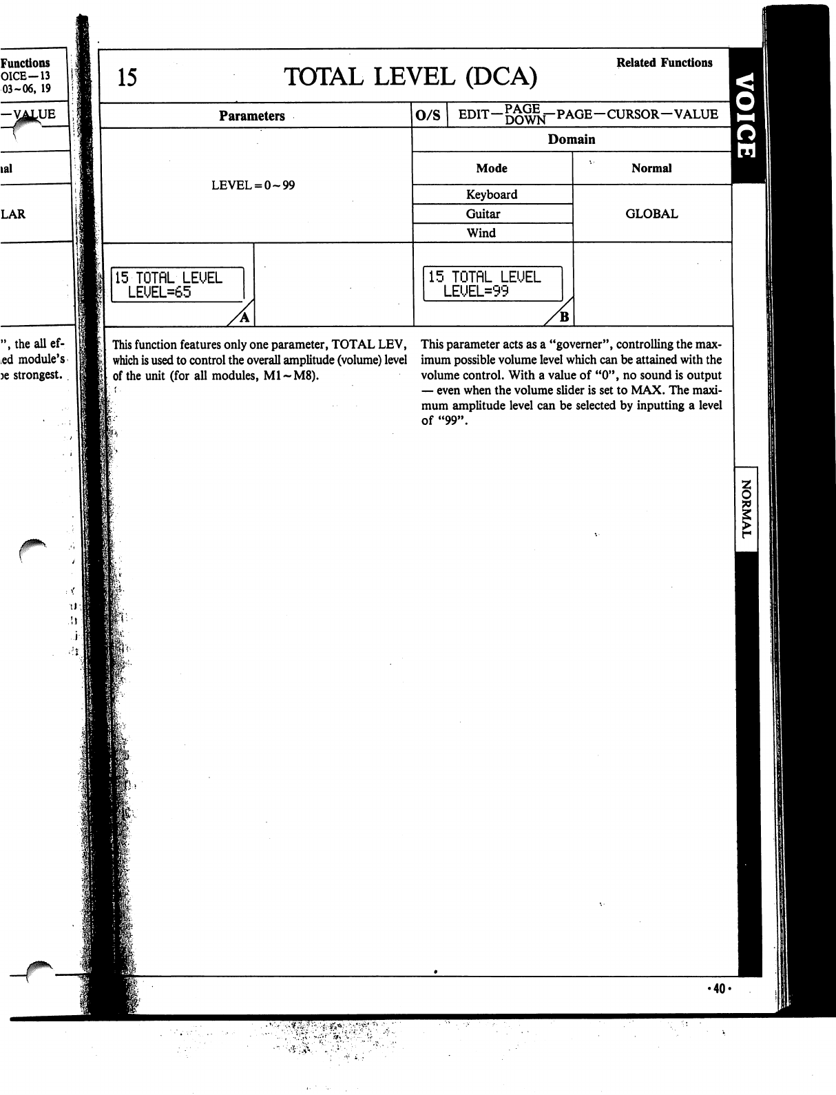
Functions
O1CE-13
03-06,
19
-VATUE
lal
LAR
15
TOTAL
LEVEL
(DCA)
Related
Functions
Parameters
LEVEL
=
0-99
15-TOTflL
LEUEL
LEUEL=65
O/S
EDIT—gg^j-PAGE—CURSOR—VALUE
Domain
Mode
Keyboard
Guitar
Wind
15
TOTflL
LEUEL
LEUEL=99
Normal
GLOBAL
",theallef-
ed
module's
)e
strongest.
This
function
features
only
one
parameter,
TOTAL
LEV,
This
parameter
acts
as
a
"governer",
controlling
the
max-
which
is
used
to
control
the
overall
amplitude
(volume)
level
imum
possible
volume
level
which
can
be
attained
with
the
of
the
unit
(for
all
modules,
M1~M8).
volume
control.
With
a
value
of
"0",
no
sound
is
output
—
even
when
the
volume
slider
is
set
to
MAX.
The
maxi
mum
amplitude
level
can
be
selected
by
inputting
a
level
of
"99".
•40«
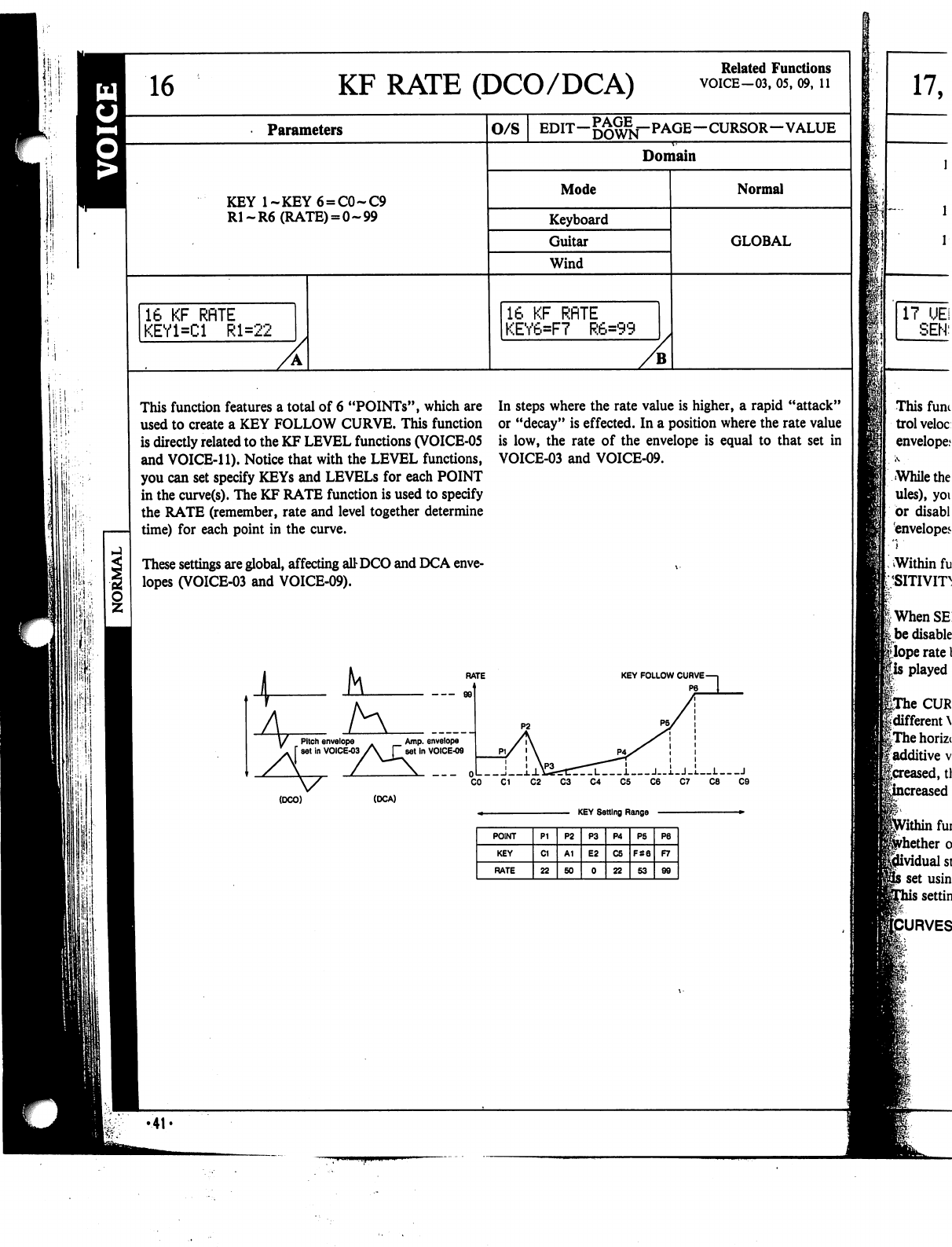
16
KF RATE
(DCO/DCA)
Related
Functions
VOICE-03,
05,
09,
11
Parameters
O/S
EDIT—
—CURSOR—VALUE
Domain
KEY
l~KEY6
=
C0~C9
R1-R6
(RATE)
= 0-99
Mode
Keyboard
Guitar
Wind
Normal
GLOBAL
16
KF
RflTE
KEY1=C1
Rl=22
16
KF
RflTE
KEY6=F7
R6=99
This
function
features
a
total
of
6
"POINTs",
which
are
used
to
create
a
KEY
FOLLOW
CURVE.
This
function
is
directly
related
to
the
KF
LEVEL
functions
(VOICE-05
and
VOICE-11).
Notice
that
with
the
LEVEL
functions,
you
can
set
specify
KEYs
and
LEVELs
for
each
POINT
in
the
curve(s).
The
KF
RATE
function
is
used
to
specify
the
RATE
(remember,
rate
and
level
together
determine
time)
for
each
point
in
the
curve.
These
settings
are
global,
affecting
attDCO
and
DCA
enve
lopes
(VOICE-03
and
VOICE-09).
In
steps
where
the
rate
value
is
higher,
a
rapid
"attack"
or
"decay"
is
effected.
In
a
position
where
the
rate
value
is
low,
the
rate
of
the
envelope
is
equal
to
that
set
in
VOICE-03
and
VOICE-09.
(DCO)
(DCA)
KEY
Setting
Range
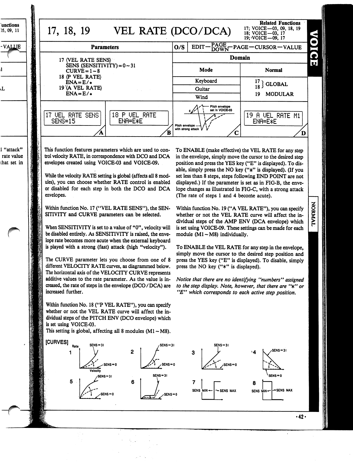
r
17,
18,
19
VEL
RATE
(DCO/DCA)
Related
Functions
17;
VOICE—03,
09,
18,
19
18;
VOICE-03,
17
19;>VOICE-09,
17
Parameters
17
(VEL
RATE
SENS)
SENS
(SENSITIVITY)
=
CURVE=1~8
18
(P
VEL
RATE)
ENA=E/*
19
(A
VEL
RATE)
ENA=E/*
:0~31
17
UEL
RflTE
SENS
SENS=15
18
P
UEL
RflTE
ENfl=E*E
0/S
EDIT—5£^j-PAGE—CURSOR—VALUE
^^
Domain
Mode
Keyboard
Guitar
Wind
Pitch
envelope
—\
/
\
/
with
strong
attack
V
V
Normal
GLOBAL
17
1
18
J
19
MODULAR
19
fl
UEL
RflTE
Ml
ENR=E*E
This
function
features
parameters
which
are
used
to
con
trol
velocity
RATE,
in
correspondence
with
DCO
and
DCA
envelopes
created
using
VOICE-03
and
VOICE-09.
While
the
velocity
RATE
setting
is
global
(affects
all
8
mod
ules),
you
can
choose
whether
RATE
control
is
enabled
or
disabled
for
each
step
in
both
the
DCO
and
DCA
envelopes.
Within
function
No.
17
("VEL
RATE
SENS"),
the
SEN
SITIVITY
and
CURVE
parameters
can
be
selected.
When
SENSITIVITY
is
set
to
a
value
of
"0",
velocity
will
be
disabled
entirely.
As
SENSITIVITY
is
raised,
the
enve
lope
rate
becomes
more
acute
when
the
external
keyboard
is
played
with a
strong
(fast)
attack
(high
"velocity").
The
CURVE
parameter
lets
you
choose
from
one
of
8
different
VELOCITY
RATE
curves,
as
diagrammed
below.
The
horizontal
axis
of
the
VELOCITY
CURVE
represents
additive
values
to
the
rate
parameter.
As
the
value
is
in
creased,
the
rate
of
steps
in
the
envelope
(DCO/DCA)
are
increased
further.
Within
function
No.
18
("P
VEL
RATE"),
you
can
specify
whether
or
not
the
VEL
RATE
curve
will
affect
the
in
dividual
steps
of
the
PITCH
ENV
(DCO
envelope)
which
is
set
using
VOICE-03.
This
setting
is
global,
affecting
all
8
modules
(Ml
~M8).
To
ENABLE
(make
effective)
the
VEL
RATE
for
any
step
in
the
envelope,
simply
move
the
cursor
to
the
desired
step
position
and
press
the
YES
key
("E"
is
displayed).
To
dis
able,
simply
press
the
NO
key
("*"
is
displayed).
(If
you
set
less
than
8
steps,
steps
following
END
POINT
are
not
displayed.)
If
the
parameter
is
set
as
in
FIG-B,
the
enve
lope
changes
as
illustrated
in
FIG-C,
with
a
strong
attack
(The
rate
of
steps
1
and
4
become
acute).
Within
function
No.
19
("A
VEL
RATE"),
you
can
specify
whether
or
not
the
VEL
RATE
curve
will
affect
the
in
dividual
steps
of
the
AMP
ENV
(DCA
envelope)
which
is
set
using
VOICE-09.
These
settings
can
be
made
for
each
module
(M1-M8)
individually.
To
ENABLE
the
VEL
RATE
for
any
step
in
the
envelope,
simply
move
the
cursor
to
the
desired
step
position
and
press
the
YES
key
("E"
is
displayed).
To
disable,
simply
press
the
NO
key
("*"
is
displayed).
Notice
that
there
are
no
identifying
"numbers"
assigned
to
the
step
display.
Note,
however,
that
there
are
'%"
or
"E"
which
corresponds
to
each
active
step
position.
[CURVES]
SENS-31
SENS-0
SENS
=
31
SENS«0
SENS
=
31
SENS
=
0
SENS
=
31
SENS«=0
XSENS=O
SENS
=
SENS
MIN
«"-->*
SENS
MAX
8
SENS
SENS
MAX
•42-
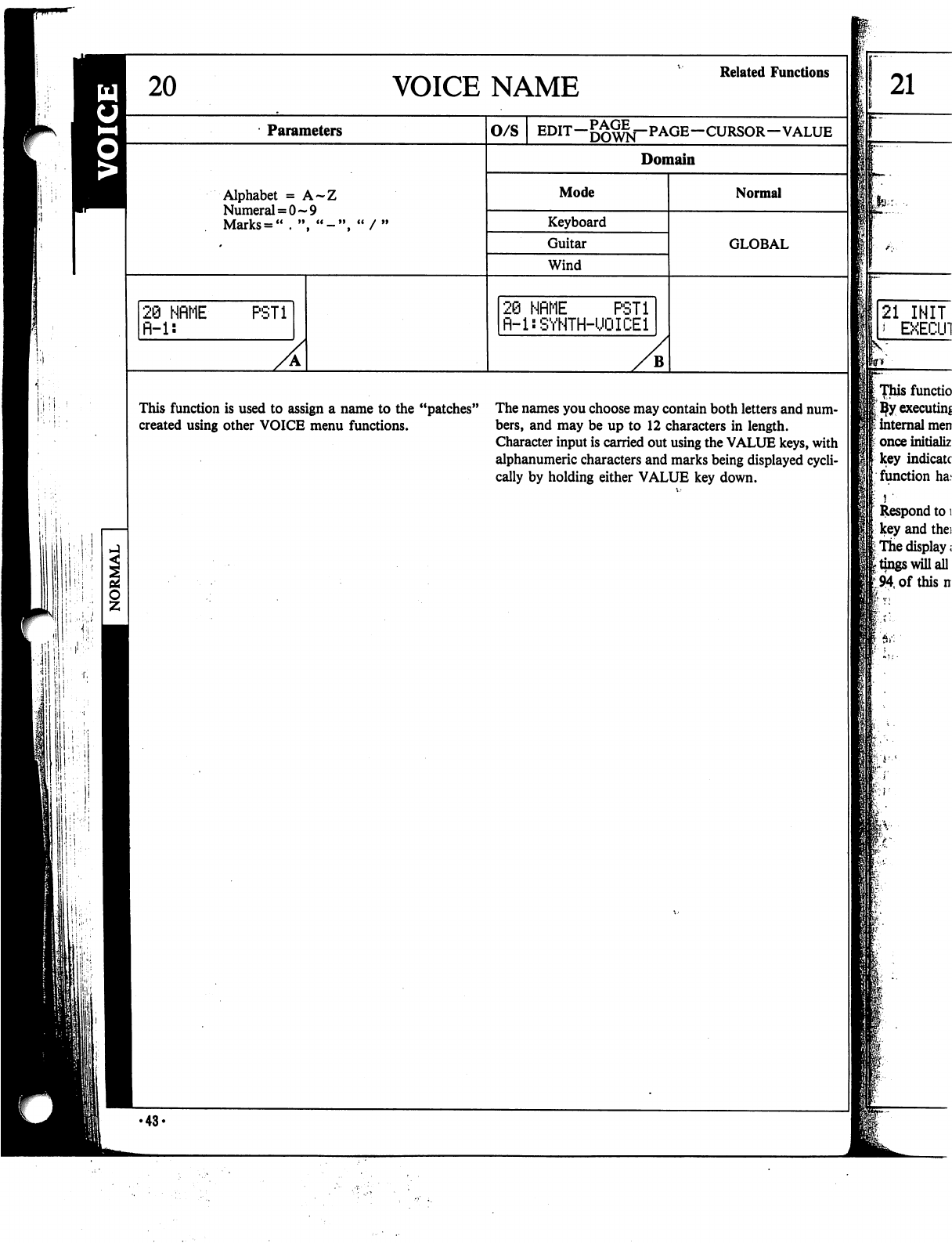
VOICE
NAME
Related
Functions
Parameters
Alphabet
=
A~Z
Numeral
=
0-9
Marks
=
"
♦
",
"-'
28
NfiME
fi-1:
PST1
O/S
EDIT—DOWN~~
PAGE—CURSOR-VALUE
Domain
Mode
Keyboard
Guitar
Wind
20
NflME
PSTi
fl-l:SYNTH-UQICEl
B
Normal
GLOBAL
This
function
is
used
to
assign
a
name
to the
"patches"
The
names
you
choose
may
contain
both
letters
and
num-
created
using
other
VOICE
menu
functions.
bers,
and
may
be
up
to
12
characters
in
length.
Character
input
is
carried
out
using
the
VALUE
keys,
with
alphanumeric
characters
and
marks
being
displayed
cycli
cally
by
holding
either
VALUE
key
down.
21
21
INIT
*
EXECU1
[Thisfunctio
I
ijfy
executing
■
internal
men
t
once
initializ
key
indicate
function
ha.«
Respond
to
i
key
and
the:
I
The
display;
I
tings
will
all
194,
of
this
n
:
■■$!•:■
■
•43-
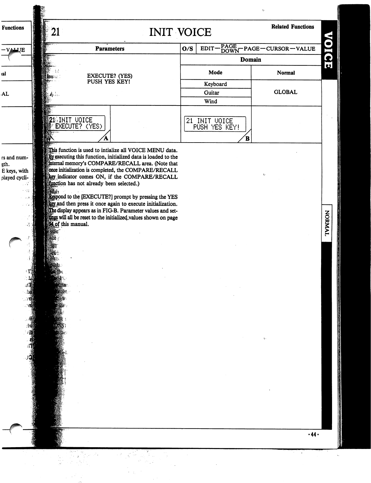
Functions
rs
and
num-
gth.
E
keys,
with
played
cycli-
21
INIT
VOICE
Related
Functions
Parameters
EXECUTE?
(YES)
PUSH
YES
KEY!
UOICE
EXECUTE?
(YES)
o/s
EDIT—DOWN""
PAGE—CURSOR—VALUE
Domain
Mode
Keyboard
Guitar
Wind
21
INIT
UOICE
PUSH
YES
KEY!
Normal
GLOBAL
j
function
is
used
to
intialize
all
VOICE
MENU
data.
>y,
executing
this
function,
initialized
data
is
loaded
to
the
1
memory's
COMPARE/RECALL
area.
(Note
that
|once
initialization
is
completed,
the
COMPARE/RECALL
^indicator
comes
ON,
if
the
COMPARE/RECALL
on
has
not
already
been
selected.)
1
to
the
[EXECUTE?]
prompt
by
pressing
the
YES
j^and
then
press
it
once
again
to
execute
initialization.
3
display
appears
as
in
FIG-B.
Parameter
values
and
set-
5
will
all
be
reset
to the
initialize^values
shown
on
page
Lof
this
manual.
•44-
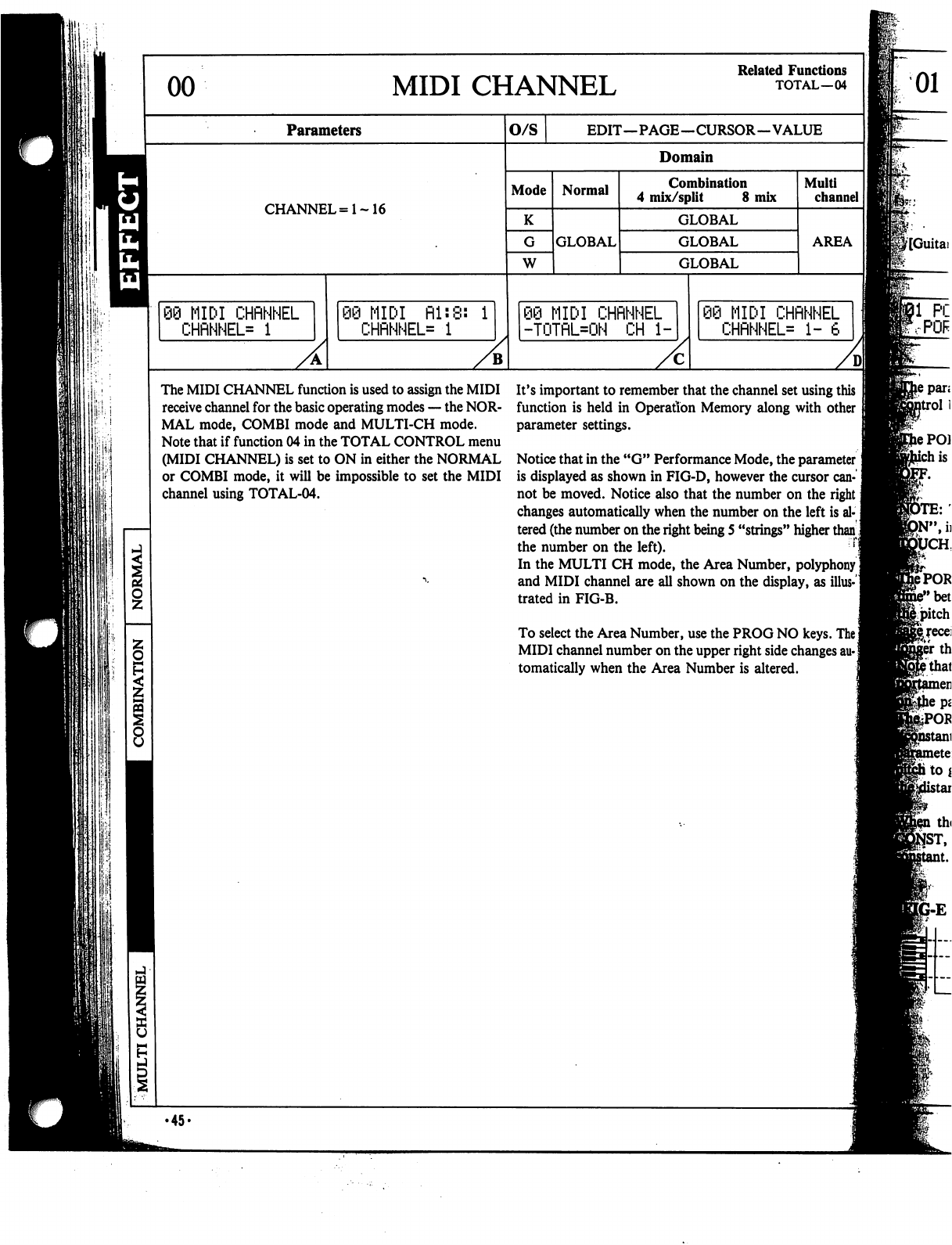
\\:\
!$!
00
MIDI
CHANNEL
Related
Functions
TOTAL—04
Parameters
CHANNEL=1~16
89
MIDI
CHRNNEL
CHRNNEL=
1
MIDI
Rl:8:
1
CHRNNEL=
1
O/S
EDIT—PAGE—CURSOR—VALUE
Domain
Mode
K
W
Normal
GLOBAL
Combination
4
mix/split
8
mix
GLOBAL
GLOBAL
GLOBAL
89
MIDI
CHRNNEL
-TOTRL=ON
CH
1-
Multi
channel
AREA
MIDI
CHRNNEL
CHRNNEL*
1-
6
The
MIDI
CHANNEL
function
is
used
to
assign
the
MIDI
receive
channel
for
the
basic
operating
modes
—
the
NOR
MAL
mode,
COMBI
mode
and
MULTI-CH
mode.
Note
that
if
function
04
in
the
TOTAL
CONTROL
menu
(MIDI
CHANNEL)
is
set
to
ON
in
either
the
NORMAL
or
COMBI
mode,
it
will
be
impossible
to
set
the
MIDI
channel
using
TOTAL-04.
It's
important
to
remember
that
the
channel
set
using
this
function
is
held
in
Operation
Memory
along
with
other
parameter
settings.
Notice
that
in
the
"G"
Performance
Mode,
the
parameter!
is
displayed
as
shown
in
FIG-D,
however
the
cursor
can
not be
moved.
Notice
also
that
the
number
on
the
right
j
changes
automatically
when
the
number
on
the
left
is al
tered
(the
number
on
the
right
being
5
"strings"
higher
than]
the
number
on
the
left).
In
the
MULTI
CH
mode,
the
Area
Number,
polyphony
I
and
MIDI
channel
are
all
shown
on
the
display,
as
illus-1
trated
in
FIG-B.
To
select
the
Area
Number,
use
the
PROG
NO
keys.
The]
MIDI
channel
number
on
the
upper
right
side
changes
au-|
tomatically
when
the
Area
Number
is
altered.
01
8
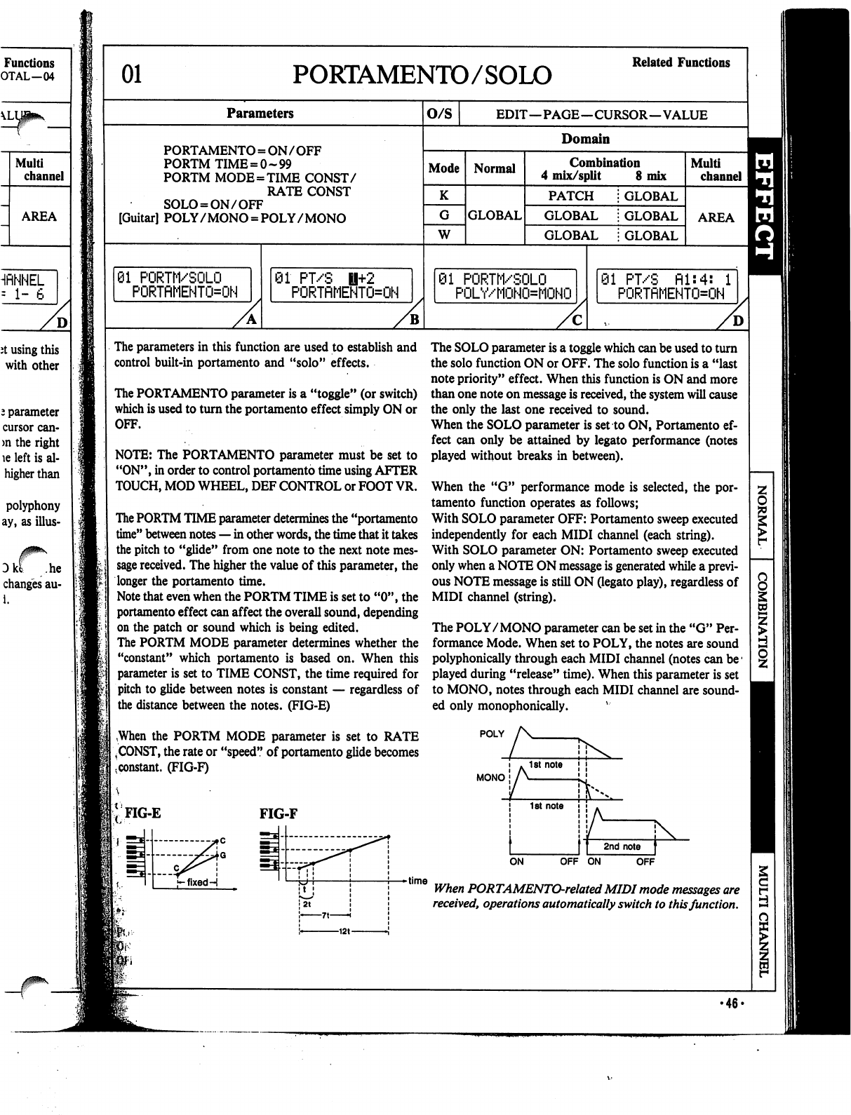
Functions
OTAL—04
HflNNEL
=
1-
6
D
it
using
this
with
other
2
parameter
cursor
can-
>n
the
right
le
left
is
al-
higher
than
polyphony
ay,
as
illus-
Dkt
.he
changes
au-
i.
01
PORTAMENTO/SOLO
Related
Functions
Parameters
PORTAMENTO
=
ON
/
OFF
PORTM
TIME
=
0-99
PORTM
MODE=TIME
CONST/
RATE
CONST
SOLO
=
ON/OFF
[Guitar]
POLY
/
MONO
=
POLY/MONO
81
PORTM/SOLO
PORTRMEHTO=ON
01
PT/S
H+2
PORTflMENTO=ON
O/S
EDIT—PAGE—CURSOR—VALUE
Domain
Mode
K
W
Normal
GLOBAL
Combination
4
mix/split
8
mix
PATCH
GLOBAL
GLOBAL
GLOBAL
GLOBAL
GLOBAL
01
PORTM/SOLO
POLY/MOHO=MOHO
Multi
channel
AREA
91
PT/S
fll:4:
1
PORTflMENTO=OH
The
parameters
in
this
function
are
used
to
establish
and
control
built-in
portamento
and
"solo"
effects.
The
PORTAMENTO
parameter
is
a
"toggle"
(or
switch)
which
is
used
to
turn
the
portamento
effect
simply
ON
or
OFF.
NOTE:
The
PORTAMENTO
parameter
must
be
set
to
"ON",
in
order
to
control
portamento
time
using
AFTER
TOUCH,
MOD
WHEEL,
DEF
CONTROL
or
FOOT
VR.
The
PORTM
TIME
parameter
determines
the
"portamento
time"
between
notes
—
in
other
words,
the
time
that
it
takes
the
pitch
to
"glide"
from
one
note
to
the
next
note
mes
sage
received.
The
higher
the
value
of
this
parameter,
the
longer
the
portamento
time.
Note
that
even
when
the
PORTM
TIME
is
set
to
"0",
the
portamento
effect
can
affect
the
overall
sound,
depending
on
the
patch
or
sound
which
is
being
edited.
The
PORTM
MODE
parameter
determines
whether
the
"constant"
which
portamento
is
based
on.
When
this
parameter
is
set
to
TIME
CONST,
the
time
required
for
pitch
to
glide
between
notes
is
constant
—
regardless
of
the
distance
between
the
notes.
(FIG-E)
,When
the
PORTM
MODE
parameter
is
set
to
RATE
|
,
CONST,
the
rate
or
"speed"
of
portamento
glide
becomes
.constant.
(FIG-F)
The
SOLO
parameter
is
a
toggle
which
can
be
used
to
turn
the
solo
function
ON
or
OFF.
The
solo
function
is
a
"last
note
priority"
effect.
When
this
function
is
ON
and
more
than
one
note
on
message
is
received,
the
system
will
cause
the
only
the
last
one
received
to
sound.
When
the
SOLO
parameter
is
set
to
ON,
Portamento
ef
fect
can
only
be
attained
by
legato
performance
(notes
played
without
breaks
in
between).
When
the
"G"
performance
mode
is
selected,
the
por
tamento
function
operates
as
follows;
With
SOLO
parameter
OFF:
Portamento
sweep
executed
independently
for
each
MIDI
channel
(each
string).
With
SOLO
parameter
ON:
Portamento
sweep
executed
only
when
a
NOTE
ON
message
is
generated
while
a
previ
ous
NOTE
message
is
still
ON
Oegato
play),
regardless
of
MIDI
channel
(string).
The
POLY/MONO
parameter
can
be
set
in
the
"G"
Per
formance
Mode.
When
set
to
POLY,
the
notes
are
sound
polyphonically
through
each
MIDI
channel
(notes
can
be1
played
during
"release"
time).
When
this
parameter
is
set
to
MONO,
notes
through
each
MIDI
channel
are
sound
ed
only
monophonically.
v
POLY
MONO
FIG-E
FIG-F
f-fixedH
OFF
ON
OFF
time
When
PORTAMENTO-related
MIDI
mode
messages
are
received,
operations
automatically
switch
to
this
function.
•46-
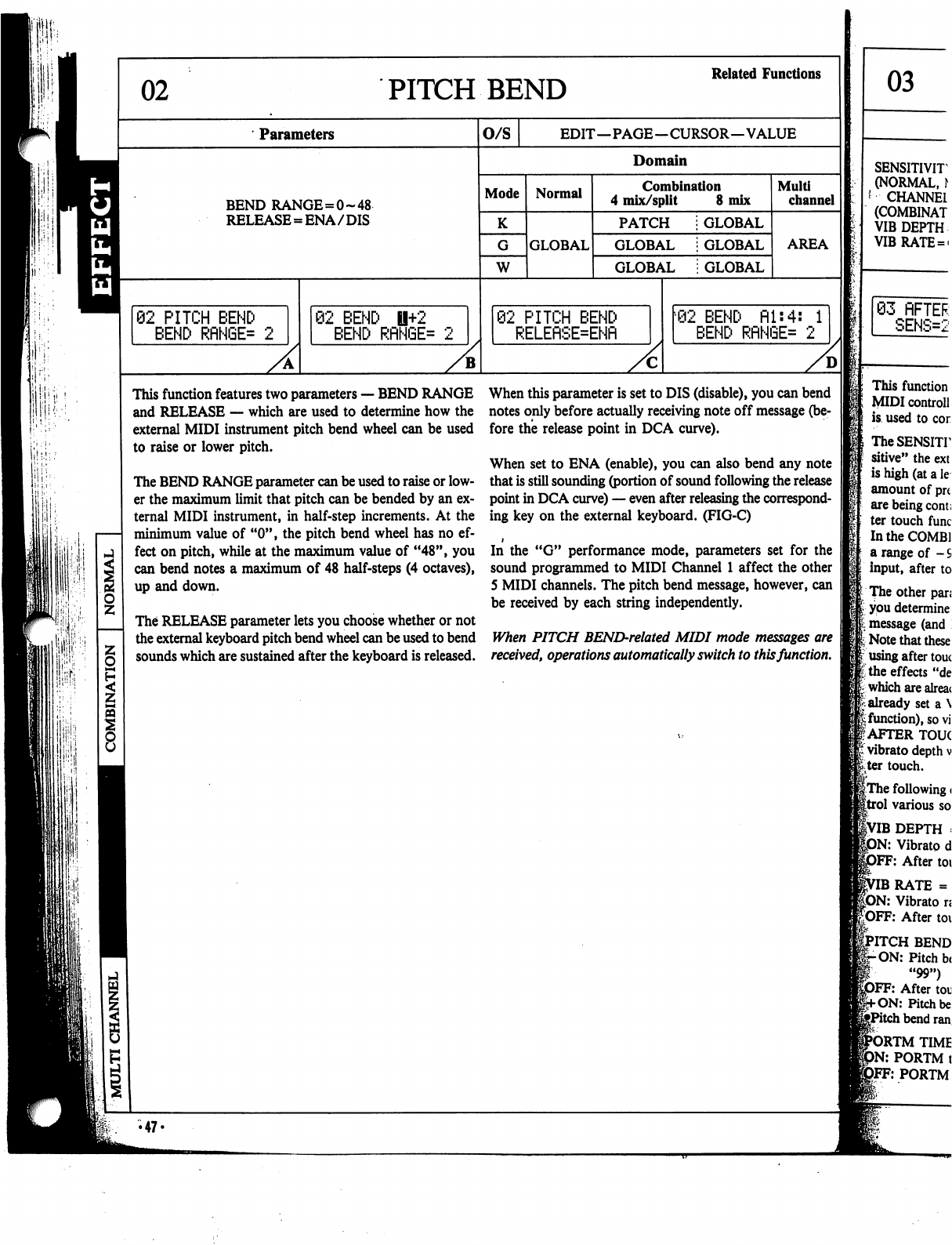
ri
I1
r
PITCH
BEND
Related
Functions
Parameters
BEND
RANGE=0~48
RELEASE
=
ENA/DIS
62
PITCH
BEND
BEND
RflNGE=
2
@2
BEND
U+2
BEND
RflN6E=
O/S
EDIT—PAGE—CURSOR—VALUE
Domain
Mode
K
W
Normal
GLOBAL
Combination
4
mix/split
8
mix
PATCH
GLOBAL
GLOBAL
GLOBAL
GLOBAL
GLOBAL
02
PITCH
BEND
RELEflSE=ENfl
Multi
channel
AREA
02
BEND
fil:4:
1
BEND
RflNGE=
2
This
function
features
two
parameters
—
BEND
RANGE
and
RELEASE
—
which
are
used
to
determine
how
the
external
MIDI
instrument
pitch
bend
wheel
can
be
used
to
raise
or
lower
pitch.
The
BEND
RANGE
parameter
can
be
used
to
raise
or
low
er
the
maximum
limit
that
pitch
can
be
bended
by
an
ex
ternal
MIDI
instrument,
in
half-step
increments.
At
the
minimum
value
of
"0",
the
pitch
bend
wheel
has
no
ef
fect
on
pitch,
while
at
the
maximum
value
of
"48",
you
can
bend
notes
a
maximum
of
48
half-steps
(4
octaves),
up
and
down.
The
RELEASE
parameter
lets
you
choose
whether
or
not
the
external
keyboard
pitch
bend
wheel
can
be
used
to
bend
sounds
which
are
sustained
after
the
keyboard
is
released.
When
this
parameter
is
set
to
DIS
(disable),
you
can
bend
notes
only
before
actually
receiving
note
off
message
(be
fore
the
release
point
in
DCA
curve).
When
set
to
ENA
(enable),
you
can
also
bend
any
note
that
is
still
sounding
(portion
of
sound
following
the
release
point
in
DCA
curve)
—
even
after
releasing
the
correspond
ing
key
on
the
external
keyboard.
(FIG-C)
In
the
"G"
performance
mode,
parameters
set
for
the
sound
programmed
to
MIDI
Channel
1
affect
the
other
5
MIDI
channels.
The
pitch
bend
message,
however,
can
be
received
by
each
string
independently.
When
PITCH
BEND-related
MIDI
mode
messages
are
received,
operations
automatically
switch
to
this
function.
•47«
03
SENSITIVIT
(NORMAL,
\
'
CHANNEL
(COMBINAT
VIB
DEPTH
VIBRATE
=
«
03
RFTER
SENS=2
This
function
MIDI
controll
is
used
to
cor
TheSENSHT
sitive"
the
ext
is
high
(at
a
le
amount
of
pn
are
being
com;
ter
touch
func
In
the
COMB!
a
range
of
-
S
input,
after
to
The
other
pan
I
you
determine
message
(and
;■
Note
that
these
using
after
touc
I
the
effects
"de
which
are
alreac
already
set
a
\
function),
so
vi
AFTER
TOUC
vibrato
depth
v
ter
touch.
|The
following
<
1
various
so
1VIB
DEPTH
:
)N:
Vibrato
d
}FF:
After
toi
IB
RATE
=
DN:
Vibrato
ri
After
toi
RTM
TIME
PORTM
t
FF:
PORTM
PITCH
BEND
-ON:
Pitch
b(
"99")
DFF:
After
toi
Pitch
be
i
bend
ran
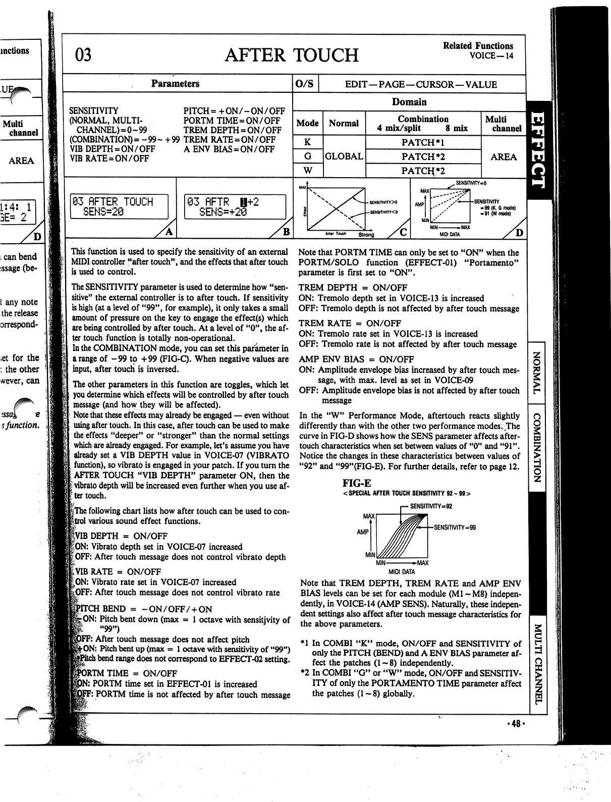
03
AFTER
TOUCH
Related
Functions
VOICE-14
Parameters
O/S
EDIT—PAGE—CURSOR—VALUE
SENSITIVITY
PITCH
=
+
ON
/
-
ON
/
OFF
(NORMAL,
MULTI-
PORTM
TIME=ON/OFF
CHANNEL)=0-99
TREM
DEPTH
=
ON
/
OFF
(COMBINATION)
=
-99-
+99
TREM
RATE=ON/OFF
VIB
DEPTH=ON/OFF
A
ENV
BIAS=ON/OFF
VIBRATE=ON/OFF
Mode
G
W
83
flFTER
TOUCH
SENS=28
Normal
GLOBAL
Domain
Combination
4
mix/split
8
mix
PATCH
PATCH
*2
PATOi*2
63
flFTR
H+2
SENS=+28
Multi
channel
AREA
SENSITIVITY»O
•SENSITIVITY
-99
(K,
6
mode)
-91
(W
mode)
M1N
►MAX
MIDI
DATA
This
function
is
used
to
specify
the
sensitivity
of
an
external
MIDI
controller
"after
touch",
and
the
effects
that
after
touch
is
used
to
control.
The
SENSITIVITY
parameter
is
used
to
determine
how
"sen
sitive"
the
external
controller
is
to
after
touch.
If
sensitivity
is
high
(at
a
level
of
"99",
for
example),
it
only
takes
a
small
amount
of
pressure
on
the
key
to
engage
the
effect(s)
which
are
being
controlled
by
after
touch.
At
a
level
of
"0",
the
af
ter
touch
function
is
totally
non-operational.
In the
COMBINATION
mode,
you
can
set
this
parameter
in
a
range
of
-99
to
+99
(FIG-Q.
When
negative
values
are
input,
after
touch
is
inversed.
The
other
parameters
in
this
function
are
toggles,
which
let
you
determine
which
effects
will
be
controlled
by
after
touch
message
(and
how
they
will
be
affected).
Note
that
these
effects
may
already
be
engaged
—
even
without
using
after
touch.
In
this
case,
after
touch
can
be
used
to
make
the
effects
"deeper"
or
"stronger"
than
the
normal
settings
which
are
already
engaged.
For
example,
let's
assume
you
have
already
set
a
VIB
DEPTH
value
in
VOICE-07
(VIBRATO
function),
so
vibrato
is
engaged
in
your
patch.
If
you
turn
the
:
AFTER
TOUCH
"VIB
DEPTH"
parameter
ON,
then
the
|
vibrato
depth
will
be
increased
even
further
when
you
use
af-
:ter
touch.
if
|The
following
chart
lists
how
after
touch
can
be
used
to
con-
ftrol
various
sound
effect
functions.
|VIB
DEPTH
=
ON/OFF
|ON:
Vibrato
depth
set
in
VOICE-07
increased
^OFF:
After
touch
message
does
not
control
vibrato
depth
RATE
=
ON/OFF
|>ON:
Vibrato
rate
set
in
VOICE-07
increased
F:
After
touch
message
does
not
control
vibrato
rate
BEND
=
-
ON/OFF/
+
ON
-ON:
Pitch
bent
down
(max
=
1
octave
with
sensitjvity
of
"99")
F:
After
touch
message
does not
affect
pitch
jhON:
Pitch
bent
up
(max
=
1
octave
with
sensitivity
of
"99")
l
bend
range
does
not
correspond
to
EFFECT-02
setting.
DRTM
TIME
=
ON/OFF
:
PORTM
time
set
in
EFFECT-01
is
increased
F:
PORTM
time
is
not
affected
by
after
touch
message
Note
that
PORTM
TIME
can
only
be
set
to
"ON"
when
the
PORTM/SOLO
function
(EFFECT-01)
"Portamento"
parameter
is
first
set
to
"ON".
TREM
DEPTH
=
ON/OFF
ON:
Tremolo
depth
set
in
VOICE-13
is
increased
OFF:
Tremolo
depth
is
not
affected
by
after
touch
message
TREM
RATE
=
ON/OFF
ON:
Tremolo
rate
set
in
VOICE-13
is
increased
OFF:
Tremolo
rate
is
not
affected
by
after
touch
message
AMP
ENV
BIAS
=
ON/OFF
ON:
Amplitude
envelope
bias
increased
by
after
touch
mes
sage,
with
max.
level
as
set
in
VOICE-09
OFF:
Amplitude
envelope
bias
is
not
affected
by
after
touch
message
In
the
"W"
Performance
Mode,
aftertouch
reacts
slightly
differently
than
with
the
other
two
performance
modes.
The
curve
in
FIG-D
shows
how
the
SENS
parameter
affects
after-
touch
characteristics
when
set
between
values
of
"0"
and
"91".
Notice
the
changes
in
these
characteristics
between
values
of
"92"
and
"99"(FIG-E).
For
further
details,
refer
to
page
12.
FIG-E
<
SPECIAL
AFTER
TOUCH
SENSITIVITY
92
-
99
>
SENSITIVITY-92
•SENSITIVITY=:99
MIDI
DATA
Note
that
TREM
DEPTH,
TREM
RATE
and
AMP
ENV
BIAS
levels
can
be
set
for
each
module
(Ml
~M8)
indepen
dently,
in
VOICE-14
(AMP
SENS).
Naturally,
these
indepen
dent
settings
also
affect
after
touch
message
characteristics
for
the
above
parameters.
♦1
In
COMBI
"K"
mode,
ON/OFF
and
SENSITIVITY
of
only
the
PITCH
(BEND)
and
A
ENV
BIAS
parameter
af
fect
the
patches
(1~8)
independently.
♦2
In
COMBI
"G"
or
"W"
mode,
ON/OFF
and
SENSITIV
ITY
of
only
the
PORTAMENTO
TIME
parameter
affect
the
patches
(1-8)
globally.
Cd
I
S
•48-
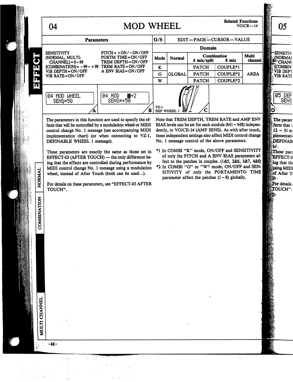
04
MOD
WHEEL
Related
Functions
VOICE—14
Parameters
SENSITIVITY
PITCH=
+ON/-ON/OFF
(NORMAL,
MULTI-
PORTM
TIME=ON
/
OFF
CHANNEL)=0~99
TREM
DEPTH=ON/OFF
(COMBINATION)
=
-99-
+99
TREM
RATE=ON/OFF
VIB
DEPTH=ON/OF?
A
ENV
BIAS=ON/OFF
VIB
RATE=ON/OFF
84
MOD
WHEEL
SEN§=50
84
MOD
i+2
SEHS=+50
B
O/S
EDIT—PAGE—CURSOR—VALUE
Domain
Mode
K
W
Normal
GLOBAL
Combination
4
mix/split
8
mix
PATCH
PATCH
PATCH
COUPLE*!
COUPLER
COUPLER
vz-i
DEF
WHEEL
1
Mult!
channel
I
AREA
The
parameters
in
this
function
are
used
to
specify
the
ef
fects
that
will
be
controlled
by
a
modulation
wheel
or
MIDI
control
change
No.
1
message
(see
accompanying
MIDI
implementation
chart) (or
when
connecting
to
VZ-1,
DEFINABLE
WHEEL
1
message).
These
parameters
are
exactly
the
same
as
those
set
in
EFFECT-03
(AFTER
TOUCH)
—
the
only
difference
be
ing
that
the
effects
are
controlled
during
performance
by
MIDI
control
change
No.
1
message
using
a
modulation
wheel,
instead
of
After
Touch
(both
can
be
used...).
For
details
on
these
parameters,
see
"EFFECT-03
AFTER
TOUCH".
Note
that
TREM
DEPTH,
TREM
RATE
and
AMP
ENV
BIAS
levels
can
be
set
for
each
module
(Ml
~
M8)
indepen
dently,
in
VOICE-14
(AMP
SENS).
As
with
after
touch,
these
independent
settings
also
affect
MIDI
control
change
]
No.
1
message
control
of
the
above
parameters.
♦1
In
COMBI
"K"
mode,
ON/OFF
and
SENSITIVITY
]
of
only
the
PITCH
and
A
ENV
BIAS
parameters
af
fect
to the
patches
in
couples.
(1&5,
2&6,
3&7,
4&8)
I
♦2
In
COMBI
"G"
or
"WV
mode,
ON/OFF
and
SEN
SITIVITY
of
only
the
PORTAMENTO
TIME]
parameter
affect
the
patches
(1-8)
globally.
05
.49.
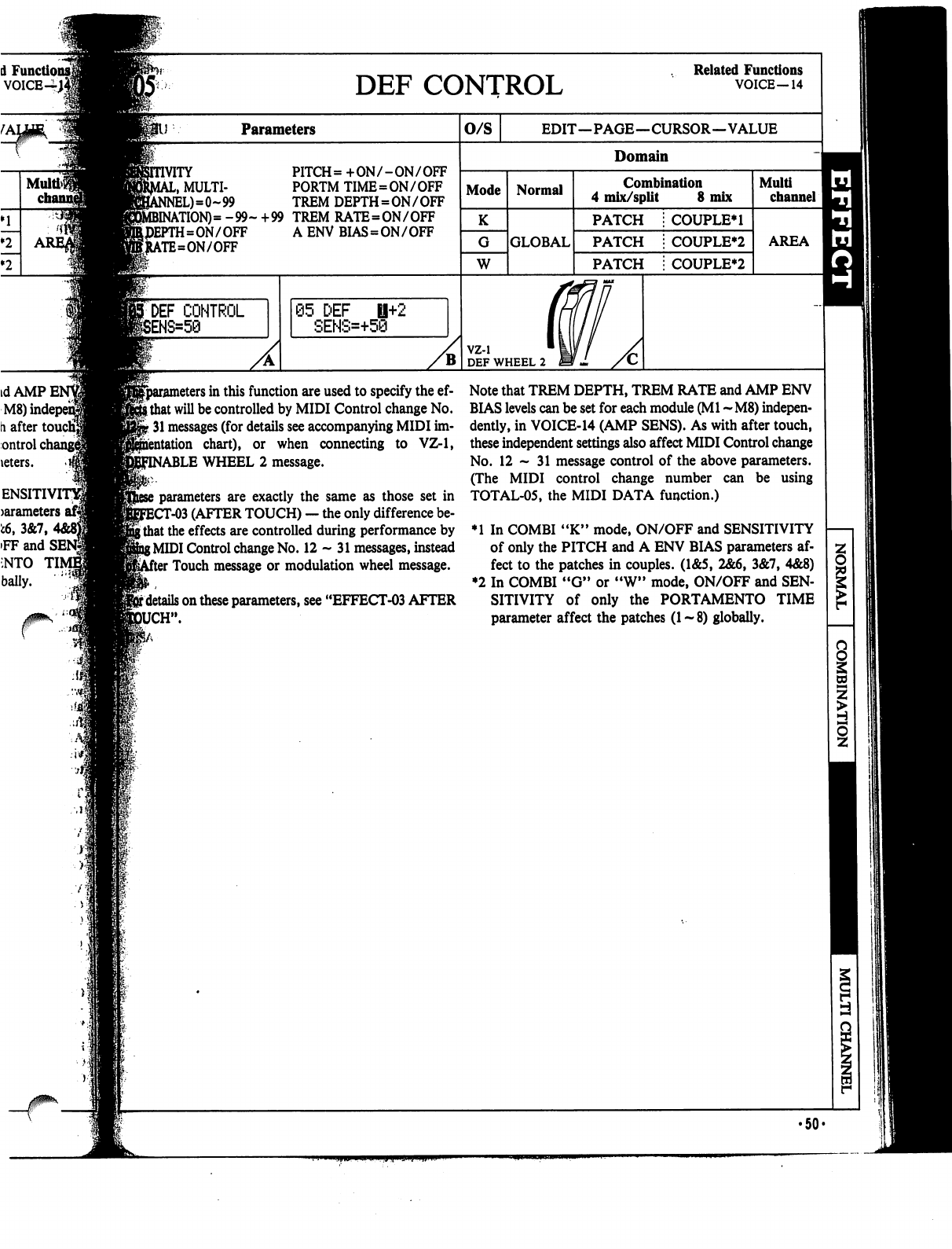
A
Functio
voice-i;
Multi>$
DEF
CONTROL
Related
Functions
VOICE—14
Parameters
PITCH=
+ON/-ON/OFF
,
MULTI-
PORTM
TIME=ON
/
OFF
L)=0~99
TREM
DEPTH=ON/OFF
\TION)=
-99-
+99
TREM
RATE=ON/OFF
I=ON/OFF
A
ENV
BIAS
=
ON/OFF
\TE=ON/OFF
DEF
CONTROL
05
DEF
0+2
SENS=+50
O/S
EDIT—PAGE—CURSOR—VALUE
Domain
Mode
K
W
Normal
GLOBAL
Combination
4
mix/split
8
mix
PATCH
PATCH
PATCH
COUPLE*!
COUPLE*2
COUPLE*2
vz-i
DEF
WHEEL
2
Multi
channel
AREA
^parameters
in
this
function
are
used
to specify
the
ef-
Ithat
will
be
controlled
by
MIDI
Control
change
No.
-
31
messages
(for
details
see
accompanying
MIDI
im-
chart),
or
when
connecting
to
VZ-1,
BLE
WHEEL
2
message.
parameters
are
exactly
the
same
as
those
set
in
T-03
(AFTER
TOUCH)
—
the
only
difference
be-
\
that
the
effects
are
controlled
during
performance
by
{MIDI
Control
change
No.
12-31
messages,
instead
'
Touch
message
or
modulation
wheel
message.
r
details
on
these
parameters,
see
"EFFECT-03
AFTER
JCH".
Note
that
TREM
DEPTH,
TREM
RATE
and
AMP
ENV
BIAS
levels
can
be
set
for
each
module
(Ml
~M8)
indepen
dently,
in
VOICE-14
(AMP
SENS).
As
with
after
touch,
these
independent
settings
also
affect
MIDI
Control
change
No.
12-31
message
control
of
the
above
parameters.
(The
MIDI
control
change
number
can
be
using
TOTAL-05,
the
MIDI
DATA
function.)
♦1
In
COMBI
"K"
mode,
ON/OFF
and
SENSITIVITY
of
only
the
PITCH
and
A
ENV
BIAS
parameters
af
fect
to
the
patches
in
couples.
(1&5,
2&6,
3&7,
4&8)
♦2
In
COMBI
"G"
or
"W"
mode,
ON/OFF
and
SEN
SITIVITY
of
only
the
PORTAMENTO
TIME
parameter
affect
the
patches
(1-8)
globally.
Si
•50-
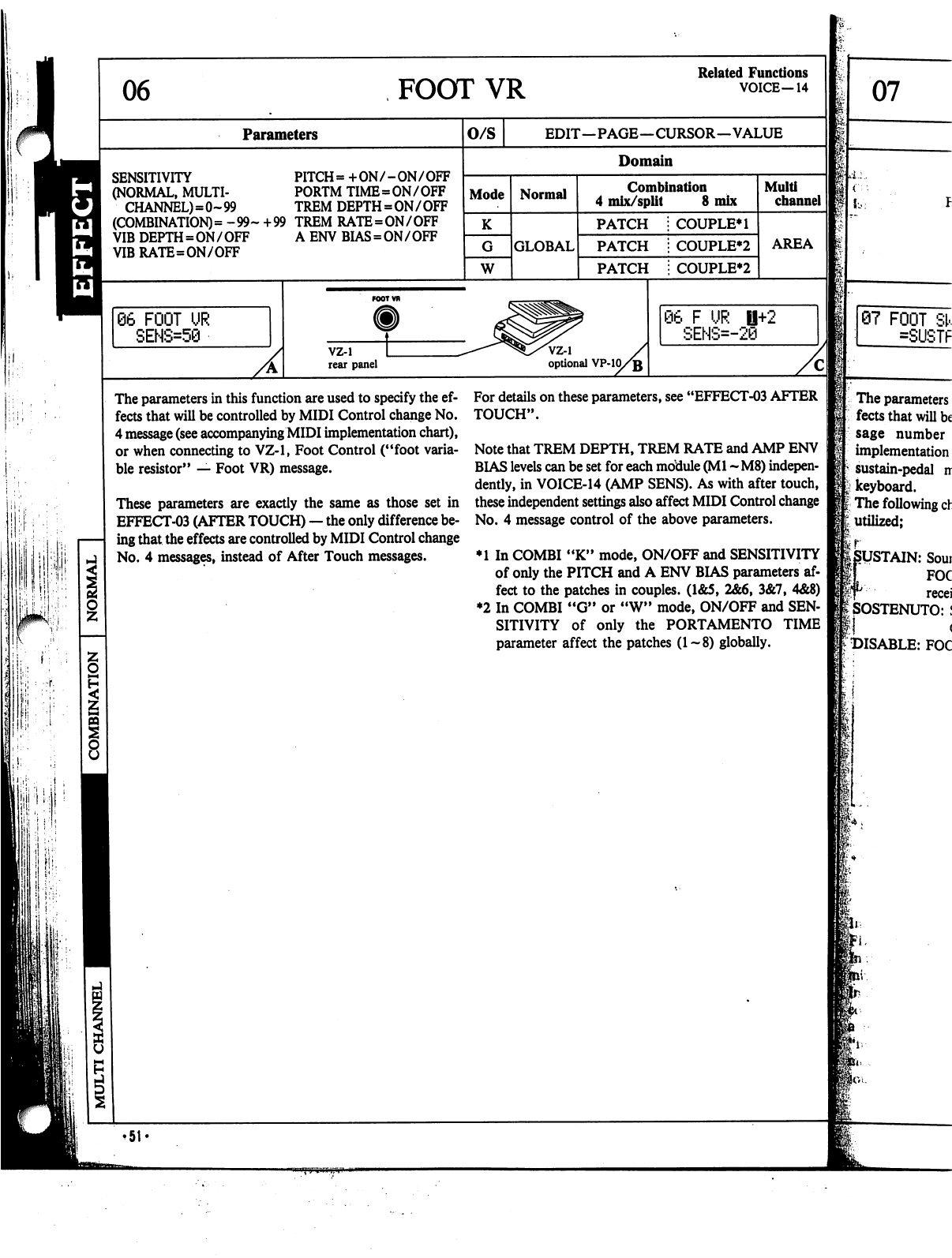
06
FOOT
VR
Related
Functions
VOICE-14
Parameters
SENSITIVITY
PITCH=
+ON/-ON/OFF
(NORMAL,
MULTI-
PORTM
TIME=ON/OFF
CHANNEL)=0~99
TREM
DEPTH=ON/OFF
(COMBINATION)
=
-99-
+99
TREM
RATE=ON/OFF
VIB
DEPTH=ON/OFF
VIBRATE=ON/OFF
AENVBIAS=ON/OFF
66
FOOT
UR
SENS=58
O/S
EDIT—PAGE—CURSOR—VALUE
Domain
Mode
W
Normal
GLOBAL
Combination
4
mix/split
8
mix
PATCH
PATCH
PATCH
COUPLE*!
COUPLE*2
COUPLE*2
vz-i
rear
panel
VZ-1
optional
VP-10/jj
Multi
channel
AREA
06
F
UR
0+2
SENS=-20
The
parameters
in
this
function
are
used
to
specify
the
ef
fects
that
will
be
controlled
by
MIDI
Control
change
No.
4
message
(see
accompanying
MIDI
implementation
chart),
or
when
connecting
to
VZ-1,
Foot
Control
("foot
varia
ble
resistor"
—
Foot
VR)
message.
These
parameters
are
exactly
the
same
as
those
set
in
EFFECT-03
(AFTER
TOUCH)
—
the
only
difference
be
ing
that
the
effects
are
controlled
by
MIDI
Control
change
No.
4
messages,
instead
of
After
Touch
messages.
For
details
on
these
parameters,
see
"EFFECT-03
AFTER
TOUCH".
Note
that
TREM
DEPTH,
TREM
RATE
and
AMP
ENV
BIAS
levels
can
be
set
for
each
motiule
(Ml
-
M8)
indepen
dently,
in
VOICE-14
(AMP
SENS).
As
with
after
touch,
these
independent
settings
also
affect
MIDI
Control
change
No.
4
message
control
of
the
above
parameters.
♦1
In
COMBI
"K"
mode,
ON/OFF
and
SENSITIVITY
of
only
the
PITCH
and
A
ENV
BIAS
parameters
af
fect
to the
patches
in
couples.
(1&5,
2&6,
3&7,
4&8)
♦2
In
COMBI
"G"
or
"W"
mode,
ON/OFF
and
SEN
SITIVITY
of
only
the
PORTAMENTO
TIME
parameter
affect
the
patches
(1-8)
globally.
07
07
FOOT
SI
=SUSTF
The
parameters
fects
that
will
be
sage
number
implementation
sustain-pedal
ir
keyboard.
The
following
ch
utilized;
r
SUSTAIN:
Soui
I
FOC
T
recei
SOSTENUTO:
I
:
DISABLE:
FOC
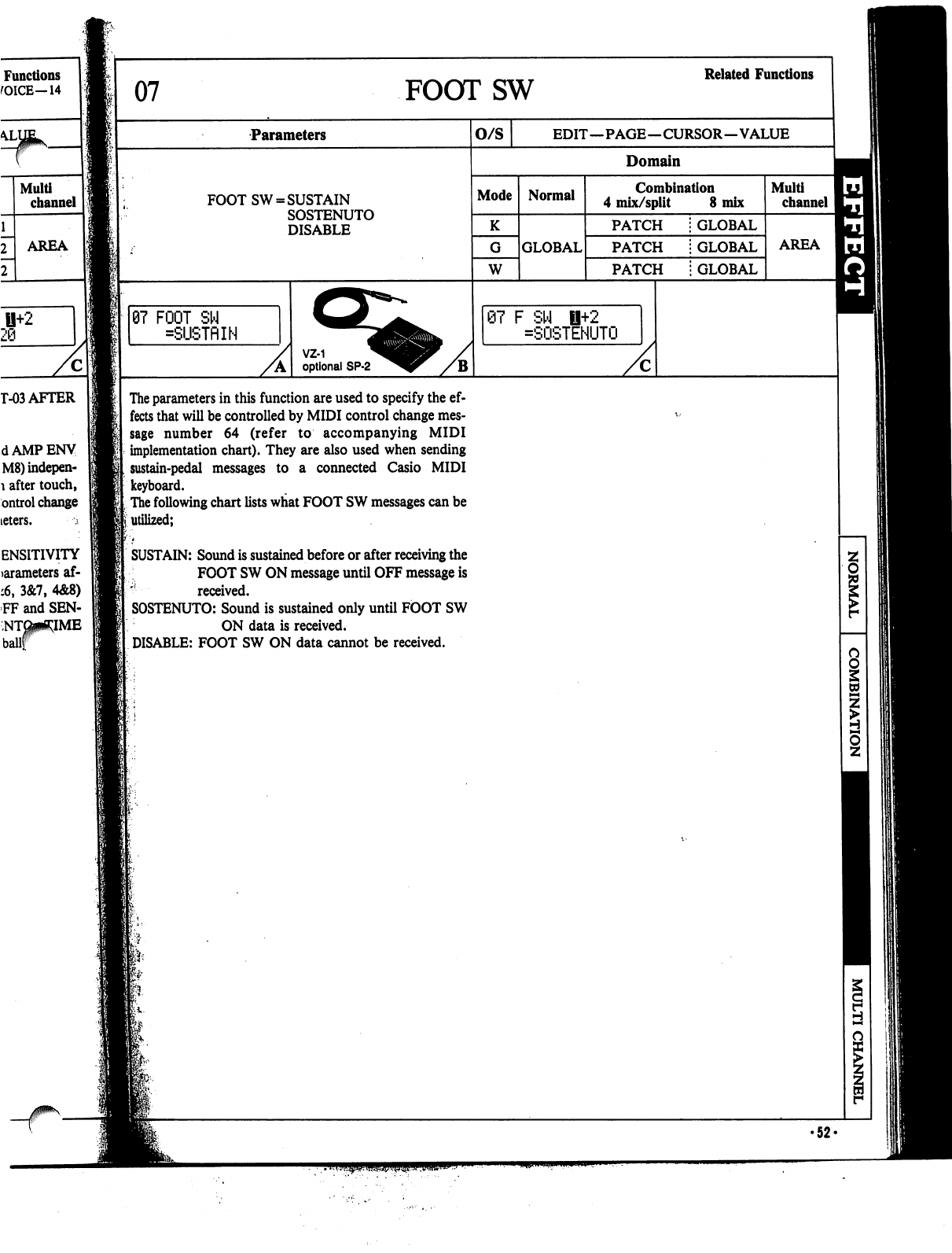
Functions
fOICE—14
U+2
29
T-03
AFTER
dAMPENV
M8)indepen-
1
after
touch,
ontrol
change
teters.
;
ENSITIVITY
>arameters
af-
:6,
3&7,
4&8)
FF
and
SEN-
07
FOOTSW
Related
Functions
Parameters
FOOT
SW
=
SUSTAIN
SOSTENUTO
DISABLE
07
FOOT
SW
=SUSTflIN
VZ-1
optional
SP-2
O/S
EDIT—PAGE—CURSOR—VALUE
Domain
Mode
W
Normal
GLOBAL
Combination
4
mix/split
8
mix
PATCH
PATCH
PATCH
GLOBAL
GLOBAL
GLOBAL
@7
F
SW
fl+2
=SOSTENUTO
Multi
channel
AREA
The
parameters
in
this
function
are
used
to
specify
the
ef
fects
that
will
be
controlled
by
MIDI
control
change
mes
sage
number
64
(refer
to
accompanying
MIDI
implementation
chart).
They
are
also
used
when
sending
sustain-pedal
messages
to
a connected Casio
MIDI
keyboard.
The
following
chart
lists
what
FOOT
SW
messages
can
be
utilized;
SUSTAIN:
Sound
is
sustained
before
or
after
receiving
the
FOOT
SW
ON
message
until
OFF
message
is
'!
received.
SOSTENUTO:
Sound
is
sustained
only
until
FOOT
SW
ON
data
is
received.
DISABLE:
FOOT
SW
ON
data
cannot
be
received.
s
•52«
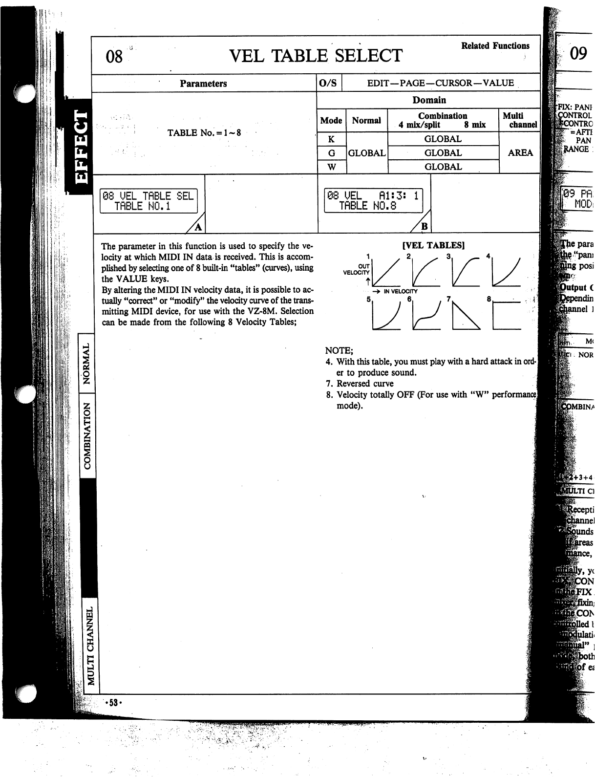
08
Parameters
TABLE
No.
=
1-
08
UEL
TflBLE
SEL
TfiBLE
NO.1
The
parameter
in
this
function
is
used
to
specify
the
ve
locity
at
which
MIDI
IN
data
is
received.
This
is
accom
plished
by
selecting
one
of
8
built-in
"tables"
(curves),
using
the
VALUE
keys.
By
altering
the
MIDI
IN
velocity
data,
it
is
possible
to
ac
tually
"correct"
or
"modify"
the
velocity
curve
of
the
trans
mitting
MIDI
device,
for
use
with
the
VZ-8M.
Selection
can
be
made
from
the
following
8
Velocity
Tables;
VEL
TABLE
SELECT
Related
Functions
O/S
EDIT—PAGE—CURSOR—VALUE
Domain
Mode
W
Normal
GLOBAL
Combination
4
mix/split
8
mix
GLOBAL
GLOBAL
GLOBAL
@8
UEL
fil:
TflBLE
HO.8
Multi
channel
AREA
[VEL
TABLES]
VELOCITY
/
->
IN
VELOCITY
5
NOTE;
4.
With
this
table,
you
must
play
with
a
hard
attack
in
ord-
]
er
to
produce
sound.
7.
Reversed
curve
8.
Velocity
totally
OFF
(For
use with
"W"
performance]
mode).
09
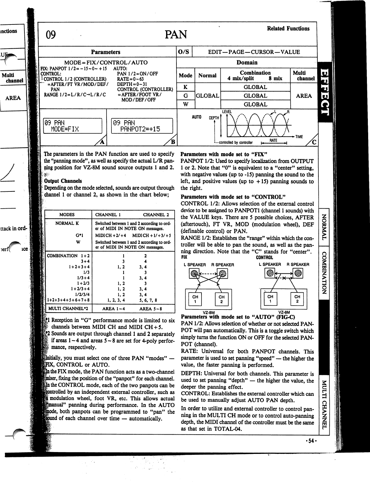
09
PAN
Related
Functions
AREA
rff
ice
<:
Parameters
MODE
=
FIX/CONTROL/AUTO
FIX:
PANPOT
l/2=-15~0~
+
15
AUTO:
CONTROL:
I
CONTROL
1/2
(CONTROLLER)
~
=AFTER/FT
VR/MOD/DEF/
PAN
RANGE
1/2=L/R/C-L/R/C
PAN
1/2=ON/OFF
RATE=0~63
DEPTH=0~31
CONTROL
(CONTROLLER)
=AFTER/FOOTVR/
MOD/DEF/OFF
3
PflN
MODE=FIX
@9
PflN
PRNP0T2=+15
O/S
EDIT—PAGE—CURSOR—VALUE
Domain
Mode
K
W
Normal
GLOBAL
Combination
4
mix/split
8
mix
GLOBAL
GLOBAL
GLOBAL
Multi
channel
AREA
LEVEL
AUTO
DEPTH
TIME
-
controlled
by
controller
|
The
parameters
in
the
PAN
function
are
used
to specify
the
"panning
mode",
as
well
as
specify
the
actual
L/R
pan
ning
position
for
VZ-8M
sound
source
outputs
1
and
2.
Output
Channels
Depending
on
the
mode
selected,
sounds
are
output
through
channel
1
or
channel
2,
as
shown
in
the
chart
below;
§|1
Reception
in
"G"
performance
mode
is
limited
to
six
channels
between
MIDI
CH
and
MIDI
CH
+
5.
|jJ2
Sounds
are
output
through
channel
1
and
2
separately
if
areas
1
~
4
and
areas
5
-
8 are
set
for
4-poly
perfor-
mance,
respectively.
y,
you
must
select
one
of
three
PAN
"modes"
—
C,
CONTROL
or
AUTO,
l
the
FIX
mode,
the
PAN
function
acts
as
a
two-channel
sr,
fixing
the
position
of
the
"panpot"
for
each
channel,
l
the
CONTROL
mode,
each
of
the
two
panpots
can
be
1
by
an
independent
external
controller,
such
as
[modulation
wheel,
foot
VR,
etc.
This
allows
actual
nual"
panning
during
performance.
In
the
AUTO
both
panpots
can
be
programmed
to
"pan"
the
1
of
each
channel
over
time
—
automatically.
Parameters
with
mode
set
to
"FIX"
PANPOT
1/2:
Used
to
specify
localization
from
OUTPUT
1
or
2.
Note
that
"0"
is
equivalent
to
a
"center"
setting,
with
negative
values
(up
to
-15)
panning
the
sound
to
the
left,
and
positive
values
(up
to
+15)
panning
sounds
to
the
right.
Parameters
with
mode
set
to
"CONTROL"
CONTROL
1/2:
Allows
selection
of
the
external
control
device
to
be
assigned
to
PANPOTl
(channel
1
sounds) with
the
VALUE
keys.
There
are
5 possible
choices,
AFTER
(aftertouch),
FT
VR,
MOD
(modulation
wheel),
DEF
(definable
control)
or
PAN.
RANGE
1/2:
Establishes
the
"range"
within
which
the
con
troller
will
be
able
to
pan
the
sound,
as
well as
the
pan
ning
direction.
Note
that
the
"C"
stands
for
"center".
FIX
CONTROL
LSPEAKER
RSPEAKER
LSPEAKER
R
SPEAKER
\
VZ-8M
VZ-8M
Parameters
with
mode
set
to
"AUTO"
(FIG-C)
PAN
1/2:
Allows
selection
of
whether
or not
selected
PAN
POT
will
pan
automatically.
This
is
a
toggle
switch
which
simply
turns
the
function
ON
or
OFF
for the
selected
PAN
POT
(channel).
RATE:
Universal
for
both
PANPOT
channels.
This
parameter
is
used
to
set
panning
"speed"
—
the
higher
the
value,
the
faster
panning
is
performed.
DEPTH:
Universal
for
both
channels.
This
parameter
is
used
to
set
panning
"depth"
—
the
higher
the
value,
the
deeper
the
panning
effect.
CONTROL:
Establishes
the
external
controller
which
can
be
used
to
manually
adjust
AUTO
PAN
depth.
In
order
to
utilize
and
external
controller
to
control
pan
ning
in
the
MULTI
CH
mode
or
to
control
auto-panning
depth,
the
MIDI
channel
of
the
controller
must
be
the
same
as
that
set
in
TOTAL-04.
8
1
i
•54<
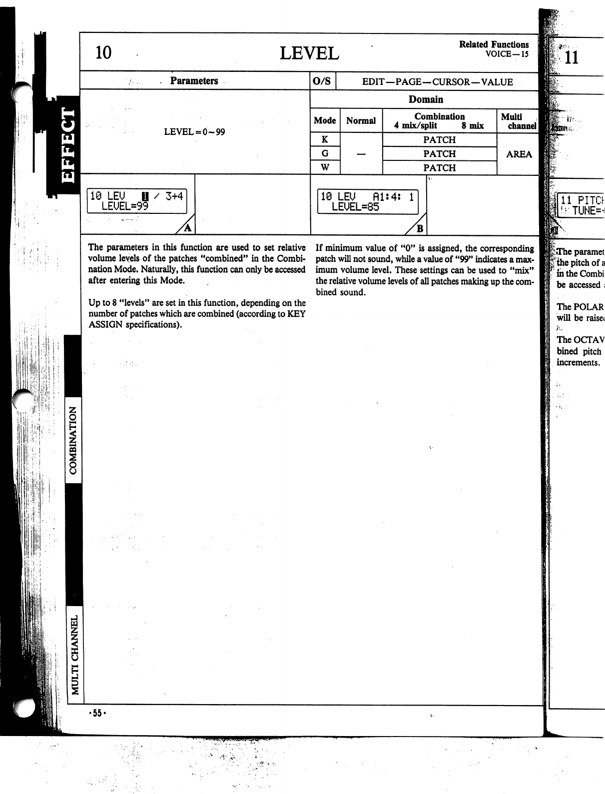
H
■;■
■il
■1
I1
,
10
LEVEL
Related
Functions
VOICE-15
Parameters
LEVEL
=
0-99
10
LEU
LEUEL=9'
/
3+4
O/S
EDIT—PAGE—CURSOR—VALUE
Domain
Mode
K
W
Normal
Combination
4
mix/split
8
mix
PATCH
PATCH
PATCH
19
LEU
Hls4s
1
LEUEL=85
Muiti
channel
I
AREA
The
parameters
in
this
function
are
used
to
set
relative
volume
levels
of
the
patches
"combined"
in
the
Combi
nation
Mode.
Naturally,
this
function
can
only
be
accessed
after
entering
this
Mode.
Up
to
8
"levels"
are
set
in
this
function,
depending
on
the
number
of
patches
which
are
combined
(according
to
KEY
ASSIGN
specifications).
If
minimum
value
of
"0"
is
assigned,
the
corresponding
patch
will
not
sound,
while
a
value
of
"99"
indicates
a
max
imum
volume
level.
These
settings
can
be
used
to
"mix"
the
relative
volume
levels
of
all
patches
making
up
the
com
bined
sound.
The
POLAR
will
be
raisei
The
OCTAV
bined
pitch
increments.
•55«
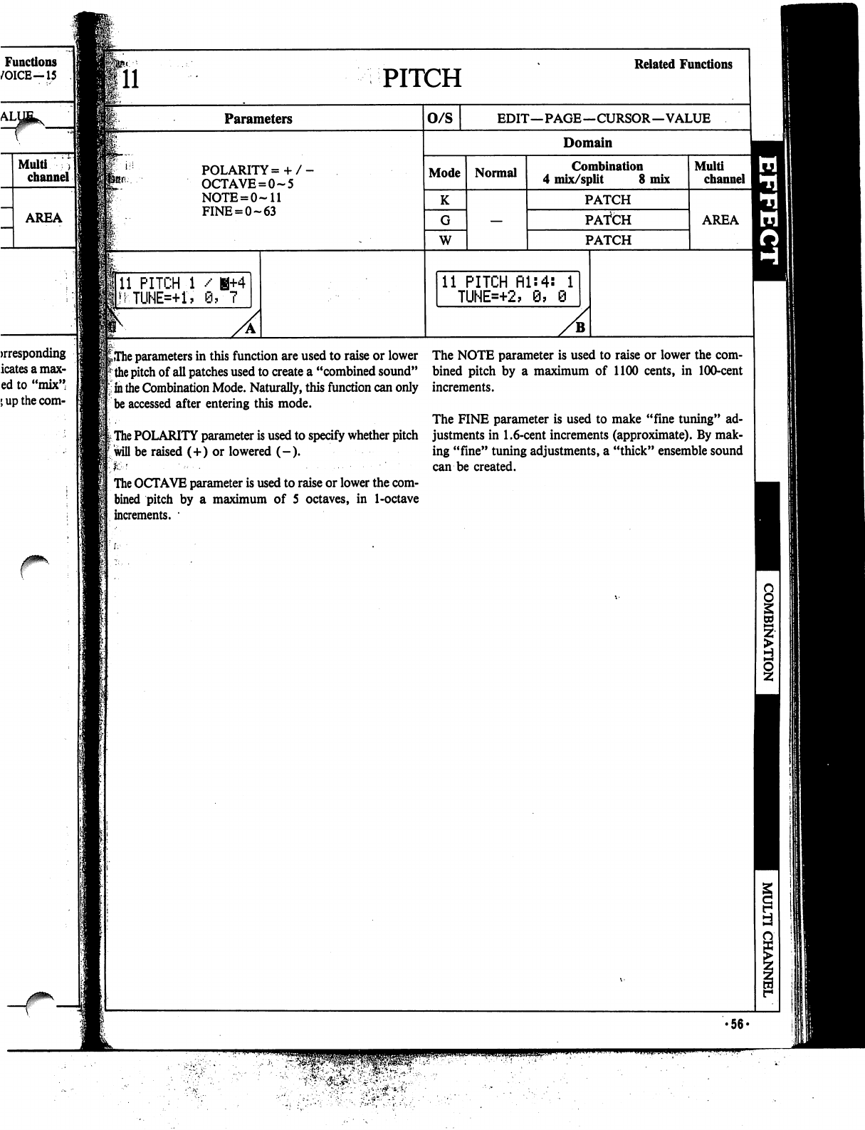
PITCH
Related
Functions
Parameters
O/S
EDIT—PAGE—CURSOR—VALUE
Domain
POLARITY=
+
OCTAVE
=
0-5
NOTE
=
0-11
FINE
=
0-63
Mode
K
W
Normal
Combination
4
mix/split
8
mix
PATCH
PATCH
PATCH
Multi
channel
AREA
11
PITCH
1
/
H+4
MTUNE=+1,
0,7
11
PITCH
fll:4:
1
TUNE=+2,
9,
0
^The
parameters
in
this
function
are
used
to
raise
or
lower
the
pitch
of
all
patches
used
to
create
a
"combined
sound"
in
the
Combination
Mode.
Naturally,
this
function
can
only
be
accessed
after
entering
this
mode.
The
POLARITY
parameter
is
used
to
specify
whether
pitch
will
be
raised
(+)
or
lowered
(-).
K
'
■•■-.
......■■
The
OCTAVE
parameter
is
used
to
raise
or
lower
the
com
bined pitch
by
a
maximum
of
5
octaves,
in
1-octave
increments.
•
The
NOTE
parameter
is
used
to
raise
or
lower
the
com
bined
pitch
by
a
maximum
of
1100
cents,
in
100-cent
increments.
The
FINE
parameter
is
used
to
make
"fine
tuning"
ad
justments
in
1.6-cent
increments
(approximate).
By
mak
ing
"fine"
tuning
adjustments,
a
"thick"
ensemble
sound
can
be
created.
•56-
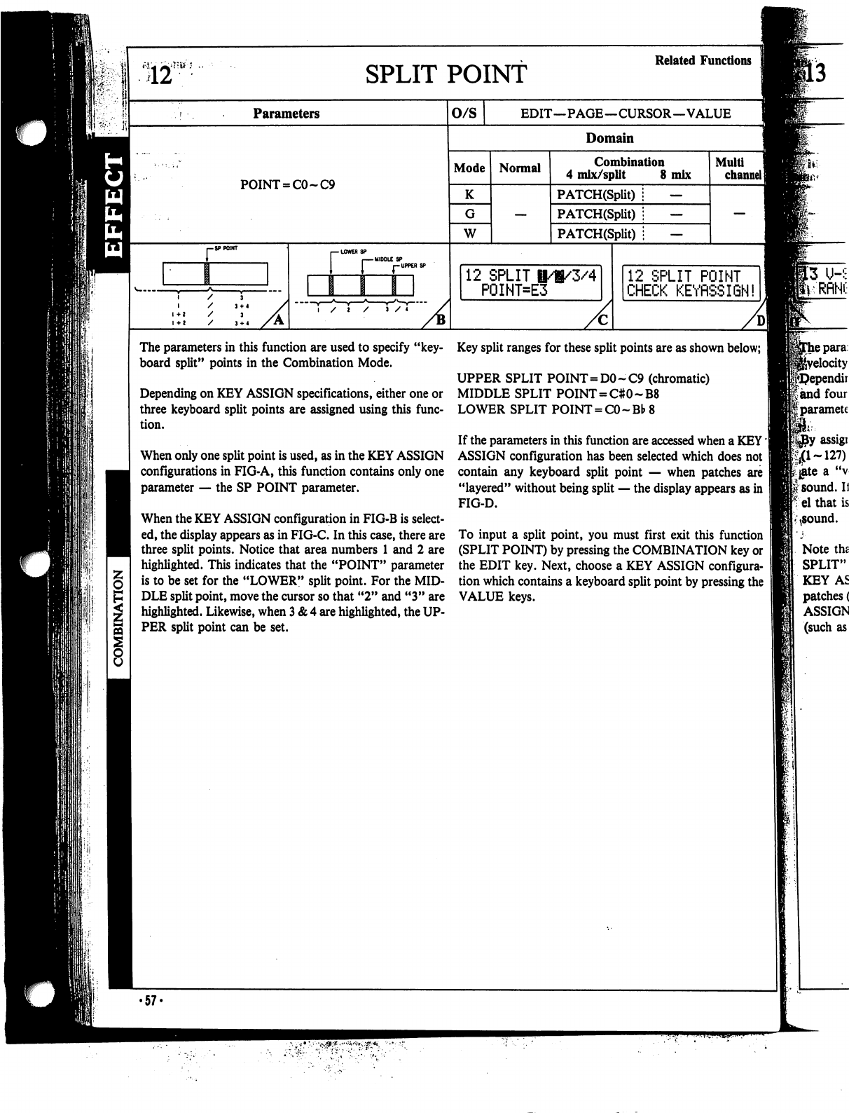
S12
SPLIT
POINT
Parameters
POINT
=
CO
~C9
r
MIDDLE
SP
r-UPPERS?
/
I
/
J
/
4
O/S
Domain
Mode
K
W
Normal
12
SPLIT
I/i/3/4
P0INT=E3
Key
split
ranges
for
these
split
points
are
as
shown
below;
J
UPPER
SPLIT
POINT=DO
-
C9
(chromatic)
MIDDLE
SPLIT
POINT
=
C#0~B8
LOWER
SPLIT
POINT
=
CO
~Bb
8
If
the
parameters
in
this
function
are
accessed
when
a
KEY'
ASSIGN
configuration
has
been
selected
which
does
not
contain
any
keyboard
split
point
—
when
patches
are
"layered"
without
being
split
—
the
display
appears
as
in
FIG-D.
Related
Functions
EDIT—PAGE—CURSOR—VALUE
Combination
4
mix/split
8
mix
PATCH(Split)
;
—
PATCH(Split)
i
—
PATCH(Split)
i
—
Multi
channel]
12
SPLIT
POINT
CHECK
KEYRSSIGN!
The
parameters
in
this
function
are
used
to
specify
"key
board
split"
points
in
the
Combination
Mode.
Depending
on
KEY
ASSIGN
specifications,
either
one
or
three
keyboard
split
points
are
assigned
using
this
func
tion.
When
only
one
split
point
is
used,
as
in
the
KEY
ASSIGN
configurations
in
FIG-A,
this
function
contains
only
one
parameter
—
the
SP
POINT
parameter.
When
the
KEY
ASSIGN
configuration
in
FIG-B
is
select
ed,
the
display
appears
as
in
FIG-C.
In
this
case,
there
are
three
split
points.
Notice
that
area
numbers
1
and
2
are
highlighted.
This
indicates
that
the
"POINT"
parameter
is
to
be
set
for
the
"LOWER"
split
point.
For
the
MID
DLE
split
point,
move
the
cursor
so
that
"2" and "3"
are
highlighted.
Likewise,
when
3
&
4
are
highlighted,
the
UP
PER
split
point
can
be
set.
To
input
a
split
point,
you
must
first
exit this
function
(SPLIT
POINT)
by
pressing
the
COMBINATION
key
or
the
EDIT
key.
Next,
choose
a
KEY
ASSIGN
configura
tion
which
contains
a
keyboard
split
point
by
pressing
the
VALUE
keys.
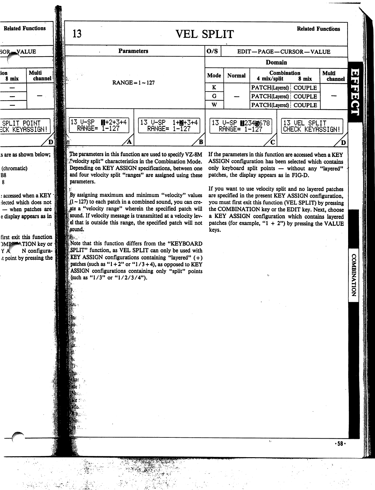
Related
Functions
ALUE
ion
8
mix
Multi
channel
13
VEL
SPLIT
Related
Functions
Parameters
RANGE=
1-127
O/S
EDIT—PAGE—CURSOR—VALUE
Domain
Mode
K
W
Normal
Combination
4
mix/split
8
mix
PATCH(Layered);
COUPLE
PATCH(Layered);
COUPLE
PATCH(Layered)
j
COUPLE
Multi
channel
SPLIT
POINT
ECK
KEYRSSIGN!
5
are
as
shown
below;
(chromatic)
B8
j
accessed
when
a
KEY
'
elected
which
does
not
—
when
patches
are
e
display
appears
as
in
first
exit this
function
TION
key
or
N
configura-i
it
point
by
pressing
the
13
U-SP
1+2+3+4
RflN6E=
1-127
13
U-SP
l+B+3+4
RflNGE=
1-127
13
U-SP
0234B678
RRN6E=
1-127
13
UEL
SPLIT
CHECK
KEYRSSIGN!
Jhe
parameters
in
this
function
are
used
to
specify
VZ-8M
^■velocity
split"
characteristics
in
the
Combination
Mode.
Depending
on
KEY
ASSIGN
specifications,
between
one
and
four
velocity
split
"ranges"
are
assigned
using
these
parameters.
|
By
assigning
maximum
and
minimum
"velocity"
values
Ll
~
127)
to
each
patch
in
a
combined
sound,
you
can
cre
ate
a
"velocity
range"
wherein
the
specified
patch
will
isound.
If
velocity
message
is
transmitted
at
a
velocity
lev-
lel
that
is
outside
this
range,
the
specified
patch
will
not
that
this
function
differs
from
the
"KEYBOARD
PUT"
function,
as
VEL
SPLIT
can
only
be
used
with
I
KEY
ASSIGN
configurations
containing
"layered"
(
+
)
I
patches
(such
as
"
1
+
2"
or
"
1
/
3
+
4),
as
opposed
to
KEY
(ASSIGN
configurations
containing
only
"split"
points
[(such
as
"1/3"
or
"1/2/3/4").
If
the
parameters
in
this
function
are
accessed
when
a
KEY
ASSIGN
configuration
has
been
selected
which
contains
only
keyboard
split
points
—
without
any
"layered"
patches,
the
display
appears
as
in
FIG-D.
If
you
want
to
use
velocity
split
and
no
layered
patches
are
specified
in
the
present
KEY
ASSIGN
configuration,
you
must
first
exit this
function
(VEL
SPLIT)
by
pressing
the
COMBINATION
key
or
the
EDIT
key.
Next,
choose
a
KEY
ASSIGN
configuration
which
contains
layered
patches
(for
example,
"1
+
2")
by
pressing
the
VALUE
keys.
•58-
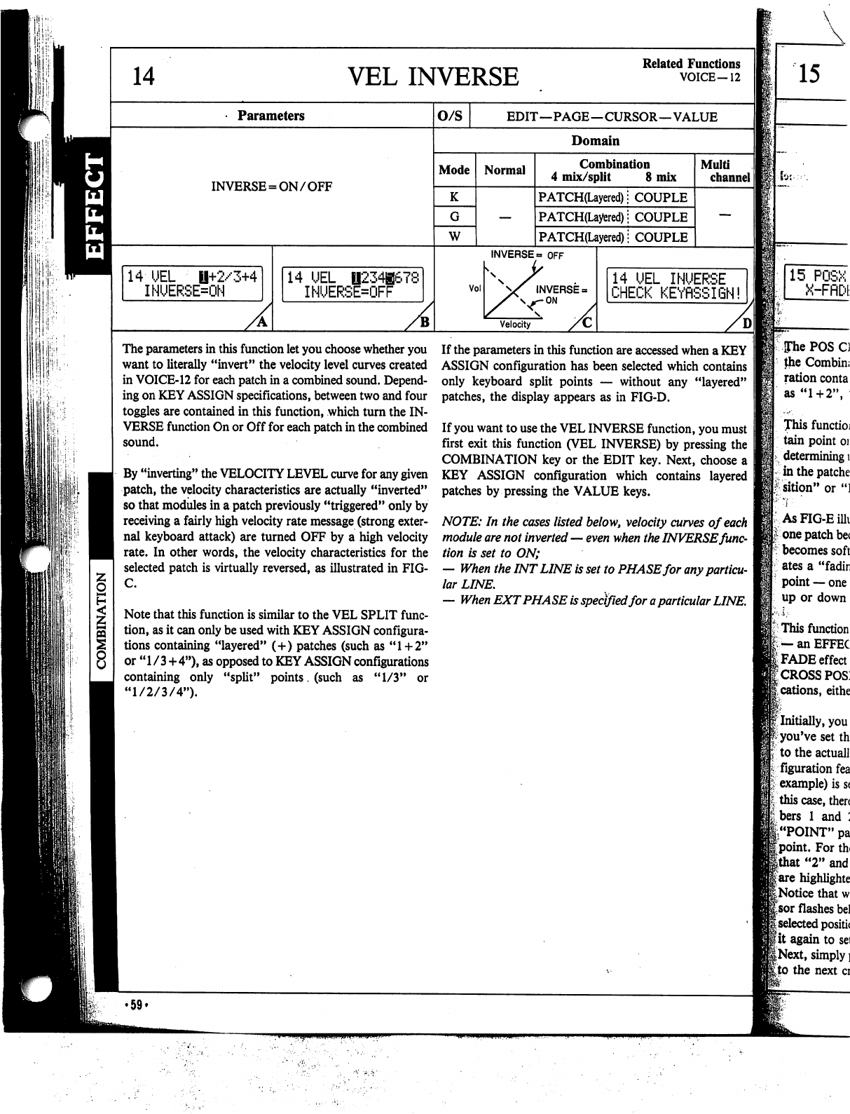
ii:
■
IS'
■
14
VEL
INVERSE
Related
Functions
VOICE-12
Parameters
INVERSE
=
ON/OFF
14
UEL
il+2/3+4
INUERSE=ON
14
UEL
||234|67£
INUERSE=OFF
O/S
EDIT—PAGE—CURSOR—VALUE
Domain
Mode
K
W
Normal
Combination
4
mix/split
8
mix
PATCH(Layered);
COUPLE
PATCH(Layered);
COUPLE
PATCH(Layered)
■
COUPLE
Vol
INVERSE
=
OFF
INVERSE
=
ON
Velocity
Multi
channel
14
UEL
INUERSE
CHECK
KEYflSSIGN!
The
parameters
in
this
function
let
you
choose
whether
you
want
to
literally
"invert"
the
velocity
level
curves
created
in
VOICE-12
for
each
patch
in
a
combined
sound.
Depend
ing
on
KEY
ASSIGN
specifications,
between
two
and
four
toggles
are
contained
in
this
function,
which
turn
the
IN
VERSE
function
On
or
Off
for
each
patch
in
the
combined
sound.
By
"inverting"
the
VELOCITY
LEVEL
curve
for
any
given
patch,
the
velocity
characteristics
are
actually
"inverted"
so
that
modules
in
a
patch
previously
"triggered"
only
by
receiving
a
fairly
high
velocity
rate
message
(strong
exter
nal
keyboard
attack)
are
turned
OFF
by
a
high
velocity
rate.
In
other
words,
the
velocity
characteristics
for
the
selected
patch
is
virtually
reversed,
as
illustrated
in
FIG-
C.
Note
that
this
function
is
similar
to
the
VEL
SPLIT
func
tion,
as
it
can
only
be
used
with
KEY
ASSIGN
configura
tions
containing
"layered"
(+)
patches
(such
as
"1+2"
or
"1
/3+4"),
as
opposed
to
KEY
ASSIGN
configurations
containing
only
"split"
points.
(such
as
"1/3"
or
"1/2/3/4").
If
the
parameters
in
this
function
are
accessed
when
a
KEY
ASSIGN
configuration
has
been
selected
which
contains
only
keyboard
split
points
—
without
any
"layered"
patches,
the
display
appears
as
in
FIG-D.
If
you
want
to
use
the
VEL
INVERSE
function,
you
must
first
exit this
function
(VEL
INVERSE)
by
pressing
the
COMBINATION
key
or
the
EDIT
key.
Next,
choose
a
KEY
ASSIGN
configuration
which
contains
layered
patches
by
pressing
the
VALUE
keys.
NOTE:
In
the
cases
listed
below,
velocity
curves
of
each
module
are
not
inverted
—
even
when
the
INVERSE
func
tion
is
set
to
ON;
—
When
the
INT
LINE
is
set
to
PHASE
for
any
particu
lar
LINE.
—
When
EXT
PHASE
is
specified
for
a
particular
LINE.
15
for:--'.
15
POSX
X-FflDE
Pie
POS
Cl
the
Combin;
ration
conta
as
"1
+
2",
This
functioj
tain
point
oj
determining
i
in
the
patche
1
sition"
or
")
As
FIG-E
ilk
i-
one
patch
be<
becomes
soft
ates
a
"fadin
point
—
one
up
or
down
]
This
function
|.
—
an
EFFEC
(FADE
effect
r
cross
posj
;
cations,
eithe
f
Initially,
you
^
you've
set
th
to
the
actuall
figuration
fea
Is
example)
is
s<
|v
this
case,
then
:
bers
1
and
:
|"POINT"
pa
|point.
For
th<
Ithat
"2"
and
|
are
highlighte
I
Notice
that
w
Isor
flashes
be!
|
selected
positic
■•it
again
to
sei
|Next,
simply
]
[to
the next
ci
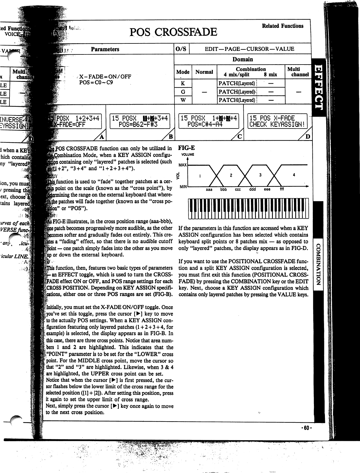
ted!
VOIC
Mu
cha
INVERSE*
■YflSSK
i
when
a
]
hich
cont
ny
"layered*
ion,
you
mu
t
pressing
i
ext,
choose^
tains
lay
urves
ofeacfq
VERSEJ
.4
icularLINE.%
-3
POS
CROSSFADE
Related
Functions
lit
Parameters
X-FADE
=
ON/OFF
POS
=
C0~C9
1+2+3+4
rflDE=OFF
15
POSX
P0S=B62-F
3+4
O/S
EDIT—PAGE—CURSOR—VALUE
Domain
Mode
K
W
Normal
Combination
4
mix/split
8
mix
PATCH(Layered);
—
PATCH(Layered>;
—
PATCH(Layered);
—
15
POSX
l+B+B+4
P0S=C#4-fl4
Multi
channel
15
POS
X-FflDE
CHECK
KEYflSSIGN!
ICROSSFADE
function
can
only
be
utilized
in
on
Mode,
when
a
KEY
ASSIGN
configu-
i
containing
only
"layered"
patches
is
selected
(such
1+2",
"3
+
4"
and
"1
+
2
+
3+4").
:(
.
^function
is
used
to
"fade"
together
patches
at
a
cer-
i
point
on
the
scale
(known
as the
"cross
point")»
by
;
the
range
on
the
external
keyboard
that
where-
j
patches
will
fade
together
(known
as
the "cross
po
ll"
or
"POS").
S
FIG-E
illustrates,
in
the
cross
position
range
(aaa-bbb),
?
patch
becomes
progressively
more
audible,
as
the
other
nes softer
and
gradually
fades
out
entirely.
This
cre-
j
a
"fading"
effect,
so
that
there
is
no
audible
cutoff
t
—
one
patch
simply
fades
into
the
other
as
you
move
gup
or
down
the
external
keyboard.
>
function,
then,
features
two
basic
types
of
parameters
•
an
EFFECT
toggle,
which
is
used
to
turn
the
CROSS-
FADE
effect
ON
or
OFF,
and
POS
range
settings
for
each
f
CROSS
POSITION.
Depending
on
KEY
ASSIGN
specifi-
ons,
either
one
or
three
POS
ranges
are
set
(FIG-B).
^Initially,
you
must
set
the
X-FADE
ON/OFF
toggle.
Once
fyou've
set
this
toggle,
press
the
cursor
[►]
key
to
move
to
the
actually
POS
settings.
When
a
KEY
ASSIGN
con
figuration
featuring
only
layered
patches
(1
+
2+3
+
4,
for
example)
is
selected,
the
display
appears
as
in
FIG-B.
In
this
case,
there
are
three
cross
points.
Notice
that
area
num
bers
1
and
2
are
highlighted.
This
indicates
that
the
(."POINT"
parameter
is
to
be
set
for
the
"LOWER"
cross
point.
For
the
MIDDLE
cross
point,
move
the
cursor
so
that
"2"
and
"3"
are
highlighted.
Likewise,
when
3
&
4
are
highlighted,
the
UPPER
cross
point
can
be
set.
Notice that
when
the
cursor
[►]
is
first
pressed,
the
cur
sor
flashes
below
the
lower
limit
of
the
cross
range
for
the
selected
position
([1]
+
[2]).
After
setting
this
position,
press
it
again
to
set
the
upper
limit
of
cross
range.
Next,
simply
press
the
cursor
[►]
key
once
again
to
move
to
the
next
cross
position.
FIG-E
VOLUME
MAX
ddd
fff
■1
If
the
parameters
in
this
function
are
accessed
when
a
KEY
ASSIGN
configuration
has
been
selected
which
contains
keyboard
split
points
or
8
patches
mix
—
as
opposed
to
only
"layered"
patches,
the
display
appears
as
in
FIG-D.
If
you
want
to
use
the
POSITIONAL
CROSSFADE
func
tion
and
a
split
KEY
ASSIGN
configuration
is
selected,
you
must
first
exit this
function
(POSITIONAL
CROSS
FADE)
by
pressing
the
COMBINATION
key
or
the
EDIT
key.
Next,
choose
a
KEY
ASSIGN
configuration
which
contains
only
layered
patches
by
pressing
the
VALUE
keys.
•60-
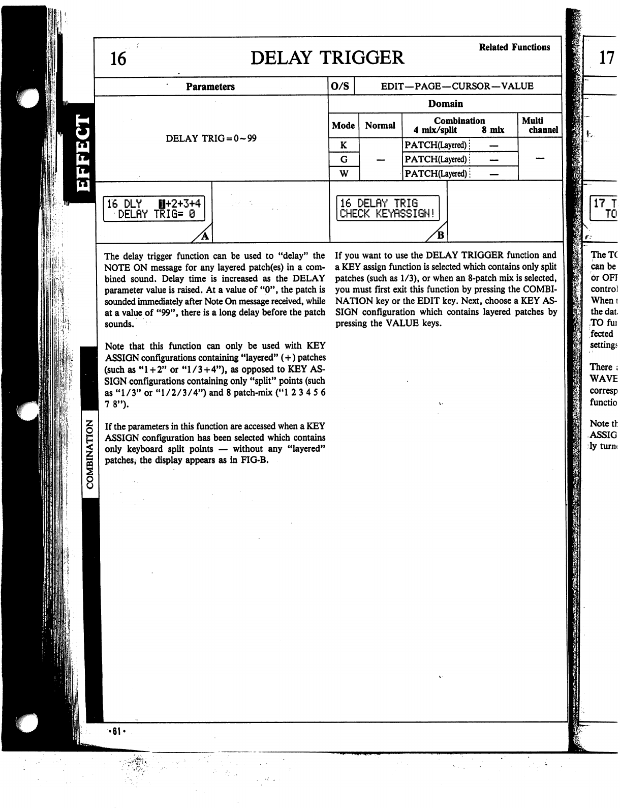
DELAY
TRIGGER
Related
Functions
Parameters
O/S
EDIT—PAGE—CURSOR—VALUE
8
Domain
Mode
DELAY
TRIG
=
0-99
K
W
16
DLY
B+2+3+4
DELflY
TRI6=
9
Normal
Combination
4
mix/split
8
mix
PATCH(Layered);
—
PATCH(Layered);
—
P
ATCH(Layered)
■
—
16
DELflY
TRIG
CHECK
KEYRSSIGN!
A
Multi
channel
The
delay
trigger
function
can
be
used
to
"delay"
the
NOTE
ON
message
for
any
layered
patch(es)
in
a
com
bined
sound.
Delay
time
is
increased
as
the
DELAY
parameter
value
is
raised.
At
a
value
of
"0",
the
patch
is
sounded
immediately
after
Note
On
message
received,
while
at
a
value
of
"99",
there
is
a
long
delay
before
the
patch
sounds.
Note
that
this
function
can
only
be
used
with
KEY
ASSIGN
configurations
containing
"layered"
(+)
patches
(such
as
"1+2"
or
"1/3+4"),
as
opposed
to
KEY
AS
SIGN
configurations
containing
only
"split"
points
(such
as
"1/3"
or
"1/2/3/4")
and
8
patch-mix
("1
2
3
4
5
6
7
8").
If
the
parameters
in
this
function
are
accessed
when
a
KEY
ASSIGN
configuration
has
been
selected
which
contains
only
keyboard
split
points
—
without
any
"layered"
patches,
the
display
appears
as
in
FIG-B.
If
you
want
to
use
the
DELAY
TRIGGER
function
and
a
KEY
assign
function
is
selected
which
contains
only
split
patches
(such
as
1/3),
or
when
an
8-patch
mix
is
selected,
you
must
first
exit
this
function
by
pressing
the
COMBI
NATION
key
or
the
EDIT
key.
Next,
choose
a
KEY
AS
SIGN
configuration
which
contains
layered
patches
by
pressing the
VALUE
keys.
-61
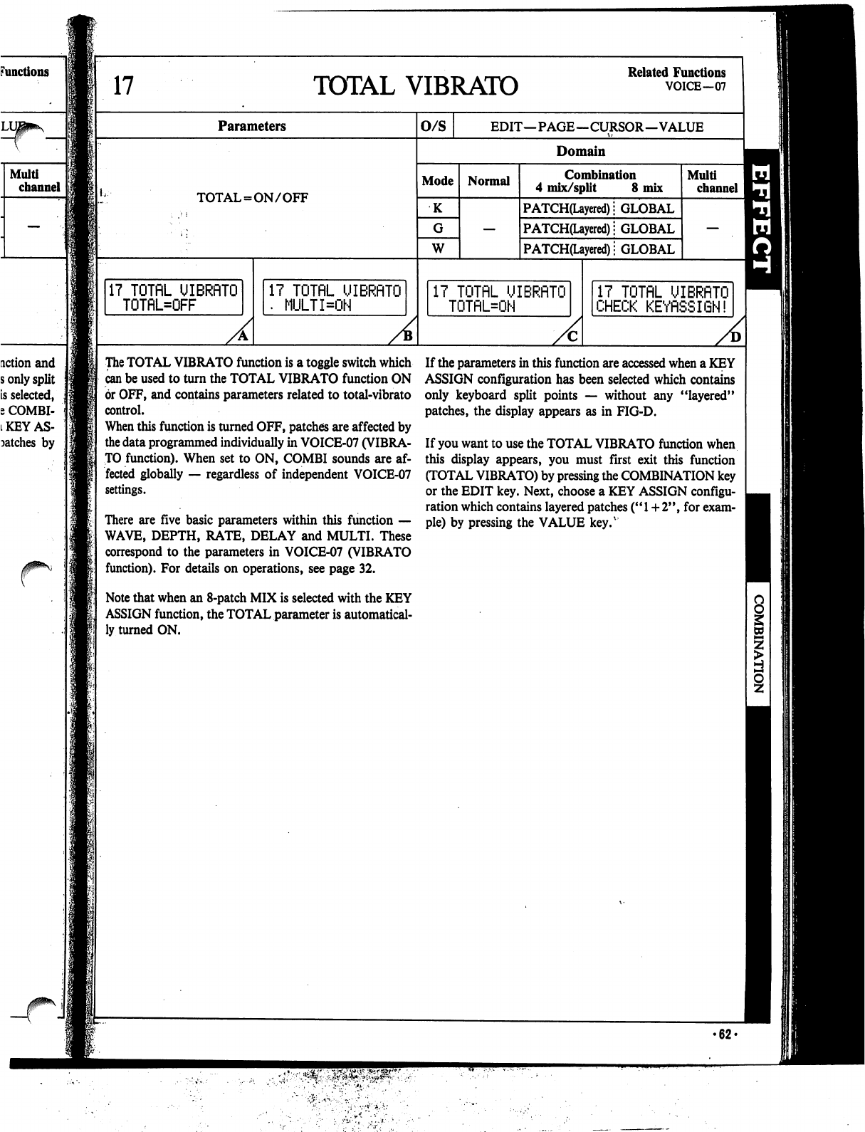
17
TOTAL
VIBRATO
Related
Functions
VOICE-07
Parameters
O/S
EDIT—PAGE—CURSOR—VALUE
Domain
Mode
TOTAL
=
ON/OFF
K
W
17
TOTflL
UIBRflTO
TOTflL=OFF
Normal
Combination
4
mix/split
8
mix
PATCH(Layered);
GLOBAL
PATCH(Layered);
GLOBAL
PATCH(Uyered)i
GLOBAL
17
TOTflL
UIBRflTO
•
MULTI=ON
17
TOTflL
UIBRflTO
TOTflL=ON
A
Multi
channel
17
TOTflL
UIBRflTO
CHECK
KEYflSSIGN!
The
TOTAL
VIBRATO
function
is
a
toggle
switch
which
can
be
used
to
turn
the
TOTAL
VIBRATO
function
ON
or
OFF,
and
contains
parameters
related
to
total-vibrato
control.
When
this
function
is
turned
OFF,
patches
are
affected
by
the
data
programmed
individually
in
VOICE-07
(VIBRA
TO
function).
When
set
to
ON,
COMBI
sounds
are
af
fected
globally
—
regardless
of
independent
VOICE-07
settings.
There
are
five
basic
parameters
within
this
function
—
WAVE,
DEPTH,
RATE,
DELAY
and
MULTI.
These
correspond
to
the
parameters
in
VOICE-07
(VIBRATO
function).
For
details
on
operations,
see
page
32.
Note
that
when
an
8-patch
MIX
is
selected
with
the
KEY
ASSIGN
function,
the
TOTAL
parameter
is
automatical
ly
turned
ON.
If
the
parameters
in
this
function
are
accessed
when
a
KEY
ASSIGN
configuration
has
been
selected
which
contains
only
keyboard
split
points
—
without
any
"layered"
patches,
the
display
appears
as
in
FIG-D.
If
you
want
to
use
the
TOTAL
VIBRATO
function
when
this
display
appears,
you
must
first
exit
this
function
(TOTAL
VIBRATO)
by
pressing
the
COMBINATION
key
or
the
EDIT
key.
Next,
choose
a
KEY
ASSIGN
configu
ration
which
contains
layered
patches
("
1
+
2",
for
exam
ple)
by
pressing
the
VALUE
key.v
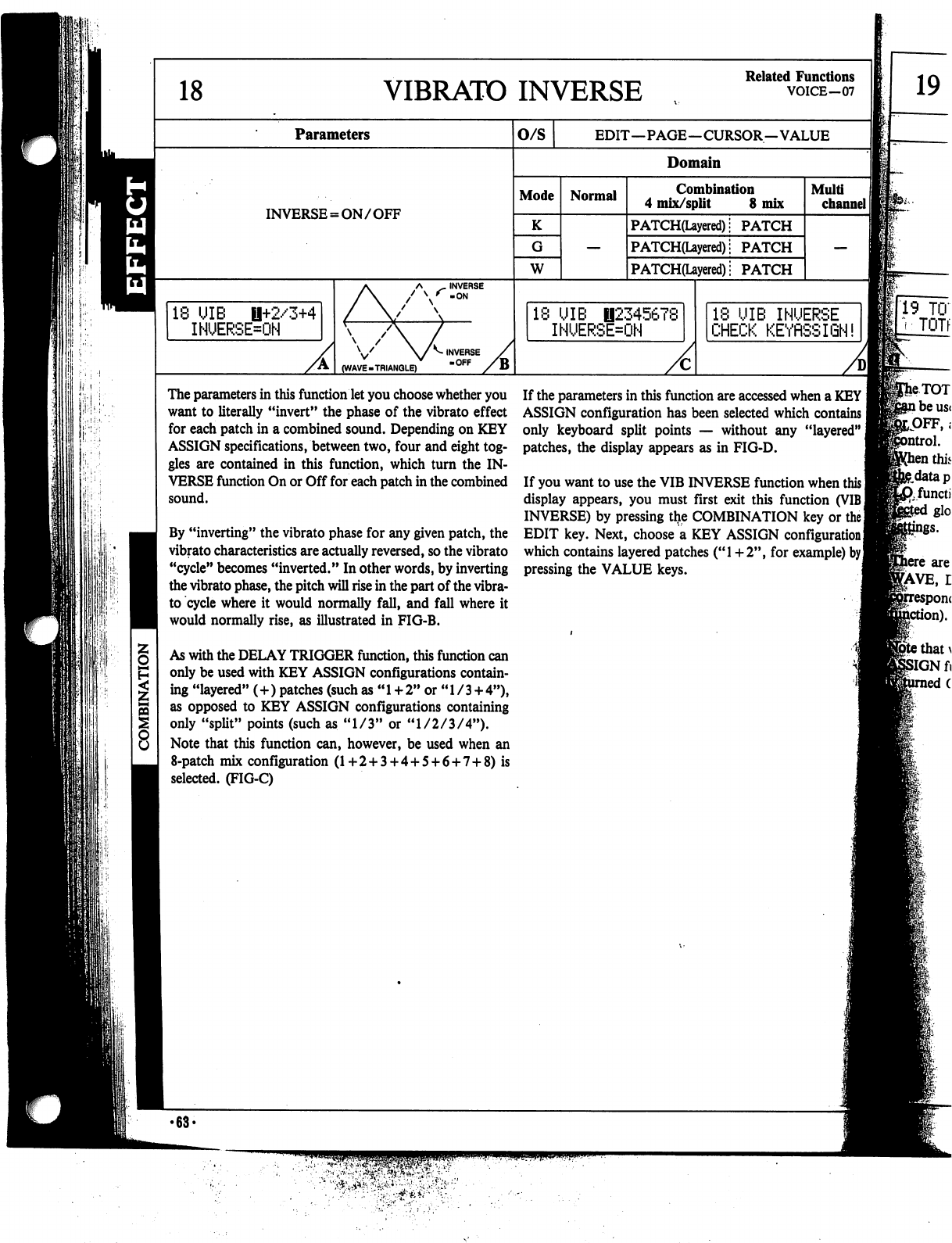
VIBRATO
INVERSE
Related
Functions
VOICE-07
19
Parameters
INVERSE
=
ON/OFF
18
UIB
0+2/3+4
INUERSE=ON
V
(WAVE
.TRIANGLE)
^
INVERSE
OFF
o/s
EDIT—PAGE—CURSOR—VALUE
Domain
Mode
K
W
Normal
Combination
4
mix/split
8
mix
PATCH(Uyered):
PATCH
PATCH(Layered)i
PATCH
PATCH(Layered)i
PATCH
*
UIB
B2345678
INUERSE=ON
Multi
channel
II
18
UIB
INUERSE
CHECK
KEYflSSIGN!
19
TO'
•
TOTf
A
The
parameters
in
this
function
let
you
choose
whether
you
want
to
literally
"invert"
the
phase
of
the
vibrato
effect
for
each
patch
in
a
combined
sound.
Depending
on
KEY
ASSIGN
specifications,
between
two,
four
and
eight
tog
gles
are
contained
in
this
function,
which
turn
the
IN
VERSE
function
On
or
Off
for
each
patch
in
the
combined
sound.
By
"inverting"
the
vibrato
phase
for
any
given
patch,
the
vibrato
characteristics
are
actually
reversed,
so
the
vibrato
"cycle"
becomes
"inverted."
In
other
words,
by
inverting
the
vibrato
phase,
the
pitch
will
rise
in
the
part
of
the
vibra
to
cycle
where
it
would
normally
fall,
and
fall
where
it
would
normally
rise,
as
illustrated
in
FIG-B.
As
with
the
DELAY
TRIGGER
function,
this
function
can
only
be
used
with
KEY
ASSIGN
configurations
contain
ing
"layered"
(+)
patches
(such
as
"1
+
2"
or
"1/3
+
4"),
as
opposed
to
KEY
ASSIGN
configurations
containing
only
"split"
points
(such
as
"1/3"
or
"1/2/3/4").
Note
that
this
function
can,
however,
be
used
when
an
8-patch
mix
configuration
(1+2
+
3
+
4
+
5
+
6
+
7
+
8)
is
selected.
(FIG-C)
If
the
parameters
in
this
function
are
accessed
when
a
KEY
ASSIGN
configuration
has
been
selected
which
contains
only
keyboard
split
points
—
without
any
"layered"
j
patches,
the display
appears
as
in
FIG-D.
If
you
want
to
use
the
VIB
INVERSE
function
when
this
I
display
appears,
you
must
first
exit
this
function
(VIB
I
INVERSE)
by
pressing
tlie
COMBINATION
key
or
the
EDIT
key.
Next,
choose
a
KEY
ASSIGN
configuration
I
which
contains
layered
patches
("1+2",
for
example)
by]
pressing
the
VALUE
keys.
STAVE,
on).
•
63*
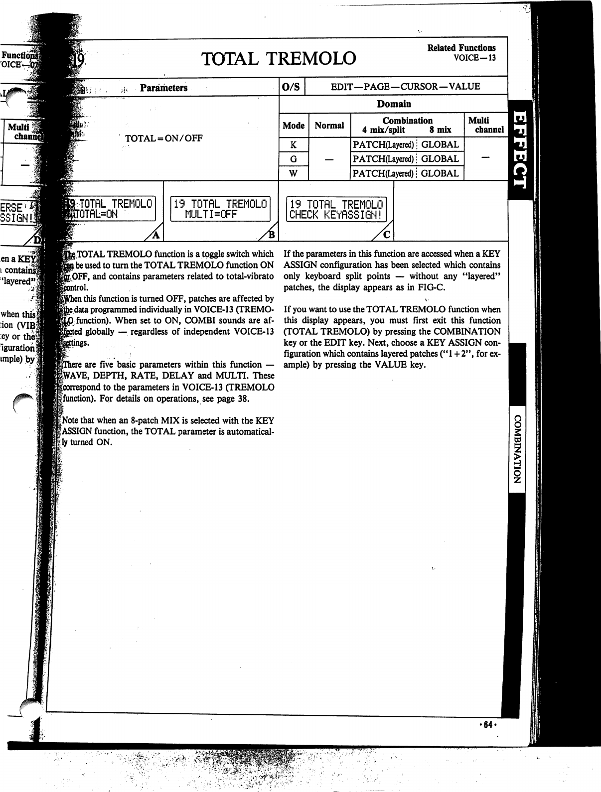
19
TOTflL
TREMOLO
MULTKFF
g.TOTAL
TREMOLO
function
is
a
toggle
switch
which
l
be
used
to
turn
the
TOTAL
TREMQLO
function
ON
[OFF,
and
contains
parameters
related
to
total-vibrato
ol.
1
this
function
is
turned
OFF,
patches
are
affected
by
e
data
programmed
individually
in
VOICE-13
(TREMO-
0
function).
When
set
to
ON,
COMBI
sounds
are
af-
:
globally
—.
regardless
of
independent
VOICE-13
ey
or the
Iguration
unple)
by
TOTAL
TREMOLO
Related
Functions
VOICE-13
A
o/s
EDIT—PAGE—CURSOR—VALUE
Domain
Mode
W
Normal
Combination
4
mix/split
8
mix
PATCH(Layered);
GLOBAL
PATCH(Layered);
GLOBAL
PATCH(Layered)!
GLOBAL
19
TOTflL
TREMOLO
CHECK
KEYfiSSIGN!
Multi
channel
i
are
five
basic
parameters
within
this
function
—
VAVE,
DEPTH,
RATE,
DELAY
and
MULTI.
These
icorrespond
to
the
parameters
in
VOICE-13
(TREMOLO
gfunction).
For
details
on
operations,
see
page
38.
1
[Note
that
when
an
8-patch
MIX
is
selected
with
the
KEY
|ASSIGN
function,
the
TOTAL
parameter
is
automatical
ly
turned
ON.
If
the
parameters
in
this
function
are
accessed
when
a
KEY
ASSIGN
configuration
has
been
selected
which
contains
only
keyboard
split
points
—
without
any
"layered"
patches,
the
display
appears
as
in
FIG-C.
\-
If
you
want
to
use
the
TOTAL
TREMOLO
function
when
this
display
appears,
you
must
first
exit
this
function
(TOTAL
TREMOLO)
by
pressing
the
COMBINATION
key
or
the
EDIT
key.
Next,
choose
a
KEY
ASSIGN
con
figuration
which
contains
layered
patches
("1+2",
for
ex
ample)
by
pressing
the
VALUE
key.
•64-
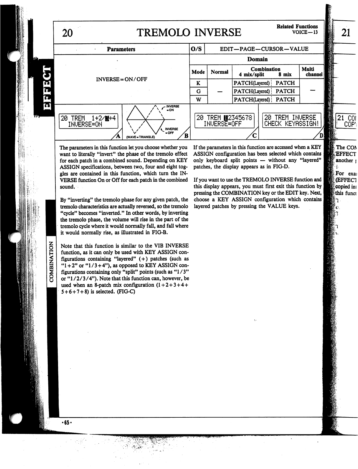
20
TREMOLO
INVERSE
Related
Functions
VOICE—13
Parameters
O/S
EDIT—PAGE—CURSOR—VALUE
21
:
'■
Domain
Mode
INVERSE=ON/OFF
K
W
20
TREM
1+2/H+4
INUERSE=ON
Normal
Combination
4
mix/split
8
mix
PATCH(Layered)!
PATCH
PATCH(Layered);
PATCH
PATCH(Layered)
|
PATCH
\
/
\
A
INVERSE
V
V
-OFF
(WAVE-TRIANGLE)
}
TREM
B2345678
INUERSE=OFF
Multi
channel
I]
2@
TREM
INUERSE
CHECK
KEYflSSIQN!
The
parameters
in
this
function
let
you
choose
whether
you
want
to
literally
"invert"
the
phase
of
the
tremolo
effect
for
each
patch
in
a
combined
sound.
Depending
on
KEY
ASSIGN
specifications,
between
two,
four
and
eight
tog
gles
are
contained
in
this
function,
which
turn
the
IN
VERSE
function
On
or
Off
for
each
patch
in
the
combined
sound,
By
"inverting"
the
tremolo
phase
for
any
given
patch,
the
tremolo
characteristics
are
actually
reversed,
so
the
tremolo
"cycle"
becomes
"inverted."
In
other
words,
by
inverting
the
tremolo
phase,
the
volume
will
rise
in
the
part
of
the
tremolo
cycle
where
it
would
normally
fall,
and
fall
where
it
would
normally
rise,
as
illustrated
in
FIG-B.
Note
that
this
function
is
similar
to
the
VIB
INVERSE
function,
as
it
can
only
be
used
with
KEY
ASSIGN
con
figurations
containing
"layered"
(+)
patches
(such
as
"
1
+
2"
or
"
1
/
3
+
4"),
as
opposed
to
KEY
ASSIGN
con
figurations
containing
only
"split"
points
(such
as
"1/3"
or
"1/2/3/4").
Note
that
this
function
can,
however,
be
used
when
an
8-patch
mix
configuration
(1+2+3
+
4
+
5
+
6+7
+
8)
is
selected.
(FIG-C)
If
the
parameters
in
this
function
are
accessed
when
a
KEY
ASSIGN
configuration
has
been
selected
which
contains
only
keyboard
split
points
—
without
any
"layered"
patches,
the
display
appears
as
in
FIG-D.
If
you
want
to
use the
TREMOLO
INVERSE
function
and
I
this
display
appears,
you
must
first
exit
this
function
by
pressing
the
COMBINATION
key
or
the
EDIT
key.
Next,
I
choose
a
KEY
ASSIGN
configuration
which
contains
|
layered
patches
by
pressing
the
VALUE
keys.
•65<
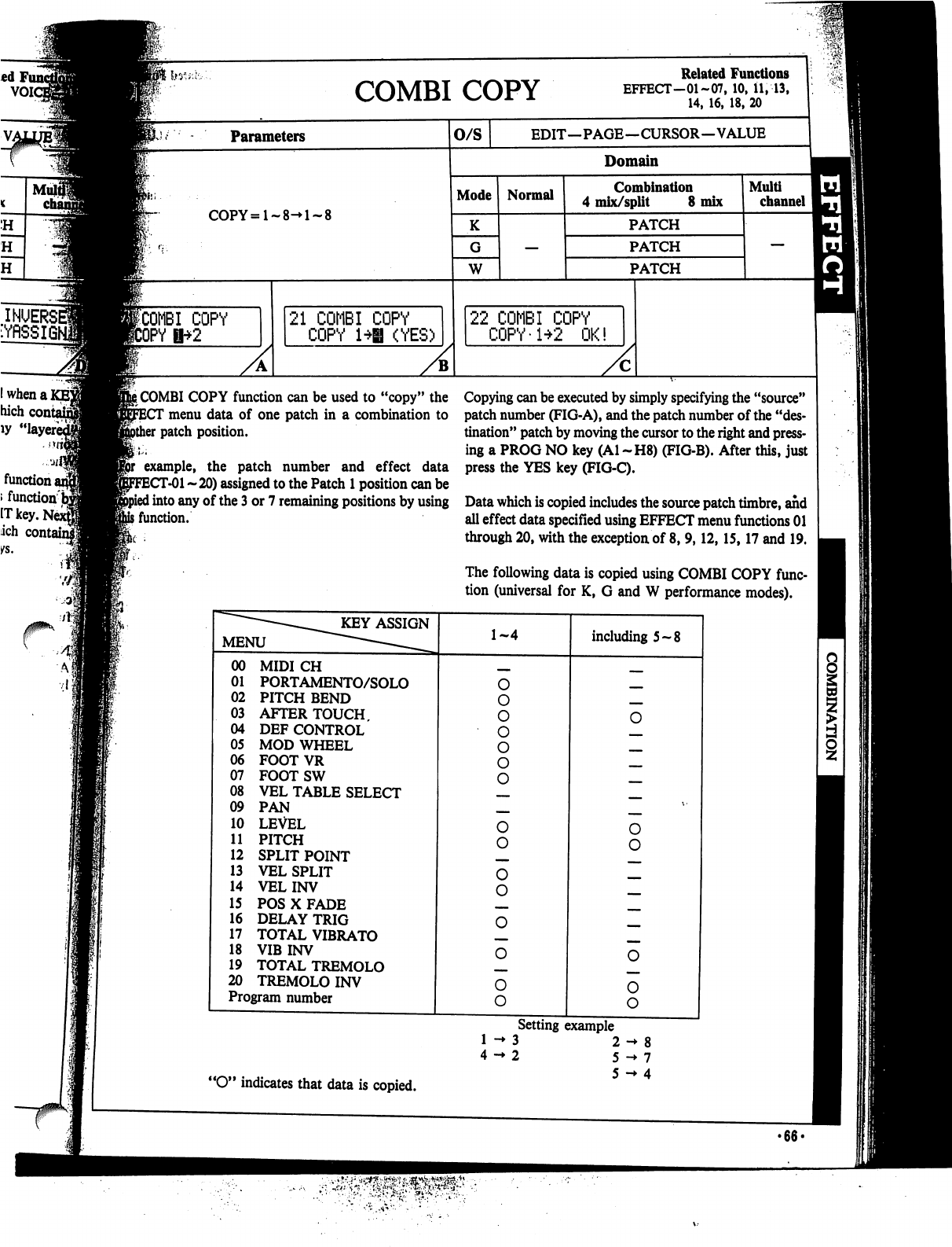
hy
s,
•,-
COPY
Related
Functions
EFFECT-01-07.10.il.--13.
Parameters
O/S
COPY=l-8-»l-8
ICOMBI
COPY
JrY
U"+^
21
COMBI
COPY
COPY
1*|
(YES)
EDIT—PAGE—CURSOR—VALUE
Domain
Mode
K
W
Normal
Combination
4
mix/split
8
mix
PATCH
PATCH
PATCH
22
COMBI
COPY
COPY-1+2
OK!
Multi
channel
i
COMBI
COPY
function
can
be
used
to
"copy"
the
menu
data
of
one
patch
in
a
combination
to
patch
position.
example,
the
patch
number
and
effect
data
T-01
~
20)
assigned
to
the
Patch
1
position
can
be
I
into
any
of
the
3
or 7
remaining
positions
by
using
i
function.
Copying
can
be
executed
by
simply
specifying
the
"source"
patch
number
(FIG-A),
and
the
patch
number
of
the
"des
tination"
patch
by
moving
the
cursor
to
the
right
and
press
ing
a
PROG
NO
key
(Al
~H8)
(FIG-B).
After
this,
just
press
the
YES
key
(FIG-C).
Data
which
is
copied
includes
the
source
patch
timbre,
and
all
effect
data
specified
using
EFFECT
menu
functions
01
through
20,
with
the
exception
of
8,
9,12,15,17
and
19.
The
following
data
is
copied
using
COMBI
COPY
func
tion
(universal
for
K,
G
and
W
performance
modes).
"O"
indicates
that
data
is
copied.
Setting
example
3
2
->
8
2
5
->
7
5
->
4
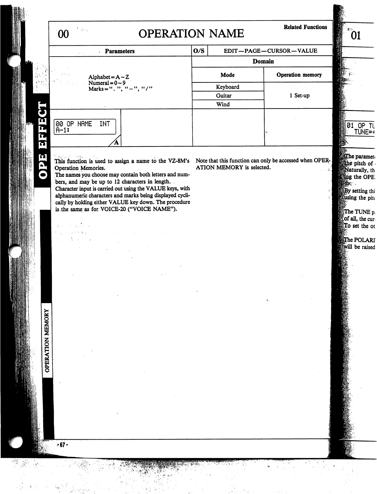
This
function
is
used
to
assign
a
name
to
the
VZ-8M's
Note
that
this
function
can
only
be
accessed
when
OPER-
Operation
Memories.
ATION
MEMORY
is
selected.
^
The
names
you
choose
may
contain
both
letters
and
num
bers,
and
may
be
up
to
12
characters
in
length.
Character
input
is
carried
out
using
the
VALUE
keys,
with
,
alphanumeric
characters
and
marks
being
displayed
cycli
cally
by
holding
either
VALUE
key
down.
The
procedure
is.the
same
as
for
VOICE-20
("VOICE
NAME").
11'
i,
neparamett
he
pitch
of
*
Naturally,
th
the
OPE
'
setting
thi
;
the
pitc
frhe
TUNE
p,
Jof
all,
the
cur
feo
set
the
ot
>
POLAR!
be
raised
♦67«
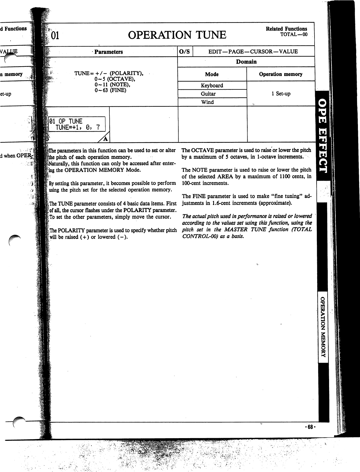
01
OPERATION
TUNE
Related
Functions
TOTAL-00
Parameters
TUNE=+/-
(POLARITY),
0-5
(OCTAVE),
0-11
(NOTE),
0-63
(FINE)
j
01
OP
TUNE
TUNE=+1?
\
parameters
in
this
function
can
be
used
to
set
or
alter
!
pitch
of
each
operation
memory,
iturally,
this
function
can
only
be
accessed
after
enter-
Rng
the
OPERATION
MEMORY
Mode.
!;
;
By
setting
this
parameter,
it
becomes
possible
to
perform
using
the
pitch
set
for
the
selected
operation
memory.
iThe
TUNE
parameter
consists
of
4
basic
data
items.
First
|
of
all,
the
cursor
flashes
under
the
POLARITY
parameter.
I:
To
set
the
other
parameters,
simply
move
the
cursor.
|The
POLARITY
parameter
is
used
to
specify
whether
pitch
f
will
be
raised
(+)
or
lowered
(-).
The
OCTAVE
parameter
is
used
to
raise
or
lower
the
pitch
by
a
maximum
of
5
octaves,
in
1-octave
increments.
The
NOTE
parameter
is
used
to
raise
or
lower
the
pitch
of
the
selected
AREA
by
a
maximum
of
1100
cents,
in
100-cent
increments.
The
FINE
parameter
is
used
to
make
"fine
tuning"
ad
justments
in
1.6-cent
increments
(approximate).
The
actual
pitch
used
in
performance
is
raised
or
lowered
according
to
the
values
set
using
this
function,
using
the
pitch
set
in
the
MASTER
TUNE
function
(TOTAL
CONTROL-00)
as
a
basis.
>68<
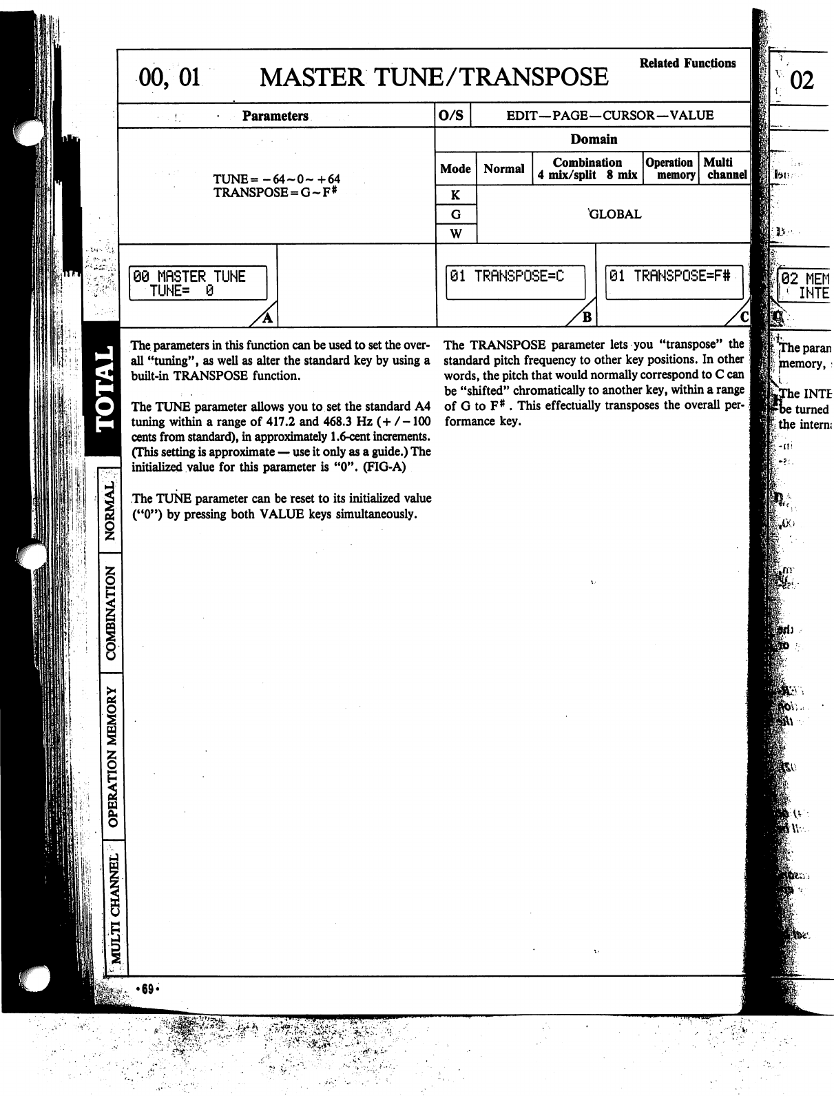
00,
01
MASTER
TUNE/TRANSPOSE
Parameters
TUNE=-64~0~+64
TRANSPOSE
=
G~F#
60
MfiSTER
TUNE
■TUNE*
0
The
parameters
in
this
function
can
be
used
to
set
the
over
all
"tuning",
as
well
as
alter
the
standard
key
by
using
a
built-in
TRANSPOSE
function.
The
TUNE
parameter
allows
you
to
set
the
standard
A4
tuning
within
a
range
of
417.2
and
468.3
Hz
(+
/-100
cents
from
standard),
in
approximately
1.6-cent
increments.
(This
setting
is
approximate
—
use
it
only
as
a
guide.)
The
initialized
value
for
this
parameter
is
"0".
(FIG-A)
The
TUNE
parameter
can
be
reset
to
its
initialized
value
("0")
by
pressing
both
VALUE
keys
simultaneously.
Related
Functions
O/S
EDIT—PAGE—CURSOR—VALUE
Domain
Mode
K
W
Normal
Combination
4
mix/split
8
mix
Operation
memory
Multi
channel
II
GLOBAL
01
TRfiNSPOSE=C
01
TRfiHSPOSE=F#
The
TRANSPOSE
parameter
lets
you
"transpose"
standard
pitch
frequency
to
other
key
positions.
In other
words,
the
pitch
that
would
normally
correspond
to
C
can
be
"shifted"
chromatically
to
another
key,
within
a
range
of
G
to
F#
.
This
effectually
transposes
the
overall
per-.;
formance
key.
02
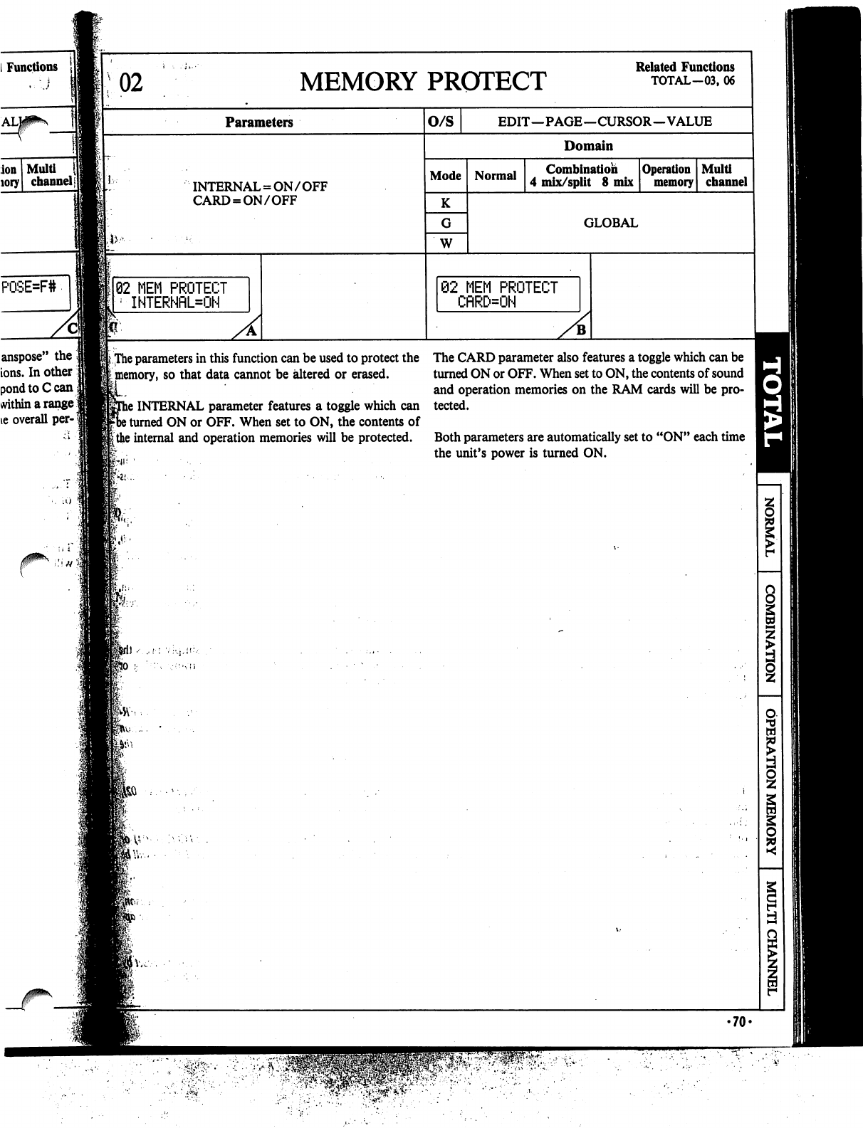
Functions
MEMORY
PROTECT
Parameters
INTERNAL
=
ON/OFF
CARD
=
ON/OFF
o/s
Mode
K
W
Normal
@2
MEM
PROTECT
CflRD=ON
»;
The
parameters
in
this
function
can
be
used
to
protect
the
The
CARD
parameter
also
features
a
toggle
which
can
be
[
memory,
so
that
data
cannot
be
altered
or
erased.
turned
ON
or
OFF.
When
set
to
ON,
the
contents
of
sound
and
operation
memories
on
the
RAM
cards
will
be
pro-
s
INTERNAL
parameter
features
a
toggle
which
can
tected.
)
turned
ON
or
OFF.
When
set
to
ON,
the
contents
of
|
the
internal
and
operation
memories
will
be
protected.
Both
parameters
are
automatically
set
to
"ON"
each
time
the
unit's
power
is
turned
ON.
ion
Multi
<
lory
channel|
82
MEM
PROTECT
INTERNflL=ON
anspose"
the
ions.
In
other
pond
toCcan
within
a
range
ie
overall
per-
Related
Functions
TOTAL-03,
06
EDIT—PAGE—CURSOR—VALUE
Domain
Combination
4
mix/split
8
mix
Operation
memory
Multi
channel
GLOBAL
8
I
•70-
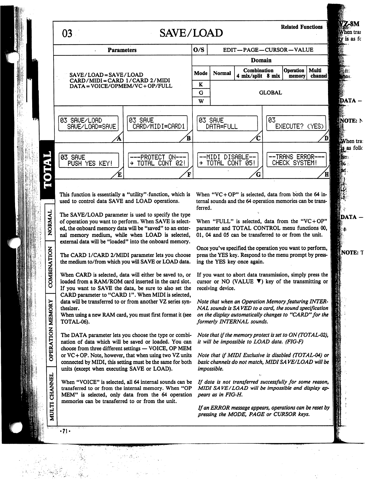
'II
SAVE/LOAD
Related
Functions
Parameters
O/S
SAVE/LOAD
=
SAVE/LOAD
CARD/MIDI
=
CARD
I/CARD
2/MIDI
DATA
=
VOICE/OPMEM/VC
+
OP/FULL
63
SflUE/LOflD
SflUE/LOflD=SRUE
A
QZ
SflUE
PUSH
YES
KEY!
A
93
SflUE
CflRD/MIDI=CflRDl
PROTECT
ON—
TOTflL
CONT
02!
EDIT—PAGE—CURSOR—VALUE
Domain
Mode
K
W
Normal
Combination
4
mix/split
8
mix
Operation
memory
GLOBAL
03
SflUE
I=FULL
—MIDI
DISflBLE™
*
TOTflL
CONT
05!
03
EXECUTE?
(YES)
--TRRNS
ERROR—
CHECK
SYSTEM!
8M
This
function
is
essentially
a
"utility"
function,
which
is
used
to
control
data
SAVE
and
LOAD
operations.
The
SAVE/LOAD
parameter
is
used
to
specify
the
type
of
operation
you
want
to
perform.
When
SAVE
is
select
ed,
the
onboard
memory
data
will
be
"saved"
to
an
exter
nal
memory
medium,
while
when
LOAD
is
selected,
external
data
will
be
"loaded"
into
the
onboard
memory.
The
CARD
I/CARD
2/MIDI
parameter
lets
you
choose
the
medium
to/from
which
you
will
SAVE
or
LOAD
data.
When
CARD
is
selected,
data
will
either
be
saved
to,
or
loaded
from
a
RAM/ROM
card
inserted
in
the
card
slot.
If
you
want
to
SAVE
the
data,
be
sure
to
also
set
the
CARD
parameter
to
"CARD
1".
When
MIDI
is
selected,
data
will
be
transferred
to
or
from
another
VZ
series
syn
thesizer.
When
using
a
new
RAM
card,
you
must
first
format
it
(see
TOTAL-06).
The
DATA
parameter
lets
you
choose
the
type
or
combi
nation
of
data
which
will
be
saved
or
loaded.
You
can
choose
from
three
different
settings
—
VOICE,
OP
MEM
or
VC+OP.
Note,
however,
that
when
using
two
VZ
units
connected
by
MIDI,
this
setting
must
be
the
same
for
both
units
(except
when
executing
SAVE
or
LOAD).
When
"VC
+
OP"
is
selected,
data
from
both
the
64
in
ternal
sounds
and
the
64
operation
memories
can
be
trans
ferred.
When
"FULL"
is
selected,
data
from
the
"VC
+
OP"
parameter
and
TOTAL
CONTROL
menu
functions
00,
01,
04
and
05
can
be
transferred
to
or
from
the
unit.
Once
you've
specified
the
operation
you
want
to
perform,
press
the
YES
key.
Respond
to
the
menu
prompt
by
press
ing
the
YES
key
once
again.
If
you
want
to
abort
data
transmission,
simply
press
the
cursor
or
NO
(VALUE
▼)
key
of
the
transmitting
or
receiving
device.
Note
that
when
an
Operation
Memory
featuring
INTER
NAL
sounds
is
SA
VED
to
a
card,
the
sound
specification
on
the
display
automatically
changes
to
"CARD"
for
the
formerly
INTERNAL
sounds.
Note
that
if
the
memory
protect
is
set
to
ON
(TOTAL-02),
it
will
be
impossible
to
LOAD
data.
(FIG-F)
Note
that
if
MIDI
Exclusive
is
disabled
(TOTAL-04)
or
basic
channels
do
not
match,
MIDISA
VE/LOAD
will
be
impossible.
When
"VOICE"
is
selected,
all
64
internal
sounds
can
be
If data
is
not
transferred
successfully
for
some
reason,
transferred
to
or
from
the
internal
memory.
When
"OP
MIDI
SA
VE/LOAD
will
be
impossible
and
display
ap-
MEM"
is
selected,
only
data
from
the
64
operation
pears
as
in
FIG-H.
memories
can be
transferred
to
or
from
the
unit.
If
an
ERROR
message
appears,
operations
can
be
reset
by
pressing
the
MODE,
PAGE
or
CURSOR
keys.
•71
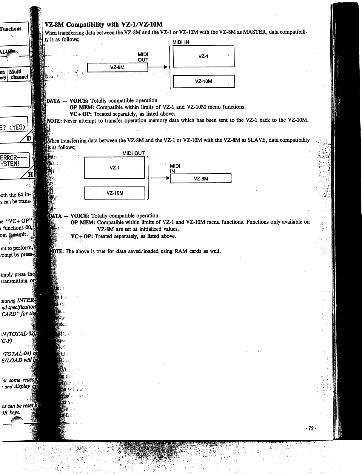
Functions
Multi
channel
E?
(YES)
ERROR-S
YSTEM!
bth
the
64
in-
\
;s
can
be
trans-
\
VZ-8M
Compatibility
with
VZ-1/VZ-10M
When
transferring
data
between
the
VZ-8M
and
the
VZ-1
or
VZ-IOM
with
the
VZ-8M
as
MASTER,
data
compatibili
ty
is
as
follows;
MIDI
IN
MIDI
OUT
VZ-8M
VZ-10M
DATA
—
VOICE:
Totally
compatible
operation
OP
MEM:
Compatible
within
limits
of
VZ-1
and
VZ-IOM
menu
functions.
VC+OP:
Treated
separately,
as
listed
above.
NOTE:
Never
attempt
to
transfer
operation
memory
data
which
has
been
sent
to
the
VZ-1
back
to the
VZ-IOM.
l
transferring
data
between
the
VZ-8M
and
the
VZ-1
or
VZ-IOM
with
the
VZ-8M
as
SLAVE,
data
compatibility
.,
■.
..
jas
follows;
../♦
MIDI
OUT
.,
fc--i
VZ-10M
MIDI
IN
VZ-8M
••'
".
\'
...*■{•_
ie
"VC+OP"j
l
functions
00,|
omtowpit
■ant
to
perform,*
rompt
by
]
.
—
VOICE:
Totally
compatible
operation
OP
MEM:
Compatible
within
limits
of
VZ-1
and
VZ-IOM
menu
functions.
Functions
only
available
on
VZ-8M
are
set
at
initialized
values.
VC+OP:
Treated
separately,
as
listed
above.
E:
The
above
is
true
for
data
saved/loaded
using
RAM
cards
as
well.
imply
press
i
transmitting
ituring
INTER§
nd
specificatU
CARD"
forth
W(TOTAL
rG-F)
(TOTAL-04)
E/LOAD
mill
or
some
>
and
display
j
ns
can
be
reset]
•72-
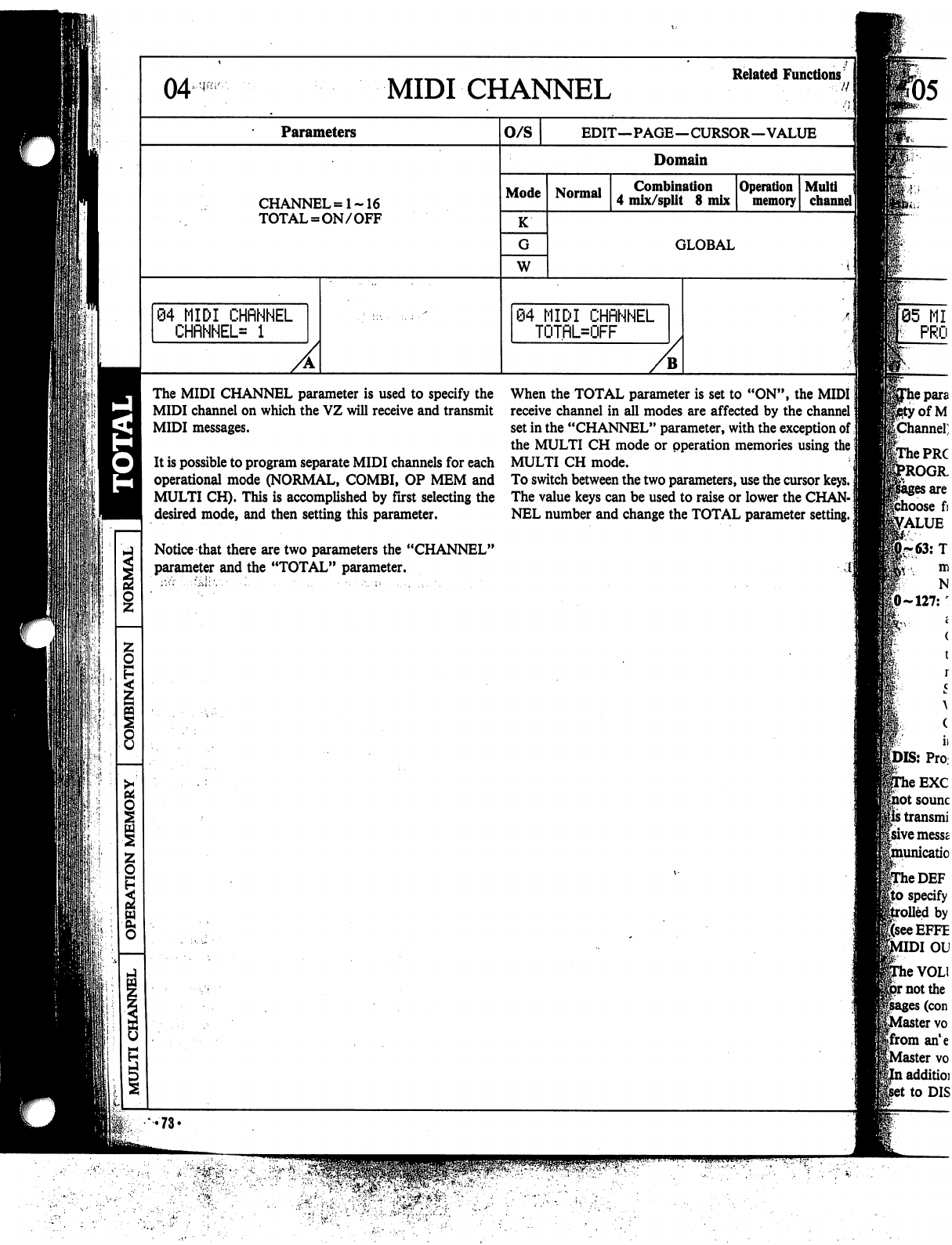
MIDI
CHANNEL
Parameters
CHANNEL
=1-16
TOTAL
=
ON/OFF
o/s
Mode
K
W
Normal
\
MIDI
CHRNNEL
TOTRL=OFF
The
MIDI
CHANNEL
parameter
is
used
to
specify
the
MIDI
channel
on
which
the
VZ
will
receive
and
transmit
MIDI
messages.
It
is
possible
to
program
separate
MIDI
channels
for
each
operational
mode
(NORMAL,
COMBI,
OP
MEM
and
MULTI
CH).
This
is
accomplished
by
first
selecting
the
desired
mode,
and
then
setting
this
parameter.
Notice
that
there
are
two
parameters
the
"CHANNEL"
parameter
and
the
"TOTAL"
parameter.
MIDI
CHRNNEL
CHflNHEL=
1
Related
Functions
EDIT—PAGE—CURSOR—VALUE
Domain
Combination
4
mix/split
8
mix
Operation
memory
GLOBAL
When
the
TOTAL
parameter
is
set
to
"ON",
the
MIDI
|
receive
channel
in
all
modes
are
affected
by
the
channel!
set
in
the
"CHANNEL"
parameter,
with
the
exception
of
the
MULTI
CH
mode
or
pperation
memories
using
the
j
MULTI
CH
mode.
To
switch
between
the
two
parameters,
use
the
cursor
keys.
]
The
value
keys
can
be
used
to
raise
or
lower
the
CHAN-
j
NEL
number
and
change
the
TOTAL
parameter
setting.
I
r05
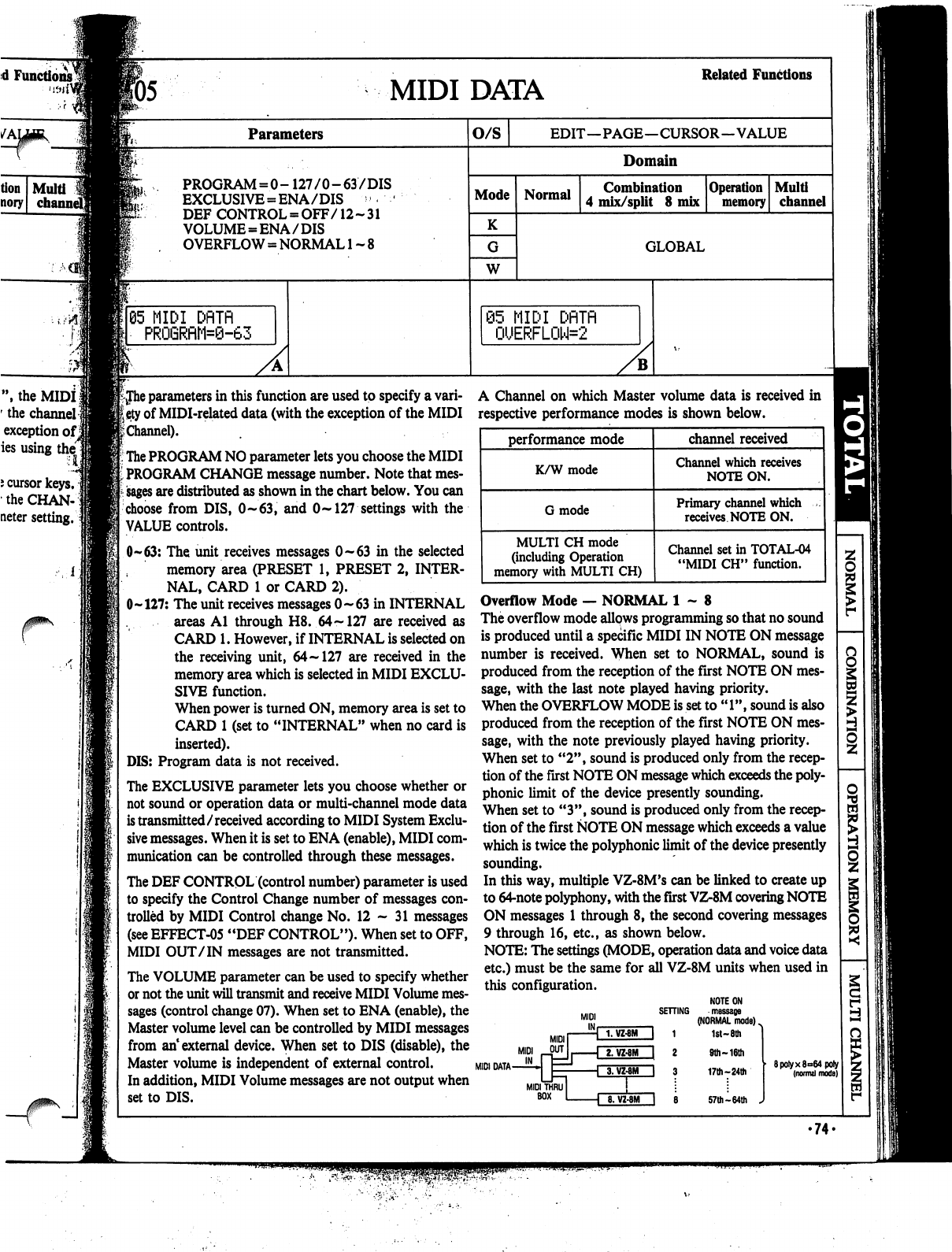
d
Functions^
f
J>,
the
MIDI
1
'
the
channel]
exception
ofj
ies
using
thel
i
cursor
keys,
the
CHAN-]
neter
setting.
F05
MIDI
DATA
Related
Functions
Parameters
PROGRAM
=
0-
127/0-63/DIS
EXCLUSIVE
=
ENA/DIS
'
DEF
CONTROL
=
OFF/12-31
VOLUME
=
ENA/DIS
OVERFLOW
=
NORMAL
1
~
8
65
MIDI
DflTfl
PRO6RflM=0-63
O/S
EDIT—PAGE—CURSOR—VALUE
Domain
Mode
K
W
Normal
Combination
4
mix/split
8
mix
Operation
memory
Multi
channel
GLOBAL
@5
MIDI
DflTfl
0UERFL0W=2
iJhe
parameters
in
this
function
are
used
to
specify
a
vari
ety
of
MIDI-related
data
(with the
exception
of
the
MIDI
£
Channel).
The
PROGRAM
NO
parameter
lets
you
choose
the
MIDI
PROGRAM
CHANGE
message
number.
Note
that
mes
sages
are
distributed as
shown
in
the chart
below.
You
can
choose
from
DIS,
0~63,
and
0~
127
settings
with
the
VALUE
controls.
0-63:
The
unit
receives
messages
0-63
in
the
selected
memory
area
(PRESET
1,
PRESET
2,
INTER
NAL,
CARD
1
or
CARD
2).
0-127:
The
unit
receives
messages
0-63
in
INTERNAL
areas
Al
through
H8.
64
~
127
are
received
as
CARD
1.
However,
if
INTERNAL
is
selected
on
the
receiving
unit,
64-127
are received
in
the
memory
area
which
is
selected
in
MIDI
EXCLU
SIVE
function.
When
power
is
turned
ON,
memory
area
is
set
to
CARD
1
(set
to
"INTERNAL"
when
no
card
is
inserted).
DIS:
Program
data
is
not
received.
The
EXCLUSIVE
parameter
lets
you
choose
whether
or
not
sound
or
operation
data
or
multi-channel
mode
data
is
transmitted/received
according
to
MIDI
System
Exclu
sive
messages.
When
it
is
set
to
ENA
(enable),
MIDI
com
munication
can
be
controlled
through
these
messages.
The
DEF
CONTROL
(control
number)
parameter
is
used
to
specify
the
Control
Change
number
of
messages
con
trolled
by
MIDI
Control
change
No.
12-31
messages
(see
EFFECT-05
"DEF
CONTROL").
When
set
to
OFF,
MIDI
OUT
/IN
messages
are
not
transmitted.
The
VOLUME
parameter
can
be
used
to
specify
whether
or
not
the
unit
will
transmit
and
receive
MIDI
Volume
mes
sages
(control
change
07).
When
set
to
ENA
(enable),
the
Master
volume
level
can
be
controlled
by
MIDI
messages
from
an1
external
device.
When
set
to
DIS
(disable),
the
Master
volume
is
independent
of
external
control.
In
addition,
MIDI
Volume
messages
are
not
output
when
set
to
DIS.
A
Channel
on
which
Master
volume
data
is
received
in
respective
performance
modes
is
shown
below.
Overflow
Mode
—
NORMAL
1-8
The
overflow
mode
allows
programming
so
that
no
sound
is
produced
until
a
specific
MIDI
IN
NOTE
ON
message
number
is
received.
When
set
to
NORMAL,
sound
is
produced
from
the
reception
of
the
first
NOTE
ON
mes
sage,
with
the
last
note
played
having
priority.
When
the
OVERFLOW
MODE
is
set
to
"1",
sound
is
also
produced
from
the
reception
of
the
first
NOTE
ON
mes
sage,
with
the
note
previously
played
having
priority.
When
set
to
"2",
sound
is
produced
only
from
the
recep
tion
of
the
first
NOTE
ON
message
which
exceeds
the
poly
phonic
limit
of
the
device
presently
sounding.
When
set
to
"3",
sound
is
produced
only
from
the
recep
tion
of
the
first
NOTE
ON
message
which
exceeds
a
value
which
is
twice
the
polyphonic
limit
of
the
device
presently
sounding.
In
this
way,
multiple
VZ-8M's
can
be
linked
to
create
up
to
64-note
polyphony,
with
the
first
VZ-8M
covering
NOTE
ON
messages
1
through
8,
the
second
covering
messages
9
through
16,
etc.,
as
shown
below.
NOTE:
The
settings
(MODE,
operation
data
and
voice
data
etc.)
must
be
the
same
for
all
VZ-8M
units
when
used
in
this
configuration.
NOTE
ON
SETTING
message
(NORMAL
mode)
^
1
1st-
8th
MIDI
DATA
MIDI
BOX
8.
VZ-8M
I
8
9th
~
16th
17th-24th
57th
-64th
J
8poiyx8°64poly
(normal
mode)
•
74.
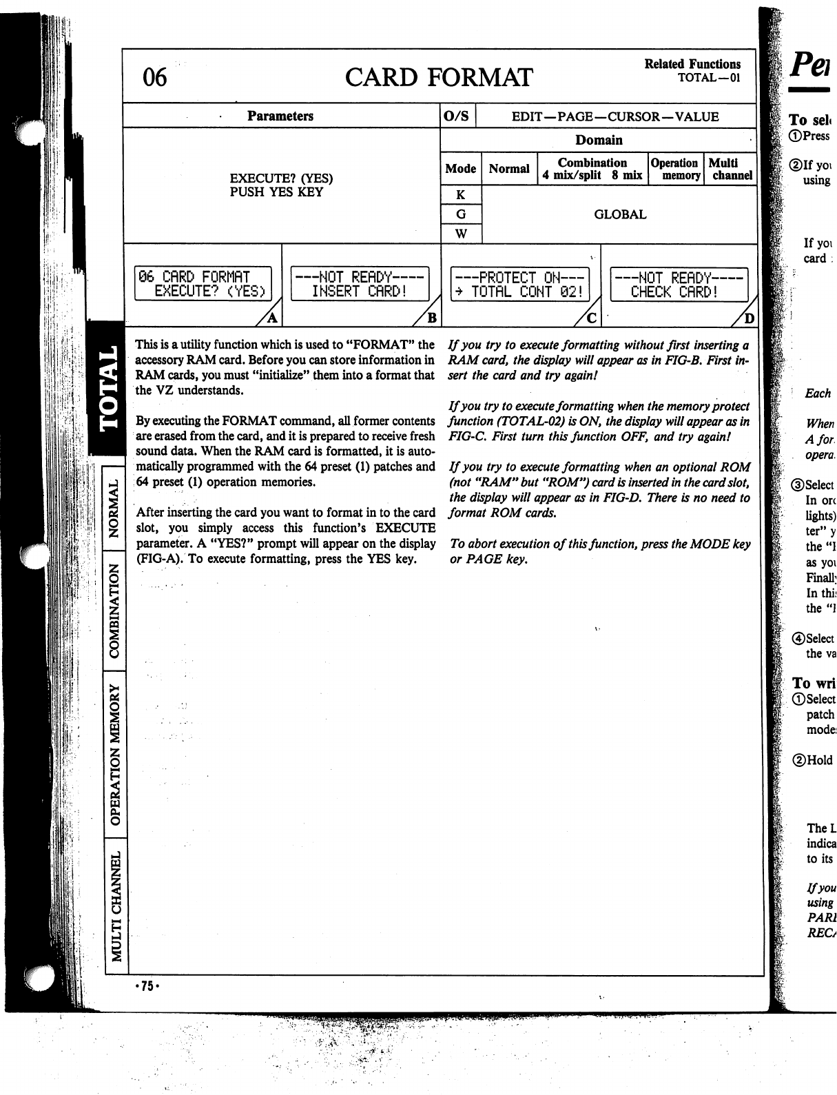
06
CARD
FORMAT
Related
Functions
TOTAL—01
Parameters
O/S
EDIT—PAGE—CURSOR—VALUE
Domain
EXECUTE?
(YES)
PUSH
YES
KEY
Mode
K
W
Normal
Combination
4
mix/split
8
mix
Operation
memory
Multi
channel
GLOBAL
66
CflRD
FQRMflT
EXECUTE?
(YES)
—NOT
REflDY—
INSERT
CflRD!
PROTECT
ON—
TOTflL
CONT
62!
—NOT
REflDY-
CHECK
CflRD!
This
is
a
utility
function
which
is
used
to
"FORMAT"
the
accessory
RAM
card.
Before
you
can
store
information
in
RAM
cards,
you
must
"initialize"
them
into
a
format
that
the
VZ
understands.
By
executing
the
FORMAT
command,
all
former
contents
are
erased
from
the
card,
and
it
is
prepared
to
receive
fresh
sound
data.
When
the
RAM
card
is
formatted,
it
is
auto
matically
programmed
with
the
64
preset
(1)
patches
and
64
preset
(1)
operation
memories.
After
inserting
the
card
you
want
to
format
in
to
the
card
slot,
you
simply
access
this
function's
EXECUTE
parameter.
A
"YES?"
prompt
will
appear
on
the
display
(FIG-A).
To
execute
formatting,
press
the
YES
key.
If
you
try to
execute
formatting
without
first
inserting
a
RAM
card,
the
display
will
appear
as
in
FIG-B.
First
in
sert
the
card
and
try
again!
If
you
try
to
execute
formatting
when
the
memory
protect
function
(TOTAL-02)
is
ON,
the
display
will
appear
as
in
FIG-C.
First
turn
this
function
OFF,
and
try
again!
If
you
try
to
execute
formatting
when
an
optional
ROM
(not
"RAM"
but
"ROM")
card
is
inserted
in
the
card
slot,
the
display
will
appear
as
in
FIG-D.
There
is
no
need
to
format
ROM
cards.
To
abort
execution
of
this
function,
press
the
MODE
key
or
PAGE
key.
•75-

d
Functions,
TOTAL—01
Performance/Editing
in
the
Normal
Modejj
fo
select
sounds
for
performance
in
the
normal
mode
])Press
the
NORMAL
mode
key.
Dlf
you
want
to
choose
a
PRESET
or
an
INTERNAL
patch,
select
by
i
using
the
SHIFT
key.
If
you
want
to
choose
a
CARD
patch,
first
insert
the
RAM
or
ROM
card
in
the
card
slot
and
then
select
by
using
the
SHIFT
key.
Each
bank
holds
up
to
64
patches
and
64
operation
memories.
When
using
a
new
RAM
card,
you
must
first
format
it
(see
TOTAL-06).
A
formatted
RAM
card
is
capable
of
storing
up
to
64
patches
and
64
operation
memories.
pSelect
the
patch
you
want
to
play.
I
In
order
to
change
the
BANK,
first
press
the
BANK
key
(indicator
lights).
Next
press
the
PROG
NO
key
corresponding
to
the
BANK
"let
ter"
you
want
to
choose.
(For
example,
the
"B2"
key
corresponds
to
the
"B"
bank.)
Notice
that
the
BANK
key
indicator
goes
out
as
soon
as
you
select
a
bank.
Finally,
select
the
voice
number
by
pressing
a
PROG
NO
key
once
again.
In
this
case,
the
keys
correspond
to
the
numbers
digit.
(For
example,
the
"B2"
key
would
now
correspond
to
voice
number
"2".)
|®Select
the
performance
mode
(Keyboard,
Guitar
or
Wind)
by
pressing
the
value
keys.
|To
write
a
single
patch
to
memory
|(pSelect
the
patch
you
want
to
write
to
memory
(preset,
internal
or
card
patch
or
Compare/Recall
ON/OFF)
and
select
one
of
the
performance
modes
(K,
G,
W).
*®Hold
down
the
WRITE
key.
The
LCD
appears
as
shown
at
the
right,
and
the
INTERNAL/CARD
indicators
go
out.
If
you
release
the
WRITE
key,
the
LCD
will
return
to
its
normal
status.
Ifyou've
used
the
COMPARE/RECALL
function
when
editing
a
patch
using
VOICE
PARAMETER
menu
functions,
be
sure
that
the
COM
PARE/RECALL
indicator
is
ON.
If
it
is
OFF,
press
the
COMPARE/
RECALL
key.
□
...
SHIFT
ON/OFF
M
ON/OFF
□
WRITE
COPY/INIT
WRITE
UOICE
INT
*-*
COMPARE/
RECALL
•76-
■»
s^;
{..
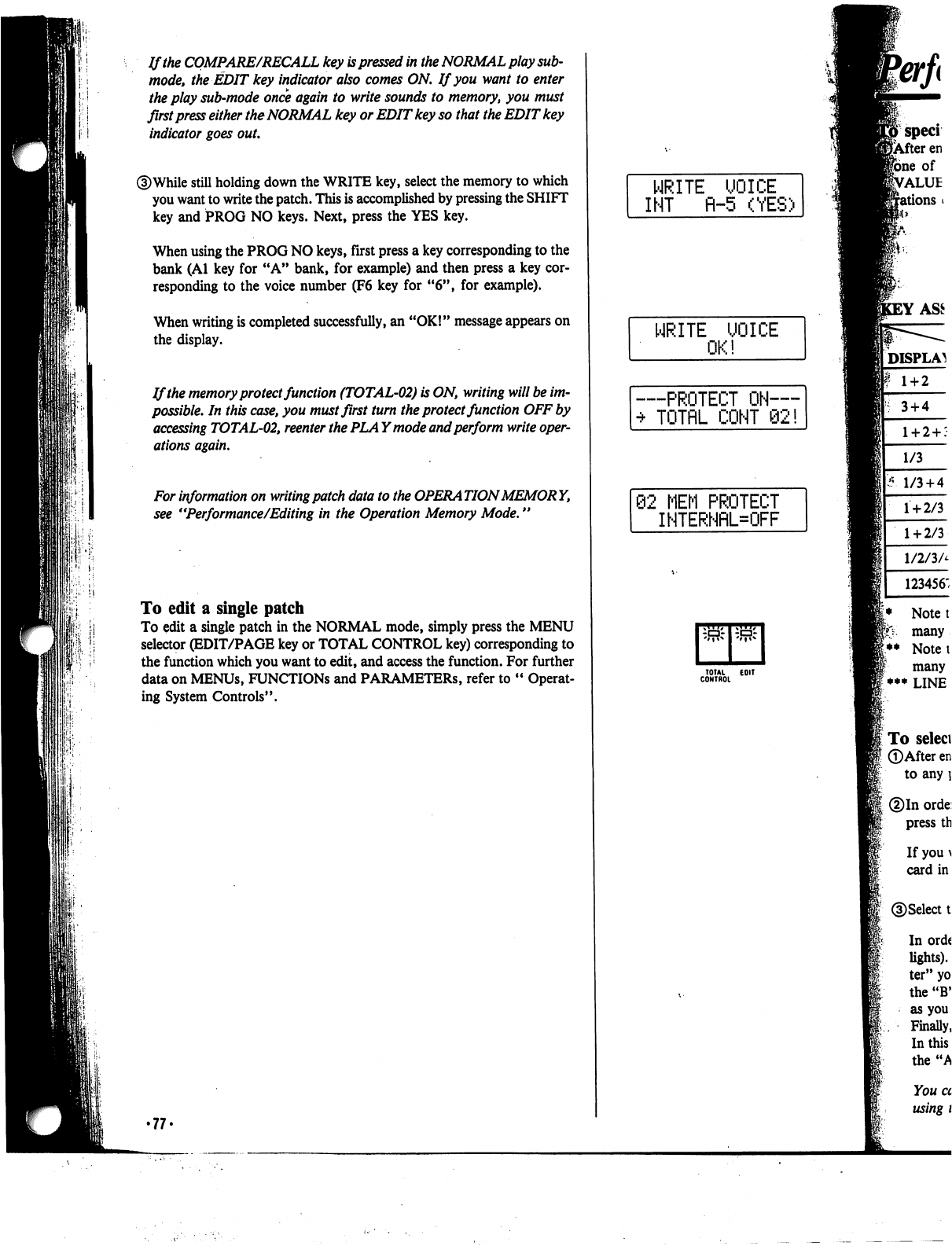
If
the
COMPARE/RECALL
key
is
pressed
in
the
NORMAL
play
sub-
mode,
the
EDIT
key
indicator
also
comes
ON.
If
you
want
to
enter
I
i"-i
the
play
sub-mode
once
again
to
write
sounds
to
memory,
you
must
first
press
either
the
NORMAL
key
or
EDIT
key
so
that
the
EDIT
key
indicator
goes
out.
©While
still
holding
down
the
WRITE
key,
select
the
memory
to
which
you
want
to
write
the
patch.
This
is
accomplished
by
pressing
the
SHIFT
key
and
PROG
NO
keys.
Next,
press
the
YES
key.
When
using
the
PROG
NO
keys,
first
press
a
key
corresponding
to
the
bank
(Al
key
for
"A"
bank,
for
example)
and
then
press
a
key
cor
responding
to
the
voice
number
(F6
key
for
"6",
for
example).
When
writing
is
completed
successfully,
an
"OK!"
message
appears
on
the
display.
If
the
memory
protect
function
(TOTAL-02)
is
ON,
writing
will
be
im
possible.
In
this
case,
you
must
first
turn
the
protect
function
OFF
by
accessing
TOTAL-02,
reenter
the
PLA
Ymode
and
perform
write
oper
ations
again.
For
information
on
writing
patch
data
to
the
OPERATION
MEMORY,
see
"Performance/Editing
in
the
Operation
Memory
Mode."
To
edit
a
single
patch
To
edit
a
single
patch
in
the
NORMAL
mode,
simply
press
the
MENU
selector
(EDIT/PAGE
key
or
TOTAL
CONTROL
key)
corresponding
to
the
function
which
you
want
to
edit,
and
access
the
function.
For
further
data
on
MENUs,
FUNCTIONS
and
PARAMETERS,
refer
to
"
Operat
ing
System
Controls".
•77'
WRITE
UOICE
INT
fl-5
(YES)
WRITE UOICE
OK!
—PROTECT
ON—
•*
TOTflL
COHT
92!
62
MEM
PROTECT
INTERNRL=OFF
rr
TOTAL
EOIT
CONTROL
3
+
4
1/3
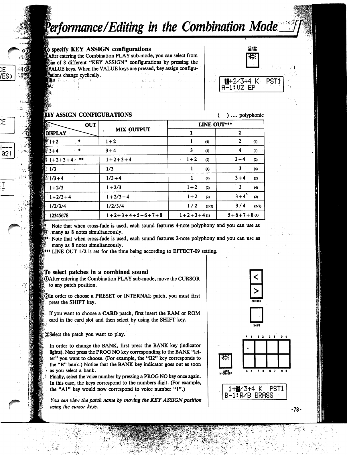
Performance/Editingin
the
Combination
Mode
specify
KEY
ASSIGN
configurations
r
entering
the
Combination
PLAY
sub-mode,
you
can
select
from
of
8
different
"KEY
ASSIGN"
configurations
by
pressing
the
VALUE
keys.
When
the
VALUE
keys
are
pressed,
key
assign
configu-
;
change
cyclically.
Si;
H+2/3+4
K
fl-UUZ
EP
PST1
Note
that
when
cross-fade
is
used,
each
sound
features
4-note
polyphony
and
you
can
use
as
many
as
8
notes
simultaneously.
Note
that
when
cross-fade
is
used,
each
sound
features
2-note
polyphony
and
you
can
use
as
many
as
8
notes
simultaneously.
LINE
OUT
1/2
is
set
for
the
time
being
according
to
EFFECT-09
setting.
|
To
select
patches
in
a
combined
sound
[©After
entering
the
Combination
PLAY
sub-mode,
move
the
CURSOR
to
any
patch
position.
(2)In
order
to
choose
a
PRESET
or
INTERNAL
patch,
you
must
first
press
the
SHIFT
key.
fed
If
you
want
to
choose
a
CARD
patch,
first
insert
the
RAM
or
ROM
card
in
the
card
slot
and
then
select
by
using
the
SHIFT
key.
©Select
the
patch
you
want
to
play.
In
order
to
change
the
BANK,
first
press
the
BANK
key
(indicator
lights).
Next
press
the
PROG
NO
key
corresponding
to
the
BANK
"let
ter"
you
want
to
choose.
(For
example,
the
"B2"
key
corresponds
to
the
"B"
bank.)
Notice
that
the
BANK
key
indicator
goes
out
as
soon
as
you
select
a
bank.
Finally,
select
the
voice
number
by
pressing
a
PROG
NO
key
once
again.
In
this
case,
the
keys
correspond
to
the
numbers
digit.
(For
example,
the
"Al"
key
would
now
correspond
to
voice
number
"1".)
You
can
view
the
patch
name
by
moving
the
KEY
ASSIGN
position
using
the
cursor
keys.
□
BANK
M
ON/OFF
141/3+4
K
PST1
B-l:R/B
BRflSS
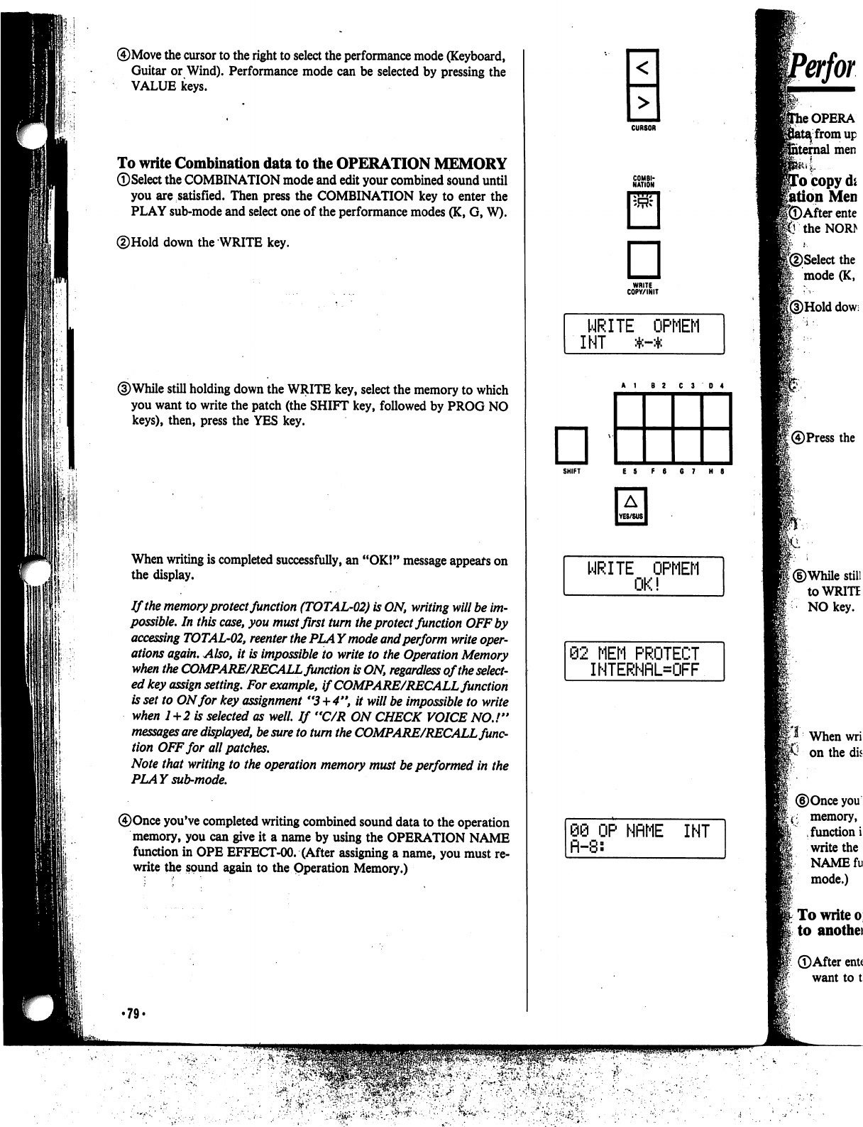
It
I'
III
®Move
the
cursor
to
the
right
to
select
the
performance
mode
(Keyboard,
Guitar
or
Wind).
Performance
mode
can
be
selected
by
pressing
the
VALUE
keys.
To
write
Combination
data
to
the
OPERATION
MEMORY
©Select
the
COMBINATION
mode
and
edit
your
combined
sound
until
you
are
satisfied.
Then
press
the
COMBINATION
key
to
enter
the
PLAY
sub-mode
and
select
one
of
the
performance
modes
(K,
G,
W).
©Hold
down
the
WRITE
key.
©While
still
holding
down
the
WRITE
key,
select
the
memory
to
which
you
want
to
write
the
patch
(the
SHIFT
key,
followed
by
PROG
NO
keys),
then, press
the
YES
key.
When
writing
is
completed
successfully,
an
"OK!"
message
appears
on
the
display.
If
the
memory
protect
function
(TOTAL-02)
is
ON,
writing
will
be
im
possible.
In
this
case,
you
must
first
turn
the
protect
function
OFF
by
accessing
TOTAL-02,
reenter
the
PLAY
mode
and
perform
write
oper
ations
again.
Also,
it
is
impossible
to
write to
the
Operation
Memory
when
the
COMPARE/RECALL
function
is
ON,
regardless
of
the
select
ed
key
assign
setting.
For
example,
if
COMPARE/RECALL
function
is
set
to
ON
for
key
assignment
"3+4",
it
will
be
impossible
to
write
when
1+2
is
selected
as
well.
If
"C/R
ON
CHECK
VOICE
NO.!"
messages
are
displayed,
be
sure
to
turn
the
COMPARE/RECALL
func
tion
OFF
for
all
patches.
Note
that
writing to
the
operation
memory
must
be
performed
in
the
PLAY
sub-mode.
®Once
you've
completed
writing
combined
sound
data
to
the
operation
memory,
you
can
give
it
a
name
by
using
the
OPERATION
NAME
function
in
OPE
EFFECT-00.
(After
assigning
a
name,
you
must
re
write
the
sound
again
to
the
Operation
Memory.)
•79'
<
■MM
>
□
WRITE
COPY/INIT
SHIFT
E S
F
6
6
7
H
8
WRITE
OPMEM
82
MEM
PROTECT
IHTERNflL=OFF
88 OP
NflME
INT
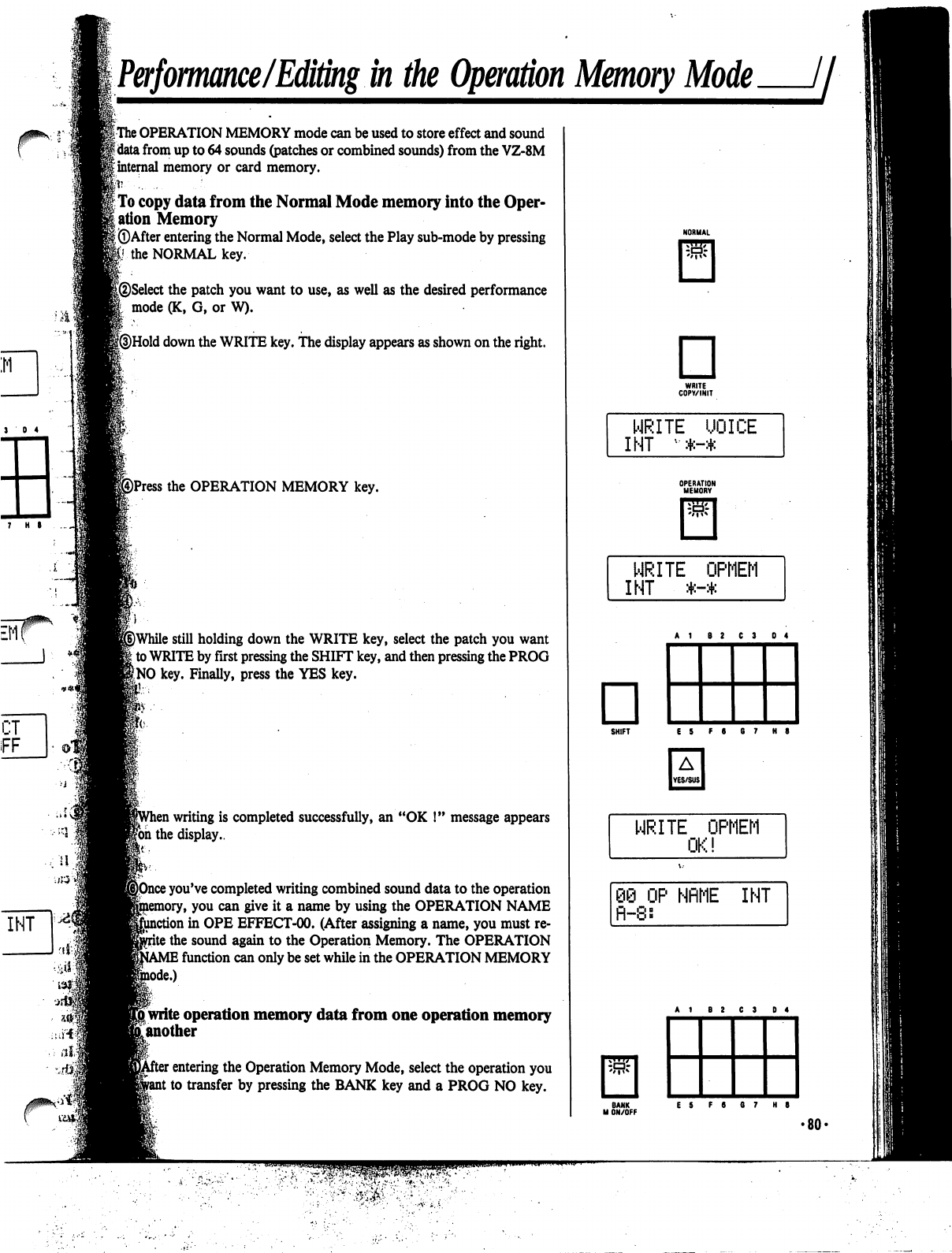
Performance/Editing
in
the
Operation
Memory
Mode
//■
3
0 4
|
The
OPERATION
MEMORY
mode
can
be
used
to
store
effect
and
sound
f
data
from
up
to
64
sounds
(patches
or
combined
sounds)
from
the
VZ-8M
|
internal
memory
or
card
memory.
h
. .
|
To
copy
data
from
the
Normal
Mode
memory
into
the
Oper
ation
Memory
I
©After
entering
the
Normal
Mode,
select
the
Play
sub-mode
by
pressing
|i the
NORMAL
key.
|®Select
the
patch
you
want
to
use,
as
well
as
the
desired
performance
I
mode
(K,
G,
or
W).
[©Hold
down
the
WRITE
key.
The
display
appears
as
shown
on
the
right.
©Press
the
OPERATION
MEMORY
key.
j)While
still
holding
down
the
WRITE
key,
select
the
patch
you
want
\
to
WRITE
by
first
pressing
the
SHIFT
key,
and
then
pressing
the
PROG
f
NO
key.
Finally,
press
the
YES
key.
i
writing
is
completed
successfully,
an
"OK
!"
message
appears
|bh
the
display..
;
you've
completed
writing
combined
sound
data
to
the
operation
y,
you
can
give
it
a
name
by
using
the
OPERATION
NAME
stion
in
OPE
EFFECT-00.
(After
assigning
a
name,
you
must
re-
\
the
sound
again
to
the
Operation
Memory.
The
OPERATION
I
function
can
only
be
set
while
in
the
OPERATION
MEMORY
*■)
[write
operation
memory
data
from
one
operation
memory
[another
:
entering
the
Operation
Memory
Mode,
select
the
operation
you
;
to
transfer
by
pressing
the
BANK
key
and
a
PROG
NO
key.
□
WRITE
COPV/INIT
WRITE
UOICE
INT
•*-*
OPERATION
MEMORY
SHIFT
E5
F6
67
H8
WRITE
OPMEM
nc
i
OP
NflME
INT
BANK
ES
F6
07
H8
M
ON/OFF
•80'
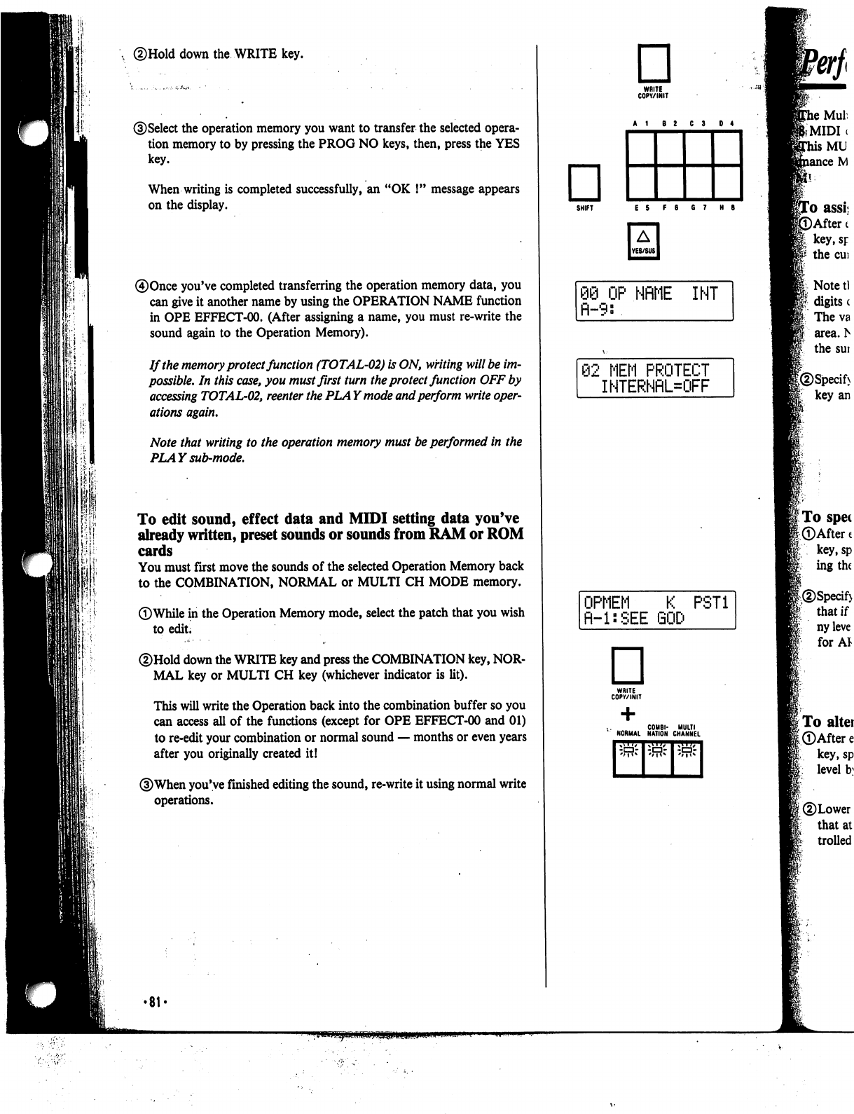
down
the
WRITE
key.
)Select
the
operation
memory
you
want
to
transfer
the
selected
opera
tion
memory
to
by
pressing
the
PROG
NO
keys,
then,
press
the
YES
key.
When
writing
is
completed
successfully,
an
"OK
!"
message
appears
on
the
display.
0Once
you've
completed
transferring
the
operation
memory
data,
you
can
give
it
another
name
by
using
the
OPERATION
NAME
function
in
OPE
EFFECT-00.
(After
assigning
a
name,
you
must
re-write
the
sound
again
to
the
Operation
Memory).
If
the
memory
protect
function
(TOTAL-02)
is
ON,
writing
will
be
im
possible.
In
this
case,
you
must
first
turn
the
protect
function
OFF
by
accessing
TOTAL-02,
reenter
the
PLAY
mode
and
perform
write
oper
ations
again.
Note
that
writing
to
the
operation
memory
must
be
performed
in
the
PLAY
sub-mode.
To
edit
sound,
effect
data
and
MIDI
setting
data
you've
already
written,
preset
sounds
or
sounds
from
RAM
or
ROM
cards
You
must
first
move
the
sounds
of
the
selected
Operation
Memory
back
to
the
COMBINATION,
NORMAL
or
MULTI
CH
MODE
memory.
©While
in
the
Operation
Memory
mode,
select
the
patch
that
you
wish
to
edit;
©Hold
down
the
WRITE
key
and
press
the
COMBINATION
key,
NOR
MAL
key
or
MULTI
CH
key
(whichever
indicator
is
lit).
This
will
write
the
Operation
back
into
the
combination
buffer
so
you
can
access
all
of
the
functions
(except
for
OPE
EFFECT-00
and
01)
to
re-edit
your
combination
or
normal
sound
—
months
or
even
years
after
you
originally
created
it!
©When
you've
finished
editing
the
sound,
re-write
it
using
normal
write
operations.
□
WRITE
COPY/INIT
□
SHIFT
ES
F8 G7
HB
08
OP
NflME
INT
fl-9:
02
MEM
PROTECT
INTERNflL=OFF
OPMEM
K
PST1
R-l:SEE
□
WRITE
COPY/INIT
C0M8I-
MULTI
NORMAL
NATION
CHANNEL
.MIDI
•81
<
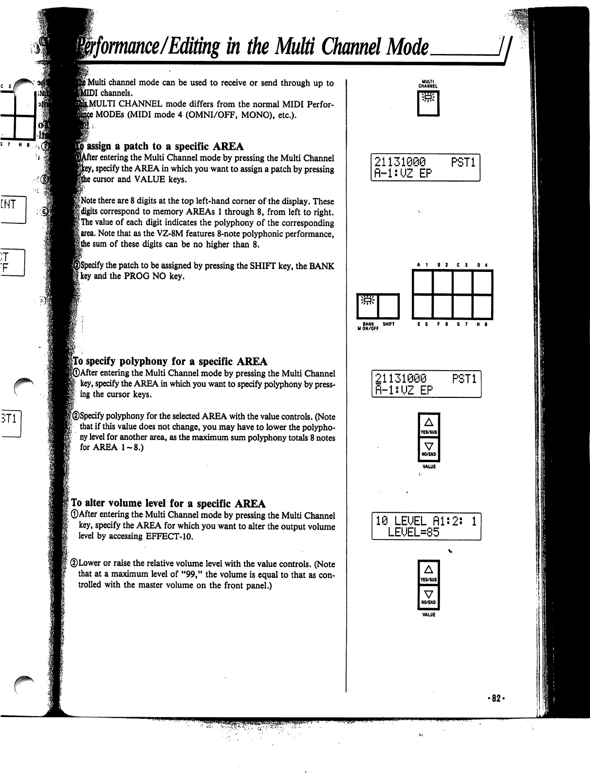
ffomance/Editing
in
the
Multi
Channel
Mode.
jj
f
Multi
channel
mode
can
be
used
to
receive
or
send
through
up
to
)I
channels.
^MULTI
CHANNEL
mode
differs
from
the
normal
MIDI
Perfor-
i
MODEs
(MIDI
mode
4
(OMNI/OFF,
MONO),
etc.).
»
assign
a
patch
to
a
specific
AREA
r
entering
the
Multi
Channel
mode
by
pressing
the
Multi
Channel
y,
specify
the
AREA
in
which
you
want
to
assign
a
patch
by
pressing
i
cursor
and
VALUE
keys.
iNote
there
are
8
digits
at
the
top
left-hand
corner
of
the
display.
These
Uigits
correspond
to
memory
AREAs
1
through
8,
from
left
to
right.
|
The
value
of
each
digit
indicates
the
polyphony
of
the
corresponding
|
area.
Note
that
as
the
VZ-8M
features
8-note
polyphonic
performance,
|the
sum
of
these
digits
can
be
no
higher
than
8.
ify
the
patch
to
be
assigned
by
pressing
the
SHIFT
key,
the
BANK
'
and
the
PROG
NO
key.
|To
specify
polyphony
for
a
specific
AREA
►After
entering
the
Multi
Channel
mode
by
pressing
the
Multi
Channel
key,
specify
the
AREA
in
which
you
want
to
specify
polyphony
by
press
ing
the
cursor
keys.
w
|@Specify
polyphony
for
the
selected
AREA
with
the
value
controls.
(Note
that
if
this
value
does
not
change,
you
may
have
to
lower
the
polypho
ny
level
for
another
area,
as
the
maximum
sum
polyphony
totals
8
notes
for
AREA
1-8.)
I
To
alter
volume
level
for
a
specific
AREA
[
©After
entering
the
Multi
Channel
mode
by
pressing
the
Multi
Channel
key,
specify
the
AREA
for
which
you
want
to
alter
the
output
volume
level
by
accessing
EFFECT-10.
©Lower
or
raise
the
relative
volume
level
with
the
value
controls.
(Note
that at
a
maximum
level
of
"99,"
the
volume
is
equal
to
that
as
con
trolled
with
the
master
volume
on
the
front
panel.)
MULTI
CHANNEL
21131090
PST1
fl-lsUZ
EP
21131006
fl-lsi,JZ
EP
PST1
A
YES/SUS
V
NO/END
3
LEUEL
fll:2:
1
LEUEL=85
A
YES/SUS
■MMH
V
NO/END
•82-
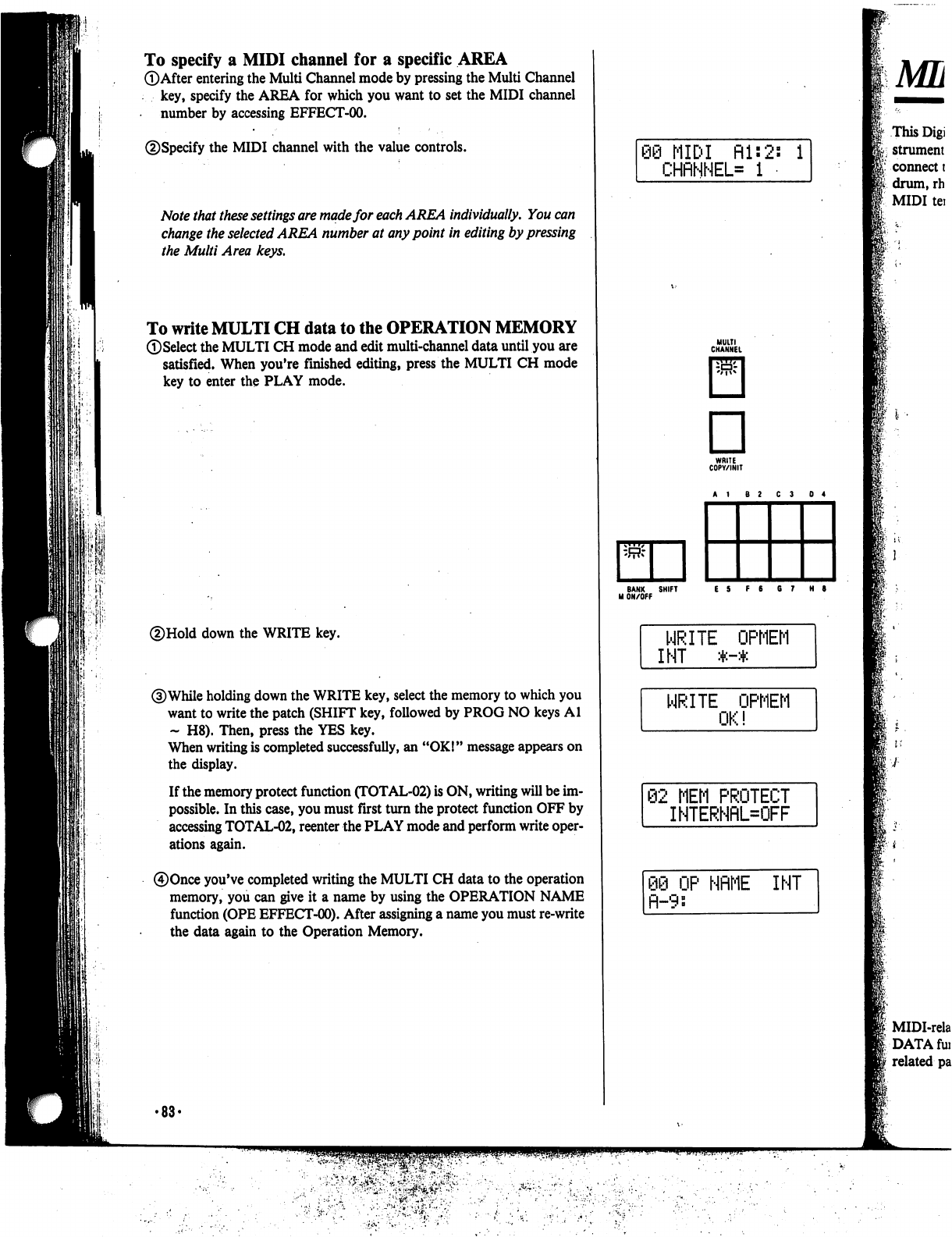
To
specify
a
MIDI
channel
for
a
specific
AREA
©After
entering
the
Multi
Channel
mode
by
pressing
the
Multi
Channel
key,
specify
the
AREA
for
which
you
want
to
set
the
MIDI
channel
number
by
accessing
EFFECT-00.
©Specify
the
MIDI
channel
with
the
value
controls.
Note
that
these
settings
are
made
for
each
AREA
individually.
You
can
change
the
selected
AREA
number
at
any
point
in
editing
by
pressing
the
Multi
Area
keys.
To
write
MULTI
CH
data
to
the
OPERATION
MEMORY
©Select
the
MULTI
CH
mode
and
edit
multi-channel
data
until
you
are
satisfied.
When
you're
finished
editing,
press
the
MULTI
CH
mode
key
to
enter
the
PLAY
mode.
©Hold
down
the
WRITE
key.
©While
holding
down
the
WRITE
key,
select
the
memory
to
which
you
want
to
write
the
patch
(SHIFT
key,
followed
by
PROG
NO
keys
Al
~
H8).
Then,
press
the
YES
key.
When
writing
is
completed
successfully,
an
"OK!"
message
appears
on
the
display.
If
the
memory
protect
function
(TOTAL-02)
is
ON,
writing
will
be
im
possible.
In
this
case,
you
must
first
turn
the
protect
function
OFF
by
accessing
TOTAL-02,
reenter
the
PLAY
mode
and
perform
write
oper
ations
again.
©Once
you've
completed
writing
the
MULTI
CH
data
to
the
operation
memory,
you
can
give
it
a
name
by
using
the
OPERATION
NAME
function
(OPE
EFFECT-00).
After
assigning
a
name
you
must
re-write
the
data
again
to
the
Operation
Memory.
•88-
68
MIDI
Rl:2s
i
CHflNNEL=
1
MULTI
CHANNEL
D
WRITE
COPY/INIT
\w-
BANK
SHIFT
ES
F6
67
H
9
M
ON/OFF
WRITE
OPMEM
INT
*-*
WRITE
OPMEM
OK!
62
MEM
PROTECT
INTERNRL=OFF
OP
NflME
INT
fl-9:
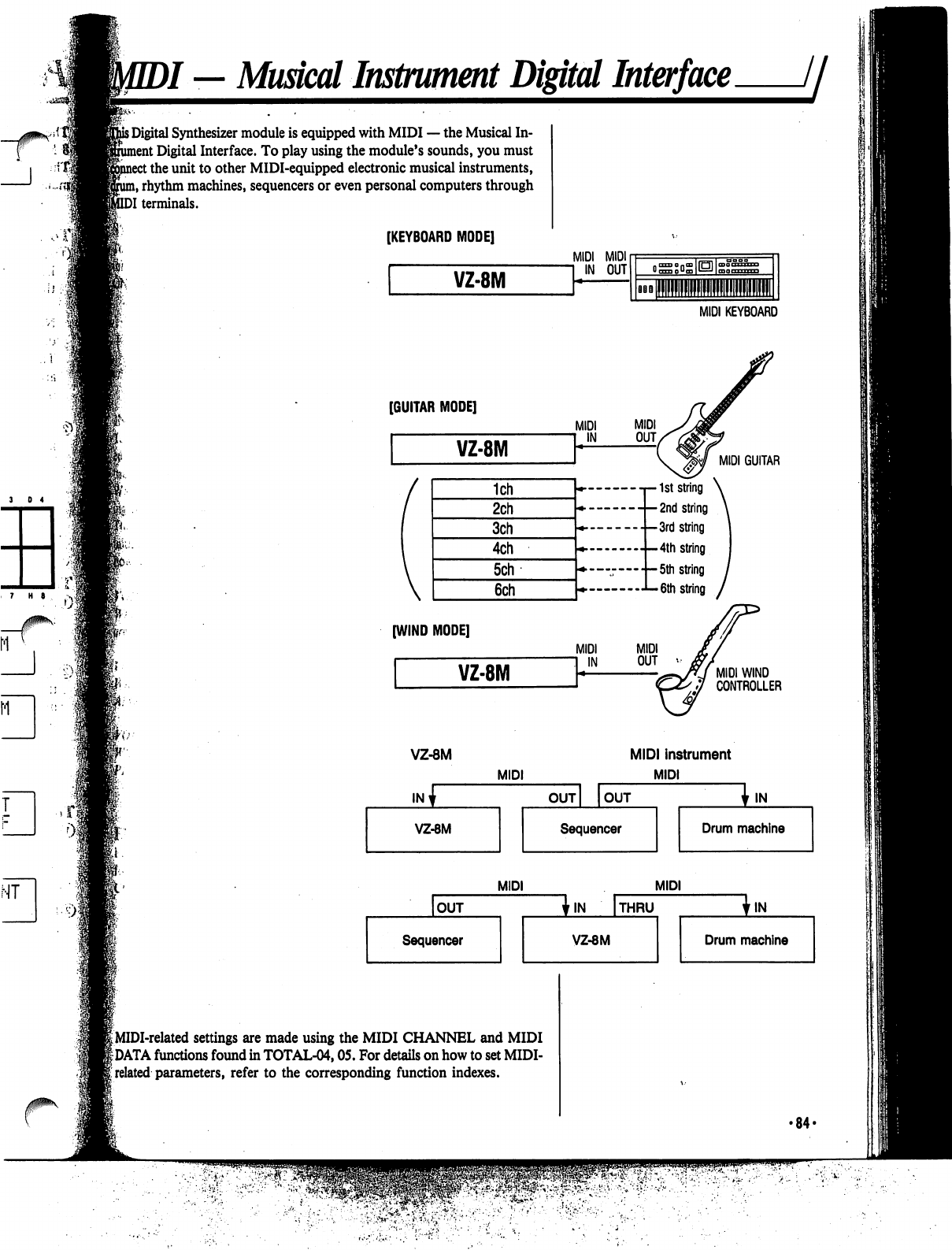
)/
—
Musical
Instrument
Digital
Interface
//
his
Digital
Synthesizer
module
is
equipped
with
MIDI
—
the
Musical
In-
ent
Digital
Interface.
To
play
using
the
module's
sounds,
you
must
:
the
unit
to
other
MIDI-equipped
electronic
musical
instruments,
n,
rhythm
machines,
sequencers
or
even
personal
computers
through
DI
terminals.
[KEYBOARD
MODE]
VZ-8M
MIDI MIDI
MIDI
KEYBOARD
[GUITAR
MODE]
V
1ch
2ch
3ch
4ch
5ch
6ch
[WIND
MODE]
VZ-8M
MIDI
IN
MIDI
GUITAR
-t—1st
string
\
-
-
2nd
string
\
string
•-3rd
string
--4th
string
•
—
5th
string
6th
string
MIDI
WIND
CONTROLLER
VZ-8M
INv
VZ-8M
MIDI
MIDI
instrument
MIDI
OUT
OUT
Sequencer
Ijn.
Drum
machine
OUT
Sequencer
MIDI
I
MIDI-related
settings
are
made
using
the
MIDI
CHANNEL
and
MIDI
|DATA
functions
found
in
TOTAL-04,05.
For
details
on
how
to
set
MIDI-
i
related
parameters,
refer
to
the
corresponding
function
indexes.
MIDI
'IN
THRU
VZ-8M
In.
Drum
machine
•84-
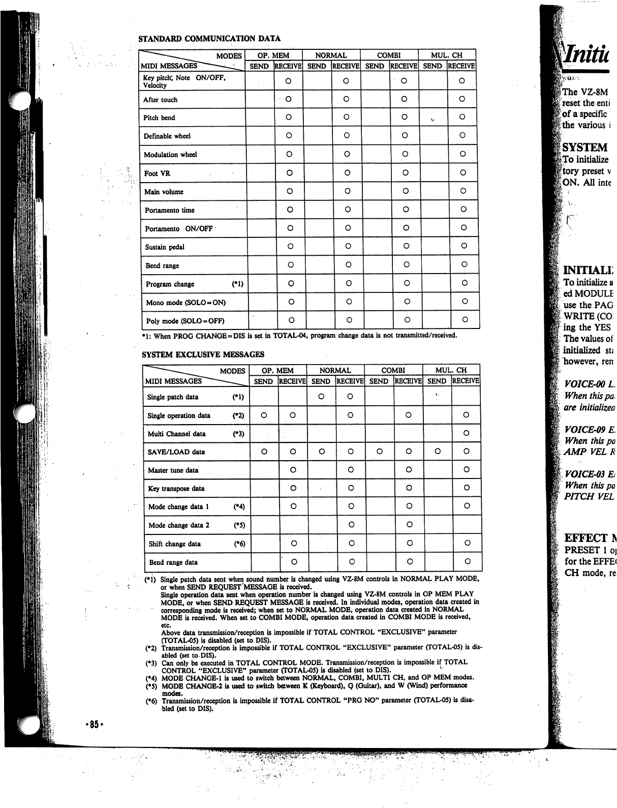
STANDARD
COMMUNICATION
DATA
MIDI
MESSAGES"
MODES
Key
pitch;
Note
ON/OFF,
Velocity
After
touch
Pitch
bend
Definable
wheel
Modulation
wheel
FootVR
Main
volume
Portamento
time
Portamento
ON/OFF
Sustain
pedal
Bend
range
Program
change
(*1)
Mono
mode
(SOLO
»
ON)
Poly
mode
(SOLO
-
OFF)
OP.
MEM
SEND
RECEIVE
o
o
NORMAL
SEND
RECEIVE
0
0
COMBI
SEND
RECEIVE
o
o
MUL.
CH
SEND
RECEIVE
o
o
*1:
When
PROG
CHANGE
»DIS
is
set
in
TOTAL-04,
program
change
data
is
not
transmitted/received.
SYSTEM
EXCLUSIVE
MESSAGES
(*1)
Single
patch
data
sent
when
sound
number
is
changed
using
VZ-8M
controls
in
NORMAL
PLAY
MODE,
or
when
SEND
REQUEST
MESSAGE
is
received.
Single
operation
data
sent
when
operation
number
is
changed
using
VZ-8M
controls
in
OP
MEM
PLAY
MODE,
or
when
SEND
REQUEST
MESSAGE
is
received.
In
individual
modes,
operation
data
created
in
corresponding
mode
is
received;
when
set
to
NORMAL
MODE,
operation
data
created
in
NORMAL
MODE
is
received.
When
set
to
COMBI
MODE,
operation
data
created
in
COMBI
MODE
is
received,
etc.
Above
data
transmission/reception
is
impossible
if
TOTAL
CONTROL
"EXCLUSIVE"
parameter
(TOTAL-05)
is
disabled
(set
to
DIS).
(♦2)
Transmission/reception
is
impossible
if
TOTAL
CONTROL
"EXCLUSIVE"
parameter
(TOTAL-05)
is
dis
abled
(set
to
DIS).
(♦3)
Can
only
be
executed
in
TOTAL
CONTROL
MODE.
Transmission/reception
is
impossible
if
TOTAL
CONTROL
"EXCLUSIVE"
parameter
(TOTAL-05)
is
disabled
(set
to
DIS).
(•4)
MODE
CHANGE-1
is
used
to switch
between
NORMAL,
COMBI,
MULTI
CH,
and
OP
MEM
modes.
(*5)
MODE
CHANOE-2
is
used
to
switch
between
K
(Keyboard),
Q
(Guitar),
and
W
(Wind)
performance
modes.
(•6)
Transmission/reception
is
impossible
if
TOTAL
CONTROL
"PRG
NO"
parameter
(TOTAL-05)
is
disa
bled
(set
to
DIS).
INITIALL
To
initialize
a
ed
MODULE
use
the
PAG
i
WRITE
(CO
■ing
the
YES
The
values
of
initialized
su
however,
ren
VOICE-00L
When
this
pa,
are
initialized
VOICE-09
E
When
this
pa
AMP
VEL R
VOICE-03
Ei
When
this
pa
PITCH
VEL
EFFECT
IN
PRESET
1
oj
for the
EFFE(
CH
mode,
re
•85-
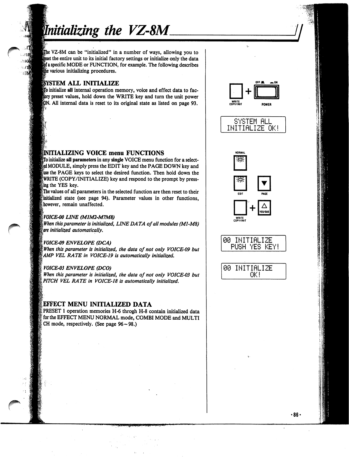
Initializing
the
VZ-8M.
/sic
r
}
VZ-8M
can
be
"initialized"
in
a
number
of
ways,
allowing
you
to
t
the
entire
unit
to
its
initial
factory
settings
or
initialize
only
the
data
fa
specific
MODE
or
FUNCTION,
for
example.
The
following
describes
s
various
initializing
procedures.
ALL
INITIALIZE
)
initialize
all
internal
operation
memory,
voice
and
effect
data
to
fac-
r
preset
values,
hold
down
the
WRITE
key
and
turn
the
unit
power
tf.
All
internal
data
is
reset
to
its
original
state
as
listed
on
page
93.
SING
VOICE
menu
FUNCTIONS
)
initialize
all
parameters
in
any
single
VOICE
menu
function
for
a
select-
i
MODULE,
simply
press
the
EDIT
key
and
the
PAGE
DOWN
key
and
fuse
the
PAGE
keys
to
select
the
desired
function.
Then
hold
down
the
fWRITE
(COPY/INITIALIZE)
key
and
respond
to
the
prompt
by
press-
ling
the
YES
key.
|The
values
of
all
parameters
in
the
selected
function
are
then
reset
to
their
finitialized
state
(see
page
94).
Parameter
values
in
other
functions,
^however,
remain
unaffected.
W01CE-00
LINE
(MIM2-M7M8)
[When
this
parameter
is
initialized,
LINE
DA
TA
of
all
modules
(M1-M8)
gore
initialized
automatically.
yOICE-09
ENVELOPE
(DCA)
\when
this
parameter
is
initialized,
the
data
of
not
only
VOICE-09
but
tAMP
VEL
RATE
in
VOICE-19
is
automatically
initialized.
VOICE-03
ENVELOPE
(DCO)
When
this
parameter
is
initialized,
the
data
of
not
only
VOICE-03
but
iPITCH
VEL
RATE
in
VOICE-18
is
automatically
initialized.
^EFFECT
MENU
INITIALIZED
DATA
|
PRESET
1
operation
memories
H-6
throgh
H-8
contain
initialized
data
]
for
the
EFFECT
MENU
NORMAL
mode,
COMBI
MODE
and
MULTI
ICH
mode,
respectively.
(See
page
96-98.)
OFFM
—.ON
POWER
SYSTEM
FILL
INITIRLIZE
OK!
"i
INITIRLIZE
PUSH
YES
KEY!
INITIRLIZE
OK!
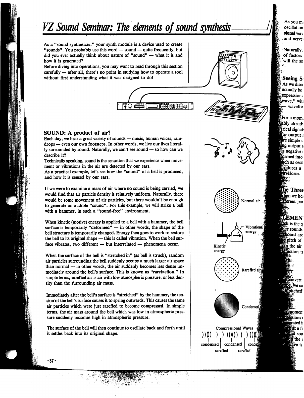
VI
Sound
Seminar:
The
elements
of
sound
synthesis
As
a
"sound
synthesizer/'
your
synth
module
is
a
device
used
to
create
"sounds".
You
probably
use
this
word
—
sound
—
quite
frequently,
but
did
you
ever
actually
think
about
nature
of
"sound"
—
what
it
is
and
how
it
is
generated?
Before
diving
into
operations,
you
may
want
to
read
through
this
section
carefully
—
after
all,
there's
no
point
in
studying
how
to
operate
a
tool
without
first
understanding
what
it
was
designed
to
do!
I|*H"l>|l'||tl«{*J(
I
I
I
|
r-
-i
I
I
SOUND:
A
product
of
air?
Each
day,
we
hear
a
great
variety
of
sounds
—
music,
human
voices,
rain
drops
—
even
our
own
footsteps.
In
other
words,
we
live
our
lives
literal
ly
surrounded
by
sound.
Naturally,
we
can't
see
sound
—
so
how
can
we
describe
it?
Technically
speaking,
sound
is
the
sensation
that
we
experience
when
move
ment
or
vibrations
in
the
air
are
detected
by
our
ears.
As
a
practical
example,
let's
see
how
the
"sound"
of
a
bell
is
produced,
and
how
it
is
sensed
by
our
ears.
If
we
were
to
examine
a
mass
of
air
where
no
sound
is
being
carried,
we
would
find
that
air
particle
density
is
relatively
uniform.
Naturally,
there
would
be
some
movement
of
air
particles,
but
there
wouldn't
be
enough
to generate
an
audible
"sound".
For
this
example,
we
will
strike
a
bell
with
a
hammer,
in
such
a
"sound-free"
environment.
When
kinetic
(motive)
energy
is
applied
to
a
bell
with
a
hammer,
the
bell
surface
is
temporarily
"deformed"
—
in
other
words,
the
shape
of
the
bell
structure
is
temporarily
changed.
Energy
then
goes
to
work
to
restore
the
bell
to
its
original
shape
—
this
is
called
vibration.
When
the
bell
sur
face
vibrates,
two
different
—
but
interrelated
—
phenomena
occur.
When
the
surface
of
the
bell
is
"stretched
in"
(as
bell
is
struck),
random
air
particles
surrounding
the
bell
suddenly
occupy a
much
larger
air
space
than
normal
—
in
other
words,
the
air
suddenly
becomes
less
dense
im
mediately
around
the
bell's
surface.
This
is
known
as
"rarefaction."
In
simple
terms,
rarefied
air
is
air
with
low
atmospheric
pressure,
or
less
den
sity
than
the
surrounding
air
mass.
Immediately
after
the
bell's
surface
is
"stretched"
by
the
hammer,
the
ten
sion
of
the
bell's
surface
causes
it
to
spring
outwards.
This
causes
the
same
air
particles
which
were
just
rarefied
to
become
compressed.
In
simple
terms,
the
air
mass
around
the
bell
which
was
low
in
atmospheric
pres
sure
suddenly
becomes
high
in
atmospheric
pressure.
The
surface
of
the
bell
will
then
continue
to
oscillate
back
and
forth
until
it
settles
back
into
its
original
shape.
•87-
CO)
condensed
rarefied
rarefied
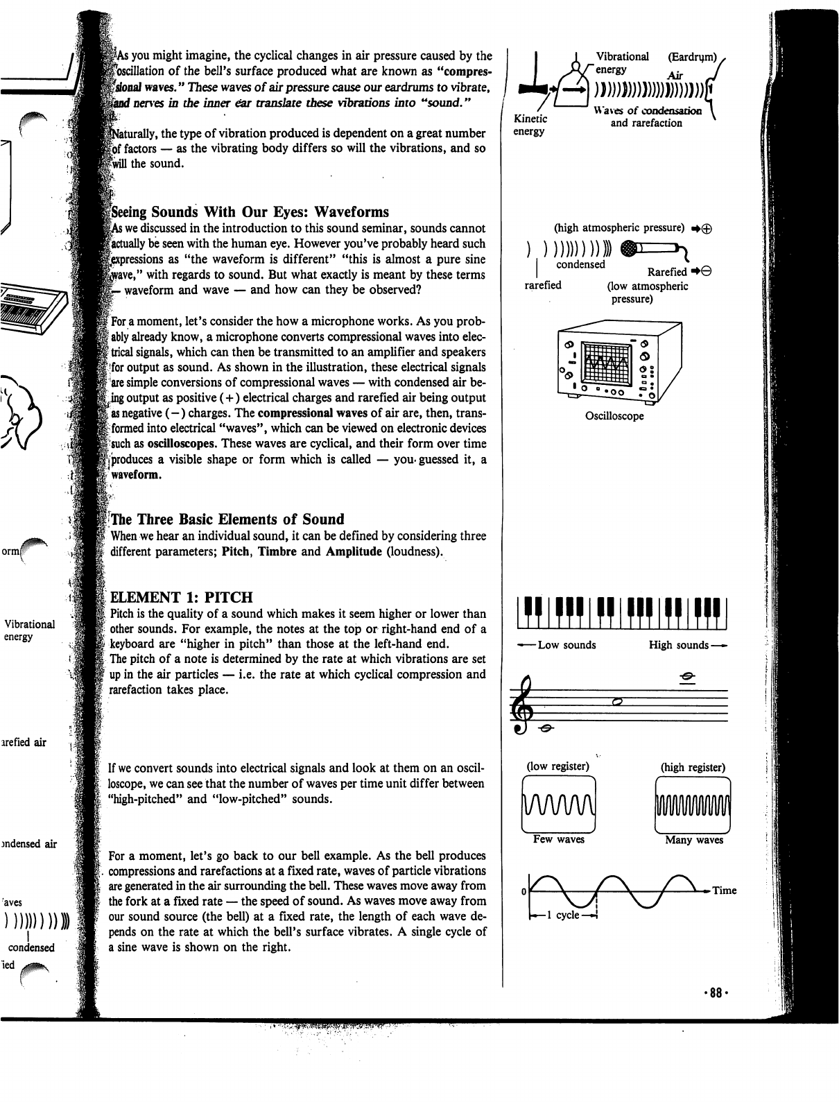
7
ormf
Vibrational
energy
arefied
air
jndensed
air
I
condensed
led
v^^v
;
you
might
imagine,
the
cyclical
changes
in
air
pressure
caused
by
the
^oscillation
of
the
bell's
surface
produced
what
are
known
as
"compres-
fsfonaJ
waves."
These
waves
of
air
pressure
cause
our
eardrums
to
vibrate,
f
nerves
in
the
inner
ear
translate
these
vibrations
into
"sound."
aturally,
the
type
of
vibration
produced
is
dependent
on
a
great
number
|6f
factors
—
as
the
vibrating
body
differs
so
will
the
vibrations,
and
so
Iwill
the
sound.
peeing
Sounds
With
Our
Eyes:
Waveforms
>
we
discussed
in
the
introduction
to
this
sound
seminar,
sounds
cannot
factually
be
seen
with
the
human
eye.
However
you've
probably
heard
such
sions
as
"the
waveform
is
different"
"this
is
almost
a
pure
sine
rave,"
with
regards
to
sound.
But
what
exactly
is
meant
by
these
terms
-
waveform
and
wave
—
and
how
can
they
be
observed?
f
For
a
moment,
let's
consider
the
how
a
microphone
works.
As
you
prob-
I
ably
already
know,
a
microphone
converts
compressional
waves
into
elec-
{trical
signals,
which
can
then
be
transmitted
to
an
amplifier
and
speakers
|
for
output
as
sound.
As
shown
in
the
illustration,
these
electrical
signals
|
are
simple
conversions
of
compressional
waves
—
with
condensed
air
be
ting
output
as
positive
(+)
electrical
charges
and
rarefied
air
being
output
I
as
negative
(-)
charges.
The
compressional
waves
of
air
are,
then, trans
it
formed
into
electrical
"waves",
which
can
be
viewed
on
electronic
devices
|-such
as
oscilloscopes.
These
waves
are
cyclical,
and
their
form
over
time
pproduces
a
visible
shape
or
form
which
is
called
—
you-guessed
it,
a
:
waveform.
I
The
Three
Basic
Elements
of
Sound
When
we
hear
an
individual
sound,
it
can
be
defined
by
considering
three
different
parameters;
Pitch,
Timbre
and
Amplitude
(loudness).
ELEMENT
1:
PITCH
Pitch
is
the
quality
of
a
sound
which
makes
it
seem
higher or
lower
than
other
sounds.
For
example,
the
notes
at
the
top
or
right-hand
end
of
a
keyboard
are
"higher
in
pitch"
than
those
at
the
left-hand
end.
The
pitch
of
a
note
is
determined
by
the
rate
at
which
vibrations
are
set
up
in
the
air
particles
—
i.e.
the
rate
at
which
cyclical
compression
and
rarefaction
takes
place.
If
we
convert
sounds
into
electrical
signals
and
look
at
them
on
an
oscil
loscope,
we
can
see
that
the
number
of
waves
per
time
unit
differ
between
"high-pitched"
and
"low-pitched"
sounds.
For
a
moment,
let's
go
back
to
our
bell
example.
As
the
bell
produces
compressions
and
rarefactions
at
a
fixed
rate,
waves
of
particle
vibrations
are
generated
in
the
air
surrounding
the
bell.
These
waves
move
away
from
the
fork
at
a
fixed
rate
—
the
speed
of
sound.
As
waves
move
away
from
our
sound
source
(the
bell)
at
a
fixed
rate,
the
length
of
each
wave
de
pends
on
the
rate
at
which
the
bell's
surface
vibrates.
A
single
cycle
of
a
sine
wave
is
shown
on
the
right.
Vibrational
(Eardrym)
s
Air
Kinetic
energy
Waves
of
condensation
and
rarefaction
(high
atmospheric
pressure)
condensed
„
_.
,
.
^
Rarefied
■►©
rarefied
(low
atmospheric
pressure)
Oscilloscope
IWllBlHlHJfflffl
-Low
sounds
High
sounds
-
(low
register)
(high
register)
Few
waves
Many
waves
r\
*-1
cycle
—!
-Time
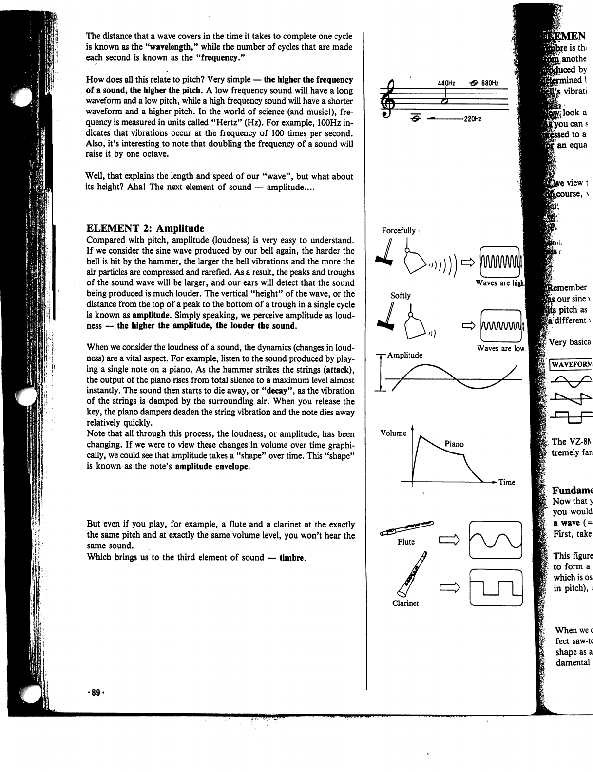
The
distance
that
a
wave
covers
in
the
time
it
takes
to
complete
one
cycle
is
known
as
the
"wavelength,"
while
the
number
of
cycles
that
are
made
each
second
is
known
as
the
"frequency."
How
does
all
this
relate
to
pitch?
Very
simple
—
the
higher
the
frequency
of
a
sound,
the
higher
the
pitch.
A
low
frequency
sound
will
have
a
long
waveform
and
a
low
pitch,
while
a
high
frequency
sound
will
have
a
shorter
waveform
and
a
higher
pitch.
In
the
world
of
science
(and
music!),
fre
quency
is
measured
in
units
called
"Hertz"
(Hz).
For
example,
lOOHz
in
dicates
that
vibrations
occur
at
the
frequency
of
100
times
per
second.
Also,
it's
interesting
to
note
that
doubling
the
frequency
of a
sound
will
raise
it
by
one
octave.
Well,
that
explains
the length
and
speed
of
our
"wave",
but
what
about
its
height?
Aha!
The
next
element
of
sound
—
amplitude....
ELEMENT
2:
Amplitude
Compared
with
pitch,
amplitude
(loudness)
is
very easy
to
understand.
If
we
consider
the
sine
wave
produced
by
our
bell
again,
the
harder
the
bell
is
hit
by
the
hammer,
the
larger
the
bell
vibrations
and
the
more
the
air
particles
are
compressed
and
rarefied.
As
a
result,
the
peaks
and
troughs
of
the
sound
wave
will
be
larger,
and
our
ears
will
detect
that
the
sound
being
produced
is
much
louder.
The
vertical
"height"
of
the
wave,
or
the
distance
from
the
top
of a
peak
to
the
bottom
of
a
trough
in
a
single
cycle
is
known
as
amplitude.
Simply
speaking,
we
perceive
amplitude
as
loud-
ness
—
the
higher
the
amplitude,
the
louder
the
sound.
When
we
consider
the
loudness
of a
sound,
the
dynamics
(changes
in
loud-
ness)
are
a
vital
aspect.
For
example,
listen
to
the
sound
produced
by
play
ing
a
single
note
on
a
piano.
As
the
hammer
strikes
the
strings
(attack),
the
output
of
the
piano
rises
from
total
silence
to
a
maximum
level
almost
instantly.
The
sound
then
starts
to
die
away,
or
"decay",
as
the
vibration
of
the
strings
is
damped
by
the
surrounding
air.
When
you
release
the
key,
the
piano
dampers
deaden
the
string
vibration
and
the
note
dies
away
relatively
quickly.
Note
that
all
through
this
process,
the
loudness,
or
amplitude,
has
been
changing.
If
we
were
to
view
these
changes
in
volume
over
time
graphi
cally,
we
could
see
that
amplitude
takes
a
"shape"
over
time.
This
"shape"
is
known
as
the
note's
amplitude
envelope.
But
even
if
you
play,
for
example,
a
flute
and
a
clarinet
at
the exactly
the
same
pitch
and
at
exactly
the
same
volume
level,
you
won't
hear
the
same
sound.
Which
brings
us
to
the
third
element
of
sound
—
timbre.
EN
istht
anothe
by
inedl
vibrati
440Hz
•&
880Hz
ucans
to
a
an
equa
ember
our
sine
\
pitch
as
a
different
\
The
VZ-8N
tremely
far.
Fundamc
Now
that
y
you
would
a
wave
(=
First,
take
This
figure
to
form
a
which
is
os
in
pitch),
i
When
we
c
feet
saw-tc
shape
as
a
damental
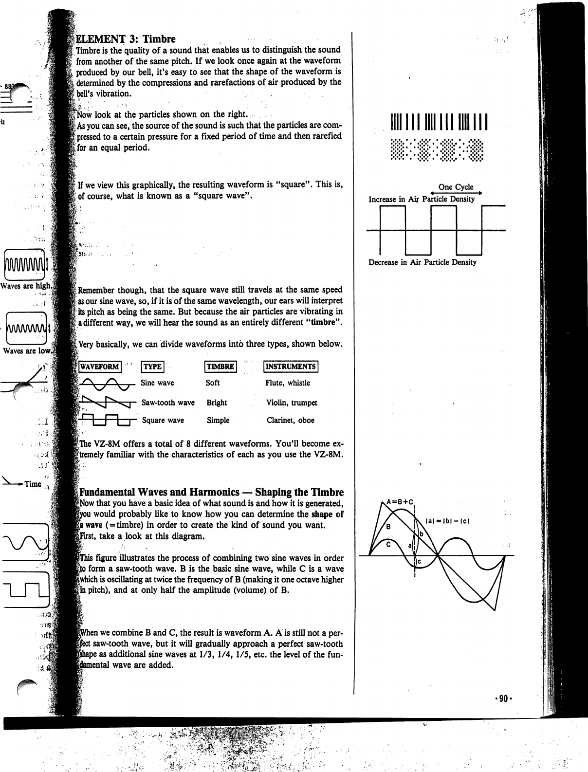
Waves
are
lowl
lELEMENT
3:
Timbre
Timbre
is
the
quality
of
a
sound
that
enables
us
to
distinguish
the
sound
from
another
of
the
same
pitch.
If
we
look
once
again
at
the
waveform
produced
by
our
bell,
it's
easy
to see that
the
shape
of
the
waveform
is
k
determined
by
the
compressions
and
rarefactions
of
air
produced
by
the
I
bell's
vibration.
jb"
..•
■ ■
■"'
:
'■■"■
'
■■
CNow
look
at
the
particles
shown
on
the
right.
£
As
you
can
see,
the
source
of
the
sound
is
such
that
the
particles
are
com-
|
pressed
to
a
certain
pressure
for
a
fixed
period
of
time
and
then
rarefied
Ifor
an
equal
period.
f
If
we
view
this
graphically,
the
resulting
waveform
is
"square".
This
is,
i
of
course,
what
is
known
as
a
"square
wave".
^Remember
though,
that
the
square
wave
still
travels
at
the
same
speed
as
our
sine
wave,
so,
if
it
is
of
the
same
wavelength,
our
ears
will
interpret
its
pitch
as
being
the
same.
But
because
the
air
particles
are vibrating
in
I
a
different
way,
we
will
hear
the
sound
as
an
entirely
different
"timbre".
|
Very
basically,
we
can
divide
waveforms
into
three
types,
shown
below.
|lWAVEFORM|
ITYPE
I
Sine
wave
Saw-tooth
wave
Bright
r,
n
l~1
p
Square
wave
Simple
[INSTRUMENTS
I
Flute,
whistle
Violin,
trumpet
Clarinet,
oboe
|The
VZ-8M
offers
a
total
of
8
different
waveforms.
You'll
become
ex-
|tremely
familiar
with
the
characteristics
of
each
as
you
use
the
VZ-8M.
[Fundamental
Waves
and
Harmonics
—
Shaping
the
Timbre
f
that
you
have
a
basic
idea
of
what
sound
is
and
how
it
is
generated,
i
would
probably
like
to
know
how
you
can
determine
the
shape
of
|a
wave
(=timbre)
in
order
to
create
the
kind
of
sound
you
want,
it,
take
a
look
at
this
diagram.
i
figure
illustrates
the
process
of
combining
two
sine
waves
in
order
i
form
a
saw-tooth
wave.
B
is
the
basic
sine
wave,
while
C
is
a
wave
|which
is
oscillating
at
twice
the
frequency
of
B
(making
it
one
octave
higher
|
in
pitch),
and
at
only
half
the
amplitude
(volume)
of
B.
i
we
combine
B
and
C,
the
result
is
waveform
A.
A
is
still
not
a
per-
:
saw-tooth
wave,
but
it
will
gradually
approach
a
perfect
saw-tooth
5
as
additional
sine
waves
at
1/3, 1/4, 1/5,
etc.
the
level
of
the
fun-
nental
wave
are
added.
•"•"•"•
•
•>
One
Cycle
Increase
in
Aij:
Particle
Density
Decrease
in
Air
Particle
Density
VA=B+C
•90-
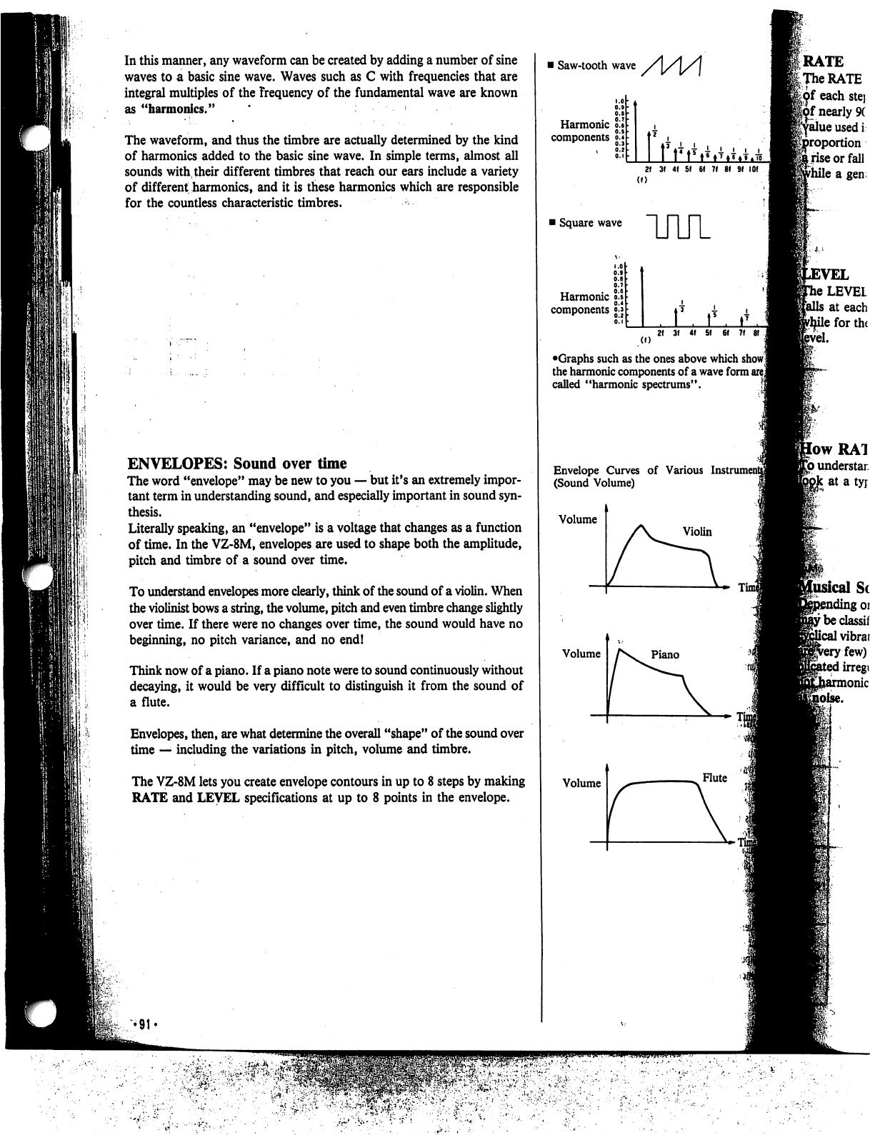
In
this
manner,
any
waveform
can
be
created
by
adding
a
number
of
sine
waves
to
a
basic
sine
wave.
Waves
such
as
C
with
frequencies
that
are
integral
multiples
of
the
frequency
of
the
fundamental
wave
are
known
as
"harmonics."
The
waveform,
and
thus
the
timbre
are
actually
determined
by
the
kind
of
harmonics
added
to
the
basic
sine
wave.
In
simple
terms,
almost
all
sounds
with,
their
different
timbres
that
reach
our
ears
include
a
variety
of
different
harmonics,
and
it
is
these
harmonics
which
are
responsible
for the
countless
characteristic
timbres.
ENVELOPES:
Sound
over
time
The
word
"envelope"
may
be
new
to
you
—
but
it's
an
extremely
impor
tant
term
in
understanding
sound,
and
especially
important
in
sound
syn
thesis.
Literally
speaking,
an
"envelope"
is
a
voltage
that
changes
as
a
function
of
time.
In
the
VZ-8M,
envelopes
are
used
to
shape
both
the
amplitude,
pitch
and
timbre
of
a
sound
over
time.
To
understand
envelopes
more
clearly,
think
of
the
sound
of
a
violin.
When
the
violinist
bows
a
string,
the
volume,
pitch
and
even
timbre
change
slightly
over
time.
If
there
were
no
changes
over
time,
the
sound
would
have
no
beginning,
no
pitch
variance,
and no
end!
Think
now
of
a
piano.
If
a
piano
note
were
to
sound
continuously
without
decaying,
it
would
be
very
difficult
to
distinguish
it
from
the
sound
of
a
flute.
Envelopes,
then,
are
what
determine
the
overall
"shape"
of
the
sound
over
time
—
including
the
variations
in
pitch,
volume
and
timbre.
The
VZ-8M
lets
you
create
envelope
contours
in
up
to
8
steps
by
making
RATE
and
LEVEL
specifications
at
up
to
8
points
in
the
envelope.
i
Saw-tooth
wave
Harmonic
components
o.l
2f
3f
4f 5f
6f 7f
81 Sf
(f)
i
Square
wave
Harmonic
components
UUl
r
(I)
•Graphs
such
as
the
ones
above
which
show!
the
harmonic
components
of
a
wave
form
are
j
called
"harmonic
spectrums".
Envelope
Curves
of
Various
L
(Sound
Volume)
Volume
Volume
Volume
AS.
piano
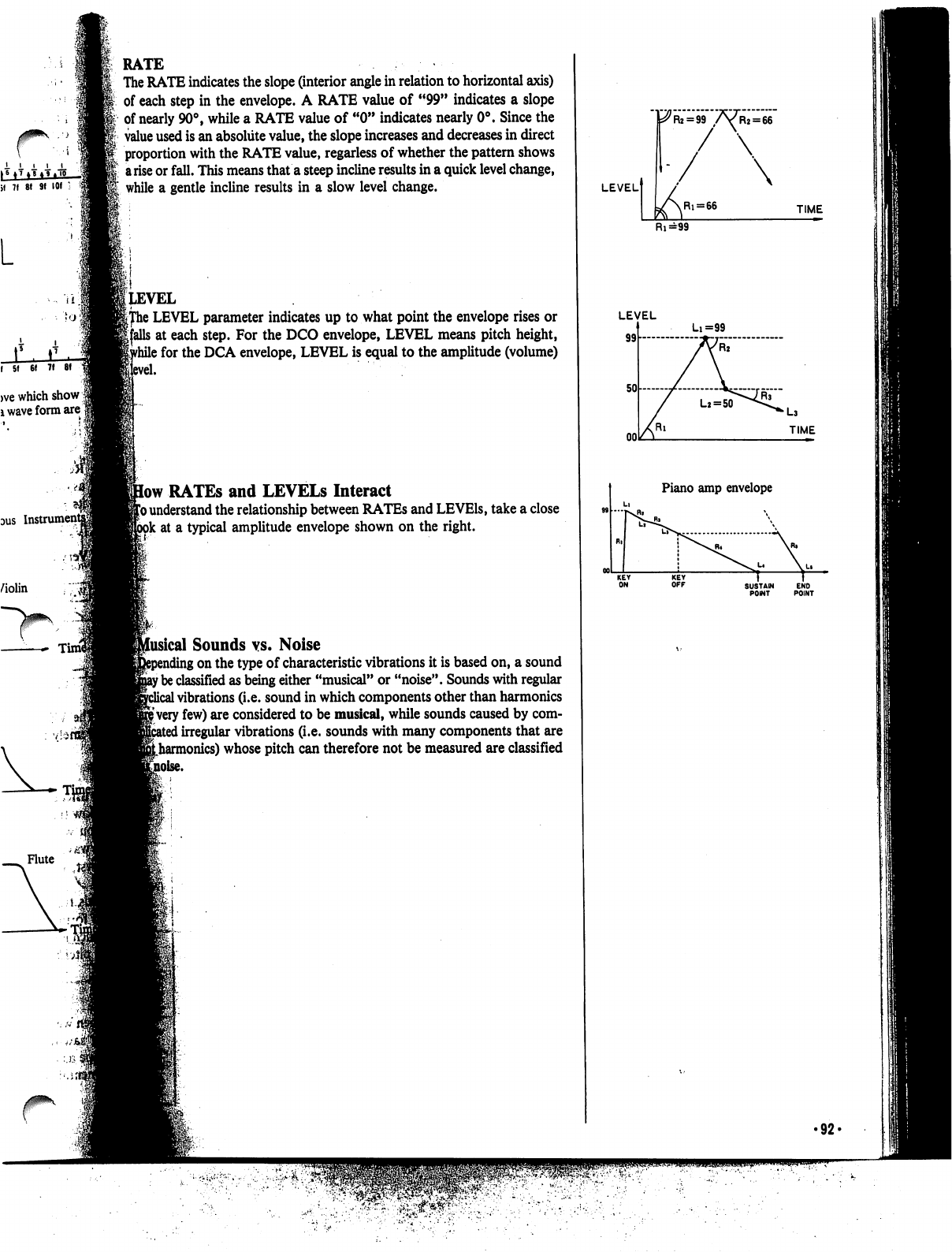
if
7f
8! 9f
101
1
L
>ve
which
show
|
i
wave
form
are
1
DUS
Violin
Tin
Flute
RATE
The
RATE
indicates
the
slope
(interior
angle
in
relation
to
horizontal
axis)
of
each
step
in
the
envelope.
A
RATE
value
of
"99"
indicates
a
slope
of
nearly
90°,
while
a
RATE
value
of
"0"
indicates
nearly
0°.
Since
the
value
used
is
an
absolute
value,
the
slope
increases
and
decreases
in
direct
proportion
with
the
RATE
value,
regarless
of
whether
the
pattern
shows
a
rise
or
fall.
This
means
that
a
steep
incline
results
in
a
quick
level
change,
while
a
gentle
incline
results
in
a
slow
level
change.
(level
i
LEVEL
parameter
indicates
up
to
what
point
the
envelope
rises
or
s
at
each
step.
For
the
DCO
envelope,
LEVEL
means
pitch
height,
\
for
the
DCA
envelope,
LEVEL
is
equal
to
the
amplitude
(volume)
low
RATEs
and
LEVELS
Interact
1*0
understand
the
relationship
between
RATEs
and
LEVEls,
take
a
close
ok
at
a
typical
amplitude
envelope
shown
on
the
right.
iical
Sounds
vs.
Noise
;
on
the
type
of
characteristic
vibrations
it
is
based
on,
a
sound
f
be
classified
as
being
either
"musical"
or
"noise".
Sounds
with
regular
1
vibrations
(i.e.
sound
in
which
components
other
than
harmonics
|
very
few)
are
considered
to
be
musical,
while
sounds
caused
by
com-
I
irregular
vibrations
(i.e.
sounds
with
many
components
that
are
Lharmonics)
whose
pitch
can
therefore
not
be
measured
are
classified
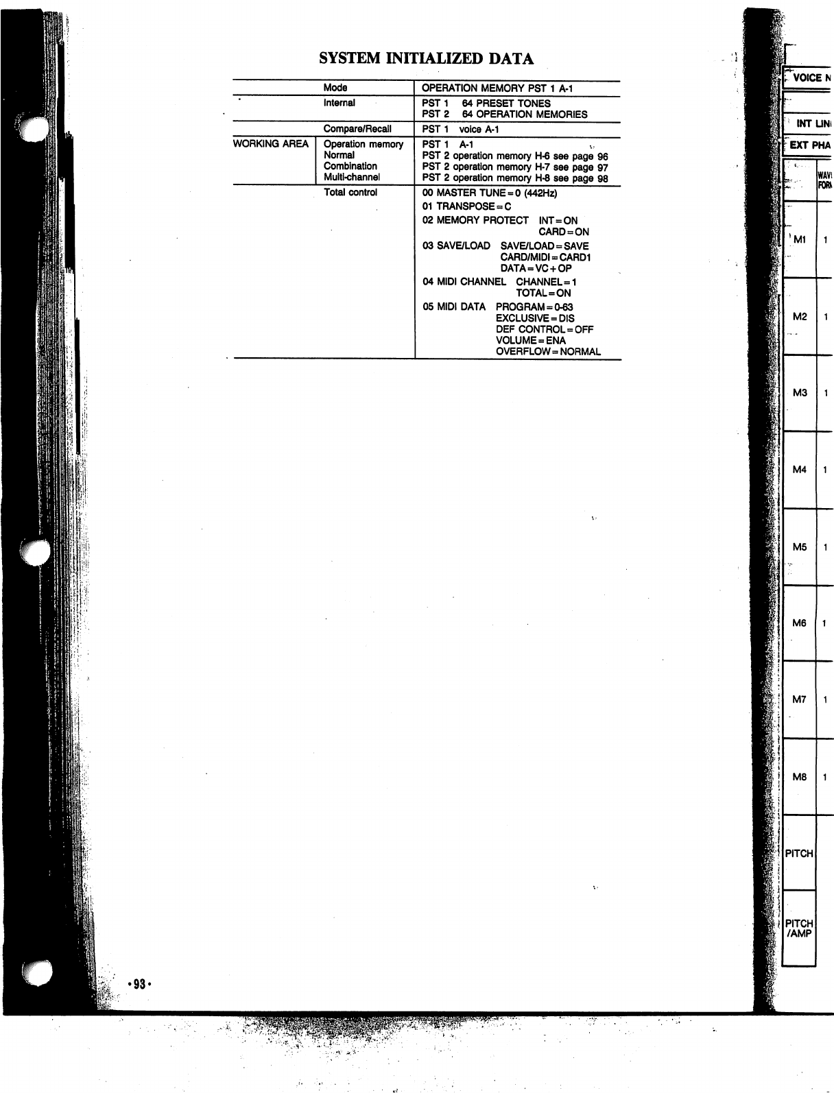
SYSTEM
INITIALIZED
DATA
P.
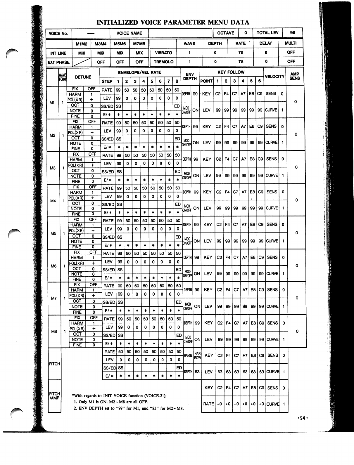
•94«
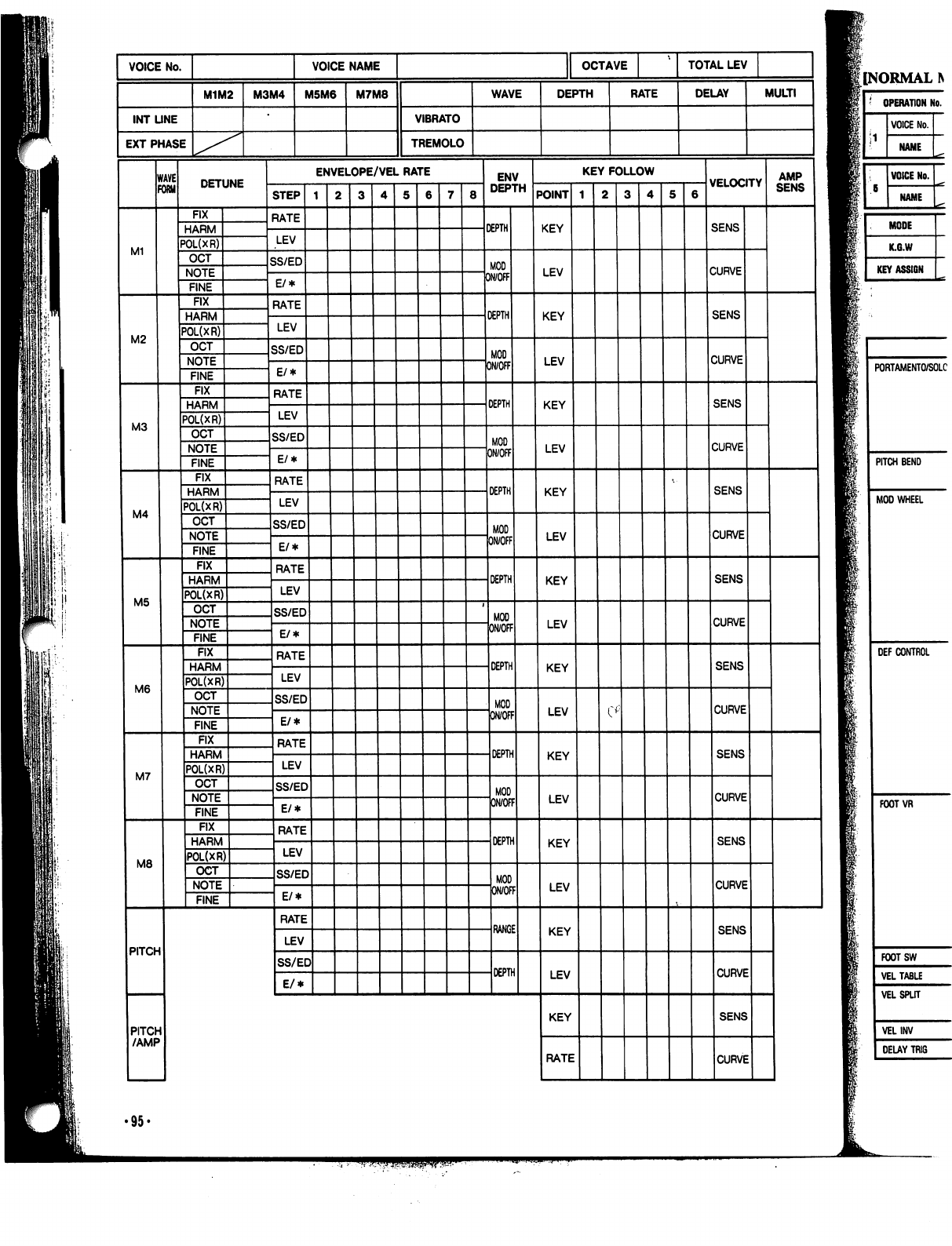
[NORMAL
PORTAMENTO/SOLC
PITCH
BEND
MOD
WHEEL
DEF
CONTROL
FOOTVR
FOOTSW
VEL
TABLE
VEL
SPLIT
VELINV
DELAY
TRIG
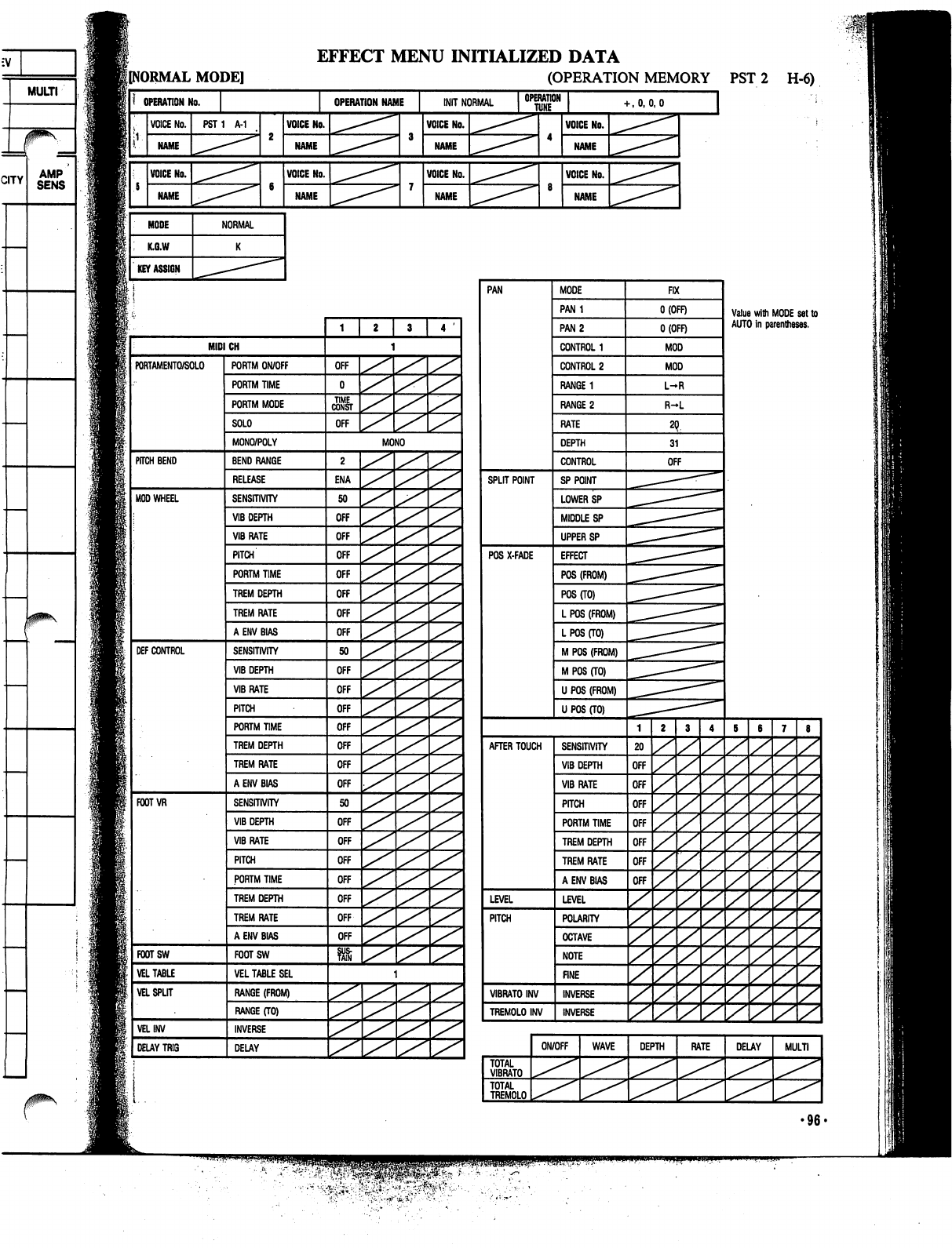
EFFECT
MENU
INITIALIZED
DATA
lINORMAL
MODE]
(OPERATION
MEMORY
PST
2
H-6)
OPERATION
No.
VOICE
No.
NAME
VOICE
No.
NAME
MODE
K.G.W
KEY
ASSIGN
PST1
A-1
NORMAL
OPERATION
NAME
[NIT
NORMAL
VOICE
No.
NAME
VOICE
No.
NAME
VOICE
No.
NAME
VOICE
No.
NAME
OPERATION
I
TUNE
•-,0,0,0
VOICE
No.
NAME
VOICE
No.
NAME
PAN
SPLIT
POINT
POS
X-FADE
MODE
PAN1
PAN
2
CONTROL
1
CONTROL
2
RANGE
1
RANGE
2
RATE
DEPTH
CONTROL
SP
POINT
LOWER
SP
MIDDLE
SP
UPPER
SP
EFFECT
POS
(FROM)
POS
(TO)
L
POS
(FROM)
L
POS
(TO)
M
POS
(FROM)
M
POS
(TO)
U POS
(FROM)
U
POS
(TO)
AFTER
TOUCH
LEVEL
PITCH
VIBRATO
INV
TREMOLO
INV
SENSITIVITY
VIB
DEPTH
VIBRATE
PITCH
PORTM
TIME
TREM
DEPTH
TREM
RATE
A
ENV
BIAS
LEVEL
POLARITY
OCTAVE
NOTE
FINE
INVERSE
INVERSE
FIX
O(OFF)
O(OFF)
MOD
MOD
L-R
R-L
OFF
20
OFF
OFF
OFF
OFF
OFF
OFF
OFF
y
y
TOTAL
VIBRATO
TOTAL
TREMOLO
ON/OFF
WAVE
DEPTH
z
z
Value
with
MODE
set
to
AUTO
in
parentheses.
z
z
z
z
z
z
z
z
z
z
RATE
DELAY
z
z
z
z
z
z
z
z
z
z
MULTI
•96-
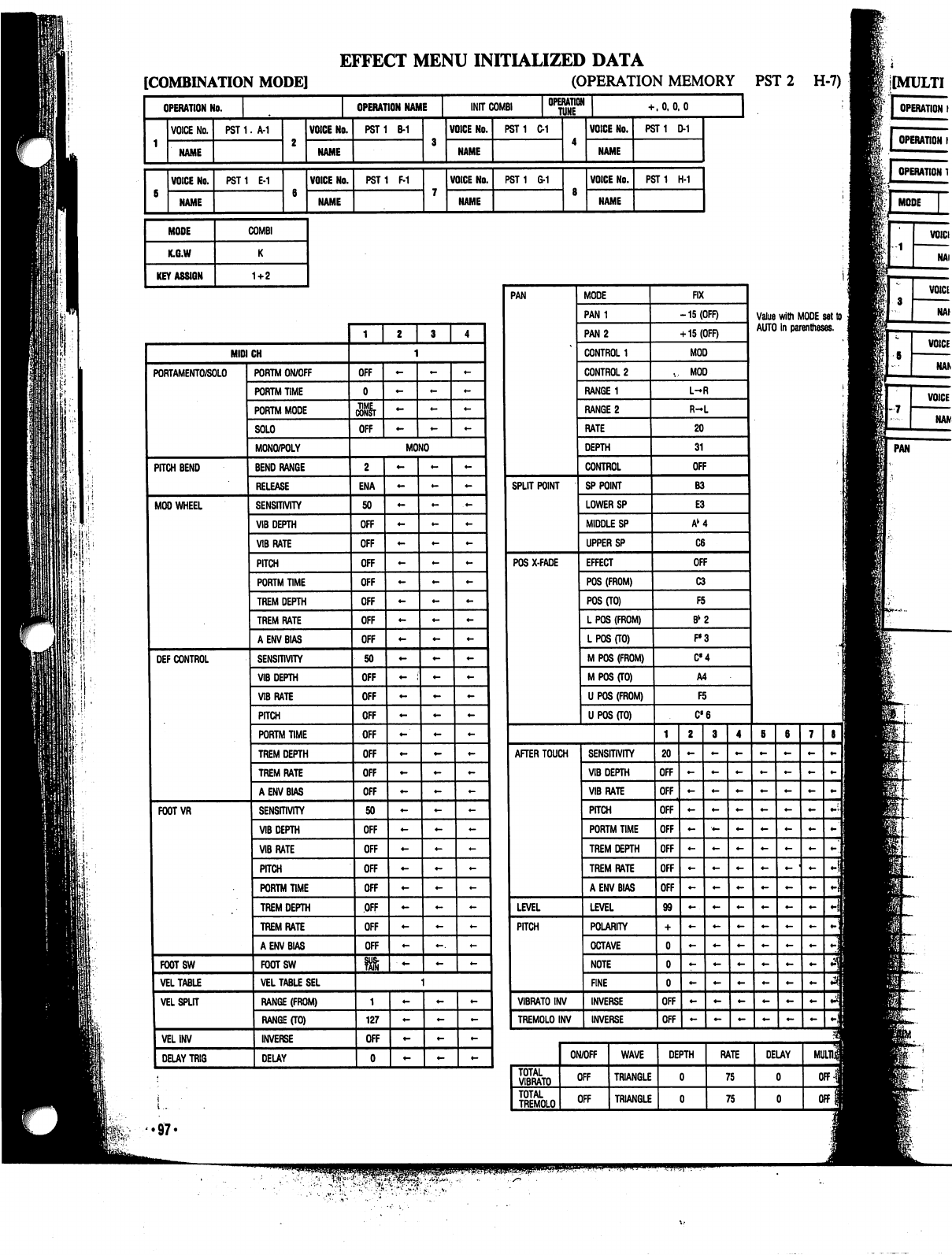
I'M-
EFFECT
MENU
INITIALIZED
DATA
[COMBINATION
MODE]
(OPERATION
MEMORY
PST
2
H-7)
OPERATION
No.
VOICE
No.
NAME
VOICE
No.
NAME
MODE
K.G.W
KEY
ASSIGN
OPERATION
NAME
INIT
COMB!
OPERATION
HJNE
PST
1.
A-1
PST1
E-1
COMBI
1+2
VOICE
No.
NAME
VOICE
No.
NAME
PST1
B-1
PST1
F-1
VOICE
No.
NAME
VOICE
No.
PST1
C-1
PST
1
6-1
+
.0,0.0
VOICE
No.
NAME
VOICE
No.
NAME
PST1
D-1
PST
1
H-1
J
OPERATION
I
PAN
.97.
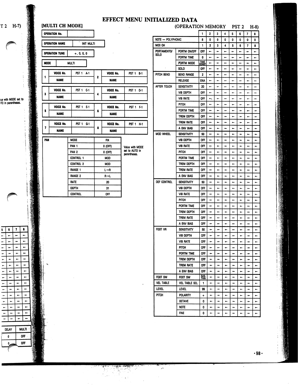
T
2
H-7)
lue
with
MODE
set
to
HO
in
parentheses.
EFFECT
MENU
INITIALIZED
DATA
(OPERATION
MEMORY
PST
2
H-8)
•98-
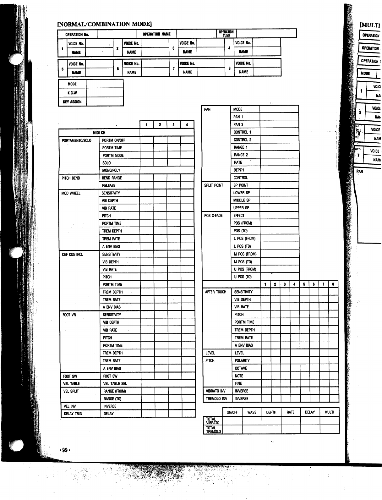
[NORMAL/COMBINATION
MODE]
OPERATION
No.
NAME
VOICE
No.
NAME
MODE
K.G.W
KEY
ASSIGN
OPERATION
NAME
VOICE
No.
NAME
VOICE
No.
NAME
VOICE
No.
NAME
VOICE
No.
NAME
OPERATION
TUNE
VOICE
No.
NAME
VOICE
NO.
NAME
MODE
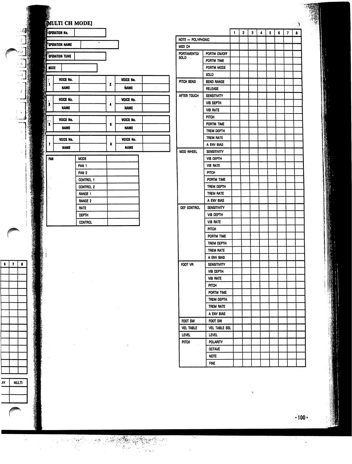
LTI
CH
MODE]
I
No.
^operation
name
["operation
tune
I
MODE
PAN
MODE
CONTROL
'100<
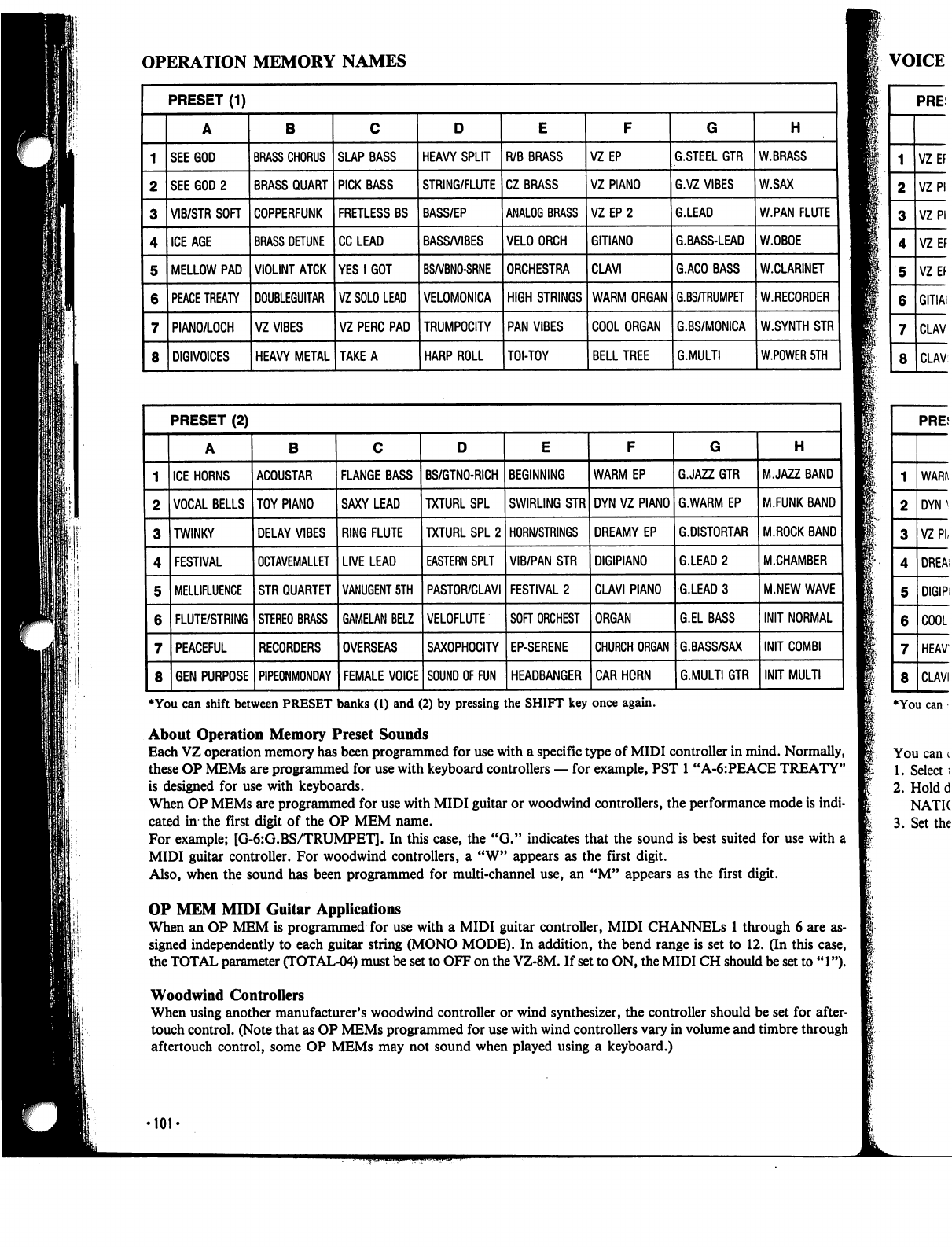
OPERATION
MEMORY
NAMES
I
♦You
can
shift
between
PRESET
banks
(1)
and
(2)
by
pressing
the
SHIFT
key
once
again.
About
Operation
Memory
Preset
Sounds
Each
VZ
operation
memory
has
been
programmed
for
use
with
a
specific
type
of
MIDI
controller
in
mind.
Normally,
these
OP
MEMs
are
programmed
for
use
with
keyboard
controllers
—
for
example,
PST
1
"A-6:PEACE
TREATY"
is
designed
for
use
with
keyboards.
When
OP
MEMs
are
programmed
for
use
with
MIDI
guitar
or
woodwind
controllers,
the
performance
mode
is
indi
cated
in
the
first
digit
of
the
OP
MEM
name.
For
example;
[G-6:G.BS/TRUMPET].
In
this
case,
the
"G."
indicates
that
the
sound
is
best
suited for
use
with
a
MIDI
guitar
controller.
For
woodwind
controllers,
a
"W"
appears
as
the
first
digit.
Also,
when
the
sound
has
been
programmed
for
multi-channel
use,
an
"M"
appears
as
the
first
digit.
OP
MEM
MIDI
Guitar
Applications
When
an
OP
MEM
is
programmed
for
use
with
a
MIDI
guitar
controller,
MIDI
CHANNELS
1
through
6
are
as
signed
independently
to
each
guitar
string
(MONO
MODE).
In
addition,
the
bend
range
is
set
to
12.
(In
this
case,
the
TOTAL
parameter
CTOTAL-04)
must
be
set
to
OFF
on
the
VZ-8M.
If
set
to
ON,
the
MIDI
CH
should
be
set
to
"1").
Woodwind
Controllers
When
using
another
manufacturer's
woodwind
controller
or
wind
synthesizer,
the
controller
should
be
set
for
after-
touch
control.
(Note
that as
OP
MEMs
programmed
for
use
with
wind
controllers
vary
in
volume
and
timbre
through
aftertouch
control,
some
OP
MEMs
may
not
sound
when
played
using
a
keyboard.)
■101'

A/.BK
W.SAX
W.PAN
FLUTE
W.OBOE
W.CLARINET
W.RECORDER
W.SYNTH
STR
W.POWER
5TH
H
MJAZZ
BAND
M.FUNK
BAND
M.ROCK
BAND
M.CHAMBER
M.NEW
WAVE
INIT
INIT
MULTI
VOICE
NAMES
♦You
can
shift
between
PRESET
banks
(1)
and
(2)
by
pressing
the
SHIFT
key
once
again.
and.
Normally,
.CE
TREATY"
:e
mode
is
indi-
i
for
use
with
a
igit.
You
can
change
the
performance
mode
that
is
preset
for
any
operation
memory
by
using
the
following
procedure:
1.
Select
the
operation
memory
for
which
you
wish
to
change
the
performance
mode.
2.
Hold
down
the
WRITE
key
and
press
either
the
COMBINATION
key
or
NORMAL
key.
Press
the
key
(COMBI
NATION
or
NORMAL)
whose
indicator
is
lit.
3.
Set
the
performance
mode
to
K,
G,
or
W
using
the
cursor
keys
and
VALUE
keys.
rough
6
are
as-
2.
(In
this
case,
d
be
set
to
"1").
be
set
for
after-
timbre
through
jP
•102-
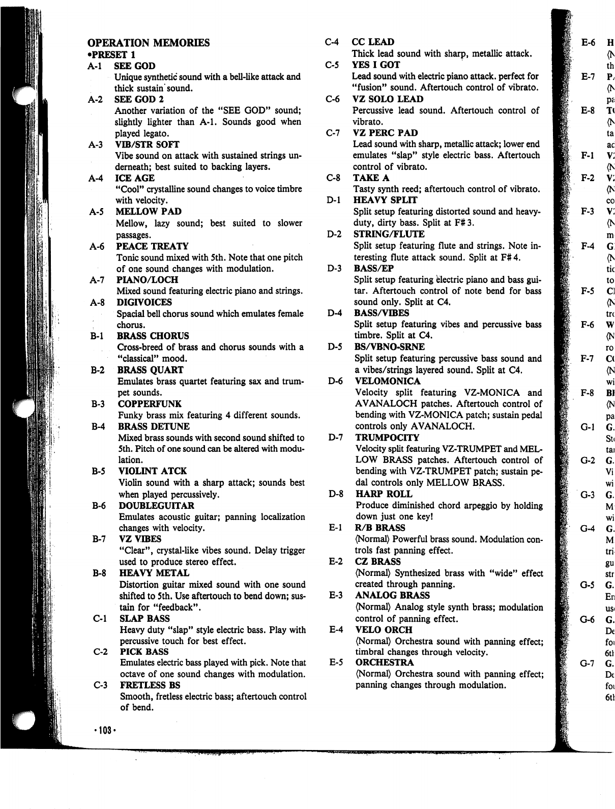
OPERATION
MEMORIES
•PRESET
1
C-4
A-l
SEE
GOD
C-5
Unique
synthetic
sound
with
a
bell-like
attack
and
thick
sustain
sound.
A-2
SEE
GOD
2
C-6
Another
variation
of
the
"SEE
GOD"
sound;
slightly
lighter
than
A-l.
Sounds
good
when
played
legato.
C-7
A-3
VIB/STR
SOFT
Vibe
sound
on
attack
with
sustained
strings
un
derneath;
best
suited
to
backing
layers.
A-4
ICE
AGE
C-8
"Cool"
crystalline
sound
changes
to
voice
timbre
with
velocity.
D-l
A-5
MELLOW
PAD
Mellow,
lazy
sound;
best
suited
to
slower
passages.
D-2
A-6
PEACE
TREATY
Tonic
sound
mixed
with
5
th.
Note
that
one
pitch
of
one
sound
changes
with
modulation.
D-3
A-7
PIANO/LOCH
Mixed
sound
featuring
electric
piano
and
strings.
A-8
DIGIVOICES
Spacial
bell
chorus
sound
which
emulates
female
D-4
'.
chorus.
B-l
BRASS
CHORUS
Cross-breed
of
brass
and
chorus
sounds
with a
D-5
"classical"
mood.
B-2
BRASS
QUART
Emulates
brass
quartet
featuring
sax
and
trum-
D-6
pet
sounds.
B-3
COPPERFUNK
Funky
brass
mix
featuring
4
different
sounds.
B-4
BRASS
DETUNE
Mixed
brass
sounds
with
second
sound
shifted
to
D-7
5th.
Pitch
of
one
sound
can be
altered
with
modu
lation.
B-5
VIOLINT
ATCK
Violin
sound
with
a
sharp
attack;
sounds
best
when
played
percussively.
D-8
B-6
DOUBLEGUITAR
Emulates
acoustic
guitar;
panning
localization
changes
with
velocity.
E-l
B-7
VZ
VIBES
"Clear",
crystal-like
vibes
sound.
Delay
trigger
used
to
produce
stereo
effect.
E-2
B-8
HEAVY
METAL
Distortion
guitar
mixed
sound
with
one
sound
shifted
to
5th.
Use
aftertouch
to
bend
down;
sus-
E-3
tain
for
"feedback".
C-l
SLAP
BASS
Heavy
duty
"slap"
style
electric
bass.
Play
with
E-4
percussive
touch
for
best
effect.
C-2
PICK
BASS
Emulates
electric
bass
played
with
pick.
Note
that
E-5
octave
of
one
sound
changes
with
modulation.
C-3
FRETLESS
BS
Smooth,
fretless
electric
bass;
aftertouch
control
of
bend.
CCLEAD
Thick
lead
sound
with
sharp,
metallic
attack.
YES
I
GOT
Lead
sound
with
electric
piano
attack,
perfect
for
"fusion"
sound.
Aftertouch
control
of
vibrato.
VZ
SOLO
LEAD
Percussive
lead
sound.
Aftertouch
control
of
vibrato.
VZ
PERC
PAD
Lead
sound
with
sharp,
metallic
attack;
lower
end
emulates
"slap"
style
electric
bass.
Aftertouch
control
of
vibrato.
TAKE
A
Tasty
synth
reed;
aftertouch
control
of
vibrato.
HEAVY
SPLIT
Split
setup
featuring
distorted
sound
and
heavy-
duty,
dirty
bass.
Split
at
F#3.
STRING/FLUTE
Split
setup
featuring
flute
and
strings.
Note
in
teresting
flute
attack
sound.
Split
at
F#
4.
BASS/EP
Split
setup
featuring
electric
piano
and
bass
gui
tar.
Aftertouch
control
of
note
bend
for
bass
sound
only.
Split
at
C4.
BASS/VIBES
Split
setup
featuring
vibes
and
percussive
bass
timbre.
Split
at
C4.
BS/VBNO-SRNE
Split
setup
featuring
percussive
bass
sound
and
a
vibes/strings
layered
sound.
Split
at
C4.
VELOMONICA
Velocity
split
featuring
VZ-MONICA
and
AVANALOCH
patches.
Aftertouch
control
of
bending
with
VZ-MONICA
patch;
sustain
pedal
controls
only
AVANALOCH.
TRUMPOCITY
Velocity
split
featuring
VZ-TRUMPET
and
MEL
LOW
BRASS
patches.
Aftertouch
control
of
bending
with
VZ-TRUMPET
patch;
sustain
pe
dal
controls
only
MELLOW
BRASS.
HARP
ROLL
Produce
diminished
chord
arpeggio
by
holding
down
just
one
key!
R/B
BRASS
(Normal)
Powerful
brass
sound.
Modulation
con
trols
fast
panning
effect.
CZ
BRASS
(Normal)
Synthesized
brass
with
"wide"
effect
created
through
panning.
ANALOG
BRASS
(Normal)
Analog
style
synth
brass;
modulation
control
of
panning
effect.
VELO
ORCH
(Normal)
Orchestra
sound
with
panning
effect;
timbral
changes
through
velocity.
ORCHESTRA
(Normal)
Orchestra
sound
with
panning
effect;
panning
changes
through
modulation.
F-l
F-2
F-3
F-4
F-5
F-6
F-7
F-8
G-l
G-2
•103-
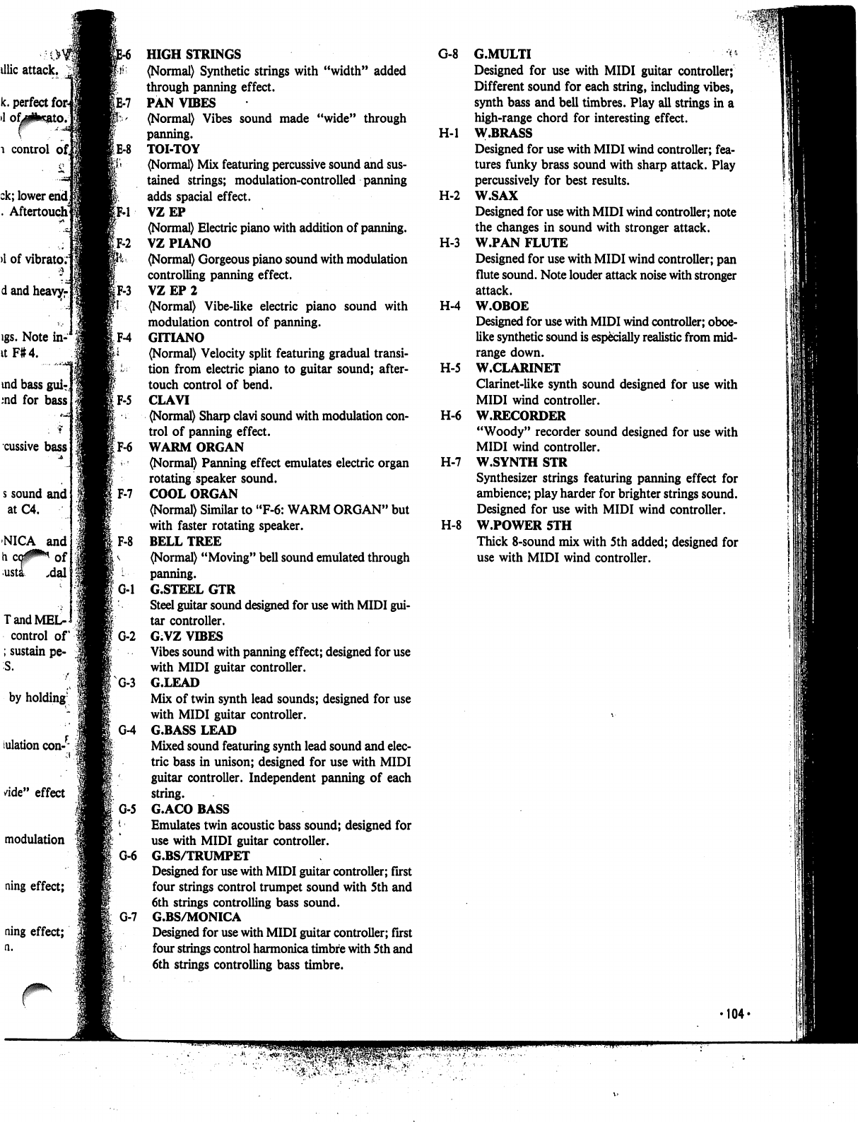
G-8
G.MULTI
^
Designed
for
use
with
MIDI
guitar
controller;
Different
sound
for
each
string,
including
vibes,
synth
bass
and
bell
timbres.
Play
all
strings
in
a
high-range
chord
for
interesting
effect.
H-l
W.BRASS
Designed
for
use
with
MIDI
wind
controller;
fea
tures
funky
brass
sound
with
sharp
attack.
Play
percussively
for
best
results.
H-2
W.SAX
Designed
for
use
with
MIDI
wind
controller;
note
the
changes
in
sound
with
stronger
attack.
H-3
W.PAN
FLUTE
Designed
for
use
with
MIDI
wind
controller;
pan
flute
sound.
Note
louder
attack
noise
with
stronger
attack.
H-4
W.OBOE
Designed
for
use
with
MIDI
wind
controller;
oboe-
like
synthetic
sound
is
especially
realistic
from
mid-
range
down.
H-5
W.CLARINET
Clarinet-like
synth
sound
designed
for
use
with
MIDI
wind
controller.
H-6
W.RECORDER
"Woody"
recorder
sound
designed
for
use
with
MIDI
wind
controller.
H-7
W.SYNTH
STR
Synthesizer
strings
featuring
panning
effect
for
ambience;
play
harder
for
brighter
strings
sound.
Designed
for
use
with
MIDI
wind
controller.
H-8
W.POWER
5TH
Thick
8-sound
mix
with
5th
added;
designed
for
use
with
MIDI
wind
controller.
►104-
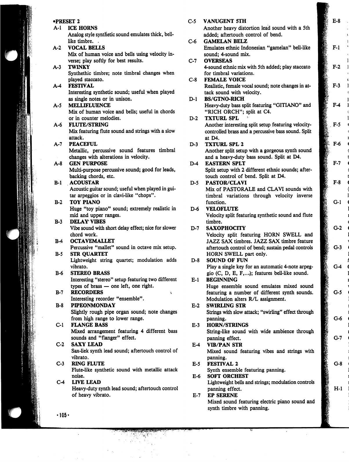
•PRESET
2
C-5
A-l
ICE
HORNS
Analog
style
synthetic
sound
emulates
thick,
bell-
like
timbre.
.
C-6
A-2
VOCAL
BELLS
Mix
of
human
voice
and
bells
using
velocity
in
verse;
play
softly
for
best
results.
C-7
A-3
TWINKY
Synthethic
timbre;
note
timbral
changes
when
played
staccato.
C-8
A-4
FESTIVAL
Interesting
synthetic
sound;
useful
when
played
as
single
notes
or
in
unison.
D-l
A-5
MELLIFLUENCE
Mix
of
human
voice
and
bells;
useful
in
chords
or
in
counter
melodies.
D-2
A-6
FLUTE/STRING
Mix
featuring
flute
sound
and
strings
with
a
slow
attack.
A-7
PEACEFUL
D-3
Metallic,
percussive
sound
features
timbral
changes
with
alterations
in
velocity.
A-8
GEN
PURPOSE
D-4
Multi-purpose
percussive
sound;
good
for
leads,
backing
chords,
etc.
B-l
ACOUSTAR
D-5
Acoustic
guitar
sound;
useful
when
played
in
gui
tar
arpeggios
or
in
clavi-like
"chops".
B-2
TOY
PIANO
Huge
"toy
piano"
sound;
extremely
realistic
in
D-6
mid
and
upper
ranges.
B-3
DELAY
VIBES
Vibe
sound
with
short
delay
effect;
nice
for
slower
D-7
chord
work.
B-4
OCTAVEMALLET
Percussive
"mallet"
sound
in
octave
mix
setup.
B-5
STR
QUARTET
Lightweight
string
quartet;
modulation
adds
D-8
vibrato.
B-6
STEREO
BRASS
Interesting
"stereo"
setup
featuring
two
different
E-l
types
of
brass
—
one
left,
one
right.
B-7
RECORDERS
Interesting
recorder
"ensemble".
B-8
PIPEONMONDAY
E-2
Slightly
rough
pipe
organ
sound;
note
changes
from
high
range
to
lower
range.
C-l
FLANGE
BASS
E-3
Mixed
arrangement
featuring
4
different
bass
sounds
and
"flanger"
effect.
C-2
SAXY
LEAD
E-4
Sax-liek
synth
lead
sound;
aftertouch
control
of
vibrato.
C-3
RING
FLUTE
E-5
Flute-like
synthetic
sound
with
metallic
attack
noise.
E-6
C-4
LIVE
LEAD
Heavy-duty
synth
lead
sound;
aftertouch
control
of
heavy
vibrato.
E-7
•105«
VANUGENT
5TH
Another
heavy
distortion
lead
sound
with
a
5th
added;
aftertouch
control
of
bend.
GAMELAN
BELZ
Emulates
ethnic
Indonesian
"gamelan"
bell-like
sound;
4-sound
mix.
OVERSEAS
4-sound
ethnic
mix
with
5th
added;
play
staccato
for
timbral
variations.
FEMALE
VOICE
Realistic,
female
vocal
sound;
note
changes
in
at
tack
sound
with
velocity.
BS/GTNO-RICH
Heavy-duty
bass
split
featuring
"GITIANO"
and
"RICH
ORCH";
split
at
C4.
TXTURL
SPL
Another
interesting
split
setup
featuring
velocity-
controlled
brass
and
a
percussive
bass
sound.
Split
at
D4.
TXTURL
SPL
2
Another
split
setup
with
a
gorgeous
synth
sound
and
a
heavy-duty
bass
sound.
Split
at
D4.
EASTERN
SPLT
Split
setup
with
2
different
ethnic
sounds;
after
touch
control
of
bend.
Split
at
D4.
PASTOR/CLAVI
Mix
of
PASTORALE
and
CLAVI
sounds
with
timbral
variations
through
velocity
inverse
function.
VELOFLUTE
Velocity
split
featuring
synthetic
sound
and
flute
timbre.
SAXOPHOCITY
Velocity
split
featuring
HORN
SWELL
and
JAZZ
SAX
timbres.
JAZZ
SAX
timbre
feature
aftertouch
control
of
bend;
sustain
pedal
controls
HORN
SWELL
part
only.
SOUND
OF
FUN
Play
a
single
key
for
an
automatic
4-note
arpeg
gio
(C,
D,
E,
F,...O;
features
bell-like
sound.
BEGINNING
Huge
ensemble
sound
emulates
mixed
sound
featuring
a
number
of
different
synth
sounds.
Modulation
alters
R/L
assignment.
SWIRLING
STR
Strings
with
slow
attack;
"swirling"
effect
through
panning.
HORN/STRINGS
String-like
sound
with
wide
ambience
through
panning
effect.
VIB/PAN
STR
Mixed
sound
featuring
vibes
and
strings
with
panning.
FESTIVAL
2
Synth
ensemble
featuring
panning.
SOFT
ORCHEST
Lightweight
bells
and
strings;
modulation
controls
panning
effect.
EP
SERENE
Mixed
sound
featuring
electric
piano
sound
and
synth
timbre
with
panning.
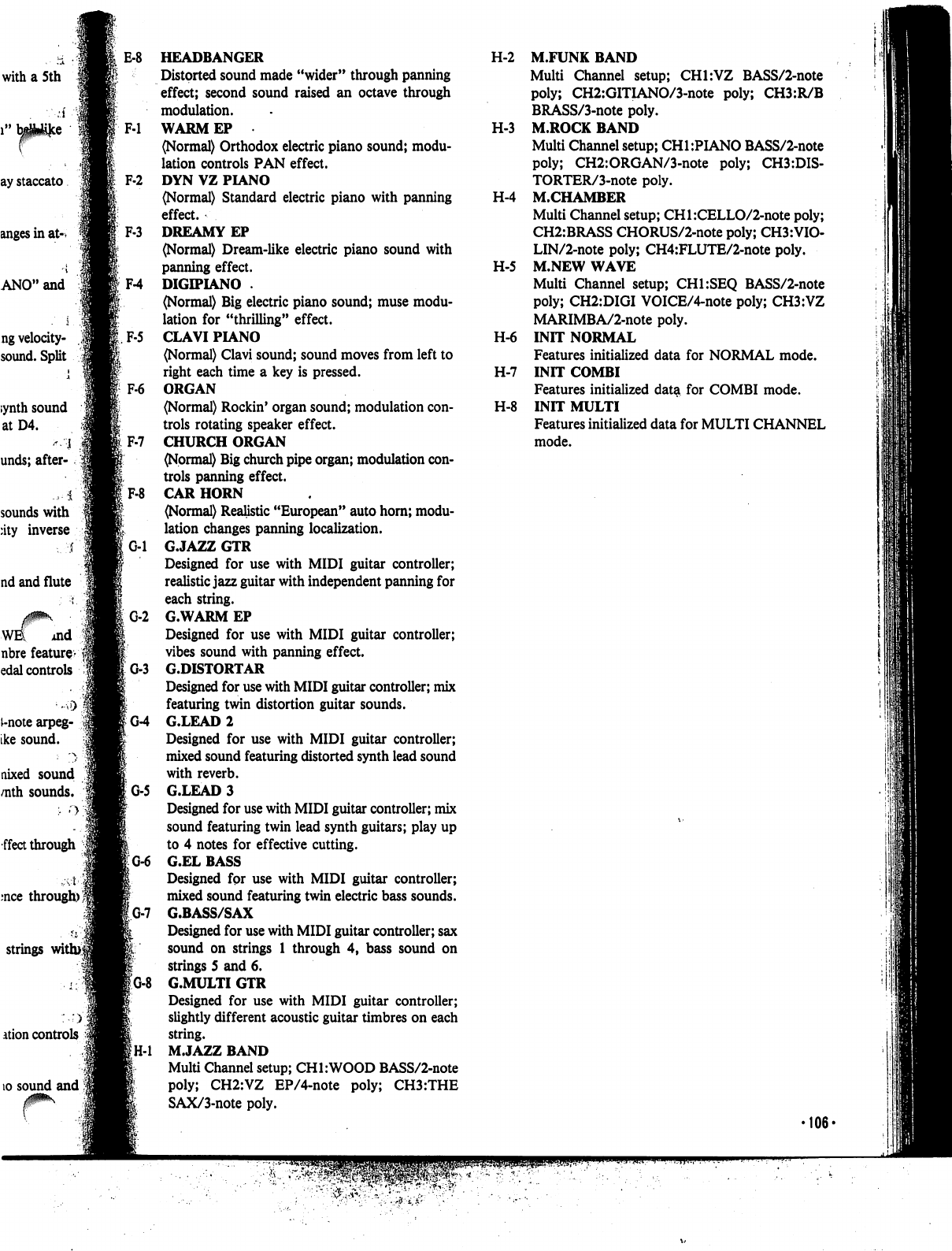
with
a
5th
ng
velocity-
sound.
Split
;ynth
sound
atD4.
"
I
unds;
after-
4
sounds
with
:ity
inverse
i
nd
and
flute
WE
md
nbre
feature-
edal
controls
i-note
arpeg-
ike
sound.
nixed
sound
/nth
sounds.
fleet
through
mce
through)';
strings
with>|
ation
controls
10
sound
and
E-8
HEADBANGER
Distorted
sound
made
"wider"
through
panning
effect;
second
sound
raised
an
octave
through
modulation.
F-l
WARMEP
(Normal)
Orthodox
electric
piano
sound;
modu
lation
controls
PAN
effect.
F-2
DYN
VZ
PIANO
(Normal)
Standard
electric
piano
with
panning
effect.
F-3
DREAMY
EP
(Normal)
Dream-like
electric
piano
sound
with
panning
effect.
F-4
DIGIPIANO
.
(Normal)
Big
electric
piano
sound;
muse
modu
lation
for
"thrilling"
effect.
F-5
CLAVI
PIANO
(Normal)
Clavi
sound;
sound
moves
from
left
to
right
each time
a
key
is
pressed.
F6
ORGAN
(Normal)
Rockin'
organ
sound;
modulation
con
trols
rotating
speaker
effect.
CHURCH
ORGAN
(Normal)
Big
church
pipe organ;
modulation
con
trols
panning
effect.
F-8
CAR
HORN
(Normal)
Realistic
"European"
auto
horn;
modu
lation
changes
panning
localization.
G-l
G.JAZZ
GTR
Designed
for
use
with
MIDI
guitar
controller;
realistic
jazz
guitar
with
independent
panning
for
each
string.
G-2
G.WARM
EP
Designed
for
use
with
MIDI
guitar
controller;
vibes
sound
with
panning
effect.
G-3
G.DISTORTAR
Designed
for
use
with
MIDI
guitar
controller;
mix
featuring
twin
distortion
guitar
sounds.
IG-4
G.LEAD
2
Designed
for
use
with
MIDI
guitar
controller;
mixed sound
featuring
distorted
synth
lead
sound
with
reverb.
G-5
G.LEAD
3
Designed
for
use
with
MIDI
guitar
controller;
mix
sound
featuring
twin
lead
synth
guitars;
play
up
to
4
notes
for
effective
cutting.
G-6
G.EL
BASS
Designed
fpr
use with
MIDI
guitar
controller;
mixed
sound
featuring
twin
electric
bass
sounds.
'G-7
G.BASS/SAX
Designed
for
use
with
MIDI
guitar
controller;
sax
sound
on
strings
1
through
4,
bass
sound
on
strings
5
and
6.
!
G.MULTI
GTR
Designed
for
use
with
MIDI
guitar
controller;
slightly
different
acoustic
guitar
timbres
on
each
string.
M.JAZZ
BAND
Multi
Channel
setup;
CHI:WOOD
BASS/2-note
poly;
CH2:VZ
EP/4-note
poly;
CH3:THE
SAX/3-note
poly.
H-2
M.FUNK
BAND
Multi
Channel
setup;
CH1:VZ
BASS/2-note
poly;
CH2:GITIANO/3-note
poly;
CH3:R/B
BRASS/3-note
poly.
H-3
M.ROCK
BAND
Multi
Channel
setup;
CH1:PIANO
BASS/2-note
poly;
CH2:ORGAN/3-note
poly;
CH3:DIS-
TORTER/3-note
poly.
H-4
M.CHAMBER
Multi
Channel
setup;
CHl:CELLO/2-note
poly;
CH2:BRASS
CHORUS/2-note
poly;
CH3:VI0-
LIN/2-note
poly;
CH4:FLUTE/2-note
poly.
H-5
M.NEW
WAVE
Multi
Channel
setup;
CH1:SEQ
BASS/2-note
poly;
CH2:DIGI
VOICE/4-note
poly;
CH3:VZ
MARIMBA/2-note
poly.
H-6
INIT
NORMAL
Features
initialized
data
for
NORMAL
mode.
H-7
INIT
COMBI
Features
initialized
data
for
COMBI
mode.
H-8
INIT
MULTI
Features
initialized
data
for
MULTI
CHANNEL
mode.
106-
Care
of
Your
Unit
jj
1.
Avoid
heat,
humidity
and
direct
sunlight.
Do
not
overexpose
your
unit to
direct
sunlight,
place
it
near
a
heater,
or
in
any
area
are
subject
to
high
temperatures.
2.
Severe
impact
can
result
in
malfunction.
This
digital
synthesizer
is
composed
of
precision
electronic
components
which
can
be
damaged
when
sub
jected
to
severe
impacts.
Be
sure
to
pack
it
carefully
when
transporting,
using
a
case
whenever
possible.
3.
Avoid
direct
contact
with
liquids,
dirt,
dust,
etc.
Never
allow
foreign
matter
to
enter
this
product.
Also,
be
especially
careful
of
metallic
objects
such
as
hairpins,
sewing
needles
or
coins.
Do
not
allow
the
unit to
get
wet.
4.
Never
attempt
to
modify
any
part
of
the
unit.
Any
modification
of,
or
tampering
with
the
unit
internal
components
can
cause
trouble
or
malfunction.
If
your
unit
is
not
operating
properly,
be
sure
to
take
it
to
an
authorized
Casio
service center.
5.
Do
not
use
caustic
cleaning
agents.
Clean
your
unit
with
a
soft
cloth
dampened
with
a
mild
detergent
solution.
Use
of
thinner,
alcohol,
ben
zene
and
similar
chemicals
should
be
avoided
under
all
circumstances.
•
6.
Avoid
using
this
unit
near
televisions,
radios,
etc.
Because
this
unit
uses
digital
circuitry,
it
may
cause
interference
with
other
electronic
devices
such
as
tele
visions,
radios,
etc.
Care
of
Your
Optional
ROM
or
RAM
Card
1.
Take
care
not
to
bend
or
drop
your
memory
cards.
Never
carry
a
card
in
your
back
pocket
or
leave
it
in
other
areas
where
it
may
be
damaged.
2.
When
not
in
use,
be
sure
to
store
your
card
in
its
custom
case
to
prevent
damage
due
to
dust
etc.
3.
Your
card
contains
precision
electronic
components.
Never
try
to
take
it
apart
for
any
reason.
4.
Casio
claims
no
responsibility
whatsoever
for
damages
due
to
losses
of
card
data.
108-
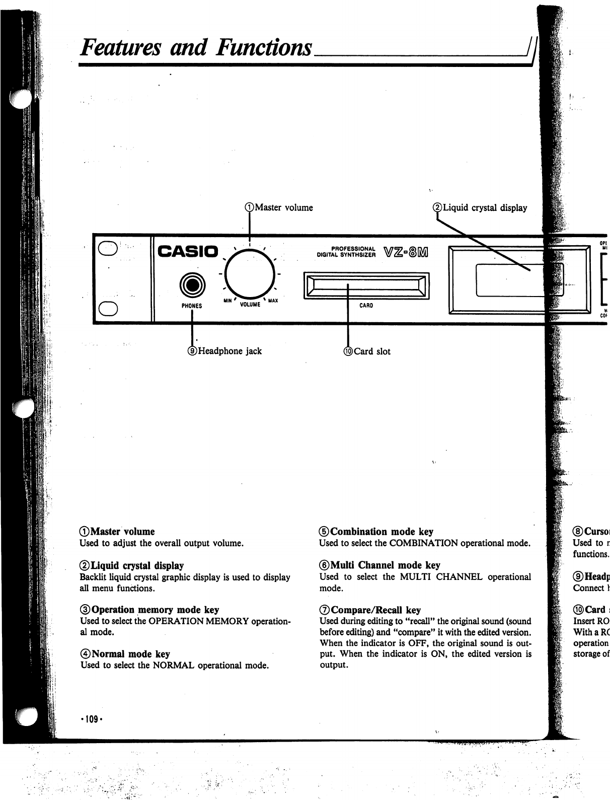
Features
and
Functions
T)Master
volume
®Liquid
crystal
display
PROFESSIONAL
DIGITAL
SYNTHSIZER
HIM
*
^^^^^^
*
UAX
PHONES
VOLUME
CARO
©Headphone
jack
©Card
slot
©Master
volume
Used
to
adjust
the
overall
output
volume.
©Liquid
crystal
display
Backlit
liquid
crystal
graphic
display
is
used
to
display
all
menu
functions.
©Operation
memory
mode
key
Used
to
select
the
OPERATION
MEMORY
operation
al
mode.
0
Normal
mode
key
Used
to
select
the
NORMAL
operational
mode.
©Combination
mode
key
Used
to
select
the
COMBINATION
operational
mode.
©Multi
Channel
mode
key
Used
to
select
the
MULTI
CHANNEL
operational
mode.
©Compare/Recall
key
Used
during
editing
to
"recall"
the
original
sound
(sound
before
editing)
and
"compare"
it
with
the
edited
version.
When
the
indicator
is
OFF,
the
original
sound
is
out
put.
When
the indicator
is
ON,
the
edited
version
is
output.
•109*
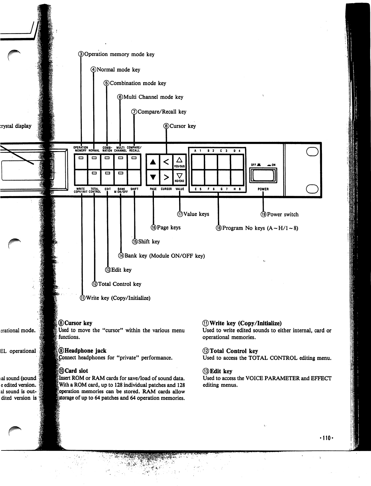
ation
memory
mode
key
(4)
Normal
mode
key
(f)
Combination
mode
key
(6)Multi
Channel
mode
key
(7)Compare/Recall
key
©Cursor
key
WRITE
TOTAL
EDIT
BANK
SHIFT
COPY/INIT
CONTROL
M
ON/OFF
PAGE
CURSOR
VALUE
E
5
F
6
6
7
H
6
©Value
keys
®Page
keys
©Shift
key
©Bank
key
(Module
ON/OFF
key)
3Edit
key
©Total
Control
key
©Write
key
(Copy/Initialize)
OFF
A
—.ON
LJI
POWER
©Power
switch
Q§)Program
No
keys
(A-H/l-8)
erational
mode.
EL
operational
©Cursor
key
jUsed
to
move
the
"cursor"
within
the
various
menu
?
functions.
I
|®Headphone
jack
|£onnect
headphones
for
"private"
performance.
|®Card
slot
ilnsert
ROM
or
RAM
cards
for
save/load
of
sound
data.
|With
a
ROM
card,
up
to
128
individual
patches
and
128
foperation
memories
can
be
stored.
RAM
cards
allow
ge
of
up
to
64
patches
and
64
operation
memories.
©Write
key
(Copy/Initialize)
Used
to
write
edited
sounds
to
either
internal,
card
or
operational
memories.
©Total
Control
key
Used
to access
the
TOTAL
CONTROL
editing
menu.
Used
to
access
the
VOICE
PARAMETER
and
EFFECT
editing
menus.
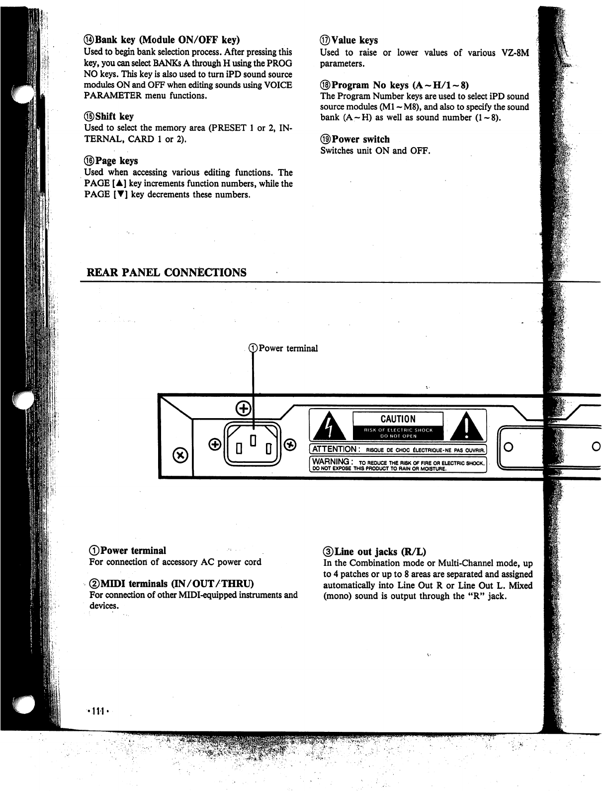
©Bank
key
(Module
ON/OFF
key)
Used
to
begin
bank
selection
process.
After
pressing
this
key,
you
can
select
BANKs
A
through
H
using
the
PROG
NO
keys.
This
key
is
also
used
to
turn
iPD
sound
source
modules
ON
and
OFF
when
editing
sounds
using
VOICE
PARAMETER
menu
functions.
Used
to
select
the
memory
area
(PRESET
1
or
2,
IN
TERNAL,
CARD
1
or
2).
©Page
keys
Used
when
accessing
various
editing
functions.
The
PAGE
[A]
key
increments
function
numbers,
while
the
PAGE
[T]
key
decrements
these
numbers.
©Value
keys
Used
to
raise
or
lower
values
of
various
VZ-8M
parameters.
©Program
No
keys
(A-H/l-8)
The
Program
Number
keys
are
used
to
select
iPD
sound
source
modules
(Ml
-
M8),
and
also to specify
the
sound
bank
(A—H)
as
well
as
sound
number
(1~8).
©Power
switch
Switches
unit
ON
and
OFF.
REAR
PANEL
CONNECTIONS
©Power
terminal
DPower
terminal
For
connection
of
accessory
AC
power
cord
©MIDI
terminals
(IN/OUT/THRU)
For
connection
of
other
MIDI-equipped
instruments
and
devices.
/
A
CAUTION
A
[ATTENTION
:
risque
de
choc
electrique-ne
pas
ouvrir,]
WARNING
:
to
reduce
the
risk
of
fire
or
electric
shock,
DO
NOT
EXPOSE
THIS
PRODUCT
TO
RAIN
OR
MOISTURE.
3)
Line
out
jacks
(R/L)
In
the
Combination
mode
or
Multi-Channel
mode,
up
to
4
patches
or
up
to 8
areas
are
separated
and
assigned
automatically
into
Line
Out
R
or
Line
Out
L.
Mixed
(mono)
sound
is
output
through
the
"R"
jack.
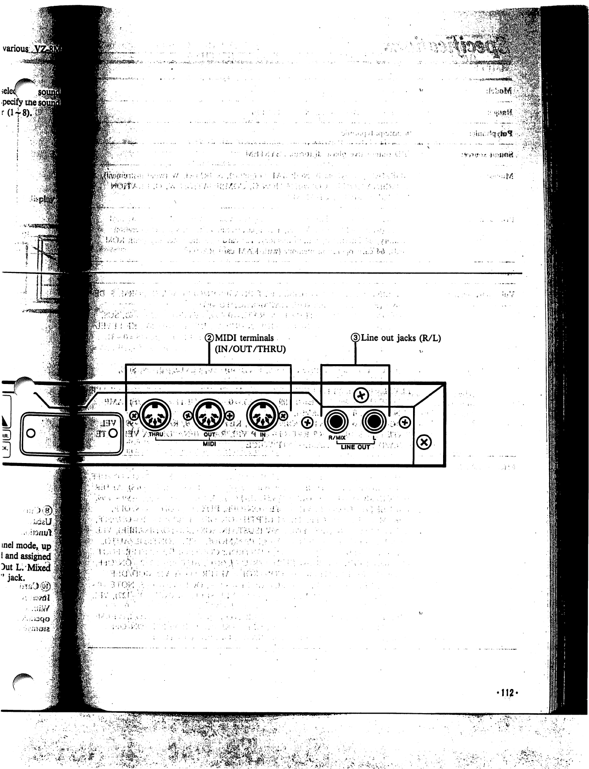
©MIDI
terminals
T
(IN/OUT/THRU)
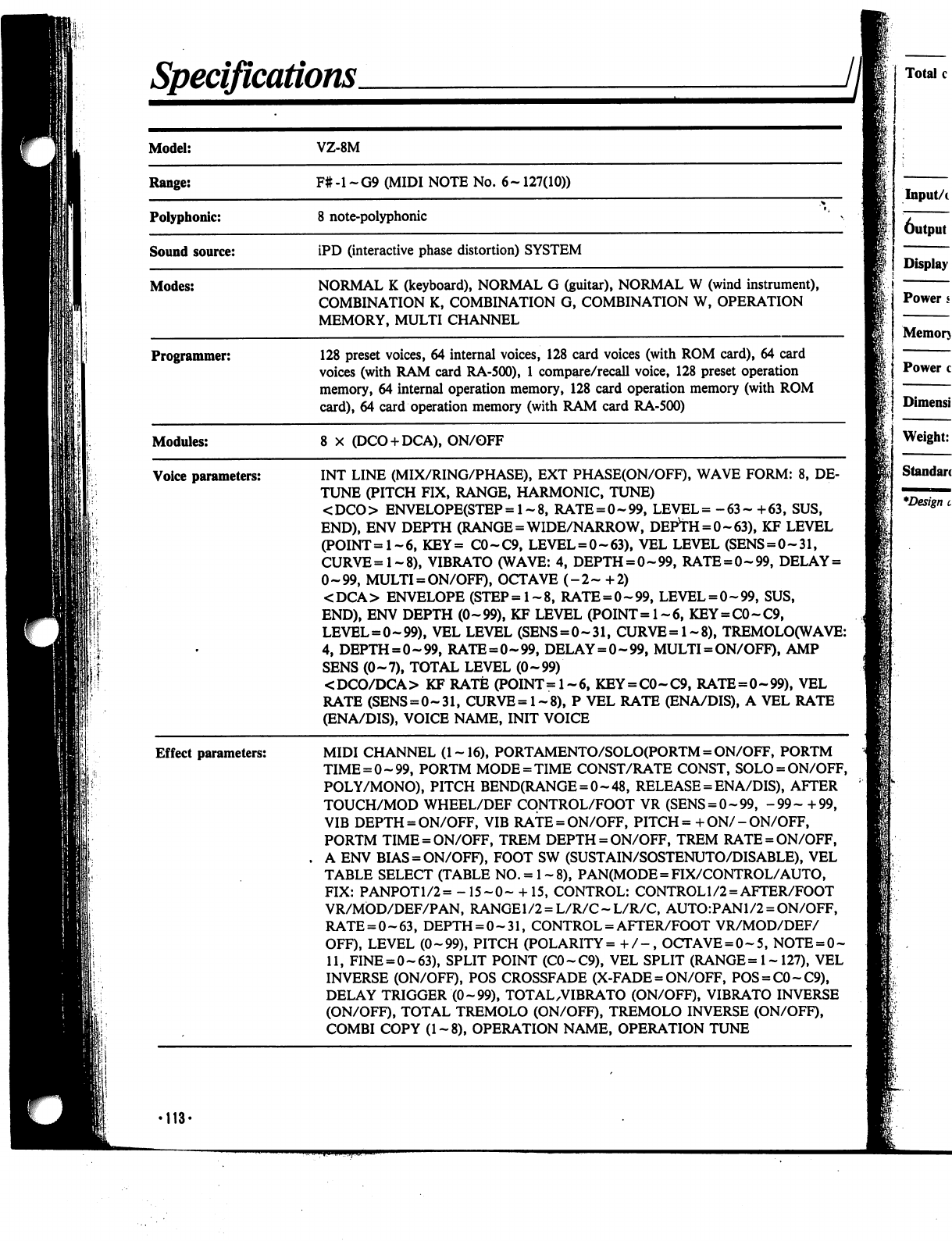
Specifications.
II
Programmer:
128
preset
voices,
64
internal
voices,
128
card
voices
(with
ROM
card),
64
card
voices
(with
RAM
card
RA-500),
1
compare/recall
voice,
128
preset
operation
memory,
64
internal
operation
memory,
128
card
operation
memory
(with
ROM
card),
64
card
operation
memory
(with
RAM
card
RA-500)
Modules:
8
X
(DCO
+
DCA),
ON/OFF
Voice
parameters:
Effect
parameters:
INT
LINE
(MIX/RING/PHASE),
EXT
PHASE(ON/OFF),
WAVE
FORM:
8,
DE
TUNE
(PITCH
FIX,
RANGE,
HARMONIC,
TUNE)
<
DCO
>
ENVELOPE(STEP
=
1-8,
RATE
=
0-99,
LEVEL
=
-
63
-
+
63,
SUS,
END),
ENV
DEPTH
(RANGE
=
WIDE/NARROW,
DEPvTH
=
0~63),
KF
LEVEL
(POINT=1~6,
KEY=
C0-C9,
LEVEL
=
0~63),
VEL
LEVEL
(SENS
=
0-31,
CURVE=l-8),
VIBRATO
(WAVE:
4,
DEPTH
=
0-99,
RATE
=
0-99,
DELAY
=
0-99,
MULTI
=
ON/OFF),
OCTAVE
(-2-
+2)
<DCA>
ENVELOPE
(STEP=l-8,
RATE
=
0-99,
LEVEL
=
0-99,
SUS,
END),
ENV
DEPTH
(0-99),
KF
LEVEL
(POINT=l-6,
KEY
=
C0-C9,
LEVEL
=
0-99),
VEL
LEVEL
(SENS
=
0-31,
CURVE=l-8),
TREMOLO(WAVE:
4,
DEPTH
=
0-99,
RATE
=
0-99,
DELAY
=
0-99,
MULTI
=
ON/OFF),
AMP
SENS
(0-7),
TOTAL
LEVEL
(0-99)
<DCO/DCA>
KF
RATE
(POINT=l-6,
KEY
=
C0-C9,
RATE=0-99),
VEL
RATE
(SENS
=
0-31,
CURVE=l-8),
P
VEL
RATE
(ENA/DIS),
A
VEL
RATE
(ENA/DIS),
VOICE
NAME,
INIT
VOICE
MIDI
CHANNEL
(1-16),
PORTAMENTO/SOLO(PORTM
=
ON/OFF,
PORTM
TIME
=
0-99,
PORTM
MODE
=
TIME
CONST/RATE
CONST,
SOLO
=
ON/OFF,
POLY/MONO),
PITCH
BEND(RANGE
=
0-48,
RELEASE
=
ENA/DIS),
AFTER
TOUCH/MOD
WHEEL/DEF
CONTROL/FOOT
VR
(SENS
=
0-99,
-99-
+99,
VIB
DEPTH
= ON/OFF,
VIB
RATE
=
ON/OFF,
PITCH
= +
ON/
-
ON/OFF,
PORTM
TIME
=
ON/OFF,
TREM
DEPTH
=
ON/OFF,
TREM
RATE
=
ON/OFF,
A
ENV
BIAS
=
ON/OFF),
FOOT
SW
(SUSTAIN/SOSTENUTO/DISABLE),
VEL
TABLE
SELECT
(TABLE
NO.
=
1
-8),
PAN(MODE
=
FIX/CONTROL/AUTO,
FIX:
PANPOTl/2=
-15-0-
+15,
CONTROL:
CONTROL
1/2
=
AFTER/FOOT
VR/MOD/DEF/PAN,
RANGE1/2
=
L/R/C-L/R/C,
AUTO:PANl/2
=
ON/OFF,
RATE
=
0-63,
DEPTH
=
0-31,
CONTROL
=
AFTER/FOOT
VR/MOD/DEF/
OFF),
LEVEL
(0-99),
PITCH
(POLARITY=
+/-,
OCTAVE
=
0-5,
NOTE
=
0-
11,
FINE
=
0-63),
SPLIT
POINT
(C0-C9),
VEL
SPLIT
(RANGE
=
1-
127),
VEL
INVERSE
(ON/OFF),
POS
CROSSFADE
(X-FADE
=
ON/OFF,
POS
=
C0-C9),
DELAY
TRIGGER
(0-99),
TOTAL
.VIBRATO
(ON/OFF),
VIBRATO
INVERSE
(ON/OFF),
TOTAL
TREMOLO
(ON/OFF),
TREMOLO
INVERSE
(ON/OFF),
COMBI
COPY
(1-8),
OPERATION
NAME,
OPERATION
TUNE
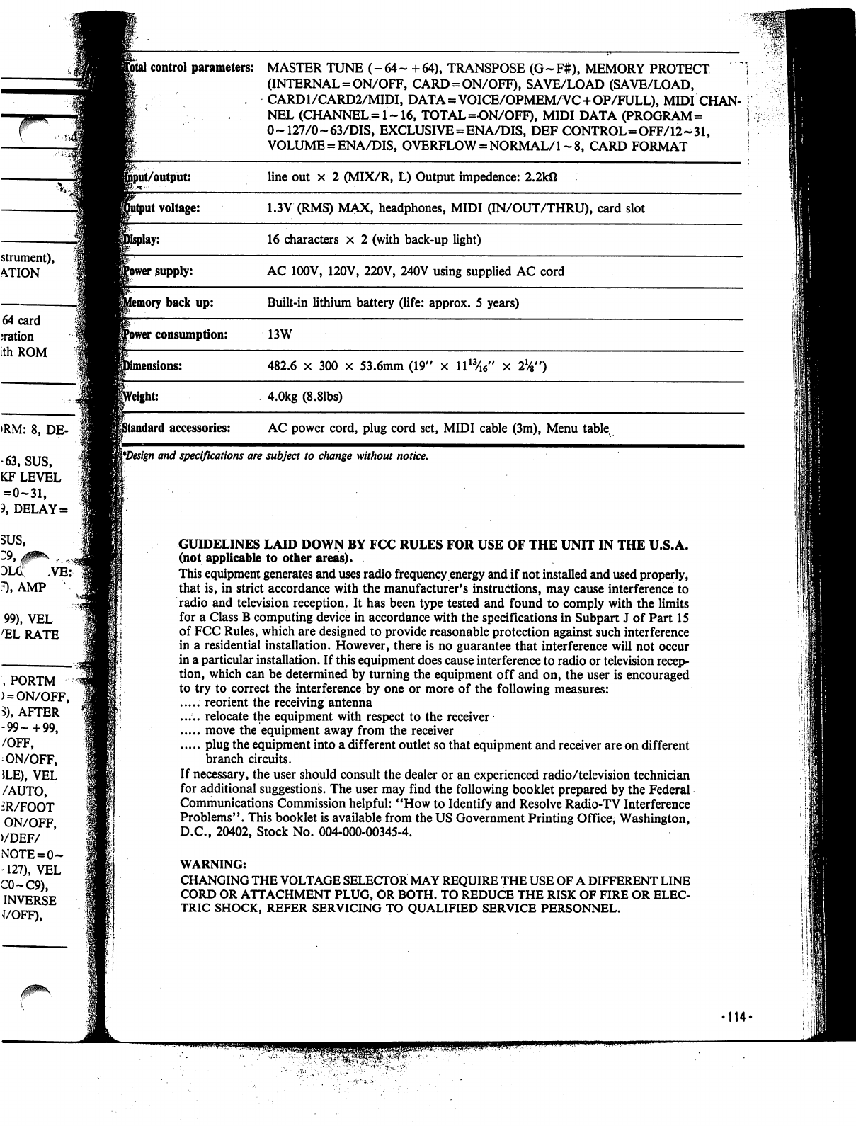
strument),
ATION
64
card
nation
ith
ROM
>RM:
8,
DE-
-63,
SUS,
KF
LEVEL
=
0-31,
9,
DELAY
=
SUS,
olq: .ve:
F),
AMP
99),
VEL
1ELRATE
,PORTM
)
=
ON/OFF,
S),
AFTER
-99-+99,
/OFF,
ON/OFF,
JLE),
VEL
/AUTO,
iR/FOOT
ON/OFF,
)/DEF/
-127),
VEL
C0-C9),
INVERSE
J/OFF),
Jfotal
control
parameters:
MASTER
TUNE
(-
64
~
+
64),
TRANSPOSE
(G
~
F#),
MEMORY
PROTECT
;
(INTERNAL =
ON/OFF,
CARD
=
ON/OFF),
SAVE/LOAD
(SAVE/LOAD,
!
.
CARD1/CARD2/MIDI,
DATA=VOICE/OPMEM/VC
+OP/FULL),
MIDI
CHAN-
I
.
.
NEL
(CHANNEL=1~16,
TOTAL
=ON/OFF),
MIDI
DATA
(PROGRAM=
j
0~
127/0-63/DIS,
EXCLUSIVE=ENA/DIS,
DEF
CONTROL=OFF/12-^31,
\
VOLUME
=
ENA/DIS,
OVERFLOW
=
NORMAL/1
~
8,
CARD
FORMAT
!
^Design
and
specifications
are
subject
to
change
without
notice.
GUIDELINES
LAID
DOWN
BY
FCC
RULES
FOR
USE
OF
THE
UNIT
IN
THE
U.S.A.
(not
applicable
to
other
areas).
This
equipment
generates
and
uses
radio
frequency
energy
and
if
not
installed
and
used
properly,
that
is,
in
strict
accordance
with
the
manufacturer's
instructions,
may
cause
interference
to
radio
and
television
reception.
It
has
been
type
tested
and
found
to
comply
with
the
limits
for
a
Class
B
computing
device
in
accordance
with
the
specifications
in
Subpart
J
of
Part
15
of
FCC
Rules,
which
are
designed
to
provide
reasonable
protection
against
such
interference
in
a
residential
installation.
However,
there
is
no
guarantee
that
interference
will
not
occur
in
a
particular
installation.
If
this
equipment
does
cause
interference
to
radio or
television
recep
tion,
which
can
be
determined
by
turning
the
equipment
off
and
on,
the
user
is
encouraged
to
try
to
correct
the
interference
by
one
or
more
of
the
following
measures:
.....
reorient
the
receiving
antenna
.....
relocate
the
equipment
with
respect
to
the
receiver
move
the
equipment
away
from
the
receiver
plug
the
equipment
into
a
different
outlet
so
that
equipment
and
receiver
are
on
different
branch
circuits.
If
necessary,
the
user
should
consult
the
dealer
or
an
experienced
radio/television
technician
for
additional
suggestions.
The
user
may
find
the
following
booklet
prepared
by
the
Federal
Communications
Commission
helpful:
"How
to
Identify
and
Resolve
Radio-TV
Interference
Problems".
This
booklet
is
available
from
the
US
Government
Printing
Office;
Washington,
D.C.,
20402,
Stock
No.
004-000-00345-4.
WARNING:
CHANGING
THE
VOLTAGE
SELECTOR
MAY
REQUIRE
THE
USE
OF
A
DIFFERENT
LINE
CORD
OR
ATTACHMENT
PLUG,
OR
BOTH.
TO
REDUCE THE
RISK
OF
FIRE
OR
ELEC
TRIC
SHOCK,
REFER
SERVICING
TO
QUALIFIED
SERVICE
PERSONNEL.
'114'

IMPORTANT
SAFETY
INSTRUCTIONS
INSTRUCTIONS
PERTAINING
TO
A
RISK
OF
FIRE,
ELECTRIC
SHOCK,
OR
INJURY
TO
PERSONS"
WARNING
—When
using
elec
tric
products,
basic
precautions
should
always
be
followed,
including
the
following:
1.
Read
all
the
instructions
before
us
ing
the
product.
2.
Do
not
use
this
product
near
water
-
for
example,
near
a
bathtub,
wash
bowl,
kitchen
sink,
in
a
wet
basement,
or
near
a
swimming
pool,
or
the
like.
3.
This
product
should
be
used
only
with
a
stand
that
is
recommended
by
the
manufacturer.
4.
This
product,
either
alone
or
in
com
bination
with
an
amplifier
and
head
phones
or
speakers,
may
be
capable
of
producing
sound
levels
that
could
cause
permanent
hearing
loss.
Do
not
operate
for
a
long
period
of
time
at
a
high
volume
level
or
at
a
level
that
is
uncomfortable.
If
you
experience
any
hearing
loss
or
ringing
in
the
ears,
you
should
consult
an
audiologist.
5.
The
product
should
be
located
so
that
its
location
or
position
does
not
in
terfere
with
its
proper
ventilation.
6.
The
product
should
be
located
away
from
heat
sources
such
as
radiators,
heat
registers,
or
other
products
that
produce
heat.
7.
The
product
should
be
connected
to
a
power
supply
only
of
the
type
described
in
the
operating
instructions
or
as
marked
on
the
product.
8.
This
product
may
be equipped
with
a
polarized
line
plug.
This
is
a
safety
feature.
If
you
are
unable
to
insert
the
plug
into
the
outlet,
contact
an
electri
cian
to
replace
your
obsolete
outlet.
Do
not
defeat
the
safety
purpose
of
the
plug.
9.
The
power-supply
cord
of
the
product
should
be
unplugged
from
the
outlet
when
left
unused
for
a
long
peri
od
of
time.
10.
Care
should
be
taken
so
that
ob
jects
do
not
fall
and
liquids
are
not
spilled
into
the
enclosure
through
openings.
11.
The
product
should
be
serviced
by
qualified
service
personnel
when:
A.
The
power-supply
cord
or
the
plug
has
been
damaged;
or
B.
Objects
have
fallen,
or
liquid
has
been
spilled
into
the
product;
or
C.
The
product
has
been
exposed
to
rain;
or
D.
The
product
does
not
appear
to
operate
normally
or
exhibits
a
marked
change
in
performance;
or
E.
The
product
has
been
dropped,
or
the
enclosure
damaged.
12.
Do
not
attempt
to
service
the
product
beyond
that
described
in
the
user-maintenance
instructions.
All
other
servicing
should
be
referred
to
qualified
service
personnel.
SAVE
THESE
INSTRUCTIONS
•115-
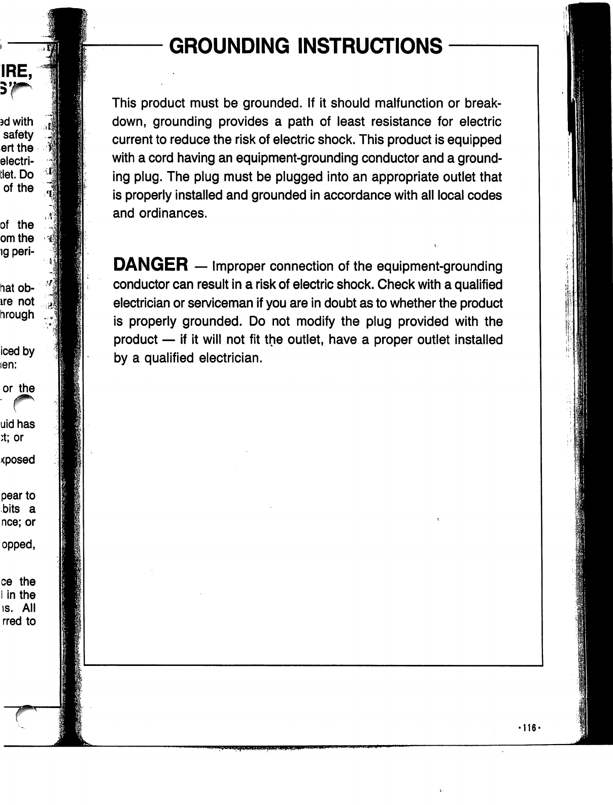
GROUNDING
INSTRUCTIONS
This
product
must
be
grounded.
If
it
should
malfunction
or
break
down,
grounding
provides
a
path
of
least
resistance
for
electric
current
to
reduce
the
risk
of
electric
shock.
This
product
is
equipped
with
a
cord
having
an
equipment-grounding
conductor
and
a
ground
ing
plug.
The
plug
must
be
plugged
into
an
appropriate
outlet
that
is
properly
installed
and
grounded
in
accordance
with
all
local
codes
and
ordinances.
DANGER
—
Improper
connection
of
the
equipment-grounding
conductor
can
result
in
a
risk
of
electric
shock.
Check
with
a
qualified
electrician
or
serviceman
if
you
are
in
doubt
as
to
whether
the
product
is
properly
grounded.
Do
not
modify
the plug
provided
with
the
product
—
if
it
will
not
fit
the
outlet,
have
a
proper
outlet
installed
by a
qualified
electrician.
•116-
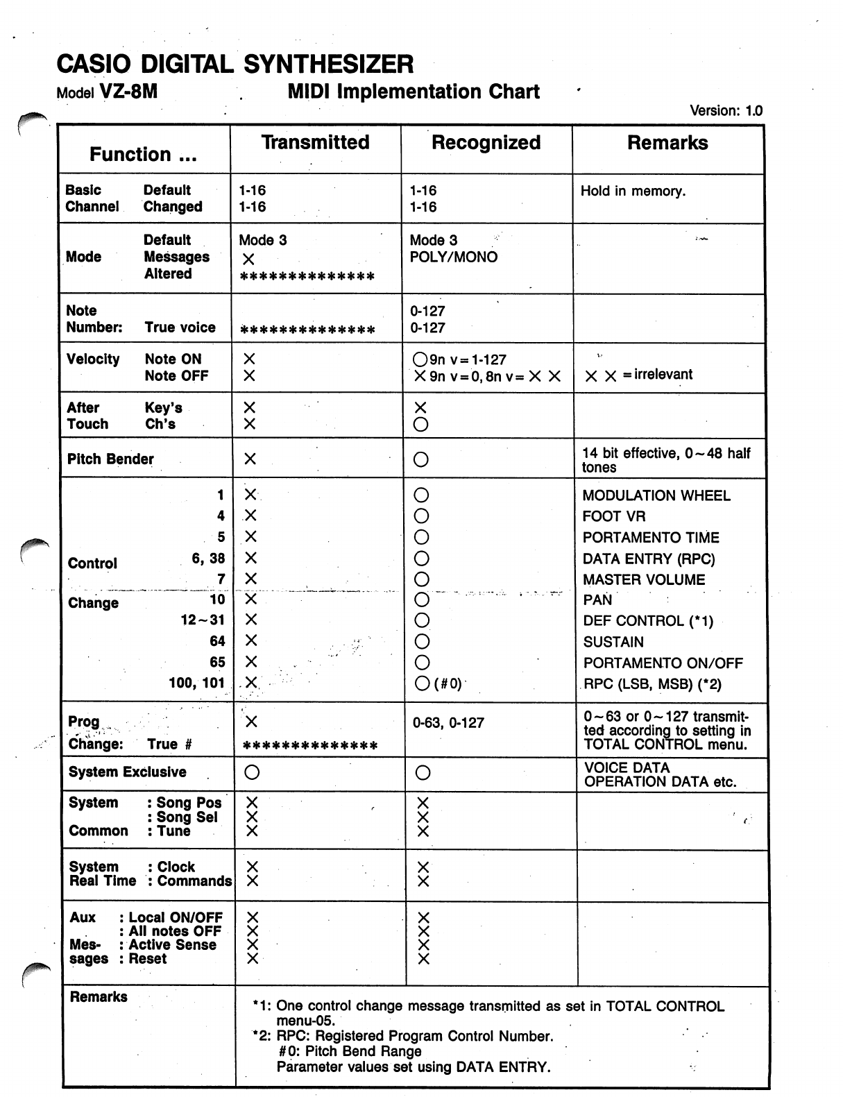
CASIO
DIGITAL
SYNTHESIZER
Model
VZ-8M
.
MIDI
Implementation
Chart
'
'«
CASIO
DIGITAL
SYNTHESIZER
-1
MIDI
SYSTEM
EXCLUSIVE
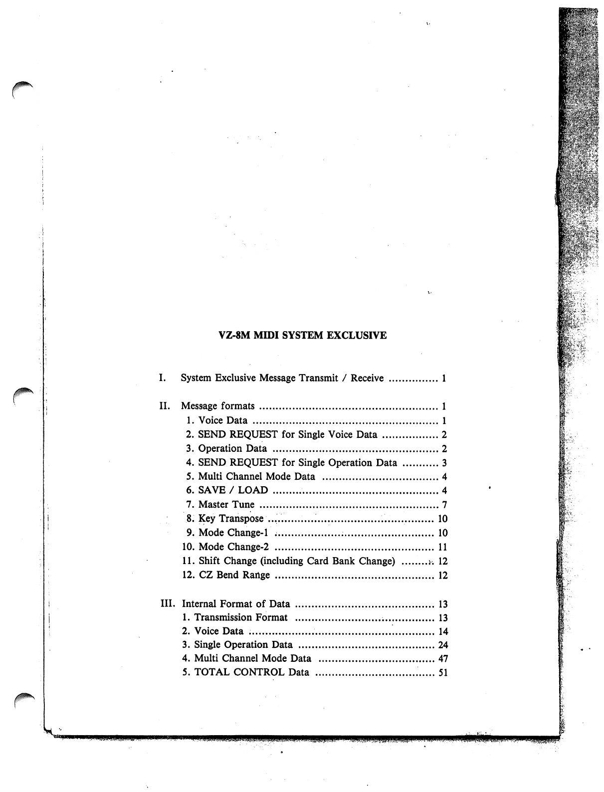
VZ-8M
MIDI
SYSTEM
EXCLUSIVE
I.
System
Exclusive
Message
Transmit
/
Receive
1
II.
Message
formats
1
1.
Voice
Data
1
2.
SEND
REQUEST
for
Single
Voice
Data
2
3.
Operation
Data
2
4.
SEND
REQUEST
for
Single
Operation
Data
3
5.
Multi
Channel
Mode
Data
4
6.
SAVE
/
LOAD
4
7.
Master
Tune
7
8.
Key
Transpose
10
9.
Mode
Change-1
10
10.
ModeChange-2
11
11.
Shift
Change
(including
Card
Bank
Change)
j.
12
12.
CZ
Bend
Range
12
III.
Internal
Format
of
Data
13
1.
Transmission
Format
13
2.
Voice
Data
14
3.
Single
Operation
Data
24
4.
Multi
Channel
Mode
Data
47
5.
TOTAL
CONTROL
Data
51
m--
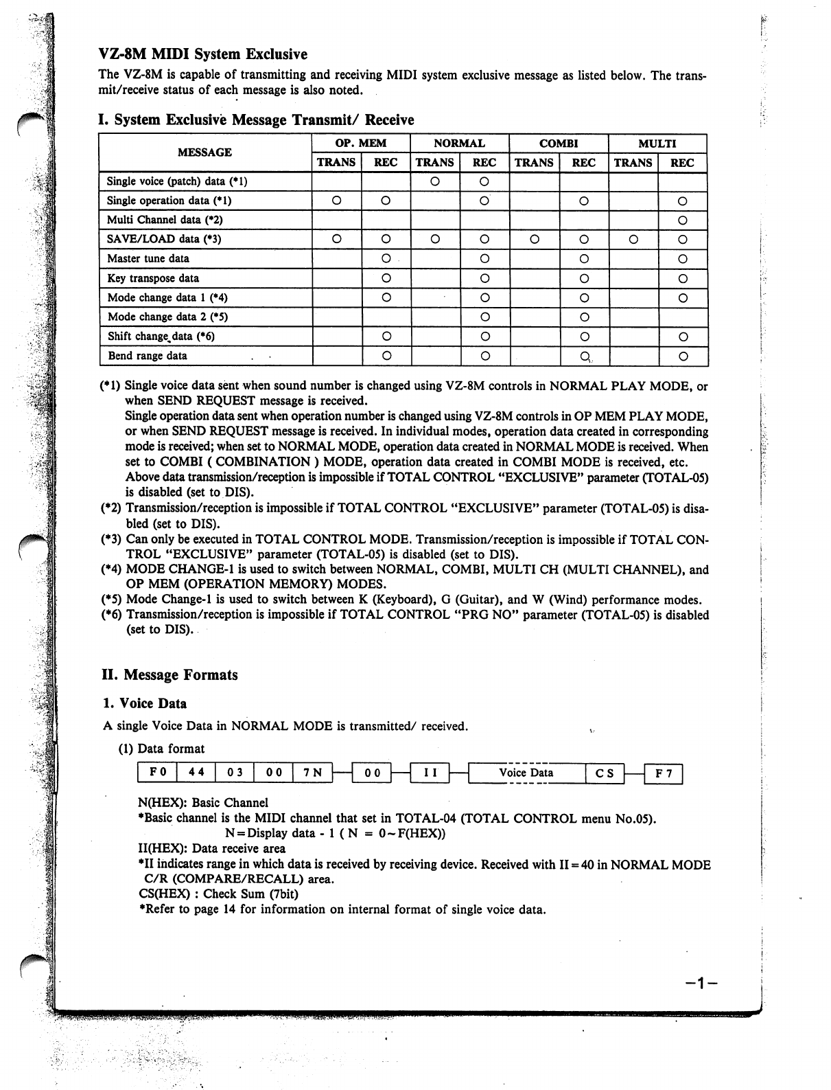
VZ-8M
MIDI
System
Exclusive
The
VZ-8M
is
capable
of
transmitting
and
receiving
MIDI
system
exclusive
message
as
listed
below.
The
trans
mit/receive
status
of
each
message
is
also
noted.
(*1)
Single
voice
data
sent
when
sound
number
is
changed
using
VZ-8M
controls
in
NORMAL
PLAY
MODE,
or
when
SEND
REQUEST
message
is
received.
Single
operation
data
sent
when
operation
number
is
changed
using
VZ-8M
controls
in
OP
MEM
PLAY
MODE,
or
when
SEND
REQUEST
message
is
received.
In
individual
modes,
operation
data
created
in
corresponding
mode
is
received;
when
set
to
NORMAL
MODE,
operation
data
created
in
NORMAL
MODE
is
received.
When
set
to
COMBI
(
COMBINATION
)
MODE,
operation
data
created
in
COMBI
MODE
is
received,
etc.
Above
data
transmission/reception
is
impossible
if
TOTAL
CONTROL
"EXCLUSIVE"
parameter
(TOTAL-05)
is
disabled
(set
to
DIS).
(*2)
Transmission/reception
is
impossible
if
TOTAL
CONTROL
"EXCLUSIVE"
parameter
(TOTAL-05)
is
disa
bled
(set
to
DIS).
(♦3)
Can
only
be
executed
in
TOTAL
CONTROL
MODE.
Transmission/reception
is
impossible
if
TOTAL
CON
TROL
"EXCLUSIVE"
parameter
(TOTAL-05)
is
disabled
(set
to
DIS).
(*4)
MODE
CHANGE-1
is
used
to
switch
between
NORMAL,
COMBI,
MULTI
CH
(MULTI
CHANNEL),
and
OP
MEM
(OPERATION
MEMORY)
MODES.
(*5)
Mode
Change-1
is
used
to
switch
between
K
(Keyboard),
G
(Guitar),
and
W
(Wind)
performance
modes.
(♦6)
Transmission/reception
is
impossible
if
TOTAL
CONTROL
"PRG
NO"
parameter
(TOTAL-05)
is
disabled
(set
to
DIS).
II.
Message Formats
1.
Voice
Data
A
single
Voice
Data
in
NORMAL
MODE
is
transmitted/
received.
(1)
Data
format
""
00
7N|
100|—|
III
1
Voice
Data
CS
F0
44
03
F7
N(HEX):
Basic
Channel
♦Basic
channel
is
the
MIDI
channel
that
set
in
TOTAL-04
(TOTAL
CONTROL
menu
No.05).
N
=
Display
data
-
1
(
N
=
O-F(HEX))
II(HEX):
Data
receive
area
♦II
indicates
range
in
which
data
is
received
by
receiving
device.
Received
with
II
=
40
in
NORMAL
MODE
C/R
(COMPARE/RECALL)
area.
CS(HEX)
:
Check
Sum
(7bit)
♦Refer
to
page
14
for
information
on
internal
format
of
single
voice
data.
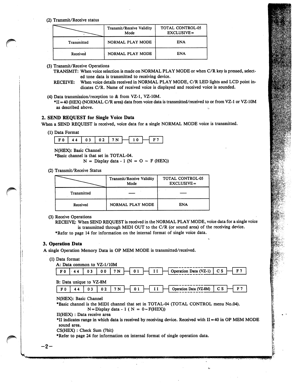
(2)
Transmit/Receive
status
r
(3)
Transmit/Receive
Operations
TRANSMIT:
When
voice
selection
is
made
on
NORMAL
PLAY
MODE
or
when
C/R
key
is
pressed,
select
ed
tone
data
is
transmitted
to
receiving
device.
RECEIVE:
When
voice
details
received
in
NORMAL
PLAY
MODE,
C/R
LED
lights
and
LCD
point
in
dicates
C/R.
Name
of
received
voice
is
displayed
and
received
voice
is
sounded.
(4)
Data
transmission/reception
to
&
from
VZ-1,
VZ-IOM.
♦11=40
(HEX)
(NORMAL
C/R
area)
data
from
voice
data
is
transmitted/received
to
or
from
VZ-1
or
VZ-IOM
as
described
above.
2.
SEND
REQUEST
for
Single
Voice
Data
When
a
SEND
REQUEST
is
received,
voice
data
for
a
single
NORMAL
MODE
voice
is
transmitted.
(1)
Data
Format
F0
44
|
03
|
02
|
7N
| 1
10
|
1
F7
N(HEX):
Basic
Channel
♦Basic
channel
is
that
set
in
TOTAL-04.
N
=
Display
data
-
1
(N
=
O
~
F
(HEX))
(2)
Transmit/Receive
Status
(3)
Receive
Operations
RECEIVE:
When
SEND
REQUEST
is
received
in
the
NORMAL
PLAY
MODE,
voice
data
for
a
single
voice
is
transmitted
through
MIDI
OUT
to
the
C/R
(or
sound
area)
of
the
receiving
device.
♦Refer
to
page
14
for
information
on
the
internal
format
of
single
voice
data.
3.
Operation
Data
A
single
Operation
Memory
Data
in
OP
MEM
MODE
is
transmitted/received.
(1)
Data
format
A:
Data
common
to
VZ-1/10M
|
F0
|
44
|
03
|
00
|
7N
|—|
0
1
|—|
II
|—|
Operation
Data
(VZ-1)
|
C
S
B:
Data
unique
to
VZ-8M
F0
|
44
|
03
|
02
7N
0
1
Operation
Data
(VZ-8M)
CS
|—|
F7
N(HEX):
Basic
Channel
♦Basic
channel
is
the
MIDI
channel
that
set
in
TOTAL-04
(TOTAL
CONTROL
menu
No.04).
N
=
Display
data
- 1
(
N
=
O-F(HEX))
II(HEX)
:
Data
receive
area
*II
indicates
range
in
which
data
is
received
by
receiving
device.
Received
with
II=40
in
OP
MEM
MODE
sound
area.
CS(HEX)
:
Check
Sum
(7bit)
♦Refer
to
page
24
for
information
on
internal
format
of
single
operation
data.
-2-
mi'
fcT
81:-.■>.:..'
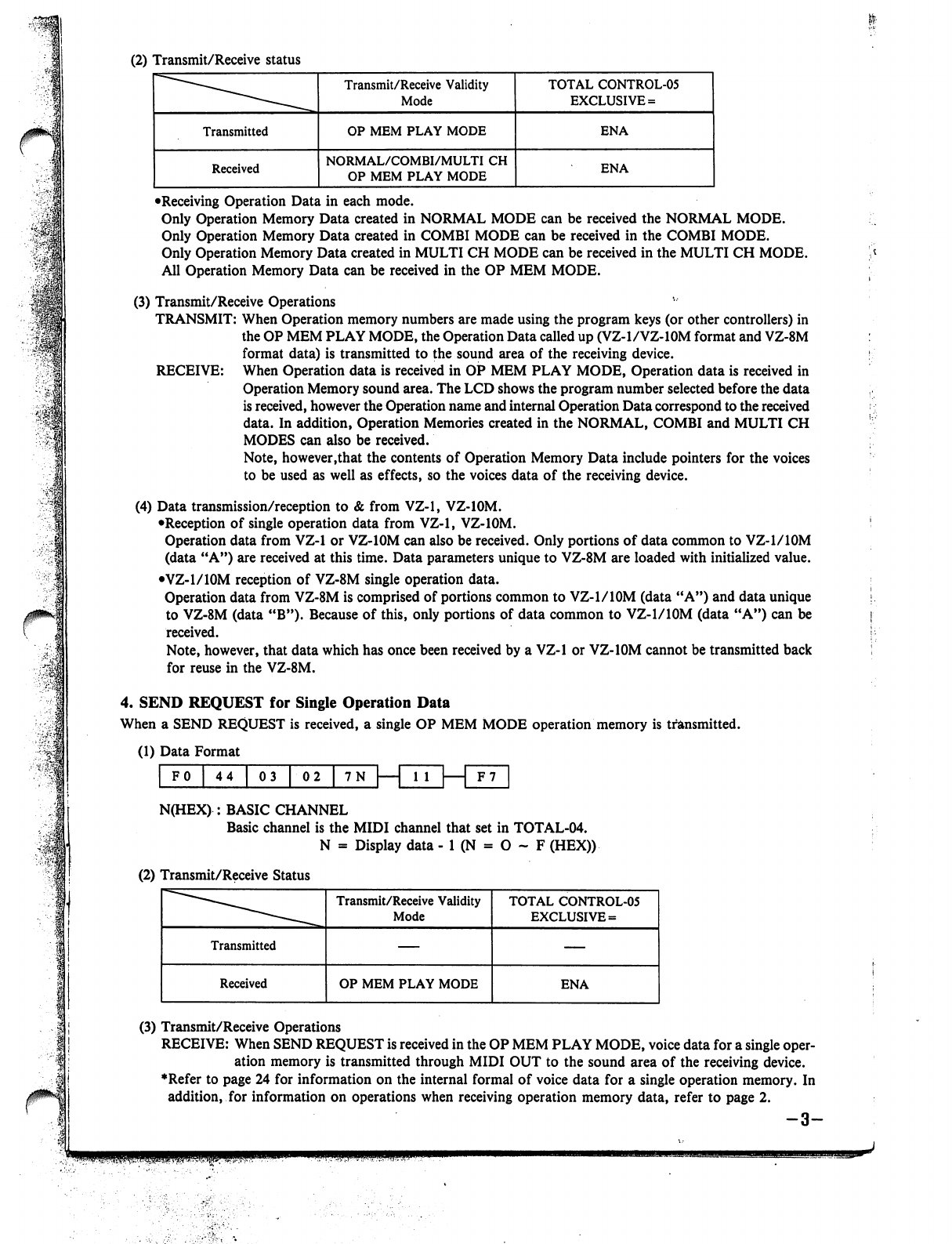
(2)
Transmit/Receive
status
•Receiving
Operation
Data
in
each
mode.
Only
Operation
Memory
Data
created
in
NORMAL
MODE
can
be
received
the
NORMAL
MODE.
Only
Operation
Memory
Data
created
in
COMBI
MODE
can
be
received
in
the
COMBI
MODE.
Only
Operation
Memory
Data
created
in
MULTI
CH
MODE
can
be
received
in
the
MULTI
CH
MODE.
All
Operation
Memory
Data
can
be
received
in
the
OP
MEM
MODE.
(3)
Transmit/Receive
Operations
TRANSMIT:
When
Operation
memory
numbers
are
made
using
the
program
keys
(or
other
controllers)
in
the
OP
MEM
PLAY
MODE,
the
Operation
Data
called
up
(VZ-1/VZ-10M
format
and
VZ-8M
format
data)
is
transmitted
to
the
sound
area
of
the
receiving
device.
RECEIVE:
When
Operation
data
is
received
in
OP
MEM
PLAY
MODE,
Operation
data
is
received
in
Operation
Memory
sound
area.
The
LCD
shows
the
program
number
selected
before
the
data
is
received,
however
the
Operation
name
and
internal
Operation
Data
correspond
to
the
received
data.
In
addition,
Operation
Memories
created
in
the
NORMAL,
COMBI
and
MULTI
CH
MODES
can
also
be
received.
Note,
however.that
the
contents
of
Operation
Memory
Data
include
pointers
for
the
voices
to
be
used
as
well
as
effects,
so
the
voices
data
of
the
receiving
device.
(4)
Data
transmission/reception
to
&
from
VZ-1,
VZ-10M.
•Reception
of
single
operation
data
from
VZ-1,
VZ-10M.
Operation
data
from
VZ-1
or
VZ-10M
can
also
be
received.
Only
portions
of
data
common
to
VZ-1/10M
(data
"A")
are
received
at
this
time.
Data
parameters
unique
to
VZ-8M
are
loaded
with
initialized
value.
•VZ-1/10M
reception
of
VZ-8M
single
operation
data.
Operation
data
from
VZ-8M
is
comprised
of
portions
common
to
VZ-1/10M
(data
"A")
and
data
unique
to
VZ-8M
(data
"B").
Because
of
this,
only
portions
of
data
common
to
VZ-1/10M
(data
"A")
can
be
received.
Note,
however,
that
data
which
has
once been
received
by
a
VZ-1
or
VZ-10M
cannot
be
transmitted
back
for
reuse
in
the
VZ-8M.
4.
SEND
REQUEST
for
Single
Operation
Data
When
a
SEND
REQUEST
is
received,
a
single
OP
MEM
MODE
operation
memory
is
transmitted.
(1)
Data
Format
F
0
I
4
4
|
0
3
|
0
2
|
7
N
| 1
1 1
| 1
F7
N(HEX)
:
BASIC
CHANNEL
Basic
channel
is
the
MIDI
channel
that
set
in
TOTAL-04.
N
=
Display
data
-
1
(N
=
O
~
F
(HEX))
(2)
Transmit/Receive
Status
(3)
Transmit/Receive
Operations
RECEIVE:
When
SEND
REQUEST
is
received
in
the
OP
MEM
PLAY
MODE,
voice
data
for
a
single
oper
ation
memory
is
transmitted
through
MIDI
OUT
to
the
sound
area
of
the
receiving
device.
♦Refer
to
page 24
for
information
on
the
internal
formal
of
voice
data
for
a
single
operation
memory.
In
addition,
for
information
on
operations
when
receiving
operation
memory
data,
refer
to
page
2.
q
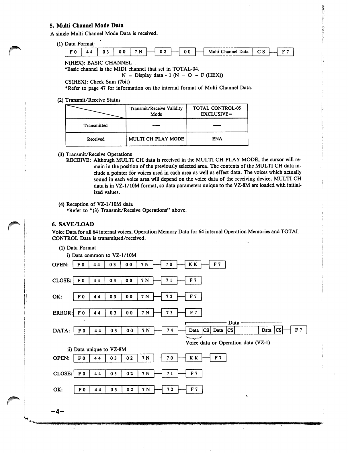
/*im\
r
5.
Multi
Channel
Mode
Data
A
single
Multi
Channel
Mode
Data
is
received.
(1)
Data
Format
FO
44
03
I
00
7N
Multi
Channel
Data
n-un
N(HEX);
BASIC
CHANNEL
♦Basic
channel
is
the
MIDI
channel
that
set
in
TOTAL-04.
N
=
Display
data
-
1
(N
=
O
~
F
(HEX))
CS(HEX):
Check
Sum
(7bit)
♦Refer
to
page
47
for
information
on
the
internal
format
of
Multi
Channel
Data.
(2)
Transmit/Receive
Status
(3)
Transmit/Receive
Operations
RECEIVE:
Although
MULTI
CH
data
is
received
in
the
MULTI
CH
PLAY
MODE,
the
cursor
will
re
main
in
the
position
of
the
previously
selected
area.
The
contents
of
the
MULTI
CH
data
in
clude
a
pointer
for
voices
used
in
each
area
as
well
as
effect
data.
The
voices
which
actually
sound
in
each
voice
area
will
depend
on
the
voice
data
of
the
receiving
device.
MULTI
CH
data
is
in
VZ-1/10M
format,
so
data
parameters
unique
to
the
VZ-8M
are
loaded
with
initial
ized
values.
(4)
Reception
of
VZ-1/10M
data
♦Refer
to
"(3)
Transmit/Receive
Operations"
above.
6.
SAVE/LOAD
Voice
Data
for
all
64
internal
voices,
Operation
Memory
Data
for
64
internal
Operation
Memories
and
TOTAL
CONTROL
Data
is
transmitted/received.
(1)
Data
Format
i)
Data
common
to
VZ-1/10M
OPEN:
I
FO
I
44
I
03
I
00
I
7N
HUD
CLOSE:
|
F0
|
44
|
03
|
00
|
7N
|—|
7
1
|
1
OK:
' ' '
'
"""
F7
1
72
F7
ERROR:|f
0
|
44
|
03
|
00J7N
|—|
73
|—|
F7
Data
■
DATA:
|
F0
|
44
|
03
|
00
|
7N
|—|
74
|—|
Data
|cs|
Data
|cs|
|
Data
|cs|
1
F7
Voice
data
or
Operation
data
(VZ-1)
ii)
Data
unique
to
VZ-8M
OPEN:
CLOSE:
|
F0
|
44
|
03
|
02
|
7N
|
1
7
1
|
[f
7
OK:
F0
|
44
|
03
~^2
|
7N
—
72
|
F7
-4-
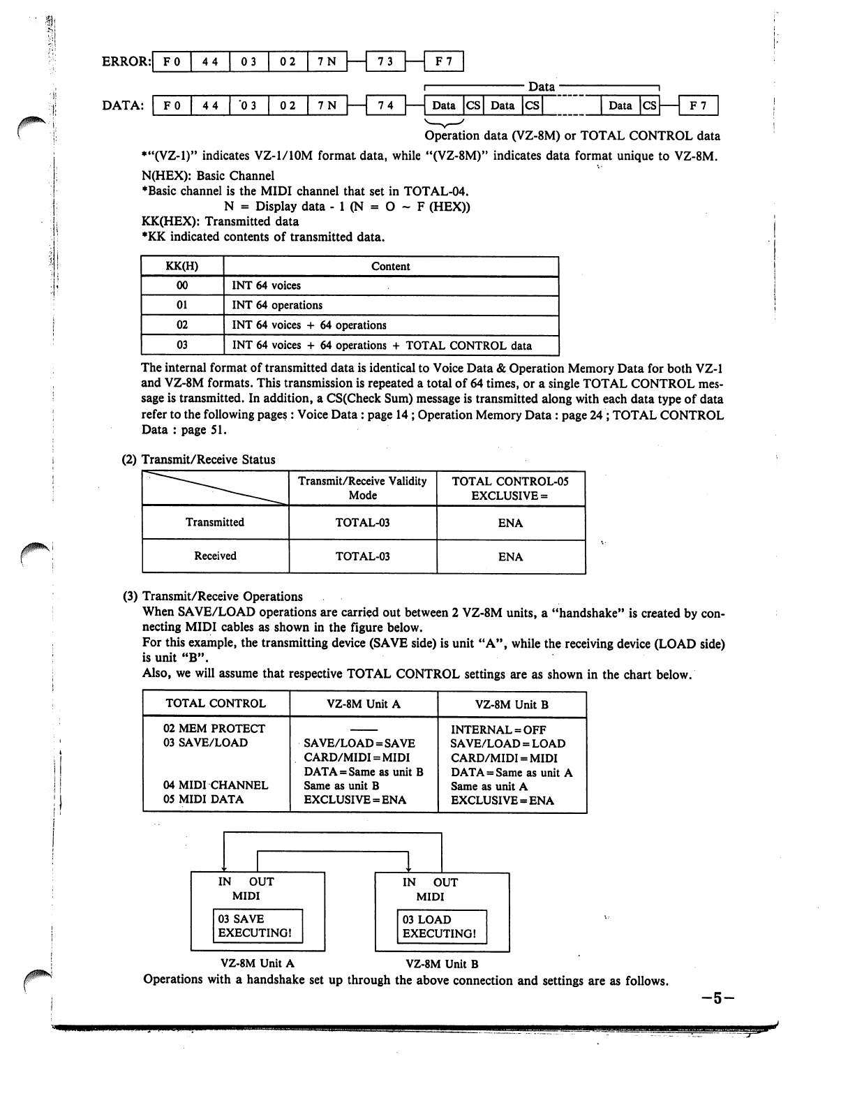
Data
74
—
Data
CS
Data
CS
Data
CS
Operation
data
(VZ-8M)
or
TOTAL
CONTROL
data
♦"(VZ-1)"
indicates
VZ-1/10M
format
data,
while
"(VZ-8M)"
indicates
data
format
unique
to
VZ-8M.
N(HEX):
Basic
Channel
♦Basic
channel
is
the
MIDI
channel
that
set
in
TOTAL-04.
N
=
Display
data
- 1
(N
=
O
~
F
(HEX))
KK(HEX):
Transmitted
data
♦KK
indicated
contents
of
transmitted
data.
The
internal
format
of
transmitted
data
is
identical
to
Voice
Data
&
Operation
Memory
Data
for
both
VZ-1
and
VZ-8M
formats.
This
transmission
is
repeated
a
total
of
64
times,
or
a
single
TOTAL
CONTROL
mes
sage
is
transmitted.
In
addition,
a
CS(Check
Sum)
message
is
transmitted
along
with
each
data
type
of
data
refer
to the
following
pages:
Voice
Data:
page
14
;
Operation
Memory
Data
:
page
24
;
TOTAL
CONTROL
Data
:
page
51.
(2)
Transmit/Receive
Status
(3)
Transmit/Receive
Operations
When
SAVE/LOAD
operations
are
carried
out
between
2
VZ-8M
units,
a
"handshake"
is
created
by
con
necting
MIDI
cables
as
shown
in
the
figure
below.
For
this
example,
the
transmitting
device
(SAVE
side)
is
unit
"A",
while
the
receiving
device
(LOAD
side)
is
unit
"B".
Also,
we
will
assume
that
respective
TOTAL
CONTROL
settings
are
as
shown
in
the
chart
below.
VZ-8M
Unit
A
VZ-8M
Unit
B
Operations
with
a
handshake
set
up
through
the
above
connection
and
settings
are
as
follows.
-5-
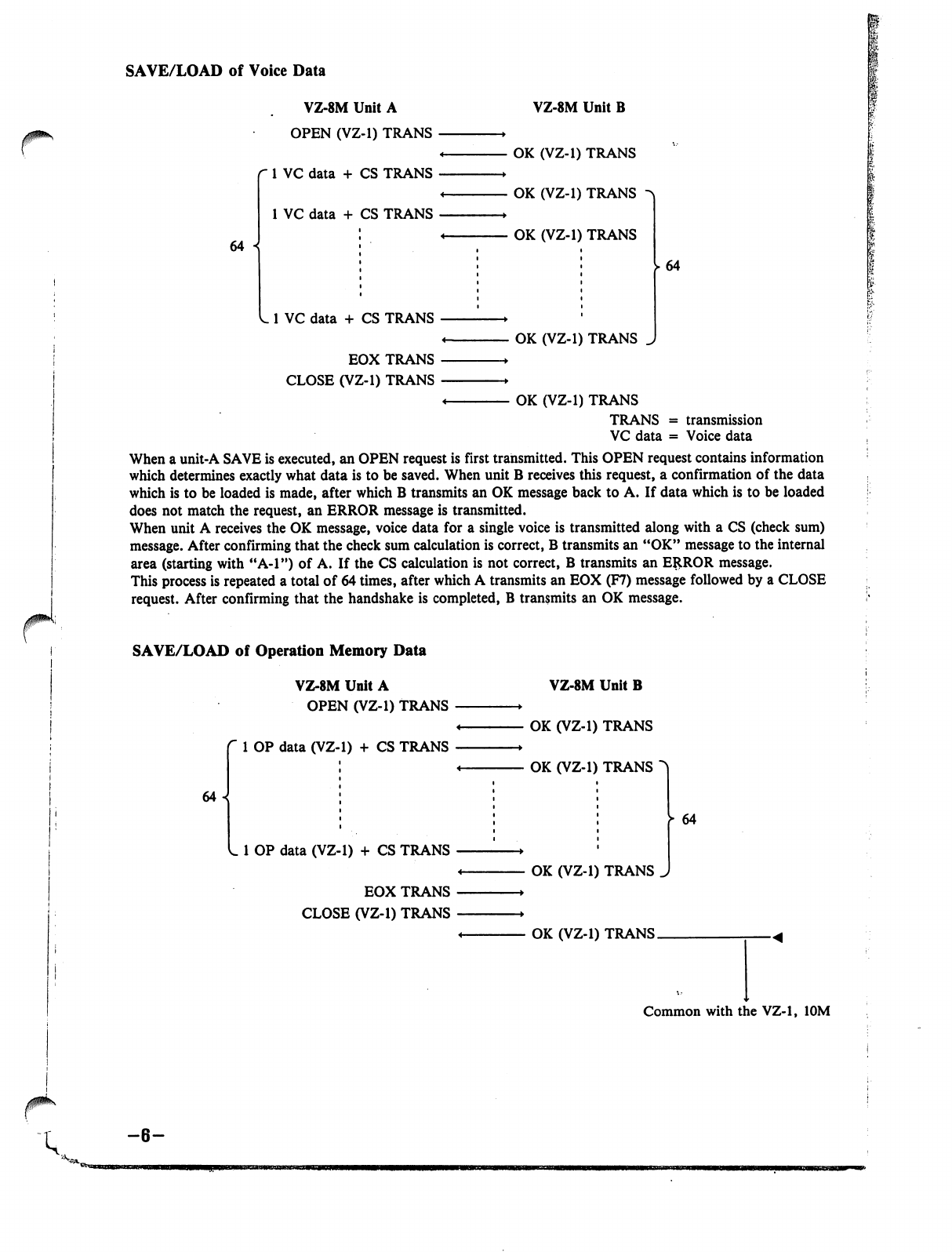
SAVE/LOAD
of
Voice
Data
r1
VZ-8M
Unit
A
OPEN
(VZ-1)
TRANS
r
1
VC
data
+ CS
TRANS
1
VC
data
+
CS
TRANS
64
VZ-8M
Unit
B
OK
(VZ-1)
TRANS
OK
(VZ-1)
TRANS
OK
(VZ-1)
TRANS
1
VC
data
+ CS
TRANS
EOX
TRANS
CLOSE
(VZ-1)
TRANS
OK
(VZ-1)
TRANS
64
I
<
OK
(VZ-1)
TRANS
TRANS
=
transmission
VC
data
=
Voice
data
When
a
unit-A
SAVE
is
executed,
an
OPEN
request
is
first
transmitted.
This
OPEN
request
contains
information
which
determines
exactly
what
data
is
to
be
saved.
When
unit
B
receives
this
request,
a
confirmation
of
the
data
which
is
to
be
loaded
is
made,
after
which
B
transmits
an
OK
message
back
to
A.
If
data
which
is
to
be
loaded
does
not
match
the
request,
an
ERROR
message
is
transmitted.
When
unit
A
receives
the
OK
message,
voice
data
for
a
single
voice
is
transmitted
along
with
a
CS
(check
sum)
message.
After
confirming
that
the
check
sum
calculation
is
correct,
B
transmits
an
"OK"
message
to
the
internal
area
(starting
with
"A-l")
of
A.
If
the
CS
calculation
is
not
correct,
B
transmits
an
ERROR
message.
This
process
is
repeated
a
total
of
64
times,
after
which
A
transmits
an
EOX
(F7)
message
followed
by
a
CLOSE
request.
After
confirming
that
the
handshake
is
completed,
B
transmits
an
OK
message.
SAVE/LOAD
of
Operation
Memory
Data
VZ-8M
Unit
A
OPEN
(VZ-1)
TRANS
1
OP
data
(VZ-1)
+
CS
TRANS
64
VZ-8M
Unit
B
OK
(VZ-1)
TRANS
OK
(VZ-1)
TRANS
L
1
OP
data
(VZ-1)
+
CS
TRANS
EOX
TRANS
CLOSE
(VZ-1)
TRANS
OK
(VZ-1)
TRANS
>
64
OK
(VZ-1)
TRANS.
Common
with
the
VZ-1,
10M
-6-
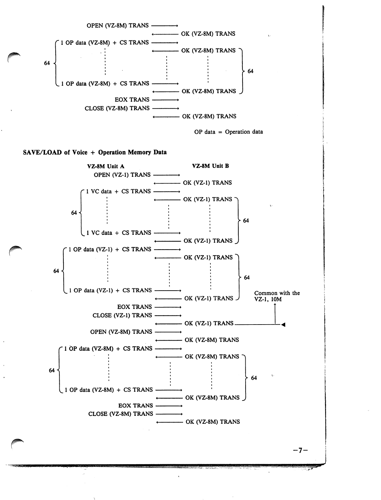
r
64
OPEN
(VZ-8M)
TRANS
1
OP
data
(VZ-8M)
+
CS
TRANS
1
OP
data
(VZ-8M)
+ CS
TRANS
EOX
TRANS
CLOSE
(VZ-8M)
TRANS
SAVE/LOAD
of
Voice
+
Operation
Memory
Data
VZ-8M
Unit
A
OPEN
(VZ-1)
TRANS
^
r
1
VC
data
+
CS
TRANS
64
64
1
VC
data
+ CS
TRANS
1
OP
data
(VZ-1)
+
CS
TRANS
64^
L
1
OP
data
(VZ-1)
+
CS
TRANS
EOX
TRANS
CLOSE
(VZ-1)
TRANS
OPEN
(VZ-8M)
TRANS
1
OP
data
(VZ-8M)
+ CS
TRANS
1
OP
data
(VZ-8M)
+
CS
TRANS
EOX
TRANS
CLOSE
(VZ-8M)
TRANS
OK
(VZ-8M)
TRANS
OK
(VZ-8M)
TRANS
64
OK
(VZ-8M)
TRANS
J
OK
(VZ-8M)
TRANS
OP
data
=
Operation
data
VZ-8M
Unit
B
-
OK
(VZ-1)
TRANS
-
OK
(VZ-1)
TRANS
^
►
64
OK
(VZ-1)
TRANS
^
OK
(VZ-1)
TRANS
~
OK
(VZ-1)
TRANS
64
Common
with
the
VZ-1,
10M
OK
(VZ-1)
TRANS.
OK
(VZ-8M)
TRANS
OK
(VZ-8M)
TRANS
OK
(VZ-8M)
TRANS
OK
(VZ-8M)
TRANS
64
-7-
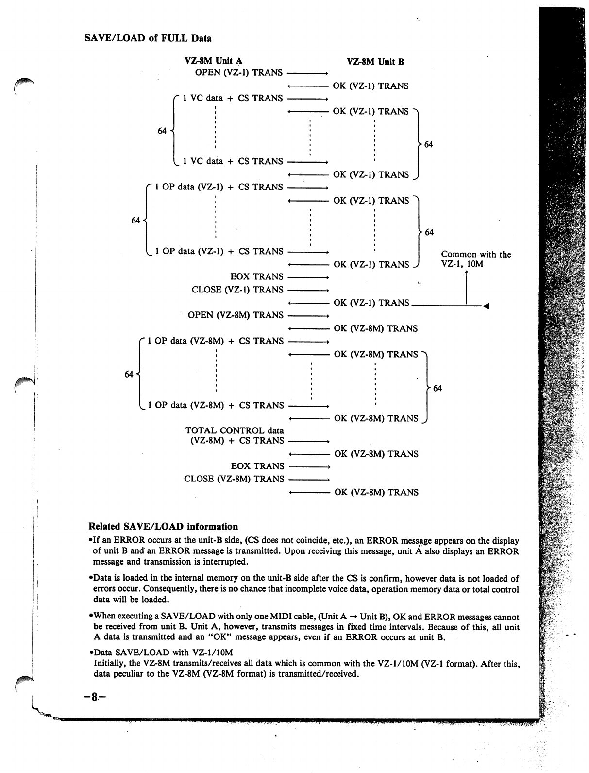
SAVE/LOAD
of
FULL
Data
64
VZ-8M
Unit
A
OPEN
(VZ-1)
TRANS
1
VC
data
+
CS
TRANS
64
«
1
VC
data
+ CS
TRANS
1
OP
data
(VZ-1)
+
CS
TRANS
64
L
1
OP
data
(VZ-1)
+ CS
TRANS
EOX
TRANS
CLOSE
(VZ-1)
TRANS
OPEN
(VZ-8M)
TRANS
1
OP
data
(VZ-8M)
+ CS
TRANS
1
OP
data
(VZ-8M)
+
CS
TRANS
TOTAL
CONTROL
data
(VZ-8M)
+
CS
TRANS
EOX
TRANS
CLOSE
(VZ-8M)
TRANS
VZ-8M
Unit
B
OK
(VZ-1)
TRANS
OK
(VZ-1)
TRANS
OK
(VZ-1)
TRANS
OK
(VZ-1)
TRANS
^64
OK
(VZ-1)
TRANS
OK
(VZ-1)
TRANS.
64
Common
with
the
VZ-1,
10M
OK
(VZ-8M)
TRANS
OK
(VZ-8M)
TRANS
OK
(VZ-8M)
TRANS
OK
(VZ-8M)
TRANS
OK
(VZ-8M)
TRANS
64
JPK
Related
SAVE/LOAD
information
•If
an
ERROR
occurs
at
the
unit-B
side,
(CS
does
not
coincide,
etc.),
an
ERROR
message
appears
on
the
display
of
unit
B
and
an
ERROR
message
is
transmitted.
Upon
receiving
this
message,
unit
A
also
displays
an
ERROR
message
and
transmission
is
interrupted.
•Data
is
loaded
in
the
internal
memory
on
the
unit-B
side
after
the
CS
is
confirm,
however
data
is
not
loaded
of
errors
occur.
Consequently,
there
is
no
chance
that
incomplete
voice
data,
operation
memory
data
or
total
control
data
will
be
loaded.
•When
executing
a
SAVE/LOAD
with only
one
MIDI
cable,
(Unit
A
->
Unit
B),
OK
and
ERROR
messages
cannot
be
received
from
unit
B.
Unit
A,
however,
transmits
messages
in
fixed
time
intervals.
Because
of
this,
all
unit
A
data
is
transmitted
and
an
"OK"
message
appears,
even
if
an
ERROR
occurs
at
unit
B.
•Data
SAVE/LOAD
with
VZ-l/lOM
Initially,
the
VZ-8M
transmits/receives
all
data
which
is
common
with
the
VZ-l/lOM
(VZ-1
format).
After
this,
data
peculiar
to
the
VZ-8M
(VZ-8M
format)
is
transmitted/received.
-8-
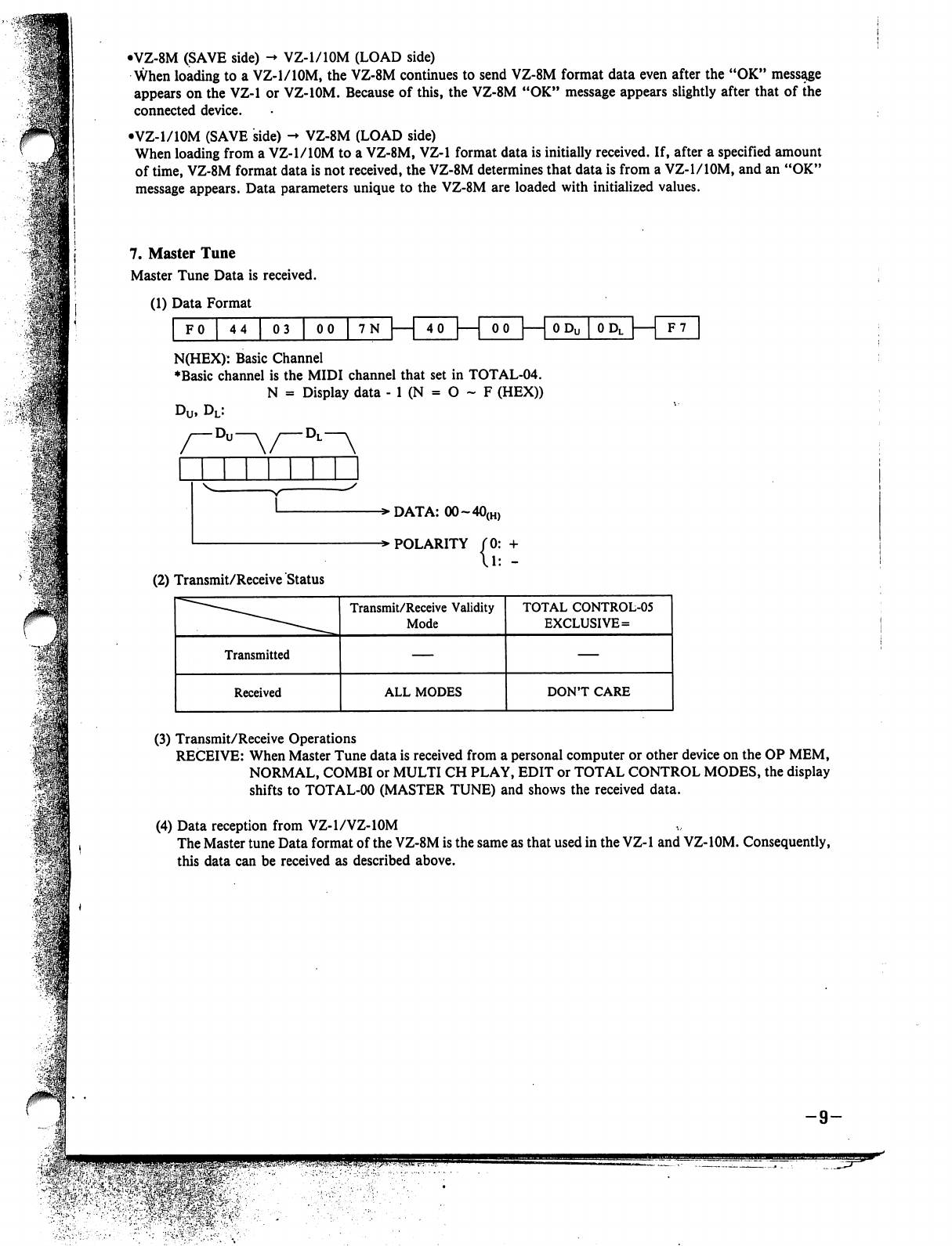
•VZ-8M
(SAVE
side)
-♦
VZ-1/10M
(LOAD
side)
When
loading
to
a
VZ-1/10M,
the
VZ-8M
continues
to
send
VZ-8M
format
data
even
after
the
"OK"
message
appears
on
the
VZ-1
or
VZ-10M.
Because
of
this,
the
VZ-8M
"OK"
message
appears
slightly
after
that
of
the
connected
device.
•VZ-1/10M
(SAVE
side)
->
VZ-8M
(LOAD
side)
When
loading
from
a
VZ-1/10M
to
a
VZ-8M,
VZ-1
format
data
is
initially
received.
If,
after
a
specified
amount
of
time,
VZ-8M
format
data
is
not
received,
the
VZ-8M
determines
that
data
is
from
a
VZ-1/10M,
and
an
"OK"
message
appears.
Data
parameters
unique
to the
VZ-8M
are
loaded
with
initialized
values.
7.
Master
Tune
Master
Tune
Data
is
received.
(1)
Data
Format
FO
44
03
00
7N
|
4
0
—|
00
0
Dl[
F7
N(HEX):
Basic
Channel
♦Basic
channel
is
the
MIDI
channel
that
set
in
TOTAL-04.
N
=
Display
data
-
1
(N
=
O
~
F
(HEX))
u,
DL:
-»DATA:
00~40(H)
-»
POLARITY
{?=:
(2)
Transmit/Receive
Status
(3)
Transmit/Receive
Operations
RECEIVE:
When
Master
Tune
data
is
received
from
a
personal
computer
or
other
device
on
the
OP
MEM,
NORMAL,
COMBI
or
MULTI
CH
PLAY,
EDIT
or
TOTAL
CONTROL
MODES,
the
display
shifts
to
TOTAL-00
(MASTER
TUNE)
and
shows
the
received
data.
(4)
Data
reception
from
VZ-1/VZ-10M
The
Master
tune
Data
format
of
the
VZ-8M
is
the
same
as that
used
in
the
VZ-1
and
VZ-10M.
Consequently,
this
data
can
be
received
as
described
above.
Q
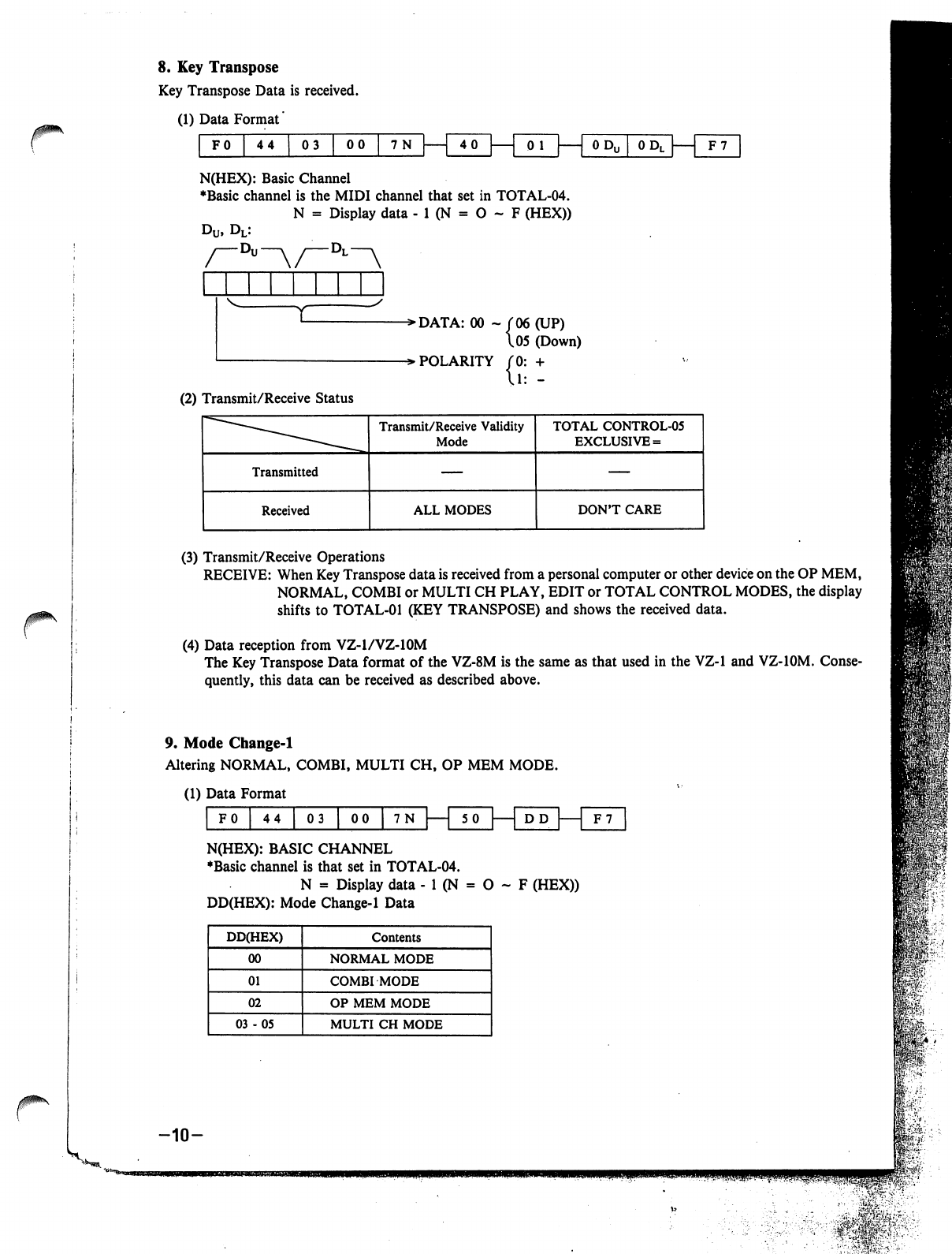
r
8.
Key
Transpose
Key
Transpose
Data
is
received.
(1)
Data
Format'
FO
44 03
00
7N
40
0
Do
[
0
DL
I
1
F7
N(HEX):
Basic
Channel
♦Basic
channel
is
the
MIDI
channel
that
set
in
TOTAL-04.
N
=
Display
data
-
1
(N
=
O
~
F
(HEX))
-Dl—v
->DATA:
00
-
f
06
(UP)
\05
(Down)
->
POLARITY
(0:
+
(2)
Transmit/Receive
Status
(3)
Transmit/Receive
Operations
RECEIVE:
When
Key
Transpose
data
is
received
from
a
personal
computer
or
other
device
on
the
OP
MEM,
NORMAL,
COMBI
or
MULTI
CH
PLAY,
EDIT
or
TOTAL
CONTROL
MODES,
the
display
shifts
to
TOTAL-01
(KEY
TRANSPOSE)
and
shows
the
received
data.
(4)
Data
reception
from
VZ-1/VZ-10M
The
Key
Transpose
Data
format
of
the
VZ-8M
is
the
same
as
that
used
in
the
VZ-1 and
VZ-10M.
Conse
quently,
this
data
can
be
received
as
described
above.
9.
Mode
Change-1
Altering
NORMAL,
COMBI,
MULTI
CH,
OP
MEM
MODE.
(1)
Data
Format
1
' '
'
""
5
0
I
L_
N(HEX):
BASIC
CHANNEL
♦Basic
channel
is
that
set
in
TOTAL-04.
N
=
Display
data
-
1
(N
=
O
~
F
(HEX))
DD(HEX):
Mode
Change-1
Data
-10-
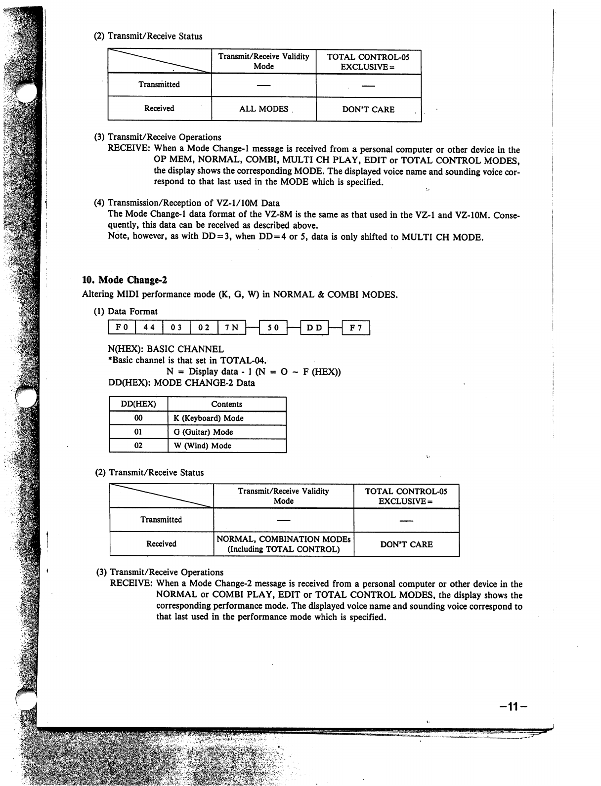
(2)
Transmit/Receive
Status
(3)
Transmit/Receive
Operations
RECEIVE:
When
a
Mode
Change-1
message
is
received
from
a
personal
computer
or
other
device
in
the
OP
MEM,
NORMAL,
COMBI,
MULTI
CH
PLAY,
EDIT
or
TOTAL
CONTROL
MODES,
the
display
shows
the
corresponding
MODE.
The
displayed
voice
name
and
sounding
voice
cor
respond
to
that
last
used
in
the
MODE
which
is
specified.
(4)
Transmission/Reception
of
VZ-1/10M
Data
The
Mode
Change-1
data
format
of
the
VZ-8M
is
the
same
as
that
used
in
the
VZ-1
and
VZ-IOM.
Conse
quently,
this
data
can
be
received
as
described
above.
Note,
however,
as
with
DD
=
3,
when
DD
=
4
or
5,
data
is
only
shifted
to
MULTI
CH
MODE.
10.
Mode
Change-2
Altering
MIDI
performance
mode
(K,
G,
W)
in
NORMAL
&
COMBI
MODES.
(1)
Data
Format
i i i i i
r
DD
FO
44
03
|
02
|
7N
|
1
SO
F7
N(HEX):
BASIC
CHANNEL
♦Basic
channel
is
that
set
in
TOTAL-04.
N
a
Display
data
-
1
(N
=
O
~
F
(HEX))
DD(HEX):
MODE
CHANGE-2
Data
(2)
Transmit/Receive
Status
(3)
Transmit/Receive
Operations
RECEIVE:
When
a
Mode
Change-2
message
is
received
from
a
personal
computer
or
other
device
in
the
NORMAL
or
COMBI
PLAY,
EDIT
or
TOTAL
CONTROL
MODES,
the
display
shows
the
corresponding
performance
mode.
The
displayed
voice
name
and
sounding
voice
correspond
to
that
last
used
in
the
performance
mode
which
is
specified.
-11-

11.
Shift
Change
(including
Card
Bank
Change)
Through
Shift
Change
messages,
MIDI
can
be
used
to
alter
the
card
banks
for
voice
number
and
Operation
Memory
number
selection.
(1)
Data
Format.
N(HEX):
Basic
Channel
♦Basic
channel
is
that
set
in
TOTAL-04.
N
=
Display
data
- 1
(N
=
O
- F
(HEX))
DD(HEX):
Shift
Change
Data
(DD
=
0
~7F(HEX))
(2)
Transmit/Receive
Status
(3)
Transmit/Receive
Operations
RECEIVE:
When
Shift
Change
data
is
received
from
a
personal
computer
or
other
device
in
the
NORMAL,
COMBI
or
MULTICH
PLAY,
EDIT
or
TOTAL
CONTROL
MODES,
the
specified
PST,
INT
or
CARD
banks
are
selected.
(4)
Reception
of
VZ-1/10M
Data
The
CARD BANK
portion
of
Shift
Change
data
for
the
VZ-1/10M
features
the
same
data
format
as
that
of
the
VZ-8M.
Consequently,
this
data
can
be
received
as
described
above.
12.
CZ
Bend
Range
CZ
Bend
Series
Bend
Range
Data
is
received.
(1)
Data
Format
F0
44
00
00
N(HEX):
Basic
Channel
♦Basic
channel
is
that
set
in
TOTAL-04.
N
=
Display
data
-
1
(N
=
O
~
F
(HEX))
DD(HEX):
CZ
Bend
Range
Data
(DD
=
0
-
7F(HEX))
-12-
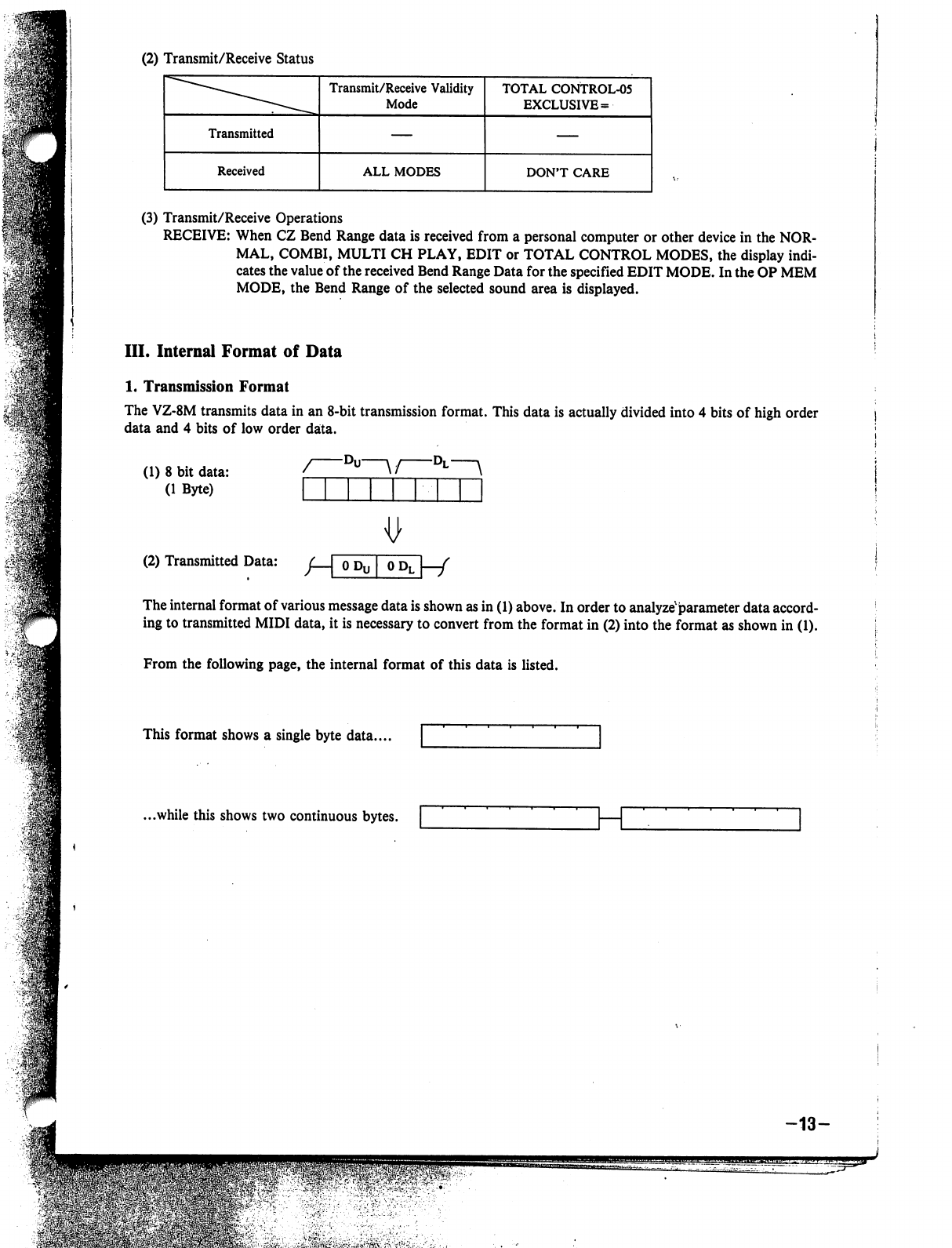
(2)
Transmit/Receive
Status
(3)
Transmit/Receive
Operations
RECEIVE:
When
CZ
Bend
Range
data
is
received
from
a
personal
computer
or
other
device
in
the
NOR
MAL,
COMBI,
MULTI
CH
PLAY,
EDIT
or
TOTAL
CONTROL
MODES,
the
display
indi
cates
the
value
of
the
received
Bend
Range
Data
for
the
specified
EDIT
MODE.
In
the
OP
MEM
MODE,
the
Bend
Range
of
the
selected
sound
area
is
displayed.
III.
Internal
Format
of
Data
1.
Transmission
Format
The
VZ-8M
transmits
data
in
an
8-bit
transmission
format.
This
data
is
actually
divided
into
4
bits
of
high
order
data
and
4
bits
of
low
order
data.
(1)
8
bit
data:
(1
Byte)
~°u
\/
°L
\
(2)
Transmitted
Data:
/
I
OP
I
OP
I
/
The
internal
format
of
various
message
data
is
shown
as
in
(1)
above.
In
order
to
analyze'parameter
data
accord
ing
to
transmitted
MIDI
data,
it
is
necessary
to
convert
from
the
format
in
(2)
into
the
format
as
shown
in
(1).
From
the
following
page,
the
internal
format
of
this
data
is
listed.
This
format
shows
a
single
byte
data....
...while
this
shows
two
continuous
bytes.
-13-
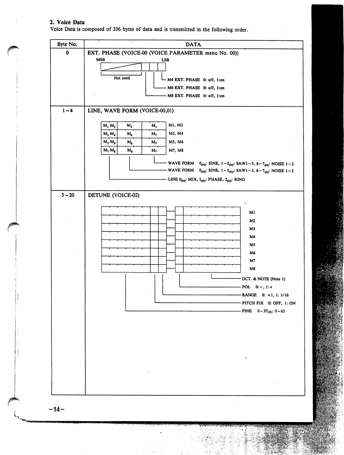
2.
Voice
Data
Voice
Data
is
composed
of
336
bytes
of
data
and
is
transmitted
in
the
following
order.
r
Byte
No.
5-20
DATA
EXT.
PHASE
(VOICE-00
(VOICE
PARAMETER
menu
No.
00))
MSB
LSB
M4
EXT.
PHASE
0:
off,
l:on
M6
EXT.
PHASE
0:
off,
Iron
M8
EXT.
PHASE
0:
off,
l:on
LINE,
WAVE
FORM
(VOICE-00,01)
Ml,
M2
M3,
M4
M5,
M6
M7,
M8
WAVE
FORM
0(H):
SINE,
1
-5(H):
SAW1
-5,
6~7(H):
NOISE
1-2
WAVE
FORM
0(H):
SINE,
1
-5(H):
SAW1
-5,
6-7(H):
NOISE
1-2
LINE
0(H):
MIX,
I(H):
PHASE,
2(H):
RING
DETUNE
(VOICE-02)
Ml
M2
M3
M4
M5
M6
M7
M8
OCT.
&
NOTE
(Note
1)
POL
0:-,l:
+
RANGE
0:
*
1,
1:
1/16
PITCH
FIX
0:
OFF,
1:
ON
FINE
0~3F(H):
0-63
-14-
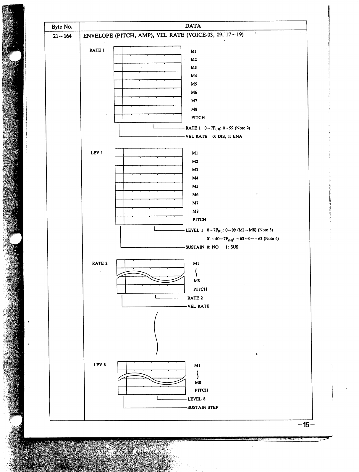
DATA
ENVELOPE
(PITCH,
AMP),
VEL
RATE
(VOICE-03,
09,
17-19)
RATE
1
0~7F(H):
0-99
(Note
2)
VEL
RATE
0:
DIS,
1:
ENA
LEVEL
1
0
-
7F(h>:
0
~
99
(M1
-
M8)
(Note
3)
M8
PITCH
LEVEL
8
SUSTAIN
STEP
01~40~7F(H):
~63~0~
+
63
(Note
4)
1:
SUS
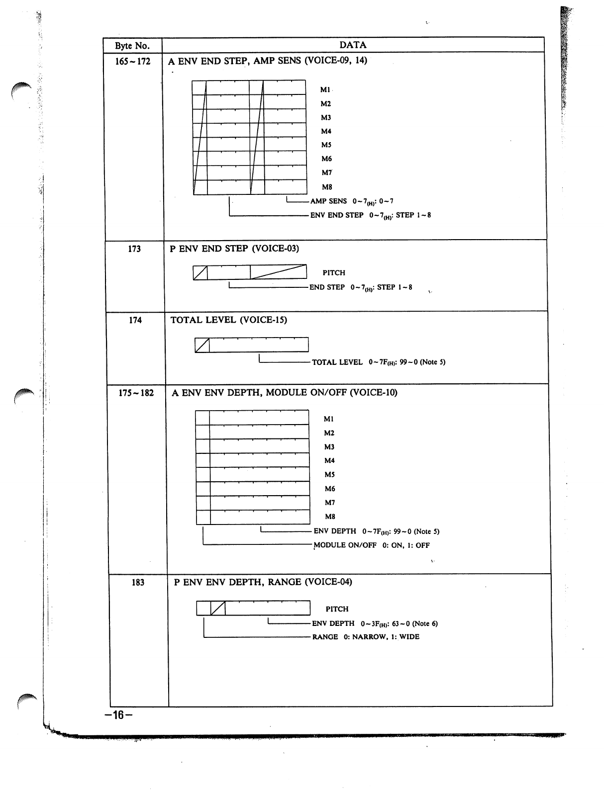
J0*\
Byte
No.
165-172
173
174
175-182
183
-16-
DATA
A
ENV
END
STEP,
AMP
SENS
(VOICE-09,
14)
Ml
M2
M3
M4
M5
M6
M7
M8
P
ENV
END
STEP
(VOICE-03)
\Z
PITCH
TOTAL
LEVEL
(VOICE-15)
7
-TOTAL
LEVEL
0-7F(H):
99-0
(Note
5)
A
ENV
ENV
DEPTH,
MODULE
ON/OFF
(VOICE-10)
Ml
M2
M3
M4
M5
M6
M7
M8
ENV
DEPTH
0~7F(H):
99-0
(Note
5)
MODULE
ON/OFF
0:
ON,
1:
OFF
P
ENV
ENV
DEPTH,
RANGE
(VOICE-04)
ZL
PITCH
ENV
DEPTH
0-3F(H):
63-0
(Note
6)
RANGE
0:
NARROW,
1:
WIDE
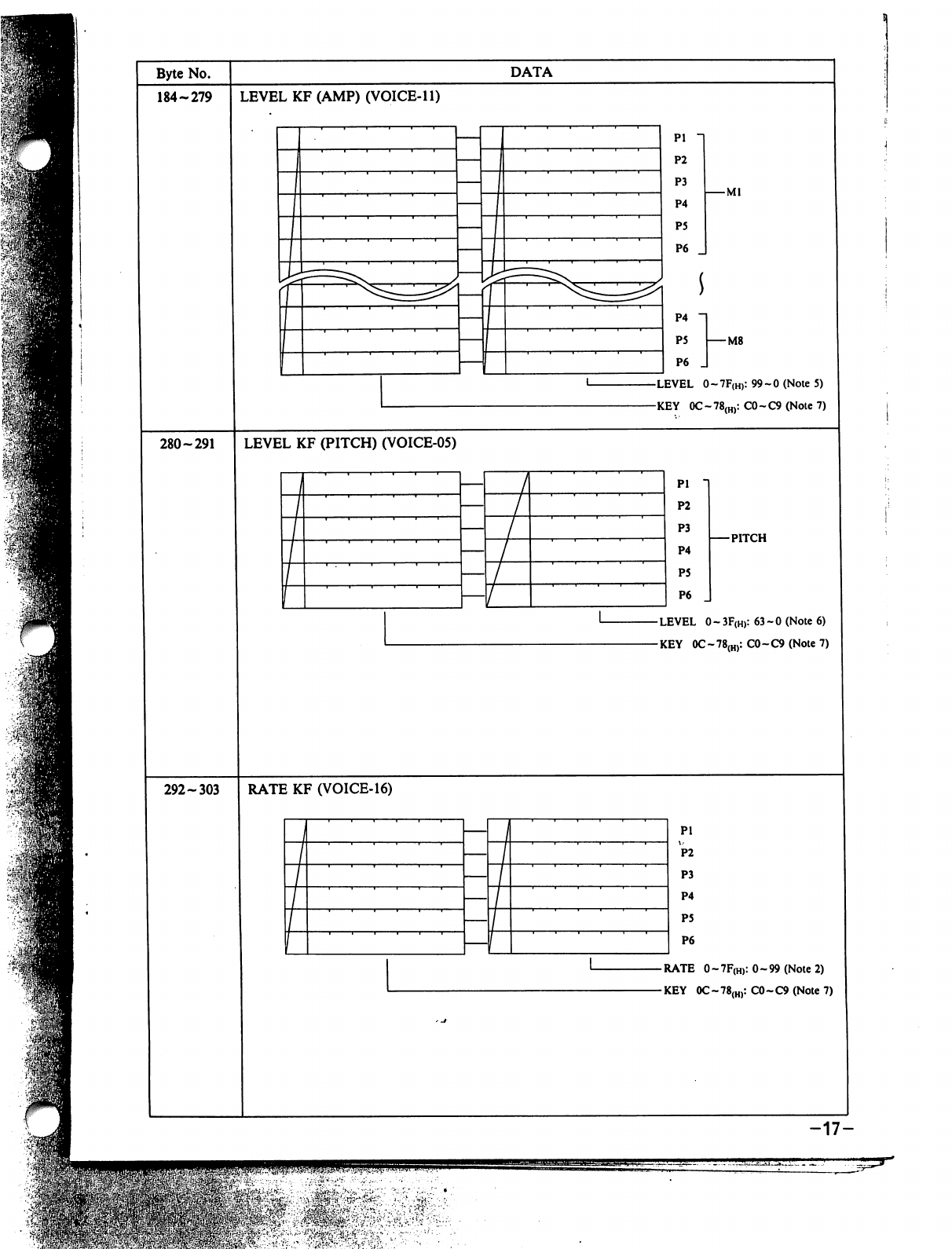
Byte
No.
184-279
DATA
LEVEL
KF
(AMP)
(VOICE-11)
-Ml
P4
P5
I
M8
P6
_
LEVEL
0~7F(H):99~0(Note5)
KEY
0C~78(H):C0~C9(Note7)
280-291
LEVEL
KF
(PITCH)
(VOICE-05)
Pi
P2
P3
P4
P5
P6
PITCH
-
LEVEL
0
~
3F(H):
63-0
(Note
6)
-KEY
0C-78(H):
C0-C9
(Note
7)
292-303
RATE
KF
(VOICE-16)
Pi
P2
P3
P4
P5
P6
-
RATE
0
-
7F(H):
0-99
(Note
2)
-KEY
0C~78(H):
C0-C9
(Note
7)
-17-
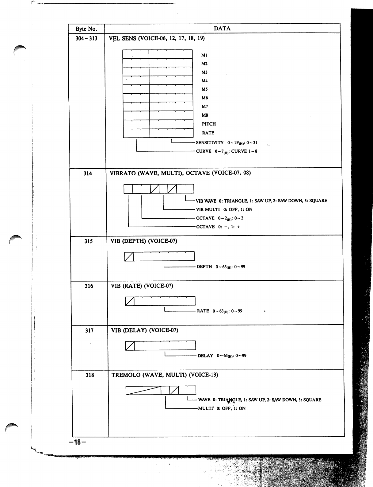
0\
jpk
Byte
No.
304-313
314
315
316
317
318
-18-
DATA
VEL
SENS
(VOICE-06,
12,
17,
18,
19)
Ml
M2
M3
M4
M5
M6
M7
M8
PITCH
RATE
SENSITIVITY
0~lF(H):0~31
CURVE
0~7(H):
CURVE
1-8
VIBRATO
(WAVE,
MULTI),
OCTAVE
(VOICE-07,
08)
VIB
WAVE
0:
TRIANGLE,
1:
SAW
UP,
2:
SAW
DOWN,
3:
SQUARE
VIB
MULTI
0:
OFF,
1:
ON
OCTAVE
0~2{H):
0-2
OCTAVE
0:
-,
1:
+
VIB
(DEPTH)
(VOICE-07)
\Z
-DEPTH
0~63(H):0~99
VIB
(RATE)
(VOICE-07)
ZL
-RATE
0~63(H):0~99
VIB
(DELAY)
(VOICE-07)
\ZL
-DELAY
0~63(H):0~99
TREMOLO
(WAVE,
MULTI)
(VOICE-13)
M
-WAVE
0:
TRI^IGLE,
1:
SAW
UP,
2:
SAW
DOWN,
3:
SQUARE
-MULTI*
0:
OFF,
1:
ON
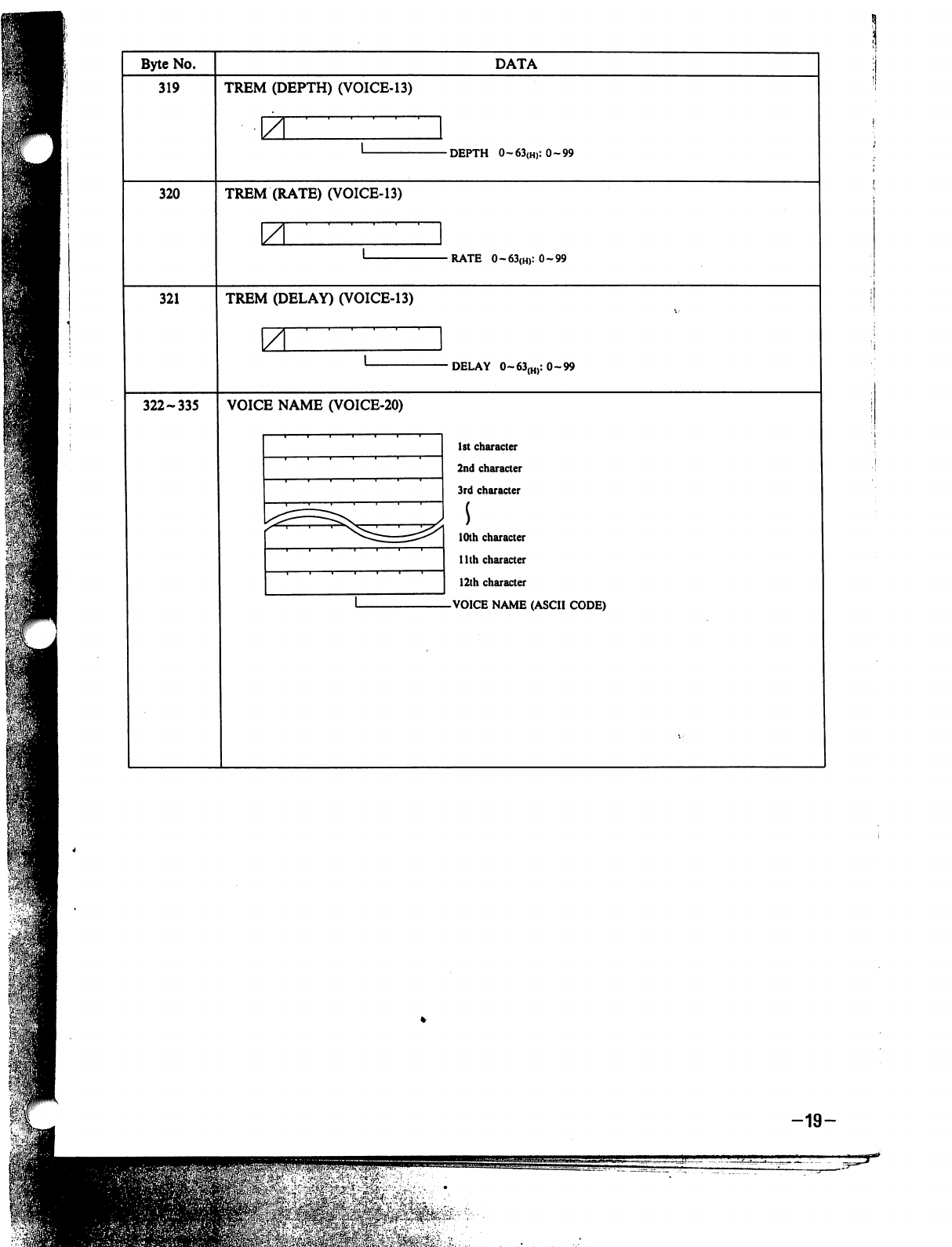
Byte
No.
319
DATA
TREM
(DEPTH)
(VOICE-13)
-DEPTH
0~63{H):0~99
320
TREM
(RATE)
(VOICE-13)
•RATE
0~63(H):0~99
321
TREM
(DELAY)
(VOICE-13)
\A
DELAY
0~63(H):
0-99
322-335
VOICE
NAME
(VOICE-20)
1st
character
2nd
character
3rd
character
10th
character
1
lth
character
12th
character
VOICE
NAME
(ASCII
CODE)
-19-
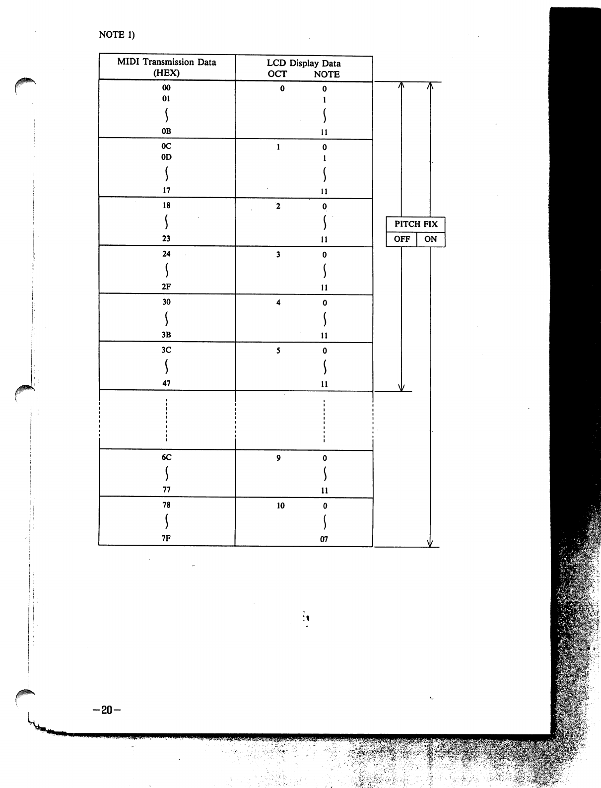
NOTE
1)
MIDI
Transmission
Data
(HEX)
LCD
Display
Data
OCT
NOTE
00
01
s
OB
0C
OD
17
18
s
23
24
s
2F
30
s
3B
3C
47
11
11
11
11
11
11
PITCH
FIX
OFF
ON
W
6C
s
77
78
s
7F
10
11
07
\
-20-
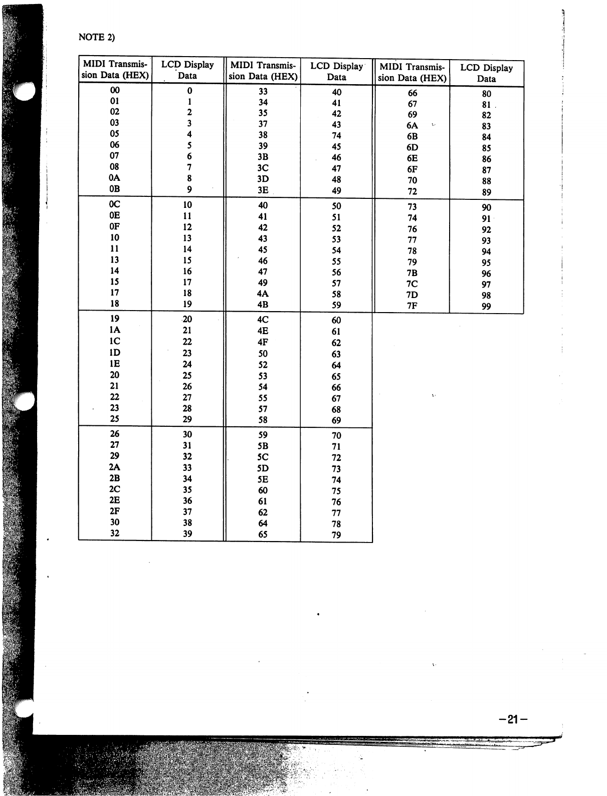
NOTE
2)
-21-
=flE&'-W>\«?.r'..
.:
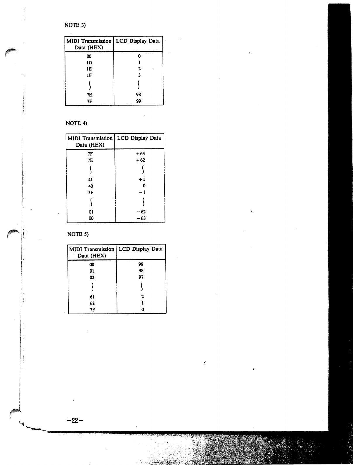
NOTE
3)
NOTE
4)
-22-
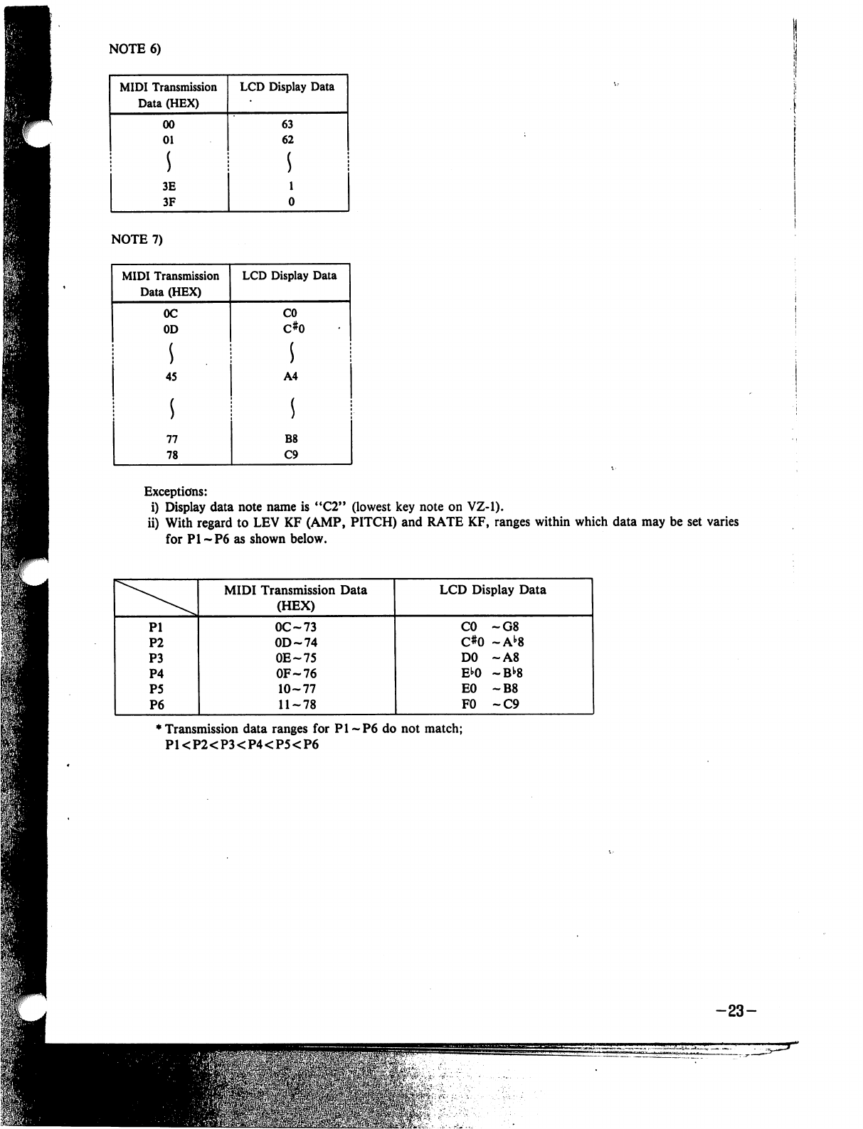
NOTE
6)
Exceptions:
i)
Display
data
note
name
is
"C2"
(lowest
key
note
on
VZ-1).
ii)
With
regard
to
LEV
KF
(AMP,
PITCH)
and
RATE
KF,
ranges
within
which
data
may
be
set
varies
for
PI-P6
as
shown
below.
♦
Transmission
data
ranges
for
PI
-P6
do
not
match;
PKP2<P3<P4<P5<P6
-23-
m
,■•-■■•■■'
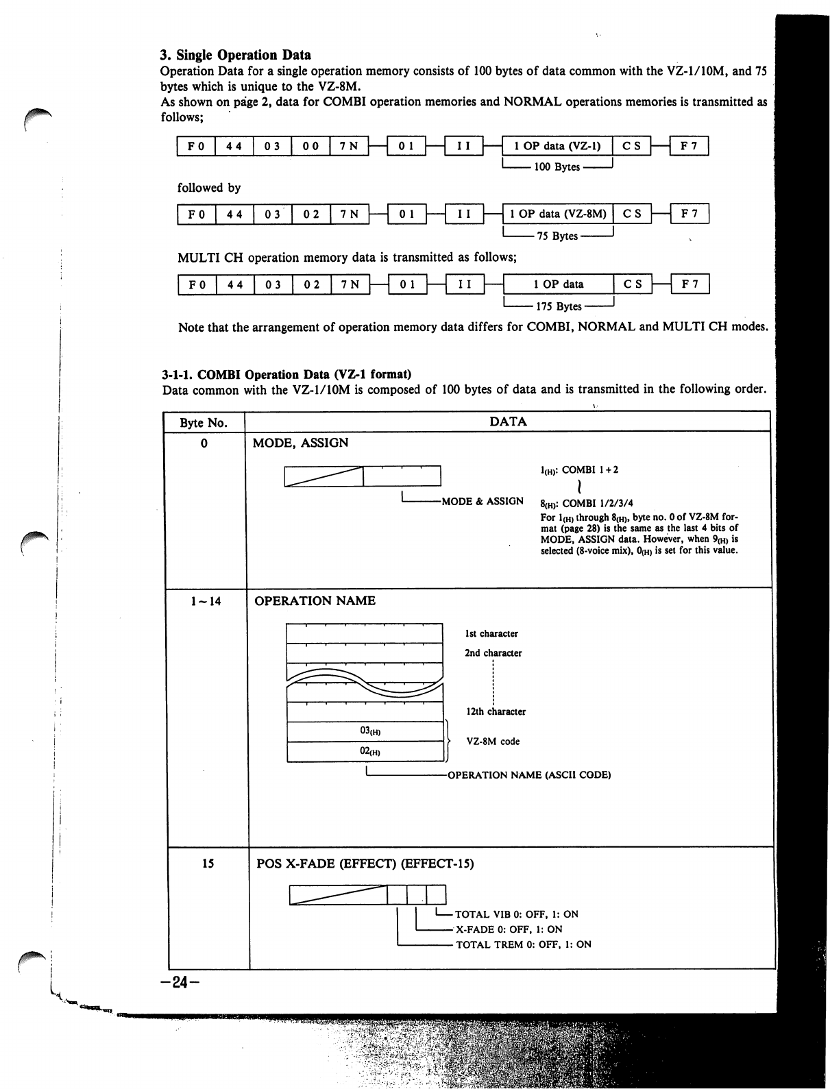
3.
Single
Operation
Data
Operation
Data
for
a
single
operation
memory
consists
of
100
bytes
of
data
common
with
the
VZ-l/lOM,
and
75
bytes
which
is
unique
to
the
VZ-8M.
As
shown
on
page
2,
data
for
COMBI
operation
memories
and
NORMAL
operations
memories
is
transmitted
as
follows;
FO
44
03
|
00
|
7N
I
I
|
1
1
OP
data
(VZ-1)
|
C
s|
F7
100
Bytes
-
followed
by
F0
44
03
02
1
OP
data
(VZ-8M)
75
Bytes-
CS
|
F7
MULTI
CH
operation
memory
data
is
transmitted
as
follows;
0
1
F0
44
|
03
|
02
1
OP
data
■175
Bytes-
CS
| 1
F7
Note
that
the
arrangement
of
operation
memory
data
differs
for
COMBI,
NORMAL
and
MULTI
CH
modes.
3-1-1.
COMBI
Operation
Data
(VZ-1
format)
Data
common
with
the
VZ-1/10M
is
composed
of
100
bytes
of
data
and
is
transmitted
in
the
following
order.
Byte
No.
DATA
MODE,
ASSIGN
]
1(H):
COMBI
1
+
2
J
I
-MODE
&
ASSIGN
8(h):
COMBI
1/2/3/4
For
1(H)
through
8(h),
byte
no.
0
of
VZ-8M
for
mat
(page
28)
is
the
same
as
the
last
4
bits
of
MODE,
ASSIGN
data.
However,
when
9(H)
is
selected
(8-voice
mix),
0(h)
is
set
for
this
value.
OPERATION
NAME
1st
character
2nd
character
12th
character
VZ-8M
code
-OPERATION
NAME
(ASCII
CODE)
15
POS X-FADE
(EFFECT)
(EFFECT-15)
'
TOTAL
VIB
0:
OFF,
1:
ON
-
X-FADE
0:
OFF,
1:
ON
-
TOTAL
TREM
0:
OFF,
1:
ON
-24-
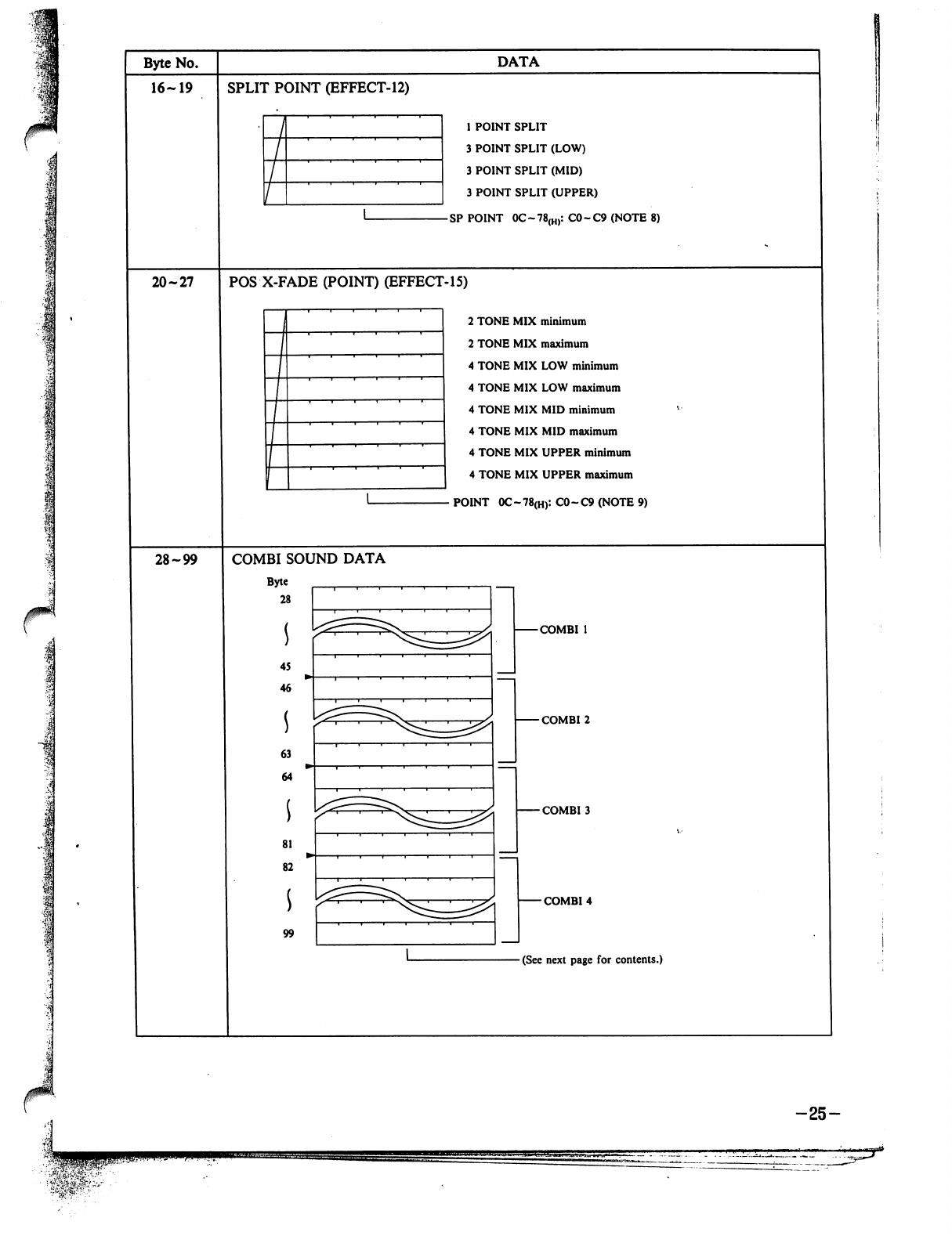
1
p
■
I
Byte
No.
16-19
20-27
28-99
SPLIT
POINT
(EFFECT-12)
DATA
1
POINT
SPLIT
3
POINT
SPLIT
(LOW)
3
POINT
SPLIT
(MID)
3
POINT
SPLIT
(UPPER)
SP
POINT
OC~78(H):CO~C9(NOTE8)
POS
X-FADE
(POINT)
(EFFECT-15)
2
TONE
MIX
minimum
2
TONE
MIX
maximum
4
TONE
MIX
LOW
minimum
4
TONE
MIX
LOW
maximum
4
TONE
MIX
MID
minimum
4
TONE
MIX MID
maximum
4
TONE
MIX
UPPER
minimum
4
TONE
MIX
UPPER
maximum
POINT
0C~78(H):
C0-C9
(NOTE
9)
COMBI
SOUND
DATA
Byte
28
45
46
63
64
81
82
99
-COMBI
1
-COMBI
2
-COMBI
3
-COMBI
4
(See next
page
for
contents.)
-25-
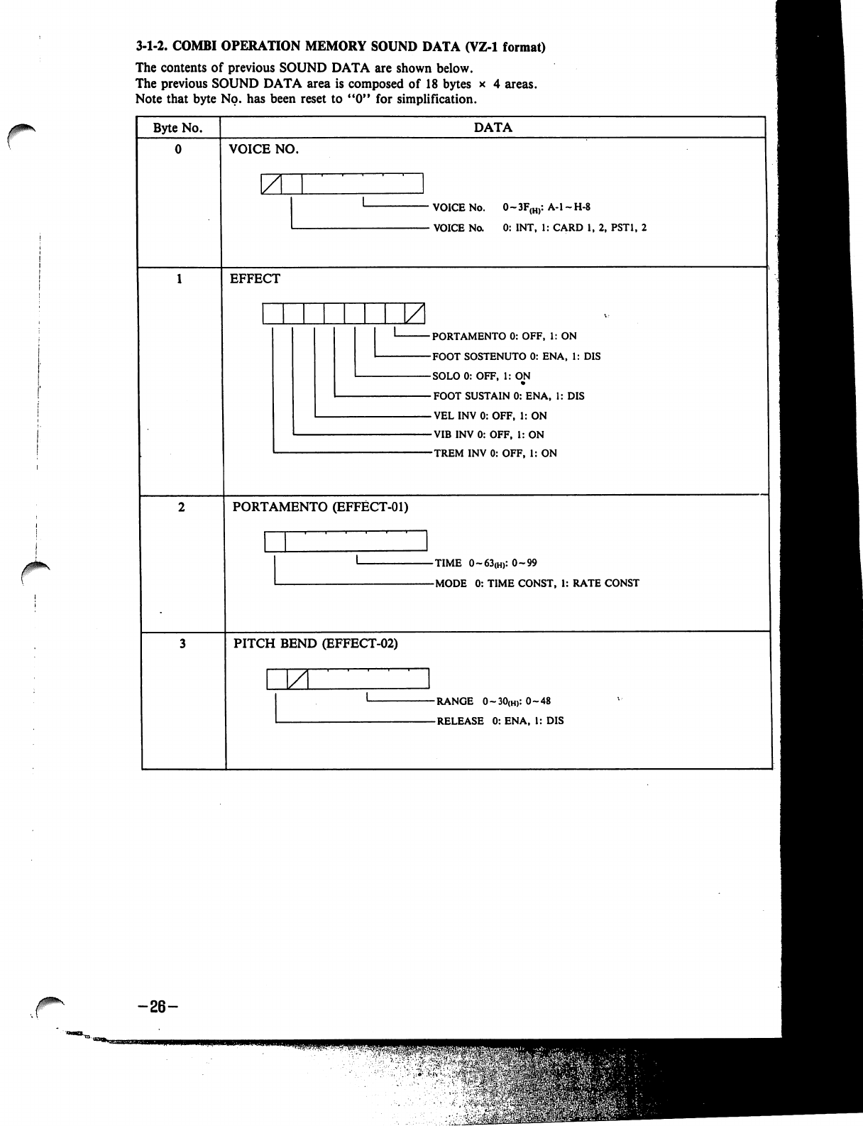
3-1-2.
COMBI
OPERATION
MEMORY
SOUND
DATA
(VZ-1
format)
The
contents
of
previous
SOUND
DATA
are
shown
below.
The
previous
SOUND
DATA
area
is
composed
of
18
bytes
x
4
areas.
Note
that
byte
No.
has
been
reset
to
"0"
for
simplification.
Byte
No.
DATA
VOICE
NO.
ZL
VOICE
No.
0~3F(H):
A-l-H-8
-
VOICE
No.
0:
INT,
1:
CARD
1,
2,
PST1,
2
EFFECT
-PORTAMENTO
0:
OFF,
1:
ON
-FOOT
SOSTENUTO
0:
ENA,
1:
DIS
-SOLO0:
OFF,
1:
OJM
-FOOT
SUSTAIN
0:
ENA,
1:
DIS
-VELINV0:OFF,
1:
ON
-VIBINV0:
OFF,
1:
ON
-TREM
INV
0:
OFF,
1:
ON
PORTAMENTO
(EFFECT-01)
-TIME
0~63(H):0~99
-MODE
0:
TIME
CONST,
1:
RATE
CONST
PITCH
BEND
(EFFECT-02)
JZL
-RANGE
O~3O(H):O~48
-RELEASE
0:
ENA,
I:
DIS
-26-
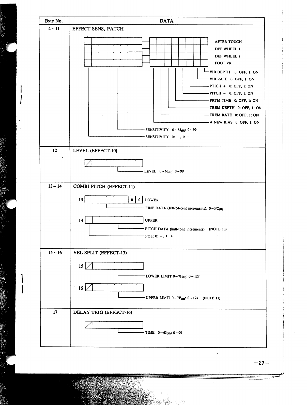
Byte
No.
4-11
DATA
EFFECT
SENS,
PATCH
L_
AFTER
TOUCH
DEF
WHEEL
1
DEF
WHEEL
2
FOOT
VR
VIB
DEPTH
0:
OFF,
1:
ON
VIB
RATE
0:
OFF,
1:
ON
PTICH
+
0:
OFF,
1:
ON
PITCH
-
0:
OFF,
1:
ON
PRT&TIME
0:OFF,
1:
ON
TREM
DEPTH
0:
OFF,
1:
ON
TREM
RATE
0:
OFF,
1:
ON
A
NEW
BIAS 0:OFF,
I:
ON
■
SENSITIVITY
0
-
63(H):
0-99
-SENSITIVITY
0:
+,
1:
-
12
LEVEL
(EFFECT-10)
ZL
-LEVEL
0~63(H):0~99
13-14
COMBI
PITCH
(EFFECT-11)
13
14
LOWER
FINE
DATA
(100/64-cent
increments),
0~FC(H)
UPPER
PITCH
DATA
(half-tone
increments)
(NOTE
10)
POL:
0:
-,
1:
+
15-16
VEL
SPLIT
(EFFECT-13)
•
LOWER
LIMIT
0~7F(H):
0-127
16
-UPPER
LIMIT
0-7F(H):
0-
127
(NOTE
11)
17
DELAY
TRIG
(EFFECT-16)
-TIME
0~63(H):0~99
-27-

3-1-3.
COMBI
OPERATION
DATA
(VZ-8M
format)
Data
unique
to
the
VZ-8M
comprises
75
bytes,
which
are
transmitted
in
the
sequence
shown
below.
Byte
No.
DATA
0
MODE,
ASSIGN
1-2
OPERATION
TUNE
0
0
LOW
-FINE
DATA
(100/64-cent
increments),
0~FC<H)
UP
-
TUNE
DATA
(half-tone
increments),
0-
-
POL:0:
-,
1:
+
3-6
VOICE
SHIFT
NO.
COMBI
1
•
VOICE
SHIFT
NO.
0(h)
CARD1
1(H)
CARD2
20(H)
PST1
21(H)
PST2
40(H)
INT
COMBI
2
COMBI
3
COMBI
4
VOICE
SHIFT
NO.
(Same
format
as
COMBI
1)
VEL
TABLE
SELECT
VEL
TABLE
SELECT
NO.
0~7{H)
-28-
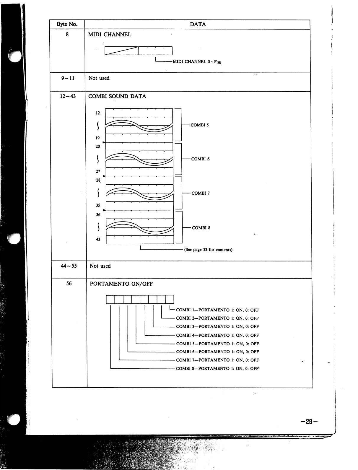
Byte
No.
8
DATA
MIDI
CHANNEL
-MIDI
CHANNEL
0-F(H)
9-11
Not
used
12-43
COMBI
SOUND
DATA
12
19
20
27
28
35
36
43
-COMBI
5
-COMBI
6
-COMBI
7
-
COMBI
8
-
(See
page
33
for
contents)
44-55
Not
used
56
PORTAMENTO
ON/OFF
L_
COMBI
COMBI
COMBI
COMBI
COMBI
COMBI
COMBI
COMBI
1-PORTAMENTO
1
2-PORTAMENTO
1
3—PORTAMENTO
1
4—PORTAMENTO
1
5—PORTAMENTO
1
6—PORTAMENTO
1
7—PORTAMENTO
1
8—PORTAMENTO
1
ON,
0:
OFF
ON,
0:
OFF
ON,
0:
OFF
ON,
0:
OFF
ON,
0:
OFF
ON,
0:
OFF
ON,
0:
OFF
ON,
0:
OFF
-29-
.levrp.#
■
':,
'V-::.."
■...';•-.

Byte
No.
57
DATA
TOTAL
VIB
(WAVE,
MULTI),
OCTAVE
VIB.
WAVE
0:
TRI,
1:
SU,
2:
SD,
3:
SQU
VIB.
MULTI
0:
OFF,
1:
ON
OCTAVE
0-2(H):
0-2
OCTAVE
0:
-,
1:
+
58
TOTAL
VIB.
(DEPTH)
-
DEPTH
0~63(H):
0-99
59
TOTAL
VIB.
(RATE)
■RATE0~63(H):
0-99
60
TOTAL
VIB.
(DELAY)
•
DELAY
0~63(H):
0-99
61
TOTAL
TREMOLO
(WAVE,
MULTI)
ZL
TREMOLO
WAVE
0:
TRI,
1:
SU,
2:
SD,
3:
SQU
TREMOLO
MULTI
0:
OFF,
1:
ON
62
TOTAL
TREMOLO
(DEPTH)
-DEPTH
0-63(H):
0-99
63
TOTAL
TREMOLO
(RATE)
•
RATE
0-63(H):
0-99
64
TOTAL
TREMOLO
(DELAY)
A
-
DELAY
0~63(H):
0-99
-30-
-■*£¥,«$
'S&&&
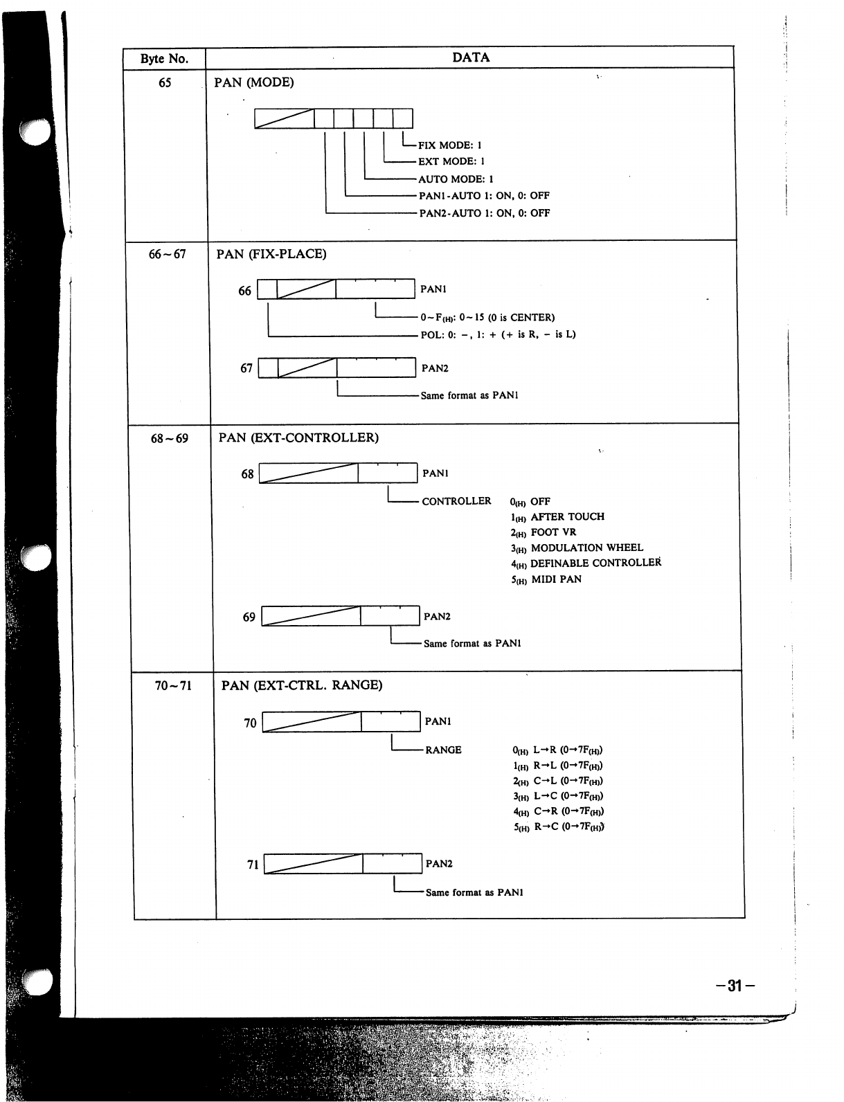
-31-
J
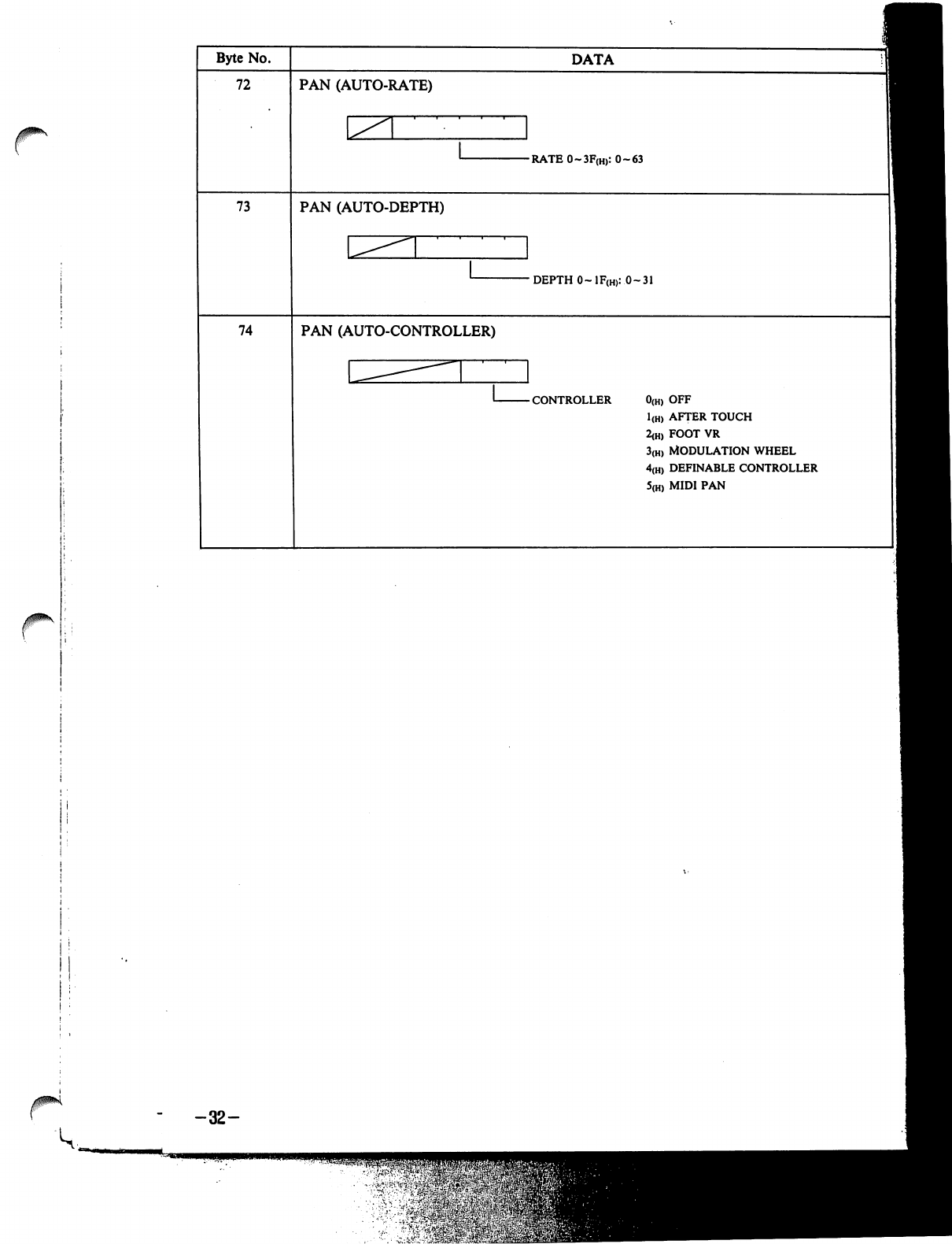
-32-
v-^iW&frS
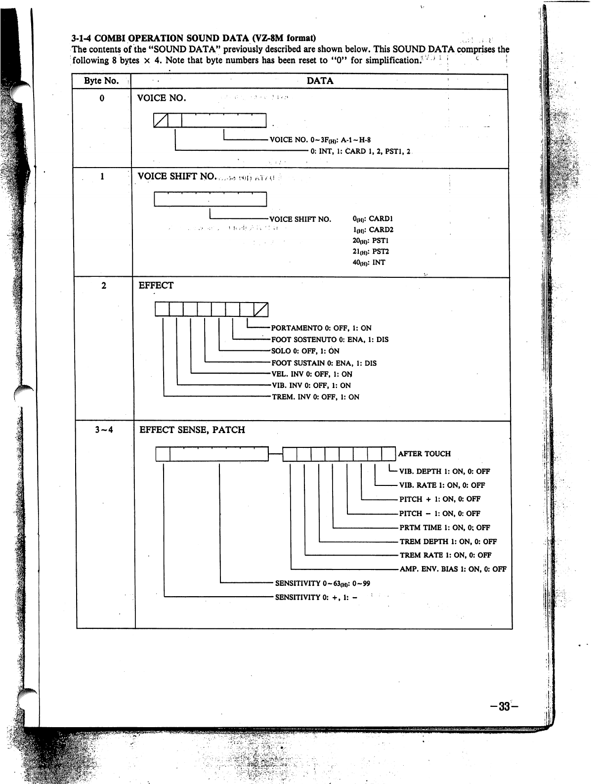
3-1-4
COMBI
OPERATION
SOUND
DATA
(VZ-8M
format)
^
The
contents
of
the
"SOUND
DATA"
previously
described
are
shown
below.
This
SOUND
DATA
comprises
the
following
8
bytes
x
4.
Note
that
byte
numbers
has
been
reset
to
"0"
for
simplification.'
l
;
c
■!
Byte
No.
DATA
VOICE
NO.
YL
-VOICE
NO.
0~3F(H):
A-l-H-8
0:
INT,
1:
CARD
1,
2,
PST1,
2
VOICE
SHIFT
NO.
-VOICE
SHIFT
NO.
0(H):
CARD1
1(H):
CARD2
20(H):
PST1
21(H):
PST2
40(H):
INT
EFFECT
PORTAMENTO
0:
OFF,
1:
ON
FOOT
SOSTENUTO
0:
EN
A,
1:
DIS
SOLO
0:
OFF,
1:
ON
FOOT
SUSTAIN
0:
ENA,
1:
DIS
VEL.
INV
0:
OFF,
1:
ON
VIB.
INV
0:
OFF,
1:
ON
TREM.
INV
0:
OFF,
1:
ON
3-4
EFFECT
SENSE,
PATCH
_J
AFTER
TOUCH
I—VIB.
DEPTH
1:
ON,
0:
OFF
VIB.
RATE
1:
ON,
0:
OFF
PITCH
+
1:
ON,
0:
OFF
PITCH
-
1:
ON,
0:
OFF
PRTM
TIME
1:
ON,
0;
OFF
TREM
DEPTH
1:
ON,
0:
OFF
TREM
RATE
1:
ON,
0:
OFF
AMP.
ENV.
BIAS
1:
ON,
0:
OFF
-
SENSITIVITY
0~63(H):
0-99
■
SENSITIVITY
0:
+,
1:
-
, i
-'!
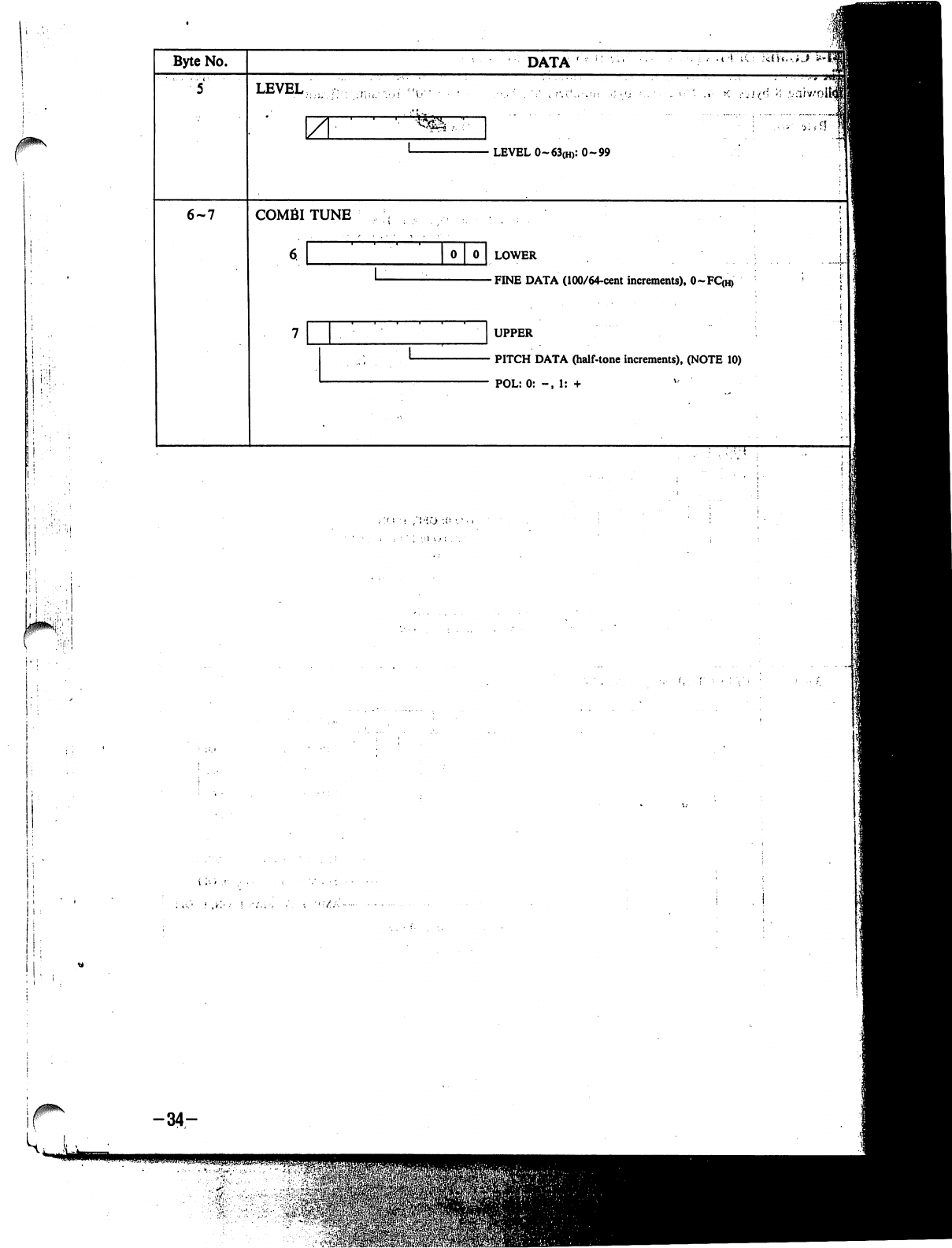
j
Byte
No.
6-7
DATA'
LEVEL
\Z
COMBITUNE
•
LEVEL
0-63(H):
0-99
0
LOWER
-FINE
DATA
(100/64-cent
increments),
0~FC(H)
UPPER
•
PITCH
DATA
(half-tone
increments),
(NOTE
10)
POL:0:
-,
1:
+
-34-
•
'»-.$$£
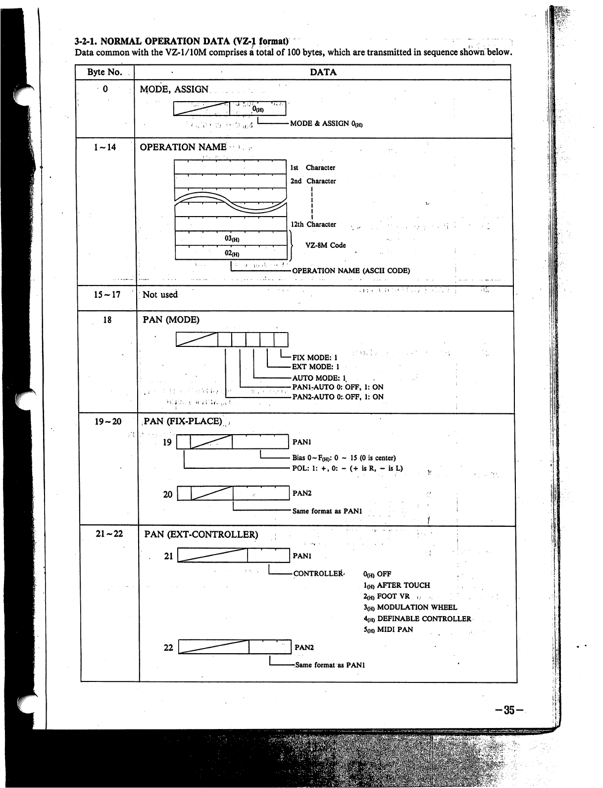
3-2-1,
NORMAL
OPERATION
DATA
(VZ-1
format)
;
Data
common
with
the
VZ-l/lOM
comprises
a
total
of
100
bytes,
which
are
transmitted
in
sequence
shown
below.
Byte
No.
15-17
18
19-20
21-22
DATA
MODE,
ASSIGN
-
MODE
&
ASSIGN
0(h)
OPERATION
NAME
03(H)
02(H)
1st
Character
2nd
Character
12th
Character
I
VZ-8M
Code
-OPERATION
NAME
(ASCII
CODE)
Not
used
PAN
(MODE)
-FIX
MODE:
1
-EXTMODE:
1
-AUTO
MODE:
1.
-PAN1-AUTO
0:
OFF,
1:
ON
-PAN2-AUTO
0:OFF,
1:
ON
PAN
(FIX-PLACE)
19
r
20
PANl
•
Bias
0~F(H>:
0
-
15
(0
is
center)
•POL:
1:
+,0:
-
(+
is
R,
-
is
L)
]
PAN2
-
Same
format
as
PANl
PAN
(EXT-CONTROLLER)
21
PANl
CONTROLLER'
0(H)
OFF
1(H)
AFTER
TOUCH
2(H)FOOTVR
,
3(H)
MODULATION
WHEEL
4(H)
DEFINABLE
CONTROLLER
5(h)
MIDI
PAN
PAN2
Same
format
as
PANl
-35-
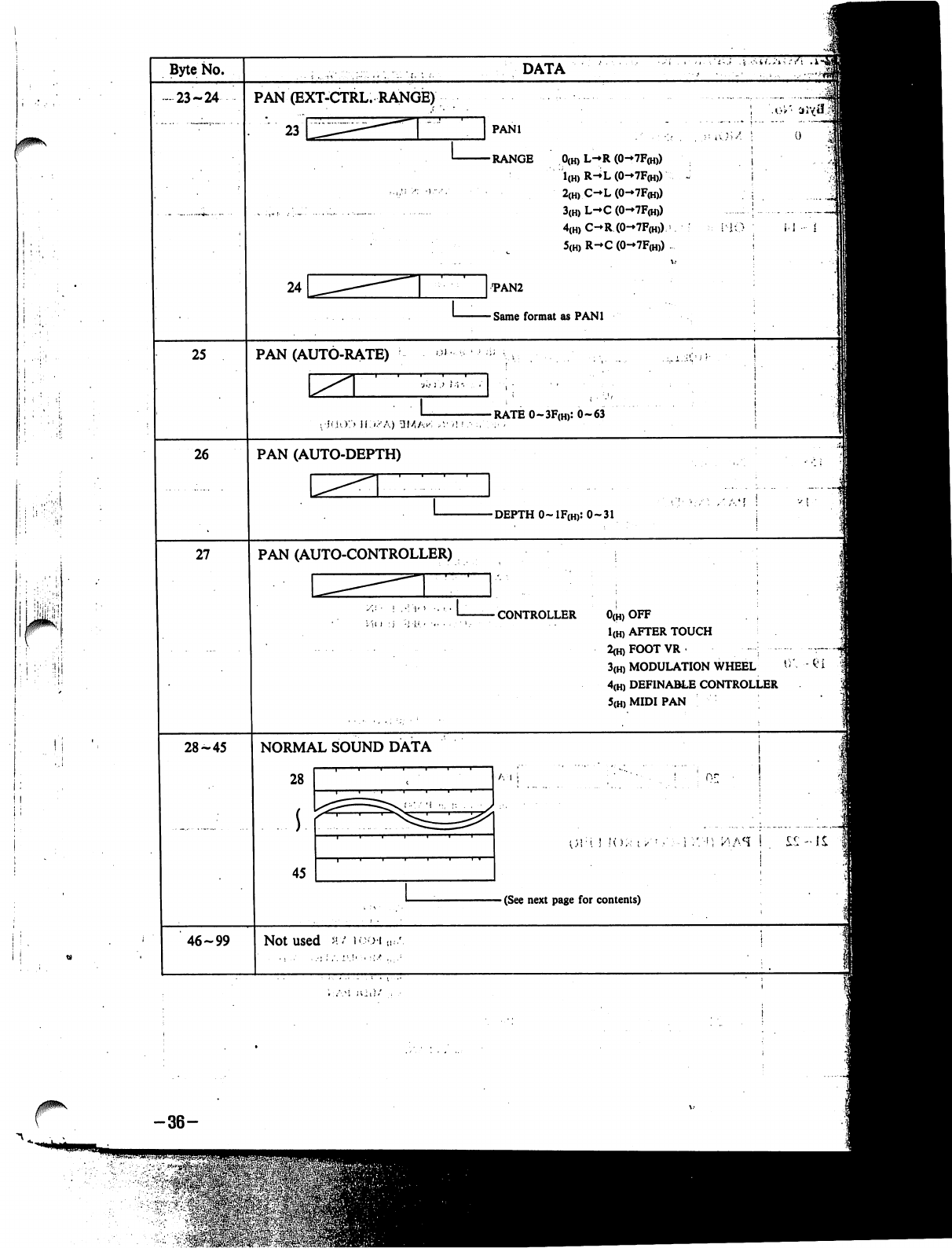
i
:'!
I;
i i
Byte
No.
•
23-24
25
26
27
28-45
46-99
PAN
(EXT-CTRL.
RANGE)
23
DATA
PANl
RANGE
0(h)
L-*R
(0-7F<h))
1(H)
R-^L
(0-7F(H))
2(H)
C-L
(0-7F(H))
3(H)
L-C
(0-7F(H))
4(H)
C-R
(0-7F<h))
>
5(H)
R-»C
(0-7F(H))
•PAN2
Same
format
as
PANl
i-1
•
i
PAN
(AUTO-RATE)
-RATE
0~3F(H):
0-63
PAN
(AUTO-DEPTH)
-DEPTH
O~1F(H):
0-31
PAN
(AUTO-CONTROLLER)
CONTROLLER
0(H)
OFF
1(H)
AFTER
TOUCH
2<h)FOOTVR
■-■:
3(H)
MODULATION
WHEEL
4(H)
DEFINABLE
CONTROLLER
5(H)
MIDI
PAN
NORMAL
SOUND
DATA
28
45
A
I
1
I
;':■';
ttfi.H
!
Sit
-
(See
next
page
for
contents)
Not
used
m/
b-oi
-36-
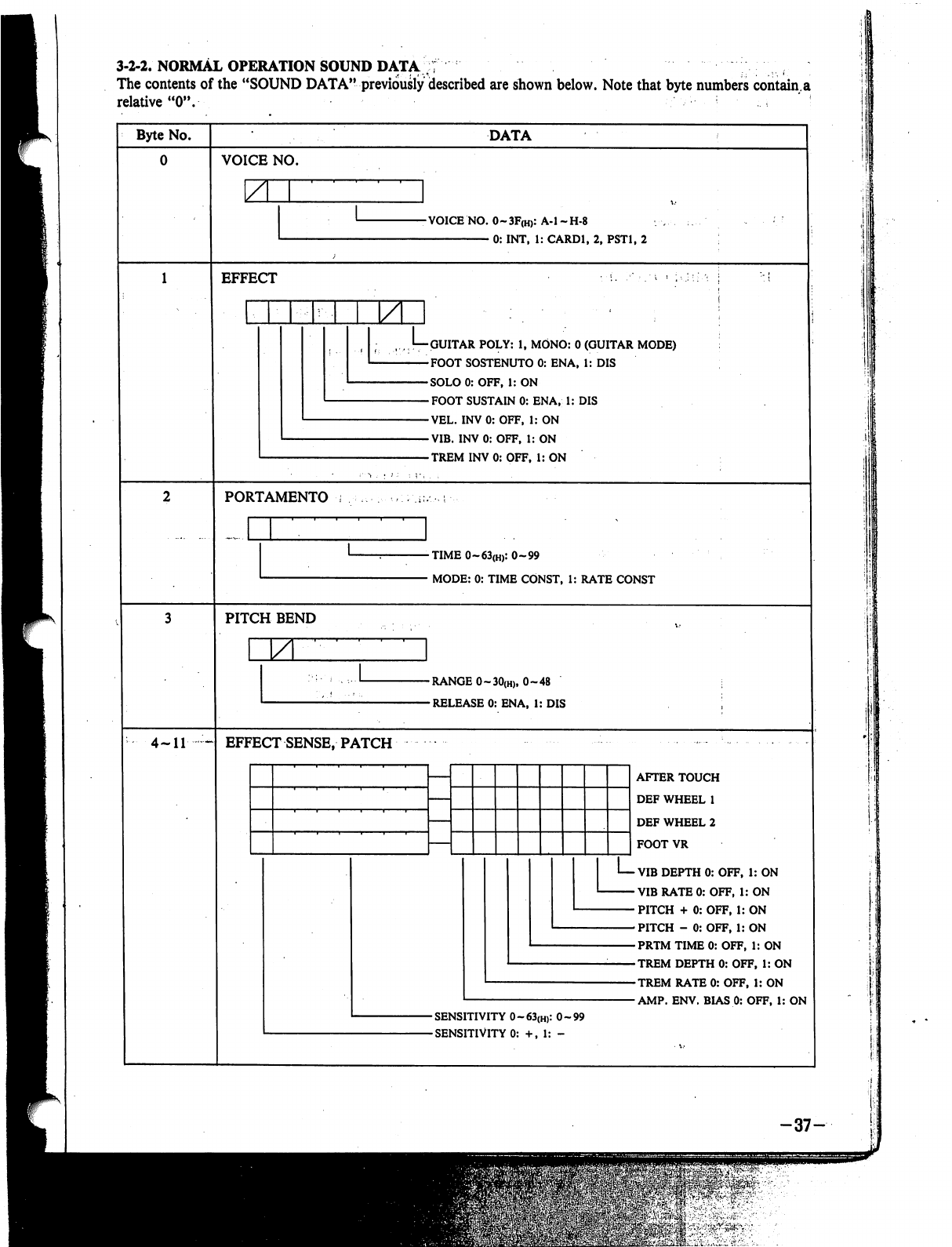
3-2-2-
NORMAL
OPERATION
SOUND
DATA
;f
;
The
contents
of
the
"SOUND
DATA"
previously
described
are
shown
below.
Note
that
byte
numbers
contain.a
relative
"0".
'
Byte
No.
4-11
~
DATA
VOICE
NO.
Z
-VOICE
NO.
0~3F(H):
A-l-H-8
0:
INT,
1:
CARD1,
2,
PST1,
2
EFFECT
GUITAR
POLY:
1,
MONO:
0
(GUITAR
MODE)
FOOT
SOSTENUTO
0:
ENA,
1:
DIS
SOLO
0:
OFF,
1:
ON
FOOT
SUSTAIN
0:
ENA,
1:
DIS
VEL.
INV
0:
OFF,
1:
ON
VIB.
INV
0:
OFF,
1:
ON
TREM
INV
0:
OFF.
1:
ON
PORTAMENTO
-TIME
0~63(H):
0-99
•
MODE:
0:
TIME
CONST,
1:
RATE
CONST
PITCH
BEND
ZL
-RANGE
0~30(H),
0-48
-RELEASE
0:
ENA,
1:
DIS
EFFECT
SENSE,
PATCH
AFTER
TOUCH
DEF
WHEEL
1
DEF
WHEEL
2
FOOT
VR
■
VIB
DEPTH
0:
OFF,
1:
ON
•
VIB
RATE
0:
OFF,
1:
ON
•
PITCH
+
0:
OFF,
1:
ON
-PITCH
-
0:OFF,
1:
ON
-PRTM
TIME
0:
OFF,
1:
ON
-TREM
DEPTH
0:
OFF,
1:
ON
-TREM
RATE
0:
OFF,
1:
ON
■AMP.
ENV.
BIAS
0:
OFF,
1:
ON
-SENSITIVITY
0~63(H):
0-99
-SENSITIVITY
0:
+,
1:
-
-37-
^u;$$q

1
I
'
Byte
No.
12
13-14
15
16
17
DATA
LEVEL
\ZL
-
LEVEL
0~63(H):
0-99
Not
used
MIDI
CHANNEL
-MIDI
CHANNEL
0~F:
1
~
16
PORTAMENT,
VEL.
TABLE
SELECT
-VEL.
TABLE
SELECT
0~7(H):
1-8
-
PORTAMENTO
0:
OFF,
1:
ON
VOICE
SHIFT
NO.
-VOICE
SHIFT
No.
0(H):
CARD1
1(H):
CARD2
2O(H):PST1
21(H):PST2
40(h>:
INT
i
:
H
I
J
"C
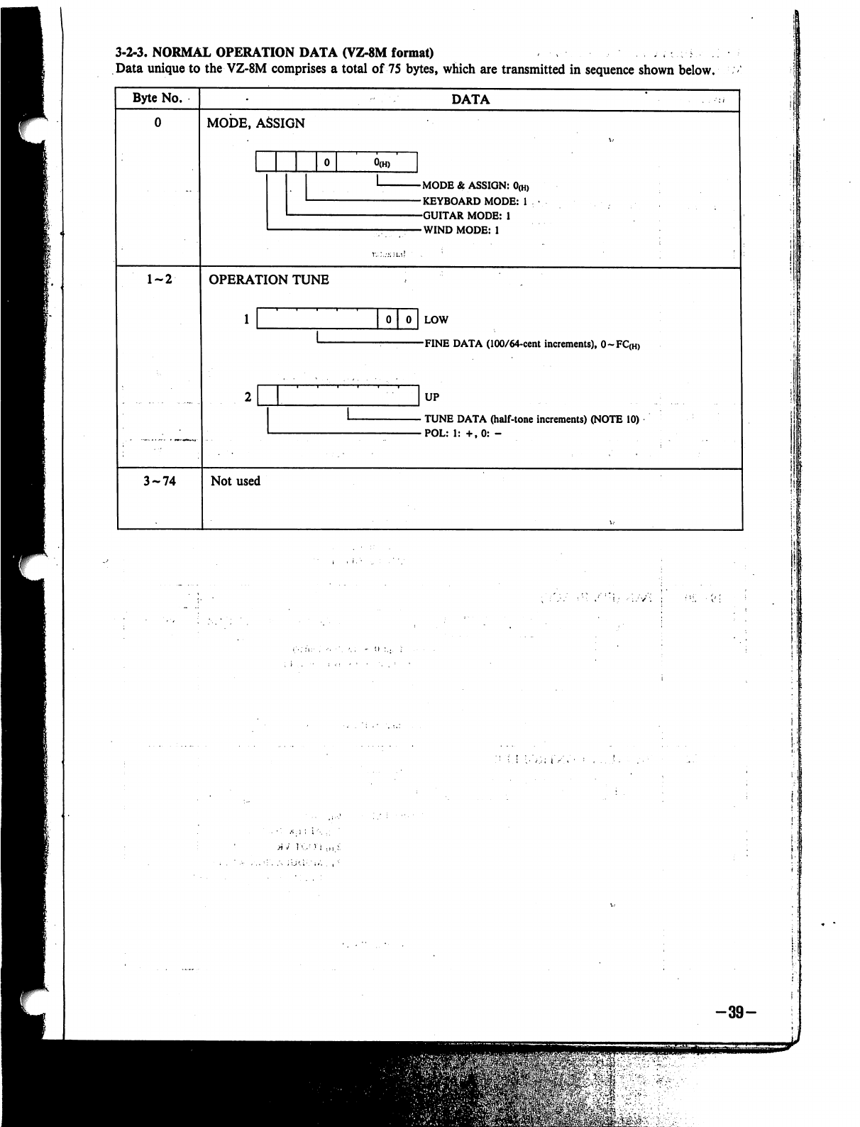
3-2-3,
NORMAL
OPERATION
DATA
(VZ-8M
format)
Data
unique
to
the
VZ-8M
comprises
a
total
of
75
bytes,
which
are
transmitted
in
sequence
shown
below.
Byte
No.
DATA
0
MODE,
ASSIGN
MODE
&
ASSIGN:
0(H)
KEYBOARD
MODE:
1
GUITAR
MODE:
1
WIND
MODE:
1
1-2
OPERATION
TUNE
LOW
FINE
DATA
(100/64-cent
increments),
0~FC(H)
UP
TUNE
DATA
(half-tone
increments)
(NOTE
10)
POL:
1:
+,0:
-
3-74
Not
used
1
!
.'
■■'
:.:
V";
-39-
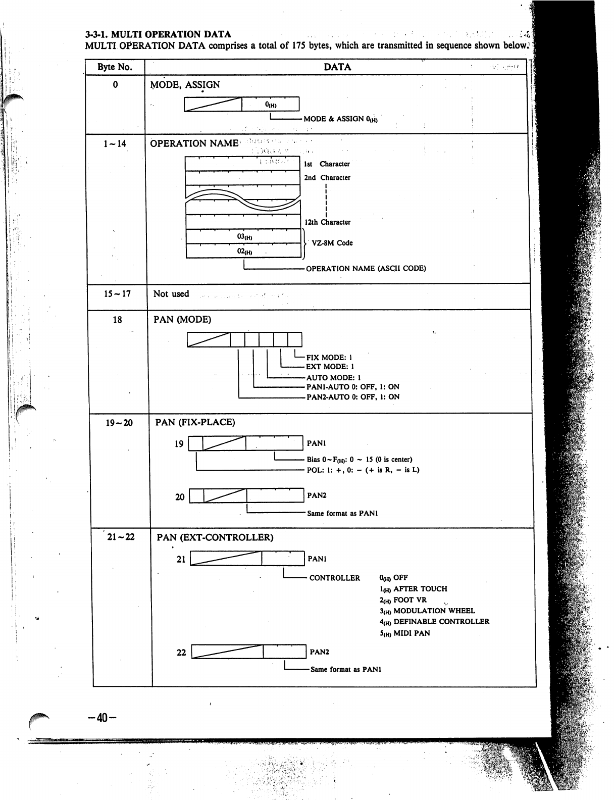
!
:
(
..
i
ii
■■•!|
3-3-1,
MULTI
OPERATION
DATA
MULTI
OPERATION
DATA
comprises
a
total
of
175
bytes,
which
are
transmitted
in
sequence
shown
below.5
Byte
No.
1-14
15-17
18
19-20
21-22
DATA
VIODE,
ASSIGN
-
MODE
&
ASSIGN
0(H)
OPERATION
NAME1
03(H)
02(H,
1st
Character
2nd
Character
12th
Character
I
VZ-8M
Code
-OPERATION
NAME
(ASCII
CODE)
Not
used
PAN
(MODE)
-FIX
MODE:
1
-EXTMODE:
1
-AUTO
MODE:
1
-PAN1-AUTO
0:
OFF,
1:
ON
-PAN2-AUTO
0:
OFF,
1:
ON
PAN
(FIX-PLACE)
19
r
20
PANl
■
Bias
0~F(h>:
0
-
15
(0
is
center)
•
POL:
1:
+,
0:
-
(+
is
R,
-
is
L)
PAN2
Same
format
as
PANl
PAN
(EXT-CONTROLLER)
21
PANl
CONTROLLER
0(H)
OFF
1(H)
AFTER
TOUCH
2(H)
FOOT
VR
3(H)
MODULATION
WHEEL
4(H)
DEFINABLE
CONTROLLER
5(H)
MIDI
PAN
22
|
PAN2
-Same
format
as
PANl
-40-
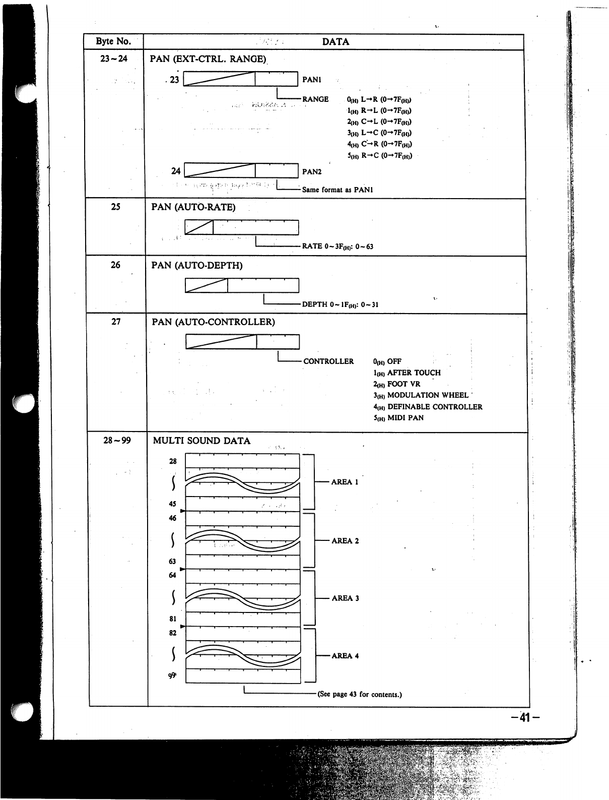
Byte
No.
23-24
25
26
27
28-99
DATA
PAN
(EXT-CTRL.
RANGE)
.23
PAN1
-RANGE
0(H)
L-R
(0-7F(H))
1(H)
R-L
(0-7F(H))
2(H)
C-L
(0-7F(H))
3(H)
L-C
(0->7F(H))
4(H)
C-R
(0-7F(H))
5(H)
R-C
(0-7F(H))
PAN2
Same
format
as
PAN1
PAN
(AUTO-RATE)
L
-RATE0-3F(H):
0-63
PAN
(AUTO-DEPTH)
-DEPTH
0~1F(h):
0-31
PAN
(AUTO-CONTROLLER)
CONTROLLER
0(H)
OFF
I
1(H)
AFTER
TOUCH
2(H)FOOTVR
3(H)
MODULATION
WHEEL
4(H)
DEFINABLE
CONTROLLER
5(H)
MIDI
PAN
MULTI
SOUND
DATA
28
s
45
46
63
i
64
81
82
-AREA
1
•AREA
2
-AREA
3
-AREA
4
-(See
page
43
for contents.)
-41-
lil
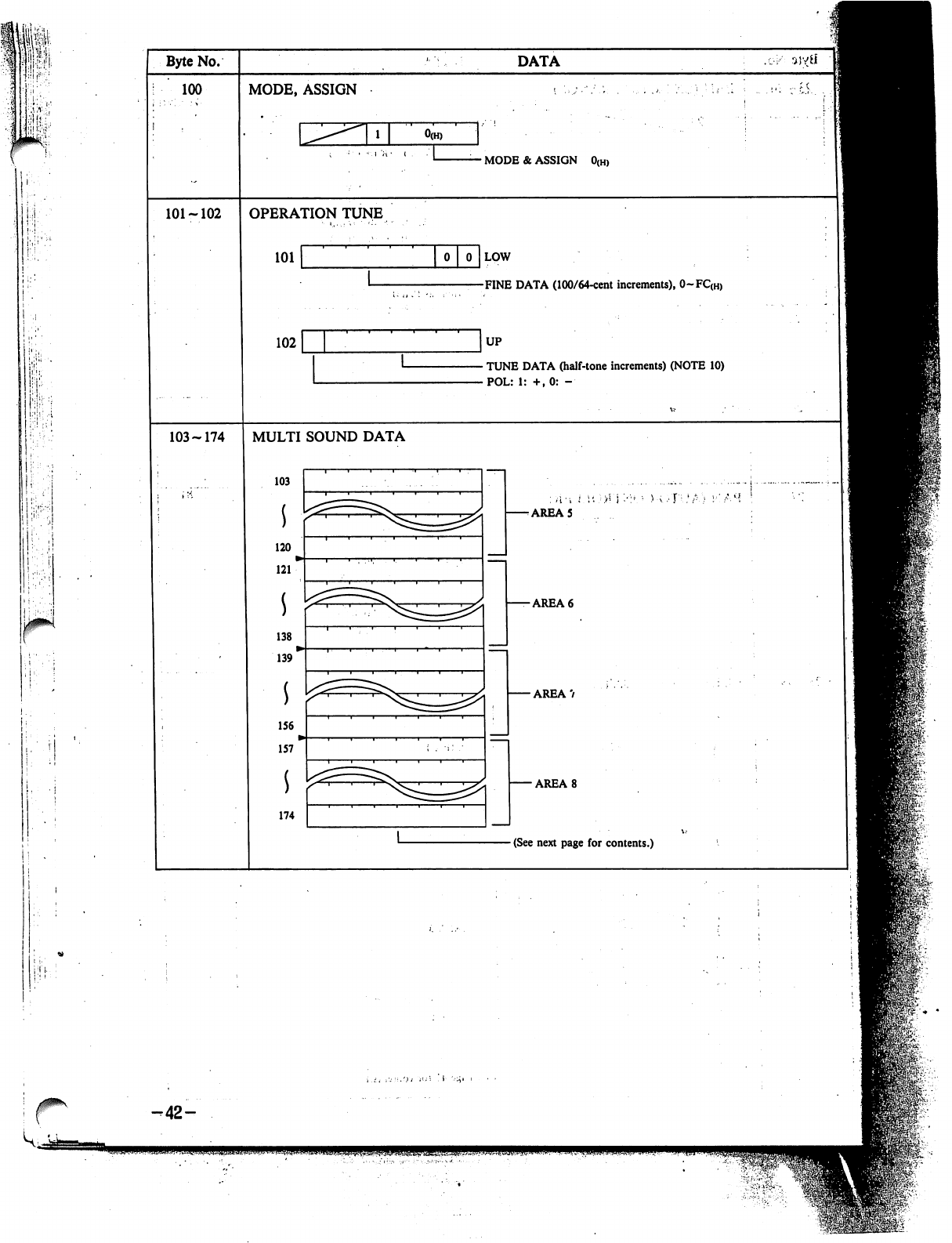
!
|.
i.
;
i
i
Byte
No.
100
101-102
103-174
DATA
MODE,
ASSIGN
-
MODE
&
ASSIGN
0(H)
OPERATION
TUNE
101
102
LOW
FINE
DATA
(100/64-cent
increments),
0~FC(H)
UP
TUNE
DATA
(half-tone
increments)
(NOTE
10)
POL:
1:
+.0:
-
MULTI
SOUND
DATA
103
120
i
121
138
i
139
156
157
*
AREA
5
-AREA
6
-
AREA
7
■AREA
8
(See
next
page
for
contents.)
r
-42-
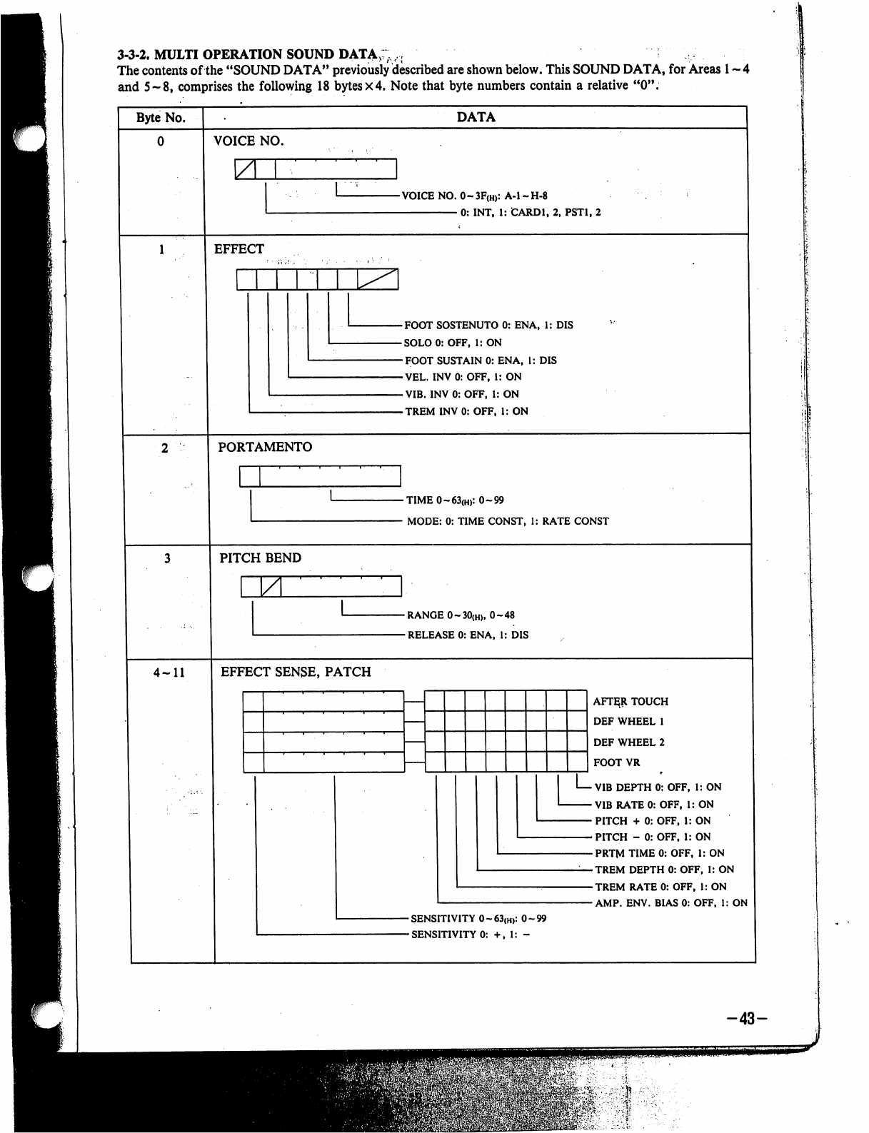
3-3-2.
MULTI
OPERATION
SOUND
DATA:;,-,
The
contents
of
the
"SOUND
DATA"
previously
described
are
shown
below.
This
SOUND
DATA,
for
Areas
1
~
4
and
5-8,
comprises
the
following
18
bytes
x4.
Note
that
byte
numbers
contain
a
relative
"0".
Byte
No.
DATA
VOICE
NO.
-VOICE
NO.
0~3F(H):
A-l-H-8
0:
INT,
1:
CARD1,
2,
PST1,
2
EFFECT
-FOOT
SOSTENUTO
0:
ENA,
1:
DIS
-SOLO0:
OFF,
1:
ON
-FOOT
SUSTAIN
0:
ENA,
1:
DIS
-VEL.
INV0:OFF,
1:
ON
-VIB.
INV0:OFF,
1:
ON
-TREM
INV
0:
OFF,
1:
ON
PORTAMENTO
-TIME
0~63(H):
0-99
-
MODE:
0:
TIME
CONST,
1:
RATE
CONST
PITCH
BEND
\ZL
-RANGE
0~30(H),
0-48
-RELEASE
0:
ENA,
1:
DIS
4-11
EFFECT
SENSE,
PATCH
AFT^R
TOUCH
DEF
WHEEL
1
DEF
WHEEL
2
FOOT
VR
VIB
DEPTH
0:
OFF,
1:
ON
VIB
RATE
0:
OFF,
i:
ON
PITCH
+
0:
OFF,
1:
ON
PITCH
-
0:
OFF,
1:
ON
PRTM
TIME
0:
OFF,
1:
ON
TREM
DEPTH
0:
OFF,
1:
ON
TREM
RATE
0:
OFF,
1:
ON
AMP.
ENV.
BIAS
0:
OFF,
1:
ON
-43-

i
jP;
-44-
Ji
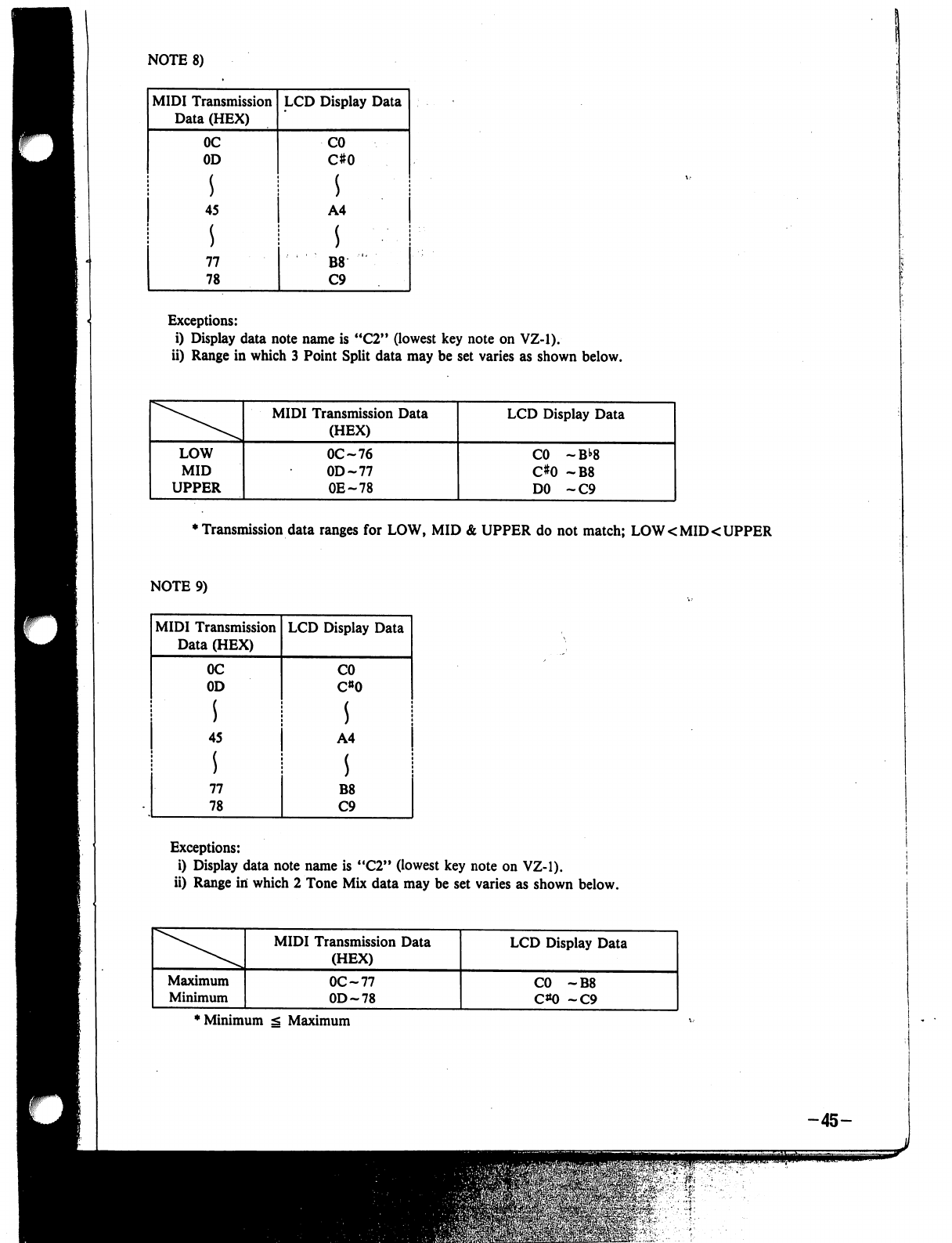
NOTE
8)
MIDI
Transmission
Data
(HEX)
LCD
Display
Data
Exceptions:
i)
Display
data
note
name
is
"C2"
(lowest
key
note
on
VZ-1).
ii)
Range
in
which
3
Point
Split
data
may
be
set
varies
as
shown
below.
♦
Transmission
data
ranges
for
LOW,
MID
&
UPPER
do
not
match;
LOW
<
MID
<
UPPER
NOTE
9)
Exceptions:
i)
Display
data note
name
is
"C2"
(lowest
key
note
on
VZ-1).
ii)
Range
in
which
2
Tone
Mix
data
may
be
set
varies
as
shown
below.
'Minimum
g
Maximum
-45-

iii)
Range
in
which
4
Tone
Mix
data
may
be
set
varies
as
shown
below.
*
LOW
Min
g
LOW
Max
s
MID
Min
g
MID
Max
g
UPPER
Min
g UPPER
Max
NOTE
10)
Pi
I!!!1...-
i
MIDI
Transmission
Data
(HEX)
00
01
S
0B
0C
0D
17
3C
3D
47
LCD
Display
Data
OCT
NOTE
0
1
11
0
1
11
0
1
11
NOTE
11)
VEL
SPLIT
Min
^
VEL
SPLIT
Max
-46-
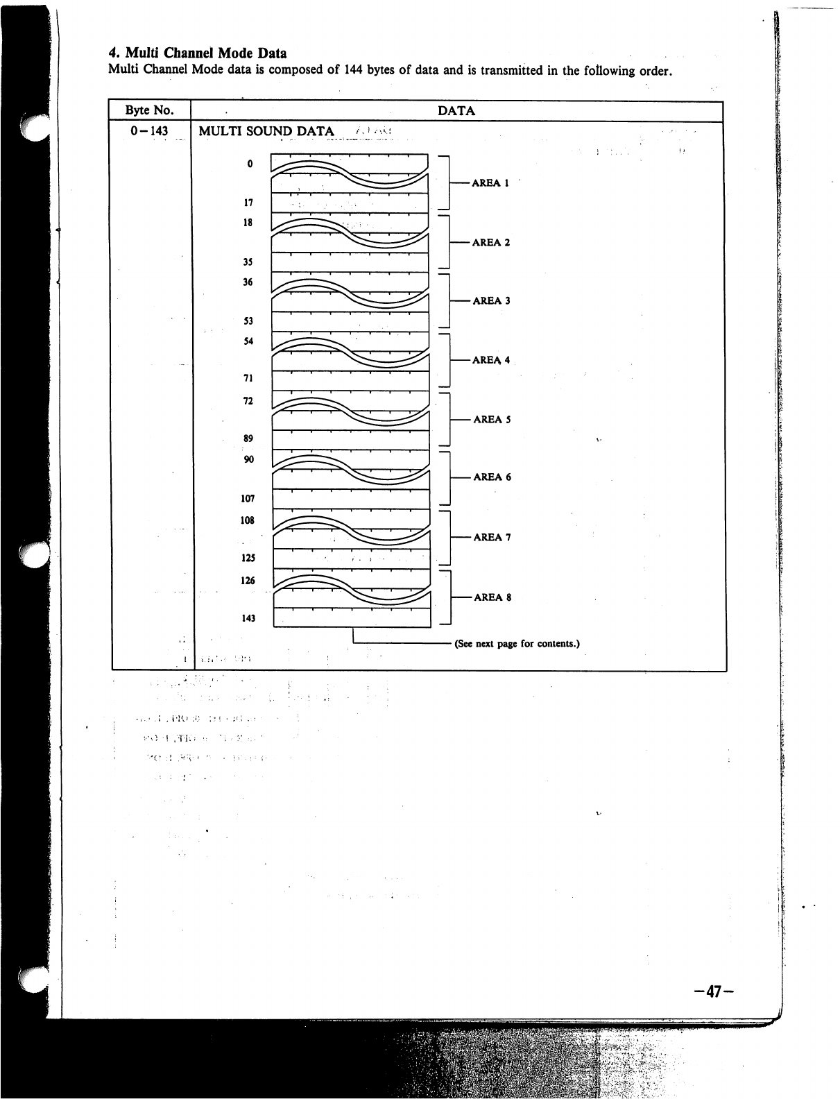
4.
Multi
Channel
Mode
Data
Multi
Channel
Mode
data
is
composed
of
144
bytes
of
data
and
is
transmitted
in
the
following
order.
Byte
No.
DATA
0-143
MULTI
SOUND
DATA
o
17
18
35
36
S3
54
71
72
89
90
107
108
125
126
143
-AREA
1
-AREA
2
-AREA
3
-AREA
4
-
AREA
5
-AREA
6
-AREA
7
-AREA
8
-
(See next
page
for
contents.)
-47-
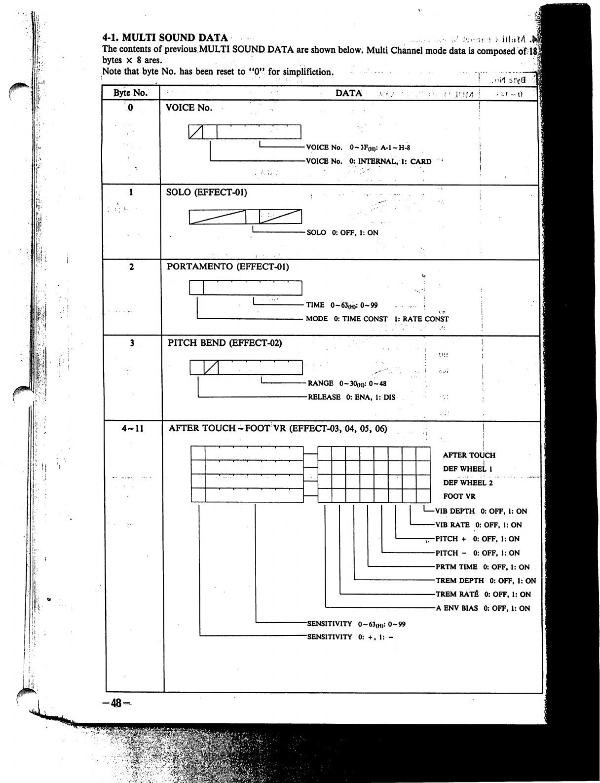
0^"-
r
4-1.
MULTI
SOUND
DATA
\.u..:Uri
;
j|f:iM
.
The
contents
of
previous
MULTI
SOUND
DATA
are
shown
below.
Multi
Channel
mode
data
is
composed
of
]
bytes
X
8
ares.
Note
that
byte
No.
has
been
reset
to
"0"
for
simplifiction.
:
; !
M
Byte
No.
4-11
-■48-
DATA
i
M
-0
VOICE
No.
\ZL
-VOICE
No.
0~3F(H):
A-l-H-8
-VOICE
No.
0:
INTERNAL,
1:
CARD
SOLO
(EFFECT-01)
-SOLO
0:OFF,
1:
ON
PORTAMENTO
(EFFECT-01)
■TIME
0~63(H):
0-99
.....
r
j
MODE
0:
TIME
CONST
1:
RATE
CONST
PITCH
BEND
(EFFECT-02)
M.
-RANGE
0-.30(h):0-48
-RELEASE
0:
ENA,
1:
DIS
AFTER
TOUCH
~FOOT
VR
(EFFECT-03,
04,
05,
06)
AFTER
TOUCH
DEF
WHEEL
1
DEFWHEEL2
FOOT
VR
I—VIB
DEPTH
0:
OFF,
1:
ON
VIB
RATE
0:
OFF,
1:
ON
-jT-PITCH
+
0:
OFF,
1:
ON
PITCH
-
0:
OFF,
1:
ON
PRTM
TIME
0:
OFF,
1:
ON
TREM
DEPTH
0:
OFF,
1:
ON
TREM
RATfi
0:
OFF,
1:
ON
A
ENV
BIAS
0:
OFF,
1:
ON
-SENSITIVITY
O~63(H):
0-99
-SENSITIVITY
0:
+,
1:
-
&O
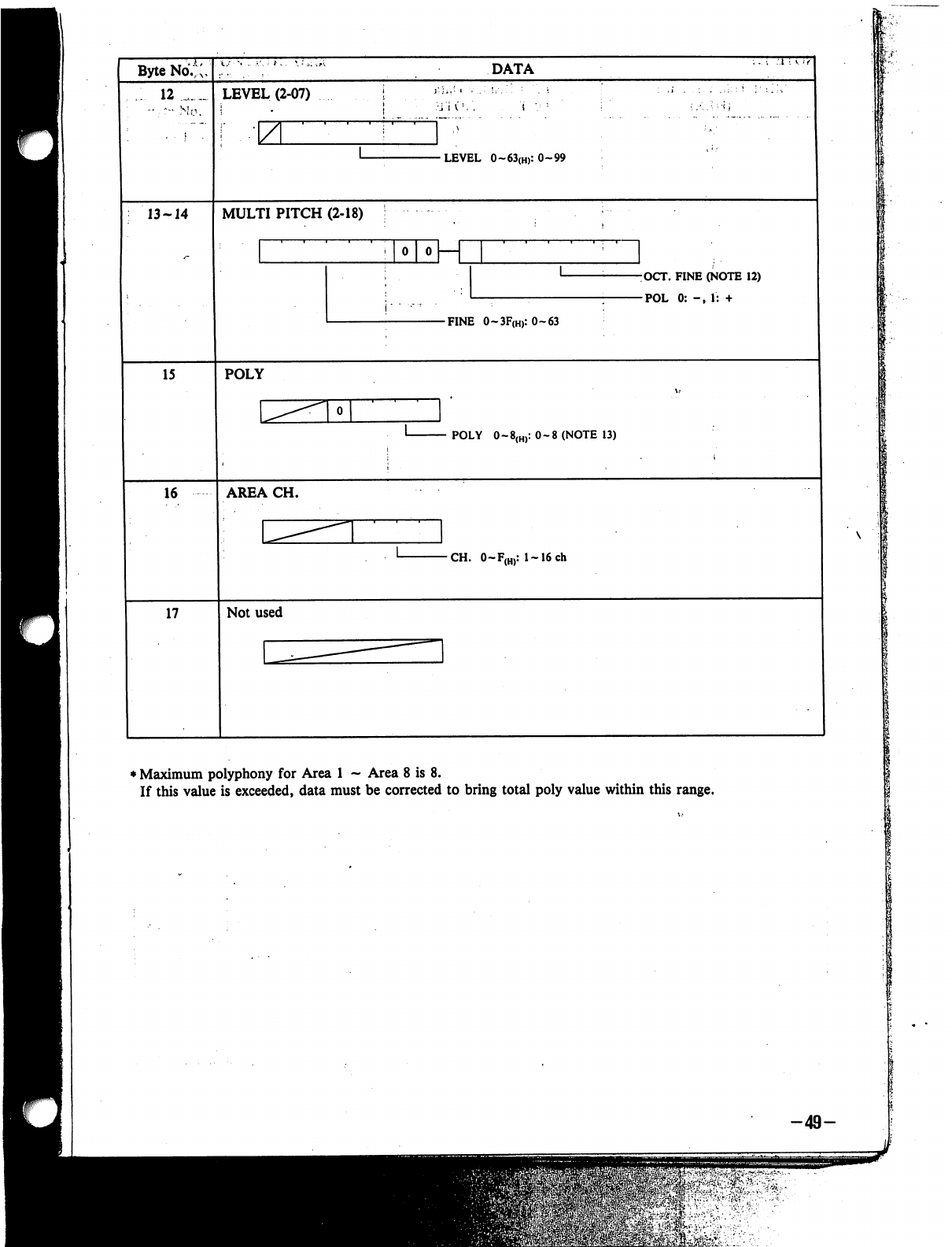
Byte
No.*;,
12
_
LEVEL
(2-07)
z
DATA
•LEVEL
0~63(H):0-99
13-14
MULTI
PITCH
(2-18)
0
0
K
j-
■
.-
r
■
-OCT.
FINE
(NOTE
12)
-POL
0:
-,
1:
+
-FINE
O~3F(H):O~63
15
POLY
POLY
0-8(H):
0-8
(NOTE
13)
16
AREA
CH.
CH.
0~F(H):
l~16ch
17
Not
used
♦
Maximum
polyphony
for
Area
1
-
Area
8
is
8.
If
this
value
is
exceeded,
data
must
be
corrected
to
bring
total
poly
value
within
this
range.
-49-

NOTE
12)
I;
MIDI
Transmission
Data
(HEX)
00
01
s
OB
0C
OD
.1.
17
3C
3D
s
47
LCD
Display
Data
OCT
NOTE
0
1
11
0
1
$
11
0
1
11
!
i'
-50-
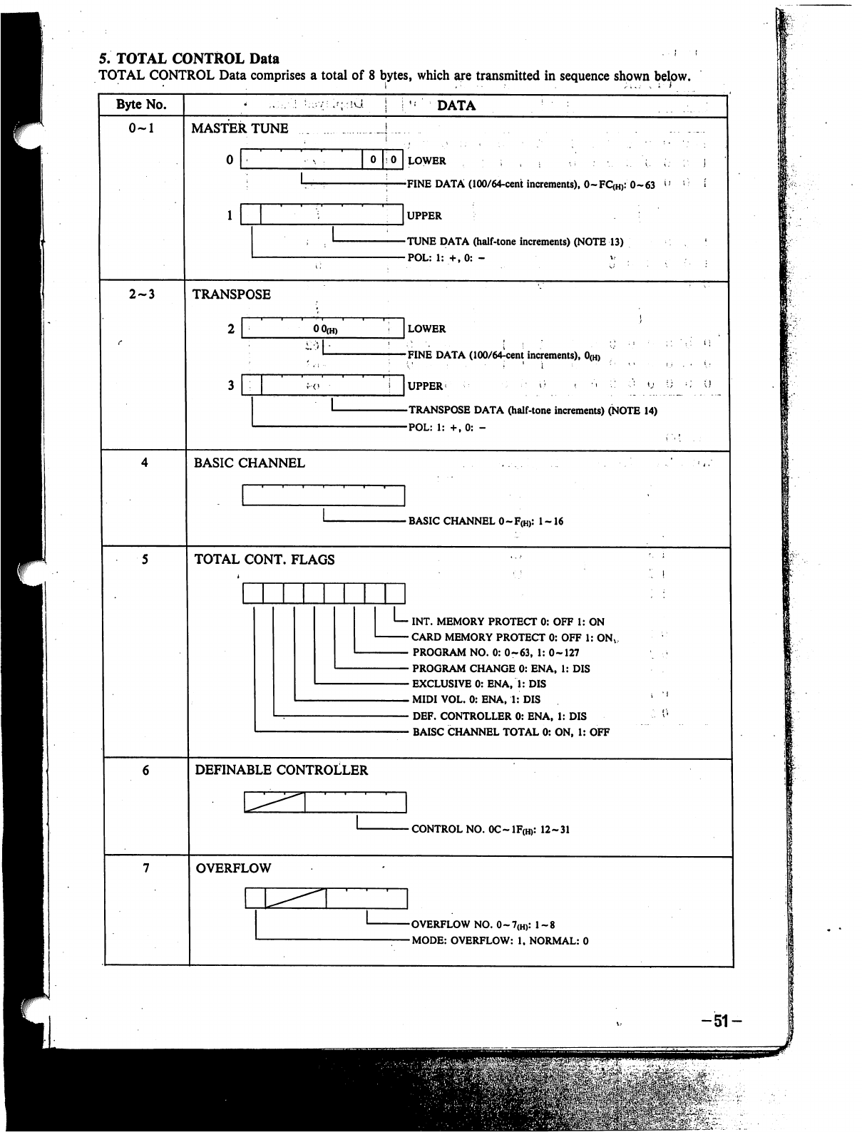
5.
TOTAL
CONTROL
Data
TOTAL CONTROL
Data
comprises
a
total
of
8
bytes,
which
are
transmitted
in
sequence
shown
below.
Byte
No.
*'.;
:!U
DATA
0-1
MASTER
TUNE
oho
lower
,
: ; , »
-,:•....
;..
;.-
;•.
]
-FINE
DATA
(100/64-cent
increments),
0-FQH):
0-63
v'
;
*
]UPPER
:
'
-TUNE
DATA
(halftone
increments)
(NOTE
13)
-POL:
1:
+,0:
-
v
2-3
TRANSPOSE
LOWER
FINE
DATA
(100/64^cent
increments),
0(H)
TRANSPOSE
DATA
(half-tone
increments)
(NOTE
14)
POL:
1:
+,0:
-
-
BASIC
CHANNEL
0-F(H):
1
-16
TOTAL
CONT.
FLAGS
INT.
MEMORY
PROTECT
0:
OFF
1:
ON
CARD
MEMORY
PROTECT
0:
OFF
1:
ONV
PROGRAM
NO.
0:
0-63,
1:
0-127
PROGRAM
CHANGE
0:
ENA,
1:
DIS
EXCLUSIVE
0:
ENA,
1:
DIS
MIDI
VOL.
0:
ENA,
1:
DIS
DEF.
CONTROLLER
0:
ENA,
1:
DIS
BAISC
CHANNEL
TOTAL
0:
ON,
1:
OFF
DEFINABLE
CONTROLLER
-
CONTROL
NO.
0C~
1F(H):
12-31
OVERFLOW
-OVERFLOW
NO.
0~7(H):
1-8
-MODE:
OVERFLOW:
1,
NORMAL:
0
-51-
m^v-
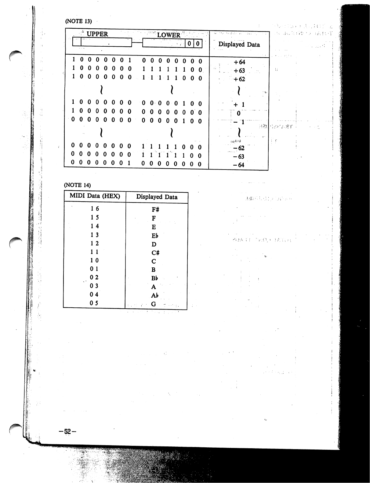
(NOTE
13)
(NOTE
14)
-52-
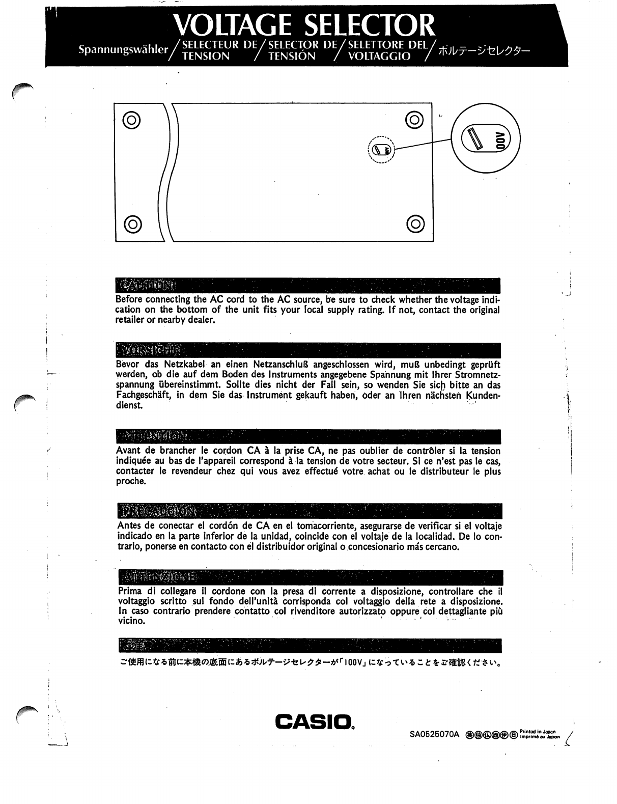
VOLTAGE
SELECTOR
r
Before
connecting
the
AC
cord
to
the
AC
source,
be
sure
to
check
whether
the
voltage
indi
cation
on
the
bottom
of
the
unit
fits
your
local
supply
rating.
If
not,
contact
the
original
retailer
or
nearby
dealer.
j
Bevor
das
Netzkabel
an
einen
NetzanschluS
angeschlossen
wird,
muB
unbedingt
geprUft
werden,
ob
die
auf
dem
Boden
des
Instruments
angegebene
Spahnung
mit
lhrer
Stromnetz-
spannung
ubereinstimmt.
Sollte
dies
nicht
der
Fall
sein,
so
wenden
Sie
sic(i
bitte
an
das
Fachgeschaft,
in
dem
Sie
das
Instrument
gekauft
haben,
Oder
an
Ihren
nachsteh
Kunden-
dienst.
Avant
de
brancher
le
cordon
CA
a
la
prise
CA,
ne
pas
oublier
de
contrdler
si
la
tension
indiqu6e
au
bas
de
Tappareil
correspond
a
la
tension
de
votre
secteur.
Si
ce
n'est
pas
le
cas,
contacter
le
revendeur
chez
qui
vous
avez
effected
votre
achat
ou
le
distributeur
le
plus
proche.
Antes
de
conectar
el
cordon
de
CA
en
el
tomacorriente,
asegurarse
de
verificar
si
el
voltaje
indicado
en
la
parte
inferior
de
la
unidad,
coincide
con
el
voltaje
de
la
local
id
ad.
De
lo
con
trario,
ponerse
en
contacto
con
el
distribuidor
original
o
concesionario
mas
cercano.
Prima
di
collegare
il
cordone
con
la
presa
di
corrente
a
disposizione,
controllare
che
voltaggio
scritto
sul
fondo
dell'unita
corrisponda
col
voltaggio
della
rete
a
disposizione.
In
caso
contrario
prendere
contatto
col
rivenditore
autorizzato
oppure
col
dettagliante
piCi
vicino.
<
a::£fc£-*ffS<K<*i\,
CASIO.
SA0525070A
®@®®@®
Printed
in
Japan
ImprimA
au
Japon
