3200 Operator's Manual Cell Dyn Operator
User Manual:
Open the PDF directly: View PDF ![]() .
.
Page Count: 676 [warning: Documents this large are best viewed by clicking the View PDF Link!]
- Cover
- Master Table of Contents
- Revision Status
- Revision Log
- Section 1. Use or Function
- Section 2. Installation Procedures and Special Requirements
- Section 3. Principles of Operation
- Section 4. Performance Characteristics and Specifications
- Section 5. Operating Instructions
- Overview
- Data Module Program Overview
- Set Up Instructions
- Routine Operation
- Start-Up Procedure
- Run Menu
- Sample Collection and Handling
- Preparing to Run Samples
- Sample Analysis on the CELL-DYN 3200SL
- Sample Analysis on the CELL-DYN 3200CS
- Alerts and Indicators
- Daily Shutdown Procedure
- Using The Work List
- Using The Data Log
- References
- Section 6. Calibration Procedures
- Section 7. Operational Precautions and Limitations
- Section 8. Hazards
- Section 9. Service and Maintenance
- Section 10. Troubleshooting and Diagnostics
- Section 11. Quality Control
- Section 12. Printers
- Section 13. Sample Loader
- Appendix A. Bar Codes
- Appendix B. Parts List
- Foreword
- How to Use This Manual
- Overview
- Manual Organization
- Front Matter
- Section 1. Use or Function
- Section 2. Installation Procedures and Special Req...
- Section 3. Principles of Operation
- Section 4. Performance Characteristics and Specifi...
- Section 5. Operating Instructions
- Section 6. Calibration Procedures
- Section 7. Operational Precautions and Limitations...
- Section 8. Hazards
- Section 9. Service and Maintenance
- Section 10. Troubleshooting and Diagnostics
- Section 11. Quality Control
- Section 12. Printers
- Section 13. Sample Loader
- Appendices
- Index
- Front Matter
- Manual Construction
- Text Conventions Used in This Manual
- Graphic Conventions Used in This Manual
- Revision Status
- Revision Log
- Conclusion
- List of Figures
- Section 1. Use or Function
- Overview
- System Components
- Analyzer Components
- Component Description
- Flow Panel
- Left Side Panel
- Right Side Panel
- Rear Panel
- Top Panel
- Data Module Components
- Display Station Components
- Sample Loader Components
- Printer
- Reagent System
- CELL-DYN Reagents
- Consumables
- Section 2. Installation Procedures and Special Requirements
- Section 3. Principles of Operation
- Overview
- Sample Analysis Cycle Overview
- Flow Cytometry
- Operational Messages and Data Flagging
- Section 4. Performance Characteristics and Specifications
- Section 5. Operating Instructions
- Overview
- Data Module Program Overview
- Set Up Instructions
- Set Up Menu
- Date/Time
- Patient Limits
- Reagent Log
- QC Set Up Menu
- Operation Set Up Menu
- Units Selection Menu
- Customize Report
- Set Up Menu
- Routine Operation
- Start-Up Procedure
- Run Menu
- Sample Collection and Handling
- Preparing to Run Samples
- Sample Analysis on the CELL-DYN 3200SL
- Sample Analysis on the CELL-DYN 3200CS
- Alerts and Indicators
- Daily Shutdown Procedure
- Using The Work List
- Introduction
- Work List Menu
- Sample Analysis — SL Model
- Sample Analysis — CS Model
- Using The Data Log
- References
- Section 6. Calibration Procedures
- Overview
- General Information
- Pre-Calibration Procedures
- Calibration Menu
- Enter Factor Method
- Latex Calibration Method
- Post Calibration Procedures
- Manual Calibration Worksheets
- References
- Section 7. Operational Precautions and Limitations
- Section 8. Hazards
- Section 9. Service and Maintenance
- Overview
- Special Protocols
- Preventive Maintenance Schedule
- Daily Maintenance Procedures
- Weekly Maintenance Procedures
- Monthly Maintenance Procedures
- Semiannual Maintenance Procedures
- Nonscheduled Maintenance Frequency
- Nonscheduled Maintenance Procedures
- Shear Valve Cleaning
- Open Sample Probe Interior Cleaning
- Unclogging the Open Sample Aspiration Probe
- Closed Sample Needle Interior Cleaning
- Unclogging the Closed Sample Aspiration Needle
- Syringe Cleaning
- HGB Flow Cell Manual Cleaning Procedure
- Bar Code Reader Window Cleaning
- Reagent Line Cleaning
- Open Sample Probe Replacement
- Closed Sample Needle Replacement
- Sample Transfer Pump Tubing Replacement
- Normally Closed Valve Tubing Replacement
- Syringe Replacement
- Fuse Replacement
- Preparation for Shipping or Extended Period of Non...
- CELL-DYN 3200 Maintenance Log
- Section 10. Troubleshooting and Diagnostics
- Overview
- Diagnostics Menu
- Troubleshooting Guide
- Troubleshooting Procedures
- Instrument Conditions and Messages
- Tables for Instrument Conditions and Messages
- Section 11. Quality Control
- Section 12. Printers
- Section 13. Sample Loader
- Appendix A. Bar Codes
- Appendix B. Parts List
- Index

ABBOTT
CELL-DYNCELL-DYN
32003200 SYSTEMSYSTEM
OPERATOR'S MANUAL
LIST NO: 01H25-01
Cell-Dyn 3200 Operator's Manual
9140181B — November 1997
Click on the Chapter Title to select.
• Foreword
• How to Use This Manual
• Table of Contents
• 1 - Use or Function
• 2 - Installation Procedures and Special Requirements
• 3 - Principles of Operation
• 4 - Performance Characteristics and Specifications
• 5 - Operating Instructions
• 6 - Calibration Procedures
• 7 - Operational Precautions and Limitations
• 8 - Hazards
• 9 - Service and Maintenance
• 10 - Troubleshooting and Diagnostics
• 11 - Quality Control
• 12 - Printers
• 13 - Sample Loader
• Appendix A: Bar Codes
• Appendix B: Cell-Dyn 3200 Parts List
• Index
EXIT
CD-TOC

CELL-DYN®3200 Operator’s Manual
9140181B — November 1997
NOTES
TOC
Go Back
Search

CELL-DYN® 3200 Operator’s Manual i
9140181B — November 1997
Foreword
Congratulations on becoming a proud operator of the
CELL-DYN 3200 System. Using state-of-the-art technology,
we have designed your instrument to function consistently
and dependably on a day-to-day basis.
The CELL-DYN 3200 System is backed by dedicated
professionals who excel in engineering, training, and technical
expertise. As you are a valued customer, we will teach you how
to operate, maintain, and troubleshoot your system.
For continuing service, we also provide telephone technical
assistance should you need additional information or
assistance in diagnosing a problem. This service is available 7
days a week, 24 hours a day in the United States.
If a problem should arise that cannot be resolved by
telephone, on-site support is offered by Abbott’s Field Service
Representatives. Our Field Service Representatives are
extensively trained in all aspects of Abbott instrumentation,
which assures proficiency in diagnosing, isolating, and
correcting problems.
Abbott Laboratories is dedicated to manufacturing the highest
quality, most reliable instrumentation available. We look
forward to serving your needs in any way possible.
Customer Support
United States: 1 (800) CELL DYN or 1 (800) 235-5396
Abbott Diagnostics Customer Support Center:
5440 Patrick Henry Drive
Santa Clara, CA 95054
Canada: 1 (800) 387-8378
International: Call your local customer support representative.
Intended Use
The CELL-DYN 3200 is a multiparameter hematology analyzer
designed for in vitro diagnostic use in clinical laboratories.
Proprietary Statement
The entire contents copyrighted 1995 by Abbott Laboratories.
Abbott Laboratories’ software programs are protected by
copyright. All rights are reserved. The software was developed
Go Back
Search
TOC

ii CELL-DYN® 3200 Operator’s Manual
9140181B — November 1997
solely for use with Abbott Laboratories equipment and for in
vitro diagnostic applications as specified in the operating
instructions. No part of this document may be reproduced,
stored, or transmitted in any form or by any means
(electronic, mechanical, photocopied, recorded, or otherwise)
without the prior written permission of Abbott Laboratories.
Patent Statement
The following U.S. Patents are relevant to the CELL-DYN 3200
Instrument: 4,726,237; 5,017,497: and 5,378,633.
Instrument Disclaimer
All operating instructions must be followed. In no event shall
Abbott be responsible for failures, errors, or other liabilities
resulting from a customer’s noncompliance with the
procedures and precautions outlined herein.
Pictorial Disclaimer
The sample printouts/screens contained in this manual are for
information and illustration purposes only. Abbott
Laboratories makes no representations or warranties about the
accuracy and reliability of the information on the printouts/
screens, and this information is not to be used for clinical or
maintenance evaluation.
Abbott Instrument Warranty
Abbott Laboratories warrants CELL-DYN Instruments sold by
Abbott Sales Representatives (the “Instrument”) to be free
from defects in workmanship and materials during normal use
by the original purchaser. This warranty shall continue for a
period of one (1) year, commencing twenty-one (21) days from
date of shipment to the original purchaser, or until title is
transferred from the original purchaser, whichever occurs first
(the “Warranty Period”).
If any defects occur during the Warranty Period, contact your
Abbott Customer Support Center immediately and be prepared
to furnish pertinent details concerning the defect, the
Instrument model number, and the serial number.
Abbott’s Warranty coverage limits are as follows:
1. Abbott Customer Support Center: 24 hours per day, 7
days per week phone support in the United States.
Go Back
Search
TOC

CELL-DYN® 3200 Operator’s Manual iii
9140181B — November 1997
2. Field Service Representative support: 8:30 A.M. to 5:00 P.M.
Monday through Friday (excluding all Abbott-observed
holidays).
3. Any on-site service performed at other times and all
service required to correct defects or malfunctions not
covered by this Warranty (as noted in the paragraph
below) will be billed at Abbott’s labor rates then in effect.
This Warranty does not cover defects or malfunctions which:
1. Are not reported to Abbott during the Warranty Period
and within one week of occurrence.
2. Result from chemical decomposition or corrosion.
3. Are caused by customer or third party abuse, misuse, or
negligence, or by failure to comply with any requirement
or instruction contained in the applicable Abbott
Operations Manual.
4. Result from maintenance, repair, or modification
performed without Abbott’s authorization.
Abbott’s liability for all matters arising from the supply,
installation, use, repair, and maintenance of the Instrument,
whether arising under this Warranty or otherwise, shall be
limited solely to the repair or (at Abbott’s sole discretion)
replacement of the Instrument or of components thereof. In
no event shall Abbott be liable for injuries sustained by third
parties, incidental or consequential damages, or lost profits.
Replaced parts shall become the property of Abbott
Laboratories.
THE FOREGOING IS THE SOLE WARRANTY MADE BY
ABBOTT LABORATORIES REGARDING THE INSTRUMENT,
AND ABBOTT SPECIFICALLY DISCLAIMS ALL OTHER
WARRANTIES, EXPRESSED OR IMPLIED, INCLUDING THE
IMPLIED WARRANTIES OF MERCHANTABILITY AND OF
FITNESS FOR A PARTICULAR PURPOSE.
The CELL-DYN 3200 Series Hematology Systems are
manufactured by Abbott Diagnostics, a wholly owned
subsidiary of Abbott Laboratories, at 5440 Patrick Henry Drive,
Santa Clara, CA 95054, U.S.A. Please direct all inquiries
concerning information in this manual to the foregoing
address.
NOTE: Direct all inquiries regarding equipment
problems to the Abbott Customer Support Center.
(U.S. customers only.)
Go Back
Search
TOC

iv CELL-DYN® 3200 Operator’s Manual
9140181B — November 1997
Trademark Statements
TEFLON is a registered trademark of E.I. DuPont de Nemours
Co., Inc.
VACUTAINER is a registered trademark of Becton, Dickinson,
and Company.
TYGON is a registered trademark of Norton Performance
Plastics.
LEVEY-JENNINGS is a registered trademark of Levey Jennings
Company.
Canon® is a registered trademark of Canon Inc.
BJC-600eTM is a trademark of Canon Inc.
OKIDATA is a registered trademark of Oki America, Inc.
MICROLINE is a registered trademark of Oki America, Inc.
CELL-DYN is a registered trademark of Sequoia-Turner
Corporation, a wholly owned subsidiary of Abbott
Laboratories.
DYN-A-WIPE is a trademark of Abbott Laboratories.
MAPSS is a trademark of Sequoia-Turner Corporation, a
wholly owned subsidiary of Abbott Laboratories.
VenojectII is a registered trademark of Terumo Medical
Company.
Go Back
Search
TOC

CELL-DYN® 3200 Operator’s Manual v
9140181B — November 1997
How to Use This Manual
Overview
This Operations Manual contains complete instructions for
using and maintaining the CELL-DYN 3200 System.
This manual was designed to fill several needs, from providing
step-by-step operating instructions to listing accessory part
numbers. You will find it a valuable aid as you learn to use the
system and an essential reference thereafter.
A basic principle of effective learning is to proceed from the
general to the specific. That is the way the material in this
manual is presented. And that is how we wish to present the
manual to you.
The first and most important step is to get acquainted with the
Master Table of Contents. For this reason, we start with a brief
overview to show you how the information is organized in
sections.
After that, we explain how the manual is physically designed
to help you locate desired information quickly and easily.
Finally, we discuss different ways material is presented for
different purposes and explain various icons that identify
specialized types of information in the text.
Please take the time to read and understand this brief
preparatory section.
Manual Organization
Front Matter
The pages in front of the Master Table of Contents contain
two main sections: A Foreword that includes customer support
and intended use information, and How to Use This Manual
that includes a description of the organization. These pages
also contain proprietary, warranty, trademark statements, and
Manuall Revision and Status Logs.
Section 1
. Use or Function
This section provides an overall description of the system and
its components. It names the major system components and
tells what they are used for.
Go Back
Search
TOC

vi CELL-DYN® 3200 Operator’s Manual
9140181B — November 1997
Section 2
. Installation Procedures and Special Requirements
This section provides instructions for installing the CELL-DYN
3200 system. It explains proper location, installation, setup,
and configuration to meet your laboratory’s specific needs.
Section 3
. Principles of Operation
This section explains the principles behind the system’s
operation. It describes what the system measures and how
those measurements are made. It also explains the translation
of those measurements into useful data and reports for the
user.
Section 4
. Performance Characteristics and Specifications
This section contains useful details on the dimensions of the
instrument, proper operating environment, and performance
specifications.
Section 5.
Operating Instructions
This section contains detailed instructions to set up the
instrument and explains the procedures for daily start-up and
shutdown, sample collection and handling, routine operation
of the instrument, sample analysis, and use of the data log.
Section 6
. Calibration Procedures
This section takes you step by step through the calibration
process. It discusses calibration materials, guidelines, and
methods, including troubleshooting procedures and corrective
action.
Section 7
. Operational Precautions and Limitations
This section contains a summary of known factors that may
adversely affect the proper operation of the instrument or the
quality of the output.
Section 8
. Hazards
This section covers possible hazards arising from the operation
of the instrument, as well as decontamination and waste
handling procedures.
Section 9
. Service and Maintenance
This section discusses routine maintenance and cleaning on a
daily, weekly, monthly, and “as needed” basis. Also included
are detailed instructions for removing, cleaning, and replacing
various components to ensure proper system performance.
Go Back
Search
TOC

CELL-DYN® 3200 Operator’s Manual vii
9140181B — November 1997
Section 10
. Troubleshooting and Diagnostics
This section discusses the diagnostics capability of the
instrument. It contains a troubleshooting guide to help users
identify probable causes of a system malfunction or of suspect
data, and to suggest the proper corrective action.
Section 11
. Quality Control
This section covers the proper mixing, handling, and running
of control material, setting up QC files and using the QC
capabilities of the instrument, and setting up and using the
X-B Analysis Program. It also provides a review of the
Westgard Rules.
Section 12
. Printers
This section reviews the setup and use of printers for graphics
output and ticket printing.
Section 13.
Sample Loader
This section includes material from all the previous sections
which pertains specifically to the installation, operation, and
maintenance of the Sample Loader.
Appendices
Appendix A describes how to use bar codes on the
CELL-DYN 3200 and contains information on bar code types
and bar code labels.
Appendix B lists the part numbers of components, accessories,
controls, reagents, and consumables associated with the
CELL-DYN 3200 System for user convenience when placing
orders.
Index
This section contains an alphabetical listing of subject matter
to help users quickly locate specific information about the
system.
Go Back
Search
TOC

viii CELL-DYN® 3200 Operator’s Manual
9140181B — November 1997
Manual Construction
The physical construction of the manual supports its sectional
organization.
Master Table of Contents
The Master Table of Contents at the beginning of this manual
lists each section and its subsections.
Section Separators and Tables of Contents
A large separator tab marks the start of each section. A section
table of contents is located immediately behind this tab in
most sections.
Text Conventions Used in This Manual
The following list summarizes the text conventions that are
used in this manual:
Soft Keys (Screen Label Keys)
Screen labels are menu keys displayed at the bottom of the
display screen. Directly below the display screen is a row of
eight unlabeled pressure-sensitive keys which correspond to
Information Presentation Examples
Menu name Sans serif font, all capital letters,
MAIN MENU
DATA LOG
menu
Soft keys (screen label
keys) Sans serif font, all capital letters,
enclosed in brackets
[RUN]
Keyboard/keypad keys Regular font, initial capital
letters only when appropriate arrow keys
↑ arrow key
Enter key
ESC key
Page Up key
the pound (#) key
the asterisk (*) key
Status Regular font, all capital letters READY
STANDBY
INITIALIZED
Data entry field Regular font, enclosed in angle
brackets
<
OPERATOR ID
>
field
Screen message or other
screen display Courier Waste Full
ON and OFF All caps, regular font ON
OFF
Go Back
Search
TOC
CELL-DYN® 3200 Operator’s Manual ix
9140181B — November 1997
the menu labels. Pressing one of these keys (on the membrane
keypad) initiates the action specified by the corresponding
menu label.
This manual indicates that one of these “soft keys” is to be
pressed by showing the label in all caps, bold, sans serif font,
and enclosed in brackets. For example, when the manual calls
for the operator to press the key under the RUN label and then
the key under the SPECIMEN TYPE label, the text will read
“Press
[RUN]
followed by
[SPECIMEN TYPE]
.”
Keyboard/Keypad Keys
In some cases, the operator must press a key on the PC
keyboard or on the pressure-sensitive keypad on the front of
the instrument. Such keys include the Enter key, the ESC key,
the pound (#) key, and other special function keys. Special
function keys, such as the arrow keys, are in regular type. The
arrow symbol may be substituted for the word. For example,
the text will read “Press the arrow keys” or “Press the ↑ key” or
“Press the ↑ arrow key.”
Graphic Conventions Used in This Manual
Throughout the text, signal words and icons appear where the
nature of the information warrants special attention.
NOTE: The note signal word appears adjacent to an
important point of information that is relevant to the
current subject matter.
This manual uses four icons to warn users of possible danger.
These icons are:
WARNING: Potential Biohazard. The biohazard icon
alerts users to an activity or area where they may be
exposed to infectious materials or substances.
WARNING: Electrical Shock Hazard. The electrical
hazard icon alerts users to the possibility of electrical
shock in the described activity or at the posted
location.
WARNING: The general warning icon alerts users to
other potential health or safety hazards.
Go Back
Search
TOC

xCELL-DYN® 3200 Operator’s Manual
9140181B — November 1997
CAUTION: The general caution icon appears adjacent
to an explanation of conditions that could interfere
with the proper functioning of the instrument.
DANGER: Class III B Laser Light. The laser icon alerts
warns against direct exposure to the laser light beam
generated by the Optical Bench Assembly.
Go Back
Search
TOC

CELL-DYN® 3200 Operator’s Manual xi
9140181B — November 1997
Revision Status
Document Control
Number(s) Revision
Date Section(s)
Revised Pages Revised
and Added
Preliminary
(9140181A) 7/97 Not Applicable Not Applicable
Initial Release
(9140181B) 11/97 All All
Go Back
Search
TOC

xii CELL-DYN® 3200 Operator’s Manual
9140181B — November 1997
NOTES
Go Back
Search
TOC

CELL-DYN® 3200 Operator’s Manual xiii
9140181B — November 1997
Revision Log
Instructions: Use this log to provide a permanent record to verify that revised chapter(s) and/or
page(s) have been added to this manual.
1. Record the document control number of the revised section in the first column. You will
find the number in the footer. Make an entry for each chapter you receive and place in the
manual.
2. Record the revision date, also found in the footer, in the second column.
3. Record the current CELL-DYN 3200 System software version in the third column.
4. Write your initials or signature in the fourth column to verify that you have placed the
revised page(s) in the manual.
5. Record the date that you added the revised section to the manual in the fifth column.
Document
Control
Number Revision
Date Software
Version
Revision
Incorporated
by Date
Incorporated
Go Back
Search
TOC

xiv CELL-DYN® 3200 Operator’s Manual
9140181B — November 1997
NOTES
Go Back
Search
TOC

CELL-DYN® 3200 Operator’s Manual xv
9140181B — November 1997
Conclusion
We hope you have found this preview of the manual useful.
The information in this section should help you better
understand the construction and organization of this manual
and help you get started easily and quickly.
Go Back
Search
TOC

xvi CELL-DYN® 3200 Operator’s Manual
9140181B — November 1997
NOTES
Go Back
Search
TOC

CELL-DYN® 3200 Operator’s Manual Table of Contents-1
9140181B — November 1997
Master Table of Contents
Table of Contents Foreword . . . . . . . . . . . . . . . . . . . . . . . . . . . . . . . . . . . . . . . . . . i
Customer Support . . . . . . . . . . . . . . . . . . . . . . . . . . . . . . . . . . . i
Intended Use . . . . . . . . . . . . . . . . . . . . . . . . . . . . . . . . . . . . . . . i
Proprietary Statement . . . . . . . . . . . . . . . . . . . . . . . . . . . . . . . . i
Patent Statement . . . . . . . . . . . . . . . . . . . . . . . . . . . . . . . . . . . ii
Instrument Disclaimer . . . . . . . . . . . . . . . . . . . . . . . . . . . . . . . ii
Pictorial Disclaimer . . . . . . . . . . . . . . . . . . . . . . . . . . . . . . . . . ii
Abbott Instrument Warranty . . . . . . . . . . . . . . . . . . . . . . . . . ii
Trademark Statements . . . . . . . . . . . . . . . . . . . . . . . . . . . . . . . iv
How to Use This Manual . . . . . . . . . . . . . . . . . . . . . . . . . . . . . .v
Overview . . . . . . . . . . . . . . . . . . . . . . . . . . . . . . . . . . . . . . .v
Manual Organization . . . . . . . . . . . . . . . . . . . . . . . . . . . . . .v
Front Matter . . . . . . . . . . . . . . . . . . . . . . . . . . . . . . . . . .v
Manual Construction . . . . . . . . . . . . . . . . . . . . . . . . . . . . viii
Master Table of Contents . . . . . . . . . . . . . . . . . . . . . . viii
Section Separators and Tables of Contents . . . . . . . . viii
Text Conventions Used in This Manual . . . . . . . . . . . . . . . . viii
Soft Keys (Screen Label Keys) . . . . . . . . . . . . . . . . . . . . . . viii
Keyboard/Keypad Keys . . . . . . . . . . . . . . . . . . . . . . . . . . . . ix
Graphic Conventions Used in This Manual . . . . . . . . . . . . . . ix
Revision Status. . . . . . . . . . . . . . . . . . . . . . . . . . . . . . . . . . . . . . . . . . . . . . . . . . . . . . . . . . . . xi
Revision Log . . . . . . . . . . . . . . . . . . . . . . . . . . . . . . . . . . . . . . . . . . . . . . . . . . . . . . . . . . . . .xiii
Conclusion . . . . . . . . . . . . . . . . . . . . . . . . . . . . . . . . . . . . . . . .xv
Section One. Use or Function
Overview . . . . . . . . . . . . . . . . . . . . . . . . . . . . . . . . . . . . . . . . . . . . . . . . . . . . . . . . . . . . . . . . .1-1
Intended Use . . . . . . . . . . . . . . . . . . . . . . . . . . . . . . . . . . . . . 1-2
System Components. . . . . . . . . . . . . . . . . . . . . . . . . . . . . . . . . . . . . . . . . . . . . . . . . . . . . . 1-5
Analyzer Components . . . . . . . . . . . . . . . . . . . . . . . . . . . . . . 1-6
Front Panel . . . . . . . . . . . . . . . . . . . . . . . . . . . . . . . . . . . . 1-6
Flow Panel . . . . . . . . . . . . . . . . . . . . . . . . . . . . . . . . . . . . 1-6
Left Side Panel . . . . . . . . . . . . . . . . . . . . . . . . . . . . . . . . . 1-6
Right Side Panel . . . . . . . . . . . . . . . . . . . . . . . . . . . . . . . . 1-7
Rear Panel . . . . . . . . . . . . . . . . . . . . . . . . . . . . . . . . . . . . . 1-7
Component Description . . . . . . . . . . . . . . . . . . . . . . . . . . . . 1-8
Front Panel . . . . . . . . . . . . . . . . . . . . . . . . . . . . . . . . . . . . 1-8
Go Back
Search
TOC

Table of Contents-2 CELL-DYN® 3200 Operator’s Manual
9140181B — November 1997
Master Table of Contents
Left Front Cover . . . . . . . . . . . . . . . . . . . . . . . . . . . . . . . . 1-8
Right Front Cover . . . . . . . . . . . . . . . . . . . . . . . . . . . . . . 1-9
Front Skirt Cover . . . . . . . . . . . . . . . . . . . . . . . . . . . . . . . 1-9
Closed Sample Tower Cover . . . . . . . . . . . . . . . . . . . . . . 1-9
Status Indicator Panel . . . . . . . . . . . . . . . . . . . . . . . . . . 1-10
Open Sample Aspiration Probe . . . . . . . . . . . . . . . . . . . 1-10
Touch Plate . . . . . . . . . . . . . . . . . . . . . . . . . . . . . . . . . . 1-10
Closed Sample Aspiration Tower Module . . . . . . . . . . . 1-10
Flow Panel . . . . . . . . . . . . . . . . . . . . . . . . . . . . . . . . . . . . . . 1-12
Shear Valve Assembly . . . . . . . . . . . . . . . . . . . . . . . . . . 1-12
Syringe Assembly . . . . . . . . . . . . . . . . . . . . . . . . . . . . . . 1-13
Sample Transfer Peristaltic Pump . . . . . . . . . . . . . . . . . 1-13
HGB Flow Cell and Mixing Chamber . . . . . . . . . . . . . . 1-13
WBC Mixing Chamber . . . . . . . . . . . . . . . . . . . . . . . . . 1-13
RBC/PLT Mixing Chamber . . . . . . . . . . . . . . . . . . . . . . 1-14
Wash Block . . . . . . . . . . . . . . . . . . . . . . . . . . . . . . . . . . 1-14
Normally Closed Valves . . . . . . . . . . . . . . . . . . . . . . . . . 1-14
Diluent Reservoir . . . . . . . . . . . . . . . . . . . . . . . . . . . . . . 1-14
Sheath Reservoir . . . . . . . . . . . . . . . . . . . . . . . . . . . . . . 1-14
Waste Chambers . . . . . . . . . . . . . . . . . . . . . . . . . . . . . . 1-14
Bubble Traps . . . . . . . . . . . . . . . . . . . . . . . . . . . . . . . . . 1-14
Aerosol Filter . . . . . . . . . . . . . . . . . . . . . . . . . . . . . . . . . 1-14
Pinch Valves . . . . . . . . . . . . . . . . . . . . . . . . . . . . . . . . . 1-14
Closed Mode Aspiration Tower . . . . . . . . . . . . . . . . . . . 1-15
Vent/Aspiration Needle . . . . . . . . . . . . . . . . . . . . . . 1-15
Wash Block . . . . . . . . . . . . . . . . . . . . . . . . . . . . . . . . 1-15
Spinner Assembly . . . . . . . . . . . . . . . . . . . . . . . . . . . 1-15
Bar Code Reader . . . . . . . . . . . . . . . . . . . . . . . . . . . . 1-15
Door Assembly (CS Model) . . . . . . . . . . . . . . . . . . . 1-15
Left Side Panel . . . . . . . . . . . . . . . . . . . . . . . . . . . . . . . . . . . 1-17
Fan . . . . . . . . . . . . . . . . . . . . . . . . . . . . . . . . . . . . . . . . . 1-17
Right Side Panel . . . . . . . . . . . . . . . . . . . . . . . . . . . . . . . . . . 1-18
Floppy Disk Drive . . . . . . . . . . . . . . . . . . . . . . . . . . . . . 1-18
Rear Panel . . . . . . . . . . . . . . . . . . . . . . . . . . . . . . . . . . . . . . 1-19
Main Power Switch . . . . . . . . . . . . . . . . . . . . . . . . . . . . 1-20
Main Power Connector . . . . . . . . . . . . . . . . . . . . . . . . . 1-20
Power Supply . . . . . . . . . . . . . . . . . . . . . . . . . . . . . . . . . 1-20
Line Frequency and Line Voltage Select Switches . . . . . 1-20
Fuse . . . . . . . . . . . . . . . . . . . . . . . . . . . . . . . . . . . . . . . . 1-21
Fan . . . . . . . . . . . . . . . . . . . . . . . . . . . . . . . . . . . . . . . . . 1-21
Waste Sensor Connector . . . . . . . . . . . . . . . . . . . . . . . . 1-21
Waste Outlet Tube Connector . . . . . . . . . . . . . . . . . . . . 1-21
Diluent/Sheath Inlet Tube Connector . . . . . . . . . . . . . . 1-21
WBC Lyse Inlet Tube Connector . . . . . . . . . . . . . . . . . . 1-21
HGB Lyse Inlet Tube Connector . . . . . . . . . . . . . . . . . . 1-21
Analyzer Serial Number Label . . . . . . . . . . . . . . . . . . . . 1-21
Disk Storage Container . . . . . . . . . . . . . . . . . . . . . . . . . 1-21
Go Back
Search
TOC

CELL-DYN® 3200 Operator’s Manual Table of Contents-3
9140181B — November 1997
Master Table of Contents
Top Panel . . . . . . . . . . . . . . . . . . . . . . . . . . . . . . . . . . . . . . . 1-22
Flow Cell Assembly . . . . . . . . . . . . . . . . . . . . . . . . . . . . 1-22
Laser Optics Bench Assembly . . . . . . . . . . . . . . . . . . . . 1-22
Data Module Components . . . . . . . . . . . . . . . . . . . . . . . . . 1-23
Computer . . . . . . . . . . . . . . . . . . . . . . . . . . . . . . . . . . . . 1-23
Data Storage . . . . . . . . . . . . . . . . . . . . . . . . . . . . . . . . . . 1-24
Printed Circuit Boards . . . . . . . . . . . . . . . . . . . . . . . . . . 1-24
Display Station Interface Connector . . . . . . . . . . . . . . . 1-24
HSSL (High Speed Serial Link) Connector . . . . . . . . . . . 1-24
Membrane Keypad Interface Connector . . . . . . . . . . . . 1-24
Graphics Printer Connector . . . . . . . . . . . . . . . . . . . . . . 1-24
Ticket Printer Connector . . . . . . . . . . . . . . . . . . . . . . . . 1-24
LIS (Laboratory Information System) Connector . . . . . 1-24
PC Keyboard Connector . . . . . . . . . . . . . . . . . . . . . . . . 1-25
Display Station Components . . . . . . . . . . . . . . . . . . . . . . . 1-25
Display Monitor . . . . . . . . . . . . . . . . . . . . . . . . . . . . . . . 1-26
Soft Keys . . . . . . . . . . . . . . . . . . . . . . . . . . . . . . . . . . . . . 1-26
Membrane Keypad Cable . . . . . . . . . . . . . . . . . . . . . . . . 1-26
Video Cable . . . . . . . . . . . . . . . . . . . . . . . . . . . . . . . . . . 1-26
Power Cord . . . . . . . . . . . . . . . . . . . . . . . . . . . . . . . . . . . 1-26
Screen Controls . . . . . . . . . . . . . . . . . . . . . . . . . . . . . . . 1-26
Sample Loader Components . . . . . . . . . . . . . . . . . . . . . . . . 1-26
Racks . . . . . . . . . . . . . . . . . . . . . . . . . . . . . . . . . . . . . . . . 1-27
Tower Cover . . . . . . . . . . . . . . . . . . . . . . . . . . . . . . . . . . 1-27
Bar Code Reader . . . . . . . . . . . . . . . . . . . . . . . . . . . . . . . 1-27
Tube Sensor Assembly . . . . . . . . . . . . . . . . . . . . . . . . . . 1-28
Mixer Assembly . . . . . . . . . . . . . . . . . . . . . . . . . . . . . . . 1-28
Printer . . . . . . . . . . . . . . . . . . . . . . . . . . . . . . . . . . . . . . . . . 1-28
Reagent System . . . . . . . . . . . . . . . . . . . . . . . . . . . . . . . . . . 1-28
Introduction . . . . . . . . . . . . . . . . . . . . . . . . . . . . . . . . . . 1-28
CELL-DYN Reagents . . . . . . . . . . . . . . . . . . . . . . . . . . . . . . 1-29
CELL-DYN 3200 Diluent/Sheath (L/N 03H79-01) . . . . . 1-29
CELL-DYN 3200 CN-Free HGB/NOC Lyse (L/N 03H80-01) 1-
29
CELL-DYN 3200 WBC Lyse (L/N 03H78-01) . . . . . . . . . 1-30
Consumables . . . . . . . . . . . . . . . . . . . . . . . . . . . . . . . . . . . . 1-30
Section Two. Installation Procedures and Special Requirements
Overview . . . . . . . . . . . . . . . . . . . . . . . . . . . . . . . . . . . . . . . . . . . . . . . . . . . . . . . . . . . . . . . . .2-1
Initial Preparation . . . . . . . . . . . . . . . . . . . . . . . . . . . . . . . . . 2-1
Package Inspection and Inventory . . . . . . . . . . . . . . . . . 2-1
CELL-DYN 3200SL . . . . . . . . . . . . . . . . . . . . . . . . . . . 2-1
CELL-DYN 3200CS . . . . . . . . . . . . . . . . . . . . . . . . . . . 2-1
CELL-DYN Accessory Kit . . . . . . . . . . . . . . . . . . . . . . 2-2
Go Back
Search
TOC

Table of Contents-4 CELL-DYN® 3200 Operator’s Manual
9140181B — November 1997
Master Table of Contents
Sample Loader Accessory Kit . . . . . . . . . . . . . . . . . . . 2-2
Space Requirements . . . . . . . . . . . . . . . . . . . . . . . . . . . . . 2-3
Waste Requirements . . . . . . . . . . . . . . . . . . . . . . . . . . . . 2-3
Power Requirements . . . . . . . . . . . . . . . . . . . . . . . . . . . . 2-4
Tubing Installation. . . . . . . . . . . . . . . . . . . . . . . . . . . . . . . . . . . . . . . . . . . . . . . . . . . . . . . . 2-5
Reagent and Waste Tubing . . . . . . . . . . . . . . . . . . . . . . . . . . 2-5
Normally Closed Valves . . . . . . . . . . . . . . . . . . . . . . . . . . . . 2-6
Open Left Front Cover . . . . . . . . . . . . . . . . . . . . . . . . . . . 2-7
Open Right Front Cover . . . . . . . . . . . . . . . . . . . . . . . . . 2-7
Remove Tower Cover . . . . . . . . . . . . . . . . . . . . . . . . . . . . 2-8
Remove Front Skirt . . . . . . . . . . . . . . . . . . . . . . . . . . . . . 2-8
Remove Sample Loader . . . . . . . . . . . . . . . . . . . . . . . . . . 2-8
Tubing Installation . . . . . . . . . . . . . . . . . . . . . . . . . . . . . 2-8
Flow Panel and Syringe Inspection . . . . . . . . . . . . . . . . 2-10
Printer Installation . . . . . . . . . . . . . . . . . . . . . . . . . . . . . . . . . . . . . . . . . . . . . . . . . . . . . . . 2-13
Overview . . . . . . . . . . . . . . . . . . . . . . . . . . . . . . . . . . . . . . . 2-13
Graphics Printer Installation Procedure . . . . . . . . . . . . . . . 2-14
Self-Test Printouts . . . . . . . . . . . . . . . . . . . . . . . . . . . . . 2-15
Ticket Printer Installation Procedure . . . . . . . . . . . . . . . . . 2-15
Loading Individual Tickets in the Ticket Printer . . . . . 2-16
Self-Test Printouts . . . . . . . . . . . . . . . . . . . . . . . . . . . . . 2-17
Sample Loader Inspection (SL Model) . . . . . . . . . . . . . . . . . 2-18
Power On . . . . . . . . . . . . . . . . . . . . . . . . . . . . . . . . . . . . . . . 2-20
Section Three. Principles of Operation
Overview. . . . . . . . . . . . . . . . . . . . . . . . . . . . . . . . . . . . . . . . . . . . . . . . . . . . . . . . . . . . . . . . . 3-1
Sample Aspiration . . . . . . . . . . . . . . . . . . . . . . . . . . . . . . . . . 3-1
Sample Analysis Cycle Overview. . . . . . . . . . . . . . . . . . . . . . . . . . . . . . . . . . . . . . . . . . 3-3
Sample Aspiration . . . . . . . . . . . . . . . . . . . . . . . . . . . . . . 3-3
Sample Segments . . . . . . . . . . . . . . . . . . . . . . . . . . . . . . . 3-3
RBC/PLT Analysis . . . . . . . . . . . . . . . . . . . . . . . . . . . . . . 3-3
Hemoglobin Analysis . . . . . . . . . . . . . . . . . . . . . . . . . . . . 3-4
WBC Analysis . . . . . . . . . . . . . . . . . . . . . . . . . . . . . . . . . 3-4
Fragile WBCs and Resistant RBCs . . . . . . . . . . . . . . . 3-5
Go Back
Search
TOC

CELL-DYN® 3200 Operator’s Manual Table of Contents-5
9140181B — November 1997
Master Table of Contents
Results Displayed . . . . . . . . . . . . . . . . . . . . . . . . . . . . . . . 3-6
Instrument Flushed . . . . . . . . . . . . . . . . . . . . . . . . . . . . . 3-6
Instrument Rinsed . . . . . . . . . . . . . . . . . . . . . . . . . . . . . . 3-6
Flow Cytometry. . . . . . . . . . . . . . . . . . . . . . . . . . . . . . . . . . . . . . . . . . . . . . . . . . . . . . . . . . . 3-7
Introduction to Flow Cytometry . . . . . . . . . . . . . . . . . . . . . . 3-7
Detection with the Optical Bench . . . . . . . . . . . . . . . . . . 3-8
Optical Flow Cell . . . . . . . . . . . . . . . . . . . . . . . . . . . . . . . 3-9
WBC Measurement . . . . . . . . . . . . . . . . . . . . . . . . . . . . . . . 3-11
Overview . . . . . . . . . . . . . . . . . . . . . . . . . . . . . . . . . . . . 3-11
WBC Reagent . . . . . . . . . . . . . . . . . . . . . . . . . . . . . . . . . 3-12
WBC Differential . . . . . . . . . . . . . . . . . . . . . . . . . . . . . . 3-13
Mononuclear-Polymorphonuclear Separation . . . . . . . 3-14
Neutrophil-Eosinophil Separation . . . . . . . . . . . . . . . . . 3-15
Mononuclear Separation . . . . . . . . . . . . . . . . . . . . . . . . 3-16
Other Scatterplots . . . . . . . . . . . . . . . . . . . . . . . . . . . . . 3-17
Nuclear Optical Count . . . . . . . . . . . . . . . . . . . . . . . . . . 3-18
Resistant RBC . . . . . . . . . . . . . . . . . . . . . . . . . . . . . . . . . 3-18
WBC Histograms . . . . . . . . . . . . . . . . . . . . . . . . . . . . . . . . . 3-19
NWBC-LYM-MONO Histogram . . . . . . . . . . . . . . . . . . . 3-19
MONO-POLY Histogram . . . . . . . . . . . . . . . . . . . . . . . . 3-19
NOC Histogram . . . . . . . . . . . . . . . . . . . . . . . . . . . . . . . 3-20
WBC Parameters . . . . . . . . . . . . . . . . . . . . . . . . . . . . . . . . . 3-20
WBC Flagging . . . . . . . . . . . . . . . . . . . . . . . . . . . . . . . . . . . 3-22
RBC/PLT Measurement . . . . . . . . . . . . . . . . . . . . . . . . . . . . 3-22
Overview . . . . . . . . . . . . . . . . . . . . . . . . . . . . . . . . . . . . 3-22
RBC Count . . . . . . . . . . . . . . . . . . . . . . . . . . . . . . . . . . . 3-23
MCV . . . . . . . . . . . . . . . . . . . . . . . . . . . . . . . . . . . . . . . . 3-23
HCT . . . . . . . . . . . . . . . . . . . . . . . . . . . . . . . . . . . . . . . . 3-24
MCH . . . . . . . . . . . . . . . . . . . . . . . . . . . . . . . . . . . . . . . . 3-24
MCHC . . . . . . . . . . . . . . . . . . . . . . . . . . . . . . . . . . . . . . 3-24
RDW . . . . . . . . . . . . . . . . . . . . . . . . . . . . . . . . . . . . . . . . 3-24
RBC Flagging . . . . . . . . . . . . . . . . . . . . . . . . . . . . . . . . . . . . 3-24
PLT Measurement . . . . . . . . . . . . . . . . . . . . . . . . . . . . . . . . 3-25
Platelet Parameters . . . . . . . . . . . . . . . . . . . . . . . . . . . . . . . . 3-26
PLT Count . . . . . . . . . . . . . . . . . . . . . . . . . . . . . . . . . . . 3-26
MPV . . . . . . . . . . . . . . . . . . . . . . . . . . . . . . . . . . . . . . . . 3-26
PCT . . . . . . . . . . . . . . . . . . . . . . . . . . . . . . . . . . . . . . . . . 3-27
PDW . . . . . . . . . . . . . . . . . . . . . . . . . . . . . . . . . . . . . . . . 3-27
Platelet Flagging . . . . . . . . . . . . . . . . . . . . . . . . . . . . . . . . . . 3-27
Hemoglobin Measurement . . . . . . . . . . . . . . . . . . . . . . . . . 3-28
Overview . . . . . . . . . . . . . . . . . . . . . . . . . . . . . . . . . . . . 3-28
HGB Parameters . . . . . . . . . . . . . . . . . . . . . . . . . . . . . . . . . . 3-28
HGB Flagging . . . . . . . . . . . . . . . . . . . . . . . . . . . . . . . . . . . . 3-29
Laboratory Worksheet Screen . . . . . . . . . . . . . . . . . . . . . . . 3-29
Go Back
Search
TOC

Table of Contents-6 CELL-DYN® 3200 Operator’s Manual
9140181B — November 1997
Master Table of Contents
Operational Messages and Data Flagging. . . . . . . . . . . . . . . . . . . . . . . . . . . . . . . . . 3-33
Introduction . . . . . . . . . . . . . . . . . . . . . . . . . . . . . . . . . . . . 3-33
Instrument Fault and Status Conditions . . . . . . . . . . . . . . . 3-33
Cell Populations and Flagging . . . . . . . . . . . . . . . . . . . . . . 3-34
Fragile WBCs . . . . . . . . . . . . . . . . . . . . . . . . . . . . . . . . . 3-34
Lyse-Resistant RBCs . . . . . . . . . . . . . . . . . . . . . . . . . . . . 3-34
Parameter Flagging Messages . . . . . . . . . . . . . . . . . . . . . . . 3-35
Dispersional Data Alerts . . . . . . . . . . . . . . . . . . . . . . . . 3-36
Suspect Parameter Flags . . . . . . . . . . . . . . . . . . . . . . . . . 3-36
Introduction to WBC Flagging . . . . . . . . . . . . . . . . 3-37
WBC Flags . . . . . . . . . . . . . . . . . . . . . . . . . . . . . . . . 3-37
PLT Flags . . . . . . . . . . . . . . . . . . . . . . . . . . . . . . . . . 3-38
Suspect Population Flags . . . . . . . . . . . . . . . . . . . . . . . . 3-40
WBC Flags . . . . . . . . . . . . . . . . . . . . . . . . . . . . . . . . 3-40
RBC Flags . . . . . . . . . . . . . . . . . . . . . . . . . . . . . . . . . 3-44
PLT Flags . . . . . . . . . . . . . . . . . . . . . . . . . . . . . . . . . 3-44
Interpretive Messages . . . . . . . . . . . . . . . . . . . . . . . . . . . 3-44
WBC Messages . . . . . . . . . . . . . . . . . . . . . . . . . . . . . 3-45
RBC Messages . . . . . . . . . . . . . . . . . . . . . . . . . . . . . . 3-45
PLT Messages . . . . . . . . . . . . . . . . . . . . . . . . . . . . . . 3-46
References . . . . . . . . . . . . . . . . . . . . . . . . . . . . . . . . . . . . . . . . . . . . . . . . . . . . . . . . . . . . . . 3-47
Section Four. Performance Characteristics and Specificatons
Overview. . . . . . . . . . . . . . . . . . . . . . . . . . . . . . . . . . . . . . . . . . . . . . . . . . . . . . . . . . . . . . . . . 4-1
System Specifications . . . . . . . . . . . . . . . . . . . . . . . . . . . . . . . . . . . . . . . . . . . . . . . . . . . . 4-3
Physical Specifications . . . . . . . . . . . . . . . . . . . . . . . . . . . . . 4-3
Power Specifications . . . . . . . . . . . . . . . . . . . . . . . . . . . . . . . 4-4
Operational Specifications . . . . . . . . . . . . . . . . . . . . . . . . . . 4-5
Operating Environment . . . . . . . . . . . . . . . . . . . . . . . . . 4-5
Startup/Shutdown Times . . . . . . . . . . . . . . . . . . . . . . . . . 4-5
Run Cycle Times . . . . . . . . . . . . . . . . . . . . . . . . . . . . . . . 4-5
Approximate Aspiration Volumes (Whole Blood) . . . . . 4-5
Batch Size . . . . . . . . . . . . . . . . . . . . . . . . . . . . . . . . . . . . . 4-5
Throughput . . . . . . . . . . . . . . . . . . . . . . . . . . . . . . . . . . . 4-6
Collection Tube and Sample Volume . . . . . . . . . . . . . . . 4-6
Bar Code Specifications — CELL-DYN 3200SL . . . . . . . . . . . 4-7
Bar Code Format . . . . . . . . . . . . . . . . . . . . . . . . . . . . . . . 4-7
Bar Code Label Specifications . . . . . . . . . . . . . . . . . . . . . 4-7
Measurement Specifications — CELL-DYN 3200SL and CS . 4-7
Measurement Channels . . . . . . . . . . . . . . . . . . . . . . . . . . 4-7
Go Back
Search
TOC

CELL-DYN® 3200 Operator’s Manual Table of Contents-7
9140181B — November 1997
Master Table of Contents
WBC (WOC) . . . . . . . . . . . . . . . . . . . . . . . . . . . . . . . . . . . 4-7
WBC (NOC) . . . . . . . . . . . . . . . . . . . . . . . . . . . . . . . . . . . 4-7
RBCs and PLTs . . . . . . . . . . . . . . . . . . . . . . . . . . . . . . . . . 4-8
HGB . . . . . . . . . . . . . . . . . . . . . . . . . . . . . . . . . . . . . . . . . 4-8
Performance Specifications . . . . . . . . . . . . . . . . . . . . . . . . . . . . . . . . . . . . . . . . . . . . . . . 4-9
Background Counts . . . . . . . . . . . . . . . . . . . . . . . . . . . . . . . . 4-9
Carryover . . . . . . . . . . . . . . . . . . . . . . . . . . . . . . . . . . . . . . . . 4-9
Precision . . . . . . . . . . . . . . . . . . . . . . . . . . . . . . . . . . . . . . . . 4-10
Hemogram Parameters . . . . . . . . . . . . . . . . . . . . . . . . . . 4-11
WBC Differential Parameters . . . . . . . . . . . . . . . . . . . . . 4-11
Linearity . . . . . . . . . . . . . . . . . . . . . . . . . . . . . . . . . . . . . . . . 4-12
Correlation . . . . . . . . . . . . . . . . . . . . . . . . . . . . . . . . . . . . . . 4-13
Hemogram Parameters . . . . . . . . . . . . . . . . . . . . . . . . . . 4-13
WBC Differential Parameters . . . . . . . . . . . . . . . . . . . . . 4-14
Comprehensive Flagging . . . . . . . . . . . . . . . . . . . . . . . . 4-14
Performance Characteristics . . . . . . . . . . . . . . . . . . . . . . . . . . . . . . . . . . . . . . . . . . . . . 4-15
Typical Precision . . . . . . . . . . . . . . . . . . . . . . . . . . . . . . . . . 4-15
Within Sample . . . . . . . . . . . . . . . . . . . . . . . . . . . . . . . . 4-15
Typical Paired Difference Precision Normal . . . . . . . . . 4-16
Sensitivity and Specificity of WBC Differential Flags . . . . . 4-16
Abnormalities . . . . . . . . . . . . . . . . . . . . . . . . . . . . . . . . . . . 4-17
Truth Table . . . . . . . . . . . . . . . . . . . . . . . . . . . . . . . . . . . . . 4-18
Sample Loader Physical Specifications . . . . . . . . . . . . . . . . 4-19
Sample Loader Operational Specifications . . . . . . . . . . . . . 4-20
Section Five. Operating Instructions
Overview . . . . . . . . . . . . . . . . . . . . . . . . . . . . . . . . . . . . . . . . . . . . . . . . . . . . . . . . . . . . . . . . .5-1
Data Module Program Overview . . . . . . . . . . . . . . . . . . . . . . . . . . . . . . . . . . . . . . . . . . . 5-3
Main Menu Screen . . . . . . . . . . . . . . . . . . . . . . . . . . . . . . . . . 5-3
Set Up Instructions . . . . . . . . . . . . . . . . . . . . . . . . . . . . . . . . . . . . . . . . . . . . . . . . . . . . . . . 5-5
Set Up Menu . . . . . . . . . . . . . . . . . . . . . . . . . . . . . . . . . . . . . 5-5
Date/Time . . . . . . . . . . . . . . . . . . . . . . . . . . . . . . . . . . . . 5-6
To Set Date/Time . . . . . . . . . . . . . . . . . . . . . . . . . . . . 5-7
Patient Limits . . . . . . . . . . . . . . . . . . . . . . . . . . . . . . . . . . 5-8
Automatic Patient Limit Set Assignment . . . . . . . . . . 5-9
Go Back
Search
TOC

Table of Contents-8 CELL-DYN® 3200 Operator’s Manual
9140181B — November 1997
Master Table of Contents
To Set Patient Limits . . . . . . . . . . . . . . . . . . . . . . . . 5-10
Reagent Log . . . . . . . . . . . . . . . . . . . . . . . . . . . . . . . . . . 5-11
To Complete Reagent Log Entry . . . . . . . . . . . . . . . 5-12
To Delete Entries . . . . . . . . . . . . . . . . . . . . . . . . . . . 5-12
QC Set Up Menu . . . . . . . . . . . . . . . . . . . . . . . . . . . . . . 5-13
X-B Setup Menu . . . . . . . . . . . . . . . . . . . . . . . . . . . . 5-14
Lab ID Set Up . . . . . . . . . . . . . . . . . . . . . . . . . . . . . . 5-16
QC Limits Menu . . . . . . . . . . . . . . . . . . . . . . . . . . . 5-16
Set Up QC File . . . . . . . . . . . . . . . . . . . . . . . . . . . . . 5-21
QC File Set Up . . . . . . . . . . . . . . . . . . . . . . . . . . . . . 5-22
To Enter Lot Number Data . . . . . . . . . . . . . . . . . . . 5-23
To Enter Replicate ID Data . . . . . . . . . . . . . . . . . . . . 5-24
Customize Display . . . . . . . . . . . . . . . . . . . . . . . . . . 5-25
Customize Printout . . . . . . . . . . . . . . . . . . . . . . . . . 5-29
Operation Set Up Menu . . . . . . . . . . . . . . . . . . . . . . . . . 5-31
Select Color . . . . . . . . . . . . . . . . . . . . . . . . . . . . . . . 5-34
Bar Code Set Up . . . . . . . . . . . . . . . . . . . . . . . . . . . . 5-36
Computer Set Up Menu . . . . . . . . . . . . . . . . . . . . . . 5-37
Units Selection Menu . . . . . . . . . . . . . . . . . . . . . . . . . . 5-41
To Change Units Selection . . . . . . . . . . . . . . . . . . . 5-42
Customize Report . . . . . . . . . . . . . . . . . . . . . . . . . . . . . 5-43
Customize Printout . . . . . . . . . . . . . . . . . . . . . . . . . 5-43
Customize Displayed Report . . . . . . . . . . . . . . . . . . 5-55
Interpretive Report Messages . . . . . . . . . . . . . . . . . . 5-57
Routine Operation . . . . . . . . . . . . . . . . . . . . . . . . . . . . . . . . . . . . . . . . . . . . . . . . . . . . . . . 5-59
General Information . . . . . . . . . . . . . . . . . . . . . . . . . . . . . . 5-59
Power ON Procedure . . . . . . . . . . . . . . . . . . . . . . . . . . . 5-59
Initializing the System . . . . . . . . . . . . . . . . . . . . . . . . . . 5-60
Operating the Instrument . . . . . . . . . . . . . . . . . . . . . . . 5-61
Activating The RUN Cycle . . . . . . . . . . . . . . . . . . . . 5-61
Orderly Stops . . . . . . . . . . . . . . . . . . . . . . . . . . . . . . 5-61
Emergency Stops . . . . . . . . . . . . . . . . . . . . . . . . . . . 5-61
Power OFF Procedure . . . . . . . . . . . . . . . . . . . . . . . . . . . 5-62
For Maintenance . . . . . . . . . . . . . . . . . . . . . . . . . . . 5-62
For Extended Period . . . . . . . . . . . . . . . . . . . . . . . . . 5-63
Start-Up Procedure . . . . . . . . . . . . . . . . . . . . . . . . . . . . . . . . . . . . . . . . . . . . . . . . . . . . . . 5-65
Daily Start-Up Procedure . . . . . . . . . . . . . . . . . . . . . . . . . . . 5-65
Run Menu . . . . . . . . . . . . . . . . . . . . . . . . . . . . . . . . . . . . . . . . . . . . . . . . . . . . . . . . . . . . . . . 5-67
RUN Screen Format . . . . . . . . . . . . . . . . . . . . . . . . . . . . . . . 5-67
Upper Left Corner (Run Screen Demographics) . . . . . . 5-67
Go Back
Search
TOC

CELL-DYN® 3200 Operator’s Manual Table of Contents-9
9140181B — November 1997
Master Table of Contents
Patient . . . . . . . . . . . . . . . . . . . . . . . . . . . . . . . . . . . 5-67
Fragile WBC and Resistant RBC . . . . . . . . . . . . . . . . 5-68
QC Specimen, Background, Latex . . . . . . . . . . . . . . 5-68
Status Box . . . . . . . . . . . . . . . . . . . . . . . . . . . . . . . . . . . . 5-68
Upper Right Corner . . . . . . . . . . . . . . . . . . . . . . . . . . . . 5-69
Upper Center Section . . . . . . . . . . . . . . . . . . . . . . . . . . . 5-69
Center Section . . . . . . . . . . . . . . . . . . . . . . . . . . . . . . . . 5-69
Bulletin Line . . . . . . . . . . . . . . . . . . . . . . . . . . . . . . . . . . 5-69
Run Menu Soft Keys . . . . . . . . . . . . . . . . . . . . . . . . . . . . . . 5-70
CS Model . . . . . . . . . . . . . . . . . . . . . . . . . . . . . . . . . . . . 5-70
SL Model . . . . . . . . . . . . . . . . . . . . . . . . . . . . . . . . . . . . . 5-71
Soft Key Description . . . . . . . . . . . . . . . . . . . . . . . . . . . 5-72
Clear Fault . . . . . . . . . . . . . . . . . . . . . . . . . . . . . . . . . . . 5-72
Work List . . . . . . . . . . . . . . . . . . . . . . . . . . . . . . . . . 5-72
Specimen Type . . . . . . . . . . . . . . . . . . . . . . . . . . . . . . . . 5-74
Selecting a Specimen Type . . . . . . . . . . . . . . . . . . . . 5-75
Patient . . . . . . . . . . . . . . . . . . . . . . . . . . . . . . . . . . . 5-75
QC Specimen . . . . . . . . . . . . . . . . . . . . . . . . . . . . . . 5-76
Background . . . . . . . . . . . . . . . . . . . . . . . . . . . . . . . . 5-77
Fragile WBC . . . . . . . . . . . . . . . . . . . . . . . . . . . . . . . 5-78
Latex . . . . . . . . . . . . . . . . . . . . . . . . . . . . . . . . . . . . . 5-79
Resistant RBC . . . . . . . . . . . . . . . . . . . . . . . . . . . . . . 5-80
Customize Report . . . . . . . . . . . . . . . . . . . . . . . . . . . . . . 5-80
Change Sampler . . . . . . . . . . . . . . . . . . . . . . . . . . . . . . . 5-81
Print Ticket . . . . . . . . . . . . . . . . . . . . . . . . . . . . . . . . . . . 5-81
Print Report . . . . . . . . . . . . . . . . . . . . . . . . . . . . . . . . . . 5-81
Main . . . . . . . . . . . . . . . . . . . . . . . . . . . . . . . . . . . . . . . . 5-81
Additional Examples of Run Menu Screens . . . . . . . . . . 5-82
Flagging Messages . . . . . . . . . . . . . . . . . . . . . . . . . . . 5-82
Bulletin Line Messages . . . . . . . . . . . . . . . . . . . . . . . 5-83
Laboratory Worksheet . . . . . . . . . . . . . . . . . . . . . . . 5-84
Sample Collection and Handling. . . . . . . . . . . . . . . . . . . . . . . . . . . . . . . . . . . . . . . . . . 5-85
Anticoagulant . . . . . . . . . . . . . . . . . . . . . . . . . . . . . . . . . . . 5-85
Sample Stability . . . . . . . . . . . . . . . . . . . . . . . . . . . . . . . . . . 5-85
Sample Collection . . . . . . . . . . . . . . . . . . . . . . . . . . . . . . . . 5-85
Interfering Substances . . . . . . . . . . . . . . . . . . . . . . . . . . . . . 5-86
Preparing to Run Samples . . . . . . . . . . . . . . . . . . . . . . . . . . . . . . . . . . . . . . . . . . . . . . . 5-87
Operator ID . . . . . . . . . . . . . . . . . . . . . . . . . . . . . . . . . . . . . 5-87
Sample Identification . . . . . . . . . . . . . . . . . . . . . . . . . . . . . 5-87
Sample Analysis on the CELL-DYN 3200SL . . . . . . . . . . . . . . . . . . . . . . . . . . . . . . . 5-89
Go Back
Search
TOC

Table of Contents-10 CELL-DYN® 3200 Operator’s Manual
9140181B — November 1997
Master Table of Contents
Introduction . . . . . . . . . . . . . . . . . . . . . . . . . . . . . . . . . . . . 5-89
Instrument Preparation . . . . . . . . . . . . . . . . . . . . . . . . . . . . 5-89
Sample Loader Operating Tips . . . . . . . . . . . . . . . . . . . 5-90
Daily Quality Control Checks . . . . . . . . . . . . . . . . . . . . . . . 5-90
Open Mode QC Procedure . . . . . . . . . . . . . . . . . . . . . . . 5-90
Closed Mode QC Procedure . . . . . . . . . . . . . . . . . . . . . . 5-91
Running Samples . . . . . . . . . . . . . . . . . . . . . . . . . . . . . . . . . 5-92
Open Mode Analysis . . . . . . . . . . . . . . . . . . . . . . . . . . . 5-92
Open Mode Procedure . . . . . . . . . . . . . . . . . . . . . . . . . . 5-93
Closed Mode Analysis . . . . . . . . . . . . . . . . . . . . . . . . . . 5-94
Closed Mode Procedure . . . . . . . . . . . . . . . . . . . . . . . . . 5-94
Sample Analysis on the CELL-DYN 3200CS. . . . . . . . . . . . . . . . . . . . . . . . . . . . . . . 5-95
Introduction . . . . . . . . . . . . . . . . . . . . . . . . . . . . . . . . . . . . 5-95
Instrument Preparation . . . . . . . . . . . . . . . . . . . . . . . . . . . . 5-95
Daily Quality Control Checks . . . . . . . . . . . . . . . . . . . . . . . 5-96
QC (Open or Closed Mode) Procedure . . . . . . . . . . . . . 5-96
Running Samples . . . . . . . . . . . . . . . . . . . . . . . . . . . . . . . . . 5-97
Open Mode Analysis . . . . . . . . . . . . . . . . . . . . . . . . . . . 5-97
Open Mode Procedure . . . . . . . . . . . . . . . . . . . . . . . . . . 5-97
Closed Mode Analysis . . . . . . . . . . . . . . . . . . . . . . . . . . 5-98
Closed Mode Procedure . . . . . . . . . . . . . . . . . . . . . . . . . 5-98
Alerts and Indicators . . . . . . . . . . . . . . . . . . . . . . . . . . . . . . . . . . . . . . . . . . . . . . . . . . . 5-101
Out of Range . . . . . . . . . . . . . . . . . . . . . . . . . . . . . . . . . . . 5-101
Fault Conditions . . . . . . . . . . . . . . . . . . . . . . . . . . . . . . . . 5-101
Flow Errors . . . . . . . . . . . . . . . . . . . . . . . . . . . . . . . . . . . . . 5-102
3 Consecutive Flow Errors . . . . . . . . . . . . . . . . . . . . . . 5-102
Sampling Errors . . . . . . . . . . . . . . . . . . . . . . . . . . . . . . . . 5-103
3 Consecutive Sampling Errors . . . . . . . . . . . . . . . . . . 5-103
Daily Shutdown Procedure. . . . . . . . . . . . . . . . . . . . . . . . . . . . . . . . . . . . . . . . . . . . . . 5-105
Daily Shutdown . . . . . . . . . . . . . . . . . . . . . . . . . . . . . . . . . 5-105
Peristaltic Pump Tubing . . . . . . . . . . . . . . . . . . . . . . . 5-106
Short Term Shutdown . . . . . . . . . . . . . . . . . . . . . . . . . 5-106
Intermediate-term Shutdown . . . . . . . . . . . . . . . . . . . 5-106
Prolonged Shutdown . . . . . . . . . . . . . . . . . . . . . . . . . . 5-107
Using The Work List . . . . . . . . . . . . . . . . . . . . . . . . . . . . . . . . . . . . . . . . . . . . . . . . . . . . 5-109
Introduction . . . . . . . . . . . . . . . . . . . . . . . . . . . . . . . . . . . 5-109
Quick Guide . . . . . . . . . . . . . . . . . . . . . . . . . . . . . . . . . 5-110
SL Model . . . . . . . . . . . . . . . . . . . . . . . . . . . . . . . . . 5-110
Go Back
Search
TOC

CELL-DYN® 3200 Operator’s Manual Table of Contents-11
9140181B — November 1997
Master Table of Contents
CS Model . . . . . . . . . . . . . . . . . . . . . . . . . . . . . . . . 5-111
Work List Review . . . . . . . . . . . . . . . . . . . . . . . . . . . . . 5-111
General . . . . . . . . . . . . . . . . . . . . . . . . . . . . . . . . . . 5-111
Download from Host . . . . . . . . . . . . . . . . . . . . . . . 5-112
Format . . . . . . . . . . . . . . . . . . . . . . . . . . . . . . . . . . 5-112
Matching Entries . . . . . . . . . . . . . . . . . . . . . . . . . . 5-113
Work List Menu . . . . . . . . . . . . . . . . . . . . . . . . . . . . . . . . . 5-115
Work List . . . . . . . . . . . . . . . . . . . . . . . . . . . . . . . . . . . 5-115
Work List Screen . . . . . . . . . . . . . . . . . . . . . . . . . . . . . 5-117
Work List Soft Keys . . . . . . . . . . . . . . . . . . . . . . . . . . . 5-118
Insert/Delete . . . . . . . . . . . . . . . . . . . . . . . . . . . . . . 5-118
Insert . . . . . . . . . . . . . . . . . . . . . . . . . . . . . . . . . . . . 5-119
Delete . . . . . . . . . . . . . . . . . . . . . . . . . . . . . . . . . . . 5-119
Delete All . . . . . . . . . . . . . . . . . . . . . . . . . . . . . . . . 5-119
Work List Set Up . . . . . . . . . . . . . . . . . . . . . . . . . . 5-119
Print Work List . . . . . . . . . . . . . . . . . . . . . . . . . . . . 5-119
Return . . . . . . . . . . . . . . . . . . . . . . . . . . . . . . . . . . . 5-119
Work List Set Up Procedure . . . . . . . . . . . . . . . . . . . . . 5-120
Sample Analysis — SL Model . . . . . . . . . . . . . . . . . . . . . . . 5-124
Closed Mode . . . . . . . . . . . . . . . . . . . . . . . . . . . . . . . . 5-124
Using the Work List with Bar Codes . . . . . . . . . . . 5-124
Running Samples with Bar Codes . . . . . . . . . . . . . 5-124
Using the Work List with Specimen IDs . . . . . . . . 5-125
Running Samples with Specimen IDs . . . . . . . . . . 5-127
Running STAT Samples . . . . . . . . . . . . . . . . . . . . . 5-128
Open Mode . . . . . . . . . . . . . . . . . . . . . . . . . . . . . . . . . 5-128
Using the Work List with Bar Codes . . . . . . . . . . . 5-128
Using the Work List with Specimen IDs . . . . . . . . 5-130
Sample Analysis — CS Model . . . . . . . . . . . . . . . . . . . . . . 5-131
Closed Mode . . . . . . . . . . . . . . . . . . . . . . . . . . . . . . . . 5-131
Using the Work List with Bar Codes . . . . . . . . . . . 5-131
Running Samples with Bar Codes . . . . . . . . . . . . . 5-131
Using the Work List with Specimen IDs . . . . . . . . 5-133
Running Samples with Specimen IDs . . . . . . . . . . 5-133
Running STAT Samples . . . . . . . . . . . . . . . . . . . . . 5-134
Open Mode . . . . . . . . . . . . . . . . . . . . . . . . . . . . . . . . . 5-134
Work List Samples . . . . . . . . . . . . . . . . . . . . . . . . . 5-134
STAT Samples . . . . . . . . . . . . . . . . . . . . . . . . . . . . . 5-134
Using The Data Log. . . . . . . . . . . . . . . . . . . . . . . . . . . . . . . . . . . . . . . . . . . . . . . . . . . . . 5-135
Introduction . . . . . . . . . . . . . . . . . . . . . . . . . . . . . . . . . . . 5-135
Scrolling Through the Data Log . . . . . . . . . . . . . . . . . 5-135
DATA LOG Menu . . . . . . . . . . . . . . . . . . . . . . . . . . . . . . . . 5-135
Edit ID . . . . . . . . . . . . . . . . . . . . . . . . . . . . . . . . . . . . . 5-137
Display Specimen . . . . . . . . . . . . . . . . . . . . . . . . . . . . . 5-137
Previous Specimen . . . . . . . . . . . . . . . . . . . . . . . . . 5-138
Go Back
Search
TOC

Table of Contents-12 CELL-DYN® 3200 Operator’s Manual
9140181B — November 1997
Master Table of Contents
Next Specimen . . . . . . . . . . . . . . . . . . . . . . . . . . . . 5-138
Edit Specimen . . . . . . . . . . . . . . . . . . . . . . . . . . . . 5-138
Customize Report . . . . . . . . . . . . . . . . . . . . . . . . . . 5-138
Transmit Specimen . . . . . . . . . . . . . . . . . . . . . . . . 5-139
Print Ticket . . . . . . . . . . . . . . . . . . . . . . . . . . . . . . . 5-139
Print Report . . . . . . . . . . . . . . . . . . . . . . . . . . . . . . 5-139
Return . . . . . . . . . . . . . . . . . . . . . . . . . . . . . . . . . . . 5-139
Find Specimen . . . . . . . . . . . . . . . . . . . . . . . . . . . . . . . 5-140
Reject From X-B . . . . . . . . . . . . . . . . . . . . . . . . . . . . . . 5-140
Customize Data Log . . . . . . . . . . . . . . . . . . . . . . . . . . . 5-141
Select Parameter . . . . . . . . . . . . . . . . . . . . . . . . . . . 5-143
Place Parameter . . . . . . . . . . . . . . . . . . . . . . . . . . . 5-143
Cancel Selection . . . . . . . . . . . . . . . . . . . . . . . . . . . 5-143
Standard Groups . . . . . . . . . . . . . . . . . . . . . . . . . . 5-143
Customize Printout . . . . . . . . . . . . . . . . . . . . . . . . 5-145
Transmit Data . . . . . . . . . . . . . . . . . . . . . . . . . . . . . . . 5-145
Print Data Log . . . . . . . . . . . . . . . . . . . . . . . . . . . . . . . 5-146
Data Log Codes . . . . . . . . . . . . . . . . . . . . . . . . . . . . . . . . . 5-147
Data Log Set Up Procedures . . . . . . . . . . . . . . . . . . . . . . . 5-149
Customizing the Data Log Display . . . . . . . . . . . . . . . 5-149
To Customize the Data Log Display . . . . . . . . . . . 5-150
Standard Groups . . . . . . . . . . . . . . . . . . . . . . . . . . 5-150
Customizing the Printout . . . . . . . . . . . . . . . . . . . 5-152
Data Review from the Data Log . . . . . . . . . . . . . . . . . . . . 5-153
Displaying A Record . . . . . . . . . . . . . . . . . . . . . . . . . . 5-153
To Display a Record . . . . . . . . . . . . . . . . . . . . . . . . 5-153
To Find a Record . . . . . . . . . . . . . . . . . . . . . . . . . . 5-154
To Edit a Record . . . . . . . . . . . . . . . . . . . . . . . . . . . 5-155
To Edit a Specimen . . . . . . . . . . . . . . . . . . . . . . . . 5-155
References . . . . . . . . . . . . . . . . . . . . . . . . . . . . . . . . . . . . . . . . . . . . . . . . . . . . . . . . . . . . . 5-157
Section Six. Calibration Procedures
Overview. . . . . . . . . . . . . . . . . . . . . . . . . . . . . . . . . . . . . . . . . . . . . . . . . . . . . . . . . . . . . . . . . 6-1
General Information . . . . . . . . . . . . . . . . . . . . . . . . . . . . . . . . . . . . . . . . . . . . . . . . . . . . . . 6-3
When to Calibrate . . . . . . . . . . . . . . . . . . . . . . . . . . . . . . . . . 6-4
Calibration Materials . . . . . . . . . . . . . . . . . . . . . . . . . . . . . . . 6-4
Instrument Logbook . . . . . . . . . . . . . . . . . . . . . . . . . . . . . . . 6-5
Pre-Calibration Procedures . . . . . . . . . . . . . . . . . . . . . . . . . . . . . . . . . . . . . . . . . . . . . . . 6-7
Go Back
Search
TOC

CELL-DYN® 3200 Operator’s Manual Table of Contents-13
9140181B — November 1997
Master Table of Contents
Overview . . . . . . . . . . . . . . . . . . . . . . . . . . . . . . . . . . . . . . . . 6-7
Calibration Guidelines . . . . . . . . . . . . . . . . . . . . . . . . . . . . . 6-7
Calibration Materials . . . . . . . . . . . . . . . . . . . . . . . . . . . . . . . 6-8
Calibrator Requirements . . . . . . . . . . . . . . . . . . . . . . . . . 6-8
Fresh Whole Blood Requirements . . . . . . . . . . . . . . . . . . 6-9
Normal Sample . . . . . . . . . . . . . . . . . . . . . . . . . . . . . . 6-9
Sample Age . . . . . . . . . . . . . . . . . . . . . . . . . . . . . . . . . 6-9
Sample Amount . . . . . . . . . . . . . . . . . . . . . . . . . . . . . 6-9
Number of Cycles . . . . . . . . . . . . . . . . . . . . . . . . . . . 6-10
Pre-Calibration Check List . . . . . . . . . . . . . . . . . . . . . . . . . . 6-10
Calibration Menu . . . . . . . . . . . . . . . . . . . . . . . . . . . . . . . . . . . . . . . . . . . . . . . . . . . . . . . . 6-15
Calibration Menu Soft Keys . . . . . . . . . . . . . . . . . . . . . . . . . 6-18
Enter Factor . . . . . . . . . . . . . . . . . . . . . . . . . . . . . . . . . . 6-18
Restore Factors . . . . . . . . . . . . . . . . . . . . . . . . . . . . . 6-18
Reset all to 1.000 . . . . . . . . . . . . . . . . . . . . . . . . . . . 6-18
Return . . . . . . . . . . . . . . . . . . . . . . . . . . . . . . . . . . . . 6-18
Calibration Log . . . . . . . . . . . . . . . . . . . . . . . . . . . . . . . 6-19
Open Sampler/Closed Sampler . . . . . . . . . . . . . . . . 6-20
Print Log . . . . . . . . . . . . . . . . . . . . . . . . . . . . . . . . . . 6-20
Return . . . . . . . . . . . . . . . . . . . . . . . . . . . . . . . . . . . . 6-21
Auto-Calibrate . . . . . . . . . . . . . . . . . . . . . . . . . . . . . . . . 6-21
Print . . . . . . . . . . . . . . . . . . . . . . . . . . . . . . . . . . . . . 6-22
Auto-Cal Method. . . . . . . . . . . . . . . . . . . . . . . . . . . . . . . . . . . . . . . . . . . . . . . . . . . . . . . . . 6-23
Overview . . . . . . . . . . . . . . . . . . . . . . . . . . . . . . . . . . . . . . . 6-23
Methodology . . . . . . . . . . . . . . . . . . . . . . . . . . . . . . . . . . . . 6-23
Determining Reference Values . . . . . . . . . . . . . . . . . . . . 6-24
Calibrator . . . . . . . . . . . . . . . . . . . . . . . . . . . . . . . . . 6-24
Fresh Whole Blood . . . . . . . . . . . . . . . . . . . . . . . . . . 6-24
Auto-Cal Menu . . . . . . . . . . . . . . . . . . . . . . . . . . . . . . . . . . 6-26
Start Auto-Cal . . . . . . . . . . . . . . . . . . . . . . . . . . . . . . . . . 6-27
Delete a Run . . . . . . . . . . . . . . . . . . . . . . . . . . . . . . . . . . 6-29
Quit . . . . . . . . . . . . . . . . . . . . . . . . . . . . . . . . . . . . . . . . 6-30
Accept . . . . . . . . . . . . . . . . . . . . . . . . . . . . . . . . . . . . . . . 6-30
Auto-Cal Procedure — Open Mode . . . . . . . . . . . . . . . . . . . 6-31
Displaying the Auto-Cal Screen . . . . . . . . . . . . . . . . . . . 6-31
Entering Reference Values . . . . . . . . . . . . . . . . . . . . . . . 6-32
Processing Samples . . . . . . . . . . . . . . . . . . . . . . . . . . . . . 6-32
Calibration Check . . . . . . . . . . . . . . . . . . . . . . . . . . . . . 6-32
Determining Which Parameters Need Calibration . . . . 6-33
Calibration Not Required . . . . . . . . . . . . . . . . . . . . . 6-33
Some Parameters Need Calibration . . . . . . . . . . . . . 6-34
Over-Limit Parameters . . . . . . . . . . . . . . . . . . . . . . . 6-34
Go Back
Search
TOC

Table of Contents-14 CELL-DYN® 3200 Operator’s Manual
9140181B — November 1997
Master Table of Contents
Completing Calibration Log . . . . . . . . . . . . . . . . . . . . . 6-34
Confirming Open Mode Calibration . . . . . . . . . . . . . . . 6-35
Auto-Cal Procedure — Closed Mode . . . . . . . . . . . . . . . . . . 6-36
Displaying the Auto-Cal Screen . . . . . . . . . . . . . . . . . . . 6-36
Entering Reference Values . . . . . . . . . . . . . . . . . . . . . . . 6-36
Processing Samples . . . . . . . . . . . . . . . . . . . . . . . . . . . . 6-36
Calibration Check . . . . . . . . . . . . . . . . . . . . . . . . . . . . . 6-37
Determining Which Parameters Need Calibration . . . . 6-37
Calibration Not Required . . . . . . . . . . . . . . . . . . . . . 6-38
Some Parameters Need Calibration . . . . . . . . . . . . . 6-38
Over-Limit Parameters . . . . . . . . . . . . . . . . . . . . . . . 6-38
Completing Calibration Log . . . . . . . . . . . . . . . . . . . . . 6-39
Confirming Closed Mode Calibration . . . . . . . . . . . . . . 6-39
Enter Factor Method . . . . . . . . . . . . . . . . . . . . . . . . . . . . . . . . . . . . . . . . . . . . . . . . . . . . . 6-40
Overview . . . . . . . . . . . . . . . . . . . . . . . . . . . . . . . . . . . . . . . 6-40
Enter Calibration Factor Screen . . . . . . . . . . . . . . . . . . . . . 6-40
General Information . . . . . . . . . . . . . . . . . . . . . . . . . . . . . . 6-40
Calibrator . . . . . . . . . . . . . . . . . . . . . . . . . . . . . . . . . . . . 6-40
Fresh Whole Blood . . . . . . . . . . . . . . . . . . . . . . . . . . . . 6-40
ICSH Recommendations . . . . . . . . . . . . . . . . . . . . . . . . 6-40
WOC, NOC, RBC, and PLT . . . . . . . . . . . . . . . . . . . 6-40
HGB . . . . . . . . . . . . . . . . . . . . . . . . . . . . . . . . . . . . . 6-40
MCV . . . . . . . . . . . . . . . . . . . . . . . . . . . . . . . . . . . . . 6-40
Determining Reference Values — Fresh Whole Blood . . . . 6-41
Calibration Procedure — Open Mode . . . . . . . . . . . . . . . . . 6-43
Determining New Calibration Factors . . . . . . . . . . . . . 6-43
Determining Which Parameters Need Calibration . . . . 6-46
Entering New Calibration Factors — Open Mode . . . . . 6-47
Confirming Open Mode Calibration . . . . . . . . . . . . . . . . . 6-48
Calibration Procedure — Closed Mode . . . . . . . . . . . . . . . . 6-49
Determining New Calibration Factors . . . . . . . . . . . . . 6-49
Determining Which Parameters Need Calibration . . . . 6-52
Entering New Calibration Factors — Closed Mode . . . . 6-53
Confirming Closed Mode Calibration . . . . . . . . . . . . . . . . 6-54
Latex Calibration Method . . . . . . . . . . . . . . . . . . . . . . . . . . . . . . . . . . . . . . . . . . . . . . . . 6-57
Post Calibration Procedures . . . . . . . . . . . . . . . . . . . . . . . . . . . . . . . . . . . . . . . . . . . . . 6-59
Manual Calibration Worksheets . . . . . . . . . . . . . . . . . . . . . . . . . . . . . . . . . . . . . . . . . . 6-61
References . . . . . . . . . . . . . . . . . . . . . . . . . . . . . . . . . . . . . . . . . . . . . . . . . . . . . . . . . . . . . . 6-65
Go Back
Search
TOC

CELL-DYN® 3200 Operator’s Manual Table of Contents-15
9140181B — November 1997
Master Table of Contents
Section Seven. Operational Precautions and Limitations
Overview . . . . . . . . . . . . . . . . . . . . . . . . . . . . . . . . . . . . . . . . . . . . . . . . . . . . . . . . . . . . . . . . .7-1
Limitations . . . . . . . . . . . . . . . . . . . . . . . . . . . . . . . . . . . . . . . 7-1
Location Requirements . . . . . . . . . . . . . . . . . . . . . . . . . . . . . 7-1
Precautions . . . . . . . . . . . . . . . . . . . . . . . . . . . . . . . . . . . . . . . . . . . . . . . . . . . . . . . . . . . . . . 7-3
Reagent Storage and Handling . . . . . . . . . . . . . . . . . . . . . . . 7-3
Printer Precautions . . . . . . . . . . . . . . . . . . . . . . . . . . . . . . . . 7-3
Section Eight. Hazards
Overview . . . . . . . . . . . . . . . . . . . . . . . . . . . . . . . . . . . . . . . . . . . . . . . . . . . . . . . . . . . . . . . . .8-1
Safety Icons . . . . . . . . . . . . . . . . . . . . . . . . . . . . . . . . . . . . . . 8-1
Types of Hazards . . . . . . . . . . . . . . . . . . . . . . . . . . . . . . . . . . . . . . . . . . . . . . . . . . . . . . . . . 8-3
Biohazards . . . . . . . . . . . . . . . . . . . . . . . . . . . . . . . . . . . . . . . 8-3
General Biohazard Information . . . . . . . . . . . . . . . . . . . . 8-3
Biohazard Information for the CELL-DYN 3200 System . 8-3
Handling and Disposing of Biohazardous Materials . . . . 8-4
Chemical Hazards . . . . . . . . . . . . . . . . . . . . . . . . . . . . . . . . . 8-4
Electrical Hazards . . . . . . . . . . . . . . . . . . . . . . . . . . . . . . . . . . 8-4
Mechanical Hazards . . . . . . . . . . . . . . . . . . . . . . . . . . . . . . . . 8-5
General Mechanical Hazard Information . . . . . . . . . . . . 8-5
References . . . . . . . . . . . . . . . . . . . . . . . . . . . . . . . . . . . . . . . . . . . . . . . . . . . . . . . . . . . . . . 8-11
Section Nine. Service and Maintenance
Overview . . . . . . . . . . . . . . . . . . . . . . . . . . . . . . . . . . . . . . . . . . . . . . . . . . . . . . . . . . . . . . . . .9-1
Special Protocols . . . . . . . . . . . . . . . . . . . . . . . . . . . . . . . . . . . . . . . . . . . . . . . . . . . . . . . . . 9-3
Special Protocols Menu . . . . . . . . . . . . . . . . . . . . . . . . . . . . . 9-3
Reagent Reservoir . . . . . . . . . . . . . . . . . . . . . . . . . . . . . . . 9-4
Empty Dil/Sheath . . . . . . . . . . . . . . . . . . . . . . . . . . . . 9-5
Empty HGB Lyse . . . . . . . . . . . . . . . . . . . . . . . . . . . . 9-5
Empty WBC Lyse . . . . . . . . . . . . . . . . . . . . . . . . . . . . 9-5
Go Back
Search
TOC

Table of Contents-16 CELL-DYN® 3200 Operator’s Manual
9140181B — November 1997
Master Table of Contents
Empty/Fill Flow Cell . . . . . . . . . . . . . . . . . . . . . . . . . . . . 9-5
Clean/Restore Shear Valve . . . . . . . . . . . . . . . . . . . . . . . . 9-6
Disable/Enable Analyzer . . . . . . . . . . . . . . . . . . . . . . . . . 9-6
More . . . . . . . . . . . . . . . . . . . . . . . . . . . . . . . . . . . . . . . . . 9-7
Auto-Clean . . . . . . . . . . . . . . . . . . . . . . . . . . . . . . . . . . . . 9-7
Daily Shutdown . . . . . . . . . . . . . . . . . . . . . . . . . . . . . . . . 9-8
Prepare Shipping . . . . . . . . . . . . . . . . . . . . . . . . . . . . . . . 9-8
Clean Needle . . . . . . . . . . . . . . . . . . . . . . . . . . . . . . . . . . 9-8
Extended Auto-Clean . . . . . . . . . . . . . . . . . . . . . . . . . . . . 9-8
More . . . . . . . . . . . . . . . . . . . . . . . . . . . . . . . . . . . . . . . . . 9-9
Preventive Maintenance Schedule. . . . . . . . . . . . . . . . . . . . . . . . . . . . . . . . . . . . . . . . 9-11
Overview . . . . . . . . . . . . . . . . . . . . . . . . . . . . . . . . . . . . . . . 9-11
Preventive Maintenance Schedule . . . . . . . . . . . . . . . . . . . 9-12
Daily . . . . . . . . . . . . . . . . . . . . . . . . . . . . . . . . . . . . . . . . 9-12
Weekly . . . . . . . . . . . . . . . . . . . . . . . . . . . . . . . . . . . . . . 9-12
Monthly . . . . . . . . . . . . . . . . . . . . . . . . . . . . . . . . . . . . . 9-12
Semi-Annual . . . . . . . . . . . . . . . . . . . . . . . . . . . . . . . . . 9-12
Nonscheduled Maintenance Procedures . . . . . . . . . . . . 9-12
Flow Panel Components . . . . . . . . . . . . . . . . . . . . . . . . 9-13
Decontamination Procedures . . . . . . . . . . . . . . . . . . . . . . . 9-14
Daily Maintenance Procedures . . . . . . . . . . . . . . . . . . . . . . . . . . . . . . . . . . . . . . . . . . . 9-15
Auto-Clean . . . . . . . . . . . . . . . . . . . . . . . . . . . . . . . . . . . . . . 9-15
Materials Required . . . . . . . . . . . . . . . . . . . . . . . . . . . . . 9-16
Procedure—CS and SL Models . . . . . . . . . . . . . . . . . . . . 9-16
Clean Aspiration Needle . . . . . . . . . . . . . . . . . . . . . . . . . . . 9-17
Materials Required . . . . . . . . . . . . . . . . . . . . . . . . . . . . . 9-17
Procedure — SL Model . . . . . . . . . . . . . . . . . . . . . . . . . . 9-18
Procedure — CS Model . . . . . . . . . . . . . . . . . . . . . . . . . 9-18
Closed Sample Tower . . . . . . . . . . . . . . . . . . . . . . . . . . . . . 9-19
Materials Required . . . . . . . . . . . . . . . . . . . . . . . . . . . . . 9-19
Procedure . . . . . . . . . . . . . . . . . . . . . . . . . . . . . . . . . . . . 9-19
Sample Loader Tray and Tube Grippers . . . . . . . . . . . . . . . 9-20
Materials Required . . . . . . . . . . . . . . . . . . . . . . . . . . . . . 9-20
Procedure . . . . . . . . . . . . . . . . . . . . . . . . . . . . . . . . . . . . 9-20
Weekly Maintenance Procedures . . . . . . . . . . . . . . . . . . . . . . . . . . . . . . . . . . . . . . . . . 9-21
Sample Loader and Racks . . . . . . . . . . . . . . . . . . . . . . . . . . 9-21
Materials Required . . . . . . . . . . . . . . . . . . . . . . . . . . . . . 9-21
Procedure . . . . . . . . . . . . . . . . . . . . . . . . . . . . . . . . . . . . 9-21
Open Sample Probe Exterior Cleaning . . . . . . . . . . . . . . . . 9-22
Materials Required . . . . . . . . . . . . . . . . . . . . . . . . . . . . . 9-22
Go Back
Search
TOC

CELL-DYN® 3200 Operator’s Manual Table of Contents-17
9140181B — November 1997
Master Table of Contents
Procedure . . . . . . . . . . . . . . . . . . . . . . . . . . . . . . . . . . . . 9-22
Sample Transfer Pump Tubing Check . . . . . . . . . . . . . . . . . 9-23
Monthly Maintenance Procedures . . . . . . . . . . . . . . . . . . . . . . . . . . . . . . . . . . . . . . . . 9-25
Fan Filter Cleaning . . . . . . . . . . . . . . . . . . . . . . . . . . . . . . . 9-25
Materials Required . . . . . . . . . . . . . . . . . . . . . . . . . . . . . 9-27
Filter Cleaning Procedure . . . . . . . . . . . . . . . . . . . . . . . 9-27
Extended Auto-Clean . . . . . . . . . . . . . . . . . . . . . . . . . . . . . . 9-28
Materials Required . . . . . . . . . . . . . . . . . . . . . . . . . . . . . 9-29
Procedure . . . . . . . . . . . . . . . . . . . . . . . . . . . . . . . . . . . . 9-29
Semiannual Maintenance Procedures. . . . . . . . . . . . . . . . . . . . . . . . . . . . . . . . . . . . . 9-31
Printer Cleaning . . . . . . . . . . . . . . . . . . . . . . . . . . . . . . . . . . 9-31
Nonscheduled Maintenance Frequency . . . . . . . . . . . . . . . . . . . . . . . . . . . . . . . . . . . 9-33
Nonscheduled Maintenance Procedures . . . . . . . . . . . . . . . . . . . . . . . . . . . . . . . . . . 9-35
Shear Valve Cleaning . . . . . . . . . . . . . . . . . . . . . . . . . . . . . . 9-35
Materials Required . . . . . . . . . . . . . . . . . . . . . . . . . . . . . 9-36
Procedure . . . . . . . . . . . . . . . . . . . . . . . . . . . . . . . . . . . . 9-36
Open Sample Probe Interior Cleaning . . . . . . . . . . . . . . . . 9-38
Materials Required . . . . . . . . . . . . . . . . . . . . . . . . . . . . . 9-38
Procedure . . . . . . . . . . . . . . . . . . . . . . . . . . . . . . . . . . . . 9-38
Unclogging the Open Sample Aspiration Probe . . . . . . . . . 9-41
Closed Sample Needle Interior Cleaning . . . . . . . . . . . . . . 9-41
Materials Required . . . . . . . . . . . . . . . . . . . . . . . . . . . . . 9-41
Procedure . . . . . . . . . . . . . . . . . . . . . . . . . . . . . . . . . . . . 9-41
Unclogging the Closed Sample Aspiration Needle . . . . . . . 9-45
Syringe Cleaning . . . . . . . . . . . . . . . . . . . . . . . . . . . . . . . . . 9-45
Materials Required . . . . . . . . . . . . . . . . . . . . . . . . . . . . . 9-46
Disabling the Analyzer . . . . . . . . . . . . . . . . . . . . . . . . . . 9-46
Procedure—Sample Injection Syringe . . . . . . . . . . . . . . 9-46
Procedure—HGB Lyse Syringe . . . . . . . . . . . . . . . . . . . . 9-48
Procedure—WBC Lyse Syringe . . . . . . . . . . . . . . . . . . . 9-48
Procedure—Diluent/Sheath Syringe . . . . . . . . . . . . . . . 9-49
Materials Required . . . . . . . . . . . . . . . . . . . . . . . . . . . . . 9-49
Procedure . . . . . . . . . . . . . . . . . . . . . . . . . . . . . . . . . . . . 9-49
Enabling the Analyzer . . . . . . . . . . . . . . . . . . . . . . . . . . 9-51
HGB Flow Cell Manual Cleaning Procedure . . . . . . . . . . . . 9-52
Materials Required . . . . . . . . . . . . . . . . . . . . . . . . . . . . . 9-53
Procedure . . . . . . . . . . . . . . . . . . . . . . . . . . . . . . . . . . . . 9-53
Bar Code Reader Window Cleaning . . . . . . . . . . . . . . . . . . 9-54
Go Back
Search
TOC

Table of Contents-18 CELL-DYN® 3200 Operator’s Manual
9140181B — November 1997
Master Table of Contents
Materials Required . . . . . . . . . . . . . . . . . . . . . . . . . . . . . 9-54
Procedure . . . . . . . . . . . . . . . . . . . . . . . . . . . . . . . . . . . . 9-55
Reagent Line Cleaning . . . . . . . . . . . . . . . . . . . . . . . . . . . . 9-55
Open Sample Probe Replacement . . . . . . . . . . . . . . . . . . . . 9-55
Materials Required . . . . . . . . . . . . . . . . . . . . . . . . . . . . . 9-55
Procedure . . . . . . . . . . . . . . . . . . . . . . . . . . . . . . . . . . . . 9-55
Closed Sample Needle Replacement . . . . . . . . . . . . . . . . . . 9-57
Materials Required . . . . . . . . . . . . . . . . . . . . . . . . . . . . . 9-57
Procedure . . . . . . . . . . . . . . . . . . . . . . . . . . . . . . . . . . . . 9-57
Sample Transfer Pump Tubing Replacement . . . . . . . . . . . 9-59
Materials Required . . . . . . . . . . . . . . . . . . . . . . . . . . . . . 9-59
Procedure . . . . . . . . . . . . . . . . . . . . . . . . . . . . . . . . . . . . 9-59
Normally Closed Valve Tubing Replacement . . . . . . . . . . . 9-60
Materials Required . . . . . . . . . . . . . . . . . . . . . . . . . . . . . 9-60
Procedure . . . . . . . . . . . . . . . . . . . . . . . . . . . . . . . . . . . . 9-60
Syringe Replacement . . . . . . . . . . . . . . . . . . . . . . . . . . . . . . 9-62
Materials Required . . . . . . . . . . . . . . . . . . . . . . . . . . . . . 9-62
Procedure . . . . . . . . . . . . . . . . . . . . . . . . . . . . . . . . . . . . 9-62
Fuse Replacement . . . . . . . . . . . . . . . . . . . . . . . . . . . . . . . . 9-63
Materials Required . . . . . . . . . . . . . . . . . . . . . . . . . . . . . 9-63
Procedure . . . . . . . . . . . . . . . . . . . . . . . . . . . . . . . . . . . . 9-63
Preparation for Shipping or Extended Period of Non-Use . 9-64
Materials Required . . . . . . . . . . . . . . . . . . . . . . . . . . . . . 9-65
Procedure . . . . . . . . . . . . . . . . . . . . . . . . . . . . . . . . . . . . 9-65
Repackaging for Shipment . . . . . . . . . . . . . . . . . . . . . . . . . 9-68
Maintenance Log . . . . . . . . . . . . . . . . . . . . . . . . . . . . . . . . . . . . . . . . . . . . . . . . . . . . . . . . 9-68
Preventive Maintenance Log for CELL-DYN 3200 . . . . . . . 9-68
Section Ten. Troubleshooting and Diagnostics
Overview. . . . . . . . . . . . . . . . . . . . . . . . . . . . . . . . . . . . . . . . . . . . . . . . . . . . . . . . . . . . . . . . 10-1
Diagnostics Menu . . . . . . . . . . . . . . . . . . . . . . . . . . . . . . . . . . . . . . . . . . . . . . . . . . . . . . . 10-3
Overview . . . . . . . . . . . . . . . . . . . . . . . . . . . . . . . . . . . . . . . 10-3
Diagnostics Menu Screen . . . . . . . . . . . . . . . . . . . . . . . . . . 10-4
Fault Report . . . . . . . . . . . . . . . . . . . . . . . . . . . . . . . . . . 10-4
Execution Times . . . . . . . . . . . . . . . . . . . . . . . . . . . . . . 10-6
CNT Rate Summary . . . . . . . . . . . . . . . . . . . . . . . . . . . . 10-6
Clear Faults . . . . . . . . . . . . . . . . . . . . . . . . . . . . . . . . . . 10-8
Raw Data Summary . . . . . . . . . . . . . . . . . . . . . . . . . . . . 10-9
More . . . . . . . . . . . . . . . . . . . . . . . . . . . . . . . . . . . . . . . . 10-9
Print . . . . . . . . . . . . . . . . . . . . . . . . . . . . . . . . . . . . . . . . 10-9
Go Back
Search
TOC

CELL-DYN® 3200 Operator’s Manual Table of Contents-19
9140181B — November 1997
Master Table of Contents
Main . . . . . . . . . . . . . . . . . . . . . . . . . . . . . . . . . . . . . . . 10-10
Second Diagnostics Menu Screen . . . . . . . . . . . . . . . . . . . 10-10
Motor Operation . . . . . . . . . . . . . . . . . . . . . . . . . . . . . 10-11
Solenoid Operation . . . . . . . . . . . . . . . . . . . . . . . . . . . 10-11
Pump Operation . . . . . . . . . . . . . . . . . . . . . . . . . . . . . . 10-11
Vacuum On . . . . . . . . . . . . . . . . . . . . . . . . . . . . . . 10-12
Pressure On . . . . . . . . . . . . . . . . . . . . . . . . . . . . . . . 10-12
Inhibit Pumps . . . . . . . . . . . . . . . . . . . . . . . . . . . . . 10-13
Vacuum Test . . . . . . . . . . . . . . . . . . . . . . . . . . . . . . 10-14
Pressure Test . . . . . . . . . . . . . . . . . . . . . . . . . . . . . . 10-14
Drain Accumulat . . . . . . . . . . . . . . . . . . . . . . . . . . . . . 10-15
Initialization . . . . . . . . . . . . . . . . . . . . . . . . . . . . . . . . . 10-16
More . . . . . . . . . . . . . . . . . . . . . . . . . . . . . . . . . . . . . . . 10-16
Main . . . . . . . . . . . . . . . . . . . . . . . . . . . . . . . . . . . . . . . 10-17
Third Diagnostics Menu Screen . . . . . . . . . . . . . . . . . . . . . 10-17
Voltage Readings . . . . . . . . . . . . . . . . . . . . . . . . . . . . . 10-18
More . . . . . . . . . . . . . . . . . . . . . . . . . . . . . . . . . . . . . . . 10-18
Print . . . . . . . . . . . . . . . . . . . . . . . . . . . . . . . . . . . . . . . 10-18
Main . . . . . . . . . . . . . . . . . . . . . . . . . . . . . . . . . . . . . . . 10-18
Fourth Diagnostics Menu Screen . . . . . . . . . . . . . . . . . . . 10-18
Fifth Diagnostics Menu Screen — CS Model . . . . . . . . . . . 10-19
Serial Test . . . . . . . . . . . . . . . . . . . . . . . . . . . . . . . . . . . 10-20
Stop Transmiss . . . . . . . . . . . . . . . . . . . . . . . . . . . . 10-22
Transmit Message . . . . . . . . . . . . . . . . . . . . . . . . . . 10-22
MORE . . . . . . . . . . . . . . . . . . . . . . . . . . . . . . . . . . . . . . 10-23
Fifth Diagnostics Menu Screen — SL Model . . . . . . . . . . . 10-23
Troubleshooting Guide . . . . . . . . . . . . . . . . . . . . . . . . . . . . . . . . . . . . . . . . . . . . . . . . . 10-25
Introduction to Troubleshooting . . . . . . . . . . . . . . . . . . . 10-25
Obtaining Technical Assistance . . . . . . . . . . . . . . . . . . . . 10-26
Customer Support . . . . . . . . . . . . . . . . . . . . . . . . . . . . . . . 10-26
Troubleshooting Procedures . . . . . . . . . . . . . . . . . . . . . . . . . . . . . . . . . . . . . . . . . . . . 10-27
Troubleshooting Tips and Techniques . . . . . . . . . . . . . . . 10-27
Introduction . . . . . . . . . . . . . . . . . . . . . . . . . . . . . . . . . 10-27
Troubleshooting the Background Count . . . . . . . . . . . 10-27
Troubleshooting Reagent Problems . . . . . . . . . . . . . . . 10-28
Troubleshooting the “Sampling Error-Incomplete
Aspiration” Message . . . . . . . . . . . . . . . . . . . . . . . . . 10-29
Troubleshooting a Flow Error Message . . . . . . . . . . . . 10-29
Troubleshooting Imprecise or Inaccurate Data . . . . . . 10-30
Instrument Conditions and Messages . . . . . . . . . . . . . . . . . . . . . . . . . . . . . . . . . . . 10-33
Overview . . . . . . . . . . . . . . . . . . . . . . . . . . . . . . . . . . . . . . 10-33
Go Back
Search
TOC

Table of Contents-20 CELL-DYN® 3200 Operator’s Manual
9140181B — November 1997
Master Table of Contents
Tables for Instrument Conditions and Messages . . . . . . . . . . . . . . . . . . . . . . . . 10-35
Table 10.1: Status . . . . . . . . . . . . . . . . . . . . . . . . . . . . . 10-35
Table 10.2: General Fault Conditions . . . . . . . . . . . . . 10-41
Table 10.3: Sample-Related Fault Conditions . . . . . . . 10-91
Table 10.4: Non-Functional Fault Conditions . . . . . . . 10-97
Section Eleven. Quality Control
Overview. . . . . . . . . . . . . . . . . . . . . . . . . . . . . . . . . . . . . . . . . . . . . . . . . . . . . . . . . . . . . . . . 11-1
QC Options . . . . . . . . . . . . . . . . . . . . . . . . . . . . . . . . . . . . . 11-1
Quality Control Menu . . . . . . . . . . . . . . . . . . . . . . . . . . . . . . . . . . . . . . . . . . . . . . . . . . . . 11-3
QC Menu Softkeys . . . . . . . . . . . . . . . . . . . . . . . . . . . . . . . . 11-3
X-B Set Up . . . . . . . . . . . . . . . . . . . . . . . . . . . . . . . . . . . 11-4
X-B File . . . . . . . . . . . . . . . . . . . . . . . . . . . . . . . . . . . . . . 11-5
Show Graphs . . . . . . . . . . . . . . . . . . . . . . . . . . . . . . 11-6
Show Data . . . . . . . . . . . . . . . . . . . . . . . . . . . . . . . . 11-6
Print . . . . . . . . . . . . . . . . . . . . . . . . . . . . . . . . . . . . . 11-7
Return . . . . . . . . . . . . . . . . . . . . . . . . . . . . . . . . . . . . 11-7
View QC Log . . . . . . . . . . . . . . . . . . . . . . . . . . . . . . . . . 11-7
Purge QC Log . . . . . . . . . . . . . . . . . . . . . . . . . . . . . . 11-9
Levey-Jennings® . . . . . . . . . . . . . . . . . . . . . . . . . . . 11-9
Reject/Accept Specimen . . . . . . . . . . . . . . . . . . . . . 11-12
Delete Specimen . . . . . . . . . . . . . . . . . . . . . . . . . . . 11-13
Move Specimen Procedure . . . . . . . . . . . . . . . . . . . 11-13
Write QC to Disk . . . . . . . . . . . . . . . . . . . . . . . . . . 11-13
Print QC Log . . . . . . . . . . . . . . . . . . . . . . . . . . . . . 11-14
Return . . . . . . . . . . . . . . . . . . . . . . . . . . . . . . . . . . . 11-14
Quality Control Guide. . . . . . . . . . . . . . . . . . . . . . . . . . . . . . . . . . . . . . . . . . . . . . . . . . . 11-15
CELL-DYN Controls . . . . . . . . . . . . . . . . . . . . . . . . . . . . . 11-15
Use of Controls . . . . . . . . . . . . . . . . . . . . . . . . . . . . . . 11-15
Mixing and Handling . . . . . . . . . . . . . . . . . . . . . . . . . 11-16
Assay Verification . . . . . . . . . . . . . . . . . . . . . . . . . . . . 11-16
Running Controls . . . . . . . . . . . . . . . . . . . . . . . . . . . . 11-17
CELL-DYN 3200 Westgard Rules . . . . . . . . . . . . . . . . . . . . 11-19
Overview . . . . . . . . . . . . . . . . . . . . . . . . . . . . . . . . . . . 11-19
Westgard Rules . . . . . . . . . . . . . . . . . . . . . . . . . . . . . . . 11-19
Rule Violations . . . . . . . . . . . . . . . . . . . . . . . . . . . . . . . 11-21
X-B Analysis . . . . . . . . . . . . . . . . . . . . . . . . . . . . . . . . . . . . 11-22
Introduction . . . . . . . . . . . . . . . . . . . . . . . . . . . . . . . . 11-22
X-B Program Operation . . . . . . . . . . . . . . . . . . . . . . . . 11-23
Go Back
Search
TOC

CELL-DYN® 3200 Operator’s Manual Table of Contents-21
9140181B — November 1997
Master Table of Contents
X-B Analysis for RBC . . . . . . . . . . . . . . . . . . . . . . . . . . 11-25
Overview . . . . . . . . . . . . . . . . . . . . . . . . . . . . . . . . . 11-25
Establishing the X-B RBC Target Value . . . . . . . . . 11-26
Troubleshooting X-B RBC Results . . . . . . . . . . . . . 11-27
Interpreting X-B RBC Results . . . . . . . . . . . . . . . . . 11-28
X-B Analysis for WBC . . . . . . . . . . . . . . . . . . . . . . . . . 11-28
Overview . . . . . . . . . . . . . . . . . . . . . . . . . . . . . . . . . 11-28
Establishing the X-B WBC Target Value . . . . . . . . 11-29
Interpreting X-B WBC Results . . . . . . . . . . . . . . . . 11-30
References . . . . . . . . . . . . . . . . . . . . . . . . . . . . . . . . . . . . . . . . . . . . . . . . . . . . . . . . . . . . . 11-31
Section Twelve. Printers
Overview . . . . . . . . . . . . . . . . . . . . . . . . . . . . . . . . . . . . . . . . . . . . . . . . . . . . . . . . . . . . . . . .12-1
Maintenance and Troubleshooting. . . . . . . . . . . . . . . . . . . . . . . . . . . . . . . . . . . . . . . . 12-3
Cleaning . . . . . . . . . . . . . . . . . . . . . . . . . . . . . . . . . . . . . . . . 12-3
Troubleshooting . . . . . . . . . . . . . . . . . . . . . . . . . . . . . . . . . 12-3
Routine Operation . . . . . . . . . . . . . . . . . . . . . . . . . . . . . . . . . . . . . . . . . . . . . . . . . . . . . . . 12-5
Graphics Printer . . . . . . . . . . . . . . . . . . . . . . . . . . . . . . . . . . 12-5
Ticket Printer . . . . . . . . . . . . . . . . . . . . . . . . . . . . . . . . . . . . 12-5
Printing Tickets . . . . . . . . . . . . . . . . . . . . . . . . . . . . . . . 12-5
Loading Individual Tickets . . . . . . . . . . . . . . . . . . . . . . 12-5
Section Thirteen. Sample Loader
Overview . . . . . . . . . . . . . . . . . . . . . . . . . . . . . . . . . . . . . . . . . . . . . . . . . . . . . . . . . . . . . . . .13-1
Physical & Performance Specifications . . . . . . . . . . . . . . . . . . . . . . . . . . . . . . . . . . . 13-3
Specifications . . . . . . . . . . . . . . . . . . . . . . . . . . . . . . . . . . . . 13-3
Dimensions and Weight . . . . . . . . . . . . . . . . . . . . . . . . 13-3
Tube Types . . . . . . . . . . . . . . . . . . . . . . . . . . . . . . . . . . . 13-3
Rack and Tube Capacity . . . . . . . . . . . . . . . . . . . . . . . . . 13-3
Minimum Sample Volume . . . . . . . . . . . . . . . . . . . . . . . 13-4
Go Back
Search
TOC

Table of Contents-22 CELL-DYN® 3200 Operator’s Manual
9140181B — November 1997
Master Table of Contents
Maximum Sample Volume . . . . . . . . . . . . . . . . . . . . . . 13-4
Sample Loader Description . . . . . . . . . . . . . . . . . . . . . . . . . . . . . . . . . . . . . . . . . . . . . . 13-5
Sample Loader Components . . . . . . . . . . . . . . . . . . . . . . . . 13-5
Bar Code Label Placement . . . . . . . . . . . . . . . . . . . . . . . 13-6
Tube Labels . . . . . . . . . . . . . . . . . . . . . . . . . . . . . . . . 13-6
Rack Labels . . . . . . . . . . . . . . . . . . . . . . . . . . . . . . . . 13-7
RUN Screens . . . . . . . . . . . . . . . . . . . . . . . . . . . . . . . . . . . . 13-8
Soft Keys . . . . . . . . . . . . . . . . . . . . . . . . . . . . . . . . . . . . . . . 13-9
Overview . . . . . . . . . . . . . . . . . . . . . . . . . . . . . . . . . . . . 13-9
Start Loader . . . . . . . . . . . . . . . . . . . . . . . . . . . . . . . . . 13-10
Stop Loader . . . . . . . . . . . . . . . . . . . . . . . . . . . . . . . . . 13-10
Restarting the Loader . . . . . . . . . . . . . . . . . . . . . . . . . . 13-10
Resume Loader . . . . . . . . . . . . . . . . . . . . . . . . . . . . 13-10
Reset Loader . . . . . . . . . . . . . . . . . . . . . . . . . . . . . . 13-11
Return . . . . . . . . . . . . . . . . . . . . . . . . . . . . . . . . . . . 13-11
Fault Conditions . . . . . . . . . . . . . . . . . . . . . . . . . . . . . 13-11
Data Station/Analyzer Faults . . . . . . . . . . . . . . . . . 13-11
Sample Loader Faults - Reset Loader . . . . . . . . . . . 13-12
Sample Loader Faults - Resume Loader . . . . . . . . . 13-12
Processing Stations . . . . . . . . . . . . . . . . . . . . . . . . . . . . . . 13-13
Rack Movement . . . . . . . . . . . . . . . . . . . . . . . . . . . . . . . . . 13-14
Load Side . . . . . . . . . . . . . . . . . . . . . . . . . . . . . . . . . . . 13-14
Mixing and Aspiration Stations . . . . . . . . . . . . . . . . . . 13-15
Unload Side . . . . . . . . . . . . . . . . . . . . . . . . . . . . . . . . . 13-16
Sample Identification . . . . . . . . . . . . . . . . . . . . . . . . . 13-17
Stopping the Sample Loader . . . . . . . . . . . . . . . . . . . . . . . 13-19
Sample Loader Operation . . . . . . . . . . . . . . . . . . . . . . . . . . . . . . . . . . . . . . . . . . . . . . . 13-21
Sample Loader Cycle . . . . . . . . . . . . . . . . . . . . . . . . . . . . . 13-21
Operating Procedures . . . . . . . . . . . . . . . . . . . . . . . . . . . . 13-23
Routine Operating Procedures . . . . . . . . . . . . . . . . . . . . . . . . . . . . . . . . . . . . . . . . . . 13-25
Installation . . . . . . . . . . . . . . . . . . . . . . . . . . . . . . . . . . . . 13-25
Running Samples . . . . . . . . . . . . . . . . . . . . . . . . . . . . . . . . 13-25
Maintenance . . . . . . . . . . . . . . . . . . . . . . . . . . . . . . . . . . . 13-25
Troubleshooting . . . . . . . . . . . . . . . . . . . . . . . . . . . . . . . . 13-25
Appendix A. Bar Codes
Overview. . . . . . . . . . . . . . . . . . . . . . . . . . . . . . . . . . . . . . . . . . . . . . . . . . . . . . . . . . . . . . . . .A-1
Bar Code Function . . . . . . . . . . . . . . . . . . . . . . . . . . . . . . . . .A-2
Go Back
Search
TOC

CELL-DYN® 3200 Operator’s Manual Table of Contents-23
9140181B — November 1997
Master Table of Contents
Understanding the Label’s Code . . . . . . . . . . . . . . . . . . . . . .A-2
Bar Code Types and Characteristics . . . . . . . . . . . . . . . . . . .A-3
Code 39 . . . . . . . . . . . . . . . . . . . . . . . . . . . . . . . . . . . . . .A-4
Code 128 . . . . . . . . . . . . . . . . . . . . . . . . . . . . . . . . . . . . .A-4
Interleaved 2 of 5 . . . . . . . . . . . . . . . . . . . . . . . . . . . . . . .A-4
Codabar . . . . . . . . . . . . . . . . . . . . . . . . . . . . . . . . . . . . . .A-4
Specifications . . . . . . . . . . . . . . . . . . . . . . . . . . . . . . . . . . . . . . . . . . . . . . . . . . . . . . . . . . . .A-5
Bar Code Label Formats . . . . . . . . . . . . . . . . . . . . . . . . . . . . .A-5
Bar Code Check Digit Formats . . . . . . . . . . . . . . . . . . . . . . .A-5
Bar Code Label Specifications . . . . . . . . . . . . . . . . . . . . . . . .A-6
CELL-DYN Bar Code Labels . . . . . . . . . . . . . . . . . . . . . . . . . .A-6
Bar Code Label Placement . . . . . . . . . . . . . . . . . . . . . . . . . . .A-6
Bar Code Operation. . . . . . . . . . . . . . . . . . . . . . . . . . . . . . . . . . . . . . . . . . . . . . . . . . . . . . .A-9
Code 39 . . . . . . . . . . . . . . . . . . . . . . . . . . . . . . . . . . . . . . . . .A-9
I2of5 . . . . . . . . . . . . . . . . . . . . . . . . . . . . . . . . . . . . . . . . . . .A-11
Codabar . . . . . . . . . . . . . . . . . . . . . . . . . . . . . . . . . . . . . . . .A-13
Code 128 . . . . . . . . . . . . . . . . . . . . . . . . . . . . . . . . . . . . . . .A-15
Acknowledgment . . . . . . . . . . . . . . . . . . . . . . . . . . . . . . . . . . . . . . . . . . . . . . . . . . . . . . . .A-31
Appendix B. Parts List
Overview . . . . . . . . . . . . . . . . . . . . . . . . . . . . . . . . . . . . . . . . . . . . . . . . . . . . . . . . . . . . . . . . .B-1
CELL-DYN 3200 Accessories . . . . . . . . . . . . . . . . . . . . . . . . .B-1
CELL-DYN 3200 Optional Accessories . . . . . . . . . . . . . . . . .B-2
Go Back
Search
TOC

Table of Contents-24 CELL-DYN® 3200 Operator’s Manual
9140181B — November 1997
Master Table of Contents
NOTES
Go Back
Search
TOC

CELL-DYN® 3200 Operator’s Manual List of Figures-1
9140181B — November 1997
Use or Function
Section 1
List of Figures
CELL-DYN 3200SL. . . . . . . . . . . . . . . . . . . . . . . . . . . . . . . . . . . . . . . . . . . 1-1
CELL-DYN 3200CS . . . . . . . . . . . . . . . . . . . . . . . . . . . . . . . . . . . . . . . . . . 1-2
CELL-DYN 3200 System Components . . . . . . . . . . . . . . . . . . . . . . . . . . . 1-5
Cell-Dyn 3200SL Analyzer Front Panel . . . . . . . . . . . . . . . . . . . . . . . . . . 1-8
Flow Panel Components . . . . . . . . . . . . . . . . . . . . . . . . . . . . . . . . . . . . 1-12
Left Side Panel . . . . . . . . . . . . . . . . . . . . . . . . . . . . . . . . . . . . . . . . . . . . 1-17
Right Side Panel Components . . . . . . . . . . . . . . . . . . . . . . . . . . . . . . . . 1-18
Rear Panel Components . . . . . . . . . . . . . . . . . . . . . . . . . . . . . . . . . . . . . 1-19
Power Supply Module . . . . . . . . . . . . . . . . . . . . . . . . . . . . . . . . . . . . . . 1-20
Optical Bench . . . . . . . . . . . . . . . . . . . . . . . . . . . . . . . . . . . . . . . . . . . . . 1-22
Data Module Components - Rear Panel . . . . . . . . . . . . . . . . . . . . . . . . . 1-23
Display Station Components . . . . . . . . . . . . . . . . . . . . . . . . . . . . . . . . . 1-25
Sample Loader Components. . . . . . . . . . . . . . . . . . . . . . . . . . . . . . . . . . 1-27
Reagent Inlet Panel . . . . . . . . . . . . . . . . . . . . . . . . . . . . . . . . . . . . . . . . . 2-6
Tubing in a Normally Closed Valve . . . . . . . . . . . . . . . . . . . . . . . . . . . . 2-10
CELL-DYN 3200 Printer Ports . . . . . . . . . . . . . . . . . . . . . . . . . . . . . . . . 2-14
Analyzer With Sample Loader . . . . . . . . . . . . . . . . . . . . . . . . . . . . . . . . 2-18
Tube Rack Showing Label Placement Locations . . . . . . . . . . . . . . . . . . 2-19
Optical Bench . . . . . . . . . . . . . . . . . . . . . . . . . . . . . . . . . . . . . . . . . . . . . . 3-7
Optical Flow Cell . . . . . . . . . . . . . . . . . . . . . . . . . . . . . . . . . . . . . . . . . . . 3-9
WBC Light Scatter. . . . . . . . . . . . . . . . . . . . . . . . . . . . . . . . . . . . . . . . . . 3-12
Mononuclear-Polymorphonuclear Scatter . . . . . . . . . . . . . . . . . . . . . . . 3-14
Neutrophil-Eosinophil Scatter . . . . . . . . . . . . . . . . . . . . . . . . . . . . . . . . 3-15
Mononuclear Scatter . . . . . . . . . . . . . . . . . . . . . . . . . . . . . . . . . . . . . . . 3-16
WBC Histograms . . . . . . . . . . . . . . . . . . . . . . . . . . . . . . . . . . . . . . . . . . 3-19
WBC Data and Scatterplots . . . . . . . . . . . . . . . . . . . . . . . . . . . . . . . . . . 3-20
RBC Data and Histogram . . . . . . . . . . . . . . . . . . . . . . . . . . . . . . . . . . . . 3-23
PLT Data and Histogram . . . . . . . . . . . . . . . . . . . . . . . . . . . . . . . . . . . . 3-26
Laboratory Worksheet Screen . . . . . . . . . . . . . . . . . . . . . . . . . . . . . . . . . 3-29
Main Menu Screen . . . . . . . . . . . . . . . . . . . . . . . . . . . . . . . . . . . . . . . . . . 5-4
Set Up Menu Screen . . . . . . . . . . . . . . . . . . . . . . . . . . . . . . . . . . . . . . . . . 5-5
Date/Time Set Up Screen . . . . . . . . . . . . . . . . . . . . . . . . . . . . . . . . . . . . . 5-6
Patient Limits Screen. . . . . . . . . . . . . . . . . . . . . . . . . . . . . . . . . . . . . . . . . 5-8
Diluent/Sheath Log Screen . . . . . . . . . . . . . . . . . . . . . . . . . . . . . . . . . . . 5-11
QC Set Up Menu Screen . . . . . . . . . . . . . . . . . . . . . . . . . . . . . . . . . . . . . 5-13
X-B Set Up Screen . . . . . . . . . . . . . . . . . . . . . . . . . . . . . . . . . . . . . . . . . . 5-14
QC Means/Limits Entry Screen . . . . . . . . . . . . . . . . . . . . . . . . . . . . . . . 5-17
QC Range Entry Screen . . . . . . . . . . . . . . . . . . . . . . . . . . . . . . . . . . . . . 5-18
Update From File Key . . . . . . . . . . . . . . . . . . . . . . . . . . . . . . . . . . . . . . . 5-20
Lot Number Entry Screen . . . . . . . . . . . . . . . . . . . . . . . . . . . . . . . . . . . . 5-23
Replicate ID Entry Screen . . . . . . . . . . . . . . . . . . . . . . . . . . . . . . . . . . . . 5-24
Customize QC Display Screen. . . . . . . . . . . . . . . . . . . . . . . . . . . . . . . . . 5-26
Customize QC Display Screen Showing Standard Groups . . . . . . . . . . 5-27
Customize QC Printout Screen . . . . . . . . . . . . . . . . . . . . . . . . . . . . . . . 5-29
Operation Set Up Menu Screen. . . . . . . . . . . . . . . . . . . . . . . . . . . . . . . . 5-31
Go Back
Search
TOC

List of Figures-2CELL-DYN® 3200 Operator’s Manual
9140181B — November 1997
Use or Function Section 1
Language Selection Screen . . . . . . . . . . . . . . . . . . . . . . . . . . . . . . . . . . . .5-32
Select Color Screen . . . . . . . . . . . . . . . . . . . . . . . . . . . . . . . . . . . . . . . . . .5-34
Bar Code Set Up Screen . . . . . . . . . . . . . . . . . . . . . . . . . . . . . . . . . . . . . .5-36
Computer Set Up Screen . . . . . . . . . . . . . . . . . . . . . . . . . . . . . . . . . . . . .5-37
Units Selection Screen. . . . . . . . . . . . . . . . . . . . . . . . . . . . . . . . . . . . . . . 5-41
Customize Printed Report Screen for the Graphics Printer . . . . . . . . . . 5-45
Customize Printout Header Screen for the Graphics Report . . . . . . . . . .5-48
Customize Printed Report Screen for Blank Tickets . . . . . . . . . . . . . . . .5-51
Customize Printed Report Screen for Pre-Printed Tickets . . . . . . . . . . . .5-54
Customize Displayed Report Screen . . . . . . . . . . . . . . . . . . . . . . . . . . . .5-56
Run Screen for Patient Samples - CS Model . . . . . . . . . . . . . . . . . . . . . . 5-72
Run Screen for Patient Samples - SL Model . . . . . . . . . . . . . . . . . . . . . . .5-73
Work List Screen - Page 1 . . . . . . . . . . . . . . . . . . . . . . . . . . . . . . . . . . . . 5-75
Work List Screen - Page 2 . . . . . . . . . . . . . . . . . . . . . . . . . . . . . . . . . . . . 5-75
Specimen Type Screen . . . . . . . . . . . . . . . . . . . . . . . . . . . . . . . . . . . . . . 5-76
Run Screen Showing Patient Results. . . . . . . . . . . . . . . . . . . . . . . . . . . . 5-77
Run Screen for a QC File . . . . . . . . . . . . . . . . . . . . . . . . . . . . . . . . . . . . .5-78
Run Screen for Background Counts . . . . . . . . . . . . . . . . . . . . . . . . . . . . .5-79
Run Screen for Fragile WBC Counts . . . . . . . . . . . . . . . . . . . . . . . . . . . .5-80
Run Screen for Latex Counts . . . . . . . . . . . . . . . . . . . . . . . . . . . . . . . . . .5-81
Run Screen for Resistant RBC Counts . . . . . . . . . . . . . . . . . . . . . . . . . . .5-82
Run Screen Showing Flagging Messages and RBC MORPH Message . . .5-84
Run Screen Showing Bulletin Line Message . . . . . . . . . . . . . . . . . . . . . .5-85
Laboratory Worksheet Screen . . . . . . . . . . . . . . . . . . . . . . . . . . . . . . . . .5-86
Work List Screen - Page 1 . . . . . . . . . . . . . . . . . . . . . . . . . . . . . . . . . . . 5-118
Work List Screen - Page 2 . . . . . . . . . . . . . . . . . . . . . . . . . . . . . . . . . . . .5-119
Work List Set Up Screen . . . . . . . . . . . . . . . . . . . . . . . . . . . . . . . . . . . . .5-122
Data Log Screen - Page 1 . . . . . . . . . . . . . . . . . . . . . . . . . . . . . . . . . . . .5-140
Display Specimen Screen . . . . . . . . . . . . . . . . . . . . . . . . . . . . . . . . . . . .5-141
Data Log Search Screen . . . . . . . . . . . . . . . . . . . . . . . . . . . . . . . . . . . . .5-143
Data Log Screen Showing Reject From X-B Key . . . . . . . . . . . . . . . . . .5-144
Data Log Screen Showing Accept Into X-B Key . . . . . . . . . . . . . . . . . . .5-145
Customize Display for Data Log Screen Showing Standard Groups . . .5-146
Customize Display for Data Log Screen Showing Group 1 Customized5-147
Customize Printout for Data Log Screen . . . . . . . . . . . . . . . . . . . . . . . .5-148
Print Data Log Screen . . . . . . . . . . . . . . . . . . . . . . . . . . . . . . . . . . . . . .5-152
Data Log Codes Screen . . . . . . . . . . . . . . . . . . . . . . . . . . . . . . . . . . . . . .5-153
Customize Display for Data Log Screen Showing Standard Groups . . .5-154
Customize Printout for Data Log Screen . . . . . . . . . . . . . . . . . . . . . . .5-156
Display Specimen Screen . . . . . . . . . . . . . . . . . . . . . . . . . . . . . . . . . . . .5-158
Find Specimen Screen . . . . . . . . . . . . . . . . . . . . . . . . . . . . . . . . . . . . . .5-159
Edit Specimen Screen . . . . . . . . . . . . . . . . . . . . . . . . . . . . . . . . . . . . . . .5-160
Calibration Menu Screen Displaying Open Sampler Factors . . . . . . . . .6-16
Calibration Menu Screen Displaying Closed Sampler Factors . . . . . . . 6-17
Enter Calibration Factor Screen . . . . . . . . . . . . . . . . . . . . . . . . . . . . . . . .6-19
Calibration Log Screen . . . . . . . . . . . . . . . . . . . . . . . . . . . . . . . . . . . . . . .6-21
Auto Calibration Screen . . . . . . . . . . . . . . . . . . . . . . . . . . . . . . . . . . . . . .6-22
Go Back
Search
TOC

CELL-DYN® 3200 Operator’s Manual List of Figures-3
9140181B — November 1997
Use or Function
Section 1
Auto Calibration Screen . . . . . . . . . . . . . . . . . . . . . . . . . . . . . . . . . . . . . 6-26
START AUTO CAL Key Displayed . . . . . . . . . . . . . . . . . . . . . . . . . . . . . 6-27
Results Display Screen. . . . . . . . . . . . . . . . . . . . . . . . . . . . . . . . . . . . . . . 6-28
ACCEPT Key Displayed . . . . . . . . . . . . . . . . . . . . . . . . . . . . . . . . . . . . . 6-30
Confirm Acceptance of New Factors . . . . . . . . . . . . . . . . . . . . . . . . . . . 6-31
Enter Factor Screen . . . . . . . . . . . . . . . . . . . . . . . . . . . . . . . . . . . . . . . . . 6-42
Laser Warning Label . . . . . . . . . . . . . . . . . . . . . . . . . . . . . . . . . . . . . . . . . 8-6
Laser Warning Label Position - Protective Cover . . . . . . . . . . . . . . . . . . 8-7
Laser Warning Label Position - Flow Panel . . . . . . . . . . . . . . . . . . . . . . . 8-8
Class 1 Laser Product Label . . . . . . . . . . . . . . . . . . . . . . . . . . . . . . . . . . . 8-8
Class 1 Laser Product Label Location . . . . . . . . . . . . . . . . . . . . . . . . . . . . 8-9
First Special Protocols Screen . . . . . . . . . . . . . . . . . . . . . . . . . . . . . . . . . . 9-3
Reagent Reservoir Keys . . . . . . . . . . . . . . . . . . . . . . . . . . . . . . . . . . . . . . . 9-4
Second Special Protocols Screen . . . . . . . . . . . . . . . . . . . . . . . . . . . . . . . . 9-7
Analyzer Flow Panel Components . . . . . . . . . . . . . . . . . . . . . . . . . . . . . 9-13
Auto-Clean Screen . . . . . . . . . . . . . . . . . . . . . . . . . . . . . . . . . . . . . . . . . 9-16
Sample Transfer Peristaltic Pump . . . . . . . . . . . . . . . . . . . . . . . . . . . . . . 9-23
Analyzer Rear Panel . . . . . . . . . . . . . . . . . . . . . . . . . . . . . . . . . . . . . . . . 9-26
Analyzer Left Side Panel . . . . . . . . . . . . . . . . . . . . . . . . . . . . . . . . . . . . . 9-27
Special Protocols: Extended Auto-Clean Screen . . . . . . . . . . . . . . . . . . 9-29
Shear Valve Assembly . . . . . . . . . . . . . . . . . . . . . . . . . . . . . . . . . . . . . . . 9-35
Open Sample Probe Assembly . . . . . . . . . . . . . . . . . . . . . . . . . . . . . . . . 9-39
Closed Sample Needle . . . . . . . . . . . . . . . . . . . . . . . . . . . . . . . . . . . . . . 9-43
Syringe Assemblies . . . . . . . . . . . . . . . . . . . . . . . . . . . . . . . . . . . . . . . . 9-45
Sample Injection Syringe Removal . . . . . . . . . . . . . . . . . . . . . . . . . . . . 9-47
Diluent/Sheath Syringe Replacement . . . . . . . . . . . . . . . . . . . . . . . . . . 9-51
HGB Flow Cell Access Tubing . . . . . . . . . . . . . . . . . . . . . . . . . . . . . . . . 9-53
Open Sample Probe Replacement . . . . . . . . . . . . . . . . . . . . . . . . . . . . . 9-56
Tubing in Normally Closed Valve . . . . . . . . . . . . . . . . . . . . . . . . . . . . . 9-61
Fuse Replacement . . . . . . . . . . . . . . . . . . . . . . . . . . . . . . . . . . . . . . . . . 9-64
First Diagnostics Menu Screen . . . . . . . . . . . . . . . . . . . . . . . . . . . . . . . . 10-4
Operator Correctable Fault Report Screen . . . . . . . . . . . . . . . . . . . . . . . 10-5
Fatal Fault Report Screen . . . . . . . . . . . . . . . . . . . . . . . . . . . . . . . . . . . . 10-6
Fault Report — No Fault Pending Screen . . . . . . . . . . . . . . . . . . . . . . . . 10-7
Count Rate Summary Screen . . . . . . . . . . . . . . . . . . . . . . . . . . . . . . . . . 10-8
WOC Count Rate Data . . . . . . . . . . . . . . . . . . . . . . . . . . . . . . . . . . . . . . 10-9
WOC Count Rate Graph . . . . . . . . . . . . . . . . . . . . . . . . . . . . . . . . . . . 10-10
Raw Data Summary Screen . . . . . . . . . . . . . . . . . . . . . . . . . . . . . . . . . 10-11
Second Diagnostics Menu Screen . . . . . . . . . . . . . . . . . . . . . . . . . . . . 10-12
Pump Operation Screen . . . . . . . . . . . . . . . . . . . . . . . . . . . . . . . . . . . . 10-14
Pump Operation Screen — Vacuum ON . . . . . . . . . . . . . . . . . . . . . . . 10-15
Inhibit Pumps Screen . . . . . . . . . . . . . . . . . . . . . . . . . . . . . . . . . . . . . . 10-16
Vacuum Test Screen . . . . . . . . . . . . . . . . . . . . . . . . . . . . . . . . . . . . . . . 10-17
Drain Accumulators Screen . . . . . . . . . . . . . . . . . . . . . . . . . . . . . . . . . 10-18
Third Diagnostics Menu Screen . . . . . . . . . . . . . . . . . . . . . . . . . . . . . . 10-19
Voltage Readings Screen . . . . . . . . . . . . . . . . . . . . . . . . . . . . . . . . . . . . 10-21
Fourth Diagnostics Menu Screen . . . . . . . . . . . . . . . . . . . . . . . . . . . . . 10-23
Go Back
Search
TOC

List of Figures-4CELL-DYN® 3200 Operator’s Manual
9140181B — November 1997
Use or Function Section 1
Fifth Diagnostics Menu Screen (CD3200CS) . . . . . . . . . . . . . . . . . . . . .10-24
Serial Test Screen . . . . . . . . . . . . . . . . . . . . . . . . . . . . . . . . . . . . . . . . . .10-25
Serial Test Transmit Message Screen . . . . . . . . . . . . . . . . . . . . . . . . . . .10-26
Fifth Diagnostics Menu Screen (CD3200SL) . . . . . . . . . . . . . . . . . . . . .10-28
Quality Control Menu Screen . . . . . . . . . . . . . . . . . . . . . . . . . . . . . . . . .11-3
X-B Set Up Screen . . . . . . . . . . . . . . . . . . . . . . . . . . . . . . . . . . . . . . . . . .11-4
X-B RBC Graphs Screen . . . . . . . . . . . . . . . . . . . . . . . . . . . . . . . . . . . . . .11-5
X-B RBC Data Screen . . . . . . . . . . . . . . . . . . . . . . . . . . . . . . . . . . . . . . . .11-6
The View QC Log Screen . . . . . . . . . . . . . . . . . . . . . . . . . . . . . . . . . . . . .11-7
The Levey-Jennings® Menu Screen . . . . . . . . . . . . . . . . . . . . . . . . . . . 11-10
The Levey-Jennings® Menu Screen Showing Next . . . . . . . . . . . . . . . .11-11
QC Log Screen With Rejected Results . . . . . . . . . . . . . . . . . . . . . . . . . .11-12
Levey-Jennings® Menu Screen Showing Westgard Rule Violations . . .11-20
Analyzer With Sample Loader . . . . . . . . . . . . . . . . . . . . . . . . . . . . . . . . .13-1
CELL-DYN 3200 Sample Loader . . . . . . . . . . . . . . . . . . . . . . . . . . . . . . .13-6
Tube Labeling Requirements . . . . . . . . . . . . . . . . . . . . . . . . . . . . . . . . . .13-8
Rack with Bar Code Labels . . . . . . . . . . . . . . . . . . . . . . . . . . . . . . . . . . . .13-9
CELL-DYN 3200SL RUN Screen . . . . . . . . . . . . . . . . . . . . . . . . . . . . . . .13-10
Sample Loader Restart Screen . . . . . . . . . . . . . . . . . . . . . . . . . . . . . . . .13-11
Sample Loader Stations . . . . . . . . . . . . . . . . . . . . . . . . . . . . . . . . . . . . .13-16
Rack Movement . . . . . . . . . . . . . . . . . . . . . . . . . . . . . . . . . . . . . . . . . . .13-17
Unload Side Full . . . . . . . . . . . . . . . . . . . . . . . . . . . . . . . . . . . . . . . . . . .13-21
Bar Code Placement Guide. . . . . . . . . . . . . . . . . . . . . . . . . . . . . . . . . . . . A-7
Go Back
Search
TOC
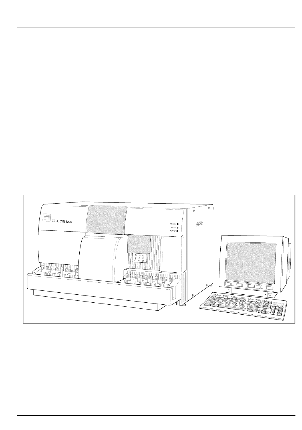
CELL-DYN®3200 Operator’s Manual 1-1
9140181B — November 1997
Use or Function
Section 1 Overview
Overview
The CELL-DYN 3200 is a multiparameter, automated
hematology analyzer designed for in vitro diagnostic use in
clinical laboratories. The instrument has two versions, the
automated sample loader (CELL-DYN 3200SL), and manual
closed sampler (CELL-DYN 3200CS). An example of each
version is shown in Figures 1.1 and 1.2.
The term CELL-DYN 3200 refers to both versions unless either
the Closed Sampler (CS) or Sample Loader (SL) model is
specifically stated. The terms open sample and closed sample
are used interchangeably with open sampler and closed
sampler. Generally, when referring to the mode of operation,
the terms Open Sampler and Closed Sampler are used and
when referring to components of the instrument, Open
Sample and Closed Sample are used, e.g., Open Sample
Aspiration Probe.
.
Figure 1.1: CELL-DYN 3200SL
The CELL-DYN 3200SL is equipped with a Sample Loader
Module. The Sample Loader provides continuous automated
closed sampling for up to 50 closed tube samples at a time. The
Sample Loader may also be referred to as the Auto Sampler.
Go Back
Search
TOC
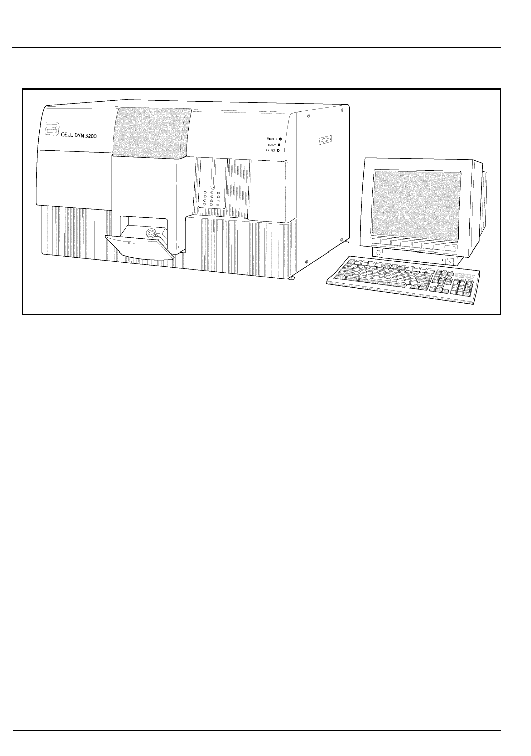
1-2 CELL-DYN® 3200 Operator’s Manual
9140181B — November 1997
Use or Function
Overview Section 1
Figure 1.2: CELL-DYN 3200CS
The CELL-DYN 3200CS is equipped with a built-in manual
Closed Sample Aspiration Module which aspirates blood from
a closed collection tube that has been inserted in the Closed
Sample Module.
Both models aspirate blood from open collection tubes. This
method is referred to as the Open Sampler mode.
Intended Use
The CELL-DYN 3200 is a multiparameter, automated
hematology analyzer designed for in vitro diagnostic use in
clinical laboratories.
The CELL-DYN 3200 generates the following hematologic
measurements on EDTA anticoagulated whole blood:
WBC — White Blood Cell or leukocyte count
NEU — Neutrophil absolute count %N — Neutrophil percent
LYM — Lymphocyte absolute count %L — Lymphocyte
percent
MONO — Monocyte absolute count %M — Monocyte percent
EOS — Eosinophil absolute count %E — Eosinophil percent
BASO — Basophil absolute count %B — Basophil percent
RBC — Red Blood Cell or erythrocyte count
Go Back
Search
TOC

CELL-DYN® 3200 Operator’s Manual 1-3
9140181B — November 1997
Use or Function
Section 1 Overview
HGB — Hemoglobin concentration
HCT — Hematocrit
MCV — Mean Cell Volume
MCH — Mean Cell Hemoglobin
MCHC — Mean Cell Hemoglobin Concentration
RDW — Red Cell Distribution Width
PLT — Platelet or thrombocyte count
MPV — Mean Platelet Volume
PDW*— Platelet Distribution Width
PCT* — Plateletcrit
* Clinical significance has not been established for these
parameters. Therefore, they are not reportable.
Go Back
Search
TOC

1-4 CELL-DYN® 3200 Operator’s Manual
9140181B — November 1997
Use or Function
Overview Section 1
NOTES
Go Back
Search
TOC

CELL-DYN® 3200 Operator’s Manual 1-5
9140181B — November 1997
Use or Function
Section 1 System Components
System Components
The CELL-DYN 3200 consists of three major modules, the
Analyzer, Data Module, and the Display Station. The Analyzer
and Data Module are housed in single chassis. The Display
Station is a standalone module. Figure 1.3 lists the major
subassemblies in each of the modules.
The Analyzer contains the hardware to aspirate, dilute, and
analyze each whole blood specimen.
The Data Module contains the components for analyzing,
storing, and reporting specimen results.
The Display Station module consists of a 15” color monitor
and pressure-sensitive keypad for selecting the displayed
commands that operate the system.
The Sample Loader attaches to the front of the CELL-DYN
3200SL Analyzer and is an integral part of the SL model. The
Sample Loader is discussed throughout this manual where
appropriate. It is also discussed in detail in Section 13.
Figure 1.3: CELL-DYN 3200 System Components
CELL-DYN 3200 System
Analyzer Data Module Display Station
Flow Panel
Electrical Power Supply
Pneumatic Power Supply
Laser Optics Assembly
Syrin
g
e Drive Assemblies
Open Sample Probe Assembly
Rea
g
ent/Waste System
Closed Sample Tower Assembly
Sample Loader (SL model only)
486 Computer 15” Color Monitor
Floppy Disk Drive
Hard Disk Drive
PC Keyboard
Serial/Parallel Interface Ports
Printed Circuit Boards
Membrane Keypad
Go Back
Search
TOC

1-6 CELL-DYN® 3200 Operator’s Manual
9140181B — November 1997
Use or Function
System Components Section 1
Analyzer Components
The major components of the Analyzer are listed below and
shown in Figures 1.4 through 1.8.
Front Panel
Right Front Cover
Left Front Cover
Front Skirt Cover (CS model)
Sample Loader (SL model)
Status Indicator Panel
Closed Sample Tower Cover
Open Sample Aspiration Probe with Touch Plate
Flow Panel
Closed Sample Aspiration Tower Module
Shear Valve Assembly
Syringes (4)
Sample Transfer Peristaltic Pump
Optical Flow Cell Assembly
Laser Optics Bench Assembly (behind Flow Panel)
HGB Flow Cell/Mixing Assembly
WBC Mixing Chamber
RBC/PLT Mixing Chamber
Open Sample Aspiration Probe and Wash Block
Normally Closed Valves (6)
Diluent Reservoirs (2)
Open/Closed Mode Switching Assembly (Y-Valve
Assembly)
Sheath Filter
Waste Chambers (4)
Venting Chamber
Bubble Traps
Aerosol Filter
Normally Open Pinch Valves
Ultrasonic Sensor
LED Sensor
Left Side Panel
Fan with Air Intake Filter
Go Back
Search
TOC

CELL-DYN® 3200 Operator’s Manual 1-7
9140181B — November 1997
Use or Function
Section 1 System Components
Right Side Panel
Floppy Disk Drive Slot
Rear Panel
Main Power Switch
Main Power Connector
Display Station Communications Connector
Line Frequency and Line Voltage Select Switches
Fuse
Fan with Air Intake Filter
Serial and Parallel Interface Ports (Data Module)
Keyboard Connector Port
Touch Pad Connector Port
Waste Sensor Connector
Waste Outlet Tube Connector
Diluent/Sheath Inlet Tube Connector
WBC Lyse Inlet Tube Connector
HGB Lyse Inlet Tube Connector
Analyzer Serial Number Label
Disk Storage Container
Go Back
Search
TOC
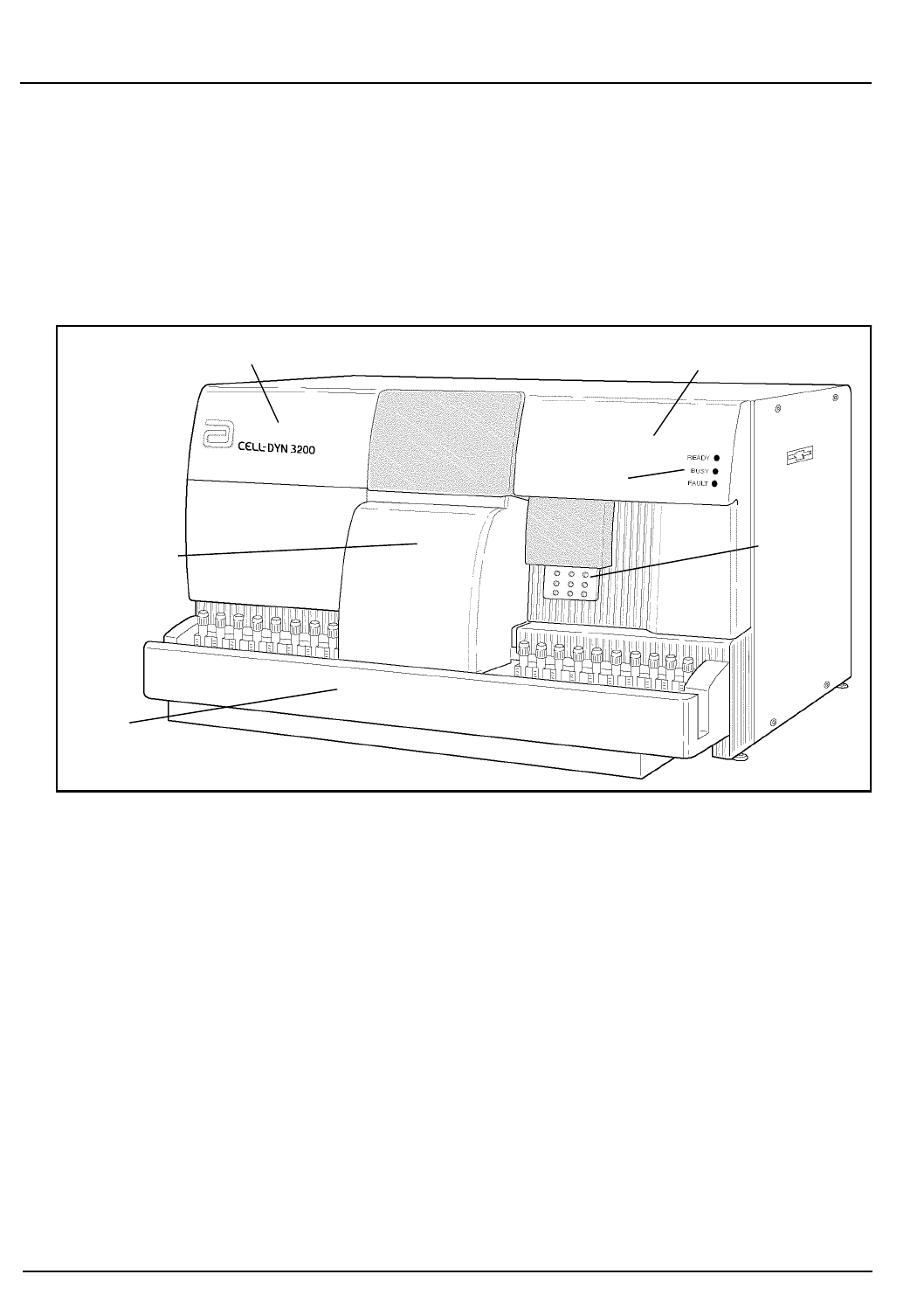
1-8 CELL-DYN® 3200 Operator’s Manual
9140181B — November 1997
Use or Function
System Components Section 1
Component Description
Front Panel
The major components of the Front Panel are depicted in
Figure 1.4. A brief functional description of each component
follows.
Figure 1.4: Cell-Dyn 3200SL Analyzer Front Panel
Left Front Cover
The Left Front Cover protects the left portion of the flow
panel. The cover is hinged on the left, opening from the center
to expose the left half of the flow panel. Access to the left half
of the flow panel is necessary to view the operation of the left
flow panel components, to access the solenoids, pinch valves,
normally closed valves, and to perform certain maintenance
procedures. The cover is held in place by hinges and a release
latch. It may be removed from the instrument.
Left Front Cover Right Front Cover
Tower Cover
Sample Loader
Tou ch
Plate
Status Indicator
Li
g
hts
Go Back
Search
TOC

CELL-DYN® 3200 Operator’s Manual 1-9
9140181B — November 1997
Use or Function
Section 1 System Components
Right Front Cover
The Right Front Cover protects the right portion of the flow
panel and supports the Touch Plate and Status Indicator Panel.
The cover is hinged on the right, opening from the center to
expose the right half of the flow panel. Access to the right half
of the flow panel is necessary to view the action of the right
flow panel components, to access the syringe assemblies,
solenoids, pinch valves, normally closed valves, and to
perform certain maintenance procedures.
The cover is held in place by hinges and a release latch.
Because two sets of wires — one for the Status Panel and one
for the Touch Plate — are connected to the inside of the Right
Front Panel, this cover should be removed only if necessary.
Before attempting to remove the cover, disconnect the
connector attached to the Status Panel circuit board and the
two connectors attached to the Touch Plate circuit board.
Remember to re-connect the connectors when reattaching the
cover.
Front Skirt Cover
The Front Skirt Cover protects the lower front part of the flow
panel. The skirt should be removed to access the two lower
Normally Closed Valves on the left side of the Flow Panel. The
Skirt is removed from the instrument by removing the four
Phillips-head screws holding the Skirt to the Analyzer. The
Skirt on the SL model has two removable sections adjacent to
the Flow Panel. The section on the right side should be
removed to provide easy access to all four syringes and two
syringe drives.
Closed Sample Tower Cover
The Closed Sample Tower Cover protects the Tower Assembly
and Shear Valve. The Tower Cover for the SL model is larger
than its counterpart on the CS model in order to cover the top
central portion of the Sample Loader. Part of the cover is
translucent to allow viewing of the Shear Valve’s operation.
The cover is held in place by two pins at the bottom and two
release latches at the top. Both covers have an Interlock Sensor
Switch which prevents the instrument from operating in the
Closed Mode if the cover is not in place.
Go Back
Search
TOC

1-10 CELL-DYN® 3200 Operator’s Manual
9140181B — November 1997
Use or Function
System Components Section 1
Status Indicator Panel
Three Status Indicator Messages (illuminated by green,
yellow and red LEDs) indicate the status of the Analyzer. The
status messages are:
• Ready (green light) —the Analyzer is ready to process a
specimen
• Busy (yellow light) —the Analyzer is busy with a normal
operational sequence
• Fault (red light) —the Analyzer is unable to process
specimens due to an existing fault condition
Open Sample Aspiration Probe
The Open Sample Aspiration Probe is used to aspirate whole
blood from an opened collection tube. The wash block moves
down to the end of the probe and returns to a position that is
covered by the Right Front Cover. When Closed Sampler mode
is selected, the Wash Block moves down to the end of the
probe and remains down until the Open Sampler mode is
again selected.
Touch Plate
The Touch Plate is used to start the run cycle for (1) both the
Open Sampler and Closed Sampler modes on the CS model
and (2) Open Sampler mode only on the SL model. It is located
directly behind the Open Sample Aspiration Probe and is part
of the Right Front Cover. Pressing the Touch Plate starts the
selected run cycle.
Closed Sample Aspiration Tower Module
The Closed Sample Aspiration Tower is used to aspirate
whole blood from a closed collection tube. It is activated when
the Closed Sampler mode is selected on either the SL or CS
model and the Touch Plate is pressed. The configuration of the
Tower Module differs depending on the model.
In the CS model, the Tower Module consists of the following
components:
• Aspiration/Vent Needle
•Wash Block
• Tube Spinner (includes motor and belt)
• Door Assembly (includes Tube Holder, Bar Code Reader,
Swivel Door, Solenoid, and Interlock
Switch).
Go Back
Search
TOC

CELL-DYN® 3200 Operator’s Manual 1-11
9140181B — November 1997
Use or Function
Section 1 System Components
In the SL model, the Tower Module consists of the following
components:
• Aspiration/Vent Needle
•Wash Block
• Tube Spinner (includes motor and belt)
The Door Assembly is eliminated from the Tower, and the Bar
Code Reader is moved to the Sample Loader which also
contains the Mixer Assembly.
The major components of the Tower Module are briefly
described below:
• A two-part Needle consisting of a venting needle and an
aspiration needle that pierces the collection tube stopper,
vents vacuum or pressure from inside the tube, aspirates
the whole blood, and is retracted for rinsing at the end of
each cycle
•A Tube Spinner to grasp and spin the tube for bar code
reading
•The Driver Motor and Belt to operate the Tube Spinner
•A Closed Sample Door/Tube Retainer which holds a
single closed collection tube in the proper position for (1)
reading the bar code if applicable, and (2) stopper
penetration and sample aspiration by the needle
Go Back
Search
TOC
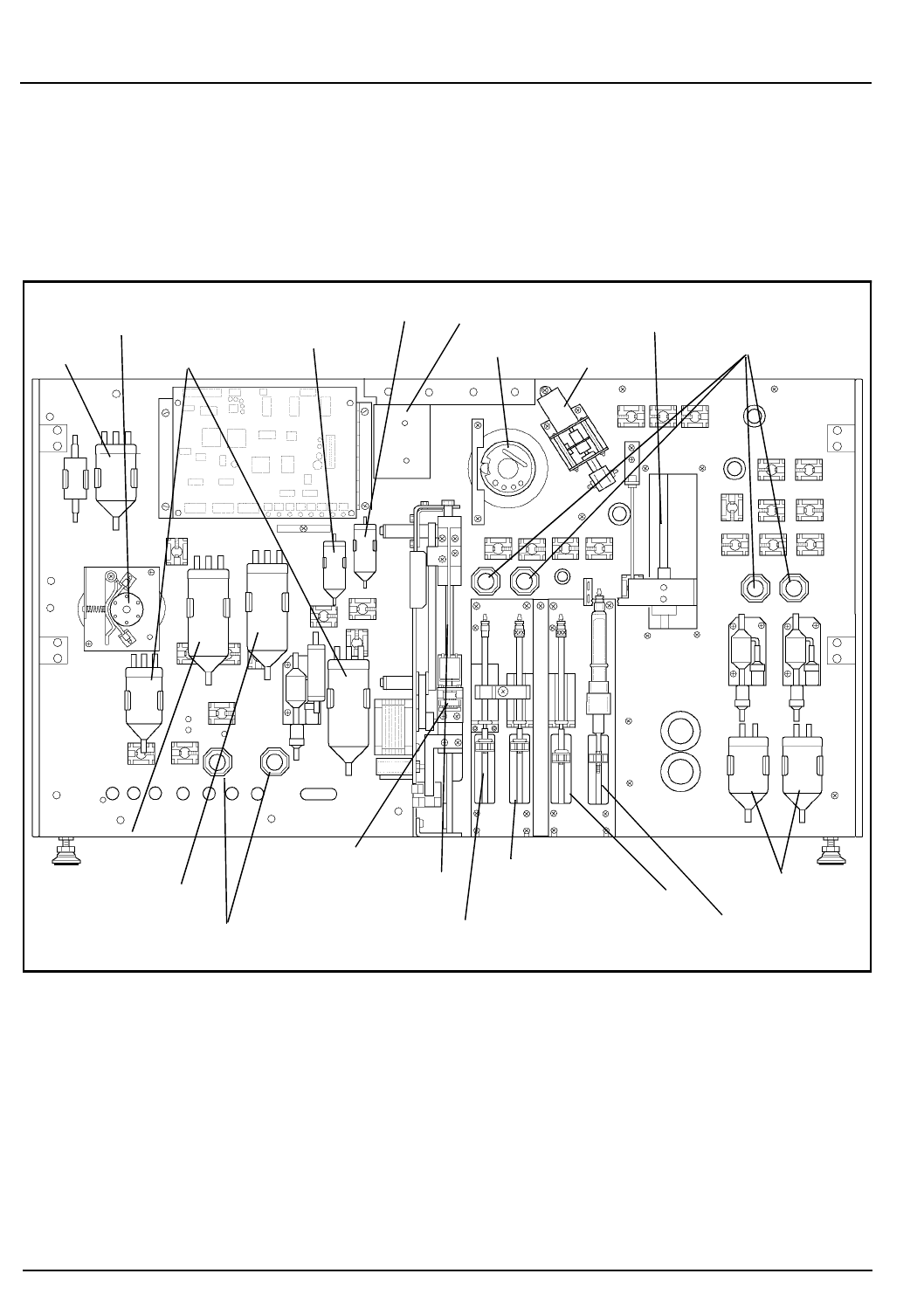
1-12 CELL-DYN® 3200 Operator’s Manual
9140181B — November 1997
Use or Function
System Components Section 1
Flow Panel
The major components of the Flow Panel are depicted in
Figure 1.5. A brief functional description of Flow Panel
components follows.
Figure 1.5: Flow Panel Components
Shear Valve Assembly
The three-piece ceramic Shear Valve isolates a precise volume
of whole blood by means of a shearing action as the front and
rear sections of the valve rotate. The aspirated blood is isolated
in three separate volume segments — one for the WBC
dilution, one for the HGB dilution and one for the RBC/PLT
dilution.
Vent
Sample Transfer Peristaltic RBC Mixing Chamber
WBC Mixing Chamber
Closed Sample Needle
Shear Valve Y Valve Normally Closed Valves
Waste Chambers
Open Sample Probe
Diluent
Normally Closed Valves
Waste Chambers
Tube Spinner
Sample Injection Syringe
HGB Lyse Syringe
WBC Lyse Syringe
Diluent/Sheath Syringe
HGB Flow Cell
Sheath
Reservoir
Reservoir
Pump (With Wash Block)
(With Wash Block)
Go Back
Search
TOC

CELL-DYN® 3200 Operator’s Manual 1-13
9140181B — November 1997
Use or Function
Section 1 System Components
Syringe Assembly
There are two syringe driver assemblies, each containing two
syringes. Each syringe is operated by its own stepper motor.
The function of each syringe is described below:
•Diluent/Sheath Syringe — (1) delivers a specific volume
of diluent to transport the RBC segment from the Shear
Valve to the RBC/PLT Mixing Chamber and to dilute the
segment prior to measurement, and (2) delivers a specific
volume of diluent to transport the HGB segment from the
Shear Valve to the HGB Mixing Chamber and to dilute
the segment prior to measurement.
•HGB Lyse Syringe — delivers a specific volume of HGB
Lyse to the HGB Mixing Chamber/Flow Cell to further
dilute the HGB segment prior to measurement.
•WBC Lyse Syringe — delivers a specific volume of WBC
Lyse to transport the WBC segment from the Shear Valve
to the WBC Mixing Chamber and to dilute the segment
prior to measurement.
•Sample Injection Syringe — injects a specific volume of
the diluted sample into the Optical Flow Cell for RBC/
PLT, WBC (WOC), and WBC (NOC) measurements.
Sample Transfer Peristaltic Pump
The Sample Transfer Peristaltic Pump is composed of a rotor
and a pump tube holder. It is used to transfer the WBC
dilution, RBC/PLT dilution, and HGB/NOC dilution to the
Optical Flow Cell from their respective mixing chambers.
HGB Flow Cell and Mixing Chamber
The HGB Flow Cell Assembly is integrated with a mixing
chamber and contains the following components:
• A fully enclosed (light-tight) mixing chamber with optical
windows and electronics
•An LED Light Source
•A Photodetector for measuring the light transmitted.
WBC Mixing Chamber
The WBC Mixing Chamber is used to swirl mix the WBC
dilution.
Go Back
Search
TOC

1-14 CELL-DYN® 3200 Operator’s Manual
9140181B — November 1997
Use or Function
System Components Section 1
RBC/PLT Mixing Chamber
The RBC/PLT Mixing Chamber is used to swirl mix the
RBC/PLT dilution.
Wash Block
There are two Wash Blocks on the instrument, one for the
Open Sample Aspiration Probe and one for the Closed Sample
Needle. Both Wash Blocks work in a similar fashion: After
aspiration, they move down the outside of the probe or
needle, rinsing it with diluent. The diluent rinse is then
transferred to the waste chamber.
Normally Closed Valves
The Normally Closed Valves prevent the backflow of reagents
in critical areas when the power is turned off.
Diluent Reservoir
The Diluent Reservoir maintains the diluent supply for
cleaning and sample dilution.
Sheath Reservoir
The Sheath Reservoir maintains a constant sheath supply for
hydrodynamic focusing in the Flow Cell.
Waste Chambers
The Waste Chambers collect the waste liquid from the
Analyzer flow panel.
Bubble Traps
The Bubble Traps (not shown) are used to prevent bubbles
and liquid from being pulled into the vacuum accumulators
and the vacuum pump.
Aerosol Filter
The Aerosol Filter (not shown) is used to prevent aerosols
escaping into the atmosphere.
Pinch Valves
The Pinch Valves (not shown) are used to control air and
liquid throughout the Analyzer.
Go Back
Search
TOC

CELL-DYN® 3200 Operator’s Manual 1-15
9140181B — November 1997
Use or Function
Section 1 System Components
Closed Mode Aspiration Tower
The Aspiration Tower contains the Aspiration/Vent Needle,
Needle Wash Block, Sample Tube Spinner Assembly, and
tubing to aspirate blood samples from closed sample tubes.
Vent/Aspiration Needle
The Vent/Aspiration Needle combines both venting and
aspiration of blood samples from closed sample tubes.
Wash Block
Discussed in the previous subsection.
Spinner Assembly
The Spinner Assembly consists of a tube holder, motor, and
belt. These are attached to the Closed Mode Aspiration Needle
drive mechanism, and they move up and down in tandem
with the needle. As the Spinner Assembly and needle descend
together, the spinning tube holder centers and rotates the
sample tube, allowing the Bar Code Reader to read the bar
code on the sample tube. After the bar code is read, the needle
penetrates the rubber stopper and aspirates the sample.
Bar Code Reader
The Bar Code Reader is an LED type and can accommodate
Code 39, Code 128, CODABAR, and Interleave 2 of 5 formats.
On the CS model, the Bar Code Reader is located to the right
of the door opening on the Door Assembly. On the SL model,
the Bar Code Reader is located to the left of the Mixing
Assembly on the Sample Loader.
Door Assembly (CS Model)
The Door Assembly consists of a tube holder/door, Bar Code
Reader, Interlock Switch, and electrical latch to open the door
after aspiration has occurred. The Interlock Switch will cause
the instrument to halt if the door is opened between the time
the Touch Plate is pressed and the system emits a beep to
indicate that aspiration is completed. Opening the door during
this period will cause a Fatal Fault condition.
Go Back
Search
TOC

1-16 CELL-DYN® 3200 Operator’s Manual
9140181B — November 1997
Use or Function
System Components Section 1
NOTES
Go Back
Search
TOC
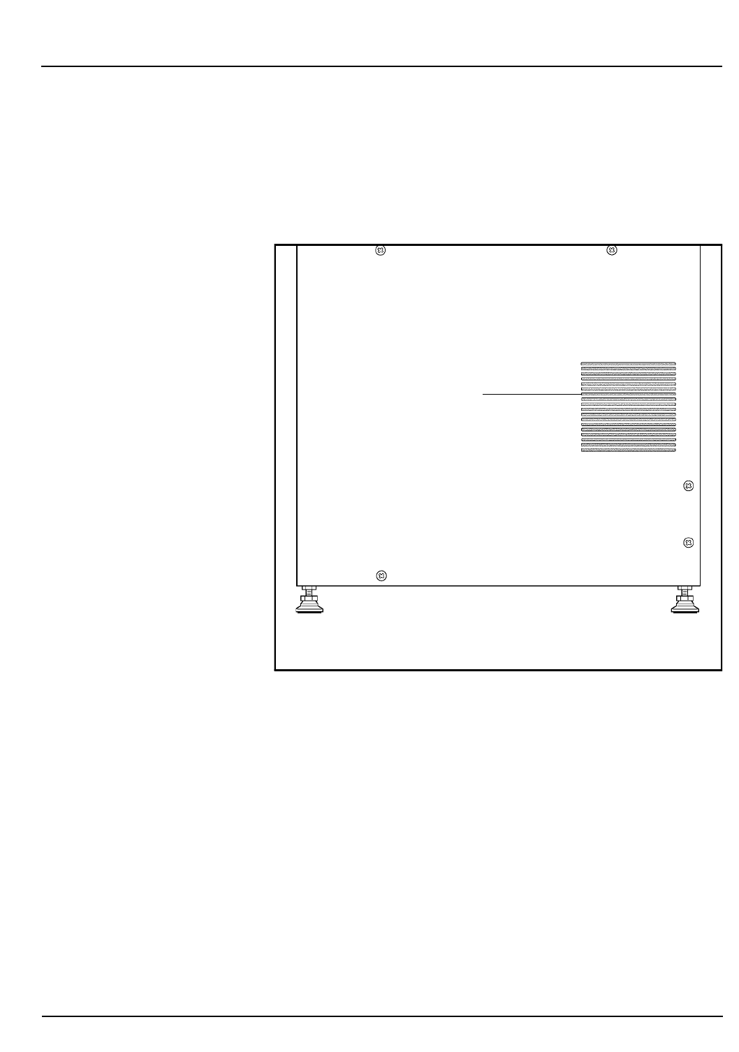
CELL-DYN® 3200 Operator’s Manual 1-17
9140181B — November 1997
Use or Function
Section 1
Left Side Panel
The only major component on the Left Side Panel is the Fan,
shown in Figure 1.6.
Fan
A Fan cools the internal components of the Analyzer.
Figure 1.6: Left Side Panel
Air Filter
Go Back
Search
TOC
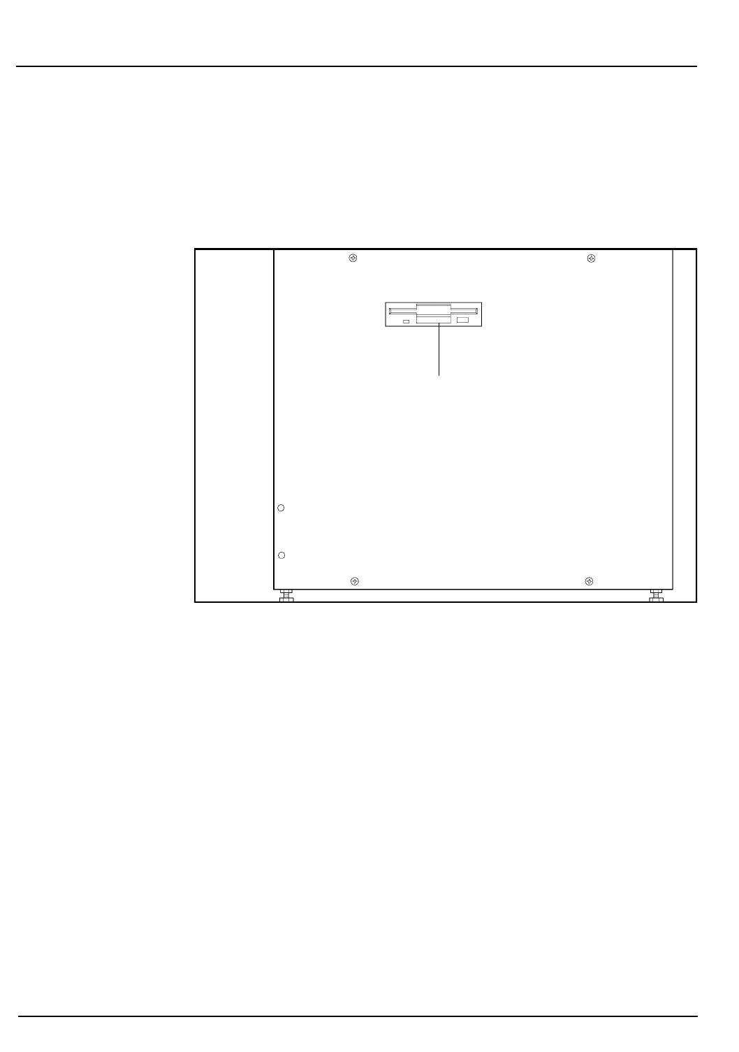
1-18 CELL-DYN® 3200 Operator’s Manual
9140181B — November 1997
Use or Function Section 1
Right Side Panel
The major components on the Right Side Panel are depicted in
Figure 1.7. A brief functional description of each component
follows.
Figure 1.7: Right Side Panel Components
Floppy Disk Drive
The Floppy Disk Drive allows information to be downloaded
or uploaded using a 3.5” floppy disk.
Floppy Disk Drive
Go Back
Search
TOC
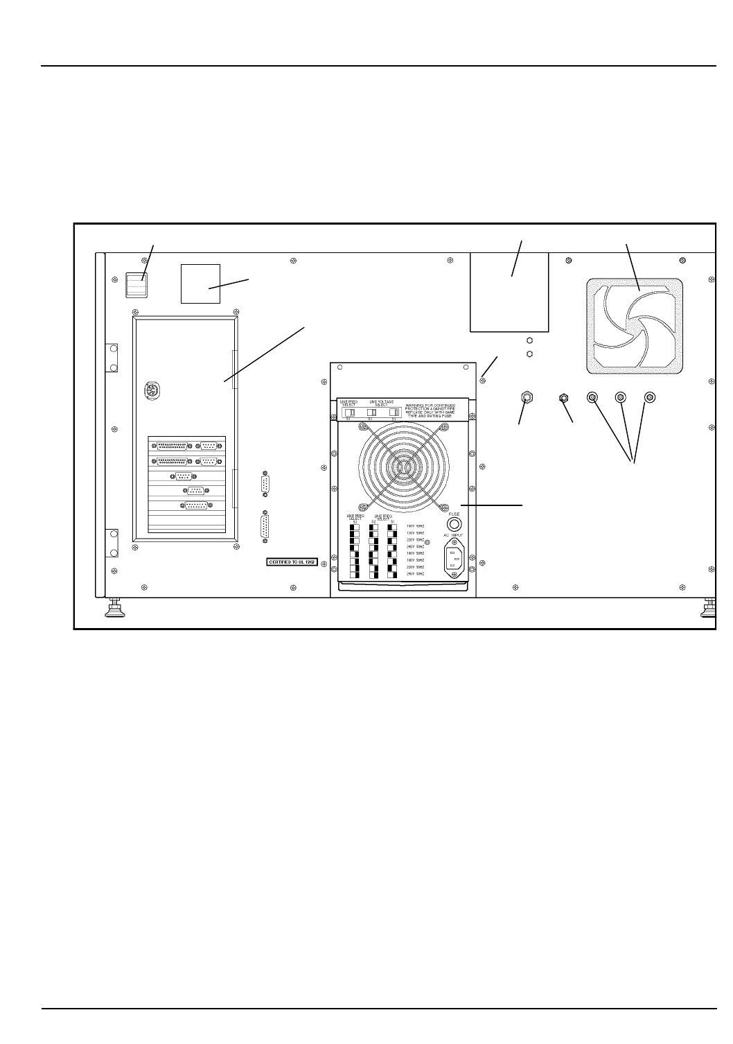
CELL-DYN® 3200 Operator’s Manual 1-19
9140181B — November 1997
Use or Function
Section 1
Rear Panel
The major components on the Rear Panel are depicted in
Figure 1.8. A brief functional description of each component
follows.
Figure 1.8: Rear Panel Components
Fan
Reagent Inlet Panel
Power Supply Module
Data Station Module
Main Power Switch
Ground
Connection
Waste
Sensor Waste
Connector
Analyzer
Serial Number
Disk Storage Container
Go Back
Search
TOC
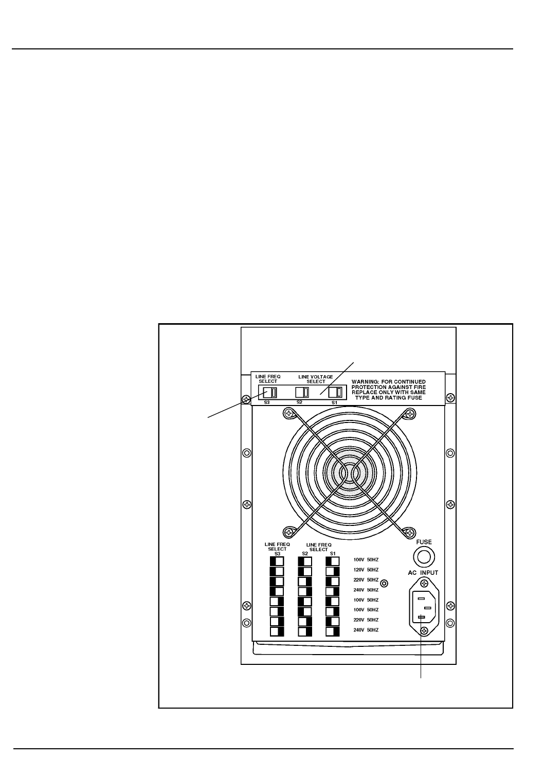
1-20 CELL-DYN® 3200 Operator’s Manual
9140181B — November 1997
Use or Function Section 1
Main Power Switch
The Main Power Switch turns on power for the Analyzer, Data
Station, Display Station, and Sample Loader (SL model only).
Main Power Connector
This receptacle is used to connect the main power cord to the
instrument.
Power Supply
The Power Supply Module supplies the power to operate the
Analyzer and Data Module.
Line Frequency and Line Voltage Select Switches
These switches are used to select the Line Frequency and
Voltage for the Analyzer (refer to Figure 1.9).
Figure 1.9: Power Supply Module
Line Frequency
Select Switch
Line Voltage
Select Switch
Main Power Connector
Go Back
Search
TOC

CELL-DYN® 3200 Operator’s Manual 1-21
9140181B — November 1997
Use or Function
Section 1
Fuse
An 8-amp (110/120 V) or 4-amp (220/240 V) Fuse protects the
Analyzer from electrical spikes.
Fan
A Fan cools the internal components of the Analyzer.
Waste Sensor Connector
The waste-full sensor plug connects to the Waste Sensor
Connector port. The ground shield on the cable should be
attached to the ground connector on the rear panel. When the
electrical sensor is tripped, the EXTERNAL WASTE FULL
message is generated and the READY status is inhibited until
the situation is corrected. The Analyzer interprets a
disconnected plug the same way as a full waste container.
Therefore, if the waste is routed to a drain, the dummy plug
(supplied in the accessory kit) must be inserted in the
connector.
Waste Outlet Tube Connector
This port is used to connect the waste outlet tube.
Diluent/Sheath Inlet Tube Connector
This color-coded (red) port is used to connect the diluent inlet
tube with its associated cap, sinker and label.
WBC Lyse Inlet Tube Connector
This color-coded (purple) port is used to connect the WBC lyse
inlet tube with its associated cap, sinker and label.
HGB Lyse Inlet Tube Connector
This color-coded (blue) port is used to connect the HGB lyse
inlet tube with its associated cap, sinker and label.
Analyzer Serial Number Label
Although not an instrument component, the Analyzer Serial
Number may be required when consulting with the Customer
Support Center.
Disk Storage Container
This container is used to store the installation and Set Up
disks.
Go Back
Search
TOC
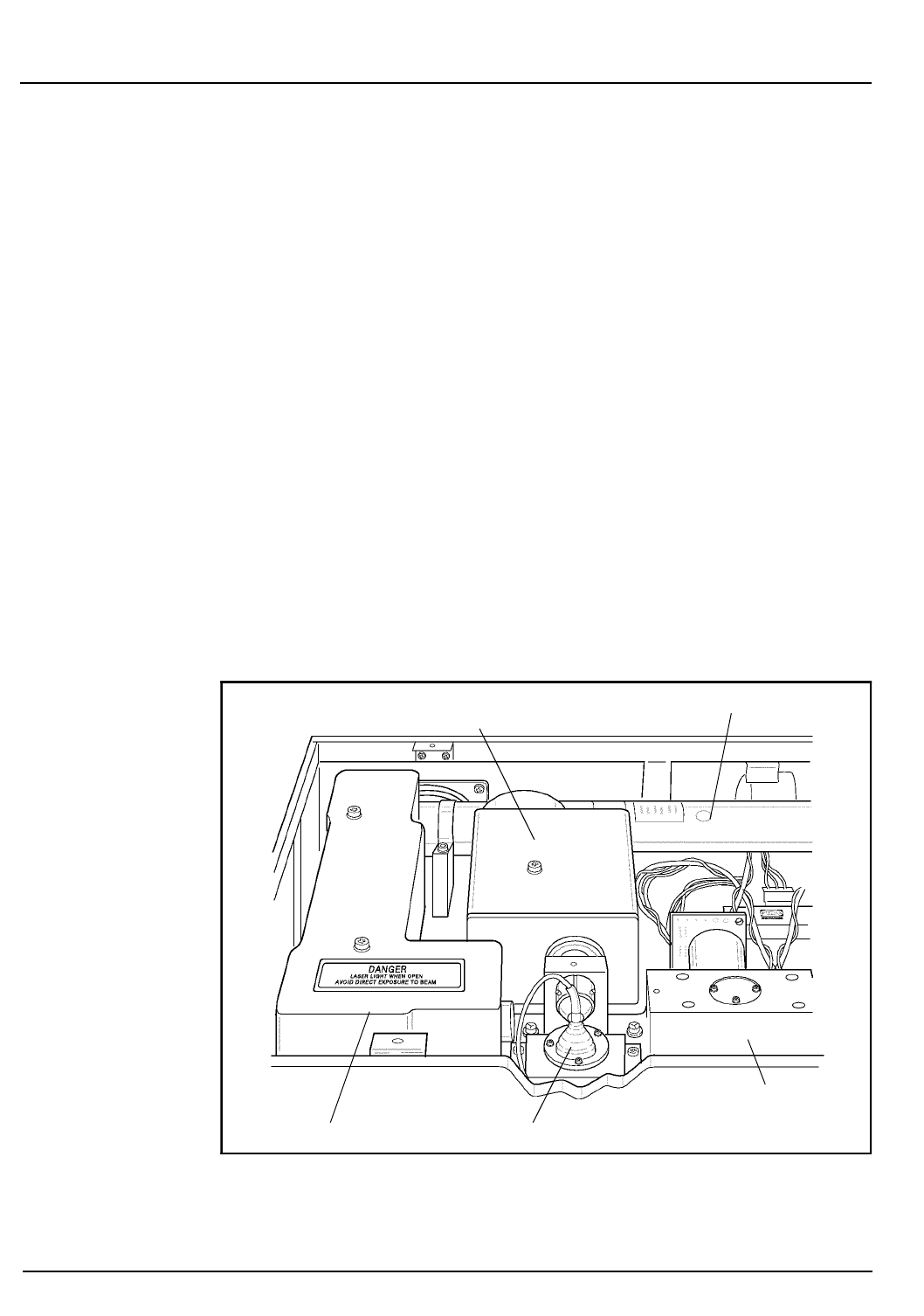
1-22 CELL-DYN® 3200 Operator’s Manual
9140181B — November 1997
Use or Function Section 1
Top Panel
Flow Cell Assembly
The Flow Cell Assembly contains the fluidics and hardware
needed to hydrodynamically focus the RBC/PLT and WBC
sample streams in the path of the laser beam for analysis. The
primary components of this assembly are:
•Sample Feed Nozzle — a specially designed tube used
to deliver the diluted sample into the sheath stream
•Sample Flow Cell — an optically clear quartz
chamber with a central square opening of a specific
size, which flares out into a cone at the bottom of the
flow cell
Laser Optics Bench Assembly
The Laser Optics Bench Assembly (located behind the Flow
Panel) contains the Helium-Neon laser, the flow cell, the
optics and the detectors required for the enumeration and
differentiation of the white blood cells, red blood cells, and
platelets (refer to Figure 1.10).
Figure 1.10: Optical Bench
Optical Flow Cell
Laser
Forward Angle
(0° and 10°) Li
g
ht
Laser Tube
Orthogonal (90° and 90°D)
Scatter Light Detectors
Detectors
Go Back
Search
TOC
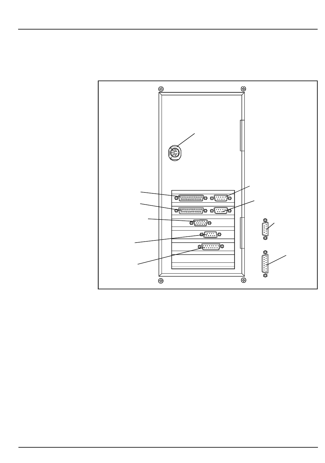
CELL-DYN® 3200 Operator’s Manual 1-23
9140181B — November 1997
Use or Function
Section 1
Data Module Components
The major components of the Data Module are depicted in
Figure 1.11. The functional description of each component
follows.
Figure 1.11: Data Module Components - Rear Panel
Computer
• Intel 486DX microprocessor
• 8 megabytes RAM (expandable to 16 megabytes)
• VGA graphics with 1 megabyte cache
• 2 enhanced parallel ports and 2 serial ports
• 2 FIFO UART Com1 and Com2 ports
•3 PCI slots
HSSL
Connector
PC Keyboard
Connector
Graphics Printer
Ticket Printer
COM1 (LIS Connector)
Display Station
Connector
Membrane
Keyboard
HSSL Connector
COM2 (Unused)
Analyzer
BDM
Diagnostics
(Unused)
Go Back
Search
TOC

1-24 CELL-DYN® 3200 Operator’s Manual
9140181B — November 1997
Use or Function Section 1
Data Storage
Data storage consists of a 3.5-inch, 1.4 megabyte Floppy Disk
Drive and a one gigabyte EIDE (enhanced IDE) Hard Disk
Drive.
The floppy disk drive is used to update the software program
and to download data. The hard drive is used to store the User
Interface Software and Patient Data Log. It has sufficient
capacity to store the most recent 10,000 cycles, including
numeric and graphics data.
Printed Circuit Boards
A set of Printed Circuit Boards constitutes the measurement
and control electronics for detection, amplification, and
processing of signals.
Display Station Interface Connector
The Display Station Interface Connector allows data to be
sent to the monitor and data to be received from the
Membrane Keypad (Soft Keys) on the Display Station.
HSSL (High Speed Serial Link) Connector
The High Speed Serial Link transfers data between the Analyzer
and the Data Station Module. The HSSL Connector on the
Data Station Module connects to the HSSL Connector on the
back panel of the Analyzer.
Membrane Keypad Interface Connector
The Membrane Keypad Interface Connector allows data to
be sent from the Membrane Keypad on the Display Monitor to
the Data Station.
Graphics Printer Connector
This port is used to connect the printer cable when the printer
is used to print data in a graphics format.
Ticket Printer Connector
This port is used to connect the printer cable when the printer
is used to print data in a ticket format.
LIS (Laboratory Information System) Connector
Two serial ports are provided. COM1 is used to connect the
Laboratory Information System to the Data Station Module.
COM2 is unused.
Go Back
Search
TOC
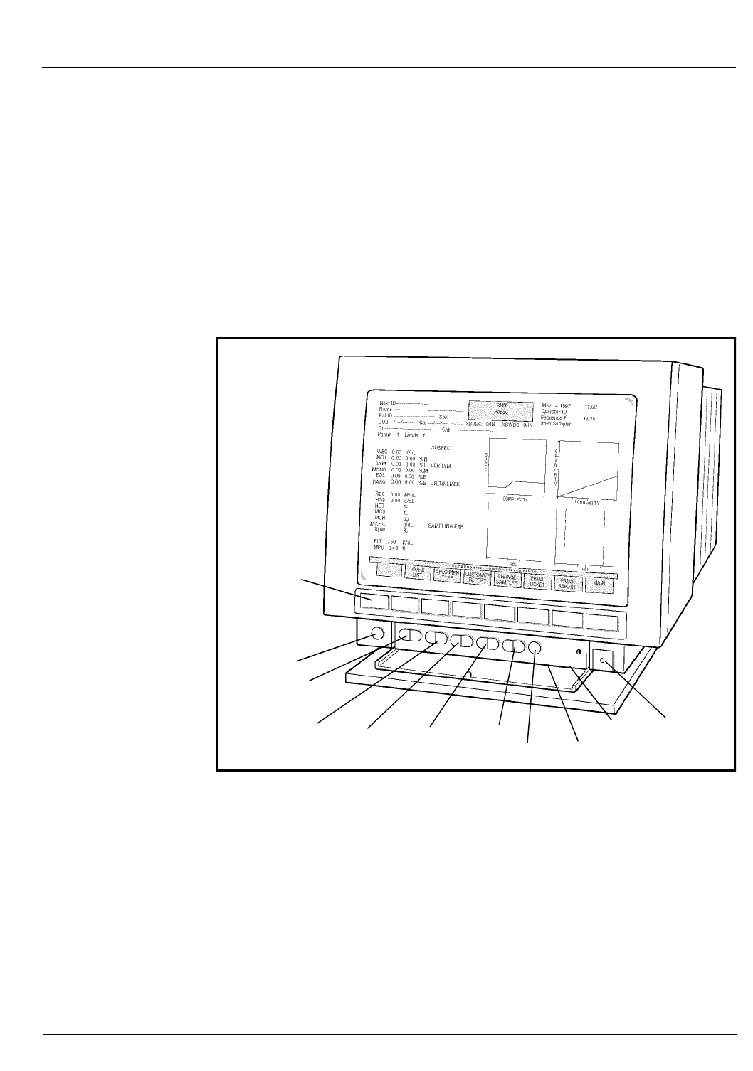
CELL-DYN® 3200 Operator’s Manual 1-25
9140181B — November 1997
Use or Function
Section 1
PC Keyboard Connector
The PC Keyboard Connector port is used to connect the
standard computer keyboard.
Display Station Components
The major components of the Display Station are shown in
Figure 1.12. The functional description of each component
follows.
Figure 1.12: Display Station Components
ON/OFF
Degauss
Reset to Default
H Shift
H Size
V Size
Side Pincushion
V Shift
Membrane
Keypad
Brightness
Contrast Switch
Go Back
Search
TOC

1-26 CELL-DYN® 3200 Operator’s Manual
9140181B — November 1997
Use or Function Section 1
Display Monitor
A 15-inch diagonal, high-resolution Display Monitor with
16-color illumination displays all alphanumeric and graphics
data.
Soft Keys
A row of eight unlabeled pressure-sensitive Soft Keys
(membrane keypad) is located directly below the screen. Each
key initiates a function defined by the screen label currently
displayed directly above it.
Membrane Keypad Cable
The Membrane Keypad Cable allows commands to be
transferred from the Display Monitor to the Data Station.
Video Cable
The Video Cable allows data from the Data Station to be
transferred to the Display Monitor.
Power Cord
A built-in power cord on the Display Station connects to an
outside power supply and provides power to the monitor and
keypad.
Screen Controls
The Controls available on the Display Monitor are shown in
Figure 1.12. The Brightness and Contrast controls are located
under the control panel shown in the figure.
Sample Loader Components
The major components of the Sample Loader are depicted in
Figure 1.13. The functional description of each component
follows.
Go Back
Search
TOC
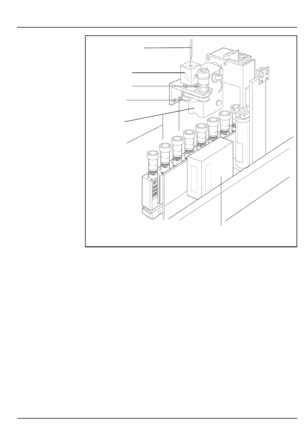
CELL-DYN® 3200 Operator’s Manual 1-27
9140181B — November 1997
Use or Function
Section 1
Figure 1.13: Sample Loader Components
Racks
Each Sample Loader Rack is able to accommodate up to 10
tubes. Racks are labeled with rack number and tube position,
and with a 2-digit Bar Code 39 format.
Tower Cover
The Tower Cover on the SL model, although not part of the
Sample Loader, has an Interlock Sensor Switch which prevents
the loader from operating if the cover is not in place. If the
cover is removed during operation, the Sample Loader comes
to an immediate halt, causing a fatal fault. This feature
provides further safety for the operator.
Bar Code Reader
The Bar Code Reader is an LED type and can accommodate
Code 39, Code 128, CODABAR, and Interleave 2 of 5 formats.
On the SL model, the Bar Code Reader is located on the
Sample Loader. It reads the bar code on the tube when the
tube is at the aspiration station.
Aspiration Needle
Wash Block
Tube Spinner
Spinner Motor
Tube Mixer
Bar Code Reader
Go Back
Search
TOC

1-28 CELL-DYN® 3200 Operator’s Manual
9140181B — November 1997
Use or Function Section 1
Tube Sensor Assembly
The Tube Sensor Assembly senses the presence of a sample
tube at each Mixing Station.
Mixer Assembly
The Mixer Assembly consists of a double-tube holder directly
attached to a stepper motor. As the rack advances, the tube
holder descends and grabs the tube. The tube holder rotates 15
times in an outward motion of approximately 135 degrees.
The double-tube configuration of the tube holder allows each
tube to be held and mixed twice in succession before it passes
to the mixing station. An air cylinder governs the rotation
movement of the tube holder.
Printer
The Printer is discussed in detail in Section 12: Printers.
Reagent System
Introduction
The Reagent System is formulated specifically for the
CELL-DYN 3200 Series instrument flow systems in order to
provide optimal system performance. Use of reagents other
than those specified in this manual is not recommended as
instrument performance can be affected. Each CELL-DYN 3200
system is checked at the factory using the specified reagents
and all performance claims are generated using these reagents.
The three reagents used with the CELL-DYN 3200 are:
•RBC/PLT Reagent - Diluent/Sheath
•WBC Reagent - WBC Lyse
•HGB Reagent - CN-Free HGB/NOC Lyse
Reagents must be stored at room temperature to ensure optimal
performance. All reagents should be protected from direct
sunlight, extreme heat and freezing during shipment and
storage. Temperatures below 32° F (0°C) may cause reagent
layering that changes the tonicity and conductivity of the
reagents. If any reagent has been frozen, it should not be used.
Go Back
Search
TOC

CELL-DYN® 3200 Operator’s Manual 1-29
9140181B — November 1997
Use or Function
Section 1
The reagent inlet tubes have a cap attached that minimizes
evaporation and contamination during use. However, reagent
quality may deteriorate with time. Therefore, use all reagents
within the dating period indicated on the label.
CELL-DYN Reagents
CELL-DYN 3200 Diluent/Sheath (L/N 03H79-01)
CELL-DYN Diluent/Sheath is formulated to meet the
following requirements:
• Act as the diluent for the RBCs, PLTs and hemoglobin
• Maintain the stable diluted cell volume of each red cell
and platelet during the count and sizing portion of the
measurement cycle
• Serve as a sheath fluid for the hydrodynamic focusing
process
• Serve as a rinsing agent for the fluidics system
• Provide background counts equal to or less than:
WOC: 0.10 x K/µL
NOC: 0.10 x K/µL
RBC: 0.02 x M/µL
HGB: 0.10 x g/dL
PLT: 5.0 x K/µL
CELL-DYN 3200 CN-Free HGB/NOC Lyse (L/N 03H80-01)
•CELL-DYN CN-Free HGB/NOC Lyse is formulated to
meet the following requirements:
• Rapidly lyse the red blood cells and minimize the
resultant stroma
• Strip the white cell cytoplasm leaving the nuclear
membrane intact so the white cell nucleii can be
enumerated
• Convert hemoglobin to a stable chromagen complex that
is measurable at 540 nm.
Go Back
Search
TOC

1-30 CELL-DYN® 3200 Operator’s Manual
9140181B — November 1997
Use or Function Section 1
CELL-DYN 3200 WBC Lyse (L/N 03H78-01)
CELL-DYN WBC Lyse is formulated to meet the following
requirements:
•Act as the diluent for the WBCs
•Osmotically lyse the red cells
•Maintain the light scattering properties of the WBCs for
the duration of the measurement period
•Provide sufficient wetting action to prevent accumulation
of air bubbles in the WBC flow system
•Maintain a WOC background count equal to or less than
0.10 x K/µL
Consumables
The following consumables are used with the CELL-DYN 3200
System:
•Preprinted tickets
•Color Ink Cartridges
•DYN-A-WIPE™ Lint-free pads
•Enzymatic Cleaner Concentrate
For information on ordering parts and accessories, reagents,
controls, calibrators, and consumables, please refer to
Appendix B - Parts and Accessories.
Go Back
Search
TOC

CELL-DYN®3200 Operator’s Manual 2-1
9140181B — November 1997
Installation Procedures and Special Requirements
Section 2 Overview
Overview
Installation of the CELL-DYN 3200 should be performed by an
authorized Abbott representative to ensure that all system
components are functioning correctly and to verify system
performance.
NOTE: Installation of the Analyzer by an unauthorized
or untrained person could result in damage to the
system. Never attempt to install the system without an
authorized Abbott representative present.
The remainder of this chapter gives general requirements for a
successful installation. Procedures are also included for
installing the Printer and Sample Loader.
Initial Preparation
Package Inspection and Inventory
The instrument is shipped from the factory as follows:
CELL-DYN 3200SL
• 1 crate containing the instrument including Sample
Loader
• 1 box containing the CELL-DYN Accessory kit and
Sample Loader Accessory kit
• 1 box containing the Color Graphics Printer
• 1 box containing the Ticket Printer (optional)
• CELL-DYN Reagents
CELL-DYN 3200CS
• 1 crate containing the instrument
• 1 box containing the CELL-DYN Accessory Kit
• 1 box containing the Color Graphics Printer
• 1 box containing the Ticket Printer (optional)
• CELL-DYN Reagents
Go Back
Search
TOC

2-2 CELL-DYN® 3200 Operator’s Manual
9140181B — November 1997
Installation Procedures and Special Requirements
Overview Section 2
CELL-DYN Accessory Kit
• Operator’s Manual
• Keyboard Cover
• Fuse, SB 8.0 amps 110/120V (2)
• Fuse, SB 4.0 amps 220/240V (2)
• Printer Paper 9.5” x 11”
• Power Cord (Analyzer)
• Reagent Line Kit
• Printer Stand
• Printer Cable
• Large Peristaltic Pump Tubing
• Waste Dummy Plug
• Interface Specification
• Wire Puller (Solenoids)
• RS232 Plug (Loop back)
Sample Loader Accessory Kit
• 5 Tube Racks (Pre-labeled)
The instrument will be uncrated and inspected for damage by
the trucking company when the system is delivered. If desired,
the trucking company will transport the instrument to the
laboratory and place it in the designated space.
Inspect the remaining boxes for damage. If there is any
damage or any crates or boxes are missing, contact the Abbott
Customer Support Center for assistance.
The reagents needed for installation are shipped when the
instrument is shipped. This shipment includes: WBC Lyse
Reagent, HGB Cyanide-free Lyse Reagent, and RBC Diluent/
Sheath.
Go Back
Search
TOC

CELL-DYN®3200 Operator’s Manual 2-3
9140181B — November 1997
Installation Procedures and Special Requirements
Section 2 Overview
The calibrator and controls needed for the installation are
shipped when the instrument is shipped. This shipment
includes: CELL-DYN Calibrator and Tri-level Control.
If any reagents, calibrator or control materials are missing,
contact the Abbott Customer Support Center for assistance.
Space Requirements
Approximately 6 linear feet of space is required on the counter
top to accommodate the instrument, display station, and
printer. Sufficient space is required beneath for the reagents
and the waste container (if one is used).
Allow six inches of space behind the instrument and 12 inches
above and in front of the fan on the left side of the instrument
for air flow. In addition, allow adequate space around the
instrument to perform necessary maintenance procedures and
to provide service access.
Locate the instrument:
• On a stable, level surface
• On a nonporous, nonabsorbent work surface and flooring
that can be easily cleaned and disinfected using
recommended procedures
• Away from direct sunlight
• Away from the path of a cooled or heated air outlet
• Away from any other instruments that may interfere with
it, such as a centrifuge, any x-ray equipment, MRI
equipment, a CRT, a video terminal, a computer, or a
copier
Place the reagents below the instrument.
Waste Requirements
Allow room for a suitable waste container or position the
instrument to permit the waste to be routed directly to a drain.
The drain must be suitable for disposal of waste with possible
biological and chemical hazard. Be sure that the waste outlet
tube is secured in the drain hole.
Regulations on permissible substances, and their amounts, for
disposal in public sewer systems vary from state to state and
even community to community. Customers are advised to be
knowledgeable about all applicable local, state, and federal
requirements, and the contents of their effluent streams,
before disposal of waste in public sewer systems.
Go Back
Search
TOC

2-4 CELL-DYN® 3200 Operator’s Manual
9140181B — November 1997
Installation Procedures and Special Requirements
Overview Section 2
Power Requirements
Be sure that the system is located at the desired site before
attempting any connections. A minimum of three power
outlets are required for either model: one outlet for the
Analyzer, one for the Printer, and one for the Display Station.
If a Ticket Printer will also be installed, a fourth power outlet
will be needed. Grounded power outlets and a voltage
regulator for the Analyzer are required for optimum
performance.
Go Back
Search
TOC

CELL-DYN®3200 Operator’s Manual 2-5
9140181B — November 1997
Installation Procedures and Special Requirements
Section 2 Tubing Installation
Tubing Installation
Reagent and Waste Tubing
1. Locate the reagent tubing in the Accessory Kit.
2. Inspect each length of tubing carefully for damage or
cracks.
3. Attach the non-weighted end of the tubing with the
Purple WBC Lyse label to the Purple Connector on the
right side of the Rear Panel. (Refer to Figure 2.1.) This
reagent is for the WBC dilution. Wipe the outside of the
tubing with a damp lint-free pad (such as DYN-A-WIPE)
and place the weighted end into the container of
CELL-DYN Sheath Reagent. Secure the cap. Place the
container on the same level as or lower than the unit.
4. Attach the non-weighted end of the tubing with the Red
Diluent/Sheath label to the Red Connector. This reagent
is for the RBC dilution and for rinsing the flow system.
Wipe the outside of the tubing with a damp lint-free pad
(such as DYN-A-WIPE) and place the weighted end into
the container of CELL-DYN Diluent/Sheath. Secure the
cap. Place the container on the same level as or lower than the
unit.
5. Attach the non-weighted end of the tubing with the Blue
HGB Lyse label to the Blue Connector. This reagent is for
the HGB dilution. Wipe the outside of the tubing with a
damp lint-free pad (such as DYN-A-WIPE) and place the
weighted end into the container of CELL-DYN HGB Lyse.
Secure the cap. Place the container on the same level as or
lower than the unit.
6. Attach the Waste Outlet Tubing to the Waste Outlet
Connector. Place the end of the tubing with the cap and
sensor into the waste collection container. Ensure that
the waste collection container is adequately labeled.
Secure the cap, or remove the cap from the tubing and
place the tubing into a drain suitable for collection of
waste with possible biological and chemical hazard. Be sure
that the tubing is secured to the drain hole.
Go Back
Search
TOC
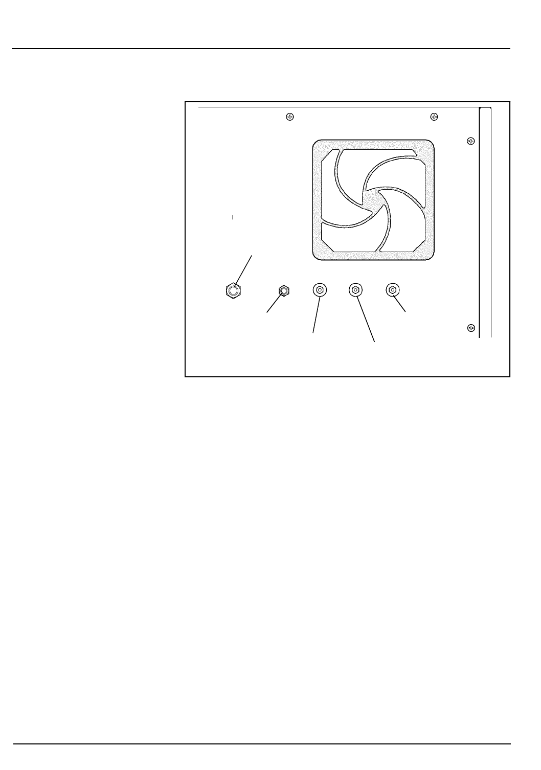
2-6 CELL-DYN® 3200 Operator’s Manual
9140181B — November 1997
Installation Procedures and Special Requirements
Tubing Installation Section 2
Figure 2.1: Reagent Inlet Panel
7. Locate the Waste-Full Sensor Plug attached to the cap's
electrode wires. Insert the plug into the Waste Sensor
connector located on the Reagent Inlet Panel. Attach the
ground shield on the cable to the connection on the rear
panel. When the waste tubing is placed directly into a drain,
insert the Dummy Plug (found in the Accessory Kit) into
the Waste Sensor Connector.
If the waste tube is placed directly into a drain, insert the
Dummy Plug (provided in the Accessory kit) into the
Waste Sensor Connector, as the EXTERNAL WASTE FULL
alert will activate if no plug is inserted. For information
on ordering a Waste Dummy Plug, refer to Appendix B —
Parts and Accessories.
Normally Closed Valves
To gain access to all six Normally Closed Valves on the Flow
Panel, open both the Left and Right Front Covers and remove
the Tower Cover. Remove the Front Skirt (CS model) or move
the Sample Loader (SL model) away from the instrument.
(Refer to instructions later in this section for opening and
removing these components.)
Waste Outlet Connector
Waste Full Sensor
WBC Lyse Connector
HGB Lyse Connector Diluent/Sheath Connector
Go Back
Search
TOC
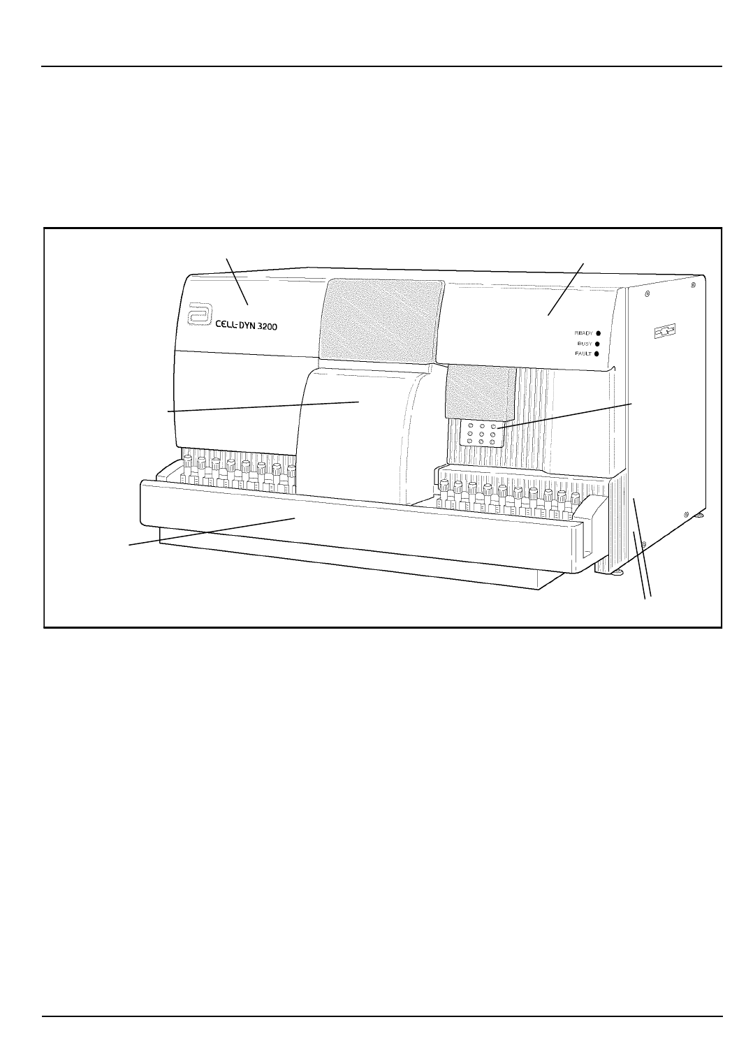
CELL-DYN®3200 Operator’s Manual 2-7
9140181B — November 1997
Installation Procedures and Special Requirements
Section 2 Tubing Installation
Before shipment, the tubing is removed from these valves. To
ensure correct system operation, the tubing must be
completely inserted in all the valves before the instrument
power is turned ON. Follow the directions below to open the
front covers and remove the Skirt or Sample Loader to allow
access to all the Normally Closed Valves. Refer to Figure 2.2.
Figure 2.2: Analyzer Front Covers — SL Model
Open Left Front Cover
To open the Left Front Cover on both the SL and CS models,
press the upper right corner of the cover to release the cover
latch. Swing the cover all the way to the left to completely
expose the left side of the Flow Panel. If necessary, it is possible
to lift the cover off its hinges to completely remove it from the
instrument.
Open Right Front Cover
To open the Right Front Cover on both the SL and CS models,
press the upper left corner of the cover to release the cover
latch. Swing the cover all the way to the right to completely
expose the right side of the Flow Panel. Because of the
attached Touch Plate and Status Panel, this cover should not
be removed from the instrument.
Left Front Cover Right Front Cover
Tower Cover
Sample Loader
Tou ch
Plate
Phillips-head Screws
Go Back
Search
TOC

2-8 CELL-DYN® 3200 Operator’s Manual
9140181B — November 1997
Installation Procedures and Special Requirements
Tubing Installation Section 2
Remove Tower Cover
To remove the Tower Cover on both the SL and CS models,
press the window on the cover to release the cover latch. Lift
the cover up and off the instrument.
Remove Front Skirt
To remove the Front Skirt Cover on the CS model, remove the
four Phillips-head screws, two on either side of the instrument,
which hold the skirt to the instrument frame. Pull the skirt
away from the instrument.
Remove Sample Loader
To remove the Sample Loader on the SL model, remove the
four Phillips-head screws, two on either side of the instrument,
which hold the Sample Loader to the instrument frame.
Carefully pull the loader away from the instrument
approximately 2-3 inches. Do not stretch the wiring or tubing
that connects the loader to the Analyzer.
Tubing Installation
NOTE: The tubing must be installed before the power is
turned ON for the instrument to operate correctly.
Follow the directions below to install the diluent
tubing.
1. Locate the six normally closed valves on the flow panel.
Refer to Figure 2.3 for the location of these valves.
2. The procedure described below applies to all the
Normally Closed Valves on the Flow Panel. Refer to Figure
2.4.
3. Select any of the Normally Closed Valves. Carefully insert
the diluent tubing into the slot at the top of the valve.
Work the tubing firmly back and forth with a flossing
motion until it is completely inserted into the valve and
resting on the bottom of the slot. Unless this tubing is
securely seated, the flow system will not function
properly.
Go Back
Search
TOC
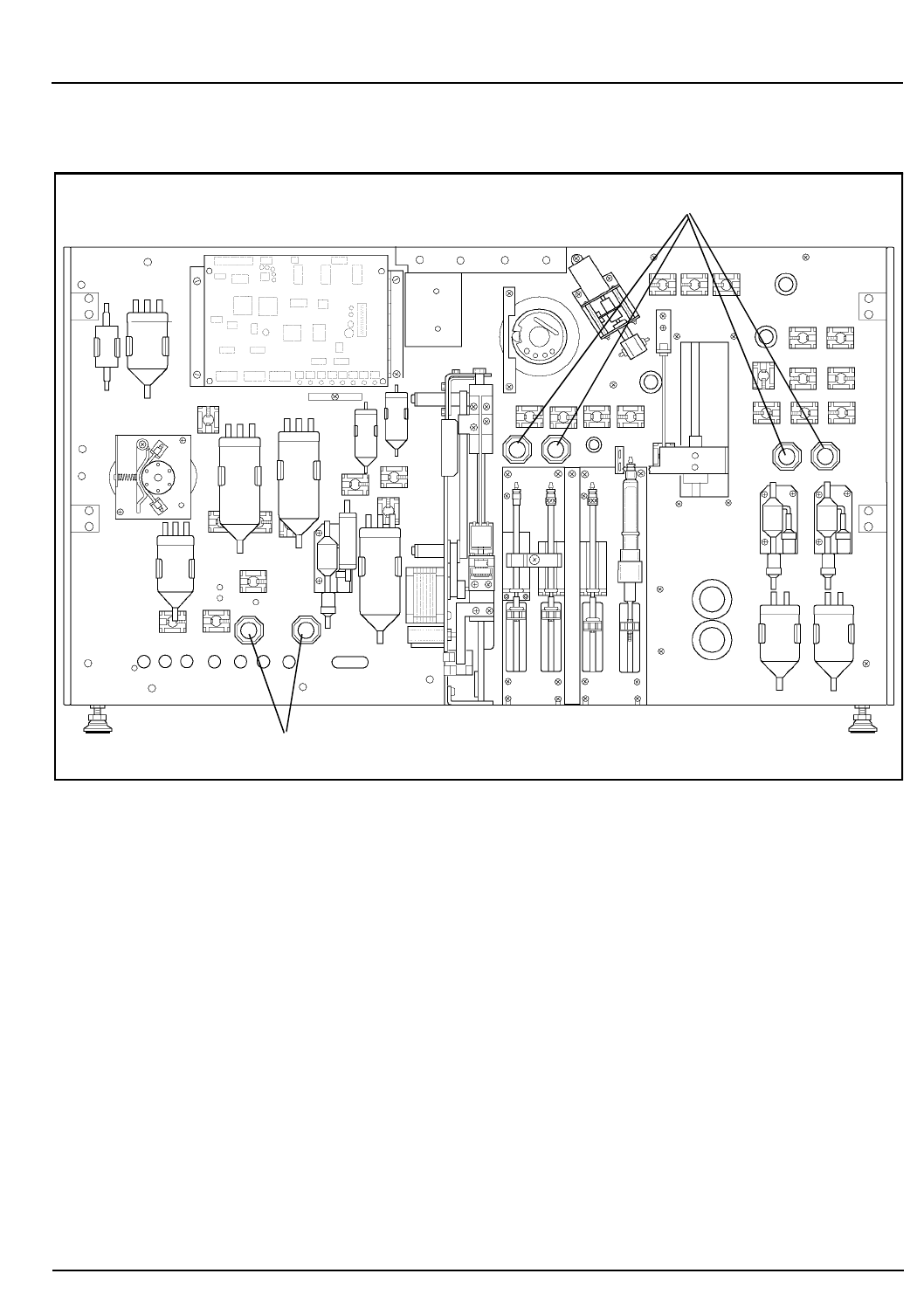
CELL-DYN®3200 Operator’s Manual 2-9
9140181B — November 1997
Installation Procedures and Special Requirements
Section 2 Tubing Installation
Figure 2.3: Normally Closed Valves
Normally Closed Valves
Normally Closed Valves
Go Back
Search
TOC
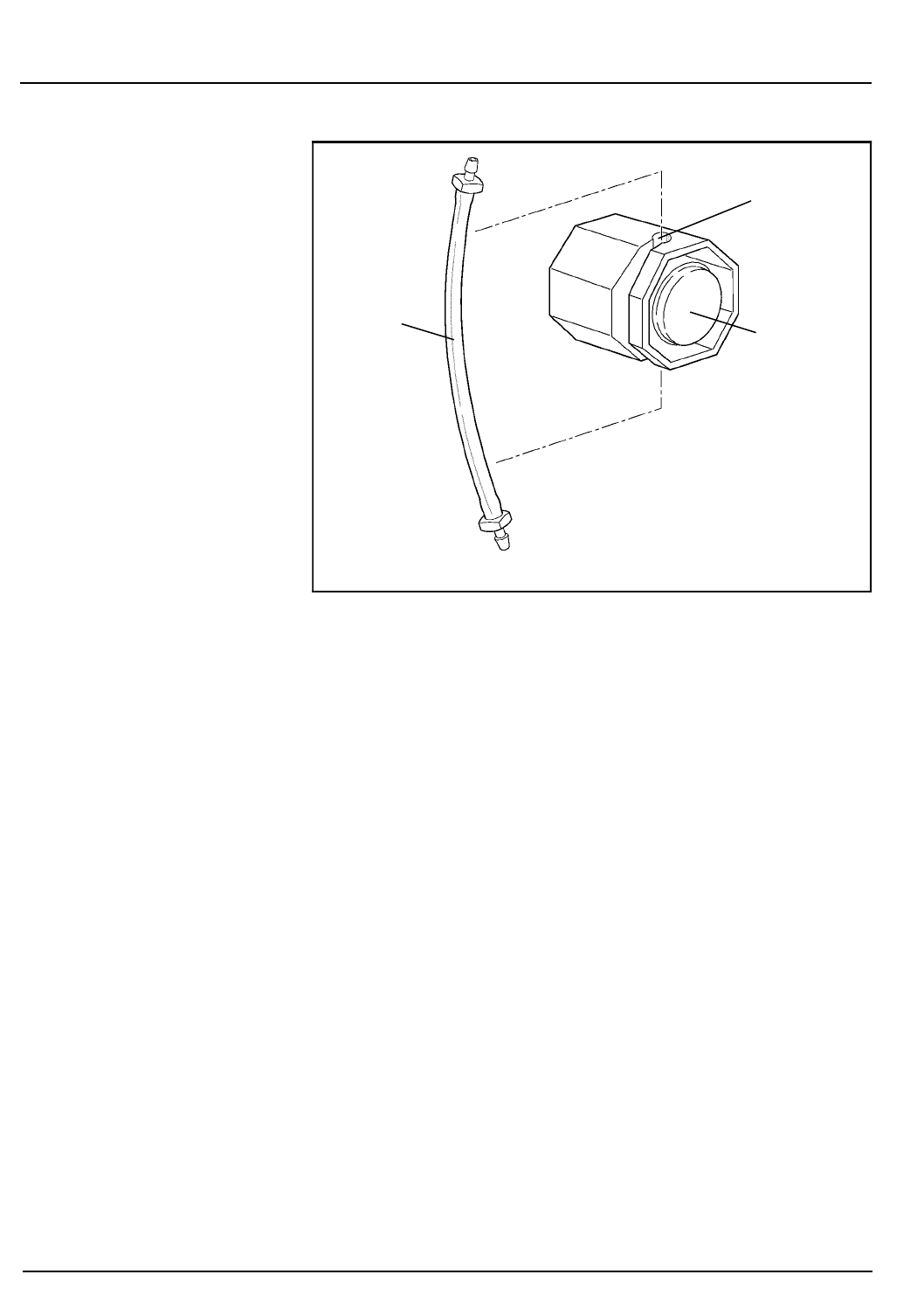
2-10 CELL-DYN® 3200 Operator’s Manual
9140181B — November 1997
Installation Procedures and Special Requirements
Tubing Installation Section 2
Figure 2.4: Tubing in a Normally Closed Valve
4. When the tubing has been installed properly, it should
move back and forth freely.
5. Confirm that both ends of the diluent tubing are firmly
attached to the connectors.
6. Repeat steps 3 through 5 until the tubing has been
inserted in all six of the Normally Closed Valves.
Flow Panel and Syringe Inspection
1. Inspect the Flow Panel components for obvious damage
and to ensure the tubing is properly positioned under all
solenoid pinch valves.
2. If there is any damage, contact the Abbott Customer
Support Center.
3. When the inspection of the Flow Panel is completed, turn
the Main Power Switch to ON.
4. Before putting the front covers and skirt back on the
instrument, run several background counts (by pressing
the Touch Plate) to observe proper functioning of the
instrument. Check for leaks, crimps in the tubing, and
the opening of the Solenoid pinch valves. Observe the
operation of the syringes. The syringes should move
freely up and down with no evidence of air bubbles.
Valve
Slot
Tubing
Go Back
Search
TOC

CELL-DYN®3200 Operator’s Manual 2-11
9140181B — November 1997
Installation Procedures and Special Requirements
Section 2 Tubing Installation
5. If no problems are detected, close the Left and Right Front
Covers and press into place. Reattach the Tower Cover
and press into place (for the SL model, line up the two
holes on the bottom of the cover with the two pins on
the Sample Loader molding). On the CS model, reattach
the Front Skirt using the four Phillips-head screws. On the
SL model, slide the Sample Loader forward using the
center guide to properly align the loader with the
Analyzer. Reattach the loader using the four Phillips-head
screws.
Go Back
Search
TOC

2-12 CELL-DYN® 3200 Operator’s Manual
9140181B — November 1997
Installation Procedures and Special Requirements
Tubing Installation Section 2
NOTES
Go Back
Search
TOC

CELL-DYN®3200 Operator’s Manual 2-13
9140181B — November 1997
Installation Procedures and Special Requirements
Section 2 Printer Installation
Printer Installation
Overview
Remove the printer(s) from its shipping container and visually
inspect it for damage. Find a suitable location adjacent to the
instrument. Be sure the printer power switch is in the OFF
position. Retain the manuals shipped with the printer(s) and
store them in a convenient location.
NOTE: If the printer is placed on top of the instrument,
be sure that the paper does not restrict air flow to the
rear panel fan.
Basic installation procedures follow for the Ticket and
Graphics Printers. When used with the CELL-DYN 3200, the
Graphics Printer prints color or black-and-white graphic
reports and the Ticket Printer prints tickets or black-and-white
graphic reports. Depending on the output desired, one or both
printers may be connected to the instrument.
Follow installation instructions carefully to be sure that the
printer(s) is connected to the correct port. (See Figure 2.5.) For
convenience, general instructions are provided for loading
individual pre-printed tickets in the Ticket Printer. For a
detailed description of the printer components and operating
instructions, refer to the manuals that accompany the printer.
IMPORTANT: The CELL-DYN 3200 System has been
configured for and tested on the following printers: Canon®
BJC-620TM color ink jet printer for graphics output, and
OKIDATA® MICROLINE® 320 dot matrix printer for ticket
printing. Abbott recommends using only these printers. If
other printers are substituted, problems may occur with your
printouts.
Go Back
Search
TOC
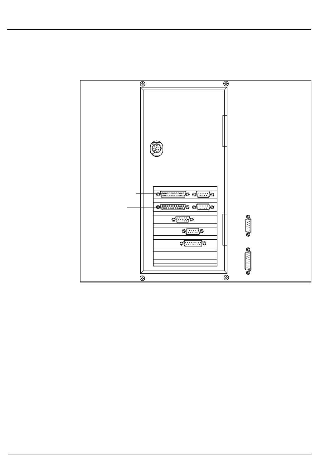
2-14 CELL-DYN® 3200 Operator’s Manual
9140181B — November 1997
Installation Procedures and Special Requirements
Printer Installation Section 2
Figure 2.5: CELL-DYN 3200 Printer Ports
Graphics Printer Installation Procedure
The Graphics Printer is a Canon® BJC-620TM color ink jet
printer or compatible printer.
1. Assemble the printer as directed in the printer manual.
2. Make sure that the printer power switch is OFF. Plug the
power cord into the printer. Do not plug the other end
into an outlet until you are ready to load paper.
3. Make sure that the power to the instrument is turned OFF.
Remove the printer cable (which looks like a power cord
with two connectors) from the Accessory kit and plug one
end into the parallel port on the rear of the printer. (There
is a metal plate covering the printer’s serial port to avoid
confusion.) Fasten the wire clips to the connector for a
secure connection.
Graphics Printer Port
Ticket Printer Port
Go Back
Search
TOC

CELL-DYN®3200 Operator’s Manual 2-15
9140181B — November 1997
Installation Procedures and Special Requirements
Section 2 Printer Installation
4.Plug the other end of the printer cable into the Graphics
Printer port on the back of the Data Module. (See Figure
2.5) Tighten the screws on the connector for a secure
connection.
NOTE: This port is configured for use as a graphics
printer only. To print tickets, you may connect a Ticket
Printer to the Ticket Printer port.
5.Install the ink cartridge as directed in the printer manual.
6.Load the paper as directed in the printer manual.
7.If necessary, refer to Section 5: Operating Instructions,
Subsection: Customize Report for instructions on
customizing the printout.
Self-Test Printouts
Run any self-test printouts before using the printer for the first
time. These self-tests may be run any time to verify proper
printer operation.
The CELL-DYN 3200 software automatically controls and
adjusts most print conditions for the Graphics Printer,
including page width and ribbon color. Occasionally, a few
settings may need to be changed in the printer’s software for
correct operation. If printing is not what you expect, refer to
the printer manual for guidance in making adjustments. If you
have additional questions or experience any problems, call the
Abbott Customer Support Center for assistance.
Ticket Printer Installation Procedure
The Ticket Printer is an OKIDATA® MICROLINE® dot matrix
printer or compatible printer.
The Ticket Printer is normally used to print result data on
blank or pre-printed tickets but can be used to print a
complete graphics report on continuous tractor-feed paper.
(Blank tickets are available in continuous tractor-feed sheets.
Pre-printed tickets must be loaded individually.)
1.Assemble the printer as directed in the printer manual.
2.Make sure that the printer power switch is OFF. Plug the
power cord into the back of the printer and plug the
other end into a grounded outlet.
IMPORTANT
Go Back
Search
TOC

2-16 CELL-DYN® 3200 Operator’s Manual
9140181B — November 1997
Installation Procedures and Special Requirements
Printer Installation Section 2
3. Make sure that the power to the instrument is turned OFF.
Remove the printer cable (which looks like a power cord
with two connectors) from the Accessory kit and plug one
end into the port on the rear of the printer. (The port is
constructed so that the connector will only fit in the
proper way.) Fasten the wire clips to the connector for a
secure connection.
4. Plug the other end of the printer cable into the Ticket
Printer port on the back of the Data Module. (See Figure
2.5.) Tighten the screws on the connector for a secure
connection.
NOTE: This port is configured for use as a ticket printer
only. To print graphics reports, you may connect a
Graphics Printer to the Graphics Printer port.
5. Install the ribbon as directed in the printer manual.
6. Load the paper or blank, continuous-feed tickets as
directed in the printer manual, OR, if you are using
pre-printed individual tickets, continue with the
following procedure.
Loading Individual Tickets in the Ticket Printer
Instructions are given for loading individual tickets. If fanfold,
continuous-feed tickets are used, they should be loaded as
directed in the printer manual for tractor-feed paper.
NOTE: To print on these tickets, the printer cable must
be connected to the Ticket Printer Connector.
1. Be sure that the printer is turned OFF and the printer
cable is connected to the Ticket Printer connector on the
back of the instrument. If the connection is incorrect,
turn the instrument power OFF, change the position of
the cable and turn the power back ON.
2. Set the ribbon cartridge headgap lever to adjust for the
thickness of the tickets. Refer to the printer manual for
detailed instructions.
3. Move the paper selection lever to the rear position to
select single-feed paper.
4. Open the access cover and be sure the guide wire on the
paper separator is pushed back into the locked position.
5. Raise the separator to its upright position.
Go Back
Search
TOC

CELL-DYN®3200 Operator’s Manual 2-17
9140181B — November 1997
Installation Procedures and Special Requirements
Section 2 Printer Installation
6. Place a ticket on the paper separator and adjust the guides
so that they barely touch the edges of the ticket.
7. Pull the bail lever forward. The ticket will automatically
feed into place. Release the bail lever.
8. Be sure the printer is deselected (Sel indicator is not
illuminated). Set the Top of Form by pressing and holding
the TOF/Quiet key and pressing the Form Feed key to
move the ticket up or pressing the Line Feed key to move
the ticket down. (The ticket moves in very fine
increments so it can be precisely positioned.)
NOTE: The ticket will only move down to a certain
point to prevent potential ticket jams. Do not move the
top of the page below the paper bail.
9. Position the ticket so that the lower red line on the paper
shield (located between the print head and the paper) is
positioned where the first line of printing should occur.
NOTE: When the Top of Form is set, the position is
retained in the printer memory until it is reset.
10. Press the Sel key to select the printer. The printer is now
ready to print.
Self-Test Printouts
Run any self-test printouts indicated in the printer manual
before using the Ticket Printer for the first time. These self-
tests may be run any time to verify proper printer operation.
Go Back
Search
TOC
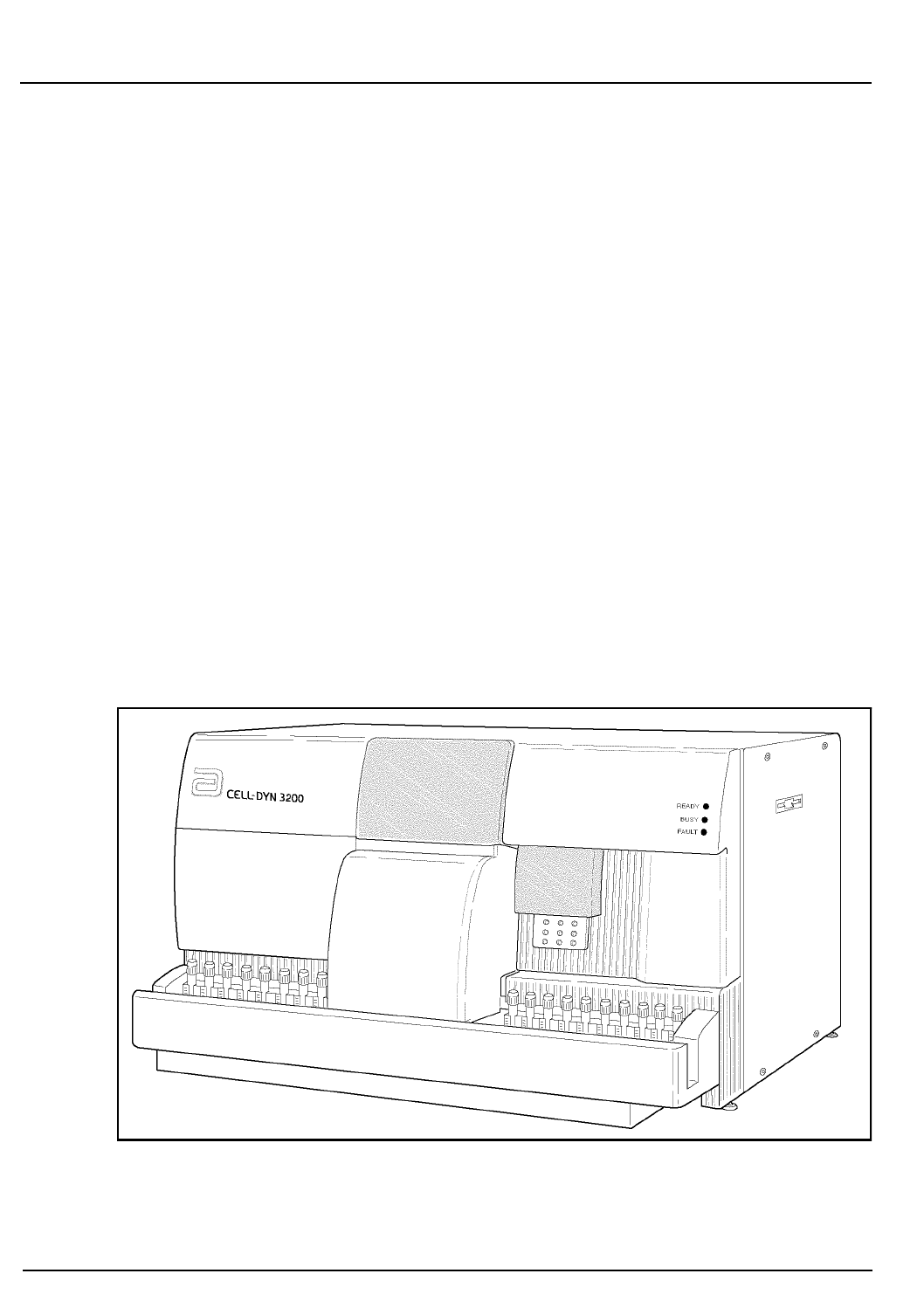
2-18 CELL-DYN® 3200 Operator’s Manual
9140181B — November 1997
Installation Procedures and Special Requirements
Printer Installation Section 2
Sample Loader Inspection (SL Model)
The Sample Loader is attached directly to the Analyzer to form
an integrated unit, as shown in Figure 2.6.
Four screws, two on either side, hold the Sample Loader to the
Analyzer. A power cord provides power from the Analyzer to
the loader, and an interface cable allows communication
between the Analyzer and loader. The Analyzer and Sample
Loader are also connected by two quick-disconnect tube lines,
one for pressure and one for vacuum.
The tube spinning and sample aspiration mechanism on the
Tower Module is identical on both the SL and CS models. The
Tower Cover on the SL model differs from its counterpart on
the CS model in two ways:
1. It is larger in order to extend over the center portion of
the Sample Loader which contains the Bar Code Reader
and Mixing Assembly.
2. It serves as a safety cover, halting operation of the Sample
Loader if it is removed.
Figure 2.6: Analyzer With Sample Loader
Go Back
Search
TOC
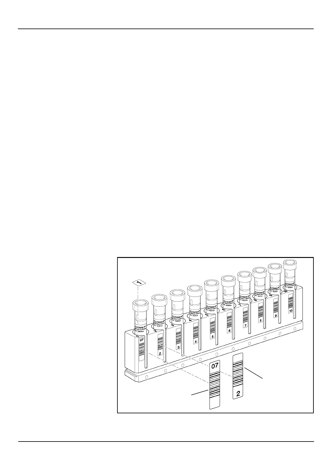
CELL-DYN®3200 Operator’s Manual 2-19
9140181B — November 1997
Installation Procedures and Special Requirements
Section 2 Printer Installation
To inspect the Sample Loader:
1.Unpack the instrument from its shipping container and
place it on a flat surface.
2.Remove the protective plastic.
3.Inspect the Sample Loader for signs of obvious damage
and verify the loader is securely attached to the Analyzer.
4.Remove the set of 5 tube racks from the Sample Loader
Accessory Kit.
5.Inspect all the tubes for signs of damage.
6. Verify that each rack has a bar code label in position 1
and that the label is on the same side as the open slots.
Refer to Figure 2.7 for proper label placement and
alignment.
NOTE: For the Sample Loader to operate properly, the
racks must be placed to the right of the tower (the
“load” area) with the labels and slots facing the
operator, not the Analyzer, so that the Bar Code Reader
can read the rack label and the tube labels through the
rack slots. Refer to Section 13: Sample Loader for
additional information on the Sample Loader.
Figure 2.7: Tube Rack Showing Label Placement Locations
Rack Bar Code Label
Rack Tube
Position Labels
Go Back
Search
TOC

2-20 CELL-DYN® 3200 Operator’s Manual
9140181B — November 1997
Installation Procedures and Special Requirements
Printer Installation Section 2
Power On
1.Turn the instrument’s Main Power Switch to ON. When
the initialization process is complete, press the
[RUN]
key
to prime the instrument. When the priming process is
complete, the READY light on the Analyzer’s indicator
panel is lit and the message READY is displayed in the
Status Box on the monitor.
2.Prime the Sample Loader by running several blood
samples in the Closed Mode. If necessary, refer to the
directions given in Section 5: Operating Instructions,
Subsection: Sample Analysis on the CELL-DYN 3200SL,
Running Samples, Closed Mode Procedure.
3.Confirm that the background count is acceptable before
running patient samples.
Go Back
Search
TOC

CELL-DYN® 3200 Operator’s Manual 3-1
9140181B — November 1997
Principles of Operation
Section 3 Overview
Overview
The principles the CELL-DYN 3200 uses to measure, count
and calculate the hematological parameters are discussed in
Sample Analysis Cycle Overview and Introduction to Flow
Cytometry within this section. Subsequent sections discuss the
measurement process for WBC, RBC, PLT, and HGB. The last
subsection, Operational Messages and Data Flagging, discusses
the flags generated by the instrument due to measured
parameters outside predefined limits, sample abnormality,
interference in the measurement process, or detection of an
abnormal subpopulation. Quality Control methodology is
discussed in Section 11: Quality Control.
The two independent measurement channels used in the
CELL-DYN 3200 are:
•The Optical channel for determining the WBC, NOC, and
RBC/PLT data
•The Hemoglobin channel for determining the HGB
During each instrument cycle, the sample is aspirated, diluted
and mixed before each parameter is measured.
NOTE: An increase in flags will occur in RRBC and
FWBC modes.
Sample Aspiration
There are two modes of whole blood sample aspiration on the
CELL-DYN 3200. The operator selects the mode of aspiration
from the RUN screen.
•The Open Sampler Mode is used to aspirate the sample
from a collection tube that has been opened and is held
under the open sample aspiration probe.
•The Closed Sampler Mode is used to aspirate the blood
directly from a closed collection tube by piercing the tube
stopper. On the CS model, sample tubes are processed
manually. On the SL model, sample tubes are processed
automatically using the Sample Loader.
Go Back
Search
TOC

3-2 CELL-DYN®3200 Operator’s Manual
9140181B — November 1997
Principles of Operation
Overview Section 3
The aspiration volumes are:
Open Mode 120 µL ± 10%
Closed Mode (CS) 250 µL ± 10%
Sample Loader (SL) 250 µL ± 10%
Once the mode of aspiration is selected, the whole blood
sample is aspirated to the Shear Valve by vacuum/pressure
action. An ultrasonic sensor, located upstream of the Shear
Valve, checks the integrity of the sample stream before it
enters the Shear Valve. An LED sensor, located downstream of
the Shear Valve, checks the sample stream to ensure the proper
amount of blood has been transferred through the Shear
Valve.
Go Back
Search
TOC

CELL-DYN® 3200 Operator’s Manual 3-3
9140181B — November 1997
Principles of Operation
Section 3 Sample Analysis Cycle Overview
Sample Analysis Cycle Overview
NOTE: Sample and reagent volumes given in this
section are stated as the nominal values. Slight
differences between instruments may cause these
volumes to vary. These differences are compensated for
by factory-set internal dilution factors.
Sample Aspiration
A sample is aspirated either in Open Mode or Closed Mode
and transferred to the Shear Valve. The sample volume in
Open Mode is 120 µL. The sample volume in Closed Mode is
250 µL.
Sample Segments
The Shear Valve rotates in order to separate three volumes of
the aspirated whole blood sample. The three volumes are:
20 µL for the WBC dilution
1.67 µL for the RBC/PLT dilution
12 µL for the HGB dilution
RBC/PLT Analysis
1. The Diluent/Sheath Syringe dispenses 2.79 mL of diluent
through the Shear Valve where the 1.67 µL RBC/PLT
volume is transferred to the RBC Mixing Chamber.
2. The segment and diluent are then routed to the RBC/PLT
Mixing Chamber where the dilution is swirl mixed. The
final dilution is 1:1672.
3. The Sample Transfer Pump transfers the RBC/PLT dilution
from the RBC/PLT Mixing Chamber to the Optical Flow
Cell Sample Feed Nozzle.
4. Diluent/Sheath reagent, under constant pressure in the
Sheath Reservoir, is directed into the Optical Flow Cell.
5. Sequentially, the Sample Metering Syringe injects 24 µL
of the RBC/PLT dilution into the flow cell at a pressure
(and speed) lower than that of the diluent/sheath
reagent.
6. The higher speed of the sheath, which surrounds the
RBC/PLT dilution, and the special geometry of the flow
cell combine to focus the RBC/PLT dilution stream so that
individual cells can be counted.
Go Back
Search
TOC

3-4 CELL-DYN®3200 Operator’s Manual
9140181B — November 1997
Principles of Operation
Sample Analysis Cycle Overview Section 3
7. A laser beam is focused on the flow cell. As the sample
stream intersects the laser beam, the light scattered by the
cells is measured by the forward (0° and 10°) detectors.
Hemoglobin Analysis
1. The Diluent/Sheath Syringe injects 2.29 mL of diluent
through the Shear Valve where the 12 µL HGB volume is
transferred to the HGB Flow Cell.
2. The HGB Lyse Syringe dispenses 0.30 mL of HGB Lyse
into the line after the diluent has transferred the HGB
volume to the HGB Flow Cell. The entry point for the
HGB Lyse is between the Shear Valve and the HGB Flow
Cell.
3. The segment, lyse, and diluent are routed to the HGB
Flow Cell where the dilution is swirl mixed. The final
dilution is 1:217.
4. A low-energy LED attached to the HGB Flow Cell
measures the absorbance of light at 540 nm. The
absorbance is proportional to the HGB concentration of
the sample.
WBC Analysis
WBCs are analyzed optically as follows:
1. The WBC Lyse Syringe dispenses 0.973 mL of WBC Lyse
reagent through the shear valve where the 20 µL WBC
volume is transferred to the WBC Mixing Chamber.
2. The segment and reagent are then routed to the WBC
Mixing Chamber where the dilution is swirl mixed. The
final dilution is 1:49. The diluted sample remains in the
mixing chamber for 14 seconds for the lysing of the red
blood cells.
3. The Sample Transfer Pump transfers the WBC dilution
from the WBC Mixing Chamber to the Optical Flow Cell
Sample Feed Nozzle.
4. Diluent/Sheath reagent, under constant pressure in the
Sheath Reservoir, is directed into the Optical Flow Cell.
5. Sequentially, the Sample Metering Syringe injects 46.5 µL
of the WBC dilution into the flow cell at a pressure (and
speed) lower than that of the diluent/sheath reagent.
6. The higher speed of the sheath, which surrounds the
WBC dilution, and the special geometry of the flow cell
combine to focus the WBC dilution stream so that
individual cells can be counted.
Go Back
Search
TOC

CELL-DYN® 3200 Operator’s Manual 3-5
9140181B — November 1997
Principles of Operation
Section 3 Sample Analysis Cycle Overview
7.A laser beam is focused on the flow cell. As the sample
stream intersects the laser beam, the light scattered by the
cells is measured at four different detectors located in the
forward (0° and 10°) and side (90° and 90°D) angles.
Fragile WBCs and Resistant RBCs
When running samples in the normal Patient mode, the
operator may suspect the presence of fragile WBCs when the
FWBC flag is displayed or may suspect the presence of resistant
RBCs when the RRBC and NRBC flags are displayed.
In the case of samples containing fragile WBCs or resistant
RBCs, an alternate method is used to measure white blood
cells. The results of this method are referred to as the Nuclear
Optical Count (NOC). The NOC measurement is derived from
the HGB dilution as described below. Refer to Nuclear Optical
Count and Resistant RBC later in this section for additional
information.
There are two different key labels on the RUN screen, one for
fragile WBCs and one for resistant RBCs, but they activate the
same alternate measurement procedure. Refer to Run Menu
Soft Keys, Subsection: Specimen Type in Section 5: Operating
Instructions for a discussion of the Specimen Types available.
When the Fragile WBC specimen type is selected, both NOC
and WOC are reported in the Data Log but only the NOC
value is reported as WBC on the RUN screen and Laboratory
Worksheet.
When the Resistant RBC specimen type is selected, both NOC
and WOC are reported in the Data Log. Either NOC or WOC is
reported as WBC (based on algorithmic decision-making) on
the RUN screen and Laboratory Worksheet.
NOTE: When QC specimen type is selected, both NOC
and WOC are reported in the Data Log. Either NOC or
WOC is reported as WBC (based on algorithmic
decision-making) on the RUN screen.
The analysis for Fragile WBC and Resistant RBC is performed
as follows:
1.The RBC/PLT analysis occurs as described in RBC/PLT
Analysis above.
2.After the HGB sample is measured (refer to Hemoglobin
Analysis above), the Sample Transfer Pump transfers the
diluted solution from the HGB Flow Cell to the Optical
Flow Cell Sample Feed Nozzle.
Go Back
Search
TOC

3-6 CELL-DYN®3200 Operator’s Manual
9140181B — November 1997
Principles of Operation
Sample Analysis Cycle Overview Section 3
3. Diluent/Sheath reagent, under constant pressure in the
Sheath Reservoir, is directed into the Optical Flow Cell.
4. Sequentially, the Sample Metering Syringe injects 140 µL
of the HGB dilution into the flow cell at a pressure (and
speed) lower than that of the diluent/sheath reagent.
5. The higher speed of the sheath, which surrounds the HGB
dilution, and the special geometry of the flow cell focus the
HGB dilution stream so that individual cells can be
counted.
6. A laser beam is focused on the flow cell. As the sample
stream intersects the laser beam, the light scattered by the
cells is measured at the same four detectors used for the
WBC Analysis. The nuclei of the lysed cells are counted.
7. The WBC Analysis occurs as described in WBC Analysis
above except that the diluted WBC segment is lysed in
the WBC Mixing Chamber for an additional 15 seconds.
Results Displayed
All data is transmitted to the Data Module for analysis. Results
are computed for all parameters and are displayed on the RUN
screen. Results are also stored in a log format called the Data
Log.
Instrument Flushed
1. The remaining sample segment from the aspiration
process is flushed to Waste Chamber #2.
2. The remaining segments in the WBC and RBC Mixing
Chambers are flushed to Waste Chamber #3.
3. The segments sent to the Optical Flow Cell are flushed to
Waste Chamber #4.
Instrument Rinsed
1. The Open Sample Aspiration Probe is rinsed internally
and externally with diluent/sheath.
2. In Closed Mode, the needle is rinsed internally and
externally with diluent/sheath.
3. The WBC and RBC/PLT Mixing Chambers are rinsed with
diluent/sheath.
4. The Optical Flow Cell and Sample Line tubing are rinsed
with diluent/sheath.
5. The HGB Flow Cell is rinsed with diluent/sheath.
Go Back
Search
TOC
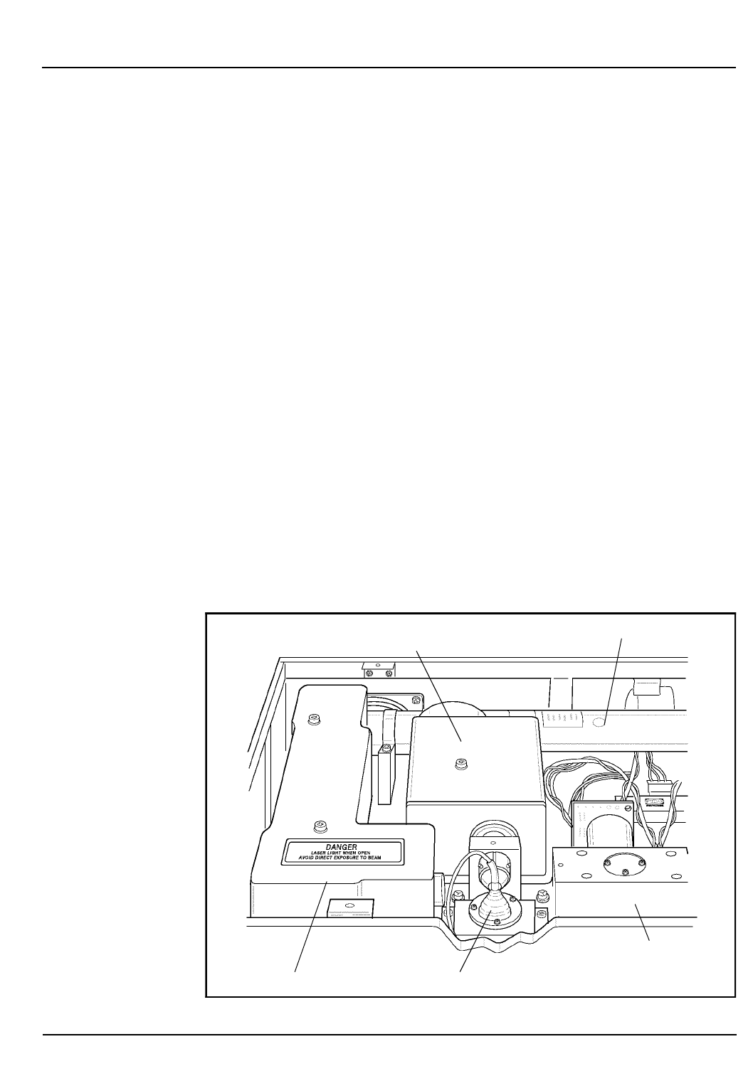
CELL-DYN® 3200 Operator’s Manual 3-7
9140181B — November 1997
Principles of Operation
Section 3 Flow Cytometry
Flow Cytometry
Introduction to Flow Cytometry
The CELL-DYN 3200 uses flow cytometric techniques to
analyze the RBC/PLT, WBC, and NOC populations. This
section gives a brief introduction to the principles of flow
cytometry.2
Flow cytometry is a process in which individual cells or other
biological particles in a single file produced by a fluid stream
are passed through a beam of light. A sensor or sensors
measure, by the loss or scattering of light, the physical or
chemical characteristics of the cells or particles.3
Flow cytometry enables the rapid screening of large numbers
of cells and provides quantitative cell analysis at the single-cell
level. The basic components of a flow cytometer include:
A sample collector and transporter
A flow system to focus the sample flow stream
A light source and focusing optics
Light collectors, signal detectors, and polarizers
Data collection and storage
Data display and analysis
Figure 3.1: Optical Bench
Optical Flow Cell
Laser
Forward Angle
(0° and 10°) Light
Laser Tube
Orthogonal (90° and 90°D)
Scatter Light Detectors
Detectors
Go Back
Search
TOC

3-8 CELL-DYN®3200 Operator’s Manual
9140181B — November 1997
Principles of Operation
Flow Cytometry Section 3
Detection with the Optical Bench
The optical bench assembly contains the components that
make up the flow cytometer. It is depicted in Figure 3.1. The
main purpose of the optical bench is to detect the light
scattered by the cells as they pass through the flow cell. The
detection process is discussed in this section.
The light source is a vertically polarized 10 mW helium-neon
laser with a wavelength of 632.8 nm. The laser beam passes
through a cylindrical lens which changes the shape from a
circle to an ellipse. The beam is then directed through a
125 µm slit which blocks the weaker outer edges. This process
yields a uniformly intense beam approximately 80 µm wide
that allows the cell stream to wander slightly in the flow cell
and still be exposed to the same light intensity. An imaging
lens centers the focused laser beam onto the quartz flow cell.
The Sample Transfer Syringe injects different sample dilutions
into the sheath stream in the Optical Flow Cell. The sample is
hydrodynamically focused into a small stream approximately
30 µm in diameter. This focused stream aligns the diluted cells
in single file as they pass through the light beam, which allows
them to be detected one at a time in the sensing region of the
detectors.
Since the average diameter of the cells are smaller than the
focused laser beam, the cells do not scatter much laser light. If
the remaining unscattered light were allowed to reach the 0°
and 10° (forward) detectors, it would saturate the electronics.
Therefore, an obscuration bar blocks 0° – 1° of the forward
unscattered light beam. The forward angles of scatter are
directed to a perforated mirror. The 0° (1° – 3°) light scatter
passes through the mirror to the 0° silicon photodiode
detector. The 10° (7° – 10° or narrow angle) light scatter is
deflected off the mirror to the 10° silicon photodiode detector.
The orthogonal scatter is directed through a 700 µm slit which
blocks the scatter from the walls of the flow cell. A beam
splitter then separates the orthogonal light scatter into two
portions. One portion of the light is directed to the 90° PMT.
The remaining light is directed through a horizontal polarizer.
Only light that has changed polarization (depolarized) can
pass through the polarizer to the 90°D PMT. (PMTs are used
because relatively little light is scattered at this angle.)
The light signals collected by each detector are converted into
electrical signals or pulses. The pulses are digitized based on
intensity and sorted into 256 channels for each angle of light
measured.
Go Back
Search
TOC
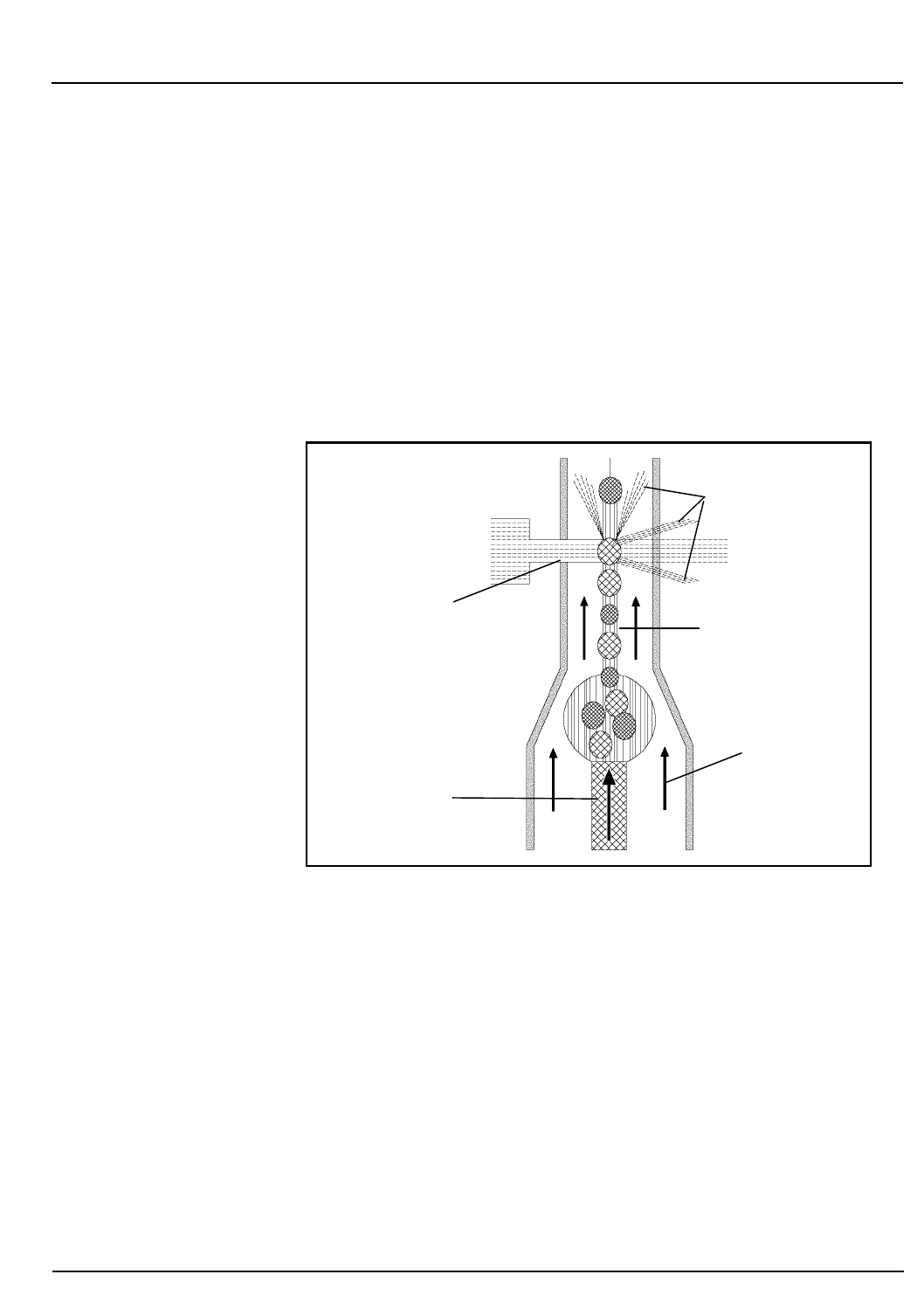
CELL-DYN® 3200 Operator’s Manual 3-9
9140181B — November 1997
Principles of Operation
Section 3 Flow Cytometry
If a pulse falls above the hardware threshold in the 0° and 10°
detectors, the cell counter counts the pulse and stores it for
further evaluation. Pulses that fall below this threshold are not
included in the count.
The information from each detector is collected in list mode.
This format stores the channel information from each of the
four dimensions. The data is then used to determine the WOC
differential and RBC, PLT, and NOC counts. Data stored on
floppy disks in the list mode format may be reconstructed into
scatterplots at any time or analyzed by different algorithms as
revisions are made.
Figure 3.2: Optical Flow Cell
Optical Flow Cell
In a flow cytometer, the cell suspension is transferred from the
mixing chamber through a sample tube into a special flow
chamber with a small opening at the tip. The suspension is then
injected into a stream of fast-moving, cell-free liquid (sheath
fluid). Since the two liquids travel at different rates of speed,
they do not intermingle. The special geometry of the flow cell
and the flow rate of the sheath fluid forces the cells into single
file. This process is known as hydrodynamic focusing. (Refer
to Figure 3.2 for a drawing of the Optical Flow Cell.)
Focused Laser
Beam
Various Angles
Sample Stream
Sheath Stream
Sample Feed
Nozzle
of Scattered Light
Go Back
Search
TOC

3-10 CELL-DYN®3200 Operator’s Manual
9140181B — November 1997
Principles of Operation
Flow Cytometry Section 3
As the cells enter the view volume (specific viewing area),
they intersect with the laser beam. The different types of cells
scatter the laser light at different angles, yielding information
about cell size, internal structure, granularity and surface
morphology. The optical signals the cells generate are detected
and converted to electrical impulses which are then stored and
analyzed by the computer.
Flow cytometers generally measure two angles of scatter.
Forward angle light scatter is a measure of cell size. Side
angle (orthogonal) light scatter is a measure of cell surface
and internal structure but is primarily a measurement of
internal granularity. Combining the information from the two
scatter measurements provides more accurate discrimination
between cell populations than either single measurement. (See
Fig. 3.3 for an example of the light scatter measured by the
CELL-DYN 3200.)
Go Back
Search
TOC

CELL-DYN® 3200 Operator’s Manual 3-11
9140181B — November 1997
Principles of Operation
Section 3 Flow Cytometry
WBC Measurement
Overview
The Optical Channel is used for the determination of WBC
data. During sample aspiration, 20 µL of sample is segmented
in the Shear Valve for WBC measurement. The WBC Syringe
dispenses 0.973 mL of WBC lyse to the Shear Valve. The
sample and lyse are then transferred to the WBC Mixing
Chamber where the dilution is swirl mixed, resulting in a 1:49
dilution ratio.
The Sample Transfer Pump transfers the WBC dilution from
the mixing chamber to the sample feed nozzle in the Optical
Flow Cell. At the same time, sheath reagent, under constant
pressure in the Sheath Reservoir, is transferred to the sheath
feed nozzle in the Optical Flow Cell and injected into the cell.
At the same time, the Sample Metering Syringe injects 46.5 µL
of the WBC dilution into a sheath stream. The sample stream
is then hydrodynamically focused to align the cells in single
file as they pass through the Optical Flow Cell, which is an
optically clear quartz chamber. A vertically polarized Helium
Neon Laser is the light source.
The instrument measures:
• Both types of forward angle light scatter (1° to 3°, referred
to as 0°, and 7° to 11°, referred to as 10° or narrow angle)
• Both types of orthogonal (side) light scatter (70° to 110°,
referred to as 90°, and 70° to 110° depolarized, referred to
as 90°D).
This is referred to as MAPSS™ (for Multi-Angle Polarized
Scatter Separation) technology. Various combinations of these
four measurements are used to classify the WBC
subpopulations and provide morphological flagging.
Go Back
Search
TOC
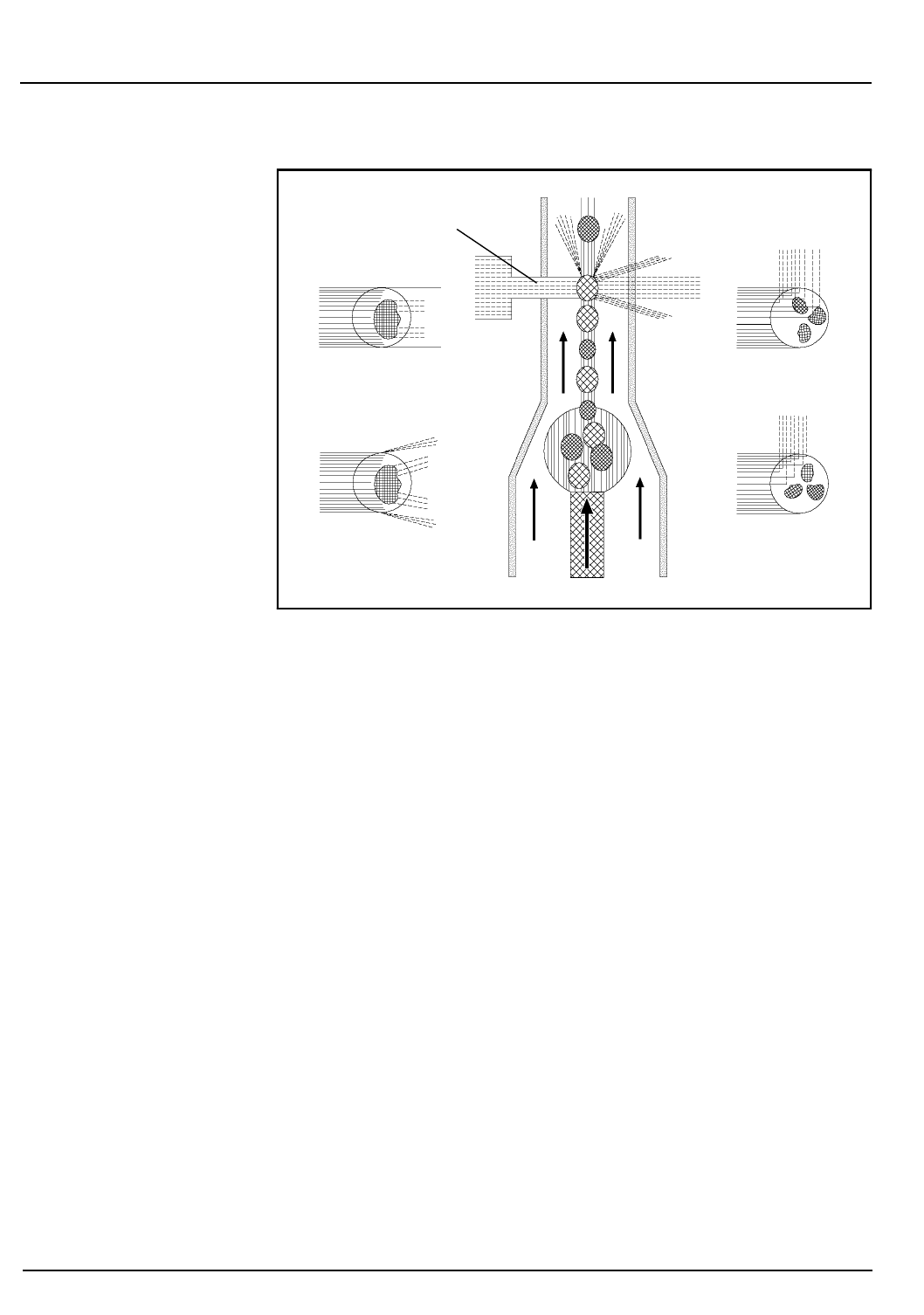
3-12 CELL-DYN®3200 Operator’s Manual
9140181B — November 1997
Principles of Operation
Flow Cytometry Section 3
Figure 3.3: WBC Light Scatter
Figure 3.3 illustrates the measurement of light scattered during
the WBC optical measurement process.
The WBC count is determined by enumerating the number of
occurrences above a hardware threshold in the 0° channel. The
information from all four measurements is used to
differentiate the WBCs into five subpopulations:
Neutrophils
Lymphocytes
Monocytes
Eosinophils
Basophils
The WBC data is presented graphically as a scatterplot. It may
also be presented in two histograms at operator request.
WBC Reagent
The WBC reagent used with the CELL-DYN 3200 instrument
is the CELL-DYN WBC Lyse. It is an integral part of the WBC
analysis. White blood cells diluted in the reagent maintain
cellular integrity close to their native state. The structure of the
basophils changes slightly due to the hygroscopic nature of
the basophilic granules.
Focused
Laser Beam
0° Scatter
10° Scatter
90° Scatter
90°D Scatter
Go Back
Search
TOC

CELL-DYN® 3200 Operator’s Manual 3-13
9140181B — November 1997
Principles of Operation
Section 3 Flow Cytometry
The RBCs are also altered by the reagent. The osmotic pressure
of the RBC is higher than that of the reagent. Therefore, the
hemoglobin in the RBC diffuses out of the cell and water from
the reagent diffuses into the cell. The cell membrane remains
intact but the RBC now has the same refractive index as the
sheath, thereby rendering it invisible to the laser.
WBC Differential
The light scatter information is graphically presented in the
form of scatterplots. (The data can also be presented in
histograms, available on request.) Each cell analyzed is
represented by a dot on the scatterplot. The dots are plotted at
a point determined by the intersection of the channel
information designated on the X and Y axes. For example, if a
cell falls in channel 50 on the X axis and channel 50 on the Y
axis, it is plotted at the intersecting point of the two channels.
The scatter information may be plotted in various
combinations to yield different information. The CELL-DYN
3200 uses the scatterplots to differentiate the WBCs into five
subpopulations:
Neutrophils
Eosinophils
Lymphocytes
Basophils
Monocytes
Go Back
Search
TOC
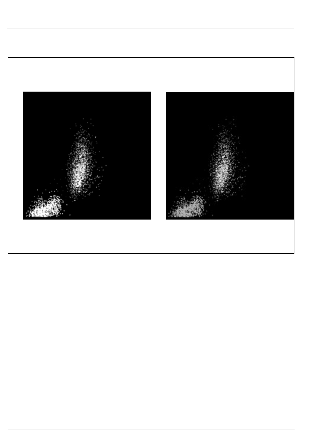
3-14 CELL-DYN®3200 Operator’s Manual
9140181B — November 1997
Principles of Operation
Flow Cytometry Section 3
Figure 3.4: Mononuclear-Polymorphonuclear Scatter
Mononuclear-Polymorphonuclear Separation
The scatter information is plotted with the 90° scatter on the Y
axis and the 10° scatter on the X axis. (The 90°/10° scatterplot
is shown in Figure 3.4.) Two populations of cells are clearly
seen on the display. The mononuclear cells fall in the cluster
in the lower left corner of the scatterplot and the
polymorphonuclear cells fall in the cluster above and to the
right of them.
The instrument uses a dynamic threshold to determine the
best separation between the two populations. Each cell is then
identified as a MONO or a POLY. Once each cell is identified,
it retains this classification no matter where it appears on
other scatterplots.
Mononuclear – Polymorphonuclear
Separation Mononuclear – Polymorphonuclear
Identification
90° Lobularity
90° Lobularity
10° Complexity 10° Complexity
Go Back
Search
TOC
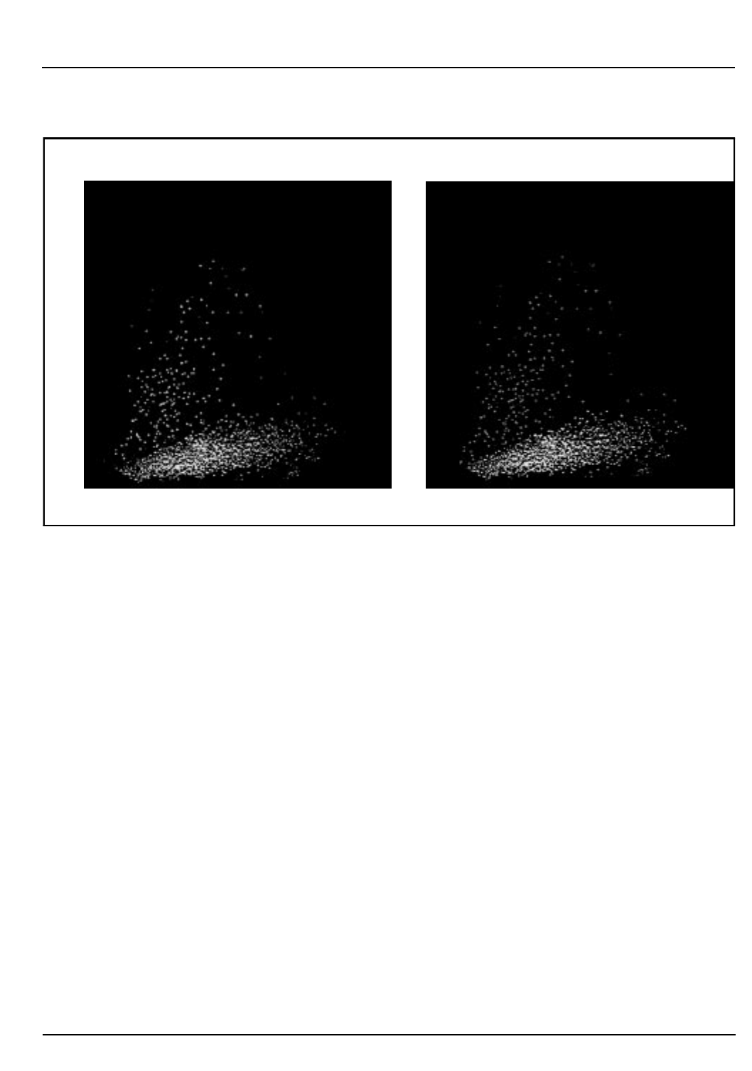
CELL-DYN® 3200 Operator’s Manual 3-15
9140181B — November 1997
Principles of Operation
Section 3 Flow Cytometry
Figure 3.5: Neutrophil-Eosinophil Scatter
Neutrophil-Eosinophil Separation
The scatter information is plotted with the 90°D scatter on the
Y axis and the 90° scatter on the X axis. (The 90°D/90°
scatterplot is shown in Figure 3.5.) Only the
polymorphonuclear cells are plotted on this scatterplot. The
mononuclear cells have been identified and therefore do not
interfere in the further classification of the
polymorphonuclear cells.
Two populations of polymorphonuclear cells are clearly seen
on the display. The neutrophils fall in the lower of the two
clusters. The eosinophils fall in the upper cluster. The
instrument uses a dynamic threshold to determine the best
separation between the two populations. Each cell is then
classified as a NEUT or an EOS.
All cells scatter a certain amount of 90°D light. The eosinophils
scatter more 90°D light than any of the other cells because of
the unique nature of granules they contain. This property of
the eosinophils is used to positively identify them and thus
clearly differentiate them from the neutrophil population.
90° Depolarized Granularity
90° Lobularity90° Lobularity
90° Depolarized Granularity
Neutrophil – Eosinophil
Separation Neutrophil – Eosinophil
Identification
Go Back
Search
TOC
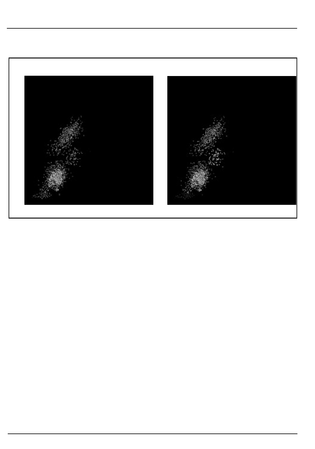
3-16 CELL-DYN®3200 Operator’s Manual
9140181B — November 1997
Principles of Operation
Flow Cytometry Section 3
Figure 3.6: Mononuclear Scatter
Mononuclear Separation
The scatter information is plotted with the 0° scatter on the Y
axis and the 10° scatter on the X axis. (The 0°/10° scatterplot is
shown in Figure 3.6.) The mononuclear cells are plotted on
this scatterplot. The algorithm also uses the orientation of the
neutrophil cluster to aid in classifying the mononuclears.
Three populations of mononuclear cells are clearly seen on the
display.
There are three populations of mononuclears because
basophils are included in the mononuclear cluster. Typically,
basophils are granulated cells and therefore more complex
than the mononuclear cells. However, the basophilic granules
are water soluble and dissolve in the WBC Lyse reagent.
Consequently, the degranulated Basophils becomes a less
complex cell that falls into the mononuclear cluster.
10° Complexity 10° Complexity
Mononuclear
Separation Mononuclear
Identification
0° Size
0° Size
Go Back
Search
TOC

CELL-DYN® 3200 Operator’s Manual 3-17
9140181B — November 1997
Principles of Operation
Section 3 Flow Cytometry
The lymphocytes fall in the lowest large cluster. (The small
population of cells below the lymphocytes contains particles
that are unlikely to be WBCs.) The basophils fall in the cluster
above and slightly to the right of the lymphocytes. The
monocytes fall in the cluster above the lymphocytes and
basophils. The instrument uses dynamic thresholds to
determine the best separation between the three main
populations. Each cell is then classified as a LYMPH, a MONO
or a BASO.
Finally, the instrument evaluates the area below the
lymphocyte cluster but above the hardware threshold
(channel 23). Any particles that fall in this area are separated
from the lymphocytes by a dynamic threshold. The following
cell types may be present in this region:
NRBCs
Unlysed RBCs
Giant PLTs
PLT clumps
All particles in this region are excluded from the WBC count
and the Differential.
Other Scatterplots
90°/0°
The scatter information is plotted with the 90° scatter on the Y
axis and the 0° scatter on the X axis.
90°D/0°
The scatter information is plotted with the 90°D scatter on the
Y axis and the 0° scatter on the X axis.
90°D/10°
The scatter information is plotted with the 90°D scatter on the
Y axis and the 10° scatter on the X axis.
All scatterplots may be displayed and printed at operator
request.
Go Back
Search
TOC

3-18 CELL-DYN®3200 Operator’s Manual
9140181B — November 1997
Principles of Operation
Flow Cytometry Section 3
Nuclear Optical Count
Samples containing fragile WBCs are difficult to measure
accurately because of the rapid breakdown of cells during the
measurement process. To obtain an accurate WBC count, an
alternate method using the HGB segment (instead of the WBC
segment) is used to measure samples containing fragile WBCs.
The HGB sample segment, after being measured in the HGB
Flow Cell, is transferred to the Optical Flow Cell instead of
being sent to a waste chamber as in normal Patient cycles.
While in the HGB Flow Cell, the HGB reagent lyses the
cytoplasmic membrane of the white blood cells but allows the
nuclear membrane to remain intact. This results is a greater
stability of the white cells in the sample. The HGB segment is
lysed for approximately 15 seconds before it is sent to the
Optical Flow Cell.
As the HGB segment passes through the Optical Flow Cell, the
nuclei of the cells are counted. The results of this measurement
are stored in the Data Log as NOC.
Resistant RBC
When the WBC count is higher than expected in certain
patient populations, lyse-resistant RBCs may be present. The
WBC Lyse used to obtain the WBC count is generally strong
enough to lyse RBCs that may be resistant to other lytic
agents. However, the “soft” osmotic lysing ability of the WBC
Lyse is usually insufficient to lyse the “resistant” cells in the
time allotted for the WBC count. Consequently, unlysed RBCs
are erroneously included in the WBC count resulting in a
falsely elevated value. In all cases there is usually a significant
amount of stroma (>2.9% of the total WBC count) present in
the N1 region below the WBC dynamic threshold on the
0º/10º scatterplot. The WBC diluted sample is held in the
mixing chamber 15 seconds longer than in the normal patient
mode. This additional lysing time is to break down the
resistant RBC cells.
NOTE: A higher incidence of false positive band flags
may be evident on specimens run under the Resistant
RBC specimen type.
Go Back
Search
TOC
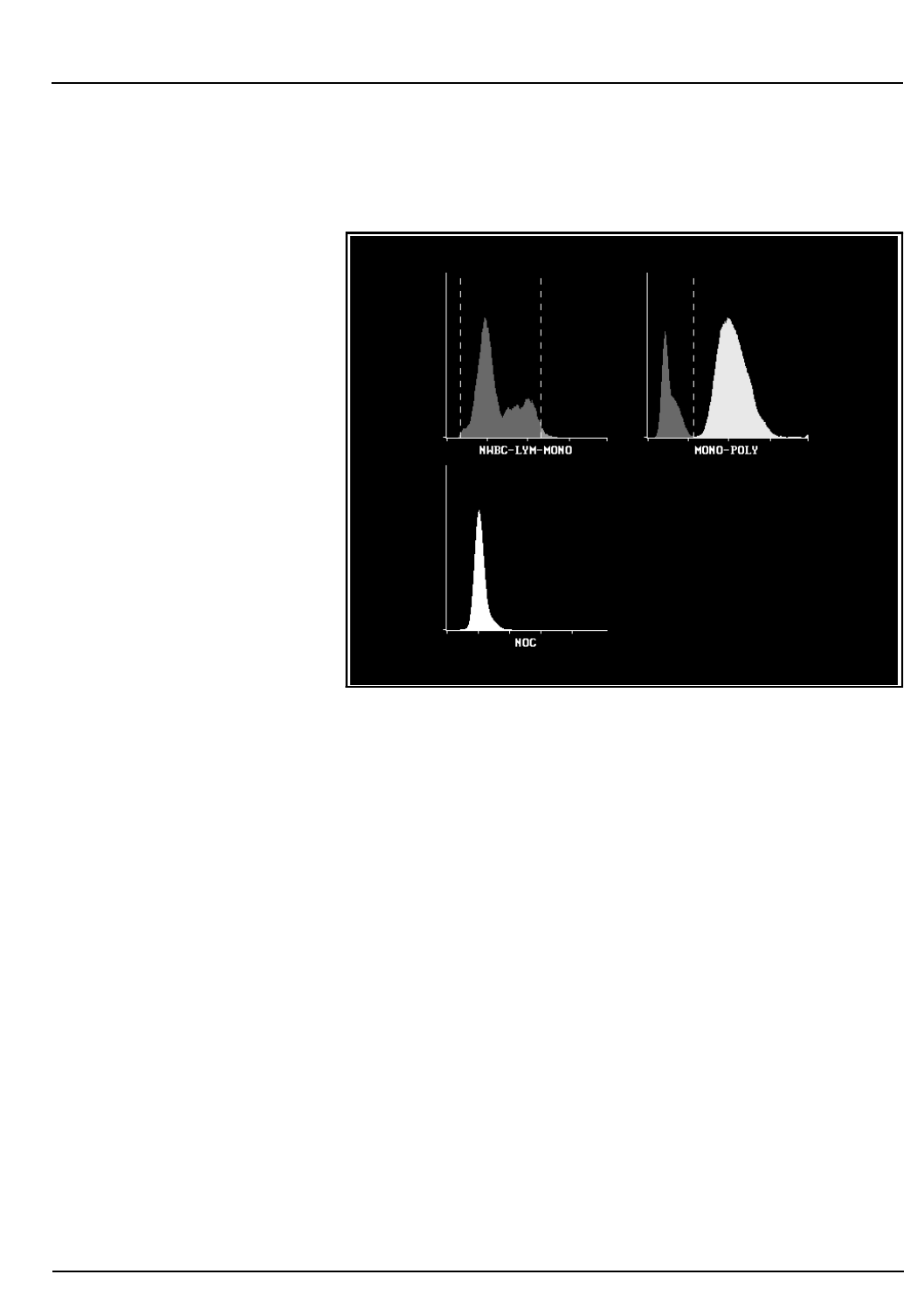
CELL-DYN® 3200 Operator’s Manual 3-19
9140181B — November 1997
Principles of Operation
Section 3 Flow Cytometry
WBC Histograms
Figure 3.7: WBC Histograms
The CELL-DYN 3200 can present the WBC scatter information
as two histograms: NWBC–LYM-MONO (N-L-M) and Mono-
Poly (M-P). The NOC (Nucleated Optical Count) data can also
be presented as a histogram. (Refer to Figure 3.7.) These
histograms may be displayed and printed at the operator's
request.
NWBC-LYM-MONO Histogram
The scatter information is plotted in a histogram format with
the relative number of cells on the Y axis and the NWBC,
Lymphocyte and Monocyte size distribution data on the X
axis.
MONO-POLY Histogram
The scatter information is plotted in a histogram format with
the relative number of cells on the Y axis and the
mononuclear and polymorphonuclear size distribution data
on the X axis.
Go Back
Search
TOC
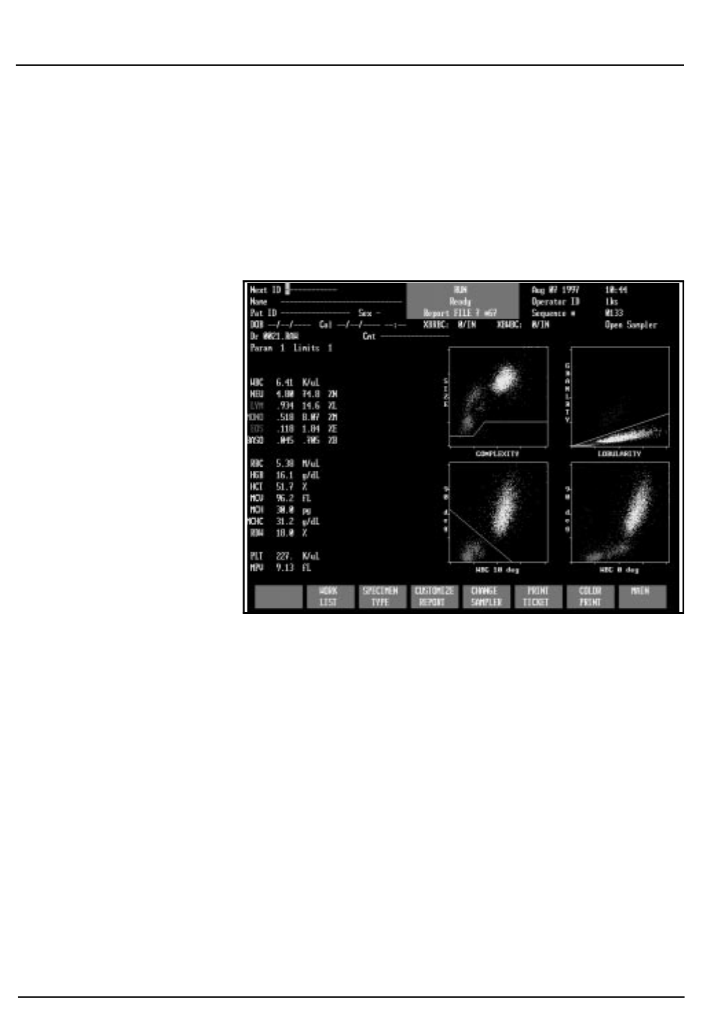
3-20 CELL-DYN®3200 Operator’s Manual
9140181B — November 1997
Principles of Operation
Flow Cytometry Section 3
NOC Histogram
The NOC data is plotted in a histogram format with the
relative number of cells on the Y axis and the cell size
distribution data on the X axis.
WBC Parameters
Figure 3.8: WBC Data and Scatterplots
The WBC data is generally displayed as depicted in Figure 3.8.
All numeric and graphic data are automatically displayed on
the RUN screen in the format selected. After the WBC scatter
information has been plotted and the cells have been classified
into the five subpopulations, the algorithms then determine
the WBC and the percent of cells in each subpopulation.
Once the WBC count is determined, the absolute number of
cells in each subpopulation is calculated by multiplying that
WBC count by the percentage. The results are expressed as
follows:
WBC # x K/µL
NEU # x K/µL and %
LYM # x K/µL and %
MONO # x K/µL and %
EOS # x K/µL and %
BASO # x K/µL and %
Go Back
Search
TOC

CELL-DYN® 3200 Operator’s Manual 3-21
9140181B — November 1997
Principles of Operation
Section 3 Flow Cytometry
The decimal point moves to display up to three decimal places
for the absolute number and percent.
The WBC subpopulations are further identified by the
following colors:
Neutrophils — yellow
Lymphocytes — blue
Monocytes — purple
Eosinophils — green
Basophils — white
NOTE: The basophils are displayed as white dots but
appear as black dots on color printouts.
The WBC scatter information is usually displayed in two
scatterplots as shown in Fig. 3.8:
SIZE/COMPLEXITY The size (0° scatter) information is
plotted on the Y axis and the
complexity (10° scatter)
information is plotted on the
X axis.
GRANLRTY/LOBULARITY The granularity (90°D scatter)
information is plotted on the Y axis
and the lobularity (90° scatter)
information is plotted on the
X axis.
Go Back
Search
TOC

3-22 CELL-DYN®3200 Operator’s Manual
9140181B — November 1997
Principles of Operation
Flow Cytometry Section 3
WBC Flagging
Refer to the “Operational Messages and Data Flagging”
subsection of this section for WBC flagging information.
RBC/PLT Measurement
Overview
The Optical Channel is used for the determination of RBC
and PLT data. During sample aspiration, 1.67 µL of sample is
segmented in the Shear Valve for RBC/PLT measurement.
The Diluent/Sheath Syringe dispenses 2.8 mL of diluent to the
Shear Valve. The sample and diluent are then transferred to
the RBC/PLT Mixing Chamber where the dilution is swirl
mixed, resulting in a 1:1,677 dilution ratio.
The Sample Transfer Pump transfers the RBC/PLT dilution
from the mixing chamber to the sheath feed nozzle in the
Optical Flow Cell. The Sample Metering Syringe injects 24 µL
of RBC/PLT dilution into the sheath stream. The sample
stream is then hydrodynamically focused to align the cells in
single file as they pass through the Optical Flow Cell, which is
an optically clear quartz chamber. A vertically polarized
Helium Neon Laser is the light source.
There are 256 size channels for each of the parameters, each
RBC size channel being equivalent to 1 fL and each PLT size
channel being equivalent to 0.137 fL.
The RBC count is corrected for coincidence. MCV is
determined from the RBC histogram. The PLT pulses are
analyzed by the PLT algorithm as discussed in the PLT
Measurement section.
The RBC count and distribution from the 0° channel is used to
determine MCV. The total PLT count is taken from the 10°
channel, the narrow-angle light scatter.
Go Back
Search
TOC
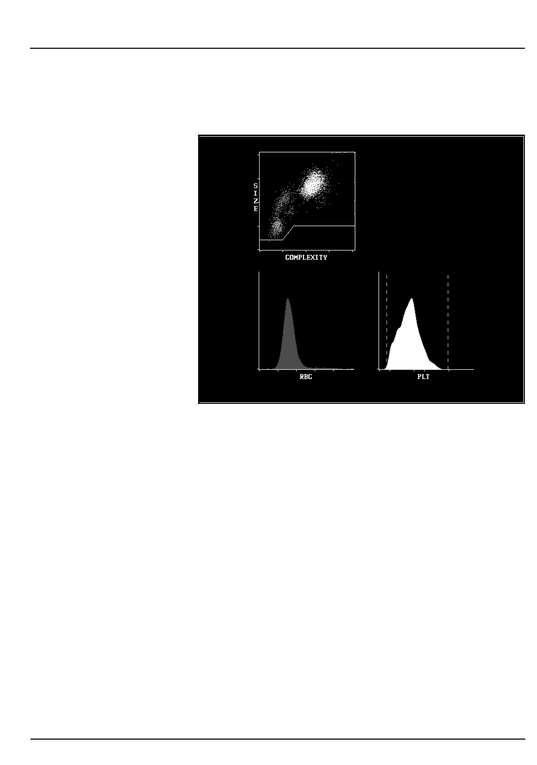
CELL-DYN® 3200 Operator’s Manual 3-23
9140181B — November 1997
Principles of Operation
Section 3 Flow Cytometry
RBC Parameters
Figure 3.9: RBC Data and Histogram
All numeric and frequency size distribution data are
automatically displayed on the RUN screen in the format
selected. The size distribution data for the red cells is displayed
graphically as a histogram. The size distribution data is plotted
on the X axis. The relative number of cells is normalized and
plotted on the Y axis. The RBC data are shown in Figure 3. 9.
RBC Count
The Red Blood Cell Count is directly measured, gives the
number of RBCs and is expressed as follows:
RBC = # x M/µL
Counts below 1.0 x M µL are displayed to three decimal places.
MCV
The Mean Cell Volume is the average volume of the
individual red blood cells. The MCV is derived from the RBC
size distribution data and is expressed in femtoliters.
Go Back
Search
TOC

3-24 CELL-DYN®3200 Operator’s Manual
9140181B — November 1997
Principles of Operation
Flow Cytometry Section 3
HCT
The Hematocrit is the ratio of red blood cells to plasma and is
expressed as a percentage of the whole blood volume. The
HCT is calculated from the red blood cell count and the mean
cell volume as follows:
HCT = (RBC x MCV)/10
MCH
The Mean Corpuscular Hemoglobin is the average amount of
hemoglobin contained in the red blood cell expressed in
picograms. The MCH is calculated from the RBC and the HGB
as follows:
MCH = (HGB/RBC) x 10
MCHC
The Mean Corpuscular Hemoglobin Concentration is the
ratio of the weight of hemoglobin to the volume of the
average red blood cell expressed in grams per deciliter. MCHC
is calculated from the HGB and the HCT as follows:
MCHC = (HGB/HCT) x 100
RDW
Red Cell Distribution Width is a measure of the
heterogeneity of the RBC population. The CELL-DYN 3200
reports a relative RDW equivalent to a CV in grams per
deciliter. The RDW is derived from the RBC histogram using
the 20th and 80th percentiles.
RBC Flagging
Refer to the “Operational Messages and Data Flagging”
subsection of this section for RBC Flagging information.
Go Back
Search
TOC

CELL-DYN® 3200 Operator’s Manual 3-25
9140181B — November 1997
Principles of Operation
Section 3 Flow Cytometry
PLT Measurement
Data recorded in the RBC/PLT dilution between 1 and 35 fL are
included in the PLT data. If the raw PLT count is estimated to
be below a predetermined value, the instrument automatically
continues to count PLTs for an extended count period. The
results from the two count periods are averaged. The PLT data
is plotted as a histogram. An algorithm analyzes the histogram
to eliminate interference and thus determine the lower and
upper thresholds for the count.
If no interference is detected, the lower and upper thresholds
are set at 2 and 30 fL respectively. If interference is detected,
the thresholds float to determine the best separation between
the interference and the PLT population. The lower threshold
floats in the 1–3 fL region and the upper threshold floats in
the 15–35 fL region. Once the thresholds have been
determined, the PLT count is derived from the data between
them.
Interference in the upper threshold region is generally caused
by microcytic RBCs. Therefore, after the PLT upper threshold
has been determined, the data between it and the RBC lower
threshold is re-evaluated. If the PLT upper threshold is less
than 35 fL, the counts above it (but less than the RBC lower
threshold) are added to the RBC count.
If the interference in either threshold region exceeds a
predetermined limit, the PLT count is flagged accordingly. The
flags are discussed in the last section of this chapter.
Go Back
Search
TOC
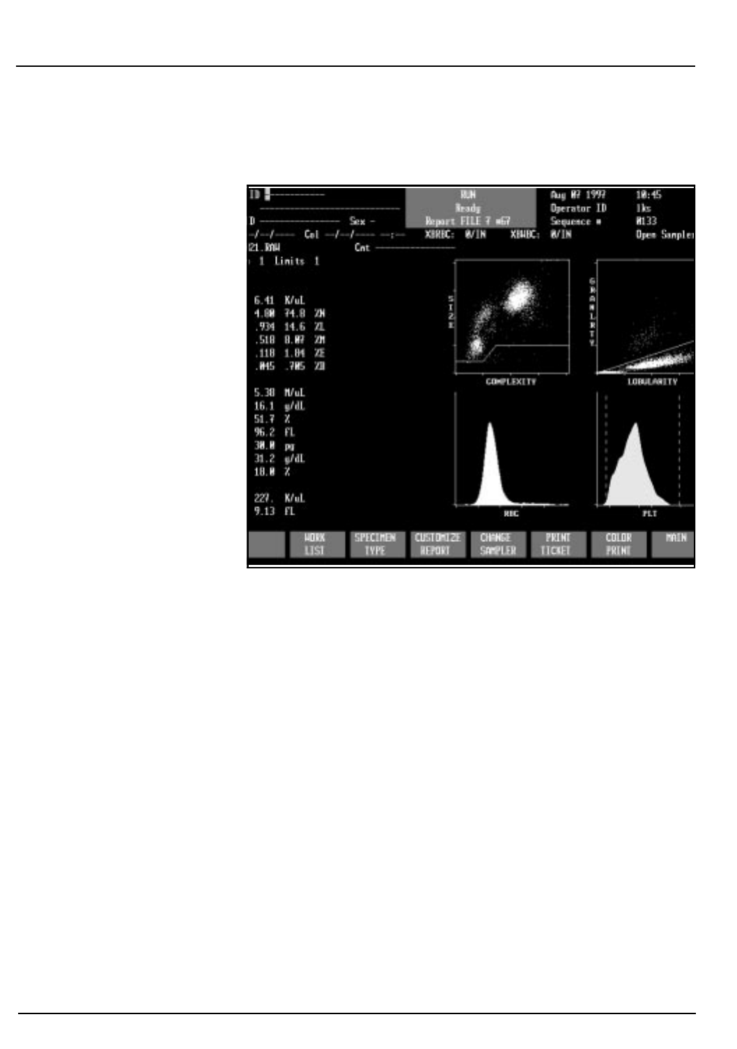
3-26 CELL-DYN®3200 Operator’s Manual
9140181B — November 1997
Principles of Operation
Flow Cytometry Section 3
Platelet Parameters
Figure 3.10: PLT Data and Histogram
All numeric and frequency size distribution data are
automatically displayed on the RUN screen in the format
selected. The size distribution data for the platelets is displayed
graphically as a histogram with the size distribution data
plotted on the X axis and the relative number of cells
normalized and plotted on the Y axis. The PLT data and
histogram are shown in Figure 3.10.
PLT Count
The Platelet Count is derived from the PLT histogram after
the PLT data has been analyzed by the platelet algorithm. The
PLT count is expressed as follows:
PLT = # x K/µL
MPV
The Mean Platelet Volume is derived from the PLT histogram
after the PLT count has been determined. The MPV is
expressed in femtoliters.
Go Back
Search
TOC

CELL-DYN® 3200 Operator’s Manual 3-27
9140181B — November 1997
Principles of Operation
Section 3 Flow Cytometry
PCT
The Plateletcrit is the product of PLT and MPV and is
analogous to the hematocrit. It is expressed in percent and is
calculated as follows:
PCT = (PLT x MPV)/10
PDW
Platelet Distribution Width is a measure of the heterogeneity
of the PLT population. It is expressed as the geometric
standard deviation.
NOTE: Clinical significance has not been established
for PCT and PDW. Therefore, they are not reportable.
Platelet Flagging
Refer to the “Operational Messages and Data Flagging” section
of this chapter for PLT flagging information.
Go Back
Search
TOC

3-28 CELL-DYN®3200 Operator’s Manual
9140181B — November 1997
Principles of Operation
Flow Cytometry Section 3
Hemoglobin Measurement
Overview
The HGB channel is used for the colorimetric determination of
hemoglobin. During sample aspiration, 12 µL of sample is
segmented in the Shear Valve for HGB measurement.
Before the HGB is measured, a reference value is obtained
using the CD3200 Diluent/Sheath in the HGB Flow Cell. A
zero or blank reading is obtained on the diluent to provide a
reference to which the sample signal is compared. Five
separate blank readings are made on each sample. The lowest
and highest are eliminated and the remaining three are
averaged to give the final HGB reference reading.
The Diluent/Sheath Syringe dispenses 2.29 mL of diluent/
sheath to the Shear Valve, transferring the HGB segment to the
HGB Mixing Chamber. The HGB Lyse Syringe then dispenses
0.30 mL of HGB Lyse into the mixing chamber. The mixture is
swirl mixed, resulting in a 1:216 dilution ratio. The HGB lyse
reagent lyses the red blood cells, converting the hemoglobin
that is released by a cyanide-free chemical process. When the
lysing action is completed, a low-energy LED in the HGB Flow
Cell, attached to the mixing chamber, measures the amount of
absorbance which is proportional to the HGB concentration.
A LED with a wavelength of 540 nm is the light source. A
photodetector measures the light that is transmitted.
Five separate HGB readings are made on each sample. The
lowest and highest are eliminated and the remaining three are
averaged to give the final HGB sample reading. After the
hemoglobin readings have been made, the HGB Flow Cell is
rinsed with diluent/sheath (in the normal run mode).
The reference and sample readings are compared to determine
the HGB concentration of the sample. The HGB result is
expressed in grams of hemoglobin per deciliter of whole
blood. Up to two decimal places may be displayed for
hemoglobin results less than 10 g/dL.
HGB Parameters
The Hemoglobin is directly measured and is expressed in
grams of hemoglobin per deciliter of whole blood.
Go Back
Search
TOC
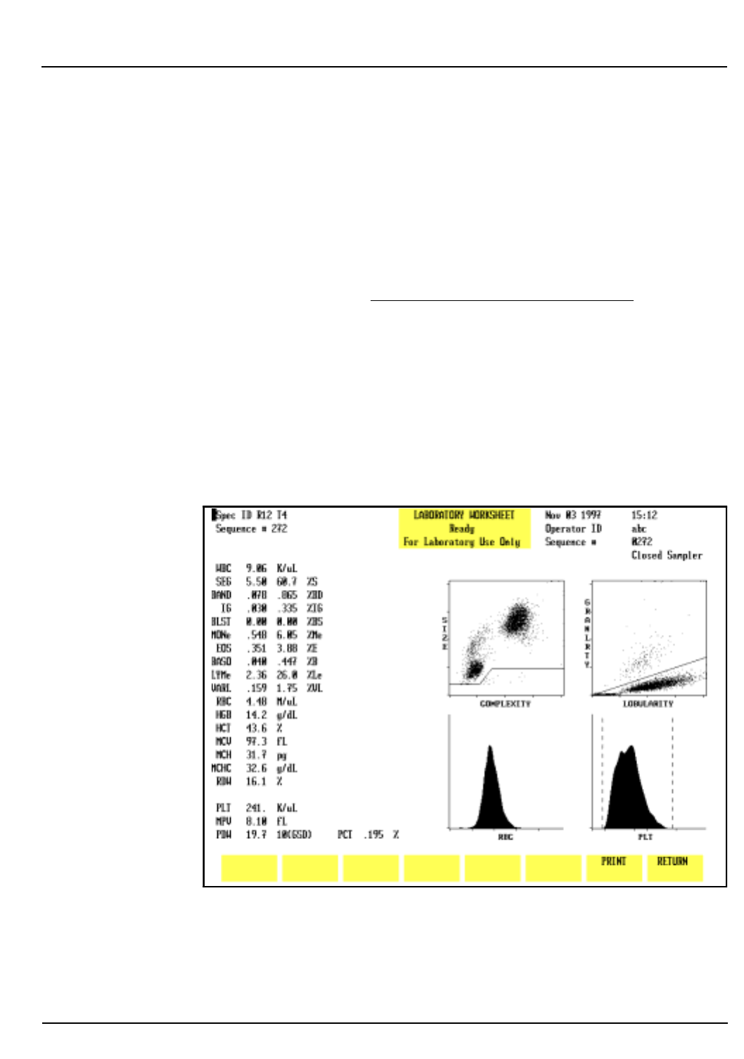
CELL-DYN® 3200 Operator’s Manual 3-29
9140181B — November 1997
Principles of Operation
Section 3 Flow Cytometry
HGB Flagging
Refer to the “Operational Messages and Data Flagging”
subsection of this section for HGB flagging information.
Laboratory Worksheet Screen
The LABORATORY WORKSHEET screen is provided to assist
the laboratory staff in data review and validation (refer to
Figure 3.11.) This screen is for laboratory use only. This screen
displays the 5-Part Differential plus additional parameters. The
RUN and DATA LOG screens display only the 5-Part
Differential. The difference between the two formats is shown
in Tables 3.1 and 3.2.
NOTE: The parameters MON and LYM have an “e”
after the label, indicating that the values are estimated.
MONe represents monos minus blasts. LYMe represents
reported lymphs minus variant lymphs.
Figure 3.11: Laboratory Worksheet Screen
Go Back
Search
TOC

3-30 CELL-DYN®3200 Operator’s Manual
9140181B — November 1997
Principles of Operation
Flow Cytometry Section 3
To access the LABORATORY WORKSHEET screen, press the
Page Down key on the keyboard while the RUN menu is
displayed or while the DISPLAY SPECIMEN screen (in the
DATA LOG menu) is displayed. The format is fixed and cannot
be changed. The specimen displayed on the screen is identified
by the Specimen ID number and Sequence number in the
upper left corner of the screen.
To print the LABORATORY WORKSHEET screen, press the
[PRINT] soft key or the Print Screen key on the keyboard. Press
[RETURN] to return to the RUN menu or DISPLAY SPECIMEN
screen (in DATA LOG menu), depending on which menu was
used to access the worksheet.
The 5-Part Differential separates WBC into 5 components:
Neutrophils, Lymphocytes, Monocytes, Eosinophils, and
Basophils. The additional parameters further separate the
Neutrophils, Lymphocytes, and Monocytes into their
constituent components. Eosinophils and Basophils are the
same in both tables.
Go Back
Search
TOC
CELL-DYN® 3200 Operator’s Manual 3-31
9140181B — November 1997
Principles of Operation
Section 3 Flow Cytometry
Table 3.1: 5-Part Differential
Parameter Results (K/µL)
WBC 11.15
1NEU 5.91
2LYM 3.16
3MONO 2.06
4EOS 0.02
5BASO 0.00
Table 3.2: 5-Part Differential Plus Additional
Parameters
Parameter Results (K/µL)
WBC 11.15
NEU 5.91
1 SEG 4.80
2BAND 0.00
3IG 1.11
LYM 3.16
4LYMe 2.01
5VARL 1.15
MONO 2.06
6BLST 1.69
7MONe 0.37
8 EOS 0.02
9BASO 0.00
Go Back
Search
TOC

3-32 CELL-DYN®3200 Operator’s Manual
9140181B — November 1997
Principles of Operation
Flow Cytometry Section 3
NOTES
Go Back
Search
TOC

CELL-DYN® 3200 Operator’s Manual 3-33
9140181B — November 1997
Principles of Operation
Section 3 Operational Messages and Data Flagging
Operational Messages and Data Flagging
Introduction
Operational messages and data flags appear on the RUN
screen, on printed reports and can be transmitted to a
laboratory computer system. The CELL-DYN 3200 monitors
instrument conditions and data criteria that may affect the
displayed results and these messages and flags are used to alert
the operator. Instructions for interpreting all flags, and
numeric, scatter and histogram data should be incorporated
into the laboratory’s procedure and used to determine the need
for further action and/or review of results. Messages are divided
into the following categories:
Instrument Messages:
Fault Conditions
Status Conditions
Parameter Flagging Messages:
Dispersional Data Alerts
Suspect Parameter Flags
Suspect Population Flags
Interpretive Messages
Detailed descriptions of the messages in each of the categories
are given in this section.
Instrument Fault and Status Conditions
The Instrument Fault and Status conditions are discussed in
Tables 10.1 through Table 10.4 in Section 10: Troubleshooting
and Diagnostics, Subsection: Troubleshooting Guide. These
messages are displayed when the instrument detects an
inappropriate condition during specimen processing. When
necessary, data is suppressed. When any of these messages are
displayed, refer to the Troubleshooting Guide for assistance.
Follow the instructions given and take the appropriate
corrective action. When the problem is corrected, repeat the
specimen.
Go Back
Search
TOC

3-34 CELL-DYN®3200 Operator’s Manual
9140181B — November 1997
Principles of Operation
Operational Messages and Data Flagging Section 3
Cell Populations and Flagging
Fragile WBCs
Typically, fragile WBCs are abnormal lymphocytes that are
present in chronic lymphocytic leukemia (CLL) and are the
“smudge cells” that appear when the blood smear is made.
When processing samples in the Patient mode (Patient is
selected as the Specimen Type in the RUN screen), if fragile
WBCs are present the WBC (WOC) count may be abnormally
low due to the gradual destruction of the cytoplasmic
membrane of these fragile cells by the lysing agents during the
Run cycle.
If there is no significant stroma interference (< 2.9% of the
total WOC count) or if LYM% > 80% and cell count > 4.0K/µl,
the FWBC flag is displayed, alerting the user to run the
specimen in the Fragile WBC mode (Fragile WBC is selected as
the Specimen Type). The Fragile WBC mode utilizes the HGB
sample segment which contains the intact nuclei of the WBCs
to obtain a more accurate count of this cell type.
Lyse-Resistant RBCs
Resistant RBCs are red blood cells which contain abnormalities
or whose membranes have been altered, making them more
resistant to the lysing process.
When running samples in the Patient mode, the hypo-osmotic
lysing ability of the WBC Lyse reagent is usually insufficient to
lyse any lyse-resistant RBC cells, if present, in the time allotted
for the WBC count. Consequently, the unlysed RBCs may be
erroneously included in the WBC count, resulting in a falsely
elevated count.
In normal patient samples, lyse-resistant RBCs are either
absent or their number is negligible. In patient samples with a
significant number of lyse-resistant RBCs, usually there is also
a significant amount of stroma interference (> 2.9% of the
total WOC count) present in the N1 region below the dynamic
WOC threshold on the 0º / 10º scatterplot.
When the stroma interference > 2.9% of the total WBC count
and other conditions are met, the RRBC (Resistant RBC) flag is
displayed, alerting the user to run the specimen in the
Resistant RBC mode (Resistant RBC is selected as the Specimen
Go Back
Search
TOC

CELL-DYN® 3200 Operator’s Manual 3-35
9140181B — November 1997
Principles of Operation
Section 3 Operational Messages and Data Flagging
Type). The WBC lyse time is extended, allowing for a complete
lysing of the lyse-resistant RBCs to obtain an accurate WBC
count.
Parameter Flagging Messages
Table 3.3 summarizes all of the parameter flagging messages by
parameter and category.
Table 3.3: Parameter Flagging Messages
Parameter Dispersional Data Alerts Suspect
Parameter Flags Suspect
Population Flags Interpretive
Messages
WBC Result displays in yellow if
below lower limit
Result displays in purple if
above upper limit
Result underlined on graphics
printout when limits exceeded
Result underlined on blank
ticket when limits exceeded
Result marked with asterisk (*)
on preprinted ticket when
results exceeded
WBC NWBC
FWBC
NRBC
RRBC
Leukopenia
Leukocytosis
Differential
NEU
LYM
MONO
EOS
BASO
Same as WBC
DFLT (NLMEB) BAND
IG
BLAST
VARIANT LYM
Neutropenia
Neutrophilia
Lymphopenia
Lymphocytosis
Monocytosis
Eosinophilia
Basophilia
RBC
HGB
MCV
RDW
Same as WBC
RBC MORPH Anemia
Polycythemia
Microcytic RBC
Macrocytic RBC
Hypochromic
Hyperchromic
Anisocytosis
PLT
MPV Same as WBC LRI
URI
LURI
The MPV value is
suppressed (not
displayed or
printed) if an
LRI, URI, or LURI
condition exists.
Thrombocytopenia
Thrombocytosis
Microcytic PLT
Macrocytic PLT
Go Back
Search
TOC

3-36 CELL-DYN®3200 Operator’s Manual
9140181B — November 1997
Principles of Operation
Operational Messages and Data Flagging Section 3
Dispersional Data Alerts
These alerts are triggered by the numeric limits entered into
the four Patient Limit Sets (see Section 5: Operating
Instructions, Subsection: Set Up Instructions for an
explanation) or taken from the instrument’s preset linearity
limits. If results for a parameter exceed these limits, they are
flagged on the screen and on the report. Dispersional alerts are
displayed or printed as follows:
Screen display: Result below lower limit shown in yellow
Result above upper limit shown in purple
Linearity Exceeded: Result displayed as
>>>
Graphic Report: Results outside limits are underlined
Blank Ticket: Results outside limits are underlined
Preprinted Ticket: Results outside limits are marked with an
asterisk
Specimens with results that exceed the linearity should be
diluted with diluent/sheath according to the laboratory’s
procedure and repeated. (Be sure to correct the results for the
dilution factor used.)
NOTE: MCV, MCH, MCHC and MPV are unaffected by
dilution and do not require correction.
Suspect Parameter Flags
These flags are generated after the instrument evaluates the
measured data for a particular parameter or group of
parameters. The result may be suspect due to interfering
substances or the inability of the instrument to measure a
particular parameter due to a sample abnormality. The name
of each flag, the location of the flag on the display, the cause
of the flag and action to be taken are given in the following
explanations.
Go Back
Search
TOC

CELL-DYN® 3200 Operator’s Manual 3-37
9140181B — November 1997
Principles of Operation
Section 3 Operational Messages and Data Flagging
Introduction to WBC Flagging
There are two WBC parameter flags: WBC and DFLT(NLMEB).
The following WBC population flags may be displayed:
NWBC, FWBC, NRBC, RRBC, BAND, IG, BLAST, VAR LYM. If
any of the WBC or parameter flags is displayed, the message
SUSPECT is displayed under and to the right of the Limits field
on the RUN and LABORATORY WORKSHEET screens. This
message also appears on printouts.
WBC Flags
WBC — displayed next to the WBC result
Cause Action
WBC result exceeds the
expected limits and one or both of
the following conditions:
1. A declining kinetic rate was
detected for WBC.
2. More than 10% of the WBC
count was located in the stroma
region.
This situation is typically caused
by lytic-resistant RBCs interfering
with the WBC measurement.
Repeat the specimen using the
Resistant RBC lyse cycle to elimi-
nate interference caused by lytic-
resistant RBCs. If the WBC flag per-
sists, review a stained smear for the
presence of NRBCs and verify the
LYM and WBC values.
Go Back
Search
TOC

3-38 CELL-DYN®3200 Operator’s Manual
9140181B — November 1997
Principles of Operation
Operational Messages and Data Flagging Section 3
NOTE: The DFLT flag is always accompanied by
additional descriptive information, NLMEB, in
brackets. These letters indicate which subpopulation or
group of subpopulations is suspect when the DFLT flag
is displayed. (N = Neutrophils, L = Lymphocytes, M =
Monocytes, E = Eosinophils, B = Basophils)
PLT Flags
DFLT (NLMEB) — displayed next to the BASO %
Causes Action
1. A default (preset) value or
threshold was used to deter-
mine the five-part differential.
This is typically due to the pres-
ence of abnormal cell clusters
that the instrument cannot reli-
ably discriminate between and
therefore, a default threshold is
selected. The flag may also be
caused by an abnormally low
number of cells in a specific
subpopulation.
2. A declining kinetic rate for
WBC.
Examine a stained smear to verify
the differential values for the
subpopulations identified by the
descriptive information.
LRI (Lower Region Interference) — displayed next to the MPV result
Cause Action
Interference in the lower threshold
region (1–3 fL) is greater than a
predetermined limit. This is gener-
ally non-biologic interference. The
flag may be caused by:
Debris (Flow Cell)
Contaminated reagent
Microbubbles
Check the background count. If it
exceeds the limits, troubleshoot
accordingly. If it is within limits,
repeat the specimen. If the flag
persists, review a stained smear to
determine the cause of the inter-
ference and verify the PLT count.
Go Back
Search
TOC

CELL-DYN® 3200 Operator’s Manual 3-39
9140181B — November 1997
Principles of Operation
Section 3 Operational Messages and Data Flagging
URI (Upper Region Interference) — displayed next to the MPV result
Cause Action
Interference in the upper thresh-
old region (15–35 fL) is greater
than a predetermined limit. This is
generally biologic interference.
The flag may be caused by:
Microcytic RBCs
Schistocytes
Giant Platelets
Sickle Cells
Platelet Clumps
NOTE: A “bumpy” platelet histo-
gram may indicate the
presence of platelet
clumps.
Review the MCV and the PLT his-
togram. If the MCV is low and/or
the histogram indicates an overlap
(poor separation at the upper dis-
criminator) in the RBC and PLT
populations, review a stained
smear to determine the cause and
confirm the PLT count.
LURI (Lower and Upper Region Interference) —
displayed next to the MPV result
Cause Action
Interference is present in both the
upper and lower regions of the PLT
histogram.
Follow the guidelines given above
for the LRI and URI flags.
Go Back
Search
TOC

3-40 CELL-DYN®3200 Operator’s Manual
9140181B — November 1997
Principles of Operation
Operational Messages and Data Flagging Section 3
Suspect Population Flags
These flags are generated when the instrument’s evaluation of
the measured data for a particular parameter or group of
parameters indicates the possible presence of an abnormal
subpopulation. A stained smear should be reviewed whenever a
suspect population flag is present. Therefore, instructions for
interpreting these flags should be incorporated into the
laboratory’s review criteria for abnormal samples.
WBC Flags
BAND — displayed next to the NEU %
Cause Action
1. The count in the region of scat-
ter (on the 0°/10° plot) where
bands are typically located is
>12.5% of the total WBC count.
2. The ratio of suspected bands to
mature neutrophils is >50%.
3. The CV of the neutrophil clus-
ter on the 0° axis exceeds ex-
pected criteria.
Review a stained smear for the
presence of bands and follow your
laboratory’s review criteria. When
bands are present, they are includ-
ed in the total neutrophil count.
IG (Immature Granulocyte) — displayed next to the NEU %
Cause Action
The count in the region of scatter
(on the 0°/10° plot) where imma-
ture granulocytes are typically lo-
cated is >3% of the total WBC
count.
Review a stained smear for the
presence of immature granulo-
cytes and follow your laboratory’s
review criteria. When IGs are
present, they are included in the
total neutrophil count.
Go Back
Search
TOC

CELL-DYN® 3200 Operator’s Manual 3-41
9140181B — November 1997
Principles of Operation
Section 3 Operational Messages and Data Flagging
NOTE: This flag may be displayed singly or in
combination with the blast flag. If the flag is displayed
with the blast flag it is displayed as VARL/BLAST.
BLAST — displayed next to the LYM %
Causes Action
1. The count in the region of scat-
ter (on the 90°/0° plot) where
blasts are typically located is
>1% of the total WBC count.
2. The MONO % is >20% of the to-
tal WBC count.
3. The MONO % is >3% of the
total WBC count and the stan-
dard deviation of the mono-
cytes on the 0° axis exceeds
expected criteria.
Review a stained smear for the
presences of blasts and follow your
laboratory’s review criteria. When
blasts are present, they are typical-
ly included in the monocyte
count.
VARIANT LYM — displayed next to the LYM %
Cause Action
The position, density or CV of the
lymphocyte cluster on the
size/complexity (0°/10°) scatter
plot exceeds expected criteria.
Review a stained smear for the
presence of variant lymphocytes
and follow your laboratory’s re-
view criteria. When VARIANT
LYMs are present, they are includ-
ed in the lymphocyte count.
Go Back
Search
TOC

3-42 CELL-DYN®3200 Operator’s Manual
9140181B — November 1997
Principles of Operation
Operational Messages and Data Flagging Section 3
NWBC (Non-White Blood Cells) — displayed next to the MONO %
Cause Action
A non-WBC population is present
in the N1 region below the dynam-
ic WBC threshold on the size/com-
plexity (0°/10°) scatter plot. The
count in the N1 region is greater
than 2.9% of the total WBC. The
cell types that may be present in
the N1 region are:
Low levels of NRBCs
Unlysed RBCs
PLT clumps
Giant PLTs
Review a stained smear and follow
your laboratory’s review criteria to
determine the cause of the elevat-
ed count in the N1 region. Correc-
tion of the WBC count is not
required. If no suspect parameter
flags are present, the WBC and Dif-
ferential may be reported.
FWBC (Fragile White Blood Cells) — displayed next to the MONO %
Cause Action
The presence of fragile WBCs is
suspected. Select Fragile WBC as the Speci-
men Type and rerun the sample.
The NOC value is always displayed
as WBC on the
RUN
screen and
LAB-
ORATORY WORKSHEET
screen. Re-
view a stained smear and follow
your laboratory’s review criteria to
confirm the LYM values.
Go Back
Search
TOC

CELL-DYN® 3200 Operator’s Manual 3-43
9140181B — November 1997
Principles of Operation
Section 3 Operational Messages and Data Flagging
NRBC — displayed next to the MONO %
Cause Action
1. The WBC result exceeds the ex-
pected limit.
2. The count in the area below the
WBC threshold on the size/
complexity (0°/10°) scatter plot
is >2.9% of the total WBC
count.
Review a stained smear for the
presence of NRBCs and follow
your laboratory’s review criteria. If
NRBCs are present, they should be
quantified according to your labo-
ratory’s procedure. Correction of
the WBC count is not required. If
the WBC flag is displayed with the
NRBC flag, repeat the specimen us-
ing the Resistant RBC cycle to
eliminate interference from any
lytic-resistant RBCs that may be
present with the NRBCs.
RRBC (Resistant Red Blood Cells) — displayed next to the MONO %
Cause Action
The presence of lyse-resistant RBCs
is suspected. Repeat the specimen using the Re-
sistant RBC cycle to eliminate
interference from any
lytic-resistant RBCs that may be
present. Either the NOC or WOC
value is displayed as WBC on the
RUN
screen and
LABORATORY WORK-
SHEET
screen. If the WBC flag is
displayed, review a stained smear
to determine the cause of the inter-
ference. Verify the WBC value by
an alternate method according to
your laboratory’s protocol.
Go Back
Search
TOC

3-44 CELL-DYN®3200 Operator’s Manual
9140181B — November 1997
Principles of Operation
Operational Messages and Data Flagging Section 3
RBC Flags
PLT Flags
Interpretive Messages
Interpretive messages appear only on the graphics report and
are generated when the numeric limits entered in the Patient
Limit Sets are exceeded. (see Section 5, Subsection: Set Up
Instructions for an explanation). These messages are printed
only when the Interpretive Report option is selected on the
CUSTOMIZE REPORT SCREEN. The Interpretive messages are
summarized below.
RBC MORPH — displayed next to the HCT result
Cause Action
One or more of the following pa-
rameters exceeds expected limits:
MCV <80fL or >100fL
MCH <25pg or >34pg
MCHC <29g/dL or >37g/dL
RDW >18.5%
Review a stained smear for abnor-
mal RBC or PLT morphology and
follow your laboratory’s review
criteria.
No MPV result displayed (data suppressed)
Cause Action
The PLT histogram did not meet
expected criteria (non-log normal
distribution).
Review a stained smear for abnor-
mal PLT morphology or the pres-
ence of PLT aggregates and follow
your laboratory’s review criteria.
Verify the PLT count.
Go Back
Search
TOC

CELL-DYN® 3200 Operator’s Manual 3-45
9140181B — November 1997
Principles of Operation
Section 3 Operational Messages and Data Flagging
WBC Messages
RBC Messages
Message Cause
Leukopenia result exceeds the lower limit for WBC
Leukocytosis result exceeds the upper limit for WBC
Neutropenia result exceeds the lower limit for Neutrophil abso-
lute number
Neutrophilia result exceeds the upper limit for Neutrophil abso-
lute number
Lymphopenia result exceeds the lower limit for Lymphocyte
absolute number
Lymphocytosis result exceeds the upper limit for Lymphocyte
absolute number
Monocytosis result exceeds the upper limit for Monocyte abso-
lute number
Eosinophilia result exceeds the upper limit for Eosinophil abso-
lute number
Basophilia result exceeds the upper limit for Basophil absolute
number
Message Cause
Anemia result exceeds the lower limit for RBCs
Polycythemia result exceeds the upper limit for RBCs
Microcytic RBC result exceeds the lower limit for MCV
Macrocytic RBC result exceeds the upper limit for MCV
Hypochromic result exceeds the lower limit for MCHC
Hyperchromic result exceeds the upper limit for MCHC
Anisocytosis result exceeds the upper limit for RDW
Go Back
Search
TOC

3-46 CELL-DYN®3200 Operator’s Manual
9140181B — November 1997
Principles of Operation
Operational Messages and Data Flagging Section 3
PLT Messages
Message Cause
Thrombocytopenia result exceeds the lower limit for PLTs
Thrombocytosis result exceeds the upper limit for PLTs
Microcytic PLT result exceeds the lower limit for MPV
Macrocytic PLT result exceeds the upper limit for MPV
Go Back
Search
TOC

CELL-DYN® 3200 Operator’s Manual 3-47
9140181B — November 1997
Principles of Operation
Section 3 References
References
1. ICSH, The Assignment of Values to Fresh Blood Used for
Calibrating Automated Cell Counters, Clinical and
Laboratory Hematology 1988, 10:203-212.
2. Clinical Applications of Flow Cytometry, ASCP National
Meeting, Spring 1990.
3. Shapiro, Howard, Practical Flow Cytometry, 1984.
Go Back
Search
TOC

3-48 CELL-DYN®3200 Operator’s Manual
9140181B — November 1997
Principles of Operation
References Section 3
NOTES
Go Back
Search
TOC

CELL-DYN®3200 Operator’s Manual 4-1
9140181B — November 1997
Performance Characteristics and Specifications
Section 4 Overview
Overview
This section is a collection of detailed information about the
CELL-DYN 3200 System.
Included in this section are:
• Physical Specifications
• Operational Specifications
• Bar Code Specifications
• Measurement Specifications
• Performance Specifications
• Performance Characteristics
• Sample Loader Specifications
Specifications for the Host Interface (LN 06H71-01) are not
included in this section but can be ordered by calling Abbott
Customer Support Center at 1 (800) 323-9100.
Go Back
Search
TOC

4-2 CELL-DYN® 3200 Operator’s Manual
9140181B — November 1997
Performance Characteristics and Specifications
Overview Section 4
NOTES
Go Back
Search
TOC
CELL-DYN®3200 Operator’s Manual 4-3
9140181B — November 1997
Performance Characteristics and Specifications
Section 4 System Specifications
System Specifications
Physical Specifications
Tables 4.1 and 4.2 contain physical specifications for both the
CELL-DYN 3200SL and CS models.
Table 4.1: Instrument Dimensions
Table 4.2: Dimensions After Packaging for Shipment
Analyzer SL Analyzer CS Display
Monitor Ticket Printer
(Dot Matrix)
Graphics
Printer
(Color Bubble
Jet)
Height 19" (48.2 cm) 19" (48.2 cm) 15" (38.1 cm) 6" (15.2 cm) 7.2" (18.3 cm)
Width 32.8" (83.3 cm) 32.8" (83.3 cm) 14" (35.5 cm) 16.5" (41.9 cm) 16.1" (40.9 cm)
Depth 29.3" (74.4 cm) 23.3" (59.2 cm) 16" (40.6 cm) 14.5" (36.8 cm) 9.9" (25.1 cm)
Weight 232 lb (105.5 kg) 214 lb (97.3 kg) 30 lb (13.6kg) 16.5 lb (7.5 kg) 9.9 lb (4.5 kg)
Analyzer SL Analyzer CS Display
Monitor Ticket Printer
(Dot Matrix)
Graphics
Printer
(Color Bubble
Jet)
Height 38" (96.5 cm) 38" (96.5 cm) 20" (50.8 cm) 9.5" (24 cm) 12" (30.5 cm)
Width 34" (86.3 cm) 34" (86.3 cm) 18" (45.7 cm) 21" (53 cm) 19.5" (49.5 cm)
Depth 31" (78.7 cm) 31" (78.7 cm) 18" (45.7 cm) 18.5" (46 cm) 14.8" (37.6 cm)
Weight 273 lb (124 kg) 255 lb (116 kg) 37.5 lb (17 kg) 21 lb (9.5 kg) 16.4 lb (7.4 kg)
Go Back
Search
TOC

4-4 CELL-DYN® 3200 Operator’s Manual
9140181B — November 1997
Performance Characteristics and Specifications
System Specifications Section 4
Power Specifications
Table 4.3 shows the power requirements for both the
CELL-DYN 3200 SL and CS models.
Table 4.3: Power Specifications
Analyzer Input Requirements
Module Voltage Frequency Max Current
Analyzer
110 VAC ± 10%
120 VAC ± 10%
220 VAC ± 10%
240 VAC ± 10%
50/60 ± 3Hz
50/60 ± 3Hz
50/60 ± 3Hz
50/60 ± 3Hz
6 amps
6 amps
3 amps
3 amps
Analyzer &
Sample Loader
110 VAC ± 10%
120 VAC ± 10%
220 VAC ± 10%
240 VAC ± 10%
50/60 ± 3Hz
50/60 ± 3Hz
50/60 ± 3Hz
50/60 ± 3Hz
6 amps
6 amps
3 amps
3 amps
Monitor 100–240 VAC 50/60 Hz 1.3 amps
Printer 120 VAC ± 10%
220 - 260 VAC 50/60 Hz 0.5 amps
Go Back
Search
TOC

CELL-DYN®3200 Operator’s Manual 4-5
9140181B — November 1997
Performance Characteristics and Specifications
Section 4 System Specifications
Operational Specifications
Operating Environment
Laboratory Temperature 15–30oC (59o–86oF)
Relative Humidity 20–80%, RHNC
Startup/Shutdown Times
Auto-Startup (from STANDBY) Approximately 5.0 minutes
Auto-Startup (from power OFF) Approximately 7.0 minutes*
Shutdown (to STANDBY) 10 minutes
* The laser requires a 15 minute warm up time. If the
power has been OFF longer than 5 minutes, wait 10
minutes after the Auto-Startup cycle is complete
before processing samples.
Run Cycle Times
Table 4.4 shows the Run cycle times for different specimen
types run in the Open and Closed Modes on the CS and SL
models.
Table 4.4: Instrument Run Cycle Times
Approximate Aspiration Volumes (Whole Blood)
Open mode 120 µL
Closed mode 250 µL
CS and SL - Open Mode
Specimen Type Cycle Times
READY to READY
Patient 45 seconds
QC, Fragile WBC, Resistant
RBC 89 seconds
CS and SL - Closed Mode
Specimen Type Cycle Times
READY to READY
Patient 53 seconds
QC, Fragile WBC, Resistant
RBC 97 seconds
Go Back
Search
TOC
4-6 CELL-DYN® 3200 Operator’s Manual
9140181B — November 1997
Performance Characteristics and Specifications
System Specifications Section 4
Batch Size
Up to 50 tubes per batch
Throughput
Table 4.5 contains sample throughput information for the
CELL-DYN 3200SL and CS.
Table 4.5: Sample Throughput (Patient Mode)
NOTE: Maximum throughput may be achieved with
normal samples that do not generate any instrument
operational messages.
Collection Tube and Sample Volume
13 mm diameter x 75 mm high collection tubes
• Minimum sample volume > 1 mL
• Maximum sample volume ~ 3 mL (Sample Loader)
NOTE: The sample volume in the tube must be within
the specified limits for adequate mixing and sampling.
CS Model Samples Per Hour
Open 80
Closed 68
SL Model Samples Per Hour
Open 80
Closed 68
Go Back
Search
TOC

CELL-DYN®3200 Operator’s Manual 4-7
9140181B — November 1997
Performance Characteristics and Specifications
Section 4 System Specifications
Bar Code Specifications — CELL-DYN 3200SL
Bar Code Format
The following formats with or without check digits are
acceptable:
• Code 39
• Code 128 (check digit only)
• Interleaved 2 of 5
•Codabar
Bar Code Label Specifications
Refer to Appendix A and ANSI specifications for complete
information on bar code label formats, check digits and
specifications.
Measurement Specifications — CELL-DYN 3200SL and CS
Measurement Channels
Laser optics for WBC and RBC/PLT
Hemoglobin Absorbance
WBC (WOC)
Method Laser light scatter
Light source Vertically polarized 5-10 mW helium-
neon laser
Wave length 632.8 nm
Dilution 1:49 of blood in diluent
Data Collection Four angles measured: 0o, 10o, 90o, and
90o depolarized. Data collected in 256
channels for each angle of light scatter
WBC (NOC)
Method Laser light scatter
Go Back
Search
TOC

4-8 CELL-DYN® 3200 Operator’s Manual
9140181B — November 1997
Performance Characteristics and Specifications
System Specifications Section 4
Light source Vertically polarized 5-10 mW helium-
neon laser
Wave length 632.8 nm
Dilution 1:216 of blood in diluent and HGB Lyse
Data Collection Four angles measured: 0o, 10o, 90o, and
90o depolarized. Data collected in 256
channels for each angle of light scatter
RBCs and PLTs
Method Laser light scatter
Light source Vertically polarized 5-10 mW helium-
neon laser
Wave length 632.8 nm
Dilution 1:1,677 of blood in diluent
Data Collection Four angles measured: 0o, 10o, 90o, and
90o depolarized. Data collected in 256
channels for each angle of light scatter
HGB
Method Modified methemoglobin
Light Source LED, wavelength: 555 nm
Filter Interference Filter
Center wavelength: 540 nm
Bandwidth at 1/2 peak: 22 nm
Wavelength 540 nm
Dilution 1:216 of blood in diluent and HGB Lyse
Data Collection Average of 5 absorbance readings for the
blank, average of 5 absorbance readings
for the sample dilution
Go Back
Search
TOC

CELL-DYN®3200 Operator’s Manual 4-9
9140181B — November 1997
Performance Characteristics and Specifications
Section 4 Performance Specifications
Performance Specifications
Background Counts
Background counts for the following parameters are
acceptable up to the limits listed:
WOC <0.10 K/µL
NOC <0.10 K/µL
RBC <0.02 M/µL
HGB <0.10 g/dL
PLT <5.0 K/µL
Carryover
Carryover, shown in Table 4.6, is the degree of influence the
previous sample has on the next sample and is expressed as a
percent. Fresh whole blood samples that are used to verify
carryover specifications should have results that fall within the
laboratory’s reference interval (normal range). Each sample is
run in triplicate followed by three background cycles. The
percent carryover is calculated using the following formula:
Absolute Carryover = Background1 - Background3
Table 4.6: Carryover for WOC, NOC, RBC, HGB and PLT
Parameter Specimen Range Carryover
WOC 4.1–11.0 x K/µL < 1% or 0.1 K/µL
NOC 4.1–11.0 x K/µL < 1% or 0.1 K/µL
RBC 4.0–6.0 x M/µL < 1% or 0.03 M/µL
HGB 12.1–17.0 g/dL < 1% or 0.1 g/dL
PLT 150.0–400.0 x K/µL < 1% or 6 K/µL
% Carryover = Background1– Background3
Background3
Sample3–X 100
Go Back
Search
TOC

4-10 CELL-DYN® 3200 Operator’s Manual
9140181B — November 1997
Performance Characteristics and Specifications
Performance Specifications Section 4
Precision
Precision is the measurement of how closely the instrument is
able to reproduce the same results from repeated runs of the
same sample.
Tables 4.7 and 4.8 present the limits of acceptable precision for
specimens run in both the Open and Closed modes. The stated
CV% in these tables represents the instrument’s precision at a
95% confidence level from N=20 replicate runs based on the
same sample.
NOTE: 95% confidence limit means that at least 19 of
the 20 determinations meet this limit.
NOTE: N=20 is based on one whole blood sample
aliquotted into 4 tubes, with each tube run 5 times in
closed mode.
Fresh whole blood samples that are used to verify precision
specifications should have results that fall within the
laboratory's normal range. These samples should not display
any of the following suspect parameter flags:
WBC
LRI
URI
LURI
The precision values listed in this section are applicable to
Patient, Fragile WBC, and Resistant RBC (Open mode only)
specimen types.
Go Back
Search
TOC
CELL-DYN®3200 Operator’s Manual 4-11
9140181B — November 1997
Performance Characteristics and Specifications
Section 4 Performance Specifications
Hemogram Parameters
Precision specifications for the hemogram parameters are
presented using coefficient of variation (CV).
The stated CV% in Table 4.6 represents the instrument
precision at a 95% confidence level from N = 20 replicate runs
based on the same sample.
Table 4.7: Precision of the Hemogram Parameters (N = 20)
WBC Differential Parameters
Precision specifications for the WBC Differential parameters
are given as a 95% confidence limit for N=20 replicate runs
based on the same sample.
This confidence limit represents the allowable difference (plus
or minus) of the individual results from the mean of the 20
determinations (runs). Specimens selected for the precision
study must have means that fall within the specimen range
listed in both tables.
These samples should not display any of the following suspect
Parameter Flags: WBC or DFLT.
To determine the 95% confidence limit of a parameter:
1. Find the value listed in the Confidence Limit column for
that parameter.
2. Add that value to the mean to determine the upper limit.
3. Subtract that value from the mean to determine the lower
limit.
Parameter Specimen Range CV
WBC WOC 4.1–11.0 x K/µL < 2.7%
WBC (NOC) 4.1–11.0 x K/µL < 2.7%
RBC 4.0–6.0 x M/µL < 1.5%
HGB 12.1–17.0 g/dL< 1.0%
MCV 81.0–100.0 fL < 1.0%
RDW 12.0–16.0% < 5.0%
PLT 150.0–400.0 x K/µL < 4.0%
MPV 5.0–10.0 fL < 5.0%
Go Back
Search
TOC
4-12 CELL-DYN® 3200 Operator’s Manual
9140181B — November 1997
Performance Characteristics and Specifications
Performance Specifications Section 4
For example, if the mean of the Neutrophil parameter is 50,
the 95% confidence limit is 47.9–52.1.
Table 4.8: Precision of the WBC Differential Parameters
(N=20)
Linearity
Linearity specifications are determined by analyzing dilutions
of a linearity material that contains no interfering substances
and displays no suspect parameter flags. Specifications are
determined by taking multiple measurements on each dilution
to minimize the effect of imprecision. The stated limits are
determined by regression analysis with the line going through
the origin (0,0). Table 4.9 contains the linearity specifications
for the hemogram parameters.
Table 4.9: Linearity Specifications
For MCV and MPV, three bead sizes were analyzed and the
method of least-squares regression (not forcing the intercept
through zero) was used for analysis of the data. It should be
noted that the reference diameters of the latex particles were
calculated by the manufacturer using electronic impedance
volume analysis. The optical analysis on the CELL-DYN 3200
is sensitive to the refractive index of the latex particles and
although the relationship is linear, a regression through zero is
not possible.
Parameter Specimen Range % 95% Confidence Limit
Neutrophil % 46–75 ± 2.2
Lymphocyte % 20–45 ± 2.8
Monocyte % 3.5–11.5 ± 2.7
Eosinophil % 0.5–8.0 ± 1.0
Basophil % 0.5–2.0 ± 1.0
Parameter Linear Range Absolute
Deviation Relative
Deviation
WOC (WBC) 0.0–250 K/µL ± 0.4 4.0%
NOC (WBC) 0.0–250 K/µL ± 0.4 4.0%
RBC 0.00–8.00 M/µL ± 0.1 2.5%
HGB 0.0–25.0 g/dL ± 0.3 2.0%
MCV 35.0–180 fL ± 2.0 2.0%
PLT 0.0–1750 K/µL ± 10.0 7.0%
MPV 2.0–18.0 fL ± 1.0 9.0%
Go Back
Search
TOC
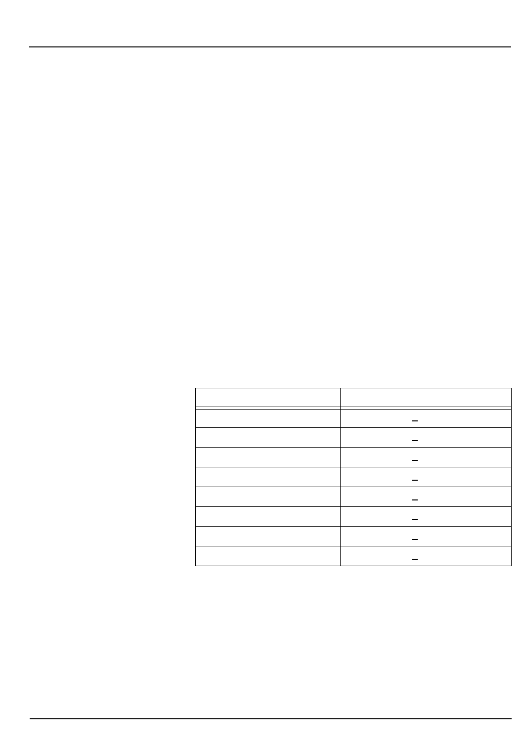
CELL-DYN®3200 Operator’s Manual 4-13
9140181B — November 1997
Performance Characteristics and Specifications
Section 4 Performance Specifications
Correlation
The CELL-DYN 3200 system can be calibrated to agree with
reference values within the allowable calibration ranges. Both
modes of operation, Open and Closed (CS and SL) may be
calibrated. Thus, it is possible to compensate for differences
between modes due to differing aspiration pathways or
operational sequences. When each mode is properly calibrated
according to the directions given in this manual, bias between
the modes is clinically insignificant.
Accuracy specifications are determined by correlation to
reference values obtained from comparison analyzers or
analysis by reference methodology. Samples that are used for
correlation studies should not display any suspect parameter
flags.
Tables 4.10 and 4.11 demonstrate the accuracy of the
hemogram parameters and WBC Differential parameters
respectively.
Hemogram Parameters
Table 4.10: Accuracy of Hemogram Parameters
* Correlation against the Technicon H.3 Systems (optical method).
Correlation against the CELL-DYN® 4000 (impedance method) was 0.90
for MCV and 0.59 for MPV.
Parameter Correlation Coefficient
WBC (WOC) > 0.99
WBC (NOC) > 0.99
RBC > 0.98
HGB > 0.98
MCV* > 0.98
RDW > 0.91
PLT > 0.98
MPV* > 0.72
Go Back
Search
TOC
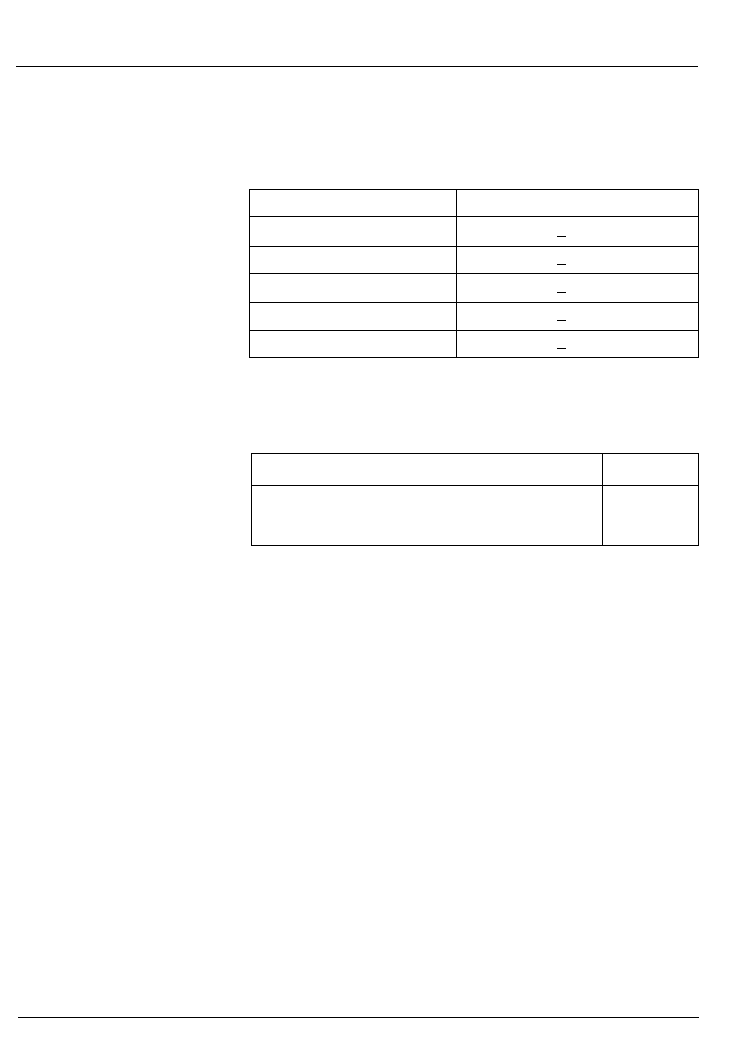
4-14 CELL-DYN® 3200 Operator’s Manual
9140181B — November 1997
Performance Characteristics and Specifications
Performance Specifications Section 4
WBC Differential Parameters
Table 4.11: Accuracy of WBC Differential Parameters
Comprehensive Flagging
Table 4.12: Flagging Analysis Using both the Distributional
and Morphological Flags
Parameter Correlation Coefficient
Neutrophil # and % > 0.95
Lymphocyte # and % > 0.94
Monocyte # and % > 0.86
Eosinophil # and % > 0.84
Basophil # and % > 0.73
Agreement True Negative and True Positive > 80%
False Positives < 20%
False Negatives < 1%
Go Back
Search
TOC

CELL-DYN®3200 Operator’s Manual 4-15
9140181B — November 1997
Performance Characteristics and Specifications
Section 4 Performance Characteristics
Performance Characteristics
Typical Precision
Within Sample
The pooled precision values (CVs) for the Hemogram
parameters, shown in Table 4.13, are based on the analysis of
data from N = 20 replicate runs based on the same sample.
NOTE: N=20 is based on one whole blood sample
aliquotted into 4 tubes, with each tube run 5 times.
The data was obtained from several CD3200 systems over a
period of weeks. These precision values represent the typical
performance from instruments that are maintained properly,
are operating in acceptable environmental conditions and are
using only recommended reagents and supplies.
Table 4.13: Typical Precision of Hemogram Parameters
Parameter CV
WBC (WOC) 1.9%
WBC (NOC) 1.9%
RBC 0.6%
HGB 0.4%
MCV 0.5%
RDW 2.3%
PLT 2.3%
MPV 1.8%
Go Back
Search
TOC
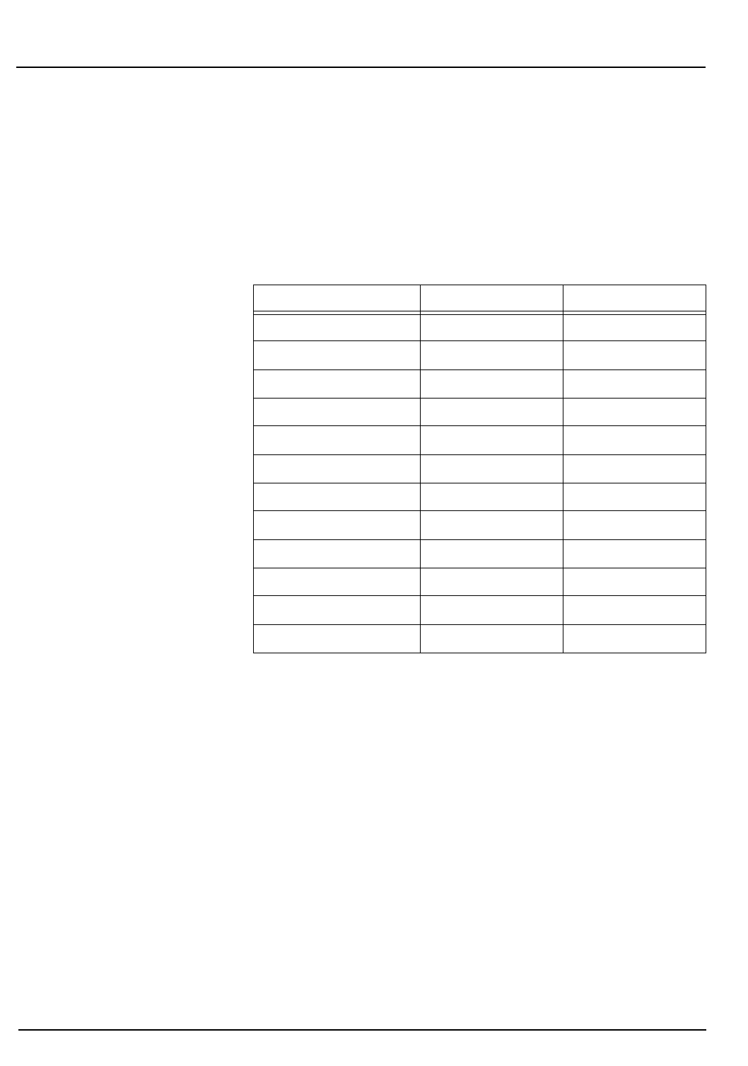
4-16 CELL-DYN® 3200 Operator’s Manual
9140181B — November 1997
Performance Characteristics and Specifications
Performance Characteristics Section 4
Typical Paired Difference Precision Normal
The typical paired difference precision of the measured
parameters is presented as the total CV calculated from
samples run in duplicate on the same system. (Refer to Table
4.14.)
Table 4.14: Typical Precision of Hemogram Parameters
Sensitivity and Specificity of WBC Differential Flags
The sensitivity and specificity of the WBC flags were evaluated
using the general principles for morphological classifications
outlined in the NCCLS H20-A Standard: "Reference Leukocyte
Differential Count (Proportional) and Evaluation of
Instrumental Methods" as a guideline. The statistics were
determined by comparing the CELL-DYN 3200 System results
with results obtained from a reference CELL-DYN 3500
System. Discrepant results were arbitrated with a manual,
microscopic, 400-cell differential count.
Parameter Number of Pairs Total CV
WBC (WOC) 10 2.01
RBC 10 0.81
HGB 10 0.72
MCV 10 0.38
RDW 10 1.76
PLT 10 3.11
MPV 10 3.68
%N 10 1.23
%L 10 2.07
%M 10 7.72
%E 10 8.06
%B 10 16.82
Go Back
Search
TOC
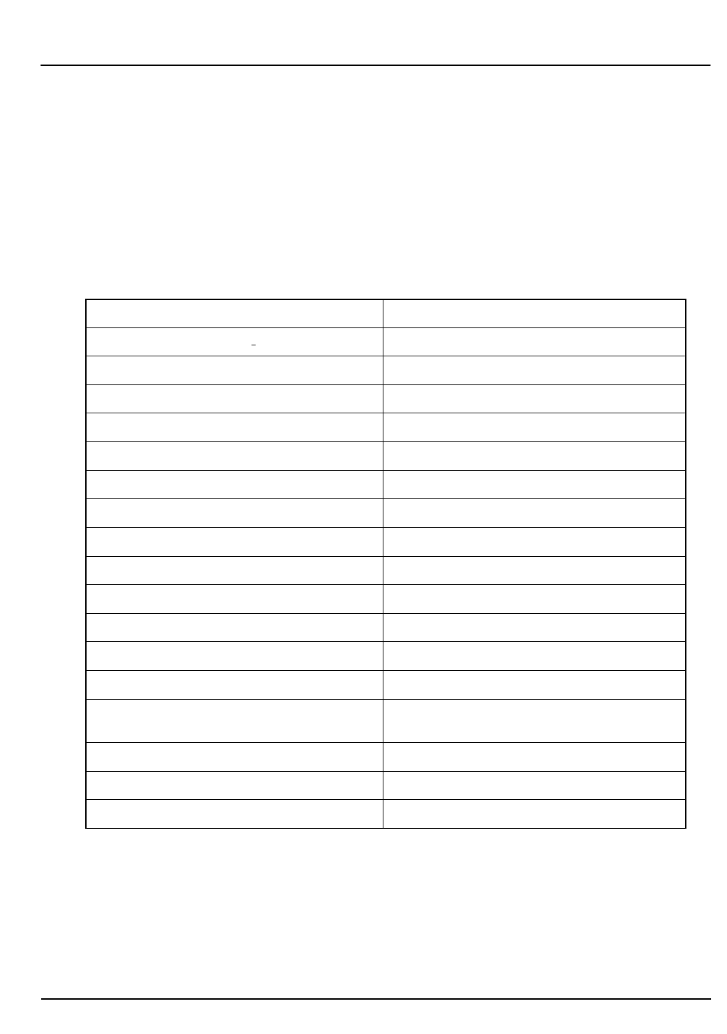
CELL-DYN®3200 Operator’s Manual 4-17
9140181B — November 1997
Performance Characteristics and Specifications
Section 4 Performance Characteristics
Abnormalities
The following tables present a list of abnormalities targeted
during this evaluation and the resultant data.
Table 4.15 lists the various types of specimens that the sites
attempted to collect during this evaluation:
Table 4.15: Abnormalities
1. RBC count <4.00 M/mL 19. Lipemic
2. RBC count >6.20 M/mL 20. Basophils >3%
3. WBC count <4.0 K/mL 21. Icteric
4. WBC count >11.0 K/mL 22. Hemoglobinopathies S and C
5. WBC count >100.0 K/mL 23. Containing macrocytic PLTs
6. PLT count <150 K/mL 24. Uremic
7. PLT count >450 K/mL 25. Paraproteinemia
8. MCV <60 fL 26. Patient's on immunosuppressant therapy
9. MCV >110 fL 27. Containing cryoglobulins
10. Containing RBCs resistant to lysis 28. Containing micro clots
11. Containing agranular neutrophils 29. Containing Cell fragments
12. Containing variant lymphocytes 30. Platelet satellitosis condition
13. Containing lymphoblasts 31. Containing cold agglutinins
14. Containing bands >5% 32. Containing dual RBC populations
15. Immature granulocytes (myelos,
metas, pros) 33. Containing Heinz and Howell-Jolly Bodies
16. Containing myeloblasts/monoblasts 34. Containing Malarial Parasites
17. Containing > 1 NRBC per 100 WBCs 35. Containing >5.0% Reticulocytes
18. Hypogranular eosinophils 36. Chronic Lymphocytic Leukemia (CLL)
Go Back
Search
TOC

4-18 CELL-DYN® 3200 Operator’s Manual
9140181B — November 1997
Performance Characteristics and Specifications
Performance Characteristics Section 4
Truth Table
The Truth Table, showing sensitivity and specificity and the
analysis of the false negative results, is presented in this
section. For the distributional analysis, absolute limits were
used. The data is based on the evaluation of a total of 853
cases.
In Table 4.16:
TP = True Positive
TN = True Negative
FP = False Positive
FN = False Negative
Table 4.16: Flagging Analysis Truth Table
Agreement = 98.0%
False Positives = 3.19%
False Negatives = 0.53%
Specificity = 96.81%
Sensitivity = 99.47%
Table 4.17 shows the manual differential and CELL-DYN 3200
differential for false negative results.
Table 4.17: Analysis of False Negative Results
CD3200
Normal
CD3200
Morphological
Positive
CD3200
Distributional
Positive Total
Reference Normal 455 TN 15 FP 0 FP 470
Reference
Morphological Positive 1 FN 167 TP 13 TP 181
Reference Distributional
Positive 1 FN 49 TP 147 TP 197
Manual Differential CD3200
Morphological False
Negative 2.5% Immature grans
and 3.5 NRBCs No flag generated
CELL-DYN 3500 CD3200
Distributional False
Negative WBC = 4.596 WBC = 4.71
Go Back
Search
TOC

CELL-DYN®3200 Operator’s Manual 4-19
9140181B — November 1997
Performance Characteristics and Specifications
Section 4 Performance Characteristics
Sample Loader Specifications
Sample Loader Physical Specifications
The Sample Loader attaches to the front of the CELL-DYN
3200SL Analyzer and is an integral part of the SL model. Table
4.18 contains the physical specifications for the Sample
Loader.
Table 4.18: Sample Loader Physical Specifications
Sample Loader (with skirt)
Height 6" (15.2 cm)
Width 32.5" (82.5 cm)
Depth 6.4" (16.2 cm)
Weight 18 lb (8.1 kg)
Go Back
Search
TOC
4-20 CELL-DYN® 3200 Operator’s Manual
9140181B — November 1997
Performance Characteristics and Specifications
Performance Characteristics Section 4
Sample Loader Operational Specifications
Operations specifications for the Sample Loader are given in
Table 4.19.
Table 4.19: Sample Loader Operational Specifications
For information on tube types and size, refer to Tube Types in
Section 13: Sample Loader, Subsection: Physical &
Performance Specifications.
For information on bar codes types and operation, refer to
Appendix A: Bar Codes.
For general information on Sample Loader operation, refer to
Section 13, Subsection: Sample Loader Description.
Feature Specification
Rack Capacity 5 racks on the load side;
5 racks on the unload side
Tube Capacity 50 (10 tubes per rack)
Sample Throughput
(1) Patient
(2) FWBC, RRBC, QC (1) xx samples/hour
(2) xx samples/hour
Run Cycle Time
(1) Patient
(2) FWBC, RRBC, QC 56 seconds
90 seconds
Number of Mixing Stations 2 - Mixing Stations #1 and #2
Degree of Mixing Rotation 0 - 135 degrees
Number of Mixing Rotations15 times at Mixing Station #1
15 times at Mixing Station #2
Maximum Tube Size 16mm (DIA) X 80mm (High)
Bar Code Reader LED type
Bar Code Labels Code 39, I2of5, Codabar, Code 128
Go Back
Search
TOC

CELL-DYN 3200 Operator’s Manual 5-1
9140181B — November 1997
Operating Instructions
Section 5 Overview
Overview
This section, which discusses the operation of the
CELL-DYN 3200, is divided into six major subsections:
Data Module Program Overview
Set Up Instructions
Specimen Collection and Handling
Routine Operation
Sample Analysis
Work List
Using the Data Log
The three major menus in the program that are used for
routine operation —
SET UP
,
RUN
, and
DATA LOG
— are discussed
in this section. The remaining parts of the program are
discussed in the following sections:
Calibration Section 6: Calibration Procedures
Special Protocols Section 9: Service and Maintenance
Troubleshooting Section 10: Troubleshooting and
Diagnostics
Quality Control Section 11: Quality Control
Go Back
Search
TOC

5-2 CELL-DYN 3200 Operator’s Manual
9140181B — November 1997
Operating Instructions
Overview Section 5
NOTES
Go Back
Search
TOC

CELL-DYN 3200 Operator’s Manual 5-3
9140181B — November 1997
Operating Instructions
Section 5 Data Module Program Overview
Data Module Program Overview
The Data Module menus are presented as key labels displayed
across the bottom of the screen. Each menu is accessed by
pressing the soft key located directly below the label. From left
to right, these soft keys correspond to keys F1–F8 on the
standard computer keyboard.
When the system is powered ON, the
MAIN MENU
screen,
depicted in Figure 5.1, is displayed. The key labels displayed
across the bottom of this screen are used to access all of the
sub-menus that are available. The main menu keys are listed
below.
MAIN MENU
keys:
SET UP
RUN
DATA LOG
QUALITY CONTROL
CALIBRATION
DIAGNOSTICS
SPECIAL PROTOCOLS
Main Menu Screen
The
MAIN MENU
screen is divided into four sections. The upper
left-hand corner shows the current version of the Data Module
software. The upper right hand corner shows the current date
and time, operator ID and the sequence number. The
information in the upper right corner is displayed on every
screen during operation.
Go Back
Search
TOC
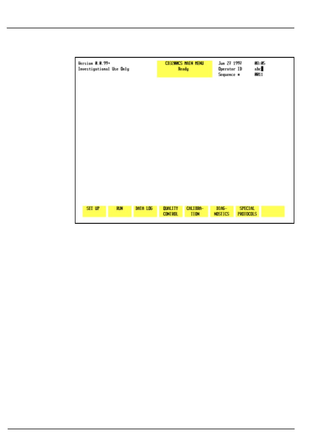
5-4 CELL-DYN 3200 Operator’s Manual
9140181B — November 1997
Operating Instructions
Data Module Program Overview Section 5
Figure 5.1: Main Menu Screen
NOTE: The cursor is positioned at the <OPERATOR ID>
field when the
MAIN MENU
screen is displayed. An
operator ID of up to three alphanumeric characters may
be entered. (An operator ID may also be entered from
the main
CALIBRATION
screen.) This operator ID will be
displayed on all screens and printed on all reports.
The Status Box is displayed in the top center of the screen. This
box appears on every screen to show the following:
Menu in use
Analyzer status
Other applicable information such as file identity,
Sample ID number, and any existing fault conditions
The
MAIN MENU
key labels are displayed across the bottom of
the screen.
Go Back
Search
TOC
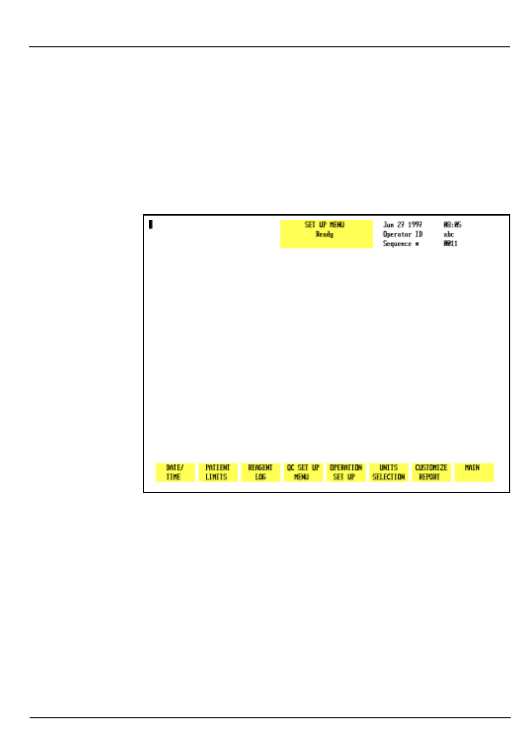
CELL-DYN 3200 Operator’s Manual 5-5
9140181B — November 1997
Operating Instructions
Section 5 Set Up Instructions
Set Up Instructions
This section discusses the options available when the
[SET UP]
key is pressed. (See Figure 5.2.) These options are used to
configure the system according to the laboratory’s
requirements. The function of each key is discussed and set up
procedures are given where applicable.
Figure 5.2: Set Up Menu Screen
Set Up Menu
When the
[SET UP]
key is pressed, the following soft key labels
are displayed:
DATE/TIME
PATIENT LIMITS
REAGENT LOG
QC SET UP MENU
OPERATION SET UP
UNITS SELECTION
CUSTOMIZE REPORT
MAIN
Go Back
Search
TOC
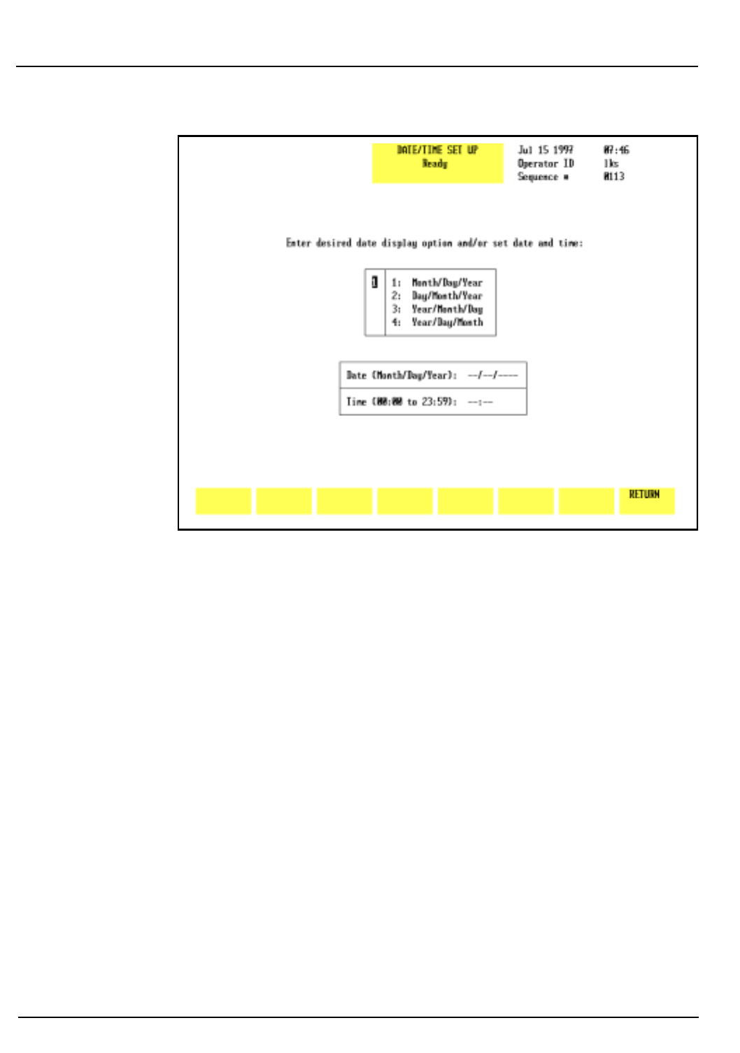
5-6 CELL-DYN 3200 Operator’s Manual
9140181B — November 1997
Operating Instructions
Set Up Instructions Section 5
Figure 5.3: Date/Time Set Up Screen
Date/Time
The
[DATE/TIME]
key is used to enter the date and time. This
screen allows the operator to select the format for displaying
the date and to change the date and time as required. Four
different date formats are available. The numbers on the
DATE/TIME SET UP
screen shown in Figure 5.3 correspond to the
following numbered options:
1. Display Format selection box:
1. Month/Day/Year
2. Day/Month/Year
3. Year/Month/Day
4. Year/Day/Month
2. DATE entry field
3. TIME entry field
Go Back
Search
TOC

CELL-DYN 3200 Operator’s Manual 5-7
9140181B — November 1997
Operating Instructions
Section 5 Set Up Instructions
The desired format is selected by typing the corresponding
number in the entry field displayed to the left of the list (1).
When the Enter key on the keyboard is pressed, the selected
format is displayed in the DATE entry field (2, below the
format selection box) and the cursor moves to the entry
position. After the date has been entered, the cursor moves to
the TIME entry field (3).
To Set Date/Time
1. From the
SET UP MENU
screen, press
[DATE/TIME]
to display
the
DATE/TIME SET UP
screen.
2. Type the number of the desired format at the cursor.
3. Press the Enter key on the keyboard to save the entry and
advance to the DATE entry field.
4. Type the date in the selected format using one or two
digits. Separate the day, month and year (year must be 4
digits) with a slash (/) or a period (.). The entry order of
the date should conform to the date format just selected.
5. Press the Enter key on the keyboard to save the entry and
advance to the TIME entry field.
6. Type the time in the 24-hour (military) time format using
one or two digits. (For example, 00 for 12 midnight, 06
for 6 am, and 13 for 1 pm.) Separate the hours and
minutes with a colon (:) or a period (.).
7. Press the Enter key on the keyboard to save the entry.
8. Press
[RETURN]
to return to the
SET UP MENU
screen.
Go Back
Search
TOC
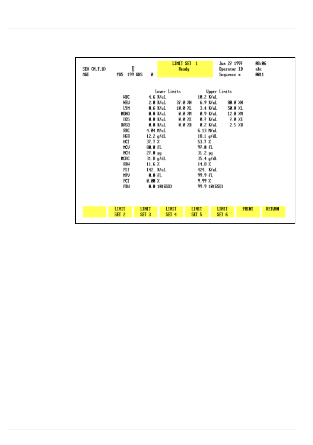
5-8 CELL-DYN 3200 Operator’s Manual
9140181B — November 1997
Operating Instructions
Set Up Instructions Section 5
Figure 5.4: Patient Limits Screen
Patient Limits
The
[PATIENT LIMITS]
key is used to enter upper and lower
flagging limits for groups of patient samples. (For example,
limits may be entered for adult males, adult females, neonates,
etc.) The following soft key labels are displayed (See Figure
5.4.) when the
[PATIENT LIMITS]
key is pressed:
LIMIT SET 1
LIMIT SET 2
LIMIT SET 3
LIMIT SET 4
LIMIT SET 5
LIMIT SET 6
PRINT
RETURN
NOTE: The key label for the limit set displayed on the
screen is not shown.
Go Back
Search
TOC

CELL-DYN 3200 Operator’s Manual 5-9
9140181B — November 1997
Operating Instructions
Section 5 Set Up Instructions
Six different sets of limits may be entered. Whenever a
parameter result exceeds an entered limit, the result is
displayed in color on the screen to alert the operator. Results
displayed in yellow are below the limit and results displayed in
purple are above the limit. The flagged result is underlined on
the graphics report and the blank ticket report. The flagged
result is marked with an asterisk (*) on the pre-printed ticket
report.
LIMIT SET 1 contains upper and lower limits pre-set at the
factory. The operator shall be able to change these limits. Once
these limits are changed, the operator can return to the
factory-set limits by either manually inputting the factory-set
limits or by re-installing the Set Up Disk.
LIMIT SETS 2 through 6 contain zeros for the lower limits and
9s for the upper limits when the instrument is first installed.
In addition to entering limit set data, the operator can also
pre-assign limit sets to patients based on patient sex and age.
Automatic Patient Limit Set Assignment
Sex and Age fields for each Patient Limit Set are shown in the
upper left corner of the
LIMIT SET
screen.
Limit Set 1 is the default Limit Set. It is assigned to any Patient
without both an age and a sex designation or whose age and
sex (if input) cannot be assigned by the system to a specific
Limit Set. The operator cannot change the displayed data in
the Sex and Age fields of Limit Set 1.
For Limit Sets 2 through 6, the operator can pre-assign a Limit
Set based on age and sex. The options for Sex are:
M for Male
F for Female
U for Undefined (either the patient’s sex is unknown or the
Limit Set is intended to cover both male and
female)
Go Back
Search
TOC

5-10 CELL-DYN 3200 Operator’s Manual
9140181B — November 1997
Operating Instructions
Set Up Instructions Section 5
Patient age is entered in Weeks and/or Years. The range for
Weeks is zero to 51. The range for Years is 1 to 199. Any
number input shall be interpreted by the system as “equal to
or less than.” Age ranges are automatically established by
using successively higher numbers. For example, if the number
1 is entered in the Years field for Limit Set 2 and the number 5
is entered in the Years field for Limit Set 3, then any patient
whose age is 1 year or less will automatically be assigned Limit
Set 2 and any patient whose age is greater than 1 year but
equal to or less than 5 years will automatically be assigned
Limit Set 3.
The appropriate Limit Set is automatically assigned when a
patient’s sex and date of birth are entered on the RUN screen
or Work List.
To Set Patient Limits
1. Press
[PATIENT LIMITS]
to display the
PATIENT LIMITS
screen.
A Patient Limit Set is displayed on the screen. When a
Limit Set is displayed on the screen, the set number (Limit
Set 1, Limit Set 2, etc.) is displayed in the status box and
the soft key corresponding to that number is blanked out.
The other limit sets may be selected by pressing the
appropriate soft key.
2. Select a Limit Set by pressing the appropriate
[LIMIT SET]
soft key.
3. To pre-assign a Limit Set based on a patient’s sex and age,
enter one of the three Sex codes and press the Enter key.
The cursor moves to the Years field. Enter a number for
years and press Enter or use the arrow keys to move the
cursor to the Weeks field. Enter a number for Weeks and
press Enter or use the arrow keys to move the cursor to
the desired limit entry field.
NOTE: Limit Set 1 is the default Limit Set and cannot
be altered.
4. With the cursor in the first entry field to be changed, type
the desired number.
5. Press the Enter key on the keyboard to save the entry and
automatically advance the cursor to the next entry
position.
6. Repeat steps 4 and 5 until all desired entries have been
made.
Go Back
Search
TOC
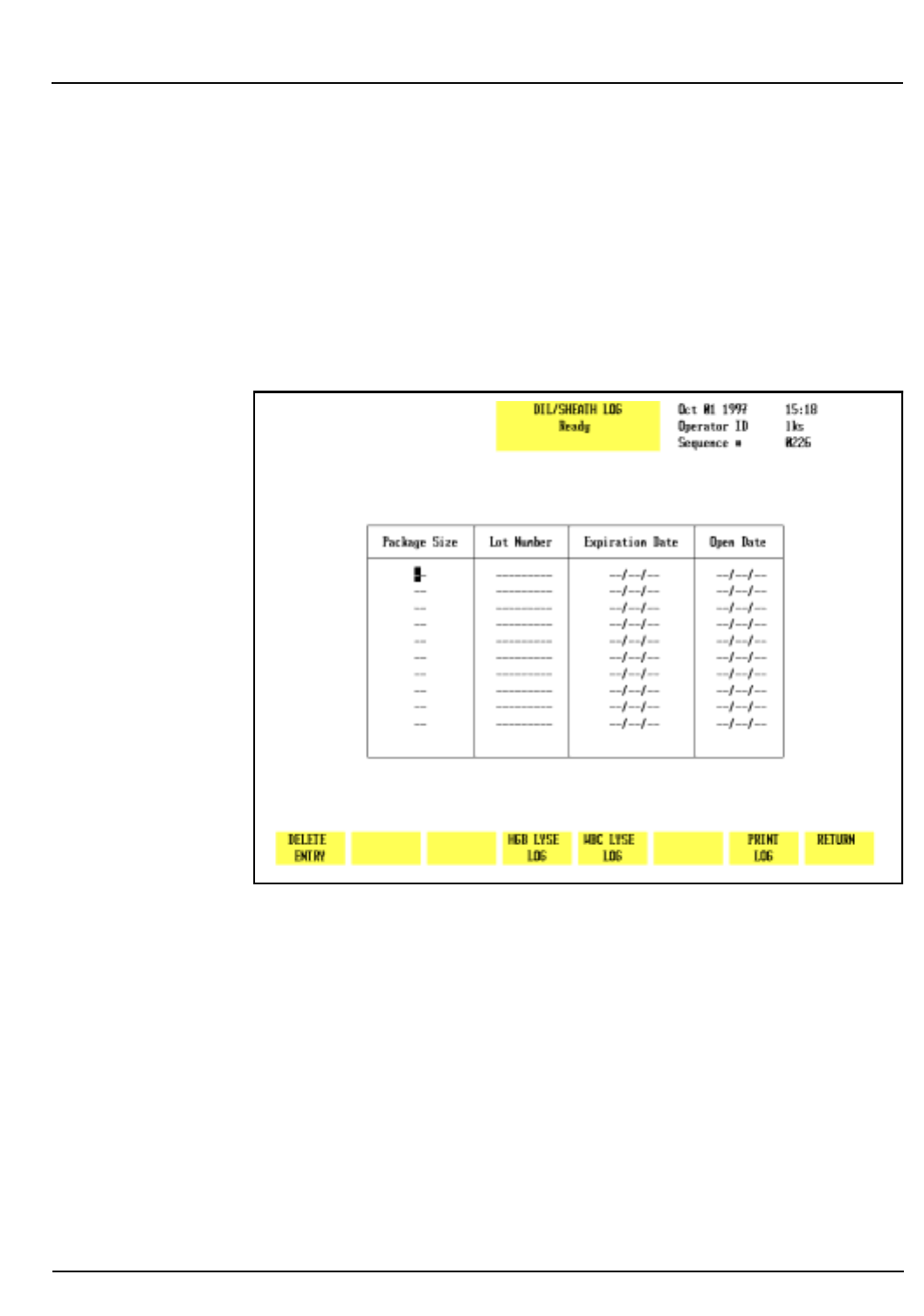
CELL-DYN 3200 Operator’s Manual 5-11
9140181B — November 1997
Operating Instructions
Section 5 Set Up Instructions
7. If desired, press
[PRINT]
to obtain a printout of the Limit
Set.
NOTE: Retaining a hard copy of each Limit Set is
recommended, as the screens do not display names or
categories for the limit sets.
8. Press the appropriate soft key to select another Limit Set
and repeat steps 3–7 to pre-assign a Limit Set and to enter
the desired limits.
9. Press
[RETURN]
to return to the
SET UP MENU
screen.
Figure 5.5: Diluent/Sheath Log Screen
Reagent Log
The
[REAGENT LOG]
key is used to enter current reagent
information into the three reagent logs. The following soft key
labels are displayed when the
[REAGENT LOG]
key is pressed:
DELETE ENTRY
DIL/SHEATH LOG
HGB LYSE LOG
WBC LYSE LOG
PRINT LOG
RETURN
Go Back
Search
TOC

5-12 CELL-DYN 3200 Operator’s Manual
9140181B — November 1997
Operating Instructions
Set Up Instructions Section 5
NOTE: The key label for the reagent log displayed in
the Status Box is not displayed with the other keys.
When the
[REAGENT LOG]
key is pressed, one of the logs is
displayed as shown in Figure 5.5. (The name of the displayed
log is indicated in the Status Box.) The other two logs may be
displayed by pressing the appropriate soft key. Each log holds
10 entries. The following information may be entered for each
reagent:
Package Size Lot Number
Expiration Date Open Date
To Complete Reagent Log Entry
1. Press
[REAGENT LOG]
to display a
REAGENT LOG
screen.
2. If the desired reagent log is not already displayed, use the
soft key to select the appropriate log.
3. Use the arrow keys on the keyboard to move the cursor to
the desired entry field.
4. Type the appropriate information.
NOTE: Entries for each field of information are
optional. Dates should be entered with a slash (/) or a
period (.) separating the month, day and year.
5. Press the Enter key on the keyboard to save the entry and
advance the cursor.
6. Repeat steps 3–5 until all desired entries have been made.
7. If desired, press
[PRINT LOG]
to obtain a printout of the log.
8. Press the appropriate soft key to select another reagent
log and repeat steps 2–7 to enter and print data.
To Delete Entries
When the log is full (the log holds 10 entries), the oldest entry
must be deleted to create space for a new entry. Abbott
suggests that the log be printed when it is full for
documentation purposes.
1. Press
[REAGENT LOG]
to display a
REAGENT LOG
screen. If
necessary, press a soft key to display the appropriate log.
2. Move the cursor to the oldest entry in the log.
3. Press
[DELETE ENTRY]
. The
[COMPLETE DELETION]
and
[RESTORE ENTRY]
keys are displayed.
Go Back
Search
TOC
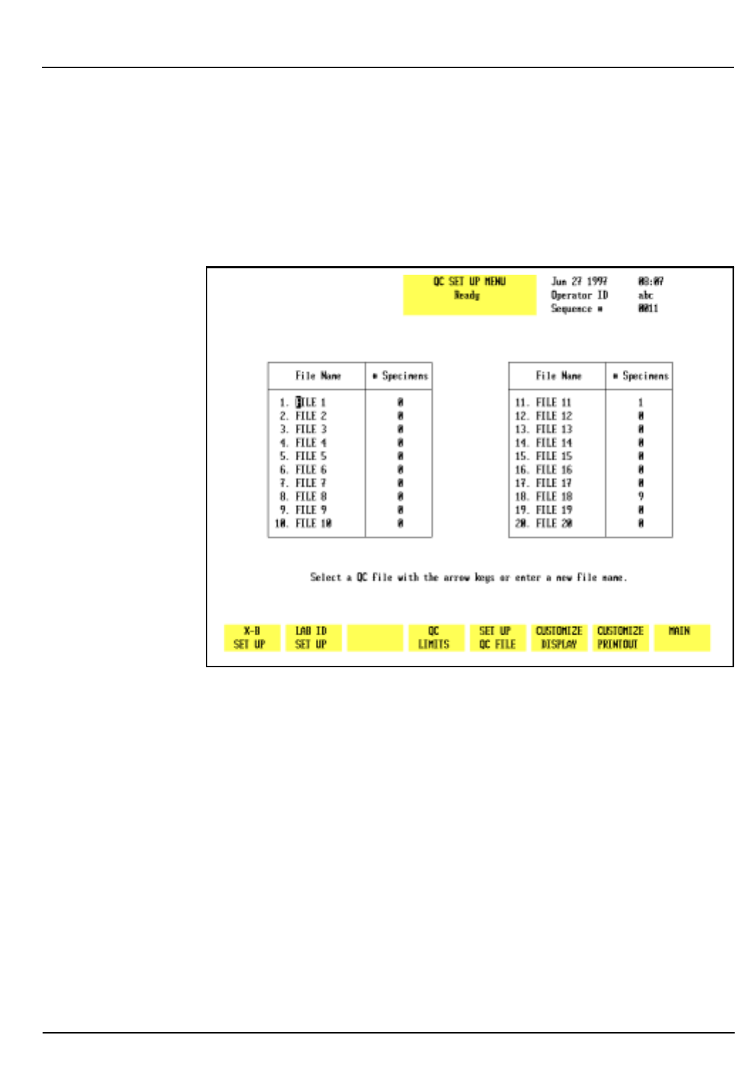
CELL-DYN 3200 Operator’s Manual 5-13
9140181B — November 1997
Operating Instructions
Section 5 Set Up Instructions
4. Press
[COMPLETE DELETION]
to delete the selected entry.
5. If desired, a new entry may then be made as described
above.
NOTE: New entries may also be made by typing over
old entries without deleting them.
6. Press
[RETURN]
to return to the main
SET UP MENU
screen.
Figure 5.6: QC Set Up Menu Screen
QC Set Up Menu
The
[QC SET UP MENU]
key is used to display a list of the QC files
(see Figure 5.6) and the following soft key labels:
X-B SET UP
LAB ID SET UP
NOTE: The
LAB ID SET UP
key is currently disabled.
QC LIMITS
SET UP QC FILE
CUSTOMIZE DISPLAY
CUSTOMIZE PRINTOUT
MAIN
Go Back
Search
TOC
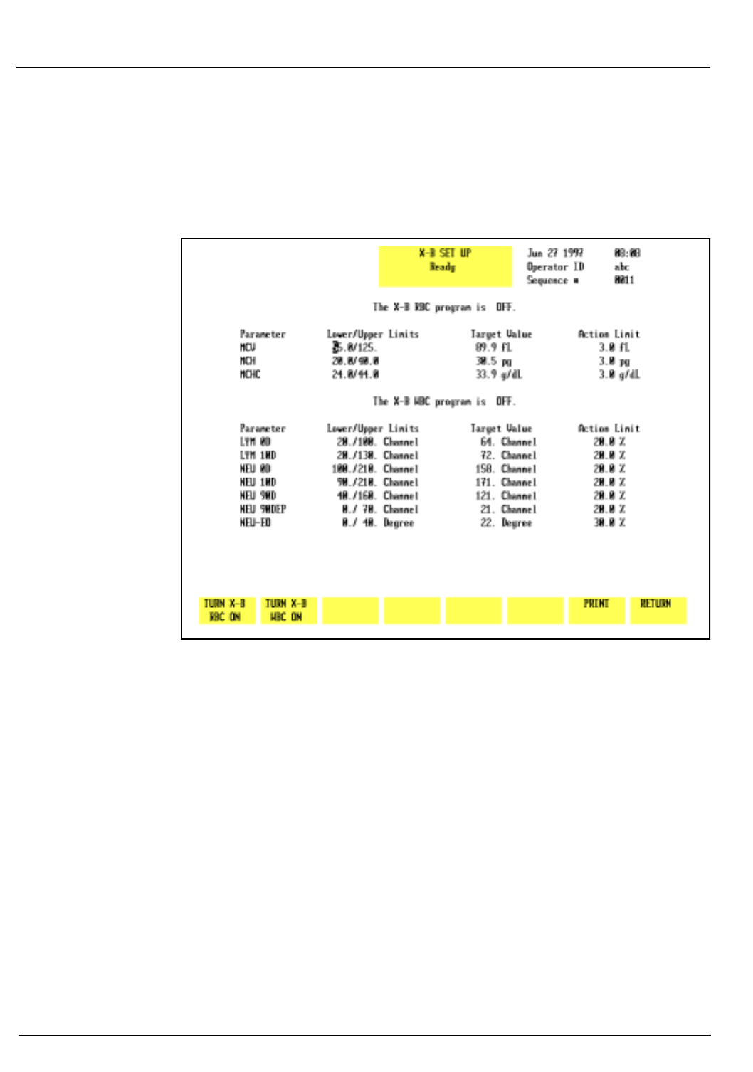
5-14 CELL-DYN 3200 Operator’s Manual
9140181B — November 1997
Operating Instructions
Set Up Instructions Section 5
This section discusses the procedures that are used to set up
the QC files. Typically, a QC file(s) is set up, then QC Limits
are established. Therefore, the keys in the
QC SET UP
menu will
be discussed in this order.
Figure 5.7: X-B Set Up Screen
X-B Setup Menu
The
[X-B SET UP]
key is used to select the
X-B SET UP
screen. (See
Figure 5.7.) This screen is used to enter upper and lower
acceptance limits, target values, and action limits for the X-B
Moving Average QC Program for both the WBC and RBC
parameters. The following soft key labels are displayed when
the
[X-B SET UP]
key is pressed:
TURN X-B RBC ON/
(The key alternates between the
TURN X-B RBC OFF
selections.)
TURN X-B WBC ON/
(The key alternates between the
TURN X-B WBC OFF
selections.)
PRINT
RETURN
Go Back
Search
TOC

CELL-DYN 3200 Operator’s Manual 5-15
9140181B — November 1997
Operating Instructions
Section 5 Set Up Instructions
The following options are available on the
X-B SET UP
screen
shown in Figure 5.7:
1.LOWER/UPPER LIMITS
The Lower and Upper Limits determine which patient
results will be used in the X-B Moving Average
calculation. Results that fall outside these limits are
automatically excluded from the X-B calculations. These
limits should be set widely to exclude grossly abnormal
samples (such as background counts) that would bias the
calculation but should include at least 95% of the patient
results.
2.TARGET VALUE
The Target Value for X-B Analysis is similar to the assay
value for a commercial control. It is derived from the
patient population that is analyzed on the instrument.
3.ACTION LIMIT
The Action Limit is the acceptable limit of variation
around the target value.
NOTE: The X-B Program is discussed in detail in
Section 11: Quality Control.
To Set Up X-B
1. Press
[X-B SET UP]
to display the
X-B SET UP
screen.
2.Use the Arrow keys on the keyboard to move the cursor to
the desired entry field.
3.Type the numbers and press the Enter key on the
keyboard to save the entry and advance the cursor to the
next entry field.
4.Repeat steps 2 and 3 until all entries have been made.
5.If desired, press
[PRINT]
to obtain a printout of the entered
values.
6.If the soft key
[TURN X-B RBC ON]
or
[TURN X-B WBC ON]
is
displayed, press the appropriate key to enable the X-B
program.
NOTE: For example, when the X-B RBC program is
enabled the screen displays the message THE X-B RBC
PROGRAM IS ON and the
[TURN X-B RBC OFF]
key is
displayed.
7. Press
[RETURN]
to return to the
QC SET UP MENU
screen.
Go Back
Search
TOC

5-16 CELL-DYN 3200 Operator’s Manual
9140181B — November 1997
Operating Instructions
Set Up Instructions Section 5
Lab ID Set Up
The
[LAB ID SET UP]
key should not be used at this time.
QC Limits Menu
The
[QC LIMITS]
key is used to display the
QC MEANS/LIMITS ENTRY
screen and the following soft key labels:
RANGE ENTRY
and
MEANS/LIMITS
(The key alternates between the
selections.)
UPDATE FROM FILE
(This key is displayed only when
there are two or more results in the
selected file.)
LOAD FROM DISK
(This key is not available at this
time.)
NOTE: The feature enabling entry of QC limits into a
QC file from a floppy disk is not available at this time.
The feature enabling the download of data from a QC
file to a floppy disk is not available at this time.
PRINT
RETURN
QC Limits Entry
QC Limits are entered by pressing the
[QC LIMITS]
key. This key
is available on the
QC SET UP MENU
screen and the
QC MENU
screen. Two types of QC limits are available:
Means and Limits —used to enter the mean value and a ±
range value that defines the upper and
lower flagging limits (see Figure 5.8)
Range Entry — used to enter the upper and lower
flagging limits as absolute numbers (see
Figure 5.9)
If Range Entry is selected by pressing the
[RANGE ENTRY]
key,
the current upper and lower limits for the selected file are
displayed as described above. If Means/Limits entry is selected
by pressing the
[MEANS/LIMITS]
key, the current means and
limits for the selected file are displayed as described above.
Go Back
Search
TOC
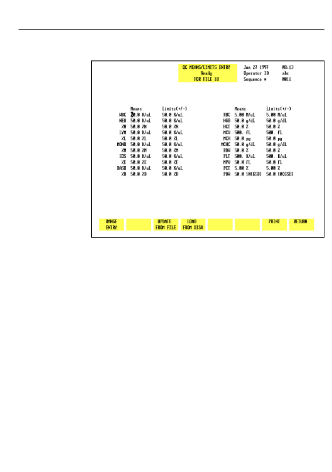
CELL-DYN 3200 Operator’s Manual 5-17
9140181B — November 1997
Operating Instructions
Section 5 Set Up Instructions
Figure 5.8: QC Means/Limits Entry Screen
Means/Limits Entry
1. Select a file from the
QC SET UP MENU
screen by using the
Arrow keys on the keyboard to move the cursor into the
desired file.
2. Press
[QC LIMITS]
followed by
[MEANS/LIMITS]
to display the
QC MEANS/LIMITS ENTRY
screen for the selected file
[MEANS/
LIMITS]
and [ RANGE ENTRY ] .
3. Use the Arrow keys on the keyboard to move the cursor to
the desired entry field.
4. Type the numbers and press the Enter key on the
keyboard to save each entry and advance the cursor to the
next entry field.
5. Repeat step 4 until all entries have been made.
6. If desired, press
[PRINT]
to obtain a printout of the entered
values.
7. Press
[RETURN]
to save the entries and return to the
QC SET
UP
screen.
Go Back
Search
TOC
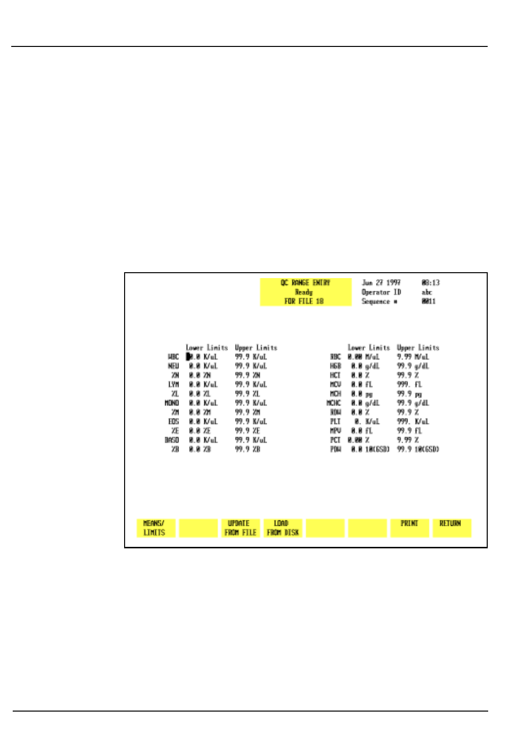
5-18 CELL-DYN 3200 Operator’s Manual
9140181B — November 1997
Operating Instructions
Set Up Instructions Section 5
NOTE: When the entries are saved by pressing the
[RETURN]
soft key, the software checks to see if any
entries would result in a negative number for the lower
limit (e.g., mean = 1.0, limit = 2.0). If a negative
number is found, the values are automatically edited to
adjust the lower limit to zero. The bulletin line displays
the message:
LIMITS WERE CHANGED TO CORRECT OUT-OF-RANGE
VALUES.
In the above example, the mean would be adjusted to
1.5 and the limit would be adjusted to 1.5.
Figure 5.9: QC Range Entry Screen
Range Entry
1. Select a file from the
QC SET UP
screen by using the Arrow
keys on the keyboard to move the cursor into the desired
file.
2. Press
[QC LIMITS]
to display the
QC RANGE ENTRY
screen for
the selected file.
3. Use the Arrow keys on the keyboard to move the cursor to
the desired entry field.
Go Back
Search
TOC
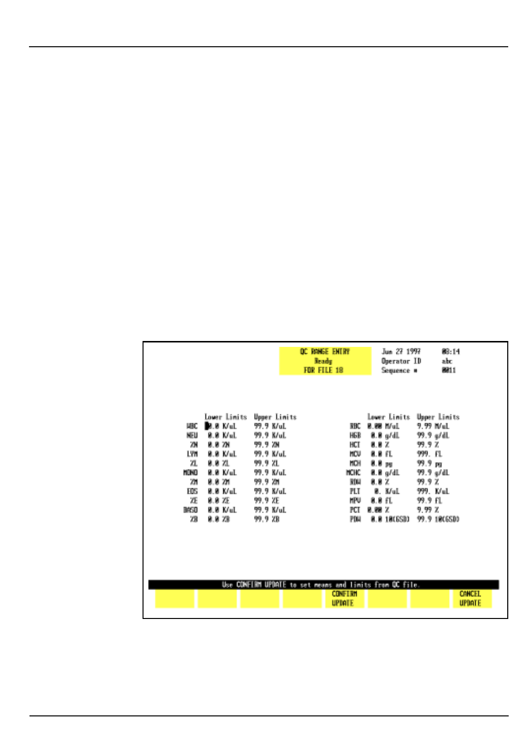
CELL-DYN 3200 Operator’s Manual 5-19
9140181B — November 1997
Operating Instructions
Section 5 Set Up Instructions
4. Type the numbers and press the Enter key on the
keyboard to save each entry and advance the cursor to the
next entry field.
5. Repeat step 4 until all entries have been made.
6. If desired, press
[PRINT]
to obtain a printout of the entered
values.
7. Press
[RETURN]
to save the entries and return to the
QC SET
UP
screen.
NOTE: When the entries are saved by pressing the
[RETURN]
soft key, the software checks to see if any
entries would result in the upper limit being less than
the lower limit. If this situation occurs, the limits are
automatically reversed. The bulletin line displays the
message:
LIMITS WERE EXCHANGED TO MAKE UPPER > LOWER
Figure 5.10: Update From File Key
Go Back
Search
TOC

5-20 CELL-DYN 3200 Operator’s Manual
9140181B — November 1997
Operating Instructions
Set Up Instructions Section 5
Update From File
The
[UPDATE FROM FILE]
key is displayed on the
QC MEANS/LIMITS
ENTRY
and
QC RANGE ENTRY
screens when there are two or more
results in the file. (See Figure 5.10.) When the
[UPDATE FROM
FILE]
key is pressed, the bulletin line displays the message USE
CONFIRM UPDATE TO SET MEANS AND LIMITS FROM QC
FILE and the following soft key labels are displayed:
CONFIRM UPDATE
CANCEL UPDATE
These keys are used to
[CONFIRM]
or
[CANCEL]
the Update From
File command.
When the
[CONFIRM UPDATE]
key is pressed, the mean value for
each parameter is computed from the values in the file. The
parameter limits are set as follows:
WBC, PLT, RDW and MPV: ± 10% of the computed
mean
NEU, LYM and MONO: ± 40% of the computed
mean
Remaining Parameters: ± 5% of the computed
mean
Load From Disk
The [LOAD FROM DISK] key should not be used at this time.
Set Up QC File
The [SET UP QC FILE] key is used to configure the QC file. If
the file is used for a commercial control, the lot number and
expiration date may be entered by pressing the [LOT NUMBER]
key. If the file is used for a patient control, the ID number of
the control may be entered by pressing the [REPLICATE ID]
key.
NOTE: The system defaults to the LOT NUMBER screen
upon initial set up. Otherwise, the screen last selected
will be displayed.
The QC SET UP screen is also used to select the Westgard Rules
that will be applied to the QC data stored in the file. The
following soft key labels are displayed when the [SET UP QC
FILE] key is pressed:
REPLICATE ID/LOT NUMBER (The key alternates between
the selections.)
Go Back
Search
TOC

CELL-DYN 3200 Operator’s Manual 5-21
9140181B — November 1997
Operating Instructions
Section 5 Set Up Instructions
TOGGLE ON/OFF (This key is only present
when the cursor is in one of
the Westgard Rule
Selection fields.)
PRINT
RETURN
The Lot Number Entry and Replicate ID Entry screens are
shown in Figures 5.11 and 5.12. The options available are as
follows:
1. <LOT NUMBER> and <EXPIRATION DATE> entry fields
These entry fields are displayed when the [LOT NUMBER]
key is pressed. This designation is intended for QC Files
that are used for commercial controls.
2. <REPLICATE ID> entry field
This entry field is displayed when the [REPLICATE ID] key
is pressed. This designation is intended for QC Files that
are used for patient controls.
3.WESTGARD RULE SELECTION
RULE 1: VALUE OUTSIDE 3 SD
RULE 2: TWO CONSECUTIVE VALUES OUTSIDE SAME
2 SD
RULE 3: TWO CONSECUTIVE VALUES OUTSIDE
OPPOSITE 2 SD
RULE 4: TWO OF THREE CONSECUTIVE VALUES
OUTSIDE SAME 2 SD
RULE 5: FOUR CONSECUTIVE VALUES OUTSIDE SAME
1 SD
RULE 6: TEN CONSECUTIVE VALUES ON SAME SIDE
OF MEAN
NOTE: Westgard rules are discussed in detail in Section
11: Quality Control.
The Westgard Rule selections are available on either of the QC
FILE SET UP screens.
QC File Set Up
1. Press [QC SET UP MENU] to display the QC SET UP MENU
screen.
2.Use the Arrow keys on the keyboard to move the cursor to
the desired QC file.
Go Back
Search
TOC
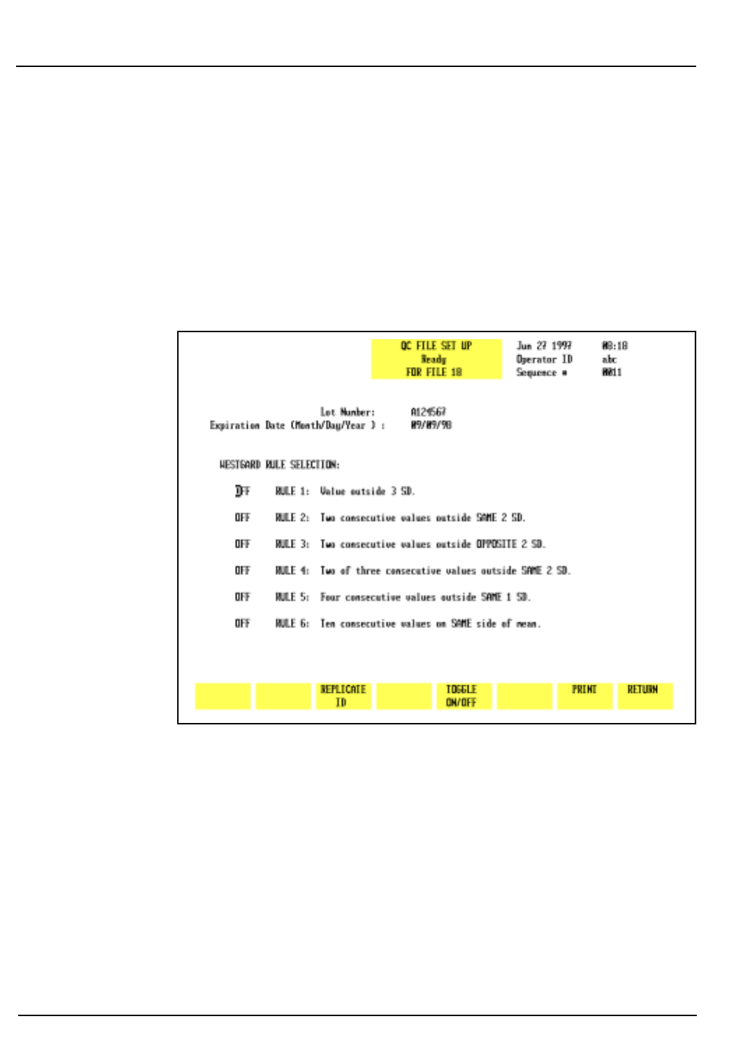
5-22 CELL-DYN 3200 Operator’s Manual
9140181B — November 1997
Operating Instructions
Set Up Instructions Section 5
3. Type the desired alphanumeric file name. (Up to 12
characters may be entered.)
4. Press the Enter key on the keyboard to save the entry and
advance the cursor to the next QC file.
5. Use the Arrow keys on the keyboard to move the cursor
back into the selected file.
6. Press [SET UP QC FILE] to display the QC FILE SET UP
screen.
Figure 5.11: Lot Number Entry Screen
To Enter Lot Number Data
1. If necessary, from the QC FILE SET UP screen, press [LOT
NUMBER] to display the <LOT NUMBER> and
<EXPIRATION DATE> entry fields.
2. The cursor is in the <LOT NUMBER> entry field. Type the
lot number and press the Enter key on the keyboard to
save the entry and advance the cursor to the
<EXPIRATION DATE> entry field.
Go Back
Search
TOC
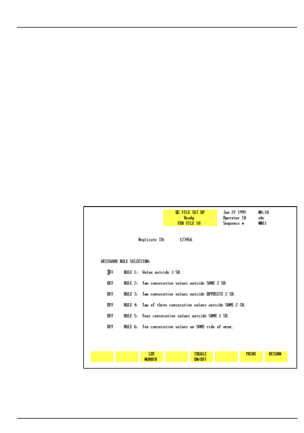
CELL-DYN 3200 Operator’s Manual 5-23
9140181B — November 1997
Operating Instructions
Section 5 Set Up Instructions
3. Type the expiration date in the format indicated using
one or two digits. This is the same format selected on the
DATE/TIME SET UP screen. Separate the digits with a slash
(/) or a period (.).
4. Press the Enter key on the keyboard to save the entry and
advance the cursor to the <WESTGARD RULE
SELECTION> entry fields.
5. Use the arrow keys on the keyboard to position the cursor
at the desired Westgard Rule.
6. Press [TOGGLE ON/OFF] to enable the rule and advance
the cursor.
7. Repeat steps 5 and 6 until all desired rule selections have
been made.
8. If desired, press [PRINT] to obtain a printout of the
entries.
9. Press [RETURN] to return to the QC FILE SET UP screen.
Figure 5.12: Replicate ID Entry Screen
Go Back
Search
TOC

5-24 CELL-DYN 3200 Operator’s Manual
9140181B — November 1997
Operating Instructions
Set Up Instructions Section 5
To Enter Replicate ID Data
1. If necessary, from the QC FILE SET UP screen, press
[REPLICATE ID] to display the <REPLICATE ID> entry
field.
2. The cursor is in the <REPLICATE ID> entry field. Type the
sample ID number (up to 12 alphanumeric characters
may be entered) and press the Enter key on the keyboard
to save the entry and advance the cursor to the
<WESTGARD RULE SELECTION> entry fields.
3. Select the Westgard Rules as directed in the To Enter Lot
Number Data procedure.
Customize Display
The [CUSTOMIZE DISPLAY] key in the QC SET UP MENU is
used to customize the display of information in the QC logs.
Figure 5.13 shows the CUSTOMIZE QC DISPLAY screen with
the standard groups displayed. Figure 5.14 shows the
CUSTOMIZE QC DISPLAY screen where the WBC and RBC
groups have been customized.
The CUSTOMIZE QC DISPLAY screen and the following key
labels are displayed when the [CUSTOMIZE DISPLAY] key is
pressed:
SELECT PARAMETER
STANDARD GROUPS
RETURN
The screen displays a matrix of 4 rows of parameters that are
currently selected in Groups 1 through 4. A list of all available
parameters is displayed under the matrix. The standard
groups, which include predetermined parameter sets, are
identified as follows:
Group 1 WBC parameters
Group 2 RBC parameters
Group 3 PLT parameters
Group 4 WBC Diff parameters
On the CUSTOMIZE QC DISPLAY screen, Parameter Group 1 is
displayed (in the order indicated from left to right) on the first
VIEW QC LOG screen. The remaining groups are displayed on
subsequent screens that are accessed by pressing the Right
Arrow key on the keyboard. The Left Arrow key is used to page
back through the screens to the first screen.
Go Back
Search
TOC
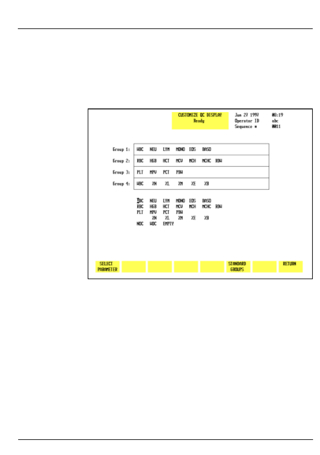
CELL-DYN 3200 Operator’s Manual 5-25
9140181B — November 1997
Operating Instructions
Section 5 Set Up Instructions
The [STANDARD GROUPS] key is used to select a
predetermined group of parameters that will be placed on a
designated page. The display may be customized by selecting
the individual parameters, standard groups of parameters, or a
combination of the two.
Figure 5.13: Customize QC Display Screen
Go Back
Search
TOC
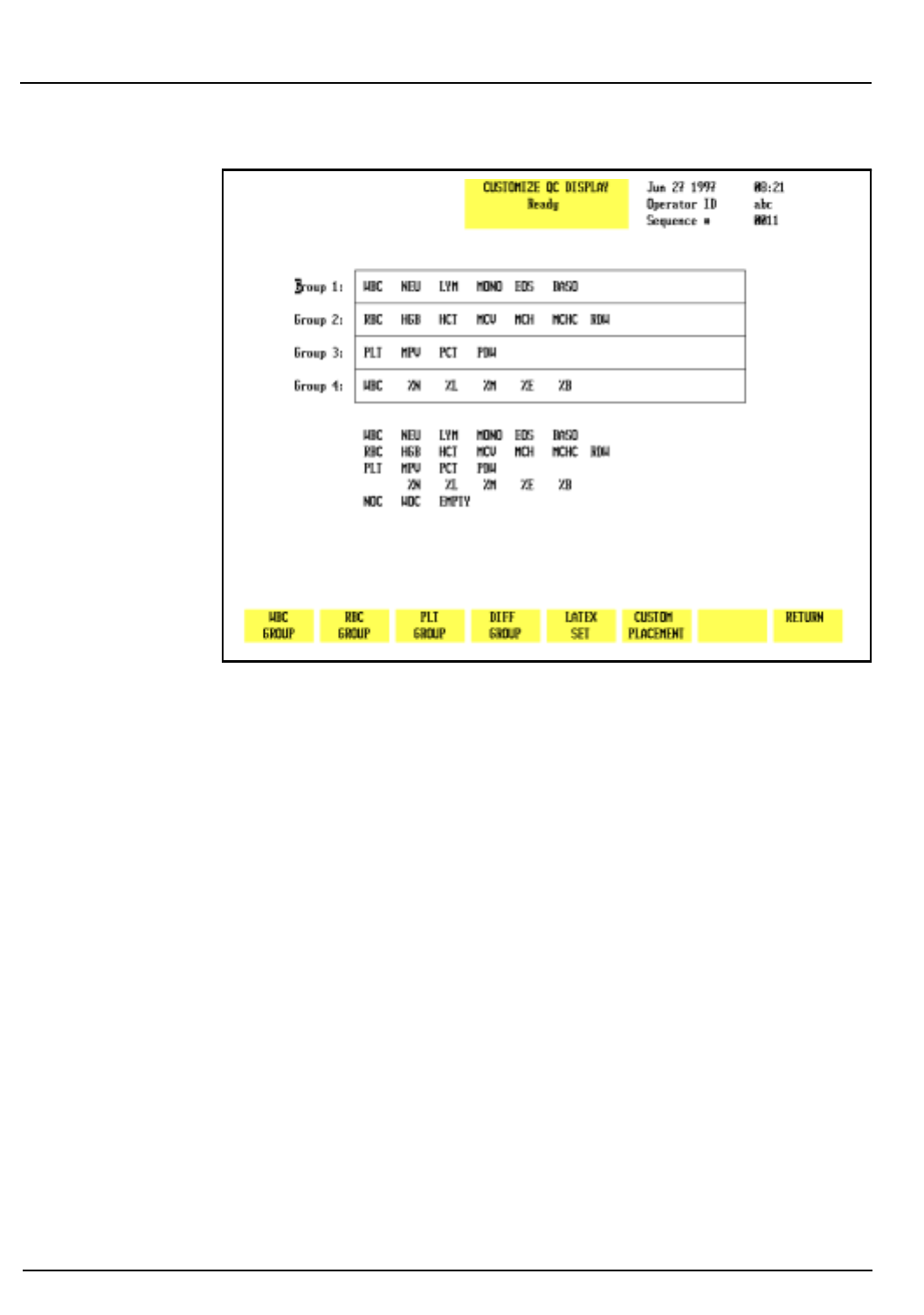
5-26 CELL-DYN 3200 Operator’s Manual
9140181B — November 1997
Operating Instructions
Set Up Instructions Section 5
Figure 5.14: Customize QC Display Screen Showing Standard
Groups
To Customize QC Log Display
1. Select a file from the QC SET UP MENU screen by moving
the cursor to the desired file.
2. Press [CUSTOMIZE DISPLAY] to display the CUSTOMIZE
QC DISPLAY screen for the selected file.
3. If necessary, press [CUSTOM PLACEMENT] to display the
CUSTOMIZE QC DISPLAY screen and the [SELECT
PARAMETER] key.
4. Use the Arrow keys on the keyboard to move the cursor to
the desired parameter in the listing under the matrix.
5. Press [SELECT PARAMETER]. The selected parameter is
highlighted and the cursor moves to the first position in
Group 1.
NOTE: The key label changes to [PLACE PARAMETER]
and a [CANCEL SELECTION] key is displayed.
6. If necessary, use the Arrow keys on the keyboard to move
the cursor to the desired location and press [PLACE
PARAMETER].
Go Back
Search
TOC

CELL-DYN 3200 Operator’s Manual 5-27
9140181B — November 1997
Operating Instructions
Section 5 Set Up Instructions
NOTE: When the [PLACE PARAMETER] key is pressed,
the selected parameter is displayed in the position
indicated by the cursor and the cursor is then advanced
to the next parameter in the listing under the matrix.
7. Repeat steps 4–6 until all selections have been made.
8. If desired, press the Print screen key on the keyboard to
obtain a printout of the selected groups.
9. Press [RETURN] to return to the QC SET UP MENU screen.
10. Repeat this procedure to customize the display for other
QC logs.
Standard Groups
Predetermined groups of parameters, called Standard Groups,
may be selected by pressing the [STANDARD GROUPS] key
(refer to Figure 5.14). When the [STANDARD GROUPS] key is
pressed, the following soft key labels are displayed:
WBC GROUP
RBC GROUP
PLT GROUP
DIFF GROUP
LATEX SET
CUSTOM PLACEMENT*
RETURN
* This key is used to return to the CUSTOMIZE QC
DISPLAY screen for operator-selected placement.
Customize QC Log Display (Standard Groups)
1. Select a file from the QC SET UP MENU screen by moving
the cursor to the desired file.
2. Press [CUSTOMIZE DISPLAY] to display the CUSTOMIZE
QC DISPLAY screen for the selected file.
3. Press [STANDARD GROUPS] to display the CUSTOMIZE QC
DISPLAY screen and key labels for Standard Groups.
4. Use the Arrow keys on the keyboard to move the cursor to
the desired group (1–4) location.
NOTE: This number indicates the order in which the
group of parameters will be displayed (Group 1 on the
first screen, Group 2 on the second, etc.).
Go Back
Search
TOC
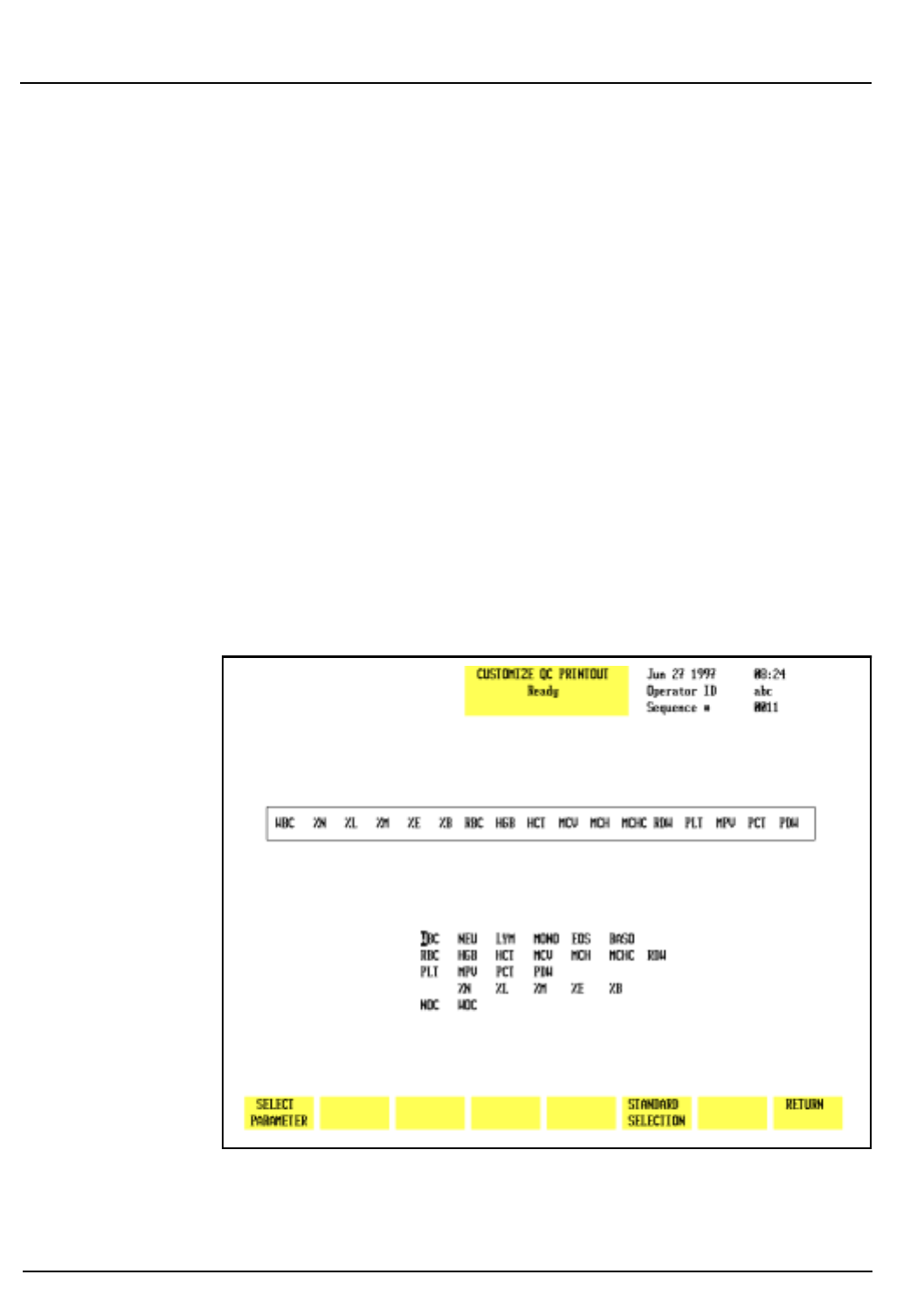
5-28 CELL-DYN 3200 Operator’s Manual
9140181B — November 1997
Operating Instructions
Set Up Instructions Section 5
5. Press the soft key corresponding to the desired parameter
group. This group is displayed in the position indicated
by the cursor.
6. Repeat steps 4 and 5 until all desired groups have been
selected.
7. If desired, press the Print screen key on the keyboard to
obtain a printout of the configuration.
8. Press [RETURN] to return to the QC SET UP MENU screen.
9. Repeat this procedure to select standard groups for other
QC logs.
Latex Set
This key is intended to be used by Abbott Service personnel
only. If the [LATEX SET] key is pressed, parameters in all
groups will be affected. The [LATEX SET] key is available from
the CUSTOMIZE QC DISPLAY screen for Standard Groups. This
key is used to customize the QC file to store information
generated by latex particles. Information is stored for each of
the four angles of scatter which are used to determine the
differential.
Figure 5.15: Customize QC Printout Screen
Go Back
Search
TOC

CELL-DYN 3200 Operator’s Manual 5-29
9140181B — November 1997
Operating Instructions
Section 5 Set Up Instructions
Customize Printout
The [CUSTOMIZE PRINTOUT] key in the QC SET UP menu is
used to customize the printout format for the QC logs. (See
Figure 5.15.) The following soft key labels are displayed when
the [CUSTOMIZE PRINTOUT] key is pressed:
SELECT PARAMETER (Toggles to PLACE
PARAMETER when pressed)
STANDARD SELECTION
RETURN
The CUSTOMIZE QC PRINTOUT screen displays the group of
parameters that is currently selected. A list of all available
parameters is displayed under the group.
Standard Selection
The [STANDARD SELECTION] key is used to automatically
arrange the parameters in a predetermined print group.
Select Parameter
The [SELECT PARAMETER/PLACE PARAMETER] key is used to
customize the QC Log printout.
1. Select a file from the QC SET UP MENU screen by moving
the cursor to the desired file.
2. Press [CUSTOMIZE PRINTOUT] to display the CUSTOMIZE
QC PRINTOUT screen for the selected file.
3. Use the Arrow keys on the keyboard to move the cursor to
the desired parameter in the list under the printout
group.
4. Press [SELECT PARAMETER]. The selected parameter is
highlighted and the cursor moves to the first position in
the group.
NOTE: The key label changes to [PLACE PARAMETER]
and a [CANCEL SELECTION] key is displayed.
5. If necessary, use the Arrow keys on the keyboard to move
the cursor to the desired location and press [PLACE
PARAMETER].
NOTE: When the [PLACE PARAMETER] key is pressed,
the selected parameter is displayed in the position
indicated by the cursor, the cursor advances to the next
parameter in the list under the printout group, and the
key label changes back to [SELECT PARAMETER].
6. Repeat steps 3–5 until all entries have been made.
7. If desired, press the Print Screen key on the keyboard to
obtain a printout of the configuration.
Go Back
Search
TOC
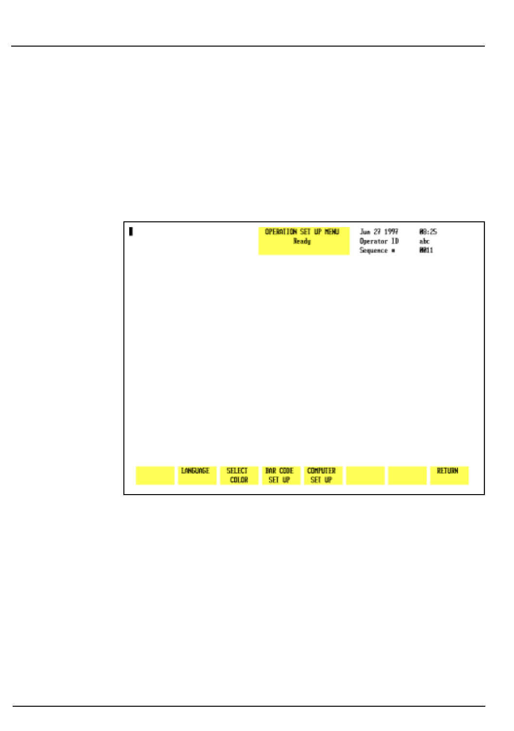
5-30 CELL-DYN 3200 Operator’s Manual
9140181B — November 1997
Operating Instructions
Set Up Instructions Section 5
8. Press [RETURN] to return to the QC SET UP MENU screen.
9.Repeat this procedure to customize the printout for other
QC logs.
Standard Selection
When the [STANDARD SELECTION] key is pressed, the
parameters are automatically arranged in the predetermined
print group shown in Figure 5.14.
Figure 5.16: Operation Set Up Menu Screen
Operation Set Up Menu
The OPERATION SET UP MENU screen (see Figure 5.16) allows
the operator to select screen colors, the type of bar code used,
and to configure the transmission to an on-line (host)
computer. The following soft key labels are displayed when
the [OPERATION SET UP] key is pressed:
LANGUAGE
SELECT COLOR
BAR CODE SET UP
COMPUTER SET UP
RETURN
Go Back
Search
TOC
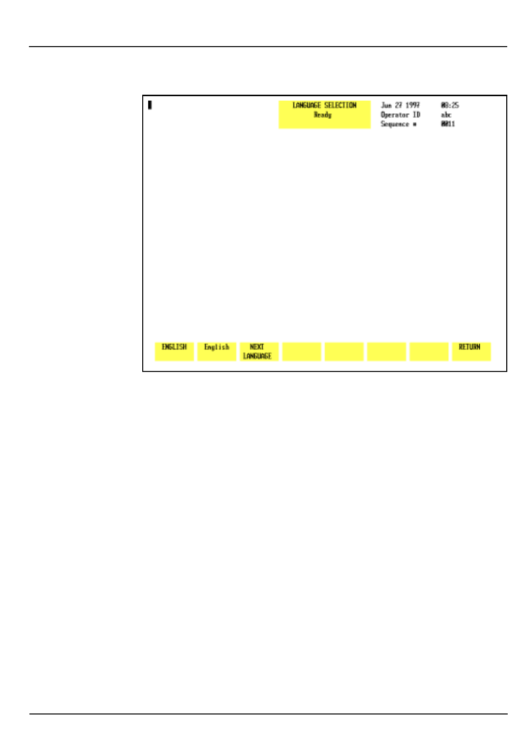
CELL-DYN 3200 Operator’s Manual 5-31
9140181B — November 1997
Operating Instructions
Section 5 Set Up Instructions
Figure 5.17: Language Selection Screen
Language Selection <
English (default language)
>
The LANGUAGE SELECTION screen, shown in Figure 5.17, will
soon allow the user to select one of the following non-English
languages for display and printout:
Spanish
French
German
Japanese
Italian
The following soft keys are displayed when the [LANGUAGE]
key is pressed:
ENGLISH (used to return to the default
language)
English (name of currently displayed
language)
NEXT LANGUAGE
RETURN
Pressing the capitalized [ENGLISH] soft key allows the operator
to return to English which is the default language.
Go Back
Search
TOC

5-32 CELL-DYN 3200 Operator’s Manual
9140181B — November 1997
Operating Instructions
Set Up Instructions Section 5
The name of the currently displayed language is displayed
next to [ENGLISH]. For example, if English is the displayed
language, then [English] will be displayed in the second key
position. The name of each language is displayed using the
spelling convention of the host language: French is displayed
as
[fran
ç
ais]
, German as
[deutsch]
, and Spanish as
[español]
.
Pressing the language key affects the display and printout of
soft keys, bulletin and screen messages, and demographic data;
it does not effect the measurement process or other functional
aspects of the program.
In a future release, pressing the [NEXT LANGUAGE] soft key
will allow the user to scroll through the available languages.
To Change the Language
1. In the OPERATION SET UP MENU, press [LANGUAGE
SELECTION].
2. Press [NEXT LANGUAGE] to scroll through the list of
languages available on the instrument.
3. When the desired language is displayed in the second soft
key label position, press [RETURN] to save the selection
and return to the OPERATION SET UP MENU.
4. If desired, attach a keyboard appropriate to the language
selected.
CAUTION: If a different keyboard will be attached to
the instrument because of the change in language, the
instrument (Analyzer only) should first be turned OFF
before the old keyboard is unplugged and the new
keyboard is attached. This will prevent accidental
injury to the operator or damage to the instrument.
Go Back
Search
TOC
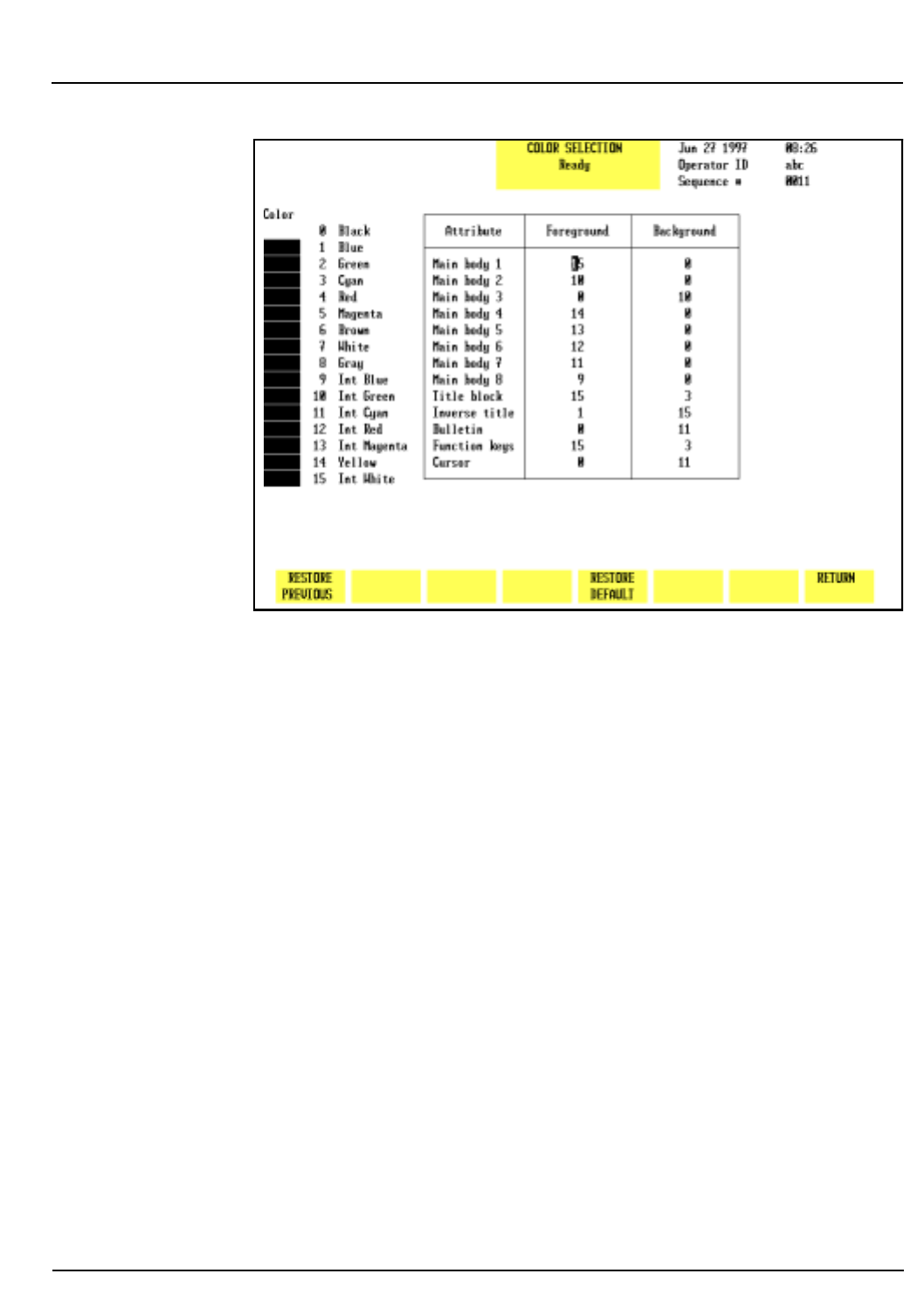
CELL-DYN 3200 Operator’s Manual 5-33
9140181B — November 1997
Operating Instructions
Section 5 Set Up Instructions
Figure 5.18: Select Color Screen
Select Color
The SELECT COLOR screen, shown in Figure 5.18, allows the
user to select various colors for displaying parameter data and
other information on the screen. The following soft keys are
displayed when the [SELECT COLOR] key is pressed:
RESTORE PREVIOUS
RESTORE DEFAULT
RETURN
Color Reference
Main Body 1 Main screen
Main Body 2 Flags
Main Body 3 Run mode description
Main Body 4 Values below limits
Main Body 5 Values above limits
Main Body 6 Sequence numbers in Data Log
Main Body 7 RBC Histogram/New entry
before Enter key is pressed
Main Body 8 PLT Histogram/New entry
after Enter key is pressed
Go Back
Search
TOC

5-34 CELL-DYN 3200 Operator’s Manual
9140181B — November 1997
Operating Instructions
Set Up Instructions Section 5
To Change Color Settings
1. Press [SELECT COLOR] in the OPERATION SET UP MENU.
2. Use the Arrow keys on the keyboard to move the cursor to
the desired location in either the Foreground or
Background columns.
3. Enter the number corresponding to the desired color
from the list on the left side of the screen. Press the Enter
key to save the entry and move the cursor to the next
position.
NOTE: The one field which cannot be changed is
Background for Main body 1. This background must
always remain black.
4. When all desired changes have been made, press
[RETURN] to return to the OPERATION SET UP MENU.
5. If the operator changes a color selection, then wishes to
cancel the change and keep the original setting, pressing
[RESTORE PREVIOUS] while this screen is still displayed
will cancel all changes and restore the original color
selection. Pressing [RESTORE DEFAULT] will cause the
screen colors to revert to the configuration set at the
factory prior to shipment.
Title Block Top center of screen
Inverse Title Title not currently used
Bulletin Alert messages above function keys
Function Keys Soft key descriptions
Cursor Screen cursor
Go Back
Search
TOC
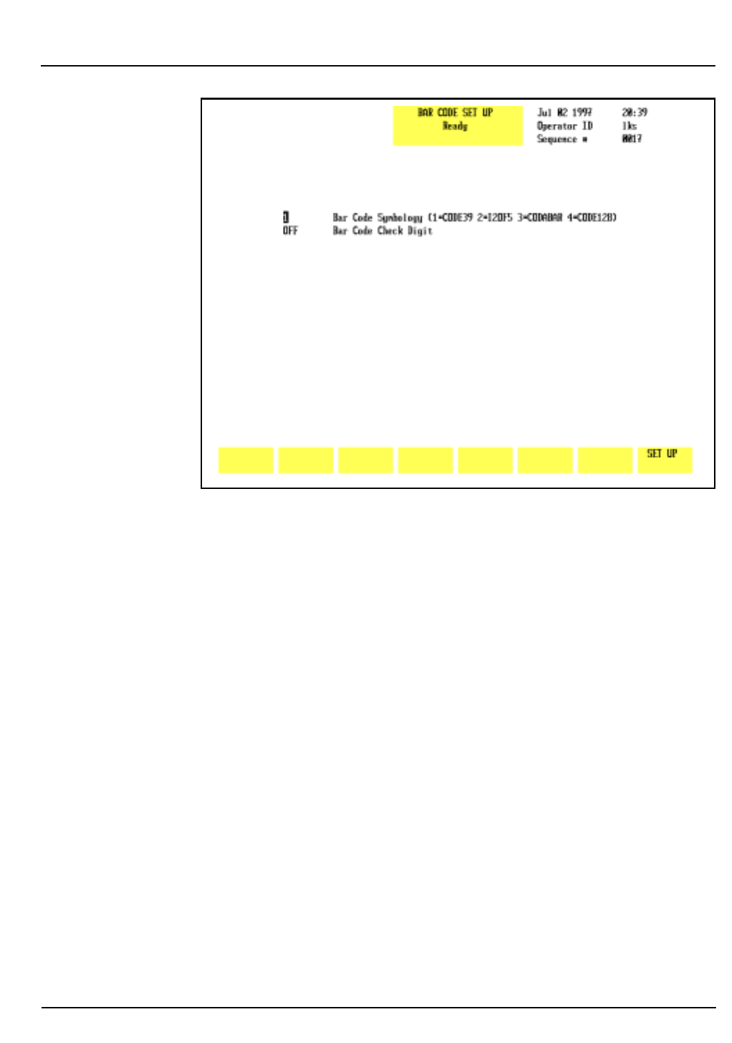
CELL-DYN 3200 Operator’s Manual 5-35
9140181B — November 1997
Operating Instructions
Section 5 Set Up Instructions
Figure 5.19: Bar Code Set Up Screen
Bar Code Set Up
The [BAR CODE SET UP] key is used to select the type of bar
code to be read and to enable or disable the check digit option
for the selected bar code. (See Figure 5.19.)
NOTE: For more information about check digits and
bar codes, refer to Appendix A, Bar Codes.
To Set Up Bar Code
1. From the OPERATION SET UP MENU screen, press [BAR
CODE SET UP] to display the BAR CODE SET UP screen.
2. Type the number for the type of bar code that will be
used:
1 — Code 39
2 — Interleaved 2 of 5
3 — CODABAR
4 — Code 128
Press the Enter key on the keyboard to save the entry and
advance the cursor to the Bar Code Check Digit field.
Go Back
Search
TOC
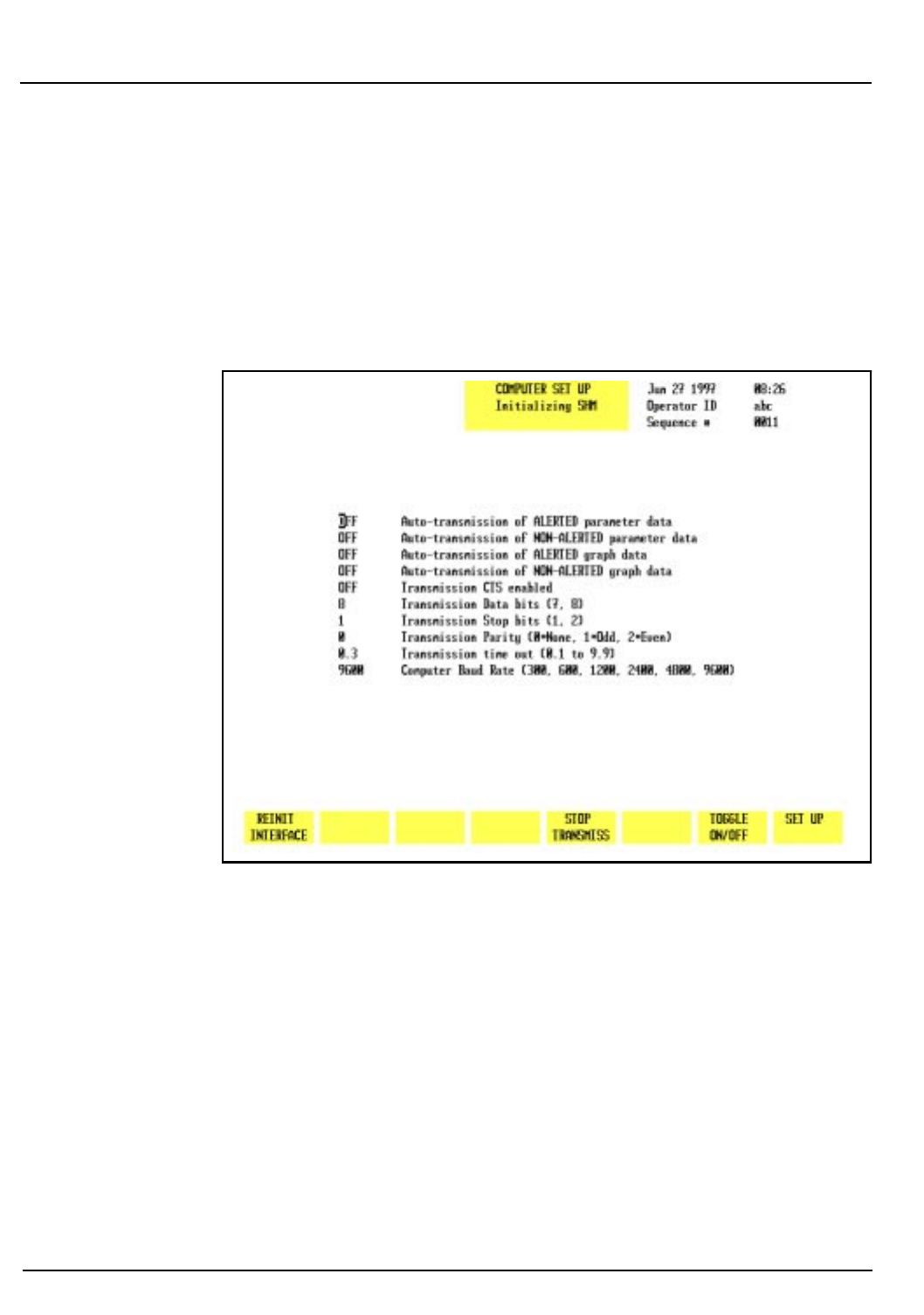
5-36 CELL-DYN 3200 Operator’s Manual
9140181B — November 1997
Operating Instructions
Set Up Instructions Section 5
3. Press [TOGGLE ON/OFF] to enable or disable the check
digit.
NOTE: The [TOGGLE ON/OFF] key is displayed only
when the cursor is positioned next to BAR CODE CHECK
DIGIT.
4. Press [SET UP] to return to the OPERATION SET UP MENU.
Figure 5.20: Computer Set Up Screen
Computer Set Up Menu
The [COMPUTER SET UP] key is used to display the COMPUTER
SET UP screen (see Figure 5.20) and the following soft key
labels:
REINIT INTERFACE
STOP TRANSMISS
TOGGLE ON/OFF
SET UP
Go Back
Search
TOC

CELL-DYN 3200 Operator’s Manual 5-37
9140181B — November 1997
Operating Instructions
Section 5 Set Up Instructions
The CELL-DYN 3200 can transmit data to an on-line computer
(Laboratory Information System) using a direct serial link.
Data may be transmitted automatically as each sample is run
or at the operator’s request. The CELL-DYN 3200 also can
receive patient information transmitted to it by the on-line
computer.
The COMPUTER SET UP screen is used to configure the
transmission format to meet the requirements of the
Laboratory Information System or on-line computer.
Instructions for using this option are given after the following
description of the soft keys.
Reinit Interface
The [REINIT INTERFACE] key is used to initialize the RS-232
interface for the displayed transmission configuration after it
is entered. The interface is automatically initialized whenever
the [STOP TRANSMISS] key is pressed.
NOTE: Refer to the Interface Specification for complete
information on interfacing.
Stop Transmiss
The [STOP TRANSMISS] key is used to terminate the current
data transmission to an on-line computer. When the [STOP
TRANSMISS] key is pressed, the following soft key labels are
displayed:
CONFIRM STOP
CANCEL STOP
Pressing [CONFIRM STOP] causes the transmission to
terminate. Pressing [CANCEL STOP] allows the transmission to
continue.
Toggle ON/OFF
The [TOGGLE ON/OFF] key enables or disables the first five
options in the list displayed on the COMPUTER SET UP screen.
A description of the options available on the COMPUTER SET
UP screen is given below:
1. AUTO-TRANSMISSION OF ALERTED PARAMETER DATA
When this option is enabled, a report is automatically
transmitted to the LIS for any sample with flagged
parameter results.
Go Back
Search
TOC

5-38 CELL-DYN 3200 Operator’s Manual
9140181B — November 1997
Operating Instructions
Set Up Instructions Section 5
2. AUTO-TRANSMISSION OF NON-ALERTED PARAMETER
DATA
When this option is enabled, a report is automatically
transmitted to the LIS for any sample without flagged
parameter results.
3. AUTO-TRANSMISSION OF ALERTED GRAPH DATA
When this option is enabled, histograms are
automatically transmitted to the LIS for any sample with
flagged results.
4. AUTO-TRANSMISSION OF NON-ALERTED GRAPH DATA
When this option is enabled, histograms are
automatically transmitted to the LIS for any sample
without flagged results.
5. The remaining options are configured according to the
requirements of the LIS:
TRANSMISSION CTS ENABLED
TRANSMISSION DATA BITS (7, 8)
TRANSMISSION STOP BITS (1, 2)
TRANSMISSION PARITY (0=NONE, 1=ODD, 2=EVEN)
TRANSMISSION TIME OUT (0.1 to 9.9)
COMPUTER BAUD RATE (300, 600, 1200, 2400,
4800, 9600)
The numbers in parentheses after the options indicate the
selections available.
NOTE: Refer to the Interface Specification for complete
information on interfacing.
Computer Set Up Procedure
1. From the OPERATION SET UP MENU, press [COMPUTER
SET UP] to display the COMPUTER SET UP screen.
2. For the first five options on the list, use the Arrow keys on
the keyboard to move the cursor to the desired selection
and press [TOGGLE ON/OFF] to enable or disable the
selection.
NOTE: The [TOGGLE ON/OFF] key is displayed when
the cursor is positioned in any of the first five entry
fields.
Go Back
Search
TOC
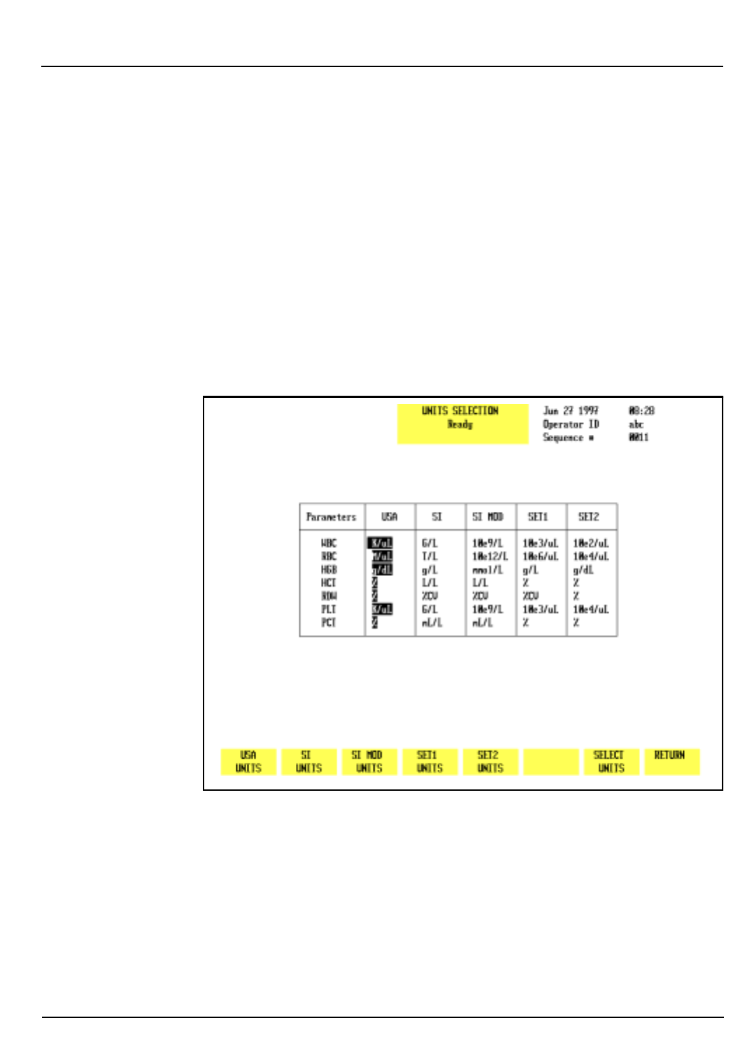
CELL-DYN 3200 Operator’s Manual 5-39
9140181B — November 1997
Operating Instructions
Section 5 Set Up Instructions
3. For the last five options on the list, type the appropriate
information and press the Enter key on the keyboard to
save the entry and advance the cursor.
4. When all the information has been entered, press [REINIT
INTERFACE] to initialize the interface for the selected
configuration.
5. If desired, press the Print Screen key on the keyboard to
obtain a printout of the configuration.
6. Press [SET UP] to return to the OPERATION SET UP MENU
screen.
7. Press [RETURN] to return to the SET UP MENU.
Figure 5.21: Units Selection Screen
Units Selection Menu
The [UNITS SELECTION] key selects the report units for the
indicated parameters. Units may be selected for each
parameter individually or a set of units may be selected by
pressing the appropriate soft key. (See Figure 5.21.) The
following soft key labels are displayed when the [UNITS
SELECTION] key is pressed:
Go Back
Search
TOC

5-40 CELL-DYN 3200 Operator’s Manual
9140181B — November 1997
Operating Instructions
Set Up Instructions Section 5
USA UNITS
SI UNITS
SI MOD UNITS
SET1 UNITS
SET2 UNITS
SELECT UNITS
RETURN
The units selected by each of the soft keys are shown on the
screen display in Figure 5.21. The following table demonstrates
how values are reported for the same sample under each
“units” category.
*NEU, LYM, MONO, EOS and BASO are reported in the same units as the WBC
**Report Unit is Geometric Standard Deviation
To Change Units Selection
1. From the SET UP MENU screen, press [UNITS SELECTION].
2. Press the appropriate soft key to select the desired units.
The group of selected units is highlighted on the screen.
OR
3. For individual unit selection, use the Arrow keys on the
keyboard to move the cursor to the desired units.
4. Press [SELECT UNITS] to enter the selection. The chosen
selection is highlighted on the display.
Table 5.1: Report Units
Parameter
USA SI SI MOD SET1 SET2
Value Units Value Units Value Units Value Units Value Units
WBC* 5.32 K/µL 5.32 G/L 5.32 10e9/L 5.32 10e3/µL 53.2 10e2/µL
RBC 5.15 M/µL 5.15 T/L 5.15 10e12/L 5.15 10e6/µL 515. 10e4/µL
HGB 16.2 g/dL 162 g/L 10.1 mmol/L 162 g/L 16.2 g/dL
HCT 47.6 % 0.476 L/L 0.476 L/L 47.6 % 47.6 %
MCV 92.3 fL 92.3 fL 92.3 fL 92.3 fL 92.3 fL
MCH 31.5 pg 31.5 pg 1.96 fmol 31.5 pg 31.5 pg
MCHC 34.1 g/dL 341 g/L 21.2 mmol/L 341 g/L 34.1 g/dL
RDW 12.5 % 12.5 %CV 12.5 %CV 12.5 %CV 12.5 %
PLT 323 K/µL 323 G/L 323 10e9/L 323 10e3/µL 32.3 10e4/µL
MPV 8.26 fL 8.26 fL 8.26 fL 8.26 fL 8.26 fL
PCT 0.267 % 2.67 mL/L 2.67 mL/L 0.267 % 0.267 %
PDW** 17.5 10GSD 17.5 10GSD 17.5 10GSD 17.5 10GSD 17.5 10GSD
Go Back
Search
TOC

CELL-DYN 3200 Operator’s Manual 5-41
9140181B — November 1997
Operating Instructions
Section 5 Set Up Instructions
5. Use the Arrow keys on the keyboard to move the cursor to
the next unit to be selected.
6. Repeat steps 4 and 5 until all selections have been made.
7. If desired, press the Print Screen key on the keyboard to
obtain a printout of the selected units.
8. Press [RETURN] to return to the SET UP MENU screen.
Customize Report
The [CUSTOMIZE REPORT] key is used to customize displayed
and/or printed reports. When the [CUSTOMIZE REPORT] key is
pressed, the screen that was displayed last will appear
(Graphics Printer is the default screen).
Customize Printout
The [CUSTOMIZE PRINTOUT] key is used to customize the
printout for the Graphics Printer and the Ticket Printer. For
ease of explanation, the two printer types are discussed
individually. Specific instructions are given for customizing a
report for the graphics printer, for a blank ticket, and for a
pre-printed ticket. When the [CUSTOMIZE PRINTOUT] key is
pressed, some of the soft key labels change with the type of
printer that is selected. The following soft key labels are
displayed when the key is pressed:
GRAPHICS PRINTER/
TICKET PRINTER (The key alternates between the
selections.)
CUSTOMIZE DISPLAY
STOP PRINTING
CUSTOMIZE HEADER
TOGGLE ON/OFF
SET UP
When the [CUSTOMIZE PRINTOUT] key is pressed, the screen
that was used for the last entry (graphics printer or ticket
printer) is displayed. A brief description of the function of the
soft keys is given in this section. For ease of explanation, the
keys are grouped according to the type of printer selected.
When the [TICKET PRINTER] key is pressed, the following soft
key label is also displayed:
BLANK TICKET/
PRE-PRNTD TICKET (The key label alternates between
the selections.)
Go Back
Search
TOC

5-42 CELL-DYN 3200 Operator’s Manual
9140181B — November 1997
Operating Instructions
Set Up Instructions Section 5
The [CUSTOMIZE DISPLAY] key is used to customize the
display as discussed in the next section.
The [STOP PRINTING] key is used to stop printing that is in
progress. When the [STOP PRINTING] key is pressed, the
following soft key labels are displayed:
CONFIRM STOP
CANCEL STOP
The [CANCEL STOP] key cancels the STOP PRINTING
command. If [CONFIRM STOP] is pressed, the print buffer (the
memory area where the material is stored while awaiting
printing) is cleared and the bulletin line displays the message:
PRINTING STOPPED. RESET PAPER TO THE TOP OF THE
PAGE
Two additional keys are displayed when the [CUSTOMIZE
HEADER] key is pressed:
RESTORE HEADER
BLANK HEADER
The [TOGGLE ON/OFF] key enables or disables the option
selected by the position of the cursor. The key label is not
displayed when a numeric entry is required.
The [SET UP] key is used to return to the SET UP MENU screen.
Go Back
Search
TOC
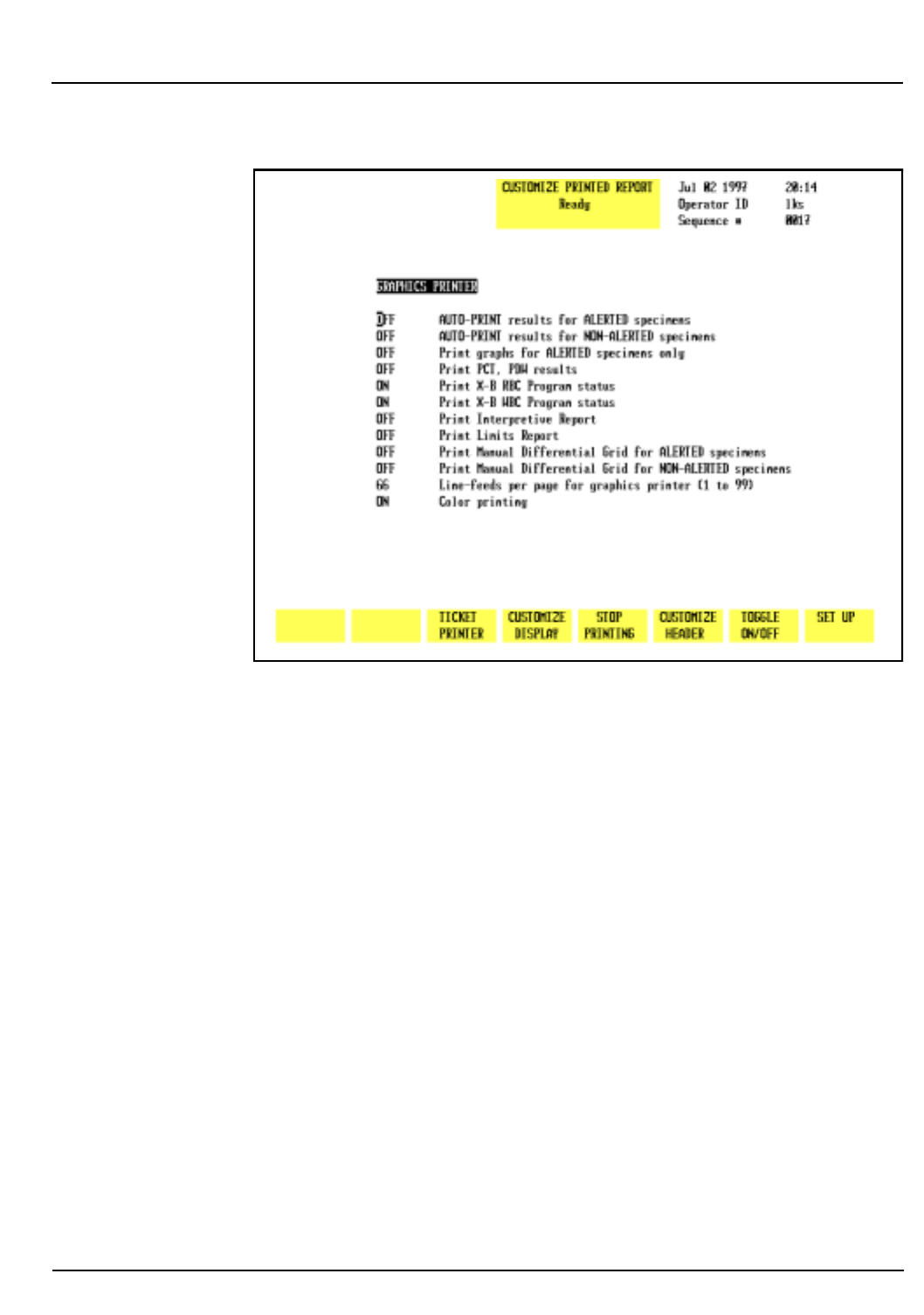
CELL-DYN 3200 Operator’s Manual 5-43
9140181B — November 1997
Operating Instructions
Section 5 Set Up Instructions
Figure 5.22: Customize Printed Report Screen for the Graphics
Printer
Graphics Printer
When the [GRAPHICS PRINTER] key is pressed, the
CUSTOMIZE PRINTED REPORT screen for the Graphics Printer
is displayed. (See Figure 5.22.) A description of the options
available on the CUSTOMIZE PRINTED REPORT screen is given
below:
1. AUTO-PRINT RESULTS FOR ALERTED SPECIMENS
When this option is enabled, a report is automatically
printed for any sample with flagged results.
2. AUTO-PRINT RESULTS FOR NON-ALERTED SPECIMENS
When this option is enabled, a report is automatically
printed for any sample without flagged results.
3. PRINT GRAPHS FOR ALERTED SPECIMENS ONLY
When this option is enabled, scatterplots and histograms
are printed only for samples with flagged results.
4. PRINT PCT, PDW RESULTS
When this option is enabled, the results for PCT and
PDW are printed on the report.
Go Back
Search
TOC

5-44 CELL-DYN 3200 Operator’s Manual
9140181B — November 1997
Operating Instructions
Set Up Instructions Section 5
NOTE: Clinical significance has not been established
for these parameters. Therefore, they are not reportable.
5.PRINT X-B RBC PROGRAM STATUS
When this option is enabled, the status of the X-B RBC
program is printed on the report. The X-B status (for
example, X-B RBC: 13/OUT2) is printed below the Status
Box.
6.PRINT X-B WBC PROGRAM STATUS
When this option is enabled, the status of the X-B WBC
program is printed on the report. The X-B status (for
example, X-B WBC: 13/OUT2) is printed below the Status
Box.
7.PRINT INTERPRETIVE REPORT
When this option is enabled, the Interpretive Report
messages are printed on the report. These messages are
generated when results exceed the Patient Limits and/or
instrument-generated flags are present. Refer to Section
3, Subsection: Operational Messages and Data Flagging
for an explanation of the Interpretive Report messages.
(Also see the [PATIENT LIMITS] key discussion earlier in
this section.)
8.PRINT LIMITS REPORT
When this option is enabled, the Patient Limits set that
was applied to the results is printed on the report.
9.PRINT MANUAL DIFFERENTIAL GRID FOR ALERTED
SPECIMENS
When this option is enabled, a grid that can be used to
report a manual Differential is printed on the report for
any specimen that is flagged.
10.PRINT MANUAL DIFFERENTIAL GRID FOR NON-
ALERTED SPECIMENS
When this option is enabled, a grid that can be used to
report a manual Differential is printed on the report for
any specimen that is not flagged.
11.LINE-FEEDS PER PAGE FOR GRAPHICS PRINTER
(1 to 99)
This option is used to select the size of the printed report.
12.COLOR PRINTING
When this option is enabled, a color printout can be
obtained on the CELL-DYN 3200 by pressing the [COLOR
PRINT] key. It is not possible to automatically obtain
color printouts.
Go Back
Search
TOC
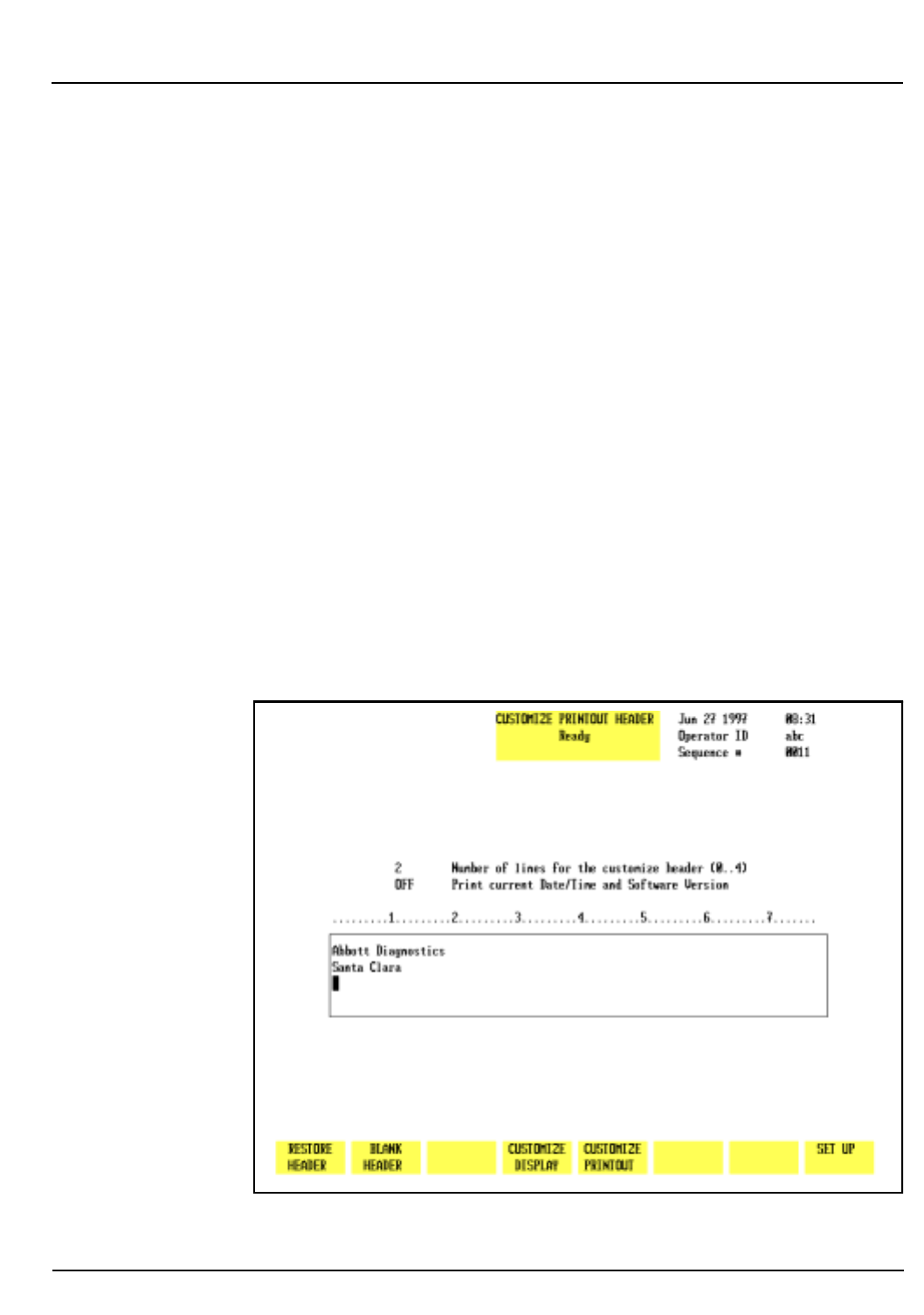
CELL-DYN 3200 Operator’s Manual 5-45
9140181B — November 1997
Operating Instructions
Section 5 Set Up Instructions
To Customize the Graphics Report
1. Go to the Graphics Printer set up section of the
CUSTOMIZE PRINTED REPORT screen (refer to Figure
5.22).
2. Use the Arrow keys on the keyboard to move the cursor to
the desired selection.
3. Press [TOGGLE ON/OFF] to enable or disable any of the
ON/OFF selections.
4. Repeat steps 2 and 3 until all selections have been made.
5. A numeric entry is required for the LINE-FEEDS PER
PAGE FOR GRAPHICS PRINTER field. Type the desired
number of line-feeds in the entry field and press the Enter
key on the keyboard to save the entry and advance the
cursor.
(An 8.5" x 11" sheet of paper has 66 lines per page.)
6. If desired, press the Print Screen key on the keyboard to
obtain a printout of the selections.
7. If desired, press [SET UP] to return to the SET UP MENU
screen, or continue with the following procedure for
customizing the header.
Figure 5.23: Customize Printout Header Screen for the
Graphics Report
Go Back
Search
TOC

5-46 CELL-DYN 3200 Operator’s Manual
9140181B — November 1997
Operating Instructions
Set Up Instructions Section 5
Customize Header
The [CUSTOMIZE HEADER] key is used to customize the
header for the graphics report. (See Figure 5.23.) Any report
printed in a graphics format will be printed with this header.
The following soft key labels are displayed when the
[CUSTOMIZE HEADER] key is pressed:
RESTORE HEADER
BLANK HEADER
CUSTOMIZE DISPLAY
CUSTOMIZE PRINTOUT
SET UP
Restore Header
The [RESTORE HEADER] key is used to restore the header to
the previous entry. This key is only functional immediately
after a new header has been entered. Once a new header is
entered and the CUSTOMIZE PRINTOUT HEADER screen has
been exited, the previous header is removed from the memory.
Blank Header
The [BLANK HEADER] key is used to erase the current header.
To Customize the Graphics Header
1. From any CUSTOMIZE PRINTED REPORT screen, press
[CUSTOMIZE HEADER] to display the CUSTOMIZE
PRINTOUT HEADER screen. Use the Arrow keys to skip a
field.
2. Type the desired number of lines for the header in the
indicated field. The header can include up to four lines.
3. Press the Enter key on the keyboard to save the entry and
advance to the next entry field.
4. Press [TOGGLE ON/OFF] to enable or disable the PRINT
CURRENT DATE/TIME AND SOFTWARE VERSION option.
5. Press the Enter key on the keyboard to save the entry and
advance to the next entry field.
6. In the header box field, type the information to be
displayed on the first line of the header. Each line holds
77 characters. Press the Enter key to move to the next
header line.
Go Back
Search
TOC

CELL-DYN 3200 Operator’s Manual 5-47
9140181B — November 1997
Operating Instructions
Section 5 Set Up Instructions
NOTE: The number of lines of data in the header box
cannot exceed the number of lines indicated in the first
field. For example, if 3 were input in the first field, then
a maximum of 3 lines will be accepted in the header
box. The operator may type in 4 lines of data, but only
the first three lines will be saved when the operator
exists this screen. (Existing information may be typed
over or an existing header may be deleted by pressing
the [BLANK HEADER] key.)
NOTE: The numbers displayed above the header box
on the screen indicate the position of the header on the
printed page. For example, centering the header/
information under the number 4 centers the header on
the page. Each line can be positioned independently of
the other lines in the header box. Use the Space Bar on
the keyboard to position the cursor for typing.
7. Press [SET UP] to return to the SET UP MENU screen.
Ticket Printer
Two options are available when the [TICKET PRINTER] key is
pressed:
BLANK TICKET/
PRE-PRNTD TICKET (The key alternates between the
selections.)
The [PRE-PRNTD TICKET] key is used to customize the printed
report for a pre-printed ticket. The [BLANK TICKET] key is used
to customize the printed report for a blank ticket.
Go Back
Search
TOC
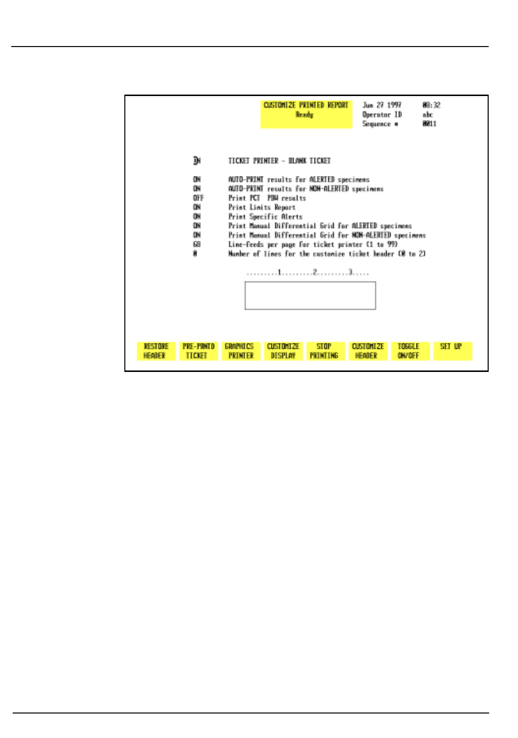
5-48 CELL-DYN 3200 Operator’s Manual
9140181B — November 1997
Operating Instructions
Set Up Instructions Section 5
Figure 5.24: Customize Printed Report Screen for Blank Tickets
Blank Ticket
When the [BLANK TICKET] key is pressed, the CUSTOMIZE
PRINTED REPORT screen for blank tickets is displayed. The
following options are available:
1. TICKET PRINTER — BLANK TICKET
When this option is enabled, the ticket printer is
configured for a blank ticket. (The pre-printed ticket
option is automatically turned OFF.)
2. AUTO-PRINT RESULTS FOR ALERTED SPECIMENS
When this option is enabled, a ticket is automatically
printed for any sample with flagged results. Flagged
results are indicated by the letters “AL” (for alert) on the
printout when the PRINT SPECIFIC ALERTS option is
turned OFF (see number 6 below). Results that exceed
Patient Limits are underlined on the printout.
3. AUTO-PRINT RESULTS FOR NON-ALERTED SPECIMENS
When this option is enabled, a report is automatically
printed for any sample without flagged results.
4. PRINT PCT, PDW RESULTS
Go Back
Search
TOC

CELL-DYN 3200 Operator’s Manual 5-49
9140181B — November 1997
Operating Instructions
Section 5 Set Up Instructions
When this option is enabled, the results for PCT and
PDW are printed on the report.
NOTE: Clinical significance has not be established for
these parameters. Therefore, they are not reportable.
5. PRINT LIMITS REPORT
When this option is enabled, the Patient Limits set that
was applied to the results is printed on the report.
6. PRINT SPECIFIC ALERTS
When this option is enabled, the specific flag (BANDS,
LRI, etc.) replaces the “AL” on the printout.
7. PRINT MANUAL DIFFERENTIAL GRID FOR ALERTED
SPECIMENS
When this option is enabled, a grid that can be used to
report a manual Differential is printed on the report for
any specimen that is flagged.
8. PRINT MANUAL DIFFERENTIAL GRID FOR NON-
ALERTED SPECIMENS
When this option is enabled, a grid that can be used to
report a manual Differential is printed on the report for
any specimen that is not flagged.
9. LINE-FEEDS PER PAGE FOR TICKET PRINTER (1 to
99)
This option is used to select the size of the printed report.
(A blank ticket typically has 68 lines.)
10. NUMBER OF LINES FOR THE CUSTOMIZE TICKET
HEADER (0 to 2)
This option is used to select the number of lines for the
header on the blank ticket. The numbers across the top of
the header can be used to center the header information
on the ticket. Centering the information under the
number 2 centers it on the ticket.
To Customize a Blank Ticket
1. If the Blank Ticket section of the CUSTOMIZE PRINTED
REPORT screen is not displayed, press [BLANK TICKET].
2. Use the Arrow keys on the keyboard to move the cursor to
the desired selection.
Go Back
Search
TOC

5-50 CELL-DYN 3200 Operator’s Manual
9140181B — November 1997
Operating Instructions
Set Up Instructions Section 5
3. Press [TOGGLE ON/OFF] to enable or disable the selection.
4. Press the Enter key on the keyboard to save the entry and
advance the cursor to the next field.
5. Repeat steps 2 through 4 until all ON/OFF selections have
been made.
6. A numeric entry is required for the LINE-FEEDS PER
PAGE FOR TICKET PRINTER field (A blank ticket
typically has 68 lines) and the NUMBER OF LINES FOR
THE CUSTOMIZE TICKET HEADER field.
7. Type the desired number of line-feeds in the entry field
and press the Enter key on the keyboard to save the entry
and advance the cursor.
8. Type the desired number of lines for the header (a
maximum of 2 lines) and press the Enter key on the
keyboard to save the entry and advance the cursor to the
header box field.
9. With the cursor in the header box, type the first line of
the header and press the Enter key on the keyboard to
save the entry and advance the cursor. Each line holds 35
characters. If desired, type a second line and press the
Enter key on the keyboard to save the entry and advance
the cursor.
NOTE: The number of lines of data in the header box
cannot exceed the number of lines entered in step 8
above. For example, if 1 were input, then a maximum
of 1 line will be accepted in the header box. The
operator may type in 2 lines of data, but only the first
line will be saved when the operator exists this screen.
NOTE: The numbers displayed above the header box
on the screen indicate the position of the header on the
printed page. Each line can be positioned
independently. Use the Space Bar on the keyboard to
position the cursor for typing.
10. If desired, press the Print Screen key on the keyboard to
obtain a printout of the selections.
11. Press [SET UP] to return to the SET UP MENU screen.
Go Back
Search
TOC
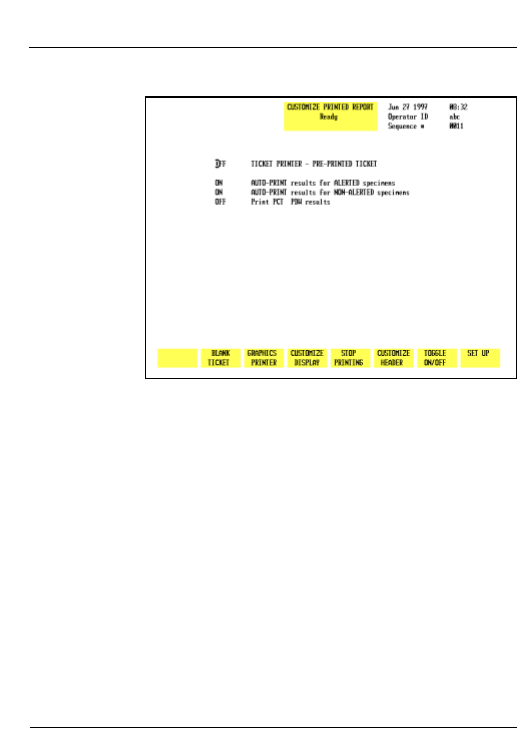
CELL-DYN 3200 Operator’s Manual 5-51
9140181B — November 1997
Operating Instructions
Section 5 Set Up Instructions
Figure 5.25: Customize Printed Report Screen for Pre-Printed
Tickets
Pre-Printed Tickets
When the [PRE-PRNTD TICKET] key is pressed, the
CUSTOMIZE PRINTED REPORT screen is displayed. The
numbers on the screen shown in Figure 5.25 correspond to the
following numbered options:
1. TICKET PRINTER — PRE-PRINTED TICKET
When this option is enabled, the ticket printer is
configured for a pre-printed ticket. (The blank ticket
option is automatically turned OFF.)
2. AUTO-PRINT RESULTS FOR ALERTED SPECIMENS
When this option is enabled, results for flagged
specimens are automatically printed as tickets are inserted
in the printer. Flagged results are marked with an asterisk
(*).
3. AUTO-PRINT RESULTS FOR NON-ALERTED SPECIMENS
When this option is enabled, results for specimens that
are not flagged are automatically printed as tickets are
inserted in the printer.
Go Back
Search
TOC

5-52 CELL-DYN 3200 Operator’s Manual
9140181B — November 1997
Operating Instructions
Set Up Instructions Section 5
4. PRINT PCT, PDW RESULTS
When this option is enabled, the PCT and PDW are
printed on the ticket.
NOTE: Clinical significance has not been established
for these parameters. Therefore, they are not reportable.
To Customize the Pre-Printed Ticket
1. Go to the Ticket Printer - Pre-printed Ticket section of the
CUSTOMIZE PRINTED REPORT screen (refer to Figure
5.25).
2. Use the arrow keys on the keyboard to move the cursor to
the desired option.
3. Press [TOGGLE ON/OFF] to enable or disable the selected
option.
4. Press the Enter key on the keyboard to save the entry and
advance the cursor to the next field.
5. Repeat steps 2 through 4 until all selections have been
made.
6. If desired, press the Print Screen key on the keyboard to
obtain a printout of the selections.
7. Press [SET UP] to return to the SET UP MENU screen.
Customize Displayed Report
Customized displays can be established for each of the four
parameter sets. The CUSTOMIZE DISPLAYED REPORT screen
(see Figure 5.26) for the indicated parameter set (in this case
PARAM SET 1) and the following soft key labels are displayed
when the [CUSTOMIZE DISPLAY] key in the CUSTOMIZE
PRINTED REPORT screen is pressed:
PARAM SET 1*
PARAM SET 2*
PARAM SET 3*
PARAM SET 4*
CUSTOMIZE PRINTOUT
CUSTOMIZE HEADER/
CANCEL GRAPH (The key label alternates
between the selections.)
SELECT GRAPH/
PLACE GRAPH (The key label alternates
between the selections.)
SET UP
*The soft key for the displayed parameter set is blanked
out.
Go Back
Search
TOC
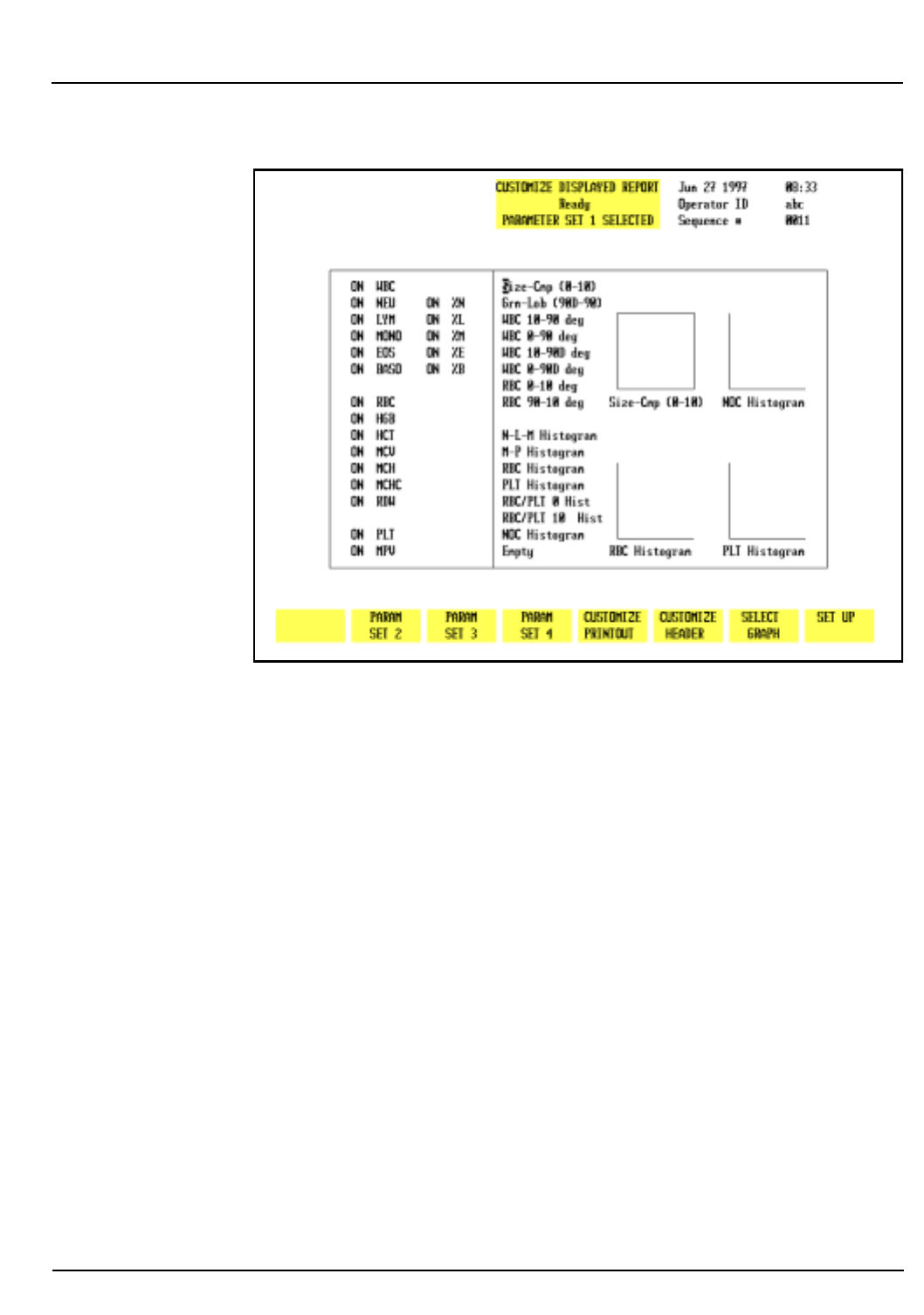
CELL-DYN 3200 Operator’s Manual 5-53
9140181B — November 1997
Operating Instructions
Section 5 Set Up Instructions
Figure 5.26: Customize Displayed Report Screen
The screen is divided into two sections. Individual parameters
are listed in the left section and the scatterplots and
histograms are listed in the right section.
Parameter Sets
Using the [PARAM SET “X”] key, the display may be
customized for four different sets of parameters. Up to 20
individual parameters and up to four scatterplots and/or
histograms may be displayed in each set.
The “Empty” selection at the bottom of the Histogram list may
be used to “blank” the scatterplot or histogram display at the
selected position. Move the cursor to Empty and press
[SELECT GRAPH]. Move the cursor to the desired scatterplot or
histogram and press [PLACE GRAPH].
To Customize the Display Screen
1. From the SET UP MENU screen, press [CUSTOMIZE
REPORT] and if necessary, press [CUSTOMIZE DISPLAY] to
display a parameter set.
2. If desired, press [PARAM SET “X”] to select a different
parameter set.
Go Back
Search
TOC

5-54 CELL-DYN 3200 Operator’s Manual
9140181B — November 1997
Operating Instructions
Set Up Instructions Section 5
3. Use the Arrow keys on the keyboard to move the cursor to
the desired parameter in the list displayed on the left
section of the screen.
4. Press [TOGGLE PARAMETER] to turn the display off or on
and advance the cursor to the next parameter. The cursor
moves through the entire list of parameters in this section
of the screen and, when at the bottom, returns to the top
of this list.
NOTE: The [TOGGLE PARAMETER] key is displayed
only when the cursor is positioned in the list of
individual parameters displayed on the left side of the
screen.
5. Repeat steps 3 and 4 until all parameter selections have
been made. Use the Right Arrow key to move the cursor
to the next section.
6. Use the Arrow keys to move the cursor to the desired
scatterplot or histogram.
7. Press [SELECT GRAPH] to select it. The scatterplot or
histogram name is highlighted and the cursor moves to a
display position. The key label changes to [PLACE
GRAPH] and the [CANCEL GRAPH] key is displayed.
8. If necessary, use the Arrow keys on the keyboard to move
the cursor to the desired display position.
9. Press [PLACE GRAPH] to display the selection at the
indicated position. The cursor moves to the next
scatterplot or histogram in the list.
10. Repeat steps 6 through 9 until all selections have been
made for the current Parameter Set.
11. If desired, press the Print Screen key on the keyboard to
obtain a printout of the selected Parameter Set.
12. Press [PARAM SET “X”] to select another Parameter set
and repeat steps 3 through 11 to customize the display for
it.
13. Press [SET UP] to return to the SET UP MENU screen.
Interpretive Report Messages
If the PRINT INTERPRETIVE REPORT option on the
CUSTOMIZE PRINTED REPORT screen for the Graphics Printer
is enabled, Interpretive Report messages are printed on the
report. Some of these messages are generated from the
information entered for the Patient Limits. The following
messages are generated by specimen results which exceed the
Patient Limits:
Go Back
Search
TOC

CELL-DYN 3200 Operator’s Manual 5-55
9140181B — November 1997
Operating Instructions
Section 5 Set Up Instructions
WBC Messages
Leukopenia —result exceeds the lower limit for WBC
Leukocytosis —result exceeds the upper limit for WBC
Neutropenia —result exceeds the lower limit for Neutrophil
absolute number
Neutrophilia —result exceeds the upper limit for Neutrophil
absolute number
Lymphopenia —result exceeds the lower limit for
Lymphocyte absolute number
Lymphocytosis —result exceeds the upper limit for
Lymphocyte absolute number
Monocytosis —result exceeds the upper limit for Monocyte
absolute number
Eosinophilia —result exceeds the upper limit for Eosinophil
absolute number
Basophilia —result exceeds the upper limit for Basophil
absolute number
RBC Messages
Anemia —result exceeds the lower limit for RBCs
Polycythemia —result exceeds the upper limit for RBCs
Microcytic RBC —result exceeds the lower limit for MCV
Macrocytic RBC —result exceeds the upper limit for MCV
Hypochromic —result exceeds the lower limit for MCHC
Hyperchromic —result exceeds the upper limit for MCHC
Anisocytosis —result exceeds the upper limit for RDW
PLT Messages
Thrombocytopenia —result exceeds the lower limit for PLTs
Thrombocytosis —result exceeds the upper limit for PLTs
Microcytic PLT —result exceeds the lower limit for MPV
Macrocytic PLT —result exceeds the upper limit for MPV
Go Back
Search
TOC

5-56 CELL-DYN 3200 Operator’s Manual
9140181B — November 1997
Operating Instructions
Set Up Instructions Section 5
NOTES
Go Back
Search
TOC

CELL-DYN® 3200 Operator’s Manual 5-57
9140181B — November 1997
Operating Instructions
Section 5 Routine Operation
Routine Operation
General Information
This subsection contains information and procedures that are
recommended for the routine operation of the
CELL-DYN 3200.
The following topics are included in this subsection:
Instrument Start-up
RUN menu
Sample Collection and Handling
Sample Analysis on the CELL-DYN 3200 SL
Sample Analysis on the CELL-DYN 3200 CS
Daily Shutdown Procedure
Unless stated otherwise, all subsections apply to both the
Sample Loader and Closed Sampler versions of the CELL-DYN
3200. For convenience, instructions for running samples in the
Open Mode are repeated in each of the two Running Samples
subsections. Refer to Section 13: Sample Loader for additional
information on Sample Loader operation and to Appendix A for
information on the use of bar code labels.
Power ON Procedure
The System power switch on the back of the Analyzer should
be left ON at all times. The instrument has been designed to
automatically maintain itself when it is idle. If the instrument
is idle for five minutes, a cleaning cycle is automatically
initiated. If the instrument is idle for four hours, an automatic
Shutdown cycle is initiated. The instrument is placed in the
STANDBY state at the end of the automatic Shutdown cycle.
Power switches for the Display Monitor and printer should be
left ON as long as power to the System is ON. Power to the
monitor and printer should be turned OFF when the System is
turned OFF, when a malfunction is suspected, or when
maintenance is required.
Power to the Printer may be left on or off at the operator’s
discretion. Refer to Section 12: Printers for complete
instructions on printer operation.
Go Back
Search
TOC

5-58 CELL-DYN® 3200 Operator’s Manual
9140181B — November 1997
Operating Instructions
Routine Operation Section 5
IMPORTANT: If the power has been OFF more than
five minutes, the laser must be allowed to warm up for
15 minutes once the power is turned back ON. Do not
process samples during this warm-up period.
To power-up the instrument:
1. Verify that all components are properly installed
(syringes, tubing in the normally closed valves, Shear
Valve, etc.).
2. Verify that all reagents are properly installed.
3. Verify that all necessary cables and power cords are
properly connected.
4. Verify that the Analyzer covers are properly installed,
including the Tower Cover.
5. If a condition caused power to the instrument to be
turned OFF, verify that the condition has been corrected.
6. Turn the power switches ON in the following order:
a. System (includes Analyzer, Data Module, and Sample
Loader)
b. Display Monitor
c. Printer
7. When the INITIALIZED message appears in the Status
Box on the
MAIN MENU
, press
[RUN]
to prime the system.
Initializing the System
The term initialization refers to the automatic process that
occurs when the instrument is first turned ON, or after certain
problems have been corrected and the instrument must again
be brought to the READY state. Initialization is a two-step
process:
1. Initializing the hardware and software
2. Priming the system with reagents
The system is initialized when the Analyzer is turned ON or
when the
[INITIALIZATION]
key, located in the second
DIAGNOSTICS
MENU
, is pressed. During the initialization process, the software
located in the Data Module is accessed and downloaded to the
Analyzer. When this has been accomplished, all Analyzer
pumps and motors are moved to their “home” positions.
(Increase motor noise is common during this period.) When
the system has been initialized, the message INITIALIZED is
displayed in the Status Box.
Go Back
Search
TOC

CELL-DYN® 3200 Operator’s Manual 5-59
9140181B — November 1997
Operating Instructions
Section 5 Routine Operation
The next step is to prime the system with reagents. When the
initialized message appears in the Status Box on the
MAIN MENU
,
press
[RUN]
to prime the system. When the priming cycle is
finished, the message READY is displayed in the Status Box.
Operating the Instrument
Activating The RUN Cycle
On the CS model, start the RUN cycle for either the Open or
Closed Mode by pressing the Touch Plate.
NOTE: The door Assembly must be closed for the
Closed Mode RUN cycle to be activated.
On the SL model, Start the RUN cycle for Open Mode by
pressing the Touch Plate. Start the RUN cycle for Closed Mode
by pressing the
[START LOADER]
key in the RUN menu. For
additional information, refer to Sample Loader Description,
Soft Keys in Section 13: Sample Loader.
Orderly Stops
The CS model, whether in Open or Closed Mode,
automatically halts after each sample has been processed
unless the Touch Plate is pressed again to start a new RUN
cycle.
The SL model in Open Mode automatically halts after each
sample has been processed unless the Touch Plate is pressed
again to start a new RUN cycle.
The SL model in Closed Mode automatically halts when no
more racks are detected on the load side and the last track has
passed under the Tower to the Unload side.
Emergency Stops
To immediately halt all operation of the instrument, do one of
the following:
1.Turn OFF the main power switch, located in the upper left
corner of the back panel.
2.Push the window section of the Tower Cover toward the
instrument to release the latches and break the safety
interlock sensor connection. As soon as the connection is
broken, the instrument halts. It is not necessary to
remove the Tower Cover to stop operations. This method
applies to both CS and SL models. In addition, the CS
model has a safety interlock sensor attached to the swivel
door mechanism which holds the sample tube.
Go Back
Search
TOC

5-60 CELL-DYN® 3200 Operator’s Manual
9140181B — November 1997
Operating Instructions
Routine Operation Section 5
Power OFF Procedure
It is not necessary to turn the system OFF under normal
operating conditions. The system should be turned OFF when
certain maintenance procedures will be performed, when the
system will be moved, or when the system will be inactive for
an extended period of time (longer than 2 weeks).
For Maintenance
When certain tests or maintenance procedures require power
to be OFF, use the following procedure:
1.With the system still ON, perform any maintenance that
is due.
2.Perform the Auto-Clean procedure in the SPECIAL
PROTOCOLS menu. (If necessary, refer to Section 9:
Service and Maintenance, Subsection: Daily
Maintenance Procedures.)
3.When the Auto-Clean cycle is finished, press
[DAILY
SHUTDOWN]
. When the DAILY SHUTDOWN cycle is
finished, the message STANDBY will be displayed in the
Status Box.
4.Turn the power switches OFF in the following order:
a.System (includes Analyzer, Data Module, and Sample
Loader)
b.Display Monitor
c.Printer
NOTE: In an emergency situation, turn power OFF in
any order as quickly as possible.
For Extended Period
Additional procedures are required if the instrument will be
inactive for an extended period of time (more than 2 weeks),
moved to a different location in the lab, or shipped to a distant
location. For detailed instructions, refer to Intermediate-term
Shutdown and Prolonged Shutdown later in this section.
Go Back
Search
TOC

CELL-DYN® 3200 Operator’s Manual 5-61
9140181B — November 1997
Operating Instructions
Section 5 Start-Up Procedure
Start-Up Procedure
To startup the instrument, do the following:
1.If the instrument is OFF, first turn the power ON. When
INITIALIZED is displayed in the MAIN MENU Status Box,
press [RUN] to prime the instrument and bring it to the
READY state.
2.If the instrument is already ON and STANDBY or
INITIALIZED is displayed in the
MAIN MENU
Status Box,
press
[RUN]
to prime the instrument and bring it to the
READY state.
3.Perform the daily Quality Control checks as directed
within this section.
Daily Start-Up Procedure
The daily start-up routine consists of the following procedures:
1.Check the reagent levels and replace reagent containers as
necessary.
2.Check printer paper; add more paper as necessary.
3.Check tubing in the Normally Closed Valves and Sample
Transfer Peristaltic Pump for breaks, crimps, or other
obstructions.
4.Run background counts until acceptable results are
obtained for all background parameters (WBC, RBC, HGB,
and PLT). Acceptable results are specified in Section 4:
Performance Characteristics and Specifications,
Subsection: Background Counts.
5.Quality control procedures (which confirm calibration)
should be performed on a daily basis according to the
laboratory’s protocol. Commercial control materials
should be properly warmed and mixed according to the
manufacturer’s recommendations. Patient controls
should be handled according to the laboratory’s protocol.
Go Back
Search
TOC

5-62 CELL-DYN® 3200 Operator’s Manual
9140181B — November 1997
Operating Instructions
Start-Up Procedure Section 5
NOTES
Go Back
Search
TOC

CELL-DYN® 3200 Operator’s Manual 5-63
9140181B — November 1997
Operating Instructions
Section 5 Run Menu
Run Menu
The
RUN
menu and its sub-menus are described below,
including soft keys, demographics area, Work List, and bulletin
line.
To display the
RUN
menu, press
[RUN]
in the
MAIN MENU
. If the
instrument has not been primed, the priming cycle occurs
before the
RUN
menu is displayed.
RUN Screen Format
Upper Left Corner (Run Screen Demographics)
The Demographics Section of the
RUN
screen differs depending
on the specimen type selected. These differences are discussed
below.
Patient
The Upper Left Corner of the RUN screen for patient samples
displays the following data entry fields:
NEXT ID —used to enter the ID number for the next sample to
be run. (Up to 12 characters may be entered.)
NAME —used to enter the patient’s name. (Up to 28 characters
may be entered.)
PAT ID —used to enter patient identification information,
such as a Social Security number. (Up to 16 characters may be
entered.)
SEX—used to enter the sex of the patient.
DOB—used to enter the date of birth of the patient. (4 digits
must be entered for the Year.)
COL—used to enter the collection date and time of the
specimen.(4 digits must be entered for the Year.)
DR—used to enter the name of the patient’s physician. (Up to
22 characters may be entered.)
CMT—used to enter operator comments. (Up to 16 characters
may be entered.)
Go Back
Search
TOC

5-64 CELL-DYN® 3200 Operator’s Manual
9140181B — November 1997
Operating Instructions
Run Menu Section 5
PARAM SET/LIMITS SET—displays the number of the
Parameter Set (1–4) and Limit Set (1-6) that will be applied to
the sample results
X-B Status—If the XB-RBC and/or the XB-WBC functions are
enabled, the XB file status for each is displayed under the
Status Box.
NOTE: The Parameter and Limits sets applied to the
sample may be changed after the sample has been run.
Refer to the description of the Data Log
[EDIT SPECIMEN]
key given in the Using the Data Log later in this
section.
An example of the
RUN
screen for patient specimens is shown
in Figure 5.27.
Fragile WBC and Resistant RBC
If the specimen type selected is FRAGILE WBC, then the label
“FrgWBC” appears instead of “Name” in the Demographics
Section. If the specimen type selected is RESISTANT RBC, then
the label “ResRBC” appears instead of “Name” in the
Demographics Section.
QC Specimen, Background, Latex
If the specimen type selected is QC SPECIMEN, BACKGROUND,
or LATEX, the following information is displayed in the
Demographics Section:
Type—displays the name of the QC file or displays Background
or Latex. For a QC file, the number of runs in the QC file and
total file space is displayed to the right of the type as in the
following example:
XX/120-current number of specimens in a batch of 120
(applies only to QC Specimens).
Param Set:—indicates the Parameter Set applied to the results
run in the QC file. For BACKGROUND and LATEX, the default
Param Set is 1.
Status Box
The Status Box is displayed in the Top Center of the
RUN
screen. It contains the following information:
•Menu in use
Go Back
Search
TOC

CELL-DYN® 3200 Operator’s Manual 5-65
9140181B — November 1997
Operating Instructions
Section 5 Run Menu
• The Status of the Analyzer — the READY, NOT READY
and FAULT messages are displayed here
• Report or File identity for results currently displayed
The Status Box also displays status and instructive messages
during the run cycle. These messages are:
Aspirating
Remove specimen
Dispensing
Counting
Rinsing
Ready
Upper Right Corner
The Upper Right Corner of the
RUN
screen displays the
following information:
• Current date and time
• Operator ID — Identification of the current operator
• Sequence # — Automatically increments as cycles are run
• Selected Sampler mode — Open Sampler or Closed
Sampler
Upper Center Section
The Upper Center Section of the RUN screen displays the
following information:
Center Section
The Center Section of the RUN screen displays the results. A
list of the parameters and results is displayed on the left side.
Scatterplots and histograms are displayed on the right side.
The area between the parameter data and the graphic data is
used to display flagging messages.
Bulletin Line
The Bulletin Line is displayed immediately above the key
labels. Messages appear in this line to identify status or fault
conditions.
Go Back
Search
TOC
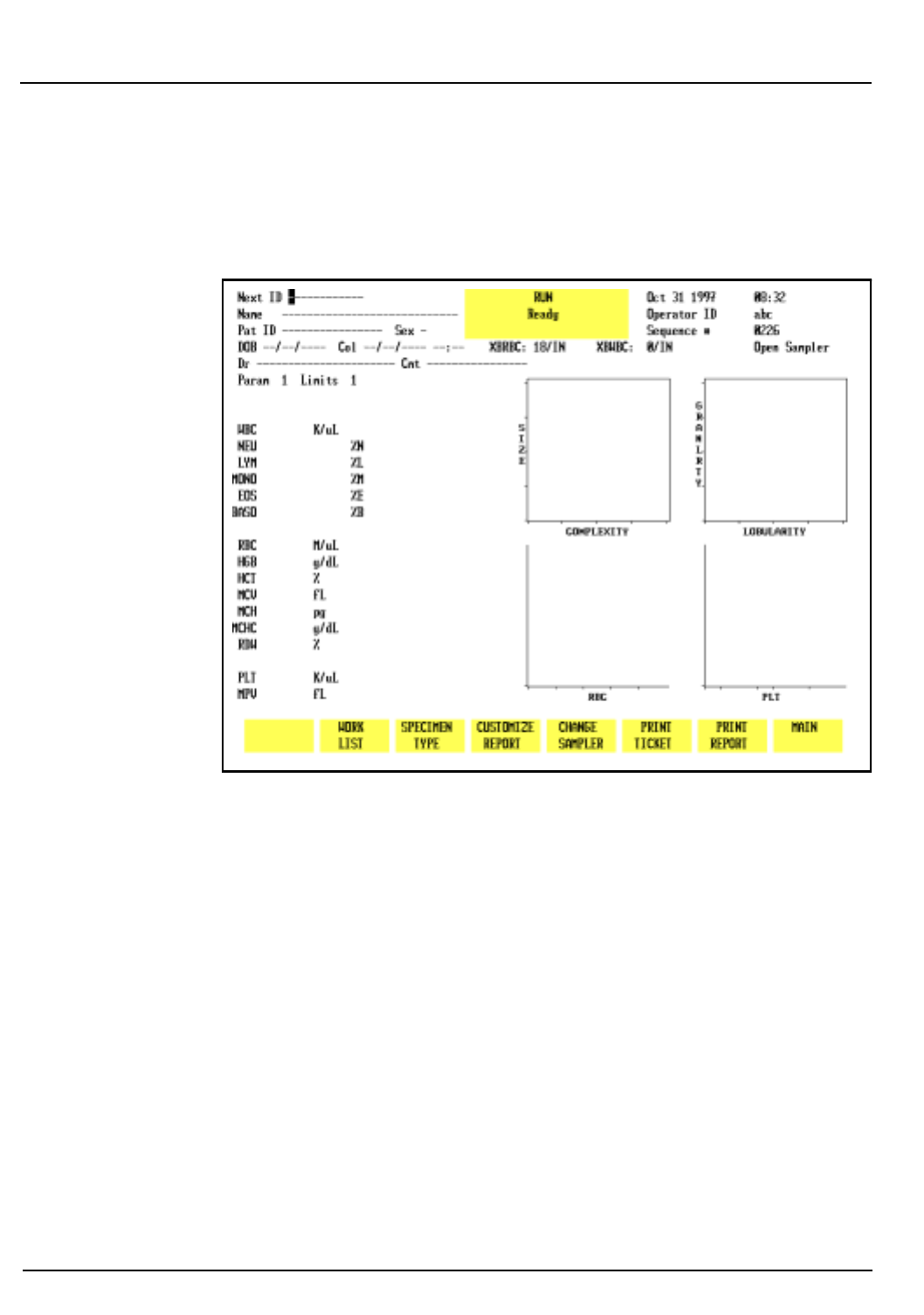
5-66 CELL-DYN® 3200 Operator’s Manual
9140181B — November 1997
Operating Instructions
Run Menu Section 5
Run Menu Soft Keys
CS Model
Figure 5.27: Run Screen for Patient Samples - CS Model
The soft keys displayed at the bottom of the
RUN
menu are
used to access the menu options that are available. The soft
keys displayed on the SL model are slightly different from the
keys displayed on the CS model. The keys shown on the CS
model are listed below. (See Figure 5.27.)
CLEAR FAULT
(This key label is blank unless a Fault
occurs.)
WORK LIST
SPECIMEN TYPE
CUSTOMIZE REPORT
CHANGE SAMPLER
PRINT TICKET
Go Back
Search
TOC
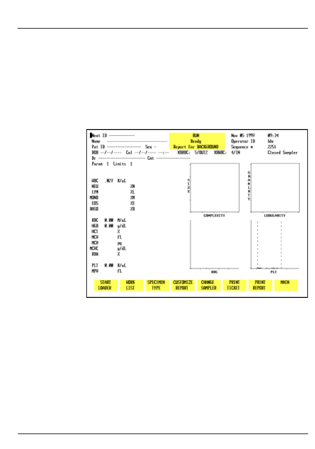
CELL-DYN® 3200 Operator’s Manual 5-67
9140181B — November 1997
Operating Instructions
Section 5 Run Menu
PRINT REPORT/
COLOR PRINT
(This key label changes to COLOR
PRINT when the color printing option is
selected in the CUSTOMIZED
PRINTED REPORT screen for the
Graphics Printer)
MAIN
SL Model
Figure 5.28: Run Screen for Patient Samples - SL Model
The soft keys shown on the SL model are similar to the CS
model except for the first key (leftmost key label on the screen)
in Closed Mode, shown below, which is used to operate the
Sample Loader. (See Figure 5.28.)
START LOADER/
STOP LOADER
(This key label alternates between
the selections)
Go Back
Search
TOC

5-68 CELL-DYN® 3200 Operator’s Manual
9140181B — November 1997
Operating Instructions
Run Menu Section 5
If a fault occurs, this key label changes to
[CLEAR FAULT]
similar
to the CS model.
Soft Key Description
A brief description of the function of each key is given below.
Instructions for running samples are given in Sample Analysis
on the CELL-DYN 3200CS and Sample Analysis on the
CELL-DYN 3200SL in this section.
Clear Fault
The blank key label in the CS model or the
[START/STOP LOADER]
key label in the SL model changes to
[CLEAR FAULT]
whenever a
system fault occurs (e.g., Diluent Empty). This key is used to
clear the fault message and return the Analyzer to the READY
state after corrective action has been taken.
NOTE: A message describing the fault appears in the
bulletin line. A list of fault conditions and corrective
action is given in Section 10: Troubleshooting and
Diagnostics.
Work List
This key is used to display the
WORK LIST
screen, shown in
Figures 5.29 and 5.30. Use the left and right arrow keys to
scroll between the pages. When the
[WORK LIST]
key is pressed,
the
WORK LIST
screen appears and the following soft key labels
are displayed:
INSERT/DELETE
DELETE ALL
WORK LIST SET UP
PRINT WORK LIST
RETURN
Go Back
Search
TOC
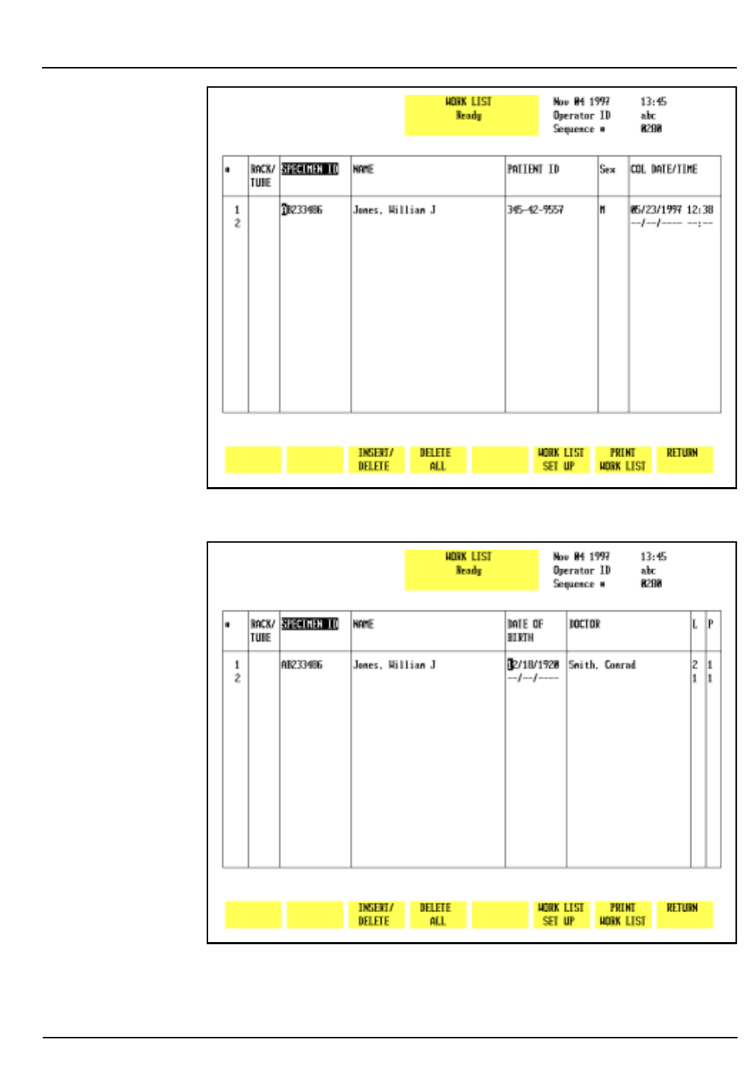
CELL-DYN® 3200 Operator’s Manual 5-69
9140181B — November 1997
Operating Instructions
Section 5 Run Menu
Figure 5.29: Work List Screen - Page 1
Figure 5.30: Work List Screen - Page 2
Go Back
Search
TOC
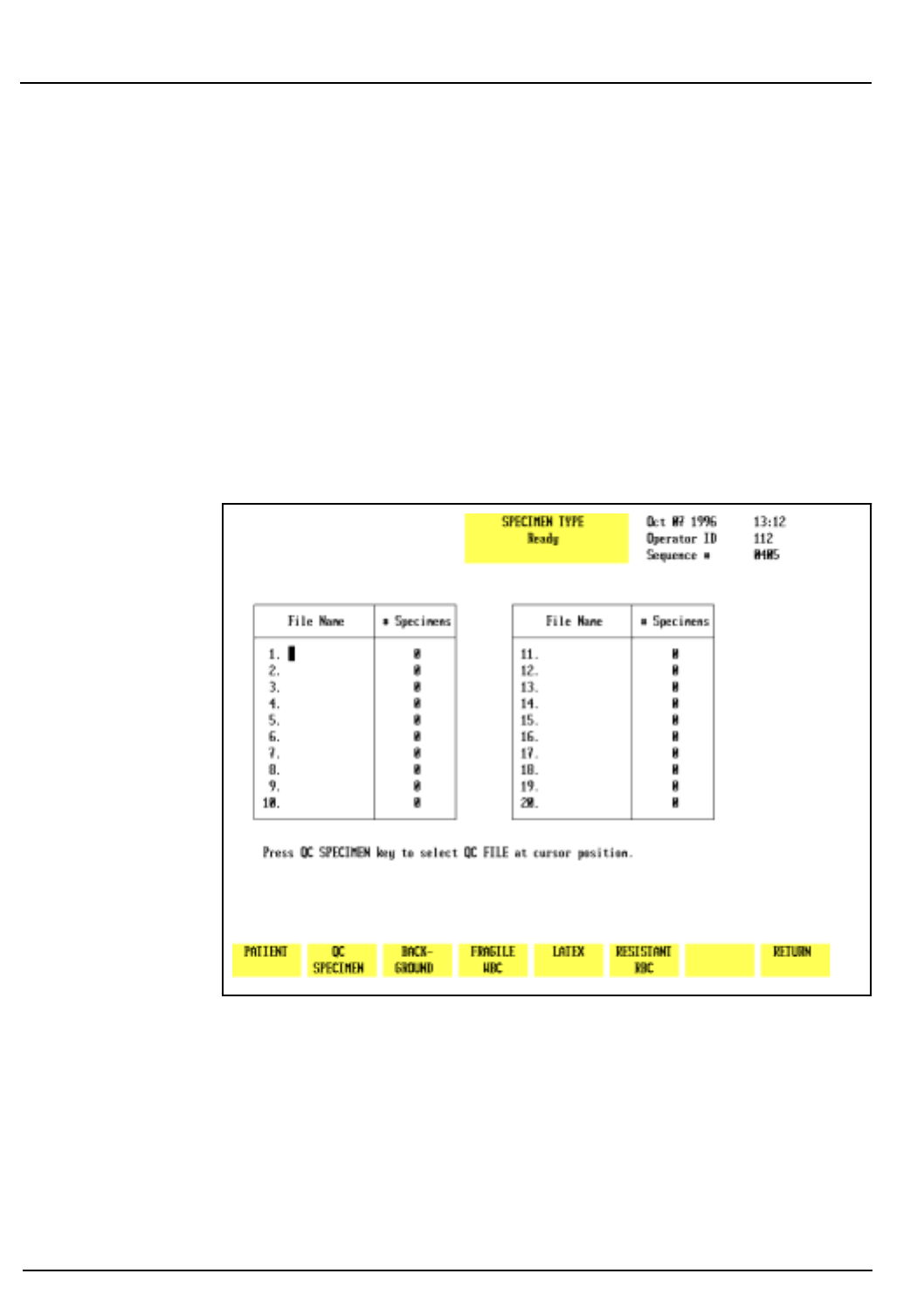
5-70 CELL-DYN® 3200 Operator’s Manual
9140181B — November 1997
Operating Instructions
Run Menu Section 5
The Work List is used to pre-assign sample identification,
display and print criteria for samples that will be run. It is
essentially a list of samples (including the pre-assigned
information) that the operator intends to run on the
instrument.
The Work List may be used with or without bar code labels on
the tubes. However, if bar codes are used on the tubes, they
must contain more than two digits to avoid a possible mis-
reading of the 2-digit bar code assigned to each rack.
For a detailed discussion of the Work List, refer to Using the
Work List later in this section.
Specimen Type
Figure 5.31: Specimen Type Screen
The
[SPECIMEN TYPE]
key is used to select the type of specimen
that will be run. (See Figure 5.31.) When the
[SPECIMEN TYPE]
key is pressed, the screen displays a list of the QC files and the
following soft key labels:
PATIENT
QC SPECIMEN
BACKGROUND
FRAGILE WBC
Go Back
Search
TOC
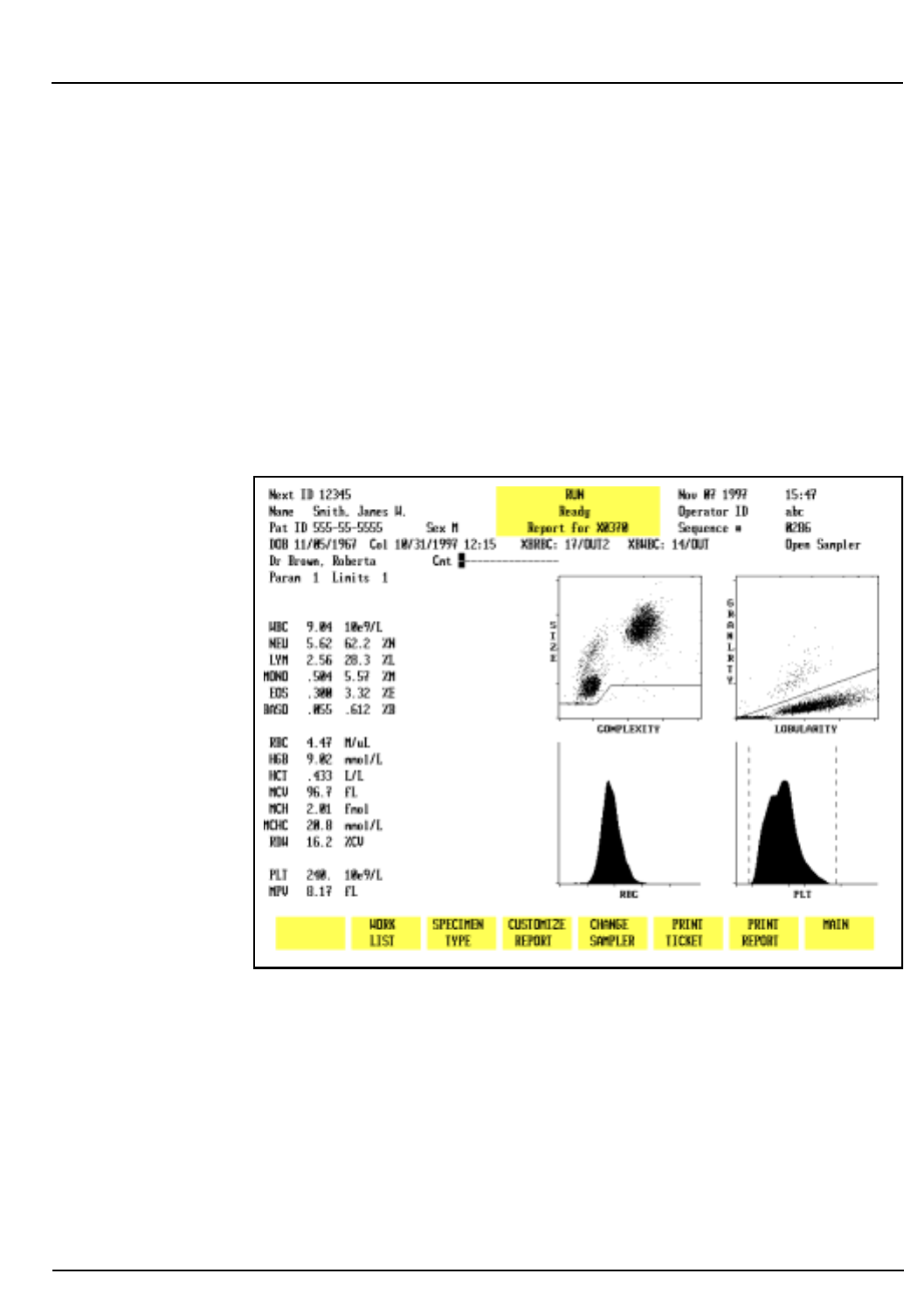
CELL-DYN® 3200 Operator’s Manual 5-71
9140181B — November 1997
Operating Instructions
Section 5 Run Menu
LATEX
RESISTANT RBC
RETURN
The function of each key is discussed below.
Selecting a Specimen Type
Most samples will be run in the Patient mode. If a FWBC or
RRBC flag is displayed on the RUN screen, the presence of
fragile WBCs or resistant RBCs is suspected. Depending on the
flag, select either Fragile WBC or Resistant RBC as the
Specimen Type and re-run the sample.
Patient
Figure 5.32: Run Screen Showing Patient Results
The
[PATIENT]
key is used to display the
RUN
screen for patient
samples. (See Figure 5.32.) Patient identification and
demographics may be entered on the
RUN
screen after this key
is pressed. Results from this run option are stored in the Data
Log.
Go Back
Search
TOC
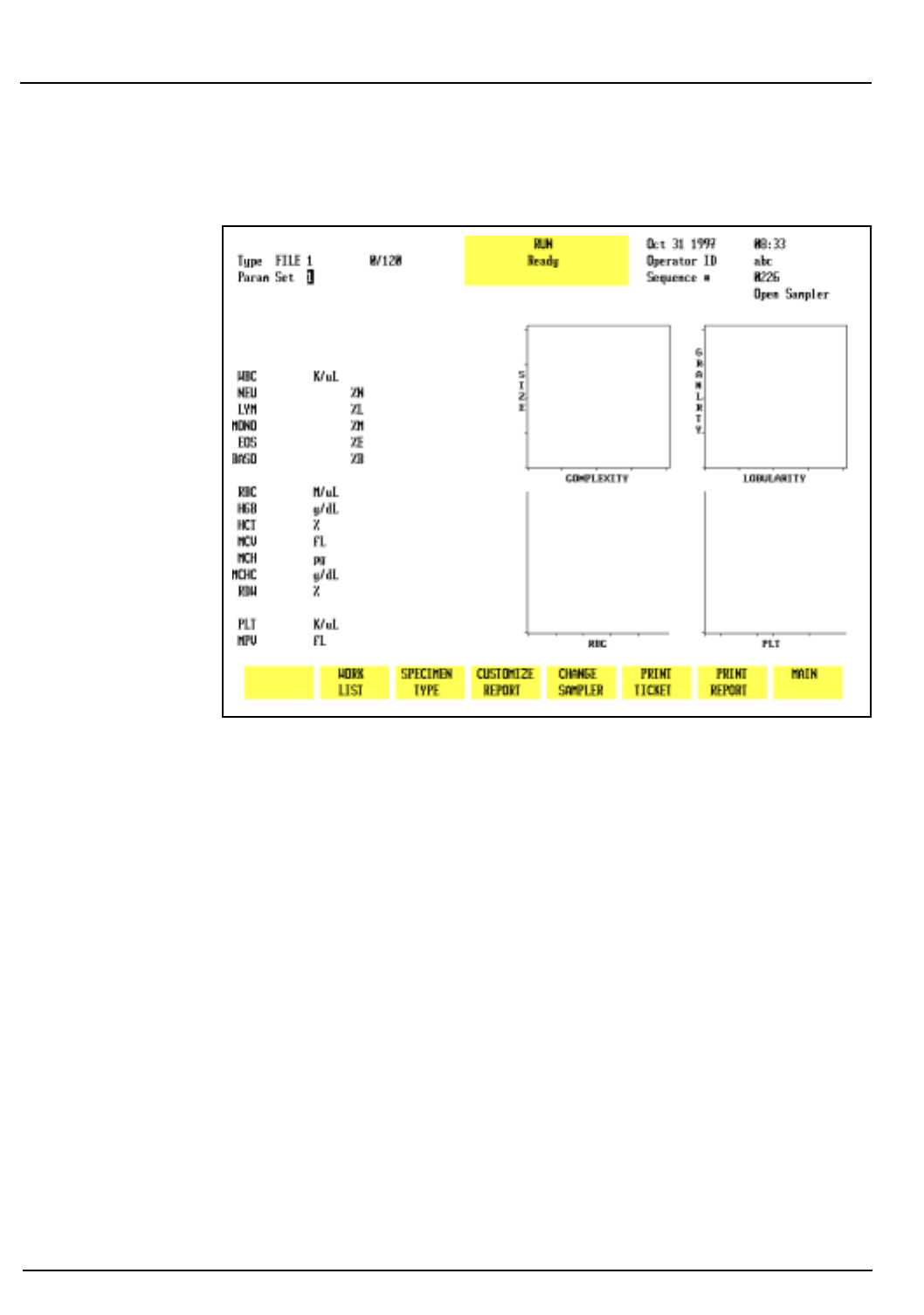
5-72 CELL-DYN® 3200 Operator’s Manual
9140181B — November 1997
Operating Instructions
Run Menu Section 5
QC Specimen
Figure 5.33: Run Screen for a QC File
This key is used to select a QC file designated by the position
of the cursor on the screen. (Refer to Figure 5.31 for a display of
QC files). After the cursor is moved to the desired file, the [
QC
SPECIMEN]
key is pressed to display the RUN screen for the
selected file. (Refer to Figure 5.33.) Results from this run
option are stored in the selected file and in the Data Log.
NOTE: The selected QC file is identified in the upper
left section of the screen and is also identified in the
Status Box after the sample has been run.
Go Back
Search
TOC
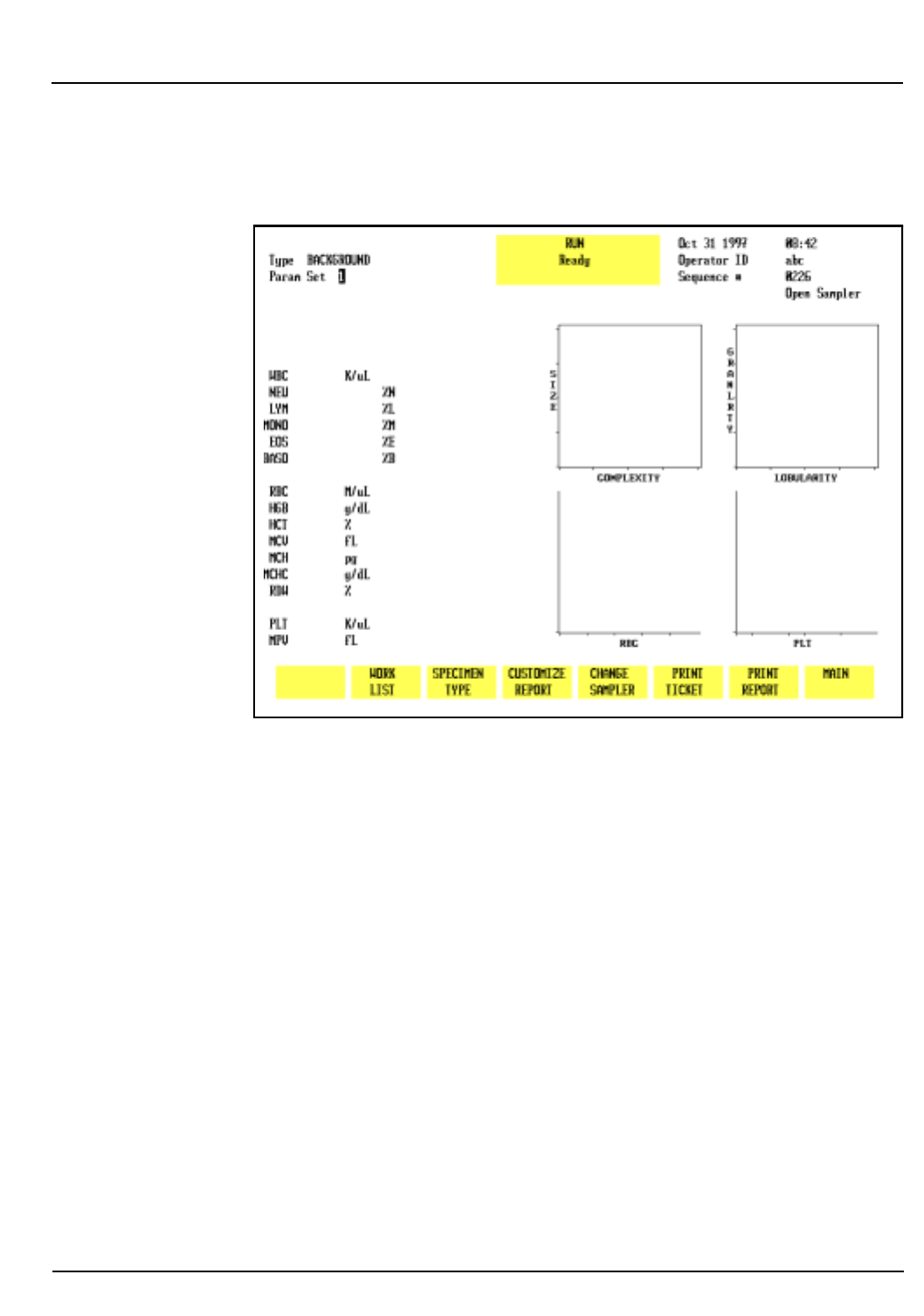
CELL-DYN® 3200 Operator’s Manual 5-73
9140181B — November 1997
Operating Instructions
Section 5 Run Menu
Background
Figure 5.34: Run Screen for Background Counts
The
[BACKGROUND]
key is used to select the run mode and
display the
RUN
screen for background counts. (Refer to Figure
5.34.) Results from this run option are identified by the
designation BACKGROUND in the Data Log and are
automatically excluded from the X-B analysis.
Go Back
Search
TOC
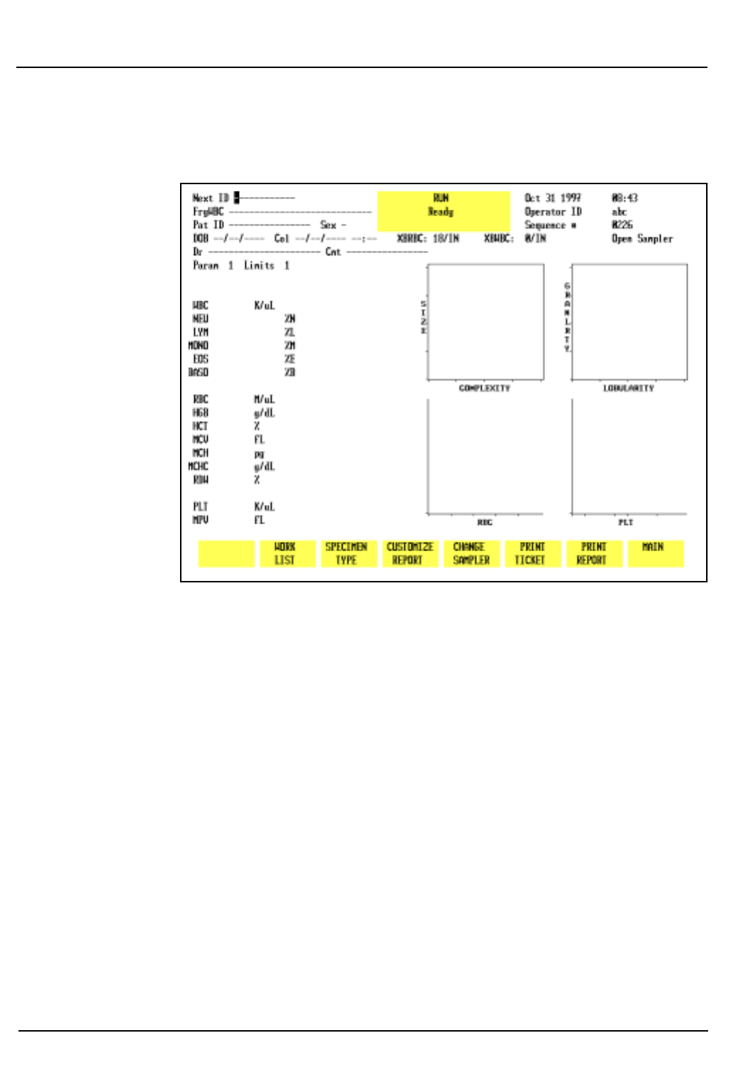
5-74 CELL-DYN® 3200 Operator’s Manual
9140181B — November 1997
Operating Instructions
Run Menu Section 5
Fragile WBC
Figure 5.35: Run Screen for Fragile WBC Counts
The
[FRAGILE WBC]
key is used to select the Fragile WBC
specimen type. This cycle is used to obtain an accurate WBC
count for samples containing fragile WBCs. After HGB has
been measured, the diluted HGB sample is sent to the Optical
Flow Cell (instead of the Waste System) where the nuclei of the
lysed white cells are counted. This count is referred to as the
Nuclear Optical Count (NOC).
The Fragile WBC screen (refer to Figure 5.35) is similar to the
Patient screen except that “FrgWBC” replaces “Name” in the
Demographics Section.
Go Back
Search
TOC
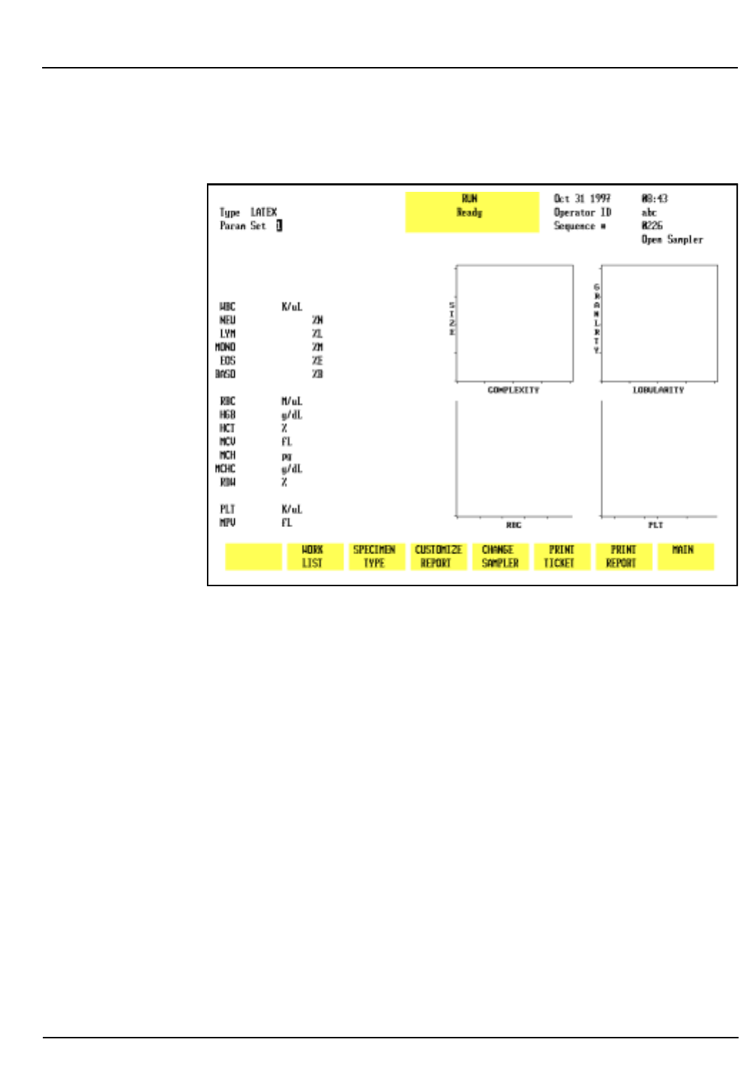
CELL-DYN® 3200 Operator’s Manual 5-75
9140181B — November 1997
Operating Instructions
Section 5 Run Menu
Latex
Figure 5.36: Run Screen for Latex Counts
The
[LATEX]
key is used to select the run mode for latex particles
and display the
RUN
screen for them. The
LATEX
screen is
similar to the
QC FILE
screen, except that “Latex” replaces the
QC File name in the Demographics Section.
This key is for use by Abbott service personnel only.
Go Back
Search
TOC

5-76 CELL-DYN® 3200 Operator’s Manual
9140181B — November 1997
Operating Instructions
Run Menu Section 5
Resistant RBC
Figure 5.37: Run Screen for Resistant RBC Counts
The
[RESISTANT RBC]
key is used to select the Resistant RBC
specimen type. This cycle is used to process samples
containing RBCs that are resistant to lysis. The sample is held
in the WBC Mixing Chamber for approximately 15 seconds
longer than the normal mixing time. The extra time enhances
the osmotic lysing effect of the WBC lyse and reduces
interference from the lyse-resistant RBCs. (The interference
caused by these RBCs frequently generates WBC and
Differential flags. The Resistant RBC mode reduces the number
of flags generated.)
The
RESISTANT RBC
screen (refer to Figure 5.37) is similar to the
Patient screen except that “ResRBC” replaces “Name” in the
Demographics Section.
Customize Report
The
[CUSTOMIZE REPORT]
key is discussed in the Set Up
Instructions earlier in this section.
Go Back
Search
TOC

CELL-DYN® 3200 Operator’s Manual 5-77
9140181B — November 1997
Operating Instructions
Section 5 Run Menu
Change Sampler
The
[CHANGE SAMPLER]
key is used to select the Open or Closed
Mode of operation. When the key is pressed, the mode
changes from the mode currently selected to the other
operating mode. The Status Box displays one of the two
following messages:
SELECTING OPEN MODE
SELECTING CLOSED MODE
Prior to running a sample, if the
[CHANGE SAMPLER]
key is
pressed, it will automatically clear any patient information
entered in the demographics section of the
RUN
screen.
Print Ticket
The
[PRINT TICKET]
key is used to print a report on a ticket when
a printer is connected to the Ticket Printer Port on the Data
Module. The report is printed on the type of ticket that is
selected from the
CUSTOMIZE PRINTED REPORT
screen.
Print Report
The
[PRINT REPORT]
key is used to print a graphics report when
printer is connected to the Graphics Printer Port on the Data
Module. When the color printing option on the
CUSTOMIZE
PRINTED REPORT
screen is ON, the key label changes to
[COLOR
PRINT]
. A color graphics report is printed when the
[COLOR
PRINT]
key is pressed and the printer connected to the Graphics
Printer Port is a color printer.
Main
The
[MAIN]
key is used to return to the
MAIN MENU
screen.
Go Back
Search
TOC
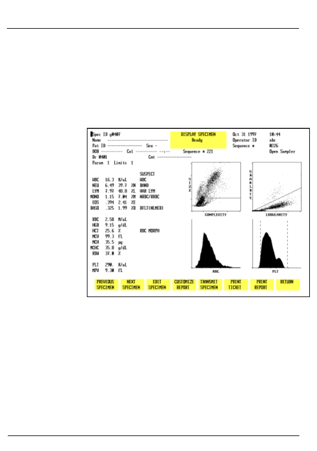
5-78 CELL-DYN® 3200 Operator’s Manual
9140181B — November 1997
Operating Instructions
Run Menu Section 5
Additional Examples of Run Menu Screens
Flagging Messages
An example of some flagging messages is shown in Figure 5.38.
A detailed explanation of all flagging messages is given in
Section 3: Principles of Operation.
Figure 5.38: Run Screen Showing Flagging Messages and RBC
MORPH Message
Go Back
Search
TOC
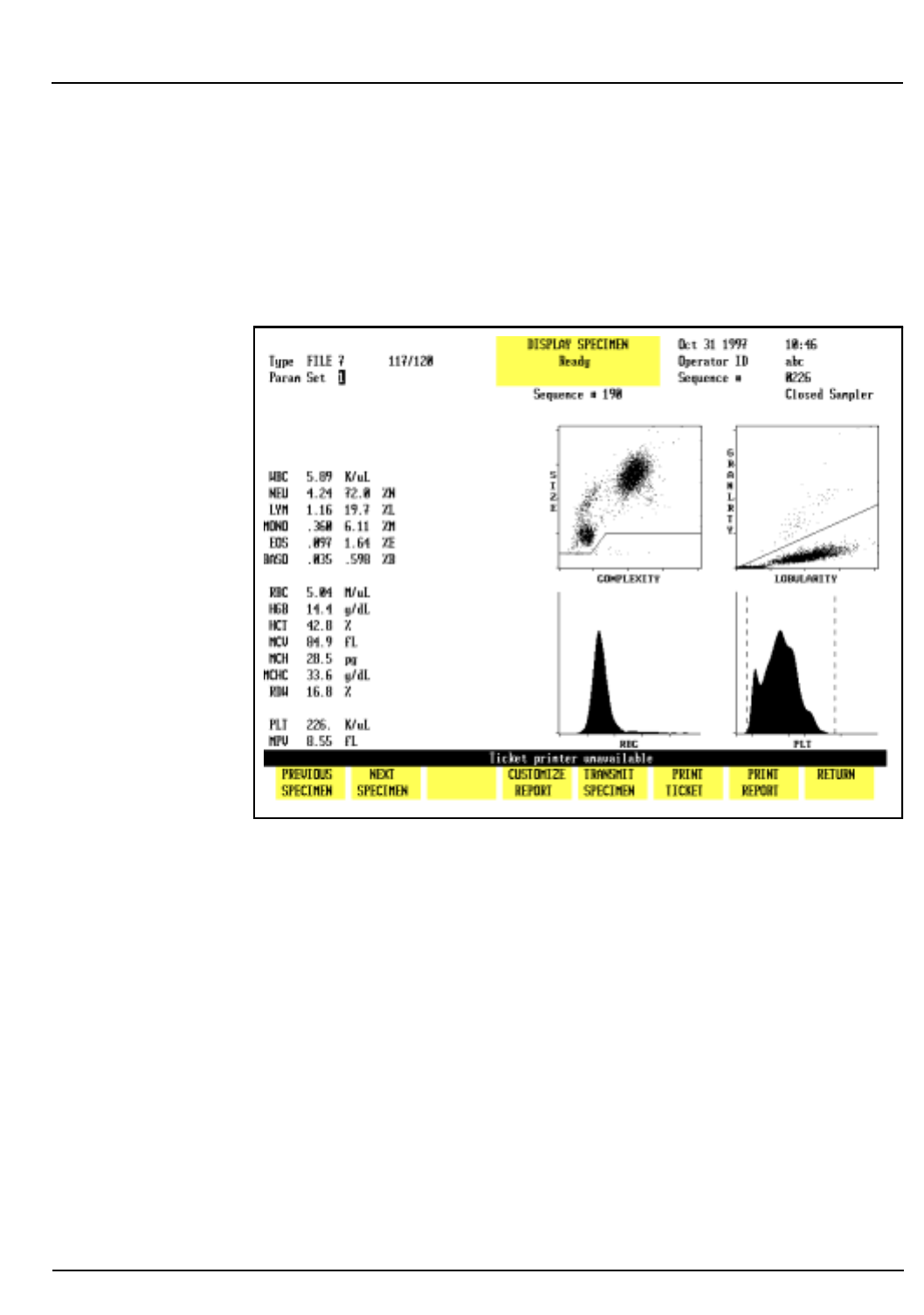
CELL-DYN® 3200 Operator’s Manual 5-79
9140181B — November 1997
Operating Instructions
Section 5 Run Menu
Bulletin Line Messages
Bulletin Line messages alert the operator to problems with the
instrument or provide instructions. An example of a Bulletin
Line message reading “Ticket printer unavailable” is shown in
Figure 5.39.
Figure 5.39: Run Screen Showing Bulletin Line Message
Go Back
Search
TOC
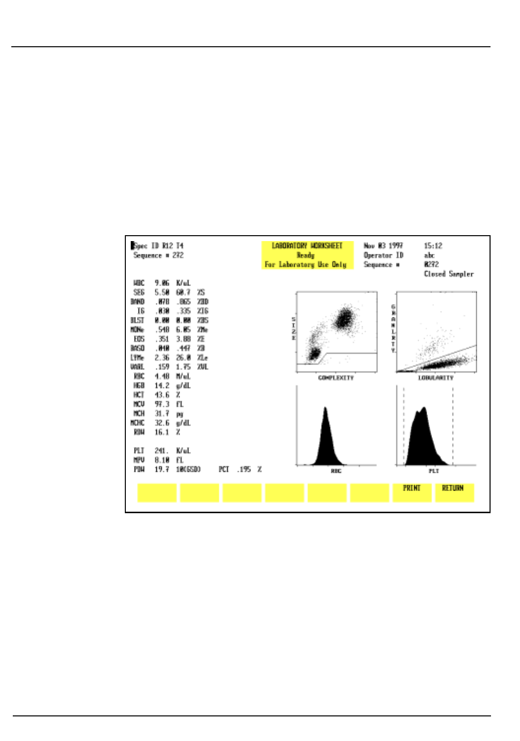
5-80 CELL-DYN® 3200 Operator’s Manual
9140181B — November 1997
Operating Instructions
Run Menu Section 5
Laboratory Worksheet
To display the
LABORATORY WORKSHEET
screen, press the Page
Down key on the keyboard while the
RUN
menu is displayed or
while the
DISPLAY SPECIMEN
screen in the
DATA LOG
menu is
displayed.
The
LABORATORY WORKSHEET
screen displays additional
parameters as shown in Figure 5.40. This screen is for
laboratory use only.
Figure 5.40: Laboratory Worksheet Screen
Go Back
Search
TOC

CELL-DYN® 3200 Operator’s Manual 5-81
9140181B — November 1997
Operating Instructions
Section 5 Sample Collection and Handling
Sample Collection and Handling
Anticoagulant
All performance claims given in this manual were generated
from samples collected in K3EDTA.
Sample Stability
Any refrigerator-stored specimens should be brought to room
temperature before processing. If specimens are to be run
within eight hours after collection, storage at room
temperature is recommended. If specimens are to be run more
than eight hours after collection, storage at temperatures
between 4° and 8° C is recommended.
Stability studies show that, when specimens are refrigerated at
temperatures between 4° and 8° C, and brought to room
temperature before mixing and processing, results for the RBC,
HGB, MCV, PLT are stable (±5%) for up to 36 hours after
collection. The total WBC and MPV is stable (±5%) for up to 24
hours after collection. The stability of the total WBC decreases
to ±10% at 36 hours after collection.
The stability of capillary samples collected in microtainers may
vary depending on the microtainer manufacturer. Refer to the
manufacturer’s package insert for stability claims.
Sample Collection
All samples should be collected using proper technique and
following the tube manufacturer’s recommendations.
NOTE: For additional information on collecting
venous and capillary samples, refer to NCCLS
Standards, H3-A31 and H4-A32.
WARNING: Potential Biohazard. Consider all
specimens, reagents, controls, calibrators, etc. that
contain human blood or serum as potentially
infectious. Wear gloves, lab coats, and safety glasses,
and follow other biosafety practices as specified in the
OSHA Bloodborne Pathogen Rule (29 CFR Part 1920,
1030) or other equivalent biosafety procedures.
Go Back
Search
TOC

5-82 CELL-DYN® 3200 Operator’s Manual
9140181B — November 1997
Operating Instructions
Sample Collection and Handling Section 5
Samples that will be run on the Sample Loader must have a
minimum volume of 1.0 mL to ensure proper mixing by the
Sample Loader.
A minimum of 180 µL should be collected for capillary
samples. This ensures an adequate amount of blood for the
Open Mode (120 µL) aspiration.
Interfering Substances
The CELL-DYN 3200 has been designed to detect and flag
samples that contain interfering substances. The following list
indicates the substances that may interfere with the listed
parameters.
WBC:NRBCs, lytic-resistant RBCs, PLT clumps, cryoglobulin
and cryofibrinogen, fragile WBCs
RBC: Elevated WBC count, increased numbers of giant PLTs,
autoagglutination, in vitro hemolysis
HGB: Elevated WBC count, increased plasma substances
(triglycerides, bilirubin, in vivo hemolysis), lytic-
resistant RBCs
MCV: Elevated WBC count, hyperglycemia, in vitro
hemolysis, increased numbers of giant PLTs
PLT: WBC fragments, in vitro hemolysis, microcytic RBCs,
cryoglobulins, PLT clumping, increased numbers of
giant PLTs. For a detailed description of the flags that
are generated, refer to Section 3: Principles of
Operation, Subsection: Operational Messages and
Data Flagging.
Go Back
Search
TOC

CELL-DYN® 3200 Operator’s Manual 5-83
9140181B — November 1997
Operating Instructions
Section 5 Preparing to Run Samples
Preparing to Run Samples
Before running specimens, the operator should enter data in
the demographics section of the RUN screen to properly
identify patient samples.
Operator ID
The operator should enter an Operator ID before running
samples. The Operator ID is displayed on all screens and
printed on the graphics report and the blank ticket report. It is
also retained in the QC logs and the Data Log.
The operator ID may be entered from the
MAIN MENU
or the
CALIBRATION
menu. When either menu is selected, the cursor is
positioned in the OPERATOR ID entry field. Type up to three
alphanumeric characters and press the Enter key on the
keyboard to save the ID number.
Sample Identification
Sample identification information is entered in the upper left
corner of the
RUN
screen. These entry fields are made available
when the Patient, Fragile WBC, or Resistant RBC specimen
types are selected. To select one of these three specimen types,
do the following:
1.Go to the
RUN
menu and press
[SPECIMEN TYPE]
.
2.Press one of the following keys to select the desired
specimen type —
[PATIENT]
,
[FRAGILE WBC]
,
[RESISTANT RBC]
.
Enter the sample identification information as follows:
1.A Sample ID number (Next ID field) of up to 12 characters
may be entered in the NEXT ID entry field.
2.The remaining patient demographic information may be
entered at the operator’s discretion. Refer to Run Screen
for Patient Samples earlier in this section for a discussion
of these fields.
Go Back
Search
TOC

5-84 CELL-DYN® 3200 Operator’s Manual
9140181B — November 1997
Operating Instructions
Preparing to Run Samples Section 5
3.Parameter Set 1 and Patient Limits Set 1 are the default
settings when the instrument is shipped from the factory.
The results are displayed and printed using these settings
unless the operator changes these entry fields. New
parameter and/or limits sets can be entered anytime
before a sample is run or after the results of a sample run
are displayed by moving the cursor to the appropriate
field and typing the desired number.
NOTE: When the results are stored in the Data Log,
other parameter and limits sets may be selected by
using the
[EDIT SPECIMEN]
key. For complete instructions,
refer to Using the Data Log later in this section.
Go Back
Search
TOC

CELL-DYN® 3200 Operator’s Manual 5-85
9140181B — November 1997
Operating Instructions
Section 5 Sample Analysis on the CELL-DYN 3200SL
Sample Analysis on the CELL-DYN 3200SL
Introduction
This section explains how samples are run on the 3200SL
model, both Open and Closed Modes. Samples should not be
run until daily QC checks have been performed and the
instrument is in the READY state. For convenience, directions
for Daily Start Up and QC are given in each section. Directions
for running samples in the Open Mode are also included in
each section.
Samples may be analyzed whenever the READY message is
displayed in the Status Box on the
RUN
screen. If the System has
been idle for 15 minutes or more, run a background immediately
prior to running a patient sample.
Samples should be well mixed (a rotary mixer is preferred3)
before they are run in the Open or Closed Mode on the
instrument. The Sample Loader automatically mixes the
samples before aspiration. However, samples must be well
mixed before they are placed in the Sample Loader racks.
Instrument Preparation
1. Be sure that the green READY light on the Analyzer Status
Indicator Panel is illuminated and the READY message is
displayed in the Status Box on the RUN screen.
2. If the Status Box on the Data Station
RUN
screen displays
STANDBY or INITIALIZED press
[RUN]
to initiate the
automatic Start Up cycle.
3. When the automatic Start Up cycle is completed, a
background count is automatically performed and the
Open Mode is selected.
4. Verify that the background counts are acceptable. If the
background counts are unacceptable, repeat the
background cycle. If the counts are still unacceptable,
troubleshoot accordingly.
NOTE: Backgrounds may be repeated by pressing the
Touch Plate.
Go Back
Search
TOC

5-86 CELL-DYN® 3200 Operator’s Manual
9140181B — November 1997
Operating Instructions
Sample Analysis on the CELL-DYN 3200SL Section 5
5.If the Sample Loader is to be used, be sure that at least
one rack (maximum of five) is in the load area to the right
of the Tower Cover and that the Tower Cover is in place.
6.To switch from Open Mode to Closed Mode, press the
[CHANGE SAMPLER]
key. Wait until the message READY is
displayed in the Status Box.
7.Perform the daily Quality Control checks as directed in
subsection Sample Analysis on the CELL-DYN 3200,
Daily Quality Control Checks.
Sample Loader Operating Tips
1.All Sample Loader tubing must be connected before
turning ON the System.
2.All samples must be properly mixed before they are
placed in the Sample Loader racks.
3. Place the labeled tubes in the Sample Loader rack and
load the rack on the Sample Loader.
4. If a tube has multiple labels on it, spin the tube by hand
after it is put in a rack to be sure it will spin freely and
therefore mix properly. (Refer to Section 13: Sample
Loader for labeling requirements.)
Daily Quality Control Checks
Quality Control checks (which confirm calibration) should be
performed on a daily basis according to the laboratory’s
protocol. Commercial control materials should be properly
warmed and mixed according to the manufacturer’s
recommendations. Patient controls should be handled
according to the laboratory’s protocol.
WARNING: Potential Biohazard. Consider all specimens
and reagents, controls, calibrators, etc. that contain
human blood or serum as potentially infectious. Wear
gloves, lab coats, and safety glasses, and follow other
biosafety practices as specified in the OSHA Bloodborne
Pathogen Rule (29 CFR Part 1910, 1030) or other
equivalent biosafety procedures.
Open Mode QC Procedure
1. In the
RUN
screen, press
[SPECIMEN TYPE]
.
Go Back
Search
TOC

CELL-DYN® 3200 Operator’s Manual 5-87
9140181B — November 1997
Operating Instructions
Section 5 Sample Analysis on the CELL-DYN 3200SL
2.Move the cursor to the desired QC file and press
[QC
SPECIMEN]
.
3.If necessary, press
[CHANGE SAMPLER]
to select the Open
Mode.
4.Run the control.
NOTE: Refer to the Running Samples subsection
following this procedure for complete instructions on
running samples.
5.Verify that the results are acceptable.
NOTE: Out-of-range results are displayed in color.
6.If the results are unacceptable, repeat the run. If the
results are still unacceptable, obtain a new bottle of the
control, be sure that it is warmed and mixed properly and
again repeat the run. If the results are still unacceptable,
run the other levels of control material. If the results on
all levels are unacceptable, troubleshoot as directed in
Section 10: Troubleshooting and Diagnostics,
Subsection: Troubleshooting Guide.
7. When the control results are acceptable, patient samples
may be analyzed.
Closed Mode QC Procedure
The operator must manually stop the Sample Loader as
directed in this procedure when different levels of controls are
run.
1. From the
RUN
screen, press
[SPECIMEN TYPE]
.
2. Use the Arrow keys on the keyboard to move the cursor to
the appropriate QC file and press
[QC SPECIMEN]
.
3.If necessary, press
[CHANGE SAMPLER]
to select Closed
Mode.
4.Place the controls in the Sample Loader rack in the order
in which they are to be run.
5.Be sure the Tower Cover is in place and press the
[START
LOADER]
key.
6.After the first control is aspirated, press the
[STOP LOADER]
key.
7.After the results are displayed, press
[SPECIMEN TYPE]
.
Go Back
Search
TOC

5-88 CELL-DYN® 3200 Operator’s Manual
9140181B — November 1997
Operating Instructions
Sample Analysis on the CELL-DYN 3200SL Section 5
8.Use the Arrow keys on the keyboard to move the cursor to
the file for the next control to be run and press
[QC
SPECIMEN]
.
9. Press the
[START LOADER]
key.
10.Repeat steps 6 – 9 until all levels of controls have been
run.
11.When all of the controls have been run, press
[MAIN]
followed by
[QUALITY CONTROL]
.
12.Use the Arrow keys on the keyboard to move the cursor to
the desired file.
13.Press
[VIEW QC LOG]
to display the
QC LOG
screen.
14.Verify that the results are acceptable.
NOTE: Out-of-range results are displayed in color.
15.Press
[RETURN]
to return to the main
QUALITY CONTROL
screen.
16.Repeat steps 12–15 for all levels of controls that were run.
17.If the results are unacceptable, repeat the run. If the
results are still unacceptable, obtain a new tube of
control, be sure that it is warmed and mixed properly and
again repeat the run. If the results are still unacceptable, run
the other levels of control material. If the results on all
levels are unacceptable, troubleshoot as directed in
Section 10, Subsection: Troubleshooting Guide.
18.When the control results are acceptable, patient samples
may be analyzed.
Running Samples
WARNING: Potential Biohazard. Consider all specimens
and reagents, controls, calibrators, etc. that contain
human blood or serum as potentially infectious. Wear
gloves, lab coats, and safety glasses, and follow other
biosafety practices as specified in the OSHA Bloodborne
Pathogen Rule (29 CFR Part 1910, 1030) or other
equivalent biosafety procedures.
Open Mode Analysis
The Open Sampler mode aspirates the sample from an open
collection tube. OPEN SAMPLER is displayed in the upper right
corner of the
RUN
screen when this mode is selected. The open
sample aspiration probe is available (Wash Block raised) only
when this mode is selected.
Go Back
Search
TOC

CELL-DYN® 3200 Operator’s Manual 5-89
9140181B — November 1997
Operating Instructions
Section 5 Sample Analysis on the CELL-DYN 3200SL
Open Mode Procedure
1. If necessary, from the
RUN
screen press
[CHANGE SAMPLER]
to select the Open Mode.
2. Be sure that the green READY light on the Analyzer Status
Indicator Panel is illuminated and READY is displayed in
the Status Box on the RUN screen.
3. With the stopper still in the tube, mix the sample well
(invert the tube a minimum of 5 times to thoroughly mix
the sample).
4. Open the sample tube and place it under the Open
Sample Aspiration Probe. Raise the tube until the end of
the probe is deeply immersed in the sample.
CAUTION: Do not let the probe touch the bottom of
the sample tube. It may affect aspiration and produce
erroneous results.
5. Press the Touch Plate located behind the probe to start
the cycle. The yellow BUSY light on the Analyzer Status
Indicator Panel is illuminated. The Status Box on the RUN
screen displays messages to indicate the various stages of
the cycle.
6. Remove the tube when the beep sounds. The message
REMOVE SPECIMEN is displayed in the Status Box. The
wash block moves down the probe and cleans it.
7. When the cycle is finished, the wash block moves up the
probe, the green READY light on the Analyzer Status
Indicator Panel is illuminated, and the results are
displayed on the RUN screen.
NOTE: Another sample may be aspirated at this point
even though READY is not displayed in the Status Box
on the screen. Generally, the READY light on the
Analyzer Status Indicator Panel will be illuminated
before the Status Box on the screen displays READY.
8. If automatic report printing has been specified, a report is
printed according to the options selected during Set Up. If
the Color Printing option was selected in the
CUSTOMIZED
PRINTED REPORT
screen for the Graphics Printer, the
printouts will be in color. Otherwise, the reports will be
printed in black and white.
Go Back
Search
TOC

5-90 CELL-DYN® 3200 Operator’s Manual
9140181B — November 1997
Operating Instructions
Sample Analysis on the CELL-DYN 3200SL Section 5
9.If automatic printing has not been specified, a report may
be printed by pressing either
[PRINT REPORT]
or
[COLOR
PRINT]
. The
[COLOR PRINT]
key will be displayed if the Color
Printing option was selected.
10.Repeat this procedure for subsequent samples.
Closed Mode Analysis
The Closed Sampler mode on CELL-DYN 3200SL models
aspirates the sample from a closed collection tube that has
been placed in a Sample Loader rack and loaded into the
Sample Loader. CLOSED SAMPLER is displayed in the upper
right corner of the
RUN
screen when this mode is selected. The
wash block moves down to the end of the open sample
aspiration probe when this mode is selected.
Closed Mode Procedure
1. If necessary, in the
RUN
screen press
[CHANGE SAMPLER]
to
select the Closed Mode.
2.Be sure that the green READY light on the Analyzer Status
Indicator Panel is illuminated and READY is displayed in
the Status Box on the
RUN
screen.
3. Place the well mixed samples in the Sample Loader racks.
NOTE: The racks and tube positions are identified by
the bar code label on the rack and indicated as RxTx.
These numbers appear as the Sample ID number if bar
code labels are not used. (If the Work List is used, the
Sample ID number is taken from it. Refer to Using the
Work List later in this section for more information.)
4.Place the racks in the Sample Loader to the right of the
Tower Cover with the slotted side (with bar code labels)
facing the operator.
5. Verify the Tower Cover is in place.
NOTE: The Sample Loader will not operate without the
Tower Cover in place.
6. Press the
[START LOADER]
key on the
RUN
screen.
7.The Sample Loader automatically processes all the
samples. Processing stops when the last rack is finished or
the
[STOP LOADER]
key is pressed. The last rack is finished
when it has moved completely to the unload side of the
Sample Loader.
Go Back
Search
TOC

CELL-DYN® 3200 Operator’s Manual 5-91
9140181B — November 1997
Operating Instructions
Section 5 Sample Analysis on the CELL-DYN 3200CS
Sample Analysis on the CELL-DYN 3200CS
Introduction
This section explains how samples are run on the 3200CS
models, both Open and Closed Modes. Samples should not be
run until daily QC checks have been performed and the
instrument is in the READY state. For convenience, directions
for Daily Start Up and QC are given in each section. Directions
for running samples in the Open Mode are also included in
each section.
Samples may be analyzed whenever the READY message is
displayed in the Status Box on the
RUN
screen. Samples should
be well mixed (a rotary mixer is preferred3) before they are run
in the Open or Closed Mode on the instrument.
Instrument Preparation
1. Be sure that the green READY light on the Analyzer Status
Indicator Panel is illuminated.
2. If the Status Box on the
RUN
screen displays STANDBY or
INITIALIZED, press
[RUN]
to initiate the automatic Start
Up cycle.
3. When the cycle is finished, a background count is
automatically performed and the Open Mode is selected.
4. Verify that the background counts are acceptable. If the
background counts are unacceptable, repeat the
background cycle. If the counts are still unacceptable,
troubleshoot accordingly.
NOTE: Backgrounds may be repeated by pressing the
touch plate.
5. If controls will be processed in Closed Mode, press
[CHANGE SAMPLER]
.
6. Perform the daily Quality Control checks as directed in
the following section.
Go Back
Search
TOC

5-92 CELL-DYN® 3200 Operator’s Manual
9140181B — November 1997
Operating Instructions
Sample Analysis on the CELL-DYN 3200CS Section 5
Daily Quality Control Checks
Quality Control checks (which confirm calibration) should be
performed on a daily basis according to the laboratory’s
protocol. Commercial control materials should be properly
warmed and mixed according to the manufacturer’s
recommendations. Patient controls should be handled
according to the laboratory’s protocol.
WARNING: Potential Biohazard. Consider all specimens
and reagents, controls, calibrators, etc. that contain
human blood or serum as potentially infectious. Wear
gloves, lab coats, and safety glasses, and follow other
biosafety practices as specified in the OSHA Bloodborne
Pathogen Rule (29 CFR Part 1910, 1030) or other
equivalent biosafety procedures.
QC (Open or Closed Mode) Procedure
1. In the
RUN
screen, press
[SPECIMEN TYPE]
.
2.Move the cursor to the desired QC file and press
[QC
SPECIMEN]
.
3.If necessary, press
[CHANGE SAMPLER]
to select the desired
mode.
4.Run the control.
NOTE: Refer to the Running Samples subsection
following this procedure for complete instructions on
running samples.
5.Verify that the results are acceptable.
NOTE: Out-of-range results are displayed in color.
6.If the results are unacceptable, repeat the run. If the
results are still unacceptable, obtain a new bottle of the
control, be sure that it is warmed and mixed properly and
again repeat the run. If the results are still unacceptable,
run the other levels of control material. If the results on
all levels are unacceptable, troubleshoot as directed in
Section 10: Troubleshooting and Diagnostics,
Subsection: Troubleshooting Guide.
7. When the control results are acceptable, patient samples
may be analyzed.
Go Back
Search
TOC

CELL-DYN® 3200 Operator’s Manual 5-93
9140181B — November 1997
Operating Instructions
Section 5 Sample Analysis on the CELL-DYN 3200CS
Running Samples
WARNING: Potential Biohazard. Consider all specimens
and reagents, controls, calibrators, etc. that contain
human blood or serum as potentially infectious. Wear
gloves, lab coats, and safety glasses, and follow other
biosafety practices as specified in the OSHA Bloodborne
Pathogen Rule (29 CFR Part 1910, 1030) or other
equivalent biosafety procedures.
Open Mode Analysis
The Open Sampler mode aspirates the sample from an open
collection tube. OPEN SAMPLER is displayed in the upper right
corner of the
RUN
screen when this mode is selected. The Open
Sample Aspiration Probe is available only when this mode is
selected.
Open Mode Procedure
1. If necessary, in the
RUN
screen press
[CHANGE SAMPLER]
to
select the Open Mode.
2. Be sure that the green READY light on the Analyzer Status
Indicator Panel is illuminated and READY is displayed in
the Status Box on the
RUN
screen.
3. With the stopper still in the tube, mix the sample well
(invert the tube a minimum of 5 times to thoroughly mix
the sample).
4. Open the sample tube and place it under the Open
Sample Aspiration Probe. Raise the tube until the end of
the probe is deeply immersed in the sample.
NOTE: Do not let the probe touch the bottom of the
sample tube. It may affect aspiration and produce
erroneous results.
5. Press the Touch Plate located behind the probe to start
the cycle. The yellow BUSY light on the Analyzer Status
Indicator Panel is illuminated. The Status Box on the
RUN
screen displays messages to indicate the various stages of
the cycle.
6. Remove the tube when the beep sounds. The message
REMOVE SPECIMEN is displayed in the Status Box. The
wash block moves down the probe and cleans it.
Go Back
Search
TOC

5-94 CELL-DYN® 3200 Operator’s Manual
9140181B — November 1997
Operating Instructions
Sample Analysis on the CELL-DYN 3200CS Section 5
7. When the cycle is finished, the wash block moves up the
probe, the green READY light on the Analyzer Status
Indicator Panel is illuminated, and the results are
displayed on the
RUN
screen.
NOTE: Another sample may be aspirated at this point
even though READY is not displayed in the Status Box
on the screen. Generally, the READY light on the
Analyzer Status Indicator Panel will be illuminated
before the Status Box on the screen displays READY.
8. If automatic report printing has been specified, a report is
printed according to the options selected during Set Up.
The reports are printed in black and white. If automatic
printing has not been specified, a report may be printed
by pressing
[PRINT REPORT]
.
NOTE: To obtain a color printout, press
[COLOR PRINT]
.
(The color printing option on the
CUSTOMIZE PRINTED
REPORT
screen must be ON.)
9. Repeat this procedure for subsequent samples.
Closed Mode Analysis
The Closed Sampler mode on Closed Sampler (CS) instruments
aspirates the sample from a closed collection tube that has
been inserted in the Closed Sample Tower Module. CLOSED
SAMPLER is displayed in the upper right corner of the RUN
screen when this mode is selected. The wash block moves
down to the end of the Open Sample Aspiration Probe when
this mode is selected.
Closed Mode Procedure
1. Be sure that the green READY light on the Analyzer Status
Indicator Panel is illuminated and READY is displayed in
the Status Box on the
RUN
screen.
2. If necessary, in the RUN screen press
[CHANGE SAMPLER]
to
select the Closed Mode.
3. With the stopper still in the tube, mix the sample well
(invert the tube a minimum of 5 times to thoroughly mix
the sample).
4. Place the well-mixed sample, with the stopper facing up,
into the Tube Holder and push the door closed.
NOTE: The Touch Plate will not operate if the door has
not been closed.
Go Back
Search
TOC

CELL-DYN® 3200 Operator’s Manual 5-95
9140181B — November 1997
Operating Instructions
Section 5 Sample Analysis on the CELL-DYN 3200CS
5. Press the Touch Plate located behind the probe to start the
cycle. The yellow BUSY light on the Analyzer Status
Indicator Panel is illuminated.
6. Remove the tube when the door opens. A beep sounds
when the door opens.
NOTE: The door automatically opens whenever a
sample has been aspirated in the Closed Mode or a
background count has been run in Open Mode. There is
also a tab under the Door Assembly that mechanically
releases the door. This tab can be used if the door is
closed and no tube is in the holder. The door will not
open if the needle is in the tube. In case of an
emergency stop, the operator will have to remove the
Tower Cover and manually raise the needle out of the
sample.
7. When the cycle is finished, the green READY light on the
Analyzer Status Indicator Panel is illuminated and the
results are displayed on the
RUN
screen.
NOTE: Another sample may be aspirated at this point
even though READY is not displayed in the Status Box
on the screen. Generally, the READY light on the
Analyzer Status Indicator Panel will be illuminated
before the Status Box on the screen displays READY.
8. Repeat this procedure for subsequent samples.
Go Back
Search
TOC

5-96 CELL-DYN® 3200 Operator’s Manual
9140181B — November 1997
Operating Instructions
Sample Analysis on the CELL-DYN 3200CS Section 5
NOTES
Go Back
Search
TOC

CELL-DYN® 3200 Operator’s Manual 5-97
9140181B — November 1997
Operating Instructions
Section 5 Alerts and Indicators
Alerts and Indicators
This subsection describes information displayed on the screen
as the samples are analyzed and/or when reports are
printed.This subsection does not discuss how to interpret
parameter flags, which are displayed after the sample is run.
Refer to Section 3: Principles of Operation, Subsection:
Operational Messages and Data Flagging.
Out of Range
•Results that fall outside the range of the selected limit set
are displayed in color. Yellow indicates that the result
exceeded the lower limit and purple indicates that the
result exceeded the upper limit. These results are
underlined on the graphics and blank ticket printouts.
They are indicated by an asterisk on a pre-printed ticket.
•Results that exceed a parameter’s linear range are
indicated by >>>> in place of the result.
Fault Conditions
The
[CLEAR FAULT]
key is displayed and a message (e.g. DILUENT
EMPTY) appears in the Status Box if a fault condition is
detected. The word “Fault” on the Analyzer status indicator is
illuminated in red. The Status Box displays the message FAULT:
SEE DIAG or SEE SPECIAL to direct the operator to the
DIAGNOSTICS
or
SPECIAL PROTOCOLS
menu for further instructions.
After the problem has been corrected, press
[CLEAR FAULT]
to
resume operation.
Flow Errors
If a RBC Flow Error occurs, results are suppressed for the RBC/
PLT parameters and the RBC FLOW ERROR message is displayed
on the Bulletin line. The RBC/PLT scatterplots are suppressed.
If a WOC Flow Error occurs, results are suppressed for the WBC
and Differential and the WOC FLOW ERROR message is
displayed on the Bulletin line. The WBC scatterplots are
suppressed.
Go Back
Search
TOC

5-98 CELL-DYN® 3200 Operator’s Manual
9140181B — November 1997
Operating Instructions
Alerts and Indicators Section 5
If a NOC Flow Error occurs, results are suppressed for the WBC
and Differential and the NOC FLOW ERROR message is
displayed on the Bulletin line. The NOC scatterplots are
suppressed.
3 Consecutive Flow Errors
If the Sample Loader is being used and the instrument detects
one of the following:
1. Three consecutive RBC flow errors.
2. Three consecutive WOC flow errors.
3. Three consecutive NOC flow errors.
The Sample Loader halts at the end of the cycle and the
Bulletin line displays the appropriate message:
1. 3 CONSECUTIVE RBC FLOW ERRORS.
2. 3 CONSECUTIVE WOC FLOW ERRORS.
3. 3 CONSECUTIVE NOC FLOW ERRORS.
Sampling Errors
The message SAMPLING ERROR-INCOMPLETE ASPIRATION is
displayed on the Bulletin line if insufficient sample was
detected during aspiration. SAMPLING ERR is displayed on the
screen and SAMPLING ERR is printed on the graphics report to
the right of the MCHC. The same message is printed to the
right of the WBC on the pre-printed ticket and printed above
the list of parameters on the blank ticket.
3 Consecutive Sampling Errors
If the Sample Loader is being used and the Instrument detects
three consecutive incomplete aspirations, the Sample Loader
halts at the end of the cycle and the Bulletin line displays the
message
3 CONSECUTIVE INCOMPLETE ASPIRATIONS.
Go Back
Search
TOC

CELL-DYN® 3200 Operator’s Manual 5-99
9140181B — November 1997
Operating Instructions
Section 5 Daily Shutdown Procedure
Daily Shutdown Procedure
Daily Shutdown
The Daily Shutdown Procedure consists of rinsing the Flow
System. Whether or not this procedure is followed on a daily
basis depends on instrument usage and the laboratory’s
procedures. It may not be necessary to perform this procedure
every day, since the instrument automatically goes into a
STANDBY state (Automatic Shutdown) if it has been idle for
four hours. Before the instrument enters the STANDBY state,
the Flow Panel is automatically rinsed.
If desired, the operator may place the instrument in the
STANDBY state by pressing the
[DAILY SHUTDOWN]
soft key in the
second level
SPECIAL PROTOCOLS
menu. When this key is
pressed or when Automatic Shutdown is initiated, the
following occurs:
• The Flow System is rinsed.
• The timer control, which periodically opens all of the
solenoid valves to prevent pinched tubing, is set.
The Daily Shutdown cycle takes approximately 10 minutes.
For a more thorough cleaning of the instrument prior to Daily
Shutdown, perform the following procedures:
1. In the
SPECIAL PROTOCOLS
menu, press
[AUTO CLEAN]
.
2. Clean Sample Loader including racks and Tower Cover.
3. Press
[DAILY SHUTDOWN]
.
4. Empty Waste (as needed)
NOTE: The Auto-Clean cycle may be run as part of the
Daily Start-Up Procedure, depending on operator
preference. The Clean Needle process should be used if
there is a problem with Closed Mode aspiration and an
obstruction in the needle is a suspected cause.
Go Back
Search
TOC

5-100 CELL-DYN® 3200 Operator’s Manual
9140181B — November 1997
Operating Instructions
Daily Shutdown Procedure Section 5
The Auto-Clean and Clean Needle procedures are described in
detail in Section 9: Service and Maintenance, Subsection:
Daily Maintenance Procedures. Procedures for cleaning the
Sample Loader are described in detail in Section 13: Sample
Loader.
In addition to the daily procedures listed above, if the
instrument will remain idle for a period of time, then
supplemental shutdown procedures are required depending on
the expected duration of the idle time — Short-term,
Intermediate, or Prolonged Shutdown. These categories are
discussed below.
Peristaltic Pump Tubing
IMPORTANT: By removing the tubing under the Sample
Transfer Peristaltic Pump, the life of the tubing is significantly
prolonged. The tubing should be removed if the instrument
will be idle for more than 24 hours and reinserted prior to
operating the instrument.
Short Term Shutdown
If the shutdown time is expected to be 72 hours or less, follow
the procedure below:
1. In the
MAIN MENU
, press
[SPECIAL PROTOCOLS]
.
2.If the instrument is to be cleaned first, press
[AUTO CLEAN]
,
otherwise go to step 3.
3. Press
[DAILY SHUTDOWN]
.
4. Leave power ON.
5.Tubing should be removed from under the Peristaltic
Pump.
Intermediate-term Shutdown
If the shutdown time is expected to exceed 72 hours (but less
than 2 weeks), follow the procedure below:
1.With the system still ON, perform any maintenance that
is due.
2. In the
MAIN MENU
, press
[SPECIAL PROTOCOLS]
.
3. Press
[AUTO CLEAN]
to clean the instrument.
4. Press
[DAILY SHUTDOWN]
.
Go Back
Search
TOC

CELL-DYN® 3200 Operator’s Manual 5-101
9140181B — November 1997
Operating Instructions
Section 5 Daily Shutdown Procedure
5. When the DAILY SHUTDOWN cycle is finished, turn
power OFF in the following order:
a.System (includes Analyzer, Data Module, and Sample
Loader)
b.Display Monitor
c.Printer
NOTE: In an emergency situation, turn OFF power in
any order as quickly as possible.
6.Remove the tubing from under the Sample Transfer
Peristaltic Pump.
Prolonged Shutdown
If the shutdown time is expected to exceed two weeks, follow
the procedure below:
1. In the
MAIN MENU
, press
[SPECIAL PROTOCOLS]
.
2. Press
[AUTO CLEAN]
to clean the instrument.
3. Press
[PREPARE FOR SHIPPING]
. Follow the instructions on
the screen.
4.When the procedure is completed, turn the power OFF.
5.Remove the following tubing:
•Tubing in the Normally Closed Valves on the Flow
Panel (refer to Figure 1.5).
•Tubing under the Peristaltic Pump.
6.Record this maintenance in your maintenance log.
CAUTION: Do not forget to reinsert the tubing securely
in the Normally Closed Valves and under the peristaltic
pump before turning the instrument back ON. Refer to
Section 2: Installation and Special Procedures,
Subsection: Tubing Installation.
For the SL model, also refer to the Prolonged Shutdown
Procedure in Section 13: Sample Loader.
If the instrument will be shipped, refer to the instructions in
Section 9: Service and Maintenance, Subsection: Prepare for
Shipping or Extended Period of Non-Use.
Go Back
Search
TOC

5-102 CELL-DYN® 3200 Operator’s Manual
9140181B — November 1997
Operating Instructions
Daily Shutdown Procedure Section 5
NOTES
Go Back
Search
TOC

CELL-DYN® 3200 Operator’s Manual 5-103
9140181B — November 1997
Operating Instructions
Section 5 Using The Work List
Using The Work List
Introduction
The Work List is used to pre-assign sample identification and
display and print criteria for samples that will be run. It is
essentially a list of samples (including the pre-assigned
information) that the operator intends to run on the instrument.
Work List entries may be downloaded from a host computer to
the CELL-DYN 3200 System, or the entries can be made by an
operator at the instrument.
This section will provide an overall review of the Work List,
discuss the
WORK LIST
menu and
WORK LIST SET UP
menu, and
discuss the procedures for running samples under the
following conditions:
1. Work List records with Bar Codes in the <Specimen ID>
field are downloaded from the LIS.
2. Work List records with other sample identification (non
Bar Code) in the <Specimen ID> field are downloaded
from the LIS.
3. Work List records with Bar Codes in the <Specimen ID>
field are entered at the instrument by the operator.
4. Work List records with other sample identification (non
Bar Code) in the <Specimen ID> field are entered at the
instrument by the operator.
As samples are processed, the Work List is accessed. If the
identifying information on the sample, such as a bar code
number, matches the identifying information of an entry in
the Work List, then a “match” has occurred and that entry is
removed from the Work List. The demographic data and the
results of the sample run are displayed on the RUN screen and
stored in the Data Log. The demographic data is also included
on the printed report.
The Work List can accept a specimen identifier other than a
bar code in the Specimen ID field. However, since both models
come equipped with a bar code reader for the Closed Mode, it
is expected that bar code numbers will be the preferred
method for identifying samples.
Go Back
Search
TOC

5-104 CELL-DYN® 3200 Operator’s Manual
9140181B — November 1997
Operating Instructions
Using The Work List Section 5
The following bar code symbologies may be used in the
<Specimen ID> field:
• Code 39, Code 128, Interleaved 2 of 5, and Codabar
NOTE: Refer to Appendix A for complete information
on the use of bar code labels.
NOTE: The number on bar code labels must be greater
than 2 digits to avoid possible confusion by the bar
code reader with the 2 digit bar code label on the racks.
Quick Guide
The Work List has been designed with three objectives in
mind:
1. Relieve the operator from the task of entering
demographic data by downloading that data from a host.
2. Process samples quickly, efficiently, and accurately.
3. Upload sample results with corresponding demographic
data to the LIS for distribution to authorized personnel.
SL Model
If the instrument is the SL model and bar codes are used with
Work List entries, the operator should do the following:
1. Wait for Work List entries to be downloaded from the
host.
2. Place the samples in the racks and load the racks onto the
Sample Loader.
3. In the
RUN
screen, press
[CHANGE SAMPLER]
to select the
Closed Mode if necessary.
4. Press
[SPECIMEN TYPE]
followed by the appropriate
specimen type (Patient, Fragile WBC, or Resistant RBC).
5. Press
[START LOADER]
to begin processing.
6. When processing is finished, verify that all entries have
been deleted from the Work List, indicating that all
samples were successfully matched to their corresponding
entries.
Go Back
Search
TOC

CELL-DYN® 3200 Operator’s Manual 5-105
9140181B — November 1997
Operating Instructions
Section 5 Using The Work List
CS Model
If the instrument is the CS model and bar codes are used with
Work List entries, the operator should do the following:
1. Wait for Work List entries to be downloaded from the
host.
2. Place a sample tube in the Door Assembly and close the
door.
3. In the
RUN
screen, press
[CHANGE SAMPLER]
to select the
Closed Mode if necessary.
4. Press
[SPECIMEN TYPE]
followed by the appropriate
specimen type (Patient, Fragile WBC, or Resistant RBC).
5. Press the Touch Plate to begin processing.
6. When processing is finished, verify that all entries have
been deleted from the Work List, indicating that all
samples were successfully matched to their corresponding
entries.
Work List Review
General
1. The Work List is always ON.
2. A host can download Work List records at any time. The
instrument will accept any record with data in the
<Specimen ID> field. This field may contain a bar code
number or other Specimen ID.
3. If a record is sent with a blank <Specimen ID> field, the
instrument will reject that record and respond by sending
a message back to the host identifying the record that was
rejected and stating the reason for the rejection.
4. The Work List can contain “mixed” records: Some records
may have bar code numbers in the <Specimen ID> field
and some may have other Specimen ID numbers.
5. The Work List can hold a maximum of 600 records. If a
batch of records is sent by the host but there is
insufficient space in the Work List to accept all the
records, the instrument will not accept any of the records
and responds by sending a message back to the host
stating the Work List is full.
6. When fields have been turned ON in the
WORK LIST SET UP
menu, those fields are highlighted on the Work List. The
cursor automatically skips to the next highlighted field
when the Enter key is pressed.
Go Back
Search
TOC

5-106 CELL-DYN® 3200 Operator’s Manual
9140181B — November 1997
Operating Instructions
Using The Work List Section 5
7. If the operator types in a bar code number or non-bar
code Specimen ID into the Specimen ID field on the RUN
screen and presses the Return key, the system
immediately searches the Work List for a matching entry.
If a match is found, the demographic information is
displayed on the RUN screen.
NOTE: This feature is not possible on the SL model
Closed Mode because the operator cannot input data to
the RUN screen.
Download from Host
1. In most cases, it is expected that Work List data will be
downloaded from a host. As an alternative, the operator
may enter all demographic data — including either a Bar
Code, other Specimen ID, or Rack and Tube # — at the
instrument.
2. If Work List records with Bar Codes are downloaded from
the host, the samples given to the operator for processing
must also have Bar Codes, otherwise no matches can
occur.
3. If Work List records with Specimen IDs (non Bar Code)
are downloaded from the host and the operator is given
samples with Specimen IDs, the operator may do the
following:
a. For SL models Closed Mode: Enter the Rack and Tube
# of each sample into the <Rack and Tube> field for
the appropriate Work List entry.
b. For SL models Open Mode: Enter the Specimen ID of
each sample into the <Next ID> field on the RUN
screen before processing the sample.
c. For CS models Open and Closed Modes: Enter the
Specimen ID of each sample into the <Next ID> field
on the RUN screen before processing the sample.
Format
1. The Work List will be searched only when the following
Specimen Types are selected in the RUN screen: Patient,
Fragile WBC, or Resistant RBC. Work List cannot be used
when Background or QC Specimen are selected.
2. There are 3 formats for matching samples with Work List
entries: Bar Code, other Specimen ID, and Rack and
Tube #.
Go Back
Search
TOC

CELL-DYN® 3200 Operator’s Manual 5-107
9140181B — November 1997
Operating Instructions
Section 5 Using The Work List
3. The <Specimen ID> field in the Work List must have
either a bar code number or other Specimen ID.
4. The <Rack and Tube #> is a separate field in the Work List
record.
Matching Entries
As stated earlier, the Work List is always ON. If the Work List
contains records when samples are processed in either Closed
or Open Mode, the system will:
1. Attempt to match the bar code number (if any) on the
sample tube with a bar code number in the Work List.
The match must be exact, including upper/lower case.
2. Attempt to match the Specimen ID (non Bar Code)
entered on the RUN screen with a Specimen ID (non Bar
Code) in the Work List entry.
3. Attempt to match the rack and tube position of a sample
with a Rack and Tube # in the Work List (the instrument
reads the bar code on the rack and keeps track of each
tube position).
If a match occurs, that entry is removed from the Work List.
The results of that sample along with its demographic data are
displayed on the RUN screen and stored in the Data Log.
If a sample cannot be matched with any of the entries in the
Work List, no entries are deleted from the Work List. The
results of that sample are displayed on the RUN screen without
demographic data (except for the Bar Code, Specimen ID, or
system-assigned Rack and Tube number) and stored in the
Data Log in the same manner. To add demographic data to
that sample, the operator must go the Data Log and, using the
[EDIT SPECIMEN]
soft key, enter the appropriate demographic
information.
If the instrument is unable to read a Bar Code on the tube and
is unable to read the bar code on the rack, a malfunction has
occurred. Sample Loader processing is terminated to avoid
possible sample mis-identification and a fault message is
displayed.
Go Back
Search
TOC

5-108 CELL-DYN® 3200 Operator’s Manual
9140181B — November 1997
Operating Instructions
Using The Work List Section 5
SL Model — Closed Mode
In the SL Closed Mode, the Work List is searched after each
tube bar code is read (the RUN cycle has begun).Work List
entries are matched using one of the following two methods:
1. Bar Codes on the sample tubes (for Bar Code Reader).
2. Rack and Tube # entered into the Work List by the
operator.
NOTE: Demographic data cannot be entered into the
RUN
screen in the Closed Mode on the SL model.
CS Model — Closed Mode
In the CS Closed Mode, the Work List is searched after each
tube bar code is read (the RUN cycle has begun). Work List
entries are matched using one of the following three methods:
1. Bar Codes on the sample tubes (for Bar Code Reader).
2. Bar Codes entered into the <Next ID> field of the RUN
screen by the operator.
3. Non-Bar Code Specimen IDs entered into the <Next ID>
field on the RUN screen by the operator.
SL Model — Open Mode
In the SL Open Mode, the Work List is searched as soon as the
operator enters a bar code number or non-bar code Specimen
ID in the <Next ID> field and presses the Enter key. If a match
is found, the demographic information is immediately
displayed on the
RUN
screen. This will occur even if the Touch
Plate is not pressed. Work List entries are matched using one of
the following two methods:
1. Bar Codes entered into the <Next ID> field of the RUN
screen by the operator.
2. Non-Bar Code Specimen IDs entered into the <Next ID>
field on the RUN screen by the operator.
NOTE: Although there is no built-in bar code reader in
the Open Mode, it is possible to attach a hand-held bar
code reader to the keyboard.
Under this condition, the operator places the cursor in
the <Next ID> field on the
RUN
screen before reading
the bar code label on the tube. The instrument will
automatically check the Work List for a match.
Go Back
Search
TOC

CELL-DYN® 3200 Operator’s Manual 5-109
9140181B — November 1997
Operating Instructions
Section 5 Using The Work List
CS Model — Open Mode
In the CS Open Mode, the Work List is searched as soon as the
operator enters a bar code number or non-bar code Specimen
ID in the <Next ID> field and presses the Enter key. If a match
is found, the demographic information is immediately
displayed on the
RUN
screen. This will occur even if the Touch
Plate is not pressed. Work List entries are matched using one of
the following three methods:
1. Bar Codes entered into the <Next ID> field of the
RUN
screen by the operator.
2. Non-Bar Code Specimen IDs entered into the <Next ID>
field on the
RUN
screen by the operator.
NOTE: Although there is no built-in bar code reader in
the Open Mode, it is possible to attach a hand-held bar
code reader to the keyboard.
Under this condition, the operator places the cursor in
the <Next ID> field on the
RUN
screen before reading
the bar code label on the tube. The instrument will
automatically check the Work List for a match.
Work List Menu
Work List
The
[WORK LIST]
key is displayed on the
RUN
screen. The
WORK
LIST
screen and the following soft key labels are displayed
when the
[WORK LIST]
key is pressed:
INSERT/DELETE
DELETE ALL
WORK LIST SET UP
PRINT WORK LIST
RETURN
Go Back
Search
TOC
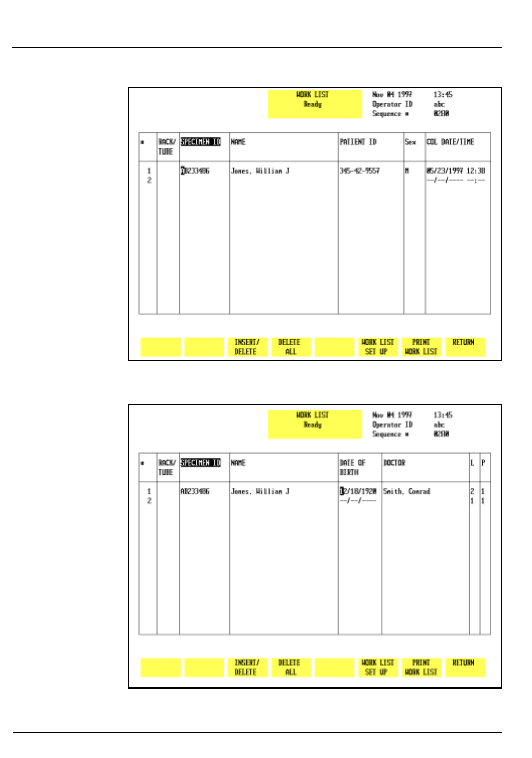
5-110 CELL-DYN® 3200 Operator’s Manual
9140181B — November 1997
Operating Instructions
Using The Work List Section 5
Figure 5.41: Work List Screen - Page 1
Figure 5.42: Work List Screen - Page 2
Go Back
Search
TOC

CELL-DYN® 3200 Operator’s Manual 5-111
9140181B — November 1997
Operating Instructions
Section 5 Using The Work List
Work List Screen
The two pages of the
WORK LIST
screen are depicted in Figures
5.41 and 5.42. Use the left and right arrow keys to scroll
between the pages.
1. Sequence #
The sequential number of the Work List entries is
displayed in this field. The Work List holds 600 entries.
When the Work List is full, existing entries must be
deleted before additional entries can be made. Work List
entries are automatically deleted as samples are run and
“matches” made.
2. RACK AND TUBE #
The rack and tube number is displayed as xxyy where xx,
the rack number, is any two digit number between 01 and
99 inclusively and yy, the tube number, is any two digit
number between 01 and 10 inclusively.
NOTE: Rack and tube number can only be entered by
the operator at the instrument, not downloaded from a
host.
In the Work List, the cursor skips the <Rack and Tube>
field when moving from entry to entry. The cursor always
starts in the <Specimen ID> field. To place the cursor in
the <Rack and Tube> field, the operator must use the left
arrow key to move the cursor from the <Specimen ID>
field to the <Rack and Tube> field.
3. SPECIMEN ID
The specimen identification must consist of either a Bar
Code number or other Specimen ID. Up to 12 characters
may be entered. The sample is identified on the RUN
screen, in the Data Log, and on the printed report using
the information entered in this field.
NOTE: An entry must be made in this field to create a
Work List record. Also, an entry must be made in this
field before a Work List record can be downloaded from
a host.
4. PATIENT NAME
The name entered in this field should be associated with
the bar code number or rack and tube number entered in
the <Specimen ID> field. Up to 28 characters can be
entered in this field.
Go Back
Search
TOC

5-112 CELL-DYN® 3200 Operator’s Manual
9140181B — November 1997
Operating Instructions
Using The Work List Section 5
5. PATIENT ID
The Patient ID can be a social security number or other
identifier. Up to 16 characters can be entered in this field.
6. PATIENT SEX
Either “M” or “F” may be entered for the sex of the
patient.
7. PATIENT DOB
The patient’s date of birth may be entered in this field
using the format selected in the Date/Time Set Up menu,
such as mm/dd/yyyy. Note that 4 digits are used for the
year.
8. COLLECTION DATE AND TIME
The date and time the specimen was collected may be
entered in this field. Date is entered as mm/dd for month
and day only with no year. Time is entered as hh/mm
where hh represents the hour (from 00 to 23) and mm
represents the minute (from 00 to 59).
9. DR NAME
The name of the patient’s doctor may be entered in this
field. Up to 22 characters may be entered.
10. LIMIT SET
This field is used to enter the number of the Patient Limit
Set that will be used for flagging the sample. If no entry is
made, the default (pre-selected) Patient Limit Set is used.
11. PARAMETER SET
This field is used to enter the number of the Parameter Set
that will be used for the sample. If no entry is made, the
default (pre-selected) Parameter Set is used.
Work List Soft Keys
The function of each of the soft keys displayed on the
WORK
LIST
screen is discussed below.
Insert/Delete
When the
[INSERT/DELETE]
key is pressed, the following soft key
labels are displayed:
INSERT
DELETE
RETURN
Go Back
Search
TOC

CELL-DYN® 3200 Operator’s Manual 5-113
9140181B — November 1997
Operating Instructions
Section 5 Using The Work List
Insert
The
[INSERT]
key is used to insert a line of information into the
Work List. The line is inserted at the cursor position and the
remainder of the Work List is moved down one line.
Delete
The
[DELETE]
key is used to delete a line of information from
the Work List. When the
[DELETE]
key is pressed, the following
soft key labels are displayed:
CONFIRM DELETION
CANCEL DELETION
These keys are used to
[CONFIRM]
or
[CANCEL]
the Delete
command.
The line is deleted at the cursor position and the remainder of
the Work List is moved up one line.
Delete All
The
[DELETE ALL]
key is used to delete all data from the Work
List. When the
[DELETE ALL]
key is pressed, the following soft
key labels are displayed:
CONFIRM DELETION
CANCEL DELETION
These keys are used to
[CONFIRM]
or
[CANCEL]
the Delete All
command.
Work List Set Up
Refer to Work List Set Up Procedure below for a discussion of
the
WORK LIST SET UP
screen and options.
Print Work List
The
[PRINT WORK LIST]
key is used to print the Work List.
Return
The
[RETURN]
key is used to return to the
RUN
screen.
Go Back
Search
TOC
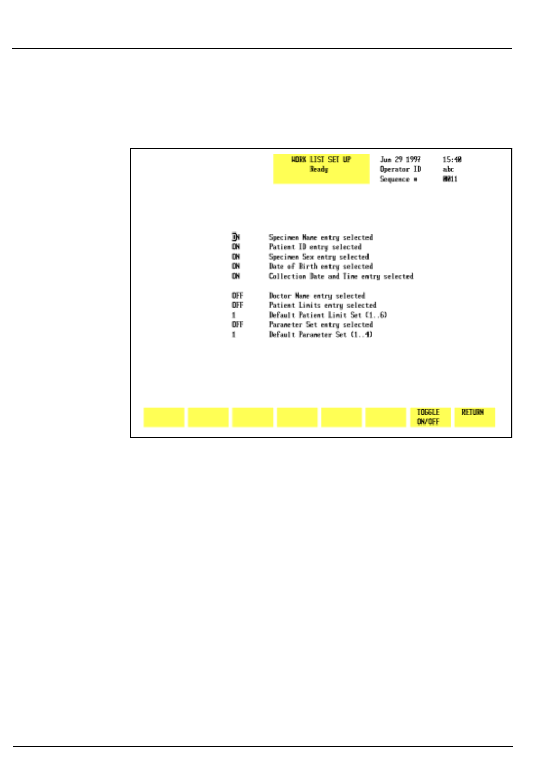
5-114 CELL-DYN® 3200 Operator’s Manual
9140181B — November 1997
Operating Instructions
Using The Work List Section 5
Work List Set Up Procedure
The
[WORK LIST SET UP]
key is used to display the
WORK LIST SET
UP
screen shown in Figure 5.43.
Figure 5.43: Work List Set Up Screen
The
WORK LIST SET UP
screen consists of eight ON/OFF toggle
fields and two “number” fields.
Use the arrow keys to move the cursor to the desired field. Use
the
[TOGGLE ON/OFF]
key to change an option and advance the
cursor to the next field.
ON/OFF Fields
Turning fields ON or OFF in this screen affects the movement
of the cursor in the
WORK LIST
screen when the operator makes
entries to the Work List.
1. When the operator enters data into a <Work List> field
and presses the Enter key, the cursor will move to the
next field that was turned ON in the
WORK LIST SET UP
screen, skipping any intervening fields that were left OFF.
2. For example:
a. Only the <Dr Name> field in the
WORK LIST SET UP
screen was turned ON, and
Go Back
Search
TOC

CELL-DYN® 3200 Operator’s Manual 5-115
9140181B — November 1997
Operating Instructions
Section 5 Using The Work List
b. The operator is making new patient entries into the
Work List.
In this case, when the operator enters data in the
<Specimen ID> field and presses the Enter key, the cursor
goes to the next ON field, which in this example is Dr
Name. All intervening fields are skipped.
NOTE: OFF fields will still accept data. The operator
can use the arrow keys to move the cursor to an OFF
field and input data. Pressing the Enter key saves the
data and moves the cursor to the next ON field.
Number Fields
The system will accept any number in the range 1 to 6 for
Patient Limits and 1 to 4 for Parameter Set. The number
selected for either field serves as the default for that field for
subsequent entries and is independent of whether that field is
ON or OFF.
For example:
1. If the <Patient Limits> field is OFF but the default setting
is changed to 6, then 6 will be displayed as the default
setting on the Work List.
2. Because the <Patient Limits> field is OFF, the cursor will
bypass this field in the Work List.
3. If the <Patient Limits> field were ON, the cursor in the
Work List would stop in this field, allowing the operator
to select a different setting, such as 2, for that entry. The
next entry would continue to display the default setting,
which in this example is 6.
NOTE: Regardless of the default value for either the
<Limit Set> or <Parameter Set> fields, the operator can
use the arrow keys to move the cursor to the field and
enter another value. This new value will affect only that
entry. All previous entries will retain their original
settings, and all subsequent entries will use the default
setting selected in the
WORK LIST SET UP
menu.
Work List Set Up Menu Fields
1. SPECIMEN NAME ENTRY SELECTED
This field is used to specify whether or not a specimen
(patient) name will be entered into the Work List. If this
option is turned OFF, the cursor will skip to the next ON
field. However, the operator can use the arrow keys to
place the cursor in this field and enter data, if desired.
Go Back
Search
TOC

5-116 CELL-DYN® 3200 Operator’s Manual
9140181B — November 1997
Operating Instructions
Using The Work List Section 5
2. PATIENT ID ENTRY SELECTED
This field is used to specify whether or not a patient ID
will be entered into the Work List. If this option is turned
OFF, the cursor will skip to the next ON field. However,
the operator can use the arrow keys to place the cursor in
this field and enter data, if desired.
3. PATIENT SEX ENTRY SELECTED
This field is used to specify whether or not the sex of the
patient will be entered into the Work List. If this option is
turned OFF, the cursor will skip to the next ON field.
However, the operator can use the arrow keys to place the
cursor in this field and enter data, if desired.
4. PATIENT DOB ENTRY SELECTED
This field is used to specify whether or not the patient’s
date of birth will be entered into the Work List. If this
option is turned OFF, the cursor will skip to the next ON
field. However, the operator can use the arrow keys to
place the cursor in this field and enter data, if desired.
5. COLLECTION DATE AND TIME ENTRY SELECTED
This field is used to specify whether or not the collection
date and time of the specimen will be entered into the
Work List. If this option is turned OFF, the cursor will skip
to the next ON field. However, the operator can use the
arrow keys to place the cursor in this field and enter data,
if desired.
6. DR NAME ENTRY SELECTED
This field is used to specify whether or not the name of
the patient’s doctor will be entered into the Work List. If
this option is turned OFF, the cursor will skip to the next
ON field. However, the operator can use the arrow keys to
place the cursor in this field and enter data, if desired.
7. PATIENT LIMITS ENTRY SELECTED
If this option is turned OFF, the prior setting will be
entered automatically for each entry. The operator can,
however, input a different setting for individual entries
by using the arrow keys to place the cursor in this field
and type in a new setting. The new setting applies only to
the entry(ies) that was changed.
Go Back
Search
TOC

CELL-DYN® 3200 Operator’s Manual 5-117
9140181B — November 1997
Operating Instructions
Section 5 Using The Work List
If this option is turned ON, the operator may then select
another default setting by typing in a number from 1 to
6. This new setting will be automatically assigned to each
new entry by the operator. The operator also has the
ability to enter a different setting for individual entries.
When the cursor moves to the <Patient Limits Set> field
of a particular entry, the operator may override the
default setting and type in a new setting for that entry.
8. DEFAULT PATIENT LIMIT SET (1 to 6)
This field is used to specify the default (pre-assigned)
Patient Limit Set that is automatically assigned to each
sample unless otherwise indicated in the Work List. Any
number between 1 and 6 inclusively may be entered.
9. PARAMETER SET ENTRY SELECTED
If this option is turned OFF, the prior setting will be
entered automatically for each entry. The operator can,
however, input a different setting for individual entries
by using the arrow keys to place the cursor in this field
and type in a new setting. The new setting applies only to
the entry(ies) that was changed.
If this option is turned ON, the operator may then select
another default setting by typing in a number from 2 to
4. This new setting will be automatically assigned to each
new entry. The operator also has the ability to enter a
different setting for individual entries. When the cursor
moves to the <Parameter Set> field of a particular entry,
the operator may override the default setting and type in
a new setting for that entry.
10. DEFAULT PARAMETER SET (1 to 4)
This field is used to specify the default (pre-assigned)
Parameter Set that is automatically assigned to each
sample unless otherwise indicated in the Work List. Any
number between 1 and 4 inclusively may be entered.
Go Back
Search
TOC

5-118 CELL-DYN® 3200 Operator’s Manual
9140181B — November 1997
Operating Instructions
Using The Work List Section 5
Sample Analysis — SL Model
The procedures described below discuss the operation of the
Work List in both Open and Closed Modes using either Bar
Codes or other Specimen ID for sample identification.
Closed Mode
On the SL model, although the RUN screen is displayed in the
Closed Mode it is not possible to enter data on this screen. If
Closed Mode is selected, demographic data can only be
entered on the
WORK LIST
or
DATA LOG
screens.
Using the Work List with Bar Codes
The Sample Loader has a built-in bar code reader that
automatically reads a bar code label placed on the tube. Refer
to Appendix A for a complete discussion of bar code labels and
instructions for correct placement of the labels on the tubes.
When bar code labels are used in Work List entries, samples
may be run in any order after the Work List has been created.
If Work List records are not downloaded from a host, they may
be entered by the operator at the instrument.
As samples are processed, the instrument does the following:
• Reads the bar code label on the tube and searches the
Work List for that bar code number.
• If a match is found, the demographic data from the Work
List is displayed on the RUN screen along with the results,
and the entire record is stored in the Data Log. The Work
List entry is deleted.
• If no match occurs, the Bar Code number is displayed on
the RUN screen without demographic data and stored in
the Data Log along with the results. No Work List entry is
deleted.
Running Samples with Bar Codes
1. In the
RUN
screen, press
[SPECIMEN TYPE]
followed by the
appropriate specimen type (Patient, Fragile WBC, or
Resistant RBC).
2. If necessary, press
[CHANGE SAMPLER]
to select the Closed
Mode.
3. Be sure that each sample to be run has a bar code label on
the tube.
Go Back
Search
TOC

CELL-DYN® 3200 Operator’s Manual 5-119
9140181B — November 1997
Operating Instructions
Section 5 Using The Work List
4. If Work List records containing bar codes were
downloaded from a host, go to step 6. If entries are to be
made by the operator at the instrument, go to step 5.
5. If Work List records are entered by the operator at the
instrument, do the following:
a. Enter all the Work List records, including bar code and
demographic data, associated with the samples to be
run into the Work List. DOUBLE CHECK to ensure
that each Bar Code was entered correctly into the
<Specimen ID> field.
6. Place all the samples to be run into the Sample Loader
racks and load the racks onto the Sample Loader (if not
already done).
NOTE: The samples in the racks do not have to be in
the same order as the Work List entries.
7. Press
[START LOADER]
to begin sample processing.
8. The samples are processed in the order in which they
were placed in the racks. The Sample Loader
automatically stops when all samples in the last rack
have been processed.
NOTE: Additional entries may be made to the Work
List while processing takes place. To input additional
entries to the Work List, press
[WORK LIST]
to display the
WORK LIST
screen. Type in the new entries.
9. When all samples have been processed, check to see if all
entries have been deleted from the Work List. Entries are
automatically deleted from the Work List when a match
occurs. Entries remaining in the Work List indicate a
successful match did not occur. The operator should
follow laboratory procedures to determine the cause of
this discrepancy.
Using the Work List with Specimen IDs
When Work List entries contain Specimen IDs (non bar code),
the operator must enter the rack and tube position of each
sample into the <Rack and Tube #> field of the appropriate
Work List entry, otherwise no match can occur. It is not
necessary for the samples in the racks to be in the same order
as the entries in the Work List, but the position of each sample
in the racks must match its Rack and Tube # in the Work List.
Sample identification is made from the information entered in
the <Rack and Tube #> field on the Work List.
Go Back
Search
TOC

5-120 CELL-DYN® 3200 Operator’s Manual
9140181B — November 1997
Operating Instructions
Using The Work List Section 5
If a match occurs (based on the Rack and Tube #), the sample
results along with the demographic data (including the
Specimen ID) are displayed on the RUN screen and sent to the
Data Log.
NOTE: The Rack and Tube # is not displayed on the
RUN screen or sent to the Data Log. The Rack and Tube
# is used only for the purpose of matching Work List
entries with samples.
If a match does not occur, it indicates the operator typed an
incorrect Rack and Tube # into the Work List. The operator
may either:
1. Correct the Rack and Tube # in the Work List and re-run
the sample (this avoids having to enter all the
demographic data manually), OR
2. Go to the Data Log, find the entry by the Rack and Tube #
assigned by the instrument, and enter the remaining
demographic information.
NOTE: If the instrument cannot match a sample with a
Work List entry using Bar Code, Specimen ID, or Rack
and Tube #, it identifies the sample by its actual rack
and tube position and assigns that number to the
<Specimen ID> field of that sample. The results along
with the assigned rack and tube number are sent to the
Data Log without deleting any records in the Work List,
since no match was made. The sample is identified in
the Data Log by the Rack and Tube # assigned by the
instrument.
NOTE: If the instrument is unable to read a Bar Code
on the tube and is unable to read the Bar Code on the
rack, a malfunction has occurred. Sample Loader
processing is halted. Determine which rack position is
the source of the problem before removing the rack.
Check the bar code label for that position to determine
the cause of the malfunction. If unable to fix or replace
the label, use a new rack. Whichever rack is used,
remove any samples that were aspirated and identified
properly. Place the rack at the starting position on the
load side of the Sample Loader. Press the
[CLEAR FAULT]
key followed by
[RESET LOADER]
to resume processing.
Go Back
Search
TOC

CELL-DYN® 3200 Operator’s Manual 5-121
9140181B — November 1997
Operating Instructions
Section 5 Using The Work List
Running Samples with Specimen IDs
1. If Work List records were downloaded from a host,
perform steps a through e below. If Work List records are
to be entered by the operator at the instrument, go to
step 2.
a. In the
RUN
screen, press
[WORK LIST]
.
b. For each sample to be run, find the matching entry in
the Work List.
c. Type the rack and tube number for that sample into
the <Rack and Tube #> field for that entry in the Work
List and place the sample into the appropriate rack
and tube position. DOUBLE CHECK to ensure the
sample was actually placed in the rack and tube
position indicated in the Work List entry.
NOTE: The samples in the racks do not have to be in
the same order as the Work List entries, but the actual
rack and tube number of each sample must be correctly
assigned to the Work List entry for that sample.
d. Repeat this process for all samples. When finished,
place the racks on the Sample Loader.
e. Go to step 3.
2. To enter Work List records at the instrument, do the
following:
a. In the
RUN
screen, press
[WORK LIST]
.
b. Enter all the Work List records associated with the
samples to be run, including the Rack and Tube #.
DOUBLE CHECK to ensure that each Specimen ID was
entered correctly in the <Specimen ID> field. DOUBLE
CHECK to ensure that the actual rack and tube
position for each sample was correctly entered in the
<Rack and Tube #> field in the Work List.
NOTE: The samples in the racks do not have to be in
the same order as the Work List entries.
c. When all entries have been completed, place the tubes
in racks and load the racks onto the Sample Loader (if
not already done).
3. Press
[RETURN]
to return to the
RUN
screen.
4. In the
RUN
screen, press
[SPECIMEN TYPE]
followed by the
appropriate specimen type (Patient, Fragile WBC, or
Resistant RBC).
5. If necessary, press
[CHANGE SAMPLER]
to select the Closed
Mode.
Go Back
Search
TOC

5-122 CELL-DYN® 3200 Operator’s Manual
9140181B — November 1997
Operating Instructions
Using The Work List Section 5
6. Press
[START LOADER]
to begin sample processing.
7.The samples are automatically processed in the order in
which they were placed in the racks. The Sample Loader
automatically stops when all samples in the last rack
have been processed.
NOTE: Additional entries may be made to the Work
List while processing takes place. To input additional
entries to the Work List, press
[WORK LIST]
to display the
WORK LIST
screen. Type in the new entries.
8.When all samples have been processed, check to see if all
entries have been deleted from the Work List. Entries are
automatically deleted from the Work List when a match
occurs. Entries remaining in the Work List indicate a
successful match did not occur. The operator should
follow laboratory procedures to determine the cause of
this discrepancy.
Running STAT Samples
1.STAT samples may be run in either the Closed or Open
Modes on the SL model.
2.STAT samples with either Bar Codes or Specimen IDs may
be run using the Work List.
3.STAT records may be downloaded from a host or entered
into the Work List by the operator.
4.STAT samples are processed in the same manner as other
Work List samples. Refer to Running Samples with Bar
Codes and Running Samples with <Specimen ID>s
discussed earlier in this section.
Open Mode
Using the Work List with Bar Codes
If Work List entries with Bar Codes have been downloaded
from a host, the operator has two options for entering the bar
code number in Open Mode:
1.Type the bar code number into the <Next ID> field on the
RUN screen.
2.Use a hand-held bar code reader (if attached to the PC
keyboard) to read the bar code on the sample into the
<Next ID> field on the
RUN
screen.
NOTE: The operator must first place the cursor in the
<Next ID> field so that the bar code number is placed
in the proper field.
Go Back
Search
TOC

CELL-DYN® 3200 Operator’s Manual 5-123
9140181B — November 1997
Operating Instructions
Section 5 Using The Work List
Under either option, when the sample is run the system will
automatically try to match the bar code number in the <Next
ID> field on the
RUN
screen with a Work List entry. If a
successful match occurs, the sample results along with the
demographic data in the Work List will be displayed on the
RUN
screen and sent to the Data Log. That entry will be deleted
from the Work List.
If a successful match does not occur, the results of the run are
sent to the Data Log with only the bar code number entered by
the operator (either manually or by the hand-held reader). The
operator must then go to the Data Log and enter the
remaining demographic data for that sample. No entry is
deleted from the Work List.
Running Samples
1. In the
RUN
screen, press
[SPECIMEN TYPE]
followed by the
appropriate specimen type (Patient, Fragile WBC, or
Resistant RBC).
2.If necessary, press
[CHANGE SAMPLER]
to select Open Mode.
3.Enter the bar code number into the <Next ID> field on
the
RUN
screen.
4. Place the well-mixed sample under the Open Sample
Aspiration Probe, make sure the end of the probe is
deeply immersed in the sample, and press the Touch Plate
to start the cycle.
NOTE: Additional entries may be made to the Work
List while processing takes place. To input additional
entries to the Work List, press
[WORK LIST]
to display the
WORK LIST
screen. Type in the new entries.
5.When all samples have been processed, check to see if all
entries have been deleted from the Work List. Entries are
automatically deleted from the Work List when a match
occurs. Entries remaining in the Work List indicate a
successful match did not occur. The operator should
follow laboratory procedures to determine the cause of
this discrepancy.
Running STAT Samples with Bar Codes
STAT samples with bar codes are processed in the same manner
as described in the sections Using the Work List with Bar
Codes and Running Samples immediately above.
Go Back
Search
TOC

5-124 CELL-DYN® 3200 Operator’s Manual
9140181B — November 1997
Operating Instructions
Using The Work List Section 5
Using the Work List with Specimen IDs
If Work List records with Specimen IDs (non bar code) were
downloaded from a host, the operator can use the Work List by
entering the Specimen ID on the sample tube into the <Next
ID> field on the
RUN
screen. When the sample is run, the
instrument will attempt to match the number in the <Next
ID> field on the
RUN
screen with a similar number in the
<Specimen ID> field in the Work List.
If a match occurs, the sample results along with the
demographic data from the Work List will be displayed on the
RUN
screen and sent to the Data Log. That entry will be deleted
from the Work List.
If a match does not occur, only the sample results and
Specimen ID entered on the
RUN
screen will be displayed on
the
RUN
screen and stored in the Data Log. No entry will be
deleted from the Work List. The operator must go to the Data
Log to enter the remaining demographic information.
Running Samples
1. In the
RUN
screen, press
[SPECIMEN TYPE]
followed by the
appropriate specimen type (Patient, Fragile WBC, or
Resistant RBC).
2.If necessary, press
[CHANGE SAMPLER]
to select Open Mode.
3.Enter the Specimen ID into the <Next ID> field on the
RUN
screen.
4. Place the well-mixed sample under the Open Sample
Aspiration Probe, make sure the end of the probe is
deeply immersed in the sample, and press the Touch Plate
to start the cycle.
NOTE: Additional entries may be made to the Work
List while processing takes place. To input additional
entries to the Work List, press
[WORK LIST]
to display the
WORK LIST
screen. Type in the new entries.
5.When all samples have been processed, check to see if all
entries have been deleted from the Work List. Entries are
automatically deleted from the Work List when a match
occurs. Entries remaining in the Work List indicate a
successful match did not occur. The operator should
follow laboratory procedures to determine the cause of
this discrepancy.
Running STAT Samples with Specimen IDs
STAT samples with Specimen IDs are processed in the same
manner as described in Using the Work List with Specimen
IDs and Running Samples immediately above.
Go Back
Search
TOC

CELL-DYN® 3200 Operator’s Manual 5-125
9140181B — November 1997
Operating Instructions
Section 5 Using The Work List
Sample Analysis — CS Model
For the CELL-DYN 3200CS model, only a Bar Code or other
Specimen ID may be used with the Work List to match entries.
Because this model has no Sample Loader, rack and tube
position cannot be used to identify specimens.
Samples are run individually in both Open and Closed Modes.
WARNING: Potential Biohazard. Consider all specimens
and reagents, controls, calibrators, etc. that contain
human blood or serum as potentially infectious. Wear
gloves, lab coats, and safety glasses, and follow other
biosafety practices as specified in the OSHA Bloodborne
Pathogen Rule (29 CFR Part 1910, 1030) or other
equivalent biosafety procedures.
Closed Mode
Using the Work List with Bar Codes
The Closed Sample Aspiration Tower has a built-in Bar Code
Reader that automatically reads a bar code label placed on the
tube. Refer to Appendix A for a complete discussion of bar
code labels and instructions for correct placement of the labels
on the tubes.
When bar code numbers are used in Work List entries, samples
may be run in any order after the Work List has been created.
If Work List records are not downloaded from a host, they may
be entered by the operator at the instrument.
As samples are processed, the instrument does the following:
• reads the bar code label on the tube and searches the
Work List for that bar code number
• If a match is found, the demographic data from the Work
List is displayed on the
RUN
screen along with the results,
and the entire record is stored in the Data Log. The Work
List entry is deleted.
• If not match is found, the Bar Code number is displayed
on the RUN screen without demographic data and stored
in the Data Log along with the results. No Work List entry
is deleted.
Running Samples with Bar Codes
1. If Work List records containing bar codes were
downloaded from a host, perform steps a through h
below. If entries are to be made by the operator at the
instrument, go to step 2.
Go Back
Search
TOC

5-126 CELL-DYN® 3200 Operator’s Manual
9140181B — November 1997
Operating Instructions
Using The Work List Section 5
a. In the RUN screen, press
[SPECIMEN TYPE]
followed by
the appropriate specimen type (Patient, Fragile WBC,
or Resistant RBC).
b. If necessary, press
[CHANGE SAMPLER]
to select the
Closed Mode.
c. Be sure that each sample to be run has a bar code label
on the tube.
d. Place a well-mixed sample in the Tube Retainer and
close the door.
e. Press the Touch Plate to run the sample.
f. When the sample has been aspirated, the door will
open. Remove the tube.
g. Repeat steps d through f until all Work List samples
have been processed.
NOTE: Additional entries may be made to the Work
List while processing takes place. To input additional
entries to the Work List, press
[WORK LIST]
to display the
WORK LIST
screen. Type in the new entries.
h. Go to step 3.
2. If Work List records are entered by the operator at the
instrument, perform steps a through h below:
a. In the
RUN
screen, press
[SPECIMEN TYPE]
followed by
the appropriate specimen type (Patient, Fragile WBC,
or Resistant RBC).
b. If necessary, press
[CHANGE SAMPLER]
to select the
Closed Mode.
c. Be sure that each sample to be run has a bar code label
on the tube.
d. Enter all the Work List records associated with the
samples to be run into the Work List. DOUBLE
CHECK to ensure that each Bar Code was entered
correctly into the <Specimen ID> field.
e. Place a well-mixed sample in the Tube Retainer and
close the door.
f. Press the Touch Plate to run the sample.
g. When the sample has been aspirated, the door will
open. Remove the tube.
h. Repeat steps e through g until all Work List samples
have been processed.
Go Back
Search
TOC

CELL-DYN® 3200 Operator’s Manual 5-127
9140181B — November 1997
Operating Instructions
Section 5 Using The Work List
NOTE: Additional entries may be made to the Work
List while processing takes place. To input additional
entries to the Work List, press
[WORK LIST]
to display the
WORK LIST
screen. Type in the new entries.
3. When all samples have been processed, check to see if all
entries have been deleted from the Work List. Entries are
automatically deleted from the Work List when a match
occurs. Entries remaining in the Work List indicate a
successful match did not occur. The operator should
follow laboratory procedures to determine the cause of
this discrepancy.
Using the Work List with Specimen IDs
To match Work List entries using Specimen ID, the operator
must first enter a sample’s Specimen ID into the <Next ID>
field on the
RUN
screen before running the sample. As the
sample is processed, the instrument searches the Work List for
a matching Specimen ID.
If a match occurs, the sample results along with the
demographic data from the Work List is displayed on the
RUN
screen and sent to the Data Log. That entry is deleted from the
Work List.
If a match does not occur, only the sample results with the
Specimen ID entered on the
RUN
screen is displayed and sent
to the Data Log. No entry is deleted from the Work List.
Running Samples with Specimen IDs
1. In the
RUN
screen, press
[SPECIMEN TYPE]
followed by the
appropriate specimen type (Patient, Fragile WBC, or
Resistant RBC).
2. If necessary, press
[CHANGE SAMPLER]
to select the Closed
Mode.
3. If Work List records were downloaded from a host, go to
step 5.
4. To enter Work List records at the instrument, do the
following:
a. In the
RUN
screen, press
[WORK LIST]
.
b. Enter all the Work List records, including
demographic data and Specimen ID, associated with
the samples to be run. DOUBLE CHECK to ensure that
each Specimen ID was entered correctly in the
<Specimen ID> field.
5. Select a sample tube and type the Specimen ID shown on
the tube into the Next ID field on the
RUN
screen.
Go Back
Search
TOC

5-128 CELL-DYN® 3200 Operator’s Manual
9140181B — November 1997
Operating Instructions
Using The Work List Section 5
6. Place a well-mixed sample in the Tube Retainer and close
the door.
7.Press the Touch Plate to run the sample.
8.When the sample has been aspirated, the door will open.
Remove the tube.
9. Repeat steps 5 through 8 until all samples have been
processed.
NOTE: Additional entries may be made to the Work
List while processing takes place. To input additional
entries to the Work List, press
[WORK LIST]
to display the
WORK LIST
screen. Type in the new entries.
10.When all samples have been processed, check to see if all
entries have been deleted from the Work List. Entries are
automatically deleted from the Work List when a match
occurs. Entries remaining in the Work List indicate a
successful match did not occur. The operator should
follow laboratory procedures to determine the cause of
this discrepancy.
Running STAT Samples
The procedure for running STAT samples is similar to the
procedure for running Work List samples described above. For
STAT samples with bar codes, refer to Running Samples with
Bar Codes above. For STAT samples with Specimen IDs, refer
to Running Samples with Specimen IDs above.
Open Mode
Work List Samples
Work List samples are processed in the Open Mode on the CS
model in the same manner as on the SL model. For a
description of this procedure, refer to Sample Analysis — SL
Model, subsection: Open Mode.
STAT Samples
STAT samples are processed in the Open Mode on the CS
model in the same manner as on the SL model. For a
description of this procedure, refer to Sample Analysis — SL
Model, subsection: Open Mode.
Go Back
Search
TOC

CELL-DYN® 3200 Operator’s Manual 5-129
9140181B — November 1997
Operating Instructions
Section 5 Using The Data Log
Using The Data Log
Introduction
The Data Log stores all data and demographic information in a
log format for the last 10,000 cycles run on the CELL-DYN
3200. The record information is stored chronologically by
sequence number. Scattergrams and histograms are stored for
all 10,000 records.
NOTE: When the log is full, subsequent entries cause
the oldest entry to be deleted and the remaining entries
to move up one line, so that the current records are
added to the bottom of the list.
The first part of this section gives a brief description of the
DATA LOG menu keys. The Data Log Set Up portion gives
instructions for customizing the display and printout of the
Data Log. The final section gives instructions for data review
from the Data Log.
Scrolling Through the Data Log
Each screen display (page) may contain up to 18 specimens.
Use the Left and Right Arrow keys to scroll through the
complete list of parameters for all specimens displayed on a
page. Use the Up and Down Arrow keys to move the cursor
between specimens on a page.
Use the Page Up key to scroll through preceding pages. Use the
Page Down key to scroll through succeeding pages.
DATA LOG Menu
The function of each of the soft keys in the
DATA LOG
menu,
shown in Figure 5.44, is discussed in this section.
The Data Log consists of 5 pages (screens). The first page
contains limited demographic data on the patient, and
subsequent pages display parameter results. The following data
is common to all 5 screens:
1. Sequence #
Go Back
Search
TOC
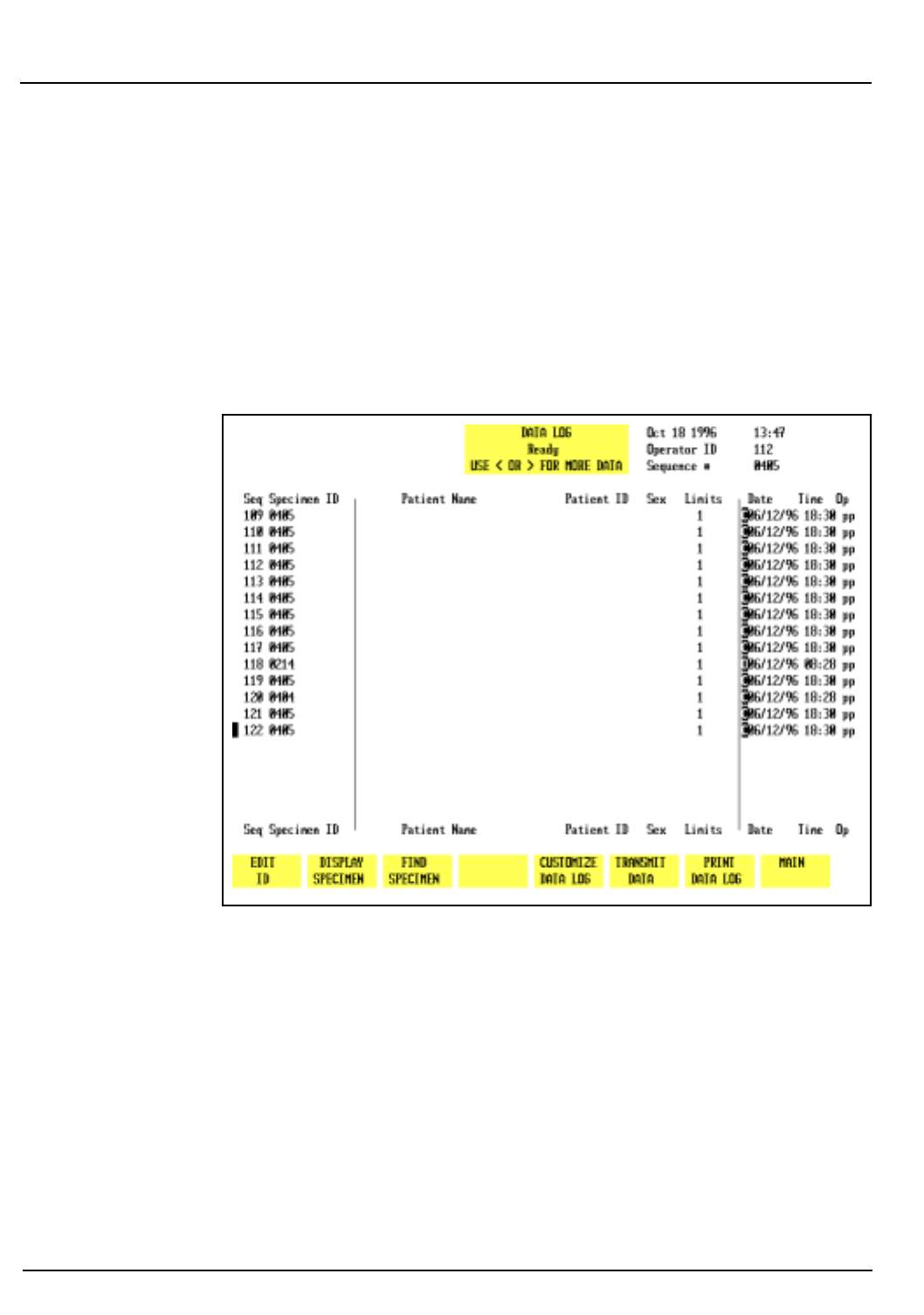
5-130 CELL-DYN® 3200 Operator’s Manual
9140181B — November 1997
Operating Instructions
Using The Data Log Section 5
2. Specimen ID
3. Collection Date and Time
4. Operator ID
The second page displays the results for the WBC Parameters.
The third page displays the results for the RBC parameters. The
fourth page displays the results for the PLT parameters. The
fifth page displays the results for the WBC parameters
expressed as a percent.
Figure 5.44: Data Log Screen - Page 1
When the
[DATA LOG]
key is pressed in the
MAIN MENU
, the
DATA
LOG
menu and the following soft key labels are displayed:
EDIT ID*
DISPLAY SPECIMEN
FIND SPECIMEN
REJECT FROM X-B**
CUSTOMIZE DATA LOG
TRANSMIT DATA
PRINT DATA LOG
MAIN
Go Back
Search
TOC
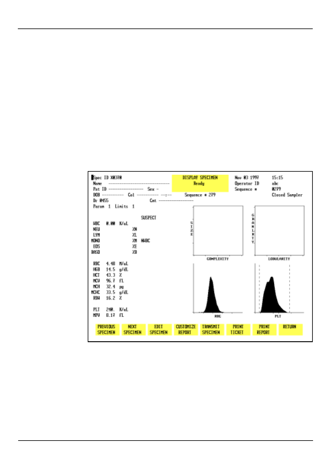
CELL-DYN® 3200 Operator’s Manual 5-131
9140181B — November 1997
Operating Instructions
Section 5 Using The Data Log
*This key is displayed only if the cursor is positioned next
to one of the following patient record types: Patient,
Fragile WBC, and Resistant RBC.
**This key is displayed if the sequence number of the
patient record is preceded by a “b”, “r”, or “w”.
Edit ID
The
[EDIT ID]
key is used to edit the Specimen ID from the
DATA
LOG
screen. When the
[EDIT ID]
key is pressed, the cursor moves
into the <Specimen ID> field and all key labels are blank. Edits
are saved by pressing the Enter key on the keyboard.
NOTE: The
[EDIT ID]
key is available only when the
cursor is positioned next to a Patient Record. It is not
available for Background or QC records.
Figure 5.45: Display Specimen Screen
Display Specimen
The
[DISPLAY SPECIMEN]
key is used to display the results for the
record indicated by the cursor position. (See Figure 5.45.) The
following soft key labels are displayed when the
[DISPLAY
SPECIMEN]
key is pressed:
PREVIOUS SPECIMEN*
NEXT SPECIMEN**
EDIT SPECIMEN***
Go Back
Search
TOC

5-132 CELL-DYN® 3200 Operator’s Manual
9140181B — November 1997
Operating Instructions
Using The Data Log Section 5
C
USTOMIZE REPORT
TRANSMIT SPECIMEN
PRINT TICKET
PRINT REPORT/COLOR PRINT
(The key label
alternates between the
selections.)
RETURN
* This key is not displayed when the first specimen in
the log is on the screen.
** This key is not displayed when the last specimen in
the log is on the screen.
*** This key is displayed only if the cursor is positioned
next to one of the following patient record types:
Patient, Fragile WBC, or Resistant RBC.
Previous Specimen
The
[PREVIOUS SPECIMEN]
key is used to display the results for
the sequence number preceding the one currently displayed
without returning to the main
DATA LOG
screen.
Next Specimen
The
[NEXT SPECIMEN]
key is used to display the results for the
sequence number following the one currently displayed
without returning to the main
DATA LOG
screen.
Edit Specimen
The
[EDIT SPECIMEN]
key is used to edit patient demographic
information for the selected record. It may also be used to edit
and display the results with a Parameter or Patient Limit Set
different from the one currently displayed. The following soft
key labels are displayed when the
[EDIT SPECIMEN]
key is
pressed:
CONFIRM
CANCEL
These keys are used to
[CONFIRM]
or
[CANCEL]
the edits. The
Bulletin line displays the message PRESS CONFIRM TO SAVE
CHANGES OR CANCEL TO CANCEL CHANGES. When the
[CONFIRM]
key is pressed, the edited record is displayed.
Customize Report
The
[CUSTOMIZE REPORT]
key is used to customize the
RUN
screen display, header and printout as described in the Set Up
Instructions section of this chapter.
Go Back
Search
TOC
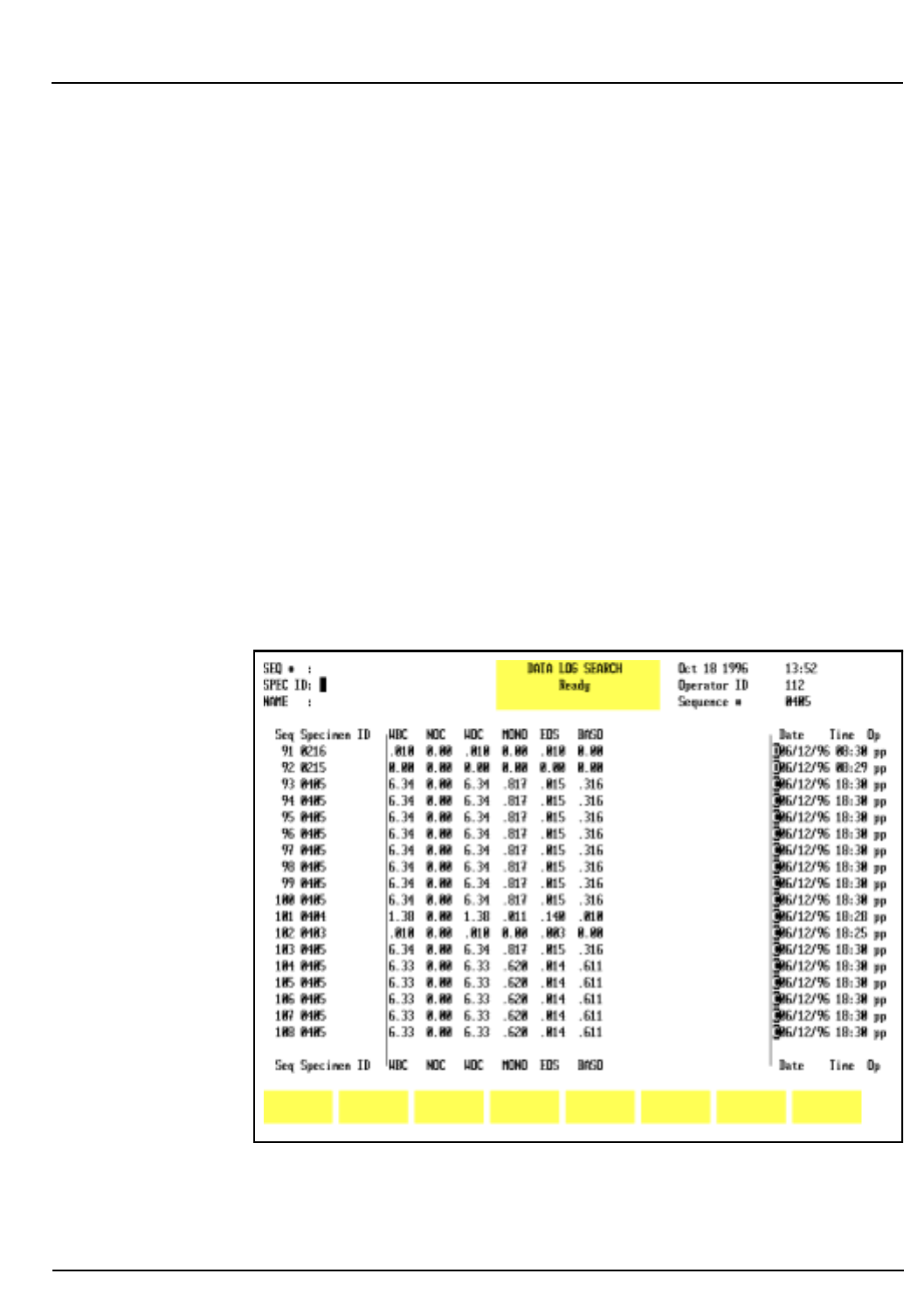
CELL-DYN® 3200 Operator’s Manual 5-133
9140181B — November 1997
Operating Instructions
Section 5 Using The Data Log
Transmit Specimen
The
[TRANSMIT SPECIMEN]
key is used to transmit the displayed
report to a Laboratory Information System or on-line
computer.
Print Ticket
The
[PRINT TICKET]
key is used to print a ticket (in the currently
selected format) for the displayed record.
Print Report
The
[PRINT REPORT]
key is used to print a graphics report (in the
currently selected format) for the displayed record.
NOTE: If color printing has been selected (refer to the
Set Up Instructions), the key label changes to
[COLOR
PRINT]
.
Return
The
[RETURN]
key is used to return to the main
DATA LOG
screen.
Figure 5.46: Data Log Search Screen
Go Back
Search
TOC
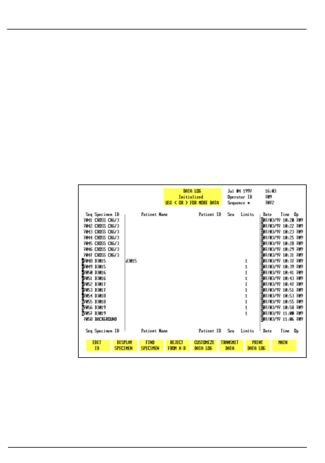
5-134 CELL-DYN® 3200 Operator’s Manual
9140181B — November 1997
Operating Instructions
Using The Data Log Section 5
Find Specimen
The
[FIND SPECIMEN]
key is used to locate a particular record by
entering the Sequence number, Specimen ID number or
Patient Name for the desired record. When this key is pressed,
the
DATA LOG SEARCH
screen is displayed. (See Figure 5.46.) If
the record is not found in the Data Log, the Bulletin line
displays the message: NO ENTRY FOUND.
Reject From X-B
If the cursor is positioned at a sample identified with a “r”,
“w”, or “b” preceding the sequence number (indicating that
the results are included in the XB analysis), the
[REJECT FROM X-B]
key label is displayed. (See Figure 5.47.)
Figure 5.47: Data Log Screen Showing Reject From X-B Key
Go Back
Search
TOC
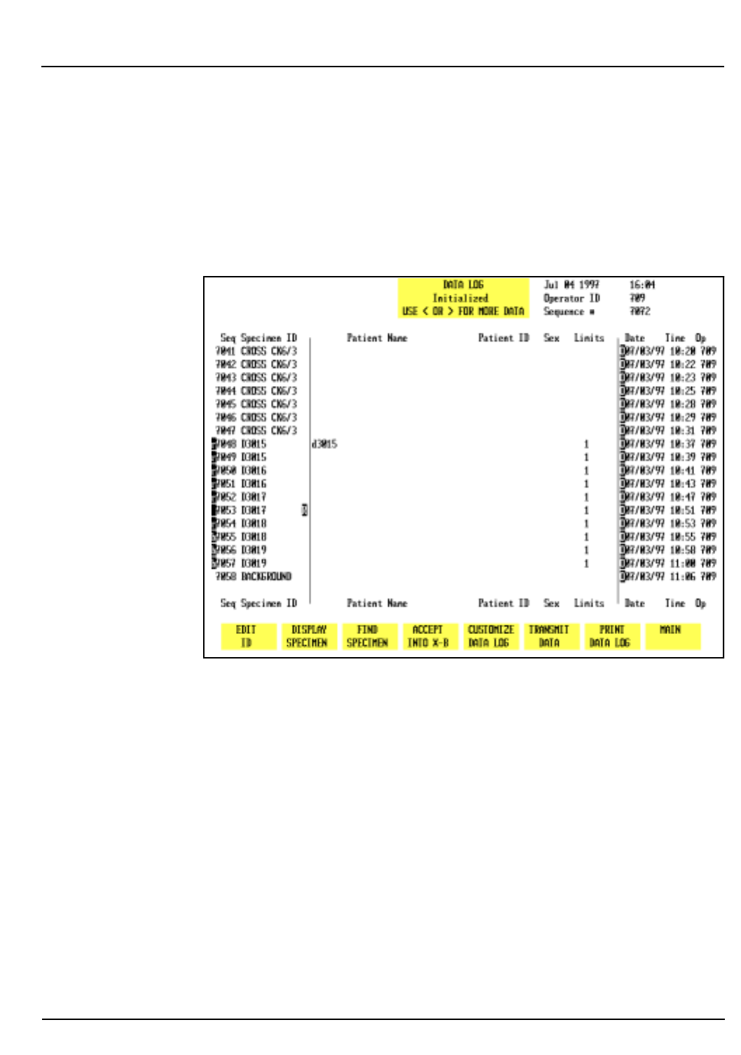
CELL-DYN® 3200 Operator’s Manual 5-135
9140181B — November 1997
Operating Instructions
Section 5 Using The Data Log
When the
[REJECT FROM X-B]
key is pressed, the sample is
marked with an “R” following the Specimen ID, the results are
excluded from the X-B analysis (the “R”, “w”, or “b” is
deleted), and the key label changes to
[ACCEPT INTO X-B]
. (See
Figure 5.48.)
If the
[ACCEPT INTO X-B]
key is pressed, the “R” is deleted, the
“r”, “w”, or “b” is displayed and results are now included in
the X-B analysis.
Figure 5.48: Data Log Screen Showing Accept Into X-B Key
Customize Data Log
The
[CUSTOMIZE DATA LOG]
key is used to customize the Data
Log display. The
CUSTOMIZE DISPLAY FOR DATA LOG
screen (see
Figure 5.49) and the following soft key labels are displayed
when the
[CUSTOMIZE DATA LOG]
key is pressed:
SELECT PARAMETER/
(The key alternates between the
PLACE PARAMETER
selections.)
STANDARD GROUPS/
(The key alternates between the
CUSTOM PLACEMENT
selections.)
Go Back
Search
TOC
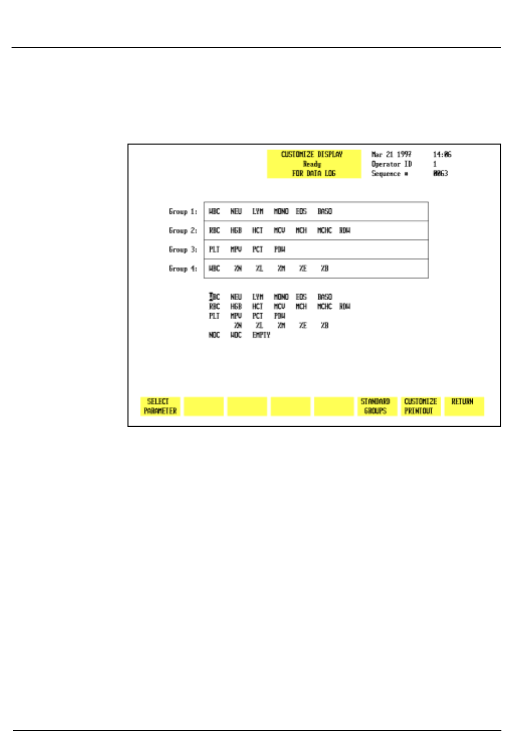
5-136 CELL-DYN® 3200 Operator’s Manual
9140181B — November 1997
Operating Instructions
Using The Data Log Section 5
CUSTOMIZE PRINTOUT
RETURN
Figure 5.49: Customize Display for Data Log Screen Showing
Standard Groups
The CUSTOMIZE DISPLAY FOR DATA LOG screen displays a
matrix showing the four parameter groups and a list of the
available parameters. Parameter Group 1 is displayed (in the
order indicated from left to right) on the second DATA LOG
screen. The remaining groups are displayed on subsequent
screens that are accessed by pressing the Right Arrow key on
the keyboard. The Left Arrow key is used to page back through
the screens to the first screen. Figure 5.50 shows a customized
Data Log display screen.
Go Back
Search
TOC
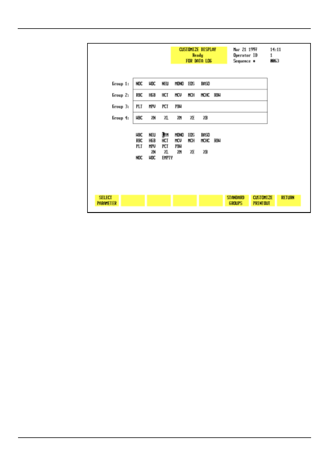
CELL-DYN® 3200 Operator’s Manual 5-137
9140181B — November 1997
Operating Instructions
Section 5 Using The Data Log
Figure 5.50: Customize Display for Data Log Screen Showing
Group 1 Customized
Select Parameter
The
[SELECT PARAMETER]
key is used to select a parameter
designated by the cursor. When the key is pressed, the selected
parameter is highlighted, the label changes to
[PLACE PARAMETER]
, and a
[CANCEL SELECTION]
key is displayed.
Place Parameter
The
[PLACE PARAMETER]
key is used to display the parameter in
the location indicated by the position of the cursor.
Cancel Selection
The
[CANCEL SELECTION]
key is used to cancel the selection and
display the
[SELECT PARAMETER]
key.
Standard Groups
Pre-determined groups of parameters, called Standard Groups,
may be selected by pressing the
[STANDARD GROUPS]
key. Refer
to Figure 5.49 which shows the
CUSTOMIZE DISPLAY FOR DATA
LOG
screen with the standard groups displayed. The following
soft key labels are displayed when the
[STANDARD GROUPS]
key
is pressed:
Go Back
Search
TOC
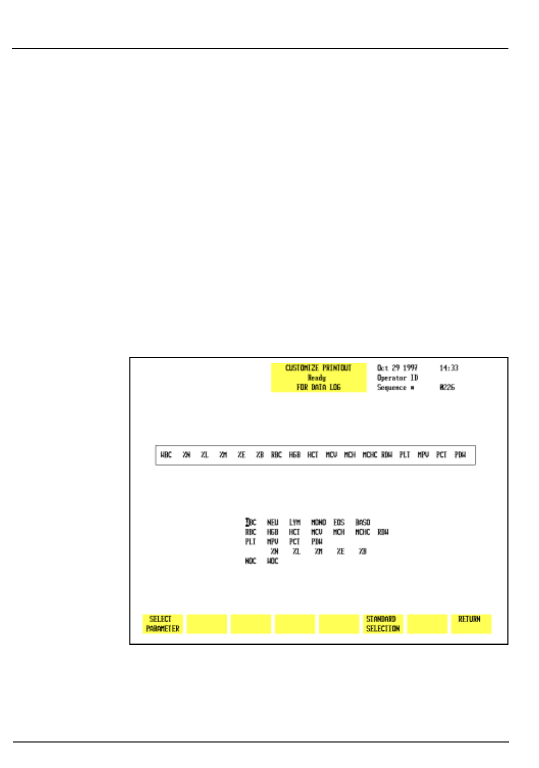
5-138 CELL-DYN® 3200 Operator’s Manual
9140181B — November 1997
Operating Instructions
Using The Data Log Section 5
WBC GROUP
RBC GROUP
PLT GROUP
DIFF GROUP
CUSTOM PLACEMENT*
CUSTOMIZE PRINTOUT
RETURN
*The
[CUSTOM PLACEMENT]
key is used to return to the
CUSTOMIZE DISPLAY FOR DATA LOG
screen for operator-selected
placement.
Figure 5.49 shows the WBC Group placed in GROUP 1, the RBC
Group placed in GROUP 2, the PLT Group placed in GROUP 3
and the Diff Group placed in GROUP 4.
When each soft key is pressed, the designated parameter group
is placed in the position indicated by the cursor.
Figure 5.51: Customize Printout for Data Log Screen
Go Back
Search
TOC

CELL-DYN® 3200 Operator’s Manual 5-139
9140181B — November 1997
Operating Instructions
Section 5 Using The Data Log
Customize Printout
The
[CUSTOMIZE PRINTOUT]
key is used to customize the printout
format of the Data Log. (See Figure 5.51.) The following soft
key labels are displayed when the
[CUSTOMIZE PRINTOUT]
key is
pressed:
SELECT PARAMETER/
(The key alternates between
PLACE PARAMETER
the selections.)
STANDARD SELECTION
RETURN
The
CUSTOMIZE PRINTOUT FOR DATA LOG
screen shows the order
(from left to right) in which the indicated parameters will be
printed.
Select Parameter
The
[SELECT PARAMETER]
key is used to select a parameter
designated by the cursor. When the key is pressed, the selected
parameter is highlighted, the label changes to
[PLACE PARAMETER]
and a
[CANCEL SELECTION]
key is displayed.
Place Parameter
The
[PLACE PARAMETER]
key is used to display the parameter in
the location indicated by the position of the cursor.
Cancel Selection
The
[CANCEL SELECTION]
key is used to cancel the selection and
display the
[SELECT PARAMETER]
key.
Standard Selection
The
[STANDARD SELECTION]
key is used to configure the printout
in the pre-determined print group shown in Figure 5.49. When
the key is pressed, the print group is changed to the Standard
Selection.
Return
The
[RETURN]
key is used to return to the main
DATA LOG
screen.
Transmit Data
The
[TRANSMIT DATA]
key is used to transmit a record to a
Laboratory Information System or on-line computer. When
the
[TRANSMIT DATA]
key is pressed, the screen prompts the
operator to enter the starting and ending sequence numbers
(from the lowest to the highest) for the desired transmission.
Records may be transmitted singly or in batches as designated
by the sequence number(s).
Go Back
Search
TOC

5-140 CELL-DYN® 3200 Operator’s Manual
9140181B — November 1997
Operating Instructions
Using The Data Log Section 5
When the
[TRANSMIT DATA]
key is pressed, the <Starting
Sequence #> field appears in the upper left corner of the screen
and the cursor is positioned in this field. The operator should
enter the sequence number of the first specimen to be
transmitted and press the Enter key. If the number is valid, the
system accepts the entry and the <Ending Sequence #> field
appears in the upper left corner of the screen. The operator
should type in the ending sequence number and press Enter.
The system begins transmitting automatically. If only one
record is to be transmitted, the starting and ending sequence
number will be the same.
NOTE: Use the ESC key to cancel this function and
return to the
DATA LOG
menu. Use the Backspace key or
left arrow key to cancel an entry and retype the
sequence number.
Because specimen records are shown in summary form on the
DATA LOG
menu, only the summary data of these records will
be transmitted. No histogram data accompanies the summary
data.
Print Data Log
The
[PRINT DATA LOG]
key is used to print the Data Log. When
the
[PRINT DATA LOG]
key is pressed, the screen prompts the
operator to enter the starting and ending sequence numbers
(from the lowest to the highest) for the desired printout. (See
Figure 5.52.)
When the
[PRINT DATA LOG]
key is pressed, the <Starting
Sequence #> field appears in the upper left corner of the screen
and the cursor is positioned in this field. The operator should
enter the sequence number of the first specimen to be printed
and press the Enter key. If the number is valid, the system
accepts the entry and the <Ending Sequence #> field appears
in the upper left corner of the screen. The operator should type
in the ending sequence number and press Enter. The system
begins printing automatically. If only one record is to be
printed, the starting and ending sequence number will be the
same.
NOTE: Use the ESC key to cancel this function and
return to the
DATA LOG
menu. Use the Backspace key or
left arrow key to cancel an entry and retype the
sequence number.
Because specimen records are shown in summary form on the
DATA LOG
menu, only the summary data of these records will
be printed. No histogram data accompanies the summary data.
Go Back
Search
TOC
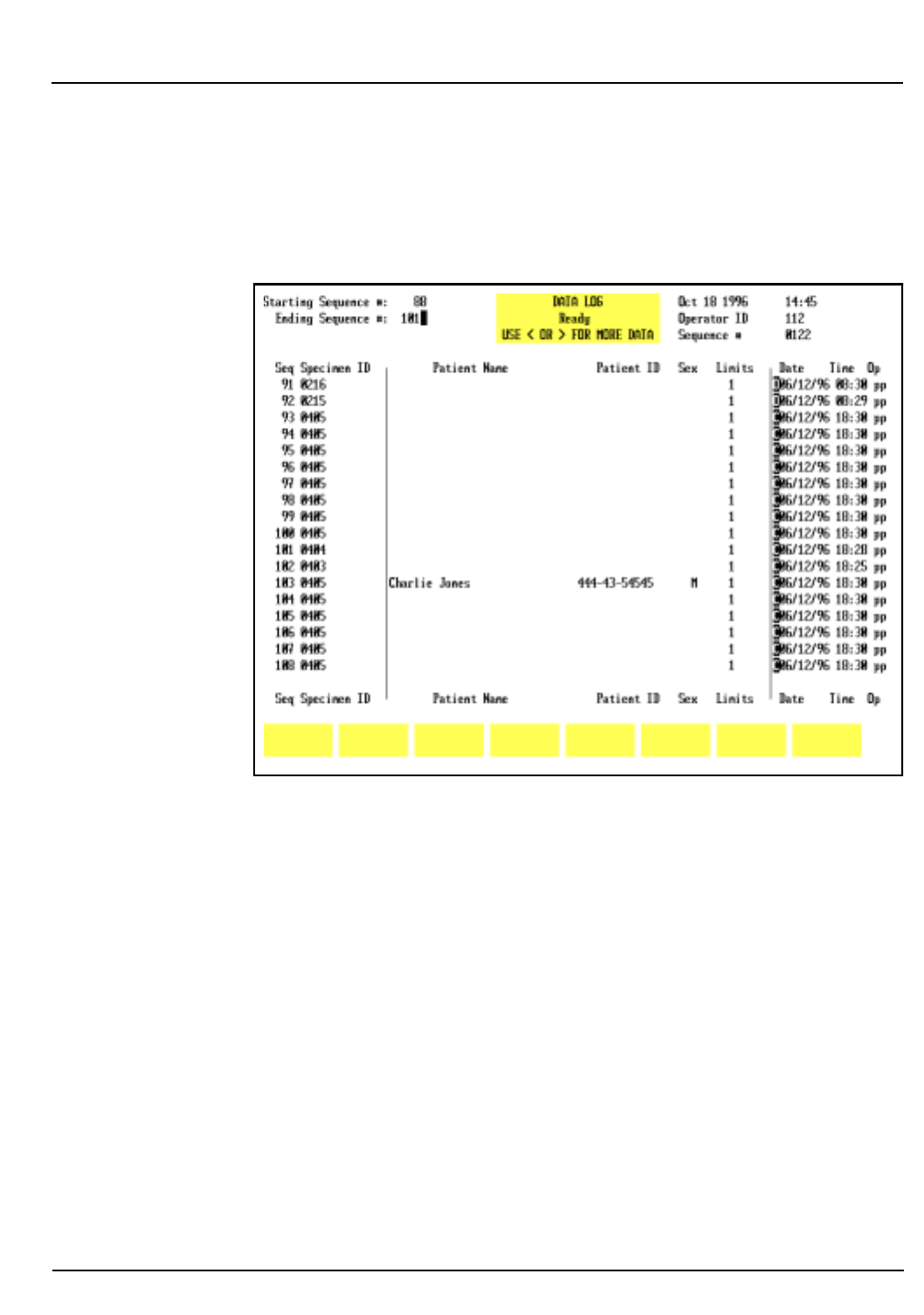
CELL-DYN® 3200 Operator’s Manual 5-141
9140181B — November 1997
Operating Instructions
Section 5 Using The Data Log
NOTE: To print histogram data, the operator must
press the
[DISPLAY SPECIMEN]
key in the
DATA LOG
menu
to select and display an individual specimen. Then, the
[PRINT REPORT]
key will print the results of the specimen
displayed on the screen, including histograms.
Figure 5.52: Print Data Log Screen
Data Log Codes
The Data Log Codes are displayed in the Data Log in the
column immediately preceding the date (see Figure 5.52).
These codes are displayed in the following order:
O — Sample was run in the Open Mode
C — Sample was run in the Closed Mode
N — Incomplete aspiration in the Open Mode
I — Incomplete aspiration in the Closed Mode
K — Flow Error
R — Resistant RBC key was used to run this sample
F — Fragile WBC key was used to run this sample
NOTE: For Background and Latex specimens, only the
O and C codes are used.
Go Back
Search
TOC
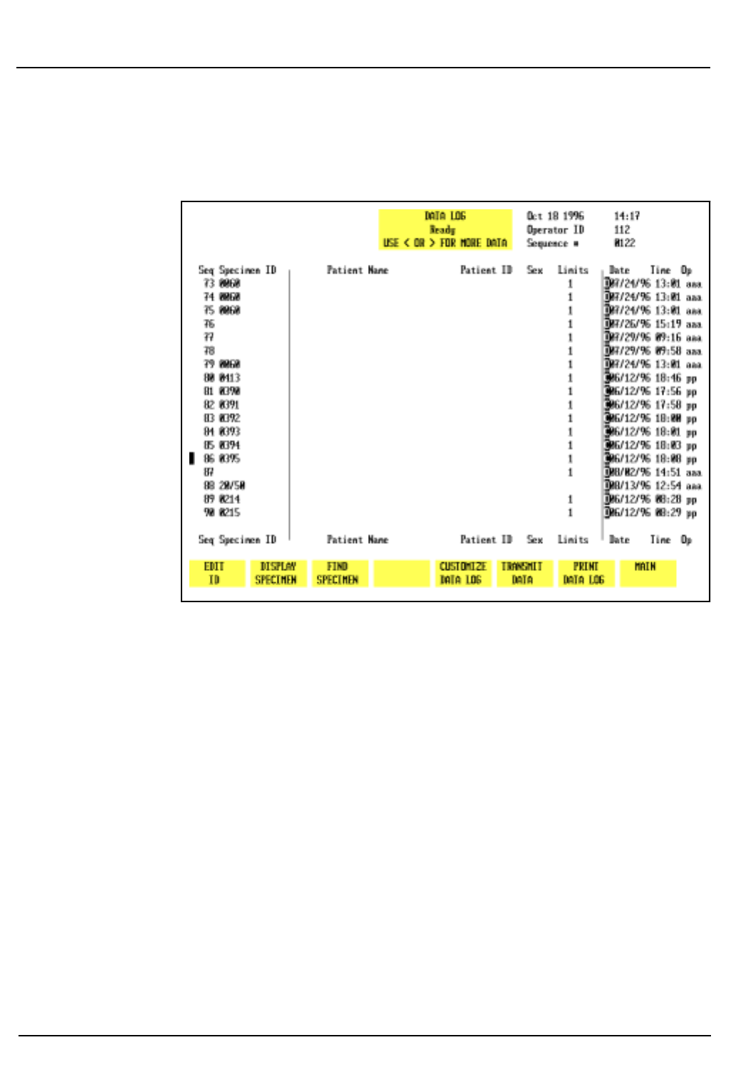
5-142 CELL-DYN® 3200 Operator’s Manual
9140181B — November 1997
Operating Instructions
Using The Data Log Section 5
An example of codes displayed in the Data Log is shown in
Figure 5.53.
Figure 5.53: Data Log Codes Screen
Go Back
Search
TOC
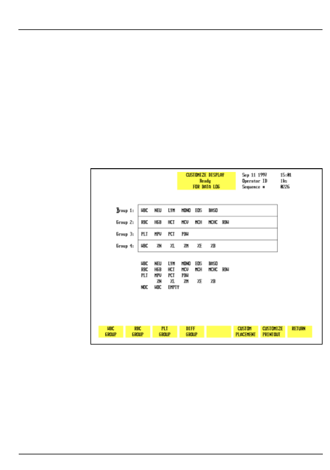
CELL-DYN® 3200 Operator’s Manual 5-143
9140181B — November 1997
Operating Instructions
Section 5 Using The Data Log
Data Log Set Up Procedures
The Data Log may be configured to display and print results in
the order selected by the operator. This section gives
instructions for Customizing the Display and Printout.
Customizing the Data Log Display
The
CUSTOMIZE DISPLAY FOR DATA LOG
screen displays a matrix
showing the four groups of parameters that will be
consecutively displayed on the four Data Log screens. (Figure
5.54 shows the Standard Groups in the matrix.) A list of all
available parameters is displayed under the matrix. The
parameters are selected from the list and placed in the desired
group to customize the display.
Figure 5.54: Customize Display for Data Log Screen Showing
Standard Groups
The display may be customized by selecting the individual
parameters, Standard Groups of parameters or a combination
of the two. In addition to the usual Hematologic parameters,
the following parameters may also be displayed in the Data
Log:
NOC Nuclear Optical Count
EMPTY Inserts an empty column in the display
Go Back
Search
TOC

5-144 CELL-DYN® 3200 Operator’s Manual
9140181B — November 1997
Operating Instructions
Using The Data Log Section 5
To Customize the Data Log Display
1. In the main
DATA LOG
screen, press
[CUSTOMIZE DATA LOG]
to display the
CUSTOMIZE DISPLAY FOR DATA LOG
screen.
2. If necessary, press
[CUSTOM PLACEMENT]
to display the
CUSTOMIZE DISPLAY FOR DATA LOG
screen and key labels for
custom placement.
3. Use the Arrow keys on the keyboard to move the cursor to
the desired parameter in the listing under the matrix.
4. Press
[SELECT PARAMETER].
The selected parameter is
highlighted and the cursor moves to the first position in
Group 1.
NOTE: The key label changes to
[PLACE PARAMETER]
and
a
[CANCEL SELECTION]
key is displayed.
5. If necessary, use the Arrow keys on the keyboard to move
the cursor to the desired location and press
[PLACE PARAMETER].
NOTE: When the
[PLACE PARAMETER]
key is pressed, the
selected parameter is displayed in the position
indicated by the cursor and the cursor is then advanced
to the next position in the group.
6. Repeat steps 3–5 until all selections have been made.
7. If desired, press the Print Screen key on the keyboard to
obtain a printout of the selected groups.
8. Press
[RETURN]
to return to the
DATA LOG
screen.
9. The Data Log is displayed configured with the selected
parameters.
Standard Groups
The Data Log display may also be customized with pre-
determined groups (Standard Groups) of parameters using the
[STANDARD GROUPS]
key. Figure 5.54 shows the WBC Group
placed in GROUP 1, the RBC Group placed in GROUP 2, the PLT
Group placed in GROUP 3 and the Diff Group placed in GROUP
4.
To Customize the Data Log Display for Standard Groups
1. From the main
DATA LOG
screen, press
[CUSTOMIZE DATA
LOG]
to display the
CUSTOMIZE DISPLAY FOR DATA LOG
screen.
2. Press
[STANDARD GROUPS]
to display the
CUSTOMIZE DISPLAY
FOR DATA LOG
screen and key labels for Standard Groups.
Go Back
Search
TOC
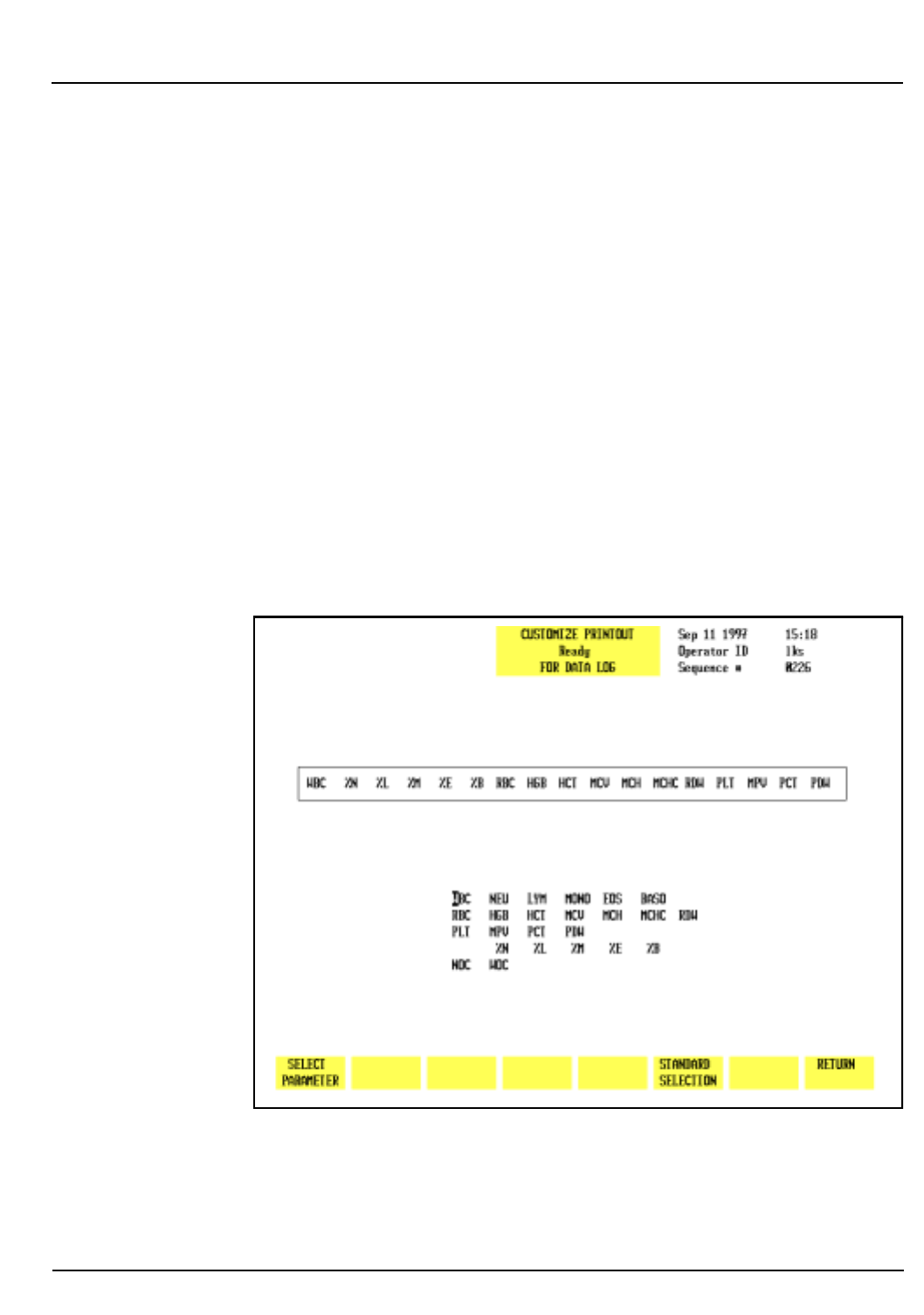
CELL-DYN® 3200 Operator’s Manual 5-145
9140181B — November 1997
Operating Instructions
Section 5 Using The Data Log
3. Use the Arrow keys on the keyboard to move the cursor to
the desired group (1–4) location.
NOTE: This number indicates the order in which the
group of parameters will be displayed (Group 1 on the
first screen, Group 2 on the second, etc.).
4. Press the soft key corresponding to the desired parameter
group. This group is displayed in the position indicated
by the cursor.
5. Repeat steps 3 and 4 until all desired groups have been
selected.
6. If desired, press the Print Screen key on the keyboard to
obtain a printout of the configuration.
7. Press
[RETURN]
to return to the
DATA LOG
screen.
8. The Data Log is displayed configured with the standard
groups of parameters.
Figure 5.55: Customize Printout for Data Log Screen Showing
Customized Print Group
Go Back
Search
TOC

5-146 CELL-DYN® 3200 Operator’s Manual
9140181B — November 1997
Operating Instructions
Using The Data Log Section 5
Customizing the Printout
The
CUSTOMIZE PRINTOUT FOR DATA LOG
screen (see Figure 5.55)
shows the group of parameters that will be printed on a Data
Log printout. A list of the available parameters is displayed
under the group. The parameters are selected from the list and
placed in the desired position to customize the printout. In
addition to the usual Hematologic parameters, the following
parameter may also be printed in the Data Log:
NOC — Nuclear Optical Count
To Customize the Data Log Printout
1. From the main
DATA LOG
screen, press
[CUSTOMIZE DATA
LOG]
followed by
[CUSTOMIZE PRINTOUT]
.
2. Use the Arrow keys on the keyboard to move the cursor to
the desired parameter in the list displayed under the
printout group.
3. Press
[SELECT PARAMETER].
The selected parameter is
highlighted and the cursor moves to the first position in
the group.
NOTE: The key label changes to
[PLACE PARAMETER]
and
a
[CANCEL SELECTION]
key is displayed.
4. If necessary, use the Arrow keys on the keyboard to move
the cursor to the desired location and press
[PLACE PARAMETER]
.
NOTE: When the
[PLACE PARAMETER]
key is pressed, the
selected parameter is displayed in the position
indicated by the cursor and the cursor then advances to
the next parameter in the list displayed under the
printout group.
5. Repeat steps 2–4 until all selections have been made.
6. If desired, press the Print Screen key on the keyboard to
obtain a printout of the configuration.
7. Press
[RETURN]
twice to return to the
DATA LOG
screen.
Standard Selection
The
[STANDARD SELECTION]
key is used to automatically arrange
the parameters in a predetermined print group.
Go Back
Search
TOC
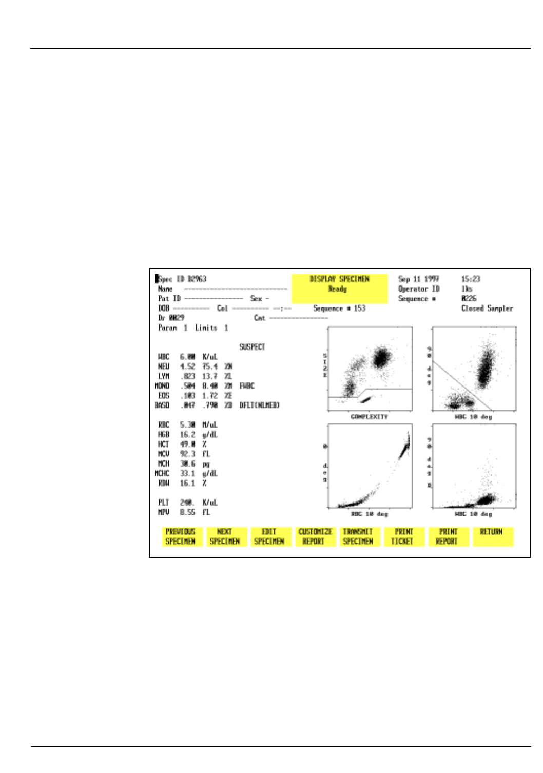
CELL-DYN® 3200 Operator’s Manual 5-147
9140181B — November 1997
Operating Instructions
Section 5 Using The Data Log
Data Review from the Data Log
Use the Page Up/Down keys and arrow keys to view Data Log
records and parameters within a record as described earlier in
Scrolling Through the Data Log.
Displaying A Record
A copy of the
RUN
screen may be displayed for all 10,000
records in the CELL-DYN 3200 Data Log. A record is displayed
by positioning the cursor at the record in the Data Log listing
and pressing
[DISPLAY SPECIMEN]
. The record is displayed on the
DISPLAY SPECIMEN
screen. (See Figure 5.56.)
Figure 5.56: Display Specimen Screen
To Display a Record
1. From the
MAIN MENU
screen, press
[DATA LOG]
.
2.Use the Arrow keys on the keyboard to move the cursor to
the desired record (use the Page Up and Page Down keys
to scroll between pages).
3. Press
[DISPLAY SPECIMEN]
to display the
RUN
screen for the
selected record.
Go Back
Search
TOC
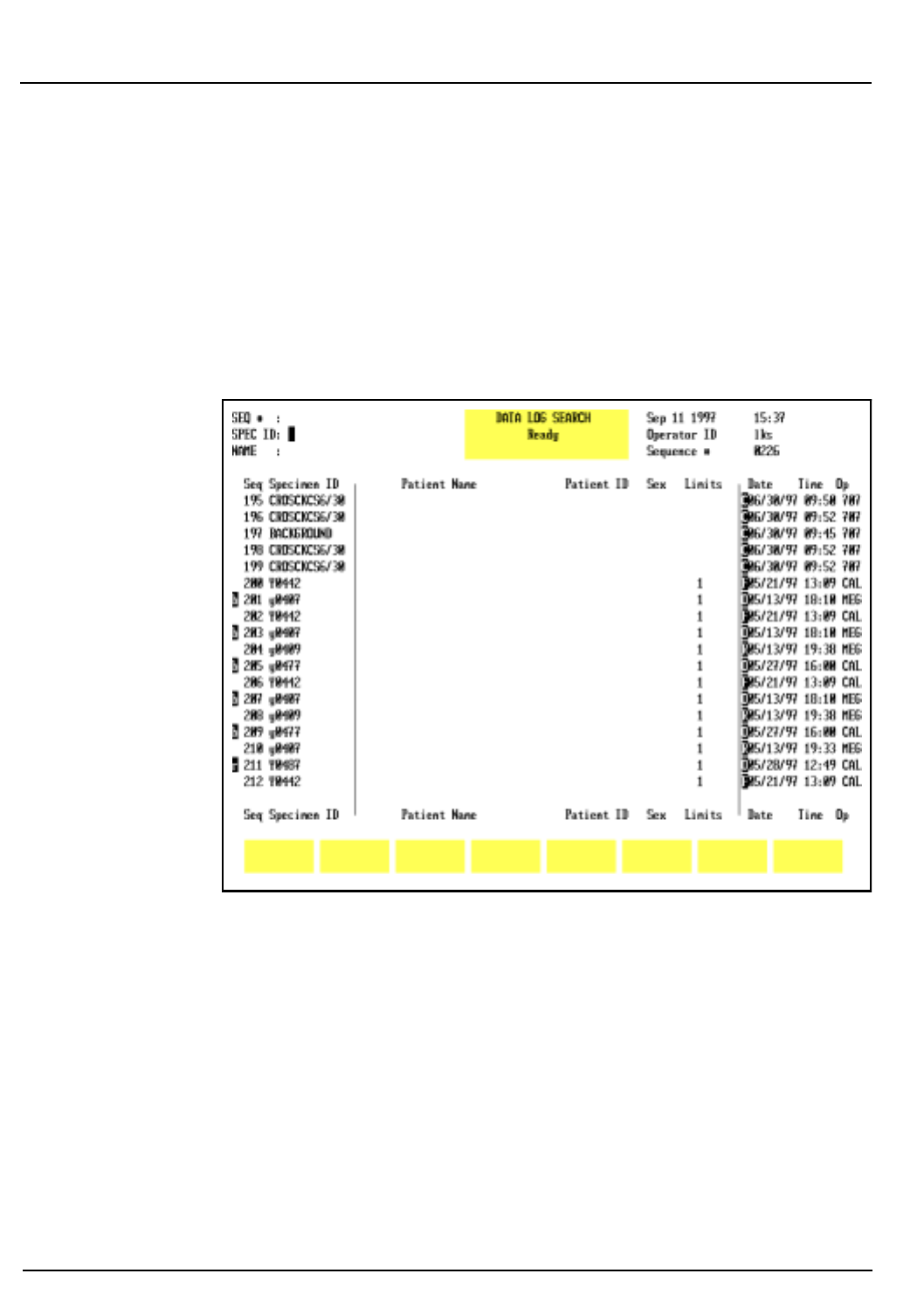
5-148 CELL-DYN® 3200 Operator’s Manual
9140181B — November 1997
Operating Instructions
Using The Data Log Section 5
4. If desired, press
[PRINT REPORT]
to obtain a printout.
NOTE: If a color printing has been selected, the key
label changes to
[COLOR PRINT]
and a color printout is
generated when the key is pressed.
5. The
[PREVIOUS SPECIMEN]
or
[NEXT SPECIMEN]
key may now
be used to display records listed in the Data Log which are
adjacent to the one currently displayed.
To Find a Record
Figure 5.57: Find Specimen Screen
1. From the
MAIN MENU
screen, press
[DATA LOG]
.
2. If the desired record is not displayed on the screen, press
[FIND SPECIMEN]
to display the
DATA LOG SEARCH
screen.
3. Use the Arrow keys on the keyboard to move the cursor to
the desired identifier: Sequence Number, Specimen ID
Number or Name. Refer to Figure 5.57.
4. Type the appropriate information and press the Enter key
on the keyboard to start the search.
NOTE: If necessary, you may press the Escape (ESC) key
or the Enter key on the keyboard to exit from the
search function and return to the
DATA LOG
screen.
Go Back
Search
TOC
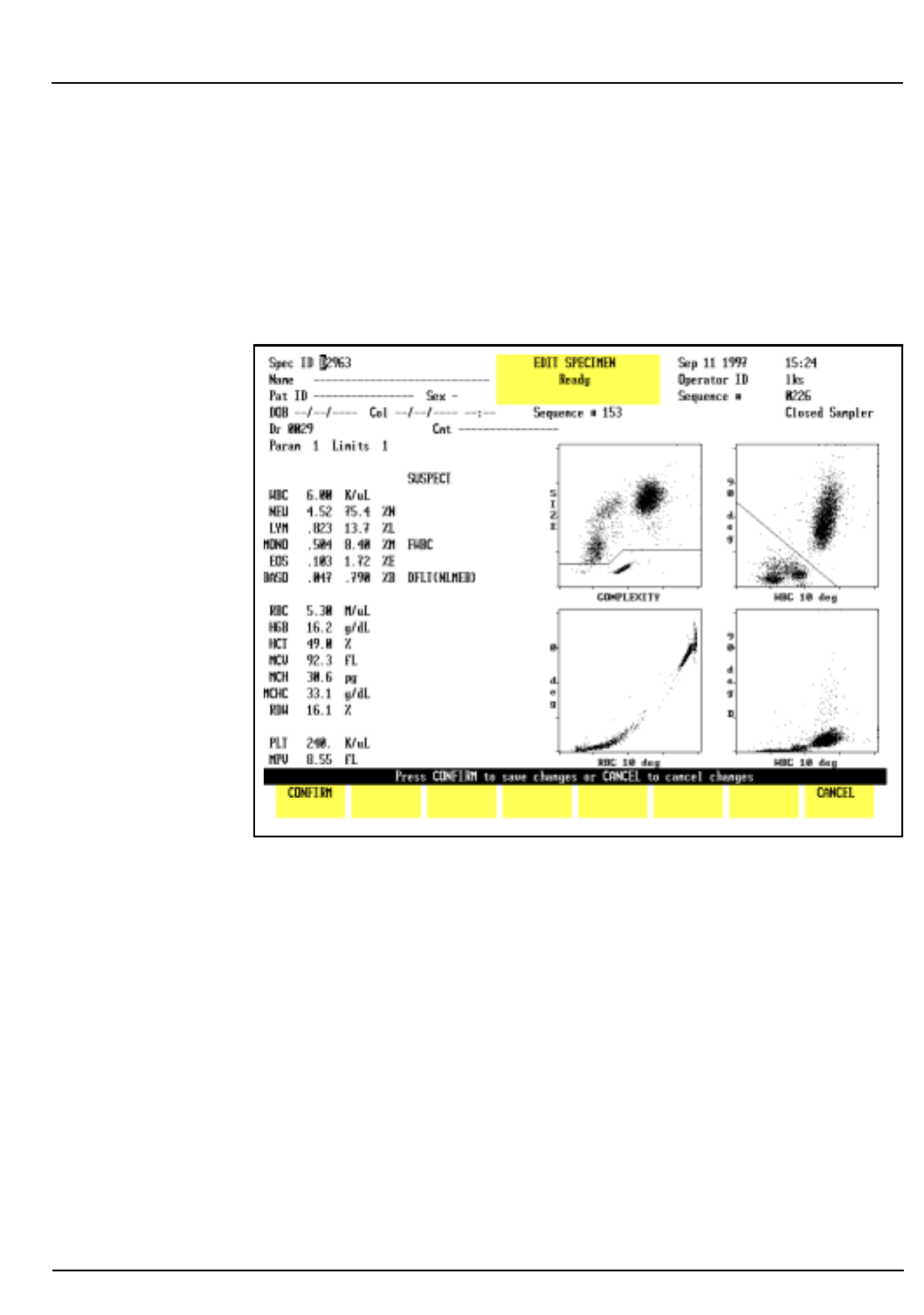
CELL-DYN® 3200 Operator’s Manual 5-149
9140181B — November 1997
Operating Instructions
Section 5 Using The Data Log
5. If the requested record is available, the screen displays the
Data Log page containing it. (The cursor is located at the
sequence number of the record.)
To Edit a Record
The Patient Demographics and the Parameter and Patient
Limits Sets may be edited for each record. (See Figure 5.58.)
Figure 5.58: Edit Specimen Screen
To Edit a Specimen
1. From the
MAIN MENU
screen, press
[DATA LOG]
.
2. Locate the desired record and press
[DISPLAY SPECIMEN]
followed by
[EDIT SPECIMEN]
.
3. Use the Arrow keys on the keyboard to move the cursor to
the line that will be edited and type the appropriate
information. Press the Enter key on the keyboard to save
the entry.
4. Press
[CONFIRM]
to display the
RUN
screen for the edited
result.
5. If desired, press
[PRINT REPORT]
or
[COLOR PRINT]
to obtain a
printout.
Go Back
Search
TOC

5-150 CELL-DYN® 3200 Operator’s Manual
9140181B — November 1997
Operating Instructions
Using The Data Log Section 5
NOTES
Go Back
Search
TOC

CELL-DYN® 3200 Operator’s Manual 5-151
9140181B — November 1997
Operating Instructions
Section 5 References
References
1. NCCLS Standard H3-A3, Procedure for the Collection of
Diagnostic Blood Specimens by Venipuncture—Third Edition;
Approved Standard (1991).
2. NCCLS Standard H4-A3, Procedure for the Collection of
Diagnostic Blood Specimens by Skin Puncture—Third
Edition; Approved Standard (1991).
3. ICSH, Protocol for Evaluation of Automated Blood Cell
Counters, Clinical and Laboratory Hematology 1988,
10:203, 212.
Go Back
Search
TOC

5-152 CELL-DYN® 3200 Operator’s Manual
9140181B — November 1997
Operating Instructions
References Section 5
NOTES
Go Back
Search
TOC

CELL-DYN® 3200 Operator’s Manual 6-1
9140181B — November 1997
Calibration Procedures
Section 6 Overview
Overview
The CELL-DYN 3200 System is calibrated at the factory just
prior to shipment. An Abbott Field Service Representative will
assist the operator in confirming the calibration during
instrument installation. Calibration may be performed using
commercial calibrator or fresh whole blood samples. Only the
directly measured parameters — WOC, NOC, RBC, HGB, MCV,
PLT, and MPV — may be calibrated.
Calibration should be confirmed on a regular basis according
to the laboratory’s schedule for maintaining good laboratory
practice.
On-board quality control programs are designed to provide
continual monitoring and verification of instrument
calibration. The laboratory should make the decision to
recalibrate based on the performance of the CELL-DYN 3200
in these quality control programs.
Instrument calibration is discussed in the following order:
• General Information
• Pre-Calibration Procedures
• Calibration Menu and Soft Keys
• Auto-Cal Method
• Enter Factor Method
• Calibration Worksheets
Go Back
Search
TOC

6-2 CELL-DYN® 3200 Operator’s Manual
9140181B — November 1997
Calibration Procedures
Overview Section 6
NOTES
Go Back
Search
TOC

CELL-DYN® 3200 Operator’s Manual 6-3
9140181B — November 1997
Calibration Procedures
Section 6 General Information
General Information
The CELL-DYN 3200 System has two modes of operation:
•Open Mode
• Closed Mode
Both the Open and Closed Modes are calibrated individually.
It is recommended that the primary mode be calibrated first.
NOTE: The procedure for calibrating Closed Mode
differs slightly between the SL and CS models.
Three methods of calibration are available on the
CELL-DYN 3200 System: Auto-Calibration, Enter Factor, and
Latex.
1. The Auto-Calibration method is designed to quickly and
easily calibrate the system, using commercial control
material or fresh whole blood.
a. On the CS model, Auto-Calibration can be used in
both the Open and Closed Modes.
b. On the SL model, Auto-Calibration can be used only
in the Open Mode. The Enter Factor Method must be
used to calibrate the Closed Mode.
2. The Enter Factor method is a manual procedure for
calibrating the instrument. With this method, Fresh
Whole Blood is normally used but Calibrator may also be
used.
3. Latex material may also be used to calibrate the
instrument but this procedure should only be performed
by Abbott service personnel.
Go Back
Search
TOC

6-4 CELL-DYN® 3200 Operator’s Manual
9140181B — November 1997
Calibration Procedures
General Information Section 6
When to Calibrate
Scheduled calibration of the CELL-DYN 3200 should conform
to the guidelines established by regulatory agencies.
Calibration should be confirmed on a regular basis according
to the requirements governing quality control in your
laboratory. In keeping with good laboratory practices, this
should include daily confirmation on each shift and following
a reagent lot number change.
Unscheduled calibration is indicated following service
adjustments performed by Abbott Field Service
Representatives, such as major component changes.
Unscheduled calibration is also necessary when indicated by
the results of the Quality Control program. Quality Control
includes (1) statistical computations and Westgard Rules for
commercial or patient controls, and (2) monitoring of patient
samples for WBC parameters with moving averages and RBC
parameters using Bull’s Moving Average Program (X-B).
The laboratory should make the decision to recalibrate based
on the results of the instrument’s performance, as indicated by
these quality control programs. However, calibration should
be considered as the very last step in a troubleshooting
sequence. Performing unnecessary calibrations may mask an
underlying problem with the instrument’s performance.
Calibration is also recommended following the replacement of
any major instrument component, such as the Shear Valve,
that could affect the accuracy of the instrument. Calibration
should also be confirmed by running the same samples used to
calibrate the instrument to test the accuracy of the reported
results. The procedures for confirming calibration are
described in subsections Auto-Cal Method and Enter Factor
Method.
Calibration Materials
WARNING: Potential Biohazard. Consider all specimens
and reagents, controls, calibrators, etc. that contain
human blood or serum as potentially infectious. Wear
gloves, lab coats, and safety glasses, and follow other
biosafety practices as specified in the OSHA Bloodborne
Pathogen Rule (29 CFR Part 1910, 1030) or other
equivalent biosafety procedures.
Go Back
Search
TOC

CELL-DYN® 3200 Operator’s Manual 6-5
9140181B — November 1997
Calibration Procedures
Section 6 General Information
Three calibration materials can be used to calibrate the
CELL-DYN 3200:
•CELL-DYN Calibrator (L/N: 99120-01)
CELL-DYN Calibrator may be used to calibrate the Open
and Closed Modes. The same Calibrator used to calibrate
should also be used to confirm calibration.
• Fresh Whole Blood
Fresh whole blood may be used to calibrate the Open
and Closed Modes. The Auto-Cal method uses one sample
to calibrate compared to the Enter Factor method which
uses five samples. Reference values are obtained by
running the sample(s) on a reference instrument, using
acceptable reference methodology, and calculating the
mean reference value for each parameter. The same
sample(s) used to calibrate should also be used to confirm
calibration.
• Latex
Latex is used to calibrate the Optical Bench. This
calibration is verified by an Abbott representative during
installation of the instrument.
Instrument Logbook
Create a logbook for the instrument. This logbook should
contain all necessary calibration documentation and other
information that is pertinent to your instrument. Suggested
sections that you may wish to include in the logbook are:
• Installation documentation
• Laboratory’s operating procedure
• Quality control
•Calibration
•Maintenance
• Reagent lot number changes
• Troubleshooting
• Problem resolution
• Service calls
• Software upgrades
This logbook should be stored near the instrument and be
accessible to all operators and Abbott Service Personnel.
Go Back
Search
TOC

6-6 CELL-DYN® 3200 Operator’s Manual
9140181B — November 1997
Calibration Procedures
General Information Section 6
NOTES
Go Back
Search
TOC

CELL-DYN® 3200 Operator’s Manual 6-7
9140181B — November 1997
Calibration Procedures
Section 6 Pre-Calibration Procedures
Pre-Calibration Procedures
Overview
The Pre-Calibration Procedures in this subsection verify
proper instrument performance to ensure a successful
calibration. These steps should be completed just prior to
beginning the calibration procedure itself. If problems are
detected during these checks, DO NOT ATTEMPT TO
CALIBRATE THE INSTRUMENT. If necessary, CALL THE
CUSTOMER SUPPORT CENTER FOR ASSISTANCE. After the
problems have been resolved, repeat the Pre-Calibration
Procedures to verify proper performance.
NOTE: Instrument calibration, including the pre-
calibration procedures, should be completed without
interruption.
Calibration Guidelines
1. Always perform the Daily, Weekly and Monthly
scheduled maintenance as directed in Section 9: Service
and Maintenance before calibrating the instrument.
Instrument cleanliness is essential for accurate
calibration. Therefore, each laboratory should perform
any additional maintenance according to its
requirements.
2.Use only recommended CELL-DYN reagents.
3.Verify the precision for the Open and Closed Modes prior
to calibration as directed in the Pre-Calibration
Procedures Checklist.
NOTE: If necessary, refer to the directions for
customizing the display and printout of a QC file given
in Section 5: Operating Instructions, Subsection: Set-
Up Instructions.
4.Select and process all whole blood samples according to
the requirements given in Fresh Whole Blood
Requirements later in this section.
5.Try to obtain a sufficient amount of sample (calibrator or
fresh whole blood) so that the same sample can be used
for precision check, calibration in Open and Closed
Modes, and confirmation in Open and Closed Modes. If
sufficient sample is not available, use a different sample
for precision check.
Go Back
Search
TOC

6-8 CELL-DYN® 3200 Operator’s Manual
9140181B — November 1997
Calibration Procedures
Pre-Calibration Procedures Section 6
6.Be certain that all samples used are brought to room
temperature and mixed well before aspiration.
7.Be certain that the technologist performing the
calibration has read and understands the information
contained in the package insert for the calibrator.
8.Be certain that the technologist performing the
calibration has read and understands the calibration
procedure(s) and the appropriate overviews described in
this manual.
9. Confirm that reagent containers are at least one third full.
Replace them as necessary.
10.Confirm that the waste container is no more than half
full. If necessary, empty it as described in Section 8:
Hazards, Subsection: Handling and Disposing of
Biohazardous Materials.
11.Confirm that background counts are within limits. If the
system has been idle for fifteen minutes or more, a
Background count should be run immediately prior to
running any calibration specimens.
12.Confirm that the Operator ID number is entered.
Calibration Materials
Calibrator Requirements
•For commercial calibrators, follow the directions given in
the package insert. Be certain to carefully read and follow
directions given for warming and mixing.
•Auto-Cal Method: The calibrator should be cycled for a
minimum of 6 and a maximum of 10 consecutive runs
when calibrating in either Open or Closed Mode.
•Enter Factor Method: The calibrator should be cycled for
a minimum of 6 consecutive runs. Additional samples
and/or repetitions of the specimens may be used to
achieve calibration accuracy beyond NCCLS
recommendations.
• The Calibrator sample should contain a minimum of
5.0 mL. If necessary, aliquot a sufficient amount of
sample into a single tube for Closed Mode processing.
Go Back
Search
TOC

CELL-DYN® 3200 Operator’s Manual 6-9
9140181B — November 1997
Calibration Procedures
Section 6 Pre-Calibration Procedures
Fresh Whole Blood Requirements
The International Committee for Standardization in
Hematology (ICSH) defines a fresh blood sample as one
available for processing less than four hours following venous
sampling.
Normal Sample
• Blood samples should be from the general patient
population, with values for all parameters which are
within the laboratory’s normal range.
• All cellular morphology must be normal.
• No known interfering substances should be present (for
example, lipemia, icterus, medications).
• All samples must be properly collected in the EDTA
anticoagulant used by the laboratory.
• Each tube should contain at least 90% of the nominal
collection volume of blood.
• Samples should be at room temperature and mixed
properly.
Sample Age
• All blood samples should be less than four hours old
when calibration begins.1 These samples must be less
than eight hours old by the time calibration is completed.
• No more than two hours should elapse between the
CELL-DYN 3200 run and the assay by reference
methodology or reference instrument. If samples are run
on the CELL-DYN 3200 first, assay by reference
methodology should be completed within one hour.
(Certain reference methodologies are sensitive to RBC
swelling caused by in vitro deoxygenation.)
Sample Amount
The whole blood sample volume should be at least 12 mL to
accomplish the following:
• Obtain reference values on a reference instrument prior
to calibration.
• Calibrate both the Open and Closed Modes.
• Confirm calibration of both modes.
Go Back
Search
TOC

6-10 CELL-DYN® 3200 Operator’s Manual
9140181B — November 1997
Calibration Procedures
Pre-Calibration Procedures Section 6
NOTE: Because only one fresh whole blood sample is
used in Auto-Cal, it is important that a representative
sample be selected to calibrate the instrument. A
sample containing abnormalities may adversely affect
calibration.
Number of Cycles
• Samples should be assayed first on a reference instrument
or by reference methodology and then on the
CELL-DYN 3200.
• Auto-Cal Method: A single fresh whole blood sample
should be cycled for 10 consecutive runs when calibrating
in either Open or Closed Mode.
• Enter Factor Method: Five fresh whole blood samples
should be cycled twice each for a total of at least ten runs
when calibrating in either Open or Closed Mode.
Additional samples and/or repetitions of the specimens
may be used to achieve calibration accuracy beyond
NCCLS recommendations.
Pre-Calibration Check List
Follow the procedures outlined in the Pre-Calibration Check
List to ensure the instrument is ready for calibration. Use the
Problem List to note any problems encountered. Make copies
of both lists as needed.
NOTE: Always complete the Pre-Calibration procedures
before beginning any calibration.
Go Back
Search
TOC

CELL-DYN® 3200 Operator’s Manual 6-11
9140181B — November 1997
Calibration Procedures
Section 6 Pre-Calibration Procedures
CELL-DYN 3200
PRE-CALIBRATION PROCEDURES CHECK LIST
Instrument: Date:
Operator:
1._______Perform all required maintenance.
2._______Verify that all reagent containers are at least 1/3 full and the waste container is less
than 1/2 full.
3._______Verify that the reagents have not reached the expiration date.
Diluent/Sheath:Lot #____________ Exp. date _______
HGB Lyse: Lot #____________ Exp. date _______
WBC Lyse: Lot #____________ Exp. date _______
4._______If applicable, verify that the calibrator has not reached the expiration date.
Lot #____________ Exp. date _______
5._______After the maintenance has been completed, verify that the Background counts are
within the acceptable limits. Record the background counts below or attach a printout
to this document.
WOC < 0.10 ________
NOC < 0.10 ________
RBC < 0.02 ________
HGB < 0.10 ________
PLT < 5.0 ________
6._______Verify the Open Mode precision by analyzing a fresh, normal whole blood sample 10
times in succession. Select an empty QC file in the
SPECIMEN TYPE
menu. Make sure
Open Mode is selected. Run the sample 10 times. When the runs have been completed,
write the CVs displayed on the screen in the appropriate spaces below or attach a file
printout to this document.
Go Back
Search
TOC

6-12 CELL-DYN® 3200 Operator’s Manual
9140181B — November 1997
Calibration Procedures
Pre-Calibration Procedures Section 6
PARAMETER CV% LIMIT CV%
WOC < 2.7% ________
NOC < 2.7% ________
RBC < 1.5% ________
HGB < 1.0% ________
MCV < 1.0% ________
PLT < 4.0% ________
7.______ If the CV for all parameters fall within the limits, go to step 8 to verify Closed Mode
precision. If a parameter’s CV exceeds the limit, run the sample again. If the over-limit
condition persists, call the Customer Support Center for assistance.
8.______ Verify the Closed Mode precision as follows:
a. For the CS model: Use the same sample as in the Open Mode. Select an empty
QC file in the
SPECIMEN TYPE
menu. Make sure Closed Mode is selected. Run the
sample 10 times.
b. For the SL model: Use the same sample as in the Open Mode. Aliquot the blood
in equal volumes into 10 5-mL tubes (each tube should contain a minimum of
1 mL of sample) containing no anticoagulant. Select an empty QC file in the
SPECIMEN TYPE
menu. Make sure Closed Mode is selected. Place the tubes in a
rack, place the rack in the “loading” position, and press the
[START LOADER]
key.
c. When all the samples have been processed on either the CS or SL model, record
the CVs below or attach a file printout to this document.
PARAMETER CV% LIMIT CV%
WOC < 2.5% ________
NOC < 2.5% ________
RBC < 1.5% ________
HGB < 1.0% ________
MCV < 1.0% ________
PLT < 4.0% ________
9.______ If any problems are detected during the procedures outlined above, document them on
the form on the following page. Make copies of this form as necessary.
Go Back
Search
TOC

CELL-DYN® 3200 Operator’s Manual 6-13
9140181B — November 1997
Calibration Procedures
Section 6 Pre-Calibration Procedures
Problems Detected
________________________________________________________________________________________
________________________________________________________________________________________
________________________________________________________________________________________
________________________________________________________________________________________
________________________________________________________________________________________
________________________________________________________________________________________
________________________________________________________________________________________
________________________________________________________________________________________
________________________________________________________________________________________
________________________________________________________________________________________
________________________________________________________________________________________
________________________________________________________________________________________
________________________________________________________________________________________
________________________________________________________________________________________
________________________________________________________________________________________
________________________________________________________________________________________
________________________________________________________________________________________
________________________________________________________________________________________
________________________________________________________________________________________
________________________________________________________________________________________
________________________________________________________________________________________
________________________________________________________________________________________
________________________________________________________________________________________
________________________________________________________________________________________
________________________________________________________________________________________
________________________________________________________________________________________
________________________________________________________________________________________
________________________________________________________________________________________
________________________________________________________________________________________
Go Back
Search
TOC

6-14 CELL-DYN® 3200 Operator’s Manual
9140181B — November 1997
Calibration Procedures
Pre-Calibration Procedures Section 6
NOTES
Go Back
Search
TOC

CELL-DYN® 3200 Operator’s Manual 6-15
9140181B — November 1997
Calibration Procedures
Section 6 Calibration Menu
Calibration Menu
Overview The
CALIBRATION
menu is accessed from the
MAIN MENU
by
pressing the
[CALIBRATION]
key. The
CALIBRATION
menu displays
the current calibration factors for the mode indicated, the date
and time the factors were entered, and the operator ID. Figure
6.1 displays the calibration factors for the Open Mode, and
Figure 6.2 displays the calibration factors for the Closed Mode.
Note that Open Sampler is displayed in both figures,
indicating Open Mode. The mode is independent of the
calibration factors being displayed.
The following soft key labels are displayed:
ENTER FACTOR
CALIBRATN LOG
AUTO-CALIBRATE
OPEN SAMPLER/
CLOSED SAMPLER
(Key label alternates between
selections)
PRINT
MAIN
The function of each key is discussed briefly in this section.
Go Back
Search
TOC
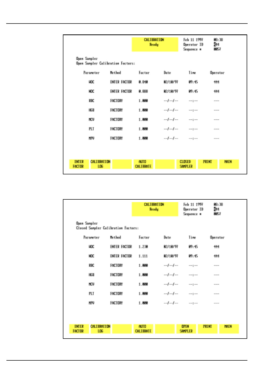
6-16 CELL-DYN® 3200 Operator’s Manual
9140181B — November 1997
Calibration Procedures
Calibration Menu Section 6
Figure 6.1: Calibration Menu Screen Displaying Open
Sampler Calibration Factors
Figure 6.2: Calibration Menu Screen Displaying Closed
Sampler Calibration Factors
Go Back
Search
TOC

CELL-DYN® 3200 Operator’s Manual 6-17
9140181B — November 1997
Calibration Procedures
Section 6 Calibration Menu
Calibration Menu Soft Keys
Enter Factor
The
[ENTER FACTOR]
key is used to display the
ENTER
CALIBRATION FACTOR
screen which displays the current whole
blood factors for the displayed mode (refer to Figure 6.3). The
soft keys available in this screen are:
RESTORE FACTORS
RESET ALL TO 1.000
RETURN
Restore Factors
The
[RESTORE FACTORS]
key is used to restore the previous
calibration factors. This key is active only immediately after
factors have been changed.
Reset all to 1.000
The
[RESET ALL TO 1.000]
key is used to reset all of the calibration
factors to 1.000.
Return
The
[RETURN]
key is used to return to the main
CALIBRATION
menu.
Go Back
Search
TOC
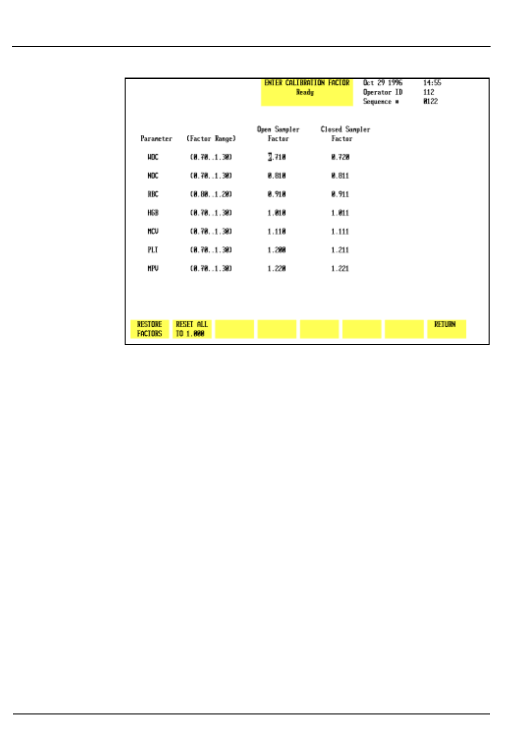
6-18 CELL-DYN® 3200 Operator’s Manual
9140181B — November 1997
Calibration Procedures
Calibration Menu Section 6
Figure 6.3: Enter Calibration Factor Screen
Calibration Log
The
[CALIBRATION LOG]
key is used to display the
CALIBRATION
LOG
screen for the Open or Closed Mode (refer to Figure 6.4).
The soft keys available in this screen are:
OPEN SAMPLER/CLOSED SAMPLER
PRINT LOG
RETURN
The
CALIBRATION LOG
holds 10 entries. The last 5 entries are
displayed on the screen. To display any previous entries, press
the Page Up key on the keyboard.
NOTE: When the log is full, subsequent entries cause
the oldest entry to be deleted and the remaining entries
to move up one line, so that the current factors are
added to the bottom of the list. Therefore, the log
should be printed periodically for purposes of
documentation.
The log displays the DATE, TIME, OPERATOR ID, CALIBRATION
FACTORS and a line for COMMENTS.
NOTE: The letters in parentheses after each factor
indicate the method of factor derivation: F = Factory,
A = Auto-Cal, E = Enter Factor (manual factor entry).
Go Back
Search
TOC
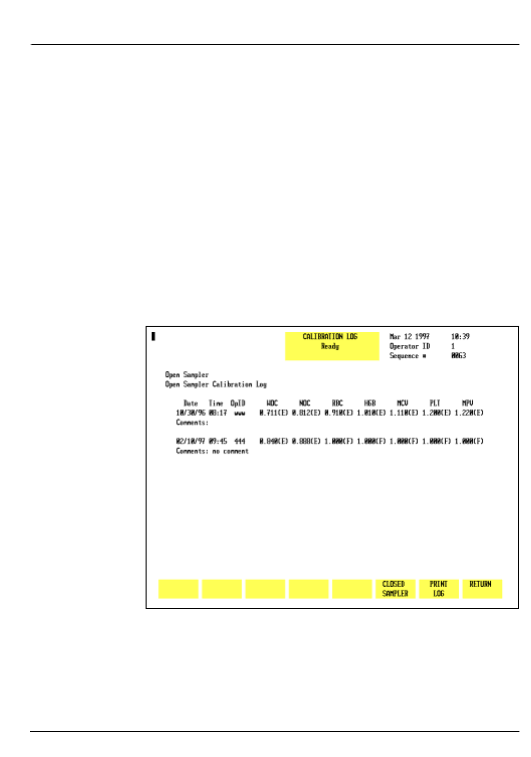
CELL-DYN® 3200 Operator’s Manual 6-19
9140181B — November 1997
Calibration Procedures
Section 6 Calibration Menu
Type any comments in the COMMENTS field. Press the Enter key
on the keyboard to save the entry and advance the cursor.
NOTE: Comments may be added to the Calibration
Log only after a calibration factor is changed or
reentered.
Open Sampler/Closed Sampler
The
[OPEN SAMPLER/CLOSED SAMPLER]
key is used to display the
calibration factors for the displayed mode. This key toggles
between the Open and Closed Sampler Calibration Factors.
Print Log
The
[PRINT LOG]
key is used to print the Calibration Log for the
displayed mode.
Figure 6.4: Calibration Log Screen
Return
The
[RETURN]
key is used to return to the main
CALIBRATION
menu.
Go Back
Search
TOC
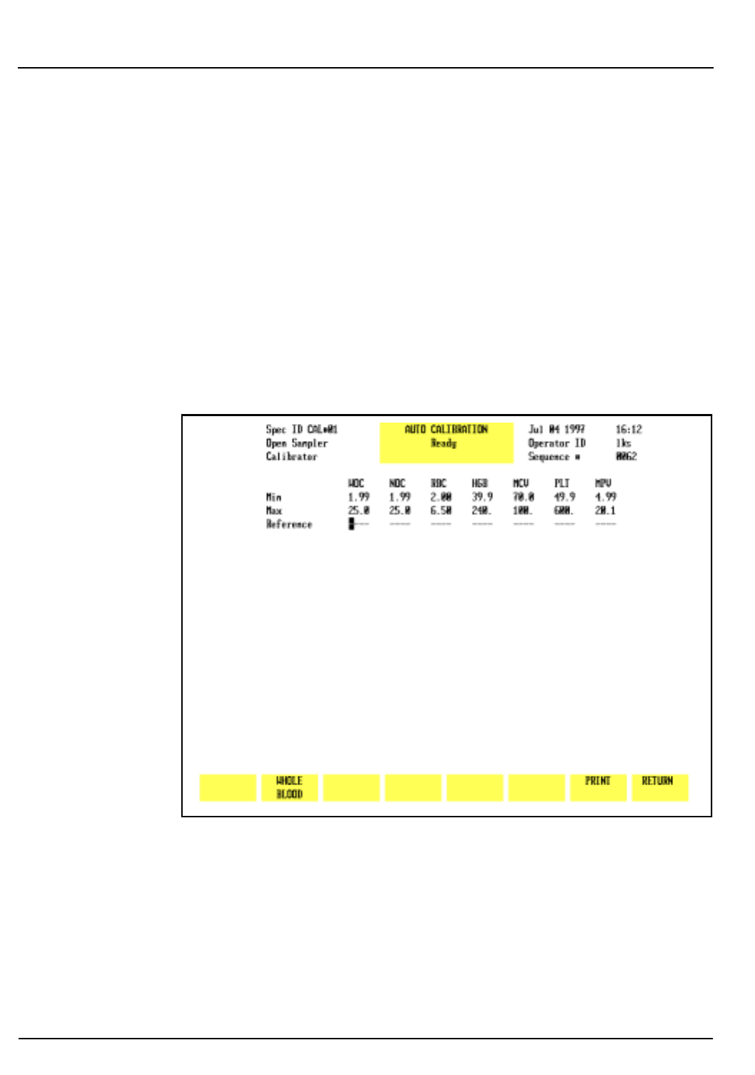
6-20 CELL-DYN® 3200 Operator’s Manual
9140181B — November 1997
Calibration Procedures
Calibration Menu Section 6
Auto-Calibrate
The
[AUTO-CALIBRATE]
key is used to display the
AUTO
CALIBRATION
screen (refer to Figure 6.5). The
AUTO CALIBRATION
screen changes during the calibration process as reference
values are entered and as runs are completed. These changes
are discussed in Auto-Cal Method later in this section.
When the
[AUTO-CALIBRATE]
key is pressed, the following soft
key labels are displayed:
WHOLE BLOOD/
(This key alternates between
CALIBRATOR
the selections)
PRINT
RETURN
Figure 6.5: Auto Calibration Screen
The
[WHOLE BLOOD]
and
[CALIBRATOR]
keys alternate to display
which type of calibration material is being used. This
information is displayed in the upper left corner of the screen
and stored with the updated calibration factors on the
Calibration Log.
Print
The
[PRINT]
key is used to print the data displayed on the
screen.
Go Back
Search
TOC

CELL-DYN® 3200 Operator’s Manual 6-21
9140181B — November 1997
Calibration Procedures
Section 6 Auto-Cal Method
Auto-Cal Method
Overview
The Auto-Cal program provides an automated calibration
method that prepares the CELL-DYN 3200 System for
calibration, calculates new calibration factors, and calibrates
the instrument.
NOTE: Always complete the Pre-Calibration procedures
before beginning any calibration.
Methodology
The instrument should be calibrated in both Open and Closed
Modes using either the CELL-DYN Calibrator or normal, fresh
whole blood.
NOTE: Auto-Calibration is not available in the Closed
Mode on the SL model. To calibrate Closed Mode, see
Calibration Procedure — Closed Mode in subsection
Enter Factor Method.
The same reference values and the same samples should be
used when calibrating both modes. Either mode may be
calibrated first, but it is recommended to calibrate the primary
mode first.
NOTE: Calibrator is the preferred material for
calibrating the CELL-DYN 3200 System.
When samples are run, Auto-Cal does the following:
1.Accepts up to ten consecutive sample runs for either
calibrator or fresh whole blood samples.
2.Compares sample results against internal precision and
reference checks, highlighting results that fail these
checks.
3.Calculates the new calibration factors (Mean Factors) and
Factor % Diff values.
4.Compares the Factor % Diff values to ranges in an
internal table to determine which parameters require
calibration.
Go Back
Search
TOC

6-22 CELL-DYN® 3200 Operator’s Manual
9140181B — November 1997
Calibration Procedures
Auto-Cal Method Section 6
NOTE: These ranges are shown in the Calibration
Range Criteria worksheets (#3 for Open Mode and #6
for Closed Mode) in Manual Calibration Worksheets
at the end of this section.
5.Highlights Factor % Diff values which require calibration
or which are over-limit.
Determining Reference Values
The minimum and maximum values for each parameter,
displayed above the reference value fields, apply to both
calibrator material and fresh whole blood.
Calibrator
Obtain the reference values from the assay sheet that is
packaged with the calibrator material.
Fresh Whole Blood
Follow the procedure below to determine the calibration
reference values using fresh whole blood.
NOTE: No more than two hours should elapse between
determining the Reference Mean Values and
performing the calibration.
WARNING: Potential Biohazard. Consider all specimens
potentially infectious. Wear gloves, lab coats, and safety
glasses and follow other biosafety procedures as
specified in the OSHA Bloodborne Pathogen Rule (29
CFR 1910.1030) or other equivalent biosafety
procedures.
1.Go to a reference hematology instrument or use
appropriate hematology methods with one sample of
normal, fresh whole blood.
2.Run a minimum of 10 replicates from this sample on the
reference instrument.
NOTE: Because the same sample will be used to first
obtain reference values on a reference instrument then
to calibrate in the Open and Closed Modes, it is
important to begin with a sufficient amount of sample.
3.If a mean value for each parameter based on at least 10
runs is not automatically calculated by the reference
hematology instrument or hematology methods, use a
calculator to determine the Reference Mean for each
parameter. For example:
Go Back
Search
TOC

CELL-DYN® 3200 Operator’s Manual 6-23
9140181B — November 1997
Calibration Procedures
Section 6 Auto-Cal Method
The cumulative Reference WBC Mean is 6.53 when the
WBC results from each run are as follows:
• RUN 1 = 6.6, RUN 2 = 6.4, RUN 3 = 6.7
• RUN 4 = 6.5, RUN 5 = 6.6, RUN 6 = 6.4
• RUN 7 = 6.7, RUN 8 = 6.3, RUN 9 = 6.5
• RUN 10 = 6.6
The cumulative mean of 6.53 equals the sum of the
values (65.3) divided by the 10 runs.
4. Save these values; they will be used to calibrate the
CELL-DYN 3200 System.
Auto-Cal Menu
When the
[AUTO-CALIBRATE]
key is pressed in the main
CALIBRATION
menu, the
AUTO-CALIBRATION
menu is displayed
(refer to Figure 6.6). Reference values are entered on this
screen.
The Spec ID field in the upper left corner of the screen defaults
to “CAL#01” to identify the sample as a “Calibration sample.”
This field is user-definable and accepts up to 6 alphanumeric
characters. As each calibration sample is run, the calibration
program adds a “-” and the run number from “01” to “10.”
Go Back
Search
TOC
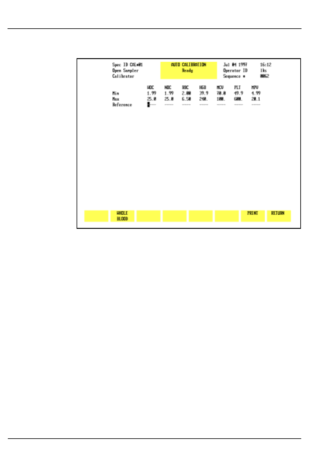
6-24 CELL-DYN® 3200 Operator’s Manual
9140181B — November 1997
Calibration Procedures
Auto-Cal Method Section 6
Figure 6.6: Auto Calibration Screen
Start Auto-Cal
Figure 6.6 shows the
AUTO CALIBRATION
screen before any
reference values are entered. When the first reference value has
been entered and the Enter key pressed, the
[START AUTO CAL]
and
[QUIT]
keys are displayed (refer to Figure 6.7).
After the
[START AUTO CAL]
key is pressed, the operator will not
be able to toggle between Calibrator and Whole Blood nor
make changes to the reference values, the Spec ID, or the
Operator ID. The instrument is ready to begin processing
samples.
Go Back
Search
TOC
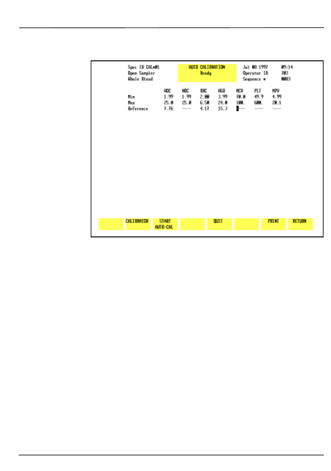
CELL-DYN® 3200 Operator’s Manual 6-25
9140181B — November 1997
Calibration Procedures
Section 6 Auto-Cal Method
Figure 6.7: START AUTO CAL Key Displayed
A message is displayed on the bulletin line alerting the
operator to start running samples.
As samples are processed, the results of each run are displayed
as shown in Figure 6.8. The following soft keys are displayed:
ACCEPT
(Label appears after the 5th run)
DELETE A RUN
(Label appears after the 1st run)
QUIT
(Label appears after the 1st run)
PRINT
RETURN
Go Back
Search
TOC
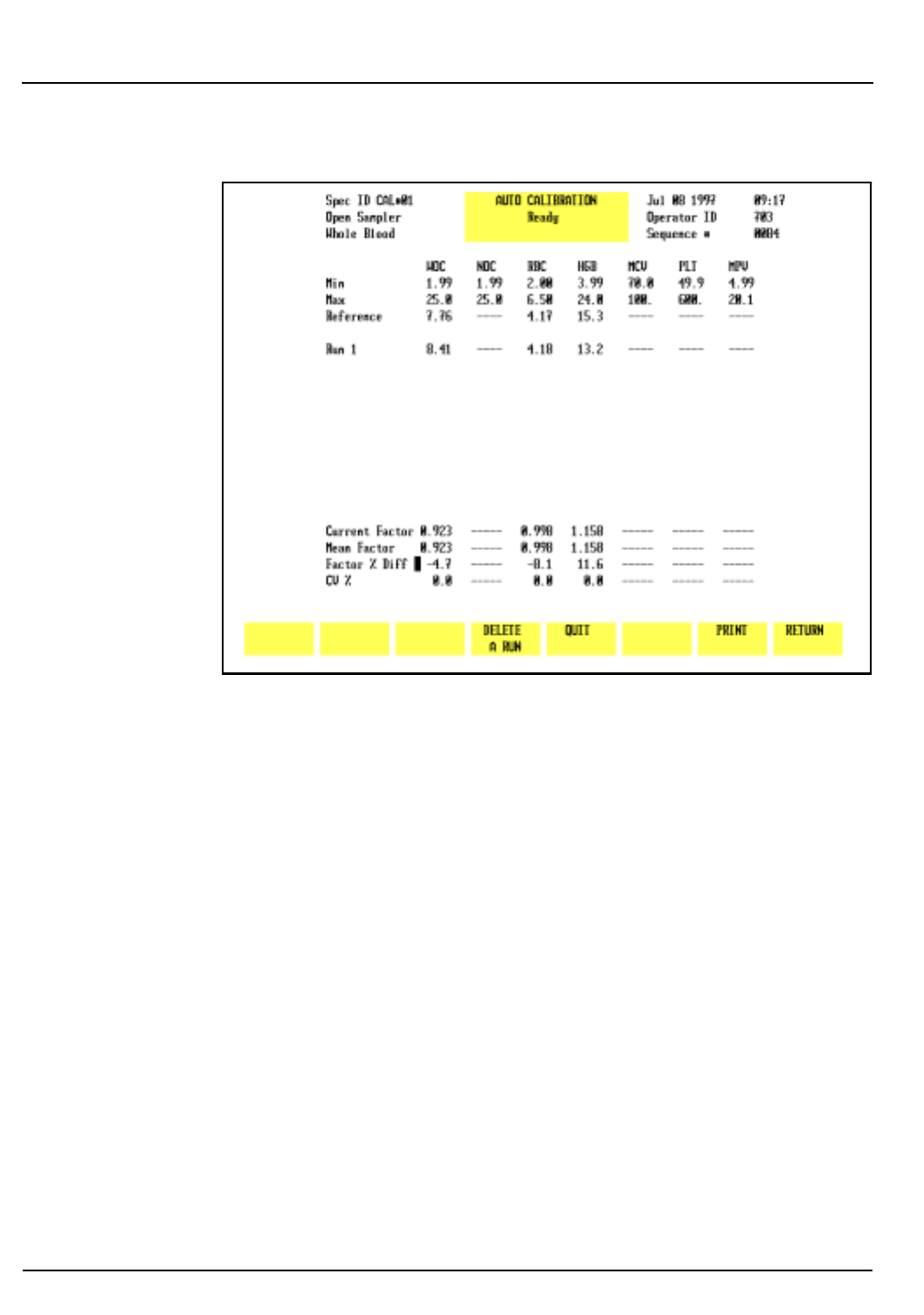
6-26 CELL-DYN® 3200 Operator’s Manual
9140181B — November 1997
Calibration Procedures
Auto-Cal Method Section 6
Figure 6.8: Results Display Screen
As the first sample is processed, the
[START AUTO-CAL]
key
disappears and the
[DELETE A RUN]
key appears. The
[ACCEPT]
key
appears after the results of the fifth run are displayed.
The following information is displayed in the lower portion of
the screen:
• Current Factor
• Mean Factor (new Calibration Factor)
• Factor % Diff
•CV %
The Current Factor is calculated for each run. The Mean Factor
is an average based on all runs. The Factor % Diff shows the
difference between the Mean Factor and the existing
Calibration Factor for that parameter. The CV (Coefficient of
Variation expressed as a percent) measures the degree of
variation between runs.
NOTE: The Mean Factor is the new Calibration Factor.
Go Back
Search
TOC

CELL-DYN® 3200 Operator’s Manual 6-27
9140181B — November 1997
Calibration Procedures
Section 6 Auto-Cal Method
If a result is highlighted in Green on the Run line, it indicates
that parameter has failed a reference or precision check. That
result will not be included in the Mean Factor and Factor %
Diff calculations for that parameter.
Consequently, the Mean Factor for some parameters may be
based on fewer runs than other parameters and may even be
based on fewer than 5 runs.
For example:
a. Five samples have been run and the [ACCEPT] is
displayed after the 5th run
b. The Factor % Diff for WOC is green, indicating it
needs to be calibrated
c. The WOC result for Run #4 is highlighted, indicating
it failed a reference or precision check
d. The Mean Factor and Factor % Diff for WOC are based
on only 4 runs because Run #4 failed its internal
check
e. If the operator presses the
[ACCEPT]
and
[CONFIRM ACCEPT]
keys, a new calibrator factor will be
entered for WOC but the new factor will be based on
4, not 5, runs.
Delete a Run
If a result for a parameter is outside a predetermined limit, that
result is highlighted and not included in the Mean Factor and
Factor % Diff calculations. The operator has the option of
keeping or deleting the entire run. To delete a run, do the
following:
1. Press
[DELETE A RUN]
.
2. A prompt will appear at the bottom of the screen. Type in
the number of the run to be deleted and press the Enter
key.
NOTE: Only one run can be deleted in each calibration
session. The system does not allow a deleted run to be
replaced with a new run. For example, if there are 10
runs and the operator deletes Run #5, then calibration
will be based on 9 runs (remember, a highlighted result
on a run will not be included in the Mean Factor or
Factor % Diff for that parameter).
Go Back
Search
TOC
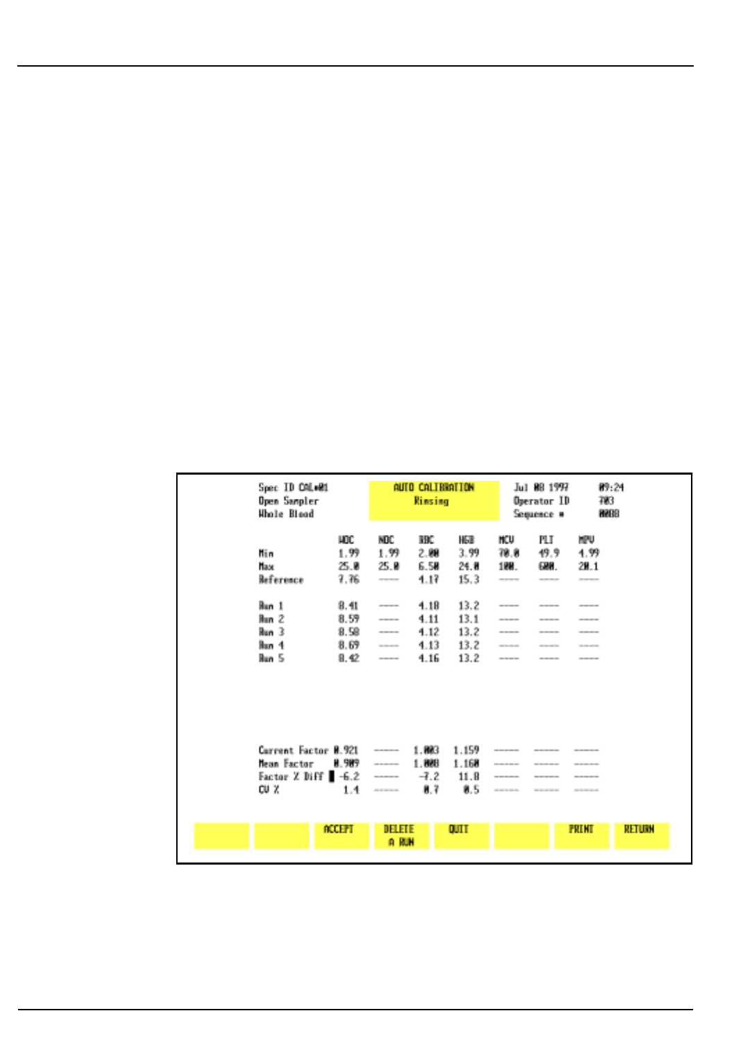
6-28 CELL-DYN® 3200 Operator’s Manual
9140181B — November 1997
Calibration Procedures
Auto-Cal Method Section 6
Quit
When
[QUIT]
is pressed, the
[CONFIRM QUIT]
and
[CANCEL QUIT]
keys are displayed. Pressing
[CONFIRM QUIT]
deletes all runs and
reference values and returns the operator to the
AUTO
CALIBRATION
screen shown in Figure 6.6. The screen is ready to
receive new reference values. Pressing
[CANCEL QUIT]
returns the
operator to the current screen.
Accept
This label appears after the results of the fifth run are displayed
on the screen, allowing the operator to accept all the
calibration factors shown in the lower portion of the screen
(refer to Figure 6.9). When
[ACCEPT]
is pressed, two key labels
[CONFIRM ACCEPT]
and
[CANCEL ACCEPT]
are displayed (refer to
Figure 6.10). Pressing
[CONFIRM ACCEPT]
saves the new
calibration factors and displays the
CALIBRATION LOG
screen.
Pressing
[CANCEL ACCEPT]
returns the operator to the
Calibration results screen.
Figure 6.9: ACCEPT Key Displayed
Go Back
Search
TOC
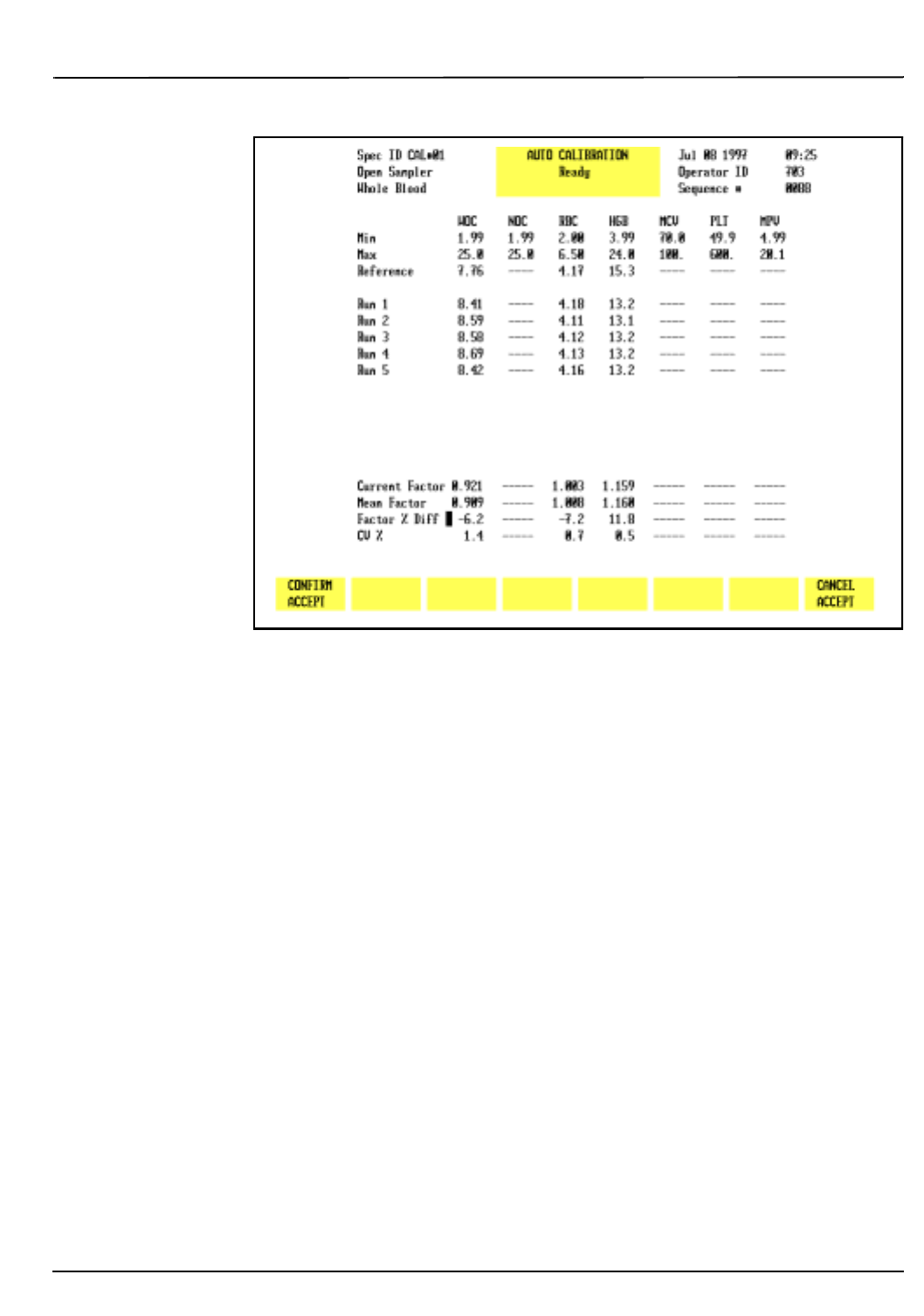
CELL-DYN® 3200 Operator’s Manual 6-29
9140181B — November 1997
Calibration Procedures
Section 6 Auto-Cal Method
Figure 6.10: Confirm Acceptance of New Factors
Auto-Cal Procedure — Open Mode
Displaying the Auto-Cal Screen
1. If necessary, go to the
RUN
screen and press
[CHANGE
SAMPLER]
to select the Open Mode.
2. In the
MAIN MENU
, press
[CALIBRATION]
to display the main
CALIBRATION
menu.
3. If necessary, press
[OPEN SAMPLER]
to display the Open
Sampler Calibration Factors.
NOTE: This key is used to display either the current
Open Sampler Factors or Closed Sampler Factors. It
does not change the mode.
4. Press
[PRINT]
to obtain a printout of the current Open
Sampler Calibration Factors.
5. Press
[AUTO-CALIBRATE]
to display the
AUTO-CALIBRATION
screen.
Entering Reference Values
1. To enter reference values for each parameter to be
calibrated:
Go Back
Search
TOC

6-30 CELL-DYN® 3200 Operator’s Manual
9140181B — November 1997
Calibration Procedures
Auto-Cal Method Section 6
a.If calibrator is used, enter the corresponding reference
(assay) value from the sheet enclosed with the
calibrator material.
b.If fresh whole blood is used, enter the mean value
obtained from the procedure in subsection Fresh
Whole Blood under Determining Reference Values
above.
2.Press the Enter key after each entry to save the value and
advance the cursor to the next parameter.
3.When all reference values have been entered, press
[START AUTO-CAL]
to ready the instrument for calibration.
The message Ready to aspirate Cal sample is displayed.
Processing Samples
1. Specimen mixing:
a.If calibrator material, prepare the calibrator for use
according to the directions given in the package
insert. Be certain to carefully read and follow
directions given for warming and mixing.
b.If fresh whole blood, mix the sample well by inverting
the tube at least ten times. Do not shake the
specimen.
2.Place the well-mixed specimen under the Open Mode
Sample Probe and press the Touch Plate. The sample is
analyzed and the results are displayed.
3. Repeat steps 1 and 2 above until the desired number of
runs for either Calibrator or Fresh Whole Blood has been
completed. Mix the sample well between each run.
Calibration Check
During the RUN cycle, if a parameter fails the internal
reference/precision checks for calibration, the value for that
parameter is backlit in green on the run line, dashes are
displayed in the Current Factor field, and the Mean Factor is
not updated.
Determining Which Parameters Need Calibration
1. After the
[ACCEPT]
key is displayed, you may continue
processing samples until the desired number of runs has
been completed.
Go Back
Search
TOC

CELL-DYN® 3200 Operator’s Manual 6-31
9140181B — November 1997
Calibration Procedures
Section 6 Auto-Cal Method
2.Observe the Factor % Diff value for each parameter being
calibrated:
a.If the value is not highlighted (remains white), that
parameter does not need calibration and the new
calibration factor (Mean Factor) displayed on the
screen will not replace the existing calibration factor
when the [ACCEPT] key is pressed. White indicates
the Factor % Diff is less than the value shown column
2 of Worksheet 3, Open Mode Calibration Range
Criteria, provided in Manual Calibration Worksheets
at the end of this section.
b.If the value is highlighted in green, that parameter
needs to be calibrated and the new calibration factor
displayed on the screen will replace the existing
calibration factor when the
[ACCEPT]
key is pressed.
Green indicates the Factor % Diff is within the range
specified in column 3 of Worksheet 3, Open Mode
Calibration Range Criteria, provided in Manual
Calibration Worksheets at the end of this section.
c.If the value is highlighted in purple, it indicates the
Factor % Diff is greater than the value shown in
column 4 of Worksheet 3, Open Mode Calibration
Range Criteria, provided in Manual Calibration
Worksheets at the end of this section.
d.If all Factor % Diff values are white, go to Calibration
Not Required below. If at least one Factor % Diff is
green, go to Some Parameters Need Calibration
below. If at least one Factor % Diff is purple, go to
subsection Over-Limit Parameters below.
Calibration Not Required
1.If all the Factor % Diff values are white, then calibration is
not required in Open Mode. No update to the Calibration
Log is required and no calibration confirmation is
required.
2.If Closed Mode has not been calibrated, go to subsection
Auto-Cal — Closed Mode, otherwise return to the
MAIN
MENU
by pressing
[RETURN]
followed by
[MAIN]
.
Go Back
Search
TOC

6-32 CELL-DYN® 3200 Operator’s Manual
9140181B — November 1997
Calibration Procedures
Auto-Cal Method Section 6
Some Parameters Need Calibration
1.If at least one Factor % Diff value is green and if no Factor
% Diff values are highlighted in purple, press
[ACCEPT]
followed by
[CONFIRM ACCEPT]
to calibrate the Open Mode.
Go to subsection Completing Calibration Log below.
Over-Limit Parameters
1.If the Factor % Diff for a parameter is highlighted in
purple, it indicates there may be an instrument problem.
In this case, do the following:
a.Determine if any component on the instrument was
changed. This could affect calibration. Such
components include the Shear Valve, Optical Flow
Cell, Hemoglobin Flow Cell, or one of the syringes.
b.If a component was changed, then treat the result as if
it fell within the “calibration range” (even though it is
greater than the upper limit). CALIBRATION IS
REQUIRED for that parameter. Use the arrow keys to
move the cursor to the Factor % Diff value. Press the
Enter key to change the purple to green, indicating
calibration is now required. Pressing
[ACCEPT]
followed
by
[CONFIRM ACCEPT]
will calibrate this “over limit”
parameter along with any other “calibration required”
parameters. Go to subsection Completing Calibration
Log below.
NOTE: Because Factor % Diff values highlighted in
purple can be changed to green using the Enter key, it is
also possible for the operator to overwrite these values.
However, the change only appears on the screen; the
actual values calculated by the calibration program
remain intact and the Mean Factors are not affected.
c.If no component was changed and your calculations
are correct, DO NOT CALIBRATE. CONFIRM THAT
ALL PRE-CALIBRATION PROCEDURES WERE
COMPLETED AND THEN CALL THE CUSTOMER
SUPPORT CENTER FOR ASSISTANCE (at 1-800-CELL-
DYN in the U.S.).
Completing Calibration Log
1.Complete the Calibration Log (adding comments) as
required. If a printout of the log is desired, press
[PRINT LOG]
.
2. Press
[RETURN]
to return to the main
CALIBRATION
screen.
Go Back
Search
TOC

CELL-DYN® 3200 Operator’s Manual 6-33
9140181B — November 1997
Calibration Procedures
Section 6 Auto-Cal Method
3. Press
[PRINT]
to obtain a copy of the new Open Sampler
Calibration Factors.
Confirming Open Mode Calibration
To confirm calibration in the Open Mode, follow the
instructions below. Use the same Calibrator or Fresh Whole
Blood Sample that was used to calibrate the instrument.
1. In the
CALIBRATION
menu, press
[MAIN]
to return to the
MAIN
MENU
.
2. In the
MAIN MENU
, press
[RUN]
followed by
[SPECIMEN TYPE]
and
[PATIENT]
.
3.Refer to Worksheet 7, Calibration Confirmation, in
Manual Calibration Worksheets at the end of this
section. Make copies of this worksheet as necessary.
4.Run the same Calibrator or Fresh Whole Blood sample 5
times. After each run, observe the values displayed on the
RUN
screen for those parameters that were calibrated and
that now need confirmation. Write these values in the
appropriate space on Worksheet 7.
5. Follow the instructions on this worksheet for calculating
a mean and comparing the mean value against the
reference value.
6.If the difference between the mean and reference (assay)
value is within the stated tolerance limits, then
calibration has been confirmed for that parameter. Go to
step 8 below.
7.If a parameter mean is outside the tolerance limits,
perform steps 4 and 5 again. If the mean is still outside
the tolerance limits, call the Customer Support Center for
assistance (at 1-800-CELL-DYN in the U.S.).
8. When Open Mode calibration has been confirmed, do
one of the following:
a.If Closed Mode has not yet been calibrated, go to
subsection Auto-Cal Procedure — Closed Mode.
b.If Closed Mode calibration has been completed, press
[MAIN]
to return to the
MAIN MENU
.
Go Back
Search
TOC

6-34 CELL-DYN® 3200 Operator’s Manual
9140181B — November 1997
Calibration Procedures
Auto-Cal Method Section 6
Auto-Cal Procedure — Closed Mode
NOTE: Auto-Calibration is not available in the Closed
Mode on the SL model. To calibrate Closed Mode, see
Calibration Procedure — Closed Mode in subsection
Enter Factor Method.
Displaying the Auto-Cal Screen
1. If necessary, go to the
RUN
screen and press
[CHANGE SAMPLER]
to select the Closed Mode.
2. In the
MAIN MENU
, press
[CALIBRATION]
to display the main
CALIBRATION
menu.
3.If necessary, press
[CLOSED SAMPLER]
to display the Closed
Sampler Calibration Factors.
4. Press
[PRINT]
to obtain a printout of the current Closed
Sampler Calibration Factors.
5. Press
[AUTO-CALIBRATE]
to display the
AUTO-CALIBRATION
screen.
Entering Reference Values
1.To enter reference values for each parameter to be
calibrated:
a.If calibrator is used, enter the corresponding reference
(assay) value from the sheet enclosed with the
calibrator material.
b.If fresh whole blood is used, enter the mean value
obtained from the procedure in subsection Fresh
Whole Blood under Determining Reference Values
above.
2.Press the Enter key after each entry to save the value and
advance the cursor to the next parameter.
3.When all reference values have been entered, press
[START AUTO-CAL]
to ready the instrument for calibration.
Processing Samples
1.Mix the sample well. If Calibrator, follow the directions
on the package insert. If Fresh Whole Blood, invert the
sample ten times. Do not shake the specimen. Place the
well-mixed specimen in the Tube Retainer, close the door,
and press the Touch Plate. The instrument performs RUN
1 and displays the values in the RUN 1 row.
Go Back
Search
TOC

CELL-DYN® 3200 Operator’s Manual 6-35
9140181B — November 1997
Calibration Procedures
Section 6 Auto-Cal Method
2.Repeat step 1 above until the desired number of runs for
either Calibrator or Fresh Whole Blood has been
completed.
Calibration Check
During the RUN cycle, if a parameter fails the internal
reference/precision checks for calibration, the value for that
parameter is backlit in green on the run line, dashes are
displayed in the Current Factor field, and the Mean Factor is
not updated.
Determining Which Parameters Need Calibration
1.After the [ACCEPT] key is displayed, you may continue
processing samples until the desired number of runs has
been completed.
2.Observe the Factor % Diff value for each parameter being
calibrated:
a.If the value is not highlighted (remains white), that
parameter does not need calibration and the new
calibration factor (Mean Factor) displayed on the
screen will not replace the existing calibration factor
when the [ACCEPT] key is pressed. White indicates the
Factor % Diff is less than the value shown in column 2
of Worksheet 6, Closed Mode Calibration Range
Criteria, provided in Manual Calibration Worksheets
at the end of this section.
b.If the value is highlighted in green, that parameter
needs to be calibrated and the new calibration factor
displayed on the screen will replace the existing
calibration factor when the
[ACCEPT]
key is pressed.
Green indicates the Factor % Diff is within the range
specified in column 3 of Worksheet 6, Closed Mode
Calibration Range Criteria, provided in Manual
Calibration Worksheets at the end of this section.
c.If the value is highlighted in purple, it indicates the
Factor % Diff is greater than the value shown in
column 4 of Worksheet 6, Closed Mode Calibration
Range Criteria, provided in Manual Calibration
Worksheets at the end of this section.
d.If all Factor % Diff values are white, go to Calibration
Not Required below. If at least one Factor % Diff is
green, go to Some Parameters Need Calibration
below. If at least one Factor % Diff is purple, go to
subsection Over-Limit Parameters below.
Go Back
Search
TOC

6-36 CELL-DYN® 3200 Operator’s Manual
9140181B — November 1997
Calibration Procedures
Auto-Cal Method Section 6
Calibration Not Required
1.If all the Factor % Diff values are white, then calibration is
not required in Closed Mode. No update to the
Calibration Log is required and no calibration
confirmation is required.
2.If Open Mode has not been calibrated, go to subsection
Auto-Cal — Open Mode, otherwise return to the
MAIN
MENU
by pressing
[RETURN]
followed by
[MAIN]
.
Some Parameters Need Calibration
1.If at least one Factor % Diff value is highlighted in green
and if no Factor % Diff values are highlighted in purple,
press
[ACCEPT]
followed by
[CONFIRM ACCEPT]
to calibrate
the Closed Mode. Go to subsection Completing
Calibration Log below.
Over-Limit Parameters
1.If the Factor % Diff for a parameter is highlighted in
purple, it indicates there may be an instrument problem.
In this case, do the following:
a.Determine if any component on the instrument was
changed. This could affect calibration. Such
components include the Shear Valve, Optical Flow
Cell, Hemoglobin Flow Cell, or one of the syringes.
b.If a component was changed, then treat the result as if
it fell within the “calibration range” (even though it is
greater than the upper limit). CALIBRATION IS
REQUIRED for that parameter. Use the arrow keys to
move the cursor to the Factor % Diff value. Press the
Enter key to change the purple to green, indicating
calibration is now required. Press
[ACCEPT]
followed by
[CONFIRM ACCEPT]
to calibrate this “over limit”
parameter along with any other “calibration required”
parameters. Go to subsection Completing Calibration
Log below.
NOTE: Because Factor % Diff values highlighted in
purple can be changed to green using the Enter key, it is
also possible for the operator to overwrite these values.
However, the change only appears on the screen; the
actual values calculated by the calibration program
remain intact and the Mean Factors are not affected.
Go Back
Search
TOC

CELL-DYN® 3200 Operator’s Manual 6-37
9140181B — November 1997
Calibration Procedures
Section 6 Auto-Cal Method
c.If no component was changed and your calculations
are correct, DO NOT CALIBRATE. CONFIRM THAT
ALL PRE-CALIBRATION PROCEDURES WERE
COMPLETED AND THEN CALL THE CUSTOMER
SUPPORT CENTER FOR ASSISTANCE (at 1-800-CELL-
DYN in the U.S.).
Completing Calibration Log
1.Complete the Calibration Log (adding comments) as
required. If a printout of the log is desired, press
[PRINT LOG]
.
2. Press
[RETURN]
to return to the main
CALIBRATION
screen.
3. Press
[PRINT]
to obtain a copy of the new Closed Sampler
Calibration Factors.
Confirming Closed Mode Calibration
To confirm calibration in the Closed Mode, follow the
instructions below. Use the same Calibrator or Fresh Whole
Blood Sample that was used to calibrate the instrument.
1. In the
CALIBRATION
menu, press
[MAIN]
to return to the
MAIN
MENU
.
2. In the
MAIN MENU
, press
[RUN]
followed by
[SPECIMEN TYPE]
and
[PATIENT]
.
3.Refer to Worksheet 7, Calibration Confirmation, in
Manual Calibration Worksheets at the end of this
section. Make copies of this worksheet as necessary.
4.Run the same Calibrator or Fresh Whole Blood sample 5
times. Refer to Processing Samples above for instructions
on running samples on the CS model compared to the SL
model.
5.After each run, observe the values displayed on the
RUN
screen for those parameters that were calibrated and that
now need confirmation. Write these values in the
appropriate space on Worksheet 7.
6. Follow the instructions on this worksheet for calculating
a mean and comparing the mean value against the
reference value.
7.If the difference between the mean and reference (assay)
value is within the stated tolerance limits, then
calibration has been confirmed for that parameter. Go to
step 9 below.
Go Back
Search
TOC

6-38 CELL-DYN® 3200 Operator’s Manual
9140181B — November 1997
Calibration Procedures
Auto-Cal Method Section 6
8. If a parameter mean is outside the tolerance limits,
perform steps 4 and 5 again. If the mean is still outside
the tolerance limits, call the Customer Support Center for
assistance (at 1-800-CELL-DYN in the U.S.).
9. When Closed Mode calibration has been confirmed, press
[MAIN]
to return to the
MAIN MENU
.
10. You may also elect to Run Commercial Control as a
means of confirming calibration.
Go Back
Search
TOC

CELL-DYN® 3200 Operator’s Manual 6-39
9140181B — November 1997
Calibration Procedures
Section 6 Enter Factor Method
Enter Factor Method
Overview
The Enter Factor Calibration Method is used to enter a
predetermined factor to adjust calibration when a consistent
bias exists between the CELL-DYN 3200 System and a
comparison analyzer.
Either Calibrator or Fresh Whole Blood can be used for
calibration.
Fresh Whole Blood: Because the same sample will be used to
first obtain reference values on a reference instrument then to
calibrate in the Open and Closed Modes, it is important to
begin with a sufficient amount of sample (12 mL
recommended).
A set of worksheets is provided in Manual Calibration
Worksheets at the end of this section to assist in the
calibration process.
NOTE: Always complete the Pre-Calibration procedures
before beginning any calibration.
Enter Calibration Factor Screen
When the Enter Factor key is pressed in the main
CALIBRATION menu, the ENTER CALIBRATION FACTOR
menu is displayed (refer to Figure 6.12). New calibration
factors are manually entered on this screen.
The following soft key labels are displayed:
RESTORE FACTORS
RESET ALL TO 1.000
RETURN
Go Back
Search
TOC
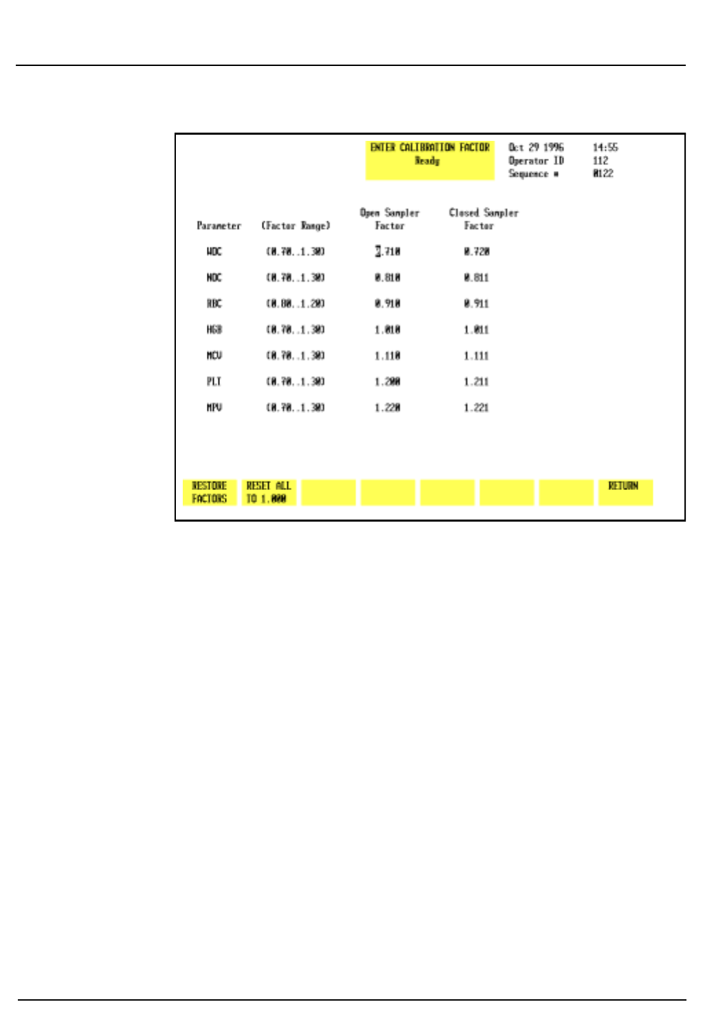
6-40 CELL-DYN 3200 Operator’s Manual
9140181B — November 1997
Calibration Procedures
Enter Factor Method Section 6
Figure 6.12: Enter Factor Screen
General Information
Calibrator
The requirements for using Calibrator in the Enter Factor
method are similar to the Auto-Cal method. Refer to
Calibrator Requirements under Calibration Materials earlier
in this section.
Fresh Whole Blood
In addition to the requirements listed in Fresh Whole Blood
Requirements under Calibration Materials earlier in this
section, the following procedures apply when using the Enter
Factor method:
1.A minimum of five samples are required for adequate
calibration. (In Auto-Cal, only one sample is run.)
2.Mean values should be calculated for each parameter
based on 10 runs (five samples, each run twice into one
QC file). These mean parameter values can then be
entered as reference values on the CELL-DYN 3200
System.
Go Back
Search
TOC

CELL-DYN® 3200 Operator’s Manual 6-41
9140181B — November 1997
Calibration Procedures
Section 6 Enter Factor Method
ICSH Recommendations
When using fresh whole blood samples, reference values
should be determined according to the following ICSH
recommendations.
WOC, NOC, RBC, and PLT
Reference values for white blood cells, red blood cells, and
platelets may be determined using multiple counts from a
certified hemocytometer, from a counter that meters a fixed,
calibrated sample volume, or from a reliably calibrated
hematology analyzer.
HGB
Reference values for hemoglobin may be determined using
either the reference cyanmethemoglobin method or a reliably
calibrated hemoglobinometer or hematology analyzer.
NOTE: DO NOT attempt to calibrate the
CELL-DYN 3200 System with a hemoglobin standard
designed for the calibration of specific reference
cyanmethemoglobin methods. The instrument uses a
modified hemiglobinhydroxyalamine method which is
not designed to analyze these standards directly.
MCV
Reference values for the mean cell volume may be determined
by calculation from the reference microhematocrit and RBC
measurements or from multiple analyses on a reliably
calibrated hematology analyzer.
NOTE: Reference microhematocrit values may be
determined by multiple analyses using the NCCLS
method for Packed Cell Volume (PCV).2 Use only plain
(non-anticoagulated) capillary tubes. Be certain to
verify the proper operation of the microhematocrit
centrifuge and the timer as recommended by NCCLS.
Determining Reference Values — Fresh Whole Blood
Follow the procedures below to determine the reference values
that will be used to calibrate the instrument using fresh whole
blood.
NOTE: No more than two hours should elapse between
determining the Reference Mean Values and
performing the calibration.
Go Back
Search
TOC

6-42 CELL-DYN 3200 Operator’s Manual
9140181B — November 1997
Calibration Procedures
Enter Factor Method Section 6
WARNING: Potential Biohazard. Consider all specimens
potentially infectious. Wear gloves, lab coats, and safety
glasses and follow other biosafety procedures as
specified in the OSHA Bloodborne Pathogen Rule (29
CFR 1910.1030) or other equivalent biosafety
procedures.
1. Go to a reference hematology instrument (or use
appropriate hematology methods) with 5 samples of
normal, fresh whole blood. Run each sample at least
twice for a minimum of 10 replicates on the reference
instrument.
NOTE: Because the same sample will be used to first
obtain reference values on a reference instrument then
to calibrate in the Open and Closed Modes, it is
important to begin with a sufficient amount of sample.
2. If a mean value for each parameter based on at least 10
runs is not automatically calculated by the reference
hematology instrument or hematology methods, use a
calculator to determine the cumulative Reference Mean
for each parameter. For example:
The cumulative Reference WOC Mean is 7.15 when the
WOC results from each run are as follows:
• Sample 1 = 9.2, 9.1
• Sample 2 = 4.5, 4.6
• Sample 3 = 6.1, 5.9
• Sample 4 = 7.0, 7.3
• Sample 5 = 8.9, 8.9
The cumulative mean of 7.15 equals the sum of the
values (71.5) divided by the 10 runs.
You may use the worksheet on the following page to
record the values obtained from running samples on a
reference instrument. Make copies of the blank worksheet
as necessary.
Go Back
Search
TOC
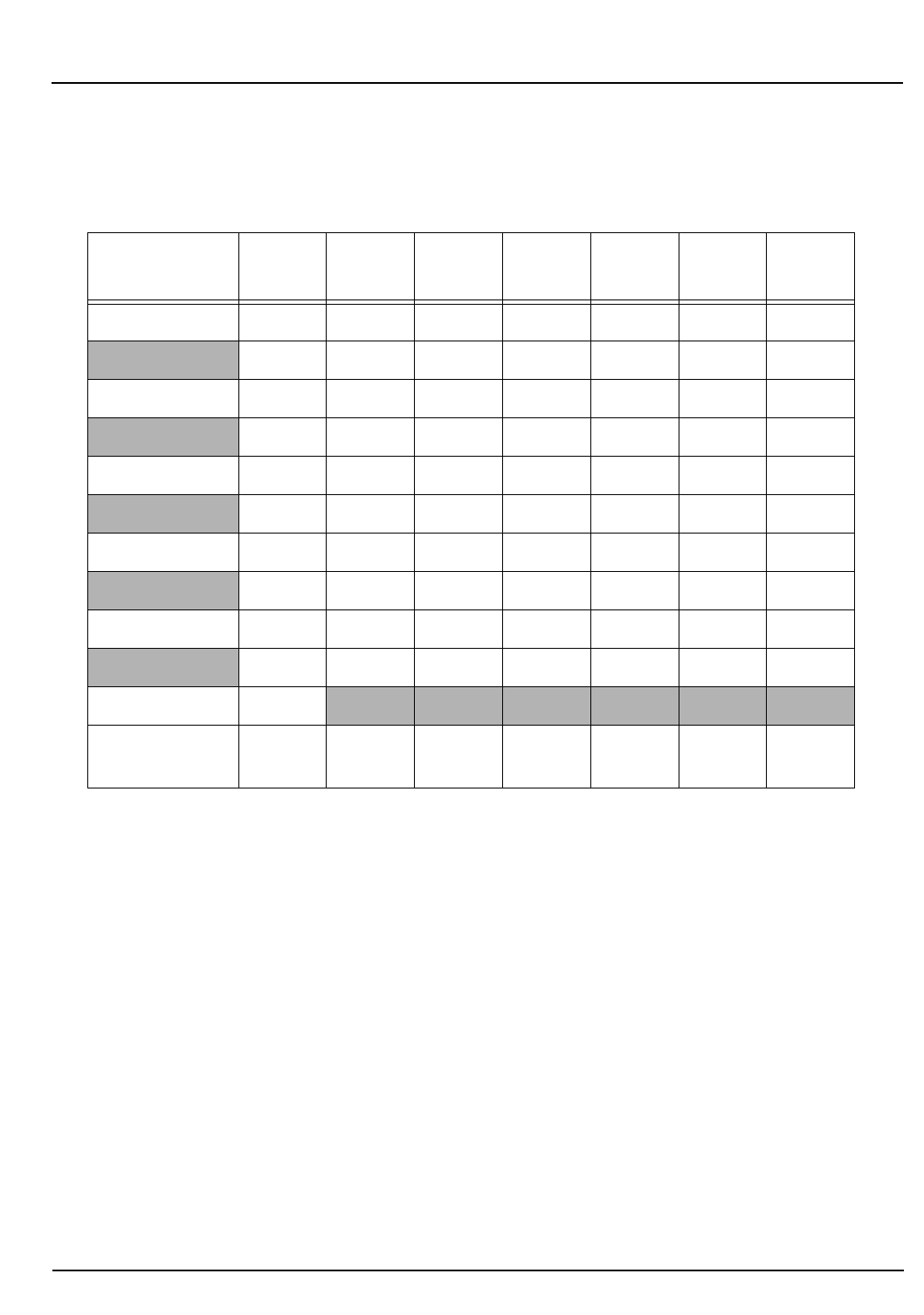
CELL-DYN® 3200 Operator’s Manual 6-43
9140181B — November 1997
Calibration Procedures
Section 6 Enter Factor Method
Whole Blood Calibration Reference Values Worksheet
Date: Technologist:
NOTE: The WBC value obtained on the Reference Instrument should be used for
calibrating both the WOC and NOC parameters on the CELL-DYN 3200
Instrument.
Calibration Procedure — Open Mode
Follow the procedure below for calibrating the instrument in the
Open Mode.
NOTE: Use the same Calibrator or Fresh Whole Blood
samples for calibrating Open and Closed Modes.
Determining New Calibration Factors
1. If necessary, go to the
RUN
menu and press
[CHANGE SAMPLER]
to select the Open Mode.
2. In the
MAIN MENU
, press
[CALIBRATION]
to display the main
CALIBRATION
menu.
Sample ID Run # WBC
(WOC) WBC
(NOC) RBC HGB MCV PLT
1
2
1
2
1
2
1
2
1
2
Cumulative
Mean
Go Back
Search
TOC

6-44 CELL-DYN 3200 Operator’s Manual
9140181B — November 1997
Calibration Procedures
Enter Factor Method Section 6
3. Obtain a printout of the current Open Sampler
Calibration Factors as follows:
a. If necessary, press
[OPEN SAMPLER]
to display the Open
Sampler Calibration Factors.
b. Press
[PRINT]
to obtain a printout of these factors. Save
this printout. It will be used when completing
Worksheet 1 at the end of this section.
4. Open an empty QC file as follows:
a. In the
MAIN MENU
, press
[RUN]
to display the
RUN
menu.
b. If necessary, press
[CHANGE SAMPLER]
to select Open
Mode.
c. Press
[SPECIMEN TYPE]
to display the
SPECIMEN TYPE
menu.
d. Use the arrow keys on the keyboard to move the
cursor to an empty QC file and type the desired file
name in the <File Name> field.
e. Press Enter to save the name. Use the Up Arrow key to
move the cursor back to the file name.
f. Press
[QC SPECIMEN]
to return to the
RUN
screen.
5. If calibrator material is used, follow the mixing
instructions found in the package insert. If fresh whole
blood is used, mix it well by inverting the tube at least ten
times. Do not shake the specimen.
WARNING: Potential Biohazard. Consider all
specimens, calibrators, and controls that contain
human blood as potentially infectious. Wear gloves, lab
coats, and safety glasses and follow other biosafety
procedures as specified in the OSHA Bloodborne
Pathogen Rule (29 CFR 1910.1030) or other equivalent
biosafety procedures.
6. If calibrator material is used, when READY appears in the
Status Box, place the calibrator under the Open Mode
Sample Probe and press the Touch Plate to run the
specimen. The results of the run are placed in the QC file
selected in step 1. Repeat this step until the minimum
number of recommended runs (6) is completed. Go to
step 7.
Go Back
Search
TOC

CELL-DYN® 3200 Operator’s Manual 6-45
9140181B — November 1997
Calibration Procedures
Section 6 Enter Factor Method
If fresh whole blood is used, when READY appears in the
Status Box place the sample under the Open Mode Sample
Probe and press the Touch Plate to run the specimen. The
results of the run are placed in the QC file selected in step
1. Repeat this process until 10 runs (2 from each sample)
are completed.
7. When sample processing is completed, press
[MAIN]
followed by [
QUALITY CONTROL]
. Use the arrow keys to
place the cursor on the appropriate QC file and press
[
VIEW QC LOG]
.
8. Press
[PRINT QC LOG]
to print the Summary Report for the
selected QC file.
9.To determine the New Calibration Factor for each
parameter:
a.For Calibrator, use the values on the assay sheet and
the CELL-DYN mean values determined in steps 2
through 8 above. Enter this information in columns 1
and 2 respectively of Worksheet 1, Open Mode
Calibration — New Factors, provided in Manual
Calibration Worksheets at the end of this section.
b.For Fresh Whole Blood, use the Reference Mean
Values determined in Determining Reference Values
— Fresh Whole Blood described earlier (refer to the
Whole Blood Calibration ReferenceValues Worksheet)
and the CELL-DYN Mean values determined in steps 2
through 8 above. Enter this information in columns 1
and 2 respectively of Worksheet 1, Open Mode
Calibration — New Factors, provided in Manual
Calibration Worksheets at the end of this section.
c.Enter the current Open Sampler Calibration Factors,
obtained in step 3 above, in column 3 of Worksheet 1.
NOTE: Be sure to make copies of this worksheet as
needed.
10.Follow the instructions on Worksheet 1 to calculate the
new Open Mode Calibration Factor for each parameter
and enter this information in column 4 of the worksheet.
The method for determining the new factors is:
CalibratorCalibration:
Go Back
Search
TOC

6-46 CELL-DYN 3200 Operator’s Manual
9140181B — November 1997
Calibration Procedures
Enter Factor Method Section 6
Whole Blood Calibration:
For example, if the Reference Mean Value for WOC is 6.6,
the CELL-DYN Mean for WOC is 7.1, and the current
Open Mode Calibration Factor for WOC is 0.98, then:
(6.6 / 7.1) x 0.98 = 0.91
and 0.91 is your New Open Mode Calibration Factor for
WOC.
Determining Which Parameters Need Calibration
To determine which parameters require calibration in the
Open Mode, follow the procedure below:
1.Obtain the values derived in column 4 of Worksheet 1
and enter these values in the new Open Mode Factor
column of Worksheet 2, Open Mode Factor% Difference,
provided in Manual Calibration Worksheets at the end
of this section.
NOTE: Make copies of this worksheet as needed.
2.Follow the instructions on this worksheet to determine
the Factor % Diff for each parameter.
3.Transfer the Factor % Diff values calculated in worksheet
2 to column 1 of Worksheet 3, Open Mode Calibration
Range Criteria, provided in Manual Calibration
Worksheets at the end of this section.
NOTE: Make copies of this worksheet as needed.
4. For each parameter, if the Factor % Diff is equal to or less
than the value in the Lower Limit column, then
CALIBRATION IS NOT REQUIRED for that parameter
because the value is within range.
5. For each parameter, if the Factor % Diff falls between the
upper and lower calibration range, shown in the
Calibration Range column, then CALIBRATION IS
REQUIRED.
Calibrator Mean
CELL-DYN Mean
---------------------------------------------Current Open Mode
Calibration Factor
×New Open Mode
Calibration Factor
=
Reference Mean
CELL-DYN Mean
---------------------------------------------Current Open Mode
Calibration Factor
×New Open Mode
Calibration Factor
=
Go Back
Search
TOC

CELL-DYN® 3200 Operator’s Manual 6-47
9140181B — November 1997
Calibration Procedures
Section 6 Enter Factor Method
6.For each parameter, if the Factor % Diff is greater than
the value in the Upper Limit column, there may be a
computation error or an instrument problem. In this case,
do the following:
a.Recheck all numbers and calculations on Worksheets
1 and 2.
b.Determine if any component on the instrument was
changed. This could affect calibration. Such
components include the Shear Valve, Optical Flow
Cell, Hemoglobin Flow Cell, or one of the syringes.
c.If a component was changed, then treat the result as if
it fell within the “calibration range” (even though it is
greater than the upper limit). CALIBRATION IS
REQUIRED for that parameter.
d.If no component was changed and your calculations
are correct, DO NOT CALIBRATE. Confirm that all
Pre-Calibration procedures were completed and call
the Customer Support Center for assistance (at 1-800-
CELL-DYN in the U.S.).
7.Based on the results from steps 1 through 6 above, do one
of the following:
a.If any parameter needs to be calibrated in the Open
Mode, go to Entering New Calibration Factors —
Open Mode.
b.If none of the parameters requires Open Mode
calibration and Closed Mode has not been calibrated,
go to Calibration Procedure — Closed Mode to
determine if Closed Mode needs calibrating.
c.If none of the parameters requires Open Mode
calibration and Closed Mode calibration has already
been completed, press
[MAIN]
to return to the
MAIN
MENU
.
Entering New Calibration Factors — Open Mode
1. In the main
CALIBRATION
menu, press
[ENTER FACTOR]
.
2.Use the arrow keys to select the first factor in the Open
Sampler column to be changed. Type in the three-digit
New Calibration Factor calculated in step 10 in
Determining New Calibration Factors above. Press the
Enter key to save the factor and advance the cursor. If
necessary, use the arrow keys to select the next factor to
be changed.
Go Back
Search
TOC

6-48 CELL-DYN 3200 Operator’s Manual
9140181B — November 1997
Calibration Procedures
Enter Factor Method Section 6
NOTE: Prior to exiting the screen, the operator may
press the
[RESTORE FACTORS]
soft key to recall factors,
stored on the Hard Disk, corresponding to the current
mode — Open or Closed.
[RESET ALL TO 1.000]
is used to
reset all factors displayed on the screen to 1.000.
3.When all new factors have been entered, press
[RETURN]
to
display the C
ALIBRATION LOG
screen with the new
calibration factors.
NOTE: If no changes are made in the ENTER
CALIBRATION FACTOR screen, pressing
[RETURN]
will
bypass the
CALIBRATION LOG
screen and display the main
CALIBRATION
menu.
4.Complete the Calibration Log (adding comments) as
required. If a printout of the log is desired, press
[PRINT LOG]
.
5. Press
[RETURN]
twice to return to the main
CALIBRATION
menu.
6. Press
[PRINT]
to obtain a copy of the new Open Sampler
Calibration Factors.
7. Press
[MAIN]
to return to the
MAIN MENU
.
Confirming Open Mode Calibration
1. Press [
RUN]
followed by
[SPECIMEN TYPE]
and
[PATIENT]
.
2.Refer to Worksheet 7, Calibration Confirmation, in
Manual Calibration Worksheets provided at the end of
this section.
NOTE: Make copies of this worksheet as necessary.
3.Take each of the five samples used in the calibration
process and run each sample once. After each run, write
the results of the parameters just calibrated in the
appropriate space on Worksheet 7.
4.Follow the instructions on the worksheet for calculating a
mean and comparing the mean value against the
reference value.
Go Back
Search
TOC

CELL-DYN® 3200 Operator’s Manual 6-49
9140181B — November 1997
Calibration Procedures
Section 6 Enter Factor Method
5. If the difference between the mean and reference value is
within the tolerance limits, then calibration has been
confirmed in the Patient mode for that parameter.
Proceed to calibrate the Closed Mode if not already
calibrated.
6. If a parameter’s mean is outside the stated tolerance
limits, repeat steps 3 and 4 above for that parameter. If
the mean is still outside the stated tolerance limits, call
the Customer Support Center for assistance (at 1-800-
CELL-DYN in the U.S.).
Calibration Procedure — Closed Mode
Follow the procedure below for calibrating the instrument in
the Closed Mode.
NOTE: Use the same Calibrator or Fresh Whole Blood
samples for calibrating Open and Closed Modes.
Determining New Calibration Factors
1. If necessary, go to the
RUN
menu and press
[CHANGE
SAMPLER]
to select the Closed Mode.
2. In the
MAIN MENU
, press
[CALIBRATION]
to display the main
CALIBRATION
menu.
3. Obtain a printout of the current Closed Sampler
Calibration Factors as follows:
a. If necessary, press
[CLOSED SAMPLER]
to display the
Closed Sampler Calibration Factors.
b. Press
[PRINT]
to obtain a printout of these factors. Save
this printout. It will be used when completing
Worksheet 4 at the end of this section.
4. Open an empty QC file as follows:
a. In the
MAIN MENU
, press
[RUN]
to display the
RUN
menu.
b. If necessary, press
[CHANGE SAMPLER]
to select Closed
Mode.
c. Press
[SPECIMEN TYPE]
to display the
SPECIMEN TYPE
menu.
d. Use the arrow keys on the keyboard to move the
cursor to an empty QC file and type the desired name
in the <File Name> field.
Go Back
Search
TOC

6-50 CELL-DYN 3200 Operator’s Manual
9140181B — November 1997
Calibration Procedures
Enter Factor Method Section 6
e. Press Enter to save the name. Use the Up Arrow key to
move the cursor back to the file name.
f. Press
[QC SPECIMEN]
to return to the
RUN
screen.
WARNING: Potential Biohazard. Consider all
specimens, calibrators, and controls that contain
human blood as potentially infectious. Wear gloves, lab
coats, and safety glasses and follow other biosafety
procedures as specified in the OSHA Bloodborne
Pathogen Rule (29 CFR 1910.1030) or other equivalent
biosafety procedures.
5. Calibrating the CS model (Calibrator or Fresh Whole
Blood):
a. Mix the specimen well. If calibrator material is used,
follow the mixing instructions found in the package
insert. If fresh whole blood is used, mix it well by
inverting the tube at least ten times. Do not shake the
specimen.
b. Place the well-mixed specimen in the Tube Retainer,
close the door, and press the Touch Plate.
c. If calibrator material is used, repeat this process until a
minimum of 6 runs has been completed.
d. If fresh whole blood is used, repeat this process until a
minimum of 10 runs has been completed.
e. Go to step 8.
6. Calibrating the SL model with Calibrator or Fresh Whole
Blood:
a. Determine the number of runs you expect to make (6
runs should be the minimum for calibrator, 10 runs
for fresh whole blood) and obtain the same number of
empty 5-mL tubes containing no anticoagulant.
b. Mix the specimen well. If Calibrator, follow the
directions on the package insert. If Fresh Whole
Blood, invert the sample ten times. Do not shake the
specimen.
c. Aliquot the sample as follows:
1. For Calibrator, aliquot the sample in equal
volumes into the tubes (each tube should
contain a minimum of 1 mL of sample).
Go Back
Search
TOC

CELL-DYN® 3200 Operator’s Manual 6-51
9140181B — November 1997
Calibration Procedures
Section 6 Enter Factor Method
2.For Fresh Whole Blood, there should be a
minimum of 5 samples (refer to Number of
Cycles under Calibration Materials earlier in
this section). Aliquot the first sample in equal
volumes into two tubes. Aliquot the second
sample in equal volumes into another two tubes.
Repeat this procedure until all 5 samples have
been aliquoted (for a total of 10 tubes).
d.Place the closed tubes on a rack and set the rack on
the “load” side (refer to Figure 13.7).
e.Press
[START LOADER]
. Allow the instrument to process
all the samples.
7. When sample processing is completed, press
[MAIN]
followed by
[QUALITY CONTROL]
. Use the arrow keys to
place the cursor on the appropriate QC file and press
[VIEW QC LOG]
.
8. Press
[PRINT QC LOG]
to print the Summary Report for the
selected QC file.
9.To determine the New Calibration Factor for each
parameter:
a.For Calibrator, use the values on the assay sheet and
the CELL-DYN mean values on the printout from step
8 above. Enter this information in columns 1 and 2
respectively of Worksheet 4, Closed Mode Calibration
— New Factors, provided in Manual Calibration
Worksheets at the end of this section.
b.For Fresh Whole Blood, use the same Reference Mean
Values determined in Determining Reference Values
— Fresh Whole Blood described earlier and the
CELL-DYN Mean values on the printout from step 8
above. Enter this information in columns 1 and 2 of
Worksheet 4, Closed Mode Calibration — New
Factors, provided in Manual Calibration Worksheets
at the end of this section.
c.Enter the current Closed Sampler Calibration Factors,
obtained in step 3 above, in column 3 of Worksheet 4.
NOTE: Make copies of this worksheet as needed.
10.Follow the instructions on Worksheet 4 to calculate the
new Closed Mode Calibration Factor for each parameter
and enter this information in column 4 of the worksheet.
The method for determining the new factors is:
Go Back
Search
TOC

6-52 CELL-DYN 3200 Operator’s Manual
9140181B — November 1997
Calibration Procedures
Enter Factor Method Section 6
Calibrator Calibration:
Whole Blood Calibration:
For example, if the Reference Mean Value for WOC is 6.6,
the CELL-DYN Mean for WOC is 7.4, and the current
Closed Mode Calibration Factor for WOC is 1.04, then:
(6.6 / 7.4) x 1.04 = 0.93
and 0.93 is your New Open Mode Calibration Factor for
WOC.
Determining Which Parameters Need Calibration
To determine which parameters require calibration in the
Closed Mode, follow the procedure below:
1. Obtain the values derived in column 4 of Worksheet 4
and enter these values in column 1 of Worksheet 5,
Closed Mode Factor % Difference, provided in subsection
Manual Calibration Worksheets at the end of this
section.
NOTE: Make copies of this worksheet as needed.
2. Follow the instructions on Worksheet 5 to determine the
Factor % Diff for each parameter.
3. Transfer the % Diff values calculated in Worksheet 5 to
column 1 of Worksheet 6, Closed Mode Calibration
Range Criteria, provided in subsection Manual
Calibration Worksheets at the end of this section.
NOTE: Make copies of this worksheet as needed.
4. For each parameter, if the Factor % Diff is equal to or less
than the value in the Lower Limit column, then
CALIBRATION IS NOT REQUIRED for that parameter
because the value is within range.
5. For each parameter, if the Factor % Diff falls between the
upper and lower calibration range, shown in the
Calibration Range column, then CALIBRATION IS
REQUIRED.
Calibrator Mean
CELL-DYN Mean
--------------------------------------------- Current Open Mode
Calibration Factor
×New Open Mode
Calibration Factor
=
Reference Mean
CELL-DYN Mean
---------------------------------------------Current Open Mode
Calibration Factor
×New Open Mode
Calibration Factor
=
Go Back
Search
TOC

CELL-DYN® 3200 Operator’s Manual 6-53
9140181B — November 1997
Calibration Procedures
Section 6 Enter Factor Method
6.For each parameter, if the Factor % Diff is greater than
the value in the Upper Limit column, there may be a
computation error or an instrument problem. In this case,
do the following:
a.Recheck all numbers and calculations on Worksheets
4 and 5.
b.Determine if any component on the instrument was
changed. This could affect calibration. Such
components include the Shear Valve, Optical Flow
Cell, Hemoglobin Flow Cell, or one of the syringes.
c.If a component was changed, then treat the result as if
it fell within the “calibration range” (even though it is
greater than the upper limit). CALIBRATION IS
REQUIRED for that parameter.
d.If no component was changed and your calculations
are correct, DO NOT CALIBRATE. Confirm that all
Pre-Calibration procedures were completed and call
the Customer Support Center for assistance
(at 1-800-CELL-DYN in the U.S.).
7.Based on the results from steps 1 through 6 above, do one
of the following:
a.If any parameter needs to be calibrated in the Closed
Mode, go to Entering New Calibration Factors —
Closed Mode.
b.If none of the parameters requires Closed Mode
calibration and Open Mode has not been calibrated,
go to Calibration Procedure — Open Mode to
determine if Open Mode needs calibrating.
c.If none of the parameters requires Closed Mode
calibration and Open Mode calibration has already
been completed, press
[MAIN]
to return to the
MAIN
MENU
.
Entering New Calibration Factors — Closed Mode
1. In the
CALIBRATION
menu, press
[ENTER FACTOR]
.
Go Back
Search
TOC

6-54 CELL-DYN 3200 Operator’s Manual
9140181B — November 1997
Calibration Procedures
Enter Factor Method Section 6
2.Use the arrow keys to select the first factor in the Closed
Sampler column to be changed. Type in the three-digit
New Calibration Factor calculated in step 10 in
Determining New Calibration Factors above. Press the
Enter key to save the factor and advance the cursor. If
necessary, use the arrow keys to select the next factor to
be changed.
NOTE: Prior to exiting the screen, the operator may
press the
[RESTORE FACTORS]
soft key to recall factors,
stored on the Hard Disk, corresponding to the current
mode — Open or Closed.
[RESET ALL TO 1.000]
is used to
reset all factors displayed on the screen to 1.000.
3.When all new factors have been entered, press
[RETURN]
to
display the
CALIBRATION LOG
screen with the new
calibration factors.
NOTE: If no changes are made in the ENTER
CALIBRATION FACTOR screen, pressing
[RETURN]
will
bypass the
CALIBRATION LOG
screen and display the main
C
ALIBRATION
menu.
4.Complete the Calibration Log (adding comments) as
required. If a printout of the log is desired, press
[PRINT LOG]
.
5. Press
[RETURN]
twice to return to the main
CALIBRATION
menu.
6. Press
[PRINT]
to obtain a copy of the new Closed Sampler
Calibration Factors.
7. Press
[MAIN]
to return to the
MAIN MENU
.
Confirming Closed Mode Calibration
1. Press
[RUN]
followed by
[SPECIMEN TYPE]
and
[PATIENT]
.
2.Refer to Worksheet 7, Calibration Confirmation, in
subsection Manual Calibration Worksheets. Make copies
of this worksheet as necessary.
3.Take each of the five samples used in the calibration
process and run each sample once. After each run, write
the results of the parameters just calibrated in the
appropriate space on the Worksheet 7.
Go Back
Search
TOC

CELL-DYN® 3200 Operator’s Manual 6-55
9140181B — November 1997
Calibration Procedures
Section 6 Enter Factor Method
4. Follow the instructions on the worksheet for calculating a
mean and comparing the mean value against the
reference value.
5. If the difference between the mean and reference value is
within the stated tolerance limits, then calibration has
been confirmed in the Patient mode for that parameter.
Proceed to calibrate the Open Mode if not already
calibrated.
6. If a parameter’s mean is outside the stated tolerance
limits, repeat steps 3 and 4 above for that parameter. If
the mean is still outside the stated tolerance limits, call
the Customer Support center for assistance (at 1-800-
CELL-DYN in the U.S.).
Go Back
Search
TOC

6-56 CELL-DYN 3200 Operator’s Manual
9140181B — November 1997
Calibration Procedures
Enter Factor Method Section 6
Go Back
Search
TOC

CELL-DYN® 3200 Operator’s Manual 6-57
9140181B — November 1997
Calibration Procedures
Section 6 Latex Calibration Method
Latex Calibration Method
Calibration is required when mean platelet volume (MPV)
values for QC (Quality Control) specimens indicate that MPV
is out of calibration.
This procedure should be performed only by an authorized
Abbott representative.
Go Back
Search
TOC

6-58 CELL-DYN 3200 Operator’s Manual
9140181B — November 1997
Calibration Procedures
Latex Calibration Method Section 6
NOTES
Go Back
Search
TOC

CELL-DYN® 3200 Operator’s Manual 6-59
9140181B — November 1997
Calibration Procedures
Section 6 Post Calibration Procedures
Post Calibration Procedures
The current calibration factors should be saved on the
CELL-DYN 3200 Set-Up disk whenever calibration is changed.
Data should also be saved whenever any Set-Up information is
changed and after any service work is performed. The back-up
procedure copies the following Set-Up information from the
Data Module to the Set-Up Disk:
• Calibration Factors
•QC Limits
• Patient Limits
• Analyzer Module Set Points (e.g., gains, dil factors
[internal calibration factors], thresholds, pressure/
vacuum settings)
• Units Selection
To back up the calibration factors, proceed as follows:
1. Turn the instrument power switch OFF.
2. Obtain the Set-Up Disk from the Disk Storage Container
located on the back of the Instrument.
3. Insert the Set-Up Disk in the floppy disk drive.
4. Turn the instrument power switch ON.
5. The following information is displayed on the display
monitor:
THIS IS THE CD3200 SETUP DISK
TO USE, TYPE EITHER SAVE [ENTER] OR RESTORE
[ENTER] AND FOLLOW THE INSTRUCTIONS.
NOTE: The restore option copies Set-Up information
from the Set-Up disk to the hard disk. This option is
used when a hardware or software failure occurs and
should only be used at the direction of Technical
Service or the Customer Support Center.
6. Type “SAVE” and press the Enter Key on the keyboard.
7. The screen displays the following:
CD3200 FILE SAVE UTILITY (VERSION 1)
Go Back
Search
TOC

6-60 CELL-DYN 3200 Operator’s Manual
9140181B — November 1997
Calibration Procedures
Post Calibration Procedures Section 6
THIS UTILITY WILL SAVE YOUR DATA FILES ONTO
YOUR SETUP DISK TO KEEP THEM BACKED UP
SAFELY.
THE FOLLOWING FILES WILL BE SAVED:
(1) NONVOL
(2) QC LOG
(3) CALIBRATION LOG
(4) MAINTENANCE LOG
PROCEED (Y/N)?
8. Type “Y” and press the Enter key on the keyboard. The
Set-Up information is copied from the hard disk onto the
Set-Up Disk. Previous Set-Up information that was stored
on the disk is overwritten.
9. When the copy process is complete, the “a:>” prompt is
displayed on the screen.
10. Remove the Set-Up Disk from the disk drive and return it
to the Disk Storage Container.
11. Turn the instrument power switch OFF.
12. Wait five seconds and then turn the power switch ON.
Go Back
Search
TOC

CELL-DYN® 3200 Operator’s Manual 6-61
9140181B — November 1997
Calibration Procedures
Section 6 Manual Calibration Worksheets
Manual Calibration Worksheets
Seven worksheets are provided to assist in the calculation and
determination of new calibration factors for the
CELL-DYN 3200 System. Three worksheets are designed for the
Open Mode procedure, three worksheets for the Closed Mode
procedure, and one worksheet for confirmation.
•Worksheet 1Open Mode Calibration — New Factors
•Worksheet 2Open Mode Factor % Difference
•Worksheet 3Open Mode Calibration Range Criteria
•Worksheet 4Closed Mode Calibration — New Factors
•Worksheet 5Closed Mode Factor % Difference
•Worksheet 6Closed Mode Calibration Range Criteria
•Worksheet 7Calibration confirmation — Patient Type
Make copies of these worksheets as necessary.
Go Back
Search
TOC
6-62 CELL-DYN 3200 Operator’s Manual
9140181B — November 1997
Calibration Procedures
Manual Calibration Worksheets Section 6
Worksheet 1
Open Mode Calibration — New Factors
Instrument: Date: Operator:
1. In column 1, enter the calibrator assay values or the fresh whole blood reference means that were used in the
calibration process (refer to step 9 on page 6.47). Use the same WBC Reference Value for WOC and NOC.
2. In column 2, enter the mean values calculated in the QC file.
3. In column 3, enter the calibration factors that existed prior to running the current calibration procedure.
4. For each parameter, divide the value in column 1 by the value in column 2 and multiply the result by the
value in column 3.
5. The value calculated in step 4 is the new calibration factor. Write this value in column 4.
6. Compare the new calibration factor in column 4 with the range shown in column 5. If the new factor falls
within the range, go to Worksheet 2. If the new factor falls outside the range, check all calculations. If neces-
sary, run the samples again into a new QC file and perform new calculations.
(Calculate All Factors To Three Decimal Places)
(1)
Assay Value
or
Ref Mean /
(2)
Open Mode
Mean x
(3)
Current Open
Mode Cal
Factor =
(4)
New
Open Mode Cal
Factor
(5)
Range
WOC / x = 0.700–1.300
NOC / x = 0.700–1.300
RBC / x = 0.800–1.200
HGB / x = 0.700–1.300
MCV / x = 0.700–1.300
PLT / x = 0.700–1.300
Go Back
Search
TOC
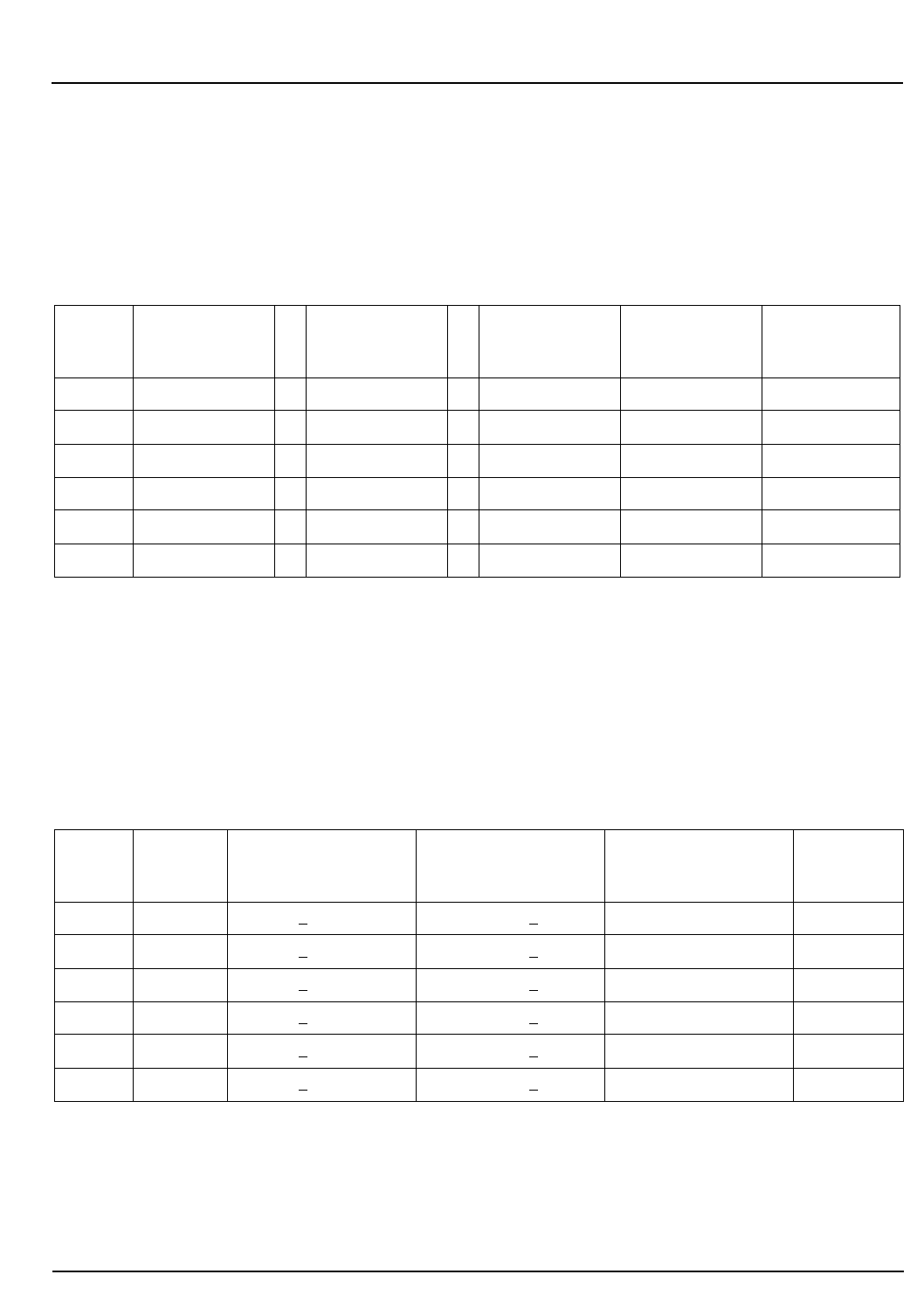
CELL-DYN® 3200 Operator’s Manual 6-63
9140181B — November 1997
Calibration Procedures
Section 6 Manual Calibration Worksheets
1. In column 1, enter the new factor calculated in column 4 of the previous worksheet.
2. In column 2, enter the calibration factor that existed prior to running the current calibration procedure.
3. Subtract the current factor in column 2 from the new factor in column 1 and divide the result by the current
factor. Enter this result in column 3.
4. Multiply the result in column 3 by 100 and enter the result in column 5.
1. In column 1, enter the new Factor % Diff from column 5 of the previous worksheet (disregard the sign).
2. If the new Factor % Diff exceeds the limit in column 4, DO NOT CALIBRATE. Call the Customer Support
Center for assistance.
Worksheet 4
Worksheet 2
Open Mode Factor % Difference
(Calculate All Factors To Three Decimal Places)
(1)
New Open
Mode Factor –
(2)
Current Open
Mode Factor /
(3)
New Open
Mode Factor
(4)
x 100 =
(5)
Factor
% Diff
WOC – / x 100 =
NOC – / x 100 =
RBC – / x 100 =
HGB – / x 100 =
MCV – / x 100 =
PLT – / x 100 =
Worksheet 3
Open Mode Calibration Range Criteria
(1)
Factor%
Diff
(2)
Lower Limit
Cal Not Required
(3)
Calibration Range
Cal Required
(4)
Upper Limit
Do Not Cal
(5)
Cal? Y/N
WOC <2.0% >2.0% but <10% >10%
NOC <2.0% >2.0% but <10% >10%
RBC <2.0% >2.0% but <10% >10%
HGB <2.0% >2.0% but <10% >10%
MCV <2.0% >2.0% but <10% >10%
PLT <3.0% >3.0% but <15% >15%
Go Back
Search
TOC

6-64 CELL-DYN 3200 Operator’s Manual
9140181B — November 1997
Calibration Procedures
Manual Calibration Worksheets Section 6
1. Select Patient as the specimen type and run the calibrator or fresh whole blood sample 5 times.
2. Calculate a mean for each parameter that was calibrated.
3. Enter the reference or assay target values used to calibrate those parameters.
4. Calculate the difference between the mean and the reference value.
5. Compare the difference with the Tolerance Limit. If within the limit, calibration is confirmed in
the Patient specimen type.
* For Calibrator, use the pre-established tolerance limits found on the Calibrator Assay Sheet.
For Fresh Whole Blood, each laboratory should establish tolerance limits according to its protocol.
Worksheet 7
Calibration Confirmation
Patient Specimen Type
Sample # WBC RBC HGB MCV PLT
1
2
3
4
5
Mean Value
of 5 Runs
Reference or
Assay Value
Difference
(absolute
value)
Tolerance
Limits *
Go Back
Search
TOC

CELL-DYN® 3200 Operator’s Manual 6-65
9140181B — November 1997
Calibration Procedures
Section 6 References
References
1. ICSH, Protocol for Evaluation of Automated Blood Cell
Counters, Clinical and Laboratory Hematology 1988,
10:203, 212.
2. NCCLS standard H7-A, Procedure for Determining Packed
Cell Volume by the Microhematrcrit Method; Approved
Standard (1985).
Go Back
Search
TOC

6-66 CELL-DYN 3200 Operator’s Manual
9140181B — November 1997
Calibration Procedures
References Section 6
NOTES
Go Back
Search
TOC

CELL-DYN 3200 Operator’s Manual 7-1
9140181B — November 1997
Operational Precautions and Limitations
Section 7 Overview
Overview
This section deals with the precautions that need to be taken
to ensure the performance and validity of the
CELL-DYN 3200 System and its test results.
The following system precautions and limitations are reviewed
in this section:
•General Limitations
•Location Requirements
•Reagent Storage and Handling
•Printer Precautions
Limitations
The CELL-DYN 3200 System is designed for in vitro diagnostic
use.
•Abbott has designed the CELL-DYN 3200 System
components for optimal performance. Substituting
reagents, calibrators, controls, and components
manufactured by other companies may adversely affect
the performance of the instrument.
•Follow the recommended maintenance schedules and
procedures as outlined in Section 9: Service and
Maintenance.
•During the warranty period, all service and repair must be
performed by Abbott-authorized representatives.
Location Requirements
The location of the CELL-DYN 3200 System is an important
consideration that affects proper instrument functioning,
operating safety, and ease of use.
•An Abbott-authorized representative must install the
instrument.
•The location should have nonporous, nonabsorbing work
surfaces and flooring that can be cleaned easily and
disinfected using recommended procedures.
•Place the CELL-DYN 3200 System on a hard, level surface.
Locate the system:
–away from direct sunlight.
Go Back
Search
TOC

7-2 CELL-DYN 3200 Operator’s Manual
9140181B — November 1997
Operational Precautions and Limitations
Overview Section 7
–away from the path of a cooled air or heated air outlet.
–away from other instruments that may interfere with
the CELL-DYN 3200 System, such as drying ovens,
centrifuges, x-ray equipment, MRI (magnetic
resonance imaging) equipment, CRTs or computers,
video terminals, copiers, ultrasonic cleaners, and
patient areas.
•Do not place reagent containers above the Analyzer.
•The following space should be available to ensure proper
ventilation:
–Bench top space: approximately 6 linear feet to
accommodate the instrument, display station, and
printer
–Below the instrument: sufficient space for reagents
and waste container (if one is used)
–Behind the instrument: 6 inches of space for proper
ventilation
–Above the instrument: 6 inches of space for proper
ventilation
–Left side of instrument: 12 inches of space in front of
the fan for proper ventilation
–Adequate space around the instrument to perform
necessary maintenance procedures
•Care should be taken to prevent blocking of the air vents
or fans on the sides and the back of the instrument.
•Before operating the instrument for the first time, verify
that each reagent line is connected to the appropriate
inlet and reagent container. Refer to Section 2:
Installation Procedures and Special Requirements.
•Make sure the waste line is connected to the appropriate
outlet and routed to a suitable waste container or drain. If
the waste is routed to a waste container, make sure the
waste sensor is properly connected. If the waste is routed
to a drain, make sure a Dummy Plug is inserted in the
Waste Sensor Connector.
•The printer and Display Station can be placed on top of
the instrument.
Go Back
Search
TOC

CELL-DYN 3200 Operator’s Manual 7-3
9140181B — November 1997
Operational Precautions and Limitations
Section 7 Precautions
Precautions
Reagent Storage and Handling
• Store reagents, calibrators, and controls according to the
directions contained in the package inserts.
• Protect reagents from extreme heat and freezing during
storage. Temperatures below 0°C (32°F) may cause layering
that changes the tonicity and conductivity of the reagent.
If freezing occurs, do not use the reagent.
• Protect reagents from direct sunlight, evaporation, and
contamination. Use the Reagent Container Cap attached
to each length of inlet tubing to minimize evaporation
and contamination.
• Never add remaining reagent from a container being
replaced to a freshly opened container. This may
contaminate the new reagent.
• Never use a hemoglobin standard other than the one
specified for the CELL-DYN 3200 System. The CELL-DYN
3200 System uses a cyanide-free reagent.
Printer Precautions
The Printhead on dot matrix printers can get very hot during
extended periods of printing. Allow it to cool before touching
it. Heat is not a problem with ink jet or bubble jet printers.
Go Back
Search
TOC

7-4 CELL-DYN 3200 Operator’s Manual
9140181B — November 1997
Operational Precautions and Limitations
Precautions Section 7
NOTES
Go Back
Search
TOC
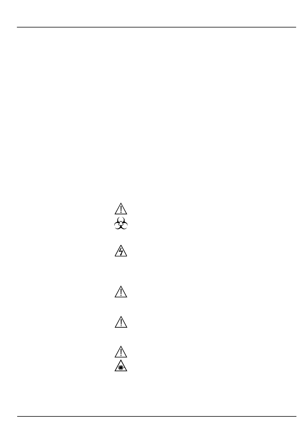
CELL-DYN® 3200 Operator’s Manual 8-1
9140181B — November 1997
Hazards
Section 8 Overview
Overview
The CELL-DYN 3200 System has been designed to minimize
hazards to the operator and other personnel. However, some
hazards are inherent to the operator of any electromechanical
equipment. Therefore, safety awareness is important when
operating the CELL-DYN 3200 System.
Safety Icons
Safety icons in this manual and on the instrument are used to
identify potentially hazardous conditions or situations. A brief
explanatory message labeled DANGER, WARNING or
CAUTION, depending on the nature of the hazard,
accompanies the icon.
For a summary of locations in the manual where safety icons
are referenced, refer to the Master Table of Contents, List of
Safety Icons.
WARNING: Potential Biohazard. The biohazard icon
alerts users to an activity or area where they may be
exposed to infectious materials or substances.
WARNING: Electrical Shock Hazard. The electrical
hazard icon alerts users to the possibility of electrical
shock in the described activity or at the posted
location.
WARNING: The general warning icon alerts users to a
potential health or safety hazard.
CAUTION: The general caution icon appears adjacent
to an explanation of conditions that could interfere
with the proper functioning of the instrument.
DANGER: Class III B Laser Light. The laser icon warns
against direct exposure to the laser light beam
generated by the Optical Bench Assembly.
Go Back
Search
TOC

8-2 CELL-DYN® 3200 Operator’s Manual
9140181B — November 1997
Hazards
Overview Section 8
NOTES
Go Back
Search
TOC

CELL-DYN® 3200 Operator’s Manual 8-3
9140181B — November 1997
Hazards
Section 8 Types of Hazards
Types of Hazards
Biohazards
General Biohazard Information
Hematology analysis involves potentially harmful substances.
Operators and other personnel working near the
CELL-DYN 3200 System should be alert to biohazards.
Operators should carefully follow all laboratory and
instrument-specific procedures.
General principles for biosafety include the following:
• Consider all human-sourced materials as potentially
infections. Specimens, controls, calibrators, and other
reference materials can contain components derived from
human sources
• Always wear a lab coat, powder-free disposable gloves,
and protective eyewear when operating or maintaining
the instrument
• Do not smoke, eat, or drink in areas where specimens are
handled
• Do not pipette by mouth
• Observe biosafety practices as specified in the OSHA
Bloodborne Pathogen Rule (29 CFR Part 1910, 1030) or
other equivalent biosafety procedures.
Biohazard Information for the CELL-DYN 3200 System
WARNING: Potential Biohazard. Consider all
specimens, reagents, controls, calibrators, etc. that
contain human blood or serum as potentially
infectious. Wear gloves, lab coats, and safety glasses,
and follow other biosafety practices as specified in the
OSHA Bloodborne Pathogen Rule (29 CFR Part 1920,
1030) or other equivalent biosafety procedures.
WARNING: Potential Biohazard. The aspiration needle
is sharp and potentially contaminated with infectious
material. Avoid contact with needle.
Go Back
Search
TOC

8-4 CELL-DYN® 3200 Operator’s Manual
9140181B — November 1997
Hazards
Types of Hazards Section 8
Handling and Disposing of Biohazardous Materials
Handle and dispose of all clinical specimens, reagents,
controls, calibrators, and reference materials carefully to avoid
aerosols and spills. Clean up spills of potentially infectious
materials in accordance with established biosafety practices.
The following is generally accepted for cleaning up such spills:
1. Absorb the spill with a towel or other absorbent material.
2. Wipe the area with a detergent solution.
3. Wipe the area with an appropriate tuberculocidal
disinfectant such as 10% bleach.
Dispose of all biohazardous materials in accordance with local,
state, and federal regulations governing the treatment of
regulated medical waste. Waste liquid is a possible source of
biological hazard. Handle with extreme care during the
disposal process. Sharps, such as contaminated probes, must
be placed in an appropriately marked, puncture-resistant
container before treatment and disposal.
Chemical Hazards
Prevent exposure to chemicals used in the operation and
maintenance of the CELL-DYN 3200 System (including
reagents) by using appropriate personal protective equipment,
work procedures, and information on Material Safety Data
Sheets (MSDS).
Electrical Hazards
Basic electrical hazard awareness is essential to the safe
operation of any hematology analyzer. To ensure safe
operation of the CELL-DYN 3200 System:
• Periodically inspect electrical cabling into and on the
instrument for signs of wear or damage
• When moving equipment, lift all power cables clear of all
system components
Go Back
Search
TOC

CELL-DYN® 3200 Operator’s Manual 8-5
9140181B — November 1997
Hazards
Section 8 Types of Hazards
• Disconnect the instrument from electrical power by
unplugging the power cord before removing any
instrument panel that is securely fastened in place by
screws or prior to replacing fuses. Replace only the
externally accessible fuse located immediately above the
power cord connector on the rear panel of the
instrument. Use a replacement fuse of the specified type
and electrical rating only
• Keep liquids away from all electrical connectors (such as
electrical outlets) or communication connectors (such as
the LIS connector)
• Keep the floor dry
• Follow instructions for correctly powering down the
instrument and all connected equipment before
performing service or maintenance
• Do NOT disconnect any electrical connection while the
power is ON
• Use only the approved power cords supplied with the
instrument. Connect power cords only to properly
grounded outlets.
Mechanical Hazards
General Mechanical Hazard Information
Observe these basic rules for mechanical safety:
• Carefully follow all procedures and instructions
• Keep all protective covers in place when processing
specimens
• Never allow any part of your body to enter the region of
movement of any mechanical component when the
instrument is operating
• Do not wear articles of clothing or accessories that could
catch on the System; keep pockets free of items that could
fall into the System; keep long hair from catching on the
System
• Wear powder-free gloves and safety glasses when
maintaining or repairing the instrument
• Avoid contact with needle tips at all times.
Go Back
Search
TOC
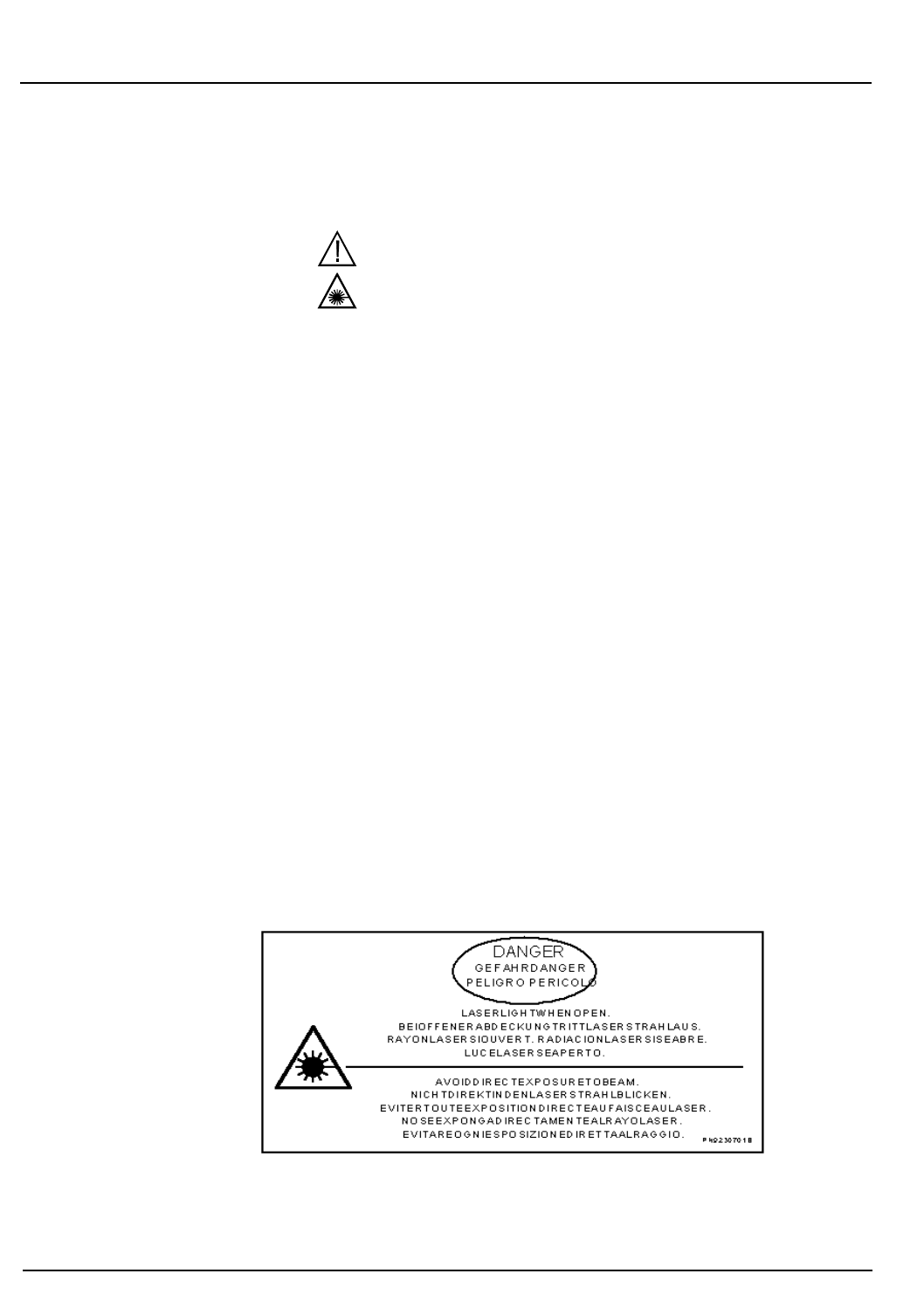
8-6 CELL-DYN® 3200 Operator’s Manual
9140181B — November 1997
Hazards
Types of Hazards Section 8
The CELL-DYN 3200 Instrument is a Class I Laser Product per
IEC 825-1 (1993). However, it contains a Class III B laser.
DANGER: Class III B Laser Light. Avoid Direct
Exposure to Beam. Do not look directly into the laser
beam or any reflections of the beam from a mirror-like
surface. When the access door, instrument top cover or
other inner protective cover are removed, Helium-Neon
laser power up to 10 mW continuous wave at 632.8 nm
in a beam with 1 mR divergence could be accessible in
the interior of the optics bench. This amount of energy,
with insignificant attenuation with distance, is
sufficient to cause eye damage.
Use of controls, adjustments or performance of
procedures other than those specified herein may result
in hazardous laser light exposure. If the instrument is
used or modified in a manner not specified by the
manufacturer, the protection provided by the
instrument may be impaired.
During normal operation, the inner protective covers
are to remain in place to prevent laser light exposure
from the optics bench. The inner protective covers are
to be removed only during servicing by qualified
personnel.
The inner protective cover laser warning labels must
not be removed and are to remain legible. The
Protective Housing Label (Abbott P/N 9230701D),
shown in Figure 8.1, consists of black lettering against a
yellow background.
Figure 8.1: Laser Warning Label
Go Back
Search
TOC
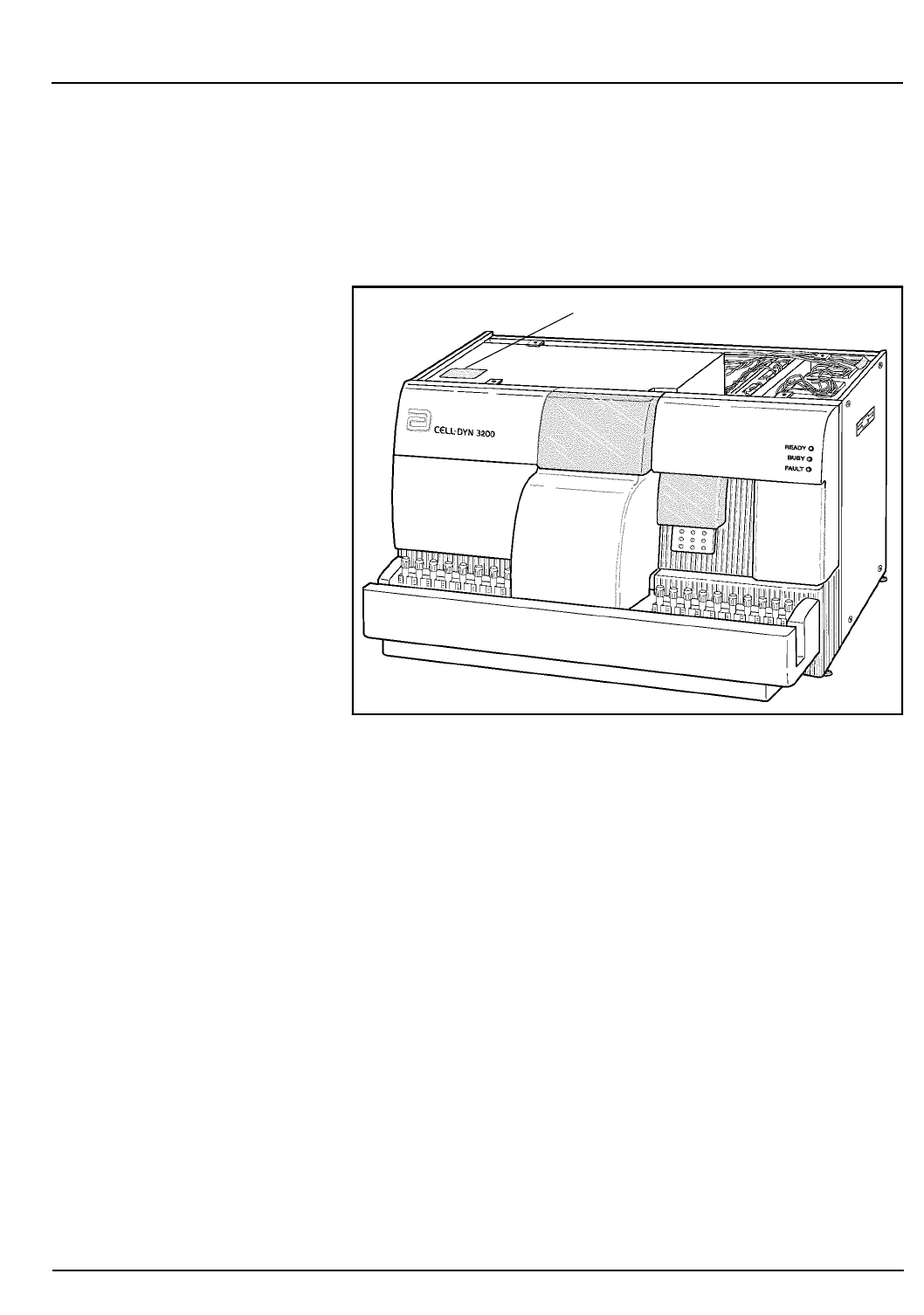
CELL-DYN® 3200 Operator’s Manual 8-7
9140181B — November 1997
Hazards
Section 8 Types of Hazards
This label is located in two places: on the black Laser
Bench Protective Cover (under the Top Cover) that
covers the laser bench (refer to Figure 8.2), and on the
upper left side of the Flow Panel (refer to Figure 8.3).
Figure 8.2: Laser Warning Label Position - Protective Cover
Laser Warning Label
Go Back
Search
TOC
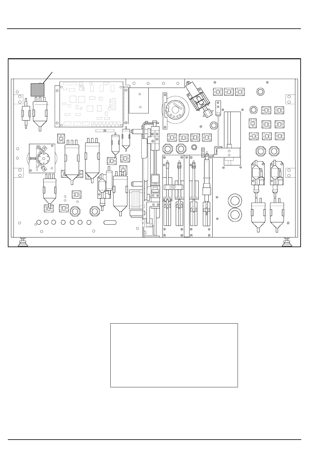
8-8 CELL-DYN® 3200 Operator’s Manual
9140181B — November 1997
Hazards
Types of Hazards Section 8
Figure 8.3: Laser Warning Label Position - Flow Panel
The Class 1 Laser Product Label (Abbott P/N
9230702A), shown in Figure 8.4, consists of black
lettering against a white background.
Figure 8.4: Class 1 Laser Product Label
Laser Warning Label
Class 1 Laser Product
per
IEC 825 - 1(1993)
PN 9230702A
Go Back
Search
TOC
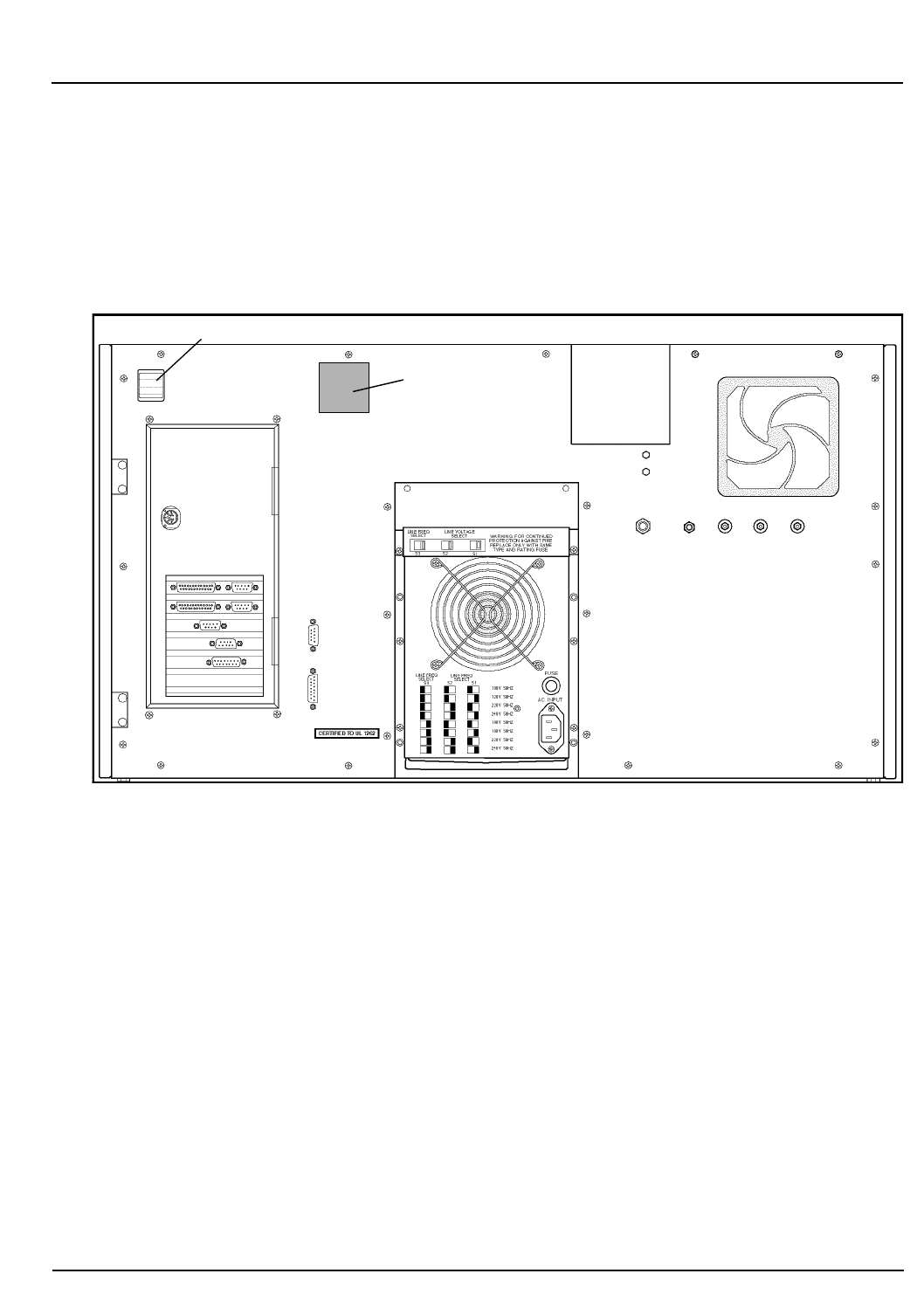
CELL-DYN® 3200 Operator’s Manual 8-9
9140181B — November 1997
Hazards
Section 8 Types of Hazards
The label is located on the upper left section of the
instrument’s Rear Panel and is positioned in a clearly
visible location, as shown in Figure 8.5.
Figure 8.5: Class 1 Laser Product Label Location
Main Power Switch
Class 1 Laser
Product Warning
Label
Go Back
Search
TOC

8-10 CELL-DYN® 3200 Operator’s Manual
9140181B — November 1997
Hazards
Types of Hazards Section 8
NOTES
Go Back
Search
TOC

CELL-DYN® 3200 Operator’s Manual 8-11
9140181B — November 1997
Hazards
Section 8 References
References
1. Occupational Safety and Health Administration, 29 CFR
Part 1910, 1030. Department of Labor. Occupational
Exposure to Bloodborne Pathogens; Final Rule. 235:64175-
64182, 1991.
2. IEO 825-1, International Electromechanical Commission
World Standards for electrical and electronic engineering, 825:
Safety of laser products, 825-1 (1993) Part 1: Equipment
classification, requirements, and users guide.
Go Back
Search
TOC

8-12 CELL-DYN® 3200 Operator’s Manual
9140181B — November 1997
Hazards
References Section 8
NOTES
Go Back
Search
TOC

CELL-DYN® 3200 Operator’s Manual 9-1
9140181B — November 1997
Service and Maintenance
Section 9 Overview
Overview
The CELL-DYN® 3200 is designed to require minimal routine
maintenance. For example:
• The fluidics are automatically rinsed between samples.
• A thorough system rinse is performed automatically
when the unit has been idle for five minutes after the last
cycle is completed.
• The instrument is automatically placed in the Standby
state if it has been idle for four hours after the last cycle is
completed.
The operator is encouraged to routinely perform the required
maintenance in order to ensure optimum performance. This
section describes the recommended preventive maintenance
procedures for the Analyzer. Instructions are also given for
preparing the instrument for a prolonged period of inactivity.
Many required preventative maintenance procedures have
been automated on the CELL-DYN 3200. These programs can
be accessed by pressing the
[SPECIAL PROTOCOLS]
key. The
SPECIAL PROTOCOLS
menu is discussed in the next section
followed by a discussion of Preventive Maintenance Schedule
Procedures.
Go Back
Search
TOC

9-2 CELL-DYN® 3200 Operator’s Manual
9140181B — November 1997
Service and Maintenance
Overview Section 9
NOTES
Go Back
Search
TOC
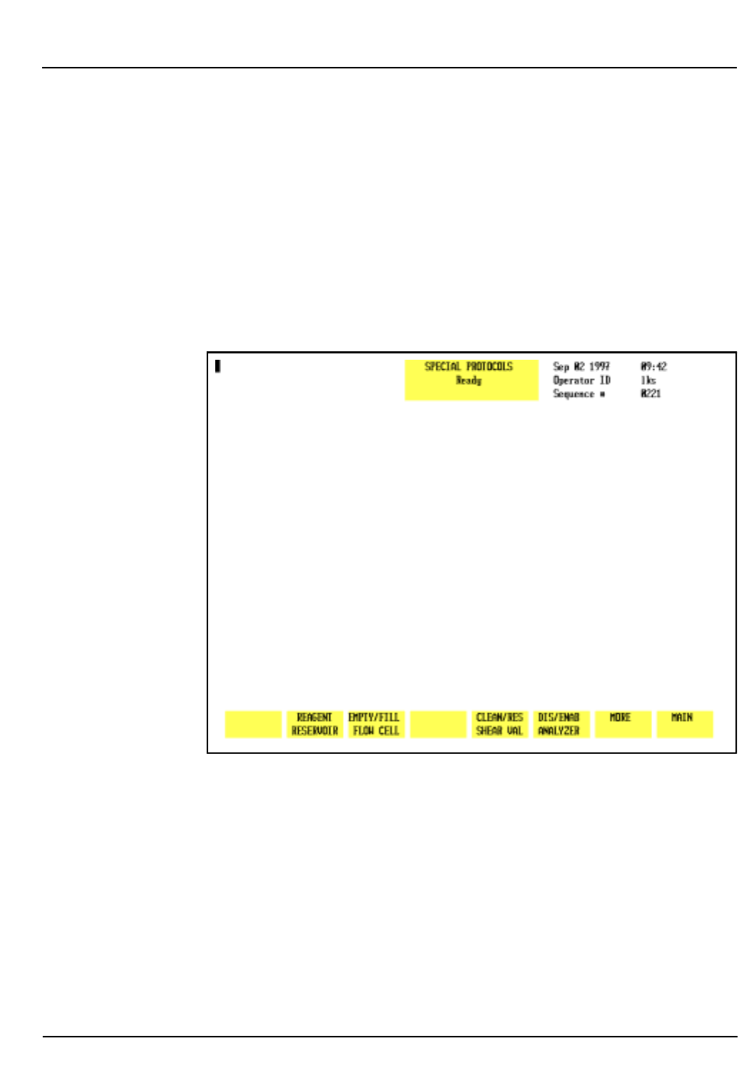
CELL-DYN® 3200 Operator’s Manual 9-3
9140181B — November 1997
Service and Maintenance
Section 9 Special Protocols
Special Protocols
The
SPECIAL PROTOCOLS
menu is used to access various
preventative maintenance procedures. There are two major
screen levels in this menu. The first level is displayed when the
[SPECIAL PROTOCOLS]
soft key in the
MAIN MENU
is pressed. The
second major screen level is accessed by pressing the
[MORE]
key in the first level. Within each major level are submenus.
Figure 9.1 displays the key labels in the first
SPECIAL
PROTOCOLS
menu.
Figure 9.1: First Special Protocols Screen
Special Protocols Menu
When the
[SPECIAL PROTOCOLS]
key is pressed in the
MAIN MENU
,
the following soft key labels are displayed:
REAGENT RESERVOIR
EMPTY/FILL FLOW CELL/
EMPTY FLOW CELL/
(Key label alternates between
FILL FLOW CELL
selections.)
Go Back
Search
TOC
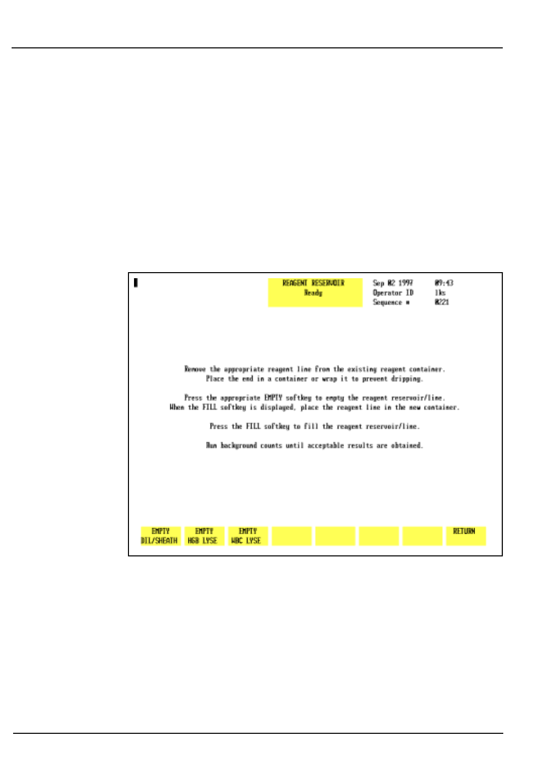
9-4 CELL-DYN® 3200 Operator’s Manual
9140181B — November 1997
Service and Maintenance
Special Protocols Section 9
CLEAN/RES SHEAR VAL/
CLEAN SHEAR VAL/
(Key label alternates between
RESTORE SHEAR VAL
selections.)
DIS/ ENAB ANALYZER/
DISABLE ANALYZER/
(Key label alternates between
ENABLE ANALYZER
selections
MORE
MAIN
A brief description of the function of each soft key follows.
Instructions for the detailed use of each key are given in the
appropriate maintenance procedure.
Figure 9.2: Reagent Reservoir Keys
Reagent Reservoir
NOTE: This procedure is performed only in the Open
Mode. If necessary, press
[CHANGE SAMPLER]
in the
RUN
screen to select Open Mode.
Go Back
Search
TOC

CELL-DYN® 3200 Operator’s Manual 9-5
9140181B — November 1997
Service and Maintenance
Section 9 Special Protocols
The
[REAGENT RESERVOIR]
key is used to drain the reagent
reservoirs located on the Flow Panel of the Analyzer. When the
[REAGENT RESERVOIR]
key is pressed, the following soft key
labels are displayed as shown in Figure 9.2:
EMPTY DIL/SHEATH
(The key alternates between the
FILL DIL/SHEATH
selections.)
EMPTY HGB LYSE
(The key alternates between the
FILL HGB LYSE
selections.)
EMPTY WBC LYSE
(The key alternates between the
FILL WBC LYSE
selections.)
RETURN
The screen displays instructions for draining and filling the
reagent reservoirs, as shown in Figure 9.2.
Empty Dil/Sheath
When the
[EMPTY DIL/SHEATH]
key is pressed, the diluent and
sheath reservoirs are drained and the key toggles to
[FILL DIL/ SHEATH]
. When the
[FILL DIL/SHEATH]
key is pressed, the
diluent and sheath reservoirs are refilled.
Empty HGB Lyse
When the
[EMPTY HGB LYSE]
key is pressed, the HGB lyse supply
tubing is drained and the key toggles to
[FILL HGB LYSE]
. When
the
[FILL HGB LYSE]
key is pressed, the HGB lyse supply tubing is
refilled.
Empty WBC Lyse
When the
[EMPTY WBC LYSE]
key is pressed, the WBC lyse
supply tubing is drained and the key toggles to
[FILL WBC LYSE]
.
When the
[FILL WBC LYSE]
key is pressed, the WBC lyse supply
tubing is refilled.
Empty/Fill Flow Cell
NOTE: This procedure is performed only in the Open
Mode. If necessary, press
[CHANGE SAMPLER]
in the
RUN
screen to select Open Mode.
Pressing the
[EMPTY/FILL FLOW CELL]
key displays a submenu
showing the
[EMPTY FLOW CELL]
and
[RETURN]
keys.
Go Back
Search
TOC

9-6 CELL-DYN® 3200 Operator’s Manual
9140181B — November 1997
Service and Maintenance
Special Protocols Section 9
When the
[EMPTY FLOW CELL]
key is pressed, diluent/sheath in
the Optical Flow Cell is drained and the key toggles to
[FILL
FLOW CELL]
upon completion.
When the
[FILL FLOW CELL]
key is pressed, the flow cell is refilled
with diluent/sheath. The system must be reinitialized after this
procedure (the [
INITALIZATION]
key is located on the second level
of the DIAGNOSTICS menu).
Clean/Restore Shear Valve
NOTE: This procedure is performed only in the Open
Mode. If necessary, press
[CHANGE SAMPLER]
in the
RUN
screen to select Open Mode.
The
[CLEAN/RES SHEAR VAL]
key is used to prepare the shear
valve for cleaning. Pressing the
[CLEAN/RES SHEAR VAL]
key
displays a submenu showing the
[CLEAN SHEAR VAL]
and
[RETURN]
keys.
When the
[CLEAN SHEAR VAL]
key is pressed, the System partially
empties the syringes, flushing the reagents out of the shear
valve and associated tubing. The shear valve then rotates into
the position necessary for its removal. After the shear valve has
rotated, the key toggles to
[RESTORE SHEAR VAL]
.
When the
[RESTORE SHEAR VAL]
key is pressed, the syringes refill
the shear valve and the associated tubing, and the shear valve
rotates back to its operational position.
Disable/Enable Analyzer
When the
[DIS/ENAB ANALYZER]
key is pressed, a submenu is
displayed showing the
[DISABLE ANALYZER]
and
[RETURN]
keys.
Pressing the
[DISABLE ANALYZER]
key prevents the Analyzer from
cycling while certain maintenance procedures are performed.
After the Analyzer has been disabled, the key toggles to
[ENABLE ANALYZER]
.
When the
[ENABLE ANALYZER]
key is pressed, the Analyzer is
returned to the state prior to disabling.
Go Back
Search
TOC
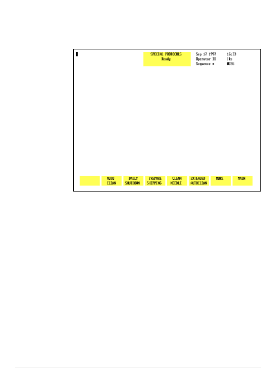
CELL-DYN® 3200 Operator’s Manual 9-7
9140181B — November 1997
Service and Maintenance
Section 9 Special Protocols
Figure 9.3: Second Special Protocols Screen
More
When the
[MORE]
key is pressed, the second
SPECIAL PROTOCOLS
screen and the following soft key labels are displayed, as
shown in Figure 9.3:
AUTO CLEAN
DAILY SHUTDOWN
PREPARE SHIPPING
CLEAN NEEDLE
EXTENDED AUTOCLEAN
MORE
MAIN
Auto-Clean
NOTE: This procedure is performed only in the Open
Mode. If necessary, press
[CHANGE SAMPLER]
in the
RUN
screen to select Open Mode.
Go Back
Search
TOC

9-8 CELL-DYN® 3200 Operator’s Manual
9140181B — November 1997
Service and Maintenance
Special Protocols Section 9
The
[AUTO CLEAN]
key is used to initiate the Auto-Clean cycle.
The Shear Valve, the RBC/PLT Mixing Chamber, the WBC
Mixing Chamber, the Optical Flow Cell, the HGB Flow Cell,
and all of the associated fluidics are automatically cleaned and
rinsed during this cycle.
When the
[AUTO CLEAN]
key is pressed, the screen displays a set
of instructions and the two following soft key labels:
AUTO CLEAN
RETURN
Press [
AUTO CLEAN]
again to activate the Auto-Clean cycle. Press
[
RETURN]
to return to the second SPECIAL PROTOCOLS screen.
Daily Shutdown
The [
DAILY SHUTDOWN]
key is used to initiate the Daily
Shutdown cycle. During the cycle, the fluidics are
automatically drained and rinsed. At the end of the cycle, the
Analyzer is placed in STANDBY. The electronic solenoid valves
are automatically opened periodically while the Analyzer is in
Standby to prevent the tubing from becoming pinched.
Prepare Shipping
NOTE: This procedure is performed only in the Open
Mode. If necessary, press
[CHANGE SAMPLER]
in the
RUN
screen to select Open Mode.
The
[PREPARE SHIPPING]
key is used to prepare the Analyzer for
shipment or an extended period of inactivity. The cycle drains
all of the reagents from the system and then rinses the fluidics
with deionized water supplied by the operator.
Clean Needle
The
[CLEAN NEEDLE]
key is used to clean the needle in the Tower
module. When the key is pressed, the needle is forcefully
rinsed with diluent.
Extended Auto-Clean
NOTE: This procedure is performed only in the Open
Mode. If necessary, press
[CHANGE SAMPLER]
in the
RUN
screen to select Open Mode.
The
[EXTENDED AUTOCLEAN]
key is used to initiate the Extended
Auto-Clean cycle, which is a longer version of the Auto-Clean
cycle.
Go Back
Search
TOC

CELL-DYN® 3200 Operator’s Manual 9-9
9140181B — November 1997
Service and Maintenance
Section 9 Special Protocols
When the
[EXTENDED AUTO CLEAN]
key is pressed, the screen
displays the message shown in Figure 9.9 in the Extended
Auto-Clean subsection. The following soft key labels are
displayed:
EXTENDED AUTO CLEAN
RETURN
Press
[EXTENDED AUTO CLEAN]
again to activate the Extended
Auto-Clean cycle. Press
[RETURN]
to return to the second
Special Protocols screen.
More
The
[MORE]
key is used to return to the first
SPECIAL PROTOCOLS
menu.
Go Back
Search
TOC

9-10 CELL-DYN® 3200 Operator’s Manual
9140181B — November 1997
Service and Maintenance
Special Protocols Section 9
NOTES
Go Back
Search
TOC

CELL-DYN® 3200 Operator’s Manual 9-11
9140181B — November 1997
Service and Maintenance
Section 9 Preventive Maintenance Schedule
Preventive Maintenance Schedule
Overview
The maintenance schedule outlined on the following page will
minimize operational problems with the CELL-DYN 3200. The
recommended intervals are based on instruments operating in
laboratories that process samples from a general patient
population. The intervals are affected by the following
variables:
•Volume of samples processed
•Workload schedule
•Operating environment
•Patient population being analyzed
Each laboratory must assess its own situation and modify these
recommended intervals as necessary.
CAUTION: Gloves should be worn during the
maintenance procedures. They should be powder-free
or rinsed before performing the maintenance as powder
may cause instrument problems. (For example, powder
may clog ports in the shear valve and cause it to leak.)
IMPORTANT: Overdue maintenance is usually indicated by an
increase in imprecision of one or more of the directly
measured parameters. This increase is due to carryover or
dilution/sampling inconsistencies. If this occurs on more than
a random basis, the appropriate maintenance should be
performed more frequently.
A diagram of the analyzer flow panel is included to assist in
component identification and location.
If you encounter trouble performing any of these maintenance
procedures, contact the Abbott Customer Support Center at:
1 (800) CELL DYN.
To order any parts, accessories, or consumables, refer to
Appendix B — Parts and Accessories.
Go Back
Search
TOC

9-12 CELL-DYN® 3200 Operator’s Manual
9140181B — November 1997
Service and Maintenance
Preventive Maintenance Schedule Section 9
Preventive Maintenance Schedule
The following procedures should be performed at the
scheduled time intervals or more often, depending on usage,
as determined by each individual laboratory.
Keep a record of routine maintenance and parts replacement
to ensure proper equipment care and to assist Abbott
Customer Service Representatives and Abbott Field Service
Representatives in diagnosing instrument problems.
Daily
Run Auto-Clean Cycle
Clean Closed Sample Aspiration Needle
Clean Closed Sample Tower
Weekly
Clean Sample Loader and Racks
Clean Exterior of Open Sample Probe
Check Sample Transfer Pump Tubing
Monthly
Clean Fan Filters
Run Extended Auto-Clean
Semi-Annual
Clean Printer
Nonscheduled Maintenance Procedures
Clean Shear Valve
Clean Interior of Open Sample Aspiration Probe
Unclog Open Sample Aspiration Probe
Clean Interior of Closed Sample Aspiration Needle
Unclog Closed Sample Aspiration Needle
Clean Syringes
Clean HGB Flow Cell
Clean Bar Code Reader Window
Clean Reagent Lines
Replace Open Sample Aspiration Probe
Replace Closed Sample Aspiration Needle
Replace Tubing in Sample Transfer Pump
Go Back
Search
TOC
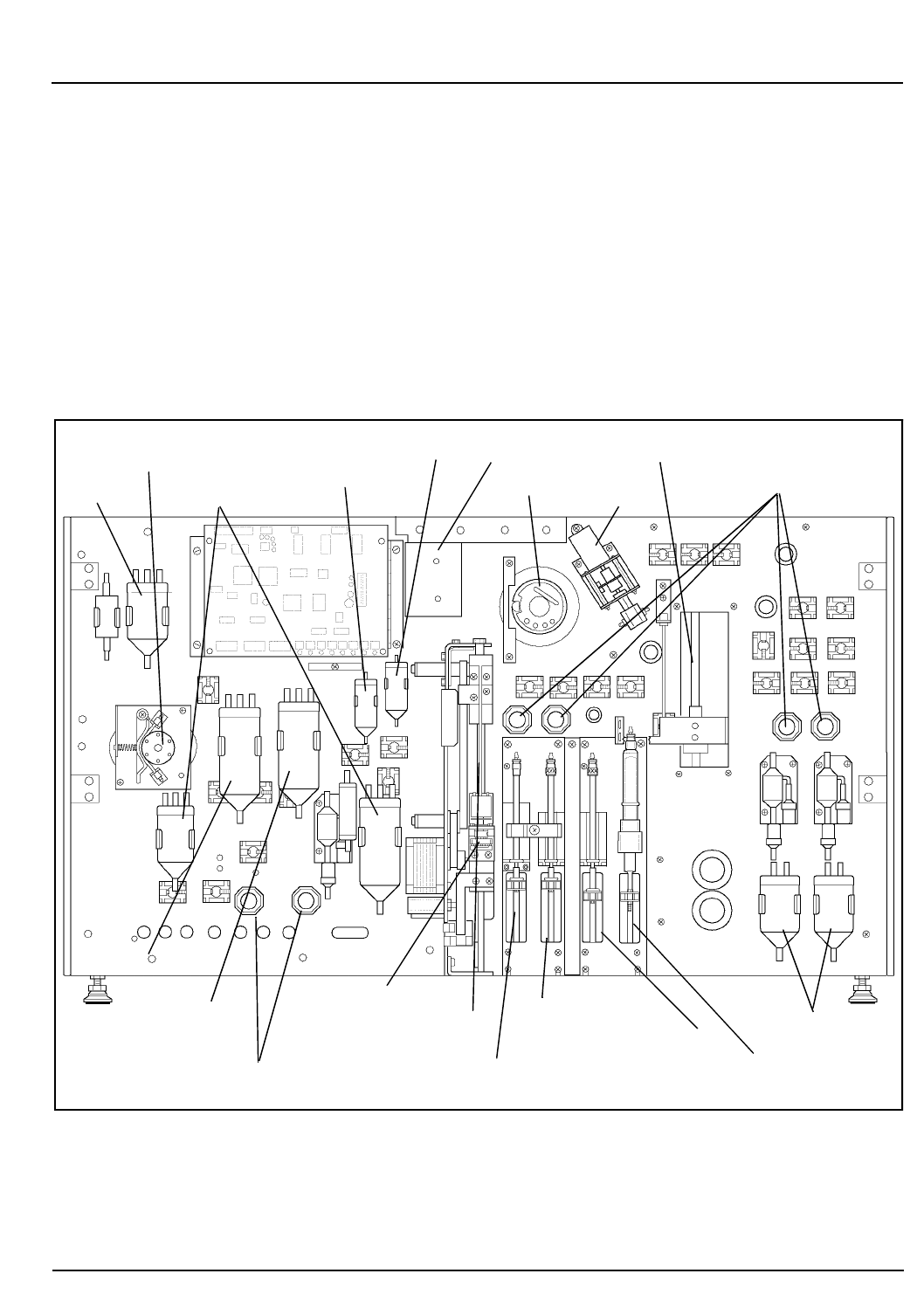
CELL-DYN® 3200 Operator’s Manual 9-13
9140181B — November 1997
Service and Maintenance
Section 9 Preventive Maintenance Schedule
Replace Tubing in Normally Closed Valves
Replace Syringes
Replace Fuse
Prepare for Shipping or Extended Period of Non-Use
Flow Panel Components
Figure 9.4 illustrates the Flow Panel components that may be
inspected, cleaned, or replaced during normal maintenance
procedures.
Figure 9.4: Analyzer Flow Panel Components
Vent
Sample Transfer Peristaltic RBC Mixing Chamber
WBC Mixing Chamber
Closed Sample Needle
Shear Valve Y Valve
Normally Closed Valves
Waste Chambers
Open Sample Probe
Diluent
Normally Closed Valves
Waste Chambers
Tube Spinner
Sample Injection Syringe
HGB Lyse Syringe
WBC Lyse Syringe
Diluent/Sheath Syringe
HGB Flow Cell
Reservoir
Sheath
Reservoir
Pump
Go Back
Search
TOC

9-14 CELL-DYN® 3200 Operator’s Manual
9140181B — November 1997
Service and Maintenance
Preventive Maintenance Schedule Section 9
Decontamination Procedures
The OSHA Bloodborne Pathogen Rule (29 CFR Part 1910,
1030) requires the decontamination of laboratory equipment
prior to servicing or shipment:
•Decontaminate the instrument by performing the Auto-
Clean cycle. This cycle flushes all of the fluid pathways
with reagents to purge any waste from the fluid
pathways. The Open Mode Sample Probe and the Closed
Sample Needle (CS Model) or Sample Loader Needle (SL
Model) are automatically rinsed after every cycle. The
surfaces of the instrument should be wiped with a
nonabrasive detergent solution to remove any soiling,
then wiped with a tuberculocidal disinfectant, such as a
10% solution of filtered bleach.
If the instrument is to be shipped, it must be decontaminated
prior to shipment. This is accomplished by pressing the
[PREPARE FOR SHIPPING]
key in the
SPECIAL PROTOCOLS
menu.
Instructions for this procedure are given in section
Preparation for Shipping or Extended Period of Non-Use.
Go Back
Search
TOC

CELL-DYN® 3200 Operator’s Manual 9-15
9140181B — November 1997
Service and Maintenance
Section 9 Daily Maintenance Procedures
Daily Maintenance Procedures
Auto-Clean
WARNING: Potential Biohazard. Wear gloves, lab coats,
and safety glasses and follow other biosafety practices
as specified in the OSHA Bloodborne Pathogen Rule (29
CFR Part 1910, 1030) or other equivalent biosafety
procedures.
The Auto-Clean Cycle is a fully automated cycle designed to
clean the Shear Valve, RBC/PLT Mixing Chamber, the WBC
Mixing Chamber, the Optical Flow Cell, the HGB Flow Cell,
Open Sample Probe, the needle in the Tower Module, and all
the associated fluidics. The forward and reverse action of the
peristaltic pump is used during this cycle to gently scrub and
remove any fibrin or debris within the system. The Auto-Clean
cycle takes approximately 11 minutes. When the
[AUTO CLEAN]
key is pressed, instructions are displayed on the screen, as
shown in Figure 9.5.
NOTE: The Auto-Clean cycle should be run prior to
performing any maintenance procedure. This ensures
that all waste is purged from the fluid pathways.
Go Back
Search
TOC
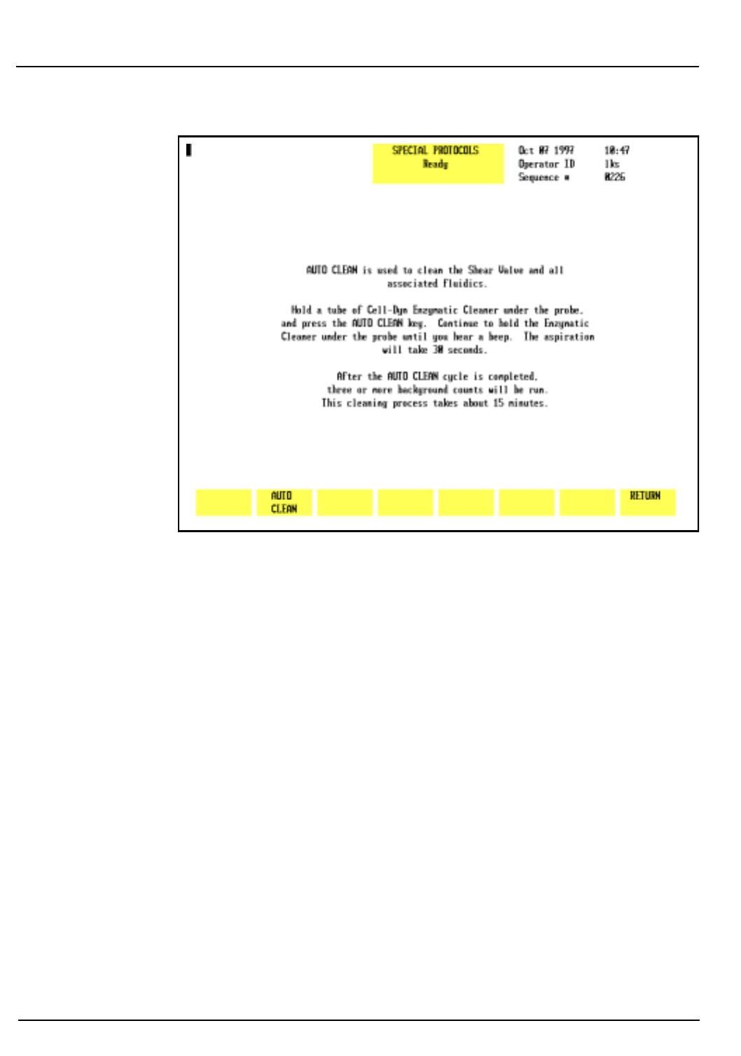
9-16 CELL-DYN® 3200 Operator’s Manual
9140181B — November 1997
Service and Maintenance
Daily Maintenance Procedures Section 9
Figure 9.5: Auto-Clean Screen
Materials Required
1. CELL-DYN Enzymatic Cleaner. Enzymatic cleaner should
be used at room temperature but stored at a temperature
between 2°C and 8°C (36°F and 46°F).
2. Clean VACUTAINER® tube or other clean container.
3. DYN-A-WIPE™ Lint-free pads (or other lint-free pads).
4. Deionized water.
Procedure—CS and SL Models
1. The instrument should be in the Open Mode. If
necessary, press the
[CHANGE SAMPLER]
key in the
RUN
screen to select the Open Mode.
2. With the Wash Block raised, carefully wipe the outside of
the Open Sample Aspiration Probe and the bottom of the
Wash Block with a DYN-A-WIPE™ (or other lint-free pad)
that has been dampened with diluted enzymatic cleaner
(one part distilled water to one part enzymatic cleaner).
3. In the
MAIN MENU
, press
[SPECIAL PROTOCOLS]
followed by
[MORE]
to access the Auto-Clean function.
Go Back
Search
TOC

CELL-DYN® 3200 Operator’s Manual 9-17
9140181B — November 1997
Service and Maintenance
Section 9 Daily Maintenance Procedures
4. Press
[AUTO CLEAN]
. Instructions for performing the
procedure are displayed on the screen.
5.Dispense approximately 1.5 mL of Enzymatic Cleaner
into the VACUTAINER® or other clean container and
hold the container under the probe.
6. Press
[AUTO CLEAN]
to
activate the cleaning cycle.
NOTE: Do not press the Touch Plate. The Auto-Clean
cycle is only initiated by the
[AUTO CLEAN]
key.
7.Continue to hold the container under the probe until a
beep tone is heard. Remove the container and discard the
remaining enzymatic cleaner.
8.When the Auto-Clean cycle is completed, press
[MAIN]
followed by
[RUN]
to go to the
RUN
screen.
9.Run at least three background counts to rinse the system.
Check that the background counts are acceptable before
running controls or patient samples. If the counts are
unacceptable, troubleshoot accordingly (refer to Section
10: Troubleshooting and Diagnostics, Subsection:
Troubleshooting Guide).
Clean Aspiration Needle
The Aspiration Needle in the Tower Module should be cleaned
regularly to remove protein buildup or debris and reduce the
possibility of a blockage. The procedure for cleaning the
needle differs slightly on the CS and SL models. Both
procedures are described below.
WARNING: Potential Biohazard. The needle in the
Tower Module is sharp and potentially contaminated
with infectious materials. Avoid any contact with the
needle.
Materials Required
1.CELL-DYN Enzymatic Cleaner
2. Diluent
3.Three empty VACUTAINER® tubes
4.Gloves, lab coat, and safety glasses
Go Back
Search
TOC

9-18 CELL-DYN® 3200 Operator’s Manual
9140181B — November 1997
Service and Maintenance
Daily Maintenance Procedures Section 9
Procedure — SL Model
1.Aliquot approximately 2 mL of Enzymatic Cleaner into
one of the VACUTAINER® tubes.
2.Aliquot approximately 2 mL of diluent each into the
other two VACUTAINER® tubes.
3.If necessary, press the
[CHANGE SAMPLER]
soft key in the
RUN
screen to select the Closed Mode.
4. In the
RUN
screen, press
[SPECIMEN TYPE]
followed by
[BACKGROUND]
.
5.Place the enzymatic cleaner tube followed by the two
diluent tubes in a Sample Loader rack.
NOTE: A convenient way to perform this procedure is
to add the tubes to the end of the last run of the day.
6.Position the rack on the load side of the Sample Loader
(refer to Figure 13.7 if necessary). Make sure the Tower
Cover is closed.
CAUTION: The Sample Loader will not operate unless
the Tower Cover is in place.
7. Press the
[START LOADER]
key to initiate processing.
8.Audible beep tones indicate that processing is completed.
9.Run at least three background counts to rinse the system.
Check that the background counts are acceptable before
running controls or patient samples. If the counts are
unacceptable, troubleshoot accordingly (refer to Section
10: Troubleshooting and Diagnostics, Subsection:
Troubleshooting Guide).
10.When cleaning is completed, remain in the
RUN
screen to
process patient samples or press
[MAIN]
to return to the
MAIN MENU
.
Procedure — CS Model
1.Aliquot approximately 2 mL of Enzymatic Cleaner into
one of the VACUTAINER® tubes.
2.Aliquot approximately 2 mL of diluent each into the
other two VACUTAINER® tubes.
3.If necessary, press the
[CHANGE SAMPLER]
soft key in the
RUN
screen to select the Closed Mode.
Go Back
Search
TOC

CELL-DYN® 3200 Operator’s Manual 9-19
9140181B — November 1997
Service and Maintenance
Section 9 Daily Maintenance Procedures
4. In the
RUN
screen, press
[SPECIMEN TYPE]
followed by
[BACKGROUND]
.
5.Open the Tower Door, place the tube containing the
Enzymatic Cleaner in the Door Assembly, and close the
door.
6.Press the Touch Plate to run the Enzymatic Cleaner.
When aspiration is finished, remove the tube.
7.Repeat steps 5 and 6 using the two diluent tubes.
8.Run at least three background counts to rinse the system.
Check that the background counts are acceptable before
running controls or patient samples. If the counts are
unacceptable, troubleshoot accordingly (refer to Section
10: Troubleshooting and Diagnostics, Subsection:
Troubleshooting Guide).
Closed Sample Tower
Daily cleaning of the Tower Module is recommended when
the Closed Mode is used.
Materials Required
1.Cleaning solution (5 mL of 5% filtered bleach added to
5 mL of water)
2. Clean, warm water for rinse
3. DYN-A-WIPE™ Lint-free pads (or other lint-free pads)
4.Gloves, lab coat, and safety glasses
Procedure
1.Press the window on the Tower Cover to release the cover
latch. Lift the cover up and off the instrument.
2.Clean the following components with a lint-free wipe
moistened with the cleaning solution prepared above.
a.Spin mechanism, including belt if necessary
b.Under the Wash Block if there is evidence of residue
build-up
c.Any other area that appears to have been
contaminated by specimen or reagents.
3.Rinse the components using a lint-free wipe moistened
with warm water.
Go Back
Search
TOC

9-20 CELL-DYN® 3200 Operator’s Manual
9140181B — November 1997
Service and Maintenance
Daily Maintenance Procedures Section 9
4. Dry the components with a DYN-A-WIPE™ (or other
lint-free pad).
5. When finished, reattach the Tower Cover and press it
into place.
Sample Loader Tray and Tube Grippers
Daily cleaning of the Sample Loader tray and tube grippers is
recommended when the Sample Loader is used.
Materials Required
1. Cleaning solution (5 mL of 5% filtered bleach added to
5 mL of water)
2. Clean, warm water for rinse
3. DYN-A-WIPE™ Lint-free pads (or other lint-free pads)
4. Gloves, lab coat, and safety glasses
Procedure
1. Press the window on the Tower Cover to release the cover
latch. Lift the cover up and off the instrument.
2. Remove any racks from the loader.
3. Clean the following components with a lint-free wipe
moistened with the cleaning solution prepared above.
a. Sample Loader tray (be sure to remove any dirt or
debris that may impede the movement of the racks)
b. Tube grippers inside the Mixing Block on the SL
model (rotate the Mixing Block to gain access to the
grippers)
c. Any other area that appears to have been
contaminated by specimen or reagents
d. Periodically check the bottom of the racks to insure
there is no residue of dirt build-up. Clean as necessary.
4. Rinse the components using a lint-free wipe moistened
with warm water.
5. Dry the components with a DYN-A-WIPE™ (or other
lint-free pad).
6. When finished, reattach the Tower Cover and press it
into place.
Go Back
Search
TOC

CELL-DYN® 3200 Operator’s Manual 9-21
9140181B — November 1997
Service and Maintenance
Section 9 Weekly Maintenance Procedures
Weekly Maintenance Procedures
WARNING: Potential Biohazard. Wear gloves, lab coats,
and safety glasses and follow other biosafety practices
as specified in the OSHA Bloodborne Pathogen Rule (29
CFR Part 1910, 1030) or other equivalent biosafety
procedures.
Sample Loader and Racks
The Sample Loader surface areas and racks should be cleaned
on a regular basis. Blood spills in the Sample Loader track or
racks should be cleaned up immediately to allow proper
movement of the racks. Weekly cleaning is recommended
when the Sample Loader is used, but more frequent cleaning
may be indicated by the laboratory workload.
Materials Required
1. Container (large enough to hold a rack) filled with a mild
detergent solution made with warm (not hot) water
2. Clean, warm water for rinse
3. DYN-A-WIPE™ Lint-free pads (or other lint-free pads)
4. Gloves, lab coat, and safety glasses.
Procedure
1. Remove the racks from the Sample Loader.
2. Wash the racks in the detergent solution. Do not allow
them to soak in the solution because the labels will come
off.
NOTE: Do not wash the racks in an automated
dishwasher that operates at high temperatures because
the heat may damage the racks.
3. Rinse the racks with warm water and dry thoroughly with
a DYN-A-WIPE™ (or other lint-free pad).
4. Wipe the Sample Loader with a lint-free wipe moistened
with water. Dry it with a DYN-A-WIPE™ (or other lint-
free pad).
5. Wipe the sides of the Sample Loader with a lint-free wipe
moistened with detergent solution. Wipe off the
detergent solution with a lint-free wipe moistened with
water. Dry the sides with a DYN-A-WIPE™ (or other lint-
free pad).
Go Back
Search
TOC

9-22 CELL-DYN® 3200 Operator’s Manual
9140181B — November 1997
Service and Maintenance
Weekly Maintenance Procedures Section 9
Open Sample Probe Exterior Cleaning
Materials Required
1. Gloves, lab coat, safety glasses
2. CELL-DYN Enzymatic Cleaner. Enzymatic cleaner should
be used at room temperature but stored at a temperature
between 2°C and 8°C (36°F and 46°F).
3. DYN-A-WIPE lint-free pads (or other lint-free pads)
4. Deionized water
Procedure
During each run cycle, the Wash Block rinses whole blood
from the outside of the Aspiration Probe. However, the
exterior portion of the probe should be routinely cleaned to
ensure that the Wash Block continues to move freely. This
procedure can be done at any time (at least weekly) or in
conjunction with other routine cleaning procedures.
WARNING: Potential Biohazard. The probe is
potentially contaminated with infectious materials. Use
caution when cleaning the probe.
1. With the power ON and Wash Block raised, carefully wipe
the outside of the probe several times with a DYN-A-
WIPE lint-free pad (or other lint-free pad) that has been
dampened with diluted enzymatic cleaner (one part
distilled water to one part enzymatic cleaner).
2. Wipe the outside of the probe with a DYN-A-WIPE (or
other lint-free pad) that has been dampened with distilled
water.
3. In the
MAIN MENU
, press
[RUN]
followed by
[SPECIMEN TYPE]
and
[BACKGROUND]
.
4. Press the Touch Plate to run a background count. Run
background counts until acceptable results are obtained
for all background parameters.
5. Record this maintenance in your maintenance log.
Go Back
Search
TOC
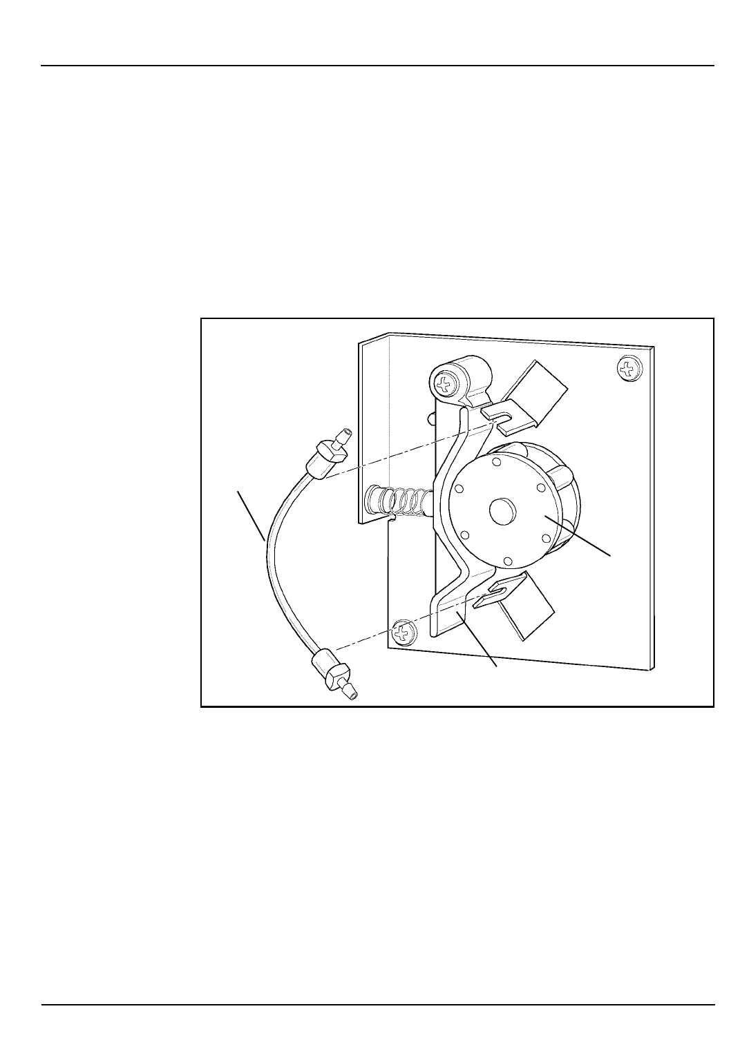
CELL-DYN® 3200 Operator’s Manual 9-23
9140181B — November 1997
Service and Maintenance
Section 9 Weekly Maintenance Procedures
Sample Transfer Pump Tubing Check
Constant pressure on the tubing under the Peristaltic Pump
Wheel tends to flatten the tubing, thereby inhibiting the flow
of liquid past the pump. This tubing should be checked at least
weekly to ensure it is maintaining its original shape. Replace
the tubing after 2000 cycles or as necessary (refer to the
Peristaltic Pump Tubing Replacement procedure in
Subsection: Nonscheduled Maintenance Procedures).
Figure 9.6: Sample Transfer Peristaltic Pump
To check the peristaltic pump tubing, follow the procedure
below:
1. In the
MAIN MENU
, press
[SPECIAL PROTOCOLS]
followed by
[
DIS/ENAB ANALYZER]
and
[
DISABLE ANALYZER]
to disable the
Analyzer.
2.Press the upper right corner of the Left Front Cover to
release the cover latch and swing the cover open.
3.Locate the Sample Transfer Pump on the left side of the
Flow Panel. (Refer to Figure 9.6.)
Pump
Wheel
Pump Shoe
Tubing
Go Back
Search
TOC

9-24 CELL-DYN® 3200 Operator’s Manual
9140181B — November 1997
Service and Maintenance
Weekly Maintenance Procedures Section 9
4.Push the Pump Shoe away from the pump wheel and slip
the tubing out. (Refer to Figure 9.6.)
5.Visually inspect the tubing for damage. If the tubing is
damaged or flattened, change the tubing. (Refer to
Peristaltic Pump Tubing Replacement later in this
section.)
6.Using your fingers, massage the tubing to test its strength
and resiliency and to remove any indentation caused by
the wheel.
7.Push the Pump Shoe away from the pump wheel and slip
the tubing back under the wheel. Make sure the tubing is
securely positioned under the wheel.
8.Close the Left Front Cover and press into place.
9. Press
[ENABLE ANALYZER]
to return the instrument to the
READY state.
10.Press
[MAIN]
to return to the
MAIN MENU
.
Go Back
Search
TOC

CELL-DYN® 3200 Operator’s Manual 9-25
9140181B — November 1997
Service and Maintenance
Section 9 Monthly Maintenance Procedures
Monthly Maintenance Procedures
WARNING: Potential Biohazard. Wear gloves, lab coats,
and safety glasses and follow other biosafety practices
as specified in the OSHA Bloodborne Pathogen Rule (29
CFR Part 1910, 1030) or other equivalent biosafety
procedures.
Fan Filter Cleaning
There are two air inlet filters that clean the air entering the
Analyzer. One filter is located on the left side panel and the
other is mounted on the back panel. Each filter requires
monthly removal and cleaning to maintain a constant,
unrestricted air flow.
NOTE: More frequent cleaning is required whenever
the instrument is located in a particularly dusty or
warm area.
Figures 9.7 and 9.8 show the location of the rear panel fan and
left side panel fan respectively.
Go Back
Search
TOC
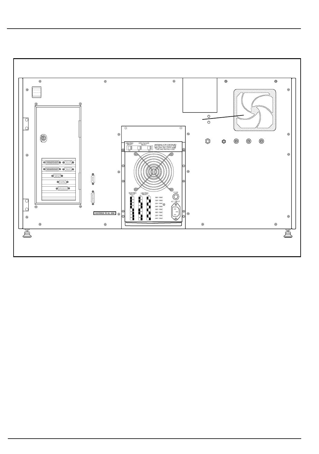
9-26 CELL-DYN® 3200 Operator’s Manual
9140181B — November 1997
Service and Maintenance
Monthly Maintenance Procedures Section 9
Figure 9.7: Analyzer Rear Panel
Fan
Disk
Storage
Container
Go Back
Search
TOC
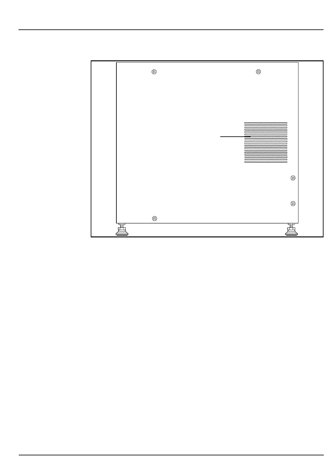
CELL-DYN® 3200 Operator’s Manual 9-27
9140181B — November 1997
Service and Maintenance
Section 9 Monthly Maintenance Procedures
Figure 9.8: Analyzer Left Side Panel
Materials Required
1. Running water
2. DYN-A-WIPE lint-free pads (or other lint-free pads)
3.Small vacuum cleaner (optional)
4. Phillips-head screwdriver (#2)
Filter Cleaning Procedure
1.Perform the Daily Shutdown procedure to place the
instrument in
STANDBY
. (Refer to Daily Shutdown
Procedure in Section 5: Operating Instructions.)
2.Turn the power switch to OFF.
3. Locate the Fan Filter on the rear panel. (Refer to Figure
9.7.)
4.Snap off the plastic frame which holds the filter in the
mounting bracket.
Fan Filter
(under cover)
Go Back
Search
TOC

9-28 CELL-DYN® 3200 Operator’s Manual
9140181B — November 1997
Service and Maintenance
Monthly Maintenance Procedures Section 9
5. To gain access to the Fan Filter on the left side, the Left
Side Panel must first be removed. Using the Phillips-head
screwdriver, unscrew the two upper and two lower screws
holding the Left Side Panel to the frame and remove the
panel. (Refer to Figure 9.8.) Snap off the plastic frame
which holds the filter in the mounting bracket.
6. Remove the filters and run a medium-pressure stream of
warm water over them, or clean the filters by vacuuming
them.
7. Blot dry the filters with a lint-free pad.
8. Reinsert each cleaned filter into its frame and snap the
frames back onto their mounting brackets.
9. Replace the Left Side Panel. Do not overtighten the four
screws holding the panel to the frame.
10. Turn the power switch to ON. After the instrument is
initialized, press
[RUN]
to prime the system and place it in
the
READY
state.
11. Record this maintenance in your maintenance log.
12. If the filter appears unusually dirty when cleaned once a
month, adjust the cleaning cycle accordingly.
Extended Auto-Clean
The Extended Auto-Clean cycle is a fully automated cycle
designed to clean the Shear Valve, the RBC/PLT and WBC
Mixing Chambers, the Optical Flow Cell, the HGB Flow Cell,
the needle in the CS or SL model, and all the associated
fluidics. The forward and reverse action of the peristaltic pump
is used during this cycle to gently scrub and remove any fibrin
or debris within the system.
The Extended Auto-Clean cycle takes approximately 2.5 hours
to complete. During this time, the instrument is not available
to process samples or manipulate data. (When the process is
complete, the instrument is automatically put in the STANDBY
state.) The cycle may be canceled after 15 minutes by pressing
the
[CANCEL]
key, which is displayed at this time.
NOTE: Once the Extended Auto-Clean cycle has been
started, it cannot be cancelled.
Information on performing the Extended Auto-Clean
procedure is displayed on the screen. (Refer to Figure 9.9.)
Go Back
Search
TOC
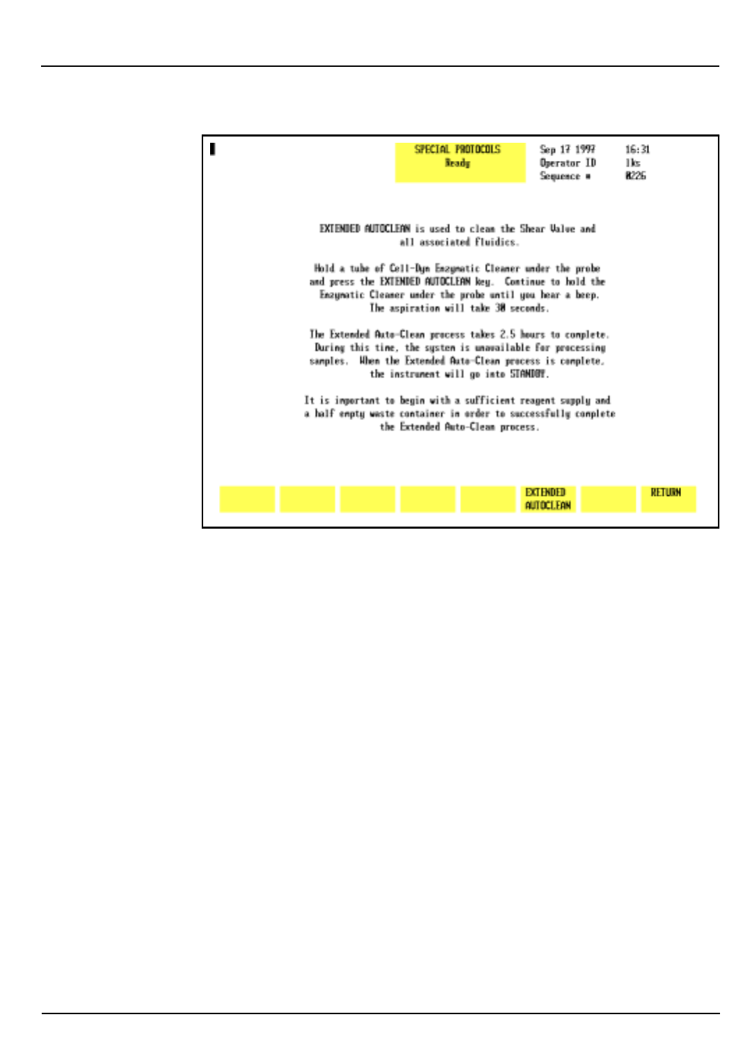
CELL-DYN® 3200 Operator’s Manual 9-29
9140181B — November 1997
Service and Maintenance
Section 9 Monthly Maintenance Procedures
Figure 9.9: Special Protocols: Extended Auto-Clean Screen
Materials Required
1. CELL-DYN Enzymatic Cleaner (L/N 99644-01)
2. Clean test tube or container
3. DYN-A-WIPE lint-free pads (or other lint-free pads)
4. Warm water
Procedure
1. Make sure the Open Sampler mode is selected.
2. Carefully wipe the outside of the Open Sample Aspiration
Probe and the bottom of the Wash Block with a DYN-A-
WIPE (or other lint-free pad) dampened with warm
water and a few drops of CELL-DYN Enzymatic Cleaner.
Wipe any dried reagent or blood off the bottom of the
wash block.
3. In the
MAIN MENU
, press
[SPECIAL PROTOCOLS]
followed by
[MORE]
and
[EXTENDED AUTOCLEAN]
.
4. Follow the instructions shown on the screen. (Refer to
Figure 9.9.)
Go Back
Search
TOC

9-30 CELL-DYN® 3200 Operator’s Manual
9140181B — November 1997
Service and Maintenance
Monthly Maintenance Procedures Section 9
5. Dispense approximately 1.5 mL of Enzymatic Cleaner into
a clean container and hold the container under the probe.
Raise the container until the end of the probe is completely
immersed in the solution.
6. Press
[EXTENDED AUTOCLEAN]
again to activate the cleaning
cycle.
NOTE: Do not press the Touch Plate. The Extended
Auto-Clean cycle is initiated only by the
[EXTENDED
AUTOCLEAN]
key.
7.Continue to hold the container under the probe until a
beep tone is heard. Remove the container and discard the
remaining Enzymatic Cleaner.
NOTE: The complete procedure takes approximately 2.5
hours and may not be terminated.
8.At the end of the 2.5 hours, the instrument automatically
goes into the STANDBY state. Press
[RUN]
to bring the
Analyzer from STANDBY to READY and to prepare it for
running samples.
9.Run at least three background counts to rinse the system.
Check that the background counts are acceptable before
running controls or patient samples. If the counts are
unacceptable, troubleshoot accordingly (refer to Section
10: Troubleshooting and Diagnostics, Subsection:
Troubleshooting Guide).
10.Record this maintenance in your maintenance log.
Go Back
Search
TOC

CELL-DYN® 3200 Operator’s Manual 9-31
9140181B — November 1997
Service and Maintenance
Section 9 Semiannual Maintenance Procedures
Semiannual Maintenance Procedures
Printer Cleaning
Every six months (or after about 300 hours of operation) turn
the printer OFF, disconnect the power cord and use a clean,
dry cloth to dust the area around the carriage shaft and platen
or ink cartridge (depending on type of printer). Be sure to
remove any loose particles of paper. Do not use solvents or
strong detergents on the cabinet.
Refer to the printer manual that accompanied your printer for
detailed cleaning and maintenance instructions.
Go Back
Search
TOC

9-32 CELL-DYN® 3200 Operator’s Manual
9140181B — November 1997
Service and Maintenance
Semiannual Maintenance Procedures Section 9
NOTES
Go Back
Search
TOC

CELL-DYN® 3200 Operator’s Manual 9-33
9140181B — November 1997
Service and Maintenance
Section 9 Nonscheduled Maintenance Frequency
Nonscheduled Maintenance Frequency
Table 9.1: Nonscheduled Maintenance Frequency
Procedure Frequency
Clean Shear Valve When it is suspected of being the
source of imprecision.
Clean Interior of Open Sample
Aspiration Probe When it is suspected of being the
source of imprecision
Unclog Open Sample Aspiration
Probe When a blockage is suspected
Clean Interior of Closed Sample
Aspiration Needle When it is suspected of being the
source of imprecision
Unclog Closed Sample Aspiration
Needle When a blockage is suspected
Clean Sample Injection Syringe,
WBC and HGB Lyse Syringes When they are suspected of being
the source of imprecision
Clean Diluent/Sheath Syringe When it is suspected of being the
source of imprecision
Clean HGB Flow Cell When Auto-Clean has not cleared
away a restriction, or an organic
buildup is suspected of causing any
of the following:
1. Elevated HGB results
2. HGB imprecision
Clean Bar Code Reader Window When particle buildup on the
window interferes with bar code
reading
Clean Reagent Lines When contamination is suspected
Replace Open Sample Aspiration
Probe 1. When the probe is bent
2. When there is a nonremovable
obstruction in the probe
Go Back
Search
TOC

9-34 CELL-DYN® 3200 Operator’s Manual
9140181B — November 1997
Service and Maintenance
Nonscheduled Maintenance Frequency Section 9
Replace Closed Sample Aspiration
Needle 1. When the needle is bent
2. When there is a nonremovable
obstruction in the needle
Replace Tubing in Sample
Transfer Pump When it shows signs of
indentation or flattening
Replace Tubing in Normally
Closed Valves When it shows signs of
indentation or flattening
Replace Syringes 1. When it develops a leak
2. When it is suspected of being a
source of imprecision
Replace Fuse 1. When the fuse fails
2. When changing the power
setting from 110/120 VAC to
220/240 VAC or vice versa
Prepare for Shipping or Extended
Period of Non-Use 1. When shipping the instrument
2. When storing the instrument
3. Before an extended period of
non-use
4. When the entire flow system is
suspected of being the source of
bacterial or fungal
contamination
Go Back
Search
TOC
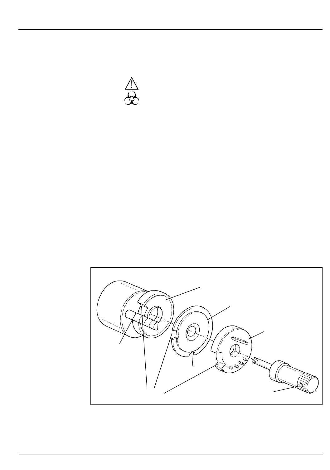
CELL-DYN® 3200 Operator’s Manual 9-35
9140181B — November 1997
Service and Maintenance
Section 9 Nonscheduled Maintenance Procedures
Nonscheduled Maintenance Procedures
WARNING: Potential Biohazard. Wear gloves, lab coats,
and safety glasses and follow other biosafety practices
as specified in the OSHA Bloodborne Pathogen Rule (29
CFR Part 1910, 1030) or other equivalent biosafety
procedures.
Shear Valve Cleaning
Regular cleaning of the Shear Valve ensures accurate and
precise performance. Any reagent or blood residue may cause
the valve to leak or function improperly. The shear valve
assembly is depicted in Figure 9.10.
The shear valve is made of a ceramic material and consists of
three separate sections — front, center and rear. The rear and
front sections are connected to the CELL-DYN 3200 by tubing
that should not be removed.
NOTE: The center section is not connected by tubing
and must be handled carefully, as it will break if it is
dropped. Care should be taken to avoid chipping,
scratching or otherwise damaging any of the sections.
Figure 9.10: Shear Valve Assembly
Retaining Screw
Front Section
Center Section
Back Section
Mounting Arm
Lock Notch
Rim
Notch
Go Back
Search
TOC

9-36 CELL-DYN® 3200 Operator’s Manual
9140181B — November 1997
Service and Maintenance
Nonscheduled Maintenance Procedures Section 9
Materials Required
1. DYN-A-WIPE™ Lint-free pads (or other lint-free pads)
2. A container of warm, deionized water
3. Gloves, lab coat, and safety glasses
Procedure
1. Press the window on the Tower Cover to release the cover
latch. Lift the cover up and off the instrument (Tower
Door on the CS model must be open).
2. In the
MAIN MENU
, press
[SPECIAL PROTOCOLS]
followed by
[CLEAN/RES SHEAR VAL
] and [
CLEAN SHEAR VAL]
. This
prepares the Shear Valve for removal and puts the
Analyzer into the
NOT READY
mode.
3. Place a clean gauze pad on the shelf in front of the Shear
Valve.
4. Turn the Shear Valve Retaining Screw counterclockwise
until it can be removed. (Refer to Figure 9.10.)
5. Pull the front section forward until it is free of the mounting
arm. Place the front section with its attached tubes on the
clean gauze pad.
6. Pull the center section forward until it is free of the
mounting arm. Keep the rear section in place.
NOTE: Be careful to keep a firm grip on the center
section, as it is not attached to the front or back
sections and it may break or crack if dropped.
7. Place the center section in a container of warm water and
allow it to soak for the remainder of the cleaning
procedure.
NOTE: Do not soak the center section in bleach
because the bleach may damage the ceramic.
8. Clean the mounting arm with a DYN-A-WIPE™ (or other
lint-free pad) dampened with warm water to remove any
blood or residue. Wipe the guide dry.
9. Pull out the rear section of the Shear Valve and wipe the
inner surface with a DYN-A-WIPE™ (or other lint-free
pad) dampened with warm water. Use care to avoid
scratching the inner surface. Wipe both surfaces dry with
a lint-free wipe.
NOTE: Hold the section by the edges to avoid getting
fingerprints on the inner surface.
Go Back
Search
TOC

CELL-DYN® 3200 Operator’s Manual 9-37
9140181B — November 1997
Service and Maintenance
Section 9 Nonscheduled Maintenance Procedures
10. Align the lock notch of the rear section with the
mounting guide. Carefully slide this section back onto
the mounting arm as far as it will go. Avoid crimping any
of the attached tubing.
11. Remove the center section from the warm water, wipe the
surfaces with a DYN-A-WIPE™ (or other lint-free pad)
dampened in warm water and dry it with a lint-free wipe.
12. Place the center section aside on a clean gauze. Use care
to avoid scratching the surfaces.
13. View each surface under reflective light to confirm that it
is clean, dry, and free of lint and fingerprints.
14. Align the lock notch of the center section with the
mounting guide. (Lock notch faces the mounting guide,
smaller rim notch faces down.) Carefully slide this section
back onto the mounting arm until it is flush with the rear
section. (Refer to Figure 9.10.)
CAUTION: Damage to the instrument can occur if the
center section is installed backwards. Be certain the rim
notch faces down.
15. Wipe the inner surface of the front section with a DYN-A-
WIPE™ (or other lint-free pad) dampened with warm
water. Use care to avoid scratching the inner surface.
Wipe both surfaces dry with a lint-free wipe.
NOTE: Hold the section by the edges to avoid getting
fingerprints on the inner surfaces.
16. Align the lock notch of the front section with the
mounting guide. A pin on the inner rim should align
with the groove on the mounting arm. Carefully slide this
section back until it touches the center section.
17. Firmly hold the three valve sections together and replace
the Shear Valve Retaining Screw. Turn the screw
clockwise until it stops.
18. Remove any cleaning materials (such as gauze pads) that
may have been left on the instrument.
19. Press
[RESTORE SHEAR VAL]
to return the Shear Valve to its
operating position and to return the instrument to the
READY
state.
20. Reattach the Tower Cover (Tower Door on the CS model
must be open) and press into place.
Go Back
Search
TOC

9-38 CELL-DYN® 3200 Operator’s Manual
9140181B — November 1997
Service and Maintenance
Nonscheduled Maintenance Procedures Section 9
21.Press
[RETURN]
followed by [MAIN
]
and
[RUN]
to display the
RUN screen.
22.Run at least three background counts to rinse the system.
Check that the background counts are acceptable before
running controls or patient samples. If the counts are
unacceptable, troubleshoot accordingly (refer to Section
10: Troubleshooting and Diagnostics, Subsection:
Troubleshooting Guide).
23.Record this maintenance in your maintenance log.
Open Sample Probe Interior Cleaning
The Open Sample Aspiration Probe is thoroughly cleaned
whenever the Auto-Clean cycle is performed. However,
additional cleaning may be required from time to time. The
probe may be cleaned manually, as described below.
Materials Required
1.Gloves, lab coat, and safety glasses
2.Syringe (10 cc or larger) with at least 3” of 1/32” silicone
tubing attached to the tip
3.Small needle-nose pliers or similar tool
4.Small beaker or container
5.Deionized water
6.Cleaning solution (5 mL of 5% filtered bleach added to
5 mL of water)
Procedure
WARNING: Potential Biohazard. The probe is sharp and
potentially contaminated with infectious material.
Avoid contact with tip of probe.
1. In the
MAIN MENU
, press
[SPECIAL PROTOCOLS]
followed by
[
DIS/ENAB ANALYZER
] and [
DISABLE ANALYZER]
.
2.Locate the tubing attached to the top of the Open Sample
Probe. (Refer to Figure 9.11.) Place a small beaker or
container under the probe to catch the rinse solution.
(Hint: Attach one end of a length of 1/32” tubing to the
aspiration end of the probe and the place the other end of
the tubing in the beaker to prevent splashing.)
Go Back
Search
TOC
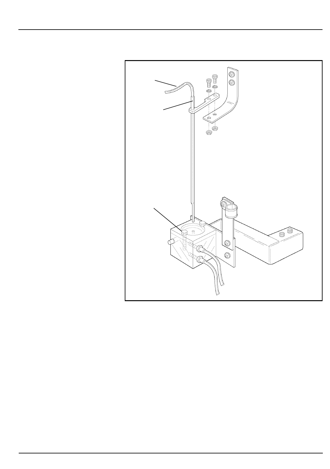
CELL-DYN® 3200 Operator’s Manual 9-39
9140181B — November 1997
Service and Maintenance
Section 9 Nonscheduled Maintenance Procedures
Figure 9.11: Open Sample Probe Assembly
3. Hold the probe firmly with one hand and with the other
hand use the pliers to carefully work the tubing up and
off the top of the probe.
4. Use a syringe with 1/32” (internal diameter) tubing
attached. Fill the syringe with the cleaning solution
prepared earlier. Insert the tubing attached to the syringe
over the top of the probe and inject the solution to flush
the probe.
5. Fill the same syringe with deionized water and inject the
water into the probe from the top to rinse the probe.
Repeat the procedure three times to thoroughly rinse the
probe.
Probe Tubing
Probe Top
Wash Block
Go Back
Search
TOC

9-40 CELL-DYN® 3200 Operator’s Manual
9140181B — November 1997
Service and Maintenance
Nonscheduled Maintenance Procedures Section 9
NOTE: Empty the container or tube between rinses as
necessary.
6.Hold the probe steady and reinsert the tubing over the
top. Use the pliers to carefully work the tubing down the
probe. Be sure the tubing is firmly seated on the probe.
(Remove any tubing that may have been placed on the
aspiration end of the probe.)
NOTE: Wetting the top portion of the probe will allow
the tubing to slide more easily.
7.Be sure to remove the beaker containing the rinse
solution from the instrument.
8. Press
[ENABLE ANALYZER]
followed by
[RETURN]
and
[MAIN]
to
return to the
MAIN MENU
.
9. Press
[RUN]
followed by
[SPECIMEN TYPE]
and
[BACKGROUND]
.
10.Run at least three background counts to rinse the system.
Check that the background counts are acceptable before
running controls or patient samples. If the counts are
unacceptable, troubleshoot accordingly (refer to Section
10: Troubleshooting and Diagnostics, Subsection:
Troubleshooting Guide).
11.Record this maintenance in your maintenance log.
Go Back
Search
TOC

CELL-DYN® 3200 Operator’s Manual 9-41
9140181B — November 1997
Service and Maintenance
Section 9 Nonscheduled Maintenance Procedures
Unclogging the Open Sample Aspiration Probe
If a blockage is suspected, it may be cleared using the
procedure described above in Open Sample Probe Interior
Cleaning.
Closed Sample Needle Interior Cleaning
The Aspiration Needle in the Tower Module should be cleaned
regularly to remove protein buildup or debris and reduce the
possibility of a blockage. In addition to the Auto-Clean
method, use the procedure described below for cleaning the
needle in the Tower Module.
Materials Required
1.Gloves, lab coat, and safety glasses
2.Syringe (10 cc or larger) with at least 3” of 1/32” silicone
tubing attached to the tip
3.Small needle-nose pliers or similar tool
4.Small beaker or container (for SL model); empty, open
VACUTAINER® tube (for CS model)
5.Deionized water
6.Cleaning solution (5 mL of 5% filtered bleach added to
5 mL of water)
Procedure
WARNING: Potential Biohazard. The sample needle is
sharp and potentially contaminated with infectious
material. Avoid contact with the tip of the needle.
1. In the
MAIN MENU
, press
[SPECIAL PROTOCOLS]
followed by
[
DIS/ENAB ANALYZER
] and [
DISABLE ANALYZER]
.
2.For the CS model, follow the procedure in step a below.
For the SL model, follow the procedure in step b below.
a.CS model: Press the window on the Tower Cover to
release the cover latch. With the Tower Door open, lift
the cover up and off the instrument. Place a small
beaker or container on the shelf directly under the
Aspiration Needle to catch the rinse solution. The
container should be small enough to fit in the Door
Assembly compartment when the door is closed. DO
NOT attempt to fit a length of tubing over the needle
point.
Go Back
Search
TOC

9-42 CELL-DYN® 3200 Operator’s Manual
9140181B — November 1997
Service and Maintenance
Nonscheduled Maintenance Procedures Section 9
b. SL model: Press the window on the Tower Cover to
release the cover latch. Lift the cover up and off the
instrument. Remove any racks that may be under the
Tower Module. Place a small beaker or container
under the Aspiration Needle to catch the rinse
solution. DO NOT attempt to fit a length of tubing
over the needle point.
3. Locate the Aspiration Tubing and Vent Tubing attached
to the top of the Closed Sample Aspiration Needle. (Refer
to Figure 9.12.)
NOTE: The Aspiration Needle consists of two separate
needles joined together, one for venting and one for
aspiration. The vent needle is the shorter of the two
and faces the instrument. Note that the tubing attached
to the opening at the top of the vent needle leads to a
vent chamber on the left side of the Tower Module,
while the tubing attached to the opening at the top of
the aspiration needle leads to Y-valve located between
the Shear Valve and the Open Sample Probe.
4. Hold the needle firmly with one hand and with the other
hand use the pliers to carefully work the Aspiration
Tubing up and off the top of the needle.
Go Back
Search
TOC
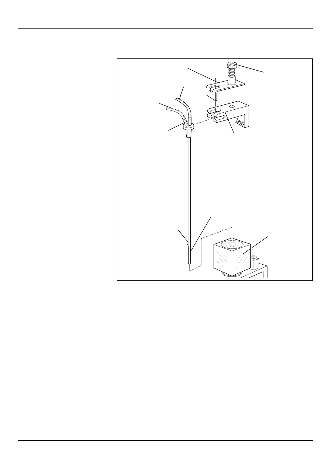
CELL-DYN® 3200 Operator’s Manual 9-43
9140181B — November 1997
Service and Maintenance
Section 9 Nonscheduled Maintenance Procedures
Figure 9.12: Closed Sample Needle
5. Use a syringe with 1/32” (internal diameter) tubing
attached. Fill the syringe with the cleaning solution
prepared earlier. Insert the tubing attached to the syringe
over the top of the Aspiration Needle and inject the
solution to flush the needle.
6. Fill the same syringe with deionized water and inject the
water into the needle from the top to rinse it. Repeat the
procedure three times to thoroughly rinse the needle.
NOTE: Empty the container between rinses as
necessary.
7. Hold the needle steady and reinsert the Aspiration Tubing
over the top. Use the pliers to carefully work the tubing
down. Be sure the tubing is firmly seated on the needle.
Thumb Screw
(with spring)
Holding Clip
Aspiration Tubing
Vent Tubing
Needle Top
Vent Needle
(shorter)
Aspiration Needle
(longer)
Wash Block
Needle Mounting
Assembly
Go Back
Search
TOC

9-44 CELL-DYN® 3200 Operator’s Manual
9140181B — November 1997
Service and Maintenance
Nonscheduled Maintenance Procedures Section 9
NOTE: Wetting the top portion of the needle will allow
the tubing to slide more easily.
8.Be sure to remove the container from under the
Aspiration Needle.
9.Reattach the Tower Cover (Tower Door on the CS model
must be open) and press into place.
10.Press
[ENABLE ANALYZER]
followed by
[RETURN]
and
[MAIN]
to
return to the
MAIN MENU
.
11.Run at least three background counts to rinse the system.
Check that the background counts are acceptable before
running controls or patient samples. If the counts are
unacceptable, troubleshoot accordingly (refer to Section
10: Troubleshooting and Diagnostics, Subsection:
Troubleshooting Guide).
12.Record this maintenance in your maintenance log.
Go Back
Search
TOC
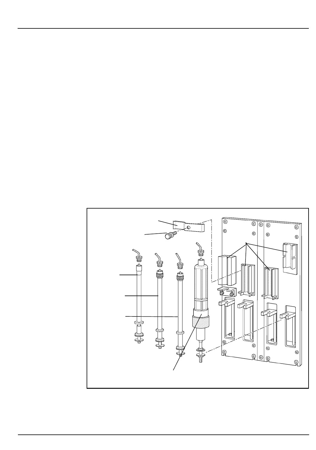
CELL-DYN® 3200 Operator’s Manual 9-45
9140181B — November 1997
Service and Maintenance
Section 9 Nonscheduled Maintenance Procedures
Unclogging the Closed Sample Aspiration Needle
If a blockage is suspected, it may be cleared using the
procedure described above in Closed Sample Needle Interior
Cleaning.
Syringe Cleaning
There are two syringe assemblies, each containing two
syringes, on the Flow Panel of the CELL-DYN 3200 system.
The syringe assemblies are depicted in Figure 9.13.
Syringes should be cleaned one at a time to ensure that each
syringe is replaced in the correct position. Replace each syringe
after it is cleaned and then remove the next one to be cleaned.
Instructions for removing, cleaning, and replacing the Sample
Injection, WBC Lyse, and HGB Lyse Syringes are given below.
Instructions for removing, cleaning, and replacing the
Diluent/Sheath Syringe are given in subsection
Diluent/Sheath Syringe Cleaning.
Figure 9.13: Syringe Assemblies
Diluent/Sheath Syringe
Sample
Injection
Syringe
WBC Lyse
Syringe
HGB Lyse
Syringe
Holding Blocks
Thumb Screw
Rotating Clip Plate
Go Back
Search
TOC

9-46 CELL-DYN® 3200 Operator’s Manual
9140181B — November 1997
Service and Maintenance
Nonscheduled Maintenance Procedures Section 9
Materials Required
1. A large container filled with approximately 500 mL of
warm, deionized water
2. DYN-A-WIPE lint-free pads (or other lint-free pads)
3. Distilled water
4. Small container of each reagent to refill the clean syringes
5. Phillips-head screwdriver (#2)
Disabling the Analyzer
1. In the
MAIN MENU
, press
[SPECIAL PROTOCOLS]
followed by
[
DIS/ENAB ANALYZER
] and [
DISABLE ANALYZER]
.
Procedure—Sample Injection Syringe
1. To gain access to the syringe assemblies, press the upper
left corner of the Right Front Cover to release the cover
latch. Swing the cover open. Press the window on the
Tower Cover to release the cover latch. Lift the cover up
and off the instrument.
a. On the CS model, remove the four Phillips-head
screws holding the Front Skirt to the instrument and
remove the skirt.
2. For the two syringes on the left — Sample Injection
Syringe and HGB Lyse Syringe — loosen the Thumb Screw
on the rotating clip plate holding the two syringes in
place. Swing the plate to a vertical position to allow
access to the syringes. There is no holding plate for the
two syringes on the right. (Refer to Figure 9.14.)
Go Back
Search
TOC

CELL-DYN® 3200 Operator’s Manual 9-47
9140181B — November 1997
Service and Maintenance
Section 9 Nonscheduled Maintenance Procedures
Figure 9.14: Sample Injection Syringe Removal
3. Pull the Sample Injection Syringe out of the holding
block until the double collar attached to the bottom of
the plunger clears the slot at the base of the mounting
bracket. Note that the glass flange at the bottom of the
barrel (which fits into a slot) has the narrow side facing
the instrument.
4. Use one hand to grasp the tube fitting at the top of the
syringe that attaches the tubing to the syringe. Use the
other hand to carefully turn the syringe counterclockwise
to release it from the fitting.
5. Note the level of reagent in the syringe, since the same
amount of reagent will have to be added after the syringe
is cleaned. Dispense the reagent into a sink or an
appropriate waste container.
6. Aspirate warm water into the syringe until it is full.
Continue to pull on the plunger until it is removed from
the barrel.
Sample
Injection
Syringe
Thumb Screw
Rotating Clip Plate
Double Collar
Base
Tube Fitting
Luer Lock
Go Back
Search
TOC

9-48 CELL-DYN® 3200 Operator’s Manual
9140181B — November 1997
Service and Maintenance
Nonscheduled Maintenance Procedures Section 9
NOTE: Do not push or pull on the plunger when the
syringe is dry, as it may damage the plunger. Avoid
touching the plunger because oil from the fingers may
cause it to move erratically.
7.Rinse the plunger and barrel thoroughly with distilled
water. Carefully reinsert the plunger into the wet barrel.
8.Refill the syringe with fresh Diluent/Sheath reagent to the
same level as noted in step 5.
9.Insert the tube fitting into the top of the syringe and turn
the syringe clockwise until the fitting is finger tight. Be
careful not to overtighten the fitting or crimp the
associated tubing.
10.Carefully adjust the position of the plunger as necessary
to insert the double collar into the slot on the mounting
bracket.
11.Insert the syringe into the holding block, making sure the
narrow side of the glass flange on the barrel fits into the
slot at the bottom of the block.
12.Return the rotating clip plate to the horizontal position,
making sure it fits properly over both syringes. Tighten
the Thumb Screw until the clip is secure.
Procedure—HGB Lyse Syringe
1.The procedure for removing, cleaning, and replacing the
HGB Lyse Syringe is similar to the Sample Injection
Syringe with two exceptions:
a.This syringe snaps into the holding block. To remove
the syringe, place one finger behind the upper portion
of the barrel and one finger being the lower portion.
Pull gently forward until the syringe barrel snaps free
of the holding block.
b.After cleaning, refill the syringe to the original level
with fresh HGB Lyse reagent.
2.Refer to the instructions in Procedure—Sample Injection
Syringe.
Procedure—WBC Lyse Syringe
1.The procedure for removing, cleaning, and replacing the
WBC Lyse Syringe is similar to the Sample Injection
Syringe with three exceptions:
a.There is no holding clip to be loosened.
Go Back
Search
TOC

CELL-DYN® 3200 Operator’s Manual 9-49
9140181B — November 1997
Service and Maintenance
Section 9 Nonscheduled Maintenance Procedures
b.This syringe snaps into the holding block. To remove
the syringe, place one finger behind the upper portion
of the barrel and one finger being the lower portion.
Pull gently forward until the syringe barrel snaps free
of the holding block.
c.After cleaning, refill the syringe to the original level
with fresh WBC Lyse reagent.
2.Refer to the instructions listed in Procedure—Sample
Injection Syringe.
Procedure—Diluent/Sheath Syringe
Like the other three syringes on the CELL-DYN 3200 system,
the Diluent/Sheath Syringe is cleaned only as necessary.
Materials Required
1.A large container filled with approximately 500 mL of
warm, deionized water
2. DYN-A-WIPE lint-free pads (or other lint-free pads)
3.Distilled water
4.Small container of each reagent to refill the clean syringes
5. Phillips-head screwdriver (#2)
Procedure
1. In the
MAIN MENU
, press
[SPECIAL PROTOCOLS]
followed by
[
DIS/ENAB ANALYZER
] and [
DISABLE ANALYZER]
.
2.To gain full access to the syringe assemblies:
a.Press the upper left corner of the Right Front Cover to
release the latch. Swing the cover open. Press the
window on the Tower Cover to release the cover latch.
Lift the cover up and off the instrument (Tower Door
on the CS model must be open).
b.On the CS model, remove the four Phillips-head
screws holding the Front Skirt to the instrument and
remove the skirt.
c.The skirt on the SL model has two removable sections
adjacent to the Flow Panel. Remove the section on the
right side of the Flow Panel by lifting it up and off its
holding pins.
Go Back
Search
TOC

9-50 CELL-DYN® 3200 Operator’s Manual
9140181B — November 1997
Service and Maintenance
Nonscheduled Maintenance Procedures Section 9
3. Locate the Diluent/Sheath Syringe (refer to Figure 9.15).
Note that the plastic barrel of this syringe has four
vertical edges, two of which fit into grooves on the
holding block, and a circular plastic flange which also fits
into a groove on the holding block.
4. Grasp the plastic tube fitting at the top of the syringe that
attaches to the Luer Lock. Carefully turn the Luer Lock on
the syringe clockwise to release it from the fitting. Use the
lint-free pads to absorb excess reagent.
5. Grasp the syringe barrel below the Luer Lock with one
hand. With the other hand, grasp the syringe plunger
below the metal band. Pull and twist one side of the
syringe to remove it from the snap-in holding block.
6. Note the liquid level in the syringe so that it can be
refilled after cleaning to approximately the same level.
7. Dispense the reagent into a sink or other appropriate
waste container.
NOTE: Do not pull the plunger out of the barrel. Also,
do not push or pull on the plunger when the syringe is
dry, as it may damage the plunger. Avoid touching the
plunger, because oil from the fingers may cause it to
move erratically.
8. Immerse the tip of the syringe in the container of
deionized water.
9. Aspirate deionized water into the syringe until it is full,
and dispense the water into a sink or other appropriate
waste container. Repeat this step several times to
thoroughly rinse the syringe.
10. Refill the syringe with Diluent/Sheath reagent to the level
noted in Step 6.
Go Back
Search
TOC
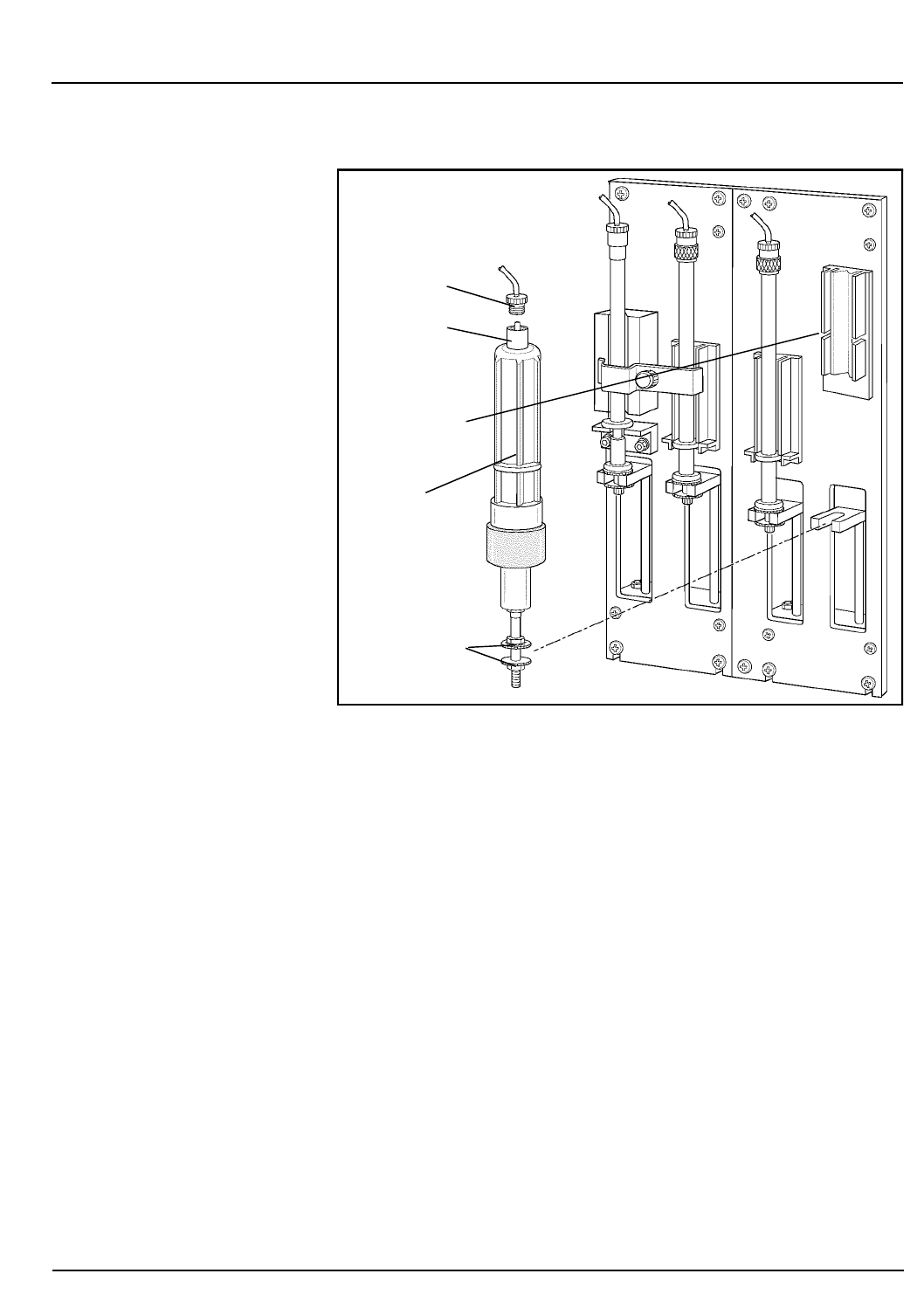
CELL-DYN® 3200 Operator’s Manual 9-51
9140181B — November 1997
Service and Maintenance
Section 9 Nonscheduled Maintenance Procedures
Figure 9.15: Diluent/Sheath Syringe Replacement
11. Insert the double collar on the plunger into the slot on
the mounting bracket and line up the circular flange on
the barrel with the slot on the holding block.
12. Insert one of the vertical edges on the barrel into a side
groove on the holding block and carefully twist the barrel
until the other side snaps into place. Make sure the
syringe is firmly in place.
13. Place the tube fitting into the Luer Lock and turn the lock
counterclockwise until the fitting is finger tight. Be
careful not to overtighten the fitting or crimp the
associated tubing.
Enabling the Analyzer
When all syringes have been re-installed, do the following:
1. Press
[ENABLE ANALYZER]
followed by
[MAIN]
and
[RUN]
to
return to the
RUN
screen.
Double Collar
Diluent/Sheath
Luer Lock
Holding Block
Tube Fitting
Syringe
Go Back
Search
TOC

9-52 CELL-DYN® 3200 Operator’s Manual
9140181B — November 1997
Service and Maintenance
Nonscheduled Maintenance Procedures Section 9
2.Run several background counts in the Open Mode and
observe the action of the syringes during the cycle. The
plungers should move smoothly up and down and
should not leak.
3.After the operation of all the syringes has been verified, do
the following:
a.On the CS model, reattach the Front Skirt using the
four Phillips-head screws. Do not pinch the tubing at
the bottom.
b.On the SL model, align the removable right side skirt
panel over its holding pins and slide down.
c.Reattach the Tower Cover (Tower Door on the CS
model must be open) and press into place.
d.Close the Right Front Cover and press into place.
4. Run at least three background counts. Check that the
background counts are acceptable before running
controls or patient samples. If the counts are
unacceptable, troubleshoot accordingly (refer to Section
10: Troubleshooting and Diagnostics, Subsection:
Troubleshooting Guide).
5.Record this maintenance in your maintenance log.
HGB Flow Cell Manual Cleaning Procedure
NOTE: This is not a routine cleaning/maintenance
procedure. It should only be performed if routine
methods fail or at the request of the Abbott Customer
Support Center.
Under normal circumstances, the Auto-Clean cycle is
sufficient to ensure the cleanliness of the HGB Flow Cell. If the
Auto-Clean cycle fails to adequately clean the flow cell, the
procedure described below may be used. The HGB Flow Cell is
depicted in Figure 9.16.
Go Back
Search
TOC
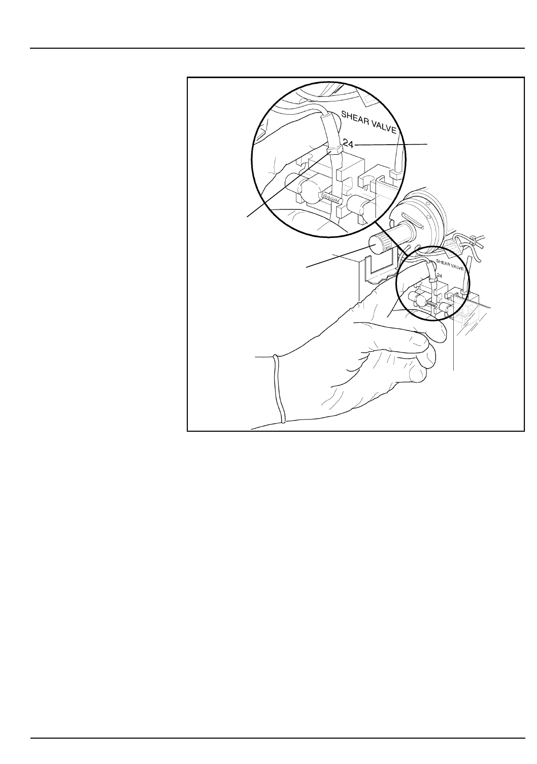
CELL-DYN® 3200 Operator’s Manual 9-53
9140181B — November 1997
Service and Maintenance
Section 9 Nonscheduled Maintenance Procedures
Figure 9.16: HGB Flow Cell Access Tubing
Materials Required
1. Cleaning Solution:
Make a 25% bleach solution by adding 5 mL of bleach to
15 mL of deionized water.
2. 10 mL syringe
3. Gloves, Lab Coat, and Safety Glasses
4. Deionized water
Procedure
1. In the
MAIN MENU
, press
[SPECIAL PROTOCOLS]
followed by
[
DIS/ENABLE ANALYZER]
and
[DISABLE ANALYZER]
to disable
the Analyzer.
2. Press the window on the Tower Cover to release the cover
latch. Lift the cover up and off the instrument (Tower
Door on the CS model must be open). Locate the HGB
Flow Cell. (Refer to Figure 9.4.)
Solenoid 24
Tube Fitting
Shear Valve
Go Back
Search
TOC

9-54 CELL-DYN® 3200 Operator’s Manual
9140181B — November 1997
Service and Maintenance
Nonscheduled Maintenance Procedures Section 9
3.Remove the black plastic drip pan under the Shear Valve
by sliding it up and off the support stand.
4.Fill the syringe with the bleach solution.
5.Locate the tubing just above solenoid #24 that attaches to
the HGB Flow Cell. (Refer to Figure 9.14.) Attach a
hemostat to the tubing between the fitting and the HGB
Flow Cell.
6.Disconnect the tubing from the fitting and insert the
syringe. Remove the hemostat. Dispense the cleaning
solution into the flow cell.
7. Allow the bleach solution to remain in the flow cell for 5
minutes.
8.When the time has elapsed, aspirate the solution back
into the syringe and reattach the hemostat.
9.Reconnect the tubing and remove the hemostat.
10.Reinsert the plastic drip pan by aligning the grooves on
the pan with the upright support arms and sliding the
pan down until it rests on the support.
11.Reattach the Tower Cover (Tower Door on the CS model
must be open) and press into place.
12.Press
[ENABLE ANALYZER]
followed by
[RETURN]
and
[MAIN]
and
[RUN]
.
13.Run at least three background counts to rinse the system.
Check that the background counts are acceptable before
running controls or patient samples. If the counts are
unacceptable, troubleshoot accordingly (refer to Section
10: Troubleshooting and Diagnostics, Subsection:
Troubleshooting Guide).
14.Record this maintenance in your maintenance log.
Bar Code Reader Window Cleaning
The cleaning procedure is similar for the SL and CS models
even though the location of the Bar Code Reader is different.
Materials Required
1.Gloves, Lab coat, and Safety Glasses
2. Applicator swabs (non-sterile)
3.Microscope lens tissues
4.Isopropyl alcohol
Go Back
Search
TOC

CELL-DYN® 3200 Operator’s Manual 9-55
9140181B — November 1997
Service and Maintenance
Section 9 Nonscheduled Maintenance Procedures
Procedure
1. In the
MAIN MENU
, press
[SPECIAL PROTOCOLS]
followed by
[
DIS/ENAB ANALYZER]
and
[DISABLE ANALYZER]
.
2. Take three applicator swabs and wrap a lens tissue around
each swab.
3.Moisten one of the wrapped swabs in isopropyl alcohol.
4.Locate the Bar Code Reader Window.
5.Wipe the window with the moistened swab. Using one of
the dry wrapped swabs, wipe the window dry. Use the
second dry swab if necessary.
6.Visually inspect the window to ensure that blood, debris,
and smudges have been removed.
7. Press the
[ENABLE ANALYZER]
key to bring the system to the
READY
state. Press
[RETURN]
followed by
[MAIN]
and
[RUN]
to
return to the
RUN
screen.
Reagent Line Cleaning
The reagent lines should be cleaned if contamination is
suspected. To clean the lines, refer to steps 1-4 under
Procedure in subsection Preparation for Shipping or Extended
Period of Non-Use later in this section.
Open Sample Probe Replacement
Materials Required
1.Gloves, lab coat, and safety glasses
2. Replacement probe
3. 7/64” Allen wrench
4.Small needle-nose pliers or similar tool
Procedure
1. In the
MAIN MENU
, press
[SPECIAL PROTOCOLS]
followed by
[DIS/ENAB ANALYZER]
and
[DISABLE ANALYZER]
.
2.Press the upper left corner of the Right Front Cover to
release the cover latch. Swing the cover open to access the
right side of the Flow Panel.
Go Back
Search
TOC
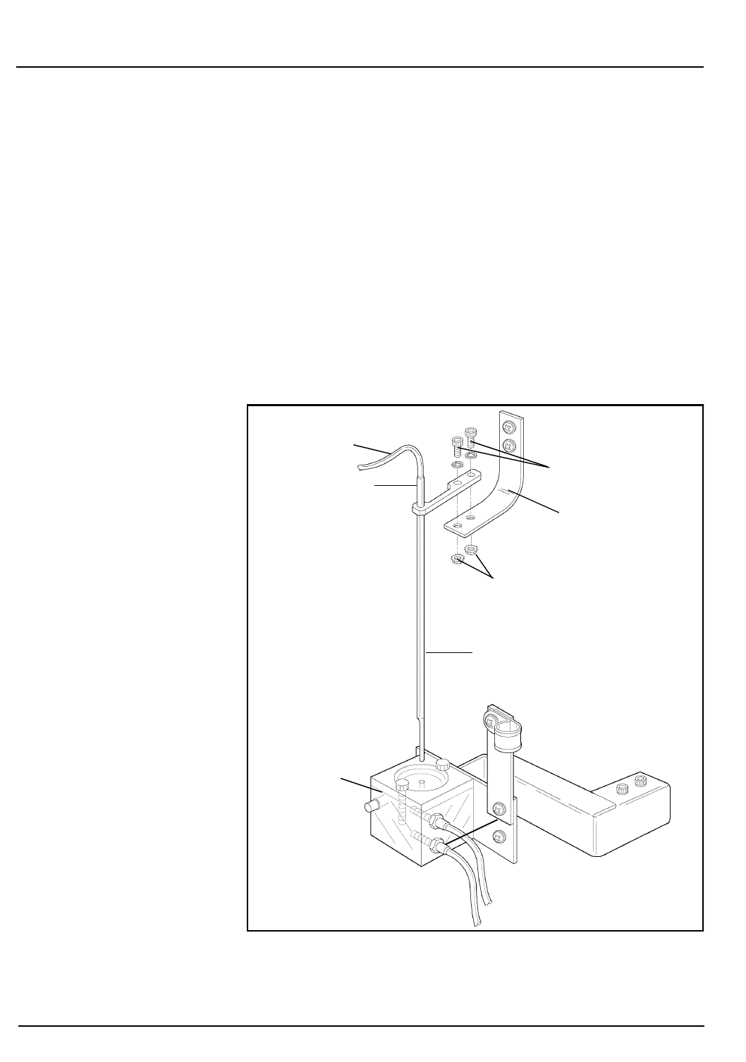
9-56 CELL-DYN® 3200 Operator’s Manual
9140181B — November 1997
Service and Maintenance
Nonscheduled Maintenance Procedures Section 9
3. Locate the tubing attached to the top of the Open Sample
Probe. (Refer to Figure 9.17.) Hold the probe firmly with
one hand and with the other hand use the pliers to
carefully work the tubing up and off the top of the probe.
4. Using the Allen wrench, remove the two hex nuts
holding the Probe Bracket Arm to the Bracket Support
Arm on the Probe Assembly Frame.
5. Pull the probe up and out of the Wash Block.
6. Insert the new probe into the Wash Block.
7. Place the Probe Bracket Arm on top of the Bracket
Support Arm. Align the holes in the bracket arm to the
holes in the Probe Assembly Frame. Insert and tighten the
two hex nuts using the Allen wrench.
Figure 9.17: Open Sample Probe Replacement
Probe Tubing
Probe Bracket Arm
Hex Nuts with
Washers
Hex Screws
Wash Block
Probe
Probe Top
Go Back
Search
TOC

CELL-DYN® 3200 Operator’s Manual 9-57
9140181B — November 1997
Service and Maintenance
Section 9 Nonscheduled Maintenance Procedures
8.Hold the probe steady and reinsert the tubing over the
top. Use the pliers to carefully work the tubing down the
probe. Be sure the tubing is firmly seated on the probe.
(Remove the tubing from the aspiration end of the probe
as necessary.)
NOTE: Wetting the top portion of the probe will allow
the tubing to slide more easily.
9. Press
[ENABLE ANALYZER]
followed by
[RETURN], [MAIN],
and
[RUN].
10.Press the Touch Plate to run a background count. Observe
the action of the probe assembly to ensure there are no
leaks and that it is operating smoothly.
11.Close the Right Front Cover and press into place.
12.Run at least three background counts to rinse the system.
Check that the background counts are acceptable before
running controls or patient samples. If the counts are
unacceptable, troubleshoot accordingly (refer to Section
10: Troubleshooting and Diagnostics, Subsection:
Troubleshooting Guide).
13.Record this maintenance in your maintenance log.
Closed Sample Needle Replacement
If the Closed Sample Aspiration Needle becomes bent or
becomes clogged (and cleaning does not remove the blockage),
the needle should be replaced.
Materials Required
1.Gloves, lab coat, and safety glasses
2. Replacement needle
3. Phillips-head screwdriver (#2)
4.Small needle-nose pliers or similar tool
Procedure
WARNING: Potential Biohazard. The sample needle is
sharp and potentially contaminated with infectious
material. Avoid contact with tip of needle.
1. In the
MAIN MENU
, press
[SPECIAL PROTOCOLS]
followed by
[
DIS/ENAB ANALYZER]
and
[DISABLE ANALYZER]
.
Go Back
Search
TOC

9-58 CELL-DYN® 3200 Operator’s Manual
9140181B — November 1997
Service and Maintenance
Nonscheduled Maintenance Procedures Section 9
2. Press the window on the Tower Cover to release the cover
latch. Lift the cover up and off the instrument (Tower
Door on the CS model must be open).
3. Locate the Aspiration Needle.
NOTE: The Aspiration Needle consists of two separate
needles joined together, one for venting and one for
aspiration. (Refer to Figure 9.12.) The vent needle is the
shorter of the two and faces the instrument. Note that
the tubing attached to the opening at the top of the
vent needle leads to a vent chamber on the left side of
the Tower Module, while the tubing attached to the
opening at the top of the aspiration needle leads to Y-
valve located between the Shear Valve and the Open
Sample Probe.
4. Hold the needle firmly with one hand and with the other
hand use the pliers to carefully work the tubing up and
off the top of both ends of the needle.
5. Loosen the Thumb Screw at the top of the Needle
Mounting Assembly and remove the clip holding the
needle to the assembly.
6. Carefully pull the top of the needle forward until the
flange clears the slot in the bracket. Lift the needle up and
out of the Wash Block.
7. Place the new needle into the Wash Block, making sure
the shorter part (venting needle) faces the instrument,
and place the flange into its slot in the top bracket.
8. Reinstall the clip over the top of the needle and tighten
the Thumb Screw.
9. Attach the vent tubing to the vent section of the needle
and the aspiration tubing to the aspiration section.
NOTE: It is important that the tubing be attached
correctly.
NOTE: Wetting the top portion of the needle will allow
the tubing to slide more easily.
10. Reattach the Tower Cover (Tower Door on the CS model
must be open) and press into place.
11. Press
[ENABLE ANALYZER]
followed by
[RETURN]
and
[MAIN]
to
return to the
MAIN MENU
.
Go Back
Search
TOC

CELL-DYN® 3200 Operator’s Manual 9-59
9140181B — November 1997
Service and Maintenance
Section 9 Nonscheduled Maintenance Procedures
12.Run at least three background counts to rinse the system.
Check that the background counts are acceptable before
running controls or patient samples. If the counts are
unacceptable, troubleshoot accordingly (refer to Section
10: Troubleshooting and Diagnostics, Subsection:
Troubleshooting Guide).
13.Record this maintenance in your maintenance log.
Sample Transfer Pump Tubing Replacement
The tubing under the Sample Transfer Peristaltic Pump needs to
be replaced on a regular basis to ensure proper fluid movement
through the instrument. This tubing should be replaced at least
every 2000 cycles. However, the frequency of replacement
depends on instrument use in each laboratory. The Sample
Transfer Pump is shown in Figure 9.6.
Materials Required
1.Sample Transfer Peristaltic Pump Tubing
2.Gloves, lab coat, and safety glasses
Procedure
1.In the MAIN MENU, press
[SPECIAL PROTOCOLS
followed
by
[DIS/ENAB ANALYZER]
and
[DISABLE ANALYZER]
.
2.Press the upper right corner of the Left Front Cover to
release the cover latch and swing the cover open.
3.Locate the Sample Transfer Peristaltic Pump on the left
side of the panel. (Refer to Figure 9.4.)
4.Push the Pump Shoe away from the pump wheel and slip
the tubing out.
5.Remove the tubing from the metal brackets that hold it
on each side of the rollers. (Refer to Figure 9.6.)
6.Disconnect the tubing at the plastic connector.
7.Connect the new tubing to the plastic connector.
8.Place the collars on the ends of the tubing into the metal
guides. Hold the Pump Shoe open and push the tubing
underneath the pump rollers.
NOTE: Position the tubing in the center of the rollers.
9.Close the Left Front Cover and press into place.
Go Back
Search
TOC

9-60 CELL-DYN® 3200 Operator’s Manual
9140181B — November 1997
Service and Maintenance
Nonscheduled Maintenance Procedures Section 9
10.Press
[ENABLE ANALYZER]
to bring the instrument to the
READY state.
11.Press
[RETURN]
followed by
[MAIN]
and
[RUN]
to display the
RUN
screen.
12.Run at least three background counts to rinse the system.
Check that the background counts are acceptable before
running controls or patient samples. If the counts are
unacceptable, troubleshoot accordingly (refer to Section
10: Troubleshooting and Diagnostics, Subsection:
Troubleshooting Guide).
13.Record this maintenance in your maintenance log.
Normally Closed Valve Tubing Replacement
Tubing in the Normally Closed Valves should be replaced
when it shows signs of indentation or flattening and is
impeding the flow of fluid through the tubing.
Materials Required
1. Valve Tubing
2.Gloves, lab coat, and safety glasses
3. Phillips-head screwdriver (#2)
Procedure
1. In the
MAIN MENU
, press
[SPECIAL PROTOCOLS]
followed by
[
DIS/ENAB ANALYZER]
and
[DISABLE ANALYZER]
.
2.Press the upper left corner of the Right Front Cover to
release the cover latch. Swing the cover open.
3.Press the upper right corner of the Left Front Cover to
release the cover latch. Swing the cover open.
4.Press the window on the Tower Cover to release the cover
latch. Lift the cover up and off the instrument (Tower
Door on the CS model must be open).
5.To gain access to the lower portion of the Flow Panel:
a.On the CS model, remove the four Phillips-head
screws holding the Front Skirt to the instrument and
remove the skirt.
Go Back
Search
TOC
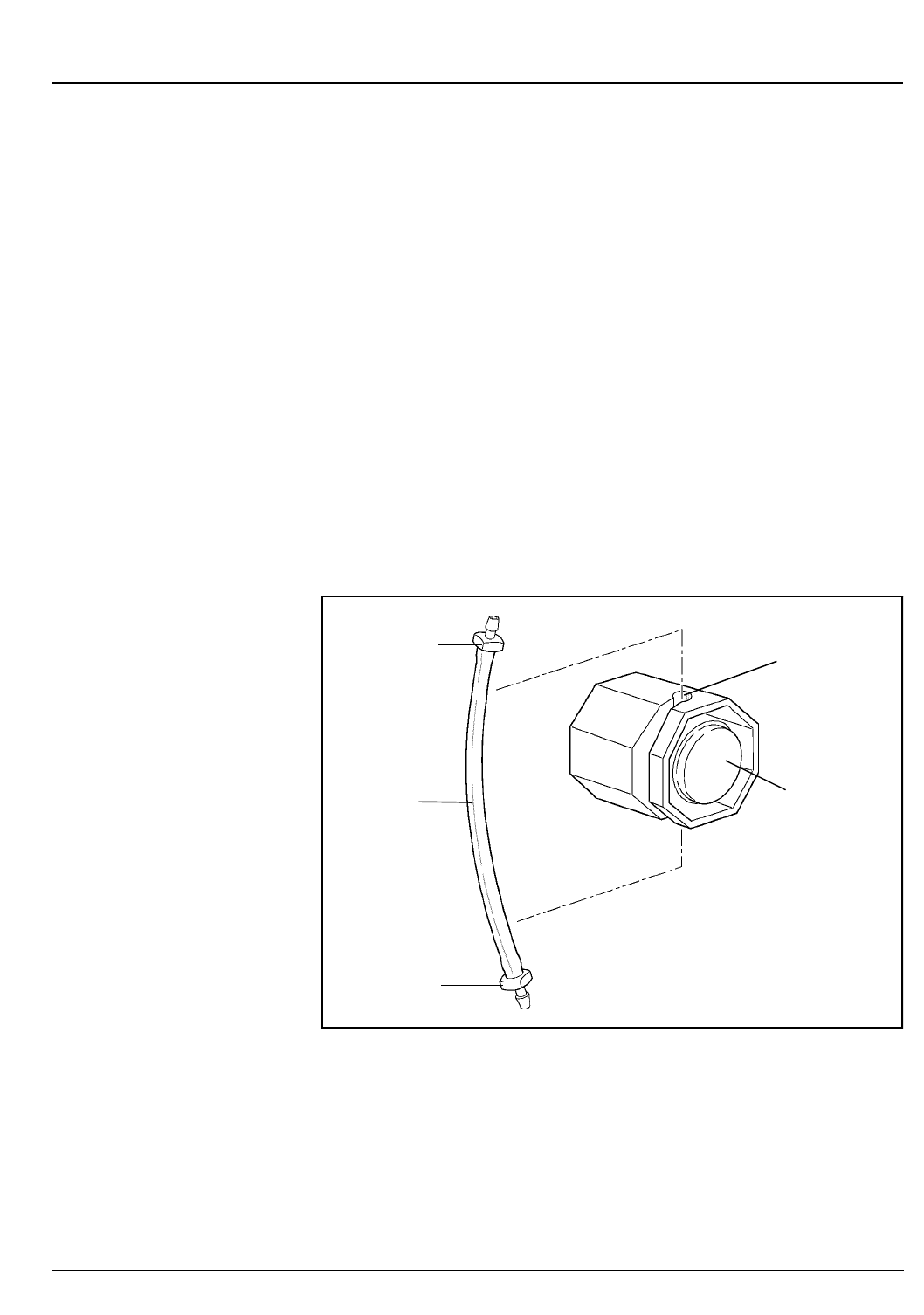
CELL-DYN® 3200 Operator’s Manual 9-61
9140181B — November 1997
Service and Maintenance
Section 9 Nonscheduled Maintenance Procedures
b. On the SL model, remove the four Phillips-head
screws holding the Sample Loader to the instrument
and pull the loader away from the Analyzer
approximately 2-3 inches to allow easy access to all
the Normally Closed Valves.
6. Locate all six Normally Closed Valves on the Flow Panel.
(Refer to Figure 9.4.)
7. Remove the tubing from each valve.
NOTE: On the SL model, space is limited between the
inner edge of the Sample Loader and the two normally
closed values on the lower left side of the Flow Panel.
Use caution when accessing the tubing in these two
valves.
8. Pull the tubing from the connectors on either side as
shown in Figure 9.18.
Figure 9.18: Tubing in Normally Closed Valve
9. Insert the new tubing section into both connectors. Make
sure the tubing is pushed all the way into the connectors.
10. Reinsert the tubing into the slot on the valves. Work the
tubing firmly back and forth until it is completely
inserted into the valve and resting on the bottom of the
slot. Unless the tubing is securely seated, the flow system
will not function properly.
Tubing
Connector
Connector
Normally
Closed
Valve
Slot
Go Back
Search
TOC

9-62 CELL-DYN® 3200 Operator’s Manual
9140181B — November 1997
Service and Maintenance
Nonscheduled Maintenance Procedures Section 9
11.Close the Left Front Cover and press into place. Close the
Right Front Cover and press into place. Reattach the
Tower Cover and press into place (Tower Door on the CS
model must be open).
a.On the CS model, reattach the Front Skirt using the
four Phillips-head screws. Do not pinch the tubing at
the bottom.
b.On the SL model, slide the Sample Loader forward
using the center guide to properly align the loader
with the Analyzer. Reattach the loader using the four
Phillips-head screws.
12.Press
[ENABLE ANALYZER]
followed by
[RETURN], [MAIN]
and
[RUN]
.
13.Run at least three background counts to rinse the system.
Check that the background counts are acceptable before
running controls or patient samples. If the counts are
unacceptable, troubleshoot accordingly (refer to Section
10: Troubleshooting and Diagnostics, Subsection:
Troubleshooting Guide).
14.Record this maintenance in your maintenance log.
Syringe Replacement
A syringe should be replaced under the following conditions:
1.There is evidence of leaking
2.Bubbles are observed in the syringe
Materials Required
1. Replacement syringe
2.Gloves, Lab coat, and Safety Glasses
Procedure
1.The procedures for removing and installing the Sample
Injection Syringe, WBC Lyse Syringe, HGB Lyse Syringe,
and Diluent/Sheath Syringe are described earlier in this
subsection.
2.After the old syringe has been removed, select the
replacement syringe in the Accessory Kit. Be sure it is the
correct syringe.
Go Back
Search
TOC

CELL-DYN® 3200 Operator’s Manual 9-63
9140181B — November 1997
Service and Maintenance
Section 9 Nonscheduled Maintenance Procedures
3. Follow the instructions in Syringe Cleaning to reinstall
the new syringe and bring the Analyzer back to the
READY
state.
Fuse Replacement
There are two conditions under which a fuse should be
replaced:
1. If the fuse has failed, or
2. If the power setting is changed from 110/120 VAC to 220/
240 VAC or vice versa.
Materials Required
1. Replacement fuse (8-amp for instruments operating at
110/120 VAC or 4-amp for instruments operating at 220/
240 VAC)
2. Flathead screwdriver
Procedure
WARNING: Electrical Shock Hazard. Always turn the
system OFF and disconnect the power cord before
checking or changing the fuse.
1. Turn the system OFF. Locate the plastic fuse holder on
the Rear Panel. (Refer to Figure 9.19.)
2. With the system OFF, insert a flathead screwdriver into
the notch on the fuse holder.
3. Push in and turn the fuse holder counter clockwise to
release the holder. Pull the holder with the fuse
completely out of its slot.
4. Pull the fuse to remove it from the holder. Check the fuse.
Go Back
Search
TOC
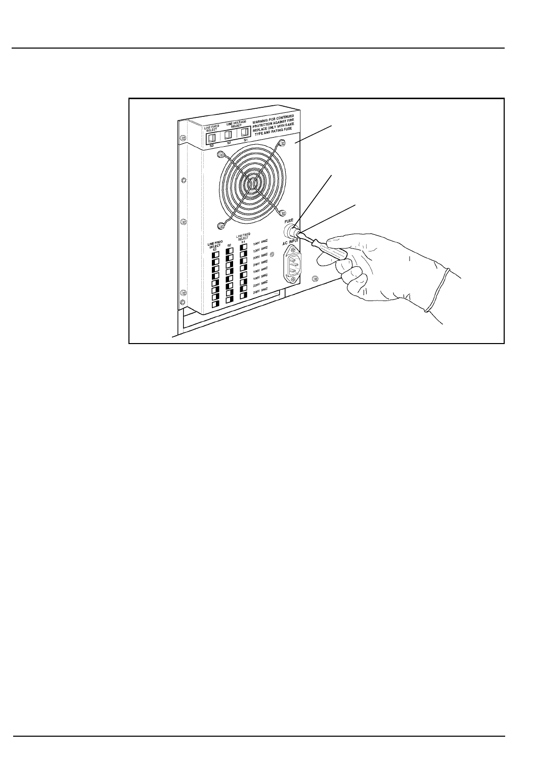
9-64 CELL-DYN® 3200 Operator’s Manual
9140181B — November 1997
Service and Maintenance
Nonscheduled Maintenance Procedures Section 9
Figure 9.19: Fuse Replacement
5. If it has obviously failed, replace it. Note the amp reading
on the fuse and be sure you replace it with the correct
fuse (8-amp or 4-amp).
NOTE: If the power setting is 110/120 VAC, use the
8-amp fuse. If the power setting is 220/240 VAC, use
the 4-amp fuse.
6. If you are not sure if the fuse has failed, replace it and see
if the problem is corrected.
7. To replace a fuse, insert the new fuse (either end) into the
holder. Insert the holder (fuse first) all the way into the
fuse slot.
8. Insert a flathead screwdriver into the notch on the fuse
holder, push in, and turn clockwise to tighten the fuse
holder.
9. Reconnect the power cord and turn the system ON.
Preparation for Shipping or Extended Period of Non-Use
The Prepare For Shipping cycle must be run if the instrument
will not be used for two weeks or more. This cycle must also be
run if:
a. The instrument will be shipped OR
Fuse Holder
Fuse Holder Notch
Power Supply
Go Back
Search
TOC

CELL-DYN® 3200 Operator’s Manual 9-65
9140181B — November 1997
Service and Maintenance
Section 9 Nonscheduled Maintenance Procedures
b. The instrument will be moved (for example, to a
different location within a laboratory) and movement
will require detaching the reagent inlet tubing.
Salt deposits and reagent residue may clog the flow system if
they are not removed prior to a prolonged period of inactivity
or shipment. In addition, the tubing should be removed from
behind the Peristaltic Pump and from all of the Normally
Closed Valves. Leaving this tubing in the pump and in the
valves while the instrument is inactive may cause it to crimp
permanently. The Peristaltic Pump and Normally Closed Valves
on the Analyzer flow panel are shown in Figure 9.4.
Materials Required
1. Gloves, lab coat, and safety glasses
2. Phillips-head screwdriver (#2)
3. Disinfectant (cleaning solution); 10% solution of filtered
bleach in deionized water
4. Container with approximately 500 mL of deionized
water.
5. Four plastic bags
If the instrument will be shipped, the following are also
needed:
6. Cardboard Disk Drive Protector
7. Shear valve dummy center section
Procedure
1. In the
MAIN MENU
, press
[SPECIAL PROTOCOLS]
followed by
[MORE]
and
[PREPARE SHIPPING]
.
2. Follow the instructions displayed on the screen.
3. Press the
[PREPARE SHIPPING]
key again to begin the rinse
cycle.
NOTE: The message SPECIAL PROTOCOL CYCLE IN
PROGRESS is displayed during the process.
4. When the process has finished, the message SPECIAL
PROTOCOL CYCLE HAS COMPLETED is displayed.
Go Back
Search
TOC

9-66 CELL-DYN® 3200 Operator’s Manual
9140181B — November 1997
Service and Maintenance
Nonscheduled Maintenance Procedures Section 9
If the reagent lines were cleaned because contamination
was suspected and the operator intends to continue
processing patient samples, do not perform any of the
remaining steps. Instead, reconnect the reagent lines, go to
the
RUN
screen, and run background counts until the
counts are acceptable.
5. Turn the main power switch OFF. Also turn OFF power to
the Display Monitor, printers, and any other devices
attached to the instrument.
6. Press the upper right corner of the Left Front Cover to
release the cover latch and swing the cover open. Press
the upper left corner of the Right Front Cover to release
the cover latch and swing the cover open. Press the
window on the Tower Cover to release the cover latch.
Lift the cover up and off the instrument (Tower Door on
the CS model must be open).
a. On the CS model, remove the four Phillips-head
screws holding the Front Skirt to the instrument and
remove the skirt.
b. On the SL model, remove the four Phillips-head
screws holding the Sample Loader to the instrument
and pull the loader away from the Analyzer
approximately 2-3 inches to allow easy access to all
the Normally Closed Valves.
7. Carefully remove the tubing from all the Normally
Closed Valves on the Flow Panel. Do not detach the
tubing. If necessary, refer to Figure 9.4 for the location of
these valves.
8. Carefully remove the tubing from behind the Sample
Transfer Peristaltic Pump. Do not detach the tubing. If
necessary, refer to Figure 9.6.
9. Remove all three Reagent Tubing lines, Waste Tubing line,
and the Waste Sensor line from their fittings on the rear
of the Analyzer. The waste line should be emptied and
rinsed with disinfectant.
10. Place each length of tubing in a separate protective plastic
bag and close the bag. (Keep the Waste line and Waste
Sensor line together.)
NOTE: Keep all tubing lines clean to prevent
contamination.
11. Place the plastic bags containing the reagent and waste
tubing in the Accessory Kit.
Go Back
Search
TOC

CELL-DYN® 3200 Operator’s Manual 9-67
9140181B — November 1997
Service and Maintenance
Section 9 Nonscheduled Maintenance Procedures
12.Wipe the instrument with the disinfectant prepared
earlier.
If the instrument will be shipped, the following steps
should also be done.
13.Insert the cardboard Disk Drive Protector into the Floppy
Disk Drive (after removing any disk).
14.Remove and clean the Shear Valve as directed in Shear
Valve Cleaning under Nonscheduled Maintenance
Procedures.
15.After the Shear Valve has been cleaned and dried, wrap
the ceramic center section carefully for protection and
place it in the Accessory Kit.
16.Obtain the Shear Valve Dummy Center section from the
Accessory Kit. Reassemble the Shear Valve on the
instrument using the dummy center section.
17.Remove the Analyzer power cord from its connector on
the rear of the Analyzer and from the outlet receptacle.
Place the cord in the Accessory Kit.
18.Remove the Display Monitor power cord from its outlet
receptacle and secure it to the monitor.
19.Detach the Display Monitor Video Cable and the
Membrane Keypad Interface Cable from their respective
connectors on the Data Module and secure the cables to
the monitor.
20.Detach the Data Station Interface Cable from the back of
the Analyzer.
21.Close the Left and Right Front Covers and press into
place. Reattach the Tower Cover and press into place
(Tower Door on the CS model must be open).
a.On the CS model, reattach the Front Skirt using the
four Phillips-head screws. Do not pinch the tubing at
the bottom.
b.On the SL model, slide the Sample Loader forward
using the center guide to properly align the loader
with the Analyzer. Reattach the loader using the four
Phillips-head screws.
Go Back
Search
TOC
9-68
c. On the
SL
model,
slide the
Sample
Loader
forward
using the
center
guide to
properly
align the
loader
with the
Analyzer.
Reattach
the loader
using the
four
Phillips-
head
screws.
Repackaging for Shipment
When the CELL-
DYN 3200 is to be
shipped and the
CELL-DYN 3200
MAINTENTANCE LOG
Year Month
Daily
Weekly
Day of Month
Semi
Annual
1 3 4 5 7 8 9 10 121314151617181920212223242526272829303126 11
N
on
S
c
h
e
d
ule
d
Run Auto-Clean
Clean Aspiration Needle
Clean Tower
Clean Shear Valve
Clean Exterior of Aspiration Probe
Check Sample Pump Tubing
Clean Fan Filters
Clean Printer
Run Extended Auto-Clean
Clean Interior of Aspiration Probe
Unclog Aspiration Probe
Clean Interior of Aspiration Needle
Unclog Aspiration Needle
Clean WBC Lyse Syringe
Clean Sample Injection Syringe
Clean Sample Loader
Monthly
Clean HGB Lyse Syringe
Clean Diluent/Sheath Syringe
Clean HGB Flow Cell
Clean Bar Code Reader Window
Clean Reagent Lines
Replace Aspiration Probe
Replace Tubing in Transfer Pump
Replace Tubing in NC Valves
Replace Sample Injection Syringe
Replace WBC Lyse Syringe
Replace Diluent/Sheath Syringe
Replace Aspiration Needle
Replace HBC Lyse Syringe
Replace Fuse
Prepare for Shipping/Non-Use
Calibration
Go Back
Search
TOC

CELL-DYN® 3200 Operator’s Manual 10-1
9140181B — November 1997
Troubleshooting and Diagnostics
Section 10 Overview
Overview
This section gives instructions for identifying, troubleshooting
and correcting instrument problems. It is intended as a referral
guide for customer troubleshooting and optimal instrument
operation. The CELL-DYN® 3200 continuously monitors the
status of the system and displays pertinent information in the
Status Box or on the Bulletin Line. If a problem is detected, the
Status Box displays FAULT: SEE DIAG or SEE SPECIAL, the
Bulletin Line displays a message and the
FAULT
indicator light
on the Analyzer status indicator panel is illuminated in red. A
description of the fault can be obtained by pressing the
[FAULT REPORT]
key in the
DIAGNOSTICS MENU
screen.
The first part of this section discusses the
DIAGNOSTICS MENU
keys. The remainder of the section is devoted to the
Troubleshooting Guide.
The Troubleshooting Guide is designed to assist the operator
in identifying and resolving instrument problems. Instructions
are also given for obtaining technical assistance from the
Abbott Customer Support Center. The Guide includes
Troubleshooting Procedures, Instructions for Component
Replacement and Troubleshooting Tips and Techniques. The
last part of this section describes the Instrument Messages and
Fault Conditions. The tables in this section include
instructions for corrective action.
Go Back
Search
TOC

10-2 CELL-DYN® 3200 Operator’s Manual
9140181B — November 1997
Troubleshooting and Diagnostics
Overview Section 10
NOTES
Go Back
Search
TOC
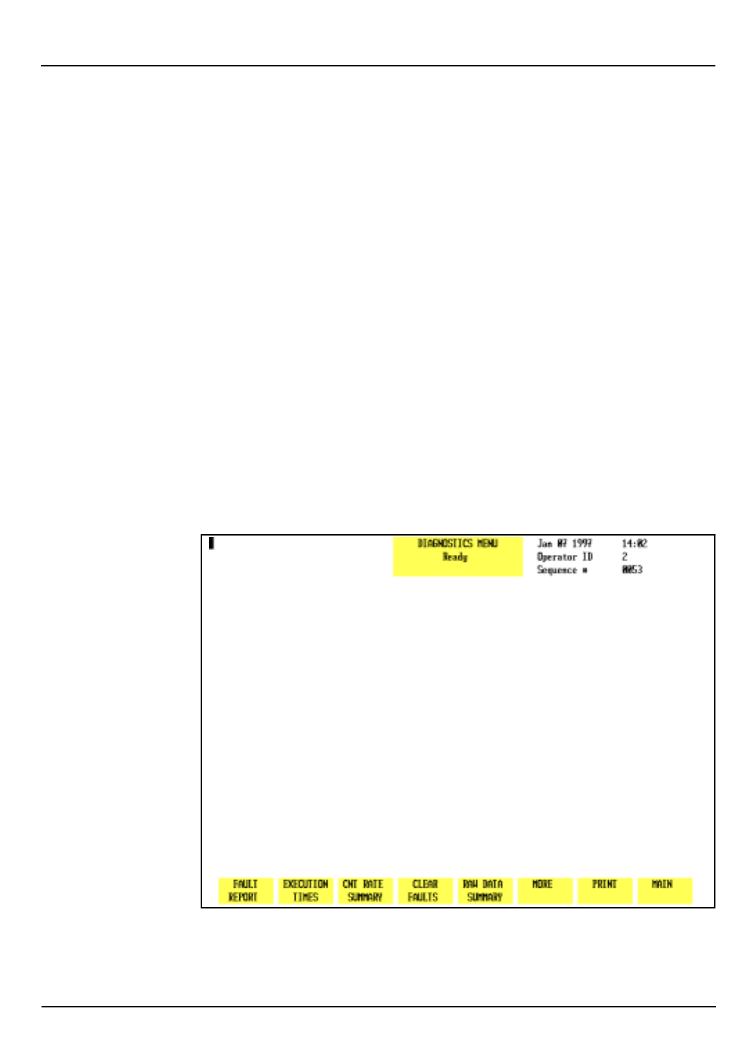
CELL-DYN® 3200 Operator’s Manual 10-3
9140181B — November 1997
Troubleshooting and Diagnostics
Section 10 Diagnostics Menu
Diagnostics Menu
Overview
This subsection describes the soft keys available from the
DIAGNOSTICS MENU
screens. These keys enable the operator or
service representative to obtain information and execute
programs that assist in troubleshooting and identify corrective
action.
Several keys listed are described “For Service Use Only.” The
data these keys provide is meaningful only to trained field
engineers and is not useful to the operator. If certain keys are
pressed inadvertently, the system may have to be re-initialized.
There are five primary screens in the
DIAGNOSTICS MENU
. For
ease of explanation, a diagram depicting the keys and
functions available in each primary screen is shown below.
Figure 10.1: First Diagnostics Menu Screen
Go Back
Search
TOC
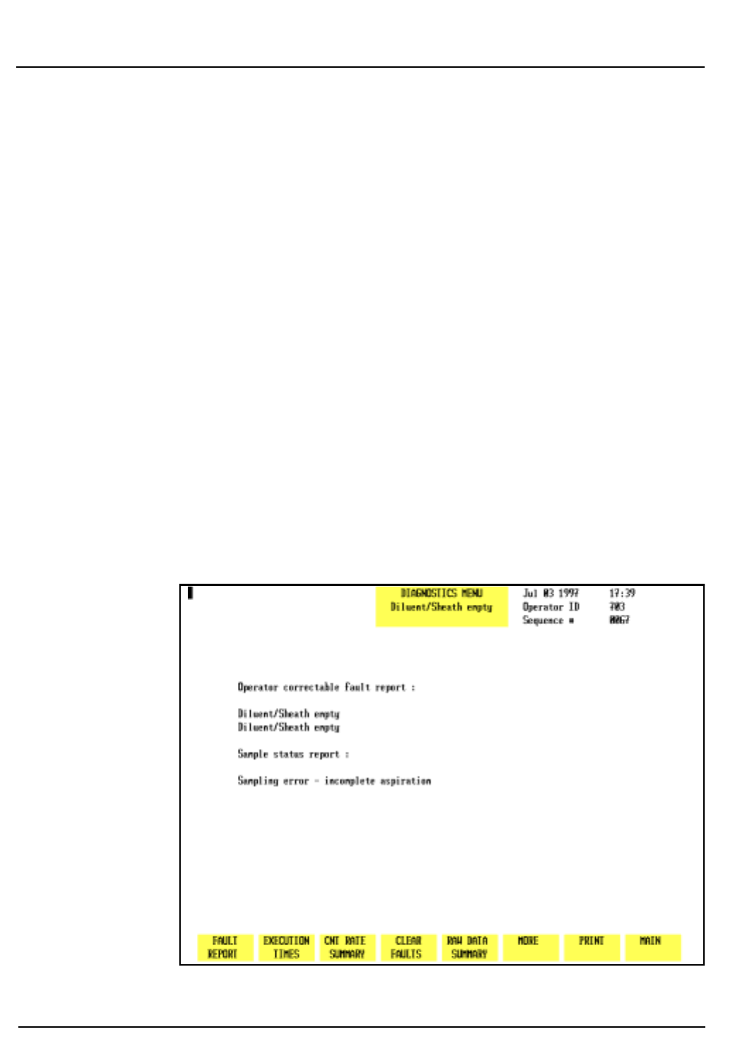
10-4 CELL-DYN® 3200 Operator’s Manual
9140181B — November 1997
Troubleshooting and Diagnostics
Diagnostics Menu Section 10
Diagnostics Menu Screen
The first
DIAGNOSTICS MENU
screen (see Figure 10.1) and the
following soft key labels are displayed when the
[DIAGNOSTICS]
key is pressed:
FAULT REPORT
EXECUTION TIMES
CNT RATE SUMMARY
CLEAR FAULTS
RAW DATA SUMMARY
MORE
PRINT
MAIN
Fault Report
When the
[FAULT REPORT]
key is pressed, information regarding
the pending fault is displayed on the screen. The screen
displays the words Operator Correctable Fault Report:
(see Figure 10.2) or Fatal Fault Report: (see Figure 10.3)
and any additional information available. If there is no fault,
the screen displays the words No Fault Pending. (See Figure
10.4.)
Figure 10.2: Operator Correctable Fault Report Screen
Go Back
Search
TOC
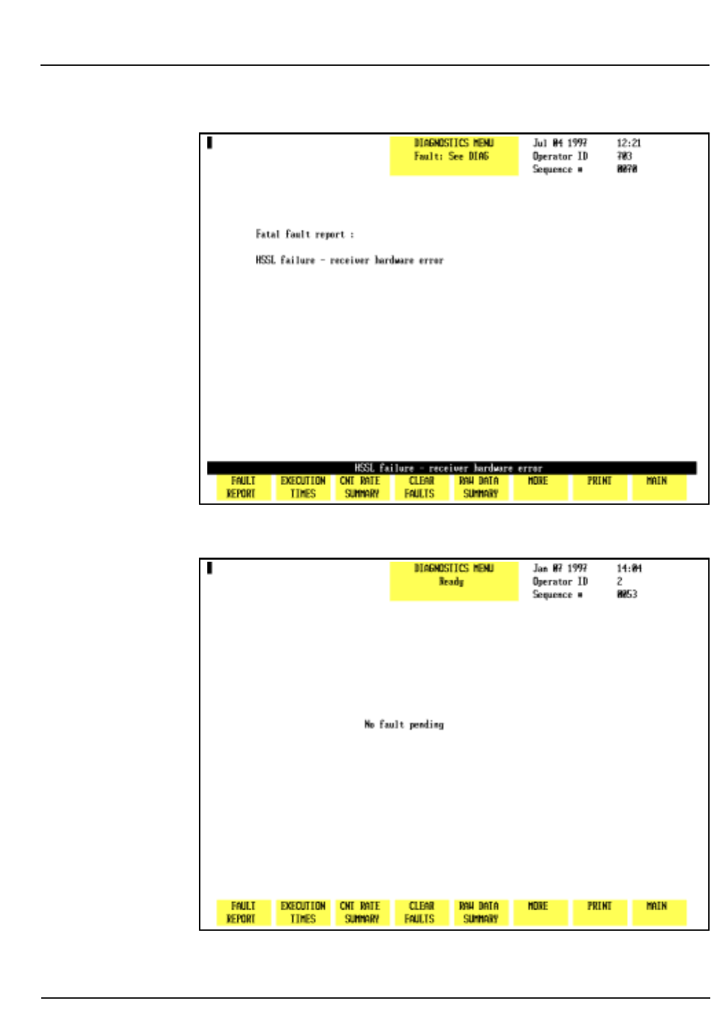
CELL-DYN® 3200 Operator’s Manual 10-5
9140181B — November 1997
Troubleshooting and Diagnostics
Section 10 Diagnostics Menu
Figure 10.3: Fatal Fault Report Screen
Figure 10.4: Fault Report — No Fault Pending Screen
Go Back
Search
TOC
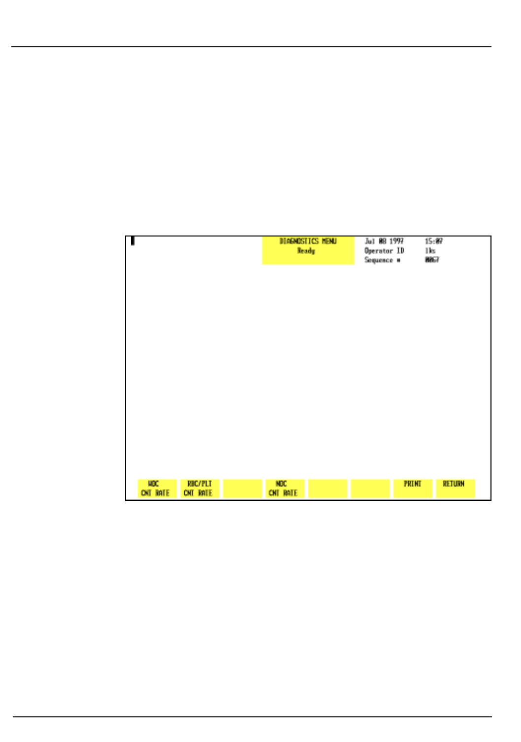
10-6 CELL-DYN® 3200 Operator’s Manual
9140181B — November 1997
Troubleshooting and Diagnostics
Diagnostics Menu Section 10
Operator correctable faults (for example, waste full, diluent
empty) can be cleared by pressing the
[CLEAR FAULT]
key after
taking corrective action. After corrective action for a fatal fault,
the system must be reinitialized by pressing the
[INITIALIZATION]
soft key in the second
DIAGNOSTICS MENU
screen (refer to Figure
10.9).
Execution Times
This key is for service use only.
Figure 10.5: Count Rate Summary Screen
CNT Rate Summary
When the
[CNT RATE SUMMARY]
key is pressed, the following soft
key labels (see Figure 10.5) are displayed:
WOC CNT RATE/WOC CNT GRAPH/WOC CNT DATA *
RBC/PLT CNT RATE/RBC/PLT CNT GRAPH/RBC/PLT CNT DATA *
NOC CNT RATE/NOC CNT GRAPH/NOC CNT DATA *
PRINT
RETURN
* Key labels alternate between the selections.
Go Back
Search
TOC
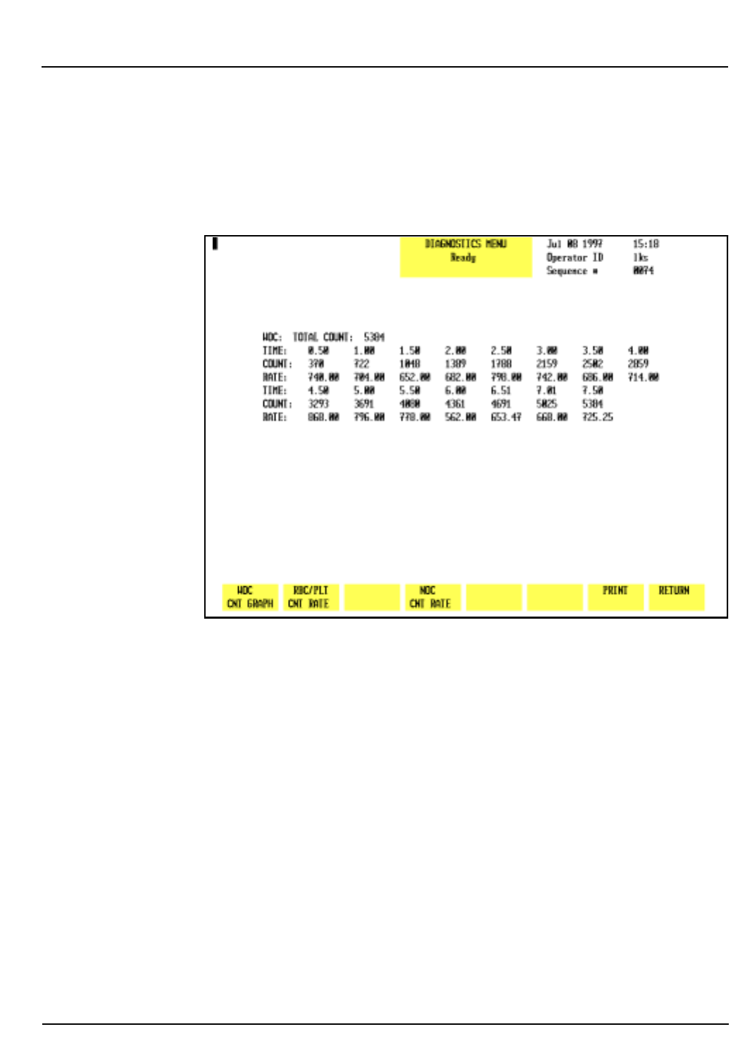
CELL-DYN® 3200 Operator’s Manual 10-7
9140181B — November 1997
Troubleshooting and Diagnostics
Section 10 Diagnostics Menu
NOTE: Once a
[CNT RATE]
key is pressed, that key
toggles between
[CNT DATA]
and
[CNT GRAPH]
until the
operator exits the screen. The keys then revert to
[CNT RATE]
.
Figure 10.6: WOC Count Rate Data
Each key displays kinetic data for the selected parameter from
the last cycle run. When each key is pressed, the count rate
data is displayed (see Figure 10.6) and the key label changes to
[CNT GRAPH]
for that parameter.
Count rate data from the last cycle is displayed in a tabular
format. The total count, time segments and rate per second are
displayed for multiple data points from that cycle. (See Figure
10.6.) When the
[CNT GRAPH]
key for a particular parameter is
pressed, the rate-per-second data is displayed as a graph. (See
Figure 10.7.) The kinetic data and graph are useful when
troubleshooting problems related to these parameters.
Go Back
Search
TOC
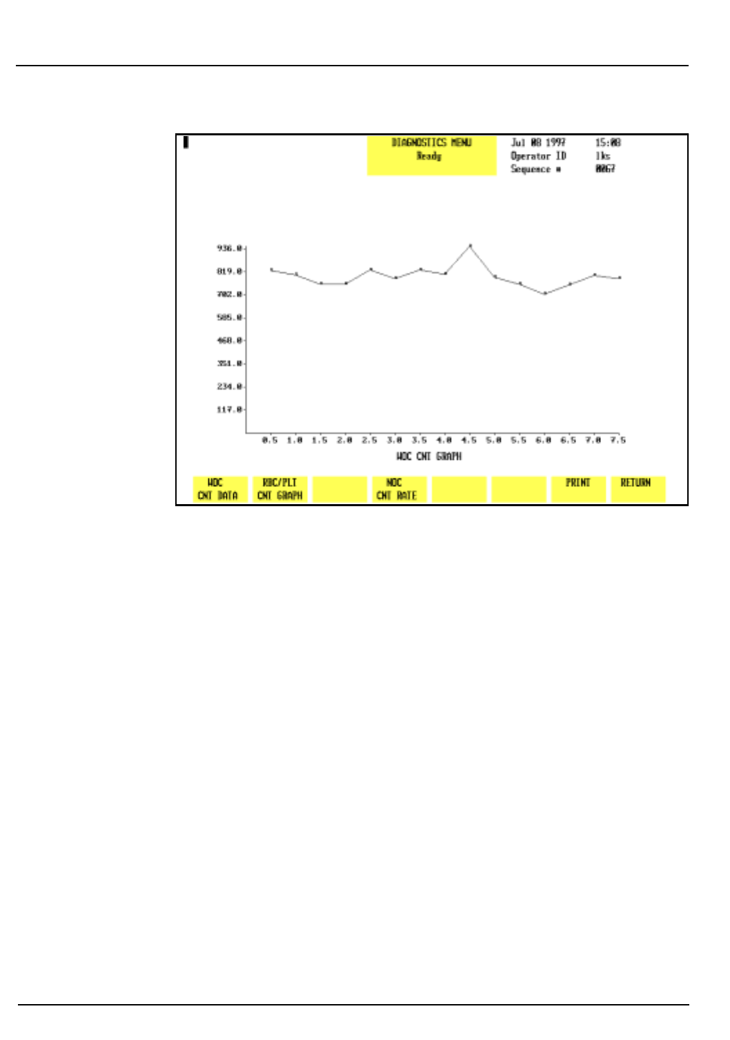
10-8 CELL-DYN® 3200 Operator’s Manual
9140181B — November 1997
Troubleshooting and Diagnostics
Diagnostics Menu Section 10
Figure 10.7: WOC Count Rate Graph
Clear Faults
When the
[CLEAR FAULTS]
key is pressed, the Analyzer returns to
the READY state if the corrective action taken resolved the
problem. If the corrective action did not correct the problem,
the fault status does not change.
NOTE: Only operator correctable faults can be cleared
with the
[CLEAR FAULTS]
key.
Go Back
Search
TOC
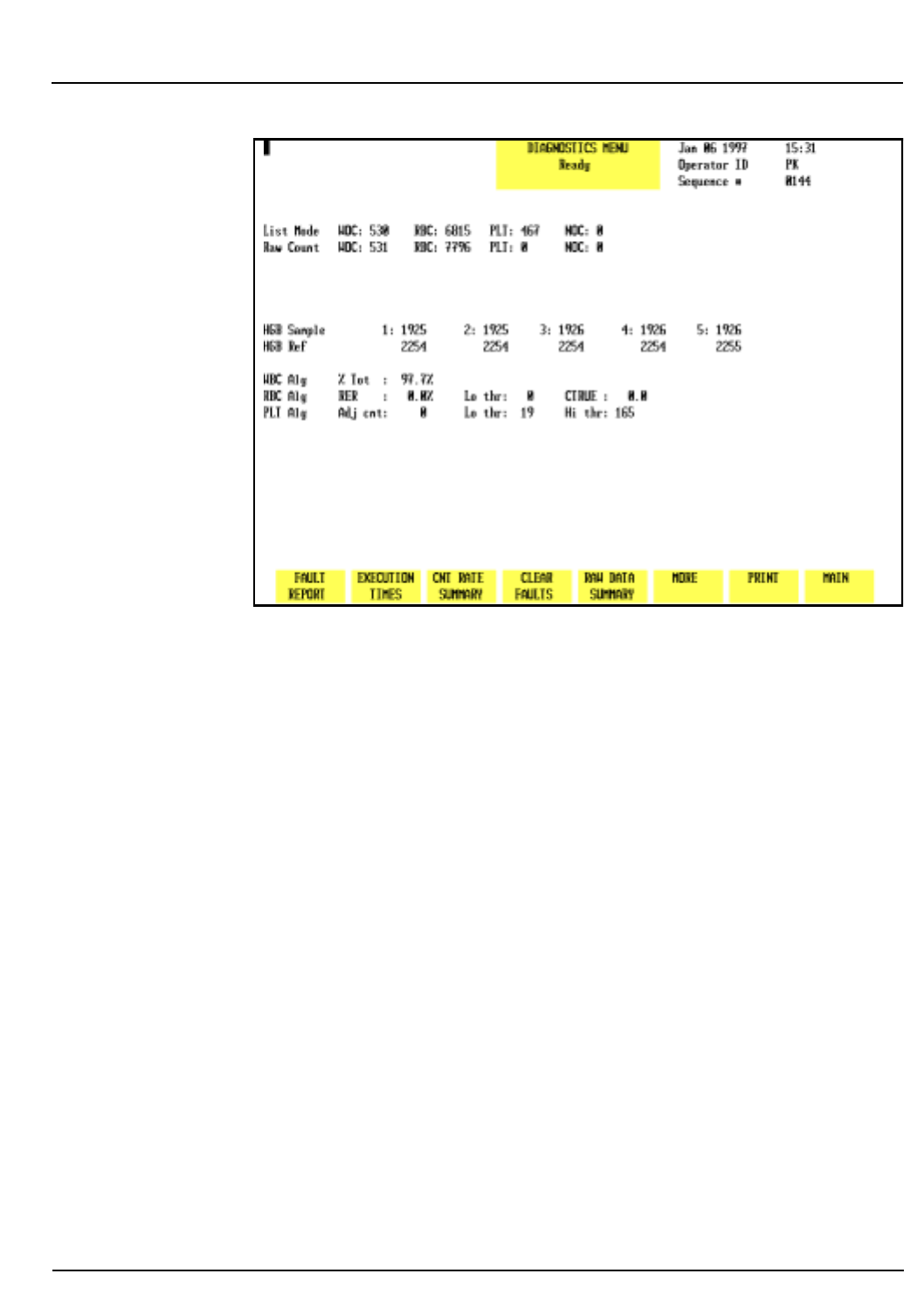
CELL-DYN® 3200 Operator’s Manual 10-9
9140181B — November 1997
Troubleshooting and Diagnostics
Section 10 Diagnostics Menu
Figure 10.8: Raw Data Summary Screen
Raw Data Summary
When the
[RAW DATA SUMMARY]
key is pressed, detailed
information pertaining to the last cycle run is displayed. An
example of the
RAW DATA SUMMARY
screen is shown in Figure
10.8.
The HGB Reference and Sample readings may be used to assist
in troubleshooting erratic or imprecise HGB results.
More
When the
[MORE]
key is pressed, the second
DIAGNOSTICS MENU
screen is displayed. The
[MORE]
keys on the remaining screens
to be discussed always display the next
DIAGNOSTICS MENU
screen.
Print
When the
[PRINT]
key is pressed, a Diagnostic Report is printed.
This report contains information pertinent to the data
displayed on the screen at the time the key is pressed. If no
data is displayed on the screen, the report prints the current
fault status.
The
[PRINT]
key functions in this way on each screen.
Therefore, it will not be discussed again in this section.
Go Back
Search
TOC
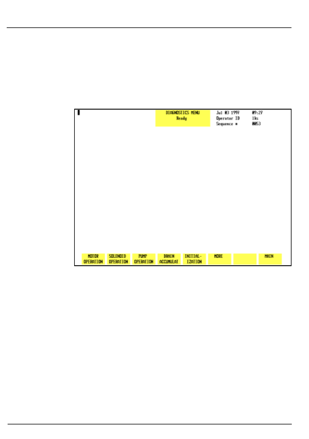
10-10 CELL-DYN® 3200 Operator’s Manual
9140181B — November 1997
Troubleshooting and Diagnostics
Diagnostics Menu Section 10
Main
The
[MAIN]
key is used to return to the
MAIN MENU
screen. The
[MAIN]
key appears on each primary
DIAGNOSTICS MENU
screen
and works the same way on each screen. Consequently, it will
not be discussed again in this section.
Figure 10.9: Second Diagnostics Menu Screen
Second Diagnostics Menu Screen
When the
[MORE]
key on the first
DIAGNOSTICS MENU
screen is
pressed, the second
DIAGNOSTICS MENU
screen (see Figure 10.9)
and the following soft key labels are displayed:
MOTOR OPERATION
SOLENOID OPERATION
PUMP OPERATION
DRAIN ACCUMULAT
INITIALIZATION
MORE
MAIN
Go Back
Search
TOC
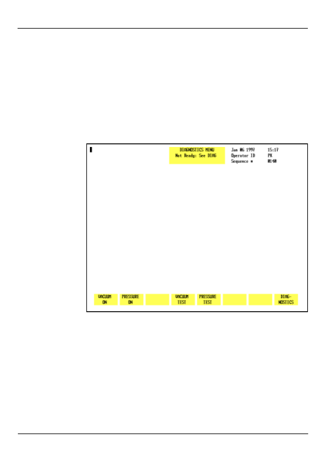
CELL-DYN® 3200 Operator’s Manual 10-11
9140181B — November 1997
Troubleshooting and Diagnostics
Section 10 Diagnostics Menu
Motor Operation
This key should be used only by an authorized Abbott
representative. The system must be initialized after this key is
pressed.
Solenoid Operation
This key should be used only by an authorized Abbott
representative. The system must be initialized after this key is
pressed.
Figure 10.10: Pump Operation Screen
Pump Operation
When the
[PUMP OPERATION]
key is pressed, the following soft
key labels (see Figure 10.10) are displayed:
VACUUM ON/VACUUM OFF
(The key label alternates
between the selections.)
PRESSURE ON/PRESSURE OFF
(The key label alternates
between the selections.)
Go Back
Search
TOC
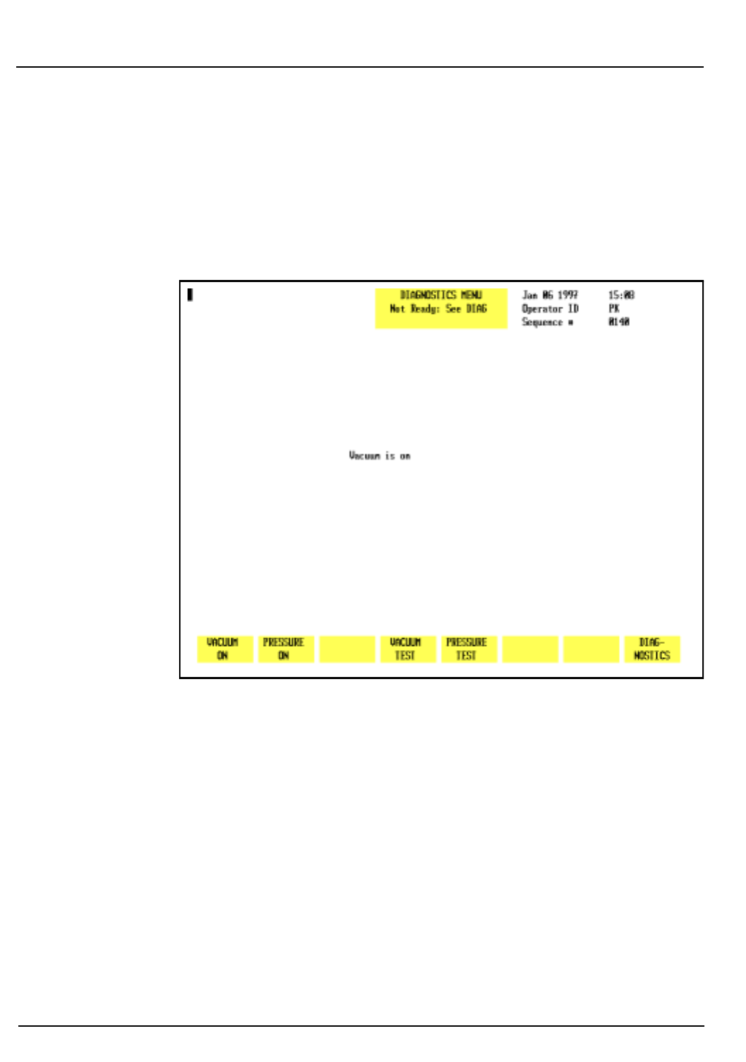
10-12 CELL-DYN® 3200 Operator’s Manual
9140181B — November 1997
Troubleshooting and Diagnostics
Diagnostics Menu Section 10
INHIBIT PUMPS/ENABLE PUMPS
(Displayed when VACUUM
or PRESSURE keys are
pressed.)
VACUUM TEST
PRESSURE TEST
DIAGNOSTICS
Figure 10.11: Pump Operation Screen — Vacuum ON
Vacuum On
When the
[VACUUM ON]
key is pressed, the key label changes to
[VACUUM OFF]
, the vacuum pump is turned ON and the screen
displays the message Vacuum Is On. (See Figure 10.11.) Press
the
[VACUUM OFF]
key to turn the pump OFF.
NOTE: The pump is automatically turned OFF and
control of the pump is returned to the instrument
when the screen is exited.
This key is useful for troubleshooting vacuum problems. If the
pump does not turn ON when the key is pressed, the pump
may be the cause of the vacuum problem.
Go Back
Search
TOC
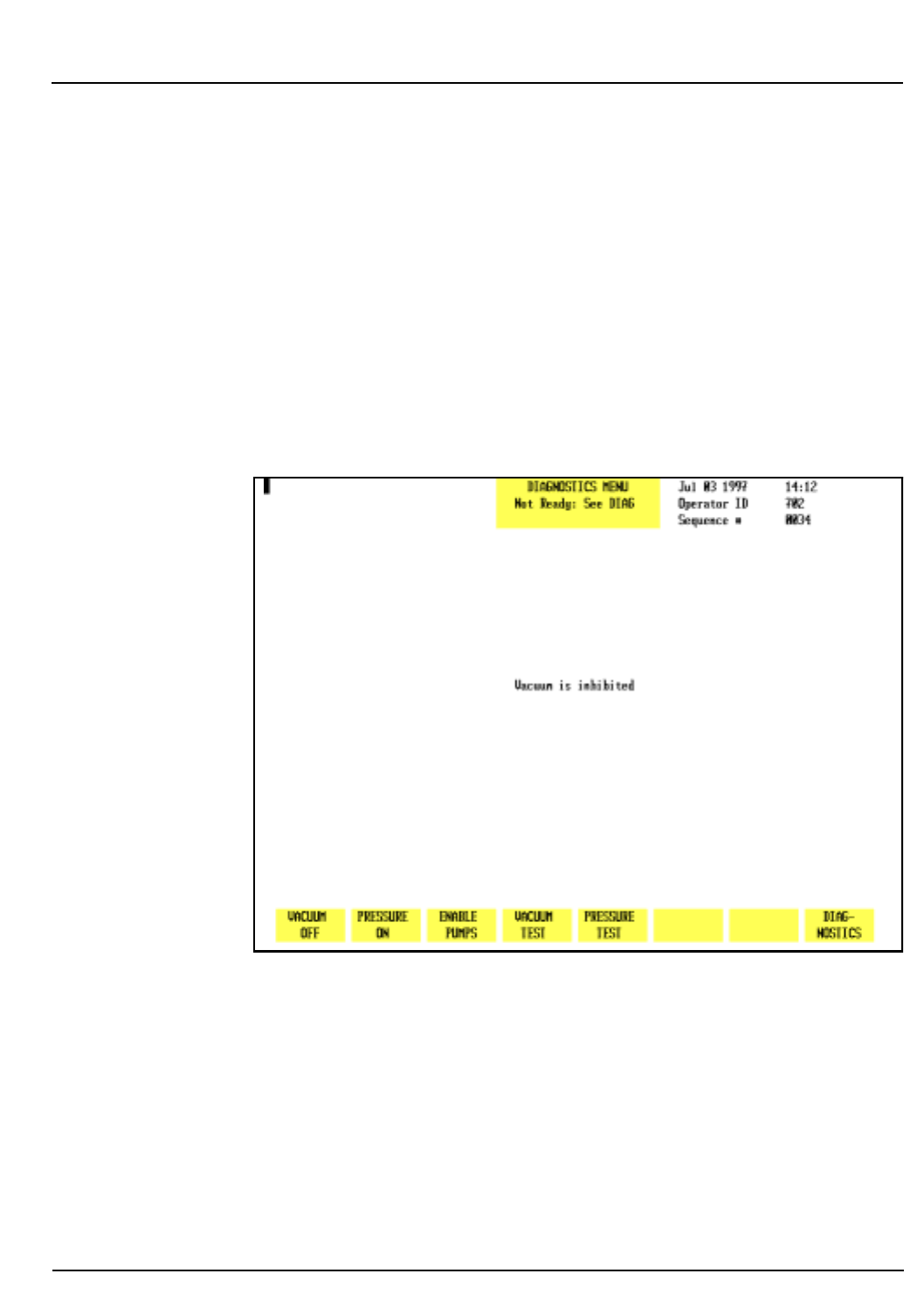
CELL-DYN® 3200 Operator’s Manual 10-13
9140181B — November 1997
Troubleshooting and Diagnostics
Section 10 Diagnostics Menu
Pressure On
When the
[PRESSURE ON]
key is pressed, the key label changes
to
[PRESSURE OFF]
, the pressure pump is turned ON and the
screen displays the message Pressure Is On. Press the
[PRESSURE OFF]
key to turn the pump OFF.
NOTE: The pump is automatically turned OFF and
control of the pump is returned to the instrument
when the screen is exited.
This key is useful for troubleshooting pressure problems. If the
pump does not turn ON when the key is pressed, the pump
may be the cause of the pressure problem.
Figure 10.12: Inhibit Pumps Screen
Go Back
Search
TOC
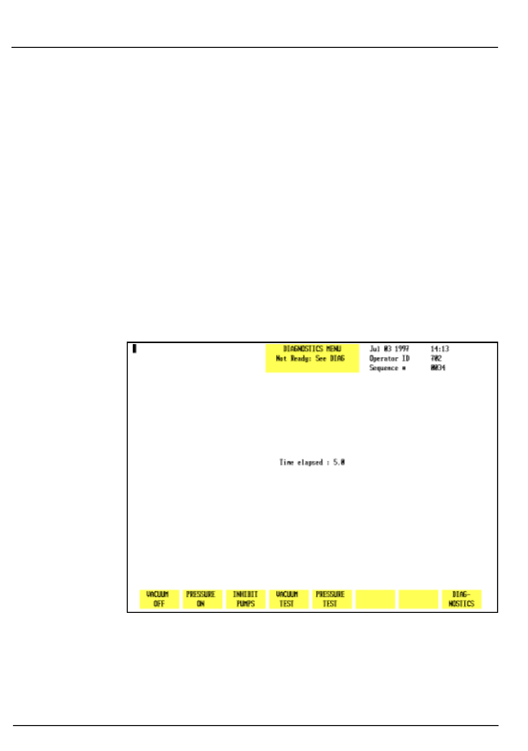
10-14 CELL-DYN® 3200 Operator’s Manual
9140181B — November 1997
Troubleshooting and Diagnostics
Diagnostics Menu Section 10
Inhibit Pumps
When the
[VACUUM]
or
[PRESSURE]
key is pressed, the
[INHIBIT PUMPS]
key appears. (See Figure 10.12.) When the
[INHIBIT PUMPS]
key is pressed, the operation of the pumps is
inhibited (no vacuum and pressure are produced), the screen
displays the message Vacuum Is Inhibited, and the key
label changes to
[ENABLE PUMPS]
. Press the
[ENABLE PUMPS]
key
to enable pump operation.
NOTE: The pumps are automatically enabled and
control of them is returned to the instrument when the
screen is exited, even if the pumps were disabled while
in the screen.
This key is useful when performing maintenance or
troubleshooting procedures that require a vacuum or pressure
line to be removed.
Figure 10.13: Vacuum Test Screen
Go Back
Search
TOC
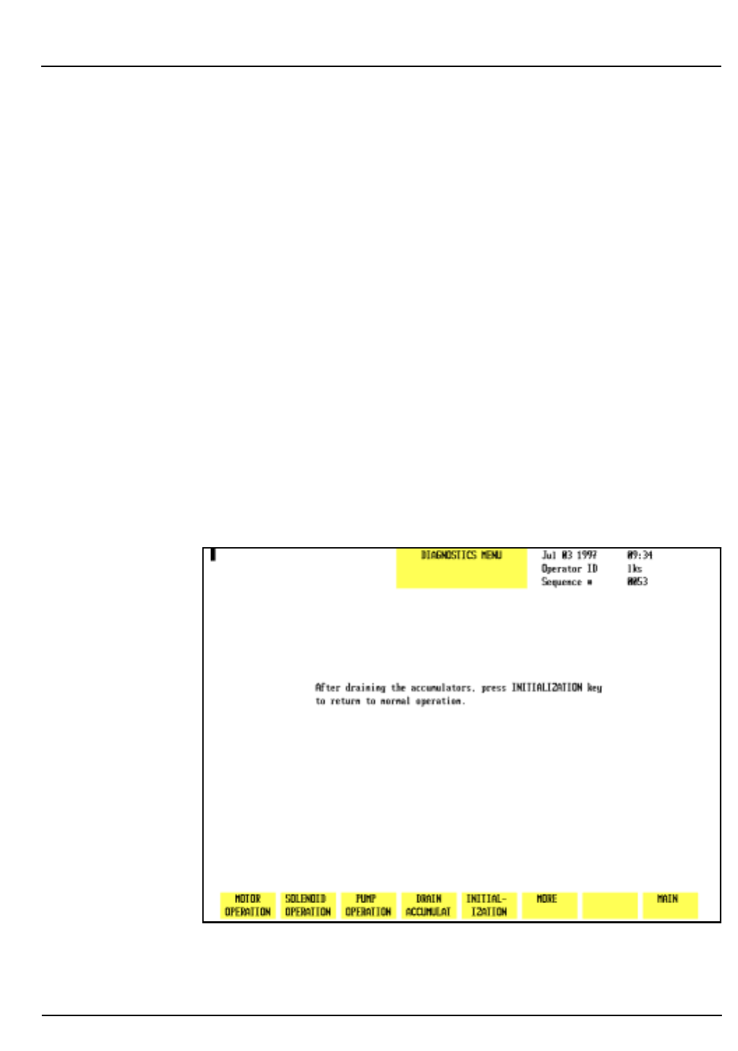
CELL-DYN® 3200 Operator’s Manual 10-15
9140181B — November 1997
Troubleshooting and Diagnostics
Section 10 Diagnostics Menu
Vacuum Test
When the
[VACUUM TEST]
key is pressed, the system releases the
vacuum to atmosphere and then determines the amount of
time required for it to return to the correct level. The key labels
disappear and the incrementing time is displayed on the
screen. (See Figure 10.13.) When the test is finished, the time
stops incrementing and the key labels are displayed.
A vacuum recovery time greater than 5 seconds may indicate a
vacuum problem.
Pressure Test
When the
[PRESSURE TEST]
key is pressed, the system releases
the pressure to atmosphere and then monitors the amount of
time required for it to return to the correct level. The key labels
disappear and the incrementing time is displayed on the
screen. When the test is finished, the time stops incrementing
and the key labels are displayed.
A pressure recovery time greater than 4 seconds may indicate a
pressure problem.
Figure 10.14: Drain Accumulators Screen
Go Back
Search
TOC
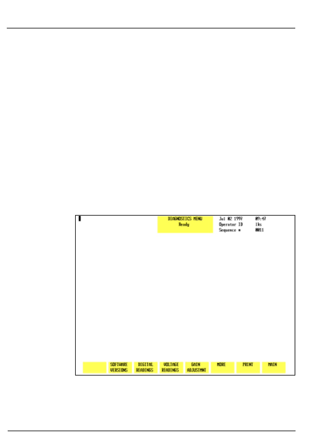
10-16 CELL-DYN® 3200 Operator’s Manual
9140181B — November 1997
Troubleshooting and Diagnostics
Diagnostics Menu Section 10
Drain Accumulat
When the
[DRAIN ACCUMULAT]
key is pressed, the internal
vacuum accumulators are drained of accumulated fluid. This
key is used to correct the “Vacuum Accumulator Wet” fault.
The screen displays (see Figure 10.14) the following message:
After draining the accumulators, press initialization key to
return to normal operation.
When the process is completed, the system must be initialized
and primed. See Initialization below.
Initialization
When the
[INITIALIZATION]
key is pressed, the Analyzer is
initialized. This is necessary when a fatal fault has occurred.
After the Analyzer is initialized, it must be primed. To prime
the Analyzer, go to the
MAIN MENU
and press the
[RUN]
soft key.
Figure 10.15: Third Diagnostics Menu Screen
Go Back
Search
TOC
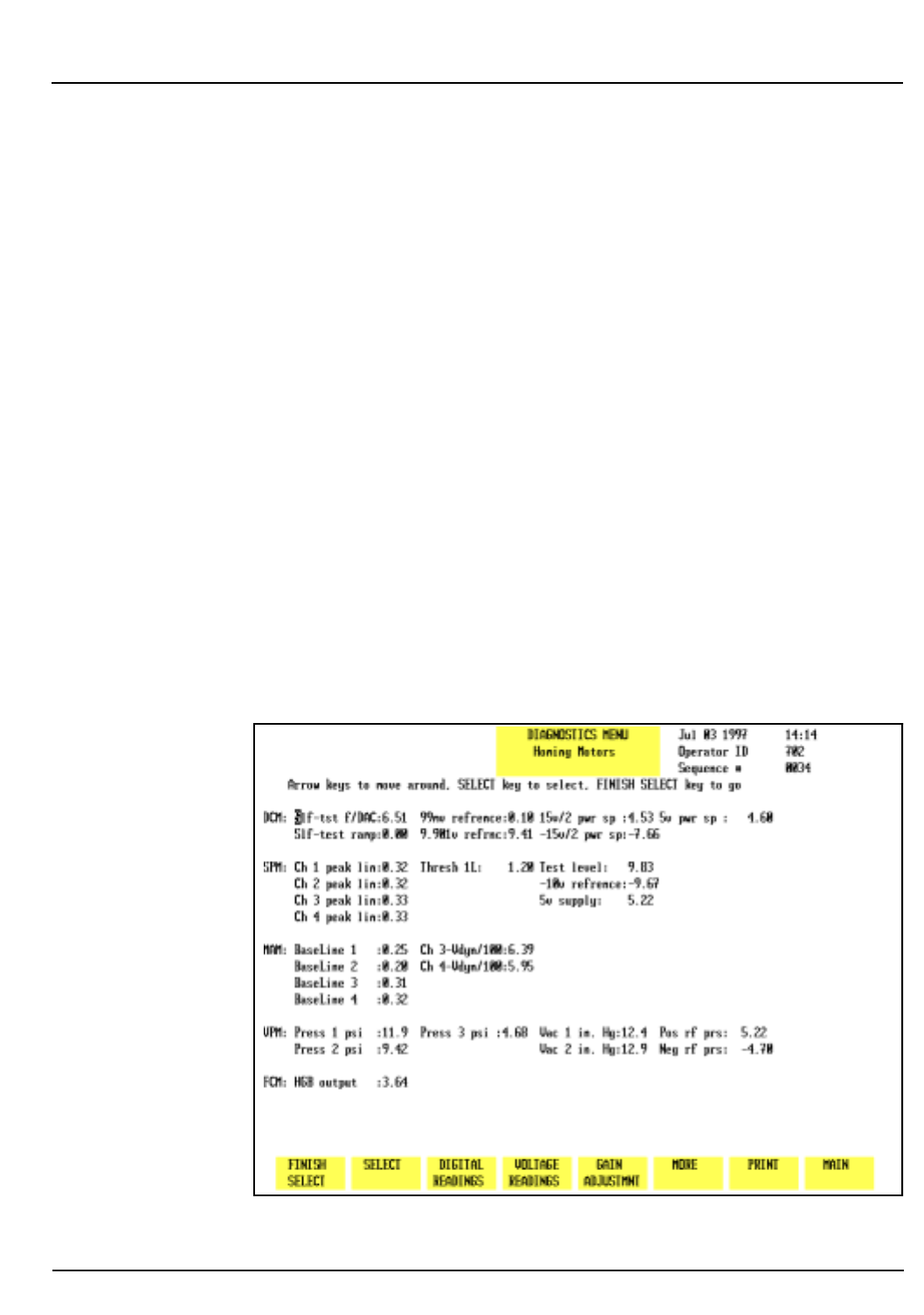
CELL-DYN® 3200 Operator’s Manual 10-17
9140181B — November 1997
Troubleshooting and Diagnostics
Section 10 Diagnostics Menu
More
When the
[MORE]
key is pressed, the third
DIAGNOSTICS MENU
screen is displayed.
Main
The
[MAIN]
key is used to return to the
MAIN MENU
screen.
Third Diagnostics Menu Screen
When the
[MORE]
key in the second
DIAGNOSTICS MENU
is
pressed, the third
DIAGNOSTICS MENU
screen (see Figure 10.15)
and the following soft key labels are displayed:
SOFTWARE VERSION *
DIGITAL READINGS *
VOLTAGE READINGS
GAIN ADJUSTMNT *
MORE
PRINT
MAIN
* These keys are for service use only.
Figure 10.16: Voltage Readings Screen
Go Back
Search
TOC

10-18 CELL-DYN® 3200 Operator’s Manual
9140181B — November 1997
Troubleshooting and Diagnostics
Diagnostics Menu Section 10
Voltage Readings
When the
[VOLTAGE READINGS]
key is pressed, the voltage and
vacuum/pressure value from a test point, measured at the
moment when the key was pressed, is displayed. (See Figure
10.16.) The following additional soft key labels are displayed:
FINISH SELECT *
SELECT *
* These two keys are for service use only.
The data provided by the
VOLTAGE READINGS
screen can be
useful in determining if a problem is caused by a hardware
malfunction.
More
When the
[MORE]
key is pressed, the fourth
DIAGNOSTICS MENU
screen is displayed.
Print
When the
[PRINT]
key is pressed, a Diagnostic Report is printed.
This report contains information pertinent to the data
displayed on the screen at the time the key is pressed. If no
data is displayed on the screen, the report prints the current
fault status.
Main
The
[MAIN]
key is used to return to the
MAIN MENU
screen.
Fourth Diagnostics Menu Screen
When the
[MORE]
key in the third
DIAGNOSTICS MENU
is pressed,
the fourth
DIAGNOSTICS MENU
screen (see Figure 10.17) and the
following soft key labels are displayed:
WBC DATA *
RBC DATA *
PLT DATA *
NOC DATA *
MORE
PRINT
MAIN
* These keys are for service use only.
Go Back
Search
TOC
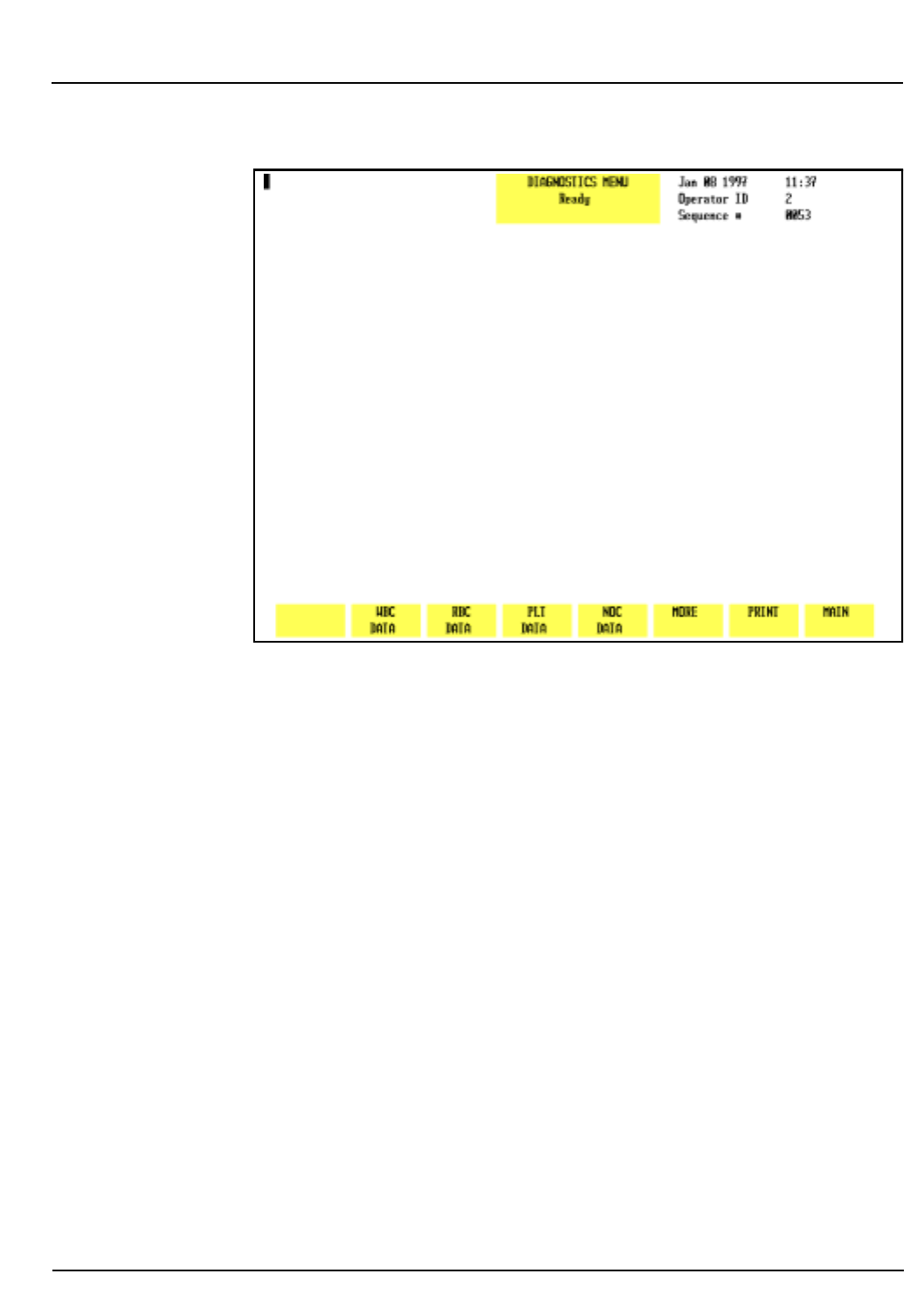
CELL-DYN® 3200 Operator’s Manual 10-19
9140181B — November 1997
Troubleshooting and Diagnostics
Section 10 Diagnostics Menu
Figure 10.17: Fourth Diagnostics Menu Screen
Fifth Diagnostics Menu Screen — CS Model
For CS models, when the
[MORE]
key in the fourth
DIAGNOSTICS
MENU
is pressed, the fifth and last
DIAGNOSTICS MENU
screen (see
Figure 10.18) and the following soft key labels are displayed:
SERIAL TEST
BAR CODE ALIGNMENT *
BAR CODE VERIFY *
TOWER TEST *
TOWER DOOR TEST *
MORE
MAIN
* These keys are for service use only.
Go Back
Search
TOC
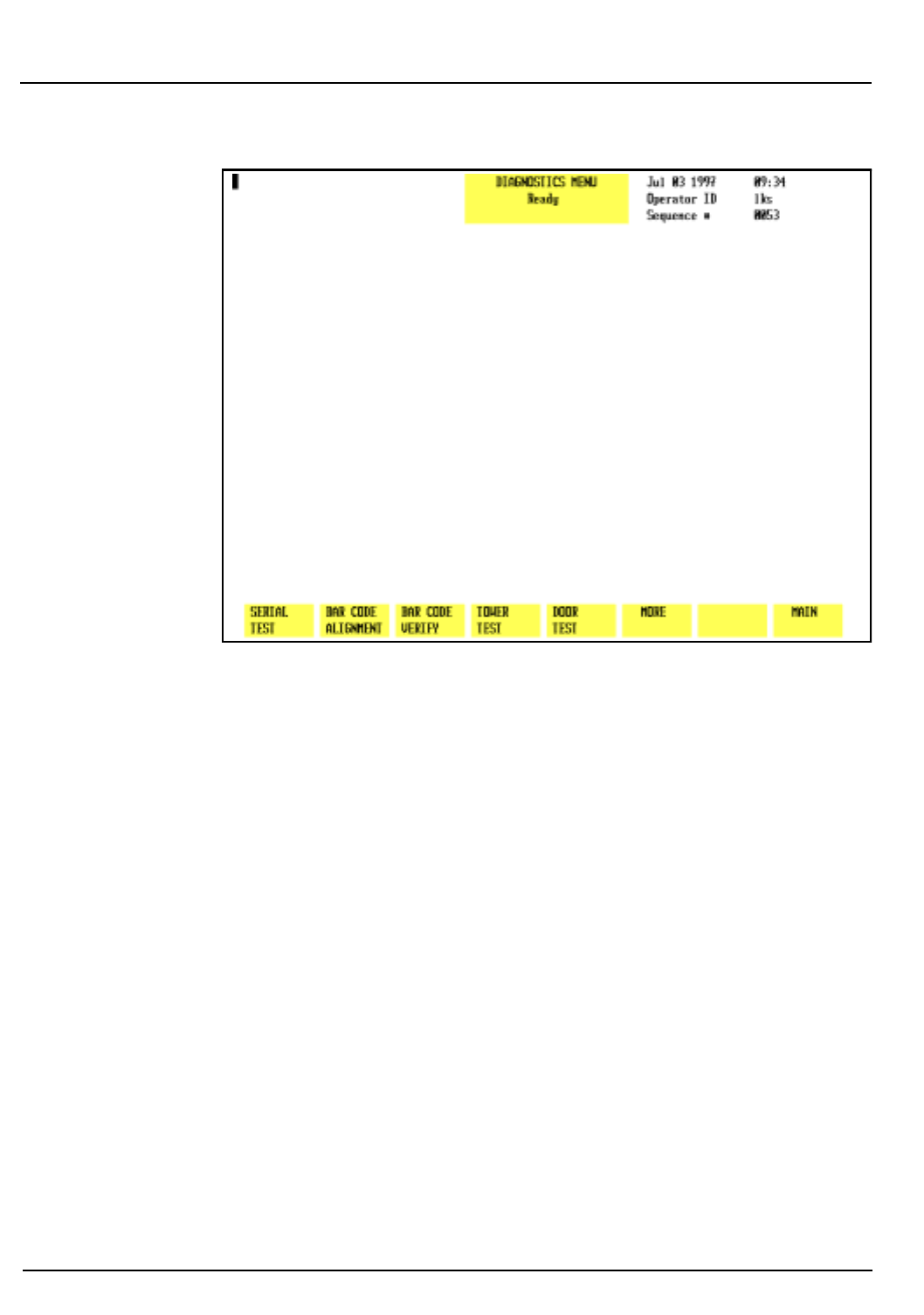
10-20 CELL-DYN® 3200 Operator’s Manual
9140181B — November 1997
Troubleshooting and Diagnostics
Diagnostics Menu Section 10
Figure 10.18: Fifth Diagnostics Menu Screen (CD3200CS)
Serial Test
The
[SERIAL TEST]
key is used to test the functionality of the
COM1 port (referred to as the “serial interface connector”) at
the rear of the instrument. This test is designed to assist in
troubleshooting problems with interfacing to a Laboratory
Information System (LIS). The loop-back connector must be
connected to the COM1 port before performing the test.
NOTE: If the laboratory does not have a LIS, the loop-
back connector may remain connected to the COM1
port for convenience, as it does not interfere with
routine operation. If a LIS is usually connected, the
loop-back connector should be stored near the
instrument when the connector is not in use.
Go Back
Search
TOC
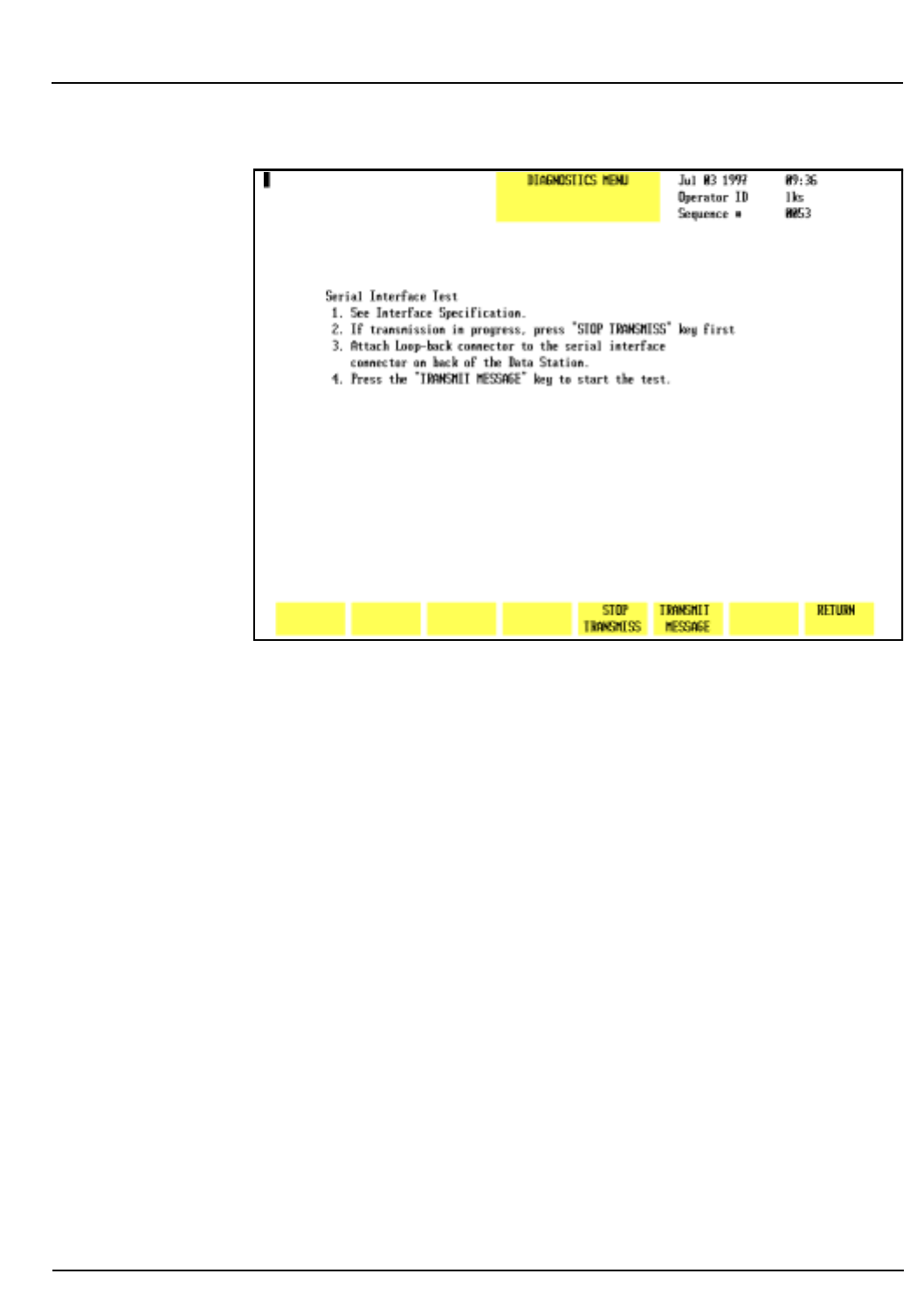
CELL-DYN® 3200 Operator’s Manual 10-21
9140181B — November 1997
Troubleshooting and Diagnostics
Section 10 Diagnostics Menu
Figure 10.19: Serial Test Screen
When the
[SERIAL TEST]
key is pressed, the following soft key
labels (see Figure 10.19) are displayed:
STOP TRANSMISS
TRANSMIT MESSAGE
DIAGNOSTICS
The screen displays the following:
Serial Interface Test
1. See Interface Specification.
2. If transmission in progress, press
[STOP TRANSMISS]
key
first.
3. Attach Loop-back Connector to the serial interface
connector on back of the Data Station.
4. Press the
[TRANSMIT MESSAGE]
key to start the test.
Go Back
Search
TOC
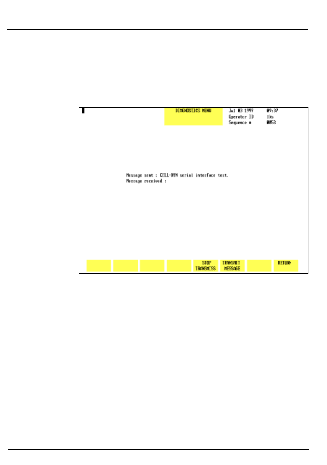
10-22 CELL-DYN® 3200 Operator’s Manual
9140181B — November 1997
Troubleshooting and Diagnostics
Diagnostics Menu Section 10
Stop Transmiss
The
[STOP TRANSMISS]
key is used to stop any transmission that
is in progress to a LIS. When the key is pressed, any
transmission in progress is aborted.
Figure 10.20: Serial Test Transmit Message Screen
Transmit Message
When the
[TRANSMIT MESSAGE]
key is pressed, the message
“CELL-DYN serial interface test” is transmitted from
the Analyzer to the COM1 port, through the loop-back
connector and back to the Analyzer. The screen (see Figure
10.20) displays the message:
MESSAGE SENT: CELL-DYN serial interface test.
If the test is successful, the screen displays the message:
MESSAGE RECEIVED: CELL-DYN serial interface test.
This message indicates that the Data Station is communicating
properly. If the test is not successful, no message appears.
Go Back
Search
TOC
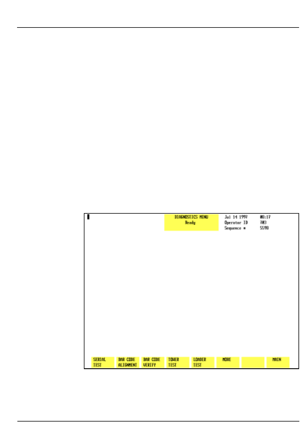
CELL-DYN® 3200 Operator’s Manual 10-23
9140181B — November 1997
Troubleshooting and Diagnostics
Section 10 Diagnostics Menu
MORE
When the
[MORE]
key is pressed in the fifth
DIAGNOSTICS MENU
screen, the first
DIAGNOSTICS MENU
screen is again displayed.
Fifth Diagnostics Menu Screen — SL Model
For SL models, when the
[MORE]
key in the fourth
DIAGNOSTICS
MENU
is pressed, the fifth and last
DIAGNOSTICS MENU
screen (see
Figure 10.21) and the following soft key labels are displayed:
SERIAL TEST
BAR CODE ALIGNMENT *
BAR CODE VERIFY *
TOWER TEST *
LOADER TEST *
MORE
MAIN
* These keys are for service use only.
Figure 10.21:Fifth Diagnostics Menu Screen (CD3200SL)
The
[SERIAL TEST]
and
[MORE]
keys function in a similar manner
to that described in section Fifth Diagnostics Menu Screen —
CS Model.
Go Back
Search
TOC

10-24 CELL-DYN® 3200 Operator’s Manual
9140181B — November 1997
Troubleshooting and Diagnostics
Diagnostics Menu Section 10
NOTES
Go Back
Search
TOC

CELL-DYN® 3200 Operator’s Manual 10-25
9140181B — November 1997
Troubleshooting and Diagnostics
Section 10 Troubleshooting Guide
Troubleshooting Guide
Introduction to Troubleshooting
Good troubleshooting skills are learned by using a logical,
step-by-step approach to problem solving. The first step in the
process is understanding normal instrument operation and
preventative maintenance. A good working knowledge of the
instrument is essential for identifying and resolving
operational problems.
Logical troubleshooting may be divided into three steps:
1. Problem Identification
2. Problem Isolation
3. Corrective Action
Step 1, the problem identification step, is not only identifying
what is wrong but also noting what is right. The investigation
should identify the problem area and eliminate areas that are
working correctly. Once this is done, the troubleshooting
process moves quickly to the next step.
Step 2, Problem Isolation, further classifies the problem.
Instrument problems are generally divided into three
categories:
Hardware — component related
Software — computer program related
Measurement — related to sample analysis
Typically, hardware and software problems are corrected by an
authorized service representative. Measurement problems are
generally operator correctable. This category is further
subdivided into problems related to Sample Handling,
Maintenance or Calibration.
Step 3, Corrective Action, involves taking appropriate action
to correct the problem. If the operator can correct the
problem, with or without technical assistance, normal
operation can quickly resume.
Go Back
Search
TOC

10-26 CELL-DYN® 3200 Operator’s Manual
9140181B — November 1997
Troubleshooting and Diagnostics
Troubleshooting Guide Section 10
This Troubleshooting Guide is designed to enhance the
troubleshooting process by providing information to assist in
problem identification, isolation and corrective action.
NOTE: Generally, conditions that are instrument- or
reagent-related will occur on all samples, including
controls. Therefore, it is important to confirm
instrument performance by rerunning controls and/or
additional patient specimens.
Obtaining Technical Assistance
Technical Assistance is obtained by calling the CELL-DYN
Customer Support Center. It is important to provide the
Customer Support Specialist with a clear and detailed
description of the problem. When assistance is needed, please
be prepared to provide the following information for the
Customer Support Specialist:
1. Instrument Model Name
2. Serial number of the Analyzer
3. Description of the problem
4. The lot numbers and expiration dates of the CELL-DYN
reagents and controls currently in use
5. Examples of sufficient data to facilitate the discussion
Customer Support
United States: 1 (800) CELL DYN or 1 (800) 235-5396
Abbott Diagnostics Customer Support Center:
5440 Patrick Henry Drive
Santa Clara, CA 95054
Canada: 1(800) 387-8378
International: Call your local customer support representative.
Go Back
Search
TOC

CELL-DYN® 3200 Operator’s Manual 10-27
9140181B — November 1997
Troubleshooting and Diagnostics
Section 10 Troubleshooting Procedures
Troubleshooting Procedures
The procedures in this section are for troubleshooting
purposes only. A specific procedure should be performed
under one of the following conditions:
1.To correct a problem described in this section
2.At the request of an Abbott Customer Support Specialist.
WARNING: Potential Biohazard. Follow established
biosafety practices when performing maintenance,
service or troubleshooting procedures. Refer to Section
8: Hazards for additional information.
Troubleshooting Tips and Techniques
Introduction
Effective troubleshooting is possible only when the problem is
clearly recognized and the probable cause is isolated. This is
always facilitated by obtaining sufficient information and data
pertaining to the specific problem. Carefully observe the
situation. Document the steps that have been taken and record
all results.
The following section is designed to guide the operator
through a logical series of steps to obtain information
regarding the nature of the problem. If it is necessary to call for
technical assistance, this information should be made
available to the Customer Support Specialist.
Troubleshooting the Background Count
1. Determine which parameter(s) exceed the background
count specifications: WBC, RBC, PLT, HGB, NOC.*
*Background counts for NOC are available in the Data
Log.
2.Check the Data Log to determine when the problem first
occurred.
3. Check the Reagent Log, Maintenance Log and if
applicable, service reports to see if the problem occurred
immediately after a specific action. For example, did the
problem occur immediately after the reagent was changed?
Go Back
Search
TOC

10-28 CELL-DYN® 3200 Operator’s Manual
9140181B — November 1997
Troubleshooting and Diagnostics
Troubleshooting Procedures Section 10
4.Check the Background count in the open and closed
modes to see if the problem is common to both modes.
To do this in closed mode, you must have a sample tube
filled with diluent/sheath to aspirate for a background
count.
5.Note the lot number of the reagent. Is it a new lot?
6.Configure the RUN screen to display the appropriate
graphic for the parameter(s) for which the background
exceeds the specifications:
Parameter Appropriate Graphic
WBC WBC histogram/scatterplots
RBC RBC and PLT histograms
PLT RBC and PLT histograms
HGB WBC, RBC and PLT histograms
NOC NOC histogram
Obtain several printouts of this information by running
multiple background cycles.
NOTE: Instructions for customizing the RUN screen
display are given in Section 5: Operating Instructions,
Subsection: Set Up Instructions, Customize Report,
Customize Displayed Report.
7.Configure the Data Log to display values for WBC, RBC,
PLT, HGB, and NOC. Obtain printouts of the Data Log,
including the sequence numbers of the background
cycles.
NOTE: Instructions for customizing the display and
printout of the Data Log are given in Section 5,
Subsection: Using the Data Log, Data Log Set Up
Procedures.
Troubleshooting Reagent Problems
If a reagent (or reagents) is suspected as the cause of a
particular problem, replace the container. However, the
Analyzer has reservoirs that contain a small amount of reagent
to maintain the supply within the system. This supply must be
depleted before installing the new reagent.
Go Back
Search
TOC

CELL-DYN® 3200 Operator’s Manual 10-29
9140181B — November 1997
Troubleshooting and Diagnostics
Section 10 Troubleshooting Procedures
NOTE: There is no reservoir for the HGB Lyse reagent.
The amount of lyse contained in the lyse supply tubing
is sufficient to maintain the system’s supply. The lyse
tubing is drained and filled by pressing the appropriate
reagent key displayed on the REAGENT RESERVOIR
screen described below.
To ensure that the new reagent is actually in the system,
proceed as follows:
1. From the first
SPECIAL PROTOCOLS
screen, press
[REAGENT RESERVOIR]
.
2. From the
REAGENT RESERVOIR
screen, press the soft key for
the desired reagent and follow the instructions given on
the screen.
3. Wipe the reagent line with a lint-free wipe before placing
it in the new container. Place the line in the container
and secure the cap.
4. Press the appropriate soft key to refill the reservoir.
5. Run five Background counts before assessing the results.
Troubleshooting the “Sampling error-incomplete aspiration” Message
1. Check to see if the problem occurs in both the Open and
Closed Modes of operation. If the problem is confined to
one mode only, the other may be eliminated as the cause
of the problem.
2. Determine whether the problem is a true incomplete
aspiration. Run a sample and verify that blood is visible
in the sample tubing above the appropriate probe or
needle.
3. Verify that blood is pulled through the Shear Valve. Blood
should be visible in the lines (approximately one inch) on
both sides of the Shear Valve before it rotates. If blood is
visible, there may be a sensor failure.
Troubleshooting a Flow Error Message
1. The flow error messages indicate a problem with the
kinetic rate of the WBC, RBC/PLT, or NOC measurements.
The kinetic information is only available immediately after
the cycle is finished. Therefore, the screen should be
printed immediately after the flow error occurs.
Go Back
Search
TOC

10-30 CELL-DYN® 3200 Operator’s Manual
9140181B — November 1997
Troubleshooting and Diagnostics
Troubleshooting Procedures Section 10
2.From the first
DIAGNOSTICS MENU
screen, press
[CNT RATE SUMMARY]
.
3.Press the appropriate
[COUNT RATE]
key (WOC, RBC, PLT,
or NOC) to display the data for the kinetic rate. Press
[PRINT]
to obtain a printout.
4.Press the appropriate
[COUNT GRAPH]
key to display the
graph of the kinetic data. Press
[PRINT]
to obtain a
printout.
5.Configure the
RUN
screen to display the Size/Complexity
scatterplot and the NLM histogram. (If necessary, refer to
the instructions given in Section 5: Operating
Instructions, Subsection: Customize Displayed Report.)
Obtain several printouts. This information can help to
determine if the flow is erratic or just momentarily
interrupted.
Troubleshooting Imprecise or Inaccurate Data
1. Obtain a normal blood sample. Select an empty QC file
and run a minimum of ten Open Mode runs into the file.
Obtain a printout.
2.Run a minimum of nine Closed Mode runs into the same
file. (For the CD3200SL, aliquot a sample into three tubes
and run each tube three times.) Use the
[REJECT SPECIMEN]
key to reject the Open Mode runs and obtain a printout.
This information can be used to determine if the problem
is mode or measurement related.
3.Obtain printouts of related data as indicated in the
following steps.
4. WBC:
•Configure the
RUN
screen to display the following and
obtain printouts by pressing the Print screen key on
the keyboard. (This requires two printouts per
sample.)
Printout 1:
Size-Cmp (0—10)
Grn-Lob (90D—90)
WBC 0—90 deg
RBC 90—10 deg
Go Back
Search
TOC

CELL-DYN® 3200 Operator’s Manual 10-31
9140181B — November 1997
Troubleshooting and Diagnostics
Section 10 Troubleshooting Procedures
Printout 2:
N-L-M histogram
M-P histogram
NOC histogram
If necessary, refer to the directions given in Section 5
for customizing the display.
• Obtain printouts of the kinetic data for WBC for
several samples. From the first
DIAGNOSTICS MENU
screen, press
[CNT RATE SUMMARY]
. Press
[WOC CNT RATE]
to display the data for the kinetic rate
followed by
[PRINT]
to obtain a printout. Press
[WOC
CNT GRAPH]
to display the graph of the kinetic data
followed by
[PRINT]
to obtain a printout.
• If there is a flagging problem or a problem with an
abnormal sample, obtain a printout of a normal
sample for comparison.
• Obtain a printout of the
RAW DATA SUMMARY
screen
immediately after the problem sample is run. From
the first
DIAGNOSTICS MENU
screen, press
[RAW DATA
SUMMARY]
followed by
[PRINT]
to obtain a printout.
• Configure the Data Log to display and print WBC
values. (If necessary, refer to the instructions given in
Section 5.) Print the results for the last 100 cycles.
5. RBC, HGB, MCV and PLT:
• Configure the
RUN
screen to display the RBC and PLT
histograms. Obtain printouts of problem samples.
• Obtain a printout of the
RAW DATA SUMMARY
screen
immediately after the problem sample is run. From
the first
DIAGNOSTICS MENU
screen, press
[RAW DATA
SUMMARY]
followed by
[PRINT]
to obtain a printout.
• Obtain a printout of the X-B data. In the
MAIN MENU
,
press
[QUALITY CONTROL]
followed by
[X-B FILE]
. If
necessary, press
[X-B RBC DATA]
to display the X-B RBC
data and press
[PRINT]
to obtain a printout.
6. NOC:
• Follow the instructions given in step 5 for WBC,
substituting the
[NOC CNT]
key for the
[WOC CNT]
key for
displaying and printing rate and graph data.
Go Back
Search
TOC

10-32 CELL-DYN® 3200 Operator’s Manual
9140181B — November 1997
Troubleshooting and Diagnostics
Troubleshooting Procedures Section 10
NOTES
Go Back
Search
TOC

CELL-DYN® 3200 Operator’s Manual 10-33
9140181B — November 1997
Troubleshooting and Diagnostics
Section 10 Instrument Conditions and Messages
Instrument Conditions and Messages
Overview
Instrument conditions can be divided into two categories,
those that generate messages, and those that do not. The
messages will be displayed in the Status Box and/or the
Bulletin Line.
NOTE: For information on Suspect Parameter Flags,
refer to Section 3: Principles of Operation, Subsection:
Operational Messages and Data Flagging.
Instrument messages fall into two categories:
1.Status Messages — inform the operator of the
instrument’s status or prompt the
operator to take action relative to
the last operator entry
2.Fault Messages — indicate fault or error detection
The status conditions are listed in Table 10.1. This table
defines each message and indicates its display location.
The fault conditions and messages are listed as follows:
•General fault conditions are listed in Table 10.2.
•Sample-Related fault conditions are listed in Table 10.3.
• Non-functional fault conditions are listed in Table 10.4.
Each of the tables is designed with the Message or Condition,
display location (if applicable), and additional information
centered on the first line. The corresponding Explanation/
Action or Probable Cause/Corrective Action is indicated
immediately below each Message or Problem.
Go Back
Search
TOC

10-34 CELL-DYN® 3200 Operator’s Manual
9140181B — November 1997
Troubleshooting and Diagnostics
Instrument Conditions and Messages Section 10
NOTES
Go Back
Search
TOC

CELL-DYN® 3200 Operator’s Manual 10-35
9140181B — November 1997
Troubleshooting and Diagnostics
Section 10 Tables for Instrument Conditions and Messages
Tables for Instrument Conditions and Messages
Index of Table 10.1: Status Conditions
Condition Page
Ready . . . . . . . . . . . . . . . . . . . . . . . . . . . . . . . . . . . . . . . . . . . . . . . . . . . . . . . . . . . . . . . . . . . 10-36
Selecting open/closed mode . . . . . . . . . . . . . . . . . . . . . . . . . . . . . . . . . . . . . . . . . . . . . . . . . 10-36
Entering standby . . . . . . . . . . . . . . . . . . . . . . . . . . . . . . . . . . . . . . . . . . . . . . . . . . . . . . . . . . 10-36
Standby . . . . . . . . . . . . . . . . . . . . . . . . . . . . . . . . . . . . . . . . . . . . . . . . . . . . . . . . . . . . . . . . . 10-36
Initialized . . . . . . . . . . . . . . . . . . . . . . . . . . . . . . . . . . . . . . . . . . . . . . . . . . . . . . . . . . . . . . . . 10-37
Unpinching valves. . . . . . . . . . . . . . . . . . . . . . . . . . . . . . . . . . . . . . . . . . . . . . . . . . . . . . . . . 10-37
Clearing fault . . . . . . . . . . . . . . . . . . . . . . . . . . . . . . . . . . . . . . . . . . . . . . . . . . . . . . . . . . . . . 10-37
Limits were changed to correct out-of-range values . . . . . . . . . . . . . . . . . . . . . . . . . . . . . . . 10-37
Entries making upper limit = lower limit were rejected . . . . . . . . . . . . . . . . . . . . . . . . . . . . 10-38
Limits were exchanged to make upper limit > lower limit . . . . . . . . . . . . . . . . . . . . . . . . . . 10-38
Westgard Warning — See Levey Jennings. . . . . . . . . . . . . . . . . . . . . . . . . . . . . . . . . . . . . . . 10-38
No Entry Found . . . . . . . . . . . . . . . . . . . . . . . . . . . . . . . . . . . . . . . . . . . . . . . . . . . . . . . . . . . 10-38
Duplicated Bar Code ID on the new line. . . . . . . . . . . . . . . . . . . . . . . . . . . . . . . . . . . . . . . . 10-39
Sample Loader is Busy . . . . . . . . . . . . . . . . . . . . . . . . . . . . . . . . . . . . . . . . . . . . . . . . . . . . . . 10-39
Change Sampler in Ready State Only . . . . . . . . . . . . . . . . . . . . . . . . . . . . . . . . . . . . . . . . . . 10-39
Change Sampler when Sample Loader is not busy . . . . . . . . . . . . . . . . . . . . . . . . . . . . . . . . 10-39
Change Specimen Type when Sample Loader is not busy . . . . . . . . . . . . . . . . . . . . . . . . . . 10-40
Loader Status 143: samples completed . . . . . . . . . . . . . . . . . . . . . . . . . . . . . . . . . . . . . . . . . 10-40
Loader Warning 145: unload area full. . . . . . . . . . . . . . . . . . . . . . . . . . . . . . . . . . . . . . . . . . 10-40
Loader Warning 146: unload area nearly full . . . . . . . . . . . . . . . . . . . . . . . . . . . . . . . . . . . . 10-40
Loader Status 158: load zone empty . . . . . . . . . . . . . . . . . . . . . . . . . . . . . . . . . . . . . . . . . . . 10-40
Go Back
Search
TOC

10-36 CELL-DYN® 3200 Operator’s Manual
9140181B — November 1997
Troubleshooting and Diagnostics
Tables for Instrument Conditions and Messages Section 10
Table 10.1: Status Conditions
Each message is followed by one of the abbreviations shown
below indicating where that message appears on the screen:
BL — Bulletin Line
SB — Status Box
__________________________________________________________
Ready/SB
––––––––––––––––Explanation/Action–––––––––
The Analyzer is ready to process samples.
__________________________________________________________
Selecting open/closed mode/SB
––––––––––––––––Explanation/Action–––––––––
The
[CHANGE SAMPLER]
key was pressed and the Analyzer is
changing to the selected mode of operation.
Resume processing when the READY message is displayed in
the Status Box.
__________________________________________________________
Entering standby/SB
–––––––––––––––Explanation/Action––––––––––
The instrument has been idle for four hours and therefore is
automatically performing a cleaning cycle before entering the
STANDBY state. (Pressing the
[DAILY SHUTDOWN]
key also
initiates this message.)
When the cycle is finished, press
[RUN]
to prime the system and
bring the instrument to the READY state. Resume operation
when the cycle is finished.
__________________________________________________________
Standby/SB
–––––––––––––––Explanation/Action––––––––––
The instrument has entered the STANDBY state.
Press
[RUN]
to prime the system and bring the instrument to
the READY state. Resume operation when the cycle is finished.
__________________________________________________________
Go Back
Search
TOC

CELL-DYN® 3200 Operator’s Manual 10-37
9140181B — November 1997
Troubleshooting and Diagnostics
Section 10 Tables for Instrument Conditions and Messages
Table 10.1 : Status Conditions (Continued)
Initialized/SB
–––––––––––––––Explanation/Action––––––––––
The Analyzer hardware initialization is completed.
Press
[RUN]
to prime the system and bring the instrument to
the READY state. Resume operation when the cycle is finished.
__________________________________________________________
Unpinching valves/SB
–––––––––––––––Explanation/Action––––––––––
The Analyzer was in standby for a predetermined time period
and therefore the valves are being exercised to be sure that
tubing is not pinched shut.
Resume processing when the READY message is displayed in
the Status Box.
__________________________________________________________
Clearing fault/SB
–––––––––––––––Explanation/Action––––––––––
The
[CLEAR FAULT]
key was pressed after an operator-correctable
fault was detected.
Resume operation when READY is displayed in the Status Box
and the READY indicator light on the status indicator panel is
illuminated in green.
__________________________________________________________
Limits were changed to correct out-of-range values/BL
–––––––––––––––Explanation/Action––––––––––
A mathematically incorrect limit was manually entered (using
[MEANS/LIMITS]
) during setup of a QC file. The numbers entered
generated a range containing a number greater than the largest
number allowed or less than zero. Therefore, the limits were
automatically changed.
Check to be sure the entered values are correct. If appropriate,
recalculate the mean and limits and enter correct values.
__________________________________________________________
Go Back
Search
TOC

10-38 CELL-DYN® 3200 Operator’s Manual
9140181B — November 1997
Troubleshooting and Diagnostics
Tables for Instrument Conditions and Messages Section 10
Table 10.1: Status Conditions (Continued)
Entries making upper limit = lower limit were rejected/BL
––––––––––––––––Explanation/Action–––––––––
A mathematically incorrect limit was entered (using
[RANGE
ENTRY]
) during setup of a QC file. The currently entered
numbers are not accepted and the previously entered numbers
for the parameter(s) remain.
Check to be sure the entered values are correct.
__________________________________________________________
Limits were exchanged to make upper > lower/BL
––––––––––––––––Explanation/Action–––––––––
A mathematically incorrect limit was entered (using
[RANGE
ENTRY]
) during setup of a QC file. The numbers entered caused
the upper limit to be less than the lower limit. Therefore, the
numbers were automatically exchanged.
Check to be sure the entered values are correct. If appropriate,
enter correct values.
__________________________________________________________
Westgard Warning — See Levey Jennings/BL.
The message is displayed on the
VIEW QC LOG
screen only.
–––––––––––––––Explanation/Action––––––––––
The Westgard Rules were selected during set up of the QC file
and the data in the file has violated one or more of the
selected rules.
Review the data in the QC file and take appropriate action.
__________________________________________________________
No Entry Found/BL
––––––––––––––––Explanation/Action–––––––––
The number (sequence number or specimen ID number)
entered on the
DATA LOG SEARCH
screen is not present in the
data log.
Check that the entry was correct. If appropriate, enter the
correct number.
__________________________________________________________
Go Back
Search
TOC

CELL-DYN® 3200 Operator’s Manual 10-39
9140181B — November 1997
Troubleshooting and Diagnostics
Section 10 Tables for Instrument Conditions and Messages
Table 10.1 : Status Conditions (Continued)
Duplicated Bar Code ID on the new line/BL
––––––––––––––––Explanation/Action–––––––––
The Work List already contains a bar code number that has
been entered.
It is not possible to enter the same bar code number twice in
the Work List. If appropriate, delete the previous entry and re-
enter the number.
__________________________________________________________
Sample Loader is busy/BL
–––––––––––––––Explanation/Action––––––––––
An action was requested during Sample Loader operation and
the Sample Loader cannot perform it.
Press the
[STOP LOADER]
soft key before requesting the desired
action.
__________________________________________________________
Change Sampler in Ready State Only/BL
–––––––––––––––Explanation/Action––––––––––
The
[CHANGE SAMPLER]
key was pressed while the Analyzer was
busy.
The
[CHANGE SAMPLER]
key can only be pressed when the
Analyzer is in the READY state.
__________________________________________________________
Change Sampler when Sample Loader is not busy/BL
–––––––––––––––Explanation/Action––––––––––
The
[CHANGE SAMPLER]
key was pressed while the Sampler
Loader was busy.
Press the
[STOP LOADER]
soft key before pressing
[CHANGE SAMPLER]
.
__________________________________________________________
Go Back
Search
TOC

10-40 CELL-DYN® 3200 Operator’s Manual
9140181B — November 1997
Troubleshooting and Diagnostics
Tables for Instrument Conditions and Messages Section 10
Table 10.1 : Status Conditions (Continued)
Change Specimen Type when Sample Loader is not busy/BL
–––––––––––––––Explanation/Action––––––––––
The
[SPECIMEN TYPE]
key was pressed while the Sample Loader
was busy.
Press the
[STOP LOADER]
soft key before pressing
[SPECIMEN TYPE]
.
__________________________________________________________
Loader Status 143: samples completed
–––––––––––––––Explanation/Action––––––––––
The last rack in the load zone has been processed. NOTE: The
Sample Loader halts.
No corrective action is necessary. When you wish to run
additional samples in the Sample Loader, load racks and press
the
[START LOADER]
key.
__________________________________________________________
Loader Warning 145: unload area full
–––––––––––––––Explanation/Action––––––––––
The unload area contains 5 racks. NOTE: The Sample Loader
halts.
No corrective action is necessary. When you wish to run
additional samples in the Sample Loader, remove the racks
from the unload area and press the
[START LOADER]
key.
__________________________________________________________
Loader Warning 146: unload area nearly full
–––––––––––––––Explanation/Action––––––––––
The unload area contains 4 racks.
No corrective action is necessary. If a rack is being processed
and there are no other faults, the Sample Loader will continue
to operate.
__________________________________________________________
Loader Status 158: load zone empty
–––––––––––––––Explanation/Action––––––––––
The load zone empty sensor is not sensing the presence of a
rack in the load zone. NOTE: The Sample Loader halts.
When you wish to run samples in the Sample Loader, load
tubes in racks and press the
[START LOADER]
key.
__________________________________________________________
Go Back
Search
TOC

CELL-DYN® 3200 Operator’s Manual 10-41
9140181B — November 1997
Troubleshooting and Diagnostics
Section 10 Tables for Instrument Conditions and Messages
Index of Table 10.2: General Fault Conditions
Condition Page
Not Ready: See DIAG or Not Ready: See Special . . . . . . . . . . . . . . . . . . . . . . . . . . . . . . . . . 10-43
Uninitialized . . . . . . . . . . . . . . . . . . . . . . . . . . . . . . . . . . . . . . . . . . . . . . . . . . . . . . . . . . . . 10-44
Initialization Failed . . . . . . . . . . . . . . . . . . . . . . . . . . . . . . . . . . . . . . . . . . . . . . . . . . . . . . . 10-44
Printer (Graphics or Ticket) Unavailable. . . . . . . . . . . . . . . . . . . . . . . . . . . . . . . . . . . . . . . 10-45
Diluent/Sheath, HGB Lyse, or WBC Lyse empty. . . . . . . . . . . . . . . . . . . . . . . . . . . . . . . . . 10-46
External waste full . . . . . . . . . . . . . . . . . . . . . . . . . . . . . . . . . . . . . . . . . . . . . . . . . . . . . . . . 10-47
Shear Valve position fault . . . . . . . . . . . . . . . . . . . . . . . . . . . . . . . . . . . . . . . . . . . . . . . . . . 10-47
RBC Diluent syringe overpressure . . . . . . . . . . . . . . . . . . . . . . . . . . . . . . . . . . . . . . . . . . . . 10-48
Vacuum accumulator 1 wet. . . . . . . . . . . . . . . . . . . . . . . . . . . . . . . . . . . . . . . . . . . . . . . . . 10-48
Vacuum accumulator 2 wet. . . . . . . . . . . . . . . . . . . . . . . . . . . . . . . . . . . . . . . . . . . . . . . . . 10-48
Flow sequence time out <x,x> . . . . . . . . . . . . . . . . . . . . . . . . . . . . . . . . . . . . . . . . . . . . . . . 10-49
Command sent at incorrect time <x> . . . . . . . . . . . . . . . . . . . . . . . . . . . . . . . . . . . . . . . . . 10-50
Data acquisition overlap . . . . . . . . . . . . . . . . . . . . . . . . . . . . . . . . . . . . . . . . . . . . . . . . . . . 10-51
List mode data phase error. . . . . . . . . . . . . . . . . . . . . . . . . . . . . . . . . . . . . . . . . . . . . . . . . . 10-51
Message acknowledgment time out. . . . . . . . . . . . . . . . . . . . . . . . . . . . . . . . . . . . . . . . . . . 10-52
Run time error . . . . . . . . . . . . . . . . . . . . . . . . . . . . . . . . . . . . . . . . . . . . . . . . . . . . . . . . . . . 10-52
Bad checksum in non-volatile RAM . . . . . . . . . . . . . . . . . . . . . . . . . . . . . . . . . . . . . . . . . . 10-52
Bad monitor command . . . . . . . . . . . . . . . . . . . . . . . . . . . . . . . . . . . . . . . . . . . . . . . . . . . . 10-53
Message retransmission failure . . . . . . . . . . . . . . . . . . . . . . . . . . . . . . . . . . . . . . . . . . . . . . 10-53
HSSL failure – bad incoming messages . . . . . . . . . . . . . . . . . . . . . . . . . . . . . . . . . . . . . . . . 10-54
HSSL failure – bad outgoing commands . . . . . . . . . . . . . . . . . . . . . . . . . . . . . . . . . . . . . . . 10-54
HSSL failure – receiver hardware error . . . . . . . . . . . . . . . . . . . . . . . . . . . . . . . . . . . . . . . . 10-55
Monitor power-on self-test error . . . . . . . . . . . . . . . . . . . . . . . . . . . . . . . . . . . . . . . . . . . . . 10-55
Missing download program . . . . . . . . . . . . . . . . . . . . . . . . . . . . . . . . . . . . . . . . . . . . . . . . 10-56
Missing flow sequence . . . . . . . . . . . . . . . . . . . . . . . . . . . . . . . . . . . . . . . . . . . . . . . . . . . . 10-56
Invalid substitutable parameter . . . . . . . . . . . . . . . . . . . . . . . . . . . . . . . . . . . . . . . . . . . . . 10-56
DMA controller error during list mode acquisition . . . . . . . . . . . . . . . . . . . . . . . . . . . . . . 10-57
DMA controller setup error . . . . . . . . . . . . . . . . . . . . . . . . . . . . . . . . . . . . . . . . . . . . . . . . . 10-57
Download program timeout . . . . . . . . . . . . . . . . . . . . . . . . . . . . . . . . . . . . . . . . . . . . . . . . 10-58
Download flow sequence timeout . . . . . . . . . . . . . . . . . . . . . . . . . . . . . . . . . . . . . . . . . . . 10-58
Command transmission timeout . . . . . . . . . . . . . . . . . . . . . . . . . . . . . . . . . . . . . . . . . . . . 10-59
Message reception timeout . . . . . . . . . . . . . . . . . . . . . . . . . . . . . . . . . . . . . . . . . . . . . . . . . 10-60
Data acquisition timeout . . . . . . . . . . . . . . . . . . . . . . . . . . . . . . . . . . . . . . . . . . . . . . . . . . 10-61
Overflow in the HSSL queue . . . . . . . . . . . . . . . . . . . . . . . . . . . . . . . . . . . . . . . . . . . . . . . . 10-61
Go Back
Search
TOC

10-42 CELL-DYN® 3200 Operator’s Manual
9140181B — November 1997
Troubleshooting and Diagnostics
Tables for Instrument Conditions and Messages Section 10
Analyzer is not communicating its mode . . . . . . . . . . . . . . . . . . . . . . . . . . . . . . . . . . . . . 10-62
Tower/Loader Fault 3: transmission failure . . . . . . . . . . . . . . . . . . . . . . . . . . . . . . . . . . . . 10-62
Tower/Loader Fault 5: communication failure . . . . . . . . . . . . . . . . . . . . . . . . . . . . . . . . . . 10-63
Tower/Loader Fault 16: direct command parameter error . . . . . . . . . . . . . . . . . . . . . . . . . 10-63
Tower/Loader Fault 17: motor command timing error . . . . . . . . . . . . . . . . . . . . . . . . . . . 10-64
Tower/Loader Fault 18: invalid direct command . . . . . . . . . . . . . . . . . . . . . . . . . . . . . . . . 10-64
Tower/Loader Fault 19: invalid process command . . . . . . . . . . . . . . . . . . . . . . . . . . . . . . 10-65
Loader Fault 40: mix head stuck in angle position . . . . . . . . . . . . . . . . . . . . . . . . . . . . . . 10-65
Loader Fault 41: mix head stuck in vertical position . . . . . . . . . . . . . . . . . . . . . . . . . . . . . 10-66
Loader Fault 42: mix head not at top position . . . . . . . . . . . . . . . . . . . . . . . . . . . . . . . . . 10-66
Loader Fault 43: mix head stuck at top position . . . . . . . . . . . . . . . . . . . . . . . . . . . . . . . . 10-67
Loader Fault 44: load zone empty detector malfunction . . . . . . . . . . . . . . . . . . . . . . . . . . 10-68
Loader Fault 45: unload zone full detector malfunction . . . . . . . . . . . . . . . . . . . . . . . . . . 10-69
Loader Fault 46: unload zone nearly full detector malfunction . . . . . . . . . . . . . . . . . . . . 10-69
Loader Fault 47: tube stuck in position 3 . . . . . . . . . . . . . . . . . . . . . . . . . . . . . . . . . . . . . . 10-70
Loader Fault 48: tube stuck in position 4 . . . . . . . . . . . . . . . . . . . . . . . . . . . . . . . . . . . . . . 10-72
Tower Fault 49: tower cover open . . . . . . . . . . . . . . . . . . . . . . . . . . . . . . . . . . . . . . . . . . . 10-74
Loader Fault 50: probe stuck at home position . . . . . . . . . . . . . . . . . . . . . . . . . . . . . . . . . 10-75
Tower Fault 100: probe unable to reach home position . . . . . . . . . . . . . . . . . . . . . . . . . . 10-76
Tower Fault 141: invalid tube height . . . . . . . . . . . . . . . . . . . . . . . . . . . . . . . . . . . . . . . . . 10-77
Tower Fault 142: no tube present . . . . . . . . . . . . . . . . . . . . . . . . . . . . . . . . . . . . . . . . . . . . 10-78
Loader Warning 144: excessive cycling . . . . . . . . . . . . . . . . . . . . . . . . . . . . . . . . . . . . . . . 10-79
Loader Fault 147: unload area hardware malfunction . . . . . . . . . . . . . . . . . . . . . . . . . . . . 10-80
Loader Fault 148: tube dropped during mixing . . . . . . . . . . . . . . . . . . . . . . . . . . . . . . . . . 10-81
Loader Fault 149: mix zone rack position error . . . . . . . . . . . . . . . . . . . . . . . . . . . . . . . . . 10-82
Loader Fault 150: unexpected tube in position 4 after rack advance . . . . . . . . . . . . . . . . 10-83
Loader Fault 151: tube lost moving from position 3 to 4 . . . . . . . . . . . . . . . . . . . . . . . . . 10-85
Loader Fault 152: mix zone must be cleared for reset . . . . . . . . . . . . . . . . . . . . . . . . . . . . 10-86
Loader Fault 153: rack bar code read failure . . . . . . . . . . . . . . . . . . . . . . . . . . . . . . . . . . . . 10-87
Loader Fault 154: tube position bar code read failure . . . . . . . . . . . . . . . . . . . . . . . . . . . . 10-88
Loader Fault 156: bar code reader failure . . . . . . . . . . . . . . . . . . . . . . . . . . . . . . . . . . . . . . 10-89
Go Back
Search
TOC

CELL-DYN® 3200 Operator’s Manual 10-43
9140181B — November 1997
Troubleshooting and Diagnostics
Section 10 Tables for Instrument Conditions and Messages
Table 10.2: General Fault Conditions
Each message is followed by one of the abbreviations shown below
indicating where that message appears on the screen:
BL — Bulletin Line
SB — Status Box
Information for each message is listed in order from the most likely cause
of the message to the least likely cause of the message. Therefore, always
troubleshoot a problem in this order. If a problem cannot be resolved by
the corrective action indicated in this table, call for technical assistance.
__________________________________________________________
Not Ready: See DIAG or Not Ready: See Special/SB
If a fault condition has occurred, the FAULT indicator light on the
Analyzer status indicator panel is illuminated in red.
––––Probable Cause–––– ––––Corrective Action–––
1. A situation that prevents the
READY state has been detected.
See the
DIAGNOSTICS MENU
screen or the
SPECIAL PROTOCOLS
MENU
screen, whichever is
indicated, for more information.
1. From the first
DIAGNOSTICS MENU
screen, press
[FAULT REPORT]
followed
by [PRINT]
to obtain a
printout describing the problem.
Refer to the appropriate table for
corrective action.
2. A diagnostic test was run using
one of the
DIAGNOSTICS MENU
screen keys.
2. The instrument must be initialized
when the diagnostic test in progress
is finished. Initialize the Analyzer
by pressing the
[INITIALIZATION]
key
on the second
DIAGNOSTICS MENU
screen.
3. A Special Protocols procedure is
in progress. 3. Check the
SPECIAL PROTOCOLS MENU
screen and perform theaction
necessary to complete the
procedure.
4. System malfunction. 4. If the message occurs repeatedly,
contact your Hematology Customer
Support Center.
Go Back
Search
TOC

10-44 CELL-DYN® 3200 Operator’s Manual
9140181B — November 1997
Troubleshooting and Diagnostics
Tables for Instrument Conditions and Messages Section 10
Table 10.2: General Fault Conditions (Continued)
Uninitialized/SB
––––Probable Cause–––– ––––Corrective Action–––
1.Main power switch is ON but the
Analyzer is not responding. 1.Turn the system OFF.
2.Ensure that all cables on the back of
the instrument are properly
attached.
3.Turn the System ON.
4.If the problem persists, contact your
Hematology Customer Support
Center.
__________________________________________________________
Initialization Failed
Bottom of screen (MAIN MENU is not displayed)
––––Probable Cause–––– ––––Corrective Action–––
1.The instrument was unable to
initialize. The CELL-DYN
software does not display the
MAIN MENU
screen.
1.Initialize the Analyzer by following
the instructions in the Power OFF
and Power ON procedures given in
Section 5, Subsection: Operation
Overview. If the Analyzer does not
initialize, press the Print Screen key
on the computer keyboard to
document any screen messages,
then contact your Hematology
Customer Support Center.
__________________________________________________________
Go Back
Search
TOC

CELL-DYN® 3200 Operator’s Manual 10-45
9140181B — November 1997
Troubleshooting and Diagnostics
Section 10 Tables for Instrument Conditions and Messages
Table 10.2: General Fault Conditions (Continued)
Printer (Graphics or Ticket) Unavailable/SB
––– -Probable Cause–––– ––– -Corrective Action–––
1. The print buffer (the memory
area where the material is stored
while awaiting printing) is full.
1. Press the
[STOP PRINTING]
key on the
CUSTOMIZE PRINTED REPORT
screen
for the appropriate printer.
2. The printer is turned OFF. 2. Turn the printer power switch ON.
3. The printer is not on-line. 3. Check that the printer “on-line”
indicator is illuminated. If
necessary, refer to the printer
manual for assistance.
4. The power cord is loose or
disconnected. The inter- face
cable is loose or disconnected.
4. Check the power cable connection
on the printer and power outlet.
Make sure the connections are
secure. Check the interface cable
connectors on the printer and
Analyzer. Make sure the
connections are secure. Press
[PRINT
REPORT]
. If the message is still
displayed, turn the printer power
switch OFF and ON to reset the
printer.
5. Printer cable is connected to the
wrong port. 5. Ensure that the graphics printer
cable is attached to the graphics
printer port and the ticket printer
cable is attached to the ticket
printer port.
__________________________________________________________
Go Back
Search
TOC

10-46 CELL-DYN® 3200 Operator’s Manual
9140181B — November 1997
Troubleshooting and Diagnostics
Tables for Instrument Conditions and Messages Section 10
Table 10.2: General Fault Conditions (Continued)
Diluent/Sheath, HGB Lyse, or WBC Lyse empty/SB and BL
––– -Probable Cause–––– ––– -Corrective Action–––
1. Container is empty. 1. Install a new container of reagent.
Press
[CLEAR FAULT]
to resume
operation.
NOTE: Do not pour any remaining reagent into the new container.
2. Reagent inlet tubing is crimped
or obstructed. 2. Inspect the inlet tubing to ensure it
is not crimped and/or remove any
obstruction.
3. Reagent line is not on the
bottom of the container. 3. Ensure that the line is properly
inserted in the container and the
sinker is on the bottom of the
container.
4. An incorrect reagent or a
nonconductive liquid is
connected to the inlet tube.
4. Check the label on the reagent
container to be sure the correct
reagent is installed. Trace the line to
the inlet connector and ensure that
it is connected to the correct one.
Check the connection to be sure it
is secure and then press
[CLEAR
FAULT]
.
5. Circuitry malfunction. 5. Contact your Hematology
Customer Support Center.
__________________________________________________________
Go Back
Search
TOC

CELL-DYN® 3200 Operator’s Manual 10-47
9140181B — November 1997
Troubleshooting and Diagnostics
Section 10 Tables for Instrument Conditions and Messages
Table 10.2: General Fault Conditions (Continued)
External waste full/SB and BL
––– -Probable Cause–––– ––– -Corrective Action–––
1. Waste container full. 1. Empty the waste container and/or
Replace it. Press CL
EAR FAULT]
to
resume operation. NOTE: Make sure
the Analyzer rinse process has been
completed before removing the
waste tube.
2. Waste sensor connector
is loose or disconnected. 2. Reconnect the waste sensor
connector and then press
[CLEAR
FAULT]
.
3. Shorted wire(s) or electrode(s) on
the waste cap. 3. Visually inspect wires and
electrodes and call for technical
assistance.
4. Circuitry malfunction. 4. If the message appears repeatedly,
contact your Hematology Customer
Support Center.
__________________________________________________________
Shear valve position fault/BL
––– -Probable Cause–––– ––– -Corrective Action–––
1. The Shear Valve did not rotate
properly or in the allotted time. 1. Clean the Shear Valve. Then,
initialize the Analyzer by pressing
the
[INITIALIZATION]
key on the
second
DIAGNOSTICS MENU
screen. If
the message appears again, reboot
the system. NOTE: If you wish to
use the Sample Loader, reset the
racks before initializing or
rebooting the System.
2. Sensor or cable malfunction. 2. If the problem occurs repeatedly,
contact your Hematology Customer
Support Center.
__________________________________________________________
Go Back
Search
TOC

10-48 CELL-DYN® 3200 Operator’s Manual
9140181B — November 1997
Troubleshooting and Diagnostics
Tables for Instrument Conditions and Messages Section 10
Table 10.2: General Fault Conditions (Continued)
RBC diluent syringe overpressure/BL
––– -Probable Cause–––– ––– -Corrective Action–––
1. The Shear Valve did not rotate
completely or in the time
allotted.
1. Clean the Shear Valve. Then,
initialize the Analyzer by pressing
the
[INITIALIZATION]
key on the
second
DIAGNOSTICS MENU
screen. If
the message appears again reboot
the system. NOTE: If you wish to
use the Sample Loader, reset the
racks before initializing or
rebooting the System.
2. The center section of the Shear
Valve is installed backwards. 2. Verify that the center section of the
Shear Valve is installed correctly.
Then, initialize or reboot the
System.
3. If the problem persists, contact your
Hematology Customer Support
Center.
__________________________________________________________
Vacuum accumulator 1 wet/BL
Vacuum accumulator 2 wet/BL
––– -Probable Cause–––– ––– -Corrective Action–––
1. The internal vacuum
accumulator has filled with
liquid beyond allowable limits.
1. From the second
DIAGNOSTICS MENU
screen, press the
[DRAIN ACCUMULAT]
key. When the cycle is finished, the
cycle is finished, initialize the
Analyzer by pressing the
[INITIALIZATION]
key on the second
DIAGNOSTICS MENU
screen. If the
fault recurs, repeat this action. If
the fault persists, contact your
Hematology Customer Support
Center.
__________________________________________________________
Go Back
Search
TOC

CELL-DYN® 3200 Operator’s Manual 10-49
9140181B — November 1997
Troubleshooting and Diagnostics
Section 10 Tables for Instrument Conditions and Messages
Table 10.2: General Fault Conditions (Continued)
Flow sequence time out <x,x>/BL
NOTE: Characters in the brackets identify the problem flow sequence
number and name.
––– -Probable Cause–––– ––– -Corrective Action–––
1. An internal Analyzer flow
sequence was not completed in
the allotted time.
1. Record the characters in the
brackets.
2. Initialize the Analyzer by pressing
the
[INITIALIZATION]
key on the
second
DIAGNOSTICS MENU
screen.
Continue processing samples.
3. If the problem recurs, contact your
Hematology Customer Support
Center.
__________________________________________________________
Command sent at incorrect time <x>/BL
––– -Probable Cause–––– ––– -Corrective Action–––
1. The Analyzer received a
command from the System
Software at the incorrect time
and could not process it.
1. Initialize the Analyzer by pressing
the [INITIALIZATION] key on the
second DIAGNOSTICS MENU
screen. If necessary, contact your
Hematology Customer Support
Center.
2. Record the characters in the
brackets. If the problem recurs,
contact your Hematology Customer
Support Center.
3. Initialize the Analyzer by pressing
the
[INITIALIZATION]
key on the
second
DIAGNOSTICS MENU
screen.
Continue processing samples.
4. If the problem recurs, contact your
Hematology Customer Support
Center.
__________________________________________________________
Go Back
Search
TOC

10-50 CELL-DYN® 3200 Operator’s Manual
9140181B — November 1997
Troubleshooting and Diagnostics
Tables for Instrument Conditions and Messages Section 10
Table 10.2: General Fault Conditions (Continued)
Command sent at incorrect time <x>/BL
––– -Probable Cause–––– ––– -Corrective Action–––
1. The Analyzer received a
command from the System
Software at the incorrect time
and could not process it.
1. Initialize the Analyzer by pressing
the [INITIALIZATION] key on the
second DIAGNOSTICS MENU
screen. If necessary, contact your
Hematology Customer Support
Center.
2. Record the characters in the
brackets. If the problem recurs,
contact your Hematology Customer
Support Center.
3. Initialize the Analyzer by pressing
the
[INITIALIZATION]
key on the
second
DIAGNOSTICS MENU
screen.
Continue processing samples.
4. If the problem recurs, contact your
Hematology Customer Support
Center.
__________________________________________________________
Go Back
Search
TOC

CELL-DYN® 3200 Operator’s Manual 10-51
9140181B — November 1997
Troubleshooting and Diagnostics
Section 10 Tables for Instrument Conditions and Messages
Table 10.2: General Fault Conditions (Continued)
Data acquisition overlap/BL
The error may occur when several tasks are requested in rapid sequence.
For example, print data log, transmit result, sample processing, print
ticket, print report, etc.
––– -Probable Cause–––– ––– -Corrective Action–––
1. The timing of communication
between the Analyzer and the
System Software is incorrect.
1. Record what happened when the
message was displayed.
2. Initialize the Analyzer by pressing
the
[INITIALIZATION]
key on the second
DIAGNOSTICS
MENU
screen.
Continue processing samples.
3. If the fault recurs, contact your
Hematology Customer Support
Center.
__________________________________________________________
List mode data phase error/BL
––– -Probable Cause–––– ––– -Corrective Action–––
1. The order of the data received for
display on the screen was
incorrect.
1. Record what happened when the
message was displayed and report
the problem to the Customer
Support Center. Initialize the
Analyzer by pressing the
[INITIALIZATION]
key on the second
DIAGNOSTICS MENU
screen. Continue
processing samples. If the fault
recurs, contact your Hematology
Customer Support Center.
2. Initialize the Analyzer by pressing
the
[INITIALIZATION]
key on the second
DIAGNOSTICS
MENU
screen.
Continue processing samples.
3. If the fault recurs, contact your
Hematology Customer Support
Center.
__________________________________________________________
Go Back
Search
TOC

10-52 CELL-DYN® 3200 Operator’s Manual
9140181B — November 1997
Troubleshooting and Diagnostics
Tables for Instrument Conditions and Messages Section 10
Table 10.2: General Fault Conditions (Continued)
Message acknowledgment time out/BL
––– -Probable Cause–––– ––– -Corrective Action–––
1. Communication between the
Analyzer and the Data Station
did not occur when expected.
1. Initialize the Analyzer by pressing
the
[INITIALIZATION]
key on the
second
DIAGNOSTIC MENU
screen. If
the fault
recurs, contact your
Hematology Customer Support
Center.
__________________________________________________________
Runtime error/BL
––– -Probable Cause–––– ––– -Corrective Action–––
1. An illegal software operation was
requested by the Analyzer. 1. Record what happened when the
message was displayed.
2. Initialize the Analyzer by pressing
the
[INITIALIZATION]
key on the
second
DIAGNOSTICS MENU
screen.
Continue processing samples. If the
fault recurs, contact your
Hematology Customer Support
Center.
__________________________________________________________
Bad checksum in non-volatile RAM/BL
––– -Probable Cause–––– ––– -Corrective Action–––
1. When the system was powered
ON, the Analyzer did not
transmit the correct message to
the Data Station.
1. Power OFF and ON again.
2. If the fault recurs, contact your
Hematology Customer Support
Center.
__________________________________________________________
Go Back
Search
TOC

CELL-DYN® 3200 Operator’s Manual 10-53
9140181B — November 1997
Troubleshooting and Diagnostics
Section 10 Tables for Instrument Conditions and Messages
Table 10.2: General Fault Conditions (Continued)
Bad monitor command/BL
NOTE: This message pertains to a software execution monitor on the
Analyzer, not the video display screen (CRT).
––– -Probable Cause–––– ––– -Corrective Action–––
1. During the initialization
process, the Data Station Module
and Analyzer did not
communicate properly.
1. Initialize the Analyzer by pressing
the
[INITIALIZATION]
key on the
second
DIAGNOSTICS MENU
screen. If
the fault recurs, contact your
Hematology Customer Support
Center.
__________________________________________________________
Message retransmission failure
Communication from the Data Station to the Analyzer failed.
––– -Probable Cause–––– ––– -Corrective Action–––
1. A hardware failure or system
error has occurred. 1. Initialize the Analyzer by pressing
the [INITIALIZATION] key on the
second DIAGNOSTICS MENU
screen. If the message appears
again, reboot the System.
NOTE: If you wish to use the
Sample Loader, reset the racks
before initializing or rebooting the
System.
2. If the message appears repeatedly,
contact your Hematology Customer
Support Center.
__________________________________________________________
Go Back
Search
TOC

10-54 CELL-DYN® 3200 Operator’s Manual
9140181B — November 1997
Troubleshooting and Diagnostics
Tables for Instrument Conditions and Messages Section 10
Table 10.2: General Fault Conditions (Continued)
HSSL failure – bad incoming messages
NOTE: HSSL stands for High Speed Serial Link.
The Data Station received unrecognizable messages from the Analyzer.
––– -Probable Cause––– ––– -Corrective Action–
1. The communication line has
become noisy, possibly due to a
partial break in the line.
1. Initialize the Analyzer by pressing
the [INITIALIZATION] key on the
second DIAGNOSTICS MENU
screen. If the message appears
again, reboot the System.
NOTE: If you wish to use the
Sample Loader, reset the racks
before initializing or rebooting the
System.
2. If the message appears repeatedly,
contact your Hematology Customer
Support Center.
__________________________________________________________
HSSL failure – bad outgoing commands
The Analyzer received unrecognizable messages from the Data Station.
––– -Probable Cause––– ––– -Corrective Action–
1. The communication line has
become noisy, possibly due to a
partial break in the line.
1. Initialize the Analyzer by pressing
the [INITIALIZATION] key on the
second DIAGNOSTICS MENU
screen. If the message appears
again, reboot the System.
NOTE: If you wish to use the
Sample Loader, reset the racks
before initializing or rebooting the
System.
2. If the message appears repeatedly,
contact your Hematology Customer
Support Center.
__________________________________________________________
Go Back
Search
TOC

CELL-DYN® 3200 Operator’s Manual 10-55
9140181B — November 1997
Troubleshooting and Diagnostics
Section 10 Tables for Instrument Conditions and Messages
Table 10.2: General Fault Conditions (Continued)
HSSL failure – receiver hardware error
The HSSL receiver on the Data Station malfunctioned.
––– -Probable Cause––– ––– -Corrective Action–
1. A hardware failure on the HSSL
card has occurred. 1. Initialize the Analyzer by
pressing the [INITIALIZATION]
key on the second
DIAGNOSTICS MENU screen. If
the message appears again,
reboot the System.
NOTE: If you wish to use the
Sample Loader, reset the racks
before initializing or rebooting
the System.
2. If the message appears
repeatedly, contact your
Hematology Customer Support
Center.
__________________________________________________________
Monitor power-on self-test error
NOTE: This message pertains to a software execution monitor on the
Analyzer, not the video display monitor.
A failure occurred during self-test.
(e.g. test pattern not successfully read from memory)
––– -Probable Cause––– ––– -Corrective Action–
1. A failure in the Analyzer
hardware has occurred. 1. Reboot the System.
NOTE: If you wish to use the
Sample Loader, reset the racks
before initializing or rebooting
the System.
2. If the message appears
repeatedly, contact your
Hematology Customer Support
Center.
__________________________________________________________
Go Back
Search
TOC

10-56 CELL-DYN® 3200 Operator’s Manual
9140181B — November 1997
Troubleshooting and Diagnostics
Tables for Instrument Conditions and Messages Section 10
Table 10.2: General Fault Conditions (Continued)
Missing download program
Download program not present on Data Station.
––– -Probable Cause––– ––– -Corrective Action–
1. Installation error, damaged hard
disk, or erased hard disk. 1. Reboot the System.
NOTE: If you wish to use the
Sample Loader, reset the racks
before rebooting the System.
2. If the message appears
repeatedly, contact your
Hematology Customer Support
Center.
_________________________________________________________
Missing flow sequence
Flow sequence not present on Data Station.
––– -Probable Cause––– ––– -Corrective Action–
1. Installation error, damaged hard
disk, or erased hard disk. 1. Reboot the System.
NOTE: If you wish to use the
Sample Loader, reset the racks
before rebooting the System.
2. If the message appears
repeatedly, contact your
Hematology Customer Support
Center.
Invalid substitutable parameter
Size or structure of parameter (e.g. gain) is invalid.
––– -Probable Cause––– ––– -Corrective Action–
1. A software error has occurred. 1. Reboot the System.
NOTE: If you wish to use the
Sample Loader, reset the racks
before rebooting the System.
2. If the message appears
repeatedly, contact your
Hematology Customer Support
Center.
_________________________________________________________
Go Back
Search
TOC

CELL-DYN® 3200 Operator’s Manual 10-57
9140181B — November 1997
Troubleshooting and Diagnostics
Section 10 Tables for Instrument Conditions and Messages
Table 10.2: General Fault Conditions (Continued)
DMA controller error during list mode acquisition
NOTE: DMA stands for Direct Memory Access.
A memory access control problem occurred during data acquisition.
––– -Probable Cause––– ––– -Corrective Action–
1. A failure in the Analyzer hardware
has occurred. 1. Initialize the Analyzer by pressing
the [INITIALIZATION] key on the
second DIAGNOSTICS MENU
screen. If the message appears again,
reboot the System.
NOTE: If you wish to use the Sample
Loader, reset the racks before
initializing or rebooting the System.
2. If the message appears repeatedly,
contact your Hematology
Customer Support Center.
DMA controller setup error
A problem occurred during setup of the memory access controller.
––– -Probable Cause––– ––– -Corrective Action–
1. A failure in the Analyzer hardware
has occurred. 1. Initialize the Analyzer by pressing
the [INITIALIZATION] key on the
second DIAGNOSTICS MENU
screen. If the message appears again,
reboot the System.
NOTE: If you wish to use the Sample
Loader, reset the racks before
initializing or rebooting the System.
2. If the message appears repeatedly,
contact your Hematology
Customer Support Center.
__________________________________________________________
Go Back
Search
TOC

10-58 CELL-DYN® 3200 Operator’s Manual
9140181B — November 1997
Troubleshooting and Diagnostics
Tables for Instrument Conditions and Messages Section 10
Table 10.2: General Fault Conditions (Continued)
Download program timeout
The allotted time for program downloading was exceeded.
––– -Probable Cause––– ––– -Corrective Action–
1. A failure in the Analyzer hardware,
possibly related to the HSSL cable,
card, or memory, has occurred.
1. Check the HSSL cable
connections. Then, initialize the
Analyzer by pressing the
[INITIALIZATION] key on the
second DIAGNOSTICS MENU
screen. If the message appears
again, reboot the System.
NOTE: For the location of the
HSSL ports, refer to Section 1:
Use or Function, Subsection:
Data Module Components.
NOTE: If you wish to use the
Sample Loader, reset the racks
before initializing or rebooting
the System.
2. If the message appears
repeatedly, contact your
Hematology Customer Support
Center.
__________________________________________________________
Download flow sequence timeout
The allotted time for flow sequence downloading was exceeded.
––– -Probable Cause––– ––– -Corrective Action–
1. The flow sequence did not compile,
possibly due to interruption by a
fatal fault, an improperly seated
Tower Cover or door, or a fluidics
problem.
1. Reboot the System.
NOTE: If you wish to use the
Sample Loader, reset the racks
before rebooting the System.
2. If the message appears
repeatedly, contact your
Hematology Customer Support
Center.
__________________________________________________________
Go Back
Search
TOC

CELL-DYN® 3200 Operator’s Manual 10-59
9140181B — November 1997
Troubleshooting and Diagnostics
Section 10 Tables for Instrument Conditions and Messages
Table 10.2: General Fault Conditions (Continued)
Command transmission timeout
The allotted time was exceeded for the Data Station to receive an
acknowledgment that a command was transmitted to the Analyzer.
––– -Probable Cause––– ––– -Corrective Action–
1. A failure in the Analyzer
hardware, possibly due to an
unplugged or damaged HSSL
cable, has occurred.
2. A software error has occurred.
1. Check the HSSL cable
connections. Then, initialize the
Analyzer by pressing the
[INITIALIZATION] key on the
second DIAGNOSTICS MENU
screen. If the message appears
again, reboot the System.
NOTE: For the location of the
HSSL ports, refer to Section 1:
Use or Function, Subsection:
Data Module Components.
NOTE: If you wish to use the
Sample Loader, reset the racks
before initializing or rebooting
the System.
2. If the message appears
repeatedly, contact your
Hematology Customer Support
Center.
_________________________________________________________
Go Back
Search
TOC

10-60 CELL-DYN® 3200 Operator’s Manual
9140181B — November 1997
Troubleshooting and Diagnostics
Tables for Instrument Conditions and Messages Section 10
Table 10.2: General Fault Conditions (Continued)
Message reception timeout
The allotted time was exceeded for the Analyzer to receive an
acknowledgment that a message was transmitted to the Data
Station.
– – – - Probable Cause – – – – – – - Corrective Action –
1. A communication error,
possibly due to a loose HSSL
cable, has occurred.
1. Check the HSSL cable
connections. Then, initialize
the Analyzer by pressing the
[INITIALIZATION] key on the
second DIAGNOSTICS MENU
screen. If the message appears
again, reboot the System.
NOTE: For the location of the
HSSL ports, refer to Section 1:
Use or Function, Subsection:
Data Module Components.
NOTE: If you wish to use the
Sample Loader, reset the racks
before initializing or rebooting
the System.
2. If the message appears
repeatedly, contact your
Hematology Customer Support
Center.
__________________________________________________________
Go Back
Search
TOC

CELL-DYN® 3200 Operator’s Manual 10-61
9140181B — November 1997
Troubleshooting and Diagnostics
Section 10 Tables for Instrument Conditions and Messages
Table 10.2: General Fault Conditions (Continued)
Data acquisition timeout
The Analyzer exceeded the allotted time for data acquisition.
––– -Probable Cause––– ––– -Corrective Action–
1. An Analyzer or Data Station
software timing error has
occurred
1. Initialize the Analyzer by
pressing the [INITIALIZATION]
key on the second
DIAGNOSTICS MENU screen. If
the message appears again,
reboot the System.
NOTE: If you wish to use the
Sample Loader, reset the racks
before initializing or rebooting
the System.
2. If the message appears
repeatedly, contact your
Hematology Customer Support
Center.
Overflow in the HSSL queue
The buffer for Analyzer-to-Data Station communication overflowed.
––– -Probable Cause––– ––– -Corrective Action–
1. The Analyzer message rate was
too high for the Data Station to
keep up with.
1. Reboot the System.
NOTE: If you wish to use the
Sample Loader, reset the racks
before rebooting the System.
2. If the message appears
repeatedly, contact your
Hematology Customer Support
Center.
__________________________________________________________
Go Back
Search
TOC

10-62 CELL-DYN® 3200 Operator’s Manual
9140181B — November 1997
Troubleshooting and Diagnostics
Tables for Instrument Conditions and Messages Section 10
Table 10.2: General Fault Conditions (Continued)
Analyzer is not communicating its mode
The Analyzer is not communicating whether it is an SL or CS model.
––– -Probable Cause––– ––– -Corrective Action–
1. An Analyzer software setup error
has occurred. 1. Reboot the System.
NOTE: If you wish to use the
Sample Loader, reset the racks
before rebooting the System.
2. If the message appears
repeatedly, contact your
Hematology Customer Support
Center.
Tower/Loader Fault 3: transmission failure
A transmission acknowledgment failure occurred between the
Analyzer and the module that controls the tower and loader.
––– -Probable Cause––– ––– -Corrective Action–
1. A failure of the electronics or
communication hardware has
occurred.
1. Reboot the System.
NOTE: If you wish to use the
Sample Loader, reset the racks
before rebooting the System.
2. If the message appears
repeatedly, contact your
Hematology Customer Support
Center.
__________________________________________________________
Go Back
Search
TOC

CELL-DYN® 3200 Operator’s Manual 10-63
9140181B — November 1997
Troubleshooting and Diagnostics
Section 10 Tables for Instrument Conditions and Messages
Table 10.2: General Fault Conditions (Continued)
Tower/Loader Fault 5: communication failure
A communication failure occurred between the Analyzer and the
module that controls the tower and loader.
– – – - Probable Cause – – – – – – - Corrective Action –
1. A communication timing or
handshake error has occurred. 1. Reboot the System.
NOTE: If you wish to use the
Sample Loader, reset the racks
before rebooting the System.
2. If the message appears
repeatedly, contact your
Hematology Customer Support
Center.
Tower/Loader Fault 16: direct command parameter error
The Analyzer command given to the module that controls the tower
and loader is invalid.
– – – - Probable Cause – – – – – – - Corrective Action –
1. A software error has occurred. 1. Reboot the System.
NOTE: If you wish to use the
Sample Loader, reset the racks
before rebooting the System.
2. If the message appears
repeatedly, contact your
Hematology Customer Support
Center.
__________________________________________________________
Go Back
Search
TOC

10-64 CELL-DYN® 3200 Operator’s Manual
9140181B — November 1997
Troubleshooting and Diagnostics
Tables for Instrument Conditions and Messages Section 10
Table 10.2: General Fault Conditions (Continued)
Tower/Loader Fault 17: motor command timing error
A motor in the Sample Loader was busy (e.g. in motion) when a
command was received and could not respond.
– – – - Probable Cause – – – – – – - Corrective Action –
1. A mechanical problem in the
Tower or Sample Loader has
occurred.
1. Check for an obstruction in
the Tower or Sample Loader
and, if one is found, remove it.
Reboot the System.
NOTE: If you wish to use the
Sample Loader, reset the racks
before rebooting the System.
2. If the message appears
repeatedly, contact your
Hematology Customer Support
Center.
Tower/Loader Fault 18: invalid direct command
The Analyzer command given to the module that controls the tower
and loader is invalid.
– – – - Probable Cause – – – – – – - Corrective Action –
1. A software error has occurred. 1. Reboot the System.
NOTE: If you wish to use the
Sample Loader, reset the racks
before rebooting the System.
2. If the message appears
repeatedly, contact your
Hematology Customer Support
Center.
__________________________________________________________
Go Back
Search
TOC

CELL-DYN® 3200 Operator’s Manual 10-65
9140181B — November 1997
Troubleshooting and Diagnostics
Section 10 Tables for Instrument Conditions and Messages
Table 10.2: General Fault Conditions (Continued)
Tower/Loader Fault 19: invalid process command
The Analyzer command given to the module that controls the tower
and loader is invalid.
––– -Probable Cause––– ––– -Corrective Action–
1. A software error has occurred. 1. Reboot the System.
NOTE: If you wish to use the
Sample Loader, reset the racks
before rebooting the System.
2. If the message appears
repeatedly, contact your
Hematology Customer Support
Center.
Loader Fault 40: mix head stuck in angle position
The Mix Head failed to return to its vertical position.
––– -Probable Cause––– ––– -Corrective Action–
1. A mechanical problem is
preventing the Mix Head from
rotating downward.
2. A failure of the sensor or related
electronics has occurred.
1. 1.Remove the Loader Cover.
Check for an obstruction that is
preventing the Mix Head from
rotating downward and, if one is
found, remove it. Then, rotate
the Mix Head to its vertical
position, reinstall the Loader
Cover, reset the racks, and reset
the Sample Loader by pressing
the following keys in order:
[CLEAR FAULT],
[START LOADER],
[RESET LOADER].
2. If the message appears
repeatedly, contact your
Hematology Customer Support
Center.
_________________________________________________________
Go Back
Search
TOC

10-66 CELL-DYN® 3200 Operator’s Manual
9140181B — November 1997
Troubleshooting and Diagnostics
Tables for Instrument Conditions and Messages Section 10
Table 10.2: General Fault Conditions (Continued)
Loader Fault 41: mix head stuck in vertical position
The Mix Head failed to move from its vertical position.
– – – - Probable Cause – – – – – – - Corrective Action –
1. A mechanical problem is preventing
the Mix Head from rotating upward.
2. A failure of the sensor or related
electronics has occurred.
1. Remove the Loader Cover. Check
for an obstruction that is
preventing the Mix Head from
rotating upward and, if one is
found, remove it. Then, rotate
the Mix Head to its vertical
position, reinstall the Loader
Cover, reset the racks, and reset
the Sample Loader by pressing
the following keys in order:
[CLEAR FAULT],
[START LOADER],
RESET LOADER].
2. If the message appears
repeatedly, contact your
Hematology Customer Support
Center.
__________________________________________________________
Loader Fault 42: mix head not at top position
The Mix Head failed to reach its top position.
– – – - Probable Cause – – – – – – - Corrective Action –
1. A mechanical problem is preventing
the Mix Head is from moving
upward.
2. A failure of the sensor or related
electronics has occurred.
1. Remove the Loader Cover. Check
for an obstruction that is
preventing the Mix Head from
rotating upward and, if one is
found, remove it. Then, rotate
the Mix Head to its vertical
position, reinstall the Loader
Cover, reset the racks, and reset
the Sample Loader by pressing
the following keys in order:
[CLEAR FAULT],
[START LOADER],
[RESET LOADER].
2. If the message appears
repeatedly, contact your
Hematology Customer Support
Center.
Go Back
Search
TOC

CELL-DYN® 3200 Operator’s Manual 10-67
9140181B — November 1997
Troubleshooting and Diagnostics
Section 10 Tables for Instrument Conditions and Messages
Table 10.2: General Fault Conditions (Continued)
Loader Fault 43: mix head stuck at top position
The Mix Head failed to move from its top position.
––– -Probable Cause––– ––– -Corrective Action–
1. A mechanical problem is
preventing the Mix Head from
moving downward.
2. A failure of the sensor or related
electronics has occurred.
1. Remove the Loader Cover.
Check for an obstruction
that is preventing the Mix
Head from rotating
downward and, if one is
found, remove it. Then,
rotate the Mix Head to its
vertical position, reinstall the
Loader Cover, reset the racks,
and reset the Sample Loader
by pressing the following
keys in order: [CLEAR
FAULT],
[START LOADER],
[RESET LOADER].
2. If the message appears
repeatedly, contact your
Hematology Customer
Support Center.
__________________________________________________________
Go Back
Search
TOC

10-68 CELL-DYN® 3200 Operator’s Manual
9140181B — November 1997
Troubleshooting and Diagnostics
Tables for Instrument Conditions and Messages Section 10
Table 10.2: General Fault Conditions (Continued)
Loader Fault 44: load zone empty detector malfunction
The system that detects when the load zone is empty failed to indicate
that it is empty.
NOTE: This fault does not lead to a Sample Loader halt because any
rack currently in the mixing zone is unaffected.
––– -Probable Cause––– ––– -Corrective Action–
1. A mechanical problem has
prevented the rack arms in the
load zone from retracting.
2. A failure of the sensor or related
electronics has occurred.
3. A failure of the sensor mechanics
has occurred.
1. Visually check for an obstruction
that is preventing the rack arms
in the load zone from retracting
and, if one is found, press the
STOP LOADER key to halt the
Sample Loader. Remove the
obstruction. Then, resume
Sample Loader operation by
pressing the following keys in
order:
[START LOADER], [RESUME
LOADER].
2. Reset the racks and reset the
Sample Loader by pressing the
following keys in order:
[CLEAR FAULT],
[START LOADER],
[RESET LOADER].
3. If the message appears
repeatedly, contact your
Hematology Customer Support
Center.
_________________________________________________________
Go Back
Search
TOC

CELL-DYN® 3200 Operator’s Manual 10-69
9140181B — November 1997
Troubleshooting and Diagnostics
Section 10 Tables for Instrument Conditions and Messages
Table 10.2: General Fault Conditions (Continued)
Loader Fault 45: unload zone full detector malfunction
The system is detecting an unload zone full condition (5 racks in
unload zone) even though there are fewer than 5 racks in the unload
zone.
––– -Probable Cause––– ––– -Corrective Action–
1. A mechanical problem has
prevented the rack arms in the
unload zone from retracting.
2. A failure of the sensor mechanics
has occurred.
1. Check for an obstruction that
is preventing the rack arms in
the load zone from retracting
and, if one is found, remove
it. Then, resume Sample
Loader operation by pressing
the following keys in order:
[START LOADER], [RESUME
LOADER].
2. If the message appears
repeatedly, contact your
Hematology Customer
Support Center.
Loader Fault 46: unload zone nearly full detector malfunction
The system is detecting an unload zone nearly full condition (4 racks
in unload zone) even though there are fewer than 4 racks in the
unload zone.
––– -Probable Cause––– ––– -Corrective Action–
1. A mechanical problem has
prevented the rack arms in the
unload zone from retracting.
2. A failure of the sensor mechanics
has occurred.
1. Check for an obstruction that
is preventing the rack arms in
the load zone from retracting
and, if one is found, remove
it. Then, resume Sample
Loader operation by pressing
the following keys in order:
[START LOADER], [RESUME
LOADER].
2. If the message appears
repeatedly, contact your
Hematology Customer
Support Center.
__________________________________________________________
Go Back
Search
TOC

10-70 CELL-DYN® 3200 Operator’s Manual
9140181B — November 1997
Troubleshooting and Diagnostics
Tables for Instrument Conditions and Messages Section 10
Table 10.2: General Fault Conditions (Continued)
Several Sample Loader-related error messages refer to tube positions 3
and 4, which are Mixing Stations 1 and 2 respectively. (Refer to Figure
13.7.) Loader Fault 47: tube stuck in position 3
The sensor for tube position 3 in the mixing zone is sensing the
presence of a tube when the tube should be lifted clear of the rack by
the Mix Head
––– -Probable Cause––– ––– -Corrective Action–
1.The Mix Head has failed to lift
the tube in position 3.
a.The tube in position 3 has
liquid on it.
b.The tube in position 3 either
has a loose bar code label or
too many bar code labels.
1.The Mix Head has failed to lift
the tube in position 3.
a.Dry the tube in position 3.
Then, reset the racks and
reset the Sample Loader by
pressing the following keys
in order:
[CLEAR FAULT],
[START LOADER], [RESET
LOADER].
b.If the bar code label is loose,
secure it in place. If multiple
bar code labels are on the
tube, remove them and
carefully apply a single bar
code label. Then, reset the
racks, and reset the Sample
Loader.
NOTE: For information
concerning proper application
of bar codes, refer to Section 13:
Sample Loader, Subsection: Bar
Code Label Placement.
_________________________________________________________
Go Back
Search
TOC

CELL-DYN® 3200 Operator’s Manual 10-71
9140181B — November 1997
Troubleshooting and Diagnostics
Section 10 Tables for Instrument Conditions and Messages
Table 10.2: General Fault Conditions (Continued)
Loader Fault 47: tube stuck in position 3 (continued)
––– -Probable Cause––– ––– -Corrective Action–
c.The Mix Head is dirty.
2.A failure of the sensor or related
electronics has occurred.
c.Remove the Loader Cover.
Using a DYN-A-WIPE™
pad or lint-free wipe
moistened with a 10%
bleach solution, clean the
Mix Head. Dry the Mix
Head thoroughly. Then,
reinstall the Loader
Cover, reset the racks, and
reset the Sample Loader.
2.Remove the Loader Cover.
Using a DYN-A-WIPE™ pad
or lint-free wipe moistened
with lens cleaner or
deionized water, clean the
tube sensors (the tube
position 3 sensor is on the
right). Dry the sensors
thoroughly. Then, reinstall
the Loader Cover, reset the
racks, and reset the Sample
Loader.
NOTE: For the location of the
tube sensors, refer to the
figure in Section 13: Sample
Loader, Subsection:
Processing Stations.
3.If the message appears
repeatedly, contact your
Hematology Customer
Support Center.
_________________________________________________________
Go Back
Search
TOC

10-72 CELL-DYN® 3200 Operator’s Manual
9140181B — November 1997
Troubleshooting and Diagnostics
Tables for Instrument Conditions and Messages Section 10
Table 10.2: General Fault Conditions (Continued)
Loader Fault 48: tube stuck in position 4
The sensor for tube position 4 in the mix zone is sensing the presence
of a tube when the tube should be lifted clear of the rack.
––– -Probable Cause––– ––– -Corrective Action–
1.The Mix Head has failed to lift
the tube in position 4.
a.The tube in position 4 has
liquid on it.
b.The tube in position 4 either
has a loose bar code label or
too many bar code labels.
1.The Mix Head has failed to lift
the tube in position 4.
a.Dry the tube in position 4.
Then, reset the racks and
reset the Sample Loader by
pressing the following keys
in order:
[CLEAR FAULT], [START
LOADER], [RESET LOADER].
b.If the bar code label is loose,
secure it in place. If multiple
bar code labels are on the
tube, remove them and
carefully apply a single bar
code label. Then, reset the
racks, and reset the Sample
Loader.
NOTE: For information
concerning proper application
of bar codes, refer to Section 13:
Sample Loader, Subsection: Bar
Code Label Placement.
__________________________________________________________
Go Back
Search
TOC

CELL-DYN® 3200 Operator’s Manual 10-73
9140181B — November 1997
Troubleshooting and Diagnostics
Section 10 Tables for Instrument Conditions and Messages
Table 10.2: General Fault Conditions (Continued)
Loader Fault 48: tube stuck in position 4 (continued)
––– -Probable Cause––– ––– -Corrective Action–
c.the Mix Head is dirty.
2.A failure of the sensor or related
electronics has occurred.
c.Remove the Loader
Cover. Using a DYN-A-
WIPE™ pad or lint-free
wipe moistened with a
10% bleach solution,
clean the Mix Head. Dry
the Mix Head thoroughly.
Then, reinstall the Loader
Cover, reset the racks, and
reset the Sample Loader.
2.Remove the Loader Cover.
Using a DYN-A-WIPE™ pad
or lint-free wipe moistened
with lens cleaner or deionized
water, clean the tube sensors
(the tube position 4 sensor is
on the left). Dry the sensors
thoroughly. Then, reinstall
the Loader Cover, reset the
racks, and reset the Sample
Loader.
NOTE: For the location of the
tube sensors, refer to the
figure in Section 13: Sample
Loader, Subsection:
Processing Stations.
3.If the message appears
repeatedly, contact your
Hematology Customer
Support Center.
_________________________________________________________
Go Back
Search
TOC

10-74 CELL-DYN® 3200 Operator’s Manual
9140181B — November 1997
Troubleshooting and Diagnostics
Tables for Instrument Conditions and Messages Section 10
Table 10.2: General Fault Conditions (Continued)
Tower Fault 49: tower cover open
The circuit formed when the Tower Cover is in place has been broken.
– – – - Probable Cause – – – – – – - Corrective Action –
1. The Tower Cover has been
removed or is not seated
properly.
2. A failure of the sensor or related
electronics has occurred.
1. Reinstall or reset the Tower
cover. Make sure the cover is
held in position by the latch
hardware on the instrument
frame. Then reset the racks and
reset the Sample Loader by
pressing the following keys in
order:
[CLEAR FAULT],
[START LOADER],
[RESET LOADER].
2. Reset the racks and reset the
Sample Loader. If the message
appears repeatedly, contact your
Hematology Customer Support
Center.
_________________________________________________________
Go Back
Search
TOC

CELL-DYN® 3200 Operator’s Manual 10-75
9140181B — November 1997
Troubleshooting and Diagnostics
Section 10 Tables for Instrument Conditions and Messages
Table 10.2: General Fault Conditions (Continued)
Loader Fault 50: probe stuck at home position
NOTE: The home position for the probe is the uppermost position.
The sensor indicates that the probe is in the home position when the
System does not expect the probe to be homed.
––– -Probable Cause––– ––– -Corrective Action–
1. A mechanical problem has
prevented the probe from leaving
the home position on the
Aspiration Tower.
2. A failure of the sensor or related
electronics has occurred.
3. The tower, motor, or related
electronics is defective.
1. Remove the Loader Cover.
Check for an obstruction on
the Aspiration Tower that is
preventing the probe from
leaving the home position
and, if one is found, remove it.
Then, reinstall the Loader
Cover, reset the racks, and
reset the Sample Loader by
pressing the following keys in
order:
[CLEAR FAULT],
[START LOADER],
[RESET LOADER].
2. Reset the racks and reset the
Sample Loader.
3. If the message appears
repeatedly, contact your
Hematology Customer Support
Center.
__________________________________________________________
Go Back
Search
TOC

10-76 CELL-DYN® 3200 Operator’s Manual
9140181B — November 1997
Troubleshooting and Diagnostics
Tables for Instrument Conditions and Messages Section 10
Table 10.2: General Fault Conditions (Continued)
Tower Fault 100: probe unable to reach home position
The sensor system indicates that the probe is not in the home position
when the system expects the probe to be homed.
––– -Probable Cause––– ––– -Corrective Action–
1. A mechanical problem has
prevented the probe from
reaching the home position on
the Aspiration Tower.
2. A failure of the sensor or related
electronics has occurred.
3. The tower, tower motor, or
related electronics is defective.
1. Remove the Loader Cover.
Check for an obstruction on the
Aspiration tower that is
preventing the probe from
reaching the home position and,
if one is found, remove it. Then,
reinstall the Loader Cover, reset
the racks, and reset the Sample
Loader by pressing the following
keys in order:
[CLEAR FAULT],
[START LOADER],
[RESET LOADER].
2. Reset the racks and reset the
Sample Loader.
3. If the message appears
repeatedly, contact your
Hematology Customer Support
Center.
_________________________________________________________
Go Back
Search
TOC

CELL-DYN® 3200 Operator’s Manual 10-77
9140181B — November 1997
Troubleshooting and Diagnostics
Section 10 Tables for Instrument Conditions and Messages
Table 10.2: General Fault Conditions (Continued)
Tower Fault 141: invalid tube height
The tube height sensor system indicates that the tube at the
Aspiration Station is either too tall or too short.
––– -Probable Cause––– ––– -Corrective Action–
1. The instrument cannot
accommodate the height of the
tube.
2. Failure of the sensor or related
electronics has occurred.
3. The tube height sensor or sensor
flag on the Tower is not moving
into position properly.
a. The Guide Shafts are dirty.
1. To run the sample in the
Sample Loader, pour the
sample into a tube without
anti-coagulant that meets
height specification. Then
reset the racks and reset the
Sample Loader by pressing the
following keys in order:
[CLEAR FAULT],
[START LOADER],
[RESET LOADER].
NOTE: For tube height
specifications, refer to Section
13: Sample Loader,
Subsection: Physical and
Performance Specifications.
2. Reset the racks and reset the
Sample Loader.
3. The tube height sensor or
sensor flag on the Tower is not
moving into position properly.
a. Remove the Loader Cover.
Using a DYN-A-WIPE™ pad
or lint-free wipe moistened
with lens cleaner or
deionized water, clean the
Guide Shafts. Then,
reinstall the Loader cover,
reset the racks, and reset
the Sample Loader.
NOTE: The Guide Shafts are
the three vertical bars on the
tower.
_________________________________________________________
Go Back
Search
TOC

10-78 CELL-DYN® 3200 Operator’s Manual
9140181B — November 1997
Troubleshooting and Diagnostics
Tables for Instrument Conditions and Messages Section 10
Table 10.2: General Fault Conditions (Continued)
Tower Fault 141: invalid tube height (continued)
––– -Probable Cause––– ––– -Corrective Action–
b. A mechanical problem is
preventing the tube spinning
assembly or tube height
sensor flag from moving up
and down properly.
c. The guide shafts are
misaligned or the tube height
sensor flag is bent.
b. Remove the Loader Cover.
Check for an obstruction that
is preventing the tube
spinning assembly or tube
height sensor flag from
moving up and down
properly and, if one is found,
remove it. Then, reinstall the
Loader Cover, reset the
racks, and reset the Sample
Loader.
c. Contact your Hematology
Customer Support Center.
__________________________________________________________
Tower Fault 142: no tube present
The tube height sensor did not sense a tube when one was expected.
––– -Probable Cause––– ––– -Corrective Action–
1. The tube being processed exceeds
height specifications.
2. A failure of the sensor or related
electronics has occurred.
1. To run the sample in the Sample
Loader, pour the sample into a
tube without anti-coagulant that
meets height specifications.
Then, reset the racks and rest the
Sample Loader by pressing the
following keys in order:
[CLEAR FAULT],
[START LOADER],
[RESET LOADER].
NOTE: For tube height
specifications, refer to Section
13: Sample Loader, Subsection:
Physical and Performance
Specifications.
2. Reset the racks and reset the
Sample Loader.
Go Back
Search
TOC

CELL-DYN® 3200 Operator’s Manual 10-79
9140181B — November 1997
Troubleshooting and Diagnostics
Section 10 Tables for Instrument Conditions and Messages
Table 10.2: General Fault Conditions (Continued)
Loader Warning 144: excessive cycling
Twenty-five rack advances have occurred without a tube being sensed
in the mix zone.
NOTE: The Sample Loader halts.
– – – - Probable Cause – – – – – – - Corrective Action –
1. The System is functioning as
intended.
2. The rack advance mechanism is
not making contact with the
racks.
1. No corrective action is necessary.
When you wish to run additional
samples in the Sample Loader,
load tubes in racks and press the
following keys in order: [CLEAR
FAULT],
[START LOADER],
[RESUME LOADER].
2. Check for an obstruction that is
preventing the rack arms from
extending and holding the racks
against the loader wall so the
racks can engage with the rack
advance mechanism. If an
obstruction is found, remove it.
Then, reset the racks and reset
the Sample Loader by pressing
the following keys in order:
[CLEAR FAULT],
[START LOADER],
[RESET LOADER].
Go Back
Search
TOC

10-80 CELL-DYN® 3200 Operator’s Manual
9140181B — November 1997
Troubleshooting and Diagnostics
Tables for Instrument Conditions and Messages Section 10
Table 10.2: General Fault Conditions (Continued)
Loader Warning 144: excessive cycling (continued)
––– -Probable Cause––– ––– -Corrective Action–
3. A failure of the sensor or related
electronics, or related
mechanisms has occurred.
3. Remove the Loader Cover.
Using a DYN-A-WIPE™ pad or
lint-free wipe moistened with
lens cleaner or deionized water,
clean the tube sensors. Then,
reinstall the Loader Cover, reset
the racks, and reset the Sample
Loader.
NOTE: For the location of the
tube sensor, refer to the figure
in Section 13: Sample Loader,
Subsection: Processing Stations.
4. If the message appears
repeatedly, contact you
Hematology Customer Support
Center.
__________________________________________________________
Loader Fault 147: unload area hardware malfunction
The sensor system is indicating that the unload area is full (contains
5 racks), but is not indicating that it is also nearly full (contains 4
racks).
––– -Probable Cause––– ––– -Corrective Action–
1. One or more racks did not move
properly in the unload area.
2. A failure of the sensor system or
related electronics has occurred.
1. Check for an obstruction that is
preventing rack movement in
the unload area and, if one is
found, remove it. Then, reset
the racks and reset the Sample
Loader by pressing the
following keys in order:
[CLEAR FAULT],
[START LOADER],
[RESET LOADER].
2. Reset the racks and reset the
Sample Loader. If the message
appears repeatedly, contact
your Hematology Customer
Support Center.
__________________________________________________________
Go Back
Search
TOC

CELL-DYN® 3200 Operator’s Manual 10-81
9140181B — November 1997
Troubleshooting and Diagnostics
Section 10 Tables for Instrument Conditions and Messages
Table 10.2: General Fault Conditions (Continued)
Loader Fault 148: tube dropped during mixing
A tube was sensed as missing from tube position 3 or 4 after the mixing
cycle.
– – – - Probable Cause – – – – – – - Corrective Action –
1. A tube slipped out of a Tube
Gripper in the Mix Head.
a. The tube has liquid on it.
b. The Tube Gripper is dirty.
2. A failure of the sensor system or
related electronics has occurred.
1. A tube slipped out of a Tube
Gripper in the Mix Head.
a. Remove the Loader Cover. Dry
the tube. Then, reinstall the
Loader Cover, reset the racks,
and reset the Sample Loader
by pressing following keys in
order:
[CLEAR FAULT],
[START LOADER],
[RESET LOADER].
b. Remove the Loader Cover.
Using a DYN-A-WIPE™ pad or
lint-free wipe moistened with
lens cleaner or deionized
water, clean the Tube Gripper.
Then, reinstall the Sample
Loader, reset the racks, and
reset the Sample Loader.
2. Remove the Loader Cover. Using a
DYN-A-WIPE™ pad or lint-free
wipe moistened with lens cleaner
or deionized water, clean the tube
sensors. Dry the sensors
thoroughly. Then, reinstall the
Loader Cover, reset the racks, and
reset the Sample Loader.
3. A failure of the bladder or bladder
pressure system has occurred.
NOTE: For the location of the
tube sensors, refer to the figure in
Section 13: Sample Loader,
Subsection: Processing Stations
3. Contact your Hematology
Customer Support Center.
__________________________________________________________
Go Back
Search
TOC

10-82 CELL-DYN® 3200 Operator’s Manual
9140181B — November 1997
Troubleshooting and Diagnostics
Tables for Instrument Conditions and Messages Section 10
Table 10.2: General Fault Conditions (Continued)
Loader Fault 149: mix zone rack position error
The tube position bar code number read was not the number
expected.
––– -Probable Cause––– ––– -Corrective Action–
1. The rack did not advance.
a. A mechanical problem is
preventing the rack from
advancing.
b. The rack and/or Sample
Loader baseplate are dirty.
c. A failure of the Air Cylinder
or the Air Cylinder pressure
system has occurred.
1. The rack did not advance.
a. Check for an obstruction
that is preventing the rack
from advancing and, if one
is found, remove it.
b. Remove the Loader Cover.
Using a DYN-A-WIPE™ pad
or lint-free wipe moistened
with deionized water, clean
the rack and Sample Loader
baseplate. Then, reinstall
the Loader Cover, reset the
racks, and reset the Sample
Loader by pressing the
following keys in order:
[CLEAR FAULT],
[START LOADER],
[RESET LOADER].
c. If the message appears
repeatedly, contact your
Hematology Customer
Support Center.
__________________________________________________________
Go Back
Search
TOC

CELL-DYN® 3200 Operator’s Manual 10-83
9140181B — November 1997
Troubleshooting and Diagnostics
Section 10 Tables for Instrument Conditions and Messages
Table 10.2: General Fault Conditions (Continued)
Loader Fault 150: unexpected tube in position 4 after rack
advance
A tube was not sensed in tube position 3 before a rack advance, but
a tube was sensed in tube position 4 after a rack advance.
––– -Probable Cause––– ––– -Corrective Action–
1. The rack did not advance.
a. A mechanical problem is
preventing the rack from
advancing.
b. The rack and/or Sample
Loader baseplate are dirty.
c. A failure of the Air Cylinder
or the Air Cylinder pressure
system has occurred.
1. The rack did not advance.
a. Check for an obstruction
that is preventing the
rack from advancing
and, if one is found,
remove it.
b. Remove the Loader
Cover. Using a DYN-A-
WIPE™ pad or lint-free
wipe moistened with
deionized water, clean
the rack and Sample
Loader baseplate. Then,
reinstall the Loader
Cover, reset the racks,
and reset the Sample
Loader by pressing the
following keys in order:
[CLEAR FAULT],
[START LOADER],
[RESET LOADER].
c. If the message appears
repeatedly, contact your
Hematology Customer
Support Center.
_________________________________________________________
Go Back
Search
TOC

10-84 CELL-DYN® 3200 Operator’s Manual
9140181B — November 1997
Troubleshooting and Diagnostics
Tables for Instrument Conditions and Messages Section 10
Table 10.2: General Fault Conditions (Continued)
Loader Fault 150: unexpected tube in position 4
after rack advance (continued)
––– -Probable Cause––– ––– -Corrective Action–
2. A failure of the sensor system or
related electronics has occurred. 2. Remove the Loader Cover. Using
a DYN-A-WIPE™ pad or lint-free
wipe moistened with lens
cleaner or deionized water, clean
the tube sensors. Dry the sensors
thoroughly. Then reinstall the
Loader Cover, reset the racks,
and reset the Sample Loader. If
the message appears repeatedly,
contact your Hematology
Customer Support Center.
__________________________________________________________
Go Back
Search
TOC

CELL-DYN® 3200 Operator’s Manual 10-85
9140181B — November 1997
Troubleshooting and Diagnostics
Section 10 Tables for Instrument Conditions and Messages
Table 10.2: General Fault Conditions (Continued)
Loader Fault 151: tube lost moving from position 3 to 4
A tube was sensed in tube position 3 before the rack advance, but a
tube was not sensed in tube position 4 after the rack advance.
––– -Probable Cause––– ––– -Corrective Action–
1. The rack did not advance.
a. A mechanical problem is
preventing the rack from
advancing.
b. The rack and/or Sample Loader
baseplate are dirty.
c. A failure of the Air Cylinder or
the Air Cylinder pressure
system has occurred.
2. A failure of the sensor system or
related electronics has occurred.
1. The rack did not advance.
a. Check for an obstruction
that is preventing the rack
from advancing and, if
one is found, remove it.
b. Remove the Loader Cover.
Using a DYN-A-WIPE™
pad or lint-free wipe
moistened with lense
cleaner or deionized
water, clean the rack and
Sample Loader baseplate.
Then, reinstall the Loader
Cover, reset the racks, and
reset the Sample Loader
by pressing the following
keys in order:
[CLEAR FAULT],
[START LOADER],
[RESET LOADER].
c. If the message appears
repeatedly, contact your
Hematology Customer
Support Center
2. Remove the Loader Cover.
Using a DYN-A-WIPE™ pad
or lint-free wipe moistened
with lens cleaner or
deionized water, clean the
tube sensors. Dry the sensors
thoroughly. Then reinstall
the Loader Cover, reset the
racks, and reset the Sample
Loader. If the message
appears repeatedly, contact
your Hematology Customer
Support Center.
_________________________________________________________
Go Back
Search
TOC

10-86 CELL-DYN® 3200 Operator’s Manual
9140181B — November 1997
Troubleshooting and Diagnostics
Tables for Instrument Conditions and Messages Section 10
Table 10.2: General Fault Conditions (Continued)
Loader Fault 152: mix zone must be cleared for reset
The sensor system indicates that a tube is present in tube position
4immedialtely after the Sample Loader was reset, but a rack has not yet
been pushed into the mix zone.
– – – - Probable Cause – – – – – – - Corrective Action –
1. A rack remains in the mix zone
when the Sample Loader is reset.
2. There is an obstruction at tube
position 4 that is activating the
sensor.
3. A failure of the sensor system or
related electronics has occurred.
1. Remove the rack from the mix
zone. Then, reset the racks and
reset the Sample Loader by
pressing the following keys in
order: [CLEAR FAULT],
[START LOADER],
[RESET LOADER].
2. Remove the Loader Cover.
Check for an obstruction at tube
position 4 that is activating the
sensor and, if one is found,
remove it. Then, reinstall the
Loader Cover, reset the racks,
and reset the Sample Loader.
3. Remove the Loader Cover. Using
a DYN-A-WIPE™ pad or lint-free
wipe moistened with lens
cleaner or deionized water, clean
the tube sensors. Dry the sensors
thoroughly. Then reinstall the
Loader Cover, reset the racks,
and reset the Sample Loader. If
the message appears repeatedly,
contact your Hematology
Customer Support Center.
_________________________________________________________
Go Back
Search
TOC

CELL-DYN® 3200 Operator’s Manual 10-87
9140181B — November 1997
Troubleshooting and Diagnostics
Section 10 Tables for Instrument Conditions and Messages
Table 10.2: General Fault Conditions (Continued)
Loader Fault 153: rack bar code read failure
The rack bar code label (the first label on the rack) could not be read.
This label has a two-digit rack number.
––– -Probable Cause––– ––– -Corrective Action–
1. The window on the Bar Code
Reader is dirty.
2. The first rack bar code label is
scuffed or dirty.
1. Remove the Loader Cover.
Using a DYN-A-WIPE™ pad or
lint-free wipe moistened with
lens cleaner or deionized
water, clean the window on
the Bar Code Reader. Dry the
window on the Bar Code
Reader thoroughly. Then,
reinstall the Loader Cover,
reset the racks, and reset the
Sample Loader by pressing the
following keys in order:
[CLEAR FAULT],
[START LOADER],
[RESET LOADER].
NOTE: For the location of the
Bar Code Reader, refer to
Section 13: Sample Loader,
Subsection: Sample Loader
Description.
2. Clean or replace the tube
position bar code label. Then,
reset the racks and reset the
Sample Loader. If the message
appears repeatedly, contact
your Hematology Customer
Support Center.
_________________________________________________________
Go Back
Search
TOC

10-88 CELL-DYN® 3200 Operator’s Manual
9140181B — November 1997
Troubleshooting and Diagnostics
Tables for Instrument Conditions and Messages Section 10
Table 10.2: General Fault Conditions (Continued)
Loader Fault 154: tube position bar code read failure
A tube position bar code label (the second through tenth labels on
the rack) could not be read.
––– -Probable Cause––– ––– -Corrective Action–
1. The window on the Bar Code
Reader is dirty.
2. The tube position bar code label
is scuffed or dirty.
1. Remove the Loader Cover.
Using a DYN-A-WIPE™ pad or
lint-free wipe moistened with
lens cleaner or deionized water,
clean the window on the Bar
Code Reader. Dry the window
on the Bar Code Reader
thoroughly. Then, reinstall the
Loader Cover, reset the racks,
and reset the Sample Loader by
pressing the following keys in
order: [CLEAR FAULT],
[START LOADER],
[RESET LOADER].
NOTE: For the location of the
Bar Code Reader, refer to
Section 13: Sample Loader,
subsection: Sample Loader
Description.
2. Clean or replace the tube
position bar code label. Then,
reset the racks and reset the
Sample Loader.
If the message appears
repeatedly, contact your
Hematology Customer Support
Center.
_________________________________________________________
Go Back
Search
TOC

CELL-DYN® 3200 Operator’s Manual 10-89
9140181B — November 1997
Troubleshooting and Diagnostics
Section 10 Tables for Instrument Conditions and Messages
Table 10.2: General Fault Conditions (Continued)
Loader Fault 156: bar code reader failure
The tube sensors have sensed a tube, but the System was
unsuccessful in reading both the rack and tube position bar code
labels.
––– -Probable Cause––– ––– -Corrective Action–
1. The rack and tube position bar
code labels are not present or are
unreadable.
2. The Bar Code Reader cable has
been disconnected, or the Bar
code Reader or related electronics
has failed.
1. Replace the rack and tube
position bar code labels with
new labels. Then, reset the
racks and reset the Sample
Loader by pressing the
following keys in order:
[CLEAR FAULT],
[START LOADER],
[RESET LOADER].
2. Reset the racks and reset the
Sample Loader. If the
message appears repeatedly,
contact your Hematology
Customer Support Center.
Go Back
Search
TOC

10-90 CELL-DYN® 3200 Operator’s Manual
9140181B — November 1997
Troubleshooting and Diagnostics
Tables for Instrument Conditions and Messages Section 10
NOTES
Go Back
Search
TOC

CELL-DYN® 3200 Operator’s Manual 10-91
9140181B — November 1997
Troubleshooting and Diagnostics
Section 10 Tables for Instrument Conditions and Messages
Index of Table 10.3: Sample-Related Fault Conditions
Condition Page
Sampling Error — Incomplete Aspiration . . . . . . . . . . . . . . . . . . . . . . . . . . . . . . . . . . . . . . 10-92
3 consecutive incomplete aspirations . . . . . . . . . . . . . . . . . . . . . . . . . . . . . . . . . . . . . . . . 10-93
WOC Flow Error. . . . . . . . . . . . . . . . . . . . . . . . . . . . . . . . . . . . . . . . . . . . . . . . . . . . . . . . . . 10-94
NOC Flow Error . . . . . . . . . . . . . . . . . . . . . . . . . . . . . . . . . . . . . . . . . . . . . . . . . . . . . . . . . . 10-95
RBC Flow Error. . . . . . . . . . . . . . . . . . . . . . . . . . . . . . . . . . . . . . . . . . . . . . . . . . . . . . . . . . . 10-96
3 consecutive WOC flow errors. . . . . . . . . . . . . . . . . . . . . . . . . . . . . . . . . . . . . . . . . . . . . . 10-96
3 consecutive NOC flow errors . . . . . . . . . . . . . . . . . . . . . . . . . . . . . . . . . . . . . . . . . . . . . . 10-96
3 consecutive RBC flow errors . . . . . . . . . . . . . . . . . . . . . . . . . . . . . . . . . . . . . . . . . . . . . . . 10-96
>>>> In Place of Results for WBC, RBC, or PLT. . . . . . . . . . . . . . . . . . . . . . . . . . . . . . . . . . 10-97
High Rate of False Flagging . . . . . . . . . . . . . . . . . . . . . . . . . . . . . . . . . . . . . . . . . . . . . . . . . 10-97
Go Back
Search
TOC

10-92 CELL-DYN® 3200 Operator’s Manual
9140181B — November 1997
Troubleshooting and Diagnostics
Tables for Instrument Conditions and Messages Section 10
Table 10.3: Sample-Related Fault Conditions
Each message is followed by one of the abbreviations shown below
indicating where that message appears on the screen:
BL — Bulletin Line
SB — Status Box
Information for each message is listed in order from the most likely
cause of the message to the least likely cause of the message. Therefore,
always troubleshoot a problem in this order.
__________________________________________________________
Sampling Error — Incomplete Aspiration/BL
SAMPLING ERR is displayed on the RUN screen (and SAMPLING ERR is
printed) to the right of the MCHC result.
“SAMPLING ERR” is printed on all reports.
Results may look like background counts.
––– -Probable Cause–––– ––– -Corrective Action–––
1.The blood sensor system did not
detect a sufficient amount of
sample on either side of the Shear
Valve at the expected time
following aspiration.
1.Check the sample tube to be
sure it contains a sufficient
quantity of blood.
2.Clean the Open Sample Probe
or the Closed Sample Needle
as directed in Section 9,
Subsections: Unclogging the
Open Sample Aspiration
Probe or Unclogging the
Closed Sample Aspiration
Needle to remove any
obstructions.
3.Clean the Shear Valve as
directed in Section 9,
Subsection: Shear Valve
Cleaning.
4.Contact your Hematology
Customer Support Center.
Go Back
Search
TOC

CELL-DYN® 3200 Operator’s Manual 10-93
9140181B — November 1997
Troubleshooting and Diagnostics
Section 10 Tables for Instrument Conditions and Messages
Table 10.3: Sample Related Fault Conditions (Continued)
3 consecutive incomplete aspirations/BL
––– -Probable Cause–––– ––– -Corrective Action–––
1.During sample processing, three
consecutive incomplete aspiration
errors were detected and the
Sample Loader halted.
1.Correct the situation on the
Analyzer as follows: Check the
appropriate tubing for a plug
or a pinch.
Clean the Closed Mode
needle. (If necessary, refer to
the instructions given in
Section 9, Subsection:
Unclogging the Closed Sample
Aspiration Needle.
2.Press the
[CLEAR FAULT]
key
followed by
[RESUME LOADER]
or
[RESET LOADER]
displayed
on the
RUN
screen. The
Sample Loader continues
processing.
3.If unable to resolve this
problem, contact your
Hematology Customer
Support Center.
__________________________________________________________
Go Back
Search
TOC

10-94 CELL-DYN® 3200 Operator’s Manual
9140181B — November 1997
Troubleshooting and Diagnostics
Tables for Instrument Conditions and Messages Section 10
Table 10.3: Sample-Related Fault Conditions (Continued)
WOC Flow Error/BL
WOC FLOW ERROR is displayed on the
RUN
screen to the right of
the EO results.
“WOC FLOW ERR” is printed on the graphics report to the right
of the NEO result.
Results for WBC and Differential are suppressed.
NOC Flow Error/BL
NOC FLOW ERROR is displayed on the RUN screen under the
BASO result.
“NOC FLOW ERR” is printed on the graphics report to the right
of the LYM result.
Results for WBC and Differential are suppressed.
––– -Probable Cause–––– ––– -Corrective Action–––
1.An increasing WOC count rate
was detected in the optical flow
cell during the WOC
measurement.
1.Repeat the sample.
2.Clean the Sample Injection
Syringe as directed in Section 9,
Subsection: Syringe Cleaning.
3.Refer to the Trouble- shooting
Tips and Techniques subsection
of this section for help with
collecting further information.
––– -Probable Cause–––– ––– -Corrective Action–––
1.An increasing NOC count rate
was detected in the optical flow
cell during the NOC
measurement.
1.Repeat the sample.
2.Clean the Sample Injection
Syringe as directed in Section 9,
Subsection: Syringe Cleaning.
3.Refer to the Trouble- shooting
Tips and Techniques subsection
of this section for help with
collecting further information.
__________________________________________________________
Go Back
Search
TOC

CELL-DYN® 3200 Operator’s Manual 10-95
9140181B — November 1997
Troubleshooting and Diagnostics
Section 10 Tables for Instrument Conditions and Messages
Table 10.3: Sample-Related Fault Conditions (Continued)
RBC Flow Error/BL
RBC FLOW ERROR is displayed on the RUN screen to the right
of the RDW result.
“RBC FLOW ERR” is printed on the graphics report to the right
of the RDW result.
Results for RBC, PLT, and related parameters are suppressed.
––– -Probable Cause–––– ––– -Corrective Action–––
1.An increasing RBC count rate
was detected in the optical flow
cell during the RBC
measurement.
1.Repeat the sample.
2.Clean the Sample Injection
Syringe as directed in Section 9,
Subsection: Syringe Cleaning.
3.Refer to the Trouble-shooting
Tips and Techniques subsection
of this section for help with
collecting further information.
__________________________________________________________
3 consecutive WOC flow errors/BL
3 consecutive NOC flow errors/BL
3 consecutive RBC flow errors/BL
––– -Probable Cause–––– ––– -Corrective Action–––
1.Three consecutive flow error
messages occurred during
Sample Loader operation.
1.Three consecutive flow errors of
the same type will cause the
Sample Loader to halt. Refer to
the three previous messages and
Troubleshooting Tips and
Techniques earlier in this
section.
2.If unable to resolve this
problem, contact your
Hematology Customer Support
Center.
__________________________________________________________
Go Back
Search
TOC

10-96 CELL-DYN® 3200 Operator’s Manual
9140181B — November 1997
Troubleshooting and Diagnostics
Tables for Instrument Conditions and Messages Section 10
Table 10.3: Sample-Related Fault Conditions (Continued)
.
High Rate of False Flagging
High number of false flags displayed on the RUN screen.
>>>> In Place of Results for WBC, RBC, or PLT
––– -Probable Cause–––– ––– -Corrective Action–––
1. Data exceeds linear range for that
parameter. 1. Dilute the sample with diluent/
sheath according to your
laboratory procedures and
rerun the sample. Multiply the
results by the dilution factor.
_________________________________________________________
––– -Probable Cause–––– ––– -Corrective Action–––
1. Contaminated WBC Lyse. 1. Replace WBC Lyse reagent.
2. Dirty optical flow cell. 2. In S
PECIAL PROTOCOLS
menu,
follow procedure for emptying
and refilling optical flow cell.
3. Optical gains have shifted. 3. Contact your Hematology
Customer Support Center.
4. Aging laser causes inaccurate
measurements. 4. Replace laser.
__________________________________________________________
Go Back
Search
TOC

CELL-DYN® 3200 Operator’s Manual 10-97
9140181B — November 1997
Troubleshooting and Diagnostics
Section 10 Tables for Instrument Conditions and Messages
Index of Table 10.4: Non-Functional Fault Conditions
Condition Page
Analyzer will not power ON. . . . . . . . . . . . . . . . . . . . . . . . . . . . . . . . . . . . . . . . . . . . . . . .10-98
No screen display on the Display Monitor.. . . . . . . . . . . . . . . . . . . . . . . . . . . . . . . . . . . .10-98
The FAULT indicator light on the Analyzer status indicator panel is illuminated in red10-99
Background count is outside acceptable limits. . . . . . . . . . . . . . . . . . . . . . . . . . . . . . . . .10-100
The PC keyboard is not operational. . . . . . . . . . . . . . . . . . . . . . . . . . . . . . . . . . . . . . . . . .10-101
The Sample Loader does not respond when START LOADER RESUME,
or RESET key is pressed. . . . . . . . . . . . . . . . . . . . . . . . . . . . . . . . . . . . . . . . . . . . . . . . . . . .10-102
The Sample Loader beeps but does not begin processing. . . . . . . . . . . . . . . . . . . . . . . . 10-102
Go Back
Search
TOC

10-98 CELL-DYN® 3200 Operator’s Manual
9140181B — November 1997
Troubleshooting and Diagnostics
Tables for Instrument Conditions and Messages Section 10
Table 10.4: Non-Functional Fault Conditions
Analyzer will not power ON
––– -Probable Cause–––– ––– -Corrective Action–––
1.Power cord is not securely
connected to the Analyzer or is
not connected to the power
outlet.
1.Ensure that the power cord is
securely connected to the
Analyzer and verify that it is
connected to the power
outlet.
2.Power source is defective. 2.Turn the power switch OFF
and connect the system to a
different power source.Turn
the power switch ON.
3.Analyzer fuse has failed or is
incorrect. 3.Analyzer fuse is located above
the power cord connector on
the rear panel. Check the fuse
as directed in the Section 9,
Subsection: Fuse
Replacement.
4.Defective power switch or other
system malfunction. 4.Contact your Hematology
Customer Support Center.
__________________________________________________________
No screen display on the Display Monitor
––– -Probable Cause–––– ––– -Corrective Action–––
1.Display Monitor brightness
control is turned down. 1.Adjust the brightness control
under the front control panel
of the Display Monitor until
the image is visible.
2.Defective Display Monitor or
other component. 2.Power OFF and ON again.
3.Contact your Hematology
Customer Support Center.
__________________________________________________________
Go Back
Search
TOC

CELL-DYN® 3200 Operator’s Manual 10-99
9140181B — November 1997
Troubleshooting and Diagnostics
Section 10 Tables for Instrument Conditions and Messages
Table 10.4: Non-Functional Fault Conditions (Continued)
The FAULT indicator light on the Analyzer status indicator panel is
illuminated in red
NOTE: This type of fault is usually accompanied by a message in the status box
and/or on the bulletin line.
––– -Probable Cause–––– ––– -Corrective Action–––
1. The Analyzer has detected a fault
situation and has stopped operating. 1. From the first
DIAGNOSTICS MENU
screen, press
[FAULT REPORT]
. Print
a
copy of the report and
perform
the indicated
corrective action.
When
the action is completed,
initialize the Analyzer by
pressing
the
[INITIALIZATION]
key on th
e
second
DIAGNOSTICS
MENU
screen.
2. If the fault report does not
indicate a message or action,
document the situation and
initialize the Analyzer by pressing
the
[INITIALIZATION]
key on the
second
DIAGNOSTICS MENU
screen.
_________________________________________________________
Go Back
Search
TOC

10-100 CELL-DYN® 3200 Operator’s Manual
9140181B — November 1997
Troubleshooting and Diagnostics
Tables for Instrument Conditions and Messages Section 10
Table 10.4: Non-Functional Fault Conditions (Continued)
Background count is outside acceptable limits
––– -Probable Cause–––– ––– -Corrective Action–––
1. The Analyzer front covers are
removed. 1. Verify that the front covers are
attached. Repeat the
background count.
2. Debris is present in the system. 2. In the second
SPECIAL
PROTOCOLS MENU
screen,
perform an
[AUTO CLEAN]
cycle to
clean the system. When the
cycle is Background count.
3. The reagents are cold —
less than 59°F (15°C). 3. Allow the reagents to warm to
room temperature and then
repeat the Background count.
4. The reagents are contaminated. 4. Replace the appropriate
reagent according to the
directions given in
Troubleshooting Reagent
Problems cited earlier in this
section.
5. There is liquid in the vacuum
accumulator. 5. In the second
DIAGNOSTICS MENU
screen, press the
[DRAIN
ACCUMULAT]
key. When the
cycle is finished, initialize the
Analyzer by pressing the
[INITIALIZATION]
key on the second
DIAGNOSTICS
MENU
screen.
Repeat the Background count
6. There are bubbles in the
Diluent/Sheath syringe. 6. Clean the Diluent/Sheath
syringe.
7. The Shear Valve is dirty. 7. Clean the Shear Valve. Repeat
the Background count.
__________________________________________________________
Go Back
Search
TOC

CELL-DYN® 3200 Operator’s Manual 10-101
9140181B — November 1997
Troubleshooting and Diagnostics
Section 10 Tables for Instrument Conditions and Messages
Table 10.4: Non-Functional Fault Conditions (Continued)
The PC keyboard is not operational
––– -Probable Cause–––– ––– -Corrective Action – – –
1. The computer is performing a
function that inhibits the keys. 1. No action required. Refer to the
screen for the current Status Box
message.
2. There is an incomplete operator
entry. 2. Complete the operator entry or
press the Esc key on the PC
keyboard.
3. A data transmission to the printer or
laboratory computer is in progress. 3. No action required. Refer to the
screen for the Status Box
message.
4. Keyboard entry is not possible on
the displayed screen. 4. No action required. Refer to the
screen for the current Status Box
message.
5. Computer, keyboard and/or
circuitry malfunction. 5. Initialize the Analyzer by
pressing the
INITIALIZATION]
key
on the second
DIAGNOSTICS MENU
screen. If necessary, contact your
Hematology Customer Support
Center.
_________________________________________________________
Go Back
Search
TOC

10-102 CELL-DYN® 3200 Operator’s Manual
9140181B — November 1997
Troubleshooting and Diagnostics
Tables for Instrument Conditions and Messages Section 10
Table 10.4: Non-Functional Fault Conditions (Continued)
The Sample Loader does not respond when the START LOADER, RESUME,
or RESET key is pressed
––– -Probable Cause–––– ––– -Corrective Action – – –
1. The internal power cord
connecting the Sample Loader to
the Analyzer is loose or
disconnected.
1. Contact your Hematology
Customer Support Center.
2. Circuitry malfunction. 2. Press
[FAULT REPORT]
in the main
DIAGNOSTICS MENU
and record
any fault listed.
3. Turn the instrument OFF and
ON again and prime the
instrument.
4. If the problem persists, contact
your Hematology Customer
Support Center.
__________________________________________________________
The Sample Loader beeps but does not begin processing
––– -Probable Cause–––– ––– -Corrective Action – – –
1. The internal cable that connects the
Sample Loader to the Analyzer is
loose or disconnected.
1. Contact your Hematology
Customer Support Center.
2. Circuitry malfunction. 2. Press
[FAULT REPORT]
in the main
DIAGNOSTICS MENU
and record
any fault listed.
3. Turn the instrument OFF and
ON again and prime the
instrument.
4. If the problem persists, contact
your Hematology Customer
Support Center.
__________________________________________________________
Go Back
Search
TOC

CELL-DYN® 3200 Operator’s Manual 11-1
9140181B — November 1997
Quality Control
Section 11 Overview
Overview
This section contains two major subsections: Quality Control
Menu, and Quality Control Guide. The Quality Control Menu
describes the functions of the keys in the QC MENU. The
Quality Control Guide discusses the interpretation of QC data.
QC Options
The CELL-DYN® 3200 offers several Quality Control options to
monitor and validate instrument performance. The options
are:
X-B Analysis — Bull’s moving average program applied to
the RBC Indices and some WBC
Differential optical parameters. This QC
option is useful for troubleshooting and
confirming that the calibration of the red
blood cell parameters has not changed.
20 QC Files — Utilizes commercial controls (low,
normal, high) or fresh whole blood
specimens to obtain statistical and
graphical analyses. The data in each file is
used to calculate the mean, standard
deviation and coefficient of variation.
Westgard Rules — A multi-rule system applied to the data in
each of the QC Files to detect drift and
imprecision and to detect systematic or
random error.
The above options may be used independently or in
combination, depending on the operator’s preference. Each
option is discussed in detail in this section.
Quality Control procedures, both internal and external, allow
the operator to verify the performance of an analytical system.
The use of Quality Control procedures in evaluating both
commercial controls and patient samples facilitates the
interpretation of laboratory data to ascertain acceptability of
patient results.
Go Back
Search
TOC

11-2 CELL-DYN® 3200 Operator’s Manual
9140181B — November 1997
Quality Control
Overview Section 11
The information in this section conforms to Abbott
Laboratories' recommended procedures for Quality Control for
all Abbott hematology instruments. It is recommended that
these guidelines be incorporated into the procedure manual
for your laboratory. In addition, refer to your laboratory's
Standard Operating Procedures and/or Quality Assurance plan
for additional Quality Control requirements.
Go Back
Search
TOC
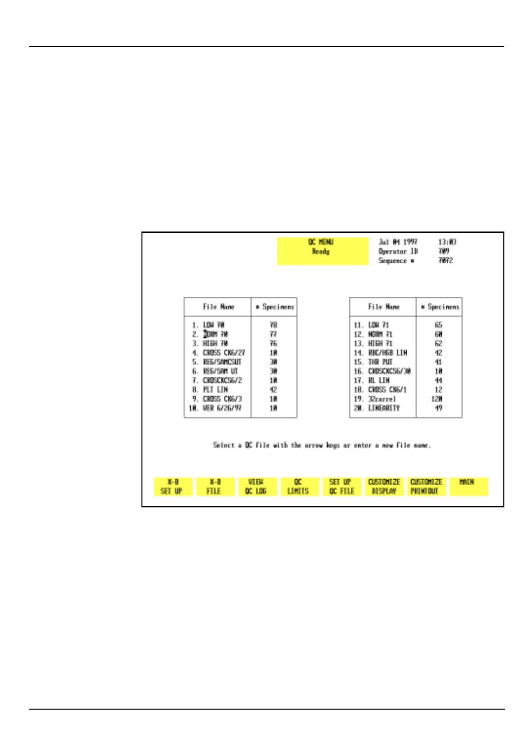
CELL-DYN® 3200 Operator’s Manual 11-3
9140181B — November 1997
Quality Control
Section 11 Quality Control Menu
Quality Control Menu
QC Menu Softkeys
This section discusses the options available when the
[QUALITY CONTROL]
key is pressed. The options used to set up the
QC Files are available from the
QUALITY CONTROL
menu (see
Figure 11.1) and the
QC SET UP
menu. Refer to Set Up QC File
in Section 5: Operating Instructions for an explanation of
these keys as they will not be discussed in this section.
Figure 11.1: Quality Control Menu Screen
The following soft key labels are displayed when the
[QUALITY CONTROL]
key on the
MAIN MENU
screen is pressed:
X-B SET UP
X-B FILE
VIEW QC LOG
QC LIMITS*
SET-UP QC FILE*
CUSTOMIZE DISPLAY *
CUSTOMIZE PRINTOUT *
MAIN
* These keys are discussed in Section 5: Operating
Instructions, Subsection: Set Up Instructions.
Go Back
Search
TOC
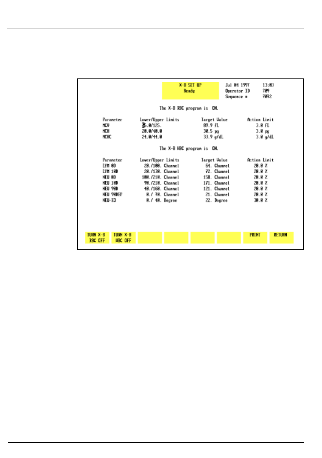
11-4 CELL-DYN® 3200 Operator’s Manual
9140181B — November 1997
Quality Control
Quality Control Menu Section 11
X-B Set Up
Figure 11.2: X-B Set Up Screen
The following soft key labels are displayed when the
[X-B SET UP]
key is pressed (refer to Figure 11.2):
TURN X-B RBC OFF
(Key label alternates
between ON/OFF
selections)
T
URN X-B WBC OFF
(Key label alternates
between ON/OFF
selections)
PRINT
RETURN
Go Back
Search
TOC
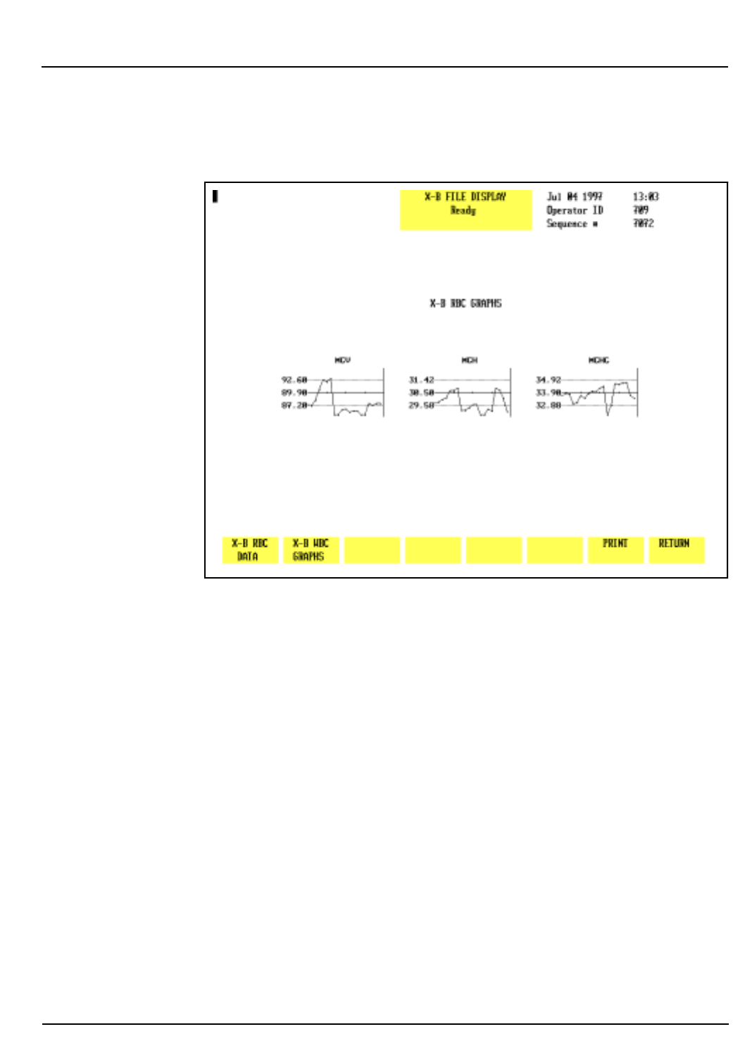
CELL-DYN® 3200 Operator’s Manual 11-5
9140181B — November 1997
Quality Control
Section 11 Quality Control Menu
X-B File
Figure 11.3: X-B RBC Graphs Screen
The following soft key labels are displayed when the
[X-B FILE]
key is pressed:
X-B RBC DATA/GRAPHS
(Key label alternates
between selections)
X-B WBC DATA/GRAPHS
(Key label alternates
between selections)
PRINT
RETURN
For a description of how the X-B Program works, refer to X-B
Program Operation later in this section.
Show Graphs
When the
[X-B RBC GRAPHS]
key or
[X-B WBC GRAPHS]
key is
pressed, the
X-B GRAPHS DISPLAY
screen for the appropriate
parameter is displayed. (Refer to Figure 11.3.)
Go Back
Search
TOC
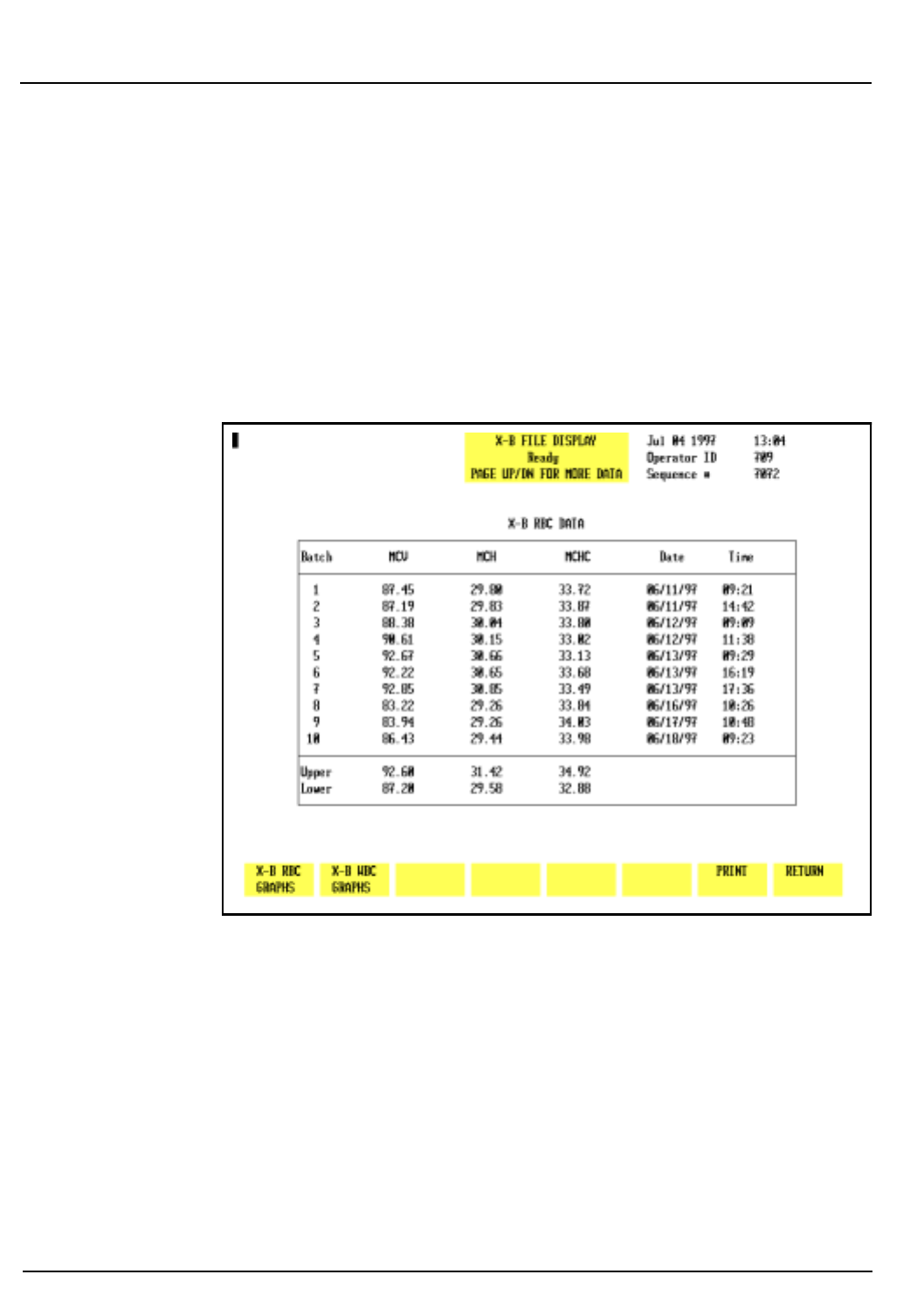
11-6 CELL-DYN® 3200 Operator’s Manual
9140181B — November 1997
Quality Control
Quality Control Menu Section 11
Show Data
When the
[X-B RBC DATA]
key or
[X-B WBC DATA]
is pressed, the
X-B DATA DISPLAY
screen for the appropriate parameter is
displayed. This screen is depicted in Figure 11.4. The screen
displays the results for X-B batches 1–10 and the lower and
upper limits. The date and time that each batch was completed
are also displayed. The Page Down key on the keyboard is used
to display batches 11–20. When batches 11–20 are displayed,
the Page Up key on the keyboard is used to display batches
1–10.
Figure 11.4: X-B RBC Data Screen
Print
The
[PRINT]
key is used to print the X-B data or graphs. When
this key is pressed, the data for all 20 batches is automatically
printed if the data is displayed. If the graphs are displayed, all
ten of them are printed.
Return
The
[RETURN]
key is used to return to the
QC MENU
screen.
Go Back
Search
TOC
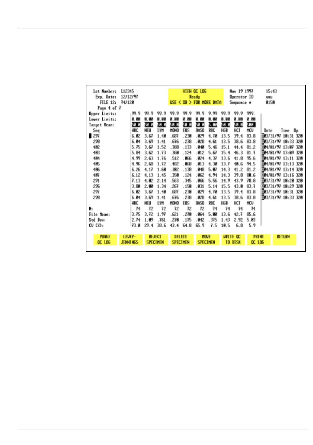
CELL-DYN® 3200 Operator’s Manual 11-7
9140181B — November 1997
Quality Control
Section 11 Quality Control Menu
View QC Log
The
[VIEW QC LOG]
key is used to display the QC Log indicated
by the position of the cursor.
Figure 11.5: The View QC Log Screen
Each QC Log display shows the following information (see
Figure 11.5):
1. Upper Left Corner
LOT NUMBER and EXPIRATION DATE if the file was
configured for this type of control. If the file was
configured for a REPLICATE ID, it is displayed instead of
the lot number and expiration date.
File name, the number of runs currently in the file and
the file capacity (e.g.: 39/120 indicates that the file
contains 39 runs out of a possible 120).
The page number of the display and the total number of
pages in the file.
2. Status Box
USE < OR > FOR MORE DATA. This message indicates
that the Left and Right Arrow keys on the keyboard
should be used to display the other groups of data.
Go Back
Search
TOC

11-8 CELL-DYN® 3200 Operator’s Manual
9140181B — November 1997
Quality Control
Quality Control Menu Section 11
3. Upper Right Corner
The current DATE, TIME and OPERATOR ID are displayed
along with the last SEQUENCE NUMBER that was used.
4. The remainder of the screen displays the file information
and the data. The UPPER and LOWER LIMITS and TARGET
MEAN entered are displayed immediately above the
parameter names. The sequence number for each result is
displayed to the left of the data. The DATE, TIME and
OPERATOR ID when the sample was run are displayed to
the right of the data.
5. The following QC Log codes are displayed in the column
immediately preceding the date. These codes are the same
as those used in the Data Log:
O — Sample was run in the Open mode
C — Sample was run in the Closed mode
N — Incomplete aspiration in the Open mode
I — Incomplete aspiration in the Closed mode
K — Flow Error occurred
Background and latex samples use only the O or C
codes.
6. The statistics are displayed below the data as follows:
N: the Number of runs used in the
calculation
FILE MEAN: the Mean value for the number of runs
used in the calculation
STD DEV: the Standard Deviation (+/-1) for the
number of runs used in the calculation
CV (%): the Coefficient of Variation in percent
for the number of runs used in the
calculation
The following soft key labels are displayed on the VIEW QC
LOG screen:
PURGE QC LOG
LEVEY-JENNINGS
REJECT SPECIMEN/
ACCEPT SPECIMEN
(Key label alternates
between selections)
Go Back
Search
TOC

CELL-DYN® 3200 Operator’s Manual 11-9
9140181B — November 1997
Quality Control
Section 11 Quality Control Menu
DELETE SPECIMEN
MOVE SPECIMEN
WRITE QC TO DISK *
PRINT QC LOG
RETURN
* The feature enabling the download of data from a QC
file to a floppy disk is not currently available. Therefore,
the
[WRITE QC TO DISK]
key should not be used at this time.
The function of each of these keys is discussed in this section.
Purge QC Log
The
[PURGE QC LOG]
key is used to delete the contents of the QC
Log. When the
[PURGE QC LOG]
key is pressed, the following soft
key labels are displayed:
C
ONFIRM PURGE
CANCEL PURGE
These keys are used to
[CONFIRM]
or
[CANCEL]
the Purge QC Log
command.
Levey-Jennings®
The
[LEVEY-JENNINGS]
key is used to display the Levey-
Jennings® graphs of the data in the QC file. (Refer to Figure
11.6.) The following soft key labels are displayed when the
[LEVEY-JENNINGS]
key is pressed. The soft key for the group
being displayed will not be shown.
GROUP 1
GROUP 2
GROUP 3
GROUP 4
PREVIOUS 10
NEXT 10
PRINT
RETURN
Go Back
Search
TOC
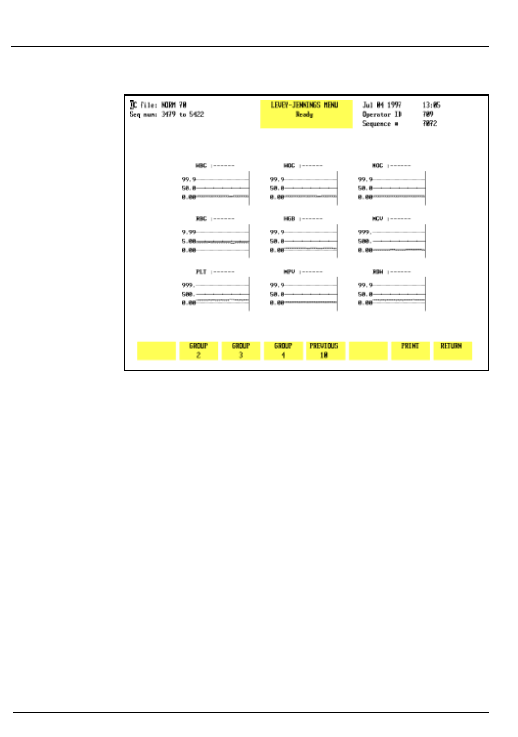
11-10 CELL-DYN® 3200 Operator’s Manual
9140181B — November 1997
Quality Control
Quality Control Menu Section 11
Figure 11.6: The Levey-Jennings® Menu Screen
If there are sufficient specimens in the QC file, when the
[PREVIOUS 10]
key is pressed, the
[NEXT 10]
key appears, allowing
the operator to scroll both forward and background through
the file. (Refer to Figure 11.7.)
Go Back
Search
TOC
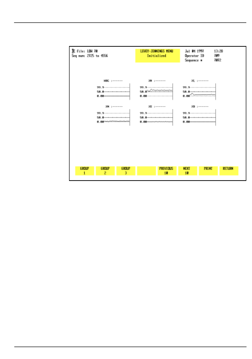
CELL-DYN® 3200 Operator’s Manual 11-11
9140181B — November 1997
Quality Control
Section 11 Quality Control Menu
Figure 11.7: The Levey-Jennings® Menu Screen Showing Next
10
Group
Each of the Group keys is used to select the graphs for a group
of data that correspond to the groups selected in the
Customize QC Display option. Subsequent groups may be
selected by pressing the appropriate soft keys.
NOTE: The soft key for the group currently shown on
the screen is not displayed.
Print
The
[PRINT]
key is used to print the Levey-Jennings graphs.
When the
[PRINT]
key is pressed, all of the graphs are
automatically printed.
Return
The
[RETURN]
key is used to return to the
VIEW QC LOG
screen.
Go Back
Search
TOC
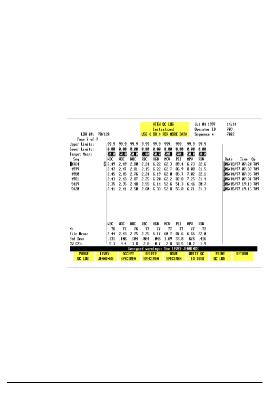
11-12 CELL-DYN® 3200 Operator’s Manual
9140181B — November 1997
Quality Control
Quality Control Menu Section 11
Reject/Accept Specimen
The
[REJECT SPECIMEN]
key is used to exclude the results for the
specimen indicated by the cursor position. When the key is
pressed, the key label changes to
[ACCEPT SPECIMEN]
, an “R” is
displayed in the column immediately left of the results and
the statistics are recomputed excluding those results. (Refer to
Figure 11.8.) The data is still displayed and stored in the file
but is excluded from the statistical calculation.
Figure 11.8: QC Log Screen With Rejected Results
When the
[ACCEPT SPECIMEN]
key is pressed, the “R” is deleted
and the statistics are recomputed including those results.
Delete Specimen
The
[DELETE SPECIMEN]
key is used to delete the results for the
specimen indicated by the cursor position. When the
[DELETE SPECIMEN]
key is pressed, the following key labels are
displayed:
CONFIRM DELETION
CANCEL DELETION
Go Back
Search
TOC

CELL-DYN® 3200 Operator’s Manual 11-13
9140181B — November 1997
Quality Control
Section 11 Quality Control Menu
These keys are used to
[CONFIRM]
or
[CANCEL]
the delete
command. When the
[CONFIRM DELETION]
key is pressed, the
results are deleted from the file (the data is not displayed or
stored in the file) and the statistics are recomputed excluding
those results.
The
[MOVE SPECIMEN]
key is used to move a QC result indicated
by the cursor position to another QC file. When the
[MOVE SPECIMEN]
key is pressed, the
QC MENU
screen is displayed,
allowing the desired file to be selected. When the
[MOVE TO FILE]
key is pressed, the result is moved to the
indicated file.
Move Specimen Procedure
1. From the
QC MENU
screen, use the Arrow keys on the
keyboard to move the cursor to the file containing the
specimen to be moved.
2. Press
[VIEW QC LOG]
.
3. Use the Arrow keys on the keyboard to position the
cursor at the result that is to be moved.
4. Press
[MOVE SPECIMEN]
to again display the
VIEW QC LOG
screen.
5. Use the Arrow keys on the keyboard to move the cursor to
the file in which the results are to be placed.
6. Press
[MOVE TO FILE]
to move the results to the designated
file.
NOTE: The result is moved to the end of the list of
data that is currently in the file.
7. The
VIEW QC LOG
screen of the original file is displayed
showing that the results have been moved.
Write QC to Disk
The
[WRITE QC TO DISK]
key should not be used at this time.
Print QC Log
The
[PRINT QC LOG]
key is used to print the entire QC log.
Return
The
[RETURN]
key is used to return to the
QC MENU
screen.
Go Back
Search
TOC

11-14 CELL-DYN® 3200 Operator’s Manual
9140181B — November 1997
Quality Control
Quality Control Menu Section 11
NOTES
Go Back
Search
TOC

CELL-DYN® 3200 Operator’s Manual 11-15
9140181B — November 1997
Quality Control
Section 11 Quality Control Guide
Quality Control Guide
The Guide is divided into three parts. The first part discusses
the handling and running of control material. The second part
discusses the Westgard Rules used on the CELL-DYN 3200
System and gives guidance for their application in the
hematology laboratory. The third part discusses the X-B
Analysis program in monitoring quality control.
All QC data should be reviewed according to your laboratory’s
protocol.
CELL-DYN Controls
The following controls are recommended for use on the
CELL-DYN 3200 System:
Tri-level, 1 box, 2.5-mL vials x 12, list number 93111-01
Tri-level, 1 box, 3.0-mL tubes x 12, list number 99129-01
* CELL-DYN controls are packaged in Vacutainer® tubes with
Hemogard closure.
Use of Controls
Controls are used to determine whether an instrument is
operating with accuracy and precision. Controls normally
consist of fixed blood cells with assayed ranges for each
measured parameter. Alternately, laboratories may use patient
samples that were previously found to be within set patient
limits. CELL-DYN Controls provide three control levels — low,
normal, and high ranges — for each measured parameter.
All QC data should be reviewed according to your laboratory’s
protocol. Refer to the section on Westgard Rules for
suggestions on how to use these rules in a review protocol.
Refer to the section on X-B Analysis for suggestions and
guidelines on interpreting X-B results.
Go Back
Search
TOC

11-16 CELL-DYN® 3200 Operator’s Manual
9140181B — November 1997
Quality Control
Quality Control Guide Section 11
Mixing and Handling
Always mix and handle commercial control materials
according to the directions given in the package insert.
Because directions may vary from manufacturer to
manufacturer, pay particular attention to the following:
• Check the condition of incoming control material. Be
sure the vials are at the proper temperature and are not
leaking. Check for hemolysis.
• Store controls at recommended temperatures inside the
refrigerator, preferably in a central location away from the
door.
• Carefully warm and resuspend the product according to
the directions given in the package insert. Proper mixing
is essential for accurate results.
• Check the shelf life and open-vial stability dating. Do not
use products longer than recommended by the
manufacturer or the results may be compromised.
• Never subject any vial to excessive heat or agitation.
Assay Verification
New lots of control material should be analyzed in parallel
with current lots prior to their expiration dates. Perform the
following steps to accomplish the transition to a new lot:
1. Set up a control file for the new lot.
2. Verify values for each new control lot by running each
level of control in triplicate along with either replicate
QC specimens or the old control when it is still in date.
3. Run the new controls twice a day for five days to establish
a mean.
4. Use the mean of the ten runs to verify that the new lot
yields the expected results. The mean should fall within
the range specified by the manufacturer in the package
insert.
5. If the calculated mean falls within the range specified by
the manufacturer, use it in place of the manufacturer's
stated mean.
Go Back
Search
TOC

CELL-DYN® 3200 Operator’s Manual 11-17
9140181B — November 1997
Quality Control
Section 11 Quality Control Guide
6. When results for any parameter(s) are flagged (outside of
operator-defined limits or reportable range), reconfirm
calibration for that parameter using specimens with
known reference values. When calibration confirmation
results are acceptable, establish a new working mean and
limits for each level of the new lot of control.
A control file should be set up for the new lot number to easily
establish the mean. If desired, this sample control file can then
be used to run the control for the remainder of the dating
period. It is not necessary to create another file.
The expected ranges published by manufacturers are generally
too broad for effective Quality Control1. Therefore, each
laboratory should establish acceptable ranges. These ranges
may be determined by evaluating three to six months of data
(data from the Interlaboratory QC Program may be used) for a
particular level of control. The individual SD (standard
deviation) values may be averaged as follows:
N = number of values obtained in a month
SD = standard deviation of values obtained in that month
i = total number of months
The resulting long-term instrument SD and the laboratory-
established mean for each lot number should be used to
monitor instrument performance.
Running Controls
Abbott recommends using CELL-DYN Control materials for
performing Quality Control checks on the CELL-DYN 3200
System. Run a minimum of two levels of control at the
beginning of each eight hours of operation prior to running
patient samples. In addition, run controls after the following
events:
• After calibration (confirmatory step).
• After Daily Start-Up procedures are completed.
• After a reagent lot number change.
• After maintenance, a service call, or component
replacement.
Average SD = (N1 × SD12) + (N2 × SD22) + ...+ (Ni × SDi2)
(N1 + N2 + ...+ Ni) − i
Go Back
Search
TOC

11-18 CELL-DYN® 3200 Operator’s Manual
9140181B — November 1997
Quality Control
Quality Control Guide Section 11
•After detection of an unusual trend or shift in patient
results.
•In accordance with the laboratory's Quality Control
protocol.
•According to regulatory requirements.
Controls should be run in both operating modes, (Open or
Closed). Always do the following:
•If the System has been idle for 15 minutes or more, run a
background immediately prior to running a control
specimen.
•Follow the proper warming and mixing procedures
previously described, including those located on the
control package insert.
•Run control samples for each measured parameter in the
same manner as patient samples.
•Verify that control results are within the laboratory's
acceptable limits.
•If the control results fall within acceptable limits, review
the data for shifts or trends, record the results, and begin
to process patient samples.
•If one or more result falls outside the laboratory's
acceptable limits, review Section 10: Troubleshooting
and Diagnostics, Subsection: Troubleshooting Guide.
Perform suggested maintenance steps for the parameter
that is out-of-range, then try using another vial from the
same lot. If the problem persists, contact the Abbott
Customer Support Center.
Go Back
Search
TOC

CELL-DYN® 3200 Operator’s Manual 11-19
9140181B — November 1997
Quality Control
Section 11 Quality Control Guide
CELL-DYN 3200 Westgard Rules
Overview
A control rule tests the control result against control limits to
determine whether the CELL-DYN 3200 shows acceptable
accuracy and precision. The limits are derived from the mean
and standard deviation of control measurements obtained
when instrument performance is stable and acceptable. The
most common rule used in Hematology Quality Control is the
mean ± 2SD limits. Ninety-five percent of the control results
should fall within the ± 2SD limits.
Quality control rules detect random or systematic error.
Random error may be defined as an increase in the SD (loss of
precision). Systematic error may be defined as a shift in the
mean value (loss of accuracy). A multi-rule quality control
procedure combines several control rules to improve the
detection of both types of error.
Westgard recommended a multi-rule approach to evaluating
quality control results.2 This approach has long been used in
the chemistry laboratory3 but is new in the hematology
laboratory. A set of modified Westgard rules may be used to
monitor quality control results on the CELL-DYN 3200.
Westgard Rules
The modified Westgard Rules (Westgard’s nomenclature is
given in parentheses) available on the CELL-DYN 3200 are:
Rule 1 (13s): Value outside 3SD
A control result exceeded the mean ± 3SD
Rule 2 (22s): Two consecutive values outside the same 2SD
Two consecutive results fell outside 2SD on
the same side of the mean
Rule 3 (R4s): Two consecutive values outside opposite 2SD
One result was greater than 2SD above the
mean and the next result was greater than
2SD below the mean. Consequently, the
range between the results is greater than 4SD.
Rule 4(2 of 32s): Two of three consecutive values outside same
2SD
Two of the last three results fell outside 2SD
on the same side of the mean
Go Back
Search
TOC
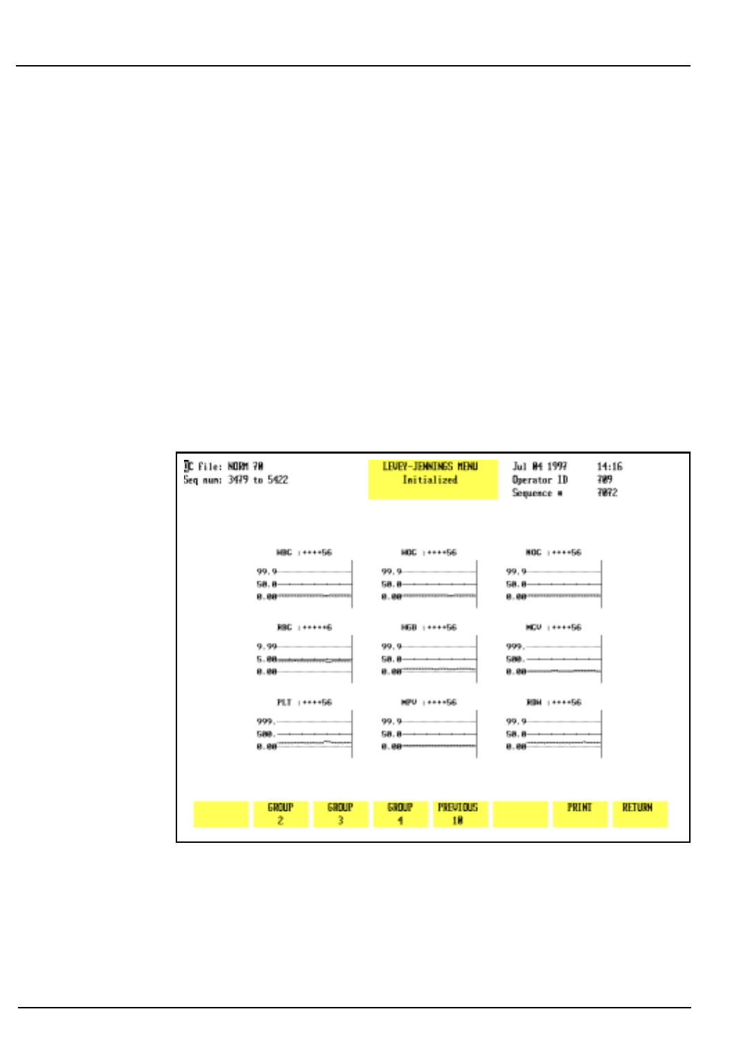
11-20 CELL-DYN® 3200 Operator’s Manual
9140181B — November 1997
Quality Control
Quality Control Guide Section 11
Rule 5 (41s): Four consecutive values outside same 1SD
Four consecutive results fell outside 1SD on
the same side of the mean
Rule 6 (10x): Ten consecutive values on the same side of
mean
Ten consecutive results fell on the same side
of the mean
The rules may be used singly or in combination depending on
operator preference. Selections are made on the
QC FILE SET UP
screen.
When a rule is selected, a plus sign is displayed to the right of
the parameter name on the
LEVEY-JENNINGS MENU
screens.
(Refer to Figure 11.9.) A minus sign is displayed if a rule is not
selected. Six plus signs indicate that all six rules are selected in
order from left to right.
Figure 11.9: Levey-Jennings® Menu Screen Showing Westgard
Rule Violations
Go Back
Search
TOC

CELL-DYN® 3200 Operator’s Manual 11-21
9140181B — November 1997
Quality Control
Section 11 Quality Control Guide
Whenever a rule is violated, the bulletin line displays the
message:
WESTGARD WARNINGS: SEE LEVEY-JENNINGS
The number of the rule that was violated is displayed in place
of the plus sign. Figure 11.9 shows examples of the plus signs
and rule-violation indications.
Rule Violations
Only the directly measured parameters need to be monitored
with multiple rules.4 In reference 4 (pp. 190–192),
Cembrowski suggests a protocol for using the Westgard rules
in Hematology. The following is a synopsis of that protocol.
Since three levels of control are typically used to monitor a
hematology analyzer, it is reasonable to consider all three runs
at the same time. In other words, check for rule violations
across the three levels, not just within a particular level. If the
same rule is violated for more than one level, determine
whether the violation indicates a loss of precision or a loss of
accuracy and troubleshoot accordingly.
Cembrowski suggests that the results for all three levels first be
checked to see if they are within their 2SD limits. If all three
levels meet this criterion, the instrument is in control.
If any control result exceeds the 2SD limits, check to see if it
exceeds the 3SD limits. If a result exceeds 3SD, there are two
possibilities. There is either an instrument problem or a
problem with the particular level of control. Therefore, if a
result exceeds 3SD, run another bottle of that control. If the
problem persists, then additional investigation is required.
Check to see if either the 2 of 32s or R4s rules have been
violated for any level or across levels. If the problem is
confined to one level of control, check for a 22s rule violation
for that level. Again, if the violations are confined to one level
of control, use another bottle and possibly another lot. Check
expiration dates and data entry. Check to be sure that the
control is run into the correct file.
If a combination of rules has been violated across the three
levels, determine whether the violations indicate a loss of
precision or a loss of accuracy and troubleshoot accordingly. If
necessary, call the Abbott Customer Support Center for
assistance.
Go Back
Search
TOC

11-22 CELL-DYN® 3200 Operator’s Manual
9140181B — November 1997
Quality Control
Quality Control Guide Section 11
When the problem has been resolved, Cembrowski suggests
that all levels be run again in duplicate to confirm that it has
in fact been corrected.
X-B Analysis
Introduction
X-B Analysis is an automated means of monitoring instrument
performance by using the known stability of the red cell
indices. The following values confirmed the values that Bull
published in an earlier study5,6,7. Consequently, these values
can be used as the Target Values to initiate the X-B Analysis
program.
MCV 89.9 fL
MCH 30.5 pg
MCHC 33.9 g/dL
To enter X-B Target Values in the
SET UP
menu for MCV, MCH,
and MCHC, do the following:
1. In the
SET UP
menu, press
[QC SET UP MENU]
followed by
[X-B SET UP]
.
2. If necessary, press
[TURN X-B RBC ON]
to turn the X-B RBC
program ON.
3. Use the arrow keys to move the cursor to the Target Value
column and type in the following:
“89.9” for MCV and press Enter
“30.5” for MCH and press Enter
“33.9” for MCHC and press Enter
4. Press
[RETURN]
to exit the
X-B SET UP MENU
and return to
the main
QC SET UP
menu.
Laboratories seeing specialized patient populations, e.g.
pediatric hospitals or tumor centers, may need to verify these
values due to “abnormal” patient populations. Target values
may be verified by evaluating approximately 500 samples and
comparing the X-B means for those samples to the entered
target values. This can be done as follows:
Go Back
Search
TOC

CELL-DYN® 3200 Operator’s Manual 11-23
9140181B — November 1997
Quality Control
Section 11 Quality Control Guide
1. Collect data from at least 500 patients. Manually calculate
the mean, SD, and CV for each index (MCV, MCH, and
MCHC). The CV on 500 samples for each index should be
less than 1.5%. (The 1.5% is one-half the allowable + 3%
action limit.) If the CVs are greater than 1.5%, an
additional 500 samples should be evaluated.
2. If the CVs calculated in step 1 are less than 1.5%, enter
the mean as the Confirmed Target Value.
X-B Program Operation
The X-B program operates in the following manner:
1. The X-B RBC and X-B WBC fields are only displayed if the
X-B functions for RBC and WBC are turned ON in the
SET UP
menu.
2. The X-B RBC and X-B WBC functions are independent of
each other and each consists of a maximum of 20
batches.
3. A completed batch has a maximum 20 specimens.
4. As soon as a 20th specimen is added to the current batch,
that batch is completed, and a new batch is started with
the next included specimen.
5. Specimens in a current batch are identified with an X-B
flag in the Data Log. The number of specimens in a
current batch, either RBC or WBC, is shown on the RUN
screen under the Status Box in the fields XBRBC: X/IN
and XBWBC: X/IN where X is a number from 0 to 20.
6. When the X-B program is first turned from OFF to ON,
the number of records in that batch is zero and 0 is
displayed on the RUN screen. When a current batch
reaches 20, the number 20 remains displayed on the RUN
screen until the first specimen is added to a new batch. At
that time, the number displayed changes to 1.
7. If there are records in a current batch and the operator
turns the program for that batch OFF (e.g., there are 5
records in the RBC batch and the X-B RBC program is
turned OFF), all records in the current batch are deleted.
When the program is turned back ON again, the number
zero is displayed for the current batch of that program.
8. The total number of completed batches, including both
RBC and WBC, is limited to 40. The total number of
batches is 42 which includes 40 completed batches plus 1
current batch for RBC and 1 current batch for WBC.
Go Back
Search
TOC

11-24 CELL-DYN® 3200 Operator’s Manual
9140181B — November 1997
Quality Control
Quality Control Guide Section 11
9. A completed batch can be viewed on the X-B File Display
Screen.
10. Each X-B File Display page is able to display 10 batches.
11. A specimen may be assigned to X-B RBC, X-B WBC, or
both. Included specimens are assigned flags in the Data
Log. These flags precede the Sequence Number.
12. In the Data Log, the X-B flag "r" refers to RBC, flag "w"
refers to WBC, and flag "b" means the specimen has been
included in both the RBC and WBC batches.
13. When a batch is complete, the X-B flags in the Data Log
are deleted from those specimens comprising the
completed batch.
14. If a combination of "r" plus "b" or "w" plus "b" specimens
becomes equal to 20, the “r” or "w" batch is completed,
and the "r" or "w" flags for those specimens are deleted.
The "b" flag changes to either "r" or "w", depending on
which batch remains.
15. If any specimen in a current batch is rejected, the
operator has the option of accepting the rejected
specimen back into the X-B program. A rejected specimen
has an "R" following the Specimen ID number in the Data
Log.
16. For a current batch containing n specimens, the operator
may reject up to n-1 specimens and still have the ability
to re-accept any or all rejected specimens back into the
current batch. However, if all n specimens are rejected,
none of the rejected specimens can be re-accepted. The
next specimen run into an X-B program becomes the first
of a new batch of 20.
17. Each RBC batch has three means: one each for MCV,
MCH, and MCHC. These means are updated whenever a
new specimen is added to, or removed from, a batch.
18. Each WBC batch has 7 means: one each for LYM OD,
LYM 10D, NEU 0D, NEU 10D, NEU 90D, NEU 90DEP, and
NEU-EO. These means are updated whenever a new
specimen is added to, or removed from, a batch.
19. If the current batch has 1 or more batch means outside
the target value/action limits specified in the X-B Setup
Menu, the message "X-BRBC: X/OUT" or "X-BWBC: X/
OUT" is displayed where the X in X/OUT is the number of
specimens in the current batch.
Go Back
Search
TOC

CELL-DYN® 3200 Operator’s Manual 11-25
9140181B — November 1997
Quality Control
Section 11 Quality Control Guide
20. If the current X-B RBC batch and at least one previous X-
B RBC batch are outside the target value/action limits
specified in the X-B Setup Menu, the message "X-BRBC:
X/OUT2" is displayed where the X in X/OUT is the
number of specimens in the current batch.
21. If the current X-B WBC batch and at least one previous X-
B WBC batch are outside the target value/action limits
specified in the X-B Setup Menu, the message "X-BWBC:
X/OUT2" is displayed where X is the number of
specimens in the current batch.
22. If a current X-B batch (RBC or WBC) is turned OFF, all
specimens in that batch are deleted.
23. If any value (Upper/Lower Limits, Target Value, or Action
Limit) for RBC is changed in the X-B Set Up menu, all
specimens in the current X-B RBC batch are deleted.
24. If any value (Upper/Lower Limits, Target Value, or Action
Limit) for WBC is changed in the X-B Set Up menu, all
specimens in the current X-B WBC batch are deleted.
X-B Analysis for RBC
Overview
The red cell indices (MCV, MCH, and MCHC) are known to be
stable because the red cell apparently functions best in a very
narrow range of size and hemoglobin content. Therefore, the
body exerts tight physiologic control and will vary the number
of red cells before altering the average volume or hemoglobin
concentration of those red cells. Consequently, the average red
cell indices of a given patient population will vary no more
than 0.5 percent from day to day and even year to year,
providing the population does not change.5 The X-B algorithm
provides a means of utilizing this information for quality
control on the CELL-DYN 3200 System.
The X-B algorithm analyzes the indices on the patient samples
run through the instrument in batches of 20. The mean of
each batch is compared to a target value, and a percent
deviation is computed and compared to the acceptable limits.
This is similar to comparing the results of a commercial
control run to the appropriate assay value to determine
whether the result falls within the 2SD range. If the percent
deviation exceeds acceptable limits, the message: X-B OUT is
displayed on the screen.
Go Back
Search
TOC

11-26 CELL-DYN® 3200 Operator’s Manual
9140181B — November 1997
Quality Control
Quality Control Guide Section 11
Establishing the X-B RBC Target Value
A recent study6 by Dr. Bull collected data from 1,767 hospitals
and yielded the following mean values:
MCV 89.9 fL
MCH 30.5 pg
MCHC 33.9 g/dL
These values confirmed values that Bull had published in an
earlier study.7 Consequently, the values shown above can be
used as the Target Values to initiate the X-B analysis program.
Laboratories seeing specialized patient populations (for
example, pediatric hospitals or tumor centers) may need to
verify these values due to “abnormal” patient populations.
Target values may be verified by evaluating approximately 500
samples and comparing the X-B means for those samples to
the entered target values.
The CV on 500 samples for each index should be < 1.5%. (Dr.
Bull’s study found CVs from 0.5% to 1.2%. The 1.5% is one-
half the allowable ± 3% action limit, which is acceptable for
this confirmatory step.) If the CVs are >1.5%, an additional
500 samples should be evaluated.
Each laboratory should establish its own target value for the
RBC indices. It is suggested that the process be started by using
the default values (preset values from Dr. Bull’s earlier studies)
displayed on the X-B SET UP screen or by entering the values
from Dr. Bull’s recent study described above. The 3% action
limits may be used or widened to 5% during the study and
tightened to 3% when the Target Values are confirmed. The
default values for the Lower/Upper Limits may also be used or
widened depending on the specimen population analyzed by
the laboratory.
Collect data from 25 batches of 20 specimens each for a total
of 500 specimens. Data collection should be from specimens
which represent the typical specimen population that is
processed through the instrument. When all 25 batches are
complete, print the X-B DATA DISPLAY screen for RBC.
Calculate the mean, standard deviation (SD), and coefficient of
variation (CV) for MCV, MCH, and MCHC. The CV for each
index should be < 1.5%. If the CV for each index meets these
criteria, enter the calculated mean value as the target value
and set the action limits to 3%.
Go Back
Search
TOC

CELL-DYN® 3200 Operator’s Manual 11-27
9140181B — November 1997
Quality Control
Section 11 Quality Control Guide
NOTE: Laboratories analyzing specialized patient
populations (as described above) may need to widen
the action limits slightly to accommodate results from
these abnormal patients.
If the CV for each index is >1.5%, evaluate another 500
specimens and repeat the calculations.
When an acceptable target value has been entered, evaluate
data from an additional 500 specimens to confirm the entered
values.
Troubleshooting X-B RBC Results
When XB-RBC results are out of control, data should be
reviewed for shifts and trends in the results.
Shifts in results are usually caused by a non-random batch of
20 specimens such as those from dialysis or pediatric units.
Multiple repeats of the same abnormal specimen within a
given batch of 20 may also cause a non-random population in
that batch. Review the Data Log for the last 20 specimens and
determine if this is the case. Shifts caused by non-random data
will usually be corrected in the next batch of 20 as long as
those data are random.
Shifts may also be caused by a change in reagent container or a
lot number change. If containers or lot numbers recently
changed, try another container and see if the problem persists.
Calibration changes may also cause a shift in results. If a shift
cannot be explained as described above, run commercial
controls or run a patient selected from a previous batch when
X-B results were in control. If values are within acceptable
limits, a calibration shift is not the cause of the problem.
Trends in X-B results are usually caused by instrument
problems. A recent component change may also cause a trend
in results. Use the following table to determine the directly
measured parameter(s) involved, and troubleshoot accordingly.
If a problem is not readily identified, perform routine
maintenance and repeat the commercial and patient controls
to see if results are acceptable.
Go Back
Search
TOC

11-28 CELL-DYN® 3200 Operator’s Manual
9140181B — November 1997
Quality Control
Quality Control Guide Section 11
Since two of the RBC indices are calculated parameters, their
inter-relationships can be used to assist in troubleshooting.
The following table uses the mathematical relationships
between the indices to aid in determining which directly
measured parameter(s) are involved when X-B is out of
control. When the directly measured parameter(s) are
identified, refer to Chapter 10: Troubleshooting for
troubleshooting assistance with these parameters.
Table 11.1: Troubleshooting X-B RBC
If all efforts fail to bring results within acceptable limits,
contact the Customer Support Center (at 1-800-CELL-DYN in
the U.S.) for assistance.
Interpreting X-B RBC Results
A suggested protocol and guidelines for interpreting X-B data
can be found in Chapter 1 of Laboratory Hematology: An
Account of Laboratory Techniques, edited by I. Chanarin.8
X-B Analysis for WBC
Overview
Since the WBC Differential parameters have a wide dynamic
range, it is difficult to use a moving average algorithm to
control these results. Therefore, the CELL-DYN 3200 System
uses data obtained from the MAPSSTM technology used for the
WBC Differential measurement.
X-B
Pattern
If the MCV If the RBC If the HGB
Index
Derivation
is
increased is
decreasedis
increased is
decreasedis
increased is
decreased
MCV
will beHigh Low N/A N/A N/A N/A MCV
MCH
will beN/A N/A Low High High Low HGB/RBC
MCHC
will beLow High Low High High Low HGB/HCT
Go Back
Search
TOC

CELL-DYN® 3200 Operator’s Manual 11-29
9140181B — November 1997
Quality Control
Section 11 Quality Control Guide
Five main subpopulations of WBCs, which can vary widely in
absolute number and percentage values, are identified by the
CELL-DYN 3200 System. Even though these parameters have
varying dynamic ranges, they maintain a relatively constant
modal position on each axis of the scatterplots. It is expected
that these optical characteristics of the WBC Differential
subpopulations will remain stable over time without impact
from the wide dynamic ranges of the individual parameters.
This constant modal position, which is sensitive to changes in
the instrument’s optical measurement process, can be
monitored by the instrument and used to control the WBC
Differential parameters in much the same way that the RBC
indices are used to control the RBC parameters.
The CELL-DYN 3200 System monitors the modal positions of
the lymphocyte and neutrophil clusters on each axis of the 0°/
10° scatterplot. It also monitors the modal positions of the
neutrophil cluster on each axis and the angle of the
neutrophil/eosinophil separation on the 90°/90° depolarized
scatterplot. These seven measurements are then averaged for
each batch of 20 patients using a moving average calculation
similar to that developed by Dr. Bull for the RBC indices. For
convenience, this process is called X-B WBC.
Establishing the X-B WBC Target Value
The Target Values for X-B WBC can be established in the same
way as the Target Values for the RBC indices.
Each laboratory should establish its own target value for the
X-B WBC parameters. It is suggested that the process be started
by using the default (preset) values displayed in the following
table. The action limits in the table may be used or widened
during the study. Reenter the default action limits shown in
the following table when the Target Values are confirmed. The
values for the action limits may be widened depending on the
specimen population analyzed by the laboratory. The values
for the Lower/Upper Acceptance Limits may also be used or
widened depending on the specimen population analyzed by
the laboratory.
Collect data from 20 batches of 20 specimens each for a total
of 400 specimens. Data collection should be from specimens
which represent the typical specimen population that is
processed through the instrument. When all 20 batches are
complete, print the X-B DATA DISPLAY screen for WBC.
Calculate the mean, standard deviation (SD), and coefficient of
Go Back
Search
TOC

11-30 CELL-DYN® 3200 Operator’s Manual
9140181B — November 1997
Quality Control
Quality Control Guide Section 11
variation (CV) for each parameter. The CV for LYM 0°, LYM
10°, NEU 0°, and NEU 10° should be <2.5%. The CV for NEU
90°, NEU 90° depolarized, and NEU-EOS should be <5%. If the
CV for each index meets these criteria, enter the calculated
mean value as the target value and set the action limits to 5%
for LYM 0°, LYM 10°, NEU 0°, and NEU 10°, and to 10% for NEU
90°, NEU 90° depolarized, and NEU-EOS.
NOTE: Laboratories analyzing specialized patient
populations (as described above) may need to widen
the action limits slightly to accommodate results from
these abnormal patients.
If the CV for each index is more than the limits described
above, evaluate another 400 specimens and repeat the
calculations.
When an acceptable target value has been entered, evaluate
data from an additional 400 specimens to confirm the entered
values.
Default (Preset) X-B WBC Values
Parameter Acceptance Limits Target Mean Action
Limit
LYM 0°48 - 70 59 7
LYM 10°51 - 67 59 5
NEU 0°141 - 179 160 4
NEU 10°128 - 170 149 5
NEU 90°87 - 163 125 10
NEU 90 DEP°11 - 31 21 19
NEU-EOS°14 - 32 23 13
Interpreting X-B WBC Results
A suggested protocol and guidelines for interpreting X-B data
can be found in Chapter 1 of Laboratory Hematology, An
Account of Laboratory Techniques, edited by I. Chanarin.8
Go Back
Search
TOC

CELL-DYN® 3200 Operator’s Manual 11-31
9140181B — November 1997
Quality Control
Section 11 References
References
1. Cembrowski GS, Carey RN. Laboratory quality
management, p. 189.
2. Westgard JO et al. A multi-rule Shewhart chart for quality
control in clinical chemistry. Clin Chem 1981; 27:3:493–
501.
3. Cembrowski GS, et al. Use of a multirule control chart for the
quality control of PT and APTT analyses. Lab Med June
1989; 418–421.
4. Cembrowski GS, Carey RN. Laboratory quality
management. P. 190.
5. Bull BS, Korpman RA. Intralaboratory quality control using
patients’ data. In: Cavill I, ed. Quality Control. Edinburgh:
Churchill Livingstone 1982, 121–150.
6. Bull BS, Jones AR, Gibson M, Twedt D. A method for the
independent assessment of the accuracy of hematology whole
blood calibrators. AJCP (accepted for publication), 1992.
7. Bull BS, Hay KL. Are red blood cell indexes international?
Arch Pathol Lab Med 1985; 109:604–606.
8. Chanarin I, ed. Laboratory hematology, an account of
laboratory techniques. Edinburgh: Churchill Livingstone,
1989:3–7.
Go Back
Search
TOC

11-32 CELL-DYN® 3200 Operator’s Manual
9140181B — November 1997
Quality Control
References Section 11
NOTES
Go Back
Search
TOC

CELL-DYN® 3200 Operator’s Manual 12-1
9140181B — November 1997
Printers
Section 12 Overview
Overview
The CELL-DYN® 3200 system is configured with a color
Graphics Printer (known in this manual as the Graphics
Printer). The printer is set up to print reports, including
complete graphic information, on 8.5” X 11” paper. The
printer may be set up to print graphic information in color or
black only.
If ticket printing is desired for the CELL-DYN 3200, a second
printer (known as the Ticket Printer) can also be connected to
the system at the same time as the Graphics Printer. Results are
automatically printed at the completion of each run cycle or
are printed on command by the operator. The Ticket Printer
can be used to print reports with graphic information in black
only, but the connection to the Analyzer must be changed.
IMPORTANT: The CELL-DYN 3200 System has been
configured for and tested on the following printers: Canon®
BJC-620TM color ink jet printer for graphics output, and
OKIDATA® MICROLINE® 320 dot matrix printer for ticket
printing. Abbott recommends using only these printers. If
other printers are substituted, problems may occur with your
printouts.
Refer to Section 2: Installation Procedures and Special
Requirements, Subsection: Printer Installation for
instructions on installing both printers.
Complete directions for customizing the printout type and
format are given in Section 2, Subsection: Customizing
Printouts.
Go Back
Search
TOC

12-2 CELL-DYN® 3200 Operator’s Manual
9140181B — November 1997
Printers
Overview Section 12
NOTES
Go Back
Search
TOC

CELL-DYN® 3200 Operator’s Manual 12-3
9140181B — November 1997
Printers
Section 12 Maintenance and Troubleshooting
Maintenance and Troubleshooting
This section gives a brief overview of printer maintenance and
troubleshooting. Instructions for installation are given in
Section 2: Installation and Special Procedures, Subsection:
Printer Installation. For a detailed description of the printer
components and instructions on changing the ribbon and
loading paper, refer to the manuals that accompany the
printer.
Cleaning
Every six months (or after about 300 hours of operation) turn
the printer OFF and use a clean, dry cloth to dust the area
around the carriage shaft and platen. Be sure to remove any
loose particles of paper. Do not use solvents or strong
detergents on the cabinet.
Troubleshooting
Refer to the printer manuals for a list of the most common
printer problems and how to solve them. If the problem is not
resolved, contact the Abbott Customer Support Center for
assistance.
If, during routine system operation, the message PRINTER
UNAVAILABLE is displayed on the bulletin line, check to see
that the printer cable is securely connected to the Analyzer,
the printer power switch is turned ON, and that the Select
indicator is illuminated. Press the
[PRINT]
key. If the message is
still displayed, turn the printer power off, wait about five
seconds, turn the power on again and press the
[PRINT]
key. If
the message is still displayed, there may be an internal printer
error. Contact the Abbott Customer Support Center for
assistance.
Go Back
Search
TOC

12-4 CELL-DYN® 3200 Operator’s Manual
9140181B — November 1997
Printers
Maintenance and Troubleshooting Section 12
NOTES
Go Back
Search
TOC

CELL-DYN® 3200 Operator’s Manual 12-5
9140181B — November 1997
Printers
Routine Operation Section 12
Routine Operation
Graphics Printer
The CELL-DYN 3200 software automatically controls and
adjusts most print conditions, including page width and ink
color. Occasionally, a few settings may need to be changed in
the printer’s software for correct operation. If printing is not
what you expect, refer to the printer manual for guidance in
making adjustments. If you have additional questions or
experience any problems, call the Abbott Customer Support
Center for assistance.
Ticket Printer
For detailed information about loading continuous-feed
tickets or paper and changing the ribbon in the Ticket Printer,
refer to the manuals that accompany the printer. In particular,
note the important safety instructions. This section gives
information about ticket printing and instructions for loading
individual pre-printed tickets in the Ticket Printer.
The Ticket Printer can be used to print a complete graphics
report on continuous tractor-feed paper or to print result data
on blank or pre-printed tickets. (Blank tickets are available in
continuous tractor-feed sheets. Pre-printed tickets are loaded
individually.) To print the graphics report, the printer cable
must be connected to the Graphics Printer connector on the
back of the Data Module.
Printing Tickets
To print tickets, the printer cable must be connected to the
Ticket Printer connector on the back of the Data Module. (See
Figure 2.5 for the location of these connectors.) Refer to
Section 2, Subsection: Printer Installation for instructions
for customizing either type of printout.
Loading Individual Tickets
Instructions are given for loading individual tickets. If fan-
fold, continuous-feed tickets are used, they should be loaded
as directed in the printer manual for tractor-feed paper.
Go Back
Search
TOC

12-6 CELL-DYN® 3200 Operator’s Manual
9140181B — November 1997
Printers
Routine Operation Section 12
1. Be sure that the printer is turned OFF and the printer
cable is connected to the Ticket Printer Connector on the
back of the Analyzer. If the connection is incorrect, turn
the Analyzer power OFF, change the position of the cable
and turn the power back ON.
2. Set the ribbon cartridge headgap lever to adjust for the
thickness of the tickets. Refer to the printer manual for
the location of the headgap lever and for detailed
instructions.
3. Move the paper selection lever to the rear position to
select single-feed paper.
4. Open the access cover and be sure the guide wire on the
paper separator is pushed back into the locked position.
5. Raise the separator to its upright position.
6. Place a ticket on the paper separator and adjust the guides
so that they barely touch the edges of the ticket.
7. Pull the bail lever forward. The ticket will automatically
feed into place. Release the paper bail lever.
8. Be sure the printer is deselected (Sel indicator is not
illuminated) and set the Top of Form by pressing and
holding the TOF/Quiet key and pressing the Form Feed
key to move the ticket up or pressing the Line Feed key to
move the ticket down. (The ticket moves in very fine
increments so it can be precisely positioned.)
NOTE: The ticket will only move down to a certain
point to prevent potential ticket jams. Do not move the
top of the page below the paper bail.
9. Position the ticket so that the lower red line on the paper
shield (located between the print head and the paper) is
positioned where the first line of printing should occur.
NOTE: When the Top of Form is set, the position is
retained in the printer memory until it is reset.
10. Press the Sel key to select the printer. The printer is now
ready to print.
Go Back
Search
TOC
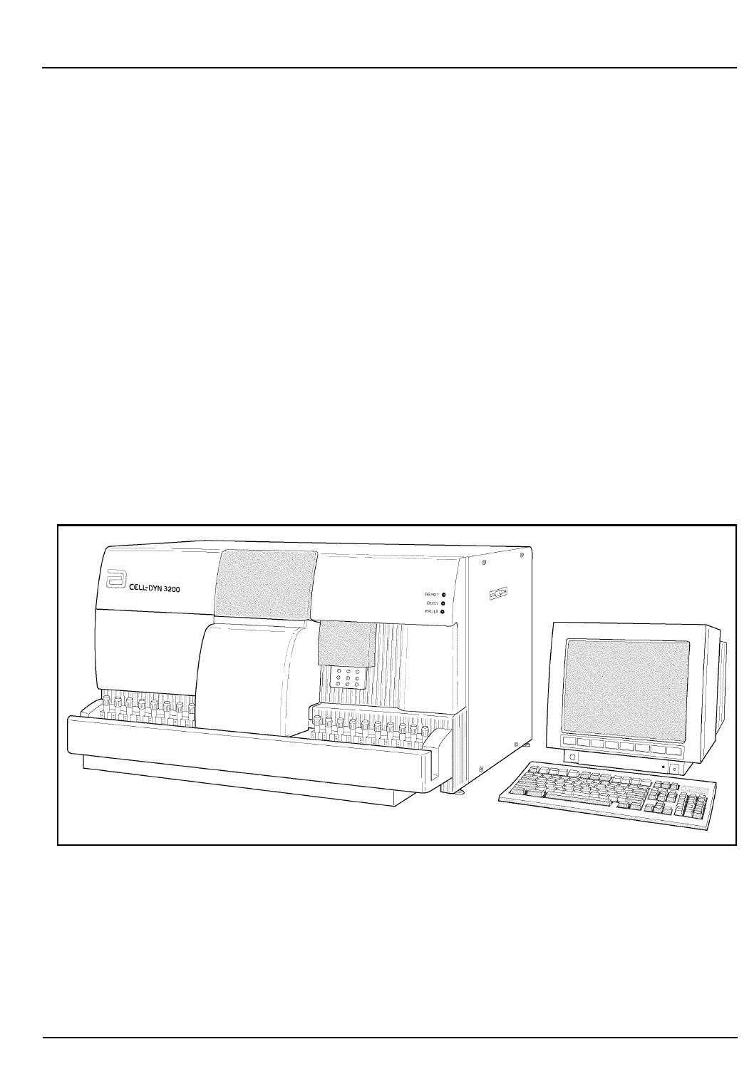
CELL-DYN® 3200 Operator’s Manual 13-1
9140181B — November 1997
Sample Loader
Section 13 Overview
Overview
The Sample Loader for the CELL-DYN® 3200SL is an
automated microprocessor-based sample-handling system
designed to be attached to the Analyzer (see Figure 13.1). The
Sample Loader delivers mixed blood samples to the Analyzer
for analysis and communicates sample identification
information and the loader’s operational status to the
CELL-DYN 3200SL. The sample tubes, in an upright position,
are transported in racks. Up to 50 tubes can be loaded onto the
Sample Loader and processed with or without bar code labels.
The Sample Loader has been designed to provide fast and
efficient throughput of patient samples. Used in conjunction
with the Work List and Bar Codes, the Sample Loader can
process approximately 70 samples per hour, including
matching patient demographic information with samples
results and storing completed sample information in the Data
Log.
Figure 13.1: Analyzer With Sample Loader
Go Back
Search
TOC

13-2 CELL-DYN® 3200 Operator’s Manual
9140181B — November 1997
Sample Loader
Overview Section 13
NOTES
Go Back
Search
TOC

CELL-DYN® 3200 Operator’s Manual 13-3
9140181B — November 1997
Sample Loader
Section 13 Physical and Performance Specifications
Physical and Performance Specifications
Specifications
Refer to Section 4: Performance and Specifications for
complete performance specifications for the 3200SL. The
following information on the Sample Loader is included here
for convenience.
Dimensions and Weight
Height 6 in (15.2 cm)
Width 32.5 in (82.5 cm)
Depth 6.4 in (16.2 cm)
Weight 18 lbs (8.1 kg)
Tube Types
The Closed Sample Tower Module and the Sample Loader are
able to accommodate the following tube types:
1. Beckton-Dickinson Type
•B-D Hemogard Stopper (5.0 mL)
•B-D Rubber Stopper (5.0 mL)
•Greiner (4.0 mL)
•Terumo Venoject® II (5.0 mL)
2.Starstedt Type
•Starstedt EDTA (2.7 mL)
•Starstedt Neutral (2.7 mL)
NOTE: All other tube types must be processed in the
Open mode.
Rack and Tube Capacity
5 racks on the load side
5 racks on the unload side
50 tubes (10 tubes per rack)
Go Back
Search
TOC

13-4 CELL-DYN® 3200 Operator’s Manual
9140181B — November 1997
Sample Loader
Physical and Performance Specifications Section 13
Minimum Sample Volume
The minimum blood volume per sample tube is 1.0 mL in the
Closed Mode.
Maximum Sample Volume
The maximum blood volume per sample tube is 3.0 mL in the
Closed Mode.
Go Back
Search
TOC
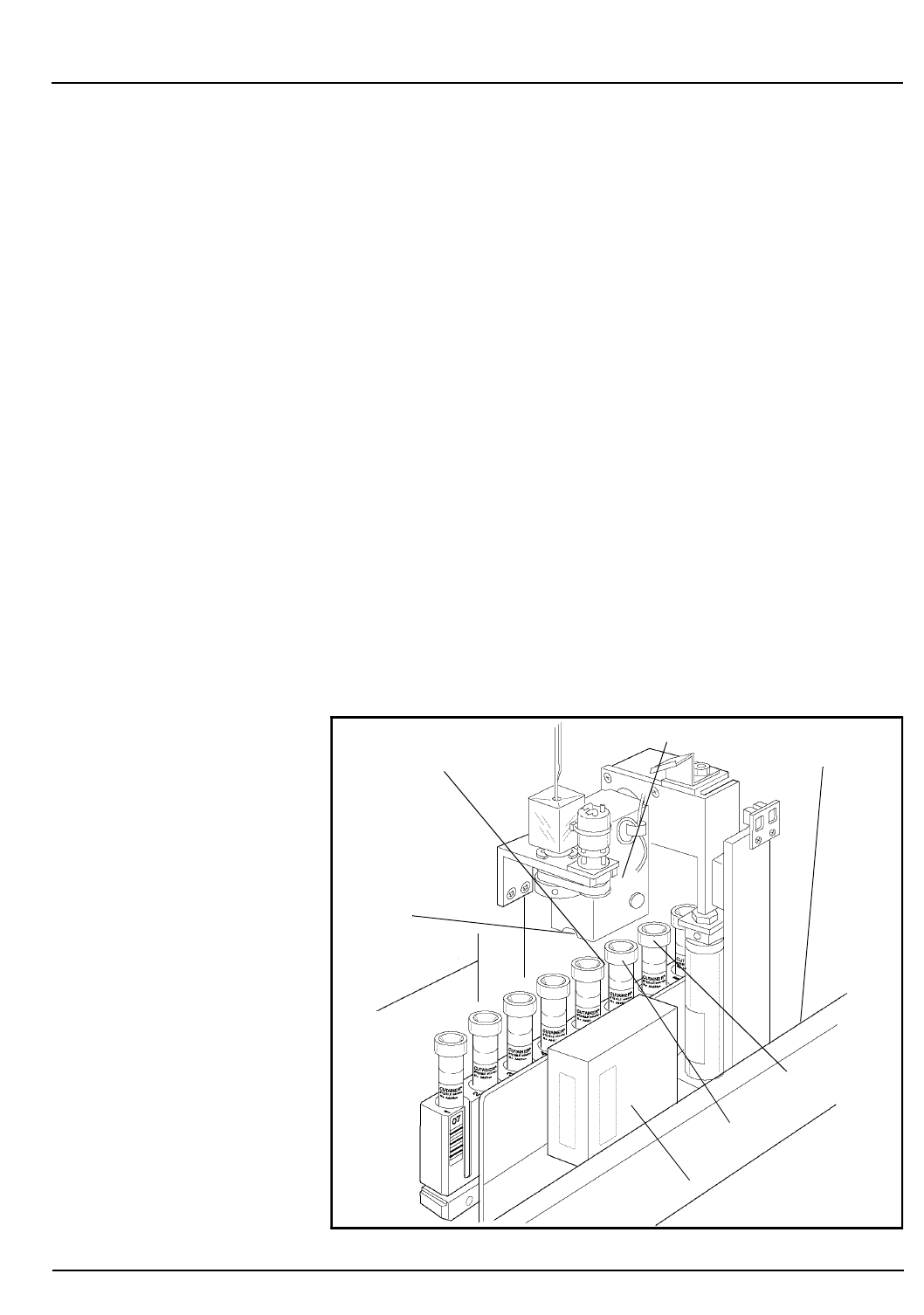
CELL-DYN® 3200 Operator’s Manual 13-5
9140181B — November 1997
Sample Loader
Section 13 Sample Loader Description
Sample Loader Description
Sample Loader Components
The Sample Loader is an integral part of the CELL-DYN 3200SL
model. It is attached to the Analyzer by four screws, two on
each side of the Analyzer and is aligned to the Aspiration
Tower through a common alignment block. The motors and
mechanical arms for rack movement are located inside the
loader. The electronic board for controlling the operation of
the Sample Loader is mounted on the left side of the Sample
Loader chassis. Cables connecting the Sample Loader with the
Analyzer are installed at the factory and should not be
removed.
The Sample Loader consists of four main assemblies: Sample
Transport Assembly, Sample Tube Sensing Assembly, Sample
Mixing Assembly, and Bar Code Reader. These components are
depicted in Figure 13.2. (The Tube Sensor Assembly is located
on the Sample Loader chassis directly behind Stations 1 and
2.) NOTE: Several Sample Loader-related error messages
refer to tube positions 3 and 4, which are Mixing
Stations 1 and 2 respectively. (Refer to Figure 13.7.)
Figure 13.2: CELL-DYN 3200 Sample Loader
Sample Transport
Tube Sensors
(behind Stations 1 and 2)
Station 1
Station 2
Bar Code Reader
Mixing Block
Tube Grippers
(under Mixing Block)
(tube position 3)
(tube position 4)
Go Back
Search
TOC

13-6 CELL-DYN® 3200 Operator’s Manual
9140181B — November 1997
Sample Loader
Sample Loader Description Section 13
The Sample Transport Assembly consists of pneumatic-
actuated arms that move the racks in an orderly process
through the sample mixing, bar code reading, and aspiration
stages of the processing cycle.
There are two Sample Tube Sensors at the two Sample Mixing
positions. The sample tube is sensed at the first tube position
on the Mixing Assembly and again at the second tube holder.
The sample loader will continue to advance racks if there are
no tubes present at both mixing positions.
The Sample Mixing Assembly consists of two tube grippers
on the Mixing Block. The block is raised pneumatically and
the mixing rotation is done by a stepper motor.
The Bar Code Reader is an LED type and can accommodate
the following formats: Code 39, Code 128, CODABAR, and
Interleaved 2 of 5. On the SL model, the Bar Code Reader is
located on the Sample Loader directly in front of the
aspiration needle/spinner assembly.
A Power Cable connecting the Sample Loader with the
Analyzer provides power from the Analyzer to the loader. An
Interface Cable connecting the Analyzer and Sample Loader
provides bi-directional communication.
Bar Code Label Placement
Tube Labels
All labels should be placed on the tubes securely. Flaps or edges
should not be sticking out. Labels should not cover the cap
(high collar) or the bottom (tail) of the tube. Labels should be
placed between 3/4 inches from the bottom of the sample tube
and 3/4 inches from the top of the tube. (See Figure 13.3.)
Layering more than 3 labels may prevent the bar codes from
being read.
NOTE: Refer to Appendix A for complete information
on Bar Codes, Check Digits, and specifications.
Go Back
Search
TOC
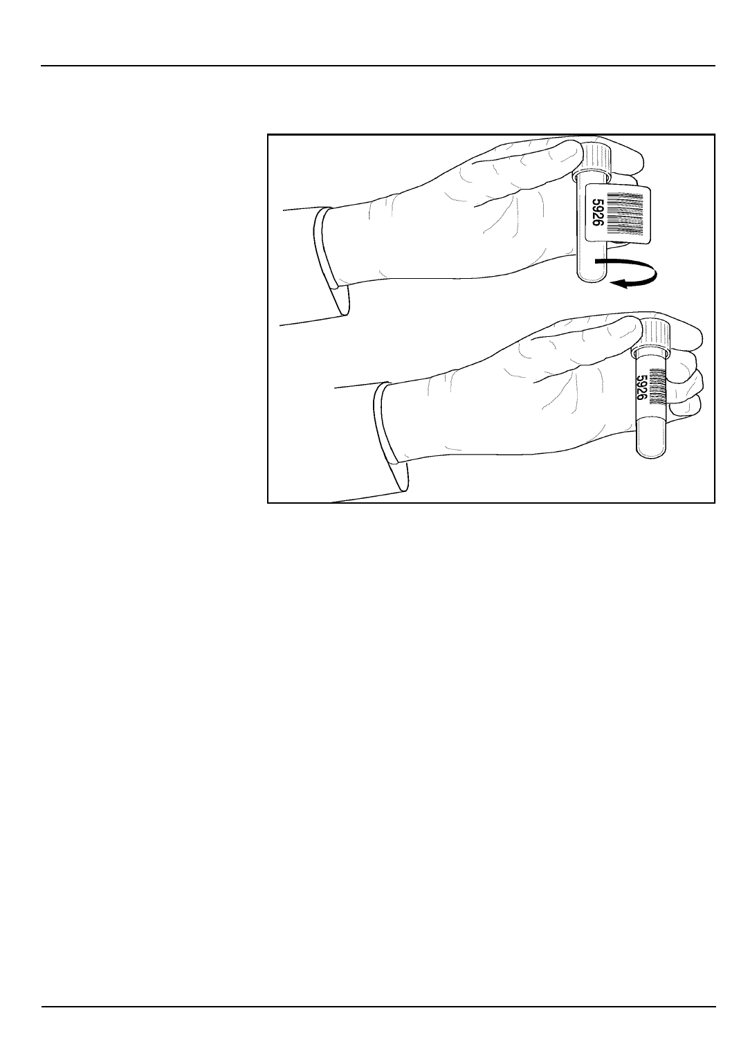
CELL-DYN® 3200 Operator’s Manual 13-7
9140181B — November 1997
Sample Loader
Section 13 Sample Loader Description
Figure 13.3: Tube Labeling Requirements
Rack Labels
Every rack and tube position is identified by a bar code label.
(See Figure 13.4.) Bar code labels on tube racks are essential for
proper Sample Loader operation. The rack label must be placed
on each rack ahead of tube position 1. This label serves to
identify the rack and tube position 1. The rack bar code label is
read when the tube in the first position is moved from Mixing
Station #2 to the Aspiration Station. Subsequent bar code
labels on the rack identify tube positions 2 through 10.
Go Back
Search
TOC
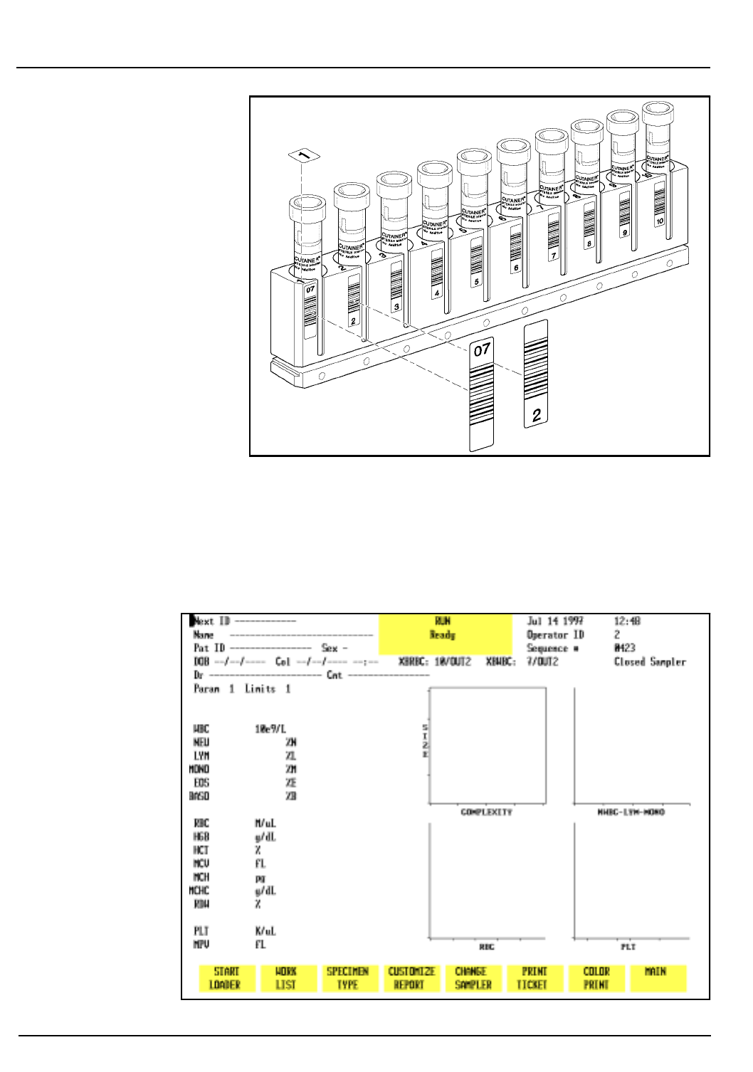
13-8 CELL-DYN® 3200 Operator’s Manual
9140181B — November 1997
Sample Loader
Sample Loader Description Section 13
Figure 13.4: Rack with Bar Code Labels
RUN Screens
The
RUN
Screens for the 3200SL model, shown in Figures 13.5
and 13.6, are slightly different from the screen for the 3200CS
model.
Figure 13.5: CELL-DYN 3200SL RUN Screen
Go Back
Search
TOC
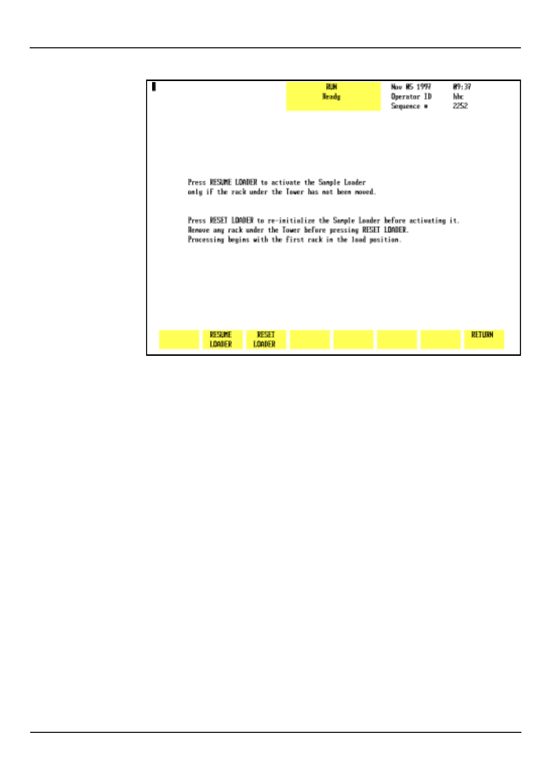
CELL-DYN® 3200 Operator’s Manual 13-9
9140181B — November 1997
Sample Loader
Section 13 Sample Loader Description
Figure 13.6: Sample Loader Restart Screen
Soft Keys
Overview
The soft key menu on the 3200SL model is similar to the menu
on the 3200CS model except for the following:
1. The
[START LOADER/STOP LOADER]
key in the first position
(refer to Figure 13.5).
NOTE: The
[CLEAR FAULT]
key will appear in the first
position whenever a Fault condition occurs.
2. A submenu that appears under certain conditions when
the
[START LOADER]
key is pressed (refer to Figure 13.6).
Pressing the
[START LOADER
] key activates the Sample Loader
and toggles to
[STOP LOADER]
without an intervening submenu
under the following two conditions:
1. When the System has been initialized or when only the
Sample Loader has been re-initialized.
2. When the Sample Loader has finished processing all
loaded racks (without the
[STOP LOADER]
key being
pressed) and comes to a halt.
Go Back
Search
TOC

13-10 CELL-DYN® 3200 Operator’s Manual
9140181B — November 1997
Sample Loader
Sample Loader Description Section 13
Start Loader
Pressing the
[START LOADER]
key displays the
RESTART
menu
shown in Figure 13.6 (the Sample Loader remains inactive)
under the following two conditions:
1.When the
[STOP LOADER]
key was pressed while the
Sample Loader was operating
2.When the
[CLEAR FAULT]
key was pressed.
Stop Loader
When the
[STOP LOADER]
key is pressed, the Sample Loader
comes to a halt after the current sample cycle is completed and
the key changes to
[START LOADER]
.
Restarting the Loader
Pressing the
[START LOADER]
key after the
[STOP LOADER]
or
[CLEAR FAULT]
key was pressed will not automatically activate
the Sample Loader. Instead, the Sample Loader
RESTART
menu
(refer to Figure 13.6) is displayed with three soft keys:
RESUME LOADER
RESET LOADER
RETURN
NOTE: If a Sample Loader fault occurs, when the
[CLEAR FAULT]
and
[START LOADER]
keys are pressed one of
two possible submenus will be displayed. Refer to
Sample Loader Faults later in this section for an
explanation.
T
he operator must decide which key to press to re-activate the
Sample Loader based on whether or not the rack under the
Tower was moved. Pressing either
[RESUME LOADER]
or
[RESET LOADER]
will activate the Sample Loader and display the
main
RUN
screen with the
[STOP LOADER]
key again displayed in
the first position.
Resume Loader
The
[RESUME LOADER]
key should be used to activate the Sample
Loader under the following conditions:
1.When the
[STOP LOADER]
key was pressed and the rack
under the Tower was not subsequently moved
Go Back
Search
TOC

CELL-DYN® 3200 Operator’s Manual 13-11
9140181B — November 1997
Sample Loader
Section 13 Sample Loader Description
2. When a Sample Loader fault occurred that did not require
re-initializing the loader.
In this case, sample processing will resume from the point
where the last specimen was aspirated. If any tubes are
detected in either Mixing Station, the sample(s) will be mixed
prior to the rack advancing.
NOTE: If the rack was moved and the
[RESUME LOADER]
key is pressed, a Fault condition will occur.
Reset Loader
The
[RESET LOADER]
key should be used to activate the Sample
Loader under the following conditions:
1. When the
[STOP LOADER]
key was pressed and the rack
under the Tower was subsequently moved
2. When a Sample Loader fault occurred that required re-
initializing the loader.
If the rack must be moved for any reason, it should be
completely removed and placed in the starting position on the
load side (or a new rack must be in the starting position). If the
Sample Loader must be re-initialized after a fault, the Tower
must be cleared and all racks placed on the load side. The
[RESET LOADER]
key re-initializes the Sample Loader before
activating the loader transport mechanism.
NOTE: If a rack is still under the Tower and the
[RESET
LOADER]
key is pressed, a Fault condition will occur.
Return
The
[RETURN]
key on the
RUN
screen submenu returns the
operator to the main
RUN
screen with the
[START LOADER]
key in
the first position.
Fault Conditions
On the SL model, there are two sources of fault conditions:
Instrument-related faults (Data Station or Analyzer) and
Sample Loader-only faults.
Data Station/Analyzer Faults
Faults related to the Data Station or Analyzer may be either
operator-correctable or fatal.
Go Back
Search
TOC

13-12 CELL-DYN® 3200 Operator’s Manual
9140181B — November 1997
Sample Loader
Sample Loader Description Section 13
If the fault is operator-correctable, when
[START LOADER]
is
pressed the
RESTART
menu is displayed with the choice of
either resuming or resetting the sample loader.
In the case of fatal faults, the entire system must be re-
initialized or rebooted. Any rack under the Tower must be
removed and placed in the starting position on the load side.
Sample Loader Faults - Reset Loader
When a fault occurs in the Closed Mode, the
[CLEAR FAULT]
key
replaces the
[STOP LOADER]
key. Some Sample Loader-only faults
require the Sample Loader to be re-initialized. In this case,
when the operator presses the
[CLEAR FAULT]
key followed by
[START LOADER]
, a submenu is displayed showing only the
[RESET LOADER]
and
[RETURN]
keys. The
[RESUME LOADER]
key is
not displayed because any rack under the Tower must be
removed and placed in the starting position on the Load side.
Refer to Restarting the Loader for a discussion on using the
RESET key.
Sample Loader Faults - Resume Loader
Some Sample Loader-only faults do not require the Sample
Loader to be re-initialized. In these cases, when the operator
presses the
[CLEAR FAULT]
key followed by
[START LOADER]
, a
submenu is displayed showing both the
[RESUME LOADER]
and
[RESET LOADER]
keys as well as
[RETURN]
. The operator has the
option of using either RESUME or RESET to activate the
Sample Loader. Refer to Restarting the Loader for a discussion
of when to use the RESUME key versus the RESET key.
Processing Stations
There are three processing stations on the Sample Loader.
These stations are described below and shown in Figure 13.7.
Mixing Station 1 corresponds to the first tube holder in the
Mixing Block and Mixing Station 2 corresponds to the second
tube holder.
Station 1, First Mixing: A sensor detects the presence of a
tube and activates the mixer. The
sample is mixed in a 135o rotation
for approximately 20 seconds.
Station 2, Second Mixing:A second sensor detects the
presence of a tube and activates
the mixer. The sample is again
mixed in a 135o rotation for
approximately 20 seconds.
Go Back
Search
TOC
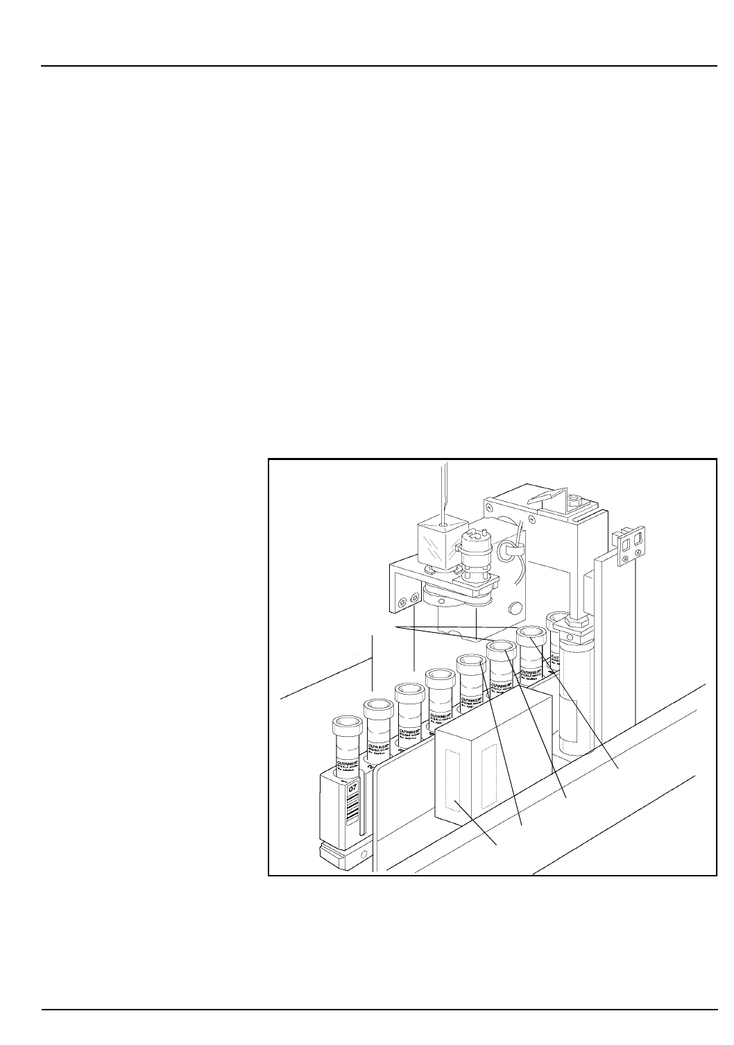
CELL-DYN® 3200 Operator’s Manual 13-13
9140181B — November 1997
Sample Loader
Section 13 Sample Loader Description
NOTE: Several Sample Loader-related error messages
refer to tube positions 3 and 4, which are Mixing
Stations 1 and 2 respectively. (Refer to Figure 13.7.)
Station 3, Vent/Aspiration: The tube is positioned for
aspiration. The bar code is read.
The spinner mechanism descends,
detects the tube height, grips and
spins the tube, allowing the Bar
Code Reader to read the label. The
tube stopper is punctured by the
Vent/Aspiration Needle (the
“Needle”) in the Tower Module.
The tube is vented and the sample
is aspirated.
These three stations are adjacent to each other. Each sample is
mixed twice before being vented and aspirated.
Figure 13.7: Sample Loader Stations
Station 1
Station 2
Station 3
Bar Code Reader
Tube Sensors
(behind Stations 1 & 2)
(tube position 3)
(tube position 4)
Go Back
Search
TOC

13-14 CELL-DYN® 3200 Operator’s Manual
9140181B — November 1997
Sample Loader
Sample Loader Description Section 13
Rack Movement
The tube racks move from the load side, through the mixing
and aspiration stations, to the unload side (refer to Figure
13.8). The rack closest to the Analyzer on the load side is the
first to be processed. This is the starting position for a rack.
Load Side
A set of mechanical arms on the load side pushes the racks
forward toward the Analyzer. If the arm does not sense a rack
on the load side, the Sample Loader emits 3 beeps to alert the
operator and displays a message on the Bulletin line stating
Loader Status 158: load zone empty.
When the 5th tube of a rack is at the Aspiration Station and no
more racks are detected on the load side, the Sample Loader
will emit three beeps to alert the operator that the last rack has
been processed. The message Loader Status 143: samples
completed is displayed on the bulletin line. Continuous
processing can be accomplished by adding more racks to the
load side and removing the processed racks from the unload
side.
Go Back
Search
TOC
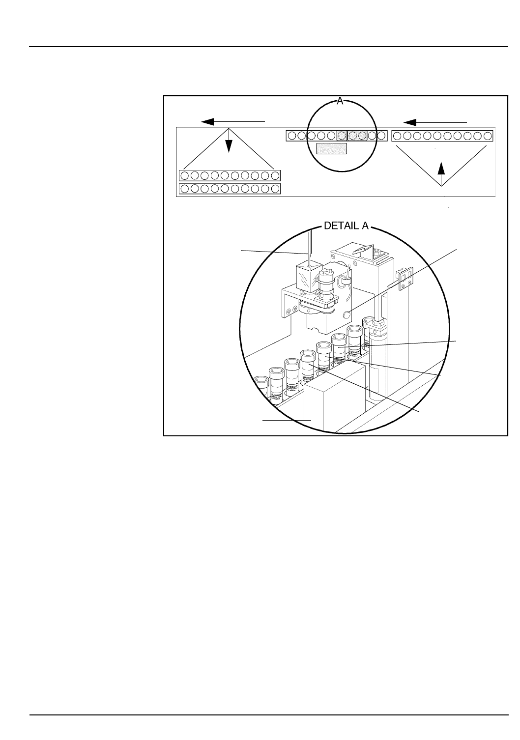
CELL-DYN® 3200 Operator’s Manual 13-15
9140181B — November 1997
Sample Loader
Section 13 Sample Loader Description
Figure 13.8: Rack Movement
Mixing and Aspiration Stations
A pneumatic-actuated mechanism advances the rack one
position at a time through the mixing and aspiration stations.
As the rack advances through the Mixing Stations, sensors
detect if a tube is at Mixing Station #1 or Mixing Station #2.
If a tube is detected at either station, the Mixer descends, grabs
one or both tubes, and mixes for approximately 20 seconds.
Each tube is mixed twice, once at each mixing station. After
being mixed at the second Mixing Station the tube advances
to the Aspiration Station where it is vented and aspirated.
When the 6th tube is at Station 3 (aspiration), the next rack on
the load side is pushed forward in preparation for processing.
Racks continue moving to the preparation position until either
the load side is empty or the unload side is full.
Rack Advance
Rack Advance
Unload Side
Load Side
Racks are pushed away
from the Analyzer
Racks are pushed
toward the Analyzer
Aspiration Needle
Mixing Block
Bar Code
Reader
Station 3
Station 2
Station 1
Go Back
Search
TOC

13-16 CELL-DYN® 3200 Operator’s Manual
9140181B — November 1997
Sample Loader
Sample Loader Description Section 13
After the last tube in a rack has been processed, the rack
continues moving until it reaches the left edge of the Sample
Loader. At this point, the rack is pushed to the most forward
position of the unload side to make room for the next racks.
If a malfunction occurs at the Mixing or Aspiration Stations,
the Sample Loader halts operation and emits a beep to alert
the operator. The
[CLEAR FAULT]
key is displayed, and a fault
message is displayed on the bulletin line.
Unload Side
When the rack reaches the edge of the left side, a mechanical
arm pushes the rack toward the front of the Sample Loader to
make room for the next rack being processed. The unload side
can accommodate 5 racks. A 5th rack, however, will prevent a
6th rack from being completely processed by interfering with
that rack’s movement through the Mixing and Aspiration
Stations.
If the unload side is full (5 racks) and a 6th rack is being
processed, the 6th rack can advance until the 6th tube
position is at the Aspiration Station (refer to Figure 13.9). If
position 6 has a sample, then that sample can be processed.
When processing is completed for that sample, the Sample
Loader will emit 3 beeps to alert the operator that the unload
side is full and the Sample Loader has stopped. The
[CLEAR
FAULT]
key is displayed, and the message Loader Warning
145: unload area full is displayed on the bulletin line.
The operator must remove racks from the unload side for the
6th rack to be completely processed.
Go Back
Search
TOC
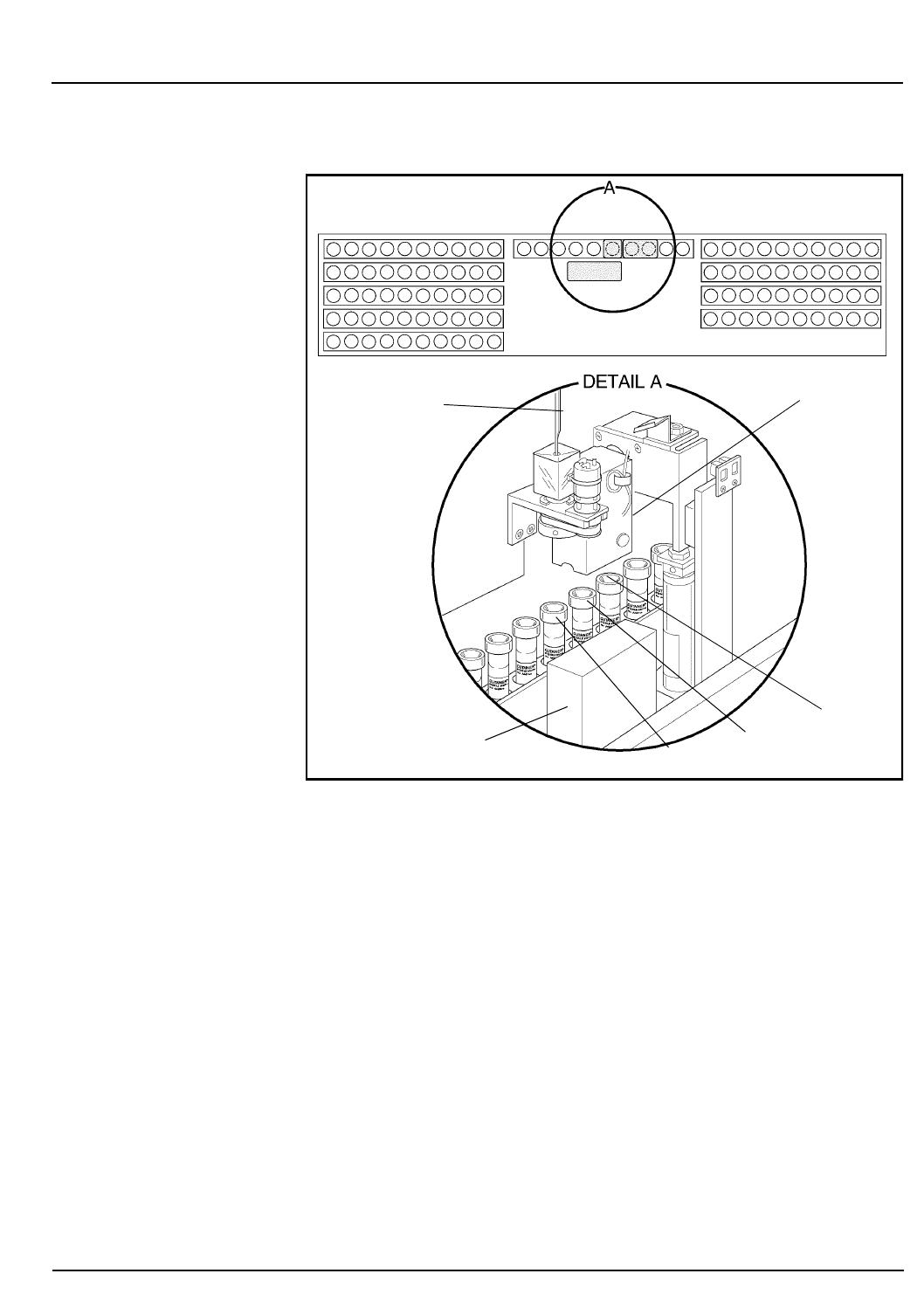
CELL-DYN® 3200 Operator’s Manual 13-17
9140181B — November 1997
Sample Loader
Section 13 Sample Loader Description
Figure 13.9: Unload Side Full
Sample Identification
Each rack must have a legible bar code label. If a rack has no
bar code label or if the label cannot be read by the Bar Code
Reader, the Sample Loader stops, and the message Loader
Fault 153: rack barcode read failure is displayed on
the bulletin line. No samples have been aspirated at this point.
The rack bar code label identifies each rack by number. The
system tracks the rack number and tube position for each
sample placed in the rack from the bar code reader signal.
Unload Side Load Side
Aspiration Needle
Mixing Block
Bar Code
Reader
Station 3
Station 2
Station 1
Go Back
Search
TOC

13-18 CELL-DYN® 3200 Operator’s Manual
9140181B — November 1997
Sample Loader
Sample Loader Description Section 13
The Sample Loader provides sample identification using an
LED-based Bar Code Reader at Station 3 (tube spinning/
aspiration). As each tube reaches Station 3, the sample tube is
rotated and the bar code reader is turned ON to read the bar
code label on the tube. If no bar code label is present or the
label is unreadable, the sample is identified by the rack
number and tube position, in the format RxTx, on the
RUN
screen and in the
DATA LOG
.
Operation of the Sample Loader with non-bar-coded samples is
allowed. However, the use of bar code labels is recommended
for positive sample identification. Refer to Section 5:
Operating Instructions, Subsection: Using the Work List for a
discussion of using the Work List with and without bar code
labels for sample identification.
Normally, non-bar-coded samples should not be removed
from the racks until all samples have been processed since the
rack and tube number of each sample is important for positive
sample identification.
If the rack being processed (under the Tower Cover) must be
removed before processing is completed (for example, the
system must be re-initialized to clear a Fatal Fault condition),
make a note of which tube was under the Aspiration Needle
before removing the rack. Follow the guidelines below:
1.Make sure the Sample Loader has stopped and the
Aspiration Needle has retracted. Remove the Tower Cover
if necessary.
2.If a fault occurred, correct the situation and press
[CLEAR FAULT]
.
3.If bar code labels are used for identification:
a.Check the Work List to determine if the entries
corresponding to the processed samples have been
deleted, indicating a match occurred and the data was
sent to the Data Log. It is permissible to remove those
samples before returning the rack to the starting
position.
b.Move the remaining tubes to the front of the rack and
place the rack in the starting position.
c.Go to step 5.
4.If rack and tube numbers are used for identification:
Go Back
Search
TOC

CELL-DYN® 3200 Operator’s Manual 13-19
9140181B — November 1997
Sample Loader
Section 13 Sample Loader Description
a. Check the Work List to determine if the entries
corresponding to the processed samples, based on
rack and tube number, have been deleted, indicating a
match occurred and the data was sent to the Data Log.
It is permissible to remove those samples before
returning the rack to the starting position.
b. DO NOT move the remaining tubes in the rack,
otherwise Work List entries will also have to be
changed to reflect the new rack and tube positions of
the remaining samples. Place the rack in the starting
position.
5. Replace the Tower Cover and press
[START LOADER]
followed by
[RESET LOADER]
to resume operations.
Stopping the Sample Loader
The Sample Loader automatically halts when all loaded racks
have been processed. There are three ways to stop the Sample
Loader during processing, as described below:
1. Power OFF. Turn the Main Power Switch on the Analyzer
to OFF. This method is not recommended unless there is
an emergency.
2. Orderly Stop. Press
[STOP LOADER]
for an orderly stop.
Orderly stops allow the vent/aspiration/cleaning process
to finish but doesn’t allow the next sample to be
aspirated. The
[START LOADER]
soft key appears and you
should press it to start the sample loading process. If the
sampling process has been interrupted for more than 20
seconds, the sampler will remix the sample before
aspiration and the process will continue.
3. Emergency Stop. Push the window section of the Tower
Cover toward the instrument to release the latches and
break the safety interlock sensor connection. Emergency
stops cause the Aspiration Needle to retract if already in
the tube and the Mixer to return the tube(s) to the rack
before bringing the Sample Loader to a halt. To
completely remove the cover, lift it vertically. An
emergency stop results in a Fatal Fault condition. To
resume the sampling process:
a. Re-initialize and prime the instrument. The Sample
Loader is automatically initialized when the Analyzer
is initialized.
Go Back
Search
TOC

13-20 CELL-DYN® 3200 Operator’s Manual
9140181B — November 1997
Sample Loader
Sample Loader Description Section 13
NOTE: To initialize the instrument, in the main
DIAGNOSTICS MENU
press
[MORE]
followed by
[INITIALIZATION]
. Refer to Section 10: Diagnostics and
Troubleshooting, Subsection: Second Diagnostics
Menu Screen. To prime the instrument, press
[RUN]
in
the
MAIN MENU
.
b.Move the rack that was under the Tower Cover to the
starting position and remove all processed samples.
c.Re-attach the Tower Cover.
d.When the system has been initialized and primed,
press
[START LOADER]
in the
RUN
menu to start
processing samples.
NOTE: The rack will not advance until the tubes, if
any, in Mixing Stations #1 and #2 are mixed again. If a
tube is sensed at Mixing Station #2, the Mixer will
perform two mixing cycles before the rack advances,
thereby ensuring that each tube is mixed at least twice
just prior to aspiration.
Go Back
Search
TOC

CELL-DYN® 3200 Operator’s Manual 13-21
9140181B — November 1997
Sample Loader
Section 13 Sample Loader Operation
Sample Loader Operation
Prior to activating the Sample Loader, racks containing tubes
to be processed should be placed on the load side of the
Sample Loader (refer to Figure 13.8).
Sample Loader Cycle
The following sequence is a basic description of the events that
occur from the time that the instrument is turned ON through
the complete processing cycle. During the cycle, the number
of tube racks is monitored by optical interrupt sensors located
on the Transport Mechanisms.
NOTE: The Sample Loader can operate with any
number of racks, the minimum being one.
1. The Sample Loader is initialized each time the instrument
is turned ON, each time the instrument is re-initialized,
and each time it completes a cycle (at least one rack has
moved through the Mixing and Aspiration Stations and
no more racks are detected on the load side).
2. When the Sample Loader has been initialized and is in
the READY state, the message
READY
is displayed in the
Status Box.
3. When the
[START LOADER]
key in the
RUN
screen is pressed,
the Sample Loader pushes the rack(s) on the load side
closest to the Analyzer.
a. As the rack advances, the sensor at Mixing Station 1
searches for a tube.
b. Even if there are no tubes present in the rack, the
Transport Mechanism continues to move the rack
under the Tower Cover until a sample tube is sensed
in Mixing Station 1.
c. If a sample tube is detected, the mixing and vent/
aspiration mechanisms will process the sample.
4. The Mixing Head moves down, picks up the tube, and
begins mixing it.
Go Back
Search
TOC

13-22 CELL-DYN® 3200 Operator’s Manual
9140181B — November 1997
Sample Loader
Sample Loader Operation Section 13
5. The first sample is mixed by 135o rotation for
approximately 20 seconds. If the loader is stopped and
then allowed to resume (by use of the
[RESUME LOADER]
soft key) the sample tube in Mixing Station 2 will mix for
20 seconds, stop briefly, and resume mixing for another
20 seconds. The total mixing time for each sample is
approximately 40 seconds.
NOTE: Tubes with more than three layers of labels on
them or with label flaps sticking out can cause
problems for the Mixing Assembly. The assembly may
not be able to pick the tube up because the labels cause
the tube to stick to the rack. The assembly may also
have trouble fitting the tube back into the rack for the
same reason.
6. When a tube has been properly mixed, it moves to the
Vent/Aspiration Station (Station 3).
a. When the Needle begins to move down, the Spinning
Assembly moves down to (a) position the tube so that
the stopper is pierced at or near the center, and to (b)
rotate the tube so that the bar code can be read.
b. The needle stops moving while the bar code label is
being read.
c. After the label is read, the needle continues moving
down. It pierces the stopper and moves to the bottom
of the tube.
d. The Sample Loader signals the Analyzer to vent the
tube and aspirate the sample.
e. The sample is pulled into the Shear Valve by vacuum
action. The Analyzer then begins a normal count
cycle.
7. When an empty space is detected by both Mixing Station
sensors, the rack automatically advances without
engaging the Mixer. When an empty space is detected by
the sensor on the Tower, the Needle and Spinner are not
engaged as the rack advances. The Mixing Assembly and
Tower Assembly will not be engaged until a tube is sensed
at either Mixing Station.
Go Back
Search
TOC

CELL-DYN® 3200 Operator’s Manual 13-23
9140181B — November 1997
Sample Loader
Section 13 Sample Loader Operation
NOTE: The Instrument operates most efficiently when
tubes in a rack are adjacent to one another. Generally,
spacing between sample tubes will have an impact on
overall throughput. If there are numerous empty
spaces, then throughput time may be significantly
slowed.
8. After the sample is aspirated, the Needle is retracted and
washed. As the Needle moves up, the Spinning Assembly
also retracts.
9. Steps 4-8 are repeated until all tubes in the rack have been
processed.
10. Regardless of how many tubes are in a rack, when the
rack has moved completely under the Tower Cover, the
second rack is moved into position on the right side of
the Cover in preparation for sample processing.
11. When all tubes in the last rack have been processed:
a. The Sample Loader automatically stops and emits
beeps to alert the operator that processing is
completed
b. The message Loader Status 43: samples
completed is displayed in the bulletin line when the
rack has traversed completely to the unload side.
c. The
[STOP LOADER]
key toggles to
[START LOADER].
d. The Sample Loader is re-initialized.
Operating Procedures
1. Press the
[START LOADER]
key in the
RUN
menu. Based on
which condition exists (refer to the Soft Keys section),
either the Sample Loader will be activated or a submenu
will be displayed.
2. If the submenu is displayed, press either
[RESUME LOADER]
or
[RESET LOADER]
(refer to the Soft Keys subsection for a
discussion of when to use each key).
3. Racks are moved in sequential order from the load side,
through the Mixing and Aspiration Stations to the unload
side (refer to Figure 13.8).
4. For sample mixing and aspiration to occur, the sensors
must detect a tube in the rack. The Sample Loader
automatically stops after the last rack is processed and no
more racks are detected on the load side.
Go Back
Search
TOC

13-24 CELL-DYN® 3200 Operator’s Manual
9140181B — November 1997
Sample Loader
Sample Loader Operation Section 13
5. When the tube is at the Vent/Aspiration Station, the
Spinner positions the tube vertically in the rack, spins the
tube for bar code reading, and holds the tube while it is
vented and the sample aspirated. Proper positioning is
necessary for the tube stopper to be pierced in the center.
6. The Tower Cover on the 3200SL model fits over the
Mixing Station and Bar Code Reader on the loader. This
cover prevents aerosol contamination and exposure to
the needle while the Sample Loader is processing
specimens.
NOTE: The Sample Loader has an interlock switch that
prevents operation when the Tower Cover is not in
place. If the Tower Cover is removed during Sample
Loader operation, processing is immediately halted. For
an orderly stop, the operator must press the
[STOP LOADER]
key and wait for the Sample Loader and
Analyzer to stop processing before lifting or removing
the cover. Lifting the cover while the Sample Loader is
operating causes an immediate Emergency Stop
condition. The entire system must be re-initialized.
Go Back
Search
TOC

CELL-DYN® 3200 Operator’s Manual 13-25
9140181B — November 1997
Sample Loader
Section 13 Routine Operating Procedures
Routine Operating Procedures
Installation
For detailed instructions on how to install the SL model, refer
to Section 2: Installation and Special Procedures.
Running Samples
Instructions for Routine Operation of the 3200SL model are
given in Section 5: Operating Instructions.
Maintenance
Maintenance procedures on the SL model should be performed
as directed in Section 9: Service and Maintenance. These
procedures consist of cleaning the Tower Cover, the Needle,
the tray and the tube racks. If the Vent/Aspiration Needle
requires replacement, refer to Section 9: Subsection: Closed
Sample Needle Replacement.
Troubleshooting
If a Sample Loader fault, error or other problem is detected, an
alert message is displayed on the bulletin line of the screen.
For a list of messages, descriptions of possible problems and
recommended actions, refer to Section 10: Diagnostics and
Troubleshooting.
Go Back
Search
TOC

13-26 CELL-DYN® 3200 Operator’s Manual
9140181B — November 1997
Sample Loader
Routine Operating Procedures Section 13
NOTES
Go Back
Search
TOC

CELL-DYN® 3200 Operator’s Manual Appendix A-1
9140181B — November 1997
Bar Codes
Appendix A Overview
Overview
This section gives a brief overview of what bar coding is, how
bar code labels are used for data entry, and the different types
of bar codes that may be used with the CELL-DYN® 3200
System.
Bar coding is an automated method of gathering
alphanumeric information and transmitting it to a computer.
Because it eliminates typing and associated errors, bar coding
offers speed, increased accuracy, and efficiency. The following
are the major elements in a bar coding system:
• The computer and appropriate software interprets and
stores bar code data. For the CELL-DYN 3200 System, this
is accomplished by the Data Station and its software.
• The scanning device "decodes" the information on the
bar code labels. The Tower Module on the CELL-DYN
3200 System incorporates an integral bar code reader,
allowing the use of bar codes on both the SL and CS
models.
• The bar code labels contain the specimen identification
codes.
Go Back
Search
TOC

Appendix A-2 CELL-DYN® 3200 Operator’s Manual
9140181B — November 1997
Bar Codes
Overview Appendix A
Bar Code Function
The bar code label contains the actual identifying data for
specimens in the form of a series of black bars and contrasting
white spaces, which represent numbers and letters. The
arrangement of the code follows one of several sets of rules for
bar code languages, called symbologies. To decode the data in
the label, a scanning device is used to pass a small spot of light
over the bars and spaces to read them.
Since dark bars reflect little light back into the scanning
device, while white space reflects a lot of light, a light detector
inside the scanner can translate the differences in reflection
into electrical signals. The signals are then converted into the
sets of ones and zeros (the binary system used by computers)
that stand for numbers and letters.
Understanding the Label’s Code
In all bar code symbologies, the code consists of elements
(single bars or white spaces) and characters (groups of
elements that stand for numbers or letters). In code 39, a
commonly used symbology, each code character contains
nine elements, at least three of which must be wide. Wide
elements (whether they are bars or spaces) in this symbology
have a binary value of 1. Narrow elements have a binary value
of 0.
Most contemporary bar code systems have several features in
common. These include the following:
•The
Quiet Zone is the area immediately before and after
the bar code symbol. This zone enables the scanner to
read the code properly.
•Start and Stop Characters indicate the beginning and end
of the bar code symbol. They allow the label to be
scanned from either right to left or left to right, ensuring
that code information is transmitted correctly.
•Intercharacter Gaps act as spaces between each character in
the bar code symbol. Code 39 contains these gaps.
However, there are other codes, such as Interleaved 2 of
5, that do not use them.
Go Back
Search
TOC

CELL-DYN® 3200 Operator’s Manual Appendix A-3
9140181B — November 1997
Bar Codes
Appendix A Overview
•The
Interpretation Line is an area at the bottom of the bar
code label where human-readable information can be
placed. This may or may not be the same data as in the
label code.
•The
Check Digit is an extra numeric character in the bar
code that permits the scanning device to mathematically
determine whether it read the code correctly. This keeps
the error rate as low as one for every billion characters
scanned.
Bar Code Types and Characteristics
The CELL-DYN 3200 System reads four types of bar code
labels:
• Code 39
• Code 128
• Interleaved 2 of 5
•Codabar
Go Back
Search
TOC

Appendix A-4 CELL-DYN® 3200 Operator’s Manual
9140181B — November 1997
Bar Codes
Overview Appendix A
Code 39
Also referred to as code 3 of 9, Code 39 encodes 43 data
characters: 0-9, A-Z, six symbols, and spaces. Every Code 39
character has five bars and four spaces. Of these nine
elements, three are wide and six are narrow, making Code 39 a
two-width code.
Code 128
Code 128 has 106 different printed characters. Each character
has three bars and three spaces comprising 11 modules. Each
printed character can have one of three different meanings,
depending on which of three different character sets is used.
Three different start characters tell the reader which of the
character sets is initially being used, and three shift codes
permit changing the character set inside a symbol.
Interleaved 2 of 5
Interleaved 2 of 5 encodes the 10 numeric digits 0-9. The
name is derived from the method used to encode two
characters that are paired together. Bars represent the first
character, and the interleaved spaces represent the second
character. Each character has two wide elements and three
narrow elements, for a total of five elements.
Codabar
Codabar uses four bars and three spaces to represent the 10
numeric digits 0-9 and certain special characters. The code is
characterized by four unique start/stop codes and variable
intercharacter spacing.
Go Back
Search
TOC

CELL-DYN® 3200 Operator’s Manual Appendix A-5
9140181B — November 1997
Bar Codes
Appendix A Specifications
Specifications
Bar Code Label Formats
The Bar Code Reader on the CELL-DYN® 3200 System can
read all four label types listed below. Code size, collection tube
length, and cap style limit the number of digits to the
following maximum numbers:
•Code 39 — 9 digits
•Code 128 — 11 digits
•Interleaved 2 of 5 — 10 or 12 digits only
•Codabar — 10 digits
NOTE: The maximum number of digits includes any
check digits within the code. For example, if one check
digit is used in Code 39, then only 8 digits can be used
for the rest of the code.
Bar Code Check Digit Formats
Bar code Check Digits are used whenever the instrument is to
read a specific type of bar code. To enable or disable the check
digit option, refer to Section 5: Operating Instructions,
Subsection: Bar Code Set Up.
Check Digit specifications are as follows:
•Code 39 - The modulus 43 sum of all the character values
in a given message
•Code 128 - The check digit is built into the Bar Code
Reader.
•Interleave 2 of 5 - The check digit is the complement of
the weighted sum of the digits modulo 10. To determine
the weight of the digits, multiply every other digit by 3,
starting with the first.
•Codabar - The modulus 16 sum of all the character values
in a given message.
Go Back
Search
TOC

Appendix A-6 CELL-DYN® 3200 Operator’s Manual
9140181B — November 1997
Bar Codes
Specifications Appendix A
NOTE: If a specific check digit option is selected and
turned ON, the Bar Code reader will read only bar
codes in that specific format. If more than one format
will be used on the instrument, it is recommended that
the check digit option be turned OFF.
Bar Code Label Specifications
Bar code labels must be printed on good quality label stock
and must meet the following specifications:
• 0.25 inch minimum quiet zone on each end
• 0.01 inch (10 mils) minimum narrow bar width
• 2:1 to 3:1 wide to narrow bar ratio
• 0.5 inch minimum bar length
• 2 inch maximum label length
• 1.25 inch maximum label width
• Maximum possible contrast between bars and
background label
CELL-DYN Bar Code Labels
CELL-DYN 4-digit Code 39 bar code labels, in rolls of 1000
labels each, can be ordered with list number L/N 99650-01.
These labels may be used for positive specimen identification
when laboratory-generated bar code labels are unavailable.
Bar Code Label Placement
The following two guidelines should be observed when
placing bar code labels on specimen tubes (refer to Figure A.1):
1. All labels should be placed on the tubes securely and
without flaps sticking out. Refer to the following figure.
Go Back
Search
TOC
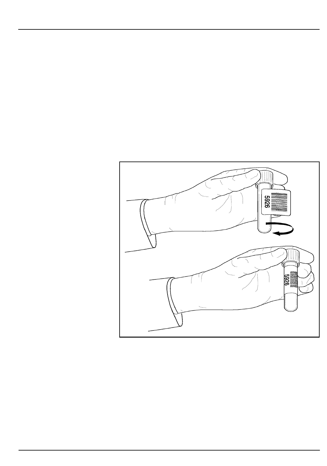
CELL-DYN® 3200 Operator’s Manual Appendix A-7
9140181B — November 1997
Bar Codes
Appendix A Specifications
2. The bar code label should be placed on the tube just
below the stopper with the bars perpendicular to the
length of the tube. This will ensure that the entire bar
code can be viewed through the slot in the rack as the
tube rotates. Be sure that at least 0.10 inch (about 1/8
inch) of space is left between (a) the bar code symbol and
the bottom of the rack slot and (b) between the bar code
symbol and tube cap. This spacing will satisfy the "quiet
zone" requirement. Refer to the following figure for
proper bar code placement.
Figure 1.1: Bar Code Placement Guide
Go Back
Search
TOC

Appendix A-8 CELL-DYN® 3200 Operator’s Manual
9140181B — November 1997
Bar Codes
Specifications Appendix A
NOTES
Go Back
Search
TOC

CELL-DYN® 3200 Operator’s Manual Appendix A-9
9140181B — November 1997
Bar Codes
Appendix A Bar Code Operation
Bar Code Operation
Tables A.1 and A.2 at the end of this section summarize how
the bar code reader reads and interprets bar code labels under
different Set Up scenarios, and what information is sent to the
Data Log. Table A.1 shows bar code operation for the SL
model, and Table A.2 shows it for the CS model. The system
can take a number of actions depending on the Bar Code Set
Up configuration and the symbology of the label. A brief
description of each possible action is given below.
Code 39
If the Instrument is configured for Code 39 with Check Digit
ON, the Instrument will:
a. read a Code 39 label with check digit.
If the check digit on the label matches the check digit
calculated by the Instrument, the “read” is good and
the Work List is searched for a matching bar code
number in the Specimen ID field. If a matching entry
is found in the Work List, the entry is sent to the Data
Log and deleted from the Work List. If no matching
entry is found, the specimen is identified in the Data
Log by the tube bar code number in the Specimen ID
field.
If the check digits do not match, the “read” is not
good and a Check Digit Error message is displayed on
the Bulletin line. The Work List is not searched. For SL
models, the Rack and Tube # is assigned to the
Specimen ID field for that specimen in the Data Log.
For CS models, only the Sequence # is used to identify
that specimen in the Data Log.
Go Back
Search
TOC

Appendix A-10 CELL-DYN® 3200 Operator’s Manual
9140181B — November 1997
Bar Codes
Bar Code Operation Appendix A
b. read a Code 39 label without a check digit.
The system reports a Check Digit Error message on
the Bulletin line. The Work List is not searched. For SL
models, the specimen is identified in the Data Log by
the Rack and Tube number assigned to the Specimen
ID field by the Instrument. For CS models, the
specimen is identified in the Data Log by the
Sequence number. The Specimen ID field is left blank.
c. ignore all other bar code symbologies.
A Bar Code Error message is displayed on the Bulletin
line and the Work List is not searched. For SL models,
the specimen is identified in the Data Log by the Rack
and Tube number assigned to the Specimen ID field
by the Instrument. For CS models, the specimen is
identified in the Data Log by the Sequence number
only and the Specimen ID field is left blank.
If the Instrument is configured for Code 39 with Check Digit
OFF, the Instrument will:
a. read a Code 39 label with a check digit.
The bar code reader reads the entire number
including the check digit and the Work List is
searched. Because the bar code label has one extra
digit (check digit), no matching entry will be found in
the Work List (which should not contain the check
digit). For SL models, the specimen is identified in the
Data Log by the tube bar code number in the
Specimen ID field. For CS models, the specimen is
identified in the Data Log by the Sequence number
only and the Specimen ID field is left blank.
Go Back
Search
TOC

CELL-DYN® 3200 Operator’s Manual Appendix A-11
9140181B — November 1997
Bar Codes
Appendix A Bar Code Operation
b. read a Code 39 label without a check digit.
The “read” is assumed to be good (without a check
digit the bar code number cannot be verified) and the
Work List is searched for a matching bar code number
in the Specimen ID field. If a matching entry is found
in the Work List, the entry is sent to the Data Log and
deleted from the Work List. If no matching entry is
found, the specimen is identified in the Data Log by
the tube bar code number in the Specimen ID field.
c. ignore all other bar code symbologies.
A Bar Code Error message is displayed on the Bulletin
line and the Work List is not searched. For SL models,
the specimen is identified in the Data Log by the Rack
and Tube number assigned to the Specimen ID field
by the Instrument. For CS models, the specimen is
identified in the Data Log by the Sequence number
only and the Specimen ID field is left blank.
I2of5
If the Instrument is configured for I2of5 with Check Digit ON,
the Instrument will:
a. read an I2of5 label with check digit.
If the check digit on the label matches the check digit
calculated by the Instrument, the “read” is good and
the Work List is searched for a matching bar code
number in the Specimen ID field. If a matching entry
is found in the Work List, the entry is sent to the Data
Log and deleted from the Work List. If no matching
entry is found, the specimen is identified in the Data
Log by the tube bar code number in the Specimen ID
field.
If the check digits do not match, the “read” is not
good and a Check Digit Error message is displayed on
the Bulletin line. The Work List is not searched. For SL
models, the Rack and Tube # is assigned to the
Specimen ID field for that specimen in the Data Log.
For CS models, only the Sequence # is used to identify
that specimen in the Data Log.
Go Back
Search
TOC

Appendix A-12 CELL-DYN® 3200 Operator’s Manual
9140181B — November 1997
Bar Codes
Bar Code Operation Appendix A
b. read an I2of5 label without a check digit.
The system reports a Check Digit Error message on
the Bulletin line. The Work List is not searched. For SL
models, the specimen is identified in the Data Log by
the Rack and Tube number assigned to the Specimen
ID field by the Instrument. For CS models, the
specimen is identified in the Data Log by the
Sequence number. The Specimen ID field is left blank.
c. ignore all other bar code symbologies.
A Bar Code Error message is displayed on the Bulletin
line and the Work List is not searched. For SL models,
the specimen is identified in the Data Log by the Rack
and Tube number assigned to the Specimen ID field
by the Instrument. For CS models, the specimen is
identified in the Data Log by the Sequence number
only and the Specimen ID field is left blank.
If the Instrument is configured for I2of5 with Check Digit OFF,
the Instrument will:
a. read an I2of5 label with a check digit.
If the check digit on the label matches the check digit
calculated by the Instrument, the “read” is good and
the Work List is searched for a matching bar code
number in the Specimen ID field. If a matching entry
is found in the Work List, the entry is sent to the Data
Log and deleted from the Work List. If no matching
entry is found, the specimen is identified in the Data
Log by the tube bar code number in the Specimen ID
field.
If the check digits do not match, the “read” is not
good and a Check Digit Error message is displayed on
the Bulletin line. The Work List is not searched. For SL
models, the Rack and Tube # is assigned to the
Specimen ID field for that specimen in the Data Log.
For CS models, only the Sequence # is used to identify
that specimen in the Data Log.
Go Back
Search
TOC

CELL-DYN® 3200 Operator’s Manual Appendix A-13
9140181B — November 1997
Bar Codes
Appendix A Bar Code Operation
b. read an I2of5 label without a check digit.
The system reports a Check Digit Error message on the
Bulletin line. The Work List is not searched. For SL
models, the specimen is identified in the Data Log by
the Rack and Tube number assigned to the Specimen
ID field by the Instrument. For CS models, the
specimen is identified in the Data Log by the
Sequence number. The Specimen ID field is left blank.
c. ignore all other bar code symbologies.
A Bar Code Error message is displayed on the Bulletin
line and the Work List is not searched. For SL models,
the specimen is identified in the Data Log by the Rack
and Tube number assigned to the Specimen ID field
by the Instrument. For CS models, the specimen is
identified in the Data Log by the Sequence number
only and the Specimen ID field is left blank.
Codabar
If the Instrument is configured for Codabar with Check Digit
ON, the Instrument will:
a. read a Codabar label with check digit.
If the check digit on the label matches the check digit
calculated by the Instrument, the “read” is good and
the Work List is searched for a matching bar code
number in the Specimen ID field. If a matching entry
is found in the Work List, the entry is sent to the Data
Log and deleted from the Work List. If no matching
entry is found, the specimen is identified in the Data
Log by the tube bar code number in the Specimen ID
field.
If the check digits do not match, the “read” is not
good and a Check Digit Error message is displayed on
the Bulletin line. The Work List is not searched. For SL
models, the Rack and Tube # is assigned to the
Specimen ID field for that specimen in the Data Log.
For CS models, only the Sequence # is used to identify
that specimen in the Data Log.
Go Back
Search
TOC

Appendix A-14 CELL-DYN® 3200 Operator’s Manual
9140181B — November 1997
Bar Codes
Bar Code Operation Appendix A
b. read an Codabar label without a check digit.
The system reports a Check Digit Error message on
the Bulletin line. The Work List is not searched. For SL
models, the specimen is identified in the Data Log by
the Rack and Tube number assigned to the Specimen
ID field by the Instrument. For CS models, the
specimen is identified in the Data Log by the
Sequence number. The Specimen ID field is left blank.
c. ignore all other bar code symbologies.
A Bar Code Error message is displayed on the Bulletin
line and the Work List is not searched. For SL models,
the specimen is identified in the Data Log by the Rack
and Tube number assigned to the Specimen ID field
by the Instrument. For CS models, the specimen is
identified in the Data Log by the Sequence number
only and the Specimen ID field is left blank.
If the Instrument is configured for Codabar with Check Digit
OFF, the Instrument will:
a. read a Codabar label with a check digit.
The bar code reader reads the entire number
including the check digit and the Work List is
searched. Because the bar code label has one extra
digit (check digit), no matching entry will be found in
the Work List (which should not contain the check
digit). For SL models, the specimen is identified in the
Data Log by the tube bar code number in the
Specimen ID field. For CS models, the specimen is
identified in the Data Log by the Sequence number
only and the Specimen ID field is left blank.
b. read a Codabar label without a check digit.
The “read” is assumed to be good (without a check
digit the bar code number cannot be verified) and the
Work List is searched for a matching bar code number
in the Specimen ID field. If a matching entry is found
in the Work List, the entry is sent to the Data Log and
deleted from the Work List. If no matching entry is
found, the specimen is identified in the Data Log by
the tube bar code number in the Specimen ID field.
Go Back
Search
TOC

CELL-DYN® 3200 Operator’s Manual Appendix A-15
9140181B — November 1997
Bar Codes
Appendix A Bar Code Operation
c. ignore all other bar code symbologies.
A Bar Code Error message is displayed on the Bulletin
line and the Work List is not searched. For SL models,
the specimen is identified in the Data Log by the Rack
and Tube number assigned to the Specimen ID field
by the Instrument. For CS models, the specimen is
identified in the Data Log by the Sequence number
only and the Specimen ID field is left blank.
Code 128
If the Instrument is configured for Code 128, the check digit
feature is automatically ON and the Instrument will:
a. read a Code 128 label.
If the check digit on the label matches the check digit
calculated by the Instrument, the “read” is good and
the Work List is searched for a matching bar code
number in the Specimen ID field. If a matching entry
is found in the Work List, the entry is sent to the Data
Log and deleted from the Work List. If no matching
entry is found, the specimen is identified in the Data
Log by the tube bar code number in the Specimen ID
field.
If the check digits do not match, the “read” is not
good and a Check Digit Error message is displayed on
the Bulletin line. The Work List is not searched. For SL
models, the Rack and Tube # is assigned to the
Specimen ID field for that specimen in the Data Log.
For CS models, only the Sequence # is used to identify
that specimen in the Data Log.
b. ignore all other bar code symbologies.
A Bar Code Error message is displayed on the Bulletin
line and the Work List is not searched. For SL models,
the specimen is identified in the Data Log by the Rack
and Tube number assigned to the Specimen ID field
by the Instrument. For CS models, the specimen is
identified in the Data Log by the Sequence number
only and the Specimen ID field is left blank.
Go Back
Search
TOC

Appendix A-16 CELL-DYN® 3200 Operator’s Manual
9140181B — November 1997
Bar Codes
Bar Code Operation Appendix A
NOTES:
Go Back
Search
TOC
Appendix A-17 CELL-DYN® 3200 Operator’s Manual
9140181B — November 1997
Bar Codes
Bar Code Operation Appendix A
TABLE A-1. Bar Code Operation - SL Model
CODE 39 with
Check Digit ON CODE 39 with
Check Digit OFF I2OF5 with
Check Digit ON I2OF5 with
Check Digit OFF CODABAR with
Check Digit ON CODABAR with
Check Digit OFF CODE 128
Code 39
label with
Check digit
Reads label. If
check digit cor-
rect, Work List
is searched. If
match found,
Work List entry
sent to Data
Log. If no
match found,
tube bar code
assigned as
Specimen ID
and sent to
Data Log. If
check digit
incorrect,
check digit
error occurs
and rack and
tube # is
assigned as
Specimen ID
and sent to
Data Log.
Reads label.
Check digit
added to bar
code number.
Work List
searched.
Because check
digit added to
number, no
Work List
match. Tube
bar code
including check
digit assigned
as Specimen ID
and sent to
Data Log.
Unable to read
label. Bar code
error. Work List
not searched.
Rack and tube #
assigned as
Specimen ID
and sent to
Data Log.
Same as
“I2OF5 with
Check Digit
ON.”
Same as
“I2OF5 with
Check Digit
ON.”
Same as
“I2OF5 with
Check Digit
ON.”
Same as
“I2OF5 with
Check Digit
ON.”
Go Back
Search
TOC

Appendix A-18 CELL-DYN® 3200 Operator’s Manual
9140181B — November 1997
Bar Codes
Bar Code Operation Appendix A
Code 39
label with-
out Check
Digit
Reads label.
Check digit
error occurs.
Work List not
searched. Rack
and tube # is
assigned as
Specimen ID
and sent to
Data Log.
Reads label.
Work List
searched. If
match found,
Work List entry
sent to Data
Log. If no
match found,
tube bar code
assigned as
Specimen ID
and sent to
Data Log.
Unable to read
label. Bar code
error. Work List
not searched.
Rack and tube #
assigned as
Specimen ID
and sent to
Data Log.
Same as
“I2OF5 with
Check Digit
ON.”
Same as
“I2OF5 with
Check Digit
ON.”.
Same as
“I2OF5 with
Check Digit
ON.”
Same as
“I2OF5 with
Check Digit
ON.”
TABLE A-1. Bar Code Operation - SL Model
CODE 39 with
Check Digit ON CODE 39 with
Check Digit OFF I2OF5 with
Check Digit ON I2OF5 with
Check Digit OFF CODABAR with
Check Digit ON CODABAR with
Check Digit OFF CODE 128
Go Back
Search
TOC

Appendix A-19 CELL-DYN® 3200 Operator’s Manual
9140181B — November 1997
Bar Codes
Bar Code Operation Appendix A
I2of5 label
with Check
Digit
Unable to read
label. Bar code
error. Work List
not searched.
Rack and tube #
assigned as
Specimen ID
and sent to
Data Log.
Same as
“CODE 39
with Check
Digit ON.”
Reads label. If
check digit cor-
rect, Work List
is searched. If
match found,
Work List entry
sent to Data
Log. If no
match found,
tube bar code
assigned as
Specimen ID
and sent to
Data Log. If
check digit
incorrect,
check digit
error occurs
and rack and
tube # assigned
as Specimen ID
and sent to
Data Log.
Reads label.
Check digit
added to bar
code number.
Work List
searched.
Because check
digit added to
number, no
Work List
match. Tube
bar code
including check
digit assigned
as Specimen ID
and sent to
Data Log.
Same as
“CODE 39
with Check
Digit ON.”
Same as
“CODE 39
with Check
Digit ON.”
Same as
“CODE 39
with Check
Digit ON.”
TABLE A-1. Bar Code Operation - SL Model
CODE 39 with
Check Digit ON CODE 39 with
Check Digit OFF I2OF5 with
Check Digit ON I2OF5 with
Check Digit OFF CODABAR with
Check Digit ON CODABAR with
Check Digit OFF CODE 128
Go Back
Search
TOC

Appendix A-20 CELL-DYN® 3200 Operator’s Manual
9140181B — November 1997
Bar Codes
Bar Code Operation Appendix A
I2of5 label
without
Check Digit
Unable to read
label. Bar code
error. Work List
not searched.
Rack and tube #
assigned as
Specimen ID
and sent to
Data Log.
Same as
“CODE 39
with Check
Digit ON.”
Reads label.
Check digit
error occurs.
Work List not
searched. Rack
and tube #
assigned as
Specimen ID
and sent to
Data Log.
Reads label.
Work List
searched. If
match found,
Work List entry
sent to Data
Log. If no
match found,
tube bar code
assigned as
Specimen ID
and sent to
Data Log.
Same as
“CODE 39
with Check
Digit ON.”
Same as
“CODE 39
with Check
Digit ON.”
Same as
“CODE 39
with Check
Digit ON.”
TABLE A-1. Bar Code Operation - SL Model
CODE 39 with
Check Digit ON CODE 39 with
Check Digit OFF I2OF5 with
Check Digit ON I2OF5 with
Check Digit OFF CODABAR with
Check Digit ON CODABAR with
Check Digit OFF CODE 128
Go Back
Search
TOC
Appendix A-21 CELL-DYN® 3200 Operator’s Manual
9140181B — November 1997
Bar Codes
Bar Code Operation Appendix A
CODABAR
label with
Check Digit
Unable to read
label. Bar code
error. Work List
not searched.
Rack and tube #
assigned as
Specimen ID
and sent to
Data Log.
Same as “Code
39 with Check
Digit ON.”
Same as “Code
39 with Check
Digit ON.”
Same as “Code
39 with Check
Digit ON.”
Reads label. If
check digit cor-
rect, Work List
is searched. If
match found,
Work List entry
sent to Data
Log. If no
match found,
tube bar code
assigned as
Specimen ID
and sent to
Data Log. If
check digit
incorrect,
check digit
error occurs
and rack and
tube # assigned
as Specimen ID
and sent to
Data Log.
Reads label.
Check digit
added to bar
code number.
Work List
searched.
Because check
digit added to
number, no
Work List
match. Tube
bar code
including check
digit assigned
as Specimen ID
and sent to
Data Log.
Same as
“Code 39
with Check
Digit ON.”
TABLE A-1. Bar Code Operation - SL Model
CODE 39 with
Check Digit ON CODE 39 with
Check Digit OFF I2OF5 with
Check Digit ON I2OF5 with
Check Digit OFF CODABAR with
Check Digit ON CODABAR with
Check Digit OFF CODE 128
Go Back
Search
TOC
Appendix A-22 CELL-DYN® 3200 Operator’s Manual
9140181B — November 1997
Bar Codes
Bar Code Operation Appendix A
CODABAR
label with-
out Check
Digit
Unable to read
label. Bar code
error. Work List
not searched.
Rack and tube #
assigned as
Specimen ID
and sent to
Data Log.
Same as “Code
39 with Check
Digit ON.”
Same as “Code
39 with Check
Digit ON.”
Same as “Code
39 with Check
Digit ON.”
Reads label.
Check digit
error occurs.
Work List not
searched. Rack
and tube #
assigned as
Specimen ID
and sent to
Data Log.
Reads label.
Work List
searched. If
match found,
Work List entry
sent to Data
Log. If no
match found,
tube bar code
assigned as
Specimen ID
and sent to
Data Log.
Same as
“Code 39
with Check
Digit ON.”
TABLE A-1. Bar Code Operation - SL Model
CODE 39 with
Check Digit ON CODE 39 with
Check Digit OFF I2OF5 with
Check Digit ON I2OF5 with
Check Digit OFF CODABAR with
Check Digit ON CODABAR with
Check Digit OFF CODE 128
Go Back
Search
TOC
Appendix A-23 CELL-DYN® 3200 Operator’s Manual
9140181B — November 1997
Bar Codes
Bar Code Operation Appendix A
NOTE: Bar Code # and Rack and Tube # are placed in Specimen ID field in the Data Log.
Code 128
label (built-
in Check
Digit)
Unable to read
label. Bar code
error. Work List
not searched.
Rack and tube #
assigned to
sample as Speci-
men ID and
sent to Data
Log.
Same as “Code
39 with Check
Digit ON.”
Same as “Code
39 with Check
Digit ON.”
Same as “Code
39 with Check
Digit ON.”
Same as “Code
39 with Check
Digit ON.”
Same as “Code
39 with Check
Digit ON.”
Reads label.
If check digit
correct, Work
List is
searched. If
match found,
Work List
entry sent to
Data Log. If
no match
found, tube
bar code
assigned as
Specimen ID
and sent to
Data Log. If
check digit
incorrect,
check digit
error occurs
and rack and
tube #
assigned as
Specimen ID
and sent to
Data Log.
TABLE A-1. Bar Code Operation - SL Model
CODE 39 with
Check Digit ON CODE 39 with
Check Digit OFF I2OF5 with
Check Digit ON I2OF5 with
Check Digit OFF CODABAR with
Check Digit ON CODABAR with
Check Digit OFF CODE 128
Go Back
Search
TOC

Appendix A-24 CELL-DYN® 3200 Operator’s Manual
9140181B — November 1997
Bar Codes
Bar Code Operation Appendix A
TABLE A-2. Bar Code Operations - CS Model
CODE 39 with
Check Digit ON CODE 39 with
Check Digit OFF I2OF5 with
Check Digit ON I2OF5 with
Check Digit OFF CODABAR with
Check Digit ON CODABAR with
Check Digit OFF CODE 128
Code 39
label with
Check digit
Reads label. If
check digit cor-
rect, Work List
is searched. If
match found,
Work List entry
sent to Data
Log. If no
match found,
tube bar code
assigned as
Specimen ID
and sent to
Data Log. If
check digit
incorrect,
check digit
error occurs.
Specimen ID
field remains
blank. Speci-
men identified
only by
Sequence # in
Data Log.
Reads label.
Check digit
added to bar
code number.
Work List
searched.
Because check
digit added to
number, no
Work List
match. Tube
bar code
including check
digit assigned
as Specimen ID
and sent to
Data Log.
Unable to read
label. Bar code
error. Work List
not searched.
Specimen iden-
tified only by
Sequence # in
Data Log.
Same as
“I2OF5 with
Check Digit
ON.”
Same as
“I2OF5 with
Check Digit
ON.”
Same as
“I2OF5 with
Check Digit
ON.”
Same as
“I2OF5 with
Check Digit
ON.”
Go Back
Search
TOC
Appendix A-25 CELL-DYN® 3200 Operator’s Manual
9140181B — November 1997
Bar Codes
Bar Code Operation Appendix A
Code 39
label with-
out Check
Digit
Reads label.
Check digit
error occurs.
Work List not
searched. Speci-
men identified
only by
Sequence # in
Data Log.
Reads label.
Work List
searched. If
match found,
Work List entry
sent to Data
Log. If no
match found,
specimen iden-
tified only by
Sequence # in
Data Log.
Unable to read
label. Bar code
error. Work List
not searched.
Specimen iden-
tified only by
Sequence # in
Data Log.
Same as
“I2OF5 with
Check Digit
ON.”
Same as
“I2OF5 with
Check Digit
ON.”
Same as
“I2OF5 with
Check Digit
ON.”
Same as
“I2OF5 with
Check Digit
ON.”
TABLE A-2. Bar Code Operations - CS Model
CODE 39 with
Check Digit ON CODE 39 with
Check Digit OFF I2OF5 with
Check Digit ON I2OF5 with
Check Digit OFF CODABAR with
Check Digit ON CODABAR with
Check Digit OFF CODE 128
Go Back
Search
TOC
Appendix A-26 CELL-DYN® 3200 Operator’s Manual
9140181B — November 1997
Bar Codes
Bar Code Operation Appendix A
I2of5 label
with Check
Digit
Unable to read
label. Bar code
error. Work List
not searched.
Specimen iden-
tified only by
Sequence # in
Data Log.
Same as
“CODE 39
with Check
Digit ON.”
Reads label. If
check digit cor-
rect, Work List
is searched. If
match found,
Work List entry
sent to Data
Log. If no
match found,
tube bar code
assigned as
Specimen ID
and sent to
Data Log. If
check digit
incorrect,
check digit
error occurs.
Specimen ID
field remains
blank. Speci-
men identified
only by
Sequence # in
Data Log.
Reads label.
Check digit
added to bar
code number.
Work List
searched.
Because check
digit added to
number, no
Work List
match. Tube
bar code
including check
digit assigned
as Specimen ID
and sent to
Data Log.
Same as
“CODE 39
with Check
Digit ON.”
Same as
“CODE 39
with Check
Digit ON.”
Same as
“CODE 39
with Check
Digit ON.”
TABLE A-2. Bar Code Operations - CS Model
CODE 39 with
Check Digit ON CODE 39 with
Check Digit OFF I2OF5 with
Check Digit ON I2OF5 with
Check Digit OFF CODABAR with
Check Digit ON CODABAR with
Check Digit OFF CODE 128
Go Back
Search
TOC

Appendix A-27 CELL-DYN® 3200 Operator’s Manual
9140181B — November 1997
Bar Codes
Bar Code Operation Appendix A
I2of5 label
without
Check Digit
Unable to read
label. Bar code
error. Work List
not searched.
Specimen iden-
tified only by
Sequence # in
Data Log.
Same as
“CODE 39
with Check
Digit ON.”
Reads label.
Check digit
error occurs.
Work List not
searched. Speci-
men identified
only by
Sequence # in
Data Log.
Reads label.
Work List
searched. If
match found,
Work List entry
sent to Data
Log. If no
match found,
specimen iden-
tified only by
Sequence # in
Data Log.
Same as
“CODE 39
with Check
Digit ON.”
Same as
“CODE 39
with Check
Digit ON.”
Same as
“CODE 39
with Check
Digit ON.”
TABLE A-2. Bar Code Operations - CS Model
CODE 39 with
Check Digit ON CODE 39 with
Check Digit OFF I2OF5 with
Check Digit ON I2OF5 with
Check Digit OFF CODABAR with
Check Digit ON CODABAR with
Check Digit OFF CODE 128
Go Back
Search
TOC

Appendix A-28 CELL-DYN® 3200 Operator’s Manual
9140181B — November 1997
Bar Codes
Bar Code Operation Appendix A
CODABAR
label with
Check Digit
Unable to read
label. Bar code
error. Work List
not searched.
Specimen iden-
tified only by
Sequence # in
Data Log.
Same as
“CODE 39
with Check
Digit ON.”
Same as
“CODE 39
with Check
Digit ON.”
Same as
“CODE 39
with Check
Digit ON.”
Reads label. If
check digit cor-
rect, Work List
is searched. If
match found,
Work List entry
sent to Data
Log. If no
match found,
tube bar code
assigned as
Specimen ID
and sent to
Data Log. If
check digit
incorrect,
check digit
error occurs.
Specimen ID
field remains
blank. Speci-
men identified
only by
Sequence # in
Data Log.
Reads label.
Check digit
added to bar
code number.
Work List
searched.
Because check
digit added to
number, no
Work List
match. Tube
bar code
including check
digit assigned
as Specimen ID
and sent to
Data Log.
Same as
“CODE 39
with Check
Digit ON.”
TABLE A-2. Bar Code Operations - CS Model
CODE 39 with
Check Digit ON CODE 39 with
Check Digit OFF I2OF5 with
Check Digit ON I2OF5 with
Check Digit OFF CODABAR with
Check Digit ON CODABAR with
Check Digit OFF CODE 128
Go Back
Search
TOC

Appendix A-29 CELL-DYN® 3200 Operator’s Manual
9140181B — November 1997
Bar Codes
Bar Code Operation Appendix A
CODABAR
label with-
out Check
Digit
Unable to read
label. Bar code
error. Work List
not searched.
Specimen iden-
tified only by
Sequence # in
Data Log.
Same as
“CODE 39
with Check
Digit ON.”
Same as
“CODE 39
with Check
Digit ON.”
Same as
“CODE 39
with Check
Digit ON.”
Reads label.
Check digit
error occurs.
Work List not
searched. Speci-
men identified
only by
Sequence # in
Data Log.
Reads label.
Work List
searched. If
match found,
Work List entry
sent to Data
Log. If no
match found,
specimen iden-
tified only by
Sequence # in
Data Log.
Same as
“CODE 39
with Check
Digit ON.”
TABLE A-2. Bar Code Operations - CS Model
CODE 39 with
Check Digit ON CODE 39 with
Check Digit OFF I2OF5 with
Check Digit ON I2OF5 with
Check Digit OFF CODABAR with
Check Digit ON CODABAR with
Check Digit OFF CODE 128
Go Back
Search
TOC
Appendix A-30 CELL-DYN® 3200 Operator’s Manual
9140181B — November 1997
Bar Codes
Bar Code Operation Appendix A
NOTE:In the Data Log, Sequence # is placed in Seq # field, not in Specimen ID field.
Code 128
label (built-
in Check
Digit)
Unable to read
label. Bar code
error. Work List
not searched.
Specimen iden-
tified only by
Sequence # in
Data Log.
Same as
“CODE 39
with Check
Digit ON.”
Same as
“CODE 39
with Check
Digit ON.”
Same as
“CODE 39
with Check
Digit ON.”
Same as
“CODE 39
with Check
Digit ON.”
Same as
“CODE 39
with Check
Digit ON.”
Reads label.
If check
digit correct,
Work List is
searched. If
match
found, Work
List entry
sent to Data
Log. If no
match
found, tube
bar code
assigned as
Specimen ID
and sent to
Data Log. If
check digit
incorrect,
check digit
error occurs.
Specimen ID
field
remains
blank. Speci-
men identi-
fied only by
Sequence #
in Data Log.
TABLE A-2. Bar Code Operations - CS Model
CODE 39 with
Check Digit ON CODE 39 with
Check Digit OFF I2OF5 with
Check Digit ON I2OF5 with
Check Digit OFF CODABAR with
Check Digit ON CODABAR with
Check Digit OFF CODE 128
Go Back
Search
TOC

CELL-DYN® 3200 Operator’s Manual Appendix A-31
9140181B — November 1997
Bar Codes
Appendix A Acknowledgment
Acknowledgment
The authors wish to acknowledge Computype, Inc. of St., Paul,
Minnesota, for providing their booklet "Bar Coding and
Productivity" to assist in the writing of this Appendix.
Go Back
Search
TOC

Appendix A-32 CELL-DYN® 3200 Operator’s Manual
9140181B — November 1997
Bar Codes
Acknowledgment Appendix A
NOTES
Go Back
Search
TOC

CELL-DYN® 3200 Operator’s Manual Appendix B-1
9140181B — November 1997
Parts List
Appendix B Overview
Overview
This section gives a lists the part numbers of components,
accessories, controls, reagents, and consumables associated
with the CELL-DYN® 3200 System for user convenience when
placing orders.
To place an order for these products, dial our toll-free
Customer Service Network at 1 (800) 323-9100.
If you require technical assistance for your CELL-DYN System,
contact the Customer Support Center at 1 (800) CELL DYN
(235-5396).
CELL-DYN 3200 Accessories
TABLE 1. CELL-DYN® 3200 Accessories Kit (List Number 04H61-01)
Part/List
Number Quantity Name Description
9520877 1 Cable, Interface (Data Station) For communication between Data
Station and Analyzer computer
20005-01 1 Cable, Interface (printer), 6’ For communication between Printer and
Data Station computer
2400516 2 Cable, Power, 6’7" For Analyzer
50065-01 2 Fuse, 8-amp Analyzer, 110 VAC
61164-01 2 Fuse, 4-amp Analyzer, 220 VAC
06H60-01 1 Manual, Operator’s English version supplied by factory
06H65-01 1 kit Reagent Line Kit See Reagent Inlet/Waste Outlet Tubing
Kit for individual tubing information
92376-01 1 pkg Tubing set, Transfer Pump Package of one Transfer Pump Tubing
Assembly
9310519 1 pkg Ring, Pull Solenoids Ring for Pulling Solenoid Pinch Valves
TABLE 2. CELL-DYN 3200 Sample Loader Accessories Kit
List Number Quantity Name Comments
04H87-01 1 set Racks, Sample Loader Set of 5 Sample Loader racks pre-
labeled with tube position numbers and
rack number label
Go Back
Search
TOC
Appendix B-2 CELL-DYN® 3200 Operator’s Manual
9140181B — November 1997
Parts List
Overview Appendix B
CELL-DYN 3200 Optional Accessories
TABLE 3. CELL-DYN 3200 Optional Accessories
Part/List
Number Quantity Name Description
01H11-01 1 Ink cartridge, Black For use with Canon® Bubble Jet™
Printer
01H52-01 1 Ink cartridge, Cyan For use with Canon Bubble Jet Printer
01H53-01 1 Ink cartridge, Magenta For use with Canon Bubble Jet Printer
06H54-01 1 Ink cartridge, Yellow For use with Canon Bubble Jet Printer
06H74-01 1 Keyboard, CELL-DYN 3200, English NMB 120439-001 (supplied by factory)
06H75-01 1 Keyboard Protective cover For use with NMB keyboard 120439-
001
25860-01 1 Label Dispenser, Bar Code Dispenser for Bar Code Label rolls
99650-01 1 Labels, CELL-DYN 3200 Tube ID Bar
Code, 1 roll Tube ID Bar Code Labels (1000 labels
per roll)
06H62-01 1 Labels, CELL-DYN 3200 Rack Bar
Code, set of 100 Bar Code Labels for Autoloader Racks
(#s 0-99)
92532-01 1 Serial Loopback Device For testing the Laboratory Information
System (LIS)
06H63-01 1 Rack, Sample Loader Single rack for CELL-DYN 3200
06H71-01 1 Specifications, Interface, CELL-DYN
3200 Description and specifications for
communications between a Laboratory
Information System (LIS) and the
CELL-DYN 3200 System
02H82-01 1 Syringe, 10 mL For dispensing Diluent/Sheath reagent
28561-01 1 Syringe, 2.5 mL For dispensing WBC Lyse or HGB Lyse
reagent
28560-01 1 Syringe, 500 µL For injecting diluted sample into optical
flow cell
03H99-01 1 Needle, Vent/Aspiration For venting/aspirating samples in Closed
Mode
Go Back
Search
TOC
CELL-DYN® 3200 Operator’s Manual Appendix B-3
9140181B — November 1997
Parts List
Appendix B Overview
NOTE: All of the items in the Reagent Inlet/Outlet Tubing Kit are
included in the Accessories Kit, but can also be ordered as a
Reagent Line Kit (06H65-01).
TABLE 4. CELL-DYN 3200 Controls/Calibrator
List Number Quantit
y
Name Descri
p
tion
99120-01 1 Calibrator, CELL-DYN 3000 2.5-mL tube with pierceable cap, insert,
and assay sheets
93111-01 1 Control, CELL-DYN 3000
(tri-level) 2.5-mL vials with insert cap, insert, and
assay sheets
99129-01 1 Control, CELL-DYN3000
(tri-level) 3.0 mL vacutainer with piercable cap,
insert, and assay sheets
TABLE 5. CELL-DYN 3200 Reagents
List Number Quantit
y
Name Sin
g
le Container Size Case Wei
g
ht,
Qt
y
/Case
03H78-01 1 Reagent, WBC Lyse 960 mL bottle 1.0 kg + .2 kg
1/case
03H79-01 1 Reagent, Diluent/Sheath 20-L cubitainer 21.9 + 0.5 kg
1/case
03H80-01 1 Reagent, CN free HGB/NOC
Lyse 960 mL bottle 1.0 kg + .2 kg
1/case
TABLE 6. CELL-DYN 3200 Reagent Inlet/Outlet Tubing (List Number 9130313)
List Number Quantit
y
Name Comments
9212059 1 Tubing, Reagent, Diluent/Sheath Includes reagent container cap,
and sinker
9212115 1 Tubing, Reagent, HGB/NOC Lyse Includes reagent container cap,
and sinker
9212101 1 Tubing, Reagent, WBC Lyse Includes reagent container cap,
and sinker
9211559 1 Assy, Waste Line CD3200 Includes reagent container cap,
and sensor
99644-01 1 Enzymatic Cleaner
1 DYN-A-WIPE
Preprinted Tickets™
Go Back
Search
TOC

Appendix B-4 CELL-DYN® 3200 Operator’s Manual
9140181B — November 1997
Parts List
Overview Appendix B
NOTES
Go Back
Search
TOC

CELL-DYN® 3200 Operator’s Manual Index-1
9140181B — November 1997
Index
AAbbott representative, 10-11
Accessory Kit, 2-2
Accuracy, 4-13
Aerosol Filter, 1-14
Alerts, 5-97
Analyzer, 1-1, 1-2, 1-5, 1-6, 1-10, 1-14,
1-21, 5-65, 5-68, 5-97, 9-1, 9-5, 9-54,
10-26
Components, 1-6
Disable, 9-6, 9-23, 9-38, 9-41, 9-46,
9-49, 9-53, 9-55, 9-57, 9-60
Enable, 9-6
faults, 13-11
Serial Number, 1-21
Anticoagulant 5-81
Aspiration, 1-2, 1-10, 1-12, 5-82, 13-13,
13-24, 13-25
Incomplete, 10-29
Aspiration Needle,
Cleaning, 9-17
Replacement, 9-57
Aspiration Open sampler, 1-10
Aspiration Probe,
interior cleaning, 9-38
Replacement, 9-55
Aspiration Tower, 1-15
Aspiration Volume, 3-2, 4-5
Auto-Cal,
Menu, 6-23
Methodology, 6-21
Reference values, 6-29, 6-34
Screen, 6-23, 6-29, 6-34
Auto-Calibrate screen, 6-20
Auto-Clean, 9-8
cycle, 5-99
Open Mode, 9-15
Automatic Shutdown, 5-99
BBackground 4-9
Counts, 6-11, 1-29, 4-9, 5-73, 9-17,
9-18, 9-19, 9-30, 9-38, 9-40, 9-44,
9-52, 9-54, 9-57, 9-59, 9-60, 9-62,
10-29
troubleshooting, 10-27
Bar Code, 5-57, 5-90, 5-118, 5-122, 13-1
Format, 4-7
Label, 13-6,13-7
placement, 13-6
Reader, 1-15, 1-27, 13-6
bias, 6-39
Biohazards, 8-3
Materials - disposal, 8-4
Bubble Traps, 1-14
Bulletin Line, 5-65, 5-68, 5-132, 5-134,
10-1
CCalibration, 6-5, 6-11, 6-12, 6-16, 6-62,
6-63, 10-25
back-up, 6-59
Criteria, 6-63
Enter Factor Method, 6-39
entering new factors, open
mode 6-47, 6-53
fresh whole blood, 6-5
frequency, 6-4
guidelines, 6-3, 6-7
latex method, 6-57
Log, 6-18
Logbook, 6-5
Materials, 5-92, 6-4
Menu, 6-15, 6-17
MPV Latex Method, 6-57
overview, 6-1
parameters,
detemining open mode 6-46,
6-52
post-calibration procedures, 6-63
Go Back
Search
TOC

Index
Index-2CELL-DYN® SMS System Operator’s Manual
9140272A — March 1998
Calibration, (continued)
pre-calibration,
checklist, 6-10
procedures, 6-7
reference values,
determining, 6-22
restore factors, 6-17
screen, 6-17
Calibrator, 6-1
Requirements, 6-8
Canon ink jet printer, 2-14
Carryover, 4-9
CD3200 setup disk, 6-59
CELL-DYN control material, 11-15
Check Digit, 5-35, A-5
Chemical Hazards, 8-4
Cleaning,
Needle, 5-99
Instrument, 9-8
Clear Fault 10-8
Clog 9-11, 9-65
Closed Mode, 1-15
QC Procedure, 5-87
Closed Sample Needle Interior
Cleaning, 9-41
Closed Sampler aspiration, 5-94
Commercial Controls, 11-1
Computer, 1-23
Consumables, 1-30
Control material, 11-15
Customer Support,
phone numbers, i
Center, 10-26
DDaily Shutdown 9-8
cycle 5-99
Procedure 5-99
Data Log, 5-64, 5-71, 5-72, 5-73, 5-103,
5-111, 5-118, 5-125, 5-129, 5-131, 5-134,
5-135, 5-137, 5-139, 10-28
Codes 5-141
Customize,
Display, 5-135, 5-144
Printout, 5-139, 5-146
Report, 5-132
Display Specimen, 5-131
Edit Specimen, 5-132
ID, 5-131
Menu, 5-130
Print Report, 5-133
Printout, 5-129, 5-130, 5-139,
5-140
Record display, 5-147
screen, 5-133
Scrolling, 5-129, 5-147
Search Screen, 5-134
Set Up, 5-143
Data Module, 1-5, 1-23
Data Station, 1-22, 1-25, 12-5
faults, 13-11
Data Storage, 1-24
Decontamination procedures, 9-14
Delete Specimen, 11-12
Diagnostics Menu,
fifth,
(CS), 10-19
(SL), 10-23
first, 10-4
fourth, 10-18
second, 10-10
third, 10-17
Differential, 5-76
Diluent Reservoirs, 1-14
Diluent/Sheath, 1-29
Syringe, 1-13
dilution ratios, 3-3, 3-4
Disable analyzer 9-6, 9-23, 9-38, 9-41,
9-46, 9-49, 9-53, 9-55, 9-57, 9-60
Go Back
Search
TOC

Index
CELL-DYN® 3200 Operator’s Manual Index-3
9140181B — November 1997
Disclaimer,
instrument, ii
pictorial, ii
Disk Drive Protector 9-67
Display, 5-131
Monitor, 1-26
Station, 1-5, 7-2
Interface Connector, 1-24
Door Assembly, 1-15
Dummy Plug, 2-6
DYN-A-WIPE, 1-30
EEDTA, 1-2
Electrical Hazards, 8-4
Emergency Stop - Sample Loader, 13-19,
13-24
Enable analyzer, 9-54
Enzymatic Cleaner Concentrate, 1-30
Error messages, 10-70, 13-5, 13-13
ESC key, viii, 5-140
Extended Auto-Clean, 9-28
FFan, 1-17, 9-25
Filters, 9-25
cleaning, 9-25
Fault, 1-10, 5-65, 5-68, 10-1, 10-16
Clearing, 5-68, 5-97, 10-8
Conditions, 1-10, 3-33, 5-65, 5-68,
5-97, 10-1, 10-33
fatal, 10-16,13-12
Non-functional, 10-33
Operator-correctable, 10-6
Sample related, 10-33
Tables, 10-1, 10-33
Flag, 4-16, 5-76, 5-112, 10-31
Messages, 3-33
PLT, 3-38
Suspect Parameter, 3-36
WBC, 3-37
Floppy Disk Drive 1-18, 1-24
Flow,Assembly, 1-22
Error, 5-141
Panel, 1-6
Fragile WBCs 3-5
Fresh Whole Blood Requirements, 6-9
Front Panel, 1-6
Front Skirt Cover, 1-9
Fuse, 1-21
Replacement 9-62, 9-63
GGain Adjustment, 10-19
Graphic,
Conventions, ix
Printer, 1-24
HHard Disk Drive, 1-24
HCT, 1-3
Calculation, 3-24
Helium Neon Laser 1-22, 3-11, 3-8, 3-22
Hemoglobin, 1-3, 1-29
Analysis, 3-6
HGB, 1-3, 6-11, 9-5, 9-53
Flow Cell, 1-13, 9-53
cleaning, 9-52
Lyse, 1-21
Histograms - WBC, 3-19
How to Use This Manual, v
HSSL Connector, 1-24
hydrodynamic focusing, 3-9
IImprecise or Inaccurate Data -
troubleshooting 10-30
Incomplete Aspiration 5-98, 5-141, 10-29
Initialization, 9-6, 10-3, 10-6, 10-11,
10-16
Intended Use,
CELL-DYN 1700, i
Interfering substances, 5-82
Intermediate-term Shutdown, 5-100
Go Back
Search
TOC

Index
Index-4CELL-DYN® SMS System Operator’s Manual
9140272A — March 1998
Kkeyboard,
text conventions, ix
LLatex, 6-5
Left Front Cover, 1-8
Levey-Jennings, 11-9
Light scatter, 1-30
Line Frequency, 1-20
Linearity, 4-12
LIS Connector, 1-24
Location Requirements, 7-1
MMain menu screen 5-77, 9-3, 9-16
Main Power,
Cord, 1-20
Switch, 1-20, 5-57
Maintenance,
Log, 10-27
nonscheduled, 9-33
frequency, 9-33
procedures, 9-35
Procedures,
daily, 9-15
monthly, 9-25
semi-annual, 9-31
weekly, 9-21
Schedule, 9-12
Manual Organization, v
MCH, 1-3, 11-25, 11-26
calculation, 3-24
MCV, 11-25, 11-26
calculation, 3-23
mechanical safety, 8-5
Membrane Keypad, 1-24
Interface Connector, 1-24
Mixing Station, 1-28
Move Specimen, 11-13
MPV, 1-3
calculation, 3-26
NNeedle,
Cleaning Block, 1-15
Exterior Cleaning, 9-23
Unclogging, 9-45
Vent/Aspiration, 1-15
Nuclear Optical Count, 3-5
OOKIDATA dot matrix printer, 2-15
Open Mode Probe, 1-10
Open Sample, 5-65
Aspiration, 5-93
Probe, 1-10, 1-14, 5-93
Description, 1-10
Unclogging, 9-41
Exterior Cleaning, 9-22
Operating Environment, 4-5
Operator,
correctable fault, 10-6, 10-8, 10-25
ID, 5-65, 5-83, 6-18
Optical bench assembly, 3-8
Optical Flow Cell, 3-9
PPackaging for shipment, 9-68
Parameter, 1-3, 4-15, 5-64, 5-65, 5-112,
5-117, 5-135, 5-137, 5-144
set, 5-52 5-132
Patent,
Statement, ii
Limit, 5-112, 5-116, 5-117, 5-132
PC Keyboard Connector, 1-25
PDW calculation, 3-27
Performance Specifications, 4-9
Peristaltic Pump, 1-13, 9-59
Tubing, 1-13, 5-100, 9-59, 9-60
WOC, 1-13
Replacement, 9-59
Physical specifications, 4-3
Go Back
Search
TOC

Index
CELL-DYN® 3200 Operator’s Manual Index-5
9140181B — November 1997
PLT, 1-3, 1-12, 1-13, 1-29, 3-44, 5-138
calculation 3-27
count 3-26
Flags 3-44
Messages 3-46
Power,
OFF Procedure, 5-60
ON Procedure, 5-57
Requirements, 2-4, 4-4
Power Supply Module, 1-20
precautions and limitations, 7-1
Preparation for shipping, 1-28, 9-8, 9-64
Pre-printed ticket, 12-5
Pressure,
Test, 10-13, 10-15, 10-18
Preventive Maintenance, 9-11
Printed Circuit Boards, 1-24
Printer, 5-57
Cleaning, 9-31
Connector, 12-6
Graphics, 1-24, 12-1
maintenance, 12-3
placement, 7-2
precautions, 7-3
Sel indicator, 12-6
Ticket, 1-24, 12-1
TOF/Quiet key, 12-6
Prolonged Shutdown, 5-101
Proprietary Statement, i
Pump Operation, 10-11
Purge QC Log, 11-9
QQuality Control, 5-86, 5-87, 5-91, 5-92,
6-5 calibration, 6-63
Daily checks, 5-86, 5-92
Guide, 11-15
Log, 11-7
codes, 11-8
Materials, 5-9
Menu Softkeys, 11-3
statistics, 11-8
RRaw data summary, 10-9, 10-31
RBC, 1-2, 1-12, 1-14, 1-29, 3-44, 5-76,
5-78, 5-138
Count, 3-23
Flags, 3-44
Messages, 3-45
PLT Analysis, 3-6
PLT Mixing Chamber, 1-14
RDW calculation, 3-24
Ready, 1-10, 1-21, 5-65, 5-68
Reagent, 1-28, 4-15, 6-5, 6-11, 7-2, 9-3,
9-8, 9-35, 10-26
Container replacement, 10-28
handling, 7-3
inlet tubing, 2-5
Line Cleaning, 9-55
residue, 9-65
storage, 7-3
System, 1-28
Troubleshooting, 10-27, 10-28
Reject/Accept Specimen, 11-12
Reliability, i, ii
Reset Loader, 13-11
Resistant RBCs, 3-5
Restarting the Loader, 13-10
Resume Loader, 13-10
Revision Status, xi
Right Front Cover, 1-9
Run Cycle Times, 4-5
Running samples,
CS closed mode, 5-94
SL closed mode, 5-90
SL open mode, 5-88
CS open mode, 5-93
SSafety icons, 8-1
Sample, 5-63, 5-66, 5-67, 5-68, 5-72,
5-76, 5-81, 5-87, 5-88, 5-92, 5-103,
5-117, 9-23, 9-28, 9-59, 10-25, 13-1
Analysis Cycle, 3-3
Go Back
Search
TOC

Index
Index-6CELL-DYN® SMS System Operator’s Manual
9140272A — March 1998
Sample, (continued)
Aspiration modes, 3-1
Feed Nozzle, 1-22
Identification, 5-70, 5-83, 5-103,
13-18
Sample Loader, 1-1, 1-5, 1-21, 4-19,
5-57, 5-86, 5-99, 13-7
cleaning, 9-21
components, 13-5
cycle, 13-21
Dimensions, 13-3
emergency stops, 13-19
End rack 5-87
fault, 13-12, 13-11
Halting, 13-19
load side, 13-14
Installation 2-18
Mixing,
Assembly, 13-6
special situation, 13-20
Orderly stop, 13-19
Operations, 13-21
Power Cable, 13-6
Processing Station, 13-12, 13-25
Rack, 1-27
Movement, 13-14
starting position, 13-14
re-initialize, 13-11, 13-19
RESTART menu, 13-10
Safety Cover, 13-24
sequence, 13-21
specifications, 13-3
stations, 13-14
Transport Assembly, 13-6
Tube Sensors, 13-6
Unload side, 13-14
Sample,
Metering Syringe, 3-11
Segments, 3-3
Stability, 5-81
Throughput times, 4-6
Transfer Pump, 3-11
Tubing Check, 9-23
Scatterplots, 10-30
Screen Controls, 1-26
Sensitivity Range, 4-16
Shear Valve, 9-11
Shear Valve Cleaning, 9-4, 9-6,
9-15, 9-35
Sheath Reservoir, 1-14, 3-11
Sheath/Diluent, 1-21
Inlet Tube, 1-21
Shutdown, 5-57
Short Term, 5-100
period of inactivity, 5-60
SIZE/COMPLEXITY, 10-30
Soft Keys, 1-26
text convention, viii
Space Requirements, 2-3
Spinner Assembly, 1-15
Standard Groups, 5-137
Standby, 5-99
starting, 13-14
Startup, 4-5
Loader, 13-10
Startup/Shutdown Times, 4-5
Status box, 5-64, 5-65, 5-72, 5-77, 5-97,
10-1
Status Conditions, 3-33, 5-65, 10-33
Status Indicator, 1-10
Suspect Parameter Flags, 3-36
Syringe, 9-53, 9-54
Cleaning, 9-25
HGB Lyse, 1-13
Replacement, 9-62
Sample Metering, 1-13
WBC Lyse, 1-13
TTechnical assistance, 9-68, 10-1, 10-25,
10-26, 10-27
printer, 12-3
Text Conventions, viii
Go Back
Search
TOC

Index
CELL-DYN® 3200 Operator’s Manual Index-7
9140181B — November 1997
Tickets, 1-24, 5-77, 5-133, 12-1
Blank, 12-5
continuous-feed, 2-16
Printer, 1-24
pre-printed, 12-5, 2-16
Tower,
cleaning, 9-19
Tower Cover, 1-27
Trademark Statements, iv
Transducer,
RBC/PLT, 1-13
WIC, 1-14
Transmit,
Message 10-22
Specimen 5-133
Troubleshooting,
printer, 12-3
guide, 10-25
Imprecise or Inaccurate Data,
10-30
procedures, 10-27
Tube, 9-60
dimensions, 4-6
racks set up, 2-19
Retainer, 5-94
adjustment, 1-11
Replacement,
Normally Closed Valves, 9-60
Pump, 9-59
Sensor Assembly, 1-28
Typical Precision 4-15
UUltrasonic sensor, 3-2
VVacutainer tube types, 13-3
Vacuum,
accumulators, 10-16
pump test, 10-12
Test, 10-15, 10-18
Valves,
Normally Closed, 1-14, 2-6
Voltage, 1-20
Readings, 10-18
WWarranty, ii
Wash Block, 1-14
Waste, 1-14, 1-21
Waste Container, 1-21, 6-11
Outlet Tube, 1-21
Requirements, 2-3
Sensor, 1-21, 2-6
Connector, 1-21
WBC, 1-2, 1-30, 3-40, 5-76, 5-138
Analysis, 3-4
Differential, 5-97, 5-98
Flags, 3-40
Lyse, 1-21, 1-30
Lyse Inlet Tube, 1-21
Messages, 3-45
Mixing Chamber, 1-13
Westgard Rules, 11-1, 11-19
Whole Blood, 6-1
WOC Flow Cell, 1-13
Work List, 5-68, 5-103, 5-118, 5-122
XX-B, accept 5-135
algorithm 11-25
analysis 11-1, 11-22
Data Display 11-26
File 11-4
reject 5-134
results - interpretation 11-30
Sample identification 5-134
Set Up 11-26
Target Values 11-22
Go Back
Search
TOC

Index
Index-8CELL-DYN® SMS System Operator’s Manual
9140272A — March 1998
NOTES
Go Back
Search
TOC
