Cervelo P5 User Manual
User Manual: Cervelo P5 User Manual
Open the PDF directly: View PDF ![]() .
.
Page Count: 19

ROUTING DI2 FRAME WIRES
Down Tube E-wire
• RemovetheBatteryCoverandHiddenBatterycompartmentfromtheframeandputaside(Figure1).
• Usingelectricaltape,attachtheendoftheDownTubeE-wirethatconnectstotheDi2JunctionBoxtoamechanicalshiftercable.Feedtheshift
cablethroughtheholeonthebackverticalwallofthe“cablebucket”untilitexitstheBBshell(Figure2,Figure3,Figure4).
TIP:ThecableandE-WireshouldremainabovetheICS3tubeswithintheframe.
TIP:Useascrewdrivertopushtheziptiesthroughthehole,onebyone.Lightlypullontheshiftcableafterinsertingeachziptie(Figure5).
• RemovetheelectricaltapeandmechanicalshiftcablefromtheE-wire.
• Slideontheheatshrinktubingtothewire.ConnectthewiretothecolormatchedcableontheDi2JunctionBox,makingsuretolineupthe
cableproperly(Figure6).
Front Derailleur E-wire
• InserttheFrontDerailleurE-wireintothecableholeontheseattube(Figure7,Figure8).
• SlideontheheatshrinktubingandconnecttheE-wiretothecolormatchedcableontheDi2JunctionBox,makingsuretolineupthecableproperly.
Rear Derailleur E-wire
• Usingelectricaltape,attachtheendoftheE-wirethatconnectstotheJunctionBoxtoamechanicalshiftercable.Feedthecablethroughthe
cableexitholeonthedrivesidechainstay,andouttheBBshell(Figure9).
• SlideontheheatshrinktubingandconnecttheE-wiretothecolormatchedportontheDi2JunctionBox(Figure10).
• InstalltherubberDi2grommetsuppliedwiththeframe,ontothecableexitholeonthedrivesidechainstay(Figure11).
Battery Mount
• FeedthecablefromtheDi2BatteryMountthroughthebatterypocketintherearwheelcutoutandoutthedrivesideoftheBBshell(Figure12).
• SlideontheheatshrinktubingandconnectthewiretothecolormatchedcableontheJunctionBox,makingsuretolineupthecableproperly
(Figure13,Figure14).
• MountthefrontderailleurontheframeandconnecttheE-wire(Figure15).
• MounttherearderailleurontheframeandconnecttheE-wire(Figure16).
• Connectthebattery,frontwiringharness,andTTshifters.TesttheDi2systemforproperfunction(Figure17,Figure18,Figure19).
• Ifthesystemdoesnotwork,doublecheckallconnectionsandensurethereissufficientchargeinthebattery.Ifproblemspersist,pleasecontact
Shimanoforfurtherassistance(Figure20).
• Ifthesystemworksproperly,disconnectthefrontharness,shiftersandbattery.Setasideforthetimebeing.
3T ADURO AEROBAR INSTALLATION
• Dry fit the fork, headset, basebar, and any spacers needed to determine the cut length of the fork steer tube based on the customer’s fit
requirements.Westronglyrecommendadetailedmeasurementofthecustomer’scurrentbiketoensureproperforkcutlengthandt(Figure21).
NOTE:ThebearingcapisNOTneededwhenusingthe3TAdurobar.Itisrequiredwithatraditionalstemandaerobarcombination.
• Cuttheforkandinstalltheinsertintothesteertube(Figure22).
• Ifspacersarebeingused,installoneoftheantirotationspacerboltsintothefrontholeontheundersideofthe3TAdurobar(Figure23).
NOTE:If10mmofspacersormorearerequired,thefirstspacerbelowtheAdurobarneedstobea10mmspacer.Acombinationoftwo5mm
spacersshouldnotbeusedtogether.If10mmisneeded,two5mmspacerswillnotfittogetherproperly,pleaseusea10mmspacer.
• Afterplacingthefirstspaceronthebar,installanotherantirotationbolt.Thisprocessiscontinueduntilthelastspacerisinstalled.Thelast
spacerdoesnotneedanantirotationbolt(Figure24).
• Attachthefairingmounttoeitherthebottomspacerordirectlytotheaerobarifnospacersarerequired.
• Mountthespacer(s),ifnecessary,andbarontotheforksteerer.Installthetopcapandbolttoensurethesystempullstogetherproperly.Torque
theAdurosteerertubepinchboltsto5Nm(Figure25).
MAGURA BRAKE INSTALLATION
Magura Front Brake Lever Installation using the 3T Aduro Aerobar
• Removethefrontbrakecoverfromthebrake.Thisisdonewithnotools,asthecoversnapsontothebrakearm(Figure26).
TIP:Itiseasiesttoremovethebrakecoverbygraspingthecoverfromthebackedge,andgentlypullingawayfromthecaliper.
• Removethehydraulichosefromthecaliper(NOTTHELEVER)usingan8mmopenendedwrenchandplacethecaliperaside.Donotsqueeze
thecaliperbrakearmsnorthebrakeleverasmineraloilwillescape(Figure27,Figure28).
• UsingtheMagurahosecutter(orasharpknifeonahardsurface)cutthehosejustabovetheolive.Removethethreadednutandsetasidewiththecaliper
(Figure29,Figure30,Figure31).
• Putaslightbendintheendofthehydraulichoseandfeeditthroughthebar(Figure32,Figure33,Figure34).
Manual

• Installtheleverintothebarandpullthehydraulichosetoensuretheleveristight.
• Usinga2mmAllenwrench,tightentheretentionscrewoneithersideoftheleverbladetolocktheleverinplace(Figure35,Figure36,Figure37).
• Feedtheendofthehydraulichosethroughthebar,anyspacers,andthefairingmount.Onceinstalled,lightlypullonthehosetoremoveanyslack(Figure38).
NOTE:Becarefulnottokinkthehydraulichoseduringthisstep.
Magura Rear Brake Lever Installation using the 3T Aduro Aerobar
• Removethehydraulichosefromthecaliper(NOTTHELEVER)usingan8mmopenendedwrenchandplacethecaliperaside.Donotsqueeze
thecaliperbrakearmsnorthebrakeleverasmineraloilwillescape(Figure27,Figure28).
• UsingtheMagurahosecutter(orasharpknifeonahardsurface)cutthehosejustabovetheolive.Removethethreadednutandsetasidewiththecaliper
(Figure29,Figure30,Figure31).
• Putaslightbendintheendofthehydraulichoseandfeeditthroughthebar(Figure32,Figure33,Figure34).
• Installtheleverintothebarandpullthehydraulichosetoensuretheleveristight.
• Usinga2mmAllenwrench,tightentheretentionscrewoneithersideoftheleverbladetolocktheleverinplace(Figure35,Figure36,Figure37).
• Feedthehosethroughthebackpartoftheaerobaranddownthroughthemiddleholeinthebottomofthecablebucket(Figure39).
• ThehoseshouldfeedthroughthedowntubeandoutthroughthecableguideholeonthebottomoftheBBshell(Figure40).
Magura Brake Lever Installation using the 3T Aura Pro Aerobar
• Usingan8mmopenendedwrench,removethehydraulichosefromthecaliper.Donotremovethehydraulichosefromthebrakelever(Figure27,Figure28).
NOTE:donotsqueezethecaliperbrakearmsorbrakelever,mineraloilwillescape.
• UsingtheMagurahosecutter(orasharpknifeonahardsurface)cutthehosejustabovetheolive.Removethethreadednutandsetasidewiththecaliper
(Figure29,Figure30,Figure31).
• Putaslightbendintheendofthehydraulichoseforeasierroutingthroughthebasebar.
• Slideabrakeferruleontoamechanicalshiftercable(Figure41,Figure42).
• FeedtheferruleandcableintotheundersideoftheAuraProbarandoutthecorrespondingexitforthefrontorrearbrakelever(Figure43,Figure44).
• Installtheferruleontothecutendofthehydraulichose(Figure45,Figure46).
• Pushthehydraulichosethroughthebarwhilelightlypullingontheshiftercable(Figure47).
• Continueuntilyoujustseetheferrulebegintoexitthebar.
• Pullontheshiftercablewithaslightdownwardmotion,whilecontinuingtopushonthehose,tohelpguidetheferruleandhydraulichoseoutof
thebar(Figure48).
• Installtheleverintothebarandpullthehydraulichosetoensuretheleveristight(Figure49).
• Usinga2mmAllenwrench,tightentheretentionscrewoneithersideoftheleverbladetolocktheleverinplace(Figure36,Figure37).
• Repeatthesameprocessfortheotherlever.
Magura Front Brake Caliper Installation
• Cutthehydraulichose1-2mmabovethecenterofthebrakemountholeontheforkcrown(Figure50,Figure51,Figure52).
• Slidethethreadednutonthehose.
• Slidethenewblackolive(includedwiththebrakes)onthehose(Figure53,Figure54).
• Insertthehosebackintothecaliperandensureitbottomsout(Figure55,Figure56).
• Tightenthethreadednut(ensuringnottocrossthread)untiltheolivebeginstodeform.Thenturnthenutanotherhalfturn(Figure57,Figure58).
• Usingthe2mmwasherandlongbrakenut,installthebrakeonthefork(Figure59,Figure60).
Magura Rear Brake Caliper Installation
• Removetheslackfromthehydraulichose,leavingroughlya5mmgapbetweenthehoseandthetopcap(Figure61).
• Cutthehydraulichose1-2mminfrontofthebrakemountholeontheBBshell(Figure62,Figure63).
• Slidethethreadednutonthehose.
• Slidethenewblackolive(includedwiththebrakes)onthehose(Figure64).
• Insertthehosebackintothecaliperandensureitbottomsout(Figure65).
• Tightenthethreadednut(ensuringnottocrossthread)untiltheolivebeginstodeform.Thenturnthenutanotherhalfturn(Figure66).
• GuidethehosethroughtheslotintheBBcableguideandattachtheguidetotheframe(Figure67,Figure68,Figure69).
• Usingthe2mmwasherandshortbrakenut,installthebrakeontotheframe(Figure70,Figure71).
3T ADURO AEROBAR
Di2 Front Wiring Harness Installation
NOTE:FrontWiringHarnessinstructionsarethesameforbothhighandlowmounts.
• ConnecttheFrontWiringHarnesstotheDownTubeE-wire.EachFrontWiringHarnesshas4wires,2foreachleftandrightside.The2wiresof
eachsidearemeanttobeusedwithDi2bar-endshifterandtheDi2shifter/brakeleveronthebasebar.WithMagurabrakes,onlythelongerwires,
toreachtheDi2bar-endshifters,willbeused.Di2basebarshiftingattheMagurabrakeleverisnotpossiblewiththecurrentsystem(Figure72).
• Thelonger,red-codedcableisusedfortherearshifterandthelonger,white-codedcableisusedforthefrontshifter.
• Routethecablesthroughthehighmountandoutthecorrespondingextensionexit(Figure73).

• Stuffalltheextracablesintothebarasyouattachthehighmounttothebasebar(Figure74,Figure75).
TIP:TheextracablescanbetapedtogethereasiertostuffthemintotheAdurobar.
NOTE:Thecontrolboxcanbestuffedintothebasebar,orasseeninthephoto,leftoutforeasyaccess.Ifleftoutofthebar,thecontrolboxcan
beattachedtothestemusingstrongdouble-sidedtape(Figure76).
• Greasethethreadsontheextensionmountandthreadonthecolletnuts(Figure77,Figure78).
• Routetheshifterwirethroughtheextensionandouttheaccessholejustbeyondthebendintheextension.Repeattheprocessfortheotherextension.
NOTE: theextensionsmayneedtobetrimmedinordertoachievetheproperfitfortherider(Figure79).
• InstallthebarendshifterpodsasperShimanoassemblyinstructions(Figure80,Figure81,Figure82).
• Useanadjustablewrenchtotightenthecolletnutstosecuretheextensions.Thenutsshouldbetighteneduntiltheextensionsnolongerrotate(Figure83).
TIP:Useacleanragbetweentheadjustablewrenchandthenutwillpreventanycosmeticdamagetothenuts.
Arm Pad Installation
• Installthebridgemountbelowtheelbowrests.Eachelbowrestshouldbelinedupwiththedesiredbolt-holeandattachedtothebarusingtheproperbolts
(Figure84,Figure85).
• Whenusingthehighmount,inserttheplasticplugsintothemountingholesonthebasebar(Figure86,Figure87).
Beard Installation
• Slidethebeardontothefairingmountandattachusingthe3xM3boltsprovidedwiththefairingmount(Figure87).
FINAL DI2 INSTALLATION STEPS
• EnsureproperconnectionandfunctionofallDi2components.
• Carefullyheat-shrinkallfourDi2JunctionBoxconnections(Figure88).
• StuffalltheconnectionsintothedowntubemakingsuretheBBareaisclearforinstallationoftheBB(Figure89).
• Attachtheadhesivefoamstriptothebottomofthebatterycompartment.
• Ifthebatterycompartmentsleevedoesnothaveanotchinthecorner,onecaneasilybecutwitharetractableknife(Figure90,Figure91).
• PlacetheDi2batteryintothecompartmentsleeveandslideitintotheframe(Figure92).
• Installthebottomscrewtosecurethecompartmentinplace(Figure93).
• Installthebatterycoverandsecureittotheframewiththescrewprovided(Figure94).
• BleedbothfrontandrearbrakesasperMagura’sbleedinginstructions.
• Usinga2.5mmAllenwrench,attachtherearbrakecoverusingthe3screwsalreadyinstalledintheframe(Figure95).
• Snapthefrontbrakecoverbackonthearmsofthebrakecaliper(Figure26,Figure96).
• EnsurethatallwiresareclearoftheBBopeningandinstalltheBB.
• Proceedwithnormalassemblyprocedureforabicycle.
ADDITIONAL P5 ASSEMBLY INFORMATION
Rear Dropout Adjustment Screws
• Thepositionofthewheelcanbeadjustedusingthepre-installeddropoutadjustmentscrews.
• Thescrewsareadjustedusinga3mmAllenwrench.
P5 Seatpost Head
• FrictionpastecomeswithallP5seatposts.
• Useofthefrictionpasteisrequiredonallmatingsurfacesoftheseatposthead,orslippagewilloccur.
Travelling with a P5
• Removethefrontbrakefromthefork.Theremovalofthefrontbrakecoverisnotnecessary.
• Loosenthestempinchboltswitha4mmAllenwrench
• Removethehighmountorthetopcoverifusingthelowmountofthe3TAduroAerobar.
• Removethetopcapanddroptheforkoutoftheframe.
• Removeheadsetpartsandplaceaside.
• Removethebeardfromthefairingmount.
• Removetherearderailleur,leavingthee-wireconnected.
• Laythebikeframe&forkintothecase.
• Putprotectivepaddingbetweentheframeandtheaerobartopreventdamageduringtransportation.
• Wrapprotectivepaddingaroundexposedpartsoftheframe,rearderailleur,crankset,andforktopreventtransportationdamage.
• Placeanylooseparts(headset,bolts,etc)inasmallbag.Itisadvisabletosecurethesmallpartsbagsoitdoesn’tmovearoundandcausepotentialdamage.
• Covertheframeandcomponentswithfoamorothersufficientpadding.
• Removetheskewersfromthewheelsandattachthemtothespokes.
• Covertheframeandcomponentswithfoamorothersufficientpadding.
• Tightendownthestrapsandputthecoveronthecase.
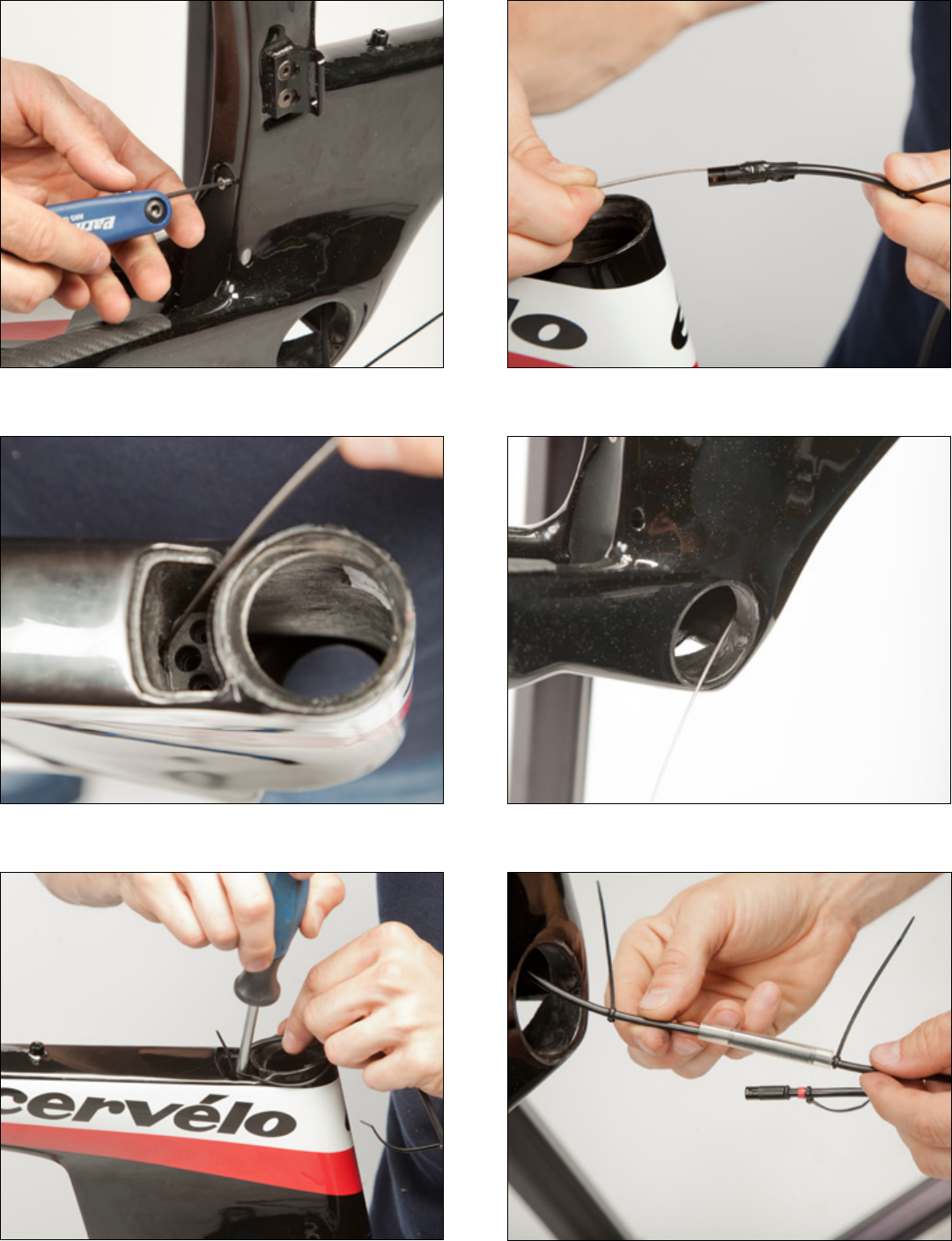
Figure2Figure1
Figure6Figure5
Figure3 Figure4
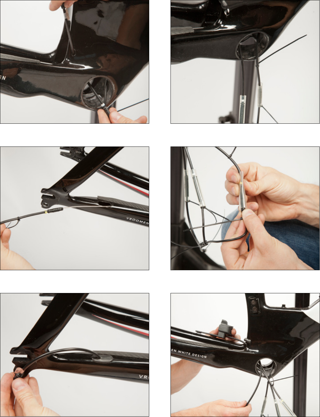
Figure8Figure7
Figure12Figure11
Figure9 Figure10
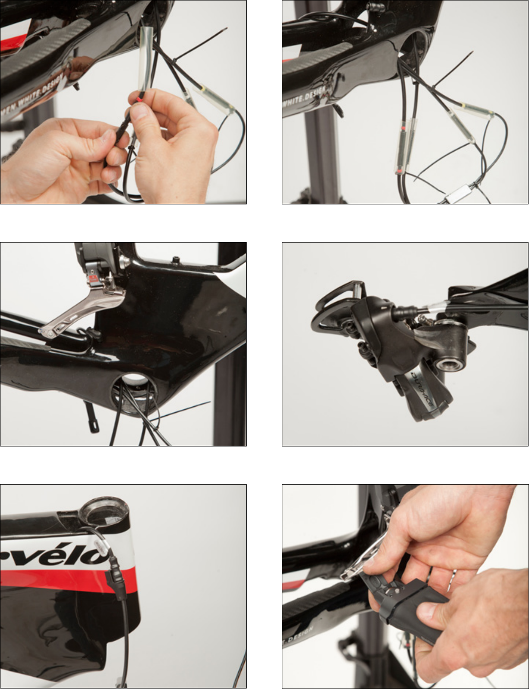
Figure14Figure13
Figure18Figure17
Figure15 Figure16
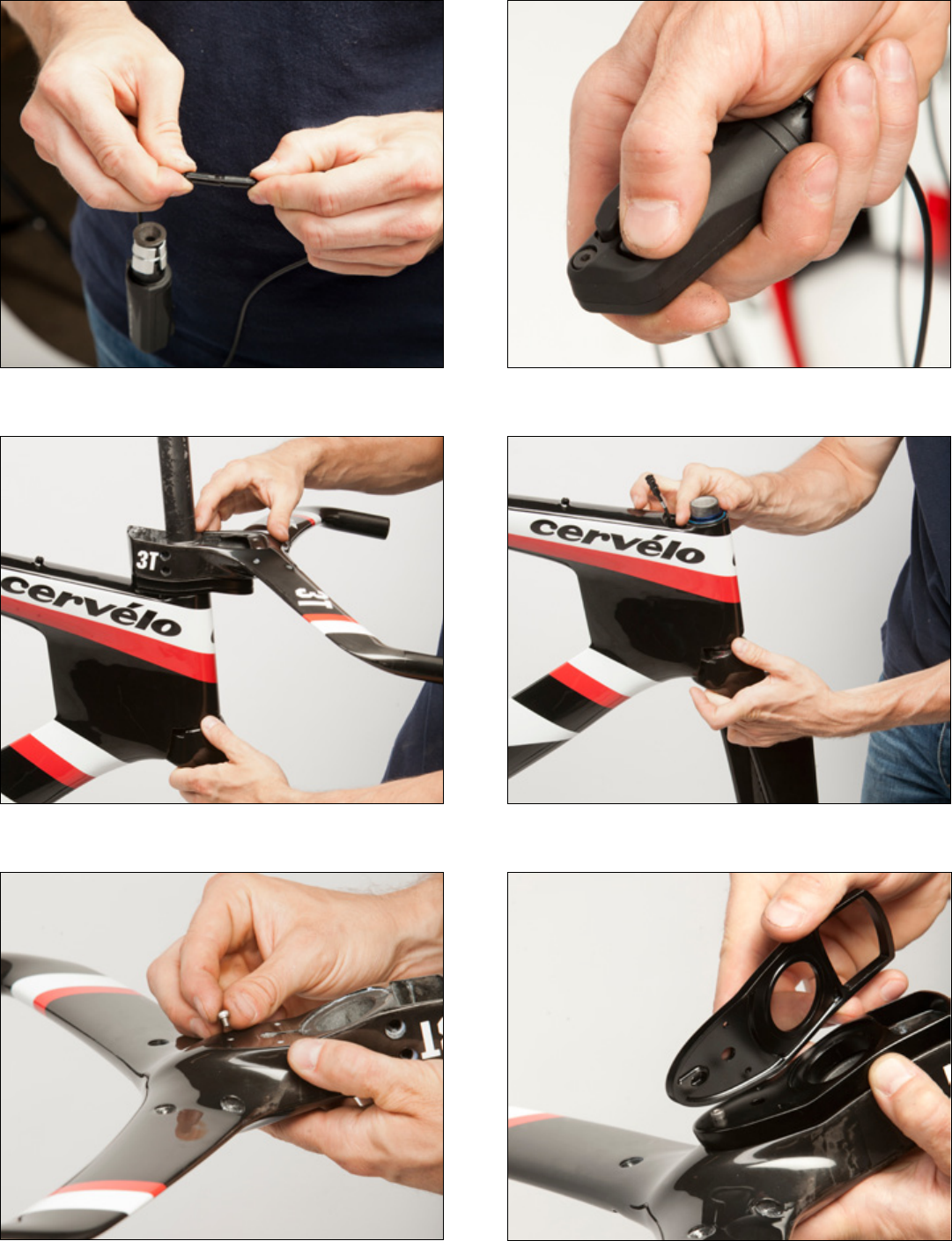
Figure20Figure19
Figure24Figure23
Figure21 Figure22
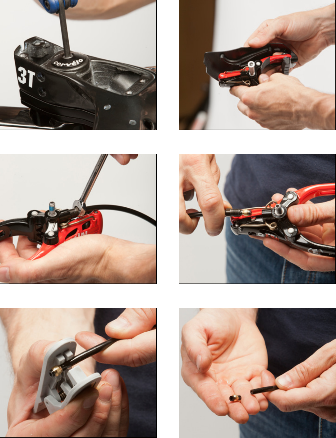
Figure26Figure25
Figure30Figure29
Figure27 Figure28
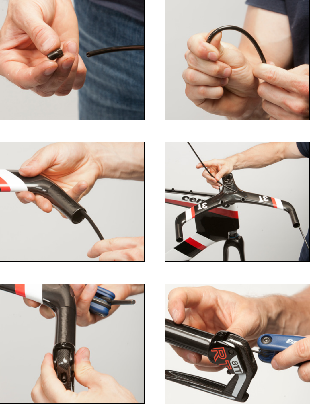
Figure32Figure31
Figure36Figure35
Figure33 Figure34
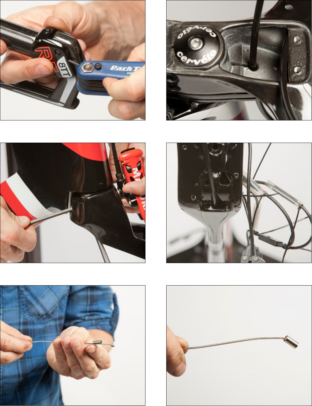
Figure38Figure37
Figure42Figure41
Figure39 Figure40
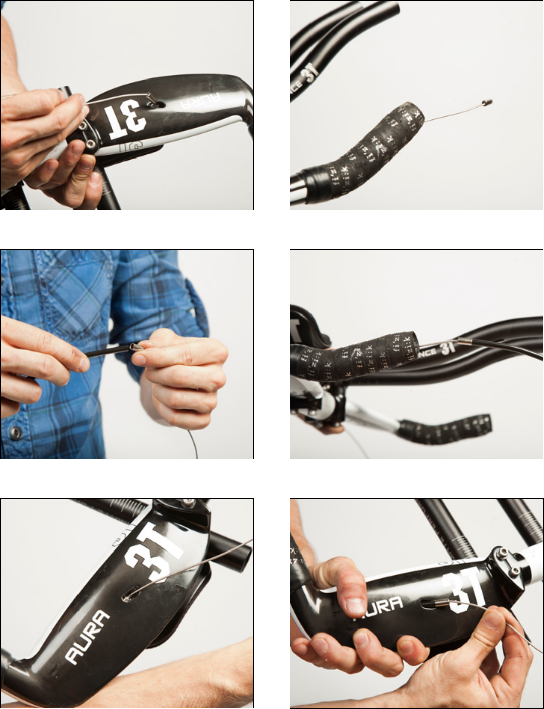
Figure44Figure43
Figure48Figure47
Figure45 Figure46
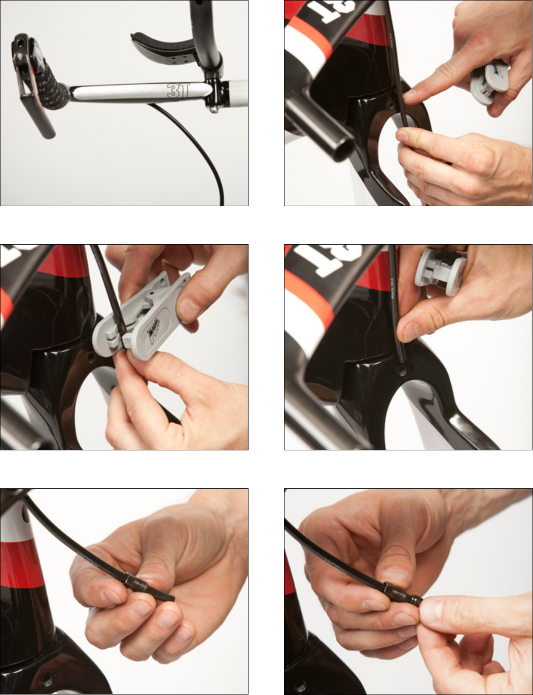
Figure50Figure49
Figure54Figure53
Figure51 Figure52
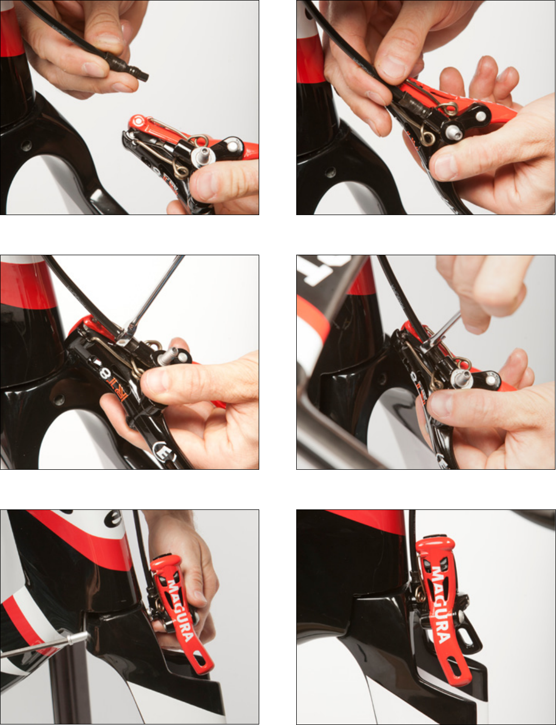
Figure56Figure55
Figure60Figure59
Figure57 Figure58
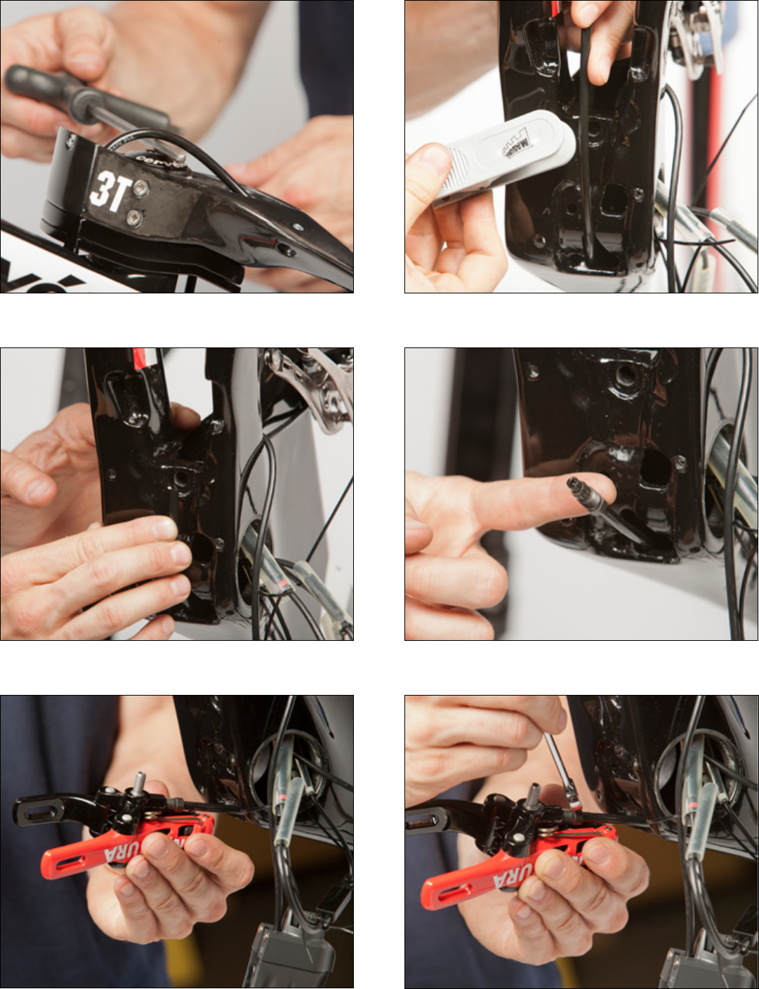
Figure62Figure61
Figure66Figure65
Figure63 Figure64
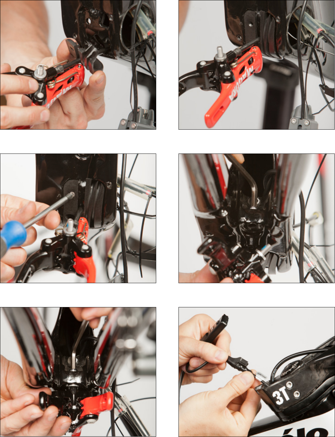
Figure68Figure67
Figure72Figure71
Figure69 Figure70
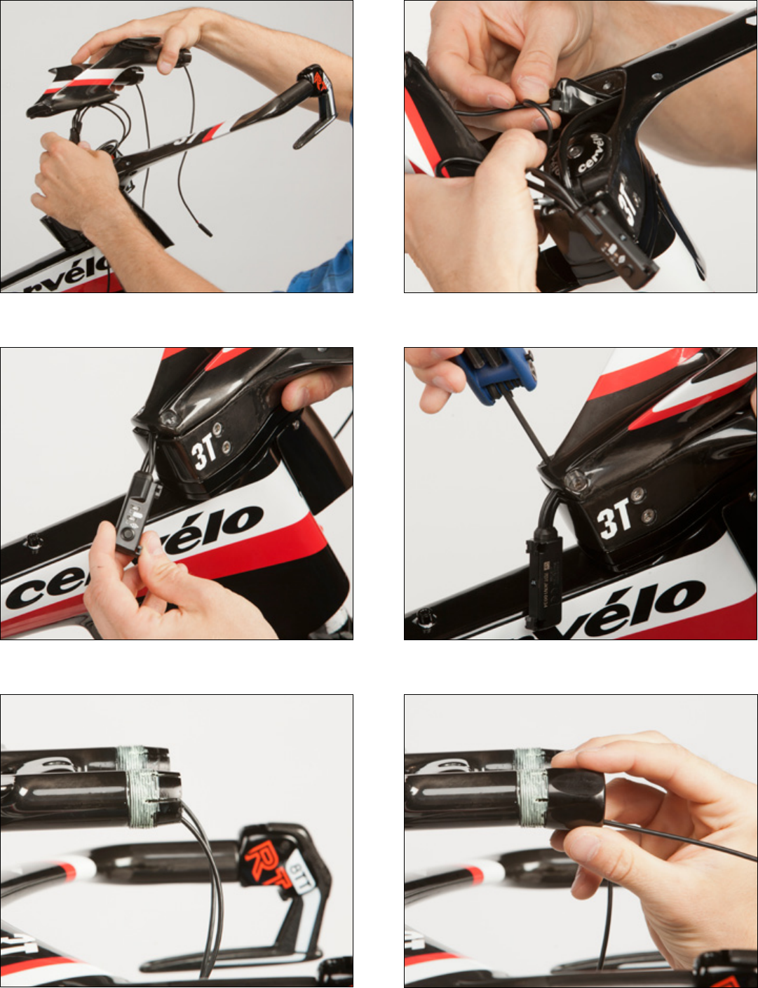
Figure74Figure73
Figure78Figure77
Figure75 Figure76
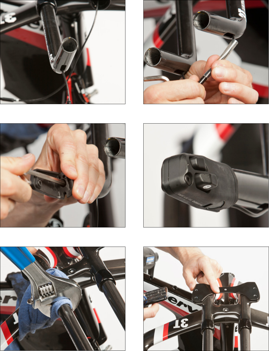
Figure80Figure79
Figure84Figure83
Figure81 Figure82
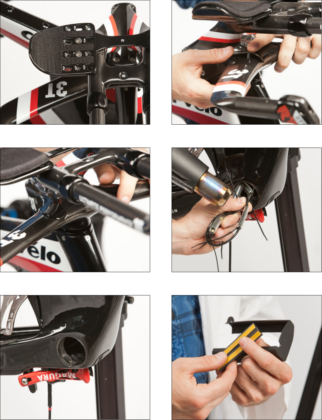
Figure86Figure85
Figure90Figure89
Figure87 Figure88
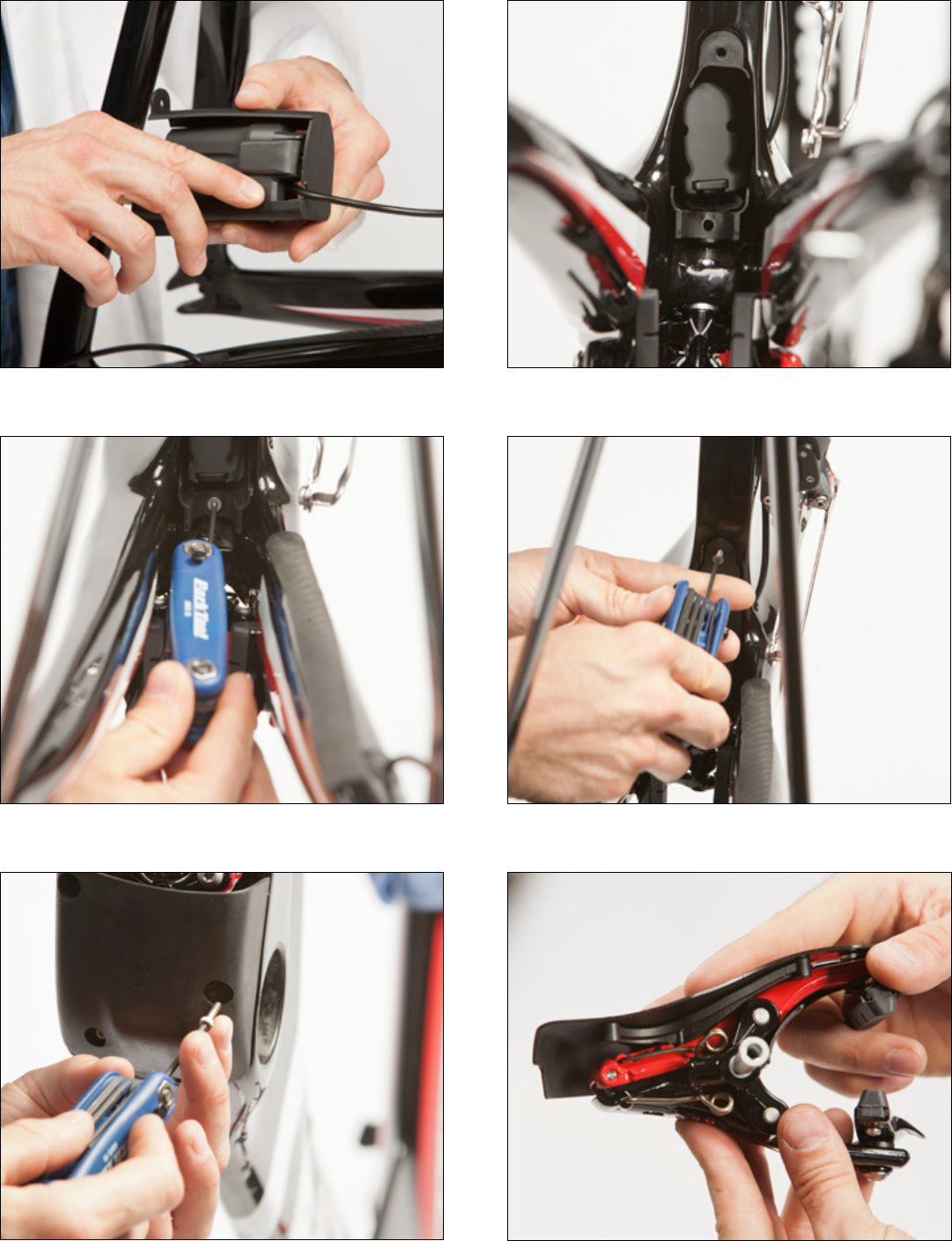
Figure92Figure91
Figure96Figure95
Figure93 Figure94
