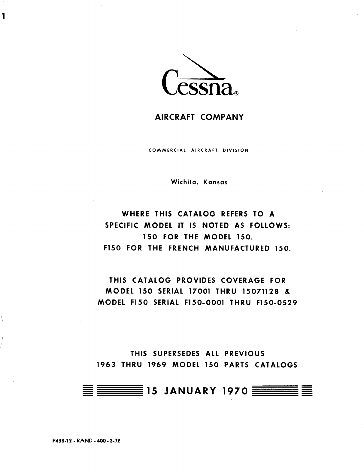
Cessna 150 Parts Catalog For 1959 Thru 1969 Cessna_150_1963 69_Parts Manual 1963 69
User Manual: Cessna_150_1963-69_PartsManual
Open the PDF directly: View PDF ![]() .
.
Page Count: 486 [warning: Documents this large are best viewed by clicking the View PDF Link!]
- Cover
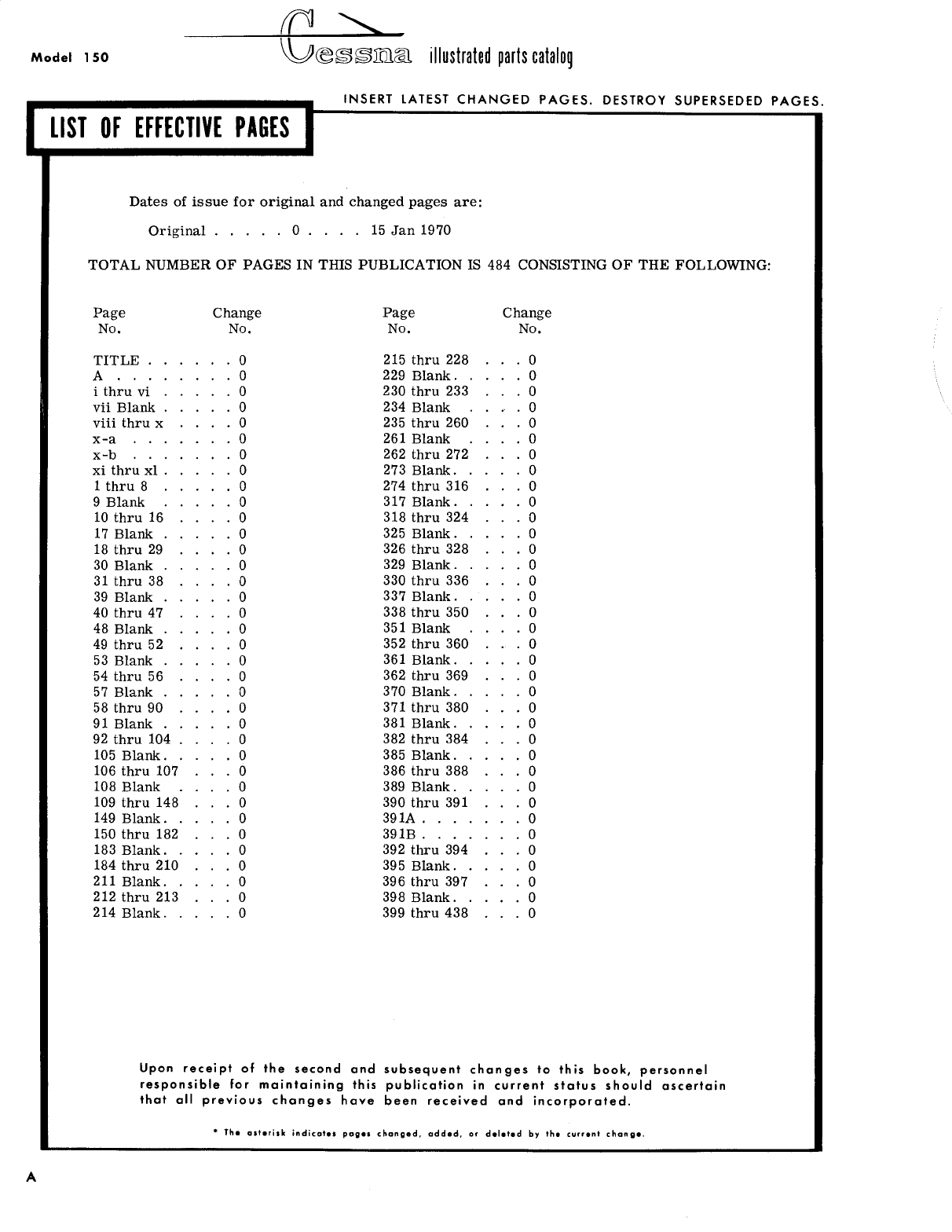
- List of Effective Pages
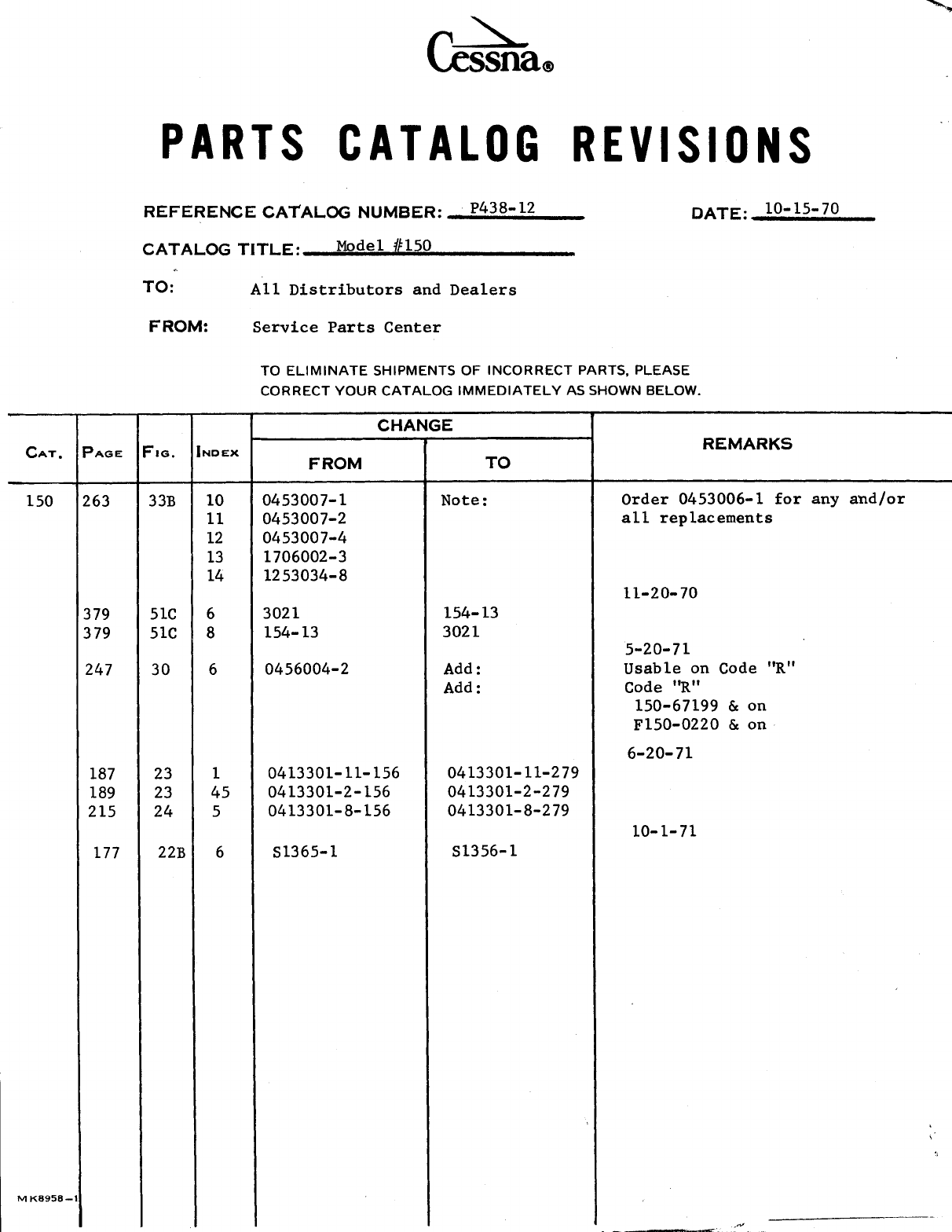
- Revision - 10/15/70
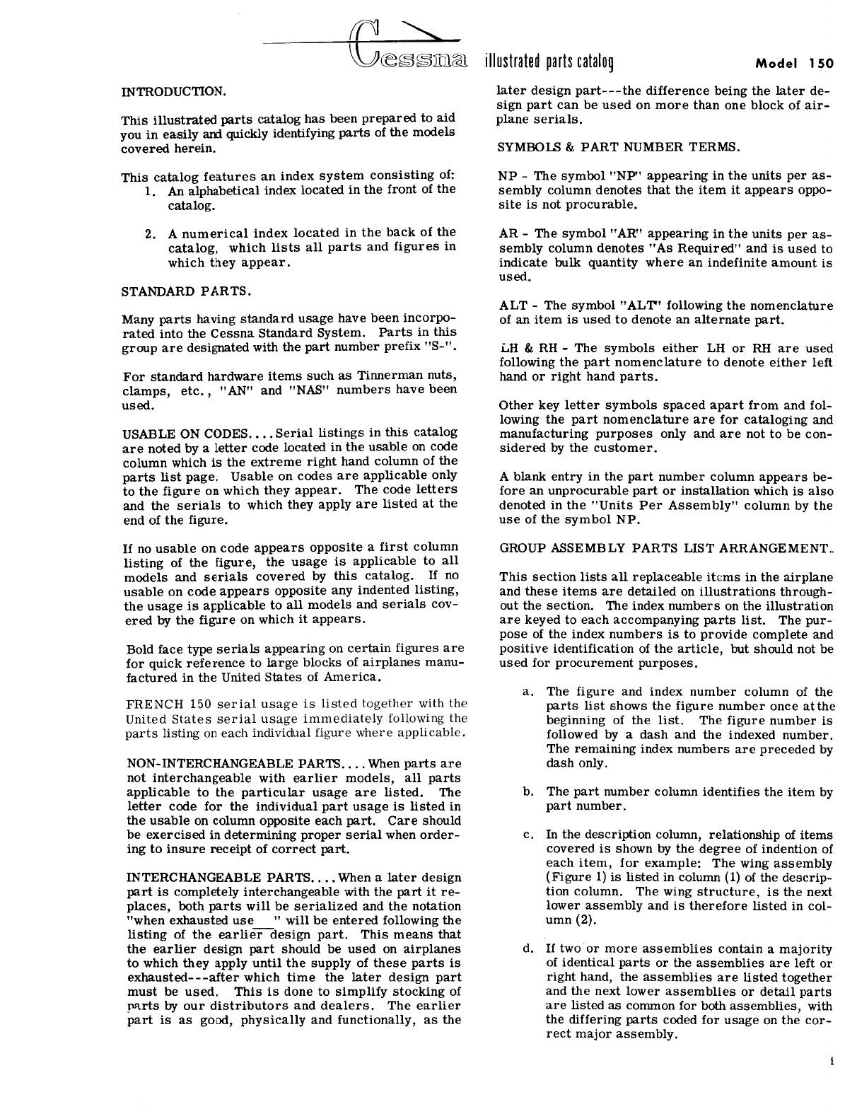
- Introduction
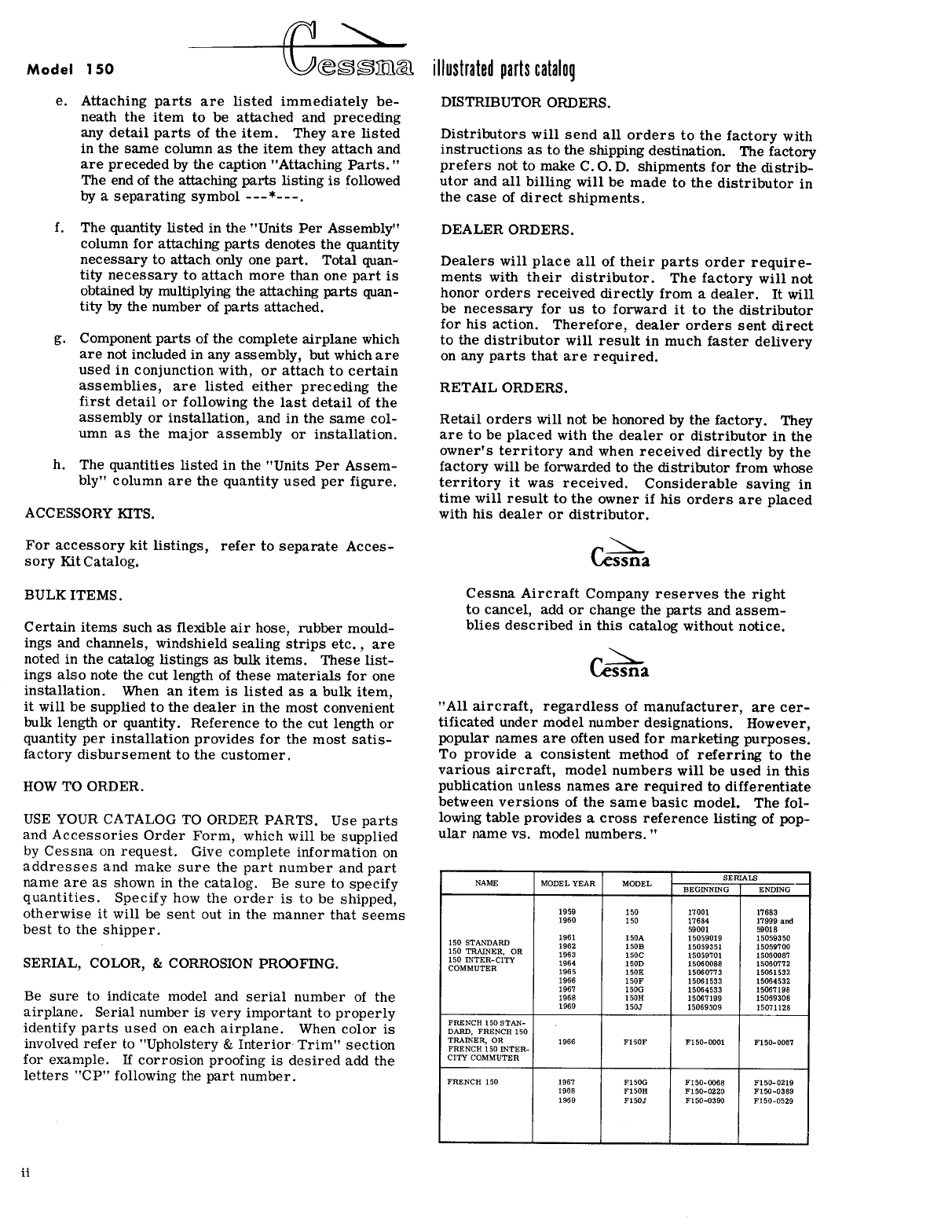
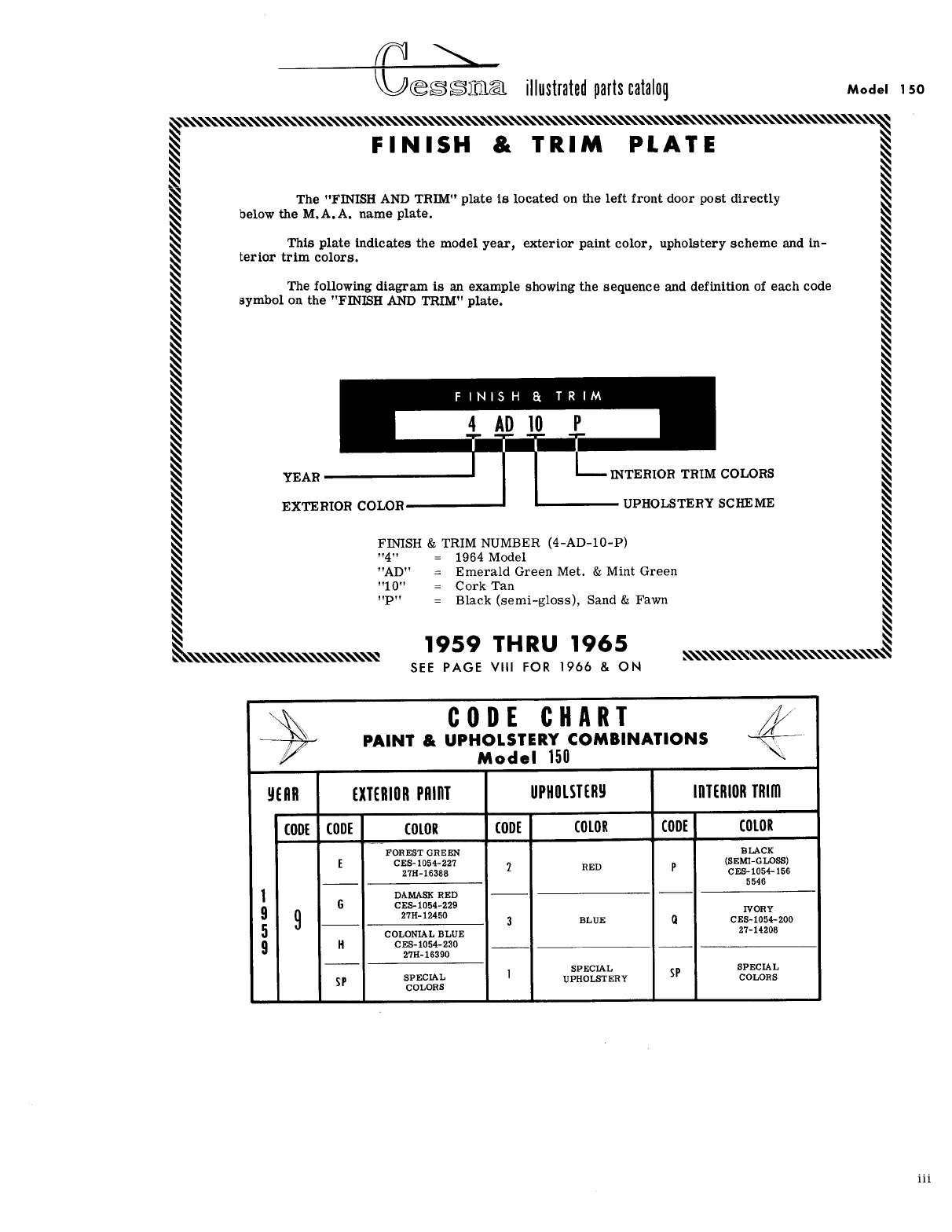
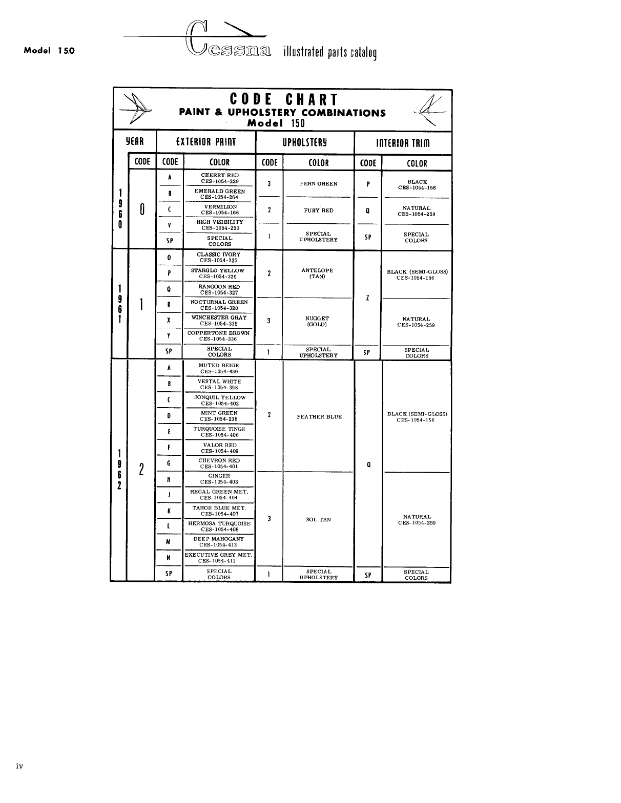
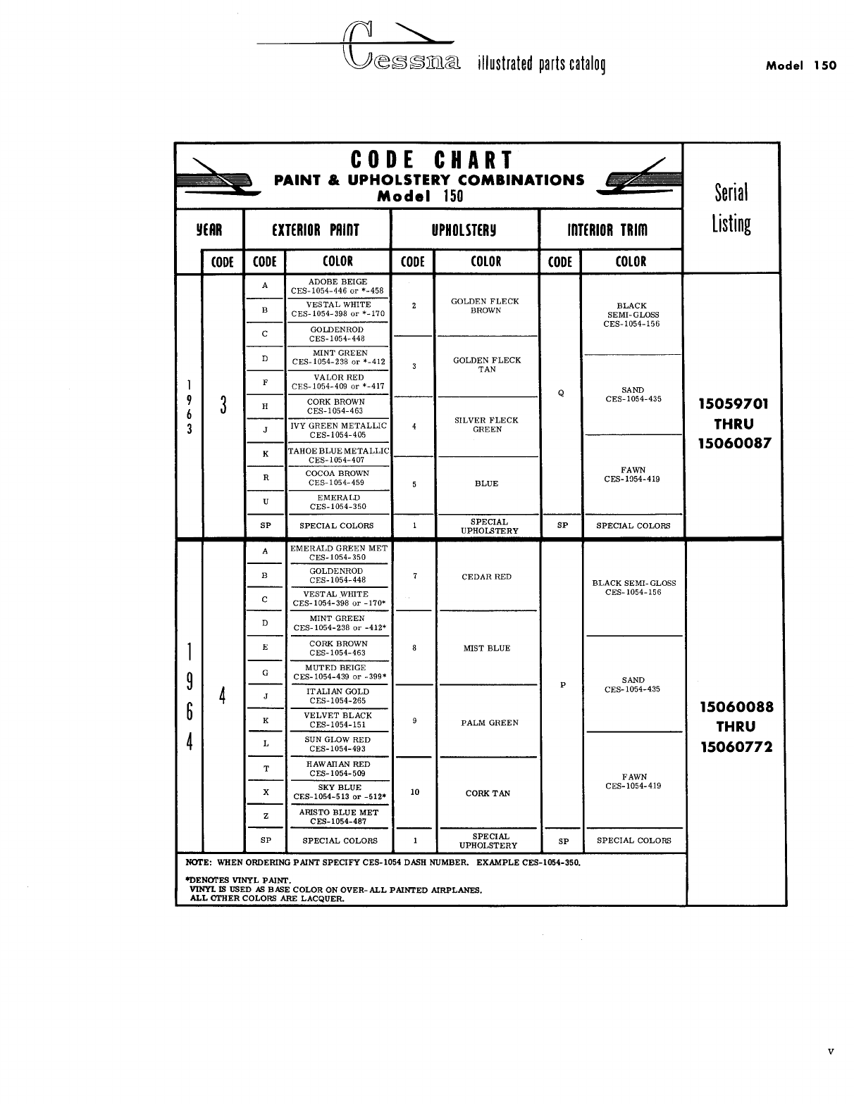
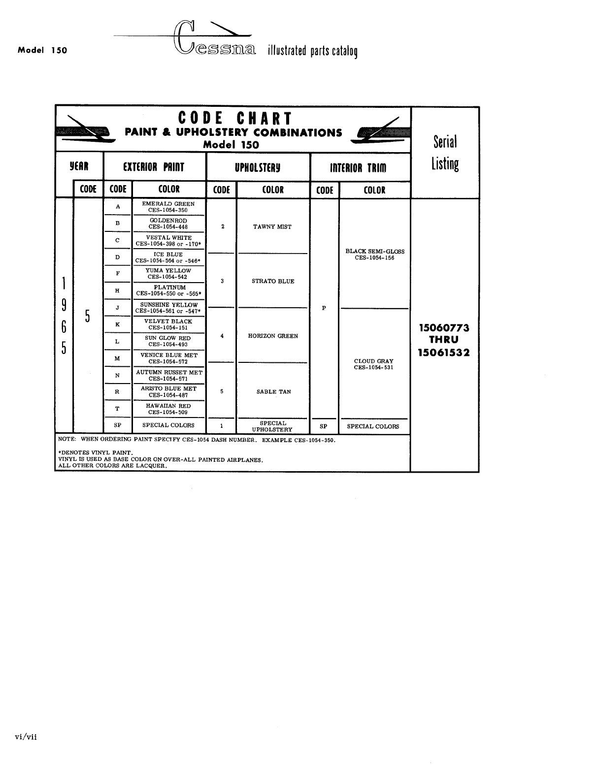
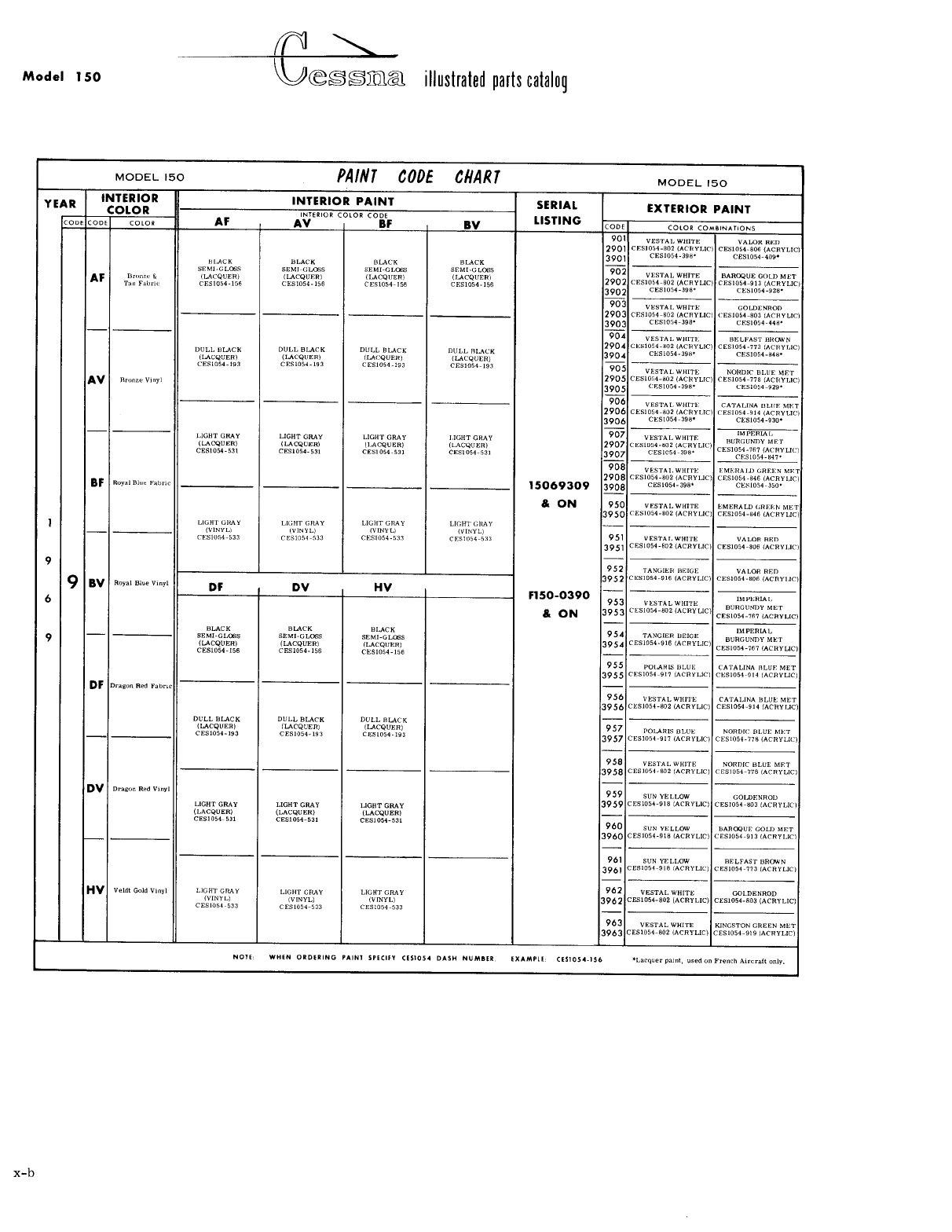
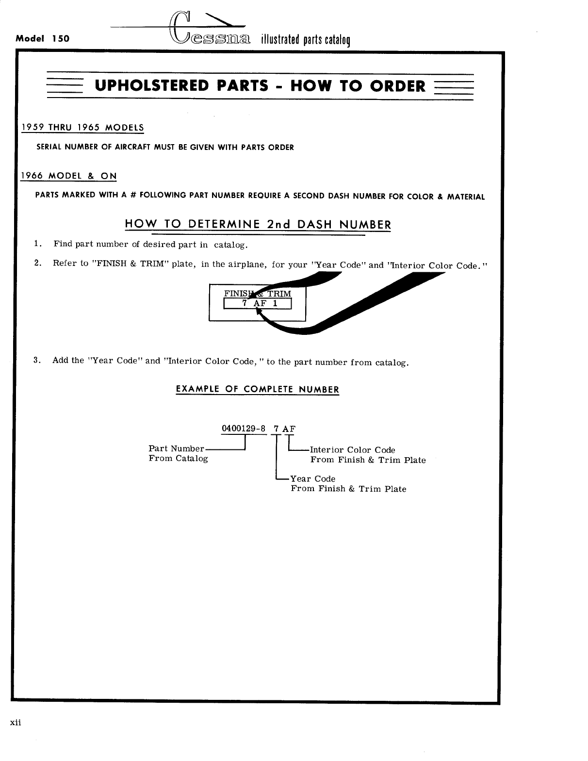
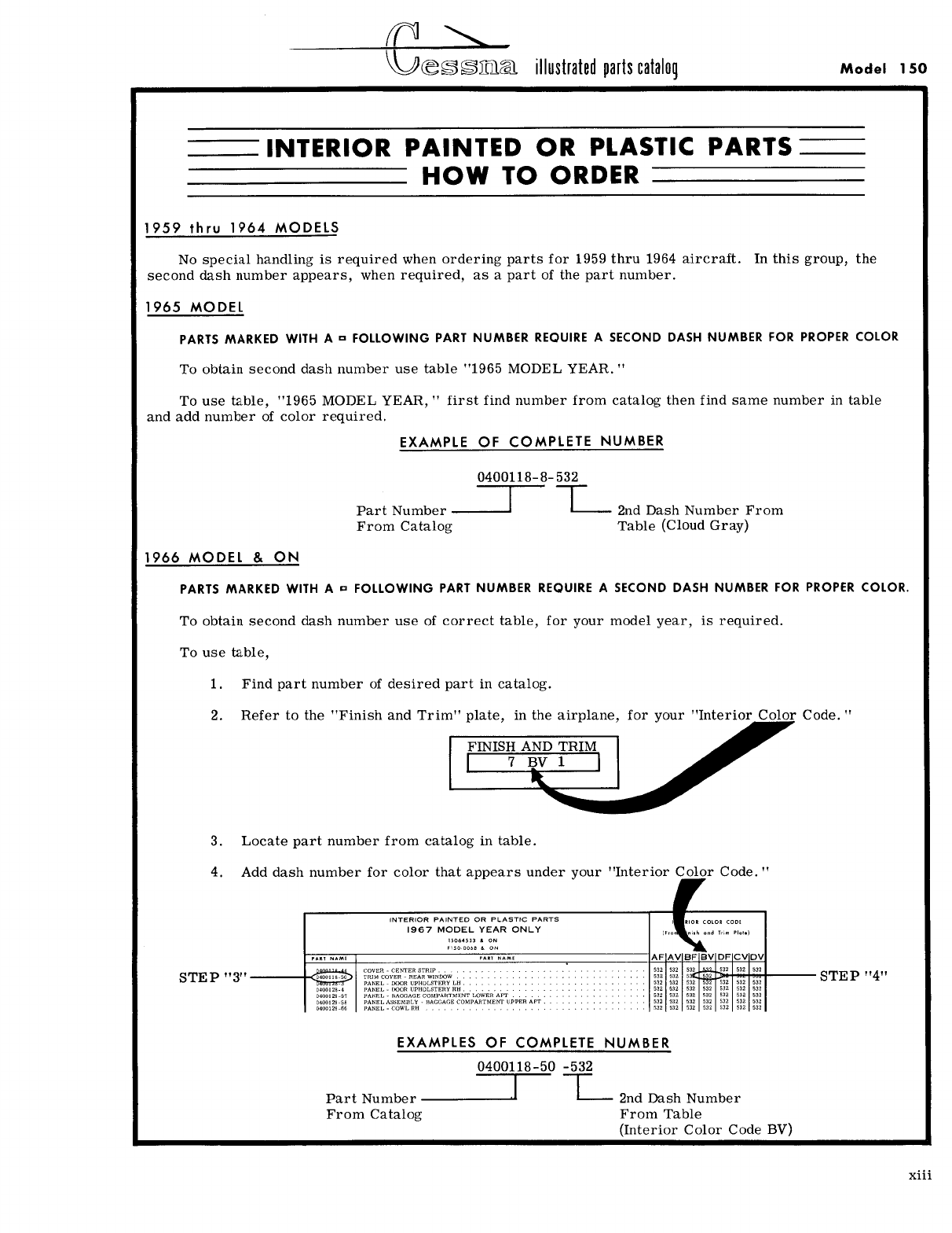
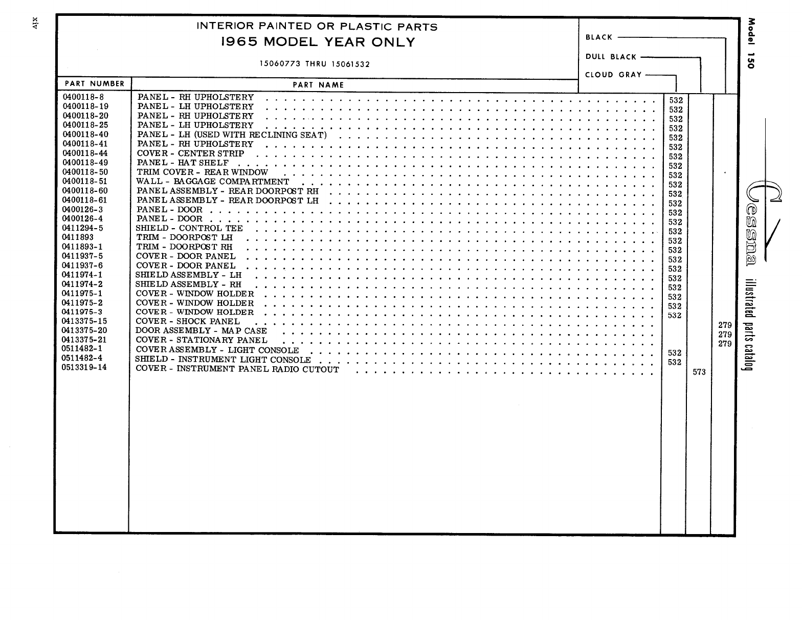
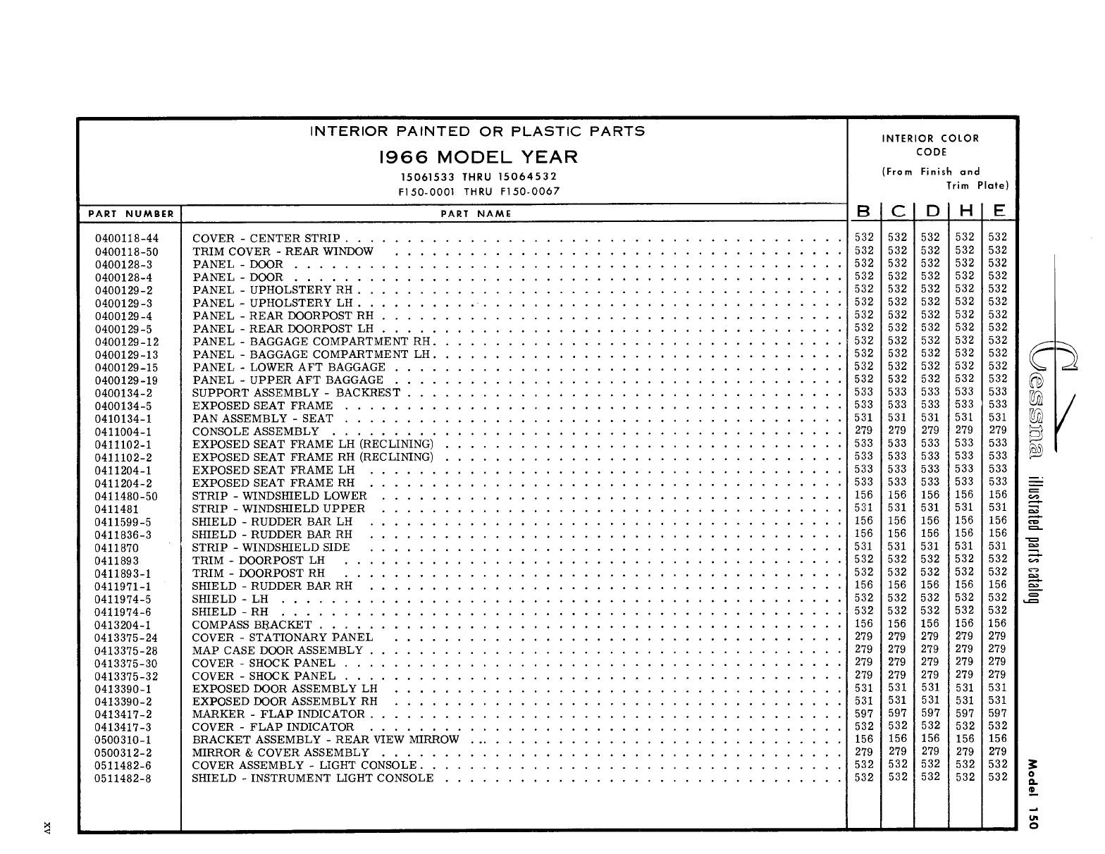
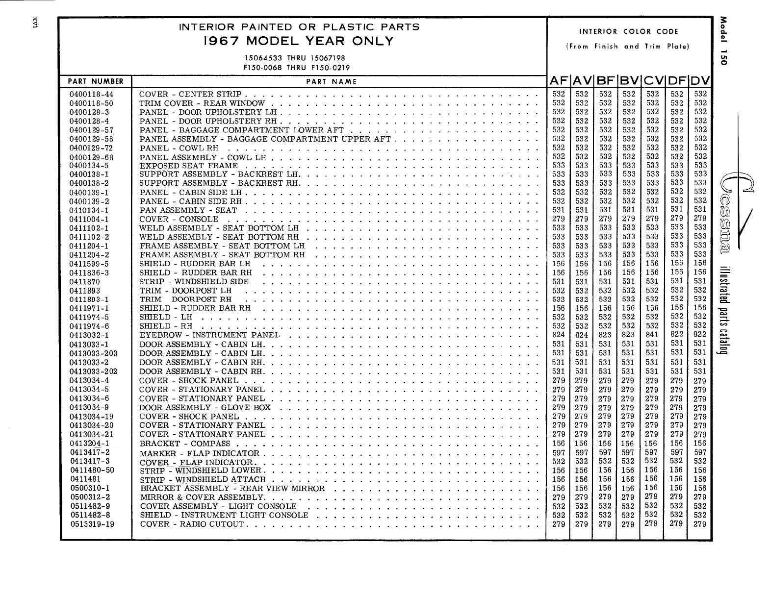
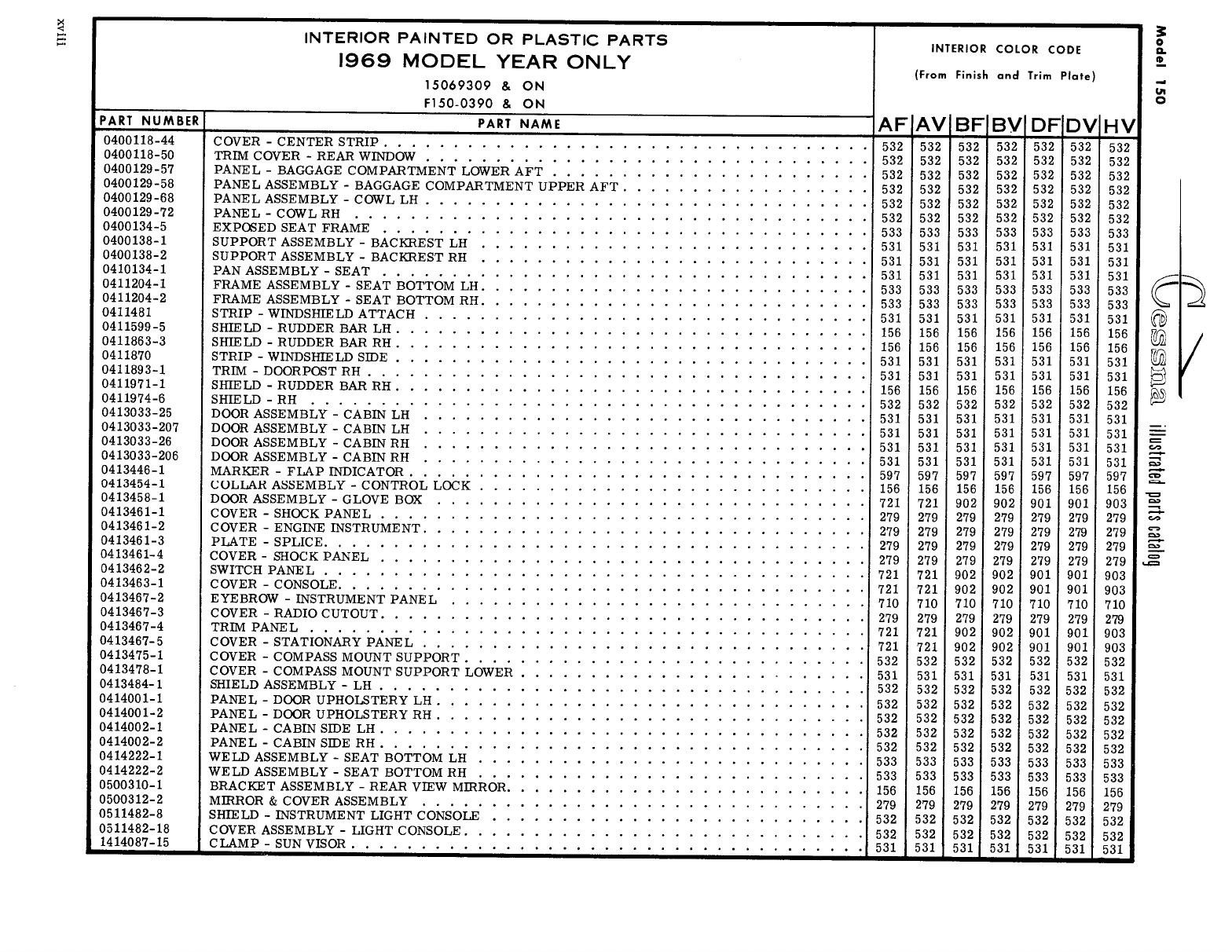
- Upholstery & Interior Trim
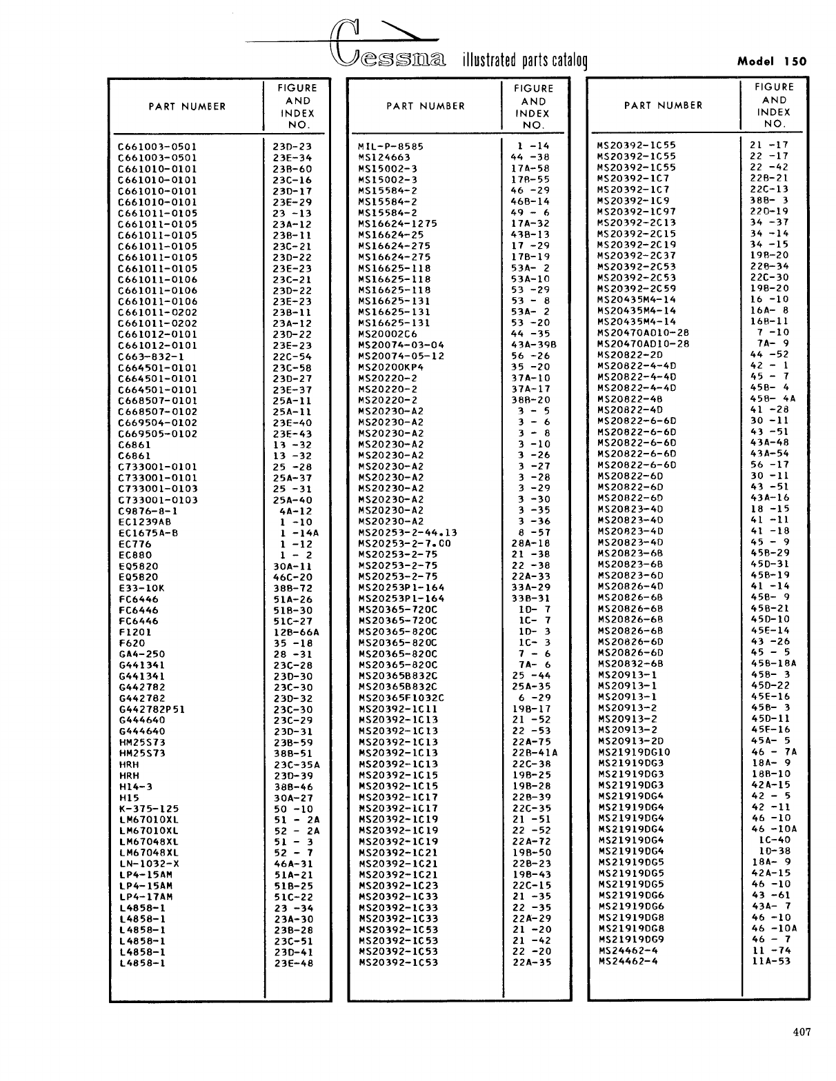
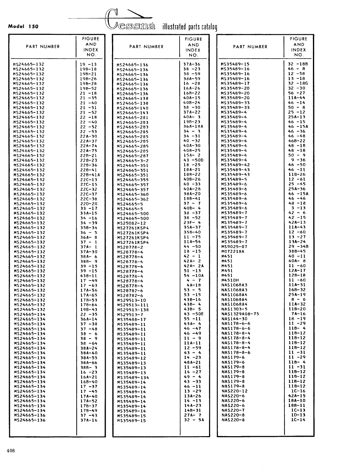
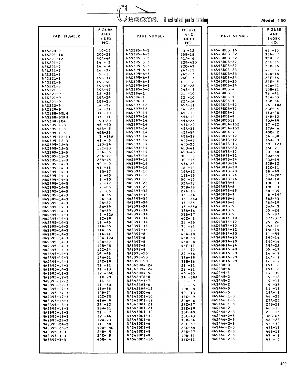
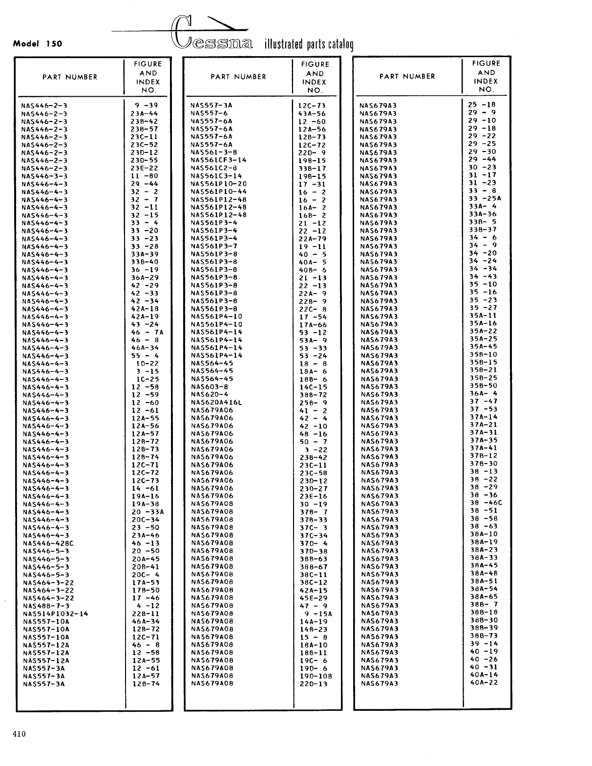
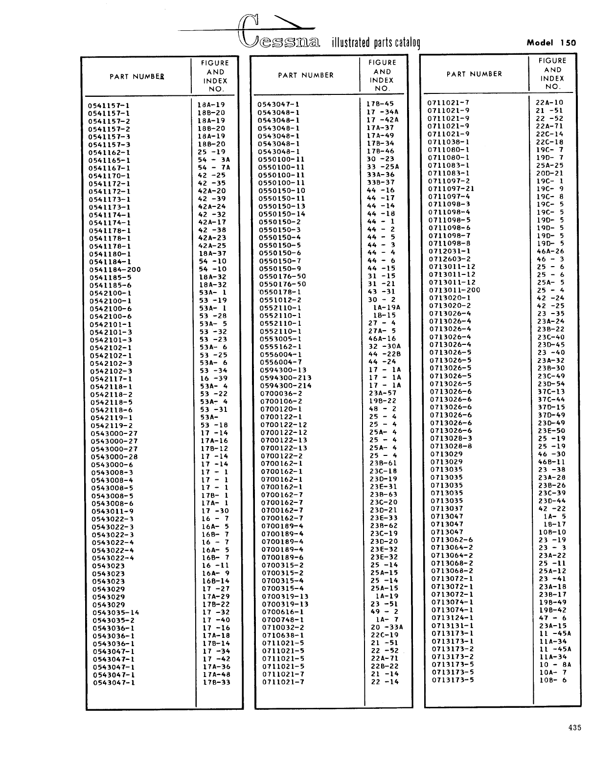
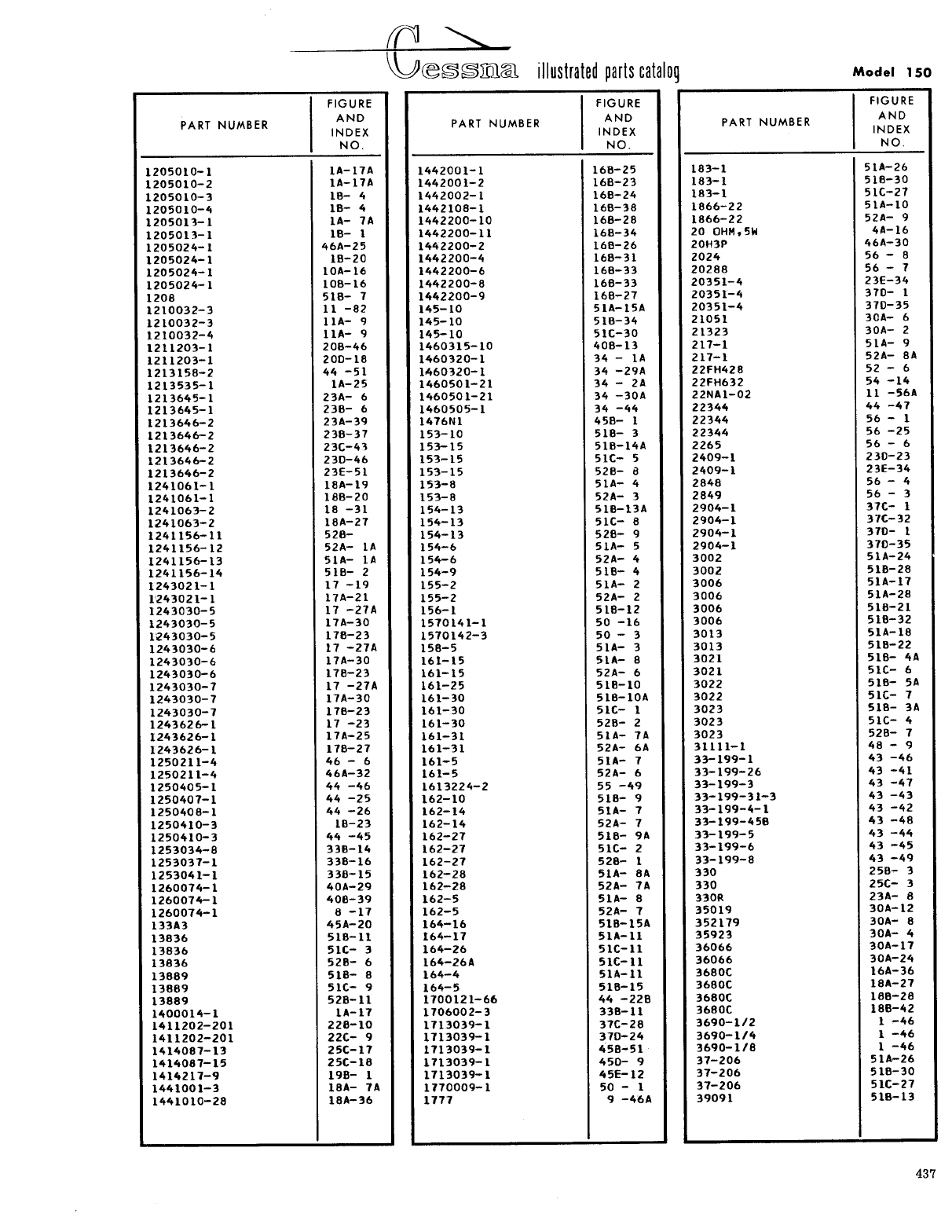
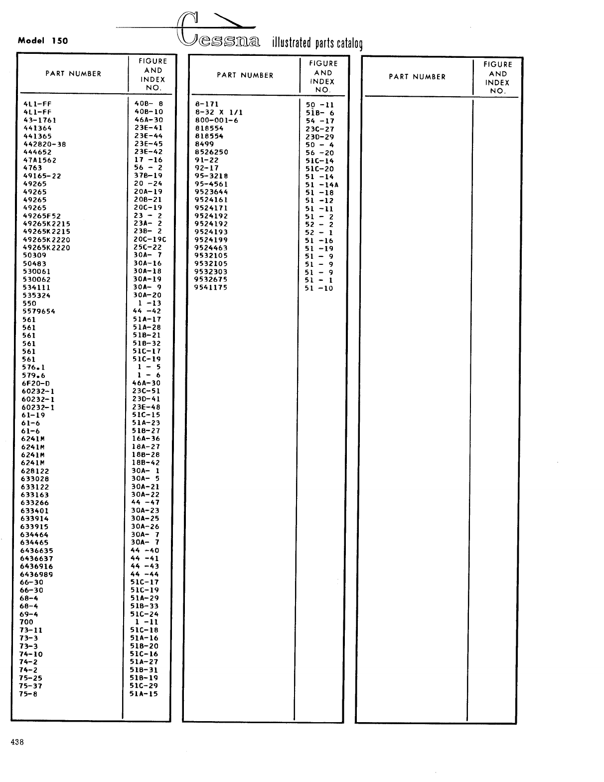
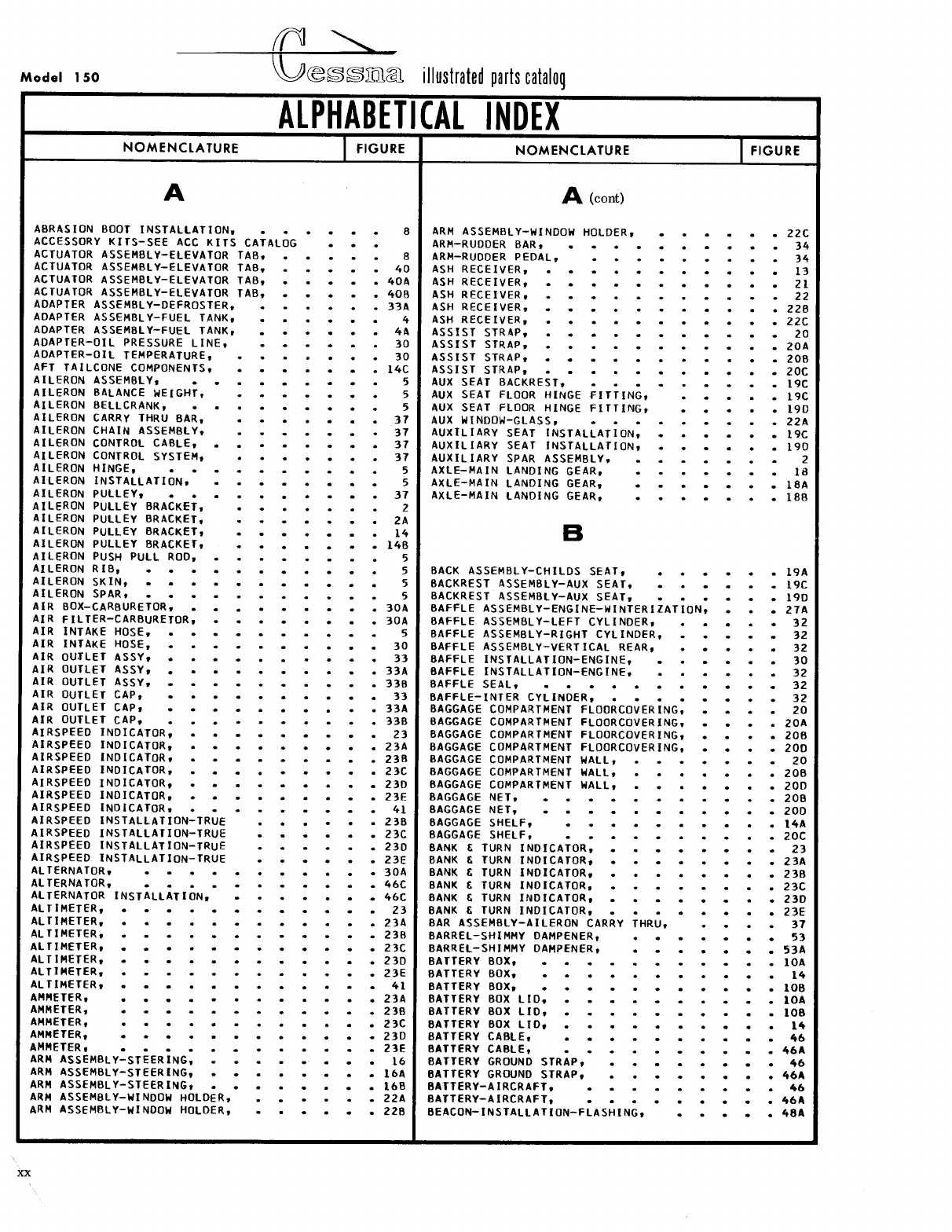
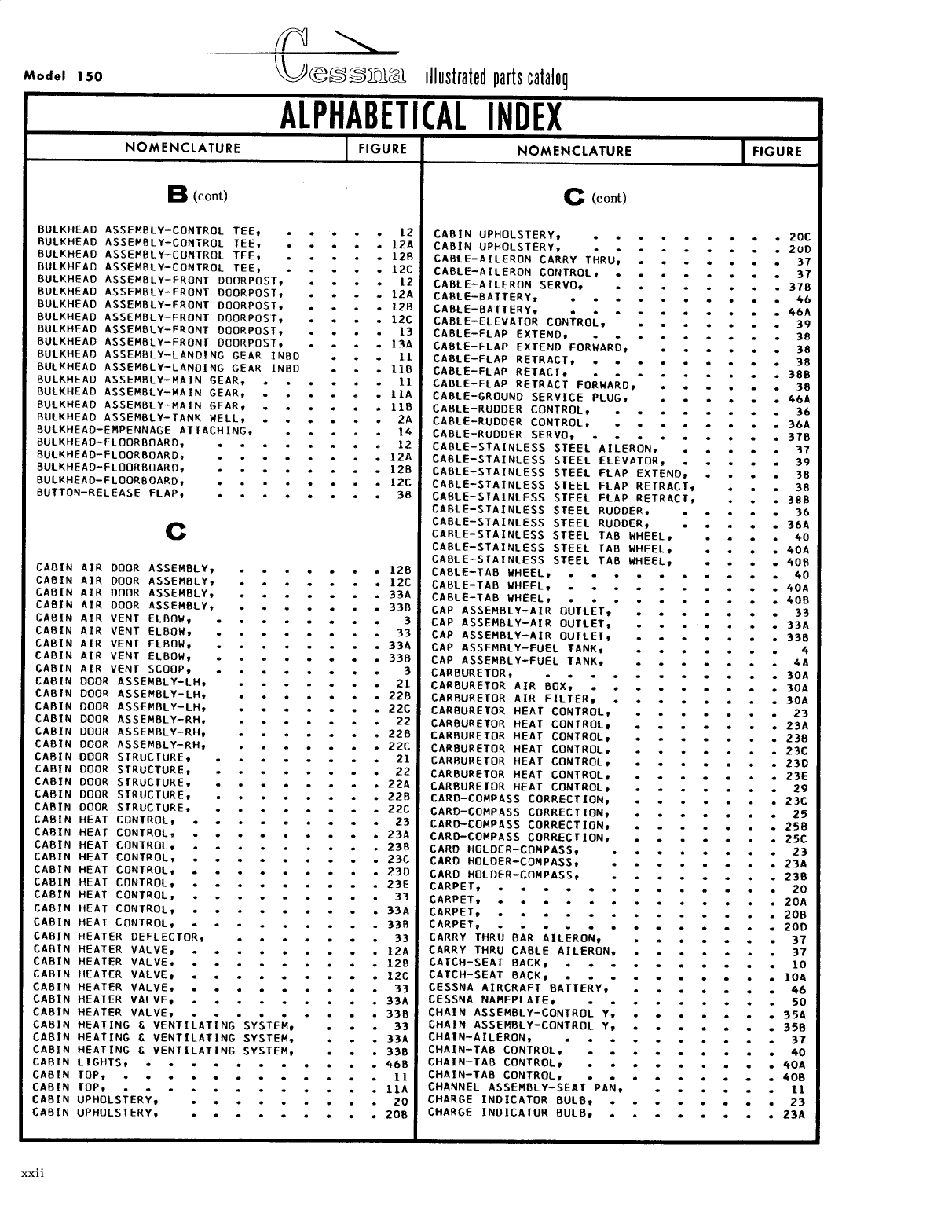
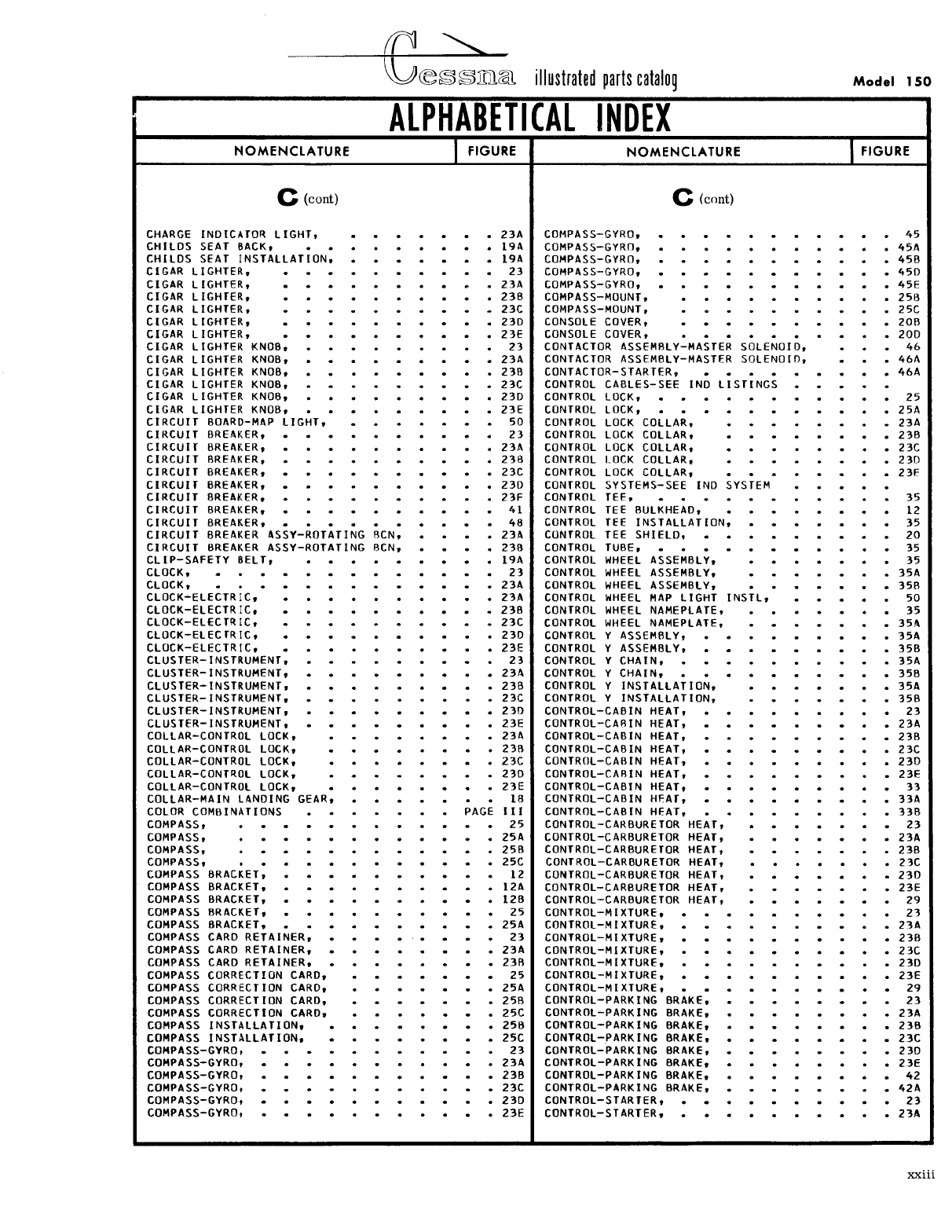
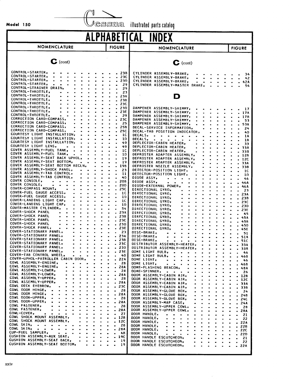
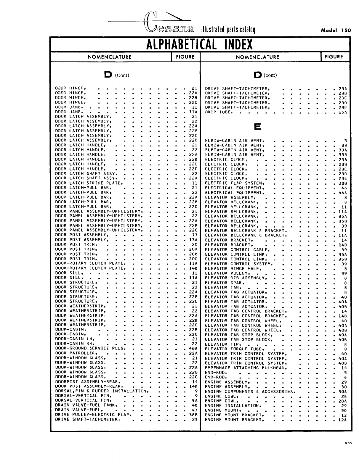
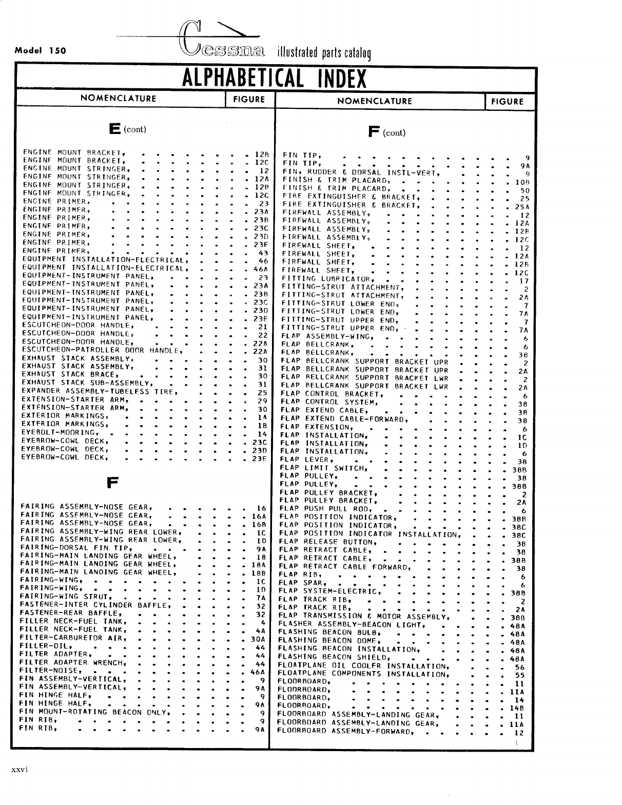
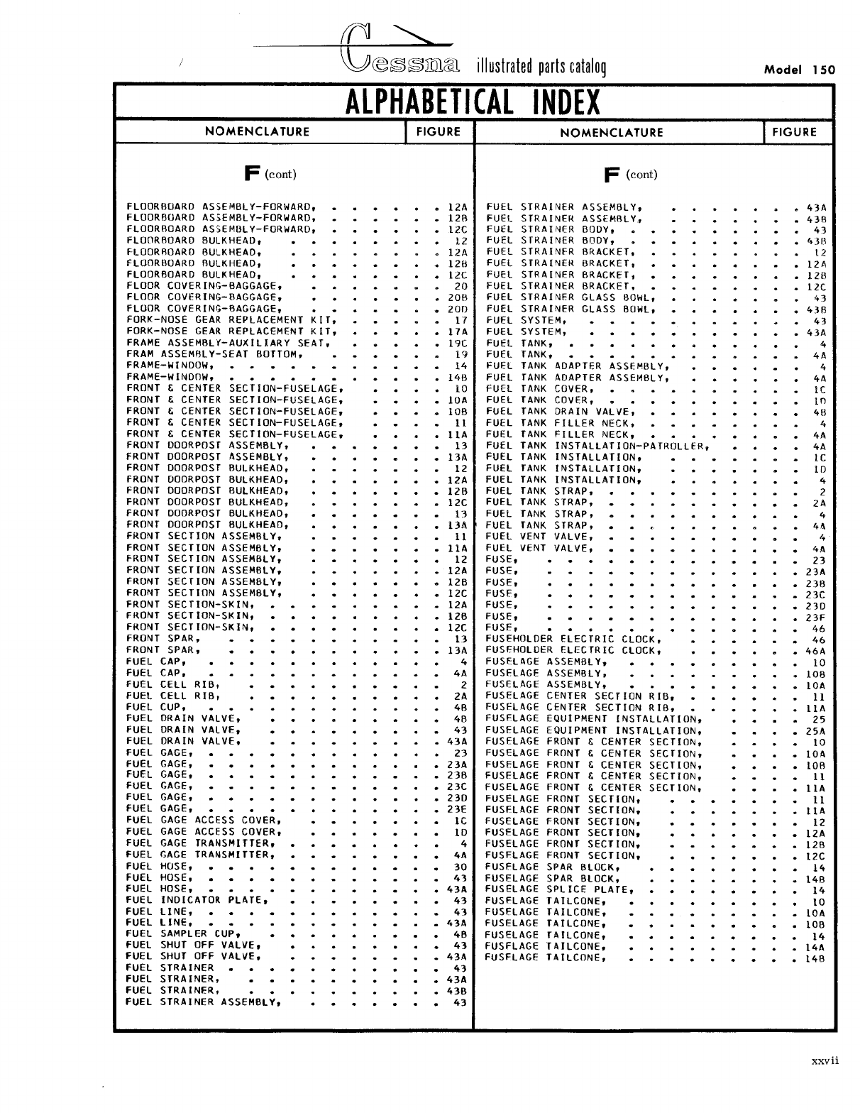
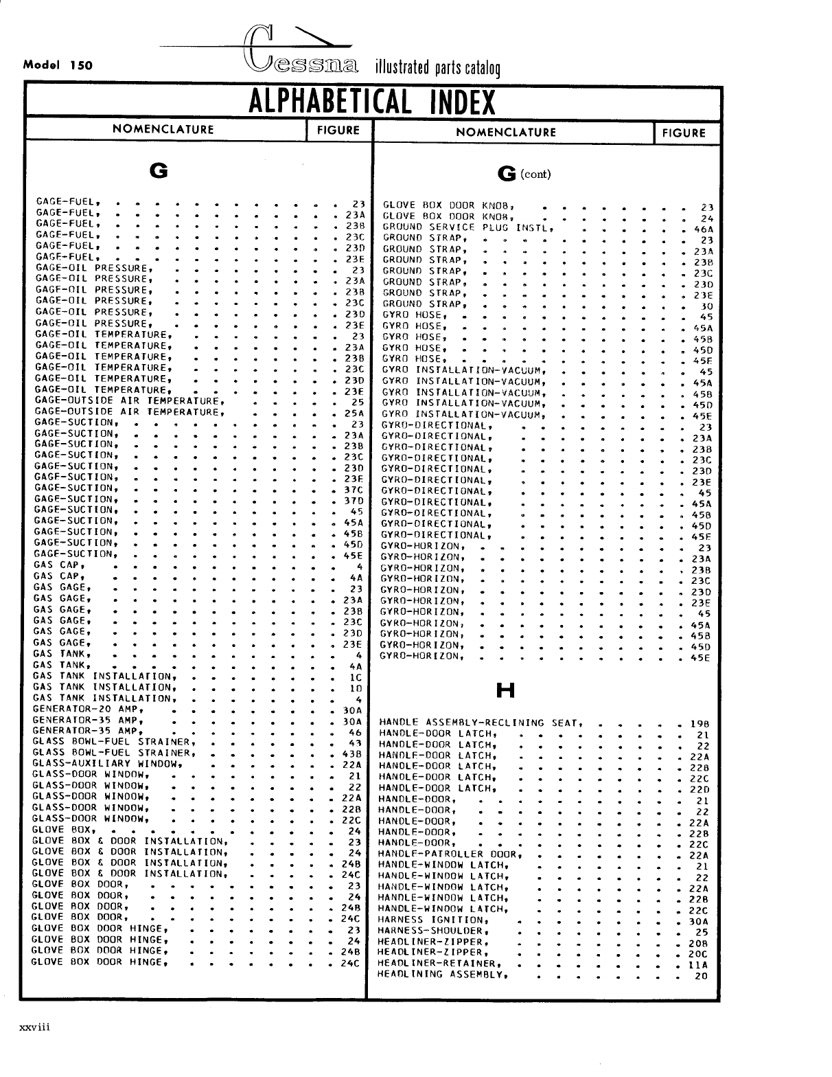
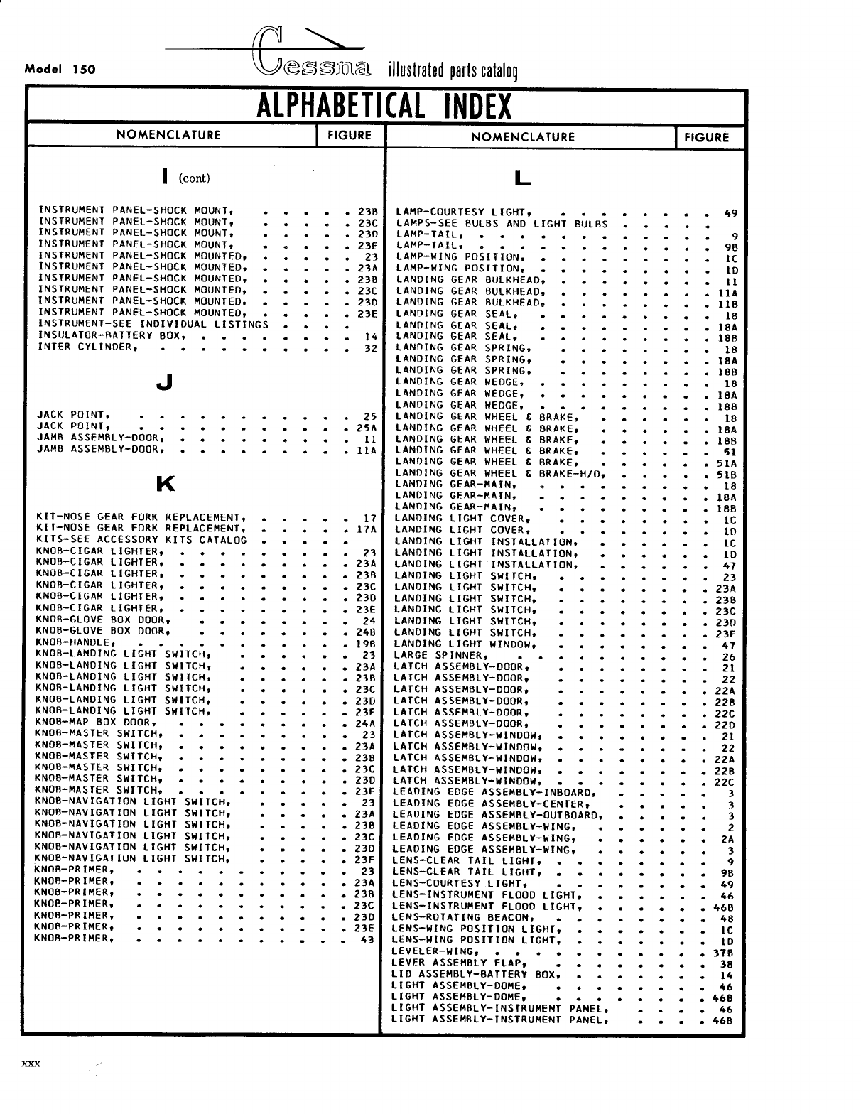
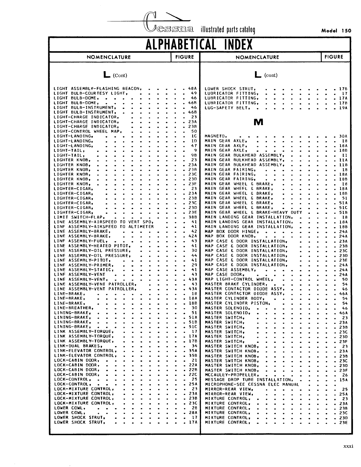
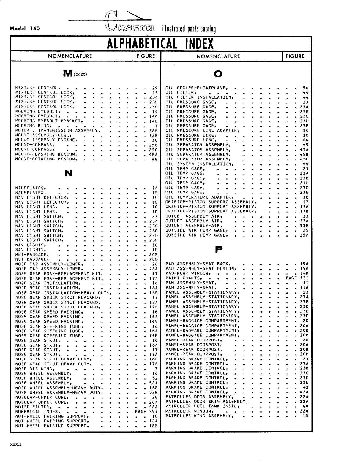
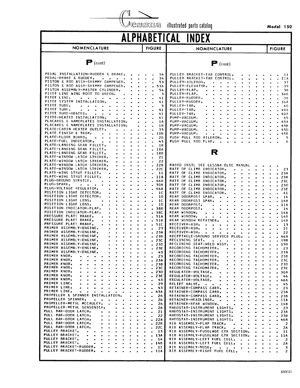
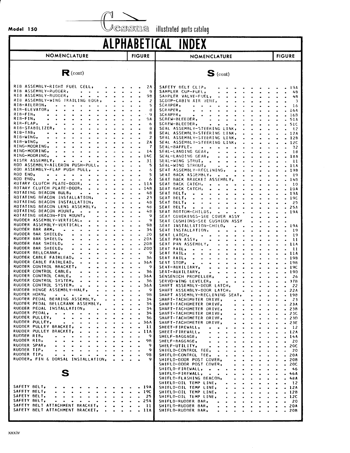
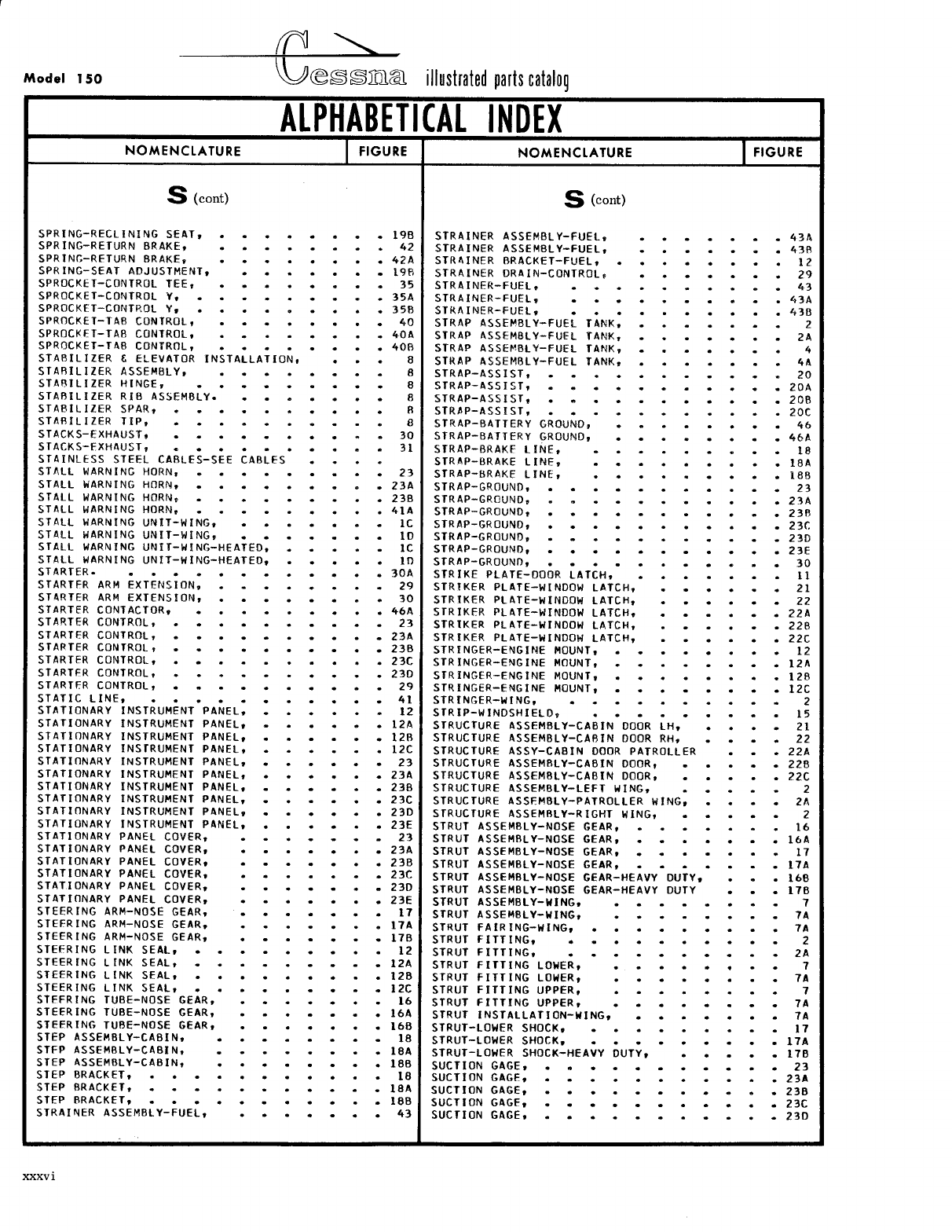
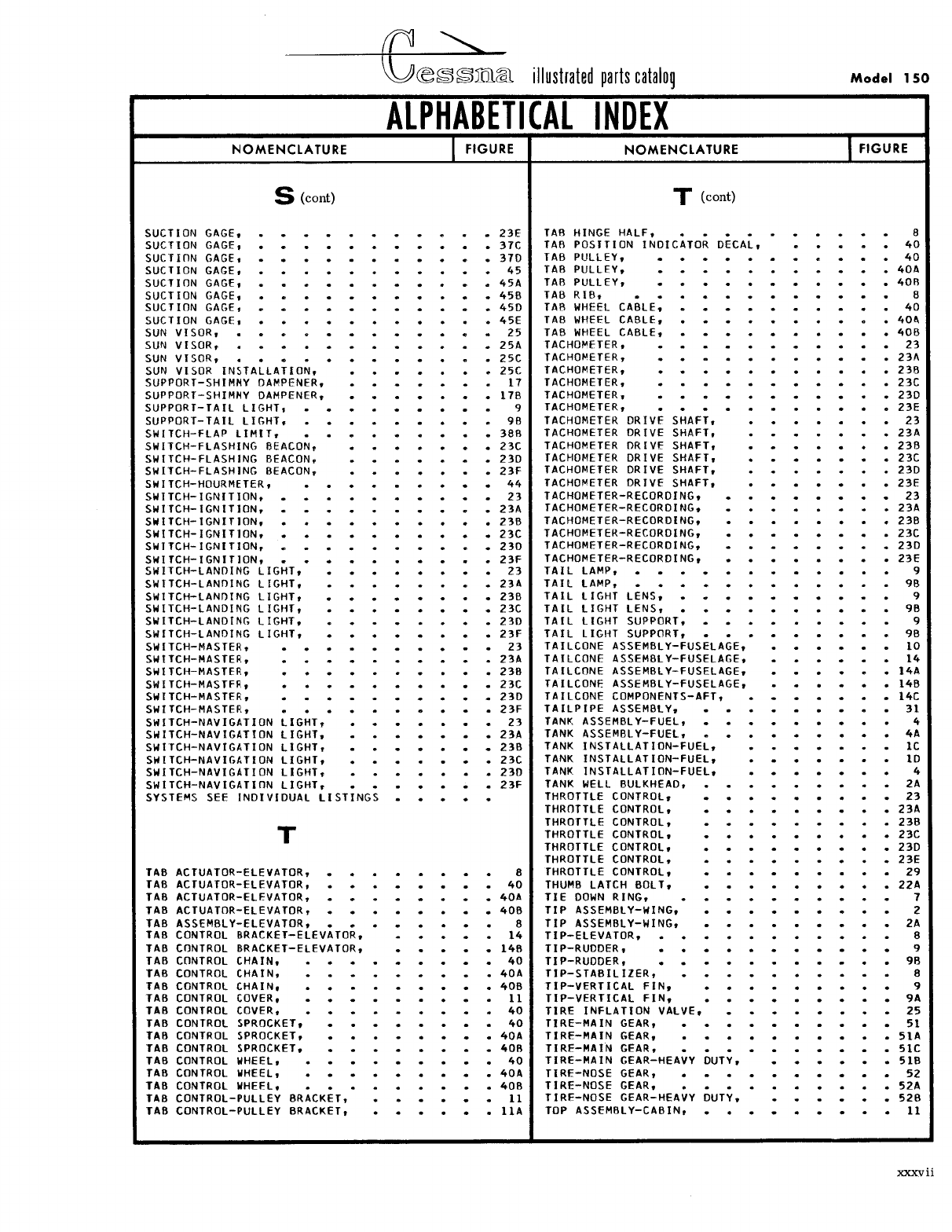
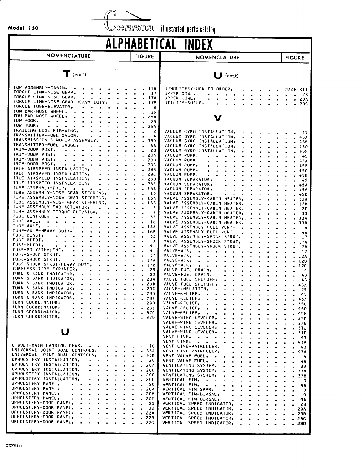
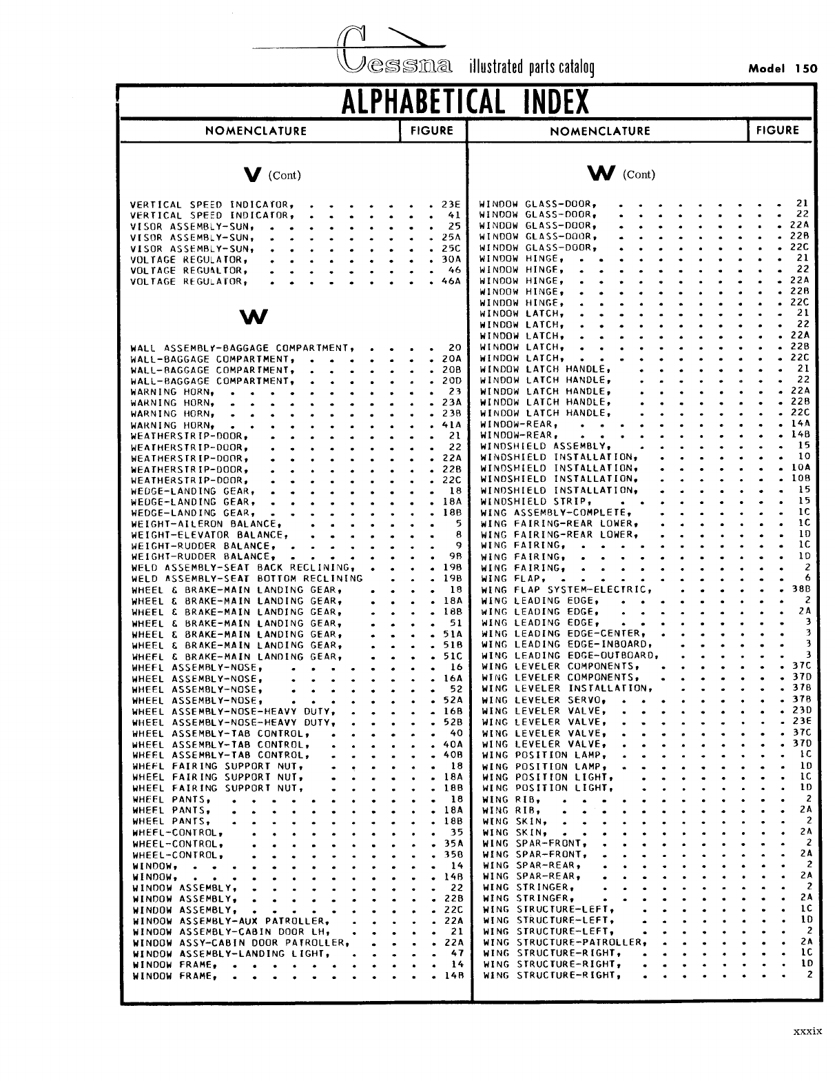
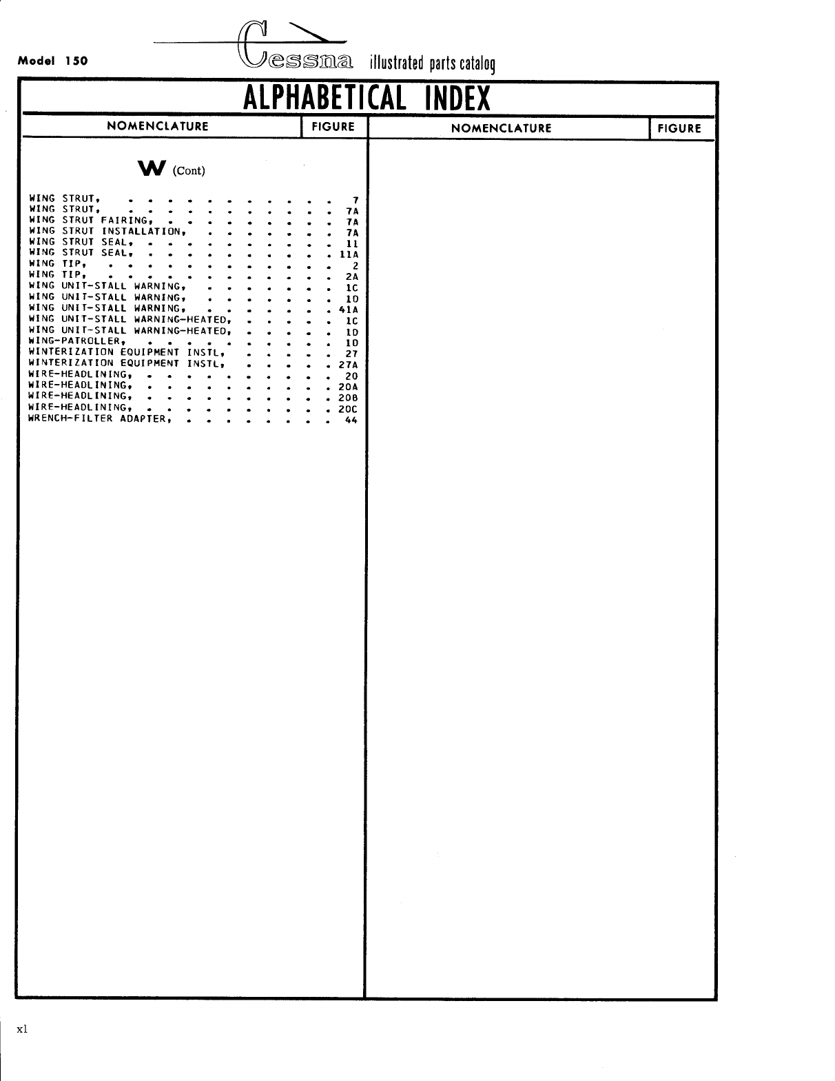
- Alphabetical Index
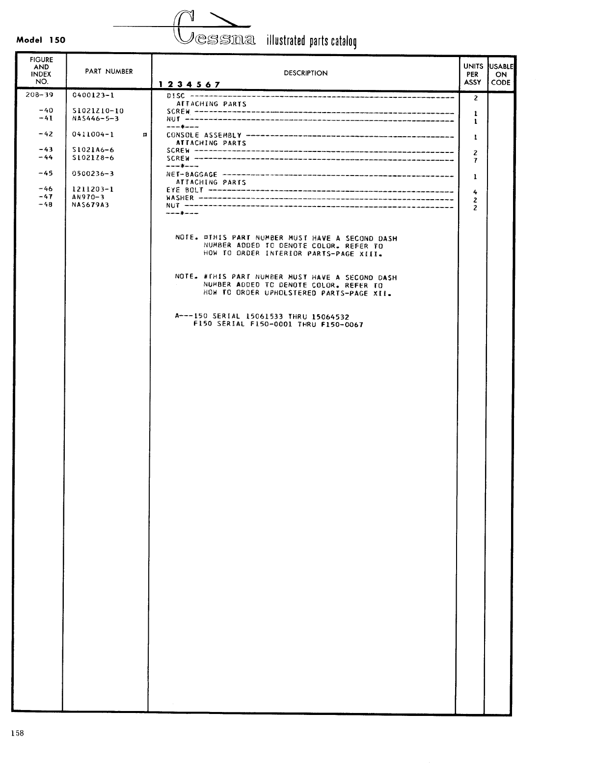
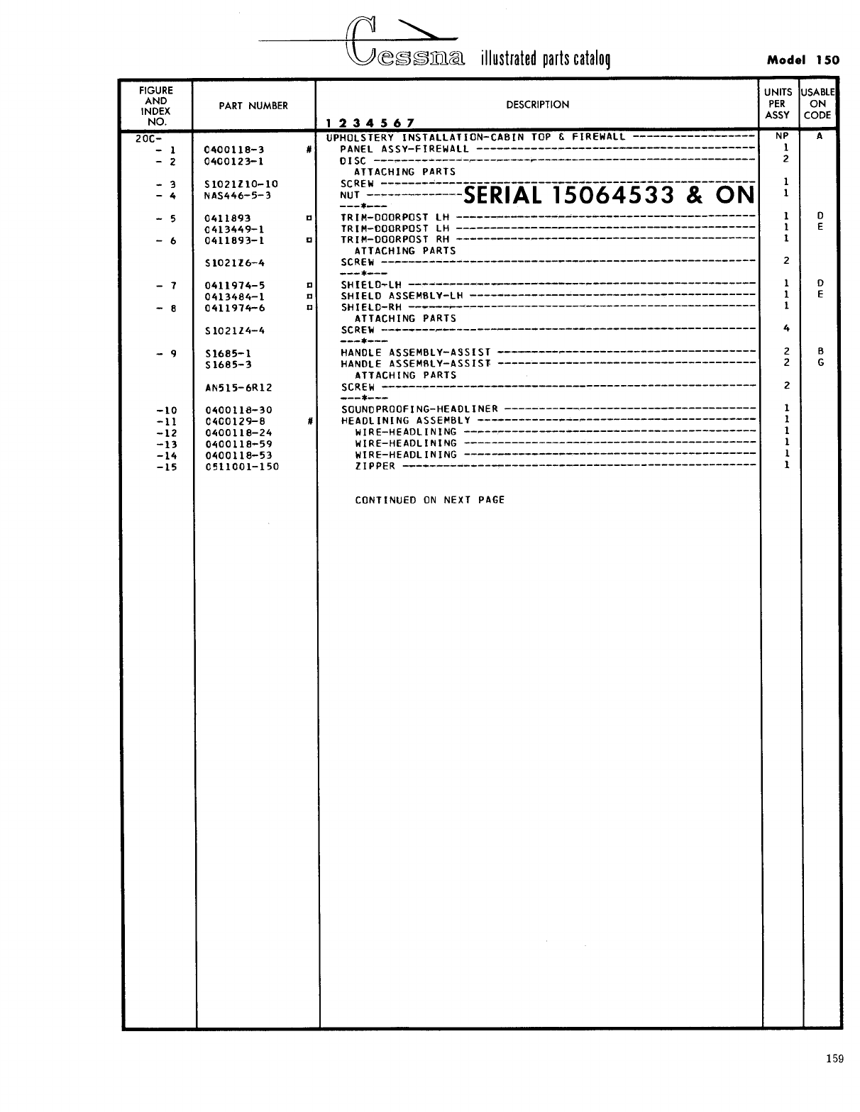
- Parts Listing / Figures
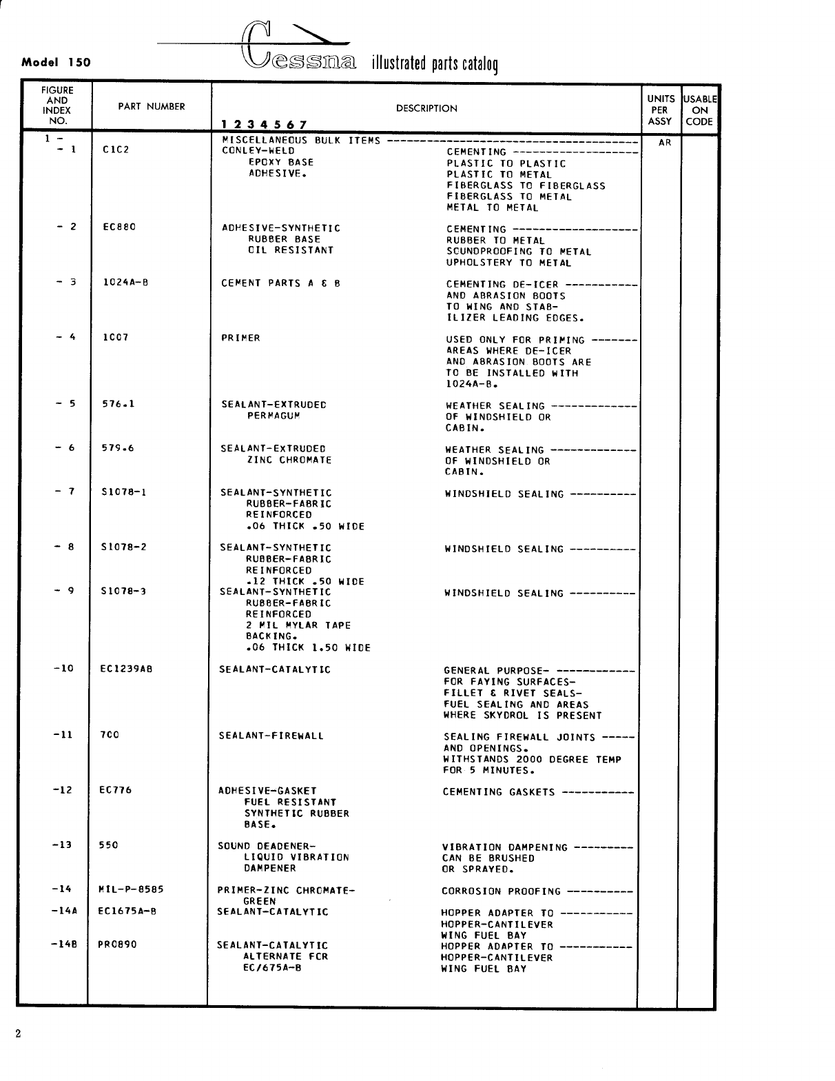
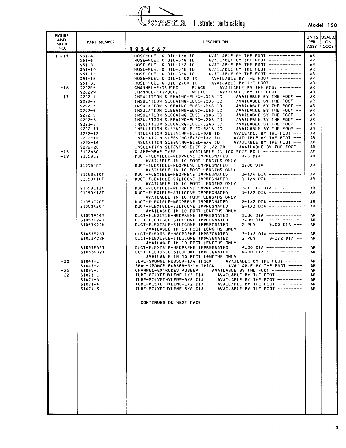
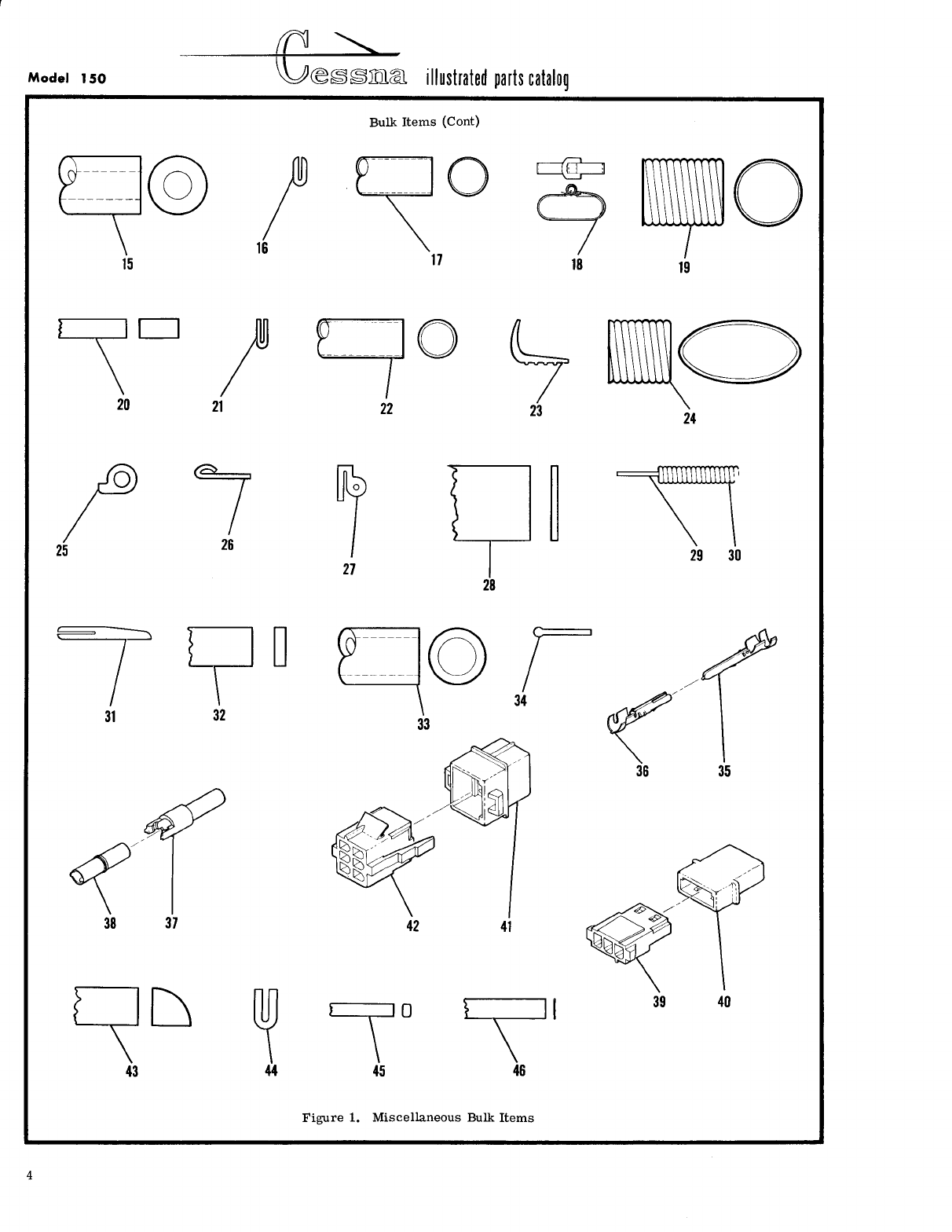
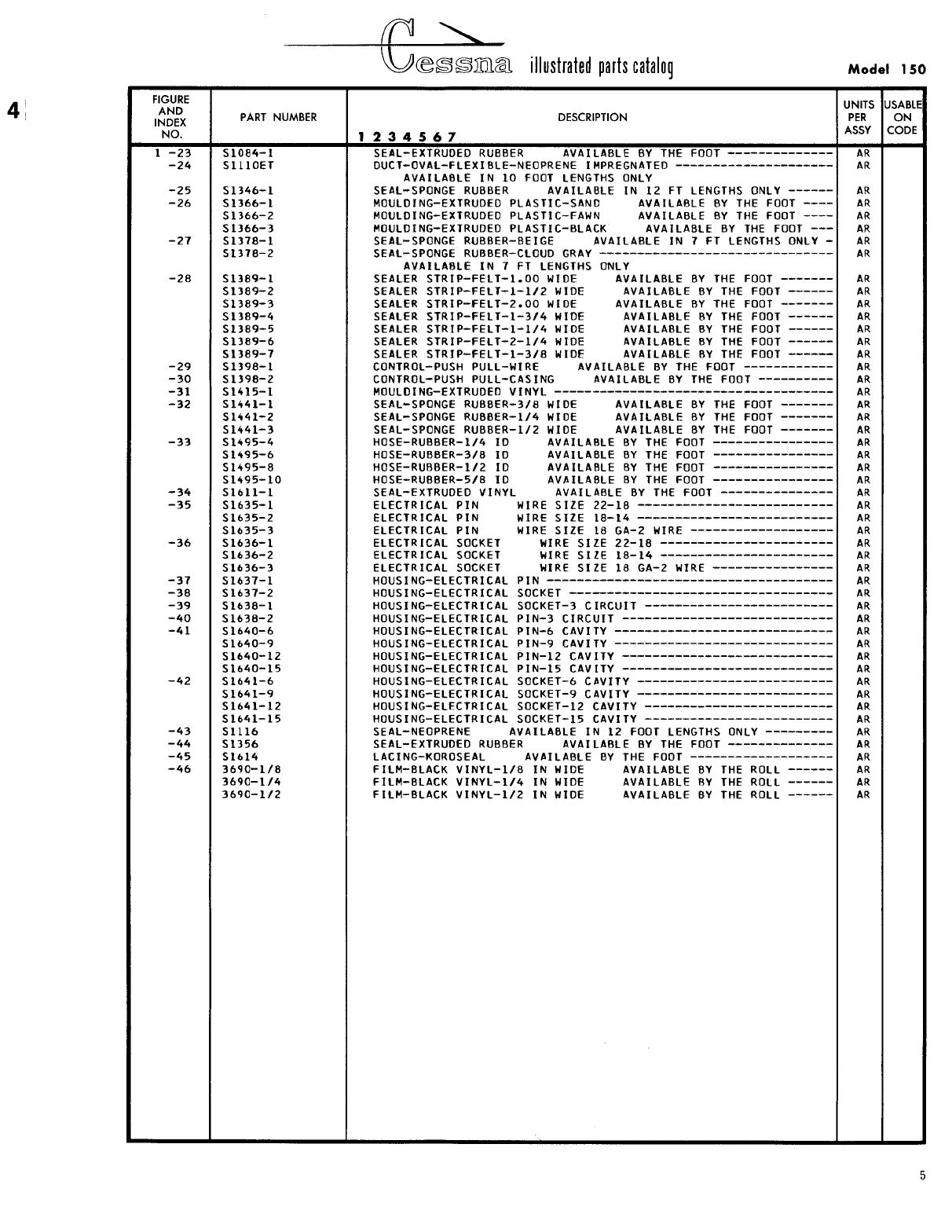
- Fig 1. Miscellaneous Bulk Items
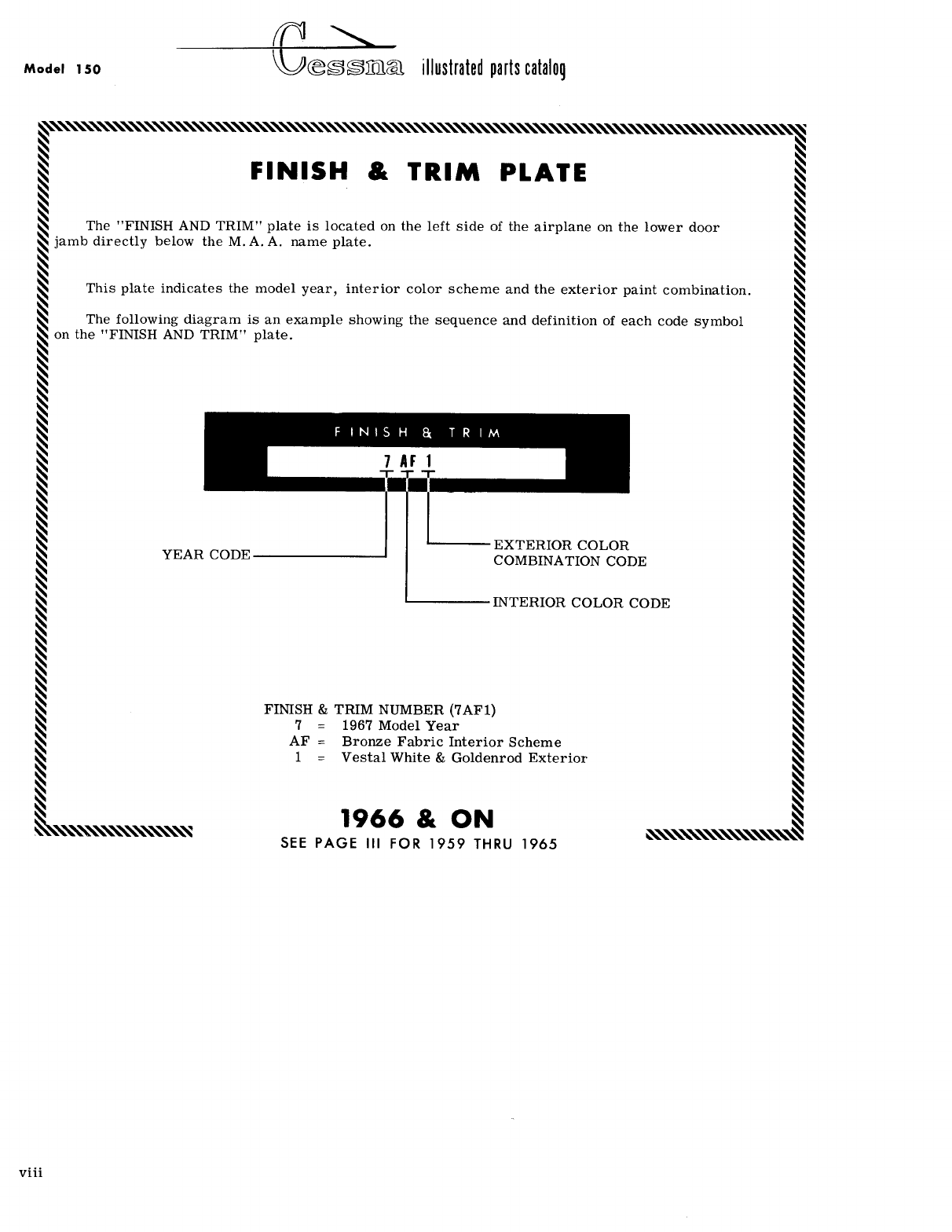
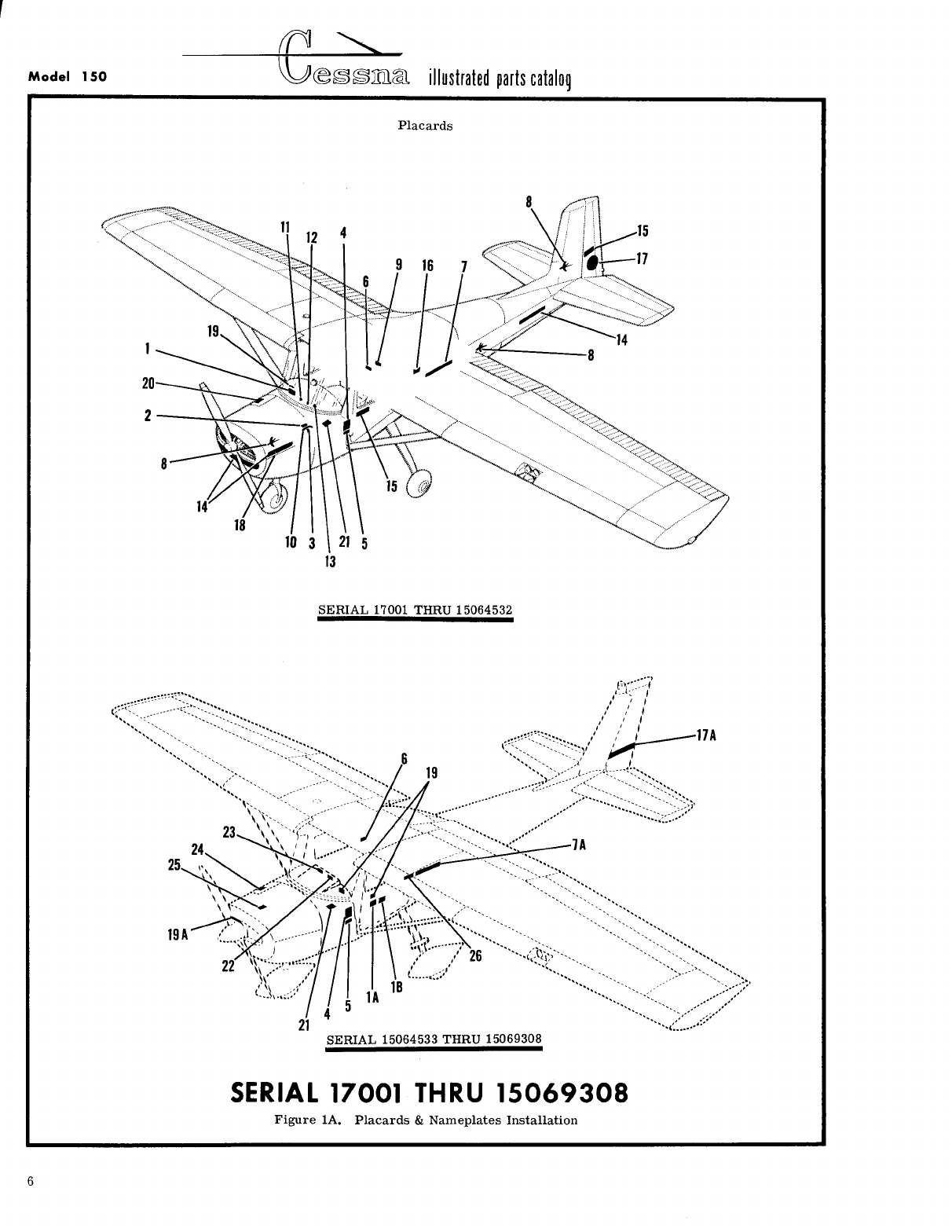
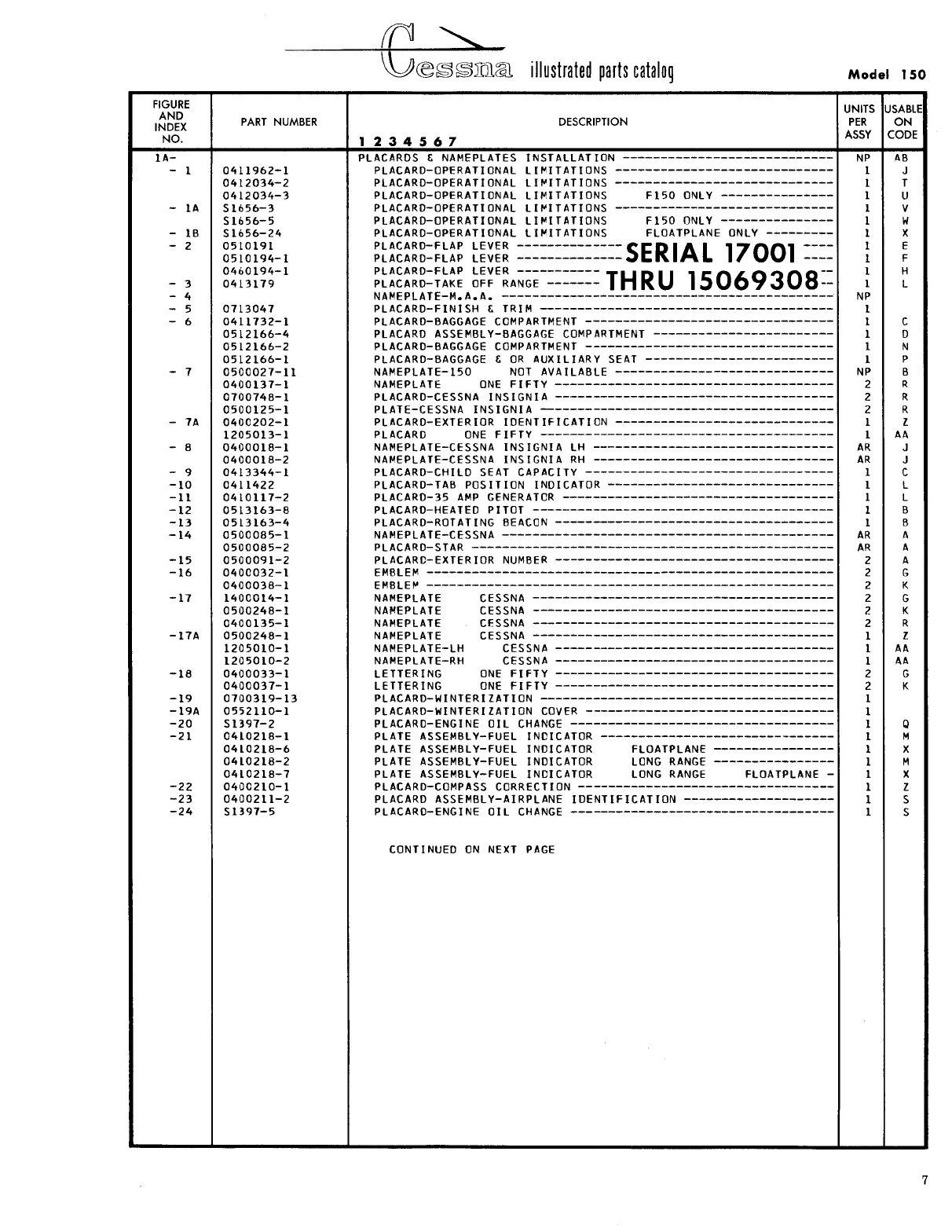
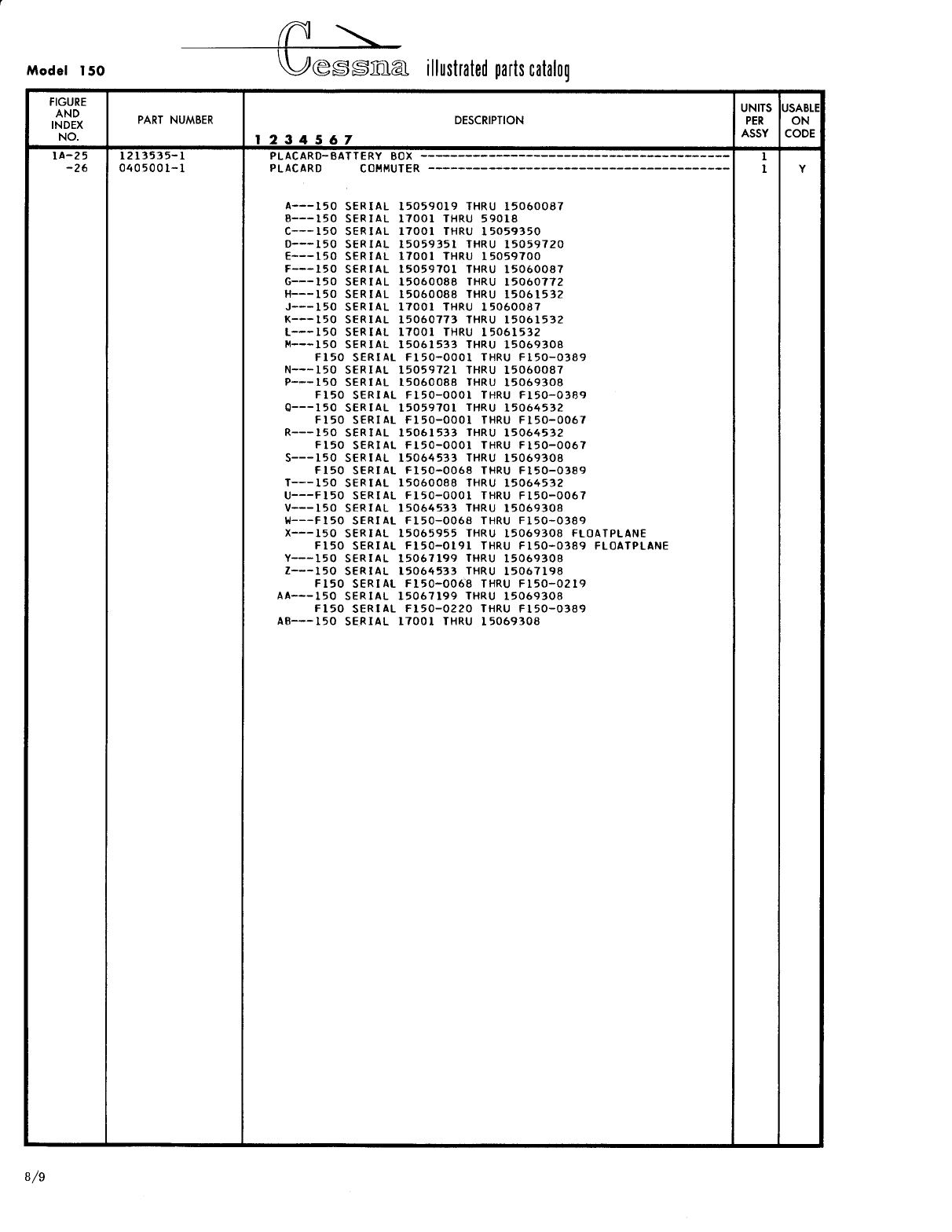
- Fig 1A. Placards & Nameplates Installation
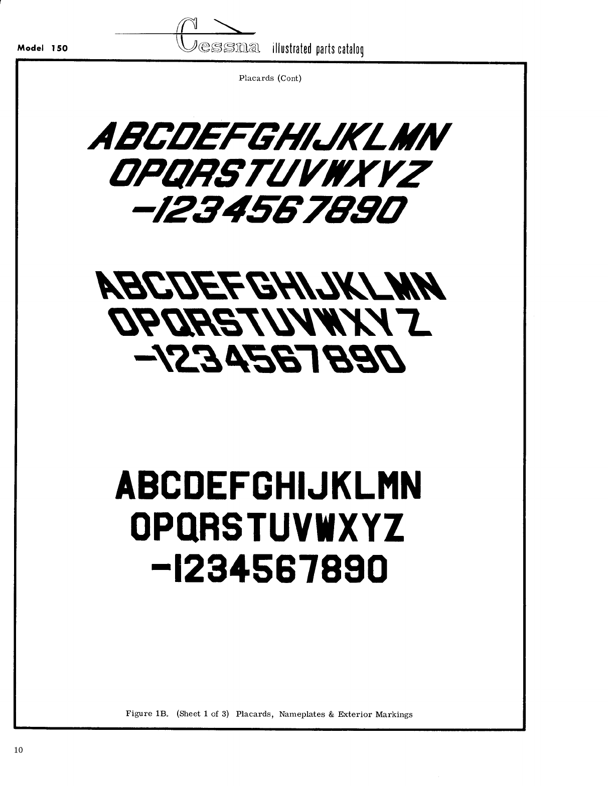
- Fig 1B. (Sheet 1 of 3) Placards, Nameplates & Exterior Markings
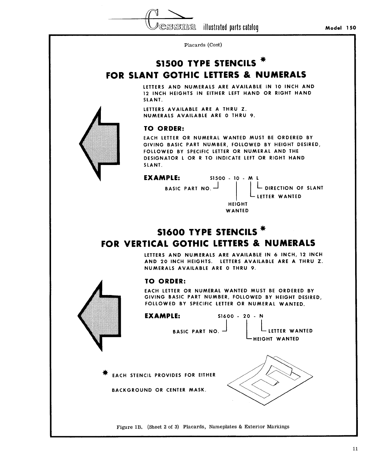
- Fig 1B. (Sheet 2 of 3) Placards, Nameplates & Exterior Markings
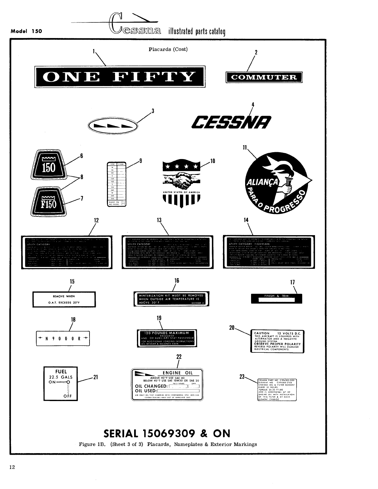
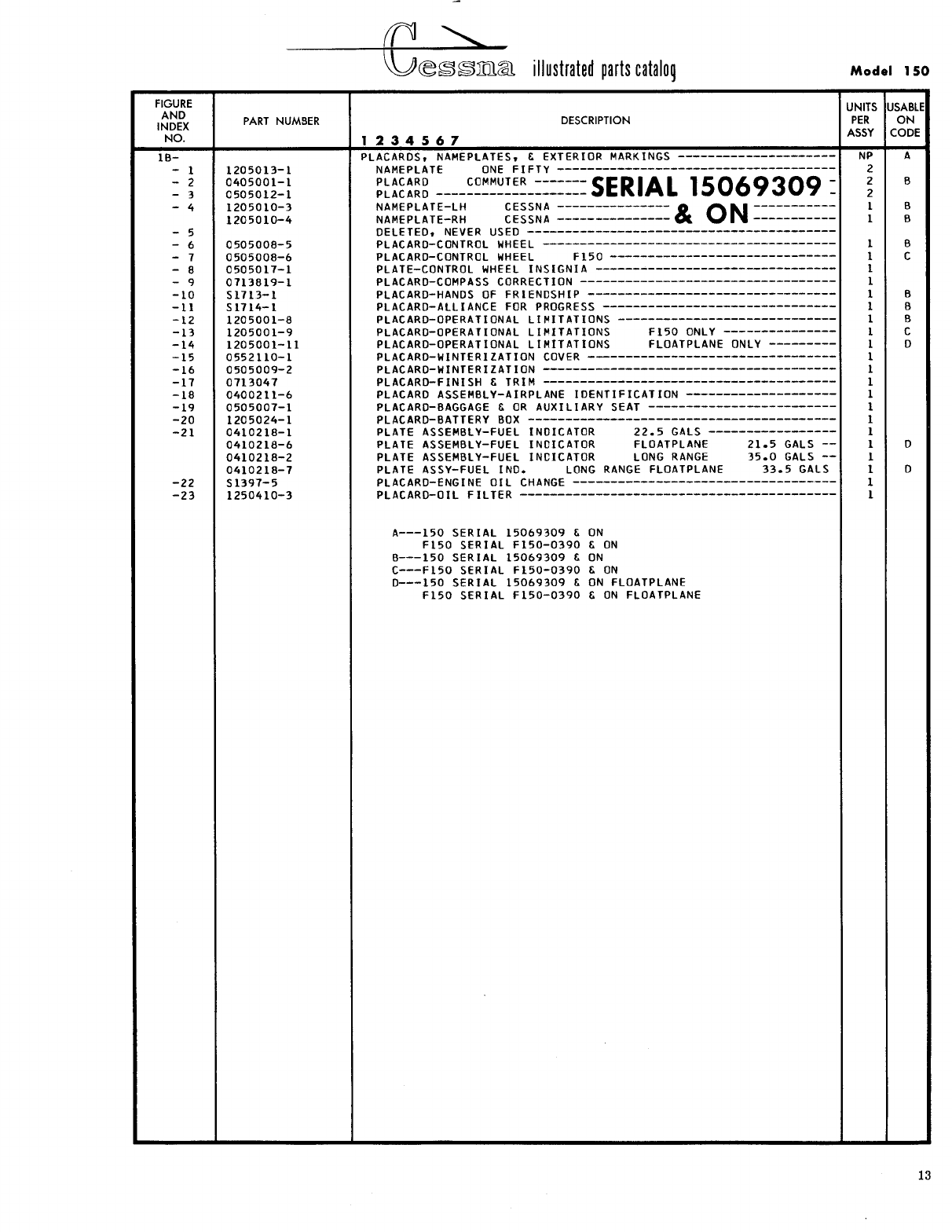
- Fig 1B. (Sheet 3 of 3) Placards, Nameplates & Exterior Markings
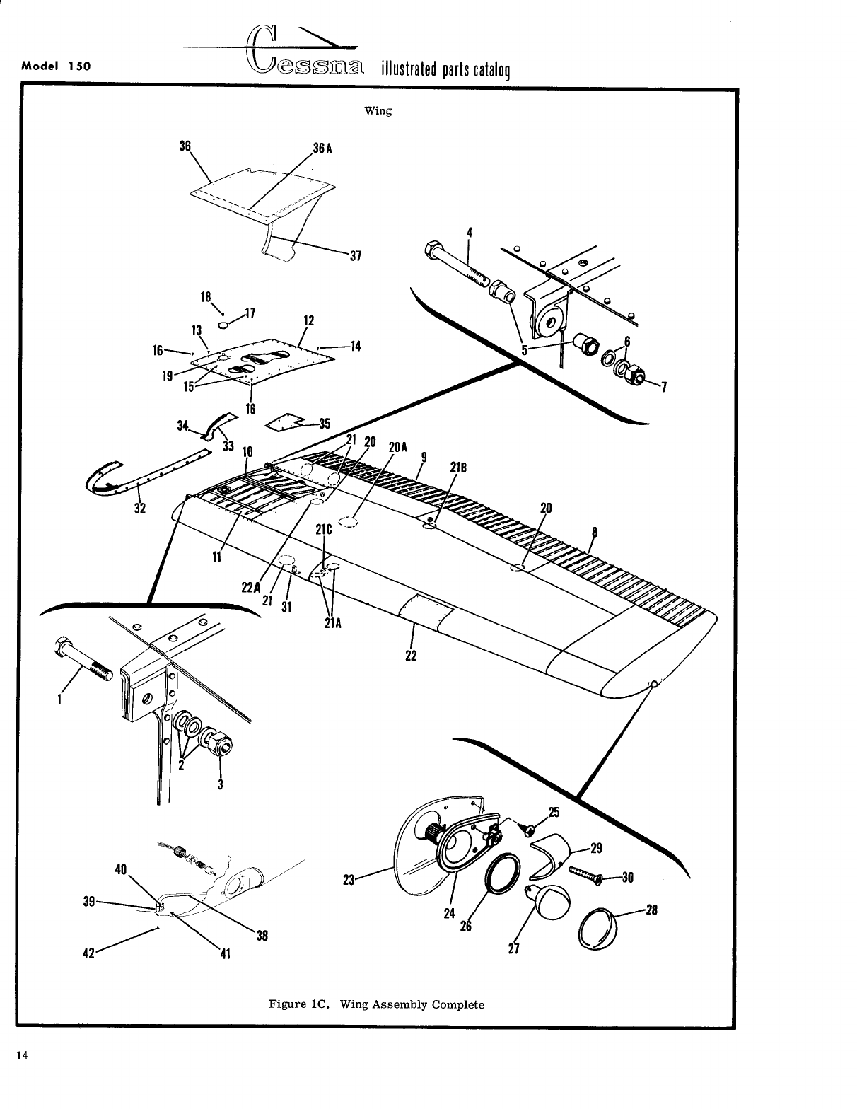
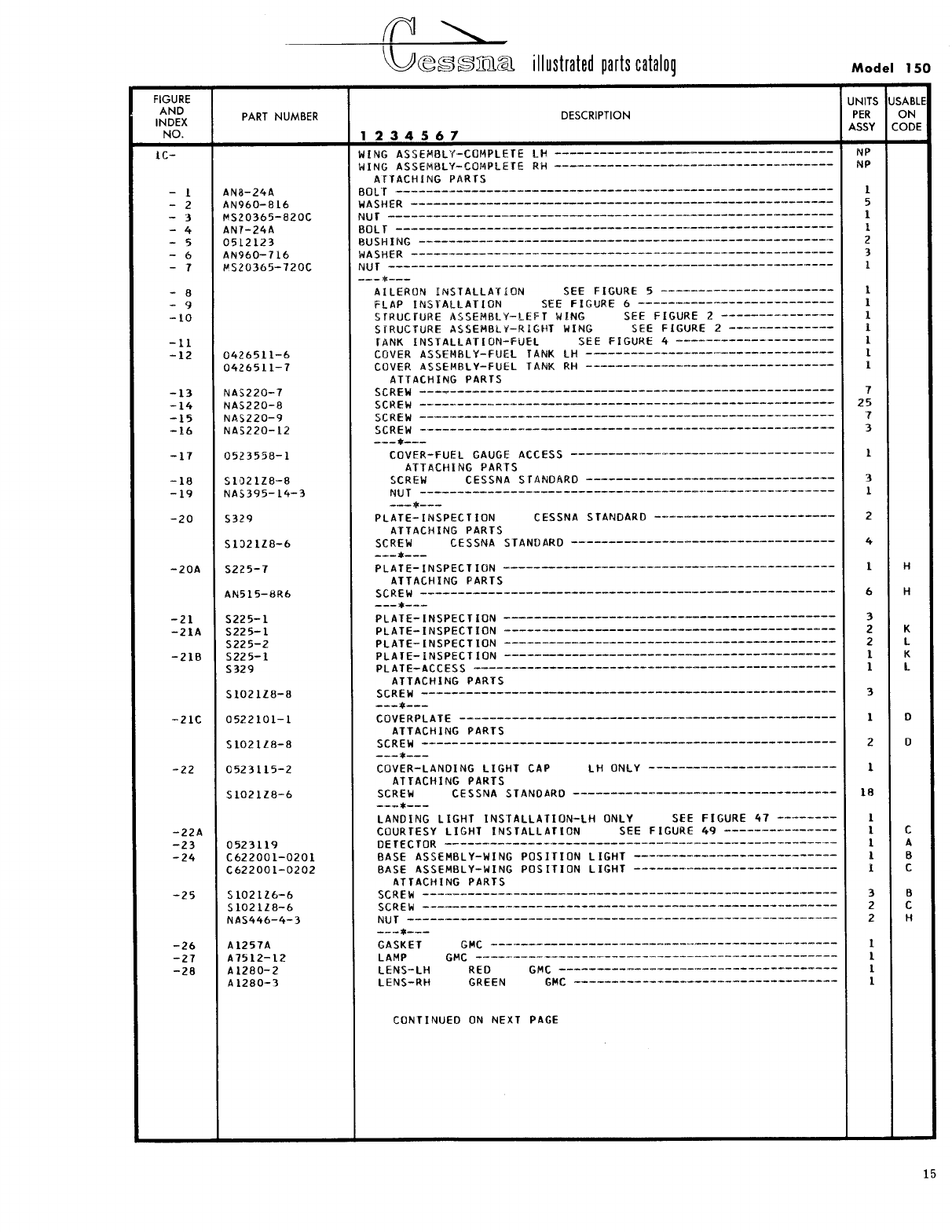
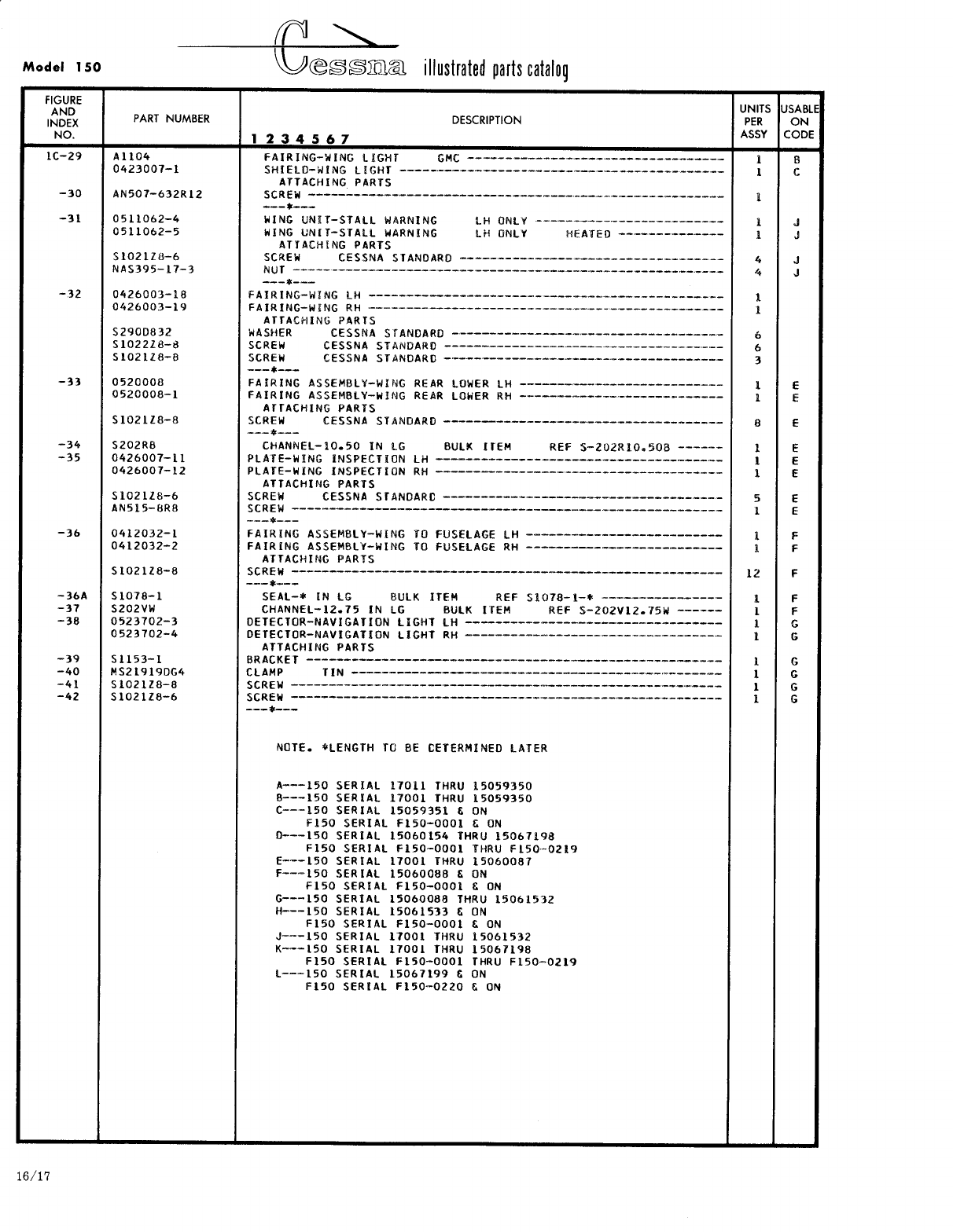
- Fig 1C. Wing Assembly Complete
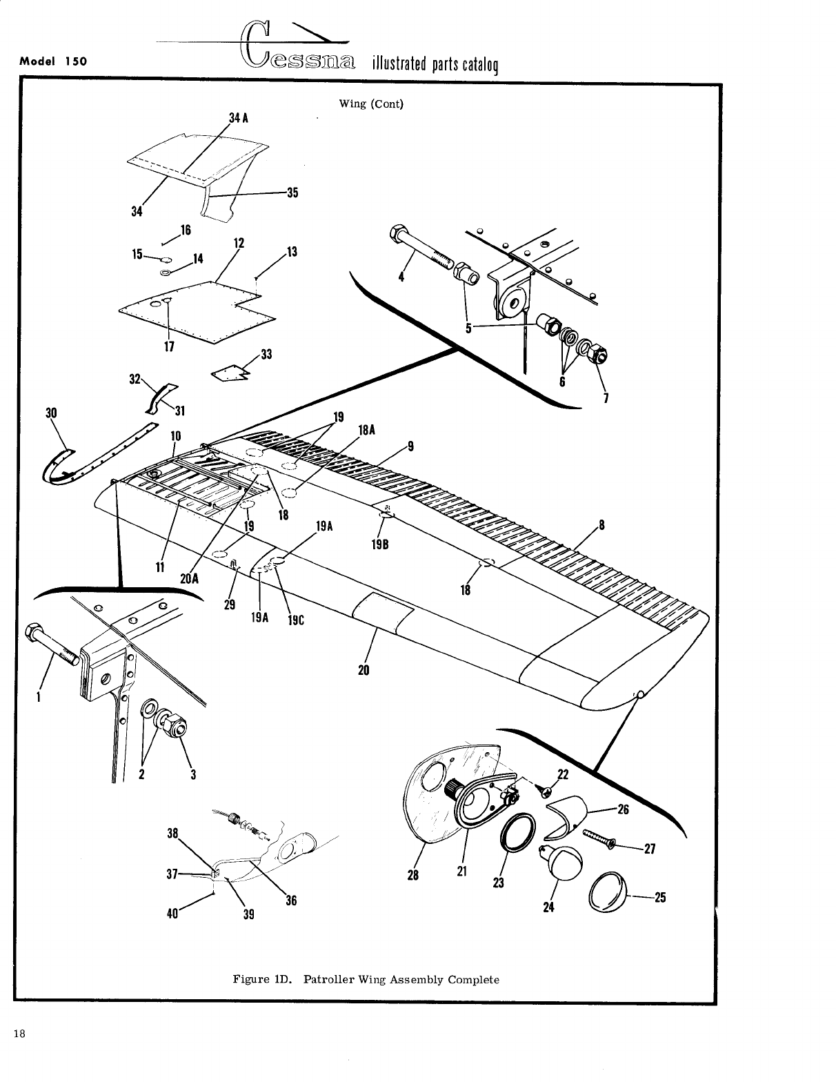
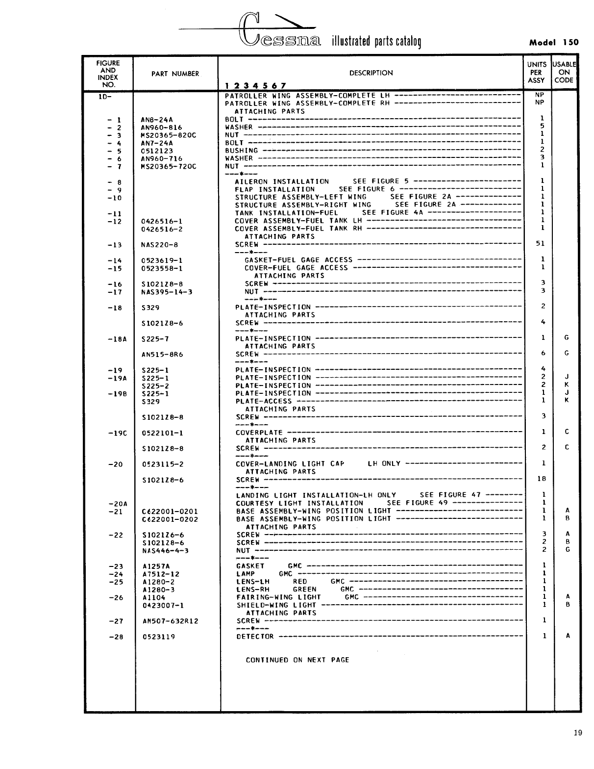
- Fig 1D. Patroller Wing Assembly Complete
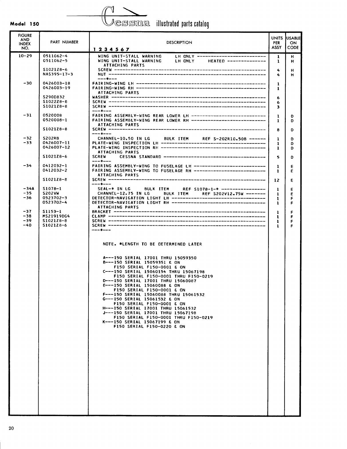
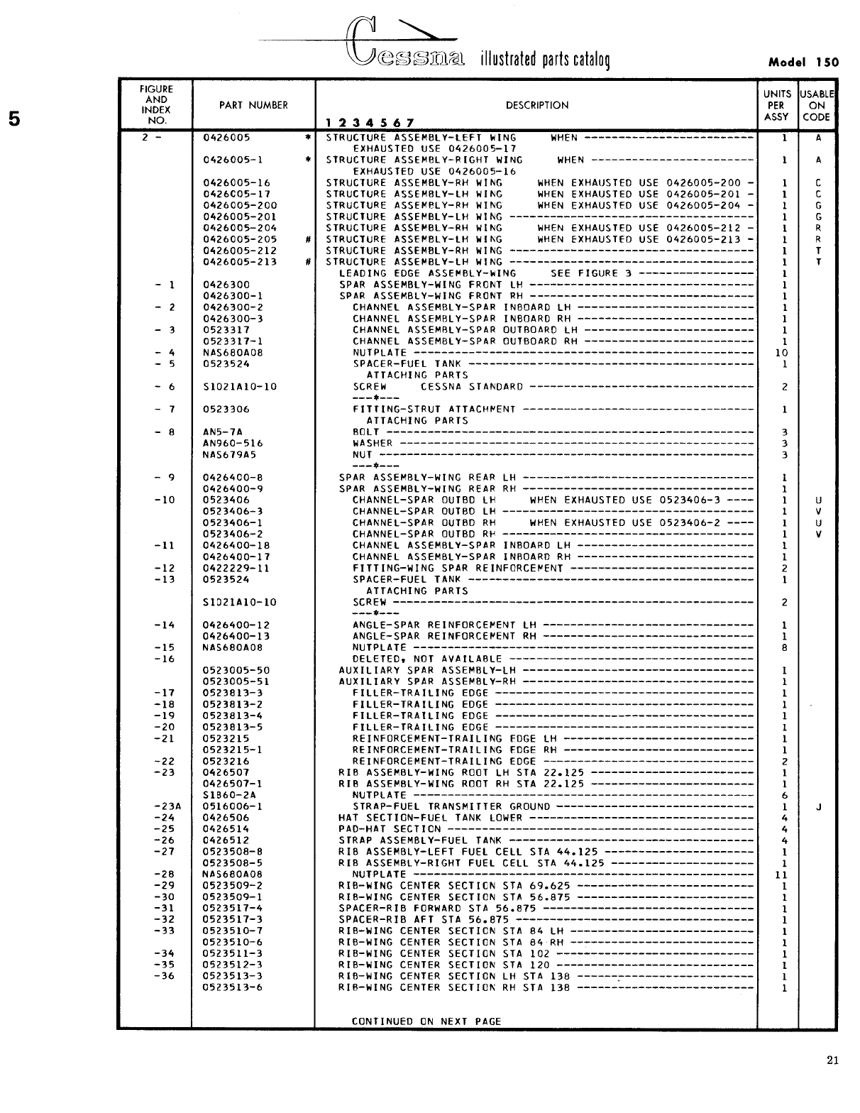
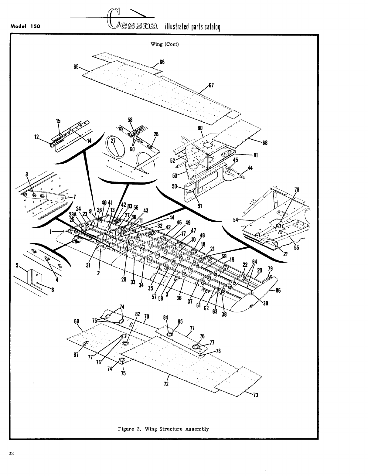
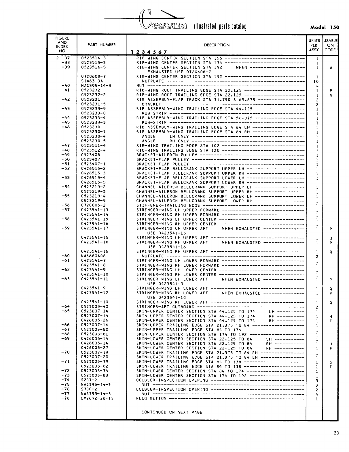
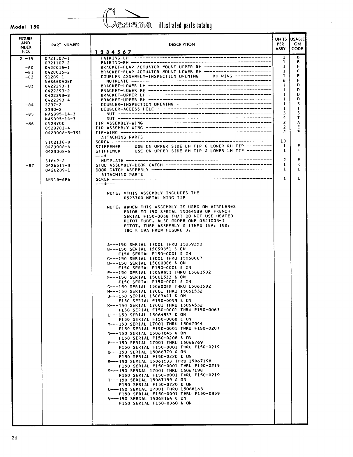
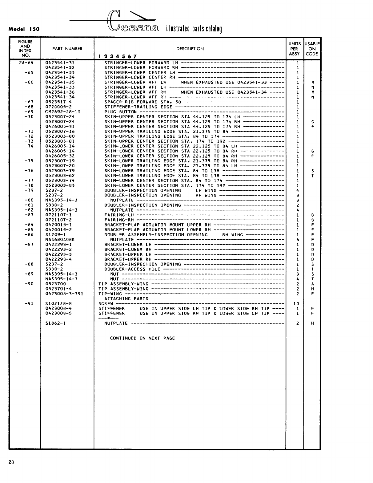
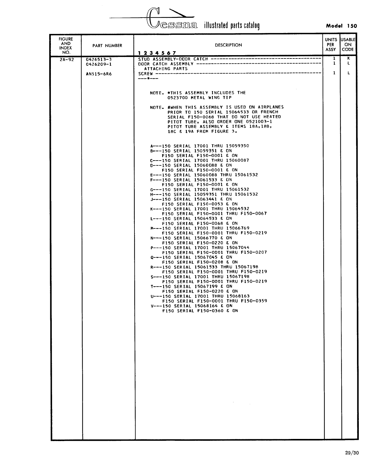
- Fig 2. Wing Structure Assembly
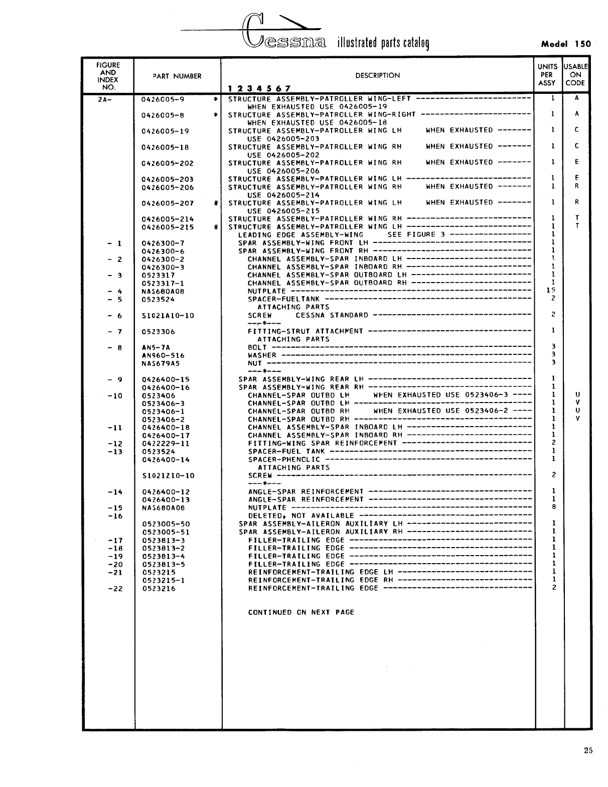
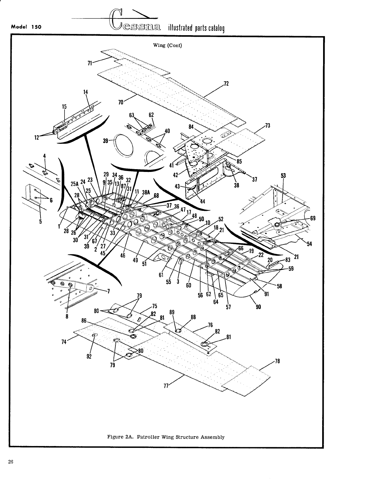
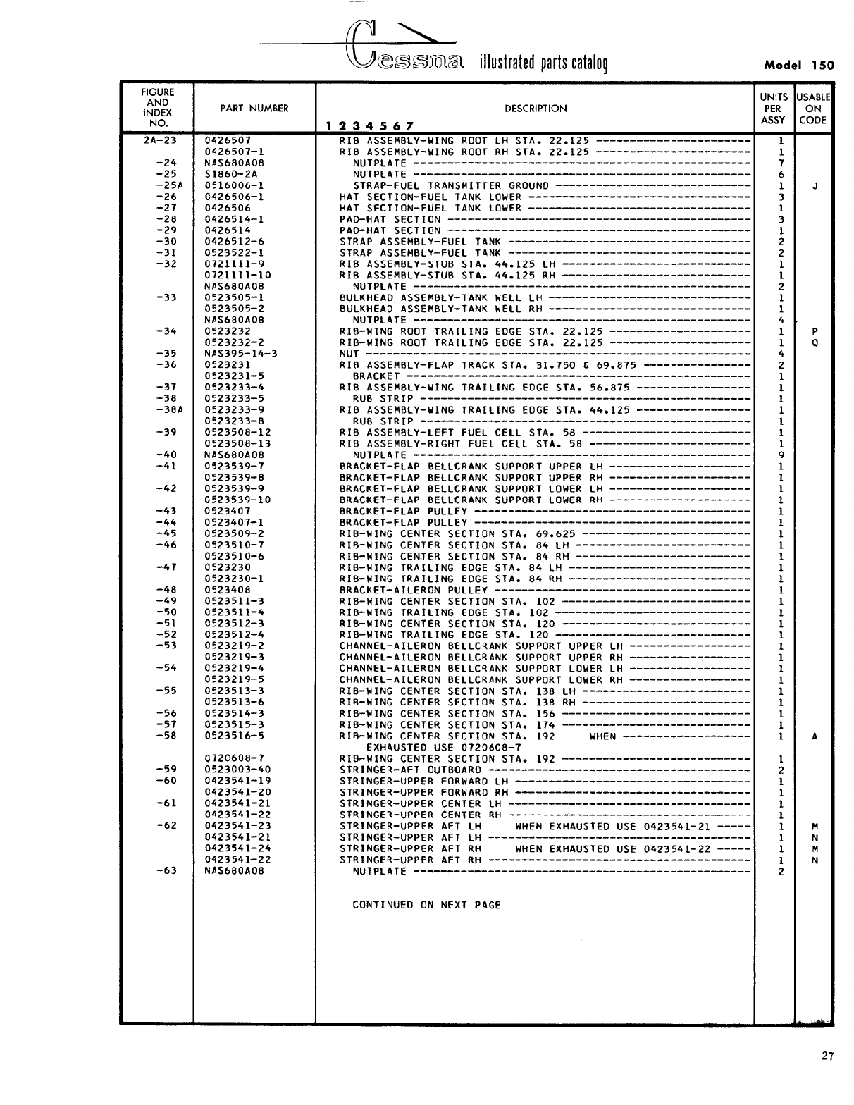
- Fig 2A. Patroller Wing Structure Assembly
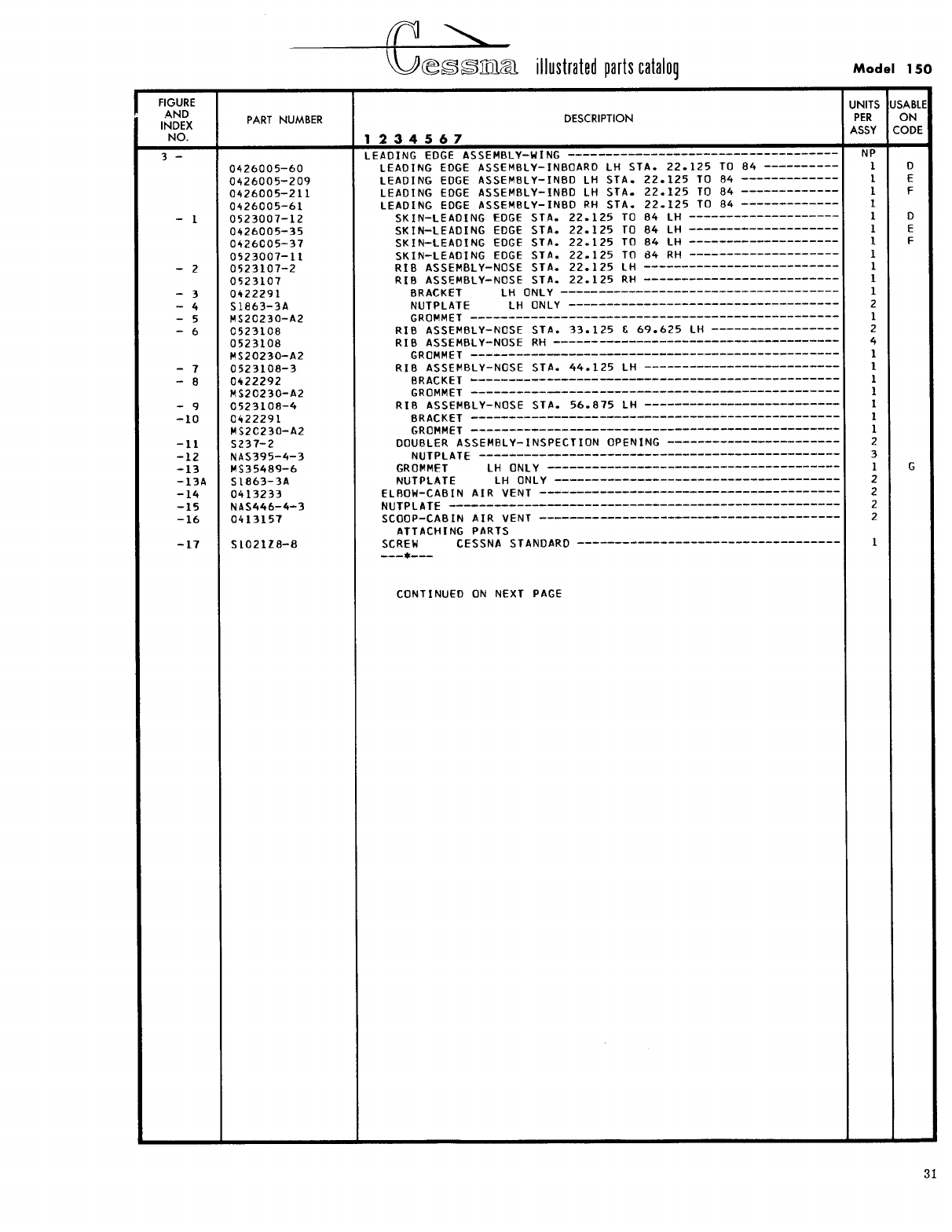
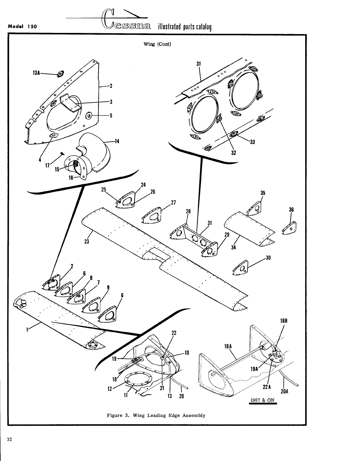
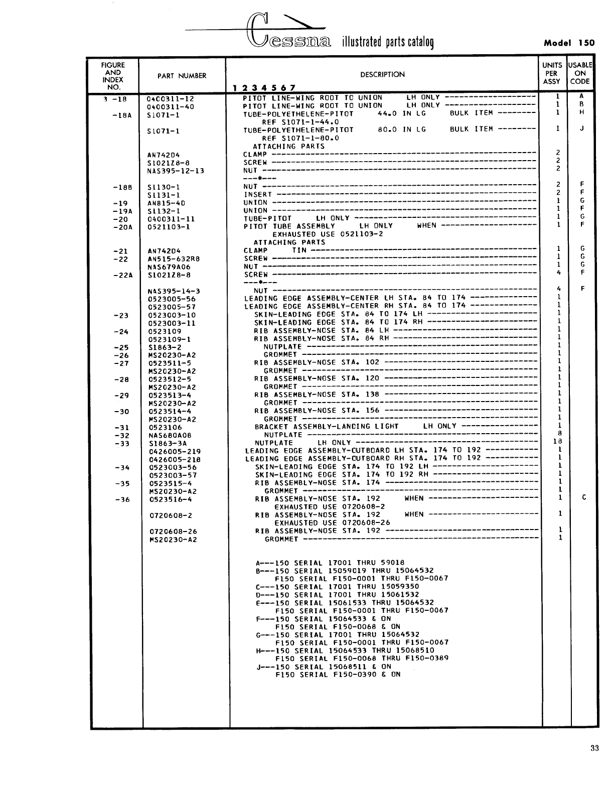
- Fig 3. Wing Leading Edge Assembly
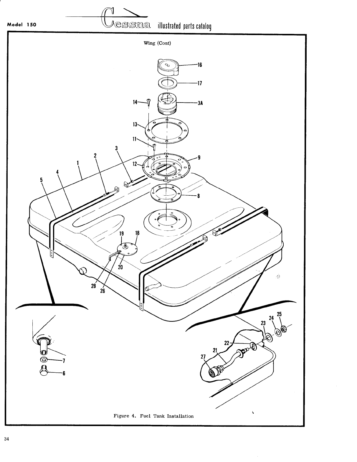
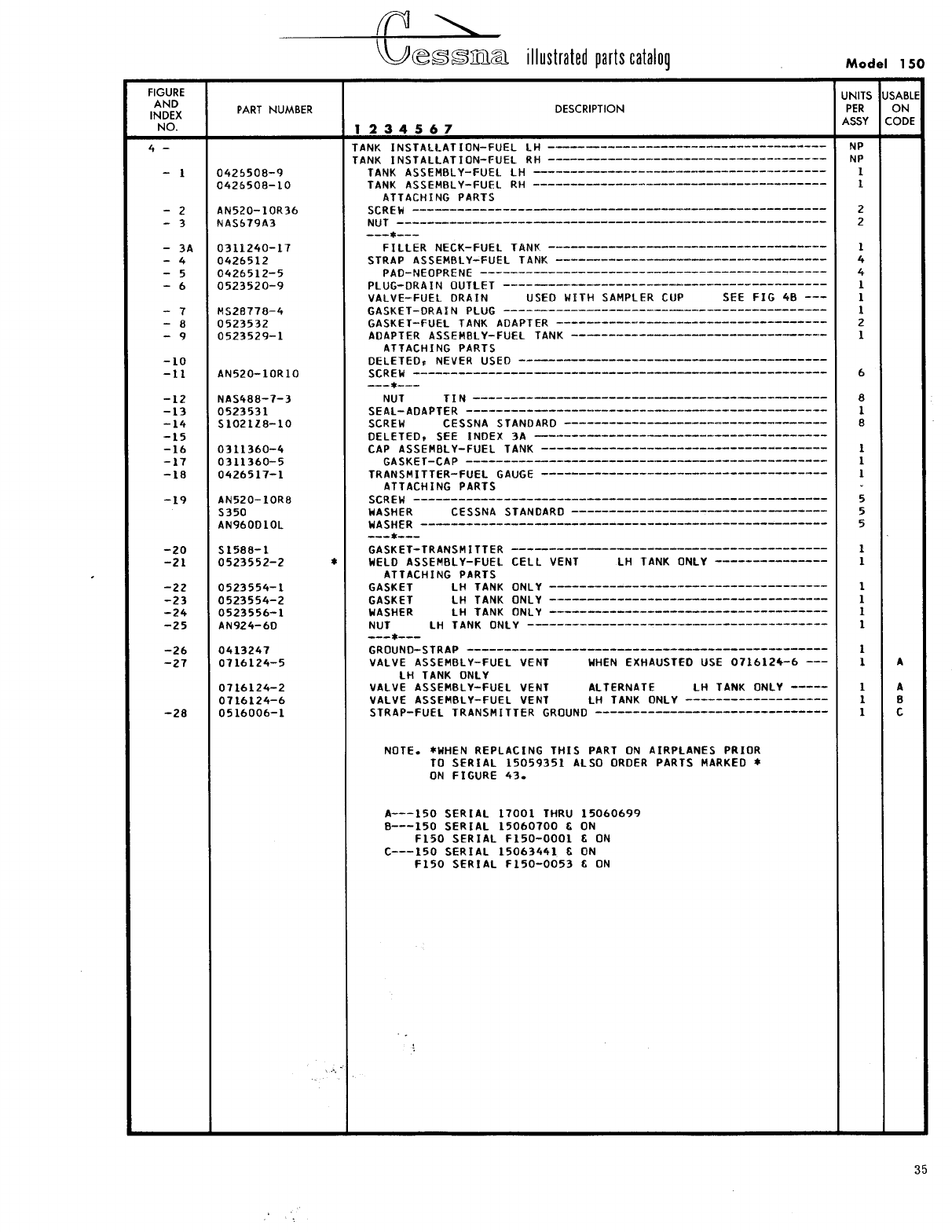
- Fig 4. Fuel Tank Installation
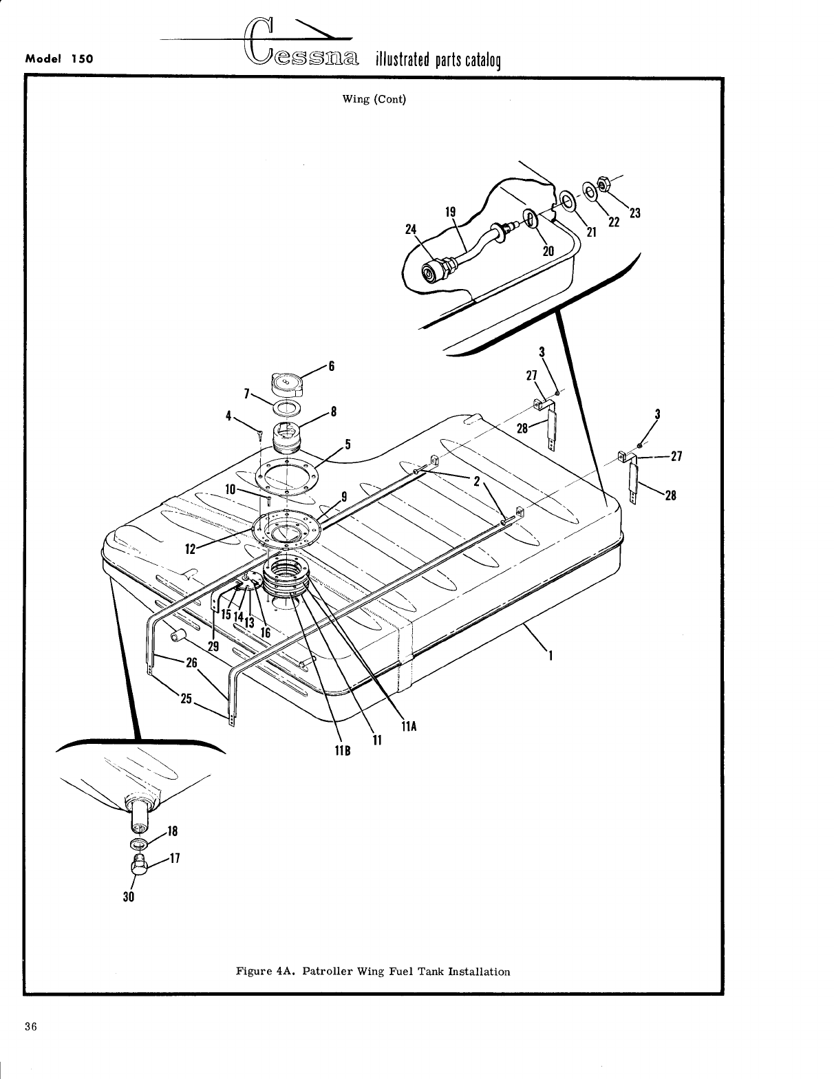
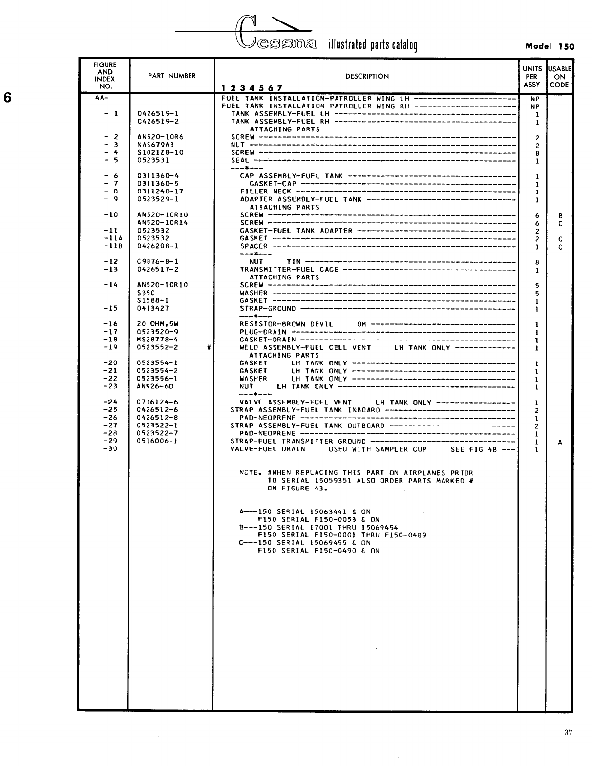
- Fig 4A. Patroller Wing Fuel Tank Installation
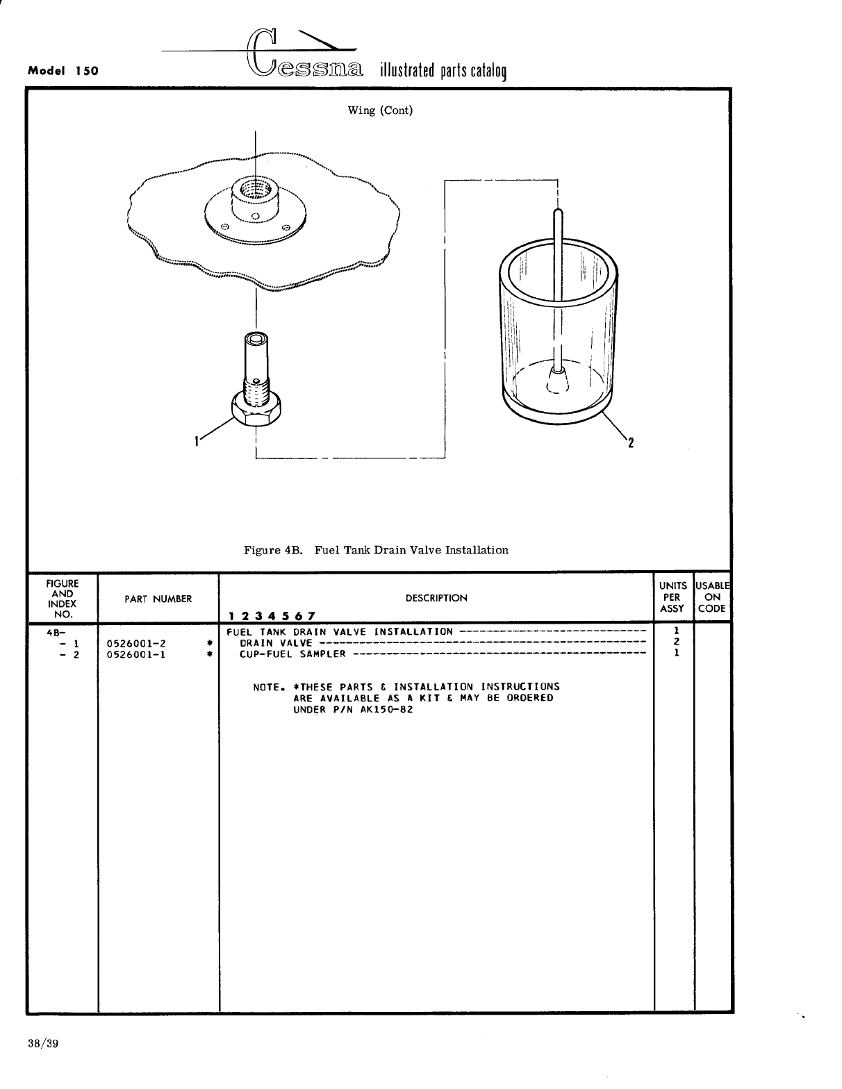
- Fig 4B. Fuel Tank Drain Valve Installation
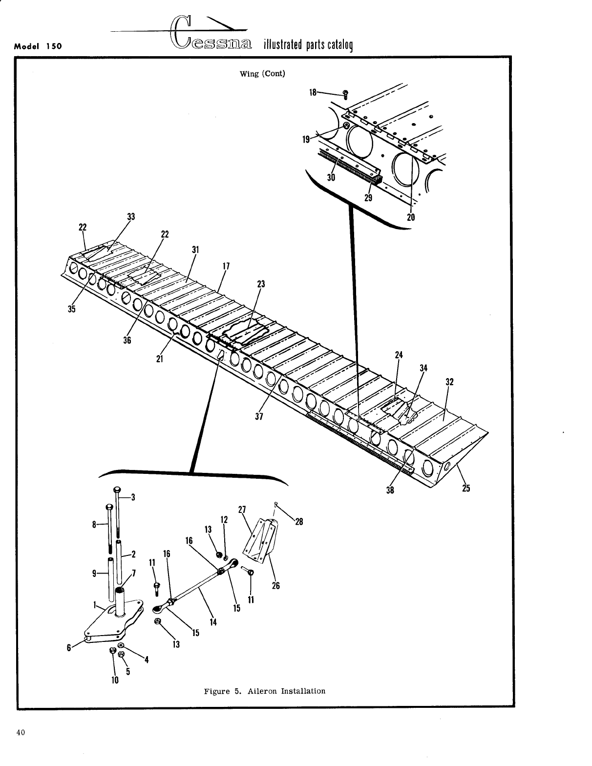
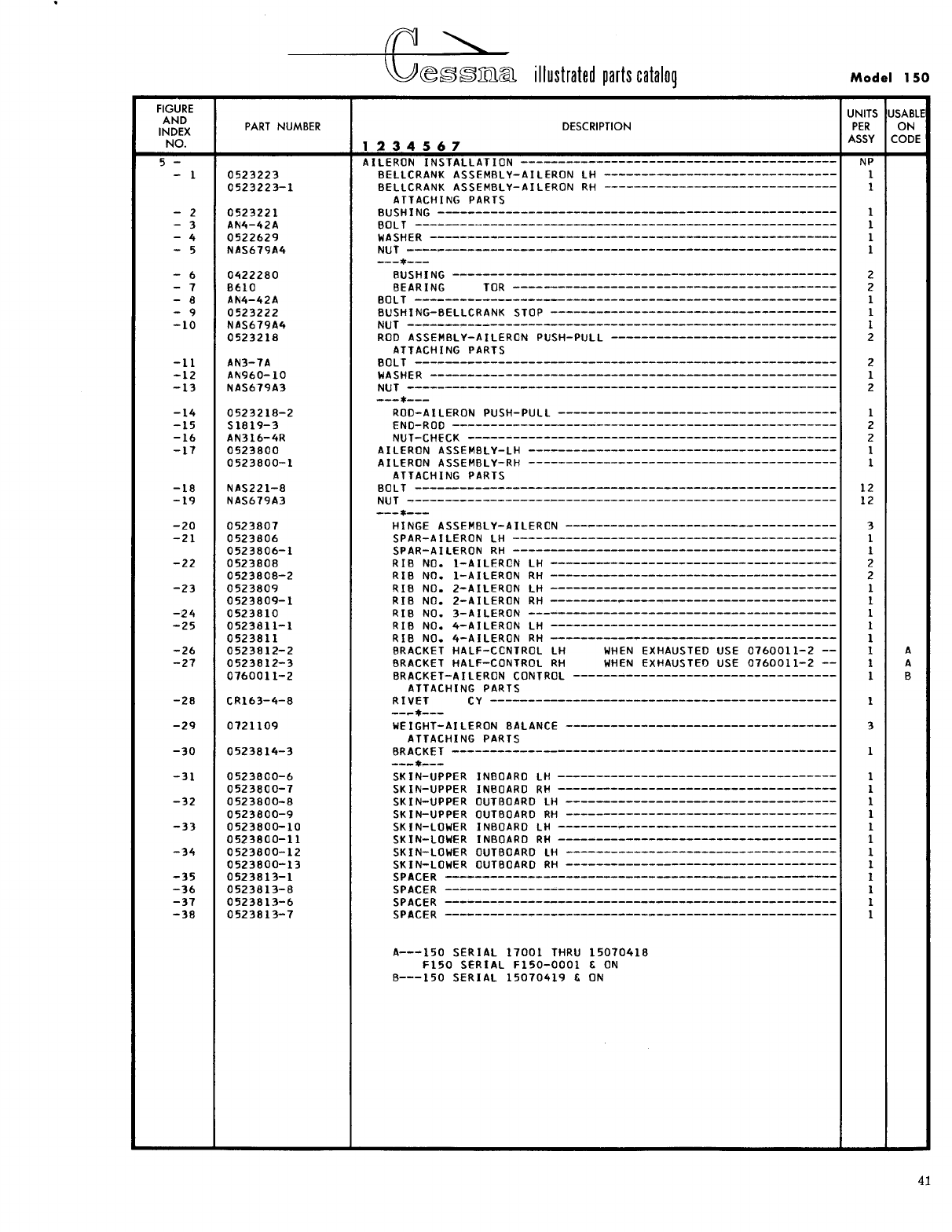
- Fig 5. Aileron Installation
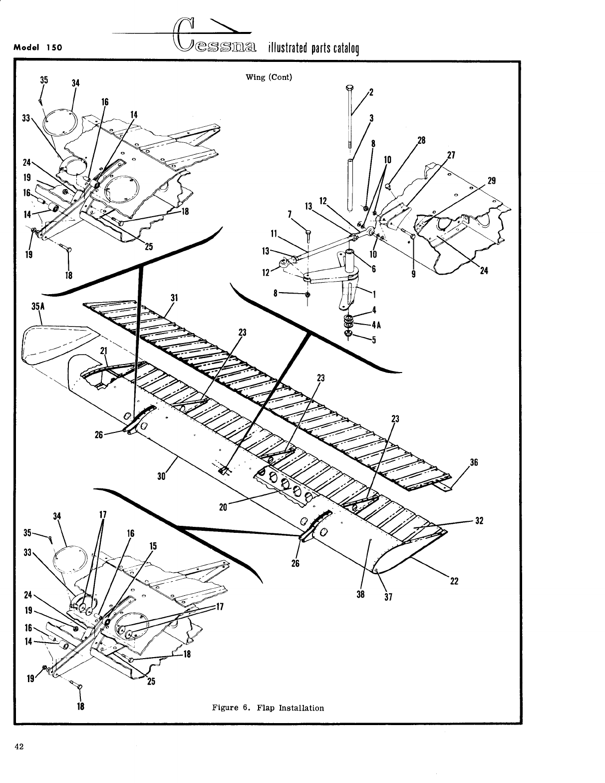
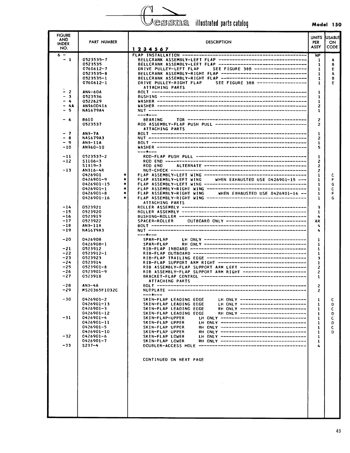
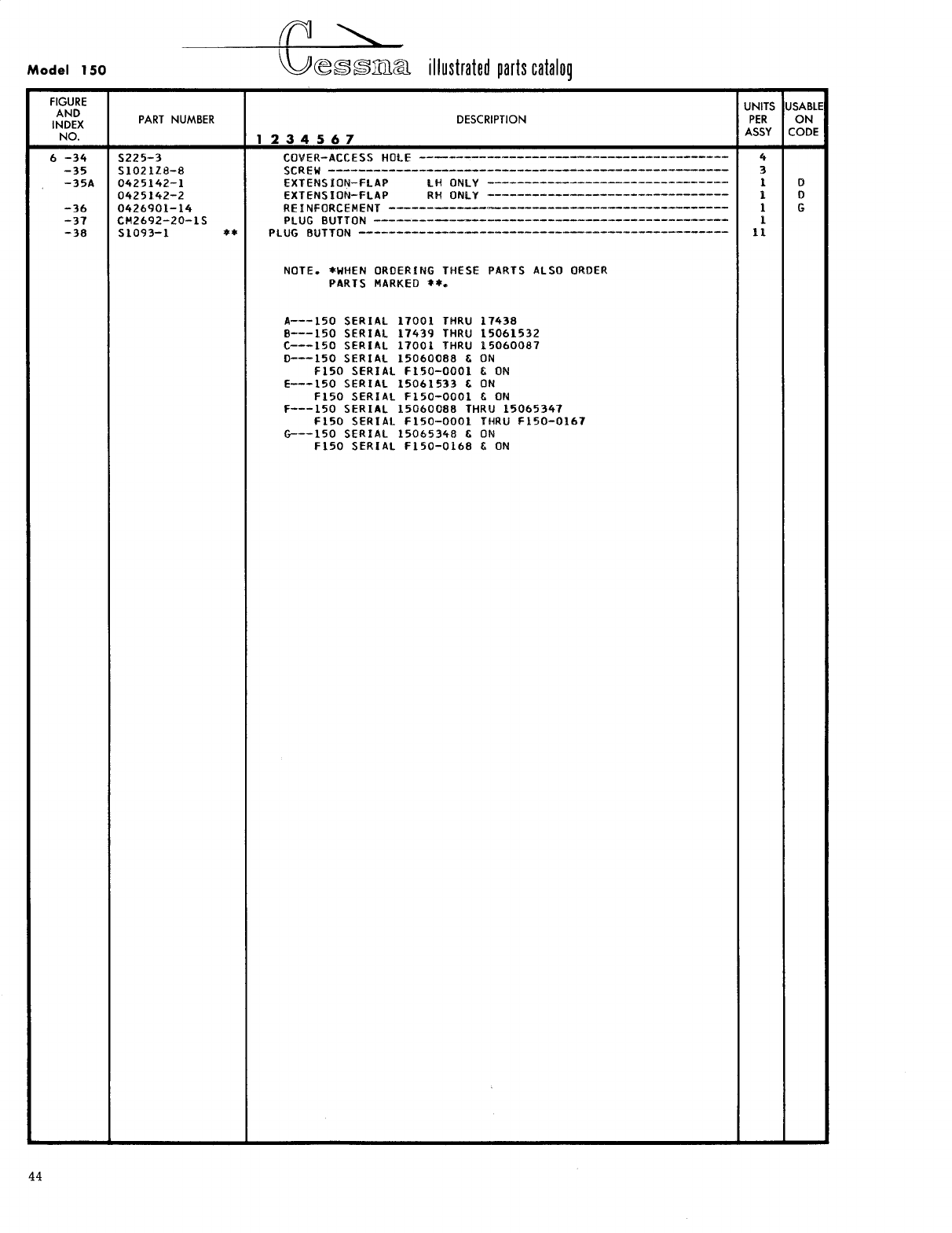
- Fig 6. Flap Installation
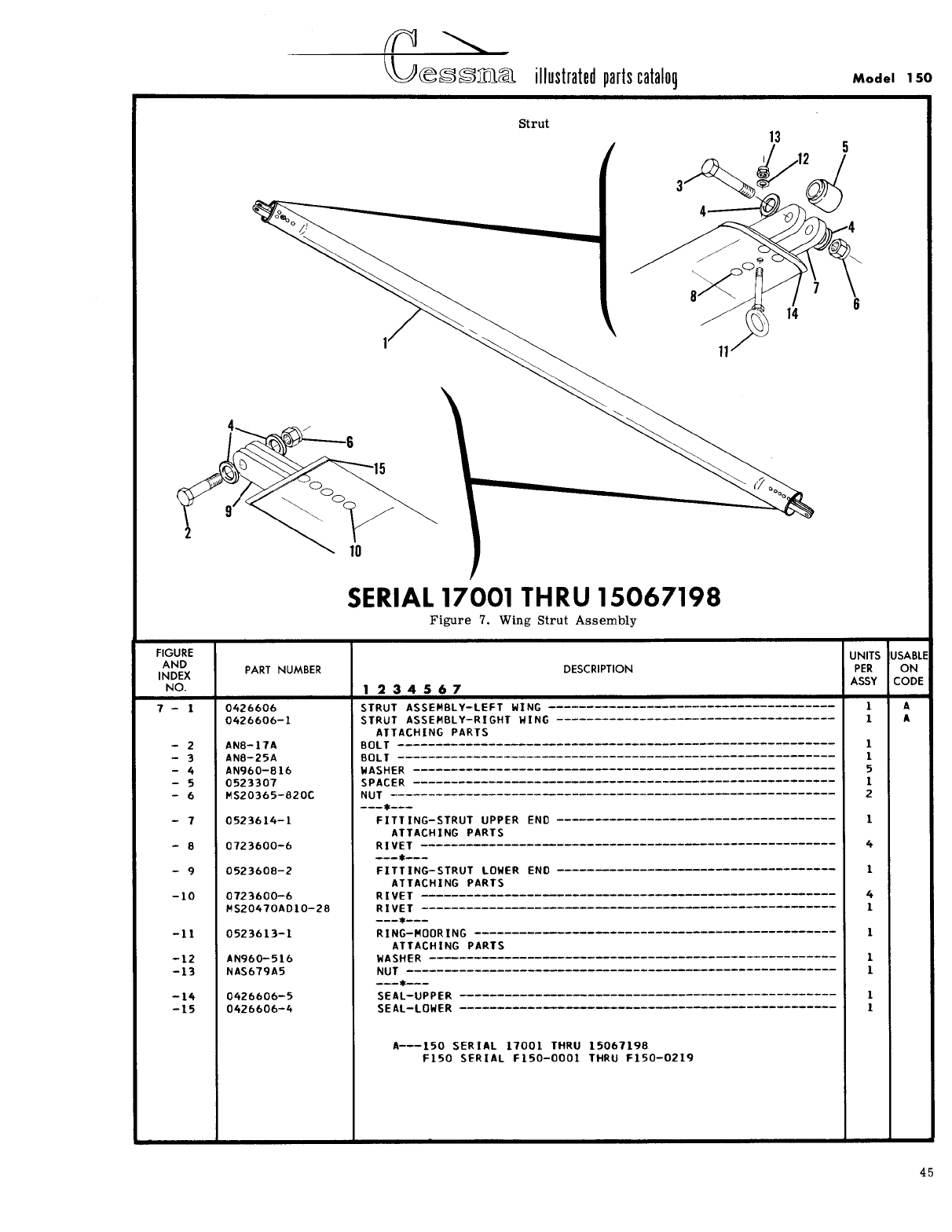
- Fig 7. Wing Strut Assembly
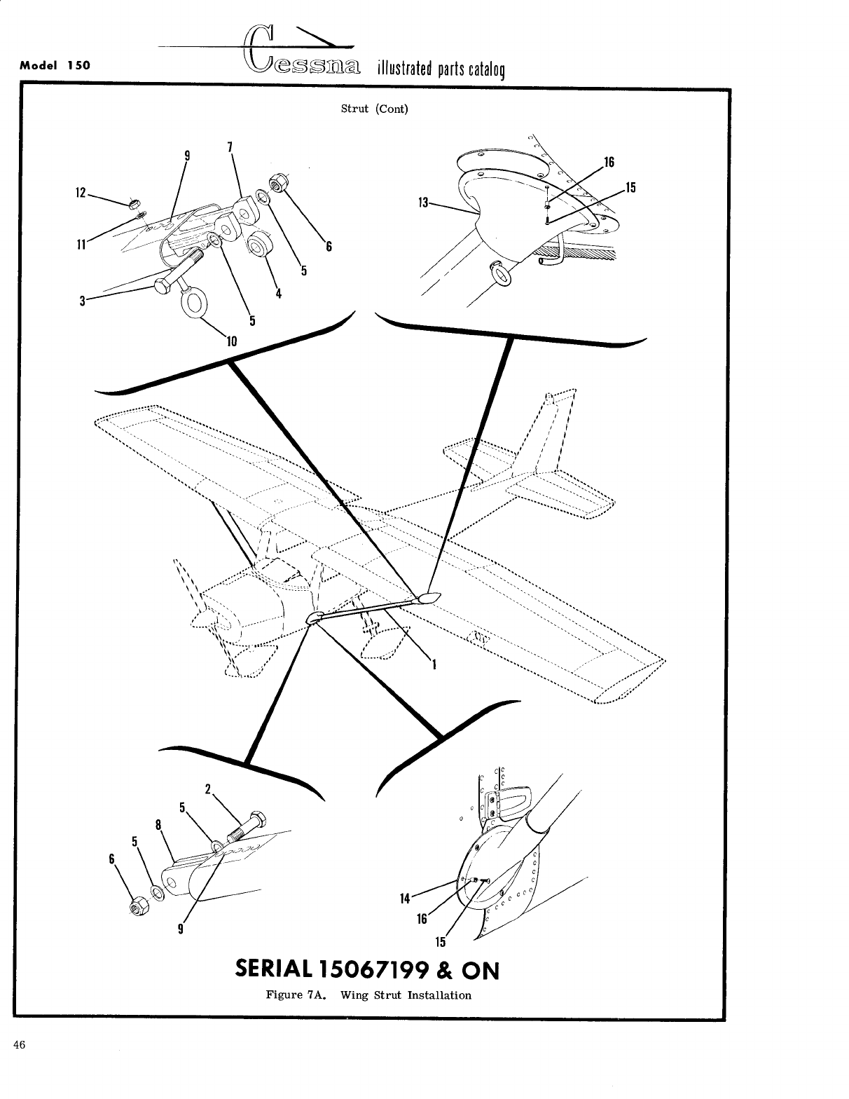
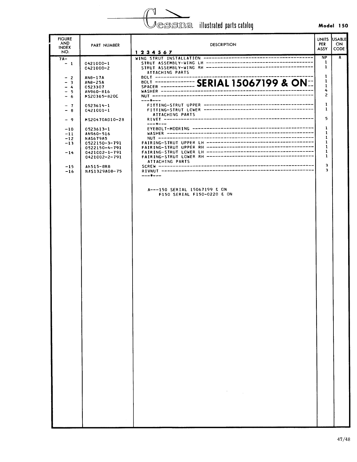
- Fig 7A. Wing Strut Assembly
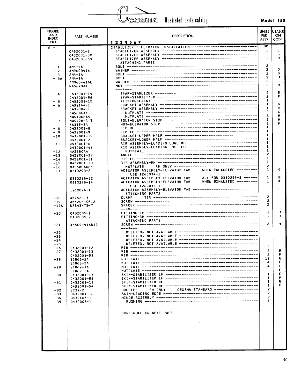
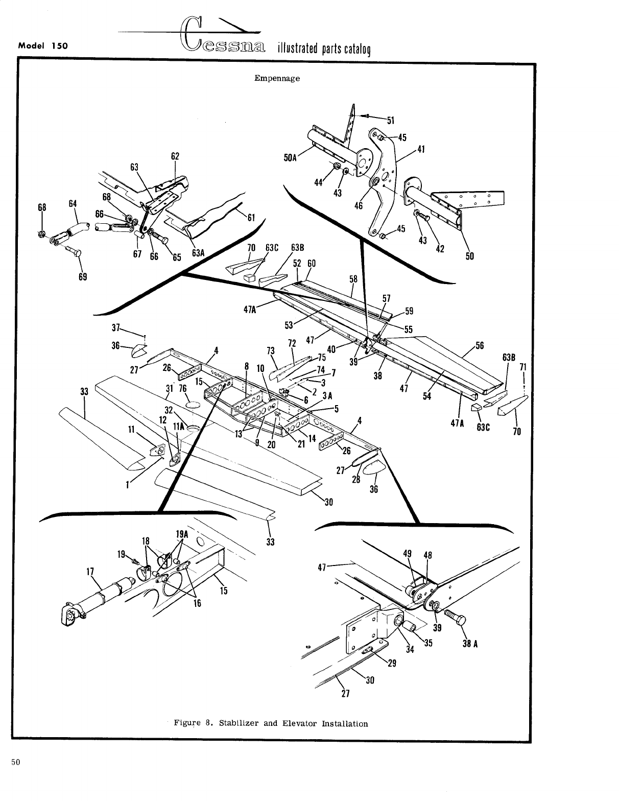
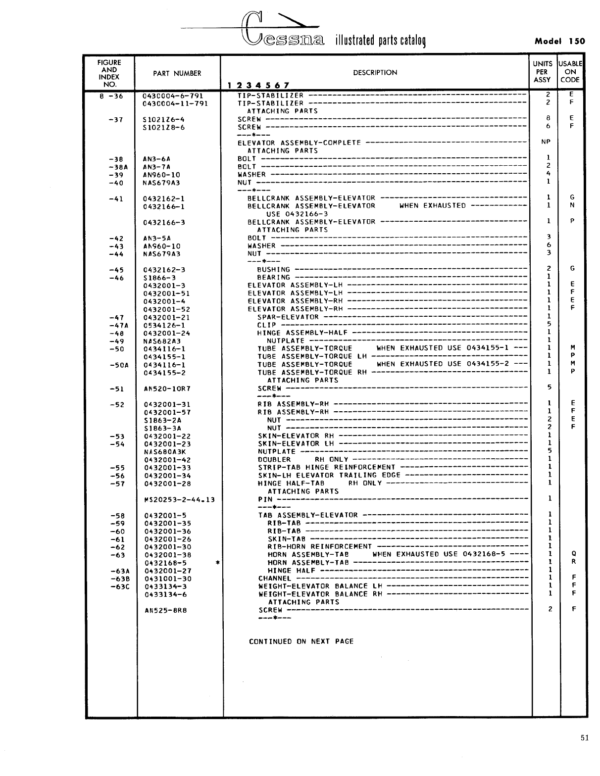
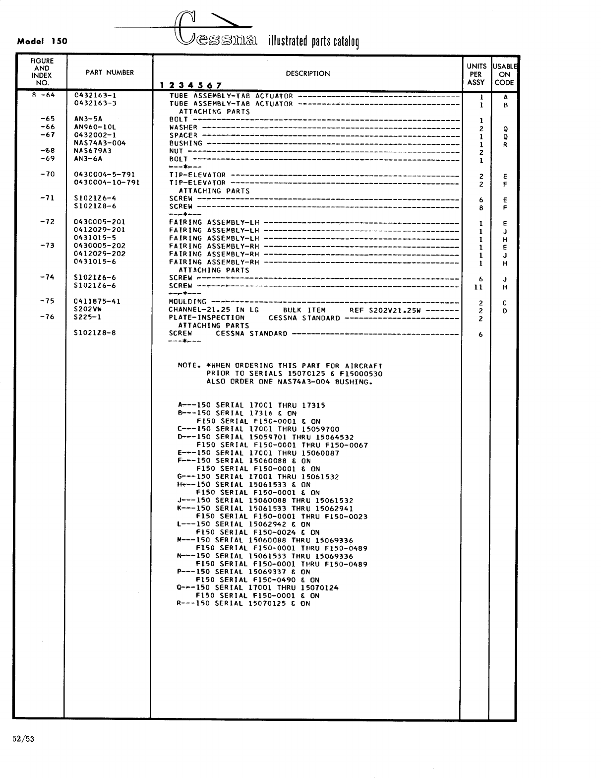
- Fig 8. Stabilizer and Elevator Installation
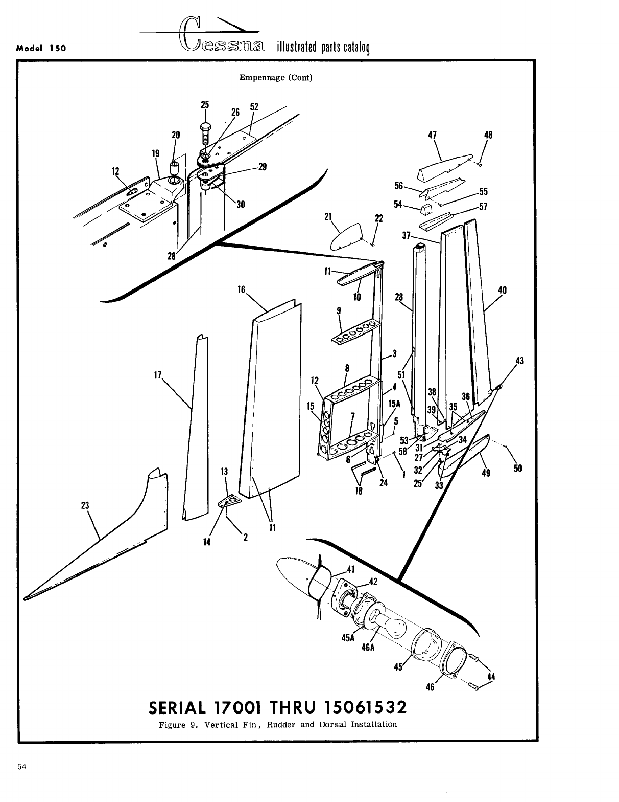
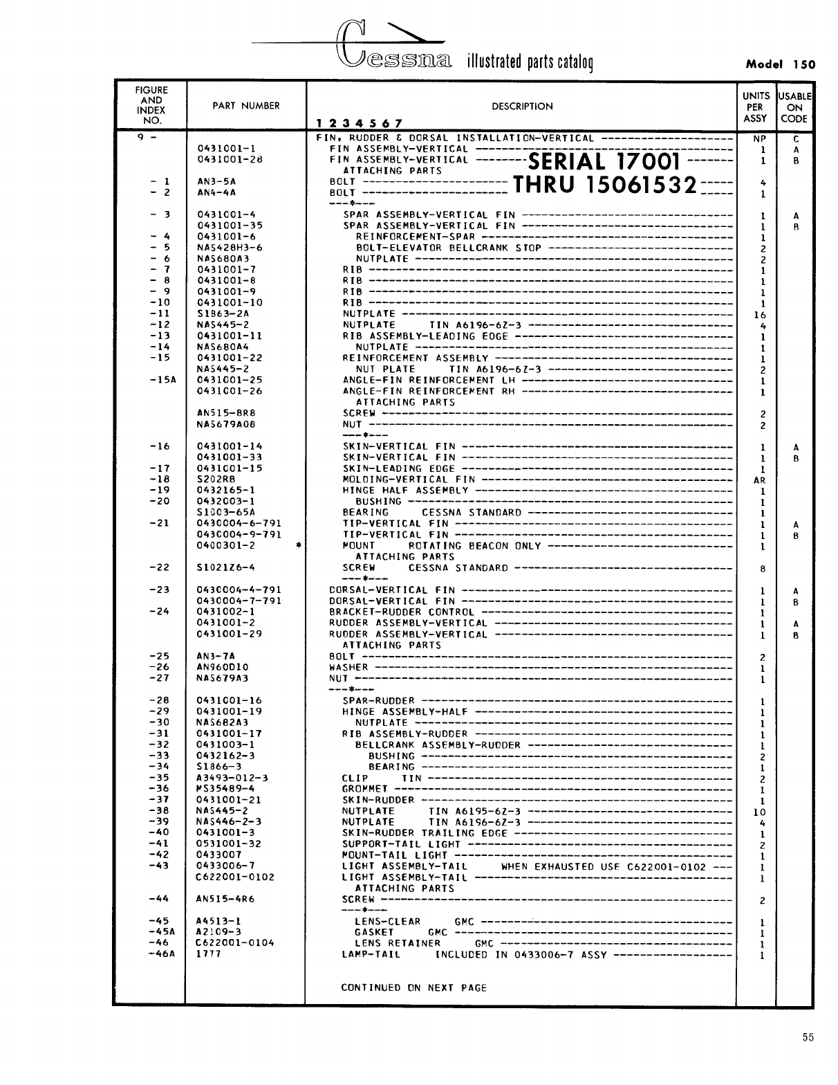
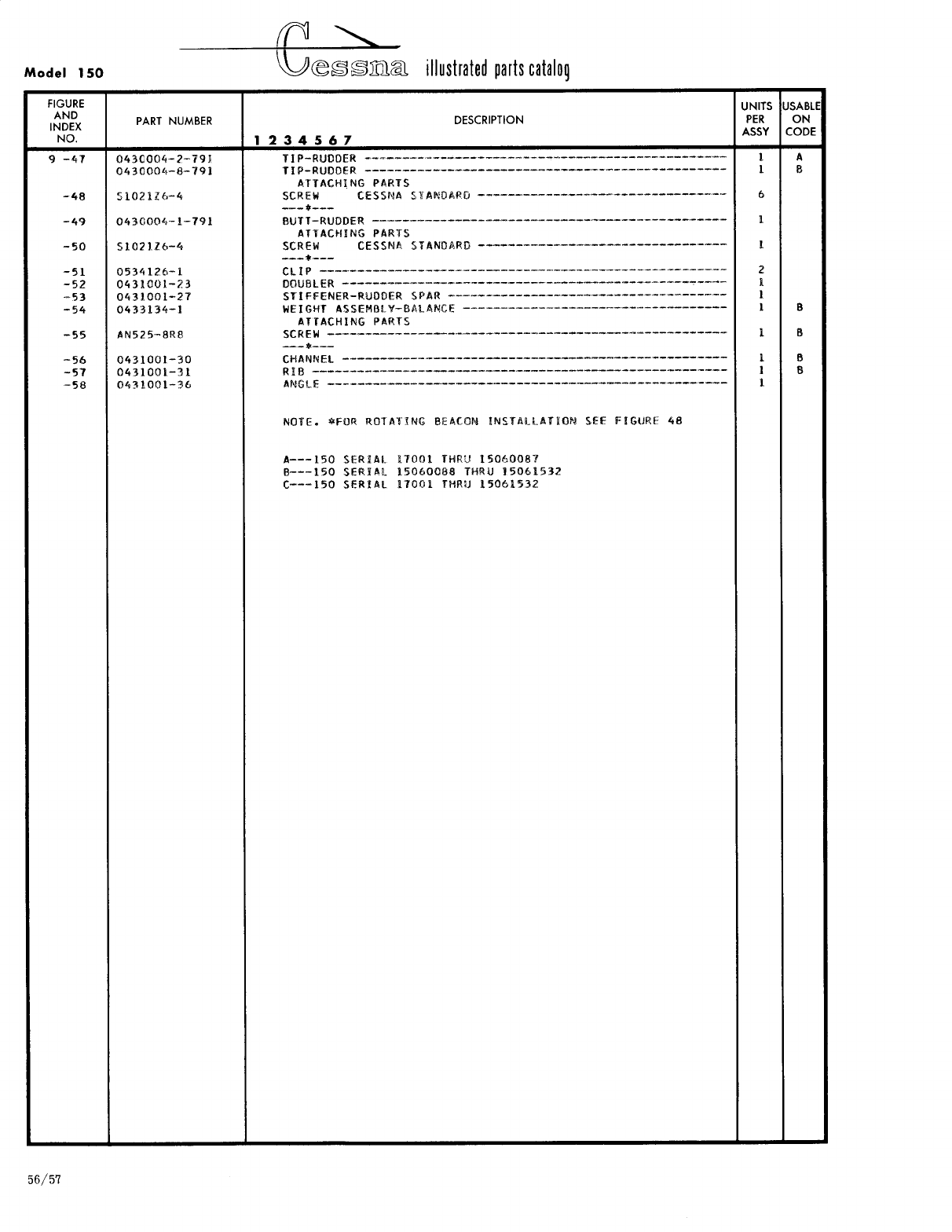
- Fig 9. Vertical Fin, Rudder and Dorsal Installation
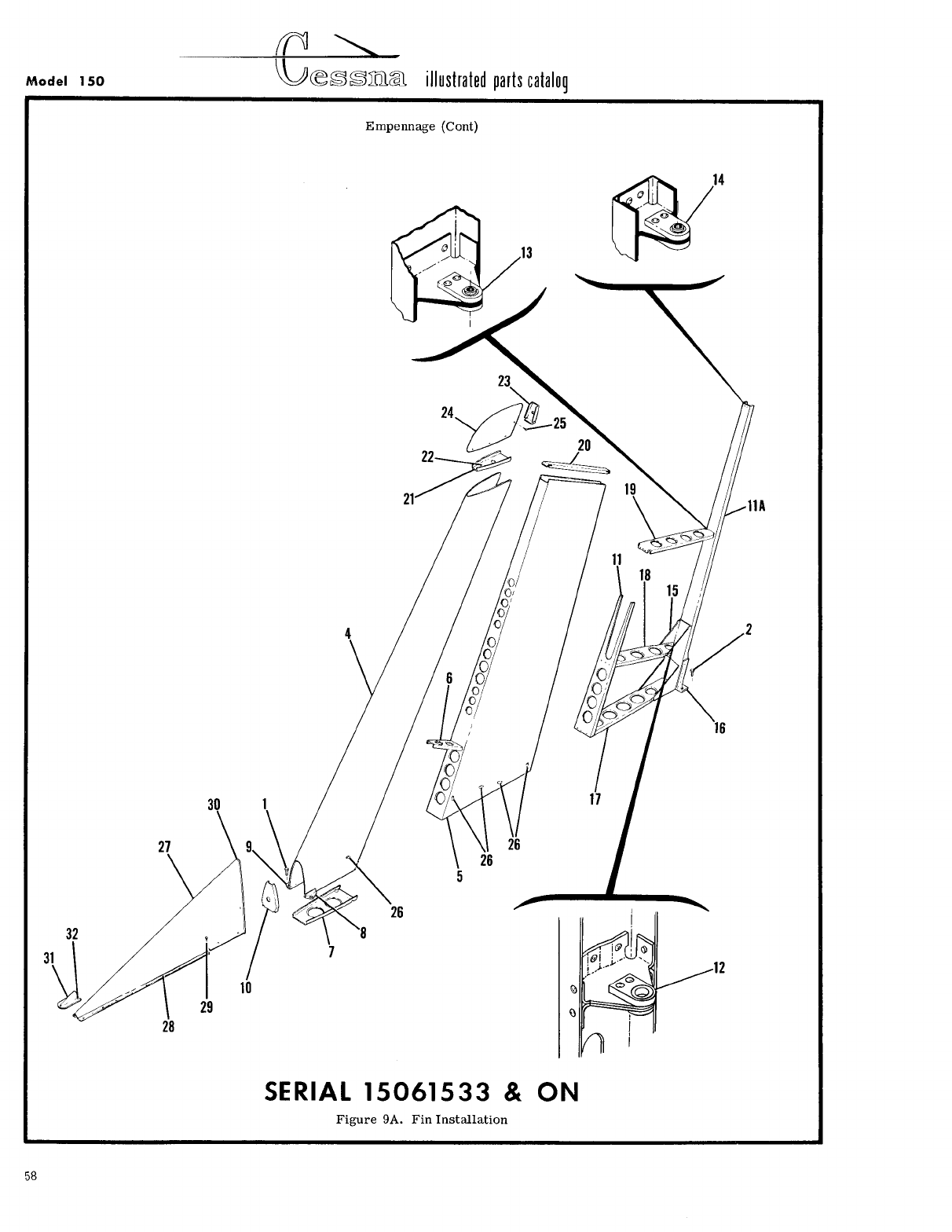
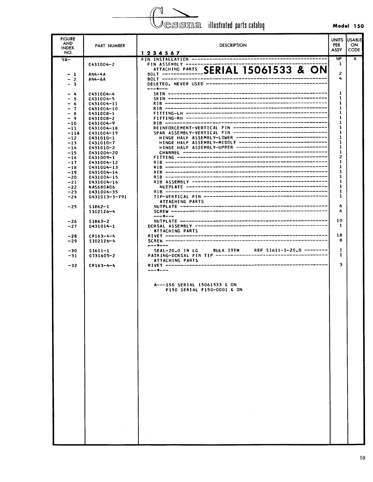
- Fig 9A. Fin Installation
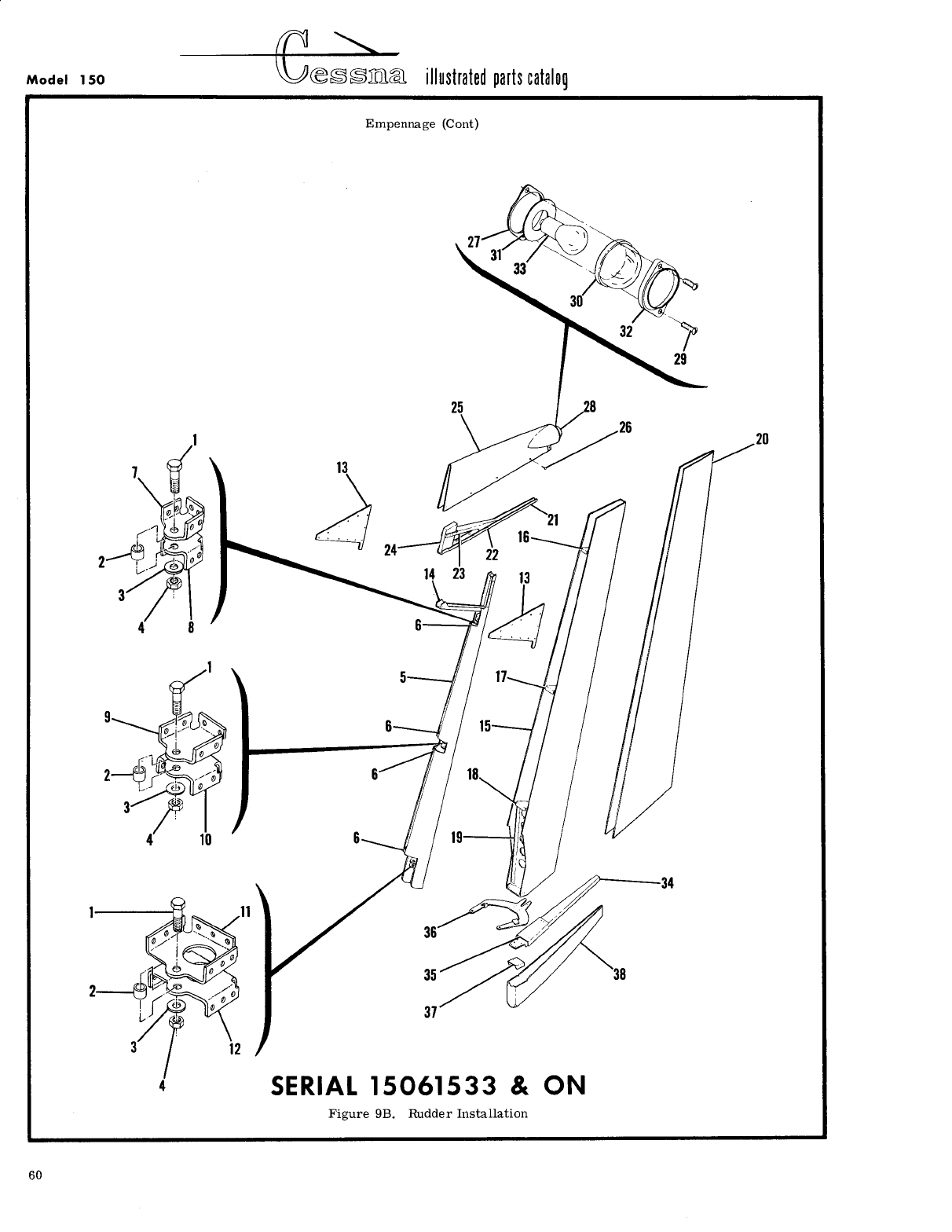
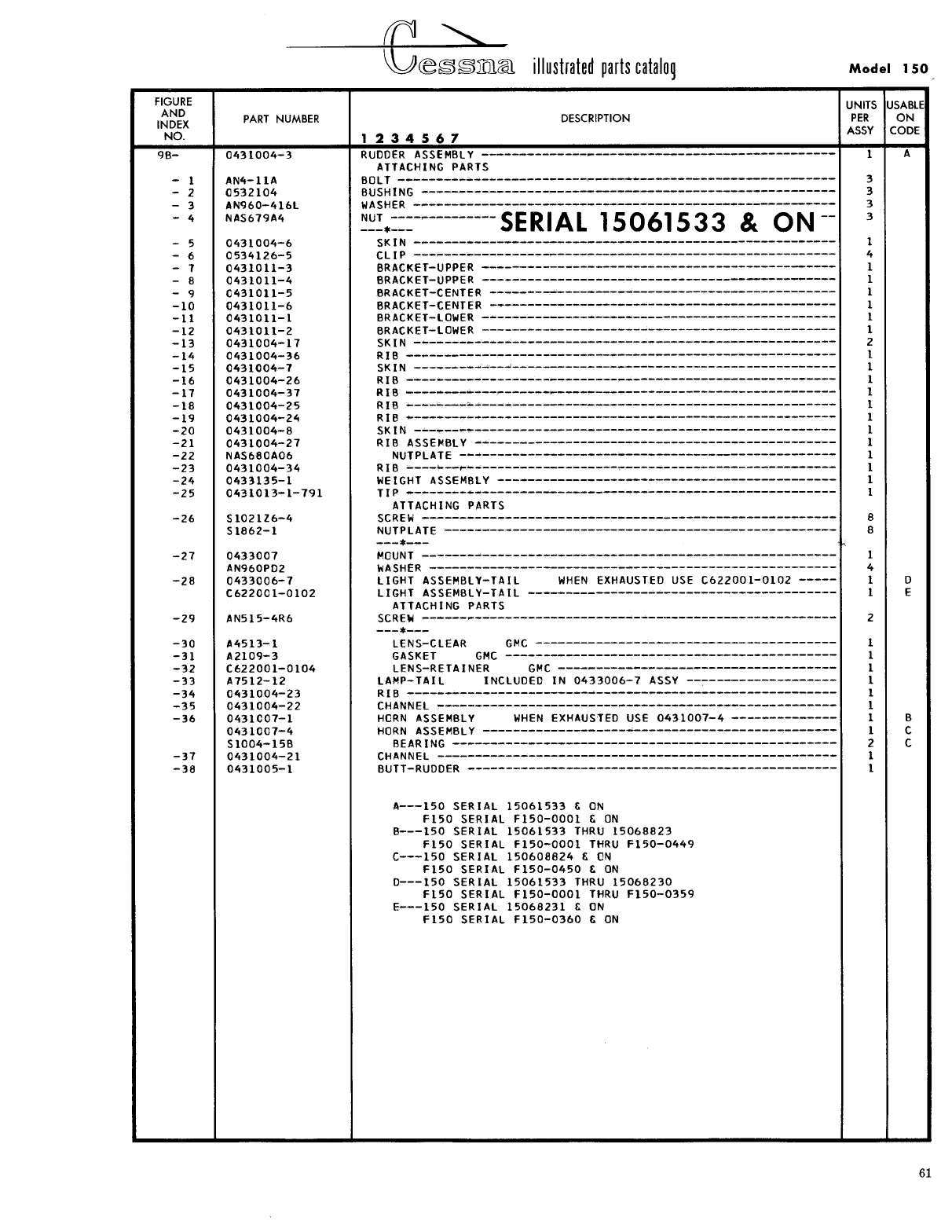
- Fig 9B. Rudder Installation
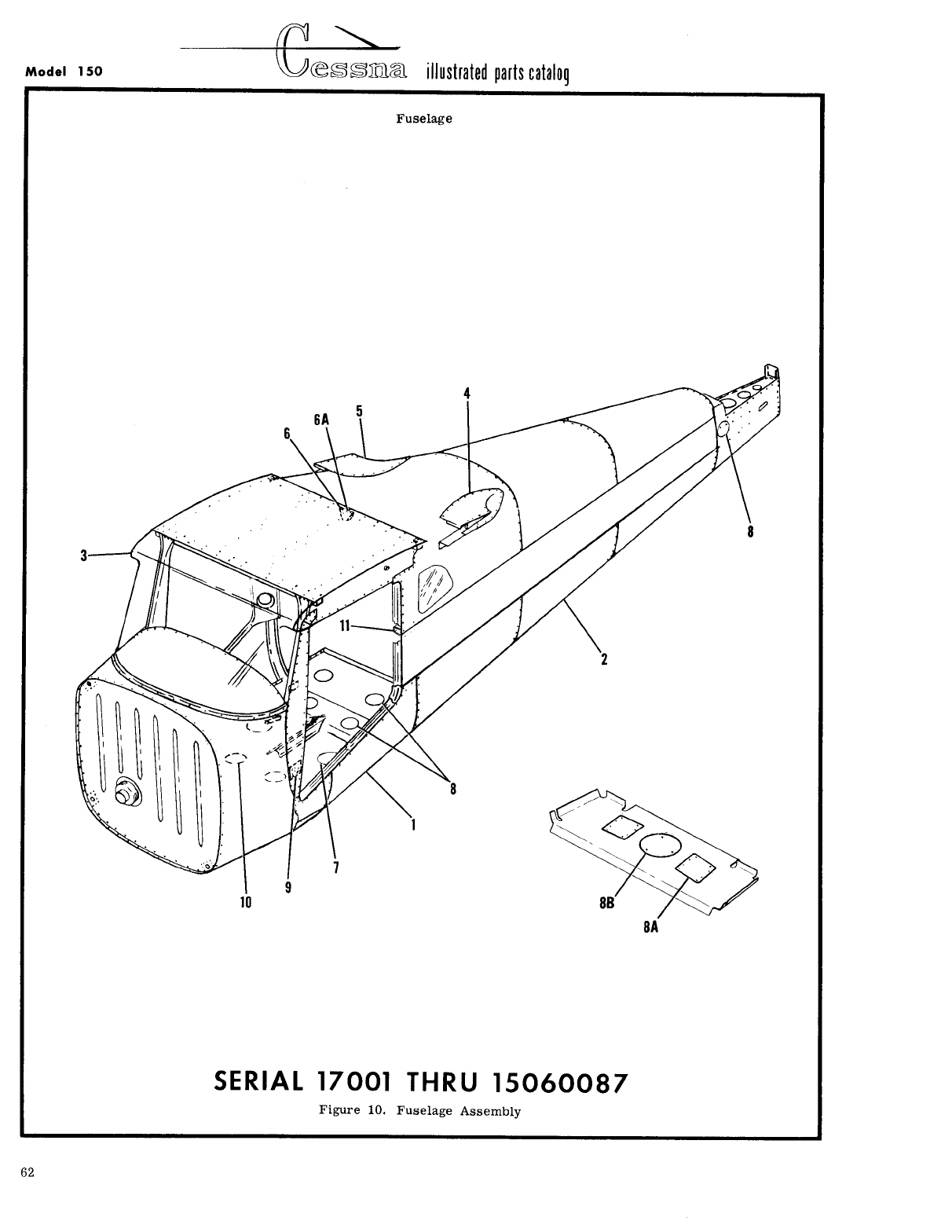
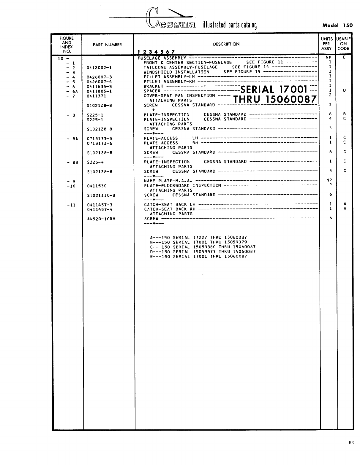
- Fig 10. Fuselage Assembly
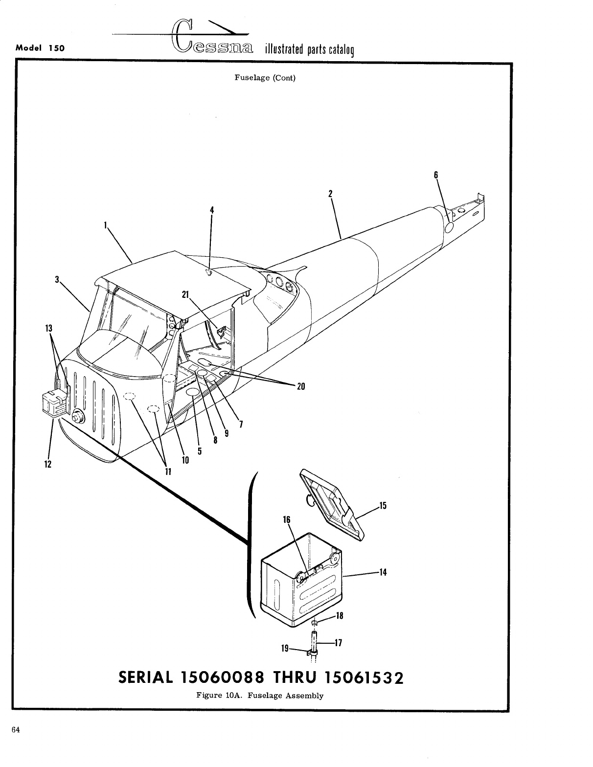
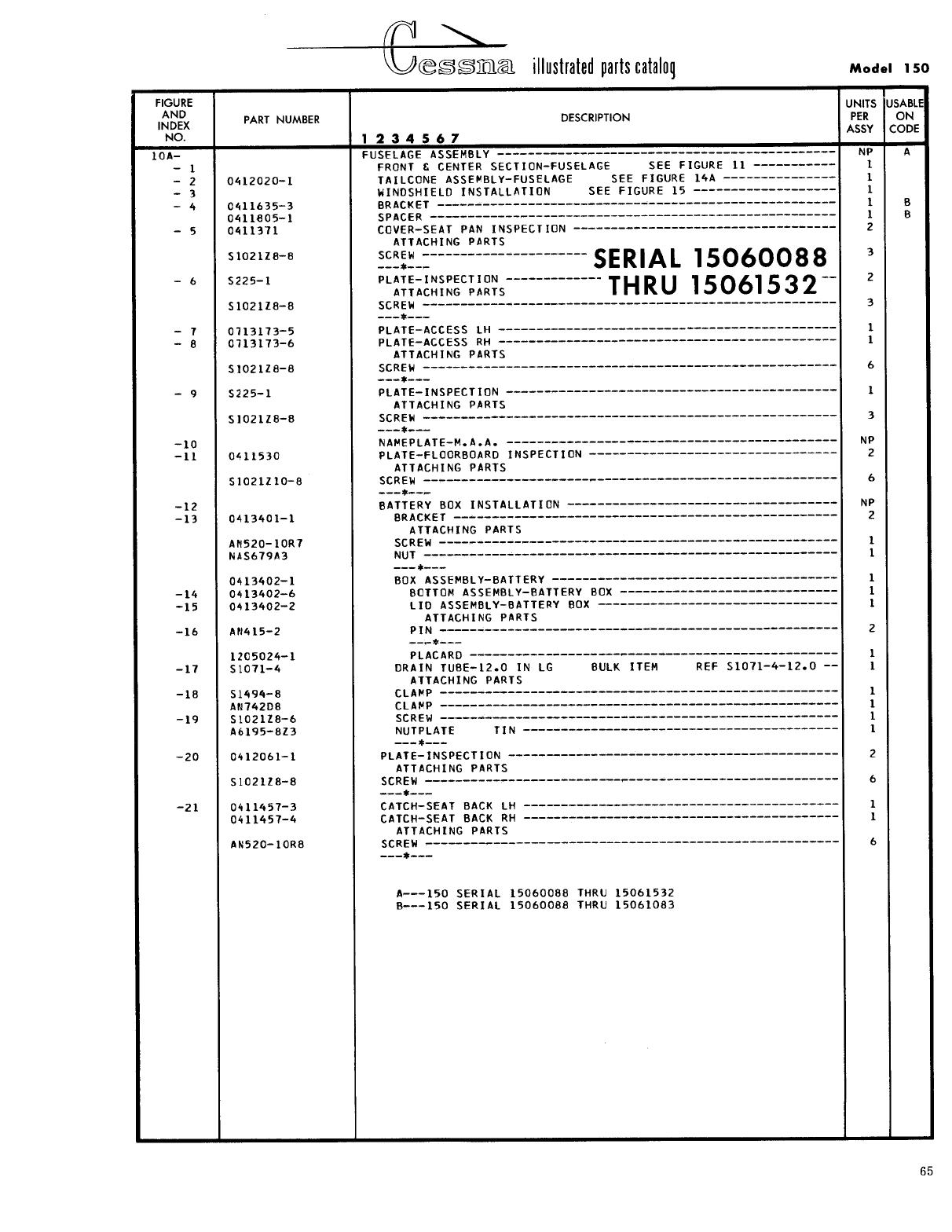
- Fig 10A. Fuselage Assembly
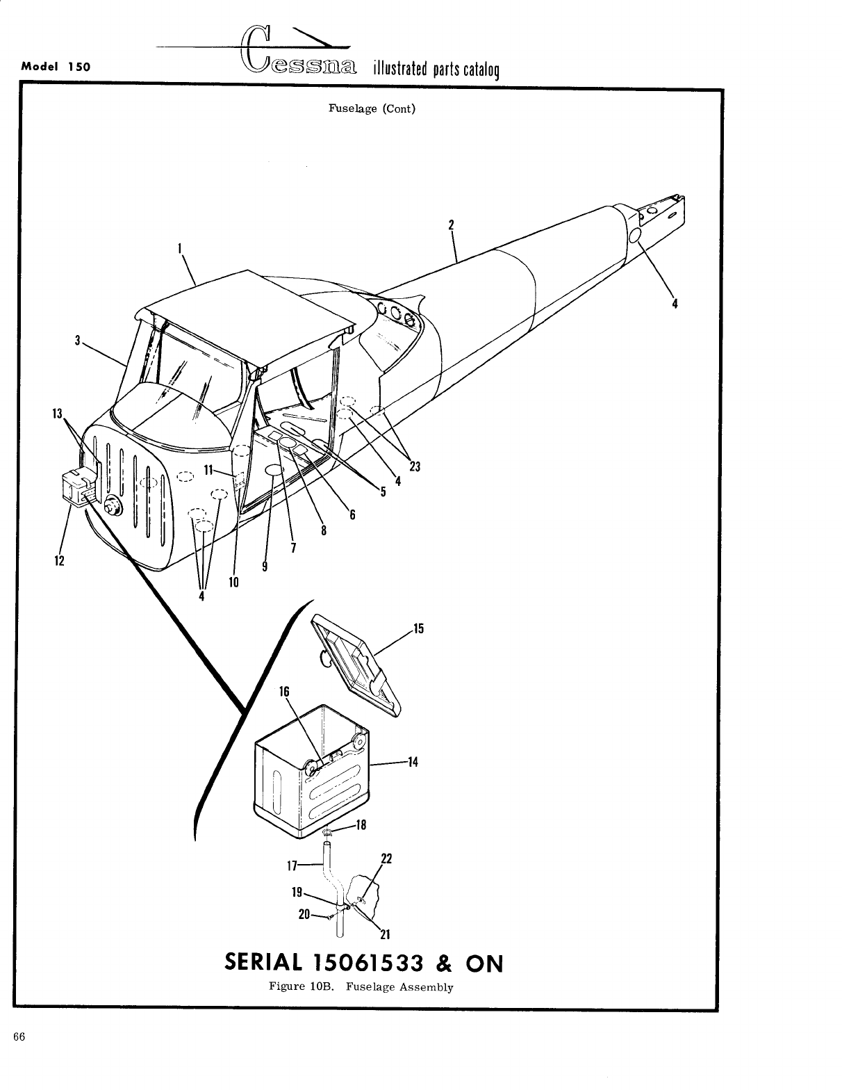
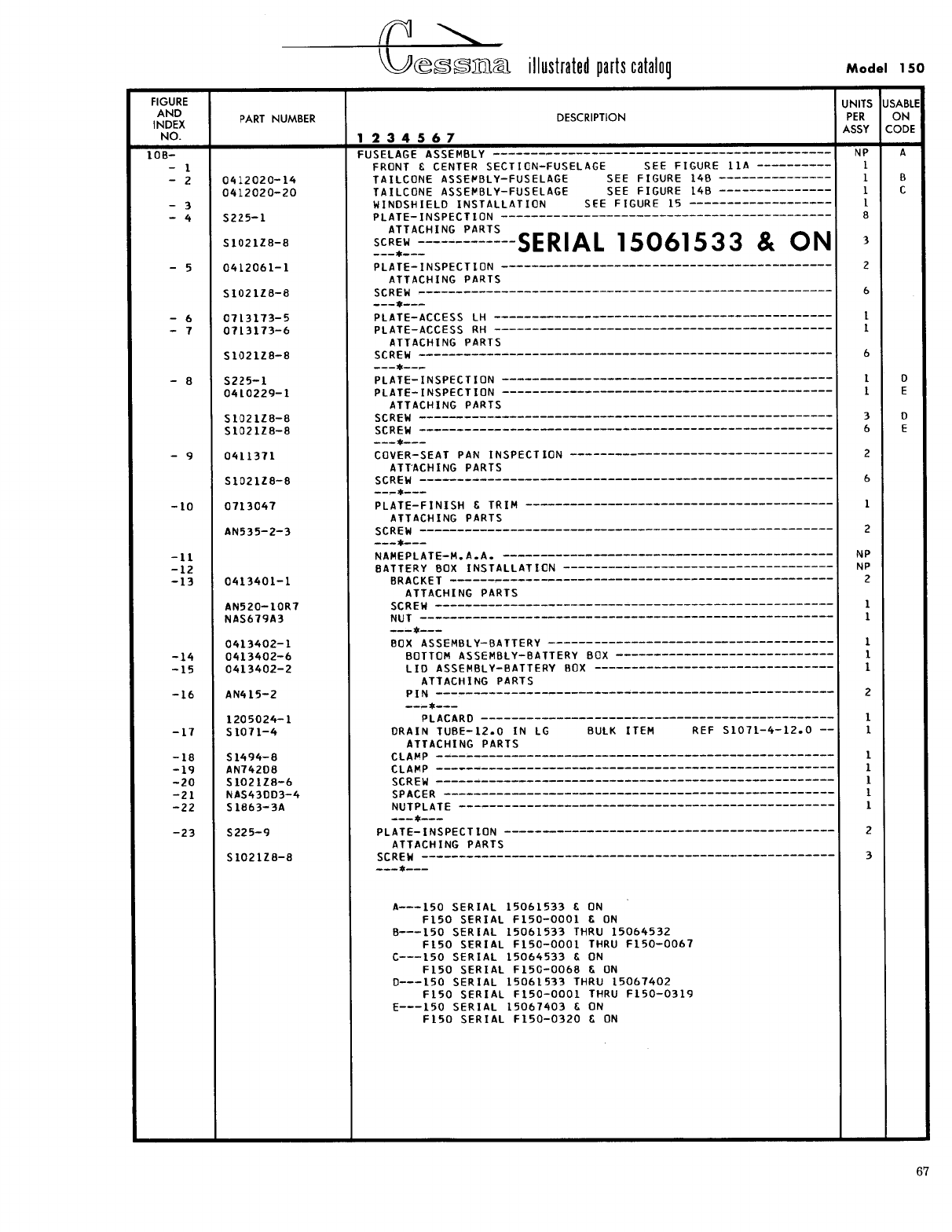
- Fig 10B. Fuselage Assembly
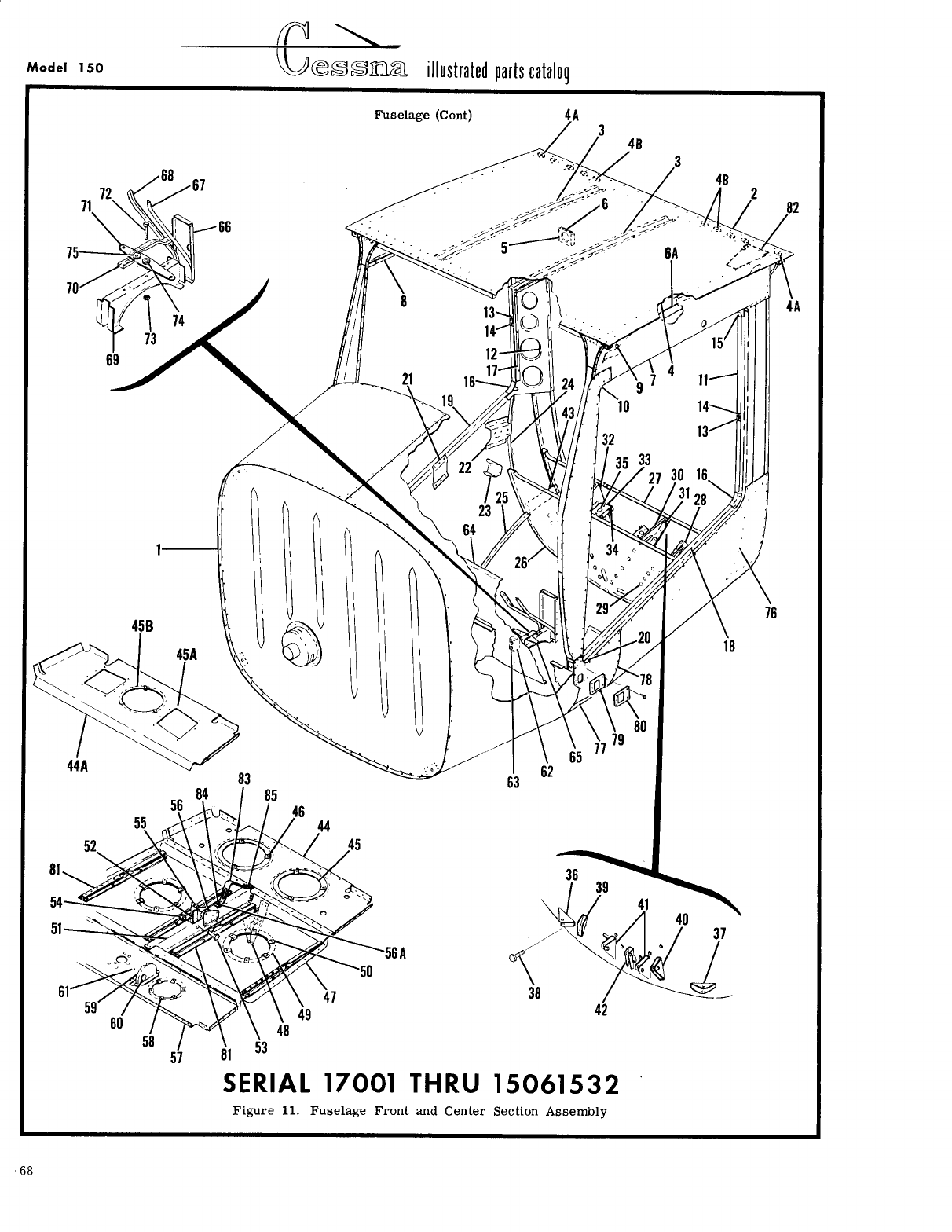
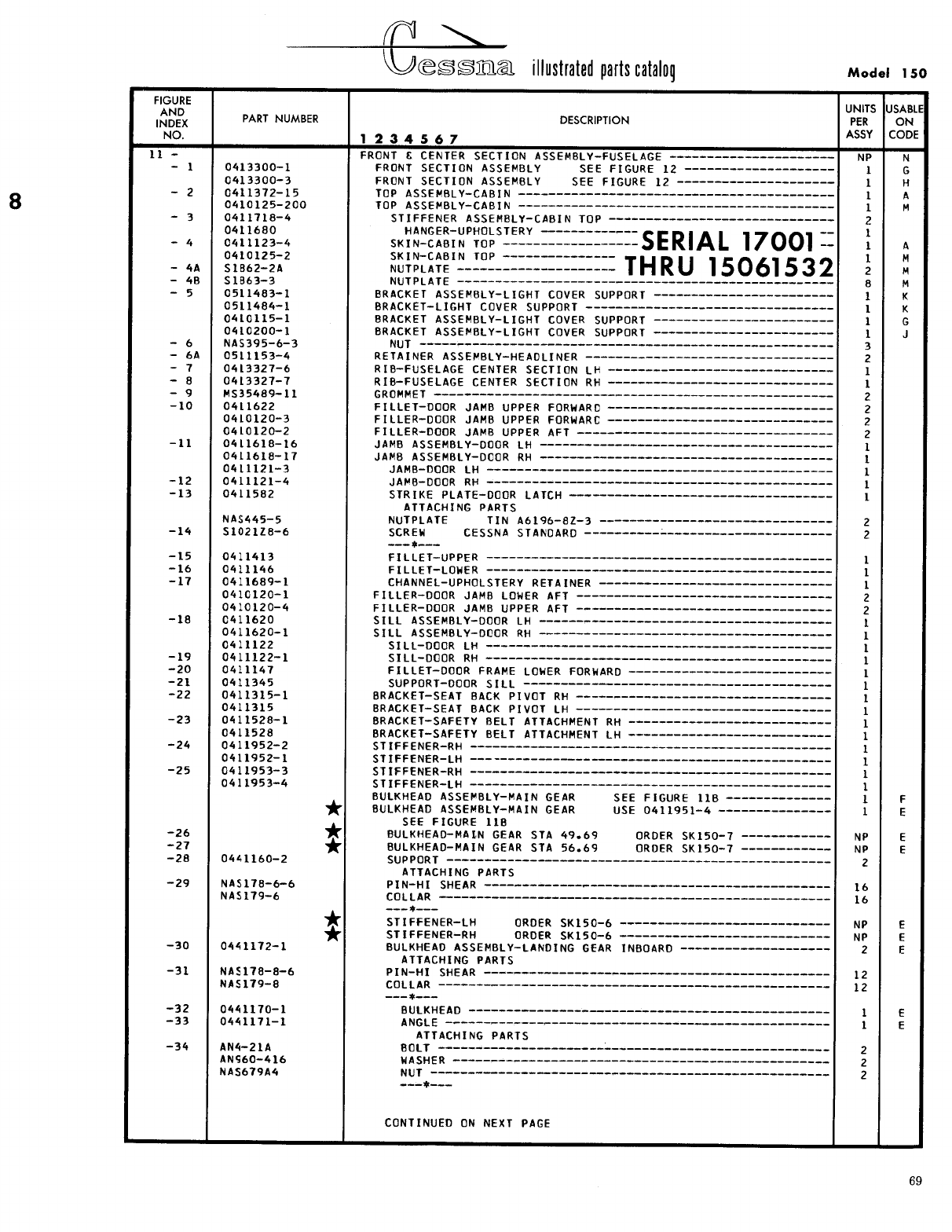
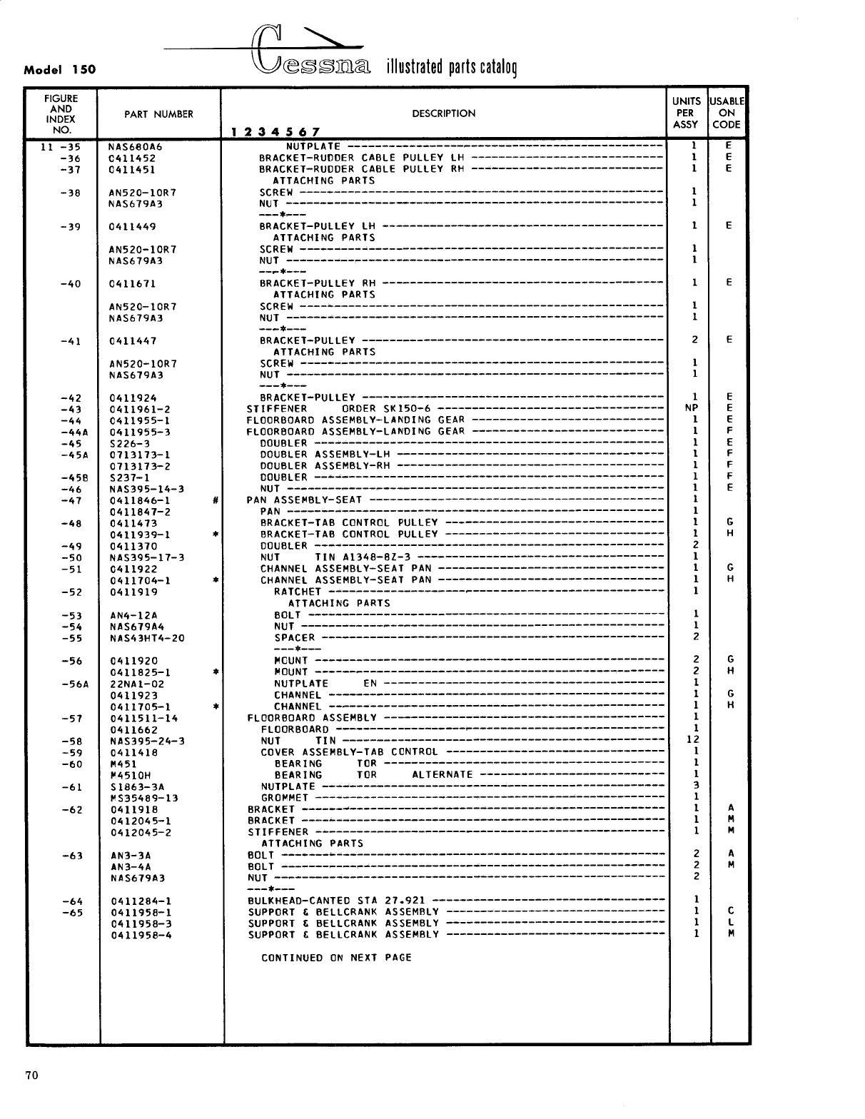
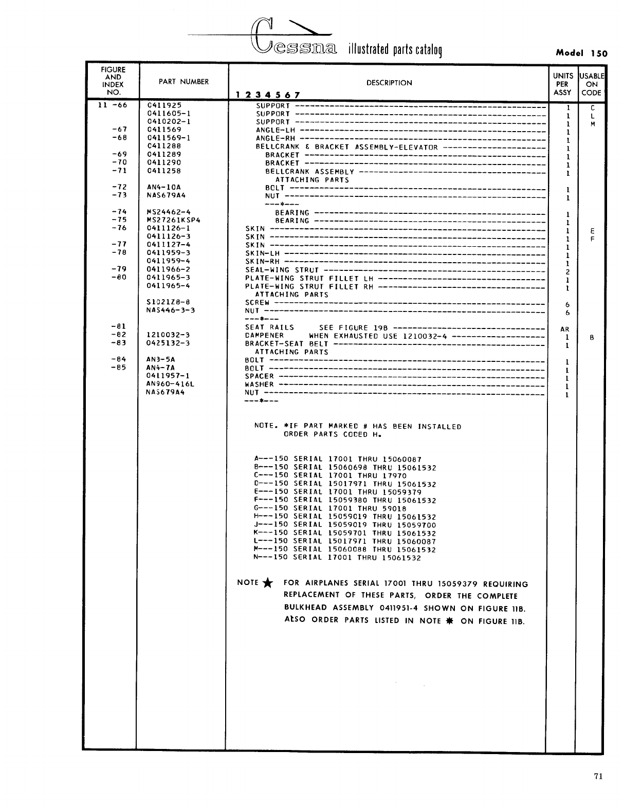
- Fig 11. Fuselage Front and Center Section Assembly
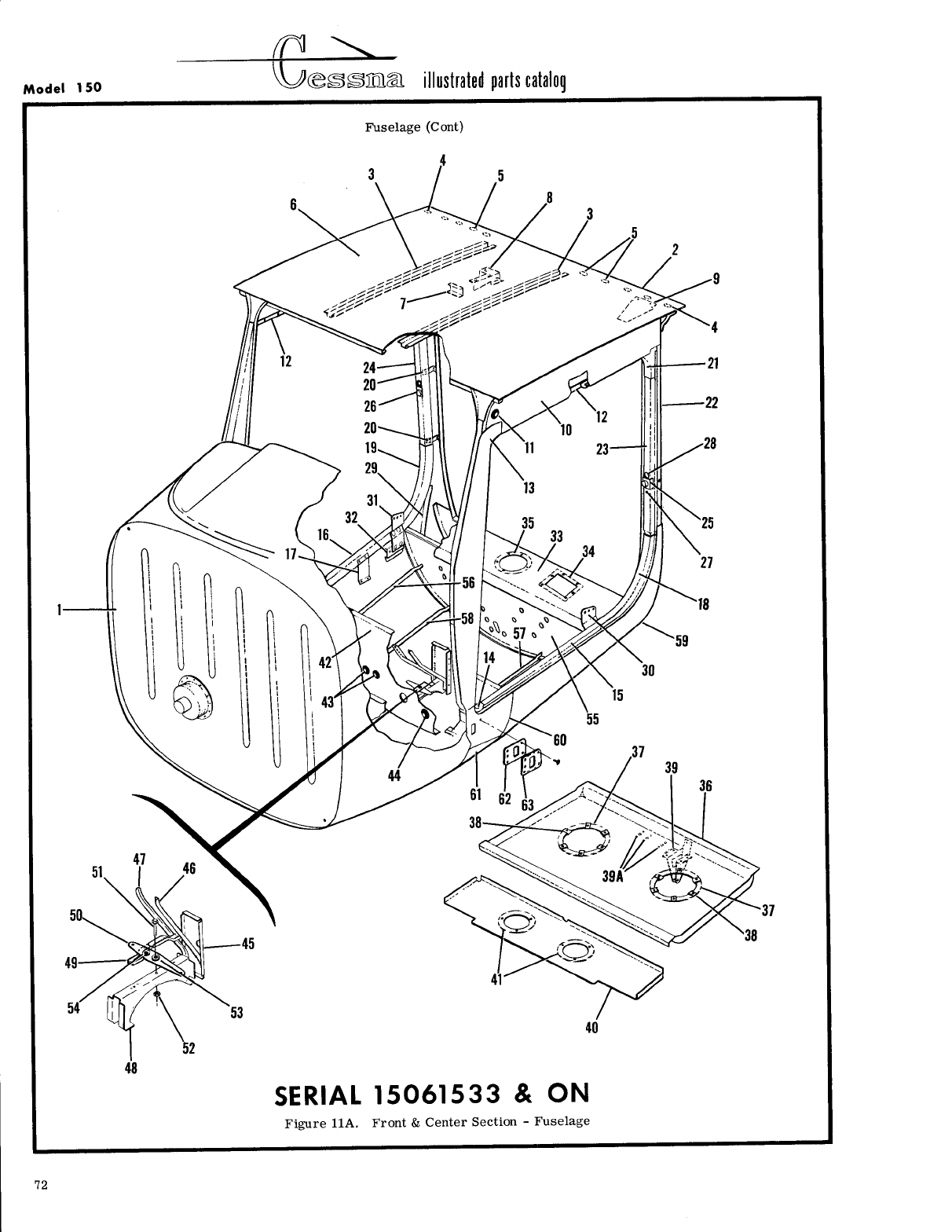
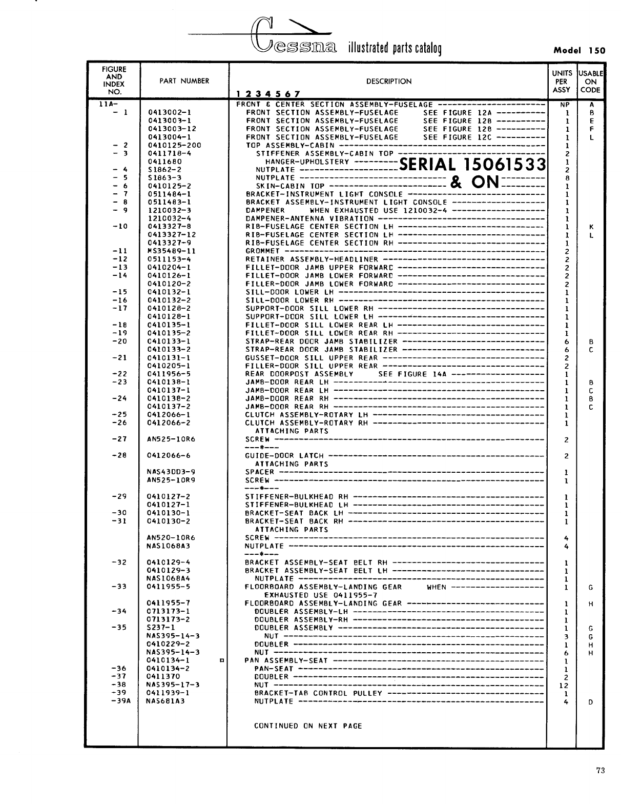
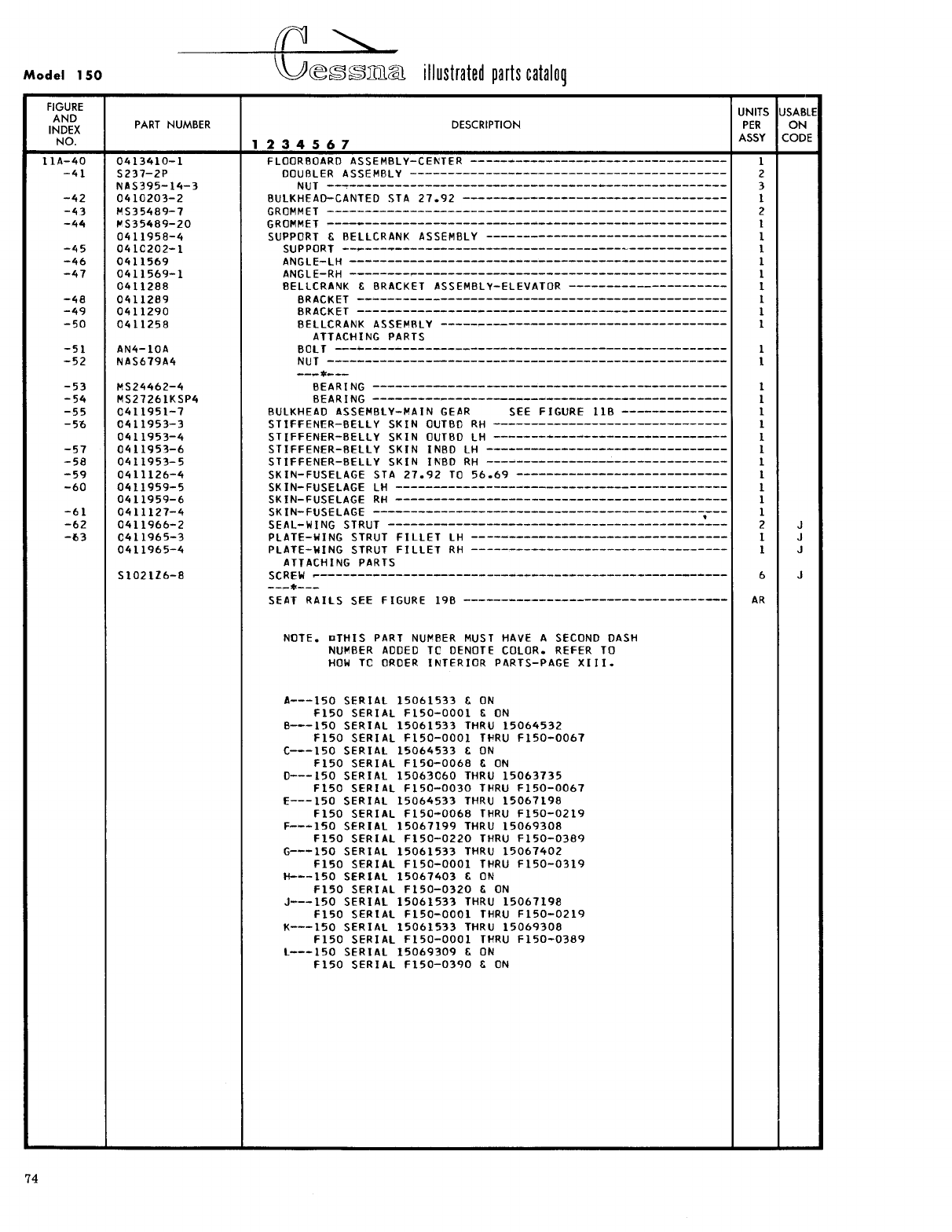
- Fig 11A. Front & Center Section - Fuselage
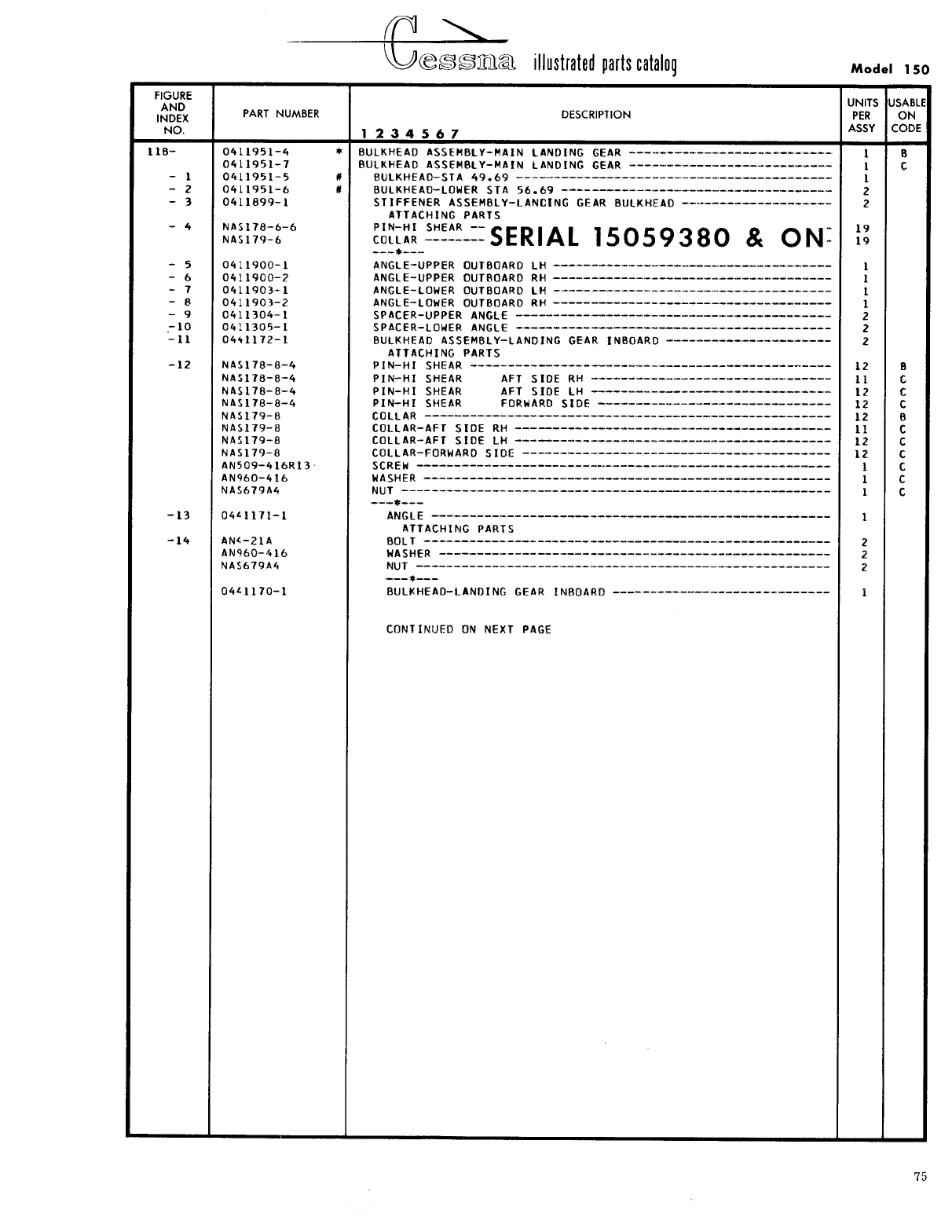
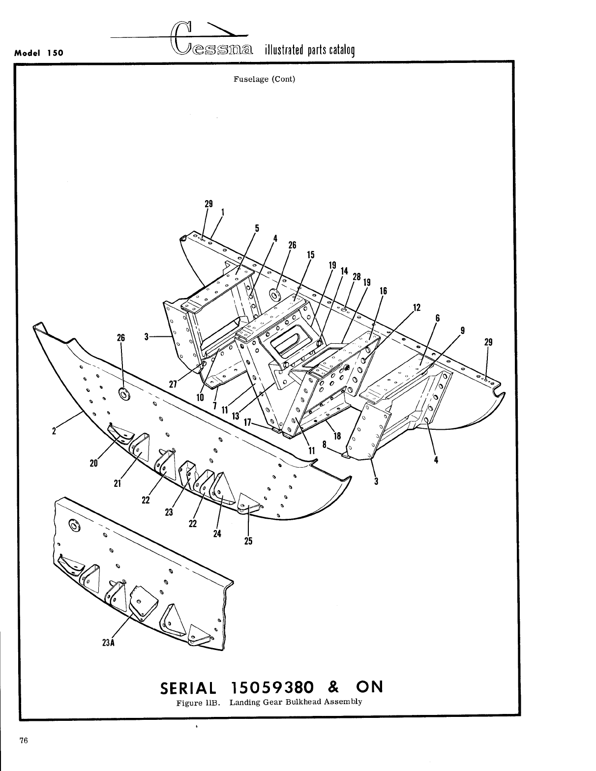
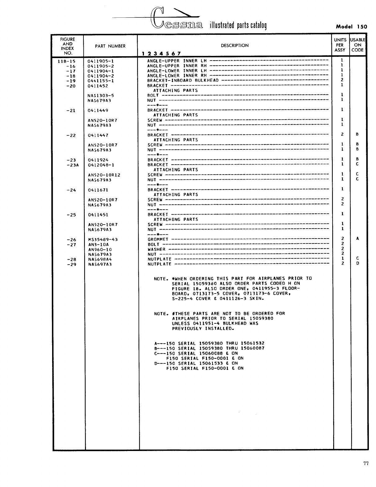
- Fig 11B. Landing Gear Bulkhead Assembly
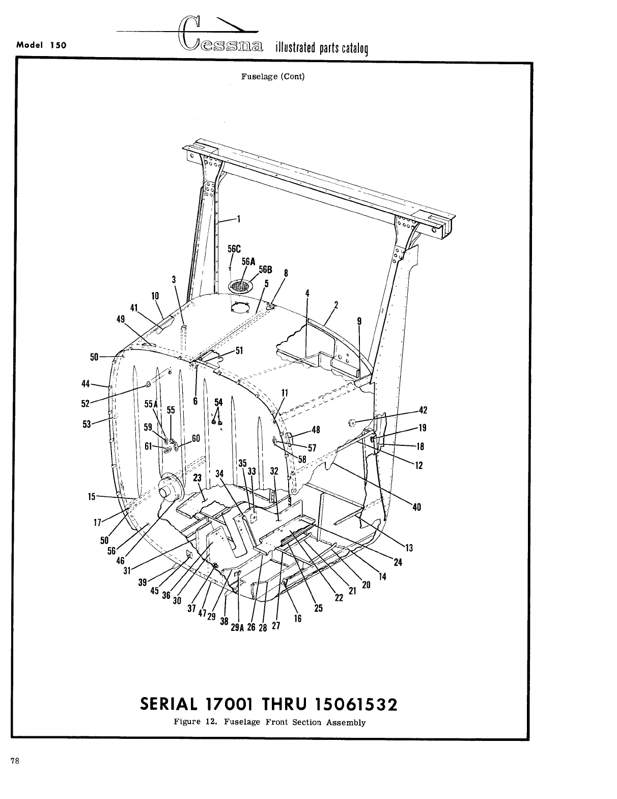
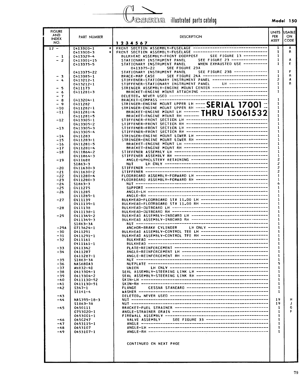
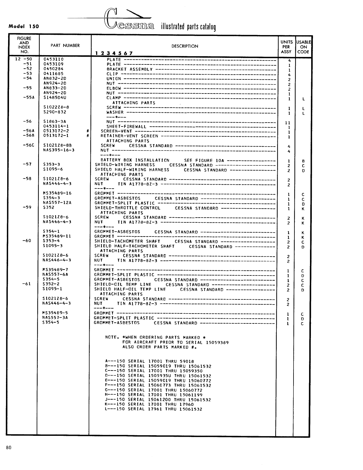
- Fig 12. Fuselage Front Section Assembly
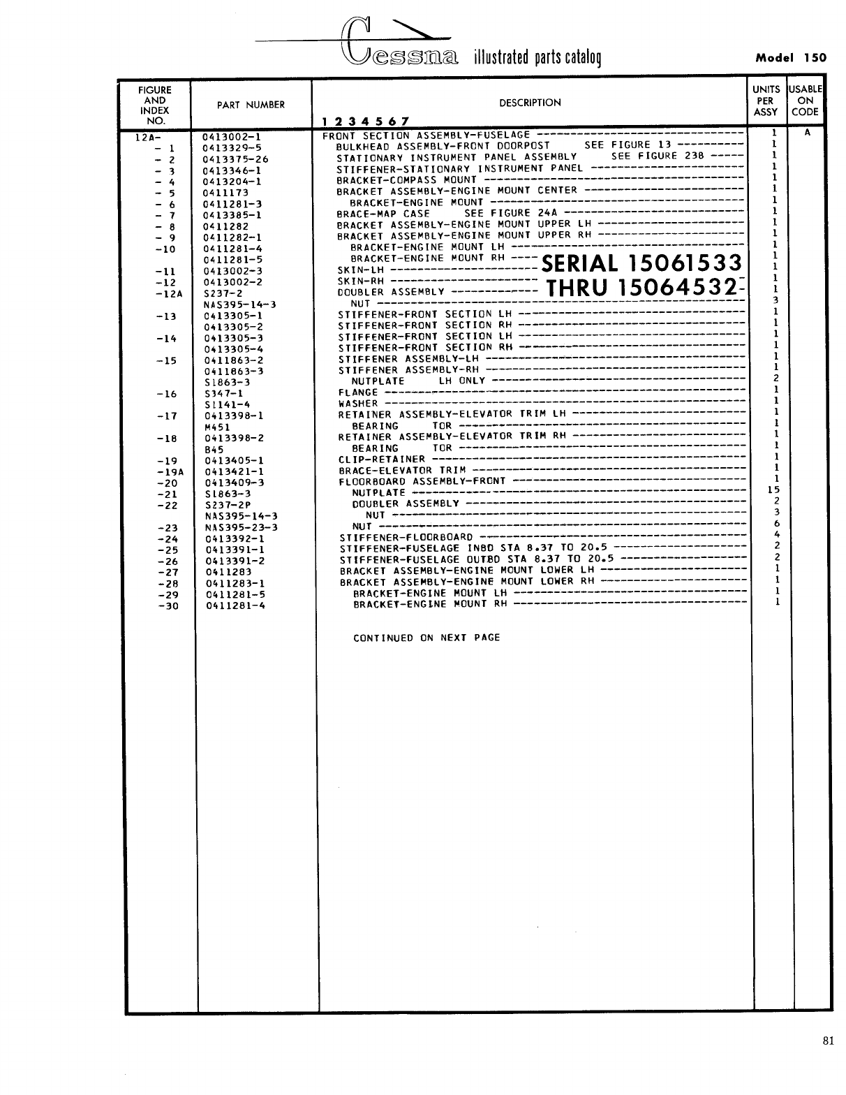
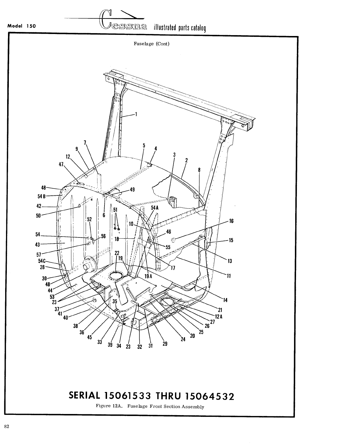
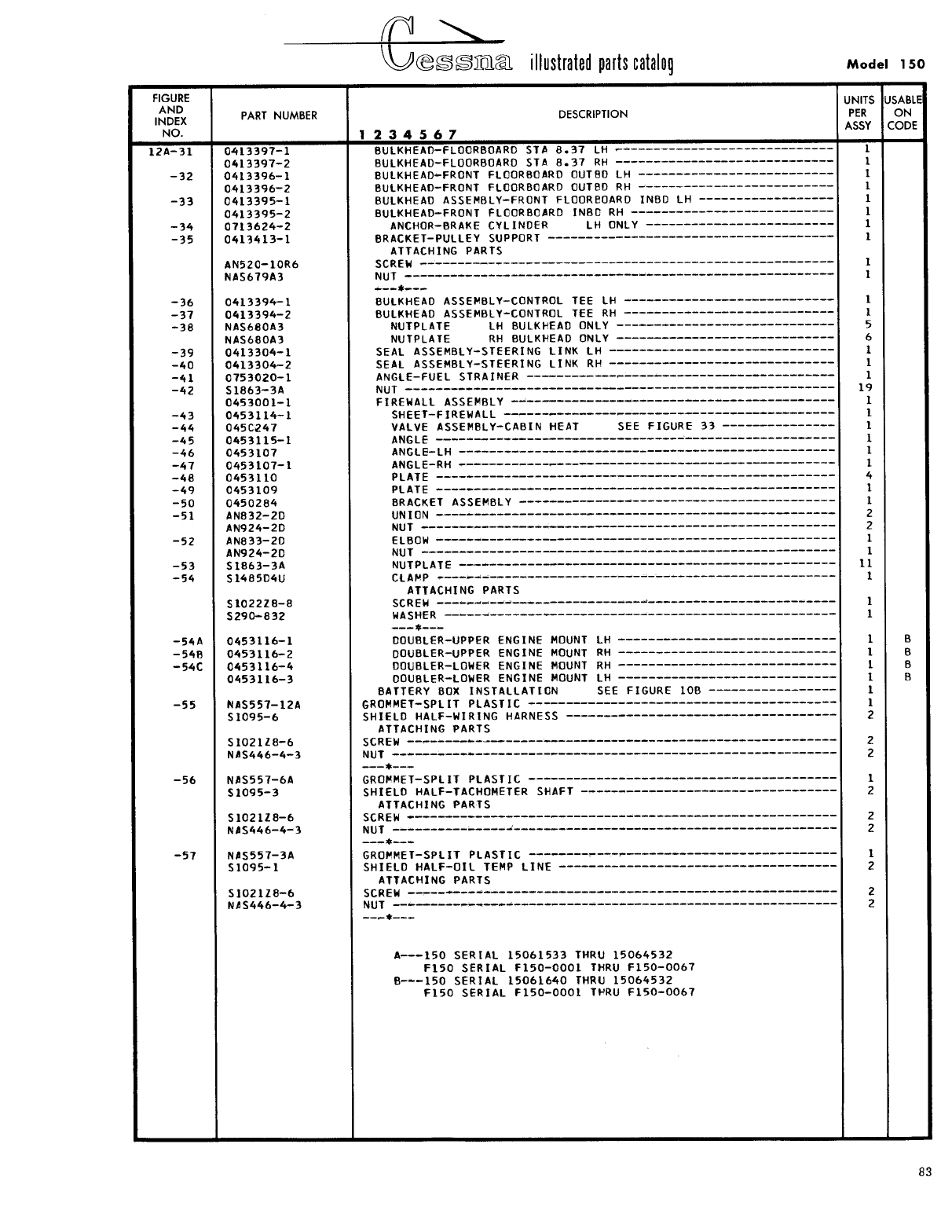
- Fig 12A. Fuselage Front Section Assembly
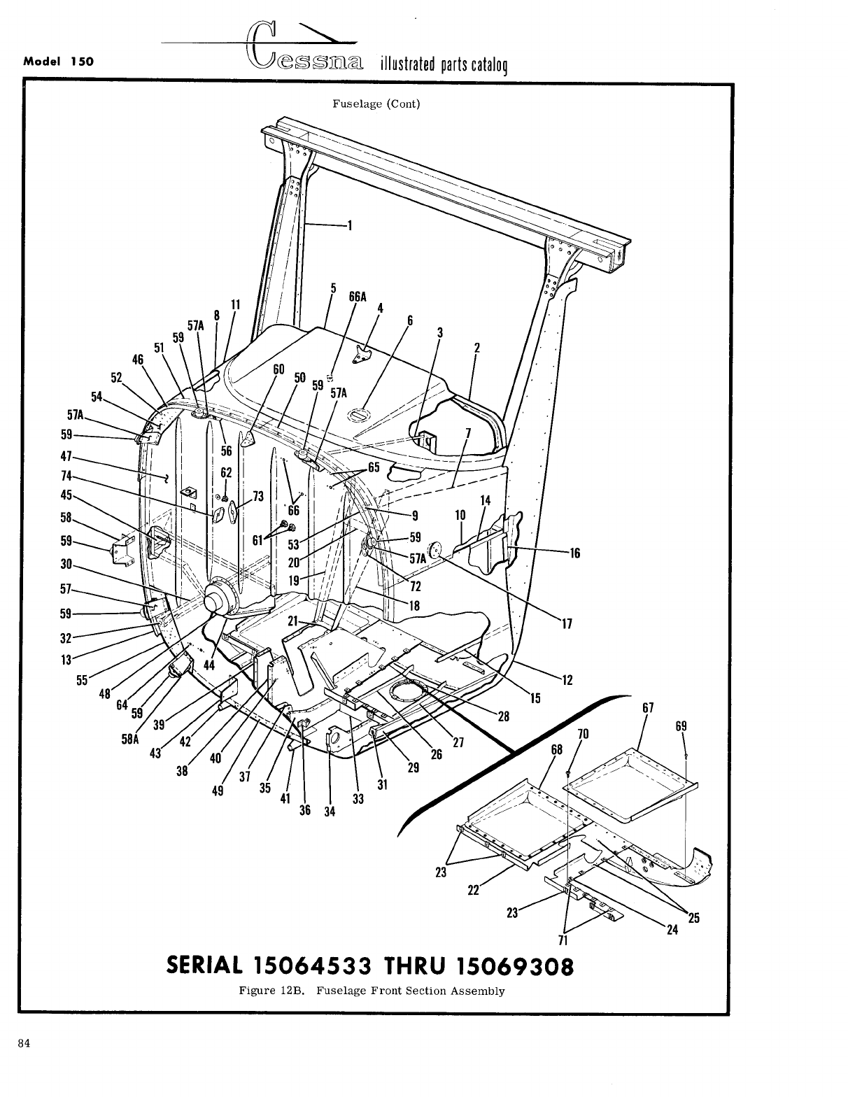
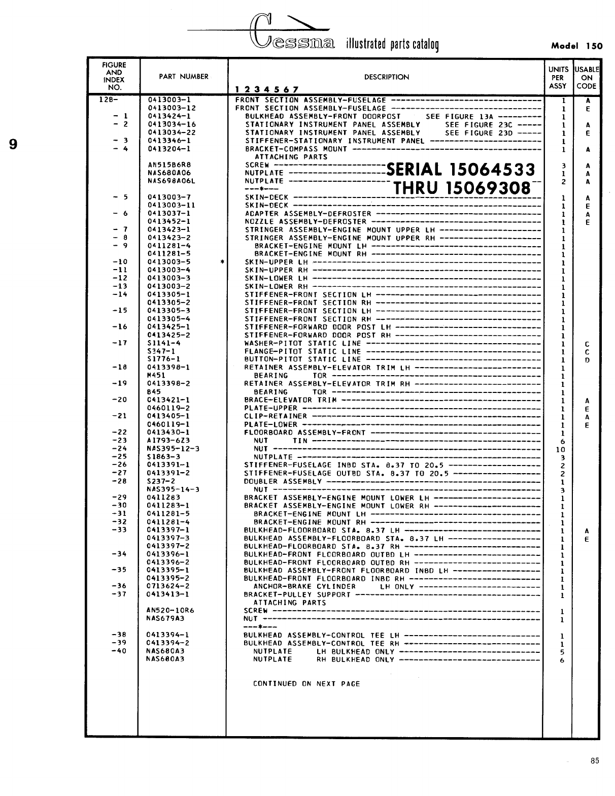
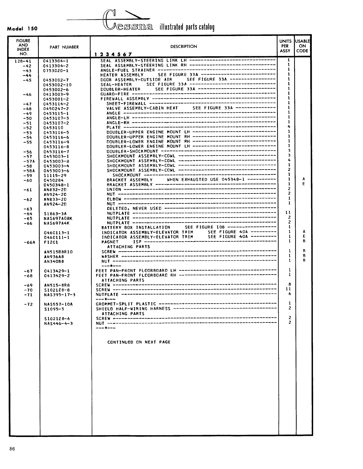
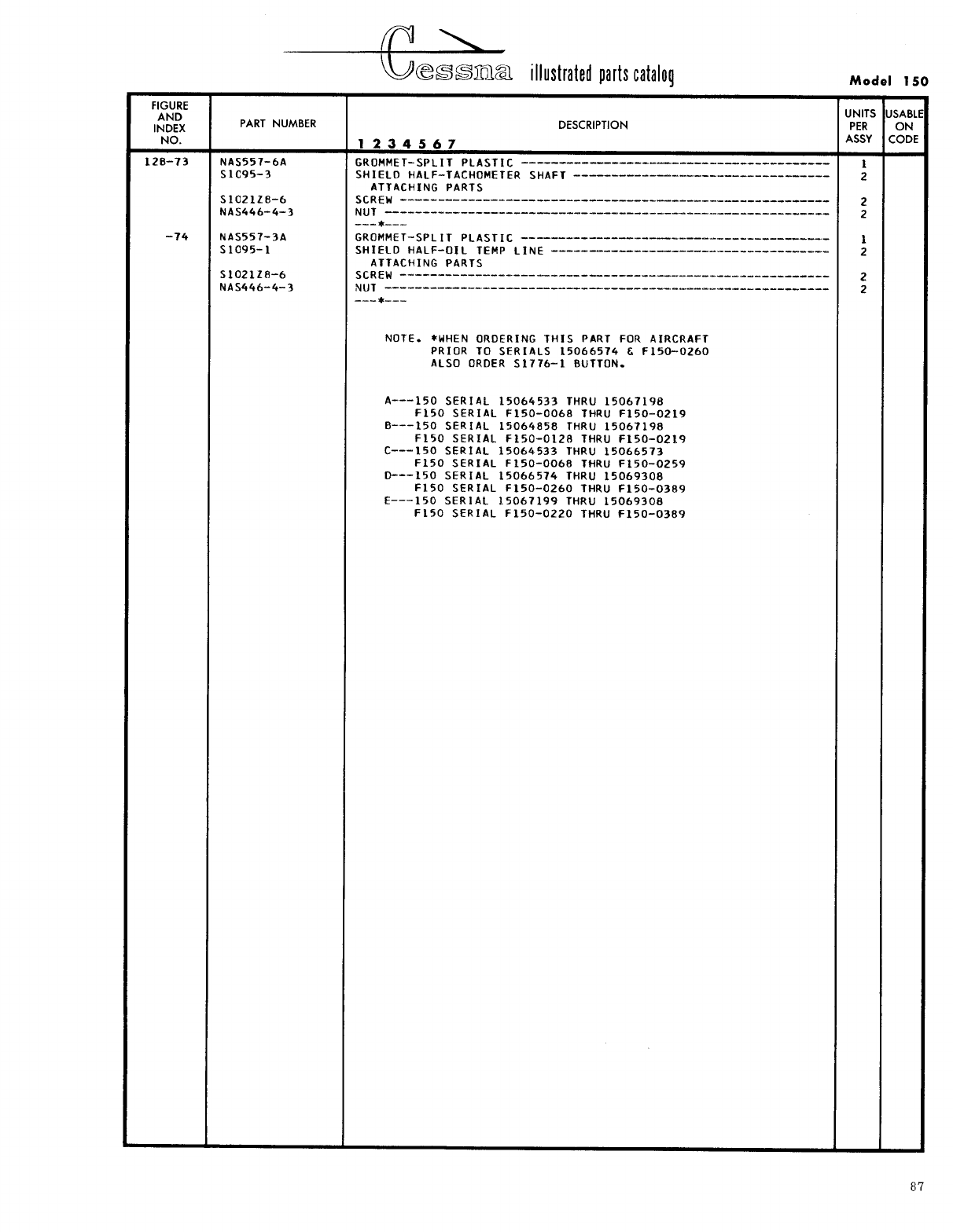
- Fig 12B. Fuselage Front Section Assembly
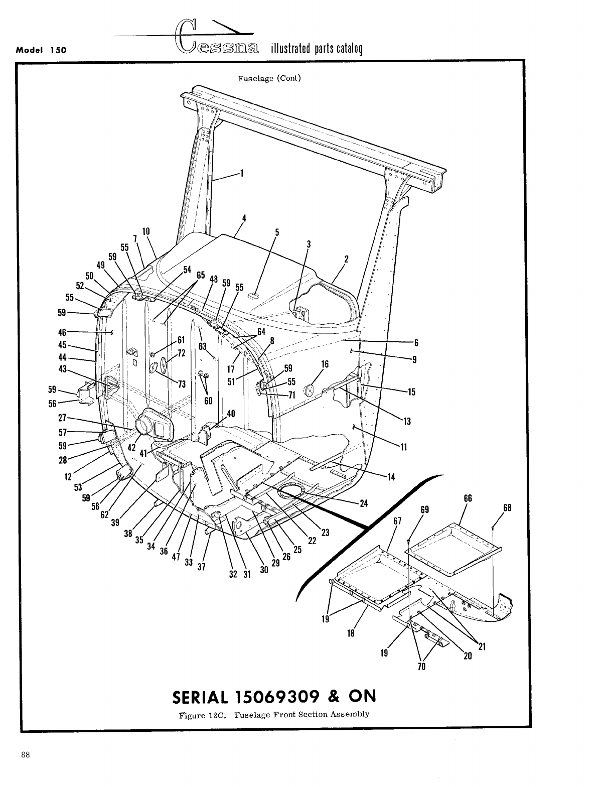
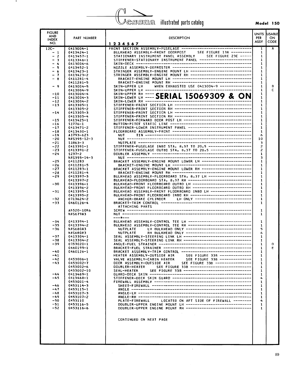
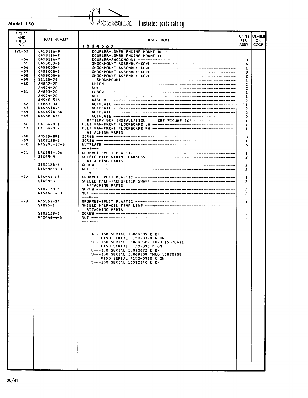
- Fig 12C. Fuselage Front Section Assembly
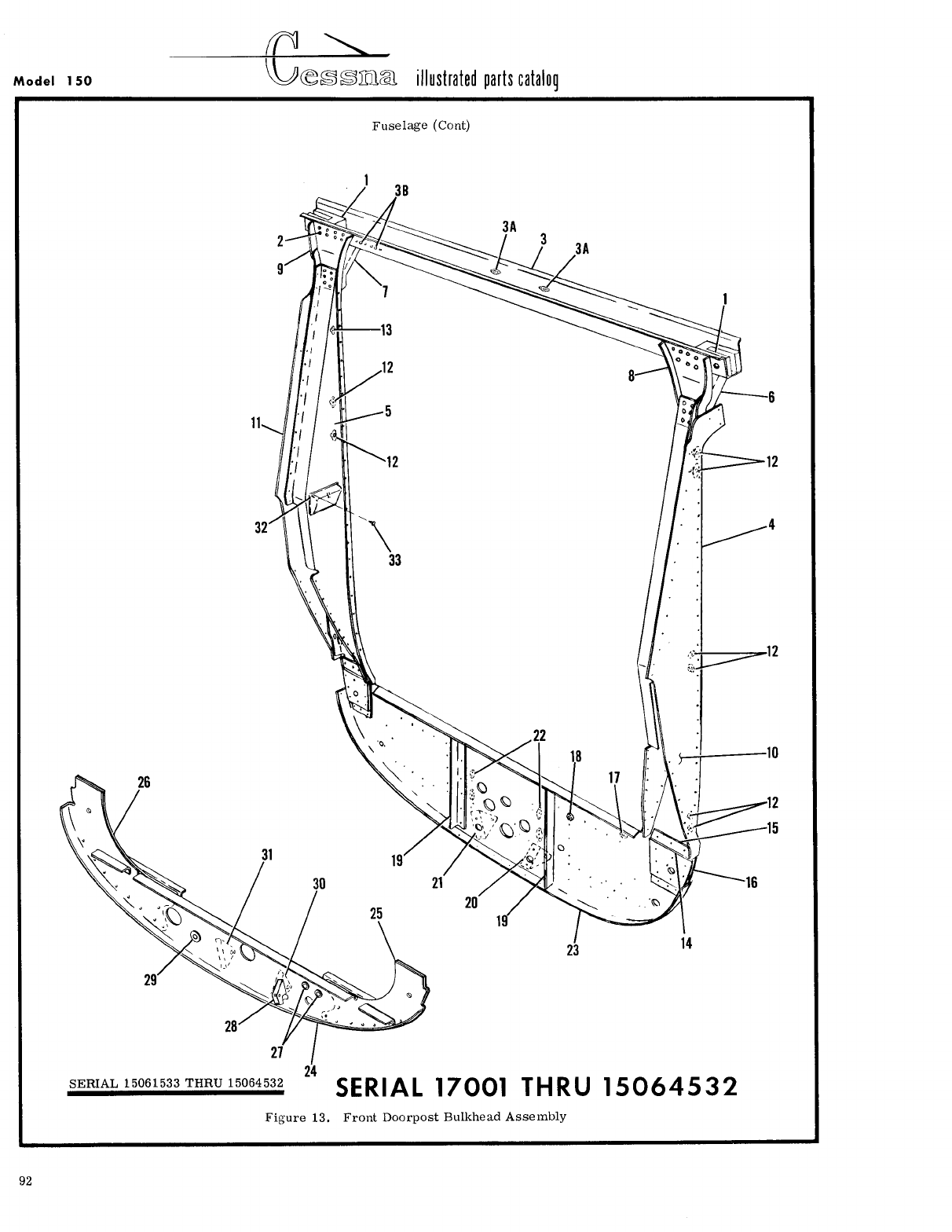
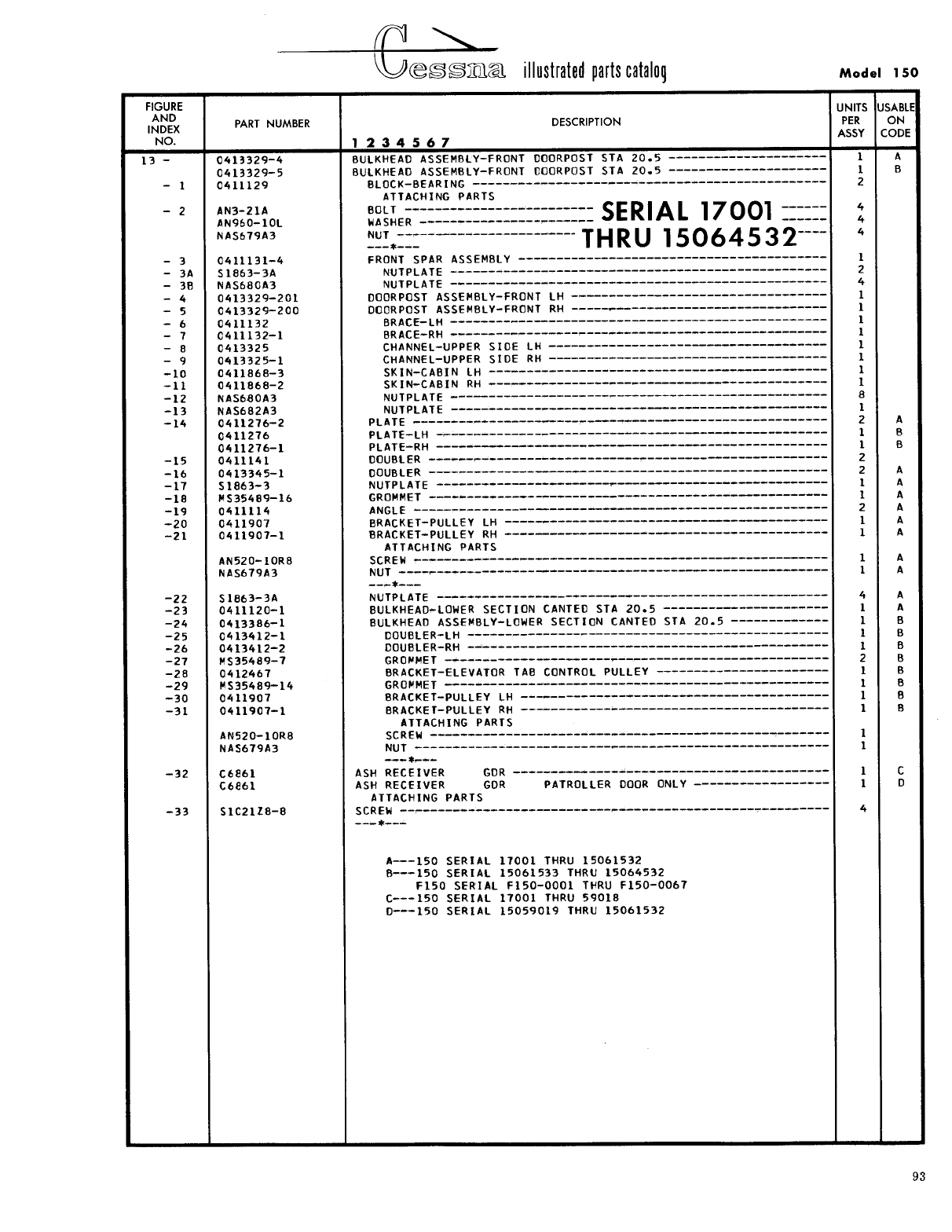
- Fig 13. Front Doorpost Bulkhead Assembly
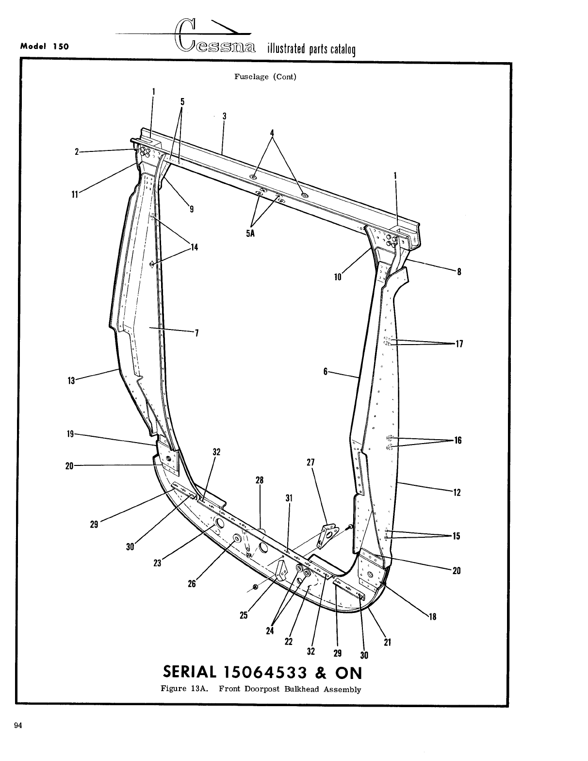
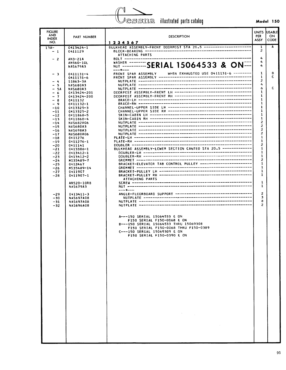
- Fig 13A. Front Doorpost Bulkhead Assembly
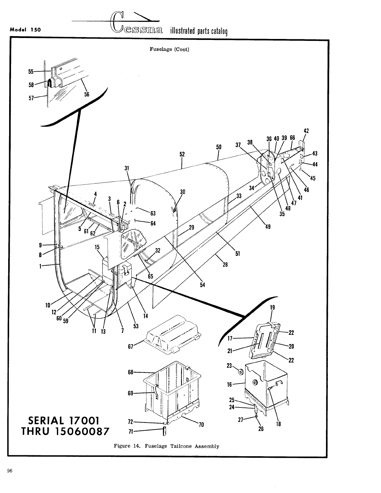
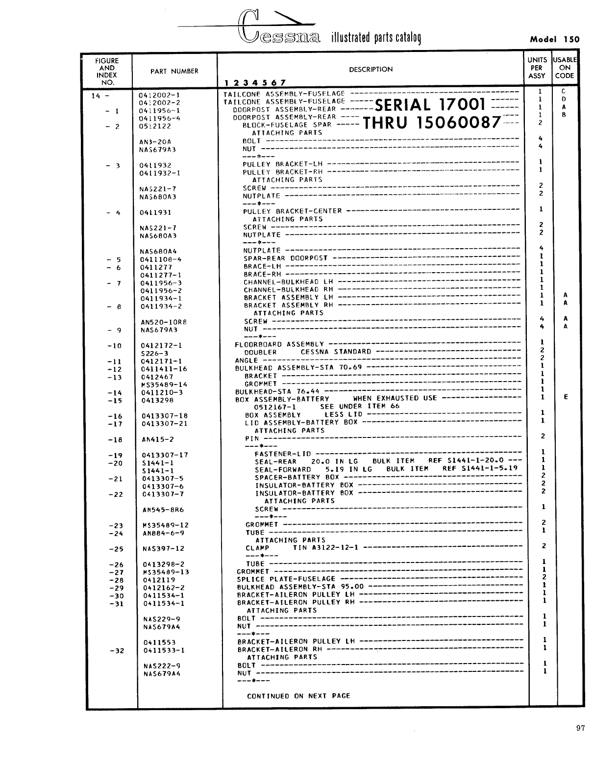
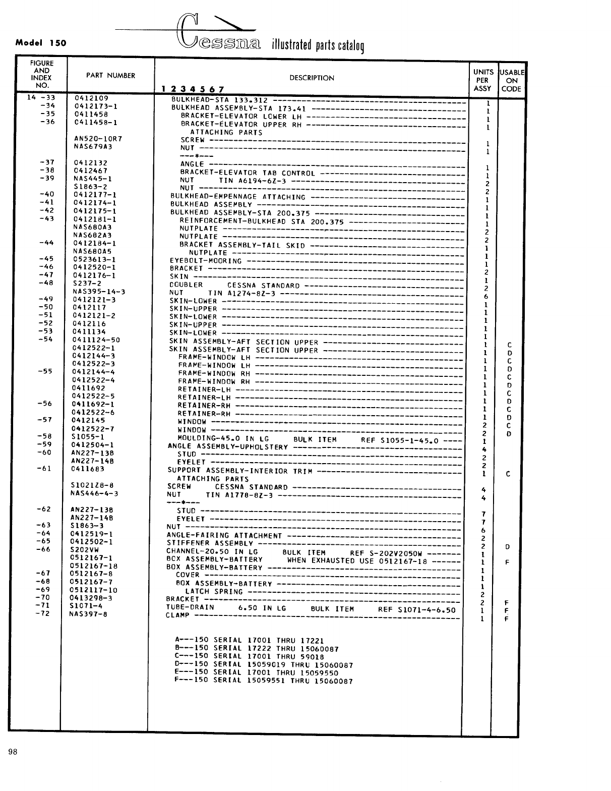
- Fig 14. Fuselage Tailcone Assembly
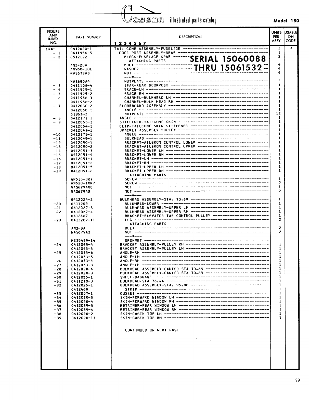
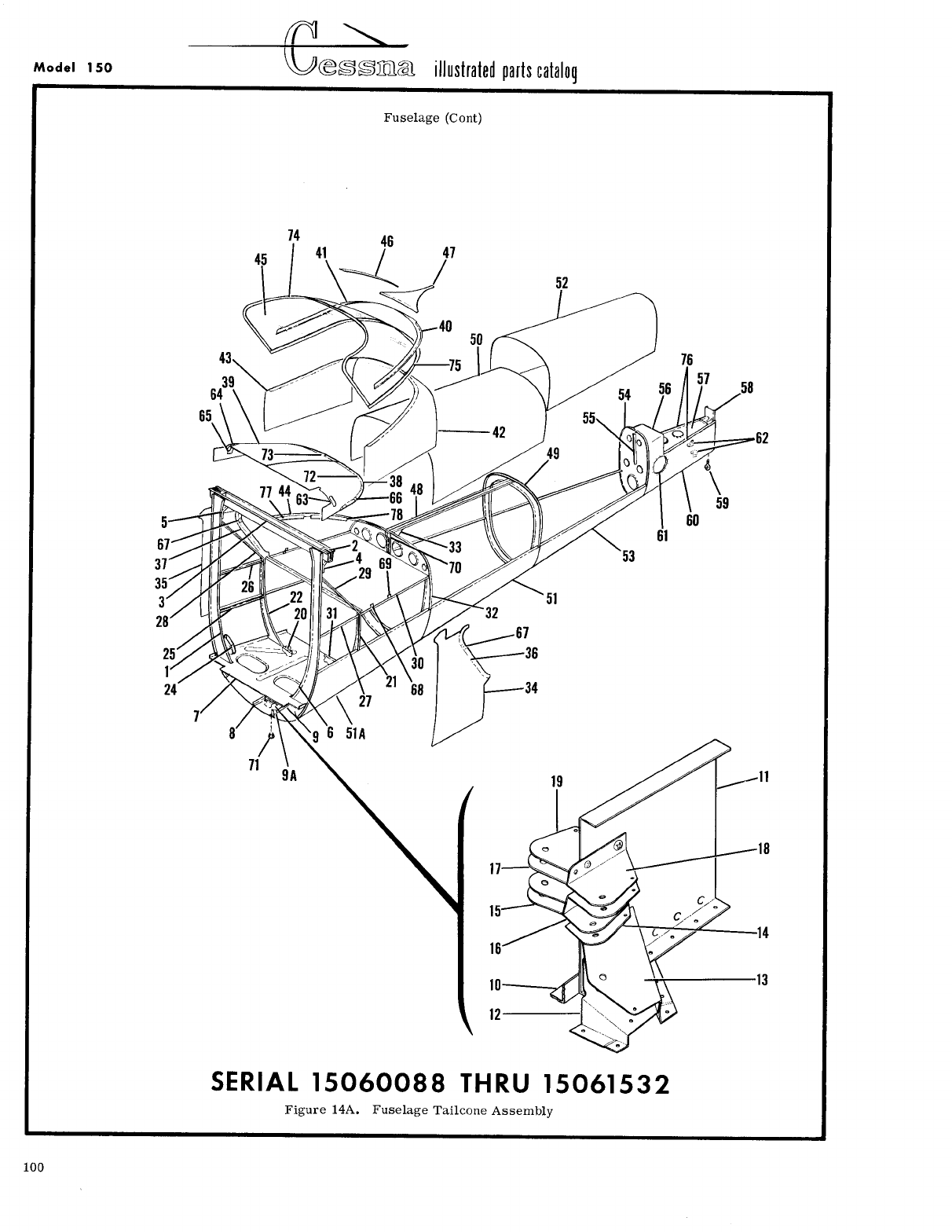
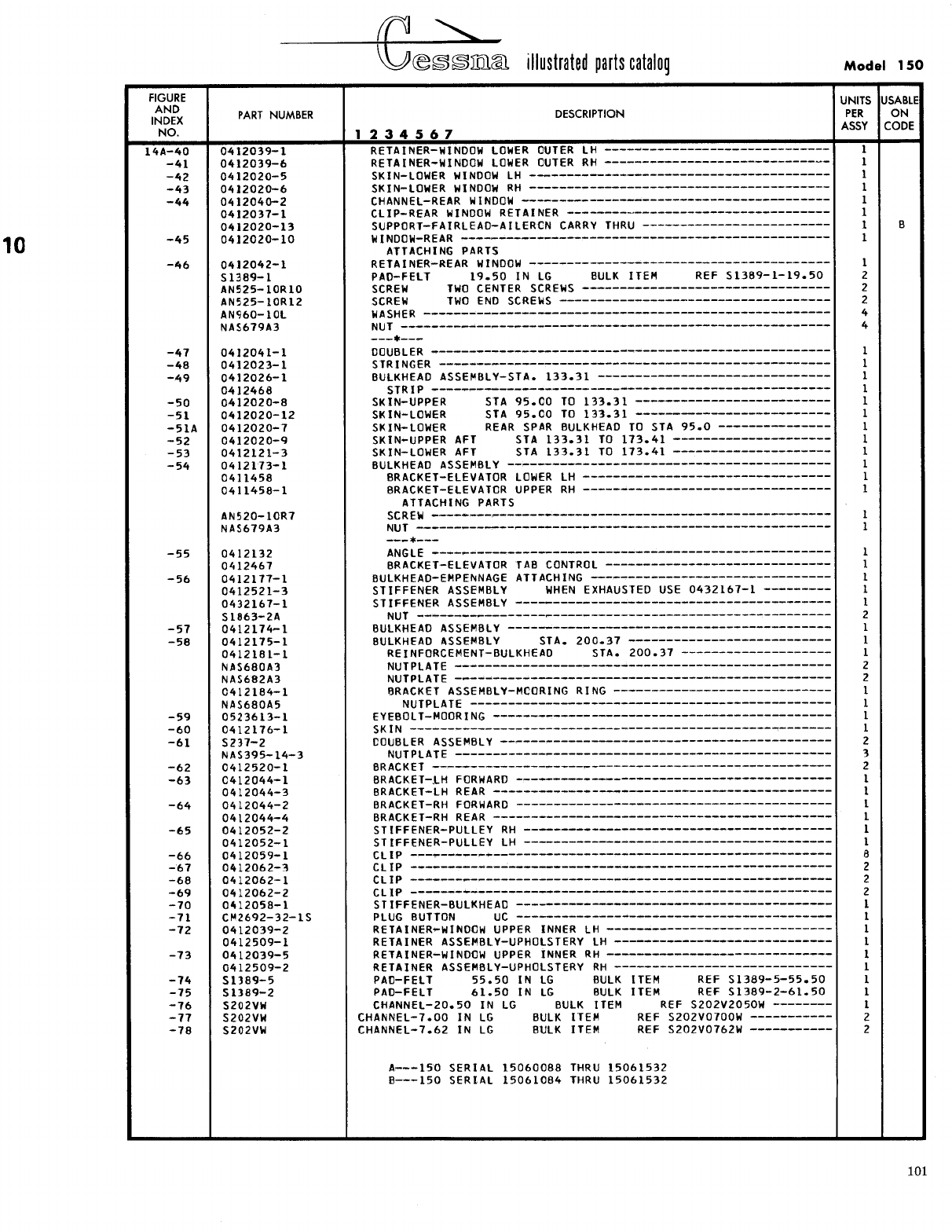
- Fig 14A. Fuselage Tailcone Assembly
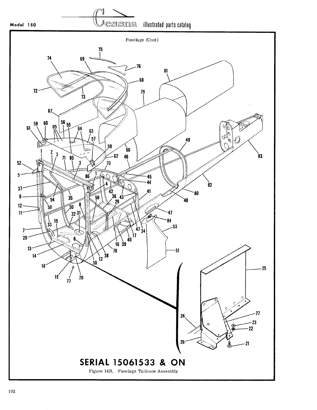
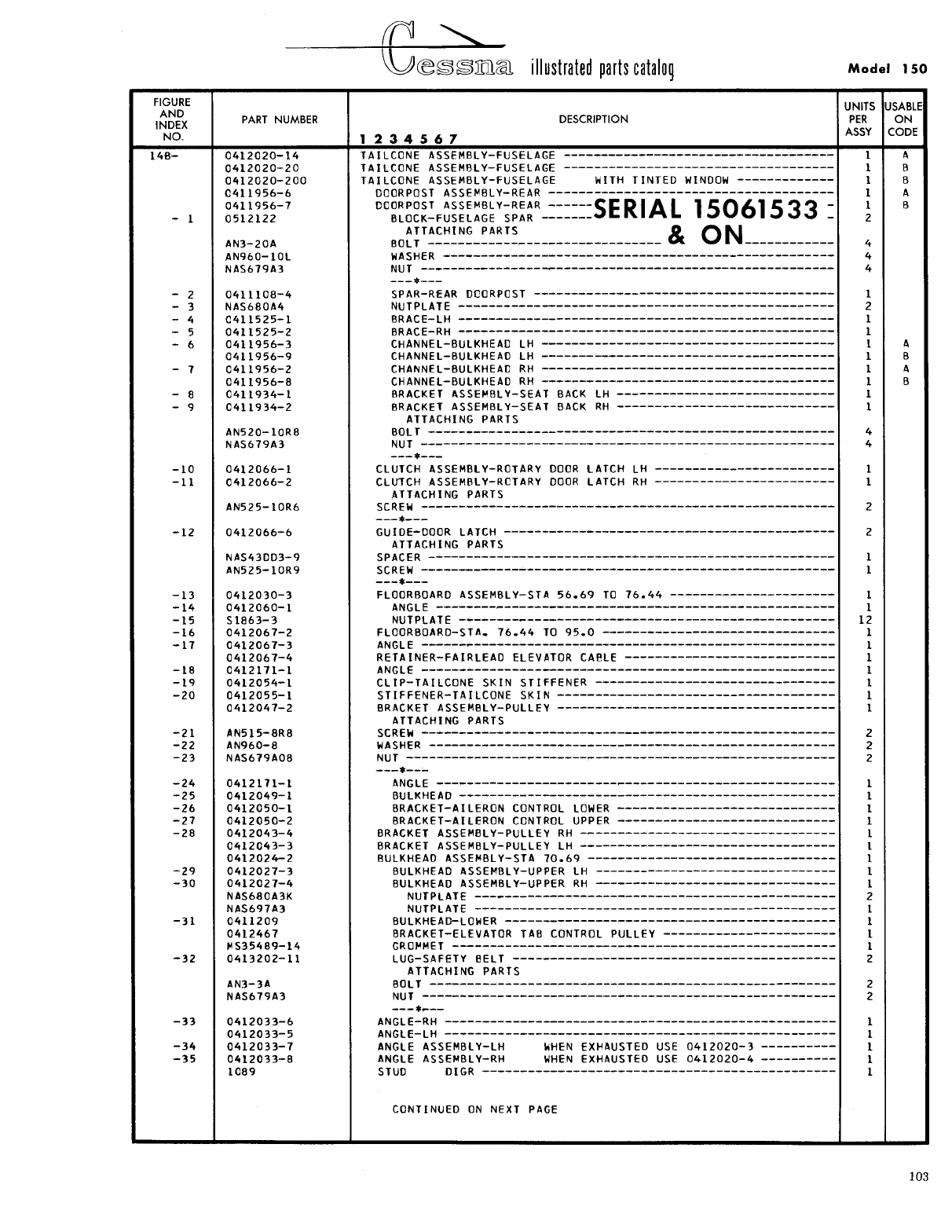
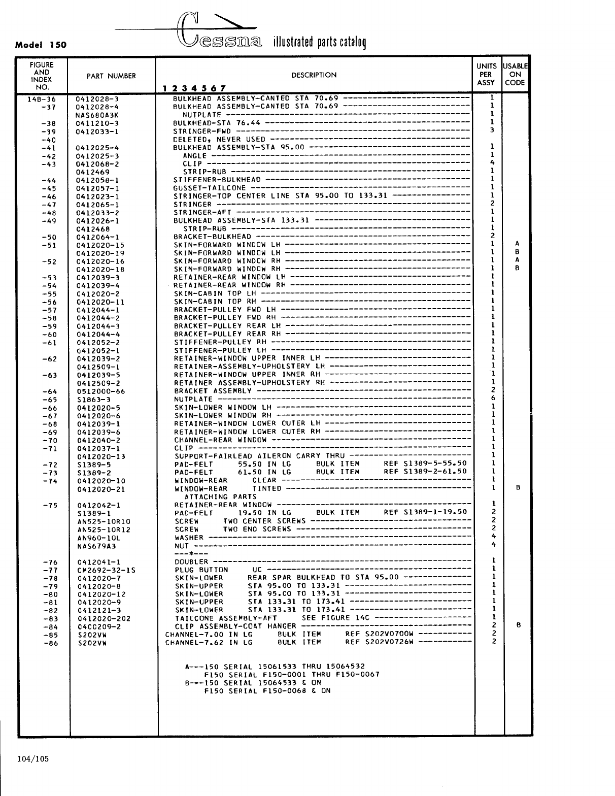
- Fig 14B. Fuselage Tailcone Assembly
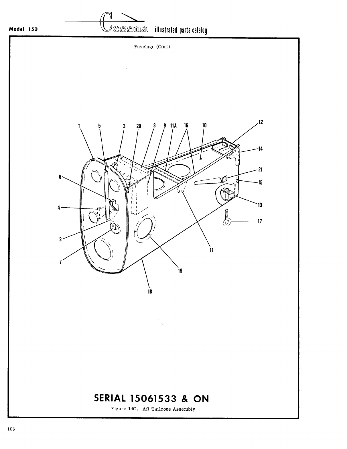
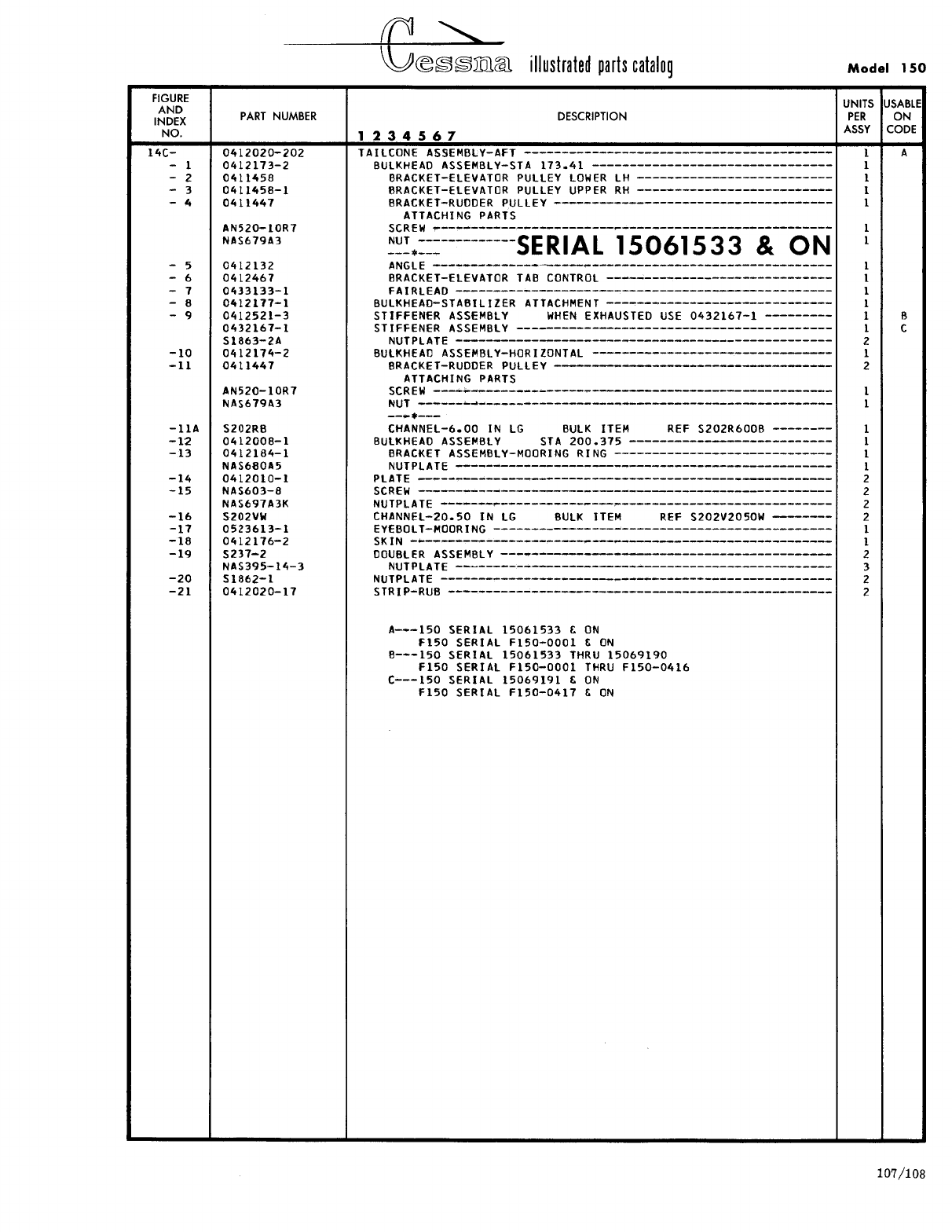
- Fig 14C. Aft Tailcone Assembly
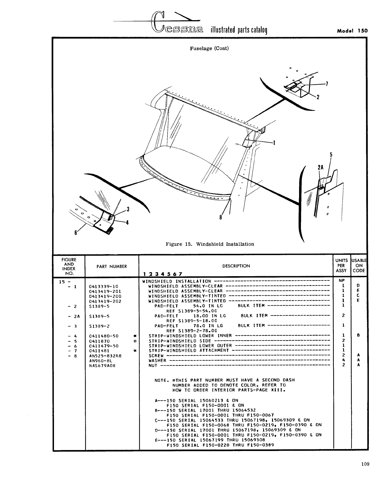
- Fig 15. Windshield Installation
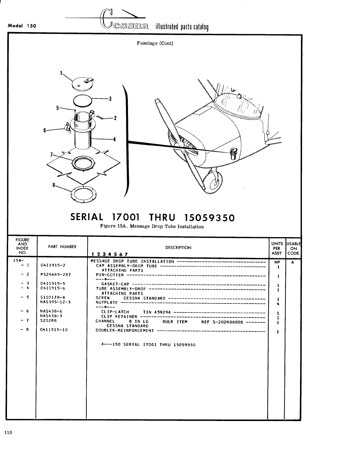
- Fig 15A. Message Drop Tube Installation
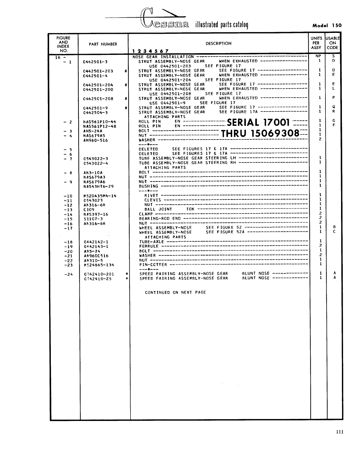
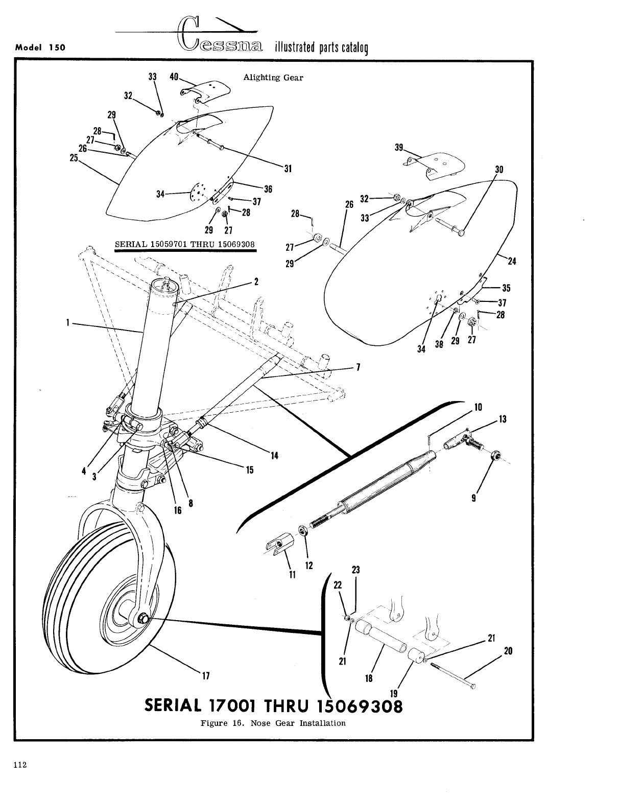
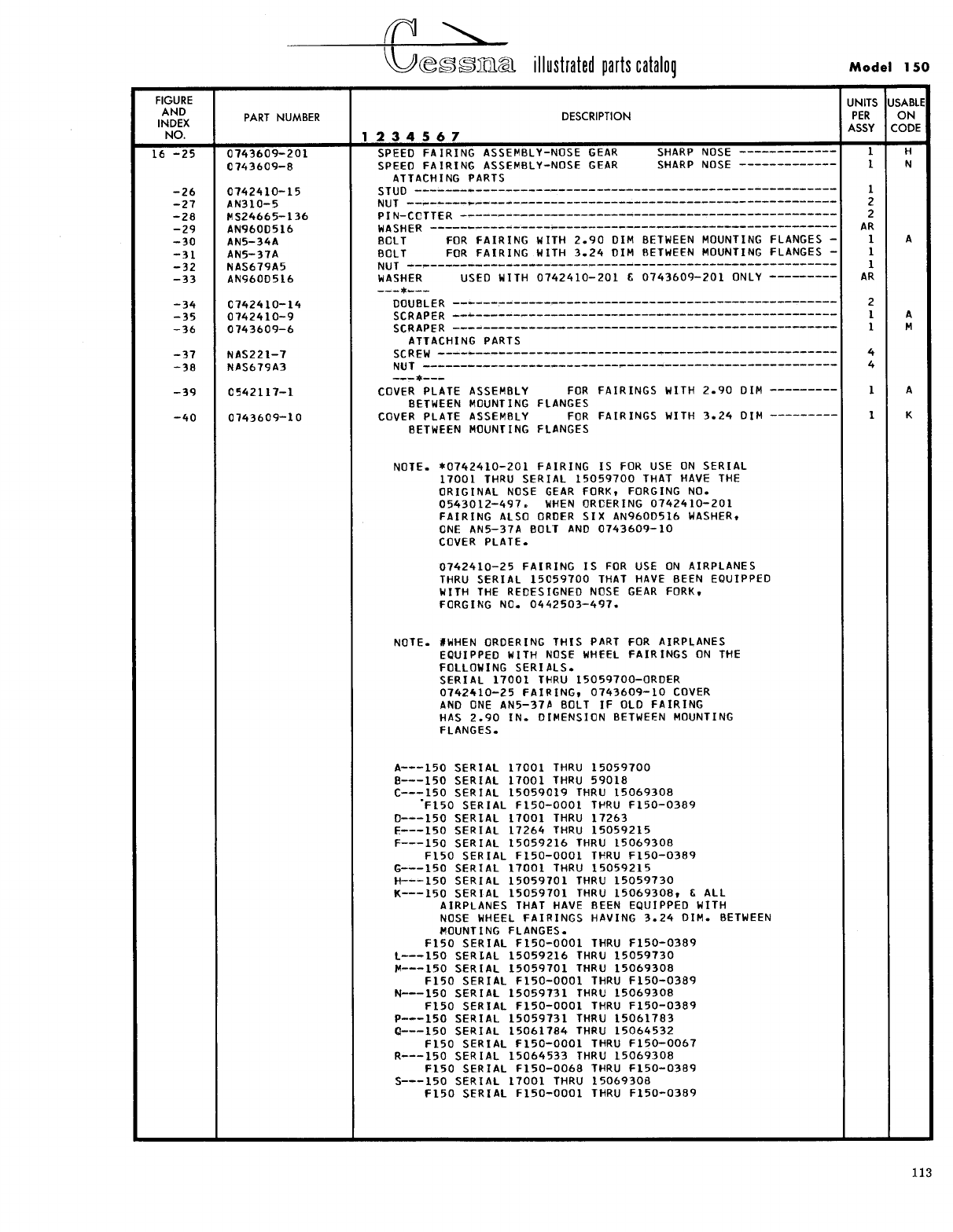
- Fig 16. Nose Gear Installation
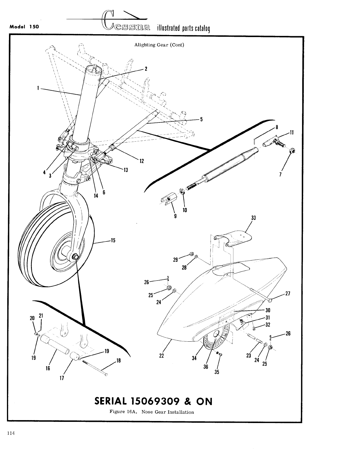
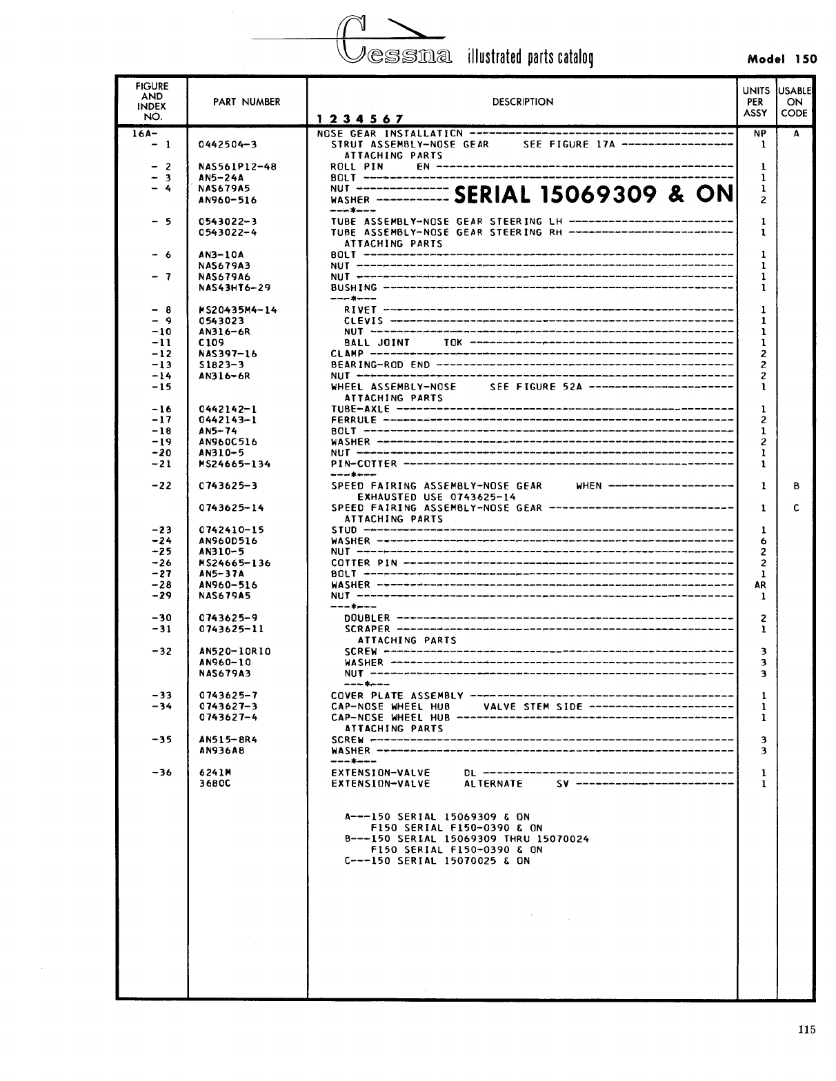
- Fig 16A. Nose Gear Installation
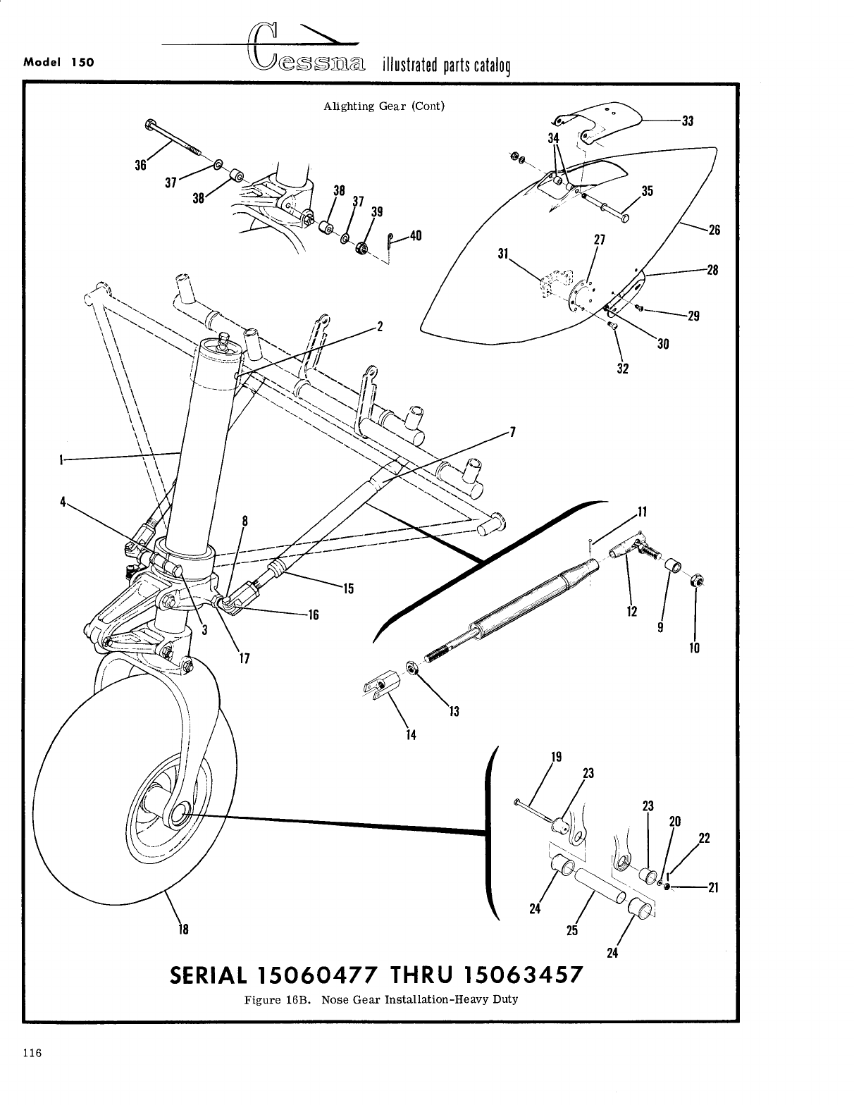
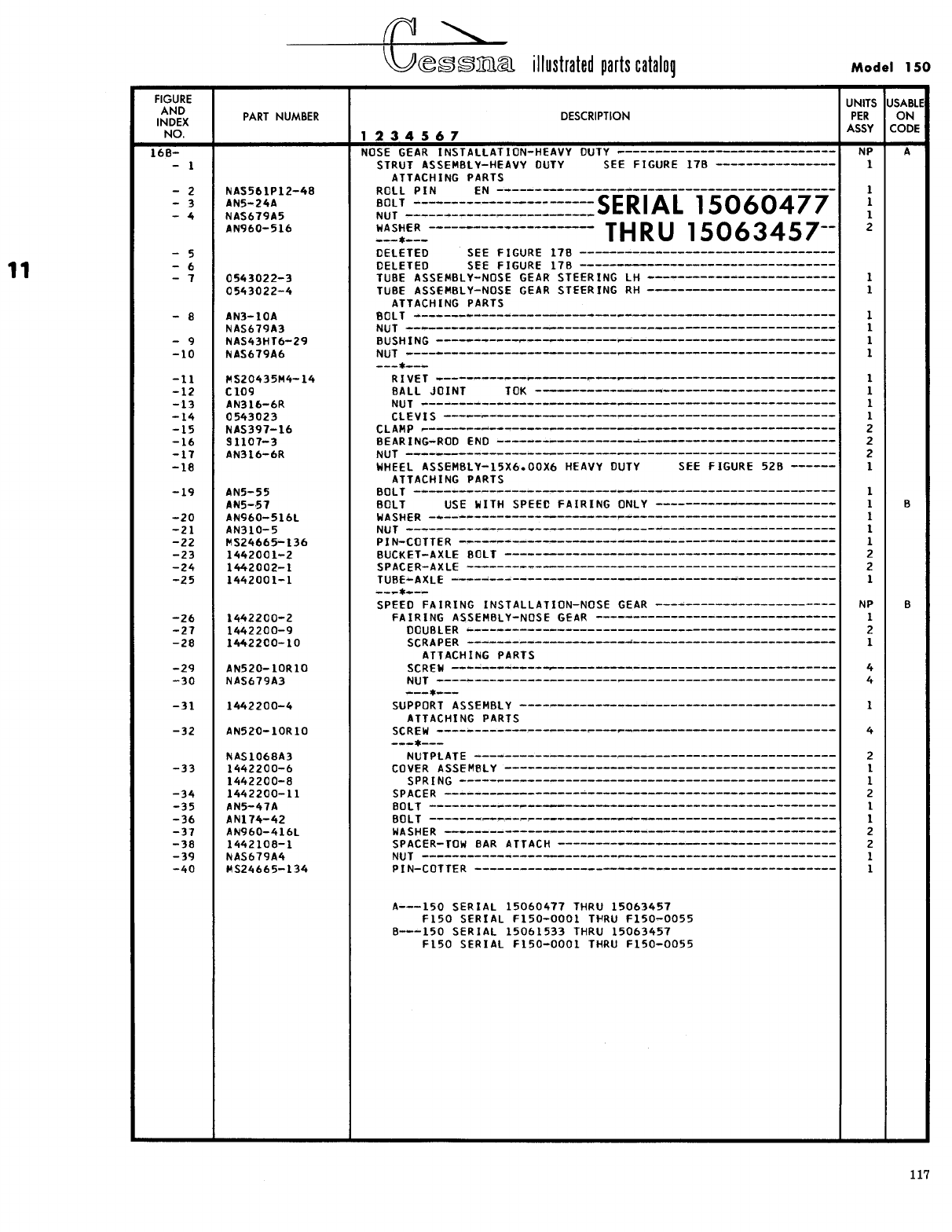
- Fig 16B. Nose Gear Installation - Heavy Duty
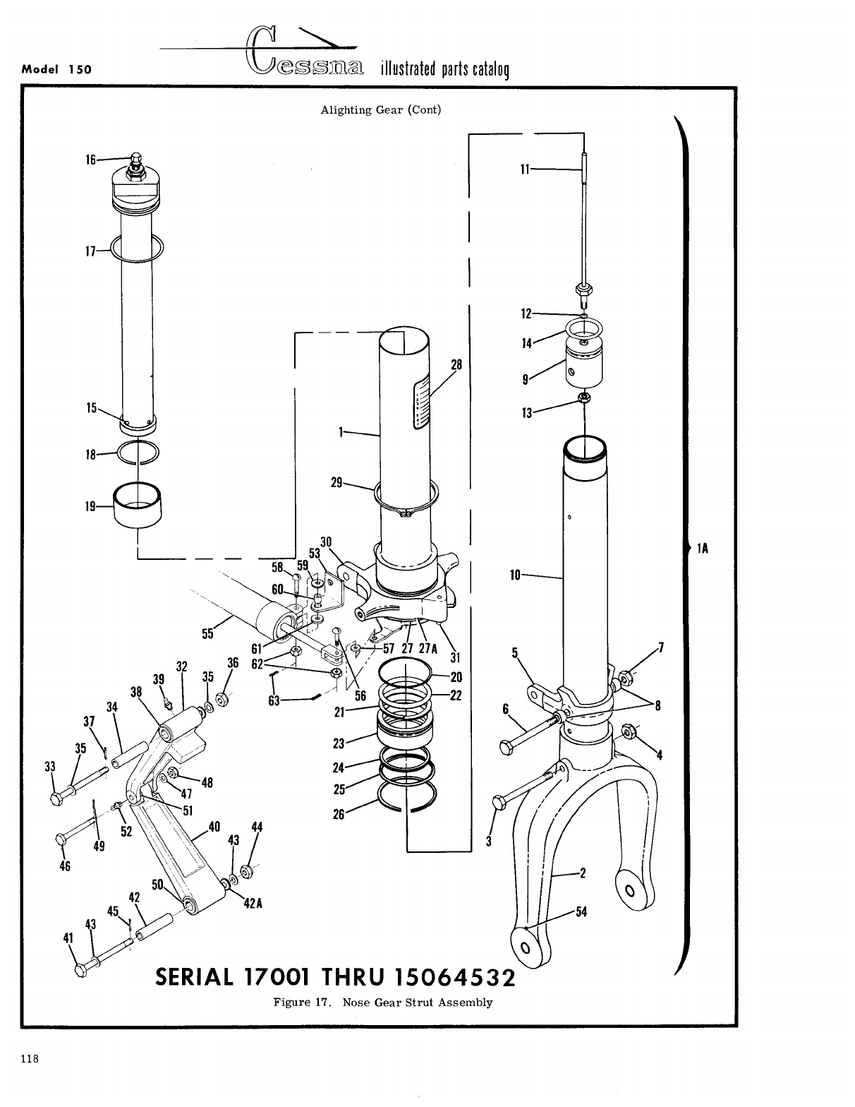
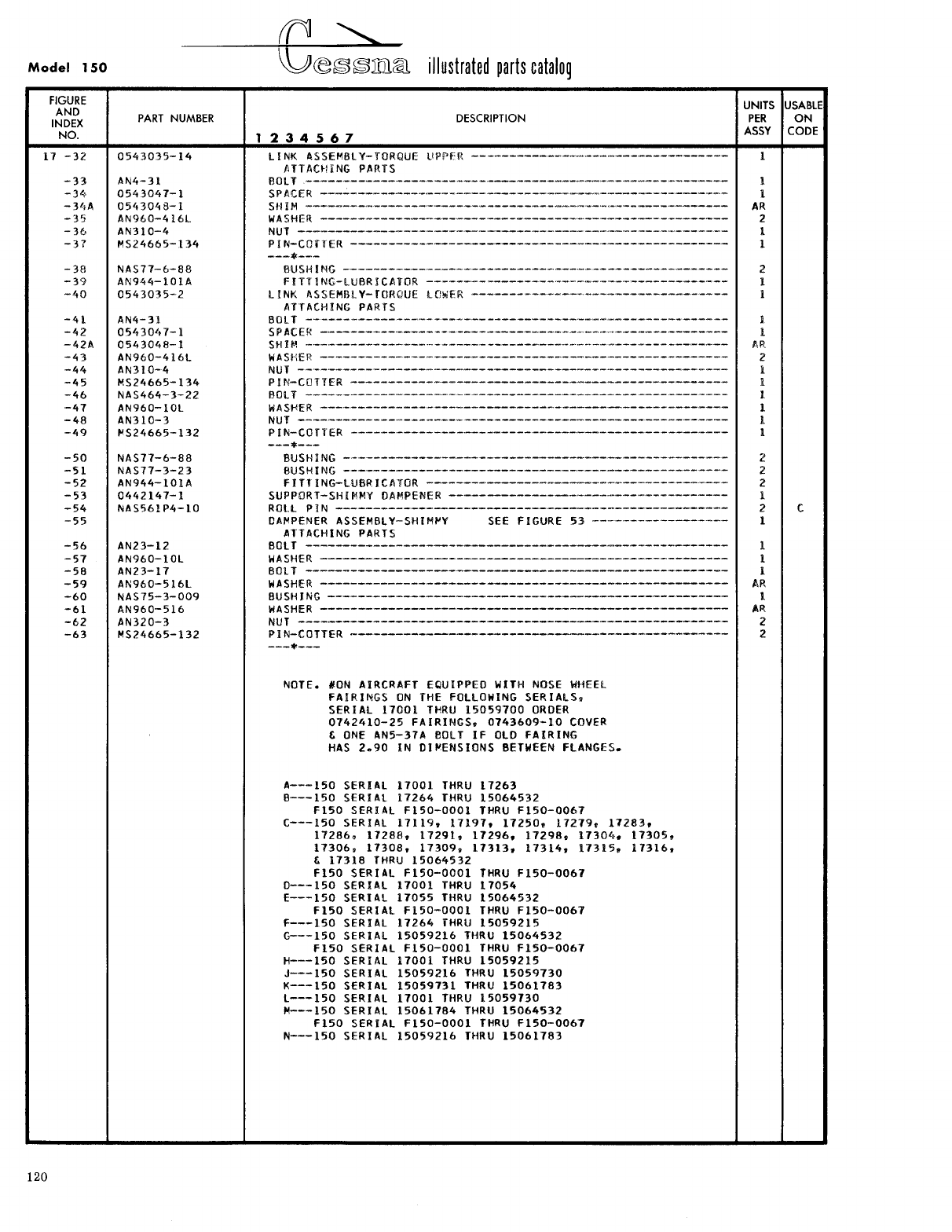
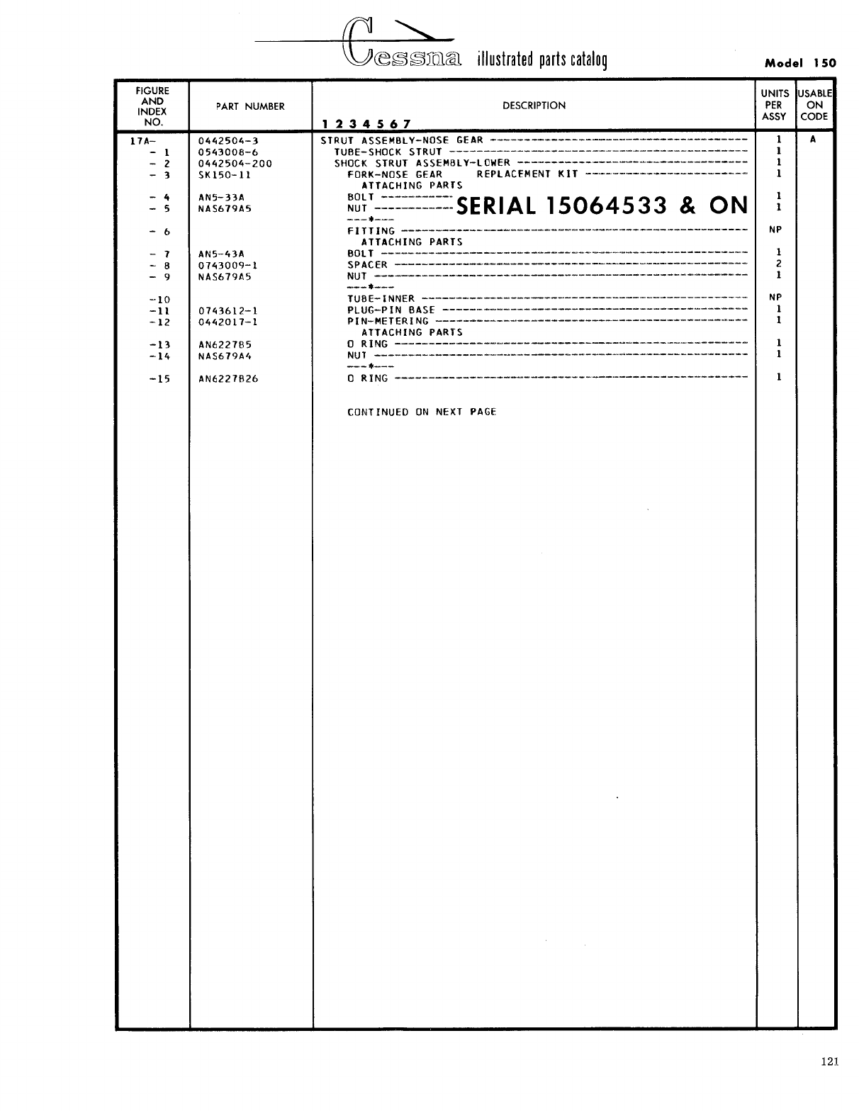
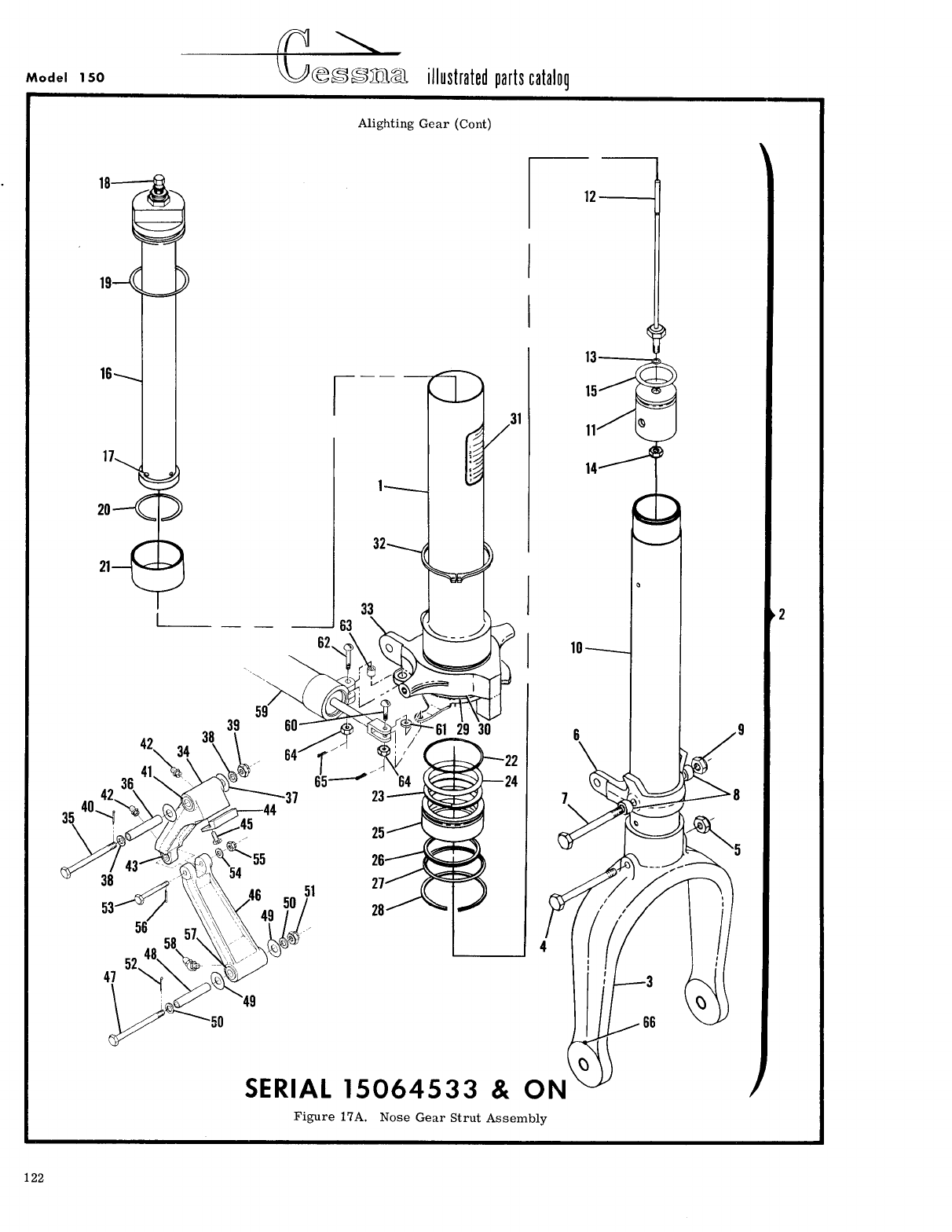
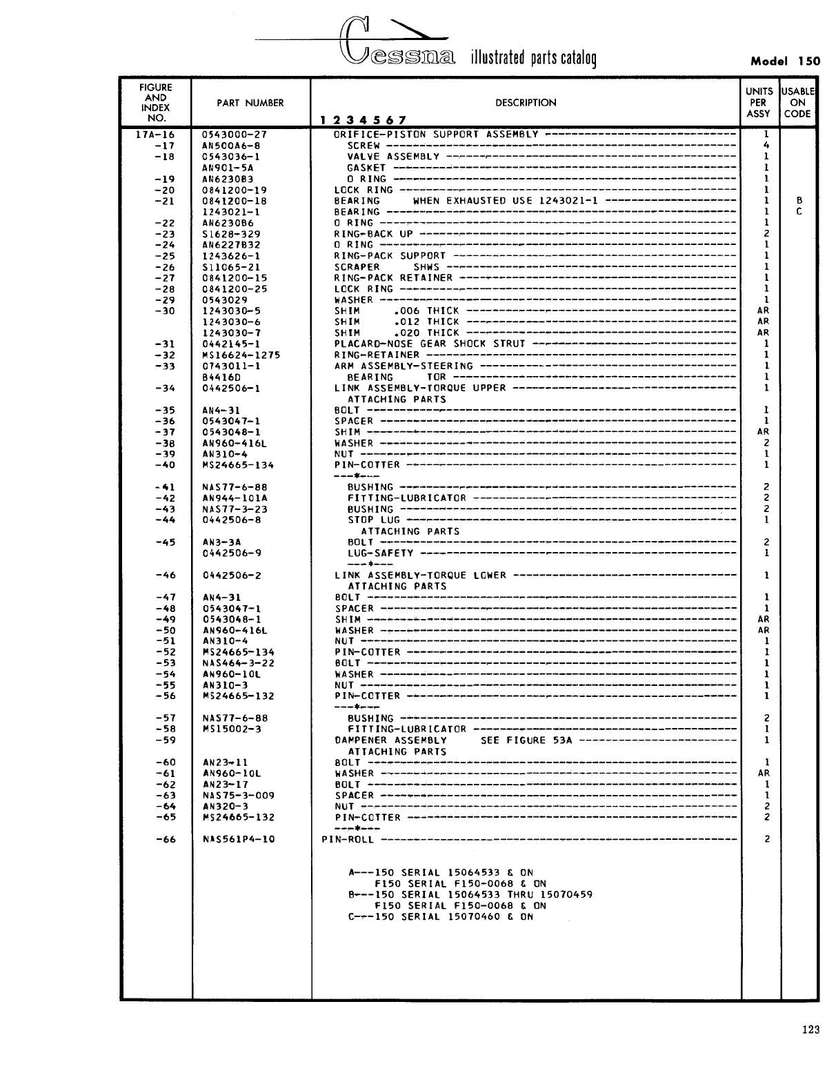
- Fig 17. Nose Gear Strut Assembly
- Fig 17A. Nose Gear Strut Assembly
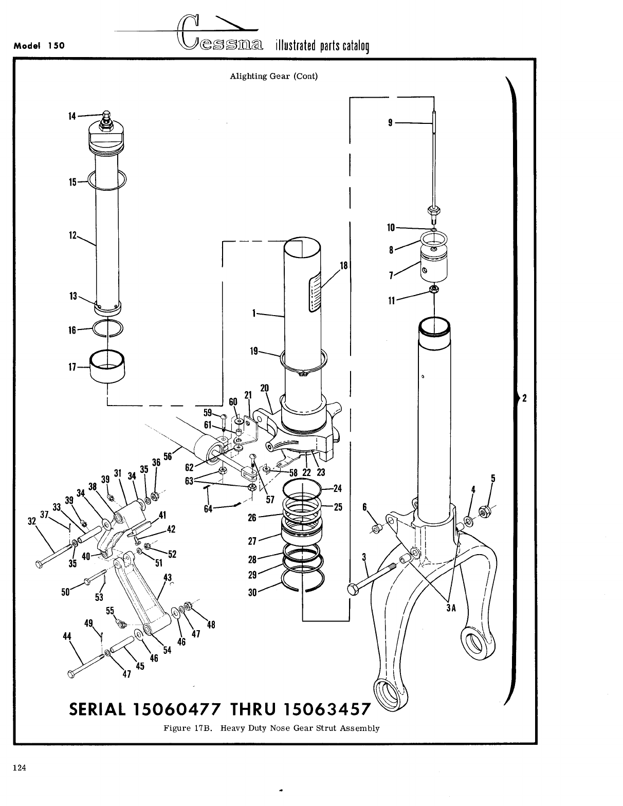
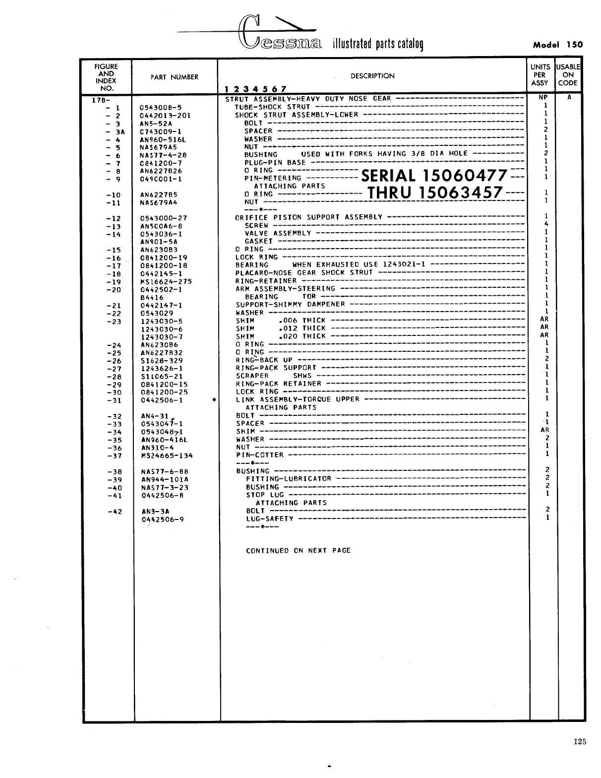
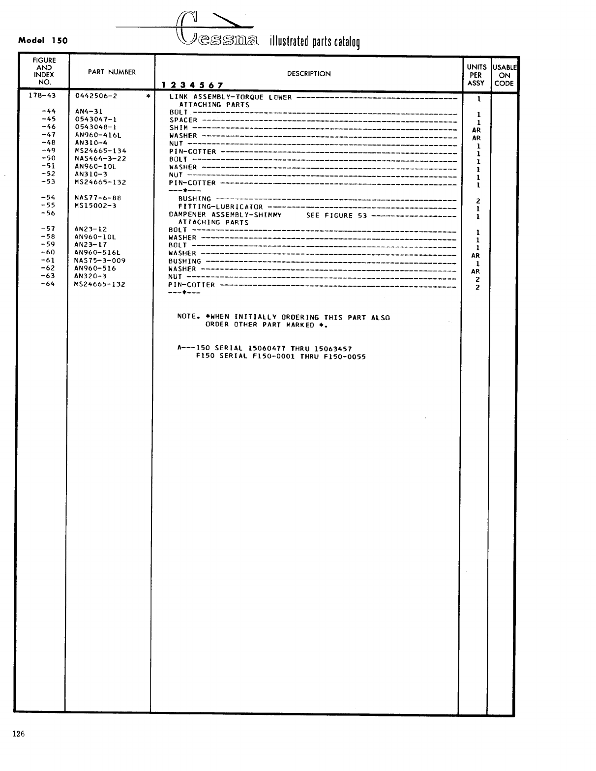
- Fig 17B. Heavy Duty Nose Gear Strut Assembly
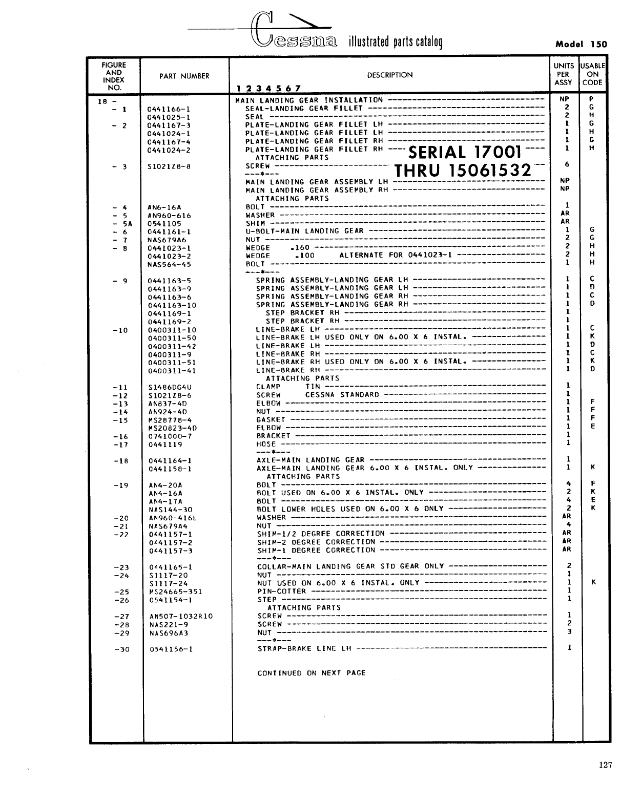
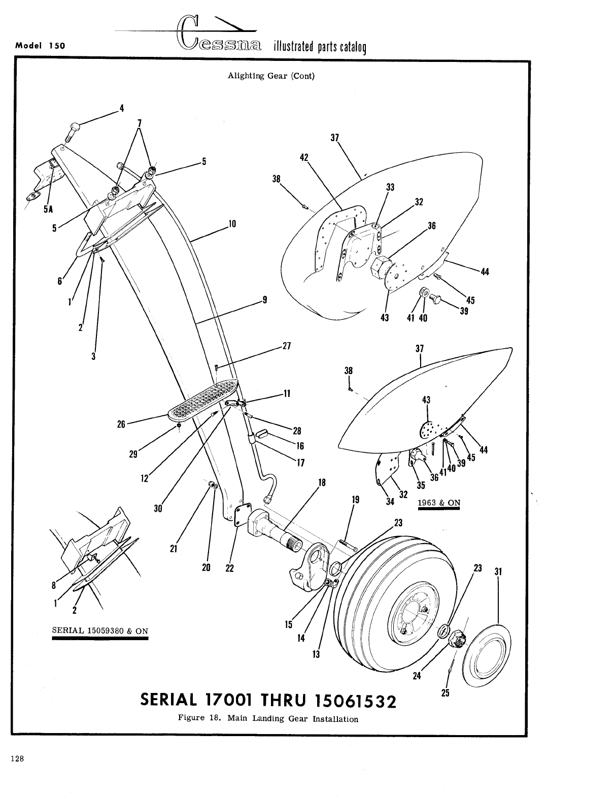
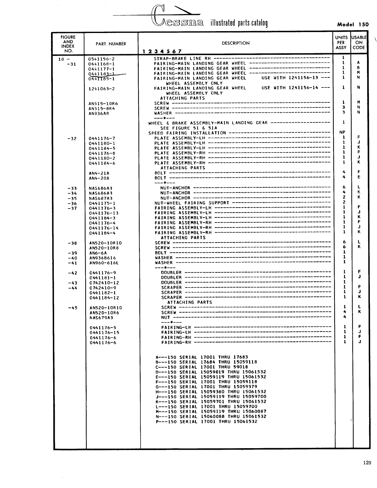
- Fig 18. Main Landing Gear Installation
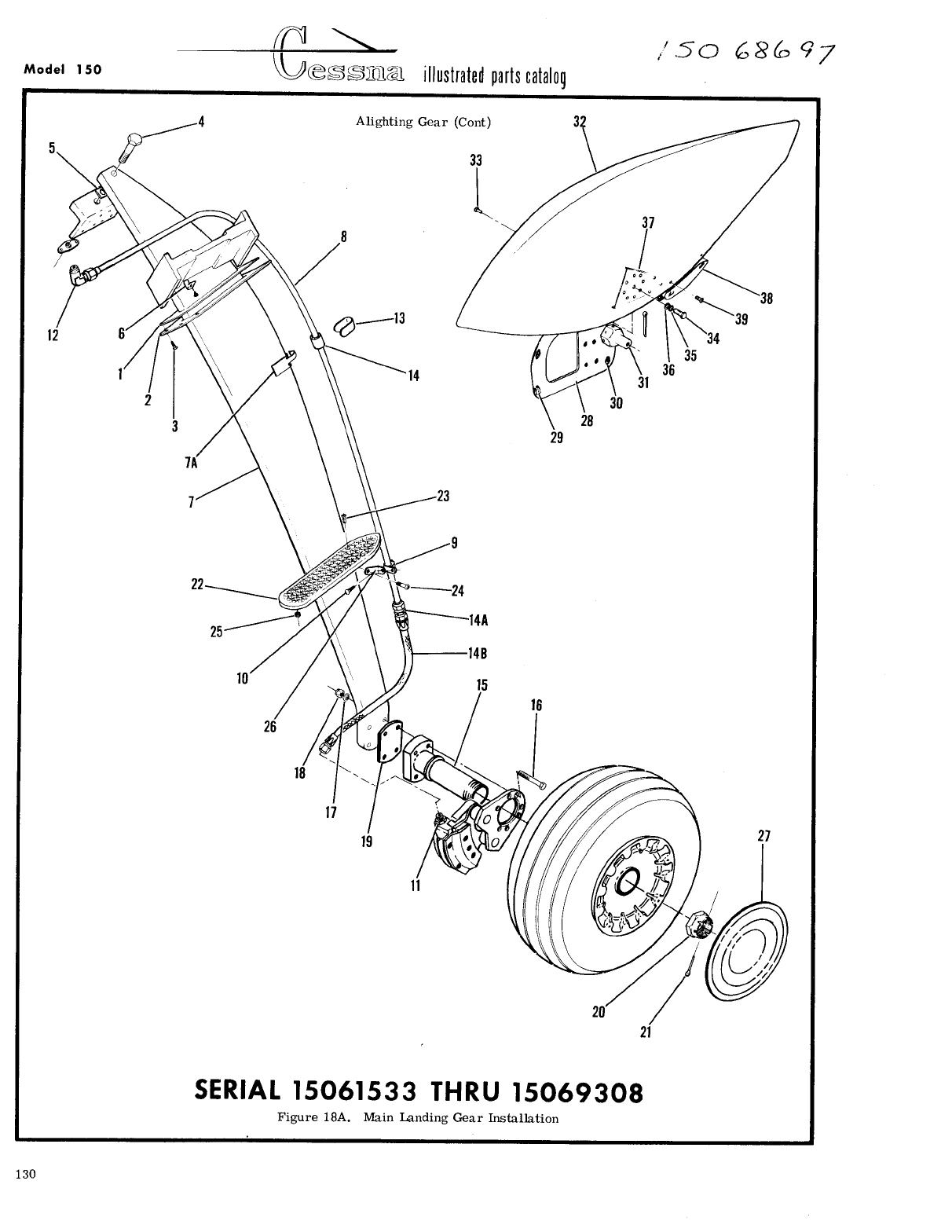
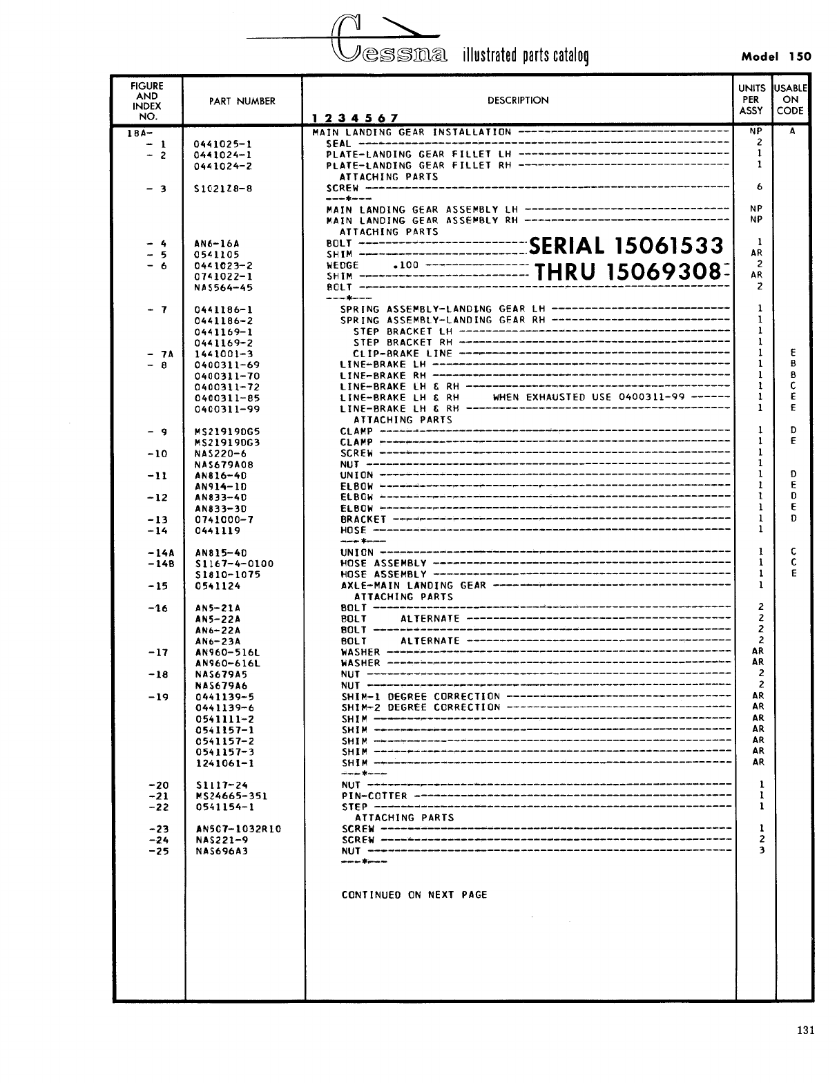
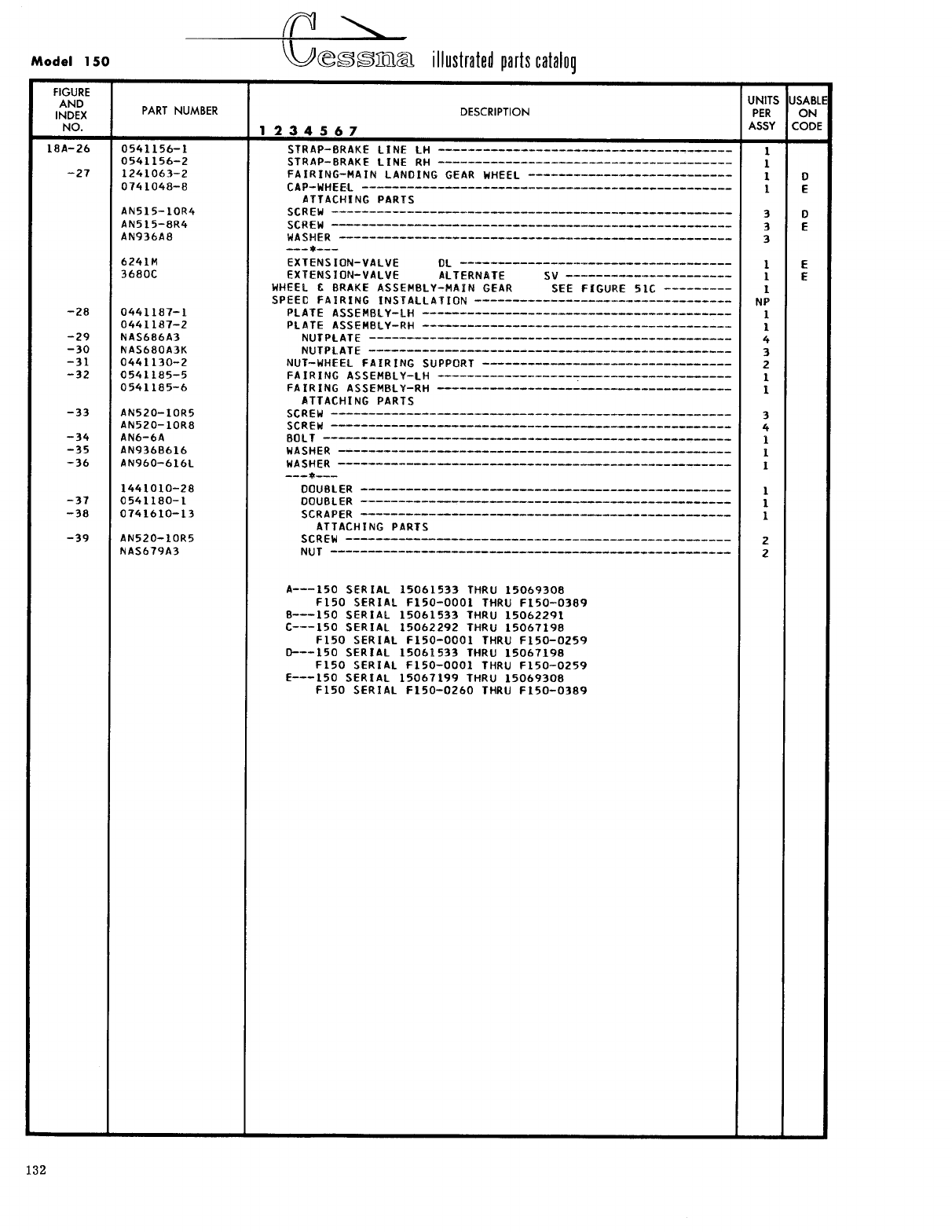
- Fig 18A. Main Landing Gear Installation
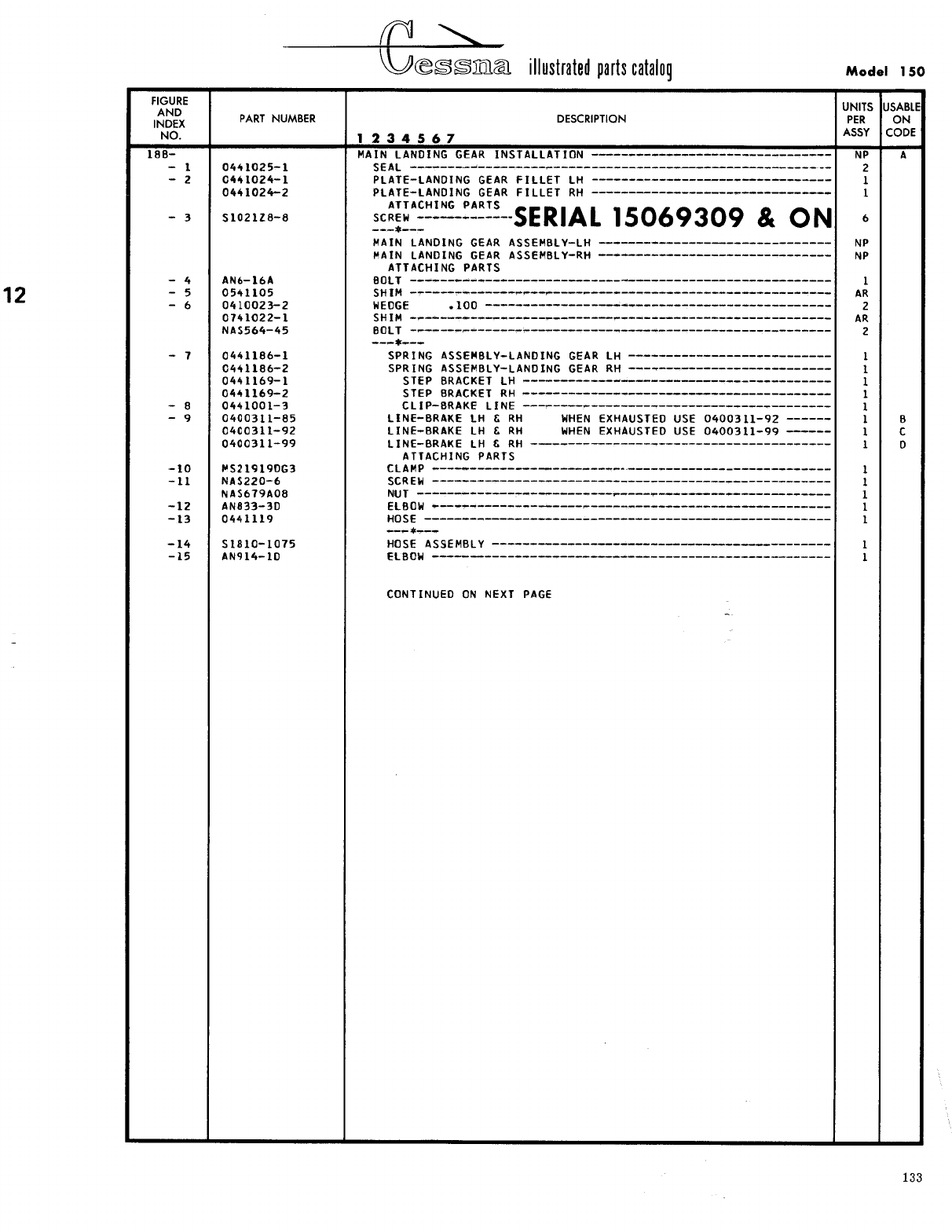
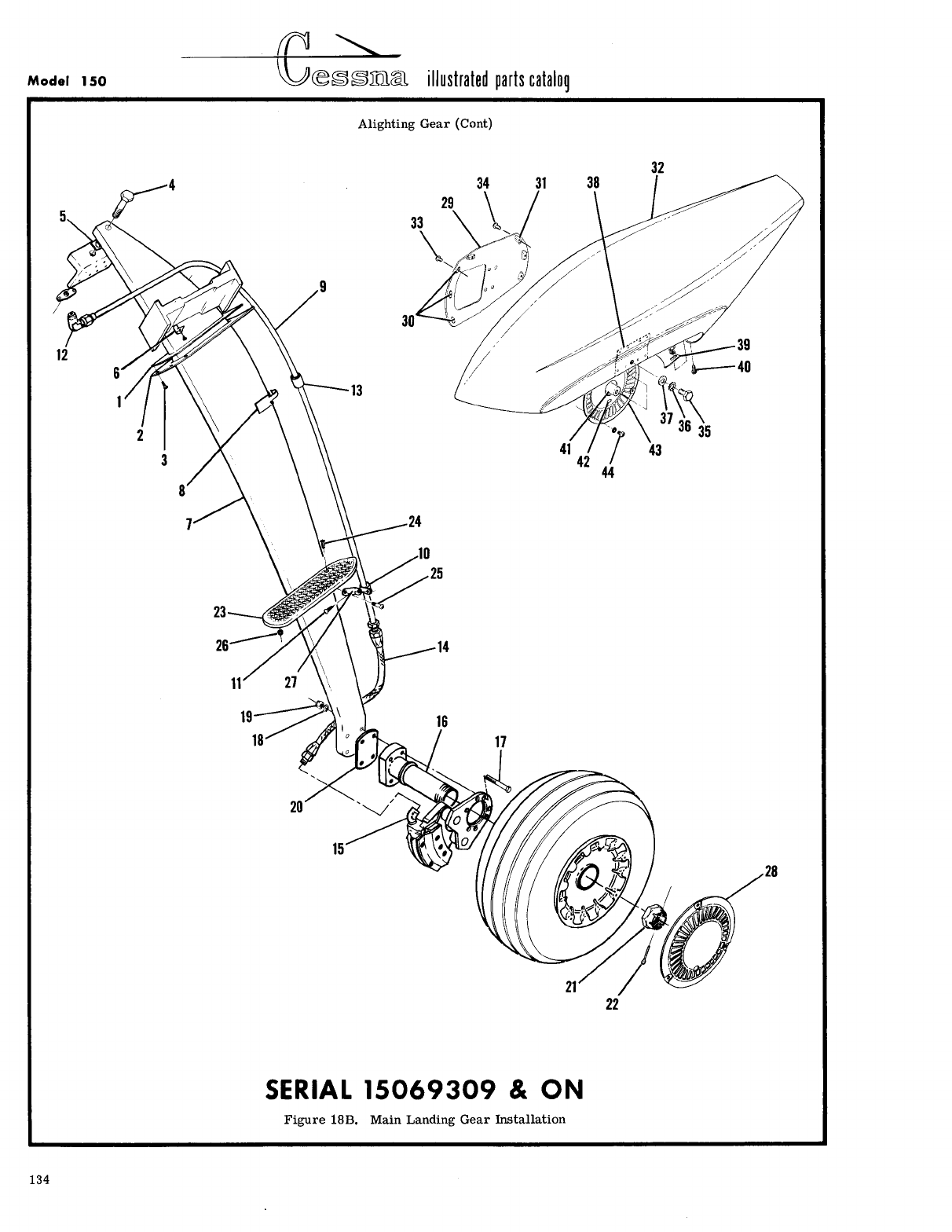
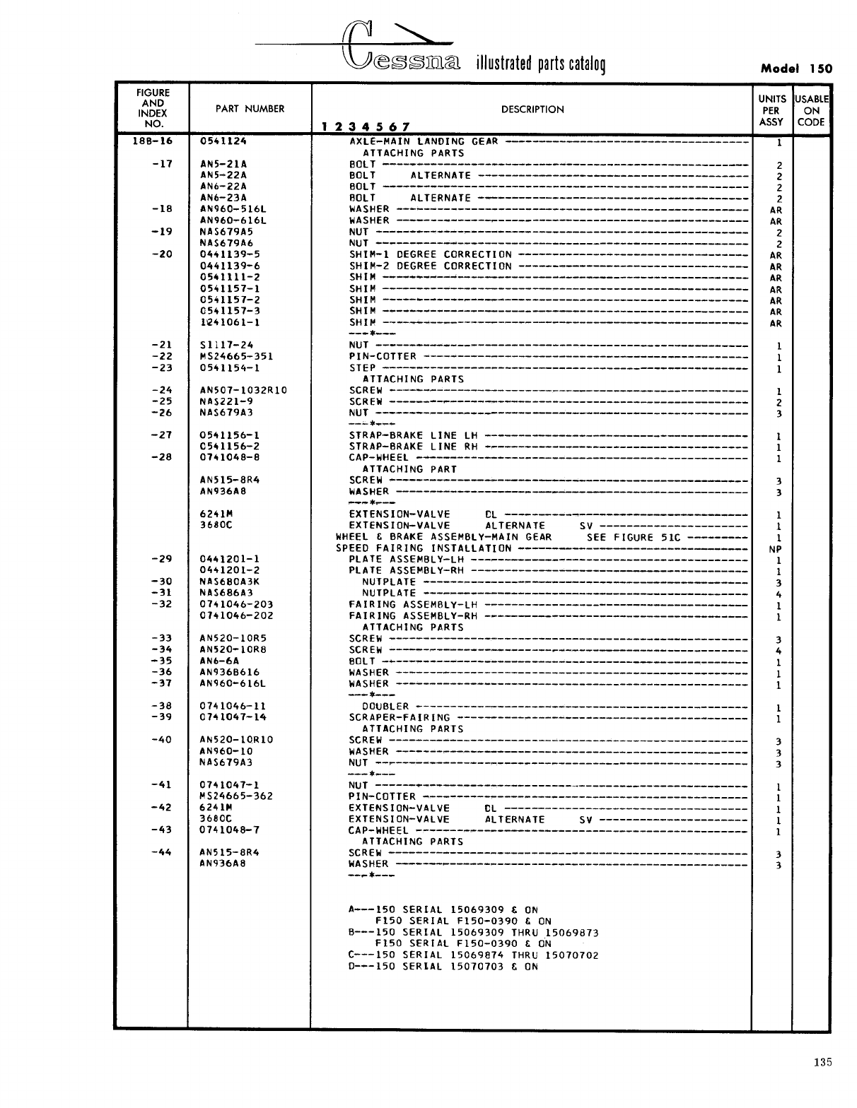
- Fig 18B. Main Landing Gear Installation
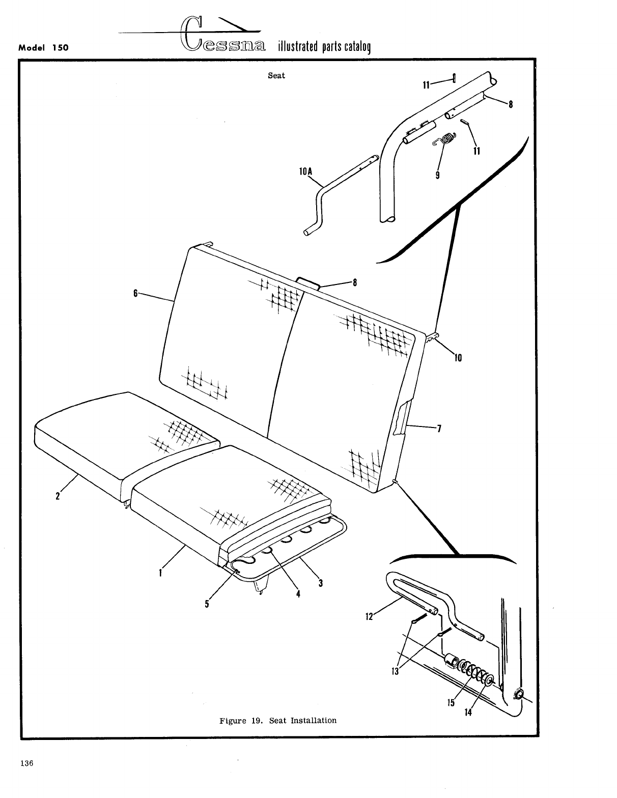
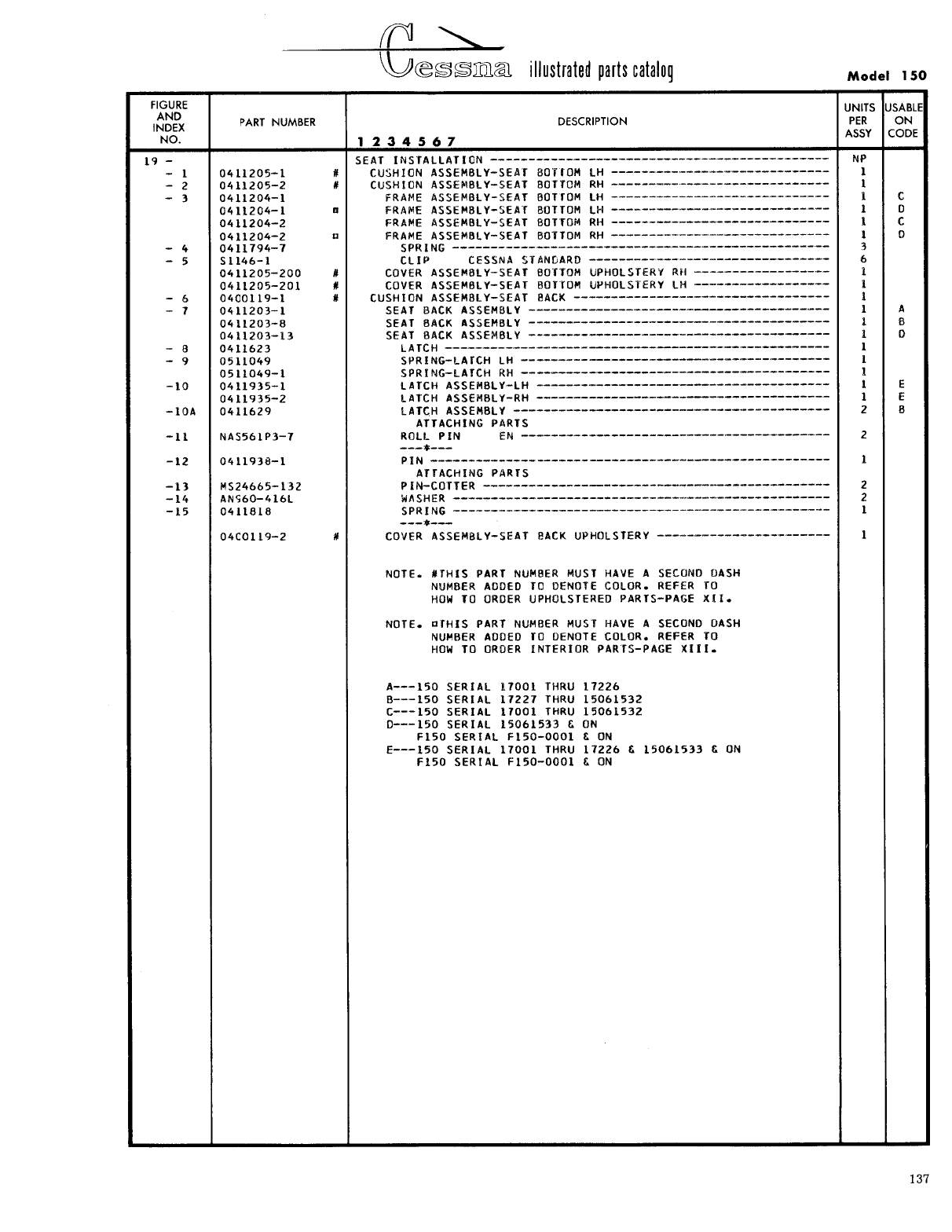
- Fig 19. Seat Installation
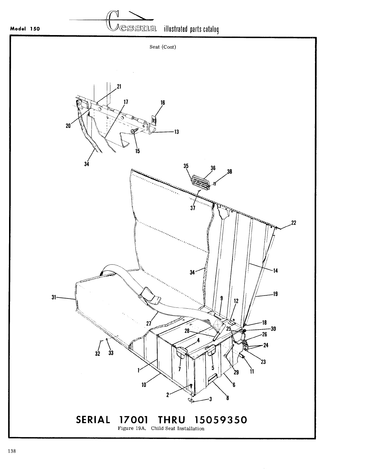
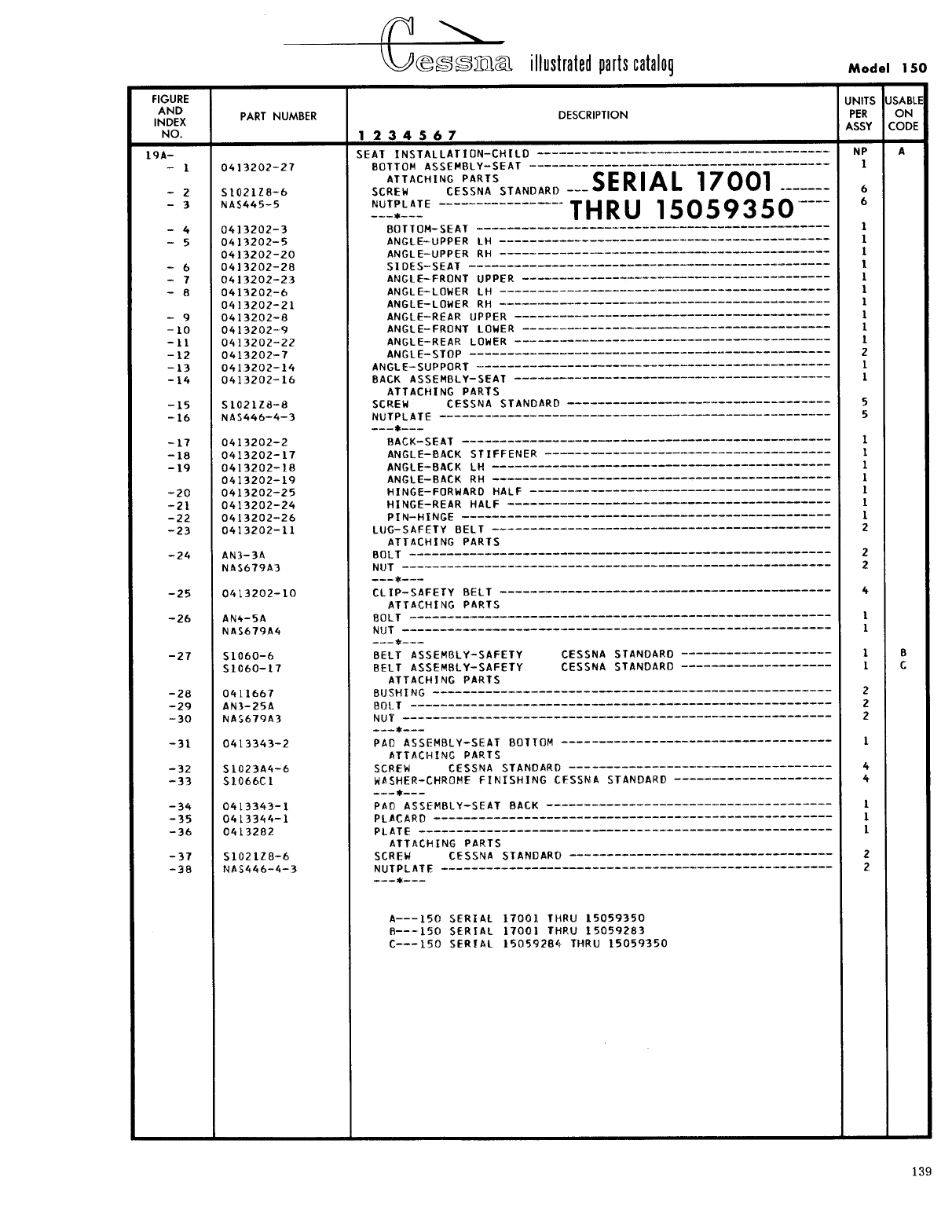
- Fig 19A. Child Seat Installation
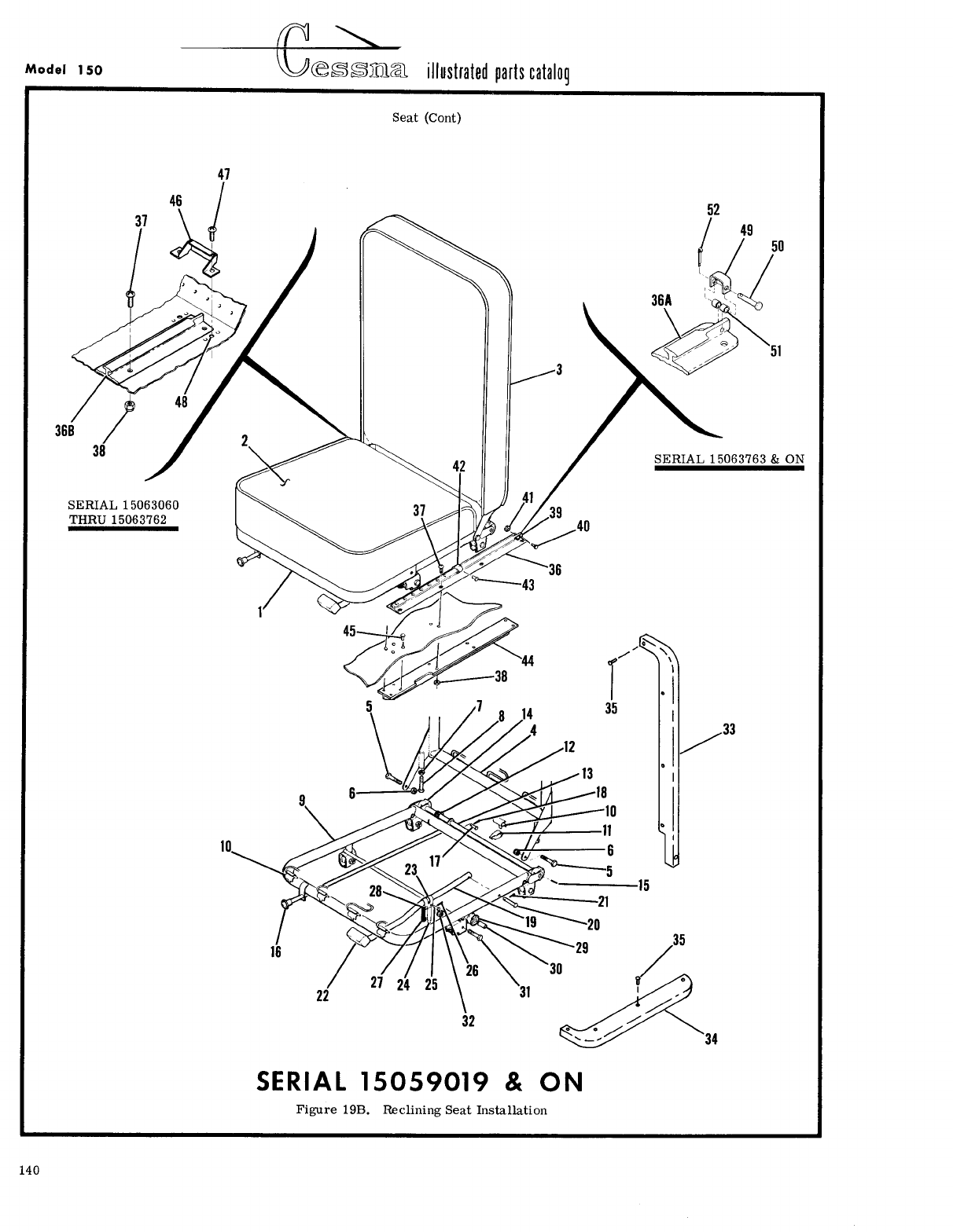
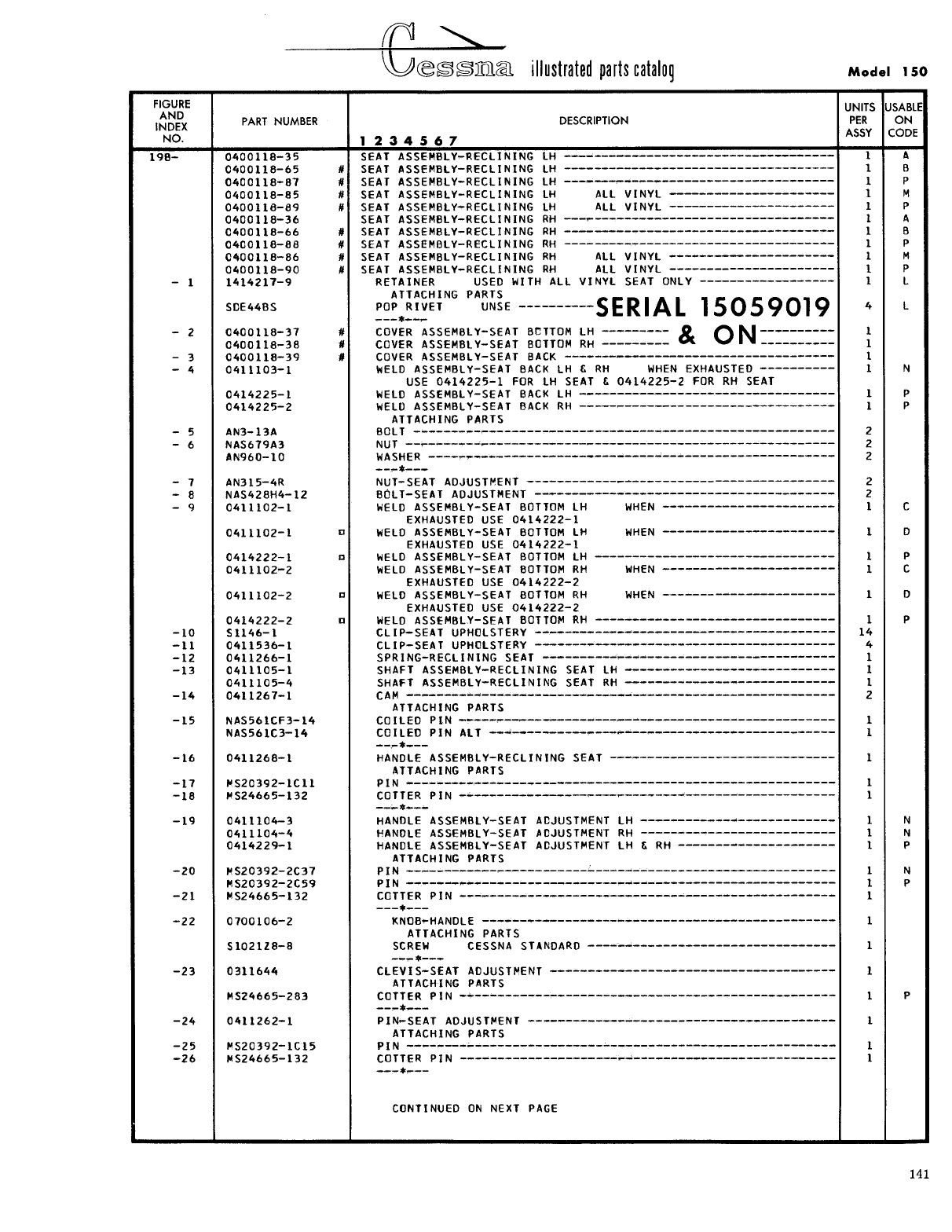
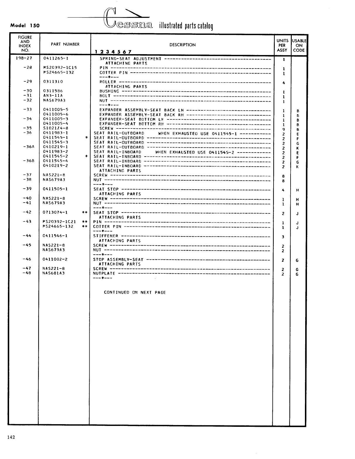
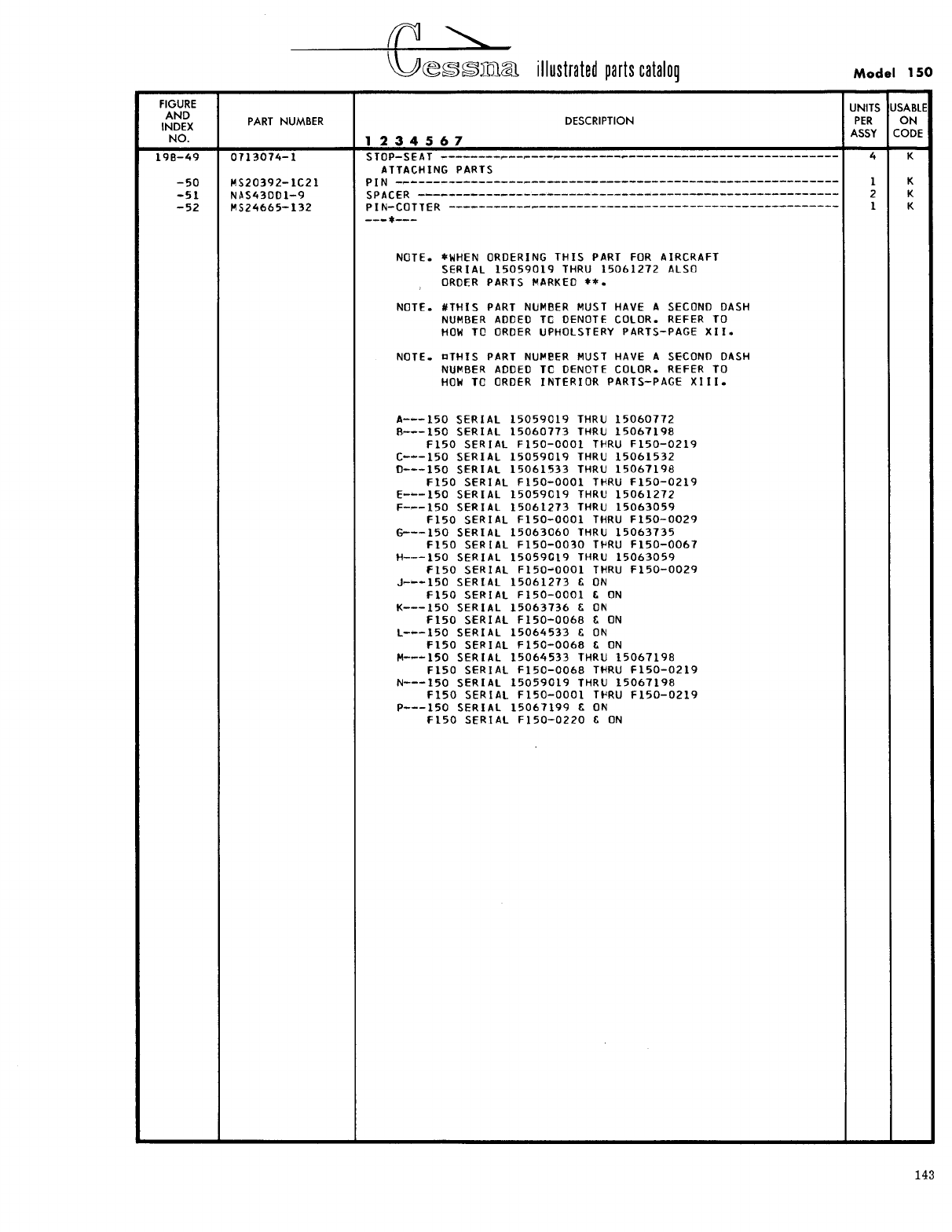
- Fig 19B. Reclining Seat Installation
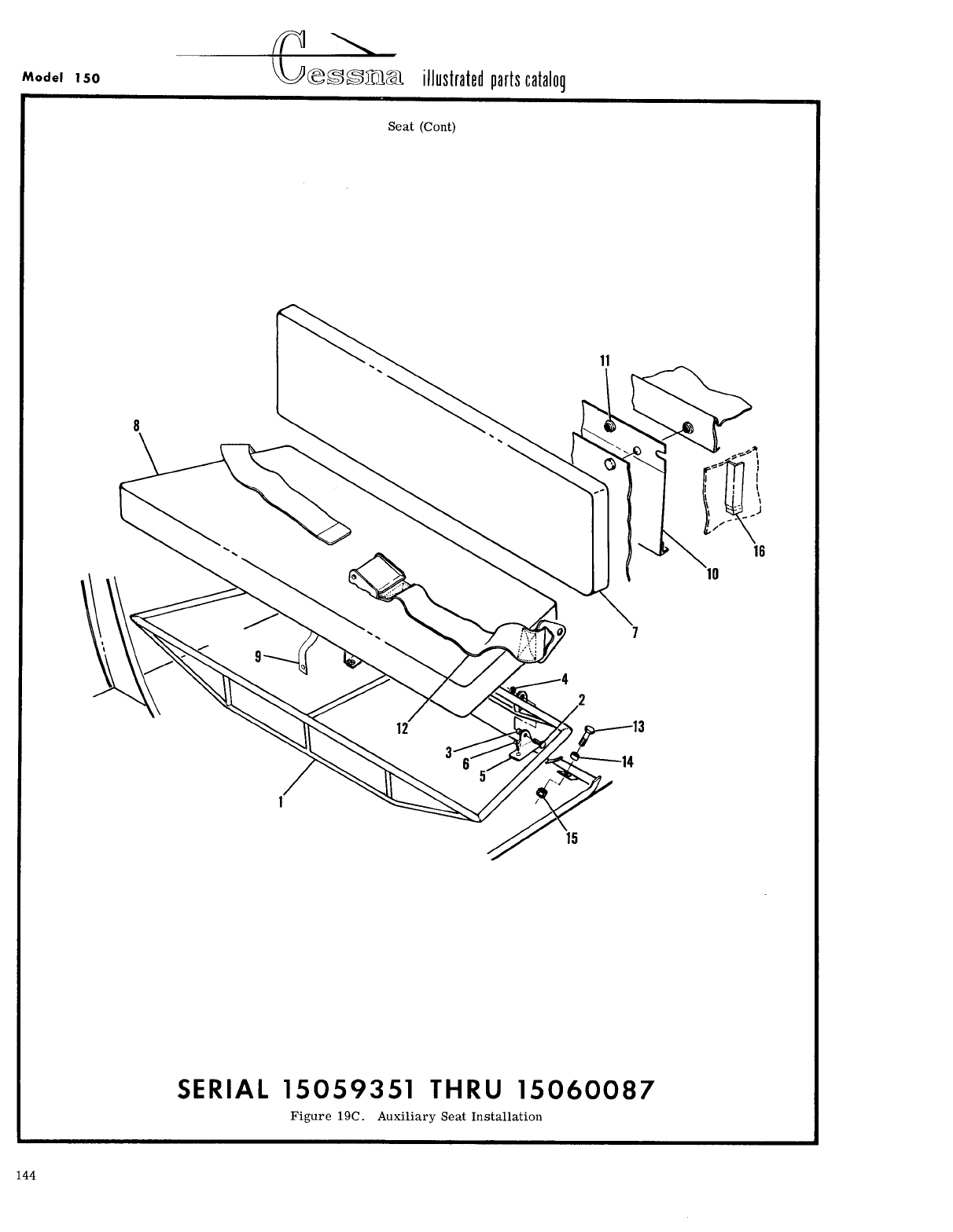
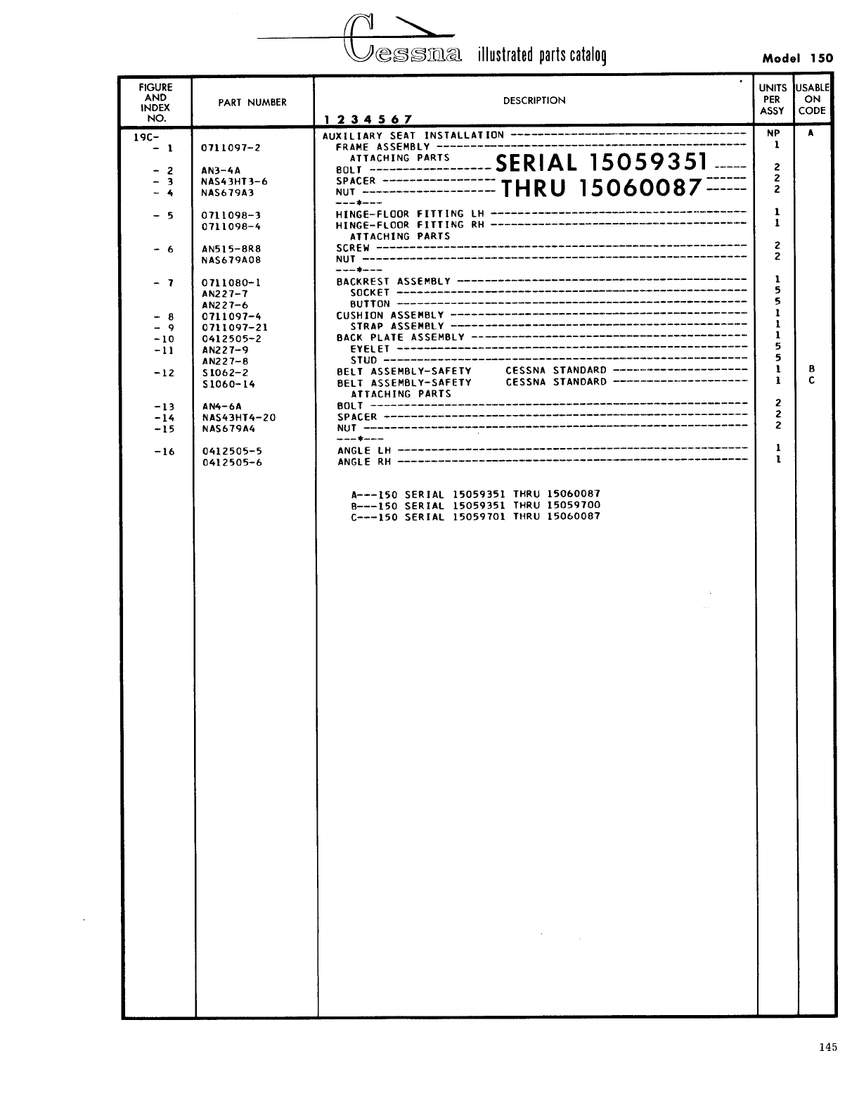
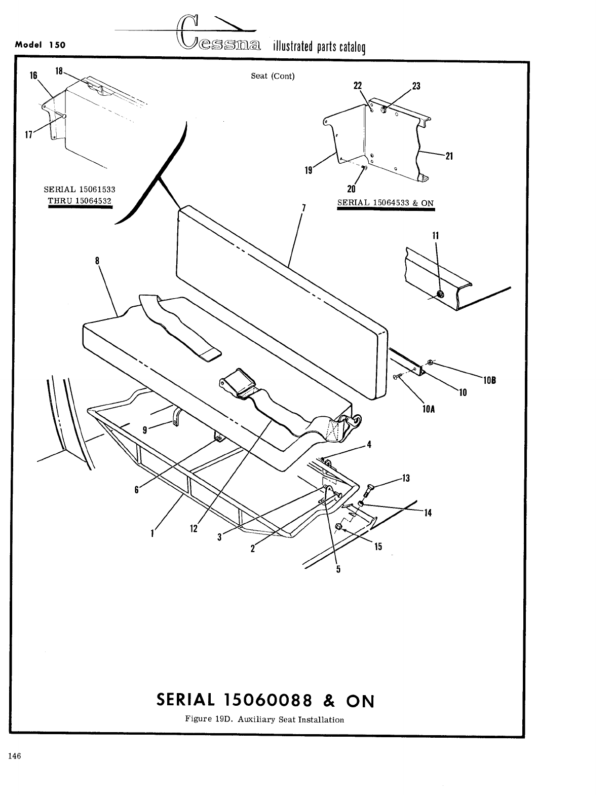
- Fig 19C. Auxiliary Seat Installation
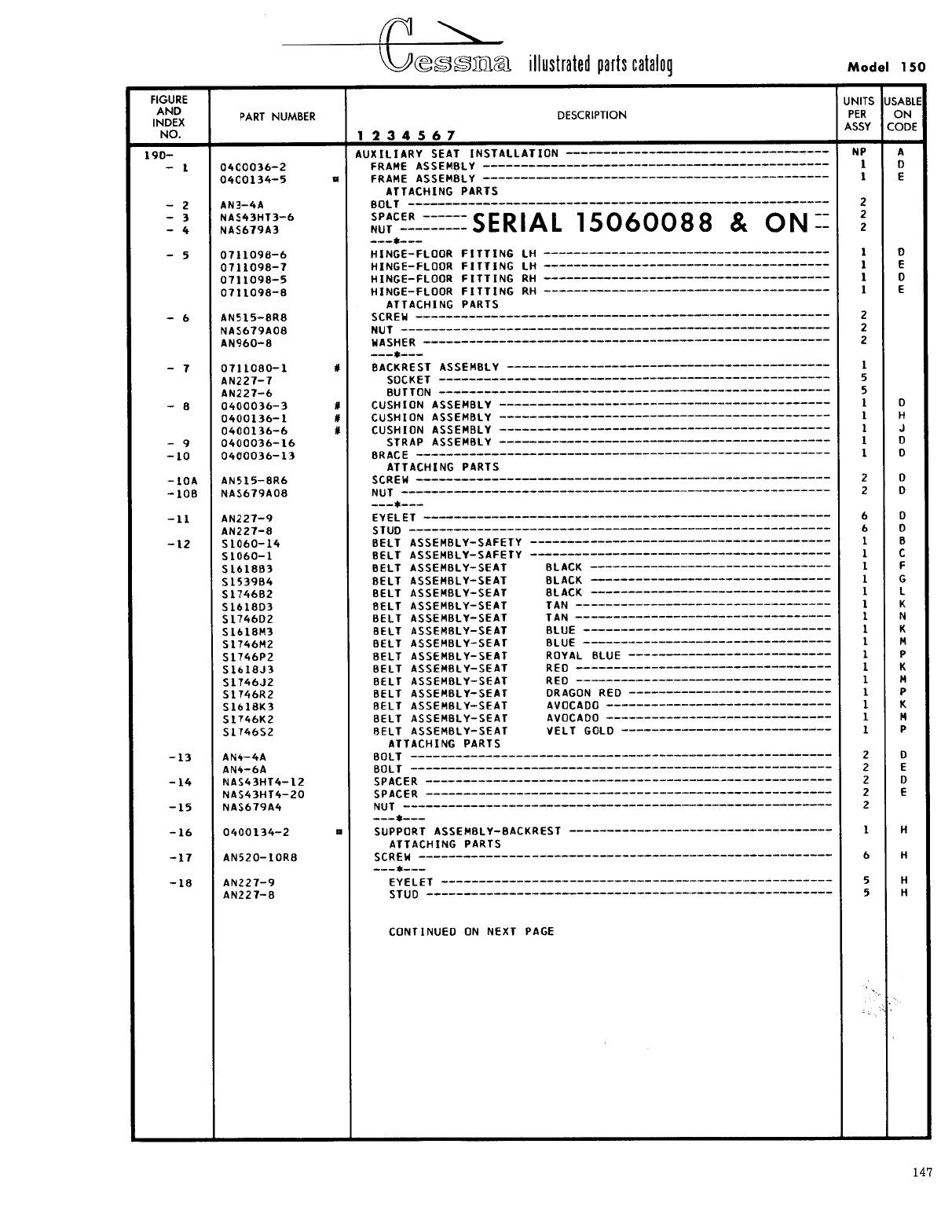
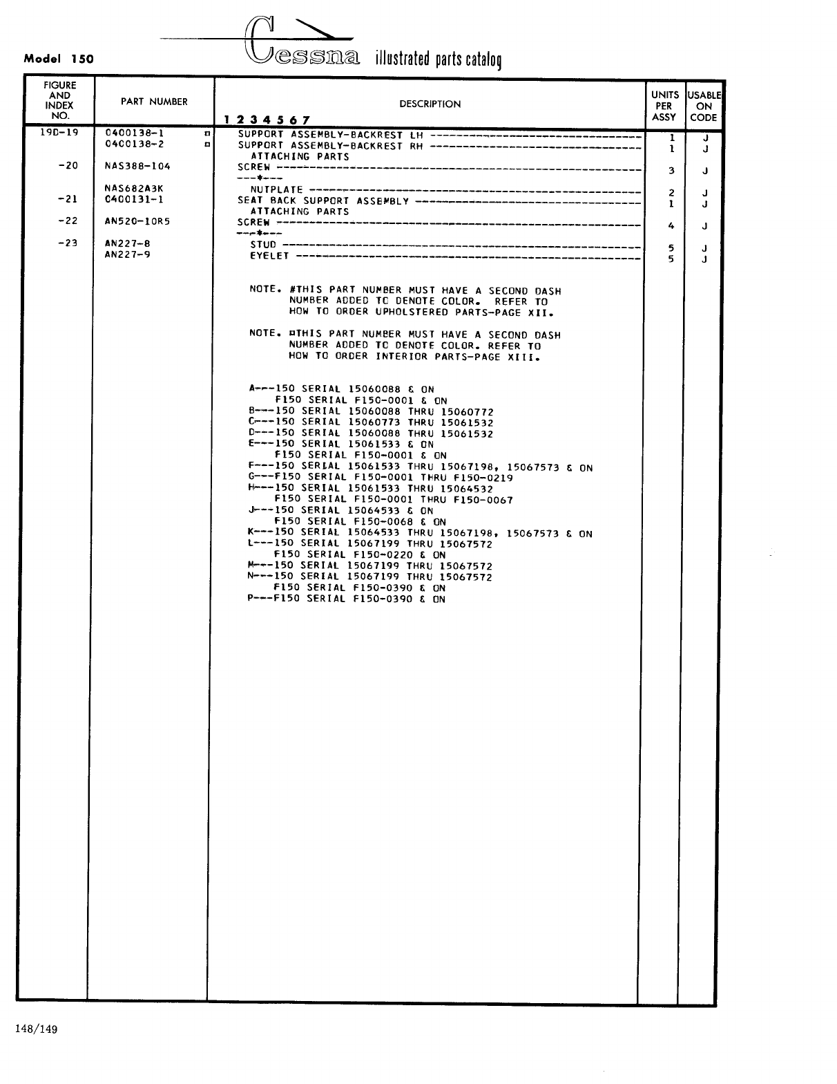
- Fig 19D. Auxiliary Seat Installation
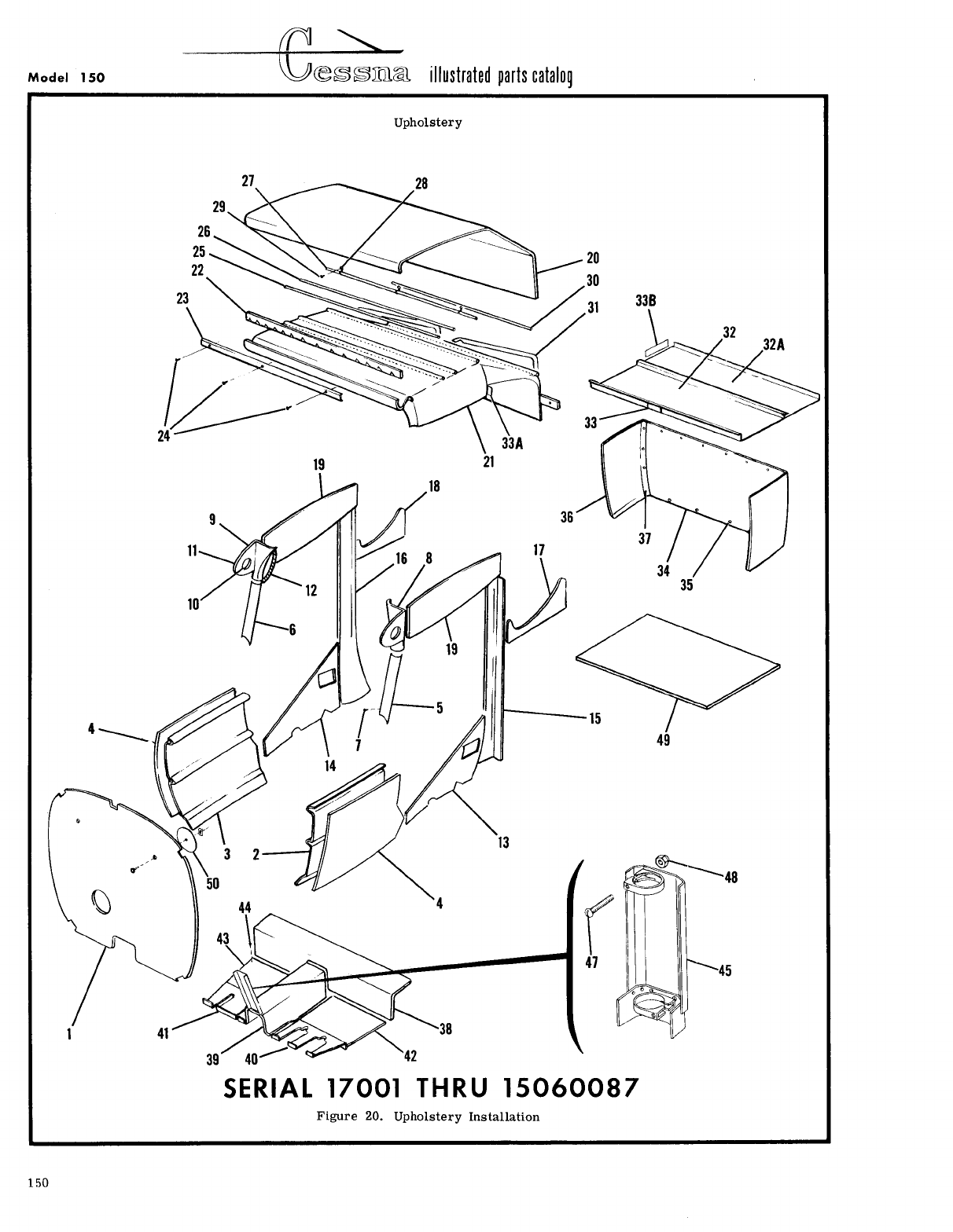
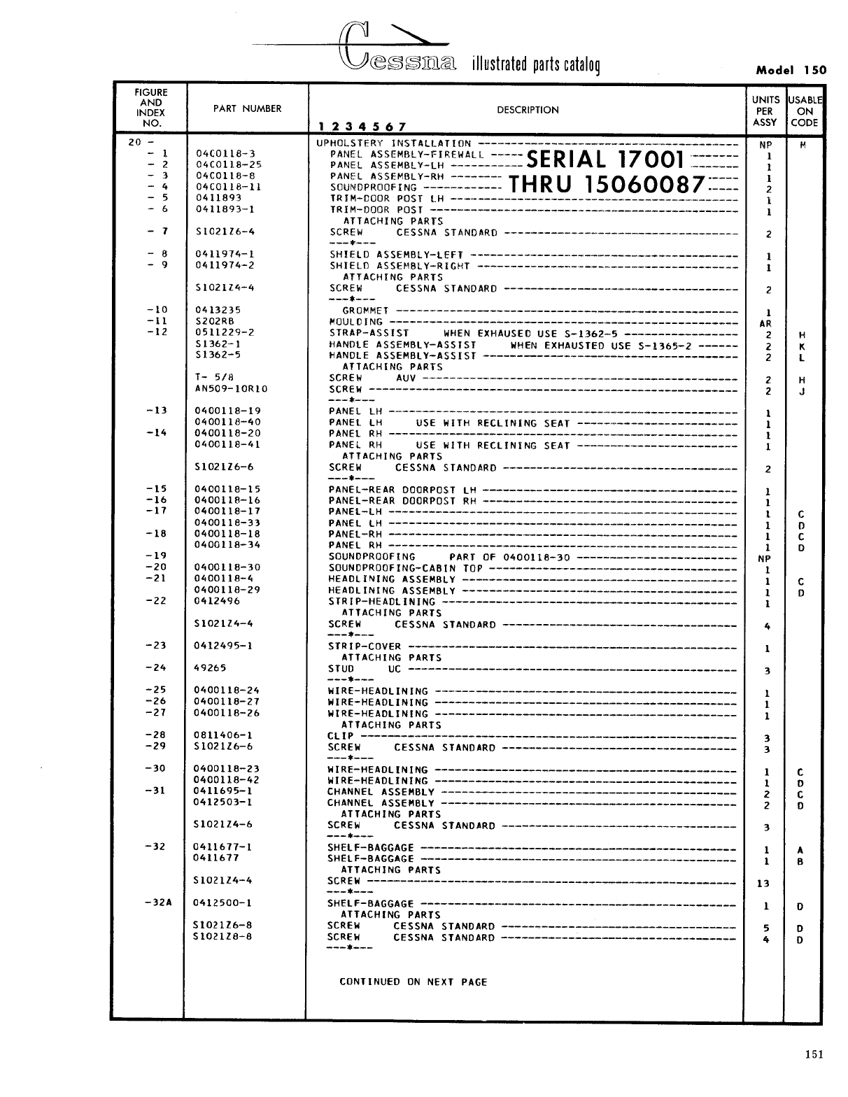
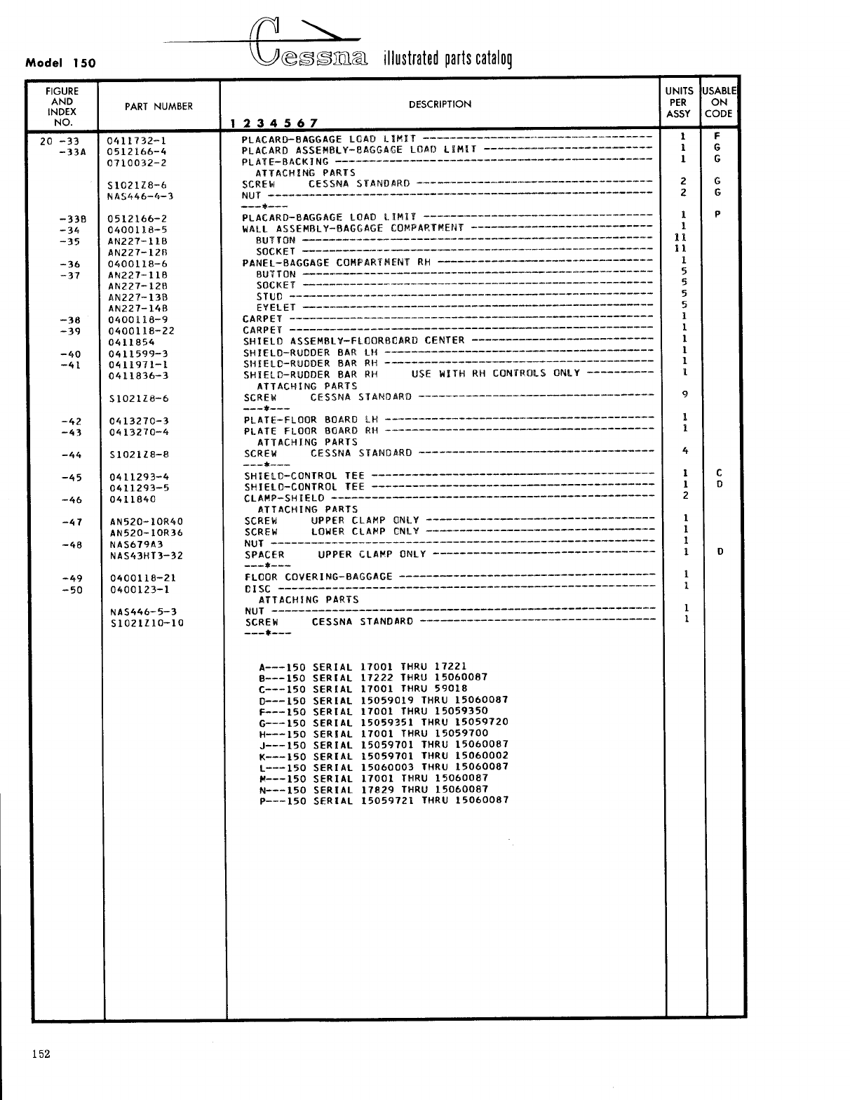
- Fig 20. Upholstery Installation
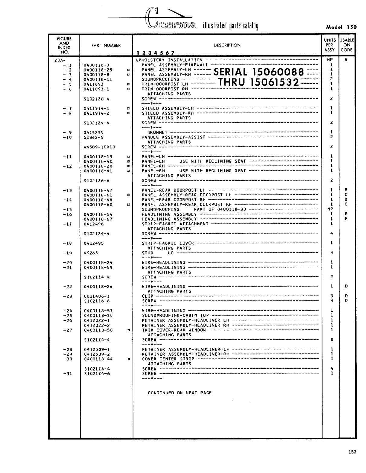
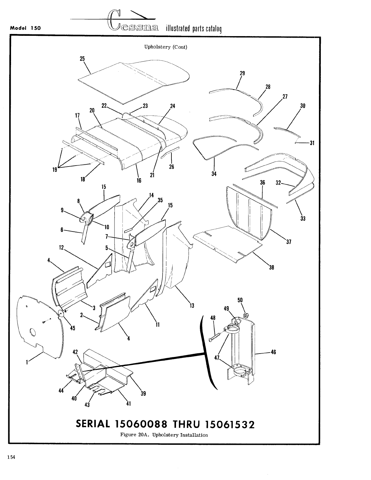
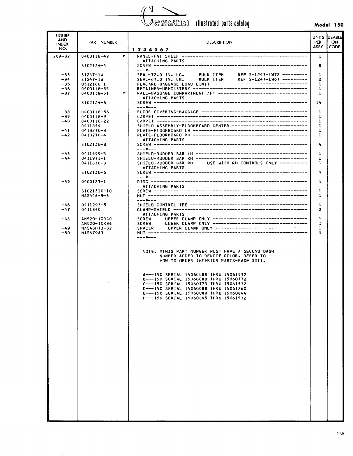
- Fig 20A. Upholstery Installation
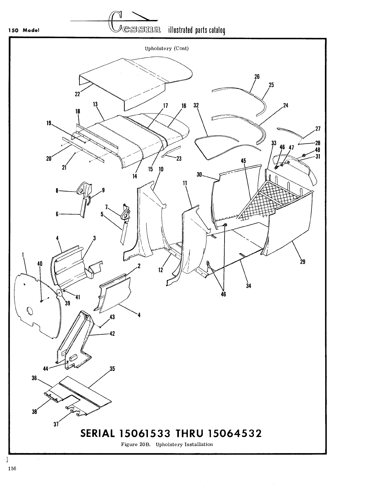
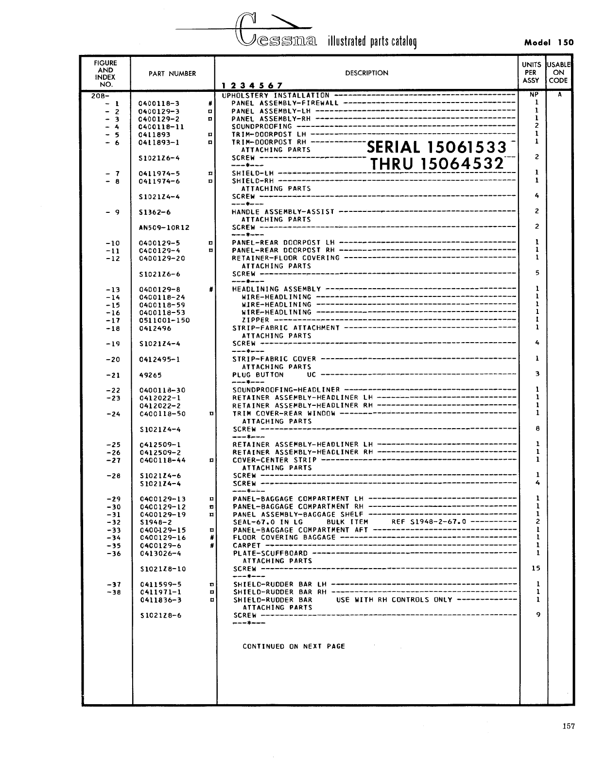
- Fig 20B. Upholstery Installation
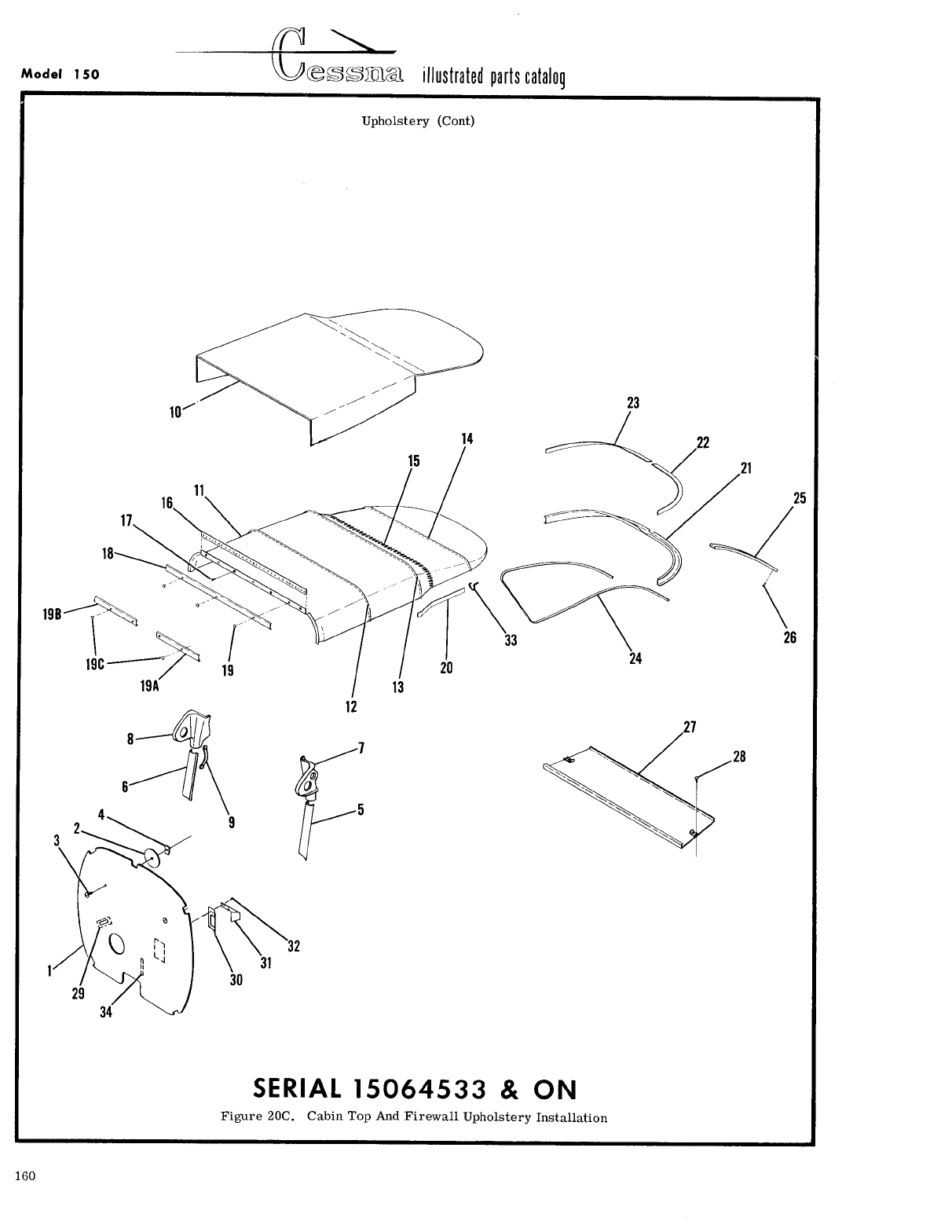
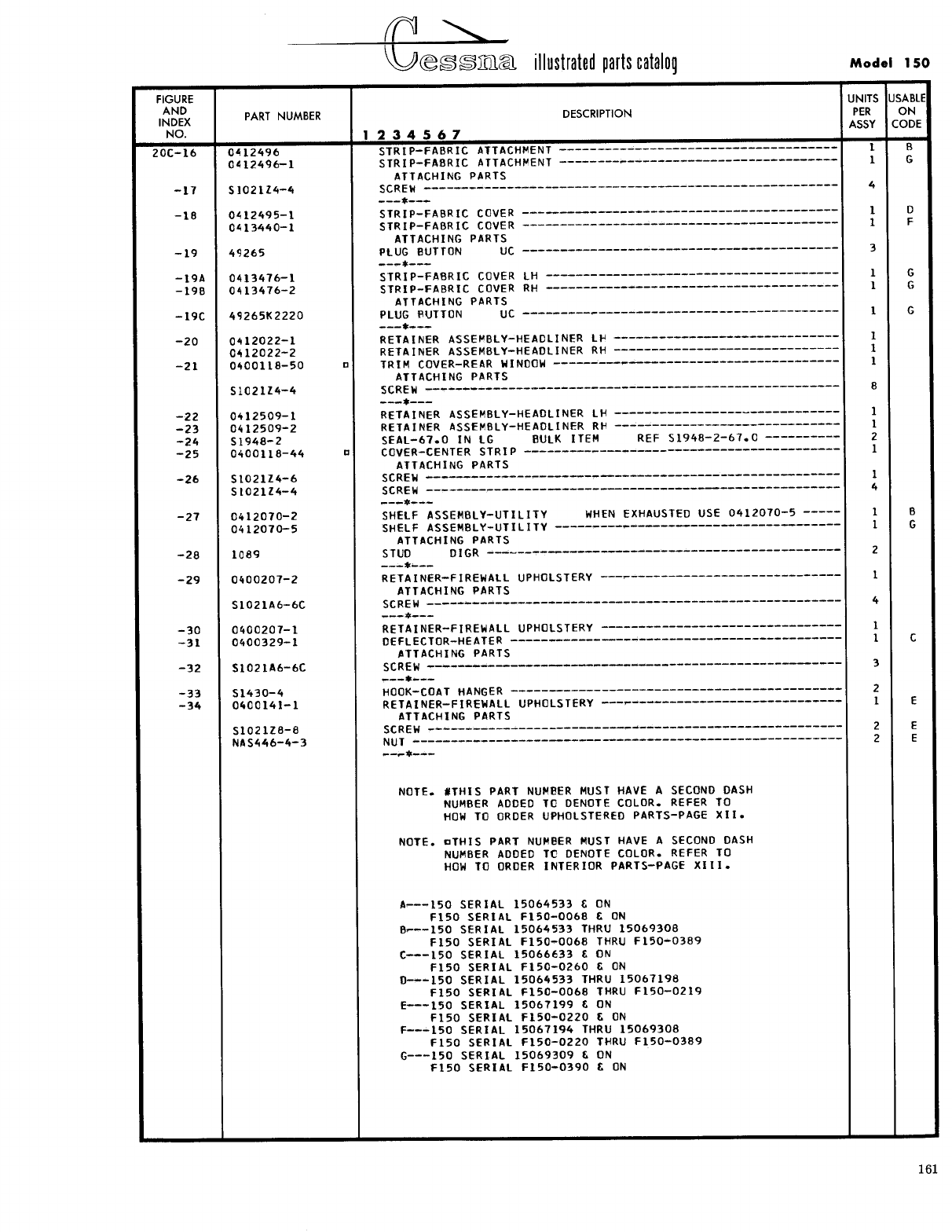
- Fig 20C. Cabin Top and Firewall Upholstery Installation
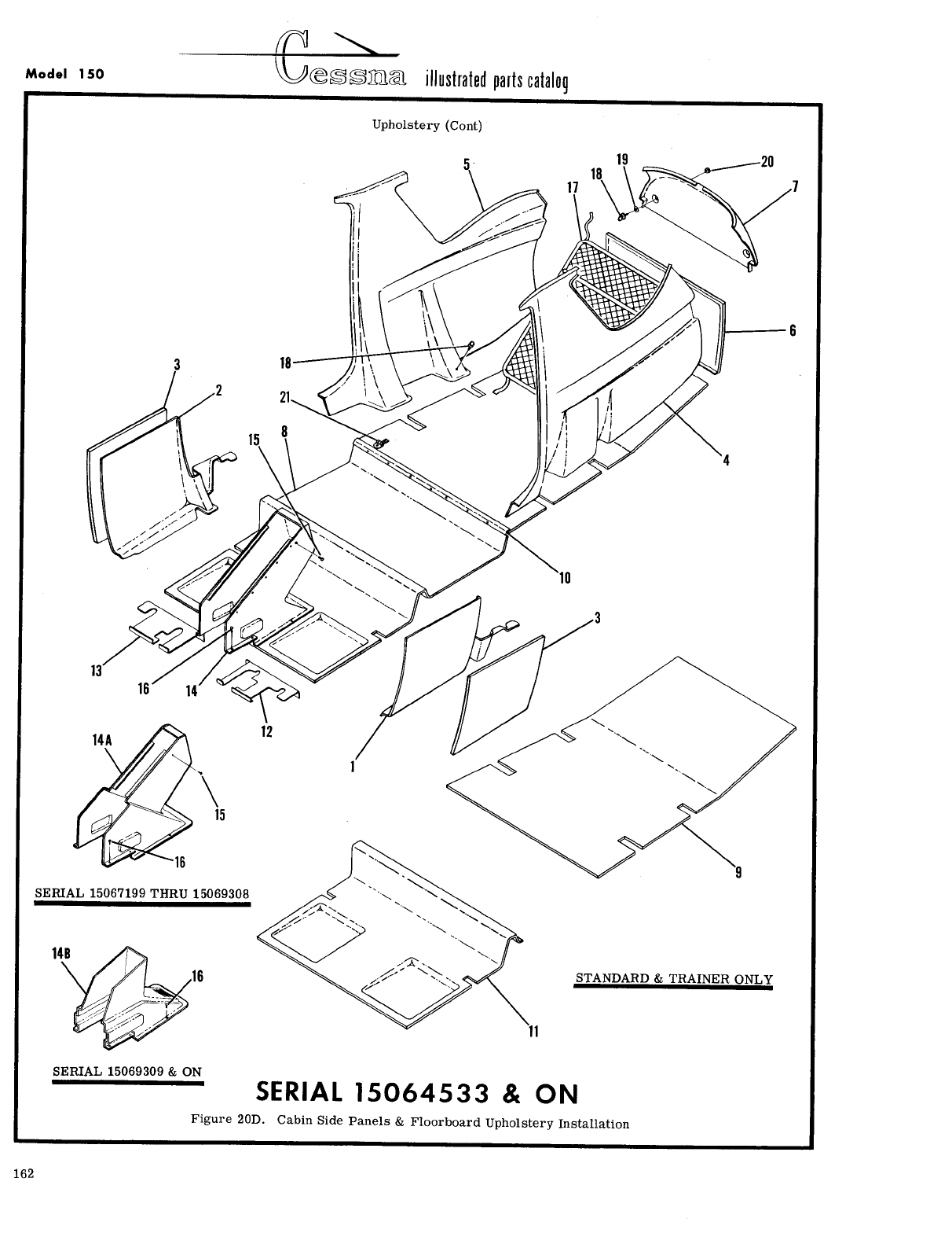
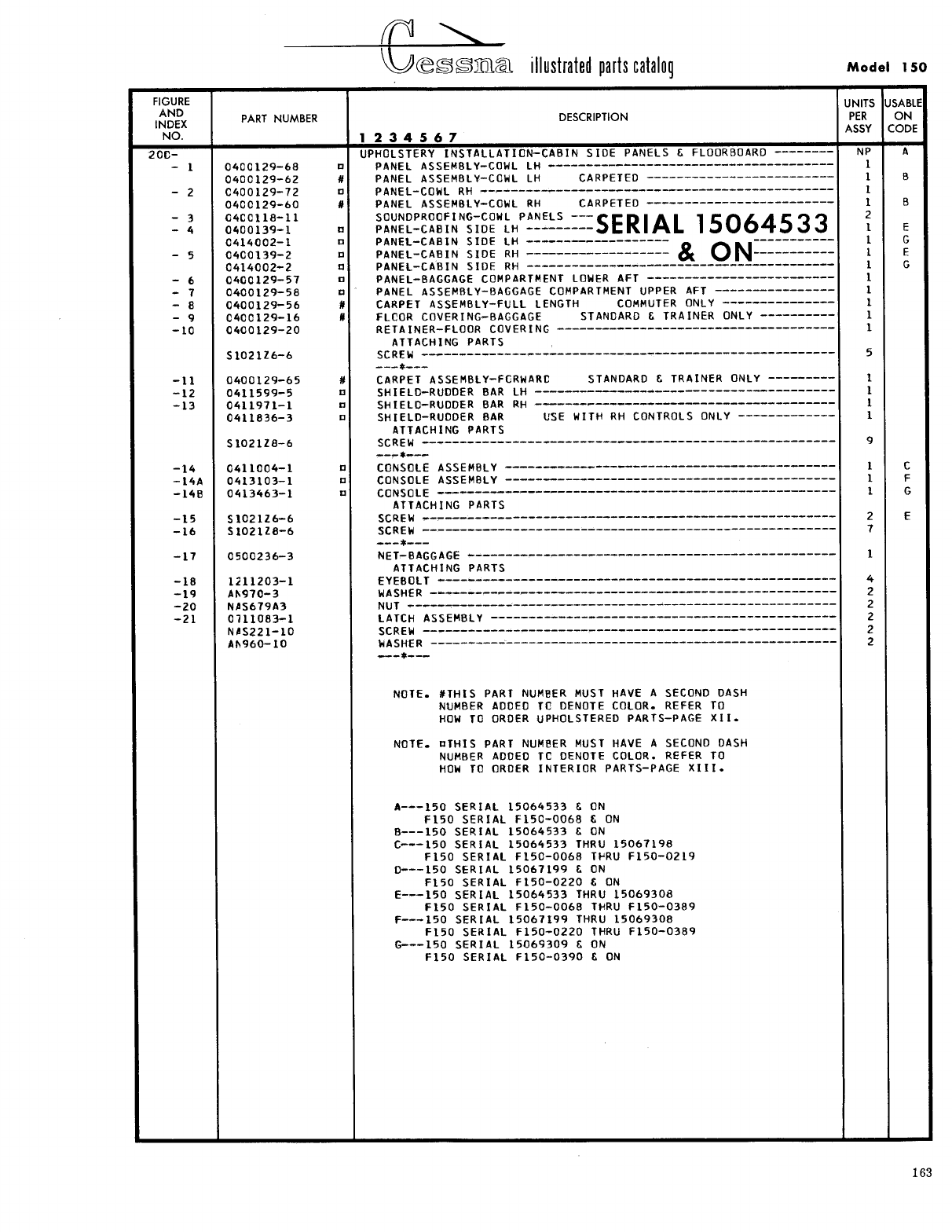
- Fig 20D. Cabin Side Panels & Floorboard Upholstery Installation
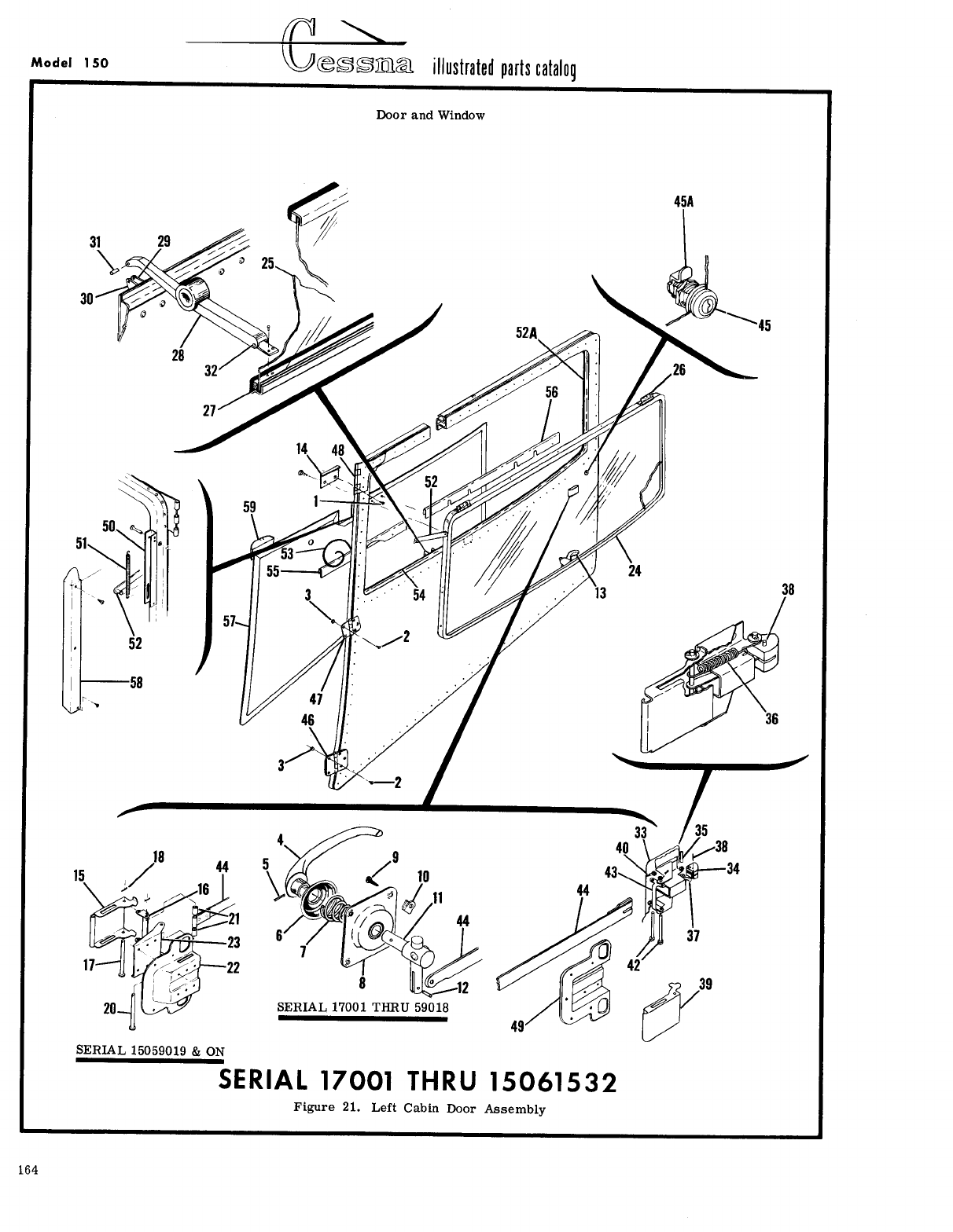
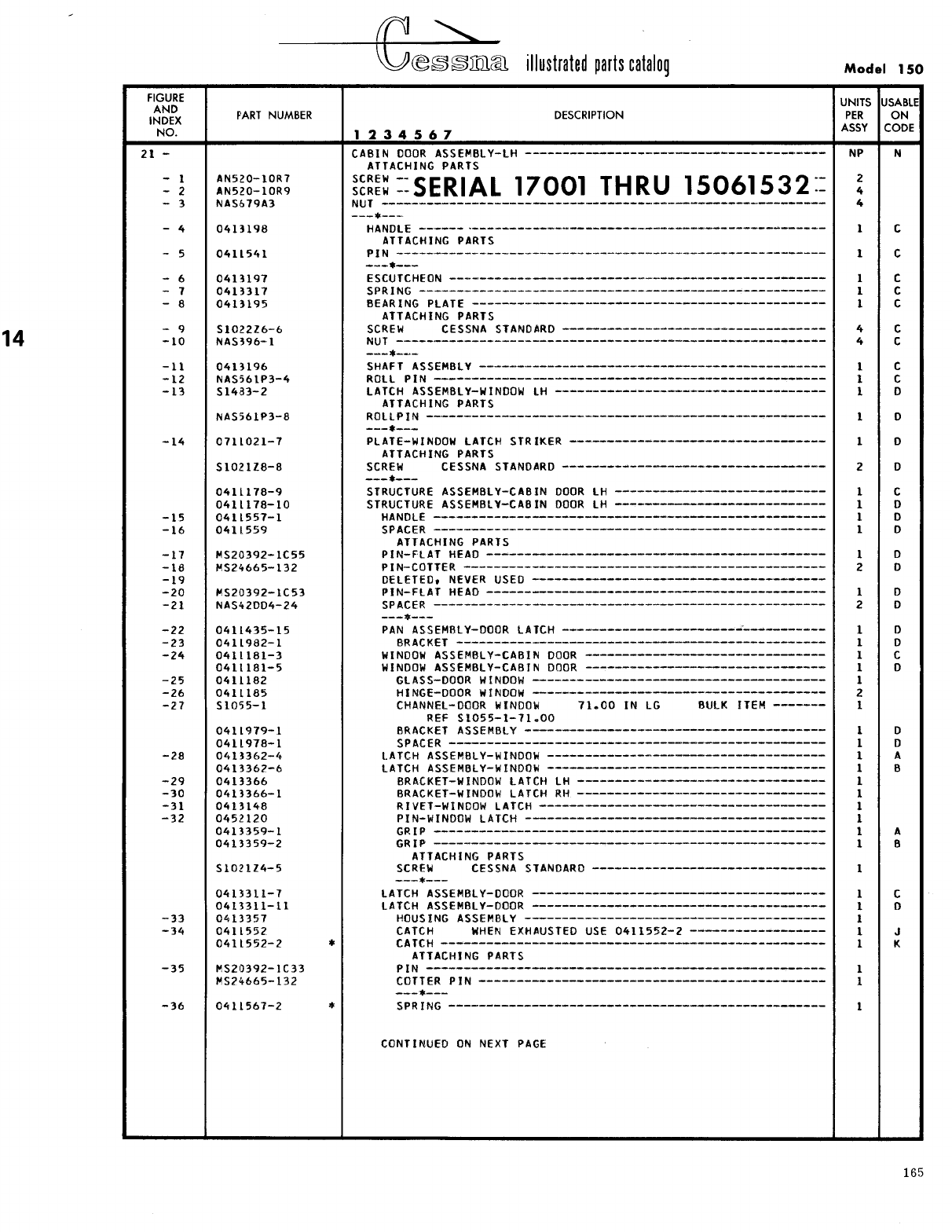
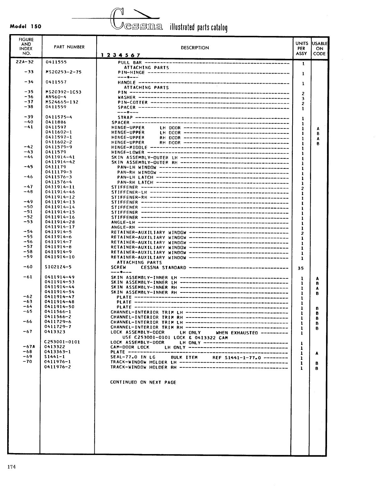
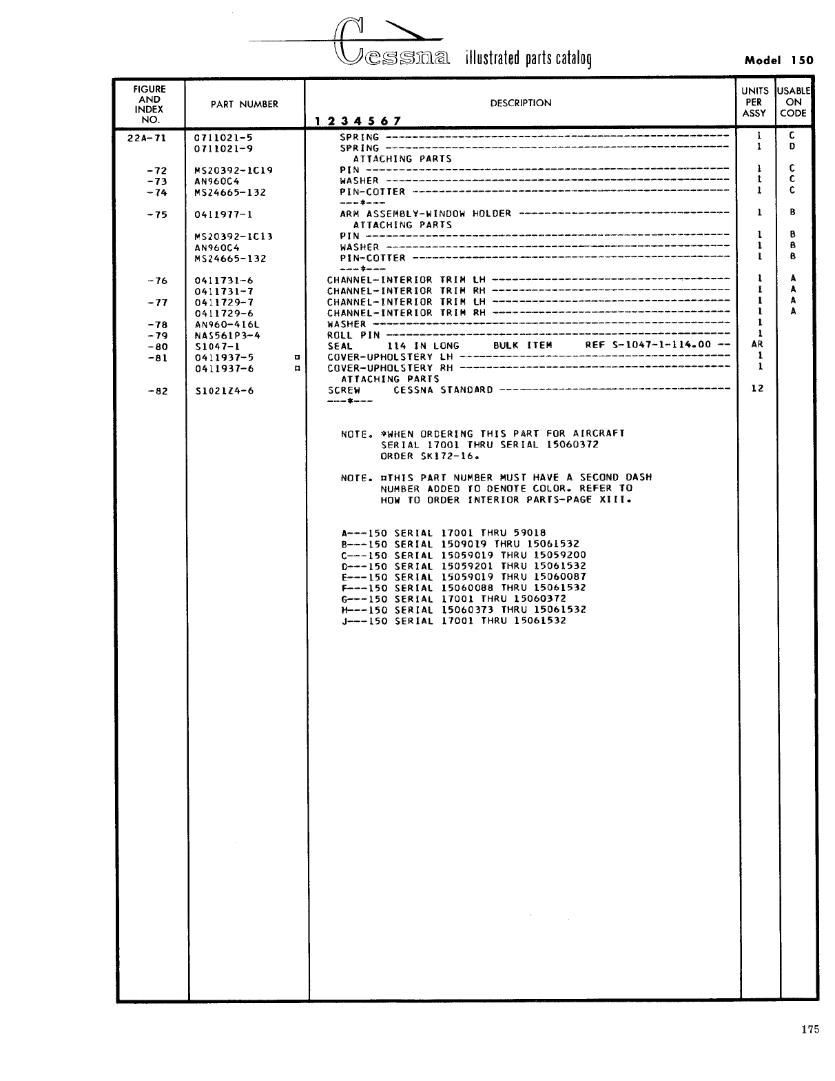
- Fig 21. Left Cabin Door Assembly
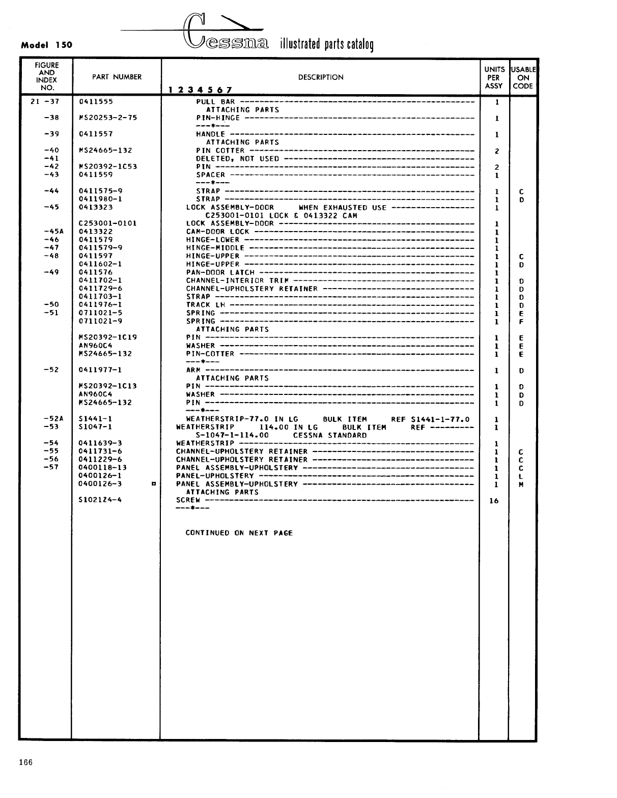
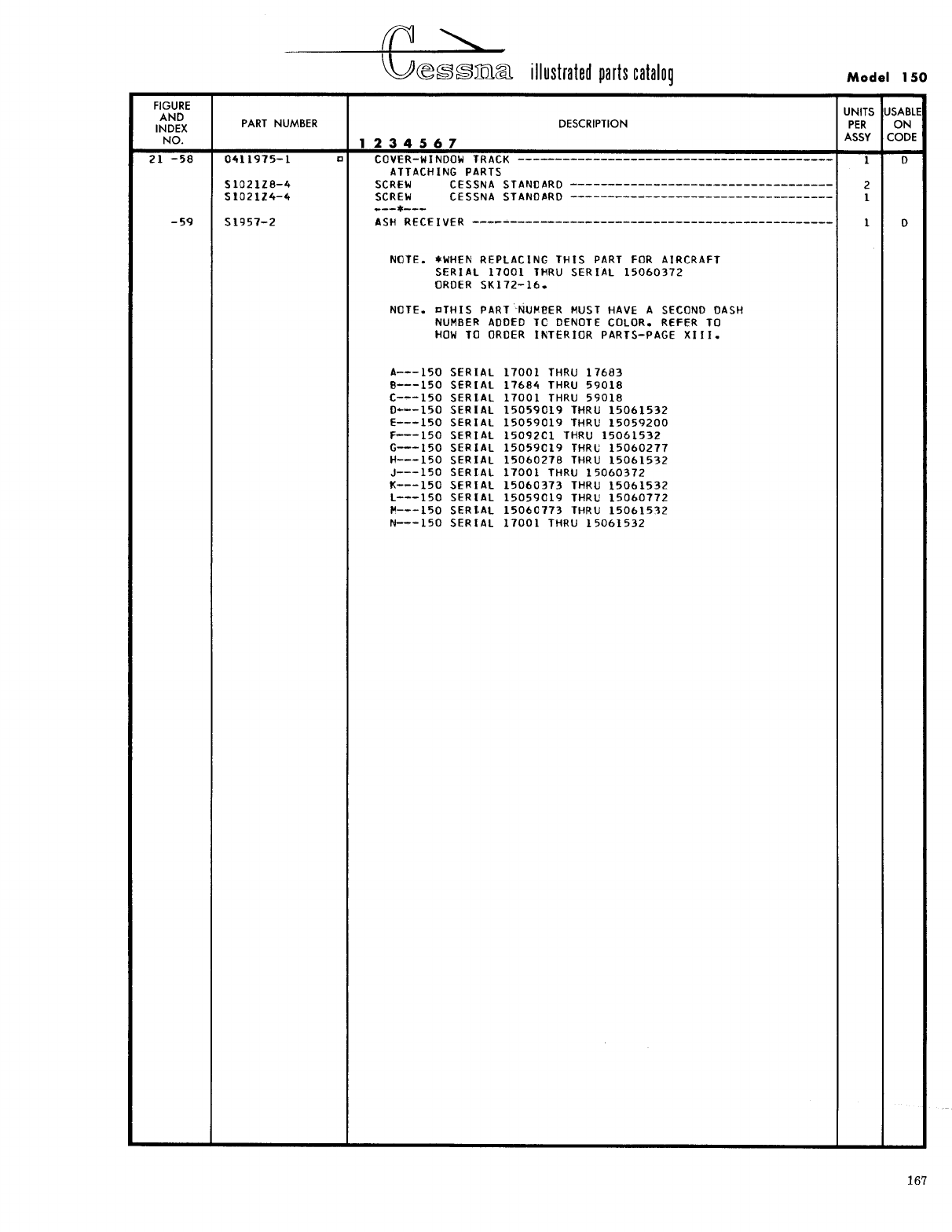
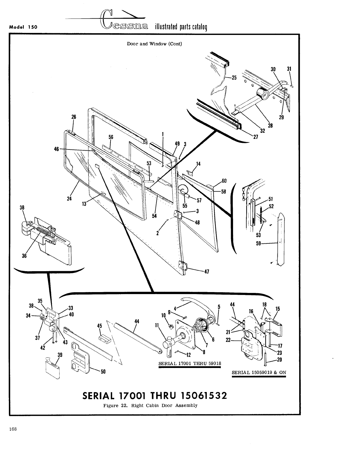
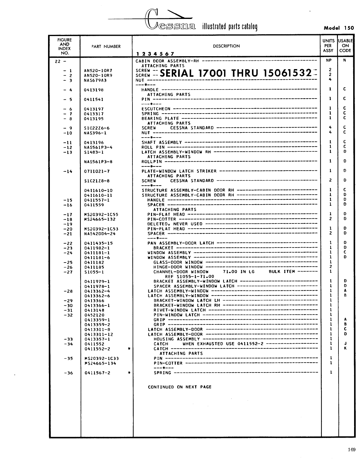
- Fig 22. Right Cabin Door Assembly
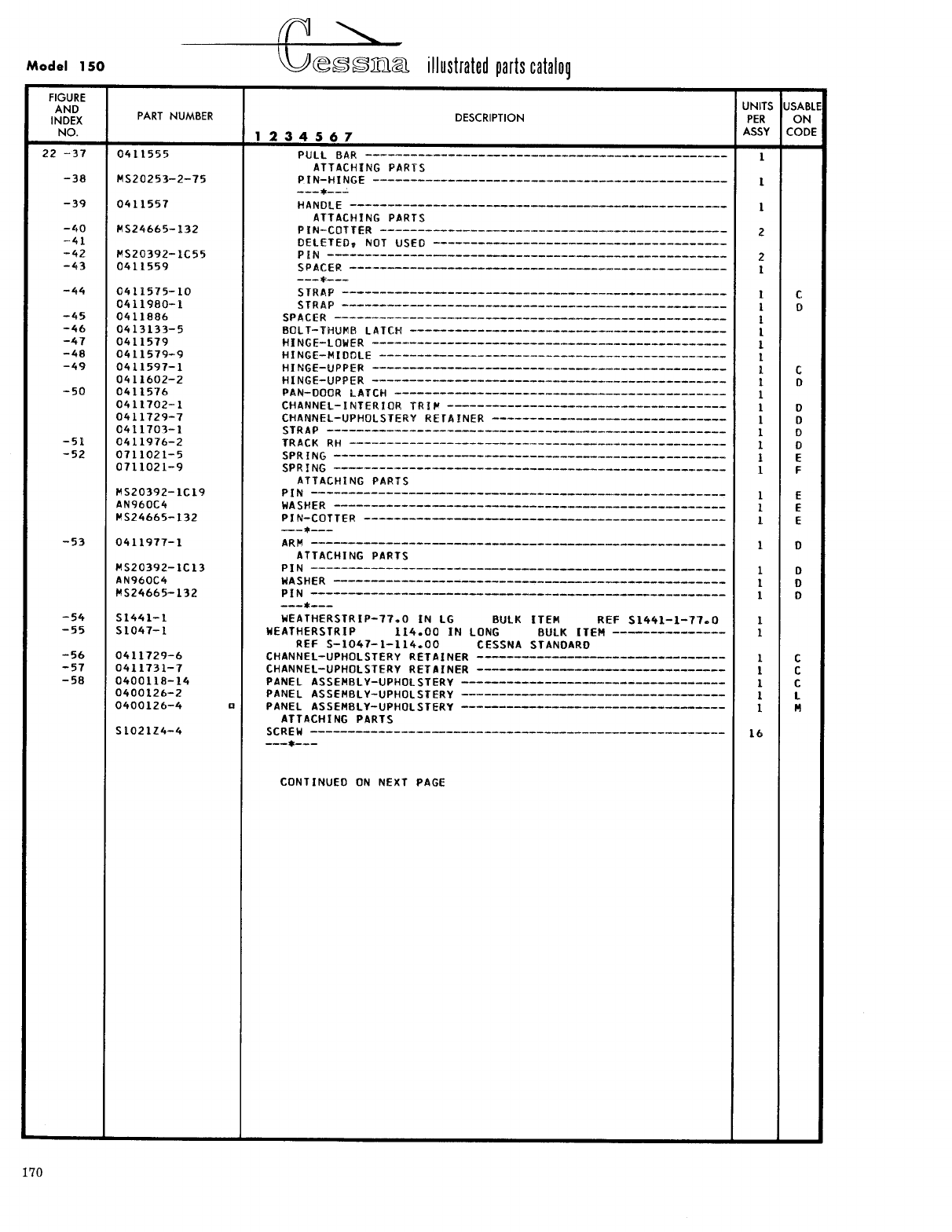
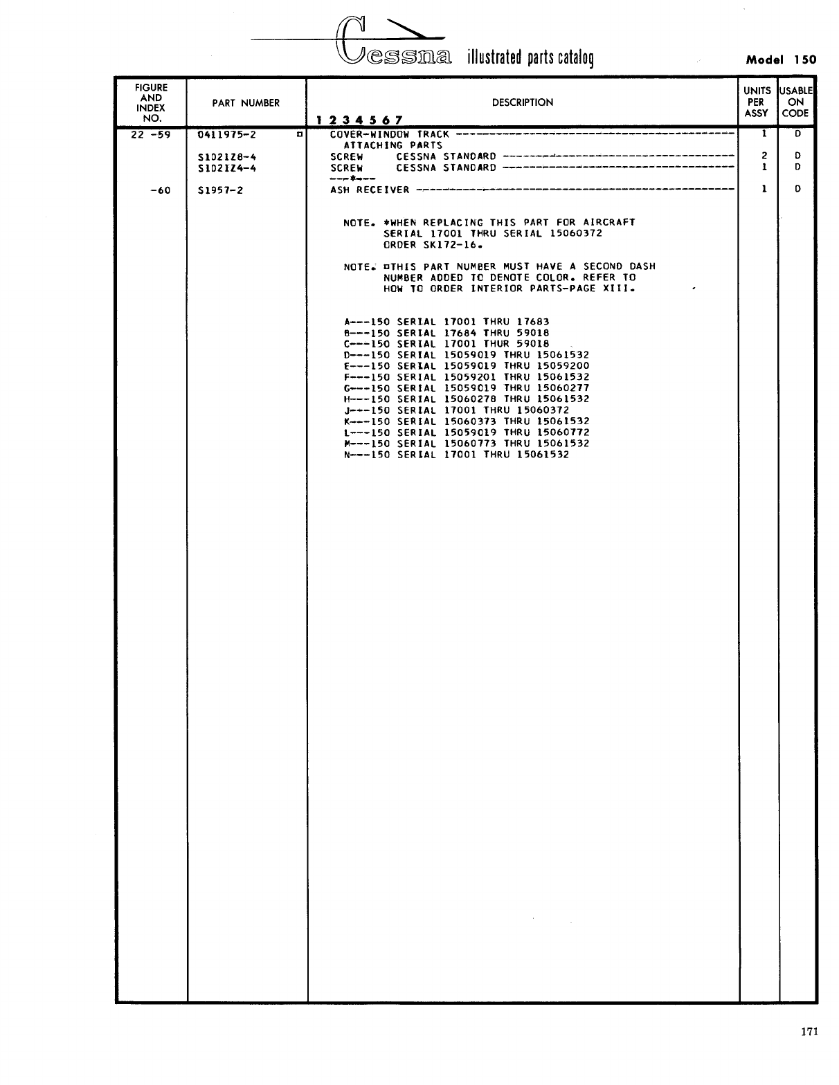
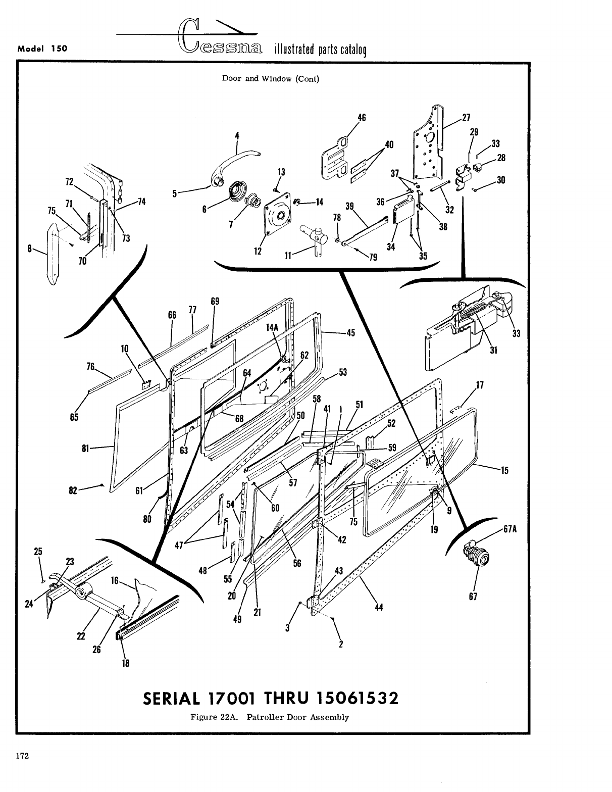
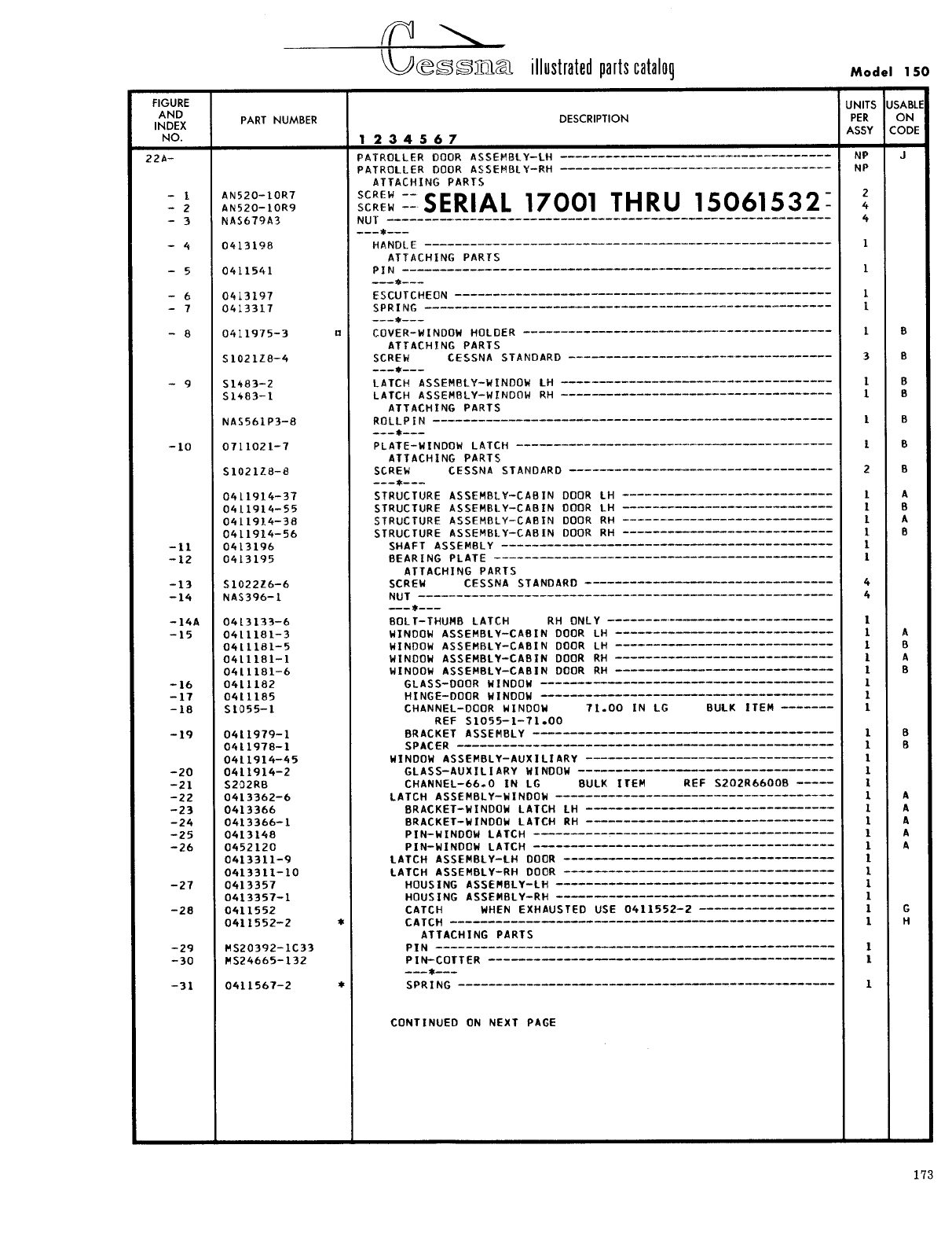
- Fig 22A. Patroller Door Assembly
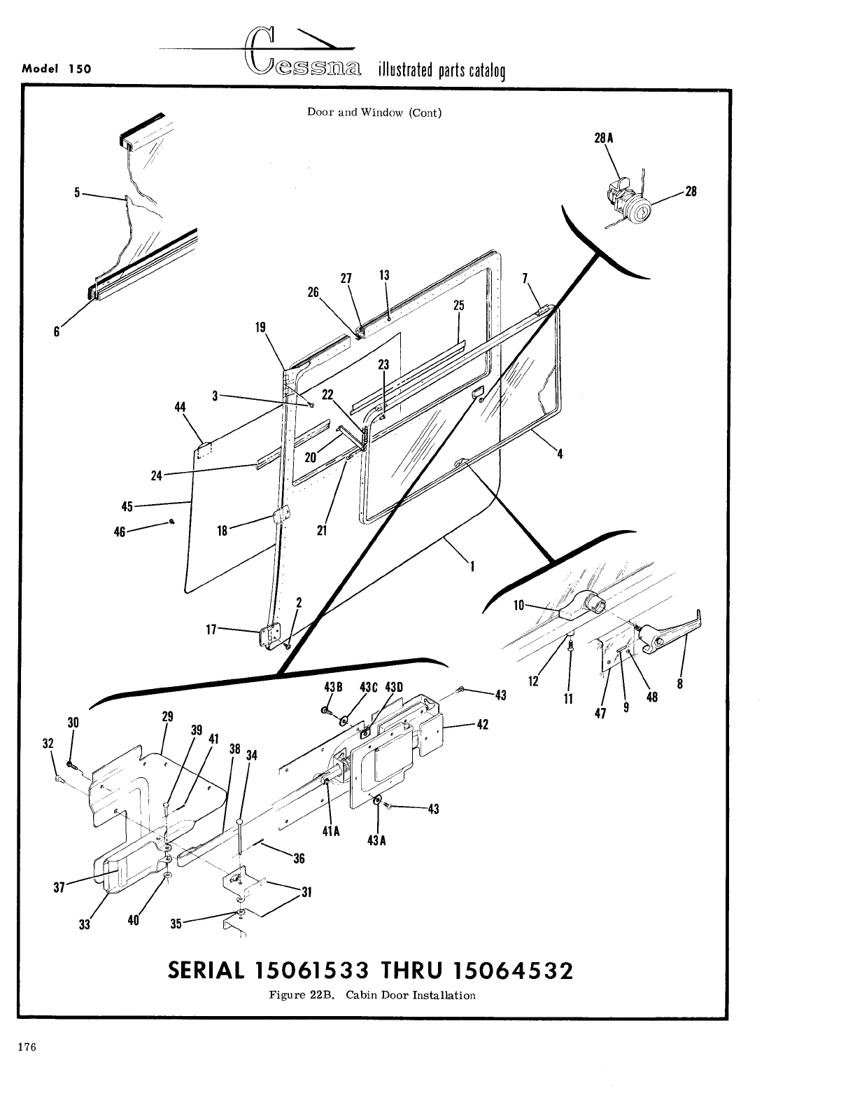
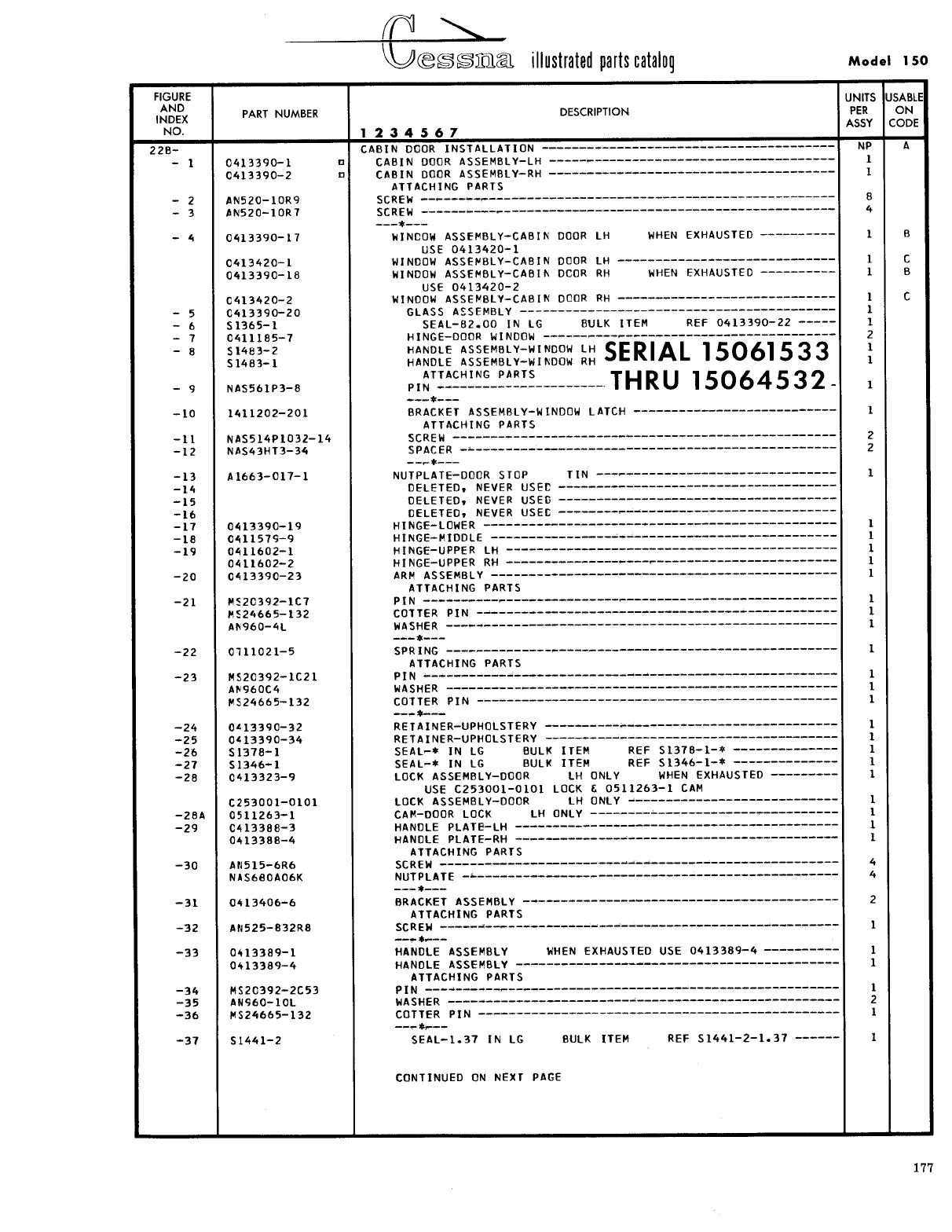
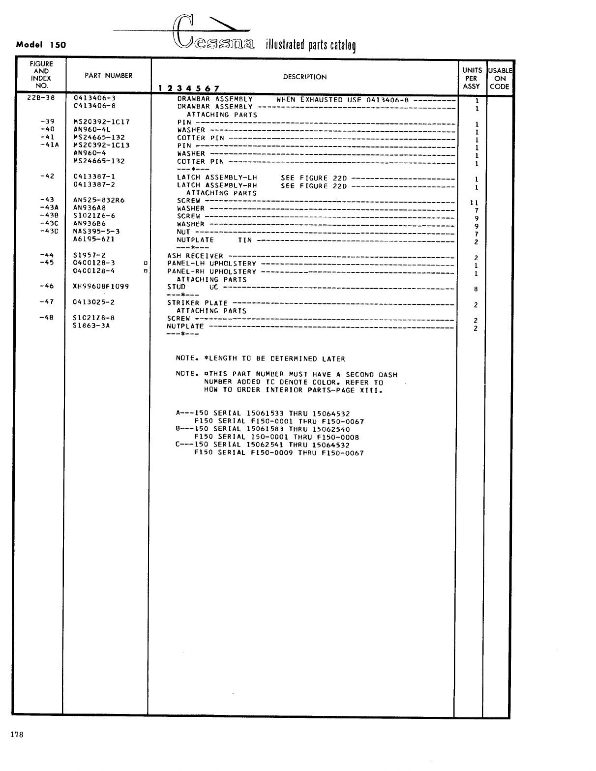
- Fig 22B. Cabin Door Installation
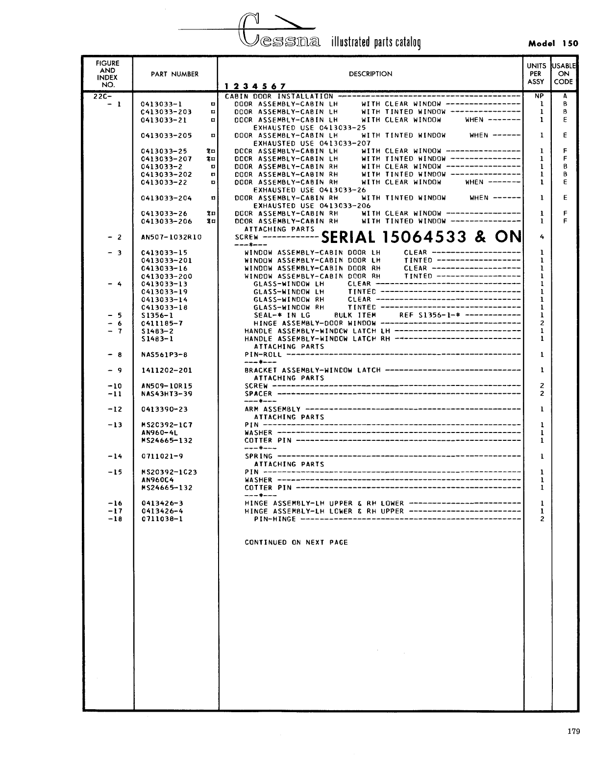
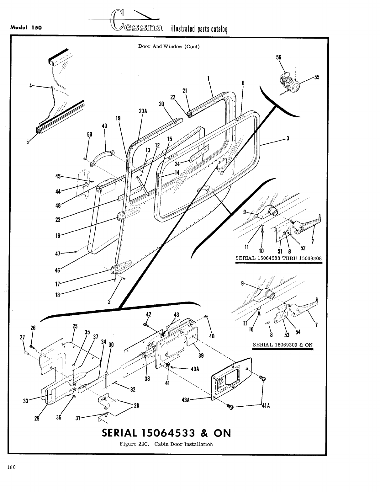
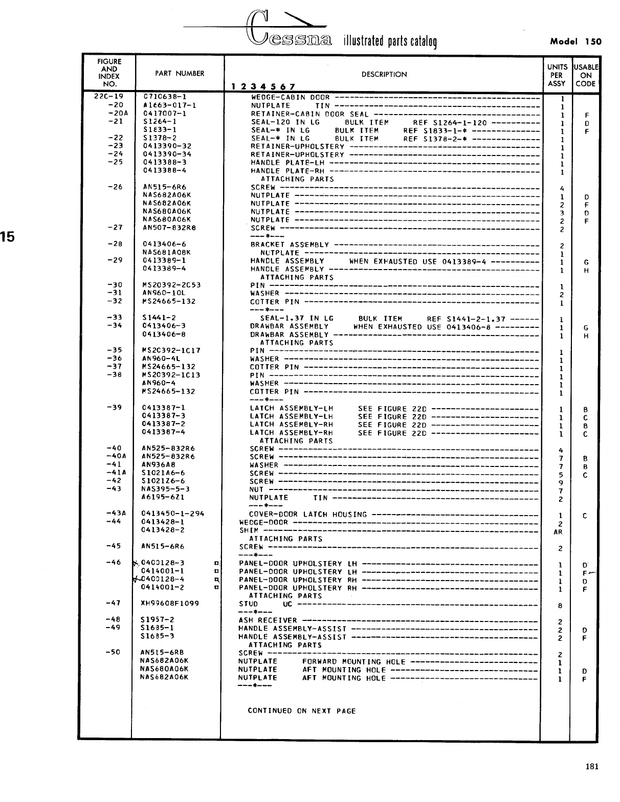
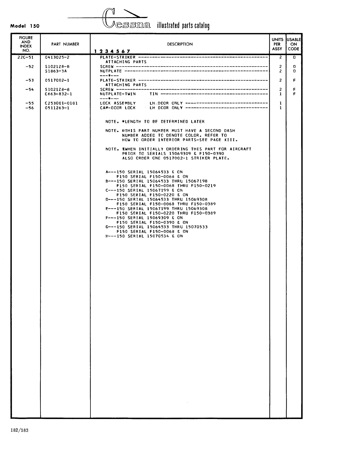
- Fig 22C. Cabin Door Installation
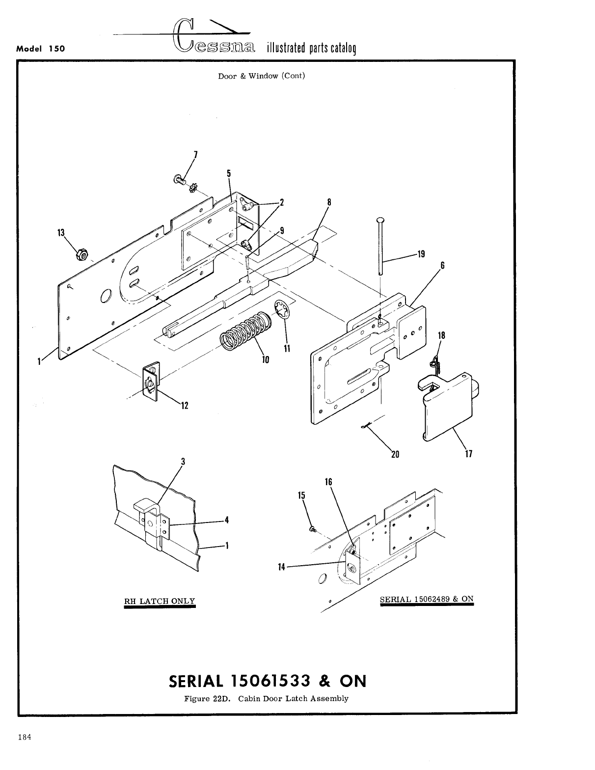
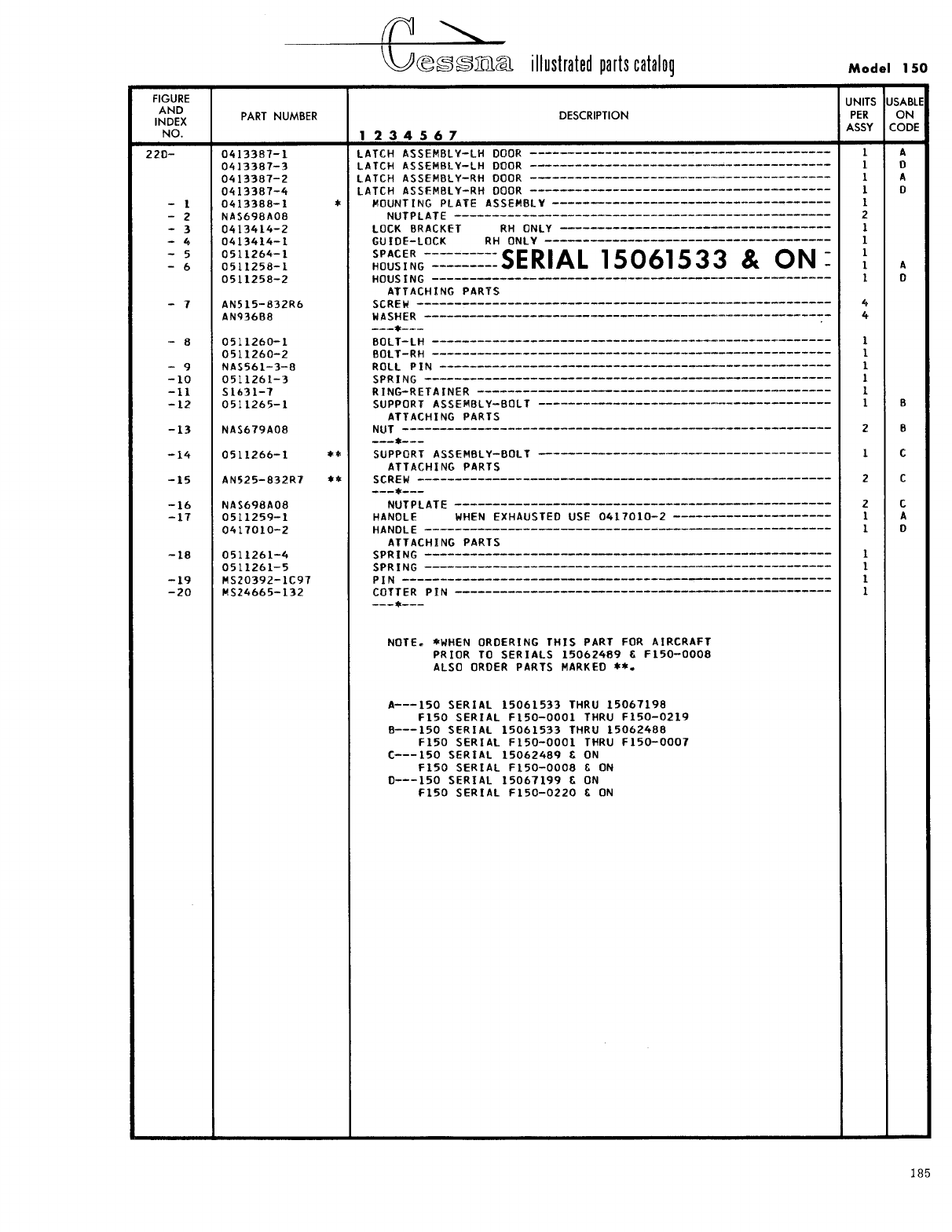
- Fig 22D. Cabin Door Latch Assembly
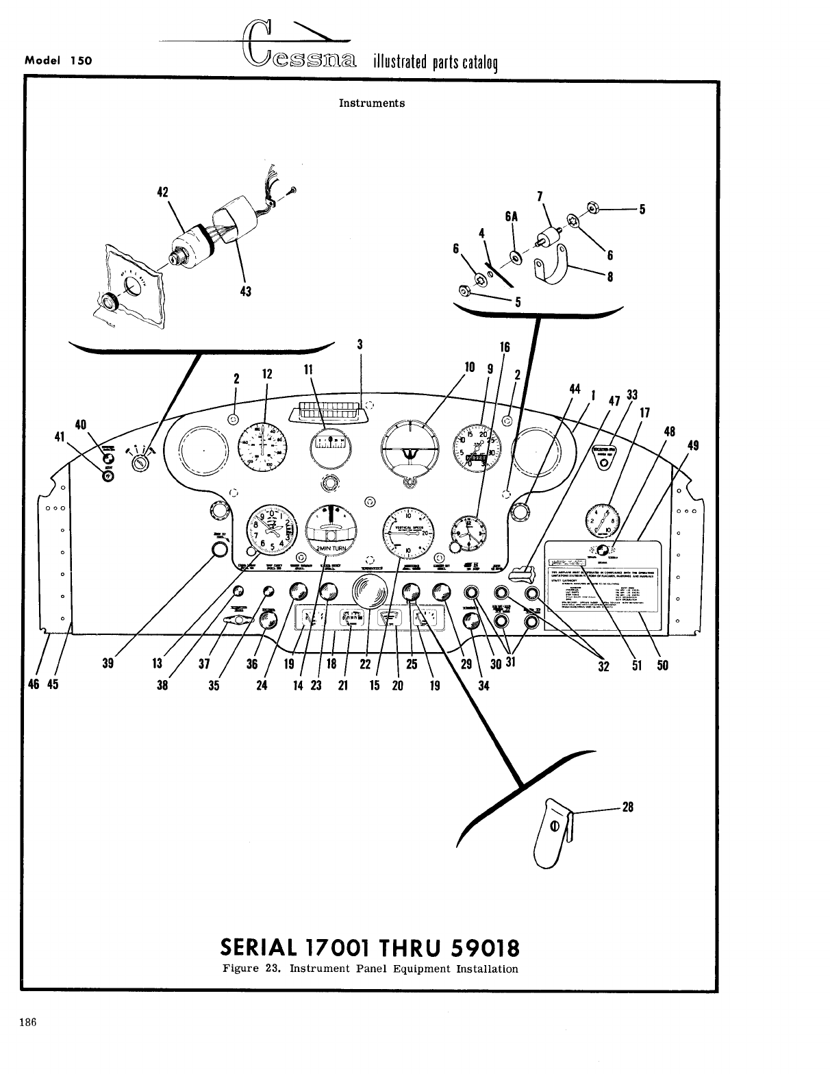
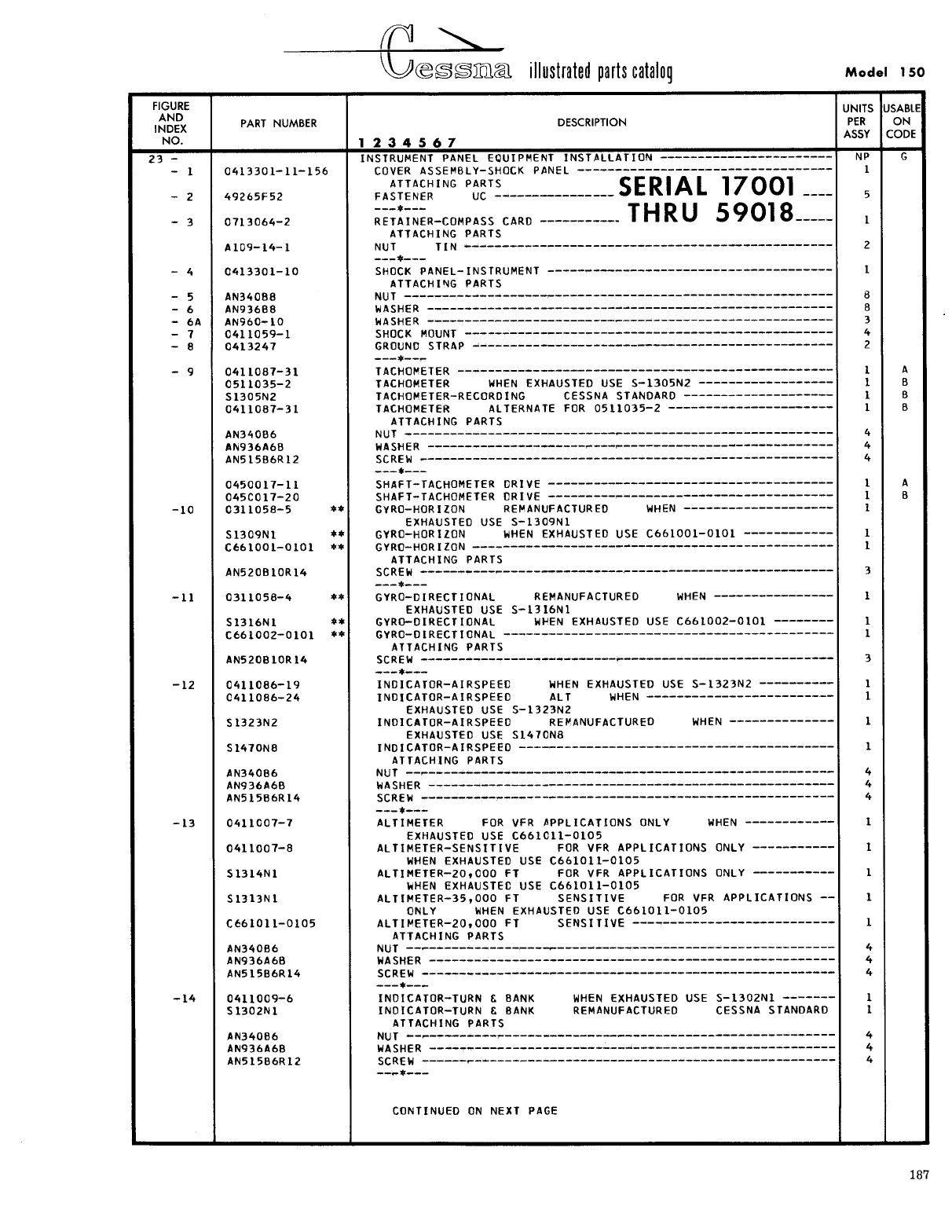
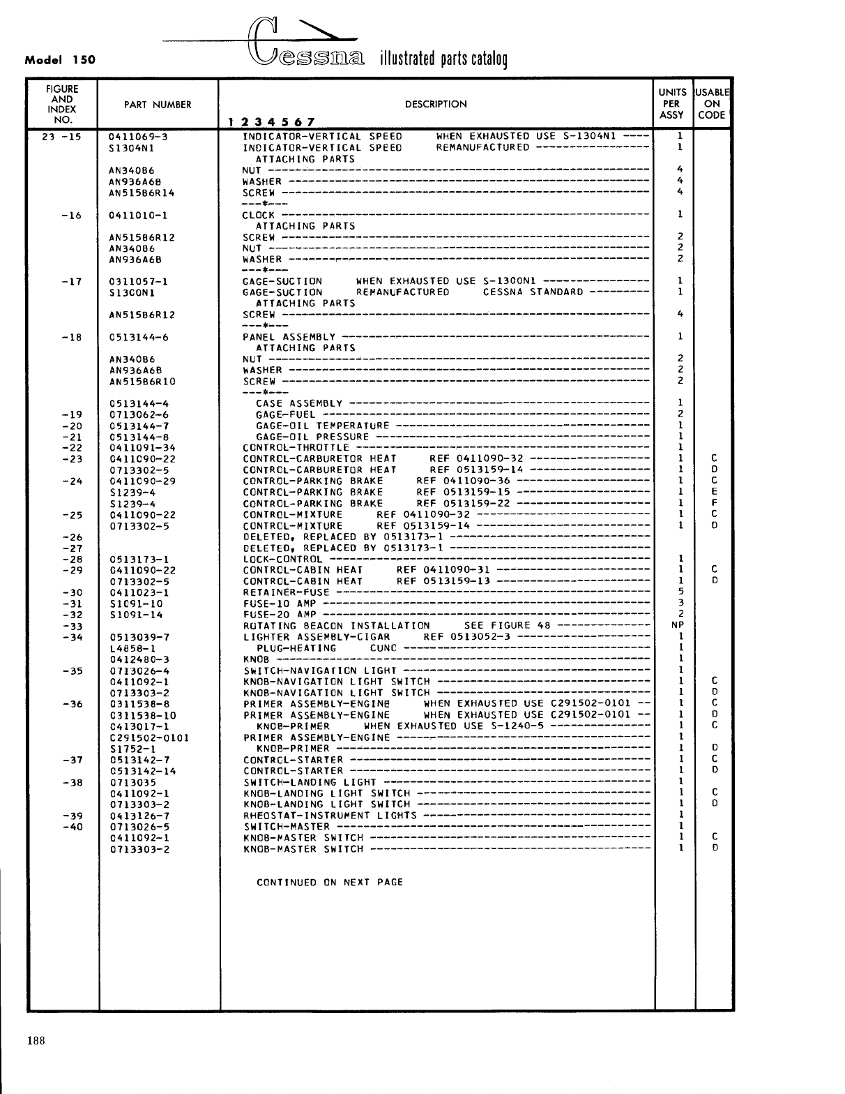
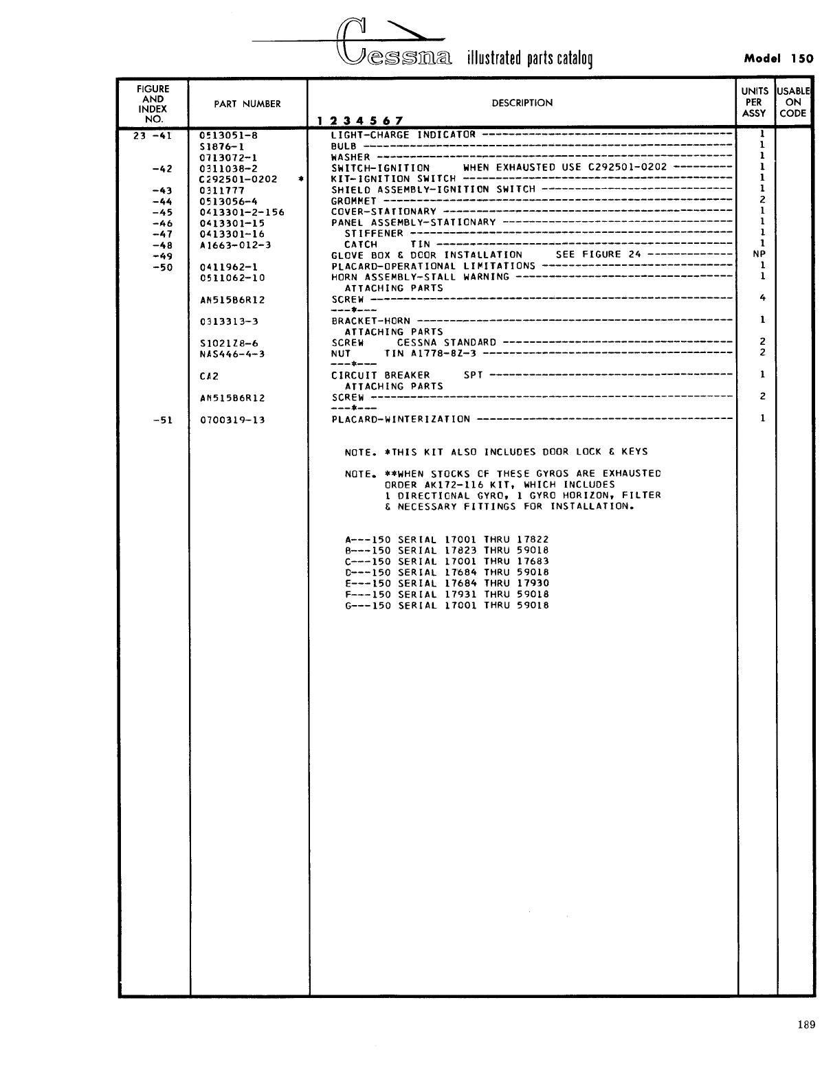
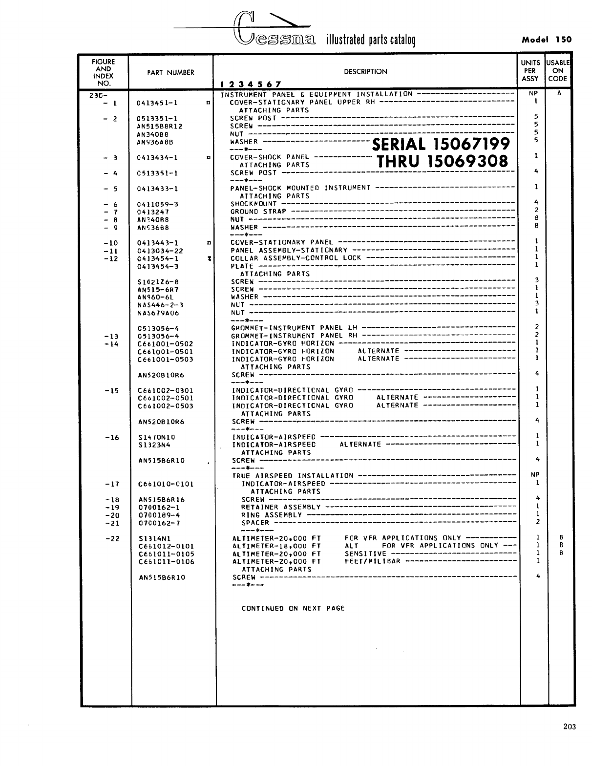
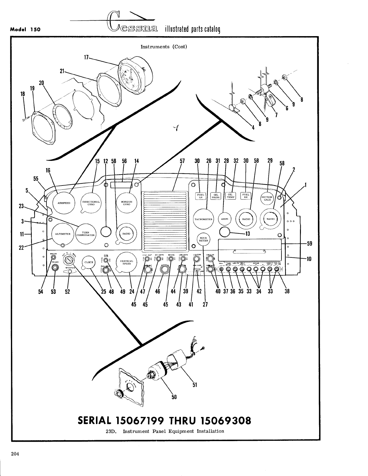
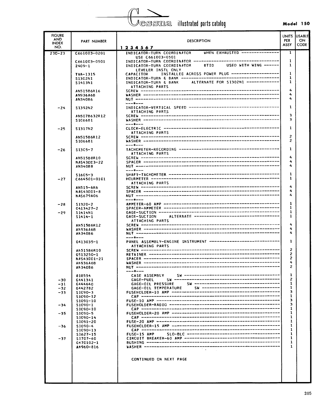
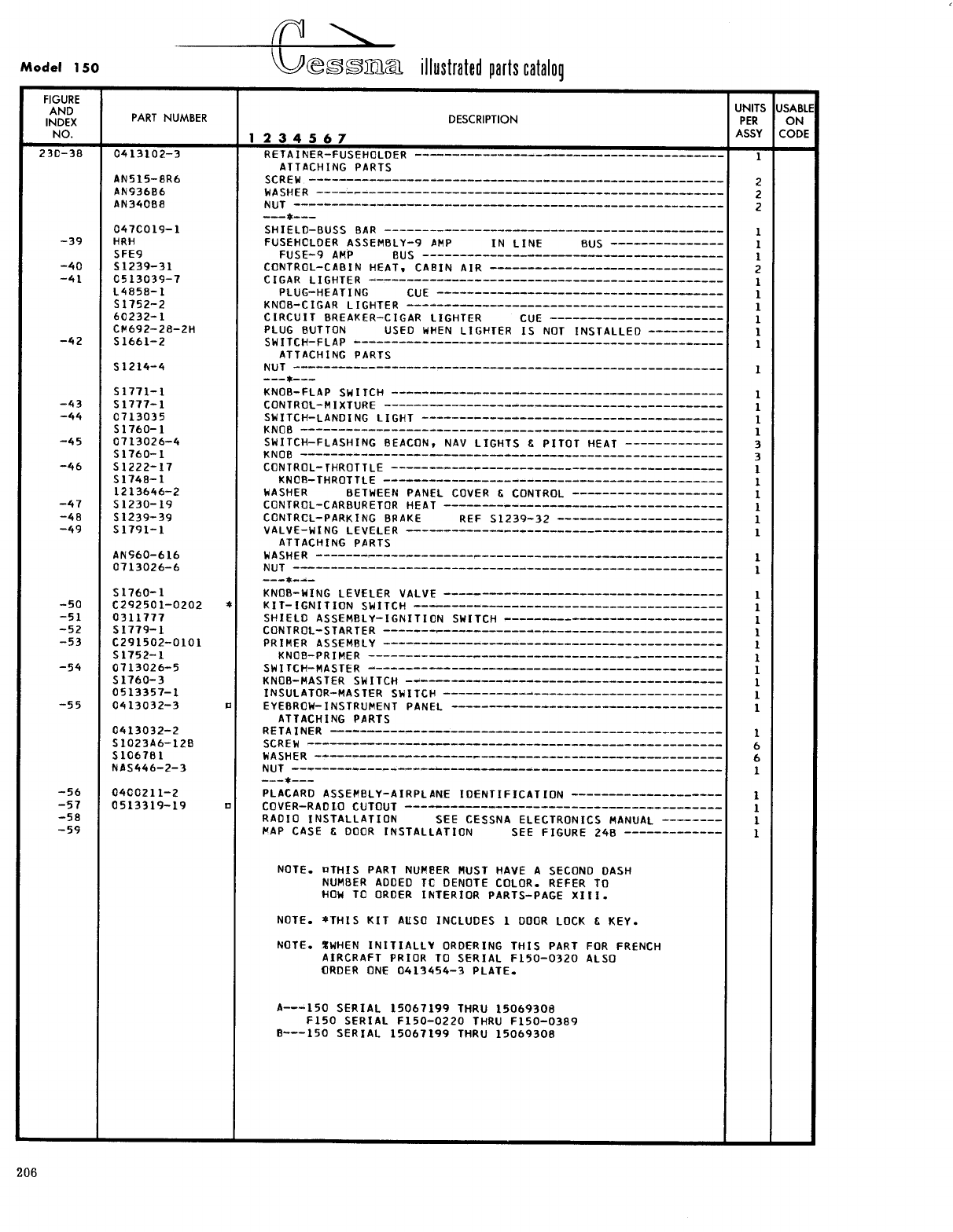
- Fig 23. Instrument Panel Equipment Installation
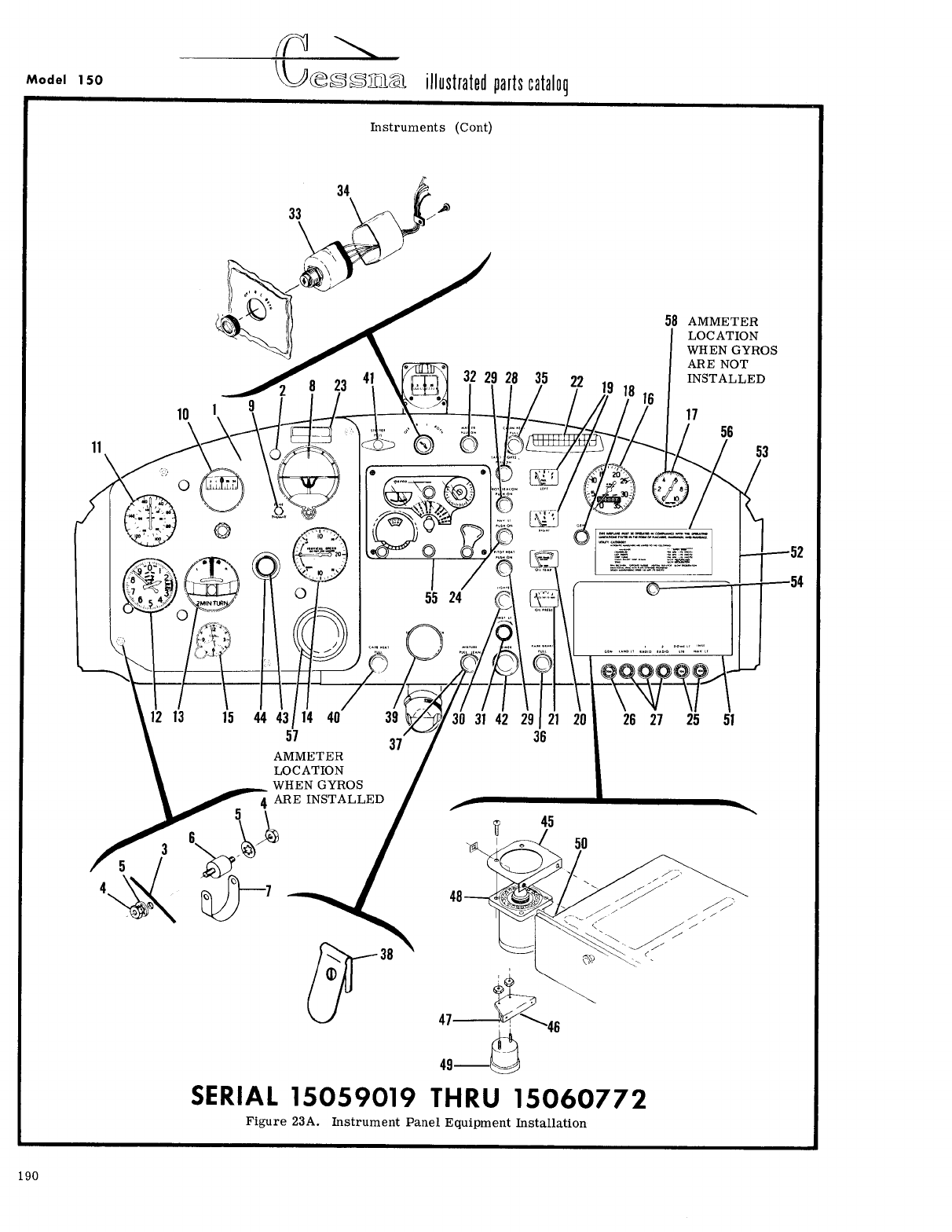
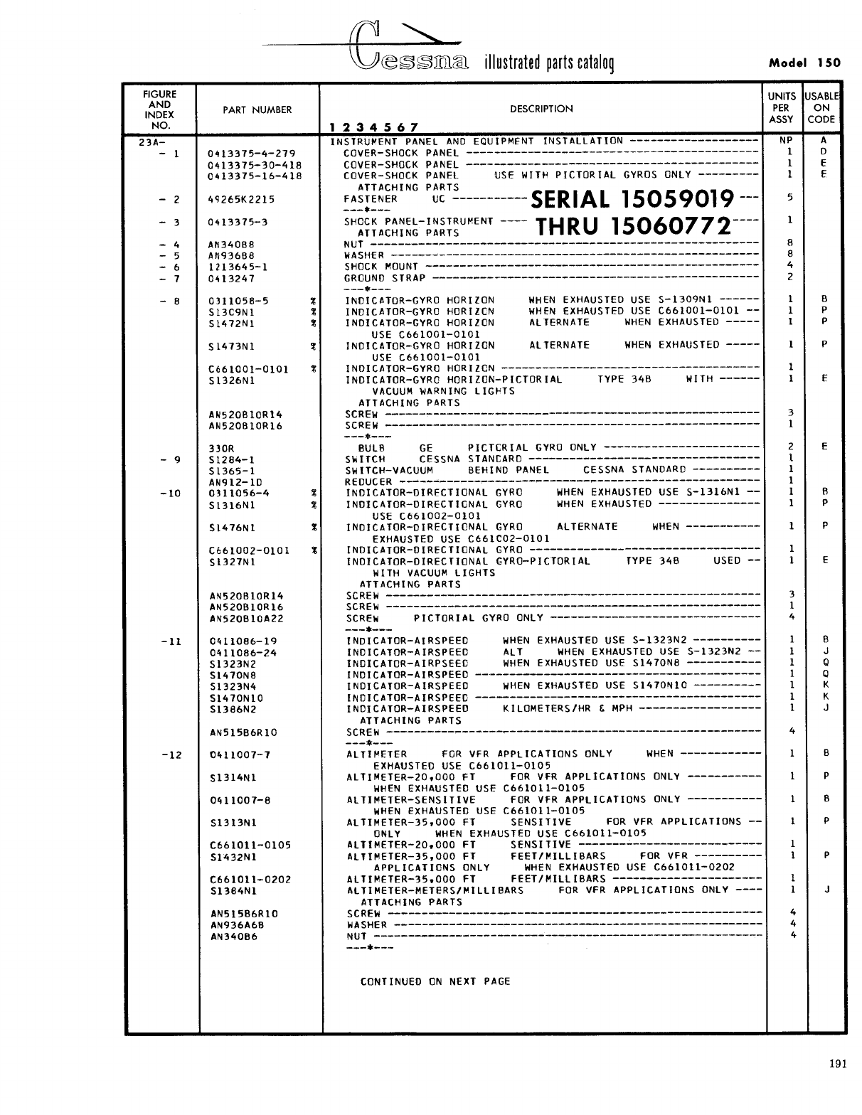
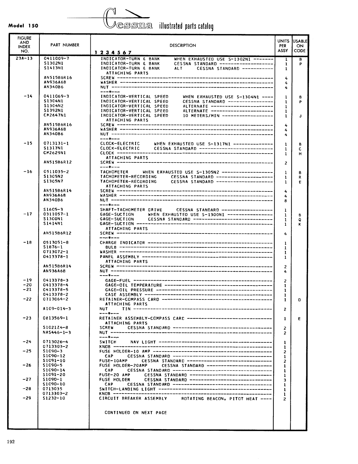
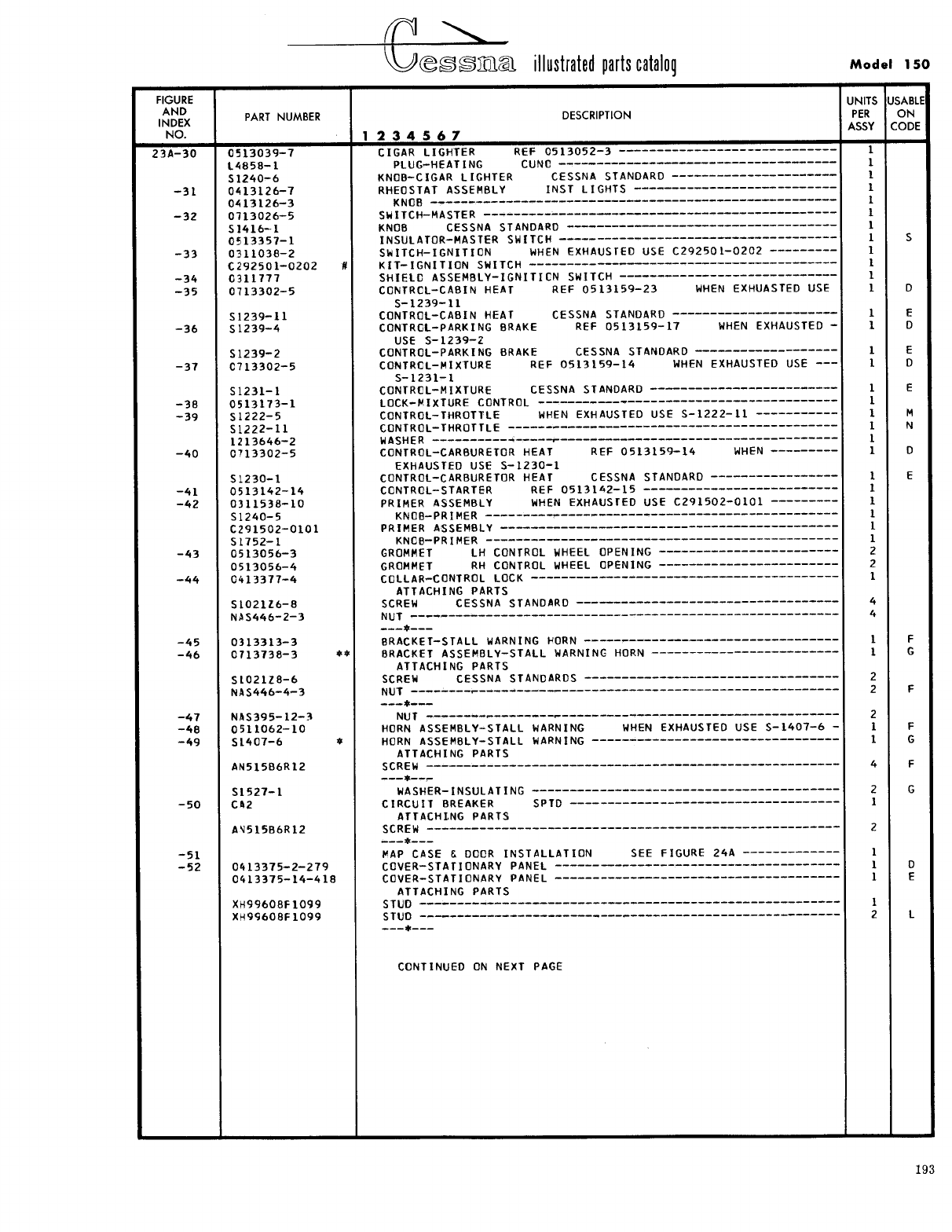
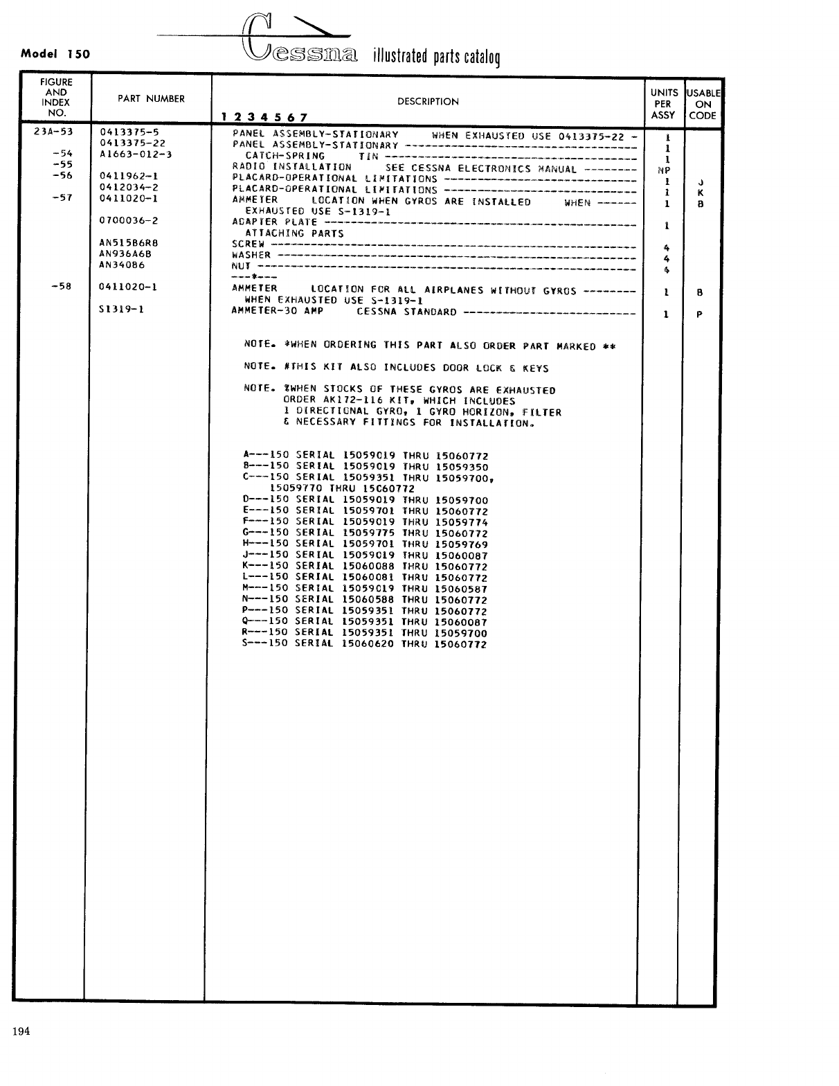
- Fig 23A. Instrument Panel Equipment Installation
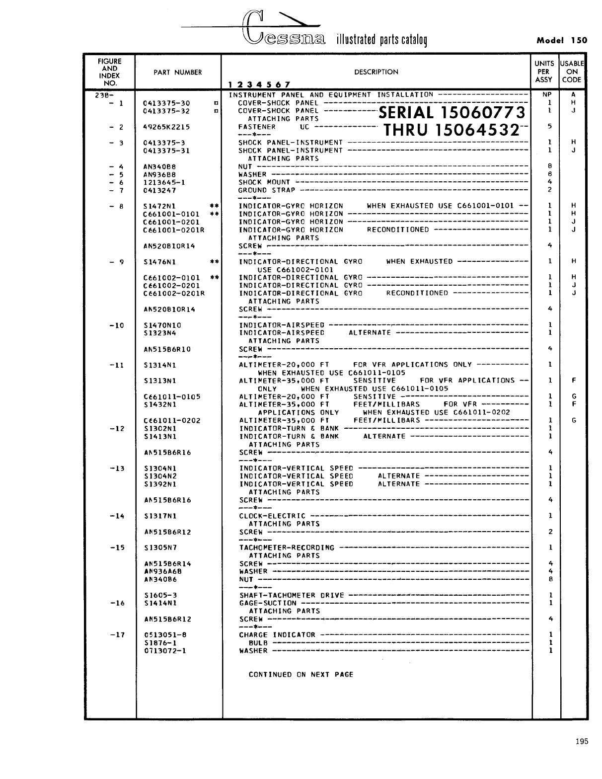
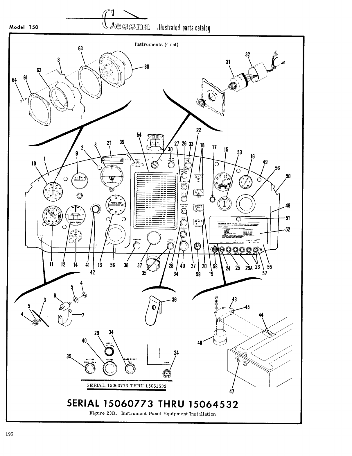
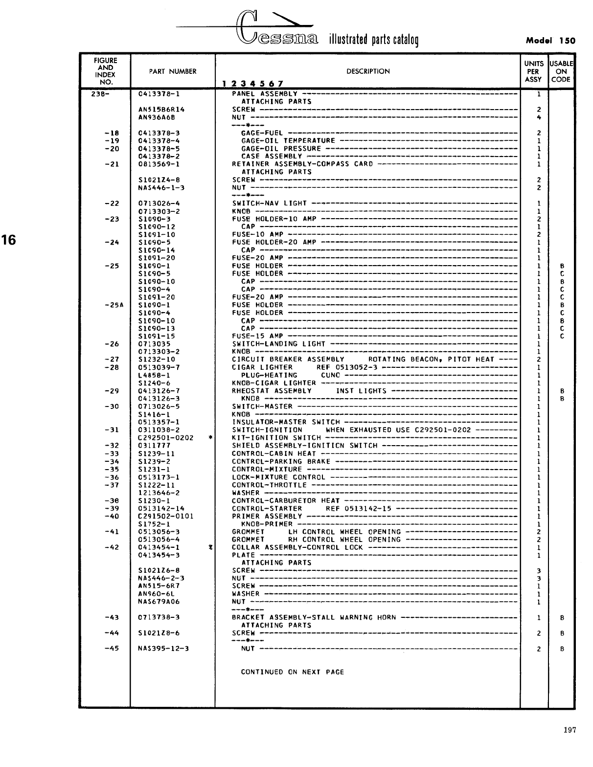
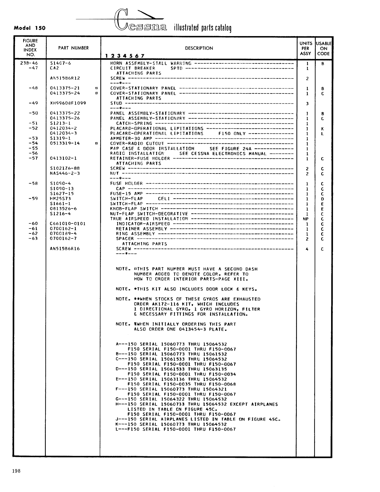
- Fig 23B. Instrument Panel Equipment Installation
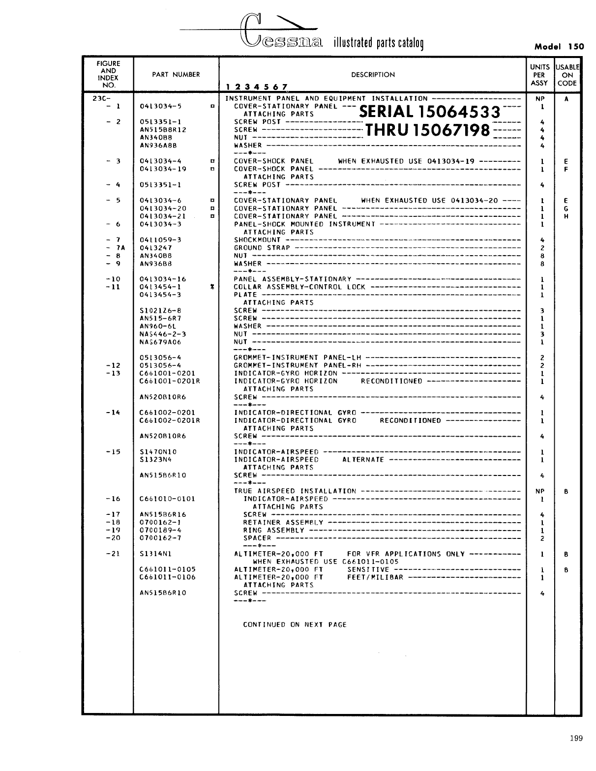
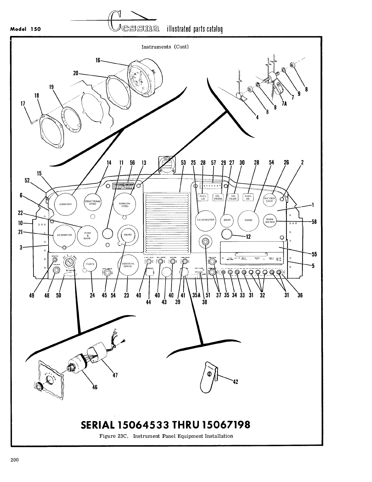
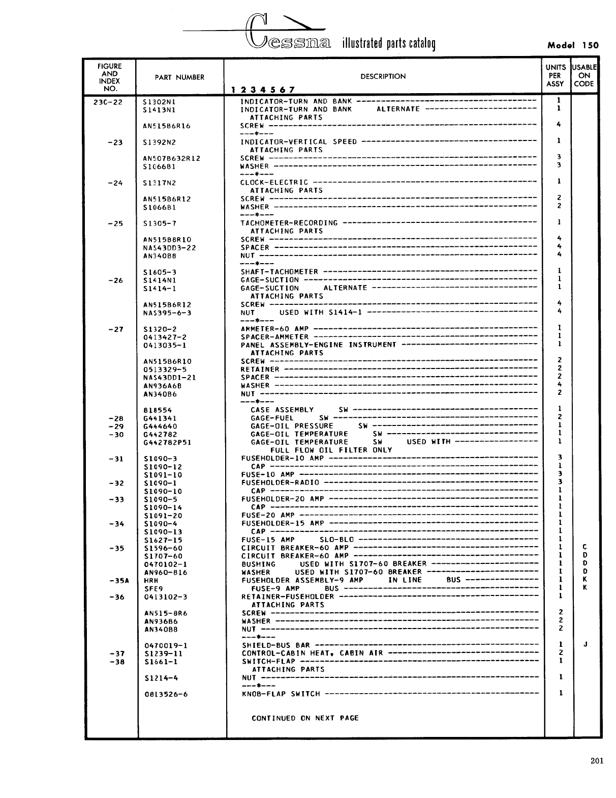
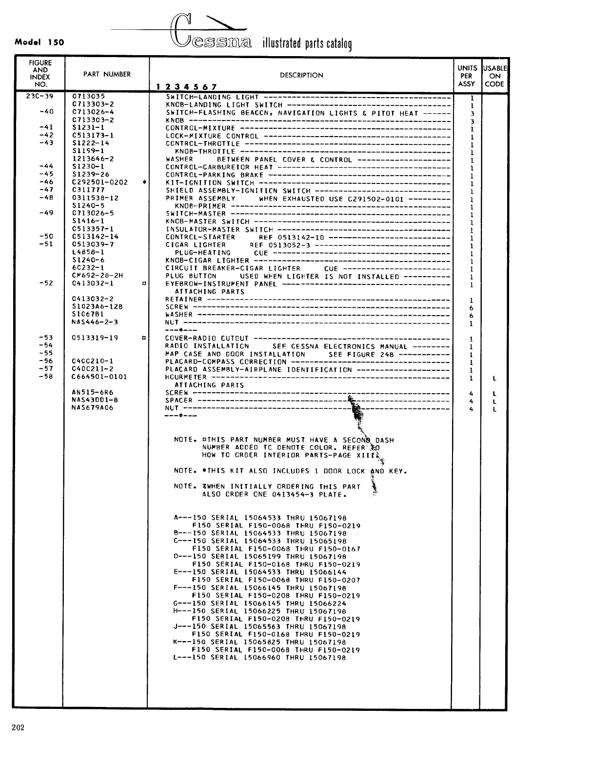
- Fig 23C. Instrument Panel Equipment Installation
- Fig 23D. Instrument Panel Equipment Installation
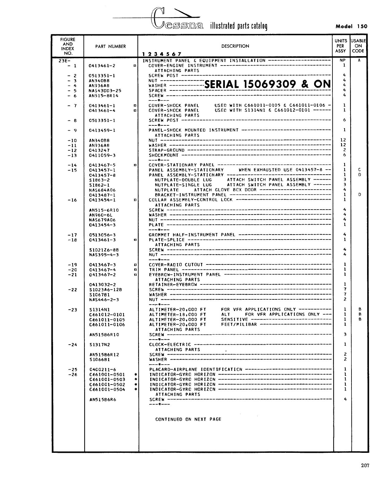
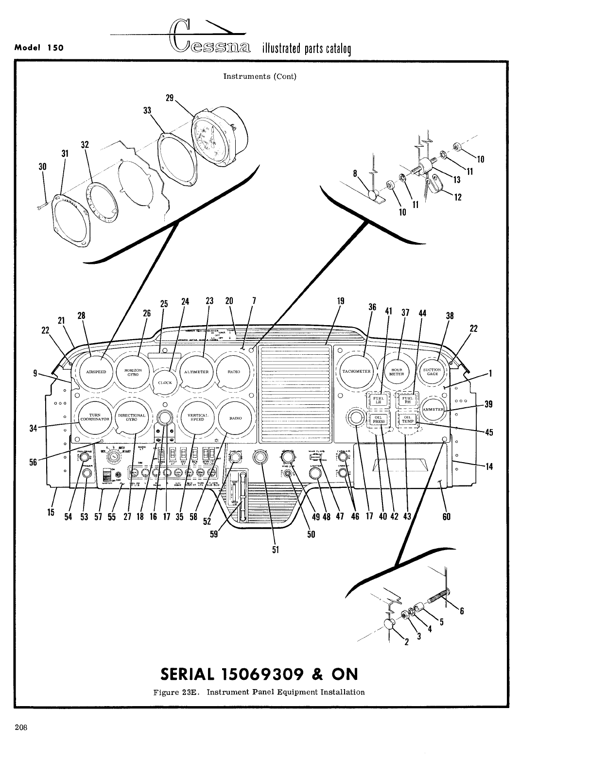
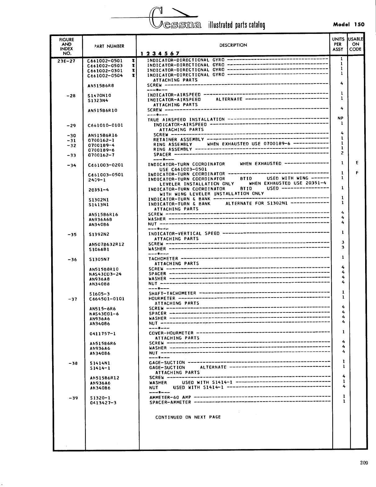
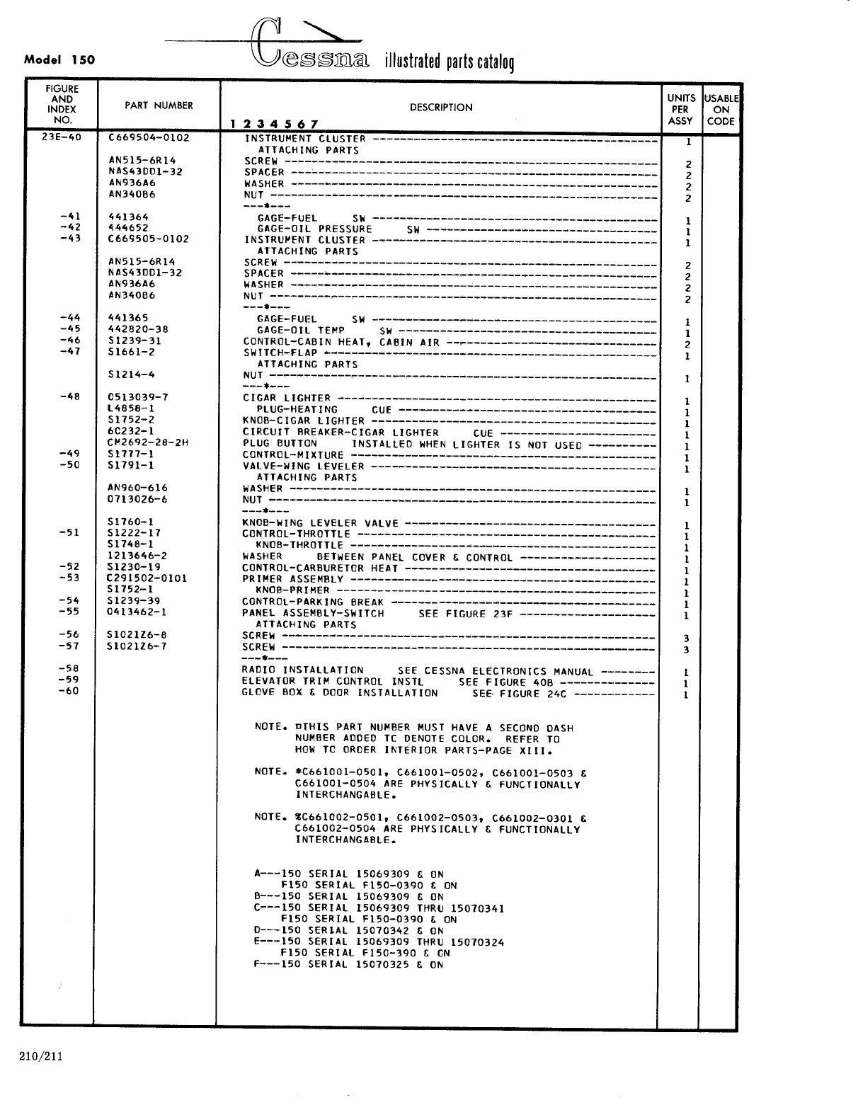
- Fig 23E. Instrument Panel Equipment Installation
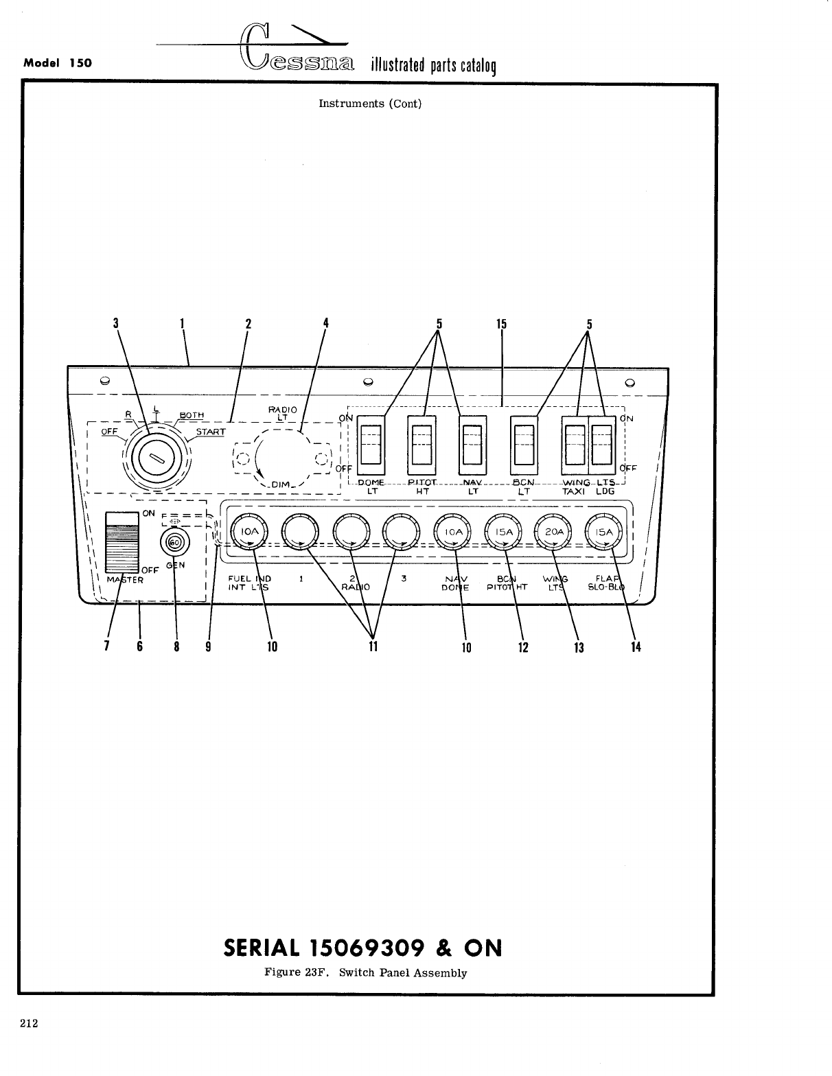
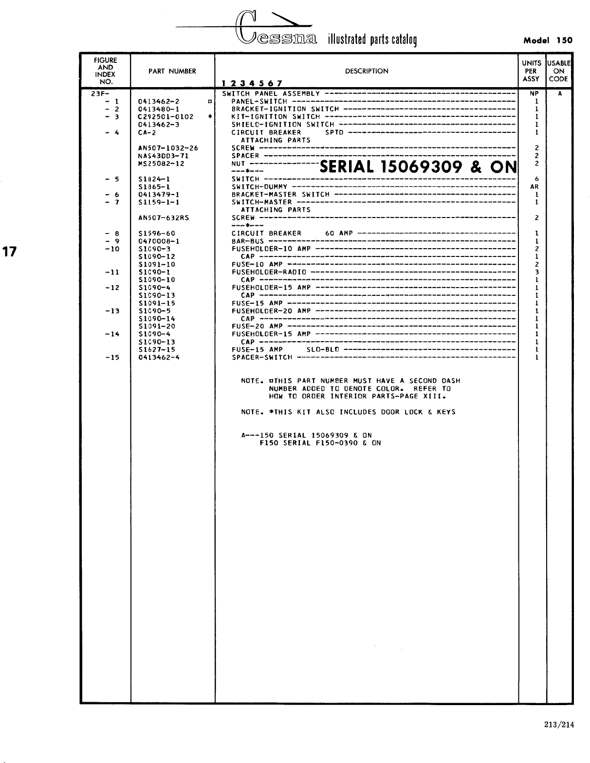
- Fig 23F. Switch Panel Assembly
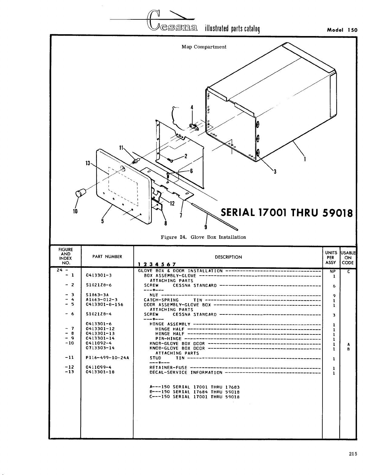
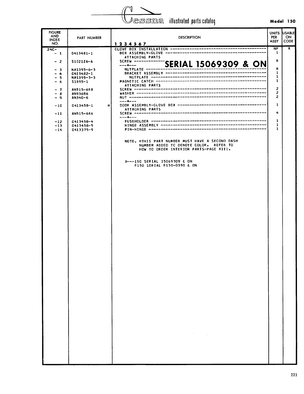
- Fig 24. Glove Box Installation
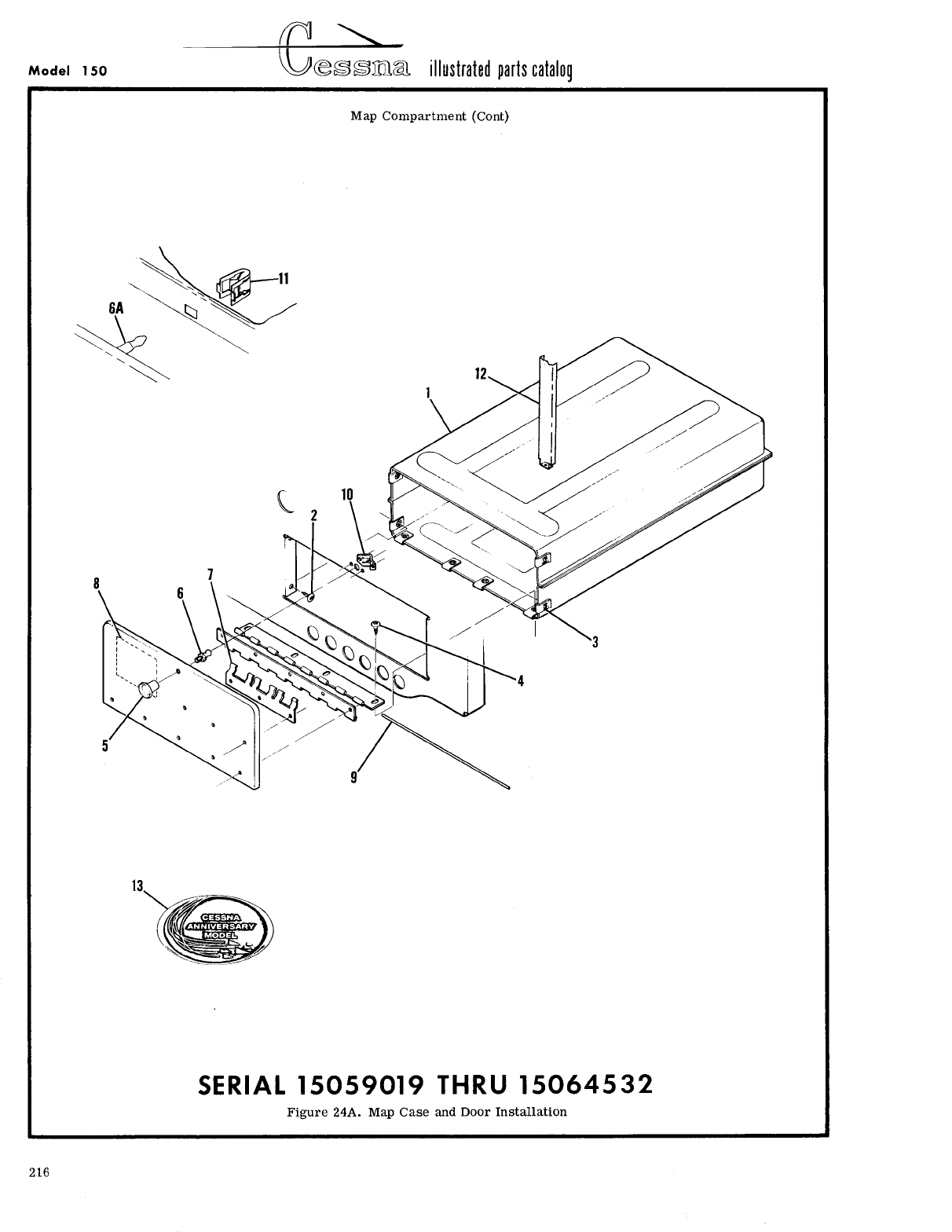
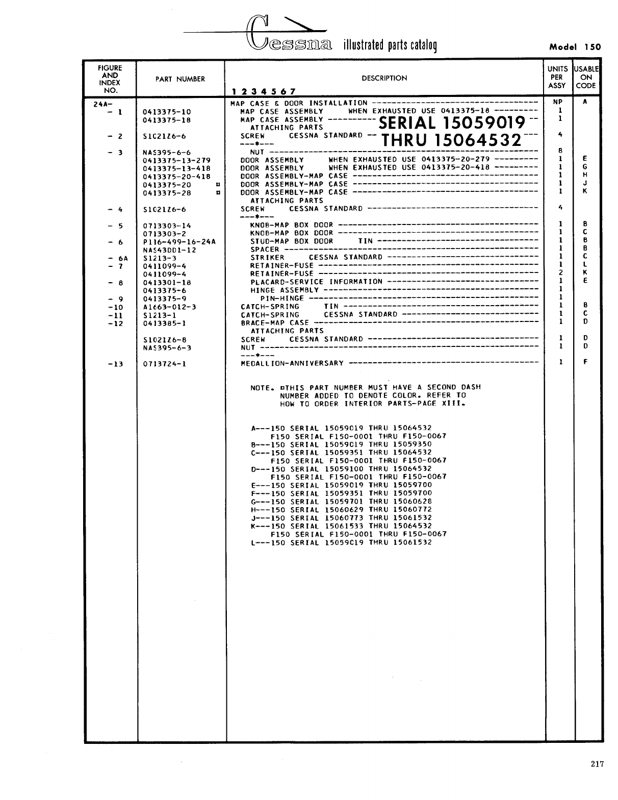
- Fig 24A. Map Case and Door Installation
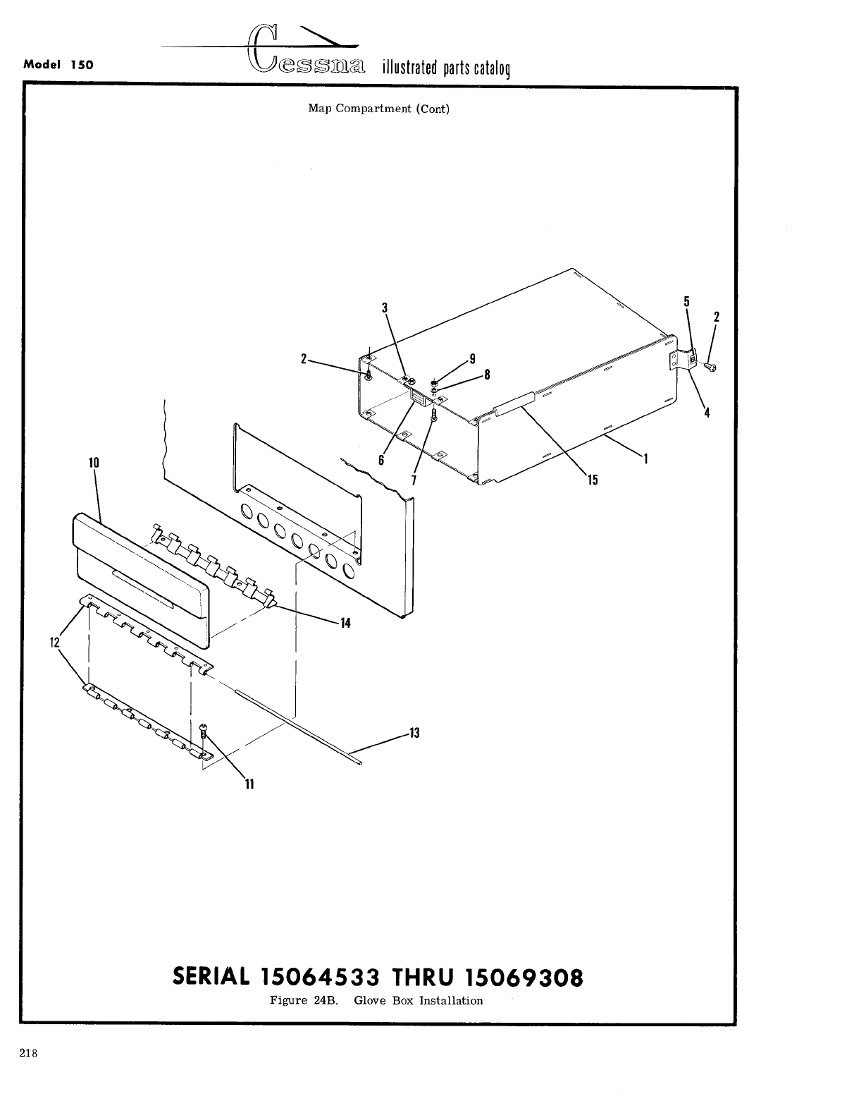
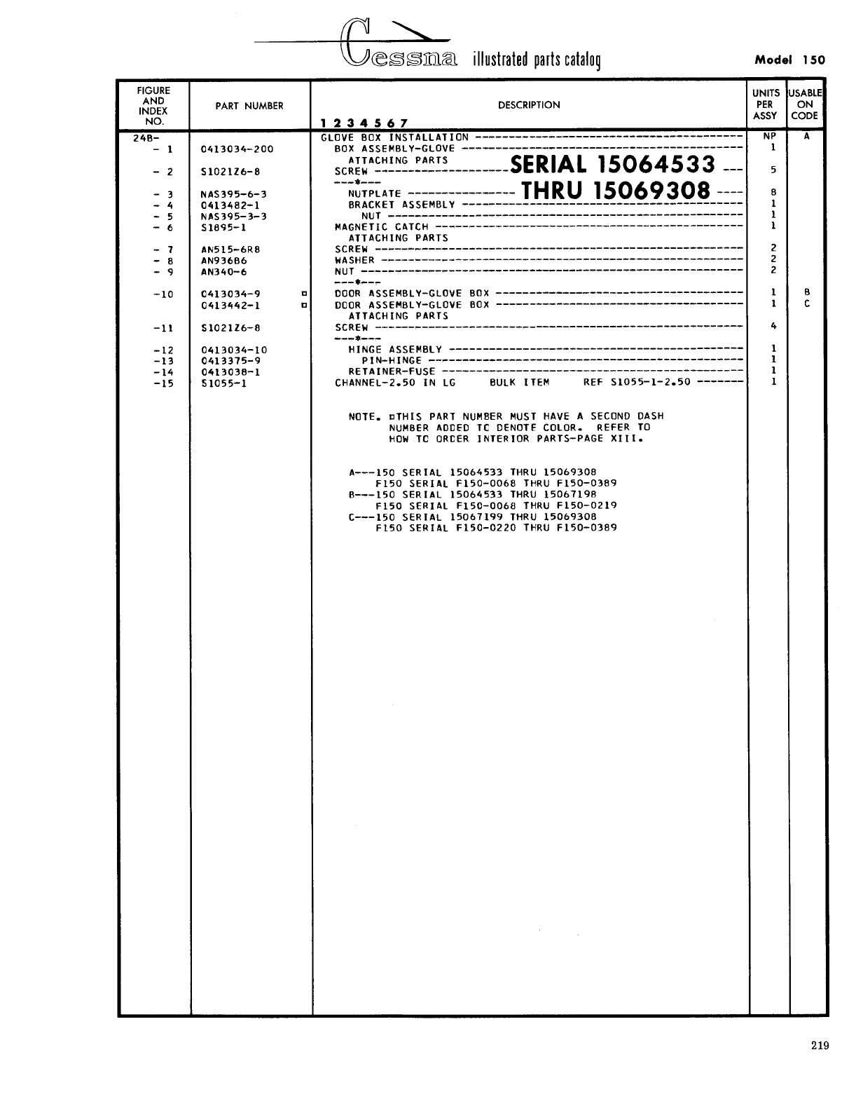
- Fig 24B. Glove Box Installation
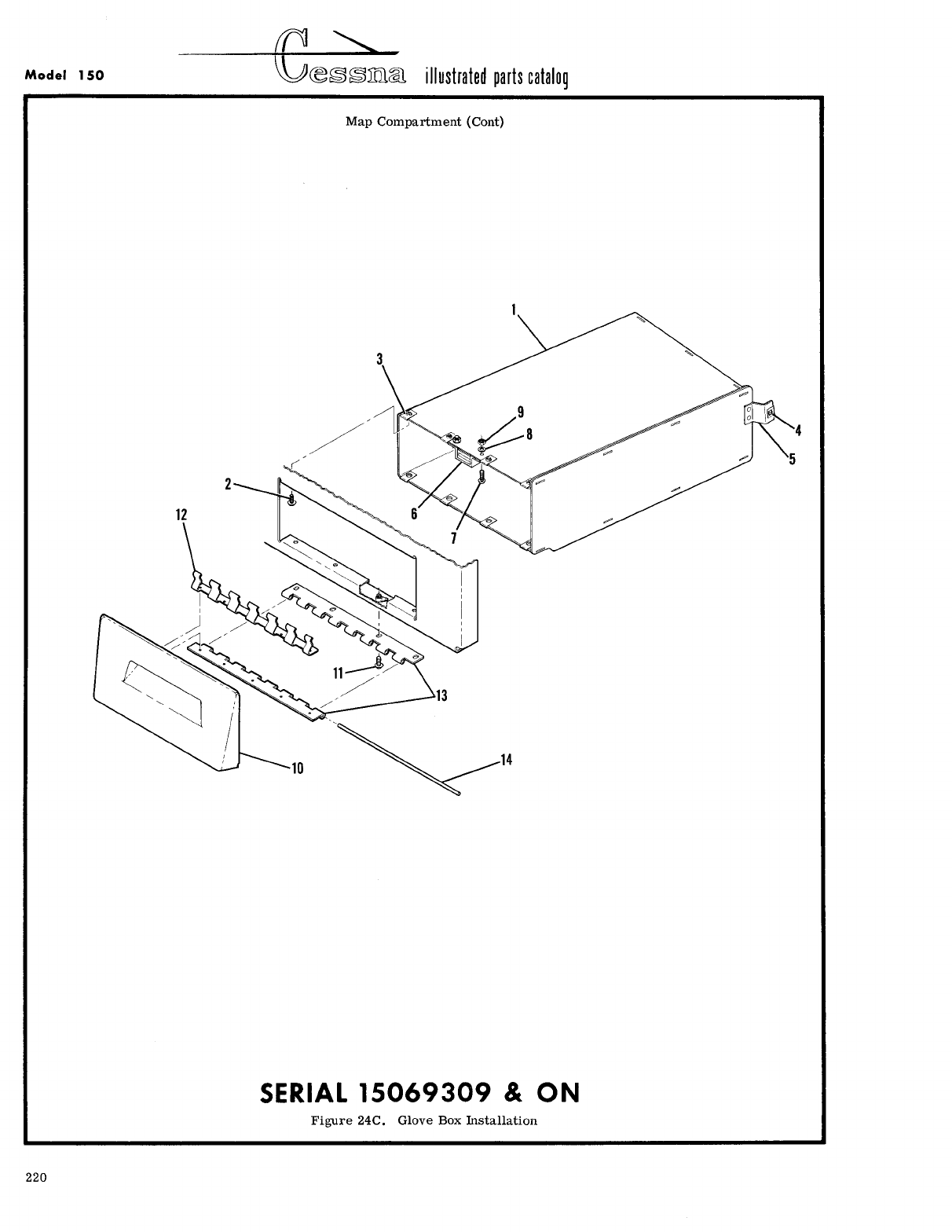
- Fig 24C. Glove Box Installation
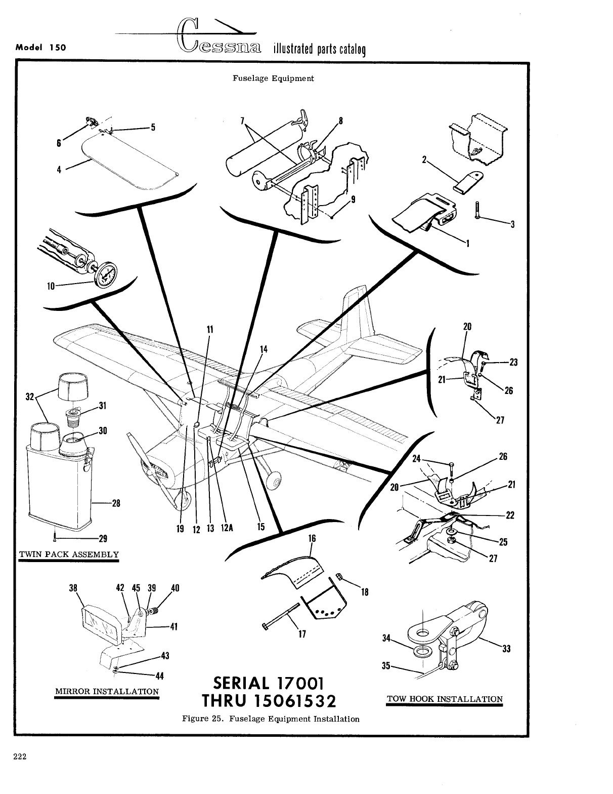
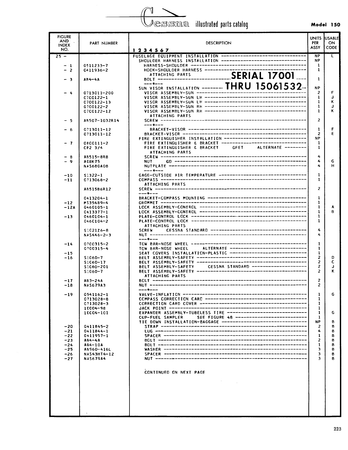
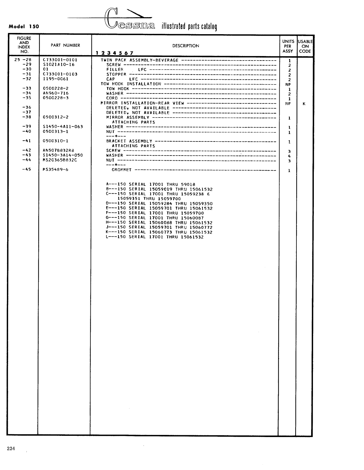
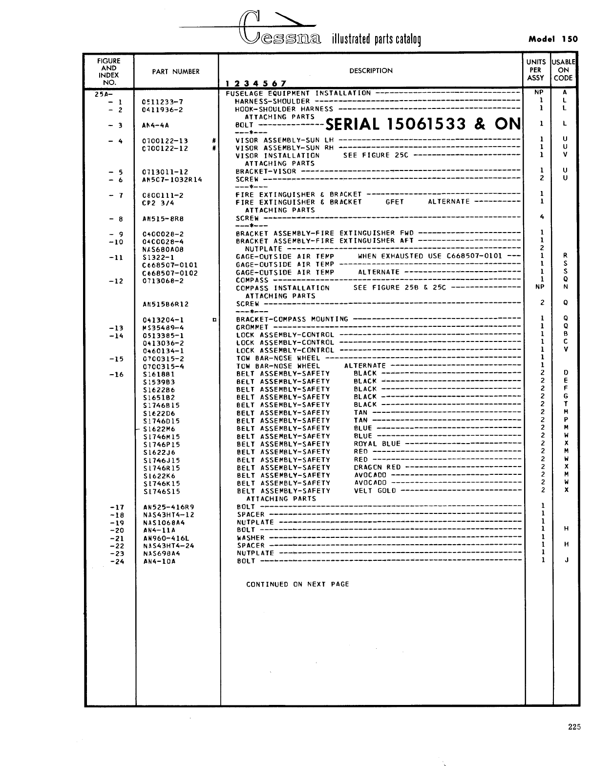
- Fig 25. Fuselage Equipment Installation
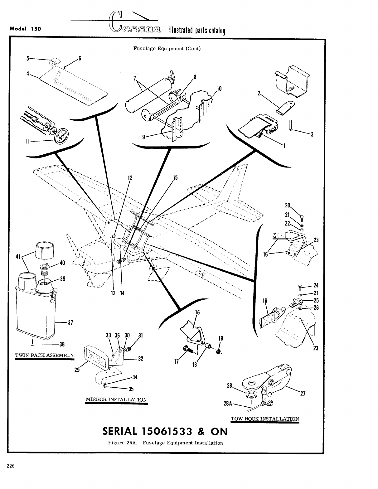
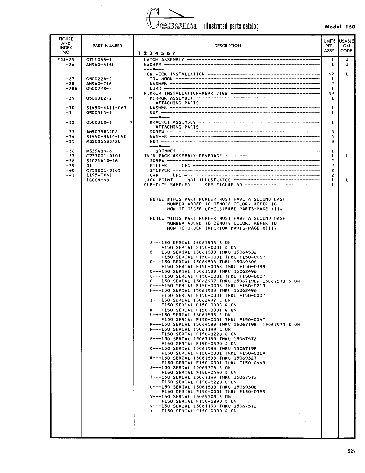
- Fig 25A. Fuselage Equipment Installation
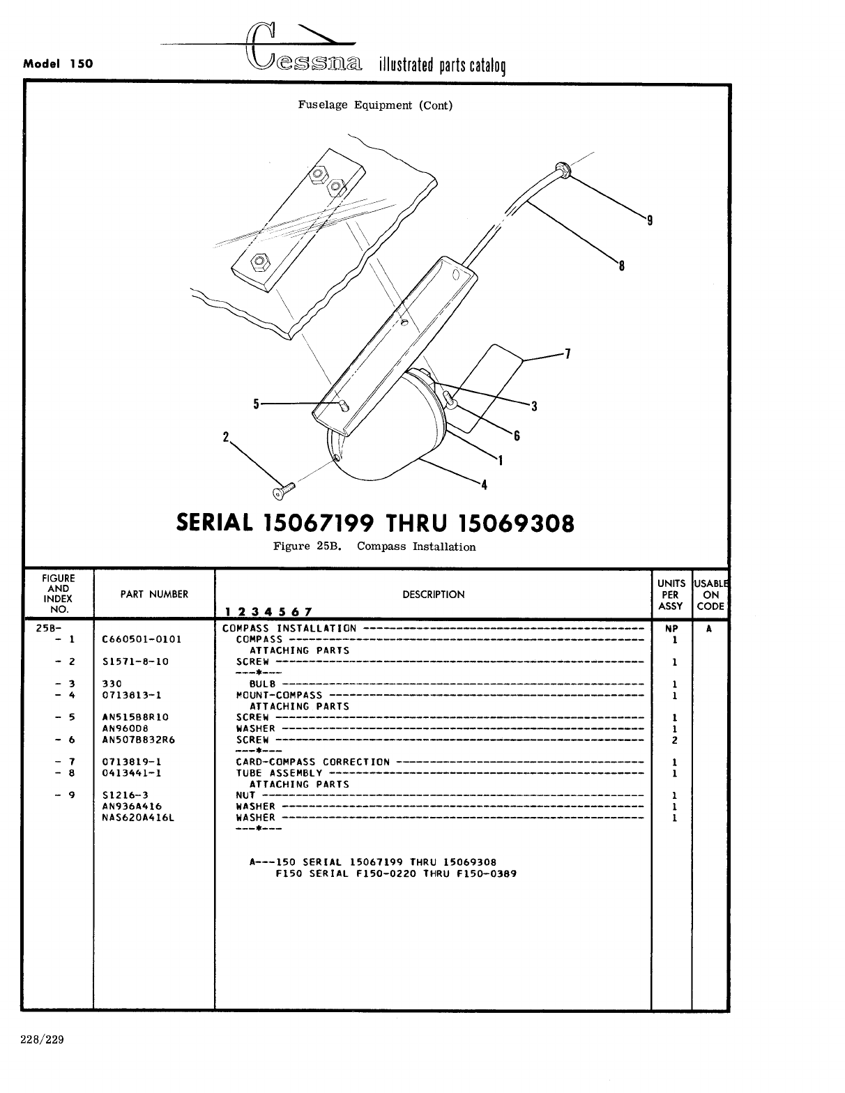
- Fig 25B. Compass Installation
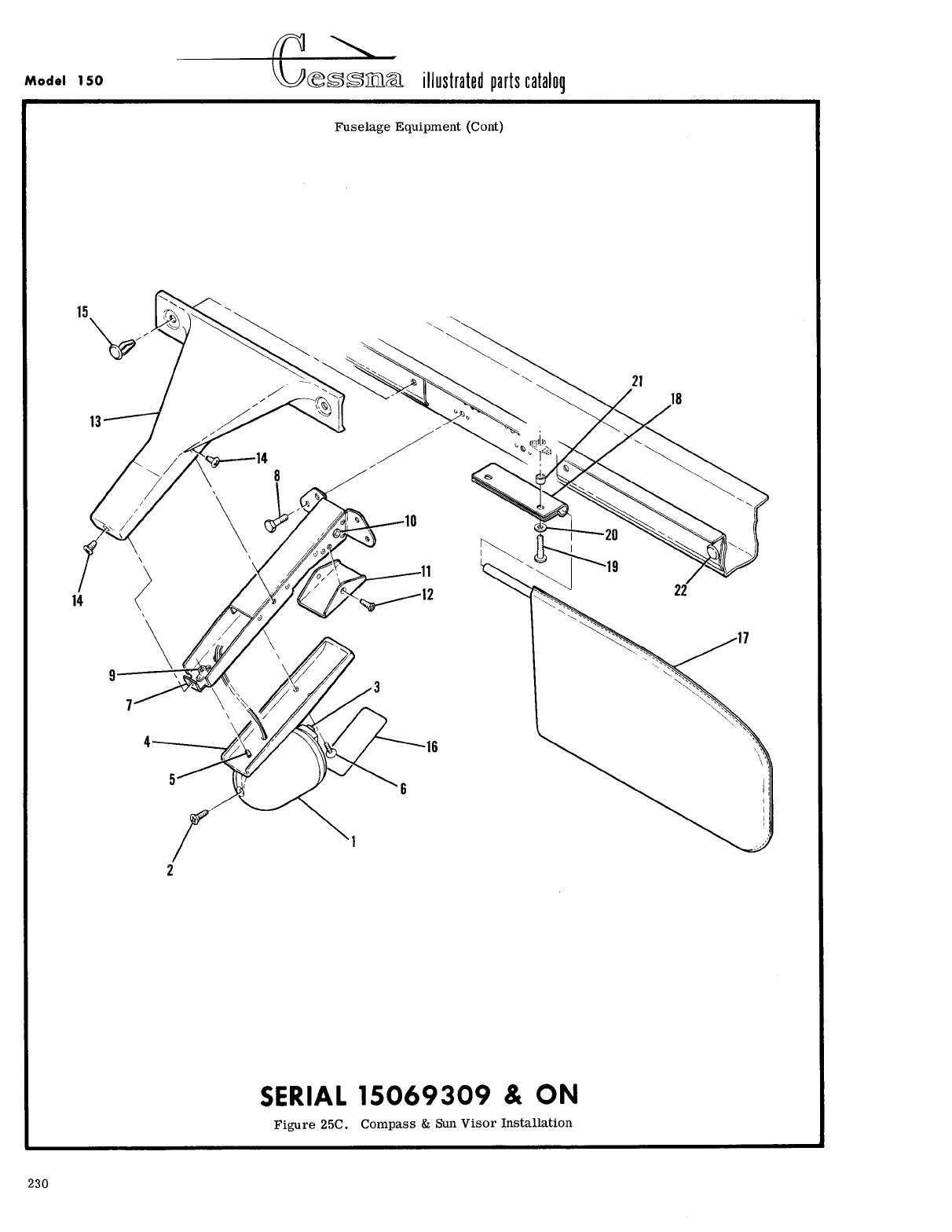
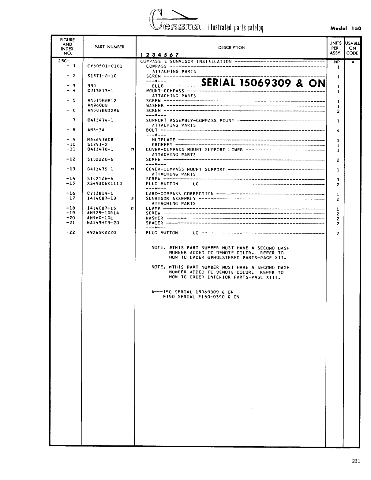
- Fig 25C. Compass & Sun Visor Installation
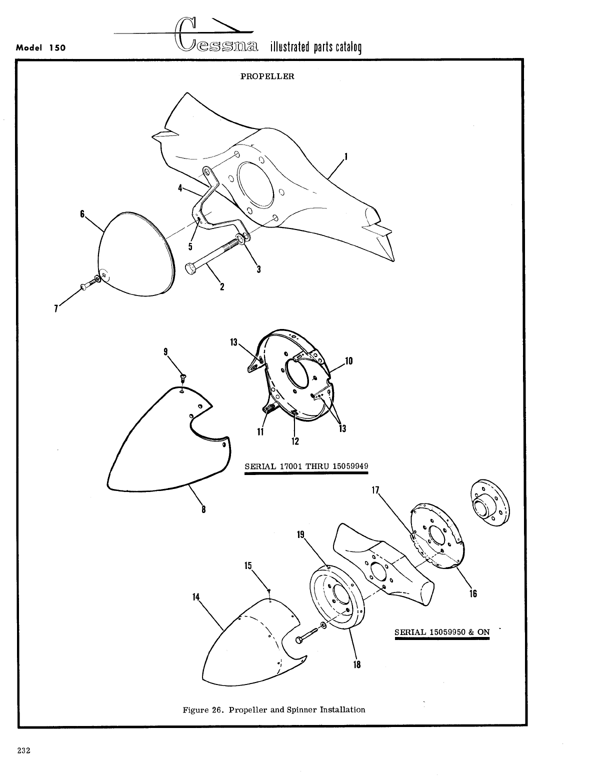
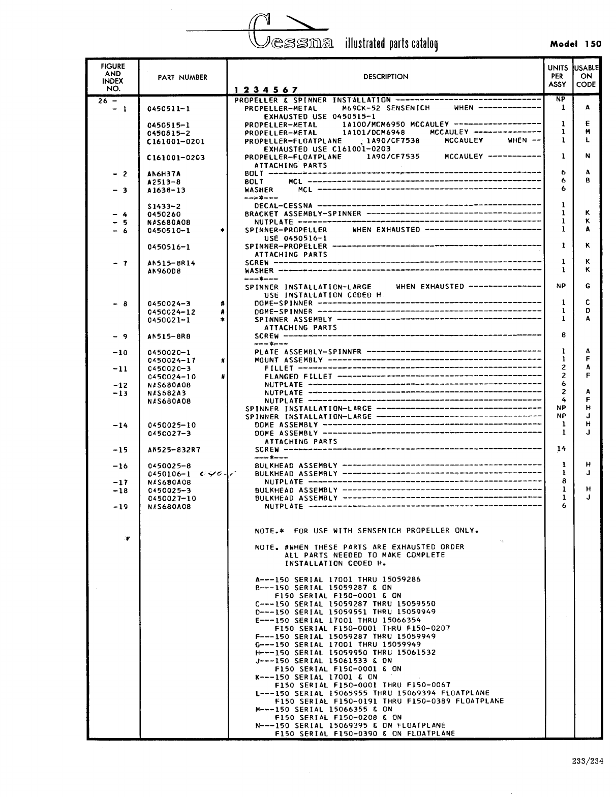
- Fig 26. Propeller and Spinner Installation
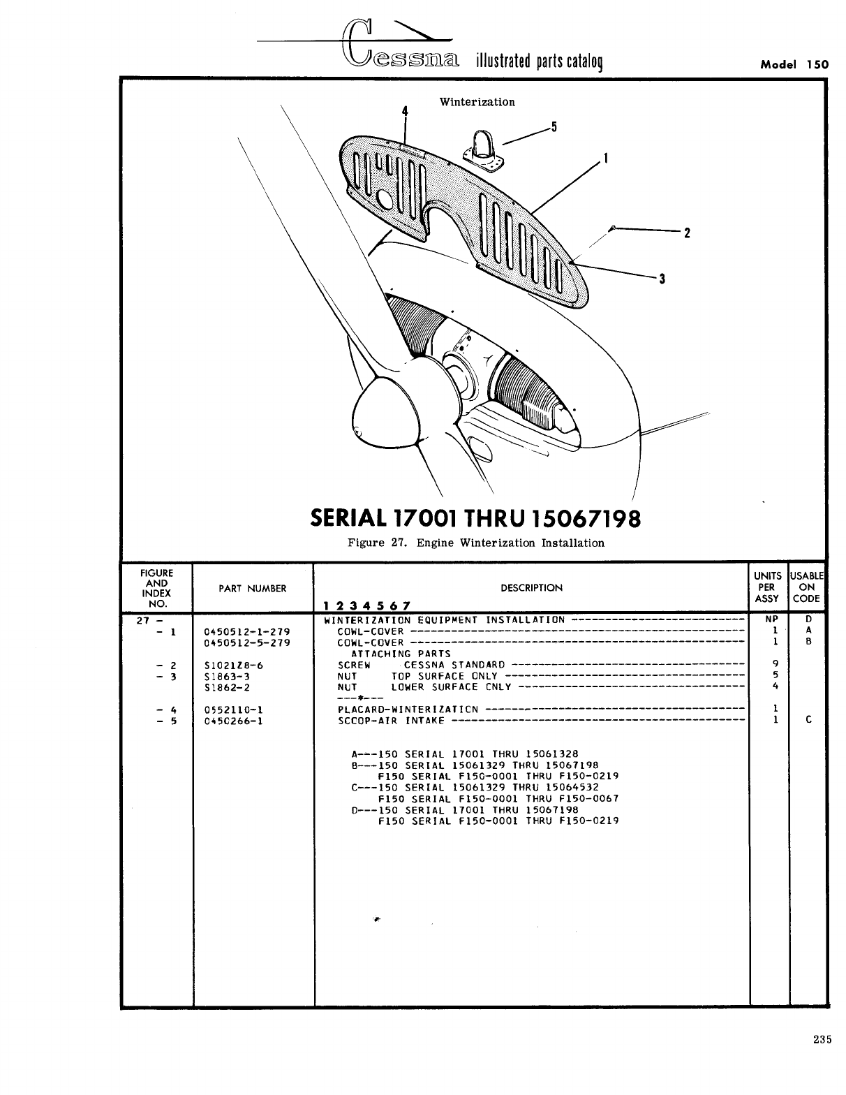
- Fig 27. Engine Winterization Installation
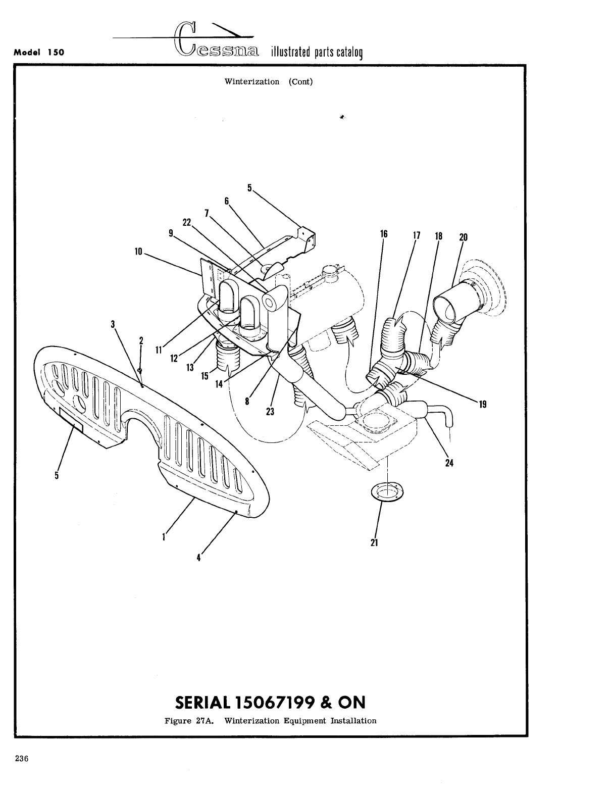
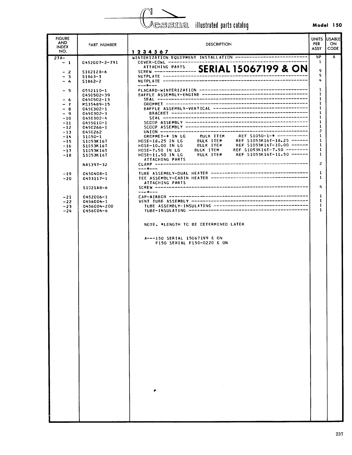
- Fig 27A. Winterization Equipment Installation
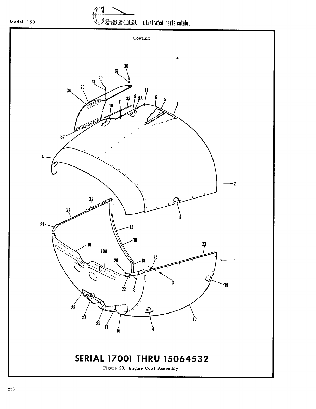
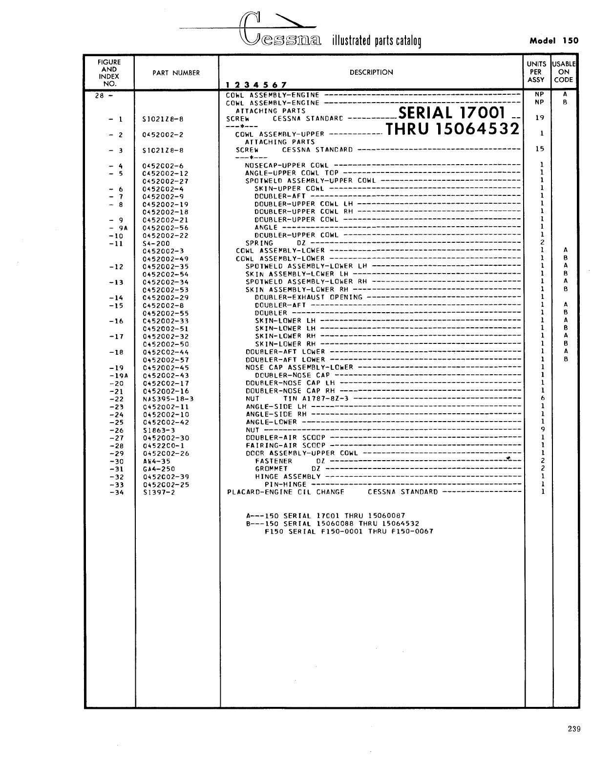
- Fig 28. Engine Cowl Assembly
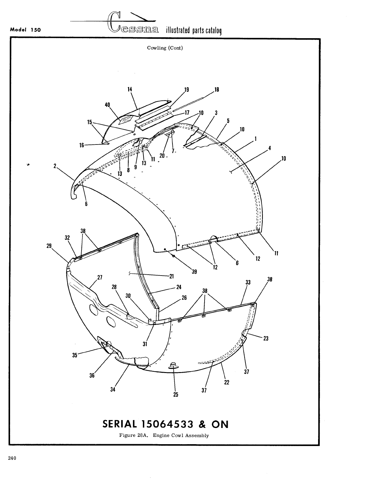
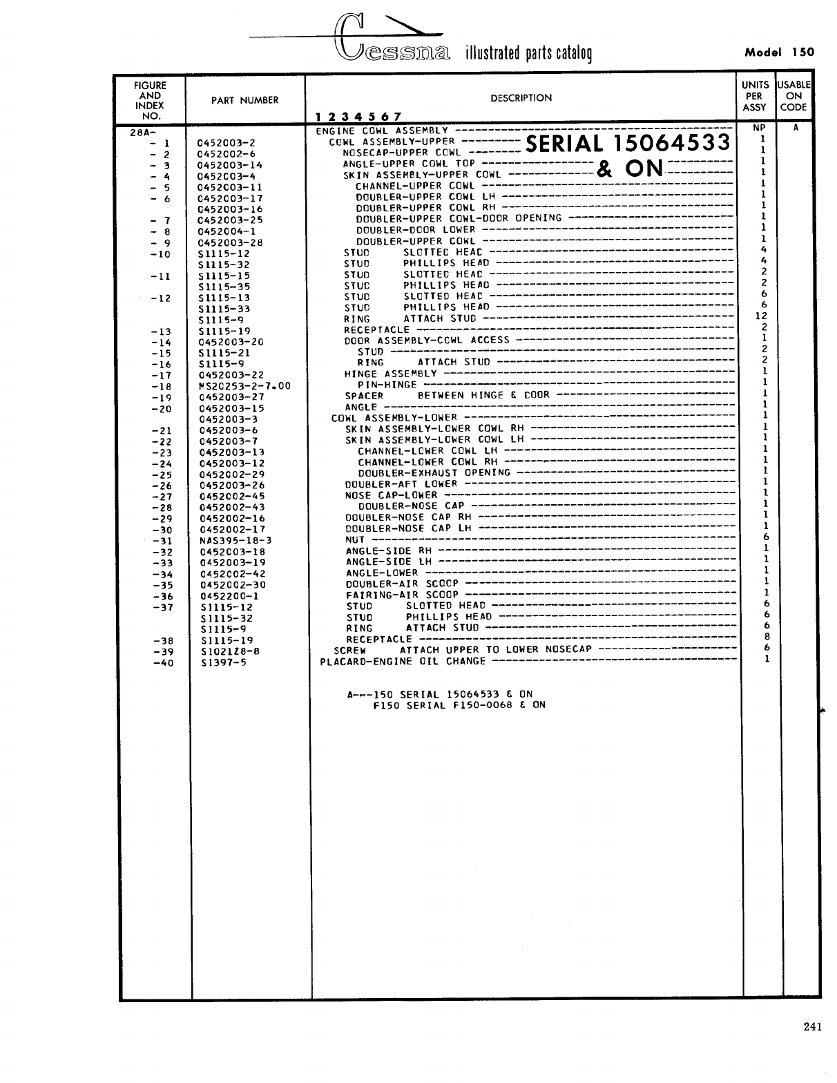
- Fig 28A. Engine Cowl Assembly
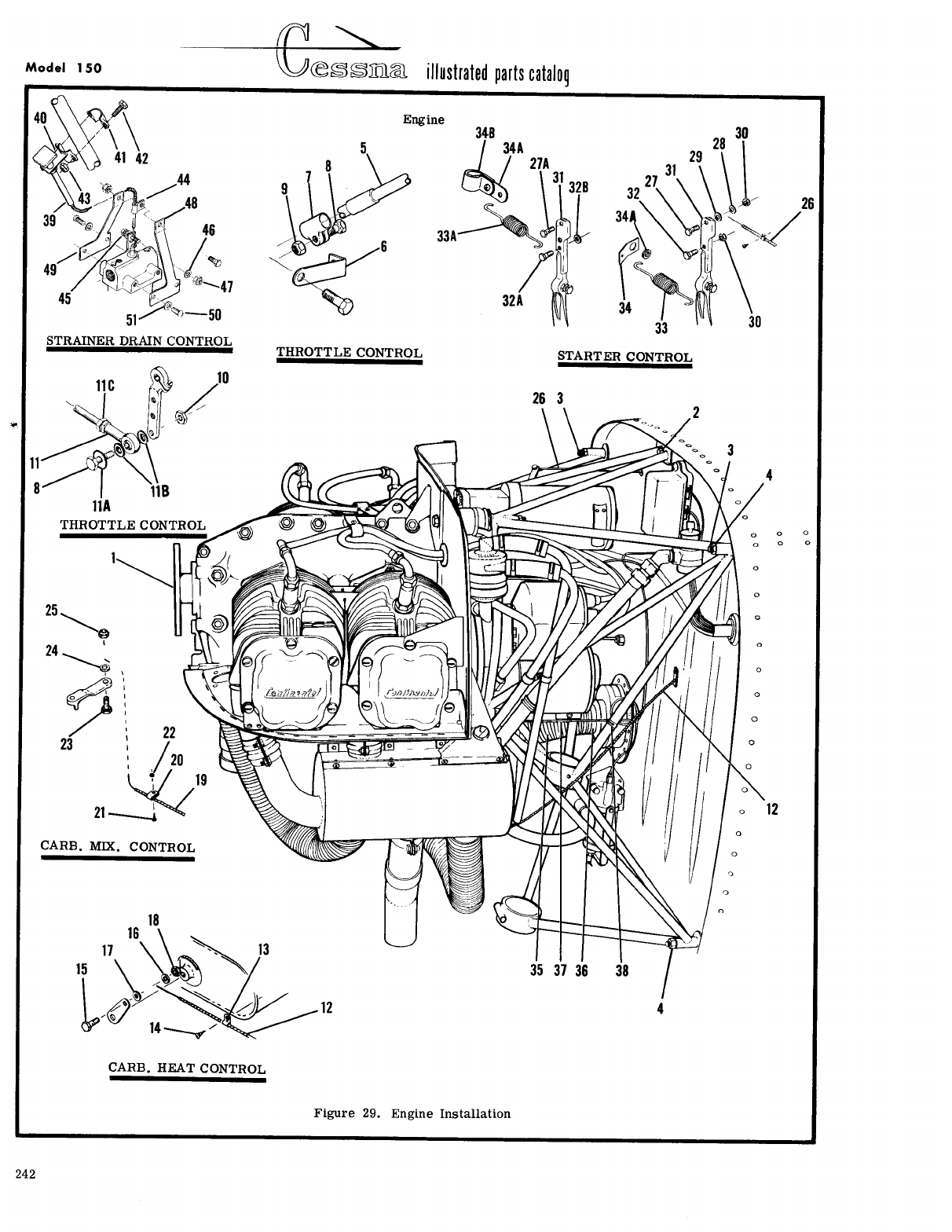
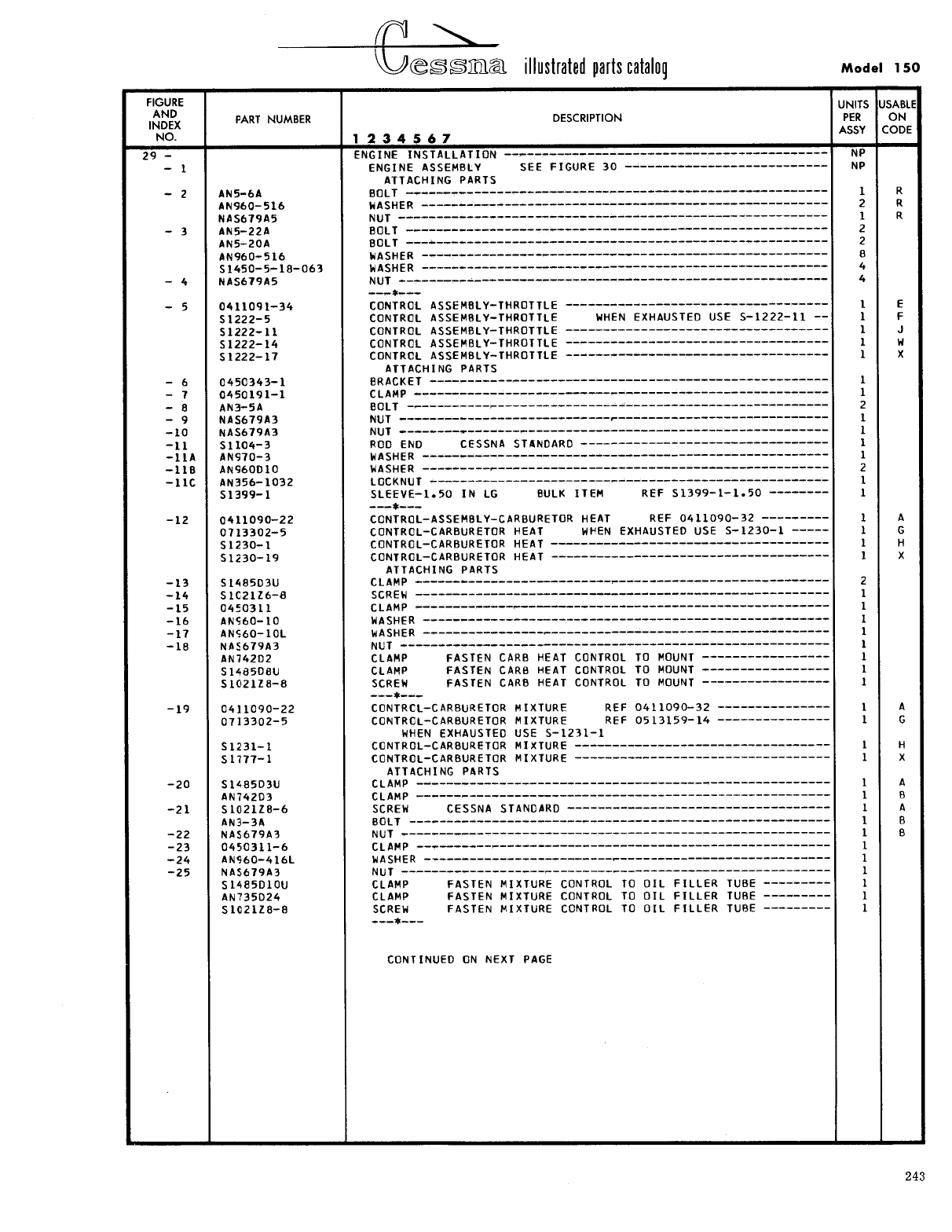
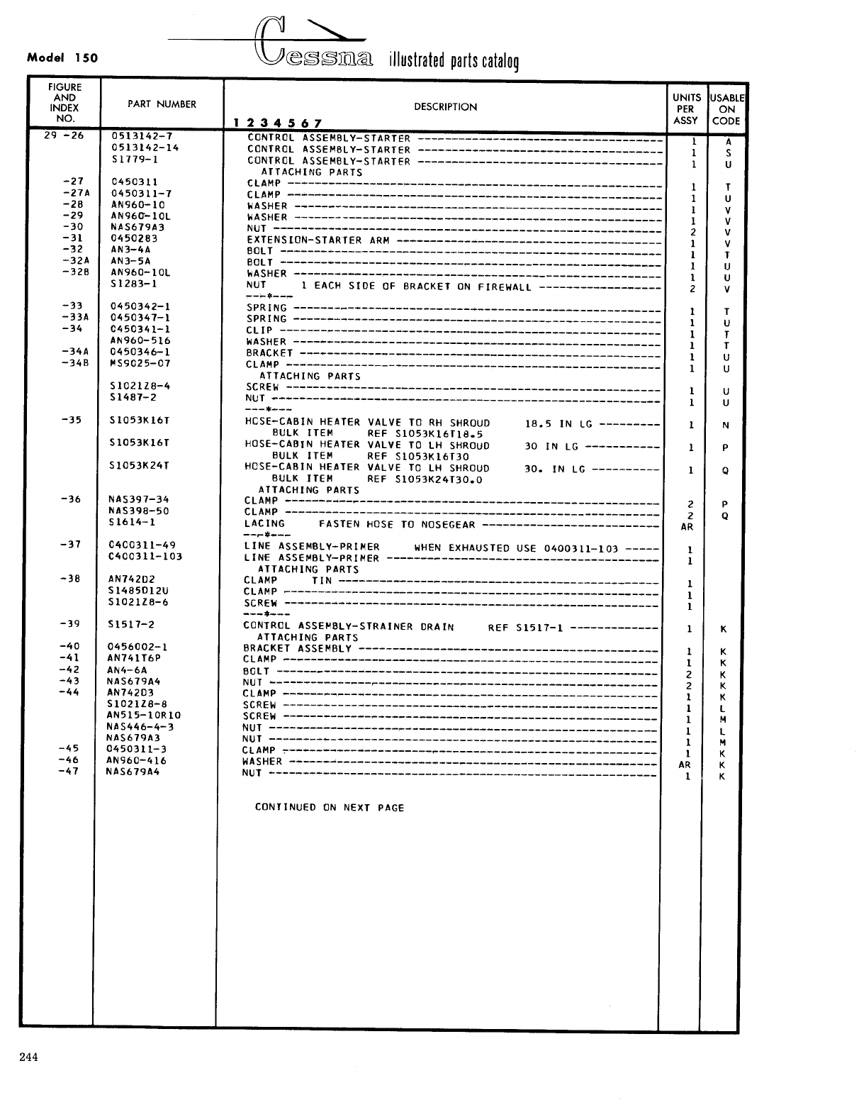
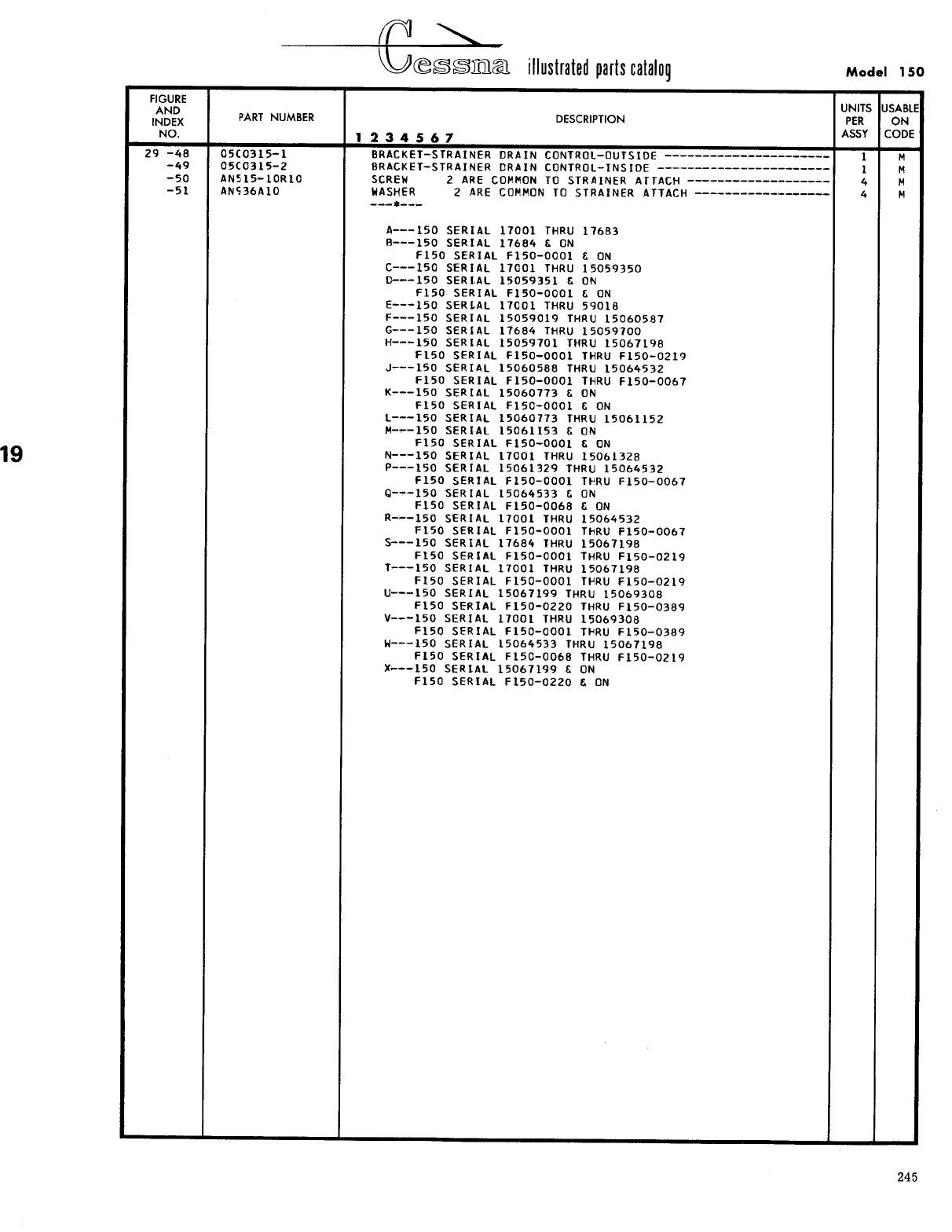
- Fig 29. Engine Installation
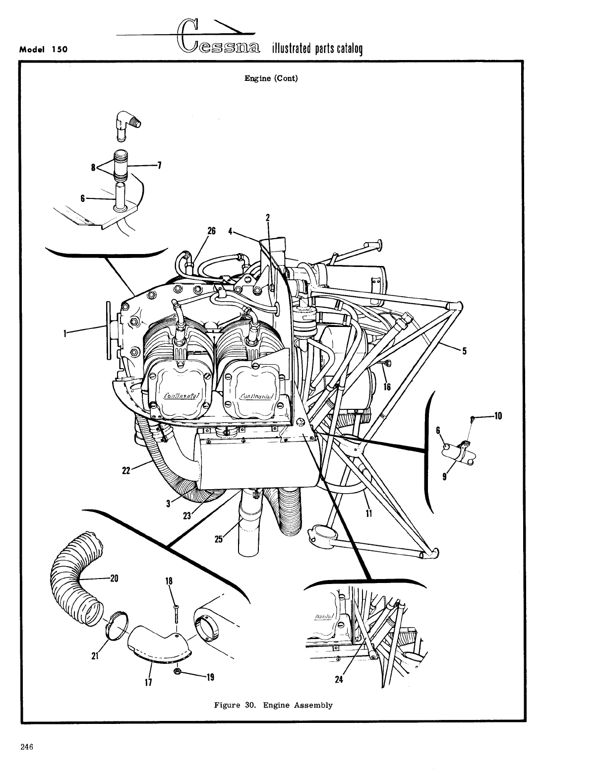
- Fig 30. Engine Assembly
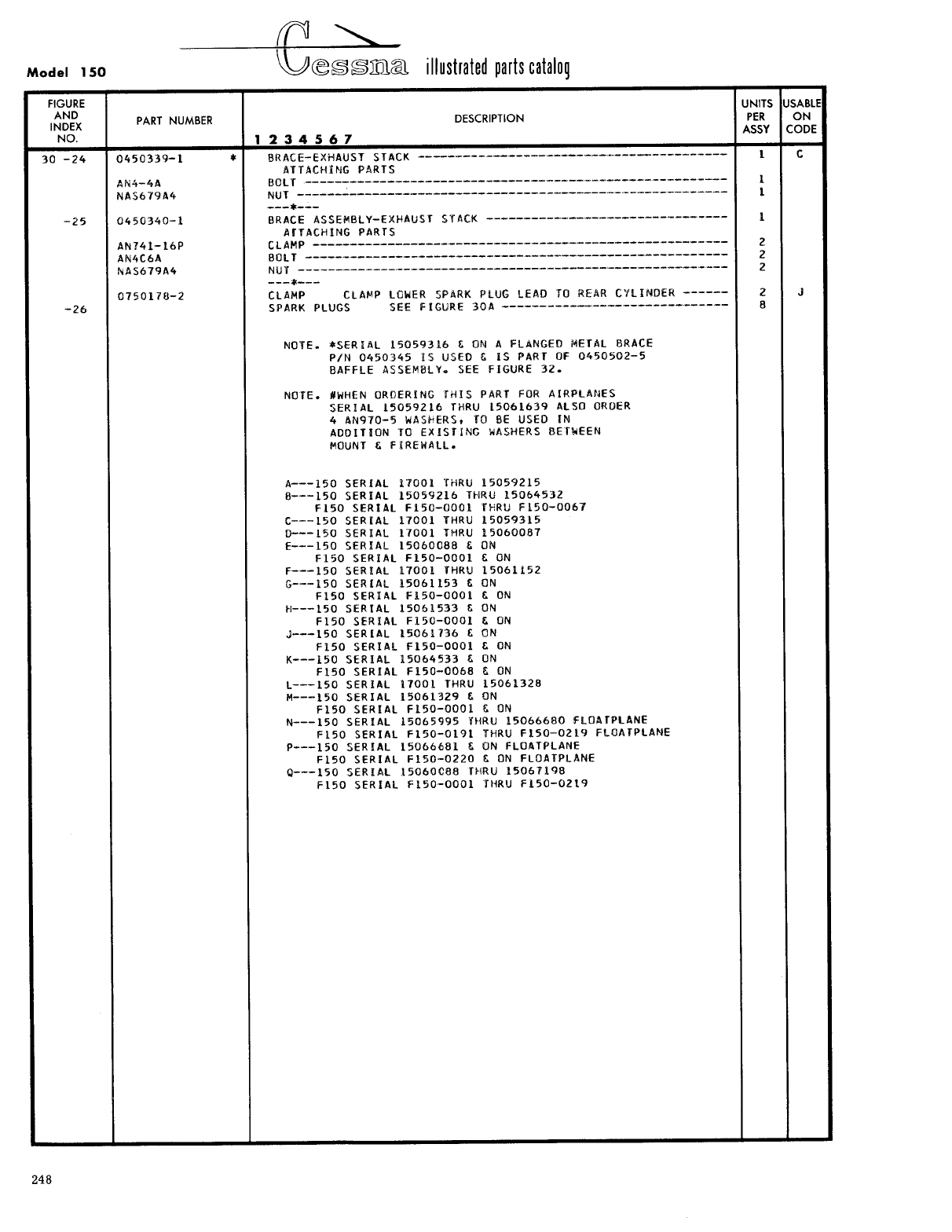
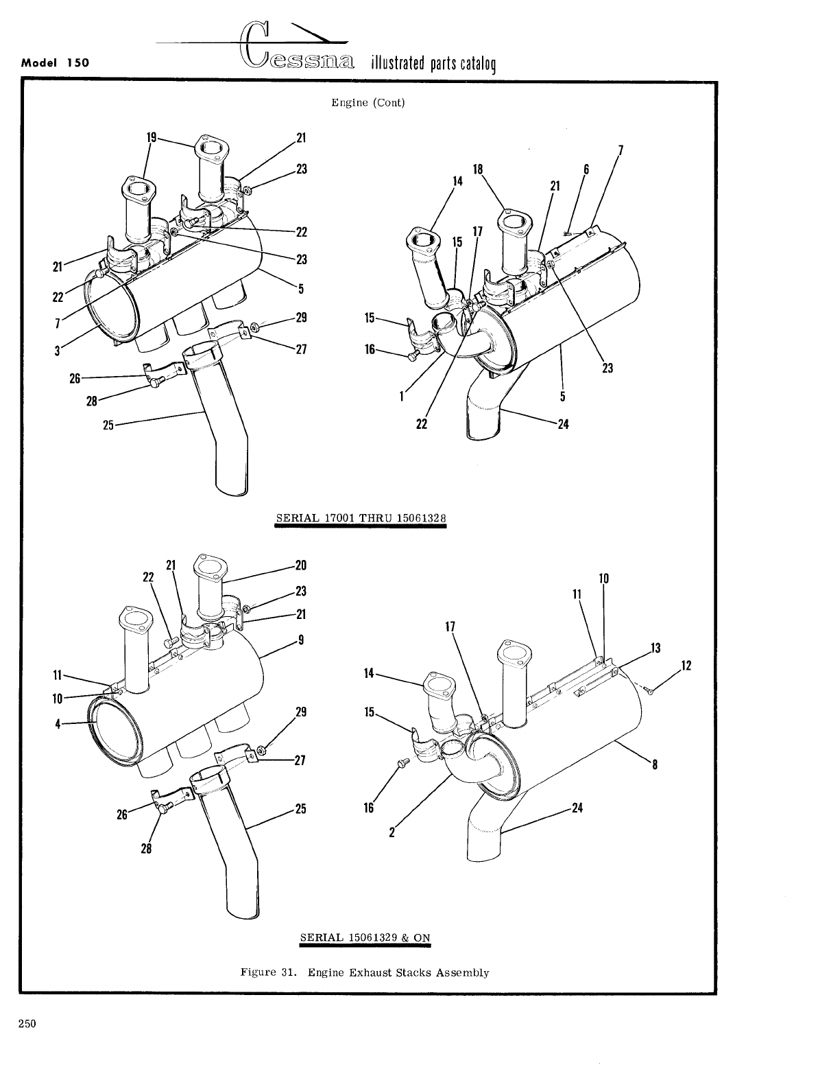
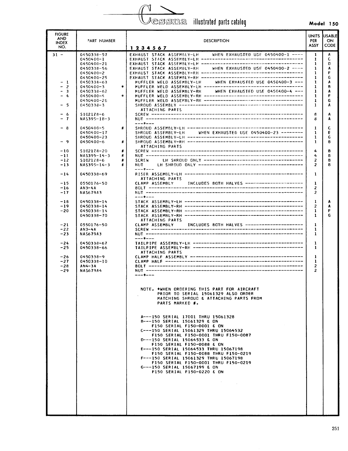
- Fig 31. Engine Exhaust Stacks Assembly
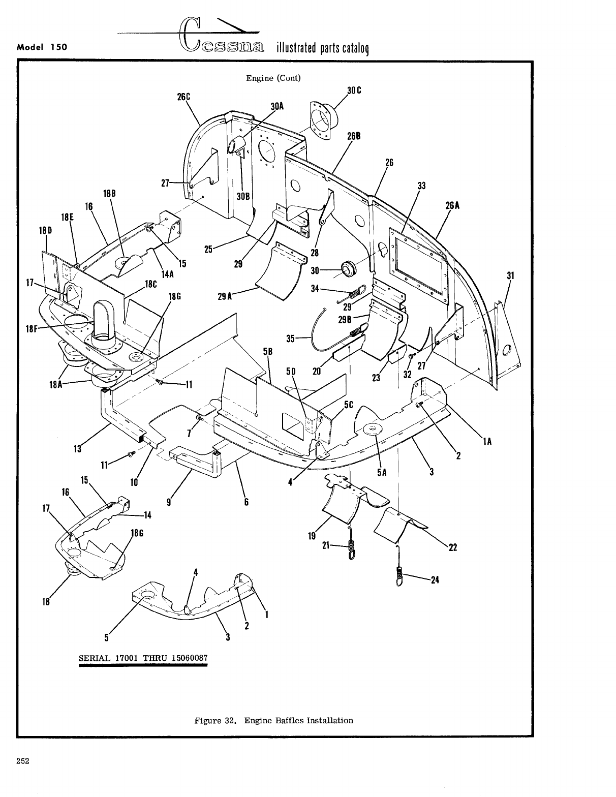
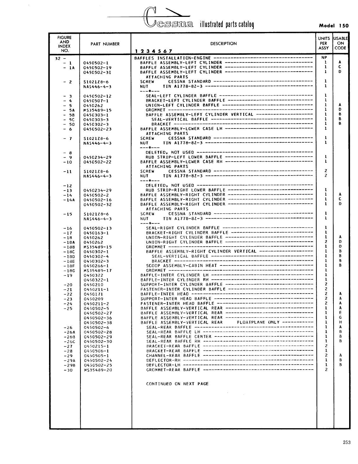
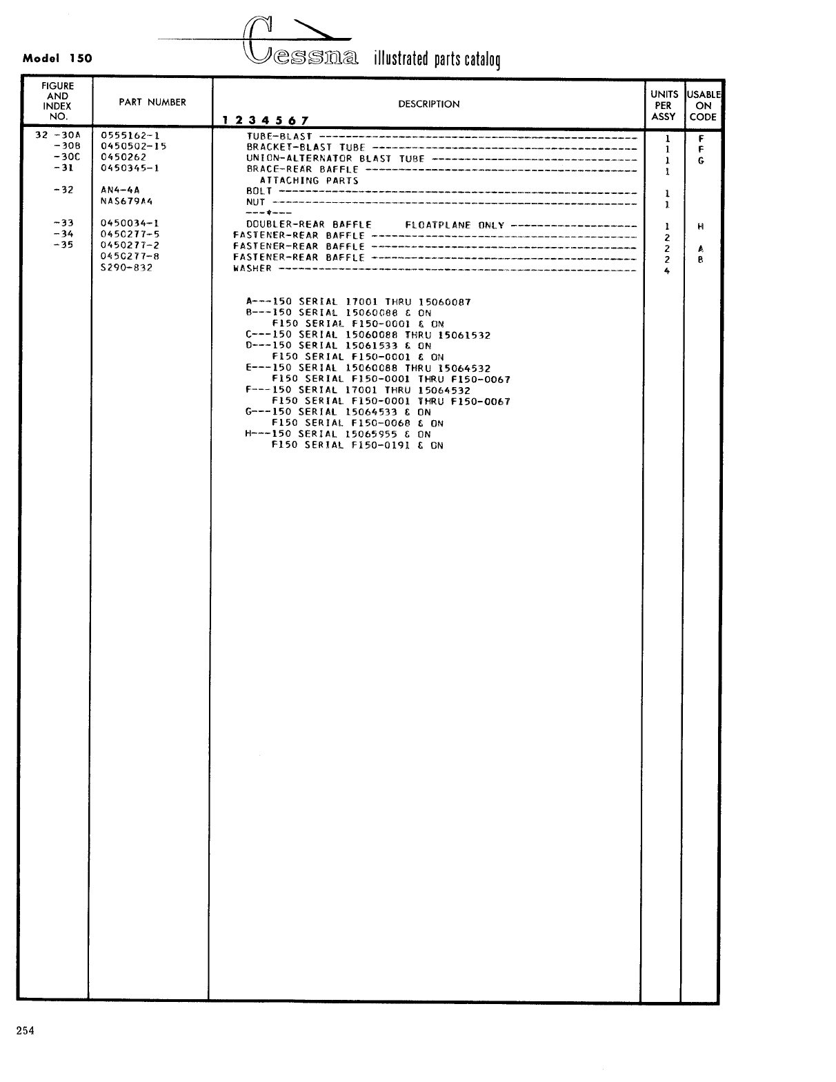
- Fig 32. Engine Baffles Installation
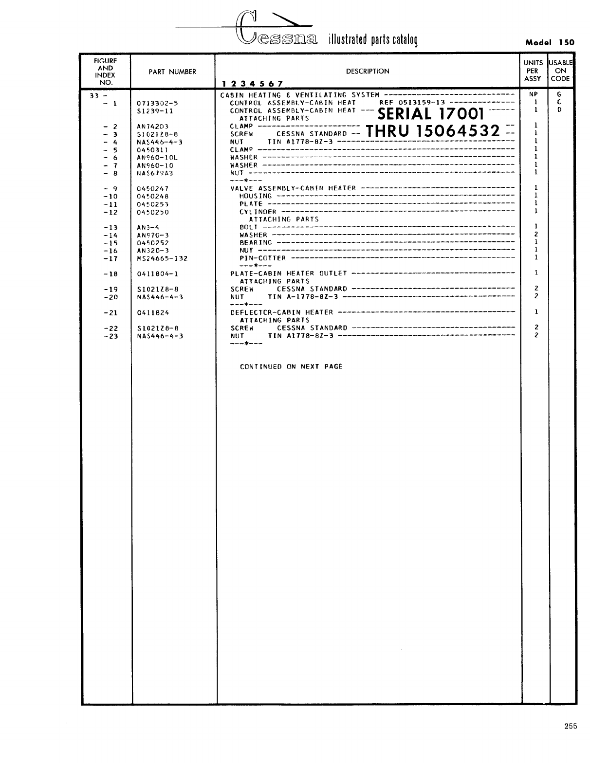
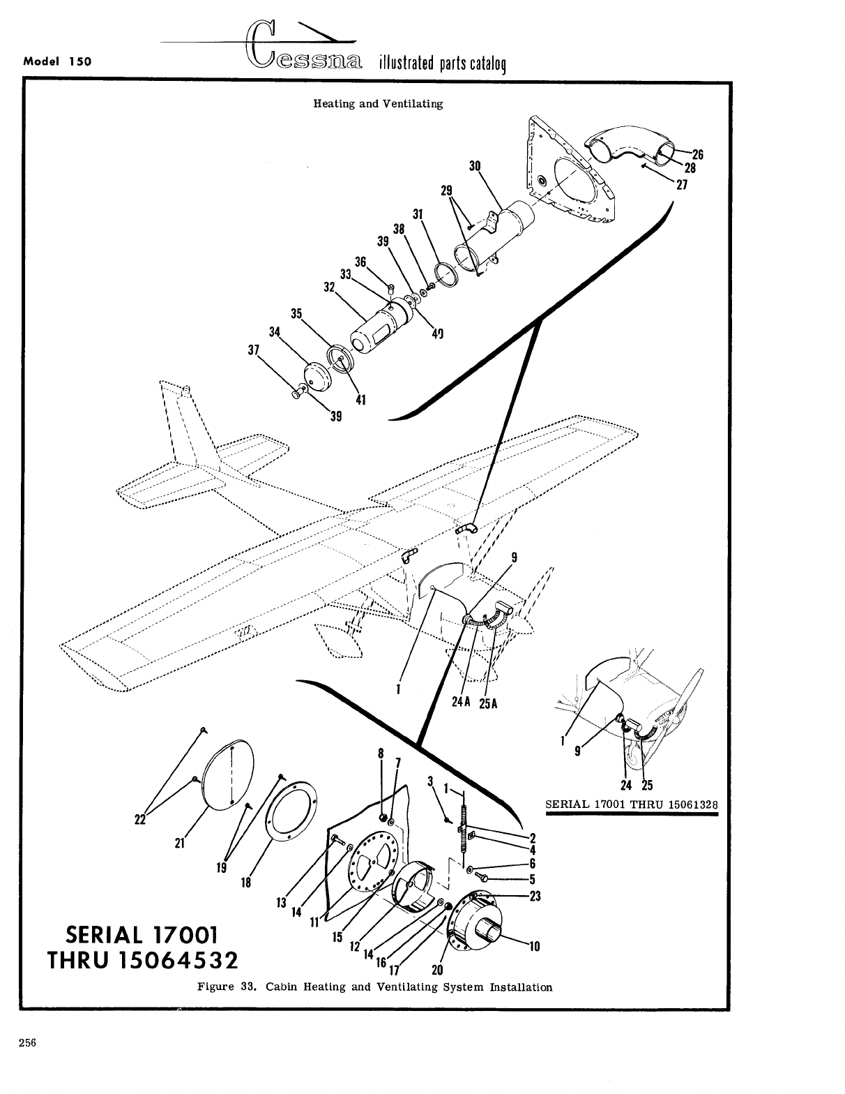
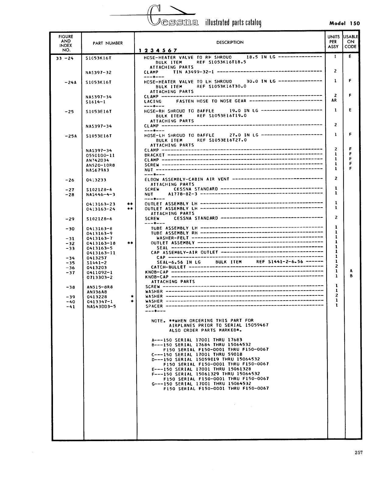
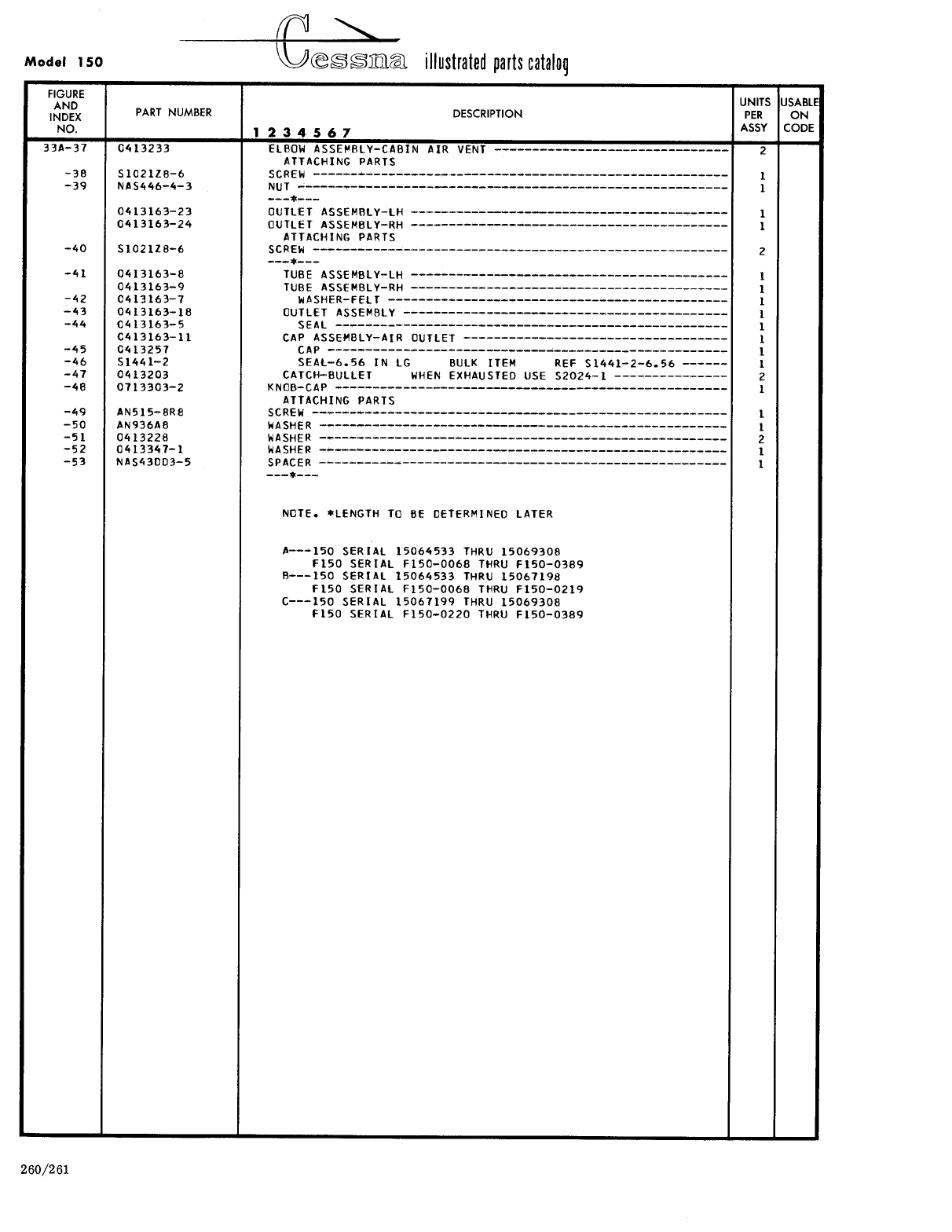
- Fig 33. Cabin Heating and Ventilating System Installation
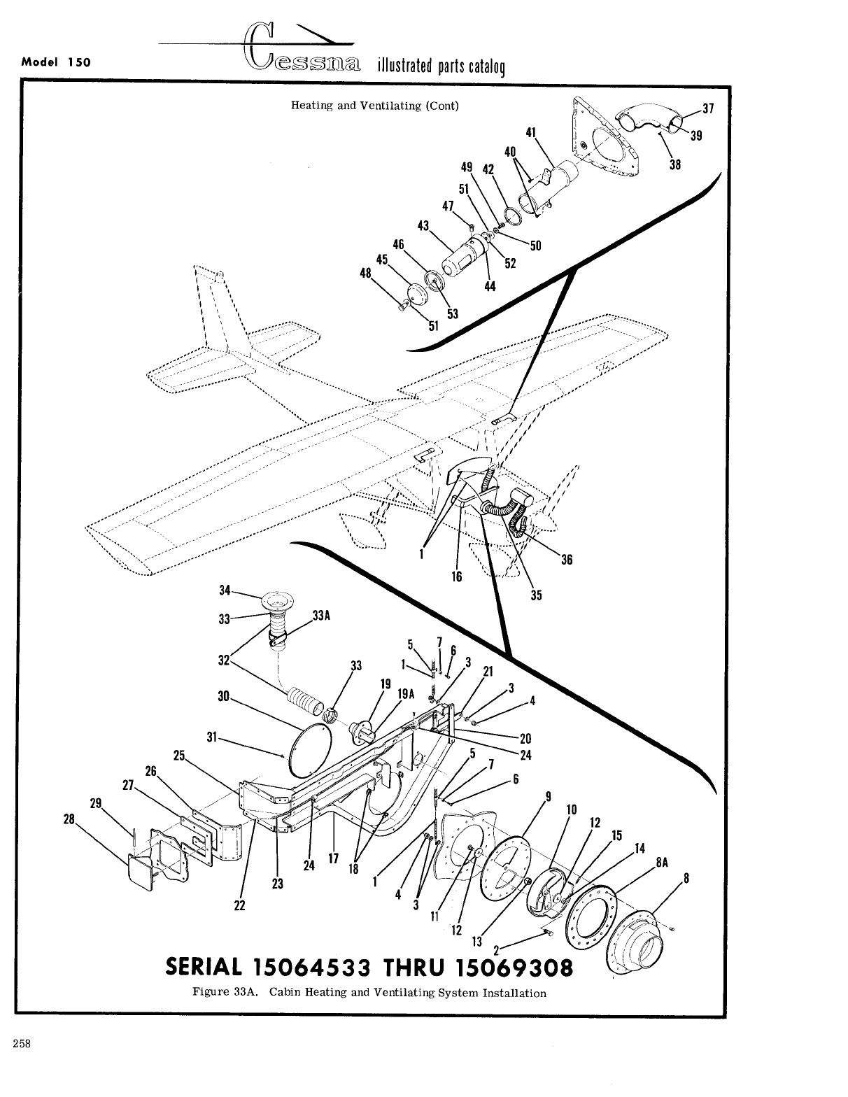
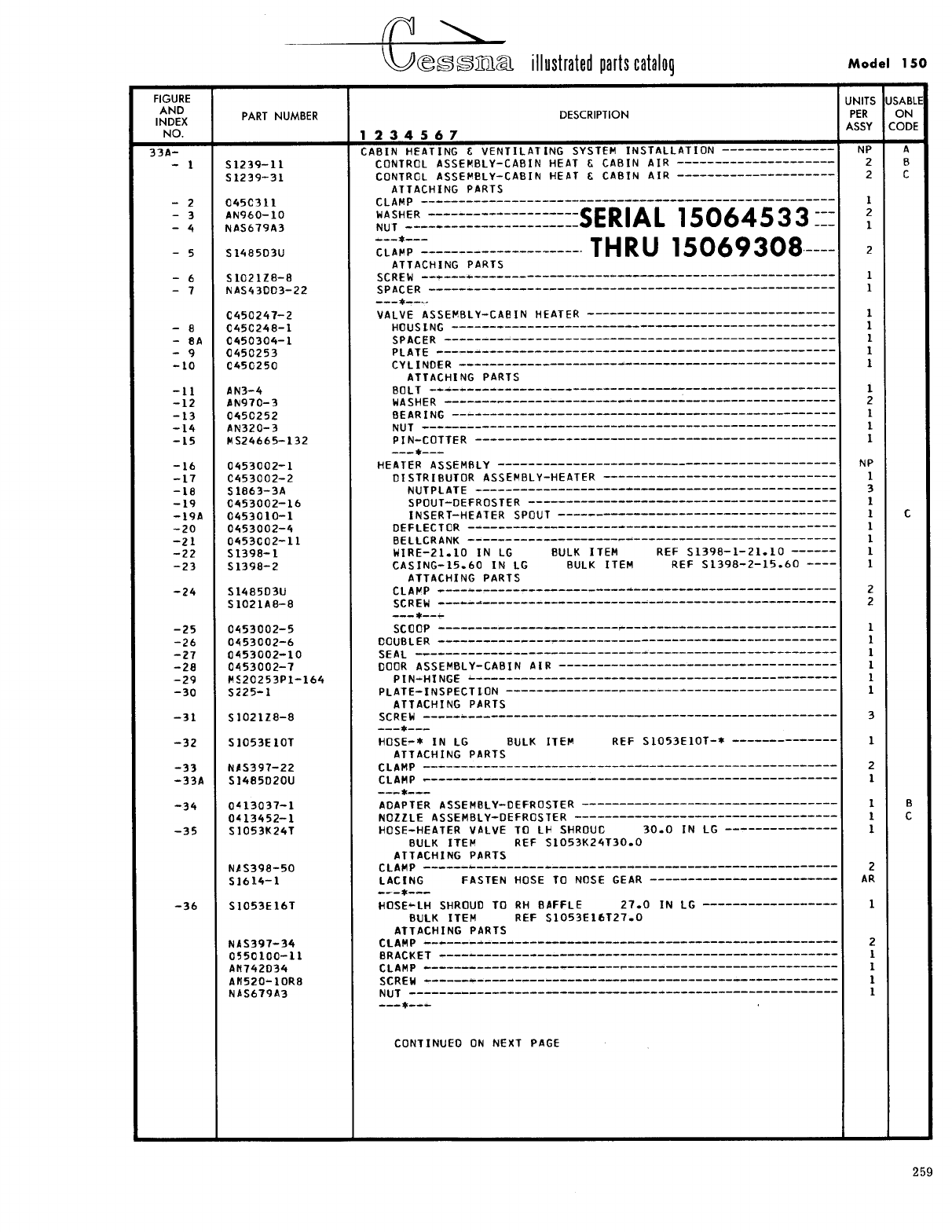
- Fig 33A. Cabin Heating and Ventilating System Installation
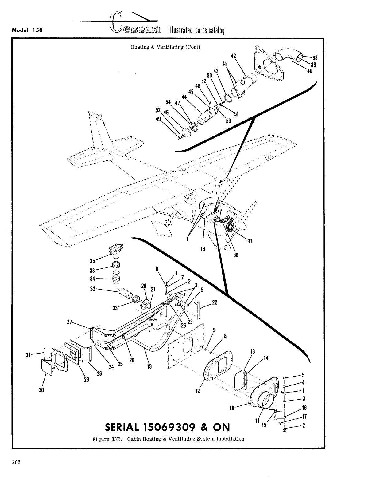
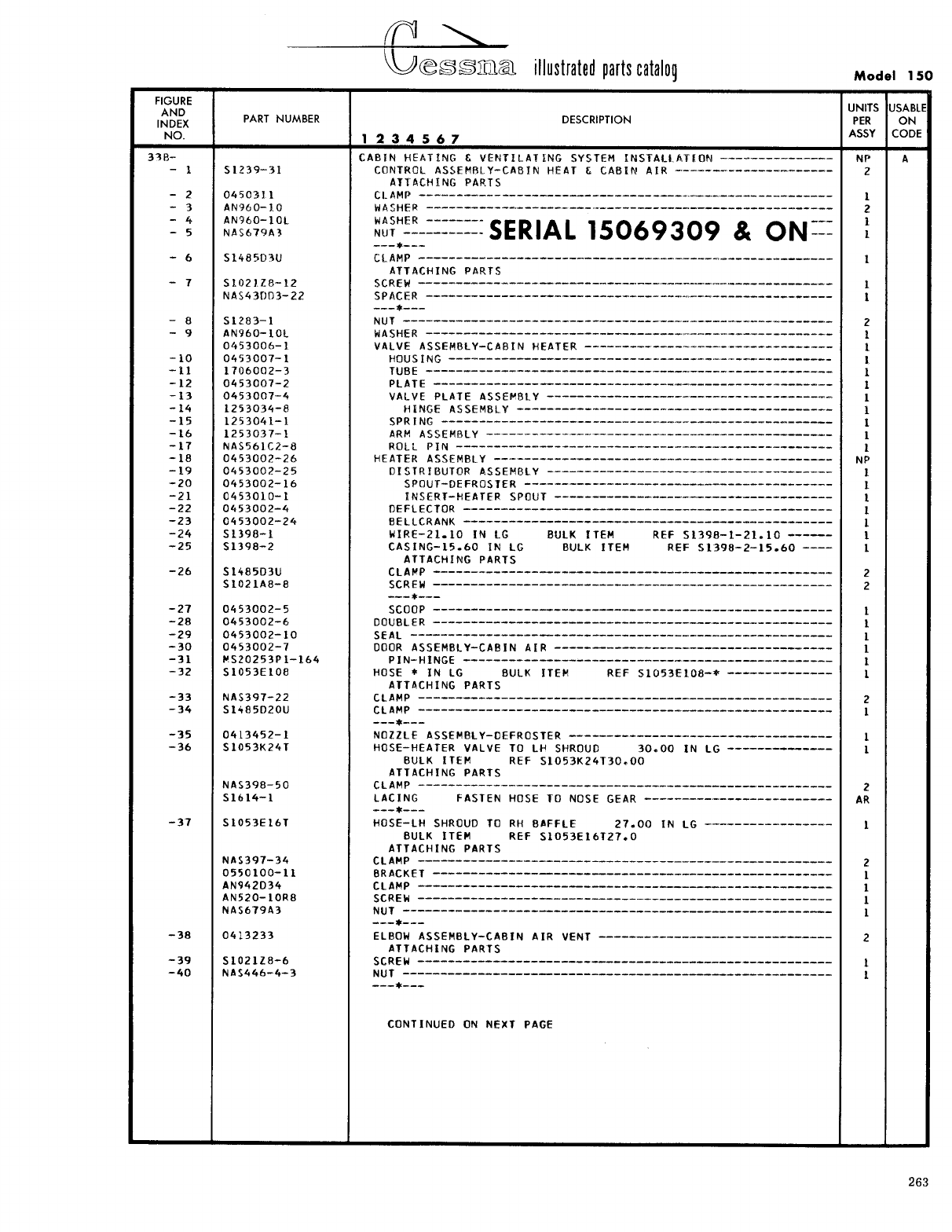
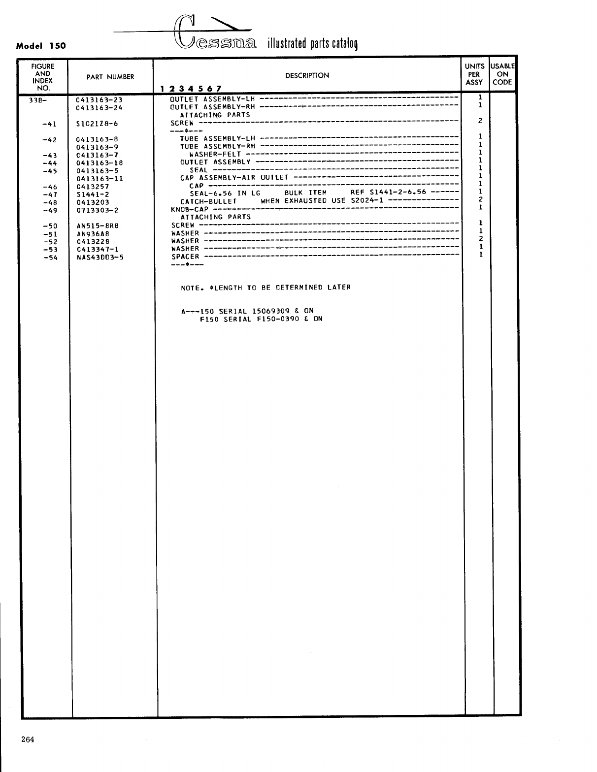
- Fig 33B. Cabin Heating & Ventilating System Installation
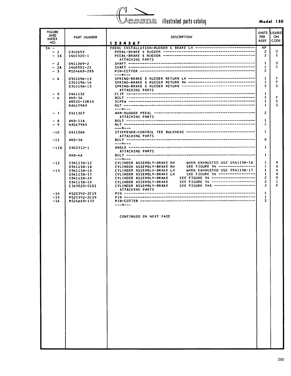
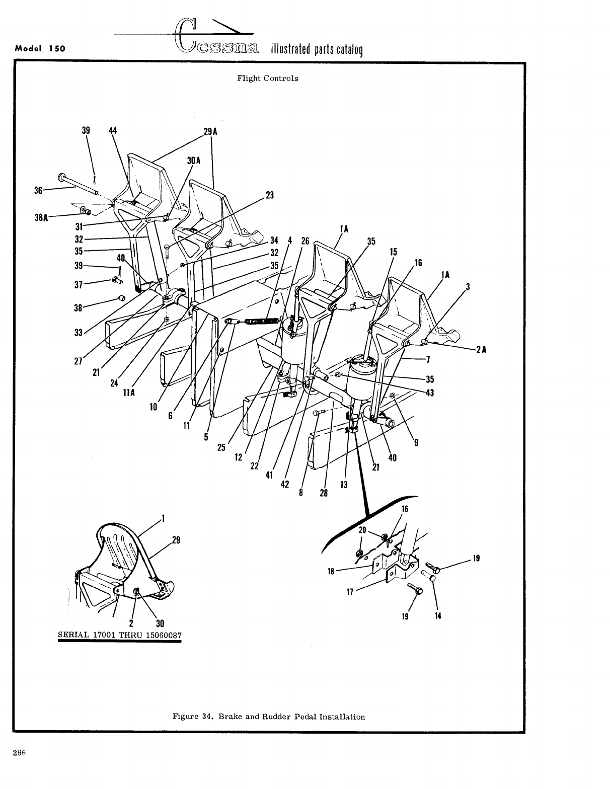
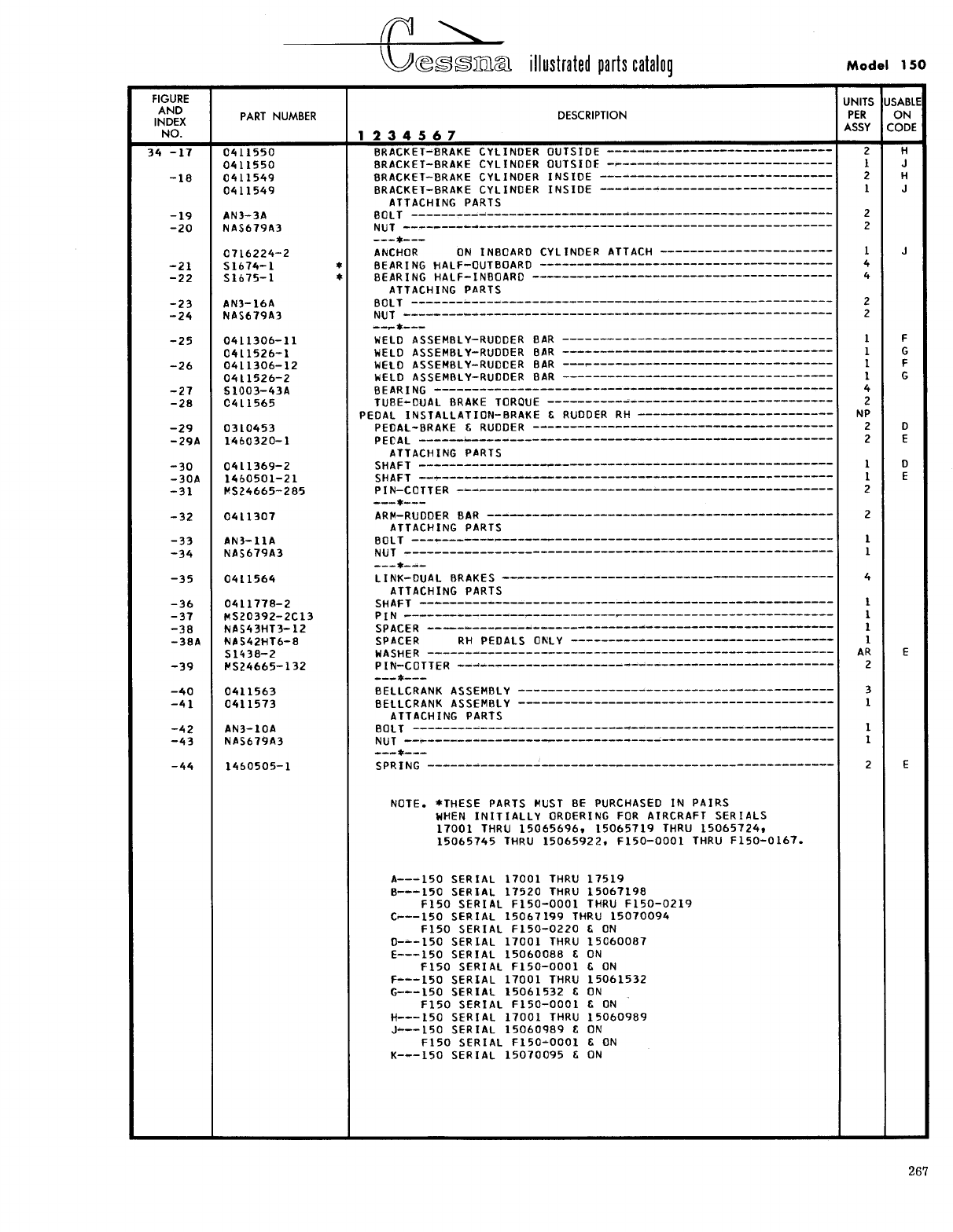
- Fig 34. Brake and Rudder Pedal Installation
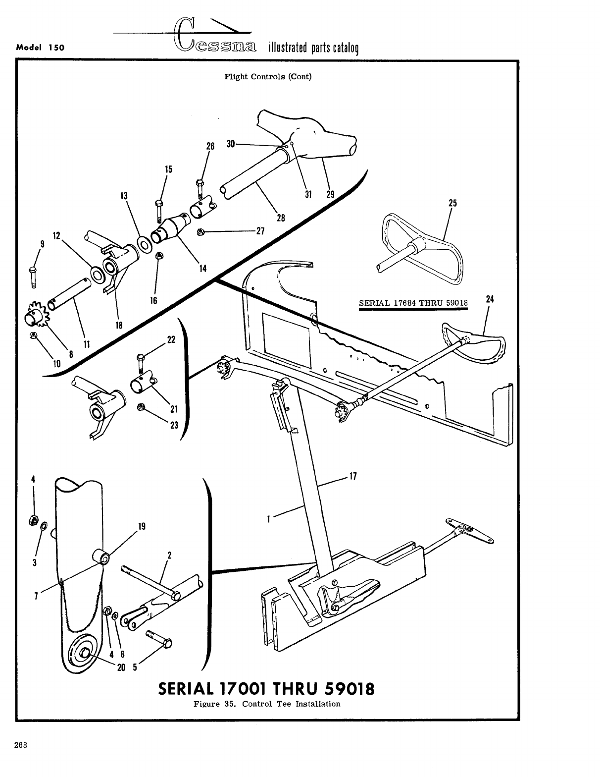
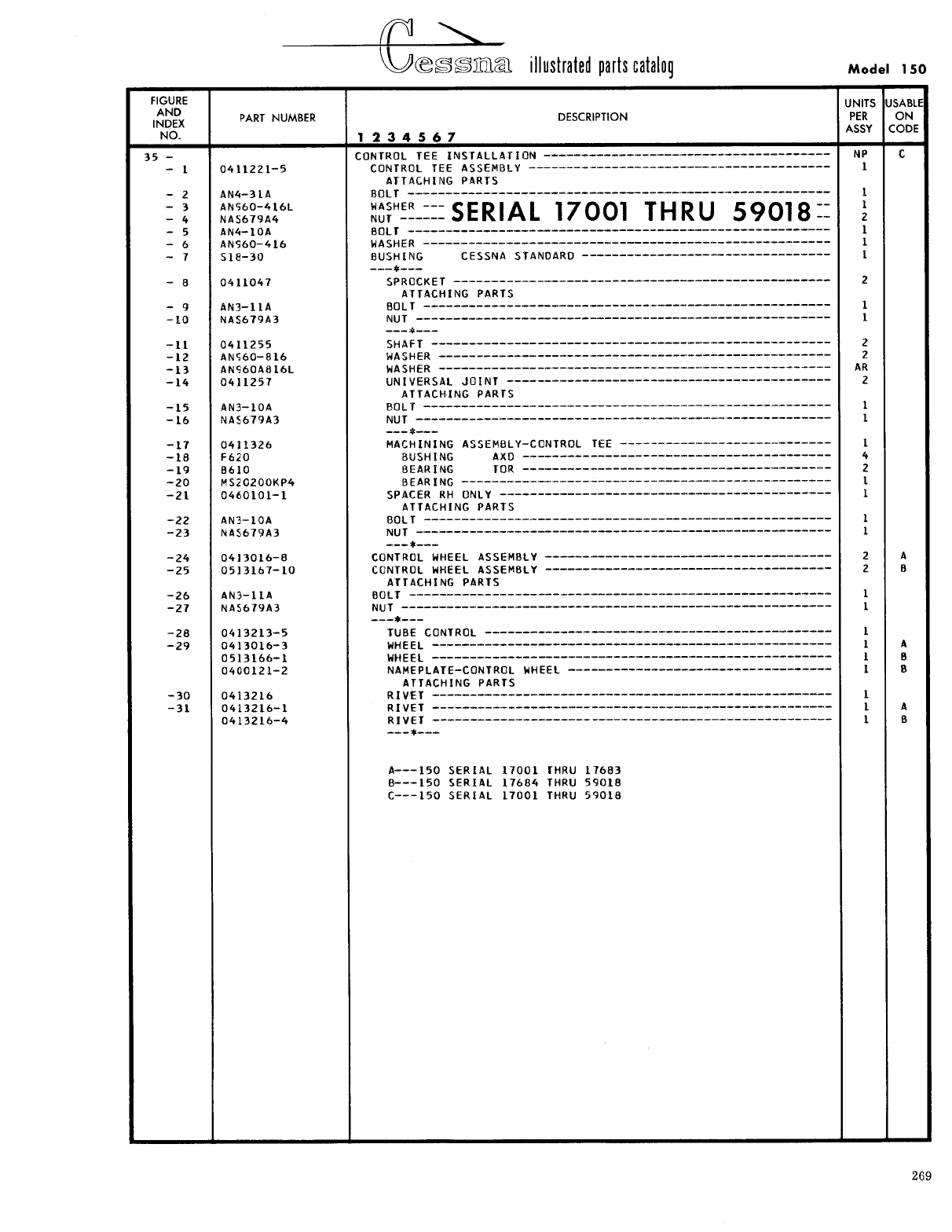
- Fig 35. Control Tee Installation
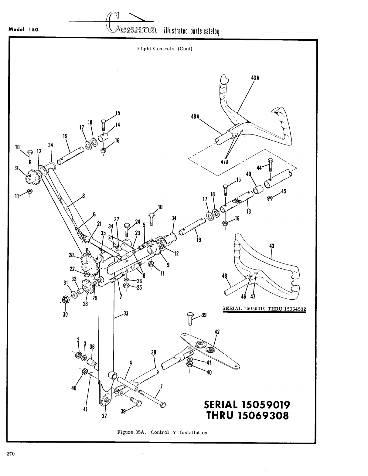
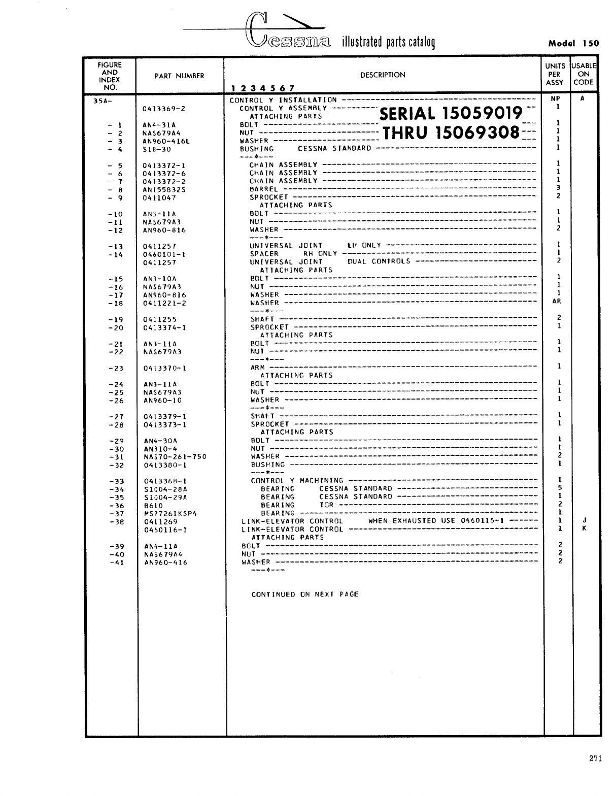
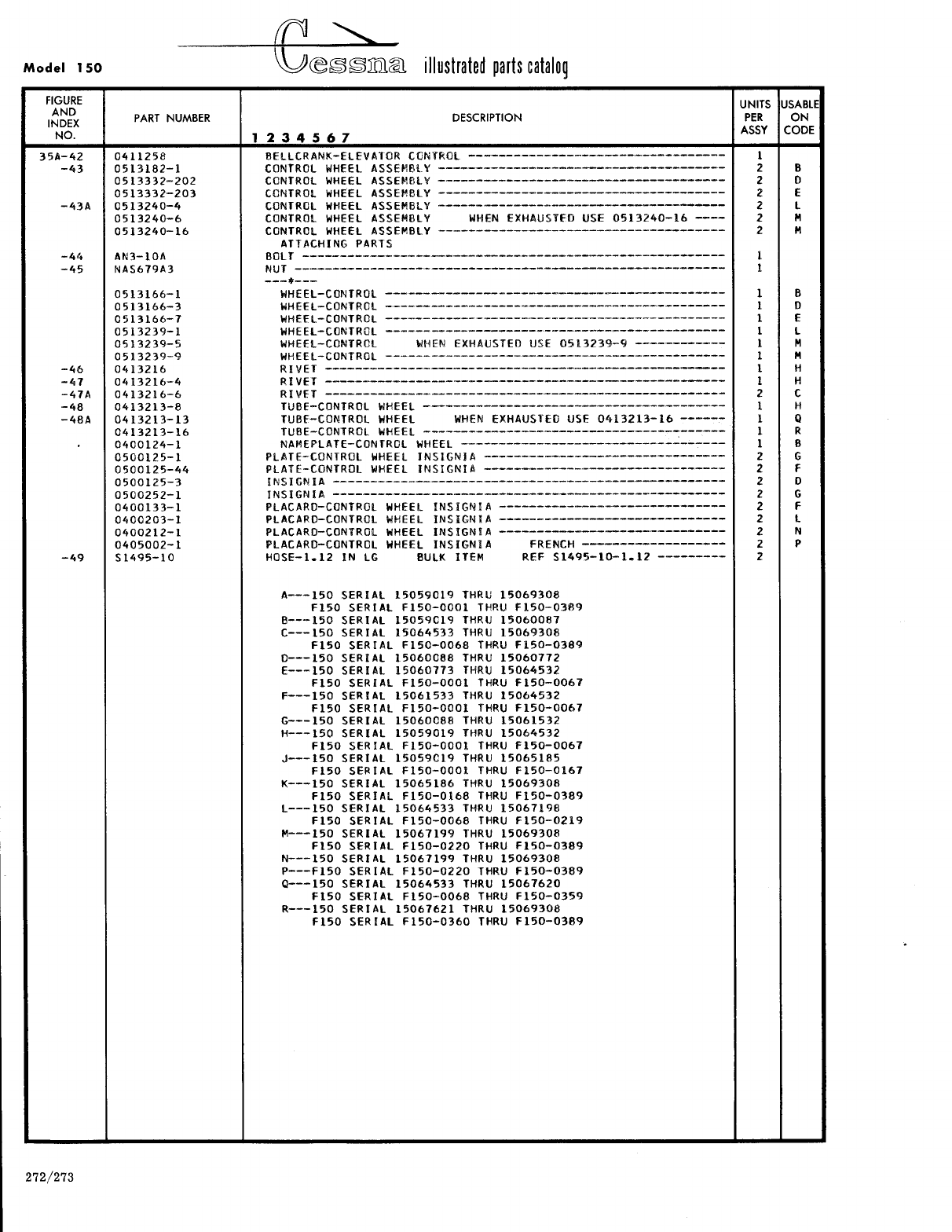
- Fig 35A. Control Y Installation
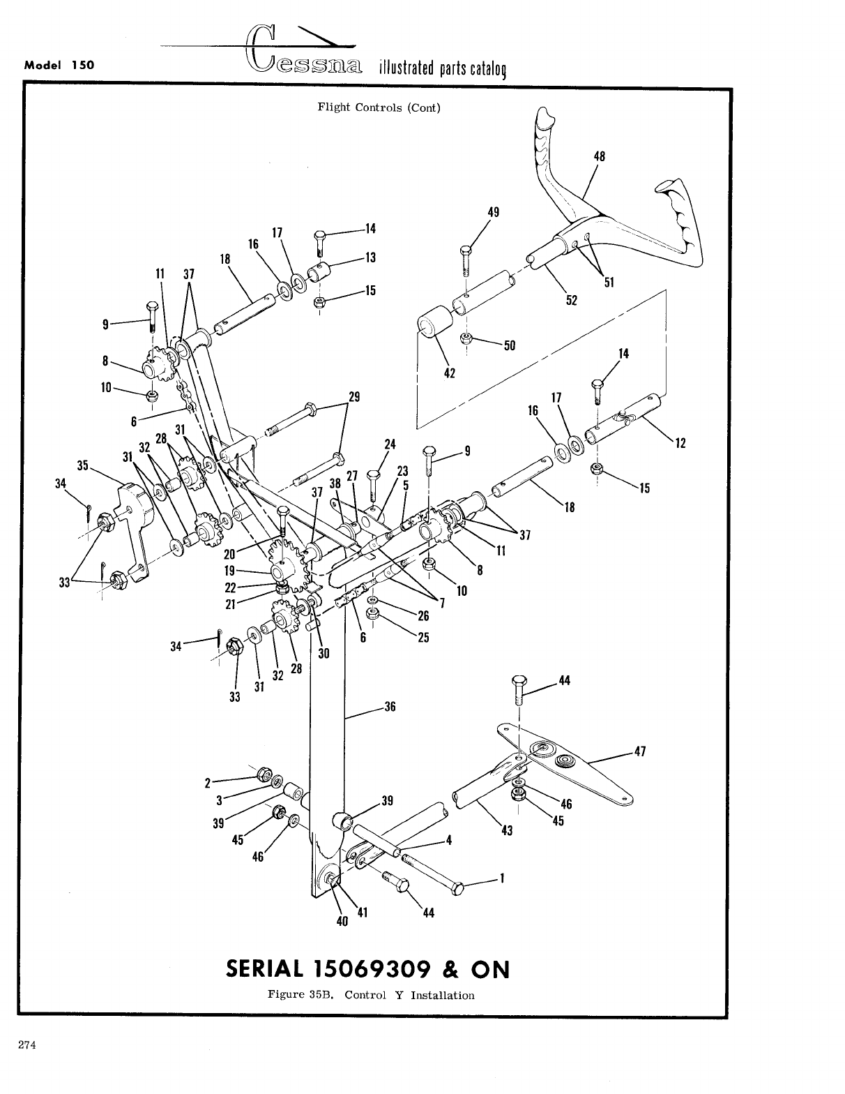
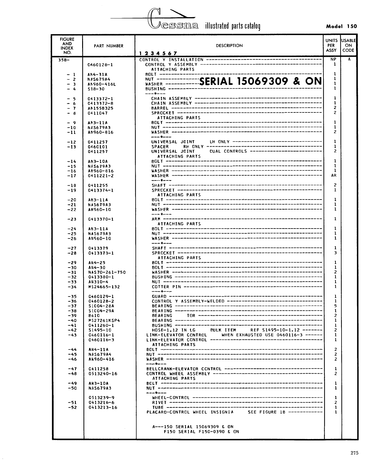
- Fig 35B. Control Y Installation
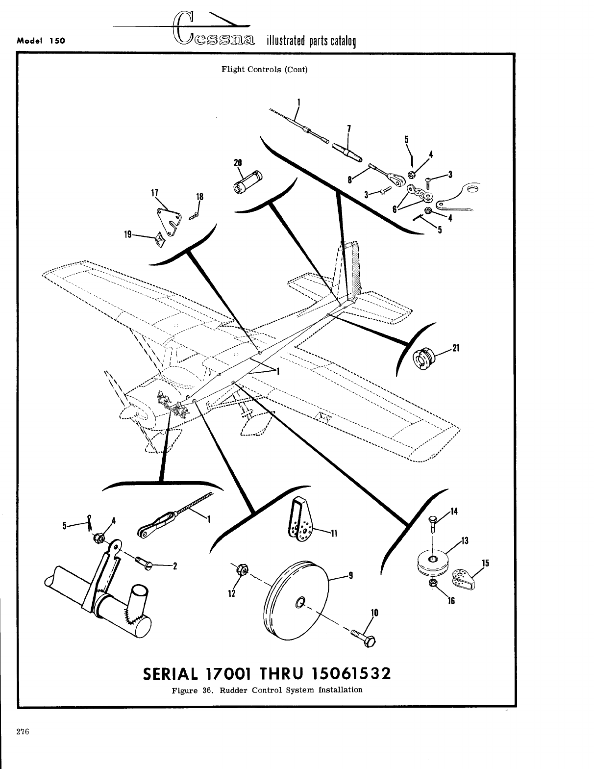
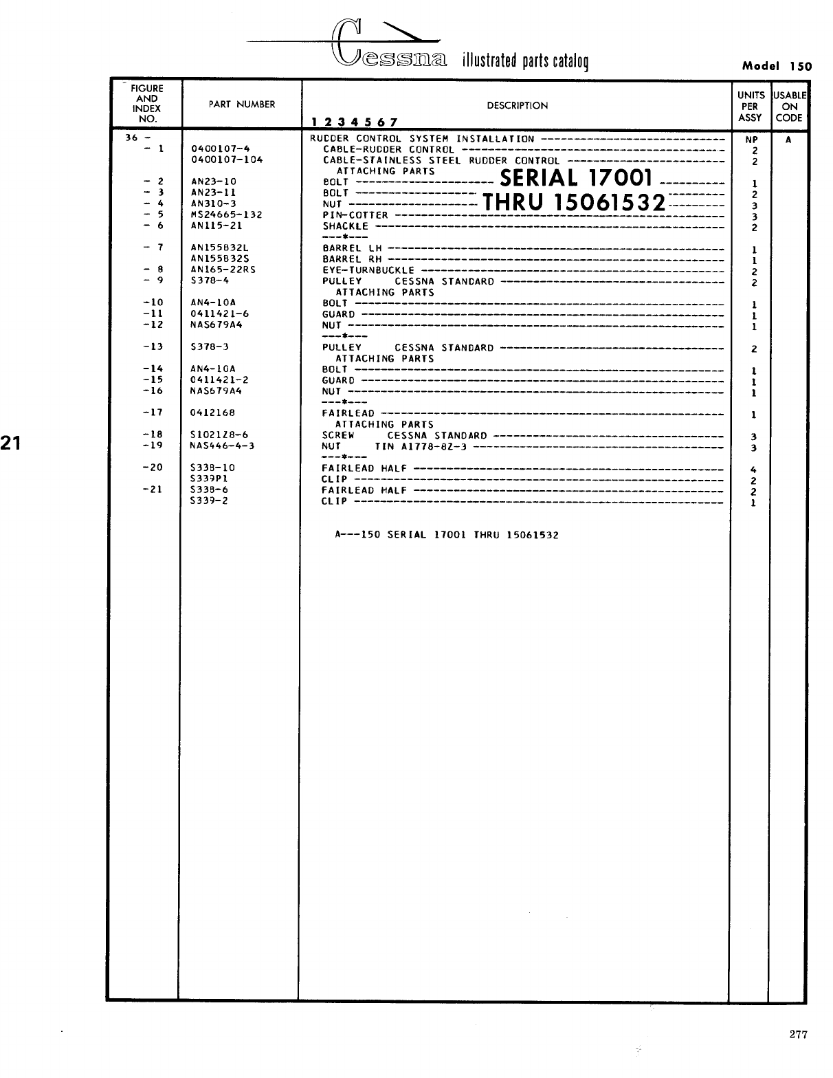
- Fig 36. Rudder Control System Installation
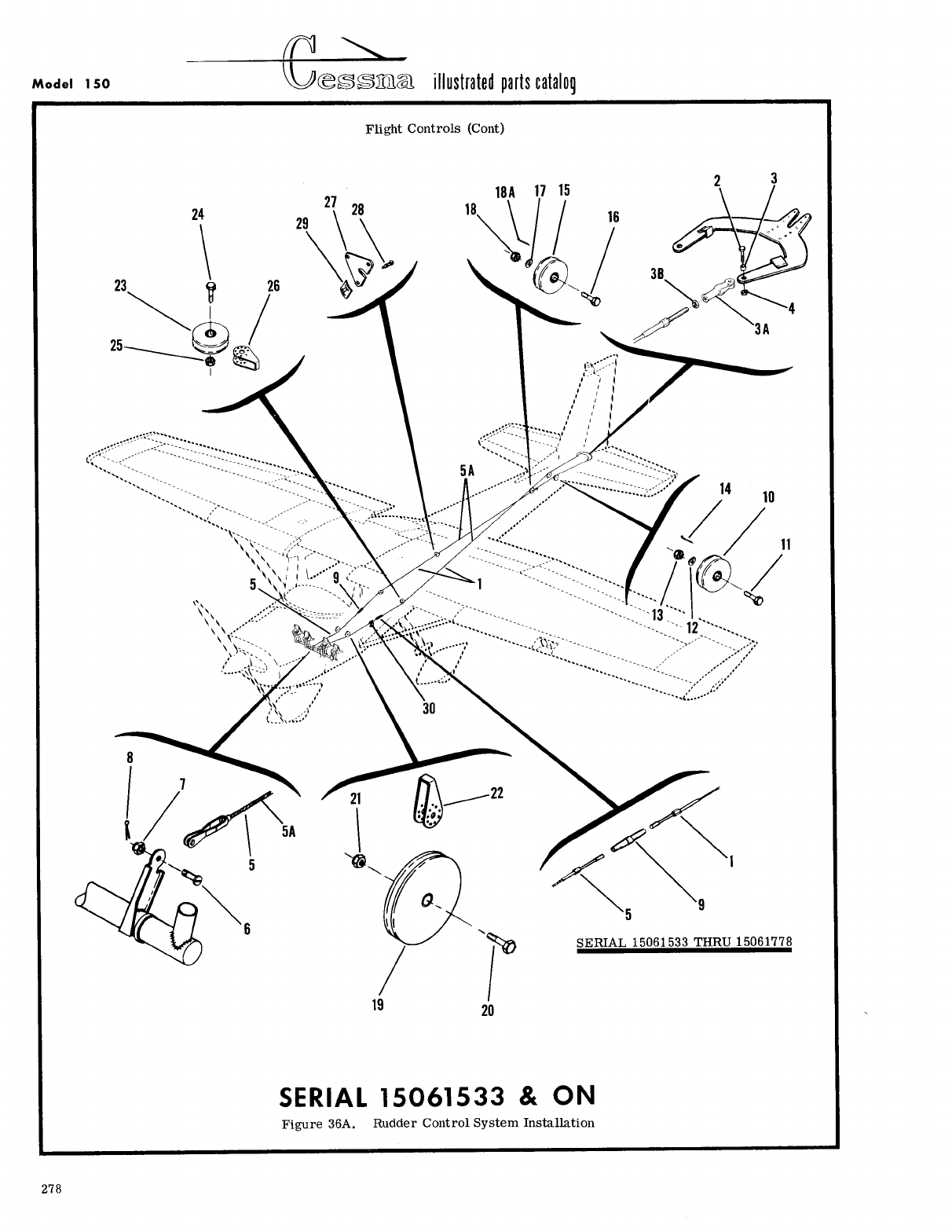
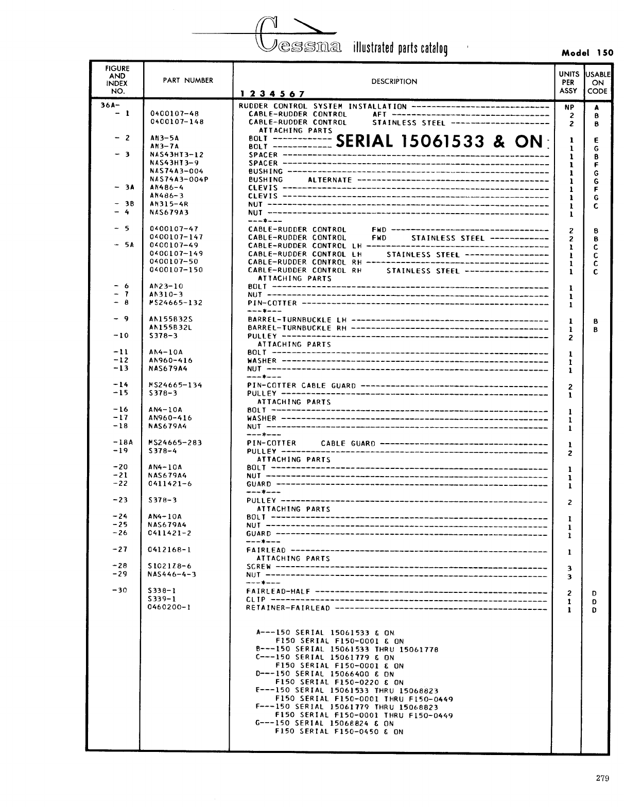
- Fig 36A. Rudder Control System Installation
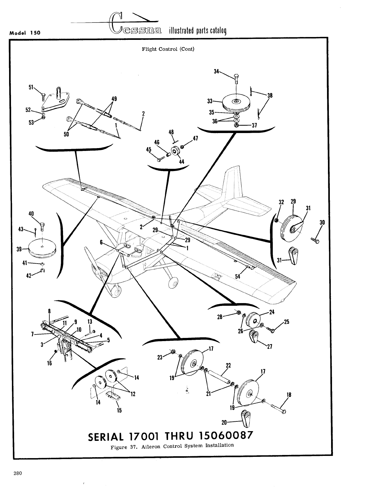
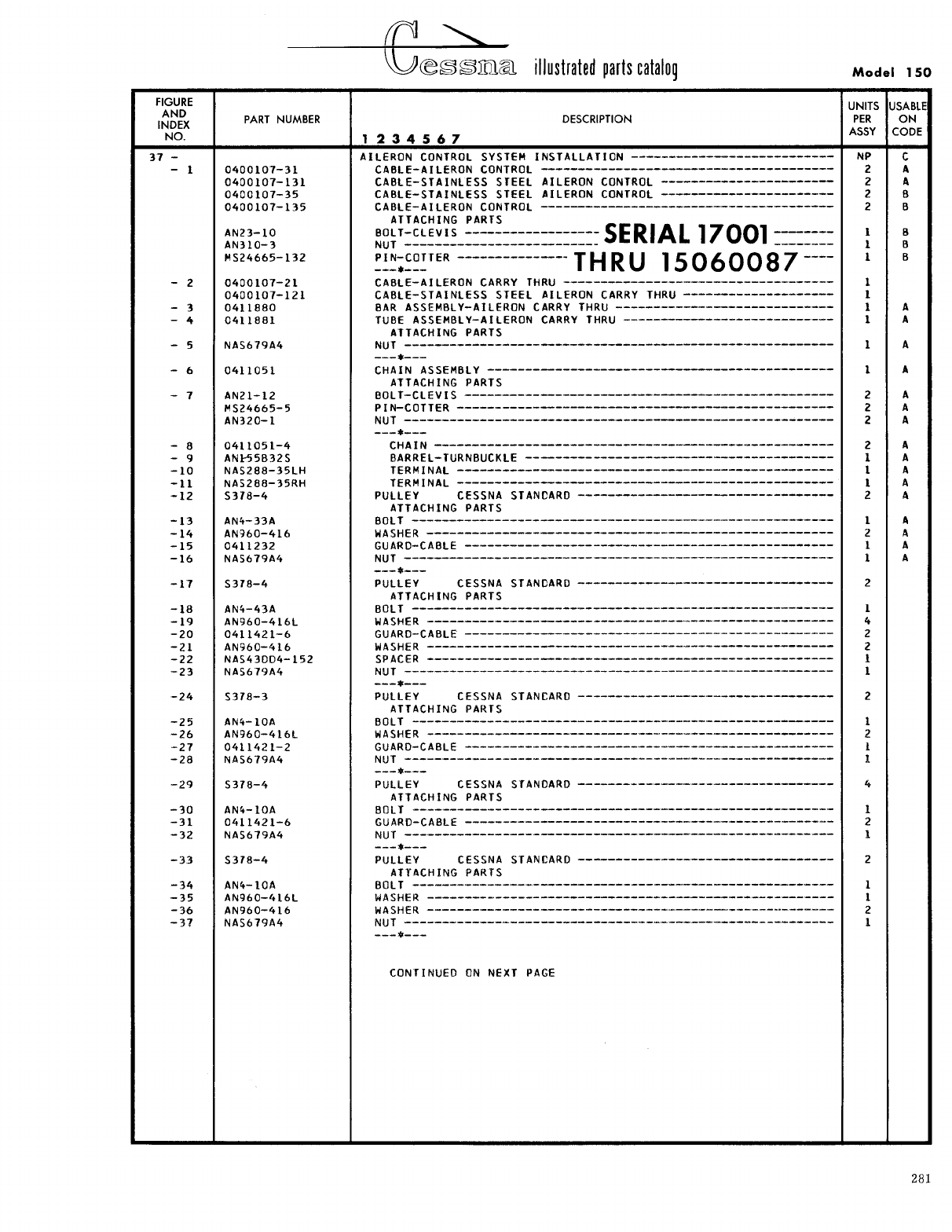
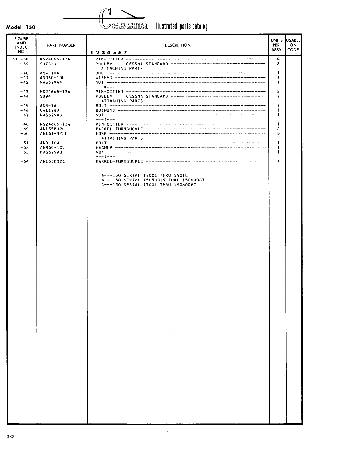
- Fig 37. Aileron Control System Installation
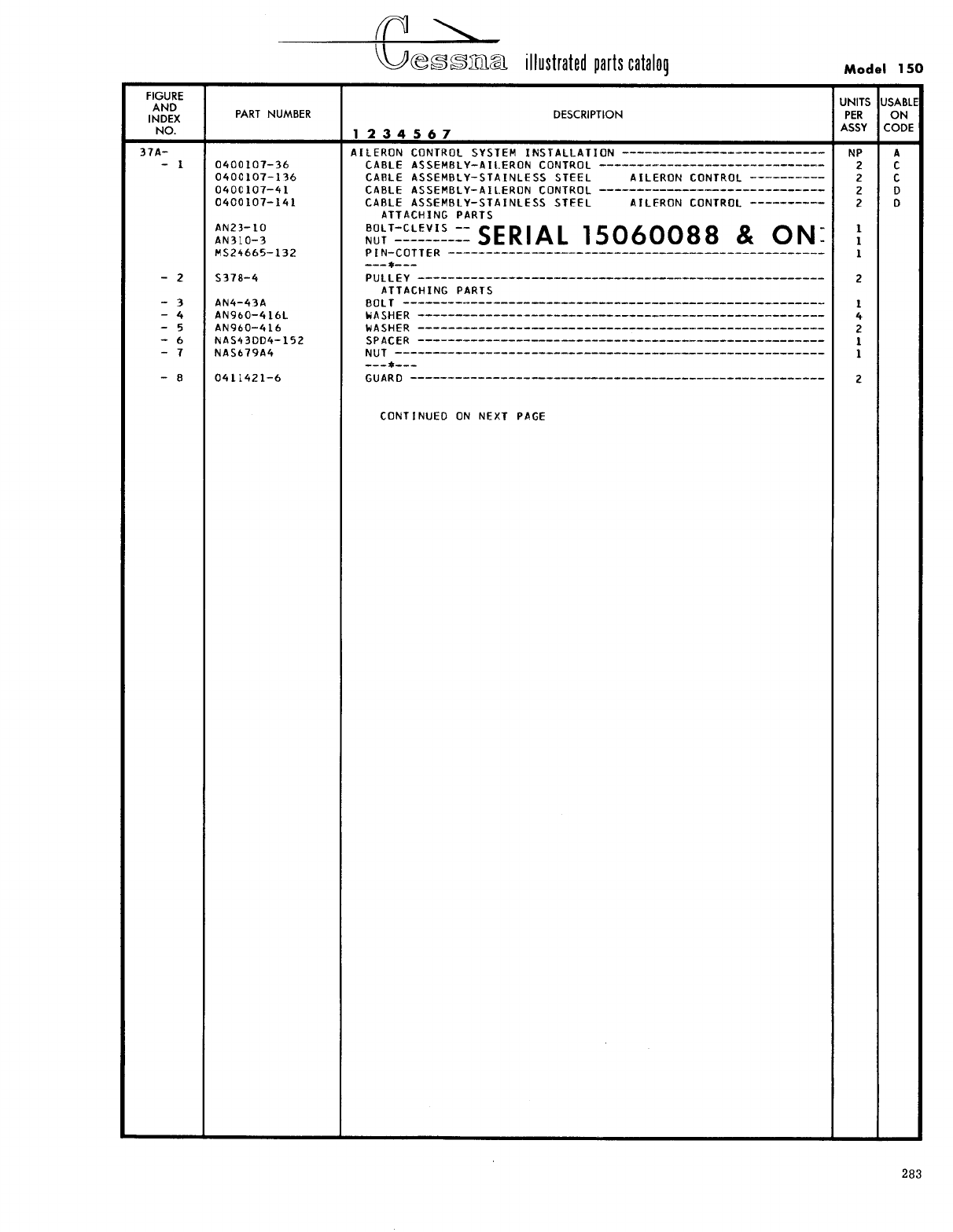
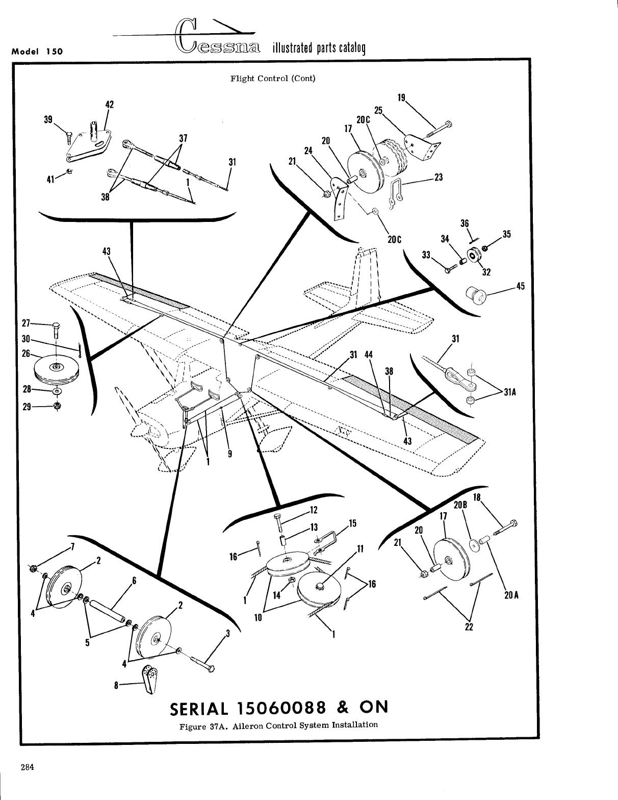
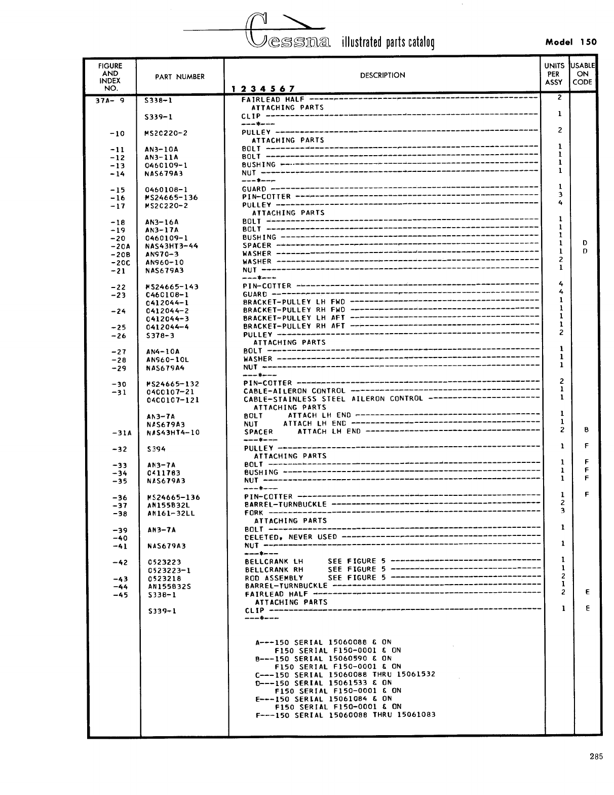
- Fig 37A. Aileron Control System Installation
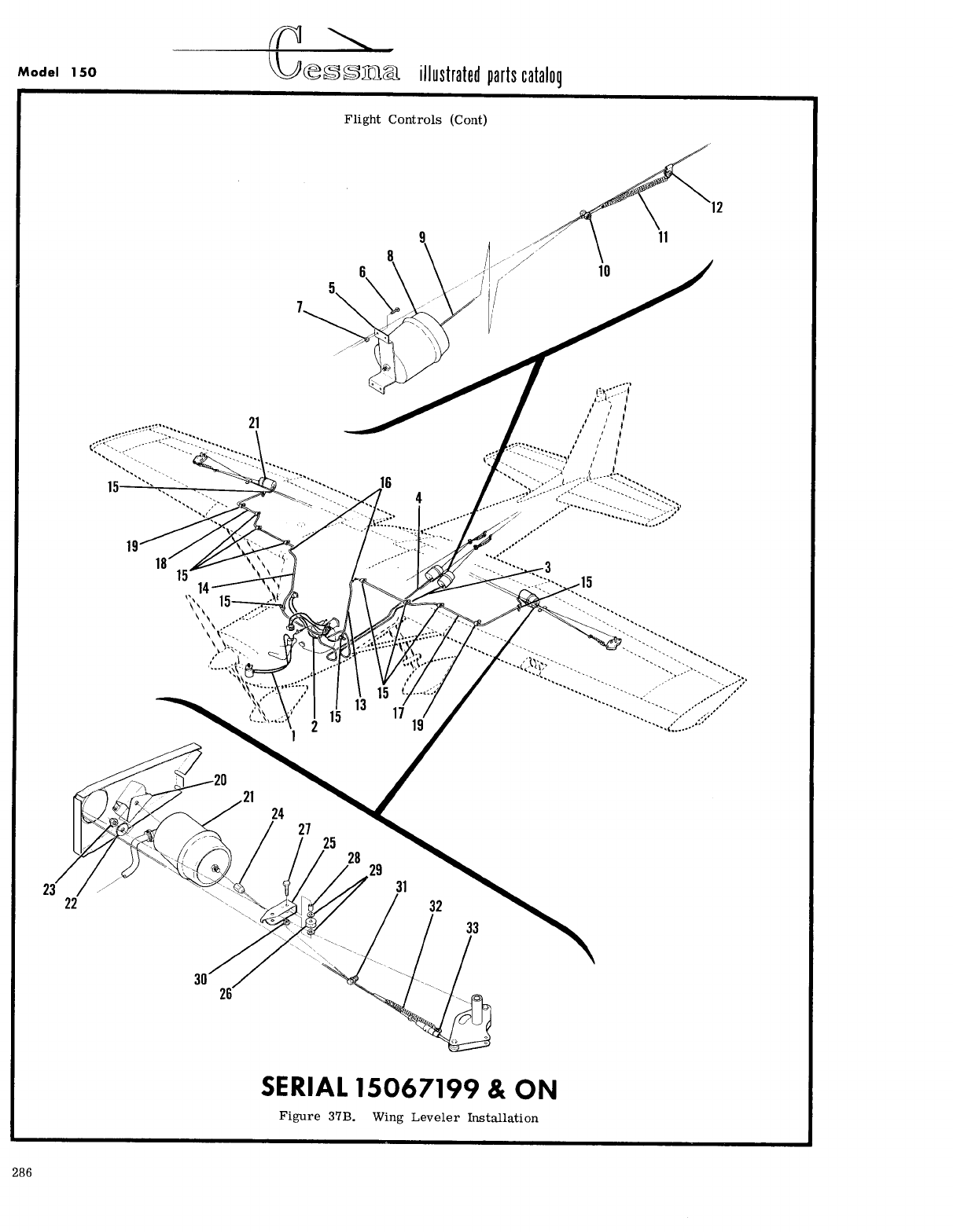
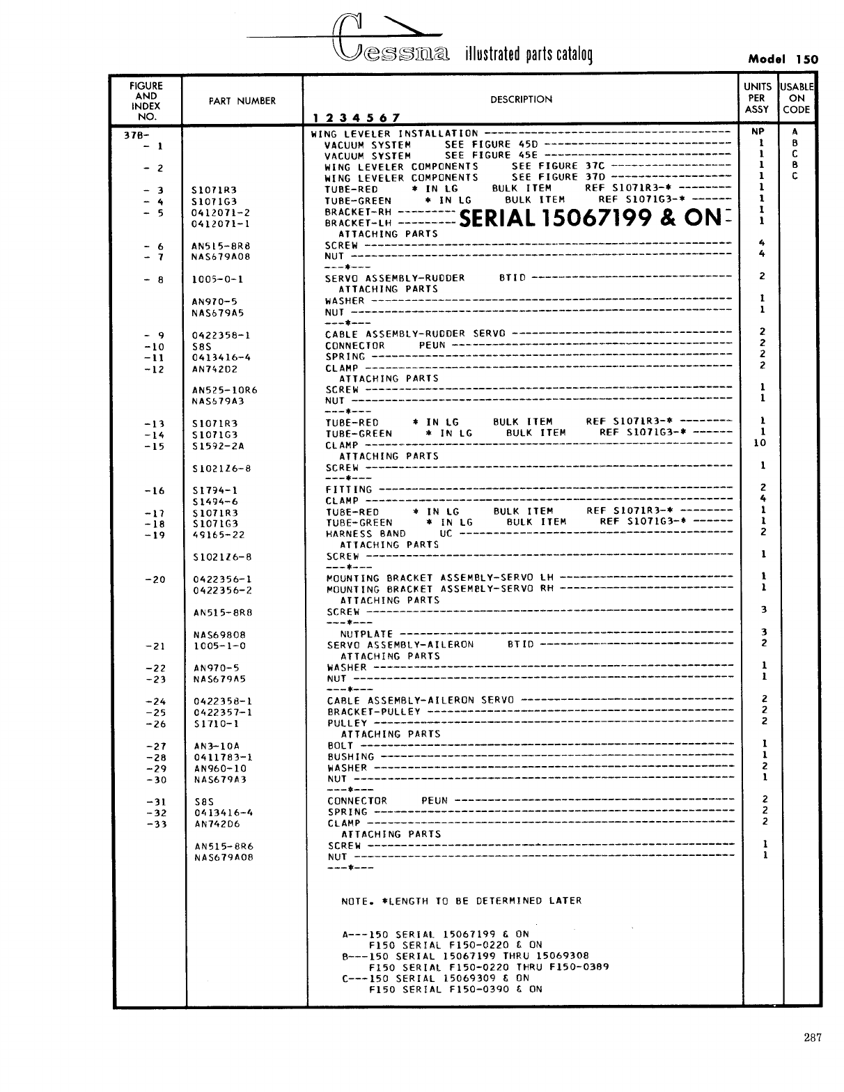
- Fig 37B. Wing Leveler Installation
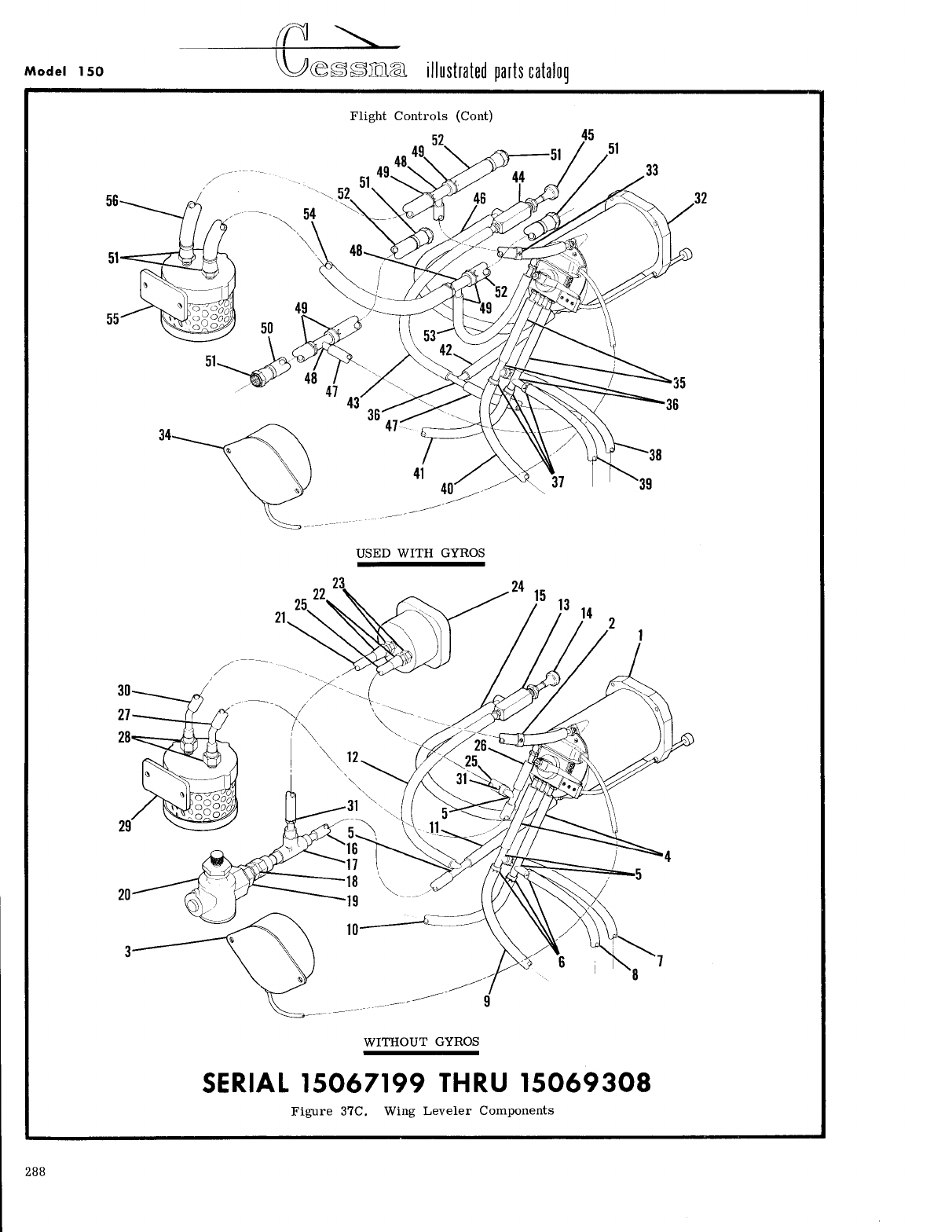
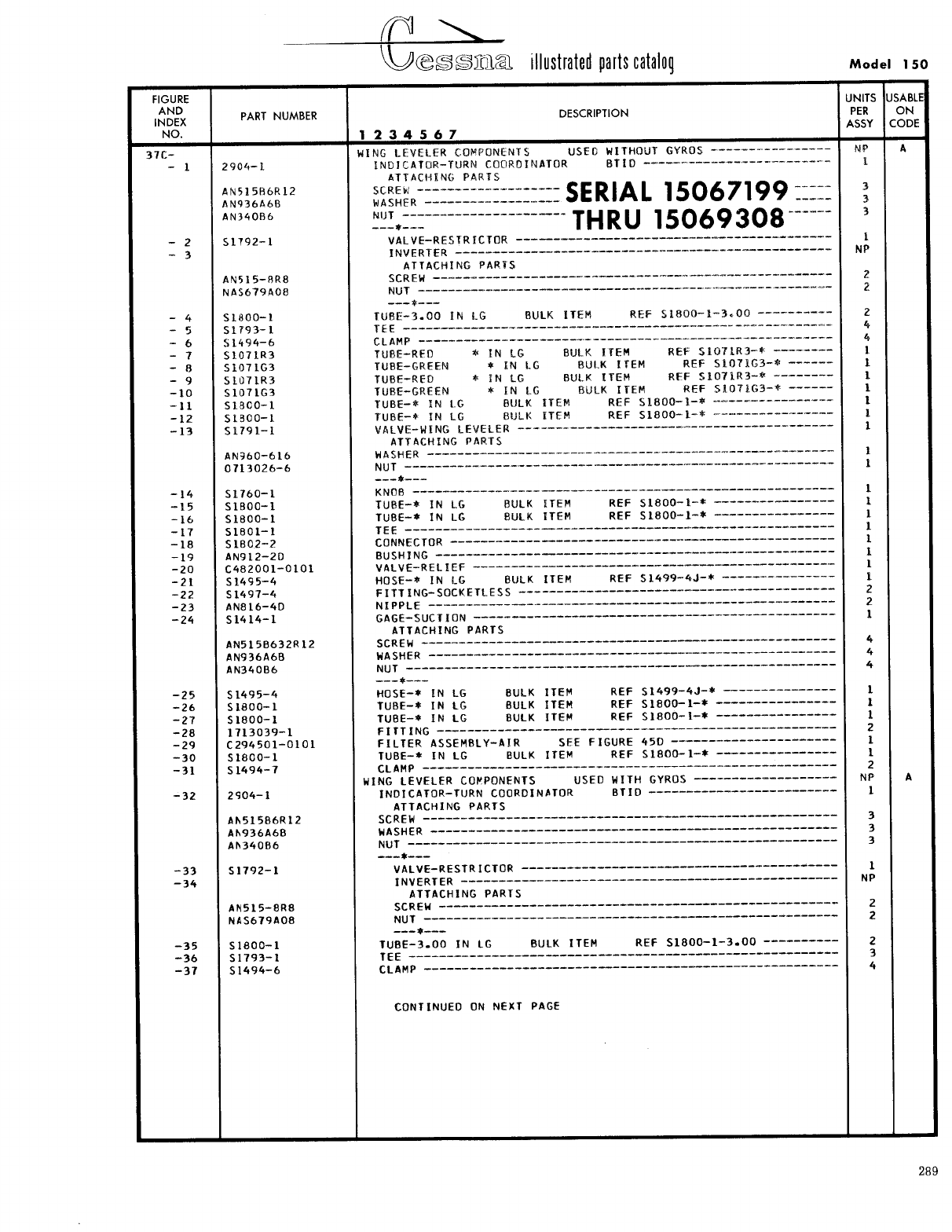
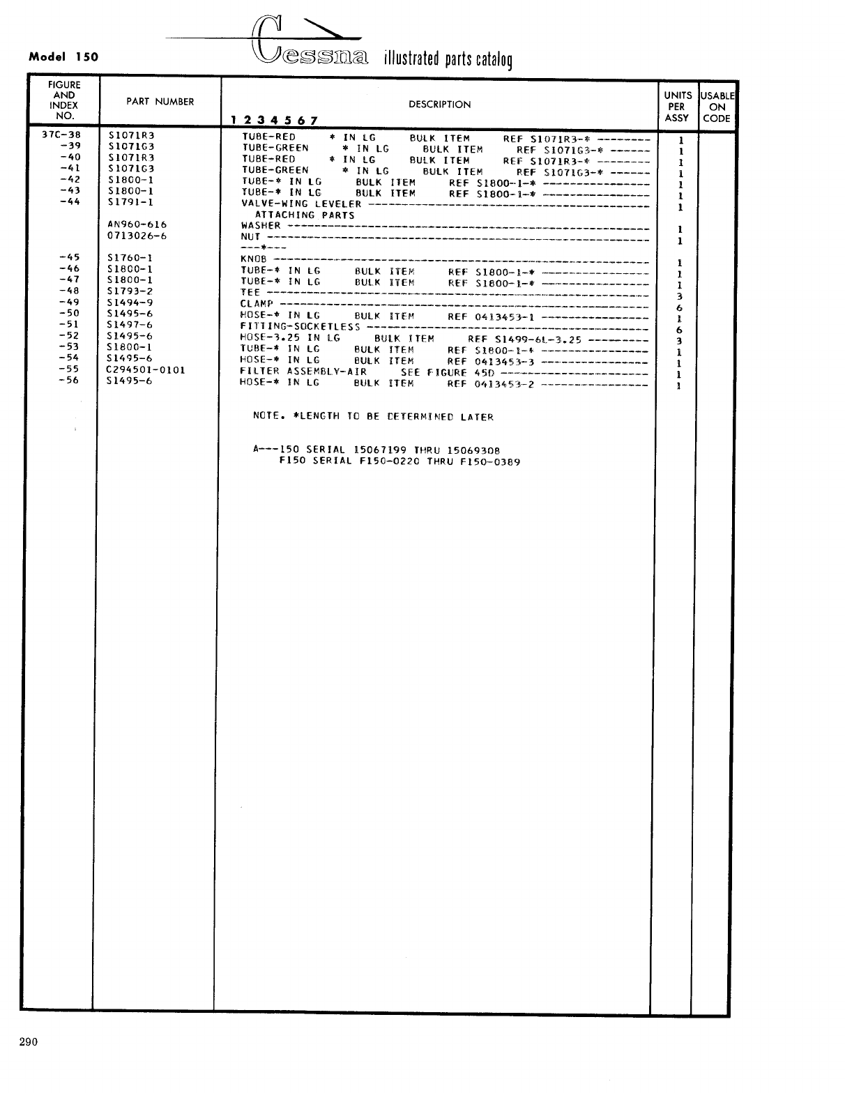
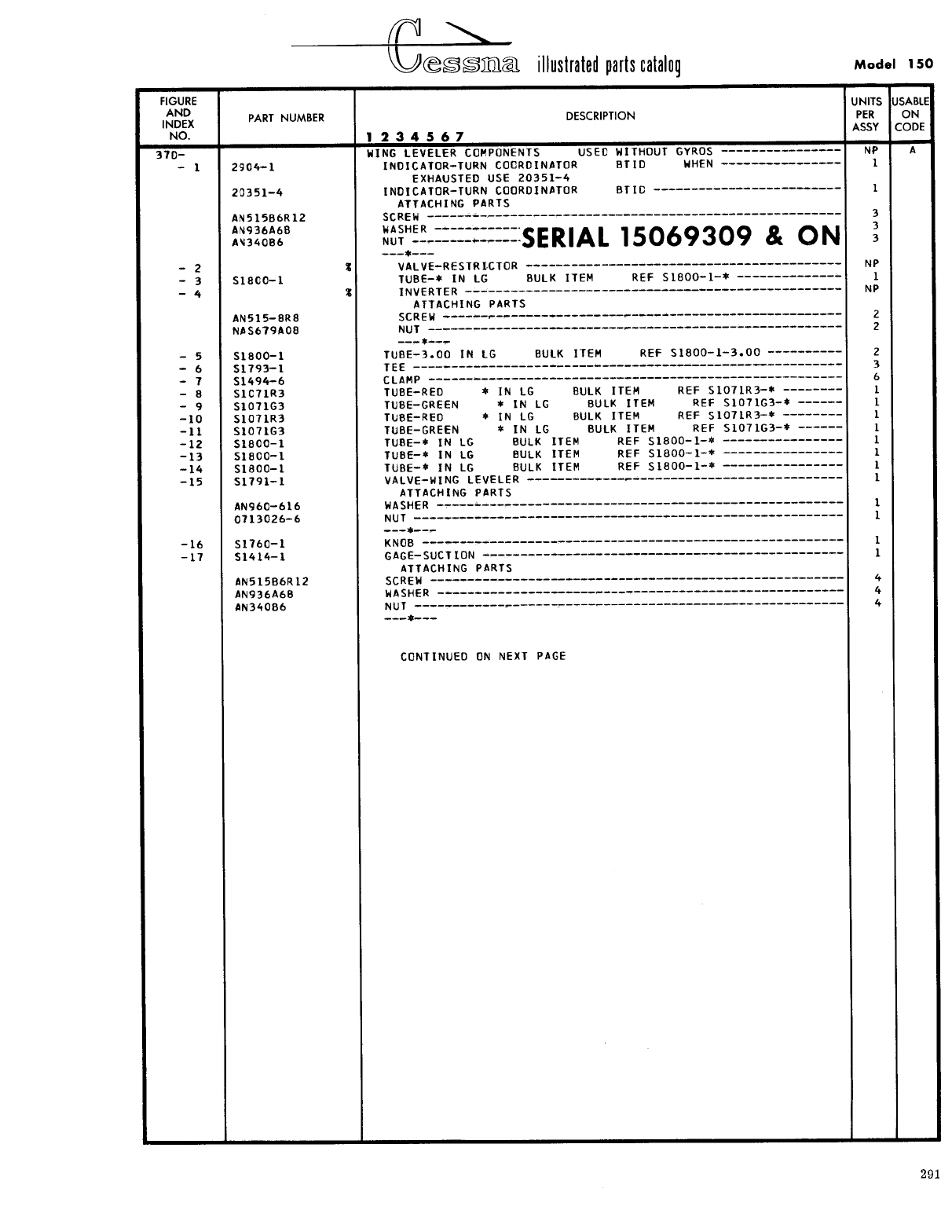
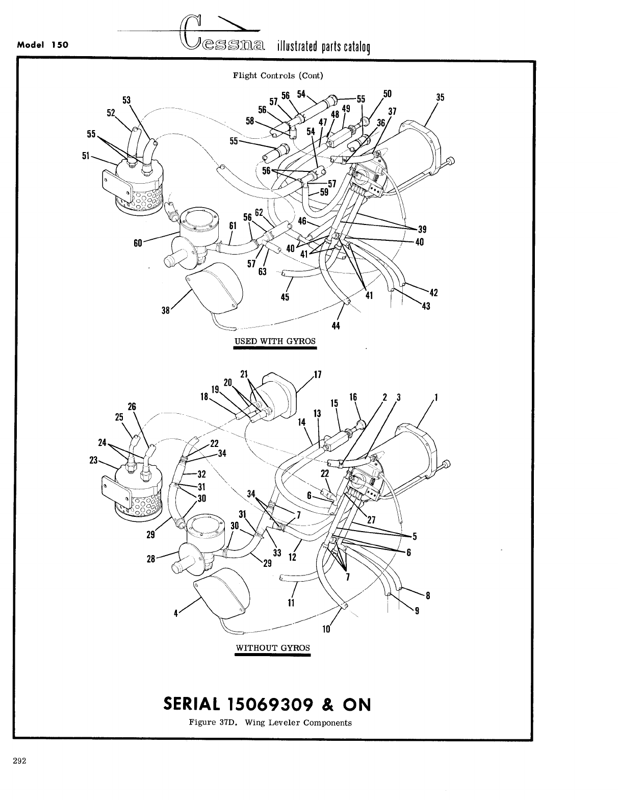
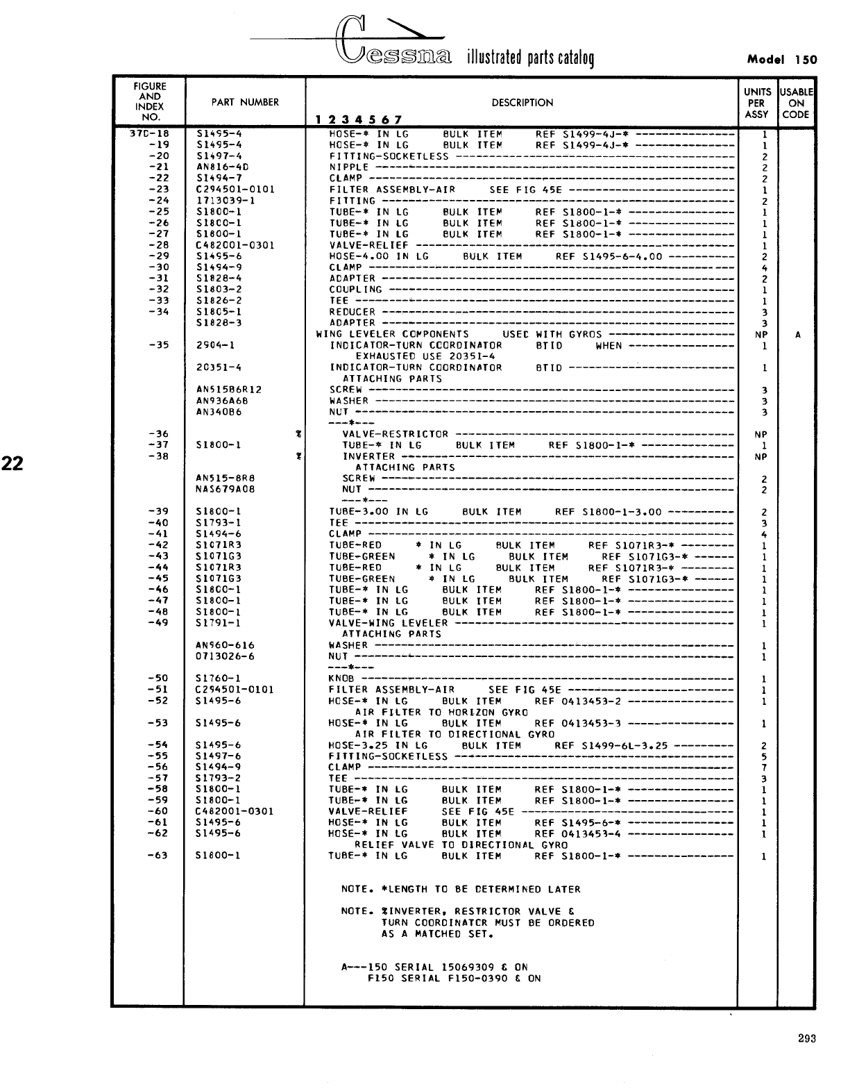
- Fig 37C. Wing Leveler Components
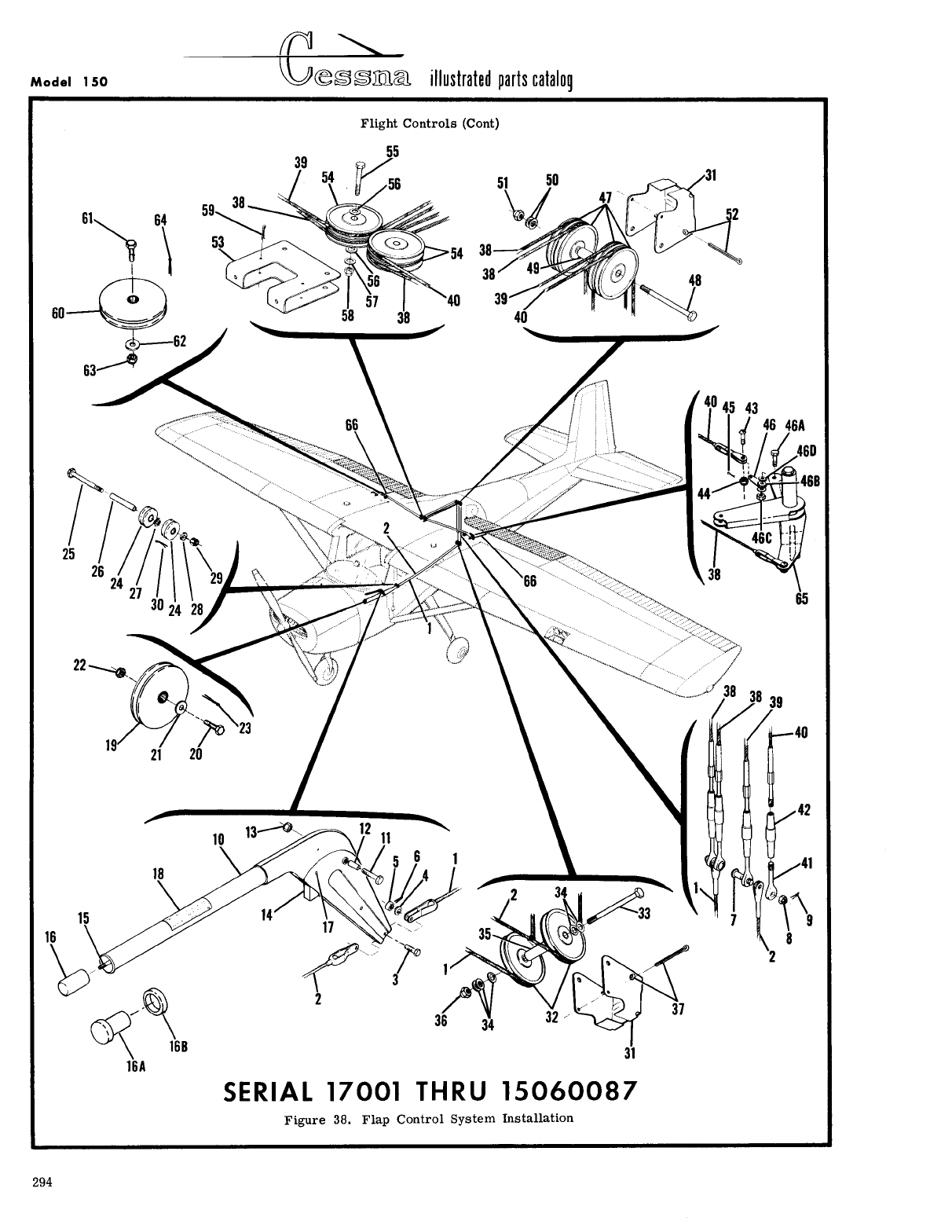
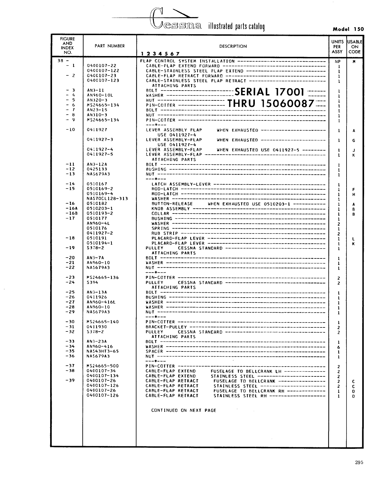
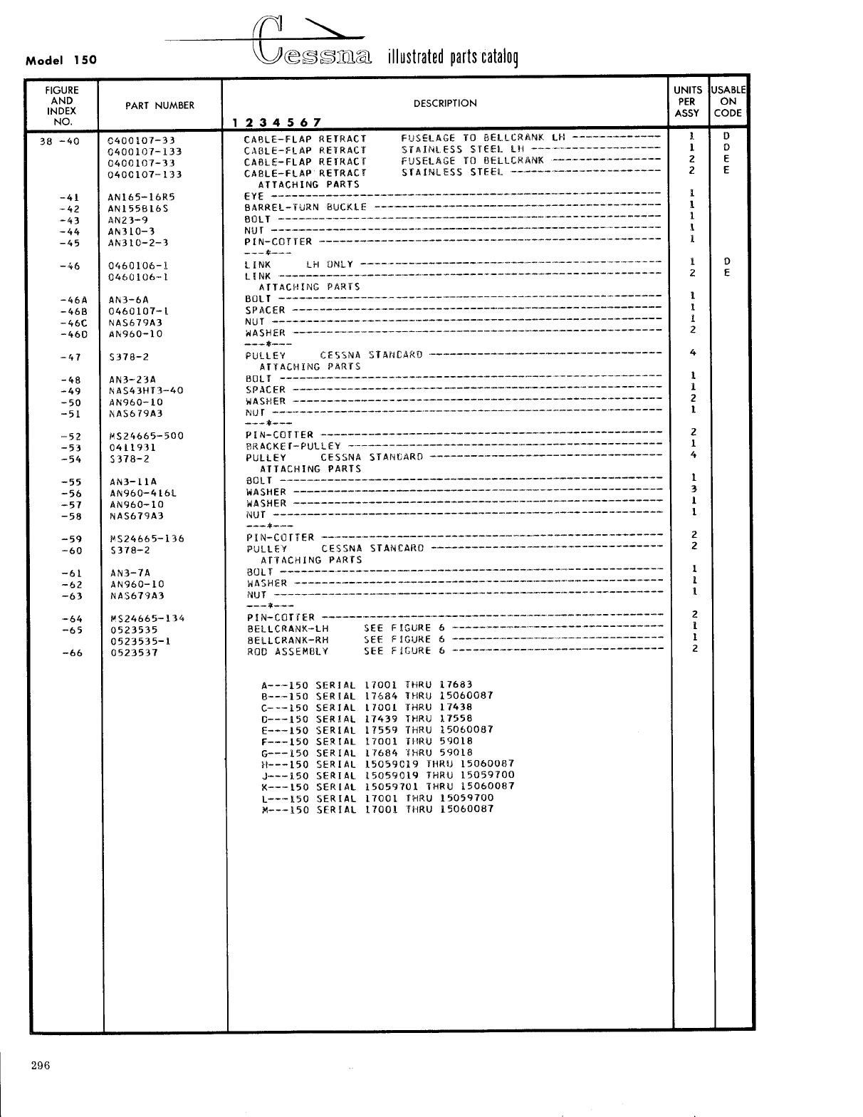
- Fig 38. Flap Control System Installation
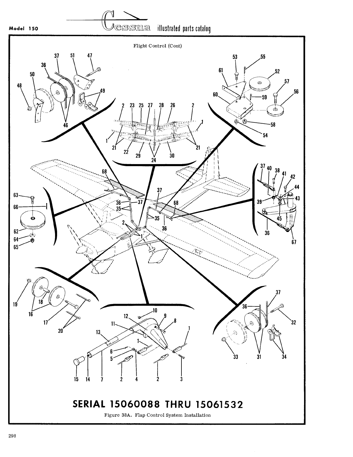
- Fig 38A. Flap Control System Installation
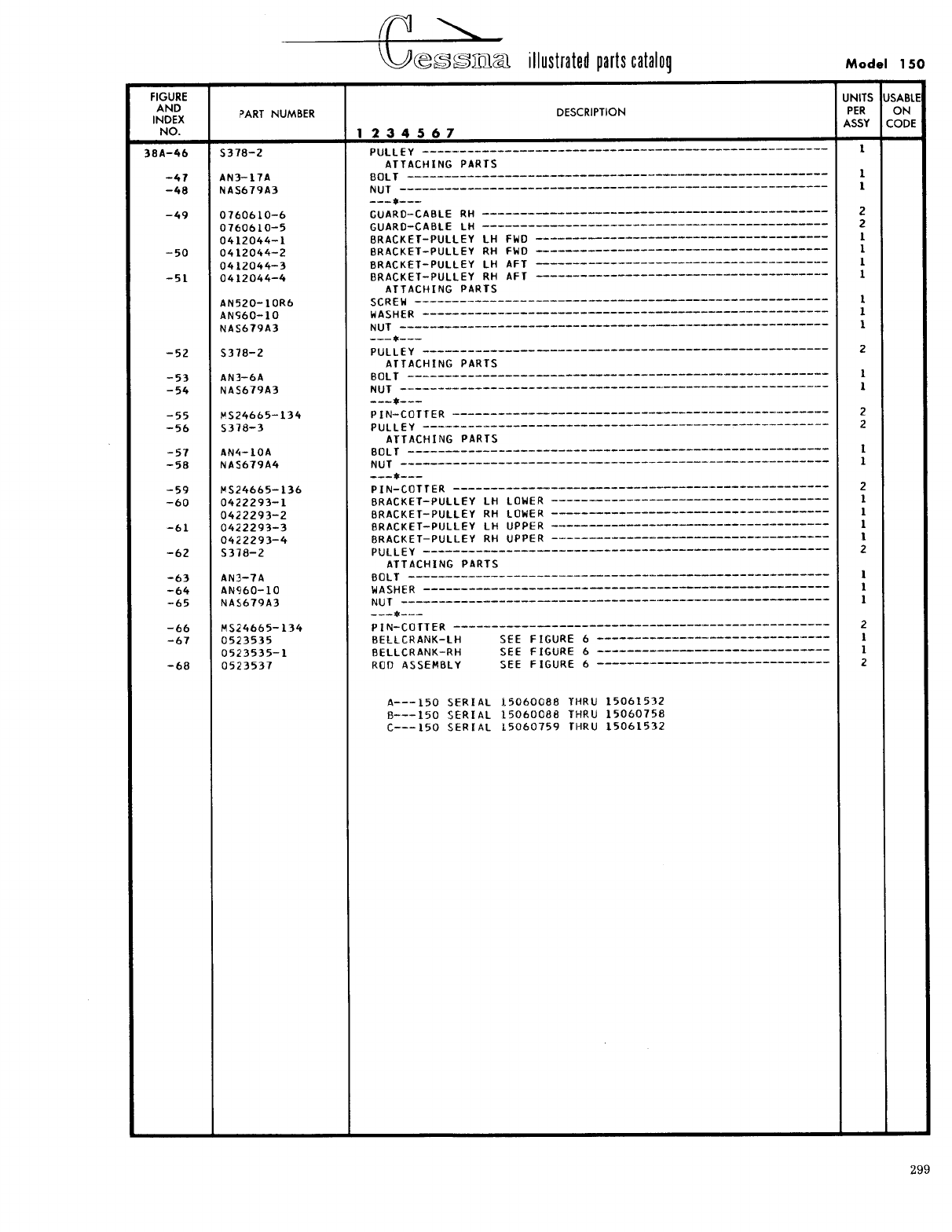
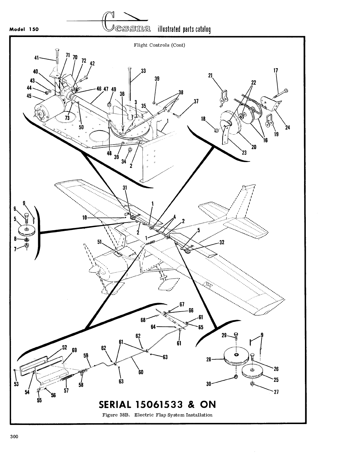
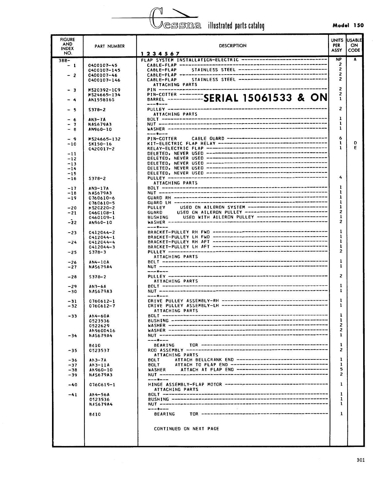
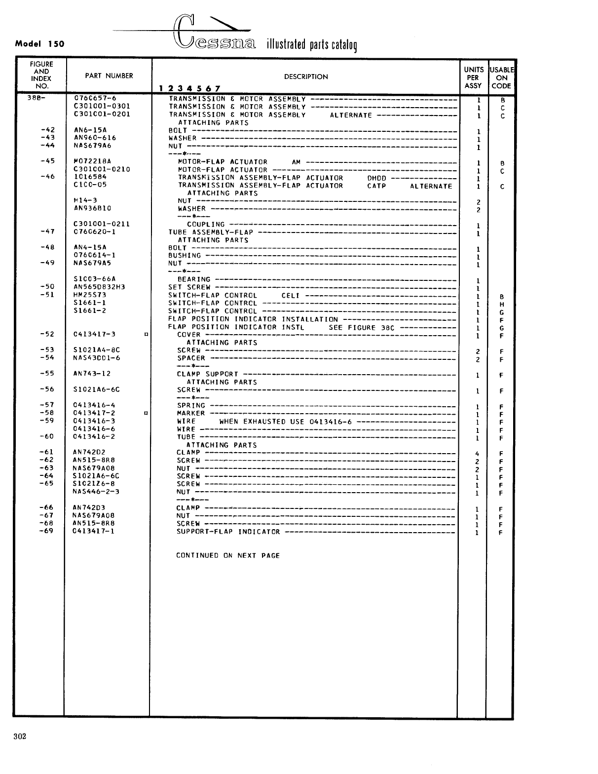
- Fig 38B. Electric Flap System Installation
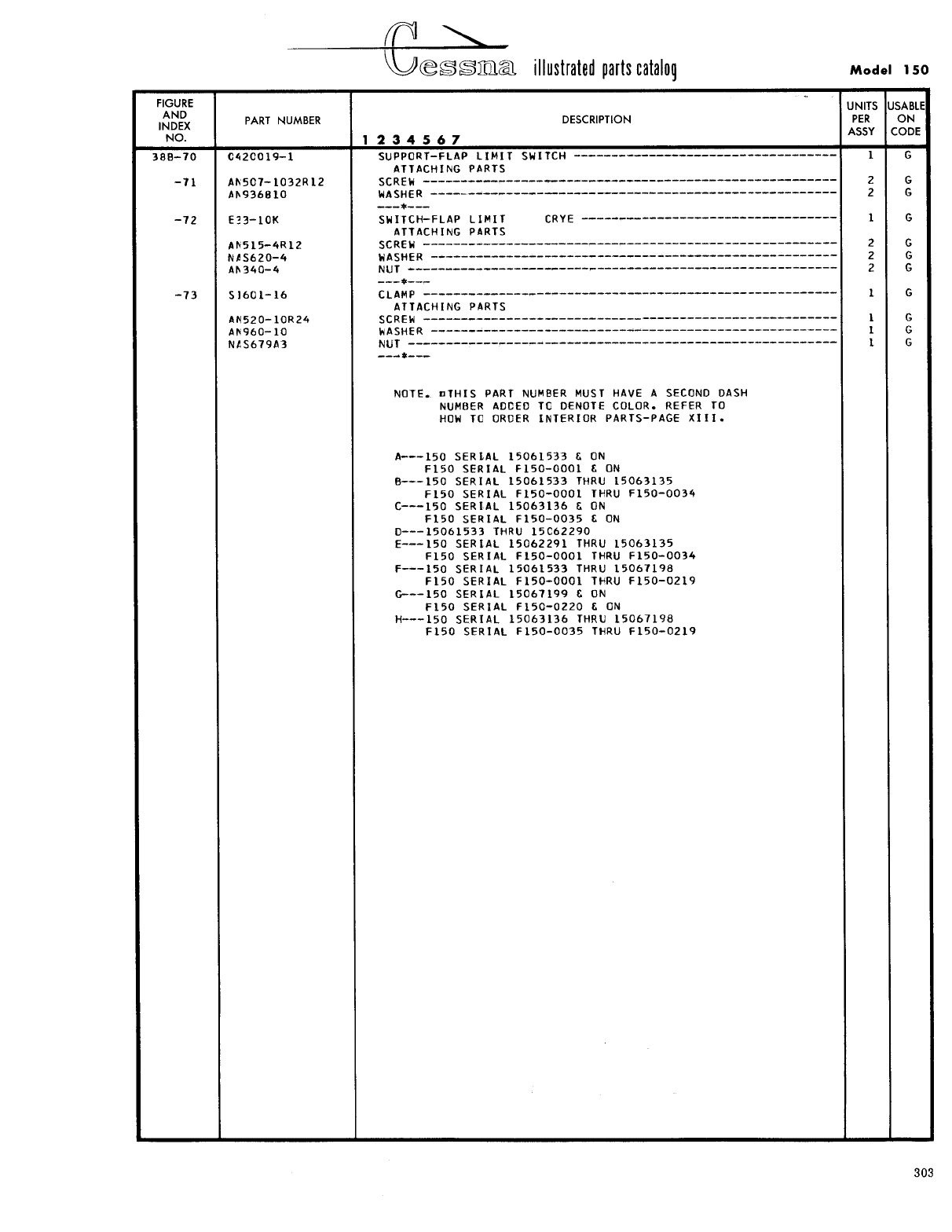
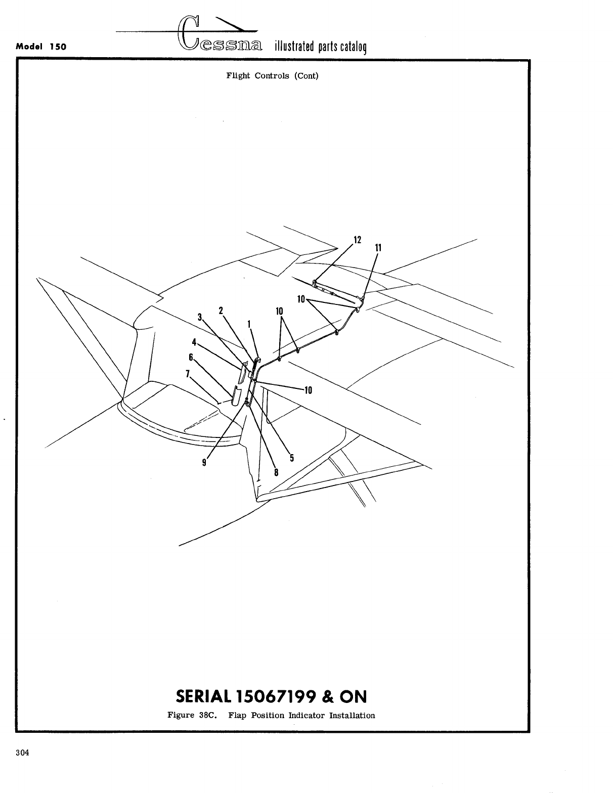
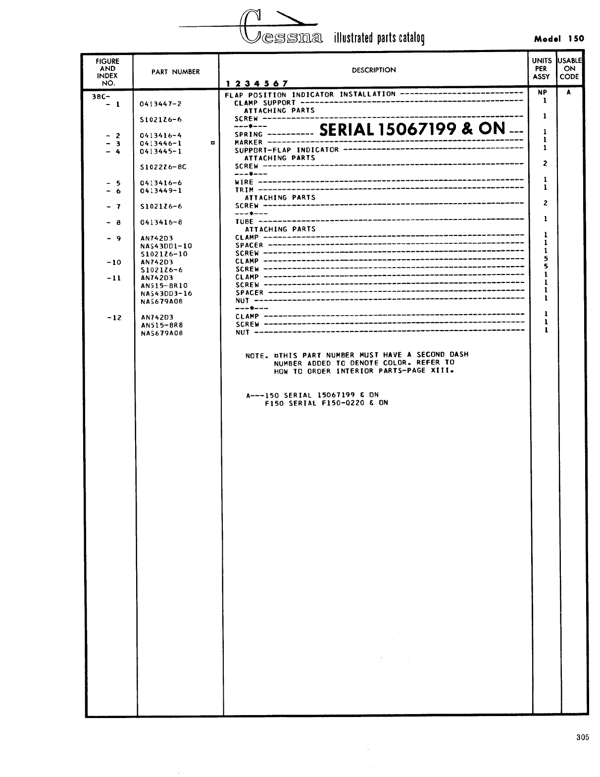
- Fig 38C. Flap Position Indicator Installation
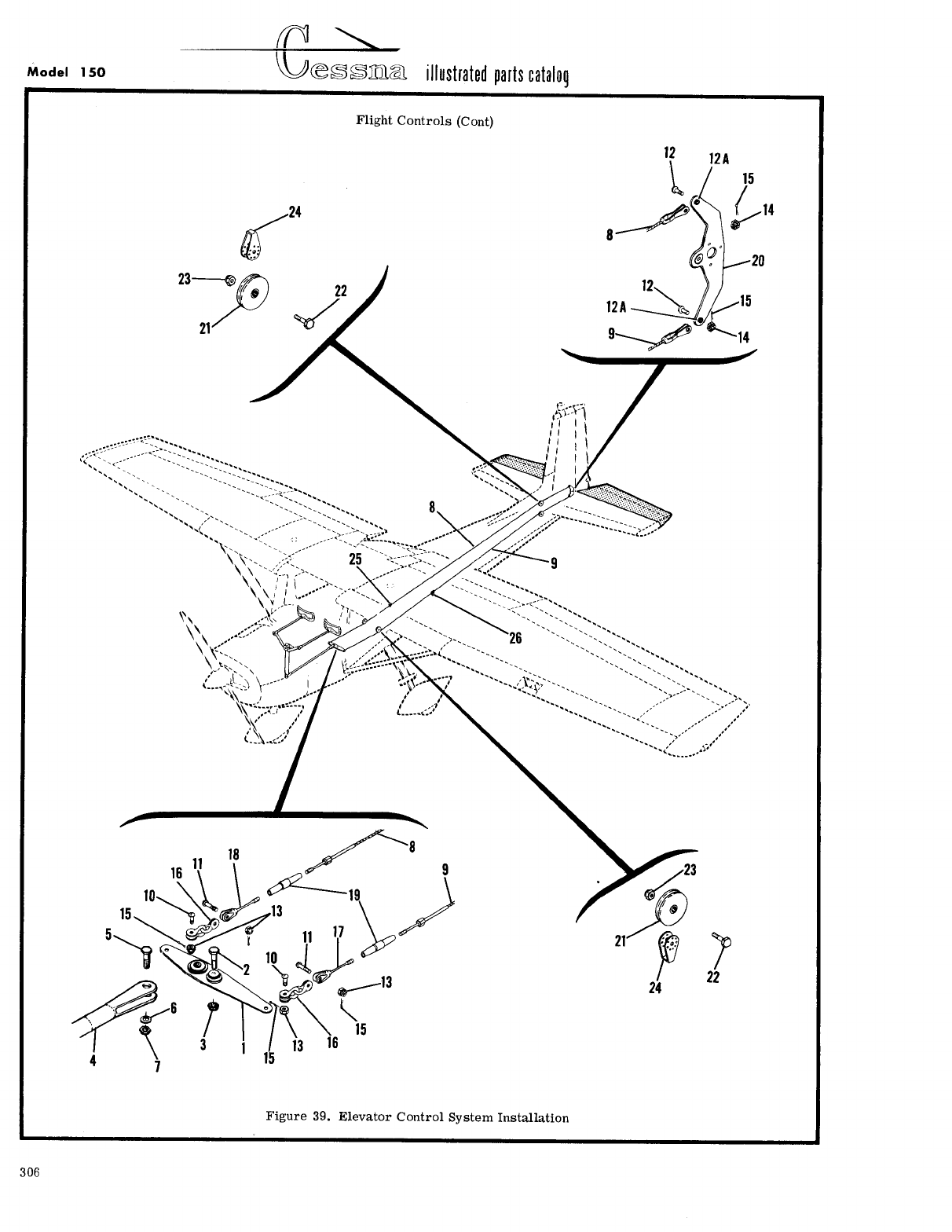
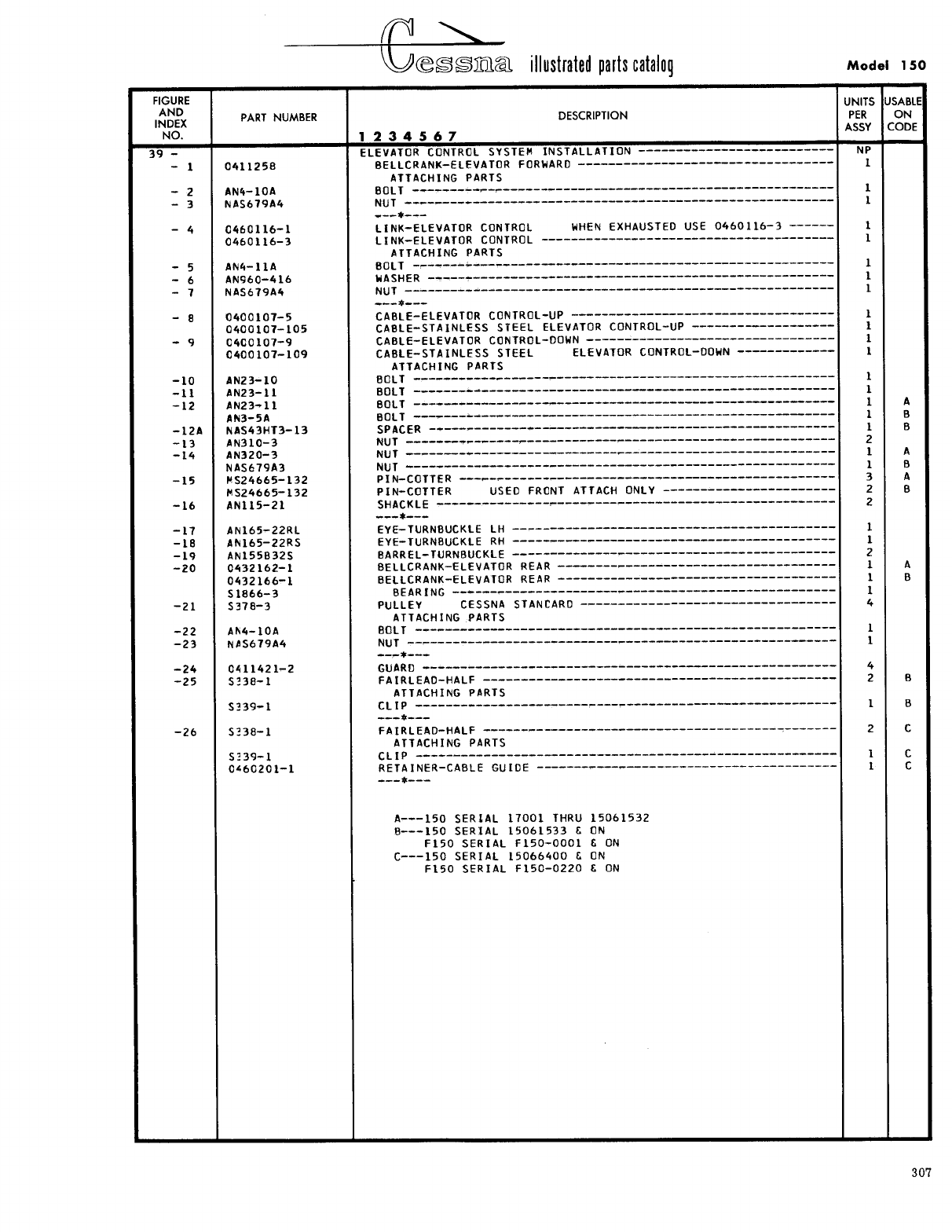
- Fig 39. Elevator Control System Installation
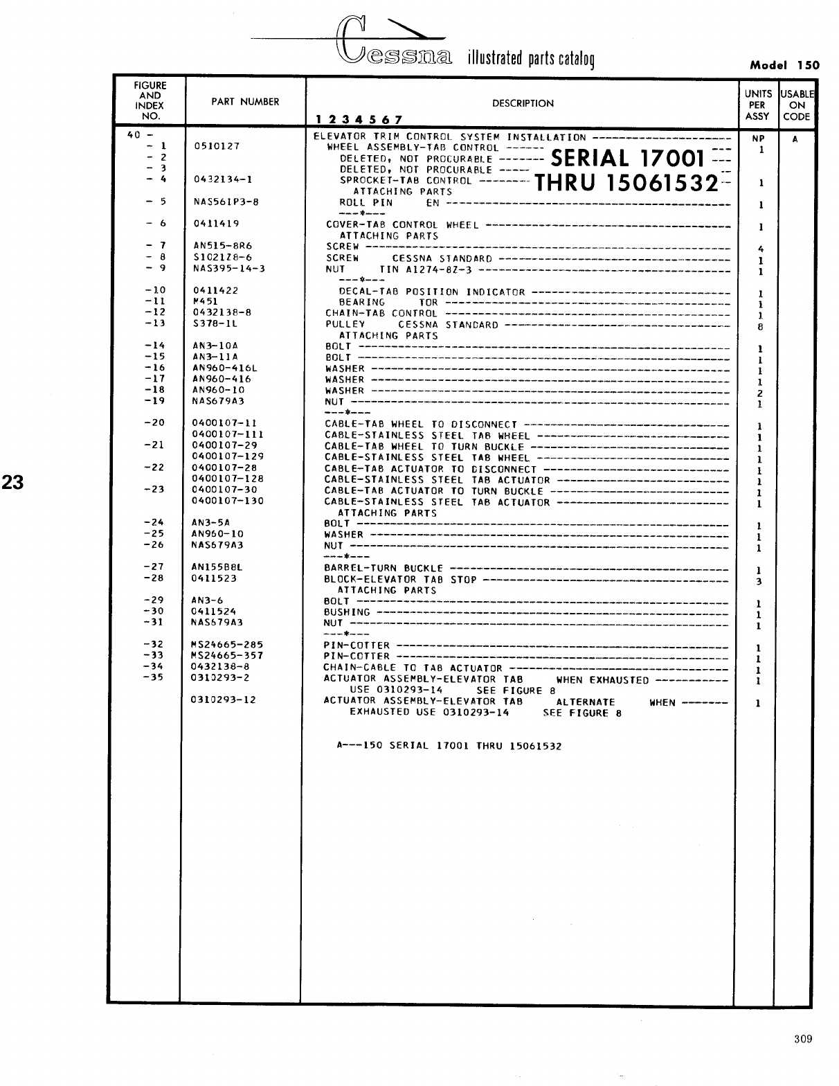
- Fig 40. Elevator Trim Control System Installation
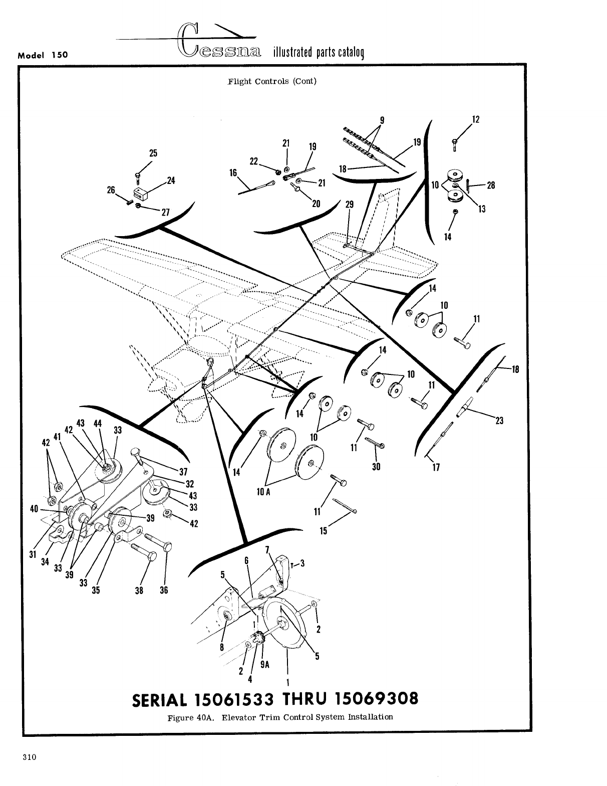
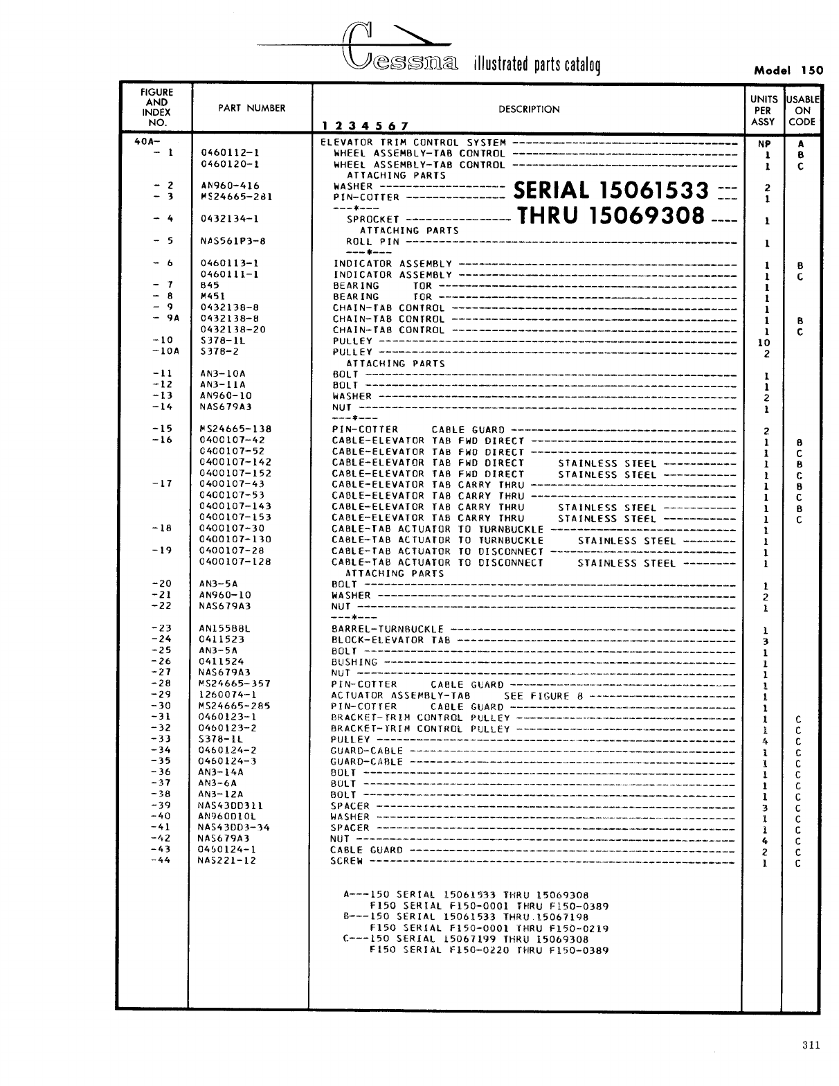
- Fig 40A. Elevator Trim Control System Installation
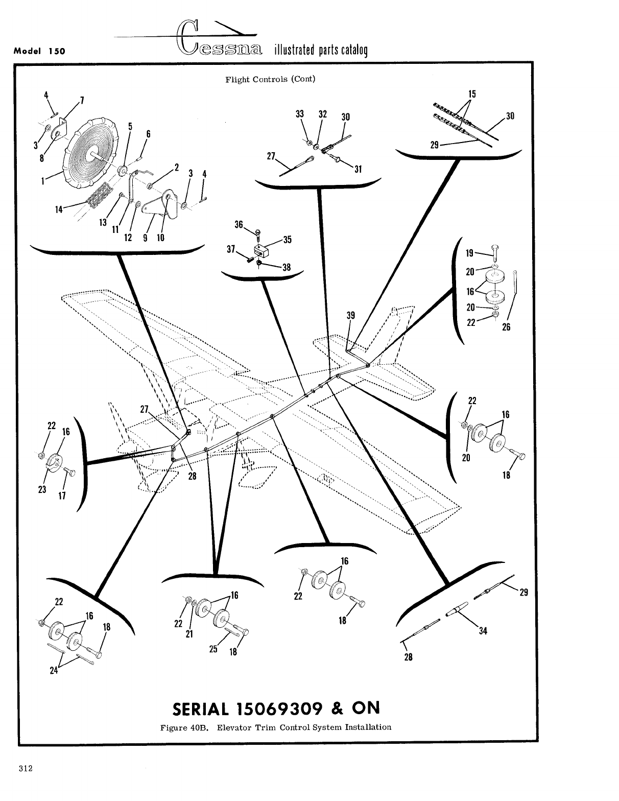
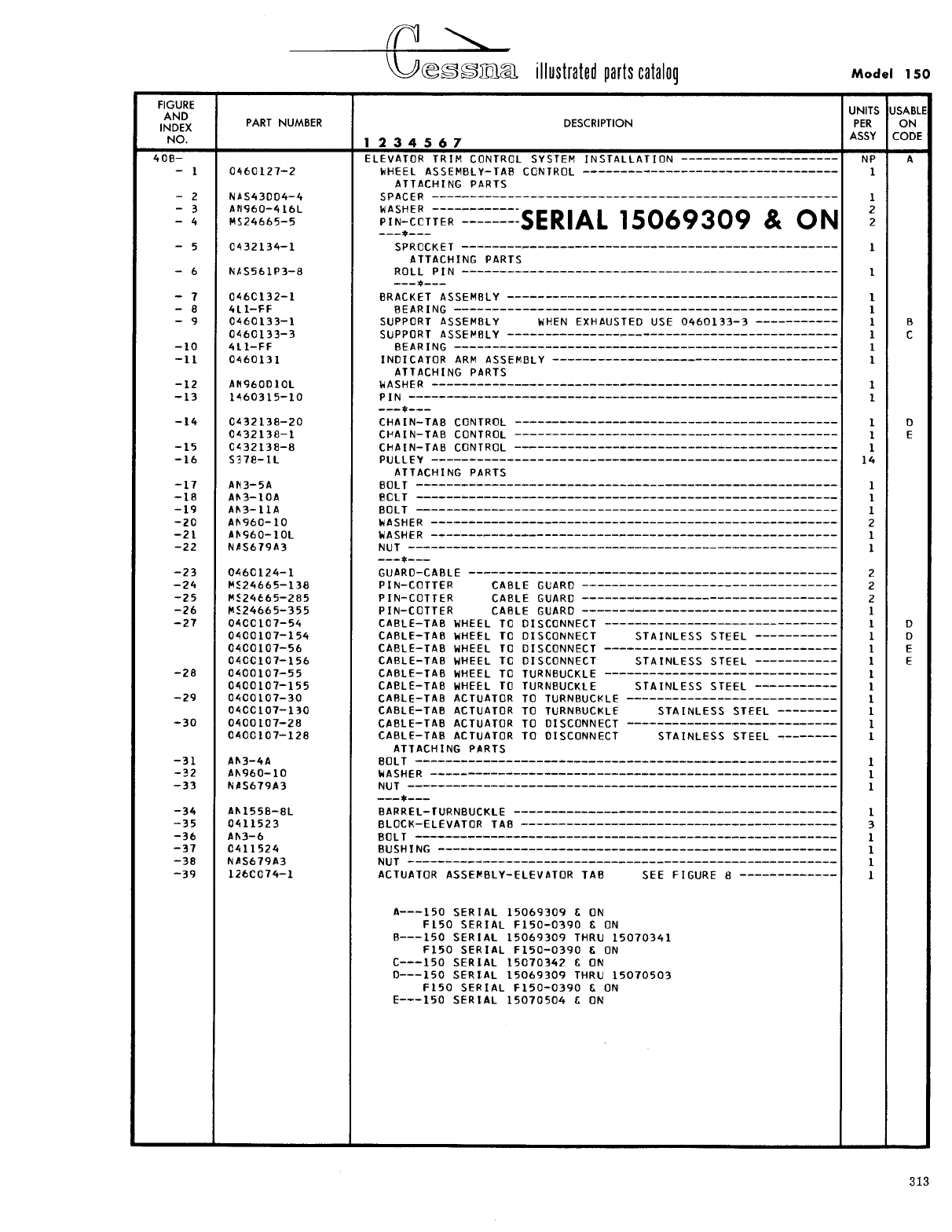
- Fig 40B. Elevator Trim Control System Installation
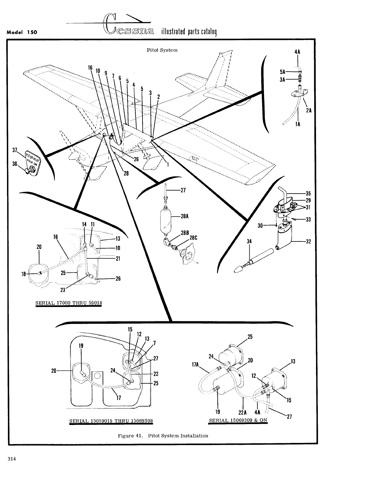
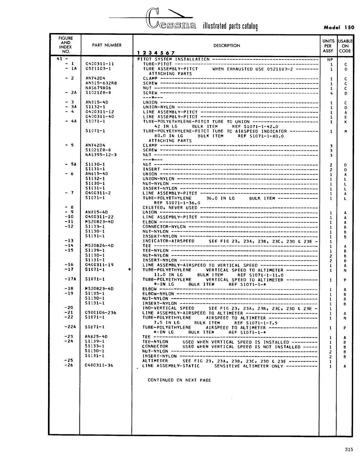
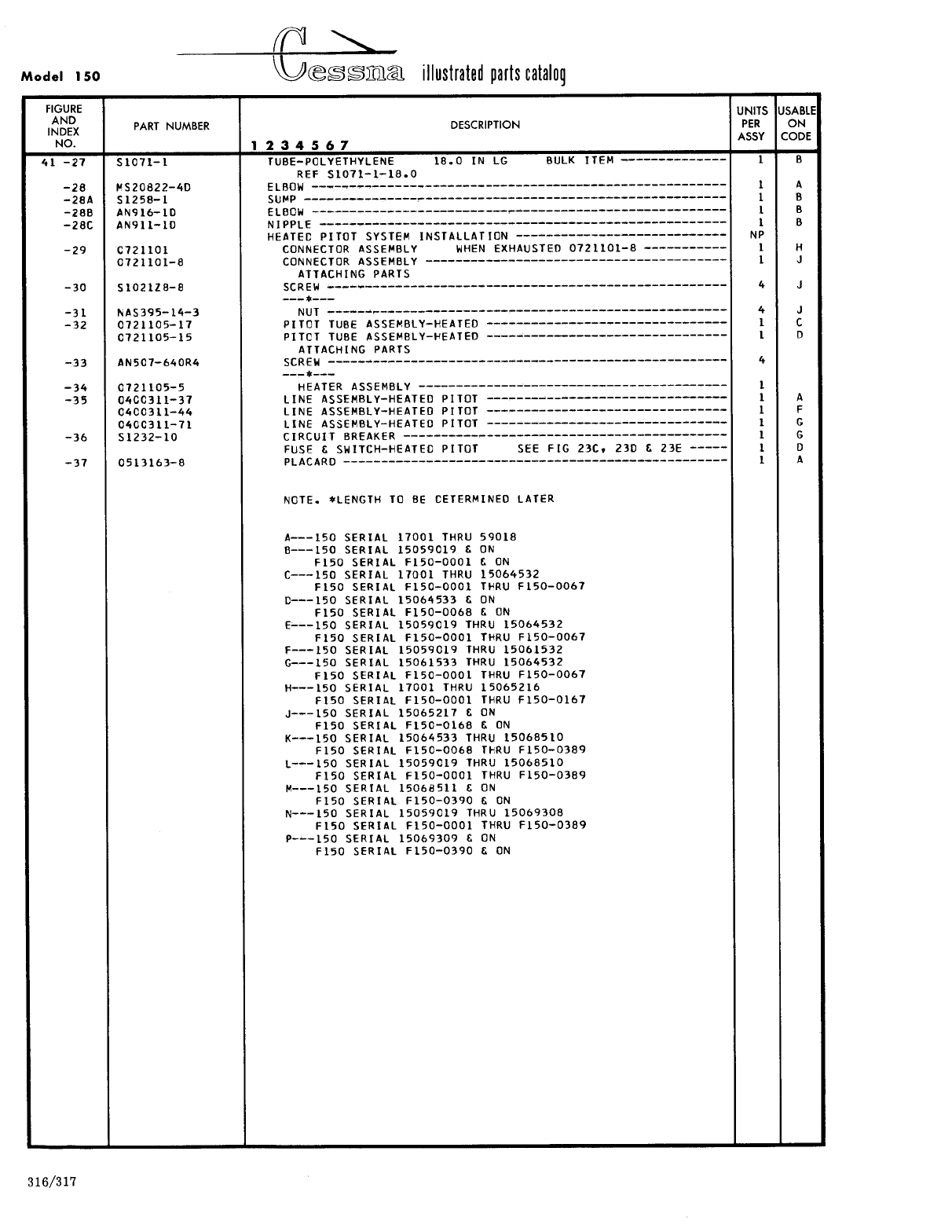
- Fig 41. Pitot System Installation
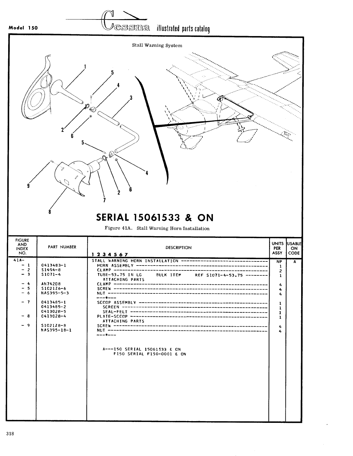
- Fig 41A. Stall Warning Horn Installation
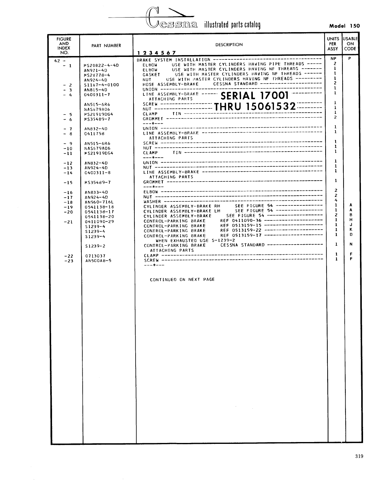
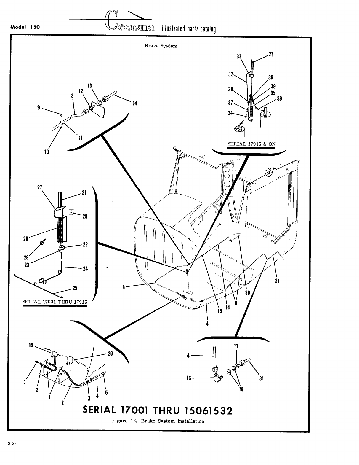
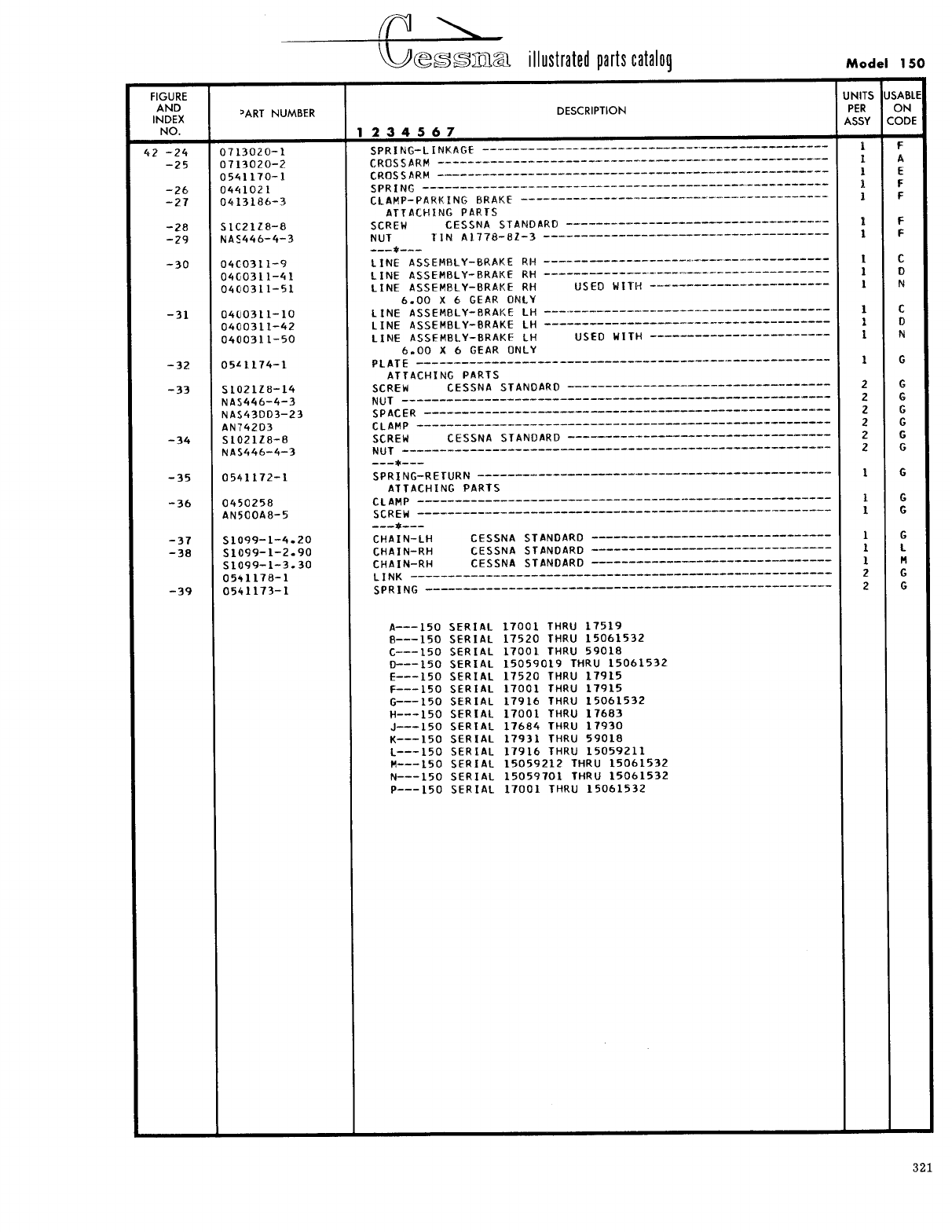
- Fig 42. Brake System Installation
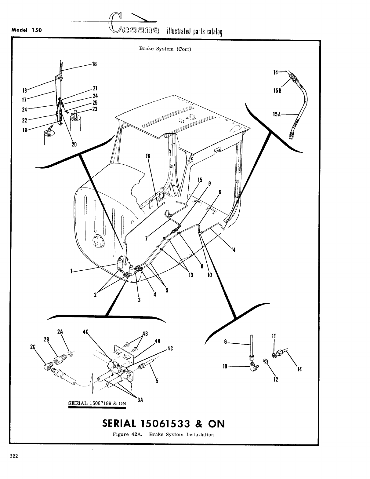
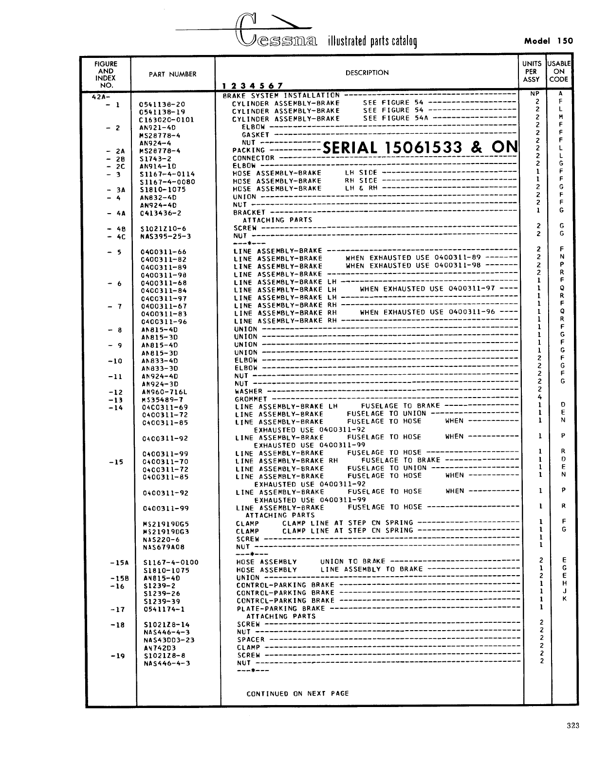
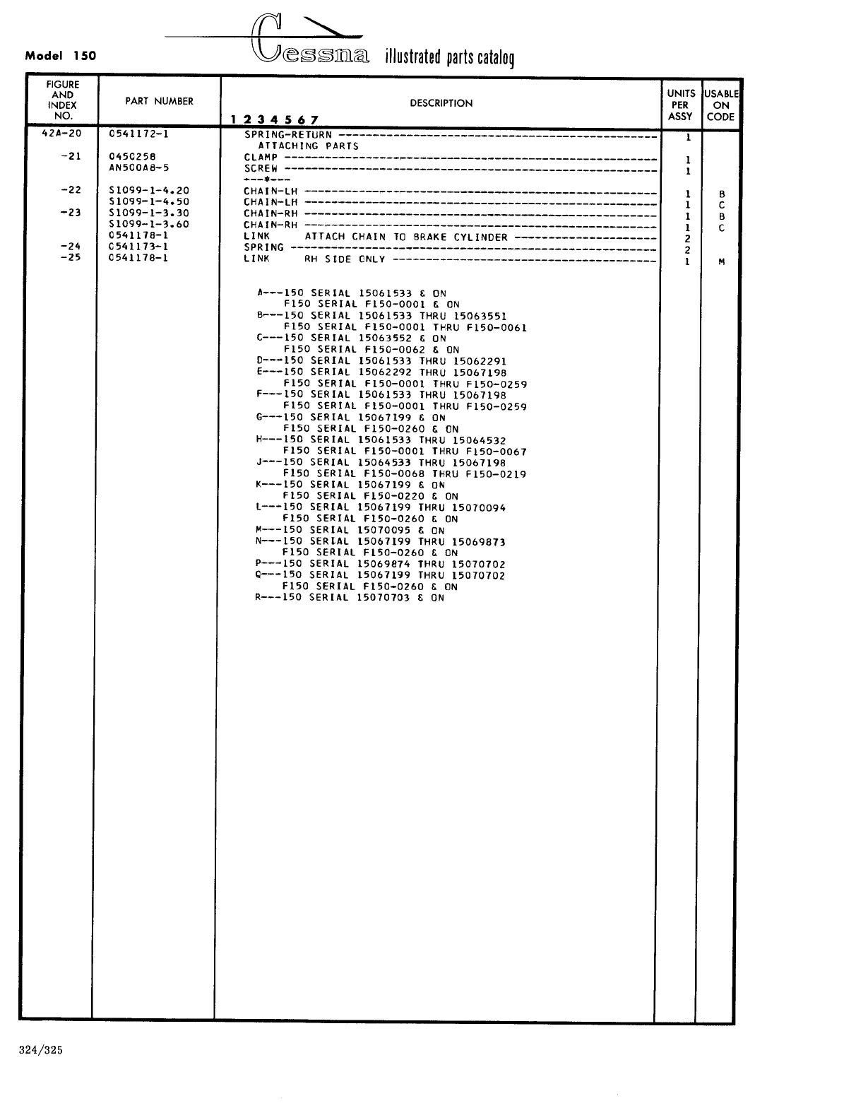
- Fig 42A. Brake System Installation
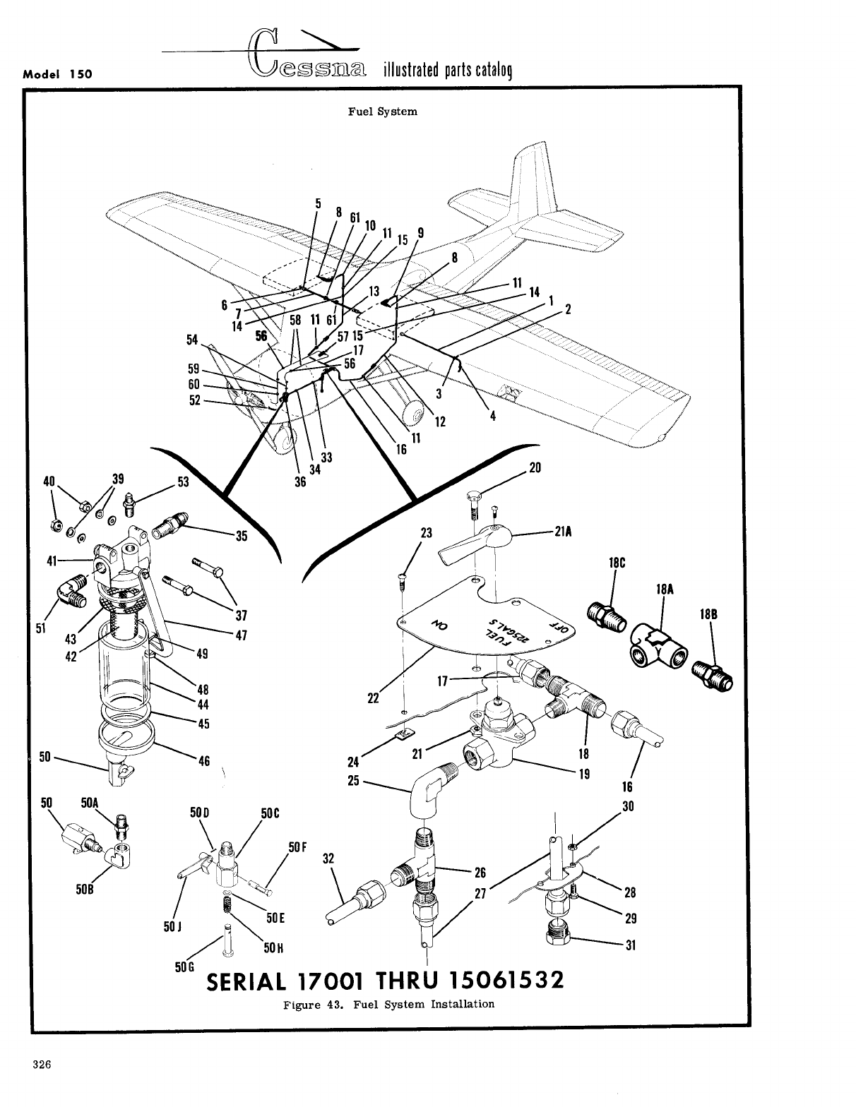
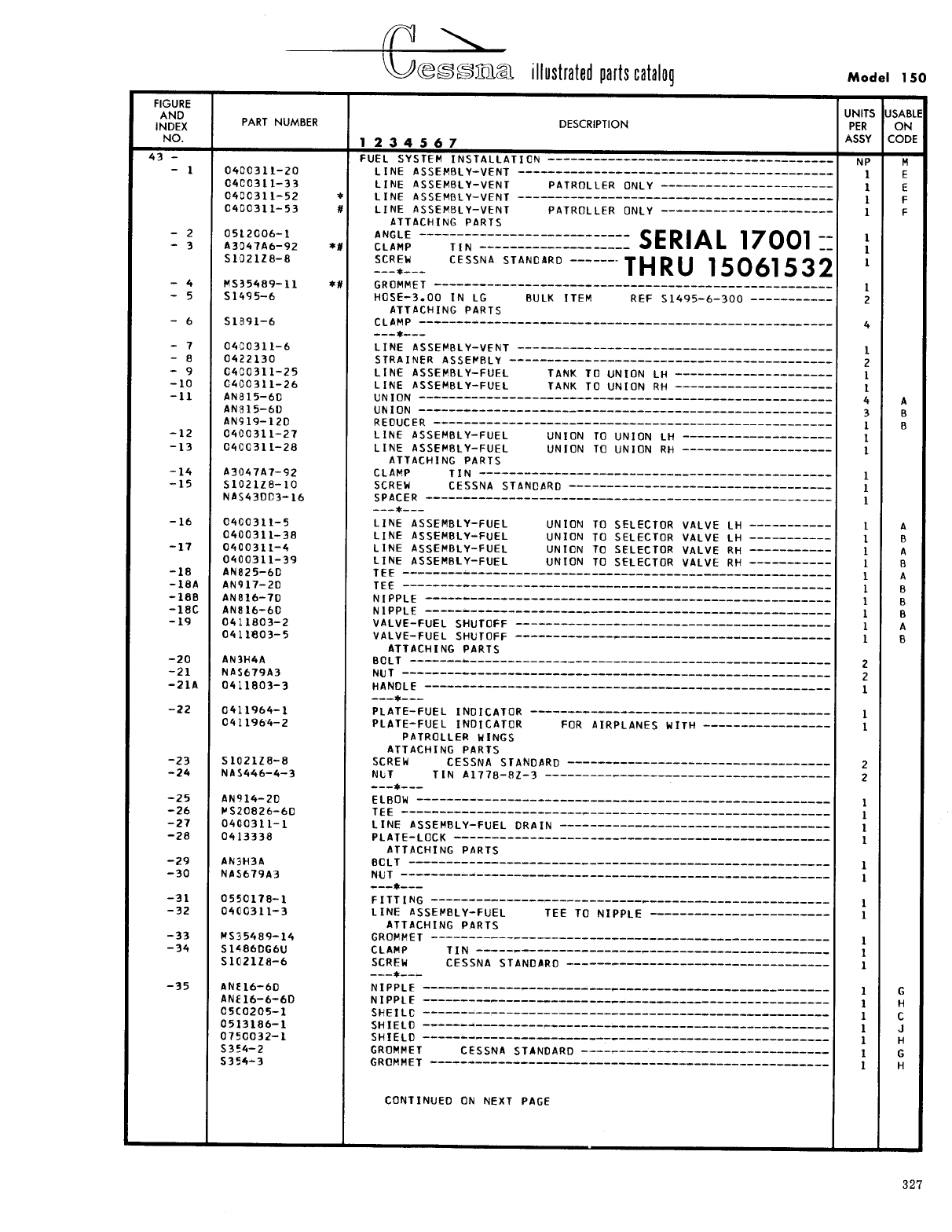
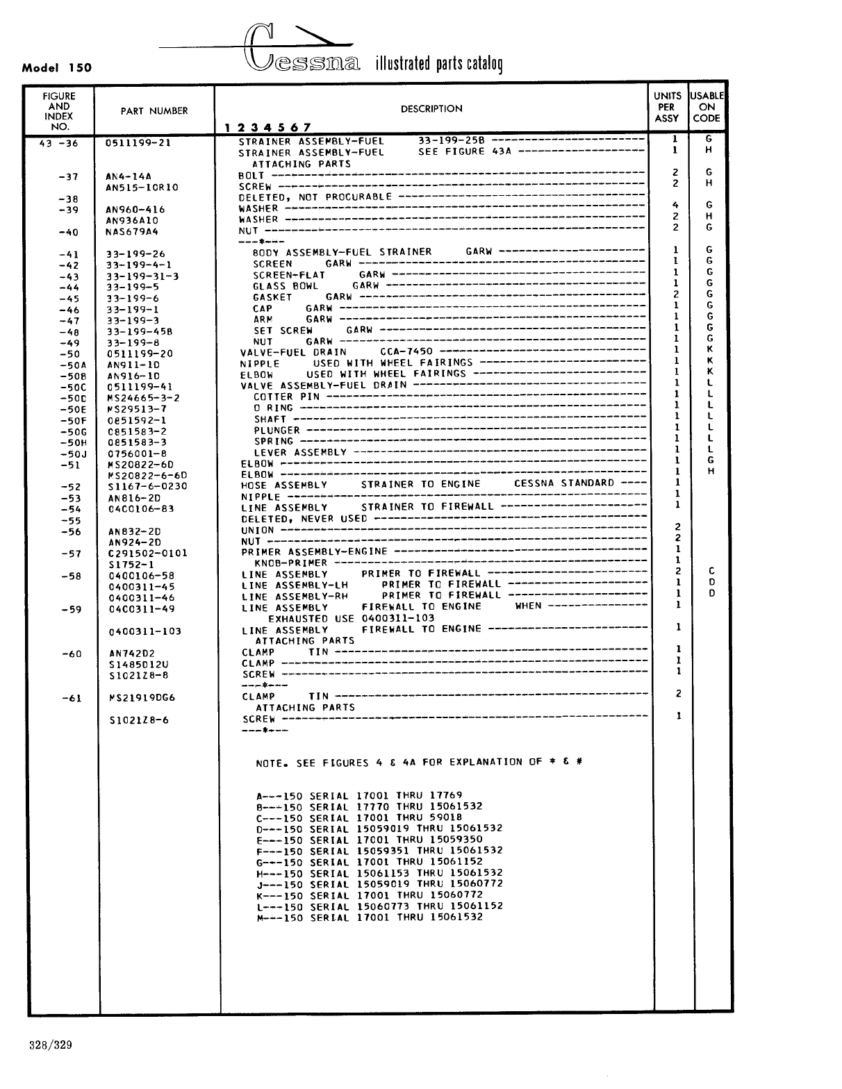
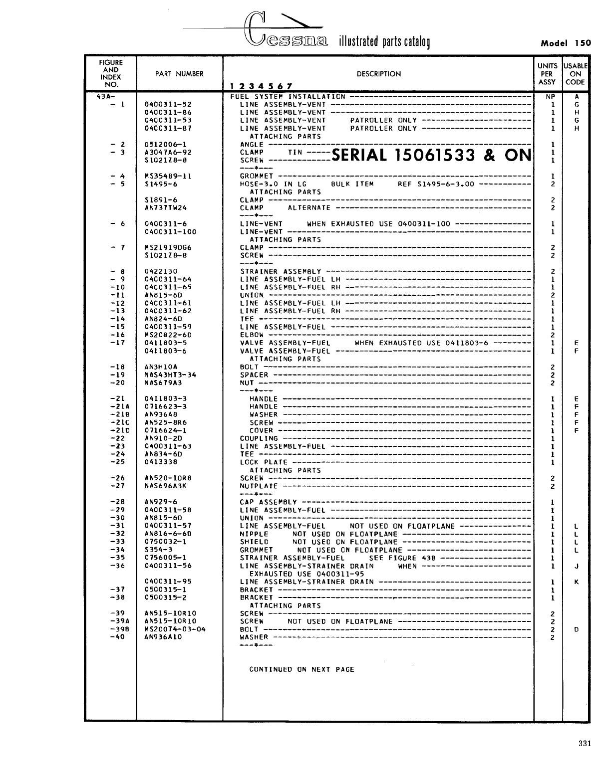
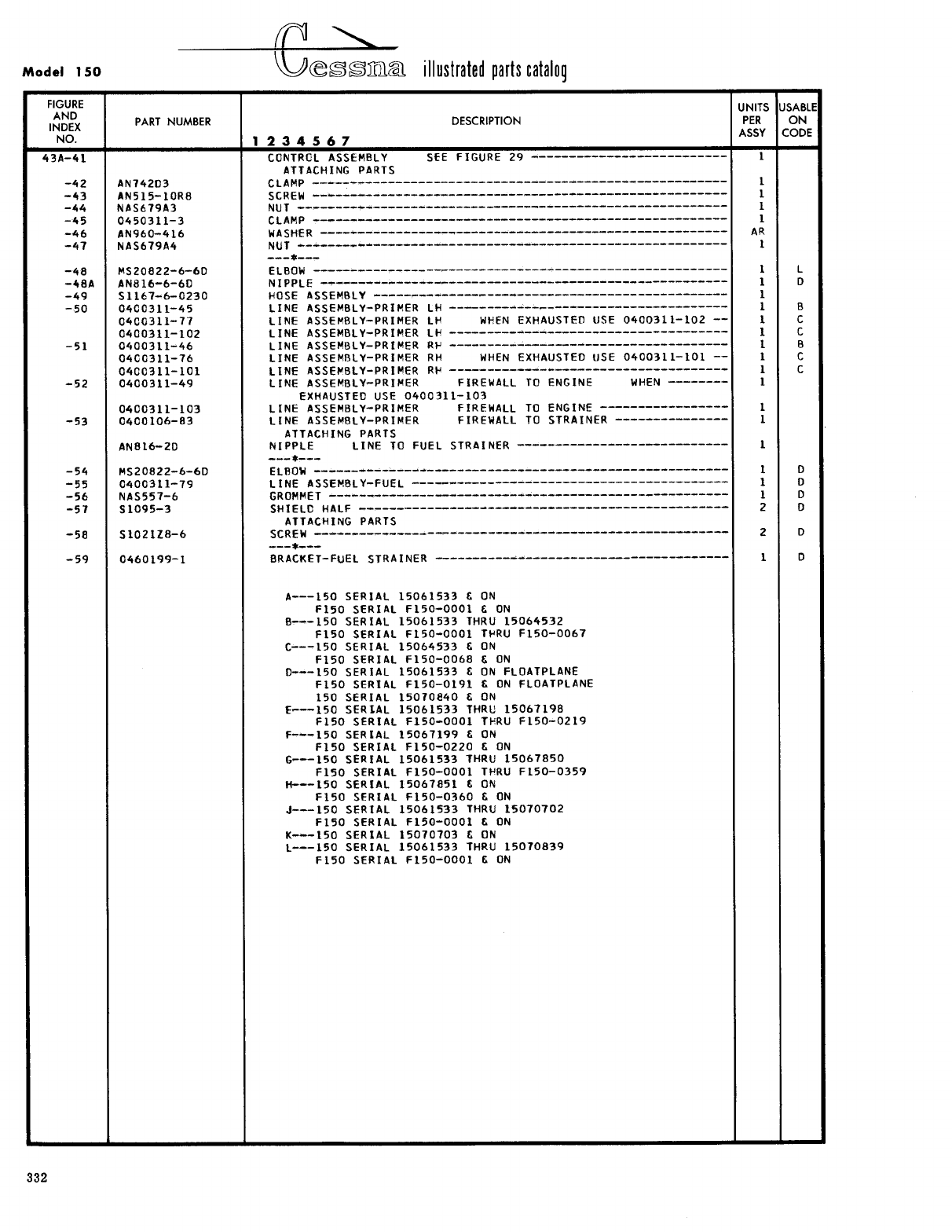
- Fig 43. Fuel System Installation
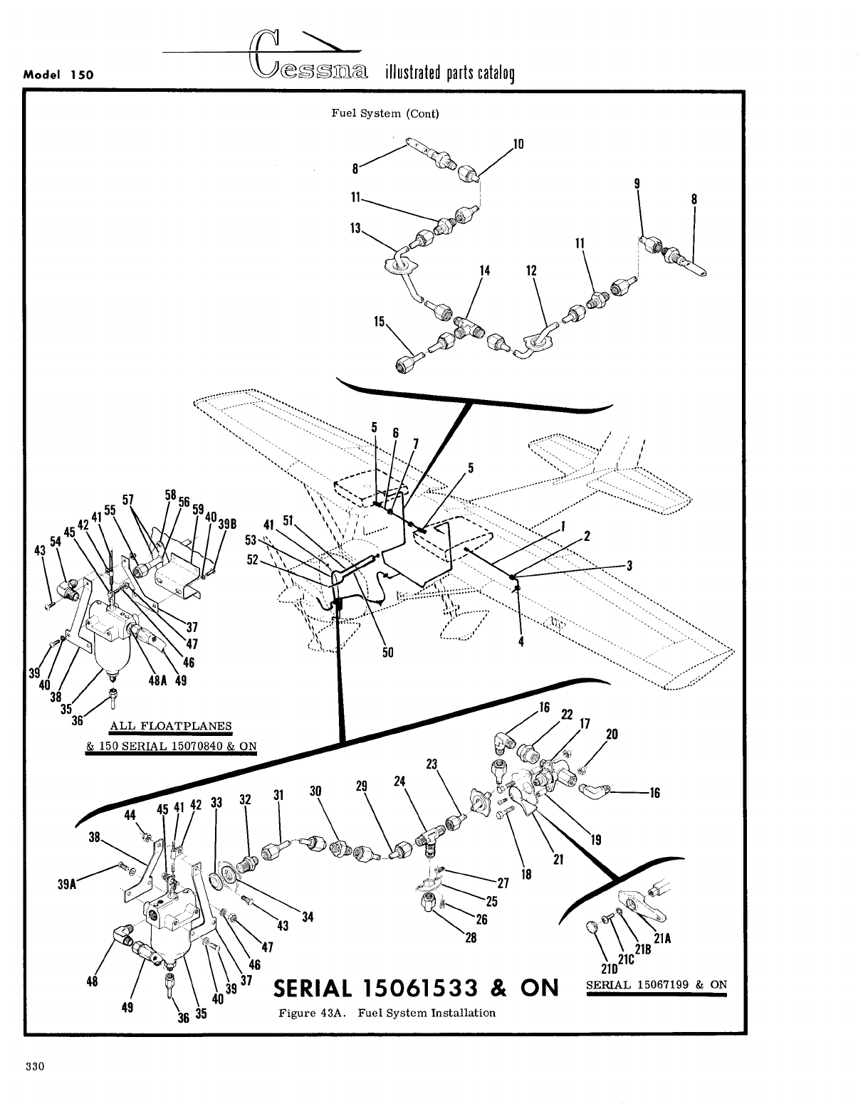
- Fig 43A. Fuel System Installation
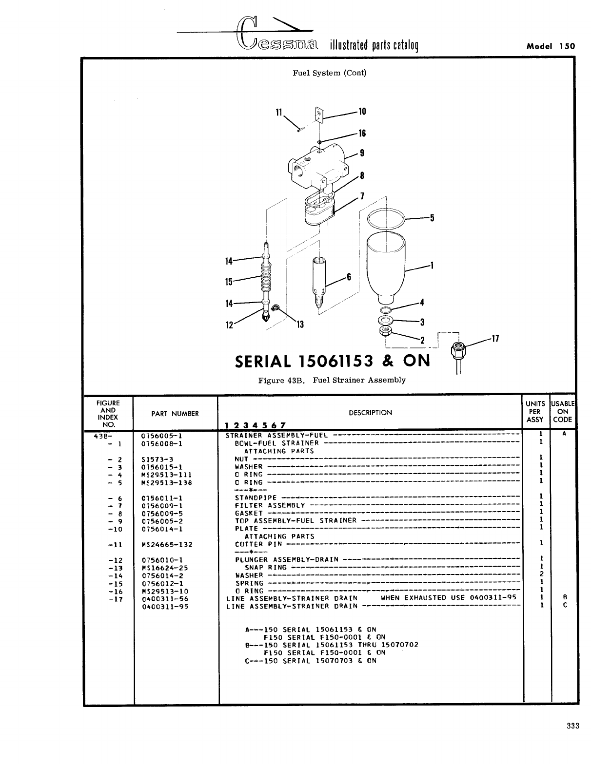
- Fig 43B. Fuel Strainer Assembly
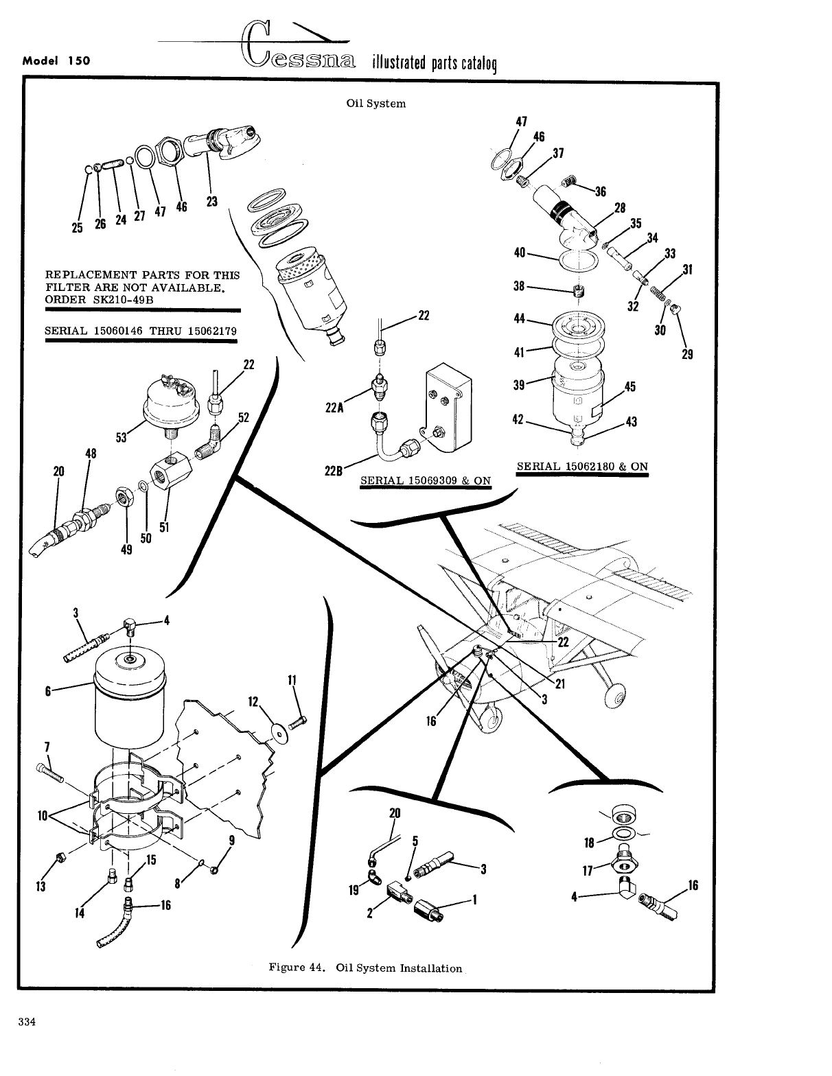
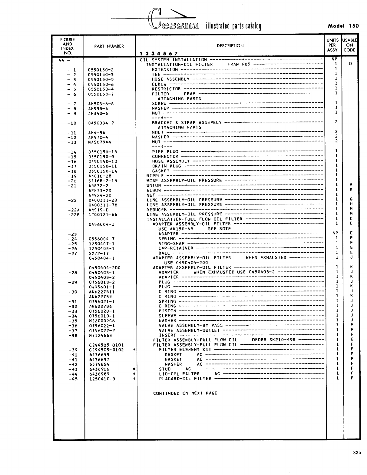
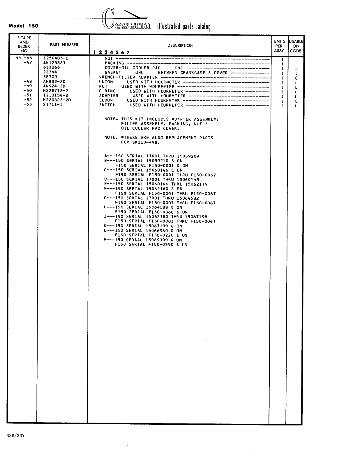
- Fig 44. Oil System Installation
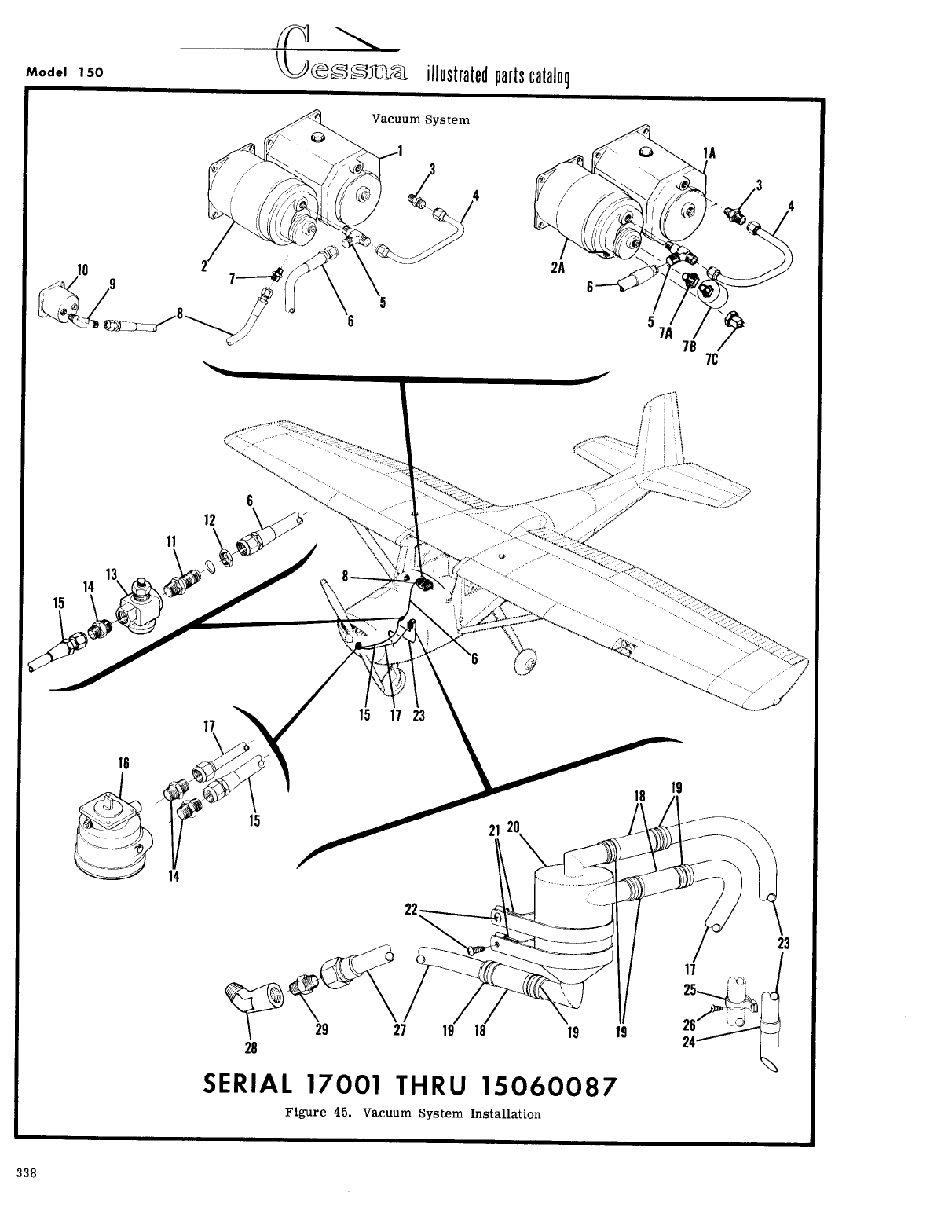
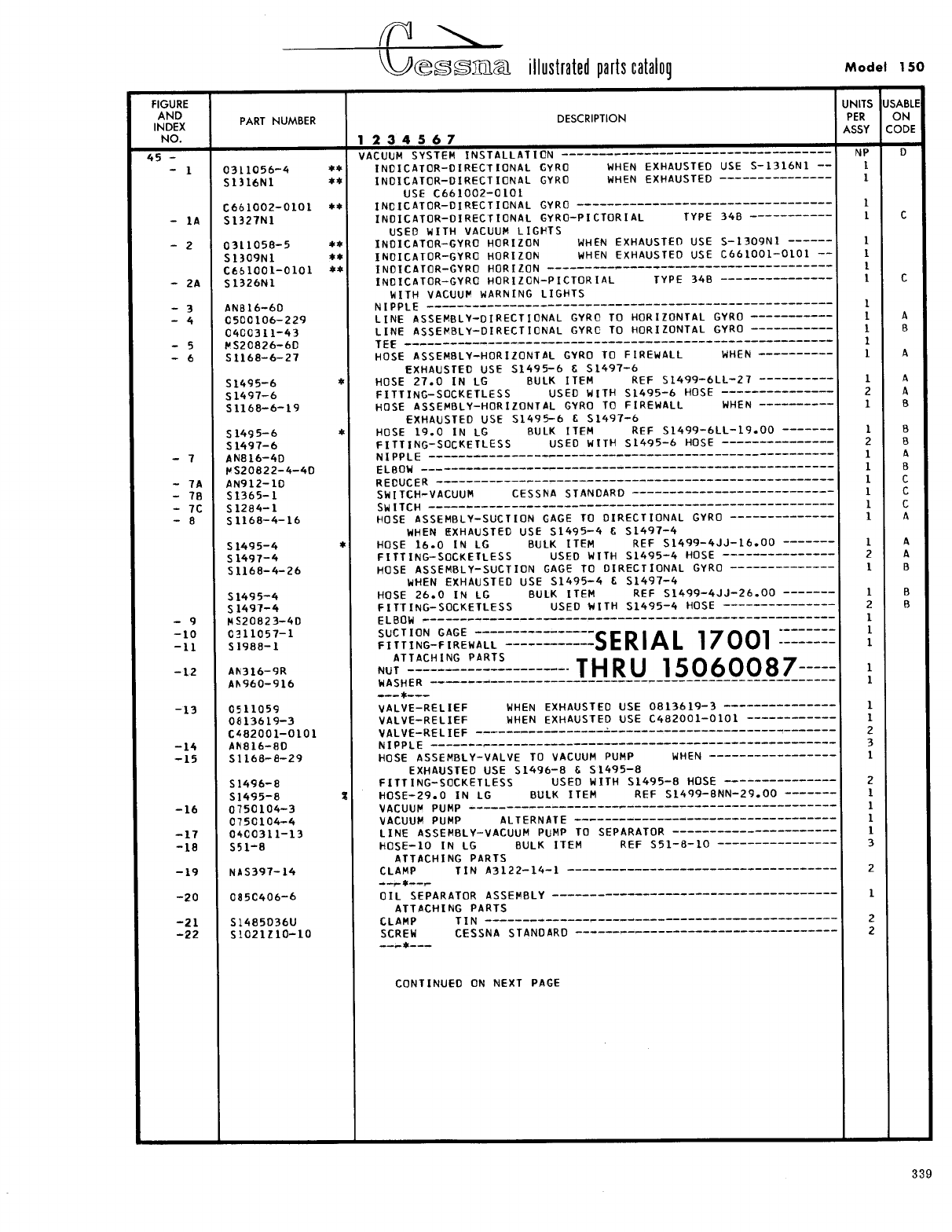
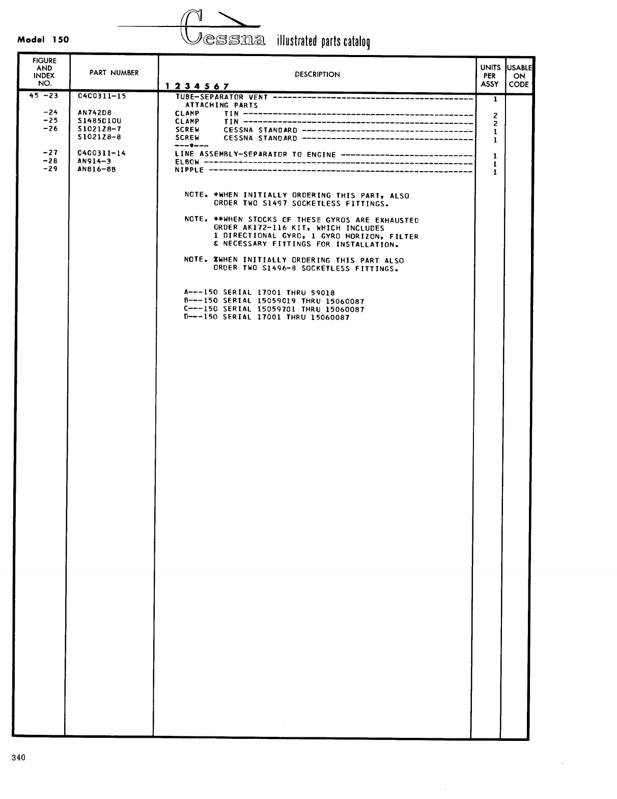
- Fig 45. Vacuum System Installation
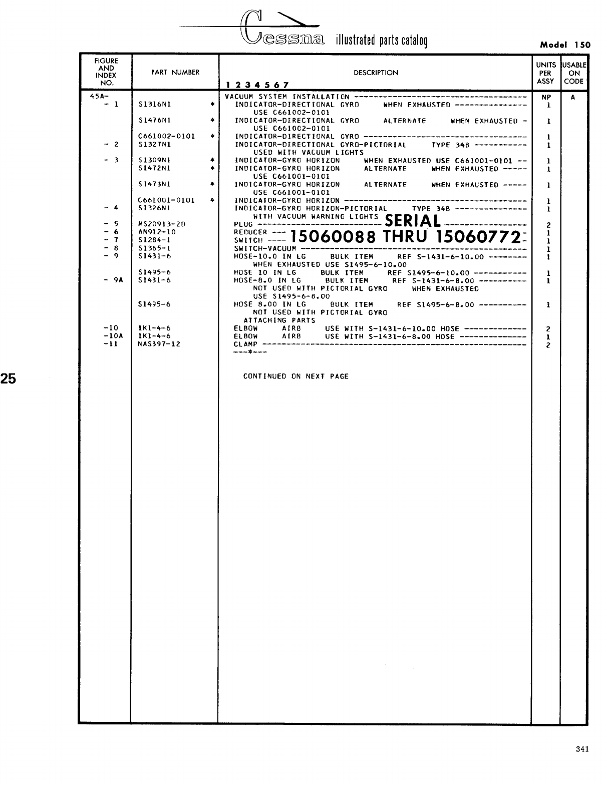
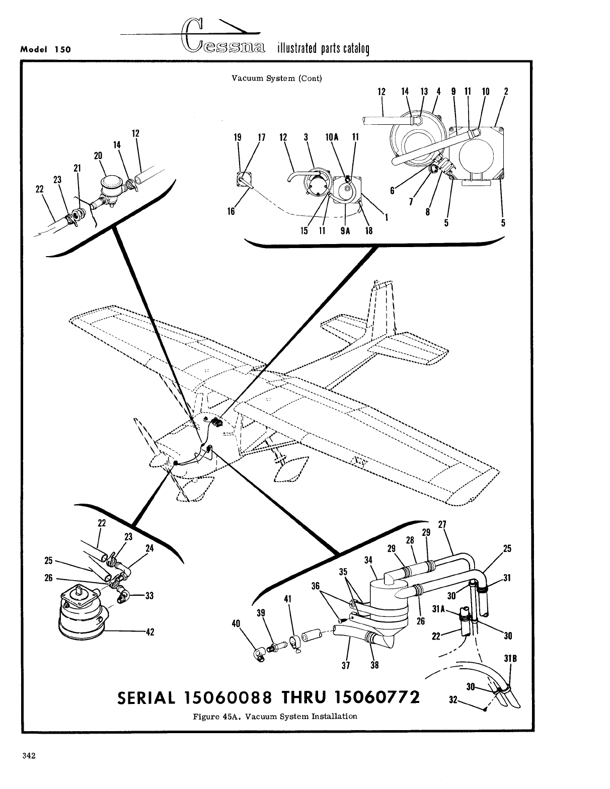
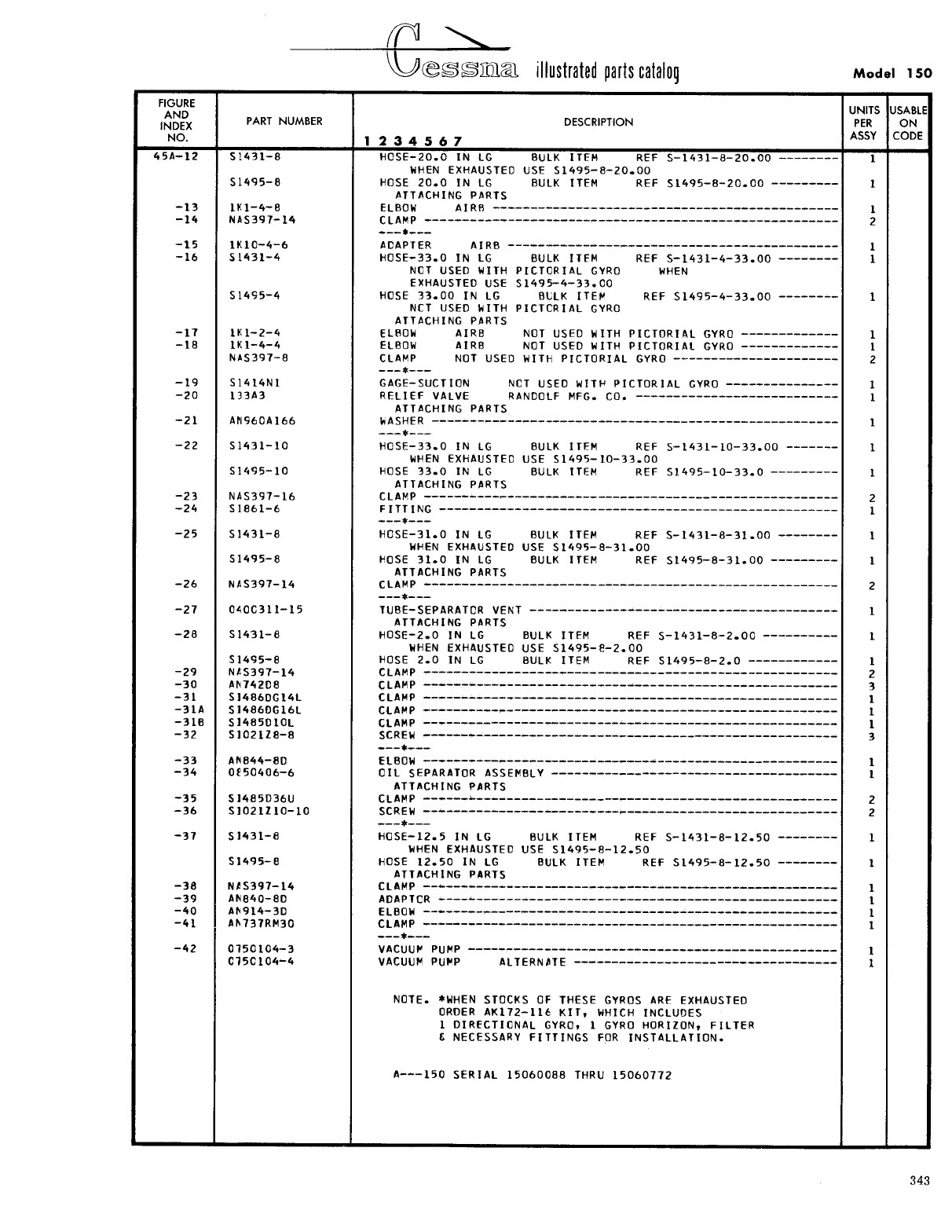
- Fig 45A. Vacuum System Installation
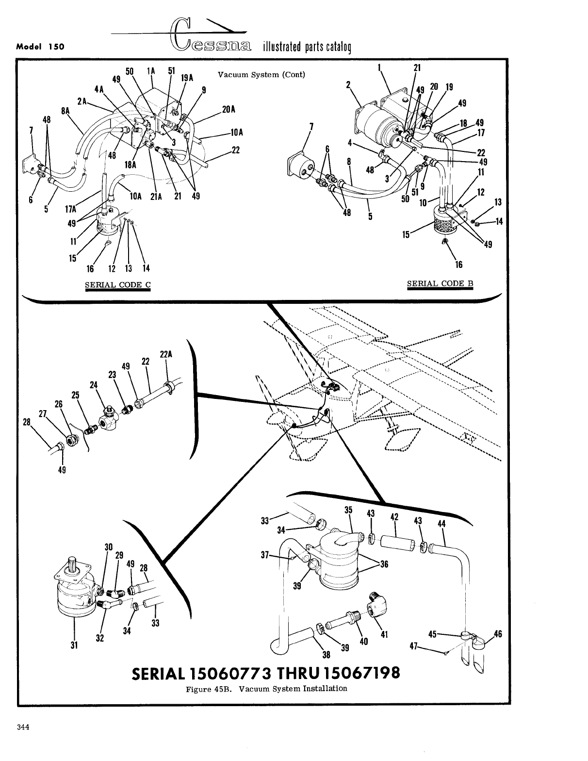
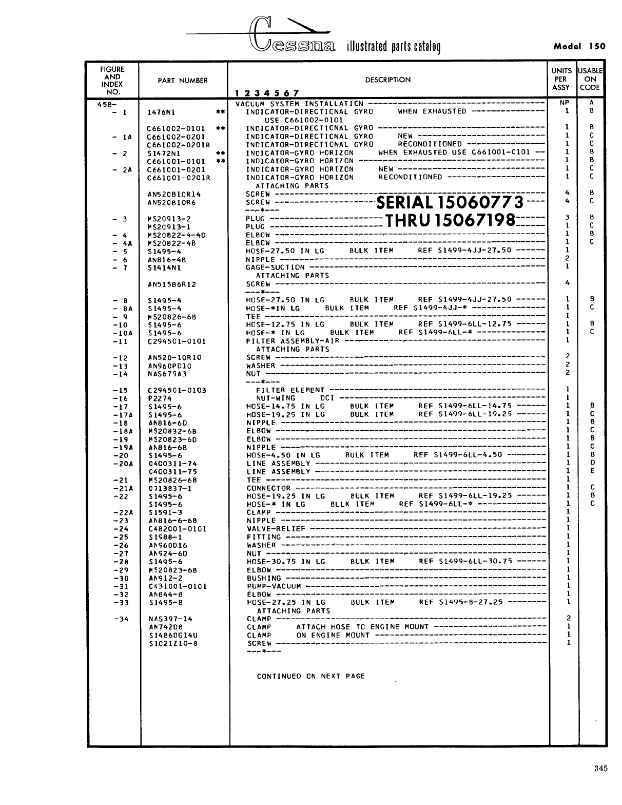
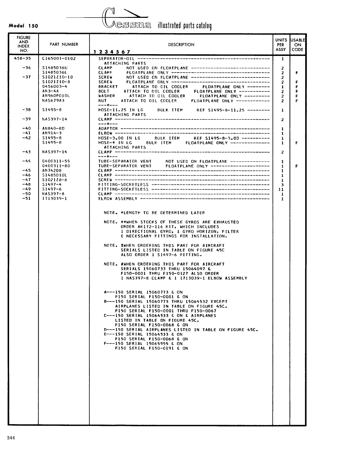
- Fig 45B. Vacuum System Installation
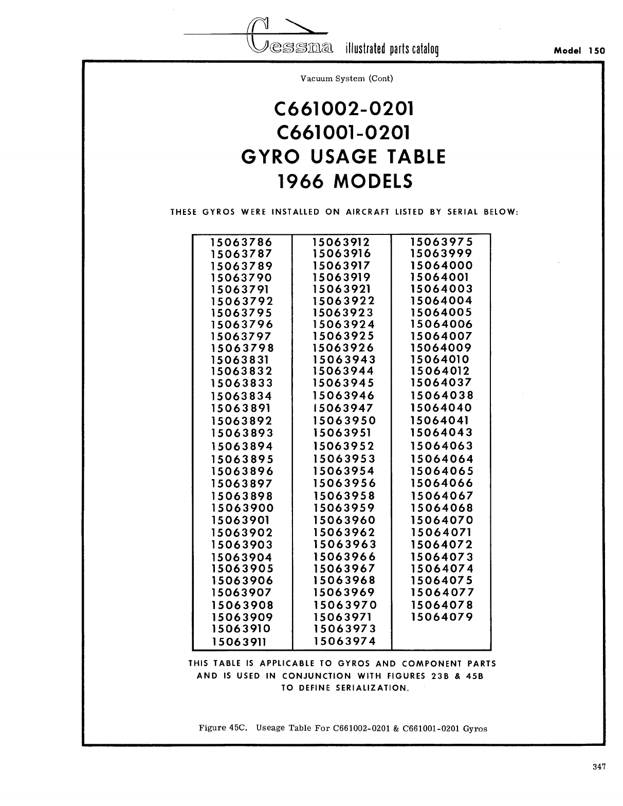
- Fig 45C. Useage Table For C661002-0201 & C661001-0201 Gyros
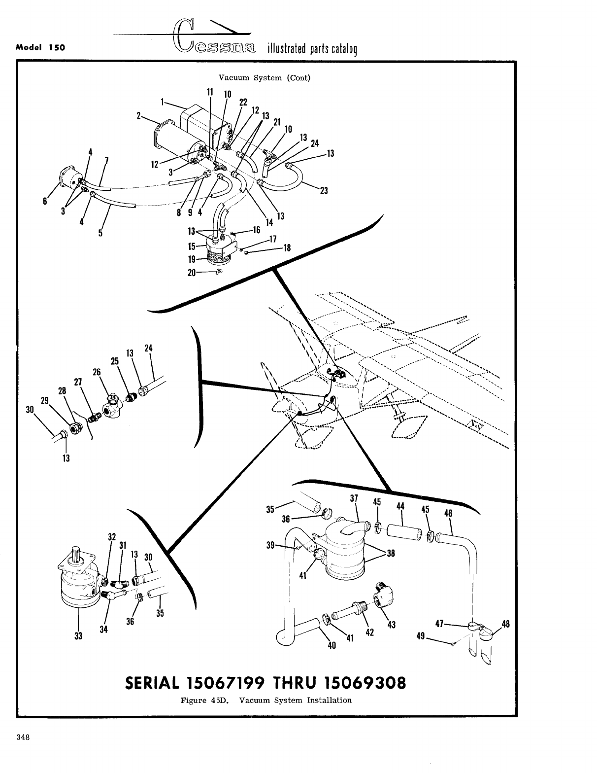
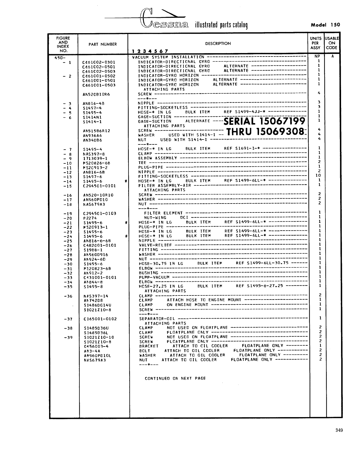
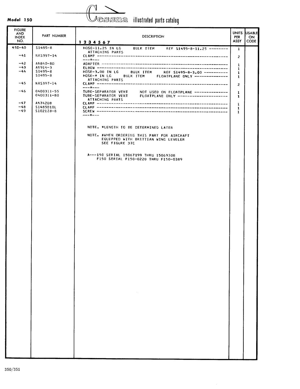
- Fig 45D. Vacuum System Installation
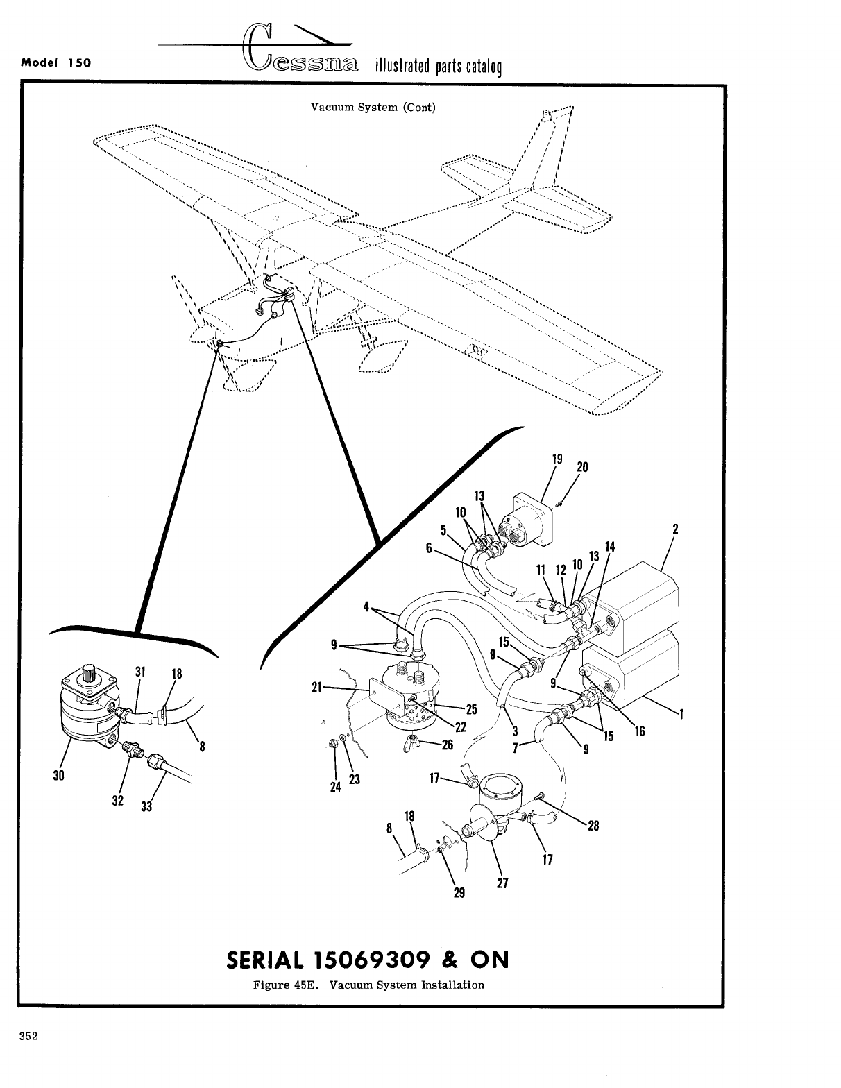
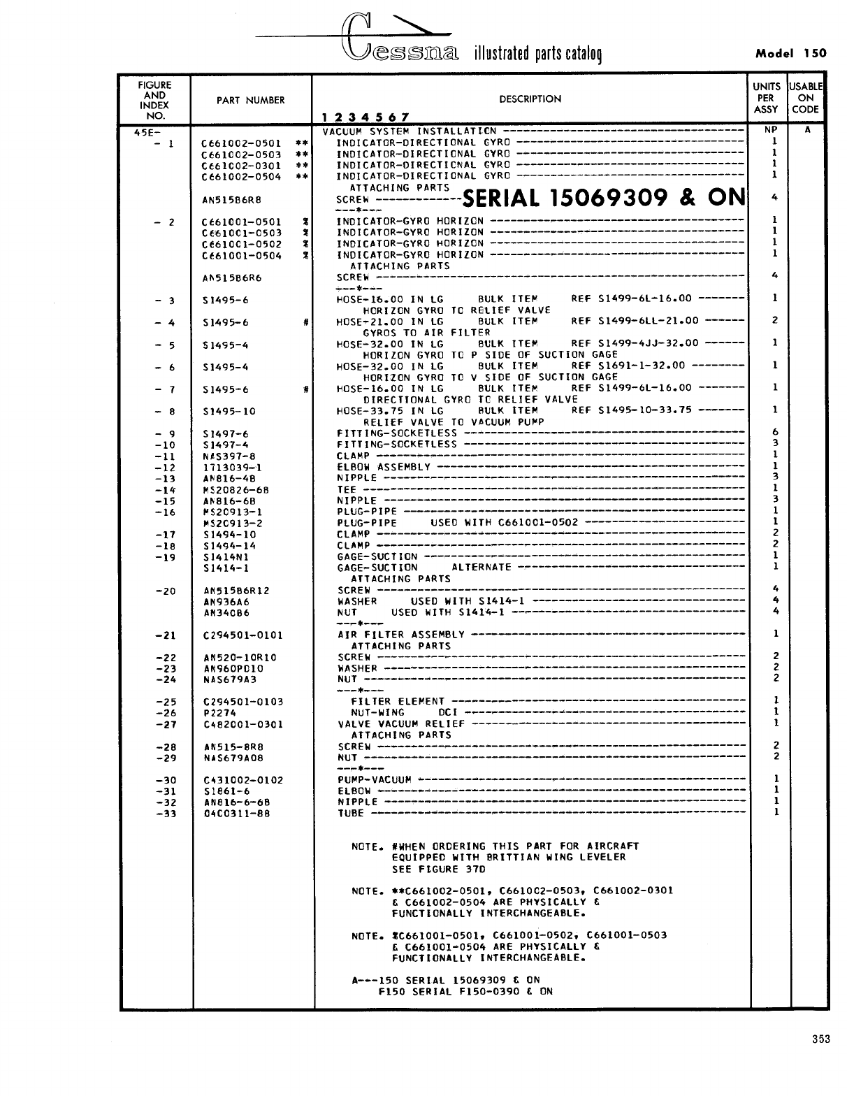
- Fig 45E. Vacuum System Installation
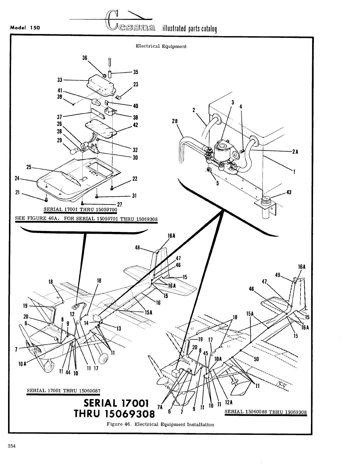
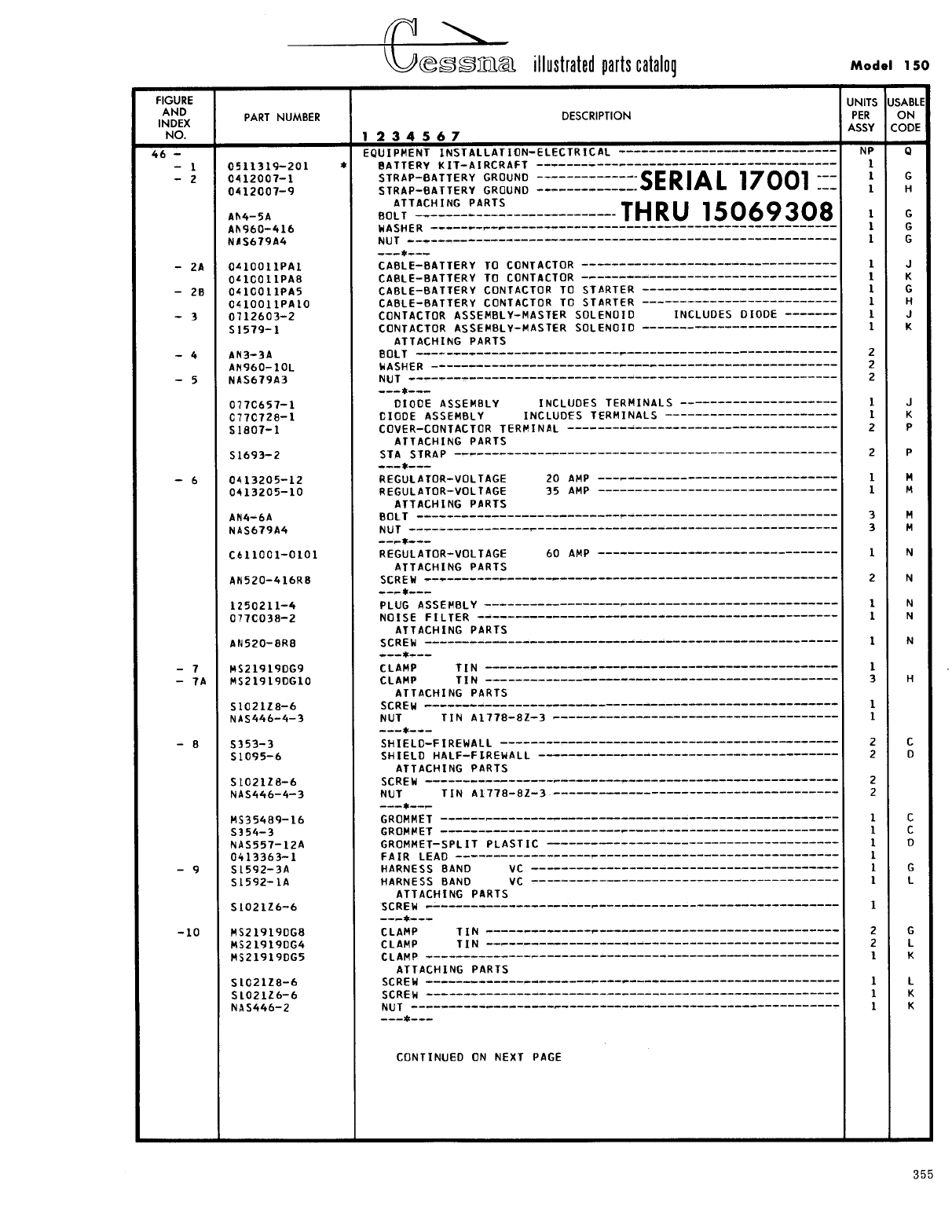
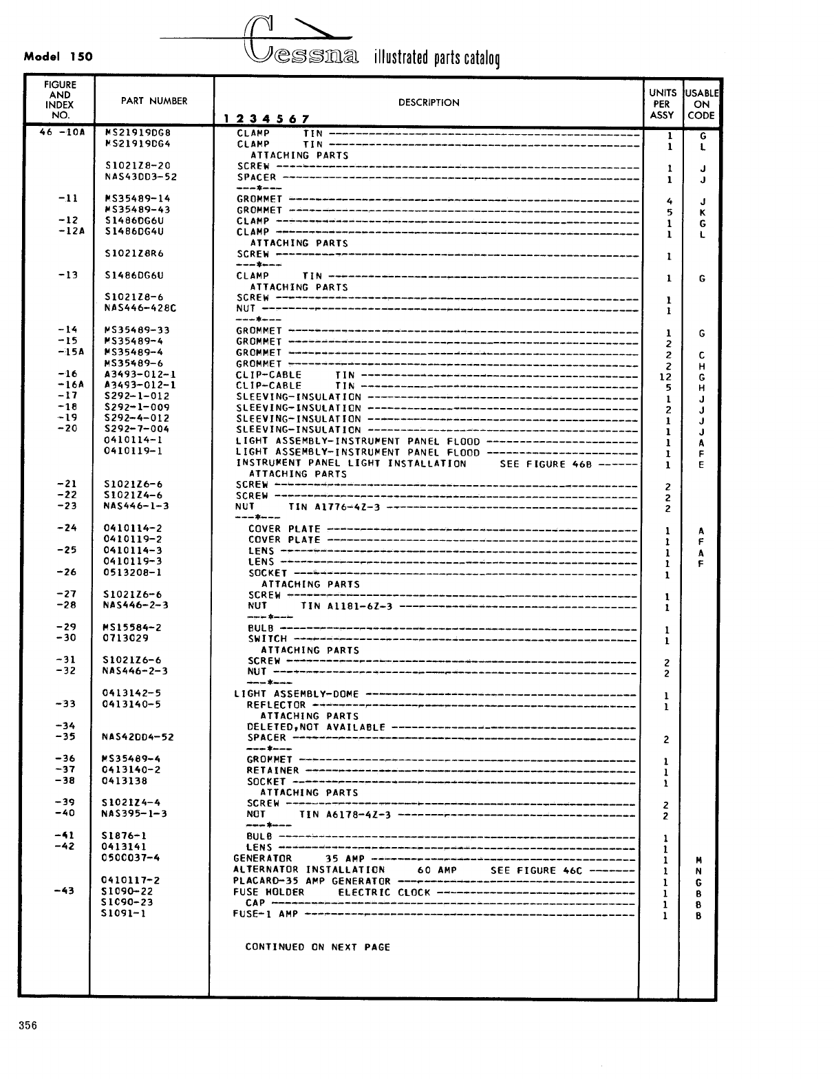
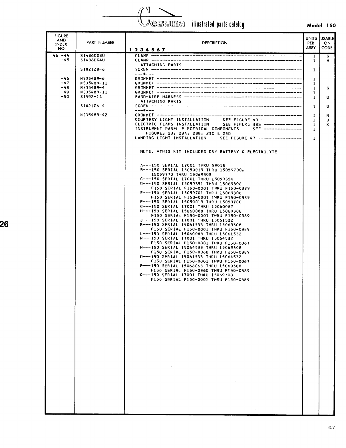
- Fig 46. Electrical Equipment Installation
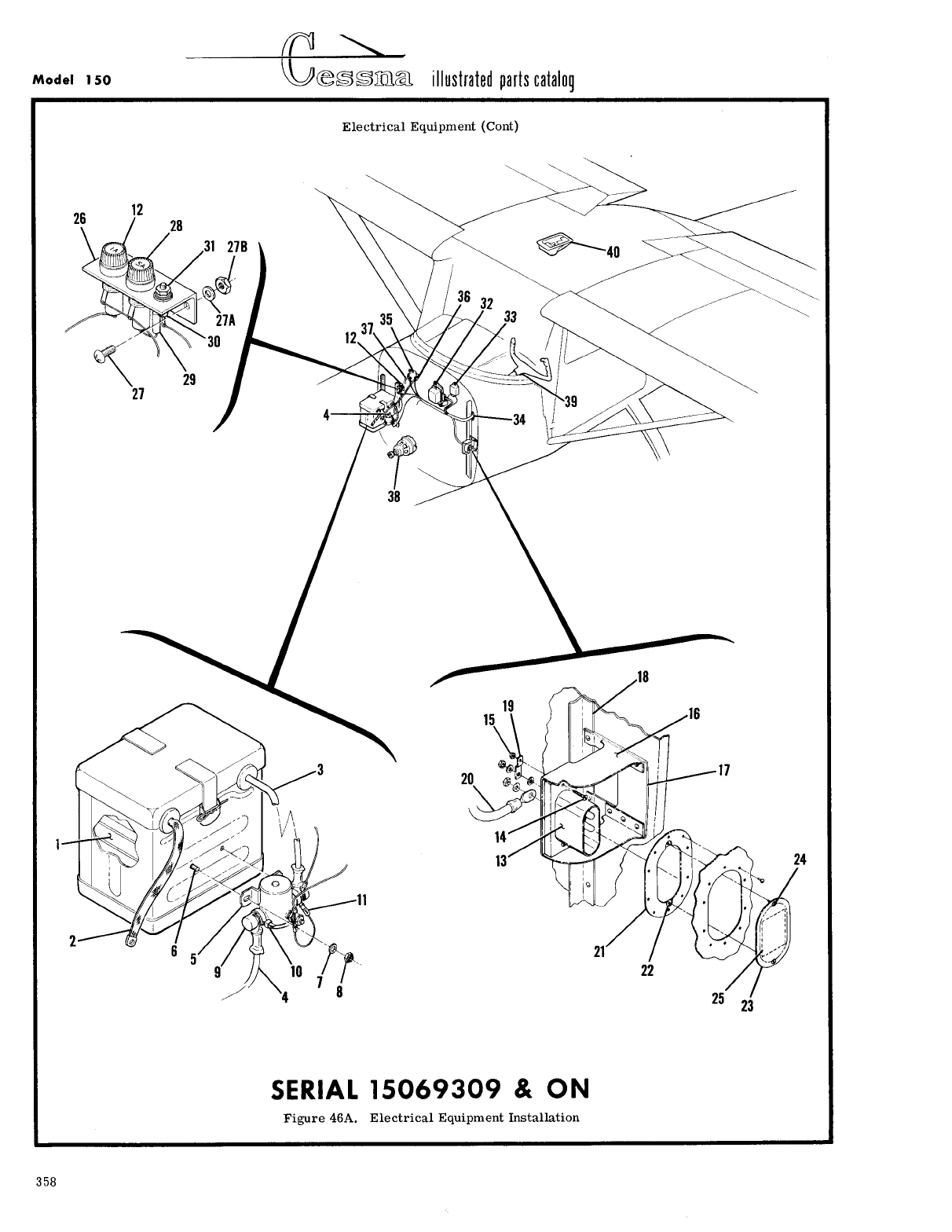
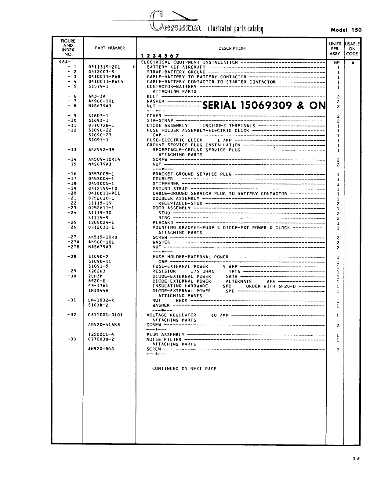
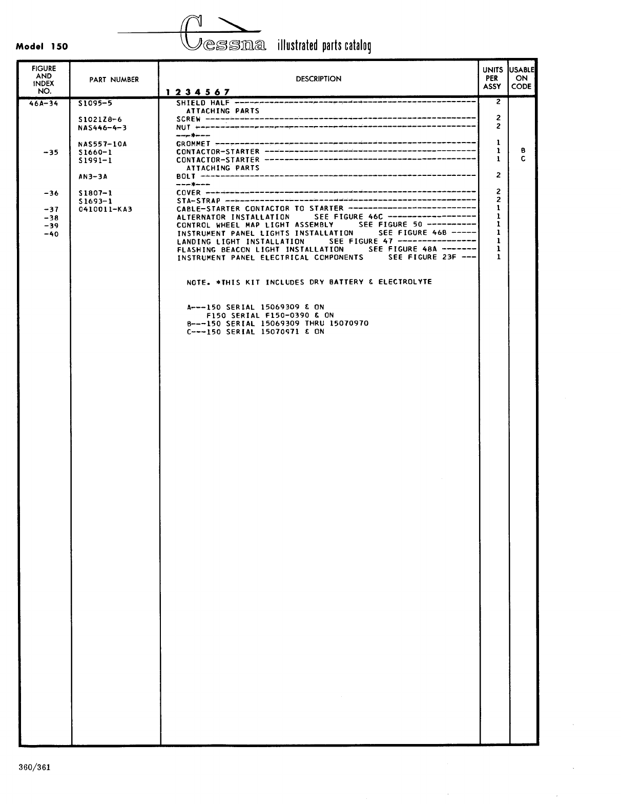
- Fig 46A. Electrical Equipment Installation
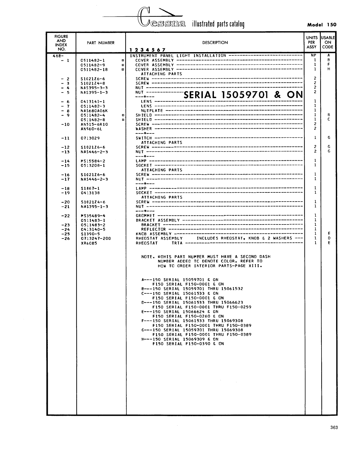
- Fig 46B. Instrument Panel Lights Installation
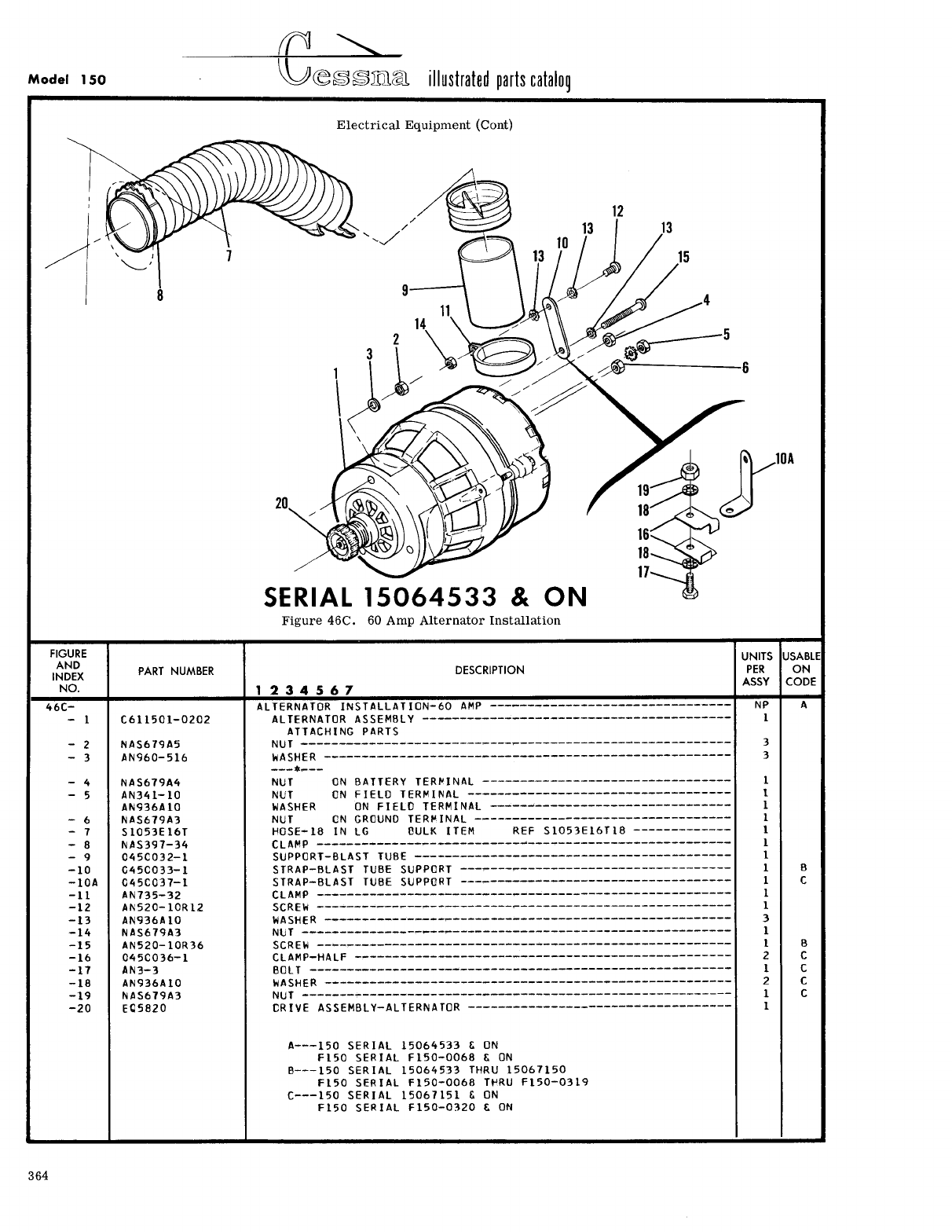
- Fig 46C. 60 Amp Alternator Installation
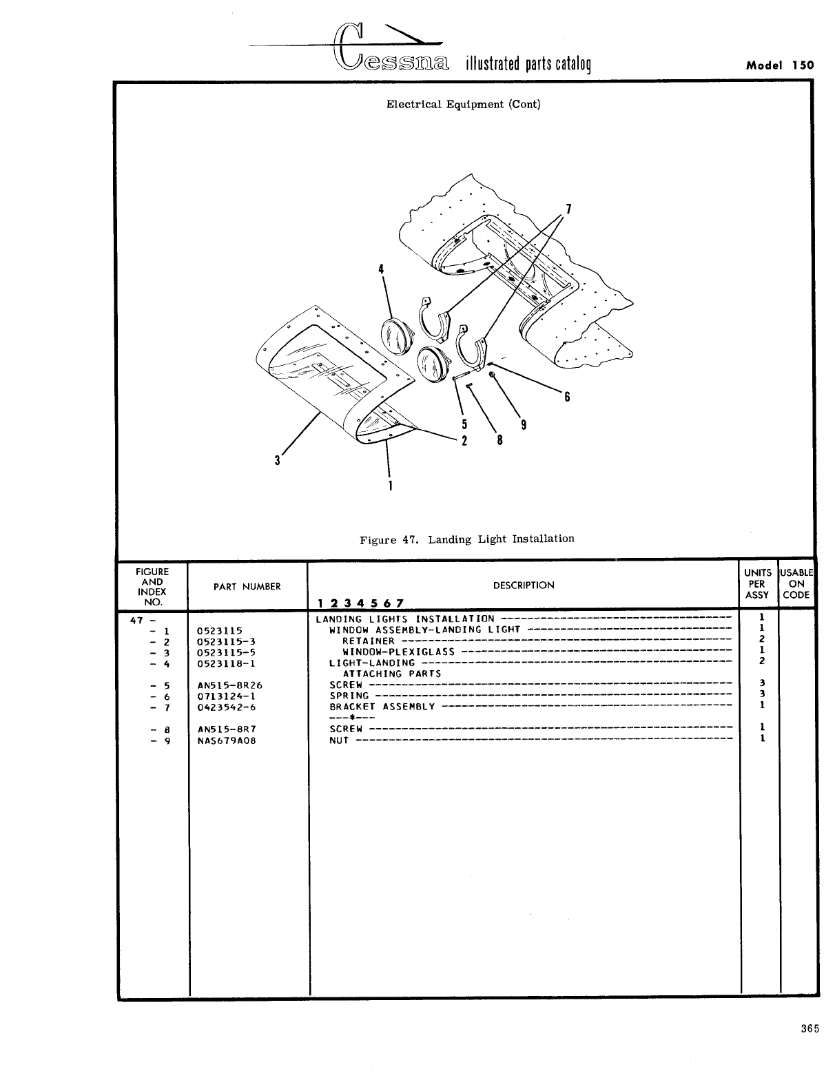
- Fig 47. Landing Light Installation
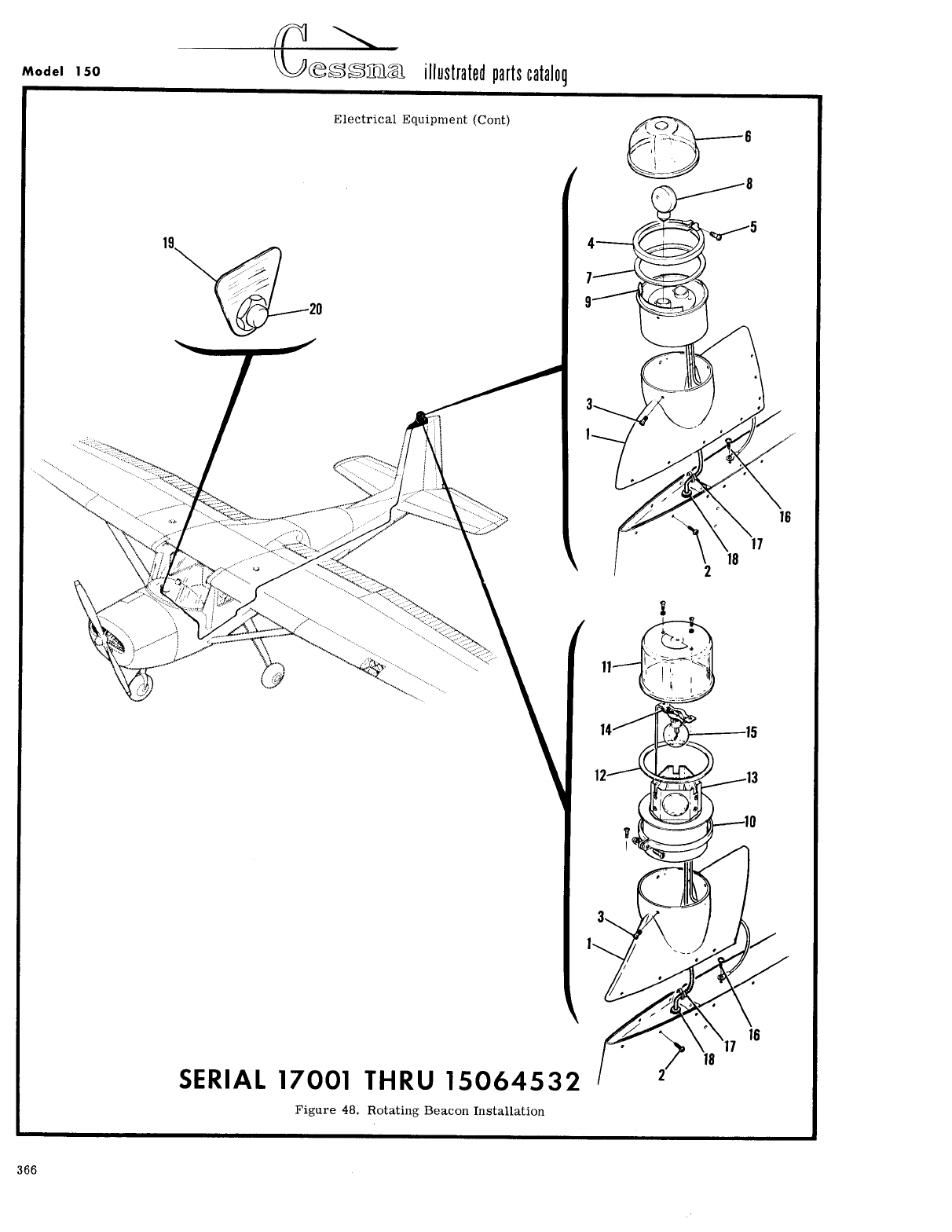
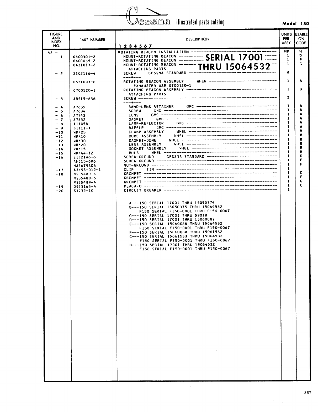
- Fig 48. Rotating Beacon Installation
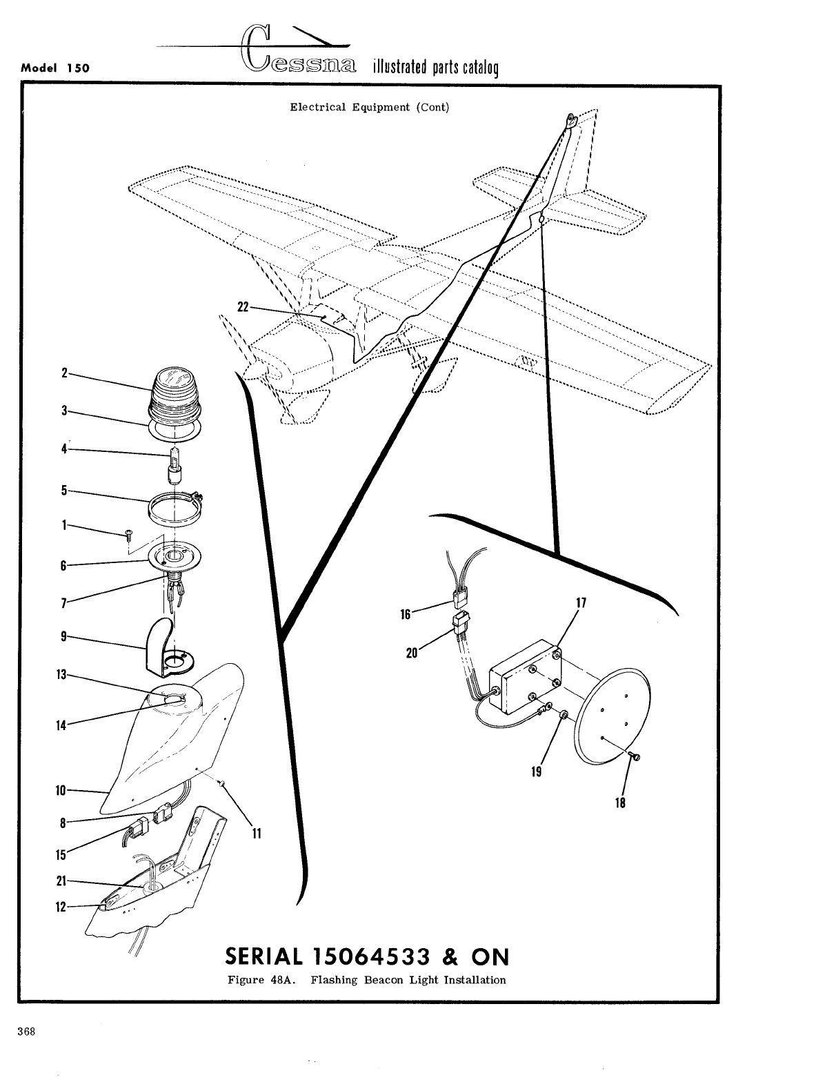
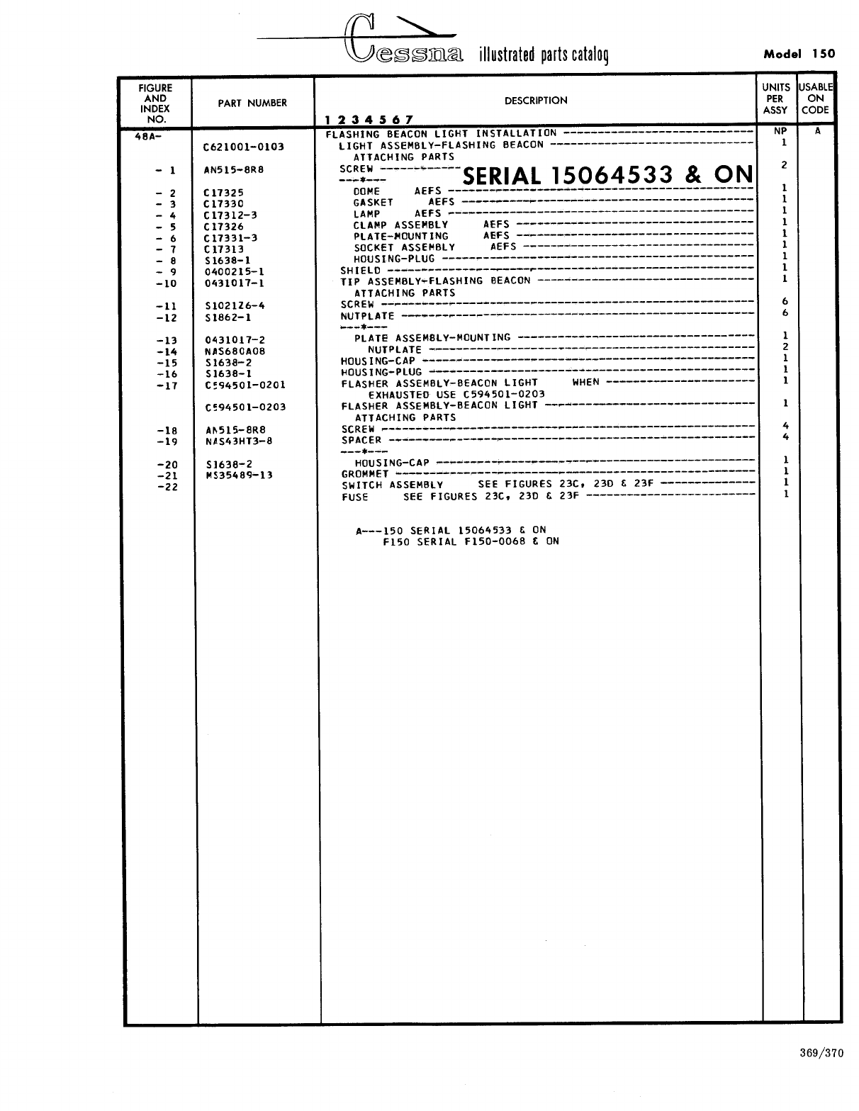
- Fig 48A. Flashing Beacon Light Installation
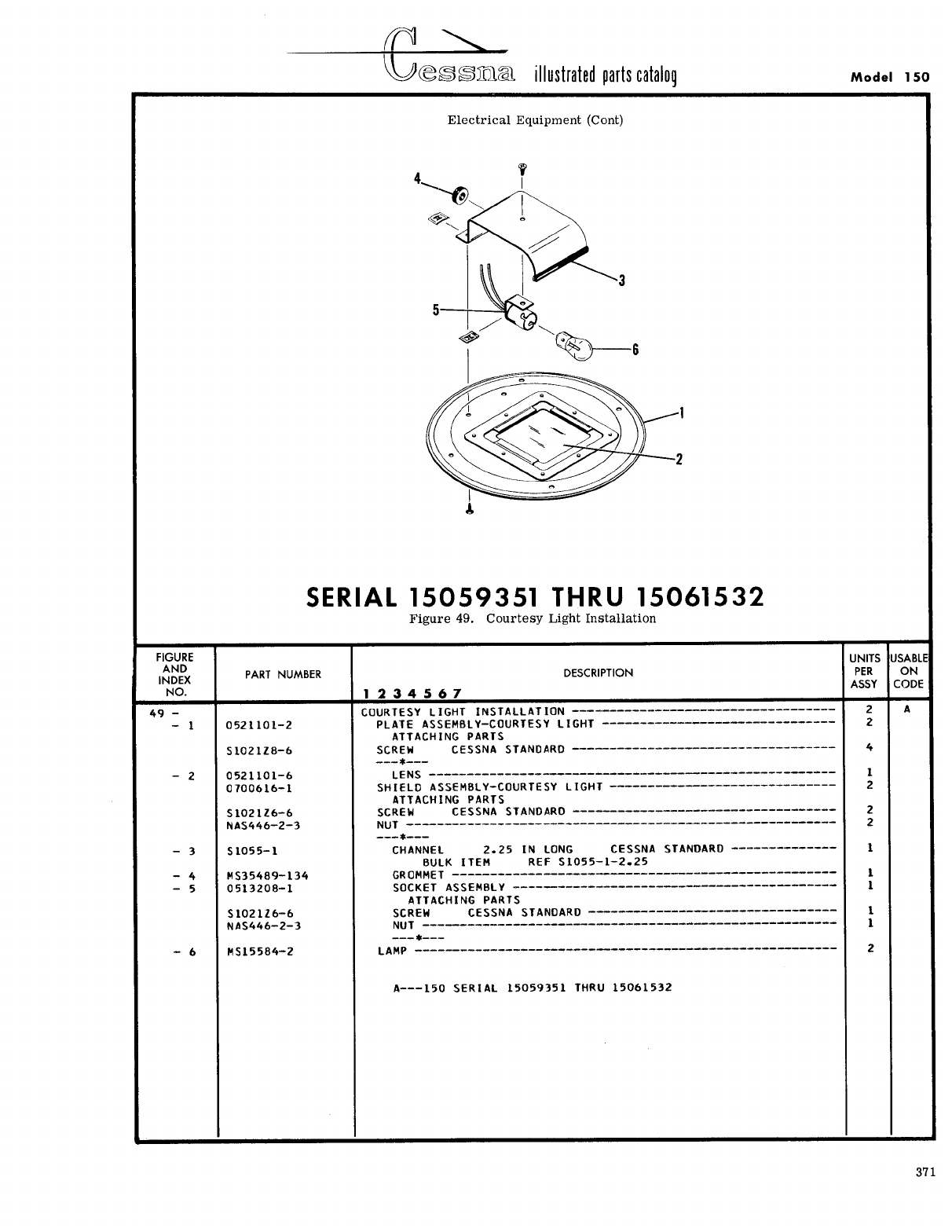
- Fig 49. Courtesy Light Installation
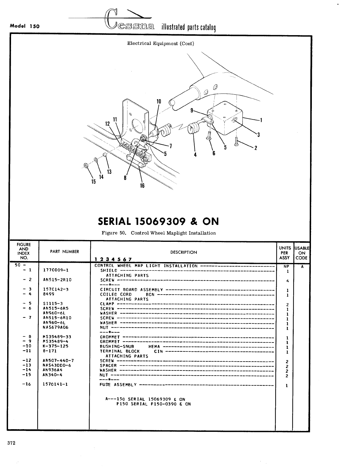
- Fig 50. Control Wheel Maplight Installation
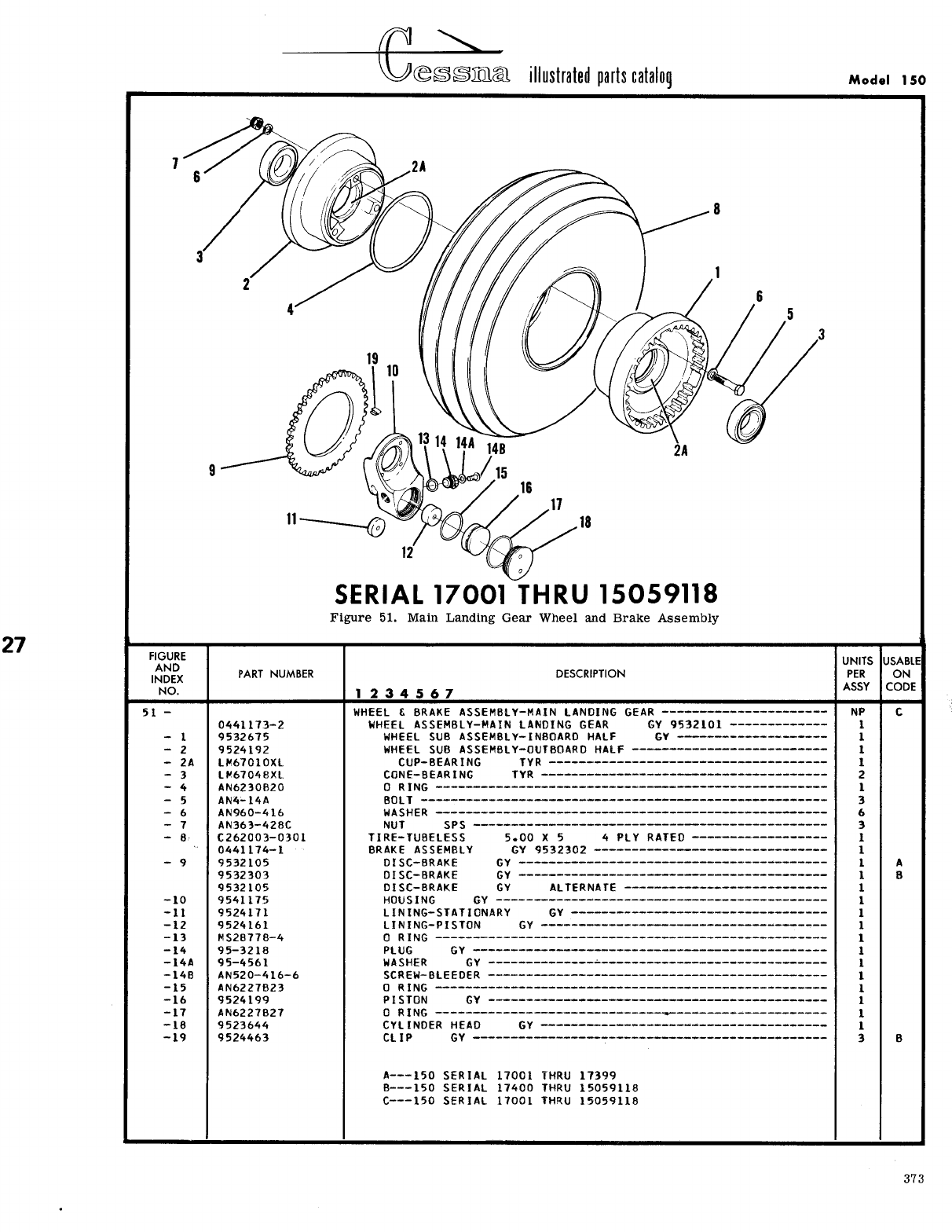
- Fig 51. Main Landing Gear Wheel and Brake Assembly
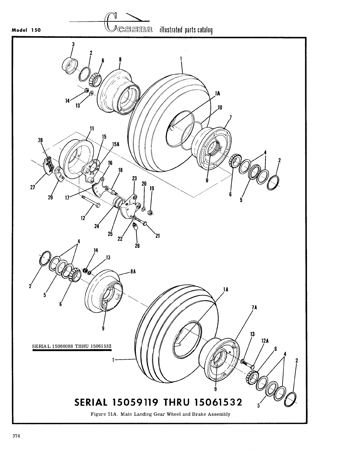
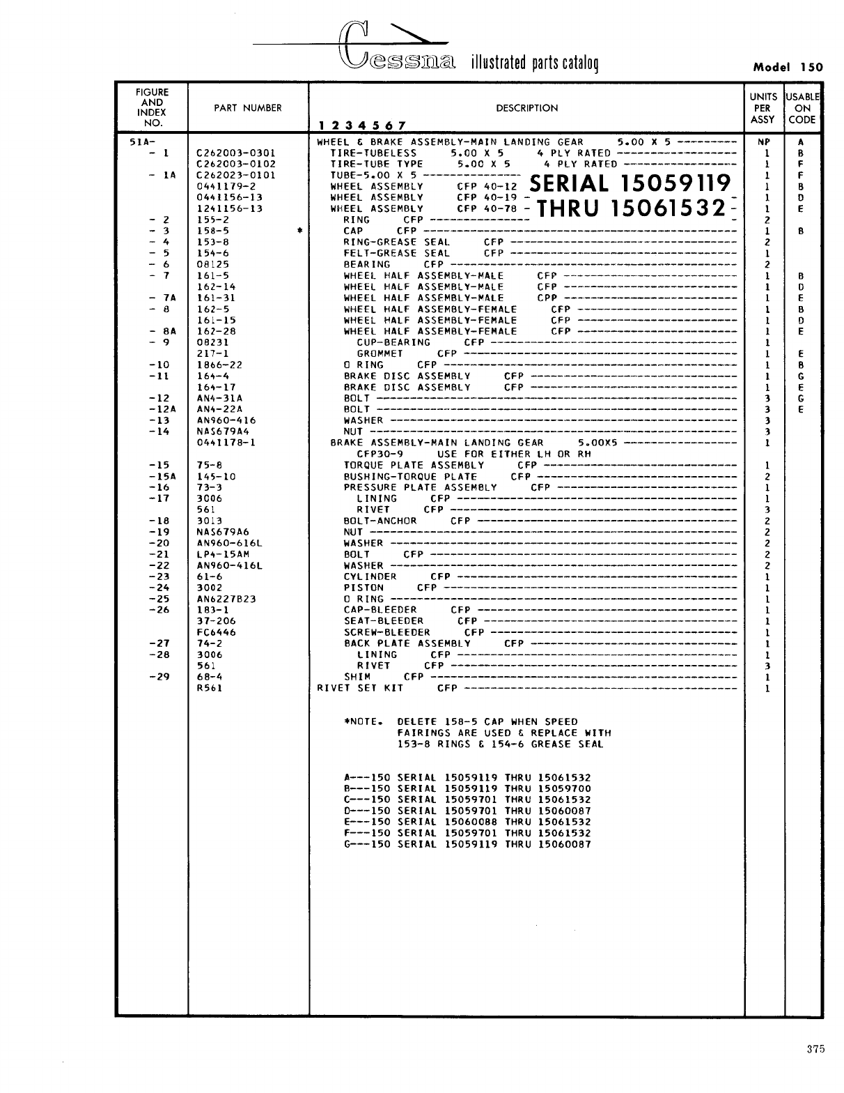
- Fig 51A. Main Landing Gear Wheel and Brake Assembly
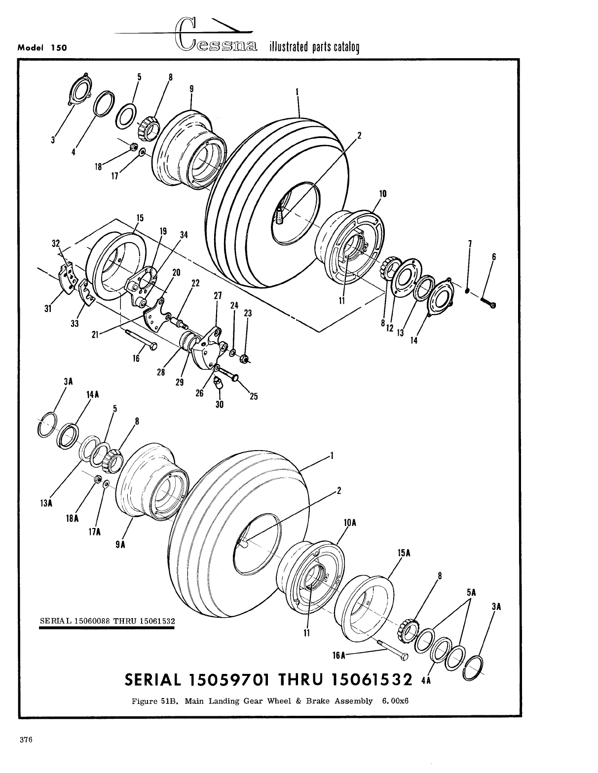
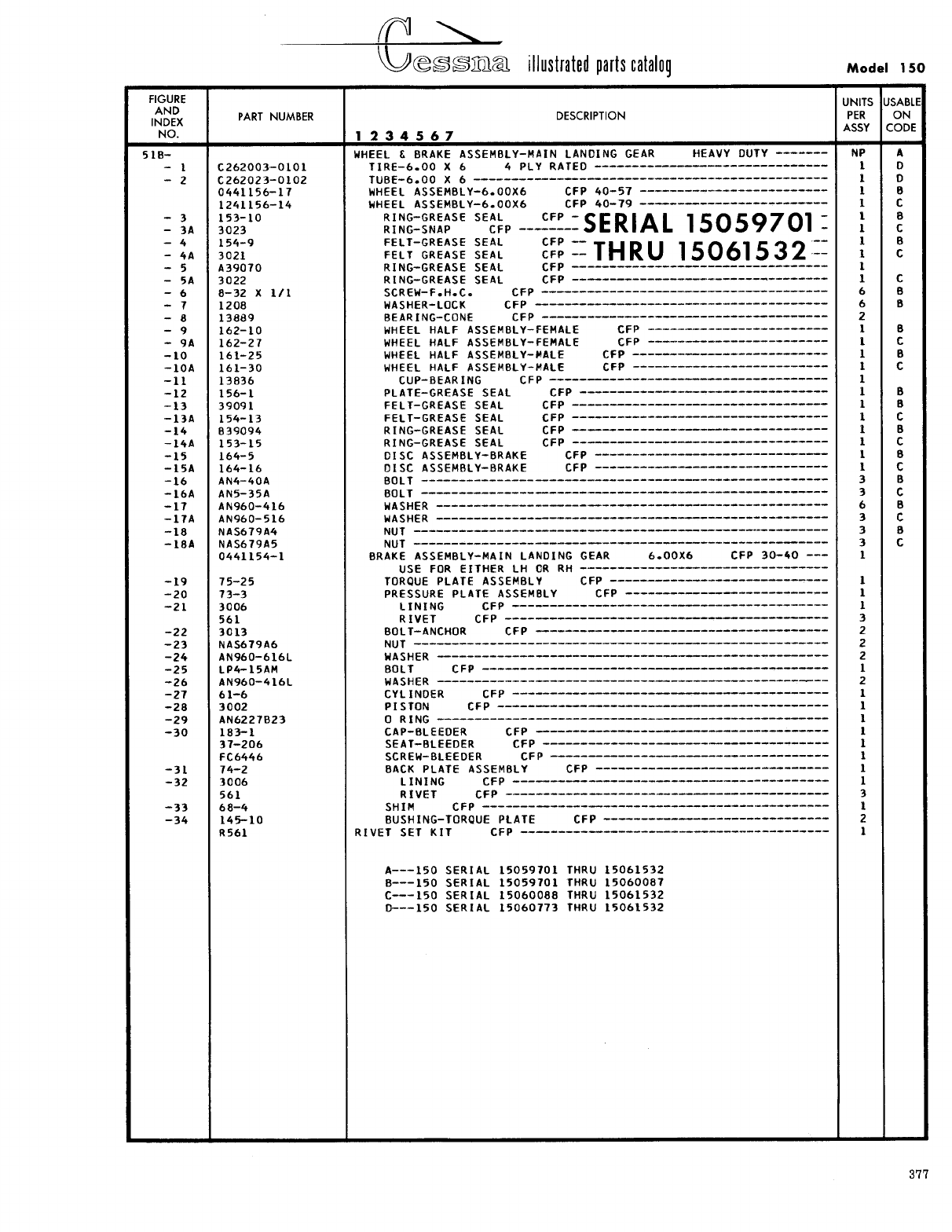
- Fig 51B. Main Landing Gear Wheel & Brake Assembly 6.00x6
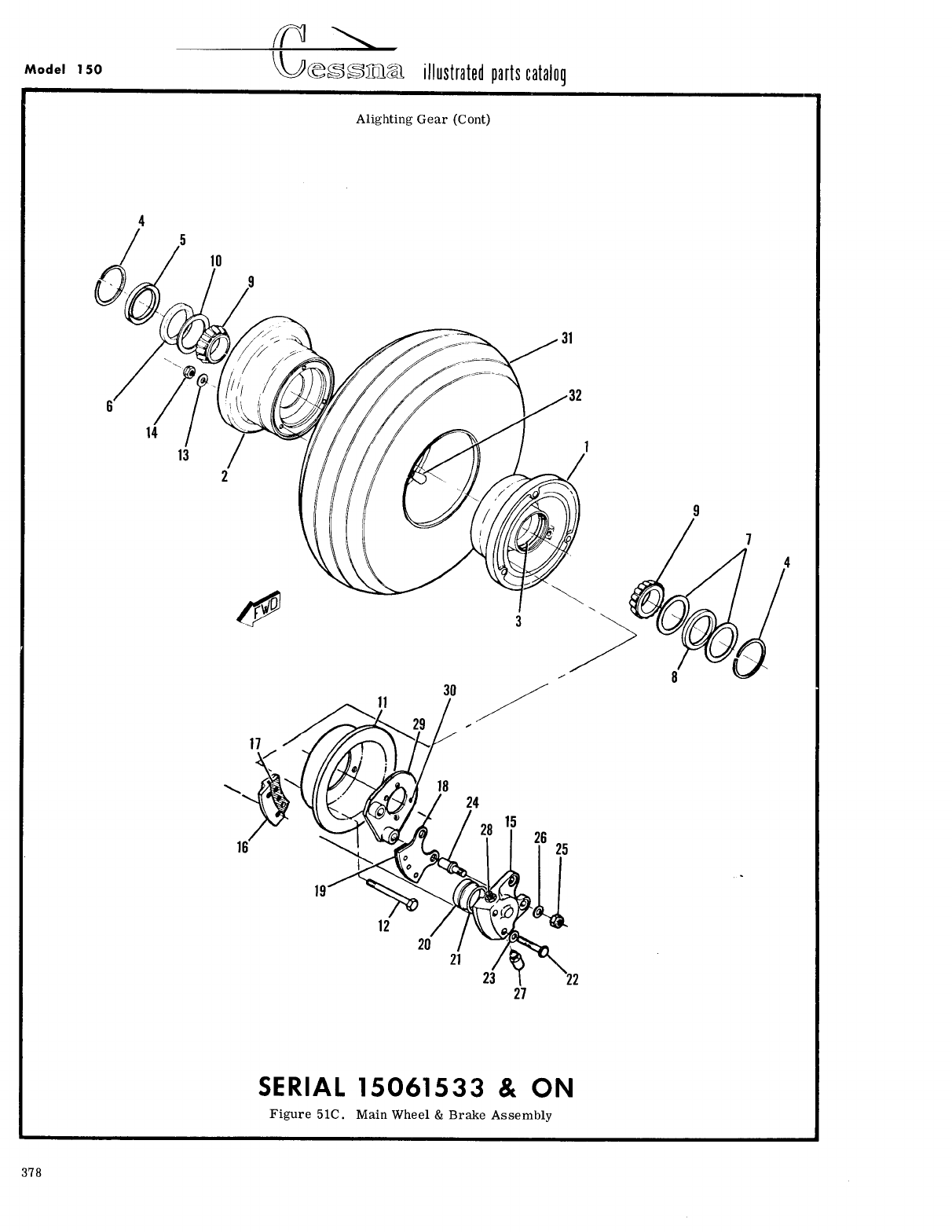
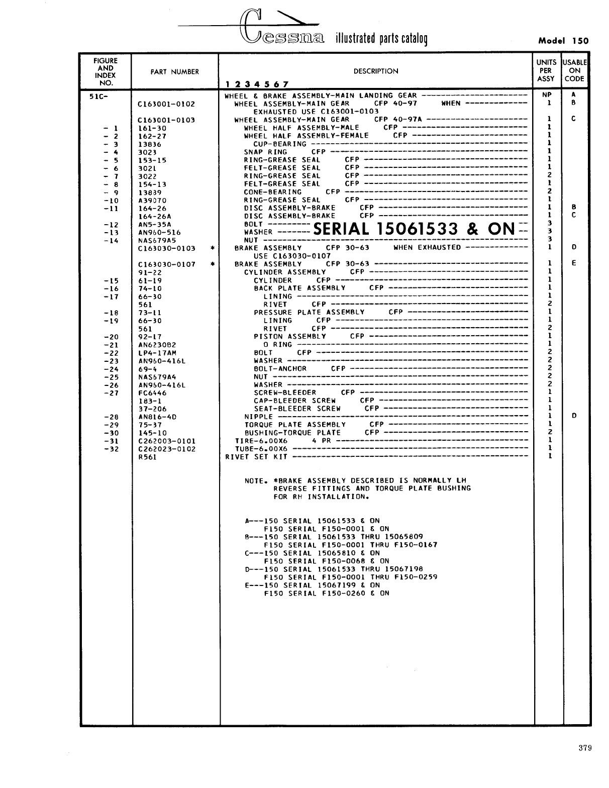
- Fig 51C. Main Wheel & Brake Assembly
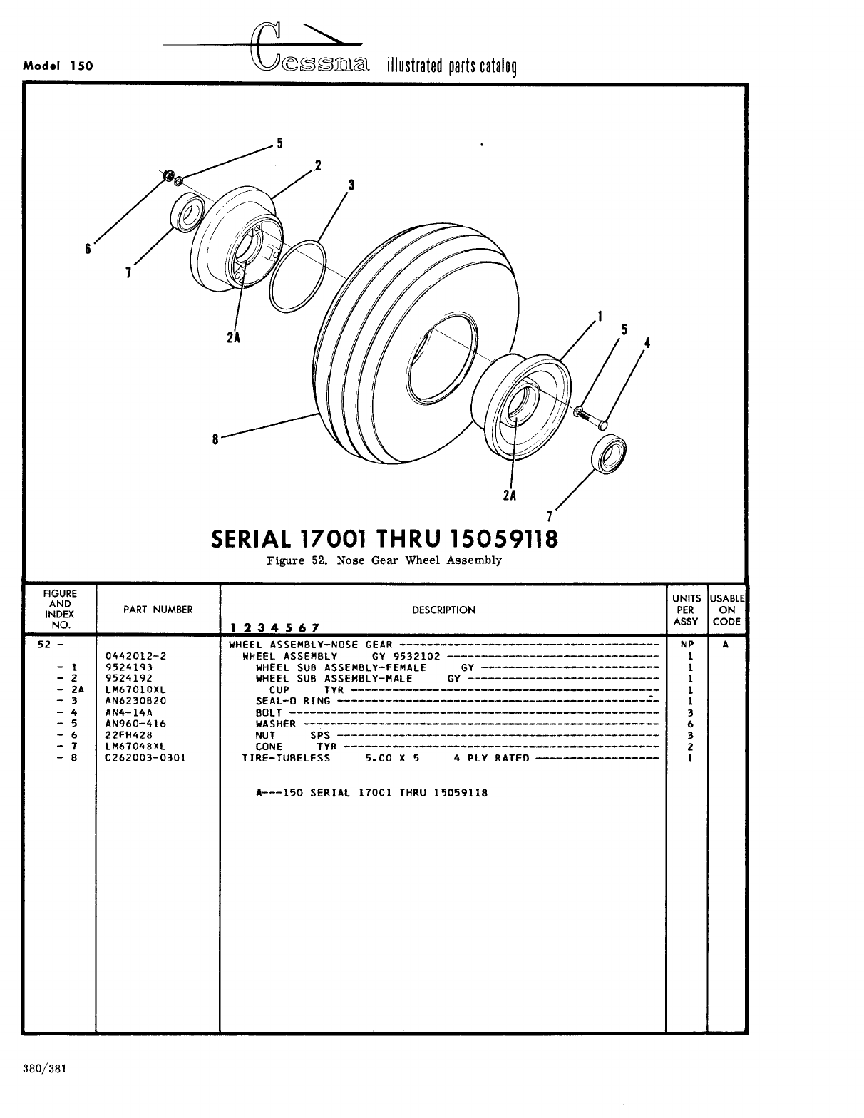
- Fig 52. Nose Gear Wheel Assembly
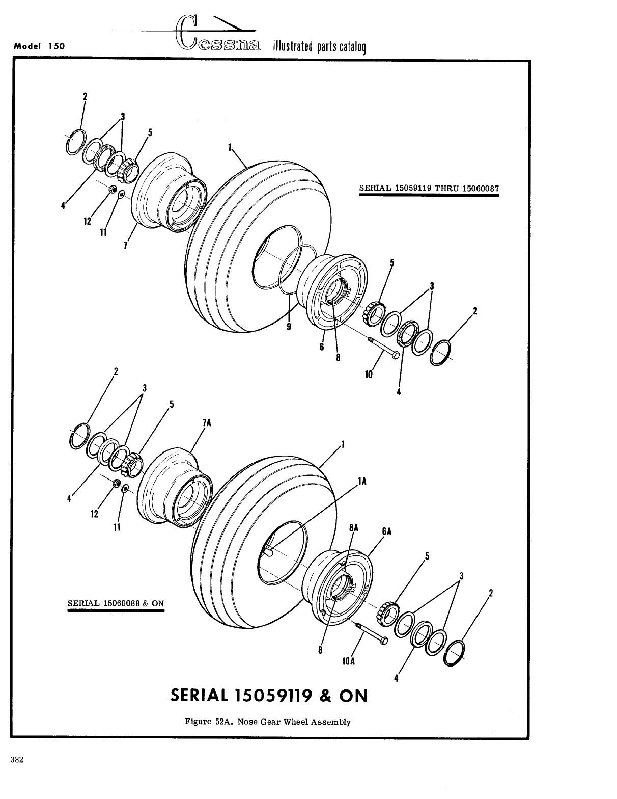
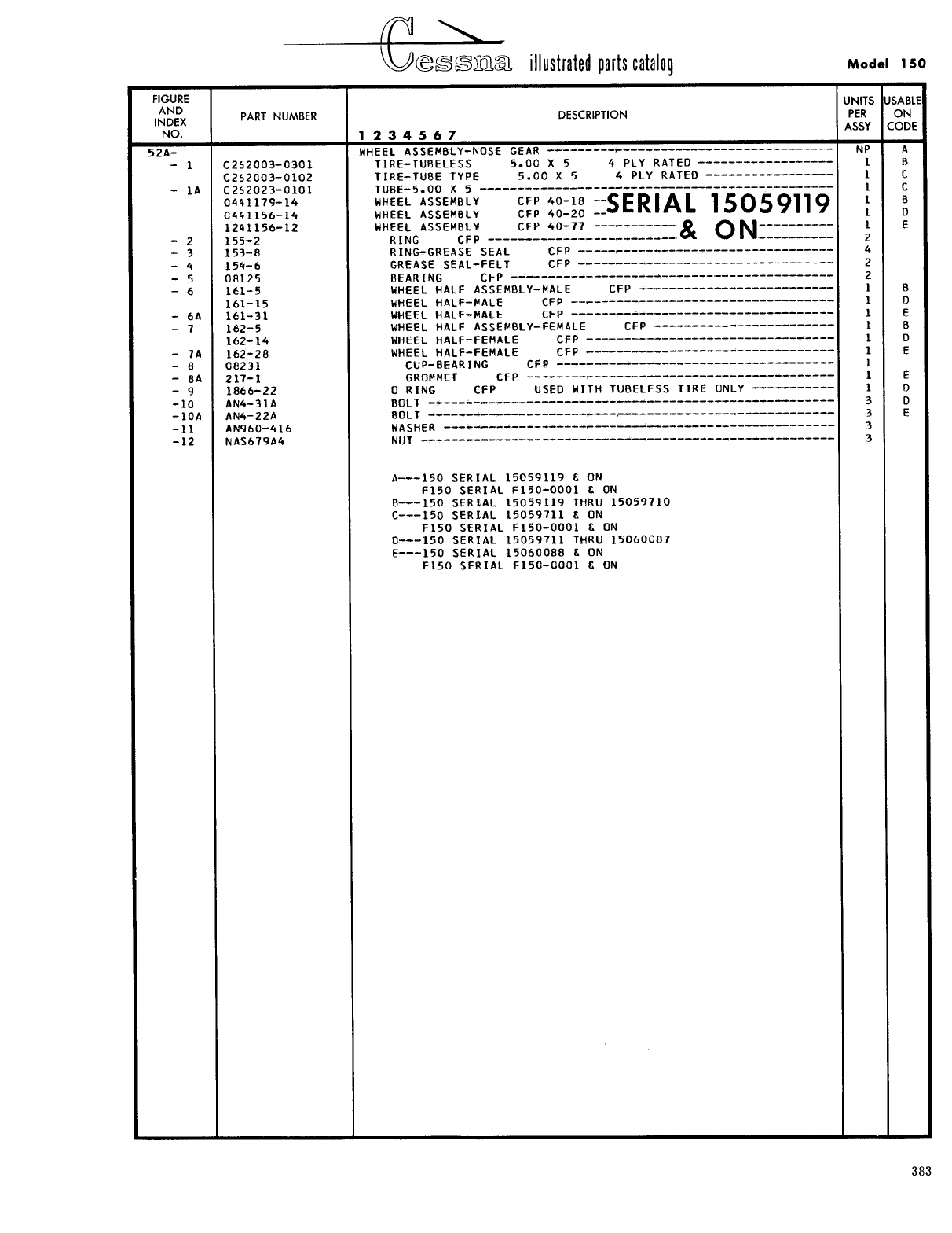
- Fig 52A. Nose Gear Wheel Assembly
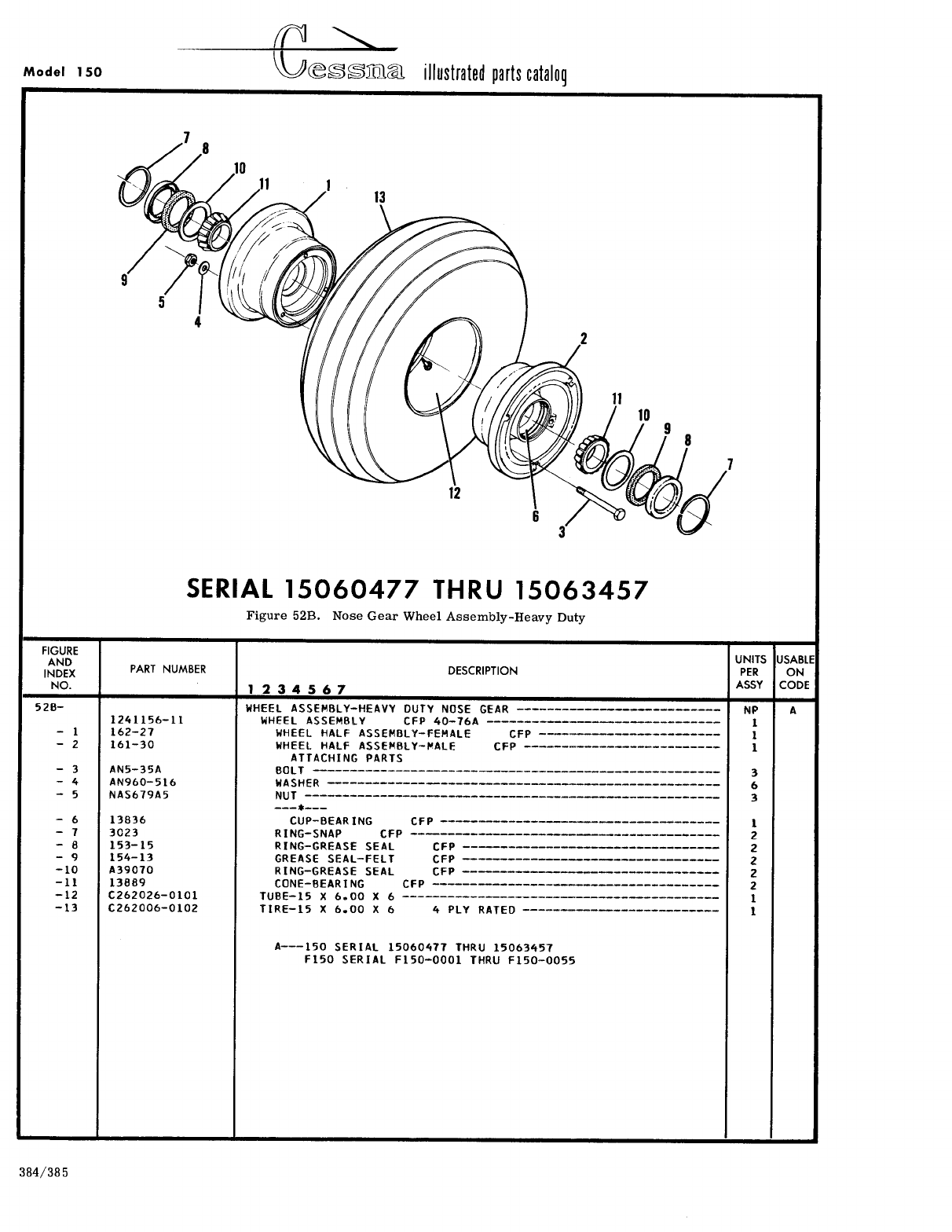
- Fig 52B. Nose Gear Wheel Assembly - Heavy Duty
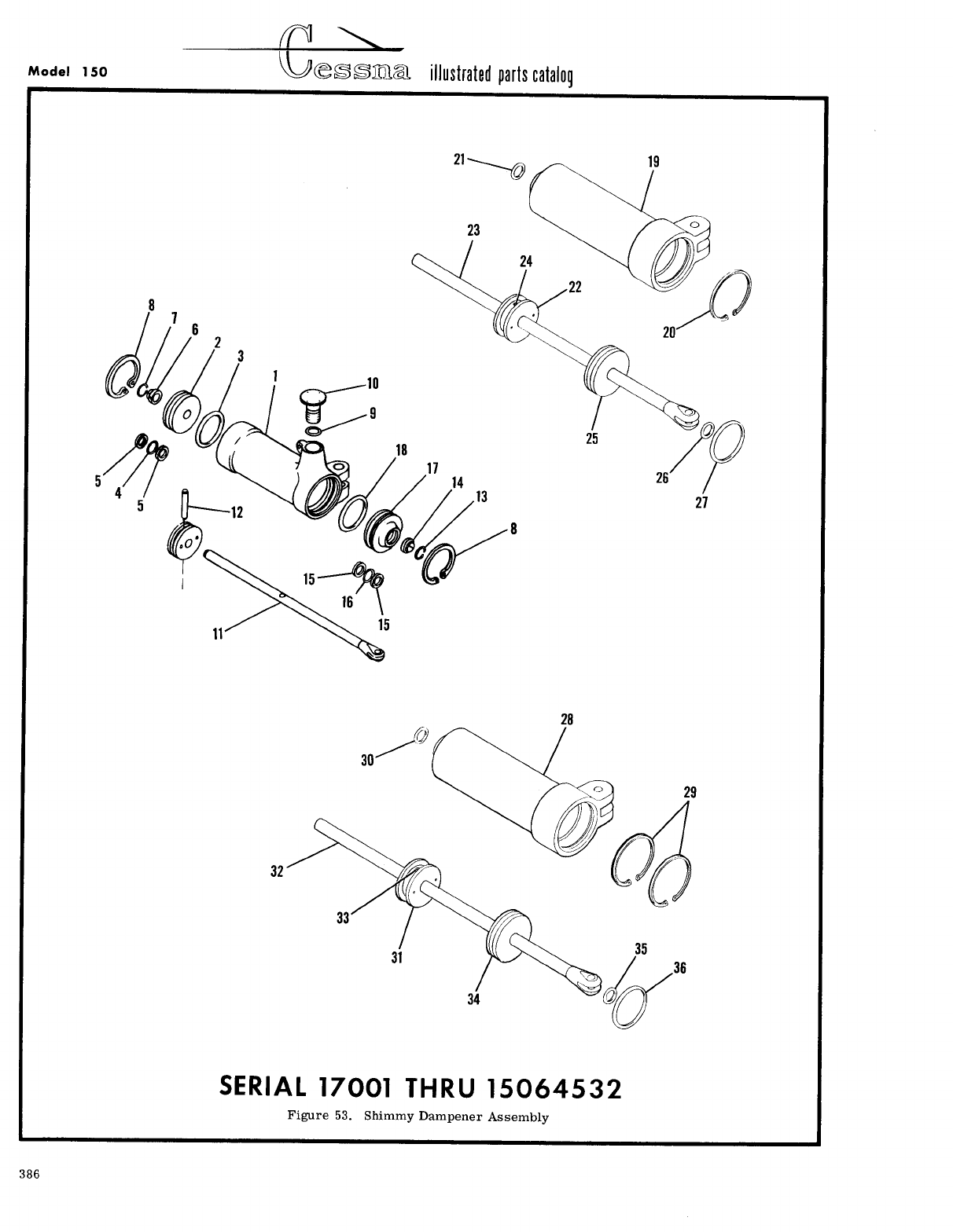
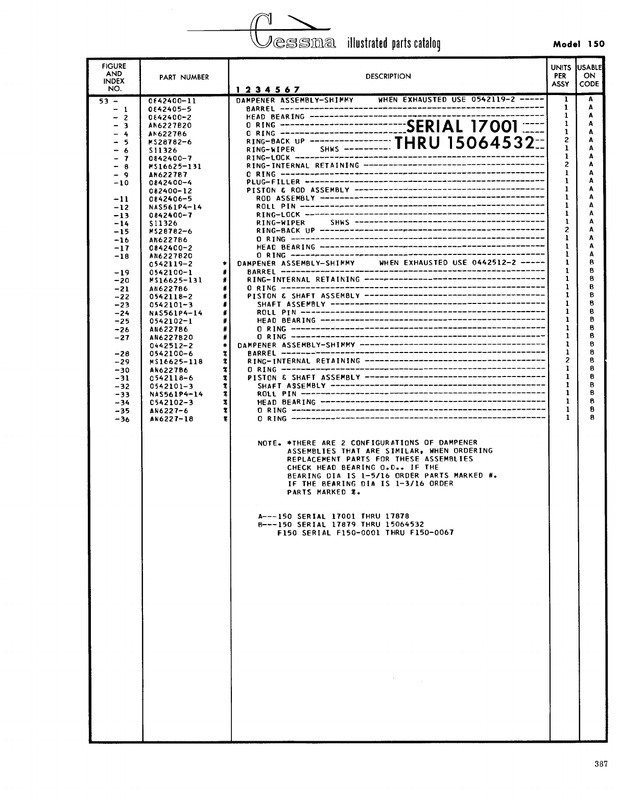
- Fig 53. Shimmy Dampener Assembly
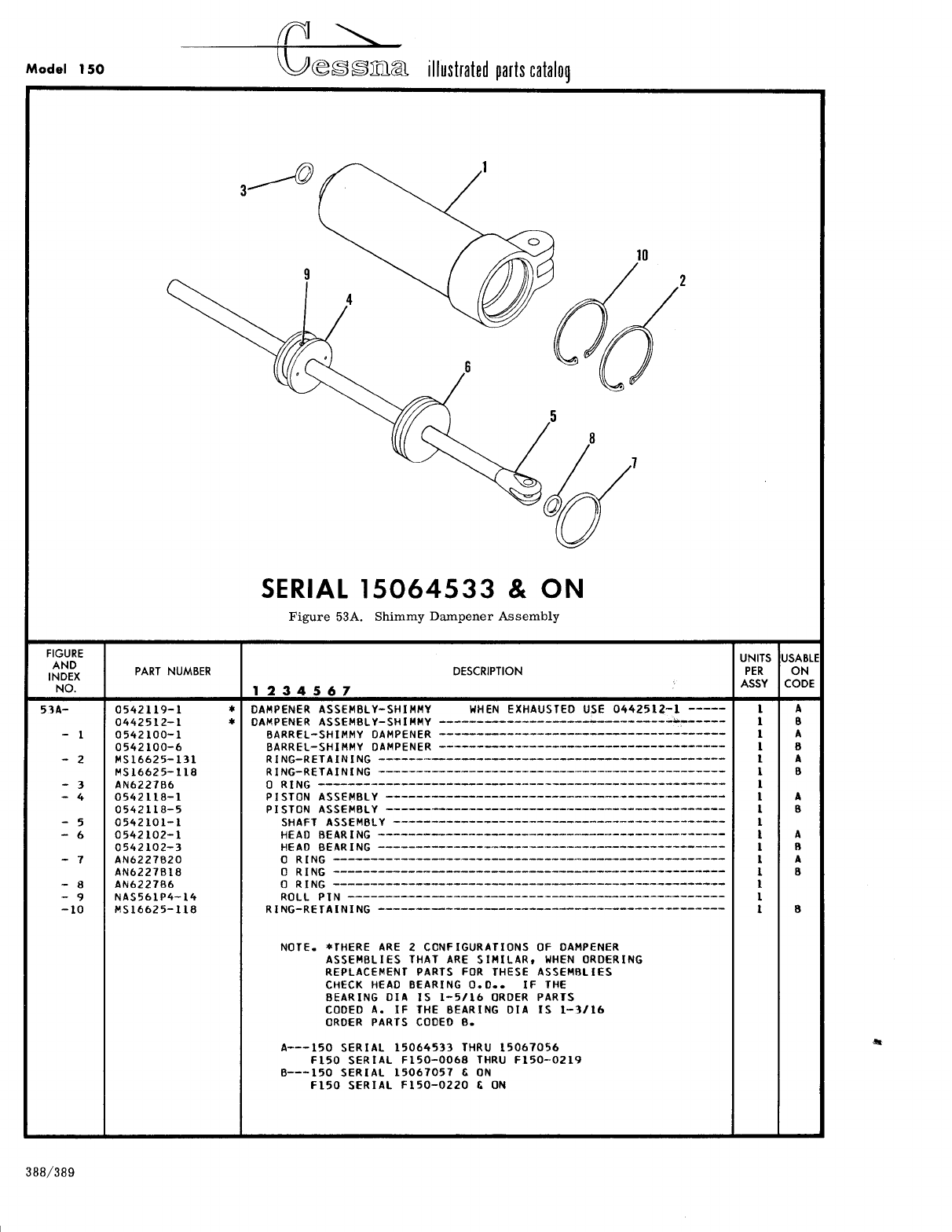
- Fig 53A. Shimmy Dampener Assembly
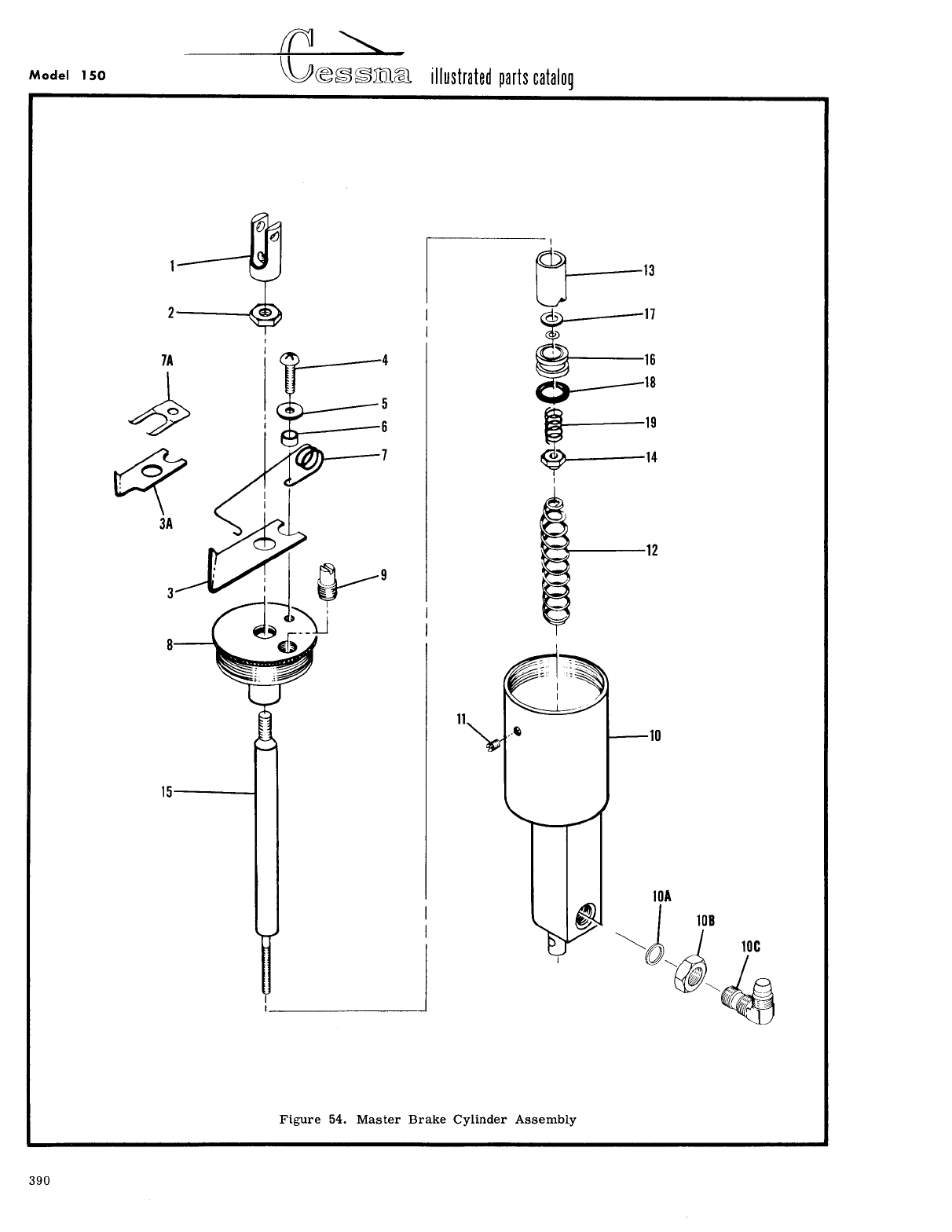
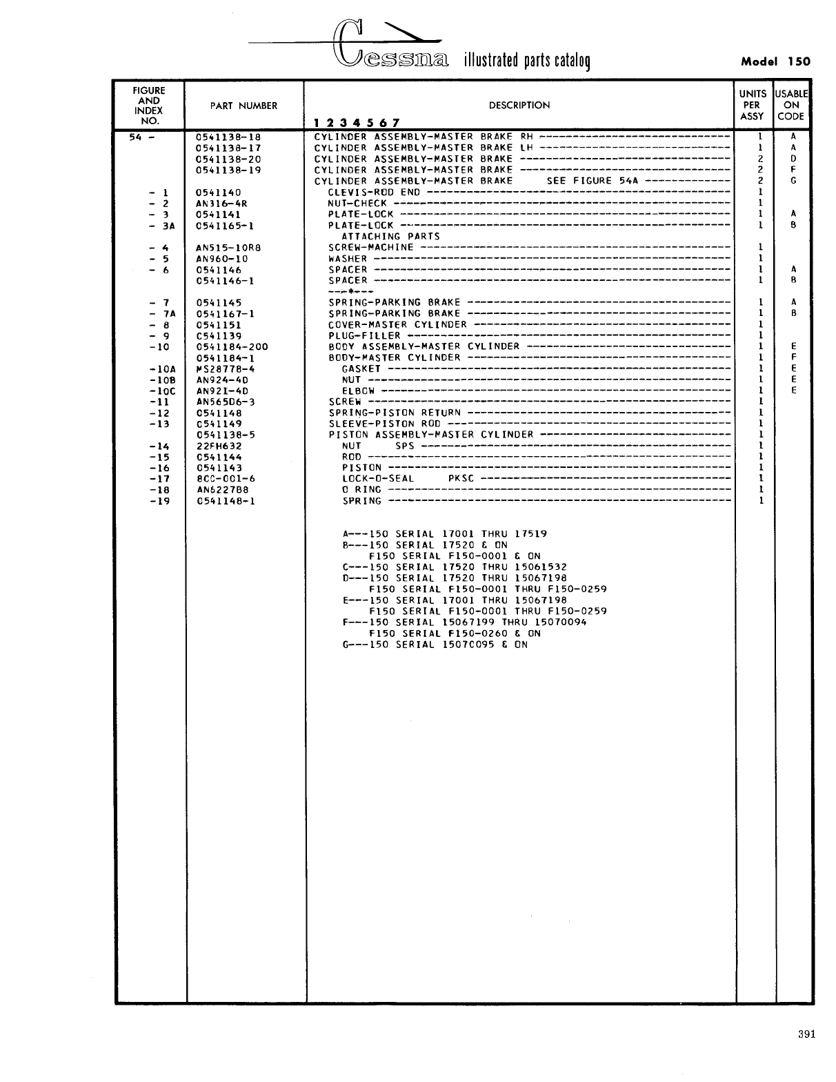
- Fig 54. Master Brake Cylinder Assembly
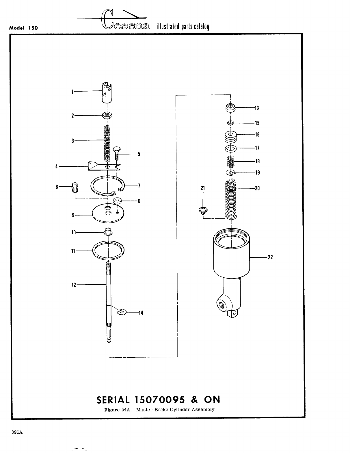
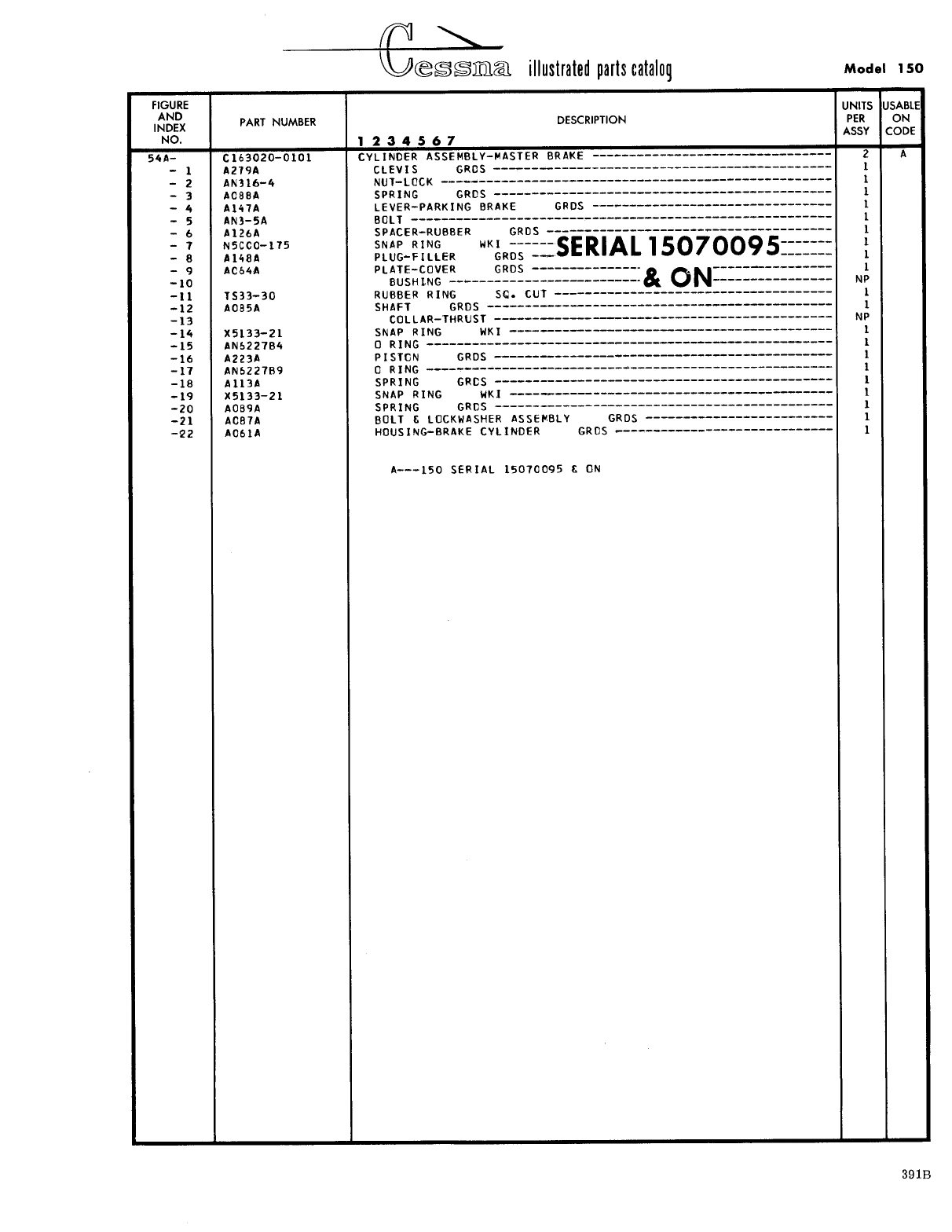
- Fig 54A. Master Brake Cylinder Assembly
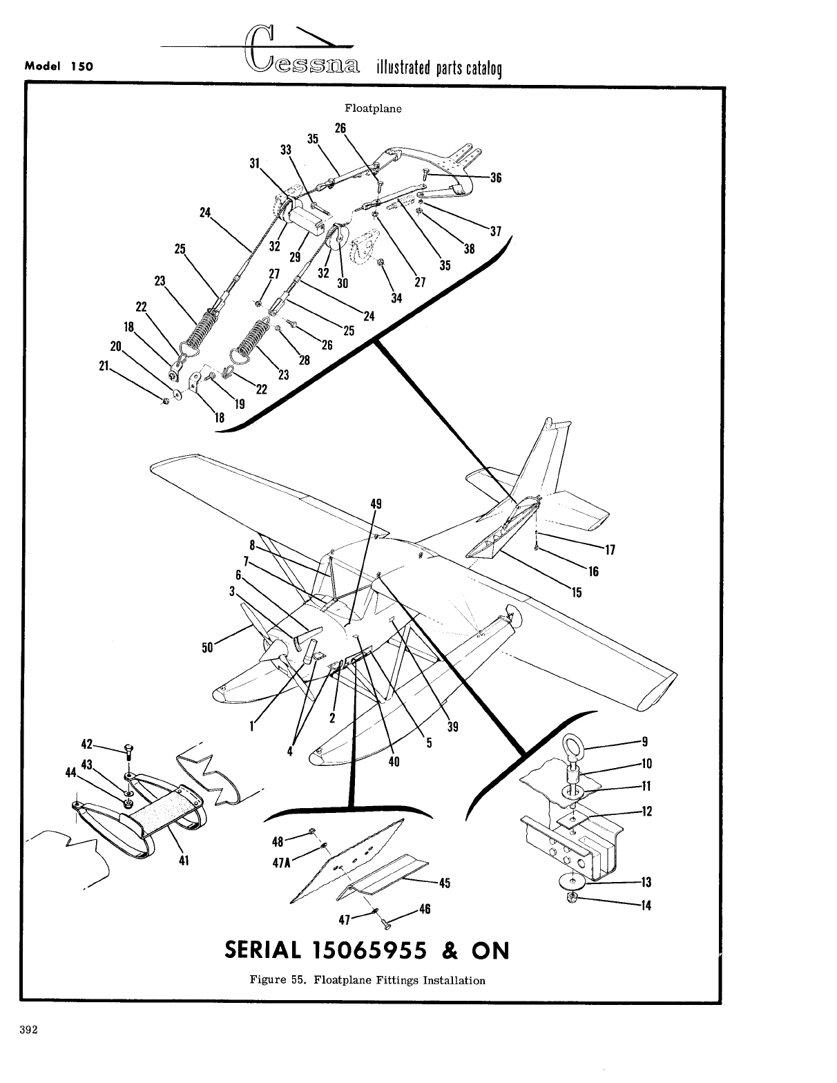
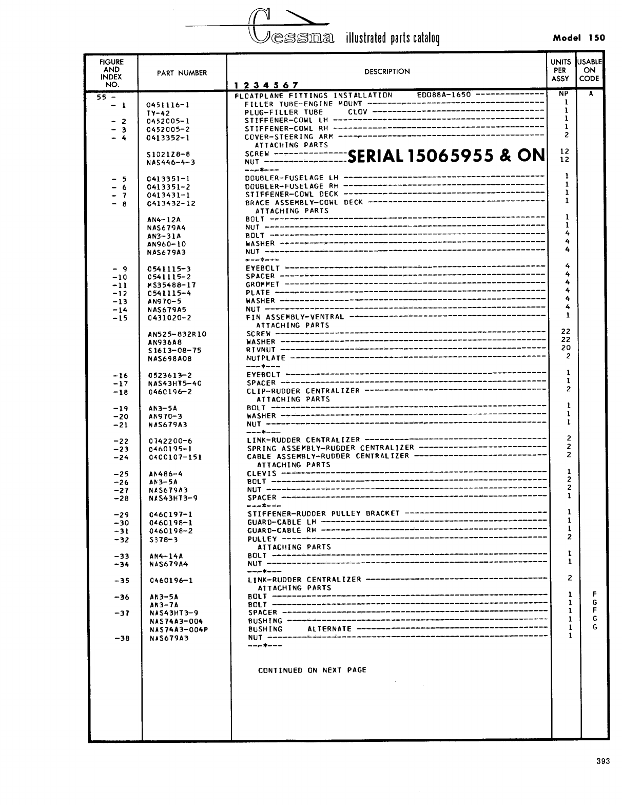
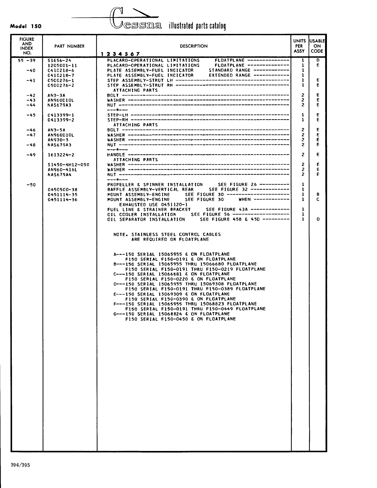
- Fig 55. Floatplane Fittings Installation
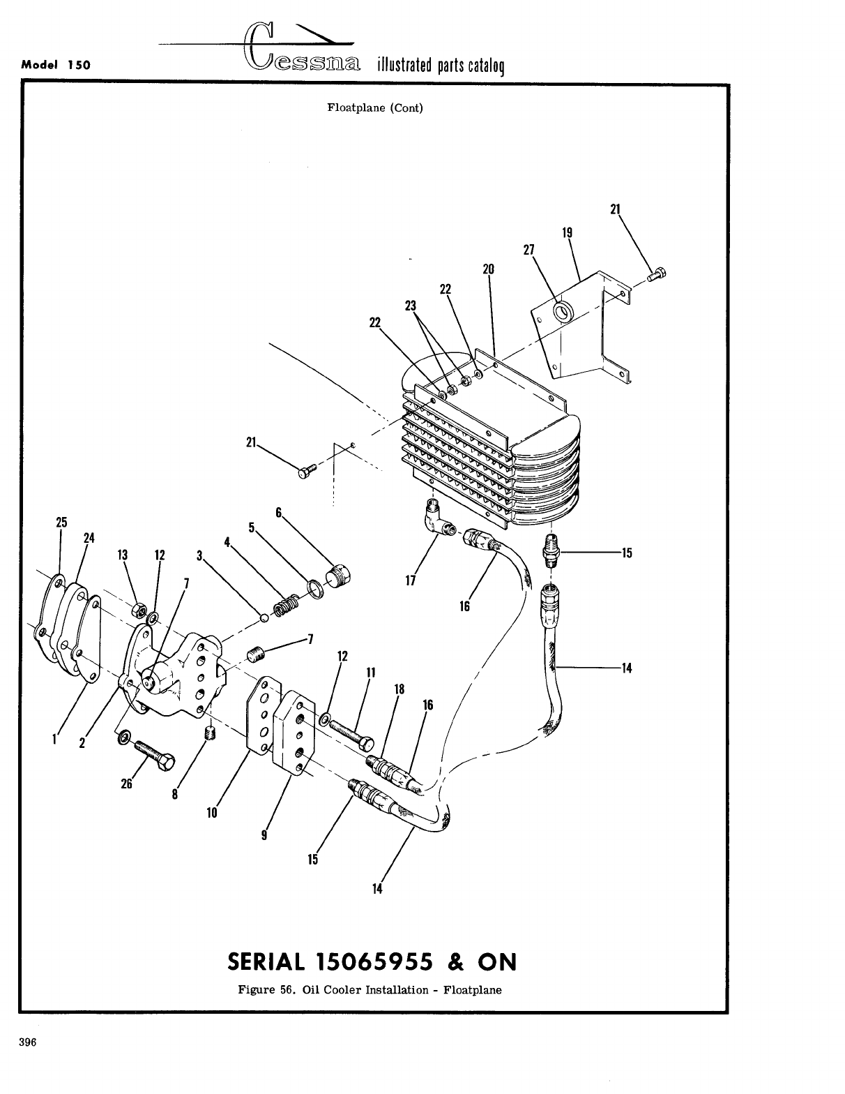
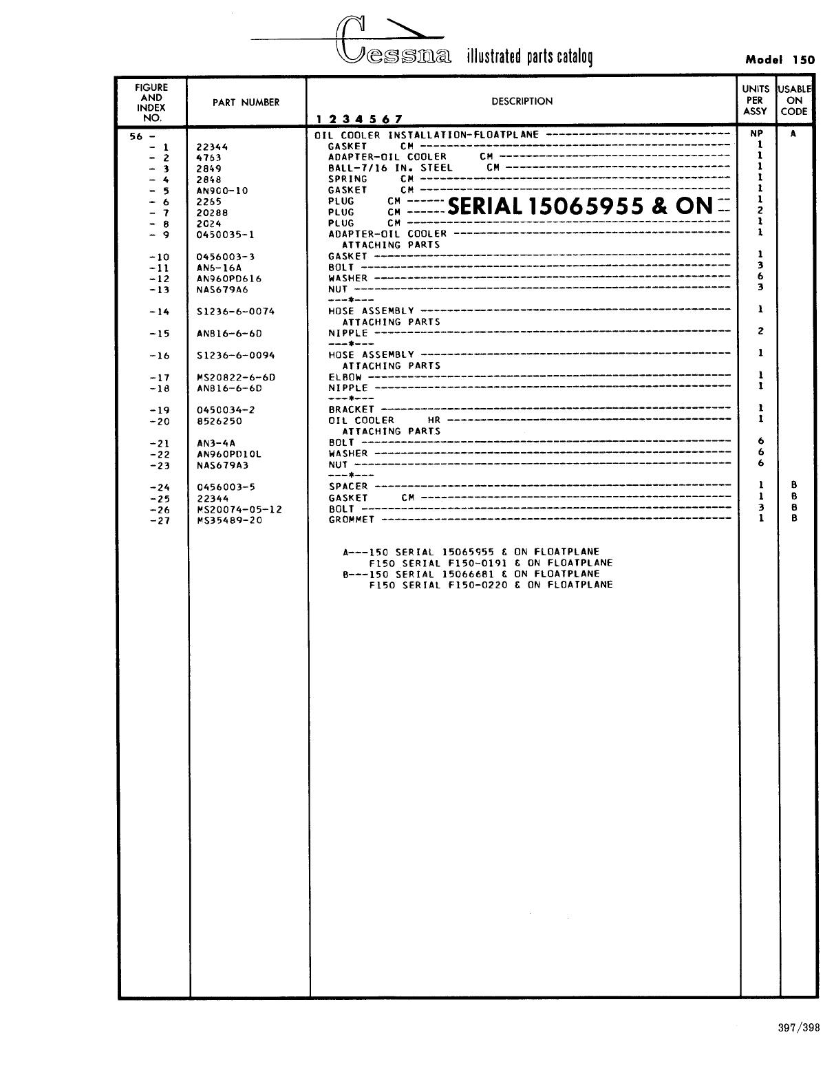
- Fig 56. Oil Cooler Installation - Floatplane
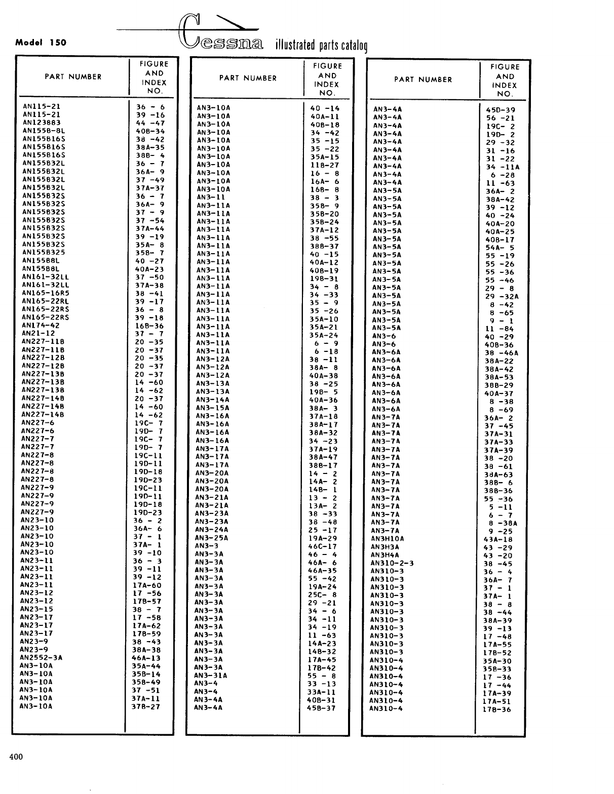
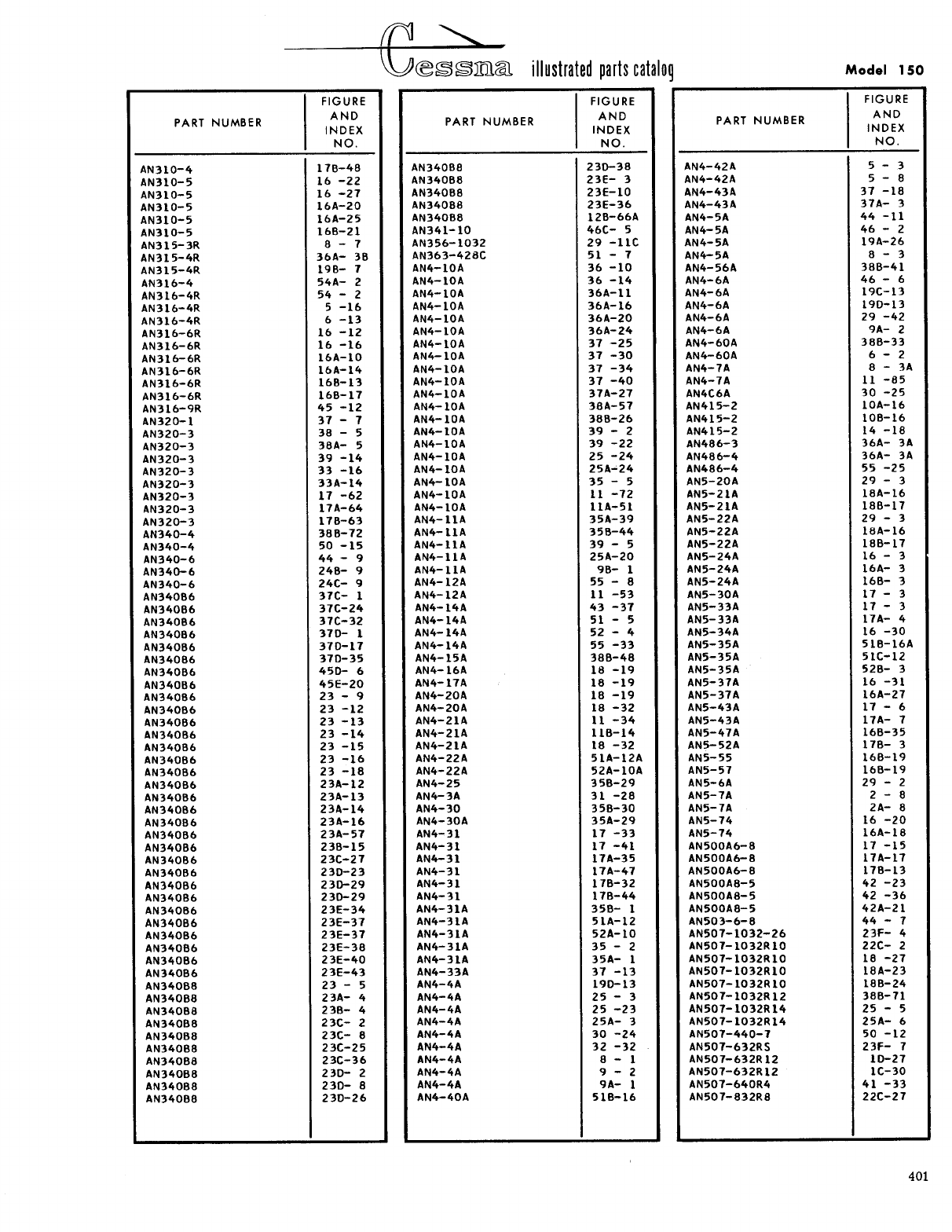
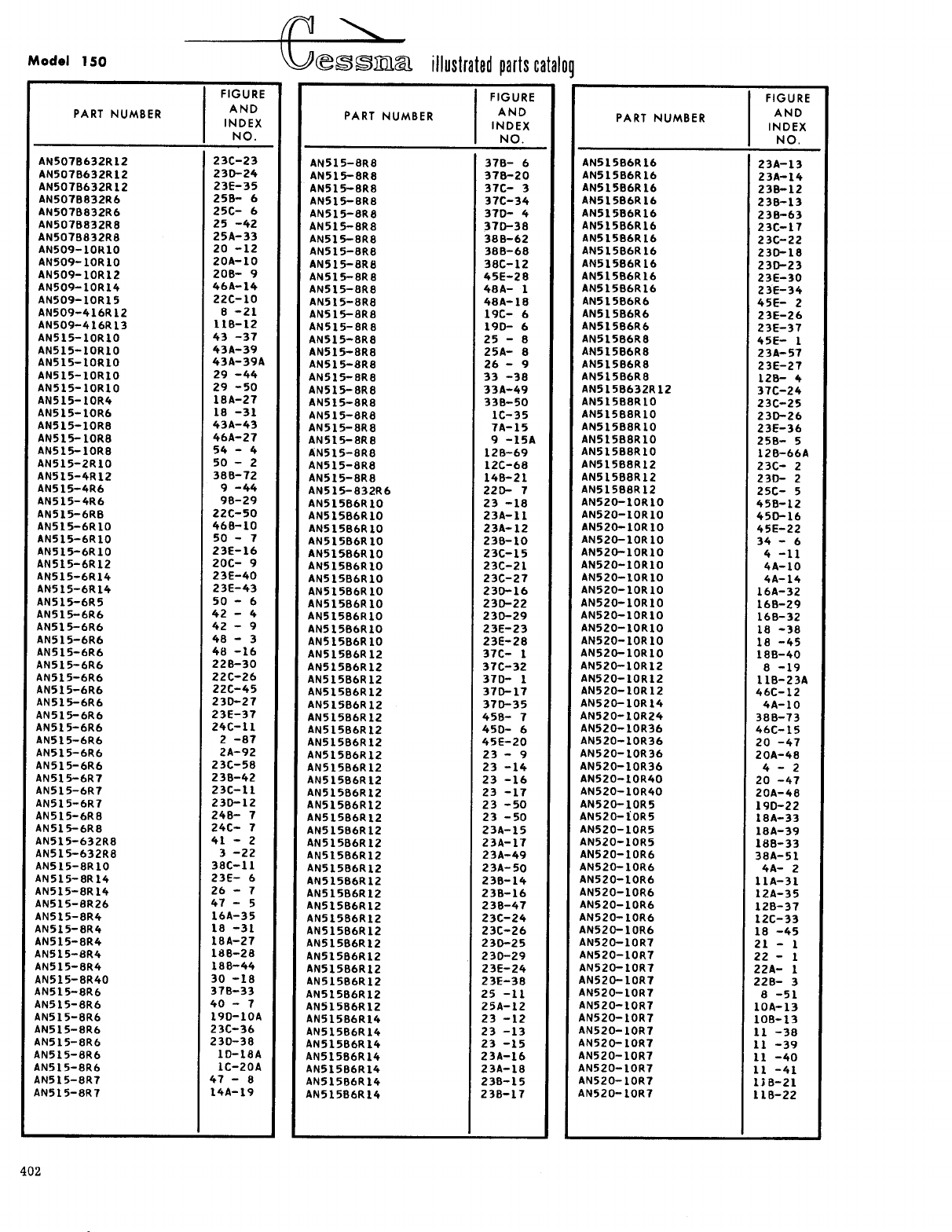
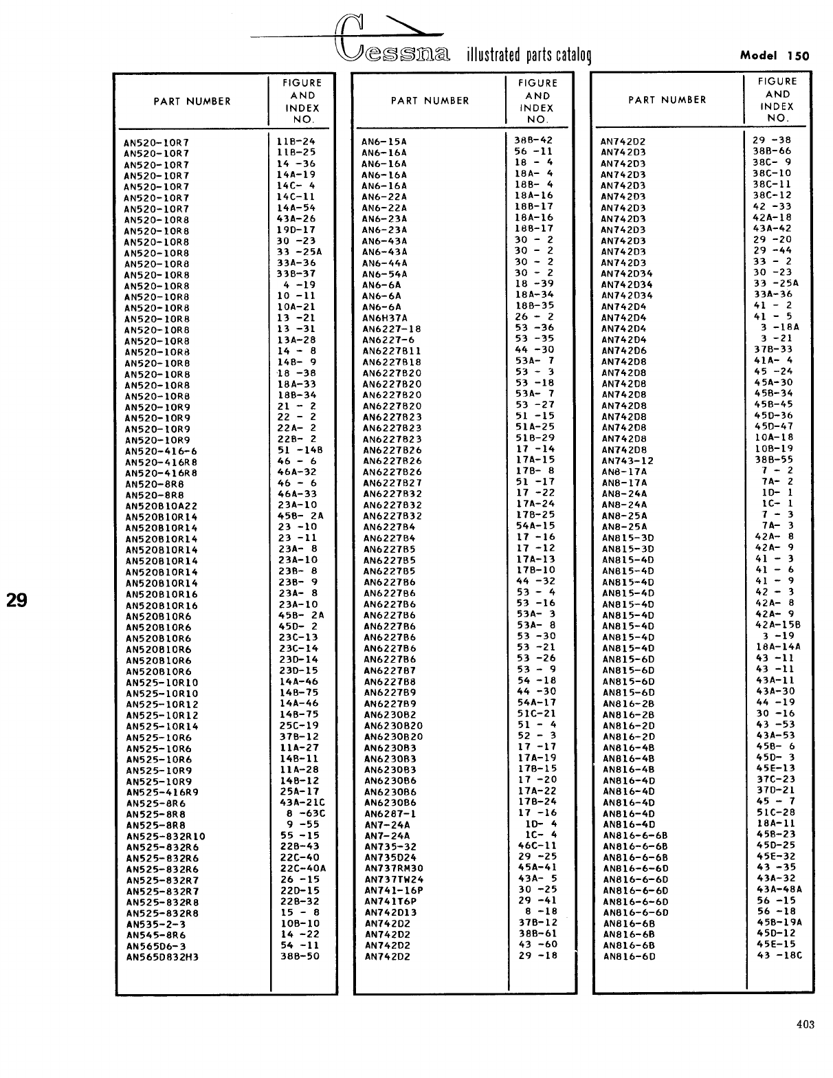
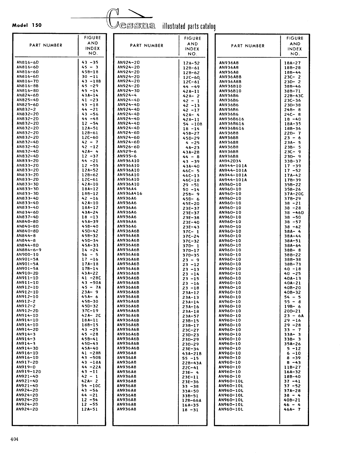
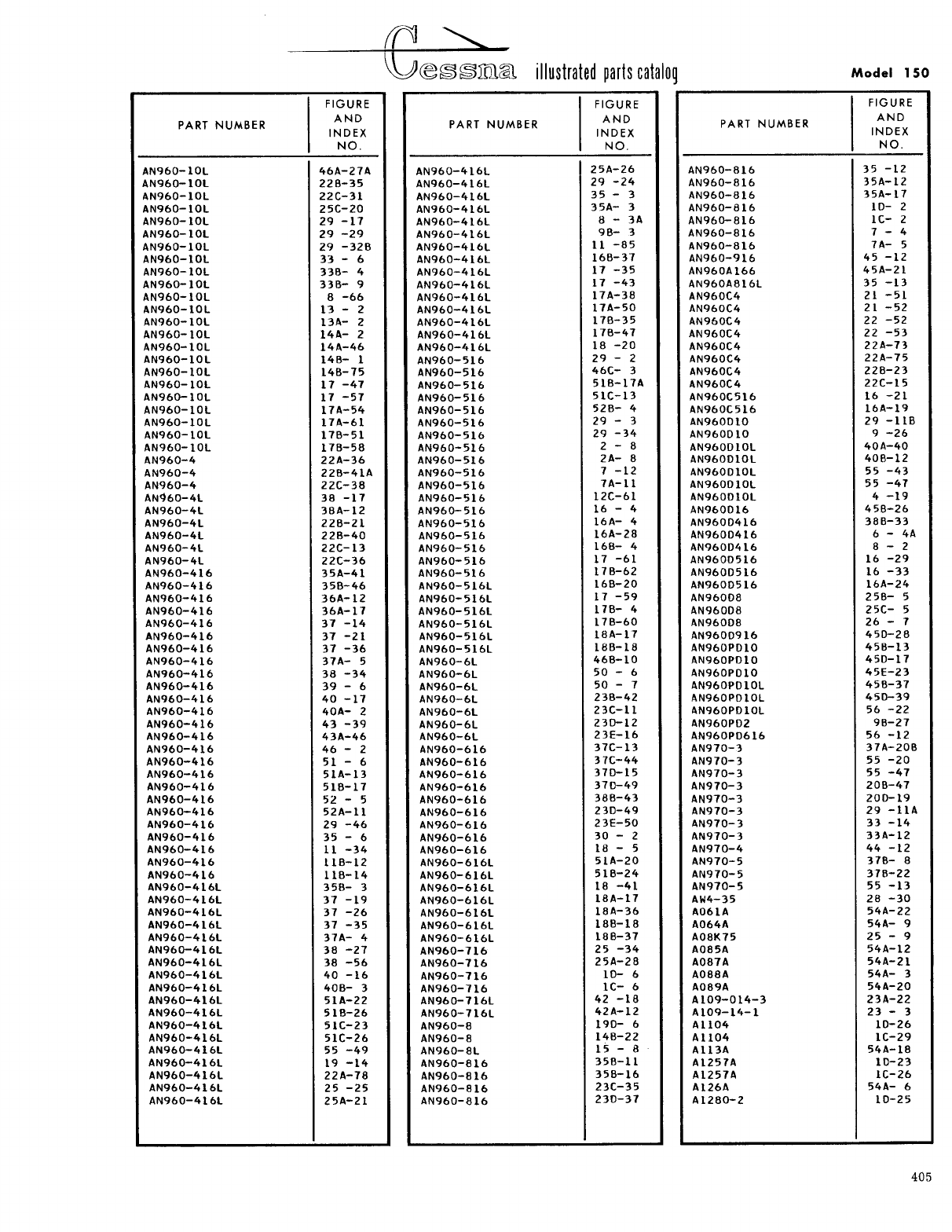
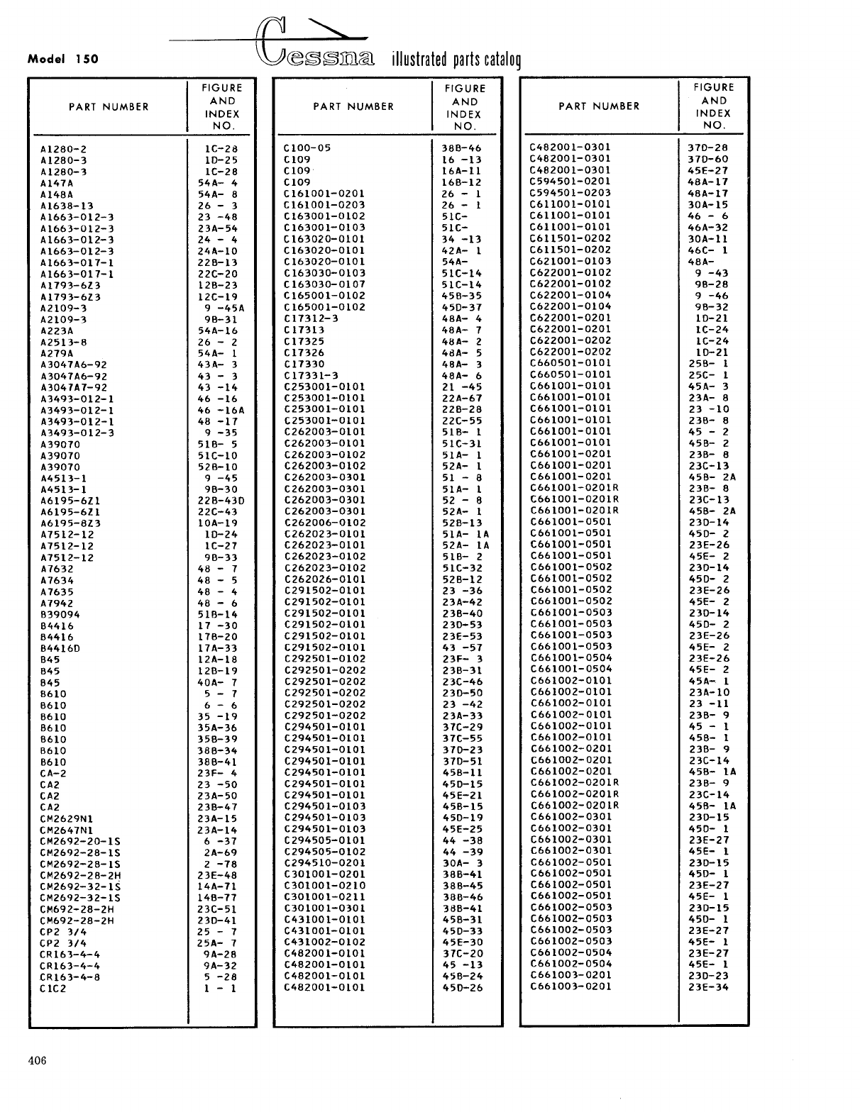
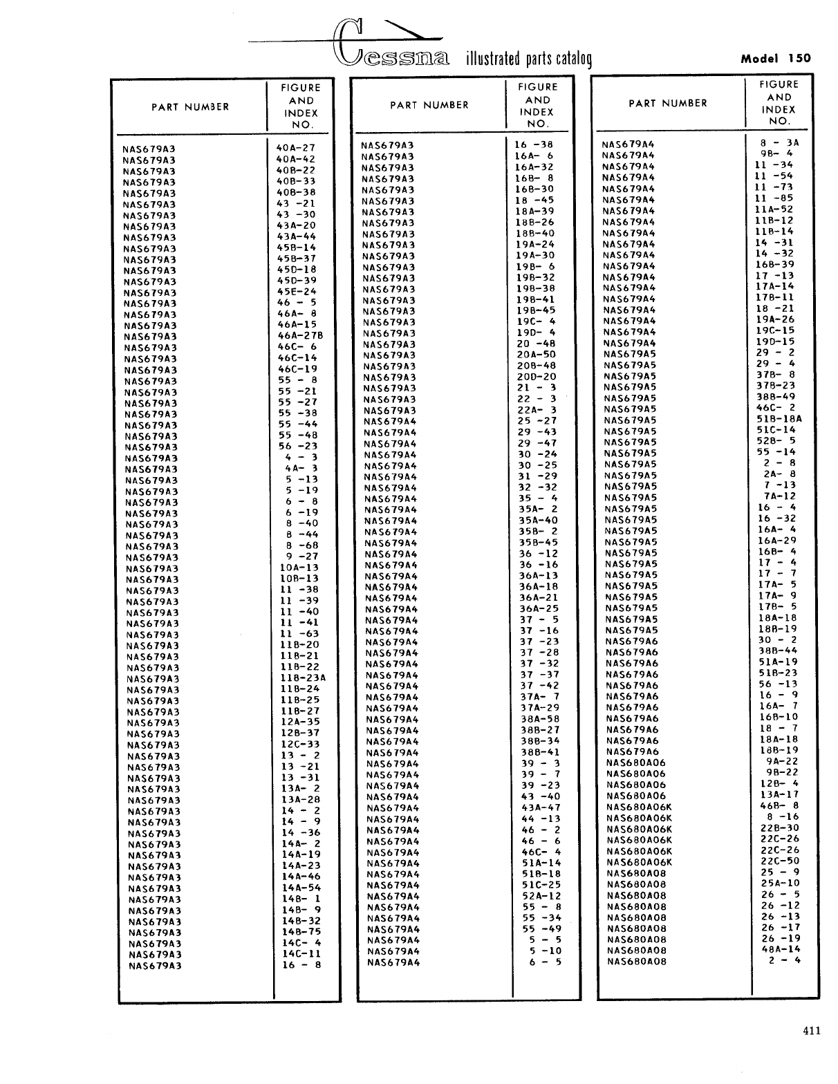
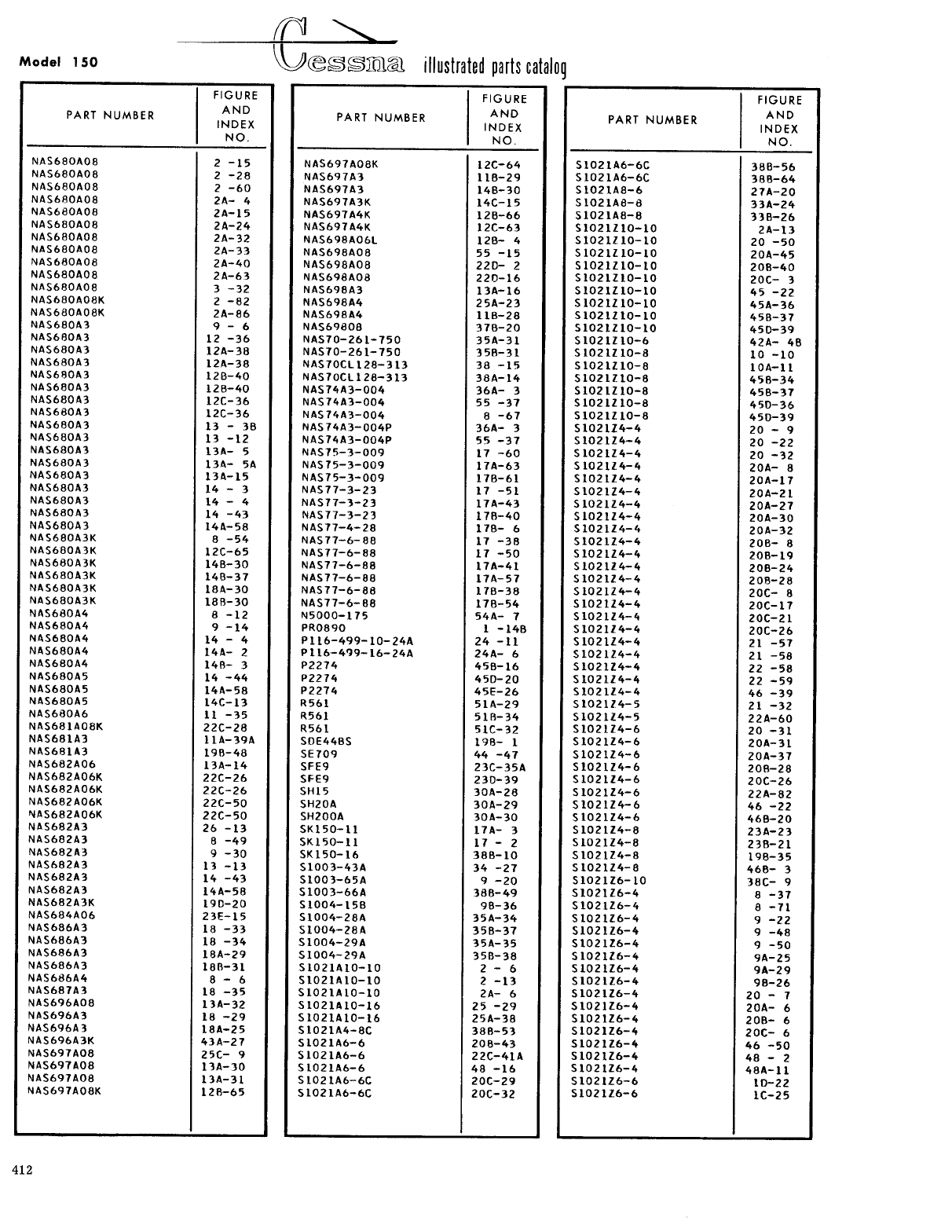
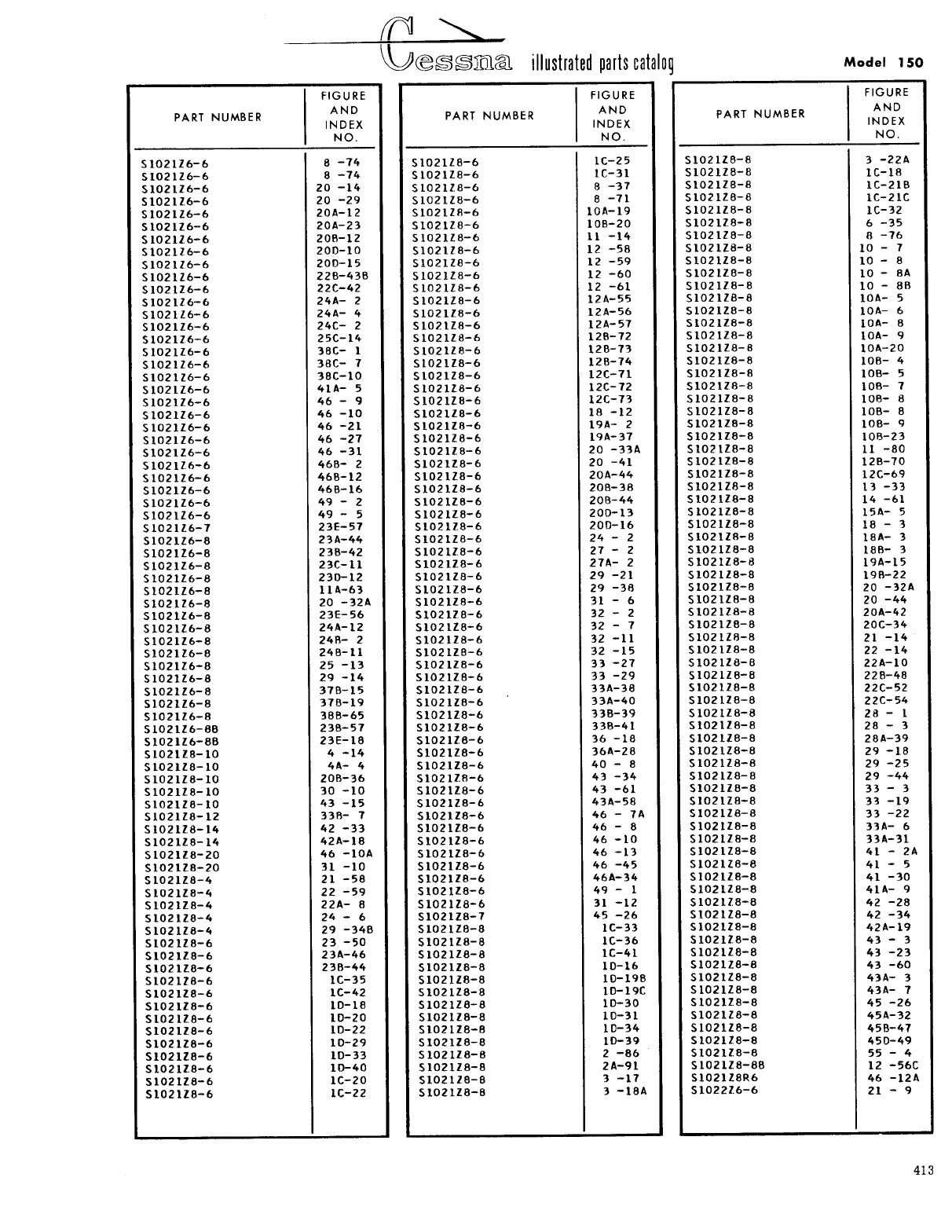
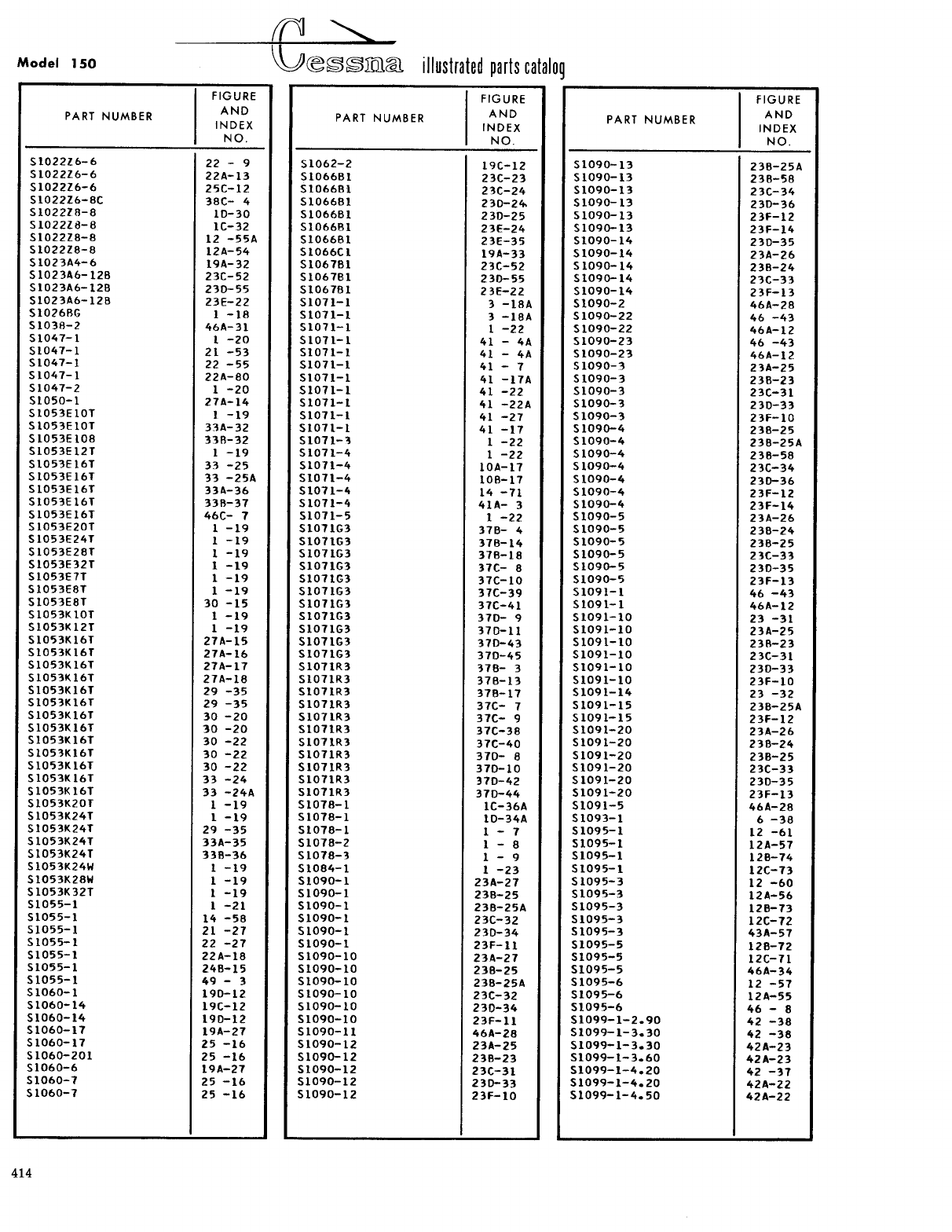
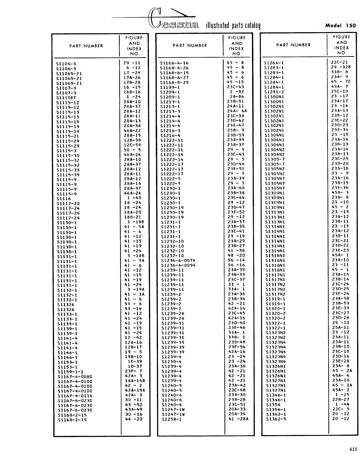
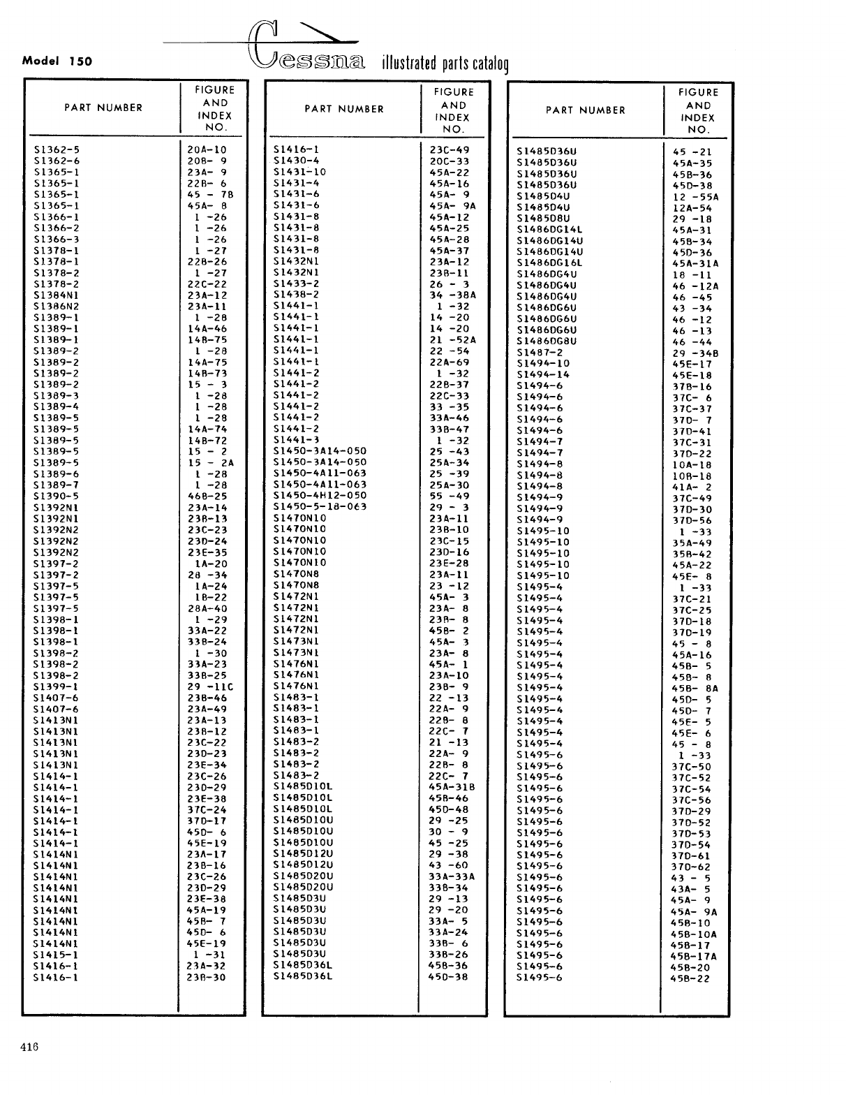
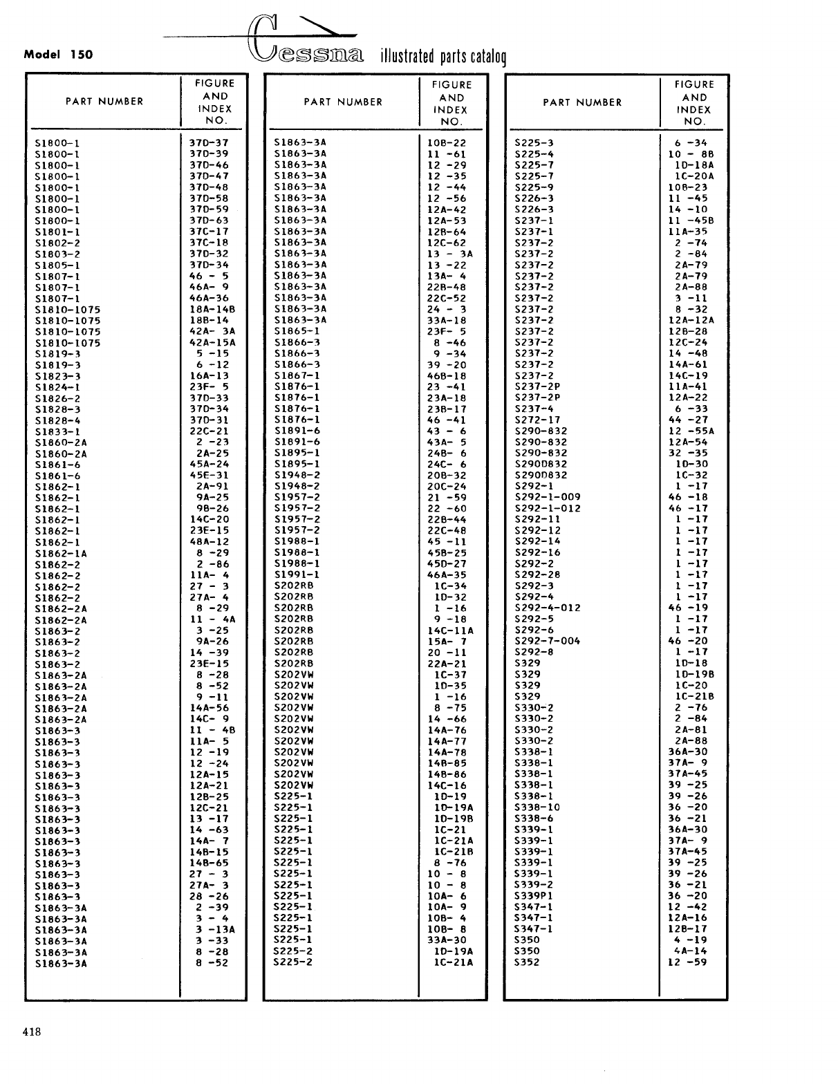
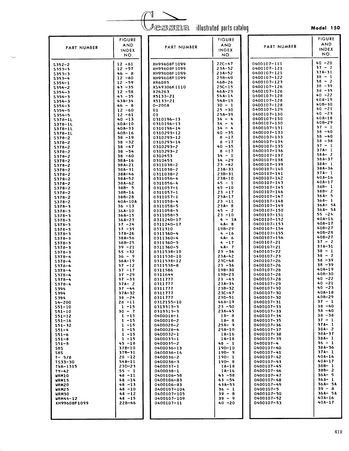
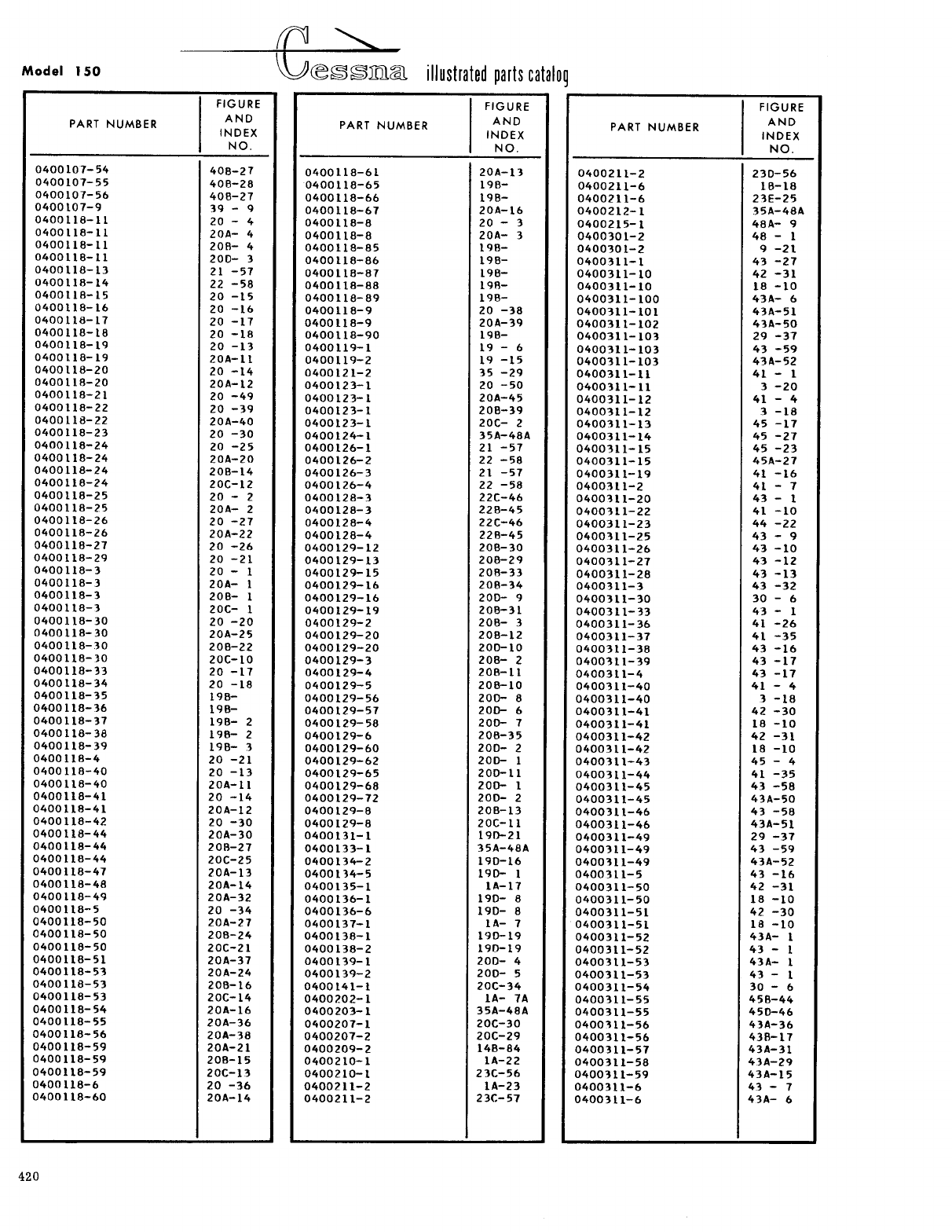
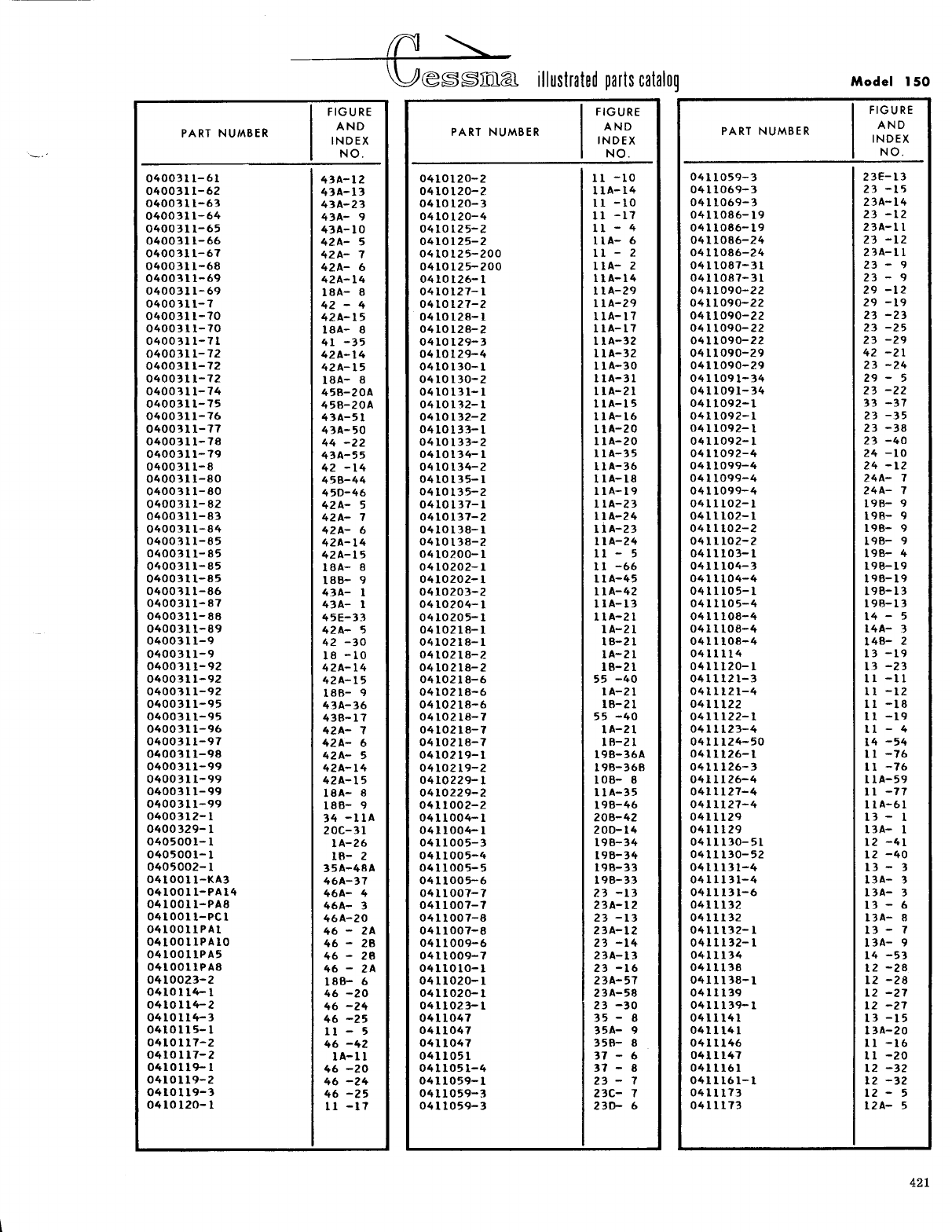
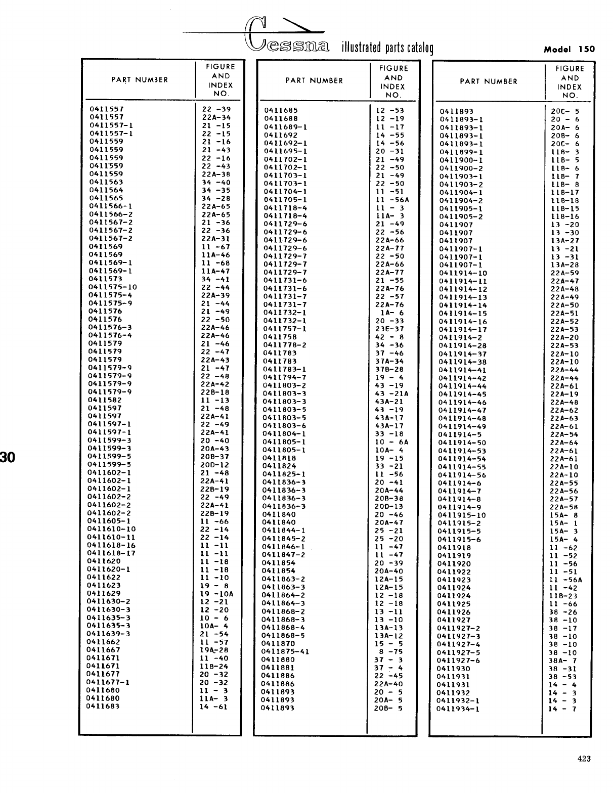
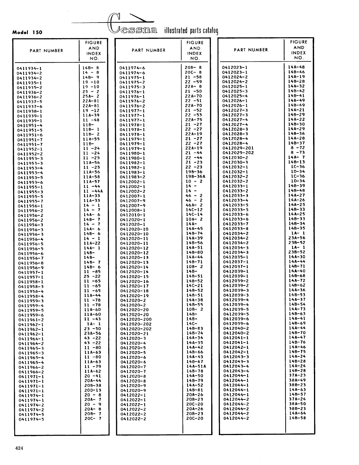
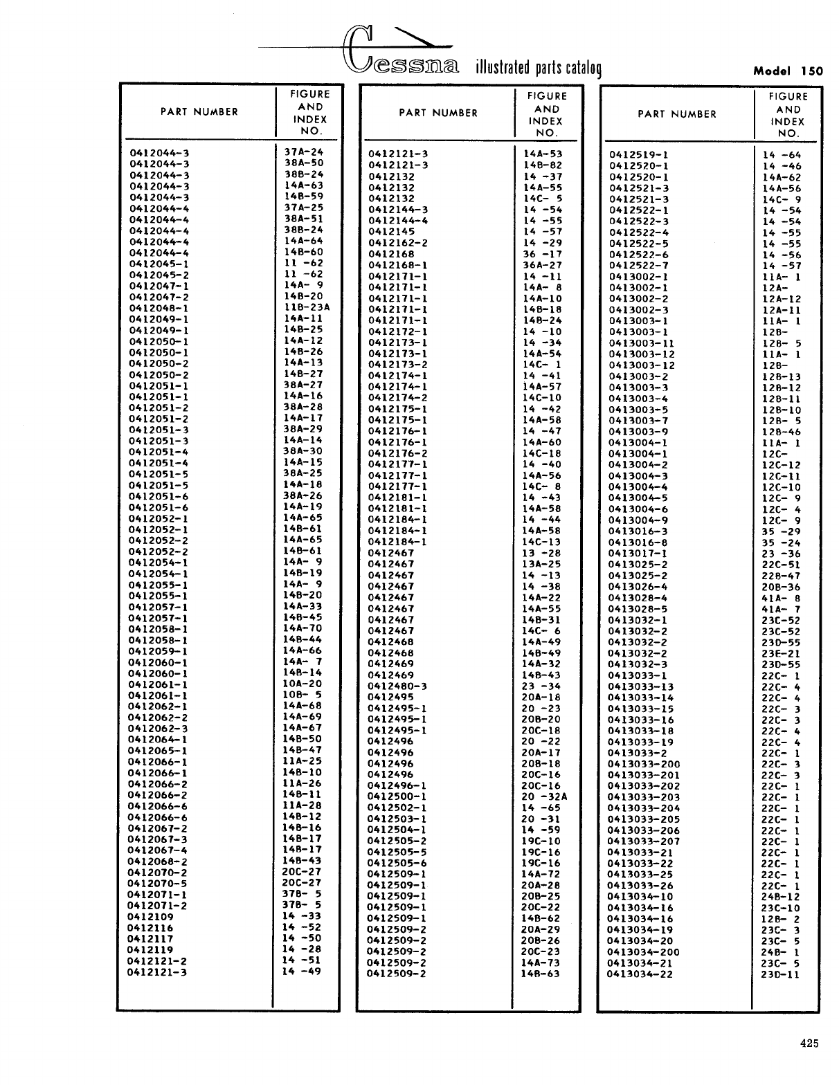
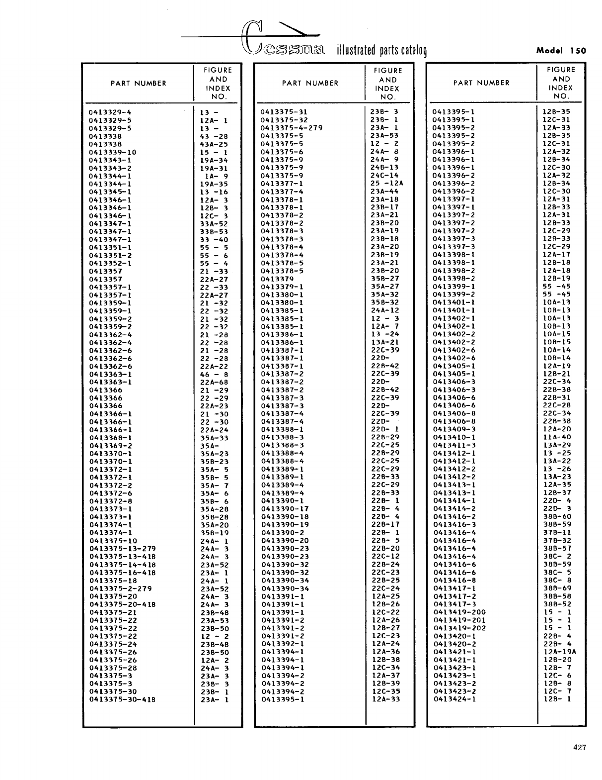
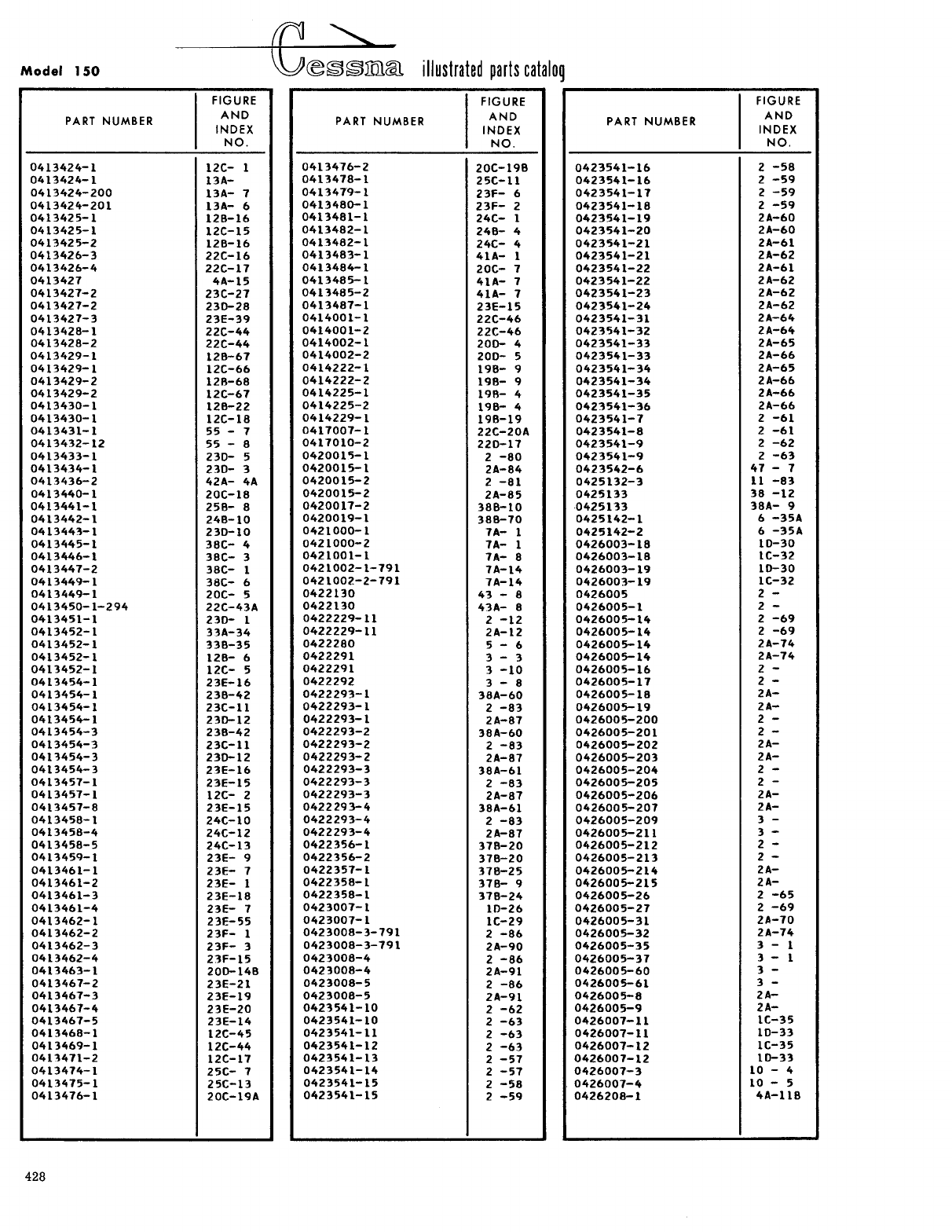
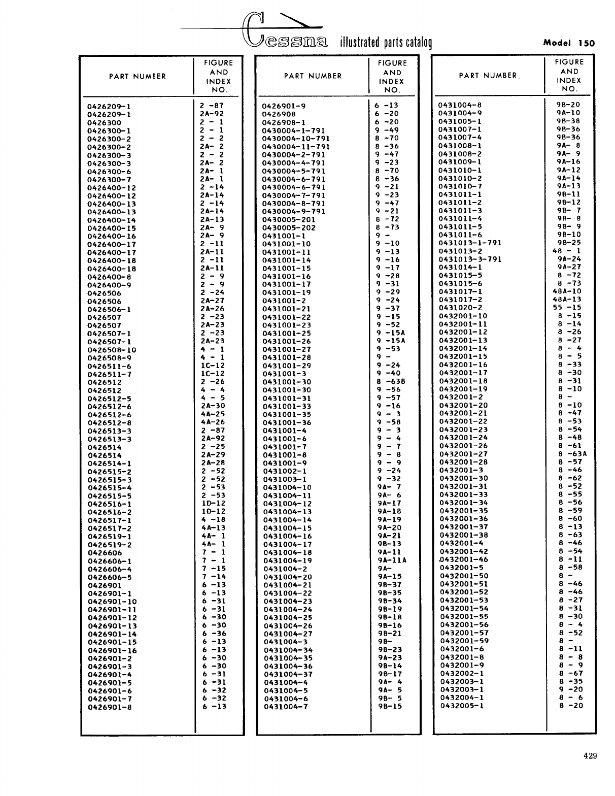
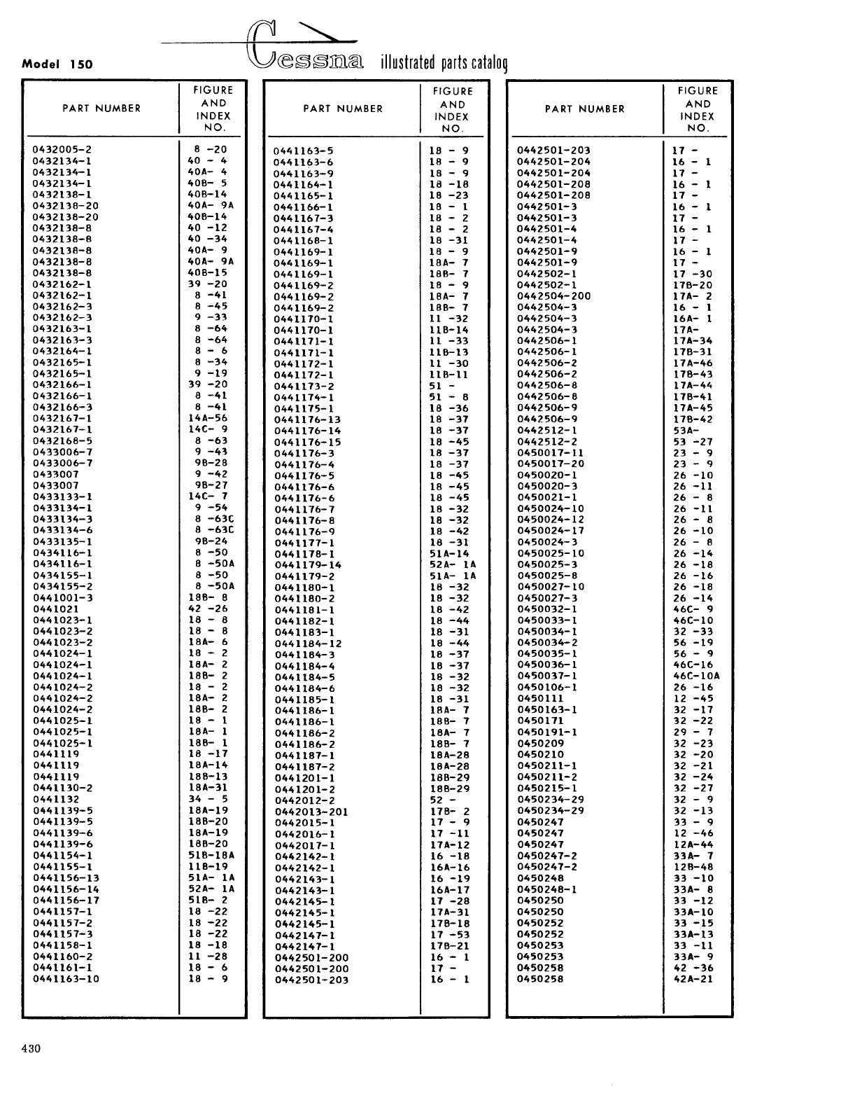
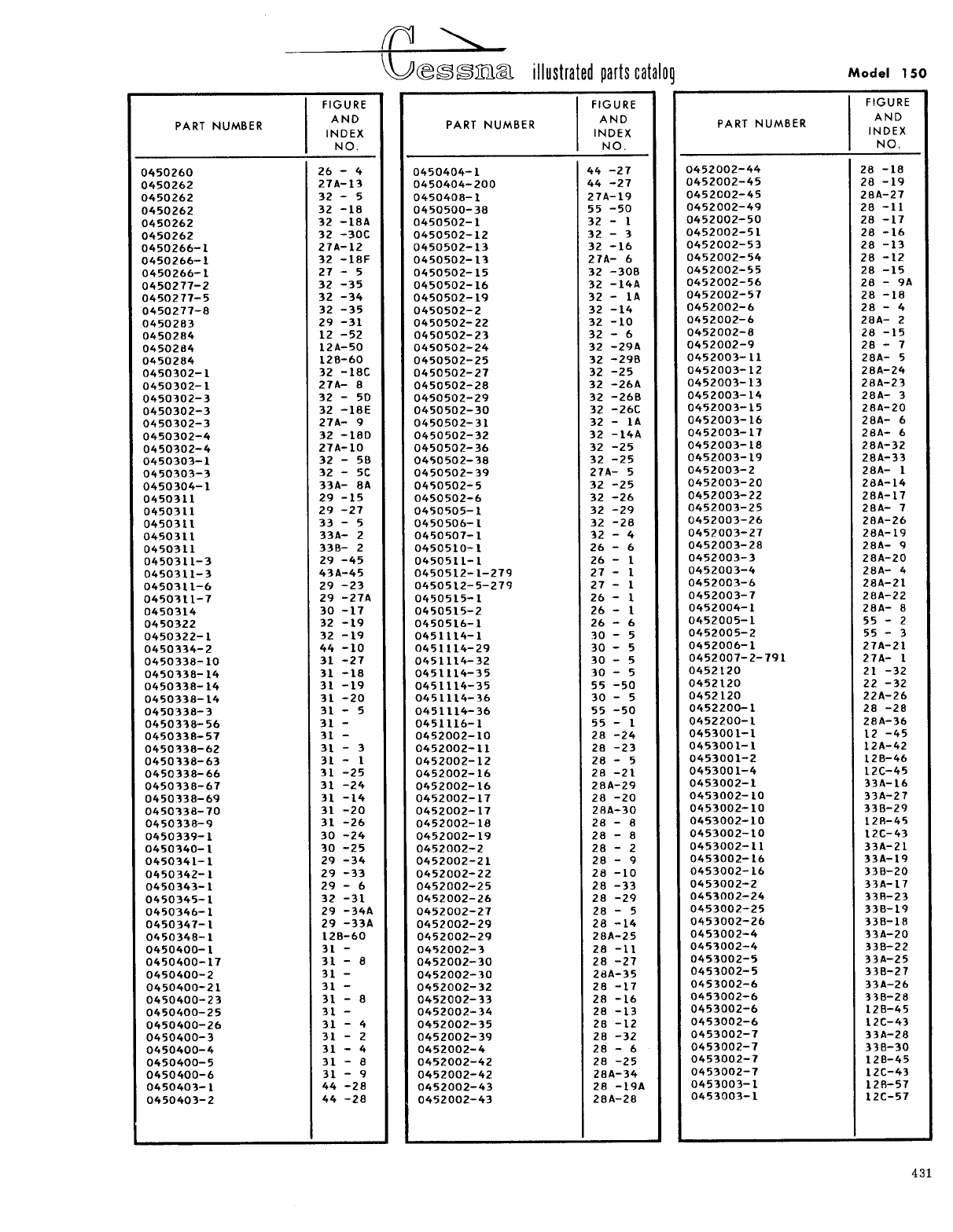
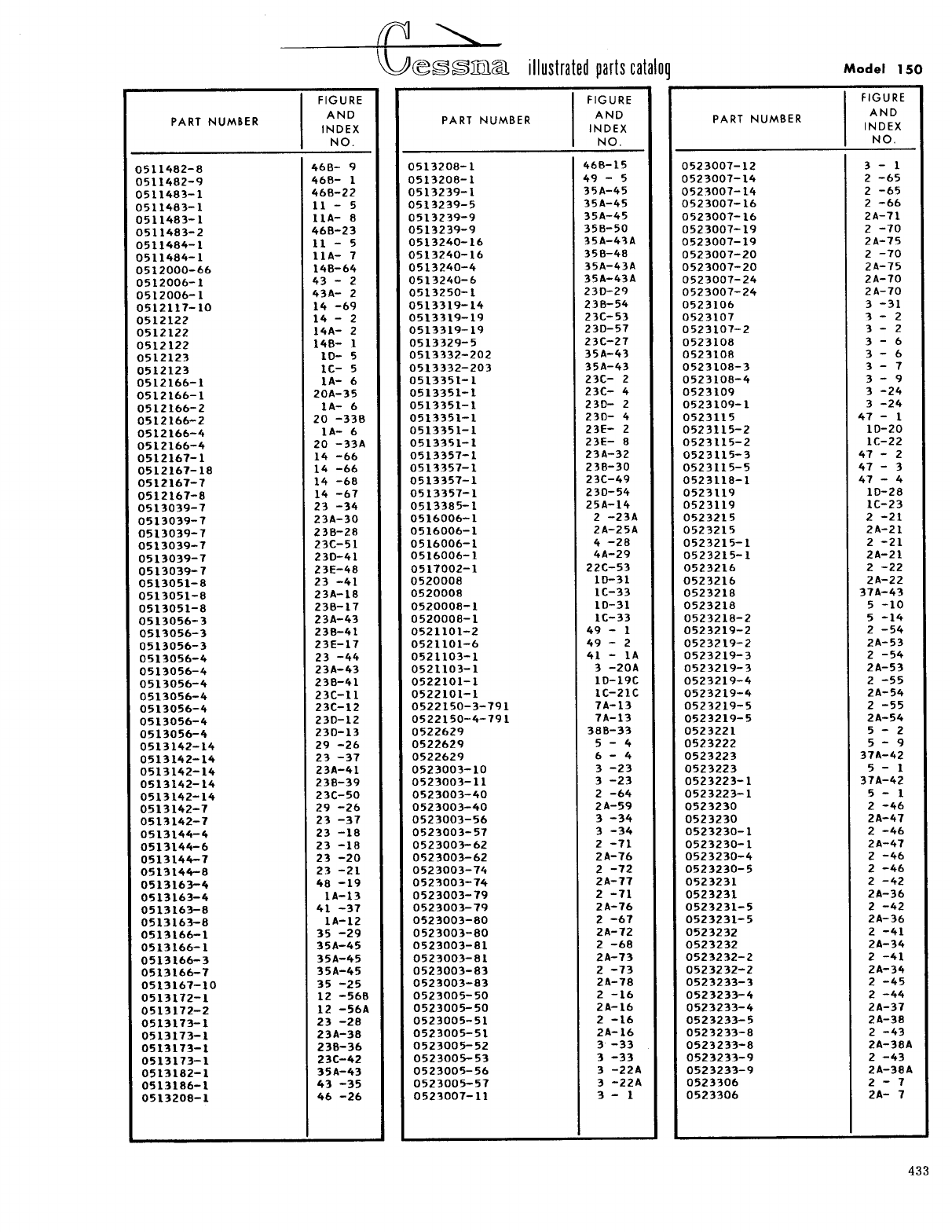
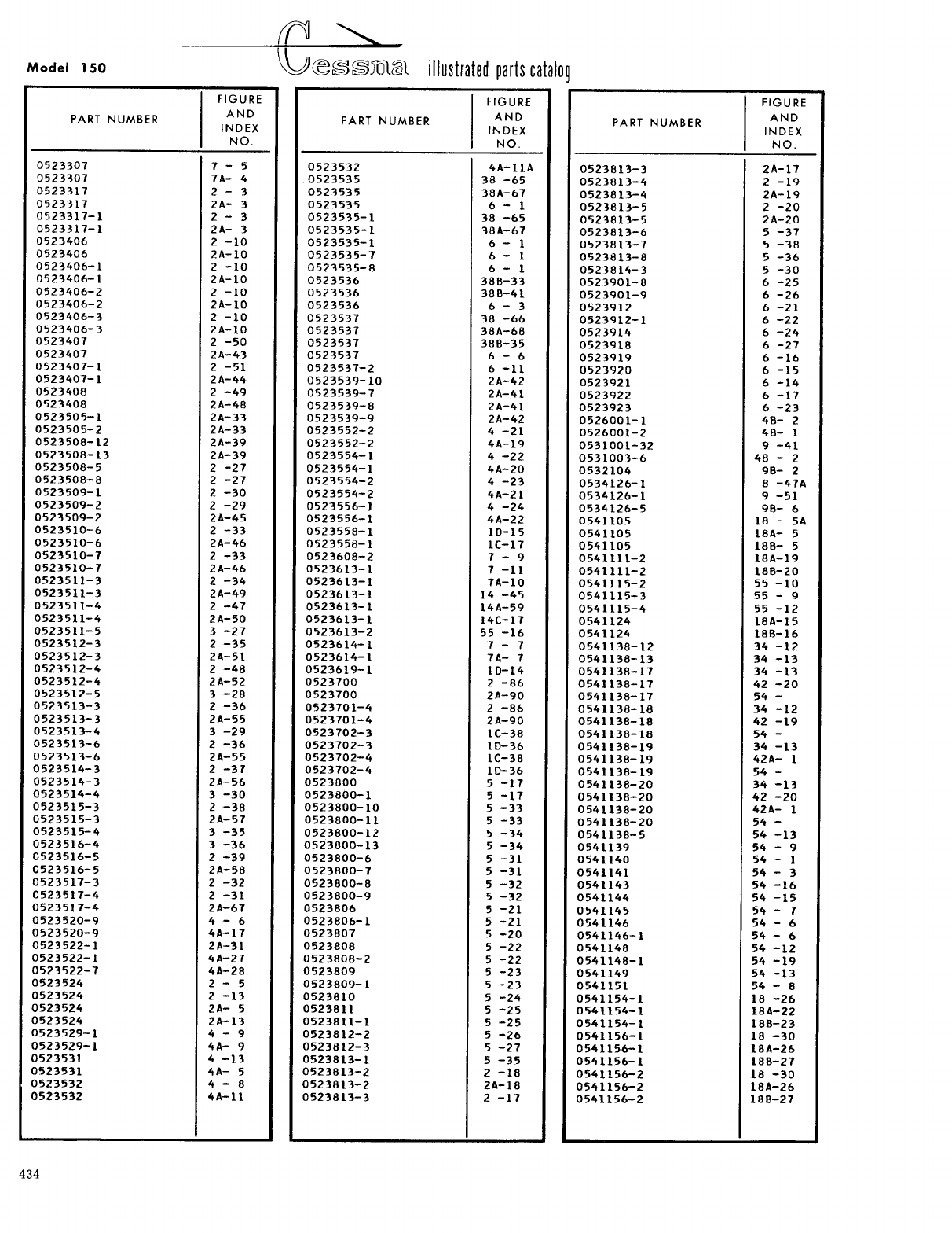
- Numerical Index
This page intentionally left blank.
This page intentionally left blank.


This page intentionally left blank.
This page intentionally left blank.
This page intentionally left blank.
This page intentionally left blank.
This page intentionally left blank.
This page intentionally left blank.
This page intentionally left blank.
This page intentionally left blank.
This page intentionally left blank.
This page intentionally left blank.

This page intentionally left blank.
S1356-1
This page intentionally left blank.
279
279
This page intentionally left blank.
This page intentionally left blank.
279
This page intentionally left blank.
This page intentionally left blank.

#
0456004-2
- 6 #
LINE - VENT ----- 150-67199 & ON, F150-0220 & ON
R
1
This page intentionally left blank.
Order
0453006-1 for
any and/or all
replacements
This page intentionally left blank.


This page intentionally left blank.
This page intentionally left blank.
This page intentionally left blank.
This page intentionally left blank.
This page intentionally left blank.
This page intentionally left blank.

This page intentionally left blank.
154-13
3021
This page intentionally left blank.
This page intentionally left blank.
This page intentionally left blank.
This page intentionally left blank.
This page intentionally left blank.