1964 Cessna 150 Patroller Cessna_150_C150D Owners_manual Retyped C150D Owners Manual
User Manual: Cessna_150_C150D-1964-owners_manual-retyped
Open the PDF directly: View PDF ![]() .
.
Page Count: 23
1964 Cessna 150 Patroller
Performance and Specifications
Gross weight 1600 lbs
Speed
Top Speed at sea level 125 mph
Cruise, 75% power at 7500 ft 122 mph
Range
Cruise, 75% Power at 7500 ft 760 mi
35.0 Gallons 6.2 hours
122 mph
Optimum Range at 10,000 ft 885 mi
35.0 Gallons 8.9 hours
99 mph
Rate of Climb at sea level 670 fpm
Service Ceiling 12650
Takeoff
Ground Run 735 ft
Total Distance over 50’ obstacle 1385 ft
Landing
Landing Roll 445 ft
Total Distance over 50’ obstacle 1075 ft
Empty Weight 1015 lbs
Baggage 120 lbs
Wing Loading 10 lb/sf
Power loading 16 lb/HP
Fuel Capacity total 38 gal
Oil Capacity 6 US qts
Propeller, Fixed Pitch, metal, dia. 69 in
Power Continental O-200 A Engine, 100 HP at 2750 RPM
page i page ii
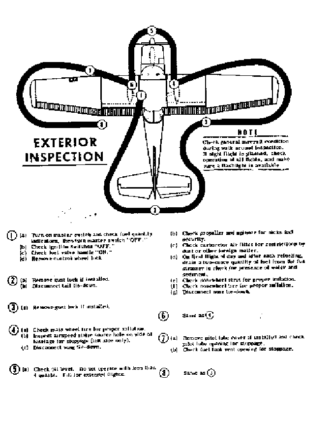
TABLE OF CONTENTS
SECTION I OPEATING CHECKLIST 1-1
SECTION II DESCRIPTION
AND OPERATING DETAILS 2-1
SECTION III OPEATING LIMITATIONS 3-1
SECTION IV CARE OF THE AIRPLANE 4-1
SECTION V OPERATIONAL DATA 5-1
ALPHABETICAL INDEX
page iii page iv
Section I
Operating Check List
One of the first steps in obtaining the utmost performance, service,
and flying enjoyment from your Cessna is to familiarize yourself with
your airplane’s equipment, systems, and controls. This can best be
done by reviewing this equipment while sitting in the airplane. Those
items whose functions and operation are not obvious are covered in
Section II
Section I lists, in the Pilot’s Check List form, the steps necessary to
operate your airplane efficiently and safely. It is not a checklist in its
true form as it is considerably longer, but it does cover briefly all of
the points that you would want to or should know concerning the
information you need for a typical flight.
The flight and operation characteristics of your airplane are normal in
all respects. There are no unconventional characteristics or
operations that need to be mastered. All controls respond in the
normal way within the entire range of operation. All airspeeds
mentioned in Sections I and II are indicated airspeeds.
Corresponding calibrated airspeeds may be obtained from the
Airspeed Correction Table in Section V.
BEFORE ENTERING THE AIRPLANE
1. Make an exterior inspection in accordance with figure 1-1
BEFORE STARTING THE ENGINE
1. Seats and seat belts – Adjust and Lock
2. Brakes – Test and set
3. Master Switch – On
4. Fuel Valve Handle –On page 1-1
STARTING THE ENGINE
1. Carburetor Heat – Cold
2. Mixture – Rich
3. Primer – As Required
4. Ignition switch – Both
5. Throttle – Open ¼ inch
6. Propeller Area – Clear
7. Starter – On
BEFORE TAKE – OFF
1. Throttle Setting – 1700 RPM
2. Engine Instruments – Within green arc and generator light out
3. Magnetos – Check (75 RPM maximum differential between
magnetos
4. Carburetor Heat – Check operation
5. Flight Controls – check
6. Trim Tab – Takeoff
7. Cabin doors – latched
8. Flight Instruments and Radios – Set
TAKE OFF
NORMAL TAKE OFF
1. Wing flaps – Up
2. Carburetor Heat – Cold
3. Throttle – Full “Open”
4. Elevator Control – Lift nose wheel at 50 mph
5. Climb Speed – 72 MPH until all obstacles are cleared, then set up
climb speed as shown in NORMAL CLIMB paragraph
MAXIMUM PERFORMANCE TAKE OFF
1. Wing Flaps – Up page 1-2
2. Carburetor Heat – Cold
3. Brakes – Hold
4. Throttle – Full OPEN
5. Brakes – release
6. Elevator Control – Slightly tail low
7. Climb Speed – 52 MPH (with obstacles ahead)
CLIMB
NORMAL CLIMB
1. Air Speed – 75 to 80 MPH
2. Power – Full throttle
3. Mixture – Rich (unless engine is rough)
MAXIMUM PERFORMANCE CLIMB
1. Air Speed – 72 MPH
2. Power – Full throttle
3. Mixture – Rich (unless engine is rough)
CRUISING
1. Power – 2000 to 2750 RPM
2. Elevator Trim – Adjust
3. Mixture – Lean to maximum RPM
BEFORE LANDING
1. Mixture – Rich
2. Carburetor Heat – Apply full heat before closing throttle
3. Airspeed – 65 to 75 MPH
4. Wing Flaps -- As desired below 100 MPH
5. Airspeed – 60 to 70 MPH with flaps extended
page 1-3
NORMAL LANDING
1. Touch down – Main wheels first
2. Landing Roll – Lower nose wheel gently
3. Braking – Minimum required
AFTER LANDING
1. Wing Flaps – Up
2. Carburetor Heat – Cold
SECURE AIRCRAFT
1. Mixture – Idle Cut-off
2. All Switches – Off
3. Parking Brake – Set
4. Control Lock – Installed
page 1-4
Section II
Description and Operating Details
The following paragraphs describe the systems and equipment whose
function and operation is not obvious when sitting in the airplane.
This section also covers in somewhat greater detail some of the items
listed in checklist form in Section I. Only those items of the checklist
requiring further explanation will be found here.
All airspeeds mentioned in this section are indicated airspeeds.
Corresponding calibrated airspeeds may be obtained from the
Airspeed Correction Table in Section V.
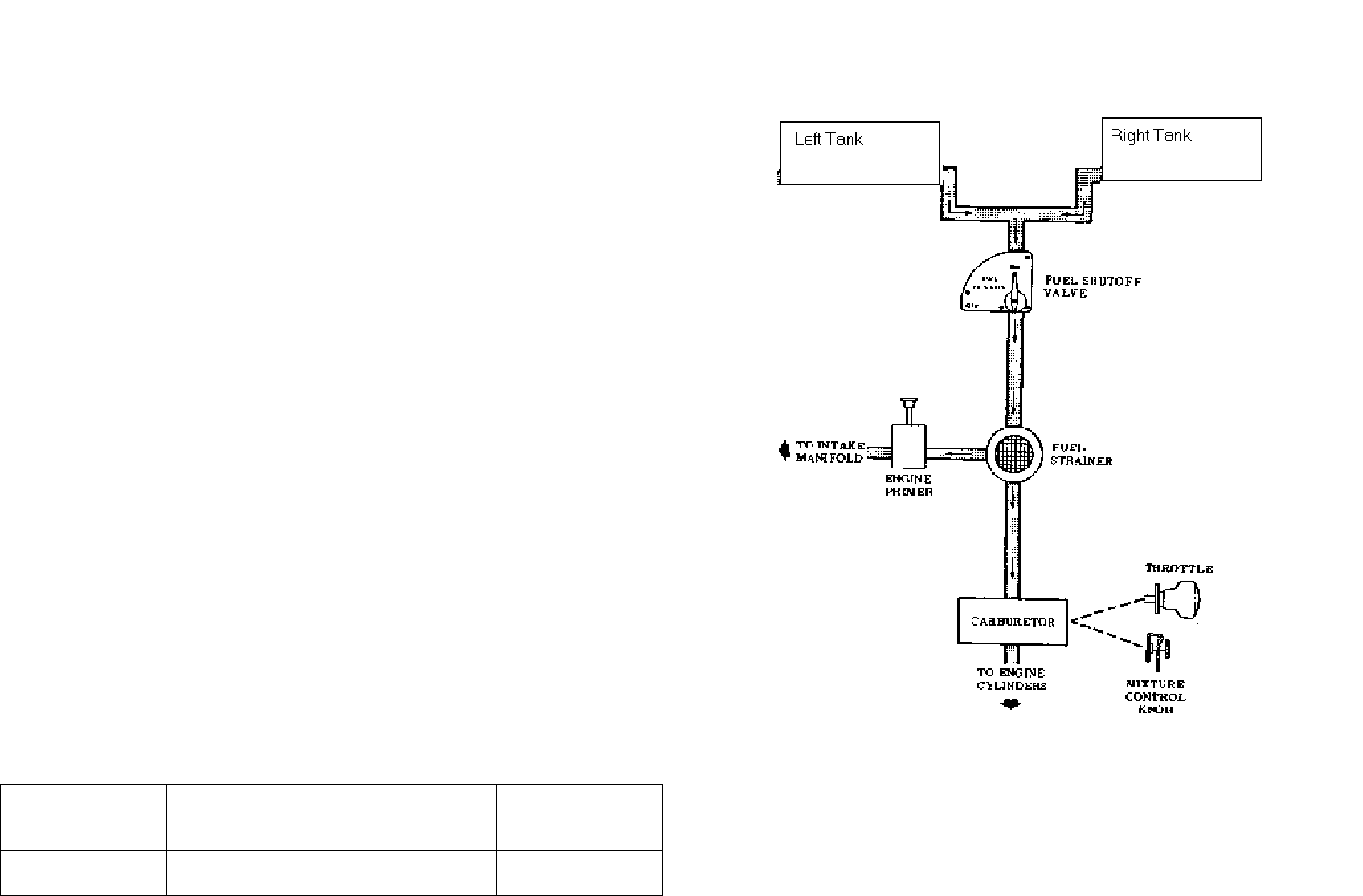
FUEL SYSTEM (Patroller)
Fuel is supplied to the engine from two 19-gallon wing tanks. From
these tanks, fuel flows by means of gravity through a fuel shutoff
valve and fuel strainer to the carburetor. The total usable fuel in all
flight conditions 35 gallons.
For fuel system service information refer to Lubrication and
Servicing Procedures in Section 4
FUEL STRAINER DRAIN
Refer to fuel strainer Servicing Procedure, Section 4
FUEL QUANTITY DATA (U. S. GALLONS)
TANKS USUABLE FUEL
ALL FLIGHT
CONDITIONS
UNUSUABLE
FUEL TOTAL FUEL
VOLUME
TWO WING
19 GAL EACH 35 3.0 38.0
fig 2-1
page 2-1
page 2-2
ELECTRICAL SYSTEM
Electrical energy is supplied by a 14-volt, direct-current system,
powered by an engine-driven 20-amp generator. A 12-volt storage
battery is located on the right forward side of the firewall, just inside
the cowl access door. The master switch controls all electrical
circuits except the clock and the ignition system.
FUSES AND CIRCUIT BREAKERS
Fuses protect many of the electrical circuits in your airplane. The
circuits controlled by each fuse are indicated above each fuse retainer.
The clock fuse is located adjacent to the battery. Fuse capacity is
indicated on each fuse retainer cap. Fuses are removed by pressing
the fuse retainers inward and rotating them counterclockwise until
they disengage. The faulty fuse may then be lifted out and replaced.
Spare fuses are held in a clip on the inside of the map compartment
door.
The fuel quantity indicators, stall warning transmitter and warning
horn system, and optional turn-and-bank indicator circuits are
protected by an automatically – reset circuit breaker which provides
intermittent emergency operation of these devices in case of a faulty
circuit. In addition to the fuse in the instrument panel, the cigar
lighter is protected by a manually-reset type circuit breaker mounted
on the back of the lighter receptacle.
LANDING LIGHTS
A three position, push-pull type switch controls the optional landing
lights mounted in the leading edge of the left wing. To turn one lamp
on for taxiing, pull the switch out to the first stop. To turn both lamps
on for landing, pull the switch out to the second stop.
page 2-3
CABIN HEATING AND VENTILATING SYSTEM
For heated ventilation air, pull the cabin heat know out the desired
amount. Additional ventilating air is provided by pulling out the
ventilators located in the upper corners of the windshield.
PARKING BRAKE SYSTEM
To set the parking brake, apply toe pressure to the pedals, pull out on
the parking brake knob, then release toe pressure. To release the
parking brake, push the knob in, then apply and release toe pressure.
STARTING ENGINE
Ordinarily the engine starts easily with one or two strokes of primer
in warm temperatures to six strokes in cold weather, with the throttle
open approximately ¼ inch. In extremely cold temperatures, it may
be necessary to continue to priming while cranking.
Weak intermittent explosions followed by puffs of black smoke from
the exhaust stack indicates overpriming or flooding. Excess fuel can
be cleaned from the combustion chambers by the following
procedure: Set the mixture control in full lean position, throttle full
open, and crank the engine trough several revolutions with the starter.
Repeat the starting procedure without any additional priming.
If the engine is underprimed (most likely in cold weather with a cold
engine) it will not fire at all, and additional priming will be necessary.
As soon as the cylinders begin to fire, open the throttle slightly to
keep it running.
After starting, if the oil gauge does not begin to show pressure within
30 seconds in the summertime and about twice that long in very cold
weather, stop engine and investigate. Lack of oil pressure can cause
serious engine damage. After starting, avoid the use of carburetor
heat unless icing conditions prevail.
page 2-4

figure 2-2
NOTE:
Strong quartering tailwinds require caution. Avoid sudden bursts of
the throttle and sharp braking when the airplane is in this attitude.
Use the steerable nose-wheel and rudder to maintain direction
page 2-5
TAXIING
When taxiing it is important that speed and use of brakes be held to a
minimum and that all controls be utilized. (see figure 2-2) to maintain
directional control and balance
Taxiing over loose gravel or cinders should be done at low engine
speed to avoid abrasion and stone damage to the propeller tips. Full
throttle run-ups over loose gravel are especially harmful to propeller
tips. When takeoffs must be made over a gravel surface, it is very
important that the throttle be advanced slowly. This allows the
airplane to start rolling before the high RPM is developed, and the
gravel will be blown back of the propeller rather than pulled into it.
When unavoidable small dents appear in the propeller, blade, they
should be immediately corrected as described in Section 4.
BEFORE TAKEOFF
WARM-UP
Most of the warm up will have been conducted during the taxi, and
additional warm up before take-off should be restricted to the checks
outlined in Section II. Since the engine is closely cowled for efficient
in-flight cooling, precautions should be taken to avoid overheating on
the ground.
MAGNETO CHECK
The magneto check should be make at 1700 RPM as follows: Move
the ignition switch first to "R" position and note RPM. Then move
switch back to "BOTH" to clear the other set of plugs. Then move
switch to "L" position and note RPM. The difference between the
two magnetos operated individually should not be more than 75
RPM.
HIGH RPM MAGNETO CHECKS
page 2-6
If there is a doubt concerning the operation of the ignition system,
RPM checks at higher engine speeds will usually confirm whether a
deficiency exists If a full throttle run up is necessary, the engine
should be run smoothly and turn approximately 2375 to 2475 RPM
with carburetor heat off.
An absence of RPM drop may be an indication of faulty grounding of
one side of the ignition system or should be cause for suspicion that
the magneto has been "bumped up" and is set in advance of the
setting specified.
TAKE-OFF
POWER CHECKS
Since the use of full throttle is not recommended in the static run-up,
it is important to check full-throttle engine operation early in the take-
off run. Any signs of rough engine operation or sluggish engine
acceleration is good cause for discontinuing the take-off. If this
occurs, you are justified in making a thorough full-throttle, static run-
up before another take-off is attempted.
Prior to take-off from fields above 5000 ft. elevation, the mixture
should be leaned to give maximum RPM in a full throttle, static run-
up.
FLAP SETTINGS
Normal and obstacle clearance take-offs are performed with flaps up.
The use of 10º flaps will shorten the ground run approximately 10%,
but this advantage is lost in the climb to a 50-ft. obstacle. Therefore,
the use of 10º flaps is reserved for minimum ground runs, or for take-
offs from soft or rough fields with no obstacles ahead.
page 2-7
If 10º flaps are used in ground runs, it is preferable to leave them
extended rather than retract them in the climb to the obstacle. The
exception to this rule would be in a high altitude takeoff in hot
weather where would be marginal with the 10º flaps (1st notch)
Flap deflections of 10º flaps and 10º flaps are not recommended at
any time for takeoff.
PERFOMRANCE CHARTS
Consult the take-off chart in Section 5 for take-off distances under
various gross weight, altitude, and headwind conditions.
CROSSWIND TAKE-OFFS
Take-offs into strong crosswinds normal are performed with the
minimum flap setting necessary for the field length, to minimize the
drift angle immediately after take-off. The airplane is accelerated to a
speed slightly higher than normal, then pull off abruptly to prevent
possible settling back to the runway while drifting. When clear of the
ground, make a coordinated turn into the wind to correct for drift.
CLIMB
For detailed data, see the Climb Performance Chart in Section 5
CLIMB SPEEDS
Normal climbs are conducted at 75 MPH to 80 MPH with flaps up
and full throttle for best engine cooling. The mixture should be full
rich unless engine is rough due to too rich a mixture. The best rate-
of-climb speeds range from 72 MPH at sea level to 66 MPH at 10,000
ft. In an obstruction dictates the use of a steep climb angle, the best
angle-of-climb speed should be used with flaps up and full throttle.
These speeds vary from 52 MPH and sea level to 60 MPH at 10.000
ft. page 2-8

NOTE
Steep climbs at these low speeds should be of short duration to allow
improved engine cooling.
CRUISE
Normal cruising is done at 65% to 75% of METO power. The
settings required to obtain these powers at various altitudes and
outside temperatures can be determined by using your Cessna Power
Computer.
Cruising can be done most efficiently at high altitude because of
lower airplane drag due to lower air density. This is illustrated in the
following table for 70% power:
ALTITUDE RPM TRUE A/S (mph
Sea Level 2430 * 111
5,000 ft 2550 * 116
9,000 ft full throttle 120
* 70% power
For detailed cruise performance, refer to the Cruise Performance
chart in Section 5.
STALLS
The stall characteristics are conventional for the flaps up and flaps
down condition Slight elevator buffeting may occur just before the
stall with flaps down.
page 2-9
The stalling speeds are shown in Section 5 for forward c.g., full
weight conditions. The are presented as calibrated airspeeds because
indicated airspeeds are inaccurate near the stall. Other loadings result
in slower stalling speeds. The stall warning horn produces a steady
signal 5 to 10 MPH before the actual stall is reached and remains on
until the airplane flight attitude is changed.
LANDING
Normal landings are made power off with any flap setting. Approach
glides are normally made at 65 to 75 MPH with flaps up, or 60 to 70
MPH with flaps down, depending upon the turbulence of the air.
SHORT FIELD LANDINGS
For a short field landing, make a power off approach at 8 MPH with
flaps 40º (fourth notch) and land on the main wheels first.
Immediately after touchdown, lower the nose gear to the ground and
apply heavy braking as required. Raising the flaps after landing will
provide more efficient braking.
CROSSWIND LANDINGS
When landing is a strong crosswind, use the minimum flap setting
required for the field length. Use a wing low, crab, or combination
method of drift correction and land in a nearly level attitude. Hold a
straight course with the steerable nosewheel and occasional braking if
necessary.
COLD WEATHER OPEATION
page 2-10
Prior to starting on clod mornings, it is advisable to pull the propeller
through several times by hand to "break loose" or "limber" the oil,
thus conserving battery energy. In extremely cold (-20ºF) weather
the use of an external preheater is recommended whenever possible to
reduce wear and abuse to the engine and electrical system. Cold
weather starting procedures are as follows:
With preheat
1. Clear propeller
2. Master Switch -- On
3. With magneto switch "OFF" and throttle closed, prime the engine
four to ten strokes as the engine is being turned over
NOTE
Use heavy strokes of primer for best atomization of fuel. After
priming, push primer all the way in and turn to locked position to
avoid possibility of engine drawing fuel through the primer.
4. Turn magneto switch to "Both"
5. Open throttle to 1/4" and engage starter
Without preheat
1. Prime the engine 8 to 10 heavy strokes while the propeller is
being turn by hand.
2. Clear propeller
3. Pull the master switch "On"
4. Turn magneto switch to "Both"
5. Open throttle 1/4"
6. Pull carburetor air heat knob to full on
7. Engage the starter and continue to prime engine until it is running
smoothly
8. Keep carburetor heat on until engine has warmed up.
page 2-11
NOTE
If the engine does not start the first time it is probable that the
spar plugs have been frosted over. Preheat must be used before
another start is attempted.
During cold weather operation, no indication will be apparent on the
oil temperature gauge prior to take of if outside air temperatures are
very cold. After a suitable warm-up period (2 to 5 minutes at 1000
RPM) accelerate the engine several times to higher engine RPM. If
the engine accelerates smoothly and the oil pressure remains normal
and steady, the airplane is ready for take-off
When operating sub-zero temperature, avoid using partial carburetor
heat. Partial heat may increase the carburetor air temperature to the
32º to 80ºF range, where icing is critical under certain atmospheric
conditions.
An optional winterization kit is available for use when operating to
temperatures below 20º F.
page 2-12
Section III
OPERATING LIMITATIONS
OPEATIONS AUTHORIZED
Your Cessna 150, with standard equipment as certified under FAA
Type Certificate is approved for day and night operation under VFR.
Additional optional equipment is available to increase its utility and
to make it authorized under IFR day and night.
Your airplane must be operated in accordance with all FAA approved
markings placards and checklists in the airplane. If there is any
information in this section, which contradicts the FAA approved
markings, placards and checklists, it is to be disregarded.
MANEUVERS - - UTILITY CATEGORY
This airplane is not designed for purely aerobatic flight. However, in
the acquisition of various certificates such as commercial pilot,
instrument pilot and flight instructor, certain maneuvers are required
by the FAA. All of these maneuvers are permitted in the Cessna 150.
In connection with the foregoing, the following gross weights and
flight load factors apply, with recommended entry speed for
maneuvers as shown.
Maximum Design Weight 1600 lbs
Flight Maneuvering Load factor, *Flaps Up +4.4 to -1.76
Flight Maneuvering Load Factor, *Flaps Down +3.5
* The design load factors are 150% of the above and in all cases the
structure meets or exceeds design loads.
No aerobatic maneuvers are approved except those listed below:
page 3-1
MANEUVER RECOMMENDED ENTRY SPEED
Chandelles 109 MPH (95 knots)
Lazy Eights 109 MPH (95 knots)
Steep Turns 109 MPH (95 knots)
Spins Use slow Deceleration
Stalls Use slow Deceleration
During prolonged spins the aircraft engine may stop; however, spin
recovery is not adversely affected by engine stoppage.
Aerobatics that may impose high inverted loads should not be
attempted. The important thing to bear in mind in-flight maneuvers is
that the Cessna 150 is clean in aerodynamic design and will build up
speed quickly with the nose down. Proper speed control is an
essential requirement for execution of any maneuver, and care should
always be exercised to avoid excessive speed which, in turn, can
impose excessive loads. In the execution of all maneuvers, avoid
abrupt use of controls.
AIRSPEED LIMITATIONS
The following are the certificated calibrated airspeed limits for the
Cessna 150:
Maximum (Glide or dive, smooth air) 162 MPH (red line)
Caution Range 120-162 MPH (yellow arc)
Normal Range 56-120 MPH (green arc)
Flap Operating Range 49-100 MPH (white arc)
Maneuvering Speed * 109 MPH
* The maximum speed at which you can use abrupt control travel
without exceeding the design load factor
ENGINE OPEATION LIMITAIONS
Power and Speed 100 BHP at 2750 RPM
Page 3-2

ENGINE ISNTRUMENT MARKINGS
OIL TEMPERATURE GAUGE
Normal Operating Range Green Arc
Maximum Allowable Red Line
OIL PRESSURE GUAGE
Minimum Idling 10 psi (red line)
Normal Operating Range 30 - 50 psi
Maximum 100 psi (red line)
FUEL QUANTITY INDICATORS
Empty (1.75 gallons unusable each tank) E (red line)
TACHOMETER
Normal Operating Range:
At sea level 2000 - 2550 (inner green arch)
At 5000 feet 2000 - 2650 (middle green arc)
At 10,00 2000 - 2750 (outer green arc)
Maximum Allowable 2750 (red line)
WEIGHT AND BALANCE
The following information will enable you to operate your Cessna
150 within the prescribed weight and center of gravity limitations.
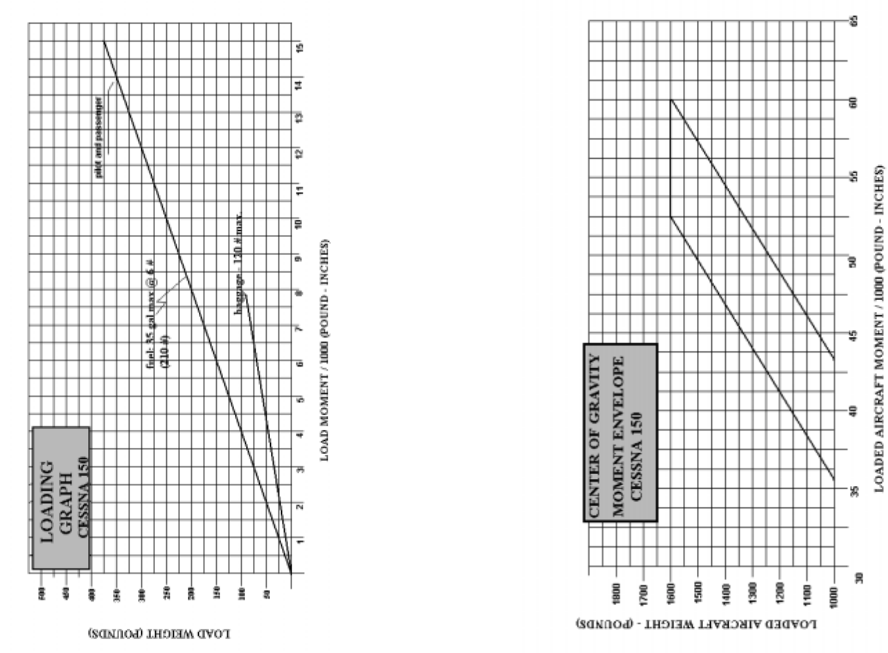
To figure the weight and balance for your particular airplane, use the
Sample Problem, Loading Graph, and Center of Gravity Moment
Envelope as follows:
Take the licensed Empty Weight and Moment/1000 from the Weight
and Balance Data Sheet, plus any changes noted on forms FAA-337
carried in your airplane, and write them down in the proper columns.
Using the Loading Graph, determine the moment/1000 of each item
to be carried. Total the weights and moments/1000 and use the
Center of Gravity Moment Envelope to determine whether the point
falls within the envelope and if the loading is acceptable.
page 3-3
SAMPLE
AIRPLANE YOUR
AIRPLANE
SAMPLE
LOADING
PROBLEM
WT
(lbs) Moment
(lb-in)
/ 1000)
WT
(lbs) Moment
(lb-in)
/ 1000)
Licensed Empty
Weight (sample
airplane)
1038 34.2
Oil 6 qts ** 11 -0.1
Pilot and
Passenger 340 13.3
Fuel (22.5 gal @
6 lb/ gal 135 5.7
Baggage 76 4.9
Total Aircraft
Weight 1600 58
Locate this point (1600 at 58.0) on the Center of Gravity envelope
chart and since this falls within the envelope, the loading is
acceptable.
** NOTE: Normally, full oil may be assumed for all flights
page 3-4
page 3-5 page 3-6
Section IV
CARE OF THE AIRPLANE
If your airplane is to retain that new plane performance, stamina, and
dependability, certain inspection and maintenance requirements must
be followed. It is always wise to follow a planned schedule of
lubrication and maintenance based on the climatic and flying
conditions encountered in your locality.
Keep in touch with your Cessna dealer, and take advantage of his
knowledge and experience. He knows your airplane and how to
maintain it. He will remind you when lubrications and oil changes
are necessary and about outer seasonal and periodic services.
GROUND HANDLING
The airplane is most easily and safely maneuvered by hand with a
tow-bar attached to the nose wheel
NOTE
When using the tow-bar, never exceed the turning angle of 30º either
side of center, or damage to the gear will result.
MOORING YOUR AIRPLANE
Proper tie-down is the best precaution against damage to your parked
airplane by gusty or strong winds.
To tied down your airplane securely, proceed as follows:
1. Set parking brake and install control wheel lock
2. Install a surface control lock between each aileron and flap
3. Tie sufficiently strong ropes or chains (700 pounds tensile
strength) to wing, and tail tail-down fittings and secure each rope
to ramp tie-down
4. Install a surface control lock over the fin and rudder
page 4-1
5. Install a pitot tube cover
6. Tie a rope to an exposed portion of the engine mount and secure
the opposite end to a ramp tie-down
WINDSHIELD - - WINDOWS
The plastic windshield and windows should be kept clean and waxed
at all times. To prevent scratches and crazing, wash them carefully
with plenty of soap and water, using the palm of the hand to feel and
dislodge dirt and mud. A soft cloth, chamois or sponge may be used,
but only to carry water to the surface. Rinse thoroughly, then dry
with a clean moist chamois. Rubbing the surface of the plastic with a
dry cloth builds up an electrostatic charge so that it attracts dust
particles in the air. Wiping with a moist chamois will remove both
the dust and this charge
Remove oil and grease with a cloth moistened with kerosene. Never
use gasoline, benzine, alcohol, acetone, carbon tetrachloride, fire
extinguisher or anti-ice fluid, lacquer thinner or glass cleaner. These
materials will soften the plastic and may cause it to craze.
After removing dirt and grease, if the surface is not badly scratched, it
should be waxed with a good grade of commercial wax. The wax
will fill in minor scratches and help prevent further scratching. Apply
a thin even coat of was and bring it to a high polish by rubbing lightly
with a clean, dry, soft flannel cloth. Do not use a power buffer; the
heat generated by the buffing pad may soften the plastic.
Do not use a canvas cover on the windshield unless freezing rain or
sleet is anticipated. Canvas covers may scratch the plastic surface.
page 4-2
PAINTED SURFACES
The painted surfaces of your new Cessna require an initial curing
period which may be as long as 90 days after the finish is applied.
During this curing period some precautions should be taken to avoid
damaging the finish or interfering with the curing process. The finish
should be cleaned only by washing with clean water and mild soap,
followed by a rinse with water and drying with cloths or a chamois.
Do not use polish or wax, which would exclude air from the surface,
during this 90-day curing period. Do not rub or buff the finish and
avoid flying through rain, sleet or hail.
Once the finish has cured completely, it may be waxed with a good
automotive wax. A heavier coating of was on the leading edges of
the wings and tail and on the engine nose cap and propeller spinner
will help reduce the abrasion encountered in these areas.
ALUMINUM SURFACES
The clad aluminum surfaces of your Cessna require only a minimum
of care to keep them bright and clean. The airplane may be washed
with clear water to remove dirt; oil and grease may be removed with
gasoline, naphtha, carbon tetrachloride or other non-alkaline solvents.
Dulled aluminum surfaces may be cleaned effectively with an aircraft
aluminum polish.
After cleaning and periodically thereafter, waxing with a good
automotive was will preserve the bright appearance and retard
corrosion. Regular waxing is especially recommended for airplanes
operated in salt water areas as a protection against corrosion.
page 4-3
PROPELLER CARE
Preflight inspection of propeller blades for nicks, and wiping them
occasionally with an oily cloth to clean off grass and bug stains will
assure long, trouble-free service. It is vital that small nicks on the
propellers, particularly near the tips and on the leading edges, are
dressed out as soon as possible since these nicks produce stress
concentrations, and if ignored, may result in cracks. Never use an
alkaline cleaner on the blades. Remove grass and dirt with carbon
tetrachloride or Stoddard solvent.
INTERIOR CARE
To remove dust and loose dirt from the upholstery, headliner, and
carpet, clean the interior regularly with a vacuum cleaner.
Blot up any spilled liquid promptly, with cleansing tissue or rags.
Don’t pat the spot; press the blotting material firmly and hold it for
several seconds. Continue blotting until no more liquid is taken up.
Scrape off sticky materials with a dull knife, then spot-clean the area.
Oily spots may be cleaned with household spot removers used
sparingly. Before using any solvent, read the instructions on the
container and test it on an obscure place on the fabric to be cleaned.
Never saturate the fabric with a volatile solvent; it may damage the
padding and backing materials.
Soiled upholstery and carpet may be cleaned with foam-type
detergent, and used according to the manufacturer's instructions. To
minimize wetting the fabric, keep the foam as dry as possible and
remove it with a vacuum cleaner,
page 4-4
The plastic trim, instrument panel and control knobs need only be
wiped off with a damp cloth. Oil and grease on the control wheel and
control knobs can be removed with a cloth moistened with kerosene.
Volatile solvents, such as mentioned in paragraphs on care of the
windshield, must never be used since they soften the craze the plastic.
INSPECTION SERVICE AND INSPECTION PERIODS
With your airplane you will receive an Owner's Service Policy.
Coupons attached to the policy entitle you to an initial inspection and
the first 100-hour inspection at no charge. If you take delivery from
your Dealer, he will perform the initial inspection before delivery of
the airplane to you. If you pick up the airplane at the factory, plan to
take it to your Dealer reasonably soon after you take deliver on it.
This will permit him to check it over and to make any minor
adjustments that may appear necessary.
Also, plan an inspection by your Dealer at 100 hours or 90 days,
which ever comes first. This inspection also is performed by your
Dealer for you at no charge. While these important inspections will
be performed for you by any Cessna Dealer, in most cases you will
prefer to have the Dealer from whom you purchased the airplane
accomplish this work.
Civil Air Regulations required that all airplanes have a periodic
(annual) inspection as prescribed by the administrator, and performed
a person designated by the administrator. In addition, 100-hour
periodic inspections made by an "appropriately-rated mechanic" are
required if the airplane is flown for hire. The Cessna Aircraft
Company recommends the 100-hour periodic inspection for your
airplane. The procedure for this 100-hour inspection has been
carefully worked out by the factory and is followed by the Cessna
Dealer Organization. The complete familiarity of the Cessna Dealer
Organization with Cessna equipment and factory-approved
procedures provides the highest type of service possible at lower cost.
page 4-5
AIRPLANE FILE
There are miscellaneous data, information and licenses that are a part
of the airplane file. The following is a checklist for that file. In
addition, a periodic check should be made of the latest Civil Air
Regulations in insure that all data requirements are met.
1) To be displayed in the airplane at all times:
a) Aircraft Airworthiness Certificate (Form FAA-1362)
b) Aircraft Registration Certificate (Form FAA -500A)
c) Airplane Radio Station License (Form FCC-404, if transmitter
installed)
2) To be carried in the airplane at all times
a) Weight and Balance, and associated papers (latest copy of the
Repair and Alteration Form, FAA-337 if applicable)
b) Airplane Equipment List
3) To be made available upon request:
a) Airplane Log Book
b) Engine Log Book
LUBRICATION AND SERVICING PROCEDURES
Specific servicing information is provided here for items requiring
daily attention. A Service Frequency checklist is included to inform
the pilot when to have other items checked and serviced
DAILY
Fuel Tank Filler
Service after each flight with 80/87 minimum grade fuel. The
capacity of each wing tank is 19 gallons for optional patroller tanks
Fuel Strainer
On the first flight of the day and after each refueling, drain for about
four seconds, to clear fuel strainer of possible water and sediment.
Turn the drain knob, then check that strainer drain is close after
draining. page 4-6
Oil Filler
When preflight check shows low oil level, service with aviation grade
engine oil: SAE 20 below 40ºF and SAE 40 above 40ºF. Your
Cessna was delivered from the factory with straight mineral oil (non-
detergent) and should be operated with straight mineral oil for the
first 25 hours. The use of mineral oil during the 25-hour break-in
period will help seat the piston rings and will result in less oil
consumption. After the first 25 hours, either mineral oil or detergent
oil may be used. If a detergent oil is used, it must conform to
Continental Motors Corporation Specification MHS-24. Your Cessna
Dealer can supply an approved brand.
Oil Dipstick
Check oil level before each flight. Do not operate on less than 4
quarts and fill if an extended flight is planned. The oil capacity of
each engine is 7 quarts (optional oil filter has been installed)
SERVICING INTERVALS CHECKLIST
EACH 25 HOURS
Battery Check and Service
Engine Oil Change
Engine Oil Screen Clean
Induction Air Filter Clean or Replace
Nose Gear Torque Links Lubricate
EACH 50 HOURS
Engine Oil Filter Change
page 4-7
EACH 100 HOURS
Brake Master Cylinders Check and Fill
Gyro Instrument Air Filters Replace. Replace sooner if erratic
or sluggish responses are noted with normal suction gauge readings.
Shimmy Dampener Check and Fill
Suction Relief Valve Inlet Screen Check inlet screen for dirt or
obstruction
Fuel Tank Sump Drains Drain water and sediment
Fuel Line Drain Plug Drain water and sediment
Vacuum System Oil Separator Clean
EACH 500 HOURS
Wheel Bearings Lubricate. Lubricate at first 100 hours and at
500 hours thereafter
page 4-8

Section V
OPERATIONAL DATA
The operational data shown on the following pages are compiled
from actual tests with airplane and engine in good condition, and
using average piloting technique and best power mixture. You will
find this data a valuable aid when planning your flights. However,
inasmuch as the number of variables included precludes great
accuracy, an ample fuel reserve should be provided. The range
performance show makes no allowance for wind, navigation error,
pilot technique, warm-up, take-off, climb etc., which may different on
each flight you make. All of these factors must be considered when
estimating fuel reserve.
To realize the maximum usefulness from your Cessna 150, you
should take advantage of its high cruising speeds. However, if range
is of primary importance, it may pay you to fly at a low cruising RPM
thereby increasing your range and allowing you to make the trip non-
sop with ample fuel reserve. The range table on page 6-3 should be
used to solve flight-planning problems of this nature.
In the table (figure 5-4) range and endurance are given for lean
mixture from 2500 feet to 12,500 feet. All figures are based on zero
wind, 35 gallons of fuel for cruise, McCauley 1A100/MCM6950
propeller, 1600 pounds gross weight, and standard atmospheric
conditions. Mixture is leaned to maximum RPM. Allowances for
fuel reserve, headwinds, takeoffs and climb, and variation in mixture
leaning technique should be made as no allowances are shown on the
chart. Other indeterminate variables such as carburetor metering
characteristics, engine and propeller conditions, and turbulence of the
atmosphere may account for variations of 10% or more in maximum
range.
page 5-1
AIRSPEED CORRECTION TABLE
FLAPS UP
IAS 40 50 60 70 80 90 100 110 120 130 140
CAS 51 57 65 73 82 91 100 109 118 127 136
FLAPS DOWN
IAS 40 50 60 70 80 90 100 110 120 130 140
CAS49556372818998
figure 5-1
STALLING SPEEDS
Power off, (mph)
ANGLE OF BANK
Gross
Weight
1600 lbs 0º 20º 40º 60º
Flaps 0º 55 57 63 78
Flaps 20º 49 51 56 70
Flaps 40º 48 49 54 67
figure 5-2
page 5-2

figure 5-3
page 5-3
CRUISE PERFORMANCE
(WITH LEAN MIXTURE)
NOTE: Maximum performance cruise is limited to 75% power
ALTITUDE RPM %BHP TAS
MPH
GAL/
HR
* END.
(HOURS)*RANGE
(MILES)
2500 2750
2700
2600
2500
2400
2300
2200
2100
94
89
79
71
63
56
50
45
126
124
119
114
108
102
95
87
7.2
6.8
6.0
5.3
4.7
4.2
3.8
3.5
4.9
5.2
5.9
6.6
7.4
8.3
9.1
10.0
610
640
700
755
805
845
865
870
5000 2750
2700
2600
2500
2400
2300
2200
2100
87
82
74
66
58
53
47
44
126
124
119
113
107
100
92
86
6.6
6.2
5.5
4.9
4.4
4.0
3.7
3.4
5.3
5.6
6.3
7.1
7.9
8.7
9.5
10.2
670
700
755
800
845
865
875
875
7500 2700
2600
2500
2400
2300
2200
2100
76
68
61
55
50
46
44
123
117
111
104
97
90
85
5.7
5.1
4.6
4.2
3.8
3.6
3.4
6.1
6.8
7.6
8.3
9.1
9.7
10.2
755
805
845
865
880
875
870
10,000 2700
2600
2500
2400
2300
2200
71
64
58
52
48
45
122
116
109
101
94
89
5.3
4.8
4.4
4.0
3.7
3.6
6.6
7.3
8.0
8.7
9.4
9.8
805
840
870
880
887
875
12,500 2650
2600
2500
2400
2300
63
60
55
51
48
117
113
105
99
89
4.7
4.5
4.2
3.9
3.7
7.4
7.7
8.4
9.0
9.5
860
875
885
890
845
* NOTE: No allowance is made for takeoff or reserve
figure 5.4
page 5-4
Altitude Temp (F) Temp (C)

Sea Level 59 15
1,000 55.5 13
2,000 52 11
3,000 48.5 9
4,000 45 7
5,000 41.5 5
6,000 38 3
7,000 34.5 1
8,000 31 -1
9,000 27.5 -3
10,000 24 -5
11,000 20.5 -7
12,000 17 -9
13,000 13.5 -11
14,000 10 -13
15,000 6.5 -15
16,000 3 -17
17,000 -0.5 -19
18,000 -4 -21
19,000 -7.5 -23
20,000 -11 -25
Standard Temperatures
ALPHABETICAL
INDEX
A
After landing, 1-4
Airplane
before entering, 1-1
file, 4-5
ground handling, 4-1
mooring, 4-1
secure, 1-4
Airspeed correction table, 5-2
Airspeed limitations, 3-2
Aluminum surfaces, 4-3
Authorized operations, 3-1
B
Baggage capacity, i
Before entering airplane, 1-1
Before landing, 1-3
Before starting engine, 1-1
Before takeoff, 1-2, 2-6
Brake system, parking 2-4
C
Cabin heating and ventilating
system, 2-4
Capacity
baggage, i
fuel, i
oil, i
Carburetor, 2-2
Care
exterior, 4-2
interior, 4-3
propeller, 4-3
Center of gravity moment
envelope, 3-6
Checklist, servicing intervals, 4-
7,4-8
Climb, 1-3
data table, 5-3
maximum performance, 1-3
normal, 1-3
speeds, 2-8
Cold weather operation, 2-10
Correction Table, airspeed, 5-2
Cruise performance table, 5-4
Cruising, 1-3
D
Diagram, exterior inspection, iv
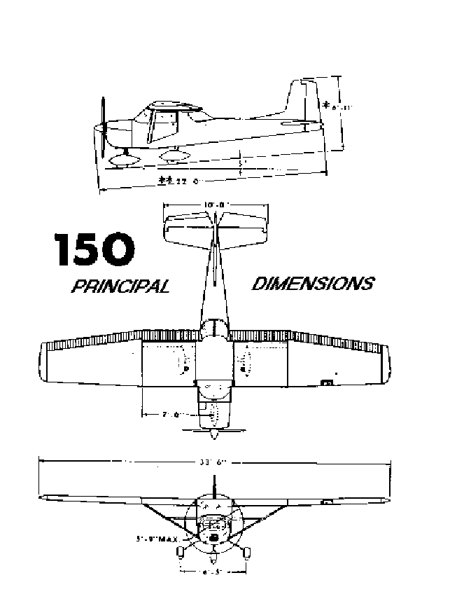
Dimensions, principal, ii
Distance table
landing, 5-3
takeoff, 5-3
E
Electrical system, 2-3
fuses and circuit breakers, 2-3
generator warning light, 2-3
Empty weight, i
Engine,
Before starting, 1-1
instrument markings, 3-3
operation limitations, 3-2
primer, 2-2
starting, 1-2
Exterior care, 4-2
Exterior Inspection , iv
F
File, airplane, 4-5
Fuel System, 2-1
capacity, i
carburetor, 2-2
primer, 2-2
quantity, 2-1
quantity indicators, 3-3
schematic, 2-2
shutoff valve, 2-2
strainer, 2-2,4-6
tank fillers, 2-7
Flap Settings, 2-7
Fuses and Circuit Breakers, 2-3
G
Generator warning light, 2-3
Gross weight, i
Ground handling, 4-1
H
Heating and ventilation system,
cabin, 2-4
I
Indicator, fuel quantity, 3-3
Inspection diagram, exterior, iv
Inspection service and inspection
periods, 4-4
Instrument markings, engine,3-3
Interior care, 4-3
L
Landing, i, 2-9
after, 1-4
before, 1-3
distance table, 6-2
lights, 2-3
normal, 1-3
short field, 2-9
Light, landing, 2-3
Limitations,
airspeed, 3-2
engine operation, 3-2
Loading graph, 3-5
Loading problem, sample, 3-4
Lubrications and servicing
procedures, 4-6
M
Magneto check, 2-6
Maneuvers, utility category, 3-1
Markings, instrument 3-3
Maximum performance climb, 1-
3
Maximum performance takeoff,
1-2
Mooring your airplane, 4-1
N
Normal climb, 1-3
Normal landing, 1-3
Normal takeoff, 1-2
O
Oil capacity, i
Dipstick, 4-7
Filler, 4-6
Temperature gauge, 3-3
Pressure gauge, 3-3
Operation, cold weather 2-10
Operations, authorized, 3-1
Owner follow-up system, 4-5
P
Performance - specifications, i
Power checks, 2-7
Power, i
Power loading, i
Primer, engine, 2-2
Principal dimensions, ii
Propeller care, 4-3
Q
Quantity data, fuel, 2-1
Quantity indicators, fuel, 3-3
R
Range, i, 5-4
Rate of climb, i
S
Sample loading problem, 3-4
Secure aircraft, 1-4
Service ceiling, i
Servicing and lubrication, 4-6
Servicing intervals, check list, 4-
7, 4-8
servicing requirements table ,
after index
Shut-off valve, fuel, 2-2
Specifications, performance, i
Speed, i
Stalls, 2-9
speed chart, 5-2
Starting engine, 1-2, 2-4
before, 1-1
Strainer, fuel, 2-2
System
cabin heating and ventilating,
2-4 electrical, 2-3
fuel, 2-1
owner follow-up, 4-5
parking brake, 2-4
T
Tachometer, 3-3
Takeoff, i, 1-2, 2-7
before takeoff, 1-2, 2-6
crosswind, 2-8
distance table, 5-3
maximum performance, 1-2
normal, 1-2
Taxiing, 2-4
diagram, 2-5
U
Utility category, maneuvers, 3-1
V
Valve, fuel shutoff, 2-2
W
Weight,
empty, i
gross, i
Weight and balance, 3-3
center of gravity moment
envelope, 3-6
loading graph, 3-6-5
sample loading problem, 3-4
Windshield - windows, 4-2
Wing loading, i
Servicing Requirements
FUEL
Aviation Grade 80/87 Minimum, grade
Capacity, each 19 gallons capacity of sump 7
qts with oil filter
do not operate with less than 4 qts
ENGINE OIL
aviation grade SAE 20 below 40º
SAE 24 above 40º
HYDRAULIC FLUID
MIL - H - 5606 Hydraulic fluid
TIRE PRESSURE
Nose gear 30 psi
Main gear 30 psi (5:00 x 5 tire)
21 psi (6:00 x 6 tire, optional
